Embed Size (px)
Citation preview
PROOF COVER SHEET
Author(s): C. Wu
Article title: Effect of process conditions on the steam reforming of ethanol with a nano-Ni/SiO2 catalyst
Article no: TENT586731
Enclosures: 1) Query sheet 2) Article proofs
Dear Author,
1. Please check these proofs carefully. It is the responsibility of the corresponding author to check these and approve or amend them. A second proof is not normally provided. Taylor & Francis cannot be held responsible for uncorrected errors, even if introduced during the production process. Once your corrections have been added to the article, it will be considered ready for publication.
For detailed guidance on how to check your proofs, please see http://journalauthors.tandf.co.uk/production/checkingproofs.asp.
2. Please review the table of contributors below and confirm that the first and last names
are structured correctly and that the authors are listed in the correct order of contribution.
This check is to ensure that your name will appear correctly online and when the article is indexed.
Sequence Prefix Given name(s) Surname Suffix
1 C. Wu
2 P.T. Williams

Queries are marked in the margins of the proofs. Unless advised otherwise, submit all corrections and answers to the queries using the CATS online correction form, and then press the “Submit All Corrections” button.
AUTHOR QUERIES
General query: You have warranted that you have secured the necessary written permission from the appropriate copyright owner for the reproduction of any text, illustration, or other material in your article. (Please see http://journalauthors.tandf.co.uk/preparation/permission.asp.) Please check that any required acknowledgements have been included to reflect this.
QUERY NO. QUERY DETAILS
AQ1 Please check that abbreviations are defined as intended.
AQ2 Is the inserted ‘°C’ correct?
AQ3 Please check that the journal title is correct.

1234567891011121314151617181920212223242526272829303132333435363738394041424344454647484950515253545556
57585960616263646566676869707172737475767778798081828384858687888990919293949596979899100101102103104105106107108109110111112
Techset Composition Ltd, Salisbury TENT586731 Page#: 8 Printed: 5/7/2011
Environmental TechnologyVol. 00, No. 0, Month 2011, 1–8
Effect of process conditions on the steam reforming of ethanol with a nano-Ni/SiO2 catalyst
C. Wu∗ and P.T. Williams
Energy & Resources Research Institute, The University of Leeds, Leeds LS2 9JT, UK
(Received 10 March 2011; final version received 4 May 2011 )
In this paper, a nano-Ni/SiO2 catalyst was prepared by a sol-gel method and tested for hydrogen production from ethanol steamreforming using a two-stage fixed-bed reaction system. The reaction conditions, such as reaction temperature, water/ethanolratio and sample feeding rate, were investigated with the prepared nano-Ni/SiO2 catalyst. Brunauer–Emmett–Teller surfacearea and porosity, temperature-programmed oxidation, X-ray diffraction and focused ion beam (FIB)/scanning electronmicroscopy were used in this work to analysis the fresh and/or reacted catalysts. An extended catalyst stability test for ethanolsteam reforming with the Ni/SiO2 catalyst was carried out at a reaction temperature of 600 ◦C, when the water/ethanol ratiowas kept at 3.5 and sample feeding rate was 4.74 g h−1. The results showed that a stabilized gas and hydrogen productionwas obtained with a potential H2 production of about 40 wt.%. Increasing the reaction temperature during ethanol steamreforming with the Ni/SiO2 catalyst resulted in an increase of gas and hydrogen production. The gas yield was slightlyreduced when the water/ethanol ratio was increased from 2.0 to 3.5. However, the potential H2 production was increased.The investigation of the sample feeding rate showed that the gas production per hour was increased due to the higher samplefeeding rate, but the potential H2 production was reduced.
Keywords: nickel; ethanol; reforming; sol-gel; nano
IntroductionHydrogen production from ethanol steam reforming hascurrently attracted much attention [1–3] due to the inter-est in the utilization of bio-ethanol and the advantages ofhydrogen as a clean energy [4,5]. Catalysts play an impor-tant role during the ethanol steam reforming process, byincreasing hydrogen production and reducing the requiredreaction temperature. Among the catalysts researched, Ni-based catalysts have been widely investigated and acceptedas a promising candidate due to their comparatively lowcost and effective catalytic activity [2,3,6,7]. In addition,the Ni/Al2O3 catalyst is a typical catalyst used for ethanolsteam reforming [8–10]. However, Ni/Al2O3 catalysts suf-fer serious deactivation due to sintering of Ni particlesand coke deposition on the catalyst during the process ofethanol steam reforming. Therefore, various methods havebeen studied to improve the performance of Ni-based cat-alysts, including the addition of a second metal, such asPt [11], Rh [12] or Cu [13,14] into the Ni catalyst system,changes to the Ni catalyst support, such as MgO-CeO2 [15],CeO2-ZrO2 [16,17] and SiO2 [14], and modification of thepreparation method of the catalyst [18,19]. Uniform nano-Ni particles supported with highly porous materials havebeen reported to reduce the deactivation of catalysts dur-ing the steam reforming of hydrocarbons by increasing Nidispersion and pore volume [20,21].
∗Corresponding authors. Email: [email protected] (C. Wu); [email protected] (P.T. Williams)
Recently, we produced a nano-Ni/SiO2 catalyst usinga sol-gel method and tested the catalyst for hydrogen pro-duction from ethanol steam reforming. The catalyst (withhigh Ni dispersion and uniform particle size) prepared bythe sol-gel method was reported to be more effective than aNi/SiO2 catalyst prepared by an impregnation method [22].In addition, process conditions are important for hydrogenproduction and catalyst performance during ethanol steamreforming [23,24]. In this paper, a nano-Ni/SiO2 catalystprepared by a sol-gel method was applied to investigatethe influence of reaction temperature, sample feeding rateand water/ethanol ratio for the production of hydrogenfrom the steam reforming of ethanol. In addition, the sta-bility of the catalyst in relation to hydrogen production andcoke deposition was also examined over an extended 7 hperiod.
Experimental detailsCatalyst preparationA 20 wt.% Ni/SiO2 catalyst was prepared by a sim-ple sol-gel method adapted from the literature [25].Ni(NO3)2·6H2O (Sigma-Aldrich), anhydrous citric acid(Alfa Aesar), deionized water, absolute ethanol (Sigma-Aldrich) and tetraethyl orthosilicate (TEOS) (Sigma-Aldrich) were used as raw materials. Ni(NO3)2·6H2O
ISSN 0959-3330 print/ISSN 1479-487X online© 2011 Taylor & FrancisDOI: 10.1080/09593330.2011.586731http://www.informaworld.com
113114115116117118119120121122123124125126127128129130131132133134135136137138139140141142143144145146147148149150151152153154155156157158159160161162163164165166167168
169170171172173174175176177178179180181182183184185186187188189190191192193194195196197198199200201202203204205206207208209210211212213214215216217218219220221222223224
2 C. Wu and P.T. Williams
(0.01 mol) and 0.01 mol of citric acid were first dissolvedinto 200 ml of absolute ethanol and stirred at 60 ◦C for 3 h.Deionized water (25 ml) and 8.7 ml of TEOS were addedinto the solution. After drying at 80 ◦C in a water bath forabout 4 hours, the precursor was calcined at 450 ◦C in astatic air atmosphere for 3 h. A test of the catalyst thermalstability (using a thermogravimetric analyser at a heatingrate of 10 ◦C min−1 to 700 ◦C in an air atmosphere) hadshown that the non-calcined catalyst was stabilized after400 ◦C. The catalyst was crushed and sieved to granuleswith a size between 0.08 and 0.20 mm.
Characterization of catalystsThe Brunauer–Emmett–Teller (BET) surface area and theporosity of the prepared catalysts were determined using aNONA 2200e Surface Area and Pore Size Analyser. Sam-ples were initially degassed under vacuum (0.016 mm Hg)for 2 h at a temperature of 120 ◦C before surface analysis.The system operates by measuring the quantity of nitrogenadsorbed onto or desorbed from a solid sample at differentequilibrium vapour pressures. The BET analysis showedthat the BET surface area of the prepared Ni/SiO2 catalystwas about 386 m2 g−1, Barrett–Joyner–Halenda (BJH) poreQ1volume was about 0.108 cm3 g−1 and BJH pore diameterwas 3.4 nm.
The temperature-programmed oxidation (TPO) of thereacted catalysts was carried out using a Stanton-Redcroftthermogravimetric analyser (derivative thermogravimetric(DTG) and thermogravimetric analysis (TGA)) to deter-Q1mine the properties of the coked carbons deposited on thereacted catalysts. About 10 mg of the reacted catalyst washeated in an atmosphere of air at 15 ◦C min−1 to a finaltemperature of 800 ◦C, with a dwell time of 10 minutes.
X-ray diffraction (XRD) (Philips PW 1830) was car-ried out for the fresh and reacted catalysts. The sample wasloaded into the 20 mm aperture of an aluminium sampleholder. The data was collected by Hiltonbrooks’ HBX dataacquisition software. The phase identification was obtainedusing GBC Scientific Equipment Ltd TRACES softwareusing the ICDD PDF2 (International Centre for DiffractionData Powder Diffraction Files) database.
A high-resolution scanning electron microscope (SEM,LEO 1530) coupled to an energy-dispersive X-ray
spectroscope (EDXS) was used to characterize and exam-ine the characteristics of the carbon deposited on thecoked catalysts. A Nanolab Dualbeam focused ion beam(FIB)/SEM coupled to an EDXS was also used to anal-yse the cross section of the reacted catalyst. Transmissionelectron microscopy (TEM) (Philips CM200) was used todetermine the fresh and reacted catalysts. For the TEM anal-ysis, the samples were ground, dispersed with methanol, andthen deposited on a Cu grid covered with a perforated carbonmembrane.
Reaction system for the ethanol steam reformingTesting of the prepared Ni/SiO2 catalysts was carried outwith a two-stage reaction system consisting of a pre-heatedstage and a gasification stage. A schematic diagram of thereaction system is shown in our previous paper [22].
A mixture of absolute ethanol and deionized water wasintroduced into the pre-heated stage of the reaction system(190 ◦C) using a syringe pump. The pre-heated mixture ofgaseous feedstock then passed through the gasification stagewith N2 as carrier gas (80 ml min−1) and was reformed inthe presence of the prepared catalyst (0.5 g). The derivedgaseous products were condensed with an air-cooled con-denser and a dry ice-cooled condenser to collect the liquidproducts. The non-condensed gases were collected with aTedlar™ gas sample bag. The reproducibility of the reac-tion system was tested thoroughly to ensure the reliabilityof research results.
The gases collected in the sample bag were analysedoff-line by packed column gas chromatography (GC). C1–C4 hydrocarbons were analysed using a Varian 3380 gaschromatograph with a flame ionization detector, with an80–100 mesh Hysep column and nitrogen carrier gas. Per-manent gases (H2, CO, O2, N2 and CO2) were analysed bya second Varian 3380 gas chromatograph with two separatecolumns. Hydrogen, oxygen, carbon monoxide and nitro-gen were analysed on a 60–80 mesh molecular sieve columnwith argon carrier gas, whilst carbon dioxide was analysedon a Hysep 80–100 mesh column with argon carrier gas.
Table 1. Mass balance and hydrogen production for the 7 h testing in relation to ethanol steam reforming.
Reaction time (h)1 2 3 4 5 6 7
Gas production (g h−1) 2.26 2.12 2.20 1.92 2.13 2.14 2.11H2 production (g h−1) 0.21 0.20 0.22 0.19 0.22 0.21 0.21Potential H2 production (wt.%) 40.9 38.1 43.0 36.6 41.4 40.7 39.4Average gas yield (wt.%) 44.9Total liquid yield (wt.%) 45.4
225226227228229230231232233234235236237238239240241242243244245246247248249250251252253254255256257258259260261262263264265266267268269270271272273274275276277278279280
281282283284285286287288289290291292293294295296297298299300301302303304305306307308309310311312313314315316317318319320321322323324325326327328329330331332333334335336
Environmental Technology 3
Results and discussionSeven-hour testing of Ni/SiO2 catalyst for the ethanolsteam reformingThe Ni/SiO2 catalyst prepared by the sol-gel method wastested for ethanol steam reforming for 7 h while the sam-ple (water and ethanol, molar ratio 3.5:1) feeding rate wasmaintained at 4.74 g h−1 and the reforming temperature waskept at 600 ◦C. The gas sample was collected and analysed
1 2 3 4 5 6 70
10
20
30
40
50
60
70
Gas
com
posi
tion
s (V
ol.%
)
Reaction time (h)
CO H
2
CO2
CH4
C2-C
4
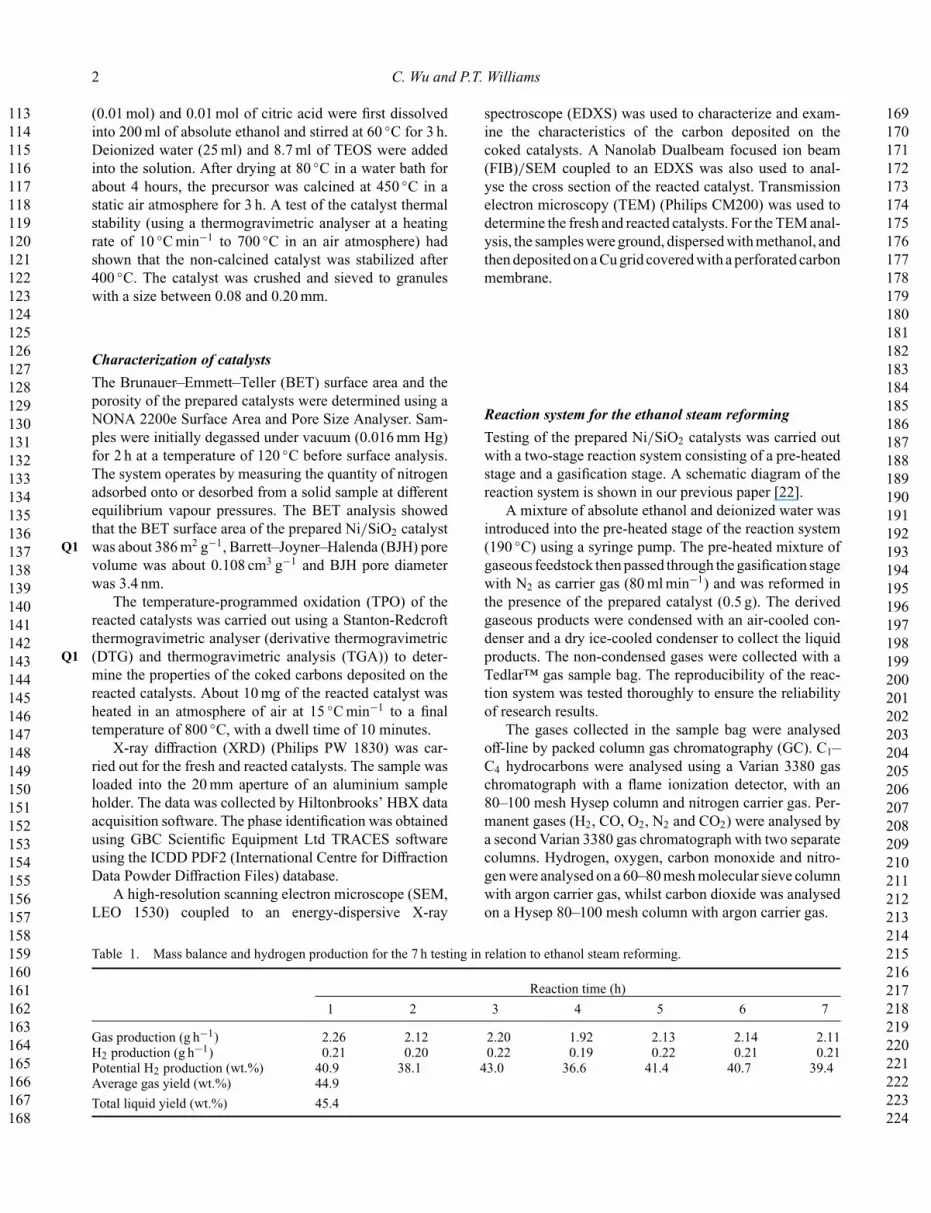
Figure 1. Gas compositions from ethanol steam reforming withthe Ni/SiO2 catalyst.
at hourly intervals. Mass balance data and hydrogen pro-duction data are presented in Table 1. As shown in Table 1,the gas production was around 2.10 g h−1, the hydrogenproduction was around 0.20 g h−1 and the potential H2 pro-duction was around 40 wt.%, respectively, during the 7 hethanol steam reforming process. In this paper, the potentialhydrogen production was calculated from the H2 produc-tion divided by the maximum hydrogen production fromthe steam reforming of the injected ethanol (0.26 g maxi-mum H2/g ethanol). Therefore, it is shown from Table 1that the gas and hydrogen production were quite stable overthe 7 h ethanol steam reforming period. From Table 1, theaverage gas yield related to the mass of injected samplewas about 44.9 wt.% and the liquid production (mass ofcondensed products divided by the mass of injected sam-ple) was about 45.4 wt.%. Song et al. [26] investigatedethanol steam reforming over supported cobalt catalysts;a 38.1 wt.% H2 yield (equates to the potential H2 produc-tion in this paper) was obtained at a reforming temperatureof 550 ◦C, H2O/ethanol ratio of 10 and weight hourly spacevelocity of 0.54 (g ethanol per g of catalyst per hour). Incomparison, the weight hourly space velocity in this workis about 4.0 (g ethanol per g of catalyst per hour).
The gas concentrations from the 7 h testing of the cata-lyst in relation to ethanol steam reforming are presented inFigure 1. From Figure 1, the H2, CO, CO2 and CH4 concen-trations were stabilized at around 65, 11, 18 and 4 Vol.%,respectively. Therefore, a stable gas concentration could
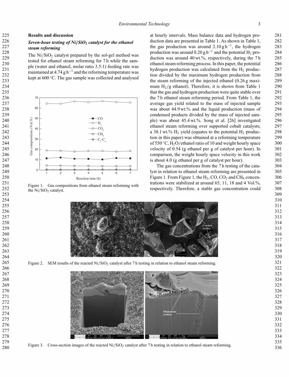
Figure 2. SEM results of the reacted Ni/SiO2 catalyst after 7 h testing in relation to ethanol steam reforming.
Figure 3. Cross-section images of the reacted Ni/SiO2 catalyst after 7 h testing in relation to ethanol steam reforming.
337338339340341342343344345346347348349350351352353354355356357358359360361362363364365366367368369370371372373374375376377378379380381382383384385386387388389390391392
393394395396397398399400401402403404405406407408409410411412413414415416417418419420421422423424425426427428429430431432433434435436437438439440441442443444445446447448
4 C. Wu and P.T. Williams
also be concluded, indicating the stable performance of theprepared Ni/SiO2 catalyst.
SEM and FIB/SEM analysis were used to character-ize the reacted Ni/SiO2 catalyst after the 7 h investiga-tion of ethanol steam reforming. The SEM results areshown in Figure 2 and the FIB/SEM results are shown inFigure 3. Filamentous carbons were observed from both theSEM and FIB/SEM analysis (Figures 2 and 3). Figure 2shows cracking of the catalyst particles. The cracking ofthe catalyst after the ethanol steam reforming was alsoobserved in the FIB/SEM analysis (Figure 3), where crack-ing lines were obvious. The filamentous carbons were notonly deposited on the top of the surface of the catalyst(Figures 2 and 3), but also were found in the gaps ofcracked particles (Figure 3). The cracking of the Ni-Mg-Al catalyst after the pyrolysis gasification of polypropylenehas been reported by Wu and Williams [27]. It is sug-gested that some gaseous intermediates might permeateinto the catalyst during the reforming and generate aninitial force to crack the catalyst for the Ni/SiO2 cata-lyst used in this work. However, the initially generated
0 100 200 300 400 500 600 700 800 9000.88
0.90
0.92
0.94
0.96
0.98
1.00
-0.0010
-0.0008
-0.0006
-0.0004
-0.0002
0.0000
0.0002
Der
ivat
ive
wei
ght (
°C-1)
Wei
ght r
atio
Temperature (°C)
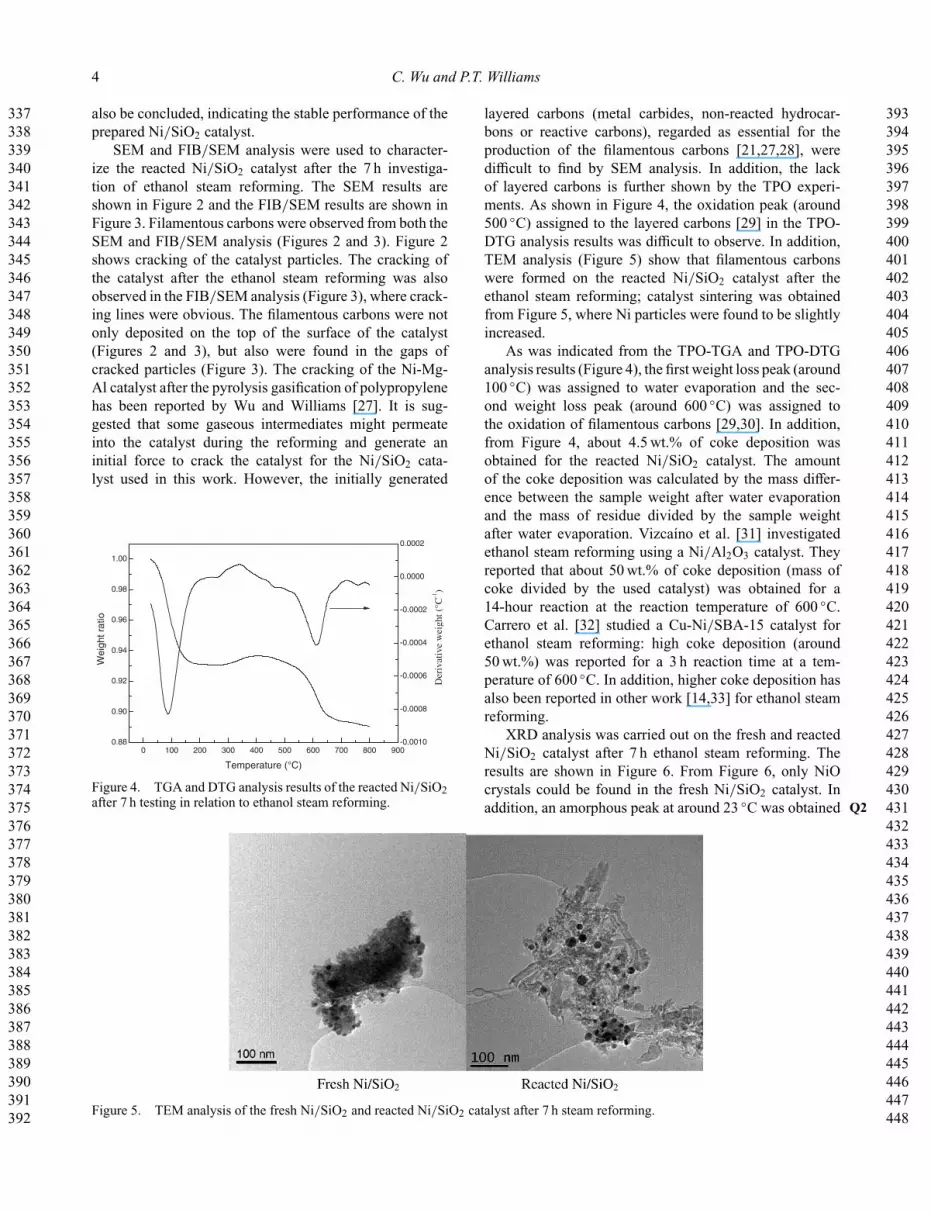
Figure 4. TGA and DTG analysis results of the reacted Ni/SiO2after 7 h testing in relation to ethanol steam reforming.
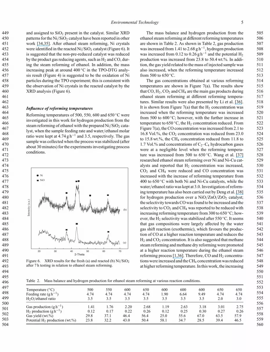
layered carbons (metal carbides, non-reacted hydrocar-bons or reactive carbons), regarded as essential for theproduction of the filamentous carbons [21,27,28], weredifficult to find by SEM analysis. In addition, the lackof layered carbons is further shown by the TPO experi-ments. As shown in Figure 4, the oxidation peak (around500 ◦C) assigned to the layered carbons [29] in the TPO-DTG analysis results was difficult to observe. In addition,TEM analysis (Figure 5) show that filamentous carbonswere formed on the reacted Ni/SiO2 catalyst after theethanol steam reforming; catalyst sintering was obtainedfrom Figure 5, where Ni particles were found to be slightlyincreased.
As was indicated from the TPO-TGA and TPO-DTGanalysis results (Figure 4), the first weight loss peak (around100 ◦C) was assigned to water evaporation and the sec-ond weight loss peak (around 600 ◦C) was assigned tothe oxidation of filamentous carbons [29,30]. In addition,from Figure 4, about 4.5 wt.% of coke deposition wasobtained for the reacted Ni/SiO2 catalyst. The amountof the coke deposition was calculated by the mass differ-ence between the sample weight after water evaporationand the mass of residue divided by the sample weightafter water evaporation. Vizcaíno et al. [31] investigatedethanol steam reforming using a Ni/Al2O3 catalyst. Theyreported that about 50 wt.% of coke deposition (mass ofcoke divided by the used catalyst) was obtained for a14-hour reaction at the reaction temperature of 600 ◦C.Carrero et al. [32] studied a Cu-Ni/SBA-15 catalyst forethanol steam reforming: high coke deposition (around50 wt.%) was reported for a 3 h reaction time at a tem-perature of 600 ◦C. In addition, higher coke deposition hasalso been reported in other work [14,33] for ethanol steamreforming.
XRD analysis was carried out on the fresh and reactedNi/SiO2 catalyst after 7 h ethanol steam reforming. Theresults are shown in Figure 6. From Figure 6, only NiOcrystals could be found in the fresh Ni/SiO2 catalyst. Inaddition, an amorphous peak at around 23 ◦C was obtained Q2
Figure 5. TEM analysis of the fresh Ni/SiO2 and reacted Ni/SiO2 catalyst after 7 h steam reforming.
449450451452453454455456457458459460461462463464465466467468469470471472473474475476477478479480481482483484485486487488489490491492493494495496497498499500501502503504
505506507508509510511512513514515516517518519520521522523524525526527528529530531532533534535536537538539540541542543544545546547548549550551552553554555556557558559560
Environmental Technology 5
and assigned to SiO2 present in the catalyst. Similar XRDpatterns for the Ni/SiO2 catalyst have been reported in otherwork [34,35]. After ethanol steam reforming, Ni crystalswere identified in the reacted Ni/SiO2 catalyst (Figure 6). Itis suggested that the non-pre-reduced catalyst was reducedby the product gas reducing agents, such as H2 and CO, dur-ing the steam reforming of ethanol. In addition, the massincreasing peak at around 400 ◦C in the TPO-DTG analy-sis result (Figure 4) is suggested to be the oxidation of Niparticles during the TPO experiment; this is consistent withthe observation of Ni crystals in the reacted catalyst by theXRD analysis (Figure 6).
Influence of reforming temperaturesReforming temperatures of 500, 550, 600 and 650 ◦C wereinvestigated in this work for hydrogen production from thesteam reforming of ethanol with the prepared Ni/SiO2 cata-lyst, when the sample feeding rate and water/ethanol molarratio were kept at 4.74 g h−1 and 3.5, respectively. The gassample was collected when the process was stabilized (afterabout 30 minutes) for the experiments investigating processconditions.
20 30 40 50 60 70
Inte
nsit
y (a
.u.)
2-Theta
Ni
NiO
(a)
(b)
Figure 6. XRD results for the fresh (a) and reacted (b) Ni/SiO2after 7 h testing in relation to ethanol steam reforming.
The mass balance and hydrogen production from theethanol steam reforming at different reforming temperaturesare shown in Table 2. As shown in Table 2, gas productionwas increased from 1.41 to 2.68 g h−1, hydrogen productionwas increased from 0.12 to 0.26 g h−1 and the potential H2production was increased from 23.8 to 50.4 wt.%. In addi-tion, the gas yield related to the mass of injected sample wasalso increased, when the reforming temperature increasedfrom 500 to 650 ◦C.
The gas concentrations obtained at various reformingtemperatures are shown in Figure 7(a). The results showthat CO, H2, CO2 and CH4 are the main gas products duringethanol steam reforming at different reforming tempera-tures. Similar results were also presented by Li et al. [36].It is shown from Figure 7(a) that the H2 concentration wasincreased when the reforming temperature was increasedfrom 500 to 600 ◦C; however, with the further increase intemperature to 650 ◦C, the H2 concentration reduced. FromFigure 7(a), the CO concentration was increased from 2.1 to16.8 Vol.%, the CO2 concentration was reduced from 23.0to 15.8 wt.%, the CH4 concentration reduced from 11.8 to1.7 Vol.% and concentrations of C2–C4 hydrocarbon gaseswere at a negligible level when the reforming tempera-ture was increased from 500 to 650 ◦C. Wang et al. [37]researched ethanol steam reforming over Ni and Ni-Cu cat-alysts and reported that H2 concentration was increased,CO2 and CH4 were reduced and CO concentration wasincreased with the increase of reforming temperature from400 to 650 ◦C with both Ni and Ni-Cu catalysts, while thewater/ethanol ratio was kept at 3.0. Investigation of reform-ing temperature has also been carried out by Deng et al. [38]for hydrogen production over a NiO/ZnO/ZrO2 catalyst;the selectivity towards CO was found to be increased and theselectivity to CO2 and CH4 was reported to be reduced withincreasing reforming temperature from 300 to 650 ◦C; how-ever, the H2 selectivity was stabilized after 550 ◦C. It seemsthat gas compositions were largely affected by the watergas shift reaction (exothermic), which favours the produc-tion of CO at a higher reaction temperature and reduces theH2 and CO2 concentration. It is also suggested that methanesteam reforming and methane dry reforming were promotedat a higher reaction temperature during the ethanol steamreforming process [1,36]. Therefore, CO and H2 concentra-tions were increased and the CH4 concentration was reducedat higher reforming temperature. In this work, the increasing
Table 2. Mass balance and hydrogen production for ethanol steam reforming at various reaction conditions.
Temperature (◦C) 500 550 600 650 600 600 600 650 650Feeding rate (g h−1) 4.74 4.74 4.74 4.74 1.90 6.64 9.49 4.74 4.74H2O/ethanol ratio 3.5 3.5 3.5 3.5 3.5 3.5 3.5 2.0 3.0
Gas production (g h−1) 1.41 1.76 2.20 2.68 1.19 2.63 3.18 3.01 2.75H2 production (g h−1) 0.12 0.17 0.22 0.26 0.12 0.25 0.30 0.27 0.26Gas yield (wt.%) 29.8 37.1 46.4 56.4 25.0 55.6 67.0 63.5 57.9Potential H2 production (wt.%) 23.8 32.2 43.0 50.4 58.1 34.7 28.5 39.4 46.5

561562563564565566567568569570571572573574575576577578579580581582583584585586587588589590591592593594595596597598599600601602603604605606607608609610611612613614615616
617618619620621622623624625626627628629630631632633634635636637638639640641642643644645646647648649650651652653654655656657658659660661662663664665666667668669670671672
6 C. Wu and P.T. Williams
500 550 600 6500
10
20
30
40
50
60
70
2 4 6 8 10 1.5 2.0 2.5 3.0 3.5 4.0
CO H
2
CO2
CH4
C2-C
4
CO H
2
CO2
CH4
C2-C
4
CO H
2
CO2
CH4
C2-C
4
Gas
com
posi
tion
s (V
ol.%
)
Temperature (°C)
(a) (b)
Feeding rate (g h-1)
(c)
H2O/ethanol ratio
Figure 7. Gas compositions from ethanol steam reforming at different reaction conditions: (a) reaction temperature; (b) sample feedingrate; (c) H2O/ethanol ratio.
H2 concentration might be due to the promotion of ethanolsteam reforming and steam reforming intermediates, suchas methane steam reforming, when the reforming tempera-ture was increased from 500 to 600 ◦C. However, when thereaction temperature further increased to 650 ◦C, the watergas shift reaction might be more dominant for the hydrogenpartial pressure in the experiment, and hence results in lowerH2 concentration compared to 600 ◦C. Maximum concen-tration of H2 during hydrocarbon gasification at differentreaction temperatures have also been presented in otherwork [3,39].
Influence of water/ethanol ratiosIn this section, water/ethanol ratios (2.0, 3.0 and 3.5) wereinvestigated with the prepared Ni/SiO2 catalyst in rela-tion to hydrogen production from the steam reforming ofethanol. Throughout the experiments, the reforming tem-perature and the sample feeding rate were controlled at650 ◦C and 4.74 g h−1, respectively. The results in termsof mass balance and hydrogen production are shown inTable 2. With increasing water/ethanol ratio in the sam-ple feed, the gas production was reduced from 3.01 to2.68 g h−1 and the H2 production rate was only changedslightly (Table 2). However, as shown in Table 2, the poten-tial H2 production was increased from 39.4 to 50.4 wt.%with increasing water/ethanol ratio from 2.0 to 3.5. Theincreasing of hydrogen selectivity (related to the poten-tial hydrogen production in this paper) has also beenreported to be increased with the increase of water/ethanolratio during ethanol steam reforming by Goula et al. [23]using a commercial Pd/γ -Al2O3 catalyst. Hydrogen selec-tivity was also reported to be increased with increasing
water/ethanol ratio from 3.0 to 6.0; however, with the fur-ther increase of water/ethanol ratio, hydrogen selectivitywas stabilized [40]. The promotion of hydrogen productionat higher water/ethanol ratio has also been observed in otherreports [38,41].
In addition, the gas concentrations from the ethanolsteam reforming at different water/ethanol ratios are pre-sented in Figure 7(b). The results show that H2 and CO2 con-centrations were increased and CO and CH4 concentrationswere decreased when the water/ethanol ratio was increasedfrom 2.0 to 3.5. It seems that at higher water/ethanol ratios,the water gas shift reaction was promoted, and resultedin higher concentrations of H2 and CO2 and lower con-centrations of CO. In addition, methane steam reformingand methane dry reforming also seemed to be improved athigher water content during the ethanol steam reformingprocess, and resulted in lower concentration of CH4 andhigher production of hydrogen.
Influence of sample feeding ratesIn this paper, sample feeding rates of 1.90, 4.74, 6.64 and9.49 g h−1 were investigated using the prepared Ni/SiO2catalyst in relation to their influence on hydrogen produc-tion from the steam reforming of ethanol. During the studyof various sample feeding rates, the reforming temperatureand water/ethanol molar ratio were kept at 600 ◦C and 3.5,respectively.
The mass balance and the hydrogen production resultsare presented in Table 2, which shows that the gas andhydrogen production appeared to be increased with theincrease of the sample feeding rate. For example, gas pro-duction was increased from 1.19 to 3.18 g h−1, and the

673674675676677678679680681682683684685686687688689690691692693694695696697698699700701702703704705706707708709710711712713714715716717718719720721722723724725726727728
729730731732733734735736737738739740741742743744745746747748749750751752753754755756757758759760761762763764765766767768769770771772773774775776777778779780781782783784
Environmental Technology 7
hydrogen production increased from 0.12 to 0.30 g h−1,when the sample feeding rate increased from 1.90 to9.49 g h−1. However, the potential H2 production wasreduced from 58.1 to 28.5 wt.% with increasing samplefeeding rate. The reduction of the potential H2 productionmight be due to the reduced contact time between reactantsand the catalytic sites during the process of ethanol steamreforming due to the increased sample feeding rate.
The gas concentrations from ethanol steam reformingat various sample feeding rates are shown in Figure 7(c).The results show that H2 concentration was slightly reducedfrom 67.6 to 63.6 Vol.% and CH4 concentration increasedfrom 2.5 to 6.8 Vol.% with the increase of the sample feed-ing rate from 1.90 to 9.49 g h−1. However, the concentrationof CO, CO2 and C2–C4 hydrocarbons were stabilized ataround 11, 18 and 0.6 Vol.%, respectively.
ConclusionsThe main objective of this work was to investigate the pro-cess conditions during ethanol steam reforming with a nano-Ni/SiO2 catalyst. Stabilized gas production (2.10 g h−1) andpotential H2 production (40 wt.%) were observed for 7 hethanol steam reforming with the Ni/SiO2 catalyst, andfilamentous carbons were observed on the surface of thecatalyst and inside the gaps of the cracked catalyst by usingSEM and FIB/SEM analysis. With the increase of reactiontemperature from 500 to 650 ◦C, gas production and hydro-gen production were found to be increased. Potential H2production was reduced from 58.1 to 28.5 wt.% when thesample feeding rate was increased from 1.19 to 9.49 g h−1.In addition, the increase of water/ethanol ratio resulted inan increase in the potential H2 production.
AcknowledgementThis work was supported by the UK Engineering and PhysicalSciences Research Council under EPSRC Grant EP/D053110/1.
References[1] W. Cai, F. Wang, A.V. Veen, C. Descorme, Y. Schuurman, W.
Shen, and C. Mirodatos, Hydrogen production from ethanolsteam reforming in a micro-channel reactor, Int. J. HydrogenEnergy 35 (2010), pp. 1152–1159.
[2] A.E. Galetti, M.F. Gomez, L.A. Arrua, A.J. Marchi, and M.C.Abello, Study of CuCoZnAl oxide as catalyst for the hydro-gen production from ethanol reforming, Catal. Commun. 9(2008), pp. 1201–1208.
[3] H. Muroyama, R. Nakase, T. Matsui, and K. Eguchi, Ethanolsteam reforming over Ni-based spinel oxide, Int. J. HydrogenEnergy 35 (2010), pp. 1575–1581.
[4] D. Barnard, A. Casanueva, M. Tuffin, and D. Cowan,Extremophiles in biofuel synthesis, Environ. Technol. 31(2010), pp. 871–888.
[5] Jêdrzejewska, and K. Kozak, Ethanol production fromwhey permeate in a continuous anaerobic bioreactor byKluyveromyces marxianus, Environ. Technol. 32 (2011), pp.37–42.
[6] J.Y. Liu, C.C. Lee, C.H. Wang, C.T. Yeh, and C.B. Wang,Application of nickel-lanthanum composite oxide on thesteam reforming of ethanol to produce hydrogen, Int. J.Hydrogen Energy 35 (2010), pp. 4069–4075.
[7] F. Murena, Catalytic hydrodechlorination of monochloro-biphenyls using Ni-Mo/γ -Al2O3 sulphided catalyst, Envi-ron. Technol. 18 (1997), pp. 317–324.
[8] J. Comas, F. Mariño, M. Laborde, and N. Amadeo, Bio-ethanol steam reforming on Ni/Al2O3 catalyst, Chem. Eng.J. 98 (2004), pp. 61–68.
[9] A.L. Alberton, M.M.V.M. Souza, and M. Schmal, Car-bon formation and its influence on ethanol steam reform-ing over Ni/Al2O3 catalysts, Catal. Today 123 (2007),pp. 257–264.
[10] H.V. Fajardo and L.F.D. Probst, Production of hydrogenby steam reforming of ethanol over Ni/Al2O3 sphericalcatalysts, Appl. Catal., A 306 (2006), pp. 134–141.
[11] F. Soyal-Baltacloðlu, A.E. Aksoylu, and Z.I. Önsan, Steamreforming of ethanol over Pt-Ni catalysts, Catal. Today 138(2008), pp. 183–186.
[12] J. Kugai, V. Subramani, C. Song, M.H. Engelhard, andY.H. Chin, Effects of nanocrystalline CeO2 supports on theproperties and performance of Ni-Rh bimetallic catalyst foroxidative steam reforming of ethanol, J. Catal. 2 (2006), pp.430–440.
[13] A.J. Vizcaíno, A. Carrero, and J.A. Calles, Hydrogenproduction by ethanol steam reforming over Cu-Ni sup-ported catalysts, Int. J. Hydrogen Energy 32 (2007),pp. 1450–1461.
[14] A. Carrero, J.A. Calles, and A.J. Vizcaíno, Effect of Mg andCa addition on coke deposition over Cu-Ni/SiO2 catalystsfor ethanol steam reforming, Chem. Eng. J. 163 (2010), pp.395–402.
[15] Q. Shi, C. Liu, and W. Chen, Hydrogen production fromsteam reforming of ethanol over Ni/MgO-CeO2 catalyst atlow temperature, J. Rare Earths 27 (2009), pp. 948–954.
[16] P. Biswas and D. Kunzru, Steam reforming of ethanol forproduction of hydrogen over Ni/CeO2-ZrO2catalyst: Effectof support and metal loading, Int. J. Hydrogen Energy 32(2007), pp. 969–980.
[17] N. Srisiriwat, S. Therdthianwong, and A. Therdthianwong,Oxidative steam reforming of ethanol over Ni/Al2O3 cat-alysts promoted by CeO2, ZrO2 and CeO2–ZrO2, Int. J.Hydrogen Energy 34 (2009), pp. 2224–2234.
[18] S. Liu, D. Chen, K. Zhang, J. Li, and N. Zhao, Produc-tion of hydrogen by ethanol steam reforming over catalystsfrom reverse microemulsion-derived nanocompounds, Int. J.Hydrogen Energy 33 (2008), pp. 3736–3747.
[19] A.E. Galetti, M.F. Gomez, L.A. Arrúa, and M.C. Abello, Nicatalysts supported on modified ZnAl2O4 for ethanol steamreforming, Appl. Catal., A 380 (2010), pp. 40–47.
[20] R. Takahashi, S. Sato, T. Sodesawa, and S. Tomiyama,CO2-reforming of methane over Ni/SiO2 catalyst preparedby homogeneous precipitation in sol-gel-derived silica gel,Appl. Catal., A 286 (2005), pp. 142–147.
[21] S. Natesakhawat, R.B. Watson, X. Wang, and U.S. Ozkan,Deactivation characteristics of lanthanide-promoted sol-gelNi/Al2O3 catalysts in propane steam reforming, J. Catal. 234(2005), pp. 496–508.
[22] C. Wu and P.T. Williams, A novel nano-Ni/SiO2 catalyst forhydrogen production from steam reforming of ethanol, Env.Sci. Technol. 44 (2010), pp. 5993–5998.
[23] M.A. Goula, S.K. Kontou, and P.E. Tsiakaras, Hydrogenproduction by ethanol steam reforming over a commer-cial Pd/γ -Al2O3 catalyst, Appl. Catal., B 49 (2004), pp.135–144.

785786787788789790791792793794795796797798799800801802803804805806807808809810811812813814815816817818819820821822823824825826827828829830831832833834835836837838839840
841842843844845846847848849850851852853854855856857858859860861862863864865866867868869870871872873874875876877878879880881882883884885886887888889890891892893894895896
8 C. Wu and P.T. Williams
[24] A.N. Fatsikostas and XE Verykios, Reaction network ofsteam reforming of ethanol over Ni-based catalysts, J. Catal.225 (2004), 439–452.
[25] N.J. Tang, W. Zhong, W. Liu, H.Y. Jiang, X.L. Wu, andY.W. Du, Synthesis and complex permeability of Ni/SiO2nanocomposite, Inst. Phys. Publishing 15 (2004), pp. 1756–1758.Q3
[26] H. Song, L. Zhang, and U. Ozkan, Investigation of the reac-tion network in ethanol seam reforming over supportedcobalt catalysts, Ind. Eng. Chem. Res. 49 (2010), pp.8984–8989.
[27] C. Wu and P.T. Williams, Investigation of coke formation onNi-Mg-Al catalyst for hydrogen production from the catalyticsteam pyrolysis-gasification of polypropylene, Appl. Catal.,B 96 (2010), pp. 198–207.
[28] JK Chinthaginjala, DB Thakur, K Seshan, and L Lefferts,How carbon-nano-fibers attach to Ni foam, Carbon 46(2008), pp. 1638–1647.
[29] C. Wu and P.T. Williams, Hydrogen production by steamgasification of polypropylene with various nickel catalysts,Appl. Catal., B 87 (2009), pp. 152–161.
[30] S. Wang and G.Q. Lu, A comprehensive study on carbondioxide reforming of methane over Ni/γ -Al2O3 catalysts,Ind. Eng. Chem. Res. 38 (1999), pp. 2615–2625.
[31] A.J. Vizcaíno, P. Arena, G. Baronetti, A. Carrero, J.A. Calles,M.A. Laborde, and N. Amadeo. Ethanol steam reforming onNi/Al2O3 catalysts: Effect of Mg addition, Int. J. HydrogenEnergy 33 (2008), pp. 3489–3492.
[32] A. Carrero, J.A. Calles, and A.J. Vizcaino, Hydro-gen production by ethanol steam reforming over Cu-Ni/SBA-15 supported catalysts prepared by direct syn-thesis and impregnation, Appl. Catal., A 327 (2007), pp.82–94.
[33] M. Lindo, A.J. Vizcaino, J.A. Calles, and A. Carrero, Ethanolsteam reforming on Ni/Al-SBA-15 catalysts: effect of thealuminium content, Int. J. Hydrogen Energy 35 (2010), pp.5895–5910.
[34] R. Takahashi, S. Sato, T. Sodesawa, M. Suzuki, and N.Ichikuni. Ni/SiO2 prepared by sol-gel process using cit-ric acid, Microporous Mesoporous Mater. 66 (2003), pp.197–208.
[35] R Takahashi, S Sato, T Sodesawa, M Yoshida, and STomiyama. Addition of zirconia in Ni/SiO2 catalyst forimprovement of steam resistance. Appl. Catal., A 273 (2004),pp. 211–215.
[36] M. Li, X. Wang, S. Li, S. Wang, and X. Ma. Hydrogen pro-duction from ethanol steam reforming over nickel based cat-alyst derived from Ni/Mg/Al hydrotalcite-like compounds,Int. J. Hydrogen Energy 35 (2010), pp. 6699–6708.
[37] F Wang, Y Li, W Cai, E Zhan, X Mu, and W Shen. Ethanolsteam reforming over Ni and Ni-Cu catalysts, Catal. Today146 (2009), pp. 31–36.
[38] X. Deng, J. Sun, S. Yu, J. Xi, W. Zhu, and X. Qiu.Steam reforming of ethanol for hydrogen production overNiO/ZnO/ZrO2 catalysts, Int. J. Hydrogen Energy 33(2008), pp. 1008–1013.
[39] S.Q. Chen and Y. Liu, LaFeyNi1−yO3 supported nickel cat-alysts used for steam reforming of ethanol, Int. J. HydrogenEnergy 34 (2009), pp. 4735–4746.
[40] L. Zhang, W. Li, J. Liu, C. Guo, Y. Wang, and J. Zhang.Ethanol steam reforming reactions over Al2O3 · SiO2-supported Ni-La catalysts, Fuel 88 (2009), pp. 511–518.
[41] V. Klouz, V. Fierro, P. Denton, H. Katz, J.P. Lisse, S. Bouvot-Mauduit, and C. Mirodatos. Ethanol reforming for hydrogenproduction in a hybrid electric vehicle: process optimisation,J. Power. Sour. 105 (2002), pp. 26–34.