Embed Size (px)
Citation preview
DOI: 10.1002/cctc.201200481
Nickel Catalysts Supported Over TiO2, SiO2 and ZrO2 forthe Steam Reforming of GlycerolIlenia Rossetti,*[a, c] Alessandro Gallo,[b] Vladimiro Dal Santo,[c] Claudia L. Bianchi,[a]
Valentina Nichele,[d] Michela Signoretto,[d] Elisabetta Finocchio,[e] Gianguido Ramis,[e] andAlessandro Di Michele[f]
Introduction
Different catalyst formulations have been proposed for thesteam reforming (SR) of bioalcohols, in order to produce H2
from renewable feedstocks.[1–3] Ni showed to be one of themost promising active phases for such an application, especial-ly if it was highly dispersed and thermally stabilised by thesupport. Coking and sintering are the main causes of catalystfailure. In spite of its lower activity and higher tendency to de-activation with respect to noble metal-based catalysts, Ni, ifsupported over Al2O3 in particular, is commonly used in indus-try for the steam reforming of hydrocarbons because of its lowcost and wide availability. Ni is considered as a promising cata-lyst ; this owes to its activity in C�C, O�H and C�H bond cleav-age and in the water–gas shift (WGS) reaction.
Glycerol is the main by-product in biodiesel production;therefore a glut in its market is expected in the next few yearsowing to a rise in biodiesel production. The pathway for thesteam reforming of glycerol (GSR) is usually considered as simi-lar to that of ethanol SR, even if this is not exhaustively under-stood. The reported mechanism for metal-catalysed GSR relatesto the one previously proposed for hydrocarbon reforming.[4, 5]
GSR is an energy intensive process and C�C cleavage is com-monly considered to be the rate determining step. Glycerolcan dehydrogenate and adsorb onto the metal, subsequentC�C breakings lead to adsorbed CO that can be further oxi-dised through the WGS reaction, which is thermodynamicallyfavoured at low temperature. The CO is then either convertedto methane or desorbed. Methane can also be derived fromCO2 methanation.
Ni-based catalysts supported on TiO2, ZrO2 and SiO2 (in theform of mesoporous Santa Barbara Amorphous 15 (SBA-15)and amorphous dense nanoparticles), were employed in thesteam reforming of glycerol. Each sample was prepared byliquid phase synthesis of the support followed by impregna-tion with the active phase and calcination at 800 8C or bydirect synthesis through flame pyrolysis. Many techniques havebeen used to assess the physical chemical properties of boththe fresh and spent catalysts, such as atomic absorption, N2 ad-sorption/desorption, XRD, SEM, TEM, temperature-pro-grammed reduction (TPR), X-ray photoelectron spectroscopy(XPS), Micro-Raman and FTIR spectroscopy. The samplesshowed different textural, structural and morphological proper-ties, as well as different reducibility and thermal resistance de-
pending on the preparation method and support. Some ofthese properties were tightly bound to catalyst performance,in terms of H2 productivity and stability towards coking andsintering. A key parameter was the metal–support interaction,which strongly depended on the preparation procedure. Inparticular, the stronger the interaction, the more stable themetallic Ni clusters, which in turn lead to a higher catalytic ac-tivity and stability. Surface acidity was also taken into account,in which the nature of the acid sites was differentiated (sila-nols, titanols or Lewis acid sites). The characterisation of thespent catalysts also allowed us to interpret the deactivationprocess. The formation of multi-walled nanotubes was ob-served for every sample, though it was only in some cases thatthis led to severe deactivation.
[a] Dr. I. Rossetti, Prof. C. L. BianchiDip. Chimica fisica ed ElettrochimicaUniversit� degli Studi di Milanovia C. Golgi, 19, I-20133 Milano (Italy)and INSTM Unit Milano-Universit�Fax: (+ 39) 02-50314300E-mail : [email protected]
[b] Dr. A. GalloCNR-ISTMvia G. Fantoli 16/15 20138 Milano (Italy)and INSTM Unit Milano-Universit�
[c] Dr. I. Rossetti, Dr. V. Dal SantoCNR-ISTMvia C. Golgi 19, 20133 Milano (Italy)and INSTM Unit Milano-Universit�.
[d] Dr. V. Nichele, Prof. M. SignorettoDip. di Scienze Molecolari e NanosistemiUniversit� C� Foscari VeneziaCalle Larga S. Marta, 2137, Venezia (Italy)and INSTM Unit Venezia
[e] Dr. E. Finocchio, Prof. G. RamisDip. di Ingegneria Chimica e di Processo “G. Bonino”Universit� degli Studi di GenovaP.le Kennedy 1, I-16129, Genova (Italy)and INSTM Unit Genova
[f] Dr. A. Di MicheleDip. di FisicaUniversit� degli Studi di PerugiaVia Pascoli, 06123 Perugia (Italy)
� 2013 Wiley-VCH Verlag GmbH & Co. KGaA, Weinheim ChemCatChem 2013, 5, 294 – 306 294
CHEMCATCHEMFULL PAPERS
The main reaction route is parallel to coking by CO decom-position and dehydration of the substrate to form surfaceolefin species, which may desorb, reformate or, regrettably,polymerise to form carbonaceous deposits.[6] This is especiallythe case if a low water/glycerol feeding ratio is employed.Coke may also form as a result of the Bouduard reaction (COdisproportion), which may be thermodynamically favouredbelow 700 8C.[7] Coke removal is possible by steaming andgasification, particularly at high temperature.[2, 8]
Detailed investigations into catalyst deactivation are avail-able for methane or ethanol SR. The dehydration reactionpathway is mainly favoured by big Ni particles,[9, 10] but also bystrong surface acidity (e.g. in the case of Al2O3 supported sam-ples). Considerable efforts have been devoted to develop non-acidic supports, such as MgAl2O4,[2, 11] NixMg1�xO
[12] or MgO.[13, 14]
Up until now, these have mainly been adopted for the SR ofethanol. Unfortunately, such catalysts either showed unsatisfac-tory activity or, even when active, induced some scale-up prob-lems owing to poor mechanical properties or formation prob-lems. Alternatively, attempts have been made to limit surfaceacidity of common supports, for example, by impregnatingalumina or zirconia with lanthanum oxide.[6, 15]
The best catalytic systems appear to be the ones in whichthe synergism between the metal and the support leads tometal stabilisation and decreases the rate of coke formation.MgO, CeO2 and TiO2 were used for their well-known ability toretard coke formation and to interact with metals that pro-mote the catalytic activity as supports.[16, 17] Furthermore, themodification of Ni/Al2O3 with Ce, Zr, Mg and La, brought aboutan improvement in hydrogen selectivity owing to surface Niexposure in the case of Mg, steam activation for Zr, and stabili-ty of the metallic phase under the reaction conditions if Ce orLa were added.[18]
Nevertheless, in spite of a growing number of papers onGSR, activity data are often contrasting and no clear relation-ships between the main physicochemical properties of the cat-alyst and its activity, selectivity and durability have beendrawn.
Therefore, the aim of this work was to design, synthesiseand characterise supported Ni catalysts for GSR.
TiO2, SiO2, mesoporous SBA-15 and ZrO2 were chosen assupports owing to their different acidic and redox properties,and interaction with the metallic active phase. The catalystswere prepared by using different synthetic procedures, whichwere able to tune the thermal resistance and Ni dispersion. Inparticular, each sample was synthesised from the liquid phase,with the active phase deposited by impregnation, and calcinedat 800 8C to impart proper thermal resistance for this high tem-perature application. In addition, a special preparation proce-dure, namely flame pyrolysis (FP) was employed to achievehigh temperature stability and high metal dispersion. Thelatter technique proved effective for the preparation of ther-mally resistant samples for different high-temperature applica-tions, such as the catalytic combustion of methane.[19, 20] Fur-thermore, it led to unexpectedly high dispersion of the activephase in differently supported V-based catalysts even at rela-tively high loading (up to 10 wt %).[21, 24] Therefore, it seems in-
teresting to compare the effect of different preparation meth-ods, which in principle lead to different dispersions of theactive phase and interactions with the support.
Every sample was characterised by N2 adsorption-desorption,temperature-programmed reduction/oxidation (TPR–TPO),atomic absorption (AA), X-ray photoelectron spectroscopy(XPS), SEM, TEM, XRD, FTIR and Micro-Raman spectroscopy. At-tention was also paid to the characterisation of the spent cata-lysts, particularly with regards to the assessment of the natureand amount of coke deposits.
The main physicochemical properties of each sample havebeen discussed on the basis of the support and the prepara-tion method. Activity and durability data for GSR were com-pared on the basis of catalytic properties.
Results and Discussion
Textural, structural and morphological characterisations
The textural properties of the samples prepared and the actualconcentration of Ni are reported in Table 1.
Different surface areas were obtained for the FP preparedsamples, ranging from 60 to 200 m2 g�1, depending on the de-composition mechanism of the oxide precursor in the flameand on the type of solvent used.[27, 28] Very low surface areawas observed for NiTiL. In general, the surface area increasedfrom titania to silica for both sets of samples and, accordingly,Ni concentration per m2 decreased in the order TiO2>ZrO2>
SiO2.The results of surface analysis (XPS) are summarised in
Table 1; they are expressed in terms of relative atomic percent-age.
The Ni fraction exposed on the support surface was alwayshigher for samples obtained by FP. This was ascribed to Ni in-corporation into the support during catalyst preparation.
TEM micrographs of the as-prepared catalyst NiTiL showedbig particles that were relatively uniform in size (Figure 1 a).
Table 1. The main physicochemical properties of the freshly preparedsamples. Some data have already been reported in Ref. [31]
Sample Preparation method Niloading[a]
[wt %]
SSA[b]
[m2 g�1]
Crystalsize[c]
[nm]
SurfaceNi[d]
[atom %]
NiTiL TiO2 by precipitationwith NaOH, calcined at800 8C
6.7 4 31 (20–30) 0.9
NiSiL SBA-15 calcined at800 8C
8.9 309 21 (20–30) 0.8
NiZrL ZrO2 by precipitationwith NH3, calcined at800 8C
8.8 43 18 (�20) 1.2
NiTiF FP 8.2 63 26 (20–30) 1.0NiSiF FP 9.6 211 18 (20–30) 1.4NiZrF FP 8.8 83 8 (10–15) 2.2
[a] From atomic absorption analysis. [b] Based on the BET model. [c] NiOcrystal size determined by the Scherrer equation and TEM between pa-rentheses. [d] From XPS analysis.
� 2013 Wiley-VCH Verlag GmbH & Co. KGaA, Weinheim ChemCatChem 2013, 5, 294 – 306 295
CHEMCATCHEMFULL PAPERS www.chemcatchem.org

Some NiO nanoparticles were also evident, with a mean size of20–30 nm (Table 1), in which most of the active phase wasmore dispersed on the support surface or was more likely tobe incorporated into its structure. The latter hypothesis is con-sistent with the morphology ofNi clusters observed upon reduc-tion at 700 8C under a 10 vol %H2/He flow for 1 h, which mimicscatalyst activation. The particlesize of the NiTiL sample re-mained very uniform and wasalmost unaffected by thermaltreatment; this reveals a suitablethermal stability of the support(Figure 1 b), also confirmed bySEM (Figure 2 a,b). By contrast,Ni particle size became less uni-form. The enlargement of thepreviously existing metal oxideclusters upon reduction and theformation of much smaller Niparticles that were well-dis-persed over the surface areshown in (Figure 1 b); this waslikely to be formed from sinter-ing of very dispersed NiO. Theparticle size of the NiSiL samplewas even larger than that ofNiTiL, whereas the ZrO2 particlesize was approximately 20–30 nm in the NiZrL sample.[31]
Particles with a high homoge-neity constituted the NiTiFsample, with sizes up to 30 nmas detailed by TEM (Figure 3 a).Similar dimensions were foundfor all the FP-prepared samples(Figure 3 a–c). A slightly lowerhomogeneity of the NiO parti-cles was observed for NiSiL (Fig-ure 3 d).
EDX analysis also confirmedthe Ni loading with respect toatomic absorption, and repeatedanalyses in different zones dem-
onstrated a rather uniform distribution of the active phase.The latter conclusion has also been supported by several mapsthat reveal an even incorporation of Ni into each oxide matrixin the case of FP-prepared samples.
Ni or NiO particle size that is similar to catalyst particle sizehas sometimes been found, which is likely to indicate a fullcoverage of the nanoparticle by the metal, as observed for in-stance in Figure 3 c, e relative to both zirconia-supportedsamples.
The TPR technique was employed to identify the differentspecies present in the catalysts according to the different re-duction temperatures. Reducibility data may help to evaluatethe strength of interaction between the active phase and thesupport. In general, one may say that a low reducibility of theactive phase indicates a strong interaction with the support.This may possibly lead to dispersed metal clusters that are
Figure 1. TEM analysis of the NiTiL sample a) as-prepared and b) reducedunder 10 vol % H2 flow at 700 8C for 1 h. Scale bars : 100 nm.
Figure 2. SEM analysis of samples a) NiTiL, b) NiTiL reduced under 10 vol % H2 flow at 700 8C for 1 h and c) NiTiF.Scale bars: 2 mm.
Figure 3. TEM micrographs of selected samples: a) NiTiF, b) NiSiF, c) NiZrF, d) NiSiL and e) NiZrL.Scale bars: 100 nm.
� 2013 Wiley-VCH Verlag GmbH & Co. KGaA, Weinheim ChemCatChem 2013, 5, 294 – 306 296
CHEMCATCHEMFULL PAPERS www.chemcatchem.org

stable even at high temperature. It is also well-known thatmetal/support interaction increases with calcination tempera-ture. It was also reported that a lower reduction temperaturemay be ascribed to bigger particle size. Large Ni particlesexpose a small interface with the support surface, which leadsto a weaker interaction and, thus, easier reduction.[32] However,there is not full agreement on this point in the literature.
TPR–TPO–TPR cycles were performed. At first, the FP prepa-ration procedure induced at least partial incorporation of Niinto the support matrix, which possibly led to a mixed oxidephase. It may be supposed that some reconstruction of theoxide may occur during metal reduction, so a second TPR ena-bled us to investigate the activated catalyst. Furthermore, acti-vation may induce redistribution of the active phase or sinter-ing in each sample.
The TPR pattern of NiTiL (Figure 4) revealed a sharp reduc-tion peak, which suggests the presence of only one type of Ni-
containing species. No “free” NiO, that is, none that interactswith the support was found (unsupported NiO has a reductiontemperature of approximately 280 8C).[33] By contrast, the pres-ence of peaks at higher temperature reveals significant interac-tion of NiO with titania.[34] Besides, such a high reduction tem-perature is compatible with the reduction of NiTiO3,[35] as re-vealed by XRD analysis (vide infra). This may be of utmost im-portance in stabilising Ni and achieving satisfactory catalyticactivity. The second TPR pattern revealed the reversibility ofthe reduction treatment, but a slight shift of the reductiontemperature towards lower values may indicate a lower inter-action with the support or, possibly, some Ni sintering.
The first TPR run of NiTiF (Figure 5) showed a series of broadand overlapping peaks that spanned a wide temperaturerange (300–700 8C), which could owe to the reduction of freesurface NiO, bulk NiO and NiO, which have, respectively, stron-ger interactions with the TiO2 surface, as discussed above. Met-allic Ni can be oxidised at 300 8C, however, the second TPRshowed a much simpler pattern, with only one peak centred atapproximately 600 8C. This may indicate a stronger interactionwith the support with respect to the as-prepared sample, andsuggested the need of higher reduction temperature toreduce Ni after the first redox cycle. This feature also indicated
the irreversibility of the process with respect to the transforma-tion of “free” NiO particles into more uniform species that arestrongly bound to the support, maybe as a mixed oxide. Cata-lyst NiTiF was found to be a bit more reducible than its above-reported homologue, even during the second reduction cycle.
The TPR profile of the NiSiL catalyst[31] showed different re-duction zones, which indicates the presence of “free” NiO par-ticles that don’t interact with the support (sharp peak) and thepresence of NiO particles with stronger interactions with thesilica support (very broad)[36, 37] After oxidation, the second TPRrun indicated an increased reducibility.[31, 32] A broad and fea-tureless peak ranging between 250 and 600 8C was observedwith sample NiSiF, that shifted by approximately 50 8C ata higher temperature during the second TPR analysis, but re-mained unaltered in its shape. The metal was oxidised back atapproximately 300 8C, as seen for the titania-supported cata-lyst. These data were interpreted as showing an almost per-fectly reversible reduction process and very broad heterogenei-ty of Ni oxide sites. Nevertheless, in contrast with sample NiSiL,some increase of the metal support interaction after activationcould indicate the retention of a high Ni dispersion.
The NiZrL catalyst had a higher temperature peak (with itsmaximum at 655 8C), which can be assigned to NiO particlesthat have a strong interaction with the ZrO2 surface, anda peak at lower temperature (shoulder at approximately450 8C), which is attributed to NiO species that have weak in-teractions with the support.[38, 39] After oxidation, the samplebecame more reducible.
Also, for the FP NiZrF sample, two distinguishable NiO spe-cies may be found, which appear at lower temperature thanthose of NiZrL (approximately 350 8C and 380–510 8C). The sub-sequent TPO showed that Ni oxidation occurred at approxi-mately 240 8C, whereas the last TPR run evidenced that the dis-tinction between different Ni species was retained, though theformer peak was less intense than the latter. Furthermore, thesecond peak became more intense and shifted towards highertemperature, which indicates the formation of stronger Ni–sup-port interactions after the first treatment.
In general, NiO species impregnated over supports preparedby precipitation seem less reducible when fresh, comparedwith those synthesised by FP, and a tentative reducibility scale
Figure 4. TPR–TPO–TPR cycle for the FP-prepared NiTiL.
Figure 5. TPR–TPO–TPR cycle for the FP-prepared NiTiF.
� 2013 Wiley-VCH Verlag GmbH & Co. KGaA, Weinheim ChemCatChem 2013, 5, 294 – 306 297
CHEMCATCHEMFULL PAPERS www.chemcatchem.org

may be drawn (SiO2>ZrO2>TiO2). The strength of the metal–support interaction is expected to increase in the opposite di-rection. However, during the second reduction cycle, an in-crease in the metal-support interaction strength is seen for theFP samples; this can probably be attributed to a reconstructionof the metallic crystallites after activation. By contrast, the re-ducibility increased after activation for the samples prepared inthe liquid phase, which indicates a lower metal–support inter-action.
XRD analysis of the as-prepared samples was performed toidentify the different phases present in the samples (Figure 6).Approximate calculation of the NiO crystal size was obtainedfrom the Scherrer equation (Table 1) and compared with TEMdata.
By comparing the diffractograms of the titania-supportedsamples with literature data, one may conclude that the NiTiLsample was mainly constituted by rutile, plus a fraction of il-menite (NiTiO3), as confirmed by the TPR profiles (vide supra).By contrast, the main component of NiTiF was rutile, withlower contributions of anatase and NiTiO3. After activation,both the anatase and mixed oxide phases almost disappearedand the reflections of metallic Ni formed. The XRD pattern ofthe NiSiL sample confirmed the mesoporous structure of theSBA-15 support. By contrast, the NiSiF sample was amorphous,and only very broad NiOx reflections with low intensity ap-peared. Therefore, it was not possible to unequivocally attri-bute the Ni-containing phase. The structure of the NiZrFsample was mainly tetragonal, which was expected as thisphase is stable above 1100 8C. By contrast, NiZrL showeda more complex XRD pattern owing to the coexistence of boththe tetragonal and monoclinic phases.
The average NiOx crystal size, calculated from the Scherrerequation for samples with the same support was lower for theFP-prepared catalysts than for their homologues prepared byimpregnation. This confirms the higher Ni-dispersion of theformer, in spite of the very high calcination temperature at-tained in the flame. In general, metal dispersion increased inthe order TiO2<SiO2<ZrO2. The smallest Ni clusters were ob-served for NiZrF. This is related to the very good incorporationof Ni into the support, as testified by the NiO reducibility scale.The SiO2 supported samples turned out to be the most reduci-ble, that is, the ones with poorly stabilised Ni oxide particlesthat are possibly more prone to aggregation. Lower reducibili-ty was progressively observed for ZrO2 and TiO2. However, thelatter was characterised by the formation of a mixed oxide(thus justifying the much lower reducibility in the first reduc-tion cycle). After reduction, rutile was the main TiO2 phase,which usually has a low capability of hosting metals (Figure 6).Therefore, higher dispersion was achieved after activation forthe ZrO2 supported samples, especially if synthesised by FP.
Additional structural information may be drawn from skele-tal FTIR spectra. The typical characterisation peaks for SiO2-based materials at n= 1100 cm�1 (shoulder at 1250 cm�1), 800and 450 cm�1 were observed for the NiSiF sample and a broadpeak was observed for TiO2 at n= 680 cm�1(NiTiF sample).[40]
The spectra of the zirconia-based samples were consistentwith the formation of monoclinic ZrO2 (band at n= 745 cm�1),together with the most abundant tetragonal phase, for whichthe peaks are overlapped with the monoclinic phase in thelow frequency region.
Typical features of the NiTiO3 structure appeared in the skel-etal IR spectra of NiTiL, characterised by peaks at n= 530, 410and 320 cm�1; these are in agreement with literature data.[41]
The shoulder at n= 690 cm�1 can be attributed to the rutilephase, which is also detected by XRD. Another broad absorp-tion at approximately n= 610 cm�1 was detected for the NiTiLsample, but not assigned.
In summary, with the same support: the crystal structurewas comparable for the samples prepared with different meth-ods except for silica; Ni dispersion was always higher for theFP prepared samples, which also denoted increased reducibili-ty after the second reduction cycle. If one compares differentsupports, the highest Ni dispersion was exhibited by zirconia.
FTIR analysis
Following a thermal treatment at 500 8C, pure powder spectraof activated and hydrogen-reduced NiTiF catalysts showeda clean surface that was almost completely dehydroxylated.Low temperature CO adsorption over the same sample gaverise to several IR bands in the C�O carbonyl spectral region(Figure 7 a). As widely reported in the literature and summar-ised by Hadjiivanov et al. , bands at n= 2184 cm�1, shifting ton= 2191 cm�1 at decreasing coverage, characterise carbonylspecies over acidic coordinatively unsaturated Ti cations actingas Lewis sites of different strength (Ti4 +).[42] Another weak com-ponent at n= 2165 cm�1, detected here as a broad shouldertailing to n= 2139 cm�1, was attributed to an interaction be-
Figure 6. XRD diffractograms of a) NiTiL, b) NiTiL after activation, c) NiTiF,d) NiSiL, e) NiSiF, f) NiZrL and g) NiZrF.
� 2013 Wiley-VCH Verlag GmbH & Co. KGaA, Weinheim ChemCatChem 2013, 5, 294 – 306 298
CHEMCATCHEMFULL PAPERS www.chemcatchem.org
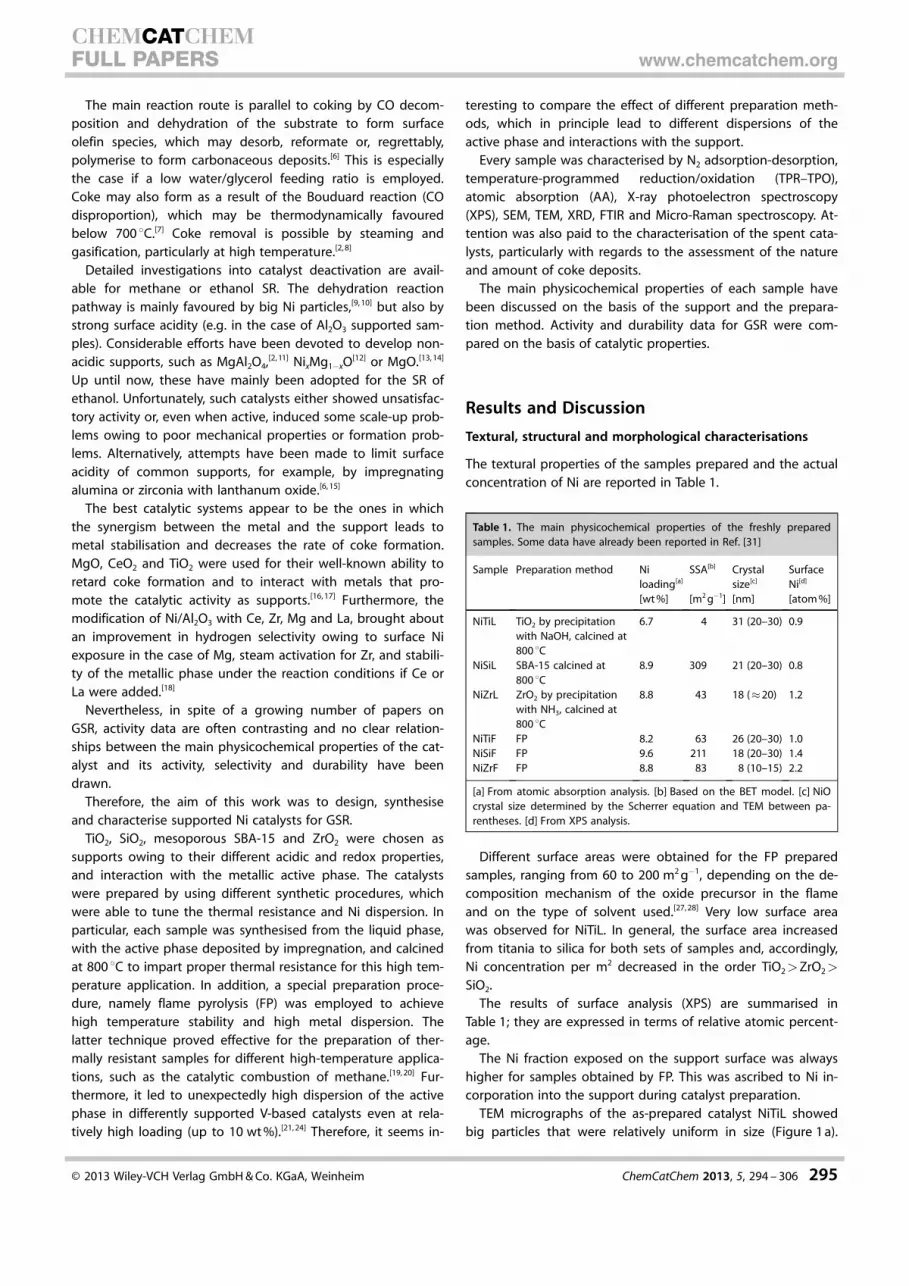
tween CO and residual OH groups. These assignments werealso confirmed by the behaviour of the bands after degassing:bands attributed to carbonyl interactions with Lewis sites weremore resistant, whereas bands attributed to H-bonded CO,readily disappeared, as long as the weak bands attributed tothe isolated OH stretching mode were restored in the spectra.It can be observed that only a few different bands related toNi species can be identified in the region n= 1850–2130 cm�1.The weak band at 2128 cm�1 indicated the presence of gemi-nal dicarbonyls over Ni+ ions, to which the associated band lo-cated at approximately n= 2090 cm�1 could be masked by thestrong band at n= 2064 cm�1.This band disappeared only afterevacuation at room temperature,which is in agreement with liter-ature findings that reported Ni+
–CO complexes are much morestable than Ni2 +–CO complexes.
Two intense bands at n=
2064 cm�1 and 2036 cm�1, withsimilar resistance to degassing,were observed in the region n=
2000–2100 cm�1. These featureswere associated with CO linearlyadsorbed onto Ni0 small clusterswith different crystal face expo-sure, size and possibly a differentmetal–support interaction. Anadditional broad band at n=
2003 cm�1, which shifted to n=
1992 cm�1 at decreasing cover-age, was detected in the regionn= 2000–1980 cm�1. This bandcorresponds to bridging CO over
larger metal Ni0 centres. Nobands associated with the pres-ence of residual Ni2+–CO speciesof NiO or nickel titanate weredetected following the reductiontreatment. Thus, Ni was broadlyreduced at the catalyst surface.On the other hand, the hetero-geneity of the Ni species is inagreement with TPR results,which highlights the presence ofat least three kinds of Ni metalparticles, metal clusters stronglyinteracting with the support,and Ni ions with different reduc-tion abilities. In fact upon de-gassing and warming, CO2 wasformed (band at approximatelyn= 2350 cm�1) as a result of COoxidation by Ni ions.
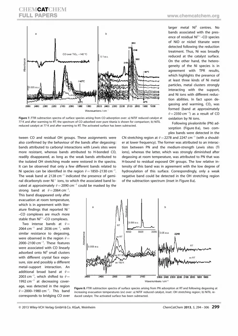
Following pivalonitrile (PN) ad-sorption (Figure 8 a), two com-plex bands were detected in the
CN stretching region at n= 2278 and 2247 cm�1 (with a should-er at lower frequency). The former was attributed to an interac-tion between PN and the medium-strength Lewis sites (Tiions), whereas the latter, which was strongly diminished afterdegassing at room temperature, was attributed to PN that wasH-bound to residual exposed OH groups. The low relative in-tensity of this band was in agreement with the low degree ofhydroxylation of this surface. Correspondingly, only a weaknegative band could be detected in the OH stretching regionof the subtraction spectrum (inset in Figure 8 a).
Figure 7. FTIR subtraction spectra of surface species arising from CO adsorption over: a) NiTiF reduced catalyst at77 K and after warming to RT; the spectrum of CO adsorbed over pure titania is shown for comparison; b) NiTiLreduced catalyst at 77 K and after warming to RT. The activated surface has been subtracted.
Figure 8. FTIR subtraction spectra of surface species arising from PN adsorption at RT and following degassing atincreasing evacuation temperatures (ev) over: a) NiTiF reduced catalyst, inset: OH stretching region; b) NiTiL re-duced catalyst. The activated surface has been subtracted.
� 2013 Wiley-VCH Verlag GmbH & Co. KGaA, Weinheim ChemCatChem 2013, 5, 294 – 306 299
CHEMCATCHEMFULL PAPERS www.chemcatchem.org
Low temperature CO adsorption over NiTiL (Figure 7 b) gaverise to bands in the C�O spectral region: at n= 2156 cm�1 (aninteraction between CO and OH groups that was possiblyoverlapped with CO adsorbed over Ni ions; this completelydisappeared after degassing at low temperature), and at n=
2130 cm�1 (weak), together with the band at n= 2095 cm�1
(symmetric/asymmetric stretching modes of poly(di)carbonylspecies stable at low temperature and characteristic of a dis-persed Ni fraction). Bands at n= 2060 cm�1, and possibly2040 cm�1, were assigned to carbonyl species on Ni0 crystals,as well as the band at n= 2020 cm�1 (shoulder), for which thelower frequency suggested the assignation to larger Ni0 parti-cles. No bands attributed to CO coordinated over exposed Ticentres can be detected (approximately n= 2190 cm�1) and,correspondingly, no bands attributed to PN interacting withLewis centres were observed.
As a matter of fact, PN adsorption led to the detection ofonly one band (Figure 8 b), owing to the presence of H-boundspecies, which disappears after degassing at room tempera-ture. This can be attributed to the collapse of surface area inthese samples and also to the formation of a titanate phase, asevidenced by XRD and skeletal FTIR spectra (vide supra).
Thus, we detected carbonyl groups that were already coordi-nated over Ni metal particles after reduction at 500 8C, togeth-er with a fraction of Ni ionic species (Ni that strongly interactswith the surface and titanate species). This effect is in agree-ment with the TPR data, which indicates that the main reduc-tion peaks appear at temperatures above 600 8C.
A detailed description of FTIR characterisation of the remain-ing samples has been providedelsewhere.[31] As for the NiSiF FP-prepared sample, the typical fea-tures of silica were evident andremained almost unchangedafter reduction. CO adsorptionover this sample evidenced thepresence of relatively extendedmetal particles that were charac-terised by bridging carbonyl spe-cies. Moreover, the formation ofNi+–polycarbonyl species wasalso suggested, although thesewere strongly reduced with respect to the NiTiF catalyst, andwere present alongside some atomically dispersed Ni. This het-erogeneity of Ni species facilely disappears after the two TPRreduction cycles.
PN adsorption mainly evidenced the presence of silanolgroups (H-bound species that were weakly held) and of Lewisacid centres, which are likely attributed to the metal phase.
The FTIR spectra of the NiSiL catalyst did not evidence isolat-ed free silanol bands in the activated sample spectra after thereduction treatment, but only highly disordered surface hy-droxyl groups. CO adsorption confirmed the presence of sila-nols (weak physisorption) and extended Ni metal particles. PNadsorption confirmed the presence of weakly H-bound speciesonly, without Lewis acidity ascribed to Ni, contrarily to sampleFP. Catalyst NiZrF was characterised by very poor transmit-
tance, which probably owes to the presence of reduced metal.Zr4 + Lewis acid sites were detected after both CO and PNadsorption.
Finally, NiZrL had exposed Zr ions acting as Lewis acid sitesand quite large Ni metal particles.
Therefore, medium Lewis acidity attributed to exposed sup-port ions, characterises both the titania- and zirconia-basedcatalysts. In the case of the former, this is accompanied bysome weakly acidic OH groups, which are available for H-bound formation with probe molecules. By contrast, silica sup-ported catalysts showed weak acidity owing to the presenceof silanols, with Lewis acidity only induced by Ni particles forthe Ni/SiO2 FP catalyst.
A relatively heterogeneous population of Ni species was de-tected over the hydrogen-reduced samples (500 8C). This con-sisted of residual Ni+ ions, Ni clusters and larger metallic Niparticles, according to the metal reducibility scale extrapolatedby TPR data.
Unfortunately, the FTIR characterisation of the spent cata-lysts was not possible owing to the presence of quartzpowder, which diluted the sample, and coke deposits.
Catalytic activity for GSR
The catalytic activity was tested under isothermal conditions at650 8C for 20 h on-stream after activation at 700 8C. Table 2 re-ports the main data on catalytic performance after 5, 10 and20 h on-stream, that is, glycerol conversion, H2 yield and selec-tivity to CO2, CO and CH4 (see the Experimental Section).
A blank test at 650 8C on quartz (0.20 g, 0.355–0.500 mm),revealed a 3 % glycerol conversion to gaseous products after3 h on-stream; the reactant was found in the condensed prod-ucts and selectivities of 87 % to CO, 13 % to CH4 and nil to CO2
were also found. The test evidenced that without any catalyst,thermal decomposition was negligible at the selected temper-ature and almost no WGS reaction was promoted.
NiTiL and NiTiF showed comparable initial activity, witha glycerol conversion higher than 95 %, and a low selectivity toCO, even if the FP-prepared sample maintained a higher activi-ty, a better CO and CH4 selectivity and a higher H2 productivityfor the whole duration of the test. This is in agreement witha higher maintained dispersion of Ni after activation of NiTiF.Generally, the selectivity to CH4 of the titania-supported sam-ples remained stable for the whole duration of the test. In par-
Table 2. Results of catalytic test runs for GSR.
Fi [%]5 h on-stream 10 h on-stream 20 h on-stream
Sample XC Y CO2 CH4 CO XC Y CO2 CH4 CO XC Y CO2 CH4 CO
NiTiL 97 88 85.9 2.7 11.4 99 89 80.5 2.7 16.8 98 82 67.2 2.6 30.2NiTiF 100 97 91.5 0.7 7.7 100 95 89.6 1.2 9.3 100 85 86.7 0.8 12.5NiSiL 87 82 87.8 1.3 10.9 88 81 86.0 1.1 12.9 100 87 70.2 1.5 28.3NiSiF 97 82 75.9 1.5 22.6 90 71 62.7 1.7 35.6 71 55 53.4 2.4 44.2NiZrL 95 89 88.1 0.0 12.0 97 92 92.2 0.0 7.8 82 80 91.1 0.0 8.9NiZrF 87 80 89.6 0.0 10.4 90 87 92.8 0.0 7.2 87 84 93.5 0.0 6.5
� 2013 Wiley-VCH Verlag GmbH & Co. KGaA, Weinheim ChemCatChem 2013, 5, 294 – 306 300
CHEMCATCHEMFULL PAPERS www.chemcatchem.org

ticular, if one considers the performances of NiTiL, despite thestable conversion of glycerol for 20 h on-stream, the WGS ac-tivity markedly decreased as illustrated in Figure 9, with a pro-gressive increase in the selectivity to CO and a correspondingdecrease of that to CO2.
By comparing the performance of NiTiL with that of thesame catalyst calcined at 500 8C instead of 800 8C and mainlyconstituted by anatase,[43] it can be observed that NiO speciessupported on anatase were much more reducible than the cat-alysts supported on rutile and the mixed oxide phase. Thesamples calcined at 500 8C were also far less stable and hadlower activities during the activity testing. Therefore, the for-mation of a strong metal–support interaction seems key toachieving a suitable Ni dispersion and activity. The metal–sup-port interaction may be increased with an increase in the calci-nation temperature, but proper thermal stability of the formedNi clusters is also needed to ensure stable performance withtime-on-stream.
The NiSiL sample showed a stable conversion and hydrogenyield up to 20 h on-stream. Indeed, both parameters reacheda stable value at 10 h on-stream (87 % and 82 %, respectively),to increase to 100 % and 87 % after 20 h on-stream. However,also in this case, CO selectivity increased during the test, re-vealing a progressive depletion of WGS activity, despite theexcess of water. This feature could be attributed either to theloss of support specific area during the reaction or to Ni sinter-ing, which owes to the huge amount of water vapour at hightemperature combined with the lowest metal–support interac-tion within this series of catalysts.
Even though it is more stable than other silica mesoporousordered supports,[39, 44] SBA-15 may undergo a collapse of thestructure under our reaction conditions, especially if it is notstabilised at high temperature. It is generally accepted thatwater is activated by the support during steam reforming ofhydrocarbons.[45–47] Therefore, a progressive decrease in its spe-cific surface area (SSA) can result in a lower water activation.Another explanation could be that the active metallic sitesinside the pores become progressively less accessible owing toa partial collapse of the mesoporous structure. The resultingdecrease in metallic surface area affected the activity of thecatalyst, but it cannot explain why the activity decrease only
affected reactivity for the WGS reaction. Additionally, CH4 couldnot be completely reformed under the present reaction condi-tions.
The conversion of glycerol achieved with NiSiF was higherthan 95 % after 5 h on-stream, but it continuously ceased toreach approximately 70 % after 20 h on-stream. This samplewas characterised by Lewis acidity, which is attributed to Ni. Itis likely that this feature induced coke deposition over theactive sites, progressively deactivating them.
ZrO2 demonstrated an interesting support for this reaction,especially if one takes into account its WGS activity and selec-tivity to methane. Indeed, almost complete conversion was at-tained for NiZrL, though with some deactivation after 10 h on-stream. By contrast, even if the FP-prepared NiZrF showeda lower activity (�87 % glycerol conversion), it demonstrateda surprising stability till the end of the test. This is in line withthe highest C balance obtained with this catalyst during paral-lel tests for ethanol steam reforming at 500 8C, in which severecoking ruled out many other samples.[31] Furthermore, com-plete methane reforming and very low selectivity to CO wereachieved with both the zirconia-supported catalysts. This maybe attributed to the ability of this support in the activation ofsteam if it interacts with metals, as already reported by Iriondoet al. for a ZrO2 doped Ni/Al2O3 catalyst for GSR.[18]
All the catalysts showed similar initial activity, except fora lower conversion achieved with NiZrF, and this remainedconstant for the whole duration of the test.
Such results may be compared with similar samples calcinedat 500 8C reported elsewhere.[43] For instance, the same SBA-15-supported sample calcined at 500 8C, was much less active anddeactivation led to a conversion of 48 % after only 20 h on-stream. Similarly, titania-supported catalysts calcined at 500 8Cwere found to be completely inactive for both the present re-action[43] and for the steam reforming of ethanol. This evi-denced how catalyst activity tightly depended on the calcina-tion temperature of the support. Only the samples calcined athigh temperature or synthesised by FP reached almost fullconversion, coupled with a sufficient stability. A strong metal–support interaction, depending on support nature or whetherattainable after calcination at high temperature, could accountfor this behaviour. The same effect of stabilisation was evi-denced for the Pt/ZrO2 system and it was associated witha strong Pt–Zrd+ interaction, which resulted in the formationof ZrOx species on the Pt surface.[48–50] In the case of a weakmetal–support interaction, metal sintering may occur, thusleading to a strong decrease in the available metallic surfacearea and therefore of the catalytic activity.
A suitable stabilisation of the metallic phase by the supportcould also lead to a catalyst less prone to deactivation. Themost effective parameter that determined the catalyst perfor-mance appears to be the reducibility of the Ni species, asa measure of their interaction with the support. The mostactive and stable catalysts were the ones that showed lowerreducibility, which indicates a stronger interaction between themetal and the support. This parameter increased from silica totitania, and an element of the parameter that is important forattaining an even stronger interaction is the Ni incorporation
Figure 9. GSR at 650 8C on NiTiL, showing glycerol conversion (^), hydrogenyield (&) and CO2 (~), CO (�) and CH4 (*) fractions in the gas phase.
� 2013 Wiley-VCH Verlag GmbH & Co. KGaA, Weinheim ChemCatChem 2013, 5, 294 – 306 301
CHEMCATCHEMFULL PAPERS www.chemcatchem.org

in the support or the formation of a mixed oxide phase duringthe synthesis. For instance, the presence of a mixed oxide(NiTiO3) was evidenced by XRD for both the titania-supportedsamples.
Other parameters, such as the Ni exposure or the texturalproperties of the support (SSA and pore morphology), seem tonot deeply affect the catalyst performance.
As a matter of fact, however, the most critical aspect for GSRis catalyst durability. In the present study, the deposition ofcoke was relatively limited because of the huge excess ofwater in the feed (the catalytic tests were virtually performedin the no carbon deposition region with respect to tempera-ture and water/glycerol ratio[51]), but GSR is a severe reactionthat suffers from low H2 productivity and strong deactivationcompared with ethanol or methane reforming,[52–54] owing tothe high reactivity of glycerol.
During steam reforming, the catalyst may deactivate by theformation of olefins that can polymerise over the surface andpossibly cover the active phase. Coke precursors can derivefrom dehydration, dehydrogenation and cyclisation of glycer-ol.[55] One way to decrease coking is to operate with a highwater to glycerol ratio, as in the case of the present study. Thisalso improves hydrogen productivity, by increasing the WGSactivity and methane reforming.
Ni particle size is often related to catalyst deactivation bycoking and extensive studies have been conducted for thesteam reforming of methane.[10, 56–59] Usually, a low coking rateis exhibited by small Ni particles. In the present case we mayobserve that the most stable behaviour has been shown byNiZrF, which is indeed characterised by the smallest particlesize. By keeping the support constant, catalyst stability versustime-on-stream was always higher with lower particle size, thatis, for the FP-prepared materials, except for NiSiF. For the latter,the acidic character of the active phase may be invoked to ex-plain the depletion of activity with time-on-stream.
The rate of deactivation may also be correlated with theacidity of the catalyst. As an example, the acidity of the sup-port caused a rapid deactivation of the Ni/Al2O3 catalyst duringglycerol reforming.[60] The addition of La2O3 or CeO2 to the Ni/Al2O3 catalyst was found to be effective for hindering deactiva-tion. The basic character of CeO2 was also related with the in-hibition of undesired reactions[61] and the same positive effecton H2 and CO2 productivity, owing to a reduction in acidity ofAl2O3 by the addition of La2O3, which was evidenced by Iriondoet al.[62] The employment of oxides, such as La2O3, CeO2, TiO2,ZrO2, MgO, as supports or as dopants, allowed for superior andstable catalytic performances in GSR.[18, 63, 64] Such oxides arealso well-known for stabilising the Ni particles; they stronglyinteract with the metal. In Ni/Al2O3 catalysts doped with La, Ce,Mg, Zr, the “decoration” of metallic particles by dispersed spe-cies from the support has been also reported, which improvethe performance of the catalyst.
The NiSiF sample was characterised by the presence of sila-nols and by Lewis acid sites attributed to Ni. By contrast, onlysilanols were observed for NiSiL. Both Lewis acid sites and sila-nols may in principle be subject to coke deposition. However,coking in the latter case only occurs on the support, and
severe catalyst deactivation with time-on-stream may be ruledout. Indeed, sample NiSiL showed a stable behaviour duringthe whole test, even with increasing conversion. On the con-trary, the FP sample showed full glycerol conversion at the be-ginning of the test, but it rapidly deactivated. This is attributedto progressive coking of the Ni active sites showing strongerLewis acidity, provoking a decrease of catalytic activity untiltheir complete deactivation. Based on the characterisation ofthe spent catalysts, we interpreted the deactivation of the FPsample by encapsulation of the active phase in a network ofcarbon nanotubes (vide infra). A similar conclusion is likely tobe drawn for sample NiZrL deactivating after 10 h on-stream,and possibly to explain the low initial activity of NiZrF. Howev-er, it should be underlined that for the latter samples no evi-dence of Lewis acidity of Ni can be extrapolated from spectro-scopic data because Lewis acidity of the metal would be cov-ered by PN interacting with Zr Lewis acid sites.
With the TiO2 and ZrO2 supports, which induce mediumLewis acidity, coking occurs in case on the support (less critical)and there is no deactivation of the active phase.
To evaluate the amount of coke deposited on the samplesduring the catalytic test, thermogravimetric analysis (TGA) inair flow up to 1000 8C was performed on the spent catalystsafter 20 h on-stream. The following scale of weight loss(always below 10 wt %) was obtained, almost regardless of thesynthetic method: TiO2<SiO2<ZrO2. It was only in the case ofthe ZrO2-supported samples that different amounts of cokehave been observed, which depend on the preparation proce-dure. Indeed, the weight loss was three times higher for NiZrFthan for NiZrL.
Micro-Raman spectra have also been recorded over thespent catalysts (Figure 10). The typical D and G bands ap-peared and were attributed to the presence of multi-walledcarbon nanotubes (MWCNTs).[65, 66]
The attribution of most carbonaceous species to MWCNTshas been also confirmed by FE-SEM analysis, which clearlyshows the morphology of carbon deposits over spent samples,as exemplified in Figure 11. Carbon nanotubes were evident
Figure 10. Micro-Raman analysis of spent catalysts a) NiZrL, b) NiTiL, c) NiSiL,d) NiZrF, e) NiTiF and f) NiSiF after 20 h on stream. The characteristic D and Gbands of carbon nanotubes are evidenced.
� 2013 Wiley-VCH Verlag GmbH & Co. KGaA, Weinheim ChemCatChem 2013, 5, 294 – 306 302
CHEMCATCHEMFULL PAPERS www.chemcatchem.org
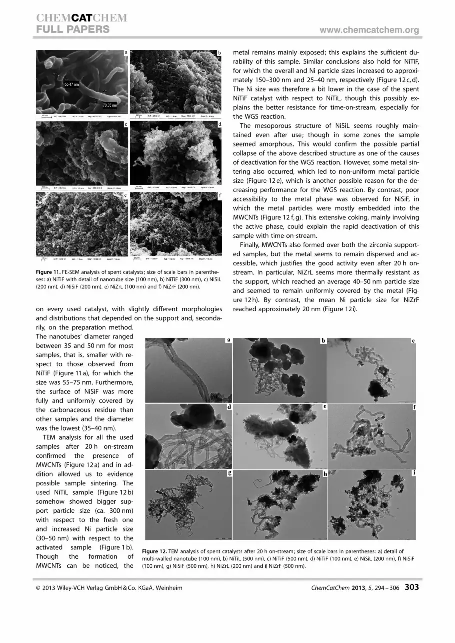
on every used catalyst, with slightly different morphologiesand distributions that depended on the support and, seconda-rily, on the preparation method.The nanotubes’ diameter rangedbetween 35 and 50 nm for mostsamples, that is, smaller with re-spect to those observed fromNiTiF (Figure 11 a), for which thesize was 55–75 nm. Furthermore,the surface of NiSiF was morefully and uniformly covered bythe carbonaceous residue thanother samples and the diameterwas the lowest (35–40 nm).
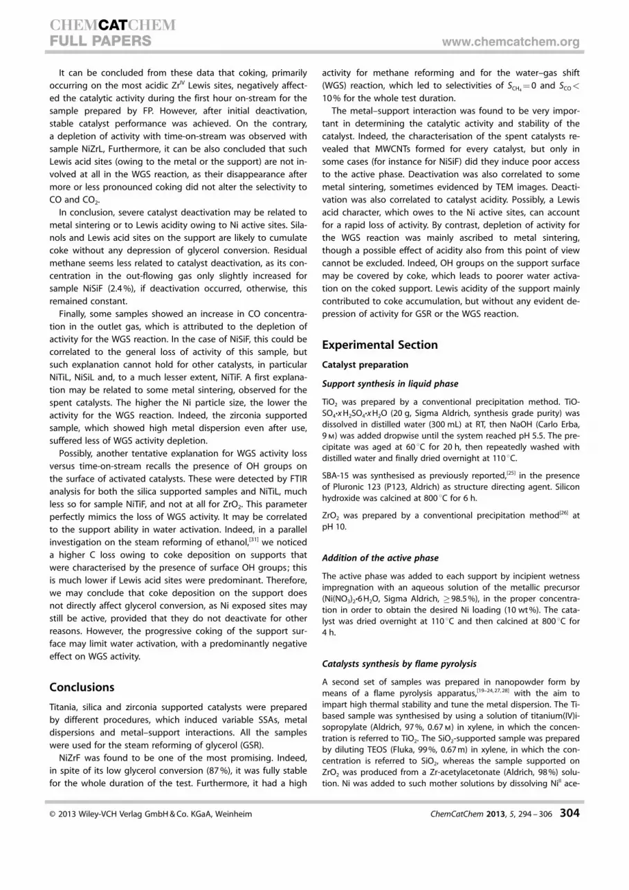
TEM analysis for all the usedsamples after 20 h on-streamconfirmed the presence ofMWCNTs (Figure 12 a) and in ad-dition allowed us to evidencepossible sample sintering. Theused NiTiL sample (Figure 12 b)somehow showed bigger sup-port particle size (ca. 300 nm)with respect to the fresh oneand increased Ni particle size(30–50 nm) with respect to theactivated sample (Figure 1 b).Though the formation ofMWCNTs can be noticed, the
metal remains mainly exposed; this explains the sufficient du-rability of this sample. Similar conclusions also hold for NiTiF,for which the overall and Ni particle sizes increased to approxi-mately 150–300 nm and 25–40 nm, respectively (Figure 12 c, d).The Ni size was therefore a bit lower in the case of the spentNiTiF catalyst with respect to NiTiL, though this possibly ex-plains the better resistance for time-on-stream, especially forthe WGS reaction.
The mesoporous structure of NiSiL seems roughly main-tained even after use; though in some zones the sampleseemed amorphous. This would confirm the possible partialcollapse of the above described structure as one of the causesof deactivation for the WGS reaction. However, some metal sin-tering also occurred, which led to non-uniform metal particlesize (Figure 12 e), which is another possible reason for the de-creasing performance for the WGS reaction. By contrast, pooraccessibility to the metal phase was observed for NiSiF, inwhich the metal particles were mostly embedded into theMWCNTs (Figure 12 f, g). This extensive coking, mainly involvingthe active phase, could explain the rapid deactivation of thissample with time-on-stream.
Finally, MWCNTs also formed over both the zirconia support-ed samples, but the metal seems to remain dispersed and ac-cessible, which justifies the good activity even after 20 h on-stream. In particular, NiZrL seems more thermally resistant asthe support, which reached an average 40–50 nm particle sizeand seemed to remain uniformly covered by the metal (Fig-ure 12 h). By contrast, the mean Ni particle size for NiZrFreached approximately 20 nm (Figure 12 i).
Figure 11. FE-SEM analysis of spent catalysts; size of scale bars in parenthe-ses: a) NiTiF with detail of nanotube size (100 nm), b) NiTiF (300 nm), c) NiSiL(200 nm), d) NiSiF (200 nm), e) NiZrL (100 nm) and f) NiZrF (200 nm).
Figure 12. TEM analysis of spent catalysts after 20 h on-stream; size of scale bars in parentheses: a) detail ofmulti-walled nanotube (100 nm), b) NiTiL (500 nm), c) NiTiF (500 nm), d) NiTiF (100 nm), e) NiSiL (200 nm), f) NiSiF(100 nm), g) NiSiF (500 nm), h) NiZrL (200 nm) and i) NiZrF (500 nm).
� 2013 Wiley-VCH Verlag GmbH & Co. KGaA, Weinheim ChemCatChem 2013, 5, 294 – 306 303
CHEMCATCHEMFULL PAPERS www.chemcatchem.org
It can be concluded from these data that coking, primarilyoccurring on the most acidic ZrIV Lewis sites, negatively affect-ed the catalytic activity during the first hour on-stream for thesample prepared by FP. However, after initial deactivation,stable catalyst performance was achieved. On the contrary,a depletion of activity with time-on-stream was observed withsample NiZrL, Furthermore, it can be also concluded that suchLewis acid sites (owing to the metal or the support) are not in-volved at all in the WGS reaction, as their disappearance aftermore or less pronounced coking did not alter the selectivity toCO and CO2.
In conclusion, severe catalyst deactivation may be related tometal sintering or to Lewis acidity owing to Ni active sites. Sila-nols and Lewis acid sites on the support are likely to cumulatecoke without any depression of glycerol conversion. Residualmethane seems less related to catalyst deactivation, as its con-centration in the out-flowing gas only slightly increased forsample NiSiF (2.4 %), if deactivation occurred, otherwise, thisremained constant.
Finally, some samples showed an increase in CO concentra-tion in the outlet gas, which is attributed to the depletion ofactivity for the WGS reaction. In the case of NiSiF, this could becorrelated to the general loss of activity of this sample, butsuch explanation cannot hold for other catalysts, in particularNiTiL, NiSiL and, to a much lesser extent, NiTiF. A first explana-tion may be related to some metal sintering, observed for thespent catalysts. The higher the Ni particle size, the lower theactivity for the WGS reaction. Indeed, the zirconia supportedsample, which showed high metal dispersion even after use,suffered less of WGS activity depletion.
Possibly, another tentative explanation for WGS activity lossversus time-on-stream recalls the presence of OH groups onthe surface of activated catalysts. These were detected by FTIRanalysis for both the silica supported samples and NiTiL, muchless so for sample NiTiF, and not at all for ZrO2. This parameterperfectly mimics the loss of WGS activity. It may be correlatedto the support ability in water activation. Indeed, in a parallelinvestigation on the steam reforming of ethanol,[31] we noticeda higher C loss owing to coke deposition on supports thatwere characterised by the presence of surface OH groups; thisis much lower if Lewis acid sites were predominant. Therefore,we may conclude that coke deposition on the support doesnot directly affect glycerol conversion, as Ni exposed sites maystill be active, provided that they do not deactivate for otherreasons. However, the progressive coking of the support sur-face may limit water activation, with a predominantly negativeeffect on WGS activity.
Conclusions
Titania, silica and zirconia supported catalysts were preparedby different procedures, which induced variable SSAs, metaldispersions and metal–support interactions. All the sampleswere used for the steam reforming of glycerol (GSR).
NiZrF was found to be one of the most promising. Indeed,in spite of its low glycerol conversion (87 %), it was fully stablefor the whole duration of the test. Furthermore, it had a high
activity for methane reforming and for the water–gas shift(WGS) reaction, which led to selectivities of SCH4
= 0 and SCO<
10 % for the whole test duration.The metal–support interaction was found to be very impor-
tant in determining the catalytic activity and stability of thecatalyst. Indeed, the characterisation of the spent catalysts re-vealed that MWCNTs formed for every catalyst, but only insome cases (for instance for NiSiF) did they induce poor accessto the active phase. Deactivation was also correlated to somemetal sintering, sometimes evidenced by TEM images. Deacti-vation was also correlated to catalyst acidity. Possibly, a Lewisacid character, which owes to the Ni active sites, can accountfor a rapid loss of activity. By contrast, depletion of activity forthe WGS reaction was mainly ascribed to metal sintering,though a possible effect of acidity also from this point of viewcannot be excluded. Indeed, OH groups on the support surfacemay be covered by coke, which leads to poorer water activa-tion on the coked support. Lewis acidity of the support mainlycontributed to coke accumulation, but without any evident de-pression of activity for GSR or the WGS reaction.
Experimental Section
Catalyst preparation
Support synthesis in liquid phase
TiO2 was prepared by a conventional precipitation method. TiO-SO4·x H2SO4·x H2O (20 g, Sigma Aldrich, synthesis grade purity) wasdissolved in distilled water (300 mL) at RT, then NaOH (Carlo Erba,9 m) was added dropwise until the system reached pH 5.5. The pre-cipitate was aged at 60 8C for 20 h, then repeatedly washed withdistilled water and finally dried overnight at 110 8C.
SBA-15 was synthesised as previously reported,[25] in the presenceof Pluronic 123 (P123, Aldrich) as structure directing agent. Siliconhydroxide was calcined at 800 8C for 6 h.
ZrO2 was prepared by a conventional precipitation method[26] atpH 10.
Addition of the active phase
The active phase was added to each support by incipient wetnessimpregnation with an aqueous solution of the metallic precursor(Ni(NO3)2·6 H2O, Sigma Aldrich, �98.5 %), in the proper concentra-tion in order to obtain the desired Ni loading (10 wt %). The cata-lyst was dried overnight at 110 8C and then calcined at 800 8C for4 h.
Catalysts synthesis by flame pyrolysis
A second set of samples was prepared in nanopowder form bymeans of a flame pyrolysis apparatus,[19–24, 27, 28] with the aim toimpart high thermal stability and tune the metal dispersion. The Ti-based sample was synthesised by using a solution of titanium(IV)i-sopropylate (Aldrich, 97 %, 0.67 m) in xylene, in which the concen-tration is referred to TiO2. The SiO2-supported sample was preparedby diluting TEOS (Fluka, 99 %, 0.67 m) in xylene, in which the con-centration is referred to SiO2, whereas the sample supported onZrO2 was produced from a Zr-acetylacetonate (Aldrich, 98 %) solu-tion. Ni was added to such mother solutions by dissolving NiII ace-
� 2013 Wiley-VCH Verlag GmbH & Co. KGaA, Weinheim ChemCatChem 2013, 5, 294 – 306 304
CHEMCATCHEMFULL PAPERS www.chemcatchem.org

tate (Aldrich, 98 %) in propionic acid (Aldrich, 97 %) to achievea nominal 10 wt % metal loading with respect to the support oxideand a 1:1 volume/volume solution of the two solvents. The solu-tions were fed to the nozzle by using a glass syringe (50 mL) witha flow rate of 2.2 mL min�1 and a 1.5 bar pressure-drop across thenozzle, co-fed with 5 L min�1 of O2. (1 bar = 100 000 Pa)
Catalysts were named as NiAB, in which A = Ti, Si or Zr with refer-ence to TiO2, SiO2 and ZrO2 carriers, respectively and B indicatesthe liquid-phase synthesis of the support (L) or flame pyrolysis (F).
Characterisation
To evaluate the actual metal concentration in the catalysts, atomicabsorption spectroscopy measurements were performed ona Perkin–Elmer AAnalysis instrument after dissolution of thesample.
XRD patterns were collected on a Bruker D8 Advance diffractome-ter equipped with a Si(Li) solid-state detector (SOL-X) and a sealedtube providing CuKa radiation. Phase recognition was possible bycomparison with literature data.[29] Crystal size was calculated withthe Scherrer equation.
SSA and pore size distributions were evaluated through N2 adsorp-tion-desorption isotherms at �196 8C (Micromeritics, ASAP 2000Analyser). Surface areas were calculated on the basis of the BETequation, whereas the pores size distributions were determined bythe Barrett–Joyner–Halenda method, which was applied to the N2
desorption branch of the isotherm. Prior to analysis, the samplewas dried overnight at 110 8C and then degassed at the same tem-perature for 2 h.
XPS analysis was performed for each fresh sample by means ofa monochromatised Surface Science Instrument (SSI).
TPR measurements were performed by placing the catalyst ina quartz reactor and heating at a rate of 10 8C min�1 from RT to800 8C in a H2/Ar mixed gas stream (5 vol %) flowing at40 mL min�1. TPO was performed by heating at a rate of10 8C min�1 from RT to 800 8C in an O2/He gas stream (5 vol %)flowing at 40 mL min�1. TPR–TPO–TPR cycles were performed onall the samples.
SEM images were obtained by using a Philips XL-30CP electron mi-croscope and the surface and elemental composition of catalystswas determined by using energy dispersive X-ray measurements(EDX). The scanning electron microscope was equipped with anLaB6 source and an EDAX/DX4 detector. The acceleration potentialvoltage was maintained between 15 keV and 20 keV and sampleswere metallised with gold. Spent catalysts were analysed by fieldemission gun scanning electron microscopy (FEGSEM) on an LEO1525 microscope, after metallisation with Cr.
TEM images of fresh and spent samples were obtained with a Phi-lips 208 transmission electron microscope. The samples were pre-pared by putting one drop of an ethanol dispersion of the cata-lysts on a copper grid pre-coated with a Formvar film and dried inair. The particle size was averaged out from at least five picturesthat were made on different zones of the catalyst.
FTIR spectra were recorded under static conditions by a NicoletNexus Fourier transform instrument, by using conventional IR cellsconnected to a gas manipulation apparatus. Pressed disks of purecatalyst and support powders (�20 mg) were thermally pre-treat-ed in the IR cell by heating under vacuum at 500 8C. The sampleswere heated in pure H2 at 500 8C after this pre-treatment to reduce
them (600 Torr, 2 cycles, 30 min each); this was followed by anevacuation step at the same temperature. CO adsorption experi-ments were performed at liquid nitrogen temperature, and weresubsequently degassed upon warming.
PN adsorption experiments were performed over the reduced sam-ples at RT and degassing was performed subsequently at increas-ing temperatures.
TGA was performed on spent samples by means of a Perkin–ElmerTGA7 instrument by heating the sample (20–30 mg) in air.
Micro-Raman sampling was made by an OLYMPUS microscope(model BX40) connected to an ISA Jobin–Yvon model TRIAX320single monochromator, with a resolution of 1 cm�1. The source ofexcitation was a Melles Griot 25LHP925 He-Ne laser that was usedin single line excitation mode at l= 632.8 nm. The power focusedon the samples was always less than 2 mW. The scattered Ramanphotons were detected by a liquid-nitrogen cooled charge coupleddevice (CCD, Jobin Yvon mod. Spectrum One).
The steam reforming of glycerol
GSR experiments were performed by using a micropilot continuousplant.[30] The catalysts were loaded on a fixed bed quartz reactor,operating at atmospheric pressure. Each sample (200 mg, 0.355–0.500 mm), diluted with the same amount of quartz of equal grainsize, was reduced in situ at 700 8C under an H2 flow, with a flowrate of 25 cm3 min�1, for 1 h. The time factor during activity testingwas 1.8 g GLY/(g CAT*h), obtained by feeding 0.060 mL min�1 ofa 10 wt % glycerol aqueous solution by means of a diaphragm me-tering pump (Stepdos, KNF). He was used as a sweeping gas, witha flow rate of 30 cm3 min�1. A pressure controller was placedbefore releasing the inlet gas to prevent overpressure phenomena.Vaporisation of the solution took place at 250 8C before enteringthe catalytic bed in a unit filled with quartz beads. The outlet gaswas sent through a vent line or to the gas analysis apparatus,whereas condensables were removed through a refrigerated coil.
The analysis of the out-flowing gas was performed by using a gaschromatograph (Agilent, mod. 6890N) equipped with two columnsconnected in series (MS and Poraplot U) with thermal conductivityand flame ionisation detectors (TCD-FID), properly calibrated forthe quantification of CH4, CO, CO2, H2, whereas the gas flow wascontinuously monitored by an on-line volumetric flowmeter (BIOSDefender 530 L).
Typically, the reaction temperature was 650 8C for approximately20 h on-stream, and repeated steady state analyses of the effluentgas were collected. The performance of the catalysts is presentedhere in terms of H2 yield, C conversion and CO, CH4 and CO2 selec-tivity in the gaseous phase (Fi), based specifically on the followingreaction [Eq. (1)] and Equations (2)–(4):
C3H8O3 þ 3 H2O! 7 H2 þ 3 CO2 ð1Þ
H2 yield ð%Þ Y ¼ mol H2 out
mol C3H8O3 in � 7� 100 ð2Þ
C conversion ð%Þ : XC ¼S mol iout
mol C3H8O3 in � 3� 100 ð3Þ
Products distribution ð%Þ : F i ¼mol i
S mol iout� 100 ð4Þ
in which i = detected gaseous products (CO2, CO and CH4).
� 2013 Wiley-VCH Verlag GmbH & Co. KGaA, Weinheim ChemCatChem 2013, 5, 294 – 306 305
CHEMCATCHEMFULL PAPERS www.chemcatchem.org
Acknowledgements
The authors are grateful to Regione Lombardia and the Consorti-um for Material Science and Technology (INSTM) for financialsupport. A.G. and V.D.S. would like to thank the Italian Ministryof Education, University and Research (Project “ItalNanoNet” pro-tocol no. RBPR05JH2P). The valuable help of the PhD studentCesare Biffi and of the MoS graduating student Mauro Castellanais gratefully acknowledged.
Keywords: hydrogen · Lewis acids · nanotubes · nickel ·supported catalysts
[1] V. A. Kirillov, V. D. Meshcheryakov, V. A. Sobyanin, V. D. Belyaev, Yu. I.Amosov, N. A. Kuzin, A. S. Bobrin, Theor. Found. Chem. Eng. 2008, 42, 1.
[2] L. J. I. Coleman, W. Epling, R. R. Hudgins, E. Croiset, Appl. Catal. A 2009,363, 52.
[3] J. Sun, X.-P. Qui, F. Wu, W.-T. Zhu, Int. J. Hydrogen Energy 2005, 30, 437.[4] J. R. H. Ross, M. C. F. Steel, A. Zeini-Isfahani, J. Catal. 1978, 52, 280.[5] D. Sutton, B. Kelleher, J. R. H. Ross, Fuel Process. Technol. 2001, 73, 155.[6] M. Benito, R. Padilla, A. Serrano-Lotina, L. Rodr�guez, J. J. Brey, L. Daza, J.
Power Sources 2009, 192, 158.[7] F. Wang, Y. Li, W. Cai, E. Zhan, X. Mu, W. Shen, Catal. Today 2009, 146,
31.[8] C. W. Bartholomew, Appl. Catal. A 2001, 212, 17.[9] A. J. Vizca�no, A. Carrero, J. A. Calles, Catal. Today 2009, 146, 63.
[10] G. Centi, S. Perathoner, Catal. Today 2009, 148, 191.[11] M. N. Barroso, A. E. Galetti, M. C. Abello, Appl. Catal. A 2011, 394, 124.[12] M. Li, S. Li, C. Zhang, S. Wang, X. Ma, J. Gong, Int. J. Hydrogen Energy
2011, 36, 326.[13] S. Freni, S. Cavallaro, N. Mondello, L. Spadaro, F. Frusteri, Catal.
Commun. 2003, 4, 259.[14] F. Frusteri, S. Freni, V. Chiodo, L. Spadaro, O. D. Blasi, G. Bonura, S. Caval-
laro, Appl. Catal. A 2004, 270, 1.[15] A. N. Fatsikostas, X. E. Verykios, J. Catal. 2004, 225, 439.[16] S. Adhikari, S. D. Fernando, A. Haryanto, Renewable Energy 2008, 33,
1097.[17] S. Adhikari, S. D. Fernando, S. D. F. To, R. M. Bricka, P. H. Steele, A. Har-
yanto, Energy Fuels 2008, 22, 1220.[18] A. Iriondo, V. L. Barrio, J. F. Cambra, P. L. Arias, M. B. Guemez, R. M. Nav-
arro, M. C. Sanchez-Sanchez, J. L. G. Fierro, Top. Catal. 2008, 49, 46.[19] G. L. Chiarello, I. Rossetti, L. Forni, J. Catal. 2005, 236, 251.[20] G. L. Chiarello, I. Rossetti, P. Lopinto, G. Migliavacca, L. Forni, Catal.
Today 2006, 117, 549.[21] I. Rossetti, L. Fabbrini, N. Ballarini, C. Oliva, F. Cavani, A. Cericola, B.
Bonelli, M. Piumetti, E. Garrone, H. Dyrbeck, E. A. Blekkan, L. Forni, J.Catal. 2008, 256, 45.
[22] I. Rossetti, L. Fabbrini, N. Ballarini, C. Oliva, F. Cavani, A. Cericola, B.Bonelli, M. Piumetti, E. Garrone, H. Dyrbeck, E. A. Blekkan, L. Forni, Catal.Today 2009, 141, 271.
[23] O. Buchneva, I. Rossetti, C. Biffi, M. Allieta, A. Kryukov, N. Lebedeva,Appl. Catal. A 2009, 370, 24.
[24] O. Buchneva, I. Rossetti, C. Oliva, M. Scavini, S. Cappelli, B. Sironi, M. Al-lieta, A. Kryukov, L. Forni, J. Mater. Chem. 2010, 20, 10021.
[25] E. Ghedini, M. Signoretto, F. Pinna, G. Cruciani, Catal. Lett. 2008, 125,359.
[26] F. Zane, S. Melada, M. Signoretto, F. Pinna, Appl. Catal. A 2006, 299, 137.[27] G. L. Chiarello, I. Rossetti, L. Forni, P. Lopinto, G. Migliavacca, Appl. Catal.
B 2007, 72, 218.[28] G. L. Chiarello, I. Rossetti, L. Forni, P. Lopinto, G. Migliavacca, Appl. Catal.
B 2007, 72, 227.[29] Selected Powder Diffraction Data, Miner. DBM, JCPDS, Swarthmore, PA,
1974 – 1992, Vol. 1 – 40.[30] A. Gallo, C. Pirovano, M. Marelli, R. Psaro, V. Dal Santo, Chem. Vap. Depo-
sition 2010, 16, 305.
[31] I. Rossetti, C. Biffi, C. Bianchi, V. Nichele, M. Signoretto, F. Menegazzo, E.Finocchio, G. Ramis, G. Garbarino, A. Di Michele, Appl. Catal. B 2012,117 – 118, 384.
[32] B. Pawelec, S. Damyanova, K. Arishtirova, J. L. G. Fierro, L. Petrov, Appl.Catal. A 2007, 323, 188.
[33] Q. G. Yan, W. Z. Weng, H. L. Wan, H. Toghiani, R. K. Toghiani, C. U. Pitt-man, Jr. , Appl. Catal. A 2003, 239, 43.
[34] S. Zhang, J. Wang, X. Wang, J. Nat. Gas Chem. 2008, 17, 179.[35] M. J. Lazaro, Y. Echegoyen, C. Alegre, I. Suelvea, R. Moliner, J. M. Pala-
cios, Int. J. Hydrogen Energy 2008, 33, 3320.[36] M. Lindo, A. J. Vizcaino, J. A. Calles, A. Carrero, Int. J. Hydrogen Energy
2010, 35, 5895.[37] S. He, Q. Jing, W. Yu, L. Mo, H. Lou, X. Zheng, Catal. Today 2009, 148,
130.[38] Y. Q. Song, D. H. He, B. Q. Xu, Appl. Catal. A 2008, 337, 19.[39] V. Garc�a, J. J. Fern�ndez, W. Ru�z, F. Mondrag�n, A. Moreno, Catal.
Commun. 2009, 11, 240.[40] G. Busca, C. Resini, Encyclopedia of Analitycal Chemistry, (Ed. : R. A.
Meyers), Wiley, Chichester, 2000, pp. 10984.[41] M. I. Baraton, G. Busca, M. C. Prieto, G. Ricchiardi, V. Sanchez Escribano,
J. Solid State Chem. 1994, 112, 9.[42] K. I. Hadjivanov, G. N. Vayssilov, Adv. Catal. 2002, 47, 307.[43] V. Nichele, M. Signoretto, F. Menegazzo, A. Gallo, V. Dal Santo, G. Crucia-
ni, G. Cerrato, Appl. Catal. B 2012, 111 – 112, 225.[44] F. Zhang, Y. Yan, H. Yang, Y. Meng, C. Yu, B. Tu, D. Zhao, J. Phys. Chem. B
2005, 109, 8723.[45] M. H. Halabi, M. H. J. M. de Croon, J. van der Schaaf, P. D. Cobden, J. C.
Schouten, Appl. Catal. A 2010, 389, 68.[46] J. R. Rostrup-Nielsen, J. Catal. 1973, 31, 173.[47] K. Takanabe, K. Aika, K. Seshan, L. Lefferts, J. Catal. 2004, 227, 101.[48] M. M. V. Souza, M. Schmal, Stud. Surf. Sci. Catal. 2004, 147, 133.[49] M. C. J. Bradford, M. A. Vannice, J. Catal. 1998, 173, 157.[50] M. M. V. Souza, D. A. G. Aranda, M. Schmal, J. Catal. 2001, 204, 498.[51] M. L. Dieuzeide, N. Amadeo, Chem. Eng. Technol. 2010, 33, 89.[52] J. Xuan, M. K. H. Leung, D. Y. C. Leung, M. Ni, Renewable Sustainable
Energy Rev. 2009, 13, 1301.[53] X. Hu, G. Lu, Energy Fuels 2009, 23, 926.[54] G. Yang, H. Yu, F. Peng, H. Wang, J. Yang, D. Xie, Renew. Energy 2011, 36,
2120.[55] F. Pompeo, G. Santori, N. N. Nichio, Int. J. Hydrogen. Energy 2010, 35,
8912.[56] V. M. Gonzalez-Dela Cruz, J. P. Holgado, R. Pereniguez, A. Caballero, J.
Catal. 2008, 257, 307.[57] K. O. Christensen, D. Chen, R. Lødeng, A. Holmen, Appl. Catal. A 2006,
314, 9.[58] D. Chen, K. O. Christensen, E. Ochoa-Fernandez, Z. Yu, B. Tøtdal, N. La-
torre, A. Monz�n, A. Holmen, J. Catal. 2005, 229, 82.[59] T. Horiuchi, K. Sakuma, T. Fukui, Y. Kubo, T. Osaki, T. Mori, Appl. Catal.
1996, 144, 111.[60] E. A. S�nchez, M. A. D’Angelo, R. A. Comelli, Int. J. Hydrogen Energy
2010, 35, 5902.[61] I. N. Buffoni, F. Pompeo, G. F. Santori, N. N. Nichio, Catal. Commun. 2009,
10, 1656.[62] A. Iriondo, V. L. Barrio, J. F. Cambra, P. L. Arias, M. B. G�emez, R. M. Nav-
arro, M. C. Sanchez-Sanchez, J. L. G. Fierro, Catal. Commun. 2009, 10,1275.
[63] L. P. R. Profeti, E. A. Ticianelli, E. M. Assaf, Int. J. Hydrogen Energy 2009,34, 5049.
[64] A. Iriondo, V. L. Barrio, J. F. Cambra, P. L. Arias, M. B. Guemez, M. C. San-chez-Sanchez, R. M. Navarro, J. L. G. Fierro, Int. J. Hydrogen Energy 2010,35, 11622.
[65] C. Gao, Y. Z. Jin, H. Kong, R. L. D. Whitby, S. F. A. Acquah, G. Y. Chen, H.Qian, A. Hartschuh, S. R. P. Silva, S. Henley, P. Fearon, H. W. Kroto,D. R. M. Walton, J. Phys. Chem. B 2005, 109, 11925.
[66] P. Delhaes, M. Couzi, M. Trinquecoste, J. Dentzer, H. Hamidou, C. Vix-Guterl, Carbon 2006, 44, 3005.
Received: July 17, 2012Published online on October 2, 2012
� 2013 Wiley-VCH Verlag GmbH & Co. KGaA, Weinheim ChemCatChem 2013, 5, 294 – 306 306
CHEMCATCHEMFULL PAPERS www.chemcatchem.org


![SiO[sub 2]–TiO[sub 2] interfaces studied by ellipsometry and x-ray photoemission spectroscopy](https://img.dokumen.tips/doc/110x75/634632a803a48733920bb674/siosub-2tiosub-2-interfaces-studied-by-ellipsometry-and-x-ray-photoemission.jpg)


![Electrical spin injection into Si(001) through a SiO[sub 2] tunnel barrier](https://img.dokumen.tips/doc/110x75/635c85e288f33c6f82003b5c/electrical-spin-injection-into-si001-through-a-siosub-2-tunnel-barrier.jpg)


![Nanoscale probing of dielectric breakdown at SiO[sub 2]/3C-SiC interfaces](https://img.dokumen.tips/doc/110x75/6347f4c27442d262850ec5bc/nanoscale-probing-of-dielectric-breakdown-at-siosub-23c-sic-interfaces.jpg)


![Distribution and segregation of arsenic at the SiO[sub 2]/Si interface](https://img.dokumen.tips/doc/110x75/635852a73cd558f04e053eeb/distribution-and-segregation-of-arsenic-at-the-siosub-2si-interface.jpg)


