Embed Size (px)
Citation preview

Journal of Babylon University/Engineering Sciences/ No.(1)/ Vol.(25): 2017
129
Effect of Length of Symmetrical Cantilever Edges on The Absolute Maximum Bending Moment in Uniformly Loaded Simply Supported Reinforced Concrete Beams
Talib Abdul Jabbar AL-Eyssawi
Lecturer/Al-FuratAlawsat Technical University/ Babylon Technical Institute Email:[email protected]
ABSTRACT This paper is devoted to study the effect of length of symmetrical overhanging edges on the
absolute maximum bending moment of uniformly loaded simply supported reinforced concrete beams. Successful implementation demonstrates the abilities and performance of STAAD Pro V8i which is the most popular structural engineering software products for 3D model generation, analysis and multi-material design. All calculations had been carried out done based on elastic analysis and the ultimate strength method of design as per ACI 318M-14 code requirements for flexural and deflection constraints.
It is approved that the beam with optimallength of overhanging edge (��) equal to 0.35 the beam length between supports (��) has equal maximum positive bending moment and maximum negative bending moment and optimal absolute maximum bending moment compared with the same beam but with other lengths of overhanging edges. Different beams cases had shown that the area of tension reinforcement may be increased up to 120% when the length of overhanging edge is away from the optimal length ofoverhanging edge of the same beam. The convergence from the optimal length of overhanging edge may lead to good relative economy of the beam.
Keywords: reinforced concrete, simply supported beam, overhanging edge, bending moment, tension reinforcement, STAAD Pro
الخالصــــــةواالسناد البسیط في العتبات الخرسانیة المسلحة ذو الحمل المنتظم الناتئةةللحاف المتماثل لطولكرس هذا البحث لدراسة تأثیر ا
والمستخدم من قبل مهندسي STAAD Pro V8iاستخدم وبنجاح برنامج التحلیل والتصمیم المشهور. على العزم المطلق االعظم
باالعتماد على متطلبات التحلیل المرن جمیع الحسابات تمت . وباستعمال المواد المختلفة لنماذج المجسمةلتحلیل وتصمیم ااالنشاءات
.ومحدداتها لالنثناء واالنحراف ACI 318M-14والتصمیم بطریقة المقاومة القصوى للمواصفة األمریكیة
ب مساوي من طول العتبة بین المساند، لها عزم اعظم موج 0.35یساوي الناتئةان العتبة التي لها طول أمثل للحافة لقد اتبت ا
اوضحت حاالت مختلفة .الناتئةالعتبة ذاتها واطوال اخرى للحافات عزم مطلق اعظم بالمقارنة مع أمثلللعزم االعظم السالب ولها
ان . عن الطول االمثل الناتئةعندما یبتعد طول الحافة % 120تسلیح الشد یمكن ان یزداد بنسبة قد تصل الى مساحة ان للعتبات
.االقتصاد النسبي للعتباتالى سوف یؤدي ربما الناتئةاالقتراب من الطول االمثل للحافة
pro Staatبرنامج ، تسلیح الشد ، حافة ناتة عزم االنحناء،السناد البسیط عتبة ذو ا، خرسانة مسلحة -:الكلمات المفتاحیة
1. INTRODUCTION Economic reinforced concrete structures can be obtained by reducing the
bending moments, and thus member sizes are smaller[McCormacand Brown, 2014]. A load placed in one span of a continuous structure will cause shears, moments,
and deflections in the other spans of that structure. Whatever steel percentages are used, the resulting members will have to be carefully checked for deflections, particularly for long-span beams, cantilever beams, and shallow beams and slabs[McCormac and Brown, 2014].
For designing of reinforced concrete structures and for formwork consideration of concrete framing system, spandrel beams ( overhangs) are more cost intensive than interior beams due to their location at the edge of a floor slab or at a slab opening[Kamara and Novak, 2011].

Journal of Babylon University/Engineering Sciences/ No.(1)/ Vol.(25): 2017
130
Optimal designof reinforced concrete structuresresults in cost savings over typical-practice design solutions. For portal frames of span length 14 m or larger, the associated bending moment distributions have equal negative and positive moment magnitudes[Guerra and Kiousis, 2006].
The location of the absolute maximum bending moment in short simply supported beams under the influence of several moving point loads is investigated, and found that traditional method to consider the absolute maximum bending moment by positioning the beam center-line midway between the resultant of the loads and the nearer heavy load is not always valid[Yassen, 2012].
For the redistribution of moments of continuous beams provisions, there is a reduction in the values of maximum negative moments in the support regions and an increase in the values of positive moments between supports from those calculated by elastic analysis.Economies in reinforcement can sometimes be realized by reducing maximum elastic positive moments and increasing negative moments, thus narrowing the envelope of maximum negative and positive moments at any section in the span[ACI Committee 318, 2014].
In simply supported beams, the maximum (positive) bending moment occurs at or near the midspan, and the beam section is accordingly designed. Similarly, in continuous spans, the cross-section at the face of the support is designed for the maximum negative moment, and the cross-section at the midspan region is designed for the maximum positive moment[Menon and Pillai, 2009].
For the redistribution of moments of continuous beams provisions, reduction in the maximum moment levels (and a corresponding increase in the lower moments at other locations)leads to the design of a more economical structure with better balanced proportions, and less congestion of reinforcement at the critical sections[Menon and Pillai, 2009].
This paper is study the effect of length of symmetrical cantilever edges on the absolute maximum bending moment in uniformly loaded simply supported reinforced concrete beams.
STAAD Pro V8i software [Bently Systems, 2015] and EXCEL spreadsheet are used for the calculations based on elastic analysis and the ultimate strength method of design as per ACI 318M-14 code requirements for flexural and deflection constraints. STAAD Pro V8iis one of the most popular structural engineering software products for 3D model generation, analysis and multi-material design [Thakur and Kushwah, 2015].STAAD.Prois very easy to learn and work, accurate for both analysis and design,and one of the leading softwares for the design of structures[Ramya and Sai Kumar, 2015].Also, STAAD.Prois usedinstead of making calculations manually, which is a time and effort consuming process, and used for generating the input / output sets of data[Keryou et.al., 2012].
2. SCOPE AND METHODOLOGY 2.1 OBJECTIVE
This paper aims to study the effect of length of symmetrical cantilever edges on the absolute maximum bending moment in uniformly loaded simply supported reinforced concrete beams. For different beams, loadings, lengths of overhanging edges as well as the optimal length of overhanging edge of each beam, the maximum positive and maximum negative moments and the short-term deflection due to unfactored live load [McCormac and Brown, 2014]will be calculated. Only bending and deflection effects on the critical cross section are considered. So, the beam has to be checked for shear considerations[Galeb, 2009].
2.2 FORMULATION OF THE PROBLEM

Journal of Babylon University/Engineering Sciences/ No.(1)/ Vol.(25): 2017
131
2.2.1 SOLUTION PROCEDURE All calculations have been carried out using STAAD Pro V8i software and
EXCEL spreadsheet based on elastic analysis and the ultimate strength method of design as per ACI 318M-14 code for bending moment and deflection.
2.2.2 OPTIMAL LENGTH OF OVERHANGINGEDGES
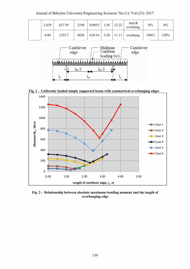
For the uniformly loaded simply supported reinforced concrete beam with symmetrical overhanging edges which is shown in the Fig. (1)and applying the equations of equilibrium [Hibbeler, 2012],the maximum positive bending moment atthe midspan and maximum negative bending moment of the symmetrical overhanging edges at each face of the support can be expressed,
Maximum positive moment =�(�� + ��
�)��
�− �
�(�� +
��
�)2
Simplifying the above expression,
Maximum positive moment =�
���
2− �
���2 ( 1 )
Maximum negativemoment = �
���2 ( 2 )
When the maximumpositive and maximumnegative moments have equal
magnitude, equating the above Eqs. (1), (2) and simplifying, the length of overhanging edge of the beamcan be expressed and will be called later as the optimal length ofoverhanging edge,
��= ��
�√� ≈ 0.3536�� ( 3 )
2.2.3 CONSTRAINTS The design of reinforced concrete beams should satisfied two groups of
requirements, which are the strength design method requirements and the serviceability requirements as per ACI 318M-14 code. The flexural and deflection are considered for the strength design method requirements and the serviceability requirements respectively.
2.2.3.1 FLEXURAL CONSTRAINTS The ACI code provides two factors of safety, one is called the load factors and
equal to 1.2 and 1.6 for unfactoreddead and unfactoredlive load respectively, and the other is called the strength reduction factor (ϕ). The strength reduction factor (ϕ) varies from 0.90 to o.65.
Applying the conditions of equilibrium and compatibility of strains with maximum concrete compressive strain at crushing of the concrete equal to (ϵc=0.003) and other hypotheticals sanctioned by this codefortension controlled beams where the strength reduction factor (ϕ) is equal 0.90[Nawy, 2009 and Nilson et.al., 2010],
� = ����
�.������
( 4 )
Mu = 0.9����( d − �
�) ( 5 )

Journal of Babylon University/Engineering Sciences/ No.(1)/ Vol.(25): 2017
132
The limitation of the area of tension reinforcement (As) for the maximum reinforcement ratio and the minimum reinforcement ratio is given by:
ρmax(ϵs=0.005) = 0.31875β1 ���
��( 6 )
ρmin =
�.������
�� ≥
�.�
�� ( 7 )
where β1 is equal to 0.85 for ��
� up to and including 28 MPa and 0.05 less for each 7 MPa of strength in excess of 28 MPa , but β1 shall not be taken less than 0.65. Also, the strains of concrete and steel are (�� = 0.003)and(�� = 0.005) respectively.
For ��� equals 21MPa and ��equals 420MPa which are widely used and studied
in the following numerical examples, the tension reinforcement ratio (ρ) should satisfy the following constraintsfor the maximum reinforcement ratio and the minimum reinforcement ratio[Hassoun and Al-Manaseer, 2008]: 0.0033 ≤ ρ ≤ 0.0135 ( 8 ) where ρ is equal to:
ρ = ��
��( 9 )
2.2.3.2 DEFLECTION CONSTRAINT
Deflection constraint limits the short-term deflection due to unfactored live load (Δs) [McCormac and Brown, 2014 andGaleb, 2009]to the following maximum permissible computed deflections limit (Δl) [ACI Committee 318, 2014]:
Δl=�
���( 10 )
3. NUMERICAL EXAMPLES 3.1 SELECTION OF BEAMS
Six main cases of uniformly loaded simply supported reinforced concrete beamsare presented here to find the optimal absolute maximum bending moment and illustrate the effect of length of symmetrical overhanging edges. These beams have different lengths, widths, depths, uniformly live loads and uniformly dead loads. Each main case has different lengths of overhanging edges and one optimallength of overhanging edge which is calculated by the above Eq. (3). The lengths of overhanging edges is(6, 6, 8, 9, 9 and 10) for the beam main cases (1, 2, 3, 4, 5 and 6) respectively with increments of 0.5 m for each case, and consequently the total number of beams is 48 different beams. All variables are chosen in such a way that satisfy the strength design method requirements and the serviceability requirements of the ACI code.
For all beams presented here, the compressive strength of concrete (���)is
21MPa, the yield stress of steel(��) is 420 MPa, the clear cover of tensile reinforcement is 40 mm, the unit weight of reinforced concrete is 24

Journal of Babylon University/Engineering Sciences/ No.(1)/ Vol.(25): 2017
133
kN/m3[(McCormac and Brown, 2014), (Arya, 2009)and (Jasim and Hameed, 2012)]. The details of all beams are shown in the following Table (1).
3.2 RESULTS AND DISCUSSIONS
The different absolute maximum positive and maximum negative moments (Mu), area of tension reinforcement (As), tension reinforcement ratio (ρ), short-term deflection due to unfactored live load (Δs) and maximum permissible computed deflections limit (Δl) for all the beam cases and all lengths of overhanging edges associated with the optimallengths of overhanging edges are calculated by using STAAD Pro V8i software and EXCEL spreadsheet according to the requirements of ACI 318M-14code.Table (2)shows the results for upper and lower bounds of (Mu), (As), percentage increase in (Mu) and (As). Also, the same table shows (Δs), (Δl) for corresponding lengths of overhanging edges. Appendix A indicates STAAD Pro V8i design output file for the beam between supports of case 6 with optimal overhanging edges which is shown in Table (2), whereas Appendix B indicates STAAD Pro V8i design cross section, design load, design parameter, bending moment and deflection of same beam.
It is clearly appeared from Table (2)that the reinforcement ratio (ρ) varies from 0.0034to 0.0116, which satisfy the flexural constraints with a wide range of Eq. (8).
The short-term deflection due to unfactored live load (Δs) varies from 0.27 mm
to 5.20 mm, which also satisfies the deflection constraint for all lengths of the beams between the supports and for all lengths of overhanging edges. It is obvious that for all beams cases, the deflection of the optimal length of overhanging edges of each case is smaller than the deflection of that length when it’s equal zero or equal lc/2.
The upper bounds of absolute maximum bending momentsare (56.47, 103.78, 240.95, 321.69, 774.00 and 1255.70 kN.m), while the lower bounds of absolute maximum bending momentsof the optimal overhangingedgesare (28.21, 51.87, 120.40, 160.83, 389.96 and 627.59 kN.m) for the cases (1, 2, 3, 4, 5 and 6) respectively. The corresponding areas of tension reinforcement provided for the upper bounds of absolute maximum bending moments are (604, 805, 1473, 1884, 3217 and 4826 mm2), while the areas of tension reinforcement provided for the lower bounds of absolute maximum bending moments of the optimal overhanging edges are (340, 402, 679, 905, 1473 and 2198 mm2)of the same cases.
All these lower bounds of absolute maximum bending moments occur when the beam has equal positive bending moment atthe midspan and negative bending moment at the face of the support for the beams with optimal lengths of overhanging edgesof the same case, and that absolute bending moment is referred to the optimalabsolute maximum bending moments.
The optimallength of overhanging edge(��)equals to 0.35 the length of the beam between supports(��) as per the preceding Eq. (3).
The results indicate that the lower bounds of absolute maximum bending moments(i.e, optimal absolute maximum bending moments) of the optimal overhanging edges have half values of upper bounds of absolute maximum bending moments of the same case, and these values have little difference due to rounding offthe optimal length ofoverhanging edge calculated from Eq. ( 3 ).
Fig.(2) illustrates the relationship betweenthe absolute maximum bending moment (Mu) and the length of overhanging edge including the optimal length of overhanging edge (��) for all beams. Fig.(3) illustrates the relationship between percentage increase in absolute maximum bending moment with respect to the

Journal of Babylon University/Engineering Sciences/ No.(1)/ Vol.(25): 2017
134
optimal absolute maximum bending moment and the length of overhanging edge (��), also for all beams.
It is clearly appeared that Fig.(3) simulates Fig.(2) andthe absolute maximum bending moment has given various increases which may reach up to 100% with respect to the optimal absolute maximum bending moment compared with the beam which has same length between supports but with differentlengths of overhanging edges other than the optimal length of overhanging edge. That maximum increase in the absolute maximum bending moment is happened for the beams without overhanging edges (�.�, �� = 0) and for the beams with overhanging edges of length equal maximum �� through this study (�.�, �� = ��/2).
Fig.(4) illustrates the relationship between the area of tension reinforcement (As)
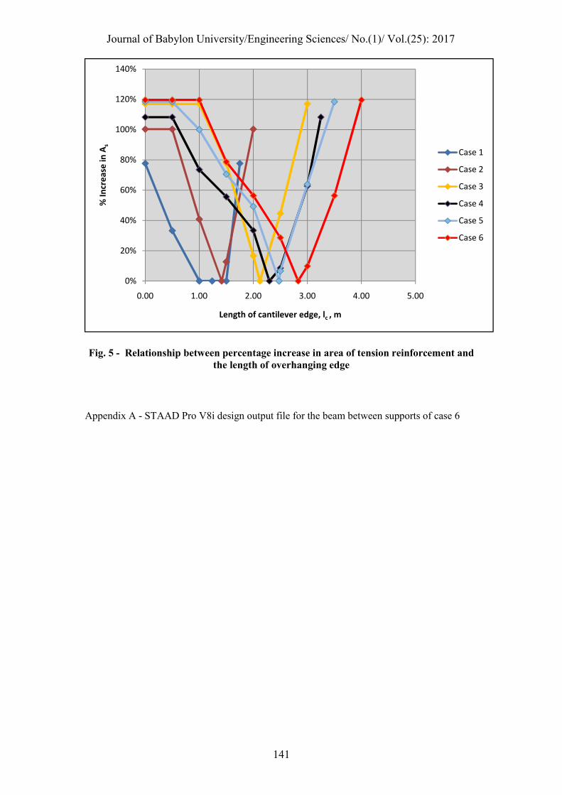
and the length of overhanging edge (��) for all beams. Fig.(5) illustrates the relationship between percentage increase in area of tension reinforcement for absolute maximum bending moment with respect to the area of tension reinforcement for the optimal absolute maximum bending moment and the length of overhanging edge (��), also for all beams.
It is clearly appeared that Fig.(5) simulates Fig.(4) andthe area of tension reinforcement for the absolute maximum bending moment has given various increases which may reach up to 120% with respect to the area of tension reinforcement for the optimal absolute maximum bending moment compared with the than the optimal length of overhanging edge.Also, that beam which has same length between supports but with different lengths of overhanging edges other maximum increase in the area of tension reinforcement is happened for the beams without overhanging edges (�.�, �� = 0) and for the beams with overhanging edges of length equal maximum �� through this study (�.�, �� = ��/2).
Figs.(2) through (5)illustrate thatconvergence in the values of the absolute maximum bending moment and consequently the area of tension reinforcement to thatvalues of the beams with optimalabsolute maximum bending momentscan be achieved as the length of overhanging edge converges to the optimallength of overhanging edge and vice versa.If small percentages of steel are used, there will belittle difficulty in placing the bars and in getting the concrete between them[McCormac and Brown, 2014].
Structural designers believe that keeping steel percentages fairly low will result in good economy[McCormac and Brown, 2014].
That approach of the uniformly loaded simply supported reinforced concrete beams to optimal lengths of overhanging edges and consequently optimal absolute maximum bending moments may reduce the amount of reinforcement relatively and improve the economy.
4. CONCLUSIONS This study was done by STAAD Pro softwarebased on elastic analysis and the
ultimate strength method of design as per ACI 318M-14 code. The main results can be indicated as following: 1. The optimalabsolute maximumbending moment of the simply supported beam with
symmetrical overhanging edges can be reached by equating the positive bending moment at midspan and negative bending moment of the overhanging edge at the face of the support.

Journal of Babylon University/Engineering Sciences/ No.(1)/ Vol.(25): 2017
135
2. The optimalabsolute maximumbending moment of the simply supported beam with symmetrical overhanging edges can be reached when the optimal length of overhanging edge equals to 0.35 the length of the beambetween supports.
3. The results indicate that the lower bounds of absolute maximum bending moments (i.e, optimal absolute maximum bending moments) of the optimal overhanging edges have half values of upper bounds of absolute maximum bending moments of the same beam case.
4. The results indicate that the absolute maximum bending momentshave given an increase up to 100% with respect to the optimal absolute maximum bending momentscompared with the beams which have same length between supports but without overhanging edges (�.�, �� = 0) and for the beams with overhanging edges of length equal half the length between supports (�.�, �� = ��/2).
5. The results indicate that the areas of tension reinforcement for the absolute maximum bending moment have given an increase up to 120% with respect to theareas of tension reinforcement forthe optimal absolute maximum bending moment compared with the beams which have same length between supports but without overhanging edges (i.e, l� = 0) and for the beams with overhanging edges of length equal half the length between supports (i.e, l� = lm/2).
6. Convergence valuesof the absolute maximum bending moment and consequently the area of tension reinforcement to that values of the beams with optimal absolute maximum bending moments can be achieved as the length of overhanging edge converges to the optimal length of overhanging edge and vice versa.That convergence may reduce the amount of reinforcement relatively and improve the economy.
REFRENCES
ACI Committee 318, 2014, “Building Code Requirements for Structural Concrete and Commentary (ACI 318M-14)”, American Concrete Institute, Farmington Hills, MI.
Arya, C., 2009, “Design of Structural Elements”, 3rd Ed., Taylor & Francis. Bently Systems Inc., 2015, “Staad. Pro for windows”, version 8i, release 20.07.11.33,
Pennsylvania. Galeb, A., C., 2009, “Optimum Design of Reinforced Concrete Rectangular Beams Using
Simulated Annealing ”, Iraqi Journal For Mechanical And Material Engineering, Special Issue (B), pp 201-210.
Guerra, A. and Kiousis, P., D., 2006, “Design Optimization of Reinforced Concrete Structures”, Journal of Computers and Concrete, Vol. 3, No. 5, pp. 313-334.
Hassoun, M., N. and Al-Manaseer, A., 2008, “Structural Concrete”, 4th Ed., John Wiley and Sons, Inc.
Hibbeler, R., C., 2012, “Structural Analysis” 8th Ed, Pearson, Inc., New Jersey, pp. 300-308. Jasim, N., A. and Hameed, F., M., 2012, “Optimal Design of Reinforced Concrete Counterfort
Retaining Walls” , Basrah Journal for Engineering Science, pp. 13-30. Kamara, M., E. and Novak, L., C., 2011, “Simplified Design of Reinforced Concrete Buildings”,
4th Ed., Portland Cement Association, Old Orchard Road, Skokie, Illinois, pp 279. Keryou, A., B., Al-Nima, R., R. and Wadie, R. N., 2012, “Design of Beam-Columns Using
Artificial Neural Networks”, Journal of Engineering and Technical, Vol. 30, No. 16, pp 2843-2857.
McCormac, J., C. and Brown, R., H., 2014, “Design of Reinforced Concrete”, 9th Ed., John Wiley and Sons, Inc.
Menon, D. and Pillai, S., 2009, “Reinforced Concrete Design”, 3rd Ed., Tata McGraw-Hill Education Pvt. Ltd., New Delhi.
Nawy, E., G., 2009, “Reinforced Concrete”, 6th Ed., Pearson Education, Inc., New Jersey. Nilson, A., H., Darwin, D. and Dolan, C., W., 2010, “ Design of Concrete Structures”, 14th Ed.,
McGraw-Hill.

Journal of Babylon University/Engineering Sciences/ No.(1)/ Vol.(25): 2017
136
Ramya, D. and Sai Kumar, A., V., 2015, “Comparative Study on Design and Analysis of Multistoreyed Building (g+10) by Staad.Pro and Etabs Software’s”, International Journal of Engineering Sciences and Research, Vol. 4, No. 10, pp 125-130.
Thakur, S. and Kushwah, S., S., 2015, “Cost and Strength Optimization of ISMB and Hollow Section of Steel Structures”, International Journal of Scientific Progress and Research, Vol. 14, No. 2, pp 63-69.
Wang, C., K., Salmon, C., G. and Pincheira, J., A., 2006, “Reinforced Concrete Design”, 7th Ed., John Wiley and Sons, Inc.
Yassen, L., A. , 2012, “Absolute Maximum Bending Moment in Short Simply Supported Beams under Moving Point Loads”, Journal of Engineering and Technical, Vol. 30, No. 16, pp 2811-2833.
Notation
�� = area of tension reinforcement, mm2
� = depth of equivalent rectangular stress block, mm
� = width of beam, mm
d =distance from extreme compression fiber to centroid of tension reinforcement, mm
��� = specified compressive strength of concrete, MPa
�� =specified yield strength of reinforcement, MPa
h = overall depth of beam, mm
lc = length of overhanging edge of the beam, m
lm =length of the beam between supports, which contains the midspan section, m
Mu = factored bending moment, kN.m
w = uniformly distributed load per unit length of beam, kN/m
wD = uniformly distributed dead load per unit length of beam, kN/m
wL = uniformly distributed live load per unit length of beam, kN/m
β1 =factor relating depth of equivalent rectangular compressive stress block to neutral axis depth
ϕ =strength reduction factor , and for bending equal 0.9
ρ =ratio of As to bd
�� = maximum usable strain at extreme concrete compression fiber
�� = net tensile strain in extreme layer of longitudinal tension reinforcement at nominal strength
Δl =short-term deflection due to unfactored live load, mm
Δl =maximum permissible computed deflections limit, mm
Table (1) - Beams details
Beam Information
Case 1 Case 2 Case 3 Case 4 Case 5 Case 6 Notes
b, mm 250 300 350 400 450 500
h, mm 400 450 550 600 800 900 Satisfy deflection constraint
h/b ratio 1.60 1.50 1.57 1.50 1.78 1.80 Ratio between 1.5 to 2 [McCormac and Brown,2014,Wang

Journal of Babylon University/Engineering Sciences/ No.(1)/ Vol.(25): 2017
137
et al, 2006]
d/h ratio 0.85 0.87 0.89 0.90 0.93 0.93
lm, m 3.5 4 6 6.5 7 8
Length of the beam between supports, which contains the midspan section
lm / h 8.75 8.89 10.91 10.83 8.75 8.89
Optimal lc, m 1.238 1.414 2.122 2.298 2.475 2.829 As per Eq.(3)
Table (1) - Beams details (Continued)
Beam Information
Case 1 Case 2 Case 3 Case 4 Case 5 Case 6 Notes
lc, m
0, 0.5, 1, 1.238, 1.5, 1.75
0, 0.5, 1, 1.414, 1.5, 2
0, 0.5, 1, 1.5, 2, 2.122, 2.5, 3
0, 0.5, 1, 1.5, 2, 2.298, 2.5, 3, 3.25
0, 0.5, 1, 1.5, 2, 2.475, 2.5, 3,
3.5
0, 0.5, 1, 1.5, 2, 2.5,
2.829, 3, 3.5,
4
Length of symmetrical overhanging edges
Max. lc, m 1.75 2 3 3.25 3.5 4 Max. lc = lm / 2
Max. lc/h 4.38 4.44 5.45 5.42 4.38 4.44
wL, kN/m 10 15 15 15 35 45 Unfactored load
wD, kN/m 15 20 20 25 50 60 Unfactored load
Beam dead weight, kN/m
2.4 3.24 4.62 5.76 8.64 10.8
Unfactored load, concrete density=24 kN/m3
[(McCormac and Brown, 2014), (Arya, 2009) and (Jasim, and Hameed, 2012)]
Number of beams for each case
6 6 8 9 9 10 Six main cases

Journal of Babylon University/Engineering Sciences/ No.(1)/ Vol.(25): 2017
138
Total Number of
beams 48
Table (2) - Beams results for upper and lower bounds of (Mu), (As), (Δs), (Δl), percentage increase in (Mu) and (As)
Beam Case
lc, m Absolute Mu, kN.m
As, mm2
ρ Δs, mm
Δl, mm
Position of Mu&Δs
% Mu Increase
% As Increase
1
0.00 56.47 604 0.0070 0.68 9.72 mid. 100% 78%
1.238 28.21 340 0.0039 0.27 9.72 mid.&
overhang. 0% 0%
1.75 56.47 604 0.0070 0.96 4.86 overhang. 100% 78%
Table (2) - Beams results for upper and lower bounds of (Mu), (As), (Δs), (Δl), percentage
increase in (Mu) and (As) (Continued)
Beam Case
lc, m Absolute Mu, kN.m
As, mm2
ρ Δs, mm
Δl, mm
Position of Mu &Δs
% Mu Increase
% As Increase
2
0.00 103.78 805 0.0068 1.01 11.11 mid. 100% 100%
1.414 51.87 402 0.0034 0.40 11.11 mid.&
overhang. 0% 0%
2.00 103.78 805 0.0068 1.44 5.56 overhang. 100% 100%
3
0.00 240.95 1473 0.0086 2.40 16.67 mid. 100% 117%
2.122 120.40 679 0.0039 0.96 16.67 mid.&
overhang. 0% 0%
3.00 240.95 1473 0.0086 3.41 8.33 overhang. 100% 117%
4
0.00 321.69 1884 0.0087 2.23 18.06 mid. 100% 108%
2.298 160.83 905 0.0041 0.89 18.06 mid.&
overhang. 0% 0%
3.25 321.69 1884 0.0087 3.16 9.03 overhang. 100% 108%
5
0.00 774.00 3217 0.0097 2.62 19.44 mid. 100% 118%
2.475 386.96 1473 0.0044 1.05 19.44 mid.&
overhang. 0% 0%
3.50 774.00 3217 0.0097 3.75 9.72 overhang. 100% 118%
6 0.00 1255.7 4826 0.0116 3.64 22.22 mid. 100% 120%
Journal of Babylon University/Engineering Sciences/ No.(1)/ Vol.(25): 2017
139
2.829 627.59 2198 0.0052 1.45 22.22 mid.&
overhang. 0% 0%
4.00 1255.7 4826 0.0116 5.20 11.11 overhang. 100% 120%
Fig. 1 - Uniformly loaded simply supported beam with symmetrical overhanging edges
Fig. 2 - Relationship between absolute maximum bending moment and the length of overhanging edge
0
200
400
600
800
1000
1200
1400
0.00 1.00 2.00 3.00 4.00 5.00
Ab
solu
te M
u ,
kN.m
Length of cantilever edge, lc , m
Case 1
Case 2
Case 3
Csae 4
Case 5
Case 6

Journal of Babylon University/Engineering Sciences/ No.(1)/ Vol.(25): 2017
140
Fig. 3 - Relationship between percentage increase inabsolute maximum bending moment andthe length of overhanging edge
Fig. 4 - Relationship between the area of tension reinforcement and the length of overhanging edge
0%
20%
40%
60%
80%
100%
120%
0.00 1.00 2.00 3.00 4.00 5.00
% In
cre
ase
in M
u
Length of cantilever edge, lc , m
Case 1
Case 2
Case 3
Case 4
Case 5
Case 6
0
1000
2000
3000
4000
5000
6000
0.00 1.00 2.00 3.00 4.00 5.00
Are
a o
f te
nsi
on
re
info
rce
me
nt,
As , m
m2
Length of cantilever edge, lc , m
Case 1
Case 2
Case 3
Case 4
Case 5
Case 6
Journal of Babylon University/Engineering Sciences/ No.(1)/ Vol.(25): 2017
141
Fig. 5 - Relationship between percentage increase in area of tension reinforcement and
the length of overhanging edge Appendix A - STAAD Pro V8i design output file for the beam between supports of case 6
0%
20%
40%
60%
80%
100%
120%
140%
0.00 1.00 2.00 3.00 4.00 5.00
% In
cre
ase
in A
s
Length of cantilever edge, lc , m
Case 1
Case 2
Case 3
Case 4
Case 5
Case 6

Journal of Babylon University/Engineering Sciences/ No.(1)/ Vol.(25): 2017
142
Appendix B - STAAD Pro V8i design cross section, design load, design parameter,
bending moment and deflection for the beam between supports of case 6

Journal of Babylon University/Engineering Sciences/ No.(1)/ Vol.(25): 2017
143
Appendix B - STAAD Pro V8i design cross section, design load, design parameter, bending moment and deflection for the beam between supports of case 6 (Continued)

Journal of Babylon University/Engineering Sciences/ No.(1)/ Vol.(25): 2017
144


