Embed Size (px)
Citation preview
Active Power Line Conditioners Based on Symmetrical Topologies
Ryszard Strzelecki, Jacek Kukluk, Jacek Rusinski Technical University of Zielona Gora,
Institute of Industrial Electrical Engineering, ul. Podgorna 50, 65-246 Zielona Gora, Poland,
tel.: (+48-68) 325483 1 ext.538, fax: (t-48-68) 3254615, strzelec@iep .pz. zgora. pl
Abstract - There have been the new universal configurations of Active Power Line Conditioners (APLC) proposed. In the simplest case, they are combinations of two base APLC sys- tems connected symmetrically in a cascade with one common add-on source. The basic one-phase symmetrical APLC and example of possible applications are shown in the paper. Power flow between add-on sources of the two basic APLC and their energetic properties are compared to indicate that the new proposed solution allow to minimize losses and are superior to the base APLC.
I. INTRODUCTION
The Universal Active Power Line Conditioners (APLC), mainly Unified Power Flow Controllers (UPFC) and Uni- fied Power Quality Conditioners (UPQC) are in a stage of hard research and increasingly applied [ 1-51, Their possi- ble functions are enlarging and include power flow control [5, 101, compensating current and voltage harmonic, volt- age imbalance, reactive power, negative sequence current and improving system stability. Performance and control strategies were widely discussed but descriptions of prop- erties dependent on different configurations has not been met. Controllers and conditioners mentioned above consist series and shunt active filters which can be represented as a current and voltage source. Current source can be con- nected to the system before or after the voltage source.
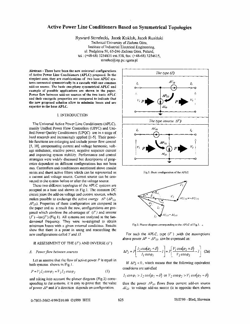
These two different topologies of the APLC systems are accepted as a base and shown in Fig.1. The common DC circuit joins the add-on voltage and current sources, which makes possible to exchange the active energy LIP (AI'(,,, AP,,). Properties of these configuration are compared in the paper and as a result the new, configurations are pro- posed which combine the advantages of (I') and inverse (I') -inv(T) (Fig. 1). All systems are analyzed at the fun- damental frequency. They were investigated to obtain minimum losses with a given external conditions. Results show that there is a point in using and researching the new configurations called 7' and Ll
I1 ASSESSMENT OF THE (r) AND INVERSE (I")
A. Power flow between sources
Let as assume that the flow of active power P is equal in both systems shown in Fig. 1.
P = VI I1 cos p1 = v21, cos p2 (1)
and taking into account the phasor diagram (Fig.2) corre- sponding to the systems, it is easy to prove that the value of power AP and it's direction depends on configuration.
The type inverse (r)
- Fig. 1 : Basic configuration of the APLC
Fig.2. Phasor diagram corresponding to the APLC of Fig. 1. 4
For such the APLC, type (T) ,with the assumptions above power AP = AP, can be expressed as:
If AP2 < 0 , which means that the following equivalent conditions are satisfied
z1 cospl z I , cos(p2 + 6) or v2 cosp2 z V, cos(p2 + 6)
thus the power AP, flows from current add-on source AI, to voltage add-on source (it is opposite then shown
0-7803-5662-4/99/$10.00 01999 IEEE 825 ISIE'99 - Bled, Slovenia
in Fig. 1.). This direction is preferred. The opposite case is not recommended For inverse (r) system, we have
If Ml < 0 , which means that the following equivalent conditions are satisfied
l1 cos(pl - 6) > 12 cos p 2 or ~2 cos(p1 - 8) > VI cos p1,
then the power flows from add-on current source to volt- age source. This direction is not recommended. Opposite direction is advisable
Example: Let as assume that voltages VI and V2 are in one phase, so 6 =O, but different amplitude. It is evident from the equations (2a) that the value of power flow be- tween add-on sources depends on relation between am- plitudes of VI and V2. If V2> VI then the r system is profit- able, because < [ M I . If V+V2 the inverse T sys- tem is better. The power flow is different in these two fil- ters as well. Using limitations introduced in B P=IS~lcosp2 (JS,J-apparent power), we can find that
Similarly the exchange real power between sources for in- verse (T)
= Is, \(cos Pz - kv c m Pz cos 6 ) (4)
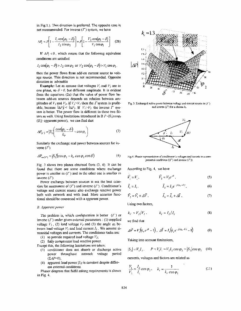
Fig. 3 shows two planes obtained from (3, 4). It can be found that there are some conditions where exchange power is smaller in (r) and in the other one is smaller in inverse (r)
Power exchange between sources is not the best crite- rion for assessment of (T) and inverse (r). Conditioner’s voltage and current source also exchange reactive power both with network and with load. More accurate func- tional should be connected with a apparent power.
B. Apparent power
The problem is, which configuration is better (I‘) or inverse (T) under given external parameters : (1) supplied voltage V I , (2) load voltage VZ and (3) the angle p2 be- tween load voltage V2 and load current l, . We assume si- nusoidal voltages and currents. The conditioner tasks are:
(1) to provide required load voltage V2; (2) fully compensate load reactive power.
(3) conditioner does not absorb or discharge active power throughout network voltage period (Cdp=O);
(4) apparent load power lSzl is constant despite differ- ent external conditions.
Phasor diagram that fulfil asking requirements is shown
Except this, the following limitations are taken:
in Fig. 4.
Fig. 3. Exchanged active power between voltage and current source in (I-) and inverse (r) for a chosen k,
Fig.4. Phasor representation of conditioner’s voltages and curents in a corn- pensated conditions ((T) and inverse (T)).
Taking into account limitations,
Is2\ = VJ, . P = v,l, = V212 cosp2 = ~ s 2 ~ c o s q 2 (10)
currents, voltages and factors are related as
826
The complex power for each source (AI - current source, AV- voltage source) in (I-) and inverse (T) topologies can be written as:
s[$] = -A@-; s[:/ = -<d*, (12)
qnTi) = -,@* S!"] 4 r ) = -<U-*, (13)
Simpler equation can be found when
is taken as a criterion. In this case the value 6 for which functional reach minimum is independent on k,
6 = arctg( e) for inverse (I-) system (15) The best
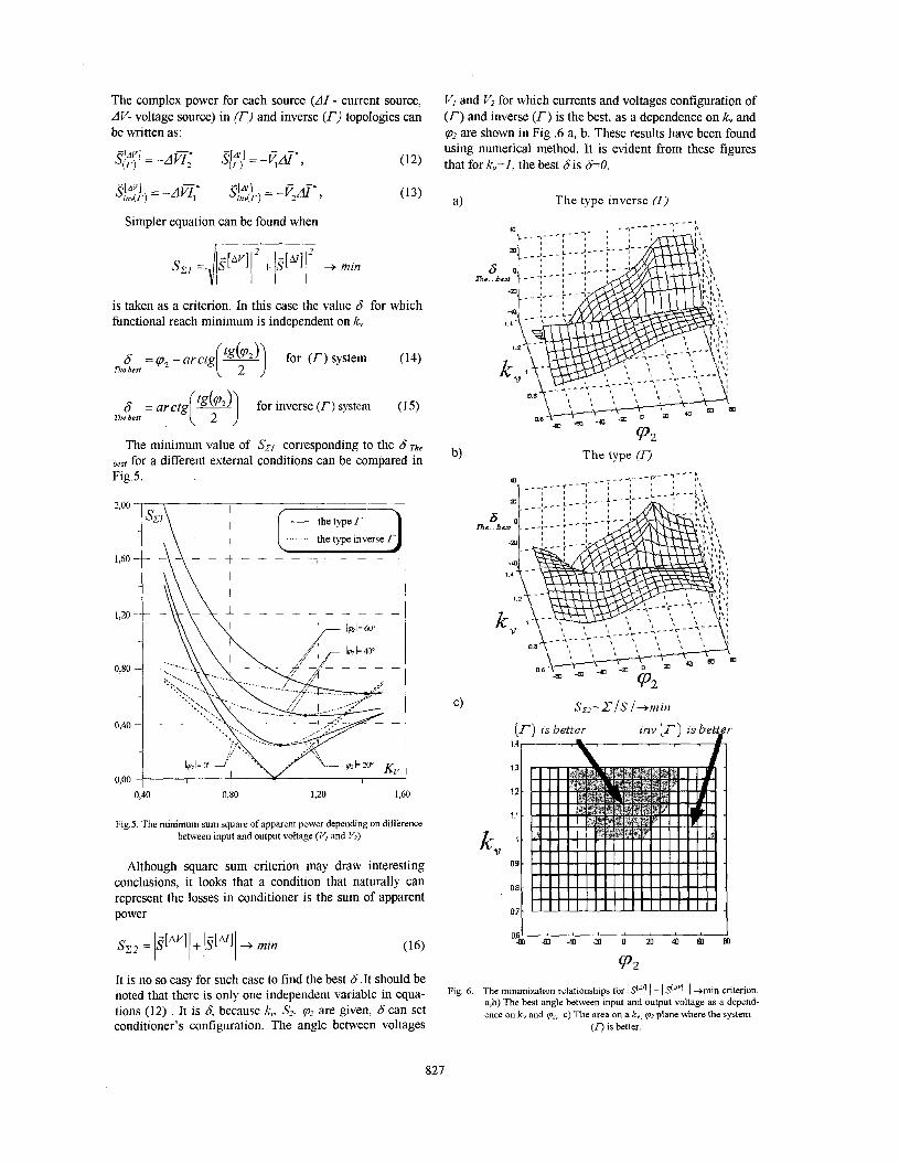
The minimum value of Szl corresponding to the S The
besf for a different external conditions can be compared in Fig.5.
2,oo
1,60
i \\\ !
I T I
I
0,40 0,80 1,io 1,60
Fig.5. The minimum sum square of apparent power depending on difference between input and output voltage (V, and l4)
Although square sum criterion may draw interesting conclusions, it looks that a condition that naturally can represent the losses in conditioner is the sum of apparent power
It is no so easy for such case to find the best 6 .It should be noted that there is only one independent variable in equa- tions (12) , It is 6, because k , Sj, p2 are given, 6 can set conditioner's configuration. The angle between voltages
VI and Vz for which currents and voltages configuration of (T) and inverse (T) is the best, as a dependence on k, and pz are shown in Fig .6 a, b. These results have been found using numerical method. It is evident from these figures that for k,=l, the best Sis S=O.
a) The type inverse (IJ
P2
Fig. 6. The minimization relationships for I s[N I + I s""l I +min criterion. a,b) The best angle between input and output voltage as a depend- ence on k, and qz, c) The area on a k,, qz plane where the system
(0 is better.
827
It is clear that since magnitude I V j 1 , I VZ I are very close, there is no point to make phase angle between voltages. Similarly, if the load is a resistance, the best 6 is 6=0. Figure 6a,b also present how to control compared systems. We are interested in possible minimum value of functional I SI4 I + 1s"" I as a dependence on k, and pz. It can be
found from function I s(4 I + I I = f ( k , pz, &he best) with the optimum &&hp best. These relations are presented in a very important graph Fig.6 c. It is obtained from (12,13). From Fig.6 c we find that there are values k, , vz where we can reach smaller sum I I + I 9'" I (especially for k,>1) in (I-) system and for same conditions inverse (I- ) is better (especially for k ,< l ) .
111. THE NEW ( I3 ) AND ( T ) TOPOLOGY
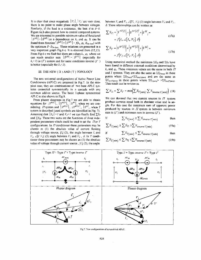
The new universal configurations of Active Power Line Conditioners (APLC) are proposed in Fig.7. In the sim- plest case, they are combinations of two base APLC sys- tems connected symmetrically in a cascade with one common add-on source. The basic 1-phase symmetrical APLC is also shown in Fig.8.
From phasor diagrams in Fig.7 we are able to obtain equations for 1 fl'" 1 , I Sd[") 1, 1 Sd" I , when we are con- sidering 17 system and I Sd"'" I , 1 Sdv'2) /, I y \, when T system is described (used symbols are identified in Fig. 7). Assuming that I Sz I = 1 and V2=1 we can finally find EST and CS, These two sums are the functions of three inde- pendent parameters which could be used to set the n o r T configurations. In 27 conditioner these parameters may be chosen as (1) the absolute value of current flowing through voltage source, pvIyI (2), the angle between 1, and V j , L[I ,V,] (3) angle between V, and V2 , 6. In T condi- tioner these parameters may be chosen as (1) the absolute value of voltage through current source , ]VI] (2), the angle
between V~and VI , L[VI , V I ] (3) angle between VI and Vz , 6. These relationships can be written as
Using numerical method the minimum CS, and EST have been found in different external conditions determined by k, and p ~ . These minimum values are the same in both n and T systems. They are also the same as CSj-(min) in these points where CSr(min)<CSinv(r)(min) and are the same as CSinv(~(min) in these points where CSr(,,,in)> >CSinv(r)~min). This result can be written as
We can demand that two current sources in I7 system produce currents equal both in absolute value and in an- gle. For this case the minimum sum of apparent power produced by sources in i7system is between minimum sum in (r) and minimum sum in inverse (I-).
Type U= Type r+ Type inverse r
Phasor diagram
~
Type T = Type inverse I-+ Type r
Phasor diagram
Fig.7. New configurations of symmetrical AF'LC
828
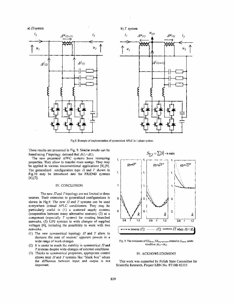
a) nsystem b) T system
r- Fig.8. Example of implementation of symmetrical APLC in I-phase system.
S,=Cld+min These results are presented in Fig. 9. Similar results can be found using T topology, demand that AU,=AU2.
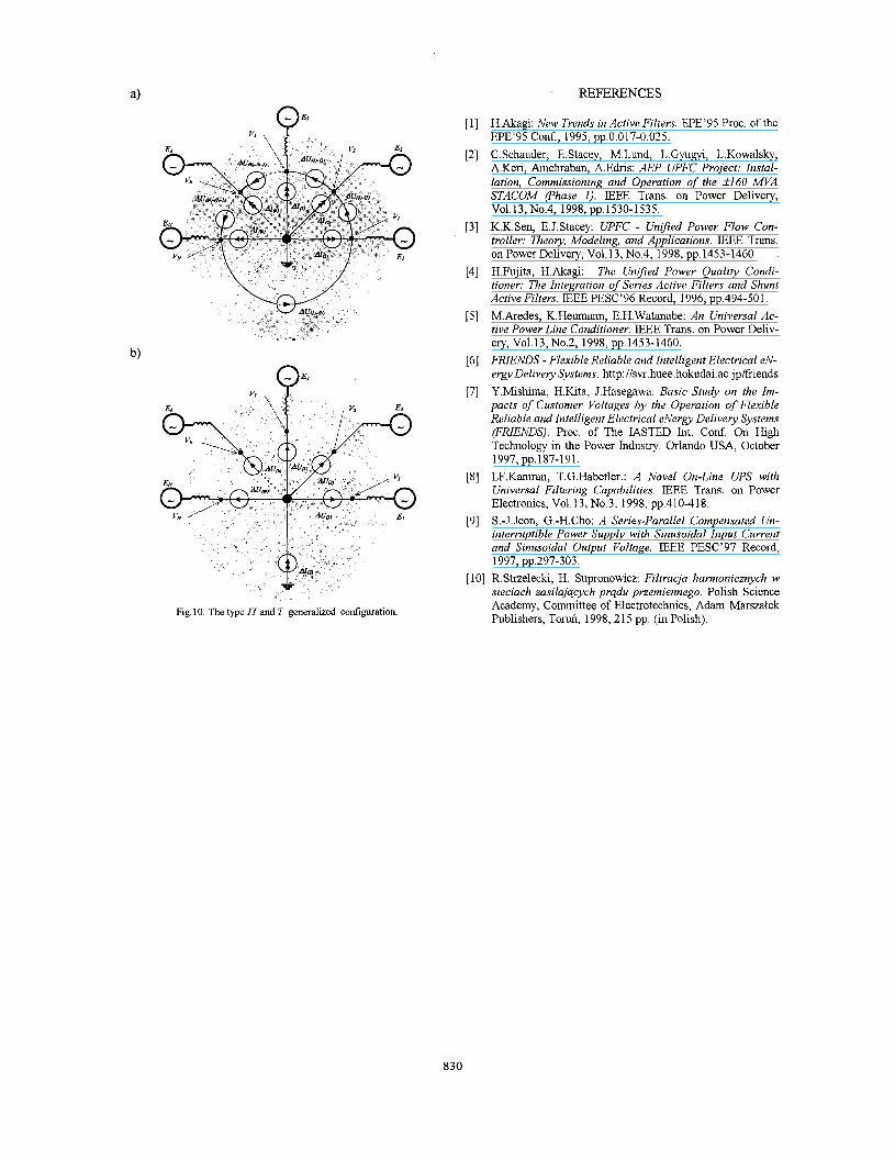
The new presented APFC systems have interesting properties. They allow to transfer more energy. They may be applied in various unconventional applications [8],[9]. The generalized configuration type I7 and r shown in Fig.10 may be introduced into the FRIEND systems [61,[71*
IV. CONCLUSION
The new n a n d T topology are not limited to three sources. Their extension to generalized configurations is shown in Fig.9. The new I7 and T systems can be used everywhere instead APLC conditioners. They may be particularly useful in (1) a scattered supply systems (cooperation between many alternative sources), (2) as a component (especially T system) for creating branched networks, (3) UPS systems in wide changes of supplied voltages [9], including the possibility to work with two networks. (1) The new symmetrical topology I7 and T allow to
decrease the sum of sources’ apparent powers in a wide range of work changes
(2) It is easier to reach the stability in symmetrical n a n d T systems despite wide changes of external conditions
(3) Thanks to symmetrical properties, appropriate control allows treat n a n d T systems like “black box” where the difference between input and output is not important.
1. ” r I 1. o.b
0.
0.8 1 1.2 0.8 1 1.2
IV. ACKNOWLEDGMENT
This work was supported by Polish State Committee for Scientific Research, Project KBN No. 8T10B 02315
829
REFERENCES
Fig. 10. The type 17 and T generalized configuration.
H.Akagi: New Trends in Active Filters. EPE’95 Proc. of the EPE’ 95 Conf., 1 995, pp.0.0 17-0.02 5. C. Schauder, E. Stacey, M.Lund, L. Gyugyi, L Kowalsky, A.Keri, Amehraban, A.Edris: AEP UPFC Project: Instal- lation, Commissioning and Operation of the 2160 MVA STACOM (Phase 1). IEEE Trans. on Power Delivery,
K.K.Sen, E.J.Stacey: UPFC - Uni’j-ied Power Flow Con- troller: Theoy, Modeling, and Applications. IEEE Trans. on Power Delivery, Vo1.13, No.4, 1998, pp.1453-1460. H.Fujita, H.Akagi: The Unified Power Quality Condi- tioner: The Integration of Series Active Filters and Shunt Active Filters. IEEE PESC’96 Record, 1996, pp.494-501. M.Aredes, K.Heumann, E.H.Watanabe: An Universal Ac- tive Power Line Conditioner. IEEE Trans. on Power Deliv- ery, Vo1.13, No.2, 1998, pp.1453-1460. FRIENDS - Flexible Reliable and Intelligent Electrical eN- e r a Delivery Systems: http : Ilsvr . huee . hokudai . ac .j p /friends Y.Mishima, H.Kita, J.Hasegawa: Basic Study on the Im- pacts of Customer Voltages by the Operation of Flexible Reliable and Intelligent Electrical eNergv Delivery Systems (FRIENDS). Proc. of The IASTED Int. Conf. On High Technology in the Power Industry. Orlando USA, October
LF.Kamran, T.G.Habetler.: A Novel On-Line UPS with Universal Filtering Capabilities. IEEE Trans. on Power Electronics, Vo1.13, No.3, 1998, pp.410-418. S.-J. Jeon, G.-H.Cho: A Series-Parallel Compensated Un- interruptible Power Supply with Sinusoidal Input Current and Sinusoidal Output Voltage. IEEE PESC’97 Record,
V01.13,No.4, 1998,pp.1530-1535.
1997, pp.187-191.
1997, pp.297-303. [ 101 R.Strzelecki, H. Supronowicz: Filtracja harmonicznych w
sieciach zasilajqcych prqdu przemiennego. Polish Science Academy, Committee of Electrotechnics, Adam Marszaiek Publishers, Toruh, 1998,215 pp. (in Polish).
830


