Embed Size (px)
Citation preview

EAST AFRICAN SCHOOL OF AVIATION
ENGINEERING DEPARTMENT
TRADE PROJECT
TITLE
LASER GUIDED NIGHT RUNWAY DEBRIS DETECTOR
BY
JOHN MUTUKU MUTHAMA
PRESENTED TO THE KENYA NATIONAL EXAMINATION COUNCIL IN PARTIAL
FULFILMENT FOR THE AWARD OF DIPLOMA IN AERONAUTICAL
ENGINEERING AVIONICS OPTION

OCTOBER/NOVEMBER 2013
DECLARATION
Declaration by candidate:
This trade project is my original work and to the best of my knowledge has not been previously presented for the award of a degree, diploma or any certificate in any college or university.
Name: JOHN MUTUKU MUTHAMA
Index no: ……………………………..
Sign: ………………………………….
Date: ………………………………….
Declaration by supervisor:
This trade project has been submitted with my approval as East African School of Aviation trade project supervisor.
Supervisor: ………………………….
Sign: …………………………………

Date: …………………………………
DEDICATION
I dedicate this project to my family, friends and my esteemed supervisor.

ACKNOWLEDGEMENT
Due to the success of this project I would like to thank my brother Mr. Wilson for the financial support, my friends for encouraging me since without their support it would not have beena success. Also I would like to thank my supervisor Mr. E.OMONDI for his guidance and overwhelming support he offered me through the entire period of the formulation of this project.

SYNOPSIS
Chapter 1: introduces the main problem statements, background andobjectives of the trade project.
Chapter 2: provides a theoretical review which gives the details of the entire system, with the choice of various components and exact specifications.
Chapter 3: illustrates various block diagrams, the projects methodology and circuits, also shows how the beams flow out from the laser for detection.
Chapter 4: provides the assembly procedure, testing and failures encountered. Also brings out the precaution to be taken especially during components interconnection, conclusions and reference pages.

TABLEOF CONTENTS
CONTENT
DECLARATION ………………………………………………………………………………….
DEDICATION …………………………………………………………………………………….
ACKNOWLEDGEMENT …………………………………………………………………………
ABSTRACT ……………………………………………………………………………………….
TABLE OF CONTENTS ………………………………………………………………………….
LIST OF CHARTS ………………………………………………………………………………..
LIST OF FIGURES ……………………………………………………………………………….
LIST OF ABREVIATIONS ………………………………………………………………………
DEFINATION OF TERMS ……………………………………………………………………....
CHAPTER ONE: INTRODUCTION ………………………………………………………… 1
1.1 Introduction ………………………………………………………………………………….. 1
1.2 Background to the trade project ………………………………………………………………
1.3 Statement of the problem ……………………………………………………………………...
1.4 Trade project objectives ………………………………………………………………………
1.5 Scope of trade project …………………………………………………………………………
CHAPTER TWO: LITRATURE REVIEW
2.1 INTRODUCTION ……………………………………………………………………………
2.2 DIFFERENT DESIGN APPROCHES TO TRADE PROJECT……………………………...
2.3.1 SUB UNITS OF MAIN BLOCK DIAGRAM …………………………………………….
2.3.2 CIRCUIT DIAGRAM OF SUB UNITS …………………………………………………..
2.3.3 FINAL CIRCUIT DIAGRAM …………………………………………………………….
CHAPTER THREE: TRADE PROJECT METHODOLY
3.0 TRADE PROJECT METHODOLOGY ……………………………………………………
3.1 INTRODUCTION ………………………………………………………………………….
3.2 DESCRIPTION OF THE DESIGN APPROACH AND CONSTRUCTION ……………..
CHAPTER FOUR: DATA ANALYSIS AND INTERPRETATION
4.0 DATA ANALYSIS AND INTERPRETATION ……………………………………………
4.1 INTRODUCTION ………………………………………………………………………….
4.2 TEST RESULTS ……………………………………………………………………………
4.3 POSSIBLE CAUSES OF FAILURE IN DESIGNING THE PROJECT …………………..
4.4 CONCLUSIONS …………………………………………………………………………...
4.5 RECOMMENDATIONS …………………………………………………………………..
4.6 REFRENCES ………………………………………………………………………………
4.8 APPENDICES ……………………………………………………………………………..

LIST OFCHARTS
Chart 2.5.1: simplified laser line chart ………………………………………………………….

LIST OF FIGURES
Figure 2.1: Open loop scanner block diagram ……………………………………………………
Figure 2.1.2: Closed loop scanner block diagram………………………………………………...
Figure 2.2: cross section of a galvo/scanner ……………………………………………………..
Figure 2.2.1: Galvanometer motor ………………………………………………………………
Figure 2.4: laser projector block diagram ……………………………………………………….
Figure 2.5.3: Direct-current power of argon laser ………………………………………………

ABREVIATIONS
LASER – light Amplification by Stimulated emission of radiations.
F.O.D – foreign object damage.

DEFINATIONOF TERMS
F.O.D – this is term used define any object in or outside the aircraft, that may cause a malfunction or hinder the aircrafts’ normal operation during or before flight.
Galvo - refers to the basic galvanometer itself, without an attached mirror
Scanner - refers to a galvanometer that has a mirror attached to it such that it can deflect a laser beam by applying appropriate control signals.
DUT – refers to device under test.
CHAPTER ONE
1.1 Introduction
This chapter highlights in detail the projects’ background, its objectives, information about its functionality mode and the fullproject statement.
1.2 Background to the trade project
This project is based on the concord supersonic aircraft, which was been flown by captain Christian Marty, from Paris to new Yorkon July ,25,2000 at 4.40,which busted into flames minutes before take-off, due to a tyre burst into fragments killing 109 crew on board within 120 seconds. This tyre burst was caused by a 43cm mystery strip of metal on the run way, confirmed to have been displaced from an engine, mounted on a DC 10 aircraft mounting, which had took off 5 minutes before concord, on the same runway.
1.3 PROBLEM STATEMENT
Due to the presence of non-visible F.O.D on the runway and taxi ways at night, this system of purely laser propagation is devisedto cater for the assumption that there is no F.O.D present from the arriving/departing aircrafts, taxing tractors crossing the runways and animals especially dead birds. The beams should be viewed from the ground tower and by the tractor man down the runway.
1.4 TRADE PROJECT OBJECTIVE
It’s to propagate continuous beams of straight lines with reflection mirrors across and at the end of the runway and taxi ways’ lights subsequently for detection of debris to a minimum of3cm in length and width.
1.5 Scope of the project
For the final documentation of this project it will take seven months, one month for typing and editing, and six months of intense research and formulation.
CHAPTER TWO
2.1 Introduction
This chapter describes various types of the laser scanners, how the mirror galvanometer and scanners work, and the projector unitfunctions.
2.2 Types of scanners
- There are two major types of scanners used in laser light shows - open loop and closed loop. A scanner is open loop if no
position detection device is used, and closed loop if a position detection device is used.
2.2.1 Open loop
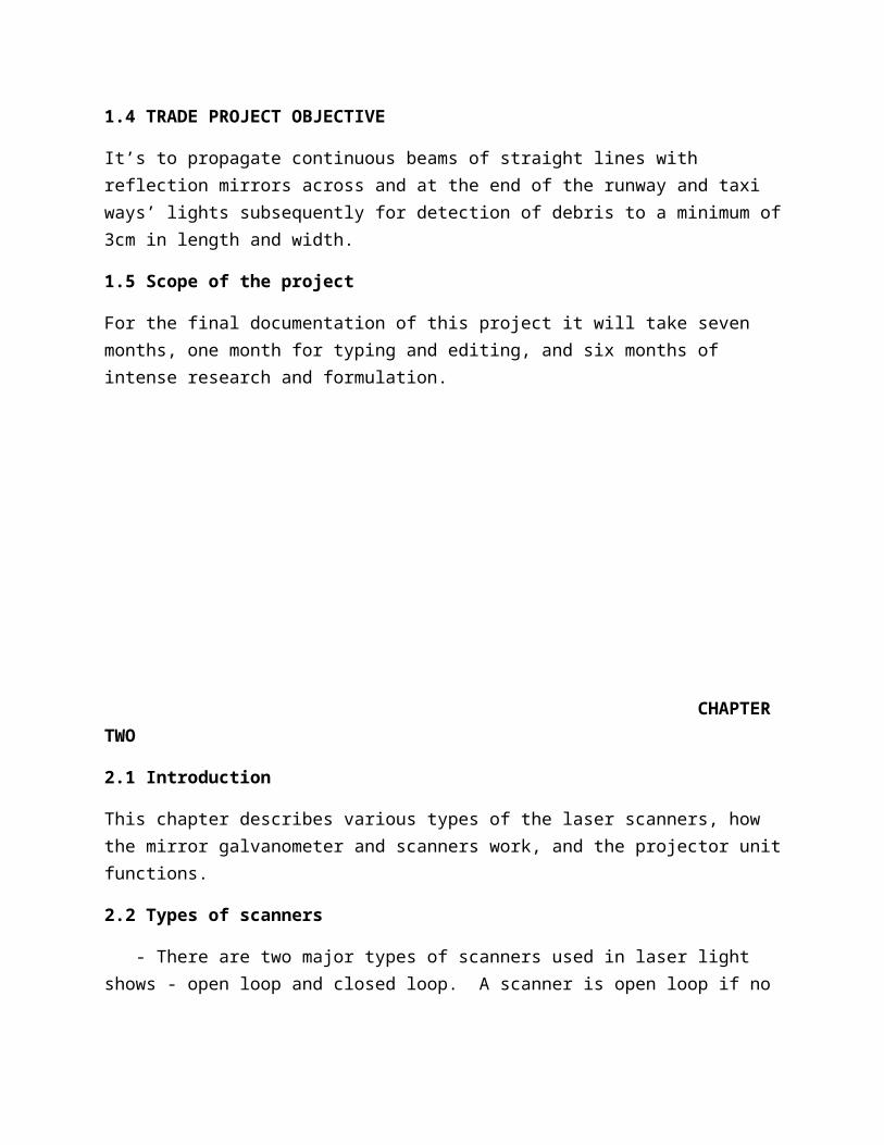
- Open loop scanners are typically built as shown in the diagram above. The rotor has a shaft running through it with topand bottom bearings. The shaft protrudes outside the housing of the scanner so that a mirror can be attached to the shaft.
Open loop scanner block diagram
Figure 2.1.
- When a current is applied to the drive coils, the shaft movesin the direction determined by the polarity of the signal, and inan amount proportional to the current applied. The movement is relatively predictable but there is no way to know exactly where the shaft with the attached mirror is. Open loop scanners are thus useful as actuators and for beam.
Limitation of open loop scanner
-Lack the precision needed for accurate applications such as laser graphics.
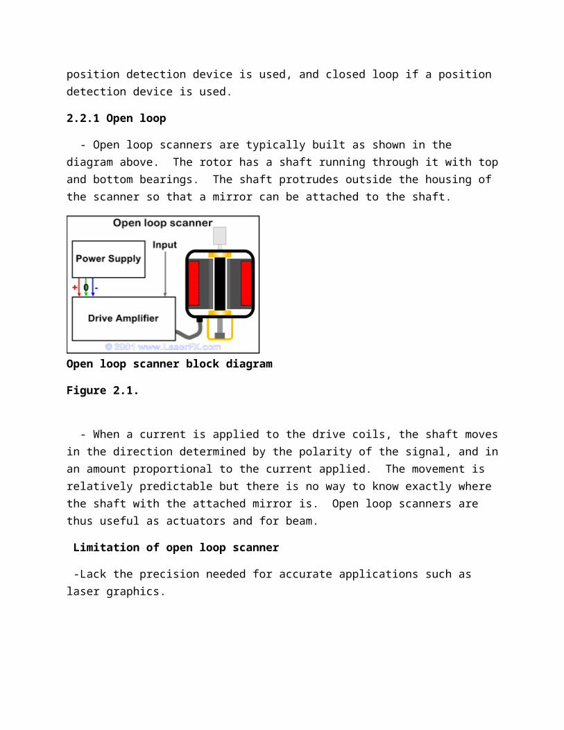
Closed loop - The closed loop scanner adds an additional element. The shaftis fitted with a position detector that can determine where the scanner is within its range of motion. In modern high-speed scanners, the position detector uses an optical system with a vane that occludes the light from an LED falling onto a photo sensor. As the shaft moves through its range of motion, more or less light falls on the photo sensor generating a signal that is proportional to the position of the shaft and its attached mirror.
Figure 2.1.2
-The LED is shown in green and the photo detector in light blue with an occluding vane attached to the shaft between then. The closed loop scanner amplifier is also more complex than the typical open loop scanner amp. The input signal is sent to the scanner drive stage circuit after passing through the input conditioning circuit. The position of the shaft is derived from the photo detector in the position detection circuit, which sends that signal to a positioncorrection circuit. The position correction circuit compares theactual position of the mirror, with the position the mirror should be in according to the signal from the input conditioning circuit. It then generates an error correction signal and sends
that to the scanner drive stage where it is combined with the input signal. The drive stage provides the current to the coils in the scanner to move the mirror. The position of the mirror is thus compared in real time withthe input signal and corrected for any inaccuracy. This allows the very precise and accurate control of the mirror that is necessary for projecting laser.
Limitation
Since this is a mechanical system, there are limits to how fast the mirror can be moved.
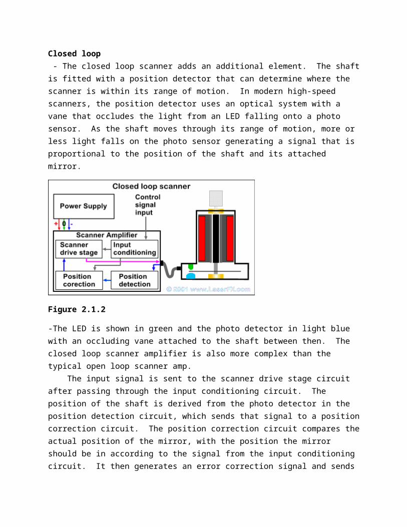
2.2.1 Mirror Galvanometer
-As shown in figure 2.2 it is a mechanical meter that senses electric current that instead of a moving needle, it moves a mirror.
Figure 2.2.0
2.2.2 Galvanometer motor
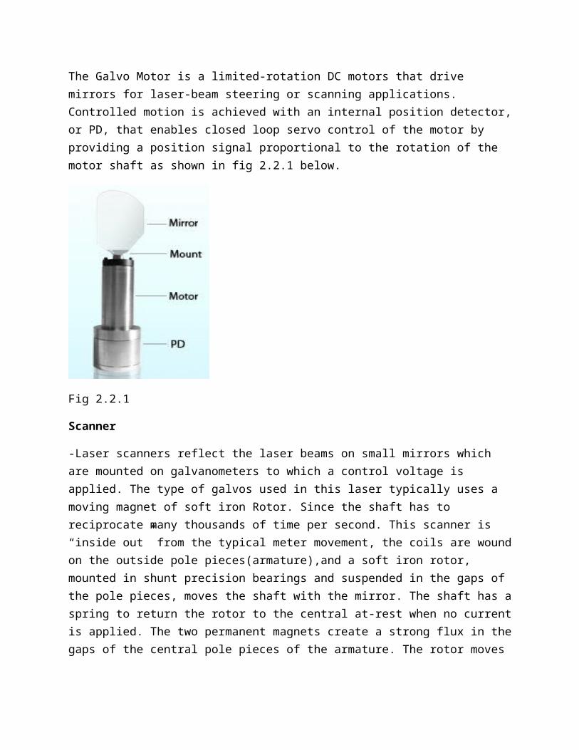
The Galvo Motor is a limited-rotation DC motors that drive mirrors for laser-beam steering or scanning applications. Controlled motion is achieved with an internal position detector,or PD, that enables closed loop servo control of the motor by providing a position signal proportional to the rotation of the motor shaft as shown in fig 2.2.1 below.
Fig 2.2.1
Scanner
-Laser scanners reflect the laser beams on small mirrors which are mounted on galvanometers to which a control voltage is applied. The type of galvos used in this laser typically uses a moving magnet of soft iron Rotor. Since the shaft has to reciprocate many thousands of time per second. This scanner is “inside out” from the typical meter movement, the coils are woundon the outside pole pieces(armature),and a soft iron rotor, mounted in shunt precision bearings and suspended in the gaps of the pole pieces, moves the shaft with the mirror. The shaft has aspring to return the rotor to the central at-rest when no currentis applied. The two permanent magnets create a strong flux in thegaps of the central pole pieces of the armature. The rotor moves
the shaft with attached mirror in response to variation in the magnetic flux caused by current applied to the drive cells.
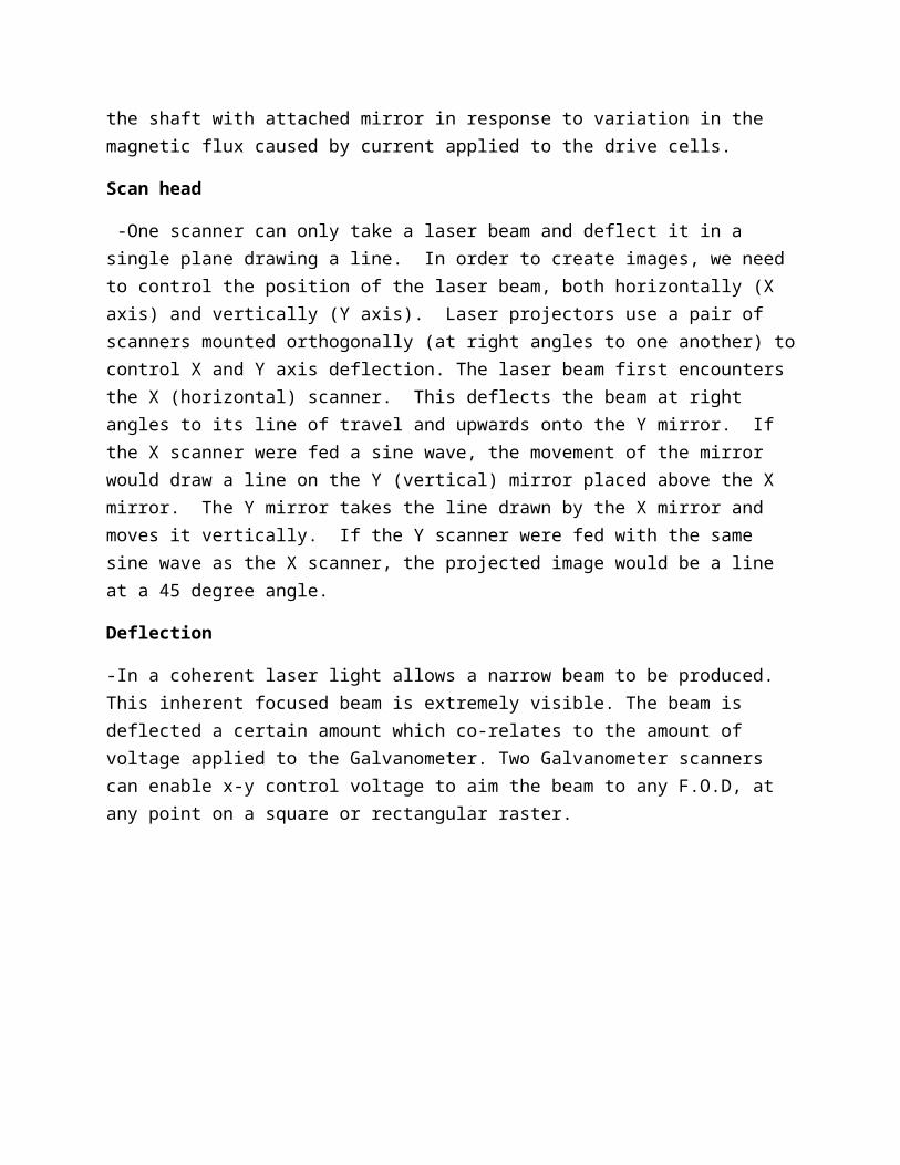
Scan head
-One scanner can only take a laser beam and deflect it in a single plane drawing a line. In order to create images, we need to control the position of the laser beam, both horizontally (X axis) and vertically (Y axis). Laser projectors use a pair of scanners mounted orthogonally (at right angles to one another) tocontrol X and Y axis deflection. The laser beam first encounters the X (horizontal) scanner. This deflects the beam at right angles to its line of travel and upwards onto the Y mirror. If the X scanner were fed a sine wave, the movement of the mirror would draw a line on the Y (vertical) mirror placed above the X mirror. The Y mirror takes the line drawn by the X mirror and moves it vertically. If the Y scanner were fed with the same sine wave as the X scanner, the projected image would be a line at a 45 degree angle.
Deflection
-In a coherent laser light allows a narrow beam to be produced. This inherent focused beam is extremely visible. The beam is deflected a certain amount which co-relates to the amount of voltage applied to the Galvanometer. Two Galvanometer scanners can enable x-y control voltage to aim the beam to any F.O.D, at any point on a square or rectangular raster.
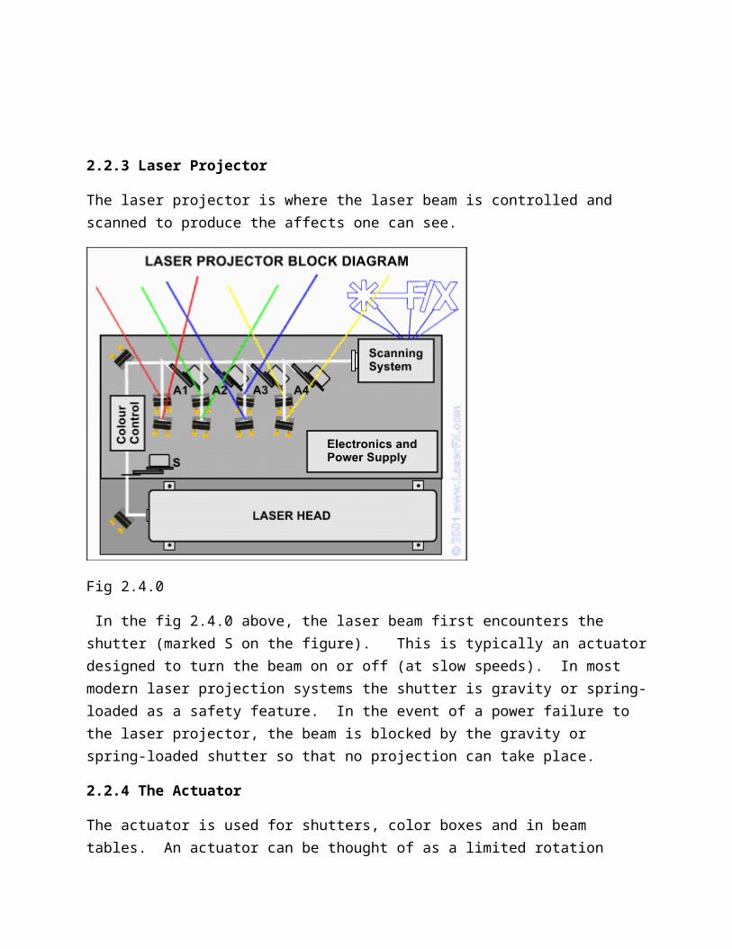
2.2.3 Laser Projector
The laser projector is where the laser beam is controlled and scanned to produce the affects one can see.
Fig 2.4.0
In the fig 2.4.0 above, the laser beam first encounters the shutter (marked S on the figure). This is typically an actuatordesigned to turn the beam on or off (at slow speeds). In most modern laser projection systems the shutter is gravity or spring-loaded as a safety feature. In the event of a power failure to the laser projector, the beam is blocked by the gravity or spring-loaded shutter so that no projection can take place.
2.2.4 The Actuator
The actuator is used for shutters, color boxes and in beam tables. An actuator can be thought of as a limited rotation
electrical motor that only moves a few degrees when power is applied. In a beam table, the shaft of the actuator is fitted with a lightweight arm that has a mirror glued to the end of it. It is mounted below a laser beam at a 45 degree angle to the beam, such that the mirror is close to, but not touching, thelaser beam. Sending an electrical signal to the actuator pulls the arm (and mirror) into the beam so that the laser is deflectedat 90 degrees to its original line of travel.
Color control
This is where the beam gets it color from before been propagated for visibility. Lasers either use a tandem laser pair - an Argonlaser for the blue and green.
- Krypton laser for the red.
The beams from the two lasers are combined to form a "white" beam.
The white light laser also is used to produces red, green and blue from one laser system.
Color control can be either- subtractive - where unwanted colors are subtracted from the beam
- Additive where colors are added to make the desired color.
Laser lines
Laser lines are measured in nanometers rather than colors, since the color of the beam perceived by the eye is a function of the frequency of the photon oscillations.
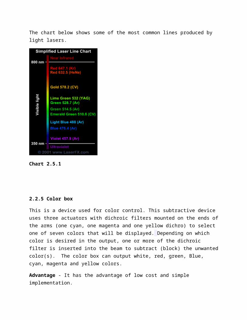
The chart below shows some of the most common lines produced by light lasers.
Chart 2.5.1
2.2.5 Color box
This is a device used for color control. This subtractive device uses three actuators with dichroic filters mounted on the ends ofthe arms (one cyan, one magenta and one yellow dichro) to select one of seven colors that will be displayed. Depending on which color is desired in the output, one or more of the dichroic filter is inserted into the beam to subtract (block) the unwantedcolor(s). The color box can output white, red, green, Blue, cyan, magenta and yellow colors.
Advantage - It has the advantage of low cost and simple implementation.
Disadvantage - It has a relatively slow response time as it is a mechanical device thus it can only produce a limited number of color changes in each frame.
2.2.6 Power supply
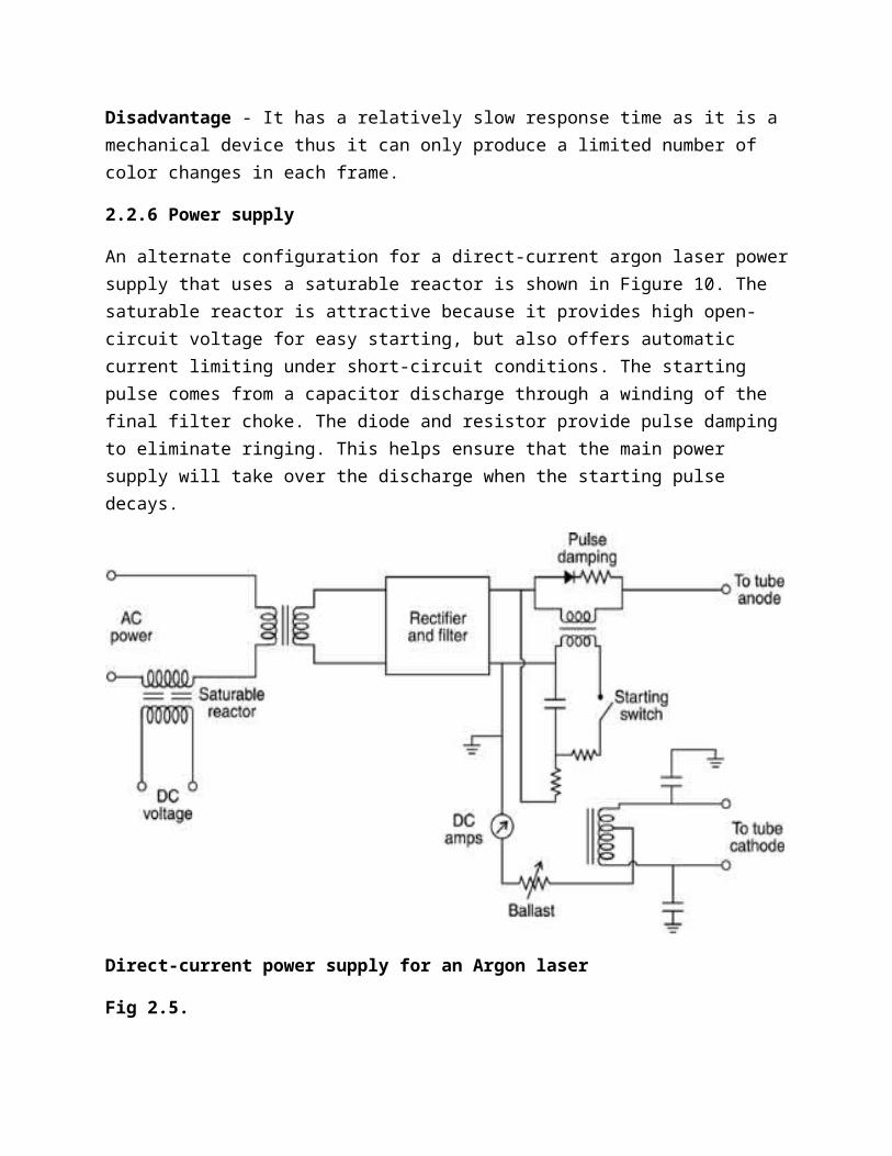
An alternate configuration for a direct-current argon laser powersupply that uses a saturable reactor is shown in Figure 10. The saturable reactor is attractive because it provides high open-circuit voltage for easy starting, but also offers automatic current limiting under short-circuit conditions. The starting pulse comes from a capacitor discharge through a winding of the final filter choke. The diode and resistor provide pulse damping to eliminate ringing. This helps ensure that the main power supply will take over the discharge when the starting pulse decays.
Direct-current power supply for an Argon laser
Fig 2.5.
CHAPTER THREE
TRADE PROJECT METHODOLOGY
3.1 Introduction
This chapter entails the design approach and explanation of the various stages operations.
3.2 Description of the design approach and constriction of the various stages
This stage includes the following.
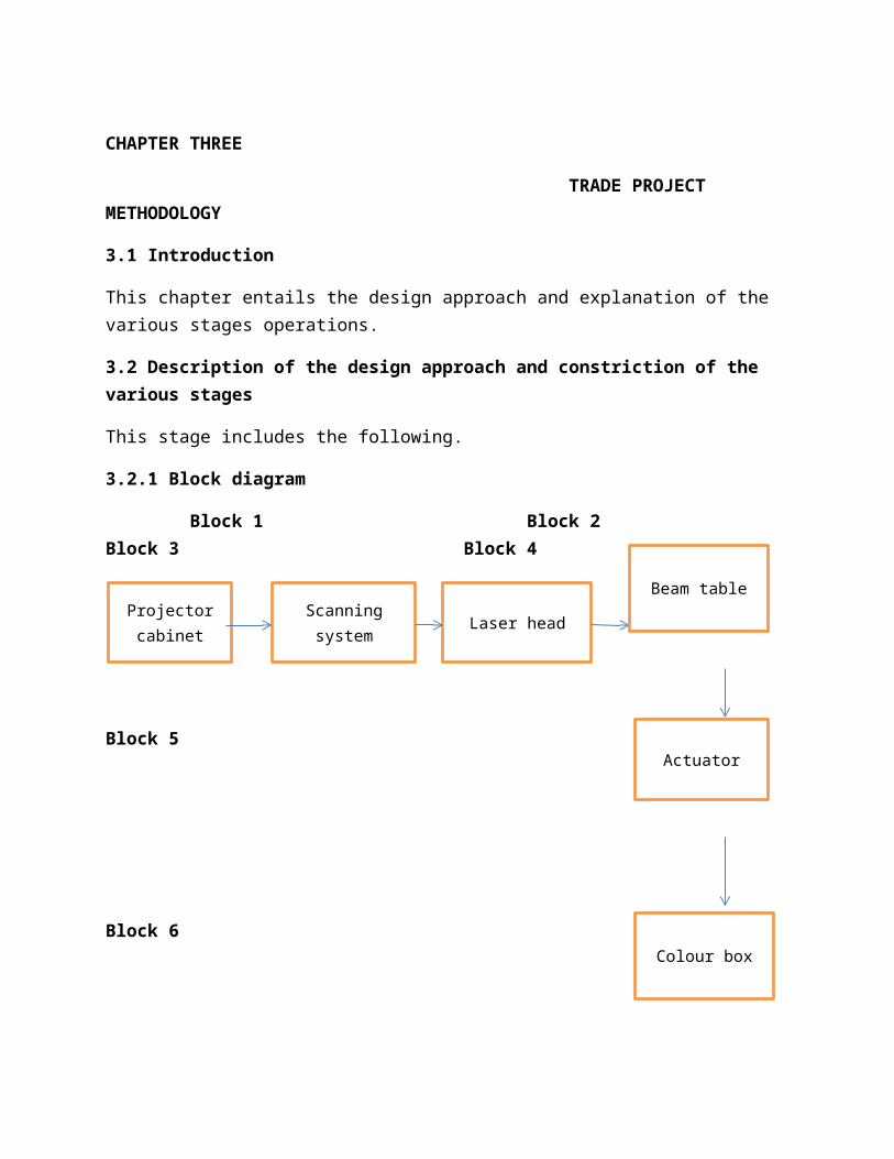
3.2.1 Block diagram
Block 1 Block 2 Block 3 Block 4
Block 5
Block 6
Projectorcabinet
Scanningsystem Laser head
Actuator
Colour box
Beam table
Block 1
This usually includes all of the power supplies, cooling fans anddriver cards used to make the projection system work. Support electronics also include safety features such as power-off interlocks and scan fail detectors.
Block 2
Here one finds the scanners which refer to the galvanometers thathave mirrors attached to it such that it can deflect a laser beamby applying appropriate control signals. The type of galvanometers used in laser scanning systems typically use a moving magnet or soft iron rotor, mounted in small precision bearings and suspended in the gaps of the pole pieces, which moves the shaft with the mirror, making thousands of scans per second.
Block 3
This is where the laser beam is deflected in a single plane drawing a straight line. The scan head controls the position of the laser beam, both horizontally (X axis) and vertically (Y axis).
Block 4
The beam table acts as a digital beam switching device since the actuators can only be in or out of the beam. The beam table system uses the mechanical movement of the actuator the same position each time, to deflect the beam to optics on kinematic (X-Y adjustable) mounts.
Block 5
This can be thought of as a limited rotation electrical motor. When one sends an electrical signal to the actuator, it pulls thearm together with the mirror into the beam so that the laser is deflected at 90 degrees to its previously projected travelling line.
Block 6
This is where color is added to the beam using a subtractive device which produces a limited number of color changes dependingon which color is desired during the final projection output beam.
CHAPTER FOUR
DATA ANALYSIS AND INTERPRETATION
4.1 Introduction
This chapter contains: the test result, analysis of test result, recommendation and appendices.
4.2 Test result
Testing laser detectors requires that the beam be positioned, and held in that position, with great precision. During testing one can use the Test Hardware which is a custom test set, using an I2C evaluation board, an HP34401 multi-meter, and a laptop computer, used to supply input to the DUT, monitor the DUT outputand monitor the power supply current. Tests can be performed on the DUTs to measure the SEL susceptibility as a function of laserenergy. The DUT can be exposed to the laser 6 times. The lowest photodiode amplitude at which SELs should be observed is 10mV, which equates to beam energy of 2pJ.
Aiming the laser
The laser gun must be securely mounted in order to produce a repeatable point of aim, knowing that the beam is very narrow, practically a rifle shot, with the laser gun in a rigid fixture, aim the beam straight down the test lane at a spot on the runway 500 to 800 feet from the gun. The exact same spot, and unvaryingmoon/stars light, are necessary to give each detector the same chance at detection. With each detector mounted in a repeatable position on a test runway tinted shield.
4.2.1 Failures in laser.
At long ranges, a beam hits lots of things besides its target. Remembering also that the bright section of the beam is only one-fifth of a degree wide, the brighter the moon at night, the harder it is to find a faint laser beam.
4.2.2 Effects to human
Due to a Laser injury up to 20% of hair will continue to grow (albeit in a finer and slower way), and many hair follicles will recover from the laser injury over time. Permanent hair reductioninvolves the use of either a single wavelength of light (laser)
or a flash of light containing hundreds of wavelengths (IPL or broadband light BBL).
Lasers interpretation to the human eye
-The difference of looking at the Sun and into a laser
- When looking directly at the sun
Assume the pupil diameter of the eye =2mm
the sun's irradiance=1.4kW/m2
Then , a power of 3mW will pass through the pupil of the eye;and the image of the sun on the retina has a diameter of 0.2mm and area of 0.03 mm2
As a result , the irradiance at the retina of the eye is 3mW/0.03mm2 = 100mW/mm2
4.2.3 Conclusions
The main objective of this project was to come up with a laser system which can propagate light visibly, to encounter the assumption of lack of F.O.Ds on the runway, which cause ground crashes, aircraft veering of the runway and bird strikes on the engine blades due to ground suction
4.3 Recommendation.
Due to the high cost of aircraft tyre and maintenance, aircrafts landing gear maintenance, engine maintenance and aircraft

insuarance,it is the opportune time the airport authorities employ such a devices, on the runways to reduce all this costs incurred by the airlines, for them to generate high revenues on their flights. Lasers require minimal maintenance costs, and thusare much safer than the use of vehicles on the runway.
REFERENCES
1 Siegman, Anthony E. (1986). Lasers. University Science Books. p. 2.
2 Silfvast, William T. (1996). Laser Fundamentals, Cambridge University Press.
3 http://en.wikipedia.org/wiki/Laser.

APPENDICES