Embed Size (px)
Citation preview
Drainage Criteria Manual Vol. 1

City of Colorado Springs
Drainage Criteria Manual Volume 1
May 2014 Revised November 2020
30 S. Nevada Ave.
Revised January 2021
May 2014 City of Colorado Springs Drainage Criteria Manual, Volume 1
i-5
Drainage Criteria Manual Volume 1
Contents Preface ............................................................................................................................................ i-1 to i-4
1.0 General Provisions ............................................................................................................. 1-1 to 1-7
2.0 Drainage Principles ............................................................................................................ 2-1 to 2-3
3.0 Drainage Policies .............................................................................................................. 3-1 to 3-16
4.0 Submittals ......................................................................................................................... 4-1 to 4-28
5.0 Floodplain Management .................................................................................................. 5-1 to 5-11
6.0 Hydrology.......................................................................................................................... 6-1 to 6-63
7.0 Street Drainage................................................................................................................. 7-1 to 7-15
8.0 Inlets .................................................................................................................................. 8-1 to 8-17
9.0 Storm Sewers .................................................................................................................... 9-1 to 9-14
10.0 Conduit Outlet Structures ............................................................................................. 10-1 to 10-6
11.0 Culverts and Bridges.................................................................................................... 11-1 to 11-10
12.0 Open Channels ............................................................................................................. 12-1 to 12-30
13.0 Storage........................................................................................................................... 13-1 to 13-35
14.0 Wetland and Channel Vegetation............................................................................... 14-1 to 14-18

May 2014 City of Colorado Springs Drainage Criteria Manual, Volume 1
i-1
Preface Contents 1.0 Acknowledgements ........................................................................................................................... 1
2.0 Overview/Purpose ............................................................................................................................ 2
3.0 Versions/Updates .............................................................................................................................. 3
4.0 Disclaimer ......................................................................................................................................... 3

May 2014 City of Colorado Springs Drainage Criteria Manual, Volume 1
i-1
Chapter i Preface
1.0 Acknowledgements This Manual was prepared by the Project Team consisting of the City of Colorado Springs Engineering Division staff and the Matrix Design Group/Wright Water Engineers consultant team under contract to the City of Colorado Springs with input from many organizations and individuals within the community and state. In particular, the Technical Leadership Team, the Executive Leadership Team, and individuals who participated in Issue Groups were critical to the successful completion of the project. The support of city managers in providing funding and guidance was also important and appreciated.
The City of Colorado Springs provides special recognition to the Urban Drainage and Flood Control District (UDFCD) of Denver for their many years of commitment to stormwater management and the development of state-of-the-art practices that have done so much to transform stormwater management from what has often been considered a community nuisance into a community asset. UDFCD’s manuals, design spreadsheets, and software programs are critical supplements to this Manual. Their cooperation in providing original electronic files for our use, integrating our local inlet type into their design spreadsheet and their advice have reduced the project cost for this Manual and made it possible for the community to take advantage of well-established practices, while also adapting them when necessary to better address our community goals and conditions.
We are also indebted to Douglas County, Colorado, for providing original electronic document files that were used for the initial draft for much of the material contained in this Manual, making our effort much more efficient.
Executive Leadership Team
Gary Bostrom, Colorado Springs Utilities Andre Brackin, El Paso County, County Engineer Helen Migchelbrink, Colorado Springs, Director of Public Works/City Engineer William Mutch, Colorado Springs Housing and Building Association Bob Schmidt, Pueblo County, County Engineer Earl Wilkinson, City of Pueblo, Public Works Director
Technical Leadership Team
William Alspach, Woodland Park, Director of Public Works Carol Baker, Colorado Springs Utilities Kyle Campbell, Classic Consulting Pat Coffee, Pueblo County Harold Franson, Colorado Springs Utilities Rich Harvey, El Paso County Bard Lower, Colorado Springs, Streets Division Dennis Maroney and Richard Mulledy, City of Pueblo Rich Muzzy, Pikes Peak Area Council of Governments Alf Randall, Pueblo County Mark Shea, Colorado Springs Utilities Richard Wray and Liz Klein, Kiowa Engineering
City of Colorado Springs Drainage Criteria Manual, Volume 1
May 2014 i-2
Chapter i Preface
Other Contributing Organizations
CH2MHill, JPS Engineering, U.S. Air Force Academy, U.S. Geological Survey, Shooksrun Agroforestry Project, Town of Monument, Town of Manitou Springs, Town of Green Mountain Falls, NV5 (Nolte), Colorado Parks and Wildlife, Banning Lewis Ranch, URS Corp., Wilson & Co., Contech, U.S. Army Corps of Engineers, Pikes Peak Regional Building Dept., J.R. Engineering, Drexel Barrell, and the Fountain Creek Watershed Flood Control and Greenway District Technical Advisory Committee.
Project Team
City Staff Dan Bare, P.E., Project Manager/Sr. Civil Engineer Lisa Ross, P.E., Sr. Civil Engineer Tim Mitros, P.E., Engineering Development Review/Stormwater Manager Steve Gardner, P.E., CFM, Stormwater Program Manager Ben Sheets, P.E., Civil Engineer II
Consultant Team Matrix Design Group, Graham Thompson, P.E. and Robert Krehbiel, P.E. Wright Water Engineers, Andrew Earles, Ph.D., P.E. and Jane Clary THK, Kevin Shanks, RLA Urban Watersheds Institute, Ben Urbonas, P.E.
2.0 Overview/Purpose The City of Colorado Springs Drainage Criteria Manual, Volumes 1 and 2 (Manual) provides owners, developers, engineers, applicants, designers and contractors with information necessary to comply with requirements for drainage system and stormwater quality planning, design and implementation related to new development, redevelopment and construction activities. The owner/applicant is responsible for ensuring that site plans, designs, and construction activities at a site comply with the policies in this manual, applicable statutes, and ordinances. The Manual should be used in conjunction with other relevant engineering references and best professional judgment.
The standards set forth in this Manual represent minimum requirements to achieve the goals for proper stormwater management. Alternatives to the requirements stated herein may be proposed by the owner/applicant subject to the established processes for variances or amendments. The burden of proof that the proposed alternative methods or application are consistent with the stormwater management objectives contained herein lies with the owner/applicant.
The Manual provides policy and guidance in these areas:
1. Overall stormwater management principles.
2. Requirements for submittals.
3. Floodplain management guidance.
4. Methods of defining and conveying design flows.
May 2014 City of Colorado Springs Drainage Criteria Manual, Volume 1
i-3
Chapter i Preface
5. Methods for estimating reductions in design flows and volumes due to volume reduction practices.
6. Design criteria and guidance pertaining to street drainage, inlets, storm sewers, conduit outlet
structures, culverts, and bridges.
7. Design criteria and guidance for open channels.
8. Requirements for detention storage to reduce adverse impacts due to increased runoff from development.
9. Requirements and procedures for inclusion of stormwater quality Permanent Control Measures
(PCMs) and designs in new developments and redevelopments.
3.0 Versions/Updates It is anticipated that this Manual or portions of this Manual will be modified from time to time. To identify these modifications, the date of the original Manual is located on each page. As modifications are made, the date of the most recent revision will be added to each page and a summary of the revisions will be included in this section.
Notification of revisions will NOT be sent individually to Manual holders. Notifications will be posted on the appropriate web sites and electronic versions of an updated Manual will be made available.
To date, the following revisions/updates have been issued:
Date Manual Location Description/Purpose
4.0 Disclaimer
Attention all persons using the Urban Storm Drainage Criteria Manual (USDCM) or UDFCD Manual, its Design Form Spreadsheets, AutoCAD™ Details, and Related Software Products:
The products listed above have been developed using a high standard of care, including professional review for identification of errors, bugs, and other problems related to the software. However, as with any release of publications, details, and software, errors will be discovered. The developers of these products welcome user feedback in helping to identify them so that improvements can be made to future releases of this manual and all related products.
This manual and all related products are intended to assist and streamline the planning and design process of drainage facilities. The AutoCAD™ details are intended to show design concepts. Preparation of final design plans, addressing details of structural adequacy, public safety, hydraulic functionality, maintainability, and aesthetics, remain the sole responsibility of the designer.

City of Colorado Springs Drainage Criteria Manual, Volume 1
May 2014 i-4
Chapter i Preface
By the use of the USDCM and/or related design form worksheets, spreadsheets, AutoCAD™ details, software and all other related products, the user agrees to the following:
DISCLAIMER OF WARRANTIES AND DAMAGES
THE USDCM, ITS DESIGN FORM SPREADSHEETS, AUTO CADTH DETAILS AND RELATED SOFTWARE ARE PROVIDED BY URBAN DRAINAGE AND FLOOD CONTROL DISTRICT (“UDFCD”) AND ITS CONTRACTORS, ADVISORS, REVIEWERS AND MEMBER GOVERNMENTAL AGENCIES (“CONTRIBUTORS”) "AS IS" AND “WITH ALL FAULTS”. ANY EXPRESS OR IMPLIED WARRANTIES, INCLUDING, BUT NOT LIMITED TO, THE IMPLIED WARRANTIES OF MERCHANTABILITY AND FITNESS FOR A PARTICULAR PURPOSE ARE DISCLAIMED. IN NO EVENT SHALL UDFCD OR ITS CONTRIBUTORS BE LIABLE FOR ANY DIRECT, INDIRECT, INCIDENTAL, SPECIAL, EXEMPLARY, OR CONSEQUENTIAL DAMAGES (INCLUDING, BUT NOT LIMITED TO, PROCUREMENT OF SUBSTITUTE GOODS OR SERVICES; LOSS OF USE, DATA, INFORMATION OR PROFITS; OR BUSINESS INTERRUPTION) HOWEVER CAUSED AND ON ANY THEORY OF LIABILITY, WHETHER IN CONTRACT, STRICT LIABILITY, OR TORT (INCLUDING NEGLIGENCE OR OTHERWISE) ARISING IN ANY WAY OUT OF THE USE OF THE USDCM, ITS DESIGN FORM SPREADSHEETS, AUTOCADTM DETAILS, AND RELATED SOFTWARE.
Drainage Criteria Manual, Volume 1
Chapter 1 General Provisions Contents 1.0 Introduction ...................................................................................................................................... 1
2.0 Enactment Authority ....................................................................................................................... 1
3.0 Jurisdiction ....................................................................................................................................... 1
4.0 Purpose .............................................................................................................................................. 1
5.0 Reference Documents ....................................................................................................................... 1
6.0 Enforcement Responsibility ............................................................................................................ 2
7.0 Review and Acceptance ................................................................................................................... 3
8.0 Interpretation and Application ....................................................................................................... 3
9.0 Amendments and Revisions ............................................................................................................. 4
10.0 Variances ........................................................................................................................................... 4
11.0 Acronyms .......................................................................................................................................... 6
May 2014 City of Colorado Springs 1-i

Chapter 1 General Provisions
May 2014 City of Colorado Springs Drainage Criteria Manual, Volume 1
1-1
1.0 Introduction The criteria and design standards presented in this document, together with all future amendments and referenced documents, comprise the City of Colorado Springs Drainage Criteria Manual (hereafter called the “Manual”). The Manual includes two volumes, Volumes 1 and 2, which address drainage and water quality criteria, respectively. The two volumes are to be applied as complementary documents, and the requirements of each shall be jointly applied to create fully integrated drainage systems. All drainage reports, plans, drainage system analyses, and drainage system designs, submitted as a requirement of the City of Colorado Springs Engineering Criteria Manual, zoning or subdivision codes, ordinances, resolutions or guidelines adopted by the City of Colorado Springs (hereafter called “Regulations”), shall comply with the requirements of this Manual. In addition, it is the responsibility of the owner, owner’s representative, developer, planner, and designer (hereafter called “Applicant”) to ensure that the proposed improvements are consistent with other applicable documents such as the City of Colorado Springs Comprehensive Plan, Drainage Basin Planning Studies, land use master plans, transportation plans, utility plans, etc. and that all applicable permits are in place and have been complied with.
2.0 Enactment Authority This Manual was adopted pursuant to the authority conferred by the Charter of the City of Colorado Springs and Resolution 49-14 accompanying this chapter (Exhibit A) provides the authorization and effective date of the Manual. This Manual was amended by Resolution __-20 (Exhibit B).
3.0 Jurisdiction This Manual shall apply to all land within the incorporated areas of the City of Colorado Springs, including any public lands, except as may be exempted by state or federal laws. This Manual shall apply to all storm drainage systems and facilities constructed in or on public rights-of-way, easements dedicated for drainage across public or private property, easements or tracts for public use, and to all privately owned and maintained stormwater conveyance, detention, retention, or water quality facilities.
4.0 Purpose This Manual provides the policies and minimum design procedures and technical criteria for the planning, analysis and design of storm drainage systems within the City of Colorado Springs for the purpose of protecting the public health, safety and welfare. All subdivisions, re-subdivisions, planned unit developments, or any other proposed construction submitted for acceptance under the provisions of the Regulations shall include adequate and appropriate storm drainage system planning, analysis, design and improvements. Such planning, analysis, and design shall conform with or exceed the requirements set forth herein.
5.0 Reference Documents This Manual depends on and references other documents. To the extent that there are conflicts or differences between this Manual and referenced documents this Manual shall apply. To the extent that needed guidance is not found in this Manual referenced documents are intended to supplement this Manual. Should this Manual or referenced documents not provide adequate guidance it is the responsibility of the Applicant to seek and obtain guidance from the official(s) responsible for enforcing the provisions of this Manual. Primary documents that supplement this Manual and are included by reference are the following:
City of Colorado Springs Drainage Criteria Manual, Volume 1
May 2014 1-2
Chapter 1 General Provisions
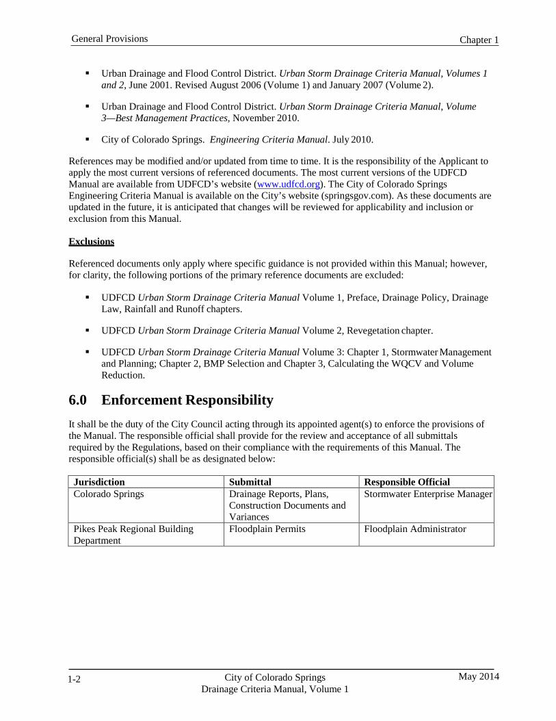
Urban Drainage and Flood Control District. Urban Storm Drainage Criteria Manual, Volumes 1 and 2, June 2001. Revised August 2006 (Volume 1) and January 2007 (Volume 2).
Urban Drainage and Flood Control District. Urban Storm Drainage Criteria Manual, Volume
3—Best Management Practices, November 2010.
City of Colorado Springs. Engineering Criteria Manual. July 2010.
References may be modified and/or updated from time to time. It is the responsibility of the Applicant to apply the most current versions of referenced documents. The most current versions of the UDFCD Manual are available from UDFCD’s website (www.udfcd.org). The City of Colorado Springs Engineering Criteria Manual is available on the City’s website (springsgov.com). As these documents are updated in the future, it is anticipated that changes will be reviewed for applicability and inclusion or exclusion from this Manual.
Exclusions
Referenced documents only apply where specific guidance is not provided within this Manual; however, for clarity, the following portions of the primary reference documents are excluded:
UDFCD Urban Storm Drainage Criteria Manual Volume 1, Preface, Drainage Policy, Drainage
Law, Rainfall and Runoff chapters.
UDFCD Urban Storm Drainage Criteria Manual Volume 2, Revegetation chapter.
UDFCD Urban Storm Drainage Criteria Manual Volume 3: Chapter 1, Stormwater Management and Planning; Chapter 2, BMP Selection and Chapter 3, Calculating the WQCV and Volume Reduction.
6.0 Enforcement Responsibility It shall be the duty of the City Council acting through its appointed agent(s) to enforce the provisions of the Manual. The responsible official shall provide for the review and acceptance of all submittals required by the Regulations, based on their compliance with the requirements of this Manual. The responsible official(s) shall be as designated below:
Jurisdiction Submittal Responsible Official Colorado Springs Drainage Reports, Plans,
Construction Documents and Variances
Stormwater Enterprise Manager
Pikes Peak Regional Building Department
Floodplain Permits Floodplain Administrator
Chapter 1 General Provisions
May 2014 City of Colorado Springs Drainage Criteria Manual, Volume 1
1-3
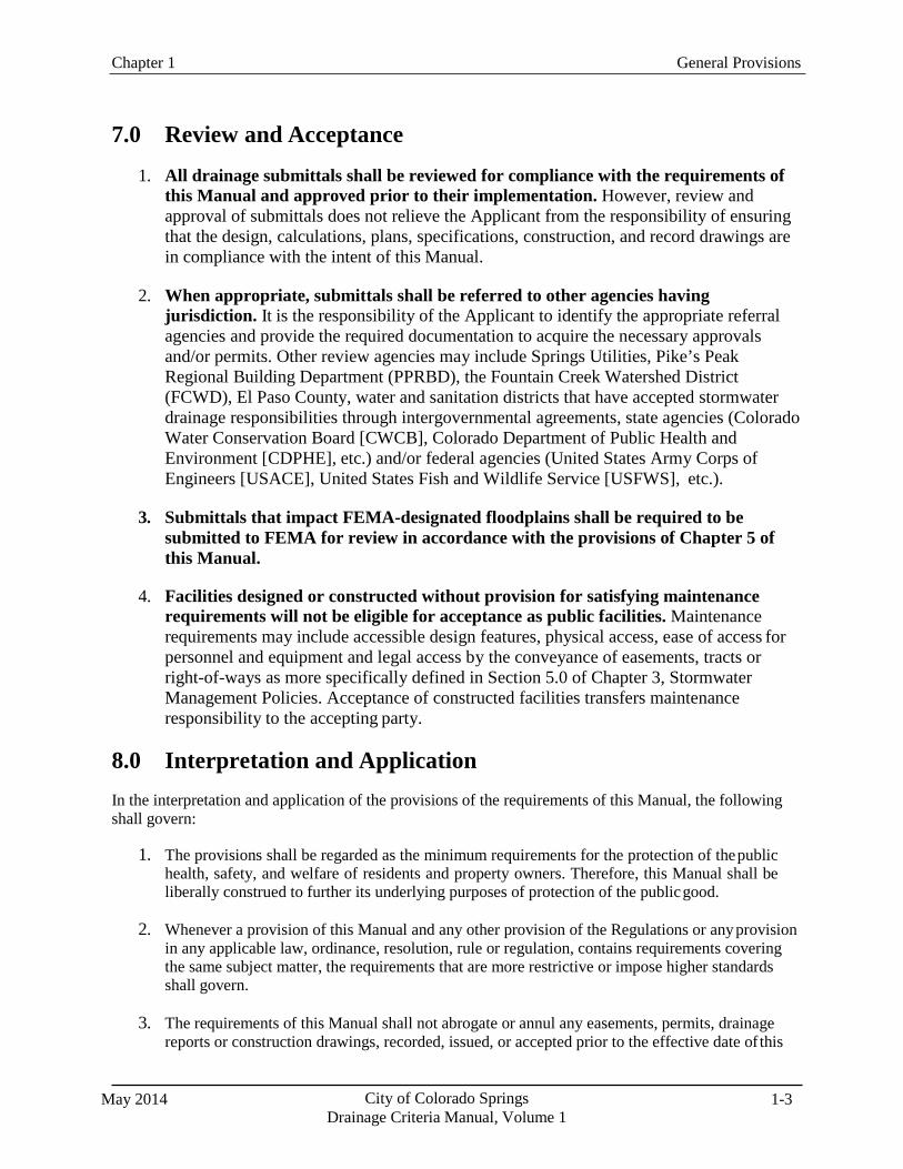
7.0 Review and Acceptance
1. All drainage submittals shall be reviewed for compliance with the requirements of this Manual and approved prior to their implementation. However, review and approval of submittals does not relieve the Applicant from the responsibility of ensuring that the design, calculations, plans, specifications, construction, and record drawings are in compliance with the intent of this Manual.
2. When appropriate, submittals shall be referred to other agencies having
jurisdiction. It is the responsibility of the Applicant to identify the appropriate referral agencies and provide the required documentation to acquire the necessary approvals and/or permits. Other review agencies may include Springs Utilities, Pike’s Peak Regional Building Department (PPRBD), the Fountain Creek Watershed District (FCWD), El Paso County, water and sanitation districts that have accepted stormwater drainage responsibilities through intergovernmental agreements, state agencies (Colorado Water Conservation Board [CWCB], Colorado Department of Public Health and Environment [CDPHE], etc.) and/or federal agencies (United States Army Corps of Engineers [USACE], United States Fish and Wildlife Service [USFWS], etc.).
3. Submittals that impact FEMA-designated floodplains shall be required to be
submitted to FEMA for review in accordance with the provisions of Chapter 5 of this Manual.
4. Facilities designed or constructed without provision for satisfying maintenance
requirements will not be eligible for acceptance as public facilities. Maintenance requirements may include accessible design features, physical access, ease of access for personnel and equipment and legal access by the conveyance of easements, tracts or right-of-ways as more specifically defined in Section 5.0 of Chapter 3, Stormwater Management Policies. Acceptance of constructed facilities transfers maintenance responsibility to the accepting party.
8.0 Interpretation and Application In the interpretation and application of the provisions of the requirements of this Manual, the following shall govern:
1. The provisions shall be regarded as the minimum requirements for the protection of the public
health, safety, and welfare of residents and property owners. Therefore, this Manual shall be liberally construed to further its underlying purposes of protection of the public good.
2. Whenever a provision of this Manual and any other provision of the Regulations or any provision
in any applicable law, ordinance, resolution, rule or regulation, contains requirements covering the same subject matter, the requirements that are more restrictive or impose higher standards shall govern.
3. The requirements of this Manual shall not abrogate or annul any easements, permits, drainage
reports or construction drawings, recorded, issued, or accepted prior to the effective date of this
City of Colorado Springs Drainage Criteria Manual, Volume 1
May 2014 1-4
Chapter 1 General Provisions
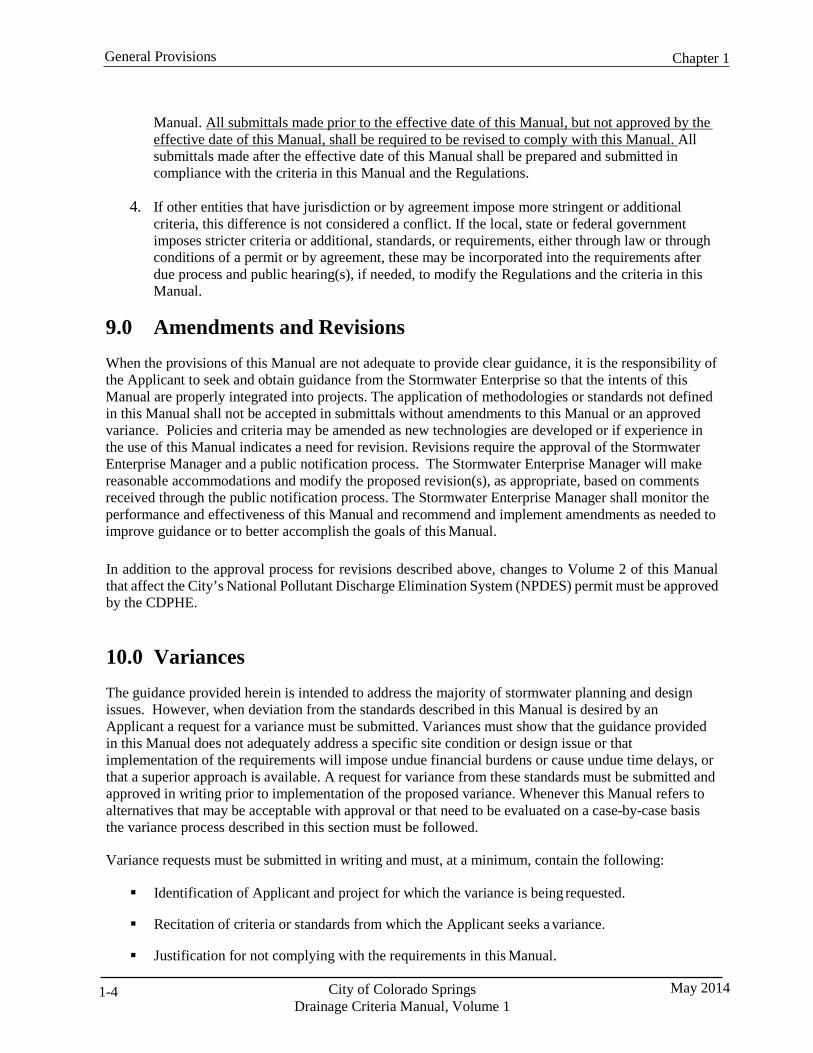
Manual. All submittals made prior to the effective date of this Manual, but not approved by the effective date of this Manual, shall be required to be revised to comply with this Manual. All submittals made after the effective date of this Manual shall be prepared and submitted in compliance with the criteria in this Manual and the Regulations.
4. If other entities that have jurisdiction or by agreement impose more stringent or additional
criteria, this difference is not considered a conflict. If the local, state or federal government imposes stricter criteria or additional, standards, or requirements, either through law or through conditions of a permit or by agreement, these may be incorporated into the requirements after due process and public hearing(s), if needed, to modify the Regulations and the criteria in this Manual.
9.0 Amendments and Revisions When the provisions of this Manual are not adequate to provide clear guidance, it is the responsibility of the Applicant to seek and obtain guidance from the Stormwater Enterprise so that the intents of this Manual are properly integrated into projects. The application of methodologies or standards not defined in this Manual shall not be accepted in submittals without amendments to this Manual or an approved variance. Policies and criteria may be amended as new technologies are developed or if experience in the use of this Manual indicates a need for revision. Revisions require the approval of the Stormwater Enterprise Manager and a public notification process. The Stormwater Enterprise Manager will make reasonable accommodations and modify the proposed revision(s), as appropriate, based on comments received through the public notification process. The Stormwater Enterprise Manager shall monitor the performance and effectiveness of this Manual and recommend and implement amendments as needed to improve guidance or to better accomplish the goals of this Manual.
In addition to the approval process for revisions described above, changes to Volume 2 of this Manual that affect the City’s National Pollutant Discharge Elimination System (NPDES) permit must be approved by the CDPHE.
10.0 Variances The guidance provided herein is intended to address the majority of stormwater planning and design issues. However, when deviation from the standards described in this Manual is desired by an Applicant a request for a variance must be submitted. Variances must show that the guidance provided in this Manual does not adequately address a specific site condition or design issue or that implementation of the requirements will impose undue financial burdens or cause undue time delays, or that a superior approach is available. A request for variance from these standards must be submitted and approved in writing prior to implementation of the proposed variance. Whenever this Manual refers to alternatives that may be acceptable with approval or that need to be evaluated on a case-by-case basis the variance process described in this section must be followed.
Variance requests must be submitted in writing and must, at a minimum, contain the following:
Identification of Applicant and project for which the variance is being requested.
Recitation of criteria or standards from which the Applicant seeks a variance.
Justification for not complying with the requirements in this Manual.
Chapter 1 General Provisions
May 2014 City of Colorado Springs Drainage Criteria Manual, Volume 1
1-5
Alternate criterion or standard that is proposed to comply with the intent of the criteria in this Manual and other applicable guidance documents.
Supporting documentation, including necessary calculations, reference materials, software,
design plans, details, specifications, installation and maintenance requirements, etc., adequate to evaluate how the proposed variance satisfies the intent of the criteria in this Manual.
Signature and stamp of a Professional Engineer licensed in the State of Colorado.
Additional information may be requested in order to more fully understand the proposed variance and the implications of its implementation. A pre-submittal conference is advisable to discuss the proposed variance and submittal contents prior to the formal request being submitted.
A request for a variance does not guarantee approval. The right to deny any request for a variance is reserved. Approval of a variance is based on the specific conditions of a particular project or situation and is limited to the circumstances for which it is requested and approved. Approval of a variance does not constitute an amendment to this Manual. Subsequent applications of an approved variance require the submittal of a separate variance request and approval prior to its application to a project.
Variances cannot be granted in a manner that effectively negates the minimum requirement of the Four Step Process as previously described in this chapter. The variance process cannot be implemented in a manner that would create a condition of non-compliance with the City’s MS4 permit.
The variance process is not intended to address changes to reports or plans that are made subsequent to approval if those changes are consistent with the criteria contained in this Manual. However, review of these changes may be required as specified elsewhere in this Manual or in other Regulations.
City of Colorado Springs Drainage Criteria Manual, Volume 1
May 2014 1-6
Chapter 1 General Provisions
11.0 Acronyms As used in this Manual, the following acronyms shall apply:
ASCE American Society of Civil Engineers ASTM American Society for Testing and Materials BCD Baffle Chute Drop BFE Base Flood Elevation BMP Best Management Practice CAP Corrugated Aluminum Pipe CAPA Corrugated Aluminum Pipe Arch CCM Construction Control Measure CDOT Colorado Department of Transportation CDPHE Colorado Department of Public Health and Environment CEC Consulting Engineers Council CGIA Colorado Governmental Immunity Act CLOMA Conditional Letter of Map Amendment CLOMR Conditional Letter of Map Revision CMP Corrugated Metal Pipe CMPA Corrugated Metal Pipe Arch CRS Colorado Revised Statutes CSP Corrugated Steel Pipe CSPA Corrugated Steel Pipe Arch CWA Federal Clean Water Act CWCB Colorado Water Conservation Board DCIA Directly Connected Impervious Area DBPS Drainage Basin Planning Study EDB Extended Detention Basin EGL Energy Grade Line EPA U.S. Environmental Protection Agency ESA Endangered Species Act EURV Excess Urban Runoff Volume FAA Federal Aviation Administration FCWD Fountain Creek Watershed Flood Control and Greenway District FEMA Federal Emergency Management Agency FHAD Flood Hazard Area Delineation FHWA Federal Highway Administration FIRM Flood Insurance Rate Map FIS Flood Insurance Study FPE Flood Protection Elevation GI Green Infrastructure GSB Grouted Sloping Boulder HDS Hydraulic Design Series
HEC Hydraulic Engineering Center HEC-HMS Hydraulic Engineering Center Hydrologic Modeling System HEC-RAS Hydraulic Engineering Center River Analysis System HERCP Horizontal Elliptical Reinforced Concrete Pipe HGL Hydraulic Grade Line HUD U.S. Department of Housing and Urban Development H:V Horizontal to Vertical Ratio of a Slope ICC Increased Cost of Compliance LID Low Impact Development LOMA Letter of Map Amendment
Chapter 1 General Provisions
May 2014 City of Colorado Springs Drainage Criteria Manual, Volume 1
1-7
LOMR Letter of Map Revision MDCIA Minimized Directly Connected Impervious Area NAVD North American Vertical Datum NFIA National Flood Insurance Act NFIP National Flood Insurance Program NGVD National Geodetic Vertical Datum NOAA National Oceanic and Atmospheric Administration NPDES National Pollutant Discharge Elimination System NRCS Natural Resources Conservation Service NWS National Weather Service P.E. Professional Engineer (Licensed by the State of Colorado) PCM Permanent Control Measure PMF Probable Maximum Flood PMP Probable Maximum Precipitation PPRBD Pikes Peak Regional Building Department PWD Public Works and Development RCBC Reinforced Concrete Box Culvert RCP Reinforced Concrete Pipe ROW Right-of-Way SBA Small Business Administration SEO Colorado State Engineer’s Office SCM Stormwater Construction Manual SFHA Special Flood Hazard Area SFIP Standard Flood Insurance Policy SPP Structural Plate Pipe SPPA Structural Plate Pipe Arch SWMM Stormwater Management Model TRC Technical Review Committee TWE Tailwater Elevation UDFCD Urban Drainage & Flood Control District UDSWMM Urban Drainage Stormwater Management Model USFWS U.S. Fish and Wildlife Service USACE U.S. Army Corps of Engineers WQCV Water Quality Capture Volume
City of Colorado Springs Drainage Criteria Manual, Volume 1
May 2014 2-i
Chapter 2 Drainage Principles Contents 1.0 Introduction ...................................................................................................................................... 1
2.0 Principles ........................................................................................................................................... 1
Chapter 2 Drainage Principles
May 2014 City of Colorado Springs Drainage Criteria Manual, Volume 1
2-1
1.0 Introduction Provisions for effective drainage is necessary to preserve and improve the general health, safety, welfare, and economic well-being of the region, including the City of Colorado Springs, El Paso County, surrounding communities and the Fountain Creek watershed. Drainage affects all governmental jurisdictions and parcels of property, requiring management that balances public and private interests. The governmental agencies most directly involved must provide coordination and planning, but drainage management must also be integrated on a regional/watershed basis.
When planning drainage facilities, certain underlying principles provide direction. The principles are made operational through policy statements (see Chapter 3). The application of the policy is, in turn, facilitated by technical criteria and data, procedures, funding, construction, operation and maintenance for drainage improvements. When considered in a comprehensive manner, on a regional level with public and private involvement, drainage facilities can be provided in a manner that will enhance the general health, safety and welfare of the region, while also providing economic, environmental and social benefits. The effectiveness of these policies will depend on their faithful and consistent application and integration into policies and practices in related areas such as land use and transportation planning and design.
2.0 Principles The following principles for managing drainage shall guide the planning, design and implementation of drainage facilities.
1. Drainage is a regional phenomenon that does not respect the boundaries between
governmental jurisdictions or between properties. Systems that are planned and designed without considering regional implications may be ineffective and costly. Therefore, it is necessary to formulate programs that include public, private and multi-jurisdictional involvement. The governmental agencies involved must provide coordination, consistent standards, master planning, and possibly, joint-funding for key projects to achieve optimum results.
2. The drainage system is a subsystem of the total urban infrastructure system. Developing a
drainage system independent of considering how it relates to other infrastructure systems limits the potential for compatible integration and increases the probability of conflicts between the functions of different types of infrastructure. Drainage system planning and design must be compatible with local and regional comprehensive plans and must be coordinated with planning and designs for land uses, open space, utilities, wildlife, recreation, transportation corridors and other infrastructure.
3. Development activity may greatly alter the amount and character of runoff resulting in
significant impacts to man-made or natural systems. Land development activities and supporting infrastructure (buildings, roads, schools, parking, etc.) have the potential to introduce significant changes to hydrology and water quality, including increased peak flow rates, runoff volumes and pollutant loadings that may cause negative impacts such as flooding, water quality degradation, erosion and sedimentation. These changes have the potential to damage man-made improvements as well as natural systems. Increased flow rates and runoff volumes typically result from increased runoff from impervious areas. Water quality degradation may result from the mixing of runoff with pollutants associated with human activity, from increased sediment loads and/or from hydromodification effects of increased runoff on streams. Generally, the effects of development are most pronounced for runoff from the more frequent storm events, including those that may not have produced runoff prior to development. The increased
Chapter 2 Drainage Principles
City of Colorado Springs Drainage Criteria Manual, Volume 1
May 2014 2-2
frequency and volume of runoff from these events may significantly alter the hydrologic conditions in a watershed. Implementation of water quality features, channel stabilization measures and flood control detention are typically necessary to mitigate the adverse hydrologic and water quality effects of urbanization.
4. Every urban area has a minor and a major drainage system, whether or not they are
actually planned and designed. The minor drainage system is designed to provide public convenience and to accommodate low to moderate, frequently occurring flows. The major system carries more water less frequently and operates when runoff exceeds the capacity of the minor system. To provide for orderly urban growth, reduce costs to future generations, and limit the loss of life, property damage and environmental impacts, both systems must be properly planned, designed and constructed.
5. Handling runoff properly is largely a space allocation problem. The volume of water present
at a given point in time in an urban region cannot be compressed or diminished. Natural processes possess a prescriptive easement for intermittent occupancy by runoff. Encroachments into this easement may adversely affect adjacent properties and natural systems during inevitable periods of natural easement occupancy. If adequate space is not provided, stormwater runoff may conflict with other land uses, increasing the potential for damages, environmental impacts and disruption of the functioning of other urban systems.
6. The diversion of storm runoff from one watershed or basin to another may introduce
significant capacity and legal problems. Drainage problems should not be transferred from one watershed or basin to another. Diversions should be avoided unless specific and prudent reasons justify and dictate such a transfer, and downstream damages are sufficiently mitigated.
7. Resources to implement drainage plans and improvements are limited. Drainage systems
should be a multi-objective and multi-means effort. The many competing demands placed upon space and resources require a management strategy that meets multiple objectives, including the preservation of ecological systems, water quality enhancement, groundwater recharge, recreation, wetland preservation, enhancement and creation, protection of landmarks/amenities, control of erosion and sediment deposition, and creation of open spaces.
8. Natural systems possess a number of beneficial features that should be preserved and
incorporated into the design of the drainage system. Good designs incorporate the effectiveness of the natural systems rather than negate, replace or ignore them. Existing features such as natural drainageways, depressions, wetlands, floodplains, permeable soils, habitat, and vegetation provide for infiltration, help control the volume and rate of runoff, extend the travel time, prevent erosion, filter sediments and other pollutants, and recycle nutrients and support the ecology.
9. Natural drainage systems respond to and are dependent upon the full range of hydrologic
conditions and sources of water, including snowmelt, groundwater and the full range of rainfall events. To be effective, the planning and design of drainage systems must address all of these potential sources of water and the full range of potential rates of flow and volumes and how they may be altered by development activity. By “mimicking” pre-development runoff as a result of implementing development techniques and/or runoff control measures downstream impacts can be reduced. Mimicking pre-development runoff is achieved by approximating the rate, volume and timing of storm-caused runoff into the receiving system.
10. The drainage system must be designed, beginning with the outlet or point of outflow from
Chapter 2 Drainage Principles
May 2014 City of Colorado Springs Drainage Criteria Manual, Volume 1
2-3
the project, giving full consideration to potential impacts and the effects of off-site flows entering the system. The design of the drainage management system shall take into account runoff from upstream sites and shall evaluate the downstream conveyance system to ensure that it has sufficient capacity to accept design discharges without adverse backwater or downstream impacts such as flooding, stream bank erosion, channel degradation, and sediment deposition. An assessment of potential downstream impacts should be based on quantifiable measures that relate to basin conditions immediately after project completion and with regard to future development and its timing.
11. Poorly maintained systems may not function properly, reducing their effectiveness and
reducing the benefits from the economic investment required to construct them. Operation and maintenance procedures and activities must be developed and documented with the facility design, including the identification and acquisition of rights of access. Clear assignment of maintenance responsibilities must be identified and assigned to an established entity with the resources and understanding required to ensure proper ongoing maintenance.
12. Floodplains, both regulated and unregulated, are areas of potential hazard due to high rates
of runoff. Modification of floodplains requires large investments in resources, and risks may increase when they are not properly managed. Flooding potential exists throughout the drainage system and is not limited to “regulatory” floodplains. In addition, flooding potential is not limited to regulatory flows (flows used to define regulatory floodplains), and flow estimates may not accurately represent risk. Multiple times each year estimated rainfalls and/or flood flows are normally exceeded somewhere in Colorado or the Fountain Creek watershed. It is not a question of if estimated flood flows (regulatory or non-regulatory) will be exceeded, but when and where they will be exceeded. The preservation of floodplains serves to reduce flood flows by providing temporary “storage” in the overbank areas. Floodplain preservation also, minimize hazards, preserve habitat and open space, improve water quality, create a more livable environment, and protect the public health, safety, and welfare.
13. Drainage law places certain obligations on those who cause or oversee modifications to the
natural effects of the hydrologic cycle and the conveyance of runoff overland. It is incumbent on individuals and agencies to safeguard the right of those potentially impacted by modifications to stormwater runoff to reduce the potential for impacts to public health, safety and welfare and to maintain the orderly development of human-made systems.
City of Colorado Springs Drainage Criteria Manual, Volume 1
May 2014 3-4
Chapter 3 Drainage Policies
Contents 1.0 Introduction ...................................................................................................................................... 1
2.0 Planning and Design ......................................................................................................................... 1 2.1 Reports and Plans ...................................................................................................................................... 1 2.2 Early Planning ........................................................................................................................................... 1 2.3 Integrated Comprehensive Planning ......................................................................................................... 1 2.4 Multi-purpose Resource ............................................................................................................................ 1 2.5 Master Plans .............................................................................................................................................. 2 2.6 Site Design and Layout ............................................................................................................................. 2 2.7 Basin Diversions ....................................................................................................................................... 2
2.7.1 Intra-basin Diversions ....................................................................................................................... 2 2.7.2 Inter-basin Diversions ....................................................................................................................... 2
2.8 Groundwater Mitigation ............................................................................................................................ 3
3.0 Runoff Volume Mitigation and Water Quality.............................................................................. 3 3.1 Runoff Volume Mitigation ........................................................................................................................ 3 3.2 Control Measures ..................................................................................................................................... 3 3.3 Separation of Stormwater and Sanitary Sewer Flows ............................................................................... 3
4.0 Storm Drain Systems ....................................................................................................................... 4 4.1 Minor System ............................................................................................................................................ 4 4.2 Major System ............................................................................................................................................ 4
5.0 Drainageways .................................................................................................................................... 4 5.1 Minor Drainageways ................................................................................................................................. 5 5.2 Major Drainageways ................................................................................................................................. 5
6.0 Detention ........................................................................................................................................... 5 6.1 Purpose and Planning Considerations ....................................................................................................... 5 6.2 Previous Detention Approach ................................................................................................................... 6 6.3 Locating Detention Facilities .................................................................................................................... 6 6.4 Detention Requirements ............................................................................................................................ 7
6.4.1 Drainage Basin Plans ........................................................................................................................ 7 6.4.2 Site Redevelopment .......................................................................................................................... 7 6.4.3 Site Expansion .................................................................................................................................. 7
6.5 Full Spectrum Detention ........................................................................................................................... 8 6.6 On-Site Detention ...................................................................................................................................... 8 6.7 Rooftop and Underground Detention ........................................................................................................ 8
7.0 Floodplain Management .................................................................................................................. 8 7.1 Flood Flows ............................................................................................................................................... 8 7.2 Floodplain Encroachment ......................................................................................................................... 9 7.3 Floodplain Easements ............................................................................................................................... 9 7.4 Building Above Floodplains ..................................................................................................................... 9 7.5 Levees ....................................................................................................................................................... 9
8.0 Construction of Public Improvements ............................................................................................ 9 8.1 Minor Drainage System ............................................................................................................................ 9 8.2 Major Drainageway System .....................................................................................................................10 8.3 Master Plan Improvements ......................................................................................................................10
9.0 Operations, Maintenance and Access............................................................................................ 10 9.1 Operation and Maintenance Plan .............................................................................................................10 9.2 Owner Responsibility ...............................................................................................................................11 9.3 Maintenance Considerations in Designs ..................................................................................................11 9.4 Access ......................................................................................................................................................11 9.5 Private Detention......................................................................................................................................11 9.6 Conveyance of Upstream Runoff .............................................................................................................12 9.7 Easements on Residential Lots .................................................................................................................12
10.0 Drainage Basin Fee Program ......................................................................................................... 12
11.0 Regulatory/Legal ............................................................................................................................. 12 11.1 Local Permits ...........................................................................................................................................12 11.2 Environmental Permitting ........................................................................................................................13
11.2.1 Section 404 Wetlands Permit ........................................................................................................13 11.2.2 Threatened and Endangered Species Act ......................................................................................13
11.3 Erosion Control/Stormwater Management Permitting .............................................................................14 11.4 Fountain Creek Watershed .......................................................................................................................14 11.5 Floodplains ...............................................................................................................................................14 11.6 Water Rights ............................................................................................................................................14 11.7 Drainage Law ...........................................................................................................................................14
12.0 Special Planning Areas and Districts ............................................................................................ 15 12.1 Fountain Creek Watershed Flood Control and Greenway District (FCWD)............................................15
13.0 Public Safety .................................................................................................................................... 15
14.0 Jurisdictional Dams and Reservoirs .............................................................................................. 15
15.0 Irrigation Canals or Ditches .......................................................................................................... 16
3-ii City of Colorado Springs May 2014 Drainage Criteria Manual, Volume 1

Chapter 3 Drainage Policies
May 2014 City of Colorado Springs Drainage Criteria Manual, Volume 1
3-1
1.0 Introduction Stormwater management is an integral component of overall development planning and site design that should be considered in the earliest planning stages to provide an effective and economical drainage and stormwater quality management system. To conduct initial feasibility studies or preliminary site analyses, it is important to have a clear understanding of stormwater management policies, regulatory requirements and criteria, site design practices for effective stormwater management, and existing site characteristics.
This chapter provides drainage policies that should be recognized and implemented in the planning stages of a project and summarizes concepts which are further developed in this Manual. Additional guidance for planning of the urban storm runoff system is also provided in the City of Colorado Springs Engineering Criteria Manual (ECM), Chapter 4.0 and Chapter 4, Planning, Volume 1 of the UDFCD Manual.
2.0 Planning and Design The following sections provide policies for addressing the impacts of urbanization and factors to consider when planning and designing for stormwater management. All drainage systems shall be designed in accordance with the methods, criteria and requirements of the Manual.
2.1 Reports and Plans
Drainage reports and plans are required for new development and redevelopment as specified in this Manual and the Engineering Criteria Manual and shall be prepared in accordance with the submittal requirements identified in Chapter 4 of this Manual and other applicable regulations.
2.2 Early Planning
Effective stormwater management is best achieved when considered early in the planning process before space limitations constrain options and pose permitting and planning process challenges. Incorporating stormwater management planning in the initial stages helps to identify key issues so that they are adequately addressed and may lead to reduced infrastructure costs, better long-term function and maintenance access. Planning efforts should include an assessment of sensitive site features and functions and identification of measures for preservation and enhancement of natural features and functions.
2.3 Integrated Comprehensive Planning
A jurisdictionally unified approach is preferred to ensure an integrated comprehensive regional drainage plan. Individual drainage plans should be consistent with regional drainage plans and other regional plans for infrastructure systems. This Manual has been created considering these regional goals and objectives; however, when projects have regional significant, it may be necessary to modify project requirements to better implement or comply with regional goals.
2.4 Multi-purpose Resource
Drainageways and stormwater runoff can be urban resources that are amenities in urbanizing areas. When viewed as a resource, aesthetically pleasing, multi-purpose drainage designs can be integrated into developments, reconciling the competing demands for space during site development. For example,
Chapter 3 Drainage Policies
City of Colorado Springs Drainage Criteria Manual, Volume 1
May 2014 3-2
stormwater management facilities can be designed to fulfill recreational purposes and open space requirements along with stormwater runoff conveyance or detention. Additionally, facilities not intended primarily for drainage purposes may be designed to incorporate water quantity and quality benefits. For example, street medians, parking space islands, parking lots, landscaped areas, and other features can often be designed to provide stormwater management functions. Engineers are encouraged to involve a landscape architect for effective, multi-functional integration of stormwater management with site landscaping.
2.5 Master Plans
Drainage systems must be planned through the development of detailed master plans, which set forth site requirements for development and identify required public improvements. Developers, project planners and designers are required to incorporate master planned improvements into their development plans. In areas without a master plan, the developer may be required to conduct analyses necessary to develop a plan that adheres to the requirements in this Manual. Where projects are expected to be phased, master plans shall address the conditions that may occur in the period between development phases, including interim improvements, to comply with this Manual. Master plans will be approved, adopted, and revised as necessary to accommodate changes that occur within the development or drainage basin.
2.6 Site Design and Layout
Good site design and development layout are keys to effective stormwater management. Initial planning must identify important natural features and environmentally sensitive areas such as floodplains, riparian areas, wetlands, forested areas and areas with soils that are conducive to infiltration. Protection of those areas should be incorporated into the site plan. Other site characteristics such as topography, geologic features, rock outcroppings, and soils with low infiltration rates may also present unique challenges for stormwater management planning. Detention and water quality facilities should be carefully planned and located to be integrated into the site design. Minimizing directly connected impervious areas can reduce runoff volumes and slow runoff rates resulting in smaller downstream facilities and fewer downstream impacts. The incorporation of infiltration and stormwater conveyance into landscaped areas furthers the concept of designing stormwater management facilities that are aesthetically pleasing and effectively integrated within the site.
2.7 Basin Diversions
2.7.1 Intra-basin Diversions
Some intra-basin diversion of runoff may occur within major basins, as sub-basin boundaries are changed with a development. Those diversions should be minimized and, to the extent possible, historic outfall locations to natural drainageways shall be maintained. When a diversion is necessary, potential adverse impacts that result shall be mitigated with proper stormwater management design and adequate right-of- way.
2.7.2 Inter-basin Diversions
Inter-basin diversion of runoff from one major drainageway basin to another major drainageway basin shall be avoided unless specific and prudent reasons justify and dictate a diversion. These diversions must be part of a master plan that fully recognizes the potential impacts and provides for adequate mitigation measures.
Chapter 3 Drainage Policies
May 2014 City of Colorado Springs Drainage Criteria Manual, Volume 1
3-3
2.8 Groundwater Mitigation
Shallow groundwater has the potential to adversely impact the construction, capacity, long-term function, and maintainability of stormwater management facilities. It is the Applicant’s responsibility to perform investigations and analyses to quantify potential effects of shallow groundwater and to implement facility designs that are effective under such conditions.
Other groundwater related issues may occur when groundwater or subsurface flows increase as a result of development and urbanization. In such cases, foundation drains and sump pumps are often installed to collect and discharge these flows to the surface. If discharged quantities are excessive or continuous, icing and algae can create nuisance conditions. Mitigation of these problems may require an additional collection system, which may ultimately discharge into the storm sewer system. These additional flows have the potential to affect the capacity or function of the stormwater systems. Also, during wet weather, runoff in the storm sewer system may surcharge the subsurface collection system reducing its capacity.
3.0 Runoff Volume Mitigation and Water Quality Stormwater runoff quantity and quality management approaches can include a combination of runoff volume mitigation practices and structural, non-structural and construction control measure. Avoiding mixing runoff with sources of contamination is also an important design consideration.
3.1 Runoff Volume Mitigation
In addition to managing peak flow rates, mitigating overall stormwater runoff volume is a desirable goal that contributes to effective stormwater management. Peak flow rates have been managed historically to avoid damage to downstream property. It is anticipated that future regulatory requirements may require the incorporation of runoff volume mitigation practices into development and project plans.
Whenever practical, site planning and design techniques should reduce imperviousness, minimize directly connected impervious area, lengthen the time of travel and increase infiltration in order to decrease the rate and volume of stormwater runoff from a site. PCMs that provide for infiltration as well as water quality treatment have the ability to conjunctively reduce runoff quantity and improve runoff quality. A series of PCMs should be implemented to meet these goals. Chapter 1, Stormwater Management and Planning, in Volume 2 of this Manual should be consulted for a more detailed discussion regarding the implementation of volume reduction practices.
3.2 Control Measures
All new developments and redevelopments are required to address stormwater quality for post- construction conditions (PCMs) and during construction (CCMs), as described in Chapters 4 and 7, respectively, in Volume 2 of this Manual. Planning and design of PCMs is best addressed hand-in-hand with stormwater conveyance and detention storage requirements for a site.
3.3 Separation of Stormwater and Sanitary Sewer Flows
Sanitary sewage systems that overflow or bypass untreated sewage into surface streams are not permitted in Colorado and stormwater planning should prevent inflow or infiltration into sanitary sewers.
Chapter 3 Drainage Policies
City of Colorado Springs Drainage Criteria Manual, Volume 1
May 2014 3-4
Connections to the stormwater system or leakage from sanitary sewers to the stormwater system must be avoided and corrected to protect public health.
4.0 Storm Drain Systems Storm drain systems are classified as minor or major systems based on the design storms that they are designed to convey. Design requirements for each system are summarized below.
4.1 Minor System
The minor stormwater system shall be designed to convey runoff up from a storm event with a return period of 5 years (20% annual exceedance probability). The minor drainage system shall be designed to transport runoff with minimum disruption to the urban environment and to preserve and protect the natural environment.
Minor storm drainage is most often conveyed in the curb, gutter and storm sewer system of the street but can also be conveyed in roadside ditches/swales, which provide greater opportunities for infiltration and volume reduction. Minor system design shall be based on runoff peak flows for fully developed conditions in the watershed. The design shall also consider the effect of nuisance flows that result from excess irrigation, snowmelt and other sources and implement measures to minimize problems that may result from biological growth or decay, ice formation or other hazards.
Inlets, when needed, shall be located and designed to maximize collection or interception efficiency. Inlets in vehicular traffic or parking areas are much different than inlets in landscaped or pedestrian traffic areas. Inlet types and grate designs must consider the setting of the inlet and potential inundation effects on adjacent property.
Storm sewer design and layout should consider proximity to proposed structures, other utilities, and adjacent properties; depth of cover; traffic loading; proposed surface improvements; accessibility for future maintenance/repair; and other factors.
4.2 Major System
The major storm drain system shall be designed to convey runoff events up to a return period of 100 years (1% annual exceedance probability). The major drainage system shall be designed to convey runoff in a manner that minimizes health and safety hazards, damage to structures and natural systems, and interruption to traffic and services. Major storm flows are typically carried in the street system, swales/channels, storm sewers and other facilities, provided that capacity exists when future development is considered. Although the 100-year event is designated as the major event, larger events can and will occur. In cases with significant risk to public health, safety and welfare, events in excess of the major event may need to be considered.
5.0 Drainageways Drainageways occur naturally as flows accumulate from the upper portions of watersheds and become sufficient to shape the land into a system for conveying runoff. Drainageways can generally be placed into a minor or major category as discussed below.
Chapter 3 Drainage Policies
May 2014 City of Colorado Springs Drainage Criteria Manual, Volume 1
3-5
5.1 Minor Drainageways
A minor drainageway is defined as any conveyance that drains a tributary area of less than approximately 130 acres. In developing areas upstream of detention facilities, minor drainageways typically will be designed to carry undetained flows to detention facilities. As a result, minor drainageways may require significant modifications to accommodate developed flows. However, the application of the major drainageway standards and criteria to minor drainageways is encouraged, where practical.
5.2 Major Drainageways
A major drainageway is defined as any channel draining a tributary area of approximately 130 acres or more and that maintains beneficial features associated with natural channels. Major drainageways will typically begin downstream of regional detention so that flows from development are reduced to levels similar to those conveyed in the channel prior to development. Managing developed flows entering major drainageways is critical to the implementation of “natural channel” design concepts presented in this Manual. The 130-acre threshold for defining a major drainageway is approximate and may vary depending on specific basin conditions, including the density of upstream development, opportunities for detention embankment construction, street-channel crossing locations, the quality of natural channel features downstream, and the capacity of the downstream system.
Major drainageways shall be preserved in their natural state, to the extent practical, and stabilization measures shall be designed to complement and enhance their natural character. Preserving natural channels provides ecological and hydrologic benefits such as riparian habitat, flood storage and opportunity for groundwater recharge, and should reduce the cost of improvements. Natural channels can also be valuable amenities when integrated into open space areas. Major drainageway flows shall not be conveyed in closed conduits.
However, even with implementation of upstream flow reduction measures in the tributary watershed, some increase in frequency and volume of runoff is still expected. In addition, urbanization of drainage basins can reduce the availability of sediment over time, potentially increasing erosion in downstream drainageways. Therefore, some degree of drainageway stabilization will probably always be required to mitigate the effects of urbanization.
6.0 Detention
6.1 Purpose and Planning Considerations
Detention serves a critical role in the management of increased runoff due to development and should be carefully integrated into early planning stages. Detention should be designed to mitigate the full range of developed condition runoff rates by mimicking runoff from the upstream basin under undeveloped conditions up to the 100-year, major storm event. There has been a common misconception that providing detention facilities that control flood flows adequately mitigates development impacts to downstream drainageways. However, detention facilities that do not provide mitigation for the more frequent runoff events can result in significant downstream impacts due to erosion and sedimentation. Volume reduction measures should be implemented to mimic pre-development runoff volume characteristics in conjunction with detention storage, particularly for frequently occurring storm events.
Detention facilities have special design considerations and space allocation requirements. Sufficient space must be allocated to meet the criteria in this Manual and to allow for long-term maintenance and repair. Detention facilities should not be designed based only on minimum required volume calculations
Chapter 3 Drainage Policies
City of Colorado Springs Drainage Criteria Manual, Volume 1
May 2014 3-6
or by assuming that retaining walls or steep slopes can be used to minimize the land area needed for the improvements. Generally, aesthetics and long-term operation and maintenance are severely compromised when required storage volumes and maintenance access are not integrated early in the planning stages. Detention designs should be incorporated into the overall site and landscape plans to create multi- purpose, aesthetically pleasing, safe and maintainable assets.
The types of detention and design guidance are provided in Chapter 13.
6.2 Previous Detention Approach
Past detention approaches that allowed flows from development to be conveyed long distances before being attenuated in detention facilities have resulted in the degradation or elimination of natural drainageway functions, difficulties in effective implementation and higher system costs. These approaches have placed large detention facilities on major drainageways where the natural process of sediment transport is interrupted resulting in high maintenance costs. Analyses of alternative detention storage approaches, such as those completed with the draft Jimmy Camp Creek DBPS, have shown that multiple ponds placed in a parallel configuration (located on tributaries to major drainageways and serving relatively small drainage areas, as opposed to being placed on the major drainageways themselves) provide a better opportunity to accomplish stormwater management goals and result in lower overall system costs.
6.3 Locating Detention Facilities
The location of a detention facility can depend on its intended function within the drainage system. Detention storage may be needed upstream of existing facilities with capacity limitations or upstream of natural systems to mitigate adverse increases in runoff due to urbanization.
The location of detention facilities can separate minor drainageways that convey developed flows and may require extensive modification, from major drainageways, that convey attenuated flows and are intended to maintain nature channel features. Placing detention on minor tributaries, in a parallel configuration, increases the length of channel that benefits from attenuated developed condition flows, reducing channel improvement costs. Locating detention with a contributing drainage area between 130 and 640 acres can significantly aid in achieving important stormwater management goals including natural channel preservation, habitat preservation and floodplain preservation. To maximize the benefits of this approach, it should be implemented throughout a watershed. Detention facilities located on this size of drainage basin are considered “regional detention”. Detention facilities serving drainage basins between 20 and 130 acres are considered “sub-regional detention”. Unless an alternative detention concept is approved through a master planning process, this approach to detention shall be implemented in all drainage basins.
Detention facilities should also be located where sediment loads will be reduced due to upstream stabilization or development to lower maintenance costs. When detention facilities are located on channels downstream of undeveloped or slowly developing drainage basins, or on channels that transport large volumes of sediment, maintenance costs can be high.
Detention storage facilities should also be located to avoid classification as jurisdictional dams by the Office of the State Engineer. The criteria for non-jurisdictional dams are defined in the Rules and Regulations for Dam Safety and Dam Construction (State of Colorado Department of Natural Resources, Division of Water Resources Office of the State Engineer 2007). Jurisdictional dams must be reviewed and approved by the State Engineer and may require special design, construction, inspection and maintenance considerations, which tends to increase their cost.
Chapter 3 Drainage Policies
May 2014 City of Colorado Springs Drainage Criteria Manual, Volume 1
3-7
6.4 Detention Requirements
Detention facilities shall be provided for all new development sites larger than 1 acre unless an approved basin plan includes the site being developed. In cases where project-specific conditions cause detention to be infeasible or ineffective, a variance may be requested. Water quality treatment will be required as describe in Volume 2 of this Manual and may or may not be related to detention requirements.
6.4.1 Drainage Basin Plans
When included in an approved basin plan (DBPS or MDDP, see Chapter 4), facilities must be designed and constructed in compliance with the approved plan. If conditions assumed in the basin plan have changed, the basin plan should be revised accordingly. Responsibility for revising a plan will be determined as part of the review process, depending on the nature of the basin changes, the size of the development, available funding, and other considerations.
When development occurs in areas where there is no approved basin plan and it is anticipated that development will be phased or will involve multiple property owners, a basin plan should be completed. Responsibility for completing the plan will be determined as part of the review process.
6.4.2 Site Redevelopment
The redevelopment of a site of 1 acres or less shall not require on-site detention to be provided. The redevelopment of a site larger than 1 acre may require on-site detention to be provided if the downstream drainage system is shown to be inadequate to convey storm runoff for the entire site in compliance with this Manual. Increasing the capacity of the downstream conveyance system may be an alternative to on- site detention.
6.4.3 Site Expansion
Expansion of a site occurs when the impervious area on a partially developed site is increased by greater than 50% of the initial impervious area. The expansion of a site of 1 acre or less shall not require on-site detention to be provided. If the property is larger than 1 acre, there are two conditions that determine the on-site detention requirements. These conditions are:
Detention has been provided for the existing developed area: The new expansion shall require
that additional detention be provided to accommodate the expanded development or that the existing facilities be modified to serve the full site development.
Detention has not been provided for the existing developed area: Detention will be required for
the full expansion and to the extent possible, for the existing site area that has previously been un- detained. A reasonable attempt to provide detention storage will be required for the previously developed, un-detained portion of the site or the release rates from the expansion area must be less than the allowable release rates to compensate for the un-detained area.
Alternately, if the downstream drainage system is shown to be adequate to convey storm runoff for the entire site in compliance with this Manual on-site detention will not be required. Increasing the capacity of the downstream conveyance system may also be an alternative to on-site detention.
Chapter 3 Drainage Policies
City of Colorado Springs Drainage Criteria Manual, Volume 1
May 2014 3-8
6.5 Full Spectrum Detention
Full spectrum detention is a relatively new approach to detention that is expected to effectively limit peak flow rates to near predevelopment levels. In addition to reducing runoff rates, full spectrum detention can also provide some mitigation of increased runoff volume and water quality benefits. Unless an alternative detention concept is approved through a master planning process, the full spectrum detention approach, as defined in Chapter 13 of this Manual, shall be implemented as the standard detention approach. Alternative detention approaches will be evaluated based on their ability to achieve results similar to full spectrum detention and not only based on potential cost reductions.
Although full spectrum detention is expected to mitigate increases in peak flow rates and runoff volumes for the full range of runoff events, it probably will not eliminate the need for channel stabilization downstream.
6.6 On-Site Detention
On-site detention shall not be allowed when a master plan including detention has been approved. When development or redevelopment is proposed within a basin where a master plan has not been approved on- site detention may be required as described in Section 6.4. Design guidance for on-site detention is provided in Chapter 13. If a proposed development contains land uses that have a significantly greater impervious area than those assumed in the approved master plan an amended master plan may be required rather than implementing on-site detention for the changed land use conditions.
6.7 Rooftop and Underground Detention
Rooftop and underground detention facilities present special access and maintenance conditions that may be difficult to overcome making them less reliable. Due to their location or space limitations, they may also provide little benefit for mitigating increased runoff from the entire developed site. Therefore, rooftop and underground detention for flood control are prohibited, except as approved by the variance process in this Manual. Variances for rooftop or underground detention may only be appropriate when there are severe space limitations or when the downstream system capacity is very limited.
7.0 Floodplain Management Two primary goals for floodplain management are: reduce vulnerability of people and property to the danger and damage caused by flooding; preserve and enhance the natural benefits of floodplains. General policies related to floodplains are described below. A more complete discussion of floodplain management is provided in Chapter 5 of this Manual.
7.1 Flood Flows
Flood risk evaluation and delineation of the regulatory floodplain and floodway shall be based on a runoff event with a return period of 100 years (annual exceedance probability of 1%). Flood flows for the regulatory floodplains shall be based on existing basin condition flows and approved by FEMA. Flood flows for planning and design purposes shall be based on fully-developed, future land use conditions. Effects of detention storage facilities on flood flow rates can be considered, provided that the detention facilities have been implemented in compliance with approved master plans and have adequate assurances for long-term operation and maintenance (typically publicly owned and/or maintained facilities). Effects of on-site detention practices shall not be taken into account for the determination of flood flows because long-term maintenance of private, on-site facilities is not assured and on-site detention is not likely to
Chapter 3 Drainage Policies
May 2014 City of Colorado Springs Drainage Criteria Manual, Volume 1
3-9
effect a large enough portion of the drainage basin to affect the mapping of floodplains. Where critical facilities, such as hospitals, fire stations, water treatment plants, police stations, electrical sub-stations or other facilities, provide important public services and emergency response capabilities, protection from a more severe storm event, such as the 500-year event, should be considered
7.2 Floodplain Encroachment
Floodplains will remain as undisturbed riparian corridors, wildlife habitat or wetlands whenever possible. Encroachment into the regulated and unregulated floodplains is strongly discouraged. When considering requests for floodplain filling or relocation, the impacts to adjacent properties, channel hydraulics, channel aesthetics, flood storage, and riparian habitat shall be evaluated and mitigated whenever possible. Alterations to floodplains must acknowledge that anticipated flood flows may not be accurately estimated and that less frequent (more extreme) events will occur, eventually. Any alteration of the regulatory floodplain must be reviewed by the Floodplain Administrator and approved by FEMA according to the local floodplain regulations.
7.3 Floodplain Easements
Where development occurs along an unimproved drainageway, flood easements or property ownership should be retained for the 100-year floodplain to ensure its preservation and limit encroachments. The limits of the easement or ownership should include adequate land to include likely futures changes to the floodplain boundary.
7.4 Building Above Floodplains
When developing adjacent to floodplains, buildings shall be constructed sufficiently above the estimated flooding elevation to allow for uncertainties related to flood flows and hydraulic calculations.
7.5 Levees
Due to risk of failure and the high degree of regulatory requirements, the use of levees to contain flows is prohibited with regard to new development. Levees will be considered with regard to the protection of existing development only when no other mitigation option is feasible.
8.0 Construction of Public Improvements When drainage reports or other applicable reports or studies identify public improvements that are necessary to properly manage stormwater runoff, mechanisms for funding the improvements are required. Funding mechanisms should equitably distribute the construction and maintenance costs in proportion to the benefits received. In accordance with the Regulations, subdividers or developers are required to construct, or guarantee to construct, stormwater management facilities that are necessary to serve the subdivision or development. Such facilities may include improvements to convey off-site flows through the property and participation in the stabilization or improvement of the major drainageway system. Public improvements typically consist of the minor drainage system and the major drainageway system, as described in the remainder of this section.
8.1 Minor Drainage System
The minor (or local) drainage system, as defined by the Final Drainage Report (see Chapter 4), must be designed and constructed with all new development and redevelopment. The minor drainage system
Chapter 3 Drainage Policies
City of Colorado Springs Drainage Criteria Manual, Volume 1
May 2014 3-10
consists of curb and gutter, inlets and storm sewers, culverts, bridges, swales, ditches, channels, detention facilities, and water quality PCMs within the subdivision or development. The minor drainage system also includes facilities required to convey the minor and major storm runoff to the major drainageway system and those facilities necessary to convey off-site flows across or through the developing property. The drainageway improvements may be master planned or may require the preparation of detailed analysis by the Applicant. It is the responsibility of the Applicant to demonstrate that improvements on the site will be protected from minor and major storm flows, flooding, channel degradation and bank erosion. Conveyance of off-site runoff is discussed in detail in Chapter 6, Hydrology.
8.2 Major Drainageway System
The major drainageway system consists of channels, storm sewers, bridges, culverts, detention facilities, and water quality PCMs generally serving a tributary area of approximately 130 acres or greater and, in many cases, more than one subdivision or development. The major drainageway system within the development, as defined by master plans and/or the Final Drainage Report, must be designed and constructed with all new development and redevelopment. Equitable participation in the design and construction of the off-site major drainageway system that serves the development may be required.
8.3 Master Plan Improvements
Drainage system improvements within or adjacent to a development must be designed and constructed with all new development and redevelopment in accordance with approved master plans or other studies as defined by the approved Final Drainage Report. Responsibility for funding these improvements, which may serve multiple ownerships or projects, shall be determined through discussion and negotiation during the preparation of Final Drainage Report.
9.0 Operations, Maintenance and Access Maintenance activities, including inspection, routine maintenance, restorative maintenance, rehabilitation and repair, are required to ensure the long-term function and effectiveness of stormwater management infrastructure. Such tasks are necessary to preclude the facility from becoming ineffective and to avoid reduced conveyance capability, unsightliness, and malfunction. Projects must incorporate provisions for adequate access and space to perform maintenance activities for all stormwater management facilities. Routine maintenance of facilities may include removal of debris and sediment, trash rack clearing, mowing, noxious weed control, etc. Non-routine restorative maintenance activities include repairs to or replacement of structures, stabilization, removal of unauthorized fill, safety issues and other improvements necessary to retain the effectiveness of the system. All facility designs shall be held to the same standards, regardless of the organization or entity that has accepted responsibility for maintenance. Maintenance operations shall be in accordance with approved plans. In El Paso County BOCC Resolution 07-82 establishes A Stormwater Drainage Facility Maintenance Policy.
9.1 Operation and Maintenance Plan
The design of all stormwater management facilities must be performed with access and short-term and long-term operation and maintenance being priority considerations. An Operation and Maintenance Manual (O&M Manual) must be developed and approved concurrent with the design and shall define O&M plans and those entities responsible for the maintenance and management of open channels, detention facilities, or water quality PCMs. The purpose of the O&M Manual is to provide guidance and standard forms for those responsible for the long-term inspection and maintenance of the facilities. Chapter 4 of Volume 1 of this Manual provides guidance on the development of O&M
Chapter 3 Drainage Policies
May 2014 City of Colorado Springs Drainage Criteria Manual, Volume 1
3-11
Manuals for open channels. Water quality PCMs require an Inspection and Maintenance Plan (I&M) as described in Chapter 6 of Volume 2 of this Manual, which satisfies the O&M Manual requirement. Detention facility O&M Manuals shall be based on the requirements for EDBs.
9.2 Owner Responsibility
The property owner shall be responsible for the all inspection, maintenance, rehabilitation and repair of stormwater facilities located on the property unless another party accepts such responsibility in writing and responsibility is properly assigned through legal documentation. Maintenance responsibility shall be defined on final plats and final development plans, in drainage reports or right-of-way conveyance documents or by maintenance agreements.
To ensure that drainageways are adequately preserved and properly maintained, all minor and major drainageways that convey flows from other properties should be placed on tracts of land owned by a public entity (e.g., special district, homeowner’s association, county, other regional agencies).
9.3 Maintenance Considerations in Designs
Stormwater facilities shall be designed and constructed to facilitate ongoing maintenance operations by minimizing maintenance requirements, using quality, durable and readily available materials and by incorporating features that facilitate access. Consideration shall be given to type of activities and equipment required to perform required maintenance. Designs that rely on the establishment of vegetative cover, such as bioengineered or grass-lined channels, must include a plan for establishment, including temporary or permanent irrigation of the area. Maintenance operations shall be in accordance with the approved operations and maintenance manual (O&M Manual) for the facility.
9.4 Access
Drainage easements, tracts and access easements, or public right-of-way shall be provided for all stormwater management facilities that convey public runoff or that will be maintained by a public entity. For the purposes of acquiring access, public runoff shall be defined as surface waters resulting from rainfall, snowmelt or groundwater seepage that originates on privately or publicly owned property and combines with other surface waters from publicly owned property. In general, easements are required for detention facilities, structural water quality enhancement PCMs, storm sewers, swales, channels, parking lot areas that convey runoff from adjacent properties (blanket type easements), culverts, major drainageways, and floodplains. Drainage easements shall be granted for inspection and maintenance purposes and shall be shown on the drainage plans, Final Plats, and Site Improvement Plans, as applicable. Maintenance access for all facilities must be adequate for the anticipated maintenance vehicles and equipment and shall be kept clear of impediments to flow and access. Access from public rights-of-way to the easement or tract shall also be provided in an easement or tract. The minimum easement requirements include the area necessary to contain the maximum design water levels, including freeboard and associated facilities, excavation and embankment slopes. Additional easement or right-of- way may be required to facilitate the construction. All easements shall be conveyed by appropriate legal documents such as plats or grant of easements.
9.5 Private Detention
When detention storage facilities receive runoff only from private parcels, but release flows into a public system or onto public right-of-way, easements shall be provided for access, inspection and maintenance.
Chapter 3 Drainage Policies
City of Colorado Springs Drainage Criteria Manual, Volume 1
May 2014 3-12
9.6 Conveyance of Upstream Runoff
Developing properties shall convey runoff from upstream properties across their site within dedicated drainage easements or tracts in accordance with approved drainage plans. This may require the conveyance of developed runoff if the approved plan includes downstream detention storage facilities.
9.7 Easements on Residential Lots
Drainage leaving individual residential lots can combine with other privately owned residential lots and contribute to excess runoff entering adjacent lots, creating the potential for saturated ground, local flooding and a general nuisance. Applicants and designers are responsible for providing grading and drainage plans that mitigate potential injury that can occur from storm events or other sources, such as snow melt and irrigation. Private easements should be provided along lot lines or private tracts should be provided so that these flows can be conveyed safely. Swales placed within these easements should remain free of obstructions such as fences, excessive vegetation, materials storage and/or debris. Flows that remain on private properly must be managed and mitigated by the private property owners affected. The City of Colorado Springs does not assume liability for or manage sub-surface or surface water on private property.
10.0 Drainage Basin Fee Program Planning, designing and construction of stormwater improvements to implement the goals of this Manual and other regulatory/guidance documents will require that some development projects include facilities that provide benefits to other development projects within the same basin. To recognize these benefits and to provide for the implementation of a consistent basin plan, the drainage basin fee program is administered to more equitably distribute the cost of implementation in proportion to the relative impact of developments.
The authorization and administration of this program is described in the City of Colorado Springs City Code, Chapter 7, Planning, Development and Building, Article 7, Subdivision Regulations, Part 9, Subdivision Drainage Facilities. The procedure for reimbursement of eligible costs is described in the City of Colorado Springs Engineering Criteria Manual, Chapter 13, Drainage Reimbursement and in the El Paso County Engineering Criteria Manual, Appendix L.
Drainage Basin Planning Studies that identify needed improvements, reimbursable improvements and the associated fees shall be completed in accordance with this Manual.
11.0 Regulatory/Legal Stormwater planning and design can be a multi-jurisdictional process, and must comply with regulations and requirements ranging from local criteria and regulations to federal laws. Discussions with the relevant permitting authorities should be held early in the design development process and throughout construction to ensure that permitting and regulatory requirements are being met. Some of the most common and significant permitting processes required are listed below. The list is not all-inclusive and additional permits may be required.
11.1 Local Permits
The construction of stormwater management facilities may require one or more of the following permits:
Chapter 3 Drainage Policies
May 2014 City of Colorado Springs Drainage Criteria Manual, Volume 1
3-13
1. Floodplain Development Permit: Projects that include work within designated 100-year floodplain limits of drainageways require a Floodplain Development Permit. Consult Chapter 5, Floodplain Management, of this Manual for additional details.
2. Right-of-Way Access Permit: Projects that include use of or construction in the public right-of
way must obtain a Right-of-Way Access Permit.
3. Grading and Erosion Control Plans: A plan must be submitted and approved prior to the start of land-disturbing activities.
11.2 Environmental Permitting
In addition to local permitting processes, the construction of stormwater management facilities often requires permitting through state and federal agencies. Permits are required from the Colorado Department of Public Health and Environment Water Quality Control Division with regard to stormwater management during construction and construction dewatering; from the United States Army Corps of Engineers (USACE) relative to Section 404 of the Clean Water Act (wetlands permitting); and from the United States Fish and Wildlife Service regarding threatened and endangered species. Also, applications for federal permits may require environmental impact assessments under the National Environmental Policy Act of 1969. In Colorado, provisions of Senate Bill 40, which requires a Wildlife Certification, must be addressed on any stream impacts. Permits not specifically indentified in this Manual may also be required. It is strongly recommended that initial project planning incorporate input from the appropriate agencies to determine permitting process requirements because these processes can be complex and time consuming. It is the responsibility of the owner or developer to anticipate and comply with all permit requirements for a project.
Compliance with state or federal permitting requirements does not replace the need to fully comply with local regulations, standards, or criteria. If necessary, joint discussions between all regulatory agencies shall be initiated in project planning stages and continued as needed.
11.2.1 Section 404 Wetlands Permit
Streams designated by the U.S. Army Corps of Engineers (USACE) as “jurisdictional” under Section 404 of the Clean Water Act are subject to specific protections established during the 404 permit process. The 404 permit may impose limits on the amount of disturbance of existing wetland and riparian vegetation, may require disturbed areas to be mitigated, and may influence the character of proposed stream improvements.
Additionally, Section 404 jurisdictional streams located upstream of water quality facilities typically require protection in the form of on-site measures to reduce directly connected impervious area. Volume 2 of this Manual describes these minimum on-site measures.
11.2.2 Threatened and Endangered Species Act
Construction of improvements along drainageways may also be subject to regulation under the federal Threatened and Endangered Species Act. The USACE, as part of the 404 permit process, will typically coordinate with the U.S. Fish and Wildlife Service (USFWS) to assess potential impacts to threatened and endangered (T&E) species. The USFW may require a Biological Assessment to determine impacts and significant mitigation measures may be required if impacts are expected. In some areas, Block Clearances may be in place so that some environmental assessments are not necessary. The designer should determine whether a Block Clearance is effective for the project.
Chapter 3 Drainage Policies
City of Colorado Springs Drainage Criteria Manual, Volume 1
May 2014 3-14
Additionally, T&E species must be addressed as part of the FEMA Conditional Letter of Map Revision (CLOMR) process. If T&E species will not be affected by work associated with a CLOMR, the applicant typically submits a letter with a finding of “no likely impact” that has received concurrence from the USFWS. If T&E species will be affected by work associated with a CLOMR, FEMA requires documentation that the appropriate permits have been obtained before they will issue a Letter of Map Revision (LOMR).
11.3 Erosion Control/Stormwater Management Permitting
Projects that will disturb one or more acres of land require the development of a Stormwater Management Plan (SWMP) and submittal of a Notice of Intent (i.e., application) to obtain certification of coverage under the Colorado Department of Public Health and Environment (CDPHE) General Permit for Stormwater Discharges Associated with Construction Activity. Local government entities in some cases require their own erosion control or construction stormwater discharge permits in addition to the CDPHE permitting process.
11.4 Fountain Creek Watershed
Jurisdictions within the Fountain Creek watershed may be subject to the requirements of the Fountain Creek Watershed Flood Control and Greenway District, the Colorado Department of Public Health and Environment Water Quality Control Commission Regulations No. 32: Classifications and Numeric Standards for Arkansas River Basin, No. 65: Regulations Controlling Discharges to Storm Sewers or No. 93: Colorado's Section 303(d) List of Impaired Waters and Monitoring and Evaluation List or the Southern Delivery System 1041 permit as stated in City of Colorado Springs Resolution No. 94-09.
11.5 Floodplains
Jurisdictions within El Paso County are participants in the National Flood Insurance Program (NFIP) and implement and enforce floodplain development regulations that meet or exceed the minimum standards provided in 44 Code of Federal Regulations, Part 60, through the Pikes Peak Regional Building Department (PPRBD) Floodplain Administrator. A Floodplain Development Permit issued by the Floodplain Administrator is required for all activities proposed within FEMA mapped floodplains. Refer to Chapter 5, Floodplain Management and the Pikes Peak Regional Building Department (PPRBD) website for a fuller discussion of floodplain management policies and regulations.
11.6 Water Rights
It is the responsibility of the owner/developer to recognize that certain stormwater management facilities may impact water rights. The integrity of water rights shall be preserved in the planning, design, and construction of stormwater drainage facilities according to Colorado law and the rules administered by the Office of the State Engineer.
11.7 Drainage Law
The general principles of Colorado drainage law and specific Colorado Revised Statutes guide and affect many aspects of stormwater management, including, but not limited to, private and municipal liability, maintenance and repair of drainage improvements, construction of drainage improvements by local governments, financing of drainage improvements, floodplain management, irrigation ditches, dams and detention facilities, water rights, and water quality.
Chapter 3 Drainage Policies
May 2014 City of Colorado Springs Drainage Criteria Manual, Volume 1
3-15
12.0 Special Planning Areas and Districts There are Special Planning Areas or Districts where additional or unique considerations affect stormwater management planning or design. Special policies or recommendations may be implemented for these areas.
12.1 Fountain Creek Watershed Flood Control and Greenway District (FCWD)
The FCWD has land use jurisdiction within the floodplain of Fountain Creek between Colorado Springs and Pueblo, within both El Paso County and Pueblo County, and review authority for projects within the watershed. Owners and developers must participate in the review process of the FCWD and incorporate this process into their submittal requirement and project schedules.
13.0 Public Safety Public safety shall be an essential objective when planning, designing and maintaining stormwater facilities. Stormwater facilities shall be designed with careful consideration of the potential hazards associated with the use, operation and maintenance of the facility and shall include appropriate design features to minimize these risks.
14.0 Jurisdictional Dams and Reservoirs Limitations on the location of development may need to be considered based on the Rules and Regulations for Dam Safety and Construction administered by the Office of the State Engineer. Dam safety and hazard issues may be associated with water storage facilities due to the risks associated with dam failure, emergency spillway locations, and downstream flow paths. Jurisdictional dams are classified by the State Engineer as low, moderate, or high hazard structures depending on the risks dams pose to downstream property and public safety. Dams presently rated as low or moderate hazard structures may be changed to a high hazard rating if development occurs within the potential path of flooding due to a dam breach. In this case, the reservoir owners would be liable for the cost of upgrading the structure to meet the higher hazard classification.
Pursuant to Section 37-87-123, CRS, as amended, the Office of the State Engineer has prepared flood hazard maps that predict potential results of a failure of the high hazard dams within the State. These reports have been made available to various cities, towns, and counties that may be affected by a dam breach. The following shall apply when development is proposed in the vicinity of jurisdictional dams or reservoirs:
Development shall be allowed only in areas that would not be inundated by water rising to the level
of the dam’s embankment crest or by operation of the dam outlet works under design flow conditions. Development shall be restricted to areas outside of the high water line created by the breach of a dam
(except for high hazard classified dams which have passed inspection by the State Engineer’s Office in accordance with Sections 37-87-105, et. seq., CRS 1973). For more information, refer to the State Engineer’s Office.
Development shall be restricted to areas outside of the existing or potential emergency spillway paths,
beginning at the dam and proceeding to the point where the floodwater returns to the natural drainage course.
Chapter 3 Drainage Policies
City of Colorado Springs Drainage Criteria Manual, Volume 1
May 2014 3-16
Due to the potential liabilities and regulatory and administrative requirements, the creation of jurisdictional dams is strongly discouraged. The creation of a jurisdictional dam shall not be allowed, unless special approval is obtained. Detention pond embankment heights shall be limited, and other elements of pond design shall be considered to avoid the creation of a jurisdictional dam.
15.0 Irrigation Canals or Ditches Irrigation ditches and reservoirs have historically intercepted the storm runoff from rural and agricultural basins. Urbanization of the basins, however, has increased the rate, quantity and frequency of stormwater runoff and can have negative effects on water quality. Irrigation ditches are designed with flat slopes and have limited carrying capacity, decreasing in the downstream direction. In addition, certain ditches are abandoned after urbanization and, therefore, cannot be successfully utilized for storm drainage.
Stormwater runoff shall be directed into historic and natural drainageways and avoid discharging into an irrigation canal or ditch, except as required by water rights or as permitted by canal or ditch owners and operators in writing. Where irrigation ditches cross major drainageways, it may be necessary to design and construct appropriate structures to separate stormwater runoff from ditch flows. The engineer or developer shall coordinate with the ditch owner to determine the design requirements for separation of irrigation and stormwater flow paths.
In certain instances, however, irrigation ditches have been successfully utilized as outfall points for the drainage system. Since the owner’s liability from ditch failure increases with the acceptance of storm runoff, the responsibility must be clearly defined before a combined system is approved. Whenever new development will increase flow rates, volumes, or change the manner or points of discharge into irrigation ditches, the hydrologic and hydraulic conditions relating to the irrigation system shall be fully analyzed and written consent from the ditch owner/operator shall be submitted with the development application and included in the drainage report. It is the responsibility of the owner/developer to identify the proper representatives or operators and satisfy their requirements for impacts to their system. The discharge of runoff into the irrigation ditch shall be approved only if such discharge is consistent with an adopted drainage plan.
May 2014 City of Colorado Springs Drainage Criteria Manual, Volume 1
4-i
Chapter 4 Submittals Contents 1.0 Introduction ...................................................................................................................................... 1
2.0 Submittal Requirements .................................................................................................................. 1 2.1 Drainage Basin Planning Study (DBPS) ................................................................................................... 3 2.2 Master Development Drainage Plan (MDDP)........................................................................................... 4 2.3 Preliminary Drainage Report (PDR) ......................................................................................................... 4
2.3.1 Typical PDR ............................................................................................................................... 5 2.3.2 Transitional PDR ........................................................................................................................ 5
2.4 Final Drainage Report (FDR) .................................................................................................................... 6 2.5 Drainage Letter Report for Small Subdivisions or Resubdivisions ........................................................... 7 2.6 Report and Plan Statements ....................................................................................................................... 7 2.7 Stormwater Infrastructure Improvements Not Related to New Development or Redevelopment ............. 7 2.8 Stormwater Management Facility Operation and Maintenance ................................................................ 7 2.9 Erosion and Stormwater Quality Control .................................................................................................. 8 2.10 Reimbursable Improvements ..................................................................................................................... 8
3.0 Submittal Guidelines ........................................................................................................................ 8
Figures Figure 4-1. Flow Chart for Drainage Study Submittals ............................................................................... 2
Exhibits Exhibit 4-2. Guidelines for a Master Development Drainage Plan (MDDP) ............................................ 12 Exhibit 4-2. Guidelines for a Master Development Drainage Plan (MDDP) (cont’d) .............................. 13 Exhibit 4-3. Guidelines for a Preliminary Drainage Report (PDR) ........................................................... 15 Exhibit 4-4. Guidelines for a Final Drainage Report (FDR) ..................................................................... 17 Exhibit 4-5. Guidelines for a “Drainage Letter” ........................................................................................ 19 Exhibit 4-6. Drainage Report and Plan Statements ................................................................................... 20 Exhibit 4-7. Construction Plan Drainage Statements and Notes ............................................................... 22 Exhibit 4-8. Guidelines for Channel Design Report .................................................................................. 23 Exhibit 4-9. Guidelines for a Channel Maintenance Plan .......................................................................... 27

Chapter 4 Submittals
May 2014 City of Colorado Springs Drainage Criteria Manual, Volume 1
4-1
1.0 Introduction Drainage system planning often proceeds in parallel with land use plans, progressing from annexation and zoning through platting, construction, acceptance, and warranty periods. At each phase of the process, drainage and stormwater management plans should build upon and refine the previous efforts according to this Manual and other applicable regulations. Although available information may be limited early in the process, additional detail about the proposed land uses and surrounding conditions should become better as the project moves through the process. As this information becomes more defined, drainage and stormwater management plans should incorporate more detailed information. Generally, plans progress from a conceptual level that identifies the overall context of the project to a detailed description of conditions and specific requirements for constructing and approving the necessary drainage infrastructure.
This chapter describes the overall drainage system planning process for land development projects, including requirements for stormwater-related submittals such as drainage reports and construction drawings for stormwater management facilities. The Applicant must prepare the required submittals in compliance with previously approved governing documents and the criteria in this Manual. The requirements presented in this chapter are the minimum necessary and will be used to evaluate the adequacy of submittals. Depending on project-specific conditions, additional studies and submittals may be necessary.
Plans for addressing stormwater management issues for each phase of a project may include a Drainage Basin Planning Study, a Master Drainage Development Plan, a Preliminary Drainage Report, and a Final Drainage Report. In some cases, a Drainage Letter Report may be sufficient. Requirements for each of these documents are described in the remainder of this chapter. The Subdivision Policy Manual in the Engineering Criteria Manual describes how each submittal fits into the overall review process.
2.0 Submittal Requirements Planning and engineering documents must be submitted to that describe the characteristics of the drainage system, land uses, and necessary improvements associated with the land or projects. The reports shall contain appropriate analyses and information as described herein, prepared under the supervision of and certified by a Professional Engineer licensed in Colorado. The analyses and documents required shall be assembled into formal reports with supporting documentation as described herein. All reports shall be prepared in the appropriate format and properly bound. The drawings, figures, and tables shall be bound with the report or included in a pocket attached to the report. Technical appendices shall be included to provide detailed descriptions of data and analyses summarized in the report. All report text and documentation shall also be provided in an acceptable electronic format, such as PDF. Technical analyses, including computer software model files and design spreadsheets shall also be provided in digital format. A general description of the review and approval process is shown in Figure 4-1; however, specific project processes may vary.
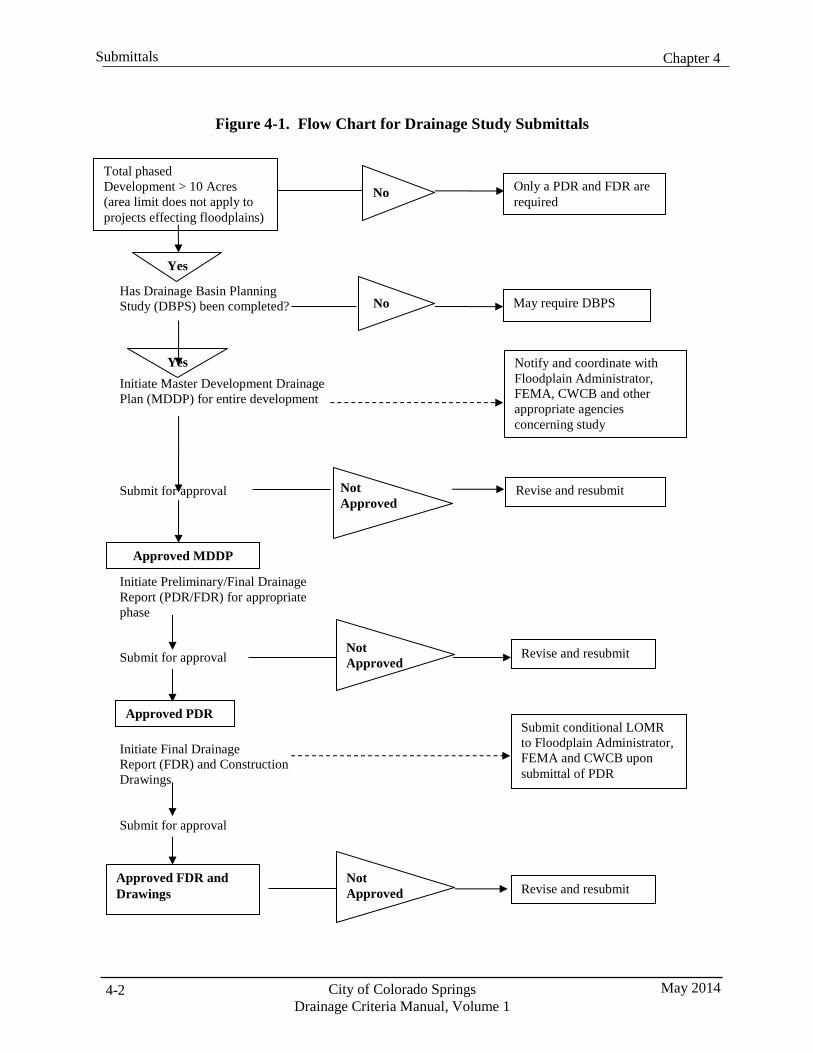
Chapter 4 Submittals
City of Colorado Springs Drainage Criteria Manual, Volume 1
May 2014 4-2
No May require DBPS
Not Approved
Revise and resubmit
Figure 4-1. Flow Chart for Drainage Study Submittals
Has Drainage Basin Planning Study (DBPS) been completed?
Yes Initiate Master Development Drainage Plan (MDDP) for entire development
Submit for approval
Initiate Preliminary/Final Drainage Report (PDR/FDR) for appropriate phase
Submit for approval
Initiate Final Drainage Report (FDR) and Construction Drawings
Submit for approval
Total phased Development > 10 Acres (area limit does not apply to projects effecting floodplains)
No
Yes
Only a PDR and FDR are required
Approved MDDP
Approved PDR
Not Approved
Not Approved
Notify and coordinate with Floodplain Administrator, FEMA, CWCB and other appropriate agencies concerning study
Revise and resubmit
Submit conditional LOMR to Floodplain Administrator, FEMA and CWCB upon submittal of PDR
Approved FDR and Drawings Revise and resubmit
Chapter 4 Submittals
May 2014 City of Colorado Springs Drainage Criteria Manual, Volume 1
4-3
2.1 Drainage Basin Planning Study (DBPS)
To establish a comprehensive approach to stormwater management within each drainage basin, Drainage Basin Planning Studies (DBPSs) should be completed to identify historic and future basin conditions and major system improvements so that existing deficiencies can be corrected and impacts from future land development can be adequately addressed according the principles and policies defined in this Manual. DBPSs apply to basins tributary to major streams such as Monument and Fountain Creeks and are used to establish basin fees charged to developers. These studies typically involve several ownerships and multiple development projects. By identifying existing deficiencies and the costs of correcting them, a DBPS can also be used to budget for and schedule system improvements. DBPSs should include a method for rating system deficiencies and assigning a priority to each proposed improvement. In general, these studies are intended to address:
Regional and basin-wide drainage system issues.
Economical use of resources.
Environmental preservation and enhancement.
Social and recreational enhancement.
Compatibility with comprehensive plans.
Responsibility for funding and implementation.
Health, safety and welfare of citizenry.
A DBPS shall show the conduits, channels, natural drainage courses, detention ponds, easements, tracts, culverts and all other hydraulic facilities required to control surface waters from base flows to the 100- year flood event within the basin and to carry such waters to points of insignificant impact. Subbasins shall be delineated to appropriately identify hydrologically significant features and design points with an average contributing drainage size of approximately 130 acres.
The study shall include an estimate of the cost of needed drainage facilities segregated by the cost of upgrading deficient existing facilities, reimbursable development-related improvement costs and the cost of improvements within each jurisdiction in the drainage basin. Reimbursable costs are used to develop the unit drainage fee for each basin which is discussed in Section 2.10.
The adoption of a DBPS is considered an amendment to the Comprehensive Plan and requires a public process. Generally, completing a DBPS requires the execution of these six phases:
1. Scoping and Stakeholder Involvement. Early in the study process, stakeholders who may be
affected by the study results must be identified and included. During this phase, the number and type of public meetings and presentations to committees, council and commissions are identified.
2. Problem Identification/Existing and Future Conditions. After collecting relevant data and
analyzing system capacities for existing and future conditions, deficiencies and needed improvements can be identified.
3. Alternatives Development, Evaluation and Selection. During this phase of the study, possible
solutions for resolving existing and future system deficiencies are evaluated. Options should include locating detention storage facilities to reduce peak flows and capacity improvements to convey
Chapter 4 Submittals
City of Colorado Springs Drainage Criteria Manual, Volume 1
May 2014 4-4
estimated flows. Evaluation criteria should be defined to compare alternatives based on effectiveness in addressing capacity, environmental and cost considerations.
4. Plan Development. Based on the preferred alternative, the proposed approach is applied throughout
the basin and the cost of final improvements is quantified. The estimated cost of existing system deficiencies are prioritized and used to provide guidance on needed remedial improvements. The estimated costs of system improvements required to serve future development are used for fee calculation for each affected jurisdiction.
5. Fee Development. A unit drainage fee is calculated by dividing the estimated cost of development-
related improvements by the developable land to be platted. See Section 2.10 for a discussion of reimbursable costs.
6. Plan and Fee Adoption. After acceptance by stakeholders, the proposed plan and fees are presented
to the appropriate committees, boards, City Council, and Board of County Commissioners, as necessary. Periodic meetings and presentations of the study progress should be conducted to provide updates to the relevant parties.
The guidelines for a typical DBPS report are more fully described in Exhibit 4-1.
2.2 Master Development Drainage Plan (MDDP)
The purpose of the Master Development Drainage Plan (MDDP) is to implement the concepts identified in the overall basin plan for a particular development project. The MDDP must identify major drainageways, detention areas, locations of culverts, bridges, open channels and drainage areas contained within the proposed development. When the project is within a drainage basin with an approved DBPS, the MDDP must be consistent with the concepts and costs identified in the DBPS or provide updated information to identify proposed changes to the approved DBPS.
Phased developments greater than 10 acres must submit a MDDP. The ability of downstream drainage facilities to pass developed runoff from the proposed development must be thoroughly analyzed in the MDDP. Proposed phasing of the development must be addressed by identifying likely phasing scenarios and coordinating the planned facilities with the phasing plan.
The purpose of the MDDP is to complete drainage planning for the proposed development before embarking on individual phases or later stages of the project. Site requirements, including public improvements for the development, must be identified in the MDDP. The MDDP must identify the hydrology and hydraulics of existing and proposed drainageways and appurtenant structures that are within or affected by a proposed development. The hydrology must be compatible with the DBPS. Changes proposed by the MDDP must be analyzed within the context of the DBPS to determine impacts on drainageways, including safety and maintenance. The MDDP must identify measures to protect public facilities, such as bridge crossings and utilities, and private property adjacent to the banks of the drainageways. Right-of-way requirements must be delineated on the plans for all drainageways, storage facilities, and other drainage structures.
The guidelines for a typical MDDP report are more fully described in Exhibit 4-2.
2.3 Preliminary Drainage Report (PDR)
A Preliminary Drainage Report (PDR) may accompany a Preliminary Plat or Development Plan that is within a land parcel that has previously been included in a MDDP. The purpose of the PDR is to refine
Chapter 4 Submittals
May 2014 City of Colorado Springs Drainage Criteria Manual, Volume 1
4-5
the conceptual plan described in previously completed master plans and identify specific solutions for on- site and off-site existing and future conditions resulting from the development of the planned project. Undeveloped land, not included in the project area, shall be assumed to be developed and the highest density allowed by its zoning. In addition, problems that exist prior to development must be addressed in the PDR.
A PDR is not intended to evaluate conceptual approaches to stormwater management that differ from the previously approved planning documents. The proposed improvements must be consistent with the previously approved plans. Detailed analysis of drainage basin hydrology and hydraulics is required based on the best available site information and land use plans. Alternative solutions to drainage problems not previously identified shall be noted and the capacity of drainage facilities on- and off-site shall be evaluated. Proposed alternatives to the approved planning documents may require that the planning documents be revised to assess the impact of the proposed changes on the overall basin plan. Specific improvements, including open channels, storm sewers, grading, site stabilization, catch basins, culverts and other improvements, will be located and sized to meet requirements of the minor and major drainage systems. Drainage easements and tracts necessary to access and maintain the proposed improvements must be identified.
2.3.1 Typical PDR
A typical PDR generally consists of a narrative portion and appendices with supporting calculations and other pertinent information. The narrative shall lead the reader logically through the entire analysis and design process and provide a clear picture of stormwater management issues. The narrative portion shall provide detailed discussion regarding the general location and description of the site, off-site and on-site drainage basins and subbasins, drainage design criteria, stormwater management facility design, and conclusions. Discussion of methodology, assumptions, input, and a summary of results shall be provided in the narrative for all hydrologic or hydraulic modeling efforts. Peak flow rates, storage volumes, critical water surface elevations, and stormwater management facility sizes shall also be summarized and discussed in the report narrative. The appendices must provide the appropriate backup information and calculations, but the reader should not have to review information contained in the appendices to have a clear and thorough understanding of the project and the stormwater management analysis and facility designs.
The guidelines for a typical PDR are more fully described in Exhibit 4-3.
2.3.2 Transitional PDR
PDR requirements may be reduced at the request of the applicant if there is uncertainty regarding the final developed characteristics of individual parcels, lots, or sites within the proposed development. There is frequently uncertainty with commercial and business park developments at the preliminary or final plat stage regarding the size and placement of buildings, the detailed lot or parcel grading, the extent of paved areas, and the location of local stormwater management facilities and detention facilities. As the individual lots or parcels develop, separate FDRs are typically prepared as the site characteristics and layout are determined. If a transitional PDR is prepared for a development, the standard PDR requirements shall be adhered to with the following exceptions or modifications:
Conservative assumptions may be applied in areas where there is uncertainty regarding drainage
factors related to the development of the site.
The level of detail may be reduced in the hydraulic and hydrologic analysis in areas where uncertainty exists.
Chapter 4 Submittals
City of Colorado Springs Drainage Criteria Manual, Volume 1
May 2014 4-6
Areas where assumptions are made and where the level of detail is limited shall be clearly identified so that they can be analyzed in full detail with the individual Phase III drainage reports and updated transitional Phase II drainage report.
Stormwater runoff routing calculations shall be completed using the assumed conditions. The
drainage plan shall show flow paths and the method of conveyance (open channel, street, or street and storm sewer). In addition, preliminary sizing shall be provided for all conveyance facilities, based on the conservative assumptions, if necessary.
The longitudinal slope on streets may not be established, but the direction of the slope and the
location of the high points and the sumps in the streets shall be determined.
The location of detention and water quality facilities shall be shown on the plan. The volume and land area required shall be conservatively estimated, and the type of detention shall be described. Detailed outlet design calculations are not required.
It is important that all other requirements of a PDR are addressed in detail. Specifically, attention needs to be given to these issues:
Full detail shall be provided for the analysis of offsite flows entering the development.
Full detail shall be provided for the analysis of the conveyance of flow from the development to
the nearest major drainageway.
Detailed floodplain delineations shall be provided for all major drainageways within or adjacent to the development.
A transitional PDR is not considered final until it has been updated to reflect the land use characteristics, final grading, and local storm sewer facilities of the individual lots or parcels within the development. The developer must commit to updating the transitional PDR, as FDRs are completed for the individual lots or parcels. Continuous updating is necessary, as details become available, to ensure that the original assumptions are valid, to ensure that general drainage patterns are consistent with the original assumptions, and to ensure that properly sized stormwater conveyance facilities, detention facilities, and water quality facilities are provided for the entire development.
2.4 Final Drainage Report (FDR)
The purpose of the Final Drainage Report (FDR) is to finalize the planned improvements identified in previously completed studies of the basin and property and to present the design details for the proposed improvements. The FDR must also identify changes to the preliminary design that were incorporated due to review comments.
The analyses included in the FDR provide the background for the design that is incorporated into construction plans for the proposed platted land. The analyses shall include calculations that support the location and sizing of all drainage features required to properly convey on-site and off-site surface runoff for proposed platted development, including grading, streets profiles, pond grading and outlet designs, street sections, storm sewer and channel profiles and water quality features, etc.
The guidelines for a typical FDR are more fully described in Exhibit 4-4.
Chapter 4 Submittals
May 2014 City of Colorado Springs Drainage Criteria Manual, Volume 1
4-7
2.5 Drainage Letter Report for Small Subdivisions or Resubdivisions
When sites are small or when a portion of previously platted land is resubdivided and the proposed division of lots is consistent with previously approved reports for the property, a modified drainage report format may be submitted with approval. In this situation a “Drainage Letter” rather than a complete Final Drainage Report may be proposed.
The guidelines for a typical “Drainage Letter” are more fully described in Exhibit 4-5.
2.6 Report and Plan Statements
Drainage reports and plans must include official statements by the designer and the owner to certified general compliance with the applicable standards and commitment to implement the standards. These statements are provided in Exhibits 4-6 and 4-7.
2.7 Stormwater Infrastructure Improvements Not Related to New Development or
Redevelopment
Stormwater infrastructure improvements completed to address existing deficiencies or to implement portions of approved plans apart from the processing of a specific land development project must also comply with the principles, policies and methods defined in this Manual. Reporting requirements shall be similar to those described herein for development related projects, but may be revised to more specifically address project conditions.
These guidelines for a channel design report are provided in Exhibit 4-8.
2.8 Stormwater Management Facility Operation and Maintenance
Each open channel, detention, and post-construction water quality PCM project must include an Operation and Maintenance (O&M) or an Inspection and Maintenance (I&M) Manual developed in conjunction with the final design to ensure that maintenance considerations have been incorporated into project designs and to document how those provisions must be implemented. A Manual is not required for storm sewer or culvert projects. Although many common maintenance provisions apply to projects, each plan must also identify the unique features of each project that need to be addressed.
The Manuals must provide guidance and standard forms for those responsible for the maintenance of stormwater management facilities. The Manual must be submitted for acceptance with the construction drawings. The Manual for channels shall be prepared by the design engineer and certified by the owner and design engineer in accordance with the template provided in Exhibit 4-9. The Manual for detention ponds shall be prepared based on the Standard Operating Procedures (SOP) and Inspection and Maintenance (I&M) plan for Extended Detention Basins (EDBs) in Chapter 6 of Volume 2 of this Manual.
Exhibit 4-9 also identifies standard appendices that must be included in the O&M Manual. Standard operating procedures, inspection forms, and maintenance forms have been developed for some of the commonly constructed stormwater PCMs and can be found on the City of Colorado Springs web site (coloradosprings.gov). If standard operating procedures, inspection forms, or maintenance forms are available for a specific stormwater management facility, they shall be used and inserted in the appropriate appendix. If standard operating procedures, inspection forms, or maintenance forms have not been
Chapter 4 Submittals
City of Colorado Springs Drainage Criteria Manual, Volume 1
May 2014 4-8
developed for a specific stormwater management facility, they must be developed by the design engineer in a format that is consistent with those already developed. The stormwater facility maintenance notification form is a standard form similar to what has been developed for other PCMs. The remaining appendices consist of an overall site plan and project construction drawings developed by the design engineer. The accepted construction drawings and/or the approved Site Improvement Plan shall be included in these appendices.
2.9 Erosion and Stormwater Quality Control
Requirements for Grading and Erosion Control (GEC) Plans and City Stormwater Management Plans (CSWMPs) are detailed in the Stormwater Construction Manual. A Permanent Control Measure Plan must be submitted if a PCM is required according to Volume II of this Manual. PCM Plans must be submitted prior to implementation of the final phase of the GEC Plan.
2.10 Reimbursable Improvements
Reimbursable improvements are identified in DBPSs to form the basis for unit drainage fees. At the time of platting, the FDR provides an estimate of the cost of reimbursable improvements to be constructed and the fees due. Upon completion and acceptance of reimbursable improvements, a request must be submitted to the City/County Drainage Board for the reimbursable amount to be approved. No reimbursements for qualifying improvements can be made unless approved by the City/County Drainage Board. A detailed description of the procedures and documentation needed to submit a reimbursement request is provided in the City Engineering Criteria Manual, Section I, Subdivision Policy Manual, Chapter 13, Drainage Reimbursements and in the El Paso County Engineering Criteria Manual, Appendix L.
3.0 Submittal Guidelines Exhibits 4-1 through 4-9 provide guidance for submittal formats and content associated with the drainage studies described in Section 2.
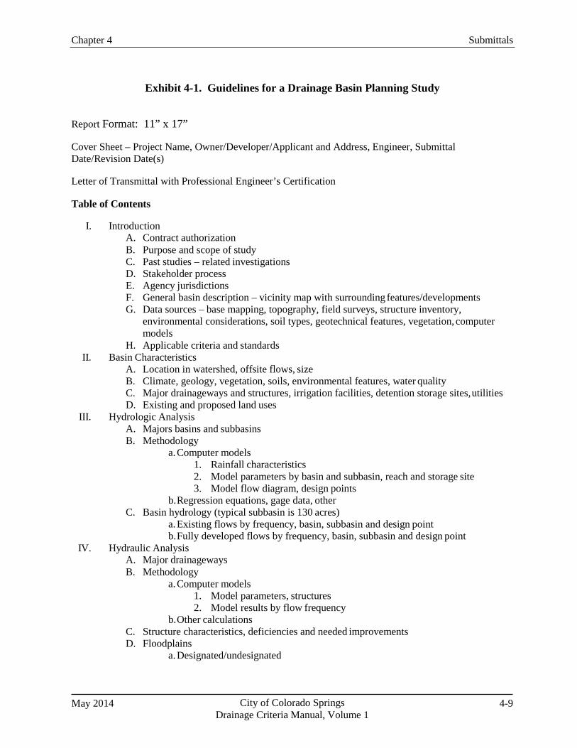
Chapter 4 Submittals
May 2014 City of Colorado Springs Drainage Criteria Manual, Volume 1
4-9
Exhibit 4-1. Guidelines for a Drainage Basin Planning Study
Report Format: 11” x 17”
Cover Sheet – Project Name, Owner/Developer/Applicant and Address, Engineer, Submittal Date/Revision Date(s)
Letter of Transmittal with Professional Engineer’s Certification
Table of Contents
I. Introduction A. Contract authorization B. Purpose and scope of study C. Past studies – related investigations D. Stakeholder process E. Agency jurisdictions F. General basin description – vicinity map with surrounding features/developments G. Data sources – base mapping, topography, field surveys, structure inventory,
environmental considerations, soil types, geotechnical features, vegetation, computer models
H. Applicable criteria and standards II. Basin Characteristics
A. Location in watershed, offsite flows, size B. Climate, geology, vegetation, soils, environmental features, water quality C. Major drainageways and structures, irrigation facilities, detention storage sites, utilities D. Existing and proposed land uses
III. Hydrologic Analysis A. Majors basins and subbasins B. Methodology
a. Computer models 1. Rainfall characteristics 2. Model parameters by basin and subbasin, reach and storage site 3. Model flow diagram, design points
b. Regression equations, gage data, other C. Basin hydrology (typical subbasin is 130 acres)
a. Existing flows by frequency, basin, subbasin and design point b. Fully developed flows by frequency, basin, subbasin and design point
IV. Hydraulic Analysis A. Major drainageways B. Methodology
a. Computer models 1. Model parameters, structures 2. Model results by flow frequency
b. Other calculations C. Structure characteristics, deficiencies and needed improvements D. Floodplains
a. Designated/undesignated
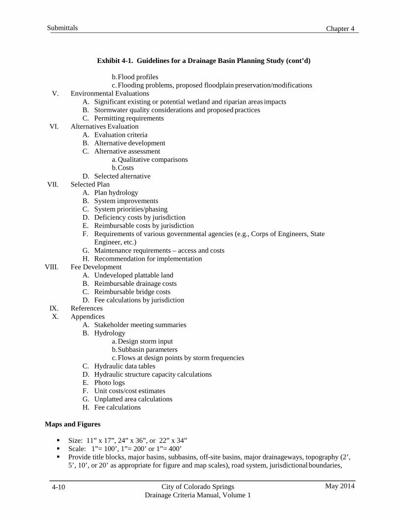
Chapter 4 Submittals
City of Colorado Springs Drainage Criteria Manual, Volume 1
May 2014 4-10
Exhibit 4-1. Guidelines for a Drainage Basin Planning Study (cont’d)
b. Flood profiles c. Flooding problems, proposed floodplain preservation/modifications
V. Environmental Evaluations A. Significant existing or potential wetland and riparian areas impacts B. Stormwater quality considerations and proposed practices C. Permitting requirements
VI. Alternatives Evaluation A. Evaluation criteria B. Alternative development C. Alternative assessment
a. Qualitative comparisons b. Costs
D. Selected alternative VII. Selected Plan
A. Plan hydrology B. System improvements C. System priorities/phasing D. Deficiency costs by jurisdiction E. Reimbursable costs by jurisdiction F. Requirements of various governmental agencies (e.g., Corps of Engineers, State
Engineer, etc.) G. Maintenance requirements – access and costs H. Recommendation for implementation
VIII. Fee Development A. Undeveloped plattable land B. Reimbursable drainage costs C. Reimbursable bridge costs D. Fee calculations by jurisdiction
IX. References X. Appendices
A. Stakeholder meeting summaries B. Hydrology
a. Design storm input b. Subbasin parameters c. Flows at design points by storm frequencies
C. Hydraulic data tables D. Hydraulic structure capacity calculations E. Photo logs F. Unit costs/cost estimates G. Unplatted area calculations H. Fee calculations
Maps and Figures
Size: 11” x 17”, 24” x 36”, or 22” x 34” Scale: 1”= 100’, 1”= 200’ or 1”= 400’ Provide title blocks, major basins, subbasins, off-site basins, major drainageways, topography (2’,
5’, 10’, or 20’ as appropriate for figure and map scales), road system, jurisdictional boundaries,
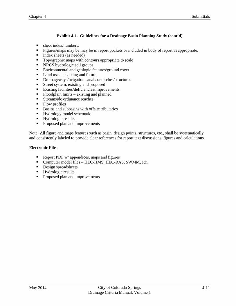
Chapter 4 Submittals
May 2014 City of Colorado Springs Drainage Criteria Manual, Volume 1
4-11
Exhibit 4-1. Guidelines for a Drainage Basin Planning Study (cont’d)
sheet index/numbers. Figures/maps may be may be in report pockets or included in body of report as appropriate. Index sheets (as needed) Topographic maps with contours appropriate to scale NRCS hydrologic soil groups Environmental and geologic features/ground cover Land uses – existing and future Drainageways/irrigation canals or ditches/structures Street system, existing and proposed Existing facilities/deficiencies/improvements Floodplain limits – existing and planned Streamside ordinance reaches Flow profiles Basins and subbasins with offsite tributaries Hydrology model schematic Hydrologic results Proposed plan and improvements
Note: All figure and maps features such as basin, design points, structures, etc., shall be systematically and consistently labeled to provide clear references for report text discussions, figures and calculations.
Electronic Files
Report PDF w/ appendices, maps and figures Computer model files – HEC-HMS, HEC-RAS, SWMM, etc. Design spreadsheets Hydrologic results Proposed plan and improvements
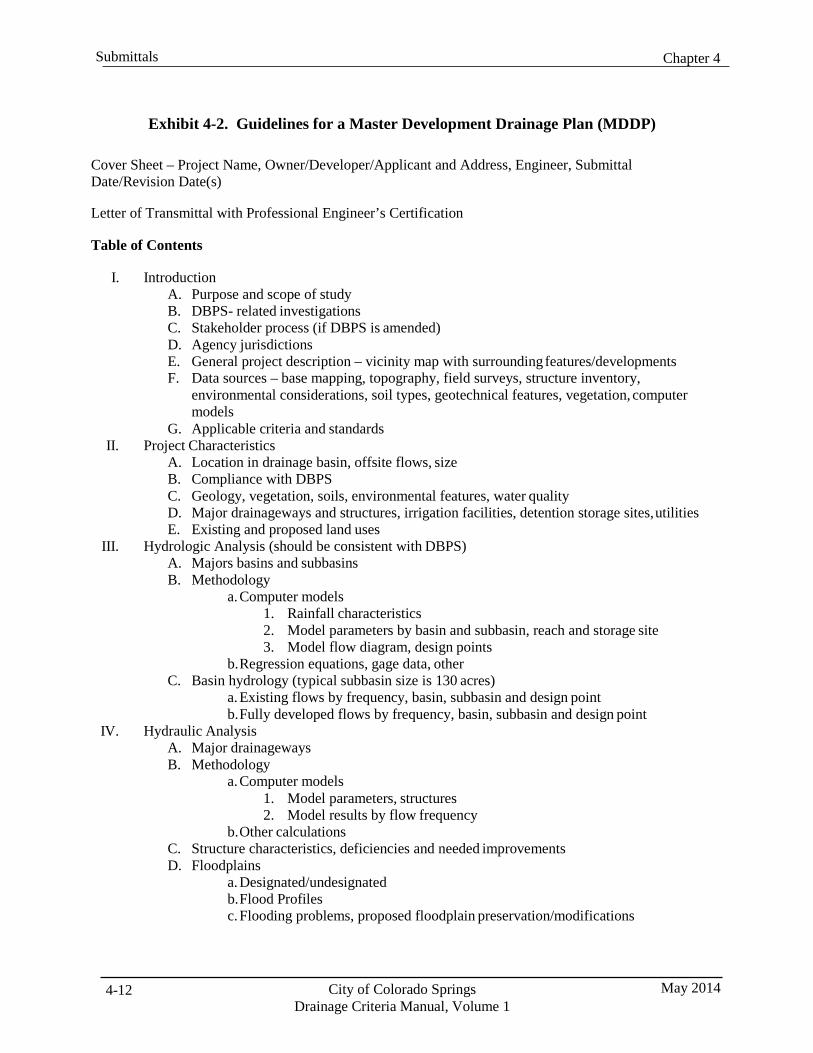
Chapter 4 Submittals
City of Colorado Springs Drainage Criteria Manual, Volume 1
May 2014 4-12
Exhibit 4-2. Guidelines for a Master Development Drainage Plan (MDDP)
Cover Sheet – Project Name, Owner/Developer/Applicant and Address, Engineer, Submittal Date/Revision Date(s)
Letter of Transmittal with Professional Engineer’s Certification
Table of Contents
I. Introduction
A. Purpose and scope of study B. DBPS- related investigations C. Stakeholder process (if DBPS is amended) D. Agency jurisdictions E. General project description – vicinity map with surrounding features/developments F. Data sources – base mapping, topography, field surveys, structure inventory,
environmental considerations, soil types, geotechnical features, vegetation, computer models
G. Applicable criteria and standards II. Project Characteristics
A. Location in drainage basin, offsite flows, size B. Compliance with DBPS C. Geology, vegetation, soils, environmental features, water quality D. Major drainageways and structures, irrigation facilities, detention storage sites, utilities E. Existing and proposed land uses
III. Hydrologic Analysis (should be consistent with DBPS) A. Majors basins and subbasins B. Methodology
a. Computer models 1. Rainfall characteristics 2. Model parameters by basin and subbasin, reach and storage site 3. Model flow diagram, design points
b. Regression equations, gage data, other C. Basin hydrology (typical subbasin size is 130 acres)
a. Existing flows by frequency, basin, subbasin and design point b. Fully developed flows by frequency, basin, subbasin and design point
IV. Hydraulic Analysis A. Major drainageways B. Methodology
a. Computer models 1. Model parameters, structures 2. Model results by flow frequency
b. Other calculations C. Structure characteristics, deficiencies and needed improvements D. Floodplains
a. Designated/undesignated b. Flood Profiles c. Flooding problems, proposed floodplain preservation/modifications
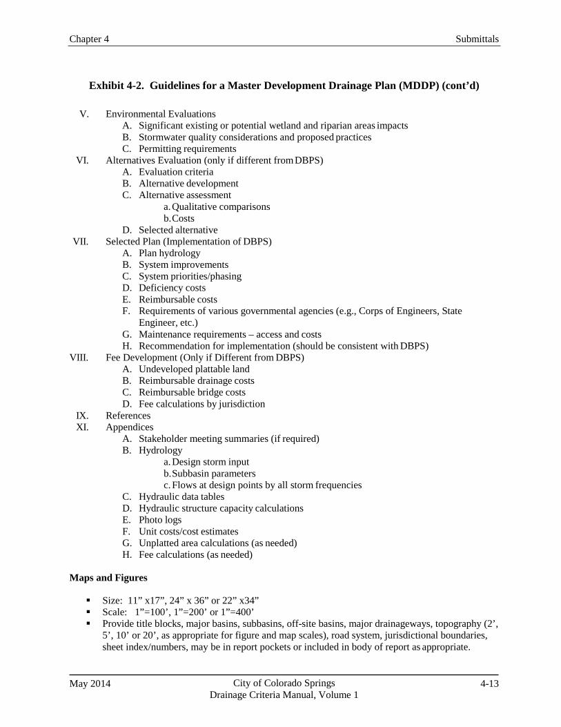
Chapter 4 Submittals
May 2014 City of Colorado Springs Drainage Criteria Manual, Volume 1
4-13
Exhibit 4-2. Guidelines for a Master Development Drainage Plan (MDDP) (cont’d)
V. Environmental Evaluations A. Significant existing or potential wetland and riparian areas impacts B. Stormwater quality considerations and proposed practices C. Permitting requirements
VI. Alternatives Evaluation (only if different from DBPS) A. Evaluation criteria B. Alternative development C. Alternative assessment
a. Qualitative comparisons b. Costs
D. Selected alternative VII. Selected Plan (Implementation of DBPS)
A. Plan hydrology B. System improvements C. System priorities/phasing D. Deficiency costs E. Reimbursable costs F. Requirements of various governmental agencies (e.g., Corps of Engineers, State
Engineer, etc.) G. Maintenance requirements – access and costs H. Recommendation for implementation (should be consistent with DBPS)
VIII. Fee Development (Only if Different from DBPS) A. Undeveloped plattable land B. Reimbursable drainage costs C. Reimbursable bridge costs D. Fee calculations by jurisdiction
IX. References XI. Appendices
A. Stakeholder meeting summaries (if required) B. Hydrology
a. Design storm input b. Subbasin parameters c. Flows at design points by all storm frequencies
C. Hydraulic data tables D. Hydraulic structure capacity calculations E. Photo logs F. Unit costs/cost estimates G. Unplatted area calculations (as needed) H. Fee calculations (as needed)
Maps and Figures
Size: 11” x17”, 24” x 36” or 22” x34” Scale: 1”=100’, 1”=200’ or 1”=400’ Provide title blocks, major basins, subbasins, off-site basins, major drainageways, topography (2’,
5’, 10’ or 20’, as appropriate for figure and map scales), road system, jurisdictional boundaries, sheet index/numbers, may be in report pockets or included in body of report as appropriate.
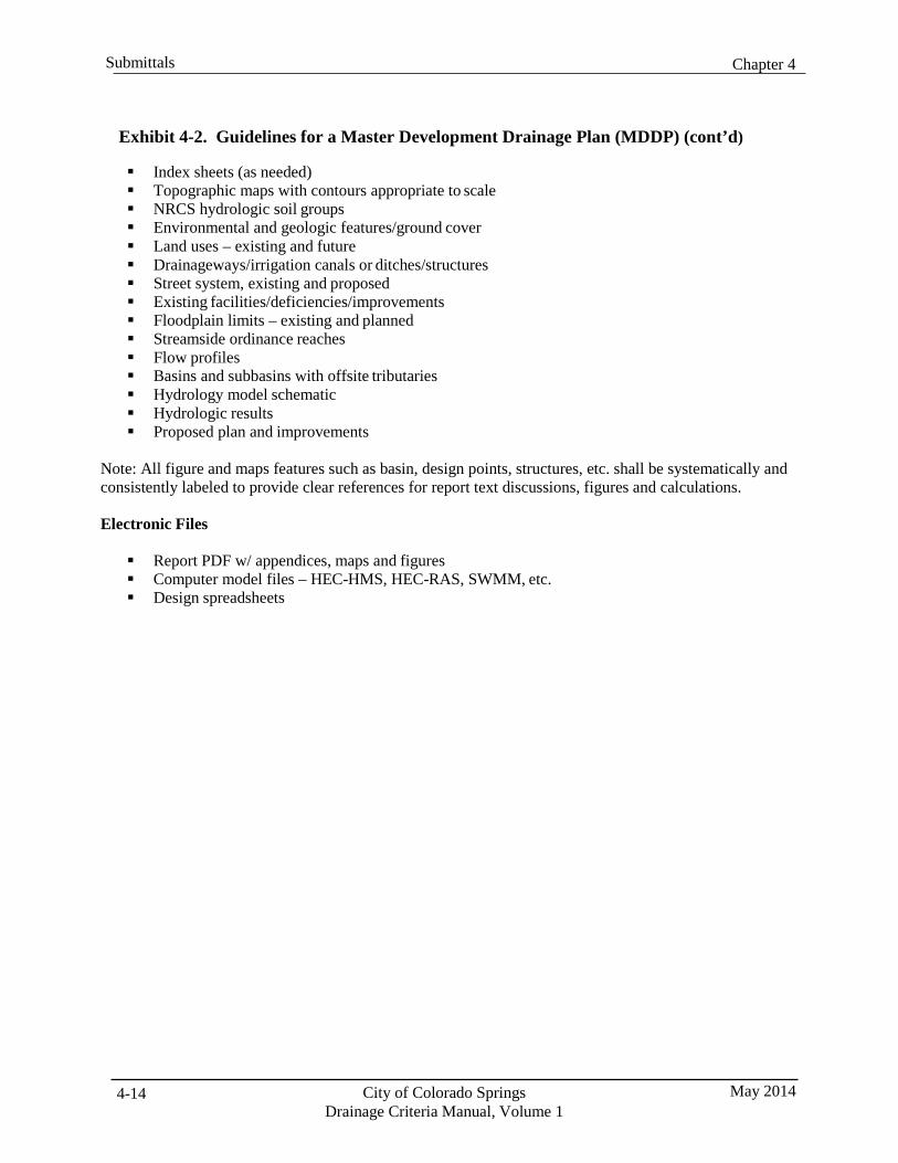
Chapter 4 Submittals
City of Colorado Springs Drainage Criteria Manual, Volume 1
May 2014 4-14
Exhibit 4-2. Guidelines for a Master Development Drainage Plan (MDDP) (cont’d)
Index sheets (as needed) Topographic maps with contours appropriate to scale NRCS hydrologic soil groups Environmental and geologic features/ground cover Land uses – existing and future Drainageways/irrigation canals or ditches/structures Street system, existing and proposed Existing facilities/deficiencies/improvements Floodplain limits – existing and planned Streamside ordinance reaches Flow profiles Basins and subbasins with offsite tributaries Hydrology model schematic Hydrologic results Proposed plan and improvements
Note: All figure and maps features such as basin, design points, structures, etc. shall be systematically and consistently labeled to provide clear references for report text discussions, figures and calculations.
Electronic Files
Report PDF w/ appendices, maps and figures Computer model files – HEC-HMS, HEC-RAS, SWMM, etc. Design spreadsheets
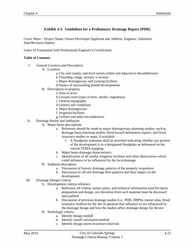
Chapter 4 Submittals
May 2014 City of Colorado Springs Drainage Criteria Manual, Volume 1
4-15
Exhibit 4-3. Guidelines for a Preliminary Drainage Report (PDR)
Cover Sheet – Project Name, Owner/Developer/Applicant and Address, Engineer, Submittal Date/Revision Date(s)
Letter of Transmittal with Professional Engineer’s Certification
Table of Contents
I. General Location and Description
A. Location a. City and county, and local streets within and adjacent to the subdivision b. Township, range, section, ¼ section c. Major drainageways and existing facilities d. Names of surrounding platted developments
B. Description of property a. Area in acres b. Ground cover (type of trees, shrubs, vegetation) c. General topography d. General soil conditions e. Major drainageways f. Irrigation facilities g. Utilities and other encumbrances
II. Drainage Basins and Subbasins A. Major basin descriptions
a. Reference should be made to major drainageways planning studies; such as drainage basin planning studies, flood hazard delineation reports, and flood insurance studies or maps, if available
1. A floodplain statement shall be provided indicating whether any portion of the development is in a designated floodplain as delineated on the current FEMA mapping
b. Major basin drainage characteristics c. Identification of all nearby irrigation facilities and other obstructions which
could influence or be influenced by the local drainage B. Subbasin description
a. Discussion of historic drainage patterns of the property in question b. Discussion of off-site drainage flow patterns and their impact on the
development III. Drainage Design Criteria
A. Development criteria reference a. Reference all criteria, master plans, and technical information used for report
preparation and design; any deviation from such material must be discussed and justified
b. Discussion of previous drainage studies (i.e., PDR, DBPSs, master plan, flood insurance studies) for the site in question that influence or are influenced by the drainage design and how the studies affect drainage design for the site
B. Hydrologic criteria a. Identify design rainfall b. Identify runoff calculation method c. Identify design storm recurrence intervals
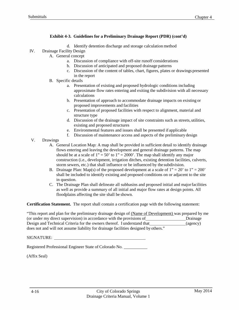
Chapter 4 Submittals
City of Colorado Springs Drainage Criteria Manual, Volume 1
May 2014 4-16
Exhibit 4-3. Guidelines for a Preliminary Drainage Report (PDR) (cont’d)
d. Identify detention discharge and storage calculation method IV. Drainage Facility Design
A. General concept a. Discussion of compliance with off-site runoff considerations b. Discussion of anticipated and proposed drainage patterns c. Discussion of the content of tables, chart, figures, plates or drawings presented
in the report B. Specific details
a. Presentation of existing and proposed hydrologic conditions including approximate flow rates entering and exiting the subdivision with all necessary calculations
b. Presentation of approach to accommodate drainage impacts on existing or proposed improvements and facilities
c. Presentation of proposed facilities with respect to alignment, material and structure type
d. Discussion of the drainage impact of site constraints such as streets, utilities, existing and proposed structures
e. Environmental features and issues shall be presented if applicable f. Discussion of maintenance access and aspects of the preliminary design
V. Drawings A. General Location Map: A map shall be provided in sufficient detail to identify drainage
flows entering and leaving the development and general drainage patterns. The map should be at a scale of 1” = 50’ to 1” = 2000’. The map shall identify any major construction (i.e., development, irrigation ditches, existing detention facilities, culverts, storm sewers, etc.) that shall influence or be influenced by the subdivision.
B. Drainage Plan: Map(s) of the proposed development at a scale of 1” = 20’ to 1” = 200’ shall be included to identify existing and proposed conditions on or adjacent to the site in question.
C. The Drainage Plan shall delineate all subbasins and proposed initial and major facilities as well as provide a summary of all initial and major flow rates at design points. All floodplains affecting the site shall be shown.
Certification Statement. The report shall contain a certification page with the following statement:
“This report and plan for the preliminary drainage design of (Name of Development) was prepared by me (or under my direct supervision) in accordance with the provisions of Drainage Design and Technical Criteria for the owners thereof. I understand that (agency) does not and will not assume liability for drainage facilities designed by others.”
SIGNATURE:
Registered Professional Engineer State of Colorado No.
(Affix Seal)
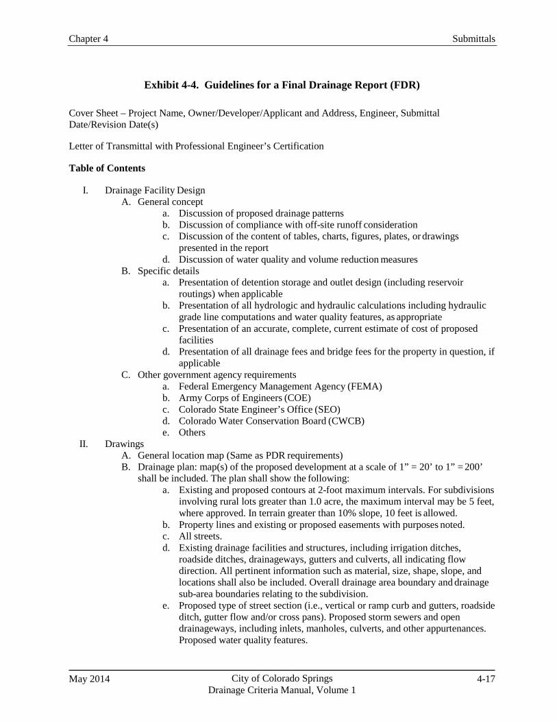
Chapter 4 Submittals
May 2014 City of Colorado Springs Drainage Criteria Manual, Volume 1
4-17
Exhibit 4-4. Guidelines for a Final Drainage Report (FDR)
Cover Sheet – Project Name, Owner/Developer/Applicant and Address, Engineer, Submittal Date/Revision Date(s)
Letter of Transmittal with Professional Engineer’s Certification
Table of Contents
I. Drainage Facility Design
A. General concept a. Discussion of proposed drainage patterns b. Discussion of compliance with off-site runoff consideration c. Discussion of the content of tables, charts, figures, plates, or drawings
presented in the report d. Discussion of water quality and volume reduction measures
B. Specific details a. Presentation of detention storage and outlet design (including reservoir
routings) when applicable b. Presentation of all hydrologic and hydraulic calculations including hydraulic
grade line computations and water quality features, as appropriate c. Presentation of an accurate, complete, current estimate of cost of proposed
facilities d. Presentation of all drainage fees and bridge fees for the property in question, if
applicable C. Other government agency requirements
a. Federal Emergency Management Agency (FEMA) b. Army Corps of Engineers (COE) c. Colorado State Engineer’s Office (SEO) d. Colorado Water Conservation Board (CWCB) e. Others
II. Drawings A. General location map (Same as PDR requirements) B. Drainage plan: map(s) of the proposed development at a scale of 1” = 20’ to 1” = 200’
shall be included. The plan shall show the following: a. Existing and proposed contours at 2-foot maximum intervals. For subdivisions
involving rural lots greater than 1.0 acre, the maximum interval may be 5 feet, where approved. In terrain greater than 10% slope, 10 feet is allowed.
b. Property lines and existing or proposed easements with purposes noted. c. All streets. d. Existing drainage facilities and structures, including irrigation ditches,
roadside ditches, drainageways, gutters and culverts, all indicating flow direction. All pertinent information such as material, size, shape, slope, and locations shall also be included. Overall drainage area boundary and drainage sub-area boundaries relating to the subdivision.
e. Proposed type of street section (i.e., vertical or ramp curb and gutters, roadside ditch, gutter flow and/or cross pans). Proposed storm sewers and open drainageways, including inlets, manholes, culverts, and other appurtenances. Proposed water quality features.
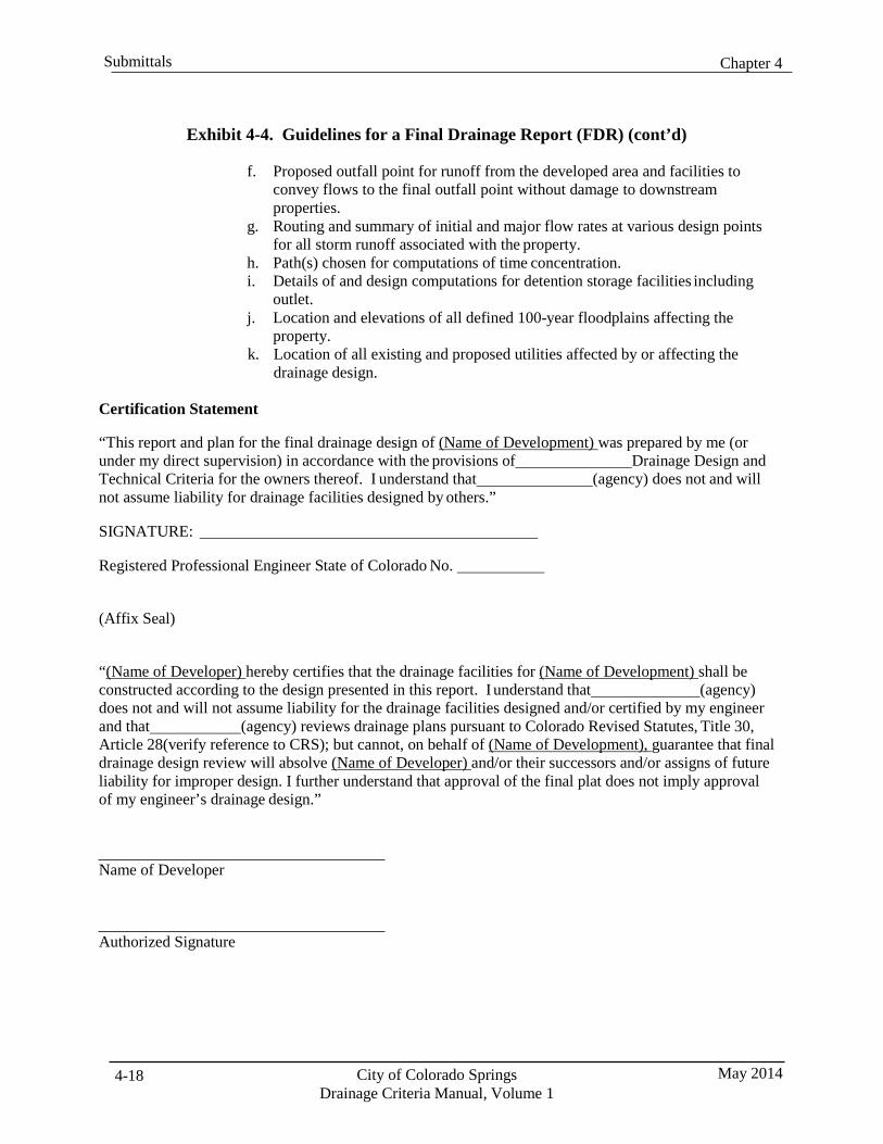
Chapter 4 Submittals
City of Colorado Springs Drainage Criteria Manual, Volume 1
May 2014 4-18
Exhibit 4-4. Guidelines for a Final Drainage Report (FDR) (cont’d)
f. Proposed outfall point for runoff from the developed area and facilities to convey flows to the final outfall point without damage to downstream properties.
g. Routing and summary of initial and major flow rates at various design points for all storm runoff associated with the property.
h. Path(s) chosen for computations of time concentration. i. Details of and design computations for detention storage facilities including
outlet. j. Location and elevations of all defined 100-year floodplains affecting the
property. k. Location of all existing and proposed utilities affected by or affecting the
drainage design.
Certification Statement
“This report and plan for the final drainage design of (Name of Development) was prepared by me (or under my direct supervision) in accordance with the provisions of Drainage Design and Technical Criteria for the owners thereof. I understand that (agency) does not and will not assume liability for drainage facilities designed by others.”
SIGNATURE:
Registered Professional Engineer State of Colorado No.
(Affix Seal)
“(Name of Developer) hereby certifies that the drainage facilities for (Name of Development) shall be constructed according to the design presented in this report. I understand that (agency) does not and will not assume liability for the drainage facilities designed and/or certified by my engineer and that (agency) reviews drainage plans pursuant to Colorado Revised Statutes, Title 30, Article 28(verify reference to CRS); but cannot, on behalf of (Name of Development), guarantee that final drainage design review will absolve (Name of Developer) and/or their successors and/or assigns of future liability for improper design. I further understand that approval of the final plat does not imply approval of my engineer’s drainage design.”
Name of Developer
Authorized Signature

Chapter 4 Submittals
May 2014 City of Colorado Springs Drainage Criteria Manual, Volume 1
4-19
Exhibit 4-5. Guidelines for a “Drainage Letter”
This format is designed for the “Drainage Letter” which is required for a resubdivision or replat of property for which a complete drainage report has previously been approved by the City/County Engineer and significant changes from such report is not proposed.
The “Drainage Letter” must include the following:
1. Cover sheet or statement stating the name and purpose of the report. This shall include the date
of preparation and the name of the previous subdivision. 2. Engineer’s statement. 3. Developer’s statement. 4. Body of the report shall include:
a. General property description with acreage. b. General existing drainage characteristics (on and off site). c. General proposed drainage characteristics (on and off site). d. Hydrologic calculations with tabulations of areas, runoff, coefficients, time of
concentration intensity, or “Q”, “qp”, time to peak, etc. (Required if existing conditions have channels.)
5. A site map showing location with regard to the surrounding area. 6. A drainage plan indicating site and adjacent property as platted with name and filing. Indicate
storm runoff routing and rates if applicable. 7. Drainage fees (cash or letter of credit) shall be determined in accordance with the latest drainage
ordinances/resolutions and applicable basin fees.

Chapter 4 Submittals
City of Colorado Springs Drainage Criteria Manual, Volume 1
May 2014 4-20
Exhibit 4-6. Drainage Report and Plan Statements
The following statements must be included with drainage reports and detailed drainage plans and specifications.
Engineer’s Statement:
The attached drainage plan and report were prepared under my direction and supervision and are correct to the best of my knowledge and belief. Said drainage report has been prepared according to the established criteria for drainage reports and said report is in conformity with the master plan of the drainage basin. I accept responsibility for any liability caused by any negligent acts, errors or omissions on my part in preparing this report.
Seal Name
Developer’s Statement:
I, the developer have read and will comply with all of the requirements specified in this drainage report and plan.
Business Name
By:
Title:
Address:
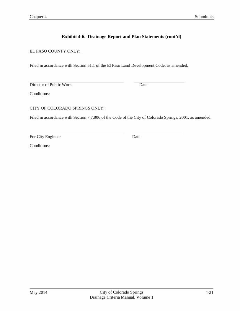
Chapter 4 Submittals
May 2014 City of Colorado Springs Drainage Criteria Manual, Volume 1
4-21
Exhibit 4-6. Drainage Report and Plan Statements (cont’d)
EL PASO COUNTY ONLY:
Filed in accordance with Section 51.1 of the El Paso Land Development Code, as amended.
Director of Public Works Date
Conditions:
CITY OF COLORADO SPRINGS ONLY:
Filed in accordance with Section 7.7.906 of the Code of the City of Colorado Springs, 2001, as amended.
For City Engineer Date
Conditions:
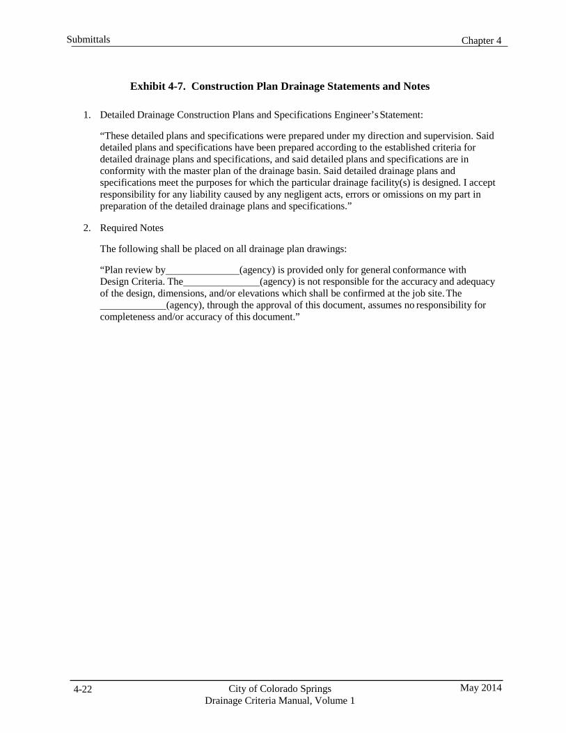
Chapter 4 Submittals
City of Colorado Springs Drainage Criteria Manual, Volume 1
May 2014 4-22
Exhibit 4-7. Construction Plan Drainage Statements and Notes
1. Detailed Drainage Construction Plans and Specifications Engineer’s Statement:
“These detailed plans and specifications were prepared under my direction and supervision. Said detailed plans and specifications have been prepared according to the established criteria for detailed drainage plans and specifications, and said detailed plans and specifications are in conformity with the master plan of the drainage basin. Said detailed drainage plans and specifications meet the purposes for which the particular drainage facility(s) is designed. I accept responsibility for any liability caused by any negligent acts, errors or omissions on my part in preparation of the detailed drainage plans and specifications.”
2. Required Notes
The following shall be placed on all drainage plan drawings:
“Plan review by (agency) is provided only for general conformance with Design Criteria. The (agency) is not responsible for the accuracy and adequacy of the design, dimensions, and/or elevations which shall be confirmed at the job site. The (agency), through the approval of this document, assumes no responsibility for completeness and/or accuracy of this document.”
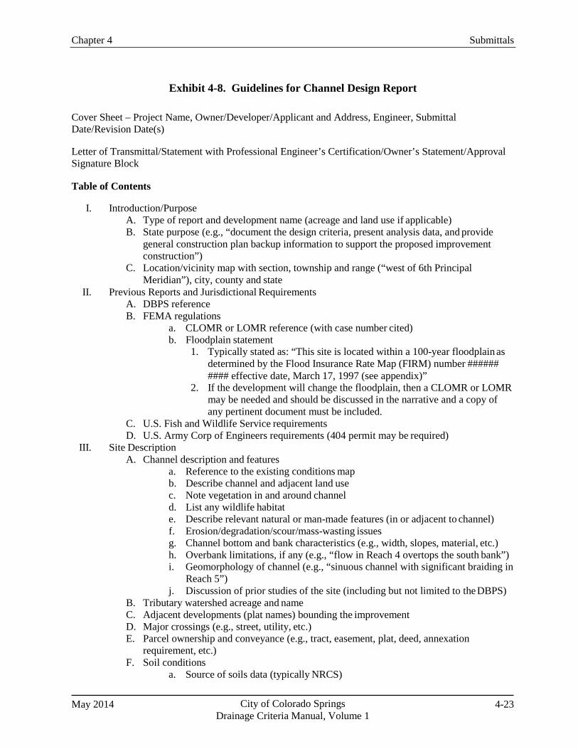
Chapter 4 Submittals
May 2014 City of Colorado Springs Drainage Criteria Manual, Volume 1
4-23
Exhibit 4-8. Guidelines for Channel Design Report
Cover Sheet – Project Name, Owner/Developer/Applicant and Address, Engineer, Submittal Date/Revision Date(s)
Letter of Transmittal/Statement with Professional Engineer’s Certification/Owner’s Statement/Approval Signature Block
Table of Contents
I. Introduction/Purpose A. Type of report and development name (acreage and land use if applicable) B. State purpose (e.g., “document the design criteria, present analysis data, and provide
general construction plan backup information to support the proposed improvement construction”)
C. Location/vicinity map with section, township and range (“west of 6th Principal Meridian”), city, county and state
II. Previous Reports and Jurisdictional Requirements A. DBPS reference B. FEMA regulations
a. CLOMR or LOMR reference (with case number cited) b. Floodplain statement
1. Typically stated as: “This site is located within a 100-year floodplain as determined by the Flood Insurance Rate Map (FIRM) number ###### #### effective date, March 17, 1997 (see appendix)”
2. If the development will change the floodplain, then a CLOMR or LOMR may be needed and should be discussed in the narrative and a copy of any pertinent document must be included.
C. U.S. Fish and Wildlife Service requirements D. U.S. Army Corp of Engineers requirements (404 permit may be required)
III. Site Description A. Channel description and features
a. Reference to the existing conditions map b. Describe channel and adjacent land use c. Note vegetation in and around channel d. List any wildlife habitat e. Describe relevant natural or man-made features (in or adjacent to channel) f. Erosion/degradation/scour/mass-wasting issues g. Channel bottom and bank characteristics (e.g., width, slopes, material, etc.) h. Overbank limitations, if any (e.g., “flow in Reach 4 overtops the south bank”) i. Geomorphology of channel (e.g., “sinuous channel with significant braiding in
Reach 5”) j. Discussion of prior studies of the site (including but not limited to the DBPS)
B. Tributary watershed acreage and name C. Adjacent developments (plat names) bounding the improvement D. Major crossings (e.g., street, utility, etc.) E. Parcel ownership and conveyance (e.g., tract, easement, plat, deed, annexation
requirement, etc.) F. Soil conditions
a. Source of soils data (typically NRCS)
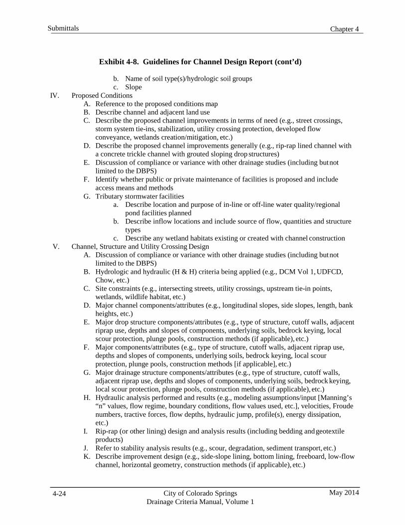
Chapter 4 Submittals
City of Colorado Springs Drainage Criteria Manual, Volume 1
May 2014 4-24
Exhibit 4-8. Guidelines for Channel Design Report (cont’d)
b. Name of soil type(s)/hydrologic soil groups c. Slope
IV. Proposed Conditions A. Reference to the proposed conditions map B. Describe channel and adjacent land use C. Describe the proposed channel improvements in terms of need (e.g., street crossings,
storm system tie-ins, stabilization, utility crossing protection, developed flow conveyance, wetlands creation/mitigation, etc.)
D. Describe the proposed channel improvements generally (e.g., rip-rap lined channel with a concrete trickle channel with grouted sloping drop structures)
E. Discussion of compliance or variance with other drainage studies (including but not limited to the DBPS)
F. Identify whether public or private maintenance of facilities is proposed and include access means and methods
G. Tributary stormwater facilities a. Describe location and purpose of in-line or off-line water quality/regional
pond facilities planned b. Describe inflow locations and include source of flow, quantities and structure
types c. Describe any wetland habitats existing or created with channel construction
V. Channel, Structure and Utility Crossing Design A. Discussion of compliance or variance with other drainage studies (including but not
limited to the DBPS) B. Hydrologic and hydraulic (H & H) criteria being applied (e.g., DCM Vol 1, UDFCD,
Chow, etc.) C. Site constraints (e.g., intersecting streets, utility crossings, upstream tie-in points,
wetlands, wildlife habitat, etc.) D. Major channel components/attributes (e.g., longitudinal slopes, side slopes, length, bank
heights, etc.) E. Major drop structure components/attributes (e.g., type of structure, cutoff walls, adjacent
riprap use, depths and slopes of components, underlying soils, bedrock keying, local scour protection, plunge pools, construction methods (if applicable), etc.)
F. Major components/attributes (e.g., type of structure, cutoff walls, adjacent riprap use, depths and slopes of components, underlying soils, bedrock keying, local scour protection, plunge pools, construction methods [if applicable], etc.)
G. Major drainage structure components/attributes (e.g., type of structure, cutoff walls, adjacent riprap use, depths and slopes of components, underlying soils, bedrock keying, local scour protection, plunge pools, construction methods (if applicable), etc.)
H. Hydraulic analysis performed and results (e.g., modeling assumptions/input [Manning’s “n” values, flow regime, boundary conditions, flow values used, etc.], velocities, Froude numbers, tractive forces, flow depths, hydraulic jump, profile(s), energy dissipation, etc.)
I. Rip-rap (or other lining) design and analysis results (including bedding and geotextile products)
J. Refer to stability analysis results (e.g., scour, degradation, sediment transport, etc.) K. Describe improvement design (e.g., side-slope lining, bottom lining, freeboard, low-flow
channel, horizontal geometry, construction methods (if applicable), etc.)
Chapter 4 Submittals
May 2014 City of Colorado Springs Drainage Criteria Manual, Volume 1
4-25
Exhibit 4-8. Guidelines for Channel Design Report (cont’d)
VI. Drainage and Bridge Fees A. List major watershed (e.g., Sand Creek Basin) B. List the current year and the fees associated (fees are updated every year and approved
by City Council) • Fees are derived from the unit price ($/acre) established in the DBPS and the total
site platted acreage • Some basins have special additional fees associated with them, a review of the basin
summary sheet SERT compiles is appropriate prior to acceptance of the values • Fees are due prior to plat recordation and must be stated as such in the report text,
typically after the estimate table VII. Construction Cost Opinion
A. Cost opinions are required for private and public facilities B. Clear distinction needs to be made regarding private and public responsibilities C. Clearly define reimbursable and non-reimbursable costs (reference to the DBPS or other
pertinent study is essential); when using DBPS costs, they must be extrapolated to the current year prices
D. Table should include a description, quantity, unit price and cost as well as an engineering contingency that should not exceed 10% (per City criteria for drainage reimbursements) and of course a grand total
E. Unit prices should be reviewed for general acceptance only (i.e., they should be reasonable)
F. Consultants typically include a disclaimer, but it is not required VIII. Phasing
A. General timeline of construction and limits of each phase B. Major facility (e.g., roadway, utility, culvert, water quality pond, etc.) timing constraints C. Outline of order of construction coupled with adjacent development (if applicable) D. Reference to report or other document or process which will refine schedule
IX. Summary A. General statement regarding scope of work and need B. Statement that design may be refined during further preparation of construction
documents C. Statement that this report and findings are in general conformance with the MDDP or
DBPS or other pertinent studies D. Statement that this facility will preserve environmental habitat (if applicable) E. Statement that this facility will be safe
X. References - listing of noted sources
Appendices
FEMA Floodplain Map - site boundary on FIRM, panel number, effective date, north arrow and scale.
Soils Map - NRCS soil map(s) with soil types (numbered) labeled, site boundary, north arrow and scale.
HEC-RAS Calculations - existing and proposed conditions – reach diagram, input and output tables (flow and structure), cross sections, cross section locations, channel profile(s), etc. Reports should provide essential parameters and results that show that design criteria are being satisfied and avoid reporting parameters and results that are extraneous.
Chapter 4 Submittals
City of Colorado Springs Drainage Criteria Manual, Volume 1
May 2014 4-26
Exhibit 4-8. Guidelines for Channel Design Report (cont’d)
Hydraulic Analyses – existing and proposed conditions, design methodology, assumptions, input and output, spreadsheets, documentation; flow hydraulics, stability, drop structures, flow profile(s).
HEC-RAS Model Maps – Existing and proposed conditions; property boundary, streets, contours, storm pipe and structures labeled with size, material and type (and condition if applicable), ditches/swales/channels with labels and grades (and cross section identifier if applicable), basin boundaries with label or legend item, adjacent development plat name labels, drainage easements or tracts with labels, 100-year floodplain with label or legend reference, environmental habitat areas, discharge values at key locations (typically site inflow and outflow locations, at a minimum), off-site basins with labels, proposed conditions (same as for existing conditions with the exception of proposed facilities to include site structures, adjacent development improvements and proposed contours).
Chapter 4 Submittals
Drainage Criteria Manual, Volume 1
Exhibit 4-9. Guidelines for a Channel Maintenance Plan
A Channel Maintenance Plan shall be submitted for all channel projects as a condition of acceptance. It shall consist of a single sheet that includes all the necessary information for long-term maintenance of the site, and shall generally conform to the guidelines that follow. Any comments must be addressed by the Engineer until the plan has been formally approved. Graphical elements included on the sheet are to reflect As-built Record Drawing information associated with the completed project.
The following outline shall be used to guide the development of the Channel Maintenance Plan. Some items may not apply to all projects, and any unique features may warrant inclusion of additional information if pertinent to the anticipated maintenance of the site.
Table of Contents
I. Project Information A. General information
a. Drainageway designation/location b. Property owner/local government agency - include contact phone number and
email address c. Design engineer - include contact phone number and email address. d. Project completion date - can be listed in drawing title, as shown in example
B. Hydraulic information a. Type of channel b. Flow rates - all applicable flow rates should be listed (e.g., base flow, low flow
and flood flow, any storm flows that were evaluated) c. Facility description - include additional design information for the facility,
including water surface elevations, types of vegetation, materials used, etc. C. Miscellaneous information
a. Project survey information - include survey control information and at least one on-site "Maintenance Control Point" established during construction for use during maintenance activities
b. Seed mix c. Mow area - include area in acres and description of mow limits d. Long-term monitoring requirements - if applicable, list monitoring requirements
such as 404 Permit Reports or any other required monitoring II. Project Notes
A. General facility description - include function, flow source, flow pattern through project, any special features, and any additional information that may be helpful in understanding the basic function of the facility
B. Maintenance notes a. Maintenance frequency b. Equipment and special tools required c. Power source (if applicable)
C. Maintenance procedure a. Dewatering b. Sediment removal c. Debris removal d. Site inspection - list all general features and equipment that should be inspected
to ascertain additional maintenance needs
May 2014 City of Colorado Springs 4-27
Chapter 4 Submittals
City of Colorado Springs Drainage Criteria Manual, Volume 1
May 2014 4-28
Exhibit 4-9. Guidelines for a Channel Maintenance Plan (cont’d)
e. Materials testing - list any contaminant testing requirements for sediment removed from the pond
f. Post-maintenance considerations – list any additional maintenance-related tasks such as restoring flow patterns or additional cleanup requirements
D. Noxious Weed Management a. Identify areas of infestation b. Identify species of concern c. Specify methods of control d. Specify monitoring procedures and measures of success
III. Site Plan A. Vicinity map B. Plan view - all major features of the facility should be labeled, including the following:
a. Trickle channel b. Low-flow channel c. Drop structures d. Special maintenance-related information should be identified, such as: • Maintenance control point location and elevation • Maintenance entrance, access road, gates, turnarounds - list applicable
information such as road material, width, maximum grade, etc. • Power source • Weight-restricted areas • Wetland or natural areas to avoid
C. Hydraulic profile a. Major features b. Other applicable water surface elevations c. Flow direction d. Shading identifying wetlands and sediment removal zones e. Wetland or natural areas to avoid
IV. Details A. Trickle channel section B. Low-flow channel section C. Drop structures D. Maintenance road E. Outfall structures
Maps and Drawings
The Engineer shall submit one 22" x 34" and one 11" x 17" Maintenance Site Plan with the project's As- built Record Drawings. The Plan will be will be reviewed and comments provided. Any comments shall be addressed by the Engineer until approval has been granted. Once approval has been granted, the final submittal shall include: Two 22” x 34” Maintenance Site Plans (one mylar, one bond) One 11” x 17” plan Electronic files of AutoCAD drawings and a PDF of the plan
City of Colorado Springs Drainage Criteria Manual, Volume 1
May 2014 5-i
Chapter 5 Floodplain Management Contents 1.0 Introduction ...................................................................................................................................... 1
2.0 Floodplain Management and Regulation ....................................................................................... 1 2.1 City Code ................................................................................................................................................... 1 2.2 Floodplain Management ............................................................................................................................ 2 2.3 Regulatory Flood Flows ............................................................................................................................ 2 2.4 National Flood Insurance Program ............................................................................................................ 3 2.5 Colorado Water Conservation Board ......................................................................................................... 4 2.6 Floodplain Development Regulations........................................................................................................ 4 2.7 Flooding Outside of SFHAs ...................................................................................................................... 4
3.0 Sources of and Use of Existing Floodplain Information ............................................................... 5 3.1 FEMA Flood Insurance Rate Maps (FIRMs) and Flood Insurance Study (FIS) ....................................... 5 3.2 Drainage Basin Planning Studies ............................................................................................................... 6 3.3 Other Floodplain Information .................................................................................................................... 6 3.4 Confirmation of Floodplain Data ............................................................................................................... 7
4.0 Construction in or Development Adjacent to Floodplains ............................................................ 7 4.1 Floodway ................................................................................................................................................... 7 4.2 Flood Fringe .............................................................................................................................................. 8 4.3 Subdivision Platting and Floodplains ........................................................................................................ 8 4.4 Freeboard Requirements ............................................................................................................................ 9
5.0 FEMA Map Revisions and Amendments ..................................................................................... 10 5.1 General .................................................................................................................................................... 10 5.2 Conditional Letter of Map Revision (CLOMR) ...................................................................................... 10 5.3 Conditional Letter of Map Revision Based on Fill (CLOMR-F) ............................................................. 10 5.4 Letter of Map Revision (LOMR) ............................................................................................................. 10 5.5 Letter of Map Revision Based on Fill (LOMR-F) ................................................................................... 10 5.6 Conditional Letter of Map Amendment (CLOMA) ................................................................................. 11 5.7 Letter of Map Amendment (LOMA) ....................................................................................................... 11 5.8 Physical Map Revision ............................................................................................................................ 11
6.0 Floodproofing .................................................................................................................................. 11
7.0 References ....................................................................................................................................... 11

Chapter 5 Floodplain Management
May 2014 City of Colorado Springs Drainage Criteria Manual, Volume 1
5-1
1.0 Introduction Nature has claimed a prescriptive easement for floods, via its floodplains, that cannot be denied without public and private cost (White 1945). Flooding can result in loss of life, increased threats to public health and safety, damage to public and private property, damage to public infrastructure and utilities, and economic impacts to residents. In contrast, natural floodplains provide many benefits, including natural attenuation of flood peaks, water quality enhancement, groundwater recharge, wildlife habitat and movement corridors, and opportunities for recreation.
Floodplains have been created and recreated over millennia and are the result of a complex interaction between hydrologic forces, vegetation, wildlife activity and geologic features. Changes to any of the factors that contribute to their natural function and dynamic adjustment to natural phenomenon may have far-reaching consequences and must be thoroughly evaluated.
As a matter of public health and safety, it is desirable to minimize risks associated with potential flooding. The most effective means of minimizing these risks is to preserve flood-prone areas and to avoid alterations to flood flows and floodplains.
This chapter describes policies, practices, and procedures for floodplain management. The requirements presented in this chapter apply to development within and adjacent to floodplains.
2.0 Floodplain Management and Regulation
2.1 City Code
In Colorado Springs, floodplains are managed and regulated through requirements in Chapter 7 of the City Code of the City of Colorado Springs (2001, as amended), including these articles:
The Comprehensive Plan, which is Article 1 and provides an overall perspective on development.
The Zoning Code, which is provided in Articles 2 through 5 and pertains to specific standards,
regulations and requirements for planning and development.
The Subdivision Code, which is provided in Articles 6 through 9 and pertains to standards and regulations for subdivision and platting of property.
The relationship between floodplains and development activity is also discussed in several other articles of Chapter 7 of the City Code. Part 15, Section 7.7.1505 (W.) of the City Code provides this general guidance on development impacts to floodplains:
Fill is prohibited in the 100-year floodplain as defined by either FEMA issued Flood Insurance Rate Maps (FIRMs), or by City approved drainage basin planning studies (DBPSs), and as determined by the City Engineer if conflicts exist between the two (2) documents. Exceptions to this prohibition include:
1. Fill that is consistent with the recommended channel improvements of an approved
DBPS and is approved by FEMA with a conditional letter of map revision (CLOMR) and/or a letter of map revision (LOMR), as appropriate.
City of Colorado Springs Drainage Criteria Manual, Volume 1
May 2014 5-2
Chapter 5 Floodplain Management
2. Fill that is in compliance with an approved development plan and a floodplain development permit.
3. Fill that is part of an approved utility and/or public works project, and is permitted by
the Floodplain Administrator and other appropriate agencies having jurisdiction over public waters. (Ord. 96-44; Ord. 01-42; Ord. 02-130; Ord. 07-180; Ord. 08-44)
The City of Colorado Springs Land Use Review Department provides codes, publications and maps for purchase, review or download. Representative resources include the Landscape Code and Policy Manual, Hillside Manual, Streamside Design Guidelines, Downtown Colorado Springs Form-Based Code, Mixed Use Design Manual, and Traditional Neighborhood Development Manual.
2.2 Floodplain Management
Floodplain management is generally defined as a comprehensive program of preventative and corrective measures to reduce losses associated with flooding. Floodplain management measures may include, but are not limited to, land use regulations (including new development and construction policy), construction of flood control projects, floodproofing, floodplain preservation, acquisition of flood-prone properties, education, and implementation of early warning systems. These measures must be implemented in a consistent manner to be of value. Some of the objectives of floodplain management are to:
adopt effective floodplain regulations,
improve local land use practices, programs and regulations in flood-prone areas,
provide a balanced program of measures to reduce losses from flooding,
reduce reliance on local, state and federal disaster relief programs,
minimize water quality impacts, and
foster the creation or preservation of greenbelts, with associated wildlife and other ecological
benefits.
2.3 Regulatory Flood Flows
The standard of practice, as defined by FEMA, requires implementation of floodplain management criteria within the “regulatory” 100-year (base flood) floodplain. The regulatory 100-year floodplain is the land area that will be inundated or flooded based on the stormwater runoff produced by the 100-year storm event as delineated on adopted FIRMs. The 100-year storm event is defined as the rainfall event that has a 1% probability of being equaled or exceeded in any given year. The flood flows used to determine floodplains shall be estimated using the methods defined in the Hydrology Chapter (Chapter 6) of this Manual, accepted published documents, and sources and methods otherwise approved by FEMA. Regulatory flood flows used to establish flood insurance rate zones are based on basin conditions at the time the effective maps were created. As basin conditions change the regulatory flood flow may need to be revised through the submittal of updated data and analyses to FEMA. Discharge flow rates in excess of the 100-year estimate can and will occur, but with lower probability. In those instances, the depth of flow and floodplain width will typically be greater than indicated on the floodplain maps.
Chapter 5 Floodplain Management
May 2014 City of Colorado Springs Drainage Criteria Manual, Volume 1
5-3
In some cases, a higher level of protection should be provided for flooding events in excess of the 100- year event. A higher level of protection should be considered for “critical facilities” and access routes that are necessary to avoid significant risks to public health, safety, and welfare. Critical facilities are structures or infrastructure that, if flooded, may interrupt essential services, involve hazardous materials or at-risk populations or that are vital to the restoration of normal services. Critical facilities are further described in Section RBC313.6 of the PPRBC and by Rule 6 of the CWCB Rules (see Section 2.4). The event for which protection should be provided should be determined on a case-by-case basis and be appropriate to the consequences of incurring the potential hazards. The Colorado Water Conservation Board encourages communities to regulate development of critical facilities within the 500-year floodplain, when available.
2.4 National Flood Insurance Program
The National Flood Insurance Program (NFIP) is a federal program enabling property owners to purchase insurance protection against losses from flooding. Participation in the NFIP is based on an agreement between local communities and the federal government, which states that if a community will implement and enforce measures to reduce future flood risks to new construction in Special Flood Hazard Areas (SFHAs) or “designated floodplains,” the federal government will make flood insurance available within the community. The SFHA is the land area covered by the base flood. Within a SFHA the NFIP must be enforced and the purchase of flood insurance is mandatory. The SFHA includes Zones A, AO, AH, A1- 30, AE, A99, AR, AR/A1-30, AR/AE, AR/AO, AR/AH, AR/A, VO, V1-30, VE and V. In the past, the national response to flooding disasters was generally limited to constructing flood control projects and providing disaster relief to flood victims after a flood occurred. This did not reduce losses or discourage unwise development in flood-prone areas. Additionally, the public could not buy flood coverage from private insurance companies. Faced with mounting flood losses and escalating costs to the general taxpayers, Congress created the NFIP. The City of Colorado Springs entered the Regular Program of the NFIP in June, 1984 and agreed to adopt and enforce floodplain development regulations that meet or exceed the minimum outlined in 44 Code of Federal Regulations, Part 60. If a community does not enforce the regulations that have been adopted, the community can be put on probation or suspended from the program. If suspended, the communities become “non-participating” and flood insurance policies cannot be written or renewed.
To recognize and encourage communities that exceed the minimum NFIP requirements FEMA administers the Community Rating System (CRS), which is a voluntary incentive program. Depending on a communities rating on a scale of 1 to 10 with a 1 being the best, flood insurance premium rates are discounted to reflect the reduced flood risk. To improve its rating a community can take actions that meet three goals:
1. Reduce flood damage to insurable property;
2. Strengthen and support the insurance aspects of the NFIP; and
3. Encourage a comprehensive approach to floodplain management.
Colorado Springs and El Paso County participate in the CRS.
City of Colorado Springs Drainage Criteria Manual, Volume 1
May 2014 5-4
Chapter 5 Floodplain Management
2.5 Colorado Water Conservation Board
The Colorado Water Conservation Board (CWCB) is the State Coordinating Agency of the NFIP. The Flood Protection Program of the CWCB assists in the prevention of and recovery from flood disasters. The CWCB is responsible for technical review and approval of all reports and maps that are normally used by local governments for regulatory, floodplain administration, and insurance purposes. The CWCB review and approval process is officially known as floodplain designation. Designation and approval of the existing floodplain mapping enhance a community’s ability to regulate 100-year floodplains more effectively. State enabling law for local zoning and subdivision regulation requires that technical information used for regulation of flood-prone areas be designated and approved by the CWCB.
New state-wide rules adopted by the CWCB January, 2011 (Rules and Regulations for Regulatory Floodplains in Colorado, November 17, 2010), hereafter referred to as CWCB Rules, are required to be adopted locally by January, 2014. The new rules affect the surcharge height for floodways, include definitions for critical facilities and increase the freeboard required for critical facilities as described in Section 4.0 below.
2.6 Floodplain Development Regulations
The governing regulation for floodplains within the City of Colorado Springs is contained within the City Code, Chapter 7, Planning, Development and Building, Article 8, Floodplain Management, which adopts by reference the Pikes Peak Regional Building Code, Section RBC313. The governing regulation for floodplains within El Paso County is the Pikes Peak Regional Building Code, Section RBC313 and the El Paso County Land Development Code. The relationship between floodplains and development activity is also discussed in several other articles of Chapter 7 of the City Code. The detailed requirements defined in the applicable codes are not reproduced in this chapter.
The Pikes Peak Regional Building Department (PPRBD) Floodplain Administrator (FPA) or a designated representative administers and implements the Floodplain Development Permit process, provides review of technical information that is required to ensure compliance with the regulations, and makes determinations regarding the boundaries of the SFHA. The Floodplain Administrator will evaluate the application and submittal information and approve the permit, approve the permit with conditions, or deny the permit.
2.7 Flooding Outside of SFHAs
Flooding can and does occur outside of FEMA-designated SFHAs. A significant number of flood insurance claims result from areas outside of regulatory floodplains. By definition, flooding occurs whenever rainfall causes water to inundate the surface of the ground. While this occurs frequently without consequence, a failure to adequately accommodate these conditions can result in significant flood related losses.
Applicants are responsible for addressing the potential for flooding in areas outside of the designated SFHAs by the delineation of the potential flood limits and the mitigation of flood risks for the base flood. Management of these potential flood areas includes, proper grading, improved conveyance facilities, the preservation of adequate right-of-way and the mitigation of safety hazards. The FEMA process for mapping and map revision procedures is not required in these undesignated flood risk areas.
Chapter 5 Floodplain Management
May 2014 City of Colorado Springs Drainage Criteria Manual, Volume 1
5-5
3.0 Sources of and Use of Existing Floodplain Information 3.1 FEMA Flood Insurance Rate Maps (FIRMs) and Flood Insurance Study (FIS)
The purpose of FIRMs is to identify flood-prone areas, by approximate or more detailed methods, and to establish flood risk zones for insurance rate purposes within those flood-prone areas. FIRMs are based on watershed conditions at the time the engineering analyses and accompanying survey were completed. In addition, detailed contour mapping may not have been available or used in the preparation of the original FIRMs. The information provided on the FIRMs and in the FIS is not based on consideration of changes that may have occurred since the study was completed or may occur due to future development in the watershed. Therefore, this information should not be solely relied upon as the actual limits of the 100- year floodplain or to identify areas prone to flooding. Further investigation of the assumptions, methodologies, and mapping that was used to produce the flood information on the FIRMs should be performed by a Professional Engineer registered in the State of Colorado. In some cases, the FIRMs are the only source of information available and can be used as an aid, but additional investigation and analyses may be required to define the actual floodplain limits on a particular parcel of land.
FIRMs, however, are the official regulatory maps published by FEMA for flood insurance purposes and, therefore, must be used when determining limits of the SFHA, and for complying with the floodplain regulations, as discussed previously. Important characteristics of FIRMs include:
4. Detailed Studies. FIRMs contain SFHA designations that were developed through a detailed
study or by approximate methods. For drainageways that have a detailed study, BFEs are provided on the maps and information is available in the FIS regarding floodplain and floodway widths, drainage areas, and peak discharges at select locations. In most cases, the BFEs can be used in conjunction with detailed topographic information to produce a reasonable estimate of the floodplain limits on a particular parcel of land, as long as it can be verified that the topographic information and the BFEs are referenced to the same vertical datum.
5. Approximate Zones. SFHA designations that were developed by approximate methods (Zone A)
are generally less accurate and BFEs are not provided. Typically, there is no published information regarding peak flow rates used to calculate the approximate limits. As a result, making floodplain determinations and correctly delineating the floodplain on a specific property is more difficult. When a project is adjacent to a Zone A floodplain, floodplain limits must be developed using topographic mapping and an acceptable level of hydrologic and hydraulic analysis or a registered Professional Engineer must certify that flooding is unlikely. Procedures for making floodplain estimations in Zone A areas are outlined in the FEMA publication Managing Floodplain Development in Approximate Zone A Areas; however, the applicant’s engineer should consult with the governing jurisdiction prior to selection of methodology or level of detail to confirm that they are reasonable and appropriate.
6. Map Revisions. FIRMs are often updated due to development or construction projects, changes
in hydrology, the use of better topographic information, or other factors that affect the accuracy of the current SFHA limits. In most cases, the updates occur through a process called a Letter of Map Revision (LOMR). A LOMR provides revised floodplain information for a particular area, which supersedes the previous information and becomes the effective SFHA designation. However, the LOMR is a separate document, and the FIRMs typically are not re-published with the changes resulting from a revision. When reviewing FIRMs, it is important to determine
City of Colorado Springs Drainage Criteria Manual, Volume 1
May 2014 5-6
Chapter 5 Floodplain Management
whether any LOMRs have been completed for the area in question since these changes (LOMRs) may not yet be shown on the FIRM.
7. Map Availability. Current copies of the FIRMs and LOMR information are available for review
in the office of the Floodplain Administrator. Maps can also be acquired through the FEMA Region 8 Office in Denver, or on-line at www.fema.gov.
3.2 Drainage Basin Planning Studies
Floodplains may also be delineated as part of a Drainage Basin Planning Study (DBPS). Mapping used to define flooding limits is typically developed using aerial photogrammetric methods from aerial photography, and the contour interval for the mapping is generally 2 feet. These studies provide relatively accurate representations of the floodplain limits. In some cases, these studies may be used as the basis for updating the FIRMs. However, these studies are not a substitute for approved FIRMs and cannot be used for flood insurance purposes unless approved by FEMA. Important considerations for use of DBPSs include:
1. Existing and Future Watershed Conditions. The DBPSs generally contain floodplain information
for projected future land use conditions. The future conditions are based on the projected land use and associated impervious percentages within the basin.
2. Verify Assumptions. When relying on DBPS information, it is important to verify that the
current land use conditions and projections are consistent with the assumptions made in the DBPS. Existing topographic conditions must also be compared to mapping used to define the floodplain limits in the DBPS study. Topography can change through natural erosive processes, grading, or construction of physical improvements. The construction of improvements upstream or downstream of a particular site or channel reach can also impact the floodplain limits and elevations that were previously defined.
3. Drainage Basin Planning Study Revision. The process to revise a DBPS generally consists of the
local jurisdictions and/or developers participating in a project to update the DBPS, when necessary, due to significant changes in development or other assumptions on which the original DBPS was based. Modifications to the floodplain resulting from adjacent development, construction of road crossings, or improvements should generally be documented in drainage reports, floodplain studies, or construction drawings, which are submitted during the development process. The governing jurisdictions should be consulted when questions arise regarding the validity of floodplain limits or elevations presented in a DBPS.
4. Drainage Basin Planning Study Availability. DBPSs are available for purchase or review through
the websites for the City of Colorado Springs and El Paso County.
3.3 Other Floodplain Information
Floodplain data may be obtained from other sources, including the Colorado Water Conservation Board, special districts that have completed floodplain studies and mapping, other local government initiated studies, and studies that have been prepared by private property owners or developers. In some cases, the information may be used as a basis for floodplain delineation for permitting and land development purposes, but the accuracy of all such information must be verified and the use of the information approved.
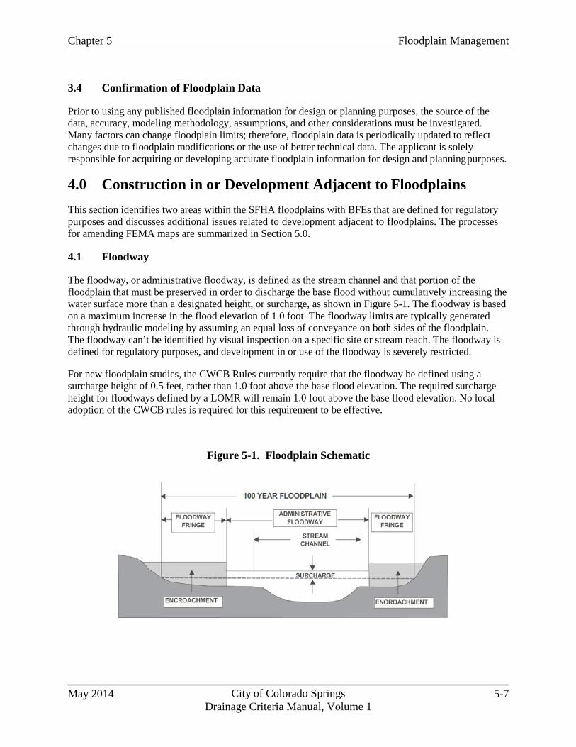
Chapter 5 Floodplain Management
May 2014 City of Colorado Springs Drainage Criteria Manual, Volume 1
5-7
3.4 Confirmation of Floodplain Data
Prior to using any published floodplain information for design or planning purposes, the source of the data, accuracy, modeling methodology, assumptions, and other considerations must be investigated. Many factors can change floodplain limits; therefore, floodplain data is periodically updated to reflect changes due to floodplain modifications or the use of better technical data. The applicant is solely responsible for acquiring or developing accurate floodplain information for design and planning purposes.
4.0 Construction in or Development Adjacent to Floodplains This section identifies two areas within the SFHA floodplains with BFEs that are defined for regulatory purposes and discusses additional issues related to development adjacent to floodplains. The processes for amending FEMA maps are summarized in Section 5.0.
4.1 Floodway
The floodway, or administrative floodway, is defined as the stream channel and that portion of the floodplain that must be preserved in order to discharge the base flood without cumulatively increasing the water surface more than a designated height, or surcharge, as shown in Figure 5-1. The floodway is based on a maximum increase in the flood elevation of 1.0 foot. The floodway limits are typically generated through hydraulic modeling by assuming an equal loss of conveyance on both sides of the floodplain. The floodway can’t be identified by visual inspection on a specific site or stream reach. The floodway is defined for regulatory purposes, and development in or use of the floodway is severely restricted.
For new floodplain studies, the CWCB Rules currently require that the floodway be defined using a surcharge height of 0.5 feet, rather than 1.0 foot above the base flood elevation. The required surcharge height for floodways defined by a LOMR will remain 1.0 foot above the base flood elevation. No local adoption of the CWCB rules is required for this requirement to be effective.
Figure 5-1. Floodplain Schematic
City of Colorado Springs Drainage Criteria Manual, Volume 1
May 2014 5-8
Chapter 5 Floodplain Management
4.2 Flood Fringe
The flood fringe, or floodway fringe, is the portion of the 100-year floodplain that is not within the floodway as shown in Figure 5-1. Although development and other forms of encroachment may be considered in the floodplain fringe, it should not be assumed that there is an inherent right to fill in the flood fringe, if a floodway has been identified.
Encroachments into the flood fringe reduce beneficial floodplain storage areas, and the cumulative effect of such encroachments can have significant impacts on downstream properties. Encroachment evaluations are only based on flood depth and do not consider impacts to channel stability as a result of increased channel velocity. Reduction of floodplain storage areas can increase peak flow rates and associated BFEs downstream, even though theoretically there may be limited impact at the site where the encroachment occurs. For this reason, encroachment into the flood fringe is contrary to the objectives of minimizing damage to life and property and of maintaining floodplains as open space. Therefore, encroachments into the floodplain fringe are discouraged. When considering requests involving floodplain fringe encroachment, at a minimum, the following shall be considered:
Impacts to adjacent properties. If the encroachment creates a rise in the BFE on properties other
than that of the applicant, the applicant will be required to obtain floodplain easements for the additional floodplain property. FEMA typically will not allow any encroachment that causes a rise on an existing habitable structure.
Channel hydraulics and design. If the encroachment creates a significantly narrow channel, with
steep side slopes and undesirable velocities, mitigating channel improvements may be required, or the floodplain encroachment may not be supported.
Channel stability, aesthetics and land use. If the fringe encroachment significantly impacts the
functions, stability or aesthetics of the natural drainageway, and the resulting channel improvements create a drainageway that is not deemed compatible with the surrounding land uses, the floodplain fringe encroachment may not be supported.
Threatened and Endangered Species. FEMA requires that the U.S. Fish and Wildlife Service
(USFWS) sign-off for threatened and endangered species for CLOMRs. If there is no effect, the USFWS provides a letter of concurrence of “no taking.” If habitat for threatened and endangered species is affected, a CLOMR review may not begin until a permit is issued by the USFWS, which can delay the CLOMR and project schedule.
Previous encroachments into the flood fringe should be eliminated, when feasible, however, floodproofing of a property currently within a regulatory floodplain or floodway may be acceptable, if approved through the variance process. Variances related to floodplain management within Colorado Springs shall be as prescribed by RBC 313 as amended in Section 7.8.102 of the City Code.
4.3 Subdivision Platting and Floodplains
Lots should be platted outside of the 100-year floodplain limits. Subdivision layout should also consider these factors: the size of the tributary watershed and higher degrees of protection where 500-year floodplains have been identified; the stability of the drainageway and anticipated improvements in the floodplain; access and trail requirements adjacent to the floodplain; the proximity of steep or vertical banks relative to the location of lot lines; the potential for the channel to migrate horizontally over time;
Chapter 5 Floodplain Management
May 2014 City of Colorado Springs Drainage Criteria Manual, Volume 1
5-9
the topography of the proposed lots; and the differences in elevation between the flooding elevation and potential structure locations. Lot lines should not be placed within or immediately adjacent to the floodplain limits without consideration of these factors.
Within large lot zoning districts, it may be feasible to use floodplain easements and define building envelopes to ensure that proposed structures are located outside of the floodplain limits and that uses are restricted in the floodplain portion of the lot. However, the flood insurance implications should be fully considered. Additional considerations include:
1. Actual Floodplain Limits. The floodplain limits used for subdivision layout must be based on
existing or proposed floodplain information that has been verified for accuracy, or floodplain limits must be developed through detailed hydrologic and hydraulic analyses, based on fully- developed conditions in the upstream watershed.
2. FEMA SFHAs. In addition to the physical floodplain limits, FEMA-designated SFHA
boundaries must be considered in subdivision layout, where applicable. When the SFHA boundary accurately represents the proposed floodplain limits, lots should be platted as discussed above. There are cases, however, where the SFHA is much wider than the actual or proposed floodplain. This situation frequently arises in locations where the SFHA was delineated using approximate methods or where improvements are proposed to confine the floodplain. In this case, platted lots should be outside of the SFHA and the actual floodplain, whichever is more restrictive. Alternatively, subdivision layout can be based on the actual or proposed floodplain, with the other considerations outlined in this section. Although outside of the actual floodplain, if lots are partially or totally within the SFHA, owners can be burdened with mandatory flood insurance purchase requirements.
When a proposed development is within 300 feet of an approximate SFHA, such as a Zone A, a detailed delineation of the floodplain is required. This may be completed as part of a FEMA process or certification by an Engineer.
4.4 Freeboard Requirements
A minimum vertical clearance, or freeboard, shall be provided between the 100-year base flood elevation (BFE) and structures and other applicable facilities which may be impacted by the floodplain. Freeboard is required to allow for uncertainty in the floodplain modeling, changes to the drainageway (i.e., increased invert due to sedimentation or increased vegetation), and to provide an additional factor of safety for structures and facilities which would result in damages or hazards during inundation. A minimum of 1 foot of freeboard shall be provided between the 100-year BFE and the lowest finished floor elevation of all structures (this includes basements). The required freeboard should be contained within the floodplain tract and/or easement.
When the CWCB rules are adopted locally the freeboard required for critical facilities will be increased from 1 foot to 2 feet above the base flood elevation.
City of Colorado Springs Drainage Criteria Manual, Volume 1
May 2014 5-10
Chapter 5 Floodplain Management
5.0 FEMA Map Revisions and Amendments 5.1 General
FEMA FIRMs are the official regulatory maps (see Section 3.1) that must be used for implementation and enforcement of the floodplain development regulations, which are generally discussed in this chapter. Additionally, the maps show projected flooding elevations, flood velocities, floodway dimensions, and flood risk zones used for insurance purposes. Maps must be updated to correct non-flood-related features, include analyses based on better ground elevation data, reflect changes in ground elevations within the floodplain, provide revised flooding data, and reflect flood control projects or other construction in the floodplain. Detailed information, revision request forms, technical requirements for map revisions or amendments, and construction requirements are included in the NFIP Regulations in 44 Code of Federal Regulations or are available through FEMA. The following sections provide brief descriptions of the various types of map revisions or amendments and how the requirements impact proposed projects.
5.2 Conditional Letter of Map Revision (CLOMR)
A CLOMR is prepared to allow FEMA to comment on a proposed project or the use of better data that would affect the hydrologic or hydraulic characteristics of a flooding source and thus result in the modification of the existing regulatory floodway, BFEs, or SFHA limits. A CLOMR is required by FEMA, prior to construction, for projects or construction in the floodway that will result in an increase in the BFEs. At the discretion of the Floodplain Administrator, a CLOMR may also be required for other projects when it is important to ensure that the SFHA will be revised based on a proposed project or the use of better data.
5.3 Conditional Letter of Map Revision Based on Fill (CLOMR-F)
A CLOMR-F is prepared to allow FEMA to comment on whether a proposed project involving the placement of fill outside of the regulatory floodway would exclude an area from the SFHA based on elevation. A technical review is not required for a CLOMR-F application. A CLOMR-F may also be required for a project when it is important to ensure that the SFHA will be revised based on a proposed project that involves fill in the flood fringe.
5.4 Letter of Map Revision (LOMR)
A LOMR is an official revision, by letter, to an effective FIRM. A LOMR may change flood insurance risk zones, floodplain and/or floodway boundary delineations, planimetric features, and/or BFEs. The LOMR may be based on the use of better data or as-built conditions reflecting flood control or other construction projects. The LOMR must be completed and issued in order to revise the effective SFHA.
5.5 Letter of Map Revision Based on Fill (LOMR-F)
A LOMR-F is a document issued by FEMA that officially removes a property and/or structure from the SFHA. A LOMR-F provides FEMA’s determination concerning whether a structure or parcel has been elevated on fill above the BFE and excluded from the SFHA.
Chapter 5 Floodplain Management
May 2014 City of Colorado Springs Drainage Criteria Manual, Volume 1
5-11
5.6 Conditional Letter of Map Amendment (CLOMA)
A CLOMA is FEMA’s comment on a proposed structure or group of structures that would, upon construction, be located on existing natural ground above the BFE. Generally, a CLOMA involves parcels, portions of parcels, or individual structures that were inadvertently included in the SFHA.
5.7 Letter of Map Amendment (LOMA)
A LOMA is a document issued by FEMA that officially removes a property and/or structure from the SFHA. A LOMA establishes a property’s or structure’s location in relation to the SFHA.
5.8 Physical Map Revision
A physical map revision is an official republication of a map to change flood insurance zones, floodplain delineations, flood elevations, floodways, and planimetric features. A community can submit scientific and technical data to FEMA to support the request for a map revision. The data will be analyzed, and the map will be revised if warranted.
6.0 Floodproofing In areas where structures may be within an existing floodplain or where local flooding may be expected, floodproofing can provide protection against flooding or reduce flood damage. For more information on floodproofing, see the technical bulletins provided by FEMA as part of the NFIP.
7.0 References City of Colorado Springs. Ordinances, Codes and Manuals webpage:
http://www.springsgov.com/Page.aspx?NavID=1030. Accessed September 20, 2012.
CWCB 2010. Rules and Regulations for Regulatory Floodplains in Colorado. Accessible at http://cwcb.state.co.us/legal/Pages/CWCBFloodplainRulesandRegulationsProcess.aspx
FEMA 1995. Managing Floodplain Development in Approximate Zone A Areas - A Guide for Obtaining and Developing Base (100-yr) Flood Elevations. FEMA Publication 265. Accessible at www.fema.gov.
FEMA National Floodplain Insurance Program webpage: http://www.fema.gov/national-flood-insurance-
program. Accessed September 20, 2012.

May 2014 City of Colorado Springs Drainage Criteria Manual, Volume 1
6-i
Chapter 6 Hydrology
Contents
1.0 Introduction ...................................................................................................................................... 1 1.1 Design Flows ............................................................................................................................................. 2 1.2 Sources of Design Flows and Types of Hydrologic Analyses .................................................................. 3
1.2.1 Published Hydrologic Information ................................................................................................... 4 1.2.2 Statistical Methods ........................................................................................................................... 4 1.2.3 Rainfall/Runoff Methods .................................................................................................................. 5 1.2.4 Paleo-flood Analysis ......................................................................................................................... 5
1.3 Data Requirements .................................................................................................................................... 5 1.4 Selecting Methods for Estimating Design Flows ...................................................................................... 6
2.0 Rainfall .............................................................................................................................................. 8 2.1 Rainfall Depths.......................................................................................................................................... 8 2.2 Design Storms ........................................................................................................................................... 9
2.2.1 Depth-Area Reduction Factors (DARFs) ....................................................................................... 12 2.2.2 Dominant Design Storm ................................................................................................................. 14
2.3 Hydrologic Basis of Design for Water Quality—Water Quality Capture Volume ................................. 14
3.0 Rational Method ............................................................................................................................. 15 3.1 Rational Method Runoff Coefficient (C) ................................................................................................ 15 3.2 Time of Concentration ............................................................................................................................ 17
3.2.1 Overland (Initial) Flow Time .......................................................................................................... 18 3.2.2 Travel Time .................................................................................................................................... 18 3.2.3 First Design Point Time of Concentration in Urban Catchments ................................................... 19 3.2.4 Minimum Time of Concentration ................................................................................................... 19 3.2.5 Post-Development Time of Concentration ..................................................................................... 19 3.2.6 Common Error in Calculating Time of Concentration ................................................................... 20
3.3 Rainfall Intensity (I) ................................................................................................................................ 20 3.4 Basin Area (A) ........................................................................................................................................ 20
4.0 NRCS Curve Number Loss and Dimensionless Unit Hydrograph Method .............................. 20 4.1 NRCS Curve Numbers ............................................................................................................................ 21
4.1.1 Hydrologic Soil Groups (HSG) ...................................................................................................... 21 4.1.2 Land Cover ..................................................................................................................................... 23 4.1.3 Antecedent Runoff Condition (ARC) ............................................................................................. 23
4.2 Pre-development Thunderstorm Curve Numbers .................................................................................... 24 4.3 Frontal Storm and Post-Development Thunderstorm Curve Numbers.................................................... 24 4.4 Composite Curve Numbers ..................................................................................................................... 24 4.5 Initial Abstraction.................................................................................................................................... 25 4.6 Lag Time ................................................................................................................................................. 29
4.6.1 Overland Flow Time for NRCS Method ........................................................................................ 31 4.6.2 Shallow Concentrated Flow ............................................................................................................ 32 4.6.3 Concentrated Flow .......................................................................................................................... 32
4.7 Peak Flow Estimation .............................................................................................................................. 33
City of Colorado Springs Drainage Criteria Manual, Volume 1
May 2014 6-ii
5.0 EPA Stormwater Management Model (EPA SWMM) ............................................................... 34
5.1 Model Overview ...................................................................................................................................... 34 5.1.1 Surface Flows and Routing Features ............................................................................................... 38 5.1.2 Flow Routing Method of Choice ..................................................................................................... 40
5.2 Application of SWMM ............................................................................................................................ 40
6.0 Sub-basin Delineation and Hydrograph Routing ......................................................................... 41 6.1 Channel Routing ...................................................................................................................................... 41
6.1.1 Kinematic Wave Channel Routing .................................................................................................. 41 6.1.2 Muskingum-Cunge Channel Routing .............................................................................................. 42
6.2 Reservoir Routing .................................................................................................................................... 43
7.0 Volume Reduction Methods ........................................................................................................... 43 7.1 Four Step Process ..................................................................................................................................... 43 7.2 Effective Imperviousness ......................................................................................................................... 44
7.2.1 Application of Effective Imperviousness ........................................................................................ 46 7.2.2 Effective Imperviousness Spreadsheet ............................................................................................ 46
8.0 Estimating Baseflows ...................................................................................................................... 46 8.1 Baseflow Estimates for Gaged Streams ................................................................................................... 46 8.2 Baseflow Estimates for Ungaged Streams (Developing Relationships for Baseflow as a Function of
Area) ..................................................................................................................................................... 47
9.0 Design Flows for Low-Flow Channels ........................................................................................... 48 9.1 Stabilized Natural Channels ..................................................................................................................... 48 9.2 Constructed Natural Channels and Constructed Channels ....................................................................... 49 9.3 Fountain Creek and Monument Creek ..................................................................................................... 49
10.0 Design Hydrology Based on Future Development Conditions .................................................... 49 10.1 On-site Flow Analysis .............................................................................................................................. 49 10.2 Off-site Flow Analysis ............................................................................................................................. 49
11.0 Consideration of Detention Benefits in Off-Site Flow Analysis .................................................. 50 11.1 Major Drainageway Basin Distinction ..................................................................................................... 50 11.2 Analysis When System is Part of a Major Drainageway Basin................................................................ 50 11.3 Analysis When System is Not Part of a Major Drainageway Basin ........................................................ 50
12.0 Additional Considerations Regarding Conveyance of Runoff from Major Drainageway Basins ............................................................................................................................................... 50
13.0 References ........................................................................................................................................ 51
May 2014 City of Colorado Springs Drainage Criteria Manual, Volume 1
6-iii
Tables Table 6-1. Methods for Estimating Design Flows ........................................................................................ 8 Table 6-2. 2-Hour Design Storm Distribution, < 1 mi2 .............................................................................. 10 Table 6-3. Colorado Springs 6-Hour Design Storm Distribution, 15-20 mi2 ............................................. 11 Table 6-4. NRCS 24-Hour Type II Design Storm Distribution, <10 mi2 ................................................... 12 Table 6-5. 2-Hour Design Storm Distributions by Drainage Basin Area ................................................... 13 Table 6-6. Runoff Coefficients for Rational Method ................................................................................. 17 Table 6-7. Conveyance Coefficient, Cv ...................................................................................................... 19 Table 6-8. HSG for Soils in the Pike National Forest ................................................................................ 23 Table 6-9. NRCS Curve Numbers for Pre-Development Thunderstorms Conditions (ARC I) ................. 26 Table 6-10. NRCS Curve Numbers for Frontal Storms & Thunderstorms for Developed Conditions (ARCII) ..................................................................................................................... 28 Table 6-11. Roughness Coefficients (Manning’s n) for NRCS Overland Flow ........................................ 31 Table 6-12. Kinematic Wave Shape Factors (X=A/L2 ≤ 4) ....................................................................... 40 Table 6-13. Kinematic Wave Channel Routing Method Inputs ................................................................. 42 Table 6-14. Muskingum-Cunge Channel Routing Method Inputs............................................................. 42 Table 6-15. Coefficients (K) and Regression Coefficients (R2) for the 2-Year Baseflows ........................ 48 Table 6-16. 6-Hour Design Storm Distributions by Drainage Basin Area ................................................. 56
City of Colorado Springs Drainage Criteria Manual, Volume 1
May 2014 6-iv
Figures (Note: Figures 6-5 through 6-13 located at end of chapter.)
Figure 6-1. Flow Segments for Time of Concentration ............................................................................. 30 Figure 6-2. Conceptual SWMM Watershed Schematic ............................................................................. 39 Figure 6-3. SWMM Kinematic Overland Flow Conceptualization of Watershed with Pervious and
Impervious Areas ............................................................................................................................. 39 Figure 6-4. Land Use Components ............................................................................................................ 45 Figure 6-5. Colorado Springs Rainfall Intensity Duration Frequency ....................................................... 53 Figure 6-6a. Example Nomograph for Determination of 1-Hour Rainfall Depth for Range of
Recurrence Intervals ......................................................................................................................... 54 Figure 6-6b. Blank Nomograph for Determination of 1-Hour Rainfall Depth for Range of
Recurrance Intervals ......................................................................................................................... 54 Figure 6-7. 2-Hour Design Storm Distributions By Drainage Basin Area ................................................ 55 Figure 6-8. NRCS Type II 24-Hour Storm Distribution (< 10 mi2)........................................................... 58 Figure 6-9. Depth-Area-Duration Adjustment Factors for 2-Hour Thunderstorms ................................... 59 Figure 6-10. Depth-Area-Duration Adjustment Factors for 24-Hour Frontal Storms ............................... 60 Figure 6-11. Standard Form SF-1, Time of Concentration ........................................................................ 61 Figure 6-12. Standard Form SF-2, Rational Method Calculations ............................................................ 62 Figure 6-13. Estimate of Average Concentrated Shallow Flow ................................................................ 63
Chapter 6 Hydrology
May 2014 City of Colorado Springs Drainage Criteria Manual, Volume 1
6-1
1.0 Introduction This chapter describes the basis for determining design flows and volumes for the planning and design of stormwater management facilities using various hydrologic methods and summarizes these methods. The development of appropriate hydrology for a project is often one of the first steps in the planning or design process. Accurately estimating design flows and volumes is critical to the proper functioning of facilities. Depending on the size of the drainage basin and the type of project different hydrologic methods may be appropriate. In many cases flow estimates may be available from previous studies and these should be considered and evaluated, especially when new hydrologic analysis results in significant changes to previous estimates. A general discussion of the overall process of developing plans and analyzing drainage systems can be found in the UDFCD Storm Drainage Criteria Manual (UDFCD Manual) Volume 1, Planning chapter.1
Design flows for stormwater facilities are primarily based on rainfall events, and a range of possible storm events must be considered. Other sources of runoff such as snowmelt and nuisance flows can affect a project design and must also be identified. Anticipated changes to basin conditions, especially due to development, must also be fully considered for facilities to function as intended.
Rainstorms in the Fountain Creek watershed and El Paso County have been identified as being of two primary types with significantly different spatial and temporal characteristics. Short-duration thunderstorms (cloud bursts) occur frequently and can be very intense (produce significant rainfall depths rapidly), but are localized and not expected to produce widespread flooding. Longer-duration storms occur less frequently, may be part of a much larger storm system influenced by regional conditions, and are generally less intense; however, they can affect much larger areas and produce widespread flooding. The type of storm that must be evaluated depends on the size of the drainage basin, the type of project, and other site- and basin-specific factors. In some cases, both types of storms may need to be evaluated. Rainstorms of any significance typically occur between the months of May and September.
Urbanization can have a significant impact on runoff by increasing peak flow rates, runoff volumes, and the frequency of runoff. This increase in runoff can lead to severe stream erosion, habitat degradation, and increased pollutant loading. However, with proper planning, increased runoff can be managed to create or supplement existing wetland areas or riparian habitats, which may provide significant benefits to the watershed. The increase in runoff from development is especially pronounced when drainage systems are designed to quickly and “efficiently” convey runoff from paved areas and roofs directly into inlets and storm sewers, discharging eventually into drainageways that are typically designed to convey flows at maximum acceptable velocities. Whether for one site or for a whole watershed, this increase in runoff and acceleration of flood peaks can be estimated by the hydrologic methods discussed herein.
In addition to increased runoff, the reduction of available sediment due to urbanization also has the potential to destabilize downstream channels. When the natural sources of sediment are eliminated by paving, building structures or stabilized channels, runoff will tend to replace the natural sediment supply by satisfying its capacity for sediment transport with new sources. Therefore, even an effective reduction in developed runoff to levels approximating historic rates will probably not eliminate the need for the stabilization of downstream systems.
1 Some of the terminology used in the UDFCD Manual varies from the terminology in Colorado Springs (e.g., Drainage Basin Planning Study[DBPS] in Colorado Springs versus Major Drainageway Planning Studies/Outfall Systems Planning Studies in the UDFCD Manual). Additionally, the UDFCD Manual does not address requirements for site-level drainage report and design preparation because these requirements are usually explicitly defined by the municipalities that make up UDFCD.
Chapter 6 Hydrology
City of Colorado Springs Drainage Criteria Manual, Volume 1
May 2014 6-2
As discussed in Volume 2 of this Manual, which addresses stormwater quality, effective stormwater management seeks to disconnect impervious surfaces, decrease flow velocities, and convey runoff over vegetated ground surfaces, leading to filtering, infiltration, and attenuation of flows. These principles can also be reflected in the hydrologic variables discussed in this chapter, yielding longer times of concentration and reduced runoff peaks and volumes.
1.1 Design Flows
A broad range of events pass through stormwater facilities and natural drainageways. These range from those producing little or no runoff prior to development to extensive and extreme storm events that produce life threatening and destructive floods. To effectively and efficiently analyze even a small percentage of all possible events is time and cost prohibitive. Therefore, to efficiently plan and design stormwater facilities, “design flows” have been established to represent events that are typical or representative of the range of runoff events that can occur. In most cases, projects can be adequately designed using estimates of these representative flows. Depending on the type of project, design flows may include “baseflows,” “low flows,” “minor flows,” “major flows” and “flood flows.” A description of each of these types of flows is provided below and methods for estimating these design flows are described later in this chapter.
1. Baseflows: Baseflow estimates (sometimes referred to as “trickle flows”) are used to account for
flows that may not be directly related to storm events but may be created by groundwater recharge of streams, wastewater return flows, excess irrigation, water system losses, and other urban water uses. Baseflows are the flows that can be observed in streams and engineered drainageways during dry weather. Methods for directly identifying the source and quantity of these flows are not generally available for drainage basins. Where available, such as on Monument and Fountain Creeks, baseflows may be estimated from gage data and possibly from projections of future return flows. The Fountain Creek Watershed Hydrology Report (USACE 2006) provides some baseflow data. Channel improvements must account for these flows to address erosion potential in the lower portion of channel sections. The presence of these flows in historically dry basins can also interfere with the growth of certain types of vegetation. However, these same flows can provide water to sustain vegetation along low-flow channel banks or in channels with wetland bottoms where vegetation was not previously supported.
2. Low Flows: Low flows are used primarily for open channel design and are defined as those
flows resulting from relatively frequent storm events that are contained within a well-defined or main channel portion of the floodplain (sometimes these are referred to as “bankfull flows” or “channel forming flows” for natural streams). Flows greater than the low-flow event begin to flow beyond the main channel into the overbank or floodplain portion of natural channels.
In natural channels, the capacity of the low-flow portion of the channel can be represented by the “bankfull” flow. It is difficult to relate this flow to a particular return period since it represents the combined influence of a wide variety of storm events occurring over a long period of time in the upstream drainage basin. However, it is generally accepted that the bankfull discharge has a return period that is in the 1-year to 2-year range, but this value can change significantly in different hydrologic regions, especially when there is urbanization in a basin. “Low flows” should not be confused with “minor flows” which are associated with a specific recurrence interval, as described below, and are generally greater than “low flows” for natural channels.
3. Minor Flow: Minor flows are defined as those flows resulting from relatively frequent storm
events that are contained within a portion of the conveyance system such as gutters and storm sewers and are typically defined by a specific return period. Flows greater than the minor flow
Chapter 6 Hydrology
May 2014 City of Colorado Springs Drainage Criteria Manual, Volume 1
6-3
event begin to flow beyond the normal acceptable limits, like street gutters, onto adjacent improvements, like sidewalks, and begin to interfere with human activity, such as traffic and pedestrian access. For the purposes of this Manual, the minor flow is defined by the 5-year storm runoff event.
4. Major Flow: Major flows must be conveyed to avoid safety hazards, undue interference with
human activity, damage to adjacent structures and damage to conveyance systems. The 100-year runoff event has been identified as the major flow that must be safely conveyed according to this Manual. This design flow is typically used to determine maximum street capacities and to size certain facilities such as culverts.
5. Flood Flows: In this Manual the term “flood flows” is used to refer to any flows that exceed the
low-flow channel, whether natural or engineered. Flood flows must be conveyed to avoid safety hazards, damage to adjacent structures and damage to conveyance systems. Flood flows are typically used to design open channels, size detention ponds and to delineate floodplains. Flooding is often associated with rather extreme events, but is actually defined by any event that causes flows to spill from the low-flow channel onto the overbank or floodplain area of a channel. The 100-year runoff event has been identified as the major flood event that defines the regulatory floodplain according to this Manual. However, flood studies typically include evaluation of other events such as the 10-, 25-, 50- and 500-year events. In some cases, it may be necessary to evaluate lesser flows, such as the 2-year or 5-year flow, to consider critical hydraulic conditions. In some situations, it may be appropriate to address more severe flows, such as the 500-year flow. For instance, drop structures may be largely submerged during the 100-year event, with critical hydraulic conditions occurring during lesser floods. Also, where critical infrastructure, such as hospitals, power plants or emergency response facilities may be at risk, it may State and local floodplain regulations may require evaluation of less frequent events such as the 500-year flood.
Prudent management of upstream land uses and the implementation of runoff reducing practices such as “Low Impact Development” and/or “Full-Spectrum Detention” have the potential to reduce the volume and rate of runoff for design flows received by downstream systems. These effects generally are most significant for frequently occurring events. How design flows are affected by upstream basin conditions (under future “build out” conditions) must be fully considered.
1.2 Sources of Design Flows and Types of Hydrologic Analyses
Estimates of runoff are required for a variety of purposes in stormwater management analyses. In many cases, previously completed analyses may be available for the project area. Given adequate periods of record and relatively static basin conditions, gage data may be the most reliable source of flow estimates. Designers should first investigate the existence of relevant studies that can be applied to the project at hand. However, it is often necessary to complete new analyses that more accurately represent project conditions and provide estimates where they are needed to complete the project. Whenever new analyses are needed, they shall be completed based on the methodologies described in this Manual.
To provide plans and designs that are appropriate for current and future conditions, hydrologic analyses must include various scenarios. Scenarios will typically include multiple runoff events, changes in land uses and alternative system plans such as for transportation. Each scenario must be identified and properly described so that the drainage system plan and possible alternatives can be adequately evaluated.
Chapter 6 Hydrology
City of Colorado Springs Drainage Criteria Manual, Volume 1
May 2014 6-4
1.2.1 Published Hydrologic Information
Drainage master plans have been prepared for many of the Colorado Springs drainage basins. These reports may contain information regarding peak flow and runoff volume from the 2-year through 100-year storm events at numerous design points within the study watersheds. These studies contain information about watershed and sub-watershed boundaries, soil types, percent imperviousness, and rainfall. If there are published flow rate values available, these values shall be used for design unless they are considered to be inaccurate or unreliable due to physical changes in the drainage basin or in criteria. The need for additional evaluation and the use of other values shall be approved in writing in advance of any related planning or design work.
Published hydrologic information for major drainageways can also be found in Federal Emergency Management Agency (FEMA) Flood Insurance Studies (FIS). For all FEMA-related projects, the FEMA hydrologic data shall be consulted. Flow rates published in FEMA FIS studies typically represent existing conditions at the time the study was completed and generally do not incorporate any future development. The analysis and design of stormwater facilities must be on future development flow rates; therefore, FEMA flow rates shall not be used without written approval.
1.2.2 Statistical Methods
In some situations, statistical analysis of measured stream flow data provides an acceptable means of determining design flows. Statistical analyses for larger, less-frequent storm events are to be limited to drainageways with a long period of reliable flow data that had no significant changes occur in land uses within the tributary watershed during the flow record. A minimum period of record of 30 years is recommended for statistical analysis of events up to and including the 100-year event; however, when performing statistical analysis for frequently occurring events, such as a 2- or 5-year event, a shorter period of record may be acceptable. Statistical methods may be useful in calibrating a hydrologic model for existing development conditions, but these methods are not suited for estimating the flow for expected future watershed development conditions.
Gage data available for Fountain Creek have been analyzed in a report prepared for FEMA titled “Flood Hydrology for Fountain Creek” (Michael Baker Jr. 2010). The results of this study shall apply for analyses of flood flows on Fountain Creek.
Statistical analyses of gage data should be completed using the Log-Pearson Type III analysis as performed by programs such as the U.S. Geological Survey (USGS) PeakFQ analysis tool. The gage identification and location should be indicated on all calculation sheets and model output.
Statistical methods can be used where a long-term record of flows is available and where the upstream basin characteristics are not expected to change significantly through urbanization or through the construction of flow altering structures or inflows. Limitations of these methods are:
It is not uncommon for stream gages to be relocated over time. If the relocation is relatively near the
former gaging station, an adjustment based on ratios of contributing drainage areas can be used to adjust gage data for a more direct comparison.
Stream gage data should not be used for statistical analysis unless it has gone through a Quality
Assurance/Quality Control (QA/QC) check to verify that the data are reasonable. QA/QC checks to verify that data are reasonable to use for statistical analysis and to assure that the reported data are being interpreted correctly typically include the following:
Chapter 6 Hydrology
May 2014 City of Colorado Springs Drainage Criteria Manual, Volume 1
6-5
▫ Contact the agency that operates and maintains the gage to learn how flows are measured,
how different rating curves may be applied to low and high flows, how rating curves have “shifted” over time and other information on the quality of the data from the gage operator. Ask the operators of the gage for the estimated accuracy of flow measurements during low flow and peak flow conditions.
▫ Plot data and look for unusual “jumps” or “drops” in the data, which could potentially reflect
changes in rating curves used to determine flow from stage data. It is common for one rating curve to be used for the low flow range and a separate curve used for the high flow range. Identifying when flow measurements switch from the low flow range to the high flow range can be important for understanding data.
▫ Evaluate the period of record and the types and amount of data reported within the period of
record. For example, if the user is interested in annual peak flow values for a stream, but the period of record has many unreported values during spring runoff months, this would be an indication that the peak flow estimates may not be reliable due to spotty data.
▫ Evaluate the statistical distribution of the data and perform statistical tests for outliers if any
data points appear to be extreme. While most rainfall and streamflow data are log-normally distributed, it is important to verify this assumption, either by plotting data, looking at model output statistics or calculating simple statistical parameters on log-transformed data using a normality test.
Availability of peak flow data can be a challenge for statistical hydrology. Do not run Log-Pearson
Type III analysis on average daily flows to determine flood flows. Annual peak flows are needed for this purpose but unfortunately are not available at all stream gages.
1.2.3 Rainfall/Runoff Methods
It is often necessary to estimate runoff for a project when no previous estimates have been provided. The most common method for making these estimates is by converting rainfall (using intensity, depth and temporal and spatial characteristics) to runoff by representing basin characteristics that affect the volume and rate of runoff expected. There are numerous methods that can be applied, but only a few have been adopted for this Manual. The method selected will depend on the purpose of the analysis and the size of the drainage basin.
Rainfall/runoff methods are based on approximations of parameters that can vary significantly from basin to basin or between climatic zones. Whenever flow data are available they should be compared to the calculated estimates of flow to confirm the reasonableness of the estimates.
1.2.4 Paleo-flood Analysis
By assessing geologic conditions and remnants of flood flows within a stream valley evidence of past floods can be observed and evaluated to determine their limits and approximate timing. The application of these methods requires special expertise, but may provide additional insight into the flood potential within a project reach, especially for large flood events that may not be captured in the modern stream gage record. These methods are documented in USGS publications, but must be approved prior to their application.
1.3 Data Requirements
Prior to commencing a hydrologic analysis the designer must research and collect the necessary data to provide inputs for the hydrologic method to be used. These data may be available from existing sources or may need to be created for the project at hand. These data will typically include: topographic mapping,
Chapter 6 Hydrology
City of Colorado Springs Drainage Criteria Manual, Volume 1
May 2014 6-6
existing and future land use conditions for each scenario to be evaluated, an inventory of existing and proposed structures (in waterways and other structures associated with development) within the study area, soil types, ground cover types, groundwater conditions, site location information (horizontally and vertically), previous studies, and any other documents that can provide needed background information. It is the responsibility of the designer to identify and collect the most appropriate and accurate data available to complete the analysis. Some useful sources of information include previous major drainage planning studies, Natural Resources Conservation Service (NRCS) Soil Surveys, USGS mapping (detailed survey data are needed for design), the USGS StreamStats program, nearby rain gages and stream gages, storm sewer mapping maintained by most communities with a municipal NPDES stormwater permit, the City’s FIMS data, historic and current aerial photography, and other sources.
1.4 Selecting Methods for Estimating Design Flows
The approved methods for estimating design flows and volumes are:
Gage analysis
Rational Method
NRCS Curve Number Loss Method and Unit Hydrograph as implemented in USACE HEC-HMS
model U.S. Environmental Protection Agency Stormwater Management Model (EPA SWMM)
Bankfull regression equation (low flows)
Gage analyses can only be performed where a sufficiently long and reliable set of data is available. The application of this method depends on an understanding of the basin conditions over the period of time that the data were collected. Significant changes in the basin conditions, such as the construction of reservoirs or diversions or significant development, can make the data less reliable. This method is typically not useful for projecting future estimates unless changes in the drainage basin have been well documented over time.
When a rainfall/runoff methodology is used for hydrologic analyses, the Rational Method, the EPA SWMM method, or the NRCS Unit Hydrograph (Curve Number) method shall be applied. Alternative methods may be proposed on a case by case basis; however, these may be used only after careful consideration and with adequate justification and documentation that the results will be consistent with approved methods or locally available recorded data. The application of these methods is described in the UDFCD Manual, Volume 1, Runoff chapter and in this chapter. The Rational Method is a relatively simple approach used for smaller watersheds where only peak flows are required and a hydrograph is not required. For more complex drainage basins and routing requirements, the HEC-HMS model or the EPA SWMM method is better suited, but requires more experience and expertise to properly apply. The EPA SWMM method also provides hydrographs, reservoir routing, and the ability to evaluate volume reduction practices in detail. For larger or complex drainage basins, the NRCS method may be used.
The bankfull regression equations can be used for estimating low flows for channel designs in major drainageways downstream of detention storage ponds. This method only provides a peak flow estimate and cannot provide an estimate of runoff volume.
The following considerations may help the user to select an appropriate method:
If no detention facilities are planned or if detention facilities are to be sized using simplified methods,
hydrograph information is not required, and the Rational Method would be the simpler of the methods. This applies only to small drainage basins without complex routing. The Rational Method
Chapter 6 Hydrology
May 2014 City of Colorado Springs Drainage Criteria Manual, Volume 1
6-7
is most commonly used for sizing inlets and storm sewers.
If detention facilities are to be sized based on hydrograph routing, or if hydrograph information is
desired for any other reason, the EPA SWMM or the NRCS method must be used. If more detailed information on time to peak, duration of flow, rainfall losses, and/or infiltration is
desired, the EPA SWMM or the NRCS method (HEC-HMS model) offers this information. If the effects of volume reduction practices need to be considered, each of the rainfall/runoff methods
can be applied, but with varying levels of detail. This can be accomplished through the application of “effective imperviousness” values with each of these methods.
Public domain software, including the USACE HEC-HMS model and EPA SWMM, is preferred to
proprietary software because reviewers may not have the ability to open and inspect input and output files using proprietary models and because documentation of proprietary software packages is not always freely available. However, users of this Manual may use proprietary software and submittals will be allowed based on proprietary software provided that; (1) the proprietary software uses the methods accepted by this Manual, (2) the user provides a full listing of all input and output files in an easy to understand format that clearly shows that the model results comply with applicable criteria and (3) the results are comparable to what would be obtained using accepted software, such as HEC- HMS or EPASWMM. To confirm that the proprietary software produces similar results it be necessary to provide documentation of the methodologies used and sample comparisons of the results from each program for conditions specific to the project being evaluated.
Regardless of the method used, the maximum sub-watershed size for basin planning studies shall be approximately 130 acres. This is to reduce discrepancies in peak flow predictions between master plan hydrology and flow estimates based on single sub-watersheds significantly larger than 130 acres and to provide consistent guidance on sub-watershed delineation.
The selected method must be applied to calculate the flows corresponding to the return period of the design storms. In most cases, this will require calculations for both the “minor” and “major” storm events, at a minimum. Table 6-1 summarizes each method for estimating design flows.
Chapter 6 Hydrology
City of Colorado Springs Drainage Criteria Manual, Volume 1
May 2014 6-8
Table 6-1. Methods for Estimating Design Flows
Method Drainage Basin Area
Runoff Type Routing Effects
System Complexit
PCM/Volume Reduction
Gage Analysis
Any Peak flow NA NA NA
Rational Method
<130 acres Peak flow Simple Simple Effective imperviousness
NRCS/ HEC- HMS
Not typically applied to
basins < 10 acres
Peak flow/volume/ /hydrograph
Simple to complex
Moderate to complex
Effective imperviousness
EPA SWMM <640 acres (most
commonly applied to urbanized
watersheds)
Peak flow/volume/ /hydrograph
Simple to complex
Complex
Effective imperviousness, cascading planes
or individual feature modeling
Bankfull Eq. (Eq. 6-24)
>130 acres Low flow peak only
NA NA NA
2.0 Rainfall This section describes rainfall characteristics for use with the hydrologic methods in determining design flows and volumes. Rainfall data to be used are based on two sources:
National Oceanic and Atmospheric Administration, Precipitation-Frequency Atlas of the United
States, Volume 8-Colorado (NOAA Atlas 14), published in 2013. The NOAA Atlas is used to provide Depth-Area Reduction Factor (DARF) curves for longer-duration (6-hour and 24-hour) events.
Fountain Creek Rainfall Characterization Study, Carlton Engineering, Inc., prepared for the City of
Colorado Springs, January, 2011. This study evaluated rainfall gage and gage-adjusted NEXRAD data within the Fountain Creek watershed and eastern Colorado. The results of this study have been evaluated and incorporated into this Manual.
2.1 Rainfall Depths
Rainfall depths must be determined based on the duration and return period of the design storm and the size of the drainage basin being evaluated. Depths should be taken directly from the NOAA Atlas 14 website (https://hdsc.nws.noaa.gov/hdsc/pfds/pfds_map_cont.html?bkmrk=co). The depths reported in the NOAA Atlas represent probable total depths for each duration and return period at a point on the ground. An extensive evaluation of available rain gage data was completed with the Carlton Study. While some increase in recorded depths was noted from the airport gage data, the other long-term gage locations showed that depths consistent with the NOAA Atlas can be expected. These depths can be applied to the design storms or converted to intensities (inches/hour) for the Rational Method as described below. However, as the basin area increases, it is unlikely that the reported point rainfalls will occur uniformly over the entire basin. To account for this characteristic of rain storms an
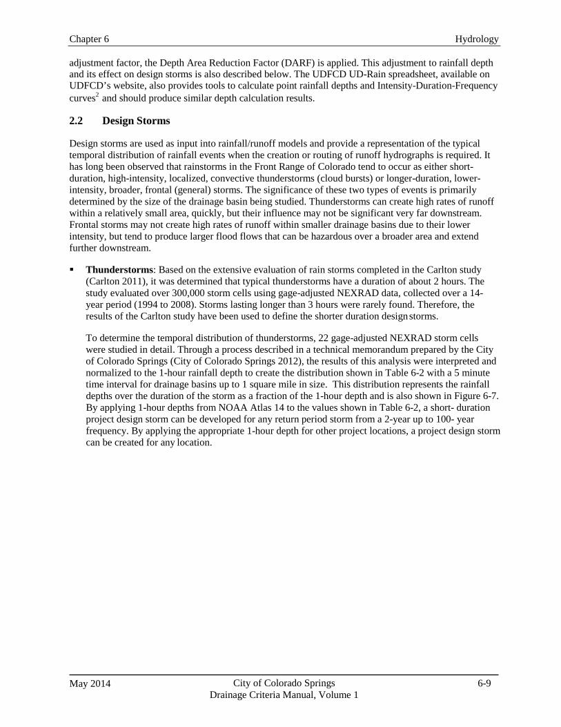
Chapter 6 Hydrology
May 2014 City of Colorado Springs Drainage Criteria Manual, Volume 1
6-9
adjustment factor, the Depth Area Reduction Factor (DARF) is applied. This adjustment to rainfall depth and its effect on design storms is also described below. The UDFCD UD-Rain spreadsheet, available on UDFCD’s website, also provides tools to calculate point rainfall depths and Intensity-Duration-Frequency curves2 and should produce similar depth calculation results.
2.2 Design Storms
Design storms are used as input into rainfall/runoff models and provide a representation of the typical temporal distribution of rainfall events when the creation or routing of runoff hydrographs is required. It has long been observed that rainstorms in the Front Range of Colorado tend to occur as either short- duration, high-intensity, localized, convective thunderstorms (cloud bursts) or longer-duration, lower- intensity, broader, frontal (general) storms. The significance of these two types of events is primarily determined by the size of the drainage basin being studied. Thunderstorms can create high rates of runoff within a relatively small area, quickly, but their influence may not be significant very far downstream. Frontal storms may not create high rates of runoff within smaller drainage basins due to their lower intensity, but tend to produce larger flood flows that can be hazardous over a broader area and extend further downstream.
Thunderstorms: Based on the extensive evaluation of rain storms completed in the Carlton study
(Carlton 2011), it was determined that typical thunderstorms have a duration of about 2 hours. The study evaluated over 300,000 storm cells using gage-adjusted NEXRAD data, collected over a 14- year period (1994 to 2008). Storms lasting longer than 3 hours were rarely found. Therefore, the results of the Carlton study have been used to define the shorter duration design storms.
To determine the temporal distribution of thunderstorms, 22 gage-adjusted NEXRAD storm cells were studied in detail. Through a process described in a technical memorandum prepared by the City of Colorado Springs (City of Colorado Springs 2012), the results of this analysis were interpreted and normalized to the 1-hour rainfall depth to create the distribution shown in Table 6-2 with a 5 minute time interval for drainage basins up to 1 square mile in size. This distribution represents the rainfall depths over the duration of the storm as a fraction of the 1-hour depth and is also shown in Figure 6-7. By applying 1-hour depths from NOAA Atlas 14 to the values shown in Table 6-2, a short- duration project design storm can be developed for any return period storm from a 2-year up to 100- year frequency. By applying the appropriate 1-hour depth for other project locations, a project design storm can be created for any location.
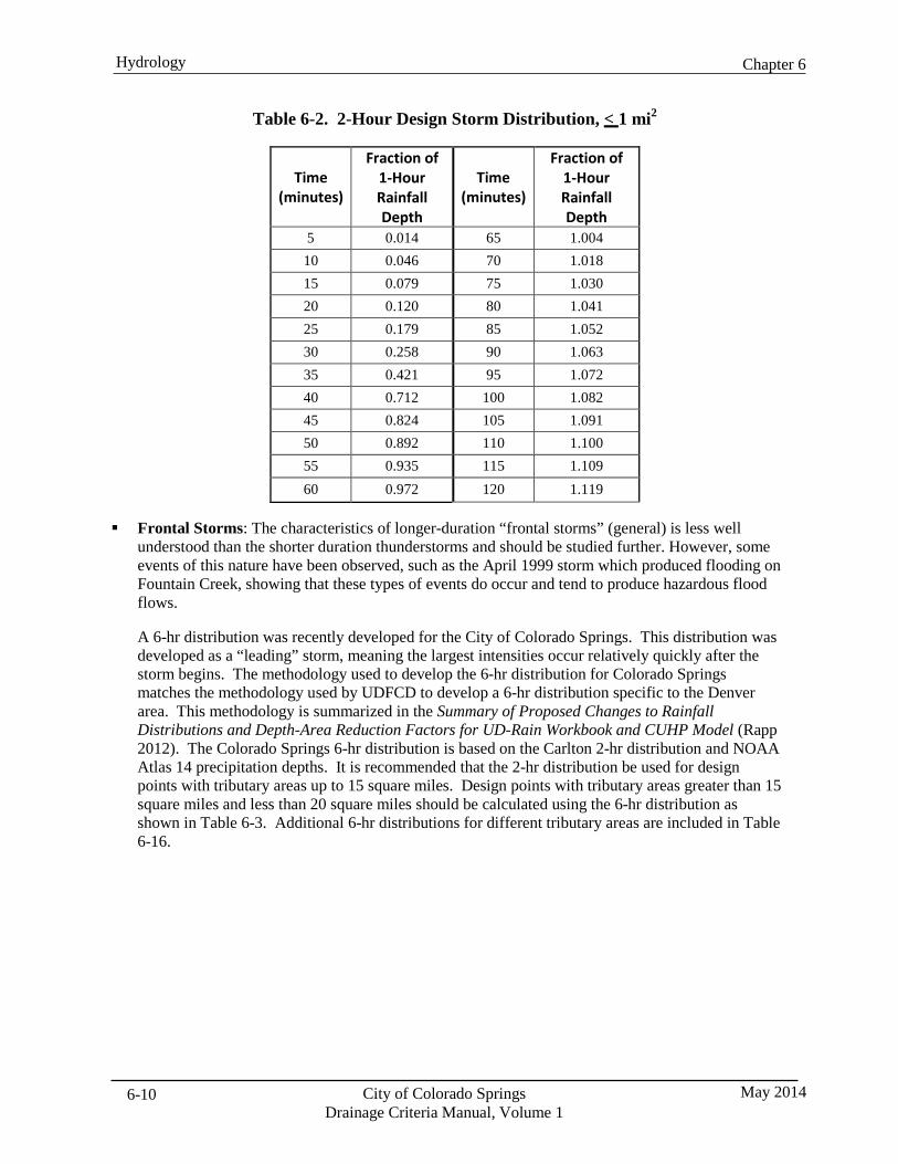
Chapter 6 Hydrology
City of Colorado Springs Drainage Criteria Manual, Volume 1
May 2014 6-10
Table 6-2. 2-Hour Design Storm Distribution, < 1 mi2
Time (minutes)
Fraction of 1-Hour Rainfall Depth
Time
(minutes)
Fraction of 1-Hour Rainfall Depth
5 0.014 65 1.004 10 0.046 70 1.018 15 0.079 75 1.030 20 0.120 80 1.041 25 0.179 85 1.052 30 0.258 90 1.063 35 0.421 95 1.072 40 0.712 100 1.082 45 0.824 105 1.091 50 0.892 110 1.100 55 0.935 115 1.109 60 0.972 120 1.119
Frontal Storms: The characteristics of longer-duration “frontal storms” (general) is less well understood than the shorter duration thunderstorms and should be studied further. However, some events of this nature have been observed, such as the April 1999 storm which produced flooding on Fountain Creek, showing that these types of events do occur and tend to produce hazardous flood flows.
A 6-hr distribution was recently developed for the City of Colorado Springs. This distribution was developed as a “leading” storm, meaning the largest intensities occur relatively quickly after the storm begins. The methodology used to develop the 6-hr distribution for Colorado Springs matches the methodology used by UDFCD to develop a 6-hr distribution specific to the Denver area. This methodology is summarized in the Summary of Proposed Changes to Rainfall Distributions and Depth-Area Reduction Factors for UD-Rain Workbook and CUHP Model (Rapp 2012). The Colorado Springs 6-hr distribution is based on the Carlton 2-hr distribution and NOAA Atlas 14 precipitation depths. It is recommended that the 2-hr distribution be used for design points with tributary areas up to 15 square miles. Design points with tributary areas greater than 15 square miles and less than 20 square miles should be calculated using the 6-hr distribution as shown in Table 6-3. Additional 6-hr distributions for different tributary areas are included in Table 6-16.
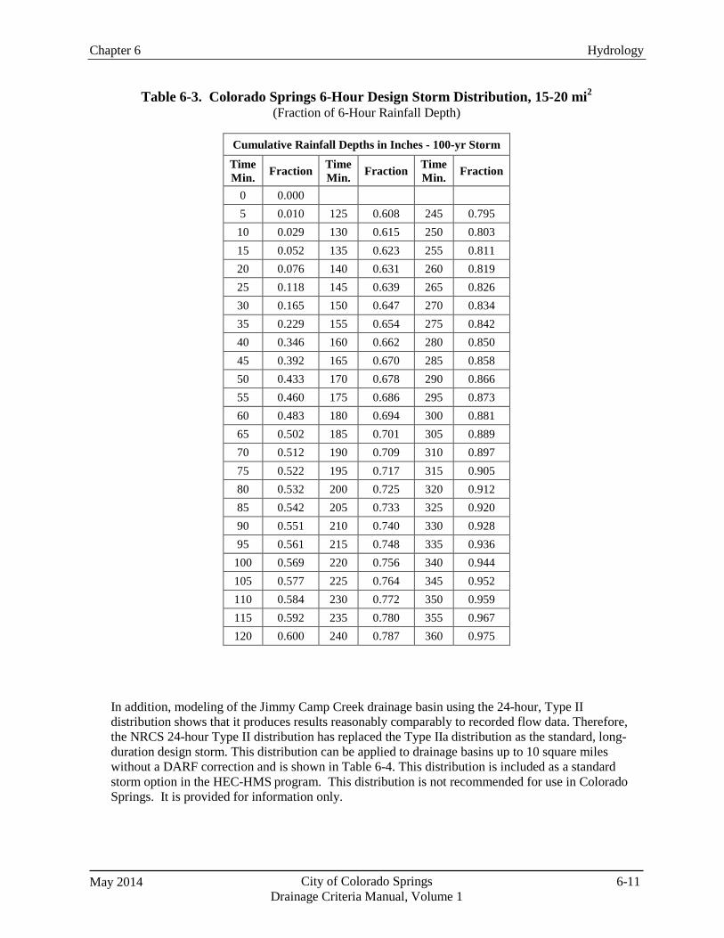
Chapter 6 Hydrology
May 2014 City of Colorado Springs Drainage Criteria Manual, Volume 1
6-11
Table 6-3. Colorado Springs 6-Hour Design Storm Distribution, 15-20 mi2
(Fraction of 6-Hour Rainfall Depth)
Cumulative Rainfall Depths in Inches - 100-yr Storm Time Min. Fraction Time
Min. Fraction Time Min. Fraction
0 0.000 5 0.010 125 0.608 245 0.795 10 0.029 130 0.615 250 0.803 15 0.052 135 0.623 255 0.811 20 0.076 140 0.631 260 0.819 25 0.118 145 0.639 265 0.826 30 0.165 150 0.647 270 0.834 35 0.229 155 0.654 275 0.842 40 0.346 160 0.662 280 0.850 45 0.392 165 0.670 285 0.858 50 0.433 170 0.678 290 0.866 55 0.460 175 0.686 295 0.873 60 0.483 180 0.694 300 0.881 65 0.502 185 0.701 305 0.889 70 0.512 190 0.709 310 0.897 75 0.522 195 0.717 315 0.905 80 0.532 200 0.725 320 0.912 85 0.542 205 0.733 325 0.920 90 0.551 210 0.740 330 0.928 95 0.561 215 0.748 335 0.936
100 0.569 220 0.756 340 0.944 105 0.577 225 0.764 345 0.952 110 0.584 230 0.772 350 0.959 115 0.592 235 0.780 355 0.967 120 0.600 240 0.787 360 0.975
In addition, modeling of the Jimmy Camp Creek drainage basin using the 24-hour, Type II distribution shows that it produces results reasonably comparably to recorded flow data. Therefore, the NRCS 24-hour Type II distribution has replaced the Type IIa distribution as the standard, long- duration design storm. This distribution can be applied to drainage basins up to 10 square miles without a DARF correction and is shown in Table 6-4. This distribution is included as a standard storm option in the HEC-HMS program. This distribution is not recommended for use in Colorado Springs. It is provided for information only.
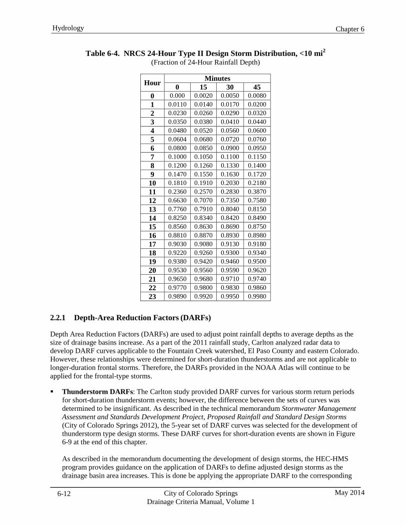
Chapter 6 Hydrology
City of Colorado Springs Drainage Criteria Manual, Volume 1
May 2014 6-12
Table 6-4. NRCS 24-Hour Type II Design Storm Distribution, <10 mi2
(Fraction of 24-Hour Rainfall Depth)
Hour Minutes 0 15 30 45
0 0.000 0.0020 0.0050 0.0080 1 0.0110 0.0140 0.0170 0.0200 2 0.0230 0.0260 0.0290 0.0320 3 0.0350 0.0380 0.0410 0.0440 4 0.0480 0.0520 0.0560 0.0600 5 0.0604 0.0680 0.0720 0.0760 6 0.0800 0.0850 0.0900 0.0950 7 0.1000 0.1050 0.1100 0.1150 8 0.1200 0.1260 0.1330 0.1400 9 0.1470 0.1550 0.1630 0.1720 10 0.1810 0.1910 0.2030 0.2180 11 0.2360 0.2570 0.2830 0.3870 12 0.6630 0.7070 0.7350 0.7580 13 0.7760 0.7910 0.8040 0.8150 14 0.8250 0.8340 0.8420 0.8490 15 0.8560 0.8630 0.8690 0.8750 16 0.8810 0.8870 0.8930 0.8980 17 0.9030 0.9080 0.9130 0.9180 18 0.9220 0.9260 0.9300 0.9340 19 0.9380 0.9420 0.9460 0.9500 20 0.9530 0.9560 0.9590 0.9620 21 0.9650 0.9680 0.9710 0.9740 22 0.9770 0.9800 0.9830 0.9860 23 0.9890 0.9920 0.9950 0.9980
2.2.1 Depth-Area Reduction Factors (DARFs)
Depth Area Reduction Factors (DARFs) are used to adjust point rainfall depths to average depths as the size of drainage basins increase. As a part of the 2011 rainfall study, Carlton analyzed radar data to develop DARF curves applicable to the Fountain Creek watershed, El Paso County and eastern Colorado. However, these relationships were determined for short-duration thunderstorms and are not applicable to longer-duration frontal storms. Therefore, the DARFs provided in the NOAA Atlas will continue to be applied for the frontal-type storms.
Thunderstorm DARFs: The Carlton study provided DARF curves for various storm return periods
for short-duration thunderstorm events; however, the difference between the sets of curves was determined to be insignificant. As described in the technical memorandum Stormwater Management Assessment and Standards Development Project, Proposed Rainfall and Standard Design Storms (City of Colorado Springs 2012), the 5-year set of DARF curves was selected for the development of thunderstorm type design storms. These DARF curves for short-duration events are shown in Figure 6-9 at the end of this chapter.
As described in the memorandum documenting the development of design storms, the HEC-HMS program provides guidance on the application of DARFs to define adjusted design storms as the drainage basin area increases. This is done be applying the appropriate DARF to the corresponding
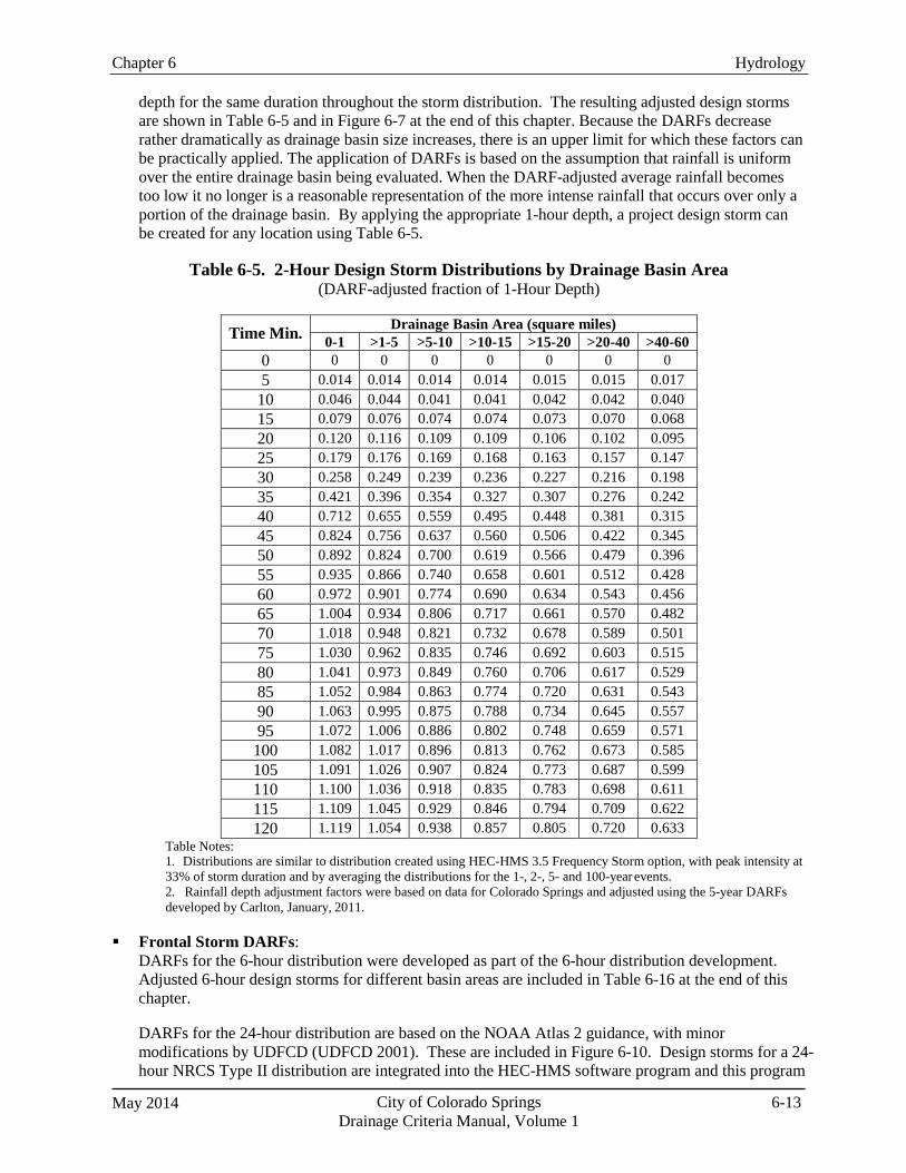
Chapter 6 Hydrology
May 2014 City of Colorado Springs Drainage Criteria Manual, Volume 1
6-13
depth for the same duration throughout the storm distribution. The resulting adjusted design storms are shown in Table 6-5 and in Figure 6-7 at the end of this chapter. Because the DARFs decrease rather dramatically as drainage basin size increases, there is an upper limit for which these factors can be practically applied. The application of DARFs is based on the assumption that rainfall is uniform over the entire drainage basin being evaluated. When the DARF-adjusted average rainfall becomes too low it no longer is a reasonable representation of the more intense rainfall that occurs over only a portion of the drainage basin. By applying the appropriate 1-hour depth, a project design storm can be created for any location using Table 6-5.
Table 6-5. 2-Hour Design Storm Distributions by Drainage Basin Area
(DARF-adjusted fraction of 1-Hour Depth)
Time Min. Drainage Basin Area (square miles) 0-1 >1-5 >5-10 >10-15 >15-20 >20-40 >40-60
0 0 0 0 0 0 0 0 5 0.014 0.014 0.014 0.014 0.015 0.015 0.017 10 0.046 0.044 0.041 0.041 0.042 0.042 0.040 15 0.079 0.076 0.074 0.074 0.073 0.070 0.068 20 0.120 0.116 0.109 0.109 0.106 0.102 0.095 25 0.179 0.176 0.169 0.168 0.163 0.157 0.147 30 0.258 0.249 0.239 0.236 0.227 0.216 0.198 35 0.421 0.396 0.354 0.327 0.307 0.276 0.242 40 0.712 0.655 0.559 0.495 0.448 0.381 0.315 45 0.824 0.756 0.637 0.560 0.506 0.422 0.345 50 0.892 0.824 0.700 0.619 0.566 0.479 0.396 55 0.935 0.866 0.740 0.658 0.601 0.512 0.428 60 0.972 0.901 0.774 0.690 0.634 0.543 0.456 65 1.004 0.934 0.806 0.717 0.661 0.570 0.482 70 1.018 0.948 0.821 0.732 0.678 0.589 0.501 75 1.030 0.962 0.835 0.746 0.692 0.603 0.515 80 1.041 0.973 0.849 0.760 0.706 0.617 0.529 85 1.052 0.984 0.863 0.774 0.720 0.631 0.543 90 1.063 0.995 0.875 0.788 0.734 0.645 0.557 95 1.072 1.006 0.886 0.802 0.748 0.659 0.571 100 1.082 1.017 0.896 0.813 0.762 0.673 0.585 105 1.091 1.026 0.907 0.824 0.773 0.687 0.599 110 1.100 1.036 0.918 0.835 0.783 0.698 0.611 115 1.109 1.045 0.929 0.846 0.794 0.709 0.622 120 1.119 1.054 0.938 0.857 0.805 0.720 0.633
Table Notes: 1. Distributions are similar to distribution created using HEC-HMS 3.5 Frequency Storm option, with peak intensity at 33% of storm duration and by averaging the distributions for the 1-, 2-, 5- and 100-year events. 2. Rainfall depth adjustment factors were based on data for Colorado Springs and adjusted using the 5-year DARFs developed by Carlton, January, 2011.
Frontal Storm DARFs:
DARFs for the 6-hour distribution were developed as part of the 6-hour distribution development. Adjusted 6-hour design storms for different basin areas are included in Table 6-16 at the end of this chapter.
DARFs for the 24-hour distribution are based on the NOAA Atlas 2 guidance, with minor modifications by UDFCD (UDFCD 2001). These are included in Figure 6-10. Design storms for a 24-hour NRCS Type II distribution are integrated into the HEC-HMS software program and this program
Chapter 6 Hydrology
City of Colorado Springs Drainage Criteria Manual, Volume 1
May 2014 6-14
will create a DARF-adjusted design storm. The only data required are the unadjusted 24-hour rainfall depth for the return period being evaluated and the size of the drainage basin. The program makes the appropriate adjustments to the rainfall depth for the area of the basin being evaluated and distributes the rainfall over the storm duration accordingly.
2.2.2 Dominant Design Storm
For flood studies or when the highest probable design flow for sizing facilities is required, it may be necessary to evaluate both thunderstorms and frontal storms to determine the appropriate design flows. It is the responsibility of the designer to determine the dominant design storm for each project. Both peak flow rates and runoff volumes should be checked since the volume of runoff can be a critical design parameter for some types of facilities, especially those designed for detention storage.
Also, it must be recognized that each design storm applies to the total drainage area included in the study area and that the resulting flows only apply to the reach that receives the total area. To determine peak flows for smaller portions of the drainage basin, different design storms, based on different DARFs appropriate for the contributing area, may be needed to determine design flows. For example, within a 60-square-mile drainage basin, it may be necessary to apply a thunderstorm distribution to determine peak flows for sub-basins of 1 square mile and smaller and for other portions up to the area where the frontal storm dominates.
It is important that both of these types of design storms assume that the rainfall occurs uniformly over the entire drainage basin. For larger drainage basins, such as the area contributing to lower Fountain Creek, a spatial distribution of the storm is likely to be more representative of an appropriate design storm that will reproduce low frequency flood flow estimates. This type of storm distribution (based on “storm centering”) was used in the 2006 Fountain Creek Watershed Hydrology Report and may need to be considered for certain projects, especially those involving large watersheds and/or large and complex stream systems. The application of this type of design storm is complicated and requires experience and judgment to determine the placement of the storm over the watershed so that the highest potential flows are created. Resources from the Colorado Department of Natural Resources, State Engineers Office, Dam Safety Office provide guidance on developing storm events for Extreme Storm Precipitation (ESP). Additionally, relevant work by Dr. James Guo at the University of Colorado-Denver includes a peer- reviewed paper “Storm Centering Approach for Flood Predictions from Large Watersheds” in the Journal of Hydrologic Engineering (Guo, publication pending as of July 2012). For extreme precipitation events, such as estimating the Probable Maximum Precipitation (PMP), see Hydrometeorological Report No. 55A (HMR-55A), Probable Maximum Precipitation Estimates—United States Between the Continental Divide and the 103rd Meridian and/or the Extreme Precipitation Analysis Tool (EPAT) developed by the State Engineer’s Office.
2.3 Hydrologic Basis of Design for Water Quality—Water Quality Capture Volume
While guidance in the preceding sections focuses on the hydrologic events related to flood control and conveyance facilities, small frequently occurring events form the basis of design for water quality facilities. The water quality capture volume (WQCV), corresponding to roughly an 80th percentile event, defines storage volume requirements for stormwater PCMs. The basis for establishing the 80th percentile event and guidance for implementing water quality facilities is described in the Volume 2 of this Manual.
Chapter 6 Hydrology
May 2014 City of Colorado Springs Drainage Criteria Manual, Volume 1
6-15
The guidance provided in Volume 2 of this Manual was based on data from the Denver Metropolitan area. A detailed analysis of rainfall gage records in the Colorado Springs area was conducted to determine an appropriate value for the 80th percentile storm. The results of this analysis are reported in a technical memorandum prepared for the City titled “Water Quality Capture Volume Analysis for Colorado Springs” (Wright Water Engineers 2011). While there were some minor differences between the UDFCD data and the data from the Colorado Springs gages, on average, the curves were very similar. Based on the results of this report, the UDFCD results and methods for the WQCV are acceptable for determining the WQCV in Colorado Springs.
3.0 Rational Method The Rational Method is used to determine runoff peak discharges for drainage basins up to and including 130 acres in size and when hydrologic routing is relatively simple. However, the drainage area should be divided into sub-basins that represent homogeneous land uses, soil types or land cover. The Rational Method is most typically applied for inlet and storm drain sizing.
The Rational Method is based on the direct relationship between rainfall and runoff, and is expressed by the following equation:
Q = C·I·A (Eq. 6-5)
In which: Q = the maximum rate of runoff (cubic feet per second [cfs])
C = the runoff coefficient that is the ratio between the runoff volume from an area and the average rainfall depth over a given duration for that area I = the average intensity of rainfall for a duration equal to the time of concentration (in/hr)
A = drainage basin area (acres)
The assumptions and limitations of the Rational Method are described in the UDFCD Manual, Volume 1, Runoff chapter. Standard Form 1 (SF-1) and Standard Form 2 (SF-2) are provided at the end of this chapter as Figure 6-11 and Figure 6-12, respectively to provide a standard format for Rational Method calculations. The SF-1 Form is used for calculating the time of concentration, and the SF-2 form is used to estimate accumulated peak discharges from multiple basins as storm runoff flows downstream in a channel or pipe. Results from the Rational Method calculations shall be included with the drainage report submittal. As an alternative to SF-1 and SF-2, the UD-Rational spreadsheet can be used to document basin parameters and calculations or other spreadsheets or programs can be used as long as the information and format is the similar to that shown in these standard forms.
3.1 Rational Method Runoff Coefficient (C)
The runoff coefficient represents the integrated effects of infiltration, detention storage, evaporation, retention, flow routing, and interception, all of which affect the time distribution and peak rate of runoff. Runoff coefficients are based on the imperviousness of a particular land use and the hydrologic soil type of the area and are to be selected in accordance with Table 6-6.
The procedure for determining the runoff coefficient includes these steps:
1. Categorize the site area into one or more similar land uses, each with a representative
imperviousness, according to the information in Table 6-6.
Chapter 6 Hydrology
City of Colorado Springs Drainage Criteria Manual, Volume 1
May 2014 6-16
2. Based on the dominant hydrologic soil type in the area, use Table 6-6 to estimate the runoff coefficient for the particular land use category for the design storms of interest.
3. Calculate an area-weighted average runoff coefficient for the site based on the runoff coefficients
from individual land use areas of the site.
When analyzing an area for design purposes, urbanization of the full watershed, including both on-site and off-site areas, shall be assumed.
Gravel parking areas, storage areas, and access drives proposed on Site Improvement Plans shall be analyzed based on an imperviousness of 80%. This is due to the potential for gravel areas being paved over time by property owners and the resulting adverse impacts on the stormwater management facilities and adjacent properties.
There are some circumstances where the selection of impervious percentage values may require additional investigation due to unique land characteristics (e.g., recent burn areas). When these circumstances arise, it is the designer’s responsibility to verify that the correct land use assumptions are made.
When multiple sub-basins are delineated, the composite C value calculation is:
Cc = (C1A1 + C2A2 + C3A3 +…CiAi) / At (Eq. 6-6)
Where:
Cc = composite runoff coefficient for total area Ci = runoff coefficient for subarea corresponding to surface type or land use Ai = area of surface type corresponding to Ci (units must be the same as those used for total area)
At = total area of all subareas for which composite runoff coefficient applies i = number of surface types in the drainage area
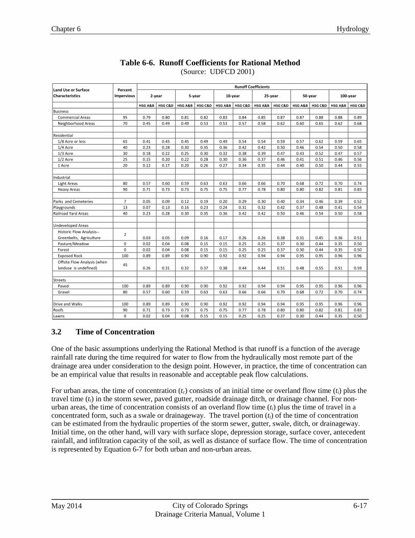
May 2014 City of Colorado Springs Drainage Criteria Manual, Volume 1
6-17
Chapter 6 Hydrology
Table 6-6. Runoff Coefficients for Rational Method (Source: UDFCD 2001)
Land Use or Surface Characteristics
Percent Impervious
Runoff Coefficients
2-year 5-year 10-year 25-year 50-year 100-year
HSG A&B HSG C&D HSG A&B HSG C&D HSG A&B HSG C&D HSG A&B HSG C&D HSG A&B HSG C&D HSG A&B HSG C&D
Business Commercial Areas 95 0.79 0.80 0.81 0.82 0.83 0.84 0.85 0.87 0.87 0.88 0.88 0.89 Neighborhood Areas 70 0.45 0.49 0.49 0.53 0.53 0.57 0.58 0.62 0.60 0.65 0.62 0.68
Residential
1/8 Acre or less 65 0.41 0.45 0.45 0.49 0.49 0.54 0.54 0.59 0.57 0.62 0.59 0.65 1/4 Acre 40 0.23 0.28 0.30 0.35 0.36 0.42 0.42 0.50 0.46 0.54 0.50 0.58 1/3 Acre 30 0.18 0.22 0.25 0.30 0.32 0.38 0.39 0.47 0.43 0.52 0.47 0.57 1/2 Acre 25 0.15 0.20 0.22 0.28 0.30 0.36 0.37 0.46 0.41 0.51 0.46 0.56 1 Acre 20 0.12 0.17 0.20 0.26 0.27 0.34 0.35 0.44 0.40 0.50 0.44 0.55
Industrial
Light Areas 80 0.57 0.60 0.59 0.63 0.63 0.66 0.66 0.70 0.68 0.72 0.70 0.74 Heavy Areas 90 0.71 0.73 0.73 0.75 0.75 0.77 0.78 0.80 0.80 0.82 0.81 0.83
Parks and Cemeteries 7 0.05 0.09 0.12 0.19 0.20 0.29 0.30 0.40 0.34 0.46 0.39 0.52 Playgrounds 13 0.07 0.13 0.16 0.23 0.24 0.31 0.32 0.42 0.37 0.48 0.41 0.54 Railroad Yard Areas 40 0.23 0.28 0.30 0.35 0.36 0.42 0.42 0.50 0.46 0.54 0.50 0.58
Undeveloped Areas
Historic Flow Analysis-- Greenbelts, Agriculture
2 0.03
0.05
0.09
0.16
0.17
0.26
0.26
0.38
0.31
0.45
0.36
0.51
Pasture/Meadow 0 0.02 0.04 0.08 0.15 0.15 0.25 0.25 0.37 0.30 0.44 0.35 0.50 Forest 0 0.02 0.04 0.08 0.15 0.15 0.25 0.25 0.37 0.30 0.44 0.35 0.50 Exposed Rock 100 0.89 0.89 0.90 0.90 0.92 0.92 0.94 0.94 0.95 0.95 0.96 0.96 Offsite Flow Analysis (when landuse is undefined)
45 0.26
0.31
0.32
0.37
0.38
0.44
0.44
0.51
0.48
0.55
0.51
0.59
Streets
Paved 100 0.89 0.89 0.90 0.90 0.92 0.92 0.94 0.94 0.95 0.95 0.96 0.96 Gravel 80 0.57 0.60 0.59 0.63 0.63 0.66 0.66 0.70 0.68 0.72 0.70 0.74
Drive and Walks 100 0.89 0.89 0.90 0.90 0.92 0.92 0.94 0.94 0.95 0.95 0.96 0.96 Roofs 90 0.71 0.73 0.73 0.75 0.75 0.77 0.78 0.80 0.80 0.82 0.81 0.83 Lawns 0 0.02 0.04 0.08 0.15 0.15 0.25 0.25 0.37 0.30 0.44 0.35 0.50
3.2 Time of Concentration
One of the basic assumptions underlying the Rational Method is that runoff is a function of the average rainfall rate during the time required for water to flow from the hydraulically most remote part of the drainage area under consideration to the design point. However, in practice, the time of concentration can be an empirical value that results in reasonable and acceptable peak flow calculations.
For urban areas, the time of concentration (tc) consists of an initial time or overland flow time (ti) plus the travel time (tt) in the storm sewer, paved gutter, roadside drainage ditch, or drainage channel. For non- urban areas, the time of concentration consists of an overland flow time (ti) plus the time of travel in a concentrated form, such as a swale or drainageway. The travel portion (tt) of the time of concentration can be estimated from the hydraulic properties of the storm sewer, gutter, swale, ditch, or drainageway. Initial time, on the other hand, will vary with surface slope, depression storage, surface cover, antecedent rainfall, and infiltration capacity of the soil, as well as distance of surface flow. The time of concentration is represented by Equation 6-7 for both urban and non-urban areas.
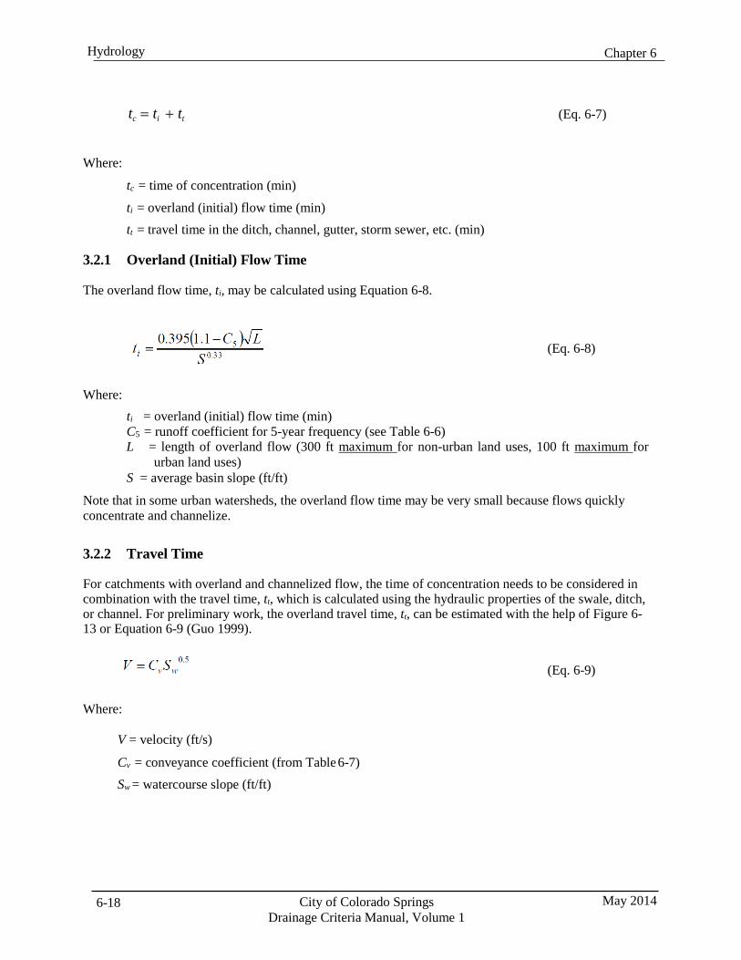
Chapter 6 Hydrology
City of Colorado Springs Drainage Criteria Manual, Volume 1
May 2014 6-18
tc = ti + tt
(Eq. 6-7)
Where:
tc = time of concentration (min)
ti = overland (initial) flow time (min) tt = travel time in the ditch, channel, gutter, storm sewer, etc. (min)
3.2.1 Overland (Initial) Flow Time
The overland flow time, ti, may be calculated using Equation 6-8.
(Eq. 6-8)
Where:
ti = overland (initial) flow time (min) C5 = runoff coefficient for 5-year frequency (see Table 6-6) L = length of overland flow (300 ft maximum for non-urban land uses, 100 ft maximum for
urban land uses) S = average basin slope (ft/ft)
Note that in some urban watersheds, the overland flow time may be very small because flows quickly concentrate and channelize.
3.2.2 Travel Time
For catchments with overland and channelized flow, the time of concentration needs to be considered in combination with the travel time, tt, which is calculated using the hydraulic properties of the swale, ditch, or channel. For preliminary work, the overland travel time, tt, can be estimated with the help of Figure 6- 13 or Equation 6-9 (Guo 1999).
(Eq. 6-9)
Where:
V = velocity (ft/s)
Cv = conveyance coefficient (from Table 6-7) Sw = watercourse slope (ft/ft)
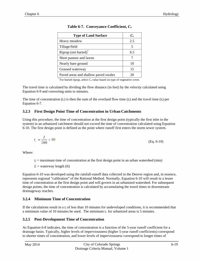
May 2014 City of Colorado Springs Drainage Criteria Manual, Volume 1
6-19
Chapter 6 Hydrology
Table 6-7. Conveyance Coefficient, Cv
Type of Land Surface Cv
Heavy meadow 2.5 Tillage/field 5 Riprap (not buried)*
6.5 Short pasture and lawns 7 Nearly bare ground 10 Grassed waterway 15 Paved areas and shallow paved swales 20
* For buried riprap, select Cv value based on type of vegetative cover.
The travel time is calculated by dividing the flow distance (in feet) by the velocity calculated using Equation 6-9 and converting units to minutes.
The time of concentration (tc) is then the sum of the overland flow time (ti) and the travel time (tt) per Equation 6-7.
3.2.3 First Design Point Time of Concentration in Urban Catchments
Using this procedure, the time of concentration at the first design point (typically the first inlet in the system) in an urbanized catchment should not exceed the time of concentration calculated using Equation 6-10. The first design point is defined as the point where runoff first enters the storm sewer system.
(Eq. 6-10)
Where:
tc = maximum time of concentration at the first design point in an urban watershed (min) L = waterway length (ft)
Equation 6-10 was developed using the rainfall-runoff data collected in the Denver region and, in essence, represents regional “calibration” of the Rational Method. Normally, Equation 6-10 will result in a lesser time of concentration at the first design point and will govern in an urbanized watershed. For subsequent design points, the time of concentration is calculated by accumulating the travel times in downstream drainageway reaches.
3.2.4 Minimum Time of Concentration
If the calculations result in a tc of less than 10 minutes for undeveloped conditions, it is recommended that a minimum value of 10 minutes be used. The minimum tc for urbanized areas is 5 minutes.
3.2.5 Post-Development Time of Concentration
As Equation 6-8 indicates, the time of concentration is a function of the 5-year runoff coefficient for a drainage basin. Typically, higher levels of imperviousness (higher 5-year runoff coefficients) correspond to shorter times of concentration, and lower levels of imperviousness correspond to longer times of
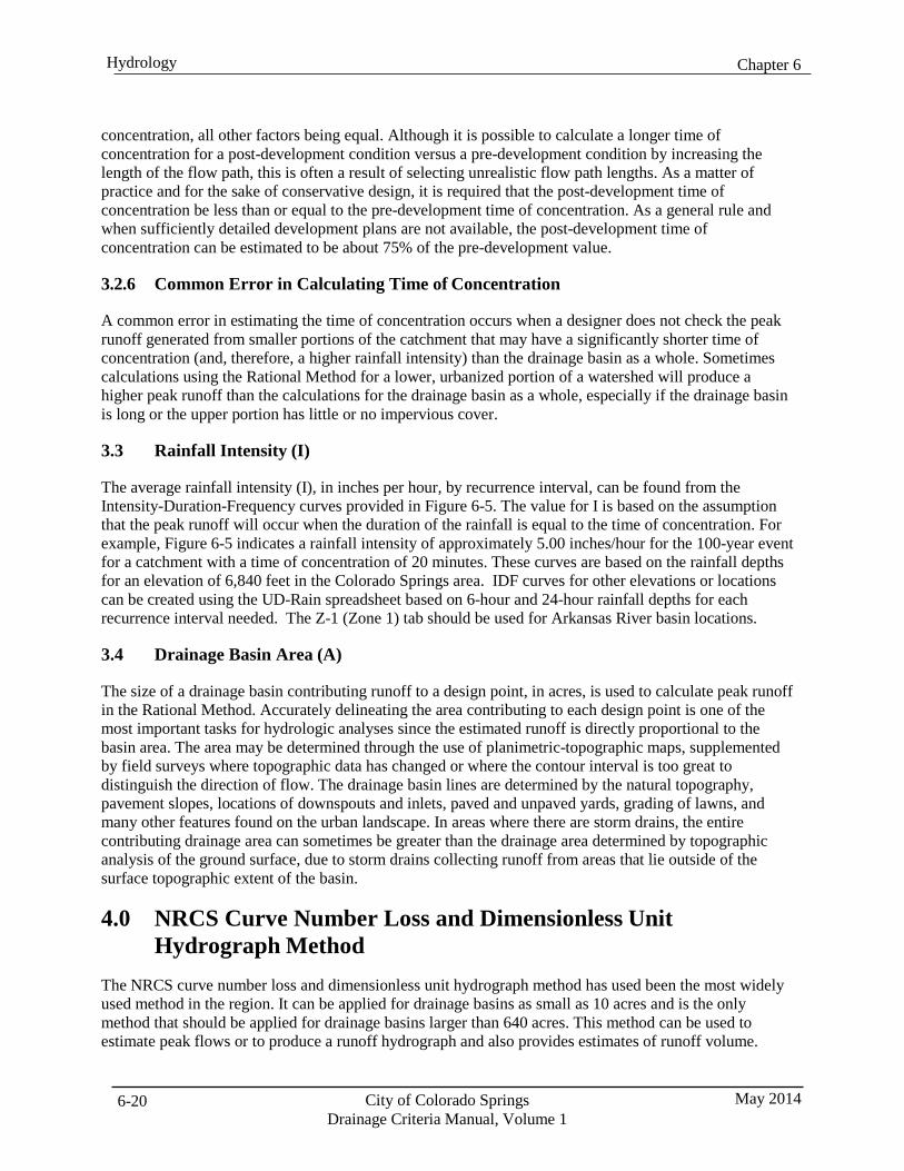
Chapter 6 Hydrology
City of Colorado Springs Drainage Criteria Manual, Volume 1
May 2014 6-20
concentration, all other factors being equal. Although it is possible to calculate a longer time of concentration for a post-development condition versus a pre-development condition by increasing the length of the flow path, this is often a result of selecting unrealistic flow path lengths. As a matter of practice and for the sake of conservative design, it is required that the post-development time of concentration be less than or equal to the pre-development time of concentration. As a general rule and when sufficiently detailed development plans are not available, the post-development time of concentration can be estimated to be about 75% of the pre-development value.
3.2.6 Common Error in Calculating Time of Concentration
A common error in estimating the time of concentration occurs when a designer does not check the peak runoff generated from smaller portions of the catchment that may have a significantly shorter time of concentration (and, therefore, a higher rainfall intensity) than the drainage basin as a whole. Sometimes calculations using the Rational Method for a lower, urbanized portion of a watershed will produce a higher peak runoff than the calculations for the drainage basin as a whole, especially if the drainage basin is long or the upper portion has little or no impervious cover.
3.3 Rainfall Intensity (I)
The average rainfall intensity (I), in inches per hour, by recurrence interval, can be found from the Intensity-Duration-Frequency curves provided in Figure 6-5. The value for I is based on the assumption that the peak runoff will occur when the duration of the rainfall is equal to the time of concentration. For example, Figure 6-5 indicates a rainfall intensity of approximately 5.00 inches/hour for the 100-year event for a catchment with a time of concentration of 20 minutes. These curves are based on the rainfall depths for an elevation of 6,840 feet in the Colorado Springs area. IDF curves for other elevations or locations can be created using the UD-Rain spreadsheet based on 6-hour and 24-hour rainfall depths for each recurrence interval needed. The Z-1 (Zone 1) tab should be used for Arkansas River basin locations.
3.4 Drainage Basin Area (A)
The size of a drainage basin contributing runoff to a design point, in acres, is used to calculate peak runoff in the Rational Method. Accurately delineating the area contributing to each design point is one of the most important tasks for hydrologic analyses since the estimated runoff is directly proportional to the basin area. The area may be determined through the use of planimetric-topographic maps, supplemented by field surveys where topographic data has changed or where the contour interval is too great to distinguish the direction of flow. The drainage basin lines are determined by the natural topography, pavement slopes, locations of downspouts and inlets, paved and unpaved yards, grading of lawns, and many other features found on the urban landscape. In areas where there are storm drains, the entire contributing drainage area can sometimes be greater than the drainage area determined by topographic analysis of the ground surface, due to storm drains collecting runoff from areas that lie outside of the surface topographic extent of the basin.
4.0 NRCS Curve Number Loss and Dimensionless Unit Hydrograph Method
The NRCS curve number loss and dimensionless unit hydrograph method has used been the most widely used method in the region. It can be applied for drainage basins as small as 10 acres and is the only method that should be applied for drainage basins larger than 640 acres. This method can be used to estimate peak flows or to produce a runoff hydrograph and also provides estimates of runoff volume.
May 2014 City of Colorado Springs Drainage Criteria Manual, Volume 1
6-21
Chapter 6 Hydrology
Detailed descriptions of the curve number loss method and the dimensionless unit hydrograph can be found in these references:
U.S. Department of Agriculture Natural Resources Conservation Service (NRCS) 1986. Urban
Hydrology for Small Watersheds. Technical Release 55 (TR-55) (Second Edition). Prepared by Conservation Engineering Division.
U.S. Army Corps of Engineers (USACE) 2010. Hydrologic Modeling System HEC-HMS User’s
Manual. Hydrologic Engineering Center, CPD-74A.
While it is possible to perform hydrograph analysis using the NRCS curve number loss method and dimensionless unit hydrograph using spreadsheet tools, it is cumbersome. More commonly, computer models such as the USACE HEC-HMS model are used. This section describes model input requirements for pre- and post-development modeling using HEC-HMS. Primary inputs include basin characteristics such as the drainage area, curve number and lag time. In addition, channel routing parameters are specified in HEC-HMS.
Other computer programs that use the NRCS loss method and dimensionless unit hydrograph may also be used, provided that the model results can be replicated using HEC-HMS. However, the curve number option for calculating rainfall losses in EPA SWMM is not acceptable because it is not an accurate implementation of the NRCS method and may produce results that vary significantly from HEC-HMS and TR-55.
4.1 NRCS Curve Numbers
NRCS curve numbers range from 0 to 100 (the recommended lower limit is 40) and can be used to calculate the volume of runoff from a storm event based on land use characteristics. A curve number of 0 would represent zero runoff (100% losses), and a curve number of 100 would represent zero losses (100% runoff).
The selection of a curve number value depends on the type of soil, identified by the NRCS hydrologic soil group (HSG), the land cover or treatment, and the antecedent runoff condition (ARC).
4.1.1 Hydrologic Soil Groups (HSG)
HSGs are determined by soil surveys published by the NRCS, which are generally done on a county-wide basis. The NRCS Soil Survey Geographic (SSURGO) Database is an online tool that may be used to characterize soils and HSGs.
The locations of each soil type for the drainage basin being studied must be identified by their HSG designation. The four hydrologic soil groups are defined by soil scientists, according to their runoff potential, as:
Group A: Low runoff potential. Soils having low runoff potential and high infiltration rates even
when thoroughly wetted. These consist chiefly of deep, well to excessively drained sand or gravel and have a high rate of water transmission (> 0.30 in/hr).
Group B: Moderate runoff potential. Soils having moderate infiltration rates when thoroughly
wetted and consist chiefly of moderately deep to deep, moderately well to well drained soils with moderately fine to moderately coarse textures. These soils have a moderate rate of water transmission (0.15-0.30 in/hr).
Chapter 6 Hydrology
City of Colorado Springs Drainage Criteria Manual, Volume 1
May 2014 6-22
Group C: Moderate to High runoff potential. Soils having low infiltration rates when thoroughly wetted and consist chiefly of soils with a layer that impedes downward movement of water and soils with moderately fine to fine texture. These soils have a low rate of water transmission (0.05-0.15 in/hr).
Group D: High runoff potential. Soils have high runoff potential. They have very low infiltration
rates when thoroughly wetted and consist chiefly of clay soils with a high swelling potential, soils with a permanent high water table, soils with a claypan or clay layer at or near the surface, and shallow soils over a nearly impervious material. These soils have a very low rate of water transmission (0.00-0.05 in/hr).
Soils in the Pike National Forest
Large portions of the Fountain Creek watershed extend into the foothills of the Rocky Mountains and also include the northern and eastern faces of Pikes Peak. Soils in these areas were mapped as part of a soil survey completed for the Pike National Forest in 1992. The Soil Survey of the Pike National Forest (USDA 1992) is a third order survey while the Soil Survey of El Paso County, encompassing the balance of the County, is a second order survey (USDA 1981). The order of a soil survey indicates its level of detail and intended use. Third order surveys are “extensive” in nature and are typically conducted at twice the scale when compared with more “intensive” second order surveys. According to the Soil Survey Manual (USDA 1993), “[t]hird order surveys are made for land uses that do not require precise knowledge of small areas or detailed soils information.” As a result, soil mapping for some portions of the foothills does not have adequate resolution to accurately characterize rock outcroppings, depth to bedrock and potential for infiltration and runoff.
Many of the soils in the Pike National Forest were assigned to Group D likely due to the inclusion of scattered rock outcroppings and a perceived depth to bedrock. However, these soils are derived from decomposed Pikes Peak granite parent material that is highly fractured and deeply weathered below the soil profile. These soils have very gravelly coarse sandy loam textures and exhibit high infiltration rates with no free water occurring within the soil profile. As such, they do not meet the definition of HSG D as defined by the Soil Survey Manual (Table 3-9 in USDA 1993).
For the purposes of establishing hydrology for City projects, the HSG for soil mapping units in the Pike National Forest should be assigned as shown in Table 6-8. These HSG assignments vary from the original published data and may not be appropriate for hydrology studies requiring the approval of other agencies or jurisdictions (e.g., floodplain study requiring FEMA approval). Soils mapped in the Sphinx, Catamount, and Legault mapping units were originally published as Group D soils, but should be treated as HSG B. Soils mapped in the Ivywild mapping unit were originally published as Group C soils, but should be treated as HSG B. Soils mapped in the Circue land mapping unit were originally published as Group A soils, but should be treated as HSG D. Soils mapped in the Rock outcrop, Tecolote, Aquolls, Condie, and Pendant mapping units shall retain their published HSG. Other minor soils map units shall retain their published HSG. Where runoff from rock outcroppings flows onto pervious areas, it may also be reasonable to represent the outcroppings as disconnected impervious area based on guidance provided in TR-55.
May 2014 City of Colorado Springs Drainage Criteria Manual, Volume 1
6-23
Chapter 6 Hydrology
Table 6-8. HSG for Soils in the Pike National Forest
Map Symbol Major Soil Component Assigned HSG 42,43,44,45,46,47 Sphinx B
5,6,7 Catamount B 21 Ivywild B
33,34,35,36 Rock outcrop D 24,25,26 Legault B
48,49 Tecolote B 9 Cirque land D 2 Aquolls D 10 Condie B
29,31 Pendant D Note: Minor soil map units not listed above shall retain the published HSG.
4.1.2 Land Cover
The type of cover on the surface of the ground within a drainage basin has a significant effect on the amount and rate of runoff. Land cover includes type of vegetation, density of vegetation and impervious surfaces including roads, buildings, parking lots, etc. The standard method for adjusting curve number for imperviousness assumes that the impervious areas are directly connected to the receiving system. Adjustments to imperviousness to determine “effective imperviousness” can be made as described in Volume 3 of the UDFCD Manual (with accompanying spreadsheet) when volume reduction practices such as PCMs and Green Infrastructure (GI) practices are implemented.
4.1.3 Antecedent Runoff Condition (ARC)
The ARC represents the conditions in the drainage basin prior to the onset of the design storm event relative to runoff potential and can be influenced by the type of storm being evaluated. It is represented by three categories: ARC I, ARC II and ARC III. ARC I represents the lowest runoff potential, and ARC III represents the highest. Considerations for thunderstorm and frontal storm ARCs include:
Thunderstorm ARCs: Previously, an ARC II category was used as the standard condition for all
design purposes. However, as a part of the update of this Manual, Colorado Springs conducted a hydrologic modeling study of the Jimmy Creek Camp watershed to evaluate appropriate curve number values. This study included model simulations that were calibrated to USGS stream gage data just upstream of the confluence with Fountain Creek. The curve number values presented in this section were selected based on NRCS guidance and the results of the modeling study. One of the most notable conclusions of the modeling analysis, which was also supported by the Carleton (2011) study, is that basin conditions prior to short-duration storm events are better represented by ARC I curve numbers. The modeling analyses showed that using curve numbers based on ARC II significantly overestimate pre-development runoff based on the relatively short-duration storm events that were studied. However, when areas develop most pervious areas will be landscaped and irrigated. Therefore, the developed condition ARC is better represented by curve numbers based on an ARC II condition.
Frontal Storm ARCs: A detailed analysis of conditions prior to longer-duration storms has not been
conducted due to the lack of adequate data. However, by observation and by a detailed evaluation of the April 1999 storm event, it is apparent that longer-duration storms tend to be part of a broader storm system with rainfall occurring in the days leading up to a more intense period of rainfall.
Chapter 6 Hydrology
City of Colorado Springs Drainage Criteria Manual, Volume 1
May 2014 6-24
Therefore, curve numbers for longer-duration frontal storms will continue to be based on ARC II conditions. Under some conditions, an ARC III category could be appropriate, but there is insufficient storm and basin data to establish these conditions, but they are expected to be rare.
4.2 Pre-development Thunderstorm Curve Numbers
Pre-development (undeveloped) curve numbers are determined based on land use and cover, the HSG and the ARC. For undeveloped land, ARC I (lower runoff potential) applies for short-duration thunderstorms. Table 6-9 provides curve numbers for undeveloped, non-irrigated land that should be used for assessment of pre-development hydrology for thunderstorms.
4.3 Frontal Storm and Post-Development Thunderstorm Curve Numbers
Post-development curve numbers are determined using the standard guidance provided by the NRCS for ARC II from Technical Release (TR) 55 guidance (NRCS 1986) when pervious areas are landscaped and irrigated for both short-duration thunderstorms and longer-duration frontal storms. Because it is anticipated that conditions prior to frontal storm events in undeveloped drainage basins will have increased runoff potential, ARC II curve numbers should also be used for these analyses. Table 6-10 provides curve numbers to be used for assessing these conditions.
Also, to recognize that soils within a development project are usually disturbed and covered with top soil, sod or landscaping and irrigated, Type A soils must be represented as Type B soils for post development curve number calculations. Type A soils are not required to be represented as Type B soils if these portions of a site are avoided and protected during development. However, if they are irrigated, they must be represented by ARC II curve numbers.
4.4 Composite Curve Numbers
Drainage basins are often composed of various soil types, land uses, land covers or other features that cannot be represented by a single value from the standard tables. To represent these conditions a composite curve number must be calculated using the following equation:
CNc = (CN1 A1 + CN1 A2 + CN3 A3 +…..CNi Ai) / At (Eq. 6-11)
Where:
CNc = composite curve number for total area CNi = curve number for subarea Ai = area of each subarea (units must be consistent with units used for total area) At = total area of all drainage subareas for which composite curve number applies
Chapter 6 Hydrology
May 2014 City of Colorado Springs Drainage Criteria Manual, Volume 1
6-25
While compositing curve numbers is a fairly common practice, it is important to remember that curve numbers are non-linear and compositing methods assume a linear relationship (for example, a curve number of 90 does not produce twice as much runoff as a curve number of 45 for the same rainfall amount). If there are large variations in the magnitude of curve numbers that are being composited, sub- basins should be redefined to represent more homogeneous land uses or runoff can be calculated from individual land uses, added together and a representative curve number for the overall basin can be back- calculated. This is especially important in urban areas, where compositing of highly impervious areas with less pervious land uses can result in under prediction of peak runoff peaks and volumes. To the extent practical, subareas should be defined to avoid compositing of curve numbers for land uses with distinct differences in runoff characteristics. Note that the composite curve number values shown in Table 6-10 for various land uses types do not include the adjacent streets and sidewalks. These areas, and their corresponding curve numbers, should be incorporated into the calculation of the overall composite curve number with the areas and curve numbers for the other land use types within a subarea.
Some software programs, including HEC-HMS, provide an option to represent directly connected impervious areas by entering a percent imperviousness for a subarea. In this case, the runoff volume from the directly connected impervious area is calculated separately from the remaining portion of the subarea which is represented by a composite curve number. When applying this method only directly connected impervious areas such as streets, sidewalks, driveways, parking areas and roof sections that are hydraulically connected should be included in the percent impervious value. The composite curve number used incorporates the curve number values for the various pervious areas and any disconnected impervious areas not included in the percent impervious value. This method may provide a more accurate representation of the effect of urbanization and directly connected imperviousness, especially for the more frequent storm events (ie. 5-year or less).
4.5 Initial Abstraction
The initial abstraction (Ia) represents a volume of rainfall that must fall to satisfy losses in a drainage basin before runoff begins. The default value for Ia is 0.20 times the potential maximum retention (S). Through modeling of the Jimmy Camp Creek drainage basin using gage-adjusted, NEXRAD-generated rainfall input and comparing model results with recorded flow data, it was determined that a more appropriate value for Ia is 0.10∙S. Therefore, this value shall replace the default value for any evaluations that apply the NRCS curve number method for rainfall losses. To apply this adjustment when using HEC-HMS it will be necessary to provide the initial abstraction as a depth in inches rather to a fraction of the potential maximum retention. The initial abstraction in inches is calculated using Equation 6-12.
Ia = 0.1 [(1000/CN) – 10] (Eq. 6-12)
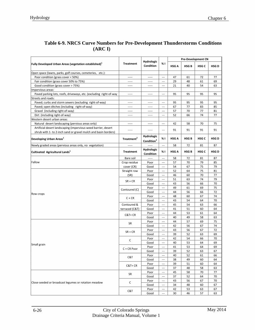
Chapter 6 Hydrology
City of Colorado Springs Drainage Criteria Manual, Volume 1
May 2014 6-26
Table 6-9. NRCS Curve Numbers for Pre-Development Thunderstorms Conditions (ARC I)
Fully Developed Urban Areas (vegetation established)1
Treatment
Hydrologic Condition
% I
Pre-Development CN
HSG A HSG B HSG C HSG D
Open space (lawns, parks, golf courses, cemeteries, etc.): Poor condition (grass cover < 50%) ----- ----- --- 47 61 72 77 Fair condition (grass cover 50% to 75%) ----- ----- --- 29 48 61 69 Good condition (grass cover > 75%) ----- ----- --- 21 40 54 63
Impervious areas: Paved parking lots, roofs, driveways, etc. (excluding right-of-way ----- ----- --- 95 95 95 95
Streets and roads: Paved; curbs and storm sewers (excluding right-of-way) ----- ----- --- 95 95 95 95 Paved; open ditches (including right-of-way) ----- ----- --- 67 77 83 85 Gravel (including right-of-way) ----- ----- --- 57 70 77 81 Dirt (including right-of-way) ----- ----- --- 52 66 74 77
Western desert urban areas: Natural desert landscaping (pervious areas only) ----- ----- --- 42 58 70 75 Artificial desert landscaping (impervious weed barrier, desert shrub with 1- to 2-inch sand or gravel mulch and basin borders)
----- ----- --- 91 91 91 91
Developing Urban Areas1 Treatment2
Hydrologic Condition3
% I HSG A HSG B HSG C HSG D
Newly graded areas (pervious areas only, no vegetation) ----- ----- --- 58 72 81 87
Cultivated Agricultural Lands1 Treatment
Hydrologic Condition
% I HSG A HSG B HSG C HSG D
Fallow
Bare soil ----- --- 58 72 81 87 Crop residue
cover (CR) Poor --- 57 70 79 85 Good --- 54 67 75 79
Row crops
Straight row (SR)
Poor --- 52 64 75 81 Good --- 46 60 70 77
SR + CR Poor --- 51 63 74 79 Good --- 43 56 66 70
Contoured (C) Poor --- 49 61 69 75 Good --- 44 56 66 72
C + CR Poor --- 48 60 67 74 Good --- 43 54 64 70
Contoured & terraced (C&T)
Poor --- 45 54 63 66 Good --- 41 51 60 64
C&T+ CR Poor --- 44 53 61 64 Good --- 40 49 58 63
Small grain
SR Poor --- 44 57 69 75 Good --- 42 56 67 74
SR + CR Poor --- 43 56 67 72 Good --- 39 52 63 69
C Poor --- 42 54 66 70 Good --- 40 53 64 69
C + CR Poor Poor --- 41 53 64 69 Good --- 39 52 63 67
C&T Poor --- 40 52 61 66 Good --- 38 49 60 64
C&T+ CR Poor --- 39 51 60 64 Good --- 37 48 58 63
Close-seeded or broadcast legumes or rotation meadow
SR Poor --- 45 58 70 77 Good --- 37 52 64 70
C Poor --- 43 56 67 70 Good --- 34 48 60 67
C&T Poor --- 42 53 63 67 Good --- 30 46 57 63
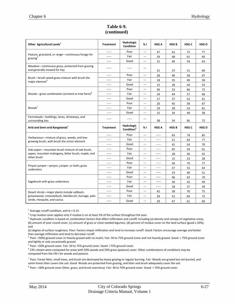
Chapter 6 Hydrology
May 2014 City of Colorado Springs Drainage Criteria Manual, Volume 1
6-27
Table 6-9.
(continued)
Other Agricultural Lands1
Treatment Hydrologic
Condition
% I
HSG A
HSG B
HSG C
HSG D
Pasture, grassland, or range—continuous forage for grazing4
----- Poor --- 47 61 72 77 ----- Fair --- 29 48 61 69 ----- Good --- 21 40 54 63
Meadow—continuous grass, protected from grazing and generally mowed for hay ----- ----- ---
15
37
51
60
Brush—brush-weed-grass mixture with brush the major element5
----- Poor --- 28 46 58 67 ----- Fair --- 18 35 49 58 ----- Good --- 15 28 44 53
Woods—grass combination (orchard or tree farm)6
----- Poor --- 36 53 66 72 ----- Fair --- 24 44 57 66 ----- Good --- 17 37 52 61
Woods7
----- Poor --- 26 45 58 67 ----- Fair --- 19 39 53 61 ----- Good --- 15 34 49 58
Farmsteads—buildings, lanes, driveways, and surrounding lots ----- ----- ---
38
54
66
72
Arid and Semi-arid Rangelands1
Treatment Hydrologic
Condition8
% I
HSG A
HSG B
HSG C
HSG D
Herbaceous—mixture of grass, weeds, and low- growing brush, with brush the minor element
----- Poor --- ----- 63 74 85 ----- Fair --- ----- 51 64 77 ----- Good --- ----- 41 54 70
Oak-aspen—mountain brush mixture of oak brush, aspen, mountain mahogany, bitter brush, maple, and other brush
----- Poor --- ----- 45 54 61 ----- Fair --- ----- 28 36 42 ----- Good --- ----- 15 23 28
Pinyon-juniper—pinyon, juniper, or both; grass understory
----- Poor --- ----- 56 70 77 ----- Fair --- ----- 37 53 63 ----- Good --- ----- 23 40 51
Sagebrush with grass understory
----- Poor --- ----- 46 63 70 ----- Fair --- ----- 30 42 49 ----- Good --- ----- 18 27 34
Desert shrub—major plants include saltbush, greasewood, creosotebush, blackbrush, bursage, palo verde, mesquite, and cactus
----- Poor --- 42 58 70 75 ----- Fair --- 34 52 64 72 ----- Good --- 29 47 61 69
1. Average runoff condition, and Ia = 0.1S. 2. Crop residue cover applies only if residue is on at least 5% of the surface throughout the year. 3. Hydraulic condition is based on combination factors that affect infiltration and runoff, including (a) density and canopy of vegetative areas, (b) amount of year-round cover, (c) amount of grass or close-seeded legumes, (d) percent of residue cover on the land surface (good ≥ 20%), and (e) degree of surface roughness. Poor: Factors impair infiltration and tend to increase runoff. Good: Factors encourage average and better than average infiltration and tend to decrease runoff. 4. Poor: <50%) ground cover or heavily grazed with no mulch. Fair: 50 to 75% ground cover and not heavily grazed. Good: > 75% ground cover and lightly or only occasionally grazed. 5. Poor: <50% ground cover. Fair: 50 to 75% ground cover. Good: >75% ground cover. 6. CN’s shown were computed for areas with 50% woods and 50% grass (pasture) cover. Other combinations of conditions may be computed from the CN’s for woods and pasture. 7. Poor: Forest litter, small trees, and brush are destroyed by heavy grazing or regular burning. Fair: Woods are grazed but not burned, and some forest litter covers the soil. Good: Woods are protected from grazing, and litter and brush adequately cover the soil. 8. Poor: <30% ground cover (litter, grass, and brush overstory). Fair: 30 to 70% ground cover. Good: > 70% ground cover.
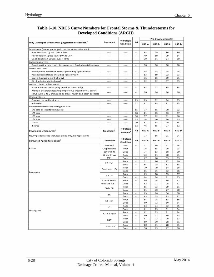
Chapter 6 Hydrology
City of Colorado Springs Drainage Criteria Manual, Volume 1
May 2014 6-28
Table 6-10. NRCS Curve Numbers for Frontal Storms & Thunderstorms for Developed Conditions (ARCII)
Fully Developed Urban Areas (vegetation established)1
Treatment
Hydrologic Condition
% I
Pre-Development CN
HSG A HSG B HSG C HSG D
Open space (lawns, parks, golf courses, cemeteries, etc.): Poor condition (grass cover < 50%) ----- ----- --- 68 79 86 89 Fair condition (grass cover 50% to 75%) ----- ----- --- 49 69 79 84 Good condition (grass cover > 75%) ----- ----- --- 39 61 74 80
Impervious areas: Paved parking lots, roofs, driveways, etc. (excluding right-of-way ----- ----- --- 98 98 98 98
Streets and roads: Paved; curbs and storm sewers (excluding right-of-way) ----- ----- --- 98 98 98 98 Paved; open ditches (including right-of-way) ----- ----- --- 83 89 92 93 Gravel (including right-of-way) ----- ----- --- 76 85 89 91 Dirt (including right-of-way) ----- ----- --- 72 82 87 89
Western desert urban areas: Natural desert landscaping (pervious areas only) ----- ----- --- 63 77 85 88 Artificial desert landscaping (impervious weed barrier, desert shrub with 1- to 2-inch sand or gravel mulch and basin borders)
----- ----- --- 96 96 96 96
Urban districts: Commercial and business ----- ----- 85 89 92 94 95 Industrial ----- ----- 72 81 88 91 93
Residential districts by average lot size: 1/8 acre or less (town houses) ----- ----- 65 77 85 90 92 1/4 acre ----- ----- 38 61 75 83 87 1/3 acre ----- ----- 30 57 72 81 86 1/2 acre ----- ----- 25 54 70 80 85 1 acre ----- ----- 20 51 68 79 84 2 acres ----- ----- 12 46 65 77 82
Developing Urban Areas1 Treatment2
Hydrologic
Condition3
% I HSG A HSG B HSG C HSG D
Newly graded areas (pervious areas only, no vegetation) ----- ----- --- 77 86 91 94
Cultivated Agricultural Lands1 Treatment
Hydrologic Condition
% I HSG A HSG B HSG C HSG D
Fallow
Bare soil ----- --- 77 86 91 94 Crop residue
cover (CR) Poor --- 76 85 90 93 Good --- 74 83 88 90
Row crops
Straight row (SR)
Poor --- 72 81 88 91 Good --- 67 78 85 89
SR + CR Poor --- 71 80 87 90 Good --- 64 75 82 85
Contoured (C) Poor --- 70 79 84 88 Good --- 65 75 82 86
C + CR Poor --- 69 78 83 87 Good --- 64 74 81 85
Contoured & terraced (C&T)
Poor --- 66 74 80 82 Good --- 62 71 78 81
C&T+ CR Poor --- 65 73 79 81 Good --- 61 70 77 80
Small grain
SR Poor --- 65 76 84 88 Good --- 63 75 83 87
SR + CR Poor --- 64 75 83 86 Good --- 60 72 80 84
C Poor --- 63 74 82 85 Good --- 61 73 81 84
C + CR Poor Poor --- 62 73 81 84 Good --- 60 72 80 83
C&T Poor --- 61 72 79 82 Good --- 59 70 78 81
C&T+ CR Poor --- 60 71 78 81 Good --- 58 69 77 80
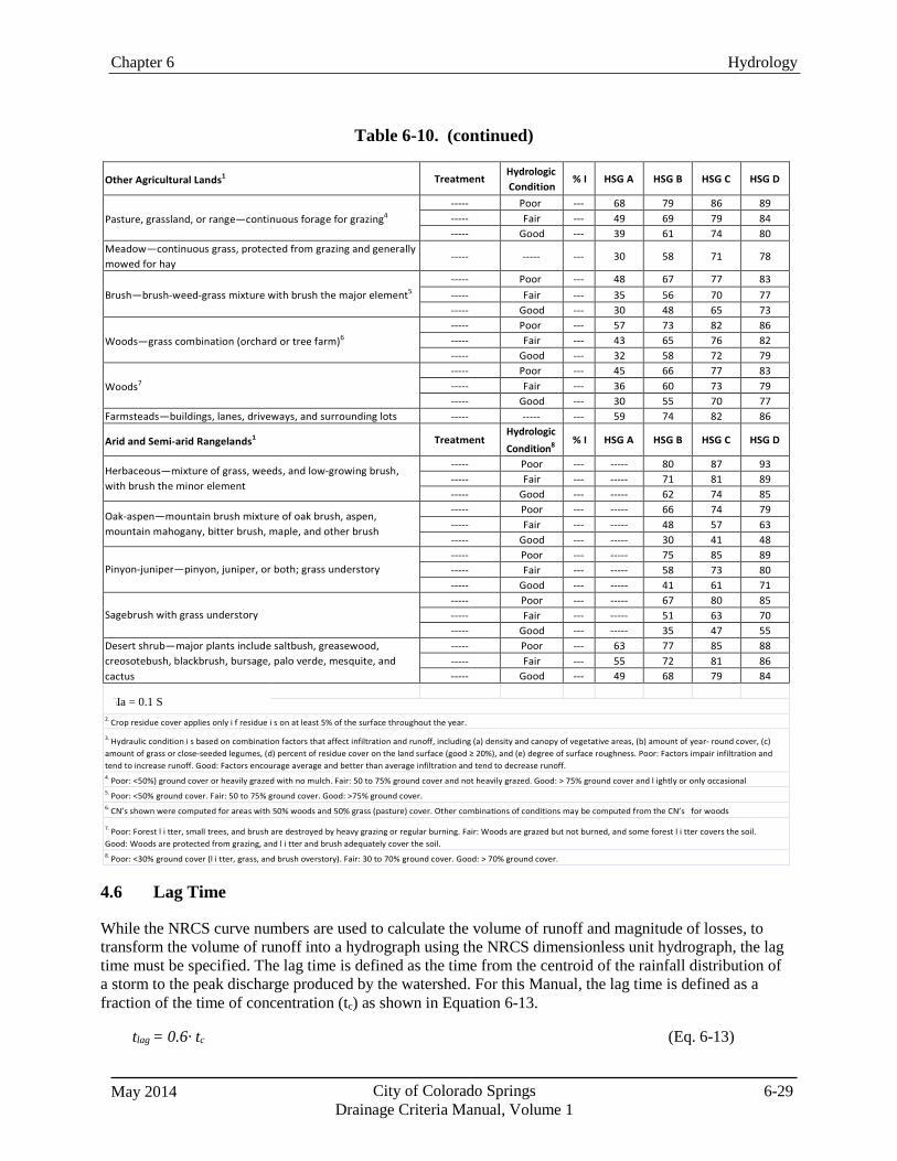
Chapter 6 Hydrology
May 2014 City of Colorado Springs Drainage Criteria Manual, Volume 1
6-29
1. Average runoff condition, and Ia = 0.2S.
Table 6-10. (continued)
Other Agricultural Lands1
Treatment
Hydrologic Condition
% I
HSG A
HSG B
HSG C
HSG D
Pasture, grassland, or range—continuous forage for grazing4
----- Poor --- 68 79 86 89 ----- Fair --- 49 69 79 84 ----- Good --- 39 61 74 80
Meadow—continuous grass, protected from grazing and generally mowed for hay
----- ----- --- 30 58 71 78
Brush—brush-weed-grass mixture with brush the major element5
----- Poor --- 48 67 77 83 ----- Fair --- 35 56 70 77 ----- Good --- 30 48 65 73
Woods—grass combination (orchard or tree farm)6
----- Poor --- 57 73 82 86 ----- Fair --- 43 65 76 82 ----- Good --- 32 58 72 79
Woods7
----- Poor --- 45 66 77 83 ----- Fair --- 36 60 73 79 ----- Good --- 30 55 70 77
Farmsteads—buildings, lanes, driveways, and surrounding lots ----- ----- --- 59 74 82 86
Arid and Semi-arid Rangelands1 Treatment
Hydrologic Condition8
% I HSG A HSG B HSG C HSG D
Herbaceous—mixture of grass, weeds, and low-growing brush, with brush the minor element
----- Poor --- ----- 80 87 93 ----- Fair --- ----- 71 81 89 ----- Good --- ----- 62 74 85
Oak-aspen—mountain brush mixture of oak brush, aspen, mountain mahogany, bitter brush, maple, and other brush
----- Poor --- ----- 66 74 79 ----- Fair --- ----- 48 57 63 ----- Good --- ----- 30 41 48
Pinyon-juniper—pinyon, juniper, or both; grass understory
----- Poor --- ----- 75 85 89 ----- Fair --- ----- 58 73 80 ----- Good --- ----- 41 61 71
Sagebrush with grass understory
----- Poor --- ----- 67 80 85 ----- Fair --- ----- 51 63 70 ----- Good --- ----- 35 47 55
Desert shrub—major plants include saltbush, greasewood, creosotebush, blackbrush, bursage, palo verde, mesquite, and cactus
----- Poor --- 63 77 85 88 ----- Fair --- 55 72 81 86 ----- Good --- 49 68 79 84
Ia = 0.1 S
2. Crop residue cover applies only i f residue i s on at least 5% of the surface throughout the year.
3. Hydraulic condition i s based on combination factors that affect infiltration and runoff, including (a) density and canopy of vegetative areas, (b) amount of year- round cover, (c) amount of grass or close-seeded legumes, (d) percent of residue cover on the land surface (good ≥ 20%), and (e) degree of surface roughness. Poor: Factors impair infiltration and tend to increase runoff. Good: Factors encourage average and better than average infiltration and tend to decrease runoff. 4. Poor: <50%) ground cover or heavily grazed with no mulch. Fair: 50 to 75% ground cover and not heavily grazed. Good: > 75% ground cover and l ightly or only occasional 5. Poor: <50% ground cover. Fair: 50 to 75% ground cover. Good: >75% ground cover. 6. CN’s shown were computed for areas with 50% woods and 50% grass (pasture) cover. Other combinations of conditions may be computed from the CN’s for woods
7. Poor: Forest l i tter, small trees, and brush are destroyed by heavy grazing or regular burning. Fair: Woods are grazed but not burned, and some forest l i tter covers the soil. Good: Woods are protected from grazing, and l i tter and brush adequately cover the soil. 8. Poor: <30% ground cover (l i tter, grass, and brush overstory). Fair: 30 to 70% ground cover. Good: > 70% ground cover.
4.6 Lag Time
While the NRCS curve numbers are used to calculate the volume of runoff and magnitude of losses, to transform the volume of runoff into a hydrograph using the NRCS dimensionless unit hydrograph, the lag time must be specified. The lag time is defined as the time from the centroid of the rainfall distribution of a storm to the peak discharge produced by the watershed. For this Manual, the lag time is defined as a fraction of the time of concentration (tc) as shown in Equation 6-13.
tlag = 0.6· tc (Eq. 6-13)

Chapter 6 Hydrology
City of Colorado Springs Drainage Criteria Manual, Volume 1
May 2014 6-30
The time of concentration is calculated following the guidance provided in TR-55 (NRCS 2005) by dividing the flow path into multiple segments. These segments can generally be categorized as overland flow, shallow concentrated flow and concentrated or channelized flow. For each of the flow segments, the estimated 2-year flow or the “low flow” should be used to calculate velocity.
Figure 6-1. Flow Segments for Time of Concentration
Overland Flow (A to B)
Concentrated Flow (C to D)
Drainage Basin Outlet
Shallow Concentrated Flow (B to C)
The Time of Concentration is the sum of overland flow time and the tt values for the various consecutive flow segments:
tc = ti + tt1 + tt2 + tt3 …ttm (Eq. 6-14)
Where:
tc = time of concentration ( hr) ti = overland (initial) flow time (hr) ttm = travel time for each flow segment (hr) m = number of flow segments
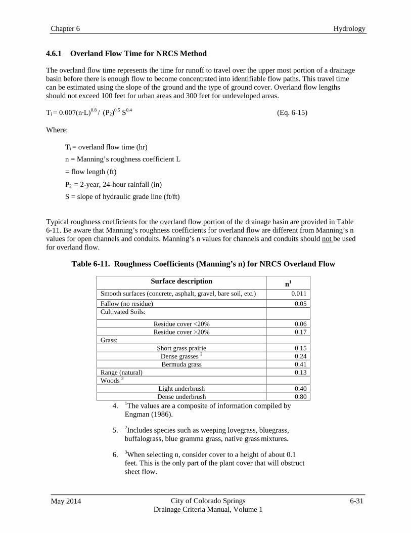
May 2014 City of Colorado Springs Drainage Criteria Manual, Volume 1
6-31
Chapter 6 Hydrology
4.6.1 Overland Flow Time for NRCS Method
The overland flow time represents the time for runoff to travel over the upper most portion of a drainage basin before there is enough flow to become concentrated into identifiable flow paths. This travel time can be estimated using the slope of the ground and the type of ground cover. Overland flow lengths should not exceed 100 feet for urban areas and 300 feet for undeveloped areas.
Ti = 0.007(n∙L)0.8 / (P2)0.5 S0.4 (Eq. 6-15)
Where:
Ti = overland flow time (hr) n = Manning’s roughness coefficient L
= flow length (ft)
P2 = 2-year, 24-hour rainfall (in) S = slope of hydraulic grade line (ft/ft)
Typical roughness coefficients for the overland flow portion of the drainage basin are provided in Table 6-11. Be aware that Manning’s roughness coefficients for overland flow are different from Manning’s n values for open channels and conduits. Manning’s n values for channels and conduits should not be used for overland flow.
Table 6-11. Roughness Coefficients (Manning’s n) for NRCS Overland Flow
Surface description n1
Smooth surfaces (concrete, asphalt, gravel, bare soil, etc.) 0.011 Fallow (no residue) 0.05 Cultivated Soils:
Residue cover <20% 0.06 Residue cover >20% 0.17
Grass: Short grass prairie 0.15
Dense grasses 2 0.24 Bermuda grass 0.41
Range (natural) 0.13 Woods 3
Light underbrush 0.40 Dense underbrush 0.80
4. 1The values are a composite of information compiled by Engman (1986).
5. 2Includes species such as weeping lovegrass, bluegrass, buffalograss, blue gramma grass, native grass mixtures.
6. 3When selecting n, consider cover to a height of about 0.1 feet. This is the only part of the plant cover that will obstruct sheet flow.
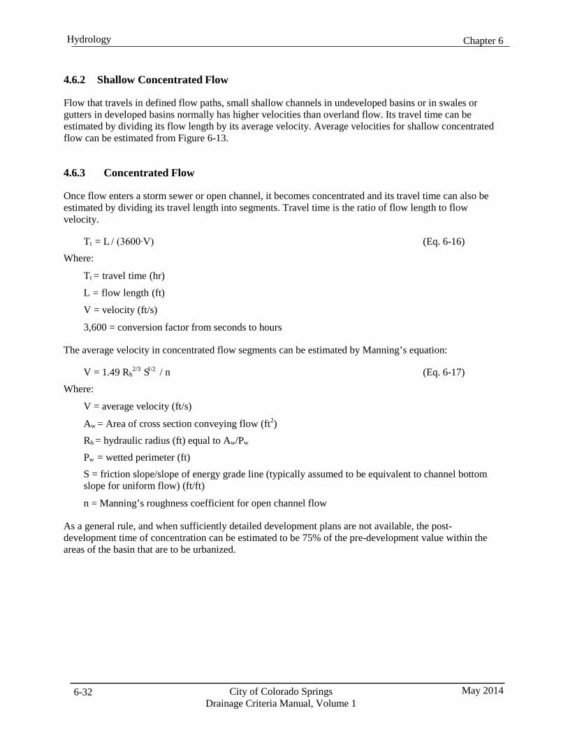
Chapter 6 Hydrology
City of Colorado Springs Drainage Criteria Manual, Volume 1
May 2014 6-32
2/3 1/2
4.6.2 Shallow Concentrated Flow
Flow that travels in defined flow paths, small shallow channels in undeveloped basins or in swales or gutters in developed basins normally has higher velocities than overland flow. Its travel time can be estimated by dividing its flow length by its average velocity. Average velocities for shallow concentrated flow can be estimated from Figure 6-13.
4.6.3 Concentrated Flow
Once flow enters a storm sewer or open channel, it becomes concentrated and its travel time can also be estimated by dividing its travel length into segments. Travel time is the ratio of flow length to flow velocity.
Tt = L / (3600∙V) (Eq. 6-16)
Where:
Tt = travel time (hr)
L = flow length (ft)
V = velocity (ft/s)
3,600 = conversion factor from seconds to hours
The average velocity in concentrated flow segments can be estimated by Manning’s equation:
V = 1.49 Rh S / n (Eq. 6-17) Where:
V = average velocity (ft/s)
Aw = Area of cross section conveying flow (ft2) Rh = hydraulic radius (ft) equal to Aw/Pw
Pw = wetted perimeter (ft) S = friction slope/slope of energy grade line (typically assumed to be equivalent to channel bottom slope for uniform flow) (ft/ft)
n = Manning’s roughness coefficient for open channel flow
As a general rule, and when sufficiently detailed development plans are not available, the post- development time of concentration can be estimated to be 75% of the pre-development value within the areas of the basin that are to be urbanized.
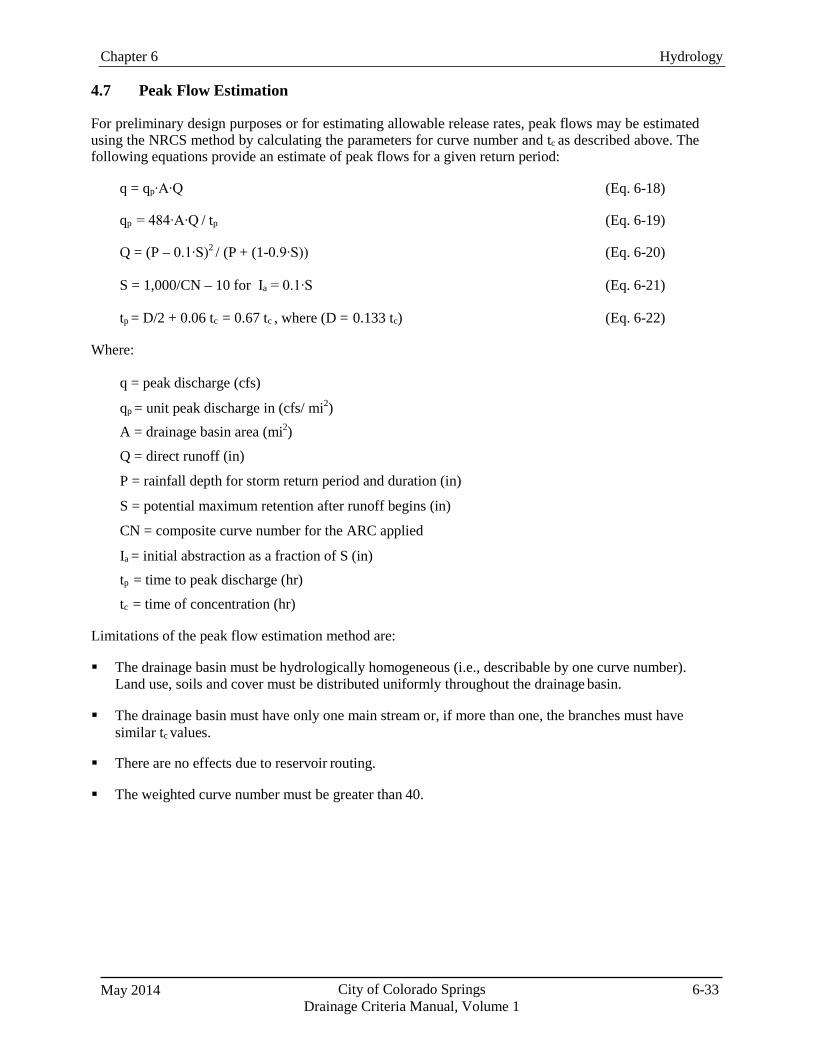
May 2014 City of Colorado Springs Drainage Criteria Manual, Volume 1
6-33
Chapter 6 Hydrology
4.7 Peak Flow Estimation
For preliminary design purposes or for estimating allowable release rates, peak flows may be estimated using the NRCS method by calculating the parameters for curve number and tc as described above. The following equations provide an estimate of peak flows for a given return period:
q = qp∙A∙Q (Eq. 6-18)
qp = 484∙A∙Q / tp (Eq. 6-19)
Q = (P – 0.1∙S)2 / (P + (1-0.9∙S)) (Eq. 6-20)
S = 1,000/CN – 10 for Ia = 0.1∙S (Eq. 6-21)
tp = D/2 + 0.06 tc = 0.67 tc , where (D = 0.133 tc) (Eq. 6-22)
Where:
q = peak discharge (cfs)
qp = unit peak discharge in (cfs/ mi2) A = drainage basin area (mi2) Q = direct runoff (in)
P = rainfall depth for storm return period and duration (in)
S = potential maximum retention after runoff begins (in)
CN = composite curve number for the ARC applied
Ia = initial abstraction as a fraction of S (in) tp = time to peak discharge (hr) tc = time of concentration (hr)
Limitations of the peak flow estimation method are: The drainage basin must be hydrologically homogeneous (i.e., describable by one curve number).
Land use, soils and cover must be distributed uniformly throughout the drainage basin. The drainage basin must have only one main stream or, if more than one, the branches must have
similar tc values.
There are no effects due to reservoir routing. The weighted curve number must be greater than 40.
Chapter 6 Hydrology
City of Colorado Springs Drainage Criteria Manual, Volume 1
May 2014 6-34
5.0 EPA Stormwater Management Model (EPA SWMM) EPA’s SWMM 5 is a computer model that is used to generate surface runoff hydrographs from sub-basins and then route and combine these hydrographs. The purpose of the discussion of SWMM in this chapter is to provide general background on the use of the model to perform more complex stormwater runoff calculations using SWMM. Complete details about the use of the model, specifics of data format and program execution is provided in the Users' Manual for SWMM 5.0. Software, Users’ Manual and other information about EPA’s SWMM 5.0 may be downloaded from the EPA website. The following section includes excerpts from the SWMM 5.0 User’s Manual (EPA 2008) that describes capabilities and primary inputs for the model.
5.1 Model Overview
The EPA Stormwater Management Model User’s Manual, Version 5.0 (EPA 2008) provides the following overview of SWMM and its hydrologic and hydraulic modeling capabilities:
[SWMM] is a dynamic rainfall-runoff simulation model used for single event or long-term (continuous) simulation of runoff quantity and quality from primarily urban areas. The runoff component of SWMM operates on a collection of subcatchment areas that receive precipitation and generate runoff and pollutant loads. The routing portion of SWMM transports this runoff through a system of pipes, channels, storage/treatment devices, pumps, and regulators. SWMM tracks the quantity and quality of runoff generated within each subcatchment, and the flow rate, flow depth, and quality of water in each pipe and channel during a simulation period comprised of multiple time steps.
SWMM accounts for various hydrologic processes that produce runoff from urban areas. These include:2
Time-varying rainfall, Evaporation of standing surface water, Snow accumulation and melting, Rainfall interception from depression storage, Infiltration of rainfall into unsaturated soil layers, Percolation of infiltrated water into groundwater layers, Interflow between groundwater and the drainage system, Nonlinear reservoir routing of overland flow.
Spatial variability in all of these processes is achieved by dividing a study area into a collection of smaller, homogeneous subcatchment areas, each containing its own fraction of pervious and impervious sub-areas. Overland flow can be routed between sub-areas, between subcatchments, or between entry points of a drainage system.
SWMM also contains a flexible set of hydraulic modeling capabilities used to route runoff and external inflows through the drainage system network of pipes, channels, storage/treatment units and diversion structures. These include the ability to:
Handle networks of unlimited size Use a wide variety of standard closed and open conduit shapes as well as natural channels Model special elements such as storage/treatment units, flow dividers, pumps, weirs, and orifices…
Model various flow regimes, such as backwater, surcharging, reverse flow, and surface [in dynamic
flow mode].

May 2014 City of Colorado Springs Drainage Criteria Manual, Volume 1
6-35
Chapter 6 Hydrology
Typical model elements for an urban drainage SWMM model include the following:
Rain Gages
Rain Gages supply precipitation data for one or more subcatchment areas in a study region. The rainfall data can be either a user-defined time series or come from an external file. Several different popular rainfall file formats currently in use are supported, as well as a standard user-defined format.
The principal input properties of rain gages include:
Rainfall data type (e.g., intensity, volume, or cumulative volume), Recording time interval (e.g., hourly, 15-minute, etc.), Source of rainfall data (input time series or external file), Name of rainfall data source.
2 For most urban drainage applications in Colorado Springs, the hydrologic processes that will generally modeled are those related to rainfall-runoff, hydraulic conveyance elements (channels and pipes) and detention routing. Other modeling capabilities including snowmelt hydrology, surface water/groundwater interactions, and water quality algorithms are usually applied only in special cases by experienced users.
Subcatchments (i.e., sub-basins):
Subcatchments are hydrologic units of land whose topography and drainage system elements direct surface runoff to a single discharge point. The user is responsible for dividing a study area into an appropriate number of subcatchments, and for identifying the outlet point of each subcatchment. Discharge outlet points can be either nodes of the drainage system or other subcatchments.
Subcatchments can be divided into pervious and impervious subareas. Surface runoff can infiltrate into the upper soil zone of the pervious subarea, but not through the impervious subarea. Impervious areas are themselves divided into two subareas - one that contains depression storage and another that does not. Runoff flow from one subarea in a subcatchment can be routed to the other subarea, or both subareas can drain to the subcatchment outlet.
Principal input parameters for subcatchments include:
[Infiltration method and associated parameters (Horton or Green Ampt—curve number algorithm is
inconsistent with TR-55 and should not be used in Colorado Springs)], Assigned rain gage, Outlet node or subcatchment, Assigned land uses, Tributary surface area, Imperviousness, Slope, Characteristic width of overland flow [additional information provided below], Manning's n for overland flow on both pervious and impervious areas [see Table 6-11], Depression storage in both pervious and impervious areas, and Percent of impervious area with no depression storage.
Chapter 6 Hydrology
City of Colorado Springs Drainage Criteria Manual, Volume 1
May 2014 6-36
Junction Nodes
Junctions are drainage system nodes where links join together. Physically, they can represent the confluence of natural surface channels, manholes in a sewer system, or pipe connection fittings. External inflows can enter the system at junctions. Excess water at a junction can become partially pressurized while connecting conduits are surcharged and can either be lost from the system or be allowed to pond atop the junction and subsequently drain back into the junction.
The principal input parameters for a junction are:
Invert elevation, Height to ground surface, Ponded surface area when flooded (optional), External inflow data (optional).
Outfall Nodes
Outfalls are terminal nodes of the drainage system used to define final downstream boundaries under Dynamic Wave flow routing. For other types of flow routing they behave as a junction. Only a single link can be connected to an outfall node.
The boundary conditions at an outfall can be described by any one of the following stage relationships:
The critical or normal flow depth in the connecting conduit, A fixed stage elevation… A user-defined time series of stage versus time.
The principal input parameters for outfalls include:
Invert elevation, Boundary condition type and stage description, Presence of a flap gate to prevent backflow through the outfall.
Storage Units
Storage units are drainage system nodes that provide storage volume. Physically they could represent storage facilities as small as a catch basin or as large as a lake. The volumetric properties of a storage unit are described by a function or table of surface area versus height.
The principal input parameters for storage units include:
Invert elevation, Maximum depth, Depth-surface area data, Evaporation potential, Ponded surface area when flooded (optional), External inflow data (optional).
May 2014 City of Colorado Springs Drainage Criteria Manual, Volume 1
6-37
Chapter 6 Hydrology
Conduits
Conduits are pipes or channels that move water from one node to another in the conveyance system. Their cross-sectional shapes can be selected from a variety of standard open and closed geometries. Most open channels can be represented with a rectangular, trapezoidal, or user-defined irregular cross-section shape.
Outlets
Most commonly in SWMM, outflow from a storage unit (detention pond) can be defined by orifice and/or weir flow that can be determined from the geometry of the outlet structure. When special head-discharge relationships exist that cannot be easily modeled with weirs and/or orifices, SWMM provides an option for the user to define an outlet rating curve. The following describes the outlet option in SWMM from the User’s Manual:
Outlets are flow control devices that are typically used to control outflows from storage units. They are used to model special head-discharge relationships that cannot be characterized by pumps, orifices, or weirs. Outlets are internally represented in SWMM as a link connecting two nodes. An outlet can also have a flap gate that restricts flow to only one direction. A user-defined rating curve determines an outlet's discharge flow as a function of the head difference across it. Control Rules can be used to dynamically adjust this flow when certain conditions exist.
SWMM also has options for flow dividers, pumps, flap gates with control rules and other features that typically are not used in most urban drainage applications.
Chapter 6 Hydrology
City of Colorado Springs Drainage Criteria Manual, Volume 1
May 2014 6-38
5.1.1 Surface Flows and Routing Features
The SWMM model is different from other hydrologic methods, which generally treat a sub-basin as a single unit with associated losses (infiltration). SWMM on the other hand conceptualizes a sub-basin as a rectangle consisting of two planes, one pervious and the other impervious and uses a kinematic wave conceptualization of overland flow to generate flow from these two planes, as shown in Figures 6-2 and 6-3 below.
SWMM represents a watershed by an aggregate of idealized runoff planes, channels, gutters, pipes and specialized units such as storage nodes, outlets, pumps, etc. The program can accept rainfall hyetographs and make a step-by-step accounting of rainfall infiltration losses in pervious areas, surface retention, overland flow, and gutter flow leading to the calculation of hydrographs. After SWMM calculates hydrographs from a number of sub-basins, the resulting hydrographs from these sub-basins can be combined and routed through a series of links (i.e., channels, gutters, pipes, dummy links, etc.) and nodes (i.e., junctures, storage, diversion, etc.) to compute the resultant hydrographs at any number of design points within the watershed.
Stormwater runoff hydrographs generated by SWMM using either the Horton or Green-Ampt rainfall/runoff methods can be routed through a system of stormwater conveyances, diversions, storage facilities, and other elements of a complex urban watershed. It is up to the model user to demonstrate compatibility between SWMM model results and model results that would be achieved using the NRCS curve number procedures, both in terms of rates and volumes. Under no circumstances shall the curve number method in SWMM be used because it is not an accurate representation of the NRCS curve number loss method as published in TR-55 and implemented in HEC-HMS.
Figure 6-2 illustrates how a single kinematic flow plane can be used to represent a portion of a watershed with overland flow occurring over a specified overland flow length (Xw) and being collected and conveyed to the sub-basin outlet by channel or gutter flow with a width of Lw. The choice of Lw, which also defines Xw because the plane is conceptualized as a rectangle, is one of the most important (and sensitive) parameters in a SWMM model. Another key parameter for modeling overland flow in SWMM is the Manning’s n value for overland flow. These values are provided in Table 6-11 and should not be confused with Manning’s n values for open channel flow, which are typically considerably lower than Manning’s n values for overland flow.
Figure 6-3 illustrates how this would be applied to a sub-basin with both pervious and impervious kinematic wave planes.
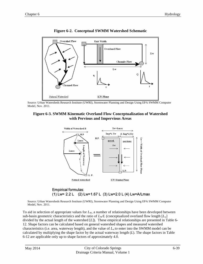
May 2014 City of Colorado Springs Drainage Criteria Manual, Volume 1
6-39
Chapter 6 Hydrology
Figure 6-2. Conceptual SWMM Watershed Schematic
Source: Urban Watersheds Research Institute (UWRI), Stormwater Planning and Design Using EPA SWMM Computer Model, Nov. 2011.
Figure 6-3. SWMM Kinematic Overland Flow Conceptualization of Watershed
with Pervious and Impervious Areas
Source: Urban Watersheds Research Institute (UWRI), Stormwater Planning and Design Using EPA SWMM Computer Model, Nov. 2011.
To aid in selection of appropriate values for LW, a number of relationships have been developed between sub-basin geometric characteristics and the ratio of LW/L (conceptualized overland flow length [Lw] divided by the actual length of the watershed [L]). These empirical relationships are presented in Table 6- 12. Shape factors can be calculated based on general watershed shapes and measured watershed characteristics (i.e. area, waterway length), and the value of Lw to enter into the SWMM model can be calculated by multiplying the shape factor by the actual waterway length (L). The shape factors in Table 6-12 are applicable only up to shape factors of approximately 4.0.
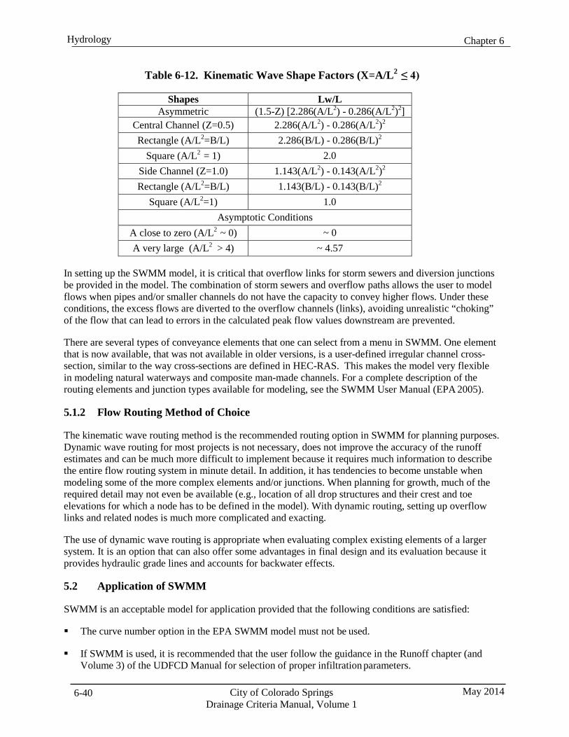
Chapter 6 Hydrology
City of Colorado Springs Drainage Criteria Manual, Volume 1
May 2014 6-40
Table 6-12. Kinematic Wave Shape Factors (X=A/L2 ≤ 4)
Shapes Lw/L Asymmetric (1.5-Z) [2.286(A/L2) - 0.286(A/L2)2]
Central Channel (Z=0.5) 2.286(A/L2) - 0.286(A/L2)2
Rectangle (A/L2=B/L) 2.286(B/L) - 0.286(B/L)2
Square (A/L2 = 1) 2.0 Side Channel (Z=1.0) 1.143(A/L2) - 0.143(A/L2)2
Rectangle (A/L2=B/L) 1.143(B/L) - 0.143(B/L)2
Square (A/L2=1) 1.0 Asymptotic Conditions
A close to zero (A/L2 ~ 0) ~ 0 A very large (A/L2 > 4) ~ 4.57
In setting up the SWMM model, it is critical that overflow links for storm sewers and diversion junctions be provided in the model. The combination of storm sewers and overflow paths allows the user to model flows when pipes and/or smaller channels do not have the capacity to convey higher flows. Under these conditions, the excess flows are diverted to the overflow channels (links), avoiding unrealistic “choking” of the flow that can lead to errors in the calculated peak flow values downstream are prevented.
There are several types of conveyance elements that one can select from a menu in SWMM. One element that is now available, that was not available in older versions, is a user-defined irregular channel cross- section, similar to the way cross-sections are defined in HEC-RAS. This makes the model very flexible in modeling natural waterways and composite man-made channels. For a complete description of the routing elements and junction types available for modeling, see the SWMM User Manual (EPA 2005).
5.1.2 Flow Routing Method of Choice
The kinematic wave routing method is the recommended routing option in SWMM for planning purposes. Dynamic wave routing for most projects is not necessary, does not improve the accuracy of the runoff estimates and can be much more difficult to implement because it requires much information to describe the entire flow routing system in minute detail. In addition, it has tendencies to become unstable when modeling some of the more complex elements and/or junctions. When planning for growth, much of the required detail may not even be available (e.g., location of all drop structures and their crest and toe elevations for which a node has to be defined in the model). With dynamic routing, setting up overflow links and related nodes is much more complicated and exacting.
The use of dynamic wave routing is appropriate when evaluating complex existing elements of a larger system. It is an option that can also offer some advantages in final design and its evaluation because it provides hydraulic grade lines and accounts for backwater effects.
5.2 Application of SWMM
SWMM is an acceptable model for application provided that the following conditions are satisfied:
The curve number option in the EPA SWMM model must not be used.
If SWMM is used, it is recommended that the user follow the guidance in the Runoff chapter (and
Volume 3) of the UDFCD Manual for selection of proper infiltration parameters.
May 2014 City of Colorado Springs Drainage Criteria Manual, Volume 1
6-41
Chapter 6 Hydrology
Regardless of the infiltration method used, it is incumbent on the design engineer to demonstrate reasonable equivalency between SWMM results and those that would be obtained from the standard NRCS procedure in terms of runoff rates and volumes. Justification must be provided for why the SWMM model is being used.
The SWMM model should not be applied by inexperienced users.
Proprietary versions of SWMM for which there is no valid software license to conduct a detailed
review and run of the model are not permitted.
For additional guidance, refer to the Runoff chapter and Volume 3 of the UDFCD Manual and/or the EPA SWMM manual available on EPA’s website.
6.0 Sub-basin Delineation and Hydrograph Routing Rainfall/runoff models such as the NRCS dimensionless unit hydrograph method within the HEC-HMS program and EPA SWMM require that a systematic approach be used to delineate and combine sub- basins within the larger drainage basin being evaluated. Sub-basins should be about 130 acres in size and be delineated to represent areas of the basin that are relatively homogeneous. Besides topography, features that might be used to identify sub-basins are land uses (existing and future), soil types and land cover. Identifying locations or design points where flow information is important may also determine sub-basin delineation.
Hydrographs from each sub-area must be routed and combined to determine the hydrograph for the entire drainage area contributing to design points. Sub-basins are joined by routing elements that may have a wide variety of characteristics, but are typically open channels. Hydrograph routing must account for the effects of flow traveling in channels, through storage areas and other features, such as diversion channels that change the hydrograph. The designer should identify sub-basins and routing elements prior to coding a model so that element numbers and descriptions are systematic and help in the interpretation of model results.
6.1 Channel Routing
The Kinematic Wave Channel Routing Method or the Muskingum-Cunge Method are the preferred methods, although other methods may be acceptable upon approval on a case-by-case basis. Where appreciable hydrograph attenuation is anticipated due to storage effects along a reach, a method that explicitly accounts for channel storage effects, such as the Modified-Puls method, may also be applied.
6.1.1 Kinematic Wave Channel Routing
The Kinematic Wave Channel Routing Method is used to route an upstream inflow hydrograph through a reach with known geometric characteristics. Theoretically, a flood wave routed by the Kinematic Wave Channel Routing Method is translated, but not attenuated, through a reach (although a degree of attenuation is introduced by the finite difference solution to the governing equations). The lack of significant peak attenuation during hydrograph translation is a fairly common characteristic of urban conveyances. Table 6-13 summarizes input parameters required for the Kinematic Wave Channel Routing Method. Manning’s roughness values should be selected in accordance with the Open Channels chapter.
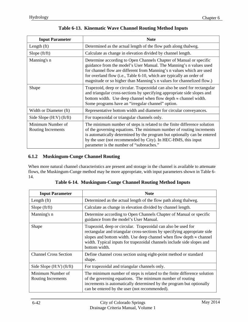
Chapter 6 Hydrology
City of Colorado Springs Drainage Criteria Manual, Volume 1
May 2014 6-42
Table 6-13. Kinematic Wave Channel Routing Method Inputs
Input Parameter Note
Length (ft) Determined as the actual length of the flow path along thalweg. Slope (ft/ft) Calculate as change in elevation divided by channel length. Manning's n Determine according to Open Channels Chapter of Manual or specific
guidance from the model’s User Manual. The Manning’s n values used for channel flow are different from Manning’s n values which are used for overland flow (i.e., Table 6-10, which are typically an order of magnitude or so higher than Manning’s n values for channelized flow.)
Shape Trapezoid, deep or circular. Trapezoidal can also be used for rectangular and triangular cross-sections by specifying appropriate side slopes and bottom width. Use deep channel when flow depth ≈ channel width. Some programs have an “irregular channel” option.
Width or Diameter (ft) Representative bottom width and diameter for circular conveyances. Side Slope (H:V) (ft/ft) For trapezoidal or triangular channels only. Minimum Number of Routing Increments
The minimum number of steps is related to the finite difference solution of the governing equations. The minimum number of routing increments is automatically determined by the program but optionally can be entered by the user (not recommended by City). In HEC-HMS, this input parameter is the number of “subreaches.”
6.1.2 Muskingum-Cunge Channel Routing
When more natural channel characteristics are present and storage in the channel is available to attenuate flows, the Muskingum-Cunge method may be more appropriate, with input parameters shown in Table 6- 14.
Table 6-14. Muskingum-Cunge Channel Routing Method Inputs
Input Parameter Note Length (ft) Determined as the actual length of the flow path along thalweg. Slope (ft/ft) Calculate as change in elevation divided by channel length. Manning's n Determine according to Open Channels Chapter of Manual or specific
guidance from the model’s User Manual. Shape Trapezoid, deep or circular. Trapezoidal can also be used for
rectangular and triangular cross-sections by specifying appropriate side slopes and bottom width. Use deep channel when flow depth ≈ channel width. Typical inputs for trapezoidal channels include side slopes and bottom width.
Channel Cross Section Define channel cross section using eight-point method or standard shape.
Side Slope (H:V) (ft/ft) For trapezoidal and triangular channels only. Minimum Number of Routing Increments
The minimum number of steps is related to the finite difference solution of the governing equations. The minimum number of routing increments is automatically determined by the program but optionally can be entered by the user (not recommended).
May 2014 City of Colorado Springs Drainage Criteria Manual, Volume 1
6-43
Chapter 6 Hydrology
6.2 Reservoir Routing
For watersheds with significant detention structures, the effects of routing hydrographs through facilities can have important implications on the peak flow rates and their timing from sub-watersheds. Hydrologic modeling and analysis must account for the effects of detention by performing reservoir routing calculations. The criteria and methods for reservoir routing are presented in the Storage Chapter of this Manual and are also documented in the user’s manuals and technical reference manuals for many of the software packages. Options for routing using common methods are included in HEC-HMS and SWMM and many other commercially available hydrology software packages.
7.0 Volume Reduction Methods Conventional methods for evaluating increased runoff volume and peak flows associated with urbanization make certain assumptions about the relationship between impervious surfaces and their effect on runoff. A primary assumption of many conventional methods is that the impervious surfaces are directly connected to the drainage features receiving the runoff. In reality, this connection is not always so direct, and adjusting land use planning and design practices to “disconnect” impervious areas (i.e. route flows from impervious areas to pervious areas rather than the gutter and street inlets), can reduce the rate and volume of runoff downstream. Many of the same practices that have been developed for improving water quality are also beneficial for reducing runoff volumes and peak flows. These practices can generally be referred to as PCMs and GI approaches. The effects of urbanization, the selection of PCMs, the implementation of GI approaches and their potential for reducing runoff are discussed in detail in Volume 2 in this Manual. Key concepts associated with these practices are briefly summarized below with regard to their implications for estimating runoff.
7.1 Four Step Process
The Four Step Process focuses on reducing runoff volumes, treating the water quality capture volume (WQCV), stabilizing drainageways, and implementing long-term source controls. The Four Step Process pertains to management of smaller, frequently occurring events, as opposed to larger storms for which drainage and flood control infrastructure are sized. The Four Step Process is summarized as follows:
1. Step 1: Reduce runoff by disconnecting impervious area, eliminating “unnecessary” impervious
area and encouraging infiltration into soils that are suitable.
2. Step 2: Treat and slowly release the WQCV.
3. Step 3: Stabilize stream channels.
4. Step 4: Implement source controls.
Implementation of these four steps helps to achieve stormwater permit requirements. Added benefits of implementing the complete process can include improved site aesthetics through functional landscaping features that also provide water quality benefits. Additionally, volume reduction can decrease required storage volumes, increasing developable land and reduce the size of downstream facilities. A detailed description of the Four Step Process is provided in Volume 2 of this Manual, providing PCM selection tools and quantitative procedures for completing these steps.
There are two primary approaches to reducing runoff volume and peak flows provided in this Manual. The first is to represent volume reduction practices in the standard methods by converting the effects of these practices into a reduced value for imperviousness on a basin or sub-basin level. The second is to more directly represent the physical impacts of the PCMs and GI practices through modeling each of the
Chapter 6 Hydrology
City of Colorado Springs Drainage Criteria Manual, Volume 1
May 2014 6-44
elements at a sub-basin level. There is a significant difference in the level of detail and expertise required in the application of these two approaches. Most situations can be reasonably addressed through the application of an adjusted value for imperviousness, or “effective imperviousness”.
7.2 Effective Imperviousness
Runoff calculations typically assume that imperviousness in a drainage basin is directly connected to the receiving system or that combines impervious runoff factors with pervious factors, creating a composite value. To adequately evaluate methods for volume reduction practices such as Minimizing Directly Connected Impervious Area (MDCIA), PCMs, and GI, it is necessary to be able to segregate these sources of runoff. Conceptually, the relationship between impervious and pervious areas is shown in Figure 6-4.
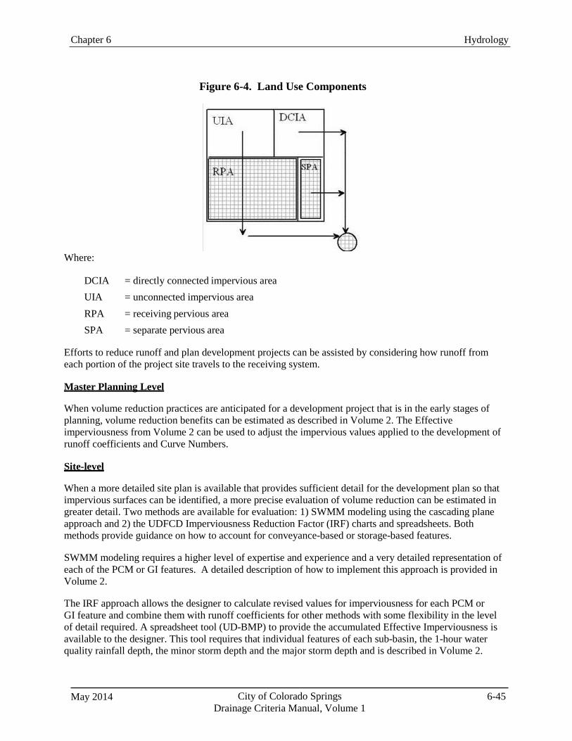
May 2014 City of Colorado Springs Drainage Criteria Manual, Volume 1
6-45
Chapter 6 Hydrology
Figure 6-4. Land Use Components
Where:
DCIA = directly connected impervious area UIA = unconnected impervious area RPA = receiving pervious area SPA = separate pervious area
Efforts to reduce runoff and plan development projects can be assisted by considering how runoff from each portion of the project site travels to the receiving system.
Master Planning Level
When volume reduction practices are anticipated for a development project that is in the early stages of planning, volume reduction benefits can be estimated as described in Volume 2. The Effective imperviousness from Volume 2 can be used to adjust the impervious values applied to the development of runoff coefficients and Curve Numbers.
Site-level
When a more detailed site plan is available that provides sufficient detail for the development plan so that impervious surfaces can be identified, a more precise evaluation of volume reduction can be estimated in greater detail. Two methods are available for evaluation: 1) SWMM modeling using the cascading plane approach and 2) the UDFCD Imperviousness Reduction Factor (IRF) charts and spreadsheets. Both methods provide guidance on how to account for conveyance-based or storage-based features.
SWMM modeling requires a higher level of expertise and experience and a very detailed representation of each of the PCM or GI features. A detailed description of how to implement this approach is provided in Volume 2.
The IRF approach allows the designer to calculate revised values for imperviousness for each PCM or GI feature and combine them with runoff coefficients for other methods with some flexibility in the level of detail required. A spreadsheet tool (UD-BMP) to provide the accumulated Effective Imperviousness is available to the designer. This tool requires that individual features of each sub-basin, the 1-hour water quality rainfall depth, the minor storm depth and the major storm depth and is described in Volume 2.
Chapter 6 Hydrology
City of Colorado Springs Drainage Criteria Manual, Volume 1
May 2014 6-46
7.2.1 Application of Effective Imperviousness
When the details of how a development project may be constructed are not known, the benefits of PCM and GI practices can be approximated so that hydrologic estimates of runoff and infrastructure sizing can be adjusted in anticipation of future implementation.
Once determined, the adjusted values of imperviousness can be applied to any of the methods described in the chapter to calculate revised values for runoff volume and peak flows.
The NRCS method presented inTR-55 includes procedures for accounting for disconnected
impervious area. TR-55 guidance should be used for adjusting HEC-HMS model parameters to account for disconnected impervious area.
The UDFCD Imperviousness Reduction Factor (IRF) charts and spreadsheets provide another method
to account for volume reduction due to PCMs that provide the WQCV and conveyance-based GI practices (e.g., swales) that promote infiltration. When detailed site characteristics and routing are known, the UDFCD method can be used to calculate an “effective imperviousness” that can then be used to look up revised Rational Method runoff coefficients or curve numbers corresponding to the reduced imperviousness. The IRF method is described in detail in Volume 3 of the UDFCD Manual and in a peer-reviewed paper by Guo et al. (2010).
7.2.2 Effective Imperviousness Spreadsheet
Because most sites will consist of multiple sub-basins, some using the conveyance-based approach and others using the storage-based approach, a spreadsheet capable of applying both approaches to multiple sub-basins to determine overall site effective imperviousness and volume reduction benefits is a useful tool. The UD-BMP workbook has this capability. A full description of the spreadsheet capabilities are provided in Volume 2.
8.0 Estimating Baseflows
8.1 Baseflow Estimates for Gaged Streams
When reliable low-flow stream measurements are available, as they are for many larger drainageways such as Fountain and Monument Creeks, the best method for developing baseflow estimates is to analyze the long-term gage record, using baseflow separation techniques and knowledge of timing of major diversions and other factors related to the administration of water rights to develop a baseflow hydrograph (i.e., a hydrograph of flow versus time, excluding the effects of storm events). This baseflow hydrograph can then be analyzed statistically to determine probabilities of different baseflow levels, as well as seasonal trends. It is typically acceptable to adjust the measured baseflows from the gage nearest the site by multiplying the measured flow by the ratio of watershed area contributing at the point of interest on the stream to the area contributing to the stream gage. The Fountain Creek Watershed Hydrology Report (USACE 2006) provides some baseflow data.
When determining baseflow at gaged sites, baseflow separation techniques can be used. Baseflow separation is the process of dividing a hydrograph into direct runoff and baseflow. Several different techniques can be used for baseflow separation, the simplest of which is to draw a straight line on the hydrograph extending from the point of lowest discharge before surface runoff begins across to the point on the receding limb of the hydrograph where it is evident that flows have approached pre-storm baseflow levels. Other techniques for baseflow separation can be found in many hydrology references and include exponential extension of hydrograph recession to baseflow conditions.
May 2014 City of Colorado Springs Drainage Criteria Manual, Volume 1
6-47
Chapter 6 Hydrology
8.2 Baseflow Estimates for Ungaged Streams (Developing Relationships for Baseflow as a Function of Area)
Methods for developing estimates of baseflows for ungaged streams are not widely available and are difficult to develop due to the lack of baseflow data on many smaller drainageways. This section summarizes a method that was recently developed in the Denver metropolitan area that could serve as a method for rough estimates of baseflows in Colorado Springs.
In the case of the UDFCD analysis, regional data were analyzed to develop relationships for baseflow as a function of tributary area using statistical software. These relationships may be used to estimate baseflow in gaged or ungaged areas. UDFCD developed baseflow equations for watersheds in the Denver area using flow data that have been collected at 29 gage sites around the Denver area for over 30 years. This data set was used to characterize baseflow as a function of area using the following steps:
1. The baseflow data set was scrutinized for outlier values. All zero and apparent rainfall affected
flows (i.e., higher flow values) were removed.
2. The baseflow data for each gage site was ranked from low to high and Weibul probability distributions were computed.
3. The data were plotted to identify the 95th percentile and lower values of baseflows. Anything
above 95th percentile value was set to the 95th percentile value.
4. The “cleaned-up” monthly baseflow data was run through the U.S. Army Corps of Engineers HEC-SSP software. A Bulletin 17B protocol flow frequency analysis was run for each gage. The 1.01- and 2-year monthly baseflows were determined for each gage.
5. All of the computed 1.01-year and 2-year baseflow values for each month were plotted against
the gross tributary area of each gage site and a regression equation was determined.
A linear regression equation was developed to represent baseflows for each month and had a high coefficient of regression (R2 value indicating a good statistical correlation) for the 2-year flows. The 1.01-year regressions did not have consistently acceptable regression coefficients, and for many of the months, regression coefficients were quite low; therefore, these data were not used in baseflow estimation for UDFCD’s purposes. The baseflow regression equations for each month take the form of Equation 6- 22 below. The coefficients (K values) are summarized in Table 6-15.
Q = K∙A (Eq. 6-23)
Where:
Q = 2-year baseflow (cfs)—the 2-year baseflow is the peak baseflow that could be expected in any given month on average once every two years, or in other terms, the flow that would have a 50% chance of being exceeded in any given month K = the linear regression coefficient—unless monthly analysis of baseflows is needed, a coefficient, K, of 0.3 should be applied
A = tributary drainage basin area (mi2)
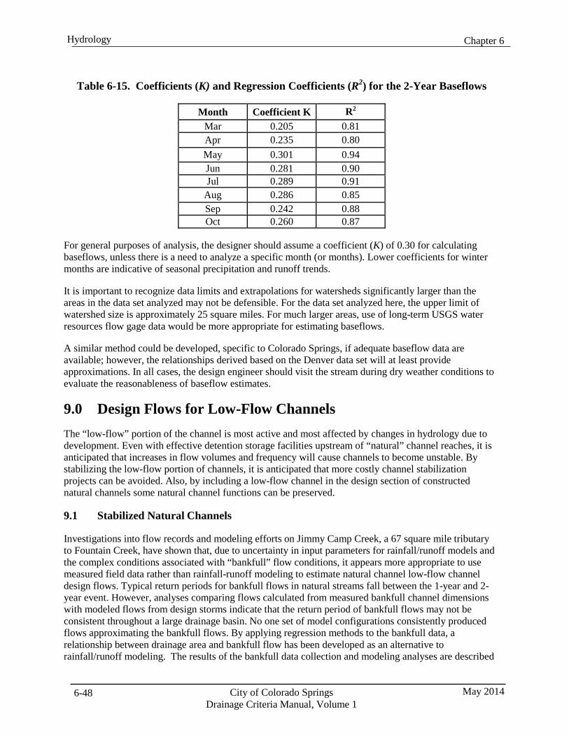
Chapter 6 Hydrology
City of Colorado Springs Drainage Criteria Manual, Volume 1
May 2014 6-48
Table 6-15. Coefficients (K) and Regression Coefficients (R2) for the 2-Year Baseflows
Month Coefficient K R2
Mar 0.205 0.81 Apr 0.235 0.80 May 0.301 0.94 Jun 0.281 0.90 Jul 0.289 0.91
Aug 0.286 0.85 Sep 0.242 0.88 Oct 0.260 0.87
For general purposes of analysis, the designer should assume a coefficient (K) of 0.30 for calculating baseflows, unless there is a need to analyze a specific month (or months). Lower coefficients for winter months are indicative of seasonal precipitation and runoff trends.
It is important to recognize data limits and extrapolations for watersheds significantly larger than the areas in the data set analyzed may not be defensible. For the data set analyzed here, the upper limit of watershed size is approximately 25 square miles. For much larger areas, use of long-term USGS water resources flow gage data would be more appropriate for estimating baseflows.
A similar method could be developed, specific to Colorado Springs, if adequate baseflow data are available; however, the relationships derived based on the Denver data set will at least provide approximations. In all cases, the design engineer should visit the stream during dry weather conditions to evaluate the reasonableness of baseflow estimates.
9.0 Design Flows for Low-Flow Channels The “low-flow” portion of the channel is most active and most affected by changes in hydrology due to development. Even with effective detention storage facilities upstream of “natural” channel reaches, it is anticipated that increases in flow volumes and frequency will cause channels to become unstable. By stabilizing the low-flow portion of channels, it is anticipated that more costly channel stabilization projects can be avoided. Also, by including a low-flow channel in the design section of constructed natural channels some natural channel functions can be preserved.
9.1 Stabilized Natural Channels
Investigations into flow records and modeling efforts on Jimmy Camp Creek, a 67 square mile tributary to Fountain Creek, have shown that, due to uncertainty in input parameters for rainfall/runoff models and the complex conditions associated with “bankfull” flow conditions, it appears more appropriate to use measured field data rather than rainfall-runoff modeling to estimate natural channel low-flow channel design flows. Typical return periods for bankfull flows in natural streams fall between the 1-year and 2- year event. However, analyses comparing flows calculated from measured bankfull channel dimensions with modeled flows from design storms indicate that the return period of bankfull flows may not be consistent throughout a large drainage basin. No one set of model configurations consistently produced flows approximating the bankfull flows. By applying regression methods to the bankfull data, a relationship between drainage area and bankfull flow has been developed as an alternative to rainfall/runoff modeling. The results of the bankfull data collection and modeling analyses are described
May 2014 City of Colorado Springs Drainage Criteria Manual, Volume 1
6-49
Chapter 6 Hydrology
in a technical memorandum titled; ”Low Flow Estimation for Natural Channel Design”, (Matrix Design Group, March 22, 2013).
The measured bankfull values were adjusted to account for variability in the data and to provide a low- flow design value that should more reliably transport sediment loads. The low-flow regression equations for stabilized natural channels are provided as Equation 6-2 below. This approach assumes that runoff from development will be attenuated by passing through detention storage facilities so that flow in the design reach are similar to flows that occurred in the undeveloped basin.
Qlow-flow = 103 DA0.4 (Eq. 6-2) Where:
Qlow-flow = design low-flow discharge (cfs) DA = tributary drainage basin area (mi2)
9.2 Constructed Natural Channels and Constructed Channels
For constructed natural channels or constructed channels where the design is based on fully developed or partially developed condition flows without full attenuation due to detention storage, the 2-year storm event based on developed basin conditions shall be used for design of the low-flow channel.
9.3 Fountain Creek and Monument Creek
To determine the low flow for designs on Fountain Creek and Monument Creek, the long-term gage data should be analyzed for the project reach using standard methods for statistical analysis (e.g., Log Pearson III analysis with a sufficient period of record of good quality data). Based on the frequency analysis of gage data, the 1.3-year flow should be used to size low-flow channel improvements.
If sufficient baseflow data are available, a similar procedure should be used to estimate baseflows through the project reach, including considerations for seasonal variability.
10.0 Design Hydrology Based on Future Development Conditions 10.1 On-site Flow Analysis
Full site development shall be considered when the design engineer selects runoff coefficients or impervious percentage values and performs the hydrologic analyses for on-site areas. Changes in flow patterns and sub-basin boundaries due to site grading and proposed street and roadway locations must be considered. Time of concentration calculations must reflect increased surface flow velocities and velocities associated with proposed runoff conveyance facilities.
10.2 Off-site Flow Analysis
Fully developed conditions shall be considered when the design engineer selects runoff coefficients or impervious percentage values and performs the hydrologic analyses for off-site areas. Where the off-site area is undeveloped, fully developed conditions shall be projected using the best available land use information, current zoning, or approved land use applications. The City shall be consulted to verify all assumptions regarding future development in off-site areas. If information is not available, runoff calculations shall be based on the impervious percentage value presented in Table 6-6.
Where the off-site area is fully or partially developed, the hydrologic analysis shall be based on existing platted land uses, constructed conveyance facilities, and developed topographic characteristics. Consideration of potential benefits related to detention provided in off-site areas depends on the type of
Chapter 6 Hydrology
City of Colorado Springs Drainage Criteria Manual, Volume 1
May 2014 6-50
detention provided and whether or not the off-site tributary area is part of a major drainageway basin, as discussed previously in this chapter.
11.0 Consideration of Detention Benefits in Off-Site Flow Analysis 11.1 Major Drainageway Basin Distinction
When determining whether on-site detention benefits may be recognized in off-site flow analysis, a distinction is made between systems that are part of the major drainageway basin system (defined as generally greater than 130 acres of tributary area) and for those that are higher upstream in the watershed (generally less than 130 acres of tributary area), and are not considered a part of the major drainageway basin system.
11.2 Analysis When System is Part of a Major Drainageway Basin
When determining minor storm event peak flow rates from off-site areas, no benefit shall be recognized for detention in the off-site areas.
For determination of peak flow rates from the major storm event and other less frequent events, no benefit shall be recognized for on-site detention in the off-site areas. While the smaller on-site detention ponds provide some benefit immediately downstream, it has been shown that the benefit diminishes as the number of relatively small ponds increases with the accumulation of more tributary area. It has been suggested that there may be very little benefit along the major drainageway when numerous on-site detention ponds are provided in the upstream watershed (Urbonas and Glidden 1983).
For determination of peak flow rates from the major storm event and other less frequent events, the benefits provided by constructed, publicly operated and maintained, regional detention facilities in the off-site areas may be recognized, if approved by the City. On-site and regional detention facilities are discussed in more detail in the Storage Chapter.
11.3 Analysis When System is Not Part of a Major Drainageway Basin
When determining minor storm event peak flow rates from off-site areas, no benefit shall be recognized for detention in the off-site areas.
For determination of peak flow rates from the major storm event and other less frequent events, runoff may be calculated assuming historic runoff rates if the off-site area is undeveloped. Benefits of constructed and City-accepted on-site detention facilities in the off-site area can be recognized if the off- site area is partially or fully developed.
12.0 Additional Considerations Regarding Conveyance of Runoff from Major Drainageway Basins
Although the benefits provided by constructed, publicly operated and maintained regional detention facilities may be recognized if approved by Colorado Springs Engineering, a fully developed “emergency conditions” scenario must be analyzed that does not consider the benefits of upstream regional detention facilities. Conveyance facilities and channel improvements may be designed considering the benefits of upstream regional detention when approved by Colorado Springs Engineering. In addition, it must be shown that the “emergency conditions” runoff can be safely conveyed, using additional capacity provided by freeboard or buffer areas, without impacting proposed structures or homes. Consideration of this additional scenario is warranted because of the potential threat to public health, safety, and welfare associated with flooding along major drainageways.
May 2014 City of Colorado Springs Drainage Criteria Manual, Volume 1
6-51
Chapter 6 Hydrology
13.0 References City of Colorado Springs. 2012. Memorandum to SMA Project Team Leaders from Dan Bare, Project
Manager, Re: Stormwater Management Assessment and Standards Development Project Proposed Rainfall and Standard Design Storms. June 2012.
Guo, J.C.Y, G. E. Blackler, T. A. Earles, and K. MacKenzie. 2010. Incentive Index Developed to Evaluate
Storm-Water Low-Impact Designs. Journal of Environmental Engineering, December, Vol. 136, Issue 12.
Guo, J.C.Y. 1999. Streets Hydraulics and Inlet Sizing: Water Resources Publications, Littleton, CO.
Guo, J.C.Y. publication pending as of 2012. Storm Centering Approach for Flood Predictions from Large
Watersheds. ASCE Journal of Hydrologic Engineering (publication pending).
Miller, J.F., Hensen, E.M., Fenn, D.D., Shcreiner, L.C., and Jensen, D.T. 1988. Hyrdometeorological Report 55A: Probable Maximum Precipitation Estimates – United States Between the Continental Divide and the 103rd Meridian (GPO Publication No. 1988-215-175). U.S. Department of Commerce, National Oceanic and Atmospheric Administration; U.S. Department of Army Corps of Engineers; U.S. Department of Interior, Bureau of Reclamation. Washington, D.C.: U.S. Government Printing Office.
U.S. Department of Agriculture (USDA). 1981. Soil Survey of El Paso County Area, Colorado.
U.S. Department of Agriculture (USDA). 1992. Soil Survey of Pike National Forest, Eastern Colorado,
Parts of Douglas, El Paso, Jefferson and Teller Counties, Colorado. Prepared by Forest Service and Soil Conservation Service in Cooperation with Colorado Agricultural Experiment Station.
U.S. Department of Agriculture (USDA). 1993. Soil Survey Manual. Handbook No. 18, USDA, Soil Survey
Division Staff.
U.S. Department of Agriculture Natural Resources Conservation Service (NRCS). 1986. Urban Hydrology for Small Watersheds. Technical Release 55, Conservation Engineering Division.
U.S. Department of Commerce, National Oceanic and Atmospheric Administration, US
Department of Army Corps of Engineers, US Department of Interior, Bureau of Reclamation. 1988. Hydrometeorological Report No. 55A (HMR-55A), Probable Maximum Precipitation Estimates—United States Between the Continental Divide and the 103rd Meridian. Silver Springs, MD.
U.S. Environmental Protection Agency (EPA). 2008. Stormwater Management Model User’s Manual, Version 5.0. EPA/600/R-05/040, Revised March 2008. By Lewis A. Rossman, Water Supply and Water Resources Division, National Risk Management Research Laboratory, Cincinnati, OH.
Chapter 6 Hydrology
City of Colorado Springs Drainage Criteria Manual, Volume 1
May 2014 6-52
Urban Drainage and Flood Control District (UDFCD). 2001. Denver Urban Storm Drainage Criteria Manual, Volumes 1 & 2. UDFCD, Denver, CO. Revised April 2008.
Urban Watersheds Research Institute (UWRI). 2011. Water Quality Capture Optimization and Statistics
Model (WQ-COSM). April 2011 Edition. Urban Watersheds Research Institute, Denver, CO.
Urbonas, B. and M. Glidden. 1983. Potential Effectiveness of Detention Policies. Presented at the Southwest Storm Drainage Symposium: Texas A&M, November.
Urbonas, B., C.Y. Guo, and L.S. Tucker. 1990. Optimization of Stormwater Quality Capture Volume. Urban
Stormwater Quality Enhancement. Proceedings of the Engineering Foundation Conference. American Society of Civil Engineering (ASCE). New York, NY.
Urbonas, B., L. A. Roesner, and C. Y. Guo. 1996. Hydrology for Optimal Sizing of Urban Runoff Treatment
Control Systems. Water Quality International. International Association for Water Quality: London, England.
Water Environment Federation (WEF) and American Society of Civil Engineers (ASCE). 1998. Urban
Runoff Quality Management, WEF Manual of Practice No. 23 and ASCE Manual and Report on Engineering Practice No. 87. Water Environment Federation (WEF): Alexandria, VA.
Wright Water Engineers, Inc. 2011. Technical Memorandum to the City of Colorado Springs Regarding
Water Quality Capture Volume Analysis for Colorado Springs, April 6, 2011.
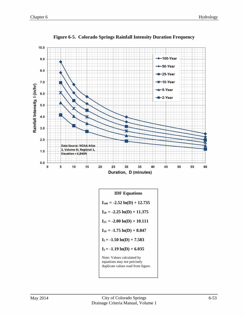
Chapter 6 Hydrology
May 2014 City of Colorado Springs Drainage Criteria Manual, Volume 1
6-53
Figure 6-5. Colorado Springs Rainfall Intensity Duration Frequency
IDF Equations
I100 = -2.52 ln(D) + 12.735
I50 = -2.25 ln(D) + 11.375
I25 = -2.00 ln(D) + 10.111
I10 = -1.75 ln(D) + 8.847
I5 = -1.50 ln(D) + 7.583
I2 = -1.19 ln(D) + 6.035
Note: Values calculated by equations may not precisely duplicate values read from figure.
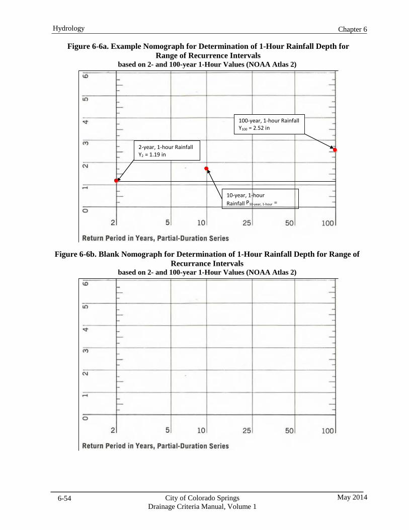
Chapter 6 Hydrology
City of Colorado Springs Drainage Criteria Manual, Volume 1
May 2014 6-54
Figure 6-6a. Example Nomograph for Determination of 1-Hour Rainfall Depth for
Range of Recurrence Intervals based on 2- and 100-year 1-Hour Values (NOAA Atlas 2)
Figure 6-6b. Blank Nomograph for Determination of 1-Hour Rainfall Depth for Range of Recurrance Intervals
based on 2- and 100-year 1-Hour Values (NOAA Atlas 2)
100-year, 1-hour Rainfall Y100 = 2.52 in
2-year, 1-hour Rainfall Y2 = 1.19 in
10-year, 1-hour Rainfall P10-year, 1-hour =
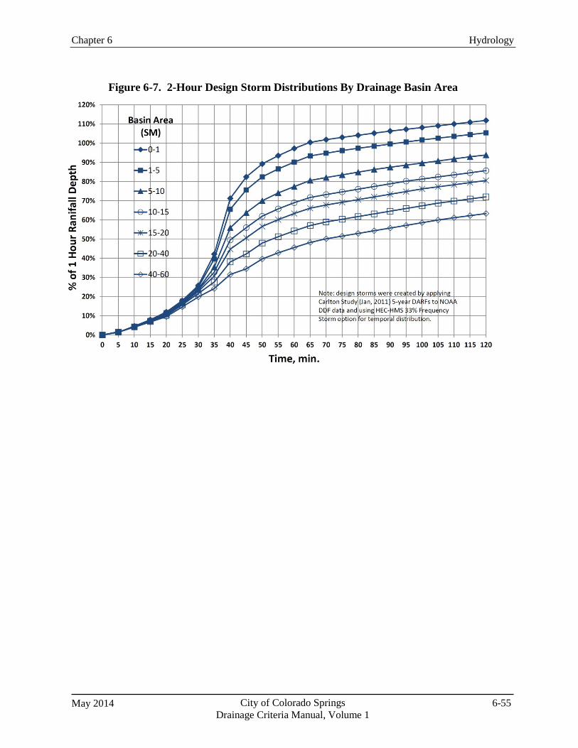
May 2014 City of Colorado Springs Drainage Criteria Manual, Volume 1
6-55
Chapter 6 Hydrology
Figure 6-7. 2-Hour Design Storm Distributions By Drainage Basin Area
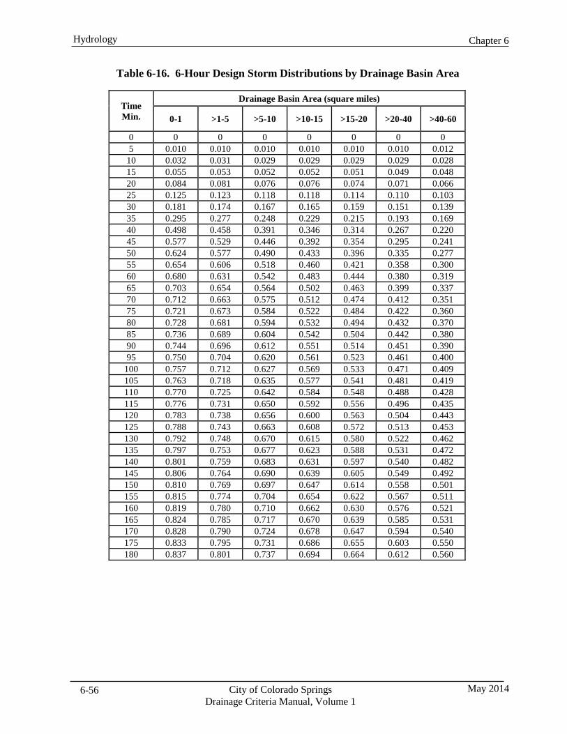
Chapter 6 Hydrology
City of Colorado Springs Drainage Criteria Manual, Volume 1
May 2014 6-56
Table 6-16. 6-Hour Design Storm Distributions by Drainage Basin Area
Time Min.
Drainage Basin Area (square miles)
0-1 >1-5 >5-10 >10-15 >15-20 >20-40 >40-60
0 0 0 0 0 0 0 0 5 0.010 0.010 0.010 0.010 0.010 0.010 0.012
10 0.032 0.031 0.029 0.029 0.029 0.029 0.028 15 0.055 0.053 0.052 0.052 0.051 0.049 0.048 20 0.084 0.081 0.076 0.076 0.074 0.071 0.066 25 0.125 0.123 0.118 0.118 0.114 0.110 0.103 30 0.181 0.174 0.167 0.165 0.159 0.151 0.139 35 0.295 0.277 0.248 0.229 0.215 0.193 0.169 40 0.498 0.458 0.391 0.346 0.314 0.267 0.220 45 0.577 0.529 0.446 0.392 0.354 0.295 0.241 50 0.624 0.577 0.490 0.433 0.396 0.335 0.277 55 0.654 0.606 0.518 0.460 0.421 0.358 0.300 60 0.680 0.631 0.542 0.483 0.444 0.380 0.319 65 0.703 0.654 0.564 0.502 0.463 0.399 0.337 70 0.712 0.663 0.575 0.512 0.474 0.412 0.351 75 0.721 0.673 0.584 0.522 0.484 0.422 0.360 80 0.728 0.681 0.594 0.532 0.494 0.432 0.370 85 0.736 0.689 0.604 0.542 0.504 0.442 0.380 90 0.744 0.696 0.612 0.551 0.514 0.451 0.390 95 0.750 0.704 0.620 0.561 0.523 0.461 0.400
100 0.757 0.712 0.627 0.569 0.533 0.471 0.409 105 0.763 0.718 0.635 0.577 0.541 0.481 0.419 110 0.770 0.725 0.642 0.584 0.548 0.488 0.428 115 0.776 0.731 0.650 0.592 0.556 0.496 0.435 120 0.783 0.738 0.656 0.600 0.563 0.504 0.443 125 0.788 0.743 0.663 0.608 0.572 0.513 0.453 130 0.792 0.748 0.670 0.615 0.580 0.522 0.462 135 0.797 0.753 0.677 0.623 0.588 0.531 0.472 140 0.801 0.759 0.683 0.631 0.597 0.540 0.482 145 0.806 0.764 0.690 0.639 0.605 0.549 0.492 150 0.810 0.769 0.697 0.647 0.614 0.558 0.501 155 0.815 0.774 0.704 0.654 0.622 0.567 0.511 160 0.819 0.780 0.710 0.662 0.630 0.576 0.521 165 0.824 0.785 0.717 0.670 0.639 0.585 0.531 170 0.828 0.790 0.724 0.678 0.647 0.594 0.540 175 0.833 0.795 0.731 0.686 0.655 0.603 0.550 180 0.837 0.801 0.737 0.694 0.664 0.612 0.560
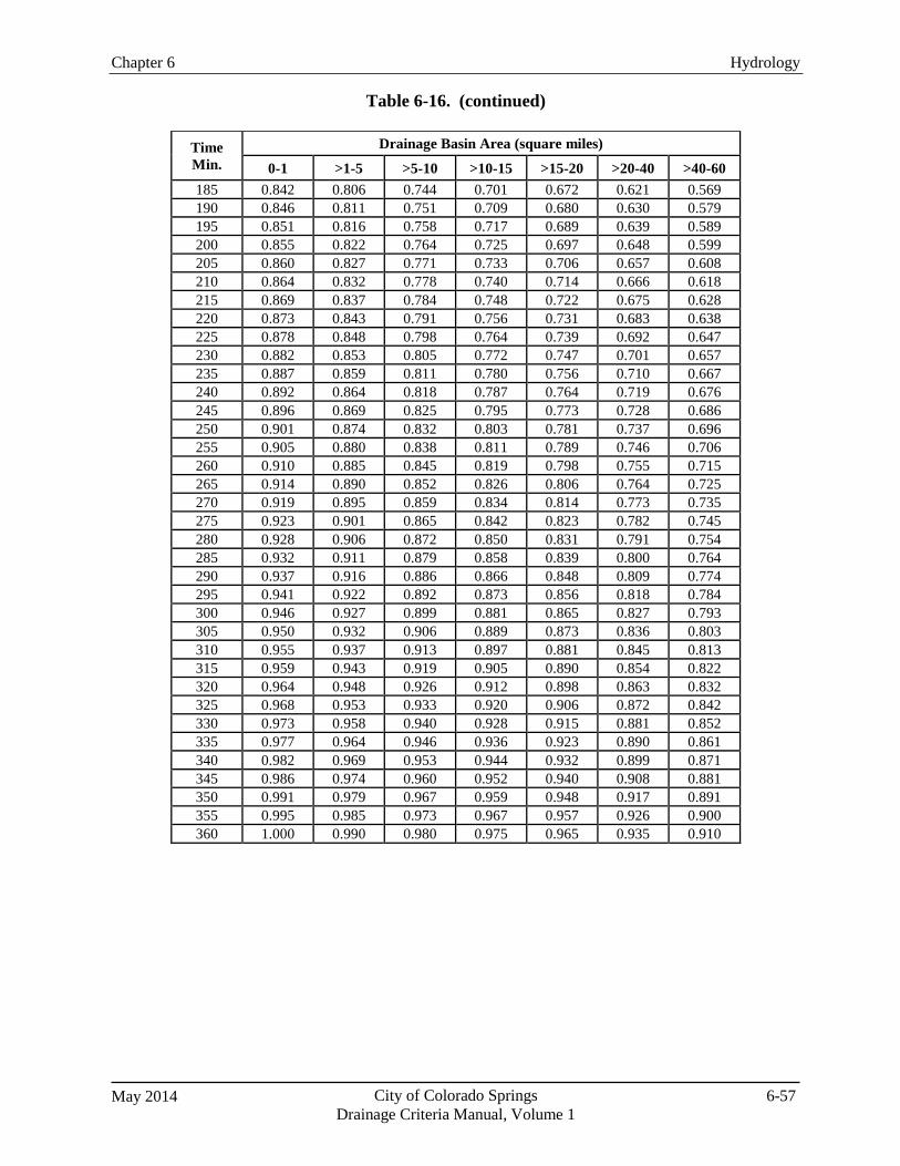
Chapter 6 Hydrology
May 2014 City of Colorado Springs Drainage Criteria Manual, Volume 1
6-57
Table 6-16. (continued)
Time Min.
Drainage Basin Area (square miles) 0-1 >1-5 >5-10 >10-15 >15-20 >20-40 >40-60
185 0.842 0.806 0.744 0.701 0.672 0.621 0.569 190 0.846 0.811 0.751 0.709 0.680 0.630 0.579 195 0.851 0.816 0.758 0.717 0.689 0.639 0.589 200 0.855 0.822 0.764 0.725 0.697 0.648 0.599 205 0.860 0.827 0.771 0.733 0.706 0.657 0.608 210 0.864 0.832 0.778 0.740 0.714 0.666 0.618 215 0.869 0.837 0.784 0.748 0.722 0.675 0.628 220 0.873 0.843 0.791 0.756 0.731 0.683 0.638 225 0.878 0.848 0.798 0.764 0.739 0.692 0.647 230 0.882 0.853 0.805 0.772 0.747 0.701 0.657 235 0.887 0.859 0.811 0.780 0.756 0.710 0.667 240 0.892 0.864 0.818 0.787 0.764 0.719 0.676 245 0.896 0.869 0.825 0.795 0.773 0.728 0.686 250 0.901 0.874 0.832 0.803 0.781 0.737 0.696 255 0.905 0.880 0.838 0.811 0.789 0.746 0.706 260 0.910 0.885 0.845 0.819 0.798 0.755 0.715 265 0.914 0.890 0.852 0.826 0.806 0.764 0.725 270 0.919 0.895 0.859 0.834 0.814 0.773 0.735 275 0.923 0.901 0.865 0.842 0.823 0.782 0.745 280 0.928 0.906 0.872 0.850 0.831 0.791 0.754 285 0.932 0.911 0.879 0.858 0.839 0.800 0.764 290 0.937 0.916 0.886 0.866 0.848 0.809 0.774 295 0.941 0.922 0.892 0.873 0.856 0.818 0.784 300 0.946 0.927 0.899 0.881 0.865 0.827 0.793 305 0.950 0.932 0.906 0.889 0.873 0.836 0.803 310 0.955 0.937 0.913 0.897 0.881 0.845 0.813 315 0.959 0.943 0.919 0.905 0.890 0.854 0.822 320 0.964 0.948 0.926 0.912 0.898 0.863 0.832 325 0.968 0.953 0.933 0.920 0.906 0.872 0.842 330 0.973 0.958 0.940 0.928 0.915 0.881 0.852 335 0.977 0.964 0.946 0.936 0.923 0.890 0.861 340 0.982 0.969 0.953 0.944 0.932 0.899 0.871 345 0.986 0.974 0.960 0.952 0.940 0.908 0.881 350 0.991 0.979 0.967 0.959 0.948 0.917 0.891 355 0.995 0.985 0.973 0.967 0.957 0.926 0.900 360 1.000 0.990 0.980 0.975 0.965 0.935 0.910
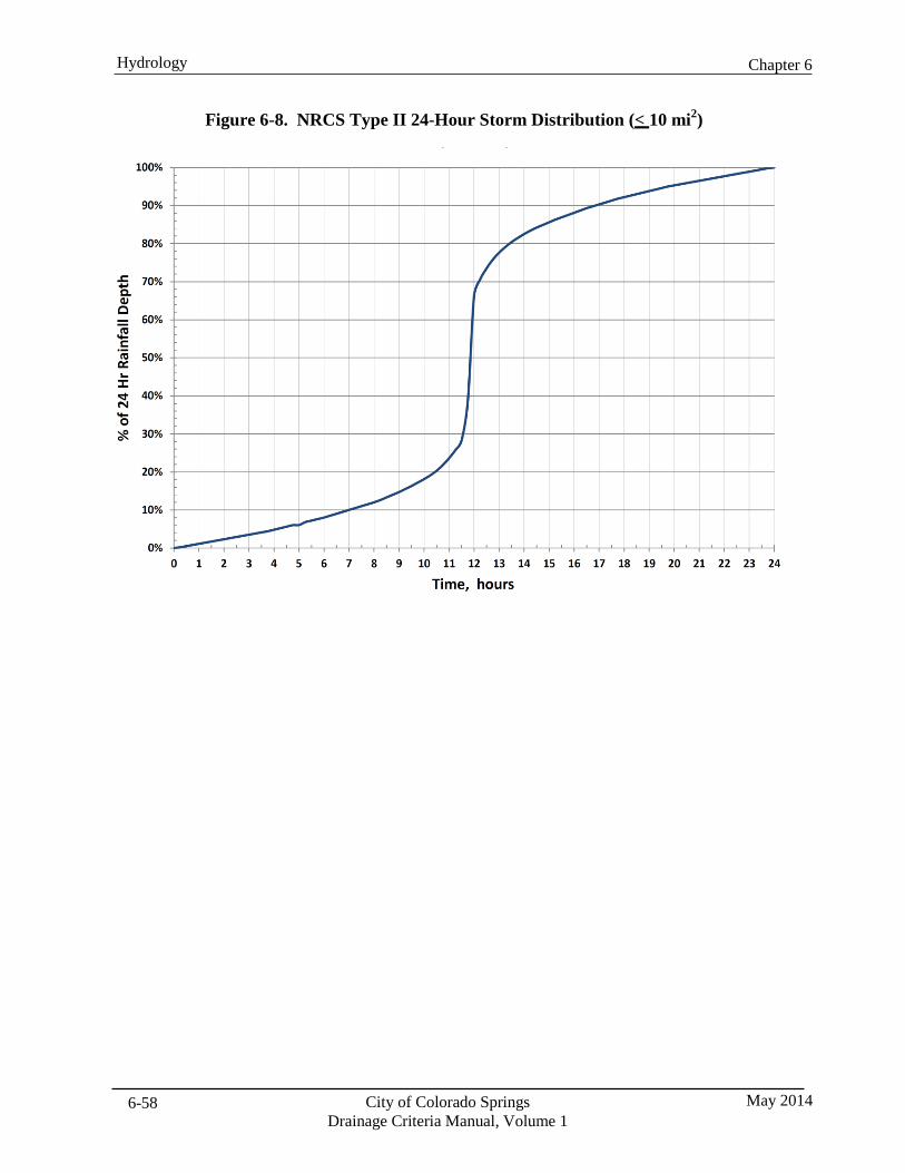
Chapter 6 Hydrology
City of Colorado Springs Drainage Criteria Manual, Volume 1
May 2014 6-58
Figure 6-8. NRCS Type II 24-Hour Storm Distribution (< 10 mi2)
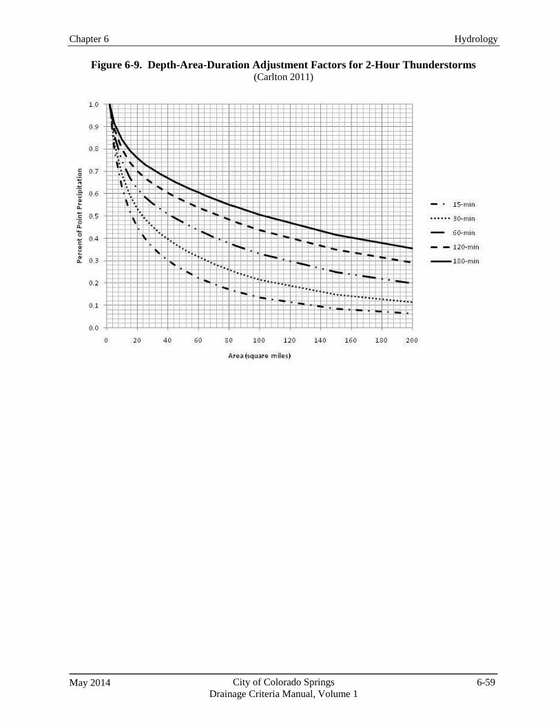
Chapter 6 Hydrology
May 2014 City of Colorado Springs Drainage Criteria Manual, Volume 1
6-59
Figure 6-9. Depth-Area-Duration Adjustment Factors for 2-Hour Thunderstorms
(Carlton 2011)
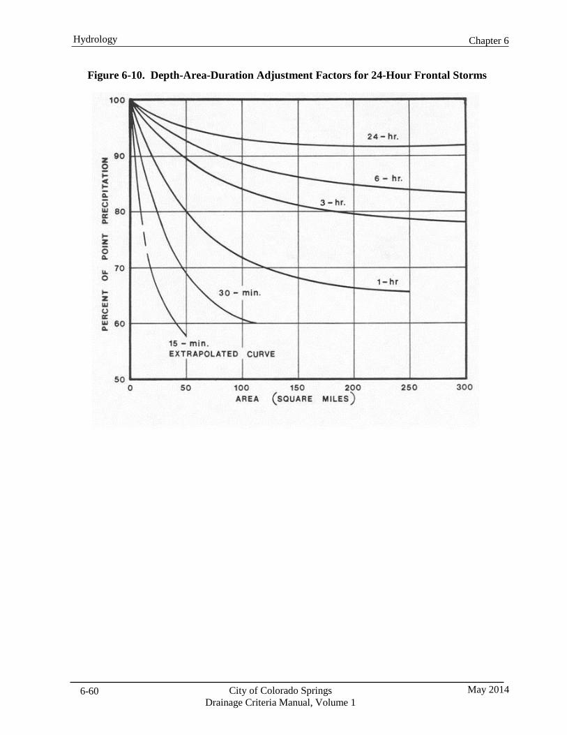
Chapter 6 Hydrology
City of Colorado Springs Drainage Criteria Manual, Volume 1
May 2014 6-60
Figure 6-10. Depth-Area-Duration Adjustment Factors for 24-Hour Frontal Storms
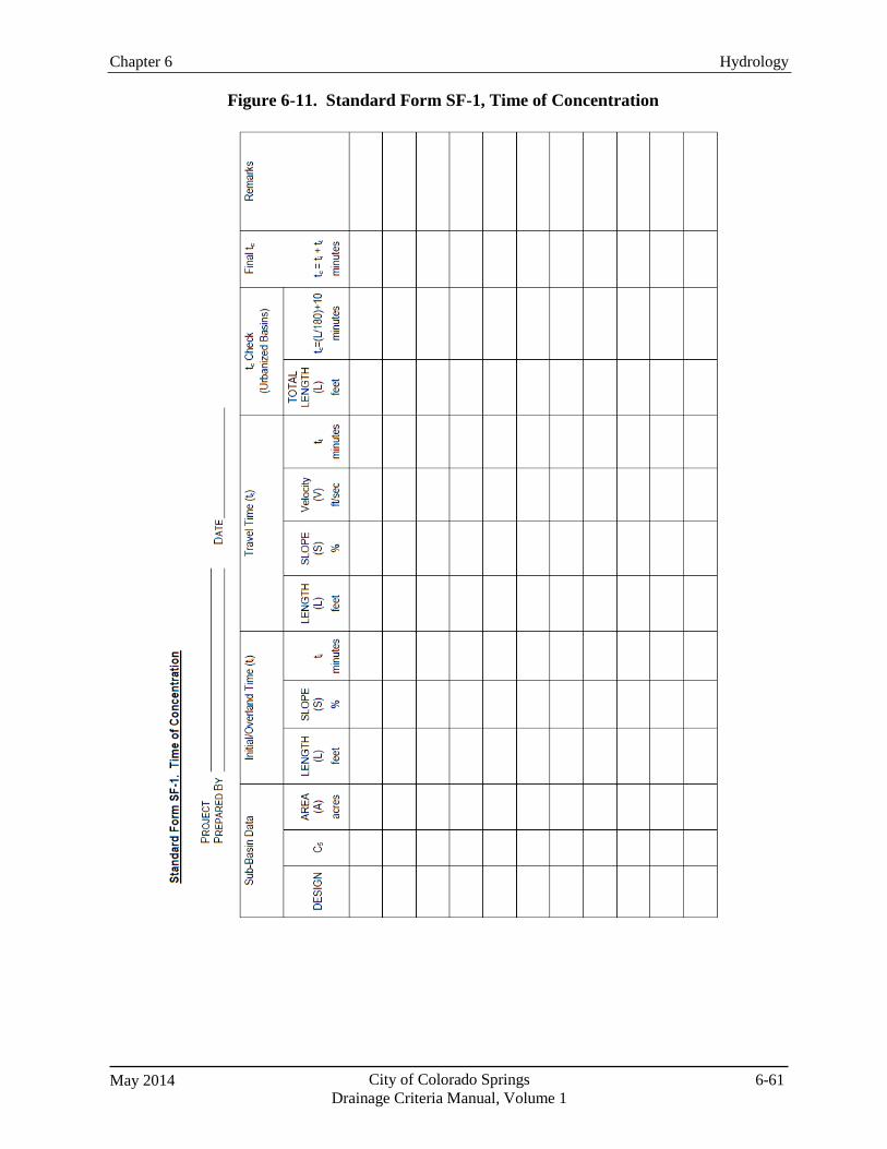
Chapter 6 Hydrology
May 2014 City of Colorado Springs Drainage Criteria Manual, Volume 1
6-61
Figure 6-11. Standard Form SF-1, Time of Concentration
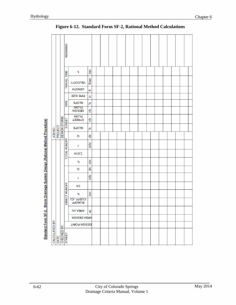
Chapter 6 Hydrology
City of Colorado Springs Drainage Criteria Manual, Volume 1
May 2014 6-62
Figure 6-12. Standard Form SF-2, Rational Method Calculations
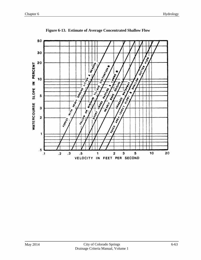
May 2014 City of Colorado Springs Drainage Criteria Manual, Volume 1
6-63
Chapter 6 Hydrology
Figure 6-13. Estimate of Average Concentrated Shallow Flow

May 2014 City of Colorado Springs Drainage Criteria Manual, Volume 1
7-i
Chapter 7 Street Drainage Contents 1.0 Introduction ...................................................................................................................................... 1
2.0 Function of Streets in the Drainage System ................................................................................... 1 2.1 Primary Function of Streets ....................................................................................................................... 1 2.2 Design Criteria Based on Frequency and Magnitude ................................................................................ 1 2.3 Street Function in Minor Storm Event ....................................................................................................... 1 2.4 Street Function in Major Storm Event ....................................................................................................... 1
3.0 Street Classification .......................................................................................................................... 1
4.0 Minor Storm Street Flow for Streets with Curb and Gutter ........................................................ 2
5.0 Major Storm Street Flow for Streets with Curb and Gutter ....................................................... 2
6.0 Hydraulic Evaluation of Street Capacity ....................................................................................... 2 6.1 Minor Storm Street Capacity Worksheet ................................................................................................... 2 6.2 Minor Storm Street Capacity Charts .......................................................................................................... 2 6.3 Major Storm Street Capacity Worksheet ................................................................................................... 3 6.4 Major Storm Street Capacity Charts .......................................................................................................... 3 6.5 Non-Standard Street Sections .................................................................................................................... 3
7.0 Cross-Street Flow ............................................................................................................................. 3 7.1 Cross-Street Flow Conditions .................................................................................................................... 3 7.2 Influence on Traffic ................................................................................................................................... 3 7.3 Allowable Cross-Street Flow Due to Gutter Flow Spread over the Street Crown ..................................... 4 7.4 Cross-Pans ................................................................................................................................................. 4
8.0 Curbless Streets with Roadside Swales .......................................................................................... 4 8.1 Urban Roadside Swales ............................................................................................................................. 4 8.2 Allowable Capacity ................................................................................................................................... 4 8.3 Driveways and Street Cross-Flow ............................................................................................................. 5 8.4 Downstream Facilities ............................................................................................................................... 5
9.0 Rural Roadside Ditches .................................................................................................................... 5 9.1 Roadside Ditches ....................................................................................................................................... 5 9.2 Roadside Ditch Design Criteria ................................................................................................................. 5
City of Colorado Springs Drainage Criteria Manual, Volume 1
May 2014 7-ii
Figures Figure 7-1 Street Capacity Chart Principal Arterial Type I .................................................................. 7 Figure 7-2 Street Capacity Chart Principal Arterial Type II ................................................................. 8 Figure 7-3 Street Capacity Chart Minor Arterial .................................................................................. 9 Figure 7-4 Street Capacity Chart Industrial ........................................................................................ 10 Figure 7-5 Street Capacity Chart Collector (with Parking) ................................................................ 11 Figure 7-6 Street Capacity Chart Collector (without Parking) ........................................................... 12 Figure 7-7 Street Capacity Chart Residential (Detached Sidewalk) ................................................... 13 Figure 7-8 Street Capacity Chart Minor Residential (Detached Sidewalk) ........................................ 14 Figure 7-9 Street Capacity Chart Minor Residential (Attached Sidewalk) ......................................... 15
Chapter 7 Street Drainage
May 2014 City of Colorado Springs Drainage Criteria Manual, Volume 1
7-1
1.0 Introduction This chapter summarizes methods to evaluate runoff conveyance in various standard street cross sections and curb types and identifies acceptable upper limits of street capacity for minor and major storm events.
Additionally, this chapter provides guidance for reducing urban runoff and pollutant loading through the use of curbless (or intermittent curb) streets with adjacent grass swales. Although this approach requires prior approval, it can be used in situations where land uses and traffic engineering constraints are compatible with limited or no curb and where street grades are favorable to stable flow regimes. The use of curbless streets with grass swales for volume reduction and enhanced water quality is discussed in Sections 8.0 and 9.0.
2.0 Function of Streets in the Drainage System
2.1 Primary Function of Streets
Urban streets not only carry traffic, but stormwater runoff as well. The primary function of urban streets is for traffic movement; therefore, the drainage function is subservient and must not interfere with the traffic function of the street. When runoff in the street exceeds allowable limits, a storm sewer system or open channel is required to convey the excess flows.
2.2 Design Criteria Based on Frequency and Magnitude
The design criteria for the collection and conveyance of stormwater runoff on public streets are based on an allowable frequency and magnitude of traffic interference. The primary design objective is to keep the depth and spread (encroachment) of stormwater on the street below an acceptable value for a given storm event and road classification.
2.3 Street Function in Minor Storm Event
The primary function of streets in a minor storm event is to convey the frequently occurring flows quickly, efficiently, and economically to the next intended drainage conveyance system with minimal disruption to street traffic.
2.4 Street Function in Major Storm Event
For the major storm event, the function of streets is to provide an emergency passageway for infrequent flood flows while maintaining public safety and minimizing flood damage. In the major event, the street becomes an open channel and must be analyzed to determine when flooding depths exceed acceptable levels.
3.0 Street Classification Cross-section drawings of standard street sections are defined in the Engineering Criteria Manual. Each roadway section has a different capacity, so it is important to use the section dimensions that apply to the particular street section of interest. These standard sections are the basis for the design guidance and charts provided in this chapter and are provided in Figures 7-1 through 7-9. When alternate roadway sections are approved, appropriate guidance for flow spreading and depth of flow must be established.
City of Colorado Springs Drainage Criteria Manual, Volume 1
May 2014 7-2
Chapter 7 Street Drainage
4.0 Minor Storm Street Flow for Streets with Curb and Gutter The use of streets for drainage conveyance during the minor storm event is allowed with limitations on the depth of flow in the curb and gutter, flow velocity and the spread of flow onto the roadway. Figures 7-1 through 7-9 show these limitations for each street classification. The maximum allowable street capacity is determined by these limits and may be affected by the type of curb and gutter and the geometry of the standard street sections.
5.0 Major Storm Street Flow for Streets with Curb and Gutter The use of streets for drainage conveyance in the major storm is allowed with limitations on the depth of flow in the curb and gutter. Figures 7-1 through 7-9 show these limitations for each street classification. The maximum street capacity is based on the allowable depth at the gutter flowline, the curb and gutter type, flow velocity, and keeping flow within the public right-of-way. Where the depth of flow overtops the crown, the flow spread is set equal to the distance from the flowline to the crown for purposes of the capacity calculation even though flow will be outside of the flowline. Where there is a median curb, the flow spread cannot exceed the distance from the flowline to the median curb.
6.0 Hydraulic Evaluation of Street Capacity Once the design discharge is calculated (see Chapter 6, Hydrology), hydraulic calculations must be completed to determine the capacity of streets and the resulting encroachment onto the street section. Through an iterative process, the drainage area contributing to each street section is adjusted to determine the estimated flow for each design storm. The storm sewer system must be located and sized so that the allowable flow limits are not exceeded. All street capacity and encroachment calculations shall conform to Figures 7-1 through 7-9.
6.1 Minor Storm Street Capacity Worksheet
The UDFCD Manual, Volume 1, provides an analysis spreadsheet tool named UD-Inlet, used for determining the minor storm street capacity and flow encroachment. The “Q-Allow” worksheet is contained within the UD-Inlet spreadsheet, which can be accessed via the internet at www.udfcd.org. This worksheet completes a hydraulic evaluation of the theoretical street capacity for the minor storm by calculating the street flow capacity based on both 1) the allowable spread and 2) the allowable gutter depth. A reduction factor is then applied to the theoretical gutter flow based on allowable depth, and the lesser of the allowable street capacities governs for the minor event.
6.2 Minor Storm Street Capacity Charts
The allowable minor storm street capacity for each standard street cross-section has been calculated based on the “Q-Allow” worksheet. The results of these calculations are shown in Figures 7-1 through 7-9 at the end of this chapter. These charts shall only be used for streets that are consistent with all of the referenced standard street parameters, including street width, pavement cross slope, and a depressed gutter, consistent with the standard cross-sections as noted. These minor event capacity calculations were performed for various street slopes to generate the street capacity charts located at the end of this chapter. A Manning’s n-value of 0.016 was used in the calculations. These charts apply for one-half of the standard street sections.
Chapter 7 Street Drainage
May 2014 City of Colorado Springs Drainage Criteria Manual, Volume 1
7-3
6.3 Major Storm Street Capacity Worksheet
The UDFCD Manual, Volume 1, provides an analysis tool used for determining the major storm street capacity. This worksheet completes a hydraulic evaluation of the theoretical street capacity for the major storm and then applies the major storm reduction factor.
6.4 Major Storm Street Capacity Charts
The allowable major storm street capacities for all standard street cross-sections have been calculated based on the “Q-Allow” worksheet. The results of these calculations are shown on Figures 7-1 through 7- 9 at the end of this chapter. These charts shall only be used for streets that are consistent with all of the referenced standard street parameters, including street width, pavement cross slope, and a depressed gutter consistent with the standard cross-sections as noted. A Manning’s n-value of 0.016 was used for the paved portion of the street cross section, and an n-value of 0.020 was used behind the back of curb to the right-of-way line. These charts present the allowable capacity for one-half of the standard street sections and include the conveyance capacity of the street sections between the curb and gutter and the right-of-way. The allowable capacity curves are based on the assumption of a vertical “wall” at the street crown or median. The allowable capacity curves were calculated based on the following conditions:
1. The major storm flow must be contained within the roadway right-of-way.
2. Conveyance of the major storm flow at the allowable depths will not result in diversions at
driveways, intersections, or other locations prior to the designed outfall point.
It is the responsibility of the design engineer to verify that these conditions are satisfied. In subdivisions where the conditions stated above are not met, the allowable capacity in each side of the street during the major storm shall be reduced so that these conditions are met.
6.5 Non-Standard Street Sections
When a non-standard street section has been approved, the design engineer must use the “Q-Allow” worksheet in UD-Inlet to determine the allowable street capacity. The appropriate limits for flow spread widths and flow depths for the minor and major storm events must be determined whenever a non- standard street section is approved.
7.0 Cross-Street Flow
7.1 Cross-Street Flow Conditions
Cross-street flow can occur in an urban drainage system under three conditions. One condition occurs when the runoff in a gutter spreads across the street crown to the opposite gutter. The second is when cross-pans are used. The third condition is when the flow in a drainageway exceeds the capacity of a road culvert and/or bridge and subsequently overtops the crown of the street. Allowable cross-street flow or overtopping at culvert crossings is limited by the criteria provided in Chapter 11, Culverts and Bridges.
7.2 Influence on Traffic
Whenever storm runoff, other than sheet flow, moves across a traffic lane, traffic movement is affected. The cross flow may be caused by super-elevation of a curve, by the intersection of two streets, by exceeding the capacity of the higher gutter on a street with cross fall, or street design that has not met the criteria provided herein. The problem associated with this type of flow is that it is localized in nature and
City of Colorado Springs Drainage Criteria Manual, Volume 1
May 2014 7-4
Chapter 7 Street Drainage
vehicles may be traveling at speeds that are incompatible with the cross flow when they reach the location.
7.3 Allowable Cross-Street Flow Due to Gutter Flow Spread over the Street Crown
In the minor storm event, cross street flow is not allowed. In the major storm event, allowable cross- street flow must not exceed 12 inches at the gutter flowline or 4 inches at the crown.
The analysis to quantify the amount of cross-street flow can be complex due to the fact that the runoff is moving longitudinally down the street. In addition, it is often assumed that runoff being conveyed in the gutter will follow the path of the associated gutter at intersections, which generally requires the full flow to turn corners, without the appropriate consideration being given to the momentum that was established in one direction. There is potential for cross-street flow, if the flow isn’t conveyed around the corner, as assumed. It is the responsibility of the design engineer to make conservative assumptions relative to cross-street flow and to design the inlets and storm sewer system accordingly. When the combined flow from intersecting streets causes the allowable cross-street flows to be exceeded, flows must be intercepted by a storm sewer system or other conveyance system upstream of the intersection to keep the cross-street flows to allowable limits.
7.4 Cross-Pans
The use of cross-pans at allowed locations shall adhere to the criteria presented in the Engineering Criteria Manual. Cross-pans shall be designed to convey the minor and major storm event within the criteria presented in this chapter. The design engineer shall evaluate the carrying capacity (with calculations provided) considering water on the roadway, as well as the side street. When the combined flow from intersecting streets causes the allowable cross-street flows to be exceeded, flows must be intercepted by a storm sewer system or other conveyance system upstream of the intersection.
8.0 Curbless Streets with Roadside Swales 8.1 Urban Roadside Swales
For urban roadside swales, the engineer shall use the Engineering Criteria Manual to determine the appropriate standard street section(s) for the project and seek approval for an alternate, non-standard street section, as necessary. The use of urban roadside swales must be approved prior to drainage report or plan submittal. Urban roadside swales provide an opportunity to minimize directly connected impervious areas and thereby reduce the volume and peak rate of runoff and enhance stormwater quality. Roadside swales can be used in conjunction with curbless (or intermittent curb) streets.
Urban roadside swales shall be designed based on site-specific conditions. However, they will generally have a depth of 6 to 9 inches below the edge of the street shoulder, a bottom width of at least 2 feet, and side slopes of 8:1 or flatter. Swales shall be stabilized for the minor storm design flow with vegetation, including irrigated bluegrass or irrigated sod-forming native grasses or an appropriate stabilization material as approved. The longitudinal slope of the swale should generally be similar to the longitudinal slope of the street.
8.2 Allowable Capacity
The allowable flow depth and roadway encroachment in the minor and major storm events for curbless streets can be estimated using Figures 7-1 through 7-9. These figures are based on the allowable flow depth at the gutter flowline, but can be used for curbless streets by applying the allowable flowline depth
Chapter 7 Street Drainage
May 2014 City of Colorado Springs Drainage Criteria Manual, Volume 1
7-5
at the edge of the street shoulder (rather than the gutter flowline) or the allowable flow spread, whichever is more restrictive. When sufficient right-of-way is not available to contain the design flows within the right-of-way, the allowable flow depths and capacities must be reduced to properly contain design flows within the available right-of-way.
Flow in a roadside swale is limited by capacity (this generally governs at low street slopes) and by velocity considerations (this governs at higher street slopes). To limit the potential for erosion, the allowable capacity for roadside swales is based on the peak flow from the minor storm event. Roadside swales shall be designed in accordance to the criteria for grass swales provided in Chapter 14, Stormwater Quality.
The lowest point of water entry (first floor or basement window) of any structure adjacent to the swale shall be at least 1.0 foot above the 100-year water surface, or generally about 2.0 feet above the edge of the road.
8.3 Driveways and Street Cross-Flow
In general, driveways or sidewalks that cross a roadside swale are intended to conform to the swale cross section, such that storm flows will pass over the driveway as opposed to under it. A structure designed to pass nuisance flows and avoid sediment and ice accumulation is required at the low point in the driveway. Cross-pans are typically used to convey swale flow across a street at a stop condition intersection.
8.4 Downstream Facilities
At the point where the maximum capacity of the swale is reached for the design event, runoff must be conveyed in an alternate system. The swale flow shall be diverted into a vegetated drainageway or collected in an area inlet and storm sewer. Of the two, a vegetated drainageway is preferred to provide further contact of runoff with vegetation and soil and increase infiltration potential.
9.0 Rural Roadside Ditches
9.1 Roadside Ditches
Roadside ditches may be used in lieu of curb and gutter when rural street sections are approved. These types of streets are normally associated with low-density residential developments or developments located within the hillside area overlay where driveway crossings are less frequent and imperviousness is low. Maintenance shall be considered when designing and using roadside ditches, including adequate area and side slopes to allow for maintenance access and vehicles.
9.2 Roadside Ditch Design Criteria
The minor storm event runoff shall not encroach onto the roadway shoulder when roadside ditches are used. A maximum flow depth of 6 inches is allowed at the street crown for conveyance of the major storm event runoff if adequate right-of-way is provided to contain the design flow. When sufficient right- of-way is not available, the allowable flow depths and capacities must be reduced to contain design flows within the available right-of-way. At least 12 inches of freeboard shall be provided from the major stormwater surface elevation to the lowest point of water entry at any adjacent structures.
Rural roadside ditches shall be designed in accordance with the criteria for minor drainageway grass-lined channels shown in Chapter 12, Open Channel Design using minor storm design flow. The longitudinal
City of Colorado Springs Drainage Criteria Manual, Volume 1
May 2014 7-6
Chapter 7 Street Drainage
slope of the swale should generally be similar to the longitudinal slope of the street. Grade control structures may be required to maintain velocities less than the maximum allowable.
There are cases when the roadside ditch criteria may need to be more stringent due to the function of the rural road. Even if a rural road has a low traffic volume, it may be important for emergency access to several properties and therefore require special design criteria. More stringent criteria for single point access roads may also be required.
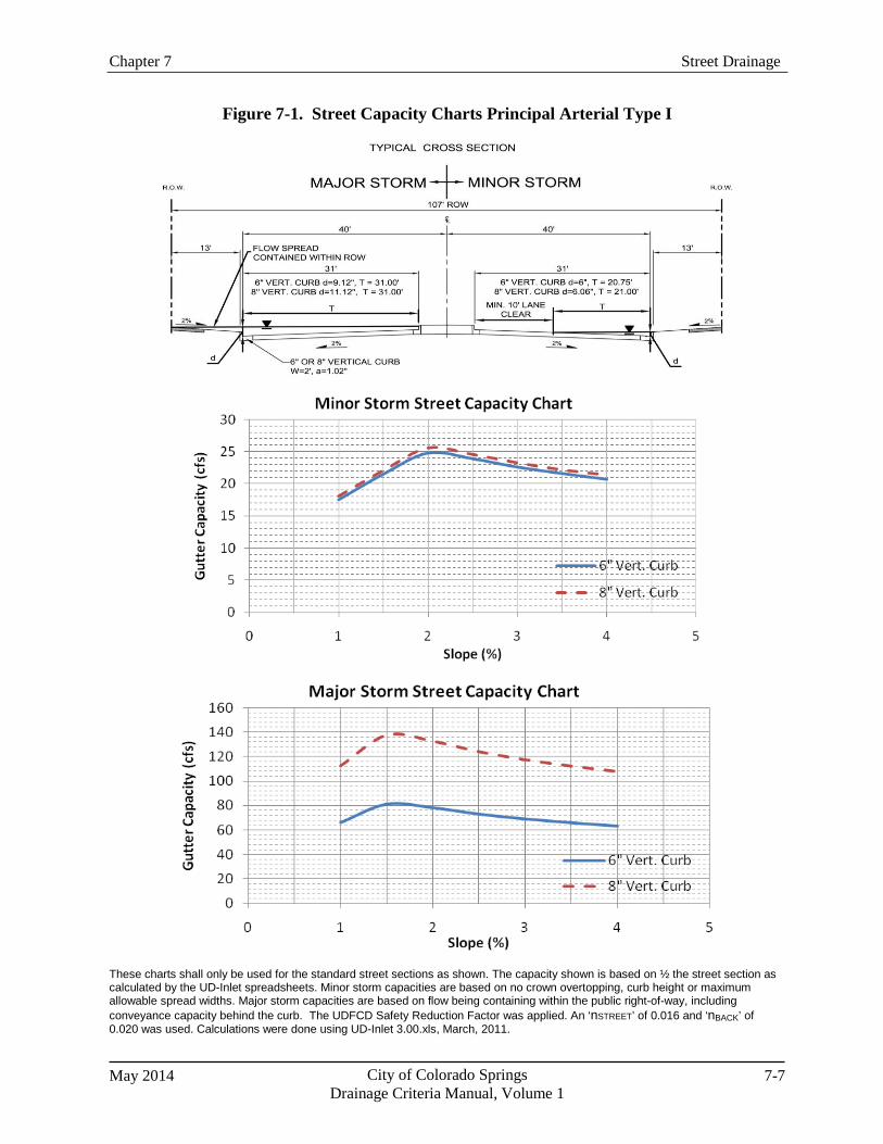
Chapter 7 Street Drainage
May 2014 City of Colorado Springs Drainage Criteria Manual, Volume 1
7-7
Figure 7-1. Street Capacity Charts Principal Arterial Type I
These charts shall only be used for the standard street sections as shown. The capacity shown is based on ½ the street section as calculated by the UD-Inlet spreadsheets. Minor storm capacities are based on no crown overtopping, curb height or maximum allowable spread widths. Major storm capacities are based on flow being containing within the public right-of-way, including conveyance capacity behind the curb. The UDFCD Safety Reduction Factor was applied. An ‘nSTREET’ of 0.016 and ‘nBACK’ of 0.020 was used. Calculations were done using UD-Inlet 3.00.xls, March, 2011.
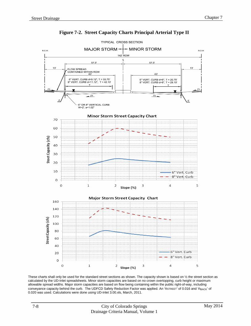
City of Colorado Springs Drainage Criteria Manual, Volume 1
May 2014 7-8
Chapter 7 Street Drainage
Figure 7-2. Street Capacity Charts Principal Arterial Type II
These charts shall only be used for the standard street sections as shown. The capacity shown is based on ½ the street section as calculated by the UD-Inlet spreadsheets. Minor storm capacities are based on no crown overtopping, curb height or maximum allowable spread widths. Major storm capacities are based on flow being containing within the public right-of-way, including conveyance capacity behind the curb. The UDFCD Safety Reduction Factor was applied. An ‘nSTREET’ of 0.016 and ‘nBACK’ of 0.020 was used. Calculations were done using UD-Inlet 3.00.xls, March, 2011.
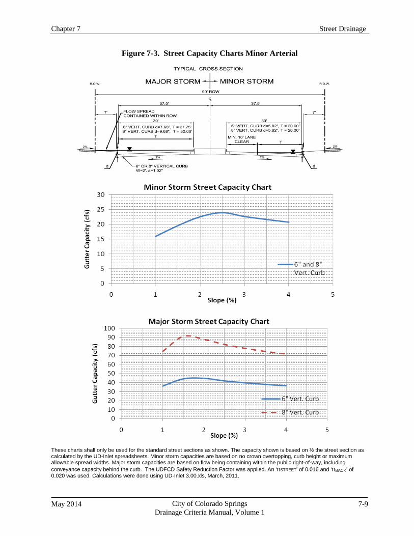
Chapter 7 Street Drainage
May 2014 City of Colorado Springs Drainage Criteria Manual, Volume 1
7-9
Figure 7-3. Street Capacity Charts Minor Arterial
These charts shall only be used for the standard street sections as shown. The capacity shown is based on ½ the street section as calculated by the UD-Inlet spreadsheets. Minor storm capacities are based on no crown overtopping, curb height or maximum allowable spread widths. Major storm capacities are based on flow being containing within the public right-of-way, including conveyance capacity behind the curb. The UDFCD Safety Reduction Factor was applied. An ‘nSTREET’ of 0.016 and ‘nBACK’ of 0.020 was used. Calculations were done using UD-Inlet 3.00.xls, March, 2011.
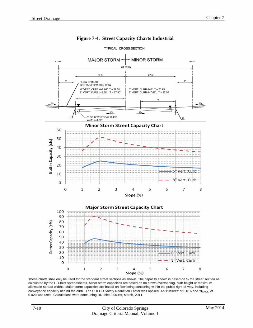
City of Colorado Springs Drainage Criteria Manual, Volume 1
May 2014 7-10
Chapter 7 Street Drainage
Figure 7-4. Street Capacity Charts Industrial
These charts shall only be used for the standard street sections as shown. The capacity shown is based on ½ the street section as calculated by the UD-Inlet spreadsheets. Minor storm capacities are based on no crown overtopping, curb height or maximum allowable spread widths. Major storm capacities are based on flow being containing within the public right-of-way, including conveyance capacity behind the curb. The UDFCD Safety Reduction Factor was applied. An ‘nSTREET’ of 0.016 and ‘nBACK’ of 0.020 was used. Calculations were done using UD-Inlet 3.00.xls, March, 2011.
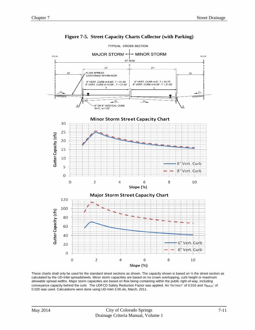
Chapter 7 Street Drainage
May 2014 City of Colorado Springs Drainage Criteria Manual, Volume 1
7-11
Figure 7-5. Street Capacity Charts Collector (with Parking)
These charts shall only be used for the standard street sections as shown. The capacity shown is based on ½ the street section as calculated by the UD-Inlet spreadsheets. Minor storm capacities are based on no crown overtopping, curb height or maximum allowable spread widths. Major storm capacities are based on flow being containing within the public right-of-way, including conveyance capacity behind the curb. The UDFCD Safety Reduction Factor was applied. An ‘nSTREET’ of 0.016 and ‘nBACK’ of 0.020 was used. Calculations were done using UD-Inlet 3.00.xls, March, 2011.
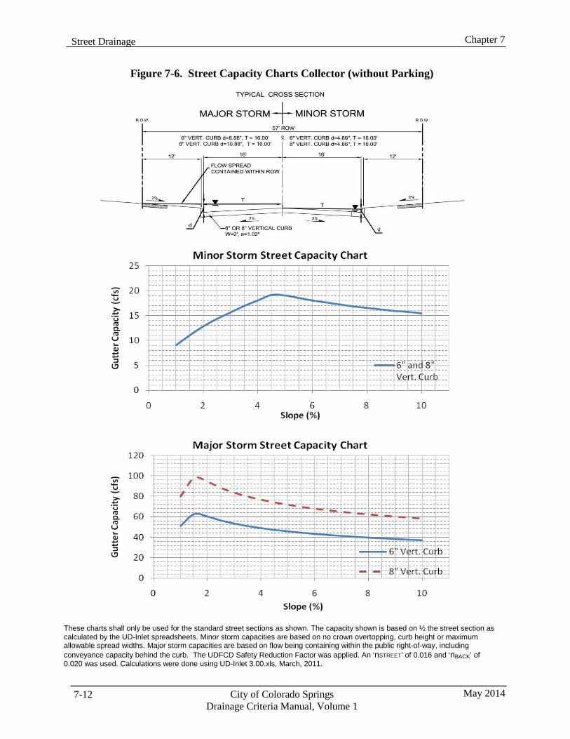
City of Colorado Springs Drainage Criteria Manual, Volume 1
May 2014 7-12
Chapter 7 Street Drainage
Figure 7-6. Street Capacity Charts Collector (without Parking)
These charts shall only be used for the standard street sections as shown. The capacity shown is based on ½ the street section as calculated by the UD-Inlet spreadsheets. Minor storm capacities are based on no crown overtopping, curb height or maximum allowable spread widths. Major storm capacities are based on flow being containing within the public right-of-way, including conveyance capacity behind the curb. The UDFCD Safety Reduction Factor was applied. An ‘nSTREET’ of 0.016 and ‘nBACK’ of 0.020 was used. Calculations were done using UD-Inlet 3.00.xls, March, 2011.
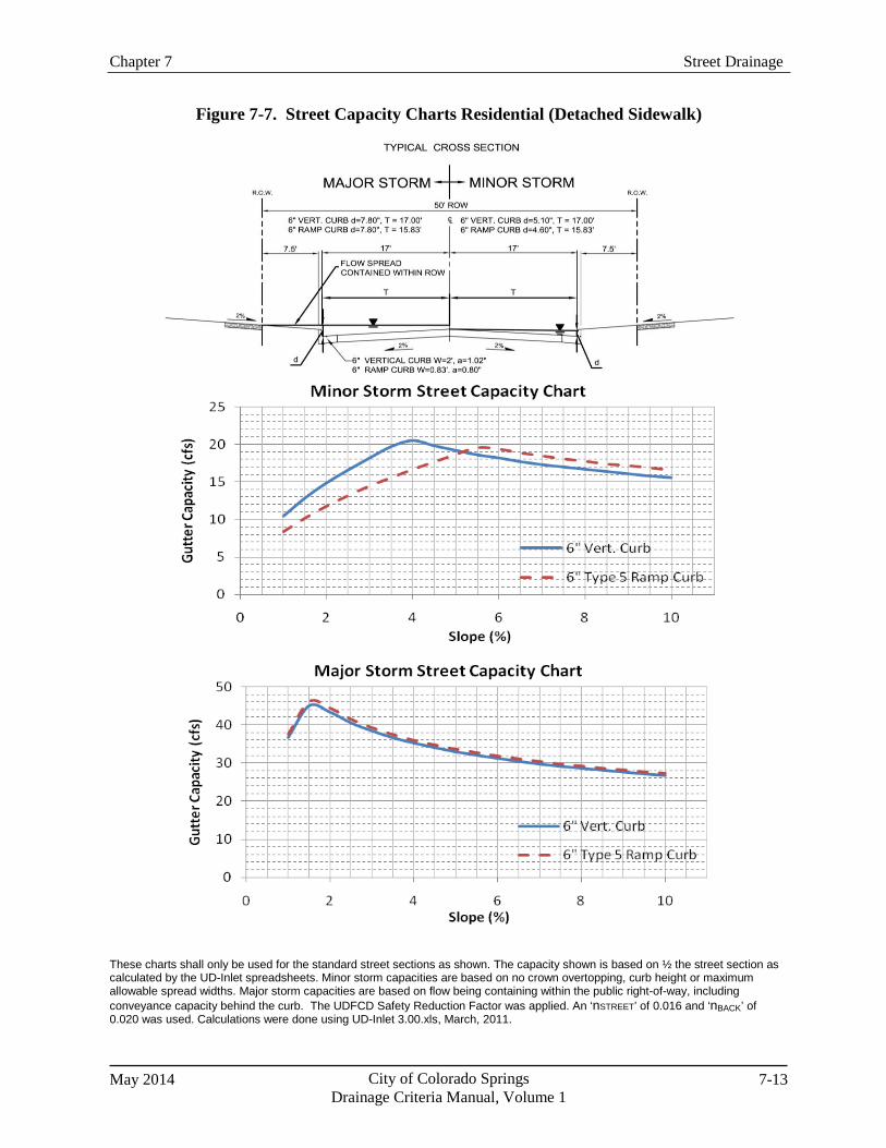
Chapter 7 Street Drainage
May 2014 City of Colorado Springs Drainage Criteria Manual, Volume 1
7-13
Figure 7-7. Street Capacity Charts Residential (Detached Sidewalk)
These charts shall only be used for the standard street sections as shown. The capacity shown is based on ½ the street section as calculated by the UD-Inlet spreadsheets. Minor storm capacities are based on no crown overtopping, curb height or maximum allowable spread widths. Major storm capacities are based on flow being containing within the public right-of-way, including conveyance capacity behind the curb. The UDFCD Safety Reduction Factor was applied. An ‘nSTREET’ of 0.016 and ‘nBACK’ of 0.020 was used. Calculations were done using UD-Inlet 3.00.xls, March, 2011.
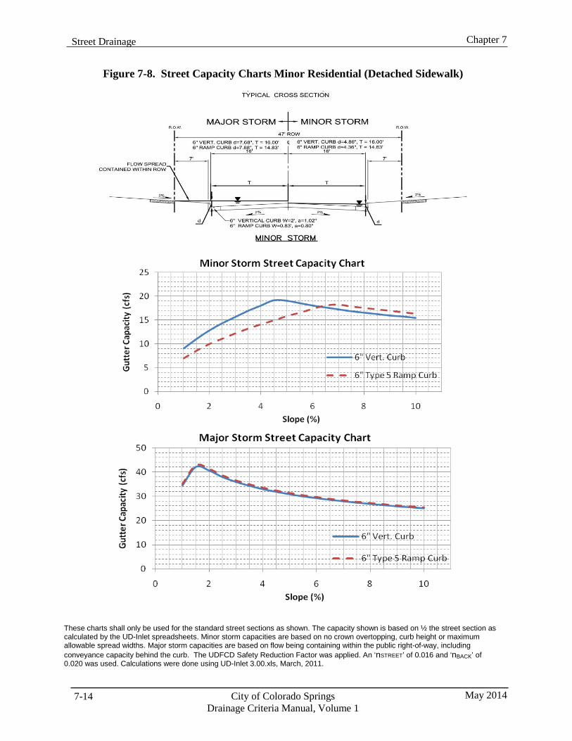
City of Colorado Springs Drainage Criteria Manual, Volume 1
May 2014 7-14
Chapter 7 Street Drainage
Figure 7-8. Street Capacity Charts Minor Residential (Detached Sidewalk)
These charts shall only be used for the standard street sections as shown. The capacity shown is based on ½ the street section as calculated by the UD-Inlet spreadsheets. Minor storm capacities are based on no crown overtopping, curb height or maximum allowable spread widths. Major storm capacities are based on flow being containing within the public right-of-way, including conveyance capacity behind the curb. The UDFCD Safety Reduction Factor was applied. An ‘nSTREET’ of 0.016 and ‘nBACK’ of 0.020 was used. Calculations were done using UD-Inlet 3.00.xls, March, 2011.
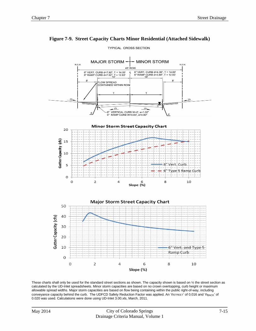
Chapter 7 Street Drainage
May 2014 City of Colorado Springs Drainage Criteria Manual, Volume 1
7-15
Figure 7-9. Street Capacity Charts Minor Residential (Attached Sidewalk)
These charts shall only be used for the standard street sections as shown. The capacity shown is based on ½ the street section as calculated by the UD-Inlet spreadsheets. Minor storm capacities are based on no crown overtopping, curb height or maximum allowable spread widths. Major storm capacities are based on flow being containing within the public right-of-way, including conveyance capacity behind the curb. The UDFCD Safety Reduction Factor was applied. An ‘nSTREET’ of 0.016 and ‘nBACK’ of 0.020 was used. Calculations were done using UD-Inlet 3.00.xls, March, 2011.

Chapter 8 Inlets
May 2014 City of Colorado Springs Drainage Criteria Manual, Volume 1
8-i
Chapter 8 Inlets Contents 1.0 Introduction ...................................................................................................................................... 1
2.0 Inlet Selection ................................................................................................................................... 1 2.1 Types of Inlets ........................................................................................................................................... 1 2.2 Application for Inlet Types ....................................................................................................................... 2 2.3 Standard Inlets ........................................................................................................................................... 2
3.0 Inlets on a Continuous Grade ......................................................................................................... 3 3.1 Location and Spacing ................................................................................................................................ 3 3.2 Capacity Factors ........................................................................................................................................ 3 3.3 Hydraulic Capacity.................................................................................................................................... 3
3.3.1 Capacity Charts ............................................................................................................................. 3 3.3.2 Spreadsheets .................................................................................................................................. 4
4.0 Inlets in Sump Conditions ............................................................................................................... 4 4.1 Location .................................................................................................................................................... 4 4.2 Capacity Factors ........................................................................................................................................ 4 4.3 Hydraulic Capacity.................................................................................................................................... 4 4.4 Overflow Path ........................................................................................................................................... 5 4.5 Type C Inlets ............................................................................................................................................. 5
5.0 Other Design Considerations .......................................................................................................... 5 5.1 Curb Chase Drain (Sidewalk Chase) ......................................................................................................... 5 5.2 Median Inlets ............................................................................................................................................. 5 5.3 Maximum Inlet Length.............................................................................................................................. 5
8-ii City of Colorado Springs Drainage Criteria Manual, Volume 1
May 2014
Tables Table 8-1 Inlet Type Summary ............................................................................................................ 2 Table 8-2 Standard City Inlets ............................................................................................................. 2
Figures Figure 8-1. Inlet Capacity Chart, Principal Arterial Type I .......................................................................... 6 Figure 8-2. Inlet Capacity Chart, Principal Arterial Type II ........................................................................ 7 Figure 8-3. Inlet Capacity Chart, Minor Arterial .......................................................................................... 8 Figure 8-4. Inlet Capacity Chart, Industrial .................................................................................................. 9 Figure 8-5. Inlet Capacity Chart, Collector (with Parking) ........................................................................ 10 Figure 8-6. Inlet Capacity Chart, Collector (without Parking) ................................................................... 11 Figure 8-7. Inlet Capacity Chart, Residential (Local) Streets (Attached and Detached Sidewalk) ........... 12 Figure 8-8. Inlet Capacity Chart, Minor Residential (Local) Streets (Detached Sidewalk) ....................... 13 Figure 8-9. Inlet Capacity Chart, Minor Residential (Local) Streets (Attached Sidewalk) ........................ 14 Figure 8-10. Inlet Capacity Chart Sump Conditions, Area (Type C) Inlet ................................................. 15 Figure 8-11. Inlet Capacity Chart Sump Conditions , Curb Opening (Type R) Inlet ................................. 16 Figure 8-12. Inlet Capacity Chart Sump Conditions, Curb Opening (D-10-R) Inlet ................................. 17
Chapter 8 Inlets
May 2014 City of Colorado Springs Drainage Criteria Manual, Volume 1
8-1
1.0 Introduction Criteria and methodology for design and evaluation of storm sewer inlets are presented in this chapter. The review of all planning submittals will be based on the criteria presented herein.
The primary purpose of storm drain inlets is to intercept excess surface runoff and convey it into a storm drainage system, thereby reducing or eliminating surface flooding. Roadway geometry often dictates the location of street inlets along the curb and gutter. In general, inlets are placed at all low points (sumps), along continuous grade curb and gutter, and at median breaks, intersections, and crosswalks. The spacing of inlets along a continuous grade segment of roadway is governed by the allowable spread of flow. See further details of allowable spread of flow in Chapter 7, Street Drainage.
The following guidelines shall be used when designing inlets along a street section:
Design and location of inlets shall take into consideration pedestrian and bicycle traffic. All inlet
grates shall be pedestrian and bicycle-safe.
Design and location of inlets shall be in accordance with the criteria established in Chapter 7, Street Drainage.
Maintenance of inlets shall be considered when determining inlet locations. The slope of the
street, the potential for debris and ice accumulations, the distance between inlets and/or manholes, and other factors shall be considered. Maintenance access shall be provided for all inlets.
To avoid potential damage from large vehicles driving over the curb return and interference with
pedestrian traffic, inlets shall not be placed in the curb return radii.
Selection of the appropriate inlet grate shall be based on a number of factors, including, but not limited to, the adjacent land use and potential for pedestrian or bicycle traffic, the potential for debris and ice accumulation, visibility, expected loading from vehicles, and hydraulic capacity.
Consideration should be given to flanking inlets on each side of the low point when the depressed
area has no outlet except through the system. The purpose of flanking is to provide relief if the inlet at the low point becomes clogged. Consult HEC-22 for additional information regarding this concept.
In many cases inlets are necessary at grade breaks where street or ditch grades flatten resulting in
reduced conveyance capacities. Additionally, it is common for icing or sediment deposition to occur with nuisance flows in reaches where grades are relatively mild.
The procedures used to define the capacity of standard inlets under continuous grade or sump flow conditions generally consist of defining the quantity and depth of flow in the gutter and determining the allowable flow interception by the inlet. The UD-Inlet spreadsheet can be used for these calculations.
2.0 Inlet Selection
2.1 Types of Inlets
There are four major types of inlets approved for use within the right-of-way, including curb opening, grate, combination, and slotted. Inlets are further classified as being on a “continuous grade” or in a “sump.” The term “continuous grade” refers to an inlet placed in a curb and gutter so that the grade of the
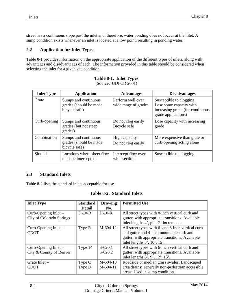
8-2 City of Colorado Springs Drainage Criteria Manual, Volume 1
May 2014
Chapter 8 Inlets
street has a continuous slope past the inlet and, therefore, water ponding does not occur at the inlet. A sump condition exists whenever an inlet is located at a low point, resulting in ponding water.
2.2 Application for Inlet Types
Table 8-1 provides information on the appropriate application of the different types of inlets, along with advantages and disadvantages of each. The information provided in this table should be considered when selecting the inlet for a given site condition.
Table 8-1. Inlet Types (Source: UDFCD 2001)
Inlet Type Application Advantages Disadvantages
Grate Sumps and continuous grades (should be made bicycle safe)
Perform well over wide range of grades
Susceptible to clogging Lose some capacity with increasing grade (for continuous grade applications)
Curb-opening Sumps and continuous grades (but not steep grades)
Do not clog easily Bicycle safe
Lose capacity with increasing grade
Combination Sumps and continuous grades (should be made bicycle safe)
High capacity Do not clog easily
More expensive than grate or curb-opening acting alone
Slotted Locations where sheet flow must be intercepted
Intercept flow over wide section
Susceptible to clogging
2.3 Standard Inlets
Table 8-2 lists the standard inlets acceptable for use.
Table 8-2. Standard Inlets
Inlet Type Standard Detail
Drawing No.
Permitted Use
Curb-Opening Inlet – City of Colorado Springs
D-10-R D-10-R All street types with 8-inch vertical curb and gutter, with appropriate transitions. Available inlet lengths 4’, plus 2’ increments.
Curb-Opening Inlet – CDOT
Type R M-604-12 All street types with 6- and 8-inch vertical curb and gutter and 4-inch mountable curb and gutter, with appropriate transitions. Available inlet lengths 5’, 10’, 15’.
Curb-Opening Inlet – City & County of Denver
Type 14 S-620.1 S-620.2
All street types with 6-inch vertical curb and gutter, with appropriate transitions. Available inlet lengths 6’, 9’, 12’, 15’.
Grate Inlet – CDOT
Type C Type D
M-604-10 M-604-11
Roadside or median grass swales; Landscaped area drains; generally non-pedestrian accessible areas; Used in sump condition.
Chapter 8 Inlets
May 2014 City of Colorado Springs Drainage Criteria Manual, Volume 1
8-3
Combination Curb- Opening and Grate Inlet – City & County of Denver
Type 16 S-616.1 S-616.2 S-616.3
All street types with 6-inch vertical curb and gutter, with appropriate transitions. Available inlet lengths single (4’8”), double (8’5”) and triple (12’3”).
Other inlets used in Colorado that may be acceptable include the Colorado Springs D-9 and D-11, Denver Type 13 Inlet, and Vane Grate Inlet. For retrofit situations or when special circumstances exist, other inlets may be used but will be evaluated on a case-by-case basis. UD-Inlet can be used for hydraulic analysis of 18 different typical inlet/grate combinations. Design of non-standard inlets will require detailed computations and justification for their use.
3.0 Inlets on a Continuous Grade
3.1 Location and Spacing
As the flow increases in the gutter on a long, continuous grade segment of roadway, so does the depth and spread. Since the depth and spread (encroachment) is not allowed to exceed the maximum values specified in Chapter 7, Street Drainage, inlets need to be strategically placed to remove flow from the gutter. A properly designed storm sewer system makes efficient use of the conveyance capacity of the street gutters by positioning inlets at the point where the allowable depth or spread is about to be exceeded for the design storm. This location is found through an iterative process of delineating contributing areas to the street curb, comparing estimated flows for Minor and Major storm events with the allowable street capacities and revising the location as needed so that the estimated flows do not exceed the allowable street capacity. The Streets/Inlets/Storm Sewers Chapter in Volume 1 of the UDFCD Manual provides a detailed discussion on inlet placement on continuous grades.
3.2 Capacity Factors
The capacity of an inlet located on a continuous grade to intercept flow is dependent upon a variety of factors including gutter slope, depth and velocity of flow in the gutter, height and length of the curb opening, street cross slope, and the amount of depression at the inlet. Inlets placed on continuous grades rarely intercept all of the flow in the gutter during the minor storm. This results in flow continuing downstream of the inlet and is typically referred to as “carryover” or “flow-by”. The amount of carryover must be accounted for in the drainage system evaluation, as well as in the design of the downstream inlet. See the Streets/Inlets/Storm Sewers Chapter in Volume 1 of the UDFCD Manual for additional information on the efficiency and design of curb opening inlets on continuous grades.
3.3 Hydraulic Capacity
3.3.1 Capacity Charts
Figures 8-1 through 8-9 (located at the end of this chapter) provide capacity charts for inlets on continuous grades along standard street sections for the minor and major storm events, based on the maximum allowable flow in the street section. These charts also incorporate clogging factors as discussed in the Streets/Inlets/Storm Sewers Chapter in Volume 1 of the UDFCD Manual.
It is recommended that these charts be used for preliminary design phases and rough inlet placement. For final design, the design engineer can use these charts if the street is at maximum allowable flow. When flow in the gutter is less than the maximum allowed flow (minor or major event) as determined per
8-4 City of Colorado Springs Drainage Criteria Manual, Volume 1
May 2014
Chapter 8 Inlets
Chapter 7, Street Drainage, the UD-Inlet spreadsheets can be used to determine the interception rate more precisely. See the Streets/Inlets/Storm Sewers Chapter of the UDFCD Manual for further discussion on maximum street flows allowed and the use of UD-Inlet for less than maximum allowable flow.
3.3.2 Spreadsheets
The Streets/Inlets/Storm Sewers Chapter of the UDFCD Manual provides detailed instruction on the appropriate analysis of inlet capacities including equations, coefficients, and examples. The worksheets are the most accurate means of determining inlet capture rates and capacity calculations. The UD-Inlet Spreadsheets may be downloaded from the UDFCD web site at www.udfcd.org.
The design engineer must also use the UD-Inlet worksheets when a non-standard street section is analyzed or when the charts for the inlet being analyzed are not provided. Whenever a non-standard inlet is being used, it is the responsibility of the designer to provide adequate support for its hydraulic capacity and documenting its characteristics, dimensions and construction details.
4.0 Inlets in Sump Conditions
4.1 Location
The location and spacing of inlets is based upon street design considerations, topography (sumps), maintenance requirements, and the allowable spread of flow within the street. A significant amount of cost savings can be realized if inlets are placed in locations where their efficiency is maximized. The greater the efficiency of an inlet, the smaller the carryover flow, which may result in a smaller number of inlets downstream. Inlets are most efficient in a sump condition or along mild continuous street grades.
4.2 Capacity Factors
Inlets located in sumps (low points) must be sized to intercept all of the design storm flows at an allowable depth of ponding. The capacity of an inlet in a sump is dependent upon the depth of ponding above the inlet invert and the amount of debris clogging the inlet. Ponded water is a nuisance and can be a hazard to the public; therefore curb opening and combination inlets (where approved for use) are highly recommended for sump conditions due to their reduced clogging potential versus grate inlets acting alone.
4.3 Hydraulic Capacity
Capacity charts for Type C, Type R, and Type D-10-R inlets in a sump condition are provided in Figures 8-10 through 8-12. These charts are based upon the depth of ponding above the inlet. The depth of ponded water shall not exceed the maximum allowable water depth for the given street classification as summarized in Chapter 7, Street Drainage. Capacity charts for Type 16 and Type D inlets in sumps are available in the City and County of Denver, Storm Drainage Design Technical Criteria manual, Figure 8.1, Allowable Inlet Capacity-Sump Conditions.
When the depth of ponding in front of a sump inlet overtops the street crown consideration must be given to whether the design flow remains contained in front of the inlet or whether a portion of it flows away from the inlet to the other side of the street. If flow overtops the street crown it may be combined with other flows and/or be captured by other inlets. If flow that overtops the street crown is not contained by the opposing street curb so that the depth of the opposing curb’s ponding does not exceed the height of the crown, the capacity of the inlet being sized will be limited by the depth of ponding at the street crown. If the flow overtopping the street crown is contained by the opposing curb so that the depth of ponding
Chapter 8 Inlets
May 2014 City of Colorado Springs Drainage Criteria Manual, Volume 1
8-5
exceeds the height of the street crown the capacity of the inlet being sized will be determined by the depth of ponding in front of the inlet.
4.4 Overflow Path
A surface flow path shall be provided at all sump inlets to provide for overflows if the inlet becomes clogged or if storm runoff exceeds design flows. The emergency overflow shall be designed to convey the major storm discharge assuming that no flow is carried in the storm sewer. The depth of ponding shall not exceed the maximum allowable water depth for the given street classification as summarized in Chapter 7, Street Drainage. Channels conveying overflows shall be designed based on criteria for open channels and shall be contained within public right-of-way or a tract, including the required freeboard.
4.5 Type C Inlets
The capacity curves provided in Figure 8-10 include a 50% reduction factor for a standard grate and a 75% reduction factor for a close mesh grate. If a Type C inlet is placed in an area with pedestrian traffic, a close mesh grate shall be used.
5.0 Other Design Considerations
5.1 Curb Chase Drain (Sidewalk Chase)
Curb chase drains shall NOT be used in place of a standard inlet to remove runoff from a street section. Curb chase drains have limited efficiency and have poor long-term performance.
5.2 Median Inlets
Median curbs are typically configured to direct flows away from the median or are normally “spill” curbs. In situations where the street configuration directs flows toward medians or where runoff from medians is concentrated, inlets must be placed to collect the flows. Inlets are required along or within the median to reduce ponding at curb and gutter low points and to eliminate concentrated flow crossing over the lanes of traffic. The final design and construction drawings must address inlet sizing, dimensions, and required curb and gutter transitions. In some cases, using a depressed, vegetated median with an inlet at the bottom of the depression can be an effective way to disconnect impervious area.
5.3 Maximum Inlet Length
Inlets shall be designed to blend in with the streetscape, and not present a dramatic structural departure from the general surroundings. The use of extremely long inlets is discouraged, as they are generally not aesthetic, require increased maintenance, and are viewed as a hazard by the public. In addition, studies by the UDFCD show that excessively long inlets do not significantly increase interception rates. The maximum length of an inlet in a specific location should not exceed 9 feet for Type 16 inlets, 15 feet for Type R and 16 feet for Type D-10-R inlets.
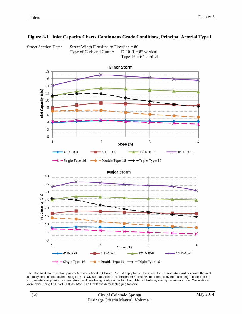
8-6 City of Colorado Springs Drainage Criteria Manual, Volume 1
May 2014
Chapter 8 Inlets
Figure 8-1. Inlet Capacity Charts Continuous Grade Conditions, Principal Arterial Type I
Street Section Data: Street Width Flowline to Flowline = 80’ Type of Curb and Gutter: D-10-R = 8” vertical
Type 16 = 6” vertical
The standard street section parameters as defined in Chapter 7 must apply to use these charts. For non-standard sections, the inlet capacity shall be calculated using the UDFCD spreadsheets. The maximum spread width is limited by the curb height based on no curb overtopping during a minor storm and flow being contained within the public right-of-way during the major storm. Calculations were done using UD-Inlet 3.00.xls, Mar., 2011 with the default clogging factors.
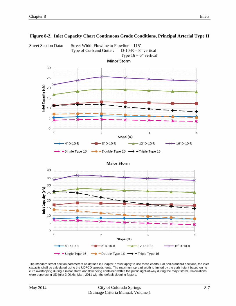
Chapter 8 Inlets
May 2014 City of Colorado Springs Drainage Criteria Manual, Volume 1
8-7
Figure 8-2. Inlet Capacity Chart Continuous Grade Conditions, Principal Arterial Type II
Street Section Data: Street Width Flowline to Flowline = 115’ Type of Curb and Gutter: D-10-R = 8” vertical
Type 16 = 6” vertical
The standard street section parameters as defined in Chapter 7 must apply to use these charts. For non-standard sections, the inlet capacity shall be calculated using the UDFCD spreadsheets. The maximum spread width is limited by the curb height based on no curb overtopping during a minor storm and flow being contained within the public right-of-way during the major storm. Calculations were done using UD-Inlet 3.00.xls, Mar., 2011 with the default clogging factors.
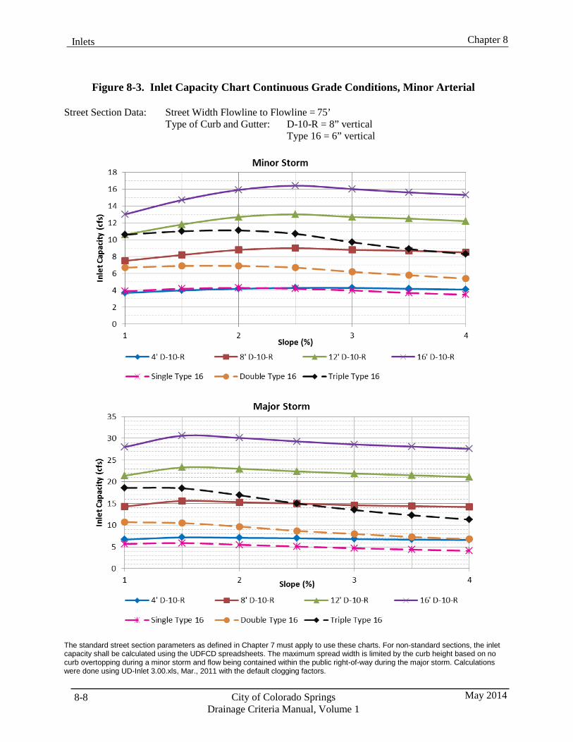
8-8 City of Colorado Springs Drainage Criteria Manual, Volume 1
May 2014
Chapter 8 Inlets
Figure 8-3. Inlet Capacity Chart Continuous Grade Conditions, Minor Arterial
Street Section Data: Street Width Flowline to Flowline = 75’ Type of Curb and Gutter: D-10-R = 8” vertical
Type 16 = 6” vertical
The standard street section parameters as defined in Chapter 7 must apply to use these charts. For non-standard sections, the inlet capacity shall be calculated using the UDFCD spreadsheets. The maximum spread width is limited by the curb height based on no curb overtopping during a minor storm and flow being contained within the public right-of-way during the major storm. Calculations were done using UD-Inlet 3.00.xls, Mar., 2011 with the default clogging factors.
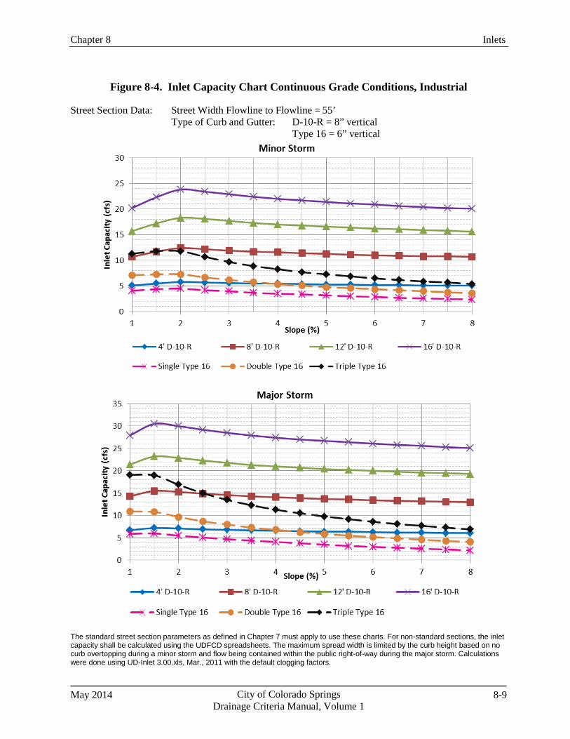
Chapter 8 Inlets
May 2014 City of Colorado Springs Drainage Criteria Manual, Volume 1
8-9
Figure 8-4. Inlet Capacity Chart Continuous Grade Conditions, Industrial
Street Section Data: Street Width Flowline to Flowline = 55’ Type of Curb and Gutter: D-10-R = 8” vertical
Type 16 = 6” vertical
The standard street section parameters as defined in Chapter 7 must apply to use these charts. For non-standard sections, the inlet capacity shall be calculated using the UDFCD spreadsheets. The maximum spread width is limited by the curb height based on no curb overtopping during a minor storm and flow being contained within the public right-of-way during the major storm. Calculations were done using UD-Inlet 3.00.xls, Mar., 2011 with the default clogging factors.
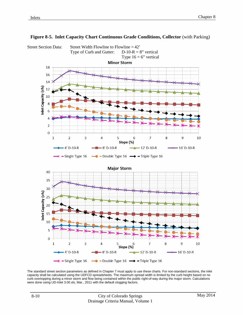
8-10 City of Colorado Springs Drainage Criteria Manual, Volume 1
May 2014
Chapter 8 Inlets
Figure 8-5. Inlet Capacity Chart Continuous Grade Conditions, Collector (with Parking)
Street Section Data: Street Width Flowline to Flowline = 42’ Type of Curb and Gutter: D-10-R = 8” vertical
Type 16 = 6” vertical
The standard street section parameters as defined in Chapter 7 must apply to use these charts. For non-standard sections, the inlet capacity shall be calculated using the UDFCD spreadsheets. The maximum spread width is limited by the curb height based on no curb overtopping during a minor storm and flow being contained within the public right-of-way during the major storm. Calculations were done using UD-Inlet 3.00.xls, Mar., 2011 with the default clogging factors.
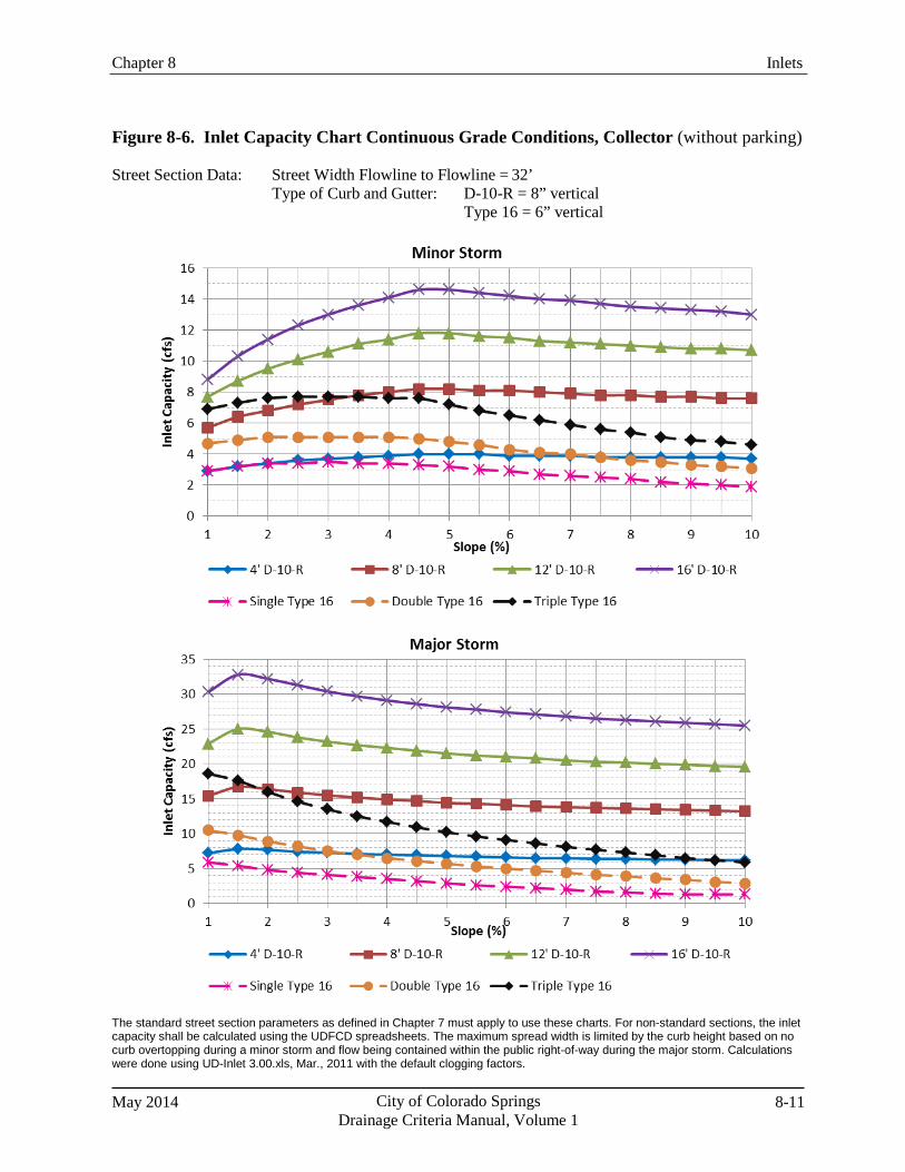
Chapter 8 Inlets
May 2014 City of Colorado Springs Drainage Criteria Manual, Volume 1
8-11
Figure 8-6. Inlet Capacity Chart Continuous Grade Conditions, Collector (without parking)
Street Section Data: Street Width Flowline to Flowline = 32’ Type of Curb and Gutter: D-10-R = 8” vertical
Type 16 = 6” vertical
The standard street section parameters as defined in Chapter 7 must apply to use these charts. For non-standard sections, the inlet capacity shall be calculated using the UDFCD spreadsheets. The maximum spread width is limited by the curb height based on no curb overtopping during a minor storm and flow being contained within the public right-of-way during the major storm. Calculations were done using UD-Inlet 3.00.xls, Mar., 2011 with the default clogging factors.
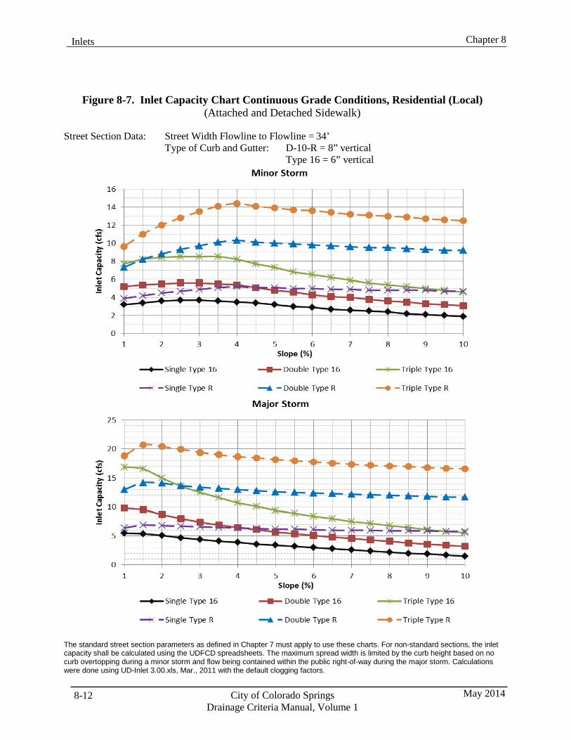
8-12 City of Colorado Springs Drainage Criteria Manual, Volume 1
May 2014
Chapter 8 Inlets
Figure 8-7. Inlet Capacity Chart Continuous Grade Conditions, Residential (Local) (Attached and Detached Sidewalk)
Street Section Data: Street Width Flowline to Flowline = 34’
Type of Curb and Gutter: D-10-R = 8” vertical Type 16 = 6” vertical
The standard street section parameters as defined in Chapter 7 must apply to use these charts. For non-standard sections, the inlet capacity shall be calculated using the UDFCD spreadsheets. The maximum spread width is limited by the curb height based on no curb overtopping during a minor storm and flow being contained within the public right-of-way during the major storm. Calculations were done using UD-Inlet 3.00.xls, Mar., 2011 with the default clogging factors.
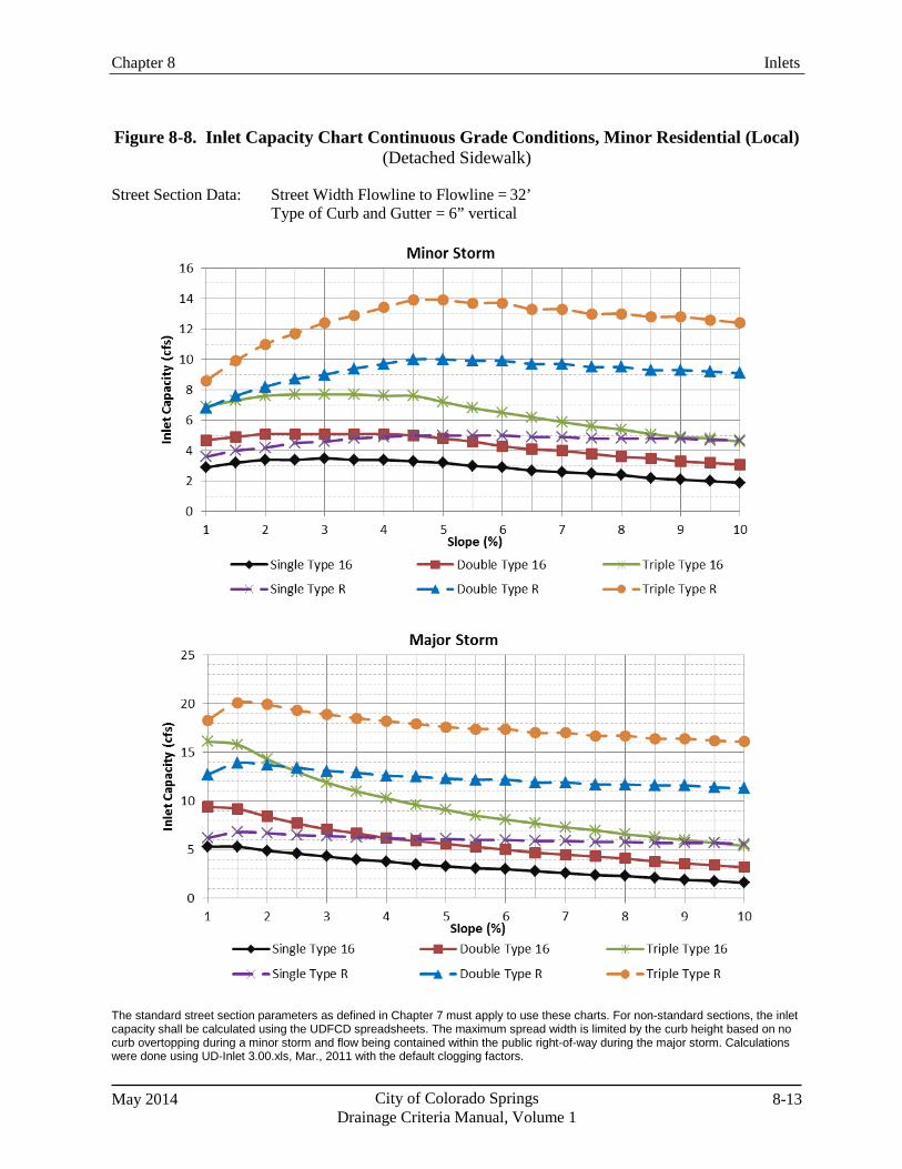
Chapter 8 Inlets
May 2014 City of Colorado Springs Drainage Criteria Manual, Volume 1
8-13
Figure 8-8. Inlet Capacity Chart Continuous Grade Conditions, Minor Residential (Local) (Detached Sidewalk)
Street Section Data: Street Width Flowline to Flowline = 32’
Type of Curb and Gutter = 6” vertical
The standard street section parameters as defined in Chapter 7 must apply to use these charts. For non-standard sections, the inlet capacity shall be calculated using the UDFCD spreadsheets. The maximum spread width is limited by the curb height based on no curb overtopping during a minor storm and flow being contained within the public right-of-way during the major storm. Calculations were done using UD-Inlet 3.00.xls, Mar., 2011 with the default clogging factors.
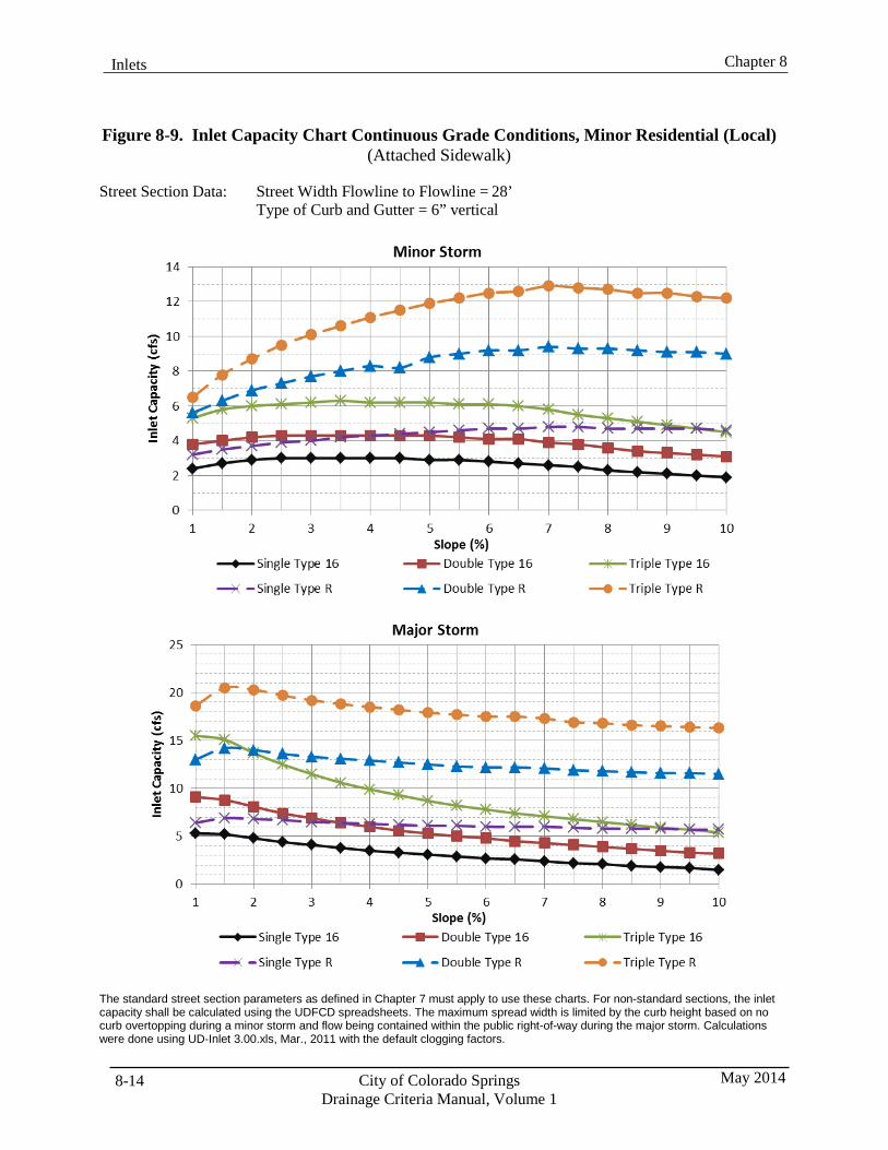
8-14 City of Colorado Springs Drainage Criteria Manual, Volume 1
May 2014
Chapter 8 Inlets
Figure 8-9. Inlet Capacity Chart Continuous Grade Conditions, Minor Residential (Local) (Attached Sidewalk)
Street Section Data: Street Width Flowline to Flowline = 28’
Type of Curb and Gutter = 6” vertical
The standard street section parameters as defined in Chapter 7 must apply to use these charts. For non-standard sections, the inlet capacity shall be calculated using the UDFCD spreadsheets. The maximum spread width is limited by the curb height based on no curb overtopping during a minor storm and flow being contained within the public right-of-way during the major storm. Calculations were done using UD-Inlet 3.00.xls, Mar., 2011 with the default clogging factors.
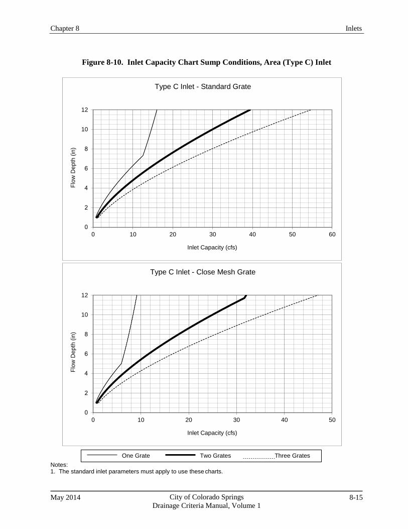
Chapter 8 Inlets
May 2014 City of Colorado Springs Drainage Criteria Manual, Volume 1
8-15
Figure 8-10. Inlet Capacity Chart Sump Conditions, Area (Type C) Inlet
Notes: 1. The standard inlet parameters must apply to use these charts.
One Grate Two Grates Three Grates
Type C Inlet - Close Mesh Grate
12
10
10 20 30 40 50
Inlet Capacity (cfs)
Type C Inlet - Standard Grate
12
10
10 20 30 40 50 60
Inlet Capacity (cfs)
Flow
Dep
th (i
n)
Flow
Dep
th (i
n)
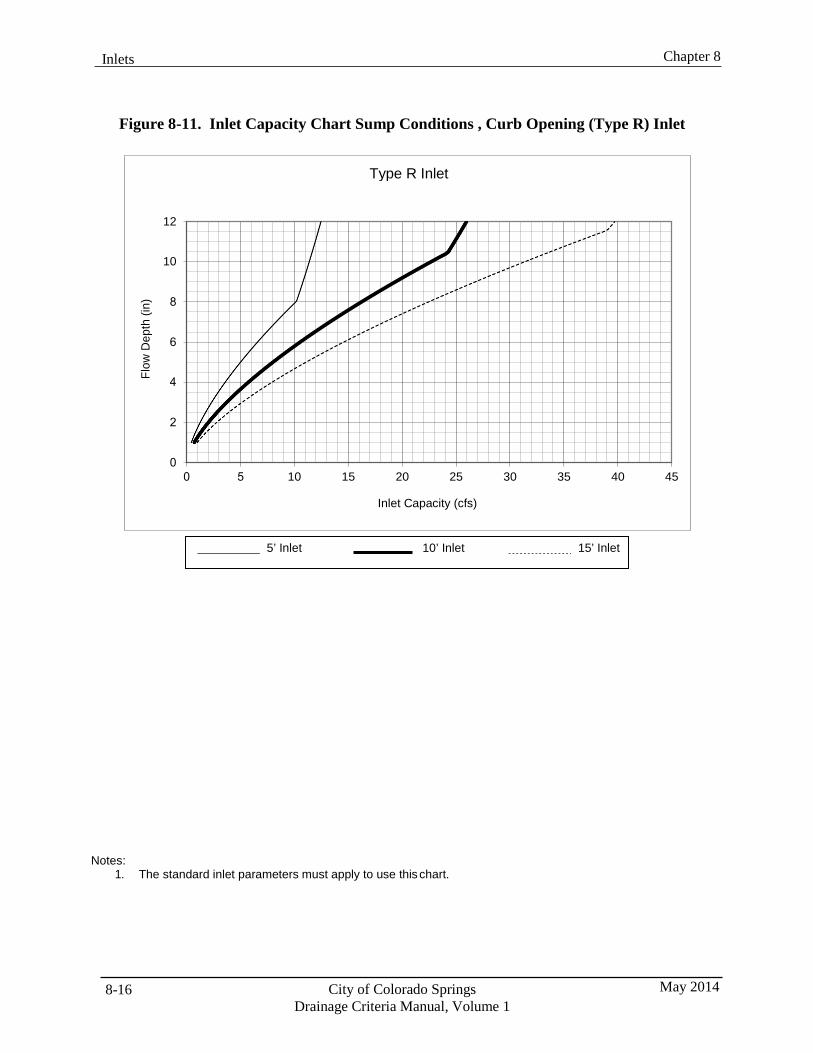
8-16 City of Colorado Springs Drainage Criteria Manual, Volume 1
May 2014
Chapter 8 Inlets
Figure 8-11. Inlet Capacity Chart Sump Conditions , Curb Opening (Type R) Inlet
Notes: 1. The standard inlet parameters must apply to use this chart.
5’ Inlet 10’ Inlet 15’ Inlet
Type R Inlet
12
10
10 15 20 25 30 35 40 45
Inlet Capacity (cfs)
Flow
Dep
th (i
n)
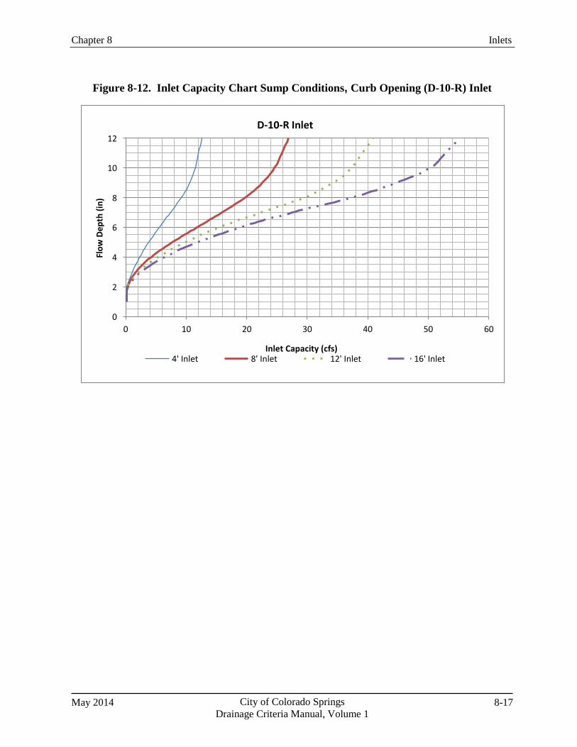
Chapter 8 Inlets
May 2014 City of Colorado Springs Drainage Criteria Manual, Volume 1
8-17
Figure 8-12. Inlet Capacity Chart Sump Conditions, Curb Opening (D-10-R) Inlet
D-10-R Inlet 12
10
10 20 30 40 50 60
Inlet Capacity (cfs) 4' Inlet 8' Inlet 12' Inlet 16' Inlet
Flow
Dep
th (i
n)

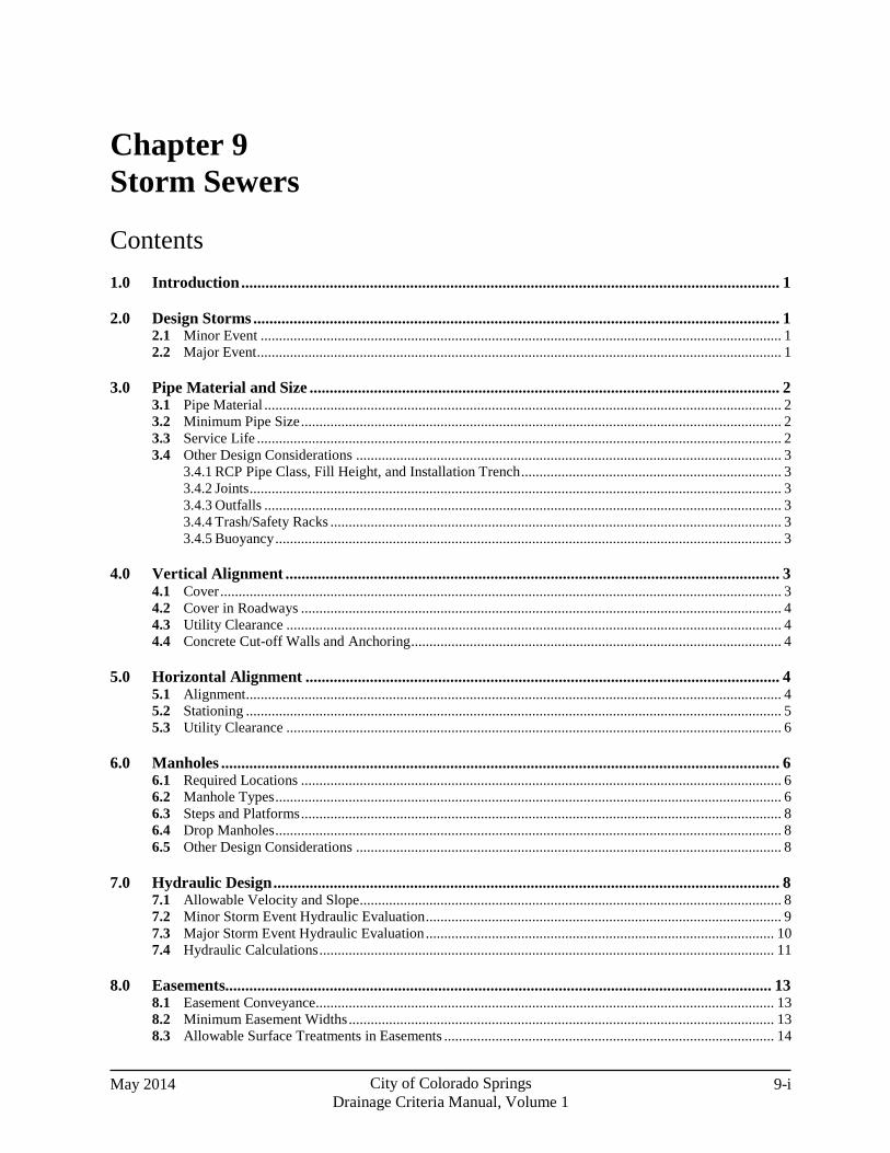
May 2014 City of Colorado Springs Drainage Criteria Manual, Volume 1
9-i
Chapter 9 Storm Sewers
Contents 1.0 Introduction ...................................................................................................................................... 1
2.0 Design Storms ................................................................................................................................... 1 2.1 Minor Event .............................................................................................................................................. 1 2.2 Major Event ............................................................................................................................................... 1
3.0 Pipe Material and Size ..................................................................................................................... 2 3.1 Pipe Material ............................................................................................................................................. 2 3.2 Minimum Pipe Size ................................................................................................................................... 2 3.3 Service Life ............................................................................................................................................... 2 3.4 Other Design Considerations .................................................................................................................... 3
3.4.1 RCP Pipe Class, Fill Height, and Installation Trench ....................................................................... 3 3.4.2 Joints ................................................................................................................................................. 3 3.4.3 Outfalls ............................................................................................................................................. 3 3.4.4 Trash/Safety Racks ........................................................................................................................... 3 3.4.5 Buoyancy .......................................................................................................................................... 3
4.0 Vertical Alignment ........................................................................................................................... 3 4.1 Cover ......................................................................................................................................................... 3 4.2 Cover in Roadways ................................................................................................................................... 4 4.3 Utility Clearance ....................................................................................................................................... 4 4.4 Concrete Cut-off Walls and Anchoring ..................................................................................................... 4
5.0 Horizontal Alignment ...................................................................................................................... 4 5.1 Alignment .................................................................................................................................................. 4 5.2 Stationing .................................................................................................................................................. 5 5.3 Utility Clearance ....................................................................................................................................... 6
6.0 Manholes ........................................................................................................................................... 6 6.1 Required Locations ................................................................................................................................... 6 6.2 Manhole Types .......................................................................................................................................... 6 6.3 Steps and Platforms ................................................................................................................................... 8 6.4 Drop Manholes .......................................................................................................................................... 8 6.5 Other Design Considerations .................................................................................................................... 8
7.0 Hydraulic Design .............................................................................................................................. 8 7.1 Allowable Velocity and Slope ................................................................................................................... 8 7.2 Minor Storm Event Hydraulic Evaluation ................................................................................................. 9 7.3 Major Storm Event Hydraulic Evaluation ............................................................................................... 10 7.4 Hydraulic Calculations ............................................................................................................................ 11
8.0 Easements........................................................................................................................................ 13 8.1 Easement Conveyance............................................................................................................................. 13 8.2 Minimum Easement Widths .................................................................................................................... 13 8.3 Allowable Surface Treatments in Easements .......................................................................................... 14
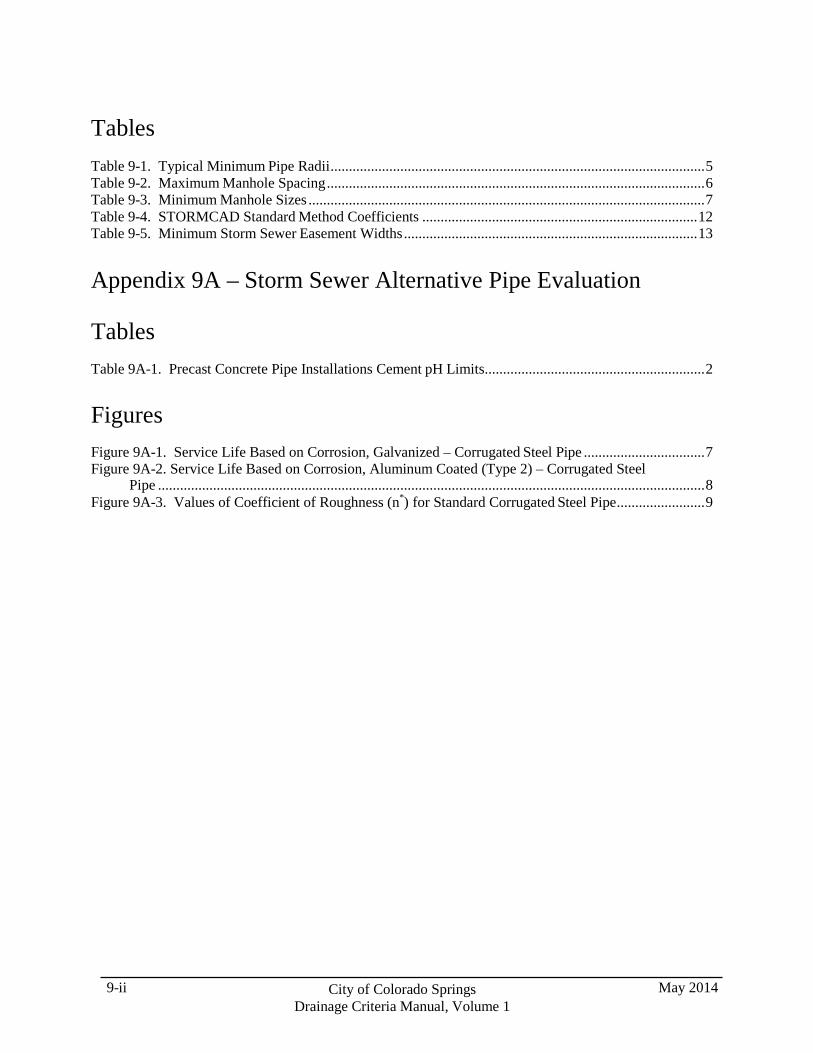
9-ii City of Colorado Springs Drainage Criteria Manual, Volume 1
May 2014
Tables Table 9-1. Typical Minimum Pipe Radii ...................................................................................................... 5 Table 9-2. Maximum Manhole Spacing ....................................................................................................... 6 Table 9-3. Minimum Manhole Sizes ............................................................................................................ 7 Table 9-4. STORMCAD Standard Method Coefficients ........................................................................... 12 Table 9-5. Minimum Storm Sewer Easement Widths ................................................................................ 13
Appendix 9A – Storm Sewer Alternative Pipe Evaluation
Tables Table 9A-1. Precast Concrete Pipe Installations Cement pH Limits ............................................................ 2
Figures Figure 9A-1. Service Life Based on Corrosion, Galvanized – Corrugated Steel Pipe ................................. 7 Figure 9A-2. Service Life Based on Corrosion, Aluminum Coated (Type 2) – Corrugated Steel
Pipe ..................................................................................................................................................... 8 Figure 9A-3. Values of Coefficient of Roughness (n*) for Standard Corrugated Steel Pipe ........................ 9
Chapter 9 Storm Sewers
May 2014 City of Colorado Springs Drainage Criteria Manual, Volume 1
9-1
1.0 Introduction This chapter summarizes design criteria and evaluation methods for storm sewer systems.
Traditionally, urban development has relied on storm sewer systems in the upper portions of watersheds to prevent local flooding and to carry flows away quickly. As storm sewers pick up more drainage area, they increase in size and convey urban runoff quickly downstream with almost no reduction in its rate or volume or improvement in water quality.
Today, with the emphasis on volume reduction and water quality enhancement, stormwater management practices are being revised to promote infiltration, attenuation and water quality enhancement. Properly designed sites with grass swales and other mitigation techniques can serve to reduce reliance on storm sewers or allow smaller and less extensive storm sewers to be constructed downstream. When planning a new project, the use of runoff reducing methods such as porous landscaped detention and grass swales is encouraged. This concept, termed “minimizing directly connected impervious areas,” or “low impact development” can also improve the quality of stormwater runoff and reduce the amount of dedicated water quality features required.
Although using grass swales is compatible with many land uses, such as residential, parks, institutional, and others with relatively low densities, grass swales may not be practical in highly urbanized land uses and in areas where there are many access points across the planned drainage path. Therefore, storm sewers will continue to be an integral part of many drainage systems.
2.0 Design Storms Both the “minor” and “major” storm events must be considered for properly designing storm sewers. In each case, storm sewers are to be designed to carry the portion of runoff that cannot be conveyed on the surface, as dictated by the available capacity in streets and swales.
2.1 Minor Event
At a minimum, storm sewers are to be designed to convey storm runoff for the minor event (defined in Chapter 3, Drainage Policies) when flow exceeds the allowable street capacity as defined in Chapter 7, Street Drainage. Inlets shall be located at appropriate locations to intercept the minor event flow and direct it to the storm sewer. The storm sewer shall be designed to convey the minor design storm without surcharging. Section 8.2 provides information on hydraulic design methods for the minor storm.
2.2 Major Event
Under certain conditions, the storm sewer system must be designed to convey flows greater than the minor storm runoff, possibly up to the major storm event (defined in Chapter 3, Drainage Policies) runoff. These conditions include, but may not be limited to:
Where the street capacity for the major storm is exceeded.
Where street crown overtopping would otherwise exceed criteria.
Where major storm flows can split off in undesirable directions (i.e., flow splits at intersections).
Chapter 9 Storm Sewers
City of Colorado Springs Drainage Criteria Manual, Volume 1
May 2014 9-2
Where the storm sewer system is accepting flow from an upstream storm sewer system or branch that
is designed for the major storm. Where regional storm sewers are designed for the major storm.
Where storm sewers must convey undetained flows to a detention pond.
If a storm sewer is designed to carry major storm flows, the inlets to the storm sewer shall be sized accordingly. The major storm event hydraulic grade line is allowed to rise above the top of the storm sewer pipe and surcharge the system. The ability of the storm sewer to convey the major storm event shall be based on its capacity when the hydraulic grade line elevation is at least 1 foot below the final grade elevation, measured from the lowest gutter flowline elevation at inlets. In no case shall the surcharge create system velocities in excess of the maximum defined in Section 8.2.
The major storm event hydraulic grade line should also be analyzed for storm sewer systems designed to convey the minor storm event runoff. Since the flow depth in the street during the major storm will typically be greater than the minor storm, inlets may intercept additional runoff and the flow in the storm sewer will be greater than during the minor storm event. Any surcharge created by conveyance of the additional runoff is subject to the limits outlined above. Section 8.3 provides additional information on hydraulic design methods for the major storm.
3.0 Pipe Material and Size
3.1 Pipe Material
All storm sewers located within public rights-of-way, public easements or tracts shall be constructed with approved pipe materials. Reinforced concrete pipe (RCP) is approved for all pipe sizes. Double-walled polypropylene pipe may be used up to and including 60”. HDPE pipe is approved for private pipes with pipe diameters of 36 inches or less only. HDPE pipe is not approved for public use. Circular pipe is the most cost-effective option for reinforced concrete, but elliptical pipe or box conduits may be a more appropriate option in areas where available cover is limited or to avoid utility conflicts.
Alternate pipe materials may be considered, with approval, prior to submittal of drainage reports for review since the hydraulics of the pipe material must be evaluated at the time of the design. Trench details, bedding material, installation specifications, minimum cover or fill height limits, service life and construction testing requirements for alternate pipe materials shall be consistent with those recommended by the manufacturer/supplier or as determined appropriate.
3.2 Minimum Pipe Size
The minimum allowable pipe size for storm sewers located within rights-of-way, public easements or tracts shall be 15-inch for laterals and 18-inch for trunk lines that collect flows from laterals or from upstream trunk lines.
3.3 Service Life
The service life for storm sewer systems shall be 50 years. An extended service life of 100 years shall be required under these conditions:
The depth of cover exceeds 15 feet.
The system is located within the travel lanes of 4-lane or major and minor arterial roadways.
Chapter 9 Storm Sewers
May 2014 City of Colorado Springs Drainage Criteria Manual, Volume 1
9-3
The centerline of the storm sewer pipe is located 15 feet or less horizontally from any building
structure.
Service life shall be determined according to analyses described in Appendix 9-A at the back of this chapter. Approval of alternative pipe materials shall be based on the determination that its service life is estimated to be at least equal to service life durations stated herein and other issues such as constructability and maintenance.
3.4 Other Design Considerations
3.4.1 RCP Pipe Class, Fill Height, and Installation Trench
The minimum class of reinforced concrete pipe shall be Class III, however, the depth of cover, live load, and field conditions may require structurally stronger pipe. Trench installation requirements, trench installation details, and allowable fill heights are shown in the City of Colorado Springs Standard Specifications, Sheets D-30, D-31 and D-32. It is the responsibility of the design engineer to develop and submit alternate trench and installation details when project specific conditions or loadings require modification to the standard installation. Alternate designs shall follow ASTM C1479.
3.4.2 Joints
When storm sewers are designed to operate under pressurized conditions, they shall have gasketed, water- tight joints. ASTM Standard C 443 covers flexible watertight joints for circular concrete sewer pipe and precast manhole sections, using rubber gaskets for sealing the joints. Adhere to local and manufacturer’s specifications for the maximum allowable joint gaps to form a water tight seal.
3.4.3 Outfalls
Where storm sewers discharge into open channels or detention ponds, protection of the bank and overbank or pond bottom shall be provided to prevent erosion due to flows discharged from the storm sewer. Erosion protection shall be designed to convey the storm sewer design flow assuming that no flow is in the receiving channel or pond. The stability of the outfall protection must also be evaluated based on the flow conditions in the receiving channel. Design guidance for outfall conditions is provided in Chapter 10 of this manual.
3.4.4 Trash/Safety Racks
Trash/safety racks shall not be used at storm sewer outlets.
3.4.5 Buoyancy
Where groundwater is anticipated to submerge pipelines, buoyancy calculations shall be required and the use of ballast for pipes and structures shall be evaluated.
4.0 Vertical Alignment 4.1 Cover
All storm sewers shall be designed so that they will be structurally adequate for both minimum and maximum cover conditions. A minimum cover shall be maintained to withstand AASHTO HS-20
Chapter 9 Storm Sewers
City of Colorado Springs Drainage Criteria Manual, Volume 1
May 2014 9-4
loading on the pipe. The minimum cover to withstand live loading depends upon the pipe size, type and class, and soil bedding condition, but shall not be less than 1 foot to the exterior pipe wall at any point along the pipe. Additional cover will be required at manhole locations to facilitate the construction of the base over the pipe, manhole lid, ring and cover. There are numerous factors that ultimately affect the depth of cover over a pipe and in most cases it is likely that the cover will have to be greater than the minimum allowed due to other design factors. Some of the other factors that affect the depth of the pipe are hydraulic grade line elevations, inlet depths, adjacent utilities or utility crossings, including water and sewer services lines along residential streets, and connections to existing storm sewer systems. The maximum cover over storm sewers shall also be considered and evaluated according to manufacturer’s specifications. Should a design require a cover depth of greater than 15 feet, an extended service life installation shall be provided.
4.2 Cover in Roadways
The roadway subgrade, which supports the pavement section is typically plowed (or scarified) to a certain depth, moisture treated and compacted prior to the placement of the sub-base, base course, and surfacing. There are also instances where the subgrade material must be excavated and replaced or treated to a certain depth to mitigate swelling soils. These efforts can impact the storm sewer system if it has not been designed with adequate depth. The design engineer shall use the best information available, including pavement design or soils reports to ensure that storm sewer pipes have adequate depth during and after construction, but a minimum cover of 1 foot should be provided below the pavement subgrade.
4.3 Utility Clearance
For all storm sewer crossings at utility lines, the appropriate agency shall be contacted to determine the requirements for the crossing. A minimum clearance of 18 inches is required between a storm sewer and a water main, sanitary sewer, or other utility above or below (all clearances are defined as outside-of-pipe to outside-of-pipe). Additional stormwater clearance requirements are included in the Colorado Springs Utilities Water Line Extension and Service Standards.
4.4 Concrete Cut-off Walls and Anchoring
Where the storm sewer pipe trench is susceptible to erosion, reinforced cast-in-place concrete cut-off walls shall be installed at no greater than 30 foot horizontal intervals. In addition, where storm sewer pipe is installed in a slope of 3:1 or steeper, anchoring shall be provided at intervals no greater than 30 feet.
5.0 Horizontal Alignment
5.1 Alignment
In general, storm sewer alignments between drainage structures (inlets or manholes) shall be straight. The angle of confluence where pipe centerlines intersect shall be 90 degrees or less. In addition, the change in the energy grade line through the junction shall not exceed 3 feet. Parallel pipes may not be used without a variance. Variances for parallel pipes must be based on extreme existing site constraints.
Except for lateral pipe connections between inlets, the alignment should allow the entire system to be constructed between the street gutters to avoid the placement of the system under curb, gutter and sidewalk and in utility corridors. The outside edge of manhole covers shall be at least 1 foot outside of street gutters. To the extent possible, place manholes in the center of travel lanes to avoid traffic impacts.
May 2014 City of Colorado Springs Drainage Criteria Manual, Volume 1
9-5
Storm Sewers Chapter 9
Curvilinear sections may be permitted on trunk lines or lateral lines connecting inlets. When proposed, the designer must demonstrate the need for a curvilinear alignment. The limitations on the radius for pulled-joint pipe are dependent on the pipe length and diameter, and amount of opening permitted in the joint. A maximum joint opening of approximately 1/3 the joint depth is typically allowed. Typical allowable pulled-joint openings and minimum design pipe radii for standard circular pipe sizes are provided in Table 9-1. Allowable pulled-joint openings and minimum radii are based on a pipe section length of 8 feet. The minimum radius may vary for specific pipe manufacturers and pipe classes.
Table 9-1. Typical Minimum Pipe Radii
Pipe
Diameter Allowable Pulled-
Joint Opening Minimum Pipe
Radius
18 inch 1.0 inches 207 feet 24 inch 1.0 inches 270 feet 30 inch 1.0 inches 333 feet 36 inch 1.0 inches 396 feet 42 inch 1.5 inches 323 feet 48 inch 1.5 inches 367 feet 54 inch 1.5 inches 421 feet 60 inch 1.5 inches 465 feet 66 inch 1.5 inches 510 feet 72 inch 1.5 inches 554 feet 78 inch 1.75 inches 526 feet 84 inch 1.75 inches 565 feet 90 inch 1.75 inches 604 feet 96 inch 1.75 inches 635 feet 102 inch 1.75 inches 674 feet 108 inch 1.75 inches 713 feet
Curves may also be produced by fabricating beveled ends for pipes 48 inches in diameter and larger. Beveled ends shall be limited to a maximum angle of 45 degrees. Alignments may also be adjusted horizontally using prefabricated bends of no more than 45 degrees for pipes 30 inches in diameter or larger.
5.2 Stationing
Storm sewer system stationing shall increase from the downstream limit of the system to the upstream limit with the intersection of the alignment with the receiving system being the beginning point. Lateral pipes and inlets shall be stationed from the intersection with the alignment of the trunk line they are connected to. When a storm sewer runs parallel to a roadway stationing, the roadway stationing may be used; however, pipe slope calculations must be based on the actual distances along the pipe line alignment. Vertical stationing and horizontal stationing must be the same for the same location in the system. Vertical stationing refers to the horizontal location assigned to features shown in a profile view, such as at manhole inverts that correspond to their horizontal point of reference.
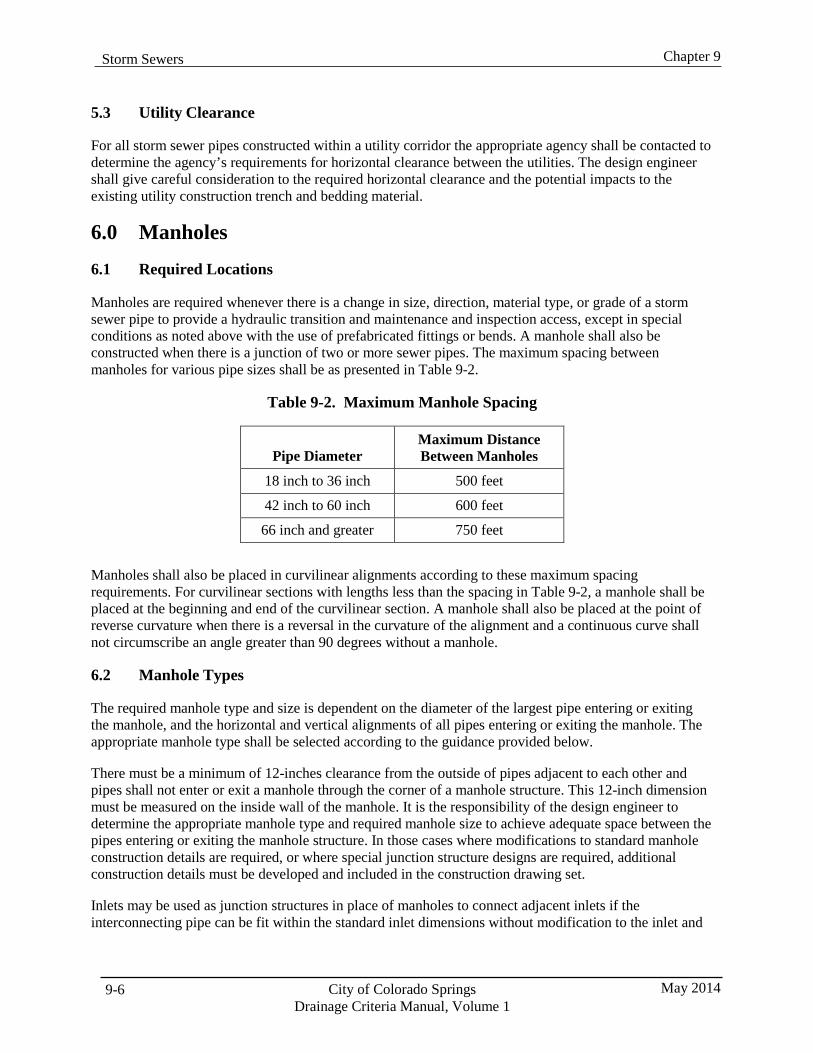
Chapter 9 Storm Sewers
City of Colorado Springs Drainage Criteria Manual, Volume 1
May 2014 9-6
5.3 Utility Clearance
For all storm sewer pipes constructed within a utility corridor the appropriate agency shall be contacted to determine the agency’s requirements for horizontal clearance between the utilities. The design engineer shall give careful consideration to the required horizontal clearance and the potential impacts to the existing utility construction trench and bedding material.
6.0 Manholes
6.1 Required Locations
Manholes are required whenever there is a change in size, direction, material type, or grade of a storm sewer pipe to provide a hydraulic transition and maintenance and inspection access, except in special conditions as noted above with the use of prefabricated fittings or bends. A manhole shall also be constructed when there is a junction of two or more sewer pipes. The maximum spacing between manholes for various pipe sizes shall be as presented in Table 9-2.
Table 9-2. Maximum Manhole Spacing
Pipe Diameter Maximum Distance Between Manholes
18 inch to 36 inch 500 feet
42 inch to 60 inch 600 feet
66 inch and greater 750 feet
Manholes shall also be placed in curvilinear alignments according to these maximum spacing requirements. For curvilinear sections with lengths less than the spacing in Table 9-2, a manhole shall be placed at the beginning and end of the curvilinear section. A manhole shall also be placed at the point of reverse curvature when there is a reversal in the curvature of the alignment and a continuous curve shall not circumscribe an angle greater than 90 degrees without a manhole.
6.2 Manhole Types
The required manhole type and size is dependent on the diameter of the largest pipe entering or exiting the manhole, and the horizontal and vertical alignments of all pipes entering or exiting the manhole. The appropriate manhole type shall be selected according to the guidance provided below.
There must be a minimum of 12-inches clearance from the outside of pipes adjacent to each other and pipes shall not enter or exit a manhole through the corner of a manhole structure. This 12-inch dimension must be measured on the inside wall of the manhole. It is the responsibility of the design engineer to determine the appropriate manhole type and required manhole size to achieve adequate space between the pipes entering or exiting the manhole structure. In those cases where modifications to standard manhole construction details are required, or where special junction structure designs are required, additional construction details must be developed and included in the construction drawing set.
Inlets may be used as junction structures in place of manholes to connect adjacent inlets if the interconnecting pipe can be fit within the standard inlet dimensions without modification to the inlet and
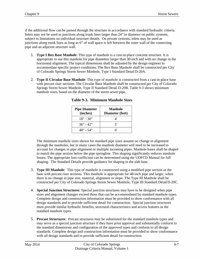
Chapter 9 Storm Sewers
May 2014 City of Colorado Springs Drainage Criteria Manual, Volume 1
9-7
if the additional flow can be passed through the structure in accordance with standard hydraulic criteria. Inlets may not be used as junctions along trunk lines larger than 24” in diameter on public systems, subject to limitations on individual structure details. On private systems, inlets may be used as junctions along trunk lines as long as 6” of wall space is left between the outer wall of the connecting pipe and an adjacent structure wall.
1. Type I Box Base Manhole: This type of manhole is a cast-in-place concrete structure. It is
appropriate to use this manhole for pipe diameters larger than 30-inch and with no change in the horizontal alignment. The typical dimensions shall be adjusted by the design engineer to accommodate specific project conditions. The Box Base Manhole shall be constructed per City of Colorado Springs Storm Sewer Manhole, Type I Standard Detail D-20A.
2. Type II Circular Base Manhole: This type of manhole is constructed from a cast-in-place base
with precast riser sections. The Circular Base Manhole shall be constructed per City of Colorado Springs Storm Sewer Manhole, Type II Standard Detail D-20B. Table 9-3 shows minimum manhole sizes, based on the diameter of the storm sewer pipe.
Table 9-3. Minimum Manhole Sizes
Pipe Diameter
(inches) Manhole
Diameter (feet) 18” - 30” 4' 36” - 42” 5' 48” - 54” 6'
The minimum manhole sizes shown for standard pipe sizes assume no change in alignment through the manholes, but in many cases the manhole diameter will need to be increased to account for changes in pipe alignment or multiple incoming pipes. Manhole bases shall be shaped to match the pipe section below the pipe springline. This shaping significantly reduces manhole losses. The appropriate loss coefficient can be determined using the UDFCD Manual for full shaping. The Standard Details provide guidance for shaping in the slab base.
3. Type III Manhole: This type of manhole is constructed using a modified pipe section as the
base with precast riser sections. This manhole is appropriate for 48-inch pipe and larger, when there is no change in pipe size, material, alignment or slope. The Type III Manhole shall be constructed per City of Colorado Springs Storm Sewer Manhole, Type III Standard Detail D-20C.
4. Special Junction Structures: Special junction structures may have to be designed when pipe
sizes and alignment changes exceed those that can be accommodated by standard manhole types. Complete design and construction information must be provided to show conformance with all design standards and to provide sufficient detail for construction. Special junction structures must provide similar hydraulic benefits, structural characteristics and access features as the standard manhole types.
5. Precast Structures: Precast structures may be substituted for the standard manhole types and
may serve as a special junction structure if they have prior approval and substantially conform to the standard dimensions and configuration of the approved types and conform to all design standards. Complete design and construction information must be provided to show conformance with all design standards and to provide sufficient detail for construction.
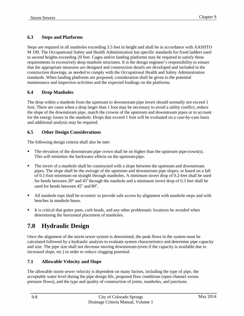
Chapter 9 Storm Sewers
City of Colorado Springs Drainage Criteria Manual, Volume 1
May 2014 9-8
6.3 Steps and Platforms
Steps are required in all manholes exceeding 3.5 feet in height and shall be in accordance with AASHTO M 199. The Occupational Safety and Health Administration has specific standards for fixed ladders used to ascend heights exceeding 20 feet. Cages and/or landing platforms may be required to satisfy these requirements in excessively deep manhole structures. It is the design engineer’s responsibility to ensure that the appropriate measures are designed and construction details are developed and included in the construction drawings, as needed to comply with the Occupational Health and Safety Administration standards. When landing platforms are proposed, consideration shall be given to the potential maintenance and inspection activities and the expected loadings on the platforms.
6.4 Drop Manholes
The drop within a manhole from the upstream to downstream pipe invert should normally not exceed 1 foot. There are cases when a drop larger than 1 foot may be necessary to avoid a utility conflict, reduce the slope of the downstream pipe, match the crowns of the upstream and downstream pipes or to account for the energy losses in the manhole. Drops that exceed 1 foot will be evaluated on a case-by-case basis and additional analysis may be required.
6.5 Other Design Considerations
The following design criteria shall also be met:
The elevation of the downstream pipe crown shall be no higher than the upstream pipe crown(s).
This will minimize the backwater effects on the upstream pipe. The invert of a manhole shall be constructed with a slope between the upstream and downstream
pipes. The slope shall be the average of the upstream and downstream pipe slopes, or based on a fall of 0.1-foot minimum on straight through manholes. A minimum invert drop of 0.2-feet shall be used for bends between 20° and 45o through the manhole and a minimum invert drop of 0.3 feet shall be used for bends between 45o and 90o.
All manhole tops shall be eccentric to provide safe access by alignment with manhole steps and with benches in manhole bases.
It is critical that gutter pans, curb heads, and any other problematic locations be avoided when
determining the horizontal placement of manholes.
7.0 Hydraulic Design Once the alignment of the storm sewer system is determined, the peak flows in the system must be calculated followed by a hydraulic analysis to evaluate system characteristics and determine pipe capacity and size. The pipe size shall not decrease moving downstream (even if the capacity is available due to increased slope, etc.) in order to reduce clogging potential.
7.1 Allowable Velocity and Slope
The allowable storm sewer velocity is dependent on many factors, including the type of pipe, the acceptable water level during the pipe design life, proposed flow conditions (open channel versus pressure flows), and the type and quality of construction of joints, manholes, and junctions.
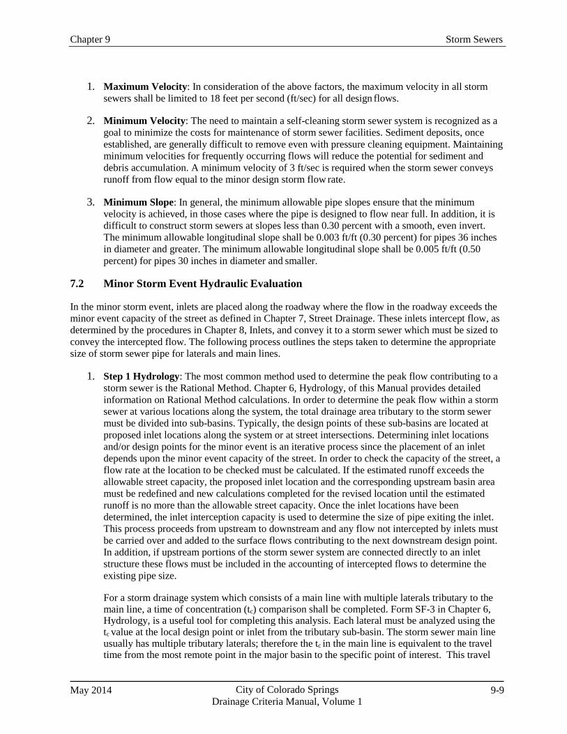
Chapter 9 Storm Sewers
May 2014 City of Colorado Springs Drainage Criteria Manual, Volume 1
9-9
1. Maximum Velocity: In consideration of the above factors, the maximum velocity in all storm sewers shall be limited to 18 feet per second (ft/sec) for all design flows.
2. Minimum Velocity: The need to maintain a self-cleaning storm sewer system is recognized as a
goal to minimize the costs for maintenance of storm sewer facilities. Sediment deposits, once established, are generally difficult to remove even with pressure cleaning equipment. Maintaining minimum velocities for frequently occurring flows will reduce the potential for sediment and debris accumulation. A minimum velocity of 3 ft/sec is required when the storm sewer conveys runoff from flow equal to the minor design storm flow rate.
3. Minimum Slope: In general, the minimum allowable pipe slopes ensure that the minimum
velocity is achieved, in those cases where the pipe is designed to flow near full. In addition, it is difficult to construct storm sewers at slopes less than 0.30 percent with a smooth, even invert. The minimum allowable longitudinal slope shall be 0.003 ft/ft (0.30 percent) for pipes 36 inches in diameter and greater. The minimum allowable longitudinal slope shall be 0.005 ft/ft (0.50 percent) for pipes 30 inches in diameter and smaller.
7.2 Minor Storm Event Hydraulic Evaluation
In the minor storm event, inlets are placed along the roadway where the flow in the roadway exceeds the minor event capacity of the street as defined in Chapter 7, Street Drainage. These inlets intercept flow, as determined by the procedures in Chapter 8, Inlets, and convey it to a storm sewer which must be sized to convey the intercepted flow. The following process outlines the steps taken to determine the appropriate size of storm sewer pipe for laterals and main lines.
1. Step 1 Hydrology: The most common method used to determine the peak flow contributing to a
storm sewer is the Rational Method. Chapter 6, Hydrology, of this Manual provides detailed information on Rational Method calculations. In order to determine the peak flow within a storm sewer at various locations along the system, the total drainage area tributary to the storm sewer must be divided into sub-basins. Typically, the design points of these sub-basins are located at proposed inlet locations along the system or at street intersections. Determining inlet locations and/or design points for the minor event is an iterative process since the placement of an inlet depends upon the minor event capacity of the street. In order to check the capacity of the street, a flow rate at the location to be checked must be calculated. If the estimated runoff exceeds the allowable street capacity, the proposed inlet location and the corresponding upstream basin area must be redefined and new calculations completed for the revised location until the estimated runoff is no more than the allowable street capacity. Once the inlet locations have been determined, the inlet interception capacity is used to determine the size of pipe exiting the inlet. This process proceeds from upstream to downstream and any flow not intercepted by inlets must be carried over and added to the surface flows contributing to the next downstream design point. In addition, if upstream portions of the storm sewer system are connected directly to an inlet structure these flows must be included in the accounting of intercepted flows to determine the existing pipe size.
For a storm drainage system which consists of a main line with multiple laterals tributary to the main line, a time of concentration (tc) comparison shall be completed. Form SF-3 in Chapter 6, Hydrology, is a useful tool for completing this analysis. Each lateral must be analyzed using the tc value at the local design point or inlet from the tributary sub-basin. The storm sewer main line usually has multiple tributary laterals; therefore the tc in the main line is equivalent to the travel time from the most remote point in the major basin to the specific point of interest. This travel
Chapter 9 Storm Sewers
City of Colorado Springs Drainage Criteria Manual, Volume 1
May 2014 9-10
time is a combination of the tc to the inlet where the flow was intercepted and the travel time from the inlet to the specific location being analyzed.
The increased area draining to trunk lines usually results in a design flow greater than the lateral pipe design flow(s). However, it may be possible that the combination of a longer tc and lower overall imperviousness of the total contributing area can produce a lower design flow than the flow from a lateral pipe that drains a highly impervious, but smaller area. The trunk line design flow should never be less than the flow from any of its tributary subareas.
2. Step 2 Pipe Capacity: Storm sewers shall be designed to convey minor storm flows without
surcharging so that the design flow depth is no greater than to 80 percent of the pipe height.
For the minor storm event, a storm sewer is not flowing full, therefore the sewer acts like an open channel and the hydraulic properties can be calculated using Manning’s Equation. Based on the flow in the pipe as determined by Step 1, Manning’s Equation should be solved for the pipe diameter and slope. Consult the UDFCD Manual for information on Manning’s equation and storm sewer sizing calculations.
3. Step 3 Hydraulic Grade Line: For partial flow conditions, the hydraulic grade line is equal to
the water surface in the pipe. Hydraulic grade line calculations must be performed to account for energy losses and to ensure that the system is not surcharged during the minor storm event. There may be some special cases where the proposed storm sewer pipe is connected to an existing storm pipe (or a detention pond). If this existing pipe is surcharged, then the proposed system will receive backwater from the downstream pipe. In this situation, the minor event hydraulic grade line must be calculated to determine the impacts on the hydraulic grade line through the upstream portions of the system. Where the storm sewer outfalls into a detention pond or channel the tailwater condition will be determined based on the hydraulic grade elevation for the minor design storm event occurring in the receiving facility.
7.3 Major Storm Event Hydraulic Evaluation
The storm sewer system layout determined for the minor event analysis must also be evaluated for the major storm event. If necessary, larger or additional inlets must be placed along the roadway when the flow in the roadway exceeds the major storm event capacity of the street as defined in Chapter 7, Street Drainage. The interception rates for all of the inlets shall then be calculated for the major storm event, based on the procedures in Chapter 8 Inlets, and the minor storm pipe sizes must be adjusted to convey the additional flows.
1. Step 1 Hydrology: Typically the design points of sub-basins along a storm sewer system are
located at proposed inlet locations or at street intersections. Determining inlet locations and/or design points is an iterative process since the placement of an inlet depends upon the minor and major event capacity of the street. In order to check the capacity of the street, a flow rate at the location to be checked must be calculated. If the estimated runoff exceeds the allowable street capacity, the proposed inlet location and the corresponding upstream basin area must be redefined and new calculations completed for the revised location until the estimated runoff is no more than the allowable street capacity. Once the inlet locations have been determined, the inlet interception capacity for the major storm event is used to determine the size of pipe exiting the inlet. This process proceeds from upstream to downstream, and any flow not intercepted by inlets must be carried over and added to the surface flows contributing to the next downstream design point. In addition, if upstream inlets are connected directly to an inlet structure these flows must be added to the intercepted flows.
Chapter 9 Storm Sewers
May 2014 City of Colorado Springs Drainage Criteria Manual, Volume 1
9-11
If the street capacity at the initial inlet location is greater than the estimated major storm flow rate, the interception capacity of the inlet must be recalculated for the major storm event and the size of the pipe exiting the inlet verified or revised as described in Step 3 below.
A time of concentration comparison shall be completed for the major storm event using Form SF- 2 from Chapter 6, Hydrology. Each lateral must be analyzed using the tc value at the local design point or inlet from the tributary sub-basin. The storm sewer main line usually has multiple tributary laterals; therefore, the tc in the main line is equivalent to the travel time from the most remote point in the major basin to the specific point of interest. This travel time is a combination of the tc to the inlet where the flow was intercepted and the travel time from the inlet to the specific location being analyzed.
The increased area draining to trunk lines usually results in a design flow greater than the lateral pipe design flow(s). However, it may be possible that the combination of a longer tc and lower overall imperviousness of the total contributing area can produce a lower design flow than the flow from a lateral pipe that drains a highly impervious but small area. The trunk line design flow should never be less than the flow from any of its tributary subareas.
2. Step 2 Pipe Capacity: In the major storm event it is acceptable to have a surcharge in the
system. Therefore, Manning’s equation is not applicable for those pipes which are under pressure flow conditions. For pressurized flow conditions, use the Bernoulli equation (Darcy-Weisbach Friction Loss) or the Hazen-Williams equation. There may be cases where the major storm event does not result in a surcharge of the system. In these pipes the capacity can be calculated using Manning’s equation.
3. Step 3 Hydraulic and Energy Grade Lines (HGL & EGL): Hydraulic grade line calculations
for the storm sewer system shall be provided for the major storm event. The major storm hydraulic grade line elevation shall be at least 1 foot below the final grade along the storm sewer system, measured from the lowest gutter flowline elevation at inlets. When a storm sewer is flowing under a pressure flow condition, the energy and hydraulic grade lines shall be calculated using the pressure momentum theory. The hydraulic calculations generally proceed from the storm sewer outlet upstream, accounting for all energy losses. These losses are added to the energy grade line and accumulate to the upstream end of the storm sewer. The hydraulic grade line is then determined by subtracting the velocity head from the energy grade line at each change in the energy grade line slope. The HGL and EGL shall be computed and the HGL shall be plotted on the construction drawings for each design flow, and the design flow and design frequency shall be noted on the drawing. Where the storm sewer outfalls into a detention pond or channel, the tailwater condition will be determined based on the hydraulic grade elevation for the major design storm event occurring in the receiving facility.
7.4 Hydraulic Calculations
To show that a proposed design conforms to the design criteria described herein, appropriate hydraulic calculations must be completed and provided in an organized form. The methods and parameters described in the UDFCD manual must be applied or alternative methods must be applied that produce similar, reasonable results.
1. Computer Programs: It is recommended that a computer program be used for the design or as a
calculation “check” of a storm sewer system. UD-Sewer is the software created to supplement
Chapter 9 Storm Sewers
City of Colorado Springs Drainage Criteria Manual, Volume 1
May 2014 9-12
the UDFCD Manual and is an approved computer program for storm sewer analysis. UD-Sewer is a powerful tool which can calculate rainfall and runoff using the Rational Method and then size a storm sewer based on Manning’s equation. UD-Sewer also provides hydraulic grade line calculations and tabulated input and output data in preformatted reports. UD-Sewer can be used in conjunction with the UDFCD UD-Inlet spreadsheet program to evaluate street capacities, size inlets and determine carryover flows.
Alternative computer programs may be used if accepted by the City. To propose an alternative program for acceptance, documentation must be provided to show that the methodology and parameters applied in the program follow HEC-22 or the UDFCD Manual.
A study conducted by UDFCD, Modeling Hydraulic and Energy Gradients in Storm Sewers: A Comparison of Computational Methods (AMEC 2009), provides coefficients that can be applied using the standard method in StormCAD. The coefficients are summarized in Table 9-4. Note that these coefficients apply only where velocities are less than 18 ft/sec and where pipe diameters are 42 inches or less.
Table 9-4. STORMCAD Standard Method Coefficients
Bend Loss
Bend Angle K Coefficient 0° 0.05
22.5° 0.10 45° 0.40 60° 0.64 90° 1.32
LATERAL LOSS
One Lateral K Coefficient Bend Angle Non-surcharged Surcharged
45° 0.27 0.47 60° 0.52 0.90 90° 1.02 1.77
Two Laterals K Coefficient 45° 0.96 60° 1.16 90° 1.52
2. Documentation: In addition to description of the methods used to evaluate the hydraulic design
of the storm sewer system, adequate documentation of the system characteristics and configuration must be provided in both a detailed and summary format. The summary information for the entire system must show the parameters, coefficients and results for each system element in a tabular format. Documentation must include all input parameters including design flows by location, elevations, sizes, junction losses, coefficients, pipe roughness,
Chapter 9 Storm Sewers
May 2014 City of Colorado Springs Drainage Criteria Manual, Volume 1
9-13
alignment deflections, and other relevant information. Documentation must also show the results of the calculations including velocity by location, flow depth, HGL elevations (profiles), pipe capacities, and other information necessary to confirm that design criteria have been satisfied.
8.0 Easements
8.1 Easement Conveyance
Storm sewers shall normally be installed within public right-of-way, easement or tracts, but when it is necessary to route a system through private property drainage easements are required in order to ensure the proper construction, access and maintenance of storm sewers and related facilities. All easements shall be conveyed by appropriate legal documents such as plats or grant of easements.
In general, storm sewer easements shall be established exclusively for drainage facilities. If agreed to by all parties and where appropriate, such as for non-motorized public access, joint easements may be permitted on a case-by-case basis.
8.2 Minimum Easement Widths
Table 9-5 presents the minimum acceptable easement requirements for storm sewer systems. The design of the storm sewer shall include the easement width that is necessary to ensure that adequate space is provided for the construction, inspection and maintenance of the facility.
Table 9-5. Minimum Storm Sewer Easement Widths
Pipe Size Easement Width Less than 36-inch diameter 15 feet*
36-inch to 60-inch diameter 25 feet*
Greater than 60-inch diameter 30 feet* *Or as required in order to meet Occupational Safety and Health Administration (OSHA) and/or construction requirements.
The pipe shall be centered on the easement width. These minimum widths assume a relatively shallow pipe depth. Deeper pipes are required to be constructed in accordance with OSHA requirements, and appropriate easements are required to allow for construction and potential future repair or replacement. When relatively large diameter pipes are proposed or when design depths are excessive, greater easement widths will be required. Generally, easement widths greater than the minimums should be 2 times the depth to the pipe invert plus the conduit width, rounded up to the nearest 5 feet.
Easements for storm sewers should be located to one side of property lines and not centered on the lines. Additional easements necessary to provide access to the storm sewer, outlet, and other appurtenances are required if not accessible from a public right-of-way. A minimum easement width of 15 feet shall be provided for access and provisions must also be made for appropriate physical access to the easements, such as for grading and obstructions.
The width of joint or shared easements will be determined on a case-by-case basis.
Chapter 9 Storm Sewers
City of Colorado Springs Drainage Criteria Manual, Volume 1
May 2014 9-14
8.3 Allowable Surface Treatments in Easements
Although storm sewer systems are designed to have a significant service life, it is recognized that there are circumstances which may require that the storm sewer be accessed for inspection, maintenance, repair, and/or replacement. Storm sewer easements should be designed to convey above ground flows in the event the storm sewer or inlet becomes clogged or full flows exceed the design flow. It is, therefore, necessary to limit uses within the easement to ensure that surface conveyance redundancy and maintenance access is not impaired. Minor landscaping, including rock, shrubs, etc. may be appropriate where it can be demonstrated that the function of the easement is not compromised by the presence of the materials. Pavement over a storm sewer easement may be allowable, providing that the property owner accepts responsibility for replacement in the event it is necessary to remove it to access the system. Improvements that are not allowed on storm sewer easements include structures of any kind, retaining walls, permanent fencing, trees and others if determined to be a problem and/or costly to replace. Surface treatments on drainage easements shall be shown on the drainage report plan and final development plan.
Chapter 9 Storm Sewers
May 2014 City of Colorado Springs Drainage Criteria Manual, Volume 1
9A-1
Appendix 9A. Storm Sewer Alternative Pipe Evaluation If Appendix 9A conflicts with other criteria within this Manual, the written criteria in this Manual will supersede Appendix 9A.
633.0 Design Criteria for Pipe These criteria are for use with Section 630 of the City of Colorado Springs Standard Specifications requirements and Section 700 of the Colorado Department of Transportation Standard Specification for Road and Bridge Construction for the selection of alternative pipe materials for installation conditions encountered in the field.
Potentially acceptable pipe materials for installation as storm drains are:
Corrugated Steel Pipe – Galvanized (CSP)
Aluminized Corrugated Steel Pipe – Type 2 (ACSP)
Ribbed Polyvinyl Chloride Pipe (RPVC)
Smooth Wall Polyvinyl Chloride (SPVC)
Profile Wall Polyethylene Pipe (PWPE)
Corrugated Polyethylene Pipe (CPE)
633.1 Service Life
The minimum specified service life shall be ensured by the design, materials and installation of storm drains and culverts constructed as public facilities in rights-of-way, easements and within roadways with the following classifications:
A. Minimum 100-year service life for freeways, expressways and major arterials, unless otherwise
allowed.
B. Minimum 50-year service life for minor arterials, collectors, industrial, frontage roads, residential, alleys and all other roadways not noted in “A” above and in areas outside of roadways, unless otherwise required.
Thermoplastic pipe for storm drain and culvert application shall be limited to installations for 50-year service life.
The Design Engineer shall substantiate the intended service life with appropriate engineering, field and test data, as may be required.
The limit of service life is defined as the point where the pipe or culvert fails structurally, wears or corrodes to the point of perforation or leakage, or becomes misshaped or misaligned to the point where it does not function hydraulically as intended.
The pipe installation shall meet the minimum design requirements noted herein for abrasion, corrosion, chemical deterioration, and structural integrity.
Chapter 9 Storm Sewers
City of Colorado Springs Drainage Criteria Manual, Volume 1
May 2014 9A-2
633.2 Testing of Installation Site
The installation site may necessitate subsurface investigation by the project owner to determine the suitability of trench conditions for the pipe and culvert. Where required by the project engineer, geotechnical data, test holes and soil samples along the pipeline alignment shall be provided by a geotechnical engineer in order to substantiate the soil characteristics, bedding requirements and special design requirements if rock, groundwater or other unsuitable soil conditions and soil types are encountered.
The testing of the native soil types is considered essential to proper design, installation and long-term performance in the use of flexible pipe materials.
Where required, additional soil and ground water tests shall be submitted substantiating the selection of pipe materials. At a minimum, tests shall include but not be limited to:
A. For concrete pipe, test data shall be provided for sulfates and chlorides.
B. For steel pipe, test data shall be provided for the pH (ion concentration) and electrical resistivity.
633.3 Sulfates and Chlorides
For precast concrete pipe installations, the following limits should be observed in the selection of cement where pH (ion concentration) is between 5 and 9:
Table 9A-1. Precast Concrete Pipe Installations Cement pH Limits
Cement Percent Water-Soluble
Sulfate (As SO4) In Soil Samples
Parts per Million Sulfate (As SO4) In Water Samples
Type I 0 to 0.10 0 to 150
Type II 0.10 to 0.20 150 to 1,500
Type V1 0.20 to 2.00 1,500 to 10,000
Type V2 over 2.00 over 10,000
1 Type V or approved Portland pozzolon cement. 2 Type V plus approved Portland pozzolon cement.
Note: A modified Type II cement containing less than 5.0% tricalcium aluminate as required by ASTM C- 150 for Type V cement may be used when certified by the pipe manufacturer.
Where chlorides exceed 1.00% for soils or 1,000 parts per million in water, additional protection for reinforcing steel should be provided to extend the service life. Consideration should be given to increased concrete cover, higher quantity concrete with low permeability, minimizing cracks and voids as much as possible, or the application of a barrier-type protective coating as approved.
633.4 Field Resistivity Survey and Sampling for Corrosion Tests
For corrugated steel pipe installations, the soil and groundwater properties are to be substantiated by standardized measurements of pH and resistivity of the native soil and water to predict metal loss and
Chapter 9 Storm Sewers
May 2014 City of Colorado Springs Drainage Criteria Manual, Volume 1
9A-3
service life. This determination shall also apply to select imported bedding material to be used for trench backfill.
The useful service life due to metal pipe corrosion shall be determined by Figure 9A-A, “Service Life Based on Corrosion, Galvanized-Corrugated Steel Pipe” and Figure 9A-B, “Service Life Based on Corrosion, Aluminum Coated (Type 2) – Corrugated Steel Pipe.”
The geotechnical engineer shall make sufficient resistivity determinations at various locations along the pipe trench and within the pipe zone to adequately represent the entire reach. If the resistivity is reasonably uniform, a minimum of three soil samples from different locations will be required. If various locations show resistivity that differs significantly from the average for the area being surveyed, additional soil samples shall be taken, particularly in those areas with resistivity below the average.
Field resistivity tests may be performed by use of a portable earth resistivity meter for indication of the soluble salts in the soil or water and may be used as a guide for selecting samples that will be further tested in the laboratory.
The suggested field and laboratory method for determining pH and resistivity is the California Test Method 643-B.
633.5 Chemical Resistance
In the selection of the pipe materials by the design engineer, consideration shall be given to any detrimental stormwater constituents that may affect the performance of the material and the design shall be modified as necessary.
Thermoplastic pipe shall not be used for installations where it may be subject to chemical attack by substances indicated as detrimental by the manufacturer’s listing.
634.0 Requirements for Pipe Design All appropriate data required for design, type of materials and construction or installation shall be noted on the construction plans and/or specifications. Any additional design requirements of this Manual shall also be noted.
634.1 Corrosion Design
For steel pipe, one of the factors for selection of wall thickness (gage) shall be based on the potential for corrosion. The pH and resistivity of the soil and groundwater shall be determined as noted in section 633.4 and minimum wall thickness shall be selected from Figure 9-A or Figure 9-B and any other appropriate engineering data.
Where tests indicate that the pH is below 6 or above 8 with resistivity below 2,500 ohm/cm for galvanized steel or where the pH is below 6.1 or above 8.5 with resistivity below 1,000 ohm/cm for aluminized steel (Type 2), steel pipe should not be considered for installation in native soils unless additional corrosion mitigating measures are employed as approved.
634.2 Abrasion Design
It shall be assumed that a bed load will be present during at least a portion of the pipe’s service life. Design velocities established for the pipe flowing full or one-half full shall not exceed the following
Chapter 9 Storm Sewers
City of Colorado Springs Drainage Criteria Manual, Volume 1
May 2014 9A-4
limits unless remedial measures for abrasion are applied to at least the invert of the pipe (at a minimum the lower 25% of round pipe and lower 40% of pipe-arch or elliptical pipe):
A. Concrete Pipe: Where velocities exceed 18 feet per second (ft/sec), additional protection shall
be provided in the form of increased cement content (e.g., 8 sack mix), increased cover over reinforcing steel (up to 1-1/2") or the use of harder aggregate.
B. Corrugated Steel Pipe
B.1 Galvanized - Corrugated Steel Pipe: Where design velocities exceed 6 ft/sec, paved invert protection shall be provided.
B.2 Aluminum Coated (Type 2) - Corrugated Steel Pipe: Where design velocities exceed 10
ft/sec, paved invert protection shall be provided.
Invert paving shall consist of asphalt paving (moderately abrasive bed load) or concrete paving (extremely abrasive bed load), shop or field applied. Anticipated or field-observed bed-load conditions shall be determined by the design engineer.
Asphalt invert paving shall conform to AASHTO M-190, Type B with the additional provision that the paving shall have a minimum thickness of 1/4 inch above the crest of the corrugations. Asphalt paving shall not be installed within three pipe diameters from the ends of culverts or other installation conditions which may cause exposure to sunlight. In these cases, concrete paving or an alternate pipe material shall be installed in the last section of pipe. Repairs to asphalt paving shall be in conformance with ASTM A- 849.
For concrete invert paving, the minimum thickness over the top of the corrugations (or top of reinforcement, whichever controls) at the invert shall be a minimum 1/48 of the pipe diameter (or equivalent pipe diameter) or a minimum of 3/4 inch thickness, whichever is greater. The concrete paving shall have a minimum strength of 4,000 psi and prepared with a minimum of Type IIa cement according to ASTM C-150 with chemical and abrasive-resistant fine aggregate according to ASTM C-33. Where required, welded wire fabric reinforcement or deformed reinforcing bars shall be provided to maintain the integrity of the lining and shall be mechanically fastened to the pipe. The minimum area of steel for reinforcement shall not be less than 0.0018 of concrete cross sectional area. Welded wire fabric shall be galvanized and conform to AASHTO M-55. Steel reinforcement bars may be used with a design approved by the engineer.
Coating, paving or lining types other than asphalt or concrete will not be allowed unless otherwise approved.
Where velocities exceed 18 ft/sec, protection shall be provided as recommended by the manufacturer and approved by the City/County.
C. Thermoplastic Pipe: Where design velocities exceed 18 ft/sec and/or highly abrasive bed-load
conditions exist, additional protection or wall thickness shall be provided in accordance with established engineering principles and manufacturing methods and shall be approved by the City/County.
Chapter 9 Storm Sewers
May 2014 City of Colorado Springs Drainage Criteria Manual, Volume 1
9A-5
634.3 Structural Design
A. Precast concrete pipe and concrete box section installation shall be in conformance with the appropriate specifications for crack limitations in the selection of pipe class, bedding and height of cover requirements, as determined by the reference specifications in Section 635 and 637 of the City Standard Specifications or related CDOT Specifications (CDOT Standard M-603-2).
Precast pipe class selection shall be based on the D-load three-edge bearing strength required to produce a 0.01-inch crack. The appropriate load factor and factor of safety shall be considered with trench loadings and the bedding classes required. Normally, the factor of safety is 1.5 for non-reinforced pipe and 1.0 for reinforced pipe.
Wall thickness and reinforcement for cast in place box sections shall conform to the Colorado Department of Transportation Standard M-601-1 "Single Concrete Box Culvert", M-601-2 "Double Concrete Box Culvert" and M-601-3 "Triple Concrete Box Culvert", exceptions noted.
Where cast-in-place box sections do not conform with the above referenced standards, the design engineer shall submit structural calculations for the appropriate live load and dead load design requirements. Live load shall be AASHTO HS 20-44 and dead load shall be an earth load of 84 lbs/cu. ft. with equivalent fluid pressure of 30 lbs/cu. ft.
B. For corrugated steel pipe and pipe arch, the corrugations and wall thickness (gage) shall meet
with the minimum cover and height of cover requirements for H-20 highway live loads conforming to Colorado Department of Transportation Standards M-603-1 for "Metal Culvert Pipe", exceptions noted and M-510-1 for "Structural Plate Culvert Pipe", exceptions noted.
C. For thermoplastic pipe, the minimum and maximum height of cover shall conform to the
manufacturer's allowable values based on the recommended bedding classifications and H-20 highway loadings or special loading conditions as appropriate. The appropriate design data shall be submitted for approval.
Allowable pipe stiffness shall be determined by the parallel plate test according to ASTM D-2412 or equivalent standardized test methods acceptable as approved.
Design of the pipe installation shall conform to the minimum requirements of the "Standard Specifications for Highway Bridges 2002, AASHTO Section 30, Thermoplastic Pipe Interaction Systems".
634.4 Hydraulics
A. Pipe capacity and design shall be in accordance with this Criteria Manual.
B. Acceptable Manning's roughness coefficient "n" for pipe materials are:
B.1 Reinforced Concrete Pipe (RCP) 0.013
B.2 Corrugated Steel Pipe-Galvanized (CSP) see Figure 9A-C
B.3 Aluminized Corrugated Steel Pipe (ACSP) see Figure 9A-C
B.4 Ribbed Polyvinyl Chloride (RPVC) 0.012
Chapter 9 Storm Sewers
City of Colorado Springs Drainage Criteria Manual, Volume 1
May 2014 9A-6
B.5 Smooth Polyvinyl Chloride (SPVC) 0.010
B.6 Profile Wall Polyethylene (PWPE) 0.012
B.7 Corrugated Polyethylene Pipe, Type S (CPE) 0.012
634.5 Submittals
Requests for the installation of alternative pipe materials and confirmations of required service life shall be submitted in an organized written report format providing all technical information as required in this section, in addition to all supporting documentation relevant to the analyses and request; including, but not limited to, field data, manufacturers specifications and recommendations, test data, calculations, figures and maps.
Requests shall only be considered approved based on an affirming written response to the submitted request from the appropriate authority.
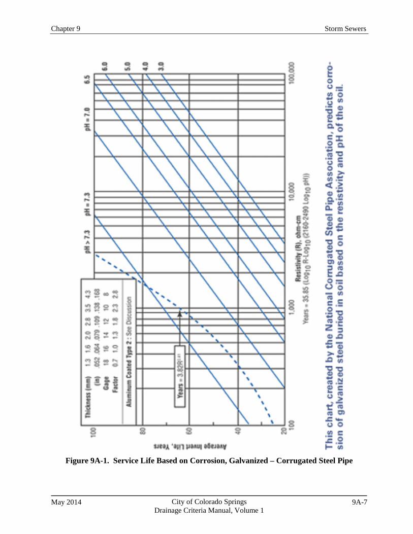
Chapter 9 Storm Sewers
May 2014 City of Colorado Springs Drainage Criteria Manual, Volume 1
9A-7
Figure 9A-1. Service Life Based on Corrosion, Galvanized – Corrugated Steel Pipe
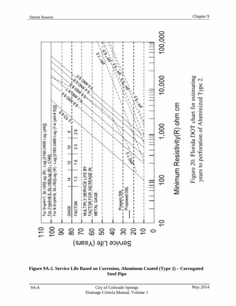
Chapter 9 Storm Sewers
City of Colorado Springs Drainage Criteria Manual, Volume 1
May 2014 9A-8
Figure 9A-2. Service Life Based on Corrosion, Aluminum Coated (Type 2) – Corrugated Steel Pipe
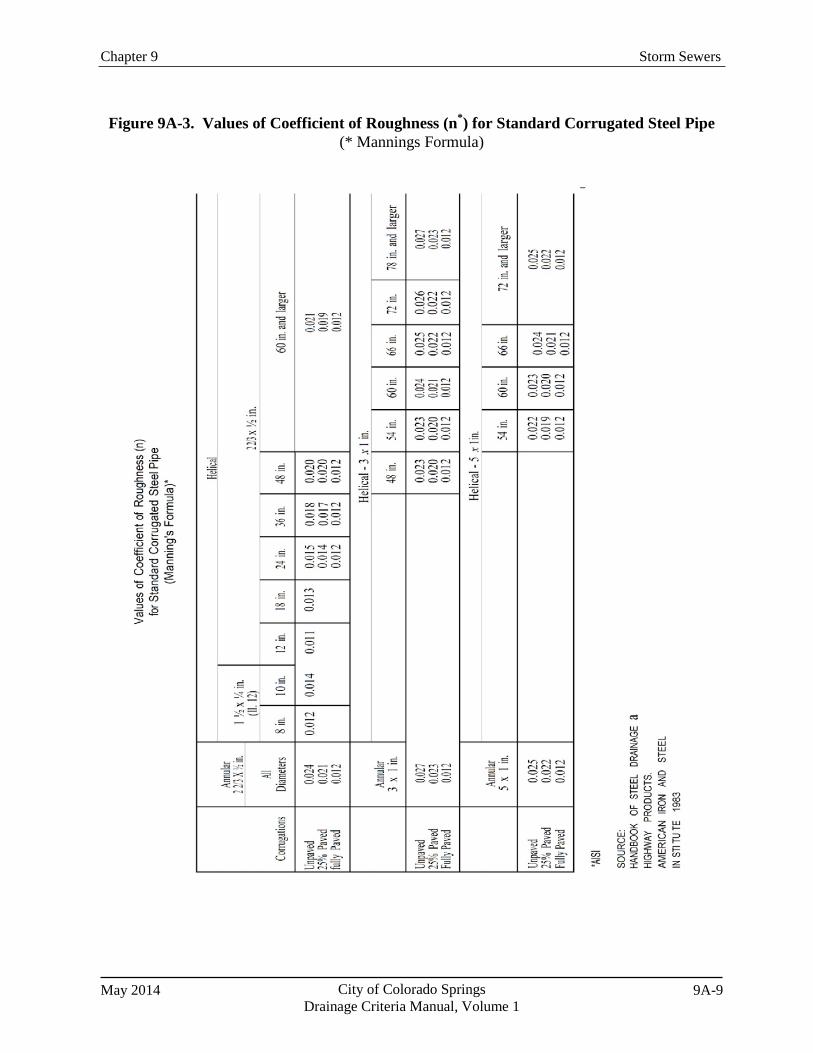
Chapter 9 Storm Sewers
May 2014 City of Colorado Springs Drainage Criteria Manual, Volume 1
9A-9
Figure 9A-3. Values of Coefficient of Roughness (n*) for Standard Corrugated Steel Pipe (* Mannings Formula)

May 2014 City of Colorado Springs Drainage Criteria Manual, Volume 1
10-i
Chapter 10 Conduit Outlet Structures Contents 1.0 Introduction ...................................................................................................................................... 1
2.0 General Design ................................................................................................................................. 1 2.1 Inlet and Outlet Configuration .................................................................................................................. 1 2.2 Safety Rails ............................................................................................................................................... 1 2.3 Flared End Sections ................................................................................................................................... 1 2.4 Transition to Drainageways ...................................................................................................................... 1
3.0 Outlet Erosion Protection ................................................................................................................ 2 3.1 Types of Erosion Protection ...................................................................................................................... 2 3.2 Selecting Type of Erosion Protection ........................................................................................................ 2
4.0 Design of Outlet Erosion Protection ............................................................................................... 3 4.1 Riprap Lining ............................................................................................................................................ 3 4.2 Low Tailwater Stilling Basins ................................................................................................................... 4 4.3 Concrete Impact Stilling Basin.................................................................................................................. 4 4.4 Concrete Baffle Chute ............................................................................................................................... 4
Tables Table 10-1 Erosion Protection at Conduit Outlets ................................................................................ 3
Figures Figure 10-1 Conceptual Toewall Detail ................................................................................................. 6

Chapter 10 Conduit Outlet Structures
May 2014 City of Colorado Springs Drainage Criteria Manual, Volume 1
10-1
1.0 Introduction This chapter addresses the design of culvert outlets, which are typically oriented in-line with the flow in a drainageway, and storm sewer outlets, which are typically oriented perpendicular to the flow in a drainage channel or detention facility. This chapter contains references to the UDFCD Manual for design procedures applying to both of these outlet types. Outlets into forebay sedimentation traps of water quality basins are discussed in Volume 2 of this Manual.
Conduit outlet structures are necessary to dissipate energy at culvert and storm sewer outlets and to provide a transition from the conduit to an open channel. A conduit outlet structure consists of an end section or headwall and wingwalls, safety rails (if required), and a riprap or concrete structure to dissipate flow energy at the exit of the conduit.
Occasionally, other hydraulic controls are located at culvert outlets. These hydraulic controls can include drop structures, which are discussed in Chapter 12, Open Channels.
2.0 General Design 2.1 Inlet and Outlet Configuration
All conduits 54 inches in diameter and larger shall be designed with headwalls and wingwalls. Conduits 48 inches in diameter and smaller may use headwalls and wingwalls or flared end sections at the inlet and outlet. Detailed grading plans showing proposed contours, spot elevations, and outlet erosion protection measures shall be included in the construction drawings at all conduit inlets and outlets.
2.2 Safety Rails
Conduit headwalls and wingwalls shall be provided with guardrails, handrails, or fencing in conformance with local building codes and roadway design safety requirements. Handrails shall be required in areas frequented by pedestrians or bicycles. The height of the handrail shall be 42 inches for pedestrian walkways or open areas and 54 inches for bicycle traffic. Acceptable materials include, but are not limited to, galvanized or painted steel, aluminum, and chain link fence. Any safety barriers adjacent to trails or sidewalks should provide sufficient separation to avoid interference with bicycle or pedestrian traffic.
2.3 Flared End Sections
Flared end sections shall not protrude from the embankment. Flared end sections require joint fasteners and toe walls at the outlet. Toe walls shall extend from the top of the vertical portion at the end of the flared end section to at least 3 feet below the invert. See Figure 10-1 for an acceptable toe wall configuration.
A minimum of three joints, including the joint connecting the last pipe segment to the flared end section, shall be mechanically locked with joint fasteners. Joint fasteners shall be constructed consistent with the details provided in CDOT Standard Plan No. M-603-10.
2.4 Transition to Drainageways
Storm sewer outlets shall be set with their inverts 1 to 2 feet (2 feet for wetland channels) above the natural channel bottom and provided with appropriate erosion protection measures. The drop is to reduce
Chapter 10 Conduit Outlet Structures
City of Colorado Springs Drainage Criteria Manual, Volume 1
May 2014 10-2
backwater effects in the storm sewer due to sedimentation. When a storm sewer outfalls into a channel with an overbank between the bank toe of the main channel and the low-flow channel, outlet protection shall be extended to the invert of the low-flow channel using the design flow for the storm sewer. However, protection extended into the main channel of the receiving channel must be evaluated for stability during the major storm event in the main channel.
In general, in-line culvert inlet and outlet elevations should match drainageway invert elevations upstream and downstream. Outlets shall be provided with erosion protection measures as discussed later in this Chapter.
If the existing drainageway has experienced degradation and the channel is incised, channel restoration improvements may raise the channel bottom back up to its former elevation. The design engineer shall determine the appropriate outlet elevations considering, at a minimum, the condition and stability of the existing channel and any potential stabilization or grade control improvements that would change the longitudinal grade or elevations along the channel. To ensure that outlets and energy dissipation improvements function properly, inlet and outlet elevations shall be set based on field survey information, rather than topographic mapping generated from aerial photography.
3.0 Outlet Erosion Protection
3.1 Types of Erosion Protection
Erosion protection in the form of riprap or concrete basins is required at the outlet of conduits to control scour. Erosion protection shall be designed for conduit outlets in accordance with Table 10-1. These are general guidelines only and are intended to supplement the UDFCD Manual. Other outlet erosion protection options, including many specialized types of concrete outlet structures, are available and may be used if approved on a case-by-case basis. These types of structures are listed in the Hydraulic Structures Chapter in Volume 2 of the UDFCD Manual.
3.2 Selecting Type of Erosion Protection
Riprap protection downstream of culverts is considered for most situations where moderate outlet hydraulics (i.e., subcritical flows with culvert exit velocities < 15 ft/sec) govern. It is highly recommended that the designer use a low tailwater basin when a storm sewer enters a drainageway at an approximate right angle, and drop structures or riprap lining should be used to guard against erosion for in-line culvert outlets on major drainageways.
In general, concrete structures are large, uncharacteristic of the natural environment, and require special safety and maintenance considerations. Concrete structures will not be approved in areas that are intended to complement the natural environment when other alternatives are feasible. Cases where a concrete stilling basin structure may be considered include situations where exit velocities are extremely high, turbulence at a conduit outlet is expected to be severe, and/or where space is particularly limited.
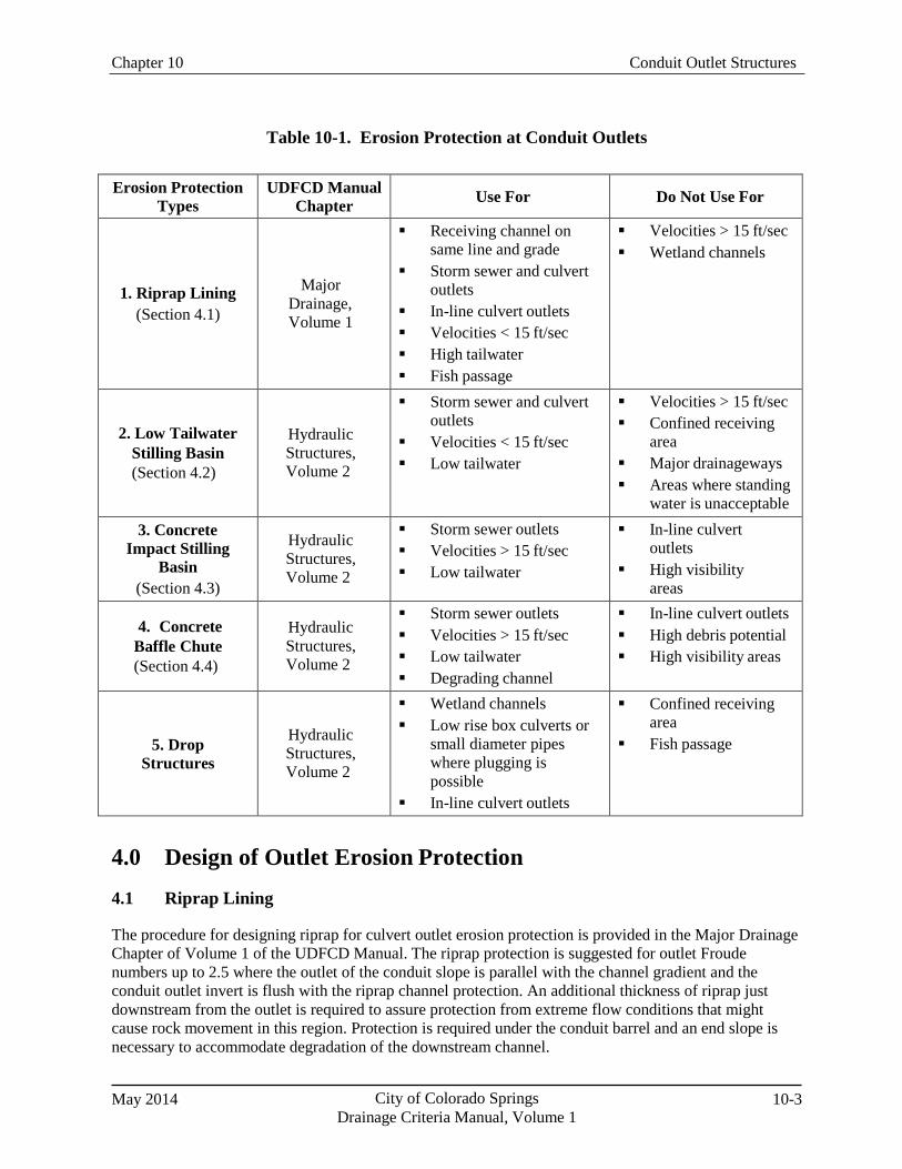
Chapter 10 Conduit Outlet Structures
May 2014 City of Colorado Springs Drainage Criteria Manual, Volume 1
10-3
Table 10-1. Erosion Protection at Conduit Outlets
Erosion Protection Types
UDFCD Manual Chapter Use For Do Not Use For
1. Riprap Lining (Section 4.1)
Major Drainage, Volume 1
Receiving channel on same line and grade
Storm sewer and culvert outlets
In-line culvert outlets Velocities < 15 ft/sec High tailwater Fish passage
Velocities > 15 ft/sec Wetland channels
2. Low Tailwater Stilling Basin (Section 4.2)
Hydraulic Structures, Volume 2
Storm sewer and culvert outlets
Velocities < 15 ft/sec Low tailwater
Velocities > 15 ft/sec Confined receiving
area Major drainageways Areas where standing
water is unacceptable 3. Concrete
Impact Stilling Basin
(Section 4.3)
Hydraulic Structures, Volume 2
Storm sewer outlets Velocities > 15 ft/sec Low tailwater
In-line culvert outlets
High visibility areas
4. Concrete Baffle Chute (Section 4.4)
Hydraulic Structures, Volume 2
Storm sewer outlets Velocities > 15 ft/sec Low tailwater Degrading channel
In-line culvert outlets High debris potential High visibility areas
5. Drop Structures
Hydraulic Structures, Volume 2
Wetland channels Low rise box culverts or
small diameter pipes where plugging is possible
In-line culvert outlets
Confined receiving area
Fish passage
4.0 Design of Outlet Erosion Protection
4.1 Riprap Lining
The procedure for designing riprap for culvert outlet erosion protection is provided in the Major Drainage Chapter of Volume 1 of the UDFCD Manual. The riprap protection is suggested for outlet Froude numbers up to 2.5 where the outlet of the conduit slope is parallel with the channel gradient and the conduit outlet invert is flush with the riprap channel protection. An additional thickness of riprap just downstream from the outlet is required to assure protection from extreme flow conditions that might cause rock movement in this region. Protection is required under the conduit barrel and an end slope is necessary to accommodate degradation of the downstream channel.
Chapter 10 Conduit Outlet Structures
City of Colorado Springs Drainage Criteria Manual, Volume 1
May 2014 10-4
4.2 Low Tailwater Stilling Basins
The majority of storm sewer pipes discharge into open drainageways, where the receiving channel may have little or no flow when the conduit is discharging. Uncontrolled pipe velocities have the potential to create erosion problems downstream of the outlet and in the channel. By providing a low tailwater basin at the end of a storm sewer conduit or culvert, the kinetic energy of the discharge is dissipated under controlled conditions, minimizing scour at the channel bottom.
Low tailwater is defined as being equal to or less than one-third of the storm sewer diameter/height and is based on the depth of flow in the receiving channel during the minor design storm event. Design criteria for low tailwater riprap basins for circular and rectangular pipe are provided in the Hydraulic Structures Chapter of Volume 2 of the UDFCD Manual.
4.3 Concrete Impact Stilling Basin
The use of concrete impact stilling basins is discouraged where moderate outlet conditions exist, but there are situations when the design engineer may have to consider using an impact stilling basin. Those situations are generally discussed in the Hydraulic Structures Chapter of Volume 2 of the UDFCD Manual. Impact stilling basins shall be designed in accordance with the Hydraulic Structures Chapter of Volume 2 of the UDFCD Manual.
Design standards for an impact stilling basin are based on the United States Bureau of Reclamation (USBR) Type VI basin, a relatively small structure that produces highly efficient energy dissipation characteristics without tailwater control. Energy dissipation is accomplished through the turbulence created by loss of momentum as flow entering the basin impacts a large overhanging baffle. Additional dissipation is produced as water builds up behind the baffle to form a highly turbulent backwater zone. Flow is then redirected under the baffle to the open basin and out to the receiving channel. A check at the basin end reduces exit velocities by breaking up the flow across the basin floor and improves the stilling action at low to moderate flow rates.
Generally, the configuration consists of an open concrete box attached directly to the conduit outlet. The Hydraulic Structures Chapter of Volume 2 of the UDFCD Manual provides a figure illustrating the general design for the impact stilling basin.
The standard USBR design referenced above will retain a standing pool of water in the basin bottom that is generally undesirable from an environmental and maintenance standpoint. The Hydraulic Structures Chapter of Volume 2 of the UDFCD Manual modifies the standard USBR design to allow drainage of the basin bottom during dry periods. These modifications are shown in figures providing examples of the modified end wall design to allow basin drainage for urban applications and providing details of a “mini” impact basin that can be used for small pipe diameters from 18 inches to 36 inches.
4.4 Concrete Baffle Chute
The use of concrete baffle chutes is discouraged where moderate outlet conditions exist, but there are situations when the design engineer may have to consider using a concrete baffle chute. Those situations are generally discussed in the Hydraulic Structures Chapter of Volume 2 of the UDFCD Manual.
A concrete baffle chute is normally used in situations where there is a very large conduit outfall, future channel degradation is expected, and there is a drop in grade between the culvert outlet and the channel invert. The original design (USBR Type IX baffled apron) has been modified slightly by UDFCD so it can be used with a conduit instead of an open channel. The Hydraulic Structures Chapter of Volume 2 of
Chapter 10 Conduit Outlet Structures
Drainage Criteria Manual, Volume 1
the UDFCD Manual provides some design and construction details for this type of basin, along with a figure providing an example of the general design for the baffle chute pipe outlet. Although this outlet dissipates energy along the slope, scour holes can form at the base of the structure. These scour holes can undermine adjacent banks, particularly where development encroaches close to the channel. The designer shall provide riprap erosion protection along the downstream channel where a scour hole is undesirable.
May 2014 City of Colorado Springs 10-5
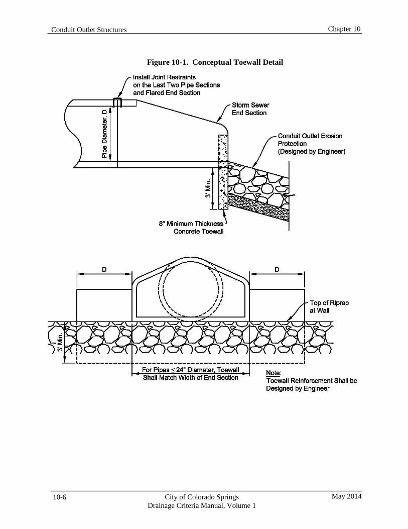
Chapter 10 Conduit Outlet Structures
City of Colorado Springs Drainage Criteria Manual, Volume 1
May 2014 10-6
Figure 10-1. Conceptual Toewall Detail
Drainage Criteria Manual, Volume 1
Chapter 11 Culverts and Bridges Contents 1.0 Introduction ...................................................................................................................................... 1
2.0 General Design ................................................................................................................................. 1 2.1 Design Criteria .......................................................................................................................................... 1 2.2 Design Flows ............................................................................................................................................. 1 2.3 Aesthetics and Safety ................................................................................................................................ 1 2.4 Trail Coordination ..................................................................................................................................... 1 2.5 Utility Coordination .................................................................................................................................. 2 2.6 Channel Stability ....................................................................................................................................... 2
3.0 Culvert and Bridge Sizing ............................................................................................................... 2 3.1 Allowable Street Overtopping ................................................................................................................... 2
3.1.1 Sizing Procedure for Streets When Overtopping is Allowed ........................................................ 3 3.2 Allowable Headwater ................................................................................................................................ 3 3.3 Freeboard Requirements ........................................................................................................................... 3
4.0 Culvert Design .................................................................................................................................. 3 4.1 Construction Material ................................................................................................................................ 3 4.2 Minimum Size ........................................................................................................................................... 4 4.3 Culvert Sizing and Design ......................................................................................................................... 4 4.4 Capacity Curves ........................................................................................................................................ 4 4.5 Design Forms ............................................................................................................................................ 4 4.6 Design Software ........................................................................................................................................ 4 4.7 Velocity Considerations ............................................................................................................................ 4 4.8 Structural Design ....................................................................................................................................... 5 4.9 Alignment .................................................................................................................................................. 5 4.10 Stationing .................................................................................................................................................. 5 4.11 Minimum Cover ........................................................................................................................................ 5 4.12 Multiple-Barrel Culverts ........................................................................................................................... 6 4.13 Trash Racks ............................................................................................................................................... 6 4.14 Inlets and Outlets ....................................................................................................................................... 6 4.15 Debris ........................................................................................................................................................ 6 4.16 Service Life ............................................................................................................................................... 6
5.0 Driveway Culverts ............................................................................................................................ 7 5.1 Construction Material ................................................................................................................................ 7 5.2 Sizing ........................................................................................................................................................ 7 5.3 Minimum Cover ........................................................................................................................................ 7 5.4 Culvert End Treatments ............................................................................................................................ 7 5.5 Design Velocity ......................................................................................................................................... 7 5.6 Drainage Report and Construction Drawings............................................................................................ 7
6.0 Bridge Hydraulic Design ................................................................................................................. 8
7.0 Low-Water Crossings/Pedestrian Bridges ..................................................................................... 8

Chapter 10 Conduit Outlet Structures
City of Colorado Springs Drainage Criteria Manual, Volume 1
May 2014 10-8
May 2014 City of Colorado Springs 11-i
Culverts and Bridges Chapter 11
11-ii City of Colorado Springs Drainage Criteria Manual, Volume 1
May 2014
8.0 References .......................................................................................................................................... 8 Tables Table 11-1. Allowable Street Overtopping at Culverts ............................................................................... 2
Figures Figure 11-1. Typical Roadside Ditch Modification for Driveway Culverts ............................................... 10
Chapter 10 Conduit Outlet Structures
City of Colorado Springs Drainage Criteria Manual, Volume 1
May 2014 10-10
1.0 Introduction This chapter addresses design criteria for culverts and bridges as they relate to drainageways. Generally, a culvert is a conduit for the passage of surface drainage water under a roadway, railroad, canal, or other embankment; a bridge is a structure carrying a pathway, roadway, or railway over a waterway.
2.0 General Design
2.1 Design Criteria
The procedures and basic data to be used for the design and hydraulic evaluation of culverts shall be consistent with the Culverts Chapter of Volume 2 of the UDFCD Manual, except as modified herein. The designer is also referred to the many texts covering the subject for additional information, including Hydraulic Design of Highway Culverts, Hydraulic Design Series No. 5 (FHWA 2005a).
Bridges are typically designed to cross the waterway with minimal disturbance to the flow. However, for practical and economic reasons, abutment encroachments and piers are often located within the waterway. Consequently, the bridge structure can cause adverse hydraulic effects and scour potential that must be evaluated and addressed as part of each design. The design of a bridge is very specific to site conditions and numerous factors must be considered.
There are many acceptable manuals that are available and should be used in bridge hydraulic studies and river stability analysis. The Bridges Section in the Hydraulic Structures Chapter of Volume 2 of the UDFCD Manual shall be consulted for basic criteria and information regarding other publications and resources. Additional references include the CDOT Drainage Design Manual, FHWA Highways in the River Environment, FHWA Evaluating Scour at Bridges, Design of Encroachments on Flood Plains Using Risk Analysis, and FHWA Stream Stability at Highway Structures.
2.2 Design Flows
Culverts and bridges shall be designed for future fully developed basin conditions consistent with approved drainage plans as outlined in Chapter 6, Hydrology. Specific requirements for culverts and bridges are contained in their respective sections and may vary depending on the classification of the roadway being crossed.
2.3 Aesthetics and Safety
The appearance and safety of structures, including headwalls and wingwalls, are important considerations for acceptance of the design. The safety of the public, especially in areas of recreational use, shall also be considered when selecting the appropriate structure and handrail treatment for a given area. Structure geometry, materials, and the texture, patterning, and color of structure surfaces shall be selected to blend with the adjacent landscape and provide an attractive appearance.
2.4 Trail Coordination
Culverts and bridges often provide an opportunity for trails to cross roadways with a grade separation, avoiding conflicts between pedestrians and vehicles. Advance coordination with Parks and Trails personnel is necessary to determine if the proposed culvert or bridge location has been identified as a potential location for a separated grade trail crossing. If the location is determined to be compatible with a grade-separated trail from a planning standpoint and the crossing is physically possible, final design

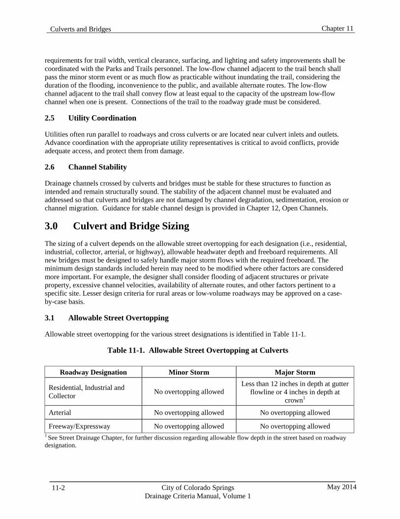
Chapter 11 Culverts and Bridges
City of Colorado Springs Drainage Criteria Manual, Volume 1
May 2014 11-2
requirements for trail width, vertical clearance, surfacing, and lighting and safety improvements shall be coordinated with the Parks and Trails personnel. The low-flow channel adjacent to the trail bench shall pass the minor storm event or as much flow as practicable without inundating the trail, considering the duration of the flooding, inconvenience to the public, and available alternate routes. The low-flow channel adjacent to the trail shall convey flow at least equal to the capacity of the upstream low-flow channel when one is present. Connections of the trail to the roadway grade must be considered.
2.5 Utility Coordination
Utilities often run parallel to roadways and cross culverts or are located near culvert inlets and outlets. Advance coordination with the appropriate utility representatives is critical to avoid conflicts, provide adequate access, and protect them from damage.
2.6 Channel Stability
Drainage channels crossed by culverts and bridges must be stable for these structures to function as intended and remain structurally sound. The stability of the adjacent channel must be evaluated and addressed so that culverts and bridges are not damaged by channel degradation, sedimentation, erosion or channel migration. Guidance for stable channel design is provided in Chapter 12, Open Channels.
3.0 Culvert and Bridge Sizing The sizing of a culvert depends on the allowable street overtopping for each designation (i.e., residential, industrial, collector, arterial, or highway), allowable headwater depth and freeboard requirements. All new bridges must be designed to safely handle major storm flows with the required freeboard. The minimum design standards included herein may need to be modified where other factors are considered more important. For example, the designer shall consider flooding of adjacent structures or private property, excessive channel velocities, availability of alternate routes, and other factors pertinent to a specific site. Lesser design criteria for rural areas or low-volume roadways may be approved on a case- by-case basis.
3.1 Allowable Street Overtopping
Allowable street overtopping for the various street designations is identified in Table 11-1.
Table 11-1. Allowable Street Overtopping at Culverts
Roadway Designation Minor Storm Major Storm
Residential, Industrial and Collector
No overtopping allowed
Less than 12 inches in depth at gutter flowline or 4 inches in depth at
crown1
Arterial No overtopping allowed No overtopping allowed
Freeway/Expressway No overtopping allowed No overtopping allowed 1 See Street Drainage Chapter, for further discussion regarding allowable flow depth in the street based on roadway designation.
Culverts and Bridges Chapter 11
11-3 City of Colorado Springs Drainage Criteria Manual, Volume 1
May 2014
When overtopping flows are allowed, adequate roadway embankment erosion protections measures should be provided to protect the roadway from erosion and potential embankment failure problems.
3.1.1 Sizing Procedure for Streets When Overtopping is Allowed
When overtopping is allowed for residential, industrial, and collector streets, the following sizing procedure shall be followed:
1. Using the future developed condition major storm flow, the allowable flow over the street shall be
determined based on the allowable overtopping depth and the roadway profile, treating the street crossing as a broad-crested weir.
2. The culvert is then sized for the difference between the major storm flow and the allowable flow
over the street, using the allowable overtopping elevation as the maximum headwater elevation.
3. The culvert is then sized for the fully developed condition minor storm flow based on applicable design criteria.
4. The minimum design culvert size shall be the larger of the two sizes.
Note that the culvert size may need to be increased if the design water surface elevation using the allowable overtopping depth does not satisfy freeboard requirements for adjacent structures.
3.2 Allowable Headwater
For all residential, industrial, and collector roadways, the maximum headwater to depth ratio (HW/D) for the major storm design flows will be 1.5 times the culvert opening height (D or H). For culverts through arterial roads and highways, the maximum headwater to depth ratio for the major storm design flows will be 1.2 times the culvert opening height. Headwater depth is typically measured from the culvert invert at its centerline.
3.3 Freeboard Requirements
When no overtopping is allowed at culvert crossing structures, the minimum freeboard shall be 2 feet, measured from the major stormwater design surface elevation to the lowest point of the roadway profile at the gutter flowline or at the edge of the shoulder.
The minimum required clearance for bridges shall be 2 feet, measured from the major stormwater surface elevation to the lowest elevation of the bridge low chord. However, the design engineer shall consider the profile grade of the bridge and roadway, potential for debris accumulation, predicted sedimentation, maintenance requirements, and other site-specific conditions to determine whether additional freeboard should be provided for the crossing structures.
4.0 Culvert Design
4.1 Construction Material
Culverts shall be made of reinforced concrete in round or elliptical cross-sections (minimum Class 3) or reinforced concrete box shapes that are either cast-in-place or supplied in precast sections. Other materials may be allowed on a case by case basis if design criteria and service life requirements can be satisfied as described in Appendix 9A.

Chapter 11 Culverts and Bridges
City of Colorado Springs Drainage Criteria Manual, Volume 1
May 2014 11-4
Special design considerations, such as bedding requirements, shall also be considered if an alternate material is used. When the culvert is expected to carry a large, persistent load of abrasive material (e.g., gravel or cobble bedload), a special design is required to protect the full invert area (lower 90 degrees).
4.2 Minimum Size
The minimum pipe size for a cross culvert within a public right-of-way shall be 18 inches in diameter for round culverts, or shall have an equivalent cross-sectional area for arch or elliptical shapes. Box culverts shall be as tall as practical, but shall not have less than a 3-foot-high inside dimension.
4.3 Culvert Sizing and Design
Culvert design involves an iterative approach. Two references are particularly helpful in the design of culverts. The Culverts Chapter of Volume 2 of the UDFCD Manual provides design aids and guidance can be taken from Hydraulic Design Series No. 5, Hydraulic Design of Highway Culverts (FHWA 2005a). The FHWA circular explains inlet and outlet control and the procedure for designing culverts.
4.4 Capacity Curves
There are many charts, tables, and curves in the literature for the computation of culvert hydraulic capacity. To assist in the review of the culvert design computations and to obtain uniformity of analysis, the Capacity Charts and Nomographs provided in the Culverts Chapter of Volume 2 of the UDFCD Manual should be used for determining culvert capacity.
Selection of the appropriate roughness and entrance coefficients shall be based on the information presented in the Culverts Chapter of Volume 2 of the UDFCD Manual or in Table 12 of Hydraulic Design of Highway Culverts (FHWA 2005a). When non-standard design elements are utilized, the designer should refer to Hydraulic Design of Highway Culverts (FHWA 2005a) for information on treating special cases.
4.5 Design Forms
Standard Form CU-8 in the Culverts Chapter of Volume 2 of the UDFCD Manual or similar forms should be used to present and document the culvert design process when spreadsheets or computer programs are not used for culvert sizing and design. Form CU-8 or a similar form should be included in the drainage report when used to document the culvert design.
4.6 Design Software
UDFCD has prepared a spreadsheet to aid with the calculations for the more common culvert designs. The spreadsheet applications utilize the FHWA nomographs. FHWA’s HY-8 Culvert Analysis program is another computer application used to design culverts. Other computer programs or software, which are based on the methodologies presented in Hydraulic Design of Highway Culverts (FHWA 2005a) may also be used for culvert design. The UD-Culvert Spreadsheet and the FHWA’s HY-8 Culvert Analysis programs are available on the UDFCD website www.udfcd.org.
4.7 Velocity Considerations
In the design of culverts, both the minimum and maximum velocities must be considered. A minimum flow velocity of 3 feet per second (ft/sec) is required when the culvert conveys runoff from frequently
Culverts and Bridges Chapter 11
11-5 City of Colorado Springs Drainage Criteria Manual, Volume 1
May 2014
occurring storm events to reduce the potential for sediment accumulation and reduce maintenance requirements. A flow equal to 25 percent of the minor storm event flow shall be used to check the minimum velocity. The culvert slope must be equal to or greater than the slope required to achieve the minimum velocity. The slope should be checked for each design, and if the proper minimum velocity is not achieved, the pipe diameter may be decreased, the slope steepened, a smoother pipe used, or a combination of these may be used.
When a large culvert size is required to pass the major storm event, it may be necessary to route the minor storm event in a separate structure or in a portion of the larger culvert to maintain minimum velocities. Also, when the channel conveying flows to the culvert has a low-flow channel within its cross section, the design flow of the low-flow channel shall be passed through the culvert while maintaining the minimum velocity.
The velocity in a culvert during the major storm event shall not exceed 15 ft/sec.
4.8 Structural Design
As a minimum, all culverts shall be designed to withstand an HS-20 loading in accordance with the design procedures in Standard Specifications for Highway Bridges (AASHTO) and with the pipe manufacturer's recommendation and anticipated static and dynamic loadings. It is the engineer’s responsibility to determine if a culvert installation needs to be designed to withstand a loading other than HS-20.
4.9 Alignment
The alignment of the culvert with respect to the natural channel is very important for proper hydraulic performance. Culverts may pass beneath the roadway normal to the centerline, or they may pass at an angle (skewed). Culverts shall be aligned with the natural channel to the extent practical. This reduces inlet and outlet transition problems.
Where the natural channel alignment would result in an exceptionally long culvert, modification of the natural channel alignment may be necessary. Modifications to the channel alignment or profile affect the natural stability of the channel, and proposed modifications shall be thoroughly investigated. In many cases where the channel alignment is modified, grade control or drop structures are needed to achieve stable channel slopes upstream or downstream of the culvert. Although economic factors are important, the hydraulic effectiveness of the culvert and channel stability must be given major consideration. Improper culvert alignment and poorly designed outlet protection may cause erosion of adjacent properties, increased instability of the natural channel and sedimentation in the culvert.
4.10 Stationing
Culvert stationing shall run from downstream to upstream and match channel stationing when designed as part of a channel improvement project. The location of the roadway centerline crossing with the culvert alignment shall be identified based on the culvert stationing.
4.11 Minimum Cover
The vertical alignment of roadways relative to the natural existing channel profile may define the maximum culvert diameter/height that can be used. Low vertical clearance may require the use of elliptical or arched culverts, or the use of a multiple-barrel culvert system. All culverts shall have a minimum of 1.0 feet of cover from the roadway subgrade elevation to the outside of the top of the pipe.
Chapter 11 Culverts and Bridges
City of Colorado Springs Drainage Criteria Manual, Volume 1
May 2014 11-6
A variance will be required for culverts with less than 1.0feet of cover. When analyzing the minimum cover over a culvert, consideration should be given to potential treatment of the subgrade for mitigation of swelling soils, the placement of other utilities, live loading conditions, and other factors that may affect the pipe cover.
4.12 Multiple-Barrel Culverts
If the available fill height limits the size of the culvert necessary to convey the design flows, multiple culverts can be used. The number of separate culvert barrels shall be kept to a minimum to minimize clogging potential and maintenance costs. If each barrel of a multiple-barrel culvert is of the same type and size and constructed so that all hydraulic parameters are equal, the total flow shall be assumed to be equally divided among each of the barrels.
4.13 Trash Racks
Designs that include trash racks or grates on culvert inlets will be reviewed on a case-by-case basis when there is sufficient justification for considering the use of a trash rack or grate. Protecting public safety is of paramount importance when considering use of trash racks. Alternatives to limit access or catch debris upstream of the culvert inlet should be thoroughly investigated prior to considering improvements to the culvert inlet. Trash racks or grates to limit access are not allowed on culvert or pipe outlets. See the Culverts Chapter in Volume 2 of the UDFCD Manual for additional discussion and requirements regarding these structures, including public safety precautions.
4.14 Inlets and Outlets
Culvert inlets will require erosion protection where stable channel velocities are exceeded. If needed, riprap erosion protection shall be designed according to the procedures outlined in the Major Drainage Chapter in Volume 1 of the UDFCD Manual. Additionally, culvert outlets are discussed further in Chapter 10, Conduit Outlet Structures.
4.15 Debris
When flows are likely to carry floating debris or other materials sufficient to obstruct the culvert entrance, the potential effects of the debris shall be considered. Flows carrying debri may be more likely downstream of national forests or in basins where there materials such as landscape materials are stored in the floodplain. To address the effect of the debris, the culvert design may be altered to pass a higher flow or debris blockage devices may need to be installed upstream of the culvert entrance. Where multi- barreled or multi-celled culverts are proposed a wider single barrel or celled structure or a longer span structure may reduce the potential for obstruction due to debris.
4.16 Service Life
The service life for culverts shall be 50 years. An extended service life of 100 years shall be required when:
The depth of cover exceeds 15 feet.
The culvert is located within the travel lanes of 4-lane or major and minor arterial roadways.
The centerline of the culvert is located 15 feet or less horizontally from any building structure.
Culverts and Bridges Chapter 11
11-7 City of Colorado Springs Drainage Criteria Manual, Volume 1
May 2014
Service life shall be determined according to analyses described in Appendix 9A. The approval of alternative pipe materials shall be based on the determination that their service life is estimated to be at least equal to durations stated herein and other considerations such as constructability and maintenance.
5.0 Driveway Culverts The requirements in this section apply to new rural residential subdivisions where the roadside ditch has some depth (typically greater than 18 inches). Urban roadside grass buffers/swales, which are usually shallow and primarily used to minimize directly connected impervious area for a development, will be treated in a different manner as described in Fact Sheet T-2, UDFCD Volume 3.
5.1 Construction Material
Driveway culverts shall be constructed from concrete (RCP) or corrugated metal (CMP/CMPA).
5.2 Sizing
Driveway culverts for new developments shall be sized to pass the minor storm ditch flow so that the allowable street encroachments and depths defined in Chapter 7, Street Drainage, are not exceeded. The minimum size for driveway culverts shall be 15 inches in diameter for round pipe or shall have a minimum cross-sectional area of 1.2 square feet for arch or elliptical shapes.
5.3 Minimum Cover
Driveway culverts shall be provided with the minimum cover recommended by the pipe structural design requirements or 1 foot, whichever is greater.
5.4 Culvert End Treatments
All driveway culverts shall be provided with end treatments on the upstream and downstream ends of the culvert to protect and help maintain the integrity of the culvert opening. Headwalls, wingwalls, and flared end sections are acceptable end treatments. Erosion protection shall be provided as necessary according to the criteria for culvert inlets and outlets.
5.5 Design Velocity
The driveway culvert design shall achieve the minimum velocities outlined in Section 4.7 of this chapter and the maximum velocity shall not exceed 10 ft/sec.
5.6 Drainage Report and Construction Drawings
Additional information must be included in the drainage report and on the construction drawings for new subdivisions where the use of roadside ditches and driveway culverts is proposed. The effect of driveway culverts on the capacity of the roadway to convey storm flows must be evaluated. The allowable flow depths and lane encroachments defined by the Chapter 7, Street Drainage, must be maintained, and flows must be contained within available right-of-way.
Driveway culverts shall be sized for each lot in the subdivision drainage report, based on the tributary area at the downstream lot line. The construction drawings shall include information regarding sizes, materials, locations, lengths, grades, and end treatments for all driveway culverts. Typical driveway
Chapter 11 Culverts and Bridges
City of Colorado Springs Drainage Criteria Manual, Volume 1
May 2014 11-8
crossing/culvert details shall be included in the construction drawings. Construction drawings must address the roadside ditch section in detail to ensure that adequate depth is provided to accommodate the driveway culverts, including the minimum cover and considering overtopping of the driveway when the culvert capacity is exceeded. See Figure 11-1 for additional information.
6.0 Bridge Hydraulic Design As described in Section 2.1, the hydraulic design of a bridge is very specific to site conditions and numerous factors must be considered. A partial list of these factors includes location and skew, structural type selection, water surface profiles and required freeboard, floodplain management and permitting, scour considerations, deck drainage, and environmental permitting. The consideration of these factors requires that every bridge project have a unique design. All new bridges shall be designed to safely handle the major design storm event flows with the required freeboard. Replacement bridge structures should also be designed to the same standards; however, depending on the site conditions, adjustments to the criteria may be necessary.
Hydraulic analysis of the channel passing under the bridge must be of sufficient extent upstream and downstream to identify any conditions that might affect the hydraulic performance of the channel and structure. The channel cross section, including the low-flow channel, should be maintained through the bridge to minimize changes to the hydraulics of the channel. Generally, a rise of no more than 1 foot in the water surface of the channel through the bridge structure should occur. Appropriate sediment transport and scour analyses shall also be completed to account for long-term changes in the channel bed or cross section. Scour analyses shall be completed according to the methods described in FHWA, HEC- 18, Evaluating Scour at Bridges. When debris flow is considered likely, the hydraulic capacity of the bridge crossing shall be appropriately adjusted to recognize the potential reduction due to accumulated debris or debris handling devices may need to be installed on the bridge or upstream.
7.0 Low-Water Crossings/Pedestrian Bridges Crossings for pedestrian use can vary greatly from small, low-use crossings to regional trail crossings. The crossings can have impacts on the floodplain, wetlands, and wildlife habitat. For these reasons, pedestrian and low-water crossings will be treated on an individual basis, with criteria established following submittal of a request for the crossing. Consideration shall be given to public safety, floodplain impacts, debris accumulation and passage, sediment transport, structural design, tethering of the structure or potential blockage of other conveyance structures, clearances to water levels and structural members, maintenance responsibility and cost, and construction and replacement cost of the structure. Low water crossings are not an acceptable alternative for vehicular traffic, except for maintenance access.
8.0 References American Association of State Highway and Transportation Officials (AASHTO). 2007. Highway Drainage Guidelines. Chapter 7: Hydraulic Analysis for the Location and Design of Bridges. Washington DC.
American Association of State Highway and Transportation Officials (AASHTO). 2002. Standard Specifications for Highway Bridges, 17th Edition. Section 6: Culverts. Washington DC.
Colorado Department of Transportation (CDOT). 2004. Drainage Design Manual. Chapter 9: Culverts Denver, CO: Colorado Department of Transportation.
Culverts and Bridges Chapter 11
11-9 City of Colorado Springs Drainage Criteria Manual, Volume 1
May 2014
Federal Highway Administration (FHWA). 2012. Evaluating Scour at Bridges, Fifth Edition, HEC-18. FHWA-HIF-12-003. Washington, DC: U.S. Department of Transportation, Federal Highway Administration.
Federal Highway Administration (FHWA). 2012. Hydraulic Design of Highway Culverts, 3rd Ed. Hydraulic Design Series Number 5. FHWA-HIF-12-026. Washington, DC: U.S. Department of Transportation, Federal Highway Administration.
Federal Highway Administration (FHWA). 2012 HY 8 Culvert Hydraulic Analysis Program. Washington, DC: U.S. Department of Transportation, Federal Highway Administration.
Federal Highway Administration (FHWA). 2012. Stream Stability at Highway Structures, HEC-20. FHWA-HIF-12-004. Washington, DC: U.S. Department of Transportation, Federal Highway Administration.
Federal Highway Administration (FHWA). 2001. Highways in the River Environment . FHWA- NHI- 01-004. Washington, DC: U.S. Department of Transportation, Federal Highway Administration
Federal Highway Administration (FHWA). 2005. Debris Control Structures Evaluation and Countermeasures, 3rd Ed., HEC-9. FHWA-IF-04-016. Washington, DC: U.S. Department of Transportation, Federal Highway Administration.
Federal Highway Administration (FHWA). 1981. Design of Encroachments on Flood Plains Using Risk Analysis, HEC-17. EPD-86-112. Washington, DC: U.S. Department of Transportation, Federal Highway Administration.
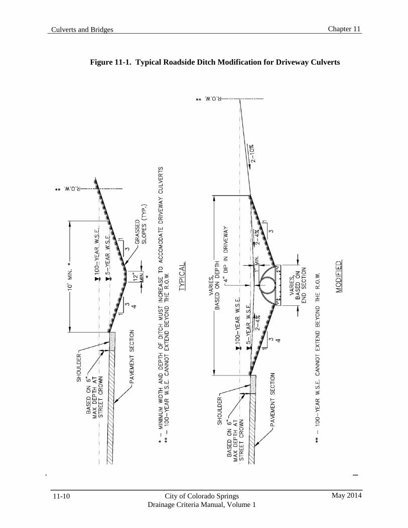
Chapter 11 Culverts and Bridges
City of Colorado Springs Drainage Criteria Manual, Volume 1
May 2014 11-10
Figure 11-1. Typical Roadside Ditch Modification for Driveway Culverts
4
4
Drainage Criteria Manual, Volume 1
Chapter 12 Open Channels
Contents 1.0 Introduction ...................................................................................................................................... 1
1.1 Natural Drainageways ............................................................................................................................... 1 1.2 Impacts of Urbanization ............................................................................................................................ 2 1.3 Vision for Drainageways ........................................................................................................................... 3 1.4 Design Flows ............................................................................................................................................. 4 1.5 Sediment Load .......................................................................................................................................... 4 1.6 Channel Types ........................................................................................................................................... 4
1.6.1 Major Drainageways ......................................................................................................................... 5 1.6.1.1 Stabilized Natural Channels .................................................................................................. 6
1.6.2 Minor Drainageways ........................................................................................................................ 7 1.6.2.1 Constructed Natural Channels ............................................................................................... 7 1.6.2.2 Constructed Channel ............................................................................................................. 8
2.0 Hydraulic Analysis ........................................................................................................................... 9 2.1 Roughness Coefficients ............................................................................................................................. 9 2.2 HEC-RAS Analysis ................................................................................................................................. 10 2.3 Normal Depth Calculations ..................................................................................................................... 11
3.0 Design Guidelines ........................................................................................................................... 11 3.1 Major Drainageways ............................................................................................................................... 11
3.1.1 Create Low-Flow Channel .............................................................................................................. 12 3.1.1.1 Low-Flow Channel Dimensions .......................................................................................... 13 3.1.1.2 Baseflow Channel ............................................................................................................... 14 3.1.1.3 Wetland Bottom Channels .................................................................................................. 14 3.1.1.4 Bioengineered Channels ...................................................................................................... 14
3.1.2 Establish a Low-Flow Design Slope ............................................................................................... 14 3.1.3 Utilize Vegetated Benches to Convey Overbank Flow ................................................................... 16 3.1.4 Stabilize Eroding Banks ................................................................................................................. 16 3.1.5 Analyze Floodplain Hydraulics ...................................................................................................... 18
3.1.5.1 Floodplain Encroachments .................................................................................................. 18 3.1.6 Consider Aquatic Ecology .............................................................................................................. 18 3.1.7 Improvements as Approved in Master Plan or Drainageway Plan ................................................. 22
3.2 Minor Drainageways ............................................................................................................................... 22 3.2.1 Constructed Natural Channels ........................................................................................................ 22 3.2.2 Grass-Lined Channels ..................................................................................................................... 23 3.2.3 Composite Channels ....................................................................................................................... 23 3.2.4 Wetland-Bottom Channels .............................................................................................................. 23 3.2.5 Bioengineered Channels ................................................................................................................. 24 3.2.6 Constructed Channels ..................................................................................................................... 24
3.2.6.1 Riprap-Lined and Concrete-Lined Channels ....................................................................... 24 3.3 Design Flow Freeboard ........................................................................................................................... 24
4.0 Grade Control (Drop) Structures ................................................................................................. 24 4.1 Low-Flow Drop Structures ...................................................................................................................... 25 4.2 Full-Channel-Width 100-Year Drop Structures ...................................................................................... 26
4.2.1 Constructed Natural Channel Drop Structures ............................................................................... 26
May 2014 City of Colorado Springs 12-i
City of Colorado Springs Drainage Criteria Manual, Volume 1
May 2014 12-ii
4.2.2 Constructed Channel Drop Structures .............................................................................................27 4.3 Drop Structure Types ...............................................................................................................................27
4.3.1 Fish Passage ....................................................................................................................................28 4.4 Drop Structure Placement ........................................................................................................................28
5.0 Revegetation .................................................................................................................................... 28
6.0 Easements ........................................................................................................................................ 29
7.0 Design for Maintenance .................................................................................................................. 29
8.0 References ........................................................................................................................................ 29 Tables Table 12-1. Channel Types .......................................................................................................................... 9 Table 12-2. Roughness Coefficients .......................................................................................................... 10 Table 12-3. Hydraulic Design Criteria for Natural Unlined Channels ....................................................... 13 Table 12-4. Plains Fish Performance Data ................................................................................................. 20 Table 12-5. Fish Habitat Structures ............................................................................................................ 21 Table 12-6. Hydraulic Design Criteria for Grass-Lined Constructed Natural Channels ............................ 23 Table 12-7. Maximum Grade Control Structure Drop Heights .................................................................. 25
Figures Figure 12-1. Functions and Benefits of Natural Drainageways.................................................................... 1 Figure 12-2. Impacts of Stream Degradation ............................................................................................... 2 Figure 12-3. Design Elements Associated With Major Natural Drainageways ......................................... 12 Figure 12-4. Maximum Low-flow Channel Design Slope for Sand-bed Channels ................................... 16
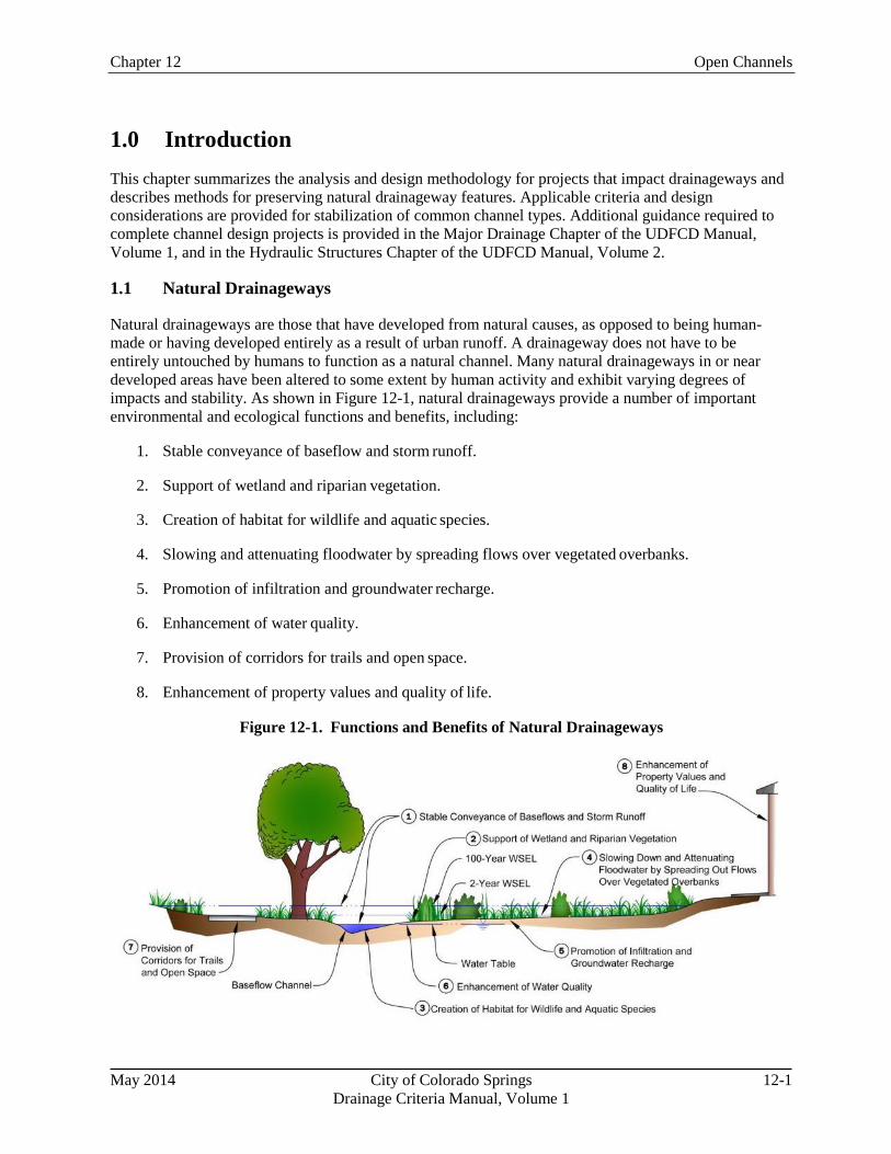
Chapter 12 Open Channels
1.0 Introduction This chapter summarizes the analysis and design methodology for projects that impact drainageways and describes methods for preserving natural drainageway features. Applicable criteria and design considerations are provided for stabilization of common channel types. Additional guidance required to complete channel design projects is provided in the Major Drainage Chapter of the UDFCD Manual, Volume 1, and in the Hydraulic Structures Chapter of the UDFCD Manual, Volume 2.
1.1 Natural Drainageways
Natural drainageways are those that have developed from natural causes, as opposed to being human- made or having developed entirely as a result of urban runoff. A drainageway does not have to be entirely untouched by humans to function as a natural channel. Many natural drainageways in or near developed areas have been altered to some extent by human activity and exhibit varying degrees of impacts and stability. As shown in Figure 12-1, natural drainageways provide a number of important environmental and ecological functions and benefits, including:
1. Stable conveyance of baseflow and storm runoff.
2. Support of wetland and riparian vegetation.
3. Creation of habitat for wildlife and aquatic species.
4. Slowing and attenuating floodwater by spreading flows over vegetated overbanks.
5. Promotion of infiltration and groundwater recharge.
6. Enhancement of water quality.
7. Provision of corridors for trails and open space.
8. Enhancement of property values and quality of life.
Figure 12-1. Functions and Benefits of Natural Drainageways
May 2014 City of Colorado Springs 12-1 Drainage Criteria Manual, Volume 1
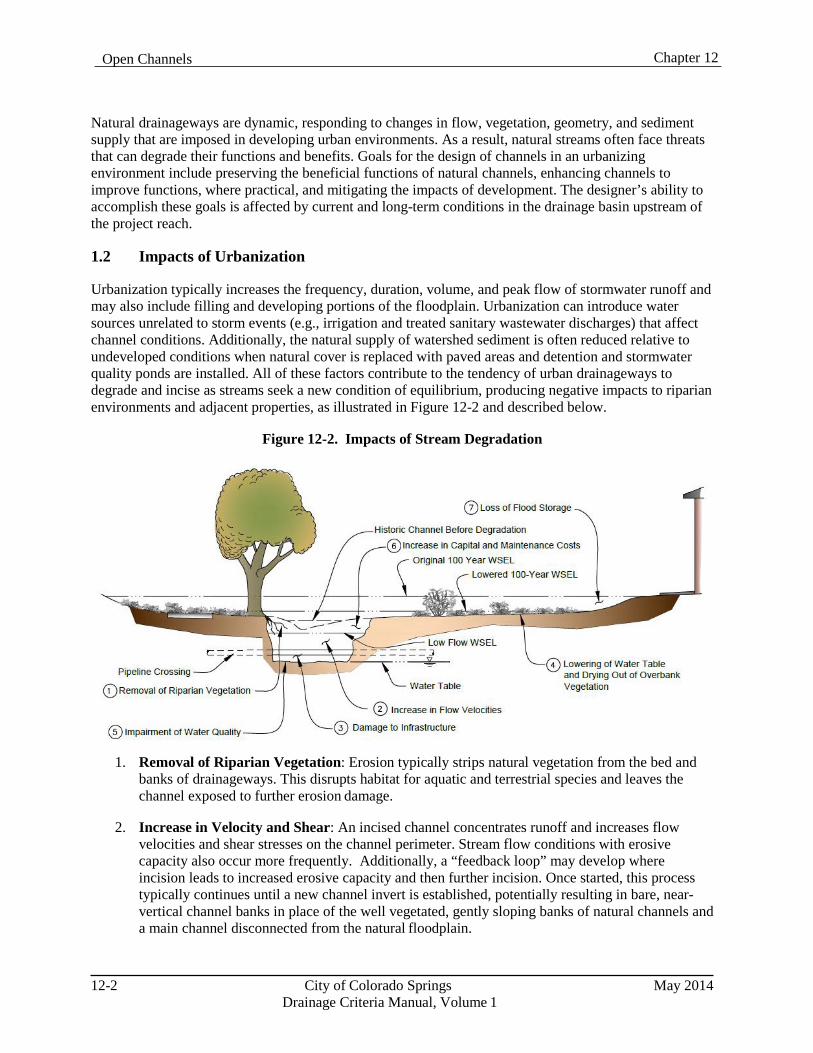
Chapter 12 Open Channels
Natural drainageways are dynamic, responding to changes in flow, vegetation, geometry, and sediment supply that are imposed in developing urban environments. As a result, natural streams often face threats that can degrade their functions and benefits. Goals for the design of channels in an urbanizing environment include preserving the beneficial functions of natural channels, enhancing channels to improve functions, where practical, and mitigating the impacts of development. The designer’s ability to accomplish these goals is affected by current and long-term conditions in the drainage basin upstream of the project reach.
1.2 Impacts of Urbanization
Urbanization typically increases the frequency, duration, volume, and peak flow of stormwater runoff and may also include filling and developing portions of the floodplain. Urbanization can introduce water sources unrelated to storm events (e.g., irrigation and treated sanitary wastewater discharges) that affect channel conditions. Additionally, the natural supply of watershed sediment is often reduced relative to undeveloped conditions when natural cover is replaced with paved areas and detention and stormwater quality ponds are installed. All of these factors contribute to the tendency of urban drainageways to degrade and incise as streams seek a new condition of equilibrium, producing negative impacts to riparian environments and adjacent properties, as illustrated in Figure 12-2 and described below.
Figure 12-2. Impacts of Stream Degradation
1. Removal of Riparian Vegetation: Erosion typically strips natural vegetation from the bed and banks of drainageways. This disrupts habitat for aquatic and terrestrial species and leaves the channel exposed to further erosion damage.
2. Increase in Velocity and Shear: An incised channel concentrates runoff and increases flow
velocities and shear stresses on the channel perimeter. Stream flow conditions with erosive capacity also occur more frequently. Additionally, a “feedback loop” may develop where incision leads to increased erosive capacity and then further incision. Once started, this process typically continues until a new channel invert is established, potentially resulting in bare, near- vertical channel banks in place of the well vegetated, gently sloping banks of natural channels and a main channel disconnected from the natural floodplain.
12-2 City of Colorado Springs May 2014 Drainage Criteria Manual, Volume 1
Chapter 12 Open Channels
3. Damage to Infrastructure: Channel erosion can threaten utility lines, bridges, and other infrastructure. Utility pipelines that were originally constructed several feet below the bed of a creek may become exposed as the channel bed lowers. Channel degradation can expose the foundations of bridge abutments and piers, leading to increased risk of undermining and scour failure during flood events. Erosion and lateral movement of channel banks can expose buried utility lines, undermine roadways and cause significant damage to adjacent properties and structures.
4. Lowering of Water Table and Drying-out of Overbank Vegetation: In many cases, lowering
of the channel thalweg and baseflow elevation leads to a corresponding lowering of the local water table. Lowering the water table can have a negative effect on bank stability and aquatic and terrestrial ecology. Substantial lowering of the channel invert can make water inaccessible to wetland plant species, causing them to die out and be replaced by upland species which have poorer ground coverage, canopy and root structure. The result can be degradation or elimination of both aquatic and terrestrial habitat and destabilization of the channel banks.
5. Impairment of Water Quality: The sediment associated with the erosion of an incised channel
can lead to water quality impairment in downstream receiving waters. One mile of channel incision 3-feet deep and 10-feet wide produces almost 6,000 cubic yards of sediment that could be deposited in downstream lakes and stream reaches. Along the Front Range of Colorado, these sediments contain phosphorus, a nutrient that can lead to accelerated eutrophication of lakes and reservoirs. Along some reaches of Fountain Creek, naturally occurring selenium can be mobilized into the stream system by urbanization and erosion into underlying geologic formations. Also, channel incision impairs the “cleansing” function that natural floodplain overbanks can provide through settling, vegetative filtering, wetland treatment processes, and infiltration.
6. Increase in Capital and Maintenance Costs: Typical stabilization projects to repair eroded
drainageways require significant capital investment; the more erosion, generally the higher the cost of rehabilitation.
7. Loss of Flood Storage: Incision of the low-flow or main channel portion of the drainageway
prevents flood flows from spilling into the overbank area where the natural storage helped to reduce downstream peak flows.
1.3 Vision for Drainageways
The vision for drainageways as described in this Manual is to go beyond simply stabilizing a channel against erosion and to implement enhanced stream stabilization. Stabilization can be accomplished by lining a channel with concrete; however, not only is this often the most expensive approach to stabilization, it also eliminates the ecological, aesthetic and recreational value of drainageways. Enhanced stream stabilization has the goal of maintaining or restoring natural streams and well-vegetated floodplains that are physically and biologically healthy, with the attributes shown in Figure 12-1. Plan form and cross-sectional geometry, riparian vegetation, grade-control features, and flood storage provisions should be integrated into channel designs to emulate the functions of natural features to the extent practical. This vision is based on recognition that streams and drainageways are a valuable resource to the community and that capital and long-term maintenance costs to the community are typically lower when channel designs work with nature rather than against it. The implementation of these concepts is directly related to upstream basin conditions, including land uses, anticipated flows and flow control measures.
May 2014 City of Colorado Springs 12-3 Drainage Criteria Manual, Volume 1
Chapter 12 Open Channels
1.4 Design Flows
Flows conveyed by open channel are highly variable. Historic flows vary over a wide range due to nature fluctuations in weather and climate and changes in the upstream drainage basin due to development or other human activity can increase this variability. Therefore, it is not feasible to evaluate all of the possible flows a channel might convey. To simplify open channel design procedures, representative design flows have been identified. In most cases, open channel projects can be adequately designed using estimates of baseflows, low flows and flood flows. Full descriptions of these design flows and methods for estimating them are described in Chapter 6, Hydrology. General descriptions of these flow conditions include:
Baseflows may not be directly related to storm events and are often not present in undeveloped
drainage basins, but can become present after development. Their presence or absence can be a determining factor in the feasibility of implementing certain channel features, such as wetland bottoms.
Low flows are normally contained within a well-defined channel that only overtops when a
significant storm event occurs. Flows within this range are usually responsible for establishing the main channel section and the slope of the stream bed.
Flood flows include any flows that exceed the low-flow or main channel capacity and have the
potential to create unsafe or damaging conditions.
Open channel designs must account for each of these types of design flows and upstream drainage basin conditions, including practices implemented to reduce runoff, such as low impact development and detention storage. By designing for these particular design flows, it is expected that adequate protection and conveyance will be provided for intermediate flows and that the proposed vision for drainageways can be achieved.
1.5 Sediment Load
The range of sediment loads carried by channels is affected by conditions and flows in the upstream drainage basin, impacts to the channel due to crossings or modifications, development activity and the extent of development-related improvements. Temporary sediment loads may differ from longer-term sediment loads and should be considered during design. It is normally desirable to pass sediment through a design reach by designing the low-flow channel with sufficient hydraulic capacity to ensure that excessive sediment is not deposited in the reach over time. Estimates of the sediment load entering the project reach can be made by an analysis of the capacity and type of material conveyed in the upstream reaches. However, applying these methods can require extensive data collection and expertise that is often not available. Any project that requires these types of analyses must include a thorough description of the data sources and methodology to be used and submitted for approval.
1.6 Channel Types
Open channels may be heavily influenced by changes in the upstream drainage basin contributing to the project reach as described above or by crossing structures, encroachments, debris and/or changes to vegetation within the project reach. The implementation of detention to attenuate peak flow rates from urbanized areas is a critical factor for selecting the type of channel for design. The design of open channels must account for the effects of these factors over the design life of the project. Typical characteristics of the most common open channel types are described below.
12-4 City of Colorado Springs May 2014 Drainage Criteria Manual, Volume 1

Chapter 12 Open Channels
1.6.1 Major Drainageways
In general, major drainageways are streams with contributing drainage basin areas greater than approximately 130 acres. This threshold corresponds to the lower threshold for regional detention facilities as described in the Storage Chapter of this Manual. Other factors besides drainage area, such as the preservation of habitat or floodplains, may determine where a major drainageway begins. As a watershed urbanizes, providing detention storage upstream of major drainageways is necessary to minimize changes to hydrology that can cause instability, exceed its capacity and degrade its natural functions. The amount of sediment transport in these drainageways can vary greatly depending on their location relative to upstream detention storage and the level of development; therefore, sediment transport estimates and stable slope considerations can also be important factors for designing major drainageways.
Projects affecting major drainageways must be completed so that natural drainageway features and benefits are preserved (and enhanced when feasible) or restored, unless otherwise designated in an approved master plan. Planning documents shall accurately identify all existing drainageways, floodplains, and other site features that may have beneficial natural features. Features proposed to be left in place and preserved or restored shall be clearly shown on the planning and/or design documents. Areas identified as protected will be subject to review and acceptance. A key consideration in the preservation of natural drainageways is obtaining an adequate easement or tract of land that allows the drainageway to provide the natural function of flood storage and to allow the creation of open spaces that can provide habitat. This approach to channel design can also reduce the need to modify floodplain maps used in the administration of the National Flood Insurance Program (NFIP).
Improvements to natural drainageways should be limited to those necessary to stabilize the low-flow channel, establish riparian vegetation and stabilize channel banks for flood flows and infrastructure protection. Encroachments into the floodplain should be very limited and full-channel-width drop structures generally should not be necessary.
To the extent practical, major drainageway projects should protect and preserve these features, if present:
Protected habitat for threatened and endangered or other protected species.
Jurisdictional wetlands.
Riparian vegetation such as cottonwood or willow trees, shrub willows, and wetland or transitional
grasses. Baseflows.
Overbank flood storage.
Bedrock outcroppings or unique landforms.
Historic, cultural, or archeological resources.
To complete the design of a major drainageway project, baseflows, low flows, flood flows, and sediment loads must be evaluated. The evaluation of flood flows will normally include delineation of the floodplain for land planning purposes and for maintaining adequate freeboard at structures on adjacent developments and may also include scour calculations for utility crossings, bridge abutments and other structures. When the floodplain for the project reach is defined on a Flood Insurance Rate Map (FIRM), a
May 2014 City of Colorado Springs 12-5 Drainage Criteria Manual, Volume 1
Chapter 12 Open Channels
revision to the regulatory floodplain may be necessary as described in Chapter 5, Floodplain Management.
1.6.1.1 Stabilized Natural Channels
Most major drainageway projects can be described as stabilized natural channels. These projects require limited modifications to drainageways that allow most of the benefits of natural channels to be preserved or enhanced. Improvements will normally be limited to stabilization of the low-flow channel (unless a meandering low-flow channel is planned), crossing structures, grade control structures and limited stabilization of the banks to manage unstable areas or protect infrastructure. Loss of flood storage due to encroachments should be mitigated by providing compensatory storage. Considerations for stabilized natural channels include:
1. Preserving Streams Not Yet Impacted: Drainageways that have not yet experienced
degradation from increased urban runoff or other forms of erosion should be preserved by implementing the following improvements:
Grade control structures to limit degradation in the low-flow channel, stabilize existing
headcutting and establish a flatter equilibrium slope than may have existed previously.
Utilization of vegetated overbank benches adjacent to the low-flow channel to allow flood flows to spread out and slow down and to dissipate energy.
Stabilized low-flow channel that can be vegetated, potentially with a bioengineered or wetland
bottom.
Bank stabilization at select locations where existing instability or the potential for future instability is identified.
Planting supplemental vegetation to provide for the transition to species suited for “wetter”
urban hydrology. Additional moisture can sustain wetland and riparian vegetation. These grasses, sedges and rushes, shrubs, and trees can help to stabilize the channel and provide diverse habitat for wildlife. The removal of invasive species can also contribute to the preservation of desirable species.
2. Restoring Impacted Streams: Drainageways that have already experienced significant erosion
and down-cutting are to be addressed similarly to streams that are not yet degraded. However, eroded, incised channels should not be stabilized in a manner that retains the incised geometry with steep side banks. Instead, incised channels should be restored by raising the channel invert up to or near its historic elevation, allowing flood flows to spread out onto the natural floodplain, avoiding deep, concentrated flood flows within the main channel. The more a drainageway is allowed to degrade, the greater the disturbance will be required to provide restoration and the higher the cost will be.
3. Channel Crossings: When influences to a natural channel are limited to a structural crossing
such as a roadway and the upstream drainage basin is not expected to change significantly over time, the design process must fully consider historic basin conditions and the natural conditions of the drainageway. Construction of the crossing should seek to minimize the impacts to the natural functions of the drainageway and provide mitigation for unavoidable impacts. In this situation, the project should avoid encroachment into and the modification of the adjacent floodplain and interference with the natural tendencies of the drainageway such as meandering
12-6 City of Colorado Springs May 2014
Drainage Criteria Manual, Volume 1
Chapter 12 Open Channels
and sediment transport. This is best achieved by structures that span all or most of the floodplain. When floodplain encroachment cannot be avoided, transitions upstream and downstream of the structure should be hydraulically efficient to minimize changes to the adjacent channel features and to the floodplain. The stabilization of eroded low-flow channels or banks to protect property or infrastructure may also be part of the project design. As part of these efforts, fill in the historic floodplain should be minimized so that the flood storage function of the channel is preserved.
By respecting natural historic drainage patterns and flood-prone areas in early planning and implementing water quality and detention practices, drainageways and floodplains can be preserved that provide adequate capacity during storm events, that are stable, cost-effective and of high environmental value, and that offer multiple use benefits to surrounding urban areas. In the absence of historic beneficial features, it may be desirable to design natural functions into projects.
1.6.2 Minor Drainageways
In general, minor drainageways are channels with contributing drainage basin areas less than approximately 130 acres. Minor drainageways may include drainage basins up to about 640 acres if identified in an approved master plan or if significant natural channel features are not present in the unimproved drainageway. These thresholds correspond to the thresholds for regional detention facilities as described in the Storage Chapter of this Manual.
Minor drainageways may be reconstructed, relocated, or replaced with a storm sewer in combination with flood conveyance in the street network. However, the creation of vegetated surface channels is encouraged wherever practical in the minor drainageway network. These drainageways will typically be located upstream of detention storage facilities, and design flows will be based on developed conditions that produce flows much greater than undeveloped conditions. Although natural channel features may not be present in these types of channels, it is desirable to create naturalistic features including base-flow channels, low-flow channels and vegetated overbank areas to provide some of the beneficial functions of natural channels.
The amount of sediment transport in minor drainageways is expected to be limited because most of the upstream basin will probably already be developed or planned for development. Sediment load may be high while the drainage basin is under development, but this is unlikely to continue as the drainage basin becomes more developed. Therefore, design slopes for these types of channels may be determined primarily by non-erosive velocities rather than by sediment transport estimates or stable slope considerations.
1.6.2.1 Constructed Natural Channels
When adequate land is available, it is desirable to construct a stabilized channel that provides the benefits of natural channels such as flood storage, aesthetic benefits and habitat. Such “constructed natural channels” should be designed to emulate the functions of natural drainageways shown in Figure 12-1. Where practical, existing natural features should be incorporated into the design. For these types of projects, the primary design considerations are to emulate natural channels, avoid flooding of adjacent structures, provide stable channel conditions, and pass sediment to reduce maintenance.
Stabilization improvements for the banks and overbank will depend on the design flows and velocities and proposed ground cover. Grade control structures will normally be required for the low-flow channel. Grade control structures will also be required across the full channel section if overbank velocities exceed non-erosive levels.
May 2014 City of Colorado Springs 12-7 Drainage Criteria Manual, Volume 1
Chapter 12 Open Channels
This channel type includes grass-lined and composite channels, as defined by the UDFCD Manual, and may include bioengineered and wetland bottom channels, as well.
To complete the design of a constructed natural channel, low flows and flood flows must be analyzed to determine channel cross sections and slopes that will promote a stable channel. The evaluation of flood flows provides a delineation of the floodplain for land-planning purposes and provides the basis to maintain adequate freeboard for structures and adjacent developments. Flood flows also provide the basis for many types of scour analyses. If a baseflow channel is included in the design, baseflows must also be estimated. The presence of baseflows will also need to be considered if wetland bottoms are part of the design.
1.6.2.2 Constructed Channel
A channel that primarily provides flood flow conveyance may be necessary when upstream drainage basin conditions have already been significantly altered or are expected to be in the future, where the floodplain has already been significantly reduced, or where existing flooding is occurring. These channels may also be necessary where right-of-way is limited. Constructed channels will typically be fully lined with riprap, soil riprap, concrete, or manufactured linings and do not provide most of the benefits of a natural channel. The design of these channel types primarily depends on flood flows, but low flows and baseflows may be needed if sediment load passage is desired. The evaluation of flood flows provides the delineation of the floodplain for land planning purposes and provides the basis to maintain adequate freeboard at structures and for adjacent developments but will not normally be shown on the NFIP FIRMs.
Most channel projects in developing drainage basins will be either a stabilized natural channel or a constructed natural channel. The conditions necessary to maintain a channel in fully natural conditions rarely occur in an urbanizing drainage basin and constructed channels are primarily intended to be used in retrofit situations where the upstream drainage basin is fully developed and there is limited right-of-way available. Table 12-1 summarizes the project conditions that generally determine the type of channel that is most appropriate.
12-8 City of Colorado Springs May 2014 Drainage Criteria Manual, Volume 1
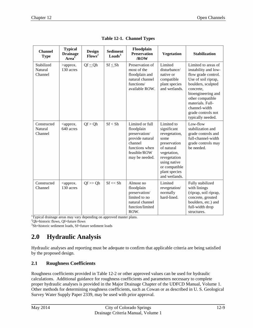
Chapter 12 Open Channels
Table 12-1. Channel Types
Channel Type
Typical Drainage
Area1
Design Flows2
Sediment Loads3
Floodplain Preservation
/ROW
Vegetation
Stabilization
Stabilized Natural Channel
>approx. 130 acres
Qf ~ Qh Sf < Sh Preservation of most of the floodplain and natural channel functions/ available ROW.
Limited disturbance/ native or compatible plant species and wetlands.
Limited to areas of instability and low- flow grade control. Use of soil riprap, boulders, sculpted concrete, bioengineering and other compatible materials. Full- channel-width grade controls not typically needed.
Constructed Natural Channel
<approx. 640 acres
Qf > Qh Sf < Sh Limited or full floodplain preservation/ provide natural channel functions when feasible/ROW may be needed.
Limited to significant revegetation, some preservation of natural vegetation, revegetation using native or compatible plant species and wetlands.
Low-flow stabilization and grade controls and full-channel-width grade controls may be needed.
Constructed Channel
<approx. 130 acres
Qf >> Qh Sf << Sh Almost no floodplain preservation/ limited to no natural channel function/limited ROW.
Limited revegetation/ normally hard-lined.
Fully stabilized with linings (riprap, soil riprap, concrete, grouted boulders, etc.) and full-width drop structures.
1Typical drainage areas may vary depending on approved master plans. 2Qh=historic flows, Qf=future flows 3Sh=historic sediment loads, Sf=future sediment loads
2.0 Hydraulic Analysis Hydraulic analyses and reporting must be adequate to confirm that applicable criteria are being satisfied by the proposed design.
2.1 Roughness Coefficients
Roughness coefficients provided in Table 12-2 or other approved values can be used for hydraulic calculations. Additional guidance for roughness coefficients and parameters necessary to complete proper hydraulic analyses is provided in the Major Drainage Chapter of the UDFCD Manual, Volume 1. Other methods for determining roughness coefficients, such as Cowan or as described in U. S. Geological Survey Water Supply Paper 2339, may be used with prior approval.
May 2014 City of Colorado Springs 12-9
Drainage Criteria Manual, Volume 1
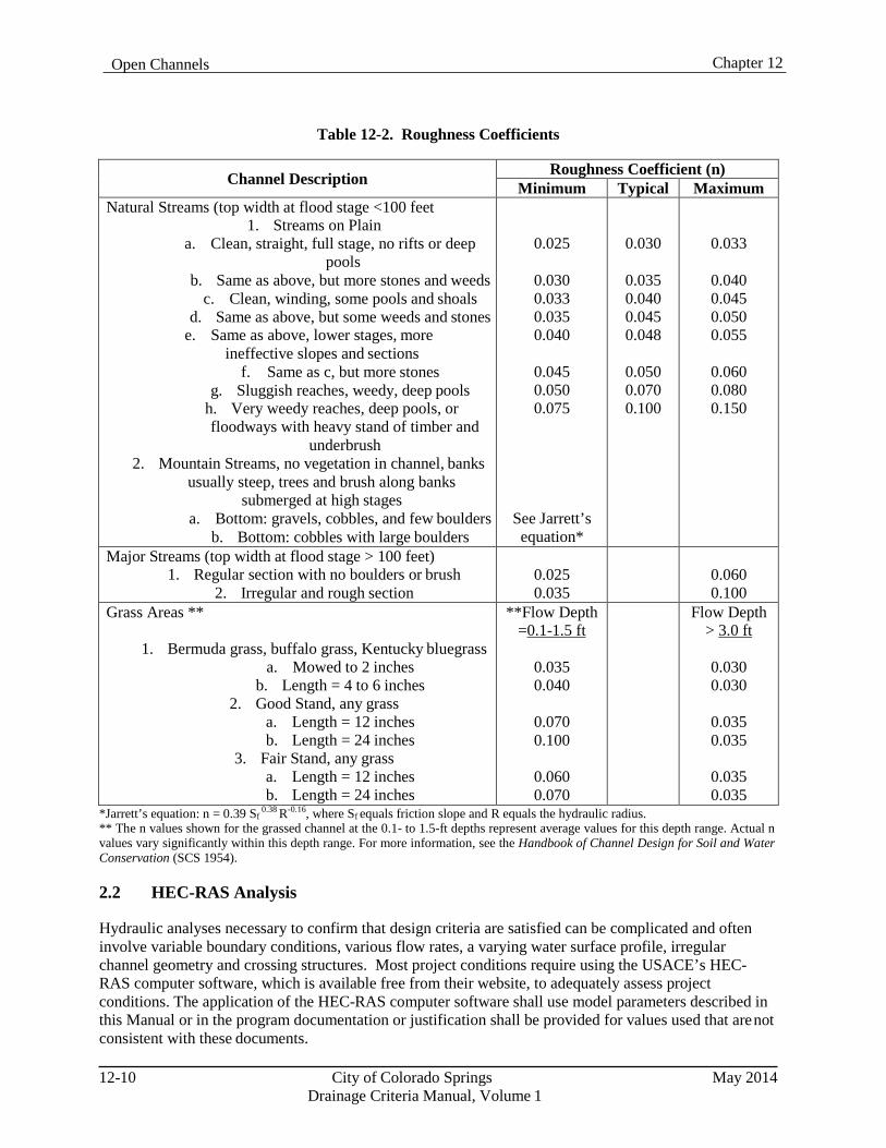
Chapter 12 Open Channels
Table 12-2. Roughness Coefficients
Channel Description Roughness Coefficient (n) Minimum Typical Maximum
Natural Streams (top width at flood stage <100 feet 1. Streams on Plain
a. Clean, straight, full stage, no rifts or deep pools
b. Same as above, but more stones and weeds c. Clean, winding, some pools and shoals
d. Same as above, but some weeds and stones e. Same as above, lower stages, more
ineffective slopes and sections f. Same as c, but more stones
g. Sluggish reaches, weedy, deep pools h. Very weedy reaches, deep pools, or floodways with heavy stand of timber and
underbrush 2. Mountain Streams, no vegetation in channel, banks
usually steep, trees and brush along banks submerged at high stages
a. Bottom: gravels, cobbles, and few boulders b. Bottom: cobbles with large boulders
0.025
0.030 0.033 0.035 0.040
0.045 0.050 0.075
See Jarrett’s equation*
0.030
0.035 0.040 0.045 0.048
0.050 0.070 0.100
0.033
0.040 0.045 0.050 0.055
0.060 0.080 0.150
Major Streams (top width at flood stage > 100 feet) 1. Regular section with no boulders or brush
2. Irregular and rough section
0.025 0.035
0.060 0.100
Grass Areas **
1. Bermuda grass, buffalo grass, Kentucky bluegrass a. Mowed to 2 inches
b. Length = 4 to 6 inches 2. Good Stand, any grass
a. Length = 12 inches b. Length = 24 inches
3. Fair Stand, any grass a. Length = 12 inches b. Length = 24 inches
**Flow Depth =0.1-1.5 ft
0.035 0.040
0.070 0.100
0.060 0.070
Flow Depth > 3.0 ft
0.030 0.030
0.035 0.035
0.035 0.035
*Jarrett’s equation: n = 0.39 Sf 0.38 R-0.16, where Sf equals friction slope and R equals the hydraulic radius.
** The n values shown for the grassed channel at the 0.1- to 1.5-ft depths represent average values for this depth range. Actual n values vary significantly within this depth range. For more information, see the Handbook of Channel Design for Soil and Water Conservation (SCS 1954).
2.2 HEC-RAS Analysis
Hydraulic analyses necessary to confirm that design criteria are satisfied can be complicated and often involve variable boundary conditions, various flow rates, a varying water surface profile, irregular channel geometry and crossing structures. Most project conditions require using the USACE’s HEC- RAS computer software, which is available free from their website, to adequately assess project conditions. The application of the HEC-RAS computer software shall use model parameters described in this Manual or in the program documentation or justification shall be provided for values used that are not consistent with these documents.
12-10 City of Colorado Springs May 2014 Drainage Criteria Manual, Volume 1
Chapter 12 Open Channels
2.3 Normal Depth Calculations
Generally, normal depth calculations may be used when these conditions are met: Channel geometry is uniform.
Channel parameters are uniform.
Design flows are steady.
Backwater effects are not present.
Water surface profile is uniform.
Hydraulic boundary conditions are well known for all design flows.
No structures are creating variable water surface elevations affecting flow in the channel.
The UDFCD has created several spreadsheet programs that provide assistance in the evaluation of typical channel designs and crossing structures when project conditions are appropriate for normal depth calculations. These design aids may be used to complete project designs when appropriate.
3.0 Design Guidelines Each reach or each segment of the project reach must be evaluated to determine the basin conditions that will influence its function within the drainage basin or watershed and the applicable design standards. Channel design requirements are determined by whether they are categorized as major or minor channels and by the particular characteristics of the project reach. The Major Drainage Chapter of Volume 1 of the UDFCD Manual provides a thorough discussion of drainageway planning considerations, which should be referenced for guidance on urban effects, route considerations, and drainageway layout within a site.
3.1 Major Drainageways
The natural channel design criteria described herein and in the Major Drainage Chapter of Volume 1 of the UDFCD Manual shall be used for all major drainageways unless otherwise identified in an approved master plan. Typical design elements included in a major natural channel design project are shown in Figure 12-3 and summarized as follows:
1. Create low-flow channel.
2. Establish a low-flow design longitudinal slope.
3. Utilize vegetated benches to convey overbank flow.
4. Slope-back and stabilize eroding banks.
5. Analyze floodplain hydraulics.
6. Evaluate potential impacts to aquatic ecology and incorporate measures to enhance biologic
functions, where practical.
7. Undertake major drainageway plan improvements if required.
May 2014 City of Colorado Springs 12-11 Drainage Criteria Manual, Volume 1
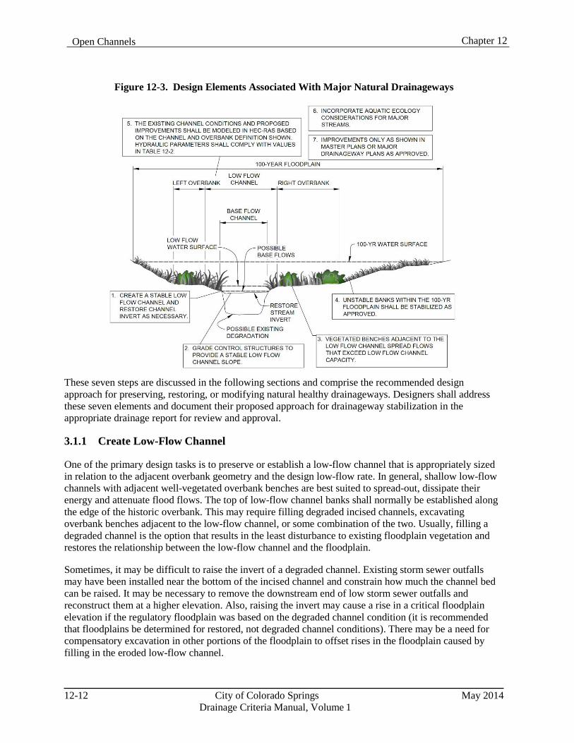
Chapter 12 Open Channels
Figure 12-3. Design Elements Associated With Major Natural Drainageways
These seven steps are discussed in the following sections and comprise the recommended design approach for preserving, restoring, or modifying natural healthy drainageways. Designers shall address these seven elements and document their proposed approach for drainageway stabilization in the appropriate drainage report for review and approval.
3.1.1 Create Low-Flow Channel
One of the primary design tasks is to preserve or establish a low-flow channel that is appropriately sized in relation to the adjacent overbank geometry and the design low-flow rate. In general, shallow low-flow channels with adjacent well-vegetated overbank benches are best suited to spread-out, dissipate their energy and attenuate flood flows. The top of low-flow channel banks shall normally be established along the edge of the historic overbank. This may require filling degraded incised channels, excavating overbank benches adjacent to the low-flow channel, or some combination of the two. Usually, filling a degraded channel is the option that results in the least disturbance to existing floodplain vegetation and restores the relationship between the low-flow channel and the floodplain.
Sometimes, it may be difficult to raise the invert of a degraded channel. Existing storm sewer outfalls may have been installed near the bottom of the incised channel and constrain how much the channel bed can be raised. It may be necessary to remove the downstream end of low storm sewer outfalls and reconstruct them at a higher elevation. Also, raising the invert may cause a rise in a critical floodplain elevation if the regulatory floodplain was based on the degraded channel condition (it is recommended that floodplains be determined for restored, not degraded channel conditions). There may be a need for compensatory excavation in other portions of the floodplain to offset rises in the floodplain caused by filling in the eroded low-flow channel.
12-12 City of Colorado Springs May 2014 Drainage Criteria Manual, Volume 1
Chapter 12 Open Channels
By measuring “bankfull” characteristics within the Jimmy Camp Creek drainage basin, a 67 square-mile tributary to Fountain Creek, and applying regression methods, a relationship between drainage area and channel dimensions has been developed. Bankfull channel dimensions can be useful to determine the configuration of the “low-flow channel” within the main channel. This is the portion of the channel that is most active and most affected by changes in hydrology due to development. Even with effective detention facilities upstream of “natural” channel reaches, it is anticipated that increases in flow volumes and frequency will cause channels to become unstable. By stabilizing the low-flow portion of the channels, it is anticipated that more significant channel stabilization projects can be avoided, reducing the overall cost of drainage facilities.
Allowable velocities for unlined low-flow channels are shown in Table 12-3. Criteria for lined channels are provided in the Major Drainage Chapter of Volume 1 of the UDFCD Manual.
Table 12-3. Hydraulic Design Criteria for Natural Unlined Channels
Design Parameter Erosive Soils or Poor Vegetation
Erosion Resistant Soils and Vegetation
Maximum Low-flow Velocity (ft/sec) 3.5 ft/sec 5.0 ft/sec
Maximum 100-year Velocity (ft/sec) 5.0 ft/sec 7.0 ft/sec
Froude No., Low-flow 0.5 0.7
Froude No., 100-year 0.6 0.8
Maximum Tractive Force, 100-year 0.60 lb/sf 1.0 lb/sf 1 Velocities, Froude numbers and tractive force values listed are average values for the cross section. 2 “Erosion resistant” soils are those with 30% or greater clay content. Soils with less than 30% clay content shall be considered “erosive soils.”
Normally, a low-flow channel exhibits some meandering and sinuosity in natural channels. Stabilized channels should feature a meander pattern typical of natural channels. Side slopes for low-flow channel banks shall be no steeper than 4H:1V without adequate bank stabilization. Flatter slopes are encouraged and may provide improved vegetative cover, bank stability and access.
3.1.1.1 Low-Flow Channel Dimensions
Based on the Jimmy Camp Creek drainage basin channel analyses, the bankfull regression equation for design low-flow cross-sectional area is provided as Equation 12-1 below.
Alow-flow = 21.3 DA0.34 Equation 12-1 Where:
Alow-flow = design low-flow cross-sectional area (ft2) DA = tributary drainage basin area (mi2)
From the design low-flow cross-sectional area, the design low-flow width for any drainage basin is calculated by Equation 12-2a below.
Wlow-flow = [(Wbankfull/Dbankfull)reference*Alow-flow] 0.5 Equation 12-2a Where:
May 2014 City of Colorado Springs 12-13
Drainage Criteria Manual, Volume 1
Chapter 12 Open Channels
Wlow-flow = design low-flow width (ft2) (Wbankfull/Dbankfull)reference = bankfull width-to-depth ratio of a stable reference reach Alow-flow = design low-flow cross-sectional area, from Eq 12-1 (ft2)
The width of the low-flow channel should approximate the width of the historic low-flow channel within the design reach or in stable reference reaches upstream or downstream. A representative width-to-depth ratio of 30 was measured for bankfull channels in the Jimmy Camp Creek drainage basin. Using a width- to-depth ratio of 30, the design width for low-flow channels in Jimmy Camp Creek may be calculated by Equation 12-2b below.
W low-flow = (30*Alow-flow) 0.5 Equation 12-2b Where:
W low-flow = design low-flow width (ft) A low-flow = design low-flow cross-sectional area, from Eq. 12-1 (ft2)
While the width-to-depth ratio of 30 is representative of measured bankfull channels in the Jimmy Camp Creek drainage basin, it is always recommended to utilize the measured bankfull width-to-depth ratio of a stable reference reach.
3.1.1.2 Baseflow Channel
If baseflows are present within the low-flow channel or are anticipated to be present in the future, it must be determined how the baseflows will be accommodated. Two common approaches include: 1) the invert of the low-flow channel can be shaped to accommodate a defined baseflow channel and a lower secondary overbank area or 2) the baseflows can be allowed to meander in the bottom of the low-flow channel without modifying the low-flow channel section. The baseflow rate may be based on available records from gage data, when available, but can be based on estimates as described in Chapter 6, Hydrology. The invert of the baseflow channel is typically unvegetated if a constant baseflow or frequent ephemeral flow is present, or vegetated with riparian or wetland species if baseflows are less frequent.
3.1.1.3 Wetland Bottom Channels
As described in the Major Drainage Chapter in Volume 1 of the UDFCD Manual, there are circumstances where the use of a wetland bottom may be appropriate within the low-flow channel of a natural channel reach. Low-flow channels shall be designed with reference to the Major Drainage Chapter in Volume 1 of the UDFCD Manual and the Treatment BMPs Chapter in Volume 3 of the UDFCD Manual. Riprap bank protection will generally not be required in wetland bottom channels.
3.1.1.4 Bioengineered Channels
Elements of bioengineered channels as described in the Major Drainage Chapter in Volume 1 of the UDFCD Manual may be used in the design or stabilization of natural channels.
3.1.2 Establish a Low-Flow Design Slope
Due to more runoff and lower sediment yields long-term stable low-flow channels slopes are expected to be less than the natural channel slope. To accommodate this anticipated change, grade control structures are required in the low-flow channel to create a “stairstep” profile to stabilize the low-flow channel and maintain the natural relationship between the low-flow channel and the floodplain. The estimated design
12-14 City of Colorado Springs May 2014 Drainage Criteria Manual, Volume 1
Chapter 12 Open Channels
slope, or equilibrium slope, determines how many grade control structures are required. A flatter design slope requires more grade control structures and increases costs. The spacing of drop structures depends on the difference between the natural channel slope and the design slope and the height of the drop structures. The design and placement of drop structures is described in Section 4.0, Grade Control Structures.
Methods for estimating theoretical slopes for ultimate basin conditions (i.e. very low sediment transport volumes) tend to produce extremely flat (near 0%) design slopes. To provide more realistic estimates for design slopes an examination of natural streams in the Denver metropolitan area was conducted by the UDFCD. This examination revealed a typical range of stable, long-term equilibrium slopes for various urban watershed sizes and flow rates. This information was used to develop the curve illustrated in Figure 12-4. Unless otherwise approved, grade control structures shall be laid out using the low-flow channel slope corresponding to the 100-year flow as shown in Figure 12-4. The design slope shall extend from the lowest crest elevation of the downstream grade control structure to the toe of the face of the upstream drop structure. The minimum low-flow design slope shall be 0.05 percent for all 100-year flows.
It is possible that channels may exhibit a steeper slope for periods of time, especially if a drainageway is temporarily subject to a high sediment load. This may lead to a partial or complete burying of grade control structures as channels aggrade from the design slope based on Figure 12-4. However, if slopes flatten over time in response to lower sediment loads, as is usually the case, this approach reduces the likelihood that drops will be undermined in the future. The designer shall be cognizant of the effects on the channel of steeper equilibrium slopes in the near term.
As alternatives to the slope resulting from Figure 12-4, designers may estimate equilibrium slopes using the following methods.
1. Reference Reach Concept: This is a quantitative fluvial geomorphology method that correlates
equilibrium longitudinal slopes from similar drainageways that have undergone adjustments in channel slope in response to urban development. Reference reaches have similar geomorphic characteristics as the project reach such as watershed size, watershed imperviousness, soil type, sediment loading, etc. In addition, the reference reach must be in equilibrium conditions and not unduly influenced by unstable upstream conditions (i.e., high sediment loads from eroding tributary). Reference reach evaluations should only be done by a designer that has expertise in geomorphology and river mechanics.
2. Sediment Transport Evaluation: This is a quantitative methodology that looks at the balance
between sediment supply and transport capacity. This method is most applicable in alluvial sand bed channels that have continuing sediment loads. Results are very sensitive to the assumptions used for sediment supply. An approximate methodology is provided in the “Design Guidelines and Criteria for Channels and Hydraulic Structures on Sandy Soil” (UDFCD June 1981). Several computer models also exist that model sediment transport such as HEC-6, SAM, and GSTARS. This method should only be used by design engineers that have significant experience and expertise in geomorphology and river mechanics. A detailed sediment transport analysis may be appropriate when potential cost savings and available data are sufficient to justify the level of expertise and technical analyses required to produce reasonable results and will be allowed only on a case-by-case basis.
3. Regional Regression Equations: Regional regression equations can provide guidance on
expected equilibrium slopes and may be related to discharge rates, drainage area or other parameter. The application of these equations is limited to watershed conditions that sufficiently similar to the watersheds are hydrologic conditions that were used to develop the equations.
May 2014 City of Colorado Springs 12-15
Drainage Criteria Manual, Volume 1
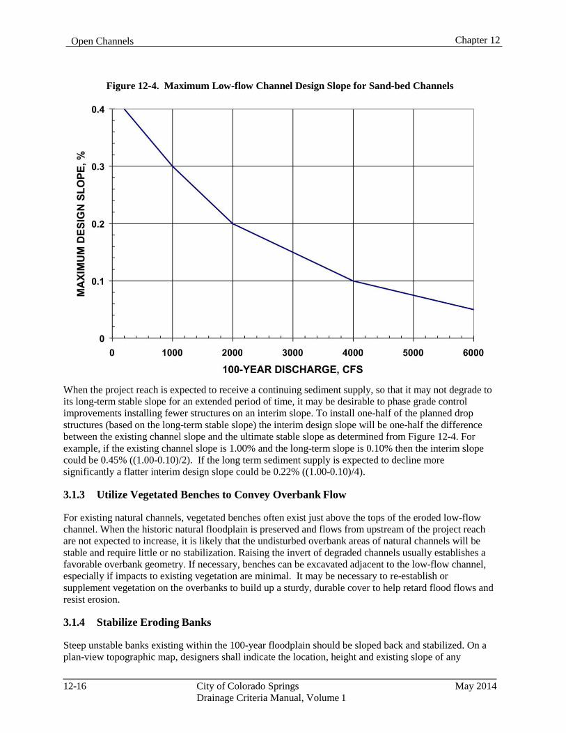
Chapter 12 Open Channels
Figure 12-4. Maximum Low-flow Channel Design Slope for Sand-bed Channels
When the project reach is expected to receive a continuing sediment supply, so that it may not degrade to its long-term stable slope for an extended period of time, it may be desirable to phase grade control improvements installing fewer structures on an interim slope. To install one-half of the planned drop structures (based on the long-term stable slope) the interim design slope will be one-half the difference between the existing channel slope and the ultimate stable slope as determined from Figure 12-4. For example, if the existing channel slope is 1.00% and the long-term slope is 0.10% then the interim slope could be 0.45% ((1.00-0.10)/2). If the long term sediment supply is expected to decline more significantly a flatter interim design slope could be 0.22% ((1.00-0.10)/4).
3.1.3 Utilize Vegetated Benches to Convey Overbank Flow
For existing natural channels, vegetated benches often exist just above the tops of the eroded low-flow channel. When the historic natural floodplain is preserved and flows from upstream of the project reach are not expected to increase, it is likely that the undisturbed overbank areas of natural channels will be stable and require little or no stabilization. Raising the invert of degraded channels usually establishes a favorable overbank geometry. If necessary, benches can be excavated adjacent to the low-flow channel, especially if impacts to existing vegetation are minimal. It may be necessary to re-establish or supplement vegetation on the overbanks to build up a sturdy, durable cover to help retard flood flows and resist erosion.
3.1.4 Stabilize Eroding Banks
Steep unstable banks existing within the 100-year floodplain should be sloped back and stabilized. On a plan-view topographic map, designers shall indicate the location, height and existing slope of any
12-16 City of Colorado Springs May 2014
Drainage Criteria Manual, Volume 1
Chapter 12 Open Channels
unvegetated, steep, or otherwise unstable banks within the 100-year floodplain, along with the proposed approach for stabilizing the banks. Steep unstable banks may occur where the low-flow channel meander impinges on the outer channel banks.
The designer shall consider the existing bank conditions and angle of attack, the estimated potential for future erosion, and the proximity of infrastructure that could be impacted by the bank erosion as a basis for determining the appropriate method for bank stabilization. Other channel characteristics such as channel geometry, longitudinal slope, existing vegetation, underlying soils, available right-of-way and expected flow conditions shall be considered and analyzed with respect to the various potential improvements.
Unstable banks shall be protected using one or more of the following measures.
1. Sloping Back Banks: Steep, unstable banks shall be cut back to a flatter slope and stabilized by
revegetation or other appropriate armoring. The maximum permissible slope shall generally be 4H:1V (horizontal:vertical). Reducing bank slopes to 6H:1V or flatter will assist in the establishment and viability of vegetation, the stability of channel banks and accessibility of the waterway for recreation. Designers are encouraged to utilize flatter slopes whenever possible. In some locations, right-of-way constraints may dictate steeper slopes. In such areas, slopes up to 3H:1V may be permitted with appropriate slope protection and approval.
2. Riprap Bank Protection: Riprap bank protection is widely used to stabilize channel banks along
the outside of existing channel bends and along steep banks that cannot be graded back sufficiently due to right-of-way constraints, where flow velocities are too high, or where overbank grades are too steep. Riprap bank protection shall be designed in accordance with the Riprap-lined Channel section of the Major Drainage Chapter in Volume 1 of the UDFCD Manual. All riprap bank protection shall consist of soil riprap that is buried with topsoil and revegetated.
The riprap need only extend up the slope to the elevation where tractive forces do not exceed the maximum allowable values for natural unlined channels as defined in Table 12-3. By applying those allowable shear stress limits to the equation for shear stress, the vertical distance from the 100-year water surface to the upper limit of the riprap layer can be calculated as follows:
If , then
For Erosive Soils, and if , then
Equation 12-3
For Erosion Resistant Soils, and if , then
Equation 12-4
Where:
d = vertical distance below 100-year water surface
S = channel overbank slope in ft/ft
3. Bioengineered Bank Protection: Experience with the application of bioengineering techniques to protect channel banks is growing along the Colorado Front Range. Bioengineering techniques are discussed in the Major Drainage Chapter of Volume 1 of the UDFCD Manual.
May 2014 City of Colorado Springs 12-17 Drainage Criteria Manual, Volume 1
Chapter 12 Open Channels
3.1.5 Analyze Floodplain Hydraulics
The floodplain associated with existing or stabilized natural channels shall be analyzed using HEC-RAS to delineate the 100-year floodplain and evaluate flow velocities to assess drainageway stability based on flow rates as described in Section 1.4, Design Flows. It is important to analyze floodplain hydraulics based on conditions that are likely to cause the greatest resistance to flow and the highest water surface elevations in the short term and over time. Some of these conditions may include the following:
Increased baseflows and runoff from development that promote increased growth of wetland and
riparian vegetation, making drainageways hydraulically rougher. Stream restoration work that raises the bed of incised channels to levels that existed prior to
degradation or flattens channel slopes. Upstream bank erosion or watershed erosion, flatter slopes, and increased channel vegetation that lead
to sediment deposition and channel aggradation, raising streambed and floodplain elevations.
Vegetation in channels is desirable to maintain their natural functions like wildlife habitat and open space. By evaluating channel capacities and floodplain limits using roughness factors representative of mature vegetative cover adequate flow depths and floodplain limits will be determined so these natural functions can be preserved.
An accurate delineation of the floodplain is also necessary for laying out development projects and setting lot and building elevations adjacent to the floodplain according to the freeboard requirements defined in Chapter 5, Floodplain Management. Assessments of freeboard at bends shall take into account super elevation calculated in accordance with Major Drainage Chapter of Volume 1 of the UDFCD Manual. The required freeboard should be contained within a floodplain tract and/or easement.
Incised or eroded channels shall not be analyzed based on their existing geometry, but on the geometry representative of a restored natural channel, as described in Section 2.0 and illustrated in Figure 12-1. Otherwise, the floodplain elevations may be inappropriately low, constraining future restoration efforts such as installing grade control structures that raise the channel bed back to earlier conditions.
3.1.5.1 Floodplain Encroachments
Floodplain encroachments that reduce natural channel storage or increase downstream flows or velocities are discouraged. However, when proposed encroachments are submitted for consideration, as described in Chapter 5, Floodplain Management, channel hydraulics must be fully analyzed and documented. To ensure that encroachments into natural floodplains are stable, the criteria in Table 12-3 shall be confirmed through a hydraulic analysis of the low-flow channel and the residual floodplain during flood flows.
3.1.6 Consider Aquatic Ecology
When streams or major drainageways, such as Fountain Creek and Monument Creek, have conditions that are favorable for supporting fish, additional consideration should be given to the baseflow and low-flow channel designs to provide conditions that are consistent with good aquatic ecological conditions, fish habitat and fish passage.
The Colorado Parks and Wildlife currently lists 14 species of fish as endangered or threatened at the state or federal level. An additional 9 species are listed as state species of concern (CDOW 2011). The majority of these species are small plains fish, whose natural habitat includes the plains and transition
12-18 City of Colorado Springs May 2014
Drainage Criteria Manual, Volume 1
Chapter 12 Open Channels
zone stream systems throughout the Front Range where urbanization impacts have been greatest. Several species of cutthroat trout are also included on the list, but trout are more prevalent in the foothills and higher elevations where colder water temperatures and coarser substrates are found.
Aquatic habitat is degraded in a variety of ways by watershed urbanization and stream modification. Potential impacts include water quality, water quantity, loss of bank vegetation, bank erosion and channel invert degradation. Implementation of the natural stream design principles presented in this Manual can significantly help preserve or improve aquatic habitat. Important aquatic habitat design considerations include:
1. Water Temperature: Water temperature is one of the most important factors in determining the
distribution of fish in freshwater streams (FISRWG 2001). Feeding and spawning activities are often keyed to water temperatures, and high water temperatures can be lethal to some species. Often in degrading stream systems, bank erosion results in a loss of perimeter vegetation and a widened channel bottom that produces shallow-flow depths. Limiting baseflow channel widths to increase typical flow depths and providing bank vegetation for shading can reduce solar heating of the water.
2. Cover and Refuge: Providing cover in the form of overhead vegetation, boulders, large woody
debris, pools and other irregular features provides fish with spawning areas, protection from predation, and habitat for species that are critical to the food chain. Channel design elements that can contribute to enhanced cover include pool and riffle sequences, a variety of vegetation types along the channel edge, variations in baseflow channel geometry, scour holes, groupings of boulders, and woody debris such as root wads and logs in various configurations. Several resources for the design of fish habitat enhancement structures are included in the references for this chapter.
3. Habitat Diversity: Diversity of habitat and hydraulic conditions allows for a greater diversity of
species and a richer ecosystem. Channel designs can incorporate riffles, pools, small drops, boulders, large woody material, changes in channel geometry and a variety of riparian plant types to create diversity.
4. Water Quality: High organic matter and chemical content is common in urban stream systems.
Channel designers typically have limited ability to change or rectify these conditions; however, identifying and understanding the characteristics of these sources should be incorporated into the project design. Sources typically include wastewater treatment plant discharges and urban runoff carrying various chemicals, fertilizers, yard cuttings and other organic matter. High organic content can lead to low dissolved oxygen levels and the death of aquatic organisms. Shading of channels with vegetation to reduce water temperatures and riffle and drop structures to induce aeration can help with this problem.
5. Substrate: Sand and silt substrates are generally the least favorable alluvial materials for
supporting aquatic organisms and support the fewest species and individuals (FISRWG 2001). Smooth bedrock surfaces devoid of alluvium, which exist in many degraded stream systems along the Front Range, are even less favorable. Raising degraded channel inverts with grade controls can naturally restore alluvial channel bottoms. Riffles and other rock structures can also add diversity to the substrate.
6. Hydrology: Both increases and decreases in natural channel flows can have adverse impacts on
aquatic habitat. Withdrawals of water for agricultural, industrial and municipal uses can reduce stream flows to essentially dry conditions at some times of the year. Increases in flows from lawn
May 2014 City of Colorado Springs 12-19
Drainage Criteria Manual, Volume 1
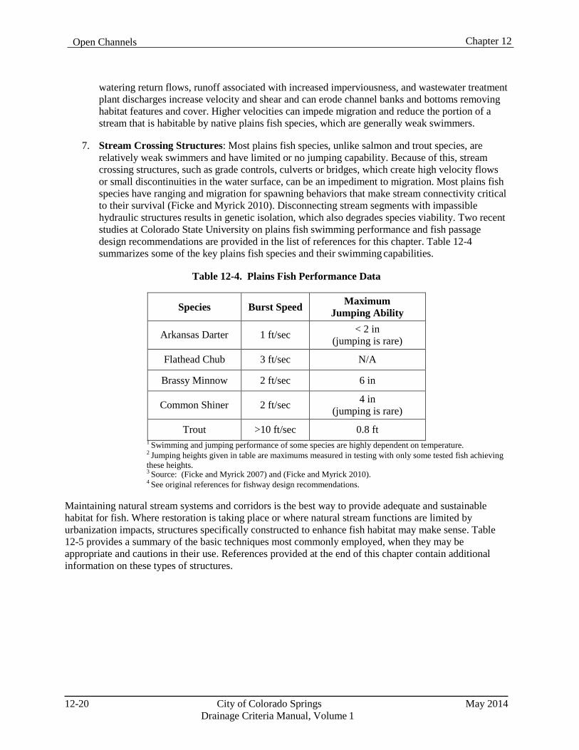
Chapter 12 Open Channels
watering return flows, runoff associated with increased imperviousness, and wastewater treatment plant discharges increase velocity and shear and can erode channel banks and bottoms removing habitat features and cover. Higher velocities can impede migration and reduce the portion of a stream that is habitable by native plains fish species, which are generally weak swimmers.
7. Stream Crossing Structures: Most plains fish species, unlike salmon and trout species, are
relatively weak swimmers and have limited or no jumping capability. Because of this, stream crossing structures, such as grade controls, culverts or bridges, which create high velocity flows or small discontinuities in the water surface, can be an impediment to migration. Most plains fish species have ranging and migration for spawning behaviors that make stream connectivity critical to their survival (Ficke and Myrick 2010). Disconnecting stream segments with impassible hydraulic structures results in genetic isolation, which also degrades species viability. Two recent studies at Colorado State University on plains fish swimming performance and fish passage design recommendations are provided in the list of references for this chapter. Table 12-4 summarizes some of the key plains fish species and their swimming capabilities.
Table 12-4. Plains Fish Performance Data
Species Burst Speed Maximum Jumping Ability
Arkansas Darter 1 ft/sec < 2 in (jumping is rare)
Flathead Chub 3 ft/sec N/A
Brassy Minnow 2 ft/sec 6 in
Common Shiner 2 ft/sec 4 in (jumping is rare)
Trout >10 ft/sec 0.8 ft 1 Swimming and jumping performance of some species are highly dependent on temperature. 2 Jumping heights given in table are maximums measured in testing with only some tested fish achieving these heights. 3 Source: (Ficke and Myrick 2007) and (Ficke and Myrick 2010). 4 See original references for fishway design recommendations.
Maintaining natural stream systems and corridors is the best way to provide adequate and sustainable habitat for fish. Where restoration is taking place or where natural stream functions are limited by urbanization impacts, structures specifically constructed to enhance fish habitat may make sense. Table 12-5 provides a summary of the basic techniques most commonly employed, when they may be appropriate and cautions in their use. References provided at the end of this chapter contain additional information on these types of structures.
12-20 City of Colorado Springs May 2014 Drainage Criteria Manual, Volume 1
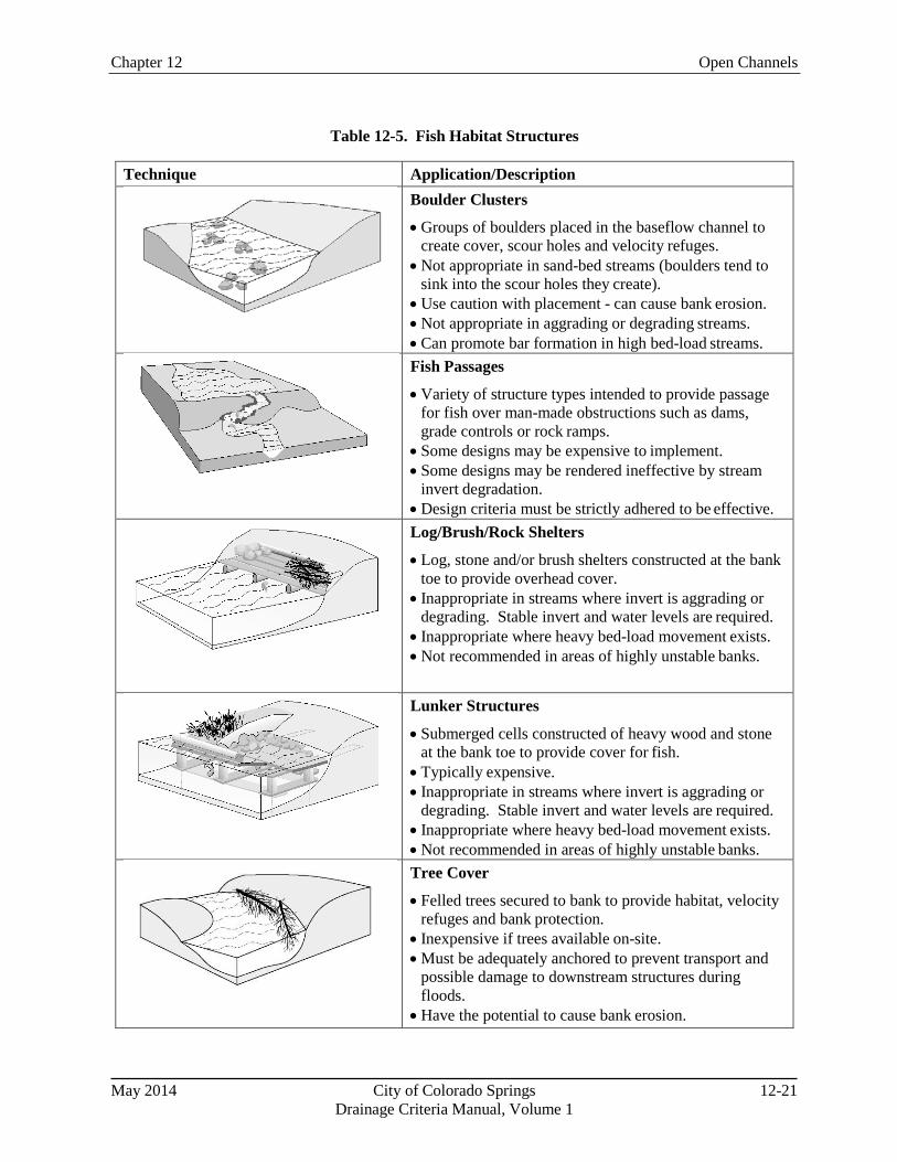
Chapter 12 Open Channels
Table 12-5. Fish Habitat Structures
Technique Application/Description
Boulder Clusters
• Groups of boulders placed in the baseflow channel to create cover, scour holes and velocity refuges.
• Not appropriate in sand-bed streams (boulders tend to sink into the scour holes they create).
• Use caution with placement - can cause bank erosion. • Not appropriate in aggrading or degrading streams. • Can promote bar formation in high bed-load streams.
Fish Passages
• Variety of structure types intended to provide passage for fish over man-made obstructions such as dams, grade controls or rock ramps.
• Some designs may be expensive to implement. • Some designs may be rendered ineffective by stream
invert degradation. • Design criteria must be strictly adhered to be effective.
Log/Brush/Rock Shelters
• Log, stone and/or brush shelters constructed at the bank toe to provide overhead cover.
• Inappropriate in streams where invert is aggrading or degrading. Stable invert and water levels are required.
• Inappropriate where heavy bed-load movement exists. • Not recommended in areas of highly unstable banks.
Lunker Structures
• Submerged cells constructed of heavy wood and stone at the bank toe to provide cover for fish.
• Typically expensive. • Inappropriate in streams where invert is aggrading or
degrading. Stable invert and water levels are required. • Inappropriate where heavy bed-load movement exists. • Not recommended in areas of highly unstable banks.
Tree Cover
• Felled trees secured to bank to provide habitat, velocity refuges and bank protection.
• Inexpensive if trees available on-site. • Must be adequately anchored to prevent transport and
possible damage to downstream structures during floods.
• Have the potential to cause bank erosion.
May 2014 City of Colorado Springs 12-21 Drainage Criteria Manual, Volume 1
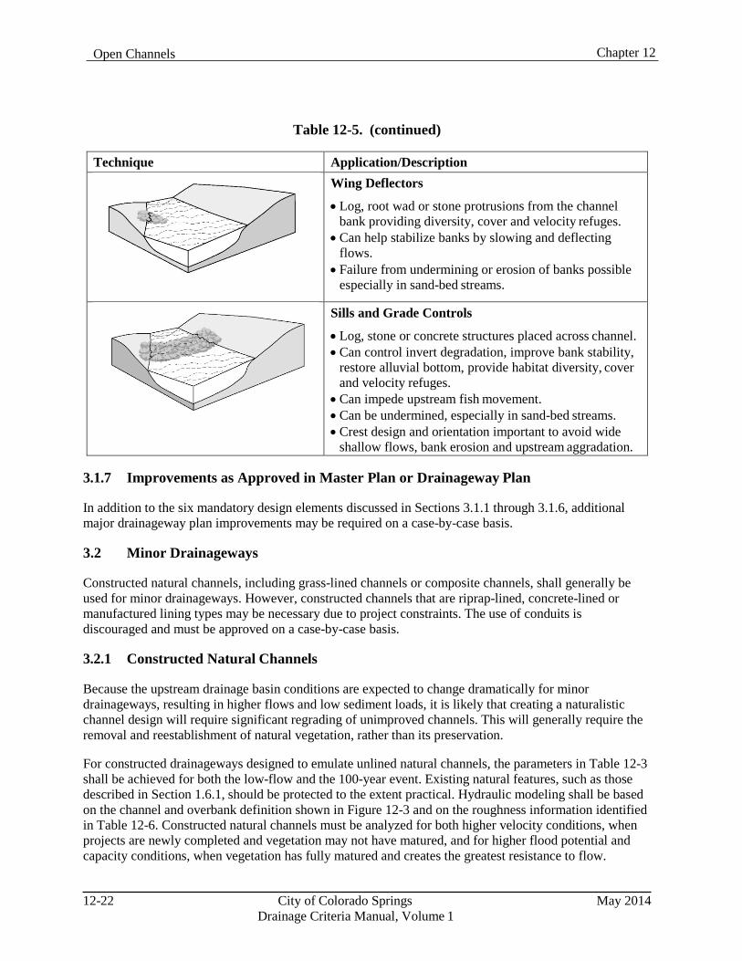
Chapter 12 Open Channels
Table 12-5. (continued)
Technique Application/Description
Wing Deflectors
• Log, root wad or stone protrusions from the channel bank providing diversity, cover and velocity refuges.
• Can help stabilize banks by slowing and deflecting flows.
• Failure from undermining or erosion of banks possible especially in sand-bed streams.
Sills and Grade Controls
• Log, stone or concrete structures placed across channel. • Can control invert degradation, improve bank stability,
restore alluvial bottom, provide habitat diversity, cover and velocity refuges.
• Can impede upstream fish movement. • Can be undermined, especially in sand-bed streams. • Crest design and orientation important to avoid wide
shallow flows, bank erosion and upstream aggradation.
3.1.7 Improvements as Approved in Master Plan or Drainageway Plan
In addition to the six mandatory design elements discussed in Sections 3.1.1 through 3.1.6, additional major drainageway plan improvements may be required on a case-by-case basis.
3.2 Minor Drainageways
Constructed natural channels, including grass-lined channels or composite channels, shall generally be used for minor drainageways. However, constructed channels that are riprap-lined, concrete-lined or manufactured lining types may be necessary due to project constraints. The use of conduits is discouraged and must be approved on a case-by-case basis.
3.2.1 Constructed Natural Channels
Because the upstream drainage basin conditions are expected to change dramatically for minor drainageways, resulting in higher flows and low sediment loads, it is likely that creating a naturalistic channel design will require significant regrading of unimproved channels. This will generally require the removal and reestablishment of natural vegetation, rather than its preservation.
For constructed drainageways designed to emulate unlined natural channels, the parameters in Table 12-3 shall be achieved for both the low-flow and the 100-year event. Existing natural features, such as those described in Section 1.6.1, should be protected to the extent practical. Hydraulic modeling shall be based on the channel and overbank definition shown in Figure 12-3 and on the roughness information identified in Table 12-6. Constructed natural channels must be analyzed for both higher velocity conditions, when projects are newly completed and vegetation may not have matured, and for higher flood potential and capacity conditions, when vegetation has fully matured and creates the greatest resistance to flow.
12-22 City of Colorado Springs May 2014 Drainage Criteria Manual, Volume 1
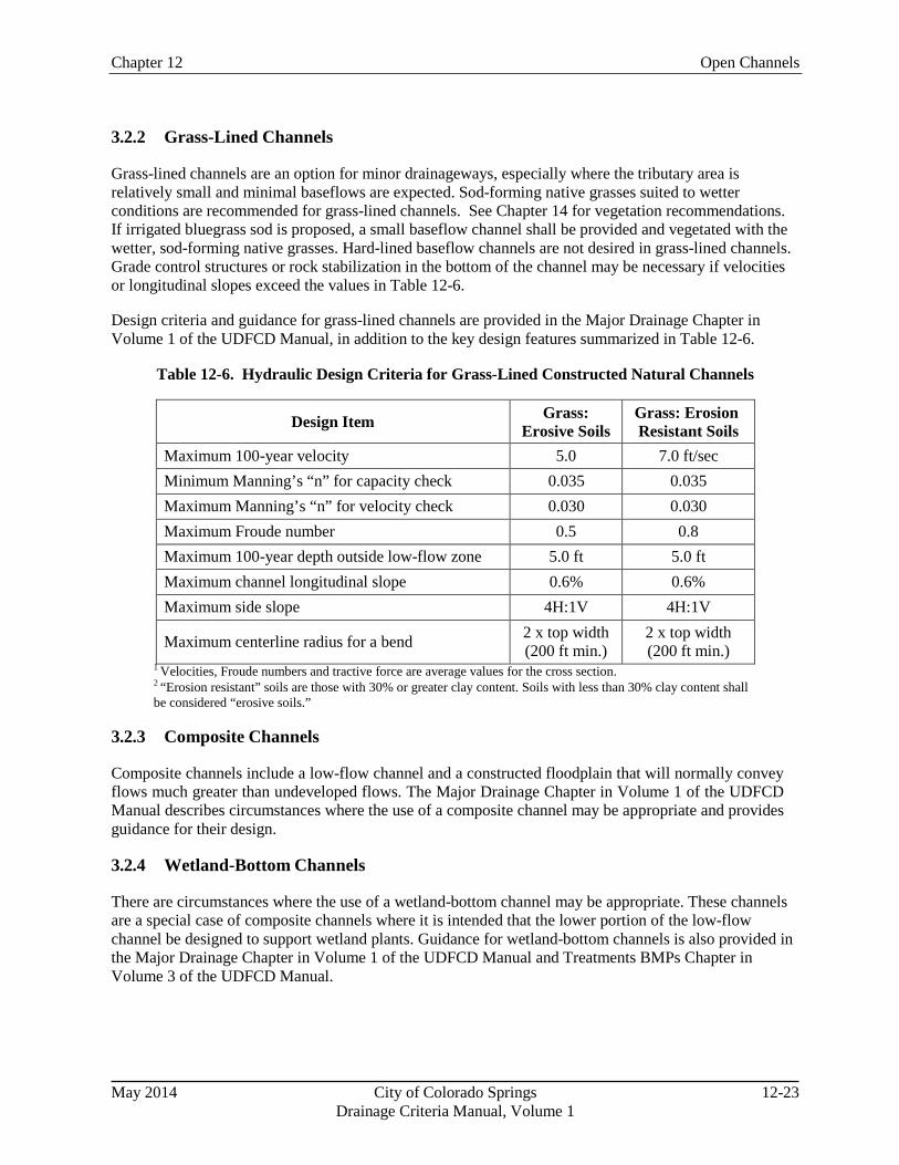
Chapter 12 Open Channels
3.2.2 Grass-Lined Channels
Grass-lined channels are an option for minor drainageways, especially where the tributary area is relatively small and minimal baseflows are expected. Sod-forming native grasses suited to wetter conditions are recommended for grass-lined channels. See Chapter 14 for vegetation recommendations. If irrigated bluegrass sod is proposed, a small baseflow channel shall be provided and vegetated with the wetter, sod-forming native grasses. Hard-lined baseflow channels are not desired in grass-lined channels. Grade control structures or rock stabilization in the bottom of the channel may be necessary if velocities or longitudinal slopes exceed the values in Table 12-6.
Design criteria and guidance for grass-lined channels are provided in the Major Drainage Chapter in Volume 1 of the UDFCD Manual, in addition to the key design features summarized in Table 12-6.
Table 12-6. Hydraulic Design Criteria for Grass-Lined Constructed Natural Channels
Design Item Grass: Erosive Soils
Grass: Erosion Resistant Soils
Maximum 100-year velocity 5.0 7.0 ft/sec Minimum Manning’s “n” for capacity check 0.035 0.035 Maximum Manning’s “n” for velocity check 0.030 0.030 Maximum Froude number 0.5 0.8 Maximum 100-year depth outside low-flow zone 5.0 ft 5.0 ft Maximum channel longitudinal slope 0.6% 0.6% Maximum side slope 4H:1V 4H:1V
Maximum centerline radius for a bend 2 x top width (200 ft min.)
2 x top width (200 ft min.)
1 Velocities, Froude numbers and tractive force are average values for the cross section. 2 “Erosion resistant” soils are those with 30% or greater clay content. Soils with less than 30% clay content shall be considered “erosive soils.”
3.2.3 Composite Channels
Composite channels include a low-flow channel and a constructed floodplain that will normally convey flows much greater than undeveloped flows. The Major Drainage Chapter in Volume 1 of the UDFCD Manual describes circumstances where the use of a composite channel may be appropriate and provides guidance for their design.
3.2.4 Wetland-Bottom Channels
There are circumstances where the use of a wetland-bottom channel may be appropriate. These channels are a special case of composite channels where it is intended that the lower portion of the low-flow channel be designed to support wetland plants. Guidance for wetland-bottom channels is also provided in the Major Drainage Chapter in Volume 1 of the UDFCD Manual and Treatments BMPs Chapter in Volume 3 of the UDFCD Manual.
May 2014 City of Colorado Springs 12-23 Drainage Criteria Manual, Volume 1
Chapter 12 Open Channels
3.2.5 Bioengineered Channels
When bioengineered channel treatments are included in composite channels, they shall be designed using the guidance provided in the Major Drainage Chapter in Volume 1 of the UDFCD Manual.
3.2.6 Constructed Channels
Constructed channels may be necessary when the upstream drainage basin is highly developed and design flows are significantly greater than undeveloped flows, when sediment loads are low, and where available right-of-way is restrictive. These channels do not provide much of the benefits of natural channels and primarily function as flood conveyance structures. Because these channels are generally steep and the flow is confined, design velocities tend to be higher, requiring a hardened channel lining to maintain stability. However, there are maximum velocity limitations on these channels; therefore, drop structures must be used to reduce design slope and lower velocities to acceptable limits. These structures will typically be designed for 100-year flows and will most often be lined with riprap, soil riprap, or concrete, but may also be lined with manufactured systems.
Because these types of channels eliminate any overbanks or floodplains, base-flow channels or low-flow channels do not normally provide a benefit. The use of base-flow or low-flow channels in these types of channels can help to pass sediment through the system and reduce maintenance requirements if sediment loads are present; however, in many cases, the available sediment load will be limited.
3.2.6.1 Riprap-Lined and Concrete-Lined Channels
The use of plain (not buried) riprap-lined or concrete-lined (formed-in-placed concrete) channels is generally discouraged, but they will be considered for minor drainageways on a case-by case basis. Design criteria for concrete-lined and riprap-lined channels are provided in the Major Drainage Chapter in Volume 1 of the UDFCD Manual.
3.3 Design Flow Freeboard
Design flow freeboard (freeboard) is the vertical distance from the design water surface elevation to the top of the design channel bank. Freeboard is provided to increase the channel design depth to allow for uncertainties that might cause the flow depth to be greater than the design flow depth. These uncertainties include, but may not be limited to; the roughness factors selected, the presence of turbulent flow or wave action, the presence of debris and the accuracy of the estimated design flow. The amount of freeboard depends on the flow regime, channel type and channel curvature. A minimum freeboard of 1.0 feet shall be provided for all channel types. Addition freeboard shall be determined as described in the Major Drainage Chapter in Volume 1 of the UDFCD Manual.
4.0 Grade Control (Drop) Structures Grade control structures, or drop structures, provide energy dissipation and are used to set a channel bottom elevation and stabilize the upstream channel reach. Table 12-7 provides allowable maximum drop heights for grade control structures in stabilized natural channels and constructed natural channels. The maximum height for drop structures in constructed channels shall be 6 feet.
12-24 City of Colorado Springs May 2014 Drainage Criteria Manual, Volume 1
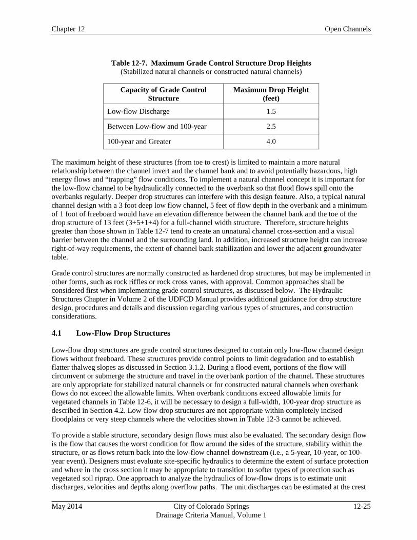
Chapter 12 Open Channels
Table 12-7. Maximum Grade Control Structure Drop Heights (Stabilized natural channels or constructed natural channels)
Capacity of Grade Control
Structure Maximum Drop Height
(feet)
Low-flow Discharge 1.5
Between Low-flow and 100-year 2.5
100-year and Greater 4.0
The maximum height of these structures (from toe to crest) is limited to maintain a more natural relationship between the channel invert and the channel bank and to avoid potentially hazardous, high energy flows and “trapping” flow conditions. To implement a natural channel concept it is important for the low-flow channel to be hydraulically connected to the overbank so that flood flows spill onto the overbanks regularly. Deeper drop structures can interfere with this design feature. Also, a typical natural channel design with a 3 foot deep low flow channel, 5 feet of flow depth in the overbank and a minimum of 1 foot of freeboard would have an elevation difference between the channel bank and the toe of the drop structure of 13 feet (3+5+1+4) for a full-channel width structure. Therefore, structure heights greater than those shown in Table 12-7 tend to create an unnatural channel cross-section and a visual barrier between the channel and the surrounding land. In addition, increased structure height can increase right-of-way requirements, the extent of channel bank stabilization and lower the adjacent groundwater table.
Grade control structures are normally constructed as hardened drop structures, but may be implemented in other forms, such as rock riffles or rock cross vanes, with approval. Common approaches shall be considered first when implementing grade control structures, as discussed below. The Hydraulic Structures Chapter in Volume 2 of the UDFCD Manual provides additional guidance for drop structure design, procedures and details and discussion regarding various types of structures, and construction considerations.
4.1 Low-Flow Drop Structures
Low-flow drop structures are grade control structures designed to contain only low-flow channel design flows without freeboard. These structures provide control points to limit degradation and to establish flatter thalweg slopes as discussed in Section 3.1.2. During a flood event, portions of the flow will circumvent or submerge the structure and travel in the overbank portion of the channel. These structures are only appropriate for stabilized natural channels or for constructed natural channels when overbank flows do not exceed the allowable limits. When overbank conditions exceed allowable limits for vegetated channels in Table 12-6, it will be necessary to design a full-width, 100-year drop structure as described in Section 4.2. Low-flow drop structures are not appropriate within completely incised floodplains or very steep channels where the velocities shown in Table 12-3 cannot be achieved.
To provide a stable structure, secondary design flows must also be evaluated. The secondary design flow is the flow that causes the worst condition for flow around the sides of the structure, stability within the structure, or as flows return back into the low-flow channel downstream (i.e., a 5-year, 10-year, or 100- year event). Designers must evaluate site-specific hydraulics to determine the extent of surface protection and where in the cross section it may be appropriate to transition to softer types of protection such as vegetated soil riprap. One approach to analyze the hydraulics of low-flow drops is to estimate unit discharges, velocities and depths along overflow paths. The unit discharges can be estimated at the crest
May 2014 City of Colorado Springs 12-25
Drainage Criteria Manual, Volume 1
Chapter 12 Open Channels
or critical section for the given total flow. Estimating the overflow path around the check can be difficult and requires judgment. The flow distribution option in HEC-RAS may be used to assist in evaluating hydraulic conditions in overbank areas so that the structure will remain with minimal or reasonable damage.
The minimum crest depth (from the invert of the crest to the top of the structure at the beginning of the overbank area) for low-flow drop structures is 1.5 feet. The maximum drop height of low-flow channel grade control structures shall be limited to 1.5 feet.
Seepage control is also an important consideration because piping and erosion under and around these structures can contribute to their failure. It is essential to provide a cutoff wall that extends laterally at least 5 to 10 feet into undisturbed bank and that has a depth appropriate to the profile dimension of the drop structure.
Check structures described in the UDFCD Manual are implemented within the UDFCD as temporary devices with the expectation that drop structures will replace the check structures as the channel degrades. This approach is not appropriate when long-term improvements must be completed with limited capital funds or for cost estimates for long-range basin plans. Rather than constructing temporary check structures, it is more appropriate to construct fewer permanent drop structures within a project reach with the goal of adding additional structures later. However, this approach is only appropriate if a funding source is available for completing the later improvements. In any case, channels must be designed for long-term conditions so that adequate funding can be identified for permanent channel improvements as needed.
4.2 Full-Channel-Width 100-Year Drop Structures
Full-channel-width drop structures are structures that are designed to convey the major flood flow within the structure and to provide a stepped invert profile so that upstream channel velocities (both in the low- flow channel and in the overbank area) do not exceed allowable limits. These structures are necessary in constructed natural channels and constructed channels when 100-year flood flow velocities exceed allowable limits. Each drop structure location is unique and designers should evaluate the required extent of hardened drop structure materials across the floodplain for each individual structure. The low-flow channel section must be incorporated into the drop structure’s crest and sill sections to provide a good transition into and out of the structure.
Grouted boulders may not need to extend to the limit of the 100-year floodplain, even where channels are incised to some degree and the floodplain has been encroached upon. Shear and velocity values typically decrease with increasing distance from the main channel; therefore, transitions to soil riprap and then to vegetation may be feasible. These floodplain hydraulic characteristics should be evaluated and hardened surfaces and soil riprap used only where necessary to minimize costs and enhance aesthetic and environmental qualities.
4.2.1 Constructed Natural Channel Drop Structures
When deep channel incision and/or development in the floodplain or increased flood flows have already occurred, or if right-of-way is limited, the potential for channel restoration may be limited. In such cases, drop and grade control structures may have to extend across the entire drainageway or a large portion of it to convey the major flood without causing significant damage.
In addition to these standard criteria, designers should consider the necessary extent of grouted rock or other hardened surface material. It may not be necessary for the hardened surface to extend across the
12-26 City of Colorado Springs May 2014
Drainage Criteria Manual, Volume 1
Chapter 12 Open Channels
entire 100-year waterway to provide 100-year protection. Instead it may be possible to transition to softer treatments such as vegetated soil riprap at the point in the floodplain where velocities and shear stresses are sufficiently reduced according to the criteria defined in Table 12-3.
4.2.2 Constructed Channel Drop Structures
Constructed channel drop structures are placed in channels that are fully hardened and under significant hydraulic stresses. These conditions normally require full-width, 100-year drop structures. The maximum height of constructed channel drop structures shall be 6 feet.
4.3 Drop Structure Types
The use of drop structure types and configurations that are functional, natural-looking, provide for fish passage, and blend-in with the drainageway and surrounding environment are encouraged. The most common type of drop structure in Colorado’s Front Range communities is the grouted sloping boulder drop structure. Grouted boulders can be used to develop more unique, natural looking configurations such as a horseshoe-arch shape or stepped configurations. Other drop types that have been used in the region include sheet pile drops, sculpted concrete drops, and soil cement drops. The sculpted concrete drops have become more popular for aesthetic reasons, particularly in upland prairie settings. The concrete is shaped, sculpted, and colored with earth tones to emulate natural rock outcroppings. Use of the following drop structure types is preferred:
Grouted sloping boulder
Grouted boulder in natural configurations
Sculpted concrete
Design guidance, detailed design criteria, and construction details have not been developed by the UDFCD for sculpted concrete drop structures. It is the responsibility of the design engineer to develop and provide detailed construction drawings, based on previous experience in the design of sculpted concrete drop structures or review of past designs that have been constructed in the Denver Metro area.
The use of soil cement and roller-compacted concrete drop structures may be allowed, but only on a case- by-case basis. Steady baseflows can quickly erode soil cement, especially when there is significant sediment being transported. Soil cement structures may be provided with a hardened low-flow channel to prevent erosion or should be reserved for ephemeral or intermittent channels. Specifications and construction quality control needed for soil cement and roller-compacted concrete are extensive and generally must be in accordance with standard specifications developed by organizations such as the Portland Cement Association.
Vertical drops greater than 2 feet in height are not permitted for safety reasons. In dry conditions, the vertical face presents a fall hazard. Under flowing conditions, reverse flows on the downstream face can form dangerous “keeper” hydraulic conditions. Vertical drops less than 2 feet in height may be permitted, but drop heights should consider fish passage if the stream supports a fishery. Additionally, they should be constructed of natural or natural appearing materials such as grouted boulders. The use of sheet pile or cast-in-place concrete walls for these structures is generally discouraged for aesthetic reasons.
Other methods of constructing low-flow drop structures, including rock riffles, ungrouted boulder drops and boulder cross vanes, may also be acceptable when floodplain and hydraulic conditions are appropriate for their use and when properly designed. These types of structures will generally not be appropriate in
May 2014 City of Colorado Springs 12-27
Drainage Criteria Manual, Volume 1
Chapter 12 Open Channels
situations where there has been significant encroachment into the floodplain, where an incised channel condition will exist, or where urbanization has significantly increased peak flood flows. Approval of the use of such structures will be on a case-by-case basis.
4.3.1 Fish Passage
Where fish passage is a concern at grade control structures, data presented in Table 12-4 can be used as a starting point for the design of structures or passages. Additional information can be found in the references provided at the end of this chapter. Ficke and Myrick (2007, 2010) provide fish performance information and passage design recommendations specifically for small plains fish species. The very limited amount of research currently available on the passage and swimming capabilities of small plains fish indicates that they are relatively weak swimmers and have very limited jumping capabilities. Designing to accommodate fish passage must first identify target species and then establish adequate flow depths, meet maximum allowable flow velocities and distances between refuges and meet maximum vertical drop heights (if any). A variety of configurations are possible, but given the very limited swimming and jumping capabilities of plains fish, use of separate fishways or ramps that allow steeper slopes across the main channel portion of a drop structure will often be the most economical approach. In addition to the swimming and jumping performance criteria previously mentioned, the design of separate fishways requires careful attention to flows and a crest design that ensures the entrance to the fishway has adequate depth and does not become obstructed by sediment or debris. Sufficient observation and supervision must be provided during construction of fish passages to ensure that they are constructed precisely according to design plans and satisfy design criteria. When possible, allowing grout to cure for 3 days prior to allowing contact with stream flows should reduce the risk of adverse impacts to water quality and aquatic life.
4.4 Drop Structure Placement
Drop-structure crest elevations establish the invert of the designed channel section and must be located so that the top of the structure is at the same elevation as the adjacent bank. In the case of low-flow drop structures, this is the top of the natural or designed low-flow bank elevation at the beginning of the floodplain and overbank area. In the case of full-width, 100-year drop structures, this is the top of the outer bank elevation.
The distance between drop structures varies with the difference between the bank slope and the design slope and the height of the upstream structure. The distance between drop structure crests is determined by dividing the height of the upstream structure by the difference between the top of bank slope and the invert design slope. By intersecting the design slope with the toe of the face of the upstream drop structure, the proper relationship between the drop structures will be maintained. Drop structures must extend down below the design slope to provide protection from local scour and long-term degradation that might extend below the estimated design slope.
Drop structures may also need to be placed where necessary to protect upstream infrastructure or to control water surface elevations to divert flood flows into detention facilities or diversion channels.
5.0 Revegetation Revegetation efforts and selection of appropriate vegetation are critical elements of all channel design projects. Chapter 14 of this Manual provides guidelines for revegetation efforts. These guidelines shall be followed for all major and minor drainageway design projects.
12-28 City of Colorado Springs May 2014 Drainage Criteria Manual, Volume 1
Chapter 12 Open Channels
6.0 Easements Minimum easement widths shall provide for conveyance of design flow rates, the required freeboard, and access for maintenance. Narrow existing channels and high flow velocities merit consideration of easements that may be wider than the existing floodplain limits or minimum values. A specific exception shall be any banks allowed to remain in place at a slope steeper than 4H:1V. Such banks shall have the easement line set back from the top of the bank to allow for some lateral movement or future grading improvements to the bank. The easement line shall be no closer than the intersection of a 4H:1V line extending from the toe of the slope to the proposed grade at the top of the bank, plus an additional width of 15 feet for an access bench if access is not feasible within the floodplain.
7.0 Design for Maintenance Continuous maintenance access, such as with a trail, shall be provided along the entire length of all major drainageways. Depending on the channel size, tributary area, expected maintenance activities, and the proximity of local streets and parking areas, a continuous stabilized trail may be required along minor drainageways. The stabilized maintenance trail shall have a stabilized surface at least 8 feet wide and a minimum clear width of 12 feet for a centerline radius greater than 80 feet and at least 14 feet for a centerline radius between 50 and 80 feet. At drop structures, the minimum clear area shall be 20 feet. The minimum centerline radius shall be 50 feet. The maximum longitudinal slope shall be 10 percent. The entity responsible for maintenance may require paving with asphalt or concrete, otherwise, as a minimum the access shall be surfaced with 6 inches of CDOT Class 2 road base. Under certain circumstances, adjacent local streets or parking lots may be acceptable in lieu of a trail for major drainages.
8.0 References Bell, M. C., 1991. Fisheries Handbook. U.S. Army Corps of Engineers.
Chow, V. T., 1959. Open Channel Hydraulics. McGraw-Hill Publishing Company.
Colorado Division of Wildlife (n.d.). “Species of Concern” website: http://wildlife.state.co.us/WildlifeSpecies/SpeciesOfConcern. Accessed November 2011.
Douglas County Colorado, 2008. Storm Drainage Design and Technical Criteria Manual. Amended
July 8, 2008.
Federal Interagency Stream Restoration Working Group, 2001. Stream Corridor Restoration, Principles, Processes and Practices. (Adopted as Part 653 of the National Engineering Handbook). Revised August.
Ficke, A.D. and C.A. Myrick, 2007. Fish Barriers and Small Plains Fishes: Fishway Design
Recommendations and the Impact of Existing Instream Structures, Final Project Report. Colorado State University. June.
Ficke, A.D. and C.A. Myrick, 2010. Swimming Performance of Two Fountain Creek Fishes:
Implications for Fishway Design at the Clear Spring Ranch Diversion. Colorado State University. January.
Fischenich, J.C. and J.V. Morrow, 2000. Stream Habitat Enhancement with Large Woody Debris, ERDC
TN-EMRRP-SR-13. U.S. Army Corps of Engineers, Ecosystem Management and Restoration
May 2014 City of Colorado Springs 12-29 Drainage Criteria Manual, Volume 1
Chapter 12 Open Channels
Research Program. May.
Harrelson, C., Rawlins, C., and J. Potyondy , 1994. Stream Channel Reference Sites: An Illustrated Guide to Field Technique, United States Department of Agriculture, Forest Service, Rocky Mountain Research Station, General Technical Report RM-245. April.
Julien, P. Y. 2002. River Mechanics. Cambridge University Press.
Natural Resources Conservation Service, 2007. National Engineering Handbook, Part 654, Stream
Restoration Design. August.
Saldi-Caromile, K., Bates, K., Skidmore, P., Barenti, J., and D. Pineo. 2004. Stream Habitat Restoration Guidelines: Final Draft. Co-published by the Washington Departments of Fish and Wildlife and Ecology and the U.S. Fish and Wildlife Service. Olympia, Washington.
Seehorn, M.E., 1992. Stream Habitat Improvement Handbook. Technical Publication R8-TP 16. U.S.
Department of Agriculture, Forest Service Southern Region, Ecosystem Management and Restoration Research Program.
Toy, T., Foster, J., and R. George. 1998. Guidelines for the use of the Revised Universal Soil Loss
Equation (RUSLE) Version 1.06 on Mined Lands, Construction Sites and Reclaimed Lands. Office of Surface Mining. August.
Urban Drainage and Flood Control District, 2008. Drainage Criteria Manual, Volume 1. Revised April.
U.S. Department of Agriculture, 1978. Predicting Rainfall Erosion Losses, Agricultural Handbook No.
537.
Copeland, R.R., Biedenharn, D.S., and J.C. Fischenich, 2000. Channel Forming Discharge, ERDC/CHL CHETN-VIII-5, U.S. Army Corps of Engineers. December. http://chl.erdc.usace.army.mil/library/publications/chetn/pdf/chetn-viii-5.pdf
Washington Department of Fish and Wildlife, 2003. Design of Roadway Culverts for Fish Passage.
12-30 City of Colorado Springs May 2014 Drainage Criteria Manual, Volume 1
May 2014 City of Colorado Springs Drainage Criteria Manual, Volume 1
13-i
Chapter 13 Storage
Contents 1.0 Introduction ...................................................................................................................................... 1
1.1 Stormwater Quality and Volume Reduction Considerations ..................................................................... 1 1.2 Stormwater Volume Considerations ......................................................................................................... 1 1.3 Downstream Improvements ...................................................................................................................... 1
2.0 Detention Requirements .................................................................................................................. 2
3.0 Types of Detention ............................................................................................................................ 2 3.1 Scale of Implementation ............................................................................................................................ 2
3.1.1 Regional Detention ........................................................................................................................... 2 3.1.2 Sub-regional Detention ..................................................................................................................... 4 3.1.3 On-site Detention .............................................................................................................................. 4 3.1.4 Detention Not Associated with Development .................................................................................. 5
3.2 Outlet Configurations ................................................................................................................................ 5 3.2.1 Full Spectrum Detention ................................................................................................................... 5 3.2.2 Multi-level Detention ....................................................................................................................... 6
3.3 Retention Ponds ........................................................................................................................................ 6
4.0 Sizing Methodology .......................................................................................................................... 6 4.1 Storage Elements ....................................................................................................................................... 7
4.1.1 Flood Control Volume ...................................................................................................................... 8 4.1.2 EURV ............................................................................................................................................... 8 4.1.3 Initial Surcharge Volume .................................................................................................................. 9 4.1.4 Design Worksheets ........................................................................................................................... 9
4.2 Allowable Release Rates ........................................................................................................................... 9 4.2.1 Flood Storage Release Rates ............................................................................................................ 9 4.2.2 EURV Release Rate ........................................................................................................................ 10
5.0 Design Guidelines ........................................................................................................................... 11 5.1 Location and Configuration .................................................................................................................... 11
5.1.1 Location .......................................................................................................................................... 11 5.1.2 Detention in Series .......................................................................................................................... 11 5.1.3 Interconnected Detention ................................................................................................................ 11
5.2 On-site Detention and Off-site Flows ..................................................................................................... 12 5.3 Discharge Location (Outlets) .................................................................................................................. 12 5.4 Excavated or Embankment Slopes .......................................................................................................... 12 5.5 Freeboard ................................................................................................................................................ 13 5.6 Low-flow Channels ................................................................................................................................. 13 5.7 Bottom Slope ........................................................................................................................................... 13 5.8 Wetland Vegetation (Constructed Wetland Pond) .................................................................................. 13 5.9 Inlet Structures ........................................................................................................................................ 14 5.10 Outlet Structures ...................................................................................................................................... 14 5.11 Trash Racks ............................................................................................................................................. 15 5.12 Emergency Spillway and Embankment Protection ................................................................................. 15 5.13 Retaining Walls ....................................................................................................................................... 16 5.14 Landscaping ............................................................................................................................................ 17
May 2014 City of Colorado Springs Drainage Criteria Manual, Volume 1
13-ii
5.15 Signage .....................................................................................................................................................18 5.16 Maintenance Access .................................................................................................................................18 5.17 Construction Phasing ...............................................................................................................................19
6.0 Parking Lot Detention .................................................................................................................... 20 6.1 Access Requirements ...............................................................................................................................20 6.2 Maintenance Requirements ......................................................................................................................20 6.3 Depth Limitation ......................................................................................................................................20 6.4 Emergency Spillway ................................................................................................................................20 6.5 Outlet Configuration ................................................................................................................................20 6.6 Flood Hazard Warning .............................................................................................................................20
7.0 Retention Ponds .............................................................................................................................. 21 7.1 Approval ..................................................................................................................................................21 7.2 Minimum Sizing Requirements ...............................................................................................................21
8.0 References ........................................................................................................................................ 21 Tables Table 13-1. Detention Sizing Methods ......................................................................................................... 7 Table 13-2. Allowable Unit Release Rates (cfs/ac) .................................................................................... 10
Figures Figure 13-1. Regional Detention Concept .................................................................................................. 22 Figure 13-2. Sub-regional Detention Concept............................................................................................ 23 Figure 13-3. On-site Detention Concept .................................................................................................... 24 Figure 13-4a. Excess Urban Runoff Volume (EURV) per Runoff Return Period [Type C/D Soils] ......... 25 Figure 13-4b. Excess Urban Runoff Volume (EURV) per Impervious Acre [Type C/D Soils] ................ 25 Figure 13-5. Options for Detention. WQCV and EURV Configurations ................................................. 26 Figure 13-6. Typical Low-flow Channel Details ....................................................................................... 27 Figure 13-7. Concept for Extended Detention Basin With a Concrete Low-flow Channel ....................... 28 Figure 13-8. Concept for Extended Detention Basin with a Benched Low-flow Channel ........................ 29 Figure 13-9. Concept for Integral Forebay at Pipe Outfall ......................................................................... 30 Figure 13-10. Concept for Outlet Structure with Parallel Wingwalls and Flush Bar Grating ................... 31 Figure 13-11. Concept for Outlet Structure with Flared Wingwalls and Handrail .................................... 32 Figure 13-12a. Emergency Spillway Profile at Roadway .......................................................................... 33 Figure 13-12b. Emergency Spillway Profile at Embankment .................................................................... 33 Figure 13-12c. Emergency Spillway Protection ......................................................................................... 34 Figure 13-12d. Riprap Types for Emergency Spillway Protection ............................................................ 34 Figure 13-13. 100-Year Required Retention Volume ................................................................................ 35
Storage Chapter 13
13-1 City of Colorado Springs Drainage Criteria Manual, Volume 1
May 2014
1.0 Introduction Detention storage facilities are primarily used to manage stormwater quantity by attenuating developed condition peak flows to approximate pre-development condition peak flows. Detention storage is necessary for new development, redevelopment and development expansion to mitigate the effects of increased runoff associated with development. These effects may include increased flooding potential, channel degradation and sedimentation, loss of natural habitat and water quality degradation. The flow control function of detention storage facilities is, therefore, critical for the implementation of key stormwater management goals, such as floodplain preservation and preserving and enhancing natural channel features. The guidance in this chapter should be supplemented with additional background, design parameters and sizing methods provided in the Storage Chapter of Volume 2 of the UDFCD Manual.
In addition, detention facilities can require significant land area and be prominent features in land development plans. Therefore, detention storage planning and design should incorporate features that serve multiple purposes and that are integrated functionally and aesthetically into the land plan. Detention facilities must also be safe and maintainable. When properly designed and maintained, detention facilities can be viewed as community assets rather than liabilities. The requirements in this chapter apply to all storage-based facilities, including facilities that provide water quality treatment only.
1.1 Stormwater Quality and Volume Reduction Considerations
Detention facilities can also be designed to enhance stormwater quality by providing extended detention to promote sedimentation and/or infiltration and biological uptake for small, frequently occurring events. This chapter provides guidance for the analysis and design of storage facilities that are implemented independently or in combination with stormwater quality facilities. Water quality treatment may also be provided through volume reduction techniques that have the potential to also affect detention storage facility sizing. Early in the planning process, opportunities to provide volume reduction, stormwater quality management and flood control should be evaluated so that a comprehensive and coordinated approach can be developed. Extended detention and other water quality best management practices and volume reduction practices are discussed in Volume 2 of this Manual.
1.2 Stormwater Volume Considerations
In addition to the increase in peak flow rates, stormwater runoff volume can increase significantly with urbanization. The increase in runoff volume, especially for more frequent storm events, has the potential to disturb the downstream receiving stream’s equilibrium and cause channel instability. Therefore, detention basin designs that help to mitigate the effects of increased runoff volumes are preferred. This chapter provides guidance on “full-spectrum detention” designs that help to mitigate the effects of increased flow volumes (See Section 3.2.1).
1.3 Downstream Improvements
Even with comprehensive management of stormwater runoff, the effects of urbanization, including excess irrigation, increased snow melt runoff, reduced sediment loads, and increases in stormwater runoff volumes are very difficult to fully mitigate. Therefore, some downstream channel instability can be anticipated due to development. This requires attention to channel improvements and right-of-way that may need to extend downstream beyond the detention facility outlet. It is normally less costly to implement stabilization measures for future anticipated flows in channels that are not yet experiencing
Chapter 13 Storage
May 2014 City of Colorado Springs Drainage Criteria Manual, Volume 1
13-2
instability rather than to stabilize already severely degraded channels.
2.0 Detention Requirements Detention storage facilities are critical elements in the management of stormwater and shall be required for new development, redevelopment, expansion or improvement projects as described in Chapter 3, Drainage Policies. Detention requirements are often identified in an approved DBPS or MDDP. The designer shall identify the applicable documents and implement facilities consistent with the approved plans. When an approved plan is not available it may be necessary to complete a basin plan.
3.0 Types of Detention Detention storage facility designs can generally be characterized based on scale of implementation and outlet configuration, as discussed below.
3.1 Scale of Implementation
Typical development-related detention facilities can be classified as “regional”, “sub-regional” or “on- site”. Regional detention facilities typically serve a broad purpose within a basin and manage flows from multiple development projects. Sub-regional ponds typically serve multiple parcels within a single development project. Regional and sub-regional detention facilities normally require a commitment for maintenance by a public entity or a legally-binding maintenance agreement. On-site facilities typically only serve a single parcel, have only localized benefits and are maintained by the property owner or private entity.
A new development must implement regional or sub-regional detention at a subdivision or project scale instead of providing on-site detention basins at the time each lot is developed. For large subdivisions, regional or sub-regional detention should be implemented by the first sub-divider rather than passing on the responsibility for detention to owners of individual filings. The coordination of development phasing with the construction of detention facilities should be addressed within the basin plans.
Each of these types may include water quality features or be used in conjunction with separate water quality features or volume reduction techniques in the basin. When a water quality capture volume is included within a detention facility, its effect on the required flood control storage varies with the type of facility. Additional information is provided below for regional, sub-regional and onsite facilities.
3.1.1 Regional Detention
Regional detention typically refers to facilities that are included in a basin plan and that serve multiple development projects or multiple phases of a development project. A primary function of regional detention facilities is to mitigate the effects of developed runoff so that downstream natural channel features and floodplains can be preserved. The location of these facilities can also differentiate “minor” drainageways from “major” drainageways. Under natural conditions, significant drainageways tend to develop when the contributing area is between 100 to 160 acres. Therefore, regional detention facilities will typically be located with a contributing area of about 130 acres. Regional facilities are best located where the upstream basin is expected to be quickly and fully developed so that sediment loads are on the decline, reducing maintenance requirements. Limiting the area contributing to regional ponds can allow downstream impacts to be mitigated as phases of development are completed. Strategically placing these ponds can also reduce the size of downstream crossing structures.
Their function within the system can be relied upon to reduce flood flows for the purposes of avoiding flood damages and delineating downstream floodplains. The overall land requirements for regional ponds
Storage Chapter 13
13-3 City of Colorado Springs Drainage Criteria Manual, Volume 1
May 2014
are less when compared to multiple sub-regional and on-site facilities that would be required to provide similar flow reduction benefits. These facilities also provide greater opportunities for riparian habitat and multi-use objectives such as parks and open space and trail connections.
A regional detention facility should not serve a contributing area larger than 640 acres (one square mile). The assumptions used to size the facilities, including uniform rainfall and undeveloped allowable release rates become less reliable with larger basins. Larger basins are also less likely to fully develop quickly and will increase long term sediment loads and maintenance requirements. It is also likely that channels collecting larger areas will have natural features that should be preserved and regulatory floodplain mapping is often initiated when the contributing area is about one square mile. Therefore, revisions to regulatory floodplain maps should be reduced if detention facilities are located with contributing basins less than 640 acres. Additionally, analyses of overall basin costs have shown that reducing flood flows throughout a watershed with more detention facilities reduces the cost of channel improvements significantly compared to the cost of the additional detention facilities. Limiting the contributing area to facilities also reduces the likelihood of the structure being regulated by the State Engineer’s Office as a jurisdictional dam. Figure 13-1 provides a generalized illustration of the regional detention concept.
Regional detention facilities should be constructed according to an approved basin plan. When not included in a previously approved basin plan, a basin plan should be completed or the approved plan should be amended. Regional detention facilities may be constructed by a public entity such as a municipality or special district or by land developers.
To be recognized in a basin plan and to be used for flood mitigation in drainageways, regional detention must:
1. Be designed to accommodate the fully developed condition flows from the upstream watershed.
2. Be owned and maintained by a public entity, with ownership and maintenance responsibilities
clearly defined to ensure the proper function of the facility in perpetuity.
3. Be within drainage easements or tracts, including access from a public street.
4. Have an approved Operations and Maintenance Manual.
5. Not be a jurisdictional dam, according to the State Engineer’s Office (SEO) definition, or be permitted and designed according to the SEO’s requirements.
6. Be permitted under applicable environmental permits and clearances.
In addition, construction of regional detention should be coordinated with development in the upstream watershed. If the regional pond has not been constructed, temporary on-site detention (and water quality treatment) may be required for individual development projects until regional detention is completed. The requirement for constructing regional detention or for temporary on-site detention will depend on the specific conditions of the proposed development.
The drainageways upstream of regional detention shall be designed to convey fully-developed flows to the regional pond and stabilized in accordance with the criteria described in Chapter 12, Open Channel Design of this Manual. If any portions of the drainageways upstream of the facility are determined to be jurisdictional with respect to 404 permitting, the development sites upstream of the jurisdictional drainageway shall implement design concepts to minimize water quality impacts to the drainageway.
Whenever possible, roadway embankments shall be used to create the required storage volume to avoid
Chapter 13 Storage
May 2014 City of Colorado Springs Drainage Criteria Manual, Volume 1
13-4
the construction of separate pond embankments. Roadways under the jurisdiction of other agencies, such as CDOT, may be prohibited from being used as pond embankments or require special consideration and permission.
3.1.2 Sub-regional Detention
Sub-regional detention refers to facilities located upstream of a minor or major drainageway (generally having a drainage area between 20 and 130 acres) and serving more than one parcel. Like regional detention, sub-regional detention may be constructed by a public entity such as a municipality or special district to serve several landowners in the upstream watershed or by a single landowner. It may be possible for a single landowner to construct sub-regional detention if the upper part of the watershed is owned by others and if the necessary conditions are achieved. Unlike regional detention, sub-regional detention may not always be recognized in the determination of flood flows for downstream major drainageways. Sub-regional detention should only be included in a basin plan or amended plan to provide regional benefits by reducing the cost of downstream facilities or by providing flood mitigation benefits to offsite properties. Figure 13-2 illustrates a typical sub-regional detention concept. The conditions listed previously for regional detention shall be adhered to for sub-regional facilities.
3.1.3 On-site Detention
On-site detention refers to facilities serving one parcel, generally commercial or industrial sites draining areas between 1 and 20 acres. On-site detention is only allowed on infill parcels where a basin plan does not identify off-site detention facilities that serve the property and where regional or sub-regional facilities are not able to be implemented. A primary function of on-site detention facilities is to reduce developed condition flows so that undersized downstream capacities are not exceeded. On-site detention may also provide an opportunity to provide water quality treatment features which may be required as described in Chapter 4, Volume 2 of this Manual. Figure 13-3 illustrates a typical on-site detention concept.
Because on-site detention is normally privately owned and maintained, and small relative to overall basin size, they will not be recognized in the determination of flows for drainageways designs or floodplain mapping.
General guidelines for on-site detention include:
Integrating Detention and Site Landscaping Requirements: Locating detention basins in areas
reserved to meet site landscaping requirements is generally encouraged. Incorporating detention into landscaped areas generally creates facilities that are easier to inspect, are relatively easy to maintain, and can enhance the overall aesthetics of a site. Further discussion regarding design features and landscaping improvements is provided in Section 5.3 of this chapter.
Parking Lot Detention: Parking lot detention may be acceptable on commercial and industrial sites
and can offset some of the storage volume that needs to be provided on landscaped areas. Parking lot detention will be allowed on a case-by-case basis. Design guidance for parking lot detention is provided in Section 6.0 of this chapter.
Underground Detention: Underground detention is prohibited, except as may be allowed through
the variance process provided in this Manual. Rooftop Detention: Rooftop detention is prohibited, except as may be allowed through the variance
process provided in this Manual.
13-5 City of Colorado Springs Drainage Criteria Manual, Volume 1
May 2014
Storage Chapter 13
3.1.4 Detention Not Associated with Development
As part of a broader watershed-wide planning effort, it may be beneficial to construct detention facilities that have a strategic flood control function within the watershed and that may serve existing or new development projects. These facilities may be planned and designed using project-specific criteria that may or may not be the same as described in this Manual. For example, very large flood control facilities (i.e., reservoirs) may not include water quality outlet designs or may be designed for different design events. Such facilities are typically constructed by a governmental agency or regional organization and are not normally the responsibility of developers.
3.2 Outlet Configurations
Detention storage facilities can also be classified by how the outlet structure is configured. Outlet structures that are designed to attenuate specific storm event peak flows, but do not address the full range of stormwater inflows are considered “multi-level” or “multi-stage” outlets. Outlet structures that are designed to better attenuate the full range of storm events are considered “full-spectrum” outlets. These outlets release an outflow hydrograph that more closely represents the undeveloped condition hydrograph. They also provide some mitigation of increased runoff volumes by releasing them over an extended period of time.
3.2.1 Full Spectrum Detention
Full Spectrum Detention (FSD) is a design concept introduced by UDFCD (Urbonas and Wulliman 2005) that provides better control of the full range of runoff rates that pass through detention facilities than the conventional multi-stage concept. This concept also provides some mitigation of increased runoff volumes by releasing a portion of the increased runoff volume at a low rate over an extended period of time (up to 72 hours). This concept can be applied for any size drainage basin up to 640 acres and can be integrated into on-site, sub-regional or regional detention designs.
By providing an Excess Urban Runoff Volume (EURV) in the lower portion of the facility storage volume with an outlet control device similar to a Water Quality Capture Volume (WQCV), frequent and infrequent inflows are released at rates approximating undeveloped conditions. The EURV is based on the incremental difference between the developed and undeveloped runoff volume for the range of storms that produce runoff from impervious land surfaces. It was determined that the incremental increase in runoff volume from basins was relatively constant per acre of additional impervious area. The runoff relationships used to develop the EURV approach are illustrated in Figures 13-4a and 13-4b. Figure 13-4b shows that the increased volume of runoff per acre of impervious area remains relatively constant over a range of storm events.
Designing a detention basin to capture the EURV and release it slowly (at a rate similar to WQCV release rates) means that the frequent storms, smaller than approximately the 2-year event, will be reduced to very low flows near or below the sediment carrying threshold value for downstream drainageways. Additionally, by incorporating an outlet structure that limits 100-year runoff to the allowable release rate or to the undeveloped condition rate, the discharge hydrograph for storms between the 2-year and 100- year storm event will approximate the hydrograph for undeveloped conditions. This reduces the likelihood that runoff hydrographs from multiple detention facilities will combine to increase downstream discharges above undeveloped conditions and helps to more effectively mitigate the effects of urbanization.
Chapter 13 Storage
May 2014 City of Colorado Springs Drainage Criteria Manual, Volume 1
13-6
3.2.2 Multi-level Detention
Multi-level detention outlet configurations do not employ an EURV and are designed for two or three specific release rates. They may be used for on-site facilities to reduce peak flows, but are not recommended for regional or sub-regional facilities. If a multi-level outlet configuration is used for an on-site pond, at a minimum, it must control runoff for the minor (5-year) and major (100-year) storm events.
3.3 Retention Ponds
Retention ponds are designed and operated like detention ponds, but include a permanent pool of water below the outlet invert elevation. The WQCV and/or EURV for these ponds are provided above the permanent pool. These ponds can provide improved water quality and aesthetic value, but there must be a legal right sufficient to store water perpetually, including an accounting of losses through evaporation and infiltration. These ponds also must be designed with attention to special maintenance and hazard considerations.
4.0 Sizing Methodology The detention facility sizing methodology varies depending on the contributing area, type of facility, and its intended function in the drainage system. To determine the appropriate methodology, the following questions should be answered:
1. What is the size of the drainage basin area contributing to the facility?
2. Will the facility be regional, sub-regional or on-site?
3. Will the facility include a WQCV?
4. Will the facility have a full-spectrum or multi-level outlet configuration?
Considering these factors, the pond characteristics including location, volume, allowable release rates, multi-use opportunities, and other design features can be determined. Determining final detention characteristics typically requires an iterative process to achieve the design goals with the minimum storage requirements. The Storage Chapter in Volume 2 of the UDFCD Manual describes a design procedure that can be applied for various types of detention storage facilities.
The UDFCD Manual provides approximate, simplified methods (empirical equations) that are adequate for smaller basins. More complex methods are available for larger, regional facilities. Use of the more complex methods may reduce the calculated required volume of the facility. The UDFCD UD-Detention workbook includes design aides for determining detention characteristics.
Table 13-1 summarizes the types of detention facilities and acceptable methods for determining their size and allowable release rates.
13-7 City of Colorado Springs Drainage Criteria Manual, Volume 1
May 2014
Storage Chapter 13
Table 13-1. Detention Sizing Methods
Type Drainage Area Volume Allowable Release Rate
Regional 130 to 640 acres
Hydrograph routing required for total volume; empirical equations allowed for EURV (EURV includes WQCV).
Calculated undeveloped basin runoff rates.
Sub- regional
Less than 130 acres
Hydrograph routing or empirical equations for total volume, empirical equations for EURV (EURV includes WQCV)
Calculated undeveloped basin runoff rates.
On-site Less than 20 acres
Empirical equations or hydrograph routing. Add 50% of WQCV for multi-level facilities. Do not add WQCV for FSD facilities.
Unit release rates or calculated undeveloped basin runoff.
4.1 Storage Elements
The required total detention storage volume is based on the type and function of the facilities and may include a combination of these storage elements:
Flood Control Volume: This storage element is normally the largest portion of the total storage and
may be subdivided into separate portions for design purposes depending on the type of storage facility. In FSDs, the flood storage is equal to the entire volume and is inclusive of the EURV and the WQCV. In multi-level facilities, a separate design volume for the minor storm release rate is needed and 50 percent of the WQCV should be added to it to determine the flood control storage volume.
Excess Urban Runoff Volume (EURV): This storage element is only implemented in an FSD
facility. The required volume is based on equations developed by UDFCD, as included in this chapter. This volume is about twice as large as the WQCV for Type C or D soils, or slightly larger than the total 2-year runoff volume. It is not necessary to increase the total storage volume by the EURV. The EURV is incorporated into the flood control storage volume.
Water Quality Capture Volume (WQCV): This storage element and methods for determining its
size are described in Chapter 3 of Volume 2 of this Manual. The WQCV is intended to capture most runoff events and reduce their pollutant load prior to discharging into drainageways. The size of this storage element depends primarily on the amount of tributary impervious area and can be reduced by implementing development practices that reduce the effective imperviousness. The WQCV may increase the overall storage required at a particular facility depending on the type of facility, as shown in Table 13-1. It is not necessary to increase the total storage volume by the WQCV for an FSD because the WQCV is already incorporated into the EURV.
Initial Surcharge Volume: This storage element is calculated as a small percentage of the WQCV
and is included within the WQCV. This small volume is provided within or adjacent to the outlet structure and above the micropool to allow nuisance flows to collect so that the low-flow channel is free to drain and the pond bottom does not become saturated and difficult to maintain.
A single facility may include a combination of these storage elements or the storage elements may be segregated into separate facilities, as shown in Figure 13-5. Segregating the storage elements may be
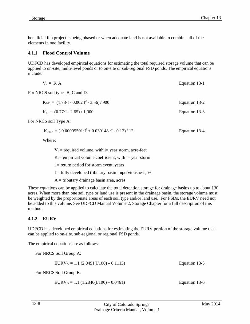
Chapter 13 Storage
May 2014 City of Colorado Springs Drainage Criteria Manual, Volume 1
13-8
beneficial if a project is being phased or when adequate land is not available to combine all of the elements in one facility.
4.1.1 Flood Control Volume
UDFCD has developed empirical equations for estimating the total required storage volume that can be applied to on-site, multi-level ponds or to on-site or sub-regional FSD ponds. The empirical equations include:
Vi = Ki A Equation 13-1
For NRCS soil types B, C and D.
K100 = (1.78·I - 0.002 I2 - 3.56) / 900 Equation 13-2
K5 = (0.77·I - 2.65) / 1,000 Equation 13-3
For NRCS soil Type A:
K100A = (-0.00005501·I2 + 0.030148 ·I - 0.12) / 12 Equation 13-4
Where:
Vi = required volume, with i= year storm, acre-feet Ki = empirical volume coefficient, with i= year storm i = return period for storm event, years
I = fully developed tributary basin imperviousness, %
A = tributary drainage basin area, acres
These equations can be applied to calculate the total detention storage for drainage basins up to about 130 acres. When more than one soil type or land use is present in the drainage basin, the storage volume must be weighted by the proportionate areas of each soil type and/or land use. For FSDs, the EURV need not be added to this volume. See UDFCD Manual Volume 2, Storage Chapter for a full description of this method.
4.1.2 EURV
UDFCD has developed empirical equations for estimating the EURV portion of the storage volume that can be applied to on-site, sub-regional or regional FSD ponds.
The empirical equations are as follows:
For NRCS Soil Group A:
EURVA = 1.1 (2.0491(I/100) – 0.1113) Equation 13-5
For NRCS Soil Group B:
EURVB = 1.1 (1.2846(I/100) – 0.0461) Equation 13-6
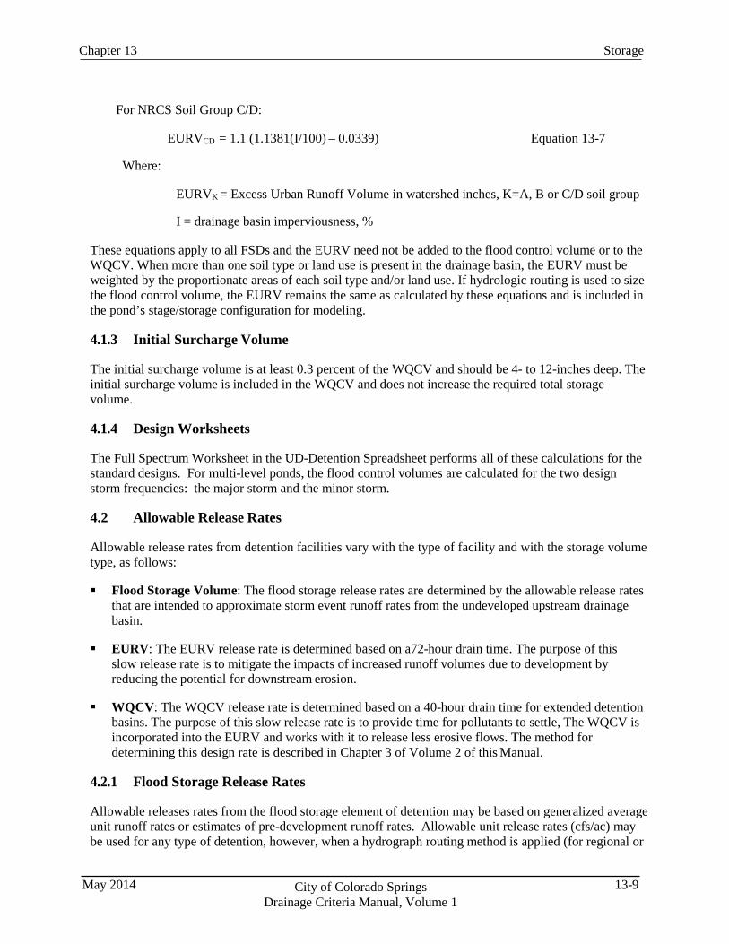
13-9 City of Colorado Springs Drainage Criteria Manual, Volume 1
May 2014
Storage Chapter 13
For NRCS Soil Group C/D:
EURVCD = 1.1 (1.1381(I/100) – 0.0339) Equation 13-7
Where:
EURVK = Excess Urban Runoff Volume in watershed inches, K=A, B or C/D soil group
I = drainage basin imperviousness, %
These equations apply to all FSDs and the EURV need not be added to the flood control volume or to the WQCV. When more than one soil type or land use is present in the drainage basin, the EURV must be weighted by the proportionate areas of each soil type and/or land use. If hydrologic routing is used to size the flood control volume, the EURV remains the same as calculated by these equations and is included in the pond’s stage/storage configuration for modeling.
4.1.3 Initial Surcharge Volume
The initial surcharge volume is at least 0.3 percent of the WQCV and should be 4- to 12-inches deep. The initial surcharge volume is included in the WQCV and does not increase the required total storage volume.
4.1.4 Design Worksheets
The Full Spectrum Worksheet in the UD-Detention Spreadsheet performs all of these calculations for the standard designs. For multi-level ponds, the flood control volumes are calculated for the two design storm frequencies: the major storm and the minor storm.
4.2 Allowable Release Rates
Allowable release rates from detention facilities vary with the type of facility and with the storage volume type, as follows:
Flood Storage Volume: The flood storage release rates are determined by the allowable release rates
that are intended to approximate storm event runoff rates from the undeveloped upstream drainage basin.
EURV: The EURV release rate is determined based on a72-hour drain time. The purpose of this
slow release rate is to mitigate the impacts of increased runoff volumes due to development by reducing the potential for downstream erosion.
WQCV: The WQCV release rate is determined based on a 40-hour drain time for extended detention
basins. The purpose of this slow release rate is to provide time for pollutants to settle, The WQCV is incorporated into the EURV and works with it to release less erosive flows. The method for determining this design rate is described in Chapter 3 of Volume 2 of this Manual.
4.2.1 Flood Storage Release Rates
Allowable releases rates from the flood storage element of detention may be based on generalized average unit runoff rates or estimates of pre-development runoff rates. Allowable unit release rates (cfs/ac) may be used for any type of detention, however, when a hydrograph routing method is applied (for regional or
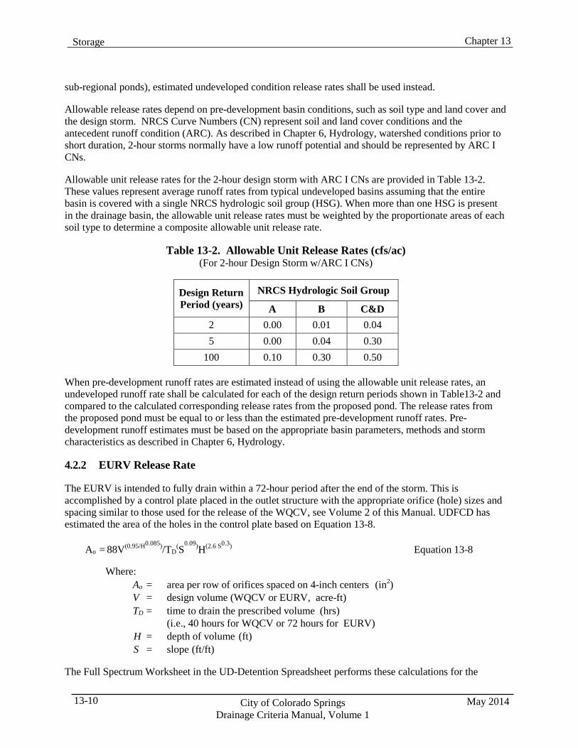
Chapter 13 Storage
May 2014 City of Colorado Springs Drainage Criteria Manual, Volume 1
13-10
sub-regional ponds), estimated undeveloped condition release rates shall be used instead.
Allowable release rates depend on pre-development basin conditions, such as soil type and land cover and the design storm. NRCS Curve Numbers (CN) represent soil and land cover conditions and the antecedent runoff condition (ARC). As described in Chapter 6, Hydrology, watershed conditions prior to short duration, 2-hour storms normally have a low runoff potential and should be represented by ARC I CNs.
Allowable unit release rates for the 2-hour design storm with ARC I CNs are provided in Table 13-2. These values represent average runoff rates from typical undeveloped basins assuming that the entire basin is covered with a single NRCS hydrologic soil group (HSG). When more than one HSG is present in the drainage basin, the allowable unit release rates must be weighted by the proportionate areas of each soil type to determine a composite allowable unit release rate.
Table 13-2. Allowable Unit Release Rates (cfs/ac)
(For 2-hour Design Storm w/ARC I CNs)
Design Return Period (years)
NRCS Hydrologic Soil Group
A B C&D 2 0.00 0.01 0.04 5 0.00 0.04 0.30
100 0.10 0.30 0.50
When pre-development runoff rates are estimated instead of using the allowable unit release rates, an undeveloped runoff rate shall be calculated for each of the design return periods shown in Table13-2 and compared to the calculated corresponding release rates from the proposed pond. The release rates from the proposed pond must be equal to or less than the estimated pre-development runoff rates. Pre- development runoff estimates must be based on the appropriate basin parameters, methods and storm characteristics as described in Chapter 6, Hydrology.
4.2.2 EURV Release Rate
The EURV is intended to fully drain within a 72-hour period after the end of the storm. This is accomplished by a control plate placed in the outlet structure with the appropriate orifice (hole) sizes and spacing similar to those used for the release of the WQCV, see Volume 2 of this Manual. UDFCD has estimated the area of the holes in the control plate based on Equation 13-8.
Ao = 88V(0.95/H0.085)/TD(S
0.09)H(2.6 S0.3) Equation 13-8
Where: Ao = area per row of orifices spaced on 4-inch centers (in2) V = design volume (WQCV or EURV, acre-ft) TD = time to drain the prescribed volume (hrs)
(i.e., 40 hours for WQCV or 72 hours for EURV) H = depth of volume (ft) S = slope (ft/ft)
The Full Spectrum Worksheet in the UD-Detention Spreadsheet performs these calculations for the
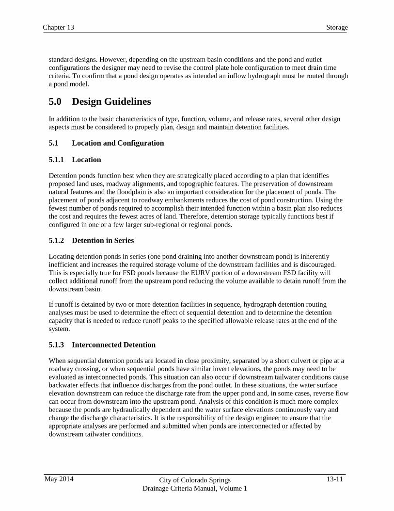
13-11 City of Colorado Springs Drainage Criteria Manual, Volume 1
May 2014
Storage Chapter 13
standard designs. However, depending on the upstream basin conditions and the pond and outlet configurations the designer may need to revise the control plate hole configuration to meet drain time criteria. To confirm that a pond design operates as intended an inflow hydrograph must be routed through a pond model.
5.0 Design Guidelines In addition to the basic characteristics of type, function, volume, and release rates, several other design aspects must be considered to properly plan, design and maintain detention facilities.
5.1 Location and Configuration
5.1.1 Location
Detention ponds function best when they are strategically placed according to a plan that identifies proposed land uses, roadway alignments, and topographic features. The preservation of downstream natural features and the floodplain is also an important consideration for the placement of ponds. The placement of ponds adjacent to roadway embankments reduces the cost of pond construction. Using the fewest number of ponds required to accomplish their intended function within a basin plan also reduces the cost and requires the fewest acres of land. Therefore, detention storage typically functions best if configured in one or a few larger sub-regional or regional ponds.
5.1.2 Detention in Series
Locating detention ponds in series (one pond draining into another downstream pond) is inherently inefficient and increases the required storage volume of the downstream facilities and is discouraged. This is especially true for FSD ponds because the EURV portion of a downstream FSD facility will collect additional runoff from the upstream pond reducing the volume available to detain runoff from the downstream basin.
If runoff is detained by two or more detention facilities in sequence, hydrograph detention routing analyses must be used to determine the effect of sequential detention and to determine the detention capacity that is needed to reduce runoff peaks to the specified allowable release rates at the end of the system.
5.1.3 Interconnected Detention
When sequential detention ponds are located in close proximity, separated by a short culvert or pipe at a roadway crossing, or when sequential ponds have similar invert elevations, the ponds may need to be evaluated as interconnected ponds. This situation can also occur if downstream tailwater conditions cause backwater effects that influence discharges from the pond outlet. In these situations, the water surface elevation downstream can reduce the discharge rate from the upper pond and, in some cases, reverse flow can occur from downstream into the upstream pond. Analysis of this condition is much more complex because the ponds are hydraulically dependent and the water surface elevations continuously vary and change the discharge characteristics. It is the responsibility of the design engineer to ensure that the appropriate analyses are performed and submitted when ponds are interconnected or affected by downstream tailwater conditions.
Chapter 13 Storage
May 2014 City of Colorado Springs Drainage Criteria Manual, Volume 1
13-12
5.2 On-site Detention and Off-site Flows
Two approaches are generally acceptable for addressing off-site flows that must be conveyed through a site and the potential impacts to the on-site detention. These approaches include:
Separate Conveyance Systems: In this approach, off-site runoff is conveyed to a point downstream
of the on-site detention pond outfall. The detention pond is sized based only on the tributary area of the site. Off-site flows and the detained runoff can be conveyed in the same system downstream of the detention pond.
Design for Off-site Flows: An alternative method is to design the detention pond for the entire
upstream watershed area, including the future development flows from off-site areas without giving any credit to off-site detention facilities. This method may be appropriate if the off-site tributary area is relatively small, but it becomes less feasible as the off-site tributary increases.
The benefits of detention facilities provided in the off-site area may be considered in some cases, if there is sufficient justification. In those cases, the design engineer shall utilize hydrograph routing methods to size the on-site detention to account for the additional detention facilities on the off-site area and the differences in timing of the various hydrographs.
5.3 Discharge Location (Outlets)
Detention ponds shall be designed to discharge into a storm sewer, drainageway, or other designated drainage system that is reasonably available. Analyses must demonstrate that the receiving drainage system where the pond discharges has the capacity to convey the detention pond flows.
When a suitable outlet is not available, and with prior approval, detention ponds may discharge into the gutter of a street, such as through a chase section, when the minor storm peak flow from the tributary area is less than 3.5 cfs and the street has adequate capacity to convey the excess runoff within the allowable limits. A transition from the outlet to a curb chase will normally be required and the chase section shall be designed to convey the discharge at a low velocity. The location of the outlet shall be designed to minimize potential problems or conflicts with other improvements. Discharge into the gutter will not be allowed on local streets, or in cases where structures along the street have finished floor elevations below the street elevation.
5.4 Excavated or Embankment Slopes
All excavated or embankment slopes from the pond bottom to the 100-year water surface elevation should be no steeper than 4 feet horizontally to 1 foot vertically (4H:1V) for stability when soils are saturated, ease of maintenance and access, especially within the WQCV and EURV. Steeper slopes, up to 3H:1V, may be allowed when the site is constrained. Excavated slopes above the 100-year water surface elevation and the slope on the downstream side of embankments must be 3H:1V or flatter. Embankments shall be provided with a top width of at least 10 feet for regional and sub-regional ponds and 8 feet for on- site ponds for maintenance access. All earthen slopes shall be covered with topsoil to the minimum depth and revegetated as described in Chapter 14 - Revegetation or according to an approved landscape plan.
It is the responsibility of the design engineer to ensure that the design of any earthen embankment is sufficient, which may require specific recommendations based on soil type, embankment height and soil saturation as determined by a qualified geotechnical engineer. Additionally, the embankment heights and pond size shall not place the structure under the jurisdiction of the Office of the State Engineer, unless specific approval is provided. Due to the extended period of ponding in the WQCV and EURV the
13-13 City of Colorado Springs Drainage Criteria Manual, Volume 1
May 2014
Storage Chapter 13
potential for piping failure through the embankment or along penetrations of the embankment, such as the outlet conduit, shall be mitigated by methods, such as seepage collars, consistent with State Engineer dam design criteria.
5.5 Freeboard
The minimum required freeboard for detention facilities is 1.0 foot above the computed water surface elevation when the emergency spillway is conveying its design flow, except as defined in Section 6.0, Parking Lot Detention. Section 5.3.10 provides design information for the emergency spillway and embankment protection.
5.6 Low-flow Channels
Detention ponds collect both wet and dry weather flows from the upstream basins, including excess irrigation water that can keep pond bottoms wet and difficult to maintain. Therefore, all grassed-bottom detention ponds shall include a low-flow channel sized to convey a minimum of 1 percent of the 100-year peak inflow. The low-flow channel shall be constructed of concrete, concrete with boulder edges, soil riprap, or any combination thereof and shall have a minimum depth of 0.5 feet. The minimum longitudinal slope shall be 0.5 percent to ensure that non-erosive velocities are maintained adjacent to the low-flow channel when the design capacity is exceeded.
Low-flow channels in detention ponds either drain through a WQCV or an EURV to the pond outlet structure where the discharge rate is constrained. This can cause flows to pond at the end of the low-flow channel, deposit sediment, and saturate the surrounding pond bottom. Therefore, the invert elevation of the low-flow channel must be set above the initial surcharge volume near the pond outlet to confine this nuisance ponding to a small area of the pond bottom and reduce maintenance requirements.
Unlined (or wetland) low-flow channels may be allowed on a case-by-case basis. The unlined low-flow channel shall be at least 1.5-feet deep below adjacent grassed benches and shall be vegetated with herbaceous wetland vegetation or riparian grasses, appropriate for the anticipated moisture conditions. The minimum longitudinal slope shall be 0.5 percent and the minimum width of the grassed bench adjacent to the low-flow channel shall be 12 feet on at least one side for equipment access. The side slope below the bench shall be no steeper than 4H:1V and the maximum bottom width of the channel shall be 12 feet if equipment can access one side of the channel or 24 feet if equipment can access both sides.
Typical cross-sections of low-flow channels are shown in Figure 13-6. Typical pond configurations with a concrete low-flow channel and a benched low-flow channel are shown in Figures 13-7 and 13-8.
5.7 Bottom Slope
For grassed detention facilities, the pond bottom shall be sloped at least 4 percent for the first 25 feet and at least 1 percent thereafter to drain toward the low-flow channel or outlet, measured perpendicular to the low-flow channel. The benches above unlined low-flow channels, if approved, shall slope at least 1 percent toward the low-flow channel.
5.8 Wetland Vegetation (Constructed Wetland Pond)
A soft bottom or constructed wetland pond bottom can be used in place of a dry pond bottom, but special considerations must be made for maintaining an adequate depth of water to allow wetland plants to survive. These types of ponds also require special attention to provide access to the bottom for maintenance. Additionally, the upstream drainage basin must be evaluated to determine whether an
Chapter 13 Storage
May 2014 City of Colorado Springs Drainage Criteria Manual, Volume 1
13-14
adequate amount of flow will be provided to support the vegetation. Section T-8, Constructed Wetland Ponds, of Volume 3 of the UDFCD Manual provides guidance on how to implement this type of facility.
5.9 Inlet Structures
Runoff shall enter a detention facility via a stabilized drainageway, drop structure, or storm sewer. Riprap rundowns are generally not accepted due to a history of erosion problems.
Capturing sediment before it enters the detention facility is important for reducing maintenance requirements inside the facility. Forebays provide locations for debris and coarse sediment to drop out of the flow and accumulate, extending the functionality of the pond features. Forebays shall be sized based on the methods described in Section T-5, Volume 3 of the UDFCD Manual. Figure 13-9 illustrates a concept for storm sewer outfalls entering a forebay at the inlet to a detention facility. Forebay designs must facilitate maintenance by providing adequate access and by having hard, stable bottoms. Pre- manufactured treatment devices may function as a forebay, especially for small ponds, and may be considered on a case-by-case basis.
Flows entering ponds often have high energy. Therefore, some form of energy dissipation may be necessary at a pond inlet. To determine the hydraulic characteristics of the inlet structures and energy dissipation devices at an entrance to a pond, account for tailwater effects of water in the pond. The elevation of the WQCV or the EURV can be used as a minimum tailwater condition for energy dissipation calculations.
A safety barrier, such as a railing of sufficient height, shall be provided around the perimeter of inlet structures whenever the difference in the elevation from the surface to the bottom of the structure is 30 inches or greater.
5.10 Outlet Structures
Detention basin outlets shall be designed to control facility discharges at the allowable release rates. Additionally, outlet structures shall be provided with safety/debris grates to reduce the potential for debris plugging, designed for ease of maintenance, equipped with safety features, and designed with favorable aesthetics.
To allow WQCVs and EURVs in FSD or water quality ponds to drain more effectively, a “micropool” must be located in front of the screen for the outlet control plate. The purpose of a micropool is to create a permanent pool of water on which debris will float, allowing flow to pass through the lower portion of the screen to the control plate. It is preferable to contain the micropool integral to the concrete portion of outlet structures. Figures 13-10 and 13-11 provide examples of integral micropools: one with parallel wingwalls with a flush bar grating and the other with flared wingwalls and handrails, respectively. Extending micropools out into the pond bottom creates areas that may contain standing water for extended periods of time and be difficult to maintain. External micropools (extending beyond the concrete outlet structures) shall only be used if a constant baseflow exists sufficient to maintain the micropool level and will be allowed only on a case-by-case basis. Although there is no volume requirement for micropools, they must have a surface area of 10 square feet or more and be at least 2.5- feet deep.
An “initial surcharge volume” above the micropool level in FSD or water quality ponds is critical to the proper functioning of a pond outlet and must be provided. This volume provides a limited amount of storage for very low flows passing through the pond and allows the low-flow channel and pond bottom to flow freely and remain drier for maintenance. It is preferable that this volume be contained within the
13-15 City of Colorado Springs Drainage Criteria Manual, Volume 1
May 2014
Storage Chapter 13
outlet structure above the micropool, but may extend out beyond it as necessary. When this volume extends beyond the micropool, a concrete curb, rock edge or other feature must separate it from the bottom of the WQCV/EURV volume so that it can be identified and preserved. The bottom of this volume can be lined with a hard surface or vegetated. This volume is considered part of the WQCV or the EURV and does not need to be added to the other design volumes. A more detailed discussion of this feature is provided in Section T-5, Extended Detention Basin, in Volume 3 of the UDFCD Manual. An initial surcharge volume is not necessary for Constructed Wetland Ponds or Retention Ponds.
The flood-control outlet shall be sized to discharge the allowable 100-year release rate when the 100-year detention volume is completely full. The outlet structure weir crest (formed by the top of the concrete) shall have adequate capacity to pass design flows so that flow control is maintained at the appropriate control device for the design event.
A safety barrier, such as a railing of sufficient height, shall be provided around the perimeter of outlet structures wherever the difference in the elevation from the top of the structure to the bottom of the structure is 30 inches or greater.
A sealant must be specified behind the orifice plate to prevent leakage around the control plate. All hydraulic sizing, concrete structure dimensions, reinforcing, and metalwork details for outlet structures shall be the responsibility of the design engineer.
5.11 Trash Racks
The design of trash racks protecting outlet control devices shall comply with the safety grate criteria discussed in the Culverts Chapter of Volume 2 of the UDFCD Manual. The trash rack or screen protecting the control plate orifices must extend to the bottom of the micropool so that flow can pass through the rack below the level of any floating debris and pass through the orifices.
Bar grating may be used on parallel sloping wingwalls, either as the primary debris grate (if orifices are at least 2.5 inches in diameter) or as a coarse screen and safety grate in lieu of handrail. Sloping bar grating shall have a lockable hinged section of at least 2 square feet to allow access to the orifice plate or well screen. Manhole steps shall be provided on the side of the wingwall directly under the hinged opening. The bearing bars for the steel bar grating shall be designed to withstand hydrostatic loading up to the spillway crest elevation (assuming the grate is completely clogged and bears the full hydrostatic head), but not be designed for larger loads (like vehicular loads) so that the hinged panels are not excessively heavy. Panels of trash racks or bar grating shall be no more than 3-feet wide and all parts of the grating and support frames shall be hot-dipped galvanized steel. Trash racks or bar grating shall be attached to the outlet structure.
The configuration and dimensions of trash racks and grates should allow debris to be raked off using standard garden tools or other commonly available equipment.
5.12 Emergency Spillway and Embankment Protection
Detention may be created by a roadway embankment or by a free standing embankment as conceptually represented by Figures 13-12a and 13-12b. Whenever a detention pond facility uses an embankment to contain water, the embankment shall be protected from catastrophic failure due to overtopping. Overtopping can occur when the pond outlet becomes obstructed or when a storm larger than a 100-year event occurs. Erosion protection for the embankment may be provided in the form of a buried soil-riprap layer at the spillway crest and on the entire downstream face of the embankment or a separate emergency spillway constructed of buried, soil riprap, grouted boulders or concrete. Alternative slope protection
Chapter 13 Storage
May 2014 City of Colorado Springs Drainage Criteria Manual, Volume 1
13-16
materials may be considered on a case-by-case basis. In either case, the protection shall be constructed to convey the 100-year developed condition flow from the upstream watershed without accounting for any flow attenuation within the detention facility.
The crest elevation of the emergency spillway shall be set at or above the calculated 100-year water surface elevation. A concrete wall shall be constructed at the emergency spillway crest extending at least to the bottom of the riprap and bedding layers located immediately downstream for regional and sub- regional ponds. On-site ponds do not require a concrete crest wall. The crest wall shall be extended at the sides up to 1 foot above the emergency spillway design water surface as shown in Figure 13-12c.
Riprap embankment protection shall be sized based on methodologies described in Development of Riprap Testing in Flumes: Phase II Follow-up Investigations (Apt et al. 1988) to determine the D50
dimension. According to this method:
D50 = 5.23 S0.43 (1.35 Cf q)0.56 Equation 13-9
Where: D50 = median rock size (in) S = longitudinal slope (ft/ft) Cf = concentration factor (1.0 to 3.0) q = unit discharge (cfs/ft)
When: η (porosity) = 0.0 (i.e., for buried soil riprap)
The unit discharge shall be determined by dividing the design flow by the crest width, excluding the side slopes. According to this method, the types of riprap needed for typical embankment slopes and design flows are shown in Figure 13-12d. The riprap types shown were determined assuming that there is no interstitial flow (i.e., no flow between the rocks—soil riprap with filled voids and porosity = 0) and that the “concentration factor” (Cf) is equal to 2.0. For plain riprap with interstitial flow, the method requires an interactive process described in Apt et al. (1988). The range for each type shown is based on the D50
dimension at the midpoint between the D50 for adjacent types. Riprap characteristics such as rock size distributions, thickness, hardness, specific gravity, angle of repose, etc., shall be as required in the Major Drainage chapter of Volume 1 in the UDFCD Manual. For design conditions outside of the parameters or conditions represented in Figure 13-12d, the designer shall propose an appropriate alternative approach that may include grouted boulders or concrete protection. Alternative approaches must be submitted for approval prior to incorporation into designs.
The emergency spillway is also needed to control the location and direction of any overflows. The emergency spillway and the path of the emergency overflow downstream of the spillway and embankment shall be clearly depicted on the drainage plan. Structures shall not be permitted in the path of the emergency spillway or overflow. The emergency overflow water surface shall be shown on the detention facility construction drawings. When emergency overflows will pass over a roadway, the depth of flow shall not be greater than 1 foot over the street crown.
5.13 Retaining Walls
The use of retaining walls within detention basins is discouraged due to the potential increase in long- term maintenance costs and concerns regarding the safety of the general public and maintenance personnel. Public retaining walls higher than 30 inches shall not be used in storage-based facilities. Private retaining walls shall only be considered for on-site facilities. If retaining walls are proposed, footings should be located above the WQCV or EURV. Wall heights not exceeding 30 inches are
13-17 City of Colorado Springs Drainage Criteria Manual, Volume 1
May 2014
Storage Chapter 13
preferred. If terracing of retaining walls is proposed, adequate horizontal separation shall be provided between adjacent walls. The horizontal separation shall ensure that each wall is loaded by the adjacent soil, based on conservative assumptions regarding the angle of repose. Separation shall consider the proposed anchoring system and equipment and space that would be needed to repair the wall in the event of a failure. The failure and repair of any wall shall not impact or affect loading on adjacent walls. In no case shall the separation be less than 2 times the adjacent wall height, such that a plane extended through the bottom of adjacent walls shall not be steeper than 2H:1V. The maximum ground slope between adjacent terraced walls shall be 4 percent.
Walls shall not be used where live loading or additional surcharge from maintenance equipment or vehicle traffic could occur. The horizontal distance between the top of a retaining wall and any adjacent private sidewalk, roadway, or structure should be at least three times the height of the wall. The horizontal distance between the top of a retaining wall and an adjacent public sidewalk, roadway, or structure shall be at least three times the height of the wall. The horizontal distance to any adjacent maintenance access drive not used as a sidewalk or roadway shall be at least 4 feet. Any future outfalls to the pond shall be designed and constructed with the detention basin out to a distance sufficient to avoid disturbing the retaining walls when the future pipeline is connected to the outfall.
Any wall exceeding a height of 30 inches requires perimeter fencing, safety railing, or guardrail, depending on the location of the wall relative to roadways, parking areas, and pedestrian walkways. Walls exceeding a height of 4 feet (measured from the bottom of the footing to the top of the wall) may require a Building Permit. The design engineer is responsible for compliance with any permitting requirements under the Uniform Building Codes.
A Professional Engineer licensed in the State of Colorado shall perform a structural analysis and design the retaining wall for the various loading conditions the wall may encounter, including the differences in hydrostatic pressure between the front and back of the wall. A drain system should be considered behind the wall to ensure that hydrostatic pressures are equalized as the water level changes in the pond. The wall design and calculations shall be stamped by the professional engineer and submitted to the City as part of the Permanent Control Measure Plan.
Retaining walls shall not be used within the limits of any impermeable lining of water quality basins or detention ponds.
5.14 Landscaping
The integration of detention facilities and site landscaping requirements is important for making facilities more aesthetically acceptable, consistent with adjacent land uses and compatible with overall stormwater management goals. The type and quantity of landscaping materials should be considered to ensure that the capacity of the pond is maintained and that maintenance activities can be performed with minimal disruption of vegetated areas. Recommendations for pond grading and landscaping include:
1. Wherever possible, involve a landscape architect in the design of detention facilities to provide
input regarding layout, grading, and the vegetation plan.
2. Create a pond with a pleasing, curvilinear, natural shape that is characterized by variation in the top, toe, and slopes of banks and avoid boxy, geometrical patterns. A “golf course look” is more attractive than straight lines and straight slopes.
3. Grass selection and plant materials are important considerations in softening the appearance of a

Chapter 13 Storage
May 2014 City of Colorado Springs Drainage Criteria Manual, Volume 1
13-18
detention area and blending it in with the surrounding landscaping and natural features. Selected species should be suitable for the particular hydrologic conditions in the pond. Wetland or riparian species should only be selected for the bottom areas subject to frequent and prolonged
13-19 City of Colorado Springs Drainage Criteria Manual, Volume 1
May 2014
Storage Chapter 13
inundation. Bluegrass rarely works well in the lowest portion of a pond. Guidelines for revegetation, along with recommended seed mixes, are provided in the Chapter 14, Revegetation.
4. Multi-purpose detention facilities are encouraged that incorporate recreational features such as
passive open space areas and pedestrian paths. Active recreational facilities should be located in upland areas to avoid usage conflicts resulting from periodic inundation.
5. To reduce the potential for clogging of debris grates, no straw mulch shall be used within the
EURV or WQCV of a detention basin. Instead, erosion control blankets shall be installed for a width of at least 6 feet on either side of concrete low-flow channels or up to a depth of 1 foot in soil riprap or benched low-flow channels. The blankets shall comply with the materials and installation requirements for erosion control blankets (straw coconut or 100 percent coconut). Site-specific conditions may require additional blanket or other erosion control measures.
6. Trees or shrubs consistent with the landscape plan or the surrounding natural environment may be
planted within the pond volume above the EURV or the 2-year water surface, whichever is higher. Trees such as Cottonwood, Willow, and Aspen shall not be planted below the 100-year water surface or on the embankment slopes of a detention pond to avoid nuisance spreading of root systems within the facility.
7. Revegetation requirements described in Chapter 14, Revegetation, shall apply to detention
facilities. These requirements go beyond plant species selection and include proper soil preparation, irrigation, weed control and other considerations.
5.15 Signage
Two signs, each with a minimum area of 3 square feet, shall be provided around the perimeter of all detention facilities. The signs shall be fabricated of durable materials, such as metal or plastic, using red lettering on a white background with the following message:
5.16 Maintenance Access
A stable access and working bench shall be provided so that equipment can be used to remove accumulated sediment and debris from the detention pond and perform other necessary maintenance activities at all components of the facility. Unless otherwise approved, the horizontal distance from the working bench to the furthest point of removal for the forebay, bottom of the pond, or outlet structure shall be no more than 24 feet. The working bench and access drive shall slope no more than 15 percent, and be at least 10 feet wide for a centerline radius greater than 50 feet and at least 11 feet wide for a centerline radius between 30 and 50 feet. The minimum centerline radius shall be 30 feet.
Unless otherwise required by a pavement design, the working bench and access drive shall be constructed as follows:
Below any permanent water surface: A reinforced concrete bottom slab at least 6 inches thick shall
be provided as a working platform. The surface of the concrete shall be provided with a grooved
WARNING
THIS AREA IS A STORMWATER FACILITY AND IS SUBJECT TO PERIODIC FLOODING
Chapter 13 Storage
May 2014 City of Colorado Springs Drainage Criteria Manual, Volume 1
13-20
finish to improve traction, with grooves oriented to drain water away to one or both sides. Concrete shall be placed on at least 6 inches of gravel base compacted subgrade.
Below the WQCV or EURV water surface: The access ramp shall be reinforced concrete as
specified above, or at least a 12 inch thick layer of aggregate base course or crushed gravel over compacted subgrade.
Above the WQCV or EURV and below the 100-year water surface: An access ramp shall be
reinforced concrete as specified above or provide at least an 8-inch-thick layer of aggregate base course or crushed gravel over compacted subgrade. Reinforced turfgrass, meeting applicable criteria, will be considered in this zone for an access drive on a site-specific basis. If used, a system of marking the edges is required so that its location is evident to maintenance crews. Also, shrubs, trees, sprinkler heads and valve boxes shall not be located in the reinforced turfgrass area.
Pavement designs for access drives shall be submitted for review and approval based on site soil conditions and H-20 loading.
Retaining walls shall be laid out in a manner that avoids access restrictions. Likewise, handrails or fences shall permit vehicular access. The entrance to an access drive from a roadway or parking lot shall be located so that traffic safety is not compromised. A means of limiting public access to the site, such as bollards and a chain or a gate, shall be provided at the entrance to the access drive.
Other improvements that could facilitate future maintenance operations are encouraged. These may include:
1. Providing adequate room for staging the equipment involved in clean-out operations.
2. Providing a power receptacle adjacent to the detention pond to enable dewatering operations
using an electric pump. Electric pumps are quieter and require less attention in the event pumps need to operate overnight.
3. For larger, natural sites, it may be worthwhile to reserve a suitable location for disposing of
sediment that is cleaned out of the pond. This has to be carefully thought through, however, to make sure it is feasible to dump the material on-site, allow it to dry, then spread it and re-seed and mulch the area, without causing erosion problems. This approach must be approved and adequately described in the Maintenance Plan, if approved.
Access requirements for on-site ponds may be revised on a case-by-case basis if pond size and space limitations prohibit compliance with these standards.
5.17 Construction Phasing
It may be possible to delay the construction of detention ponds if development upstream of the planned pond site is limited relative to the fully-developed land use plan. However, development tends to destabilize downstream channels due to an increase in flows, but also due to a reduction in available sediment (“clear water” discharges). Estimates of the impact of development on downstream channels show that even a small change in minor storm flows can begin to change downstream channel characteristics. Therefore, some limited upstream development may occur prior to construction of sub- regional or regional detention facilities. However, improvements to channels between the developed area and the pond site may need to be improved to prevent degradation.
13-21 City of Colorado Springs Drainage Criteria Manual, Volume 1
May 2014
Storage Chapter 13
6.0 Parking Lot Detention Where on-site detention is approved, portions of the site used for parking or landscaping may be inundated to provide some of the storage required.
6.1 Access Requirements
Easements for parking lot detention shall be provided, including the area of the parking lot that is inundated by the 100-year water surface elevation and the outlet structure and conveyance facilities. Easements shall also be provided from public right-of-way to the pond facilities.
6.2 Maintenance Requirements
The property owner shall be required to ensure that parking lot detention is maintained in accordance with the approved inspection and maintenance manual as described in Chapter 6, Volume 2 of this Manual for EDBs.
6.3 Depth Limitation
The 100-year design water surface shall not flood the parking area by more than 9 inches within a parking stall. When FSD is applied, the maximum allowable design depth above pavement surfaces within a parking stall for the EURV is 3 inches. The WQCV shall be located entirely out of the pavement area, possibly in one or more landscaped parking islands or adjacent landscaping.
6.4 Emergency Spillway
An emergency spillway sized for the 100-year peak inflow rate shall be provided with a crest elevation set at the 100-year water surface elevation and a maximum flow depth over the emergency spillway of 6 inches. No freeboard above the emergency spillway 100-year water surface elevation is required. The finished first floor elevation of any adjacent structures shall be at least 1.0 foot above the 100-year emergency overflow water surface elevation (equivalent to 18 inches above the 100-year pond water surface).
The emergency spillway should be integrated into the site plan and landscaping and can be vegetated over stabilization material such as soil riprap or a geotextile. Embankment protection may be eliminated if the depth of flow and velocities for the 100-year flow are low enough to avoid erosion during overtopping.
6.5 Outlet Configuration
The outlet configuration shall be designed in accordance with criteria shown in this chapter, Volume 2 of this Manual and Volume 3 of the UDFCD manual for the type of facility selected. Outlets for the EURV and 100-year events shall limit peak flows to the allowable unit release rates.
6.6 Flood Hazard Warning
All parking lot detention areas shall have a minimum of two signs posted identifying the area of potential flooding. The signs shall be fabricated of durable materials, such as metal or plastic, using red lettering on a white background and shall have a minimum area of 1.5 square feet and contain the following message:
Chapter 13 Storage
May 2014 City of Colorado Springs Drainage Criteria Manual, Volume 1
13-22
Signs shall be located at the edge of the parking area adjacent to where flooding may occur and facing the parking area. Any suitable geometry of the signs is permissible. The property owner shall be responsible to ensure that the sign is provided and maintained at all times.
7.0 Retention Ponds 7.1 Approval
Stormwater runoff retention has been used in areas where no near-term viable alternative exists for providing an outfall from a detention pond. However, problems with past retention basins, including soil expansion, siltation and lack of infiltration capacity, have created a nuisance to the general public. Retention ponds may also potentially deprive downstream water right holders of their legal right to use the retained water.
Stormwater retention shall not be permitted, except as approved on a case-by-case basis and, as an interim measure in areas where an outlet collector storm sewer system has been planned, but has not been constructed. When allowed, retention shall be required to be converted to detention when the outlet system is available. The completed detention facility shall comply with all of the detention storage design criteria as described in this Manual.
7.2 Minimum Sizing Requirements
When stormwater retention is determined to be appropriate as an interim measure, the facility shall be sized using the following criteria:
The minimum retention volume shall equal the watershed area upstream of the retention pond
(including off-site areas) times the unit runoff amount, as shown in Figure 13-13, based on the estimated future development percent imperviousness for the entire upstream watershed. Figure 13- 13 is based on 1.5 times the estimated runoff from a 24-hour, 100-year rainfall to account for storms larger than a 100-year event, storms of longer duration, or back-to-back storms.
A minimum of 1 foot of freeboard shall be provided from the water surface of the storage volume to
the top of the embankment. Additional considerations when implementing a retention facility are discussed in the Storage Chapter
in Volume 2 of the UDFCD Manual.
8.0 References Apt, S., Wittler, R., Ruff, J., LaGrone, D., Khattak, M., Nelson, J., Hinkle, D. and D. Lee. 1988.
Development of Riprap Testing in Flumes: Phase II Follow-up Investigations. NUREG/CR-4651, ORNL/TM-10100/V2. Prepared for Oak Ridge National Laboratories. Prepared by Colorado State University.
WARNING
THIS AREA IS A DETENTION POND AND IS SUBJECT TO PERIODIC FLOODING
TO A DEPTH OF 9 INCHES OR MORE
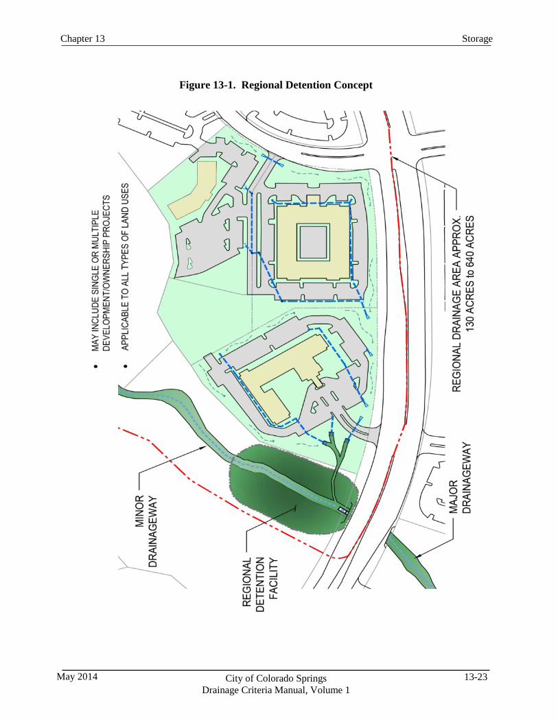
13-23 City of Colorado Springs Drainage Criteria Manual, Volume 1
May 2014
Storage Chapter 13
Figure 13-1. Regional Detention Concept
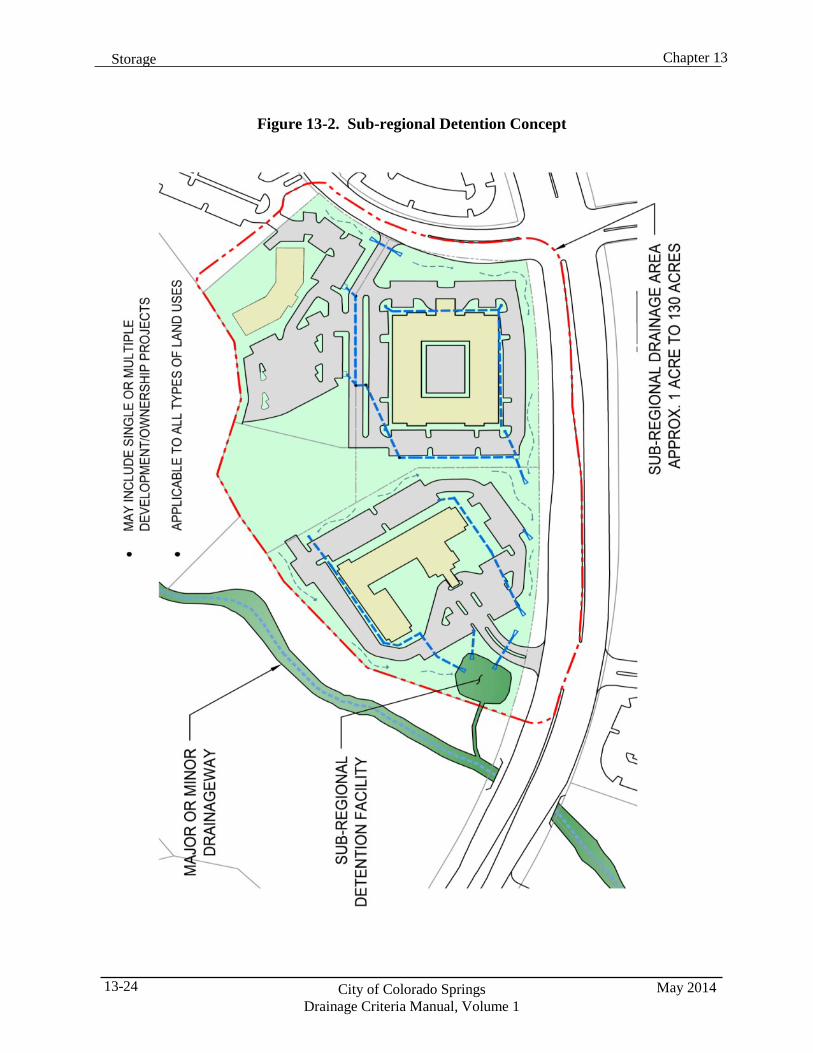
Chapter 13 Storage
May 2014 City of Colorado Springs Drainage Criteria Manual, Volume 1
13-24
Figure 13-2. Sub-regional Detention Concept
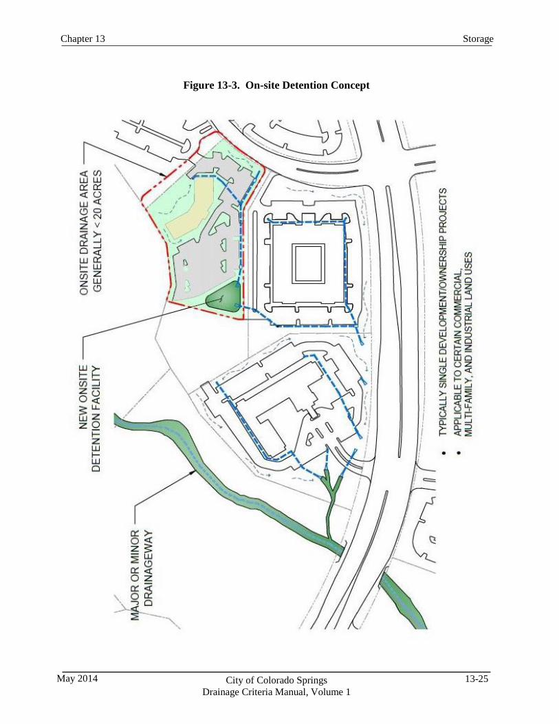
13-25 City of Colorado Springs Drainage Criteria Manual, Volume 1
May 2014
Storage Chapter 13
Figure 13-3. On-site Detention Concept
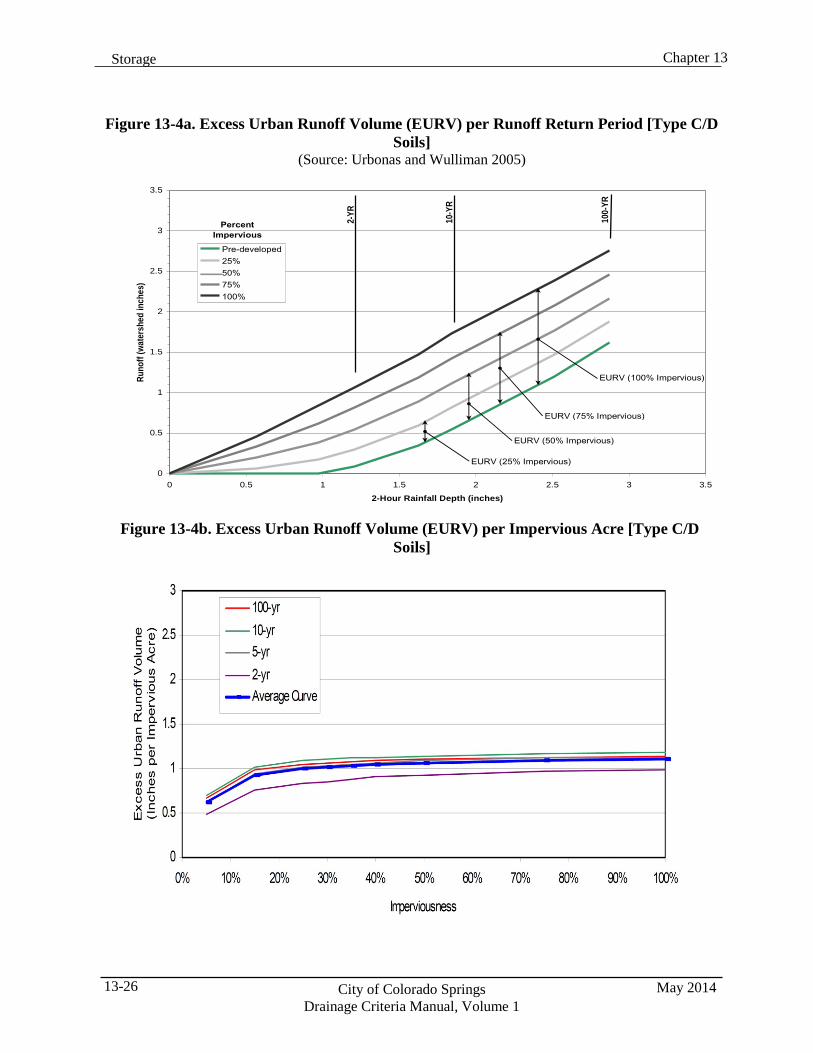
Chapter 13 Storage
May 2014 City of Colorado Springs Drainage Criteria Manual, Volume 1
13-26
Figure 13-4a. Excess Urban Runoff Volume (EURV) per Runoff Return Period [Type C/D Soils]
(Source: Urbonas and Wulliman 2005)
3.5
3
2.5
2
1.5
1
0.5
0 0 0.5 1 1.5 2 2.5 3 3.5
2-Hour Rainfall Depth (inches)
Figure 13-4b. Excess Urban Runoff Volume (EURV) per Impervious Acre [Type C/D Soils]
Runo
ff (w
ater
shed
inch
es)
2-YR
10-Y
R
100-
YR
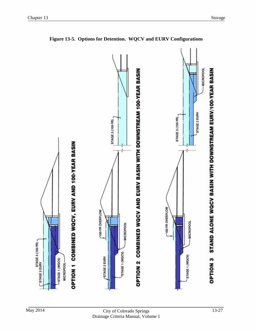
13-27 City of Colorado Springs Drainage Criteria Manual, Volume 1
May 2014
Storage Chapter 13
Figure 13-5. Options for Detention. WQCV and EURV Configurations
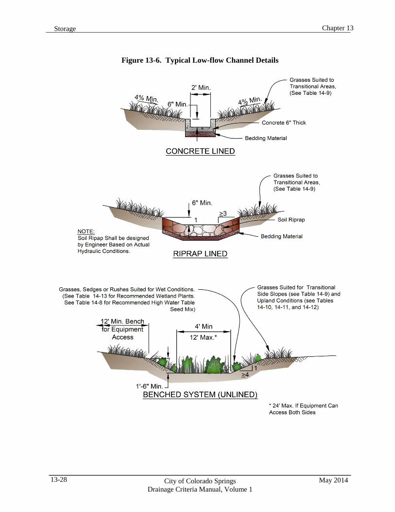
Chapter 13 Storage
May 2014 City of Colorado Springs Drainage Criteria Manual, Volume 1
13-28
Figure 13-6. Typical Low-flow Channel Details
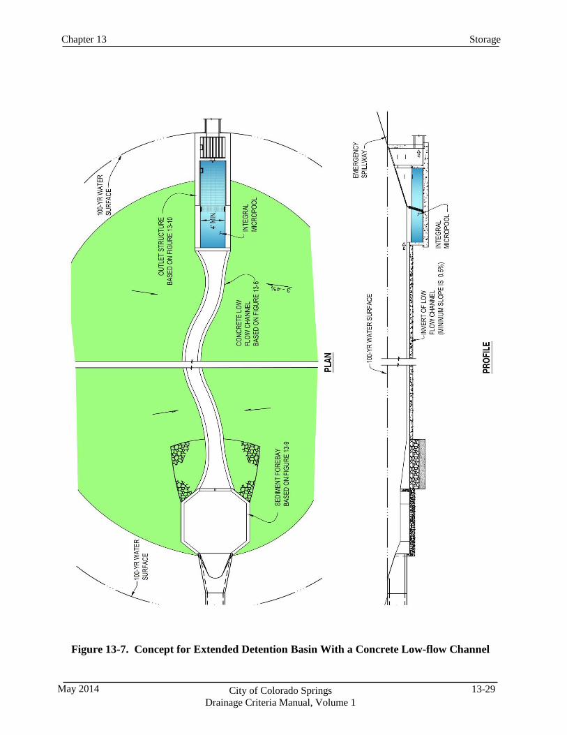
13-29 City of Colorado Springs Drainage Criteria Manual, Volume 1
May 2014
Storage Chapter 13
Figure 13-7. Concept for Extended Detention Basin With a Concrete Low-flow Channel
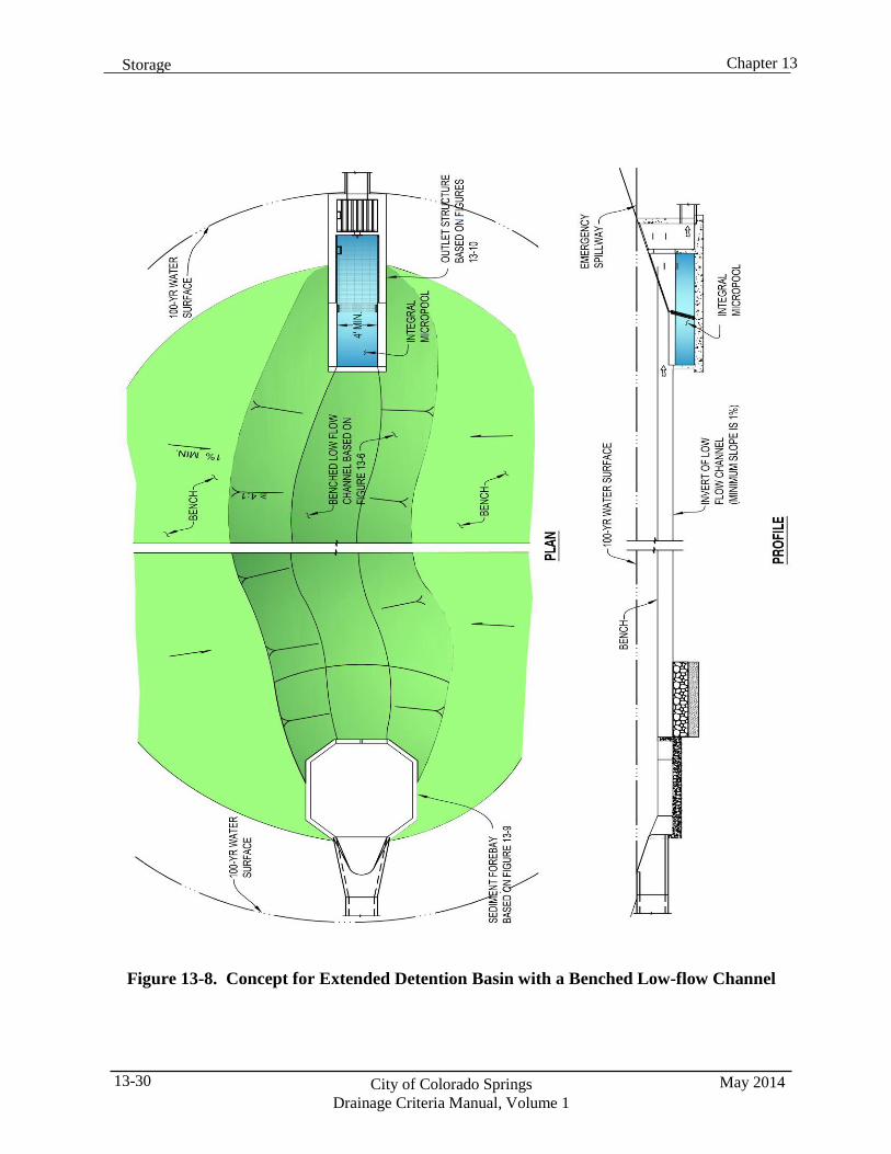
Chapter 13 Storage
May 2014 City of Colorado Springs Drainage Criteria Manual, Volume 1
13-30
Figure 13-8. Concept for Extended Detention Basin with a Benched Low-flow Channel
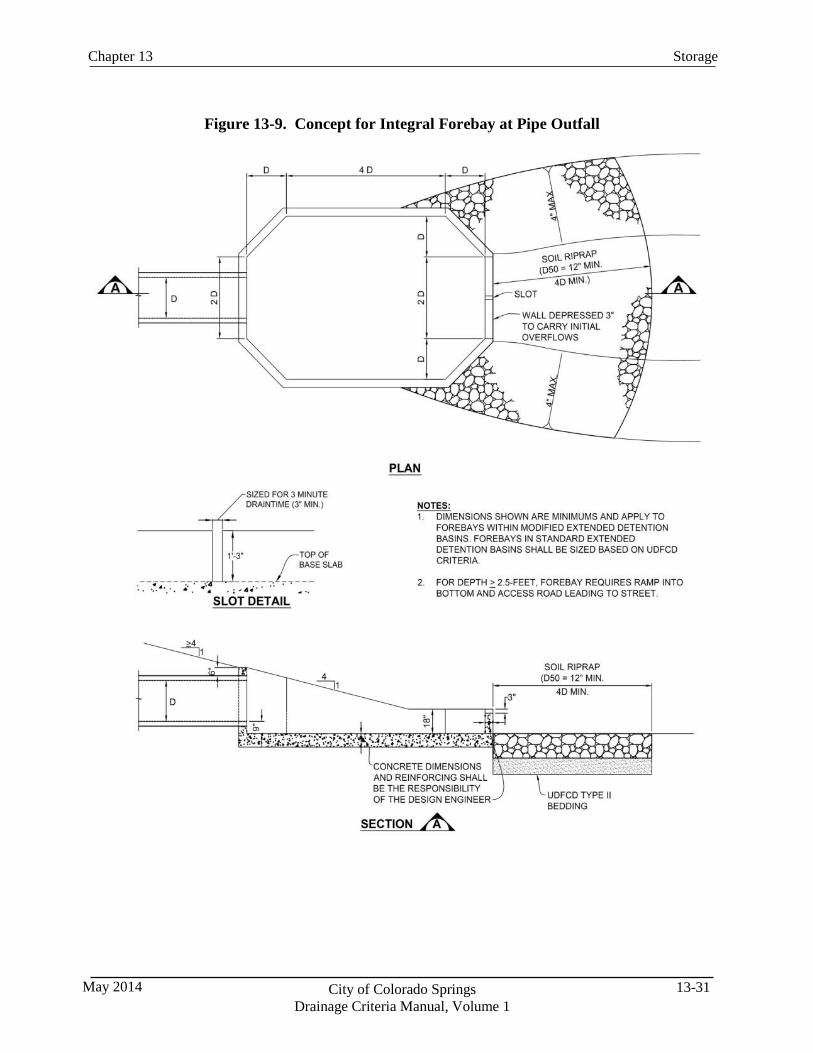
13-31 City of Colorado Springs Drainage Criteria Manual, Volume 1
May 2014
Storage Chapter 13
Figure 13-9. Concept for Integral Forebay at Pipe Outfall
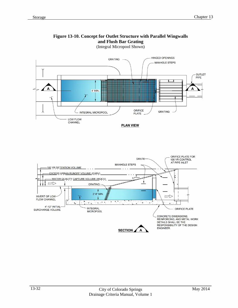
Chapter 13 Storage
May 2014 City of Colorado Springs Drainage Criteria Manual, Volume 1
13-32
Figure 13-10. Concept for Outlet Structure with Parallel Wingwalls and Flush Bar Grating
(Integral Micropool Shown)
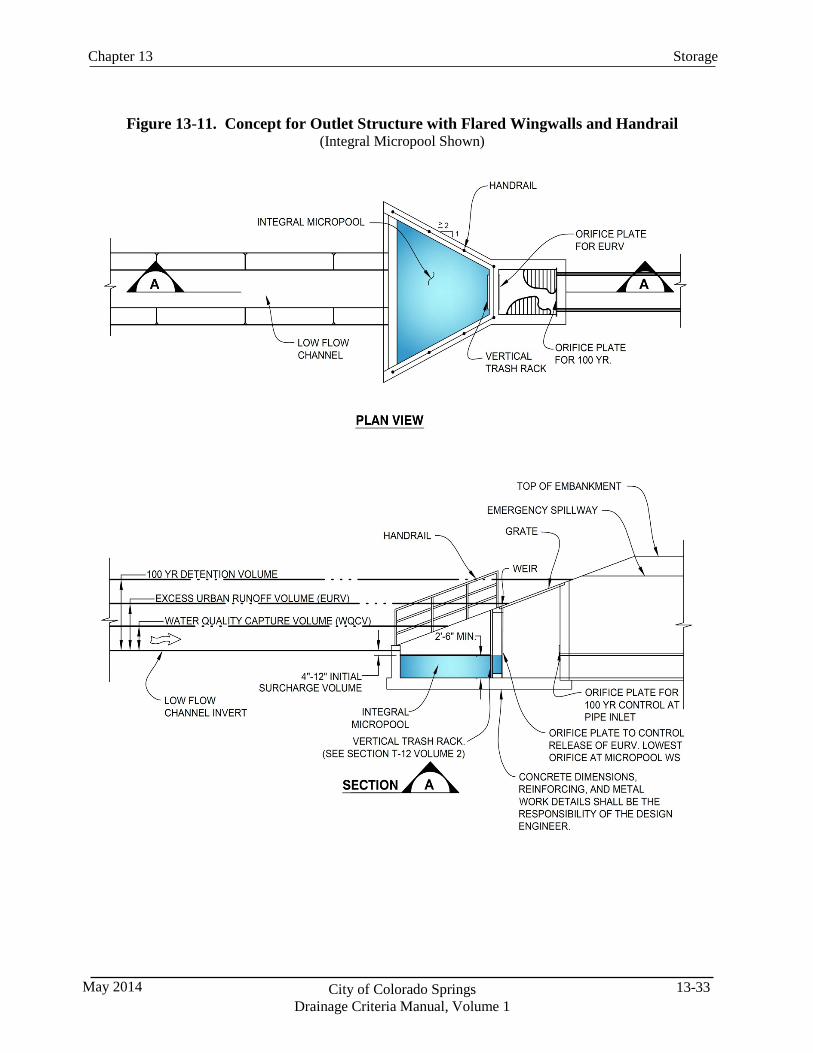
13-33 City of Colorado Springs Drainage Criteria Manual, Volume 1
May 2014
Storage Chapter 13
Figure 13-11. Concept for Outlet Structure with Flared Wingwalls and Handrail (Integral Micropool Shown)
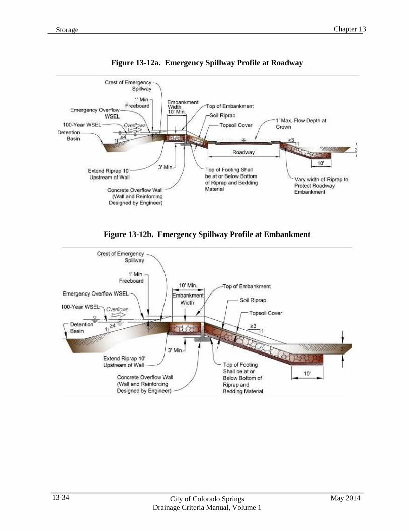
Chapter 13 Storage
May 2014 City of Colorado Springs Drainage Criteria Manual, Volume 1
13-34
Figure 13-12a. Emergency Spillway Profile at Roadway
Figure 13-12b. Emergency Spillway Profile at Embankment
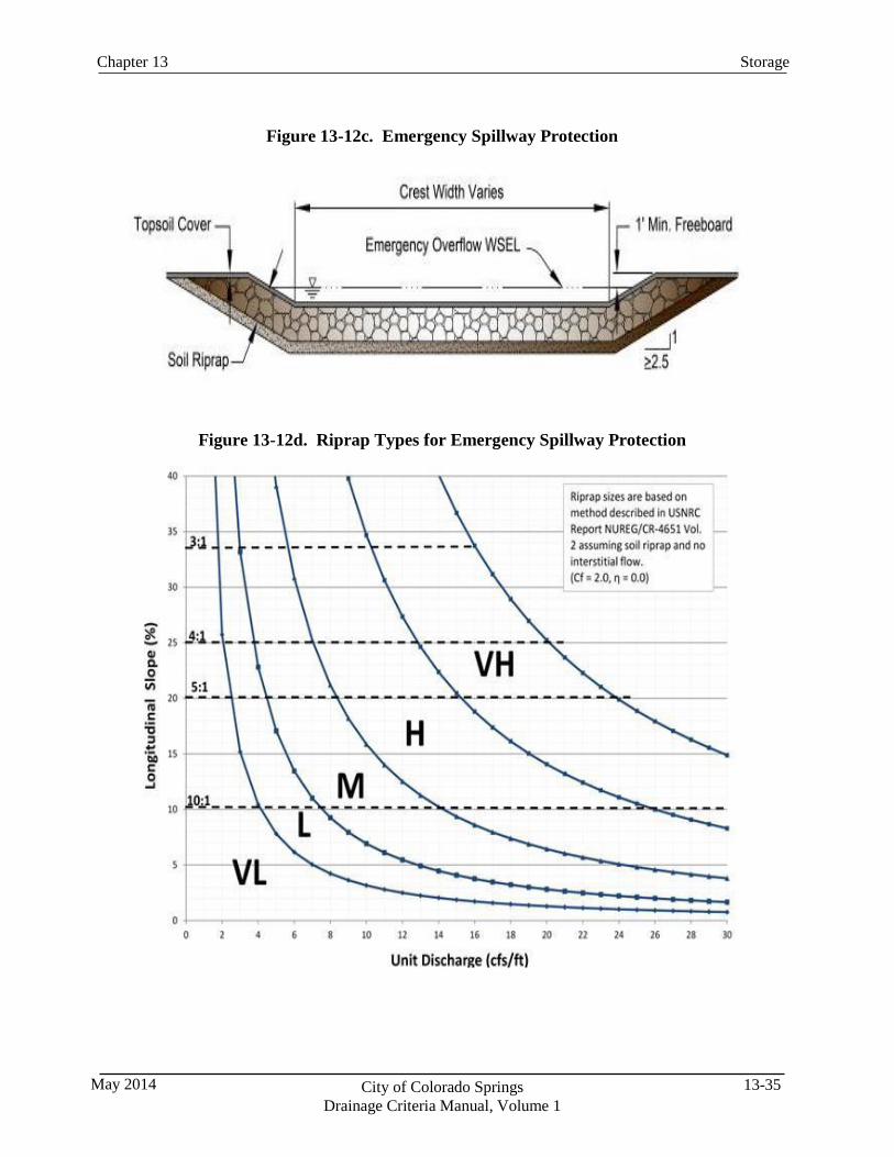
13-35 City of Colorado Springs Drainage Criteria Manual, Volume 1
May 2014
Storage Chapter 13
Figure 13-12c. Emergency Spillway Protection
Figure 13-12d. Riprap Types for Emergency Spillway Protection
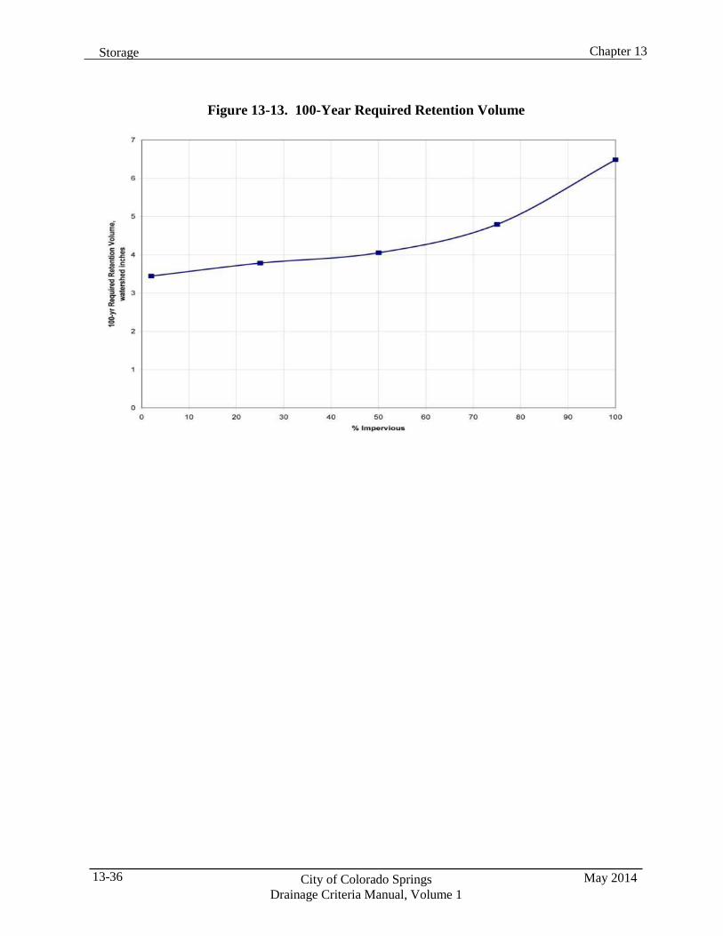
Chapter 13 Storage
May 2014 City of Colorado Springs Drainage Criteria Manual, Volume 1
13-36
Figure 13-13. 100-Year Required Retention Volume
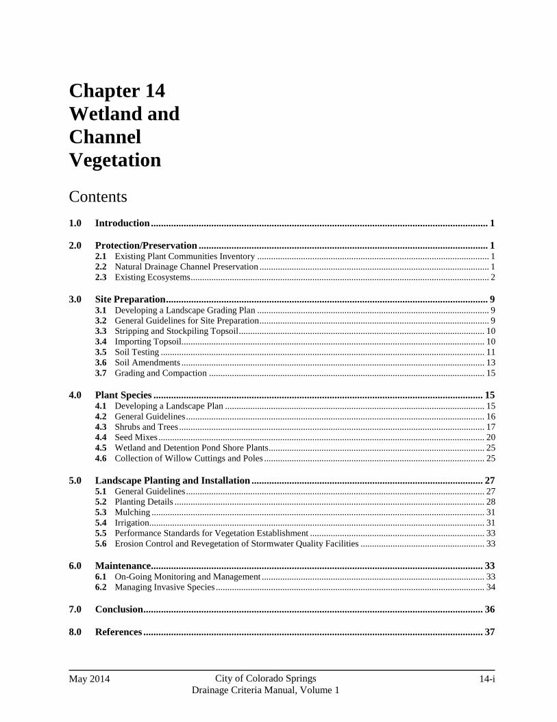
May 2014 City of Colorado Springs Drainage Criteria Manual, Volume 1
14-i
Chapter 14 Wetland and Channel Vegetation
Contents 1.0 Introduction ...................................................................................................................................... 1
2.0 Protection/Preservation ................................................................................................................... 1 2.1 Existing Plant Communities Inventory ..................................................................................................... 1 2.2 Natural Drainage Channel Preservation .................................................................................................... 1 2.3 Existing Ecosystems .................................................................................................................................. 2
3.0 Site Preparation ................................................................................................................................ 9 3.1 Developing a Landscape Grading Plan ..................................................................................................... 9 3.2 General Guidelines for Site Preparation .................................................................................................... 9 3.3 Stripping and Stockpiling Topsoil ........................................................................................................... 10 3.4 Importing Topsoil .................................................................................................................................... 10 3.5 Soil Testing ............................................................................................................................................. 11 3.6 Soil Amendments .................................................................................................................................... 13 3.7 Grading and Compaction ........................................................................................................................ 15
4.0 Plant Species ................................................................................................................................... 15 4.1 Developing a Landscape Plan ................................................................................................................. 15 4.2 General Guidelines .................................................................................................................................. 16 4.3 Shrubs and Trees ..................................................................................................................................... 17 4.4 Seed Mixes .............................................................................................................................................. 20 4.5 Wetland and Detention Pond Shore Plants .............................................................................................. 25 4.6 Collection of Willow Cuttings and Poles ................................................................................................ 25
5.0 Landscape Planting and Installation ............................................................................................ 27 5.1 General Guidelines .................................................................................................................................. 27 5.2 Planting Details ....................................................................................................................................... 28 5.3 Mulching ................................................................................................................................................. 31 5.4 Irrigation.................................................................................................................................................. 31 5.5 Performance Standards for Vegetation Establishment ............................................................................ 33 5.6 Erosion Control and Revegetation of Stormwater Quality Facilities ...................................................... 33
6.0 Maintenance .................................................................................................................................... 33 6.1 On-Going Monitoring and Management ................................................................................................. 33 6.2 Managing Invasive Species ..................................................................................................................... 34
7.0 Conclusion ....................................................................................................................................... 36
8.0 References ....................................................................................................................................... 37
May 2014 City of Colorado Springs Drainage Criteria Manual, Volume 1
14-ii
Tables Table 14-1. Sandbar/Gravel Bank Ecosystems Existing Plant List ............................................................. 2 Table 14-2. Riparian Woodland/Fringe Wetland Existing Plant List .......................................................... 3 Table 14-3. Riparian Marsh Ecosystems Existing Plant List ...................................................................... 4 Table 14-4. Cottonwood Gallery Ecosystems Existing Plant List .............................................................. 6 Table 14-5. Shrub/Grassland Ecosystems Existing Plant List .................................................................... 7 Table 14-6. Recommended Wildflower Mix for High Water Table Conditions ......................................... 9 Table 14-7. Recommended Wildflower Mix for Transition Areas ............................................................. 10 Table 14-8. Recommended Wildflower Mix for Alkali Soils in Upland Areas .......................................... 11 Table 14-9. Recommended Wildflower Mix for all other Soils in Upland Areas ....................................... 12 Table 14-10. Wildflower Mix (to be seeded with grass seed mix) ............................................................... 13 Table 14-11. Recommended Plants for Constructed Wetlands ..................................................................... 14
Figures Figure 14-1. Fountain Creek Ecosystems ..................................................................................................... 2 Figure 14-2. Single Willow Stake Detail ................................................................................................... 16 Figure 14-3. Willow Bundling Detail ......................................................................................................... 16 Figure 14-4. Cottonwood Poling Detail ..................................................................................................... 17 Figure 14-5. Beaver Protection Detail ........................................................................................................ 17
14-1 City of Colorado Springs Drainage Criteria Manual, Volume 1
May 2014
Wetland and Channel Vegetation Chapter 14
1.0 Introduction Vegetation is critical to the proper functioning of drainage infrastructure such as grass-lined channels, riparian areas, and upland areas along streams where channel improvements have been completed. Successful revegetation is required to close-out common regulatory permits associated with working in waterways, including stormwater discharge permits associated with construction activities and U.S. Army Corps of Engineers (USACE) 404 permits. This chapter provides information on methods and plant materials needed for revegetation of wetland and channel areas.
2.0 Protection/Preservation
2.1 Existing Plant Communities Inventory
Each project with an existing on-site drainageway should begin with an existing plant community inventory to identify and define potential vegetation areas that should be protected. Section 2.3 identifies the types of plant communities that may be present at a site in Colorado Springs. A landscape architect, project ecologist, riparian botanist or biologist should be retained to conduct this inventory. 2.2 Natural Drainage Channel Preservation
Maintaining and protecting reaches of stable natural channels is part of the overall U.S. Army Corp of Engineers (USACE) Fountain Creek Watershed Master Plan goals (USACE 2006). The existing plant community inventory and associated determination of ecosystem health will help guide which channel stabilization approach should be used for the project, including these options:
1. Preserve the natural channel.
2. Preserve the natural channel, but introduce drop structures.
3. Redesign the entire channel.
2.3 Existing Ecosystems
Understanding the existing ecosystems and the associated plant communities provides designers with a reference for appropriate ecological restoration when planning revegetation of drainage projects. The Fountain Creek watershed includes many healthy ecosystems that support an abundance of plant and animal life. Native vegetation plays a key role in the stability of stream systems as well as the stream systems biotic health. These ecosystems include:
Creek (open water channel)
Sandbar/gravel creek bank
Riparian woodlands/fringe wetland
Marsh riparian
Cottonwood gallery
Shrub/grassland
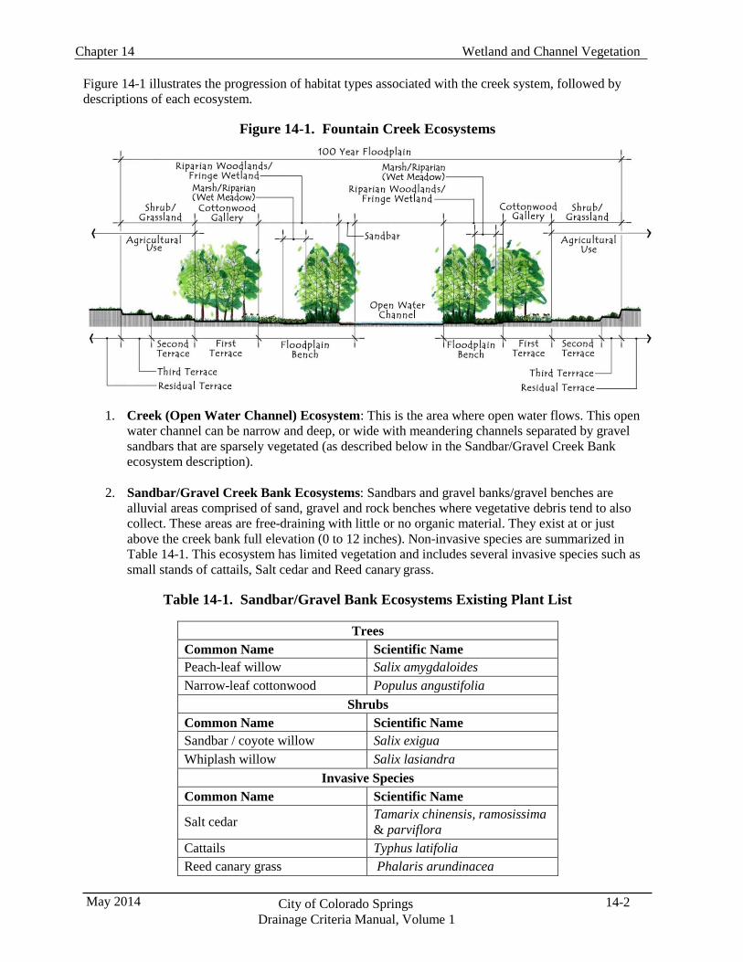
Wetland and Channel Vegetation Chapter 14
14-2 City of Colorado Springs Drainage Criteria Manual, Volume 1
May 2014
Figure 14-1 illustrates the progression of habitat types associated with the creek system, followed by descriptions of each ecosystem.
Figure 14-1. Fountain Creek Ecosystems
1. Creek (Open Water Channel) Ecosystem: This is the area where open water flows. This open water channel can be narrow and deep, or wide with meandering channels separated by gravel sandbars that are sparsely vegetated (as described below in the Sandbar/Gravel Creek Bank ecosystem description).
2. Sandbar/Gravel Creek Bank Ecosystems: Sandbars and gravel banks/gravel benches are
alluvial areas comprised of sand, gravel and rock benches where vegetative debris tend to also collect. These areas are free-draining with little or no organic material. They exist at or just above the creek bank full elevation (0 to 12 inches). Non-invasive species are summarized in Table 14-1. This ecosystem has limited vegetation and includes several invasive species such as small stands of cattails, Salt cedar and Reed canary grass.
Table 14-1. Sandbar/Gravel Bank Ecosystems Existing Plant List
Trees
Common Name Scientific Name Peach-leaf willow Salix amygdaloides Narrow-leaf cottonwood Populus angustifolia
Shrubs Common Name Scientific Name Sandbar / coyote willow Salix exigua Whiplash willow Salix lasiandra
Invasive Species Common Name Scientific Name
Salt cedar Tamarix chinensis, ramosissima & parviflora
Cattails Typhus latifolia Reed canary grass Phalaris arundinacea
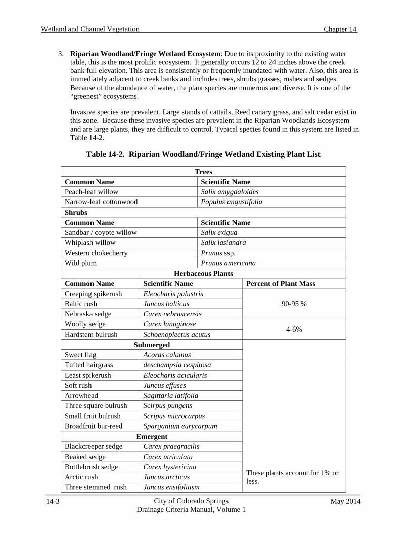
14-3 City of Colorado Springs Drainage Criteria Manual, Volume 1
May 2014
Wetland and Channel Vegetation Chapter 14
3. Riparian Woodland/Fringe Wetland Ecosystem: Due to its proximity to the existing water table, this is the most prolific ecosystem. It generally occurs 12 to 24 inches above the creek bank full elevation. This area is consistently or frequently inundated with water. Also, this area is immediately adjacent to creek banks and includes trees, shrubs grasses, rushes and sedges. Because of the abundance of water, the plant species are numerous and diverse. It is one of the “greenest” ecosystems.
Invasive species are prevalent. Large stands of cattails, Reed canary grass, and salt cedar exist in this zone. Because these invasive species are prevalent in the Riparian Woodlands Ecosystem and are large plants, they are difficult to control. Typical species found in this system are listed in Table 14-2.
Table 14-2. Riparian Woodland/Fringe Wetland Existing Plant List
Trees
Common Name Scientific Name Peach-leaf willow Salix amygdaloides Narrow-leaf cottonwood Populus angustifolia Shrubs Common Name Scientific Name Sandbar / coyote willow Salix exigua Whiplash willow Salix lasiandra Western chokecherry Prunus ssp. Wild plum Prunus americana
Herbaceous Plants Common Name Scientific Name Percent of Plant Mass Creeping spikerush Eleocharis palustris
90-95 % Baltic rush Juncus balticus Nebraska sedge Carex nebrascensis Woolly sedge Carex lanuginose
4-6% Hardstem bulrush Schoenoplectus acutus
Submerged These plants account for 1% or less.
Sweet flag Acoras calamus Tufted hairgrass deschampsia cespitosa Least spikerush Eleocharis acicularis Soft rush Juncus effuses Arrowhead Sagittaria latifolia Three square bulrush Scirpus pungens Small fruit bulrush Scripus microcarpus Broadfruit bur-reed Sparganium eurycarpum
Emergent Blackcreeper sedge Carex praegracilis Beaked sedge Carex utriculata Bottlebrush sedge Carex hystericina Arctic rush Juncus arcticus Three stemmed rush Juncus ensifoliusm
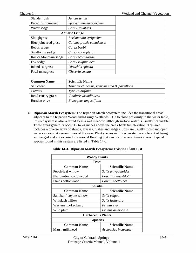
Wetland and Channel Vegetation Chapter 14
14-4 City of Colorado Springs Drainage Criteria Manual, Volume 1
May 2014
Slender rush Juncus tenuis Broadfruit bur-reed Sparganium eurycarpum Water sedge Carex aquatalis
Aquatic Fringe Sloughgrass Beckmannia syzigachne Blue joint reed grass Calamagrostis canadensis Bebbs sedge Carex bebbi Smallwing sedge Carex microptera Rocky Mountain sedge Carex scopulorum Fox sedge Carex vulpinoidea Inland saltgrass Distichlis spicata Fowl managrass Glyceria striata
Common Name Scientific Name Salt cedar Tamarix chinensis, ramosissima & parviflora Cattails Typhus latifolia Reed canary grass Phalaris arundinacea Russian olive Elaeagnus angustifolia
4. Riparian Marsh Ecosystem: The Riparian Marsh ecosystem includes the transitional areas adjacent to the Riparian Woodlands/Fringe Wetlands. Due to close proximity to the water table, this ecosystem is also referred to as a wet meadow, although surface water is usually not visible. These areas generally occur 12 to 24 inches above the creek bank full elevation. This area includes a diverse array of shrubs, grasses, rushes and sedges. Soils are usually moist and open water can exist at certain times of the year. Plant species in this ecosystem are tolerant of being submerged and are exposed to seasonal flooding that can occur several times a year. Typical species found in this system are listed in Table 14-3.
Table 14-3. Riparian Marsh Ecosystems Existing Plant List
Woody Plants
Trees Common Name Scientific Name
Peach-leaf willow Salix amygdaloides Narrow-leaf cottonwood Populus angustifolia Plains cottonwood Populus deltoides
Shrubs Common Name Scientific Name
Sandbar / coyote willow Salix exigua Whiplash willow Salix lasiandra Western chokecherry Prunus ssp. Wild plum Prunus americana
Herbaceous Plants Aquatics
Common Name Scientific Name Marsh milkweed
Asclepsias incarnata
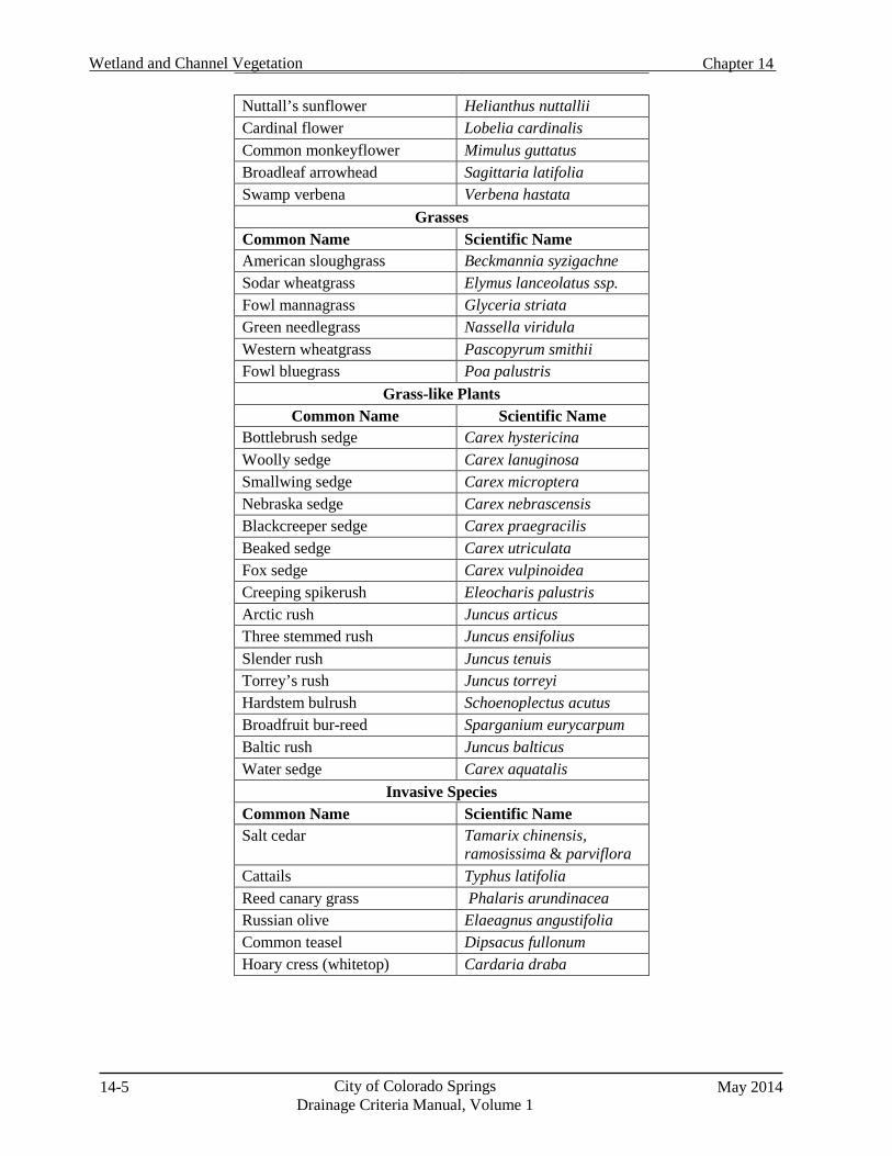
14-5 City of Colorado Springs Drainage Criteria Manual, Volume 1
May 2014
Wetland and Channel Vegetation Chapter 14
Nuttall’s sunflower Helianthus nuttallii Cardinal flower Lobelia cardinalis Common monkeyflower Mimulus guttatus Broadleaf arrowhead Sagittaria latifolia Swamp verbena Verbena hastata
Grasses Common Name Scientific Name American sloughgrass Beckmannia syzigachne Sodar wheatgrass Elymus lanceolatus ssp. Fowl mannagrass Glyceria striata Green needlegrass Nassella viridula Western wheatgrass Pascopyrum smithii Fowl bluegrass Poa palustris
Grass-like Plants Common Name Scientific Name
Bottlebrush sedge Carex hystericina Woolly sedge Carex lanuginosa Smallwing sedge Carex microptera Nebraska sedge Carex nebrascensis Blackcreeper sedge Carex praegracilis Beaked sedge Carex utriculata Fox sedge Carex vulpinoidea Creeping spikerush Eleocharis palustris Arctic rush Juncus articus Three stemmed rush Juncus ensifolius Slender rush Juncus tenuis Torrey’s rush Juncus torreyi Hardstem bulrush Schoenoplectus acutus Broadfruit bur-reed Sparganium eurycarpum Baltic rush Juncus balticus Water sedge Carex aquatalis
Invasive Species Common Name Scientific Name Salt cedar Tamarix chinensis,
ramosissima & parviflora Cattails Typhus latifolia Reed canary grass Phalaris arundinacea Russian olive Elaeagnus angustifolia Common teasel Dipsacus fullonum Hoary cress (whitetop) Cardaria draba
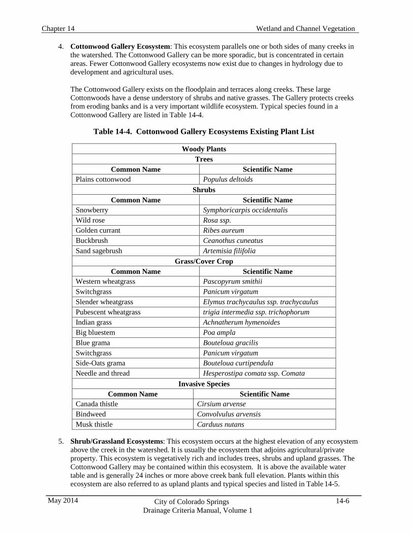
Wetland and Channel Vegetation Chapter 14
14-6 City of Colorado Springs Drainage Criteria Manual, Volume 1
May 2014
4. Cottonwood Gallery Ecosystem: This ecosystem parallels one or both sides of many creeks in
the watershed. The Cottonwood Gallery can be more sporadic, but is concentrated in certain areas. Fewer Cottonwood Gallery ecosystems now exist due to changes in hydrology due to development and agricultural uses.
The Cottonwood Gallery exists on the floodplain and terraces along creeks. These large Cottonwoods have a dense understory of shrubs and native grasses. The Gallery protects creeks from eroding banks and is a very important wildlife ecosystem. Typical species found in a Cottonwood Gallery are listed in Table 14-4.
Table 14-4. Cottonwood Gallery Ecosystems Existing Plant List
Woody Plants
Trees Common Name Scientific Name
Plains cottonwood Populus deltoids Shrubs
Common Name Scientific Name Snowberry Symphoricarpis occidentalis Wild rose Rosa ssp. Golden currant Ribes aureum Buckbrush Ceanothus cuneatus Sand sagebrush Artemisia filifolia
Grass/Cover Crop Common Name Scientific Name
Western wheatgrass Pascopyrum smithii Switchgrass Panicum virgatum Slender wheatgrass Elymus trachycaulus ssp. trachycaulus Pubescent wheatgrass trigia intermedia ssp. trichophorum Indian grass Achnatherum hymenoides Big bluestem Poa ampla Blue grama Bouteloua gracilis Switchgrass Panicum virgatum Side-Oats grama Bouteloua curtipendula Needle and thread Hesperostipa comata ssp. Comata
Invasive Species Common Name Scientific Name
Canada thistle Cirsium arvense Bindweed Convolvulus arvensis Musk thistle Carduus nutans
5. Shrub/Grassland Ecosystems: This ecosystem occurs at the highest elevation of any ecosystem above the creek in the watershed. It is usually the ecosystem that adjoins agricultural/private property. This ecosystem is vegetatively rich and includes trees, shrubs and upland grasses. The Cottonwood Gallery may be contained within this ecosystem. It is above the available water table and is generally 24 inches or more above creek bank full elevation. Plants within this ecosystem are also referred to as upland plants and typical species and listed in Table 14-5.
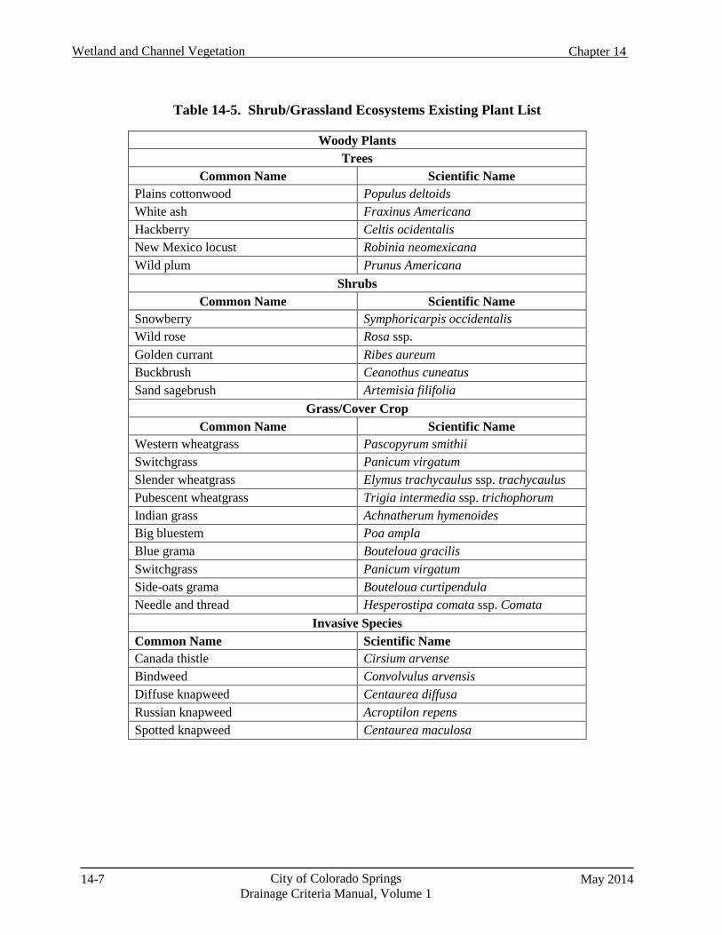
14-7 City of Colorado Springs Drainage Criteria Manual, Volume 1
May 2014
Wetland and Channel Vegetation Chapter 14
Table 14-5. Shrub/Grassland Ecosystems Existing Plant List
Woody Plants Trees
Common Name Scientific Name Plains cottonwood Populus deltoids White ash Fraxinus Americana Hackberry Celtis ocidentalis New Mexico locust Robinia neomexicana Wild plum Prunus Americana
Shrubs Common Name Scientific Name
Snowberry Symphoricarpis occidentalis Wild rose Rosa ssp. Golden currant Ribes aureum Buckbrush Ceanothus cuneatus Sand sagebrush Artemisia filifolia
Grass/Cover Crop Common Name Scientific Name
Western wheatgrass Pascopyrum smithii Switchgrass Panicum virgatum Slender wheatgrass Elymus trachycaulus ssp. trachycaulus Pubescent wheatgrass Trigia intermedia ssp. trichophorum Indian grass Achnatherum hymenoides Big bluestem Poa ampla Blue grama Bouteloua gracilis Switchgrass Panicum virgatum Side-oats grama Bouteloua curtipendula Needle and thread Hesperostipa comata ssp. Comata
Invasive Species Common Name Scientific Name Canada thistle Cirsium arvense Bindweed Convolvulus arvensis Diffuse knapweed Centaurea diffusa Russian knapweed Acroptilon repens Spotted knapweed Centaurea maculosa
Wetland and Channel Vegetation Chapter 14
14-8 City of Colorado Springs Drainage Criteria Manual, Volume 1
May 2014
4.0 Plant Species
4.1 General Guidelines
This section provides guidelines and recommendations on plant materials for revegetation of components of the drainage system including:
Natural channels
Grass-lined channels
Constructed wetlands/wetland channels
Streambank stabilization and grade control structures
There are different revegetation requirements for the various parts of these facilities. For example, planting trees and shrubs along the bottom of a channel can reduce the hydraulic capacity of the channel, increase maintenance requirements and cause the plugging of downstream bridges and culverts when uprooted by higher flows.
However, trees, shrubs and grasses due provide stabilization of the floodplain, which is critical to a healthy functioning riparian ecosystem. Native vegetation is also important to aquatic and terrestrial wildlife by providing food, effecting water temperatures and improving water quality. In order to allow native vegetation in the channel, the roughness caused by the native vegetation in the channel must be recognized in the hydraulic calculations. To the extent feasible, these guidelines should be followed when developing a landscape plan:
1. Plant material selection:
The form(s) of vegetation and species used should be adapted to the soils and moisture
conditions and intended use (e.g., conveyance of flow, side slope, etc.) of the area.
Native perennial species should be used to the extent possible.
Except along formal park settings, use of bluegrass and other species requiring irrigation and high maintenance should be avoided.
Sod-forming grasses are preferred over bunch grasses.
To the extent feasible, containerized nursery stock should be used for wetlands, trees and
shrubs.
Wetland plantings should not include cattails.
Maintenance requirements should be considered in plant selection (e.g., tall grasses should not be used in urban areas unless regular mowing will occur).
Whenever possible, live stakes, willow bundles and cottonwood poles should be obtained
from local, on-site sources (see Section 4.6).
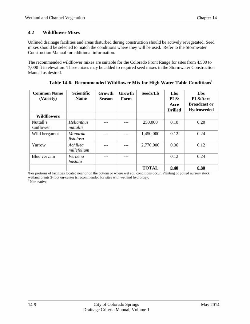
14-9 City of Colorado Springs Drainage Criteria Manual, Volume 1
May 2014
Wetland and Channel Vegetation Chapter 14
4.2 Wildflower Mixes
Unlined drainage facilities and areas disturbed during construction should be actively revegetated. Seed mixes should be selected to match the conditions where they will be used. Refer to the Stormwater Construction Manual for additional information.
The recommended wildflower mixes are suitable for the Colorado Front Range for sites from 4,500 to 7,000 ft in elevation. These mixes may be added to required seed mixes in the Stormwater Construction Manual as desired.
Table 14-6. Recommended Wildflower Mix for High Water Table Conditions1
Common Name
(Variety) Scientific
Name Growth Season
Growth Form
Seeds/Lb Lbs PLS/ Acre
Drilled
Lbs PLS/Acre
Broadcast or Hydroseeded
Wildflowers Nuttall’s sunflower
Helianthus nuttallii
--- --- 250,000 0.10 0.20
Wild bergamot Monarda fistulosa
--- --- 1,450,000 0.12 0.24
Yarrow Achillea millefolium
--- --- 2,770,000 0.06 0.12
Blue vervain Verbena hastata
--- --- 0.12 0.24
TOTAL 0.40 0.80 ¹For portions of facilities located near or on the bottom or where wet soil conditions occur. Planting of potted nursery stock wetland plants 2-foot on-center is recommended for sites with wetland hydrology. 2 Non-native
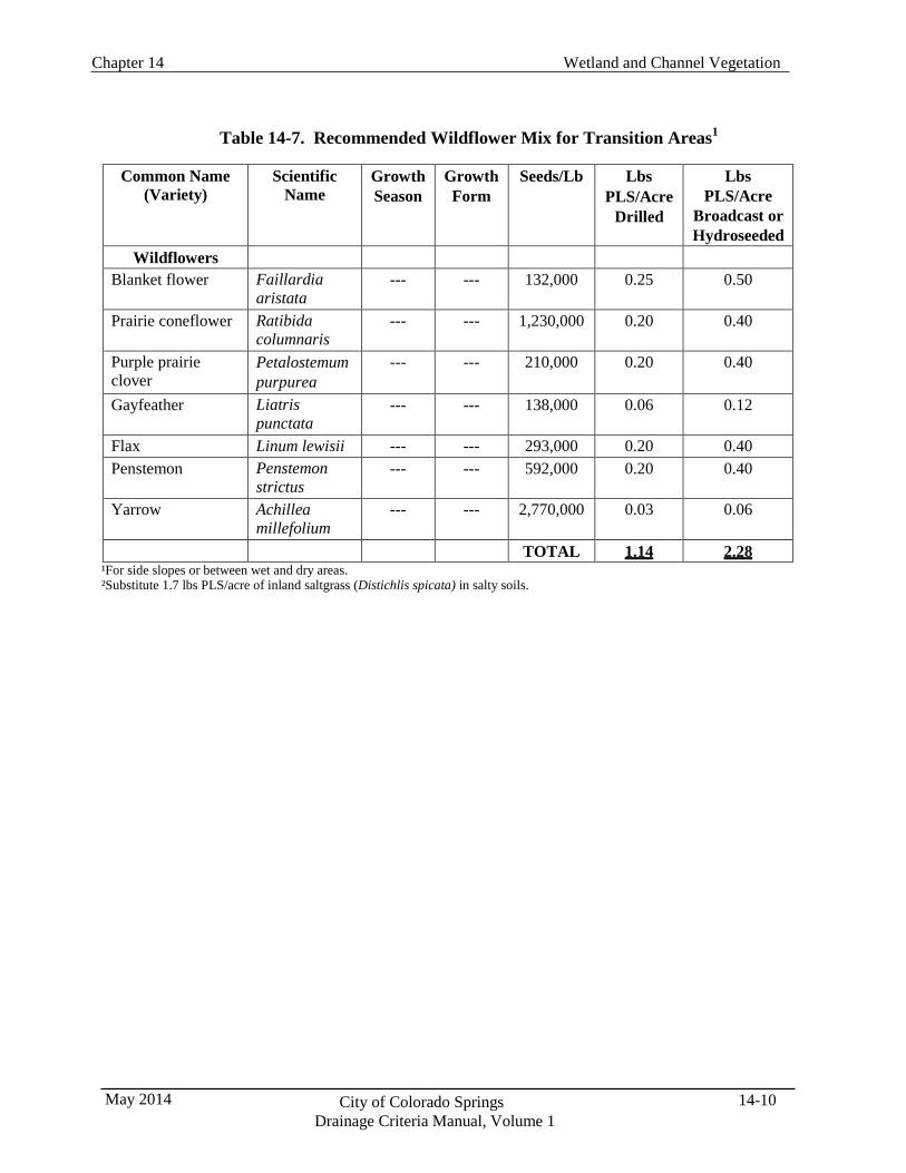
Wetland and Channel Vegetation Chapter 14
14-10 City of Colorado Springs Drainage Criteria Manual, Volume 1
May 2014
Table 14-7. Recommended Wildflower Mix for Transition Areas1
Common Name
(Variety) Scientific
Name Growth Season
Growth Form
Seeds/Lb Lbs PLS/Acre
Drilled
Lbs PLS/Acre
Broadcast or Hydroseeded
Wildflowers Blanket flower Faillardia
aristata --- --- 132,000 0.25 0.50
Prairie coneflower Ratibida columnaris
--- --- 1,230,000 0.20 0.40
Purple prairie clover
Petalostemum purpurea
--- --- 210,000 0.20 0.40
Gayfeather Liatris punctata
--- --- 138,000 0.06 0.12
Flax Linum lewisii --- --- 293,000 0.20 0.40 Penstemon Penstemon
strictus --- --- 592,000 0.20 0.40
Yarrow Achillea millefolium
--- --- 2,770,000 0.03 0.06
TOTAL 1.14 2.28 ¹For side slopes or between wet and dry areas. ²Substitute 1.7 lbs PLS/acre of inland saltgrass (Distichlis spicata) in salty soils.
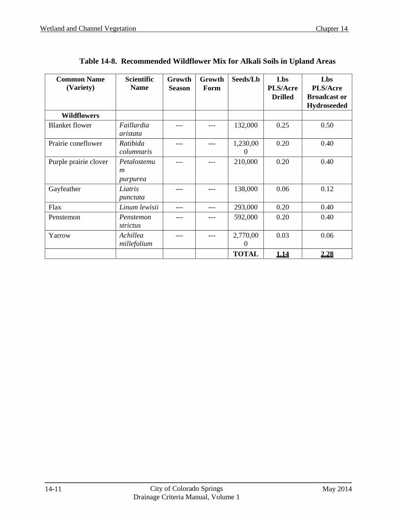
14-11 City of Colorado Springs Drainage Criteria Manual, Volume 1
May 2014
Wetland and Channel Vegetation Chapter 14
Table 14-8. Recommended Wildflower Mix for Alkali Soils in Upland Areas
Common Name (Variety)
Scientific Name
Growth Season
Growth Form
Seeds/Lb Lbs PLS/Acre
Drilled
Lbs PLS/Acre
Broadcast or Hydroseeded
Wildflowers Blanket flower Faillardia
aristata --- --- 132,000 0.25 0.50
Prairie coneflower Ratibida columnaris
--- --- 1,230,00 0
0.20 0.40
Purple prairie clover Petalostemu m purpurea
--- --- 210,000 0.20 0.40
Gayfeather Liatris punctata
--- --- 138,000 0.06 0.12
Flax Linum lewisii --- --- 293,000 0.20 0.40 Penstemon Penstemon
strictus --- --- 592,000 0.20 0.40
Yarrow Achillea millefolium
--- --- 2,770,00 0
0.03 0.06
TOTAL 1.14 2.28
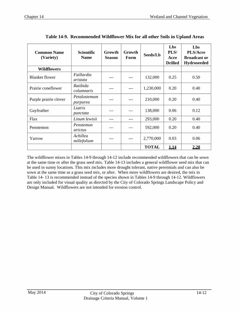
Wetland and Channel Vegetation Chapter 14
14-12 City of Colorado Springs Drainage Criteria Manual, Volume 1
May 2014
Table 14-9. Recommended Wildflower Mix for all other Soils in Upland Areas
Common Name
(Variety)
Scientific
Name
Growth Season
Growth Form
Seeds/Lb
Lbs PLS/ Acre
Drilled
Lbs PLS/Acre
Broadcast or Hydroseeded
Wildflowers
Blanket flower Faillardia aristata --- --- 132,000 0.25 0.50
Prairie coneflower Ratibida columnaris --- --- 1,230,000 0.20 0.40
Purple prairie clover Petalostemum purpurea --- --- 210,000 0.20 0.40
Gayfeather Liatris punctata --- --- 138,000 0.06 0.12
Flax Linum lewisii --- --- 293,000 0.20 0.40
Penstemon Penstemon strictus --- --- 592,000 0.20 0.40
Yarrow Achillea millefolium --- --- 2,770,000 0.03 0.06
TOTAL 1.14 2.28
The wildflower mixes in Tables 14-9 through 14-12 include recommended wildflowers that can be sown at the same time or after the grass seed mix. Table 14-13 includes a general wildflower seed mix that can be used in sunny locations. This mix includes more drought tolerant, native perennials and can also be sown at the same time as a grass seed mix, or after. When more wildflowers are desired, the mix in Table 14- 13 is recommended instead of the species shown in Tables 14-9 through 14-12. Wildflowers are only included for visual quality as directed by the City of Colorado Springs Landscape Policy and Design Manual. Wildflowers are not intended for erosion control.
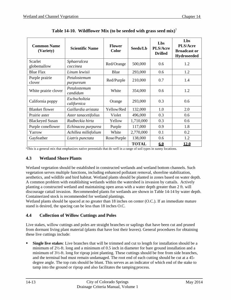
14-13 City of Colorado Springs Drainage Criteria Manual, Volume 1
May 2014
Wetland and Channel Vegetation Chapter 14
Table 14-10. Wildflower Mix (to be seeded with grass seed mix)1
Common Name (Variety)
Scientific Name
Flower Color
Seeds/Lb Lbs
PLS/Acre Drilled
Lbs PLS/Acre
Broadcast or Hydroseeded
Scarlet globemallow
Sphaeralcea coccinea Red/Orange 500,000 0.6 1.2
Blue Flax Linum lewisii Blue 293,000 0.6 1.2 Purple prairie clover
Petalostemum purpureum Red/Purple 210,000 0.7 1.4
White prairie clover Petalostemum candidum White 354,000 0.6 1.2
California poppy Eschscholtzia californica Orange 293,000 0.3 0.6
Blanket flower Gaillardia aristata Yellow/Red 132,000 1.0 2.0 Prairie aster Aster tanacetifolius Violet 496,000 0.3 0.6 Blackeyed Susan Rudbeckia hirta Yellow 1,710,000 0.3 0.6 Purple coneflower Echinacea purpurea Purple 117,000 0.9 1.8 Yarrow Achillea millefolium White 2,770,000 0.1 0.2 Gayfeather Liatris punctata Rose/Purple 138,000 0.6 1.2
TOTAL 6.0 12.0 ¹This is a general mix that emphasizes native perennials that do well in a range of soil types in sunny locations.
4.3 Wetland Shore Plants
Wetland vegetation should be established in constructed wetlands and wetland bottom channels. Such vegetation serves multiple functions, including enhanced pollutant removal, shoreline stabilization, aesthetics, and wildlife and bird habitat. Wetland plants should be planted in zones based on water depth. A common problem with establishing wetlands within the watershed is invasion by cattails. Actively planting a constructed wetland and maintaining open areas with a water depth greater than 2 ft. will discourage cattail invasion. Recommended plants for wetlands are shown in Table 14-14 by water depth. Containerized stock is recommended for wetland plantings. Wetland plants should be spaced at no greater than 18 inches on center (O.C.). If an immediate mature stand is desired, the spacing can be less than 18 inches O.C.
4.4 Collection of Willow Cuttings and Poles
Live stakes, willow cuttings and poles are straight branches or saplings that have been cut and pruned from dormant living plant material (plants that have lost their leaves). General procedures for obtaining these live cuttings include:
Single live stakes: Live branches that will be trimmed and cut to length for installation should be a
minimum of 2½-ft. long and a minimum of 0.5 inch in diameter for bare ground installation and a minimum of 3½-ft. long for riprap joint planting. These cuttings should be free from side branches, and the terminal bud must remain undamaged. The root end of each cutting should be cut at a 45- degree angle. The top cuts should be blunt. This serves as an indicator of which end of the stake to tamp into the ground or riprap and also facilitates the tamping process.
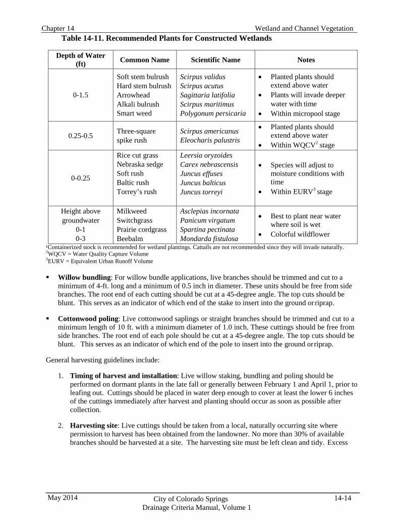
Wetland and Channel Vegetation Chapter 14
14-14 City of Colorado Springs Drainage Criteria Manual, Volume 1
May 2014
Table 14-11. Recommended Plants for Constructed Wetlands
Depth of Water (ft) Common Name Scientific Name Notes
0-1.5
Soft stem bulrush Hard stem bulrush Arrowhead Alkali bulrush Smart weed
Scirpus validus Scirpus acutus Sagittaria latifolia Scirpus maritimus Polygonum persicaria
• Planted plants should extend above water
• Plants will invade deeper water with time
• Within micropool stage
0.25-0.5 Three-square
spike rush Scirpus americanus Eleocharis palustris
• Planted plants should extend above water
• Within WQCV2 stage
0-0.25
Rice cut grass Nebraska sedge Soft rush Baltic rush Torrey’s rush
Leersia oryzoides Carex nebrascensis Juncus effuses Juncus balticus Juncus torreyi
• Species will adjust to
moisture conditions with time
• Within EURV3 stage
Height above groundwater
0-1 0-3
Milkweed Switchgrass Prairie cordgrass Beebalm
Asclepias incornata Panicum virgatum Spartina pectinata Mondarda fistulosa
• Best to plant near water where soil is wet
• Colorful wildflower
¹Containerized stock is recommended for wetland plantings. Cattails are not recommended since they will invade naturally. 2WQCV = Water Quality Capture Volume 3EURV = Equivalent Urban Runoff Volume
Willow bundling: For willow bundle applications, live branches should be trimmed and cut to a
minimum of 4-ft. long and a minimum of 0.5 inch in diameter. These units should be free from side branches. The root end of each cutting should be cut at a 45-degree angle. The top cuts should be blunt. This serves as an indicator of which end of the stake to insert into the ground or riprap.
Cottonwood poling: Live cottonwood saplings or straight branches should be trimmed and cut to a
minimum length of 10 ft. with a minimum diameter of 1.0 inch. These cuttings should be free from side branches. The root end of each pole should be cut at a 45-degree angle. The top cuts should be blunt. This serves as an indicator of which end of the pole to insert into the ground or riprap.
General harvesting guidelines include:
1. Timing of harvest and installation: Live willow staking, bundling and poling should be
performed on dormant plants in the late fall or generally between February 1 and April 1, prior to leafing out. Cuttings should be placed in water deep enough to cover at least the lower 6 inches of the cuttings immediately after harvest and planting should occur as soon as possible after collection.
2. Harvesting site: Live cuttings should be taken from a local, naturally occurring site where
permission to harvest has been obtained from the landowner. No more than 30% of available branches should be harvested at a site. The harvesting site must be left clean and tidy. Excess
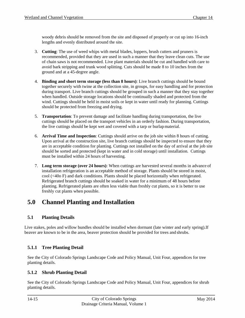
14-15 City of Colorado Springs Drainage Criteria Manual, Volume 1
May 2014
Wetland and Channel Vegetation Chapter 14
woody debris should be removed from the site and disposed of properly or cut up into 16-inch lengths and evenly distributed around the site.
3. Cutting: The use of weed whips with metal blades, loppers, brush cutters and pruners is
recommended, provided that they are used in such a manner that they leave clean cuts. The use of chain saws is not recommended. Live plant materials should be cut and handled with care to avoid bark stripping and trunk wood splitting. Cuts should be made 8 to 10 inches from the ground and at a 45-degree angle.
4. Binding and short term storage (less than 8 hours): Live branch cuttings should be bound
together securely with twine at the collection site, in groups, for easy handling and for protection during transport. Live branch cuttings should be grouped in such a manner that they stay together when handled. Outside storage locations should be continually shaded and protected from the wind. Cuttings should be held in moist soils or kept in water until ready for planning. Cuttings should be protected from freezing and drying.
5. Transportation: To prevent damage and facilitate handling during transportation, the live
cuttings should be placed on the transport vehicles in an orderly fashion. During transportation, the live cuttings should be kept wet and covered with a tarp or burlap material.
6. Arrival Time and Inspection: Cuttings should arrive on the job site within 8 hours of cutting.
Upon arrival at the construction site, live branch cuttings should be inspected to ensure that they are in acceptable condition for planting. Cuttings not installed on the day of arrival at the job site should be sorted and protected (kept in water and in cold storage) until installation. Cuttings must be installed within 24 hours of harvesting.
7. Long term storage (over 24 hours): When cuttings are harvested several months in advance of
installation refrigeration is an acceptable method of storage. Plants should be stored in moist, cool (<40o F) and dark conditions. Plants should be placed horizontally when refrigerated. Refrigerated branch cuttings should be soaked in water for a minimum of 48 hours before planting. Refrigerated plants are often less viable than freshly cut plants, so it is better to use freshly cut plants when possible.
5.0 Channel Planting and Installation
5.1 Planting Details Live stakes, poles and willow bundles should be installed when dormant (late winter and early spring).If beaver are known to be in the area, beaver protection should be provided for trees and shrubs.
5.1.1 Tree Planting Detail
See the City of Colorado Springs Landscape Code and Policy Manual, Unit Four, appendices for tree planting details.
5.1.2 Shrub Planting Detail
See the City of Colorado Springs Landscape Code and Policy Manual, Unit Four, appendices for shrub planting details.
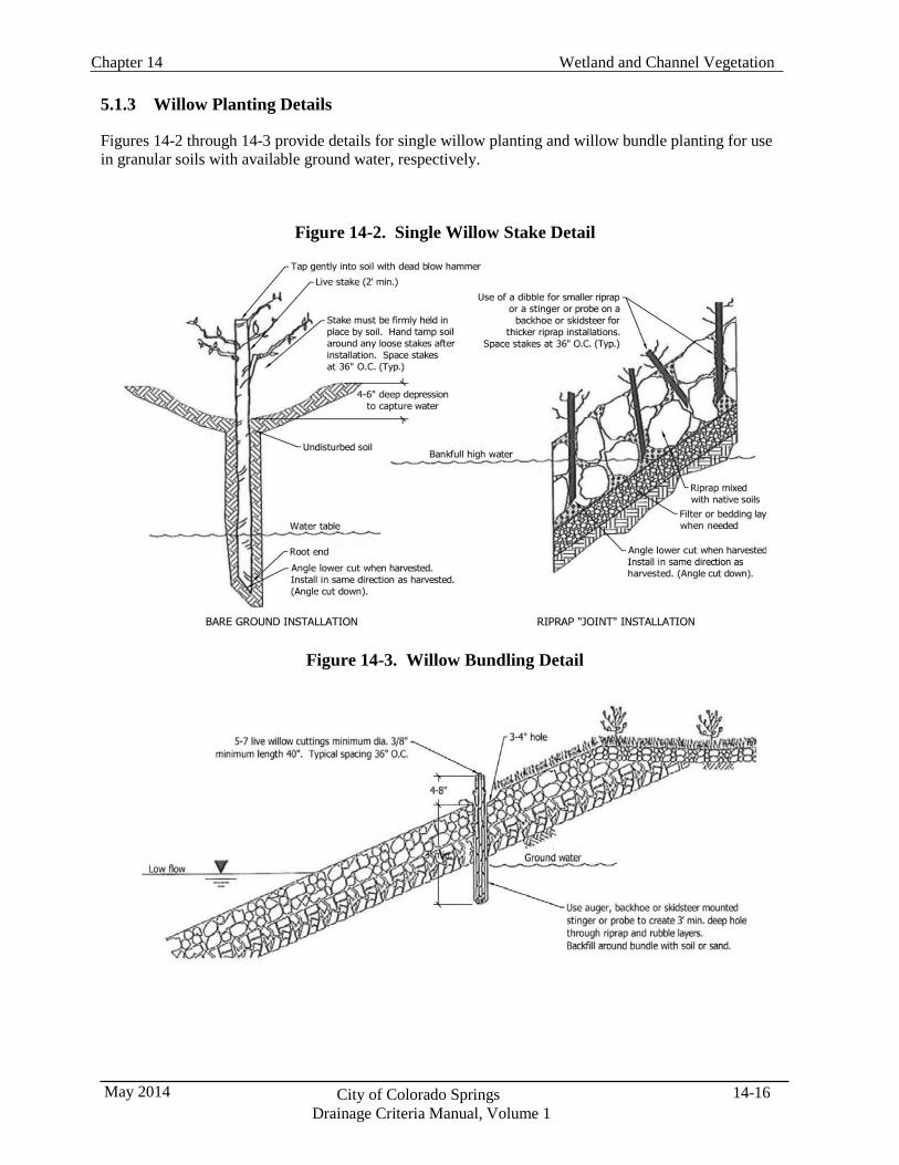
Wetland and Channel Vegetation Chapter 14
14-16 City of Colorado Springs Drainage Criteria Manual, Volume 1
May 2014
5.1.3 Willow Planting Details
Figures 14-2 through 14-3 provide details for single willow planting and willow bundle planting for use in granular soils with available ground water, respectively.
Figure 14-2. Single Willow Stake Detail
Figure 14-3. Willow Bundling Detail
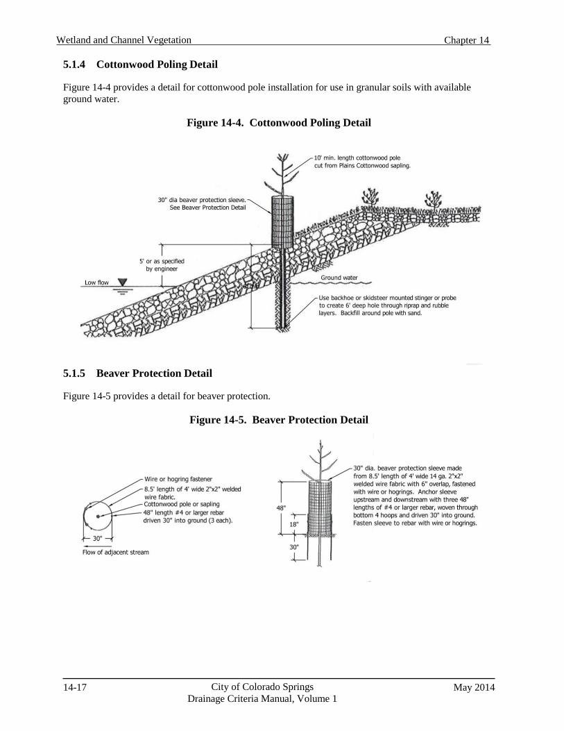
14-17 City of Colorado Springs Drainage Criteria Manual, Volume 1
May 2014
Wetland and Channel Vegetation Chapter 14
5.1.4 Cottonwood Poling Detail
Figure 14-4 provides a detail for cottonwood pole installation for use in granular soils with available ground water.
Figure 14-4. Cottonwood Poling Detail
5.1.5 Beaver Protection Detail
Figure 14-5 provides a detail for beaver protection.
Figure 14-5. Beaver Protection Detail
Wetland and Channel Vegetation Chapter 14
14-18 City of Colorado Springs Drainage Criteria Manual, Volume 1
May 2014
8.0 References Bell, F. H. 2002. City of Colorado Springs Landscape Code and Policy Manual. Prepared by Fawn
Hayes Bell, ASLA, Urban Design Site Planning, Landscape Architecture, 1619 Wood Avenue, Colorado Springs, Colorado 80907, (1st Printing 1998), (Second Printing 2002).
City of Colorado Springs, Colorado, 2009. Streamside Design Guidelines. (Revised).
Colorado State University, 2010. Extension Soil Sampling Fact Sheet No. 0.500. Issued June 1997,
Revised March 2010.
Kelso, T. and S. Tolve, 2006. Conservation Values and Management of the Venetucci Farm Riparian Corridor. A Report to the Pikes Peak Community Foundation. Prepared by Department of Biology, Department of Colorado College. February.
THK Associates, Inc. and Matrix Design Group, 2011. The Fountain Creek Corridor Restoration
Master Plan. October 18, 2011.
U.S. Army Corps of Engineers, Albuquerque District, 2009. Fountain Creek Watershed Study Watershed Management Plan. January.
USDA Forest Service 2006. Point Intercept (PO) Sampling Method, USDA Forest Service Gen. Tech.
Rep. RMRS-GTR-164-CD. Prepared by John Caratti.