Embed Size (px)
Citation preview
TS
DOE-STD-3003-2000January 2000
SupersedingDOE-STD-3003-94September 1994
DOE STANDARD
BACKUP POWER SOURCES FOR DOEFACILITIES
U.S. Department of Energy AREA EDCNWashington, D.C. 20858
DISTRIBUTION STATEMENT A. Approved for public release; distribution is unlimited.
METRIC
This document has been reproduced directly from the best available copy.
Available to DOE and DOE contractors from ES&H Technical InformationServices, U.S. Department of Energy, (800) 473-4375, fax: (301) 903-9823.
Available to the public from the U.S. Department of Commerce, TechnologyAdministration, National Technical Information Service, Springfield, VA 22161;(703) 605-6000.
DOE-STD-3003-2000
iii
FOREWORD
1. This Standard is approved for use by the U.S. Department of Energy (DOE). ThisStandard is not a DOE Order, and its requirements are not automatically invoked at anyfacilities or on any BACKUP POWER SOURCES. This Standard is intended for use by theoperations/field offices or management and operating (M&O) contractors at their discretion.Activities applying this Standard must tailor the requirements to the specific application asdiscussed in 6.3. This Standard may be invoked by contractual documents, procurementdocuments, or in the authorization basis for a facility. Unless it is invoked as above, thecontractor will not be assessed or inspected against its requirements. This Standard is alsosuitable for voluntary use by engineers responsible for BACKUP POWER SOURCES at DOEfacilities.
2. Acronyms used in this Standard are defined in Section 3 and are therefore notspelled out at their first occurrence. Terms defined in Section 3 are CAPITALIZED in the text.
3. Beneficial comments (recommendations, additions, deletions) and any pertinent datathat may improve this document should be sent to: DOE Backup Power Working Group, incare of John Fredlund, DP-45 GTN, U.S. Department of Energy, 19901 Germantown Road,Germantown, MD 20874-1290. The back page of this document may be copied for thispurpose.
4. This Standard was prepared in cooperation with and using input from the membersof the Backup Power Working Group (BPWG).
The charter of the group is as follows:
The DOE BPWG fosters safe, practical, and effective testing, maintenance, operation, design,and installation of systems and equipment used to provide backup electrical power at DOEfacilities. The BPWG provides an open forum on standard practices, safety issues, training,and solutions to problems encountered at DOE facilities. The BPWG promulgates its learningthroughout the DOE complex and industry.
To fulfill its charter, the BPWG will:
* Share practical design and operating experience with BACKUP POWER SOURCES bypromoting a continuing exchange among DOE contractor personnel, Headquarters(HQ), Operations Offices, and industry.
* Examine existing standards applicable to BACKUP POWER SOURCES and adopt,endorse, or tailor them for DOE applications.
* Identify and apply techniques to achieve and maintain reliability and availabilitycommensurate with mission/safety objectives.
* Promote worker safety, public safety, protection of the environment, and the DOEmission in the application of BACKUP POWER SOURCES.
* Exchange successful and cost-effective management techniques.
DOE-STD-3003-2000
iv
* Identify potential means for coordination of training among DOE facilities.
* Discuss graded approaches for conformance with DOE orders.
In the course of meeting this obligation, the BPWG was instrumental in the development andadoption of this Standard. The BPWG provides unique expertise (by virtue of its involvement inthe development of this Standard and its responsibilities within the organizations maintainingBACKUP POWER SOURCES) to beneficially impact the reliability of BACKUP POWERSOURCES through promotion and facilitation of the use of this Standard. For information onthe BPWG, see http://www.dp.doe.gov/CTG/bpwg/bpwg.htm or contact John Fredlund, DP-45,phone (301) 903-3059.
5. ENGINE GENERATORS, UNINTERRUPTIBLE POWER SUPPLIES, andSTATIONARY BATTERIES are used to provide electrical power to equipment upon loss of thenormal source when either external (GRID) or internal (plant equipment) failures occur. Theneed for this backup power ranges from supplying safety class equipment to convenienceonly. BACKUP POWER SOURCES may be classified under a number of different authorities.Some important aspects of the availability of electrical power are derived from public healthand safety, environmental concerns, plant security, costs related to lost production, damage toproducts or equipment, critical operating considerations, compliance with Occupational Safetyand Health Administration (OSHA) requirements, and communications. Reliable performanceof the required functions of backup and emergency sources can be ensured through properengineering, installation, appropriate testing, and maintenance. This can be seen from aUniversity of Dayton Research Institute study of diesel generator failures that resulted inseveral recommendations to improve diesel generator reliability (see Appendix I).
6. This Standard identifies fundamental criteria, surveillance testing, reporting, andreliability program considerations, which if properly implemented, should improve and maintaincapable and reliable backup and emergency power sources. Maintenance programs forBACKUP POWER SOURCES are also required by DOE 4330.4, Maintenance ManagementProgram.
7. In the process of developing this Standard, industry standards (including those of theNational Fire Protection Association (NFPA), and the Institute of Electrical and ElectronicsEngineers (IEEE)) and guidance were reviewed. This Standard incorporates thoserequirements and guidance from industry standards considered appropriate for backup powersystem equipment important to worker safety and/or the DOE mission at DOE HazardCategory II facilities. Category I facilities (as defined in DOE STD-1027-92) may place morestringent requirements on design, maintenance and testing commensurate with the safetysignificance of the power source.
8. This 2000 revision of this standard was unanimously supported by users fromseveral DOE sites. It has been updated and slightly rearranged. Several requirements weresoftened based on field experiences. Section 4.1 was changed to take advantage of DOE-STD-3024. Sections 5.3.1 and 5.4.1 were reworded to take advantage of DOE-SPEC-3018,DOE-SPEC-3019, and DOE-SPEC-3021.
DOE-STD-3003-2000
v
CONTENTS
PARAGRAPH PAGE
FOREWORD . . . . . . . . . . . . . . . . . . . . . . . . . . . . . . . . . . . . . . . . . . . . . . . . . . . . . . . . . . . . . iii
1. SCOPE . . . . . . . . . . . . . . . . . . . . . . . . . . . . . . . . . . . . . . . . . . . . . . . . . . . . . . . . . . . . . 11.1 Applicability . . . . . . . . . . . . . . . . . . . . . . . . . . . . . . . . . . . . . . . . . . . . . . . . . . . . . . 11.2 Purpose . . . . . . . . . . . . . . . . . . . . . . . . . . . . . . . . . . . . . . . . . . . . . . . . . . . . . . . . . 11.3 Background . . . . . . . . . . . . . . . . . . . . . . . . . . . . . . . . . . . . . . . . . . . . . . . . . . . . . . 1
2. APPLICABLE DOCUMENTS . . . . . . . . . . . . . . . . . . . . . . . . . . . . . . . . . . . . . . . . . . . . . 22.1 Government documents . . . . . . . . . . . . . . . . . . . . . . . . . . . . . . . . . . . . . . . . . . . . . 22.2 Non-Government publications . . . . . . . . . . . . . . . . . . . . . . . . . . . . . . . . . . . . . . . . 2
3. DEFINITIONS . . . . . . . . . . . . . . . . . . . . . . . . . . . . . . . . . . . . . . . . . . . . . . . . . . . . . . . . 4
4. GENERAL REQUIREMENTS . . . . . . . . . . . . . . . . . . . . . . . . . . . . . . . . . . . . . . . . . . . . 64.1 System Design Description . . . . . . . . . . . . . . . . . . . . . . . . . . . . . . . . . . . . . . . . . . 64.2 Conflicting Requirements . . . . . . . . . . . . . . . . . . . . . . . . . . . . . . . . . . . . . . . . . . . . 64.3 Control of changes . . . . . . . . . . . . . . . . . . . . . . . . . . . . . . . . . . . . . . . . . . . . . . . . . 64.4 Ownership . . . . . . . . . . . . . . . . . . . . . . . . . . . . . . . . . . . . . . . . . . . . . . . . . . . . . . . 64.5 User(s) . . . . . . . . . . . . . . . . . . . . . . . . . . . . . . . . . . . . . . . . . . . . . . . . . . . . . . . . . . 64.6 Identification plaque . . . . . . . . . . . . . . . . . . . . . . . . . . . . . . . . . . . . . . . . . . . . . . . . 74.7 Maintenance requirements . . . . . . . . . . . . . . . . . . . . . . . . . . . . . . . . . . . . . . . . . . . 7
4.7.1 Maintenance records . . . . . . . . . . . . . . . . . . . . . . . . . . . . . . . . . . . . . . . . 74.7.2 Coordination . . . . . . . . . . . . . . . . . . . . . . . . . . . . . . . . . . . . . . . . . . . . . . 74.7.3 Centralized Maintenance . . . . . . . . . . . . . . . . . . . . . . . . . . . . . . . . . . . . . 7
4.8 Testing . . . . . . . . . . . . . . . . . . . . . . . . . . . . . . . . . . . . . . . . . . . . . . . . . . . . . . . . . . 7
5. DETAILED REQUIREMENTS . . . . . . . . . . . . . . . . . . . . . . . . . . . . . . . . . . . . . . . . . . . . 85.1 Requirements applicable to all BACKUP POWER SOURCES . . . . . . . . . . . . . . . 8
5.1.1 Internal events . . . . . . . . . . . . . . . . . . . . . . . . . . . . . . . . . . . . . . . . . . . . . 85.1.2 External events . . . . . . . . . . . . . . . . . . . . . . . . . . . . . . . . . . . . . . . . . . . . 85.1.3 OUTPUT BREAKERS . . . . . . . . . . . . . . . . . . . . . . . . . . . . . . . . . . . . . . . 85.1.4 Maintenance . . . . . . . . . . . . . . . . . . . . . . . . . . . . . . . . . . . . . . . . . . . . . . 85.1.5 Testing . . . . . . . . . . . . . . . . . . . . . . . . . . . . . . . . . . . . . . . . . . . . . . . . . . . 9
5.2 EG Requirements . . . . . . . . . . . . . . . . . . . . . . . . . . . . . . . . . . . . . . . . . . . . . . . . . 105.2.1 EG capabilities . . . . . . . . . . . . . . . . . . . . . . . . . . . . . . . . . . . . . . . . . . . . 105.2.2 Qualification of maintenance personnel for EGs . . . . . . . . . . . . . . . . . . 135.2.3 EG testing . . . . . . . . . . . . . . . . . . . . . . . . . . . . . . . . . . . . . . . . . . . . . . . 13
5.3 UPS system requirements . . . . . . . . . . . . . . . . . . . . . . . . . . . . . . . . . . . . . . . . . . 165.3.1 UPS capabilities . . . . . . . . . . . . . . . . . . . . . . . . . . . . . . . . . . . . . . . . . . . 165.3.2 Maintenance and repair of UPS . . . . . . . . . . . . . . . . . . . . . . . . . . . . . . . 165.3.3 Testing of UPS systems . . . . . . . . . . . . . . . . . . . . . . . . . . . . . . . . . . . . 17
5.4 STATIONARY BATTERY system requirements . . . . . . . . . . . . . . . . . . . . . . . . . . 175.4.1 Battery system capabilities . . . . . . . . . . . . . . . . . . . . . . . . . . . . . . . . . . 185.4.2 Battery maintenance, testing, and surveillance . . . . . . . . . . . . . . . . . . . 18
6. NOTES . . . . . . . . . . . . . . . . . . . . . . . . . . . . . . . . . . . . . . . . . . . . . . . . . . . . . . . . . . . . 216.1 Intended use . . . . . . . . . . . . . . . . . . . . . . . . . . . . . . . . . . . . . . . . . . . . . . . . . . . . 21
DOE-STD-3003-00
vi
6.2 Revision status . . . . . . . . . . . . . . . . . . . . . . . . . . . . . . . . . . . . . . . . . . . . . . . . . . . 216.3 Tailoring guidance . . . . . . . . . . . . . . . . . . . . . . . . . . . . . . . . . . . . . . . . . . . . . . . . 216.4 Subject term (key word) listing . . . . . . . . . . . . . . . . . . . . . . . . . . . . . . . . . . . . . . . 21
APPENDIX I . . . . . . . . . . . . . . . . . . . . . . . . . . . . . . . . . . . . . . . . . . . . . . . . . . . . . . . . . . . . . . 22
APPENDIX II . . . . . . . . . . . . . . . . . . . . . . . . . . . . . . . . . . . . . . . . . . . . . . . . . . . . . . . . . . . . . . 23
CONCLUDING MATERIAL . . . . . . . . . . . . . . . . . . . . . . . . . . . . . . . . . . . . . . . . . . . . . . . . . . . 32
DOE-STD-3003-2000
1
1. SCOPE
1.1 Applicability. This Standardestablishes fundamental requirements andguidance for BACKUP POWER SOURCESat DOE facilities.
1.2 Purpose. The purpose of thisStandard is to document good engineeringpractices for the installation, testing, andmaintenance of BACKUP POWERSOURCES at DOE facilities. The term"BACKUP POWER SOURCES" as used inthis Standard covers both "emergency" and"backup" power applications. These sourcestypically supply loads used to protect healthand safety of the public, workers, and theenvironment; and to reduce theconsequences of postulated events involvingnuclear, chemical, or other hazards or havingan adverse impact on the DOE mission. ThisStandard applies to design and operatingpractices for both permanent and temporaryinstallations used while permanent powersources are being serviced. Examples ofBACKUP POWER SOURCES covered bythis Standard are those which supply powerto nuclear safety systems, radiation monitorsand alarms, fire protection systems, securitysystems, data processing equipment, andemergency lighting. The significance of eachindividual BACKUP POWER SOURCEapplication should be analyzed to determinethe design requirements and classificationlevels. See 4.1 for more information on thesignificance of BACKUP POWERSOURCES. This Standard does not providecriteria to establish the need for or level ofimportance of BACKUP POWER SOURCES.
This Standard is not intended and should notbe used as the sole source of information todevelop design requirements for specificapplications. Other requirements such asthose found in DOE Order 420.1, FacilitySafety, may apply to BACKUP POWERSOURCES depending on their application.The many appropriate recommendedpractices presented in this Standard shouldbe implemented to maintain the reliability andavailability of BACKUP POWER SOURCES
at acceptable levels for both nuclear andnon-nuclear safety applications.
1.3 Background. As a result ofconcerns expressed by former Secretary ofEnergy James D. Watkins over the numberof incidents where BACKUP POWERSOURCES failed to provide electrical powerduring tests or actual demands, anAugmented Evaluation Team (AET) wasformed to evaluate the reliability andavailability of BACKUP POWER SOURCESat DOE DP facilities. The AET conducted aseries of on-site reviews for the purpose ofunderstanding the design, operation,maintenance, and safety significance ofemergency and backup power supplies. TheAET found that the quality of programsrelated to maintenance of backup powersystems varied greatly among the sitesvisited (and often among facilities at thesame site), and identified areas where thereliability of emergency and backup powersystems should be improved. This Standardwas originally developed to provide a vehiclefor BACKUP POWER SOURCE reliabilityimprovement to respond to the Secretary'sconcern and the findings of the AET.
DOE-STD-3003-2000
2
2. APPLICABLE DOCUMENTS
Unless otherwise specified by contract,solicitation, or purchase order, the currentissue of the following documents form a partof this document to the extent specifiedherein.
2.1 Government documents.
2.1.1 DOE standards, handbooks,technical standards lists (TSLs), andspecifications.
DOE-STD-1027-92 - HazardCategorization and Accident AnalysisTechniques for Compliance with DOE5480.23, Nuclear Safety AnalysisReports
DOE-STD-1073-93 - Guide forOperational Configuration ManagementProgram including the Adjunct Programof Design Reconstitution and MaterialCondition and Aging Management
DOE-STD-3024-98 - Content of SystemDesign Descriptions
DOE-SPEC-3018-96 - Flooded-TypeLead-Acid Storage Batteries
DOE-SPEC-3019-96 - Valve-RegulatedType Lead-Acid Storage Batteries
DOE-SPEC-3021-97 - UninterruptiblePower Supply Systems
DOE-HDBK-1092-98, Electrical Safety
2.1.2 Other Government documents,drawings, and publications.
DOE O 420.1 - Facility Safety
DOE 4330.4 - MaintenanceManagement Program
DOE 5480.23 - Nuclear Safety AnalysisReports
Federal Specification VV-F-800, Fuel Oil
NRC Publication NUREG/CR 0660 -Enhancement of On-Site EmergencyDiesel Generator Reliability
NRC Regulatory Guide 1.160 -Monitoring the Effectiveness ofMaintenance at Nuclear Power Plants
NRC Regulatory Guide 1.9 - Selection,Design, Qualification, and Testing ofEmergency Diesel Generator UnitsUsed as Class 1E Onsite ElectricPower Systems at Nuclear PowerPlants
2.2 Non-Government publications.
ANS 59.51 - Fuel Oil Systems forSafety-Related Emergency DieselGenerators
ANSI/IEEE Std 944 - IEEERecommended Practice for theApplication and Testing of UninterruptiblePower Supplies for Power GeneratingStations
ASTM D975 - Standard Specification forDiesel Fuel Oils
ASTM D4057 - Standard Method ofSampling Petroleum Products
IEEE Std 387 - Standard Criteria forDiesel-Generator Units Applied asStandby Power Supplies for NuclearPower Generating Stations
IEEE Std 446 - Emergency and StandbyPower Systems for Industrial andCommercial Applications
IEEE Std 450 - Recommended Practicefor Maintenance, Testing, andReplacement of Large Lead StorageBatteries for Generating Stations andSubstations
DOE-STD-3003-2000
3
IEEE Std 484 - Recommended Practicefor Installation Design and Installation ofVented Lead-Acid Batteries forStationary Applications
IEEE Std 485 - Recommended Practicefor Sizing Large Lead Storage Batteriesfor Generating Stations andSubstations
IEEE Std 762 - Standard Definitions forUse in Reporting Electric GeneratingUnit Reliability, Availability andProductivity
IEEE Std 1106 - IEEE RecommendedPractice for Installation, Maintenance,Testing, and Replacement of VentedNickel-Cadmium Batteries for StationaryApplications
IEEE Std 1115 - RecommendedPractice for Sizing Nickel-CadmiumBatteries for Stationary Applications
IEEE Std 1187 - IEEE RecommendedPractice for Installation Design andInstallation of Valve-Regulated Lead-Acid Storage Batteries for StationaryApplications
IEEE Std 1188 - RecommendedPractice for Maintenance, Testing, andReplacement of Valve-RegulatedLead-Acid (VRLA) Batteries forStationary Applications
NFPA 37 - Standard for the Installationand Use of Stationary CombustionEngines and Gas Turbines
NFPA 110 - Standard for Emergencyand Standby Power Systems
NFPA 111 - Standard on StoredElectrical Energy Emergency andStandby Power Systems
DOE-STD-3003-2000
4
3. DEFINITIONS
All key terms used in this Standard aredefined below.
3.1 Acronyms used in this Standard.
a. ac - alternating current
b. AET - Augmented EvaluationTeam
c. ANSI - American NationalStandards Institute
d. ASTM - American Society forTesting & Materials
e. BPWG - Backup Power WorkingGroup
f. C - Centigrade
g. dc - direct current
h. DOE - Department of Energy
i. DP - Defense Programs
j. EG - ENGINE GENERATOR
k. g - grams
l. HQ - Headquarters
m. IEEE - Institute of Electrical &Electronics Engineers
n. kw - kilowatt
o. M&O - management andoperating
p. mm - millimeters
q. NCR - Nonconformance Report
r. NRC - Nuclear RegulatoryCommission
s. NFPA - National Fire ProtectionAssociation
t. OSHA - Occupational Safety andHealth Administration
u. RCA - Radiologically ControlledArea
v. RWP - Radiation Work Permit
w. STD/Std - Standard
x. UPS - UNINTERRUPTIBLEPOWER SUPPLY
3.2 Backup Power Source. Powersource used to supply electrical power whenthe normal source is unavailable. Forsimplicity, this Standard uses the term"backup" as an all-encompassing term."Emergency" is generally used only when thepower source is required for nuclear safety orto ensure personnel safety.
3.3 Continuous rating. Maximumcontinuous power output the EG canmaintain in the service environment withoutnecessitating deviation from themanufacturer's recommended scheduledmaintenance.
3.4 Design Requirements. As definedby DOE-STD-1073.
3.5 Droop mode. Mode in which the EGspeed is governed as a monotonic functionof engine load, used when operating inparallel with the GRID to avoid instabilityproblems.
3.6 Engine generator. Independentelectrical power supply unit consisting of aninternal combustion engine (diesel, gasoline)directly coupled to an electrical generatorwith associated instrumentation, controls,protective features, and auxiliary systems.
3.7 Equalizing charge. A chargeapplied to a battery, which is greater than thenormal float charge and is used to completely
DOE-STD-3003-2000
5
restore the active materials in the cell,bringing the cell FLOAT VOLTAGE and thespecific gravity of the individual cells back to"equal" values.
3.8 Float voltage. A continuous voltagesupplying a low current from a batterycharger applied to a battery in the standbymode to make up for internal losses andmaintain the battery in a fully charged state.
3.9 Grid. Offsite and/or onsiteinterconnected electrical power distributionsystem.
3.10 Hot restart. Restart of an EG fromits continuous duty equilibrium temperature.
3.11 Isochronous mode. Mode ofoperation of an EG whereby it establishes itsown operating speed to maintain the correctfrequency over the load range capacity of theEG.
3.12 Load breaker. Breaker that feedsand protects a load, located between thepower source bus and the load.
3.13 Output breaker. Breaker locatedbetween the BACKUP POWER SOURCE'soutput terminals and the bus feeding loads,intended to protect the BACKUP POWERSOURCE from various fault conditions and toprovide a means to connect and disconnectthe source from its load.
3.14 Performance Discharge Test. Testthat measures the existing capacity of abattery, to be compared to its rated capacity.The usual units of capacity are ampere-hours.
3.15 Short-time rating. Output rating(typically 110%) of an EG that can besustained for a specified time in a specifiedperiod of operation without necessitatingdeviation from normal scheduledmaintenance (usually 2 hours in 24, per IEEEStd 387).
3.16 Standby conditions. Normalequilibrium status of an EG ready to receivea start signal, either cold start or theconditions maintained by a keep-warm andcontinuous lubrication system.
3.17 Stationary Battery. A systemconsisting of a group of battery cells(connected in series, parallel, or combination)normally operated in parallel with acharger(s) and a load.
3.18 Synchronization. Bringing one acpower source of the same nominal frequencyas another into the same frequency andphase angle of the other in order to avoidexcessive current flow when paralleling twoac sources.
3.19 Uninterruptible power supply. Asystem intended to provide a continuoussource of power, without delay or transients,upon degradation or failure of the normalsource of power
DOE-STD-3003-2000
6
4. GENERAL REQUIREMENTS
4.1 System Design Description. NewBACKUP POWER SOURCE installationsshall be described in a system designdescription according to DOE-STD-3024.Owners of existing BACKUP POWERSOURCE installations should considerpreparing a system design description usingDOE-STD-3024 as guidance. Considerationshould include the safety application of theinstallation, its importance to DOE's mission,and the potential consequences of failure (forexample, excessive costs or delays).
When identifying the system functions of aBACKUP POWER SOURCE, the “SystemFunctions” section of the system designdescription should address the effects ofboth normal and BACKUP POWERSOURCE failures, any need for electricpower for safe shutdown of the facility, andprevention or mitigation of credible accidents.
The following list gives samples of bases thatmay be identified in the “Requirements andBases” section of the system designdescription.
* Legally required by Local, State andFederal (Codes and Rules).
* Necessary to prevent release ofmaterials (radioactive or toxic) harmfulto the public and/or the environment.
* Necessary to protect plant/buildingoccupants from serious injury or healtheffects.
* Necessary for plant security.* Necessary to prevent damage to
equipment or products (loss of heating,loss of refrigeration, fire.)
* Necessary to minimize lost production.* Necessary for plant communications.* Necessary to maintain equipment for
restoring normal power.
The following list gives examples ofrequirements that may be addressed in the“Requirements and Bases” section of thesystem design description.
* Load lists with load power requirementsand load functions;
* Load profile/sequence for variousabnormal or accident conditions;
* Method of load transfer or connection tonormal offsite power;
* Reliability or availability;* Protective features; and* Equipment control and protective
setpoints.
4.2 Conflicting Requirements. ThisStandard does not relieve the contractor fromcontractual or other mandatory requirements.
4.3 Control of changes. Modificationsto system design, installation, ordocumentation shall be under the auspices ofthe facility's formal change control program.DOE-STD-1073-93 provides guidance for afacility change control program.
4.4 Ownership. A single specificorganization or individual/position should beidentified as the "owner" for each BACKUPPOWER SOURCE. Typically the "owner" isthe one having possession of equipment andcontrol of its operation. The owner shall havethe responsibility and authority for ensuringthat appropriate maintenance and testingactivities are performed to sustain equipmentreliability and availability. The owner shouldbe cognizant of all users and of the typesand safety classifications of all loads on thepower sources. The owner should ensurethat all users are apprised of the types andclassifications of all other users' loads andthe scheduling, problems, andmaintenance/repair/testing activities onBACKUP POWER SOURCES. Ownersshould cooperate with maintenanceorganizations in scheduling maintenanceactivities. The owner should get concurrencefrom the user in the scheduling of allmaintenance/repair/testing activities relativeto the BACKUP POWER SOURCES onwhich the user depends.
4.5 User(s). A user is considered to bea specific organization or individual/positionthat uses or depends on the BACKUP
DOE-STD-3003-2000
7
POWER SOURCE. The owner is often oneof the users. Each user should ensure thatthe owner is aware of the types and safetyclassification of all the user's loads on thepower source.
4.6 Identification plaque. A plaque orother permanent sign should be located atthe BACKUP POWER SOURCE identifyingthe equipment, the owner and the user(s).
4.7 Maintenance requirements.BACKUP POWER SOURCES shall bemaintained in accordance with DOE 4330.4,manufacturer’s recommendations, and thedetailed requirements in Section 5. At leasttwo persons should always be present whenworking on backup electrical power systems.Refer to DOE-HDBK-1092, federal, state,and local policies for safety practices thatmay apply.
4.7.1 Maintenance records. All repairs,maintenance, and tests for BACKUPPOWER SOURCES shall be documentedand records maintained.
4.7.2 Coordination. Maintenanceorganizations should obtain authorizationfrom users prior to conductingmaintenance/repair/test activities onBACKUP POWER SOURCES. Scheduling ofmaintenance activities should be coordinatedwith owners.
4.7.3 Centralized Maintenance. Sites orfacilities should consider whether to establishcentralized maintenance of BACKUPPOWER SOURCES.
4.8 Testing. BACKUP POWERSOURCES shall be tested in accordancewith Section 5. Detailed step-by-stepprocedures shall be provided for performingtesting and surveillance activities. Theprocedures shall include the appropriateinformation specified in Section 5. Any testthat demonstrates equipment being testeddoes not meet a DESIGN REQUIREMENTshall constitute a failure. Performance datashould be recorded for all tests and actual
demands, including tests from standby mode,monthly/weekly testing, loss of normal powersimulations, and the like. Performance datashould not be recorded for maintenancetroubleshooting activities.
DOE-STD-3003-2000
8
5. DETAILED REQUIREMENTS
5.1 Requirements applicable to allBACKUP POWER SOURCES. The followingrequirements are applicable to ENGINEGENERATORS, UNINTERRUPTIBLEPOWER SUPPLIES, and STATIONARYBATTERIES:
5.1.1 Internal events. The BACKUPPOWER SOURCE shall have the capabilityto perform its required function over theexpected range of environmental and loadconditions independent of the normalsources of power. The environmentalconsiderations shall include the effects ofanticipated operating conditions and failedplant equipment that may have an adverseimpact on the ability of the BACKUP POWERSOURCE to perform its function.
5.1.2 External events. The BACKUPPOWER SOURCE, associated distributionsystems, and necessary support systems,shall be protected against those events likelyto produce a loss of normal power. Examplesof such events are hurricanes (high winds),tornadoes, floods, ice storms, lightning, fire,and seismic events. The level of protectionshould be related to the expected frequencyand consequences of total loss of ac powerdue to the particular event.
5.1.3 OUTPUT BREAKERS. OUTPUTBREAKER protection and LOAD BREAKERprotection shall be coordinated in accordancewith NFPA 110. A fault on an individual loador circuit should not trip the BACKUPPOWER SOURCE'S OUTPUT BREAKER.OUTPUT BREAKERS should have aninterrupt rating greater than or equal to themaximum available fault current at itslocation. OUTPUT BREAKERS should belocated such that a fire at the BACKUPPOWER SOURCE will not damage the busfeed circuit downstream of the OUTPUTBREAKER. This should prevent a fire at theBACKUP POWER SOURCE from causingthe loss of ability to feed loads from thenormal source.
5.1.4 Maintenance. A correctivemaintenance and preventative maintenanceprogram for the BACKUP POWER SOURCEand its supporting subsystems shall beestablished in accordance with DOE 4330.4.The program should be based on theinspection activities, intervals, and partsreplacement periods recommended by themanufacturer. The program should take intoconsideration the type of service to which theBACKUP POWER SOURCE is subjected (forexample, continuous duty or standby servicewith the number of expected demands/year).The program inspection and replacementintervals may be adjusted based ondocumented experience with the particular orsimilar equipment. The level of detail andrigor applied in a maintenance programshould be appropriate to the significance ofthe BACKUP POWER SOURCE'S failure tofunction under loss of normal powerconditions. This may result in gradedrequirements for maintenance varying fromrepair-on-failure to manufacturer-recommended periodic maintenance, or otherbased on documented experience and failureanalysis.
5.1.4.1 Management control. For anymaintenance program to be effective,maintenance priority must be established byall management levels. Managementobjectives and control of maintenanceactivities shall conform to DOE 4330.4 withparticular emphasis as follows:
a. Management shall define thegoals, organizational structure,and lines of authority andresponsibility for the maintenanceprogram.
b. Management shall assign theresponsibility for the developmentof a program and procedures forthe implementation ofmaintenance, and approve thedeveloped program.

DOE-STD-3003-2000
9
c. Management shall ensureadequate training to qualifymaintenance personnel.
d. Management shall identifyperformance indicators andcriteria to be utilized to measureequipment, systems, andpersonnel effectiveness inmaintenance activities. (Additionalguidance to be used in formulatingperformance goals may be foundin NRC Regulatory Guide 1.160.)
e. Management shall periodicallyevaluate the effectiveness of themaintenance program(recommended minimumfrequency - 18 months).
5.1.4.2 Qualification of maintenancepersonnel. DOE 4330.4 providesrequirements for qualification and training ofmaintenance personnel. The required level ofqualification of maintenance personneldepends on the level and type of involvementin maintenance activities. Important aspectssuch as safety practices, failure analysis,inspection, control adjustments, testing,calibration, disassembly, and partsreplacement require appropriate training andexperience. Training should include specificmanufacturer's operating and maintenancemanuals and the plant procedures to befollowed when performing testing andmaintenance as well as specific training onidentical or similar equipment to bemaintained. When maintenance is providedby an offsite contractor, that contractor'spersonnel shall have equivalent training andqualification.
5.1.4.3 Maintenance records.Maintenance activities shall be documentedand records maintained and utilized. DOE4330.4 provides requirements for records.Maintenance records provide theperformance history of a BACKUP POWERSOURCE and its associated supportsystems. They are also used to establishparts replacement intervals that will reduce
the potential for failure when a loss of normalpower occurs. Maintenance records provideessential information for evaluating theeffectiveness of the maintenance program.The maintenance records should becomprehensive and well organized tofacilitate ready retrieval of information foranalysis. The following should be included inthe maintenance records as appropriate:
* All inspection and maintenanceactivities
* Start Reliability (IEEE Std 762definition)
* All failures, during either testing oroperation, or during walkdowns
* Failure analysis and identified cause(s)* Corrective action(s)* Out-of-service time* All part replacements* Modifications* Critical or selected operating
parameters (for trending)
5.1.4.4 Maintenance Data. A set ofoperating data should be recordedperiodically according to manufacturer'srecommendations. The data should berecorded for standard operating conditions.This data is used to determine trends inoperating performance as a basis forpredictive maintenance actions, and is aready reference for maintenance andmanufacturer personnel in servicing theBACKUP POWER SOURCE.
5.1.5 Testing. The requirements belowshall be applied to all testing of BACKUPPOWER SOURCES.
5.1.5.1 Test Procedures. Testprocedures for BACKUP POWER SOURCESshall include acceptance criteria, review andapproval blocks for critical steps,prerequisites, precautions, and other sectionsto record the information identified in 5.1.5.2.An example of a maintenance/test procedurewith associated data sheets is included inAppendix II.
DOE-STD-3003-2000
10
5.1.5.2 Test records. All test activitiesshall be recorded and records retained. Therecords should identify the date, time, namesof test personnel, type of test procedureconducted, "as found" and "as left"conditions, values of monitored parameters,length of test, unusual conditions, test results(comparison of data to criteria), anddescription of any failures for each BACKUPPOWER SOURCE. Failures shall be definedin terms of the BACKUP POWERSOURCE'S documented requirements. Test,operating, and maintenance logs for allBACKUP POWER SOURCES should be inone comprehensive document or computerdata base readily retrievable and available tomaintenance and operating organizationsresponsible for BACKUP POWERSOURCES. Preferably, the document shouldbe kept at the facility or site level. Theidentity of information (data) related to eachBACKUP POWER SOURCE should bepreserved.
5.2 EG Requirements. This sectioncovers the EG and those associated systemsnecessary for its functioning. It does notinclude the electrical network to which it isattached beyond the generator OUTPUTBREAKER. An EG unit includes the engine,generator, starting system, automatic andmanual controls, lubricating oil system,cooling water system (if not self-contained,up to the supply valves), starting energysource (if not dedicated, from the connectionpoints on the unit), fuel supply system, andgenerator OUTPUT BREAKER (refer toIEEE-387 Std, Figure 1). Other componentsare necessary for reliability and the continuedoperation of the EG and are discussed in thisStandard. For the purposes of determiningan EG unit failure, however, they should beexcluded.
Automatic transfer devices are often part of aBackup Power System. Their purpose is toautomatically transfer loads between thenormal power source and the BACKUPPOWER SOURCE upon loss or restorationof the normal power source. Information on
transfer device features can be found inNFPA 110 and IEEE Std 446.
NFPA 37 should be used for new EGinstallations and those portions of existingequipment and installations that are changedor modified. Appendix I provides severalrecommendations to improve dieselgenerator reliability that should be consideredwhen modifying existing or developing newdesigns.
5.2.1 EG capabilities. Consideration ofenvironmental, load, and other design factorsat the specific location of the EG shall be inaccordance with NFPA 110. The followingparagraphs apply when specifyingrequirements for EGs to ensure theirfunctional performance.
5.2.1.1 Environmental and loadconditions. The EG shall have the capabilityto perform its required functions over thespecified range of conditions during andsubsequent to the loss of normal power.These conditions shall have documentedoperating ranges and performance indicatorsand shall include the following:
a. Temperature of the EG andnecessary auxiliaries includingexpected ambient extremes andtemperature rise due to the EGoperation at maximum loading
b. Combustion air quality (range ofatmospheric pressure,temperature, humidity, andimpurities)
c. Auxiliary equipment extremes andquality (electrical, lubrication,water)
d. Type and quality of fuel
e. Expected operating cycles andhours for the design lifetime (thisshould include periodic testing,estimated troubleshooting, andloss of power demands)
DOE-STD-3003-2000
11
f. The load profile (the timesequence and duration of loadapplication) including the changein load currents resulting from theextremes of allowable voltage andfrequency variations. To theextent practical, the application ofloads should be at known timeintervals. The loading sequenceshall ensure that random loadscannot occur in a manner tooverload the EG. "Permissive," asopposed to "demand," startsignals shall be evaluated toensure the loading profile is notcompromised and to identifyrandom loading problems.Automatic loading may be limitedto the necessary safety or otherimportant loads.
g. Conditions of load transferneeded between the normalsource and EG (unloaded bus,automatic SYNCHRONIZATION,manual SYNCHRONIZATION)and including consideration ofchange between ISOCHRONOUSand DROOP MODE of operation
h. Potential effect of failures orinadvertent actuation ofequipment such as water sprayfrom fire protection equipment.Refer to NFPA 110 for additionalguidance.
5.2.1.2 Starting and loading. The EGshall be capable of starting, accelerating, andloading within the time required by thedemands of the equipment/system beingsupplied. This requirement is discussed inIEEE Std 387. Voltage and frequency shallbe maintained during the loading sequencesuch that equipment will operate withoutmalfunction. Typically, the frequency shouldbe > 57 Hz and voltage > 75% of nominal.Subsequently, the steady-state operatingvoltage and frequency to the loads should bewithin the manufacturer's guaranteed
equipment ratings for continuous operation,typically ± 10% and ± 2% respectively. TheEG system full load shall be within theCONTINUOUS RATING of the EG. The EGshall have the capability to handle the loadpower factor during loading and steady-stateoperation. SHORT-TIME RATING overloadspecifications shall not be exceeded.
5.2.1.3 Engine cooling. The EG shouldbe provided with a self-contained coolingsystem. If self-cooling is not available, the EGshall be able to operate without overheatingdamage or trip for the time required toactivate an auxiliary cooling system to ensureEG cooling. Refer to NFPA 110 for additionalguidance.
5.2.1.4 HOT RESTART. EGs shouldhave the capability for immediate HOTRESTART upon shutdown at full loadtemperature conditions (after it has operatedat full load for at least 2 hours).
5.2.1.5 EG ratings. Most EGs will havecontinuous and overload ratings. Typical EGswill have more than one overload rating.These ratings shall accommodate anyoverload transient that occurs duringsequence loading of equipment or amomentary overload that could occur throughmanual action during testing. The light- andno-load rating shall accommodate thestarting and loading sequence. If the EGmust be operated under light load longerthan manufacturer's specifications, themanufacturer shall be consulted as to whatprecautions to take to rectify the accumulateddetrimental effects of low-load operationand/or how to prevent such detrimentaleffects. Refer to IEEE 387 for additionalguidance regarding light loading.
5.2.1.6 Vibration. Critical speedsassociated with excessive vibrationalstresses shall not occur within ± 5% of thenormal operating speed of the machine.Refer to IEEE Std 387 for additionalguidance.
DOE-STD-3003-2000
12
5.2.1.7 Overspeed. The engineoverspeed resulting from a SHORT-TIMERATING load rejection shall not causemoving parts to fail nor the engine to trip. Theoverspeed trip device setting shall protect theunit from damage. Refer to IEEE Std 387 foradditional guidance.
5.2.1.8 Automatic operation. If the EGis required to operate separately in DROOPand ISOCHRONOUS MODES, and thevoltage regulator is required to accommodateparalleled and nonparalleled operation, theEG controls for each of these controlsystems should automatically revert to theappropriate mode of operation upon anautomatic demand signal. The need for thisfeature should be assessed based on thesignificance of unavailability during testing,considering manual action could be taken toplace the unit in a condition where it couldthen respond. There shall be protectivefeatures to protect an EG from an overloadthat may occur during a loss of normal powerwhen the EG is operating in parallel with theGRID.
5.2.1.9 Control. The EG may haveautomatic and/or manual control capability.Automatic control should include automaticstart on a demand signal and automaticadjustment of speed and voltage to a ready-to-load condition. Manual control shall beavailable to allow operator intervention asneeded. To prevent personal injury, anengine start signal shall not override anymanual non-operating modes used for repairor maintenance. NFPA 110 and IEEE Std387 provide additional guidance. Most EGbus designs incorporate an undervoltagerelay that will trip and may block closure ofthe breaker feeding from the normal powersource to the EG bus. Features should beincorporated to allow easy restoration of theGRID if the EG fails during a test in which theGRID source is disconnected. Wherenecessary for equipment protection,especially motor-driven loads with low inertia,controls for breakers and automatic switchesshould be provided to ensure that neither theENGINE GENERATOR nor the driven loads
can be damaged by out-of-phase transferbetween normal and backup sources underboth emergency and test conditions.
5.2.1.10 Surveillance features. Asurveillance system/program should beprovided to monitor the status of the EG forthe various modes (operating, test, standby,lockout/maintenance). For importantapplications (necessary to mitigate/preventconsequences of process accidents) wherean EG is unable to perform its designfunction (when an essential auxiliary/supportsystem is inoperable as well as duringmaintenance or other lockout conditions),indication of the inoperable status should beprovided. Sufficient information should beprovided to allow any required remote actionto manually start, load/unload, or trip the EG.Where the EG is normally controlled from aremote location, a common trouble alarmmay be provided at the remote location forconditions that cannot be rectified from theremote location.
5.2.1.11 Monitored systems. EGsystems should be provided with sufficientinstrumentation to measure and display thevariables indicative of proper operation andto provide alarm signals for abnormal and tripconditions. These systems include theengine, start system (battery or air),generator, exciter or voltage regulator,cooling system, fuel supply system,lubricating system, speed governor,combustion air system, and the EG breaker.Included in the various parameters that maybe monitored are: pressure, temperature,flow, level, frequency/speed, current, voltage,power, volt-amperes, power factor, andcontact positions.
5.2.1.12 Protective features. Featuresshall be provided to protect the EG againstdamage- or failure-inducing events. Suchfeatures shall cause immediate shutdown ofthe EG upon exceeding the trip level. Alarmsof a protective trip actuation should beprovided at the appropriate location. NFPA110 provides guidance on equipment safetyindications and shutdowns using a graded
DOE-STD-3003-2000
13
approach. Protective features should be ableto be periodically tested and the tripinstrumentation and controls should beperiodically calibrated. The capability to blockprotective trips during an actual emergencycondition should be considered. Alternatively,independent indicators with coincident triplogic could be considered. The following is alist of typical equipment safety indicationsand shutdowns; use may vary withimportance and power source application:
* Low lubrication oil pressure* Engine overspeed* Generator phase current differential* Generator overcurrent* Cooling water pressure* High engine temperature (typically
cooling water temperature downstreamof the EG)
* High vibration* Low turbocharger oil pressure* High crankcase pressure* Reverse power (during operation in
parallel with GRID or other sources)* Failure to start after normal cranking
time* Emergency stop
Some protective trip functions should neverbe bypassed. Trips such as engineoverspeed, generator phase currentdifferential, reverse power, and emergencystop should always cause EG shutdown.These trips are indicative of faults or failuresthat render the EG incapable of supplying itsloads, and may cause equipment damage ifleft unchecked.
5.2.2 Qualification of maintenancepersonnel for EGs. Specific qualification forEG maintenance personnel should includethe following subjects:
a. Diesel and/or gasoline enginefundamentals (as appropriate).
b. Testing and maintenancepractices for EGs.
c. Safety precautions for engine-driven generators.
5.2.3 EG testing. EG installations shallaccommodate periodic testing duringoperation of the plant (or process) and duringshutdown. When operation of facilityprocesses does not allow such a test, theymay be performed on a less frequent basisduring planned maintenance or shutdownperiods. To the extent practical, the EGsystem test demands should duplicate actualdemands. Simulation of loss of power shouldexercise the circuits that sense power lossand initiate automatic start, and causeOUTPUT BREAKER closure and transferdevice operation. Instrument sensor designand location should permit in-placeinspection and calibration. Alarm and statusindication of important modes andparameters should be included.Communications should be establishedbetween the local test station and the normaloperating area to allow test personnel toinform operators of EG test status andcondition. Operating data should be recordedat the beginning and end of the test and atregular intervals during the test.
5.2.3.1 Periodic testing during facilityoperation. EGs for operating facilities shall beperiodically tested according to adocumented schedule to demonstrate theirability to start and accept required loads. Toavoid unnecessary and prematuredegradation of the EG, manufacturer'srecommendations should be followed inregard to prelubrication, acceleration,loading, and unloading. An EG start fromnormal STANDBY CONDITIONS (fast starttest) shall be performed annually orsemiannually if not done during the periodictest. Other engine starts should followmanufacturer's recommendations forprelubrication and/or other warmupprocedures to minimize mechanical stressand wear. (The use of these slow start testsis more important for larger machines.) Thefollowing should be performed at least onceper month, unless otherwise specified by themanufacturer or surveillance requirements:
DOE-STD-3003-2000
14
a. Record the as-found conditions,including coolant and lubricantlevels, and the identity of the testpersonnel.
b. Verify that the EG starts andaccelerates to operating rpm in(the required value) seconds.Generator voltage and frequencyshall be (required value ± 10%)volts and (60 ± 1.2) Hz within(required value) seconds.
c. Verify that the starting systemdisengages properly (if anindication is provided).
d. Verify that fuel tank levels (fuelstorage tank, day tank, andengine tank) are withinspecifications.
e. Remove accumulated water fromfuel tanks and oil/water separator.
f. Verify that the fuel transfer pumpsystem starts and that fuel isbeing transferred from the storagetank to the day and engine-mounted tank (if present).
g. Verify EG can accept loads up to90% of the CONTINUOUSRATING and operate for 1 hour(time should considermanufacturer'srecommendations). This may bedone using normal loads, a loadbank, or by synchronizing to theoffsite GRID if this capability isavailable. If a load bank isroutinely used, a dedicatedconnection should be provided.The value of 90% is used toprovide margin to avoidinadvertent overloading. If this isnot feasible, the test loadingconditions provided by NFPA 110may be substituted.
5.2.3.2 Diesel fuel tests. A programshall be established for maintaining thequality of fuel. Long-term storage of fuelrequires proper selection, proper storageconditions, and monitoring of fuel propertiesprior to and during storage. ANS 59.51 andASTM D975 provide guidance for maintainingthe quality of fuel for diesel generators. Fuelshall be procured according to therequirements of Federal Specification VV-F-800, ASTM D975, or the dieselmanufacturer's specifications if it is morerestrictive. The program shall establishcriteria for periodic testing and for thedisposition of fuel not meeting theappropriate specifications. Procedures forperiodic sampling can be found in ASTMD4057. In addition to periodic testing, watershould be periodically drained from the fueltank. The fuel should be kept cool. The tankshould be kept full to minimize breathing andreduce exposure to air. These measures willreduce the rate of buildup of condensationwater, fungi, bacteria, and oxidationproducts.
5.2.3.3 Gasoline fuel tests. Gasoline isconsiderably more reactive than diesel fueland highly susceptible to deterioration duringlong-term storage. The best practice is toplan storage capacity and fuel use to avoidprolonged storage. The volatile nature ofgasoline dictates that quantities on site bekept to the minimum necessary and allstandard precautions be taken to reduce thepotential for explosion and fire. The sameactions should be taken as with diesel fuel(periodic draining of water condensate fromthe storage tank; keeping the tank full toreduce fuel exposure to air and minimizemoisture intake; and keeping the fuel cool toslow oxidation, fungi, and bacteria rates).
5.2.3.4 Battery surveillance tests. MostEGs used in backup applications at DOEfacilities use batteries to provide the initialenergy source for the control, start, and fieldflashing power necessary to bring the unit tooperating conditions. A degraded batterymay result in failure of the BACKUP POWERSOURCE to perform. Batteries require
DOE-STD-3003-2000
15
monitoring, periodic maintenance, andcharging to ensure their readiness toperform. Refer to 5.4 for information onmaintenance and related activities forensuring reliable battery operation.
5.2.3.5 Infrequent tests. Infrequenttests are performed on EGs to verify machinecapabilities other than start and load thatneed not be demonstrated on a monthlybasis or that cannot be performed duringplant operation. Users shall be appropriatelynotified before performing disruptive tests.The following are typical EG tests that shouldbe performed on an 18-month basis or duringplant maintenance periods or shutdown asthe plant design and the safety analysisnecessitates. The EG test program should betailored to include the following tests aspertinent to the specific EG application. Thetesting in b., c., and e. may be accomplishedusing a load bank, or by synchronizing to theoffsite GRID if this capability is available. If aload bank is routinely used, a dedicatedconnection should be provided.
a. Perform manufacturer's inspectionprocedures specified for thisinterval for an EG used in standbyservice.
b. Verify the capability of the EG toreject a load of greater than orequal to (largest single load) kWwhile maintaining engine speedless than or equal to nominalspeed plus 75% of the differencebetween nominal speed and theoverspeed trip setpoint, or 15%above nominal, whichever is less.The voltage and frequencyexcursion should not causedamage or misoperation of loads.
c. Verify capability of the EG toreject a load of (90 - 100% ofCONTINUOUS RATING) kWwithout tripping on overspeed.
d. Perform a loss-of-power test thatsimulates the loss of normalpower to the EG buses and:
1) Verify that the buses that willbe powered by the EGdeenergize and loads shed,as required.
2) Verify EG auto-starts and, ifrequired, auto-loads theconnected system loadswithin any required loadtiming sequence. Verifyfrequency and voltage aremaintained withinmanufacturer's specificationsfor connected loads for bothtransient and steady-stateconditions.
If the EG is manually loaded,perform manual loading asnormally done for the specific EGapplication.
e. Perform an endurance test thatwill demonstrate that the EGoperates (typically for 8 to 24hours) at 90 - 100%CONTINUOUS RATING and, ifinstallation permits, load powerfactor. If a short-time rating isprovided, it is desirable to test theunit at this load during the 8 to 24-hour period. If the connected loadis above the CONTINUOUSRATING but within the SHORT-TIME RATING, the unit should beoperated at this load for no longerthan the time specified for theshort-time rating. The generatorvoltage and frequency shall be(required value ± 10%) volts and(60 ± 1.2) Hz throughout theduration of the load test. After thetest is complete, shut the unitdown and within 5 minutesdemonstrate the ability of the unitto HOT RESTART and load to 90-100% of its CONTINUOUS RA-
DOE-STD-3003-2000
16
TING for a minimum of 5 minutes.The HOT RESTART test may beperformed independently of theendurance and load test providedthe EG is at full temperature.
f. Where the system accommodatesparallel operation of the EG withthe GRID system for the purposeof live bus transfer of loads or fortesting, the ability to synchronizeand transfer between thesesources should be demonstrated.This is unnecessary if done duringperiodic tests.
g. For systems where the busundervoltage relay trips the GRIDsource breaker, the capability torestore the GRID circuit to the EGbus should be demonstrated.
5.2.3.6 Test failure. When recordingtest results, a failure should be recorded ifthe EG fails to start, accelerate, reachnominal voltage and frequency, accept therated load within and for the time required, orotherwise fails to satisfy the specifiedacceptance criteria. Test success and failuredata should be used to determine whetherperformance (reliability) goals are being met. Refer to IEEE Std 762, NRC Reg. Guide 1.9,and NRC Reg. Guide 1.160 for guidelines.
5.3 UPS system requirements. UPSsare used to supply an uninterrupted source ofpower to important instrumentation andcontrol systems for loss-of-normal-powerconditions. They are also used to providecontinuous, quality power for systemssensitive to disturbances occurring in anelectrical power distribution system causedby switching, faults, or power transfer. UPSdesigns include various combinations ofrectifier/charger, battery transfer and bypassswitches, and an inverter. Rotary UPSs arenot covered by this Standard.
5.3.1 UPS capabilities. Thespecification of requirements for the UPSshall include the sizing (based on the load
and duration of the load) of the unit, the typeof power required by the load (frequency,voltage), the system configuration(redundancy, transfer features), protectivefeatures, limitations of available ac power,limitations of available dc sources, short-circuit capability, required controls,instrumentation, and alarms. Refer toANSI/IEEE Std 944 and DOE-SPEC-3021 forguidance and criteria for these and otherfactors to be considered in developing thebases of a UPS system. ANSI/IEEE Std 944and DOE-SPEC-3021 shall be used todevelop the bases and requirements of UPSsystems with respect to specification ofservice conditions (environmental),specification of UPS system requirements,and specification of design test requirements.Environmental conditions exceeding thevalues in ANSI/IEEE Std 944 should beidentified and equipment specifically qualifiedto these different conditions. Refer toguidance and criteria in NFPA 111 for thedevelopment of bases and specifications fortransfer devices to be used with UPSdesigns. DOE-SPEC-3021 should be used todevelop and document the specification fornew UPS installations.
5.3.2 Maintenance and repair of UPS.The maintenance program should take intoconsideration the type of service to which theequipment is subjected (duty cycle,chemicals, dust, heat), manufacturer'srecommendations, and trending.
5.3.2.1 Qualification of maintenancepersonnel for UPSs. Specific qualification forUPS systems maintenance personnel shouldinclude the following:
a. Fundamentals of electrical andelectronic design of UPSs
b. Testing and maintenancepractices for UPS systems
c. Safety precautions for UPSsystems
DOE-STD-3003-2000
17
5.3.2.2 Routine inspections andservicing of UPS systems. UPS systemsshould be checked externally daily. The UPSshould be checked for evidence of problemsby evaluating meter readings and detrimentalenvironmental problems (heat, moisture,chemicals). Less frequent activities such asinternal cleaning, filter replacement, checkingelectrical connections for tightness, andcalibration of instruments shall be doneaccording to manufacturer's recommend-ations or at least every 18 months. Thisinterval may be adjusted according todocumented operating experience.
5.3.3 Testing of UPS systems. A UPSin its standby or normal operating mode maynot demonstrate many of the various featuresthat may be required to function duringemergency conditions such as a loss-of-power or equipment failure. Depending onthe design of the UPS system, the followingtests should be performed:
a. Light-load Test - Verify invertervoltage & frequency remainswithin specified limits. Verifyproper operation of controlswitches & meters.
b. SYNCHRONIZATION Test -Measure the rate of change ofinverter frequency while areference frequency is attenuated. Concurrently measure the invertervoltage. (only required whensynchronization with alternatesource is a design feature)
c. AC Input Failure Test - Disconnectthe input power source(s) orshutdown the rectifier on-line toverify that the dc source canindeed instantly sustain the criticalloads. Verify inverter voltage &frequency remains within specifiedlimits.
d. AC Input Return Test -Restore theinput power source(s) orreactivate the rectifier on-line to
verify that the rectifier caninstantly sustain the critical loadsand re-charge batteries (if used). Verify inverter voltage & frequencyremains within specified limits.
e. Transfer Test - (For UPS systemswhich use a Static Bypass Switch)Cycle the UPS to and from thebypass source, measuringtransients, maximum & minimumvoltages and transfer times. Simulated failures may beneeded.
f. Rated Full-Load Test - Loads(equivalent to the full-rated load)shall be applied to the output ofthe UPS at the extreme ranges ofac and dc input voltages for ratedduration.
g. Output-Voltage Balance Test -Measure inverter phase-to-phase& phase-to-neutral voltages andangles while symmetrical loadsare applied. Measure inverterphase-to-phase &phase-to-neutral voltages andangles during the transition fromno-load to an imbalanced full load.
h. Harmonic-Components Test -measure harmonic content in theoutput voltage for rated linear andnonlinear load conditions.
The tests above correspond to testsrecommended by ANSI/IEEE Std 944 andshould be performed according tomanufacturer's recommendations or on atleast an 18-month interval. UPS batteriesshall be maintained and tested in accordancewith 5.4.
5.4 STATIONARY BATTERY systemrequirements. A STATIONARY BATTERYsystem is a direct current (dc) standby powersystem consisting of a group of two or morecells connected together electrically in seriesor parallel, or combination. A system includes
DOE-STD-3003-2000
18
all switchgear and distribution equipmentnecessary to provide quality voltage andcurrent as required by the connected load.The battery is normally in full float operationwhere it is connected in parallel with acharger and the load, and where the chargersupplies the normal dc load plus any self-discharge or charging current, or both,required by the battery. The battery willsupply power to the load upon loss of acpower to the charger, failure of the charger,or when the load exceeds the charger output.STATIONARY BATTERIES are commonlyused for standby service in industrial control,electric substation control circuits, UPSs, andcommunication system service. The followingsubsections provide requirements andinformation for STATIONARY BATTERIES,including their maintenance and testing.
5.4.1 Battery system capabilities. Thespecification of requirements forSTATIONARY BATTERIES shall includebattery load (load profile), voltage, timeperiod, environment, and installation. DOE-SPEC-3018 or DOE-SPEC-3019 should beused to develop and document thespecification for new lead-acid batteryinstallations.
5.4.1.1 Battery sizing. Battery loadprofiles and sizing shall be developed inaccordance with IEEE Std 485 (for lead-acidbatteries) or IEEE Std 1115 (for nickel-cadmium batteries). This includes type ofload, nature of the load (transient andsteady-state values), timing of application ofloads, length of time for each load andoverall time needed for battery operation.IEEE Std 485 and IEEE Std 1115 providedetailed instructions on how to treat varioustypes of loads and construct a load profile.Other factors involved in assessing properbattery size include: maximum systemvoltage, minimum acceptable voltage, andbattery duty cycle. Cells may be connected inseries or series-parallel combinations toarrive at the desired voltage and batterycapacity. Refer to IEEE Std 485 or IEEE Std1115 as appropriate for detailed guidance onassessing cell and battery size (number and
capacity of cells), and for information on thetreatment of design margin and the variousassociated factors to assess whether sizingis adequate.
5.4.1.2 Installation. The followingfactors shall be addressed for an acceptablebattery installation: vibration, temperature,ventilation for hydrogen offgassing and heatremoval, local heat sources, power sourcelocation, mounting rack (support, insulation,and grounding), seismic needs, containmentfor flooded lead acid batteries,instrumentation, and alarms. Refer to IEEEStd 484 (Vented Lead-Acid), IEEE 1106(Nickle-Cadmium), or IEEE Std 1187 (Valve-Regulated Lead-Acid) for detailed guidanceon battery installation. Refer to IEEE Std 450(lead-acid), IEEE Std 1106, IEEE 1187, orIEEE 1188 for acceptance testing.Manufacturer's recommendations should befollowed, if more limiting, for all batteries.
5.4.2 Battery maintenance, testing, andsurveillance. Batteries shall be monitored,periodically maintained, and properly chargedto ensure their readiness to perform. Manytypes of batteries, if allowed to sit without acharger, will internally discharge, often withirreversible cell degradation. For these typesof batteries, it is important to maintain propercharging FLOAT VOLTAGE during standby.Due to inherent differences between cells,FLOAT VOLTAGE and specific gravity valueswill vary from cell to cell over time. If cellFLOAT VOLTAGES and/or specific gravityvalues are allowed to remain in an unequalcondition for extended periods of time, cellsulfation will result. To overcome thisproblem, periodic EQUALIZING CHARGEmust be applied to equalize cell voltages andspecific gravities. Manufacturer'srecommendations should be followed inregard to EQUALIZING CHARGE. Whenperforming an EQUALIZING CHARGE, careshould be taken to assure the chargervoltage does not exceed the voltage rating ofthe loads connected during the equalizecharge. Batteries are rated at a temperatureof 25 �C. Higher temperatures will improvecapacity at high discharge rates but
DOE-STD-3003-2000
19
significantly reduce battery life. Lowertemperatures have a significant effect inreducing battery capacity. Typical batterytypes for standby service are lead-acid(calcium, antimony), pure lead (generally a"round cell"), or nickel-cadmium. IEEE Std1106 provides criteria and guidance fornickel-cadmium batteries similar to thatprovided in IEEE Std 450 for lead-acidbatteries. Manufacturers will providenecessary information on the care,precautions, charging, and treatment ofspecific batteries including during periods ofstorage.
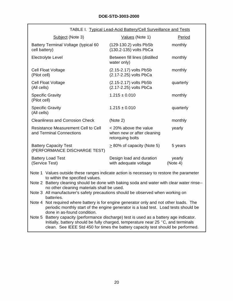
5.4.2.1 Routine maintenance andsurveillance of lead-acid batteries. Routineinspections and corrective actions forproblems found during surveillance andtesting shall be in accordance with IEEE Std450 or IEEE 1188, as applicable. Manufactur-ers also provide recommended routine main-tenance practices that should be consideredin the care of batteries. NFPA 110 providesguidance on a graded approach to batterymaintenance and surveillance. In addition,TABLE I provides an example of goodpractices for surveillance and testing of lead-acid cells. Adjustments to (increase ordecrease) the intervals in TABLE I should bebased on experience and manufacturer'srecommendations. Refer to IEEE Std 1106for maintenance, inspection, and correctiveactions for nickel-cadmium batteries.
5.4.2.2 Periodic load tests for batteries.The only real measure of a battery's capacityand capability to provide power to its requiredload is derived from the performance of twodifferent tests. One of these is called thePERFORMANCE DISCHARGE TEST, andthe other is called the Service Test. ThePERFORMANCE DISCHARGE TESTindicates the existing capacity of the batteryexpressed as a percent of the rated capacity.This provides an indication of the remaininguseful life of the battery. The Service Test isan as-found test that demonstrates the abilityof the battery to carry its required load for therequired time period (duty cycle). These twotests are the best indicators of a battery's
ability to perform its function. In order toperform the Service Test, the load profile(duty cycle) for the battery must be known.During the performance of these tests, thebattery will be unavailable for duty due tosignificant discharge. These tests should onlybe performed under conditions when theunavailability of the battery is acceptable, orprovisions should be made for an alternatesource to be temporarily connected to theloads for the duration of the test andrecharging of the battery. Intervals,procedural instructions, and criteria for thePerformance and Service Tests for lead-acidbatteries shall be in accordance with IEEEStd 450 or IEEE 1188. The schedule andprocedures for battery capacity tests fornickel-cadmium batteries shall be inaccordance with IEEE Std 1106.Replacement criteria for nickel-cadmium cellsshall be in accordance with IEEE Std 1106.Battery replacement criteria for lead-acidcells shall be in accordance with IEEE Std450.
DOE-STD-3003-2000
20
Subject (Note 3) Values (Note 1) Period
Battery Terminal Voltage (typical 60cell battery)
(129-130.2) volts PbSb(130.2-135) volts PbCa
monthly
Electrolyte Level Between fill lines (distilledwater only)
monthly
Cell Float Voltage(Pilot cell)
(2.15-2.17) volts PbSb(2.17-2.25) volts PbCa
monthly
Cell Float Voltage(All cells)
(2.15-2.17) volts PbSb(2.17-2.25) volts PbCa
quarterly
Specific Gravity(Pilot cell)
1.215 ± 0.010 monthly
Specific Gravity(All cells)
1.215 ± 0.010 quarterly
Cleanliness and Corrosion Check (Note 2) monthly
Resistance Measurement Cell to Celland Terminal Connections
< 20% above the valuewhen new or after cleaningretorquing bolts
yearly
Battery Capacity Test(PERFORMANCE DISCHARGE TEST)
> 80% of capacity (Note 5) 5 years
Battery Load Test(Service Test)
Design load and durationwith adequate voltage
yearly (Note 4)
Note 1 Values outside these ranges indicate action is necessary to restore the parameterto within the specified values.
Note 2 Battery cleaning should be done with baking soda and water with clear water rinse--no other cleaning materials shall be used.
Note 3 All manufacturer's safety precautions should be observed when working onbatteries.
Note 4 Not required where battery is for engine generator only and not other loads. Theperiodic monthly start of the engine generator is a load test. Load tests should bedone in as-found condition.
Note 5 Battery capacity (performance discharge) test is used as a battery age indicator. Initially, battery should be fully charged, temperature near 25 �C, and terminalsclean. See IEEE Std 450 for times the battery capacity test should be performed.
TABLE I. Typical Lead-Acid Battery/Cell Surveillance and Tests
DOE-STD-3003-2000
21
6. NOTES
(This section contains information of a general or explanatory nature that may be helpful,but is not mandatory.)
6.1 Intended use. This Standard is not a DOE Order, and its requirements are notautomatically invoked at any facilities or on any BACKUP POWER SOURCES. This Standardis intended for use by the operations/field offices or M&O contractors as desired. It may beinvoked by contractual documents, procurement documents, or in the authorization basis for afacility. Unless it is invoked as above, the contractor cannot be assessed or inspected againstits requirements. This Standard is also suitable for voluntary use by engineers responsible forBACKUP POWER SOURCES at DOE facilities.
6.2 Revision status. A specific revision of this Standard should only be invoked and usedwhen required by contractual considerations. In all other cases, the most current revisionshould be assumed to be used.
6.3 Tailoring guidance. For applications that are not related to nuclear safety, use of thisStandard should be tailored based on the relative importance of the power source to safety ofthe public, the environment, operating personnel, and the facility. Procurement documentsinvoking this Standard should tailor the requirements contained herein to suit the particularprocurement. Contractual or authorization basis documents invoking this document mustspecify assessment or inspection criteria appropriate to the application.
6.4 Subject term (key word) listing. The following listing of subject terms (keywords) isprovided so that this document may be found during retrieval searches.
Backup powerEmergency powerDiesel generatorENGINE GENERATORUNINTERRUPTIBLE POWER SUPPLYSTATIONARY BATTERIES
DOE-STD-3003-2000
22
APPENDIX I
Considerations to Improve Diesel Generator Reliability
NRC publication NUREG/CR 0660, Enhancement of On-Site Emergency Diesel GeneratorReliability, was developed from a comprehensive study of diesel generator problems andinstallations. The document made a number of recommendations to improve diesel generatorreliability. The following were selected for consideration by DOE facilities:
1. Provide refrigerated air dryers between the air compressor and air storage tank toreduce detrimental effects of entrained moisture causing rust and pipe scale that result indamage to air start motors.
2. Diesel generator room air quality is often poor; this can be overcome by providingdust-tight covers for relays and contactors or by providing filters for static inverters to protectfield flashing contacts. Room ventilation should be taken from about 6 m above the ground toreduce intake of local dust.
3. Provide training for those personnel operating and maintaining specific dieselgenerators.
4. Provide prelubrication for all engine starts (except true auto-start) for 3 - 5 minutes(longer per manufacturer's recommendation) to reduce potential for engine bearing wear.
5. Provide an electric fuel pump that starts upon engine auto-start signal and shuts offwhen engine is up to speed.
6. Mount instruments and controls in a separate floor-mounted panel independent ofthe EG (minimizes vibration effects on instruments and controls).
DOE-STD-3003-2000
23
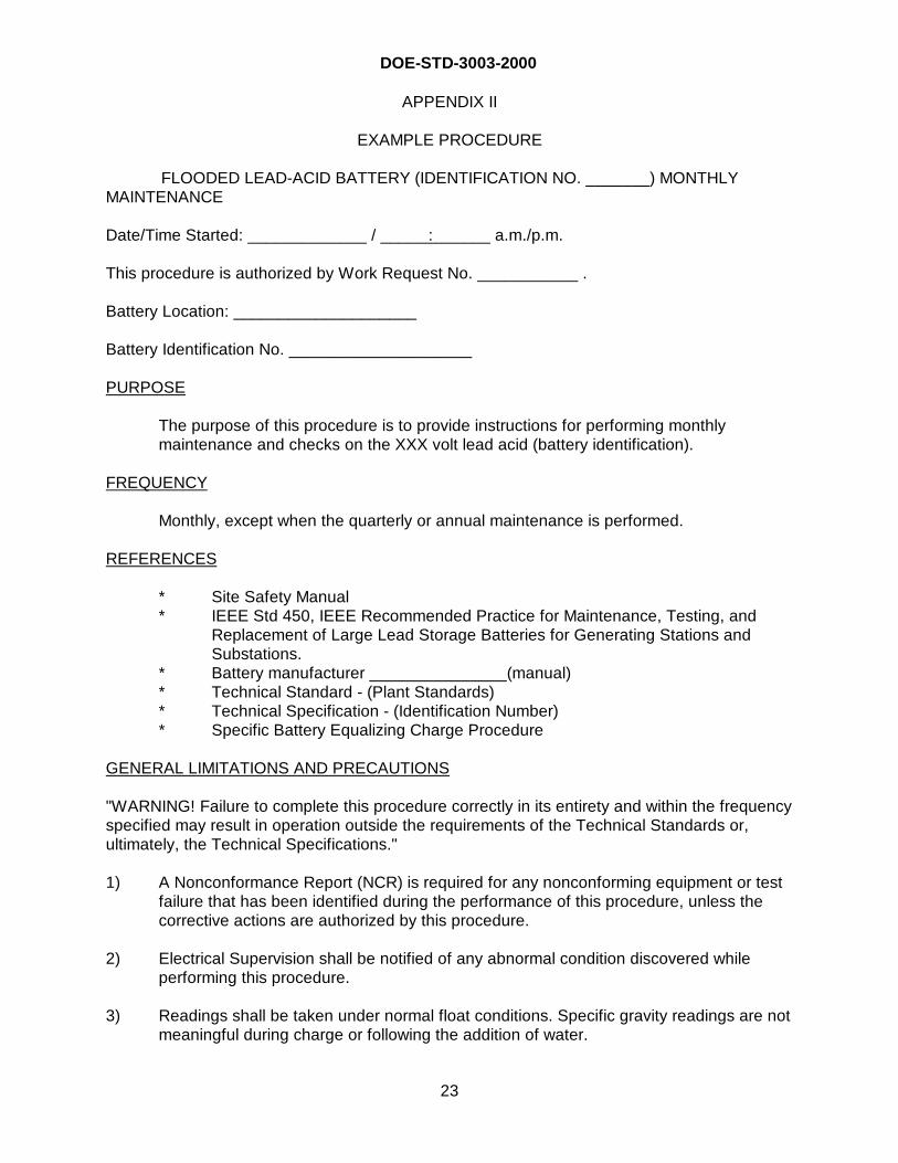
APPENDIX II
EXAMPLE PROCEDURE
FLOODED LEAD-ACID BATTERY (IDENTIFICATION NO. _______) MONTHLYMAINTENANCE
Date/Time Started: _____________ / _____ :_______ a.m./p.m.
This procedure is authorized by Work Request No. ___________ .
Battery Location: ____________________
Battery Identification No. ____________________
PURPOSE
The purpose of this procedure is to provide instructions for performing monthlymaintenance and checks on the XXX volt lead acid (battery identification).
FREQUENCY
Monthly, except when the quarterly or annual maintenance is performed.
REFERENCES
* Site Safety Manual* IEEE Std 450, IEEE Recommended Practice for Maintenance, Testing, and
Replacement of Large Lead Storage Batteries for Generating Stations andSubstations.
* Battery manufacturer _______________(manual)* Technical Standard - (Plant Standards)* Technical Specification - (Identification Number)* Specific Battery Equalizing Charge Procedure
GENERAL LIMITATIONS AND PRECAUTIONS
"WARNING! Failure to complete this procedure correctly in its entirety and within the frequencyspecified may result in operation outside the requirements of the Technical Standards or,ultimately, the Technical Specifications."
1) A Nonconformance Report (NCR) is required for any nonconforming equipment or testfailure that has been identified during the performance of this procedure, unless thecorrective actions are authorized by this procedure.
2) Electrical Supervision shall be notified of any abnormal condition discovered whileperforming this procedure.
3) Readings shall be taken under normal float conditions. Specific gravity readings are notmeaningful during charge or following the addition of water.
DOE-STD-3003-2000
24
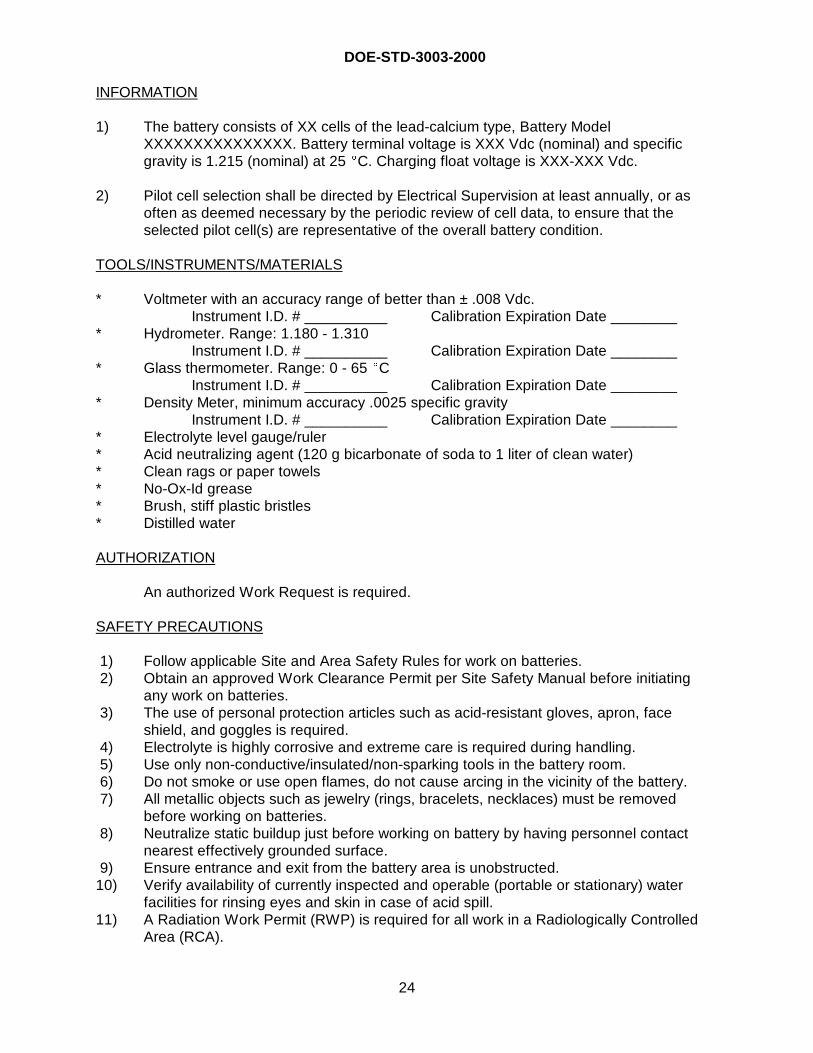
INFORMATION
1) The battery consists of XX cells of the lead-calcium type, Battery ModelXXXXXXXXXXXXXXX. Battery terminal voltage is XXX Vdc (nominal) and specificgravity is 1.215 (nominal) at 25 �C. Charging float voltage is XXX-XXX Vdc.
2) Pilot cell selection shall be directed by Electrical Supervision at least annually, or asoften as deemed necessary by the periodic review of cell data, to ensure that theselected pilot cell(s) are representative of the overall battery condition.
TOOLS/INSTRUMENTS/MATERIALS
* Voltmeter with an accuracy range of better than ± .008 Vdc.Instrument I.D. # __________ Calibration Expiration Date ________
* Hydrometer. Range: 1.180 - 1.310Instrument I.D. # __________ Calibration Expiration Date ________
* Glass thermometer. Range: 0 - 65 �CInstrument I.D. # __________ Calibration Expiration Date ________
* Density Meter, minimum accuracy .0025 specific gravityInstrument I.D. # __________ Calibration Expiration Date ________
* Electrolyte level gauge/ruler* Acid neutralizing agent (120 g bicarbonate of soda to 1 liter of clean water)* Clean rags or paper towels* No-Ox-Id grease* Brush, stiff plastic bristles* Distilled water
AUTHORIZATION
An authorized Work Request is required.
SAFETY PRECAUTIONS
1) Follow applicable Site and Area Safety Rules for work on batteries. 2) Obtain an approved Work Clearance Permit per Site Safety Manual before initiating
any work on batteries. 3) The use of personal protection articles such as acid-resistant gloves, apron, face
shield, and goggles is required. 4) Electrolyte is highly corrosive and extreme care is required during handling. 5) Use only non-conductive/insulated/non-sparking tools in the battery room. 6) Do not smoke or use open flames, do not cause arcing in the vicinity of the battery. 7) All metallic objects such as jewelry (rings, bracelets, necklaces) must be removed
before working on batteries. 8) Neutralize static buildup just before working on battery by having personnel contact
nearest effectively grounded surface. 9) Ensure entrance and exit from the battery area is unobstructed.10) Verify availability of currently inspected and operable (portable or stationary) water
facilities for rinsing eyes and skin in case of acid spill.11) A Radiation Work Permit (RWP) is required for all work in a Radiologically Controlled
Area (RCA).
DOE-STD-3003-2000
25
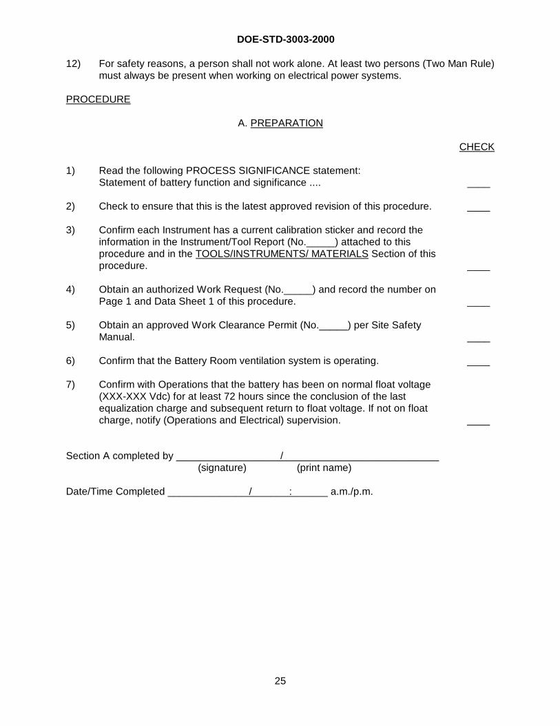
12) For safety reasons, a person shall not work alone. At least two persons (Two Man Rule)must always be present when working on electrical power systems.
PROCEDURE
A. PREPARATION
CHECK
1) Read the following PROCESS SIGNIFICANCE statement:Statement of battery function and significance .... ____
2) Check to ensure that this is the latest approved revision of this procedure. ____
3) Confirm each Instrument has a current calibration sticker and record theinformation in the Instrument/Tool Report (No._____) attached to thisprocedure and in the TOOLS/INSTRUMENTS/ MATERIALS Section of thisprocedure. ____
4) Obtain an authorized Work Request (No._____) and record the number onPage 1 and Data Sheet 1 of this procedure. ____
5) Obtain an approved Work Clearance Permit (No._____) per Site SafetyManual. ____
6) Confirm that the Battery Room ventilation system is operating. ____
7) Confirm with Operations that the battery has been on normal float voltage(XXX-XXX Vdc) for at least 72 hours since the conclusion of the lastequalization charge and subsequent return to float voltage. If not on floatcharge, notify (Operations and Electrical) supervision. ____
Section A completed by __________________ /____________________________(signature) (print name)
Date/Time Completed ______________ /_______ :_______ a.m./p.m.
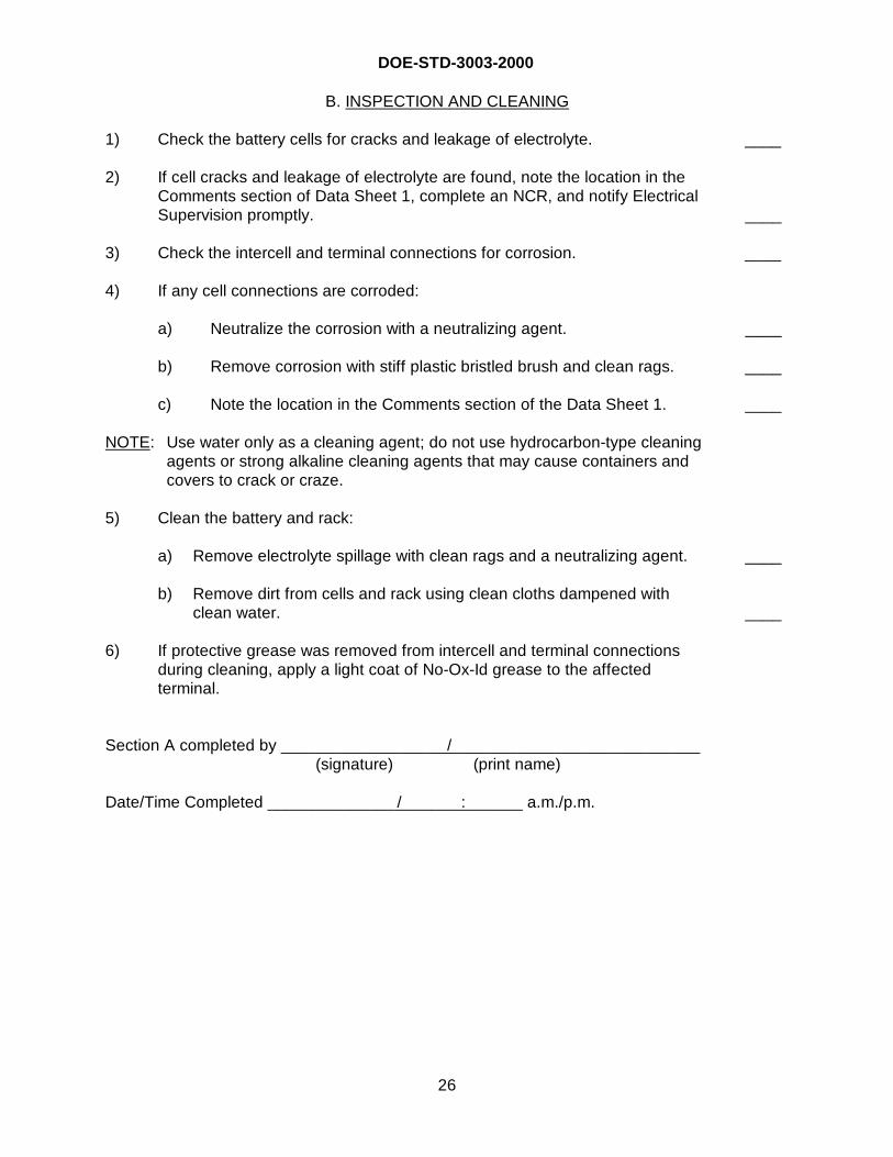
DOE-STD-3003-2000
26
B. INSPECTION AND CLEANING
1) Check the battery cells for cracks and leakage of electrolyte. ____
2) If cell cracks and leakage of electrolyte are found, note the location in theComments section of Data Sheet 1, complete an NCR, and notify ElectricalSupervision promptly. ____
3) Check the intercell and terminal connections for corrosion. ____
4) If any cell connections are corroded:
a) Neutralize the corrosion with a neutralizing agent. ____
b) Remove corrosion with stiff plastic bristled brush and clean rags. ____
c) Note the location in the Comments section of the Data Sheet 1. ____
NOTE: Use water only as a cleaning agent; do not use hydrocarbon-type cleaningagents or strong alkaline cleaning agents that may cause containers andcovers to crack or craze.
5) Clean the battery and rack:
a) Remove electrolyte spillage with clean rags and a neutralizing agent. ____
b) Remove dirt from cells and rack using clean cloths dampened withclean water. ____
6) If protective grease was removed from intercell and terminal connectionsduring cleaning, apply a light coat of No-Ox-Id grease to the affectedterminal.
Section A completed by __________________ /____________________________(signature) (print name)
Date/Time Completed ______________ /_______ :_______ a.m./p.m.
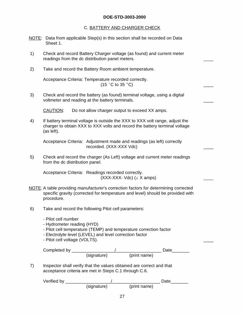
DOE-STD-3003-2000
27
C. BATTERY AND CHARGER CHECK
NOTE: Data from applicable Step(s) in this section shall be recorded on DataSheet 1.
1) Check and record Battery Charger voltage (as found) and current meterreadings from the dc distribution panel meters. ____
2) Take and record the Battery Room ambient temperature.
Acceptance Criteria: Temperature recorded correctly.(15 �C to 35 �C) ____
3) Check and record the battery (as found) terminal voltage, using a digitalvoltmeter and reading at the battery terminals.
CAUTION: Do not allow charger output to exceed XX amps.
____
4) If battery terminal voltage is outside the XXX to XXX volt range, adjust thecharger to obtain XXX to XXX volts and record the battery terminal voltage(as left).
Acceptance Criteria: Adjustment made and readings (as left) correctlyrecorded. (XXX-XXX Vdc) ____
5) Check and record the charger (As Left) voltage and current meter readingsfrom the dc distribution panel.
Acceptance Criteria: Readings recorded correctly.(XXX-XXX- Vdc) (� X amps)
NOTE: A table providing manufacturer's correction factors for determining correctedspecific gravity (corrected for temperature and level) should be provided withprocedure.
____
6) Take and record the following Pilot cell parameters:
- Pilot cell number- Hydrometer reading (HYD)- Pilot cell temperature (TEMP) and temperature correction factor- Electrolyte level (LEVEL) and level correction factor- Pilot cell voltage (VOLTS). ____
Completed by _________________ /___________________ Date_______(signature) (print name)
7) Inspector shall verify that the values obtained are correct and thatacceptance criteria are met in Steps C.1 through C.6.
Verified by __________________ /____________________ Date_______(signature) (print name)
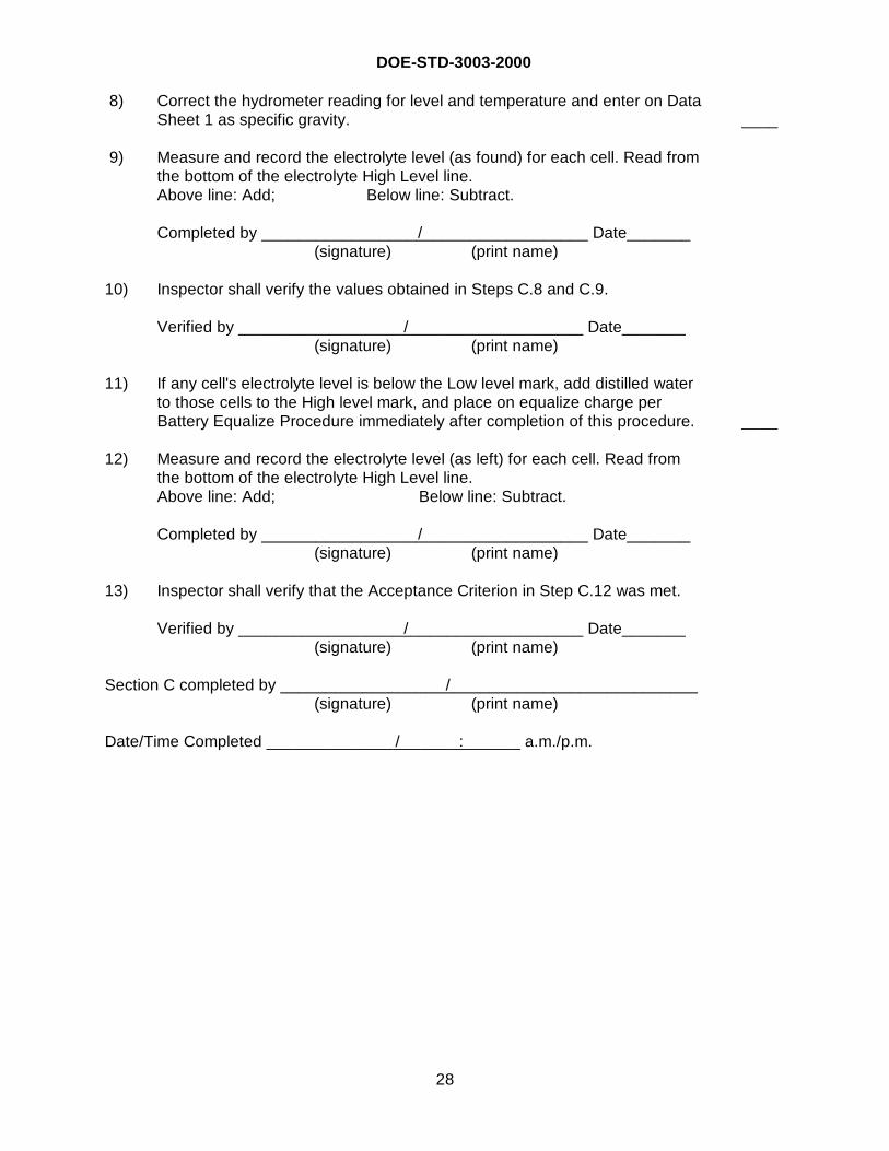
DOE-STD-3003-2000
28
8) Correct the hydrometer reading for level and temperature and enter on DataSheet 1 as specific gravity. ____
9) Measure and record the electrolyte level (as found) for each cell. Read fromthe bottom of the electrolyte High Level line.Above line: Add; Below line: Subtract.
Completed by _________________ /___________________ Date_______(signature) (print name)
10) Inspector shall verify the values obtained in Steps C.8 and C.9.
Verified by __________________ /____________________ Date_______(signature) (print name)
11) If any cell's electrolyte level is below the Low level mark, add distilled waterto those cells to the High level mark, and place on equalize charge perBattery Equalize Procedure immediately after completion of this procedure. ____
12) Measure and record the electrolyte level (as left) for each cell. Read fromthe bottom of the electrolyte High Level line.Above line: Add; Below line: Subtract.
Completed by _________________ /___________________ Date_______(signature) (print name)
13) Inspector shall verify that the Acceptance Criterion in Step C.12 was met.
Verified by __________________ /____________________ Date_______(signature) (print name)
Section C completed by __________________ /____________________________(signature) (print name)
Date/Time Completed ______________ /_______ :_______ a.m./p.m.
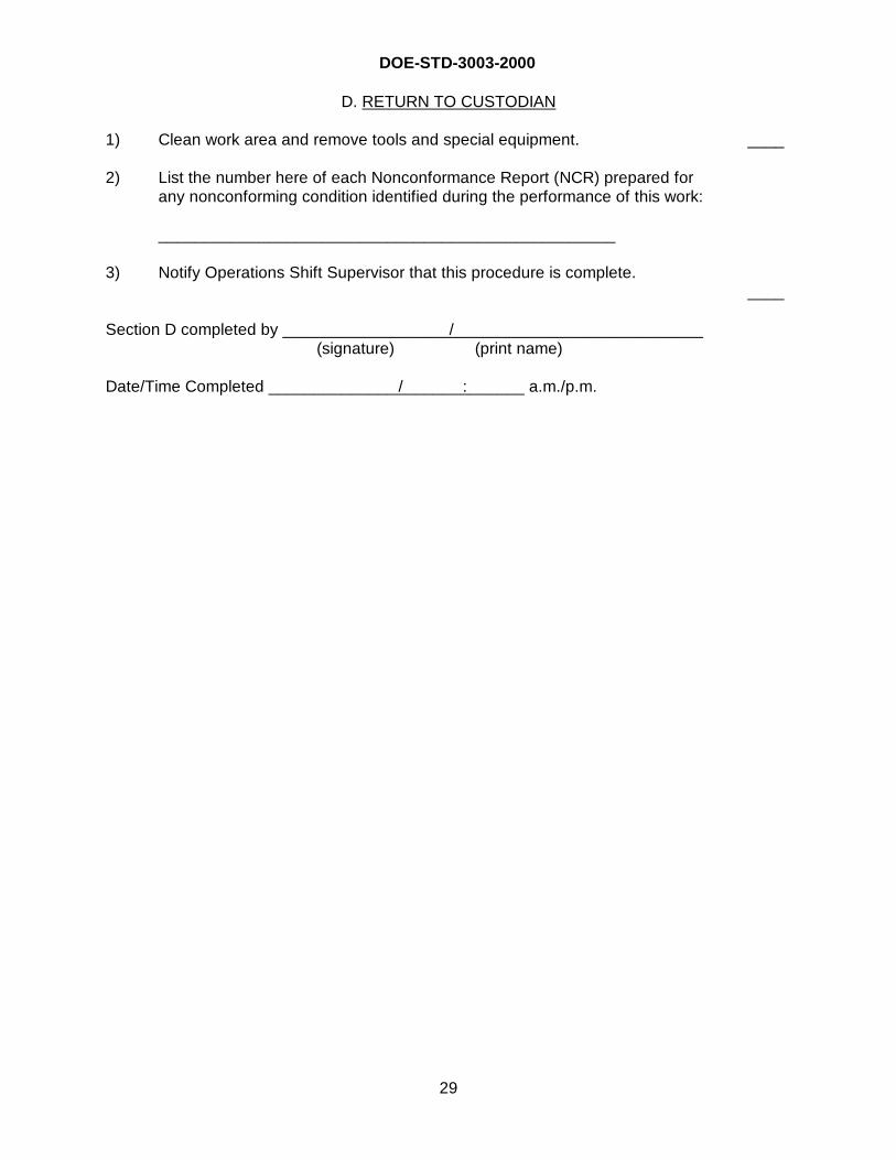
DOE-STD-3003-2000
29
D. RETURN TO CUSTODIAN
1) Clean work area and remove tools and special equipment. ____
2) List the number here of each Nonconformance Report (NCR) prepared forany nonconforming condition identified during the performance of this work:
__________________________________________________
3) Notify Operations Shift Supervisor that this procedure is complete.____
Section D completed by __________________ /____________________________(signature) (print name)
Date/Time Completed ______________ /_______ :_______ a.m./p.m.
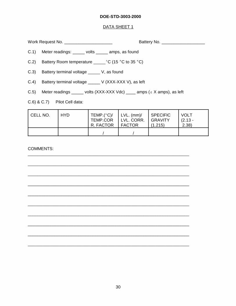
DOE-STD-3003-2000
30
DATA SHEET 1
Work Request No. ____________________ Battery No. __________________
C.1) Meter readings: _____ volts _____ amps, as found
C.2) Battery Room temperature _____�C (15 �C to 35 �C)
C.3) Battery terminal voltage _____ V, as found
C.4) Battery terminal voltage _____ V (XXX-XXX V), as left
C.5) Meter readings _____ volts (XXX-XXX Vdc) ____ amps (� X amps), as left
C.6) & C.7) Pilot Cell data:
CELL NO. HYD TEMP.(�C)/TEMP.CORR. FACTOR
LVL. (mm)/LVL. CORR.FACTOR
SPECIFICGRAVITY(1.215)
VOLT (2.13 - 2.38)
/ /
COMMENTS:___________________________________________________________________
___________________________________________________________________
___________________________________________________________________
___________________________________________________________________
___________________________________________________________________
___________________________________________________________________
___________________________________________________________________
___________________________________________________________________
___________________________________________________________________
___________________________________________________________________
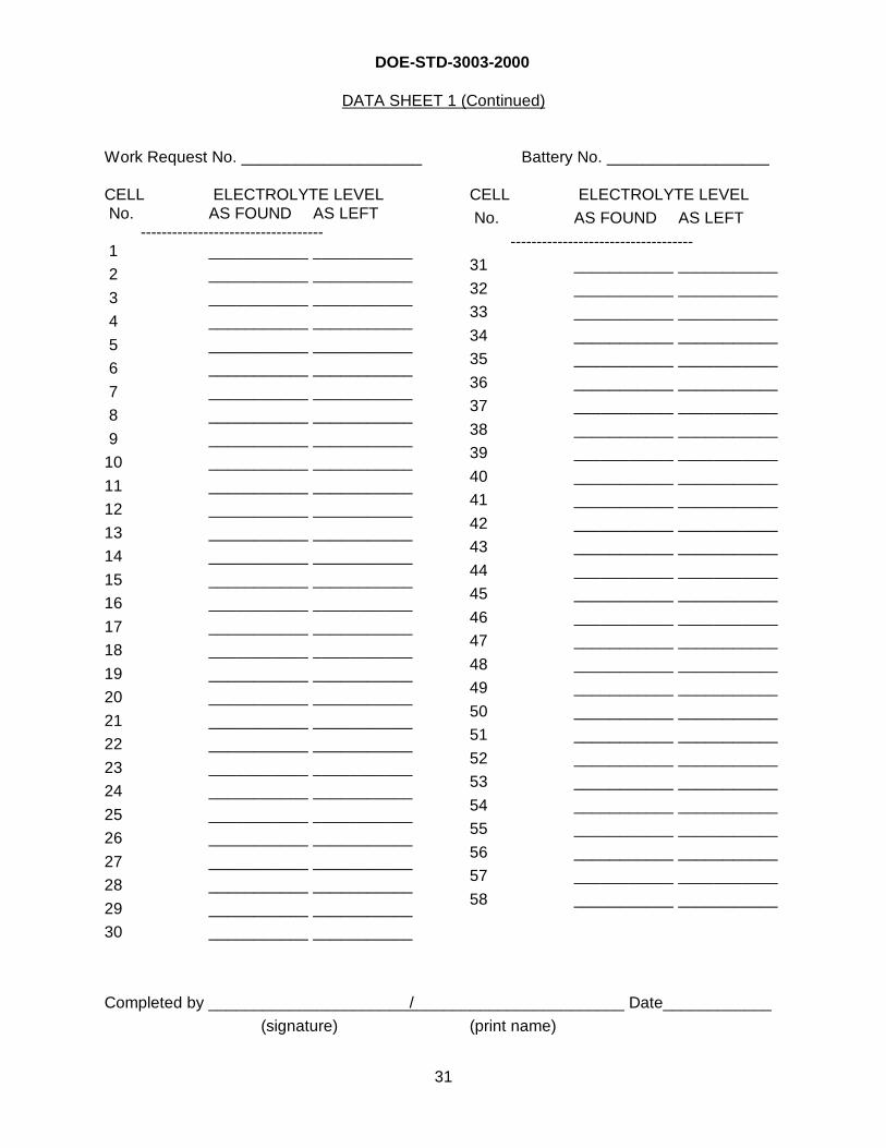
DOE-STD-3003-2000
31
DATA SHEET 1 (Continued)
Work Request No. ____________________ Battery No. __________________
CELL ELECTROLYTE LEVEL No. AS FOUND AS LEFT ----------------------------------- 1 ___________ ___________
2 ___________ ___________
3 ___________ ___________
4 ___________ ___________
5 ___________ ___________
6 ___________ ___________
7 ___________ ___________
8 ___________ ___________
9 ___________ ___________
10 ___________ ___________
11 ___________ ___________
12 ___________ ___________
13 ___________ ___________
14 ___________ ___________
15 ___________ ___________
16 ___________ ___________
17 ___________ ___________
18 ___________ ___________
19 ___________ ___________
20 ___________ ___________
21 ___________ ___________
22 ___________ ___________
23 ___________ ___________
24 ___________ ___________
25 ___________ ___________
26 ___________ ___________
27 ___________ ___________
28 ___________ ___________
29 ___________ ___________
30 ___________ ___________
CELL ELECTROLYTE LEVEL
No. AS FOUND AS LEFT
-----------------------------------
31 ___________ ___________
32 ___________ ___________
33 ___________ ___________
34 ___________ ___________
35 ___________ ___________
36 ___________ ___________
37 ___________ ___________
38 ___________ ___________
39 ___________ ___________
40 ___________ ___________
41 ___________ ___________
42 ___________ ___________
43 ___________ ___________
44 ___________ ___________
45 ___________ ___________
46 ___________ ___________
47 ___________ ___________
48 ___________ ___________
49 ___________ ___________
50 ___________ ___________
51 ___________ ___________
52 ___________ ___________
53 ___________ ___________
54 ___________ ___________
55 ___________ ___________
56 ___________ ___________
57 ___________ ___________
58 ___________ ___________
Completed by ______________________ /________________________ Date____________
(signature) (print name)

DOE-STD-3003-2000
32
INTENTIONALLY BLANK
DOE-STD-3003-2000
CONCLUDING MATERIAL
Review Activity (Original Revision): Preparing Activity:
DOE Field Offices DOE-DP-45
DP AL
EE CH Project Number:
EH ID
EM NV EDCN-0002
ER OR
FE RL
FM SF
HR SR
NE Fernald
NN Golden
PO
RW
National Laboratories
BNL
LLNL
LANL
ORNL
PNL
SNL
Area Offices
Amarillo
Kirtland
Los Alamos
Princeton
Rocky Flats
Operations Offices
Idaho
Nevada
Oakland
Oak Ridge
Richland
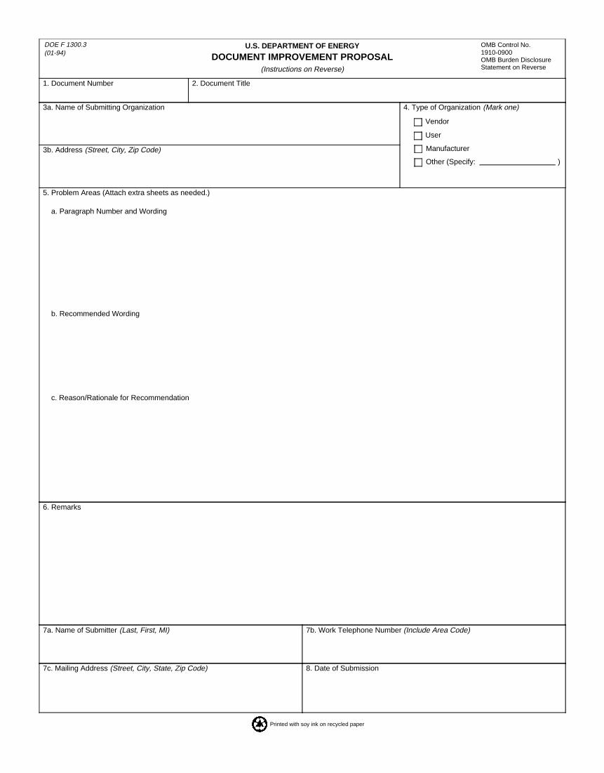
U.S. DEPARTMENT OF ENERGY
DOCUMENT IMPROVEMENT PROPOSAL(Instructions on Reverse)
DOE F 1300.3(01-94)
1. Document Number 2. Document Title
3a. Name of Submitting Organization
3b. Address (Street, City, Zip Code)
4. Type of Organization (Mark one)
5. Problem Areas (Attach extra sheets as needed.)
a. Paragraph Number and Wording
b. Recommended Wording
c. Reason/Rationale for Recommendation
6. Remarks
7a. Name of Submitter (Last, First, MI) 7b. Work Telephone Number (Include Area Code)
7c. Mailing Address (Street, City, State, Zip Code) 8. Date of Submission
OMB Control No.1910-0900OMB Burden DisclosureStatement on Reverse
Other (Specify: )
Manufacturer
User
Vendor
Printed with soy ink on recycled paper
DOE F 1300.3(01-94)
OMB Control No.1910-0900
INSTRUCTIONS: In a continuing effort to improve the U.S. Department of Energy (DOE) Technical Standards, this form isprovided for use in submitting comments and suggestions for improvements. All users of DOE Technical Standards areinvited to provide suggestions. This form may be detached, folded along the lines indicated, taped along the loose edge (DONOT STAPLE) mailed to the address indicated or faxed to (615) 574-0382.
1. The submitter of this form must complete blocks 1 through 8.
2. The Technical Standards Program Office (TSPO) will forward this form to the Preparing Activity. The Preparing Activity will reply to the submitter within 30 calendar days of receipt from the TSPO.
NOTE: This form may not be used to request copies of documents, nor to request waivers, deviations, or clarification ofspecification requirements on current contractors. Comments submitted on this form do not constitute or imply authorizationto waive any portion of the referenced document(s) or to amend contractual requirements.
Public reporting burden for this collection of information is estimated to average 30 minutes per response, including the timefor reviewing instructions, searching existing data sources, gathering and maintaining the data needed, and completing andreviewing the collection of information. Send comments regarding this burden estimate or any other aspect of this collection ofinformation, including suggestions for reducing this burden, to Office of Information Resources Management Policy, Plans,and Oversight, Records Management Division, HR-422 - GTN, Paperwork Reduction Project (1910-0900), U.S. Departmentof Energy, 1000 Independence Avenue, S.W., Washington, DC 20585; and to the Office of Management and Budget (OMB),Paperwork Reduction Project (1910-0900), Washington, DC 20503.
OMB Burden Disclosure Statement
U.S. Department of Energy Technical Standards Program Officec/o Performance Assurance Project OfficeP.O. Box 2009, Bldg. 9201-3Oak Ridge, Tennessee 37831-8065


