Embed Size (px)
Citation preview
Direct-drive inertial confinement fusion: A reviewR. S. Craxton, K. S. Anderson, T. R. Boehly, V. N. Goncharov, D. R. Harding, J. P. Knauer, R. L. McCrory, P. W.McKenty, D. D. Meyerhofer, J. F. Myatt, A. J. Schmitt, J. D. Sethian, R. W. Short, S. Skupsky, W. Theobald, W.L. Kruer, K. Tanaka, R. Betti, T. J. B. Collins, J. A. Delettrez, S. X. Hu, J. A. Marozas, A. V. Maximov, D. T.Michel, P. B. Radha, S. P. Regan, T. C. Sangster, W. Seka, A. A. Solodov, J. M. Soures, C. Stoeckl, and J. D.Zuegel Citation: Physics of Plasmas 22, 110501 (2015); doi: 10.1063/1.4934714 View online: http://dx.doi.org/10.1063/1.4934714 View Table of Contents: http://scitation.aip.org/content/aip/journal/pop/22/11?ver=pdfcov Published by the AIP Publishing Articles you may be interested in Mitigation of two-plasmon decay in direct-drive inertial confinement fusion through the manipulation of ion-acoustic and Langmuir wave damping Phys. Plasmas 20, 052705 (2013); 10.1063/1.4807036 Laser beam propagation through inertial confinement fusion hohlraum plasmasa) Phys. Plasmas 14, 055705 (2007); 10.1063/1.2515054 Modeling stimulated Brillouin scattering in the underdense corona of a direct drive inertial confinement fusiontarget Phys. Plasmas 11, 3394 (2004); 10.1063/1.1755708 Modeling of stimulated Brillouin scattering near the critical-density surface in the plasmas of direct-drive inertialconfinement fusion targets Phys. Plasmas 11, 2994 (2004); 10.1063/1.1711813 Improved performance of direct-drive inertial confinement fusion target designs with adiabat shaping using anintensity picket Phys. Plasmas 10, 1906 (2003); 10.1063/1.1562166
This article is copyrighted as indicated in the article. Reuse of AIP content is subject to the terms at: http://scitation.aip.org/termsconditions. Downloaded to IP:
128.151.32.169 On: Mon, 07 Dec 2015 20:25:34
Direct-drive inertial confinement fusion: A review
R. S. Craxton,1 K. S. Anderson,1 T. R. Boehly,1 V. N. Goncharov,1 D. R. Harding,1
J. P. Knauer,1 R. L. McCrory,1,2 P. W. McKenty,1 D. D. Meyerhofer,1,2 J. F. Myatt,1
A. J. Schmitt,3 J. D. Sethian,3 R. W. Short,1 S. Skupsky,1 W. Theobald,1 W. L. Kruer,4
K. Tanaka,5 R. Betti,1,2 T. J. B. Collins,1 J. A. Delettrez,1 S. X. Hu,1 J. A. Marozas,1
A. V. Maximov,1 D. T. Michel,1 P. B. Radha,1 S. P. Regan,1 T. C. Sangster,1 W. Seka,1
A. A. Solodov,1 J. M. Soures,1 C. Stoeckl,1 and J. D. Zuegel11Laboratory for Laser Energetics, University of Rochester, Rochester, New York 14623-1299, USA2Department of Physics and Astronomy and Department of Mechanical Engineering, University of Rochester,Rochester, New York 14623, USA3Plasma Physics Division, Naval Research Laboratory, Washington, DC 20375, USA4Lawrence Livermore National Laboratory, Livermore, California 94550, USA5Department of Electric, Electronic, and Information, Graduate School of Engineering, Osaka University,Osaka, Japan
(Received 6 February 2015; accepted 28 May 2015; published online 25 November 2015)
The direct-drive, laser-based approach to inertial confinement fusion (ICF) is reviewed from its
inception following the demonstration of the first laser to its implementation on the present genera-
tion of high-power lasers. The review focuses on the evolution of scientific understanding gained
from target-physics experiments in many areas, identifying problems that were demonstrated and
the solutions implemented. The review starts with the basic understanding of laser–plasma interac-
tions that was obtained before the declassification of laser-induced compression in the early 1970s
and continues with the compression experiments using infrared lasers in the late 1970s that pro-
duced thermonuclear neutrons. The problem of suprathermal electrons and the target preheat that
they caused, associated with the infrared laser wavelength, led to lasers being built after 1980 to op-
erate at shorter wavelengths, especially 0.35 lm—the third harmonic of the Nd:glass laser—and
0.248 lm (the KrF gas laser). The main physics areas relevant to direct drive are reviewed. The pri-
mary absorption mechanism at short wavelengths is classical inverse bremsstrahlung.
Nonuniformities imprinted on the target by laser irradiation have been addressed by the develop-
ment of a number of beam-smoothing techniques and imprint-mitigation strategies. The effects of
hydrodynamic instabilities are mitigated by a combination of imprint reduction and target designs
that minimize the instability growth rates. Several coronal plasma physics processes are reviewed.
The two-plasmon–decay instability, stimulated Brillouin scattering (together with cross-beam
energy transfer), and (possibly) stimulated Raman scattering are identified as potential concerns,
placing constraints on the laser intensities used in target designs, while other processes (self-focus-
ing and filamentation, the parametric decay instability, and magnetic fields), once considered im-
portant, are now of lesser concern for mainline direct-drive target concepts. Filamentation is
largely suppressed by beam smoothing. Thermal transport modeling, important to the interpretation
of experiments and to target design, has been found to be nonlocal in nature. Advances in shock
timing and equation-of-state measurements relevant to direct-drive ICF are reported. Room-
temperature implosions have provided an increased understanding of the importance of stability
and uniformity. The evolution of cryogenic implosion capabilities, leading to an extensive series
carried out on the 60-beam OMEGA laser [Boehly et al., Opt. Commun. 133, 495 (1997)], is
reviewed together with major advances in cryogenic target formation. A polar-drive concept has
been developed that will enable direct-drive–ignition experiments to be performed on the National
Ignition Facility [Haynam et al., Appl. Opt. 46(16), 3276 (2007)]. The advantages offered by the al-
ternative approaches of fast ignition and shock ignition and the issues associated with these con-
cepts are described. The lessons learned from target-physics and implosion experiments are taken
into account in ignition and high-gain target designs for laser wavelengths of 1/3 lm and 1/4 lm.
Substantial advances in direct-drive inertial fusion reactor concepts are reviewed. Overall, the pro-
gress in scientific understanding over the past five decades has been enormous, to the point that in-
ertial fusion energy using direct drive shows significant promise as a future environmentally
attractive energy source. VC 2015 Author(s). All article content, except where otherwise noted, islicensed under a Creative Commons Attribution 3.0 Unported License.
[http://dx.doi.org/10.1063/1.4934714]
1070-664X/2015/22(11)/110501/153 VC Author(s) 201522, 110501-1
PHYSICS OF PLASMAS 22, 110501 (2015)
This article is copyrighted as indicated in the article. Reuse of AIP content is subject to the terms at: http://scitation.aip.org/termsconditions. Downloaded to IP:
128.151.32.169 On: Mon, 07 Dec 2015 20:25:34
TABLE OF CONTENTS
I. INTRODUCTION . . . . . . . . . . . . . . . . . . . . . . . . . . . . 2
II. DIRECT-DRIVE PHYSICS OVERVIEW . . . . . . . 4
III. ONE-DIMENSIONAL HYDRODYNAMICS
AND IGNITION PHYSICS. . . . . . . . . . . . . . . . . . . 5
A. Triple-picket ignition design for the NIF . . . 6
B. Ignition physics . . . . . . . . . . . . . . . . . . . . . . . . . 9
IV. THE EARLY YEARS . . . . . . . . . . . . . . . . . . . . . . . 11
A. The quest for neutrons . . . . . . . . . . . . . . . . . . . 11
B. Suprathermal electrons . . . . . . . . . . . . . . . . . . . 14
C. Resonance absorption . . . . . . . . . . . . . . . . . . . . 16
D. Plasma diagnostics . . . . . . . . . . . . . . . . . . . . . . 17
E. The move to short wavelengths . . . . . . . . . . . 19
V. SHORT-WAVELENGTH ABSORPTION
EXPERIMENTS. . . . . . . . . . . . . . . . . . . . . . . . . . . . . 20
VI. LASER BEAM UNIFORMITY . . . . . . . . . . . . . . . 23
A. Phase plates . . . . . . . . . . . . . . . . . . . . . . . . . . . . 25
B. Induced spatial incoherence (ISI) . . . . . . . . . . 26
C. Smoothing by spectral dispersion (SSD) . . . . 28
D. Polarization smoothing. . . . . . . . . . . . . . . . . . . 30
VII. IMPRINT AND EARLY-TIME
NONUNIFORMITY EVOLUTION . . . . . . . . . . . 30
A. Laser imprint . . . . . . . . . . . . . . . . . . . . . . . . . . . 31
1. Physics of imprint . . . . . . . . . . . . . . . . . . . . 31
2. Imprint experiments . . . . . . . . . . . . . . . . . . 33
B. Imprint mitigation . . . . . . . . . . . . . . . . . . . . . . . 34
1. Foam . . . . . . . . . . . . . . . . . . . . . . . . . . . . . . . 35
2. High-Z layers and mid-Z dopants . . . . . . . 35
3. External x-ray flash. . . . . . . . . . . . . . . . . . . 37
4. Intensity picket. . . . . . . . . . . . . . . . . . . . . . . 37
C. Richtmyer–Meshkov (RM) instability . . . . . . 37
1. Physical mechanism . . . . . . . . . . . . . . . . . . 37
2. Richtmyer–Meshkov experiments . . . . . . . 38
D. Feedout . . . . . . . . . . . . . . . . . . . . . . . . . . . . . . . . 39
VIII. IMPLOSION EXPERIMENTS . . . . . . . . . . . . . . 40
A. Room-temperature implosions. . . . . . . . . . . . . 40
B. Cryogenic implosions . . . . . . . . . . . . . . . . . . . . 46
C. Polar-drive implosions . . . . . . . . . . . . . . . . . . . 51
IX. HYDRODYNAMIC STABILITY . . . . . . . . . . . . . 55
A. Theory. . . . . . . . . . . . . . . . . . . . . . . . . . . . . . . . . 55
B. Experiments . . . . . . . . . . . . . . . . . . . . . . . . . . . . 57
X. CORONAL PLASMA PHYSICS . . . . . . . . . . . . . . 61
A. Two-plasmon decay (TPD) . . . . . . . . . . . . . . . 62
1. Single-beam experiments . . . . . . . . . . . . . . 63
2. Overlapping-beam experiments . . . . . . . . . 65
3. Numerical simulations . . . . . . . . . . . . . . . . 68
B. Stimulated Brillouin scattering (SBS) and
cross-beam energy transfer (CBET) . . . . . . . . 68
C. Stimulated Raman scattering (SRS) . . . . . . . . 73
D. Self-focusing and filamentation . . . . . . . . . . . 78
1. Theory . . . . . . . . . . . . . . . . . . . . . . . . . . . . . . 78
2. Simulations . . . . . . . . . . . . . . . . . . . . . . . . . . 79
3. Experiments . . . . . . . . . . . . . . . . . . . . . . . . . 80
E. Parametric decay instability (PDI) . . . . . . . . . 82
F. Self-generated magnetic fields. . . . . . . . . . . . . 83
XI. THERMAL TRANSPORT . . . . . . . . . . . . . . . . . . . 86
XII. SHOCK TIMING AND EQUATION OF
STATE (EOS) . . . . . . . . . . . . . . . . . . . . . . . . . . . . . 92
A. VISAR and SOP diagnostics. . . . . . . . . . . . . . 92
B. Shock-timing measurements . . . . . . . . . . . . . . 93
C. Equation of state . . . . . . . . . . . . . . . . . . . . . . . . 95
XIII. CRYOGENIC TARGET FORMATION
AND CHARACTERIZATION . . . . . . . . . . . . . . 97
A. Cryogenic target systems . . . . . . . . . . . . . . . . . 98
B. Cryogenic target science . . . . . . . . . . . . . . . . . 99
1. Ice-layer formation . . . . . . . . . . . . . . . . . . . 100
2. Ice-layer characterization . . . . . . . . . . . . . . 101
3. Target properties at the moment of
implosion . . . . . . . . . . . . . . . . . . . . . . . . . . . 103
XIV. FAST IGNITION. . . . . . . . . . . . . . . . . . . . . . . . . . 105
A. Channeling concept. . . . . . . . . . . . . . . . . . . . . . 106
B. Cone-in-shell concept . . . . . . . . . . . . . . . . . . . . 108
C. Alternative concepts . . . . . . . . . . . . . . . . . . . . . 109
D. Cone-in-shell implosion experiments . . . . . . . 110
1. Osaka integrated cone-in-shell
experiments. . . . . . . . . . . . . . . . . . . . . . . . . . 110
2. LLE cone-in-shell fuel-assembly
experiments. . . . . . . . . . . . . . . . . . . . . . . . . . 111
3. LLE integrated cone-in-shell
experiments. . . . . . . . . . . . . . . . . . . . . . . . . . 111
E. Ignition-scale designs . . . . . . . . . . . . . . . . . . . . 113
XV. SHOCK IGNITION . . . . . . . . . . . . . . . . . . . . . . . . 114
A. One-dimensional analysis and simulations . . 115
B. Two-dimensional hydrodynamics . . . . . . . . . . 116
C. Laser–plasma instability simulations . . . . . . . 117
D. Experiments . . . . . . . . . . . . . . . . . . . . . . . . . . . . 118
XVI. IGNITION AND HIGH-GAIN TARGET
DESIGNS . . . . . . . . . . . . . . . . . . . . . . . . . . . . . . . . 119
XVII. INERTIAL FUSION ENERGY (IFE). . . . . . . . 123
A. Fundamental IFE reactor components . . . . . . 123
B. IFE reactor concepts . . . . . . . . . . . . . . . . . . . . . 124
1. BLASCON . . . . . . . . . . . . . . . . . . . . . . . . . . 124
2. Los Alamos laser-driven fusion reactor . . 125
3. SOLASE . . . . . . . . . . . . . . . . . . . . . . . . . . . . 125
4. SIRIUS-T . . . . . . . . . . . . . . . . . . . . . . . . . . . 126
5. SOMBRERO . . . . . . . . . . . . . . . . . . . . . . . . 126
6. Prometheus-L . . . . . . . . . . . . . . . . . . . . . . . . 127
7. High Average Power Laser (HAPL)
Program. . . . . . . . . . . . . . . . . . . . . . . . . . . . . 127
C. IFE technologies . . . . . . . . . . . . . . . . . . . . . . . . 128
1. Lasers . . . . . . . . . . . . . . . . . . . . . . . . . . . . . . 128
2. Final optics and illumination geometry . . 128
3. Target fabrication . . . . . . . . . . . . . . . . . . . . 129
4. Target injection . . . . . . . . . . . . . . . . . . . . . . 129
5. Target tracking/placement . . . . . . . . . . . . . 129
6. Target survival into the chamber . . . . . . . 129
7. First wall . . . . . . . . . . . . . . . . . . . . . . . . . . . . 130
8. Blanket . . . . . . . . . . . . . . . . . . . . . . . . . . . . . 130
I. INTRODUCTION
It has been 55 years since the demonstration of the laser
and the first proposal to use focused laser light to initiate
thermonuclear (TN) fusion. Understandable optimism led to
110501-2 Craxton et al. Phys. Plasmas 22, 110501 (2015)
This article is copyrighted as indicated in the article. Reuse of AIP content is subject to the terms at: http://scitation.aip.org/termsconditions. Downloaded to IP:
128.151.32.169 On: Mon, 07 Dec 2015 20:25:34
early hopes and claims that breakeven (fusion energy out
greater than laser energy in) was only a few years away.
However, it is only in recent years that laser technology and
understanding of the related physics have advanced to the
point that laser-driven fusion energy can be seen as a realis-
tic possibility for the future.
Inertial confinement fusion (ICF) is distinguished from
magnetic confinement fusion in that the fusion fuel is com-
pressed and maintained (briefly) at fusion densities and tem-
peratures by its own inertia. There are two approaches to
laser-driven ICF: direct drive, in which a spherical target
containing fusion fuel is directly irradiated by laser beams,1
and indirect drive, in which the laser beams heat the inside
of a typically cylindrical enclosure known as a hohlraum,
producing x rays that irradiate a spherical fuel-containing
capsule.2,3 This review is concerned solely with direct drive.
This review traces the history of direct-drive ICF from
the earliest days to recent years, demonstrating the evolution
of scientific understanding in a large number of areas critical
to the success of the concept.
Target physics is the primary focus of this review. It is
important to recognize that the growth of target-physics
understanding has depended heavily on parallel develop-
ments in laser technology, experimental diagnostics, com-
puter codes, and target fabrication, some of which have
arisen from the indirect-drive program. However, descrip-
tions of these areas are, with occasional exceptions, outside
the scope of this review. It is assumed that the interested
reader will refer to the bibliographies of the target-physics
papers cited here for the pertinent information.
The evolution of the capabilities of high-power laser sys-
tems over the period of this review is remarkable. Multibeam
spherical implosion facilities include the 20-beam Shiva,4 the
10-beam Nova,5 and the 192-beam National Ignition Facility
(NIF)6 lasers at Lawrence Livermore National Laboratory
(LLNL); the 4-beam DELTA,7 the 6-beam ZETA,8 the 24-
beam OMEGA,9 and the 60-beam OMEGA10 lasers at the
Laboratory for Laser Energetics (LLE) at the University of
Rochester; the 8-beam Helios laser11 at Los Alamos National
Laboratory (LANL); the 4-beam GEKKO IV12 and the 12-
beam GEKKO XII13 lasers at the Institute for Laser
Engineering at Osaka, Japan; the 6-beam Vulcan laser14 at
Rutherford Appleton Laboratory in the UK; the 8-beam
OCTAL laser15 at the Commissariat �a l’�energie et aux �energies
alternatives (CEA) at Limeil, France; the 9-beam Delfin laser16
at the Lebedev Physics Institute in the USSR; the 12-beam
Orion laser17 at the Atomic Weapons Establishment, UK; and
the 12-beam Iskra-5 laser18 at the Russian Federal Nuclear
Center. (In this review, unless otherwise stated, OMEGA refers
to the 60-beam laser.) Implosion facilities that are planned or
under construction include the Laser M�egajoule19 near
Bordeaux, France; the 128-beam Iskra-6 laser20 at the Russian
Federal Nuclear Center; and the SG-III (48-beam) and SG-IV
lasers21 at the Research Center of Laser Fusion in China.
Many significant advances have resulted from work at other
laser facilities such as the Nike laser22 at the Naval Research
Laboratory (NRL). The evolution of target-physics understand-
ing has been very much an international effort; for example,
results obtained on a relatively small laser facility at the Ecole
Polytechnique in France23 played an important part in the
worldwide shift to shorter-wavelength lasers.
The outline of this review is as follows. Section II
presents an overview of the main physics processes that are
associated with direct-drive implosions. Section III describes
the implosion process in more detail with reference to an
ignition target design. This description is one dimensional
(1-D), to illustrate how a target performs ideally. Later sec-
tions (Secs. XV and XVI) are concerned with two-
dimensional (2-D) and 3-D effects, whose understanding is
essential to target design.
Section IV reviews the early years of the laser fusion pro-
gram, from the earliest concepts developed by Nuckolls24
before the demonstration of the first laser until approximately
1980, when the field moved from infrared to short-wavelength
lasers. The following sections are organized by topic: laser
absorption (Sec. V), laser beam uniformity (Sec. VI), imprint
(Sec. VII), implosion experiments (Sec. VIII), hydrodynamic
stability (Sec. IX), coronal plasma physics (Sec. X), and ther-
mal transport (Sec. XI). Implosion experiments include room-
temperature implosions, used routinely to study most aspects
of implosion physics, cryogenic implosions, which correspond
more closely to ignition designs, and polar-drive implosions,
developed for use on the NIF to study direct-drive physics on a
system configured for indirect drive.
Section XII covers shock timing and equation-of-state
studies motivated by the needs of ICF implosions. Section
XIII reviews the evolution of cryogenic target systems and
cryogenic target science from the early days when the need
for the deuterium–tritium (DT) fuel to be in a solid (cryo-
genic) form was first recognized. Sections XIV (fast ignition)
and XV (shock ignition) cover two alternative approaches to
ignition. With a view toward the ultimate objective of iner-
tial fusion energy (IFE), Sec. XVI reviews ignition and high-
gain designs and Sec. XVII describes the evolution of con-
cepts for IFE reactors.
While it is convenient to arrange much of the material
by subject area, it must be recognized that there are strong
interrelationships among the different areas, with many
experiments depending on multiple physics processes, so
that the categorization of some of the material can never be
perfect. An attempt has been made to indicate many of these
interrelationships through cross-referencing.
To provide a distinction between “mature” science,
which is the focus of this review, and current developments,
as well as for practical reasons, this review covers material
published before October 2013.
Many texts and reviews on direct-drive ICF are avail-
able. Atzeni and Meyer-ter-Vehn25 give a comprehensive
treatment of ICF physics. An extensive review of the field
prior to 1993 (in French) is contained in a three-part series of
volumes edited by Dautray and Watteau.26 Other texts
include works by Duderstadt and Moses,27 Kruer,28
Yamanaka,29 Velarde et al.,30 Drake,31 and Pfalzner.32
Velarde and Carpintero-Santamar�ıa24 give an account of the
history of ICF written by its pioneers. Early ICF work was
reviewed in papers by Brueckner and Jorna,33 McCall,34 and
McCrory and Soures.35 More recently, Rosen36 provided a
useful tutorial and Lindl,37 while focusing on indirect drive
110501-3 Craxton et al. Phys. Plasmas 22, 110501 (2015)
This article is copyrighted as indicated in the article. Reuse of AIP content is subject to the terms at: http://scitation.aip.org/termsconditions. Downloaded to IP:
128.151.32.169 On: Mon, 07 Dec 2015 20:25:34
reviewed much of the physics that is common to both
approaches. A recent review of direct-drive ICF is given by
McCrory et al.38
II. DIRECT-DRIVE PHYSICS OVERVIEW
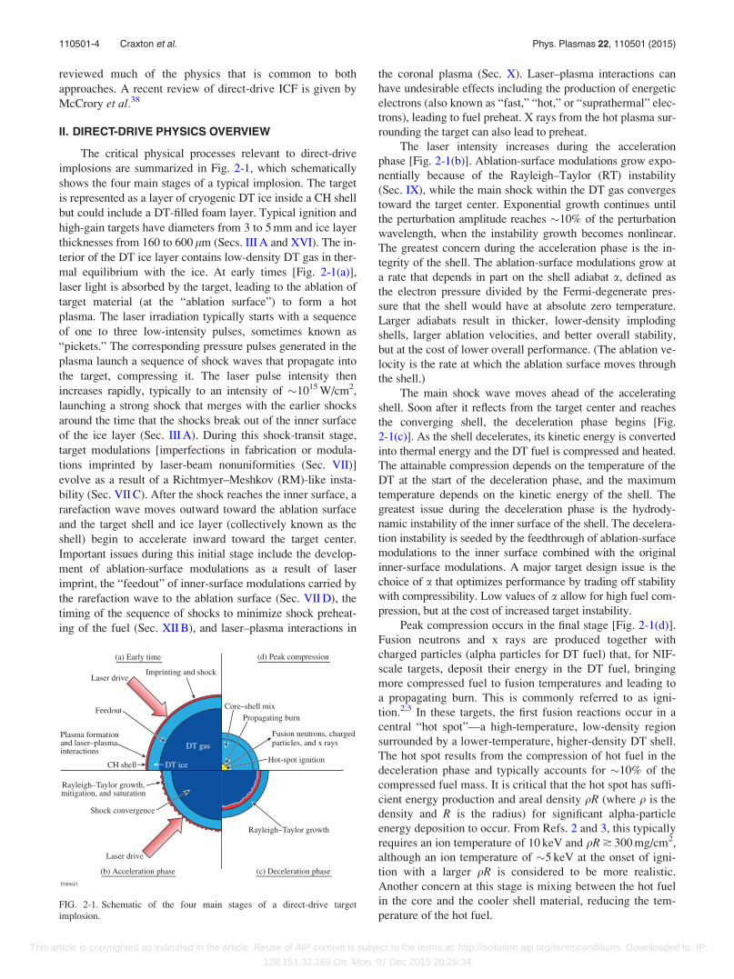
The critical physical processes relevant to direct-drive
implosions are summarized in Fig. 2-1, which schematically
shows the four main stages of a typical implosion. The target
is represented as a layer of cryogenic DT ice inside a CH shell
but could include a DT-filled foam layer. Typical ignition and
high-gain targets have diameters from 3 to 5 mm and ice layer
thicknesses from 160 to 600 lm (Secs. III A and XVI). The in-
terior of the DT ice layer contains low-density DT gas in ther-
mal equilibrium with the ice. At early times [Fig. 2-1(a)],
laser light is absorbed by the target, leading to the ablation of
target material (at the “ablation surface”) to form a hot
plasma. The laser irradiation typically starts with a sequence
of one to three low-intensity pulses, sometimes known as
“pickets.” The corresponding pressure pulses generated in the
plasma launch a sequence of shock waves that propagate into
the target, compressing it. The laser pulse intensity then
increases rapidly, typically to an intensity of �1015 W/cm2,
launching a strong shock that merges with the earlier shocks
around the time that the shocks break out of the inner surface
of the ice layer (Sec. III A). During this shock-transit stage,
target modulations [imperfections in fabrication or modula-
tions imprinted by laser-beam nonuniformities (Sec. VII)]
evolve as a result of a Richtmyer–Meshkov (RM)-like insta-
bility (Sec. VII C). After the shock reaches the inner surface, a
rarefaction wave moves outward toward the ablation surface
and the target shell and ice layer (collectively known as the
shell) begin to accelerate inward toward the target center.
Important issues during this initial stage include the develop-
ment of ablation-surface modulations as a result of laser
imprint, the “feedout” of inner-surface modulations carried by
the rarefaction wave to the ablation surface (Sec. VII D), the
timing of the sequence of shocks to minimize shock preheat-
ing of the fuel (Sec. XII B), and laser–plasma interactions in
the coronal plasma (Sec. X). Laser–plasma interactions can
have undesirable effects including the production of energetic
electrons (also known as “fast,” “hot,” or “suprathermal” elec-
trons), leading to fuel preheat. X rays from the hot plasma sur-
rounding the target can also lead to preheat.
The laser intensity increases during the acceleration
phase [Fig. 2-1(b)]. Ablation-surface modulations grow expo-
nentially because of the Rayleigh–Taylor (RT) instability
(Sec. IX), while the main shock within the DT gas converges
toward the target center. Exponential growth continues until
the perturbation amplitude reaches �10% of the perturbation
wavelength, when the instability growth becomes nonlinear.
The greatest concern during the acceleration phase is the in-
tegrity of the shell. The ablation-surface modulations grow at
a rate that depends in part on the shell adiabat a, defined as
the electron pressure divided by the Fermi-degenerate pres-
sure that the shell would have at absolute zero temperature.
Larger adiabats result in thicker, lower-density imploding
shells, larger ablation velocities, and better overall stability,
but at the cost of lower overall performance. (The ablation ve-
locity is the rate at which the ablation surface moves through
the shell.)
The main shock wave moves ahead of the accelerating
shell. Soon after it reflects from the target center and reaches
the converging shell, the deceleration phase begins [Fig.
2-1(c)]. As the shell decelerates, its kinetic energy is converted
into thermal energy and the DT fuel is compressed and heated.
The attainable compression depends on the temperature of the
DT at the start of the deceleration phase, and the maximum
temperature depends on the kinetic energy of the shell. The
greatest issue during the deceleration phase is the hydrody-
namic instability of the inner surface of the shell. The decelera-
tion instability is seeded by the feedthrough of ablation-surface
modulations to the inner surface combined with the original
inner-surface modulations. A major target design issue is the
choice of a that optimizes performance by trading off stability
with compressibility. Low values of a allow for high fuel com-
pression, but at the cost of increased target instability.
Peak compression occurs in the final stage [Fig. 2-1(d)].
Fusion neutrons and x rays are produced together with
charged particles (alpha particles for DT fuel) that, for NIF-
scale targets, deposit their energy in the DT fuel, bringing
more compressed fuel to fusion temperatures and leading to
a propagating burn. This is commonly referred to as igni-
tion.2,3 In these targets, the first fusion reactions occur in a
central “hot spot”—a high-temperature, low-density region
surrounded by a lower-temperature, higher-density DT shell.
The hot spot results from the compression of hot fuel in the
deceleration phase and typically accounts for �10% of the
compressed fuel mass. It is critical that the hot spot has suffi-
cient energy production and areal density qR (where q is the
density and R is the radius) for significant alpha-particle
energy deposition to occur. From Refs. 2 and 3, this typically
requires an ion temperature of 10 keV and qR � 300 mg/cm2,
although an ion temperature of �5 keV at the onset of igni-
tion with a larger qR is considered to be more realistic.
Another concern at this stage is mixing between the hot fuel
in the core and the cooler shell material, reducing the tem-
perature of the hot fuel.FIG. 2-1. Schematic of the four main stages of a direct-drive target
implosion.
110501-4 Craxton et al. Phys. Plasmas 22, 110501 (2015)
This article is copyrighted as indicated in the article. Reuse of AIP content is subject to the terms at: http://scitation.aip.org/termsconditions. Downloaded to IP:
128.151.32.169 On: Mon, 07 Dec 2015 20:25:34

One of the most important issues for direct drive is laser
beam uniformity (Sec. VI). Long-wavelength nonuniform-
ities, which arise from considerations such as the number of
beams and their placement around the target chamber, can
limit the target convergence. These nonuniformities are typi-
cally required to be less than �1% (rms). Shorter-wavelength
nonuniformities, which are largely associated with the indi-
vidual beam intensity profiles, are of concern as they can lead
to laser imprinting (Sec. VII) during the initial stage of the
laser–target interaction. Laser energy is deposited nonuni-
formly, according to the intensity distribution of each laser
beam, resulting in ablation-surface modulations. Imprint
occurs at early times until laser ablation produces a suffi-
ciently large plasma in which the laser-absorption region
becomes separated from the ablation surface. Thereafter, the
shorter-wavelength laser-beam nonuniformities are smoothed
by lateral thermal conduction (the “cloudy day” effect of Ref.
39) in the region between these surfaces. Imprint has been
greatly reduced as a result of the development of laser beam-
smoothing techniques (Sec. VI).
The properties of the hot coronal plasma surrounding
the target are important for ensuring that the laser energy is
efficiently absorbed and coupled to the imploding shell. The
electron density ne decreases with radius, passing through
the so-called critical density nc at the critical surface. At this
surface, the electron plasma frequency, xp, defined by
x2p ¼
4pnee2
me
; (2-1)
where ne, e, and me are the electron number density, charge,
and mass, respectively, equals the incident laser frequency
x0. The incoming laser light can propagate only up to the
critical density. Since [from Eq. (2-1)] nc is proportional to
x20; a reduction in the laser wavelength by a factor of 3 (as
for the frequency-tripled glass lasers currently being used
for fusion research) increases the critical density by a factor
of 9. (The critical density is given by nc
¼ 1:115� 1021=k20 cm�3; where k0 is the laser wavelength
in microns.) For frequency-tripled lasers, the main absorp-
tion process (inverse bremsstrahlung, Sec. V) involves elec-
trons gaining directed energy through oscillations in the
electromagnetic (EM) wave with this energy being thermal-
ized through collisions. This process is most effective near
the critical surface and favors short-wavelength lasers since
the collision rate is larger at higher density. Energy is
coupled more efficiently to the ablation surface of the
imploding shell for short-wavelength lasers since it has a
shorter distance to propagate; however, this shorter distance
reduces the amount of thermal smoothing of laser nonuni-
formities, making laser beam smoothing particularly impor-
tant. Energy transport from the absorption region to the
ablation surface occurs through electron thermal conduction
(Sec. XI), which is complicated by the existence of ener-
getic electrons in the tail of the distribution function whose
mean free paths between collisions are comparable to or
larger than the temperature scale length.
A number of nonlinear laser–plasma interactions can take
place in the portion of the plasma corona below the critical
density (known as the “underdense” region) (Sec. X). Most no-
table are the two-plasmon–decay (TPD) instability, which
occurs very close to the quarter-critical density and in which
the incident EM wave excites two electron plasma waves
(known as plasmons), and the stimulated Raman scattering
(SRS) instability, which occurs below the quarter-critical den-
sity and in which the incident EM wave excites a scattered EM
wave of lower frequency and a plasmon. These instabilities are
of concern because electric fields associated with the plasmons
can accelerate electrons to high energies. Another important
process is stimulated Brillouin scattering (SBS), which is simi-
lar to SRS except that the plasmon is replaced by an ion-
acoustic wave. This instability can occur anywhere below the
critical density and can lead to a loss of energy. In one form of
SBS, known as cross-beam energy transfer (CBET), laser
energy can be lost by being scattered from incoming rays of
one laser beam into outgoing rays of another. The effectiveness
of these instabilities increases with laser intensity, imposing
constraints on laser pulse-shape design.
Several nuclear reactions are of interest to laser-driven
ICF. Most important are primary reactions from the DT
fuel40
Dþ T!4He ð3:5 MeVÞ þ n ð14:1 MeVÞ: (2-2)
The alpha particles (4Heþþ) are reabsorbed in the fuel of
igniting targets, but the neutrons substantially escape with
some energy loss that can provide a diagnostic of the fuel
qR. For energy production, the neutrons would be captured
in the blanket of an inertial fusion reactor (Sec. XVII). Many
experiments have used D2 fuel, in which the primary reac-
tions comprise two branches with approximately equal
probabilities40
Dþ D! 3He ð0:82 MeVÞ þ n ð2:45 MeVÞ; (2-3)
Dþ D! T ð1:01 MeVÞ þ p ð3:02 MeVÞ: (2-4)
The 3He and triton products from these reactions can com-
bine with fuel deuterium in the following “secondary”
reactions:41
T� þ D! 4Heþ n ð11:8 to 17:1 MeVÞ; (2-5)
3He� þ D! 4Heþ p ð12:5 to 17:4 MeVÞ; (2-6)
where T* and 3He* indicate tritons and 3He nuclei that can
have energies less than their corresponding birth energies
[Eqs. (2-3) and (2-4)] because of slowing down in the com-
pressed fuel. The primary reaction in D3He fuel,40
Dþ 3He! 4He ð3:6 MeVÞ þ p ð14:7 MeVÞ; (2-7)
is also important. This can be used to diagnose the mix by fill-
ing the target with 3He and placing deuterated plastic at some
distance from the inner surface of a CH shell (Sec. VIII A).
III. ONE-DIMENSIONAL HYDRODYNAMICS ANDIGNITION PHYSICS
To obtain hot-spot ignition of the DT fuel in an ICF im-
plosion, a shell consisting of an inner cryogenic DT layer
110501-5 Craxton et al. Phys. Plasmas 22, 110501 (2015)
This article is copyrighted as indicated in the article. Reuse of AIP content is subject to the terms at: http://scitation.aip.org/termsconditions. Downloaded to IP:
128.151.32.169 On: Mon, 07 Dec 2015 20:25:34
and an outer layer of ablator material is accelerated inward
by a temporally shaped pressure drive. This drive is created
by laser energy absorbed in the lower-density coronal plasma
via inverse bremsstrahlung, at some distance from the
higher-density main shell. The absorbed energy is trans-
ported by electrons and radiation to the shell, causing its
outer layer to ablate and creating a force that accelerates the
shell inward. As the shell approaches peak compression and
stagnation, a hotter, lower-density central region (hot spot)
surrounded by colder, higher-density main fuel is formed.
The ion temperature and areal density of the hot spot must
be high enough to create alpha particles (produced as a result
of fusing D and T) at a rate sufficient that the hot-spot self-
heating is larger than the hot-spot cooling (by radiation and
hydrodynamic expansion), resulting in a burn wave being
launched into the main fuel.
The laser-driven ICF process leading to hot-spot ignition
is described in Sec. III A, with reference to a triple-picket
ignition design for the NIF. (The term “picket” refers to a
short laser pulse delivered prior to the main laser pulse.) The
physics of this process is common to ignition and high-gain
target designs. Section III B summarizes a simple model
describing the ignition phase of the implosion and its scaling
with laser energy. Section III focuses on 1-D physics proc-
esses. Multidimensional aspects of ignition and high-gain
designs are included in Sec. XVI. Two alternative modes of
ignition that do not use the main laser drive to form a hot
spot are described in Sec. XIV (fast ignition) and Sec. XV
(shock ignition).
A. Triple-picket ignition design for the NIF
The basic physics of ignition and high-gain target designs
is illustrated using a 1.5-MJ triple-picket design for the NIF,
similar to that shown in Ref. 42. (Here and elsewhere, the
energy associated with a design refers to the incident laser
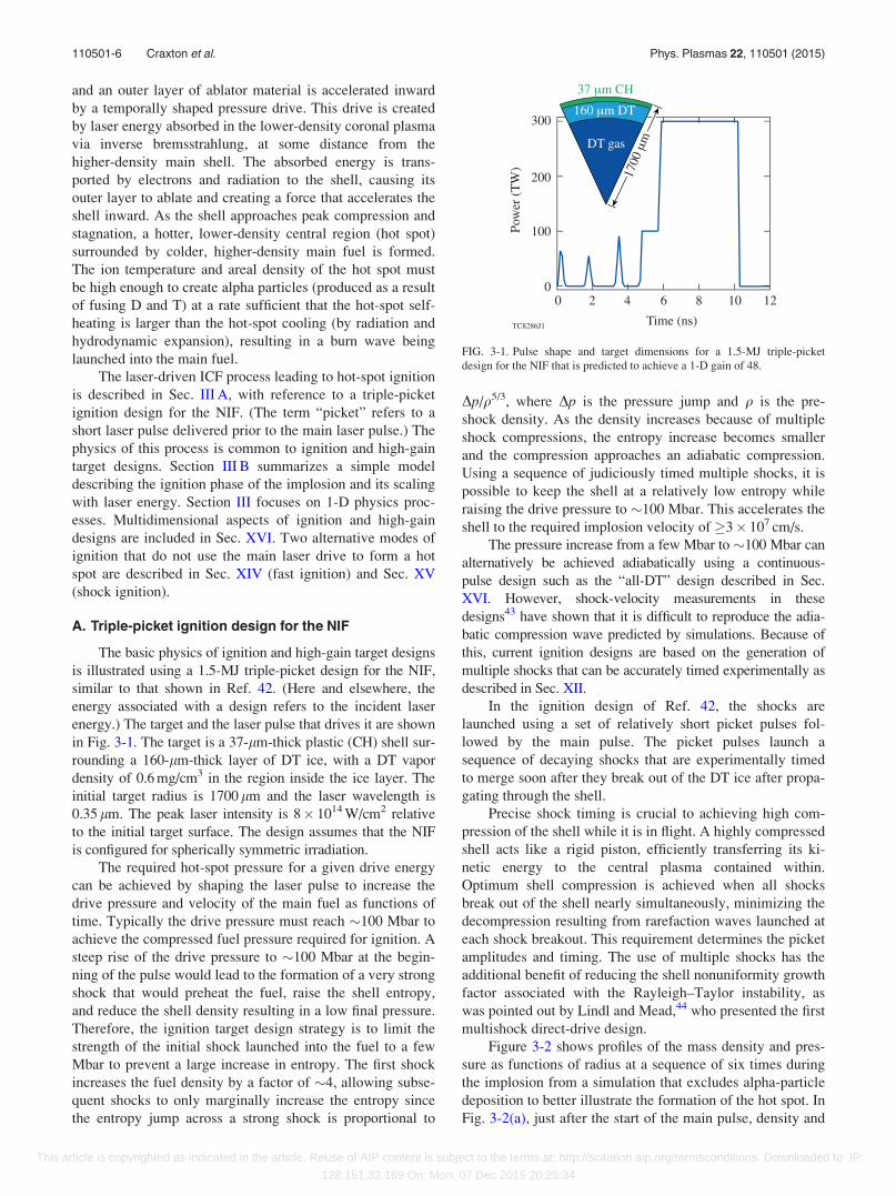
energy.) The target and the laser pulse that drives it are shown
in Fig. 3-1. The target is a 37-lm-thick plastic (CH) shell sur-
rounding a 160-lm-thick layer of DT ice, with a DT vapor
density of 0.6 mg/cm3 in the region inside the ice layer. The
initial target radius is 1700 lm and the laser wavelength is
0.35 lm. The peak laser intensity is 8� 1014 W/cm2 relative
to the initial target surface. The design assumes that the NIF
is configured for spherically symmetric irradiation.
The required hot-spot pressure for a given drive energy
can be achieved by shaping the laser pulse to increase the
drive pressure and velocity of the main fuel as functions of
time. Typically the drive pressure must reach �100 Mbar to
achieve the compressed fuel pressure required for ignition. A
steep rise of the drive pressure to �100 Mbar at the begin-
ning of the pulse would lead to the formation of a very strong
shock that would preheat the fuel, raise the shell entropy,
and reduce the shell density resulting in a low final pressure.
Therefore, the ignition target design strategy is to limit the
strength of the initial shock launched into the fuel to a few
Mbar to prevent a large increase in entropy. The first shock
increases the fuel density by a factor of �4, allowing subse-
quent shocks to only marginally increase the entropy since
the entropy jump across a strong shock is proportional to
Dp/q5/3, where Dp is the pressure jump and q is the pre-
shock density. As the density increases because of multiple
shock compressions, the entropy increase becomes smaller
and the compression approaches an adiabatic compression.
Using a sequence of judiciously timed multiple shocks, it is
possible to keep the shell at a relatively low entropy while
raising the drive pressure to �100 Mbar. This accelerates the
shell to the required implosion velocity of �3� 107 cm/s.
The pressure increase from a few Mbar to �100 Mbar can
alternatively be achieved adiabatically using a continuous-
pulse design such as the “all-DT” design described in Sec.
XVI. However, shock-velocity measurements in these
designs43 have shown that it is difficult to reproduce the adia-
batic compression wave predicted by simulations. Because of
this, current ignition designs are based on the generation of
multiple shocks that can be accurately timed experimentally as
described in Sec. XII.
In the ignition design of Ref. 42, the shocks are
launched using a set of relatively short picket pulses fol-
lowed by the main pulse. The picket pulses launch a
sequence of decaying shocks that are experimentally timed
to merge soon after they break out of the DT ice after propa-
gating through the shell.
Precise shock timing is crucial to achieving high com-
pression of the shell while it is in flight. A highly compressed
shell acts like a rigid piston, efficiently transferring its ki-
netic energy to the central plasma contained within.
Optimum shell compression is achieved when all shocks
break out of the shell nearly simultaneously, minimizing the
decompression resulting from rarefaction waves launched at
each shock breakout. This requirement determines the picket
amplitudes and timing. The use of multiple shocks has the
additional benefit of reducing the shell nonuniformity growth
factor associated with the Rayleigh–Taylor instability, as
was pointed out by Lindl and Mead,44 who presented the first
multishock direct-drive design.
Figure 3-2 shows profiles of the mass density and pres-
sure as functions of radius at a sequence of six times during
the implosion from a simulation that excludes alpha-particle
deposition to better illustrate the formation of the hot spot. In
Fig. 3-2(a), just after the start of the main pulse, density and
FIG. 3-1. Pulse shape and target dimensions for a 1.5-MJ triple-picket
design for the NIF that is predicted to achieve a 1-D gain of 48.
110501-6 Craxton et al. Phys. Plasmas 22, 110501 (2015)
This article is copyrighted as indicated in the article. Reuse of AIP content is subject to the terms at: http://scitation.aip.org/termsconditions. Downloaded to IP:
128.151.32.169 On: Mon, 07 Dec 2015 20:25:34
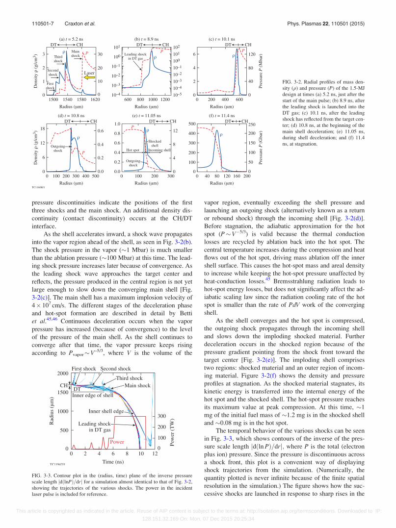
pressure discontinuities indicate the positions of the first
three shocks and the main shock. An additional density dis-
continuity (contact discontinuity) occurs at the CH/DT
interface.
As the shell accelerates inward, a shock wave propagates
into the vapor region ahead of the shell, as seen in Fig. 3-2(b).
The shock pressure in the vapor (�1 Mbar) is much smaller
than the ablation pressure (�100 Mbar) at this time. The lead-
ing shock pressure increases later because of convergence. As
the leading shock wave approaches the target center and
reflects, the pressure produced in the central region is not yet
large enough to slow down the converging main shell [Fig.
3-2(c)]. The main shell has a maximum implosion velocity of
4� 107 cm/s. The different stages of the deceleration phase
and hot-spot formation are described in detail by Betti
et al.45,46 Continuous deceleration occurs when the vapor
pressure has increased (because of convergence) to the level
of the pressure of the main shell. As the shell continues to
converge after that time, the vapor pressure keeps rising
according to Pvapor�V–5/3, where V is the volume of the
vapor region, eventually exceeding the shell pressure and
launching an outgoing shock (alternatively known as a return
or rebound shock) through the incoming shell [Fig. 3-2(d)].
Before stagnation, the adiabatic approximation for the hot
spot (P�V�5/3) is valid because the thermal conduction
losses are recycled by ablation back into the hot spot. The
central temperature increases during the compression and heat
flows out of the hot spot, driving mass ablation off the inner
shell surface. This causes the hot-spot mass and areal density
to increase while keeping the hot-spot pressure unaffected by
heat-conduction losses.45 Bremsstrahlung radiation leads to
hot-spot energy losses, but does not significantly affect the ad-
iabatic scaling law since the radiation cooling rate of the hot
spot is smaller than the rate of PdV work of the converging
shell.
As the shell converges and the hot spot is compressed,
the outgoing shock propagates through the incoming shell
and slows down the imploding shocked material. Further
deceleration occurs in the shocked region because of the
pressure gradient pointing from the shock front toward the
target center [Fig. 3-2(e)]. The imploding shell comprises
two regions: shocked material and an outer region of incom-
ing material. Figure 3-2(f) shows the density and pressure
profiles at stagnation. As the shocked material stagnates, its
kinetic energy is transferred into the internal energy of the
hot spot and the shocked shell. The hot-spot pressure reaches
its maximum value at peak compression. At this time, �1
mg of the initial fuel mass of �1.2 mg is in the shocked shell
and �0.08 mg is in the hot spot.
The temporal behavior of the various shocks can be seen
in Fig. 3-3, which shows contours of the inverse of the pres-
sure scale length jdðln PÞ=drj; where P is the total (electron
plus ion) pressure. Since the pressure is discontinuous across
a shock front, this plot is a convenient way of displaying
shock trajectories from the simulation. (Numerically, the
quantity plotted is never infinite because of the finite spatial
resolution in the simulation.) The figure shows how the suc-
cessive shocks are launched in response to sharp rises in the
FIG. 3-2. Radial profiles of mass den-
sity (q) and pressure (P) of the 1.5-MJ
design at times (a) 5.2 ns, just after the
start of the main pulse; (b) 8.9 ns, after
the leading shock is launched into the
DT gas; (c) 10.1 ns, after the leading
shock has reflected from the target cen-
ter; (d) 10.8 ns, at the beginning of the
main shell deceleration; (e) 11.05 ns,
during shell deceleration; and (f) 11.4
ns, at stagnation.
FIG. 3-3. Contour plot in the (radius, time) plane of the inverse pressure
scale length jdðlnPÞ=drj for a simulation almost identical to that of Fig. 3-2,
showing the trajectories of the various shocks. The power in the incident
laser pulse is included for reference.
110501-7 Craxton et al. Phys. Plasmas 22, 110501 (2015)
This article is copyrighted as indicated in the article. Reuse of AIP content is subject to the terms at: http://scitation.aip.org/termsconditions. Downloaded to IP:
128.151.32.169 On: Mon, 07 Dec 2015 20:25:34
laser power and how the shocks are timed to reach the inner
edge of the shell at around the same time, just prior to shell
acceleration.
The hydrodynamic efficiency of this design, defined as
the kinetic energy of the imploding shell divided by the
absorbed laser energy, is 6.7%. The absorbed laser fraction
is 95%. Not all the shell kinetic energy is converted into in-
ternal energy of the stagnated fuel. As seen in Fig. 3-2(f), the
shock has not yet reached the outer boundary of the shell at
the time of stagnation, so there is some fraction of the shell
that is unshocked and imploding (in “free fall”). The kinetic
energy of this part of the shell is not converted into internal
energy before the inner surface stagnates and the hot spot
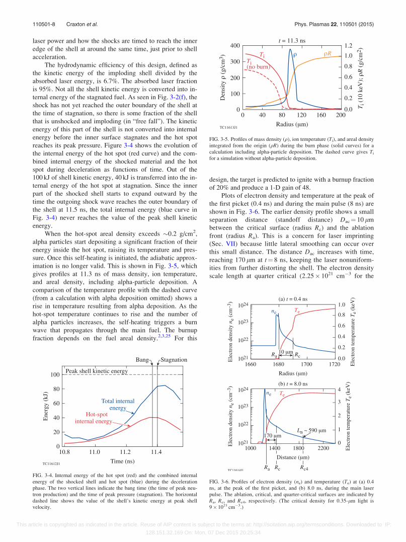
reaches its peak pressure. Figure 3-4 shows the evolution of
the internal energy of the hot spot (red curve) and the com-
bined internal energy of the shocked material and the hot
spot during deceleration as functions of time. Out of the
100 kJ of shell kinetic energy, 40 kJ is transferred into the in-
ternal energy of the hot spot at stagnation. Since the inner
part of the shocked shell starts to expand outward by the
time the outgoing shock wave reaches the outer boundary of
the shell at 11.5 ns, the total internal energy (blue curve in
Fig. 3-4) never reaches the value of the peak shell kinetic
energy.
When the hot-spot areal density exceeds �0.2 g/cm2,
alpha particles start depositing a significant fraction of their
energy inside the hot spot, raising its temperature and pres-
sure. Once this self-heating is initiated, the adiabatic approx-
imation is no longer valid. This is shown in Fig. 3-5, which
gives profiles at 11.3 ns of mass density, ion temperature,
and areal density, including alpha-particle deposition. A
comparison of the temperature profile with the dashed curve
(from a calculation with alpha deposition omitted) shows a
rise in temperature resulting from alpha deposition. As the
hot-spot temperature continues to rise and the number of
alpha particles increases, the self-heating triggers a burn
wave that propagates through the main fuel. The burnup
fraction depends on the fuel areal density.2,3,25 For this
design, the target is predicted to ignite with a burnup fraction
of 20% and produce a 1-D gain of 48.
Plots of electron density and temperature at the peak of
the first picket (0.4 ns) and during the main pulse (8 ns) are
shown in Fig. 3-6. The earlier density profile shows a small
separation distance (standoff distance) Dac¼ 10 lm
between the critical surface (radius Rc) and the ablation
front (radius Ra). This is a concern for laser imprinting
(Sec. VII) because little lateral smoothing can occur over
this small distance. The distance Dac increases with time,
reaching 170 lm at t¼ 8 ns, keeping the laser nonuniform-
ities from further distorting the shell. The electron density
scale length at quarter critical (2.25� 1021 cm�3 for the
FIG. 3-4. Internal energy of the hot spot (red) and the combined internal
energy of the shocked shell and hot spot (blue) during the deceleration
phase. The two vertical lines indicate the bang time (the time of peak neu-
tron production) and the time of peak pressure (stagnation). The horizontal
dashed line shows the value of the shell’s kinetic energy at peak shell
velocity.
FIG. 3-5. Profiles of mass density (q), ion temperature (Ti), and areal density
integrated from the origin (qR) during the burn phase (solid curves) for a
calculation including alpha-particle deposition. The dashed curve gives Ti
for a simulation without alpha-particle deposition.
FIG. 3-6. Profiles of electron density (ne) and temperature (Te) at (a) 0.4
ns, at the peak of the first picket, and (b) 8.0 ns, during the main laser
pulse. The ablation, critical, and quarter-critical surfaces are indicated by
Ra, Rc, and Rc4, respectively. (The critical density for 0.35-lm light is
9� 1021 cm�3.)
110501-8 Craxton et al. Phys. Plasmas 22, 110501 (2015)
This article is copyrighted as indicated in the article. Reuse of AIP content is subject to the terms at: http://scitation.aip.org/termsconditions. Downloaded to IP:
128.151.32.169 On: Mon, 07 Dec 2015 20:25:34
0.35-lm laser wavelength) is large (590 lm), leading to
concerns about plasma instabilities producing hot electrons
in this region (Sec. X).
Two important parameters of the 1-D design related to
target stability, discussed further in Sec. XVI, are the in-
flight aspect ratio (IFAR) and the convergence ratio. The
IFAR (24.3 for this design) is defined near the beginning of
shell acceleration, when the ablation-front radius is at 2/3 of
the initial inner radius of the shell, as the ablation-front ra-
dius divided by the shell thickness. The convergence ratio
(23 for this design) is defined as the initial inner radius of the
shell divided by the inner shell radius at peak compression
with alpha-particle deposition turned off.
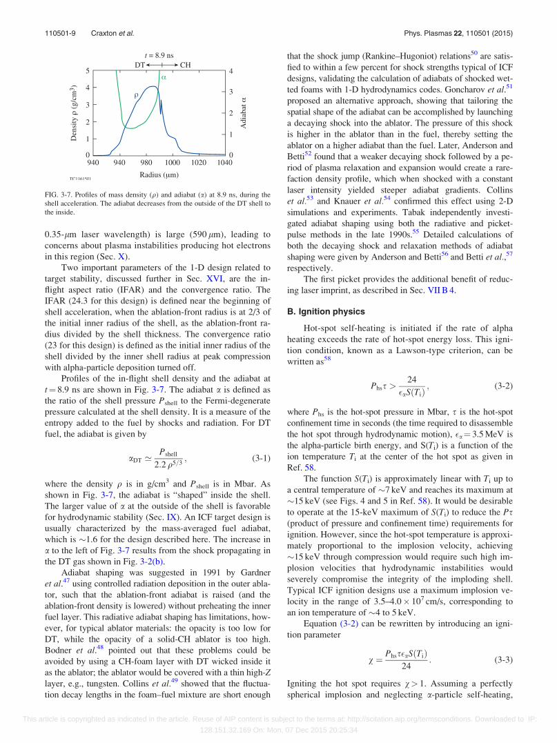
Profiles of the in-flight shell density and the adiabat at
t¼ 8.9 ns are shown in Fig. 3-7. The adiabat a is defined as
the ratio of the shell pressure Pshell to the Fermi-degenerate
pressure calculated at the shell density. It is a measure of the
entropy added to the fuel by shocks and radiation. For DT
fuel, the adiabat is given by
aDT ’Pshell
2:2 q5=3; (3-1)
where the density q is in g/cm3 and Pshell is in Mbar. As
shown in Fig. 3-7, the adiabat is “shaped” inside the shell.
The larger value of a at the outside of the shell is favorable
for hydrodynamic stability (Sec. IX). An ICF target design is
usually characterized by the mass-averaged fuel adiabat,
which is �1.6 for the design described here. The increase in
a to the left of Fig. 3-7 results from the shock propagating in
the DT gas shown in Fig. 3-2(b).
Adiabat shaping was suggested in 1991 by Gardner
et al.47 using controlled radiation deposition in the outer abla-
tor, such that the ablation-front adiabat is raised (and the
ablation-front density is lowered) without preheating the inner
fuel layer. This radiative adiabat shaping has limitations, how-
ever, for typical ablator materials: the opacity is too low for
DT, while the opacity of a solid-CH ablator is too high.
Bodner et al.48 pointed out that these problems could be
avoided by using a CH-foam layer with DT wicked inside it
as the ablator; the ablator would be covered with a thin high-Zlayer, e.g., tungsten. Collins et al.49 showed that the fluctua-
tion decay lengths in the foam–fuel mixture are short enough
that the shock jump (Rankine–Hugoniot) relations50 are satis-
fied to within a few percent for shock strengths typical of ICF
designs, validating the calculation of adiabats of shocked wet-
ted foams with 1-D hydrodynamics codes. Goncharov et al.51
proposed an alternative approach, showing that tailoring the
spatial shape of the adiabat can be accomplished by launching
a decaying shock into the ablator. The pressure of this shock
is higher in the ablator than in the fuel, thereby setting the
ablator on a higher adiabat than the fuel. Later, Anderson and
Betti52 found that a weaker decaying shock followed by a pe-
riod of plasma relaxation and expansion would create a rare-
faction density profile, which when shocked with a constant
laser intensity yielded steeper adiabat gradients. Collins
et al.53 and Knauer et al.54 confirmed this effect using 2-D
simulations and experiments. Tabak independently investi-
gated adiabat shaping using both the radiative and picket-
pulse methods in the late 1990s.55 Detailed calculations of
both the decaying shock and relaxation methods of adiabat
shaping were given by Anderson and Betti56 and Betti et al.,57
respectively.
The first picket provides the additional benefit of reduc-
ing laser imprint, as described in Sec. VII B 4.
B. Ignition physics
Hot-spot self-heating is initiated if the rate of alpha
heating exceeds the rate of hot-spot energy loss. This igni-
tion condition, known as a Lawson-type criterion, can be
written as58
Phss >24
�aS Tið Þ; (3-2)
where Phs is the hot-spot pressure in Mbar, s is the hot-spot
confinement time in seconds (the time required to disassemble
the hot spot through hydrodynamic motion), �a¼ 3.5 MeV is
the alpha-particle birth energy, and S(Ti) is a function of the
ion temperature Ti at the center of the hot spot as given in
Ref. 58.
The function S(Ti) is approximately linear with Ti up to
a central temperature of �7 keV and reaches its maximum at
�15 keV (see Figs. 4 and 5 in Ref. 58). It would be desirable
to operate at the 15-keV maximum of S(Ti) to reduce the Ps(product of pressure and confinement time) requirements for
ignition. However, since the hot-spot temperature is approxi-
mately proportional to the implosion velocity, achieving
�15 keV through compression would require such high im-
plosion velocities that hydrodynamic instabilities would
severely compromise the integrity of the imploding shell.
Typical ICF ignition designs use a maximum implosion ve-
locity in the range of 3.5–4.0� 107 cm/s, corresponding to
an ion temperature of �4 to 5 keV.
Equation (3-2) can be rewritten by introducing an igni-
tion parameter
v ¼ Phss�aS Tið Þ24
: (3-3)
Igniting the hot spot requires v> 1. Assuming a perfectly
spherical implosion and neglecting a-particle self-heating,
FIG. 3-7. Profiles of mass density (q) and adiabat (a) at 8.9 ns, during the
shell acceleration. The adiabat decreases from the outside of the DT shell to
the inside.
110501-9 Craxton et al. Phys. Plasmas 22, 110501 (2015)
This article is copyrighted as indicated in the article. Reuse of AIP content is subject to the terms at: http://scitation.aip.org/termsconditions. Downloaded to IP:
128.151.32.169 On: Mon, 07 Dec 2015 20:25:34

Eq. (3-3) can be rewritten, using the hydrodynamic relations
derived in Ref. 59, to relate v to observables
v ’ ½qR�0:8ðTi=4:7Þ1:6; (3-4)
where qR is the total neutron-averaged areal density of the
assembled fuel (including the hot spot and the main fuel) at
peak compression in g/cm2 and Ti is the neutron-averaged
ion temperature of the hot spot in keV. Both areal density
and ion temperature increase with the laser energy.59
To assess the progress of direct-drive implosions using
sub-ignition–scaled laser facilities, such as OMEGA, Eq.
(3-4) must be rewritten in terms of hydrodynamic quantities
that remain constant for subscale designs hydrodynamically
equivalent to ignition designs on MJ-scale facilities. One of
the most important parameters is the hot-spot pressure Phs
at peak compression. To write the ignition criterion in terms
of this pressure, hydrodynamic scalings59 are first used to
rewrite Eq. (3-4) in terms of the hot-spot areal density and
temperature
qRhs � Ti > 0:3 g=cm2 � 5 keV: (3-5)
Since the DT fuel pressure (assuming equal ion and electron
temperatures) is PDT ¼ 2 qTi=2:5 mp; where mp is the proton
mass, Eq. (3-5) takes the form
Phs > 100 Gbar100 lm
Rhs
� �; (3-6)
where Rhs is the hot-spot radius. Assuming that a fraction fkof the total kinetic energy of the shell Ek is converted into
the internal energy of the hot spot at peak compression,
fkEk ¼ 2pPhsR3hs; Eq. (3-6) can be rewritten in the form
Phs > 250 GbarfkEk
10 kJ
� ��1=2
: (3-7)
Equation (3-7) shows that as the shell kinetic energy
increases, the hot-spot pressure required for ignition decreases.
For example, the target of Sec. III A couples �100 kJ out of
1.5-MJ incident laser energy into shell kinetic energy with
fk� 0.4 to 0.5. According to Eq. (3-7), this results in the mini-
mum required hot-spot pressure exceeding 120–180 Gbar,
which is smaller than the 215 Gbar predicted for this design.
The maximum-allowed hot-spot size increases with the shell
kinetic energy. This can be shown by combining Eqs. (3-6)
and (3-7)
Rhs < 40 lm
ffiffiffiffiffiffiffiffiffiffifkEk
10 kJ
r: (3-8)
The condition on the minimum hot-spot pressure sets
the requirements for laser pulse shaping and target dimen-
sions. This can be understood using the following considera-
tions: The hot-spot pressure increases by converting kinetic
energy of the converging shell into internal energy of the
stagnating fuel. Assuming that a fluid with velocity v and
density q is stopped by a strong shock, the resulting pressure
of the stagnated material is
Pstag � qv2: (3-9)
This shows that the pressure at stagnation can be increased
by increasing the shell density and velocity. For a given laser
drive energy EL, the shell velocity scales as43
v � PaEL
MshellI; (3-10)
where Pa is the drive (ablation) pressure created by the
ablated plasma blowing off the target, Mshell is the shell
mass, and I is the intensity of the incident laser during the
main portion of the pulse. Equation (3-10) shows that the
shell velocity increases by reducing the shell mass and
increasing the drive pressure at a given laser intensity (by
using, for example, more-efficient ablator materials).
The scaling for the target radius R comes from an argu-
ment that the shell velocity scales with target radius R and
acceleration time taccel as v�R/taccel, where taccel � EL=R2I;so
R � ðELv=IÞ1=3: (3-11)
Using Eq. (3-11) and writing Mshell� q0D0R2, where q0 is
the initial average shell density and D0 is the initial shell
thickness, Eq. (3-10) takes the form
v �
ffiffiffiffiffiffiffiffiffiffiffiffiffiffiffiffiffiffiPa
q0
R
D0
� �s: (3-12)
Equation (3-12) indicates that for a given ablator material
(q0 is fixed), the shell velocity can be increased by raising
the laser intensity (which results in an increase in Pa) or by
increasing the initial aspect ratio of the shell R/D0. Several
design limitations control the maximum values of both quan-
tities. The maximum laser intensity is limited by the excita-
tion of laser–plasma instabilities such as the two-
plasmon–decay instability (Sec. X A) and stimulated Raman
scattering (Sec. X C), which reduce the laser coupling and
lead to the generation of suprathermal electrons that can pre-
heat the main fuel layer. The maximum value of the shell as-
pect ratio is determined by multidimensional effects, in
particular instability growth, which potentially can break up
the shell if it is too thin.
The second contributing factor to the stagnating
hot-spot pressure [see Eq. (3-9)], the shell density, is deter-
mined mainly by the fuel adiabat a. The fuel adiabat is con-
trolled primarily by shock and radiation heating. In
addition, the generation of suprathermal electrons from
laser–plasma instabilities can increase the adiabat in some
designs when the laser intensity exceeds the instability
thresholds. Calculations43 show that ignition can fail if 1%
to 2% of the shell kinetic energy is deposited in the main
fuel due to suprathermal electron preheat. The design
shown in Fig. 3-1 reaches a kinetic energy of �100 kJ, lead-
ing to a limit of 1–2 kJ in preheat energy (or �0.1% of the
incident laser energy) to avoid quenching the burn.
Suprathermal electron preheat is discussed further in Sec.
X A 2.
110501-10 Craxton et al. Phys. Plasmas 22, 110501 (2015)
This article is copyrighted as indicated in the article. Reuse of AIP content is subject to the terms at: http://scitation.aip.org/termsconditions. Downloaded to IP:
128.151.32.169 On: Mon, 07 Dec 2015 20:25:34

IV. THE EARLY YEARS
The laser-driven ICF concept originated in classified
environments, with the key physics concept of compression
predating the invention of the laser. A brief history given by
Atzeni and Meyer-ter-Vehn in Sec. 3.4 of Ref. 25 includes
descriptions of (1) the role of compression on fusion reaction
rates, from work by Eddington on stellar energetics to
imploding fission weapons and to controlled thermonuclear
micro-explosions; (2) the proposals of several scientists
(Nuckolls, Kidder, and Colgate in the U.S., and Basov,
Krokhin, and Sakharov in the Soviet Union) immediately af-
ter the operation of the first lasers to use pulsed lasers to
drive implosions; (3) the initiation of secret experimental
programs in the 1960s; (4) a talk delivered by Basov in 1971
that led to the declassification of the compression concept
and the publication of the seminal 1972 Nature article by
Nuckolls et al.;1 and (5) the later declassification of research
on indirect drive.
A more-detailed history of ICF is given in Ref. 24—a
collection of personal recollections written by pioneers of
the field. The chapter by Nuckolls in Ref. 24 is particularly
useful for its description of the origins of ICF and the now-
declassified work in the period up to 1972. As recognized by
Lindl,2,3 the concept of laser-driven ICF grew out of work by
Nuckolls in the late 1950s on the challenge of creating small
fusion explosions without the use of an atomic bomb.
Nuckolls postulated that a “non-nuclear primary” might be
able to energize a radiation-driven implosion. He considered
several candidates for the radiation source including plasma
jets, pellet guns, and charged particle beams. (Later, he advo-
cated heavy-ion accelerators for ICF power plants.) He cal-
culated quantities such as the required mass of DT and the
required radiation energy and temperature. The importance
of isentropic compression to high densities, the associated
need for a shaped drive pulse, and the problem of fluid insta-
bilities were all recognized at this time. Some of Nuckolls’
calculations were for the radiation-driven implosion of a
“bare drop” of DT. After the demonstration of the laser,
Lindl2,3 credits Nuckolls and Colgate with calculating implo-
sions in laser-driven hohlraums and Kidder with calculations
that applied a spherically symmetric pulse of laser light
directly to the target—the first direct-drive simulations.
Significant work was reported in the open literature in
the 1960s that, while omitting the concept of compression,
developed some important theoretical understanding and set
in motion experiments aimed at demonstrating laser-induced
fusion. Possibly the earliest publication on this topic is a
report from the International Solid-State Circuits Conference
in February 1961 (Ref. 60) in which Peter Franken discussed
the heating of small pellets of lithium hydride to fusion tem-
perature by a laser. Franken is quoted as warning that “the
physics of this scheme do not favor success, but the work
has, nevertheless, been started.”
In a 1962 conference abstract, Linlor61 presented what
may be the first report of a laser-produced plasma and men-
tioned its possible application to controlled fusion research.
Soon thereafter, in 1964, Dawson62 published ground-breaking
theoretical work on laser-produced plasmas, covering many
basic physics processes (such as inverse-bremsstrahlung
absorption, thermal conduction, and electron–ion equipartition)
that would subsequently be incorporated into hydrodynamic
simulation codes. Dawson’s main interest in this work was to
use the laser to heat solid or liquid particles to fuel a magnetic-
containment device. In what may be the first reference to the
physical significance of the laser wavelength, he advocated
higher-frequency lasers to heat the plasma at higher densities,
improve the equipartition, and, thereby, heat the ions to higher
temperatures.
In a later paper, Dawson et al.63 considered the inverse-
bremsstrahlung absorption process in more detail, including
a finite density gradient in the plasma surrounding the solid
particle. They recognized that efficient absorption is only
possible with a sufficiently large scale length and estimated
that a scale length of 1.4 mm would be needed to heat a deu-
terium plasma with a ruby laser (wavelength k0¼ 0.7 lm),
assuming an electron temperature of 10 keV. Considering a
1.4-mm-radius sphere of electrons at the critical density,
they estimated that an energy of the order of 100 kJ would be
needed to accomplish this. (Of course, the density–radius
product of this sphere, of the order of 1 mg/cm2, would have
been far too small for alpha-particle deposition.) They again
advocated using higher-frequency lasers (“It might be advan-
tageous to pass the light through a second harmonic gener-
ator”), noting that if the laser frequency is doubled, the
density at the point where it is absorbed is 4� greater, allow-
ing the radius of the particle to be reduced by a factor of 4.
While Dawson et al. did not take into account the need
for compression and did not have appropriate hydrodynamic
simulation codes available, their physical intuition that a
deuterium plasma of a sufficient size, driven by a short-
wavelength laser, could absorb a substantial fraction of the
laser energy was correct and showed remarkable foresight.
Their numerical estimates were mostly close, consistent with
the parameters of the all-DT ignition design described in
Sec. XVI, which has an outer radius of 1.7 mm and a coronal
scale length of �0.5 mm, uses only inverse bremsstrahlung
as an absorption mechanism, and is driven by a 0.35-lm
laser. The only estimate that was a long way off was the laser
energy (which is 1.5 MJ in the all-DT design); ignition
designs account for the �10% conversion efficiency between
the energy absorbed in the corona and the energy of implod-
ing material and the energy cost associated with ensuring
adequate target stability.
Unfortunately, the available laser energies, laser wave-
lengths, and target scale lengths in the 1960s and 1970s were
such that the regime envisaged by Dawson et al. could not
be realized. Instead, target physics was generally dominated
by other absorption mechanisms and by their often undesired
consequences.
A. The quest for neutrons
On the experimental side, leadership was provided by
the work of Basov and others at the Lebedev Institute in the
USSR. In 1964, Basov and Krokhin64,65 reported on using
lasers to heat hydrogen to fusion temperatures. (Reference
65 referred to a paper delivered by Basov at the Presidium of
110501-11 Craxton et al. Phys. Plasmas 22, 110501 (2015)
This article is copyrighted as indicated in the article. Reuse of AIP content is subject to the terms at: http://scitation.aip.org/termsconditions. Downloaded to IP:
128.151.32.169 On: Mon, 07 Dec 2015 20:25:34
the USSR Academy of Sciences as being one of the first sug-
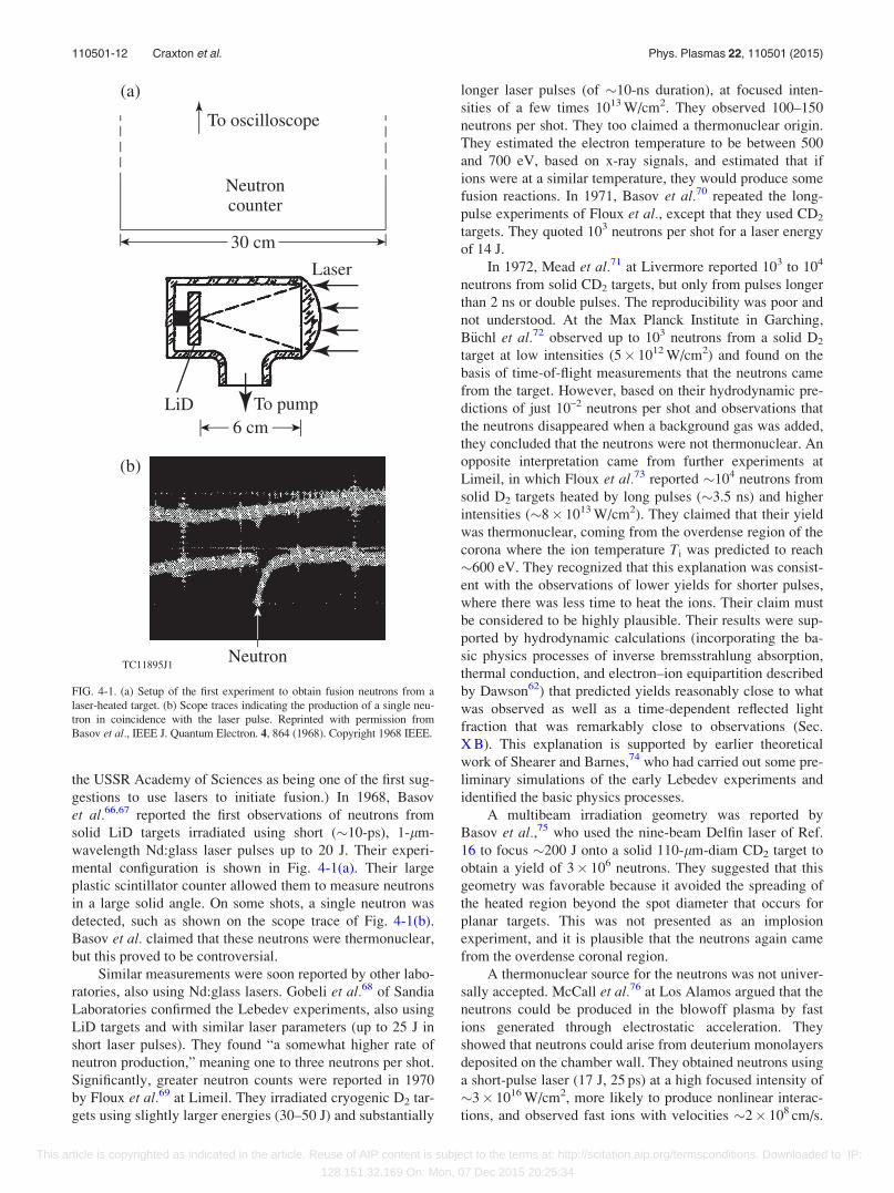
gestions to use lasers to initiate fusion.) In 1968, Basov
et al.66,67 reported the first observations of neutrons from
solid LiD targets irradiated using short (�10-ps), 1-lm-
wavelength Nd:glass laser pulses up to 20 J. Their experi-
mental configuration is shown in Fig. 4-1(a). Their large
plastic scintillator counter allowed them to measure neutrons
in a large solid angle. On some shots, a single neutron was
detected, such as shown on the scope trace of Fig. 4-1(b).
Basov et al. claimed that these neutrons were thermonuclear,
but this proved to be controversial.
Similar measurements were soon reported by other labo-
ratories, also using Nd:glass lasers. Gobeli et al.68 of Sandia
Laboratories confirmed the Lebedev experiments, also using
LiD targets and with similar laser parameters (up to 25 J in
short laser pulses). They found “a somewhat higher rate of
neutron production,” meaning one to three neutrons per shot.
Significantly, greater neutron counts were reported in 1970
by Floux et al.69 at Limeil. They irradiated cryogenic D2 tar-
gets using slightly larger energies (30–50 J) and substantially
longer laser pulses (of �10-ns duration), at focused inten-
sities of a few times 1013 W/cm2. They observed 100–150
neutrons per shot. They too claimed a thermonuclear origin.
They estimated the electron temperature to be between 500
and 700 eV, based on x-ray signals, and estimated that if
ions were at a similar temperature, they would produce some
fusion reactions. In 1971, Basov et al.70 repeated the long-
pulse experiments of Floux et al., except that they used CD2
targets. They quoted 103 neutrons per shot for a laser energy
of 14 J.
In 1972, Mead et al.71 at Livermore reported 103 to 104
neutrons from solid CD2 targets, but only from pulses longer
than 2 ns or double pulses. The reproducibility was poor and
not understood. At the Max Planck Institute in Garching,
B€uchl et al.72 observed up to 103 neutrons from a solid D2
target at low intensities (5� 1012 W/cm2) and found on the
basis of time-of-flight measurements that the neutrons came
from the target. However, based on their hydrodynamic pre-
dictions of just 10–2 neutrons per shot and observations that
the neutrons disappeared when a background gas was added,
they concluded that the neutrons were not thermonuclear. An
opposite interpretation came from further experiments at
Limeil, in which Floux et al.73 reported �104 neutrons from
solid D2 targets heated by long pulses (�3.5 ns) and higher
intensities (�8� 1013 W/cm2). They claimed that their yield
was thermonuclear, coming from the overdense region of the
corona where the ion temperature Ti was predicted to reach
�600 eV. They recognized that this explanation was consist-
ent with the observations of lower yields for shorter pulses,
where there was less time to heat the ions. Their claim must
be considered to be highly plausible. Their results were sup-
ported by hydrodynamic calculations (incorporating the ba-
sic physics processes of inverse bremsstrahlung absorption,
thermal conduction, and electron–ion equipartition described
by Dawson62) that predicted yields reasonably close to what
was observed as well as a time-dependent reflected light
fraction that was remarkably close to observations (Sec.
X B). This explanation is supported by earlier theoretical
work of Shearer and Barnes,74 who had carried out some pre-
liminary simulations of the early Lebedev experiments and
identified the basic physics processes.
A multibeam irradiation geometry was reported by
Basov et al.,75 who used the nine-beam Delfin laser of Ref.
16 to focus �200 J onto a solid 110-lm-diam CD2 target to
obtain a yield of 3� 106 neutrons. They suggested that this
geometry was favorable because it avoided the spreading of
the heated region beyond the spot diameter that occurs for
planar targets. This was not presented as an implosion
experiment, and it is plausible that the neutrons again came
from the overdense coronal region.
A thermonuclear source for the neutrons was not univer-
sally accepted. McCall et al.76 at Los Alamos argued that the
neutrons could be produced in the blowoff plasma by fast
ions generated through electrostatic acceleration. They
showed that neutrons could arise from deuterium monolayers
deposited on the chamber wall. They obtained neutrons using
a short-pulse laser (17 J, 25 ps) at a high focused intensity of
�3� 1016 W/cm2, more likely to produce nonlinear interac-
tions, and observed fast ions with velocities �2� 108 cm/s.
FIG. 4-1. (a) Setup of the first experiment to obtain fusion neutrons from a
laser-heated target. (b) Scope traces indicating the production of a single neu-
tron in coincidence with the laser pulse. Reprinted with permission from
Basov et al., IEEE J. Quantum Electron. 4, 864 (1968). Copyright 1968 IEEE.
110501-12 Craxton et al. Phys. Plasmas 22, 110501 (2015)
This article is copyrighted as indicated in the article. Reuse of AIP content is subject to the terms at: http://scitation.aip.org/termsconditions. Downloaded to IP:
128.151.32.169 On: Mon, 07 Dec 2015 20:25:34
Yamanaka et al.77 at Osaka obtained up to 2� 104 neutrons
from a solid D2 target with 2-ns pulses at up to 1014 W/cm2.
This intensity is comparable to that of Floux et al.73 and the
pulse, although shorter, is long enough to establish a reason-
able plasma scale length, so the plasma temperature must
have been comparable and the similar observed neutron yield
could also be consistent with a thermal origin. However,
Yamanaka et al. observed fast ions (with an average speed
of 108 cm/s) and invoked them as the source of the neutrons.
They also invoked the parametric decay instability (PDI)
(Sec. X E) for much of the absorption.
In Ref. 78, Basov et al. agreed with McCall et al.76 that
in the case of tight focusing on a solid target, the neutrons
were produced external to the plasma from accelerated deu-
terons. However, they found that in a multibeam irradiation
geometry with spherical targets, the neutrons were thermal,
on the basis of the width of the energy spectrum of the neu-
trons. In Ref. 79, Soures et al. reported over 104 neutrons
from a one-beam laser tightly focused onto solid spherical
LiD targets; based on time-of-flight measurements, these
neutrons originated from the target. This same conclusion
was drawn by Basov et al.80 from time-of-flight measure-
ments in their multibeam system. Bodner et al.81 proposed
that the early fusion neutrons originated from ions directly
heated to keV temperatures in a narrow turbulent region near
critical, resulting from the parametric decay instability.
Boyer82 suggested that the SBS (Sec. X B) instability could
have been responsible.
Spherical irradiation had been considered for some time.
In 1966, Daiber et al.83 proposed a laser-driven spherical im-
plosion in which a first set of beams would be focused to a
point in a gas, producing a spherical blast wave. A second
set of beams would deposit their energy in the high-density
shell of the blast wave, producing a spherically imploding
shock wave. The intended application was fusion, and laser
energies in excess of 10 MJ were envisaged for breakeven.
Kidder84 considered the implosion of a sphere of D2 just
above the critical density and found that a 100-kJ light pulse
would produce 0.3 J of fusion energy. Mead85 reported a
spherically symmetric, 12-beam ruby laser system capable of
2 J per beam, in which 10-ns laser pulses were focused into a
gas to produce spherical blast waves. Unfortunately, the
energy had to be limited to 0.2 J per beam to avoid multiple
breakdowns in the gas along the beam paths.
The field received a major impetus in 1972 with the
Nature paper published by Nuckolls et al.1 in which the con-
cept of ablative compression to high densities was disclosed.
This paper focused on solid DT spheres, although it was
mentioned that shells could have some advantages as long as
their aspect ratio was not too high. A central part of the con-
cept, shown in Fig. 4-2(a), is a shaped laser pulse whose
power increases rapidly in time over several orders of magni-
tude. (The peak power, 1015 W, exceeds that currently avail-
able on the National Ignition Facility by about a factor of 2.)
The pulse shape was designed to isentropically compress the
fuel to maximize the final density. Gain curves [Fig. 4-2(b)]
were presented, showing that the required laser energy can
be greatly reduced (e.g., to 1 kJ) if high compression can be
obtained. Many important aspects of direct-drive physics
were identified, as is evident from the following findings: (a)
a sequence of about ten pulses should suffice to create the
shaped pulse; (b) 20% uniformity could be produced with six
overlapping beams, and this could be reduced to <1% by
thermal conduction; (c) absorption occurs via inverse brems-
strahlung and plasma instabilities; and (d) there are problems
with suprathermal electrons generated by laser–plasma insta-
bilities preheating the fuel, these problems being worse for
longer-wavelength lasers such as CO2 (k0¼ 10.6 lm) and
minimized for ultraviolet lasers. The concepts described in
Ref. 1 were expanded upon in Ref. 86.
In a commentary written just after Ref. 1 that reflects the
partial physics understanding of the time, Rosenbluth and
Sagdeev87 stated, “Under conditions of interest for laser
fusion (electron temperatures of many keV) the collision fre-
quency in hydrogen is such that [inverse bremsstrahlung]
absorption will be negligibly small.” They added that, fortu-
nately, the parametric decay instability “provides a very effi-
cient mechanism for anomalous absorption.” This view was
shared by Brueckner,88 who claimed that “strong non-
classical absorption occurs for laser power in excess of 1011
to 1012 W/cm2” and anticipated that the absorption efficiency
would approach unity. Indeed, for many years thereafter, sim-
ulations by many computer codes would deposit up to 100%
FIG. 4-2. (a) Shaped laser pulse proposed by Nuckolls et al.1 to implode a
solid sphere of DT. (b) Predicted gain [thermonuclear (TN) energy divided
by incident laser energy] as a function of compression for various values of
incident laser energy. Reprinted by permission from Nuckolls et al. Nature
239, 139 (1972). Copyright 1972 Macmillan Publishers Ltd.
110501-13 Craxton et al. Phys. Plasmas 22, 110501 (2015)
This article is copyrighted as indicated in the article. Reuse of AIP content is subject to the terms at: http://scitation.aip.org/termsconditions. Downloaded to IP:
128.151.32.169 On: Mon, 07 Dec 2015 20:25:34
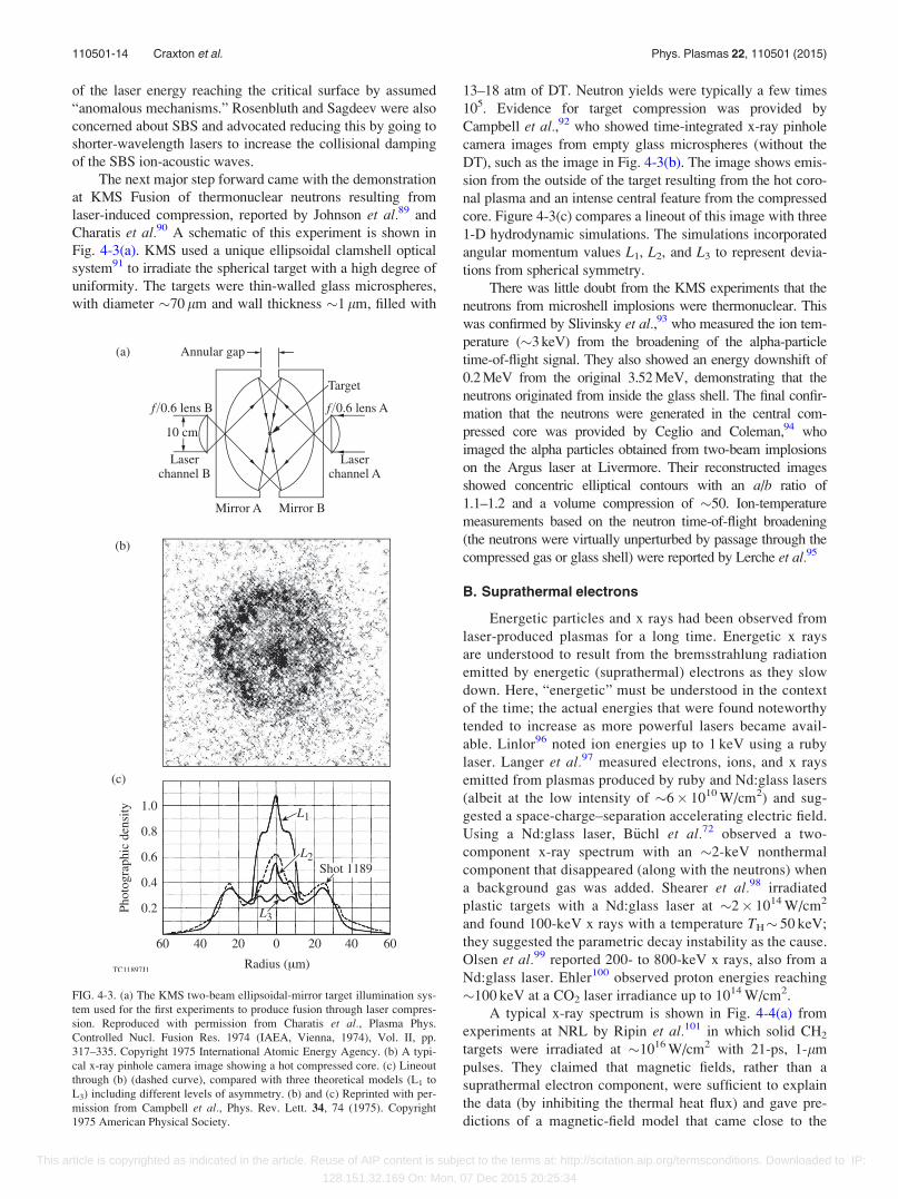
of the laser energy reaching the critical surface by assumed
“anomalous mechanisms.” Rosenbluth and Sagdeev were also
concerned about SBS and advocated reducing this by going to
shorter-wavelength lasers to increase the collisional damping
of the SBS ion-acoustic waves.
The next major step forward came with the demonstration
at KMS Fusion of thermonuclear neutrons resulting from
laser-induced compression, reported by Johnson et al.89 and
Charatis et al.90 A schematic of this experiment is shown in
Fig. 4-3(a). KMS used a unique ellipsoidal clamshell optical
system91 to irradiate the spherical target with a high degree of
uniformity. The targets were thin-walled glass microspheres,
with diameter �70 lm and wall thickness �1 lm, filled with
13–18 atm of DT. Neutron yields were typically a few times
105. Evidence for target compression was provided by
Campbell et al.,92 who showed time-integrated x-ray pinhole
camera images from empty glass microspheres (without the
DT), such as the image in Fig. 4-3(b). The image shows emis-
sion from the outside of the target resulting from the hot coro-
nal plasma and an intense central feature from the compressed
core. Figure 4-3(c) compares a lineout of this image with three
1-D hydrodynamic simulations. The simulations incorporated
angular momentum values L1, L2, and L3 to represent devia-
tions from spherical symmetry.
There was little doubt from the KMS experiments that the
neutrons from microshell implosions were thermonuclear. This
was confirmed by Slivinsky et al.,93 who measured the ion tem-
perature (�3 keV) from the broadening of the alpha-particle
time-of-flight signal. They also showed an energy downshift of
0.2 MeV from the original 3.52 MeV, demonstrating that the
neutrons originated from inside the glass shell. The final confir-
mation that the neutrons were generated in the central com-
pressed core was provided by Ceglio and Coleman,94 who
imaged the alpha particles obtained from two-beam implosions
on the Argus laser at Livermore. Their reconstructed images
showed concentric elliptical contours with an a/b ratio of
1.1–1.2 and a volume compression of �50. Ion-temperature
measurements based on the neutron time-of-flight broadening
(the neutrons were virtually unperturbed by passage through the
compressed gas or glass shell) were reported by Lerche et al.95
B. Suprathermal electrons
Energetic particles and x rays had been observed from
laser-produced plasmas for a long time. Energetic x rays
are understood to result from the bremsstrahlung radiation
emitted by energetic (suprathermal) electrons as they slow
down. Here, “energetic” must be understood in the context
of the time; the actual energies that were found noteworthy
tended to increase as more powerful lasers became avail-
able. Linlor96 noted ion energies up to 1 keV using a ruby
laser. Langer et al.97 measured electrons, ions, and x rays
emitted from plasmas produced by ruby and Nd:glass lasers
(albeit at the low intensity of �6� 1010 W/cm2) and sug-
gested a space-charge–separation accelerating electric field.
Using a Nd:glass laser, B€uchl et al.72 observed a two-
component x-ray spectrum with an �2-keV nonthermal
component that disappeared (along with the neutrons) when
a background gas was added. Shearer et al.98 irradiated
plastic targets with a Nd:glass laser at �2� 1014 W/cm2
and found 100-keV x rays with a temperature TH� 50 keV;
they suggested the parametric decay instability as the cause.
Olsen et al.99 reported 200- to 800-keV x rays, also from a
Nd:glass laser. Ehler100 observed proton energies reaching
�100 keV at a CO2 laser irradiance up to 1014 W/cm2.
A typical x-ray spectrum is shown in Fig. 4-4(a) from
experiments at NRL by Ripin et al.101 in which solid CH2
targets were irradiated at �1016 W/cm2 with 21-ps, 1-lm
pulses. They claimed that magnetic fields, rather than a
suprathermal electron component, were sufficient to explain
the data (by inhibiting the thermal heat flux) and gave pre-
dictions of a magnetic-field model that came close to the
FIG. 4-3. (a) The KMS two-beam ellipsoidal-mirror target illumination sys-
tem used for the first experiments to produce fusion through laser compres-
sion. Reproduced with permission from Charatis et al., Plasma Phys.
Controlled Nucl. Fusion Res. 1974 (IAEA, Vienna, 1974), Vol. II, pp.
317–335. Copyright 1975 International Atomic Energy Agency. (b) A typi-
cal x-ray pinhole camera image showing a hot compressed core. (c) Lineout
through (b) (dashed curve), compared with three theoretical models (L1 to
L3) including different levels of asymmetry. (b) and (c) Reprinted with per-
mission from Campbell et al., Phys. Rev. Lett. 34, 74 (1975). Copyright
1975 American Physical Society.
110501-14 Craxton et al. Phys. Plasmas 22, 110501 (2015)
This article is copyrighted as indicated in the article. Reuse of AIP content is subject to the terms at: http://scitation.aip.org/termsconditions. Downloaded to IP:
128.151.32.169 On: Mon, 07 Dec 2015 20:25:34
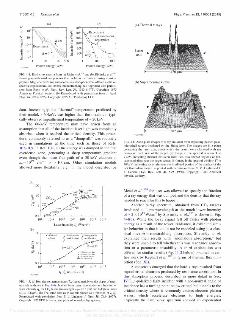
data. Interestingly, the “thermal” temperature predicted by
their model, �60 keV, was higher than the maximum typi-
cally observed suprathermal temperature of �20 keV.
The 60-keV temperature may have arisen from an
assumption that all of the incident laser light was completely
absorbed when it reached the critical density. This proce-
dure, commonly referred to as a “dump-all,” was routinely
used in simulations at the time such as those of Refs.
102–105. In Ref. 103, all the energy was dumped in the first
overdense zone, generating a sharp temperature gradient
even though the mean free path of a 20-keV electron at
ne¼ 1019 cm�3 is �100 cm. Other simulation models
allowed more flexibility; e.g., in the model described by
Mead et al.,106 the user was allowed to specify the fraction
of a ray energy that was dumped and the density that the ray
needed to reach for this to happen.
Another x-ray spectrum, obtained from CD2 targets
irradiated at 1-lm wavelength at the much lower intensity
of �2� 1013 W/cm2 by Slivinsky et al.,107 is shown in Fig.
4-4(b). While the x-ray signal fell off faster with photon
energy as a result of the lower irradiance, it exhibited simi-
lar behavior in that it could not be modeled using just clas-
sical inverse-bremsstrahlung absorption. Slivinsky et al.explained their results with “anomalous absorption,” but
they were unable to tell whether this was resonance absorp-
tion or a parametric instability. A third explanation was
offered for similar results (Fig. 11-2 below) obtained in ear-
lier work by Kephart et al.108 in terms of thermal flux inhi-
bition (Sec. XI).
A consensus emerged that the hard x rays resulted from
suprathermal electrons produced by resonance absorption. In
this absorption process, described in more detail in Sec.
IV C, p-polarized light incident with a non-normal angle of
incidence has a turning point below critical but tunnels to the
critical density where it resonantly excites electron plasma
waves, which accelerate electrons to high energies.
Typically the hard x-ray spectrum showed an exponential
FIG. 4-5. (a) Hot-electron temperatures TH (based mainly on the slopes of spec-
tra such as shown in Fig. 4-4) obtained from many laboratories as a function of
laser intensity IL for CO2 lasers (wavelength k0¼ 10.6lm) and Nd:glass lasers
(k0¼ 1.06lm). (b) The same data as in (a) but plotted as a function of ILk20:
Reproduced with permission from E. L. Lindman, J. Phys. 38, C6.9 (1977).
Copyright 1977 EDP Sciences, see jphyscol.journaldephysique.org.
FIG. 4-6. Zone-plate images of x-ray emission from exploding-pusher glass-
microshell targets irradiated on the Shiva laser. The images are in a plane
containing the laser axis, about which the beams were clustered with ten
beams on each side of the target. (a) Image in the spectral window 4 to
7 keV, indicating thermal emission from two disk-shaped regions of hot,
stagnated glass near the target center. (b) Image in the spectral window 17 to
30 keV, indicating an origin near the irradiated portion of the surface of the
�300-lm-diam target. Reprinted with permission from N. M. Ceglio and J.
T. Larsen, Phys. Rev. Lett. 44, 579 (1980). Copyright 1980 Americal
Physical Society.
FIG. 4-4. Hard x-ray spectra from (a) Ripin et al.101 and (b) Slivinsky et al.107
showing suprathermal components that could not be modeled using classical
physics. Magnetic fields (B) and anomalous absorption were offered as the re-
spective explanations. IB: inverse bremsstrahlung. (a) Reprinted with permis-
sion from Ripin et al., Phys. Rev. Lett. 34, 1313 (1975). Copyright 1975
American Physical Society. (b) Reproduced with permission from J. Appl.
Phys. 46, 1973 (1975). Copyright 1975 AIP Publishing LLC.
110501-15 Craxton et al. Phys. Plasmas 22, 110501 (2015)
This article is copyrighted as indicated in the article. Reuse of AIP content is subject to the terms at: http://scitation.aip.org/termsconditions. Downloaded to IP:
128.151.32.169 On: Mon, 07 Dec 2015 20:25:34
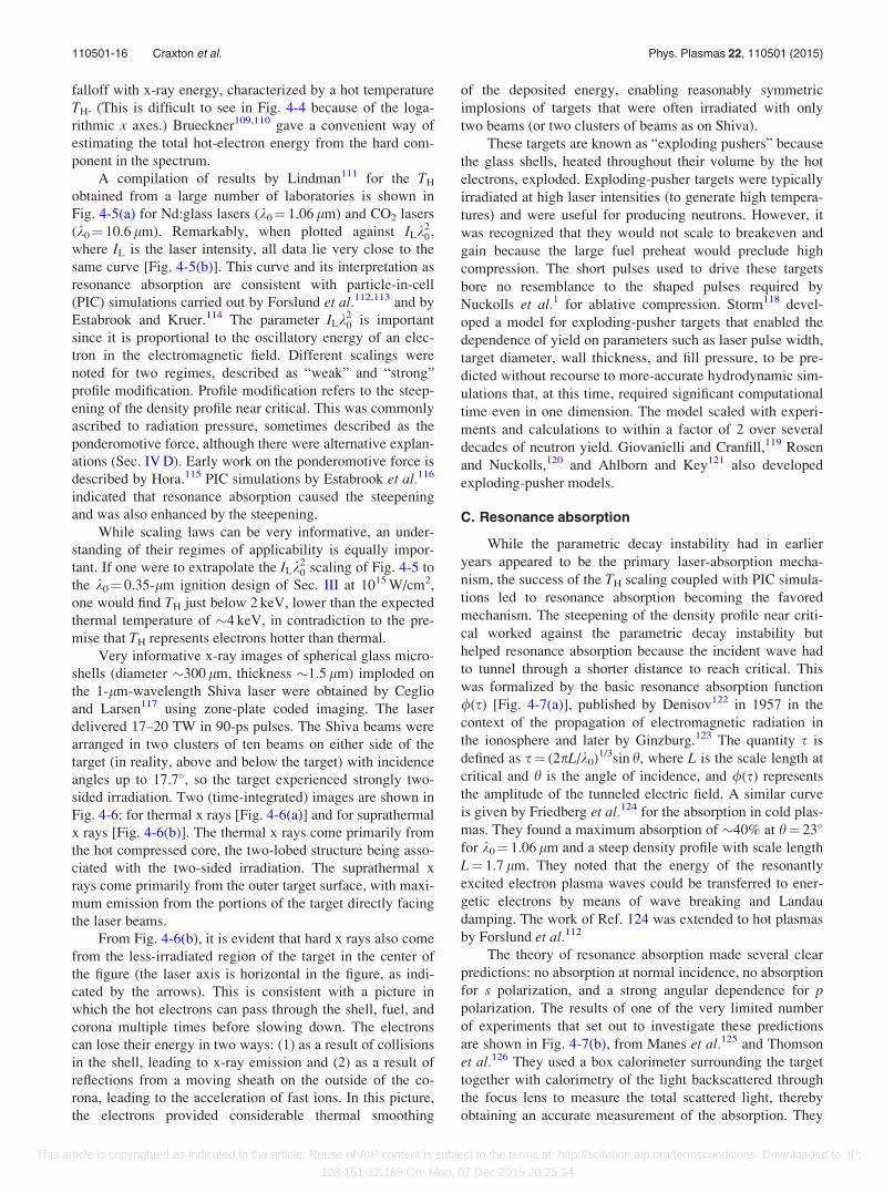
falloff with x-ray energy, characterized by a hot temperature
TH. (This is difficult to see in Fig. 4-4 because of the loga-
rithmic x axes.) Brueckner109,110 gave a convenient way of
estimating the total hot-electron energy from the hard com-
ponent in the spectrum.
A compilation of results by Lindman111 for the TH
obtained from a large number of laboratories is shown in
Fig. 4-5(a) for Nd:glass lasers (k0¼ 1.06 lm) and CO2 lasers
(k0¼ 10.6 lm). Remarkably, when plotted against ILk20;
where IL is the laser intensity, all data lie very close to the
same curve [Fig. 4-5(b)]. This curve and its interpretation as
resonance absorption are consistent with particle-in-cell
(PIC) simulations carried out by Forslund et al.112,113 and by
Estabrook and Kruer.114 The parameter ILk20 is important
since it is proportional to the oscillatory energy of an elec-
tron in the electromagnetic field. Different scalings were
noted for two regimes, described as “weak” and “strong”
profile modification. Profile modification refers to the steep-
ening of the density profile near critical. This was commonly
ascribed to radiation pressure, sometimes described as the
ponderomotive force, although there were alternative explan-
ations (Sec. IV D). Early work on the ponderomotive force is
described by Hora.115 PIC simulations by Estabrook et al.116
indicated that resonance absorption caused the steepening
and was also enhanced by the steepening.
While scaling laws can be very informative, an under-
standing of their regimes of applicability is equally impor-
tant. If one were to extrapolate the ILk20 scaling of Fig. 4-5 to
the k0¼ 0.35-lm ignition design of Sec. III at 1015 W/cm2,
one would find TH just below 2 keV, lower than the expected
thermal temperature of �4 keV, in contradiction to the pre-
mise that TH represents electrons hotter than thermal.
Very informative x-ray images of spherical glass micro-
shells (diameter �300 lm, thickness �1.5 lm) imploded on
the 1-lm-wavelength Shiva laser were obtained by Ceglio
and Larsen117 using zone-plate coded imaging. The laser
delivered 17–20 TW in 90-ps pulses. The Shiva beams were
arranged in two clusters of ten beams on either side of the
target (in reality, above and below the target) with incidence
angles up to 17.7�, so the target experienced strongly two-
sided irradiation. Two (time-integrated) images are shown in
Fig. 4-6: for thermal x rays [Fig. 4-6(a)] and for suprathermal
x rays [Fig. 4-6(b)]. The thermal x rays come primarily from
the hot compressed core, the two-lobed structure being asso-
ciated with the two-sided irradiation. The suprathermal x
rays come primarily from the outer target surface, with maxi-
mum emission from the portions of the target directly facing
the laser beams.
From Fig. 4-6(b), it is evident that hard x rays also come
from the less-irradiated region of the target in the center of
the figure (the laser axis is horizontal in the figure, as indi-
cated by the arrows). This is consistent with a picture in
which the hot electrons can pass through the shell, fuel, and
corona multiple times before slowing down. The electrons
can lose their energy in two ways: (1) as a result of collisions
in the shell, leading to x-ray emission and (2) as a result of
reflections from a moving sheath on the outside of the co-
rona, leading to the acceleration of fast ions. In this picture,
the electrons provided considerable thermal smoothing
of the deposited energy, enabling reasonably symmetric
implosions of targets that were often irradiated with only
two beams (or two clusters of beams as on Shiva).
These targets are known as “exploding pushers” because
the glass shells, heated throughout their volume by the hot
electrons, exploded. Exploding-pusher targets were typically
irradiated at high laser intensities (to generate high tempera-
tures) and were useful for producing neutrons. However, it
was recognized that they would not scale to breakeven and
gain because the large fuel preheat would preclude high
compression. The short pulses used to drive these targets
bore no resemblance to the shaped pulses required by
Nuckolls et al.1 for ablative compression. Storm118 devel-
oped a model for exploding-pusher targets that enabled the
dependence of yield on parameters such as laser pulse width,
target diameter, wall thickness, and fill pressure, to be pre-
dicted without recourse to more-accurate hydrodynamic sim-
ulations that, at this time, required significant computational
time even in one dimension. The model scaled with experi-
ments and calculations to within a factor of 2 over several
decades of neutron yield. Giovanielli and Cranfill,119 Rosen
and Nuckolls,120 and Ahlborn and Key121 also developed
exploding-pusher models.
C. Resonance absorption
While the parametric decay instability had in earlier
years appeared to be the primary laser-absorption mecha-
nism, the success of the TH scaling coupled with PIC simula-
tions led to resonance absorption becoming the favored
mechanism. The steepening of the density profile near criti-
cal worked against the parametric decay instability but
helped resonance absorption because the incident wave had
to tunnel through a shorter distance to reach critical. This
was formalized by the basic resonance absorption function
/(s) [Fig. 4-7(a)], published by Denisov122 in 1957 in the
context of the propagation of electromagnetic radiation in
the ionosphere and later by Ginzburg.123 The quantity s is
defined as s¼ (2pL/k0)1/3sin h, where L is the scale length at
critical and h is the angle of incidence, and /(s) represents
the amplitude of the tunneled electric field. A similar curve
is given by Friedberg et al.124 for the absorption in cold plas-
mas. They found a maximum absorption of �40% at h¼ 23�
for k0¼ 1.06 lm and a steep density profile with scale length
L¼ 1.7 lm. They noted that the energy of the resonantly
excited electron plasma waves could be transferred to ener-
getic electrons by means of wave breaking and Landau
damping. The work of Ref. 124 was extended to hot plasmas
by Forslund et al.112
The theory of resonance absorption made several clear
predictions: no absorption at normal incidence, no absorption
for s polarization, and a strong angular dependence for ppolarization. The results of one of the very limited number
of experiments that set out to investigate these predictions
are shown in Fig. 4-7(b), from Manes et al.125 and Thomson
et al.126 They used a box calorimeter surrounding the target
together with calorimetry of the light backscattered through
the focus lens to measure the total scattered light, thereby
obtaining an accurate measurement of the absorption. They
110501-16 Craxton et al. Phys. Plasmas 22, 110501 (2015)
This article is copyrighted as indicated in the article. Reuse of AIP content is subject to the terms at: http://scitation.aip.org/termsconditions. Downloaded to IP:
128.151.32.169 On: Mon, 07 Dec 2015 20:25:34
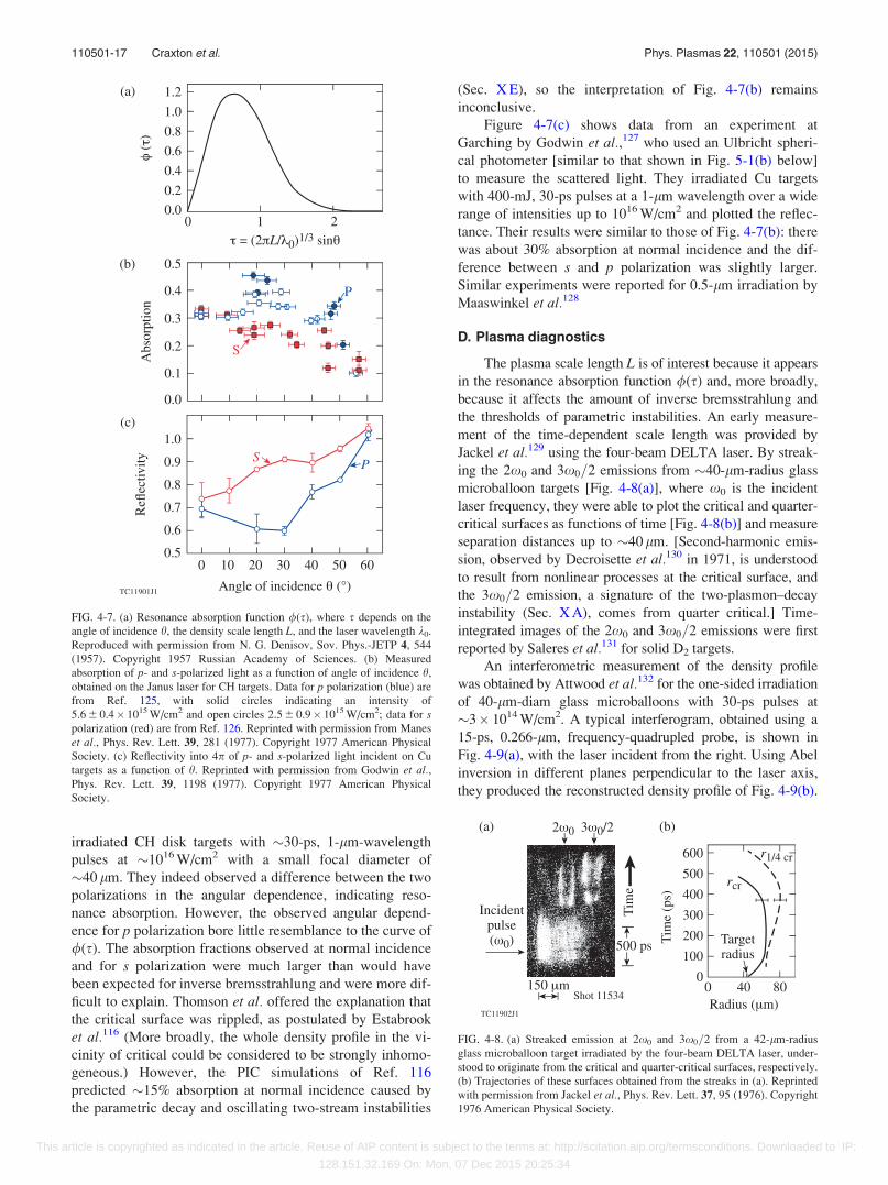
irradiated CH disk targets with �30-ps, 1-lm-wavelength
pulses at �1016 W/cm2 with a small focal diameter of
�40 lm. They indeed observed a difference between the two
polarizations in the angular dependence, indicating reso-
nance absorption. However, the observed angular depend-
ence for p polarization bore little resemblance to the curve of
/(s). The absorption fractions observed at normal incidence
and for s polarization were much larger than would have
been expected for inverse bremsstrahlung and were more dif-
ficult to explain. Thomson et al. offered the explanation that
the critical surface was rippled, as postulated by Estabrook
et al.116 (More broadly, the whole density profile in the vi-
cinity of critical could be considered to be strongly inhomo-
geneous.) However, the PIC simulations of Ref. 116
predicted �15% absorption at normal incidence caused by
the parametric decay and oscillating two-stream instabilities
(Sec. X E), so the interpretation of Fig. 4-7(b) remains
inconclusive.
Figure 4-7(c) shows data from an experiment at
Garching by Godwin et al.,127 who used an Ulbricht spheri-
cal photometer [similar to that shown in Fig. 5-1(b) below]
to measure the scattered light. They irradiated Cu targets
with 400-mJ, 30-ps pulses at a 1-lm wavelength over a wide
range of intensities up to 1016 W/cm2 and plotted the reflec-
tance. Their results were similar to those of Fig. 4-7(b): there
was about 30% absorption at normal incidence and the dif-
ference between s and p polarization was slightly larger.
Similar experiments were reported for 0.5-lm irradiation by
Maaswinkel et al.128
D. Plasma diagnostics
The plasma scale length L is of interest because it appears
in the resonance absorption function /(s) and, more broadly,
because it affects the amount of inverse bremsstrahlung and
the thresholds of parametric instabilities. An early measure-
ment of the time-dependent scale length was provided by
Jackel et al.129 using the four-beam DELTA laser. By streak-
ing the 2x0 and 3x0=2 emissions from �40-lm-radius glass
microballoon targets [Fig. 4-8(a)], where x0 is the incident
laser frequency, they were able to plot the critical and quarter-
critical surfaces as functions of time [Fig. 4-8(b)] and measure
separation distances up to �40 lm. [Second-harmonic emis-
sion, observed by Decroisette et al.130 in 1971, is understood
to result from nonlinear processes at the critical surface, and
the 3x0=2 emission, a signature of the two-plasmon–decay
instability (Sec. X A), comes from quarter critical.] Time-
integrated images of the 2x0 and 3x0=2 emissions were first
reported by Saleres et al.131 for solid D2 targets.
An interferometric measurement of the density profile
was obtained by Attwood et al.132 for the one-sided irradiation
of 40-lm-diam glass microballoons with 30-ps pulses at
�3� 1014 W/cm2. A typical interferogram, obtained using a
15-ps, 0.266-lm, frequency-quadrupled probe, is shown in
Fig. 4-9(a), with the laser incident from the right. Using Abel
inversion in different planes perpendicular to the laser axis,
they produced the reconstructed density profile of Fig. 4-9(b).
FIG. 4-8. (a) Streaked emission at 2x0 and 3x0=2 from a 42-lm-radius
glass microballoon target irradiated by the four-beam DELTA laser, under-
stood to originate from the critical and quarter-critical surfaces, respectively.
(b) Trajectories of these surfaces obtained from the streaks in (a). Reprinted
with permission from Jackel et al., Phys. Rev. Lett. 37, 95 (1976). Copyright
1976 American Physical Society.
FIG. 4-7. (a) Resonance absorption function /(s), where s depends on the
angle of incidence h, the density scale length L, and the laser wavelength k0.
Reproduced with permission from N. G. Denisov, Sov. Phys.-JETP 4, 544
(1957). Copyright 1957 Russian Academy of Sciences. (b) Measured
absorption of p- and s-polarized light as a function of angle of incidence h,
obtained on the Janus laser for CH targets. Data for p polarization (blue) are
from Ref. 125, with solid circles indicating an intensity of
5.6 6 0.4� 1015 W/cm2 and open circles 2.5 6 0.9� 1015 W/cm2; data for spolarization (red) are from Ref. 126. Reprinted with permission from Manes
et al., Phys. Rev. Lett. 39, 281 (1977). Copyright 1977 American Physical
Society. (c) Reflectivity into 4p of p- and s-polarized light incident on Cu
targets as a function of h. Reprinted with permission from Godwin et al.,Phys. Rev. Lett. 39, 1198 (1977). Copyright 1977 American Physical
Society.
110501-17 Craxton et al. Phys. Plasmas 22, 110501 (2015)
This article is copyrighted as indicated in the article. Reuse of AIP content is subject to the terms at: http://scitation.aip.org/termsconditions. Downloaded to IP:
128.151.32.169 On: Mon, 07 Dec 2015 20:25:34
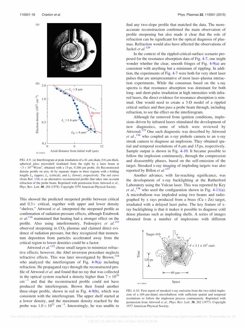
This showed the predicted steepened profile between critical
and 0.3� critical, together with upper and lower density
“shelves.” Attwood et al. interpreted the steepened profile as
confirmation of radiation-pressure effects, although Estabrook
et al.116 maintained that heating had a stronger effect on the
profile. Also using interferometry, Fedosejevs et al.133
observed steepening in CO2 plasmas and claimed direct evi-
dence of radiation pressure, but they recognized that momen-
tum deposition from particles accelerated away from the
critical region to lower densities could be a factor.
Attwood et al.132 chose small targets to minimize refrac-
tive effects; however, the Abel inversion procedure neglects
refractive effects. This was later investigated by Brown,134
who analyzed the interferogram of Fig. 4-9(a) including
refraction. He propagated rays through the reconstructed pro-
file of Attwood et al. and found that no ray that was collected
in the optical system reached a density higher than 7� 1020
cm�3 and that the reconstructed profile could not have
produced the interferogram. Brown then found another
three-slope profile, shown in red in Fig. 4-9(b), which was
consistent with the interferogram. The upper shelf started at
a lower density, and the maximum density reached by the
probe was 1.0� 1021 cm�3. Interestingly, he was unable to
find any two-slope profile that matched the data. The more-
accurate reconstruction confirmed the main observation of
profile steepening but also made it clear that the role of
refraction can be significant for the optical diagnosis of plas-
mas. Refraction would also have affected the observations of
Jackel et al.129
In the context of the rippled-critical-surface scenario pro-
posed for the resonance absorption data of Fig. 4-7, one might
wonder whether the clear, smooth fringes of Fig. 4-9(a) are
consistent with anything but a minimum of rippling. In addi-
tion, the experiments of Fig. 4-7 were both for very short laser
pulses that are unrepresentative of most laser–plasma interac-
tion experiments. While the consensus based on the x-ray
spectra is that resonance absorption was dominant for both
long- and short-pulse irradiation at high intensities with infra-
red lasers, the direct evidence for resonance absorption is min-
imal. One would need to create a 3-D model of a rippled
critical surface and then pass a probe beam through, including
refraction, to see the effect on the interferogram.
Although far removed from ignition conditions, implo-
sions driven by infrared lasers stimulated the development of
new diagnostics, some of which were reviewed by
Attwood.135 One such diagnostic was described by Attwood
et al.,136 who coupled an x-ray pinhole camera to an x-ray
streak camera to diagnose an implosion. They obtained spa-
tial and temporal resolutions of 6 lm and 15 ps, respectively.
Sample output is shown in Fig. 4-10. It became possible to
follow the implosion continuously, through the compression
and disassembly phases, based on the self-emission of the
target. Streaked x-ray imaging of imploding targets was also
reported by Billon et al.137
Another advance, with far-reaching significance, was
the development of x-ray backlighting at the Rutherford
Laboratory using the Vulcan laser. This was reported by Key
et al.,138 who used the configuration shown in Fig. 4-11(a).
A microballoon was imploded using two beams and radio-
graphed by x rays produced from a brass (CuþZn) target,
irradiated with a delayed laser pulse. The key feature of x-
ray backlighting is that it makes it possible to diagnose cold
dense plasmas such as imploding shells. A series of images
obtained from a number of implosions with different
FIG. 4-10. First report of streaked x-ray emission from the two-sided implo-
sion of a (69-lm-diam) microballoon with sufficient spatial and temporal
resolutions to follow the implosion process continuously. Reprinted with
permission from Attwood et al., Phys. Rev. Lett. 38, 282 (1977). Copyright
1977 American Physical Society.
FIG. 4-9. (a) Interferogram at peak irradiation of a 41-lm-diam, 0.6-lm-thick,
spherical glass microshell irradiated from the right by a laser beam at
�3� 1014 W/cm2, obtained with a 15-ps, 0.266-lm probe. (b) Reconstructed
density profile on axis, fit by separate slopes in three regions with e-folding
lengths Lu (upper), Lc (critical), and L‘ (lower), respectively. The red curve
(from Ref. 134) is an alternative reconstructed profile that takes into account
refraction of the probe beam. Reprinted with permission from Attwood et al.,Phys. Rev. Lett. 40, 184 (1978). Copyright 1978 American Physical Society.
110501-18 Craxton et al. Phys. Plasmas 22, 110501 (2015)
This article is copyrighted as indicated in the article. Reuse of AIP content is subject to the terms at: http://scitation.aip.org/termsconditions. Downloaded to IP:
128.151.32.169 On: Mon, 07 Dec 2015 20:25:34
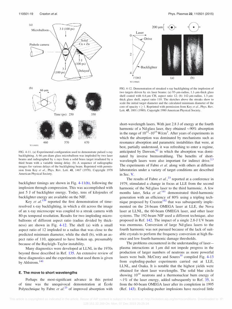
backlighter timings are shown in Fig. 4-11(b), following the
implosion through compression. This was accomplished with
just 5 J of backlighter energy. Today, tens of kilojoules of
backlighter energy are available on the NIF.
Key et al.139 reported the first demonstration of time-
resolved x-ray backlighting, in which a slit across the image
of an x-ray microscope was coupled to a streak camera with
80-ps temporal resolution. Results for two imploding micro-
balloons of different aspect ratio (radius divided by thick-
ness) are shown in Fig. 4-12. The shell (a) with a small
aspect ratio of 12 imploded to a radius that was close to the
predicted minimum diameter, while the shell (b), with an as-
pect ratio of 110, appeared to have broken up, presumably
because of the Rayleigh–Taylor instability.
Many diagnostics were developed at LLNL in the 1970s
beyond those described in Ref. 135. An extensive review of
these diagnostics and the experiments that used them is given
by Ahlstrom.140
E. The move to short wavelengths
Perhaps the most-significant advance in this period
of time was the unequivocal demonstration at �Ecole
Polytechnique by Fabre et al.23 of improved absorption with
short-wavelength lasers. With just 2.8 J of energy at the fourth
harmonic of a Nd:glass laser, they obtained �90% absorption
in the range of 1014–1015 W/cm2. After years of experiments in
which the absorption was dominated by mechanisms such as
resonance absorption and parametric instabilities that were, at
best, partially understood, it was refreshing to enter a regime,
anticipated by Dawson,62 in which the absorption was domi-
nated by inverse bremsstrahlung. The benefits of short-
wavelength lasers were also important for indirect drive.2,3
The experiments of Fabre et al. along with others at different
laboratories under a variety of target conditions are described
in Sec. V.
The results of Fabre et al.,23 reported at a conference in
1979, stimulated a change in focus at LLE from the second
harmonic of the Nd:glass laser to the third harmonic. A few
months later, Seka et al.141 demonstrated third-harmonic
generation with an efficiency of 80% using a tripling tech-
nique proposed by Craxton142 that was subsequently imple-
mented on the 24-beam OMEGA laser at LLE, the Nova
laser at LLNL, the 60-beam OMEGA laser, and other laser
systems. The 192-beam NIF used a different technique, also
proposed in Ref. 142. The impact of a single 2.8-J UV beam
was enormous. Conversion of large Nd:glass lasers to the
fourth harmonic was not pursued because of the lack of suit-
able crystals to perform the frequency conversion at high flu-
ence and low fourth-harmonic damage thresholds.
The problems encountered in the understanding of laser–-
plasma interactions at 1 lm did not impede progress in the
production of larger numbers of neutrons as more powerful
lasers were built. McCrory and Soures35 compiled Fig. 4-13
from exploding-pusher experiments carried out at LLE,
LLNL, and Osaka. It is notable that the highest yields were
obtained for short laser wavelengths. The solid blue circle
showing 1014 neutrons and a thermonuclear burn energy of
�1% of the laser energy, added subsequently to Ref. 35, is
from the 60-beam OMEGA laser after its completion in 1995
(Ref. 143). Exploding-pusher implosions have received little
FIG. 4-11. (a) Experimental configuration used to demonstrate pulsed x-ray
backlighting. A 66-lm-diam glass microballoon was imploded by two laser
beams and radiographed by x rays from a solid brass target irradiated by a
third beam with a variable timing delay. (b) A sequence of radiographic
images for various delays of the backlighting beam. Reprinted with permis-
sion from Key et al., Phys. Rev. Lett. 41, 1467 (1978). Copyright 1978
American Physical Society.
FIG. 4-12. Demonstration of streaked x-ray backlighting of the implosion of
two targets driven by six laser beams: (a) 93-lm-radius, 1.1-lm-thick glass
shell coated with 6.6 lm CH, aspect ratio 12; (b) 142-lm-radius, 1.3-lm-
thick glass shell, aspect ratio 110. The sketches above the streaks show to
scale the initial target diameter and the calculated minimum diameter of the
core of opacity s� 1. Reprinted with permission from Key et al., Phys. Rev.
Lett. 45, 1801 (1980). Copyright 1980 American Physical Society.
110501-19 Craxton et al. Phys. Plasmas 22, 110501 (2015)
This article is copyrighted as indicated in the article. Reuse of AIP content is subject to the terms at: http://scitation.aip.org/termsconditions. Downloaded to IP:
128.151.32.169 On: Mon, 07 Dec 2015 20:25:34
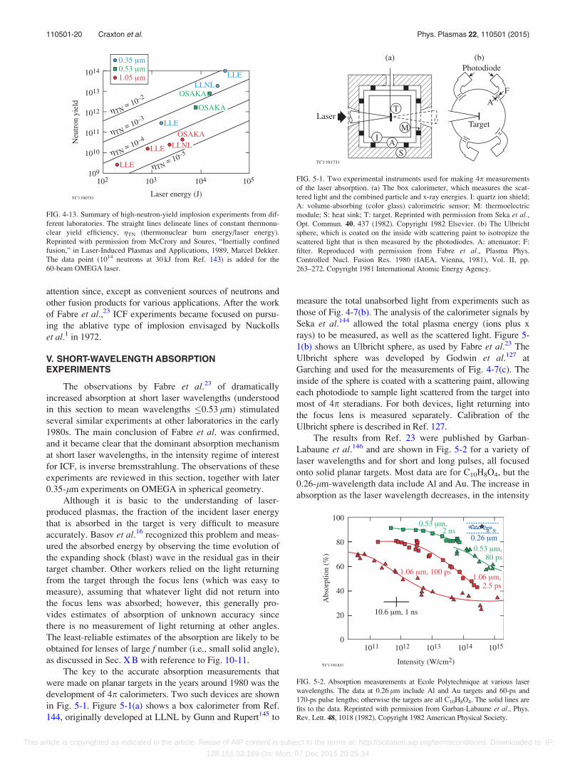
attention since, except as convenient sources of neutrons and
other fusion products for various applications. After the work
of Fabre et al.,23 ICF experiments became focused on pursu-
ing the ablative type of implosion envisaged by Nuckolls
et al.1 in 1972.
V. SHORT-WAVELENGTH ABSORPTIONEXPERIMENTS
The observations by Fabre et al.23 of dramatically
increased absorption at short laser wavelengths (understood
in this section to mean wavelengths 0.53 lm) stimulated
several similar experiments at other laboratories in the early
1980s. The main conclusion of Fabre et al. was confirmed,
and it became clear that the dominant absorption mechanism
at short laser wavelengths, in the intensity regime of interest
for ICF, is inverse bremsstrahlung. The observations of these
experiments are reviewed in this section, together with later
0.35-lm experiments on OMEGA in spherical geometry.
Although it is basic to the understanding of laser-
produced plasmas, the fraction of the incident laser energy
that is absorbed in the target is very difficult to measure
accurately. Basov et al.16 recognized this problem and meas-
ured the absorbed energy by observing the time evolution of
the expanding shock (blast) wave in the residual gas in their
target chamber. Other workers relied on the light returning
from the target through the focus lens (which was easy to
measure), assuming that whatever light did not return into
the focus lens was absorbed; however, this generally pro-
vides estimates of absorption of unknown accuracy since
there is no measurement of light returning at other angles.
The least-reliable estimates of the absorption are likely to be
obtained for lenses of large f number (i.e., small solid angle),
as discussed in Sec. X B with reference to Fig. 10-11.
The key to the accurate absorption measurements that
were made on planar targets in the years around 1980 was the
development of 4p calorimeters. Two such devices are shown
in Fig. 5-1. Figure 5-1(a) shows a box calorimeter from Ref.
144, originally developed at LLNL by Gunn and Rupert145 to
measure the total unabsorbed light from experiments such as
those of Fig. 4-7(b). The analysis of the calorimeter signals by
Seka et al.144 allowed the total plasma energy (ions plus x
rays) to be measured, as well as the scattered light. Figure 5-
1(b) shows an Ulbricht sphere, as used by Fabre et al.23 The
Ulbricht sphere was developed by Godwin et al.127 at
Garching and used for the measurements of Fig. 4-7(c). The
inside of the sphere is coated with a scattering paint, allowing
each photodiode to sample light scattered from the target into
most of 4p steradians. For both devices, light returning into
the focus lens is measured separately. Calibration of the
Ulbricht sphere is described in Ref. 127.
The results from Ref. 23 were published by Garban-
Labaune et al.146 and are shown in Fig. 5-2 for a variety of
laser wavelengths and for short and long pulses, all focused
onto solid planar targets. Most data are for C10H8O4, but the
0.26-lm-wavelength data include Al and Au. The increase in
absorption as the laser wavelength decreases, in the intensity
FIG. 4-13. Summary of high-neutron-yield implosion experiments from dif-
ferent laboratories. The straight lines delineate lines of constant thermonu-
clear yield efficiency, gTN (thermonuclear burn energy/laser energy).
Reprinted with permission from McCrory and Soures, “Inertially confined
fusion,” in Laser-Induced Plasmas and Applications, 1989, Marcel Dekker.
The data point (1014 neutrons at 30 kJ from Ref. 143) is added for the
60-beam OMEGA laser.
FIG. 5-1. Two experimental instruments used for making 4p measurements
of the laser absorption. (a) The box calorimeter, which measures the scat-
tered light and the combined particle and x-ray energies. I: quartz ion shield;
A: volume-absorbing (color glass) calorimetric sensor; M: thermoelectric
module; S: heat sink; T: target. Reprinted with permission from Seka et al.,Opt. Commun. 40, 437 (1982). Copyright 1982 Elsevier. (b) The Ulbricht
sphere, which is coated on the inside with scattering paint to isotropize the
scattered light that is then measured by the photodiodes. A: attenuator; F:
filter. Reproduced with permission from Fabre et al., Plasma Phys.
Controlled Nucl. Fusion Res. 1980 (IAEA, Vienna, 1981), Vol. II, pp.
263–272. Copyright 1981 International Atomic Energy Agency.
FIG. 5-2. Absorption measurements at Ecole Polytechnique at various laser
wavelengths. The data at 0.26 lm include Al and Au targets and 60-ps and
170-ps pulse lengths; otherwise the targets are all C10H8O4. The solid lines are
fits to the data. Reprinted with permission from Garban-Labaune et al., Phys.
Rev. Lett. 48, 1018 (1982). Copyright 1982 American Physical Society.
110501-20 Craxton et al. Phys. Plasmas 22, 110501 (2015)
This article is copyrighted as indicated in the article. Reuse of AIP content is subject to the terms at: http://scitation.aip.org/termsconditions. Downloaded to IP:
128.151.32.169 On: Mon, 07 Dec 2015 20:25:34
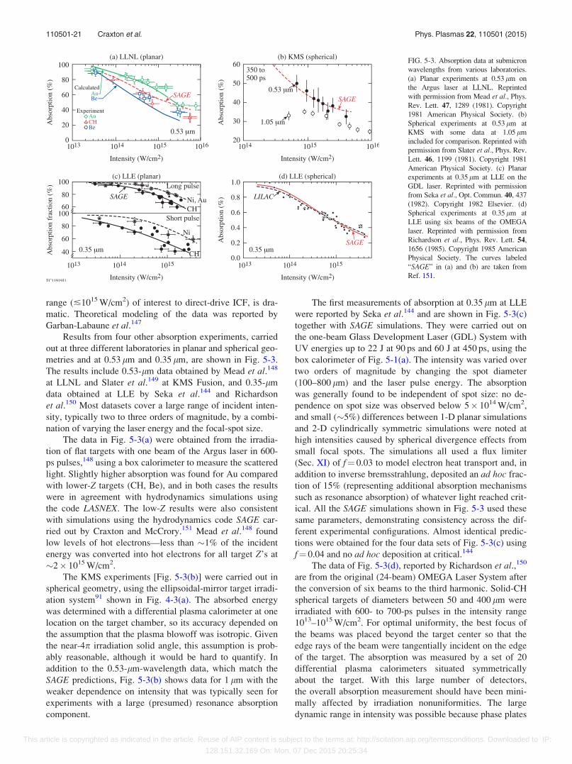
range (�1015 W/cm2) of interest to direct-drive ICF, is dra-
matic. Theoretical modeling of the data was reported by
Garban-Labaune et al.147
Results from four other absorption experiments, carried
out at three different laboratories in planar and spherical geo-
metries and at 0.53 lm and 0.35 lm, are shown in Fig. 5-3.
The results include 0.53-lm data obtained by Mead et al.148
at LLNL and Slater et al.149 at KMS Fusion, and 0.35-lm
data obtained at LLE by Seka et al.144 and Richardson
et al.150 Most datasets cover a large range of incident inten-
sity, typically two to three orders of magnitude, by a combi-
nation of varying the laser energy and the focal-spot size.
The data in Fig. 5-3(a) were obtained from the irradia-
tion of flat targets with one beam of the Argus laser in 600-
ps pulses,148 using a box calorimeter to measure the scattered
light. Slightly higher absorption was found for Au compared
with lower-Z targets (CH, Be), and in both cases the results
were in agreement with hydrodynamics simulations using
the code LASNEX. The low-Z results were also consistent
with simulations using the hydrodynamics code SAGE car-
ried out by Craxton and McCrory.151 Mead et al.148 found
low levels of hot electrons—less than �1% of the incident
energy was converted into hot electrons for all target Z’s at
�2� 1015 W/cm2.
The KMS experiments [Fig. 5-3(b)] were carried out in
spherical geometry, using the ellipsoidal-mirror target irradi-
ation system91 shown in Fig. 4-3(a). The absorbed energy
was determined with a differential plasma calorimeter at one
location on the target chamber, so its accuracy depended on
the assumption that the plasma blowoff was isotropic. Given
the near-4p irradiation solid angle, this assumption is prob-
ably reasonable, although it would be hard to quantify. In
addition to the 0.53-lm-wavelength data, which match the
SAGE predictions, Fig. 5-3(b) shows data for 1 lm with the
weaker dependence on intensity that was typically seen for
experiments with a large (presumed) resonance absorption
component.
The first measurements of absorption at 0.35 lm at LLE
were reported by Seka et al.144 and are shown in Fig. 5-3(c)
together with SAGE simulations. They were carried out on
the one-beam Glass Development Laser (GDL) System with
UV energies up to 22 J at 90 ps and 60 J at 450 ps, using the
box calorimeter of Fig. 5-1(a). The intensity was varied over
two orders of magnitude by changing the spot diameter
(100–800 lm) and the laser pulse energy. The absorption
was generally found to be independent of spot size: no de-
pendence on spot size was observed below 5� 1014 W/cm2,
and small (�5%) differences between 1-D planar simulations
and 2-D cylindrically symmetric simulations were noted at
high intensities caused by spherical divergence effects from
small focal spots. The simulations all used a flux limiter
(Sec. XI) of f¼ 0.03 to model electron heat transport and, in
addition to inverse bremsstrahlung, deposited an ad hoc frac-
tion of 15% (representing additional absorption mechanisms
such as resonance absorption) of whatever light reached crit-
ical. All the SAGE simulations shown in Fig. 5-3 used these
same parameters, demonstrating consistency across the dif-
ferent experimental configurations. Almost identical predic-
tions were obtained for the four data sets of Fig. 5-3(c) using
f¼ 0.04 and no ad hoc deposition at critical.144
The data of Fig. 5-3(d), reported by Richardson et al.,150
are from the original (24-beam) OMEGA Laser System after
the conversion of six beams to the third harmonic. Solid-CH
spherical targets of diameters between 50 and 400 lm were
irradiated with 600- to 700-ps pulses in the intensity range
1013–1015 W/cm2. For optimal uniformity, the best focus of
the beams was placed beyond the target center so that the
edge rays of the beam were tangentially incident on the edge
of the target. The absorption was measured by a set of 20
differential plasma calorimeters situated symmetrically
about the target. With this large number of detectors,
the overall absorption measurement should have been mini-
mally affected by irradiation nonuniformities. The large
dynamic range in intensity was possible because phase plates
FIG. 5-3. Absorption data at submicron
wavelengths from various laboratories.
(a) Planar experiments at 0.53 lm on
the Argus laser at LLNL. Reprinted
with permission from Mead et al., Phys.
Rev. Lett. 47, 1289 (1981). Copyright
1981 American Physical Society. (b)
Spherical experiments at 0.53 lm at
KMS with some data at 1.05 lm
included for comparison. Reprinted with
permission from Slater et al., Phys. Rev.
Lett. 46, 1199 (1981). Copyright 1981
American Physical Society. (c) Planar
experiments at 0.35 lm at LLE on the
GDL laser. Reprinted with permission
from Seka et al., Opt. Commun. 40, 437
(1982). Copyright 1982 Elsevier. (d)
Spherical experiments at 0.35 lm at
LLE using six beams of the OMEGA
laser. Reprinted with permission from
Richardson et al., Phys. Rev. Lett. 54,
1656 (1985). Copyright 1985 American
Physical Society. The curves labeled
“SAGE” in (a) and (b) are taken from
Ref. 151.
110501-21 Craxton et al. Phys. Plasmas 22, 110501 (2015)
This article is copyrighted as indicated in the article. Reuse of AIP content is subject to the terms at: http://scitation.aip.org/termsconditions. Downloaded to IP:
128.151.32.169 On: Mon, 07 Dec 2015 20:25:34
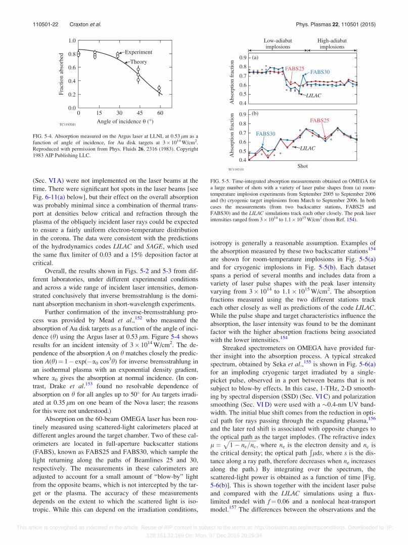
(Sec. VI A) were not implemented on the laser beams at the
time. There were significant hot spots in the laser beams [see
Fig. 6-11(a) below], but their effect on the overall absorption
was probably minimal since a combination of thermal trans-
port at densities below critical and refraction through the
plasma of the obliquely incident laser rays could be expected
to ensure a fairly uniform electron-temperature distribution
in the corona. The data were consistent with the predictions
of the hydrodynamics codes LILAC and SAGE, which used
the same flux limiter of 0.03 and a 15% deposition factor at
critical.
Overall, the results shown in Figs. 5-2 and 5-3 from dif-
ferent laboratories, under different experimental conditions
and across a wide range of incident laser intensities, demon-
strated conclusively that inverse bremsstrahlung is the domi-
nant absorption mechanism in short-wavelength experiments.
Further confirmation of the inverse-bremsstrahlung pro-
cess was provided by Mead et al.,152 who measured the
absorption of Au disk targets as a function of the angle of inci-
dence (h) using the Argus laser at 0.53 lm. Figure 5-4 shows
results for an incident intensity of 3� 1014 W/cm2. The de-
pendence of the absorption A on h matches closely the predic-
tion A(h)¼ 1� exp(�a0 cos3h) for inverse bremsstrahlung in
an isothermal plasma with an exponential density gradient,
where a0 gives the absorption at normal incidence. (In con-
trast, Drake et al.153 found no resolvable dependence of
absorption on h for all angles up to 50� for Au targets irradi-
ated at 0.35 lm on one beam of the Nova laser; the reasons
for this were not understood.)
Absorption on the 60-beam OMEGA laser has been rou-
tinely measured using scattered-light calorimeters placed at
different angles around the target chamber. Two of these cal-
orimeters are located in full-aperture backscatter stations
(FABS), known as FABS25 and FABS30, which sample the
light returning along the paths of Beamlines 25 and 30,
respectively. The measurements in these calorimeters are
adjusted to account for a small amount of “blow-by” light
from the opposite beams, which is not intercepted by the tar-
get or the plasma. The accuracy of these measurements
depends on the extent to which the scattered light is iso-
tropic. While this can depend on the irradiation conditions,
isotropy is generally a reasonable assumption. Examples of
the absorption measured by these two backscatter stations154
are shown for room-temperature implosions in Fig. 5-5(a)
and for cryogenic implosions in Fig. 5-5(b). Each dataset
spans a period of several months and includes data from a
variety of laser pulse shapes with the peak laser intensity
varying from 3� 1014 to 1.1� 1015 W/cm2. The absorption
fractions measured using the two different stations track
each other closely as well as predictions of the code LILAC.
While the pulse shape and target characteristics influence the
absorption, the laser intensity was found to be the dominant
factor with the higher absorption fractions being associated
with the lower intensities.154
Streaked spectrometers on OMEGA have provided fur-
ther insight into the absorption process. A typical streaked
spectrum, obtained by Seka et al.,155 is shown in Fig. 5-6(a)
for an imploding cryogenic target irradiated by a single-
picket pulse, observed in a port between beams that is not
subject to blow-by effects. In this case, 1-THz, 2-D smooth-
ing by spectral dispersion (SSD) (Sec. VI C) and polarization
smoothing (Sec. VI D) were used with a �0.4-nm UV band-
width. The initial blue shift comes from the reduction in opti-
cal path for rays passing through the expanding plasma,156
and the later red shift is associated with opposite changes to
the optical path as the target implodes. (The refractive index
l ¼ffiffiffiffiffiffiffiffiffiffiffiffiffiffiffiffiffiffiffi1� ne=nc
p; where ne is the electron density and nc is
the critical density; the optical pathÐlds, where s is the dis-
tance along a ray path, therefore decreases when ne increases
along the path.) By integrating over the spectrum, the
scattered-light power is obtained as a function of time [Fig.
5-6(b)]. This is shown together with the incident laser pulse
and compared with the LILAC simulations using a flux-
limited model with f¼ 0.06 and a nonlocal heat-transport
model.157 The differences between the observations and the
FIG. 5-4. Absorption measured on the Argus laser at LLNL at 0.53 lm as a
function of angle of incidence, for Au disk targets at 3� 1014 W/cm2.
Reproduced with permission from Phys. Fluids 26, 2316 (1983). Copyright
1983 AIP Publishing LLC.
FIG. 5-5. Time-integrated absorption measurements obtained on OMEGA for
a large number of shots with a variety of laser pulse shapes from (a) room-
temperature implosion experiments from September 2005 to September 2006
and (b) cryogenic target implosions from March to September 2006. In both
cases the measurements (from two backscatter stations, FABS25 and
FABS30) and the LILAC simulations track each other closely. The peak laser
intensities ranged from 3� 1014 to 1.1� 1015 W/cm2 (from Ref. 154).
110501-22 Craxton et al. Phys. Plasmas 22, 110501 (2015)
This article is copyrighted as indicated in the article. Reuse of AIP content is subject to the terms at: http://scitation.aip.org/termsconditions. Downloaded to IP:
128.151.32.169 On: Mon, 07 Dec 2015 20:25:34
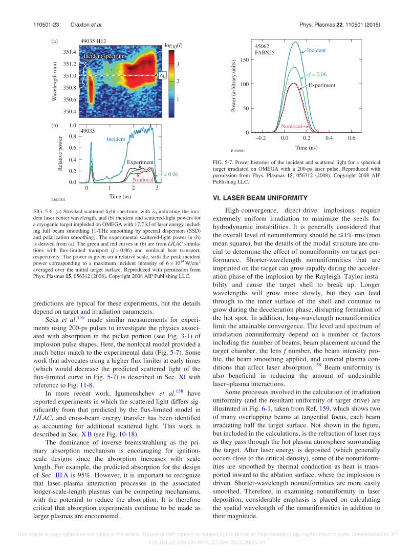
predictions are typical for these experiments, but the details
depend on target and irradiation parameters.
Seka et al.155 made similar measurements for experi-
ments using 200-ps pulses to investigate the physics associ-
ated with absorption in the picket portion (see Fig. 3-1) of
implosion pulse shapes. Here, the nonlocal model provided a
much better match to the experimental data (Fig. 5-7). Some
work that advocates using a higher flux limiter at early times
(which would decrease the predicted scattered light of the
flux-limited curve in Fig. 5-7) is described in Sec. XI with
reference to Fig. 11-8.
In more recent work, Igumenshchev et al.158 have
reported experiments in which the scattered light differs sig-
nificantly from that predicted by the flux-limited model in
LILAC, and cross-beam energy transfer has been identified
as accounting for additional scattered light. This work is
described in Sec. X B (see Fig. 10-18).
The dominance of inverse bremsstrahlung as the pri-
mary absorption mechanism is encouraging for ignition-
scale designs since the absorption increases with scale
length. For example, the predicted absorption for the design
of Sec. III A is 95%. However, it is important to recognize
that laser–plasma interaction processes in the associated
longer-scale-length plasmas can be competing mechanisms,
with the potential to reduce the absorption. It is therefore
critical that absorption experiments continue to be made as
larger plasmas are encountered.
VI. LASER BEAM UNIFORMITY
High-convergence, direct-drive implosions require
extremely uniform irradiation to minimize the seeds for
hydrodynamic instabilities. It is generally considered that
the overall level of nonuniformity should be �1% rms (root
mean square), but the details of the modal structure are cru-
cial to determine the effect of nonuniformity on target per-
formance. Shorter-wavelength nonuniformities that are
imprinted on the target can grow rapidly during the acceler-
ation phase of the implosion by the Rayleigh–Taylor insta-
bility and cause the target shell to break up. Longer
wavelengths will grow more slowly, but they can feed
through to the inner surface of the shell and continue to
grow during the deceleration phase, disrupting formation of
the hot spot. In addition, long-wavelength nonuniformities
limit the attainable convergence. The level and spectrum of
irradiation nonuniformity depend on a number of factors
including the number of beams, beam placement around the
target chamber, the lens f number, the beam intensity pro-
file, the beam smoothing applied, and coronal plasma con-
ditions that affect laser absorption.159 Beam uniformity is
also beneficial in reducing the amount of undesirable
laser–plasma interactions.
Some processes involved in the calculation of irradiation
uniformity (and the resultant uniformity of target drive) are
illustrated in Fig. 6-1, taken from Ref. 159, which shows two
of many overlapping beams at tangential focus, each beam
irradiating half the target surface. Not shown in the figure,
but included in the calculations, is the refraction of laser rays
as they pass through the hot plasma atmosphere surrounding
the target. After laser energy is deposited (which generally
occurs close to the critical density), some of the nonuniform-
ities are smoothed by thermal conduction as heat is trans-
ported inward to the ablation surface, where the implosion is
driven. Shorter-wavelength nonuniformities are more easily
smoothed. Therefore, in examining nonuniformity in laser
deposition, considerable emphasis is placed on calculating
the spatial wavelength of the nonuniformities in addition to
their magnitude.
FIG. 5-6. (a) Streaked scattered-light spectrum, with k0 indicating the inci-
dent laser center wavelength, and (b) incident and scattered-light powers for
a cryogenic target imploded on OMEGA with 17.7 kJ of laser energy includ-
ing full beam smoothing [1-THz smoothing by spectral dispersion (SSD)
and polarization smoothing]. The experimental scattered-light power in (b)
is derived from (a). The green and red curves in (b) are from LILAC simula-
tions with flux-limited transport (f¼ 0.06) and nonlocal heat transport,
respectively. The power is given on a relative scale, with the peak incident
power corresponding to a maximum incident intensity of 6� 1014 W/cm2
averaged over the initial target surface. Reproduced with permission from
Phys. Plasmas 15, 056312 (2008). Copyright 2008 AIP Publishing LLC.
FIG. 5-7. Power histories of the incident and scattered light for a spherical
target irradiated on OMEGA with a 200-ps laser pulse. Reproduced with
permission from Phys. Plasmas 15, 056312 (2008). Copyright 2008 AIP
Publishing LLC.
110501-23 Craxton et al. Phys. Plasmas 22, 110501 (2015)
This article is copyrighted as indicated in the article. Reuse of AIP content is subject to the terms at: http://scitation.aip.org/termsconditions. Downloaded to IP:
128.151.32.169 On: Mon, 07 Dec 2015 20:25:34
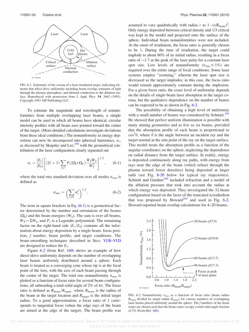
To estimate the magnitude and wavelength of nonuni-
formities from multiple overlapping laser beams, a simple
model can be used in which all beams have identical, circular
intensity profiles with all beam axes pointed toward the center
of the target. (More-detailed calculations investigate deviations
from these ideal conditions.) The nonuniformity in energy dep-
osition can now be decomposed into spherical harmonics, r‘,as discussed by Skupsky and Lee,159 with the geometrical con-
tribution of the laser configuration clearly separated out
r‘ ¼E‘E0
�������� 2‘þ 1ð Þ
Xk;k0
P‘ Xk• Xk0ð ÞWkWk0
W2T
" #1=2
; (6-1)
where the total rms standard deviation over all modes rrms is
defined as
rrms ¼X‘6¼0
r2‘
� �1=2: (6-2)
The term in square brackets in Eq. (6-1) is a geometrical fac-
tor determined by the number and orientation of the beams
(Xk) and the beam energies (Wk). The sum is over all beams,
WT¼RWk, and P‘ is a Legendre polynomial. The remaining
factor on the right-hand side jE‘=E0j contains all the infor-
mation about energy deposition by a single beam: focus posi-
tion, f number, beam profile, and target conditions. The
beam-smoothing techniques described in Secs. VI B–VI D
are designed to reduce the E‘.Figure 6-2 (from Ref. 160) shows an example of how
direct-drive uniformity depends on the number of overlapping
laser beams uniformly distributed around a sphere. Each
beam is treated as a converging cone whose tip is at the focal
point of the lens, with the axis of each beam passing through
the center of the target. The total rms nonuniformity rrms is
plotted as a function of focus ratio for several beam configura-
tions, all subtending a total solid angle of 2% of 4p. The focus
ratio is defined as Rbeam=Rtarget; where Rbeam is the radius of
the beam at the target location and Rtarget is the initial target
radius. To a good approximation, a focus ratio of 1 corre-
sponds to tangential focus (when the edge rays of the beam
are aimed at the edge of the target). The beam profile was
assumed to vary quadratically with radius r as 1�(r/Rbeam)2.
Only energy deposited between critical density and 1/3 critical
was kept in the model and projected onto the surface of the
sphere. Individual beam nonuniformities were not included.
At the onset of irradiation, the focus ratio is generally chosen
to be 1. During the time of irradiation, the target could
implode to about 60% of its initial radius, resulting in a focus
ratio of �1.7 at the peak of the laser pulse for a constant laser
spot size. Low levels of nonuniformity (rrms � 1%) are
required over the entire range of focal conditions. Some laser
systems employ “zooming,” wherein the laser spot size is
decreased as the target implodes; in this case, the focus ratio
would remain approximately constant during the implosion.
For a given focus ratio, the exact level of uniformity depends
on the details of single-beam laser absorption in the target co-
rona, but the qualitative dependence on the number of beams
can be expected to be as shown in Fig. 6-2.
The possibility of obtaining a high level of uniformity
with a small number of beams was considered by Schmitt.161
He showed that perfect uniform illumination is possible with
many aiming geometries and as few as six beams, provided
that the absorption profile of each beam is proportional to
cos2h, where h is the angle between an incident ray and the
target normal at the aim point of the ray on the target surface.
This model treats the absorption profile as a function of the
angular coordinates on the sphere, neglecting the dependence
on radial distance from the target surface. In reality, energy
is deposited continuously along ray paths, with energy from
rays near the edge of the beam (which refract through the
plasma toward lower densities) being deposited at larger
radii (see Fig. 8-20 below for typical ray trajectories).
Schmitt and Gardner162 included refraction and a model of
the ablation pressure that took into account the radius at
which energy was deposited. They investigated the 32-beam
configuration based on the faces of the truncated icosahedron
that was proposed by Howard163 and used in Fig. 6-2.
Howard reported beam overlap calculations for 4–20 beams.
FIG. 6-1. Schematic of the corona of a laser-irradiated target, indicating ele-
ments that affect drive uniformity including beam overlap, transport of light
through the plasma atmosphere, and thermal conduction to the ablation sur-
face. Reproduced with permission from J. Appl. Phys. 54, 3662 (1983).
Copyright 1983 AIP Publishing LLC.
FIG. 6-2. Nonuniformity rrms as a function of focus ratio (beam radius
Rbeam divided by target radius Rtarget) for various numbers of overlapping
laser beams placed uniformly around the sphere. The f numbers of the beam
cones are chosen such that the beam cones occupy a total solid angle fraction
of 2% (From Ref. 160).
110501-24 Craxton et al. Phys. Plasmas 22, 110501 (2015)
This article is copyrighted as indicated in the article. Reuse of AIP content is subject to the terms at: http://scitation.aip.org/termsconditions. Downloaded to IP:
128.151.32.169 On: Mon, 07 Dec 2015 20:25:34

Figure 6-2 shows that good uniformity can be obtained
with 32 beams, but this will occur over a limited range of
laser–plasma conditions and will be very sensitive to varia-
tions among the beams such as pointing errors, energy imbal-
ance, and spot shape variations. Moreover, Fig. 6-2 does not
take into account the evolving plasma conditions. To main-
tain high levels of uniformity over a broad range of laser and
target conditions, a 60-beam “stretched soccer-ball” configu-
ration (based on the vertices of a truncated icosahedron)164
was chosen for the current OMEGA laser.
The key factor that affects the level of uniformity in
experiments without beam smoothing is the on-target laser-
beam intensity profile that enters into the single-beam com-
ponent of Eq. (6-1). Typically, an unsmoothed high-power
laser beam focused onto the target will include high-
modulation intensity structure resulting from phase aberra-
tions that have accumulated through the laser chain. These
aberrations are not reproducible, so they cannot be controlled
by passive optical techniques. This section describes techni-
ques that have been developed to control the laser-spot pro-
file without relying on the detailed knowledge of the phase
aberrations.
The first technique introduced to improve beam uni-
formity was the implementation of phase plates at the end of
each beamline (Sec. VI A). Phase plates produce a well-
defined intensity envelope in the target plane but contain a
highly modulated speckle structure. The very short wave-
length components of the speckle are smoothed by thermal
conduction after laser deposition in the plasma corona. The
longer wavelengths persist, however, and are large enough to
seed hydrodynamic instabilities that can significantly de-
grade target performance. Two techniques developed to
smooth the laser speckle in time are described in Secs. VI B
[induced spatial incoherence (ISI)] and VI C [smoothing by
spectral dispersion (SSD)]. Both techniques add bandwidth
to the laser, causing the laser speckle to change rapidly in
time compared with the hydrodynamic response time of the
target, leading to a relatively smooth target drive. The non-
uniformity can also be reduced instantaneously by an addi-
tional factor offfiffiffi2p
by dispersing the two components of
laser polarization, as discussed in Sec. VI D.
A. Phase plates
When high-power laser beams are focused onto targets,
significant distortions and amplitude modulations are found
in the intensity profiles even when the near-field intensity
profile is relatively smooth. Time-resolved focal measure-
ments made by Holzrichter and Speck165 on the Janus
Nd:glass Laser System showed significant structure in the
focused spot that was consistent with phase aberrations that
accumulated throughout the laser chain (quantified in the so-
called “B-integral”). For the 24-beam OMEGA Nd:glass
laser, time-integrated equivalent-target-plane (ETP) images
showed some structure, mostly of a long spatial wavelength,
when operated in the IR, but highly modulated short-
wavelength structure (hot spots) when frequency tripled to
the UV166 (Fig. 6-3). Skupsky and Kessler166 reported high-
power laser interferometry that was used to measure the
near-field phase front of one of the IR beams. The phase var-
iations were found to explain the IR ETP intensity structure.
Upon frequency tripling, the phase variation is tripled (i.e.,
the same optical path delay is measured in terms of wave-
lengths that are three times smaller). The structure in the UV
ETP was found to be the result of small-scale-length phase
errors. These errors were too small to significantly affect the
IR beam but sufficiently large to strongly modulate the UV
beam.
A technique to mitigate the effects of intrinsic phase
errors, which was relatively insensitive to the details of the
phase, was proposed in 1982 at Osaka by Kato and
Mima167 and described in more detail by Kato et al.168 in
1984. The technique is illustrated schematically in Figs.
6-4(a) and 6-4(b). The spatial coherence of the beam is bro-
ken up by introducing a phase plate at the end of each
beamline, before the focus lens. The initial implementation
used a two-level phase plate of square elements with phases
of 0 or p introduced at random across the beam. The ele-
ment size was chosen so that the diffraction-limited focal-
spot size associated with the element was equal to the target
size. The beam is thereby broken into separate beamlets
that overlap in the target plane, with each point in the target
plane “seeing” each element of the phase plate. Phase-plate
elements are typically much smaller than the spatial scale
of the beam phase variations, making the irradiation pattern
roughly independent of the phase variations. The intensity
pattern on target [Fig. 6-4(c)] has a well-defined sinc2 enve-
lope (in two directions) produced by all phase-plate ele-
ments (sinc2x sin2x/x2). Superimposed on this envelope is
a highly modulated speckle structure resulting from inter-
ference between the beamlets. Essentially, the phase plate
shifts nonuniformity energy toward shorter spatial wave-
lengths that can be more easily smoothed by thermal con-
duction after laser deposition in the target.
Following the original Osaka work, LLE and LLNL
dedicated considerable effort toward the continued develop-
ment of phase plates. LLE employed two-level phase plates
similar to those of Fig. 6-4 except that a hexagonal pattern
was used.169 However, with two-level phase plates, close to
20% of the laser energy is diffracted outside the first zero of
FIG. 6-3. Lineouts through the center of measured equivalent-target-plane
intensity images on the 24-beam OMEGA laser for (a) a 1-lm IR beam and
(b) a frequency-tripled UV beam. Reprinted with permission from S.
Skupsky and T. Kessler, Opt. Commun. 70, 123 (1989). Copyright 1989
Elsevier.
110501-25 Craxton et al. Phys. Plasmas 22, 110501 (2015)
This article is copyrighted as indicated in the article. Reuse of AIP content is subject to the terms at: http://scitation.aip.org/termsconditions. Downloaded to IP:
128.151.32.169 On: Mon, 07 Dec 2015 20:25:34
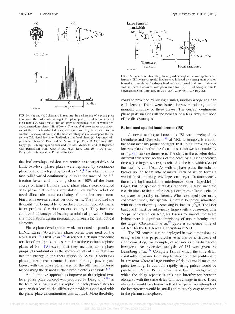
the sinc2 envelope and does not contribute to target drive. At
LLE, two-level phase plates were replaced by continuous
phase plates, developed by Kessler et al.,170 in which the sur-
face relief varied continuously, eliminating most of the dif-
fraction losses and providing close to 100% of the beam
energy on target. Initially, these phase plates were designed
with phase distributions (translated into surface relief on
fused-silica substrates) consisting of a random term com-
bined with several spatial periodic terms. They provided the
flexibility of being able to produce circular super-Gaussian
beam profiles of various orders on target. They have the
additional advantage of leading to minimal growth of inten-
sity modulations during propagation through the final optical
elements.
Phase-plate development work continued in parallel at
LLNL. Large, 80-cm-diam phase plates were used on the
Nova laser.171 Dixit et al.172 described a design procedure
for “kinoform” phase plates, similar to the continuous phase
plates of Ref. 170 except that they included some phase
jumps (discontinuities in the surface relief) of �2p that lim-
ited the energy in the focal region to �95%. Continuous
phase plates have become the norm for high-power glass
lasers, with the phase plates used on the NIF manufactured
by polishing the desired surface profile onto a substrate.173
An alternative approach to improve on the original two-
level phase-plate concept was proposed by Deng et al.174 in
the form of a lens array. By replacing each phase-plate ele-
ment with a lenslet, the diffraction problem associated with
the phase-plate discontinuities was avoided. More flexibility
could be provided by adding a small, random wedge angle to
each lenslet. There were issues, however, relating to the
manufacturability of these arrays. The current continuous
phase plate includes all the benefits of a lens array but none
of the disadvantages.
B. Induced spatial incoherence (ISI)
A novel technique known as ISI was developed by
Lehmberg and Obenschain175 at NRL to temporally smooth
the beam intensity profile on target. In its initial form, an eche-
lon was placed before the focus lens, as shown schematically
in Fig. 6-5 for one dimension. The steps in the echelon delay
different transverse sections of the beam by a laser coherence
time (tc) or larger, where tc is related to the bandwidth (D�) of
the laser by tc¼ 1/D�. As with a phase plate, the echelon
breaks up the beam into beamlets, each of which forms a
well-defined intensity envelope on target. Instantaneously
there is a high-modulation interference pattern (speckle) on
target, but the speckle fluctuates randomly in time since the
contributions to the interference pattern from different echelon
steps are temporally incoherent. When averaged over many
coherence times, the speckle structure becomes smoothed,
with the nonuniformity decreasing in time asffiffiffiffiffiffiffitc=t
p: The laser
bandwidth must be sufficiently large (with a coherence time
�2 ps, achievable on Nd:glass lasers) to smooth the beam
before there is significant imprinting of nonuniformity onto
the target. Obenschain et al.22 quote a coherence time of
�0.6 ps for the KrF Nike Laser System at NRL.
The ISI concept can be deployed in two dimensions by
using either two perpendicular echelons or a structure of
steps consisting, for example, of squares or closely packed
hexagons. An extensive analysis of ISI was given by
Lehmberg et al.176 Complete ISI, in which the time delay
constantly increases from step to step, could be problematic
in a reactor where a large number of delays could make the
pulse too long. In addition, rapidly rising pulses would be
precluded. Partial ISI schemes have been investigated in
which the delay repeats; in this case interference between
elements with the same delay will not change in time. These
elements would be chosen so that the spatial wavelength of
the interference would be small and relatively easy to smooth
in the plasma atmosphere.
FIG. 6-4. (a) and (b) Schematic illustrating the earliest use of a phase plate
to improve the uniformity on target. The phase plate, placed before a lens of
focal length F, was divided into an array of elements, each of which pro-
duced a (random) phase shift of 0 or p. The size d of the element was chosen
so that the diffraction-limited best-focus spot formed by the element (of di-
ameter �2Fk0=d; where k0 is the laser wavelength) just overlapped the tar-
get. (c) Calculated intensity distribution in a focal plane. (a) Reprinted with
permission from Y. Kato and K. Mima, Appl. Phys. B 29, 186 (1982).
Copyright 1982 Springer Science and Business Media. (b) and (c) Reprinted
with permission from Kato et al., Phys. Rev. Lett. 53, 1057 (1984).
Copyright 1984 American Physical Society.
FIG. 6-5. Schematic illustrating the original concept of induced spatial inco-
herence (ISI), wherein spatial incoherence induced by a transparent echelon
is used to smooth the focal-spot irradiance of a broadband laser in time as
well as space. Reprinted with permission from R. H. Lehmberg and S. P.
Obenschain, Opt. Commun. 46, 27 (1983). Copyright 1983 Elsevier.
110501-26 Craxton et al. Phys. Plasmas 22, 110501 (2015)
This article is copyrighted as indicated in the article. Reuse of AIP content is subject to the terms at: http://scitation.aip.org/termsconditions. Downloaded to IP:
128.151.32.169 On: Mon, 07 Dec 2015 20:25:34

The ISI concept was demonstrated by Obenschain et al.in Ref. 177. Here the transmissive echelons of Fig. 6-5 were
replaced by reflective echelons, and a frequency-doubled
Nd:glass laser was used. In addition to providing smoother
beams, ISI was found to reduce undesired laser–plasma
interaction effects. Data for hard x rays, a signature of laser–
plasma instabilities, are shown in Fig. 6-6. Without echelons,
it was hard to differentiate between high bandwidth
(tc¼ 1 ps) and low bandwidth (tc¼ 8 ps). However, with ISI
(echelons plus high bandwidth), a dramatic reduction in the
hard x-ray fluence was observed. Obenschain et al. also noted
significant decreases in the hot-electron temperature, the laser
light backscatter, and the 2x0 and 3x0=2 emissions, where x0
is the laser frequency. Lower levels of backscatter at both
1 lm and 0.53 lm were reported by Mostovych.178 Peyser
et al.179 confirmed the reduction of 3x0=2 emission with ISI,
as long as sufficient bandwidth was used. Obenschain et al.177
suggested that ISI produced these benefits by preventing the
seeding of the self-focusing (filamentation) instability.
Placing echelons at the end of each beamline would
require a large number of optically coated steps that might not
be practical for a fusion reactor. This problem was eliminated
by the development of a greatly improved technique known as
“echelon-free ISI.” This was first suggested by Lehmberg
et al.176 and described more fully by Lehmberg and
Goldhar180 in 1987. The echelon-free ISI concept is shown
schematically in Fig. 6-7. With this approach, the desired
target-plane profile is generated early in the laser chain using
broad-bandwidth light combined with a spatial beam shaper.
An image of this input profile is then relayed through the laser
chain and onto the target. A time-integrated target-plane beam
profile from Ref. 22 is shown in Fig. 6-8 to be exceedingly
smooth with variations of �1% in the flat central portion.
Another advantage of echelon-free ISI is that it allows the laser
spot to be changed dynamically during the laser pulse. In par-
ticular, the spot can be zoomed to follow the inward-moving
critical surface of a high-gain target design (see the discussion
on Fig. 16-7 below), increasing the laser coupling to the target.
The distribution of intensity in the laser spot can also be
changed to dynamically minimize the nonuniformity.
FIG. 6-6. Demonstration of the reduction of hard x rays from the first imple-
mentation of ISI. The x-ray emission near 25 keV is plotted as a function of
(0.53-lm) laser intensity for narrowband (coherence time tc¼ 8 ps) and
broadband (tc¼ 1 ps) irradiation with and without echelons. Reprinted with
permission from Obenschain et al., Phys. Rev. Lett. 56, 2807 (1986).
Copyright 1986 American Physical Society.
FIG. 6-7. Schematic of echelon-free ISI. A spatially shaped broadband input beam is imaged through the amplification stages of the laser to the target plane.
This scheme is best suited to gas lasers such as KrF because of intensity modulations formed in the amplification stages. Reprinted with permission from R. H.
Lehmberg and J. Goldhar, Fusion Technol. 11, 532 (1987). Copyright 1987 American Nuclear Society.
FIG. 6-8. (a) Focal distribution of a Nike KrF laser beam smoothed using
echelon-free ISI, averaged over a 4-ns pulse. (b) A cross section of the
beam, showing intensity variations of 1% in the flat central portion.
(Reprocessed images of the beam data shown in Ref. 22.)
110501-27 Craxton et al. Phys. Plasmas 22, 110501 (2015)
This article is copyrighted as indicated in the article. Reuse of AIP content is subject to the terms at: http://scitation.aip.org/termsconditions. Downloaded to IP:
128.151.32.169 On: Mon, 07 Dec 2015 20:25:34

This technique is appropriate for a gas laser such as
KrF, but it cannot be used with a glass laser at full power
because it produces amplitude modulations in the amplifica-
tion stages and final optics that would damage the optical
components. However, variants of ISI have been imple-
mented on glass lasers at low power by Nakano et al. at
Osaka,181–183 where it is referred to as partially coherent
light (PCL), and by V�eron et al. at Limeil.184,185
Nakano et al.181 implemented PCL in a 1-lm laser, pro-
ducing 800 J per beam with 13 A of bandwidth using an ampli-
fied spontaneous emission (ASE) source at the front end that
introduced temporal bandwidth and transverse spatial modes.
They observed some temporal spikes in the beam. Their output
beam could be frequency doubled with a modest loss of con-
version. In Ref. 182, a grating was added to the ASE beam
before the beam was injected into the preamplifier and phase
plates were added to the end of the system. Reference 182 pre-
sented data that indicated rapid smoothing. In Ref. 183, the
bandwidth was introduced via self-phase modulation in a
single-mode fiber and spatial incoherence was added in a mul-
timode fiber. V�eron et al.184 obtained spatial incoherence by
focusing the output of a broadband oscillator through a multi-
mode fiber and demonstrated both a vastly improved target-
plane profile and more-uniform x-ray emission from a gold tar-
get. A fuller description of this smoothing method was given
in Ref. 185, where the laser output was found to be reduced to
4 TW—about half its level without smoothing.
C. Smoothing by spectral dispersion (SSD)
SSD was developed by Skupsky et al.186 at LLE to pro-
vide the necessary temporal smoothing of phase-plate
speckle and meet the damage constraints imposed on glass
lasers such as OMEGA and the NIF. Like ISI, this approach
uses broadband light and time delays to create temporally
varying phase-front variations across the beam.
The basic SSD concept is shown in Fig. 6-9. Phase-
modulated bandwidth imposed upon the laser beam by an
electro-optic modulator is dispersed by a grating, resulting in
color variations across the beam (shown as blue shifts to red
shifts). The changing phase distribution across the beam com-
bined with the use of a phase plate at the focus lens results in
temporal smoothing. The pre-delay grating compensates for
the delay that the dispersion grating imposes across the beam.
The phase plates are placed after the frequency-tripling
crystals to minimize beam divergence through the crystals that
would reduce tripling efficiency. Phase-modulated bandwidth
is used, rather than the chaotic bandwidth of ISI, to minimize
amplitude modulations in the laser pulse and avoid damage to
optical components. The bandwidth is generated near the be-
ginning of the laser chain using electro-optic modulators for
OMEGA. For an early implementation on Nova for
Rayleigh–Taylor experiments,187 the bandwidth was generated
through cross-phase modulation in an optical fiber; later,188 an
electro-optical modulator was used, as on OMEGA. The band-
width is generated using fiber optics on the NIF.6 This
approach is convenient and allows one to use high modulation
frequencies, but it precludes the pre-delay grating, limiting the
ability of the laser to deliver rapidly changing pulse shapes.
The maximum bandwidth is determined by the con-
straints for efficient frequency tripling. For OMEGA, up to 1
THz (UV) is made possible by the use of dual tripler crys-
tals,189,190 providing an effective coherence time of 1 ps,
similar to the ISI bandwidth used on Nike. However, longer-
wavelength nonuniformities smooth faster with ISI for the
same bandwidth. Long-wavelength smoothing by SSD is
determined by the angular spread of the bandwidth. The maxi-
mum angular spread is limited by the laser pinholes, whose
diameters are chosen to avoid self-focusing in the laser.
An extension of SSD to two dimensions was described
by Skupsky and Craxton191 and implemented on the 60-beam
OMEGA laser. Two-dimensional SSD is shown schematically
in Fig. 6-10. Here two modulators are used, with their band-
widths dispersed in orthogonal directions. Time-delay gra-
tings are included for each modulator. The second and third
gratings shown in Fig. 6-10 can be combined.
Equivalent-target-plane intensity distributions, inte-
grated over time, are shown in Fig. 6-11 for a frequency-
tripled beam (a) without beam smoothing, (b) with a continu-
ous phase plate, (c) with 1-D SSD, and (d) with 2-D SSD.
The phase plate by itself produces a static speckle pattern.
With 1-D SSD, this is smoothed in the direction of disper-
sion. The smoothest beam is produced with 2-D SSD.
FIG. 6-10. Schematic of 2-D SSD, illustrating how the bandwidths from two
modulators are dispersed in perpendicular directions. Reproduced with permis-
sion from Phys. Plasmas 6, 2157 (1999). Copyright 1999 AIP Publishing LLC.
FIG. 6-9. Schematic of smoothing by spectral dispersion (SSD), showing
the formation of color variations (blue to red) across the beam. Reproduced
with permission from J. Appl. Phys. 66, 3456 (1989). Copyright 1989 AIP
Publishing LLC.
110501-28 Craxton et al. Phys. Plasmas 22, 110501 (2015)
This article is copyrighted as indicated in the article. Reuse of AIP content is subject to the terms at: http://scitation.aip.org/termsconditions. Downloaded to IP:
128.151.32.169 On: Mon, 07 Dec 2015 20:25:34
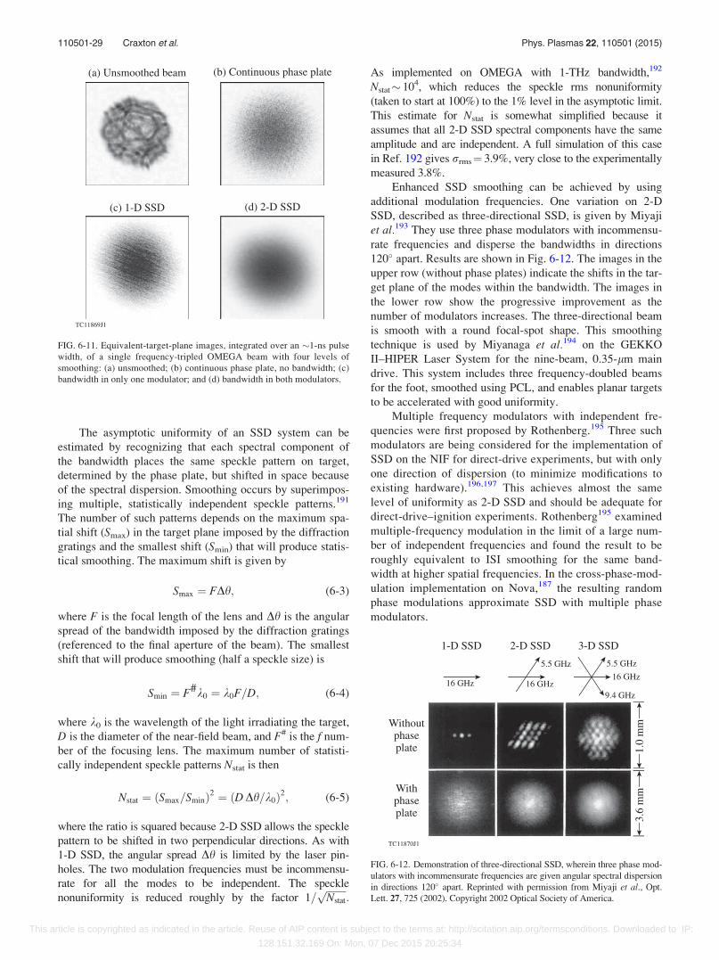
The asymptotic uniformity of an SSD system can be
estimated by recognizing that each spectral component of
the bandwidth places the same speckle pattern on target,
determined by the phase plate, but shifted in space because
of the spectral dispersion. Smoothing occurs by superimpos-
ing multiple, statistically independent speckle patterns.191
The number of such patterns depends on the maximum spa-
tial shift (Smax) in the target plane imposed by the diffraction
gratings and the smallest shift (Smin) that will produce statis-
tical smoothing. The maximum shift is given by
Smax ¼ FDh; (6-3)
where F is the focal length of the lens and Dh is the angular
spread of the bandwidth imposed by the diffraction gratings
(referenced to the final aperture of the beam). The smallest
shift that will produce smoothing (half a speckle size) is
Smin ¼ F#k0 ¼ k0F=D; (6-4)
where k0 is the wavelength of the light irradiating the target,
D is the diameter of the near-field beam, and F# is the f num-
ber of the focusing lens. The maximum number of statisti-
cally independent speckle patterns Nstat is then
Nstat ¼ ðSmax=SminÞ2 ¼ ðD Dh=k0Þ2; (6-5)
where the ratio is squared because 2-D SSD allows the speckle
pattern to be shifted in two perpendicular directions. As with
1-D SSD, the angular spread Dh is limited by the laser pin-
holes. The two modulation frequencies must be incommensu-
rate for all the modes to be independent. The speckle
nonuniformity is reduced roughly by the factor 1=ffiffiffiffiffiffiffiffiNstat
p:
As implemented on OMEGA with 1-THz bandwidth,192
Nstat� 104, which reduces the speckle rms nonuniformity
(taken to start at 100%) to the 1% level in the asymptotic limit.
This estimate for Nstat is somewhat simplified because it
assumes that all 2-D SSD spectral components have the same
amplitude and are independent. A full simulation of this case
in Ref. 192 gives rrms¼ 3.9%, very close to the experimentally
measured 3.8%.
Enhanced SSD smoothing can be achieved by using
additional modulation frequencies. One variation on 2-D
SSD, described as three-directional SSD, is given by Miyaji
et al.193 They use three phase modulators with incommensu-
rate frequencies and disperse the bandwidths in directions
120� apart. Results are shown in Fig. 6-12. The images in the
upper row (without phase plates) indicate the shifts in the tar-
get plane of the modes within the bandwidth. The images in
the lower row show the progressive improvement as the
number of modulators increases. The three-directional beam
is smooth with a round focal-spot shape. This smoothing
technique is used by Miyanaga et al.194 on the GEKKO
II–HIPER Laser System for the nine-beam, 0.35-lm main
drive. This system includes three frequency-doubled beams
for the foot, smoothed using PCL, and enables planar targets
to be accelerated with good uniformity.
Multiple frequency modulators with independent fre-
quencies were first proposed by Rothenberg.195 Three such
modulators are being considered for the implementation of
SSD on the NIF for direct-drive experiments, but with only
one direction of dispersion (to minimize modifications to
existing hardware).196,197 This achieves almost the same
level of uniformity as 2-D SSD and should be adequate for
direct-drive–ignition experiments. Rothenberg195 examined
multiple-frequency modulation in the limit of a large num-
ber of independent frequencies and found the result to be
roughly equivalent to ISI smoothing for the same band-
width at higher spatial frequencies. In the cross-phase-mod-
ulation implementation on Nova,187 the resulting random
phase modulations approximate SSD with multiple phase
modulators.
FIG. 6-11. Equivalent-target-plane images, integrated over an �1-ns pulse
width, of a single frequency-tripled OMEGA beam with four levels of
smoothing: (a) unsmoothed; (b) continuous phase plate, no bandwidth; (c)
bandwidth in only one modulator; and (d) bandwidth in both modulators.
FIG. 6-12. Demonstration of three-directional SSD, wherein three phase mod-
ulators with incommensurate frequencies are given angular spectral dispersion
in directions 120� apart. Reprinted with permission from Miyaji et al., Opt.
Lett. 27, 725 (2002). Copyright 2002 Optical Society of America.
110501-29 Craxton et al. Phys. Plasmas 22, 110501 (2015)
This article is copyrighted as indicated in the article. Reuse of AIP content is subject to the terms at: http://scitation.aip.org/termsconditions. Downloaded to IP:
128.151.32.169 On: Mon, 07 Dec 2015 20:25:34
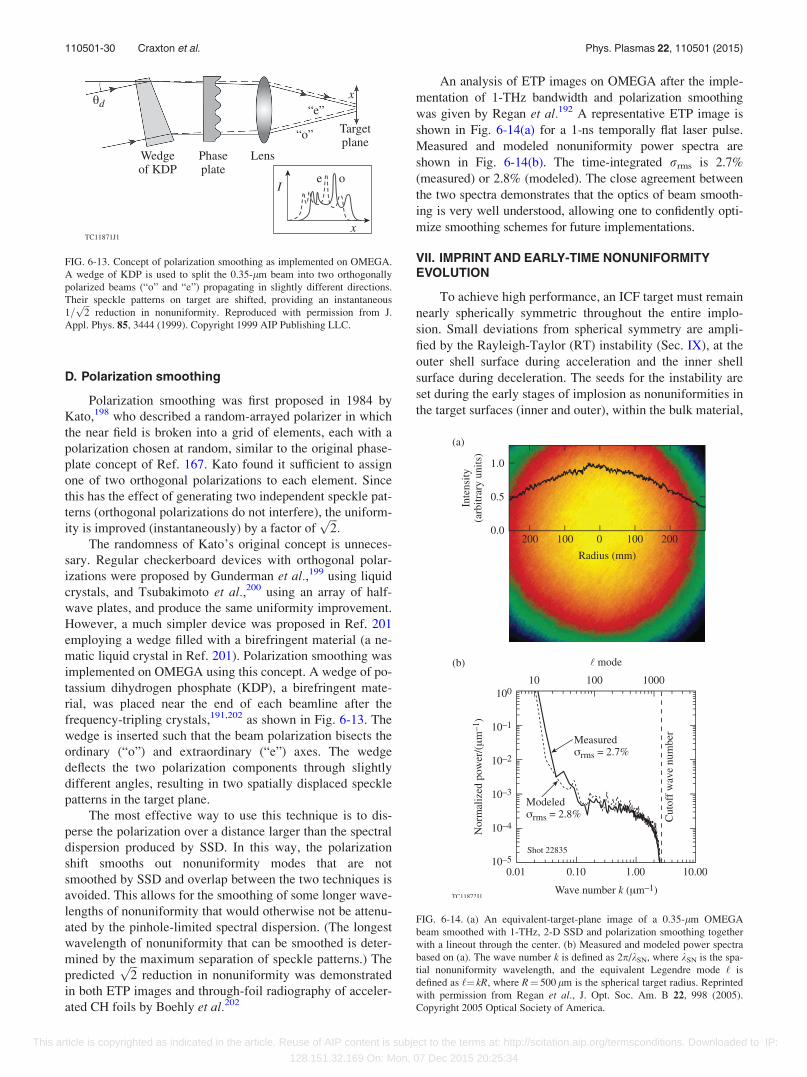
D. Polarization smoothing
Polarization smoothing was first proposed in 1984 by
Kato,198 who described a random-arrayed polarizer in which
the near field is broken into a grid of elements, each with a
polarization chosen at random, similar to the original phase-
plate concept of Ref. 167. Kato found it sufficient to assign
one of two orthogonal polarizations to each element. Since
this has the effect of generating two independent speckle pat-
terns (orthogonal polarizations do not interfere), the uniform-
ity is improved (instantaneously) by a factor offfiffiffi2p
:The randomness of Kato’s original concept is unneces-
sary. Regular checkerboard devices with orthogonal polar-
izations were proposed by Gunderman et al.,199 using liquid
crystals, and Tsubakimoto et al.,200 using an array of half-
wave plates, and produce the same uniformity improvement.
However, a much simpler device was proposed in Ref. 201
employing a wedge filled with a birefringent material (a ne-
matic liquid crystal in Ref. 201). Polarization smoothing was
implemented on OMEGA using this concept. A wedge of po-
tassium dihydrogen phosphate (KDP), a birefringent mate-
rial, was placed near the end of each beamline after the
frequency-tripling crystals,191,202 as shown in Fig. 6-13. The
wedge is inserted such that the beam polarization bisects the
ordinary (“o”) and extraordinary (“e”) axes. The wedge
deflects the two polarization components through slightly
different angles, resulting in two spatially displaced speckle
patterns in the target plane.
The most effective way to use this technique is to dis-
perse the polarization over a distance larger than the spectral
dispersion produced by SSD. In this way, the polarization
shift smooths out nonuniformity modes that are not
smoothed by SSD and overlap between the two techniques is
avoided. This allows for the smoothing of some longer wave-
lengths of nonuniformity that would otherwise not be attenu-
ated by the pinhole-limited spectral dispersion. (The longest
wavelength of nonuniformity that can be smoothed is deter-
mined by the maximum separation of speckle patterns.) The
predictedffiffiffi2p
reduction in nonuniformity was demonstrated
in both ETP images and through-foil radiography of acceler-
ated CH foils by Boehly et al.202
An analysis of ETP images on OMEGA after the imple-
mentation of 1-THz bandwidth and polarization smoothing
was given by Regan et al.192 A representative ETP image is
shown in Fig. 6-14(a) for a 1-ns temporally flat laser pulse.
Measured and modeled nonuniformity power spectra are
shown in Fig. 6-14(b). The time-integrated rrms is 2.7%
(measured) or 2.8% (modeled). The close agreement between
the two spectra demonstrates that the optics of beam smooth-
ing is very well understood, allowing one to confidently opti-
mize smoothing schemes for future implementations.
VII. IMPRINT AND EARLY-TIME NONUNIFORMITYEVOLUTION
To achieve high performance, an ICF target must remain
nearly spherically symmetric throughout the entire implo-
sion. Small deviations from spherical symmetry are ampli-
fied by the Rayleigh-Taylor (RT) instability (Sec. IX), at the
outer shell surface during acceleration and the inner shell
surface during deceleration. The seeds for the instability are
set during the early stages of implosion as nonuniformities in
the target surfaces (inner and outer), within the bulk material,
FIG. 6-13. Concept of polarization smoothing as implemented on OMEGA.
A wedge of KDP is used to split the 0.35-lm beam into two orthogonally
polarized beams (“o” and “e”) propagating in slightly different directions.
Their speckle patterns on target are shifted, providing an instantaneous
1=ffiffiffi2p
reduction in nonuniformity. Reproduced with permission from J.
Appl. Phys. 85, 3444 (1999). Copyright 1999 AIP Publishing LLC.
FIG. 6-14. (a) An equivalent-target-plane image of a 0.35-lm OMEGA
beam smoothed with 1-THz, 2-D SSD and polarization smoothing together
with a lineout through the center. (b) Measured and modeled power spectra
based on (a). The wave number k is defined as 2p/kSN, where kSN is the spa-
tial nonuniformity wavelength, and the equivalent Legendre mode ‘ is
defined as ‘¼ kR, where R¼ 500 lm is the spherical target radius. Reprinted
with permission from Regan et al., J. Opt. Soc. Am. B 22, 998 (2005).
Copyright 2005 Optical Society of America.
110501-30 Craxton et al. Phys. Plasmas 22, 110501 (2015)
This article is copyrighted as indicated in the article. Reuse of AIP content is subject to the terms at: http://scitation.aip.org/termsconditions. Downloaded to IP:
128.151.32.169 On: Mon, 07 Dec 2015 20:25:34
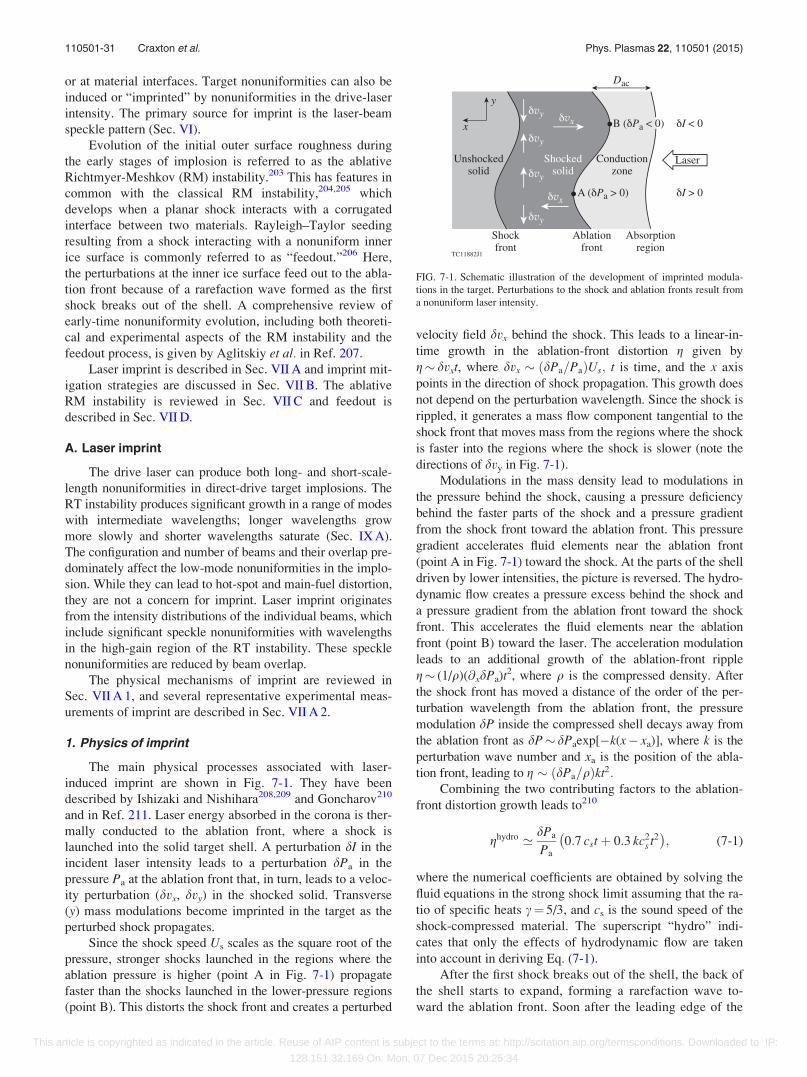
or at material interfaces. Target nonuniformities can also be
induced or “imprinted” by nonuniformities in the drive-laser
intensity. The primary source for imprint is the laser-beam
speckle pattern (Sec. VI).
Evolution of the initial outer surface roughness during
the early stages of implosion is referred to as the ablative
Richtmyer-Meshkov (RM) instability.203 This has features in
common with the classical RM instability,204,205 which
develops when a planar shock interacts with a corrugated
interface between two materials. Rayleigh–Taylor seeding
resulting from a shock interacting with a nonuniform inner
ice surface is commonly referred to as “feedout.”206 Here,
the perturbations at the inner ice surface feed out to the abla-
tion front because of a rarefaction wave formed as the first
shock breaks out of the shell. A comprehensive review of
early-time nonuniformity evolution, including both theoreti-
cal and experimental aspects of the RM instability and the
feedout process, is given by Aglitskiy et al. in Ref. 207.
Laser imprint is described in Sec. VII A and imprint mit-
igation strategies are discussed in Sec. VII B. The ablative
RM instability is reviewed in Sec. VII C and feedout is
described in Sec. VII D.
A. Laser imprint
The drive laser can produce both long- and short-scale-
length nonuniformities in direct-drive target implosions. The
RT instability produces significant growth in a range of modes
with intermediate wavelengths; longer wavelengths grow
more slowly and shorter wavelengths saturate (Sec. IX A).
The configuration and number of beams and their overlap pre-
dominately affect the low-mode nonuniformities in the implo-
sion. While they can lead to hot-spot and main-fuel distortion,
they are not a concern for imprint. Laser imprint originates
from the intensity distributions of the individual beams, which
include significant speckle nonuniformities with wavelengths
in the high-gain region of the RT instability. These speckle
nonuniformities are reduced by beam overlap.
The physical mechanisms of imprint are reviewed in
Sec. VII A 1, and several representative experimental meas-
urements of imprint are described in Sec. VII A 2.
1. Physics of imprint
The main physical processes associated with laser-
induced imprint are shown in Fig. 7-1. They have been
described by Ishizaki and Nishihara208,209 and Goncharov210
and in Ref. 211. Laser energy absorbed in the corona is ther-
mally conducted to the ablation front, where a shock is
launched into the solid target shell. A perturbation dI in the
incident laser intensity leads to a perturbation dPa in the
pressure Pa at the ablation front that, in turn, leads to a veloc-
ity perturbation (dvx, dvy) in the shocked solid. Transverse
(y) mass modulations become imprinted in the target as the
perturbed shock propagates.
Since the shock speed Us scales as the square root of the
pressure, stronger shocks launched in the regions where the
ablation pressure is higher (point A in Fig. 7-1) propagate
faster than the shocks launched in the lower-pressure regions
(point B). This distorts the shock front and creates a perturbed
velocity field dvx behind the shock. This leads to a linear-in-
time growth in the ablation-front distortion g given by
g� dvxt, where dvx � ðdPa=PaÞUs; t is time, and the x axis
points in the direction of shock propagation. This growth does
not depend on the perturbation wavelength. Since the shock is
rippled, it generates a mass flow component tangential to the
shock front that moves mass from the regions where the shock
is faster into the regions where the shock is slower (note the
directions of dvy in Fig. 7-1).
Modulations in the mass density lead to modulations in
the pressure behind the shock, causing a pressure deficiency
behind the faster parts of the shock and a pressure gradient
from the shock front toward the ablation front. This pressure
gradient accelerates fluid elements near the ablation front
(point A in Fig. 7-1) toward the shock. At the parts of the shell
driven by lower intensities, the picture is reversed. The hydro-
dynamic flow creates a pressure excess behind the shock and
a pressure gradient from the ablation front toward the shock
front. This accelerates the fluid elements near the ablation
front (point B) toward the laser. The acceleration modulation
leads to an additional growth of the ablation-front ripple
g� (1/q)(@xdPa)t2, where q is the compressed density. After
the shock front has moved a distance of the order of the per-
turbation wavelength from the ablation front, the pressure
modulation dP inside the compressed shell decays away from
the ablation front as dP� dPaexp[�k(x� xa)], where k is the
perturbation wave number and xa is the position of the abla-
tion front, leading to g � ðdPa=qÞkt2:Combining the two contributing factors to the ablation-
front distortion growth leads to210
ghydro ’ dPa
Pa
0:7 cstþ 0:3 kc2s t2
� �; (7-1)
where the numerical coefficients are obtained by solving the
fluid equations in the strong shock limit assuming that the ra-
tio of specific heats c¼ 5/3, and cs is the sound speed of the
shock-compressed material. The superscript “hydro” indi-
cates that only the effects of hydrodynamic flow are taken
into account in deriving Eq. (7-1).
After the first shock breaks out of the shell, the back of
the shell starts to expand, forming a rarefaction wave to-
ward the ablation front. Soon after the leading edge of the
FIG. 7-1. Schematic illustration of the development of imprinted modula-
tions in the target. Perturbations to the shock and ablation fronts result from
a nonuniform laser intensity.
110501-31 Craxton et al. Phys. Plasmas 22, 110501 (2015)
This article is copyrighted as indicated in the article. Reuse of AIP content is subject to the terms at: http://scitation.aip.org/termsconditions. Downloaded to IP:
128.151.32.169 On: Mon, 07 Dec 2015 20:25:34
rarefaction reaches the ablation front, the ablation front
starts to accelerate and the ablation-front modulations grow
exponentially because of the RT instability. The imprint
phase lasts from the start of the propagation of the first
shock until the rarefaction wave reaches the ablation front.
It takes t ¼ tbr ¼ D0=Us; where D0 is the initial shell thick-
ness, for the first shock to travel through the shell and (in
the strong shock limit) t ¼ trw ¼ D0=4 cs for the rarefaction-
wave leading edge to propagate across the shell (the initial
shell thickness is compressed by a factor of 4 because of the
first shock). Since Us=cs � 1:8 in the strong-shock limit, the
imprint phase lasts for timp ’ 0:8 D0=cs: Substituting timp for
time in Eq. (7-1) and assuming that the ablation pressure
scales with the laser intensity as Pa� I2/3, the amplitude of
the ablation-front ripple at the beginning of the shell accel-
eration is
ghydroimp ’
dI
ID0 0:4þ 0:1 kD0ð Þ: (7-2)
Introducing a normalized imprint amplitude defined by
�gimp ¼gimp
D0 dI=Ið Þ (7-3)
and writing the wave number k as ‘/R0, where ‘ is the
Legendre mode number and R0 is the initial shell outer ra-
dius, Eq. (7-2) can be rewritten as
�ghydroimp ’ 0:4þ 0:1
‘
A0
� �; (7-4)
where A0 ¼ R0=D0 is the initial shell aspect ratio. (For a
typical ignition design, A0 varies between 4 and 5.) Equation
7-4 does not account for the effects of thermal conduction
and mass ablation, which significantly reduce the imprint
amplitude predicted by the equation.
Because of the high temperatures, pressure perturbations
inside the conduction zone shown in Fig. 7-1 are smoothed by
thermal conduction. The simplest theory, given by Bodner39
and known as the “cloudy-day effect,” predicts that pressure
perturbations dP decay exponentially away from the critical
surface as dP� e�kx. Therefore, nonuniformities in the abla-
tion pressure are reduced by a factor of e�kDac ; where Dac is
the distance between the critical surface (representing the
absorption region) and the ablation front (Fig. 7-1). This dis-
tance increases approximately as Dac�Vct, where Vc is the
rate of growth of the width of the conduction zone, leading to
an exponential decay in the ablation-pressure modulation with
time, dPa� dPa (t¼ 0) exp(�kVct). After t� (kVc)�1, laser
nonuniformities with the wave number k decouple from the
ablation front. The k Fourier component of the perturbed
acceleration goes to zero at this time and the ablation-front
ripple subsequently grows linearly with time. The ripple ve-
locity is estimated by calculating the time derivative of Eq.
(7-1) at the decoupling time t¼ (kVc)�1, giving an asymptotic
growth of the ablation-front amplitude,
gth � dI
I
cs
Vccst: (7-5)
The superscript “th” indicates that effects of thermal con-
duction smoothing in the conduction zone are taken into
account. Larger values of Vc cause laser nonuniformities to
decouple sooner from the ablation front, resulting in a smaller
imprint amplitude. Since the sound speed cs scales with the
laser intensity as cs� I1/3 while Vc scales as Vc� I4/3 (Ref.
212), Eq. (7-5) shows that the ablation-front modulations
grow at a slower rate if the drive intensity is higher. This
result is used in the imprint-mitigation schemes that introduce
a high-intensity picket at the beginning of the laser drive (Sec.
VII B 4). Taking into account numerical coefficients obtained
from a solution of a full system of hydrodynamic equations210
leads to the following normalized imprint amplitude at the
onset of shell acceleration:
�gthimp ’ 0:3
A0
‘
D0
Dc
� �2
1� 1:4Dc
D0
� �e�kDc � 1ð Þ þ 0:3
D0
Dc
;
(7-6)
where Dc is the size of the conduction zone at the beginning
of the acceleration phase. For the all-DT design described in
Sec. XVI, the shell thickness is D0¼ 325 lm and the size of
the conduction zone Dc� 60 lm. Compared with Eq. (7-4),
which shows larger imprint amplitudes for shorter wave-
lengths, Eq. (7-6) indicates that thermal smoothing in the con-
duction zone causes laser nonuniformities for these modes to
decouple from the ablation front, leading to reduced imprint
amplitudes.
Mass ablation can further reduce imprint amplitudes by
the dynamic overpressure or “rocket” effect213,214 that results
from modulations in the mass ablation rate and blowoff veloc-
ity across the rippled shock front. These modulations are
caused by a slight increase in the temperature gradient near
the parts of the ablation front that protrude toward the plasma
corona (point B in Fig. 7-1) and a decrease in the valleys
(point A). (Note that the ablation front is an isotherm.) An
increase in the temperature gradient leads to an additional
heat flow that speeds up the heat front and increases the veloc-
ity of the blown-off material Vbl, so that dVbl> 0 at point B.
Higher blowoff (“exhaust”) velocity creates an excess in the
dynamic pressure (i.e., a larger rocket effect). At the perturba-
tion valleys, the picture is reversed. The modulation in the
dynamic pressure therefore reduces the perturbation growth.
The amplitude of the excess in dynamic pressure dPd is pro-
portional to the front distortion,210 dPd ¼ _mVblkg; where _m is
the mass ablation rate. This modulation is opposite in sign to
the ablation-pressure modulation caused by the nonuniform-
ities in the laser intensity. Therefore, the ablation-front modu-
lation continues to grow until it is balanced by the dynamic
overpressure. At this point, the perturbation amplitude reaches
the maximum value gsat defined by dPa � _mVblkgsat; giving
gsat � ðdI=IÞc2s=ðkVaVblÞ: After this time, the amplitude oscil-
lates as for the ablative RM instability. Thermal conduction
smoothing inside the conduction zone reduces the amplitude
further to
gsat �dI
I
� �c2
s
k VaVbl þ V2c
� � : (7-7)
110501-32 Craxton et al. Phys. Plasmas 22, 110501 (2015)
This article is copyrighted as indicated in the article. Reuse of AIP content is subject to the terms at: http://scitation.aip.org/termsconditions. Downloaded to IP:
128.151.32.169 On: Mon, 07 Dec 2015 20:25:34
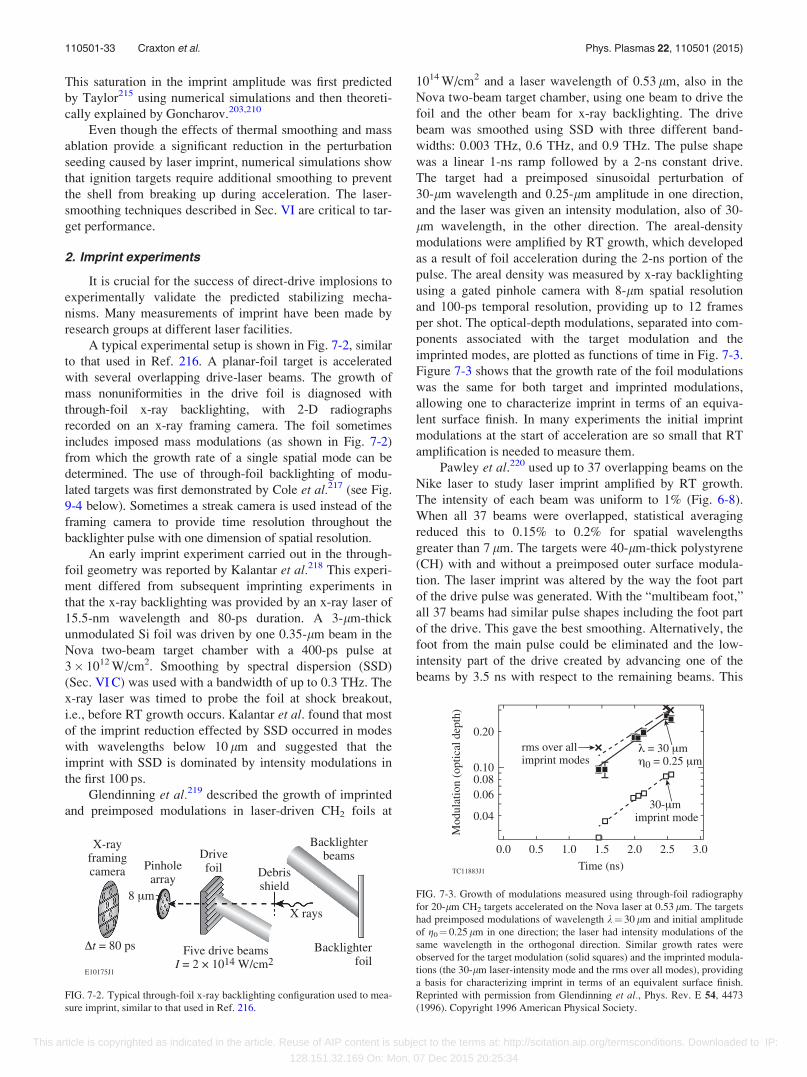
This saturation in the imprint amplitude was first predicted
by Taylor215 using numerical simulations and then theoreti-
cally explained by Goncharov.203,210
Even though the effects of thermal smoothing and mass
ablation provide a significant reduction in the perturbation
seeding caused by laser imprint, numerical simulations show
that ignition targets require additional smoothing to prevent
the shell from breaking up during acceleration. The laser-
smoothing techniques described in Sec. VI are critical to tar-
get performance.
2. Imprint experiments
It is crucial for the success of direct-drive implosions to
experimentally validate the predicted stabilizing mecha-
nisms. Many measurements of imprint have been made by
research groups at different laser facilities.
A typical experimental setup is shown in Fig. 7-2, similar
to that used in Ref. 216. A planar-foil target is accelerated
with several overlapping drive-laser beams. The growth of
mass nonuniformities in the drive foil is diagnosed with
through-foil x-ray backlighting, with 2-D radiographs
recorded on an x-ray framing camera. The foil sometimes
includes imposed mass modulations (as shown in Fig. 7-2)
from which the growth rate of a single spatial mode can be
determined. The use of through-foil backlighting of modu-
lated targets was first demonstrated by Cole et al.217 (see Fig.
9-4 below). Sometimes a streak camera is used instead of the
framing camera to provide time resolution throughout the
backlighter pulse with one dimension of spatial resolution.
An early imprint experiment carried out in the through-
foil geometry was reported by Kalantar et al.218 This experi-
ment differed from subsequent imprinting experiments in
that the x-ray backlighting was provided by an x-ray laser of
15.5-nm wavelength and 80-ps duration. A 3-lm-thick
unmodulated Si foil was driven by one 0.35-lm beam in the
Nova two-beam target chamber with a 400-ps pulse at
3� 1012 W/cm2. Smoothing by spectral dispersion (SSD)
(Sec. VI C) was used with a bandwidth of up to 0.3 THz. The
x-ray laser was timed to probe the foil at shock breakout,
i.e., before RT growth occurs. Kalantar et al. found that most
of the imprint reduction effected by SSD occurred in modes
with wavelengths below 10 lm and suggested that the
imprint with SSD is dominated by intensity modulations in
the first 100 ps.
Glendinning et al.219 described the growth of imprinted
and preimposed modulations in laser-driven CH2 foils at
1014 W/cm2 and a laser wavelength of 0.53 lm, also in the
Nova two-beam target chamber, using one beam to drive the
foil and the other beam for x-ray backlighting. The drive
beam was smoothed using SSD with three different band-
widths: 0.003 THz, 0.6 THz, and 0.9 THz. The pulse shape
was a linear 1-ns ramp followed by a 2-ns constant drive.
The target had a preimposed sinusoidal perturbation of
30-lm wavelength and 0.25-lm amplitude in one direction,
and the laser was given an intensity modulation, also of 30-
lm wavelength, in the other direction. The areal-density
modulations were amplified by RT growth, which developed
as a result of foil acceleration during the 2-ns portion of the
pulse. The areal density was measured by x-ray backlighting
using a gated pinhole camera with 8-lm spatial resolution
and 100-ps temporal resolution, providing up to 12 frames
per shot. The optical-depth modulations, separated into com-
ponents associated with the target modulation and the
imprinted modes, are plotted as functions of time in Fig. 7-3.
Figure 7-3 shows that the growth rate of the foil modulations
was the same for both target and imprinted modulations,
allowing one to characterize imprint in terms of an equiva-
lent surface finish. In many experiments the initial imprint
modulations at the start of acceleration are so small that RT
amplification is needed to measure them.
Pawley et al.220 used up to 37 overlapping beams on the
Nike laser to study laser imprint amplified by RT growth.
The intensity of each beam was uniform to 1% (Fig. 6-8).
When all 37 beams were overlapped, statistical averaging
reduced this to 0.15% to 0.2% for spatial wavelengths
greater than 7 lm. The targets were 40-lm-thick polystyrene
(CH) with and without a preimposed outer surface modula-
tion. The laser imprint was altered by the way the foot part
of the drive pulse was generated. With the “multibeam foot,”
all 37 beams had similar pulse shapes including the foot part
of the drive. This gave the best smoothing. Alternatively, the
foot from the main pulse could be eliminated and the low-
intensity part of the drive created by advancing one of the
beams by 3.5 ns with respect to the remaining beams. This
FIG. 7-2. Typical through-foil x-ray backlighting configuration used to mea-
sure imprint, similar to that used in Ref. 216.
FIG. 7-3. Growth of modulations measured using through-foil radiography
for 20-lm CH2 targets accelerated on the Nova laser at 0.53 lm. The targets
had preimposed modulations of wavelength k¼ 30 lm and initial amplitude
of g0¼ 0.25 lm in one direction; the laser had intensity modulations of the
same wavelength in the orthogonal direction. Similar growth rates were
observed for the target modulation (solid squares) and the imprinted modula-
tions (the 30-lm laser-intensity mode and the rms over all modes), providing
a basis for characterizing imprint in terms of an equivalent surface finish.
Reprinted with permission from Glendinning et al., Phys. Rev. E 54, 4473
(1996). Copyright 1996 American Physical Society.
110501-33 Craxton et al. Phys. Plasmas 22, 110501 (2015)
This article is copyrighted as indicated in the article. Reuse of AIP content is subject to the terms at: http://scitation.aip.org/termsconditions. Downloaded to IP:
128.151.32.169 On: Mon, 07 Dec 2015 20:25:34
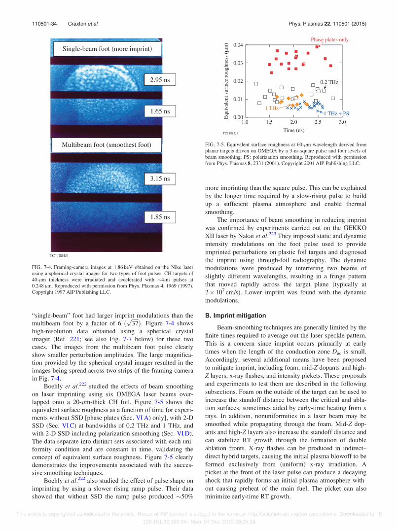
“single-beam” foot had larger imprint modulations than the
multibeam foot by a factor of 6 ðffiffiffiffiffi37pÞ: Figure 7-4 shows
high-resolution data obtained using a spherical crystal
imager (Ref. 221; see also Fig. 7-7 below) for these two
cases. The images from the multibeam foot pulse clearly
show smaller perturbation amplitudes. The large magnifica-
tion provided by the spherical crystal imager resulted in the
images being spread across two strips of the framing camera
in Fig. 7-4.
Boehly et al.222 studied the effects of beam smoothing
on laser imprinting using six OMEGA laser beams over-
lapped onto a 20-lm-thick CH foil. Figure 7-5 shows the
equivalent surface roughness as a function of time for experi-
ments without SSD [phase plates (Sec. VI A) only], with 2-D
SSD (Sec. VI C) at bandwidths of 0.2 THz and 1 THz, and
with 2-D SSD including polarization smoothing (Sec. VI D).
The data separate into distinct sets associated with each uni-
formity condition and are constant in time, validating the
concept of equivalent surface roughness. Figure 7-5 clearly
demonstrates the improvements associated with the succes-
sive smoothing techniques.
Boehly et al.222 also studied the effect of pulse shape on
imprinting by using a slower rising ramp pulse. Their data
showed that without SSD the ramp pulse produced �50%
more imprinting than the square pulse. This can be explained
by the longer time required by a slow-rising pulse to build
up a sufficient plasma atmosphere and enable thermal
smoothing.
The importance of beam smoothing in reducing imprint
was confirmed by experiments carried out on the GEKKO
XII laser by Nakai et al.223 They imposed static and dynamic
intensity modulations on the foot pulse used to provide
imprinted perturbations on plastic foil targets and diagnosed
the imprint using through-foil radiography. The dynamic
modulations were produced by interfering two beams of
slightly different wavelengths, resulting in a fringe pattern
that moved rapidly across the target plane (typically at
2� 107 cm/s). Lower imprint was found with the dynamic
modulations.
B. Imprint mitigation
Beam-smoothing techniques are generally limited by the
finite times required to average out the laser speckle pattern.
This is a concern since imprint occurs primarily at early
times when the length of the conduction zone Dac is small.
Accordingly, several additional means have been proposed
to mitigate imprint, including foam, mid-Z dopants and high-
Z layers, x-ray flashes, and intensity pickets. These proposals
and experiments to test them are described in the following
subsections. Foam on the outside of the target can be used to
increase the standoff distance between the critical and abla-
tion surfaces, sometimes aided by early-time heating from x
rays. In addition, nonuniformities in a laser beam may be
smoothed while propagating through the foam. Mid-Z dop-
ants and high-Z layers also increase the standoff distance and
can stabilize RT growth through the formation of double
ablation fronts. X-ray flashes can be produced in indirect–
direct hybrid targets, causing the initial plasma blowoff to be
formed exclusively from (uniform) x-ray irradiation. A
picket at the front of the laser pulse can produce a decaying
shock that rapidly forms an initial plasma atmosphere with-
out causing preheat of the main fuel. The picket can also
minimize early-time RT growth.
FIG. 7-4. Framing-camera images at 1.86 keV obtained on the Nike laser
using a spherical crystal imager for two types of foot pulses. CH targets of
40-lm thickness were irradiated and accelerated with �4-ns pulses at
0.248 lm. Reproduced with permission from Phys. Plasmas 4, 1969 (1997).
Copyright 1997 AIP Publishing LLC.
FIG. 7-5. Equivalent surface roughness at 60-lm wavelength derived from
planar targets driven on OMEGA by a 3-ns square pulse and four levels of
beam smoothing. PS: polarization smoothing. Reproduced with permission
from Phys. Plasmas 8, 2331 (2001). Copyright 2001 AIP Publishing LLC.
110501-34 Craxton et al. Phys. Plasmas 22, 110501 (2015)
This article is copyrighted as indicated in the article. Reuse of AIP content is subject to the terms at: http://scitation.aip.org/termsconditions. Downloaded to IP:
128.151.32.169 On: Mon, 07 Dec 2015 20:25:34
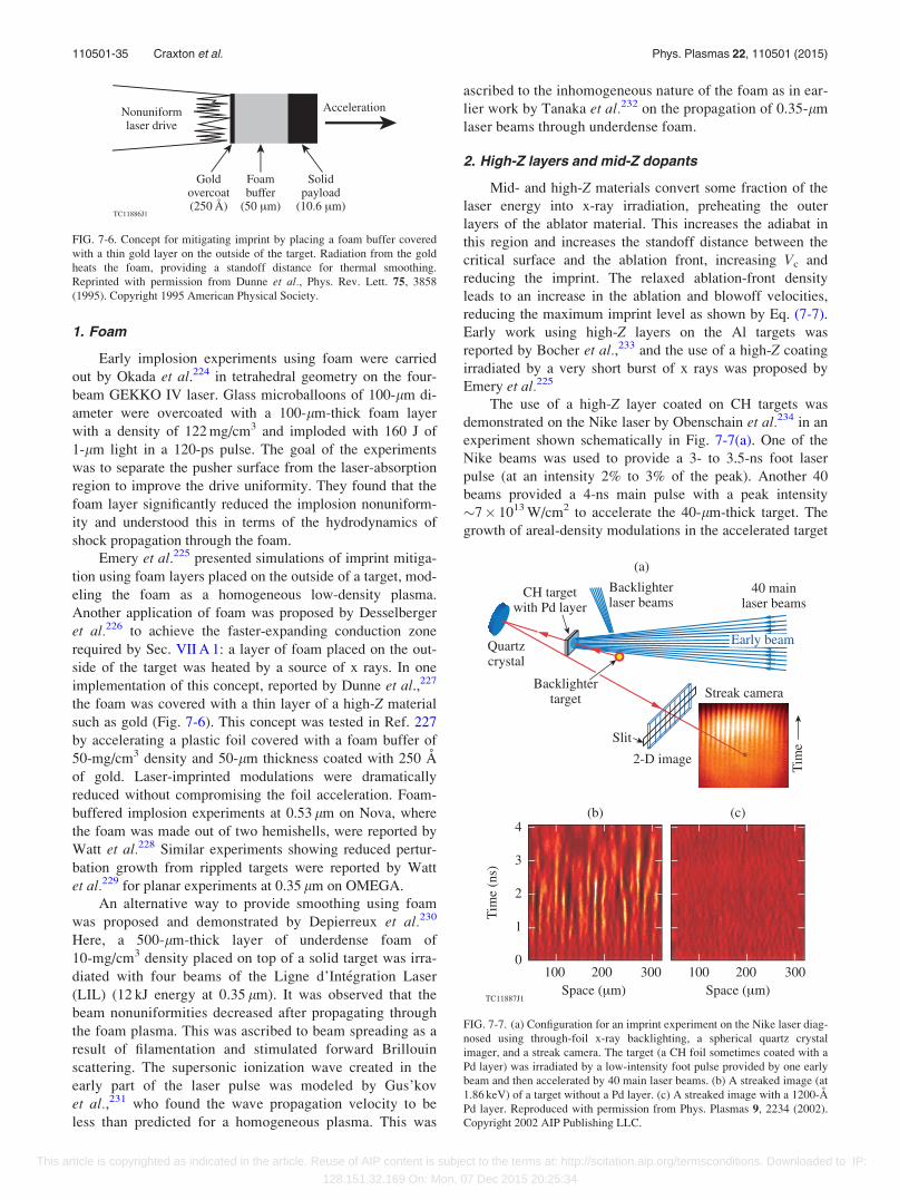
1. Foam
Early implosion experiments using foam were carried
out by Okada et al.224 in tetrahedral geometry on the four-
beam GEKKO IV laser. Glass microballoons of 100-lm di-
ameter were overcoated with a 100-lm-thick foam layer
with a density of 122 mg/cm3 and imploded with 160 J of
1-lm light in a 120-ps pulse. The goal of the experiments
was to separate the pusher surface from the laser-absorption
region to improve the drive uniformity. They found that the
foam layer significantly reduced the implosion nonuniform-
ity and understood this in terms of the hydrodynamics of
shock propagation through the foam.
Emery et al.225 presented simulations of imprint mitiga-
tion using foam layers placed on the outside of a target, mod-
eling the foam as a homogeneous low-density plasma.
Another application of foam was proposed by Desselberger
et al.226 to achieve the faster-expanding conduction zone
required by Sec. VII A 1: a layer of foam placed on the out-
side of the target was heated by a source of x rays. In one
implementation of this concept, reported by Dunne et al.,227
the foam was covered with a thin layer of a high-Z material
such as gold (Fig. 7-6). This concept was tested in Ref. 227
by accelerating a plastic foil covered with a foam buffer of
50-mg/cm3 density and 50-lm thickness coated with 250 A
of gold. Laser-imprinted modulations were dramatically
reduced without compromising the foil acceleration. Foam-
buffered implosion experiments at 0.53 lm on Nova, where
the foam was made out of two hemishells, were reported by
Watt et al.228 Similar experiments showing reduced pertur-
bation growth from rippled targets were reported by Watt
et al.229 for planar experiments at 0.35 lm on OMEGA.
An alternative way to provide smoothing using foam
was proposed and demonstrated by Depierreux et al.230
Here, a 500-lm-thick layer of underdense foam of
10-mg/cm3 density placed on top of a solid target was irra-
diated with four beams of the Ligne d’Int�egration Laser
(LIL) (12 kJ energy at 0.35 lm). It was observed that the
beam nonuniformities decreased after propagating through
the foam plasma. This was ascribed to beam spreading as a
result of filamentation and stimulated forward Brillouin
scattering. The supersonic ionization wave created in the
early part of the laser pulse was modeled by Gus’kov
et al.,231 who found the wave propagation velocity to be
less than predicted for a homogeneous plasma. This was
ascribed to the inhomogeneous nature of the foam as in ear-
lier work by Tanaka et al.232 on the propagation of 0.35-lm
laser beams through underdense foam.
2. High-Z layers and mid-Z dopants
Mid- and high-Z materials convert some fraction of the
laser energy into x-ray irradiation, preheating the outer
layers of the ablator material. This increases the adiabat in
this region and increases the standoff distance between the
critical surface and the ablation front, increasing Vc and
reducing the imprint. The relaxed ablation-front density
leads to an increase in the ablation and blowoff velocities,
reducing the maximum imprint level as shown by Eq. (7-7).
Early work using high-Z layers on the Al targets was
reported by Bocher et al.,233 and the use of a high-Z coating
irradiated by a very short burst of x rays was proposed by
Emery et al.225
The use of a high-Z layer coated on CH targets was
demonstrated on the Nike laser by Obenschain et al.234 in an
experiment shown schematically in Fig. 7-7(a). One of the
Nike beams was used to provide a 3- to 3.5-ns foot laser
pulse (at an intensity 2% to 3% of the peak). Another 40
beams provided a 4-ns main pulse with a peak intensity
�7� 1013 W/cm2 to accelerate the 40-lm-thick target. The
growth of areal-density modulations in the accelerated target
FIG. 7-6. Concept for mitigating imprint by placing a foam buffer covered
with a thin gold layer on the outside of the target. Radiation from the gold
heats the foam, providing a standoff distance for thermal smoothing.
Reprinted with permission from Dunne et al., Phys. Rev. Lett. 75, 3858
(1995). Copyright 1995 American Physical Society.
FIG. 7-7. (a) Configuration for an imprint experiment on the Nike laser diag-
nosed using through-foil x-ray backlighting, a spherical quartz crystal
imager, and a streak camera. The target (a CH foil sometimes coated with a
Pd layer) was irradiated by a low-intensity foot pulse provided by one early
beam and then accelerated by 40 main laser beams. (b) A streaked image (at
1.86 keV) of a target without a Pd layer. (c) A streaked image with a 1200-A
Pd layer. Reproduced with permission from Phys. Plasmas 9, 2234 (2002).
Copyright 2002 AIP Publishing LLC.
110501-35 Craxton et al. Phys. Plasmas 22, 110501 (2015)
This article is copyrighted as indicated in the article. Reuse of AIP content is subject to the terms at: http://scitation.aip.org/termsconditions. Downloaded to IP:
128.151.32.169 On: Mon, 07 Dec 2015 20:25:34

was diagnosed using through-foil x-ray backlighting as in
Fig. 7-2, except that the pinhole imaging was replaced with
high-spatial-resolution, monochromatic imaging provided by
a spherical quartz crystal. One-dimensional imaging of the
target was obtained along the slit of the streak camera. The
streaked image shown in Fig. 7-7(a) is for an initially rippled
target.
Streaked images of CH targets without and with a 1200-A
Pd coating are shown in Figs. 7-7(b) and 7-7(c), respectively.
The imprinted perturbations grew to a large amplitude for the
uncoated target, while no measurable RT-amplified imprint
was seen for the coated target. This was understood to result
from reduced imprint caused by a buffer plasma layer heated
by x rays from the Pd. A minimum thickness of the high-Zlayer was found to be necessary. Mostovych et al.235 reported
implosion experiments on the OMEGA Laser System using
SSD beam smoothing and targets with Pd coatings of various
thickness. They found improved performance as the coating
thickness was increased from 0 to 400 A: the neutron yield
increased by a factor of 2 and the yield compared with 1-D
simulations increased from 3% to 55%, suggesting increased
stability. However, it was hard to make a definitive comparison
between targets with and without the Pd coating since the tar-
gets with the coating imploded on a high adiabat as a result of
radiation preheat and shock mistiming. The performance
improvement was maintained for 600-A Pd layers but
degraded at 800 A.
An experiment that demonstrated the benefit of mid-Zdoping was reported by Fujioka et al.236 They used planar
brominated-plastic (CH–Br) foils to test the development of
double ablation fronts to stabilize the RT growth seeded by
mass perturbations and laser imprint. They used nine 0.35-lm
GEKKO beams following three 0.53-lm foot-pulse beams to
drive their foils. Results from these experiments are shown in
Fig. 7-8, where streaked, 1-D spatially resolved radiographs
are compared for the acceleration of CH–Br [Fig. 7-8(a)] and
CH [Fig. 7-8(b)] foils with imposed spatial modulations.
Growth factors obtained from these streaks, plotted versus
time in Fig. 7-8(c), clearly demonstrate the suppression of RT
growth. Fujioka et al. incorporated this concept into an igni-
tion design that produced a gain of �23.
An experiment that demonstrated the benefit of mid-Zdopants in spherical geometry was reported by Hu et al.237
and Fiksel et al.238 The setup is shown in Fig. 7-9(a), taken
from Ref. 239 where it was used to measure RT growth in
implosion experiments. Spherical plastic shell targets with
various dopants were imploded using forty-eight 0.35-lm
OMEGA beams. The shells had an outer diameter of 860 lm
and a thickness of 22 lm. Each shell had a 400-lm-diam
round opening into which a gold cone shield was inserted. A
Ta x-ray backlighter was irradiated with six of the remaining
OMEGA beams, making it possible to diagnose the growth
of areal-density perturbations using an x-ray framing camera.
The results [Fig. 7-9(b)] showed lower perturbation levels
for the doped shells, consistent with predictions of hydrody-
namic simulations.
FIG. 7-8. Streaked face-on radiographs of perturbed laser-driven foils con-
sisting of (a) brominated plastic (CH–Br) and (b) bare plastic (CH). (c)
Comparison of the measured growth factors derived from each experiment.
The time origin corresponds to the time of onset of the main laser drive.
Reprinted with permission from Fujioka et al., Phys. Rev. Lett. 92, 195001
(2004). Copyright 2004 American Physical Society.
FIG. 7-9. (a) Schematic of an experiment that demonstrated lower imprint in
an imploding plastic shell target doped with higher-Z elements. The shell
had a round opening into which a gold cone shield was inserted. It was
imploded by 48 OMEGA drive beams. Areal-density modulations were
diagnosed using a Ta backlighter and an x-ray framing camera. Reprinted
with permission from Smalyuk et al., Phys. Rev. Lett. 103, 105001 (2009).
Copyright 2009 American Physical Society. (b) Measured and predicted per-
turbation growth for targets with various levels of doping. The solid lines
are DRACO simulations. Reprinted with permission from Hu et al., Phys.
Rev. Lett. 108, 195003 (2012). Copyright 2012 American Physical Society.
110501-36 Craxton et al. Phys. Plasmas 22, 110501 (2015)
This article is copyrighted as indicated in the article. Reuse of AIP content is subject to the terms at: http://scitation.aip.org/termsconditions. Downloaded to IP:
128.151.32.169 On: Mon, 07 Dec 2015 20:25:34
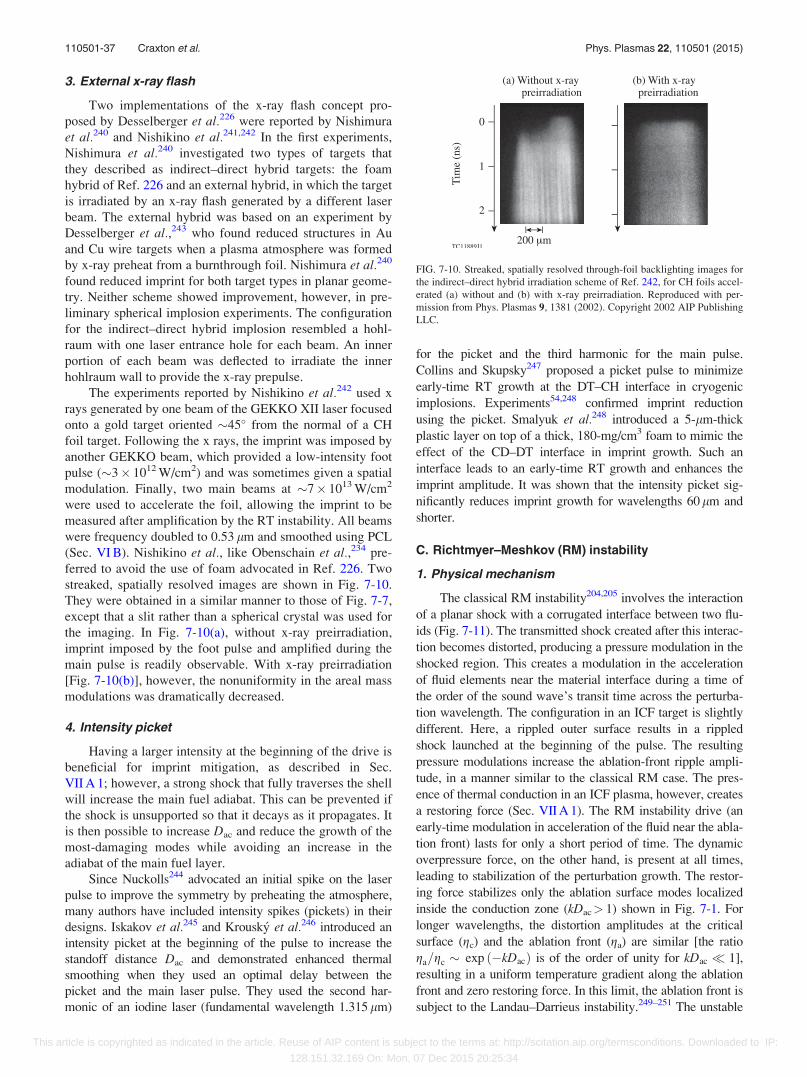
3. External x-ray flash
Two implementations of the x-ray flash concept pro-
posed by Desselberger et al.226 were reported by Nishimura
et al.240 and Nishikino et al.241,242 In the first experiments,
Nishimura et al.240 investigated two types of targets that
they described as indirect–direct hybrid targets: the foam
hybrid of Ref. 226 and an external hybrid, in which the target
is irradiated by an x-ray flash generated by a different laser
beam. The external hybrid was based on an experiment by
Desselberger et al.,243 who found reduced structures in Au
and Cu wire targets when a plasma atmosphere was formed
by x-ray preheat from a burnthrough foil. Nishimura et al.240
found reduced imprint for both target types in planar geome-
try. Neither scheme showed improvement, however, in pre-
liminary spherical implosion experiments. The configuration
for the indirect–direct hybrid implosion resembled a hohl-
raum with one laser entrance hole for each beam. An inner
portion of each beam was deflected to irradiate the inner
hohlraum wall to provide the x-ray prepulse.
The experiments reported by Nishikino et al.242 used x
rays generated by one beam of the GEKKO XII laser focused
onto a gold target oriented �45� from the normal of a CH
foil target. Following the x rays, the imprint was imposed by
another GEKKO beam, which provided a low-intensity foot
pulse (�3� 1012 W/cm2) and was sometimes given a spatial
modulation. Finally, two main beams at �7� 1013 W/cm2
were used to accelerate the foil, allowing the imprint to be
measured after amplification by the RT instability. All beams
were frequency doubled to 0.53 lm and smoothed using PCL
(Sec. VI B). Nishikino et al., like Obenschain et al.,234 pre-
ferred to avoid the use of foam advocated in Ref. 226. Two
streaked, spatially resolved images are shown in Fig. 7-10.
They were obtained in a similar manner to those of Fig. 7-7,
except that a slit rather than a spherical crystal was used for
the imaging. In Fig. 7-10(a), without x-ray preirradiation,
imprint imposed by the foot pulse and amplified during the
main pulse is readily observable. With x-ray preirradiation
[Fig. 7-10(b)], however, the nonuniformity in the areal mass
modulations was dramatically decreased.
4. Intensity picket
Having a larger intensity at the beginning of the drive is
beneficial for imprint mitigation, as described in Sec.
VII A 1; however, a strong shock that fully traverses the shell
will increase the main fuel adiabat. This can be prevented if
the shock is unsupported so that it decays as it propagates. It
is then possible to increase Dac and reduce the growth of the
most-damaging modes while avoiding an increase in the
adiabat of the main fuel layer.
Since Nuckolls244 advocated an initial spike on the laser
pulse to improve the symmetry by preheating the atmosphere,
many authors have included intensity spikes (pickets) in their
designs. Iskakov et al.245 and Krousk�y et al.246 introduced an
intensity picket at the beginning of the pulse to increase the
standoff distance Dac and demonstrated enhanced thermal
smoothing when they used an optimal delay between the
picket and the main laser pulse. They used the second har-
monic of an iodine laser (fundamental wavelength 1.315 lm)
for the picket and the third harmonic for the main pulse.
Collins and Skupsky247 proposed a picket pulse to minimize
early-time RT growth at the DT–CH interface in cryogenic
implosions. Experiments54,248 confirmed imprint reduction
using the picket. Smalyuk et al.248 introduced a 5-lm-thick
plastic layer on top of a thick, 180-mg/cm3 foam to mimic the
effect of the CD–DT interface in imprint growth. Such an
interface leads to an early-time RT growth and enhances the
imprint amplitude. It was shown that the intensity picket sig-
nificantly reduces imprint growth for wavelengths 60lm and
shorter.
C. Richtmyer–Meshkov (RM) instability
1. Physical mechanism
The classical RM instability204,205 involves the interaction
of a planar shock with a corrugated interface between two flu-
ids (Fig. 7-11). The transmitted shock created after this interac-
tion becomes distorted, producing a pressure modulation in the
shocked region. This creates a modulation in the acceleration
of fluid elements near the material interface during a time of
the order of the sound wave’s transit time across the perturba-
tion wavelength. The configuration in an ICF target is slightly
different. Here, a rippled outer surface results in a rippled
shock launched at the beginning of the pulse. The resulting
pressure modulations increase the ablation-front ripple ampli-
tude, in a manner similar to the classical RM case. The pres-
ence of thermal conduction in an ICF plasma, however, creates
a restoring force (Sec. VII A 1). The RM instability drive (an
early-time modulation in acceleration of the fluid near the abla-
tion front) lasts for only a short period of time. The dynamic
overpressure force, on the other hand, is present at all times,
leading to stabilization of the perturbation growth. The restor-
ing force stabilizes only the ablation surface modes localized
inside the conduction zone (kDac> 1) shown in Fig. 7-1. For
longer wavelengths, the distortion amplitudes at the critical
surface (gc) and the ablation front (ga) are similar [the ratio
ga=gc � exp ð�kDacÞ is of the order of unity for kDac � 1],
resulting in a uniform temperature gradient along the ablation
front and zero restoring force. In this limit, the ablation front is
subject to the Landau–Darrieus instability.249–251 The unstable
FIG. 7-10. Streaked, spatially resolved through-foil backlighting images for
the indirect–direct hybrid irradiation scheme of Ref. 242, for CH foils accel-
erated (a) without and (b) with x-ray preirradiation. Reproduced with per-
mission from Phys. Plasmas 9, 1381 (2002). Copyright 2002 AIP Publishing
LLC.
110501-37 Craxton et al. Phys. Plasmas 22, 110501 (2015)
This article is copyrighted as indicated in the article. Reuse of AIP content is subject to the terms at: http://scitation.aip.org/termsconditions. Downloaded to IP:
128.151.32.169 On: Mon, 07 Dec 2015 20:25:34
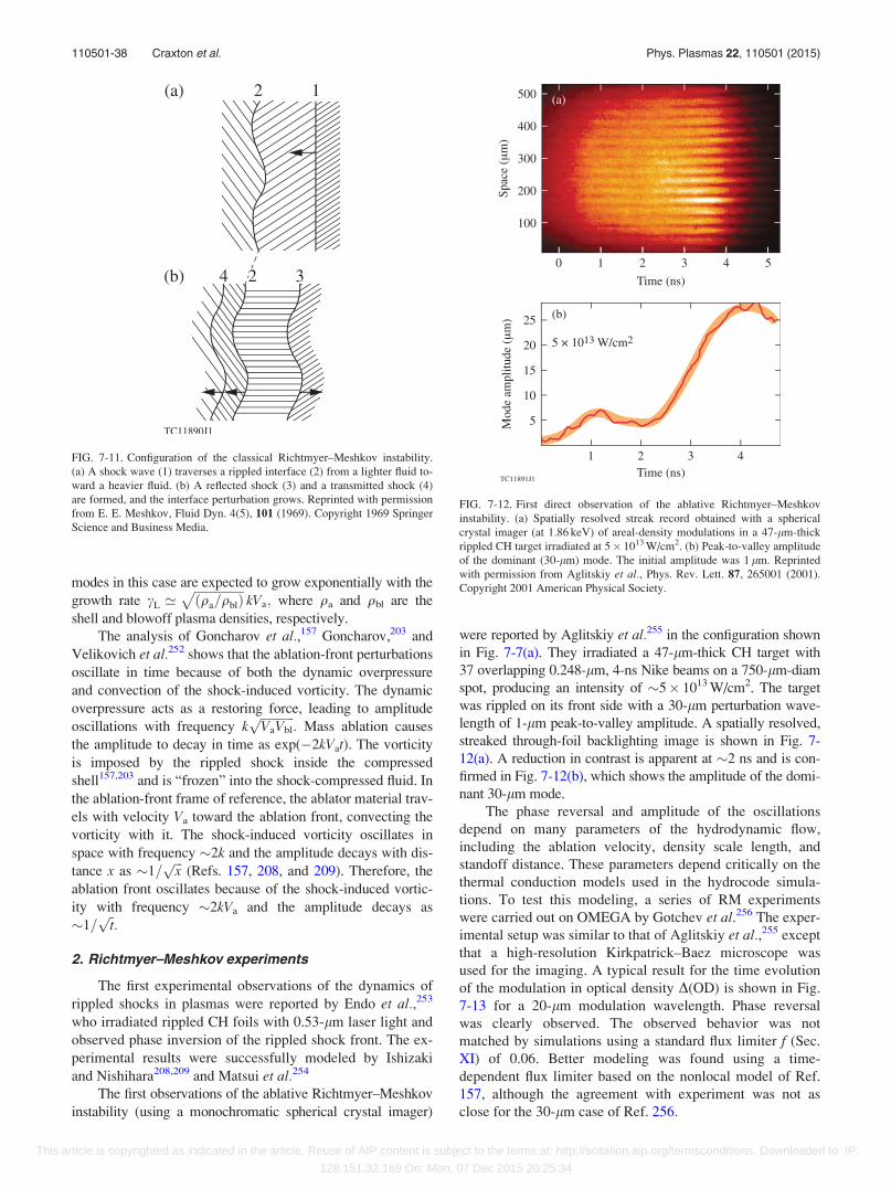
modes in this case are expected to grow exponentially with the
growth rate cL ’ffiffiffiffiffiffiffiffiffiffiffiffiffiffiffiffiðqa=qblÞ
pkVa; where qa and qbl are the
shell and blowoff plasma densities, respectively.
The analysis of Goncharov et al.,157 Goncharov,203 and
Velikovich et al.252 shows that the ablation-front perturbations
oscillate in time because of both the dynamic overpressure
and convection of the shock-induced vorticity. The dynamic
overpressure acts as a restoring force, leading to amplitude
oscillations with frequency kffiffiffiffiffiffiffiffiffiffiffiVaVbl
p: Mass ablation causes
the amplitude to decay in time as exp(�2kVat). The vorticity
is imposed by the rippled shock inside the compressed
shell157,203 and is “frozen” into the shock-compressed fluid. In
the ablation-front frame of reference, the ablator material trav-
els with velocity Va toward the ablation front, convecting the
vorticity with it. The shock-induced vorticity oscillates in
space with frequency �2k and the amplitude decays with dis-
tance x as �1=ffiffiffixp
(Refs. 157, 208, and 209). Therefore, the
ablation front oscillates because of the shock-induced vortic-
ity with frequency �2kVa and the amplitude decays as
�1=ffiffitp:
2. Richtmyer–Meshkov experiments
The first experimental observations of the dynamics of
rippled shocks in plasmas were reported by Endo et al.,253
who irradiated rippled CH foils with 0.53-lm laser light and
observed phase inversion of the rippled shock front. The ex-
perimental results were successfully modeled by Ishizaki
and Nishihara208,209 and Matsui et al.254
The first observations of the ablative Richtmyer–Meshkov
instability (using a monochromatic spherical crystal imager)
were reported by Aglitskiy et al.255 in the configuration shown
in Fig. 7-7(a). They irradiated a 47-lm-thick CH target with
37 overlapping 0.248-lm, 4-ns Nike beams on a 750-lm-diam
spot, producing an intensity of �5� 1013 W/cm2. The target
was rippled on its front side with a 30-lm perturbation wave-
length of 1-lm peak-to-valley amplitude. A spatially resolved,
streaked through-foil backlighting image is shown in Fig. 7-
12(a). A reduction in contrast is apparent at �2 ns and is con-
firmed in Fig. 7-12(b), which shows the amplitude of the domi-
nant 30-lm mode.
The phase reversal and amplitude of the oscillations
depend on many parameters of the hydrodynamic flow,
including the ablation velocity, density scale length, and
standoff distance. These parameters depend critically on the
thermal conduction models used in the hydrocode simula-
tions. To test this modeling, a series of RM experiments
were carried out on OMEGA by Gotchev et al.256 The exper-
imental setup was similar to that of Aglitskiy et al.,255 except
that a high-resolution Kirkpatrick–Baez microscope was
used for the imaging. A typical result for the time evolution
of the modulation in optical density D(OD) is shown in Fig.
7-13 for a 20-lm modulation wavelength. Phase reversal
was clearly observed. The observed behavior was not
matched by simulations using a standard flux limiter f (Sec.
XI) of 0.06. Better modeling was found using a time-
dependent flux limiter based on the nonlocal model of Ref.
157, although the agreement with experiment was not as
close for the 30-lm case of Ref. 256.
FIG. 7-12. First direct observation of the ablative Richtmyer–Meshkov
instability. (a) Spatially resolved streak record obtained with a spherical
crystal imager (at 1.86 keV) of areal-density modulations in a 47-lm-thick
rippled CH target irradiated at 5� 1013 W/cm2. (b) Peak-to-valley amplitude
of the dominant (30-lm) mode. The initial amplitude was 1 lm. Reprinted
with permission from Aglitskiy et al., Phys. Rev. Lett. 87, 265001 (2001).
Copyright 2001 American Physical Society.
FIG. 7-11. Configuration of the classical Richtmyer–Meshkov instability.
(a) A shock wave (1) traverses a rippled interface (2) from a lighter fluid to-
ward a heavier fluid. (b) A reflected shock (3) and a transmitted shock (4)
are formed, and the interface perturbation grows. Reprinted with permission
from E. E. Meshkov, Fluid Dyn. 4(5), 101 (1969). Copyright 1969 Springer
Science and Business Media.
110501-38 Craxton et al. Phys. Plasmas 22, 110501 (2015)
This article is copyrighted as indicated in the article. Reuse of AIP content is subject to the terms at: http://scitation.aip.org/termsconditions. Downloaded to IP:
128.151.32.169 On: Mon, 07 Dec 2015 20:25:34
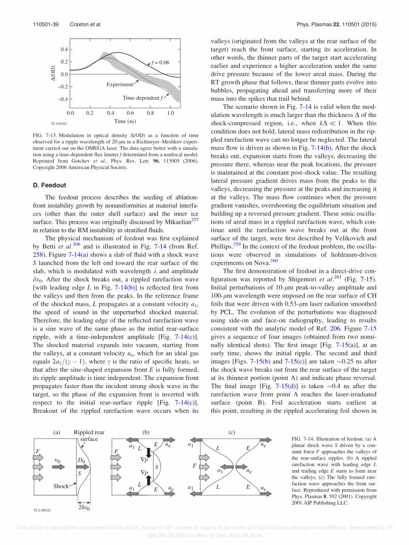
D. Feedout
The feedout process describes the seeding of ablation-
front instability growth by nonuniformities at material interfa-
ces (other than the outer shell surface) and the inner ice
surface. This process was originally discussed by Mikaelian257
in relation to the RM instability in stratified fluids.
The physical mechanism of feedout was first explained
by Betti et al.206 and is illustrated in Fig. 7-14 (from Ref.
258). Figure 7-14(a) shows a slab of fluid with a shock wave
S launched from the left end toward the rear surface of the
slab, which is modulated with wavelength k and amplitude
dx0. After the shock breaks out, a rippled rarefaction wave
[with leading edge L in Fig. 7-14(b)] is reflected first from
the valleys and then from the peaks. In the reference frame
of the shocked mass, L propagates at a constant velocity a1,
the speed of sound in the unperturbed shocked material.
Therefore, the leading edge of the reflected rarefaction wave
is a sine wave of the same phase as the initial rear-surface
ripple, with a time-independent amplitude [Fig. 7-14(c)].
The shocked material expands into vacuum, starting from
the valleys, at a constant velocity ue, which for an ideal gas
equals 2a1=ðc� 1Þ; where c is the ratio of specific heats, so
that after the sine-shaped expansion front E is fully formed,
its ripple amplitude is time independent. The expansion front
propagates faster than the incident strong shock wave in the
target, so the phase of the expansion front is inverted with
respect to the initial rear-surface ripple [Fig. 7-14(c)].
Breakout of the rippled rarefaction wave occurs when its
valleys (originated from the valleys at the rear surface of the
target) reach the front surface, starting its acceleration. In
other words, the thinner parts of the target start accelerating
earlier and experience a higher acceleration under the same
drive pressure because of the lower areal mass. During the
RT growth phase that follows, these thinner parts evolve into
bubbles, propagating ahead and transferring more of their
mass into the spikes that trail behind.
The scenario shown in Fig. 7-14 is valid when the mod-
ulation wavelength is much larger than the thickness D of the
shock-compressed region, i.e., when kD� 1: When this
condition does not hold, lateral mass redistribution in the rip-
pled rarefaction wave can no longer be neglected. The lateral
mass flow is driven as shown in Fig. 7-14(b). After the shock
breaks out, expansion starts from the valleys, decreasing the
pressure there, whereas near the peak locations, the pressure
is maintained at the constant post-shock value. The resulting
lateral pressure gradient drives mass from the peaks to the
valleys, decreasing the pressure at the peaks and increasing it
at the valleys. The mass flow continues when the pressure
gradient vanishes, overshooting the equilibrium situation and
building up a reversed pressure gradient. These sonic oscilla-
tions of areal mass in a rippled rarefaction wave, which con-
tinue until the rarefaction wave breaks out at the front
surface of the target, were first described by Velikovich and
Phillips.259 In the context of the feedout problem, the oscilla-
tions were observed in simulations of hohlraum-driven
experiments on Nova.260
The first demonstration of feedout in a direct-drive con-
figuration was reported by Shigemori et al.261 (Fig. 7-15).
Initial perturbations of 10-lm peak-to-valley amplitude and
100-lm wavelength were imposed on the rear surface of CH
foils that were driven with 0.53-lm laser radiation smoothed
by PCL. The evolution of the perturbations was diagnosed
using side-on and face-on radiography, leading to results
consistent with the analytic model of Ref. 206. Figure 7-15
gives a sequence of four images (obtained from two nomi-
nally identical shots). The first image [Fig. 7-15(a)], at an
early time, shows the initial ripple. The second and third
images [Figs. 7-15(b) and 7-15(c)] are taken �0.25 ns after
the shock wave breaks out from the rear surface of the target
at its thinnest portion (point A) and indicate phase reversal.
The final image [Fig. 7-15(d)] is taken �0.4 ns after the
rarefaction wave from point A reaches the laser-irradiated
surface (point B). Foil acceleration starts earliest at
this point, resulting in the rippled accelerating foil shown in
FIG. 7-13. Modulation in optical density D(OD) as a function of time
observed for a ripple wavelength of 20 lm in a Richtmyer–Meshkov experi-
ment carried out on the OMEGA laser. The data agree better with a simula-
tion using a time-dependent flux limiter f determined from a nonlocal model.
Reprinted from Gotchev et al., Phys. Rev. Lett. 96, 115005 (2006).
Copyright 2006 American Physical Society.
FIG. 7-14. Illustration of feedout. (a) A
planar shock wave S driven by a con-
stant force F approaches the valleys of
the rear-surface ripples. (b) A rippled
rarefaction wave with leading edge Land trailing edge E starts to form near
the valleys. (c) The fully formed rare-
faction wave approaches the front sur-
face. Reproduced with permission from
Phys. Plasmas 8, 592 (2001). Copyright
2001 AIP Publishing LLC.
110501-39 Craxton et al. Phys. Plasmas 22, 110501 (2015)
This article is copyrighted as indicated in the article. Reuse of AIP content is subject to the terms at: http://scitation.aip.org/termsconditions. Downloaded to IP:
128.151.32.169 On: Mon, 07 Dec 2015 20:25:34
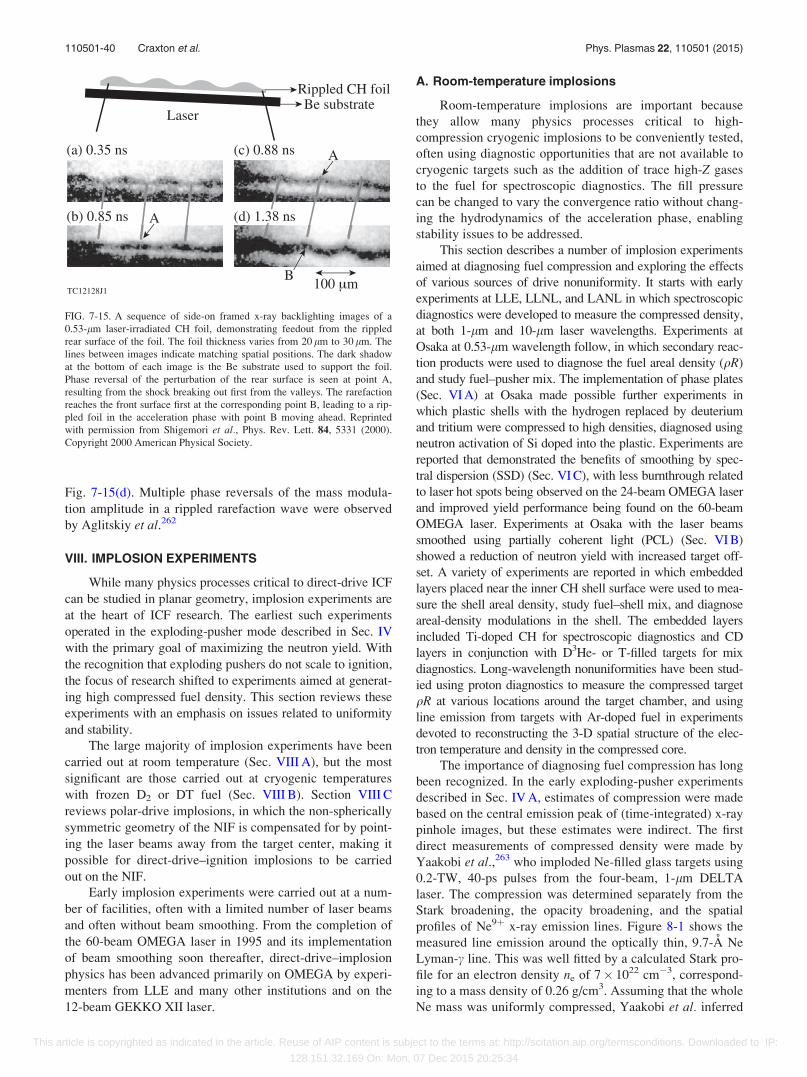
Fig. 7-15(d). Multiple phase reversals of the mass modula-
tion amplitude in a rippled rarefaction wave were observed
by Aglitskiy et al.262
VIII. IMPLOSION EXPERIMENTS
While many physics processes critical to direct-drive ICF
can be studied in planar geometry, implosion experiments are
at the heart of ICF research. The earliest such experiments
operated in the exploding-pusher mode described in Sec. IV
with the primary goal of maximizing the neutron yield. With
the recognition that exploding pushers do not scale to ignition,
the focus of research shifted to experiments aimed at generat-
ing high compressed fuel density. This section reviews these
experiments with an emphasis on issues related to uniformity
and stability.
The large majority of implosion experiments have been
carried out at room temperature (Sec. VIII A), but the most
significant are those carried out at cryogenic temperatures
with frozen D2 or DT fuel (Sec. VIII B). Section VIII C
reviews polar-drive implosions, in which the non-spherically
symmetric geometry of the NIF is compensated for by point-
ing the laser beams away from the target center, making it
possible for direct-drive–ignition implosions to be carried
out on the NIF.
Early implosion experiments were carried out at a num-
ber of facilities, often with a limited number of laser beams
and often without beam smoothing. From the completion of
the 60-beam OMEGA laser in 1995 and its implementation
of beam smoothing soon thereafter, direct-drive–implosion
physics has been advanced primarily on OMEGA by experi-
menters from LLE and many other institutions and on the
12-beam GEKKO XII laser.
A. Room-temperature implosions
Room-temperature implosions are important because
they allow many physics processes critical to high-
compression cryogenic implosions to be conveniently tested,
often using diagnostic opportunities that are not available to
cryogenic targets such as the addition of trace high-Z gases
to the fuel for spectroscopic diagnostics. The fill pressure
can be changed to vary the convergence ratio without chang-
ing the hydrodynamics of the acceleration phase, enabling
stability issues to be addressed.
This section describes a number of implosion experiments
aimed at diagnosing fuel compression and exploring the effects
of various sources of drive nonuniformity. It starts with early
experiments at LLE, LLNL, and LANL in which spectroscopic
diagnostics were developed to measure the compressed density,
at both 1-lm and 10-lm laser wavelengths. Experiments at
Osaka at 0.53-lm wavelength follow, in which secondary reac-
tion products were used to diagnose the fuel areal density (qR)
and study fuel–pusher mix. The implementation of phase plates
(Sec. VI A) at Osaka made possible further experiments in
which plastic shells with the hydrogen replaced by deuterium
and tritium were compressed to high densities, diagnosed using
neutron activation of Si doped into the plastic. Experiments are
reported that demonstrated the benefits of smoothing by spec-
tral dispersion (SSD) (Sec. VI C), with less burnthrough related
to laser hot spots being observed on the 24-beam OMEGA laser
and improved yield performance being found on the 60-beam
OMEGA laser. Experiments at Osaka with the laser beams
smoothed using partially coherent light (PCL) (Sec. VI B)
showed a reduction of neutron yield with increased target off-
set. A variety of experiments are reported in which embedded
layers placed near the inner CH shell surface were used to mea-
sure the shell areal density, study fuel–shell mix, and diagnose
areal-density modulations in the shell. The embedded layers
included Ti-doped CH for spectroscopic diagnostics and CD
layers in conjunction with D3He- or T-filled targets for mix
diagnostics. Long-wavelength nonuniformities have been stud-
ied using proton diagnostics to measure the compressed target
qR at various locations around the target chamber, and using
line emission from targets with Ar-doped fuel in experiments
devoted to reconstructing the 3-D spatial structure of the elec-
tron temperature and density in the compressed core.
The importance of diagnosing fuel compression has long
been recognized. In the early exploding-pusher experiments
described in Sec. IV A, estimates of compression were made
based on the central emission peak of (time-integrated) x-ray
pinhole images, but these estimates were indirect. The first
direct measurements of compressed density were made by
Yaakobi et al.,263 who imploded Ne-filled glass targets using
0.2-TW, 40-ps pulses from the four-beam, 1-lm DELTA
laser. The compression was determined separately from the
Stark broadening, the opacity broadening, and the spatial
profiles of Ne9þ x-ray emission lines. Figure 8-1 shows the
measured line emission around the optically thin, 9.7-A Ne
Lyman-c line. This was well fitted by a calculated Stark pro-
file for an electron density ne of 7� 1022 cm�3, correspond-
ing to a mass density of 0.26 g/cm3. Assuming that the whole
Ne mass was uniformly compressed, Yaakobi et al. inferred
FIG. 7-15. A sequence of side-on framed x-ray backlighting images of a
0.53-lm laser-irradiated CH foil, demonstrating feedout from the rippled
rear surface of the foil. The foil thickness varies from 20 lm to 30 lm. The
lines between images indicate matching spatial positions. The dark shadow
at the bottom of each image is the Be substrate used to support the foil.
Phase reversal of the perturbation of the rear surface is seen at point A,
resulting from the shock breaking out first from the valleys. The rarefaction
reaches the front surface first at the corresponding point B, leading to a rip-
pled foil in the acceleration phase with point B moving ahead. Reprinted
with permission from Shigemori et al., Phys. Rev. Lett. 84, 5331 (2000).
Copyright 2000 American Physical Society.
110501-40 Craxton et al. Phys. Plasmas 22, 110501 (2015)
This article is copyrighted as indicated in the article. Reuse of AIP content is subject to the terms at: http://scitation.aip.org/termsconditions. Downloaded to IP:
128.151.32.169 On: Mon, 07 Dec 2015 20:25:34
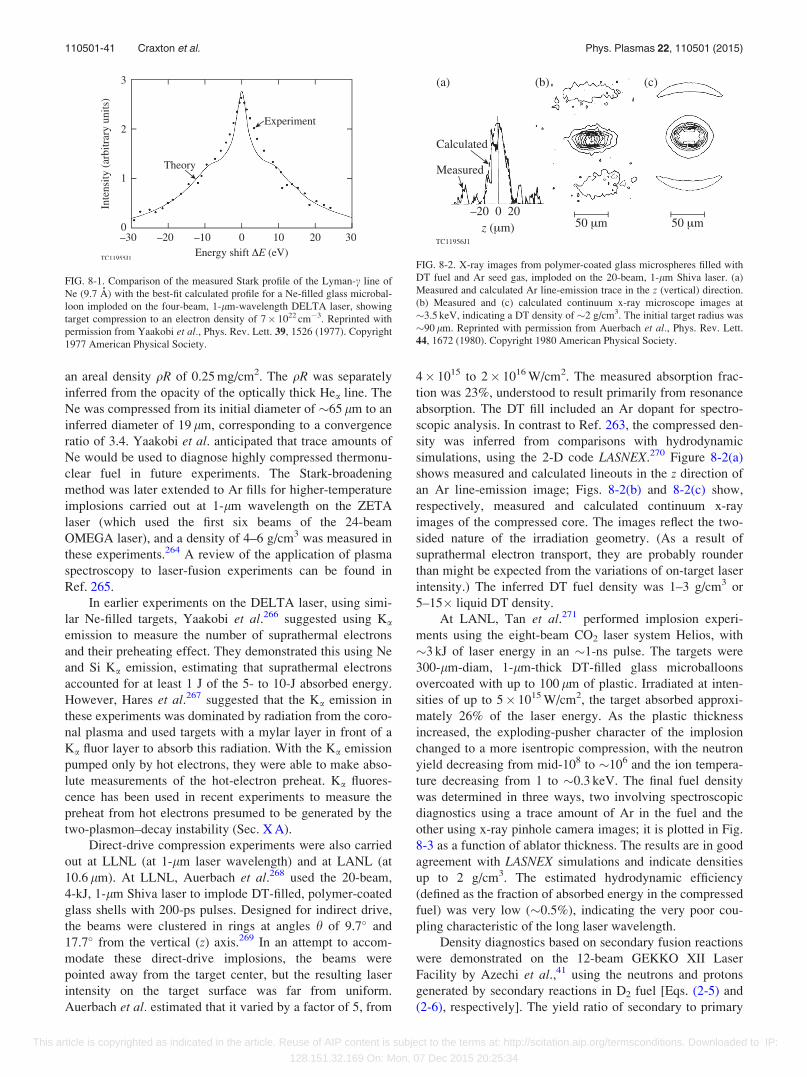
an areal density qR of 0.25 mg/cm2. The qR was separately
inferred from the opacity of the optically thick Hea line. The
Ne was compressed from its initial diameter of �65 lm to an
inferred diameter of 19 lm, corresponding to a convergence
ratio of 3.4. Yaakobi et al. anticipated that trace amounts of
Ne would be used to diagnose highly compressed thermonu-
clear fuel in future experiments. The Stark-broadening
method was later extended to Ar fills for higher-temperature
implosions carried out at 1-lm wavelength on the ZETA
laser (which used the first six beams of the 24-beam
OMEGA laser), and a density of 4–6 g/cm3 was measured in
these experiments.264 A review of the application of plasma
spectroscopy to laser-fusion experiments can be found in
Ref. 265.
In earlier experiments on the DELTA laser, using simi-
lar Ne-filled targets, Yaakobi et al.266 suggested using Ka
emission to measure the number of suprathermal electrons
and their preheating effect. They demonstrated this using Ne
and Si Ka emission, estimating that suprathermal electrons
accounted for at least 1 J of the 5- to 10-J absorbed energy.
However, Hares et al.267 suggested that the Ka emission in
these experiments was dominated by radiation from the coro-
nal plasma and used targets with a mylar layer in front of a
Ka fluor layer to absorb this radiation. With the Ka emission
pumped only by hot electrons, they were able to make abso-
lute measurements of the hot-electron preheat. Ka fluores-
cence has been used in recent experiments to measure the
preheat from hot electrons presumed to be generated by the
two-plasmon–decay instability (Sec. X A).
Direct-drive compression experiments were also carried
out at LLNL (at 1-lm laser wavelength) and at LANL (at
10.6 lm). At LLNL, Auerbach et al.268 used the 20-beam,
4-kJ, 1-lm Shiva laser to implode DT-filled, polymer-coated
glass shells with 200-ps pulses. Designed for indirect drive,
the beams were clustered in rings at angles h of 9.7� and
17.7� from the vertical (z) axis.269 In an attempt to accom-
modate these direct-drive implosions, the beams were
pointed away from the target center, but the resulting laser
intensity on the target surface was far from uniform.
Auerbach et al. estimated that it varied by a factor of 5, from
4� 1015 to 2� 1016 W/cm2. The measured absorption frac-
tion was 23%, understood to result primarily from resonance
absorption. The DT fill included an Ar dopant for spectro-
scopic analysis. In contrast to Ref. 263, the compressed den-
sity was inferred from comparisons with hydrodynamic
simulations, using the 2-D code LASNEX.270 Figure 8-2(a)
shows measured and calculated lineouts in the z direction of
an Ar line-emission image; Figs. 8-2(b) and 8-2(c) show,
respectively, measured and calculated continuum x-ray
images of the compressed core. The images reflect the two-
sided nature of the irradiation geometry. (As a result of
suprathermal electron transport, they are probably rounder
than might be expected from the variations of on-target laser
intensity.) The inferred DT fuel density was 1–3 g/cm3 or
5–15� liquid DT density.
At LANL, Tan et al.271 performed implosion experi-
ments using the eight-beam CO2 laser system Helios, with
�3 kJ of laser energy in an �1-ns pulse. The targets were
300-lm-diam, 1-lm-thick DT-filled glass microballoons
overcoated with up to 100 lm of plastic. Irradiated at inten-
sities of up to 5� 1015 W/cm2, the target absorbed approxi-
mately 26% of the laser energy. As the plastic thickness
increased, the exploding-pusher character of the implosion
changed to a more isentropic compression, with the neutron
yield decreasing from mid-108 to �106 and the ion tempera-
ture decreasing from 1 to �0.3 keV. The final fuel density
was determined in three ways, two involving spectroscopic
diagnostics using a trace amount of Ar in the fuel and the
other using x-ray pinhole camera images; it is plotted in Fig.
8-3 as a function of ablator thickness. The results are in good
agreement with LASNEX simulations and indicate densities
up to 2 g/cm3. The estimated hydrodynamic efficiency
(defined as the fraction of absorbed energy in the compressed
fuel) was very low (�0.5%), indicating the very poor cou-
pling characteristic of the long laser wavelength.
Density diagnostics based on secondary fusion reactions
were demonstrated on the 12-beam GEKKO XII Laser
Facility by Azechi et al.,41 using the neutrons and protons
generated by secondary reactions in D2 fuel [Eqs. (2-5) and
(2-6), respectively]. The yield ratio of secondary to primary
FIG. 8-1. Comparison of the measured Stark profile of the Lyman-c line of
Ne (9.7 A) with the best-fit calculated profile for a Ne-filled glass microbal-
loon imploded on the four-beam, 1-lm-wavelength DELTA laser, showing
target compression to an electron density of 7� 1022 cm�3. Reprinted with
permission from Yaakobi et al., Phys. Rev. Lett. 39, 1526 (1977). Copyright
1977 American Physical Society.
FIG. 8-2. X-ray images from polymer-coated glass microspheres filled with
DT fuel and Ar seed gas, imploded on the 20-beam, 1-lm Shiva laser. (a)
Measured and calculated Ar line-emission trace in the z (vertical) direction.
(b) Measured and (c) calculated continuum x-ray microscope images at
�3.5 keV, indicating a DT density of �2 g/cm3. The initial target radius was
�90 lm. Reprinted with permission from Auerbach et al., Phys. Rev. Lett.
44, 1672 (1980). Copyright 1980 American Physical Society.
110501-41 Craxton et al. Phys. Plasmas 22, 110501 (2015)
This article is copyrighted as indicated in the article. Reuse of AIP content is subject to the terms at: http://scitation.aip.org/termsconditions. Downloaded to IP:
128.151.32.169 On: Mon, 07 Dec 2015 20:25:34
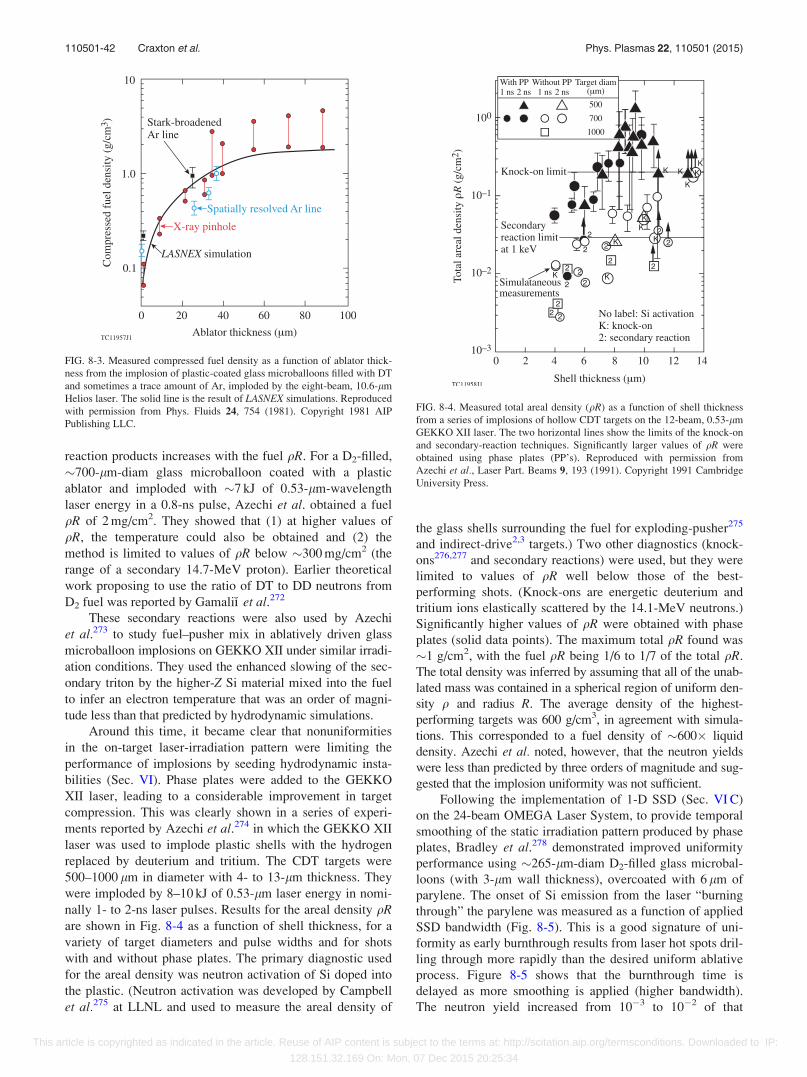
reaction products increases with the fuel qR. For a D2-filled,
�700-lm-diam glass microballoon coated with a plastic
ablator and imploded with �7 kJ of 0.53-lm-wavelength
laser energy in a 0.8-ns pulse, Azechi et al. obtained a fuel
qR of 2 mg/cm2. They showed that (1) at higher values of
qR, the temperature could also be obtained and (2) the
method is limited to values of qR below �300 mg/cm2 (the
range of a secondary 14.7-MeV proton). Earlier theoretical
work proposing to use the ratio of DT to DD neutrons from
D2 fuel was reported by GamaliK% et al.272
These secondary reactions were also used by Azechi
et al.273 to study fuel–pusher mix in ablatively driven glass
microballoon implosions on GEKKO XII under similar irradi-
ation conditions. They used the enhanced slowing of the sec-
ondary triton by the higher-Z Si material mixed into the fuel
to infer an electron temperature that was an order of magni-
tude less than that predicted by hydrodynamic simulations.
Around this time, it became clear that nonuniformities
in the on-target laser-irradiation pattern were limiting the
performance of implosions by seeding hydrodynamic insta-
bilities (Sec. VI). Phase plates were added to the GEKKO
XII laser, leading to a considerable improvement in target
compression. This was clearly shown in a series of experi-
ments reported by Azechi et al.274 in which the GEKKO XII
laser was used to implode plastic shells with the hydrogen
replaced by deuterium and tritium. The CDT targets were
500–1000 lm in diameter with 4- to 13-lm thickness. They
were imploded by 8–10 kJ of 0.53-lm laser energy in nomi-
nally 1- to 2-ns laser pulses. Results for the areal density qRare shown in Fig. 8-4 as a function of shell thickness, for a
variety of target diameters and pulse widths and for shots
with and without phase plates. The primary diagnostic used
for the areal density was neutron activation of Si doped into
the plastic. (Neutron activation was developed by Campbell
et al.275 at LLNL and used to measure the areal density of
the glass shells surrounding the fuel for exploding-pusher275
and indirect-drive2,3 targets.) Two other diagnostics (knock-
ons276,277 and secondary reactions) were used, but they were
limited to values of qR well below those of the best-
performing shots. (Knock-ons are energetic deuterium and
tritium ions elastically scattered by the 14.1-MeV neutrons.)
Significantly higher values of qR were obtained with phase
plates (solid data points). The maximum total qR found was
�1 g/cm2, with the fuel qR being 1/6 to 1/7 of the total qR.
The total density was inferred by assuming that all of the unab-
lated mass was contained in a spherical region of uniform den-
sity q and radius R. The average density of the highest-
performing targets was 600 g/cm3, in agreement with simula-
tions. This corresponded to a fuel density of �600� liquid
density. Azechi et al. noted, however, that the neutron yields
were less than predicted by three orders of magnitude and sug-
gested that the implosion uniformity was not sufficient.
Following the implementation of 1-D SSD (Sec. VI C)
on the 24-beam OMEGA Laser System, to provide temporal
smoothing of the static irradiation pattern produced by phase
plates, Bradley et al.278 demonstrated improved uniformity
performance using �265-lm-diam D2-filled glass microbal-
loons (with 3-lm wall thickness), overcoated with 6 lm of
parylene. The onset of Si emission from the laser “burning
through” the parylene was measured as a function of applied
SSD bandwidth (Fig. 8-5). This is a good signature of uni-
formity as early burnthrough results from laser hot spots dril-
ling through more rapidly than the desired uniform ablative
process. Figure 8-5 shows that the burnthrough time is
delayed as more smoothing is applied (higher bandwidth).
The neutron yield increased from 10�3 to 10�2 of that
FIG. 8-3. Measured compressed fuel density as a function of ablator thick-
ness from the implosion of plastic-coated glass microballoons filled with DT
and sometimes a trace amount of Ar, imploded by the eight-beam, 10.6-lm
Helios laser. The solid line is the result of LASNEX simulations. Reproduced
with permission from Phys. Fluids 24, 754 (1981). Copyright 1981 AIP
Publishing LLC.
FIG. 8-4. Measured total areal density (qR) as a function of shell thickness
from a series of implosions of hollow CDT targets on the 12-beam, 0.53-lm
GEKKO XII laser. The two horizontal lines show the limits of the knock-on
and secondary-reaction techniques. Significantly larger values of qR were
obtained using phase plates (PP’s). Reproduced with permission from
Azechi et al., Laser Part. Beams 9, 193 (1991). Copyright 1991 Cambridge
University Press.
110501-42 Craxton et al. Phys. Plasmas 22, 110501 (2015)
This article is copyrighted as indicated in the article. Reuse of AIP content is subject to the terms at: http://scitation.aip.org/termsconditions. Downloaded to IP:
128.151.32.169 On: Mon, 07 Dec 2015 20:25:34
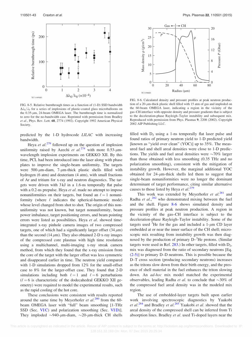
predicted by the 1-D hydrocode LILAC with increasing
bandwidth.
Heya et al.279 followed up on the question of implosion
uniformity raised by Azechi et al.274 with more 0.53-lm-
wavelength implosion experiments on GEKKO XII. By this
time, PCL had been introduced into the laser along with phase
plates to improve the single-beam uniformity. The targets
were 500-lm-diam, 7-lm-thick plastic shells filled with
hydrogen (6 atm) and deuterium (4 atm), with small fractions
of Ar and tritium for x-ray and neutron diagnostics. The tar-
gets were driven with 3 kJ in a 1.6-ns temporally flat pulse
with a 0.2-ns prepulse. Heya et al. made no attempt to impose
nonuniformities on their targets, but found an ‘¼ 1 nonuni-
formity (where ‘ indicates the spherical-harmonic mode)
whose level changed from shot to shot. The origin of this non-
uniformity was not known, but target nonuniformity, beam
power imbalance, target positioning errors, and beam pointing
errors were listed as possibilities. Heya et al. showed time-
integrated x-ray pinhole camera images of two compressed
targets, one of which had a significantly larger offset (34 lm)
than the second (14 lm). They also obtained 2-D x-ray images
of the compressed core plasmas with high time resolution
using a multichannel, multi-imaging x-ray streak camera
method, from which they found that the x-ray emission from
the core of the target with the larger offset was less symmetric
and disappeared earlier in time. The neutron yield compared
with 1-D simulations dropped from 12% for the small-offset
case to 8% for the larger-offset case. They found that 2-D
simulations including both ‘¼ 1 and ‘¼ 6 perturbations
(‘¼ 6 is characteristic of the dodecahedral GEKKO XII ge-
ometry) were required to model the experimental results, such
as the rapid cooling of the hot core.
These conclusions were consistent with results reported
around the same time by Meyerhofer et al.280 from the 60-
beam OMEGA laser with “full” beam smoothing [1-THz
SSD (Sec. VI C) and polarization smoothing (Sec. VI D)].
They imploded �940-lm-diam, �20-lm-thick CH shells
filled with D2 using a 1-ns temporally flat laser pulse and
found ratios of primary neutron yield to 1-D predicted yield
[known as “yield over clean” (YOC)] up to 35%. The meas-
ured fuel and shell areal densities were close to 1-D predic-
tions. The yields and fuel areal densities were �70% larger
than those obtained with less smoothing (0.35 THz and no
polarization smoothing), consistent with the mitigation of
instability growth. However, the marginal additional YOC
obtained for 24-lm-thick shells led them to suggest that
single-beam nonuniformities were no longer the dominant
determinant of target performance, citing similar alternative
causes to those listed by Heya et al.279
This work was extended by Meyerhofer et al.281 and
Radha et al.,282 who demonstrated mixing between the fuel
and the shell. Figure 8-6 shows simulated density and
pressure profiles at peak neutron production. A region in
the vicinity of the gas–CH interface is subject to the
deceleration-phase Rayleigh–Taylor instability. Some of the
targets used 3He for the gas and included a 1-lm CD layer
embedded at or near the inner surface of the CH shell; micro-
scopic mix resulting from instability growth was then diag-
nosed by the production of primary D–3He protons. (Similar
targets were used in Ref. 283.) In other targets, filled with D2,
mix was diagnosed from the ratio of secondary neutrons [Eq.
(2-5)] to primary D–D neutrons. This is possible because the
D–T cross section (producing secondary neutrons) increases
as the tritons slow down from their birth energy, and the pres-
ence of shell material in the fuel enhances the triton slowing
down. An ad-hoc mix model matched the experimental
observables, leading Radha et al. to conclude that �30% of
the compressed fuel areal density was in the modeled mix
region.
The use of embedded-layer targets built upon earlier
work involving spectroscopic diagnostics by Yaakobi
et al.284 and Bradley et al.285 Yaakobi et al. showed that the
areal density of the compressed shell can be inferred from Ti
absorption lines. Bradley et al. used Ti-doped layers near the
FIG. 8-5. Relative burnthrough times as a function of (1-D) SSD bandwidth
Dk0=k0 for a series of implosions of plastic-coated glass microballoons on
the 0.35-lm, 24-beam OMEGA laser. The burnthrough time is normalized
to zero for the no-bandwidth case. Reprinted with permission from Bradley
et al., Phys. Rev. Lett. 68, 2774 (1992). Copyright 1992 American Physical
Society.
FIG. 8-6. Calculated density and pressure profiles at peak neutron produc-
tion of a 20-lm-thick plastic shell filled with 15 atm of gas and imploded on
the 60-beam OMEGA laser, indicating a region in the vicinity of the
gas–CH interface with opposite density and pressure gradients that is subject
to the deceleration-phase Rayleigh–Taylor instability and subsequent mix.
Reproduced with permission from Phys. Plasmas 9, 2208 (2002). Copyright
2002 AIP Publishing LLC.
110501-43 Craxton et al. Phys. Plasmas 22, 110501 (2015)
This article is copyrighted as indicated in the article. Reuse of AIP content is subject to the terms at: http://scitation.aip.org/termsconditions. Downloaded to IP:
128.151.32.169 On: Mon, 07 Dec 2015 20:25:34
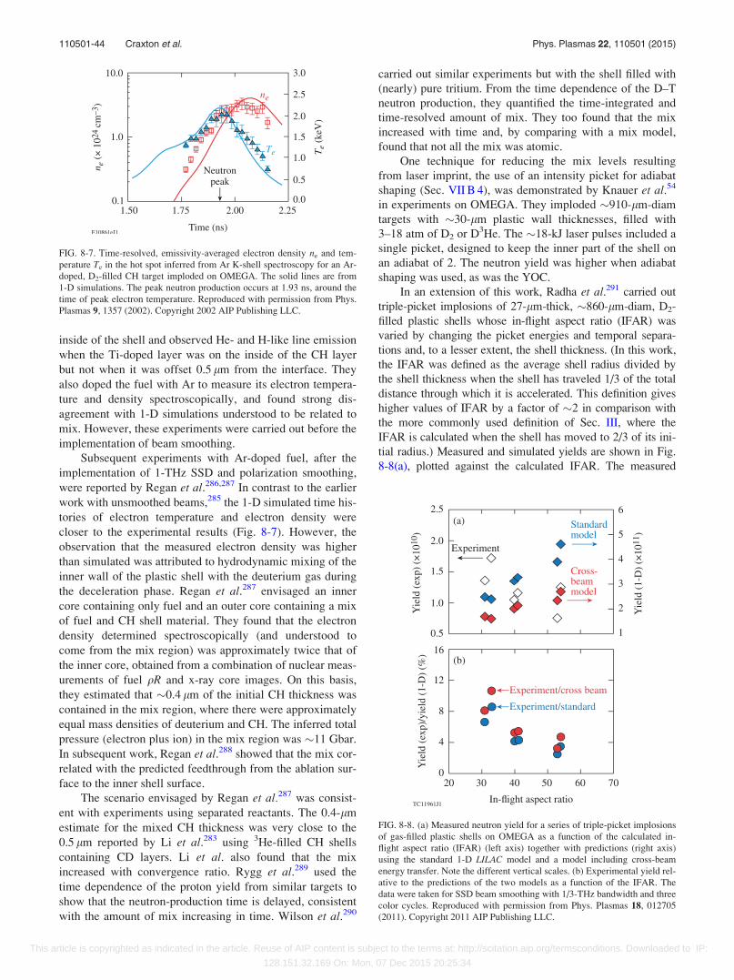
inside of the shell and observed He- and H-like line emission
when the Ti-doped layer was on the inside of the CH layer
but not when it was offset 0.5 lm from the interface. They
also doped the fuel with Ar to measure its electron tempera-
ture and density spectroscopically, and found strong dis-
agreement with 1-D simulations understood to be related to
mix. However, these experiments were carried out before the
implementation of beam smoothing.
Subsequent experiments with Ar-doped fuel, after the
implementation of 1-THz SSD and polarization smoothing,
were reported by Regan et al.286,287 In contrast to the earlier
work with unsmoothed beams,285 the 1-D simulated time his-
tories of electron temperature and electron density were
closer to the experimental results (Fig. 8-7). However, the
observation that the measured electron density was higher
than simulated was attributed to hydrodynamic mixing of the
inner wall of the plastic shell with the deuterium gas during
the deceleration phase. Regan et al.287 envisaged an inner
core containing only fuel and an outer core containing a mix
of fuel and CH shell material. They found that the electron
density determined spectroscopically (and understood to
come from the mix region) was approximately twice that of
the inner core, obtained from a combination of nuclear meas-
urements of fuel qR and x-ray core images. On this basis,
they estimated that �0.4 lm of the initial CH thickness was
contained in the mix region, where there were approximately
equal mass densities of deuterium and CH. The inferred total
pressure (electron plus ion) in the mix region was �11 Gbar.
In subsequent work, Regan et al.288 showed that the mix cor-
related with the predicted feedthrough from the ablation sur-
face to the inner shell surface.
The scenario envisaged by Regan et al.287 was consist-
ent with experiments using separated reactants. The 0.4-lm
estimate for the mixed CH thickness was very close to the
0.5 lm reported by Li et al.283 using 3He-filled CH shells
containing CD layers. Li et al. also found that the mix
increased with convergence ratio. Rygg et al.289 used the
time dependence of the proton yield from similar targets to
show that the neutron-production time is delayed, consistent
with the amount of mix increasing in time. Wilson et al.290
carried out similar experiments but with the shell filled with
(nearly) pure tritium. From the time dependence of the D–T
neutron production, they quantified the time-integrated and
time-resolved amount of mix. They too found that the mix
increased with time and, by comparing with a mix model,
found that not all the mix was atomic.
One technique for reducing the mix levels resulting
from laser imprint, the use of an intensity picket for adiabat
shaping (Sec. VII B 4), was demonstrated by Knauer et al.54
in experiments on OMEGA. They imploded �910-lm-diam
targets with �30-lm plastic wall thicknesses, filled with
3–18 atm of D2 or D3He. The �18-kJ laser pulses included a
single picket, designed to keep the inner part of the shell on
an adiabat of 2. The neutron yield was higher when adiabat
shaping was used, as was the YOC.
In an extension of this work, Radha et al.291 carried out
triple-picket implosions of 27-lm-thick, �860-lm-diam, D2-
filled plastic shells whose in-flight aspect ratio (IFAR) was
varied by changing the picket energies and temporal separa-
tions and, to a lesser extent, the shell thickness. (In this work,
the IFAR was defined as the average shell radius divided by
the shell thickness when the shell has traveled 1/3 of the total
distance through which it is accelerated. This definition gives
higher values of IFAR by a factor of �2 in comparison with
the more commonly used definition of Sec. III, where the
IFAR is calculated when the shell has moved to 2/3 of its ini-
tial radius.) Measured and simulated yields are shown in Fig.
8-8(a), plotted against the calculated IFAR. The measured
FIG. 8-7. Time-resolved, emissivity-averaged electron density ne and tem-
perature Te in the hot spot inferred from Ar K-shell spectroscopy for an Ar-
doped, D2-filled CH target imploded on OMEGA. The solid lines are from
1-D simulations. The peak neutron production occurs at 1.93 ns, around the
time of peak electron temperature. Reproduced with permission from Phys.
Plasmas 9, 1357 (2002). Copyright 2002 AIP Publishing LLC.
FIG. 8-8. (a) Measured neutron yield for a series of triple-picket implosions
of gas-filled plastic shells on OMEGA as a function of the calculated in-
flight aspect ratio (IFAR) (left axis) together with predictions (right axis)
using the standard 1-D LILAC model and a model including cross-beam
energy transfer. Note the different vertical scales. (b) Experimental yield rel-
ative to the predictions of the two models as a function of the IFAR. The
data were taken for SSD beam smoothing with 1/3-THz bandwidth and three
color cycles. Reproduced with permission from Phys. Plasmas 18, 012705
(2011). Copyright 2011 AIP Publishing LLC.
110501-44 Craxton et al. Phys. Plasmas 22, 110501 (2015)
This article is copyrighted as indicated in the article. Reuse of AIP content is subject to the terms at: http://scitation.aip.org/termsconditions. Downloaded to IP:
128.151.32.169 On: Mon, 07 Dec 2015 20:25:34
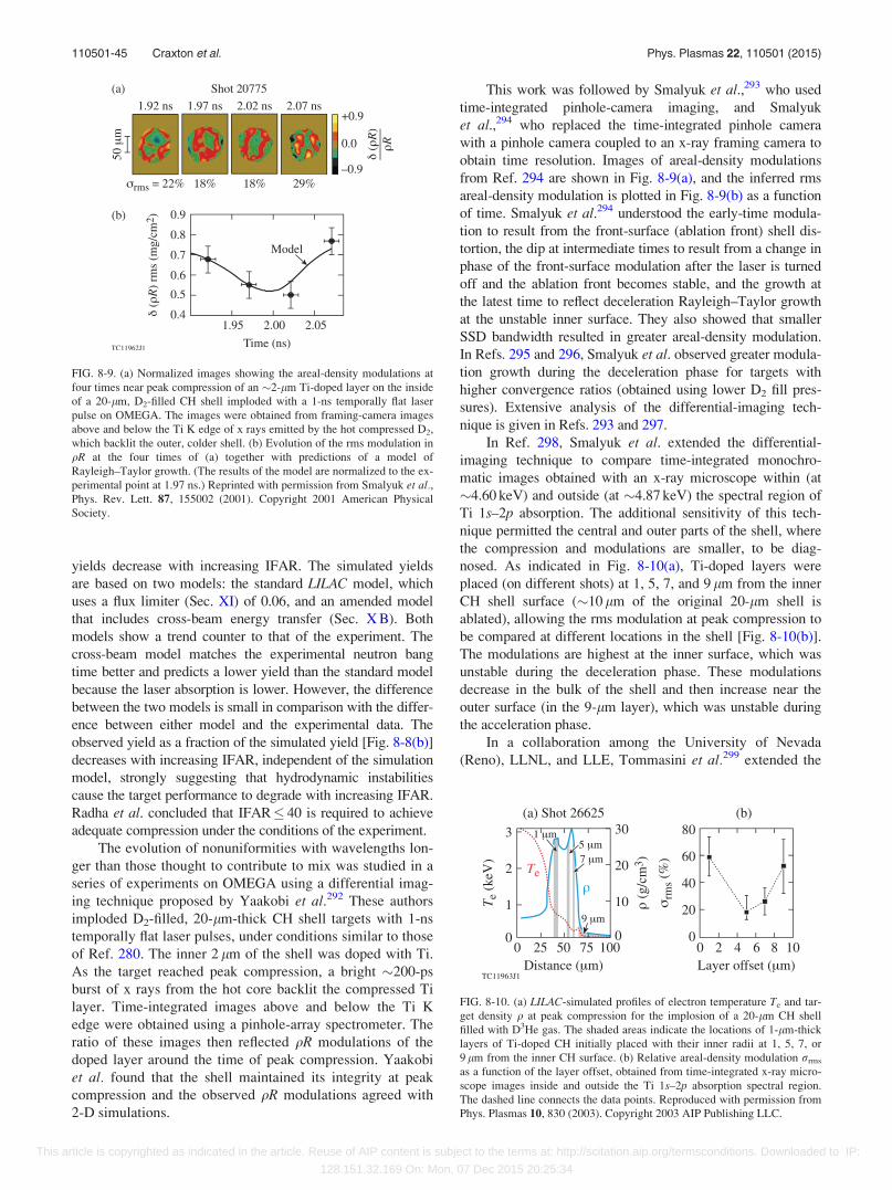
yields decrease with increasing IFAR. The simulated yields
are based on two models: the standard LILAC model, which
uses a flux limiter (Sec. XI) of 0.06, and an amended model
that includes cross-beam energy transfer (Sec. X B). Both
models show a trend counter to that of the experiment. The
cross-beam model matches the experimental neutron bang
time better and predicts a lower yield than the standard model
because the laser absorption is lower. However, the difference
between the two models is small in comparison with the differ-
ence between either model and the experimental data. The
observed yield as a fraction of the simulated yield [Fig. 8-8(b)]
decreases with increasing IFAR, independent of the simulation
model, strongly suggesting that hydrodynamic instabilities
cause the target performance to degrade with increasing IFAR.
Radha et al. concluded that IFAR 40 is required to achieve
adequate compression under the conditions of the experiment.
The evolution of nonuniformities with wavelengths lon-
ger than those thought to contribute to mix was studied in a
series of experiments on OMEGA using a differential imag-
ing technique proposed by Yaakobi et al.292 These authors
imploded D2-filled, 20-lm-thick CH shell targets with 1-ns
temporally flat laser pulses, under conditions similar to those
of Ref. 280. The inner 2 lm of the shell was doped with Ti.
As the target reached peak compression, a bright �200-ps
burst of x rays from the hot core backlit the compressed Ti
layer. Time-integrated images above and below the Ti K
edge were obtained using a pinhole-array spectrometer. The
ratio of these images then reflected qR modulations of the
doped layer around the time of peak compression. Yaakobi
et al. found that the shell maintained its integrity at peak
compression and the observed qR modulations agreed with
2-D simulations.
This work was followed by Smalyuk et al.,293 who used
time-integrated pinhole-camera imaging, and Smalyuk
et al.,294 who replaced the time-integrated pinhole camera
with a pinhole camera coupled to an x-ray framing camera to
obtain time resolution. Images of areal-density modulations
from Ref. 294 are shown in Fig. 8-9(a), and the inferred rms
areal-density modulation is plotted in Fig. 8-9(b) as a function
of time. Smalyuk et al.294 understood the early-time modula-
tion to result from the front-surface (ablation front) shell dis-
tortion, the dip at intermediate times to result from a change in
phase of the front-surface modulation after the laser is turned
off and the ablation front becomes stable, and the growth at
the latest time to reflect deceleration Rayleigh–Taylor growth
at the unstable inner surface. They also showed that smaller
SSD bandwidth resulted in greater areal-density modulation.
In Refs. 295 and 296, Smalyuk et al. observed greater modula-
tion growth during the deceleration phase for targets with
higher convergence ratios (obtained using lower D2 fill pres-
sures). Extensive analysis of the differential-imaging tech-
nique is given in Refs. 293 and 297.
In Ref. 298, Smalyuk et al. extended the differential-
imaging technique to compare time-integrated monochro-
matic images obtained with an x-ray microscope within (at
�4.60 keV) and outside (at �4.87 keV) the spectral region of
Ti 1s–2p absorption. The additional sensitivity of this tech-
nique permitted the central and outer parts of the shell, where
the compression and modulations are smaller, to be diag-
nosed. As indicated in Fig. 8-10(a), Ti-doped layers were
placed (on different shots) at 1, 5, 7, and 9 lm from the inner
CH shell surface (�10 lm of the original 20-lm shell is
ablated), allowing the rms modulation at peak compression to
be compared at different locations in the shell [Fig. 8-10(b)].
The modulations are highest at the inner surface, which was
unstable during the deceleration phase. These modulations
decrease in the bulk of the shell and then increase near the
outer surface (in the 9-lm layer), which was unstable during
the acceleration phase.
In a collaboration among the University of Nevada
(Reno), LLNL, and LLE, Tommasini et al.299 extended the
FIG. 8-9. (a) Normalized images showing the areal-density modulations at
four times near peak compression of an �2-lm Ti-doped layer on the inside
of a 20-lm, D2-filled CH shell imploded with a 1-ns temporally flat laser
pulse on OMEGA. The images were obtained from framing-camera images
above and below the Ti K edge of x rays emitted by the hot compressed D2,
which backlit the outer, colder shell. (b) Evolution of the rms modulation in
qR at the four times of (a) together with predictions of a model of
Rayleigh–Taylor growth. (The results of the model are normalized to the ex-
perimental point at 1.97 ns.) Reprinted with permission from Smalyuk et al.,Phys. Rev. Lett. 87, 155002 (2001). Copyright 2001 American Physical
Society.
FIG. 8-10. (a) LILAC-simulated profiles of electron temperature Te and tar-
get density q at peak compression for the implosion of a 20-lm CH shell
filled with D3He gas. The shaded areas indicate the locations of 1-lm-thick
layers of Ti-doped CH initially placed with their inner radii at 1, 5, 7, or
9 lm from the inner CH surface. (b) Relative areal-density modulation rrms
as a function of the layer offset, obtained from time-integrated x-ray micro-
scope images inside and outside the Ti 1s–2p absorption spectral region.
The dashed line connects the data points. Reproduced with permission from
Phys. Plasmas 10, 830 (2003). Copyright 2003 AIP Publishing LLC.
110501-45 Craxton et al. Phys. Plasmas 22, 110501 (2015)
This article is copyrighted as indicated in the article. Reuse of AIP content is subject to the terms at: http://scitation.aip.org/termsconditions. Downloaded to IP:
128.151.32.169 On: Mon, 07 Dec 2015 20:25:34
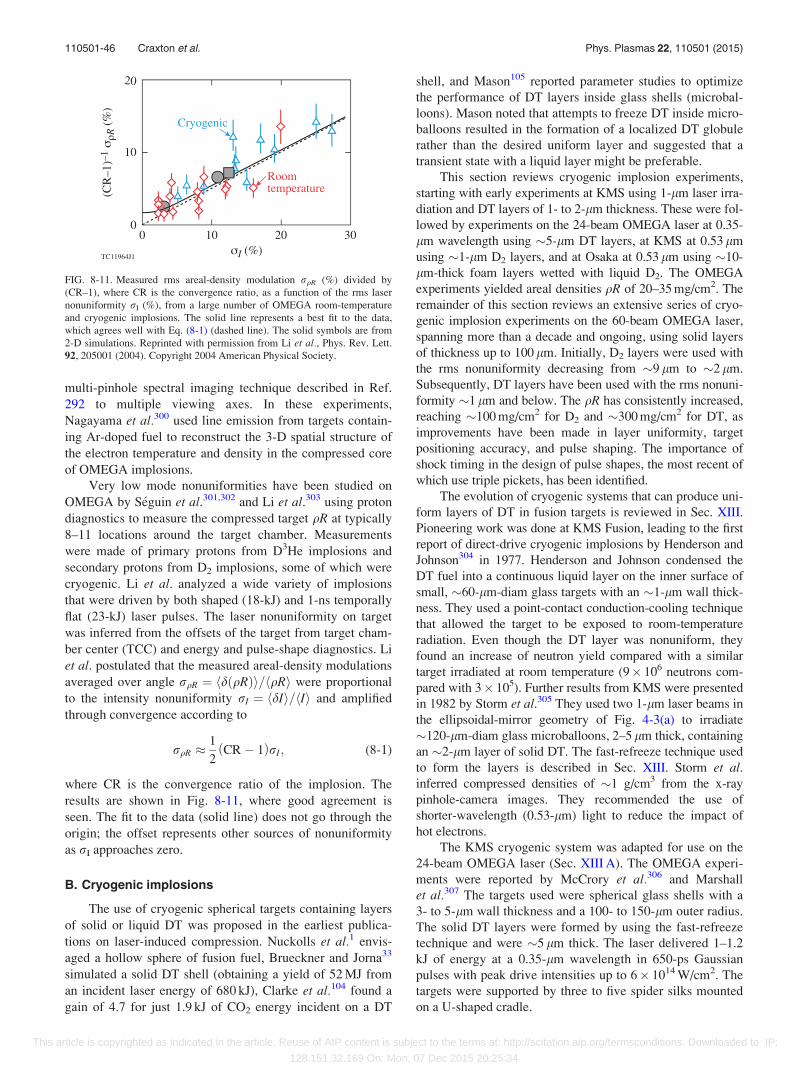
multi-pinhole spectral imaging technique described in Ref.
292 to multiple viewing axes. In these experiments,
Nagayama et al.300 used line emission from targets contain-
ing Ar-doped fuel to reconstruct the 3-D spatial structure of
the electron temperature and density in the compressed core
of OMEGA implosions.
Very low mode nonuniformities have been studied on
OMEGA by S�eguin et al.301,302 and Li et al.303 using proton
diagnostics to measure the compressed target qR at typically
8–11 locations around the target chamber. Measurements
were made of primary protons from D3He implosions and
secondary protons from D2 implosions, some of which were
cryogenic. Li et al. analyzed a wide variety of implosions
that were driven by both shaped (18-kJ) and 1-ns temporally
flat (23-kJ) laser pulses. The laser nonuniformity on target
was inferred from the offsets of the target from target cham-
ber center (TCC) and energy and pulse-shape diagnostics. Li
et al. postulated that the measured areal-density modulations
averaged over angle rqR ¼ hdðqRÞi=hqRi were proportional
to the intensity nonuniformity rI ¼ hdIi=hIi and amplified
through convergence according to
rqR �1
2CR� 1ð ÞrI; (8-1)
where CR is the convergence ratio of the implosion. The
results are shown in Fig. 8-11, where good agreement is
seen. The fit to the data (solid line) does not go through the
origin; the offset represents other sources of nonuniformity
as rI approaches zero.
B. Cryogenic implosions
The use of cryogenic spherical targets containing layers
of solid or liquid DT was proposed in the earliest publica-
tions on laser-induced compression. Nuckolls et al.1 envis-
aged a hollow sphere of fusion fuel, Brueckner and Jorna33
simulated a solid DT shell (obtaining a yield of 52 MJ from
an incident laser energy of 680 kJ), Clarke et al.104 found a
gain of 4.7 for just 1.9 kJ of CO2 energy incident on a DT
shell, and Mason105 reported parameter studies to optimize
the performance of DT layers inside glass shells (microbal-
loons). Mason noted that attempts to freeze DT inside micro-
balloons resulted in the formation of a localized DT globule
rather than the desired uniform layer and suggested that a
transient state with a liquid layer might be preferable.
This section reviews cryogenic implosion experiments,
starting with early experiments at KMS using 1-lm laser irra-
diation and DT layers of 1- to 2-lm thickness. These were fol-
lowed by experiments on the 24-beam OMEGA laser at 0.35-
lm wavelength using �5-lm DT layers, at KMS at 0.53 lm
using �1-lm D2 layers, and at Osaka at 0.53 lm using �10-
lm-thick foam layers wetted with liquid D2. The OMEGA
experiments yielded areal densities qR of 20–35 mg/cm2. The
remainder of this section reviews an extensive series of cryo-
genic implosion experiments on the 60-beam OMEGA laser,
spanning more than a decade and ongoing, using solid layers
of thickness up to 100 lm. Initially, D2 layers were used with
the rms nonuniformity decreasing from �9 lm to �2 lm.
Subsequently, DT layers have been used with the rms nonuni-
formity �1 lm and below. The qR has consistently increased,
reaching �100 mg/cm2 for D2 and �300 mg/cm2 for DT, as
improvements have been made in layer uniformity, target
positioning accuracy, and pulse shaping. The importance of
shock timing in the design of pulse shapes, the most recent of
which use triple pickets, has been identified.
The evolution of cryogenic systems that can produce uni-
form layers of DT in fusion targets is reviewed in Sec. XIII.
Pioneering work was done at KMS Fusion, leading to the first
report of direct-drive cryogenic implosions by Henderson and
Johnson304 in 1977. Henderson and Johnson condensed the
DT fuel into a continuous liquid layer on the inner surface of
small, �60-lm-diam glass targets with an �1-lm wall thick-
ness. They used a point-contact conduction-cooling technique
that allowed the target to be exposed to room-temperature
radiation. Even though the DT layer was nonuniform, they
found an increase of neutron yield compared with a similar
target irradiated at room temperature (9� 106 neutrons com-
pared with 3� 105). Further results from KMS were presented
in 1982 by Storm et al.305 They used two 1-lm laser beams in
the ellipsoidal-mirror geometry of Fig. 4-3(a) to irradiate
�120-lm-diam glass microballoons, 2–5 lm thick, containing
an �2-lm layer of solid DT. The fast-refreeze technique used
to form the layers is described in Sec. XIII. Storm et al.inferred compressed densities of �1 g/cm3 from the x-ray
pinhole-camera images. They recommended the use of
shorter-wavelength (0.53-lm) light to reduce the impact of
hot electrons.
The KMS cryogenic system was adapted for use on the
24-beam OMEGA laser (Sec. XIII A). The OMEGA experi-
ments were reported by McCrory et al.306 and Marshall
et al.307 The targets used were spherical glass shells with a
3- to 5-lm wall thickness and a 100- to 150-lm outer radius.
The solid DT layers were formed by using the fast-refreeze
technique and were �5 lm thick. The laser delivered 1–1.2
kJ of energy at a 0.35-lm wavelength in 650-ps Gaussian
pulses with peak drive intensities up to 6� 1014 W/cm2. The
targets were supported by three to five spider silks mounted
on a U-shaped cradle.
FIG. 8-11. Measured rms areal-density modulation rqR (%) divided by
(CR–1), where CR is the convergence ratio, as a function of the rms laser
nonuniformity rI (%), from a large number of OMEGA room-temperature
and cryogenic implosions. The solid line represents a best fit to the data,
which agrees well with Eq. (8-1) (dashed line). The solid symbols are from
2-D simulations. Reprinted with permission from Li et al., Phys. Rev. Lett.
92, 205001 (2004). Copyright 2004 American Physical Society.
110501-46 Craxton et al. Phys. Plasmas 22, 110501 (2015)
This article is copyrighted as indicated in the article. Reuse of AIP content is subject to the terms at: http://scitation.aip.org/termsconditions. Downloaded to IP:
128.151.32.169 On: Mon, 07 Dec 2015 20:25:34
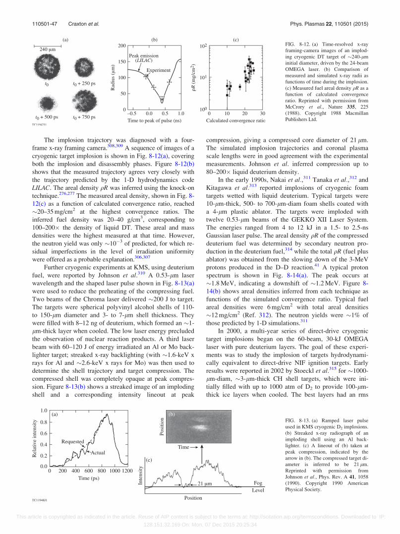
The implosion trajectory was diagnosed with a four-
frame x-ray framing camera.308,309 A sequence of images of a
cryogenic target implosion is shown in Fig. 8-12(a), covering
both the implosion and disassembly phases. Figure 8-12(b)
shows that the measured trajectory agrees very closely with
the trajectory predicted by the 1-D hydrodynamics code
LILAC. The areal density qR was inferred using the knock-on
technique.276,277 The measured areal density, shown in Fig. 8-
12(c) as a function of calculated convergence ratio, reached
�20–35 mg/cm2 at the highest convergence ratios. The
inferred fuel density was 20–40 g/cm3, corresponding to
100–200� the density of liquid DT. These areal and mass
densities were the highest measured at that time. However,
the neutron yield was only �10�3 of predicted, for which re-
sidual imperfections in the level of irradiation uniformity
were offered as a probable explanation.306,307
Further cryogenic experiments at KMS, using deuterium
fuel, were reported by Johnson et al.310 A 0.53-lm laser
wavelength and the shaped laser pulse shown in Fig. 8-13(a)
were used to reduce the preheating of the compressing fuel.
Two beams of the Chroma laser delivered �200 J to target.
The targets were spherical polyvinyl alcohol shells of 110-
to 150-lm diameter and 3- to 7-lm shell thickness. They
were filled with 8–12 ng of deuterium, which formed an �1-
lm-thick layer when cooled. The low laser energy precluded
the observation of nuclear reaction products. A third laser
beam with 60–120 J of energy irradiated an Al or Mo back-
lighter target; streaked x-ray backlighting (with �1.6-keV x
rays for Al and �2.6-keV x rays for Mo) was then used to
determine the shell trajectory and target compression. The
compressed shell was completely opaque at peak compres-
sion. Figure 8-13(b) shows a streaked image of an imploding
shell and a corresponding intensity lineout at peak
compression, giving a compressed core diameter of 21 lm.
The simulated implosion trajectories and coronal plasma
scale lengths were in good agreement with the experimental
measurements. Johnson et al. inferred compression up to
80–200� liquid deuterium density.
In the early 1990s, Nakai et al.,311 Tanaka et al.,312 and
Kitagawa et al.313 reported implosions of cryogenic foam
targets wetted with liquid deuterium. Typical targets were
10-lm-thick, 500- to 700-lm-diam foam shells coated with
a 4-lm plastic ablator. The targets were imploded with
twelve 0.53-lm beams of the GEKKO XII Laser System.
The energies ranged from 4 to 12 kJ in a 1.5- to 2.5-ns
Gaussian laser pulse. The areal density qR of the compressed
deuterium fuel was determined by secondary neutron pro-
duction in the deuterium fuel,314 while the total qR (fuel plus
ablator) was obtained from the slowing down of the 3-MeV
protons produced in the D–D reaction.41 A typical proton
spectrum is shown in Fig. 8-14(a). The peak occurs at
�1.8 MeV, indicating a downshift of �1.2 MeV. Figure 8-
14(b) shows areal densities inferred from each technique as
functions of the simulated convergence ratio. Typical fuel
areal densities were 6 mg/cm2 with total areal densities
�12 mg/cm2 (Ref. 312). The neutron yields were �1% of
those predicted by 1-D simulations.311
In 2000, a multi-year series of direct-drive cryogenic
target implosions began on the 60-beam, 30-kJ OMEGA
laser with pure deuterium layers. The goal of these experi-
ments was to study the implosion of targets hydrodynami-
cally equivalent to direct-drive NIF ignition targets. Early
results were reported in 2002 by Stoeckl et al.315 for �1000-
lm-diam, �3-lm-thick CH shell targets, which were ini-
tially filled with up to 1000 atm of D2 to provide 100-lm-
thick ice layers when cooled. The best layers had an rms
FIG. 8-12. (a) Time-resolved x-ray
framing-camera images of an implod-
ing cryogenic DT target of �240-lm
initial diameter, driven by the 24-beam
OMEGA laser. (b) Comparison of
measured and simulated x-ray radii as
functions of time during the implosion.
(c) Measured fuel areal density qR as a
function of calculated convergence
ratio. Reprinted with permission from
McCrory et al., Nature 335, 225
(1988). Copyright 1988 Macmillan
Publishers Ltd.
FIG. 8-13. (a) Ramped laser pulse
used in KMS cryogenic D2 implosions.
(b) Streaked x-ray radiograph of an
imploding shell using an Al back-
lighter. (c) A lineout of (b) taken at
peak compression, indicated by the
arrow in (b). The compressed target di-
ameter is inferred to be 21 lm.
Reprinted with permission from
Johnson et al., Phys. Rev. A 41, 1058
(1990). Copyright 1990 American
Physical Society.
110501-47 Craxton et al. Phys. Plasmas 22, 110501 (2015)
This article is copyrighted as indicated in the article. Reuse of AIP content is subject to the terms at: http://scitation.aip.org/termsconditions. Downloaded to IP:
128.151.32.169 On: Mon, 07 Dec 2015 20:25:34
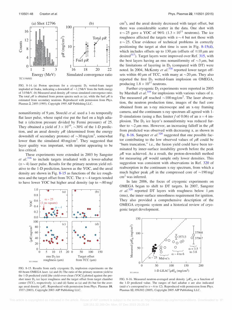
nonuniformity of 9 lm. Stoeckl et al. used a 1-ns temporally
flat laser pulse, whose rapid rise put the fuel on a high adia-
bat a (electron pressure divided by Fermi pressure) of 25.
They obtained a yield of 3� 1010, �30% of the 1-D predic-
tion, and an areal density qR (determined from the energy
downshift of secondary protons) of �30 mg/cm2, somewhat
lower than the simulated 40 mg/cm2. They suggested that
layer quality was important, with imprint appearing to be
less critical.
These experiments were extended in 2003 by Sangster
et al.316 to include targets irradiated with a lower-adiabat
(a� 4) laser pulse. Results for the primary neutron yield rel-
ative to the 1-D prediction, known as the YOC, and the areal
density are shown in Fig. 8-15 as functions of the ice rough-
ness and the target offset from TCC. The a� 4 targets tended
to have lower YOC but higher areal density (up to �80 mg/
cm2), and the areal density decreased with target offset, but
there was considerable scatter in the data. One shot with
a� 25 gave a YOC of 96% (1.3� 1011 neutrons). The ice
roughness affected the targets with a� 4 but not those with
a� 25. Clear evidence of technical problems in correctly
positioning the target at shot time is seen in Fig. 8-15(d),
which includes offsets up to 130 lm (offsets of �10 lm are
desired317). Target layers were improved over Ref. 315, with
the best layers having an rms nonuniformity of �3 lm, but
the limitations of layering in D2 (compared with DT) were
noted. In 2004, McKenty et al.318 reported lower target off-
sets within 40 lm of TCC, with many at �20 lm. They also
reported the first D2 wetted-foam implosion on OMEGA,
producing 1.8� 1011 neutrons.
Further cryogenic D2 experiments were reported in 2005
by Marshall et al.319 for implosions with various values of a.
The measured qR reached �100 mg/cm2. The laser absorp-
tion, the neutron production time, images of the fuel core
obtained from an x-ray microscope and an x-ray framing
camera, and the continuum x-ray spectrum all agreed with 1-
D simulations (using a flux limiter f of 0.06) of an a¼ 4 im-
plosion. The D2 ice layer’s nonuniformity was reduced fur-
ther to �2 lm rms. However, an increasing falloff in the qRfrom predicted was observed with decreasing a, as shown in
Fig. 8-16. Sangster et al.320 suggested that one possible fac-
tor contributing to the low observed values of qR could be
“burn truncation,” i.e., the fusion yield could have been ter-
minated by inner-surface instability growth before the peak
qR was achieved. As a result, the proton-downshift method
for measuring qR would sample only lower densities. This
suggestion was consistent with observations in Ref. 320 of
reabsorption in the continuum x-ray spectrum, from which a
much higher peak qR in the compressed core of �190 mg/
cm2 was inferred.
In late 2006, the focus of cryogenic experiments on
OMEGA began to shift to DT targets. In 2007, Sangster
et al.320 reported DT layers with roughness below 1 lm
(rms), the inner-surface smoothness requirement for ignition.
They also provided a comprehensive description of the
OMEGA cryogenic system and a historical review of cryo-
genic target development.
FIG. 8-14. (a) Proton spectrum for a cryogenic D2 wetted-foam target
imploded at Osaka, indicating a downshift of �1.2 MeV from the birth energy
of 3.0 MeV. (b) Measured areal density qR versus simulated convergence ratio.
The total qR is obtained from proton spectra such as (a), while the fuel qR is
estimated from secondary neutrons. Reproduced with permission from Phys.
Plasmas 2, 2495 (1995). Copyright 1995 AIP Publishing LLC.
FIG. 8-15. Results from early cryogenic D2 implosion experiments on the
60-beam OMEGA laser. (a) and (b) The ratio of the primary neutron yield to
the 1-D predicted yield [the yield-over-clean (YOC)] plotted against the pre-
shot inner D2 ice layer roughness and the target offset from target chamber
center (TCC), respectively. (c) and (d) Same as (a) and (b) but for the aver-
age areal density hqRi. Reproduced with permission from Phys. Plasmas 10,
1937 (2003). Copyright 2003 AIP Publishing LLC.
FIG. 8-16. Measured neutron-averaged areal density hqRin as a function of
the 1-D predicted value. The ranges of fuel adiabat a are also indicated
(mid-a’s correspond to a� 6 to 12). Reproduced with permission from Phys.
Plasmas 12, 056302 (2005). Copyright 2005 AIP Publishing LLC.
110501-48 Craxton et al. Phys. Plasmas 22, 110501 (2015)
This article is copyrighted as indicated in the article. Reuse of AIP content is subject to the terms at: http://scitation.aip.org/termsconditions. Downloaded to IP:
128.151.32.169 On: Mon, 07 Dec 2015 20:25:34
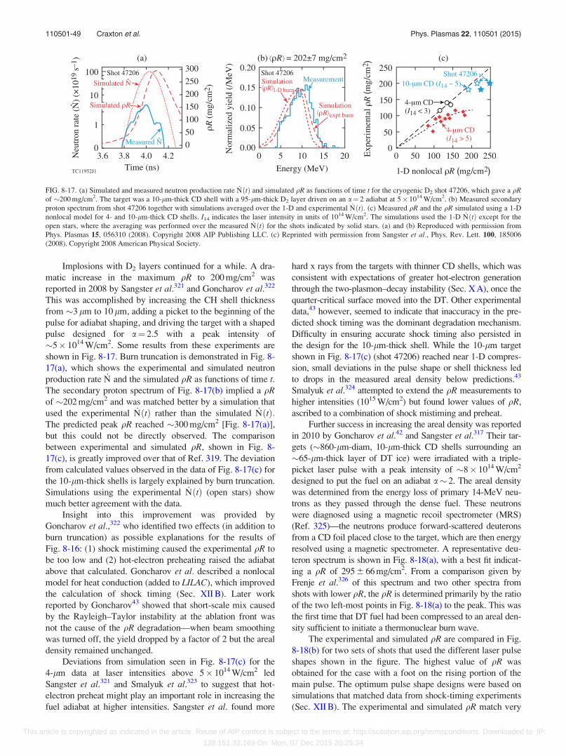
Implosions with D2 layers continued for a while. A dra-
matic increase in the maximum qR to 200 mg/cm2 was
reported in 2008 by Sangster et al.321 and Goncharov et al.322
This was accomplished by increasing the CH shell thickness
from �3 lm to 10 lm, adding a picket to the beginning of the
pulse for adiabat shaping, and driving the target with a shaped
pulse designed for a¼ 2.5 with a peak intensity of
�5� 1014 W/cm2. Some results from these experiments are
shown in Fig. 8-17. Burn truncation is demonstrated in Fig. 8-
17(a), which shows the experimental and simulated neutron
production rate _N and the simulated qR as functions of time t.The secondary proton spectrum of Fig. 8-17(b) implied a qRof �202 mg/cm2 and was matched better by a simulation that
used the experimental _NðtÞ rather than the simulated _NðtÞ:The predicted peak qR reached �300 mg/cm2 [Fig. 8-17(a)],
but this could not be directly observed. The comparison
between experimental and simulated qR, shown in Fig. 8-
17(c), is greatly improved over that of Ref. 319. The deviation
from calculated values observed in the data of Fig. 8-17(c) for
the 10-lm-thick shells is largely explained by burn truncation.
Simulations using the experimental _NðtÞ (open stars) show
much better agreement with the data.
Insight into this improvement was provided by
Goncharov et al.,322 who identified two effects (in addition to
burn truncation) as possible explanations for the results of
Fig. 8-16: (1) shock mistiming caused the experimental qR to
be too low and (2) hot-electron preheating raised the adiabat
above that calculated. Goncharov et al. described a nonlocal
model for heat conduction (added to LILAC), which improved
the calculation of shock timing (Sec. XII B). Later work
reported by Goncharov43 showed that short-scale mix caused
by the Rayleigh–Taylor instability at the ablation front was
not the cause of the qR degradation—when beam smoothing
was turned off, the yield dropped by a factor of 2 but the areal
density remained unchanged.
Deviations from simulation seen in Fig. 8-17(c) for the
4-lm data at laser intensities above 5� 1014 W/cm2 led
Sangster et al.321 and Smalyuk et al.323 to suggest that hot-
electron preheat might play an important role in increasing the
fuel adiabat at higher intensities. Sangster et al. found more
hard x rays from the targets with thinner CD shells, which was
consistent with expectations of greater hot-electron generation
through the two-plasmon–decay instability (Sec. X A), once the
quarter-critical surface moved into the DT. Other experimental
data,43 however, seemed to indicate that inaccuracy in the pre-
dicted shock timing was the dominant degradation mechanism.
Difficulty in ensuring accurate shock timing also persisted in
the design for the 10-lm-thick shell. While the 10-lm target
shown in Fig. 8-17(c) (shot 47206) reached near 1-D compres-
sion, small deviations in the pulse shape or shell thickness led
to drops in the measured areal density below predictions.43
Smalyuk et al.324 attempted to extend the qR measurements to
higher intensities (1015 W/cm2) but found lower values of qR,
ascribed to a combination of shock mistiming and preheat.
Further success in increasing the areal density was reported
in 2010 by Goncharov et al.42 and Sangster et al.317 Their tar-
gets (�860-lm-diam, 10-lm-thick CD shells surrounding an
�65-lm-thick layer of DT ice) were irradiated with a triple-
picket laser pulse with a peak intensity of �8� 1014 W/cm2
designed to put the fuel on an adiabat a� 2. The areal density
was determined from the energy loss of primary 14-MeV neu-
trons as they passed through the dense fuel. These neutrons
were diagnosed using a magnetic recoil spectrometer (MRS)
(Ref. 325)—the neutrons produce forward-scattered deuterons
from a CD foil placed close to the target, which are then energy
resolved using a magnetic spectrometer. A representative deu-
teron spectrum is shown in Fig. 8-18(a), with a best fit indicat-
ing a qR of 295 6 66 mg/cm2. From a comparison given by
Frenje et al.326 of this spectrum and two other spectra from
shots with lower qR, the qR is determined primarily by the ratio
of the two left-most points in Fig. 8-18(a) to the peak. This was
the first time that DT fuel had been compressed to an areal den-
sity sufficient to initiate a thermonuclear burn wave.
The experimental and simulated qR are compared in Fig.
8-18(b) for two sets of shots that used the different laser pulse
shapes shown in the figure. The highest value of qR was
obtained for the case with a foot on the rising portion of the
main pulse. The optimum pulse shape designs were based on
simulations that matched data from shock-timing experiments
(Sec. XII B). The experimental and simulated qR match very
FIG. 8-17. (a) Simulated and measured neutron production rate _NðtÞ and simulated qR as functions of time t for the cryogenic D2 shot 47206, which gave a qRof �200 mg/cm2. The target was a 10-lm-thick CD shell with a 95-lm-thick D2 layer driven on an a¼ 2 adiabat at 5� 1014 W/cm2. (b) Measured secondary
proton spectrum from shot 47206 together with simulations averaged over the 1-D and experimental _NðtÞ: (c) Measured qR and the qR simulated using a 1-D
nonlocal model for 4- and 10-lm-thick CD shells. I14 indicates the laser intensity in units of 1014 W/cm2. The simulations used the 1-D _NðtÞ except for the
open stars, where the averaging was performed over the measured _NðtÞ for the shots indicated by solid stars. (a) and (b) Reproduced with permission from
Phys. Plasmas 15, 056310 (2008). Copyright 2008 AIP Publishing LLC. (c) Reprinted with permission from Sangster et al., Phys. Rev. Lett. 100, 185006
(2008). Copyright 2008 American Physical Society.
110501-49 Craxton et al. Phys. Plasmas 22, 110501 (2015)
This article is copyrighted as indicated in the article. Reuse of AIP content is subject to the terms at: http://scitation.aip.org/termsconditions. Downloaded to IP:
128.151.32.169 On: Mon, 07 Dec 2015 20:25:34
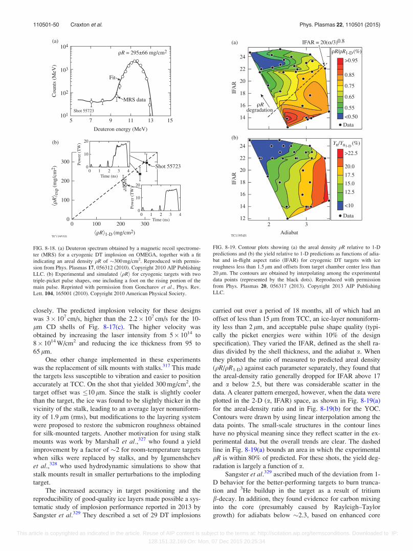
closely. The predicted implosion velocity for these designs
was 3� 107 cm/s, higher than the 2.2� 107 cm/s for the 10-
lm CD shells of Fig. 8-17(c). The higher velocity was
obtained by increasing the laser intensity from 5� 1014 to
8� 1014 W/cm2 and reducing the ice thickness from 95 to
65 lm.
One other change implemented in these experiments
was the replacement of silk mounts with stalks.317 This made
the targets less susceptible to vibration and easier to position
accurately at TCC. On the shot that yielded 300 mg/cm2, the
target offset was 10 lm. Since the stalk is slightly cooler
than the target, the ice was found to be slightly thicker in the
vicinity of the stalk, leading to an average layer nonuniform-
ity of 1.9 lm (rms), but modifications to the layering system
were proposed to restore the submicron roughness obtained
for silk-mounted targets. Another motivation for using stalk
mounts was work by Marshall et al.,327 who found a yield
improvement by a factor of �2 for room-temperature targets
when silks were replaced by stalks, and by Igumenshchev
et al.,328 who used hydrodynamic simulations to show that
stalk mounts result in smaller perturbations to the imploding
target.
The increased accuracy in target positioning and the
reproducibility of good-quality ice layers made possible a sys-
tematic study of implosion performance reported in 2013 by
Sangster et al.329 They described a set of 29 DT implosions
carried out over a period of 18 months, all of which had an
offset of less than 15 lm from TCC, an ice-layer nonuniform-
ity less than 2 lm, and acceptable pulse shape quality (typi-
cally the picket energies were within 10% of the design
specification). They varied the IFAR, defined as the shell ra-
dius divided by the shell thickness, and the adiabat a. When
they plotted the ratio of measured to predicted areal density
(qR/qR1-D) against each parameter separately, they found that
the areal-density ratio generally dropped for IFAR above 17
and a below 2.5, but there was considerable scatter in the
data. A clearer pattern emerged, however, when the data were
plotted in the 2-D (a, IFAR) space, as shown in Fig. 8-19(a)
for the areal-density ratio and in Fig. 8-19(b) for the YOC.
Contours were drawn by using linear interpolation among the
data points. The small-scale structures in the contour lines
have no physical meaning since they reflect scatter in the ex-
perimental data, but the overall trends are clear. The dashed
line in Fig. 8-19(a) bounds an area in which the experimental
qR is within 80% of predicted. For these shots, the yield deg-
radation is largely a function of a.
Sangster et al.329 ascribed much of the deviation from 1-
D behavior for the better-performing targets to burn trunca-
tion and 3He buildup in the target as a result of tritium
b-decay. In addition, they found evidence for carbon mixing
into the core (presumably caused by Rayleigh–Taylor
growth) for adiabats below �2.3, based on enhanced core
FIG. 8-18. (a) Deuteron spectrum obtained by a magnetic recoil spectrome-
ter (MRS) for a cryogenic DT implosion on OMEGA, together with a fit
indicating an areal density qR of �300 mg/cm2. Reproduced with permis-
sion from Phys. Plasmas 17, 056312 (2010). Copyright 2010 AIP Publishing
LLC. (b) Experimental and simulated hqRi for cryogenic targets with two
triple-picket pulse shapes, one including a foot on the rising portion of the
main pulse. Reprinted with permission from Goncharov et al., Phys. Rev.
Lett. 104, 165001 (2010). Copyright 2010 American Physical Society.
FIG. 8-19. Contour plots showing (a) the areal density qR relative to 1-D
predictions and (b) the yield relative to 1-D predictions as functions of adia-
bat and in-flight aspect ratio (IFAR) for cryogenic DT targets with ice
roughness less than 1.5 lm and offsets from target chamber center less than
20 lm. The contours are obtained by interpolating among the experimental
data points (represented by the black dots). Reproduced with permission
from Phys. Plasmas 20, 056317 (2013). Copyright 2013 AIP Publishing
LLC.
110501-50 Craxton et al. Phys. Plasmas 22, 110501 (2015)
This article is copyrighted as indicated in the article. Reuse of AIP content is subject to the terms at: http://scitation.aip.org/termsconditions. Downloaded to IP:
128.151.32.169 On: Mon, 07 Dec 2015 20:25:34
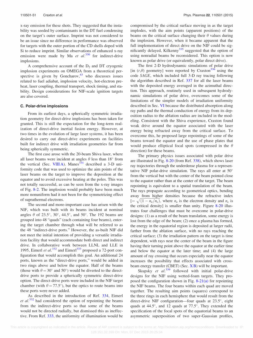
x-ray emission for these shots. They suggested that the insta-
bility was seeded by contaminants in the DT fuel condensing
on the target’s outer surface. Imprint was not considered to
be an issue since no difference in performance was observed
for targets with the outer portion of the CD shells doped with
Si to reduce imprint. Similar observations of enhanced x-ray
emission were made by Ma et al.330 for indirect-drive
implosions.
A comprehensive account of the D2 and DT cryogenic
implosion experiments on OMEGA from a theoretical per-
spective is given by Goncharov,43 who discusses issues
related to fuel adiabat, implosion velocity, hot-electron pre-
heat, laser coupling, thermal transport, shock timing, and sta-
bility. Design considerations for NIF-scale ignition targets
are also covered.
C. Polar-drive implosions
From its earliest days, a spherically symmetric irradia-
tion geometry for direct-drive implosions has been taken for
granted. This is still the expectation for the long-term real-
ization of direct-drive inertial fusion energy. However, at
two times in the evolution of large laser systems, it has been
desired to carry out direct-drive experiments on facilities
built for indirect drive with irradiation geometries far from
being spherically symmetric.
The first case arose with the 20-beam Shiva laser, where
all laser beams were incident at angles h less than 18� from
the vertical (Sec. VIII A). Manes331 described a 3-D uni-
formity code that was used to optimize the aim points of the
laser beams on the target to improve the deposition at the
equator and to avoid excessive heating at the poles. This was
not totally successful, as can be seen from the x-ray images
of Fig. 8-2. The implosion would probably have been much
more nonuniform had it not been for the symmetrizing effect
of suprathermal electrons.
The second and more-important case has arisen with the
NIF, which was built with its beams incident at nominal
angles h of 23.5�, 30�, 44.5�, and 50�. The 192 beams are
grouped into 48 “quads” (each containing four beams), enter-
ing the target chamber through what will be referred to as
the 48 “indirect-drive ports.” However, the as-built NIF did
not meet the initial intention of providing a versatile irradia-
tion facility that would accommodate both direct and indirect
drive. In collaborative work between LLNL and LLE in
1995, Eimerl et al.332 and Eimerl333 proposed a 72-port con-
figuration that would accomplish this goal. An additional 24
ports, known as the “direct-drive ports,” would be added in
two rings above and below the equator. Half of the beams
(those with h¼ 30� and 50�) would be diverted to the direct-
drive ports to provide a spherically symmetric direct-drive
option. The direct-drive ports were included in the NIF target
chamber (with h¼ 77.5�), but the optics to route beams into
these ports were never added.
As described in the introduction of Ref. 334, Eimerl
et al.332 had considered the option of repointing the beams
from the indirect-drive ports so that some of the beams
would not be directed radially, but dismissed this as ineffec-
tive. From Ref. 333, the uniformity of illumination would be
compromised by the critical surface moving in as the target
implodes, with the aim points (apparent positions) of the
beams on the critical surface changing their h values during
the implosion. However, when it became apparent that the
full implementation of direct drive on the NIF could be sig-
nificantly delayed, Kilkenny335 suggested that the option of
using nonradial beams be reconsidered. This option is now
known as polar drive (or equivalently, polar direct drive).
The first 2-D hydrodynamic simulations of polar drive
[in (r,h) geometry] were reported by Craxton336 using the
code SAGE, which included full 3-D ray tracing following
the algorithm described in Ref. 337 for all the laser beams
with the deposited energy averaged in the azimuthal direc-
tion. This approach, routinely used in subsequent hydrody-
namic simulations of polar drive, overcomes some of the
limitations of the simpler models of irradiation uniformity
described in Sec. VI because the distributed absorption along
ray paths and the thermal conduction of energy from its dep-
osition radius to the ablation radius are included in the mod-
eling. Consistent with the Shiva experience, Craxton found
weak drive around the equator associated with the laser
energy being refracted away from the critical surface. To
overcome this, he proposed large repointings of some of the
beams toward the equator and the use of phase plates that
would produce elliptical focal spots (compressed in the hdirection) for these beams.
The primary physics issues associated with polar drive
are illustrated in Fig. 8-20 (from Ref. 338), which shows laser
ray trajectories through the underdense plasma for a represen-
tative NIF polar-drive simulation. The rays all enter at 50�
from the vertical but with the center of the beam pointed close
to the equator rather than at the center of the target. The beam
repointing is equivalent to a spatial translation of the beam.
The rays propagate according to geometrical optics, bending
away from higher densities because the refractive index
[¼ffiffiffiffiffiffiffiffiffiffiffiffiffiffiffiffiffiffiffiffiffiffiffið1� ne=ncÞ
p; where ne is the electron density and nc is
the critical density] is smaller than unity. Figure 8-20 illus-
trates four challenges that must be overcome in polar-drive
designs: (1) as a result of the beam translation, some energy is
lost from the edge of the beam; (2) once a plasma has formed,
the energy in the equatorial region is deposited at larger radii,
farther from the ablation surface, with no rays reaching the
critical surface; (3) the irradiation pattern on the target is time
dependent, with rays near the center of the beam in the figure
having their turning point above the equator at the earlier time
and below the equator at the later time; and (4) the large
amount of ray crossing that occurs especially near the equator
increases the possibility that effects associated with cross-
beam energy transfer (CBET) (Sec. X B) will be important.
Skupsky et al.339 followed with initial polar-drive
designs for the NIF using wetted-foam targets. They pro-
posed the configuration shown in Fig. 8-21(a) for repointing
the NIF beams. The four beams within each quad are moved
together. The resulting aim points (squares) correspond to
the three rings in each hemisphere that would result from the
direct-drive NIF configuration—four quads at 23.5�, eight
quads at 44.5�, and 12 quads at 77.5�. They extended the
specification of the focal spots of the equatorial beams to an
asymmetric superposition of two super-Gaussian profiles,
110501-51 Craxton et al. Phys. Plasmas 22, 110501 (2015)
This article is copyrighted as indicated in the article. Reuse of AIP content is subject to the terms at: http://scitation.aip.org/termsconditions. Downloaded to IP:
128.151.32.169 On: Mon, 07 Dec 2015 20:25:34
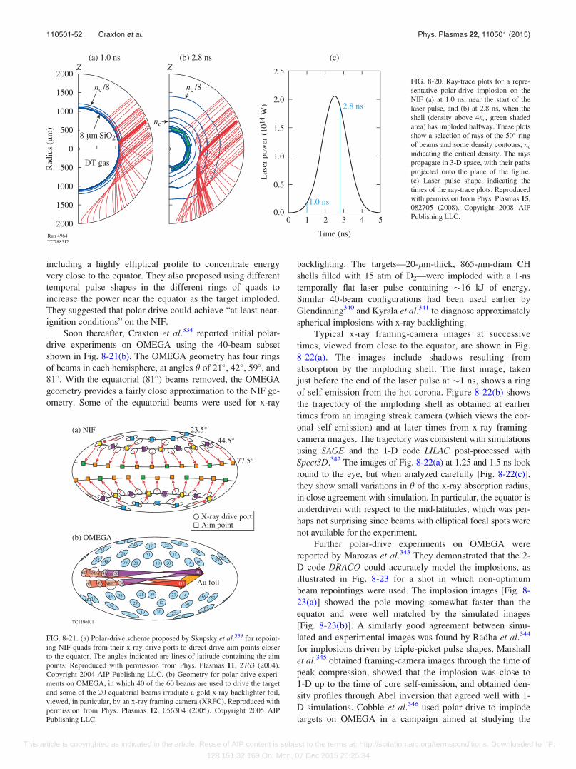
including a highly elliptical profile to concentrate energy
very close to the equator. They also proposed using different
temporal pulse shapes in the different rings of quads to
increase the power near the equator as the target imploded.
They suggested that polar drive could achieve “at least near-
ignition conditions” on the NIF.
Soon thereafter, Craxton et al.334 reported initial polar-
drive experiments on OMEGA using the 40-beam subset
shown in Fig. 8-21(b). The OMEGA geometry has four rings
of beams in each hemisphere, at angles h of 21�, 42�, 59�, and
81�. With the equatorial (81�) beams removed, the OMEGA
geometry provides a fairly close approximation to the NIF ge-
ometry. Some of the equatorial beams were used for x-ray
backlighting. The targets—20-lm-thick, 865-lm-diam CH
shells filled with 15 atm of D2—were imploded with a 1-ns
temporally flat laser pulse containing �16 kJ of energy.
Similar 40-beam configurations had been used earlier by
Glendinning340 and Kyrala et al.341 to diagnose approximately
spherical implosions with x-ray backlighting.
Typical x-ray framing-camera images at successive
times, viewed from close to the equator, are shown in Fig.
8-22(a). The images include shadows resulting from
absorption by the imploding shell. The first image, taken
just before the end of the laser pulse at �1 ns, shows a ring
of self-emission from the hot corona. Figure 8-22(b) shows
the trajectory of the imploding shell as obtained at earlier
times from an imaging streak camera (which views the cor-
onal self-emission) and at later times from x-ray framing-
camera images. The trajectory was consistent with simulations
using SAGE and the 1-D code LILAC post-processed with
Spect3D.342 The images of Fig. 8-22(a) at 1.25 and 1.5 ns look
round to the eye, but when analyzed carefully [Fig. 8-22(c)],
they show small variations in h of the x-ray absorption radius,
in close agreement with simulation. In particular, the equator is
underdriven with respect to the mid-latitudes, which was per-
haps not surprising since beams with elliptical focal spots were
not available for the experiment.
Further polar-drive experiments on OMEGA were
reported by Marozas et al.343 They demonstrated that the 2-
D code DRACO could accurately model the implosions, as
illustrated in Fig. 8-23 for a shot in which non-optimum
beam repointings were used. The implosion images [Fig. 8-
23(a)] showed the pole moving somewhat faster than the
equator and were well matched by the simulated images
[Fig. 8-23(b)]. A similarly good agreement between simu-
lated and experimental images was found by Radha et al.344
for implosions driven by triple-picket pulse shapes. Marshall
et al.345 obtained framing-camera images through the time of
peak compression, showed that the implosion was close to
1-D up to the time of core self-emission, and obtained den-
sity profiles through Abel inversion that agreed well with 1-
D simulations. Cobble et al.346 used polar drive to implode
targets on OMEGA in a campaign aimed at studying the
FIG. 8-20. Ray-trace plots for a repre-
sentative polar-drive implosion on the
NIF (a) at 1.0 ns, near the start of the
laser pulse, and (b) at 2.8 ns, when the
shell (density above 4nc, green shaded
area) has imploded halfway. These plots
show a selection of rays of the 50� ring
of beams and some density contours, nc
indicating the critical density. The rays
propagate in 3-D space, with their paths
projected onto the plane of the figure.
(c) Laser pulse shape, indicating the
times of the ray-trace plots. Reproduced
with permission from Phys. Plasmas 15,
082705 (2008). Copyright 2008 AIP
Publishing LLC.
FIG. 8-21. (a) Polar-drive scheme proposed by Skupsky et al.339 for repoint-
ing NIF quads from their x-ray-drive ports to direct-drive aim points closer
to the equator. The angles indicated are lines of latitude containing the aim
points. Reproduced with permission from Phys. Plasmas 11, 2763 (2004).
Copyright 2004 AIP Publishing LLC. (b) Geometry for polar-drive experi-
ments on OMEGA, in which 40 of the 60 beams are used to drive the target
and some of the 20 equatorial beams irradiate a gold x-ray backlighter foil,
viewed, in particular, by an x-ray framing camera (XRFC). Reproduced with
permission from Phys. Plasmas 12, 056304 (2005). Copyright 2005 AIP
Publishing LLC.
110501-52 Craxton et al. Phys. Plasmas 22, 110501 (2015)
This article is copyrighted as indicated in the article. Reuse of AIP content is subject to the terms at: http://scitation.aip.org/termsconditions. Downloaded to IP:
128.151.32.169 On: Mon, 07 Dec 2015 20:25:34
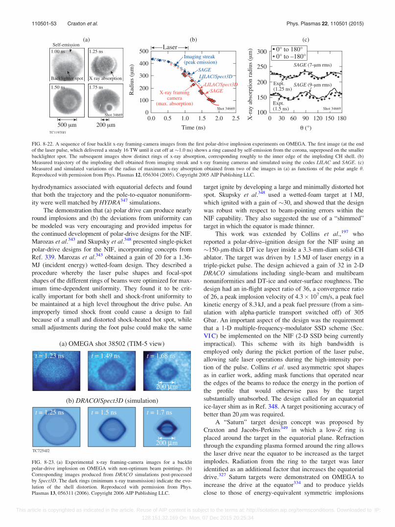
hydrodynamics associated with equatorial defects and found
that both the trajectory and the pole-to-equator nonuniform-
ity were well matched by HYDRA347 simulations.
The demonstration that (a) polar drive can produce nearly
round implosions and (b) the deviations from uniformity can
be modeled was very encouraging and provided impetus for
the continued development of polar-drive designs for the NIF.
Marozas et al.343 and Skupsky et al.348 presented single-picket
polar-drive designs for the NIF, incorporating concepts from
Ref. 339. Marozas et al.343 obtained a gain of 20 for a 1.36-
MJ (incident energy) wetted-foam design. They described a
procedure whereby the laser pulse shapes and focal-spot
shapes of the different rings of beams were optimized for max-
imum time-dependent uniformity. They found it to be crit-
ically important for both shell and shock-front uniformity to
be maintained at a high level throughout the drive pulse. An
improperly timed shock front could cause a design to fail
because of a small and distorted shock-heated hot spot, while
small adjustments during the foot pulse could make the same
target ignite by developing a large and minimally distorted hot
spot. Skupsky et al.348 used a wetted-foam target at 1 MJ,
which ignited with a gain of �30, and showed that the design
was robust with respect to beam-pointing errors within the
NIF capability. They also suggested the use of a “shimmed”
target in which the equator is made thinner.
This work was extended by Collins et al.,197 who
reported a polar-drive–ignition design for the NIF using an
�150-lm-thick DT ice layer inside a 3.3-mm-diam solid-CH
ablator. The target was driven by 1.5 MJ of laser energy in a
triple-picket pulse. The design achieved a gain of 32 in 2-D
DRACO simulations including single-beam and multibeam
nonuniformities and DT-ice and outer-surface roughness. The
design had an in-flight aspect ratio of 36, a convergence ratio
of 26, a peak implosion velocity of 4.3� 107 cm/s, a peak fuel
kinetic energy of 8.3 kJ, and a peak fuel pressure (from a sim-
ulation with alpha-particle transport switched off) of 305
Gbar. An important aspect of the design was the requirement
that a 1-D multiple-frequency-modulator SSD scheme (Sec.
VI C) be implemented on the NIF (2-D SSD being currently
impractical). This scheme with its high bandwidth is
employed only during the picket portion of the laser pulse,
allowing safe laser operations during the high-intensity por-
tion of the pulse. Collins et al. used asymmetric spot shapes
as in earlier work, adding mask functions that operated near
the edges of the beams to reduce the energy in the portion of
the profile that would otherwise pass by the target
substantially unabsorbed. The design called for an equatorial
ice-layer shim as in Ref. 348. A target positioning accuracy of
better than 20 lm was required.
A “Saturn” target design concept was proposed by
Craxton and Jacobs-Perkins349 in which a low-Z ring is
placed around the target in the equatorial plane. Refraction
through the expanding plasma formed around the ring allows
the laser drive near the equator to be increased as the target
implodes. Radiation from the ring to the target was later
identified as an additional factor that increases the equatorial
drive.327 Saturn targets were demonstrated on OMEGA to
increase the drive at the equator334 and to produce yields
close to those of energy-equivalent symmetric implosions
FIG. 8-22. A sequence of four backlit x-ray framing-camera images from the first polar-drive implosion experiments on OMEGA. The first image (at the end
of the laser pulse, which delivered a steady 16 TW until it cut off at �1.0 ns) shows a ring caused by self-emission from the corona, superposed on the smaller
backlighter spot. The subsequent images show distinct rings of x-ray absorption, corresponding roughly to the inner edge of the imploding CH shell. (b)
Measured trajectory of the imploding shell obtained from imaging streak and x-ray framing cameras and simulated using the codes LILAC and SAGE. (c)
Measured and simulated variations of the radius of maximum x-ray absorption obtained from two of the images in (a) as functions of the polar angle h.
Reproduced with permission from Phys. Plasmas 12, 056304 (2005). Copyright 2005 AIP Publishing LLC.
FIG. 8-23. (a) Experimental x-ray framing-camera images for a backlit
polar-drive implosion on OMEGA with non-optimum beam pointings. (b)
Corresponding images produced from DRACO simulations post-processed
by Spect3D. The dark rings (minimum x-ray transmission) indicate the evo-
lution of the shell distortion. Reproduced with permission from Phys.
Plasmas 13, 056311 (2006). Copyright 2006 AIP Publishing LLC.
110501-53 Craxton et al. Phys. Plasmas 22, 110501 (2015)
This article is copyrighted as indicated in the article. Reuse of AIP content is subject to the terms at: http://scitation.aip.org/termsconditions. Downloaded to IP:
128.151.32.169 On: Mon, 07 Dec 2015 20:25:34
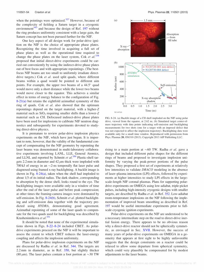
when the pointings were optimized.327 However, because of
the complexity of fielding a Saturn target in a cryogenic
environment343 and because the design of Ref. 197 without
the ring produces uniformity consistent with a large gain, the
Saturn concept has not been pursued further for the NIF.
One key aspect of all design work for polar-drive igni-
tion on the NIF is the choice of appropriate phase plates.
Recognizing the time involved in acquiring a full set of
phase plates as well as the operational time required to
change the phase plates on the laser system, Cok et al.338
proposed that initial direct-drive experiments could be car-
ried out conveniently by using the indirect-drive phase plates
out of best focus and with appropriate repointings. (The best-
focus NIF beams are too small to uniformly irradiate direct-
drive targets.) Cok et al. used split quads, where different
beams within a quad would be pointed to different aim
points. For example, the upper two beams of a 44.5� quad
would move only a short distance while the lower two beams
would move closer to the equator. This achieves a similar
effect in terms of energy balance to the configuration of Fig.
8-21(a) but retains the eightfold azimuthal symmetry of this
ring of quads. Cok et al. also showed that the optimum
repointings depend on the target material, with a higher-Zmaterial such as SiO2 requiring smaller shifts than a lower-Zmaterial such as CH. Defocused indirect-drive phase plates
have been used for implosions to calibrate NIF neutron diag-
nostics and subsequently for experiments devoted to study-
ing direct-drive physics.
It is premature to review polar-drive implosion physics
experiments on the NIF, which have just begun. It is impor-
tant to note, however, that the validity of the fundamental con-
cept of compensating for the NIF geometry by repointing the
laser beams was demonstrated in multi-laboratory collabora-
tive experiments involving LANL, LLE, General Atomics,
and LLNL and reported by Schmitt et al.350 Plastic-shell tar-
gets 2.2 mm in diameter and 42 lm thick were imploded with
700 kJ of energy in an �2-ns temporally flat laser pulse and
diagnosed using framed x-ray backlighting. A backlit image is
shown in Fig. 8-24(a), taken when the shell had imploded to
about 1/3 of its initial radius. The dark shadow, corresponding
to absorption by the dense shell, looks round to the eye. The
backlighting images were available only in a window of time
after the end of the laser pulse and before peak compression;
at other times the framing-camera images were dominated by
self-emission. In Fig. 8-24(b), Schmitt et al. plotted backlight-
ing and self-emission data together with the trajectory pre-
dicted using HYDRA, demonstrating good agreement.
Azimuthal repointing of some of the laser quads to compen-
sate for the two quads used for backlighting was described by
Krasheninnikova et al.351
It should be noted that none of the experimental simula-
tions shown in Figs. 8-22–8-24 included CBET. As polar-
drive experiments proceed on the NIF it will be important to
assess the extent to which CBET reduces the laser-energy
coupling and affects the implosion uniformity.
Plans for polar-drive implosion experiments on the NIF
are discussed by Radha et al. in Ref. 344. The targets are
2.2 mm in diameter, as in Ref. 350, but slightly thicker
(80 lm). The laser pulses contain a foot portion at �30 TW
rising to a main portion at �60 TW. Radha et al. gave a
design that included different pulse shapes for the different
rings of beams and proposed to investigate implosion uni-
formity by varying the peak-power portions of the pulse
shapes. They proposed a first set of experiments at relatively
low intensities to validate DRACO modeling in the absence
of laser–plasma interaction (LPI) effects, followed by experi-
ments at higher intensities to study LPI effects in the large-
scale-length NIF coronal plasmas. Plans for supporting polar-
drive experiments on OMEGA using low-adiabat, triple-picket
pulses, including high-intensity cryogenic designs with smaller
targets, are described by Radha et al. in Ref. 352. Low-adiabat
room-temperature implosions on the NIF following the imple-
mentation of improved beam smoothing as described in Ref.
197 would be useful intermediate experiments prior to full-
scale cryogenic ignition experiments.
Polar-drive experiments on the NIF are understood to be
a necessary intermediate step on the road to direct-drive iner-
tial fusion energy. There appears to be no obvious reason
why a direct-drive reactor should not be spherically symmet-
ric, as envisaged in Sec. XVII. However, the success of
many years of polar-drive experiments on OMEGA in a ge-
ometry that appears at first sight to be highly unfavorable
suggests that the design constraints on a reactor could be
relaxed to allow some departure from spherical symmetry,
which could very plausibly be compensated for by modest
adjustments to the laser beams.
FIG. 8-24. (a) Backlit image of a CH shell imploded on the NIF using polar
drive, viewed from the equator, at 2.62 ns. (b) Simulated target center-of-
mass trajectory with data points indicating self-emission and backlighting
measurements for two shots (one for a target with an imposed defect that
was not expected to affect the implosion trajectory). Backlighting data were
available only for a small time window. Reproduced with permission from
Phys. Plasmas 20, 056310 (2013). Copyright 2013 AIP Publishing LLC.
110501-54 Craxton et al. Phys. Plasmas 22, 110501 (2015)
This article is copyrighted as indicated in the article. Reuse of AIP content is subject to the terms at: http://scitation.aip.org/termsconditions. Downloaded to IP:
128.151.32.169 On: Mon, 07 Dec 2015 20:25:34
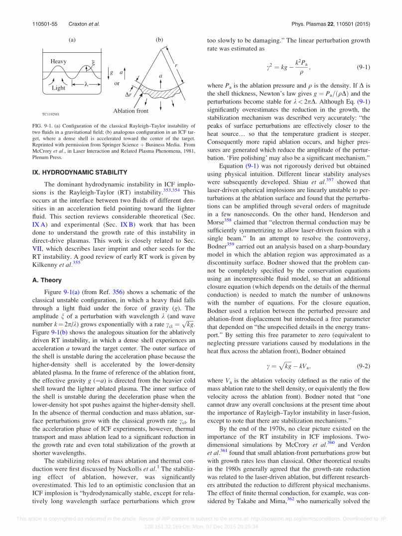
IX. HYDRODYNAMIC STABILITY
The dominant hydrodynamic instability in ICF implo-
sions is the Rayleigh-Taylor (RT) instability.353,354 This
occurs at the interface between two fluids of different den-
sities in an acceleration field pointing toward the lighter
fluid. This section reviews considerable theoretical (Sec.
IX A) and experimental (Sec. IX B) work that has been
done to understand the growth rate of this instability in
direct-drive plasmas. This work is closely related to Sec.
VII, which describes laser imprint and other seeds for the
RT instability. A good review of early RT work is given by
Kilkenny et al.355
A. Theory
Figure 9-1(a) (from Ref. 356) shows a schematic of the
classical unstable configuration, in which a heavy fluid falls
through a light fluid under the force of gravity (g). The
amplitude n of a perturbation with wavelength k (and wave
number k¼ 2p/k) grows exponentially with a rate ccl ¼ffiffiffiffiffikgp
:Figure 9-1(b) shows the analogous situation for the ablatively
driven RT instability, in which a dense shell experiences an
acceleration a toward the target center. The outer surface of
the shell is unstable during the acceleration phase because the
higher-density shell is accelerated by the lower-density
ablated plasma. In the frame of reference of the ablation front,
the effective gravity g (¼a) is directed from the heavier cold
shell toward the lighter ablated plasma. The inner surface of
the shell is unstable during the deceleration phase when the
lower-density hot spot pushes against the higher-density shell.
In the absence of thermal conduction and mass ablation, sur-
face perturbations grow with the classical growth rate ccl. In
the acceleration phase of ICF experiments, however, thermal
transport and mass ablation lead to a significant reduction in
the growth rate and even total stabilization of the growth at
shorter wavelengths.
The stabilizing roles of mass ablation and thermal con-
duction were first discussed by Nuckolls et al.1 The stabiliz-
ing effect of ablation, however, was significantly
overestimated. This led to an optimistic conclusion that an
ICF implosion is “hydrodynamically stable, except for rela-
tively long wavelength surface perturbations which grow
too slowly to be damaging.” The linear perturbation growth
rate was estimated as
c2 ¼ kg� k2Pa
q; (9-1)
where Pa is the ablation pressure and q is the density. If D is
the shell thickness, Newton’s law gives g ¼ Pa=ðqDÞ and the
perturbations become stable for k< 2pD. Although Eq. (9-1)
significantly overestimates the reduction in the growth, the
stabilization mechanism was described very accurately: “the
peaks of surface perturbations are effectively closer to the
heat source… so that the temperature gradient is steeper.
Consequently more rapid ablation occurs, and higher pres-
sures are generated which reduce the amplitude of the pertur-
bation. ‘Fire polishing’ may also be a significant mechanism.”
Equation (9-1) was not rigorously derived but obtained
using physical intuition. Different linear stability analyses
were subsequently developed. Shiau et al.357 showed that
laser-driven spherical implosions are linearly unstable to per-
turbations at the ablation surface and found that the perturba-
tions can be amplified through several orders of magnitude
in a few nanoseconds. On the other hand, Henderson and
Morse358 claimed that “electron thermal conduction may be
sufficiently symmetrizing to allow laser-driven fusion with a
single beam.” In an attempt to resolve the controversy,
Bodner359 carried out an analysis based on a sharp-boundary
model in which the ablation region was approximated as a
discontinuity surface. Bodner showed that the problem can-
not be completely specified by the conservation equations
using an incompressible fluid model, so that an additional
closure equation (which depends on the details of the thermal
conduction) is needed to match the number of unknowns
with the number of equations. For the closure equation,
Bodner used a relation between the perturbed pressure and
ablation-front displacement but introduced a free parameter
that depended on “the unspecified details in the energy trans-
port.” By setting this free parameter to zero (equivalent to
neglecting pressure variations caused by modulations in the
heat flux across the ablation front), Bodner obtained
c ¼ffiffiffiffiffikg
p� kVa; (9-2)
where Va is the ablation velocity (defined as the ratio of the
mass ablation rate to the shell density, or equivalently the flow
velocity across the ablation front). Bodner noted that “one
cannot draw any overall conclusions at the present time about
the importance of Rayleigh–Taylor instability in laser-fusion,
except to note that there are stabilization mechanisms.”
By the end of the 1970s, no clear picture existed on the
importance of the RT instability in ICF implosions. Two-
dimensional simulations by McCrory et al.360 and Verdon
et al.361 found that small ablation-front perturbations grow but
with growth rates less than classical. Other theoretical results
in the 1980s generally agreed that the growth-rate reduction
was related to the laser-driven ablation, but different research-
ers attributed the reduction to different physical mechanisms.
The effect of finite thermal conduction, for example, was con-
sidered by Takabe and Mima,362 who numerically solved the
FIG. 9-1. (a) Configuration of the classical Rayleigh–Taylor instability of
two fluids in a gravitational field; (b) analogous configuration in an ICF tar-
get, where a dense shell is accelerated toward the center of the target.
Reprinted with permission from Springer Science þ Business Media. From
McCrory et al., in Laser Interaction and Related Plasma Phenomena, 1981,
Plenum Press.
110501-55 Craxton et al. Phys. Plasmas 22, 110501 (2015)
This article is copyrighted as indicated in the article. Reuse of AIP content is subject to the terms at: http://scitation.aip.org/termsconditions. Downloaded to IP:
128.151.32.169 On: Mon, 07 Dec 2015 20:25:34
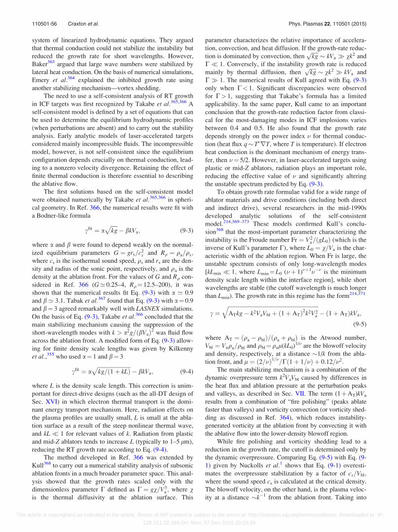
system of linearized hydrodynamic equations. They argued
that thermal conduction could not stabilize the instability but
reduced the growth rate for short wavelengths. However,
Baker363 argued that large wave numbers were stabilized by
lateral heat conduction. On the basis of numerical simulations,
Emery et al.364 explained the inhibited growth rate using
another stabilizing mechanism—vortex shedding.
The need to use a self-consistent analysis of RT growth
in ICF targets was first recognized by Takabe et al.365,366 A
self-consistent model is defined by a set of equations that can
be used to determine the equilibrium hydrodynamic profiles
(when perturbations are absent) and to carry out the stability
analysis. Early analytic models of laser-accelerated targets
considered mainly incompressible fluids. The incompressible
model, however, is not self-consistent since the equilibrium
configuration depends crucially on thermal conduction, lead-
ing to a nonzero velocity divergence. Retaining the effect of
finite thermal conduction is therefore essential to describing
the ablative flow.
The first solutions based on the self-consistent model
were obtained numerically by Takabe et al.365,366 in spheri-
cal geometry. In Ref. 366, the numerical results were fit with
a Bodner-like formula
cfit ¼ affiffiffiffiffikg
p� bkVa; (9-3)
where a and b were found to depend weakly on the normal-
ized equilibrium parameters G ¼ grs=c2s and Rq ¼ qa=qs;
where cs is the isothermal sound speed, qs and rs are the den-
sity and radius of the sonic point, respectively, and qa is the
density at the ablation front. For the values of G and Rq con-
sidered in Ref. 366 (G’ 0.25–4, Rq¼ 12.5–200), it was
shown that the numerical results fit Eq. (9-3) with a ’ 0.9
and b ’ 3.1. Tabak et al.367 found that Eq. (9-3) with a¼ 0.9
and b¼ 3 agreed remarkably well with LASNEX simulations.
On the basis of Eq. (9-3), Takabe et al.366 concluded that the
main stabilizing mechanism causing the suppression of the
short-wavelength modes with k > a2g=ðbVaÞ2 was fluid flow
across the ablation front. A modified form of Eq. (9-3) allow-
ing for finite density scale lengths was given by Kilkenny
et al.,355 who used a¼ 1 and b¼ 3
cfit ¼ affiffiffiffiffiffiffiffiffiffiffiffiffiffiffiffiffiffiffiffiffiffiffiffikg=ð1þ kLÞ
p� bkVa; (9-4)
where L is the density scale length. This correction is unim-
portant for direct-drive designs (such as the all-DT design of
Sec. XVI) in which electron thermal transport is the domi-
nant energy transport mechanism. Here, radiation effects on
the plasma profiles are usually small, L is small at the abla-
tion surface as a result of the steep nonlinear thermal wave,
and kL� 1 for relevant values of k. Radiation from plastic
and mid-Z ablators tends to increase L (typically to 1–5 lm),
reducing the RT growth rate according to Eq. (9-4).
The method developed in Ref. 366 was extended by
Kull368 to carry out a numerical stability analysis of subsonic
ablation fronts in a much broader parameter space. This anal-
ysis showed that the growth rates scaled only with the
dimensionless parameter C defined as C ¼ gv=V3a ; where v
is the thermal diffusivity at the ablation surface. This
parameter characterizes the relative importance of accelera-
tion, convection, and heat diffusion. If the growth-rate reduc-
tion is dominated by convection, thenffiffiffiffiffikgp
� kVa vk2 and
C� 1: Conversely, if the instability growth rate is reduced
mainly by thermal diffusion, thenffiffiffiffiffikgp
� vk2 kVa and
C 1: The numerical results of Kull agreed with Eq. (9-3)
only when C< 1. Significant discrepancies were observed
for C> 1, suggesting that Takabe’s formula has a limited
applicability. In the same paper, Kull came to an important
conclusion that the growth-rate reduction factor from classi-
cal for the most-damaging modes in ICF implosions varies
between 0.4 and 0.5. He also found that the growth rate
depends strongly on the power index � for thermal conduc-
tion (heat flux q� T�rT, where T is temperature). If electron
heat conduction is the dominant mechanism of energy trans-
fer, then �¼ 5/2. However, in laser-accelerated targets using
plastic or mid-Z ablators, radiation plays an important role,
reducing the effective value of � and significantly altering
the unstable spectrum predicted by Eq. (9-3).
To obtain growth rate formulae valid for a wide range of
ablator materials and drive conditions (including both direct
and indirect drive), several researchers in the mid-1990s
developed analytic solutions of the self-consistent
model.214,369–373 These models confirmed Kull’s conclu-
sion368 that the most-important parameter characterizing the
instability is the Froude number Fr ¼ V2a=ðgL0Þ (which is the
inverse of Kull’s parameter C), where L0 ¼ v=Va is the char-
acteristic width of the ablation region. When Fr is large, the
unstable spectrum consists of only long-wavelength modes
[kLmin � 1; where Lmin¼L0 (�þ 1)�þ1��� is the minimum
density scale length within the interface region], while short
wavelengths are stable (the cutoff wavelength is much longer
than Lmin). The growth rate in this regime has the form214,371
c ¼ffiffiffiffiffiffiffiffiffiffiffiffiffiffiffiffiffiffiffiffiffiffiffiffiffiffiffiffiffiffiffiffiffiffiffiffiffiffiffiffiffiffiffiffiffiffiffiffiffiffiffiffiffiffiffiffiffiffiffiffiffiffiffiffiffiffiATkg� k2VaVbl þ ð1þ ATÞ2k2V2
a
q� ð1þ ATÞkVa;
(9-5)
where AT ¼ ðqa � qblÞ=ðqa þ qblÞ is the Atwood number,
Vbl ¼ Vaqa=qbl and qbl¼qal(kL0)1/� are the blowoff velocity
and density, respectively, at a distance �1/k from the abla-
tion front, and l ¼ ð2=�Þ1=�=Cð1þ 1=�Þ þ 0:12=�2:The main stabilizing mechanism is a combination of the
dynamic overpressure term k2VaVbl caused by differences in
the heat flux and ablation pressure at the perturbation peaks
and valleys, as described in Sec. VII. The term (1þAT)kVa
results from a combination of “fire polishing” (peaks ablate
faster than valleys) and vorticity convection (or vorticity shed-
ding as discussed in Ref. 364), which reduces instability-
generated vorticity at the ablation front by convecting it with
the ablative flow into the lower-density blowoff region.
While fire polishing and vorticity shedding lead to a
reduction in the growth rate, the cutoff is determined only by
the dynamic overpressure. Comparing Eq. (9-5) with Eq. (9-
1) given by Nuckolls et al.1 shows that Eq. (9-1) overesti-
mates the overpressure stabilization by a factor of cs=Vbl;where the sound speed cs is calculated at the critical density.
The blowoff velocity, on the other hand, is the plasma veloc-
ity at a distance �k�1 from the ablation front. Taking into
110501-56 Craxton et al. Phys. Plasmas 22, 110501 (2015)
This article is copyrighted as indicated in the article. Reuse of AIP content is subject to the terms at: http://scitation.aip.org/termsconditions. Downloaded to IP:
128.151.32.169 On: Mon, 07 Dec 2015 20:25:34
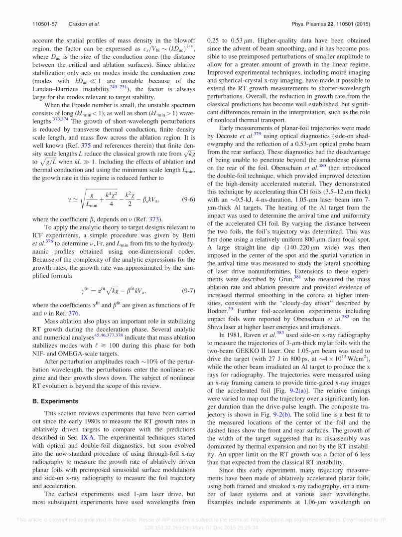
account the spatial profiles of mass density in the blowoff
region, the factor can be expressed as cs=Vbl � ðkDacÞ1=�;where Dac is the size of the conduction zone (the distance
between the critical and ablation surfaces). Since ablative
stabilization only acts on modes inside the conduction zone
(modes with kDac � 1 are unstable because of the
Landau–Darrieus instability249–251), the factor is always
large for the modes relevant to target stability.
When the Froude number is small, the unstable spectrum
consists of long (kLmin< 1), as well as short (kLmin> 1) wave-
lengths.373,374 The growth of short-wavelength perturbations
is reduced by transverse thermal conduction, finite density
scale length, and mass flow across the ablation region. It is
well known (Ref. 375 and references therein) that finite den-
sity scale lengths L reduce the classical growth rate fromffiffiffiffiffikgp
toffiffiffiffiffiffiffiffig=L
pwhen kL 1: Including the effects of ablation and
thermal conduction and using the minimum scale length Lmin,
the growth rate in this regime is reduced further to
c ’
ffiffiffiffiffiffiffiffiffiffiffiffiffiffiffiffiffiffiffiffiffiffiffig
Lmin
þ k4v2
4
s� k2v
2� bskVa; (9-6)
where the coefficient bs depends on � (Ref. 373).
To apply the analytic theory to target designs relevant to
ICF experiments, a simple procedure was given by Betti
et al.376 to determine �, Fr, and Lmin from fits to the hydrody-
namic profiles obtained using one-dimensional codes.
Because of the complexity of the analytic expressions for the
growth rates, the growth rate was approximated by the sim-
plified formula
cfit ¼ afitffiffiffiffiffikg
p� bfitkVa; (9-7)
where the coefficients afit and bfit are given as functions of Fr
and � in Ref. 376.
Mass ablation also plays an important role in stabilizing
RT growth during the deceleration phase. Several analytic
and numerical analyses45,46,377,378 indicate that mass ablation
stabilizes modes with ‘ � 100 during this phase for both
NIF- and OMEGA-scale targets.
After perturbation amplitudes reach �10% of the pertur-
bation wavelength, the perturbations enter the nonlinear re-
gime and their growth slows down. The subject of nonlinear
RT evolution is beyond the scope of this review.
B. Experiments
This section reviews experiments that have been carried
out since the early 1980s to measure the RT growth rates in
ablatively driven targets to compare with the predictions
described in Sec. IX A. The experimental techniques started
with optical and double-foil diagnostics, but soon evolved
into the now-standard procedure of using through-foil x-ray
radiography to measure the growth rate of ablatively driven
planar foils with preimposed sinusoidal surface modulations
and side-on x-ray radiography to measure the foil trajectory
and acceleration.
The earliest experiments used 1-lm laser drive, but
most subsequent experiments have used wavelengths from
0.25 to 0.53 lm. Higher-quality data have been obtained
since the advent of beam smoothing, and it has become pos-
sible to use preimposed perturbations of smaller amplitude to
allow for a greater amount of growth in the linear regime.
Improved experimental techniques, including moir�e imaging
and spherical-crystal x-ray imaging, have made it possible to
extend the RT growth measurements to shorter-wavelength
perturbations. Overall, the reduction in growth rate from the
classical predictions has become well established, but signifi-
cant differences remain in the interpretation, such as the role
of nonlocal thermal transport.
Early measurements of planar-foil trajectories were made
by Decoste et al.379 using optical diagnostics (side-on shad-
owgraphy and the reflection of a 0.53-lm optical probe beam
from the rear surface). These diagnostics had the disadvantage
of being unable to penetrate beyond the underdense plasma
on the rear of the foil. Obenschain et al.380 then introduced
the double-foil technique, which provided improved detection
of the high-density accelerated material. They demonstrated
this technique by accelerating thin CH foils (3.5–12 lm thick)
with an �0.5-kJ, 4-ns-duration, 1.05-lm laser beam into 7-
lm-thick Al targets. The heating of the Al target from the
impact was used to determine the arrival time and uniformity
of the accelerated CH foil. By varying the distance between
the two foils, the foil’s trajectory was determined. This was
first done using a relatively uniform 800-lm-diam focal spot.
A large straight-line dip (140–220 lm wide) was then
imposed in the center of the spot and the spatial variation in
the arrival time was measured to study the lateral smoothing
of laser drive nonuniformities. Extensions to these experi-
ments were described by Grun,381 who measured the mass
ablation rate and ablation pressure and provided evidence of
increased thermal smoothing in the corona at higher inten-
sities, consistent with the “cloudy-day effect” described by
Bodner.39 Further foil-acceleration experiments including
impact foils were reported by Obenschain et al.382 on the
Shiva laser at higher laser energies and irradiances.
In 1981, Raven et al.383 used side-on x-ray radiography
to measure the trajectories of 3-lm-thick mylar foils with the
two-beam GEKKO II laser. One 1.05-lm beam was used to
drive the target (with 27 J in 800 ps, at �4� 1013 W/cm2),
while the other beam irradiated an Al target to produce the x
rays for radiography. The trajectories were measured using
an x-ray framing camera to provide time-gated x-ray images
of the accelerated foil [Fig. 9-2(a)]. The relative timings
were varied to map out the trajectory over a significantly lon-
ger duration than the drive-pulse length. The composite tra-
jectory is shown in Fig. 9-2(b). The solid line is a best fit to
the measured locations of the center of the foil and the
dashed lines show the front and rear surfaces. The growth of
the width of the target suggested that its disassembly was
dominated by thermal expansion and not by the RT instabil-
ity. An upper limit on the RT growth was a factor of 6 less
than that expected from the classical RT instability.
Since this early experiment, many trajectory measure-
ments have been made of ablatively accelerated planar foils,
using both framed and streaked x-ray radiography, on a num-
ber of laser systems and at various laser wavelengths.
Examples include experiments at 1.06-lm wavelength on
110501-57 Craxton et al. Phys. Plasmas 22, 110501 (2015)
This article is copyrighted as indicated in the article. Reuse of AIP content is subject to the terms at: http://scitation.aip.org/termsconditions. Downloaded to IP:
128.151.32.169 On: Mon, 07 Dec 2015 20:25:34
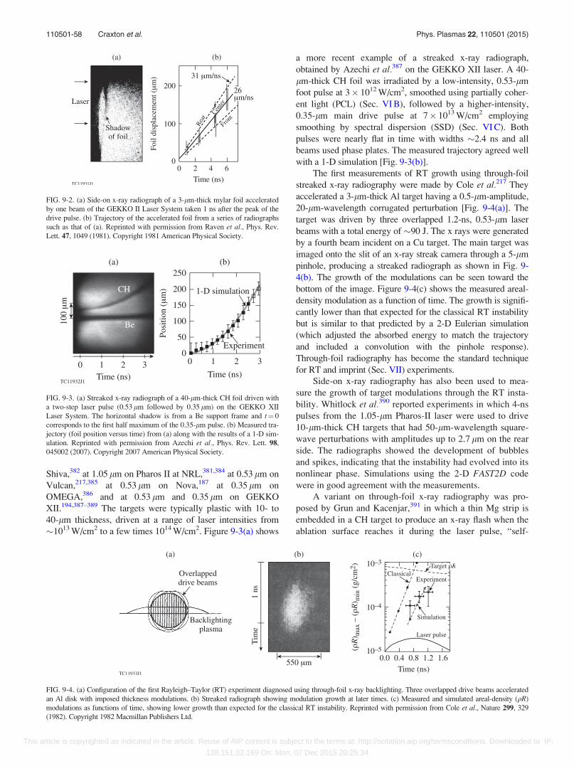
Shiva,382 at 1.05 lm on Pharos II at NRL,381,384 at 0.53 lm on
Vulcan,217,385 at 0.53 lm on Nova,187 at 0.35 lm on
OMEGA,386 and at 0.53 lm and 0.35 lm on GEKKO
XII.194,387–389 The targets were typically plastic with 10- to
40-lm thickness, driven at a range of laser intensities from
�1013 W/cm2 to a few times 1014 W/cm2. Figure 9-3(a) shows
a more recent example of a streaked x-ray radiograph,
obtained by Azechi et al.387 on the GEKKO XII laser. A 40-
lm-thick CH foil was irradiated by a low-intensity, 0.53-lm
foot pulse at 3� 1012 W/cm2, smoothed using partially coher-
ent light (PCL) (Sec. VI B), followed by a higher-intensity,
0.35-lm main drive pulse at 7� 1013 W/cm2 employing
smoothing by spectral dispersion (SSD) (Sec. VI C). Both
pulses were nearly flat in time with widths �2.4 ns and all
beams used phase plates. The measured trajectory agreed well
with a 1-D simulation [Fig. 9-3(b)].
The first measurements of RT growth using through-foil
streaked x-ray radiography were made by Cole et al.217 They
accelerated a 3-lm-thick Al target having a 0.5-lm-amplitude,
20-lm-wavelength corrugated perturbation [Fig. 9-4(a)]. The
target was driven by three overlapped 1.2-ns, 0.53-lm laser
beams with a total energy of �90 J. The x rays were generated
by a fourth beam incident on a Cu target. The main target was
imaged onto the slit of an x-ray streak camera through a 5-lm
pinhole, producing a streaked radiograph as shown in Fig. 9-
4(b). The growth of the modulations can be seen toward the
bottom of the image. Figure 9-4(c) shows the measured areal-
density modulation as a function of time. The growth is signifi-
cantly lower than that expected for the classical RT instability
but is similar to that predicted by a 2-D Eulerian simulation
(which adjusted the absorbed energy to match the trajectory
and included a convolution with the pinhole response).
Through-foil radiography has become the standard technique
for RT and imprint (Sec. VII) experiments.
Side-on x-ray radiography has also been used to mea-
sure the growth of target modulations through the RT insta-
bility. Whitlock et al.390 reported experiments in which 4-ns
pulses from the 1.05-lm Pharos-II laser were used to drive
10-lm-thick CH targets that had 50-lm-wavelength square-
wave perturbations with amplitudes up to 2.7 lm on the rear
side. The radiographs showed the development of bubbles
and spikes, indicating that the instability had evolved into its
nonlinear phase. Simulations using the 2-D FAST2D code
were in good agreement with the measurements.
A variant on through-foil x-ray radiography was pro-
posed by Grun and Kacenjar,391 in which a thin Mg strip is
embedded in a CH target to produce an x-ray flash when the
ablation surface reaches it during the laser pulse, “self-
FIG. 9-2. (a) Side-on x-ray radiograph of a 3-lm-thick mylar foil accelerated
by one beam of the GEKKO II Laser System taken 1 ns after the peak of the
drive pulse. (b) Trajectory of the accelerated foil from a series of radiographs
such as that of (a). Reprinted with permission from Raven et al., Phys. Rev.
Lett. 47, 1049 (1981). Copyright 1981 American Physical Society.
FIG. 9-3. (a) Streaked x-ray radiograph of a 40-lm-thick CH foil driven with
a two-step laser pulse (0.53 lm followed by 0.35 lm) on the GEKKO XII
Laser System. The horizontal shadow is from a Be support frame and t¼ 0
corresponds to the first half maximum of the 0.35-lm pulse. (b) Measured tra-
jectory (foil position versus time) from (a) along with the results of a 1-D sim-
ulation. Reprinted with permission from Azechi et al., Phys. Rev. Lett. 98,
045002 (2007). Copyright 2007 American Physical Society.
FIG. 9-4. (a) Configuration of the first Rayleigh–Taylor (RT) experiment diagnosed using through-foil x-ray backlighting. Three overlapped drive beams accelerated
an Al disk with imposed thickness modulations. (b) Streaked radiograph showing modulation growth at later times. (c) Measured and simulated areal-density (qR)
modulations as functions of time, showing lower growth than expected for the classical RT instability. Reprinted with permission from Cole et al., Nature 299, 329
(1982). Copyright 1982 Macmillan Publishers Ltd.
110501-58 Craxton et al. Phys. Plasmas 22, 110501 (2015)
This article is copyrighted as indicated in the article. Reuse of AIP content is subject to the terms at: http://scitation.aip.org/termsconditions. Downloaded to IP:
128.151.32.169 On: Mon, 07 Dec 2015 20:25:34
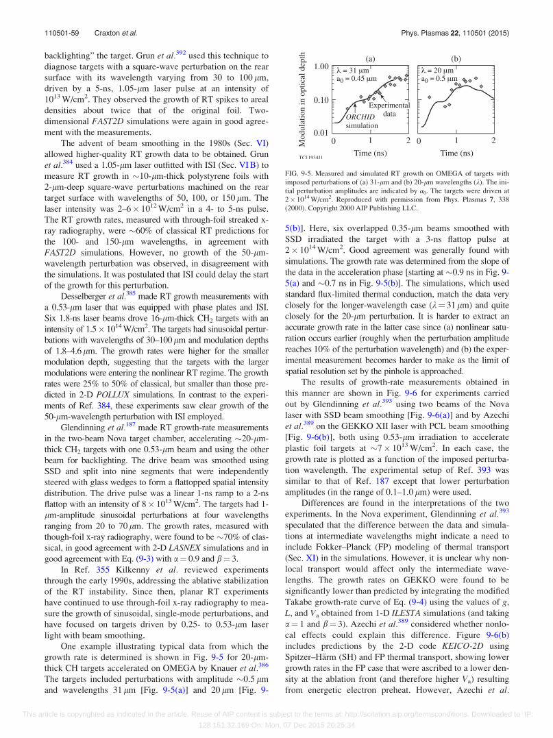
backlighting” the target. Grun et al.392 used this technique to
diagnose targets with a square-wave perturbation on the rear
surface with its wavelength varying from 30 to 100 lm,
driven by a 5-ns, 1.05-lm laser pulse at an intensity of
1013 W/cm2. They observed the growth of RT spikes to areal
densities about twice that of the original foil. Two-
dimensional FAST2D simulations were again in good agree-
ment with the measurements.
The advent of beam smoothing in the 1980s (Sec. VI)
allowed higher-quality RT growth data to be obtained. Grun
et al.384 used a 1.05-lm laser outfitted with ISI (Sec. VI B) to
measure RT growth in �10-lm-thick polystyrene foils with
2-lm-deep square-wave perturbations machined on the rear
target surface with wavelengths of 50, 100, or 150 lm. The
laser intensity was 2–6� 1012 W/cm2 in a 4- to 5-ns pulse.
The RT growth rates, measured with through-foil streaked x-
ray radiography, were �60% of classical RT predictions for
the 100- and 150-lm wavelengths, in agreement with
FAST2D simulations. However, no growth of the 50-lm-
wavelength perturbation was observed, in disagreement with
the simulations. It was postulated that ISI could delay the start
of the growth for this perturbation.
Desselberger et al.385 made RT growth measurements with
a 0.53-lm laser that was equipped with phase plates and ISI.
Six 1.8-ns laser beams drove 16-lm-thick CH2 targets with an
intensity of 1.5� 1014 W/cm2. The targets had sinusoidal pertur-
bations with wavelengths of 30–100lm and modulation depths
of 1.8–4.6lm. The growth rates were higher for the smaller
modulation depth, suggesting that the targets with the larger
modulations were entering the nonlinear RT regime. The growth
rates were 25% to 50% of classical, but smaller than those pre-
dicted in 2-D POLLUX simulations. In contrast to the experi-
ments of Ref. 384, these experiments saw clear growth of the
50-lm-wavelength perturbation with ISI employed.
Glendinning et al.187 made RT growth-rate measurements
in the two-beam Nova target chamber, accelerating �20-lm-
thick CH2 targets with one 0.53-lm beam and using the other
beam for backlighting. The drive beam was smoothed using
SSD and split into nine segments that were independently
steered with glass wedges to form a flattopped spatial intensity
distribution. The drive pulse was a linear 1-ns ramp to a 2-ns
flattop with an intensity of 8� 1013 W/cm2. The targets had 1-
lm-amplitude sinusoidal perturbations at four wavelengths
ranging from 20 to 70 lm. The growth rates, measured with
though-foil x-ray radiography, were found to be �70% of clas-
sical, in good agreement with 2-D LASNEX simulations and in
good agreement with Eq. (9-3) with a¼ 0.9 and b¼ 3.
In Ref. 355 Kilkenny et al. reviewed experiments
through the early 1990s, addressing the ablative stabilization
of the RT instability. Since then, planar RT experiments
have continued to use through-foil x-ray radiography to mea-
sure the growth of sinusoidal, single-mode perturbations, and
have focused on targets driven by 0.25- to 0.53-lm laser
light with beam smoothing.
One example illustrating typical data from which the
growth rate is determined is shown in Fig. 9-5 for 20-lm-
thick CH targets accelerated on OMEGA by Knauer et al.386
The targets included perturbations with amplitude �0.5 lm
and wavelengths 31 lm [Fig. 9-5(a)] and 20 lm [Fig. 9-
5(b)]. Here, six overlapped 0.35-lm beams smoothed with
SSD irradiated the target with a 3-ns flattop pulse at
2� 1014 W/cm2. Good agreement was generally found with
simulations. The growth rate was determined from the slope of
the data in the acceleration phase [starting at �0.9 ns in Fig. 9-
5(a) and �0.7 ns in Fig. 9-5(b)]. The simulations, which used
standard flux-limited thermal conduction, match the data very
closely for the longer-wavelength case (k¼ 31 lm) and quite
closely for the 20-lm perturbation. It is harder to extract an
accurate growth rate in the latter case since (a) nonlinear satu-
ration occurs earlier (roughly when the perturbation amplitude
reaches 10% of the perturbation wavelength) and (b) the exper-
imental measurement becomes harder to make as the limit of
spatial resolution set by the pinhole is approached.
The results of growth-rate measurements obtained in
this manner are shown in Fig. 9-6 for experiments carried
out by Glendinning et al.393 using two beams of the Nova
laser with SSD beam smoothing [Fig. 9-6(a)] and by Azechi
et al.389 on the GEKKO XII laser with PCL beam smoothing
[Fig. 9-6(b)], both using 0.53-lm irradiation to accelerate
plastic foil targets at �7� 1013 W/cm2. In each case, the
growth rate is plotted as a function of the imposed perturba-
tion wavelength. The experimental setup of Ref. 393 was
similar to that of Ref. 187 except that lower perturbation
amplitudes (in the range of 0.1–1.0 lm) were used.
Differences are found in the interpretations of the two
experiments. In the Nova experiment, Glendinning et al.393
speculated that the difference between the data and simula-
tions at intermediate wavelengths might indicate a need to
include Fokker–Planck (FP) modeling of thermal transport
(Sec. XI) in the simulations. However, it is unclear why non-
local transport would affect only the intermediate wave-
lengths. The growth rates on GEKKO were found to be
significantly lower than predicted by integrating the modified
Takabe growth-rate curve of Eq. (9-4) using the values of g,
L, and Va obtained from 1-D ILESTA simulations (and taking
a¼ 1 and b¼ 3). Azechi et al.389 considered whether nonlo-
cal effects could explain this difference. Figure 9-6(b)
includes predictions by the 2-D code KEICO-2D using
Spitzer–H€arm (SH) and FP thermal transport, showing lower
growth rates in the FP case that were ascribed to a lower den-
sity at the ablation front (and therefore higher Va) resulting
from energetic electron preheat. However, Azechi et al.
FIG. 9-5. Measured and simulated RT growth on OMEGA of targets with
imposed perturbations of (a) 31-lm and (b) 20-lm wavelengths (k). The ini-
tial perturbation amplitudes are indicated by a0. The targets were driven at
2� 1014 W/cm2. Reproduced with permission from Phys. Plasmas 7, 338
(2000). Copyright 2000 AIP Publishing LLC.
110501-59 Craxton et al. Phys. Plasmas 22, 110501 (2015)
This article is copyrighted as indicated in the article. Reuse of AIP content is subject to the terms at: http://scitation.aip.org/termsconditions. Downloaded to IP:
128.151.32.169 On: Mon, 07 Dec 2015 20:25:34
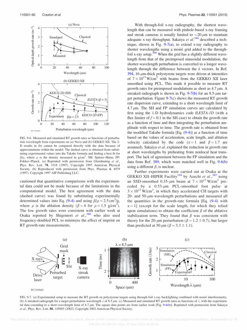
cautioned that quantitative comparisons with the experimen-
tal data could not be made because of the limitations in the
computational model. The best agreement with the data
(dashed curve) was found by substituting experimentally
determined values into Eq. (9-4) and using b/q¼ 2.5 cm3/g,
where q is the ablation density (b� 4 for q¼ 1.5 g/cm3).
The low growth rates were consistent with earlier work at
Osaka reported by Shigemori et al.,388 who also used
frequency-doubled PCL to minimize the effect of imprint on
RT growth-rate measurements.
With through-foil x-ray radiography, the shortest wave-
length that can be measured with pinhole-based x-ray framing
and streak cameras is usually limited to �20 lm to maintain
adequate x-ray throughput. Sakaiya et al.394 described a tech-
nique, shown in Fig. 9-7(a), to extend x-ray radiography to
shorter wavelengths using a moir�e grid added to the through-
foil x-ray setup.395 When the grid has a slightly different wave-
length from that of the preimposed sinusoidal modulation, the
shorter-wavelength perturbation is converted to a longer wave-
length through the difference between the k vectors. In Ref.
394, 16-lm-thick polystyrene targets were driven at intensities
of 7� 1013 W/cm2 with beams from the GEKKO XII laser
smoothed using PCL. This made it possible to measure RT
growth rates for preimposed modulations as short as 4.7 lm. A
streaked radiograph is shown in Fig. 9-7(b) for an 8.5-lm tar-
get perturbation. Figure 9-7(c) shows the measured RT growth
rate dispersion curve, extending to a short wavelength limit of
4.7 lm. The SH and FP simulation curves are calculated by
first using the 1-D hydrodynamics code ILESTA-1D (with a
flux limiter of f¼ 0.1 in the SH case) to obtain the growth rate
as a function of time and then integrating the perturbation am-
plitude with respect to time. The growth rate is obtained from
the modified Takabe formula [Eq. (9-4)] as a function of time
based on the values of acceleration, scale length, and ablation
velocity calculated by the code (a¼ 1 and b¼ 1.7 are
assumed). Sakaiya et al. explained the reduction in growth rate
at short wavelengths by preheating from nonlocal heat trans-
port. The lack of agreement between the FP simulation and the
data from Ref. 389, which were matched well in Fig. 9-6(b)
using a different b, is unclear.
Further experiments were carried out at Osaka at the
GEKKO XII–HIPER Facility194 by Azechi et al.,387 using
an SSD-smoothed 0.35-lm beam at 7� 1013 W/cm2 pre-
ceded by a 0.53-lm PCL-smoothed foot pulse at
3� 1012 W/cm2, in which they accelerated CH targets with
20- and 50-lm-wavelength perturbations and measured all
the quantities in the growth-rate formula [Eq. (9-4) with
a¼ 1] (except for the scale length, for which they relied
upon simulations) to obtain the coefficient b of the ablative
stabilization term. They found that b was consistent with
theory for the 20-lm perturbation (b¼ 1.2 6 0.7), but larger
than predicted at 50 lm (b¼ 3.3 6 1.1).
FIG. 9-6. Measured and simulated RT growth rates as functions of perturba-
tion wavelength from experiments on (a) Nova and (b) GEKKO XII. The 2-
D results in (b) cannot be compared directly with the data because of
approximations within the model. The dashed curve is obtained from substi-
tuting experimental values into the Takabe formula and finding a best fit for
b/q, where q is the density measured in g/cm3. SH: Spitzer–H€arm; FP:
Fokker–Planck. (a) Reprinted with permission from Glendinning et al.,Phys. Rev. Lett. 78, 3318 (1997). Copyright 1997 American Physical
Society. (b) Reproduced with permission from Phys. Plasmas 4, 4079
(1997). Copyright 1997 AIP Publishing LLC.
FIG. 9-7. (a) Experimental setup to measure the RT growth on polystyrene targets using through-foil x-ray backlighting combined with moir�e interferometry.
(b) A streaked radiograph for a target perturbation wavelength k of 8.5 lm. (c) Measured and simulated RT growth rates as functions of k, with the experimen-
tal data extending to a short-wavelength limit of 4.7 lm. The square data points are from earlier work [Fig. 9-6(b)]. Reprinted with permission from Sakaiya
et al., Phys. Rev. Lett. 88, 145003 (2002). Copyright 2002 American Physical Society.
110501-60 Craxton et al. Phys. Plasmas 22, 110501 (2015)
This article is copyrighted as indicated in the article. Reuse of AIP content is subject to the terms at: http://scitation.aip.org/termsconditions. Downloaded to IP:
128.151.32.169 On: Mon, 07 Dec 2015 20:25:34
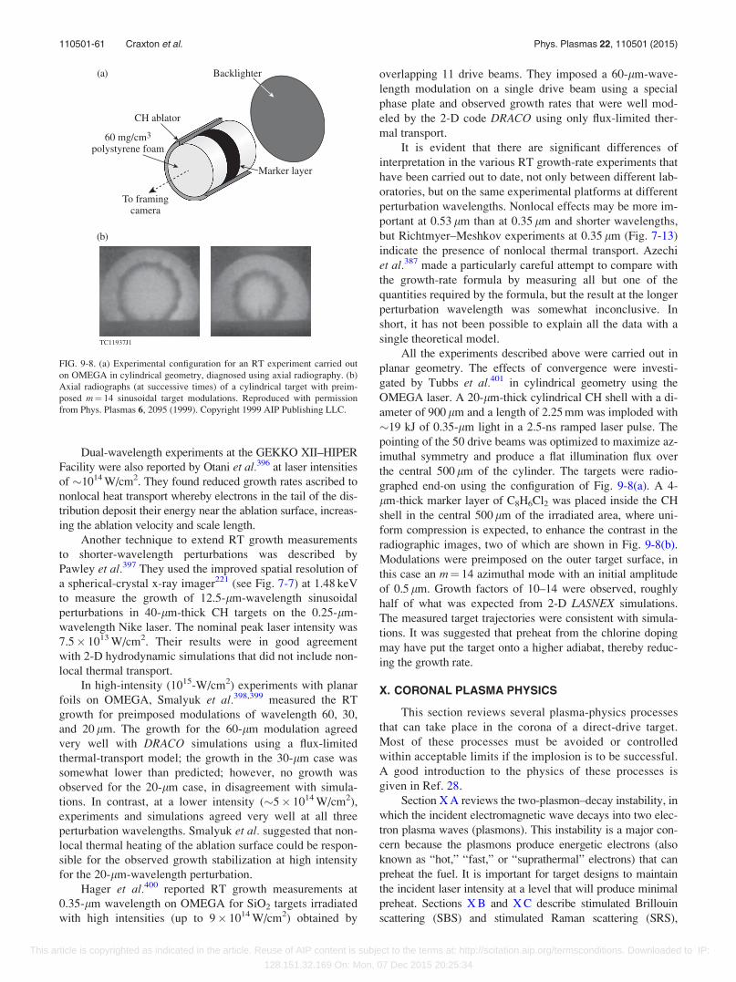
Dual-wavelength experiments at the GEKKO XII–HIPER
Facility were also reported by Otani et al.396 at laser intensities
of �1014 W/cm2. They found reduced growth rates ascribed to
nonlocal heat transport whereby electrons in the tail of the dis-
tribution deposit their energy near the ablation surface, increas-
ing the ablation velocity and scale length.
Another technique to extend RT growth measurements
to shorter-wavelength perturbations was described by
Pawley et al.397 They used the improved spatial resolution of
a spherical-crystal x-ray imager221 (see Fig. 7-7) at 1.48 keV
to measure the growth of 12.5-lm-wavelength sinusoidal
perturbations in 40-lm-thick CH targets on the 0.25-lm-
wavelength Nike laser. The nominal peak laser intensity was
7.5� 1013 W/cm2. Their results were in good agreement
with 2-D hydrodynamic simulations that did not include non-
local thermal transport.
In high-intensity (1015-W/cm2) experiments with planar
foils on OMEGA, Smalyuk et al.398,399 measured the RT
growth for preimposed modulations of wavelength 60, 30,
and 20 lm. The growth for the 60-lm modulation agreed
very well with DRACO simulations using a flux-limited
thermal-transport model; the growth in the 30-lm case was
somewhat lower than predicted; however, no growth was
observed for the 20-lm case, in disagreement with simula-
tions. In contrast, at a lower intensity (�5� 1014 W/cm2),
experiments and simulations agreed very well at all three
perturbation wavelengths. Smalyuk et al. suggested that non-
local thermal heating of the ablation surface could be respon-
sible for the observed growth stabilization at high intensity
for the 20-lm-wavelength perturbation.
Hager et al.400 reported RT growth measurements at
0.35-lm wavelength on OMEGA for SiO2 targets irradiated
with high intensities (up to 9� 1014 W/cm2) obtained by
overlapping 11 drive beams. They imposed a 60-lm-wave-
length modulation on a single drive beam using a special
phase plate and observed growth rates that were well mod-
eled by the 2-D code DRACO using only flux-limited ther-
mal transport.
It is evident that there are significant differences of
interpretation in the various RT growth-rate experiments that
have been carried out to date, not only between different lab-
oratories, but on the same experimental platforms at different
perturbation wavelengths. Nonlocal effects may be more im-
portant at 0.53 lm than at 0.35 lm and shorter wavelengths,
but Richtmyer–Meshkov experiments at 0.35 lm (Fig. 7-13)
indicate the presence of nonlocal thermal transport. Azechi
et al.387 made a particularly careful attempt to compare with
the growth-rate formula by measuring all but one of the
quantities required by the formula, but the result at the longer
perturbation wavelength was somewhat inconclusive. In
short, it has not been possible to explain all the data with a
single theoretical model.
All the experiments described above were carried out in
planar geometry. The effects of convergence were investi-
gated by Tubbs et al.401 in cylindrical geometry using the
OMEGA laser. A 20-lm-thick cylindrical CH shell with a di-
ameter of 900 lm and a length of 2.25 mm was imploded with
�19 kJ of 0.35-lm light in a 2.5-ns ramped laser pulse. The
pointing of the 50 drive beams was optimized to maximize az-
imuthal symmetry and produce a flat illumination flux over
the central 500 lm of the cylinder. The targets were radio-
graphed end-on using the configuration of Fig. 9-8(a). A 4-
lm-thick marker layer of C8H6Cl2 was placed inside the CH
shell in the central 500 lm of the irradiated area, where uni-
form compression is expected, to enhance the contrast in the
radiographic images, two of which are shown in Fig. 9-8(b).
Modulations were preimposed on the outer target surface, in
this case an m¼ 14 azimuthal mode with an initial amplitude
of 0.5 lm. Growth factors of 10–14 were observed, roughly
half of what was expected from 2-D LASNEX simulations.
The measured target trajectories were consistent with simula-
tions. It was suggested that preheat from the chlorine doping
may have put the target onto a higher adiabat, thereby reduc-
ing the growth rate.
X. CORONAL PLASMA PHYSICS
This section reviews several plasma-physics processes
that can take place in the corona of a direct-drive target.
Most of these processes must be avoided or controlled
within acceptable limits if the implosion is to be successful.
A good introduction to the physics of these processes is
given in Ref. 28.
Section X A reviews the two-plasmon–decay instability, in
which the incident electromagnetic wave decays into two elec-
tron plasma waves (plasmons). This instability is a major con-
cern because the plasmons produce energetic electrons (also
known as “hot,” “fast,” or “suprathermal” electrons) that can
preheat the fuel. It is important for target designs to maintain
the incident laser intensity at a level that will produce minimal
preheat. Sections X B and X C describe stimulated Brillouin
scattering (SBS) and stimulated Raman scattering (SRS),
FIG. 9-8. (a) Experimental configuration for an RT experiment carried out
on OMEGA in cylindrical geometry, diagnosed using axial radiography. (b)
Axial radiographs (at successive times) of a cylindrical target with preim-
posed m¼ 14 sinusoidal target modulations. Reproduced with permission
from Phys. Plasmas 6, 2095 (1999). Copyright 1999 AIP Publishing LLC.
110501-61 Craxton et al. Phys. Plasmas 22, 110501 (2015)
This article is copyrighted as indicated in the article. Reuse of AIP content is subject to the terms at: http://scitation.aip.org/termsconditions. Downloaded to IP:
128.151.32.169 On: Mon, 07 Dec 2015 20:25:34
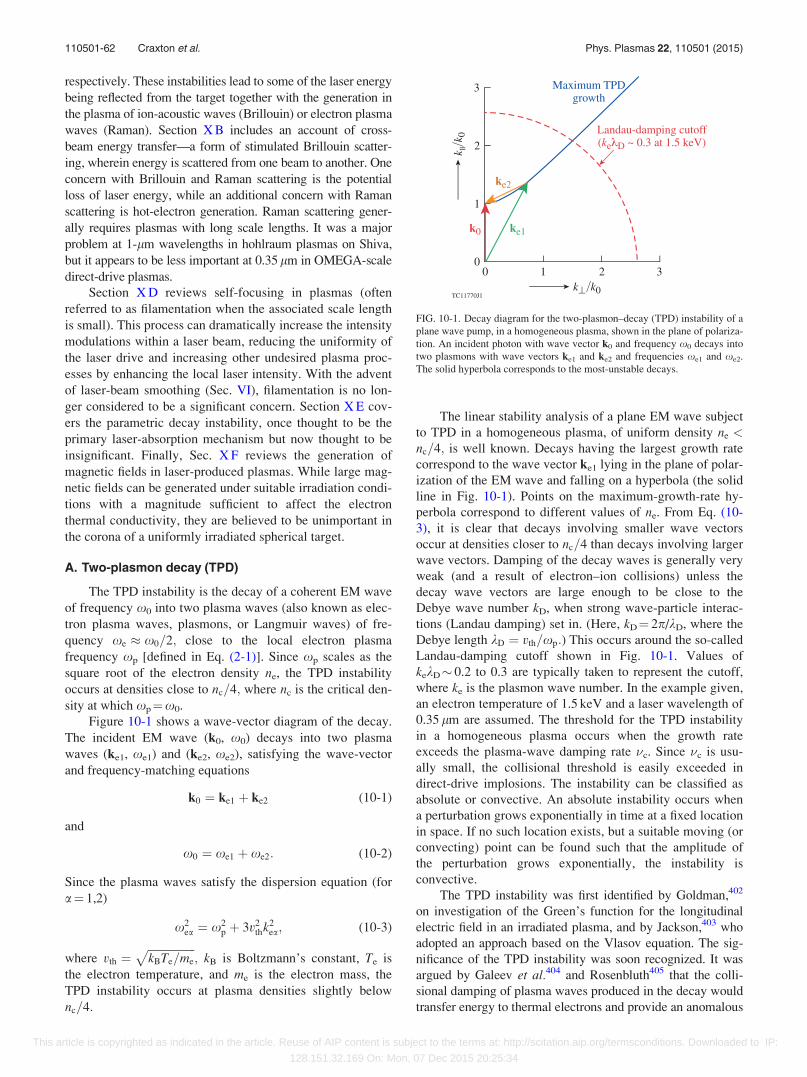
respectively. These instabilities lead to some of the laser energy
being reflected from the target together with the generation in
the plasma of ion-acoustic waves (Brillouin) or electron plasma
waves (Raman). Section X B includes an account of cross-
beam energy transfer—a form of stimulated Brillouin scatter-
ing, wherein energy is scattered from one beam to another. One
concern with Brillouin and Raman scattering is the potential
loss of laser energy, while an additional concern with Raman
scattering is hot-electron generation. Raman scattering gener-
ally requires plasmas with long scale lengths. It was a major
problem at 1-lm wavelengths in hohlraum plasmas on Shiva,
but it appears to be less important at 0.35 lm in OMEGA-scale
direct-drive plasmas.
Section X D reviews self-focusing in plasmas (often
referred to as filamentation when the associated scale length
is small). This process can dramatically increase the intensity
modulations within a laser beam, reducing the uniformity of
the laser drive and increasing other undesired plasma proc-
esses by enhancing the local laser intensity. With the advent
of laser-beam smoothing (Sec. VI), filamentation is no lon-
ger considered to be a significant concern. Section X E cov-
ers the parametric decay instability, once thought to be the
primary laser-absorption mechanism but now thought to be
insignificant. Finally, Sec. X F reviews the generation of
magnetic fields in laser-produced plasmas. While large mag-
netic fields can be generated under suitable irradiation condi-
tions with a magnitude sufficient to affect the electron
thermal conductivity, they are believed to be unimportant in
the corona of a uniformly irradiated spherical target.
A. Two-plasmon decay (TPD)
The TPD instability is the decay of a coherent EM wave
of frequency x0 into two plasma waves (also known as elec-
tron plasma waves, plasmons, or Langmuir waves) of fre-
quency xe � x0=2; close to the local electron plasma
frequency xp [defined in Eq. (2-1)]. Since xp scales as the
square root of the electron density ne, the TPD instability
occurs at densities close to nc=4; where nc is the critical den-
sity at which xp¼x0.
Figure 10-1 shows a wave-vector diagram of the decay.
The incident EM wave (k0, x0) decays into two plasma
waves (ke1, xe1) and (ke2, xe2), satisfying the wave-vector
and frequency-matching equations
k0 ¼ ke1 þ ke2 (10-1)
and
x0 ¼ xe1 þ xe2: (10-2)
Since the plasma waves satisfy the dispersion equation (for
a¼ 1,2)
x2ea ¼ x2
p þ 3v2thk2
ea; (10-3)
where vth ¼ffiffiffiffiffiffiffiffiffiffiffiffiffiffiffiffiffikBTe=me
p; kB is Boltzmann’s constant, Te is
the electron temperature, and me is the electron mass, the
TPD instability occurs at plasma densities slightly below
nc=4:
The linear stability analysis of a plane EM wave subject
to TPD in a homogeneous plasma, of uniform density ne <nc=4; is well known. Decays having the largest growth rate
correspond to the wave vector ke1 lying in the plane of polar-
ization of the EM wave and falling on a hyperbola (the solid
line in Fig. 10-1). Points on the maximum-growth-rate hy-
perbola correspond to different values of ne. From Eq. (10-
3), it is clear that decays involving smaller wave vectors
occur at densities closer to nc=4 than decays involving larger
wave vectors. Damping of the decay waves is generally very
weak (and a result of electron–ion collisions) unless the
decay wave vectors are large enough to be close to the
Debye wave number kD, when strong wave-particle interac-
tions (Landau damping) set in. (Here, kD¼ 2p/kD, where the
Debye length kD ¼ vth=xp:) This occurs around the so-called
Landau-damping cutoff shown in Fig. 10-1. Values of
kekD� 0.2 to 0.3 are typically taken to represent the cutoff,
where ke is the plasmon wave number. In the example given,
an electron temperature of 1.5 keV and a laser wavelength of
0.35 lm are assumed. The threshold for the TPD instability
in a homogeneous plasma occurs when the growth rate
exceeds the plasma-wave damping rate �c. Since �c is usu-
ally small, the collisional threshold is easily exceeded in
direct-drive implosions. The instability can be classified as
absolute or convective. An absolute instability occurs when
a perturbation grows exponentially in time at a fixed location
in space. If no such location exists, but a suitable moving (or
convecting) point can be found such that the amplitude of
the perturbation grows exponentially, the instability is
convective.
The TPD instability was first identified by Goldman,402
on investigation of the Green’s function for the longitudinal
electric field in an irradiated plasma, and by Jackson,403 who
adopted an approach based on the Vlasov equation. The sig-
nificance of the TPD instability was soon recognized. It was
argued by Galeev et al.404 and Rosenbluth405 that the colli-
sional damping of plasma waves produced in the decay would
transfer energy to thermal electrons and provide an anomalous
FIG. 10-1. Decay diagram for the two-plasmon–decay (TPD) instability of a
plane wave pump, in a homogeneous plasma, shown in the plane of polariza-
tion. An incident photon with wave vector k0 and frequency x0 decays into
two plasmons with wave vectors ke1 and ke2 and frequencies xe1 and xe2.
The solid hyperbola corresponds to the most-unstable decays.
110501-62 Craxton et al. Phys. Plasmas 22, 110501 (2015)
This article is copyrighted as indicated in the article. Reuse of AIP content is subject to the terms at: http://scitation.aip.org/termsconditions. Downloaded to IP:
128.151.32.169 On: Mon, 07 Dec 2015 20:25:34
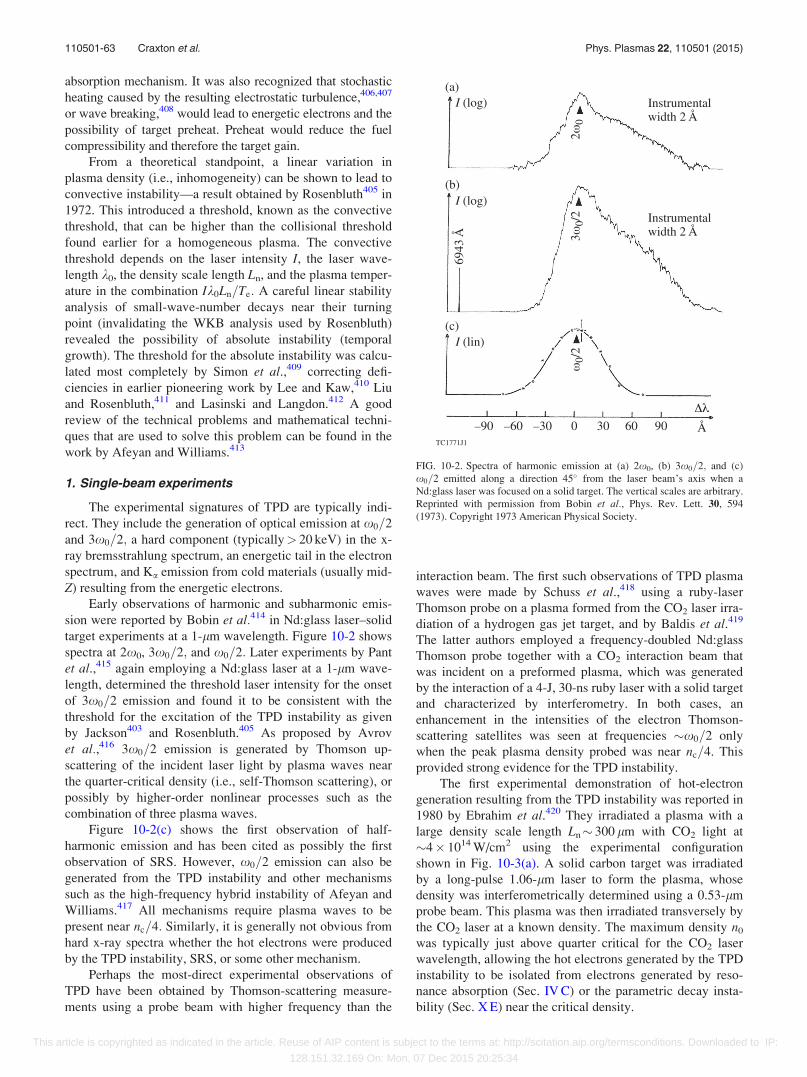
absorption mechanism. It was also recognized that stochastic
heating caused by the resulting electrostatic turbulence,406,407
or wave breaking,408 would lead to energetic electrons and the
possibility of target preheat. Preheat would reduce the fuel
compressibility and therefore the target gain.
From a theoretical standpoint, a linear variation in
plasma density (i.e., inhomogeneity) can be shown to lead to
convective instability—a result obtained by Rosenbluth405 in
1972. This introduced a threshold, known as the convective
threshold, that can be higher than the collisional threshold
found earlier for a homogeneous plasma. The convective
threshold depends on the laser intensity I, the laser wave-
length k0, the density scale length Ln, and the plasma temper-
ature in the combination Ik0Ln=Te: A careful linear stability
analysis of small-wave-number decays near their turning
point (invalidating the WKB analysis used by Rosenbluth)
revealed the possibility of absolute instability (temporal
growth). The threshold for the absolute instability was calcu-
lated most completely by Simon et al.,409 correcting defi-
ciencies in earlier pioneering work by Lee and Kaw,410 Liu
and Rosenbluth,411 and Lasinski and Langdon.412 A good
review of the technical problems and mathematical techni-
ques that are used to solve this problem can be found in the
work by Afeyan and Williams.413
1. Single-beam experiments
The experimental signatures of TPD are typically indi-
rect. They include the generation of optical emission at x0=2
and 3x0=2; a hard component (typically> 20 keV) in the x-
ray bremsstrahlung spectrum, an energetic tail in the electron
spectrum, and Ka emission from cold materials (usually mid-
Z) resulting from the energetic electrons.
Early observations of harmonic and subharmonic emis-
sion were reported by Bobin et al.414 in Nd:glass laser–solid
target experiments at a 1-lm wavelength. Figure 10-2 shows
spectra at 2x0, 3x0=2; and x0=2: Later experiments by Pant
et al.,415 again employing a Nd:glass laser at a 1-lm wave-
length, determined the threshold laser intensity for the onset
of 3x0=2 emission and found it to be consistent with the
threshold for the excitation of the TPD instability as given
by Jackson403 and Rosenbluth.405 As proposed by Avrov
et al.,416 3x0=2 emission is generated by Thomson up-
scattering of the incident laser light by plasma waves near
the quarter-critical density (i.e., self-Thomson scattering), or
possibly by higher-order nonlinear processes such as the
combination of three plasma waves.
Figure 10-2(c) shows the first observation of half-
harmonic emission and has been cited as possibly the first
observation of SRS. However, x0=2 emission can also be
generated from the TPD instability and other mechanisms
such as the high-frequency hybrid instability of Afeyan and
Williams.417 All mechanisms require plasma waves to be
present near nc=4: Similarly, it is generally not obvious from
hard x-ray spectra whether the hot electrons were produced
by the TPD instability, SRS, or some other mechanism.
Perhaps the most-direct experimental observations of
TPD have been obtained by Thomson-scattering measure-
ments using a probe beam with higher frequency than the
interaction beam. The first such observations of TPD plasma
waves were made by Schuss et al.,418 using a ruby-laser
Thomson probe on a plasma formed from the CO2 laser irra-
diation of a hydrogen gas jet target, and by Baldis et al.419
The latter authors employed a frequency-doubled Nd:glass
Thomson probe together with a CO2 interaction beam that
was incident on a preformed plasma, which was generated
by the interaction of a 4-J, 30-ns ruby laser with a solid target
and characterized by interferometry. In both cases, an
enhancement in the intensities of the electron Thomson-
scattering satellites was seen at frequencies �x0=2 only
when the peak plasma density probed was near nc=4. This
provided strong evidence for the TPD instability.
The first experimental demonstration of hot-electron
generation resulting from the TPD instability was reported in
1980 by Ebrahim et al.420 They irradiated a plasma with a
large density scale length Ln� 300 lm with CO2 light at
�4� 1014 W/cm2 using the experimental configuration
shown in Fig. 10-3(a). A solid carbon target was irradiated
by a long-pulse 1.06-lm laser to form the plasma, whose
density was interferometrically determined using a 0.53-lm
probe beam. This plasma was then irradiated transversely by
the CO2 laser at a known density. The maximum density n0
was typically just above quarter critical for the CO2 laser
wavelength, allowing the hot electrons generated by the TPD
instability to be isolated from electrons generated by reso-
nance absorption (Sec. IV C) or the parametric decay insta-
bility (Sec. X E) near the critical density.
FIG. 10-2. Spectra of harmonic emission at (a) 2x0, (b) 3x0=2; and (c)
x0=2 emitted along a direction 45� from the laser beam’s axis when a
Nd:glass laser was focused on a solid target. The vertical scales are arbitrary.
Reprinted with permission from Bobin et al., Phys. Rev. Lett. 30, 594
(1973). Copyright 1973 American Physical Society.
110501-63 Craxton et al. Phys. Plasmas 22, 110501 (2015)
This article is copyrighted as indicated in the article. Reuse of AIP content is subject to the terms at: http://scitation.aip.org/termsconditions. Downloaded to IP:
128.151.32.169 On: Mon, 07 Dec 2015 20:25:34

Figure 10-3(b) shows hot-electron spectra measured in
directions parallel (P) and perpendicular (S) to the laser elec-
tric vector for a maximum density between 0.25 nc and 0.4
nc. The angular dependence of the hot electrons is shown in
Fig. 10-3(c). It is notable that the largest signals were
observed at 645� to the laser direction. Figure 10-3(b) corre-
sponds to this case—at other angles, the difference between
the P and S directions was not observed. The slope of the Pcomponent of Fig. 10-3(b) corresponds to a temperature of
�60 keV. On the basis of the angular distribution of the elec-
trons and their polarization dependence, Ebrahim et al. iden-
tified the electrons as originating from the TPD instability
rather than processes such as SRS.
The preferred angles of observation were consistent
with the expected direction of the most-unstable TPD wave
vectors for the parameters of the experiment (n0� 3� 1018
cm�3, Te� 200 eV). From Fig. 10-1, large-wave-number
decays consist of two plasmons propagating at angles of
almost 45� and 135� with respect to the pump wave vector.
Similar single-beam experiments performed later with a
shorter-wavelength (0.35-lm) interaction beam saw much
weaker directionality, although emission was again stronger
in the plane of polarization.421 In general, the directionality
and energy spectrum of hot electrons produced by the TPD
instability at 0.35 lm have proven difficult to predict because
neither the saturated plasmon wave-number spectrum nor the
electron acceleration processes are well understood.
Additionally, most of these electrons do not escape the target
and the relationship between the source direction and emis-
sion direction is unclear.
Further evidence for the TPD instability was obtained
from the x-ray spectrum. In 1.06-lm and 10.6-lm laser
experiments, a two-temperature spectrum was commonly
observed (Sec. IV B), explained by a thermal component and
a suprathermal component with a temperature TH resulting
from resonance absorption that scaled in a well-established
way with Ik20 (where I is the laser intensity and k0 is the laser
wavelength). However, in 0.35-lm single-beam interaction
experiments reported by Keck et al.,422 there was no
evidence of such a component. Instead, the x-ray spectrum
was well fit by a “superhot” electron component with a tem-
perature TSH greatly in excess of the TH expected for reso-
nance absorption. This understanding was consistent with
experiments reported in the same paper for the irradiation of
targets in spherical geometry at 1 lm with the 24-beam
OMEGA laser, where three Maxwellian components (ther-
mal, resonance absorption, and superhot) were required to fit
the data. The temperature TSH was found to be somewhat
higher for 1-lm irradiation, and it was reasonable to assume
the same origin for the superhot component.
The superhot temperature from Keck et al.422 is plotted
as a function of I in Fig. 10-4 for 0.35-lm irradiation and
shows an approximate scaling with I0.2 from 2� 1014 to
1015 W/cm2. This scaling should be treated with caution
because the changes in density scale length (Ln) with irradia-
tion conditions were not reported. The TPD threshold is
known to decrease as Ln increases [Refs. 405, 409, and 411;
see also Eq. (10-4) below], and it is reasonable to assume that
TSH should also depend on Ln. The energy in superhot elec-
trons was estimated to be a fraction of 10�4 of the incident
energy at the highest intensities. A similar superhot compo-
nent was found by Mead et al.423 for flat targets irradiated at
0.35 lm. While both papers recognized that it was difficult to
identify whether SRS or the TPD instability was responsible,
FIG. 10-3. (a) Experimental configuration used to isolate hot electrons generated by the TPD instability. A long-scale-length plasma was preformed by a 1.06-
lm laser pulse (2 to 4 J in 20 ns). The 10.6-lm (CO2) interaction beam was incident transverse to the 1.06-lm beam, permitting a choice of maximum electron
density n0 in the range nc=10 < n0 < nc: (b) Hot-electron spectra for directions parallel (P) and perpendicular (S) to the laser electric field for collection angles
h¼ 45� and 135� and peak densities between 0.25 nc and 0.4 nc. (c) Angular distribution of hot electrons (having energies between 35 and 400 keV) for both S(open circles) and P directions (closed circles). Reprinted with permission from Ebrahim et al., Phys. Rev. Lett. 45, 1179 (1980). Copyright 1980 American
Physical Society.
FIG. 10-4. “Superhot” electron temperature TSH, attributed to the two-
plasmon decay, as a function of laser intensity for a single 0.35-lm laser
beam incident on a planar plastic target. Reproduced with permission from
Phys. Fluids 27, 2762 (1984). Copyright 1984 AIP Publishing LLC.
110501-64 Craxton et al. Phys. Plasmas 22, 110501 (2015)
This article is copyrighted as indicated in the article. Reuse of AIP content is subject to the terms at: http://scitation.aip.org/termsconditions. Downloaded to IP:
128.151.32.169 On: Mon, 07 Dec 2015 20:25:34
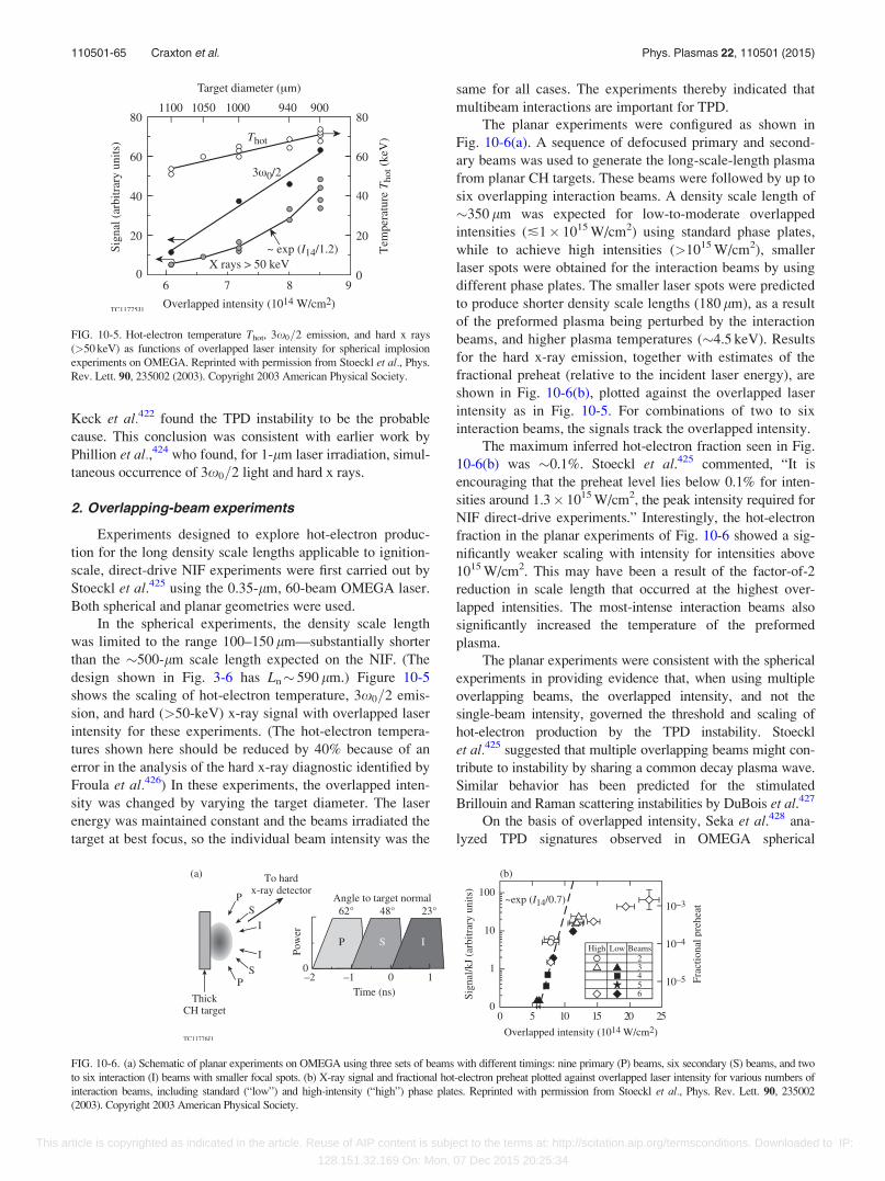
Keck et al.422 found the TPD instability to be the probable
cause. This conclusion was consistent with earlier work by
Phillion et al.,424 who found, for 1-lm laser irradiation, simul-
taneous occurrence of 3x0=2 light and hard x rays.
2. Overlapping-beam experiments
Experiments designed to explore hot-electron produc-
tion for the long density scale lengths applicable to ignition-
scale, direct-drive NIF experiments were first carried out by
Stoeckl et al.425 using the 0.35-lm, 60-beam OMEGA laser.
Both spherical and planar geometries were used.
In the spherical experiments, the density scale length
was limited to the range 100–150 lm—substantially shorter
than the �500-lm scale length expected on the NIF. (The
design shown in Fig. 3-6 has Ln� 590 lm.) Figure 10-5
shows the scaling of hot-electron temperature, 3x0=2 emis-
sion, and hard (>50-keV) x-ray signal with overlapped laser
intensity for these experiments. (The hot-electron tempera-
tures shown here should be reduced by 40% because of an
error in the analysis of the hard x-ray diagnostic identified by
Froula et al.426) In these experiments, the overlapped inten-
sity was changed by varying the target diameter. The laser
energy was maintained constant and the beams irradiated the
target at best focus, so the individual beam intensity was the
same for all cases. The experiments thereby indicated that
multibeam interactions are important for TPD.
The planar experiments were configured as shown in
Fig. 10-6(a). A sequence of defocused primary and second-
ary beams was used to generate the long-scale-length plasma
from planar CH targets. These beams were followed by up to
six overlapping interaction beams. A density scale length of
�350 lm was expected for low-to-moderate overlapped
intensities (�1� 1015 W/cm2) using standard phase plates,
while to achieve high intensities (>1015 W/cm2), smaller
laser spots were obtained for the interaction beams by using
different phase plates. The smaller laser spots were predicted
to produce shorter density scale lengths (180 lm), as a result
of the preformed plasma being perturbed by the interaction
beams, and higher plasma temperatures (�4.5 keV). Results
for the hard x-ray emission, together with estimates of the
fractional preheat (relative to the incident laser energy), are
shown in Fig. 10-6(b), plotted against the overlapped laser
intensity as in Fig. 10-5. For combinations of two to six
interaction beams, the signals track the overlapped intensity.
The maximum inferred hot-electron fraction seen in Fig.
10-6(b) was �0.1%. Stoeckl et al.425 commented, “It is
encouraging that the preheat level lies below 0.1% for inten-
sities around 1.3� 1015 W/cm2, the peak intensity required for
NIF direct-drive experiments.” Interestingly, the hot-electron
fraction in the planar experiments of Fig. 10-6 showed a sig-
nificantly weaker scaling with intensity for intensities above
1015 W/cm2. This may have been a result of the factor-of-2
reduction in scale length that occurred at the highest over-
lapped intensities. The most-intense interaction beams also
significantly increased the temperature of the preformed
plasma.
The planar experiments were consistent with the spherical
experiments in providing evidence that, when using multiple
overlapping beams, the overlapped intensity, and not the
single-beam intensity, governed the threshold and scaling of
hot-electron production by the TPD instability. Stoeckl
et al.425 suggested that multiple overlapping beams might con-
tribute to instability by sharing a common decay plasma wave.
Similar behavior has been predicted for the stimulated
Brillouin and Raman scattering instabilities by DuBois et al.427
On the basis of overlapped intensity, Seka et al.428 ana-
lyzed TPD signatures observed in OMEGA spherical
FIG. 10-5. Hot-electron temperature Thot, 3x0=2 emission, and hard x rays
(>50 keV) as functions of overlapped laser intensity for spherical implosion
experiments on OMEGA. Reprinted with permission from Stoeckl et al., Phys.
Rev. Lett. 90, 235002 (2003). Copyright 2003 American Physical Society.
FIG. 10-6. (a) Schematic of planar experiments on OMEGA using three sets of beams with different timings: nine primary (P) beams, six secondary (S) beams, and two
to six interaction (I) beams with smaller focal spots. (b) X-ray signal and fractional hot-electron preheat plotted against overlapped laser intensity for various numbers of
interaction beams, including standard (“low”) and high-intensity (“high”) phase plates. Reprinted with permission from Stoeckl et al., Phys. Rev. Lett. 90, 235002
(2003). Copyright 2003 American Physical Society.
110501-65 Craxton et al. Phys. Plasmas 22, 110501 (2015)
This article is copyrighted as indicated in the article. Reuse of AIP content is subject to the terms at: http://scitation.aip.org/termsconditions. Downloaded to IP:
128.151.32.169 On: Mon, 07 Dec 2015 20:25:34
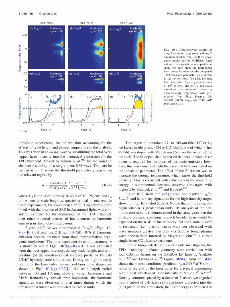
implosion experiments, for the first time accounting for the
effects of scale length and plasma temperature in the analysis.
This was done in an ad hoc way by substituting the total over-
lapped laser intensity into the theoretical expression for the
TPD threshold derived by Simon et al.409 for the onset of
absolute instability of a single plane EM wave. This can be
written as g¼ 1, where the threshold parameter g is given in
the relevant regime by
g ¼I14Ln lmð Þ
230Te keVð Þk0
0:351lm
� �; (10-4)
where I14 is the laser intensity in units of 1014 W/cm2 and Ln
is the density scale length at quarter critical in microns. In
these experiments, the coincidence of TPD signatures, com-
bined with the absence of SRS backscattered light, was con-
sidered evidence for the dominance of the TPD instability
over other potential sources of hot electrons or harmonic
emission in direct-drive implosions.
Figure 10-7 shows time-resolved 3x0=2 [Figs. 10-
7(a)–10-7(c)] and x0=2 [Figs. 10-7(d)–10-7(f)] harmonic
emission spectra obtained from three representative cryo-
genic implosions. The time-dependent threshold parameter gis shown in red in Figs. 10-7(g)–10-7(i). It was evaluated
from the overlapped intensity, density scale length, and tem-
perature (at the quarter-critical surface) predicted by 1-D
LILAC hydrodynamic simulations. During the high-intensity
portion of the laser pulse [normalized laser pulse shapes are
shown in Figs. 10-7(g)–10-7(i)], the scale length varied
between 100 and 150 lm, while Te varied between 2 and
3 keV. Remarkably, for all three implosions, the harmonic
signatures were observed only at times during which the
threshold parameter was predicted to exceed unity.
The targets all contained 77- to 100-lm-thick DT or D2
ice layers inside plastic (CH or CD) shells, one of which (shot
49156) was doped with 5% (atomic) Si over the outer half of
the shell. The Si-doped shell increased the peak incident laser
intensity required for the onset of harmonic emission; how-
ever, this was consistent with the expected behavior based on
the threshold parameter. The effect of the Si dopant was to
increase the coronal temperature, which raises the threshold
intensity. This is consistent with reductions in the amount of
energy in suprathermal electrons observed for targets with
higher Z by Smalyuk et al.429 and Hu et al.430
Figure 10-8 [from Ref. 428] shows time-resolved x0=2;3x0=2; and hard x-ray signatures for the high-intensity target
shown in Fig. 10-7 (shot 51280). Notice that all three signals
begin when g is greater than unity. By analysis of the har-
monic emission, it is demonstrated in the same work that the
unstable plasmon spectrum is much broader than would be
expected on the basis of linear theory, but the Landau cutoff
is respected (i.e., plasma waves were not observed with
wave numbers greater than 0.25 kD). Similar broad plasma
wave spectra were inferred by Meyer and Zhu431 in earlier
single-beam CO2 laser experiments.
Further long-scale-length experiments investigating the
TPD instability in planar geometry were carried out with
four 0.35-lm beams on the OMEGA EP laser by Yaakobi
et al.432 and Froula et al.426 Figure 10-9(a), from Ref. 432,
shows the plasma conditions predicted by a 2-D SAGE simu-
lation at the end of the laser pulse for a typical experiment
with a peak overlapped laser intensity of 5.8� 1014 W/cm2.
Density contours spaced by a factor of 2 are shown together
with a subset of 3-D laser ray trajectories projected into the
(r, z) plane. In the simulation, the laser energy is predicted to
FIG. 10-7. Time-resolved spectra of
3x0=2 emission (top row) and x0=2
emission (middle row) for three cryo-
genic implosions on OMEGA. Each
column corresponds to one particular
shot. For each shot, the normalized
laser power histories and the computed
TPD threshold parameter g are shown
in the bottom row. The peak incident
laser intensities I14 are given in units
of 1014 W/cm2. The 3x0=2 and x0=2
emissions are observed when gexceeds unity. Reproduced with per-
mission from Phys. Plasmas 16,
052701 (2009). Copyright 2009 AIP
Publishing LLC.
110501-66 Craxton et al. Phys. Plasmas 22, 110501 (2015)
This article is copyrighted as indicated in the article. Reuse of AIP content is subject to the terms at: http://scitation.aip.org/termsconditions. Downloaded to IP:
128.151.32.169 On: Mon, 07 Dec 2015 20:25:34
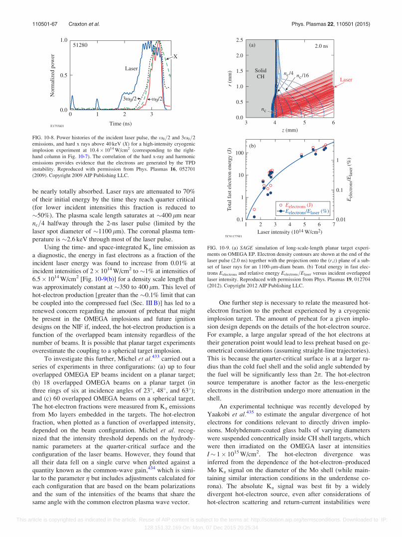
be nearly totally absorbed. Laser rays are attenuated to 70%
of their initial energy by the time they reach quarter critical
(for lower incident intensities this fraction is reduced to
�50%). The plasma scale length saturates at �400 lm near
nc=4 halfway through the 2-ns laser pulse (limited by the
laser spot diameter of �1100 lm). The coronal plasma tem-
perature is �2.6 keV through most of the laser pulse.
Using the time- and space-integrated Ka line emission as
a diagnostic, the energy in fast electrons as a fraction of the
incident laser energy was found to increase from 0.01% at
incident intensities of 2� 1014 W/cm2 to �1% at intensities of
6.5� 1014 W/cm2 [Fig. 10-9(b)] for a density scale length that
was approximately constant at �350 to 400 lm. This level of
hot-electron production [greater than the �0.1% limit that can
be coupled into the compressed fuel (Sec. III B)] has led to a
renewed concern regarding the amount of preheat that might
be present in the OMEGA implosions and future ignition
designs on the NIF if, indeed, the hot-electron production is a
function of the overlapped beam intensity regardless of the
number of beams. It is possible that planar target experiments
overestimate the coupling to a spherical target implosion.
To investigate this further, Michel et al.433 carried out a
series of experiments in three configurations: (a) up to four
overlapped OMEGA EP beams incident on a planar target;
(b) 18 overlapped OMEGA beams on a planar target (in
three rings of six at incidence angles of 23�, 48�, and 63�);and (c) 60 overlapped OMEGA beams on a spherical target.
The hot-electron fractions were measured from Ka emissions
from Mo layers embedded in the targets. The hot-electron
fraction, when plotted as a function of overlapped intensity,
depended on the beam configuration. Michel et al. recog-
nized that the intensity threshold depends on the hydrody-
namic parameters at the quarter-critical surface and the
configuration of the laser beams. However, they found that
all their data fell on a single curve when plotted against a
quantity known as the common-wave gain,434 which is simi-
lar to the parameter g but includes adjustments calculated for
each configuration that are based on the beam polarizations
and the sum of the intensities of the beams that share the
same angle with the common electron plasma wave vector.
One further step is necessary to relate the measured hot-
electron fraction to the preheat experienced by a cryogenic
implosion target. The amount of preheat for a given implo-
sion design depends on the details of the hot-electron source.
For example, a large angular spread of the hot electrons at
their generation point would lead to less preheat based on ge-
ometrical considerations (assuming straight-line trajectories).
This is because the quarter-critical surface is at a larger ra-
dius than the cold fuel shell and the solid angle subtended by
the fuel will be significantly less than 2p. The hot-electron
source temperature is another factor as the less-energetic
electrons in the distribution undergo more attenuation in the
shell.
An experimental technique was recently developed by
Yaakobi et al.435 to estimate the angular divergence of hot
electrons for conditions relevant to directly driven implo-
sions. Molybdenum-coated glass balls of varying diameters
were suspended concentrically inside CH shell targets, which
were then irradiated on the OMEGA laser at intensities
I� 1� 1015 W/cm2. The hot-electron divergence was
inferred from the dependence of the hot-electron–produced
Mo Ka signal on the diameter of the Mo shell (while main-
taining similar interaction conditions in the underdense co-
rona). The absolute Ka signal was best fit by a widely
divergent hot-electron source, even after considerations of
hot-electron scattering and return-current instabilities were
FIG. 10-8. Power histories of the incident laser pulse, the x0=2 and 3x0=2
emissions, and hard x rays above 40 keV (X) for a high-intensity cryogenic
implosion experiment at 10.4� 1014 W/cm2 (corresponding to the right-
hand column in Fig. 10-7). The correlation of the hard x-ray and harmonic
emissions provides evidence that the electrons are generated by the TPD
instability. Reproduced with permission from Phys. Plasmas 16, 052701
(2009). Copyright 2009 AIP Publishing LLC.
FIG. 10-9. (a) SAGE simulation of long-scale-length planar target experi-
ments on OMEGA EP. Electron density contours are shown at the end of the
laser pulse (2.0 ns) together with the projection onto the (r,z) plane of a sub-
set of laser rays for an 1100-lm-diam beam. (b) Total energy in fast elec-
trons Eelectrons and relative energy Eelectrons=Elaser versus incident overlapped
laser intensity. Reproduced with permission from Phys. Plasmas 19, 012704
(2012). Copyright 2012 AIP Publishing LLC.
110501-67 Craxton et al. Phys. Plasmas 22, 110501 (2015)
This article is copyrighted as indicated in the article. Reuse of AIP content is subject to the terms at: http://scitation.aip.org/termsconditions. Downloaded to IP:
128.151.32.169 On: Mon, 07 Dec 2015 20:25:34
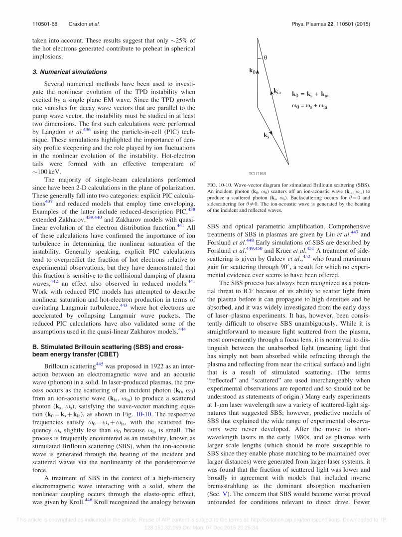
taken into account. These results suggest that only �25% of
the hot electrons generated contribute to preheat in spherical
implosions.
3. Numerical simulations
Several numerical methods have been used to investi-
gate the nonlinear evolution of the TPD instability when
excited by a single plane EM wave. Since the TPD growth
rate vanishes for decay wave vectors that are parallel to the
pump wave vector, the instability must be studied in at least
two dimensions. The first such calculations were performed
by Langdon et al.436 using the particle-in-cell (PIC) tech-
nique. These simulations highlighted the importance of den-
sity profile steepening and the role played by ion fluctuations
in the nonlinear evolution of the instability. Hot-electron
tails were formed with an effective temperature of
�100 keV.
The majority of single-beam calculations performed
since have been 2-D calculations in the plane of polarization.
These generally fall into two categories: explicit PIC calcula-
tions437 and reduced models that employ time enveloping.
Examples of the latter include reduced-description PIC,438
extended Zakharov,439,440 and Zakharov models with quasi-
linear evolution of the electron distribution function.441 All
of these calculations have confirmed the importance of ion
turbulence in determining the nonlinear saturation of the
instability. Generally speaking, explicit PIC calculations
tend to overpredict the fraction of hot electrons relative to
experimental observations, but they have demonstrated that
this fraction is sensitive to the collisional damping of plasma
waves,442 an effect also observed in reduced models.441
Work with reduced PIC models has attempted to describe
nonlinear saturation and hot-electron production in terms of
cavitating Langmuir turbulence,443 where hot electrons are
accelerated by collapsing Langmuir wave packets. The
reduced PIC calculations have also validated some of the
assumptions used in the quasi-linear Zakharov models.444
B. Stimulated Brillouin scattering (SBS) and cross-beam energy transfer (CBET)
Brillouin scattering445 was proposed in 1922 as an inter-
action between an electromagnetic wave and an acoustic
wave (phonon) in a solid. In laser-produced plasmas, the pro-
cess occurs as the scattering of an incident photon (k0, x0)
from an ion-acoustic wave (kia, xia) to produce a scattered
photon (ks, xs), satisfying the wave-vector matching equa-
tion (k0¼ ksþ kia), as shown in Fig. 10-10. The respective
frequencies satisfy x0¼xsþxia, with the scattered fre-
quency xs slightly less than x0 because xia is small. The
process is frequently encountered as an instability, known as
stimulated Brillouin scattering (SBS), when the ion-acoustic
wave is generated through the beating of the incident and
scattered waves via the nonlinearity of the ponderomotive
force.
A treatment of SBS in the context of a high-intensity
electromagnetic wave interacting with a solid, where the
nonlinear coupling occurs through the elasto-optic effect,
was given by Kroll.446 Kroll recognized the analogy between
SBS and optical parametric amplification. Comprehensive
treatments of SBS in plasmas are given by Liu et al.447 and
Forslund et al.448 Early simulations of SBS are described by
Forslund et al.449,450 and Kruer et al.451 A treatment of side-
scattering is given by Galeev et al.,452 who found maximum
gain for scattering through 90�, a result for which no experi-
mental evidence ever seems to have been offered.
The SBS process has always been recognized as a poten-
tial threat to ICF because of its ability to scatter light from
the plasma before it can propagate to high densities and be
absorbed, and it was widely investigated from the early days
of laser–plasma experiments. It has, however, been consis-
tently difficult to observe SBS unambiguously. While it is
straightforward to measure light scattered from the plasma,
most conveniently through a focus lens, it is nontrivial to dis-
tinguish between the unabsorbed light (meaning light that
has simply not been absorbed while refracting through the
plasma and reflecting from near the critical surface) and light
that is a result of stimulated scattering. (The terms
“reflected” and “scattered” are used interchangeably when
experimental observations are reported and so should not be
understood as statements of origin.) Many early experiments
at 1-lm laser wavelength saw a variety of scattered-light sig-
natures that suggested SBS; however, predictive models of
SBS that explained the wide range of experimental observa-
tions were never developed. After the move to short-
wavelength lasers in the early 1980s, and as plasmas with
larger scale lengths (which should be more susceptible to
SBS since they enable phase matching to be maintained over
larger distances) were generated from larger laser systems, it
was found that the fraction of scattered light was lower and
broadly in agreement with models that included inverse
bremsstrahlung as the dominant absorption mechanism
(Sec. V). The concern that SBS would become worse proved
unfounded for conditions relevant to direct drive. Fewer
FIG. 10-10. Wave-vector diagram for stimulated Brillouin scattering (SBS).
An incident photon (k0, x0) scatters off an ion-acoustic wave (kia, xia) to
produce a scattered photon (ks, xs). Backscattering occurs for h¼ 0 and
sidescattering for h 6¼ 0. The ion-acoustic wave is generated by the beating
of the incident and reflected waves.
110501-68 Craxton et al. Phys. Plasmas 22, 110501 (2015)
This article is copyrighted as indicated in the article. Reuse of AIP content is subject to the terms at: http://scitation.aip.org/termsconditions. Downloaded to IP:
128.151.32.169 On: Mon, 07 Dec 2015 20:25:34
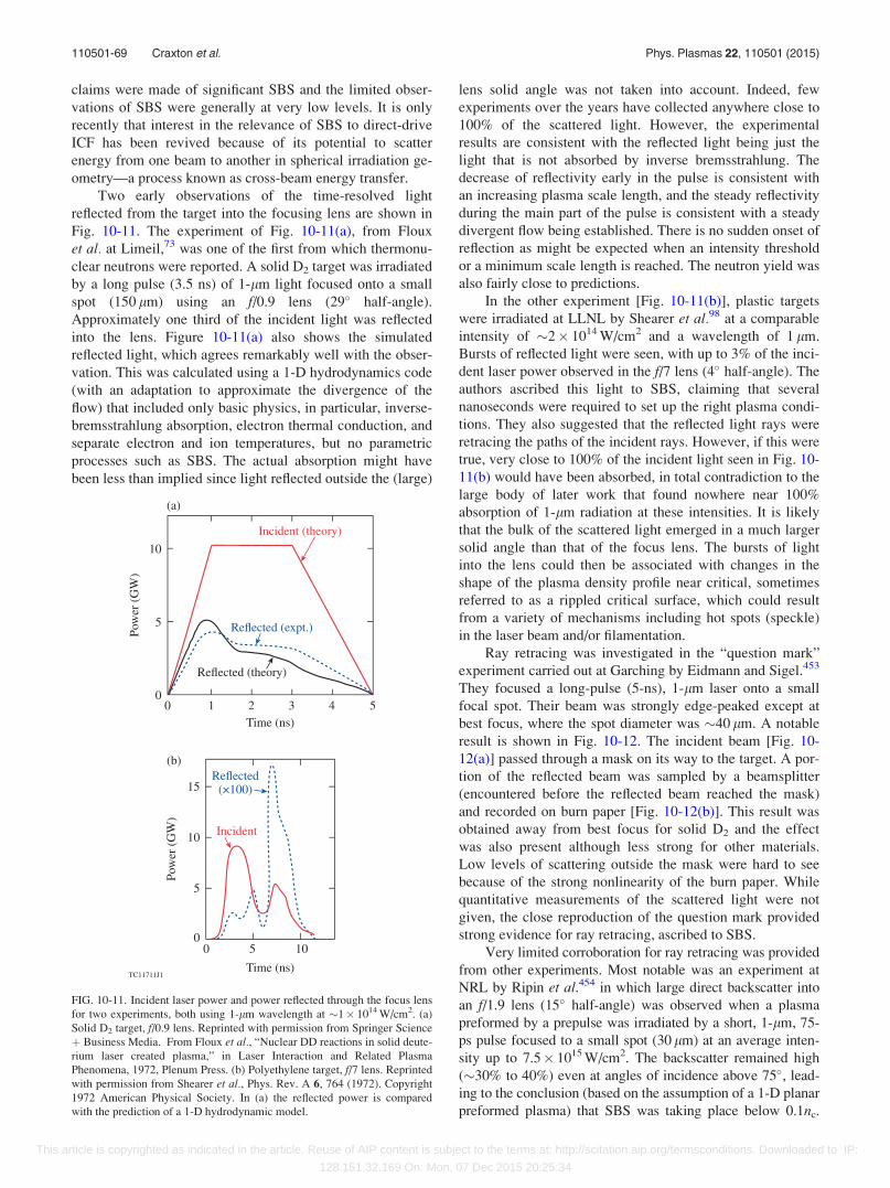
claims were made of significant SBS and the limited obser-
vations of SBS were generally at very low levels. It is only
recently that interest in the relevance of SBS to direct-drive
ICF has been revived because of its potential to scatter
energy from one beam to another in spherical irradiation ge-
ometry—a process known as cross-beam energy transfer.
Two early observations of the time-resolved light
reflected from the target into the focusing lens are shown in
Fig. 10-11. The experiment of Fig. 10-11(a), from Floux
et al. at Limeil,73 was one of the first from which thermonu-
clear neutrons were reported. A solid D2 target was irradiated
by a long pulse (3.5 ns) of 1-lm light focused onto a small
spot (150 lm) using an f/0.9 lens (29� half-angle).
Approximately one third of the incident light was reflected
into the lens. Figure 10-11(a) also shows the simulated
reflected light, which agrees remarkably well with the obser-
vation. This was calculated using a 1-D hydrodynamics code
(with an adaptation to approximate the divergence of the
flow) that included only basic physics, in particular, inverse-
bremsstrahlung absorption, electron thermal conduction, and
separate electron and ion temperatures, but no parametric
processes such as SBS. The actual absorption might have
been less than implied since light reflected outside the (large)
lens solid angle was not taken into account. Indeed, few
experiments over the years have collected anywhere close to
100% of the scattered light. However, the experimental
results are consistent with the reflected light being just the
light that is not absorbed by inverse bremsstrahlung. The
decrease of reflectivity early in the pulse is consistent with
an increasing plasma scale length, and the steady reflectivity
during the main part of the pulse is consistent with a steady
divergent flow being established. There is no sudden onset of
reflection as might be expected when an intensity threshold
or a minimum scale length is reached. The neutron yield was
also fairly close to predictions.
In the other experiment [Fig. 10-11(b)], plastic targets
were irradiated at LLNL by Shearer et al.98 at a comparable
intensity of �2� 1014 W/cm2 and a wavelength of 1 lm.
Bursts of reflected light were seen, with up to 3% of the inci-
dent laser power observed in the f/7 lens (4� half-angle). The
authors ascribed this light to SBS, claiming that several
nanoseconds were required to set up the right plasma condi-
tions. They also suggested that the reflected light rays were
retracing the paths of the incident rays. However, if this were
true, very close to 100% of the incident light seen in Fig. 10-
11(b) would have been absorbed, in total contradiction to the
large body of later work that found nowhere near 100%
absorption of 1-lm radiation at these intensities. It is likely
that the bulk of the scattered light emerged in a much larger
solid angle than that of the focus lens. The bursts of light
into the lens could then be associated with changes in the
shape of the plasma density profile near critical, sometimes
referred to as a rippled critical surface, which could result
from a variety of mechanisms including hot spots (speckle)
in the laser beam and/or filamentation.
Ray retracing was investigated in the “question mark”
experiment carried out at Garching by Eidmann and Sigel.453
They focused a long-pulse (5-ns), 1-lm laser onto a small
focal spot. Their beam was strongly edge-peaked except at
best focus, where the spot diameter was �40 lm. A notable
result is shown in Fig. 10-12. The incident beam [Fig. 10-
12(a)] passed through a mask on its way to the target. A por-
tion of the reflected beam was sampled by a beamsplitter
(encountered before the reflected beam reached the mask)
and recorded on burn paper [Fig. 10-12(b)]. This result was
obtained away from best focus for solid D2 and the effect
was also present although less strong for other materials.
Low levels of scattering outside the mask were hard to see
because of the strong nonlinearity of the burn paper. While
quantitative measurements of the scattered light were not
given, the close reproduction of the question mark provided
strong evidence for ray retracing, ascribed to SBS.
Very limited corroboration for ray retracing was provided
from other experiments. Most notable was an experiment at
NRL by Ripin et al.454 in which large direct backscatter into
an f/1.9 lens (15� half-angle) was observed when a plasma
preformed by a prepulse was irradiated by a short, 1-lm, 75-
ps pulse focused to a small spot (30 lm) at an average inten-
sity up to 7.5� 1015 W/cm2. The backscatter remained high
(�30% to 40%) even at angles of incidence above 75�, lead-
ing to the conclusion (based on the assumption of a 1-D planar
preformed plasma) that SBS was taking place below 0.1nc.
FIG. 10-11. Incident laser power and power reflected through the focus lens
for two experiments, both using 1-lm wavelength at �1� 1014 W/cm2. (a)
Solid D2 target, f/0.9 lens. Reprinted with permission from Springer Science
þ Business Media. From Floux et al., “Nuclear DD reactions in solid deute-
rium laser created plasma,” in Laser Interaction and Related Plasma
Phenomena, 1972, Plenum Press. (b) Polyethylene target, f/7 lens. Reprinted
with permission from Shearer et al., Phys. Rev. A 6, 764 (1972). Copyright
1972 American Physical Society. In (a) the reflected power is compared
with the prediction of a 1-D hydrodynamic model.
110501-69 Craxton et al. Phys. Plasmas 22, 110501 (2015)
This article is copyrighted as indicated in the article. Reuse of AIP content is subject to the terms at: http://scitation.aip.org/termsconditions. Downloaded to IP:
128.151.32.169 On: Mon, 07 Dec 2015 20:25:34
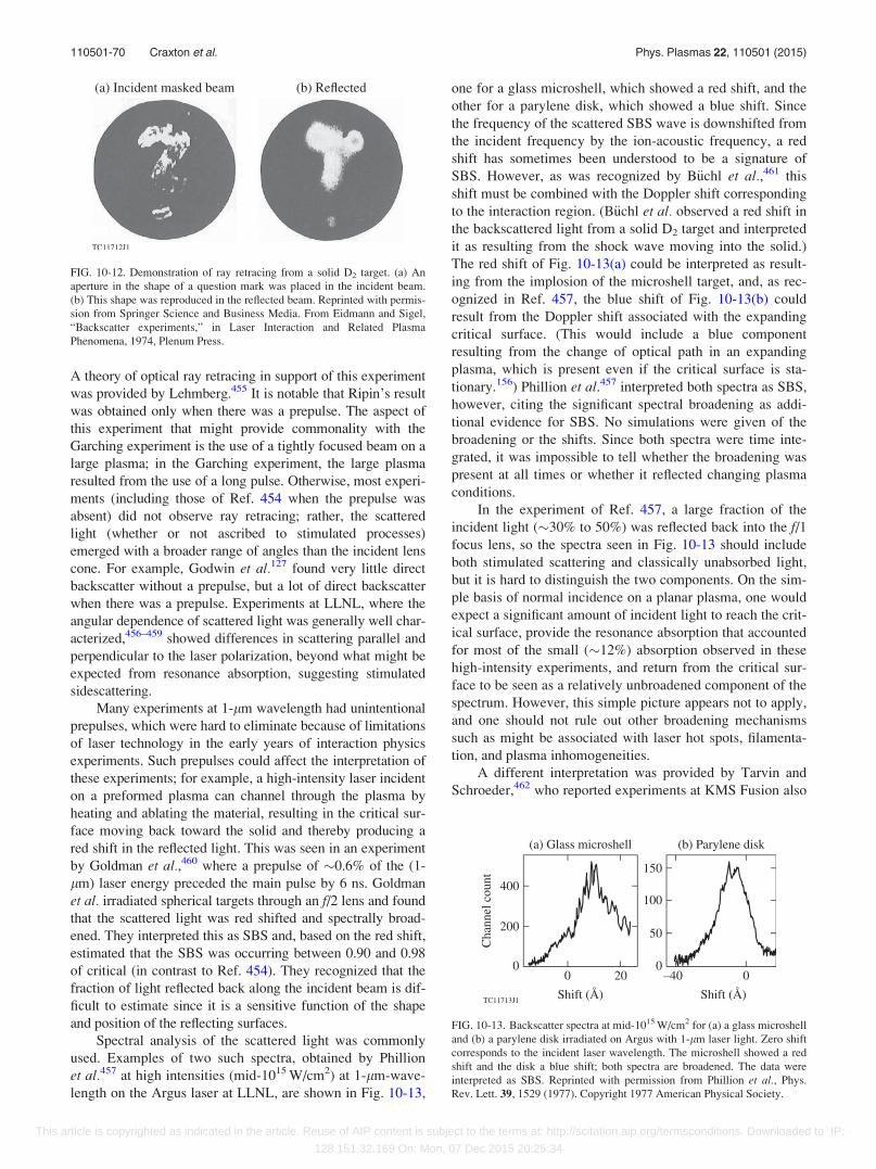
A theory of optical ray retracing in support of this experiment
was provided by Lehmberg.455 It is notable that Ripin’s result
was obtained only when there was a prepulse. The aspect of
this experiment that might provide commonality with the
Garching experiment is the use of a tightly focused beam on a
large plasma; in the Garching experiment, the large plasma
resulted from the use of a long pulse. Otherwise, most experi-
ments (including those of Ref. 454 when the prepulse was
absent) did not observe ray retracing; rather, the scattered
light (whether or not ascribed to stimulated processes)
emerged with a broader range of angles than the incident lens
cone. For example, Godwin et al.127 found very little direct
backscatter without a prepulse, but a lot of direct backscatter
when there was a prepulse. Experiments at LLNL, where the
angular dependence of scattered light was generally well char-
acterized,456–459 showed differences in scattering parallel and
perpendicular to the laser polarization, beyond what might be
expected from resonance absorption, suggesting stimulated
sidescattering.
Many experiments at 1-lm wavelength had unintentional
prepulses, which were hard to eliminate because of limitations
of laser technology in the early years of interaction physics
experiments. Such prepulses could affect the interpretation of
these experiments; for example, a high-intensity laser incident
on a preformed plasma can channel through the plasma by
heating and ablating the material, resulting in the critical sur-
face moving back toward the solid and thereby producing a
red shift in the reflected light. This was seen in an experiment
by Goldman et al.,460 where a prepulse of �0.6% of the (1-
lm) laser energy preceded the main pulse by 6 ns. Goldman
et al. irradiated spherical targets through an f/2 lens and found
that the scattered light was red shifted and spectrally broad-
ened. They interpreted this as SBS and, based on the red shift,
estimated that the SBS was occurring between 0.90 and 0.98
of critical (in contrast to Ref. 454). They recognized that the
fraction of light reflected back along the incident beam is dif-
ficult to estimate since it is a sensitive function of the shape
and position of the reflecting surfaces.
Spectral analysis of the scattered light was commonly
used. Examples of two such spectra, obtained by Phillion
et al.457 at high intensities (mid-1015 W/cm2) at 1-lm-wave-
length on the Argus laser at LLNL, are shown in Fig. 10-13,
one for a glass microshell, which showed a red shift, and the
other for a parylene disk, which showed a blue shift. Since
the frequency of the scattered SBS wave is downshifted from
the incident frequency by the ion-acoustic frequency, a red
shift has sometimes been understood to be a signature of
SBS. However, as was recognized by B€uchl et al.,461 this
shift must be combined with the Doppler shift corresponding
to the interaction region. (B€uchl et al. observed a red shift in
the backscattered light from a solid D2 target and interpreted
it as resulting from the shock wave moving into the solid.)
The red shift of Fig. 10-13(a) could be interpreted as result-
ing from the implosion of the microshell target, and, as rec-
ognized in Ref. 457, the blue shift of Fig. 10-13(b) could
result from the Doppler shift associated with the expanding
critical surface. (This would include a blue component
resulting from the change of optical path in an expanding
plasma, which is present even if the critical surface is sta-
tionary.156) Phillion et al.457 interpreted both spectra as SBS,
however, citing the significant spectral broadening as addi-
tional evidence for SBS. No simulations were given of the
broadening or the shifts. Since both spectra were time inte-
grated, it was impossible to tell whether the broadening was
present at all times or whether it reflected changing plasma
conditions.
In the experiment of Ref. 457, a large fraction of the
incident light (�30% to 50%) was reflected back into the f/1focus lens, so the spectra seen in Fig. 10-13 should include
both stimulated scattering and classically unabsorbed light,
but it is hard to distinguish the two components. On the sim-
ple basis of normal incidence on a planar plasma, one would
expect a significant amount of incident light to reach the crit-
ical surface, provide the resonance absorption that accounted
for most of the small (�12%) absorption observed in these
high-intensity experiments, and return from the critical sur-
face to be seen as a relatively unbroadened component of the
spectrum. However, this simple picture appears not to apply,
and one should not rule out other broadening mechanisms
such as might be associated with laser hot spots, filamenta-
tion, and plasma inhomogeneities.
A different interpretation was provided by Tarvin and
Schroeder,462 who reported experiments at KMS Fusion also
FIG. 10-12. Demonstration of ray retracing from a solid D2 target. (a) An
aperture in the shape of a question mark was placed in the incident beam.
(b) This shape was reproduced in the reflected beam. Reprinted with permis-
sion from Springer Science and Business Media. From Eidmann and Sigel,
“Backscatter experiments,” in Laser Interaction and Related Plasma
Phenomena, 1974, Plenum Press.
FIG. 10-13. Backscatter spectra at mid-1015 W/cm2 for (a) a glass microshell
and (b) a parylene disk irradiated on Argus with 1-lm laser light. Zero shift
corresponds to the incident laser wavelength. The microshell showed a red
shift and the disk a blue shift; both spectra are broadened. The data were
interpreted as SBS. Reprinted with permission from Phillion et al., Phys.
Rev. Lett. 39, 1529 (1977). Copyright 1977 American Physical Society.
110501-70 Craxton et al. Phys. Plasmas 22, 110501 (2015)
This article is copyrighted as indicated in the article. Reuse of AIP content is subject to the terms at: http://scitation.aip.org/termsconditions. Downloaded to IP:
128.151.32.169 On: Mon, 07 Dec 2015 20:25:34

at high intensity (6.6� 1015 W/cm2) and 1-lm wavelength,
in which the spherical targets were irradiated using two f/0.2
ellipsoidal mirrors. Figure 10-14(a) shows a streaked
backscattered-light spectrum, which is compared with a sim-
ulation in Fig. 10-14(b). The most-notable feature is an ini-
tially growing blue shift, understood to be a Doppler shift
associated with the expanding plasma,156 followed by a
return to zero shift as the plasma profiles become more sta-
tionary (i.e., change less with time). Tarvin and Schroeder
offered two explanations for the broadening: (1) the laser
rays encounter the target at different angles, experiencing a
range of Doppler shifts; and (2) different parts of the critical
surface move with different velocities at any given time.
Their simulations show very little SBS because of large gra-
dients of density and velocity outside the critical surface.
In more recent years, experiments were carried out on
the OMEGA laser in which high-intensity 0.35-lm interac-
tion beams were used to irradiate long-scale-length plasmas,
formed from flat, solid targets using low-intensity, defocused
beams, in an attempt to access parameters relevant to NIF
ignition designs. One such experiment was reported by
Regan et al.463 Exploding-foil and solid-target plasmas were
created with parameters approximating those expected at the
peak of ignition pulses. The temperature (�4 keV) was diag-
nosed spectroscopically and the evolution of the peak density
in the exploding-foil plasmas was determined from streaked
SRS measurements. Both measurements were consistent
with 2-D hydrodynamic simulations. No SBS of any signifi-
cance was seen from the interaction beam, with an upper
limit of 0.1% for the exploding foils and an estimate of 0.2%
for the solid targets.
A similar experiment, reported by Myatt et al.,464 was
designed to generate a region with a flat velocity profile,
favorable for SBS as the Doppler shift is constant along the
path of the stimulated wave. Figure 10-15 (from Ref. 464)
shows a streaked spectrum of the backscattered light at nor-
mal incidence. Of note is the component whose blue shift
increases with time. This is understood to be SBS generated
in the region, predicted to move away from the target, where
the velocity profile is flat. The square points are predictions
for the maxima in the backscattered spectrum based on an
SBS code being used to post-process profiles from hydrody-
namic simulations. Classical absorption is strong in these
experiments, and the amount of SBS (backscattered into an f/6 focus lens) is typically less than a few percent.465 The red-
shifted feature in Fig. 10-15 is associated with nonlinear
SBS in the dense plasma near the critical surface.466 In Ref.
466, the reflected light spectra have features associated with
both SBS and unabsorbed refracted light, addressing the
long-standing question about the relative roles of these two
effects.
Some insight into the origin of the SBS observed in
these experiments is provided by Fig. 10-16, which shows
the time-integrated reflectivity through a focus lens meas-
ured as a function of interaction beam intensity by Seka
et al.467 A significant difference is observed depending on
whether or not polarization smoothing (PS) (Sec. VI D) is
used. Peak speckle intensities within the beam are reduced
by a factor of 2 with PS, as the two polarizations are inde-
pendent. When the PS points are plotted with their intensity
reduced by a factor of 2, they lie together with the points
without PS. This consistency suggests that the reflectivity is
a result of SBS occurring in hot spots (high-intensity laser
speckles).
More recently, much attention has been directed to
seeded SBS. “Pure” SBS results from the amplification of
thermal noise, requiring a large velocity-gradient scale
length to provide a sufficient number of e foldings for signifi-
cant reflection unless the absolute threshold is exceeded. As
FIG. 10-14. (a) Time-resolved spectrum (deviation from the 1-lm laser
wavelength k0) from a spherical glass target irradiated at 6.6� 1015 W/cm2
on the KMS Chroma laser using a pair of f/0.2 ellipsoidal mirrors. (b)
Simulation of the data. The length of the bar at each time gives the visible
extent of the spectrum in the streak record. The spectrum was understood to
shift to the blue as a Doppler effect associated with the expanding critical
surface and return toward zero after 250 ps as the critical surface became
nearly stationary. Reprinted with permission from Tarvin and Schroeder,
Phys. Rev. Lett. 47, 341 (1981). Copyright 1981 American Physical Society.
FIG. 10-15. Time-resolved backscatter spectrum of a high-intensity
(�8.5� 1014 W/cm2) interaction beam from a long-scale-length plasma
experiment on OMEGA. The white curve gives the incident laser pulse
shape on a linear scale. The squares give the predicted locations of maxima
on the backscattered frequency spectrum based on the evolving plasma pro-
files. Reproduced with permission from Phys. Plasmas 11, 3394 (2004).
Copyright 2004 AIP Publishing LLC.
110501-71 Craxton et al. Phys. Plasmas 22, 110501 (2015)
This article is copyrighted as indicated in the article. Reuse of AIP content is subject to the terms at: http://scitation.aip.org/termsconditions. Downloaded to IP:
128.151.32.169 On: Mon, 07 Dec 2015 20:25:34
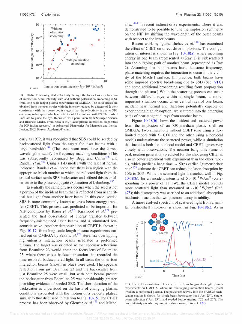
early as 1972, it was recognized that SBS could be seeded by
backscattered light from the target for laser beams with a
large bandwidth.98 (The seed beam must have the correct
wavelength to satisfy the frequency-matching conditions.) This
was subsequently recognized by Begg and Cairns468 and
Randall et al.469 Using a 1-D model with the laser at normal
incidence, Randall et al. noted that there is a region with the
appropriate Mach number at which the reflected light from the
critical surface seeds SBS backscatter and offered this as an al-
ternative to the phase-conjugate explanation of Lehmberg.455
Essentially the same physics occurs when the seed is not
a portion of the incident beam that is reflected from near crit-
ical but light from another laser beam. In this case, seeded
SBS is more commonly known as cross-beam energy trans-
fer (CBET). This process was predicted to be important for
NIF conditions by Kruer et al.470 Kirkwood et al.471 pre-
sented the first observation of energy transfer between
frequency-mismatched laser beams and a stimulated ion-
acoustic wave. Another demonstration of CBET is shown in
Fig. 10-17, from long-scale-length plasma experiments car-
ried out on OMEGA by Seka et al.472 Here, six overlapping
high-intensity interaction beams irradiated a preformed
plasma. The target was oriented so that specular reflections
from Beamline 23 would enter the focus lens of Beamline
25, where there was a backscatter station that recorded the
time-resolved backscattered light. In all cases the other four
interaction beams (shown in blue) were used. The specular
reflection from just Beamline 23 and the backscatter from
just Beamline 25 were small, but with both beams present
the backscatter from Beamline 25 was considerably greater,
providing evidence of seeded SBS. The short duration of the
backscatter is understood on the basis of changing plasma
conditions associated with the motion of a velocity plateau
similar to that discussed in relation to Fig. 10-15. The CBET
process has been observed by Glenzer et al.473 and Michel
et al.474 in recent indirect-drive experiments, where it was
demonstrated to be possible to tune the implosion symmetry
on the NIF by shifting the wavelength of the outer beams
with respect to the inner beams.
Recent work by Igumenshchev et al.158 has examined
the effect of CBET on direct-drive implosions. The configu-
ration of interest is shown in Fig. 10-18(a), where incoming
energy in one beam (represented as Ray 1) is sidescattered
into the outgoing path of another beam (represented as Ray
2). Assuming that both beams have the same frequency,
phase matching requires the interaction to occur in the vicin-
ity of the Mach-1 surface. [In practice, both beams have
some imposed spectral broadening due to SSD (Sec. VI C)
and some additional broadening resulting from propagation
through the plasma.] While the scattering process can occur
between different rays within a single beam, a more-
important situation occurs when central rays of one beam,
incident near normal and therefore potentially capable of
experiencing high absorption, are scattered into the emerging
paths of near-tangential rays from another beam.
Figure 10-18(b) shows the incident and scattered power
from the implosion of an 830-lm-diam plastic shell on
OMEGA. Two simulations without CBET (one using a flux-
limited model with f¼ 0.06 and the other using a nonlocal
model) underestimate the scattered power, while a simulation
that includes both the nonlocal model and CBET agrees very
closely with observations. The neutron bang time (time of
peak neutron generation) predicted for this shot using CBET is
also in better agreement with experiment than the other mod-
els, which predict a bang time �150 ps earlier. Igumenshchev
et al.158 estimate that CBET can reduce the laser absorption by
10% to 20%. While the scattered light is matched well in Fig.
10-18(b), for an incident intensity of 5� 1014 W/cm2 (corre-
sponding to a power of 11 TW), the CBET model predicts
more scattered light than measured at �1015 W/cm2 (Ref.
475); this discrepancy was ascribed to an additional absorption
mechanism such as the two-plasmon–decay instability.
A time-resolved spectrum of scattered light from a simi-
lar plastic-shell implosion is shown in Fig. 10-18(c). As in
FIG. 10-17. Demonstration of seeded SBS from long-scale-length plasma
experiments on OMEGA, where six overlapping interaction beams (inset)
irradiate a preformed plasma. The power reflectivity into the FABS25 back-
scatter station is shown for single-beam backscattering (“Just 25”), single-
beam reflection (“Just 23”), and seeded backscattering (“23 and 25”). The
laser intensity (in arbitrary units) is also shown (from Ref. 472).
FIG. 10-16. Time-integrated reflectivity through the focus lens as a function
of interaction beam intensity with and without polarization smoothing (PS),
from long-scale-length plasma experiments on OMEGA. The solid circles are
obtained from the open circles with the intensity reduced by a factor of 2; their
consistency with the square points suggest that the reflectivity is due to SBS
occurring in hot spots, which are a factor of 2 less intense with PS. The dashed
lines are to guide the eye. Reprinted with permission from Springer Science
and Business Media. From Seka et al., “Laser-plasma interaction diagnostics
for ICF fusion research,” in Advanced Diagnostics for Magnetic and Inertial
Fusion, 2002, Kluwer Academic/Plenum.
110501-72 Craxton et al. Phys. Plasmas 22, 110501 (2015)
This article is copyrighted as indicated in the article. Reuse of AIP content is subject to the terms at: http://scitation.aip.org/termsconditions. Downloaded to IP:
128.151.32.169 On: Mon, 07 Dec 2015 20:25:34
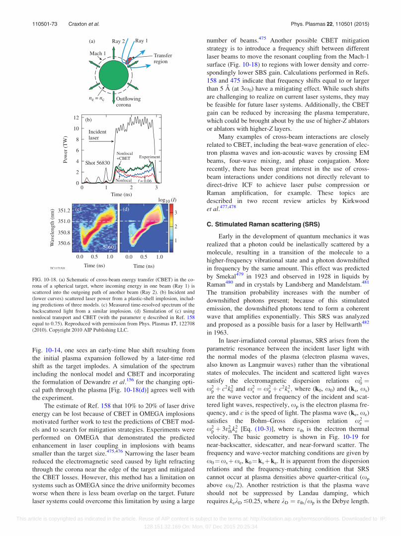
Fig. 10-14, one sees an early-time blue shift resulting from
the initial plasma expansion followed by a later-time red
shift as the target implodes. A simulation of the spectrum
including the nonlocal model and CBET and incorporating
the formulation of Dewandre et al.156 for the changing opti-
cal path through the plasma [Fig. 10-18(d)] agrees well with
the experiment.
The estimate of Ref. 158 that 10% to 20% of laser drive
energy can be lost because of CBET in OMEGA implosions
motivated further work to test the predictions of CBET mod-
els and to search for mitigation strategies. Experiments were
performed on OMEGA that demonstrated the predicted
enhancement in laser coupling in implosions with beams
smaller than the target size.475,476 Narrowing the laser beam
reduced the electromagnetic seed caused by light refracting
through the corona near the edge of the target and mitigated
the CBET losses. However, this method has a limitation on
systems such as OMEGA since the drive uniformity becomes
worse when there is less beam overlap on the target. Future
laser systems could overcome this limitation by using a large
number of beams.475 Another possible CBET mitigation
strategy is to introduce a frequency shift between different
laser beams to move the resonant coupling from the Mach-1
surface (Fig. 10-18) to regions with lower density and corre-
spondingly lower SBS gain. Calculations performed in Refs.
158 and 475 indicate that frequency shifts equal to or larger
than 5 A (at 3x0) have a mitigating effect. While such shifts
are challenging to realize on current laser systems, they may
be feasible for future laser systems. Additionally, the CBET
gain can be reduced by increasing the plasma temperature,
which could be brought about by the use of higher-Z ablators
or ablators with higher-Z layers.
Many examples of cross-beam interactions are closely
related to CBET, including the beat-wave generation of elec-
tron plasma waves and ion-acoustic waves by crossing EM
beams, four-wave mixing, and phase conjugation. More
recently, there has been great interest in the use of cross-
beam interactions under conditions not directly relevant to
direct-drive ICF to achieve laser pulse compression or
Raman amplification, for example. These topics are
described in two recent review articles by Kirkwood
et al.477,478
C. Stimulated Raman scattering (SRS)
Early in the development of quantum mechanics it was
realized that a photon could be inelastically scattered by a
molecule, resulting in a transition of the molecule to a
higher-frequency vibrational state and a photon downshifted
in frequency by the same amount. This effect was predicted
by Smekal479 in 1923 and observed in 1928 in liquids by
Raman480 and in crystals by Landsberg and Mandelstam.481
The transition probability increases with the number of
downshifted photons present; because of this stimulated
emission, the downshifted photons tend to form a coherent
wave that amplifies exponentially. This SRS was analyzed
and proposed as a possible basis for a laser by Hellwarth482
in 1963.
In laser-irradiated coronal plasmas, SRS arises from the
parametric resonance between the incident laser light with
the normal modes of the plasma (electron plasma waves,
also known as Langmuir waves) rather than the vibrational
states of molecules. The incident and scattered light waves
satisfy the electromagnetic dispersion relations x20 ¼
x2p þ c2k2
0 and x2s ¼ x2
p þ c2k2s ; where (k0, x0) and (ks, xs)
are the wave vector and frequency of the incident and scat-
tered light waves, respectively, xp is the electron plasma fre-
quency, and c is the speed of light. The plasma wave (ke, xe)
satisfies the Bohm–Gross dispersion relation x2e ¼
x2p þ 3v2
thk2e [Eq. (10-3)], where vth is the electron thermal
velocity. The basic geometry is shown in Fig. 10-19 for
near-backscatter, sidescatter, and near-forward scatter. The
frequency and wave-vector matching conditions are given by
x0¼xsþxe, k0¼ksþke. It is apparent from the dispersion
relations and the frequency-matching condition that SRS
cannot occur at plasma densities above quarter-critical (xp
above x0=2). Another restriction is that the plasma wave
should not be suppressed by Landau damping, which
requires kekD �0.25, where kD ¼ vth=xp is the Debye length.
FIG. 10-18. (a) Schematic of cross-beam energy transfer (CBET) in the co-
rona of a spherical target, where incoming energy in one beam (Ray 1) is
scattered into the outgoing path of another beam (Ray 2). (b) Incident and
(lower curves) scattered laser power from a plastic-shell implosion, includ-
ing predictions of three models. (c) Measured time-resolved spectrum of the
backscattered light from a similar implosion. (d) Simulation of (c) using
nonlocal transport and CBET (with the parameter g described in Ref. 158
equal to 0.75). Reproduced with permission from Phys. Plasmas 17, 122708
(2010). Copyright 2010 AIP Publishing LLC.
110501-73 Craxton et al. Phys. Plasmas 22, 110501 (2015)
This article is copyrighted as indicated in the article. Reuse of AIP content is subject to the terms at: http://scitation.aip.org/termsconditions. Downloaded to IP:
128.151.32.169 On: Mon, 07 Dec 2015 20:25:34
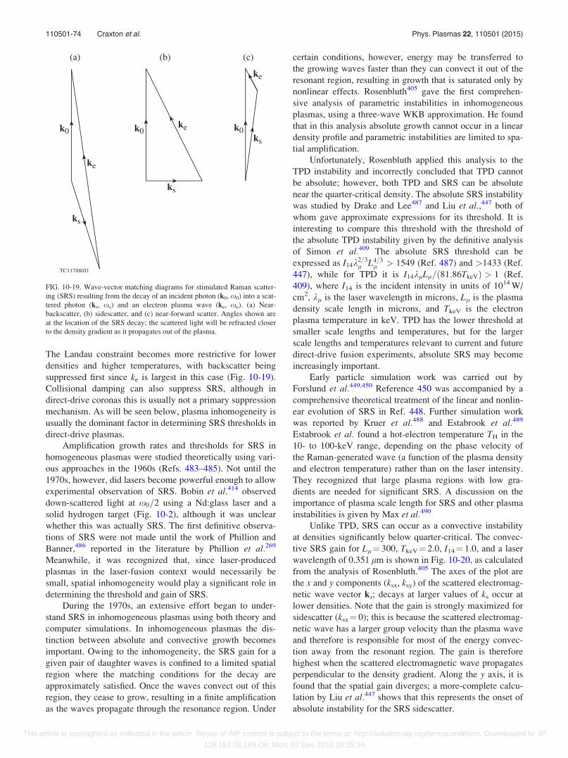
The Landau constraint becomes more restrictive for lower
densities and higher temperatures, with backscatter being
suppressed first since ke is largest in this case (Fig. 10-19).
Collisional damping can also suppress SRS, although in
direct-drive coronas this is usually not a primary suppression
mechanism. As will be seen below, plasma inhomogeneity is
usually the dominant factor in determining SRS thresholds in
direct-drive plasmas.
Amplification growth rates and thresholds for SRS in
homogeneous plasmas were studied theoretically using vari-
ous approaches in the 1960s (Refs. 483–485). Not until the
1970s, however, did lasers become powerful enough to allow
experimental observation of SRS. Bobin et al.414 observed
down-scattered light at x0=2 using a Nd:glass laser and a
solid hydrogen target (Fig. 10-2), although it was unclear
whether this was actually SRS. The first definitive observa-
tions of SRS were not made until the work of Phillion and
Banner,486 reported in the literature by Phillion et al.269
Meanwhile, it was recognized that, since laser-produced
plasmas in the laser-fusion context would necessarily be
small, spatial inhomogeneity would play a significant role in
determining the threshold and gain of SRS.
During the 1970s, an extensive effort began to under-
stand SRS in inhomogeneous plasmas using both theory and
computer simulations. In inhomogeneous plasmas the dis-
tinction between absolute and convective growth becomes
important. Owing to the inhomogeneity, the SRS gain for a
given pair of daughter waves is confined to a limited spatial
region where the matching conditions for the decay are
approximately satisfied. Once the waves convect out of this
region, they cease to grow, resulting in a finite amplification
as the waves propagate through the resonance region. Under
certain conditions, however, energy may be transferred to
the growing waves faster than they can convect it out of the
resonant region, resulting in growth that is saturated only by
nonlinear effects. Rosenbluth405 gave the first comprehen-
sive analysis of parametric instabilities in inhomogeneous
plasmas, using a three-wave WKB approximation. He found
that in this analysis absolute growth cannot occur in a linear
density profile and parametric instabilities are limited to spa-
tial amplification.
Unfortunately, Rosenbluth applied this analysis to the
TPD instability and incorrectly concluded that TPD cannot
be absolute; however, both TPD and SRS can be absolute
near the quarter-critical density. The absolute SRS instability
was studied by Drake and Lee487 and Liu et al.,447 both of
whom gave approximate expressions for its threshold. It is
interesting to compare this threshold with the threshold of
the absolute TPD instability given by the definitive analysis
of Simon et al.409 The absolute SRS threshold can be
expressed as I14k2=3l L4=3
l > 1549 (Ref. 487) and >1433 (Ref.
447), while for TPD it is I14klLl=ð81:86TkeVÞ > 1 (Ref.
409), where I14 is the incident intensity in units of 1014 W/
cm2, kl is the laser wavelength in microns, Ll is the plasma
density scale length in microns, and TkeV is the electron
plasma temperature in keV. TPD has the lower threshold at
smaller scale lengths and temperatures, but for the larger
scale lengths and temperatures relevant to current and future
direct-drive fusion experiments, absolute SRS may become
increasingly important.
Early particle simulation work was carried out by
Forslund et al.449,450 Reference 450 was accompanied by a
comprehensive theoretical treatment of the linear and nonlin-
ear evolution of SRS in Ref. 448. Further simulation work
was reported by Kruer et al.488 and Estabrook et al.489
Estabrook et al. found a hot-electron temperature TH in the
10- to 100-keV range, depending on the phase velocity of
the Raman-generated wave (a function of the plasma density
and electron temperature) rather than on the laser intensity.
They recognized that large plasma regions with low gra-
dients are needed for significant SRS. A discussion on the
importance of plasma scale length for SRS and other plasma
instabilities is given by Max et al.490
Unlike TPD, SRS can occur as a convective instability
at densities significantly below quarter-critical. The convec-
tive SRS gain for Ll¼ 300, TkeV¼ 2.0, I14¼ 1.0, and a laser
wavelength of 0.351 lm is shown in Fig. 10-20, as calculated
from the analysis of Rosenbluth.405 The axes of the plot are
the x and y components (ksx, ksy) of the scattered electromag-
netic wave vector ks; decays at larger values of ks occur at
lower densities. Note that the gain is strongly maximized for
sidescatter (ksx¼ 0); this is because the scattered electromag-
netic wave has a larger group velocity than the plasma wave
and therefore is responsible for most of the energy convec-
tion away from the resonant region. The gain is therefore
highest when the scattered electromagnetic wave propagates
perpendicular to the density gradient. Along the y axis, it is
found that the spatial gain diverges; a more-complete calcu-
lation by Liu et al.447 shows that this represents the onset of
absolute instability for the SRS sidescatter.
FIG. 10-19. Wave-vector matching diagrams for stimulated Raman scatter-
ing (SRS) resulting from the decay of an incident photon (k0, x0) into a scat-
tered photon (ks, xs) and an electron plasma wave (ke, xe). (a) Near-
backscatter, (b) sidescatter, and (c) near-forward scatter. Angles shown are
at the location of the SRS decay; the scattered light will be refracted closer
to the density gradient as it propagates out of the plasma.
110501-74 Craxton et al. Phys. Plasmas 22, 110501 (2015)
This article is copyrighted as indicated in the article. Reuse of AIP content is subject to the terms at: http://scitation.aip.org/termsconditions. Downloaded to IP:
128.151.32.169 On: Mon, 07 Dec 2015 20:25:34
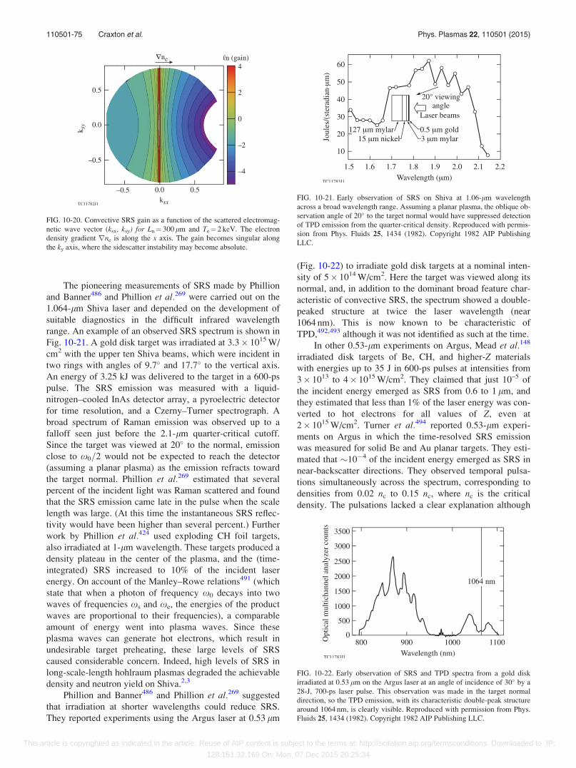
The pioneering measurements of SRS made by Phillion
and Banner486 and Phillion et al.269 were carried out on the
1.064-lm Shiva laser and depended on the development of
suitable diagnostics in the difficult infrared wavelength
range. An example of an observed SRS spectrum is shown in
Fig. 10-21. A gold disk target was irradiated at 3.3� 1015 W/
cm2 with the upper ten Shiva beams, which were incident in
two rings with angles of 9.7� and 17.7� to the vertical axis.
An energy of 3.25 kJ was delivered to the target in a 600-ps
pulse. The SRS emission was measured with a liquid-
nitrogen–cooled InAs detector array, a pyroelectric detector
for time resolution, and a Czerny–Turner spectrograph. A
broad spectrum of Raman emission was observed up to a
falloff seen just before the 2.1-lm quarter-critical cutoff.
Since the target was viewed at 20� to the normal, emission
close to x0=2 would not be expected to reach the detector
(assuming a planar plasma) as the emission refracts toward
the target normal. Phillion et al.269 estimated that several
percent of the incident light was Raman scattered and found
that the SRS emission came late in the pulse when the scale
length was large. (At this time the instantaneous SRS reflec-
tivity would have been higher than several percent.) Further
work by Phillion et al.424 used exploding CH foil targets,
also irradiated at 1-lm wavelength. These targets produced a
density plateau in the center of the plasma, and the (time-
integrated) SRS increased to 10% of the incident laser
energy. On account of the Manley–Rowe relations491 (which
state that when a photon of frequency x0 decays into two
waves of frequencies xs and xe, the energies of the product
waves are proportional to their frequencies), a comparable
amount of energy went into plasma waves. Since these
plasma waves can generate hot electrons, which result in
undesirable target preheating, these large levels of SRS
caused considerable concern. Indeed, high levels of SRS in
long-scale-length hohlraum plasmas degraded the achievable
density and neutron yield on Shiva.2,3
Phillion and Banner486 and Phillion et al.269 suggested
that irradiation at shorter wavelengths could reduce SRS.
They reported experiments using the Argus laser at 0.53 lm
(Fig. 10-22) to irradiate gold disk targets at a nominal inten-
sity of 5� 1014 W/cm2. Here the target was viewed along its
normal, and, in addition to the dominant broad feature char-
acteristic of convective SRS, the spectrum showed a double-
peaked structure at twice the laser wavelength (near
1064 nm). This is now known to be characteristic of
TPD,492,493 although it was not identified as such at the time.
In other 0.53-lm experiments on Argus, Mead et al.148
irradiated disk targets of Be, CH, and higher-Z materials
with energies up to 35 J in 600-ps pulses at intensities from
3� 1013 to 4� 1015 W/cm2. They claimed that just 10–5 of
the incident energy emerged as SRS from 0.6 to 1 lm, and
they estimated that less than 1% of the laser energy was con-
verted to hot electrons for all values of Z, even at
2� 1015 W/cm2. Turner et al.494 reported 0.53-lm experi-
ments on Argus in which the time-resolved SRS emission
was measured for solid Be and Au planar targets. They esti-
mated that �10�4 of the incident energy emerged as SRS in
near-backscatter directions. They observed temporal pulsa-
tions simultaneously across the spectrum, corresponding to
densities from 0.02 nc to 0.15 nc, where nc is the critical
density. The pulsations lacked a clear explanation although
FIG. 10-20. Convective SRS gain as a function of the scattered electromag-
netic wave vector (ksx, ksy) for Ln¼ 300 lm and Te¼ 2 keV. The electron
density gradient rne is along the x axis. The gain becomes singular along
the ky axis, where the sidescatter instability may become absolute.
FIG. 10-21. Early observation of SRS on Shiva at 1.06-lm wavelength
across a broad wavelength range. Assuming a planar plasma, the oblique ob-
servation angle of 20� to the target normal would have suppressed detection
of TPD emission from the quarter-critical density. Reproduced with permis-
sion from Phys. Fluids 25, 1434 (1982). Copyright 1982 AIP Publishing
LLC.
FIG. 10-22. Early observation of SRS and TPD spectra from a gold disk
irradiated at 0.53 lm on the Argus laser at an angle of incidence of 30� by a
28-J, 700-ps laser pulse. This observation was made in the target normal
direction, so the TPD emission, with its characteristic double-peak structure
around 1064 nm, is clearly visible. Reproduced with permission from Phys.
Fluids 25, 1434 (1982). Copyright 1982 AIP Publishing LLC.
110501-75 Craxton et al. Phys. Plasmas 22, 110501 (2015)
This article is copyrighted as indicated in the article. Reuse of AIP content is subject to the terms at: http://scitation.aip.org/termsconditions. Downloaded to IP:
128.151.32.169 On: Mon, 07 Dec 2015 20:25:34
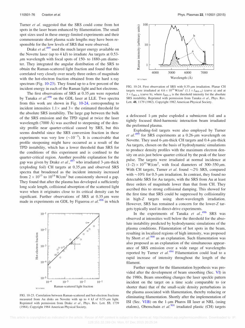
Turner et al. suggested that the SRS could come from hot
spots in the laser beam enhanced by filamentation. The small
spot sizes used in these energy-limited experiments and their
commensurate short plasma scale lengths may have been re-
sponsible for the low levels of SRS that were observed.
Drake et al.495 used the much larger energy available on
the Novette laser (up to 4 kJ) to irradiate Au targets at 0.53-
lm wavelength with focal spots of 150- to 1880-lm diame-
ter. They integrated the angular distribution of the SRS to
obtain the Raman-scattered light fraction and found that this
correlated very closely over nearly three orders of magnitude
with the hot-electron fraction obtained from the hard x-ray
spectrum (Fig. 10-23). They found up to a few percent of the
incident energy in each of the Raman light and hot electrons.
The first observations of SRS at 0.35 lm were reported
by Tanaka et al.496 on the GDL laser at LLE. Two spectra
from this work are shown in Fig. 10-24, corresponding to
incident intensities 1.1� and 3� the estimated threshold for
the absolute SRS instability. The large gap between the bulk
of the SRS emission and the TPD signal at twice the laser
wavelength (7000 A) was ascribed to steepening of the den-
sity profile near quarter-critical caused by SRS, but this
seems doubtful since the SRS conversion fraction in these
experiments was very low (�10�5). It is conceivable that
profile steepening might have occurred as a result of the
TPD instability, which has a lower threshold than SRS for
the conditions of this experiment and is confined to the
quarter-critical region. Another possible explanation for the
gap was given by Drake et al.,497 who irradiated 3-lm-thick
(exploding foil) CH targets at 0.35 lm and observed SRS
spectra that broadened as the incident intensity increased
from 2� 1013 to 1014 W/cm2 but consistently showed a gap.
They found that after the plasma has developed a sufficiently
long scale length, collisional absorption of the scattered light
wave when it originates close to its critical density can be
significant. Further observations of SRS at 0.35 lm were
made in experiments on GDL by Figueroa et al.498 in which
a defocused 1-lm pulse exploded a submicron foil and a
tightly focused third-harmonic interaction beam irradiated
the preformed plasma.
Exploding-foil targets were also employed by Turner
et al.499 for SRS experiments at a 0.26-lm wavelength on
Novette. They used 6-lm-thick CH targets and 0.4-lm-thick
Au targets, chosen on the basis of hydrodynamic simulations
to produce density profiles with the maximum electron den-
sity on axis just below quarter critical by the peak of the laser
pulse. The targets were irradiated at normal incidence at
(1–2)� 1015 W/cm2, with focal diameters of 300–350 lm.
With CH targets, Turner et al. found �2% SRS, compared
with �10% for 0.5-lm irradiation. In contrast, they found no
detectable SRS for Au targets, with the SRS from Au at least
three orders of magnitude lower than that from CH. They
ascribed this to strong collisional damping. This showed for
the first time that SRS could be suppressed by collisionality
in high-Z targets using short-wavelength irradiation.
However, SRS has remained a concern for the lower-Z tar-
gets typically used in direct-drive experiments.
In the experiments of Tanaka et al.,496 SRS was
observed at intensities well below the threshold for the abso-
lute instability predicted by hydrodynamic simulations of the
plasma conditions. Filamentation of hot spots in the beam,
resulting in localized regions of high intensity, was proposed
by Short et al.500 as an explanation. Such filamentation was
also proposed as an explanation of the simultaneous appear-
ance of SRS emission over a wide range of wavelengths
reported by Turner et al.494 Filamentation could lead to a
rapid increase of intensity throughout the length of the
filament.
Further support for the filamentation hypothesis was pro-
vided after the development of beam smoothing (Sec. VI) in
the 1980s. Beam smoothing changes the laser speckle pattern
incident on the target on a time scale comparable to (or
shorter than) that of the small-scale density perturbations in
the plasma associated with filamentation, thereby reducing or
eliminating filamentation. Shortly after the implementation of
ISI (Sec. VI B) on the 1-lm Pharos III laser at NRL (using
etalons), Obenschain et al.501 irradiated plastic (CH) targets
FIG. 10-23. Correlation between Raman-scattered and hot-electron fractions
measured from Au disks on Novette with up to 4 kJ of 0.53-lm light.
Reprinted with permission from Drake et al., Phys. Rev. Lett. 53, 1739
(1984). Copyright 1984 American Physical Society.
FIG. 10-24. First observation of SRS with 0.35-lm irradiation. Planar CH
targets were irradiated at 4.6� 1014 W/cm2 (1.1� ISRS-A) (curve a) and at
3� ISRS-A (curve b), where ISRS-A is the threshold intensity for the absolute
SRS instability. Reprinted with permission from Tanaka et al., Phys. Rev.
Lett. 48, 1179 (1982). Copyright 1982 American Physical Society.
110501-76 Craxton et al. Phys. Plasmas 22, 110501 (2015)
This article is copyrighted as indicated in the article. Reuse of AIP content is subject to the terms at: http://scitation.aip.org/termsconditions. Downloaded to IP:
128.151.32.169 On: Mon, 07 Dec 2015 20:25:34

with �2-ns pulses at �1014 W/cm2 with a spot diameter of
�300 lm and reported a reduction of SRS with broadband ISI
by three orders of magnitude (Fig. 10-25). This result was
understood to be a consequence of the suppression of filamen-
tation. The coherence time sc was 2 ps for broadband ISI. For
narrowband ISI (sc¼ 2 ns), there was, as expected, no signifi-
cant difference compared with the ordinary beam.
Corroboration of the NRL result was provided by
experiments at the Rutherford Laboratory reported by Coe
et al.502 in which a 0.5-lm interaction beam irradiated a
long-scale-length, low-density plasma (electron density ne �
0.1 nc) formed from the explosion of a thin Al strip in line-
focus geometry. [See Fig. 10-33(a) below for the configura-
tion.] The results (Fig. 10-26) showed an SRS signal that
decreased first with the introduction of phase plates and fur-
ther with ISI. Again, this was attributed to the suppression of
filamentation.
Seka et al.503 found that SRS was strongly reduced by
SSD (Sec. VI C), as shown in Fig. 10-27. In these experi-
ments at 0.35 lm on the 24-beam OMEGA laser, CH foils
were exploded with plasma-forming beams and irradiated
with a high-intensity interaction beam. The application of
SSD bandwidth was found to reduce the SRS level by three
orders of magnitude. In contrast, TPD (as evidenced by the
3x0=2 emission) was only slightly affected. Since the
speckle pattern changes too slowly to affect the growth rate
of electron plasma wave instabilities directly, the implication
is that the SSD beam modulation is suppressing filamenta-
tion (which occurs on the ion-acoustic time scale) and there-
fore indirectly suppressing SRS within filaments. TPD,
which is necessarily a multidimensional phenomenon, is not
expected to be confined to filaments and therefore would not
be affected by SSD.
As a result of beam smoothing, the levels of SRS
observed in spherical direct-drive experiments on OMEGA
were generally found to be negligible, i.e., less than the
detection threshold of 5� 10�4 of the incident beam
energy.504 In the unlikely event that the SRS emission from
a spherical target were isotropic, the applicable detection
threshold would be raised to 5� 10�3 of the total incident
energy. Interest in the topic of SRS for direct drive declined,
although SRS remained a concern for indirect-drive plasmas
with their larger scale lengths. To assess whether SRS would
be important in conditions relevant to ignition-scale direct-
drive designs, long-scale-length plasmas have been used on
OMEGA to study SRS. A typical streaked SRS spectrum
from these experiments505 is shown in Fig. 10-28 from a
plasma formed by irradiating a solid planar CH target with
defocused primary and secondary beams in the configuration
shown in Fig. 10-6(a). SRS is observed during the presence
of five overlapped interaction beams, each with an intensity
of �1.2� 1014 W/cm2, whose temporal shape is given by the
red curve. The emission just above and below 700 nm, com-
ing from the vicinity of the quarter-critical density, is under-
stood to result from the TPD instability and is consistent
with the 0.53-lm experiment on Argus shown in Fig. 10-22.
The feature whose wavelength decreases with time is con-
sistent with the motion of a density plateau that propagates
to lower densities as a result of the increased ablation rate
that occurs with the onset of the high-intensity interaction
beams. The yellow circles are predictions of an SRS model
that post-processes 2-D hydrodynamic simulations using
FIG. 10-25. Peak Raman backscatter in the 1350- to 1750-nm band as a
function of laser intensity for the 1-lm irradiation of planar CH targets,
comparing broadband ISI, narrowband ISI, and an ordinary laser beam with
narrow bandwidth. The ISI was implemented using reflective echelons.
Reprinted with permission from Obenschain et al., Phys. Rev. Lett. 62, 768
(1989). Copyright 1989 American Physical Society.
FIG. 10-26. SRS backscatter fraction from a long-scale-length, underdense
plasma ðne � nc=10Þ as a function of laser irradiance for a coherent beam
(f/10), a phase-plate beam (f/2.5), and ISI (f/10). The laser wavelength was
0.53 lm. Reproduced with permission from Coe et al., Europhys. Lett. 10,
31 (1989). Copyright 1989 EDP Sciences, see http://iopscience.iop.org/epl/.
FIG. 10-27. Reduction of SRS by SSD bandwidth in long-scale-length CH
plasmas irradiated at 0.35 lm on the 24-beam OMEGA laser. The bandwidth
is believed to suppress filamentation, thereby preventing SRS from occur-
ring in high-intensity filaments. The shaded area is to guide the eye.
Reproduced with permission from Phys. Fluids B 4, 2232 (1992). Copyright
1992 AIP Publishing LLC.
110501-77 Craxton et al. Phys. Plasmas 22, 110501 (2015)
This article is copyrighted as indicated in the article. Reuse of AIP content is subject to the terms at: http://scitation.aip.org/termsconditions. Downloaded to IP:
128.151.32.169 On: Mon, 07 Dec 2015 20:25:34

SAGE and show good agreement with the observations.
Similar streaked SRS spectra have been widely used to diag-
nose the maximum (plateau) density of exploding-foil plas-
mas (see, e.g., Refs. 503 and 506).
As direct-drive experiments extend into conditions of
larger scale length and higher temperature appropriate to the
NIF, SRS may play a larger role even with smoothed beams
since filamentation will no longer be necessary to reach the
SRS threshold. SRS therefore remains a concern, and further
experimental and theoretical investigations, including the
effects of multibeam irradiation, are required.
D. Self-focusing and filamentation
1. Theory
Laser light propagating through a plasma can undergo
self-focusing because the plasma index of refraction changes
in response to variations in the local light intensity, supporting
perturbations in the direction perpendicular to the beam. In a
plasma, the index of refraction l is related to the electron den-
sity ne as l ¼ffiffiffiffiffiffiffiffiffiffiffiffiffiffiffiffiffiffiffi1� ne=nc
p; where nc is the critical density. A
locally increased intensity can lower the electron density
(through the ponderomotive force or local plasma heating)
and increase the index of refraction, leading to ponderomotive
or thermal self-focusing, respectively. Ponderomotive self-
focusing was described in 1962 by Askar’yan.507
Thermal self-focusing is illustrated in Fig. 10-29 (from
Ref. 337). Here, a 0.35-lm-wavelength laser beam is inci-
dent on a cold CH plasma with a 500-lm scale length, heat-
ing the plasma in a channel near the axis. The plasma
expands radially, reducing the density in the channel and
thereby causing light rays to refract (or focus) into the
intense region, further increasing the intensity and producing
the instability. The locally intense region initiating the pro-
cess can be a perturbation within a larger (nominally smooth)
beam, in which case the process is known as filamentation or
small-scale self-focusing, or it can be the entire beam, in
which case the process is known as whole-beam self-focus-
ing. The physical mechanism is essentially the same.
There are two particularly important aspects of this
instability: (1) the intensity threshold is relatively low and
(2) the resulting intensity enhancement can induce other
instabilities (which would otherwise be below threshold).
The second point may explain why many early laser–plasma
instability experiments with unsmoothed laser beams exhib-
ited puzzling and sometimes irreproducible results (see, for
example, early observations of backscattered light described
in Sec. X B). It is also believed to be the reason why optical
beam smoothing has been effective in reducing instabilities
such as SRS (Sec. X C), which has a growth rate significantly
greater than the laser bandwidth. Early examples of this
effect are given in Sec. VI B, with Fig. 6-6 illustrating the
reduction in hot electrons with beam smoothing.
The linear filamentation threshold is determined by
equating the focusing effect of a plane-wave perturbation
with diffraction, which counteracts the focusing by broaden-
ing the perturbation. Different intensity thresholds in a ho-
mogeneous plasma are found for the ponderomotive508 and
thermal509 mechanisms. A useful threshold intensity I14 can
be calculated by requiring that the intensity in the filament
exponentiate once inside the plasma for the fastest-growing
spatial mode, with the plasma assumed to have a length L.
This results in510
I14 � 20nc
ne
Te keVð ÞL lmð Þk0 lmð Þ
(10-5)
for ponderomotive filamentation and
I14 � 2� 105 nc
ne
� �3 Te keVð Þ5k0 lmð Þ2
Z2L2 lmð Þ(10-6)
for classical thermal filamentation. Here, I14 is given in units
of 1014 W/cm2, Z is the plasma ionization, Te is the electron
temperature, k0 is the laser wavelength, and it is assumed
that ne � nc:Because both diffraction and the laser-induced nonlinear
plasma response depend on the wavelength k of the perturba-
tion, the resulting filamentation growth rates can depend
FIG. 10-28. Time-resolved SRS spectrum recorded from a long-scale-length
plasma on the 60-beam OMEGA laser. The red curve indicates the
interaction-beam laser intensity and the white line represents the signal inte-
grated over the spectrum. The yellow circles correspond to predicted wave-
lengths of peak SRS emission (from Ref. 505).
FIG. 10-29. Illustration of thermal self-focusing of light using the 2-D
hydrodynamics code SAGE with ray tracing. Laser rays heat a channel near
the axis, reducing the density there. The rays are then refracted toward the
axis and increase the on-axis intensity. Contour lines show the electron den-
sity in the plasma relative to the critical density nc, and the rays indicate the
direction of light propagation. Reproduced with permission from J. Appl.
Phys. 56, 108 (1984). Copyright 1984 AIP Publishing LLC.
110501-78 Craxton et al. Phys. Plasmas 22, 110501 (2015)
This article is copyrighted as indicated in the article. Reuse of AIP content is subject to the terms at: http://scitation.aip.org/termsconditions. Downloaded to IP:
128.151.32.169 On: Mon, 07 Dec 2015 20:25:34

sensitively on the perturbation wave number k (¼2p/k). The
spatial growth rates K are found by Fourier analysis of
the nonlinear wave equation, and representative examples of
the dependence of K on k are shown in Fig. 10-30 (taken from
Ref. 511) for three mechanisms, using the experimental pa-
rameters of Refs. 512 and 513. No growth occurs in any case
for wave numbers larger than a critical value since diffraction
will stop any focusing. As the wave number decreases below
this critical value, the ponderomotive filamentation growth
rate peaks and then decreases. In contrast, classical thermal
filamentation is insensitive to the wave number as long as the
perturbation wavelength is much larger than the threshold
wavelength. Its largest growth rate occurs for long wave-
lengths (small wave numbers).
The classical result for thermal filamentation can be sub-
stantially modified in the underdense plasma corona when
the mean free path of a thermal electron is greater than a
small fraction (�1/100) of the perturbation size.511 In this
case, the nonlocal nature of thermal conduction (Sec. XI)
effectively decreases the local conductivity, sharpens small-
scale temperature perturbations, and enhances the filamenta-
tion effect for shorter wavelengths. An example of this modi-
fied dispersion relation is shown in Fig. 10-30, where
nonlocal thermal filamentation dominates ponderomotive
filamentation.
Rose and DuBois514 questioned the applicability of the
linear filamentation stability analysis to laser beams
smoothed by phase plates. Such beams contain a distribution
of hot spots (local maxima) of the laser intensity within the
focal volume that are assumed to act as seeds for filamenta-
tion. Rose and DuBois argued that the evolution of self-fo-
cusing/filamentation in a laser hot spot is nonlinear from its
inception if the hot spot contains more than a certain critical
power. The concept of a critical power for self-focusing
arises from the appearance of self-localized solutions to the
cubic nonlinear Schr€odinger equation, which has been used
for a long time as a model for self-focusing.515
2. Simulations
Ray tracing coupled to hydrodynamics simulations was
first used to simulate thermal self-focusing in plasmas by
Craxton and McCrory337 and Estabrook et al.516 However,
since diffraction and interference of the electromagnetic
wave are not included in this treatment, neither ponderomo-
tive filamentation nor saturation of self-focusing was prop-
erly represented. Simulations of filamentation including
interference and diffraction effects were developed in two
dimensions by Nicholas and Sajjadi,517 Schmitt,518 and
Rankin et al.519 These studies coupled parabolic-wave-equa-
tion representations with simple models for the hydrodynam-
ics of the background plasma. They showed that optical
beam smoothing using phase plates, ISI, or SSD (Sec. VI)
could greatly reduce or eliminate filamentation in typical
ICF plasmas, while unsmoothed beams would filament and
significantly enhance the energy at intensities many times
the average. With phase plates, although the incident inten-
sity pattern is stationary, filamentation can be reduced by the
decreased perturbation amplitude driving the most rapidly
growing modes and by the disruption of filament growth
accomplished by decreasing the speckle length. For this,
smaller f/# optics (which produce smaller hot spots) perform
best. Methods using finite laser bandwidth (ISI or SSD) were
shown to further suppress filamentation by changing the
position of the laser speckles (“hot spots”) more quickly than
the plasma can respond.
These results were confirmed when the model was sub-
sequently improved by Schmitt520 and Berger et al.521 with
increasingly complex hydrodynamic modeling of the back-
ground plasma including three dimensions and nonlocal
electron thermal transport. Further development of these
wave-based filamentation models included axial hydrody-
namic coupling (which produced an interaction between fila-
mentation and both forward Brillouin smoothing and
plasma-induced incoherence522) and explicit coupling to
other instabilities such as backward Brillouin and stimulated
Raman scattering.523,524 This work showed that filamentation
can generate and interact with laser–plasma instability proc-
esses in very complex ways.
Figure 10-31 shows two typical examples of 3-D simu-
lations of filamentation, based on Ref. 520. In the simulation
of Fig. 10-31(a), the laser is spatially incoherent from phase
plates but has no bandwidth. The figure shows intensity con-
tours in cross sections of the beam at the incident plane z¼ 0
and after propagation through 500 lm of CH. Ponderomotive
filamentation dominates any thermal effects, and the incom-
ing beam (which initially has peak-to-average intensity var-
iations of �8:1) filaments to produce intensity peaks more
than 600� the average local intensity. Fine-scale diffraction
features are also seen. In contrast, a simulation using ISI
beam smoothing [Fig. 10-31(b)] shows that filamentation is
eliminated as the beam propagates through a large-scale
plasma without intensity enhancement. In this simulation the
beam propagated through a large DT plasma whose density
increased from 0.01nc (top) to 0.75nc (bottom). [The density
FIG. 10-30. Spatial growth rate K as a function of wave number k for pon-
deromotive, classical thermal, and nonlocal-thermal-conduction–dominated
filamentation, for the experimental conditions of Refs. 512 and 513:
I¼ 4.2� 1013 W/cm2, Te¼ 0.8 keV, ne=nc ¼ 0:1; k0¼ 1.06 lm, and Z¼ 3.5.
The arrow marked kexp denotes the wave vector of the applied perturbation
in the experiment of Refs. 512 and 513. Reprinted with permission from E.
M. Epperlein, Phys. Rev. Lett. 65, 2145 (1990). Copyright 1990 American
Physical Society.
110501-79 Craxton et al. Phys. Plasmas 22, 110501 (2015)
This article is copyrighted as indicated in the article. Reuse of AIP content is subject to the terms at: http://scitation.aip.org/termsconditions. Downloaded to IP:
128.151.32.169 On: Mon, 07 Dec 2015 20:25:34
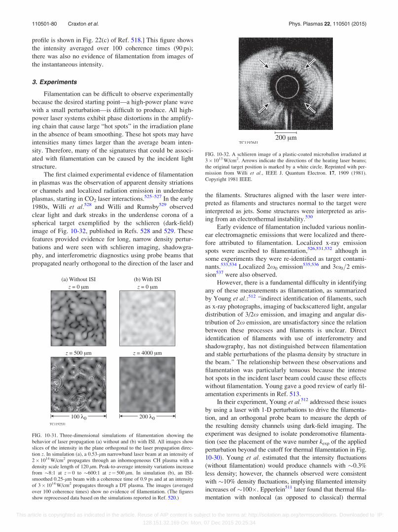
profile is shown in Fig. 22(c) of Ref. 518.] This figure shows
the intensity averaged over 100 coherence times (90 ps);
there was also no evidence of filamentation from images of
the instantaneous intensity.
3. Experiments
Filamentation can be difficult to observe experimentally
because the desired starting point—a high-power plane wave
with a small perturbation—is difficult to produce. All high-
power laser systems exhibit phase distortions in the amplify-
ing chain that cause large “hot spots” in the irradiation plane
in the absence of beam smoothing. These hot spots may have
intensities many times larger than the average beam inten-
sity. Therefore, many of the signatures that could be associ-
ated with filamentation can be caused by the incident light
structure.
The first claimed experimental evidence of filamentation
in plasmas was the observation of apparent density striations
or channels and localized radiation emission in underdense
plasmas, starting in CO2 laser interactions.525–527 In the early
1980s, Willi et al.528 and Willi and Rumsby529 observed
clear light and dark streaks in the underdense corona of a
spherical target exemplified by the schlieren (dark-field)
image of Fig. 10-32, published in Refs. 528 and 529. These
features provided evidence for long, narrow density pertur-
bations and were seen with schlieren imaging, shadowgra-
phy, and interferometric diagnostics using probe beams that
propagated nearly orthogonal to the direction of the laser and
the filaments. Structures aligned with the laser were inter-
preted as filaments and structures normal to the target were
interpreted as jets. Some structures were interpreted as aris-
ing from an electrothermal instability.530
Early evidence of filamentation included various nonlin-
ear electromagnetic emissions that were localized and there-
fore attributed to filamentation. Localized x-ray emission
spots were ascribed to filamentation,526,531,532 although in
some experiments they were re-identified as target contami-
nants.533,534 Localized 2x0 emission535,536 and 3x0=2 emis-
sion537 were also observed.
However, there is a fundamental difficulty in identifying
any of these measurements as filamentation, as summarized
by Young et al.:512 “indirect identification of filaments, such
as x-ray photographs, imaging of backscattered light, angular
distribution of 3/2x emission, and imaging and angular dis-
tribution of 2x emission, are unsatisfactory since the relation
between these processes and filaments is unclear. Direct
identification of filaments with use of interferometry and
shadowgraphy, has not distinguished between filamentation
and stable perturbations of the plasma density by structure in
the beam.” The relationship between these observations and
filamentation was particularly tenuous because the intense
hot spots in the incident laser beam could cause these effects
without filamentation. Young gave a good review of early fil-
amentation experiments in Ref. 513.
In their experiment, Young et al.512 addressed these issues
by using a laser with 1-D perturbations to drive the filamenta-
tion, and an orthogonal probe beam to measure the depth of
the resulting density channels using dark-field imaging. The
experiment was designed to isolate ponderomotive filamenta-
tion (see the placement of the wave number kexp of the applied
perturbation beyond the cutoff for thermal filamentation in Fig.
10-30). Young et al. estimated that the intensity fluctuations
(without filamentation) would produce channels with �0.3%
less density; however, the channels observed were consistent
with �10% density fluctuations, implying filamented intensity
increases of �100�. Epperlein511 later found that thermal fila-
mentation with nonlocal (as opposed to classical) thermal
FIG. 10-31. Three-dimensional simulations of filamentation showing the
behavior of laser propagation (a) without and (b) with ISI. All images show
slices of the intensity in the plane orthogonal to the laser propagation direc-
tion z. In simulation (a), a 0.53-lm narrowband laser beam at an intensity of
2� 1014 W/cm2 propagates through an inhomogeneous CH plasma with a
density scale length of 120 lm. Peak-to-average intensity variations increase
from �8:1 at z¼ 0 to �600:1 at z¼ 500 lm. In simulation (b), an ISI-
smoothed 0.25-lm beam with a coherence time of 0.9 ps and at an intensity
of 3� 1014 W/cm2 propagates through a DT plasma. The images (averaged
over 100 coherence times) show no evidence of filamentation. (The figures
show reprocessed data based on the simulations reported in Ref. 520.)
FIG. 10-32. A schlieren image of a plastic-coated microballon irradiated at
3� 1013 W/cm2. Arrows indicate the directions of the heating laser beams;
the original target position is marked by a white circle. Reprinted with per-
mission from Willi et al., IEEE J. Quantum Electron. 17, 1909 (1981).
Copyright 1981 IEEE.
110501-80 Craxton et al. Phys. Plasmas 22, 110501 (2015)
This article is copyrighted as indicated in the article. Reuse of AIP content is subject to the terms at: http://scitation.aip.org/termsconditions. Downloaded to IP:
128.151.32.169 On: Mon, 07 Dec 2015 20:25:34
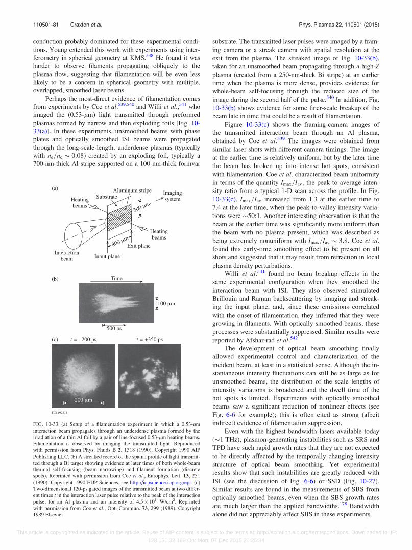
conduction probably dominated for these experimental condi-
tions. Young extended this work with experiments using inter-
ferometry in spherical geometry at KMS.538 He found it was
harder to observe filaments propagating obliquely to the
plasma flow, suggesting that filamentation will be even less
likely to be a concern in spherical geometry with multiple,
overlapped, smoothed laser beams.
Perhaps the most-direct evidence of filamentation comes
from experiments by Coe et al.539,540 and Willi et al.,541 who
imaged the (0.53-lm) light transmitted through preformed
plasmas formed by narrow and thin exploding foils [Fig. 10-
33(a)]. In these experiments, unsmoothed beams with phase
plates and optically smoothed ISI beams were propagated
through the long-scale-length, underdense plasmas (typically
with ne=nc � 0:08) created by an exploding foil, typically a
700-nm-thick Al stripe supported on a 100-nm-thick formvar
substrate. The transmitted laser pulses were imaged by a fram-
ing camera or a streak camera with spatial resolution at the
exit from the plasma. The streaked image of Fig. 10-33(b),
taken for an unsmoothed beam propagating through a high-Zplasma (created from a 250-nm-thick Bi stripe) at an earlier
time when the plasma is more dense, provides evidence for
whole-beam self-focusing through the reduced size of the
image during the second half of the pulse.540 In addition, Fig.
10-33(b) shows evidence for some finer-scale breakup of the
beam late in time that could be a result of filamentation.
Figure 10-33(c) shows the framing-camera images of
the transmitted interaction beam through an Al plasma,
obtained by Coe et al.539 The images were obtained from
similar laser shots with different camera timings. The image
at the earlier time is relatively uniform, but by the later time
the beam has broken up into intense hot spots, consistent
with filamentation. Coe et al. characterized beam uniformity
in terms of the quantity Imax=Iav; the peak-to-average inten-
sity ratio from a typical 1-D scan across the profile. In Fig.
10-33(c), Imax=Iav increased from 1.3 at the earlier time to
7.4 at the later time, when the peak-to-valley intensity varia-
tions were �50:1. Another interesting observation is that the
beam at the earlier time was significantly more uniform than
the beam with no plasma present, which was described as
being extremely nonuniform with Imax=Iav � 3:8: Coe et al.found this early-time smoothing effect to be present on all
shots and suggested that it may result from refraction in local
plasma density perturbations.
Willi et al.541 found no beam breakup effects in the
same experimental configuration when they smoothed the
interaction beam with ISI. They also observed stimulated
Brillouin and Raman backscattering by imaging and streak-
ing the input plane, and, since these emissions correlated
with the onset of filamentation, they inferred that they were
growing in filaments. With optically smoothed beams, these
processes were substantially suppressed. Similar results were
reported by Afshar-rad et al.542
The development of optical beam smoothing finally
allowed experimental control and characterization of the
incident beam, at least in a statistical sense. Although the in-
stantaneous intensity fluctuations can still be as large as for
unsmoothed beams, the distribution of the scale lengths of
intensity variations is broadened and the dwell time of the
hot spots is limited. Experiments with optically smoothed
beams saw a significant reduction of nonlinear effects (see
Fig. 6-6 for example); this is often cited as strong (albeit
indirect) evidence of filamentation suppression.
Even with the highest-bandwidth lasers available today
(�1 THz), plasmon-generating instabilities such as SRS and
TPD have such rapid growth rates that they are not expected
to be directly affected by the temporally changing intensity
structure of optical beam smoothing. Yet experimental
results show that such instabilities are greatly reduced with
ISI (see the discussion of Fig. 6-6) or SSD (Fig. 10-27).
Similar results are found in the measurements of SBS from
optically smoothed beams, even when the SBS growth rates
are much larger than the applied bandwidths.178 Bandwidth
alone did not appreciably affect SBS in these experiments.
FIG. 10-33. (a) Setup of a filamentation experiment in which a 0.53-lm
interaction beam propagates through an underdense plasma formed by the
irradiation of a thin Al foil by a pair of line-focused 0.53-lm heating beams.
Filamentation is observed by imaging the transmitted light. Reproduced
with permission from Phys. Fluids B 2, 1318 (1990). Copyright 1990 AIP
Publishing LLC. (b) A streaked record of the spatial profile of light transmit-
ted through a Bi target showing evidence at later times of both whole-beam
thermal self-focusing (beam narrowing) and filament formation (discrete
spots). Reprinted with permission from Coe et al., Europhys. Lett. 13, 251
(1990). Copyright 1990 EDP Sciences, see http://iopscience.iop.org/epl. (c)
Two-dimensional 120-ps gated images of the transmitted beam at two differ-
ent times t in the interaction laser pulse relative to the peak of the interaction
pulse, for an Al plasma and an intensity of 4.5� 1014 W/cm2. Reprinted
with permission from Coe et al., Opt. Commun. 73, 299 (1989). Copyright
1989 Elsevier.
110501-81 Craxton et al. Phys. Plasmas 22, 110501 (2015)
This article is copyrighted as indicated in the article. Reuse of AIP content is subject to the terms at: http://scitation.aip.org/termsconditions. Downloaded to IP:
128.151.32.169 On: Mon, 07 Dec 2015 20:25:34
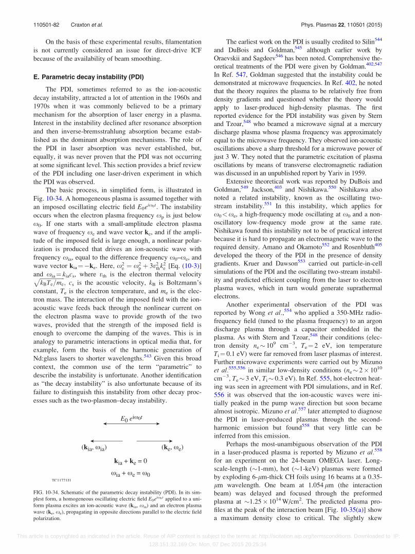
On the basis of these experimental results, filamentation
is not currently considered an issue for direct-drive ICF
because of the availability of beam smoothing.
E. Parametric decay instability (PDI)
The PDI, sometimes referred to as the ion-acoustic
decay instability, attracted a lot of attention in the 1960s and
1970s when it was commonly believed to be a primary
mechanism for the absorption of laser energy in a plasma.
Interest in the instability declined after resonance absorption
and then inverse-bremsstrahlung absorption became estab-
lished as the dominant absorption mechanisms. The role of
the PDI in laser absorption was never established, but,
equally, it was never proven that the PDI was not occurring
at some significant level. This section provides a brief review
of the PDI including one laser-driven experiment in which
the PDI was observed.
The basic process, in simplified form, is illustrated in
Fig. 10-34. A homogeneous plasma is assumed together with
an imposed oscillating electric field E0eix0t: The instability
occurs when the electron plasma frequency xp is just below
x0. If one starts with a small-amplitude electron plasma
wave of frequency xe and wave vector ke, and if the ampli-
tude of the imposed field is large enough, a nonlinear polar-
ization is produced that drives an ion-acoustic wave with
frequency xia, equal to the difference frequency x0–xe, and
wave vector kia¼�ke. Here, x2e ¼ x2
p þ 3v2thk2
e [Eq. (10-3)]
and xia¼ kiacs, where vth is the electron thermal velocityffiffiffiffiffiffiffiffiffiffiffiffiffiffiffiffiffikBTe=me
p; cs is the acoustic velocity, kB is Boltzmann’s
constant, Te is the electron temperature, and me is the elec-
tron mass. The interaction of the imposed field with the ion-
acoustic wave feeds back through the nonlinear current on
the electron plasma wave to provide growth of the two
waves, provided that the strength of the imposed field is
enough to overcome the damping of the waves. This is in
analogy to parametric interactions in optical media that, for
example, form the basis of the harmonic generation of
Nd:glass lasers to shorter wavelengths.543 Given this broad
context, the common use of the term “parametric” to
describe the instability is unfortunate. Another identification
as “the decay instability” is also unfortunate because of its
failure to distinguish this instability from other decay proc-
esses such as the two-plasmon–decay instability.
The earliest work on the PDI is usually credited to Silin544
and DuBois and Goldman,545 although earlier work by
Oraevskii and Sagdeev546 has been noted. Comprehensive the-
oretical treatments of the PDI were given by Goldman.402,547
In Ref. 547, Goldman suggested that the instability could be
demonstrated at microwave frequencies. In Ref. 402, he noted
that the theory requires the plasma to be relatively free from
density gradients and questioned whether the theory would
apply to laser-produced high-density plasmas. The first
reported evidence for the PDI instability was given by Stern
and Tzoar,548 who beamed a microwave signal at a mercury
discharge plasma whose plasma frequency was approximately
equal to the microwave frequency. They observed ion-acoustic
oscillations above a sharp threshold for a microwave power of
just 3 W. They noted that the parametric excitation of plasma
oscillations by means of transverse electromagnetic radiation
was discussed in an unpublished report by Yariv in 1959.
Extensive theoretical work was reported by DuBois and
Goldman,549 Jackson,403 and Nishikawa.550 Nishikawa also
noted a related instability, known as the oscillating two-
stream instability.551 In this instability, which applies for
x0<xe, a high-frequency mode oscillating at x0 and a non-
oscillatory low-frequency mode grow at the same rate.
Nishikawa found this instability not to be of practical interest
because it is hard to propagate an electromagnetic wave to the
required density. Amano and Okamoto552 and Rosenbluth405
developed the theory of the PDI in the presence of density
gradients. Kruer and Dawson553 carried out particle-in-cell
simulations of the PDI and the oscillating two-stream instabil-
ity and predicted efficient coupling from the laser to electron
plasma waves, which in turn would generate suprathermal
electrons.
Another experimental observation of the PDI was
reported by Wong et al.,554 who applied a 350-MHz radio-
frequency field (tuned to the plasma frequency) to an argon
discharge plasma through a capacitor embedded in the
plasma. As with Stern and Tzoar,548 their conditions (elec-
tron density ne� 109 cm�3, Te¼ 2 eV, ion temperature
Ti¼ 0.1 eV) were far removed from laser plasmas of interest.
Further microwave experiments were carried out by Mizuno
et al.555,556 in similar low-density conditions (ne� 2� 1010
cm�3, Te� 3 eV, Ti� 0.3 eV). In Ref. 555, hot-electron heat-
ing was seen in agreement with PDI simulations, and in Ref.
556 it was observed that the ion-acoustic waves were ini-
tially peaked in the pump wave direction but soon became
almost isotropic. Mizuno et al.557 later attempted to diagnose
the PDI in laser-produced plasmas through the second-
harmonic emission but found558 that very little can be
inferred from this emission.
Perhaps the most-unambiguous observation of the PDI
in a laser-produced plasma is reported by Mizuno et al.558
for an experiment on the 24-beam OMEGA laser. Long-
scale-length (�1-mm), hot (�1-keV) plasmas were formed
by exploding 6-lm-thick CH foils using 16 beams at a 0.35-
lm wavelength. One beam at 1.054 lm (the interaction
beam) was delayed and focused through the preformed
plasma at �1.25� 1014 W/cm2. The predicted plasma pro-
files at the peak of the interaction beam [Fig. 10-35(a)] show
a maximum density close to critical. The slightly skew
FIG. 10-34. Schematic of the parametric decay instability (PDI). In its sim-
plest form, a homogeneous oscillating electric field E0eix0 t applied to a uni-
form plasma excites an ion-acoustic wave (kia, xia) and an electron plasma
wave (ke, xe), propagating in opposite directions parallel to the electric field
polarization.
110501-82 Craxton et al. Phys. Plasmas 22, 110501 (2015)
This article is copyrighted as indicated in the article. Reuse of AIP content is subject to the terms at: http://scitation.aip.org/termsconditions. Downloaded to IP:
128.151.32.169 On: Mon, 07 Dec 2015 20:25:34
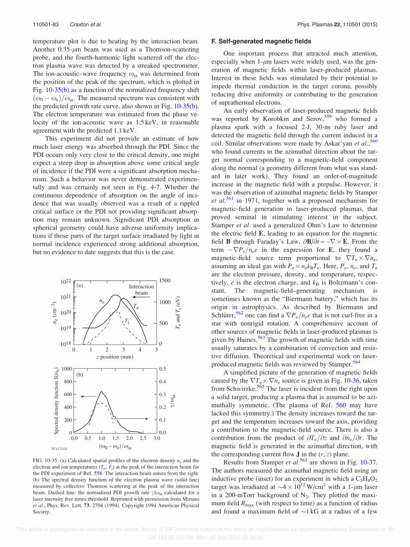
temperature plot is due to heating by the interaction beam.
Another 0.35-lm beam was used as a Thomson-scattering
probe, and the fourth-harmonic light scattered off the elec-
tron plasma wave was detected by a streaked spectrometer.
The ion-acoustic–wave frequency xia was determined from
the position of the peak of the spectrum, which is plotted in
Fig. 10-35(b) as a function of the normalized frequency shift
ðx0 � xeÞ=xia: The measured spectrum was consistent with
the predicted growth rate curve, also shown in Fig. 10-35(b).
The electron temperature was estimated from the phase ve-
locity of the ion-acoustic wave as 1.5 keV, in reasonable
agreement with the predicted 1.1 keV.
This experiment did not provide an estimate of how
much laser energy was absorbed through the PDI. Since the
PDI occurs only very close to the critical density, one might
expect a steep drop in absorption above some critical angle
of incidence if the PDI were a significant absorption mecha-
nism. Such a behavior was never demonstrated experimen-
tally and was certainly not seen in Fig. 4-7. Whether the
continuous dependence of absorption on the angle of inci-
dence that was usually observed was a result of a rippled
critical surface or the PDI not providing significant absorp-
tion may remain unknown. Significant PDI absorption in
spherical geometry could have adverse uniformity implica-
tions if those parts of the target surface irradiated by light at
normal incidence experienced strong additional absorption,
but no evidence to date suggests that this is the case.
F. Self-generated magnetic fields
One important process that attracted much attention,
especially when 1-lm lasers were widely used, was the gen-
eration of magnetic fields within laser-produced plasmas.
Interest in these fields was stimulated by their potential to
impede thermal conduction in the target corona, possibly
reducing drive uniformity or contributing to the generation
of suprathermal electrons.
An early observation of laser-produced magnetic fields
was reported by Korobkin and Serov,559 who formed a
plasma spark with a focused 2-J, 30-ns ruby laser and
detected the magnetic field through the current induced in a
coil. Similar observations were made by Askar’yan et al.,560
who found currents in the azimuthal direction about the tar-
get normal corresponding to a magnetic-field component
along the normal (a geometry different from what was stand-
ard in later work). They found an order-of-magnitude
increase in the magnetic field with a prepulse. However, it
was the observation of azimuthal magnetic fields by Stamper
et al.561 in 1971, together with a proposed mechanism for
magnetic-field generation in laser-produced plasmas, that
proved seminal in stimulating interest in the subject.
Stamper et al. used a generalized Ohm’s Law to determine
the electric field E, leading to an equation for the magnetic
field B through Faraday’s Law, @B/@t¼ –r�E. From the
term �rPe=nee in the expression for E, they found a
magnetic-field source term proportional to rTe�rne,
assuming an ideal gas with Pe¼ nekBTe. Here, Pe, ne, and Te
are the electron pressure, density, and temperature, respec-
tively, e is the electron charge, and kB is Boltzmann’s con-
stant. The magnetic-field–generating mechanism is
sometimes known as the “Biermann battery,” which has its
origin in astrophysics. As described by Biermann and
Schl€uter,562 one can find a rPe=nee that is not curl-free in a
star with nonrigid rotation. A comprehensive account of
other sources of magnetic fields in laser-produced plasmas is
given by Haines.563 The growth of magnetic fields with time
usually saturates by a combination of convection and resis-
tive diffusion. Theoretical and experimental work on laser-
produced magnetic fields was reviewed by Stamper.564
A simplified picture of the generation of magnetic fields
caused by the rTe�rne source is given in Fig. 10-36, taken
from Schwirzke.565 The laser is incident from the right upon
a solid target, producing a plasma that is assumed to be azi-
muthally symmetric. (The plasma of Ref. 560 may have
lacked this symmetry.) The density increases toward the tar-
get and the temperature increases toward the axis, providing
a contribution to the magnetic-field source. There is also a
contribution from the product of @Te=@z and @ne=@r: The
magnetic field is generated in the azimuthal direction, with
the corresponding current flow J in the (r, z) plane.
Results from Stamper et al.561 are shown in Fig. 10-37.
The authors measured the azimuthal magnetic field using an
inductive probe (inset) for an experiment in which a C5H8O2
target was irradiated at �4� 1012 W/cm2 with a 1-lm laser
in a 200-mTorr background of N2. They plotted the maxi-
mum field Bmax (with respect to time) as a function of radius
and found a maximum field of �1 kG at a radius of a few
FIG. 10-35. (a) Calculated spatial profiles of the electron density ne and the
electron and ion temperatures (Te, Ti) at the peak of the interaction beam for
the PDI experiment of Ref. 558. The interaction beam enters from the right.
(b) The spectral density function of the electron plasma wave (solid line)
measured by collective Thomson scattering at the peak of the interaction
beam. Dashed line: the normalized PDI growth rate c/xia calculated for a
laser intensity five times threshold. Reprinted with permission from Mizuno
et al., Phys. Rev. Lett. 73, 2704 (1994). Copyright 1994 American Physical
Society.
110501-83 Craxton et al. Phys. Plasmas 22, 110501 (2015)
This article is copyrighted as indicated in the article. Reuse of AIP content is subject to the terms at: http://scitation.aip.org/termsconditions. Downloaded to IP:
128.151.32.169 On: Mon, 07 Dec 2015 20:25:34
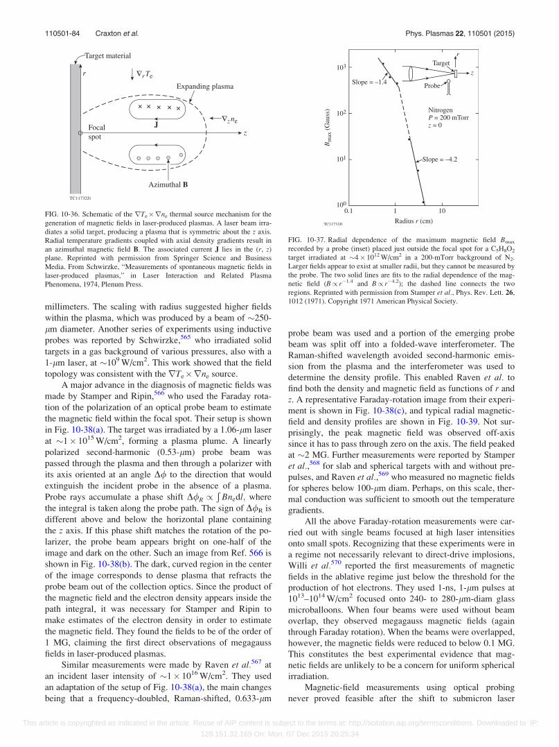
millimeters. The scaling with radius suggested higher fields
within the plasma, which was produced by a beam of �250-
lm diameter. Another series of experiments using inductive
probes was reported by Schwirzke,565 who irradiated solid
targets in a gas background of various pressures, also with a
1-lm laser, at �109 W/cm2. This work showed that the field
topology was consistent with the rTe�rne source.
A major advance in the diagnosis of magnetic fields was
made by Stamper and Ripin,566 who used the Faraday rota-
tion of the polarization of an optical probe beam to estimate
the magnetic field within the focal spot. Their setup is shown
in Fig. 10-38(a). The target was irradiated by a 1.06-lm laser
at �1� 1015 W/cm2, forming a plasma plume. A linearly
polarized second-harmonic (0.53-lm) probe beam was
passed through the plasma and then through a polarizer with
its axis oriented at an angle D/ to the direction that would
extinguish the incident probe in the absence of a plasma.
Probe rays accumulate a phase shift D/R /Ð
Bnedl; where
the integral is taken along the probe path. The sign of D/R is
different above and below the horizontal plane containing
the z axis. If this phase shift matches the rotation of the po-
larizer, the probe beam appears bright on one-half of the
image and dark on the other. Such an image from Ref. 566 is
shown in Fig. 10-38(b). The dark, curved region in the center
of the image corresponds to dense plasma that refracts the
probe beam out of the collection optics. Since the product of
the magnetic field and the electron density appears inside the
path integral, it was necessary for Stamper and Ripin to
make estimates of the electron density in order to estimate
the magnetic field. They found the fields to be of the order of
1 MG, claiming the first direct observations of megagauss
fields in laser-produced plasmas.
Similar measurements were made by Raven et al.567 at
an incident laser intensity of �1� 1016 W/cm2. They used
an adaptation of the setup of Fig. 10-38(a), the main changes
being that a frequency-doubled, Raman-shifted, 0.633-lm
probe beam was used and a portion of the emerging probe
beam was split off into a folded-wave interferometer. The
Raman-shifted wavelength avoided second-harmonic emis-
sion from the plasma and the interferometer was used to
determine the density profile. This enabled Raven et al. to
find both the density and magnetic field as functions of r and
z. A representative Faraday-rotation image from their experi-
ment is shown in Fig. 10-38(c), and typical radial magnetic-
field and density profiles are shown in Fig. 10-39. Not sur-
prisingly, the peak magnetic field was observed off-axis
since it has to pass through zero on the axis. The field peaked
at �2 MG. Further measurements were reported by Stamper
et al.,568 for slab and spherical targets with and without pre-
pulses, and Raven et al.,569 who measured no magnetic fields
for spheres below 100-lm diam. Perhaps, on this scale, ther-
mal conduction was sufficient to smooth out the temperature
gradients.
All the above Faraday-rotation measurements were car-
ried out with single beams focused at high laser intensities
onto small spots. Recognizing that these experiments were in
a regime not necessarily relevant to direct-drive implosions,
Willi et al.570 reported the first measurements of magnetic
fields in the ablative regime just below the threshold for the
production of hot electrons. They used 1-ns, 1-lm pulses at
1013–1014 W/cm2 focused onto 240- to 280-lm-diam glass
microballoons. When four beams were used without beam
overlap, they observed megagauss magnetic fields (again
through Faraday rotation). When the beams were overlapped,
however, the magnetic fields were reduced to below 0.1 MG.
This constitutes the best experimental evidence that mag-
netic fields are unlikely to be a concern for uniform spherical
irradiation.
Magnetic-field measurements using optical probing
never proved feasible after the shift to submicron laser
FIG. 10-36. Schematic of the rTe�rne thermal source mechanism for the
generation of magnetic fields in laser-produced plasmas. A laser beam irra-
diates a solid target, producing a plasma that is symmetric about the z axis.
Radial temperature gradients coupled with axial density gradients result in
an azimuthal magnetic field B. The associated current J lies in the (r, z)
plane. Reprinted with permission from Springer Science and Business
Media. From Schwirzke, “Measurements of spontaneous magnetic fields in
laser-produced plasmas,” in Laser Interaction and Related Plasma
Phenomena, 1974, Plenum Press.
FIG. 10-37. Radial dependence of the maximum magnetic field Bmax
recorded by a probe (inset) placed just outside the focal spot for a C5H8O2
target irradiated at �4� 1012 W/cm2 in a 200-mTorr background of N2.
Larger fields appear to exist at smaller radii, but they cannot be measured by
the probe. The two solid lines are fits to the radial dependence of the mag-
netic field (B/ r�1.4 and B/ r�4.2); the dashed line connects the two
regions. Reprinted with permission from Stamper et al., Phys. Rev. Lett. 26,
1012 (1971). Copyright 1971 American Physical Society.
110501-84 Craxton et al. Phys. Plasmas 22, 110501 (2015)
This article is copyrighted as indicated in the article. Reuse of AIP content is subject to the terms at: http://scitation.aip.org/termsconditions. Downloaded to IP:
128.151.32.169 On: Mon, 07 Dec 2015 20:25:34
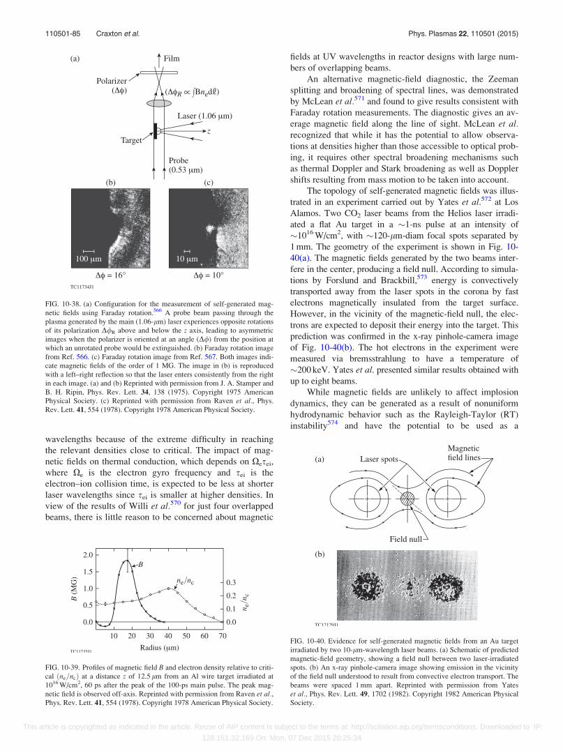
wavelengths because of the extreme difficulty in reaching
the relevant densities close to critical. The impact of mag-
netic fields on thermal conduction, which depends on Xesei,
where Xe is the electron gyro frequency and sei is the
electron–ion collision time, is expected to be less at shorter
laser wavelengths since sei is smaller at higher densities. In
view of the results of Willi et al.570 for just four overlapped
beams, there is little reason to be concerned about magnetic
fields at UV wavelengths in reactor designs with large num-
bers of overlapping beams.
An alternative magnetic-field diagnostic, the Zeeman
splitting and broadening of spectral lines, was demonstrated
by McLean et al.571 and found to give results consistent with
Faraday rotation measurements. The diagnostic gives an av-
erage magnetic field along the line of sight. McLean et al.recognized that while it has the potential to allow observa-
tions at densities higher than those accessible to optical prob-
ing, it requires other spectral broadening mechanisms such
as thermal Doppler and Stark broadening as well as Doppler
shifts resulting from mass motion to be taken into account.
The topology of self-generated magnetic fields was illus-
trated in an experiment carried out by Yates et al.572 at Los
Alamos. Two CO2 laser beams from the Helios laser irradi-
ated a flat Au target in a �1-ns pulse at an intensity of
�1016 W/cm2, with �120-lm-diam focal spots separated by
1 mm. The geometry of the experiment is shown in Fig. 10-
40(a). The magnetic fields generated by the two beams inter-
fere in the center, producing a field null. According to simula-
tions by Forslund and Brackbill,573 energy is convectively
transported away from the laser spots in the corona by fast
electrons magnetically insulated from the target surface.
However, in the vicinity of the magnetic-field null, the elec-
trons are expected to deposit their energy into the target. This
prediction was confirmed in the x-ray pinhole-camera image
of Fig. 10-40(b). The hot electrons in the experiment were
measured via bremsstrahlung to have a temperature of
�200 keV. Yates et al. presented similar results obtained with
up to eight beams.
While magnetic fields are unlikely to affect implosion
dynamics, they can be generated as a result of nonuniform
hydrodynamic behavior such as the Rayleigh-Taylor (RT)
instability574 and have the potential to be used as a
FIG. 10-38. (a) Configuration for the measurement of self-generated mag-
netic fields using Faraday rotation.566 A probe beam passing through the
plasma generated by the main (1.06-lm) laser experiences opposite rotations
of its polarization D/R above and below the z axis, leading to asymmetric
images when the polarizer is oriented at an angle (D/) from the position at
which an unrotated probe would be extinguished. (b) Faraday rotation image
from Ref. 566. (c) Faraday rotation image from Ref. 567. Both images indi-
cate magnetic fields of the order of 1 MG. The image in (b) is reproduced
with a left–right reflection so that the laser enters consistently from the right
in each image. (a) and (b) Reprinted with permission from J. A. Stamper and
B. H. Ripin, Phys. Rev. Lett. 34, 138 (1975). Copyright 1975 American
Physical Society. (c) Reprinted with permission from Raven et al., Phys.
Rev. Lett. 41, 554 (1978). Copyright 1978 American Physical Society.
FIG. 10-39. Profiles of magnetic field B and electron density relative to criti-
cal ðne=ncÞ at a distance z of 12.5 lm from an Al wire target irradiated at
1016 W/cm2, 60 ps after the peak of the 100-ps main pulse. The peak mag-
netic field is observed off-axis. Reprinted with permission from Raven et al.,Phys. Rev. Lett. 41, 554 (1978). Copyright 1978 American Physical Society.
FIG. 10-40. Evidence for self-generated magnetic fields from an Au target
irradiated by two 10-lm-wavelength laser beams. (a) Schematic of predicted
magnetic-field geometry, showing a field null between two laser-irradiated
spots. (b) An x-ray pinhole-camera image showing emission in the vicinity
of the field null understood to result from convective electron transport. The
beams were spaced 1 mm apart. Reprinted with permission from Yates
et al., Phys. Rev. Lett. 49, 1702 (1982). Copyright 1982 American Physical
Society.
110501-85 Craxton et al. Phys. Plasmas 22, 110501 (2015)
This article is copyrighted as indicated in the article. Reuse of AIP content is subject to the terms at: http://scitation.aip.org/termsconditions. Downloaded to IP:
128.151.32.169 On: Mon, 07 Dec 2015 20:25:34
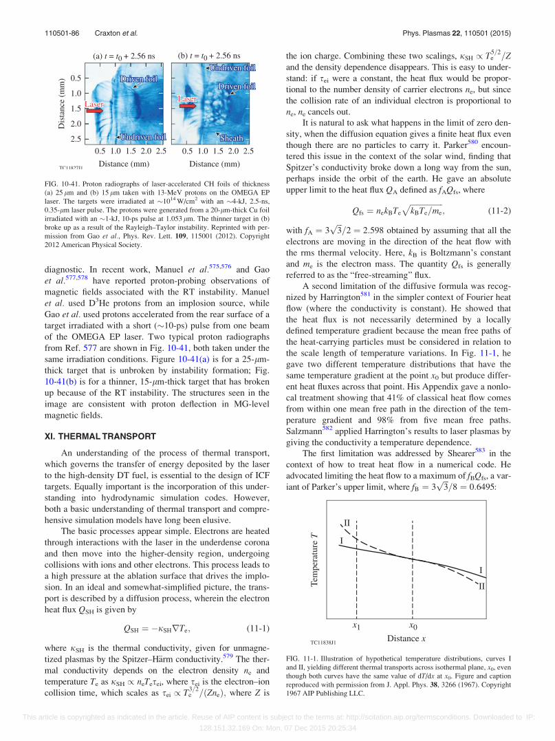
diagnostic. In recent work, Manuel et al.575,576 and Gao
et al.577,578 have reported proton-probing observations of
magnetic fields associated with the RT instability. Manuel
et al. used D3He protons from an implosion source, while
Gao et al. used protons accelerated from the rear surface of a
target irradiated with a short (�10-ps) pulse from one beam
of the OMEGA EP laser. Two typical proton radiographs
from Ref. 577 are shown in Fig. 10-41, both taken under the
same irradiation conditions. Figure 10-41(a) is for a 25-lm-
thick target that is unbroken by instability formation; Fig.
10-41(b) is for a thinner, 15-lm-thick target that has broken
up because of the RT instability. The structures seen in the
image are consistent with proton deflection in MG-level
magnetic fields.
XI. THERMAL TRANSPORT
An understanding of the process of thermal transport,
which governs the transfer of energy deposited by the laser
to the high-density DT fuel, is essential to the design of ICF
targets. Equally important is the incorporation of this under-
standing into hydrodynamic simulation codes. However,
both a basic understanding of thermal transport and compre-
hensive simulation models have long been elusive.
The basic processes appear simple. Electrons are heated
through interactions with the laser in the underdense corona
and then move into the higher-density region, undergoing
collisions with ions and other electrons. This process leads to
a high pressure at the ablation surface that drives the implo-
sion. In an ideal and somewhat-simplified picture, the trans-
port is described by a diffusion process, wherein the electron
heat flux QSH is given by
QSH ¼ �jSHrTe; (11-1)
where jSH is the thermal conductivity, given for unmagne-
tized plasmas by the Spitzer–H€arm conductivity.579 The ther-
mal conductivity depends on the electron density ne and
temperature Te as jSH / neTesei, where sei is the electron–ion
collision time, which scales as sei / T3=2e =ðZneÞ; where Z is
the ion charge. Combining these two scalings, jSH / T5=2e =Z
and the density dependence disappears. This is easy to under-
stand: if sei were a constant, the heat flux would be propor-
tional to the number density of carrier electrons ne, but since
the collision rate of an individual electron is proportional to
ne, ne cancels out.
It is natural to ask what happens in the limit of zero den-
sity, when the diffusion equation gives a finite heat flux even
though there are no particles to carry it. Parker580 encoun-
tered this issue in the context of the solar wind, finding that
Spitzer’s conductivity broke down a long way from the sun,
perhaps inside the orbit of the earth. He gave an absolute
upper limit to the heat flux QA defined as fAQfs, where
Qfs ¼ nekBTe
ffiffiffiffiffiffiffiffiffiffiffiffiffiffiffiffiffikBTe=me
p; (11-2)
with fA ¼ 3ffiffiffi3p
=2 ¼ 2:598 obtained by assuming that all the
electrons are moving in the direction of the heat flow with
the rms thermal velocity. Here, kB is Boltzmann’s constant
and me is the electron mass. The quantity Qfs is generally
referred to as the “free-streaming” flux.
A second limitation of the diffusive formula was recog-
nized by Harrington581 in the simpler context of Fourier heat
flow (where the conductivity is constant). He showed that
the heat flux is not necessarily determined by a locally
defined temperature gradient because the mean free paths of
the heat-carrying particles must be considered in relation to
the scale length of temperature variations. In Fig. 11-1, he
gave two different temperature distributions that have the
same temperature gradient at the point x0 but produce differ-
ent heat fluxes across that point. His Appendix gave a nonlo-
cal treatment showing that 41% of classical heat flow comes
from within one mean free path in the direction of the tem-
perature gradient and 98% from five mean free paths.
Salzmann582 applied Harrington’s results to laser plasmas by
giving the conductivity a temperature dependence.
The first limitation was addressed by Shearer583 in the
context of how to treat heat flow in a numerical code. He
advocated limiting the heat flow to a maximum of fBQfs, a var-
iant of Parker’s upper limit, where fB ¼ 3ffiffiffi3p
=8 ¼ 0:6495:
FIG. 10-41. Proton radiographs of laser-accelerated CH foils of thickness
(a) 25 lm and (b) 15 lm taken with 13-MeV protons on the OMEGA EP
laser. The targets were irradiated at �1014 W/cm2 with an �4-kJ, 2.5-ns,
0.35-lm laser pulse. The protons were generated from a 20-lm-thick Cu foil
irradiated with an �1-kJ, 10-ps pulse at 1.053 lm. The thinner target in (b)
broke up as a result of the Rayleigh–Taylor instability. Reprinted with per-
mission from Gao et al., Phys. Rev. Lett. 109, 115001 (2012). Copyright
2012 American Physical Society.
FIG. 11-1. Illustration of hypothetical temperature distributions, curves I
and II, yielding different thermal transports across isothermal plane, x0, even
though both curves have the same value of dT/dx at x0. Figure and caption
reproduced with permission from J. Appl. Phys. 38, 3266 (1967). Copyright
1967 AIP Publishing LLC.
110501-86 Craxton et al. Phys. Plasmas 22, 110501 (2015)
This article is copyrighted as indicated in the article. Reuse of AIP content is subject to the terms at: http://scitation.aip.org/termsconditions. Downloaded to IP:
128.151.32.169 On: Mon, 07 Dec 2015 20:25:34
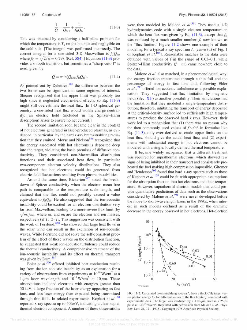
1
Q¼ 1
QSH
þ 1
fBQfs
: (11-3)
This was obtained by considering a half-plane problem for
which the temperature is Te on the hot side and negligible on
the cold side. [The integral was performed incorrectly. The
correct integral for a one-sided 3-D Maxwellian is fCQfs,
where fC ¼ffiffiffiffiffiffiffiffi2=p
p¼ 0:798 (Ref. 584).] Equation (11-3) pro-
vides a smooth transition, but sometimes a “sharp cutoff” is
used, given by
Q ¼ minðQSH; fBQfsÞ: (11-4)
As pointed out by Delettrez,585 the difference between the
two forms can be significant in some regimes of interest.
Shearer recognized that his upper limit was probably too
high since it neglected electric-field effects, so Eq. (11-3)
might still overestimate the heat flux. [In 1-D spherical ge-
ometry, a one-sided heat flux would violate charge neutral-
ity; an electric field (included in the Spitzer–H€arm
description) arises to ensure no net current.]
The second limitation soon became clear in the context
of hot electrons generated in laser-produced plasmas, as evi-
denced, in particular, by the hard x-ray bremsstrahlung radia-
tion that they emitted. Morse and Nielson586 recognized that
the energy associated with hot electrons is deposited deep
into the target, violating the basic premises of diffusive con-
ductivity. They considered non-Maxwellian distribution
functions and their associated heat flow, in particular
two-component electron velocity distributions. They also
recognized that hot electrons could be generated from
electric-field fluctuations resulting from plasma instabilities.
Around the same time, Bickerton587 noted the break-
down of Spitzer conductivity when the electron mean free
path is comparable to the temperature scale length, and
claimed that the flux could not possibly exceed a value
equivalent to fBQfs. He also suggested that the ion-acoustic
instability could be excited for an electron distribution very
far from Maxwellian, leading to a more-severe flux limit (byffiffiffiffiffiffiffiffiffiffiffiffiffime=mi
p; where me and mi are the electron and ion masses,
respectively) if Te Ti: This suggestion was consistent with
the work of Forslund,588 who showed that large heat flows in
the solar wind can result in the excitation of ion-acoustic
waves. While Forslund did not solve the self-consistent prob-
lem of the effect of these waves on the distribution function,
he suggested that weak ion-acoustic turbulence could reduce
the thermal conductivity. A comprehensive treatment of the
ion-acoustic instability and its effect on thermal transport
was given by Dum.589
Ehler et al.590 offered inhibited heat conduction result-
ing from the ion-acoustic instability as an explanation for a
variety of observations from experiments at 1016 W/cm2 at a
1-lm laser wavelength and 1014 W/cm2 at 10 lm. These
observations included electrons with energies greater than
50 keV, a large fraction of the laser energy appearing as fast
ions, and less laser energy than expected being transmitted
through thin foils. In related experiments, Kephart et al.108
reported x-ray spectra up to 50 keV, indicating a clear supra-
thermal electron component. A number of these observations
were then modeled by Malone et al.591 They used a 1-D
hydrodynamics code with a single electron temperature in
which the heat flux was given by Eq. (11-3), except that fBwas replaced by a much smaller number, f, now known as
the “flux limiter.” Figure 11-2 shows one example of their
modeling for a typical x-ray spectrum I� [curve (d) of Fig. 1
of Kephart et al.108]. Reasonable matches to the data were
obtained with values of f in the range of 0.03–0.1, while
Spitzer–H€arm conductivity (f¼1) came nowhere close to
the data.
Malone et al. also matched, in a phenomenological way,
the energy fraction transmitted through a thin foil and the
percentage of energy in fast ions and, following Ehler
et al.,590 offered ion-acoustic turbulence as a possible expla-
nation. They suggested heat-flux limitation by magnetic
fields (Sec. X F) as another possibility. Their simulations had
the limitation that they modeled a single-temperature distri-
bution; therefore, inhibiting the transport of energy deposited
at the critical-density surface led to sufficiently high temper-
atures to produce the observed hard x rays. However, their
work led to a recognition that (1) there was no reason why
the then commonly used values of f� 0.6 in formulae like
Eq. (11-3), only ever derived as crude upper limits on the
heat flux, should give the actual heat flux; and (2) experi-
ments with substantial energy in hot electrons cannot be
modeled with a single, locally defined thermal temperature.
It became widely recognized that a different treatment
was required for suprathermal electrons, which showed few
signs of being inhibited in their transport and consistently pre-
heated the fuel making high compression impossible. Gitomer
and Henderson592 found that hard x-ray spectra such as those
of Kephart et al.108 could be fit with appropriate assumptions
for the absorption fraction into hot electrons and their temper-
ature. However, suprathermal electron models that could pro-
vide quantitative predictions of data such as the observations
considered by Malone et al.591 were never developed before
the move to short-wavelength lasers in the 1980s, when inter-
est in such models declined as a result of the dramatic
decrease in the energy observed in hot electrons. Hot-electron
FIG. 11-2. Calculated bremsstrahlung spectra I� from a thick CH2 target ver-
sus photon energy h� for different values of the flux limiter f, compared with
experimental data. The target was irradiated by a 1.06-lm laser in a 25-ps
pulse at �1016 W/cm2. Reprinted with permission from Malone et al., Phys.
Rev. Lett. 34, 721 (1975). Copyright 1975 American Physical Society.
110501-87 Craxton et al. Phys. Plasmas 22, 110501 (2015)
This article is copyrighted as indicated in the article. Reuse of AIP content is subject to the terms at: http://scitation.aip.org/termsconditions. Downloaded to IP:
128.151.32.169 On: Mon, 07 Dec 2015 20:25:34

modeling has since become important in the context of fast
ignition (Sec. XIV) and shock ignition (Sec. XV) and in the
coupling of parametric-instability–generated hot electrons to
the compressed fuel (Sec. X A).
Interest in heat-flux inhibition continued with an experi-
ment by Gray et al.593 in which they attempted to isolate
heat flow from the complications associated with high-
intensity lasers such as fast-electron transport, magnetic-field
generation, and resonant absorption. They heated a hydrogen
Z pinch594 of initial density 6� 1016 cm�3 and initial tem-
perature 4 eV with a 300-MW, 3-ns CO2 laser focused to a
350-lm-diam spot and used ruby-laser scattering to measure
the evolution of Te and ne transverse to the direction of the
heating laser. They modeled their data with two adjustable
parameters—the flux limiter and a multiplier w on the classi-
cal absorption rate—obtaining results such as those shown in
Fig. 11-3(a) for the temperature profile. Without strong inhi-
bition of the heat flux, they predicted that heat would flow
away from the heated region faster than was observed. They
found best fits to the data with w¼ 1 (classical absorption)
and f¼ 0.016–0.04. [Note that their definition of f, shown as
f* in Fig. 11-3(a), was higher than f by a factor offfiffiffiffiffiffiffiffip=2
p:]
Their care in considering possible deviations from classical
absorption makes the point that uncertainties in absorption
modeling can lead to uncertainties in transport modeling and
vice versa.
Gray et al.593 also measured an enhancement up to a
factor of 14� thermal in the ion feature of their scattering
results [Fig. 11-3(b)]. This provided evidence for ion-
acoustic turbulence, which they claimed was the source of
the observed low heat flux. Gray et al. noted that the first-
order perturbation theory of Spitzer and H€arm breaks down
when the ratio of the electron mean free path ke to the
temperature-gradient scale length L exceeds 0.02. A full
report of this work is found in Ref. 584.
An alternative interpretation to ion-acoustic turbulence
was provided in 1981 by Bell et al.595 Until this time, thermal
transport was routinely modeled in an ad hoc manner with
Eq. (11-3) or (11-4), usually with a small value of f as advo-
cated by Malone et al.591 Bell et al. solved the Fokker–Planck
equation to obtain solutions for the electron distribution func-
tion for a simple 1-D heat flow problem in which the
Spitzer–H€arm theory broke down. In this approach, the elec-
tron distribution function f(v,x,h) is expressed as a Legendre
polynomial expansionP
‘f‘ðv; xÞP‘ðcos hÞ; where h is the
angle in velocity space to the direction of heat flow, with each
f‘(v,x) solved as a function of space (x) and velocity (v). In
contrast to the Spitzer–H€arm model, which uses the perturba-
tion approximation [f(v,x,h)¼ f0(v,x)þ f1(v,x) cos h], f0(v,x)
does not need to be Maxwellian. The different velocities are
coupled by an appropriate collision operator. The density was
uniform in the simulation region, and a temperature difference
between the two ends of the region was created by raising the
temperature at one end. Figure 11-4(a) shows the evolution of
the temperature profile and the associated heat flux.
From plots such as Fig. 11-4(a), Bell et al.595 were able
to scan from one end of the region to the other, plotting for
each point the ratio of the heat flux Q to Qfs and the ratio L/
ke. An example (for a normalized time of 5260) is shown in
Fig. 11-4(b), demonstrating that the heat flux is not simply a
function of the local plasma state. In this example, the heat
flux near the top of the heat front (immediately to the right
of the heated region) was �0.1 times the free-streaming limit
and the heat flux at the base of the heat front exceeded the
Spitzer–H€arm flux. The temperature gradient scale length
was a few times the mean free path of a thermal electron in
the most-extreme case considered. (The mean free path of a
heat-carrying electron, which typically has a velocity 2–3�thermal, is considerably larger than that of a thermal electron
as the mean free path of an electron scales with v4.) Bell
et al. also found that while the perturbed part of the distribu-
tion function f1 in the Spitzer–H€arm model exceeds the
unperturbed (Maxwellian) part f0 at large velocity, the ampli-
tude of f1=f0 was limited to just below unity in the
Fokker–Planck calculations. Using an ad-hoc (local) model
with a simplified collision operator, Shvarts et al.596 showed
FIG. 11-3. (a) Calculated temperature profiles for a Z pinch heated by a 300-
MW, 3-ns, CO2 laser pulse for three values of the flux limiter f*, compared
with experimental data. [Note that f � ¼ fffiffiffiffiffiffiffiffip=2
p; where f is the standard defi-
nition of the flux limiter.] For each simulation the two solid lines indicate
the band of temperatures possible within the 6100-lm alignment error. (b)
Enhancement of the ion feature above thermal ðSi0=Si;thÞ measured by ruby-
laser scattering, indicating ion-acoustic turbulence. Reprinted with permis-
sion from Gray et al., Phys. Rev. Lett. 39, 1270 (1977). Copyright 1977
American Physical Society.
110501-88 Craxton et al. Phys. Plasmas 22, 110501 (2015)
This article is copyrighted as indicated in the article. Reuse of AIP content is subject to the terms at: http://scitation.aip.org/termsconditions. Downloaded to IP:
128.151.32.169 On: Mon, 07 Dec 2015 20:25:34
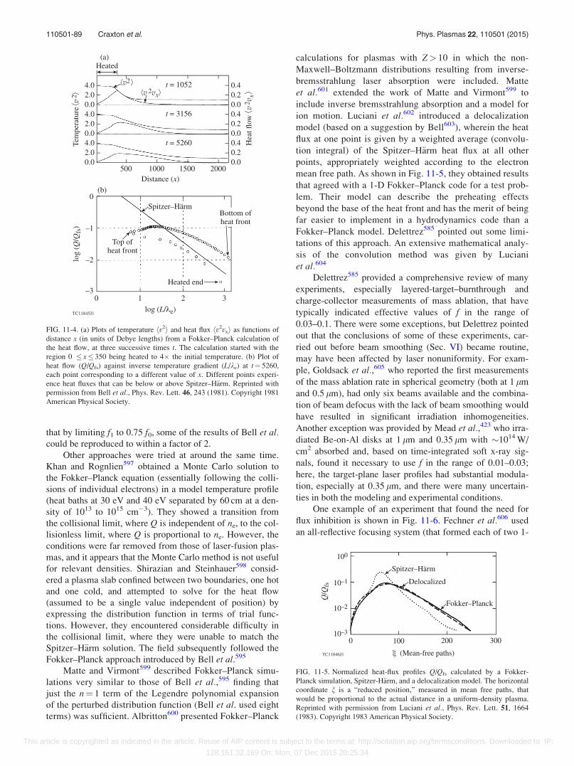
that by limiting f1 to 0.75 f0, some of the results of Bell et al.could be reproduced to within a factor of 2.
Other approaches were tried at around the same time.
Khan and Rognlien597 obtained a Monte Carlo solution to
the Fokker–Planck equation (essentially following the colli-
sions of individual electrons) in a model temperature profile
(heat baths at 30 eV and 40 eV separated by 60 cm at a den-
sity of 1013 to 1015 cm�3). They showed a transition from
the collisional limit, where Q is independent of ne, to the col-
lisionless limit, where Q is proportional to ne. However, the
conditions were far removed from those of laser-fusion plas-
mas, and it appears that the Monte Carlo method is not useful
for relevant densities. Shirazian and Steinhauer598 consid-
ered a plasma slab confined between two boundaries, one hot
and one cold, and attempted to solve for the heat flow
(assumed to be a single value independent of position) by
expressing the distribution function in terms of trial func-
tions. However, they encountered considerable difficulty in
the collisional limit, where they were unable to match the
Spitzer–H€arm solution. The field subsequently followed the
Fokker–Planck approach introduced by Bell et al.595
Matte and Virmont599 described Fokker–Planck simu-
lations very similar to those of Bell et al.,595 finding that
just the n¼ 1 term of the Legendre polynomial expansion
of the perturbed distribution function (Bell et al. used eight
terms) was sufficient. Albritton600 presented Fokker–Planck
calculations for plasmas with Z> 10 in which the non-
Maxwell–Boltzmann distributions resulting from inverse-
bremsstrahlung laser absorption were included. Matte
et al.601 extended the work of Matte and Virmont599 to
include inverse bremsstrahlung absorption and a model for
ion motion. Luciani et al.602 introduced a delocalization
model (based on a suggestion by Bell603), wherein the heat
flux at one point is given by a weighted average (convolu-
tion integral) of the Spitzer–H€arm heat flux at all other
points, appropriately weighted according to the electron
mean free path. As shown in Fig. 11-5, they obtained results
that agreed with a 1-D Fokker–Planck code for a test prob-
lem. Their model can describe the preheating effects
beyond the base of the heat front and has the merit of being
far easier to implement in a hydrodynamics code than a
Fokker–Planck model. Delettrez585 pointed out some limi-
tations of this approach. An extensive mathematical analy-
sis of the convolution method was given by Luciani
et al.604
Delettrez585 provided a comprehensive review of many
experiments, especially layered-target–burnthrough and
charge-collector measurements of mass ablation, that have
typically indicated effective values of f in the range of
0.03–0.1. There were some exceptions, but Delettrez pointed
out that the conclusions of some of these experiments, car-
ried out before beam smoothing (Sec. VI) became routine,
may have been affected by laser nonuniformity. For exam-
ple, Goldsack et al.,605 who reported the first measurements
of the mass ablation rate in spherical geometry (both at 1 lm
and 0.5 lm), had only six beams available and the combina-
tion of beam defocus with the lack of beam smoothing would
have resulted in significant irradiation inhomogeneities.
Another exception was provided by Mead et al.,423 who irra-
diated Be-on-Al disks at 1 lm and 0.35 lm with �1014 W/
cm2 absorbed and, based on time-integrated soft x-ray sig-
nals, found it necessary to use f in the range of 0.01–0.03;
here, the target-plane laser profiles had substantial modula-
tion, especially at 0.35 lm, and there were many uncertain-
ties in both the modeling and experimental conditions.
One example of an experiment that found the need for
flux inhibition is shown in Fig. 11-6. Fechner et al.606 used
an all-reflective focusing system (that formed each of two 1-
FIG. 11-4. (a) Plots of temperature hv2i and heat flux hv2vxi as functions of
distance x (in units of Debye lengths) from a Fokker–Planck calculation of
the heat flow, at three successive times t. The calculation started with the
region 0 x 350 being heated to 4� the initial temperature. (b) Plot of
heat flow (Q/Qfs) against inverse temperature gradient (L/ke) at t¼ 5260,
each point corresponding to a different value of x. Different points experi-
ence heat fluxes that can be below or above Spitzer–H€arm. Reprinted with
permission from Bell et al., Phys. Rev. Lett. 46, 243 (1981). Copyright 1981
American Physical Society.
FIG. 11-5. Normalized heat-flux profiles Q/Qfs calculated by a Fokker-
Planck simulation, Spitzer-H€arm, and a delocalization model. The horizontal
coordinate n is a “reduced position,” measured in mean free paths, that
would be proportional to the actual distance in a uniform-density plasma.
Reprinted with permission from Luciani et al., Phys. Rev. Lett. 51, 1664
(1983). Copyright 1983 American Physical Society.
110501-89 Craxton et al. Phys. Plasmas 22, 110501 (2015)
This article is copyrighted as indicated in the article. Reuse of AIP content is subject to the terms at: http://scitation.aip.org/termsconditions. Downloaded to IP:
128.151.32.169 On: Mon, 07 Dec 2015 20:25:34
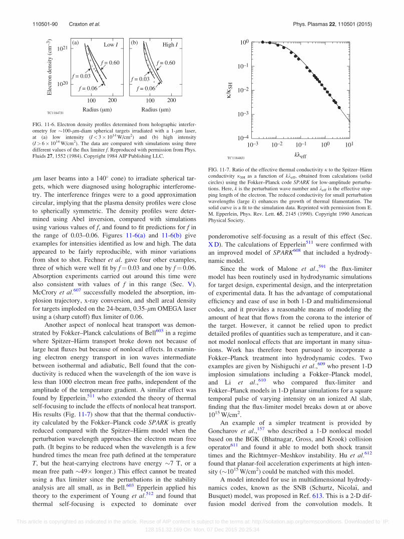
lm laser beams into a 140� cone) to irradiate spherical tar-
gets, which were diagnosed using holographic interferome-
try. The interference fringes were to a good approximation
circular, implying that the plasma density profiles were close
to spherically symmetric. The density profiles were deter-
mined using Abel inversion, compared with simulations
using various values of f, and found to fit predictions for f in
the range of 0.03–0.06. Figures 11-6(a) and 11-6(b) give
examples for intensities identified as low and high. The data
appeared to be fairly reproducible, with minor variations
from shot to shot. Fechner et al. gave four other examples,
three of which were well fit by f¼ 0.03 and one by f¼ 0.06.
Absorption experiments carried out around this time were
also consistent with values of f in this range (Sec. V).
McCrory et al.607 successfully modeled the absorption, im-
plosion trajectory, x-ray conversion, and shell areal density
for targets imploded on the 24-beam, 0.35-lm OMEGA laser
using a (sharp cutoff) flux limiter of 0.06.
Another aspect of nonlocal heat transport was demon-
strated by Fokker–Planck calculations of Bell603 in a regime
where Spitzer–H€arm transport broke down not because of
large heat fluxes but because of nonlocal effects. In examin-
ing electron energy transport in ion waves intermediate
between isothermal and adiabatic, Bell found that the con-
ductivity is reduced when the wavelength of the ion wave is
less than 1000 electron mean free paths, independent of the
amplitude of the temperature gradient. A similar effect was
found by Epperlein,511 who extended the theory of thermal
self-focusing to include the effects of nonlocal heat transport.
His results (Fig. 11-7) show that that the thermal conductiv-
ity calculated by the Fokker–Planck code SPARK is greatly
reduced compared with the Spitzer–H€arm model when the
perturbation wavelength approaches the electron mean free
path. (It begins to be reduced when the wavelength is a few
hundred times the mean free path defined at the temperature
T, but the heat-carrying electrons have energy �7 T, or a
mean free path �49� longer.) This effect cannot be treated
using a flux limiter since the perturbations in the stability
analysis are all small, as in Bell.603 Epperlein applied his
theory to the experiment of Young et al.512 and found that
thermal self-focusing is expected to dominate over
ponderomotive self-focusing as a result of this effect (Sec.
X D). The calculations of Epperlein511 were confirmed with
an improved model of SPARK608 that included a hydrody-
namic model.
Since the work of Malone et al.,591 the flux-limiter
model has been routinely used in hydrodynamic simulations
for target design, experimental design, and the interpretation
of experimental data. It has the advantage of computational
efficiency and ease of use in both 1-D and multidimensional
codes, and it provides a reasonable means of modeling the
amount of heat that flows from the corona to the interior of
the target. However, it cannot be relied upon to predict
detailed profiles of quantities such as temperature, and it can-
not model nonlocal effects that are important in many situa-
tions. Work has therefore been pursued to incorporate a
Fokker–Planck treatment into hydrodynamic codes. Two
examples are given by Nishiguchi et al.,609 who present 1-D
implosion simulations including a Fokker–Planck model,
and Li et al.,610 who compared flux-limiter and
Fokker–Planck models in 1-D planar simulations for a square
temporal pulse of varying intensity on an ionized Al slab,
finding that the flux-limiter model breaks down at or above
1015 W/cm2.
An example of a simpler treatment is provided by
Goncharov et al.,157 who described a 1-D nonlocal model
based on the BGK (Bhatnagar, Gross, and Krook) collision
operator611 and found it able to model both shock transit
times and the Richtmyer–Meshkov instability. Hu et al.612
found that planar-foil acceleration experiments at high inten-
sity (�1015 W/cm2) could be matched with this model.
A model intended for use in multidimensional hydrody-
namics codes, known as the SNB (Schurtz, Nicola€ı, and
Busquet) model, was proposed in Ref. 613. This is a 2-D dif-
fusion model derived from the convolution models. It
FIG. 11-6. Electron density profiles determined from holographic interfer-
ometry for �100-lm-diam spherical targets irradiated with a 1-lm laser,
at (a) low intensity (I< 3� 1014 W/cm2) and (b) high intensity
(I> 6� 1014 W/cm2). The data are compared with simulations using three
different values of the flux limiter f. Reproduced with permission from Phys.
Fluids 27, 1552 (1984). Copyright 1984 AIP Publishing LLC.
FIG. 11-7. Ratio of the effective thermal conductivity j to the Spitzer–H€arm
conductivity jSH as a function of kkeff, obtained from calculations (solid
circles) using the Fokker–Planck code SPARK for low-amplitude perturba-
tions. Here, k is the perturbation wave number and keff is the effective stop-
ping length of the electron. The reduced conductivity for small perturbation
wavelengths (large k) enhances the growth of thermal filamentation. The
solid curve is a fit to the simulation data. Reprinted with permission from E.
M. Epperlein, Phys. Rev. Lett. 65, 2145 (1990). Copyright 1990 American
Physical Society.
110501-90 Craxton et al. Phys. Plasmas 22, 110501 (2015)
This article is copyrighted as indicated in the article. Reuse of AIP content is subject to the terms at: http://scitation.aip.org/termsconditions. Downloaded to IP:
128.151.32.169 On: Mon, 07 Dec 2015 20:25:34
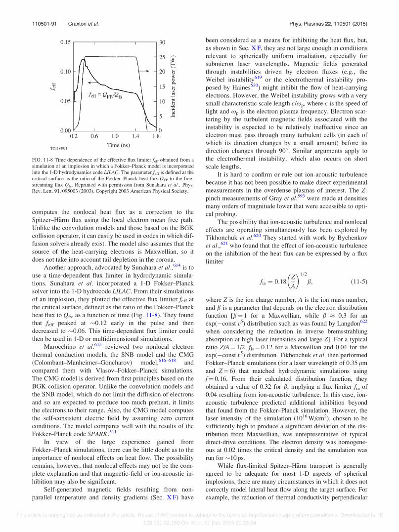
computes the nonlocal heat flux as a correction to the
Spitzer–H€arm flux using the local electron mean free path.
Unlike the convolution models and those based on the BGK
collision operator, it can easily be used in codes in which dif-
fusion solvers already exist. The model also assumes that the
source of the heat-carrying electrons is Maxwellian, so it
does not take into account tail depletion in the corona.
Another approach, advocated by Sunahara et al.,614 is to
use a time-dependent flux limiter in hydrodynamic simula-
tions. Sunahara et al. incorporated a 1-D Fokker–Planck
solver into the 1-D hydrocode LILAC. From their simulations
of an implosion, they plotted the effective flux limiter feff at
the critical surface, defined as the ratio of the Fokker–Planck
heat flux to Qfs, as a function of time (Fig. 11-8). They found
that feff peaked at �0.12 early in the pulse and then
decreased to �0.06. This time-dependent flux limiter could
then be used in 1-D or multidimensional simulations.
Marocchino et al.615 reviewed two nonlocal electron
thermal conduction models, the SNB model and the CMG
(Colombant–Manheimer–Goncharov) model,616–618 and
compared them with Vlasov–Fokker–Planck simulations.
The CMG model is derived from first principles based on the
BGK collision operator. Unlike the convolution models and
the SNB model, which do not limit the diffusion of electrons
and so are expected to produce too much preheat, it limits
the electrons to their range. Also, the CMG model computes
the self-consistent electric field by assuming zero current
conditions. The model compares well with the results of the
Fokker–Planck code SPARK.511
In view of the large experience gained from
Fokker–Planck simulations, there can be little doubt as to the
importance of nonlocal effects on heat flow. The possibility
remains, however, that nonlocal effects may not be the com-
plete explanation and that magnetic-field or ion-acoustic in-
hibition may also be significant.
Self-generated magnetic fields resulting from non-
parallel temperature and density gradients (Sec. X F) have
been considered as a means for inhibiting the heat flux, but,
as shown in Sec. X F, they are not large enough in conditions
relevant to spherically uniform irradiation, especially for
submicron laser wavelengths. Magnetic fields generated
through instabilities driven by electron fluxes (e.g., the
Weibel instability619 or the electrothermal instability pro-
posed by Haines530) might inhibit the flow of heat-carrying
electrons. However, the Weibel instability grows with a very
small characteristic scale length c/xp, where c is the speed of
light and xp is the electron plasma frequency. Electron scat-
tering by the turbulent magnetic fields associated with the
instability is expected to be relatively ineffective since an
electron must pass through many turbulent cells (in each of
which its direction changes by a small amount) before its
direction changes through 90�. Similar arguments apply to
the electrothermal instability, which also occurs on short
scale lengths.
It is hard to confirm or rule out ion-acoustic turbulence
because it has not been possible to make direct experimental
measurements in the overdense plasmas of interest. The Z-
pinch measurements of Gray et al.593 were made at densities
many orders of magnitude lower that were accessible to opti-
cal probing.
The possibility that ion-acoustic turbulence and nonlocal
effects are operating simultaneously has been explored by
Tikhonchuk et al.620 They started with work by Bychenkov
et al.,621 who found that the effect of ion-acoustic turbulence
on the inhibition of the heat flux can be expressed by a flux
limiter
fia ¼ 0:18Z
A
� �1=2
b; (11-5)
where Z is the ion charge number, A is the ion mass number,
and b is a parameter that depends on the electron distribution
function [b¼ 1 for a Maxwellian, while b � 0.3 for an
exp(�const v5) distribution such as was found by Langdon622
when considering the reduction in inverse bremsstrahlung
absorption at high laser intensities and large Z]. For a typical
ratio Z/A¼ 1/2, fia¼ 0.12 for a Maxwellian and 0.04 for the
exp(�const v5) distribution. Tikhonchuk et al. then performed
Fokker–Planck simulations (for a laser wavelength of 0.35 lm
and Z¼ 6) that matched hydrodynamic simulations using
f¼ 0.16. From their calculated distribution function, they
obtained a value of 0.32 for b, implying a flux limiter fia of
0.04 resulting from ion-acoustic turbulence. In this case, ion-
acoustic turbulence predicted additional inhibition beyond
that found from the Fokker–Planck simulation. However, the
laser intensity of the simulation (1016 W/cm2), chosen to be
sufficiently high to produce a significant deviation of the dis-
tribution from Maxwellian, was unrepresentative of typical
direct-drive conditions. The electron density was homogene-
ous at 0.02 times the critical density and the simulation was
run for �10 ps.
While flux-limited Spitzer–H€arm transport is generally
agreed to be adequate for most 1-D aspects of spherical
implosions, there are many circumstances in which it does not
correctly model lateral heat flow along the target surface. For
example, the reduction of thermal conductivity perpendicular
FIG. 11-8 Time dependence of the effective flux limiter feff obtained from a
simulation of an implosion in which a Fokker–Planck model is incorporated
into the 1-D hydrodynamics code LILAC. The parameter feff is defined at the
critical surface as the ratio of the Fokker–Planck heat flux QFP to the free-
streaming flux Qfs. Reprinted with permission from Sunahara et al., Phys.
Rev. Lett. 91, 095003 (2003). Copyright 2003 American Physical Society.
110501-91 Craxton et al. Phys. Plasmas 22, 110501 (2015)
This article is copyrighted as indicated in the article. Reuse of AIP content is subject to the terms at: http://scitation.aip.org/termsconditions. Downloaded to IP:
128.151.32.169 On: Mon, 07 Dec 2015 20:25:34
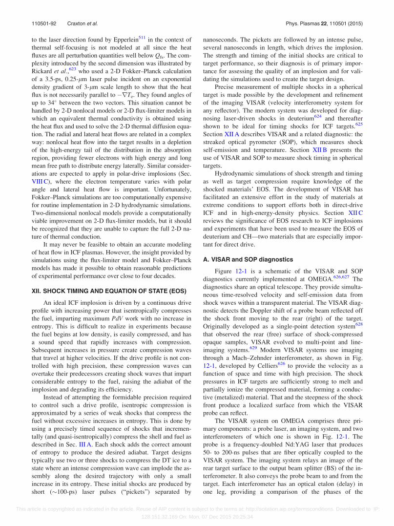
to the laser direction found by Epperlein511 in the context of
thermal self-focusing is not modeled at all since the heat
fluxes are all perturbation quantities well below Qfs. The com-
plexity introduced by the second dimension was illustrated by
Rickard et al.,623 who used a 2-D Fokker–Planck calculation
of a 3.5-ps, 0.25-lm laser pulse incident on an exponential
density gradient of 3-lm scale length to show that the heat
flux is not necessarily parallel to �rTe. They found angles of
up to 34� between the two vectors. This situation cannot be
handled by 2-D nonlocal models or 2-D flux-limiter models in
which an equivalent thermal conductivity is obtained using
the heat flux and used to solve the 2-D thermal diffusion equa-
tion. The radial and lateral heat flows are related in a complex
way: nonlocal heat flow into the target results in a depletion
of the high-energy tail of the distribution in the absorption
region, providing fewer electrons with high energy and long
mean free path to distribute energy laterally. Similar consider-
ations are expected to apply in polar-drive implosions (Sec.
VIII C), where the electron temperature varies with polar
angle and lateral heat flow is important. Unfortunately,
Fokker–Planck simulations are too computationally expensive
for routine implementation in 2-D hydrodynamic simulations.
Two-dimensional nonlocal models provide a computationally
viable improvement on 2-D flux-limiter models, but it should
be recognized that they are unable to capture the full 2-D na-
ture of thermal conduction.
It may never be feasible to obtain an accurate modeling
of heat flow in ICF plasmas. However, the insight provided by
simulations using the flux-limiter model and Fokker–Planck
models has made it possible to obtain reasonable predictions
of experimental performance over close to four decades.
XII. SHOCK TIMING AND EQUATION OF STATE (EOS)
An ideal ICF implosion is driven by a continuous drive
profile with increasing power that isentropically compresses
the fuel, imparting maximum PdV work with no increase in
entropy. This is difficult to realize in experiments because
the fuel begins at low density, is easily compressed, and has
a sound speed that rapidly increases with compression.
Subsequent increases in pressure create compression waves
that travel at higher velocities. If the drive profile is not con-
trolled with high precision, these compression waves can
overtake their predecessors creating shock waves that impart
considerable entropy to the fuel, raising the adiabat of the
implosion and degrading its efficiency.
Instead of attempting the formidable precision required
to control such a drive profile, isentropic compression is
approximated by a series of weak shocks that compress the
fuel without excessive increases in entropy. This is done by
using a precisely timed sequence of shocks that incremen-
tally (and quasi-isentropically) compress the shell and fuel as
described in Sec. III A. Each shock adds the correct amount
of entropy to produce the desired adiabat. Target designs
typically use two or three shocks to compress the DT ice to a
state where an intense compression wave can implode the as-
sembly along the desired trajectory with only a small
increase in its entropy. These initial shocks are produced by
short (�100-ps) laser pulses (“pickets”) separated by
nanoseconds. The pickets are followed by an intense pulse,
several nanoseconds in length, which drives the implosion.
The strength and timing of the initial shocks are critical to
target performance, so their diagnosis is of primary impor-
tance for assessing the quality of an implosion and for vali-
dating the simulations used to create the target design.
Precise measurement of multiple shocks in a spherical
target is made possible by the development and refinement
of the imaging VISAR (velocity interferometry system for
any reflector). The modern system was developed for diag-
nosing laser-driven shocks in deuterium624 and thereafter
shown to be ideal for timing shocks for ICF targets.625
Section XII A describes VISAR and a related diagnostic: the
streaked optical pyrometer (SOP), which measures shock
self-emission and temperature. Section XII B presents the
use of VISAR and SOP to measure shock timing in spherical
targets.
Hydrodynamic simulations of shock strength and timing
as well as target compression require knowledge of the
shocked materials’ EOS. The development of VISAR has
facilitated an extensive effort in the study of materials at
extreme conditions to support efforts both in direct-drive
ICF and in high-energy-density physics. Section XII C
reviews the significance of EOS research to ICF implosions
and experiments that have been used to measure the EOS of
deuterium and CH—two materials that are especially impor-
tant for direct drive.
A. VISAR and SOP diagnostics
Figure 12-1 is a schematic of the VISAR and SOP
diagnostics currently implemented at OMEGA.626,627 The
diagnostics share an optical telescope. They provide simulta-
neous time-resolved velocity and self-emission data from
shock waves within a transparent material. The VISAR diag-
nostic detects the Doppler shift of a probe beam reflected off
the shock front moving to the rear (right) of the target.
Originally developed as a single-point detection system628
that observed the rear (free) surface of shock-compressed
opaque samples, VISAR evolved to multi-point and line-
imaging systems.629 Modern VISAR systems use imaging
through a Mach–Zehnder interferometer, as shown in Fig.
12-1, developed by Celliers626 to provide the velocity as a
function of space and time with high precision. The shock
pressures in ICF targets are sufficiently strong to melt and
partially ionize the compressed material, forming a conduc-
tive (metalized) material. That and the steepness of the shock
front produce a localized surface from which the VISAR
probe can reflect.
The VISAR system on OMEGA comprises three pri-
mary components: a probe laser, an imaging system, and two
interferometers of which one is shown in Fig. 12-1. The
probe is a frequency-doubled Nd:YAG laser that produces
50- to 200-ns pulses that are fiber optically coupled to the
VISAR system. The imaging system relays an image of the
rear target surface to the output beam splitter (BS) of the in-
terferometer. It also conveys the probe beam to and from the
target. Each interferometer has an optical etalon (delay) in
one leg, providing a comparison of the phases of the
110501-92 Craxton et al. Phys. Plasmas 22, 110501 (2015)
This article is copyrighted as indicated in the article. Reuse of AIP content is subject to the terms at: http://scitation.aip.org/termsconditions. Downloaded to IP:
128.151.32.169 On: Mon, 07 Dec 2015 20:25:34

reflected probe-beam signal at two different times. The dif-
ference in phase between the legs results from the Doppler
shifts in wavelength accumulated during the preset time dif-
ference between the legs. The result is a series of fringes
(imposed onto the target image), as shown in Fig. 12-3
below, whose displacements are proportional to the velocity
of the rear target surface, resolved in space along the face of
the target transverse to the direction of shock propagation.
These fringe patterns are detected with an optical streak
camera to provide a velocity record as a function of space
and time, with �5-lm spatial resolution and �10- to 50-ps
temporal resolution. The second channel has a different ve-
locity sensitivity to resolve the modulo-2p ambiguities that
result when instantaneous velocity jumps (from shocks) are
greater than one fringe period. Simultaneously, the SOP
detects self-emission in the 590- to 850-nm wavelength band
to obtain time-resolved brightness temperatures.
B. Shock-timing measurements
The use of VISAR to diagnose the shock waves in liquid
(cryogenic) deuterium was first demonstrated by Munro
et al.625 They measured multiple planar shocks in liquid deu-
terium driven by hohlraums. The deuterium is a surrogate for
the deuterium–tritium ice layer in an ICF target, providing
an extended, uniform medium through which the shocks can
propagate. Munro et al. were able to measure shock veloc-
ities in the deuterium of 12–65 km/s with 2% precision. They
also detected multiple shocks with stronger ones overtaking
weaker ones, precisely as required for shock timing for igni-
tion capsules. This technique was refined for hohlraums with
re-entrant cones630 and then demonstrated in spherical geom-
etry on directly driven cryogenic spheres.324,630–632
The measurements of Refs. 631 and 632 were made on
OMEGA for deuterium in direct-drive spheres as shown in
Fig. 12-2. The velocity and timing of multiple converging
shock waves were measured inside spherical CD targets
filled with liquid deuterium. The targets were fitted with a
re-entrant diagnostic cone similar to that used in fast-ignition
experiments (Sec. XIV B). The spherical shell and cone were
filled with liquid deuterium; VISAR and the SOP observed
the shocks on the inside of the shell through an aperture in
the end of the cone, with the VISAR probe beam incident
and reflected in the directions of the arrows in Fig. 12-2. The
sphere was irradiated by 36 OMEGA beams on the hemi-
sphere opposite the VISAR line of sight. Two-dimensional
simulations indicate that this configuration produces a uni-
form intensity distribution that replicates the 60-beam irradi-
ation uniformity in a region within �620� about the VISAR
axis. These experiments were therefore an accurate surrogate
for the shock-transit portion of a spherically symmetric ICF
implosion.
The technique shown in Fig. 12-2 was used to detect all
four shocks in NIF indirect-drive shock-timing experiments
in which ignition-scale targets were employed with re-
entrant cones that extended out beyond the hohlraum and its
thermal mechanical package.633 These targets were later
extended to multi-axis measurements and used successfully
to diagnose various aspects of ignition target physics.634,635
Using pulses based on the triple-picket design of Sec.
III A, the drive laser produced a sequence of up to four
shocks whose strength and timing were designed so that later
shocks overtake earlier weaker ones at specific times and
locations in the target to produce multiply shocked deute-
rium with a predefined adiabat. Figure 12-3(a) shows VISAR
data for a three-shock experiment in a 900-lm-diam,
FIG. 12-1. Schematic of the velocity
interferometer system for any reflector
(VISAR) and streaked optical pyrome-
ter (SOP) diagnostics. BS: beam
splitter.
FIG. 12-2. (a) Schematic of cryogenic
shock-timing experiments in conver-
gent geometry, showing a 900-lm-
diam CD shell with a re-entrant Au
cone. The shell is irradiated with 36
OMEGA beams. (b) Photograph of the
capsule and cone. Both are filled with
cryogenic liquid deuterium. The arrow
indicates the direction of the incident
VISAR beam. Reproduced with per-
mission from Phys. Plasmas 18,
092706 (2011). Copyright 2011 AIP
Publishing LLC.
110501-93 Craxton et al. Phys. Plasmas 22, 110501 (2015)
This article is copyrighted as indicated in the article. Reuse of AIP content is subject to the terms at: http://scitation.aip.org/termsconditions. Downloaded to IP:
128.151.32.169 On: Mon, 07 Dec 2015 20:25:34
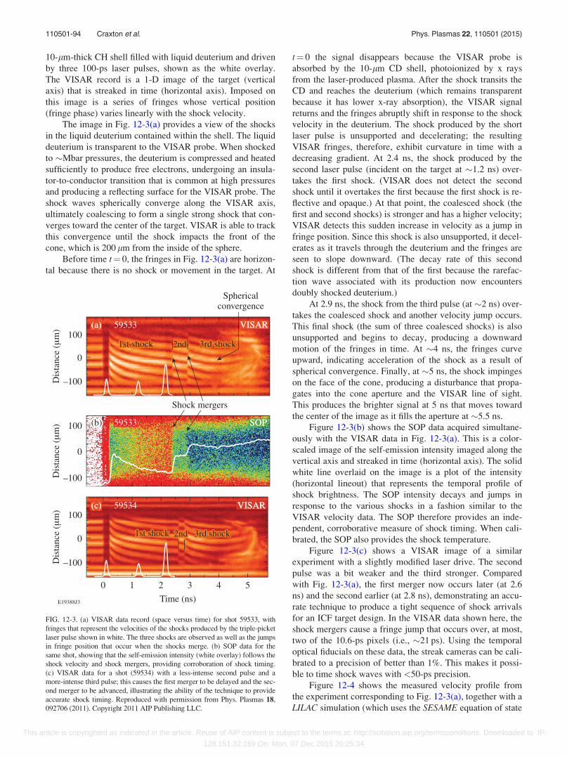
10-lm-thick CH shell filled with liquid deuterium and driven
by three 100-ps laser pulses, shown as the white overlay.
The VISAR record is a 1-D image of the target (vertical
axis) that is streaked in time (horizontal axis). Imposed on
this image is a series of fringes whose vertical position
(fringe phase) varies linearly with the shock velocity.
The image in Fig. 12-3(a) provides a view of the shocks
in the liquid deuterium contained within the shell. The liquid
deuterium is transparent to the VISAR probe. When shocked
to �Mbar pressures, the deuterium is compressed and heated
sufficiently to produce free electrons, undergoing an insula-
tor-to-conductor transition that is common at high pressures
and producing a reflecting surface for the VISAR probe. The
shock waves spherically converge along the VISAR axis,
ultimately coalescing to form a single strong shock that con-
verges toward the center of the target. VISAR is able to track
this convergence until the shock impacts the front of the
cone, which is 200 lm from the inside of the sphere.
Before time t¼ 0, the fringes in Fig. 12-3(a) are horizon-
tal because there is no shock or movement in the target. At
t¼ 0 the signal disappears because the VISAR probe is
absorbed by the 10-lm CD shell, photoionized by x rays
from the laser-produced plasma. After the shock transits the
CD and reaches the deuterium (which remains transparent
because it has lower x-ray absorption), the VISAR signal
returns and the fringes abruptly shift in response to the shock
velocity in the deuterium. The shock produced by the short
laser pulse is unsupported and decelerating; the resulting
VISAR fringes, therefore, exhibit curvature in time with a
decreasing gradient. At 2.4 ns, the shock produced by the
second laser pulse (incident on the target at �1.2 ns) over-
takes the first shock. (VISAR does not detect the second
shock until it overtakes the first because the first shock is re-
flective and opaque.) At that point, the coalesced shock (the
first and second shocks) is stronger and has a higher velocity;
VISAR detects this sudden increase in velocity as a jump in
fringe position. Since this shock is also unsupported, it decel-
erates as it travels through the deuterium and the fringes are
seen to slope downward. (The decay rate of this second
shock is different from that of the first because the rarefac-
tion wave associated with its production now encounters
doubly shocked deuterium.)
At 2.9 ns, the shock from the third pulse (at �2 ns) over-
takes the coalesced shock and another velocity jump occurs.
This final shock (the sum of three coalesced shocks) is also
unsupported and begins to decay, producing a downward
motion of the fringes in time. At �4 ns, the fringes curve
upward, indicating acceleration of the shock as a result of
spherical convergence. Finally, at �5 ns, the shock impinges
on the face of the cone, producing a disturbance that propa-
gates into the cone aperture and the VISAR line of sight.
This produces the brighter signal at 5 ns that moves toward
the center of the image as it fills the aperture at �5.5 ns.
Figure 12-3(b) shows the SOP data acquired simultane-
ously with the VISAR data in Fig. 12-3(a). This is a color-
scaled image of the self-emission intensity imaged along the
vertical axis and streaked in time (horizontal axis). The solid
white line overlaid on the image is a plot of the intensity
(horizontal lineout) that represents the temporal profile of
shock brightness. The SOP intensity decays and jumps in
response to the various shocks in a fashion similar to the
VISAR velocity data. The SOP therefore provides an inde-
pendent, corroborative measure of shock timing. When cali-
brated, the SOP also provides the shock temperature.
Figure 12-3(c) shows a VISAR image of a similar
experiment with a slightly modified laser drive. The second
pulse was a bit weaker and the third stronger. Compared
with Fig. 12-3(a), the first merger now occurs later (at 2.6
ns) and the second earlier (at 2.8 ns), demonstrating an accu-
rate technique to produce a tight sequence of shock arrivals
for an ICF target design. In the VISAR data shown here, the
shock mergers cause a fringe jump that occurs over, at most,
two of the 10.6-ps pixels (i.e., �21 ps). Using the temporal
optical fiducials on these data, the streak cameras can be cali-
brated to a precision of better than 1%. This makes it possi-
ble to time shock waves with <50-ps precision.
Figure 12-4 shows the measured velocity profile from
the experiment corresponding to Fig. 12-3(a), together with a
LILAC simulation (which uses the SESAME equation of state
FIG. 12-3. (a) VISAR data record (space versus time) for shot 59533, with
fringes that represent the velocities of the shocks produced by the triple-picket
laser pulse shown in white. The three shocks are observed as well as the jumps
in fringe position that occur when the shocks merge. (b) SOP data for the
same shot, showing that the self-emission intensity (white overlay) follows the
shock velocity and shock mergers, providing corroboration of shock timing.
(c) VISAR data for a shot (59534) with a less-intense second pulse and a
more-intense third pulse; this causes the first merger to be delayed and the sec-
ond merger to be advanced, illustrating the ability of the technique to provide
accurate shock timing. Reproduced with permission from Phys. Plasmas 18,
092706 (2011). Copyright 2011 AIP Publishing LLC.
110501-94 Craxton et al. Phys. Plasmas 22, 110501 (2015)
This article is copyrighted as indicated in the article. Reuse of AIP content is subject to the terms at: http://scitation.aip.org/termsconditions. Downloaded to IP:
128.151.32.169 On: Mon, 07 Dec 2015 20:25:34
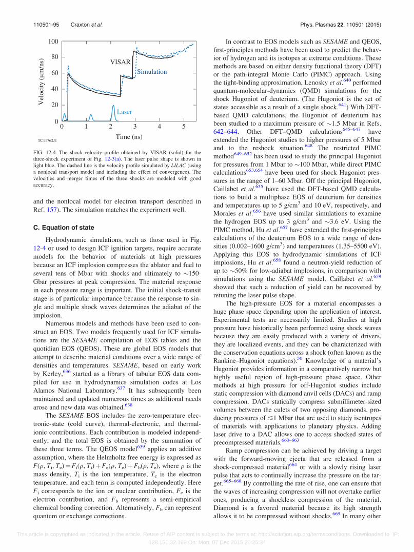
and the nonlocal model for electron transport described in
Ref. 157). The simulation matches the experiment well.
C. Equation of state
Hydrodynamic simulations, such as those used in Fig.
12-4 or used to design ICF ignition targets, require accurate
models for the behavior of materials at high pressures
because an ICF implosion compresses the ablator and fuel to
several tens of Mbar with shocks and ultimately to �150-
Gbar pressures at peak compression. The material response
in each pressure range is important. The initial shock-transit
stage is of particular importance because the response to sin-
gle and multiple shock waves determines the adiabat of the
implosion.
Numerous models and methods have been used to con-
struct an EOS. Two models frequently used for ICF simula-
tions are the SESAME compilation of EOS tables and the
quotidian EOS (QEOS). These are global EOS models that
attempt to describe material conditions over a wide range of
densities and temperatures. SESAME, based on early work
by Kerley,636 started as a library of tabular EOS data com-
piled for use in hydrodynamics simulation codes at Los
Alamos National Laboratory.637 It has subsequently been
maintained and updated numerous times as additional needs
arose and new data was obtained.638
The SESAME EOS includes the zero-temperature elec-
tronic-state (cold curve), thermal-electronic, and thermal-
ionic contributions. Each contribution is modeled independ-
ently, and the total EOS is obtained by the summation of
these three terms. The QEOS model639 applies an additive
assumption, where the Helmholtz free energy is expressed as
F(q, Ti, Te)¼Fi(q, Ti)þFe(q, Te)þFb(q, Te), where q is the
mass density, Ti is the ion temperature, Te is the electron
temperature, and each term is computed independently. Here
Fi corresponds to the ion or nuclear contribution, Fe is the
electron contribution, and Fb represents a semi-empirical
chemical bonding correction. Alternatively, Fb can represent
quantum or exchange corrections.
In contrast to EOS models such as SESAME and QEOS,
first-principles methods have been used to predict the behav-
ior of hydrogen and its isotopes at extreme conditions. These
methods are based on either density functional theory (DFT)
or the path-integral Monte Carlo (PIMC) approach. Using
the tight-binding approximation, Lenosky et al.640 performed
quantum-molecular-dynamics (QMD) simulations for the
shock Hugoniot of deuterium. (The Hugoniot is the set of
states accessible as a result of a single shock.641) With DFT-
based QMD calculations, the Hugoniot of deuterium has
been studied to a maximum pressure of �1.5 Mbar in Refs.
642–644. Other DFT–QMD calculations645–647 have
extended the Hugoniot studies to higher pressures of 5 Mbar
and to the reshock situation.648 The restricted PIMC
method649–652 has been used to study the principal Hugoniot
for pressures from 1 Mbar to �100 Mbar, while direct PIMC
calculations653,654 have been used for shock Hugoniot pres-
sures in the range of 1–60 Mbar. Off the principal Hugoniot,
Caillabet et al.655 have used the DFT-based QMD calcula-
tions to build a multiphase EOS of deuterium for densities
and temperatures up to 5 g/cm3 and 10 eV, respectively, and
Morales et al.656 have used similar simulations to examine
the hydrogen EOS up to 3 g/cm3 and �3.6 eV. Using the
PIMC method, Hu et al.657 have extended the first-principles
calculations of the deuterium EOS to a wide range of den-
sities (0.002–1600 g/cm3) and temperatures (1.35–5500 eV).
Applying this EOS to hydrodynamic simulations of ICF
implosions, Hu et al.658 found a neutron-yield reduction of
up to �50% for low-adiabat implosions, in comparison with
simulations using the SESAME model. Caillabet et al.659
showed that such a reduction of yield can be recovered by
retuning the laser pulse shape.
The high-pressure EOS for a material encompasses a
huge phase space depending upon the application of interest.
Experimental tests are necessarily limited. Studies at high
pressure have historically been performed using shock waves
because they are easily produced with a variety of drivers,
they are localized events, and they can be characterized with
the conservation equations across a shock (often known as the
Rankine–Hugoniot equations).50 Knowledge of a material’s
Hugoniot provides information in a comparatively narrow but
highly useful region of high-pressure phase space. Other
methods at high pressure for off-Hugoniot studies include
static compression with diamond anvil cells (DACs) and ramp
compression. DACs statically compress submillimeter-sized
volumes between the culets of two opposing diamonds, pro-
ducing pressures of �1 Mbar that are used to study isentropes
of materials with applications to planetary physics. Adding
laser drive to a DAC allows one to access shocked states of
precompressed materials.660–663
Ramp compression can be achieved by driving a target
with the forward-moving ejecta that are released from a
shock-compressed material664 or with a slowly rising laser
pulse that acts to continually increase the pressure on the tar-
get.665–668 By controlling the rate of rise, one can ensure that
the waves of increasing compression will not overtake earlier
ones, producing a shockless compression of the material.
Diamond is a favored material because its high strength
allows it to be compressed without shocks.669 In many other
FIG. 12-4. The shock-velocity profile obtained by VISAR (solid) for the
three-shock experiment of Fig. 12-3(a). The laser pulse shape is shown in
light blue. The dashed line is the velocity profile simulated by LILAC (using
a nonlocal transport model and including the effect of convergence). The
velocities and merger times of the three shocks are modeled with good
accuracy.
110501-95 Craxton et al. Phys. Plasmas 22, 110501 (2015)
This article is copyrighted as indicated in the article. Reuse of AIP content is subject to the terms at: http://scitation.aip.org/termsconditions. Downloaded to IP:
128.151.32.169 On: Mon, 07 Dec 2015 20:25:34
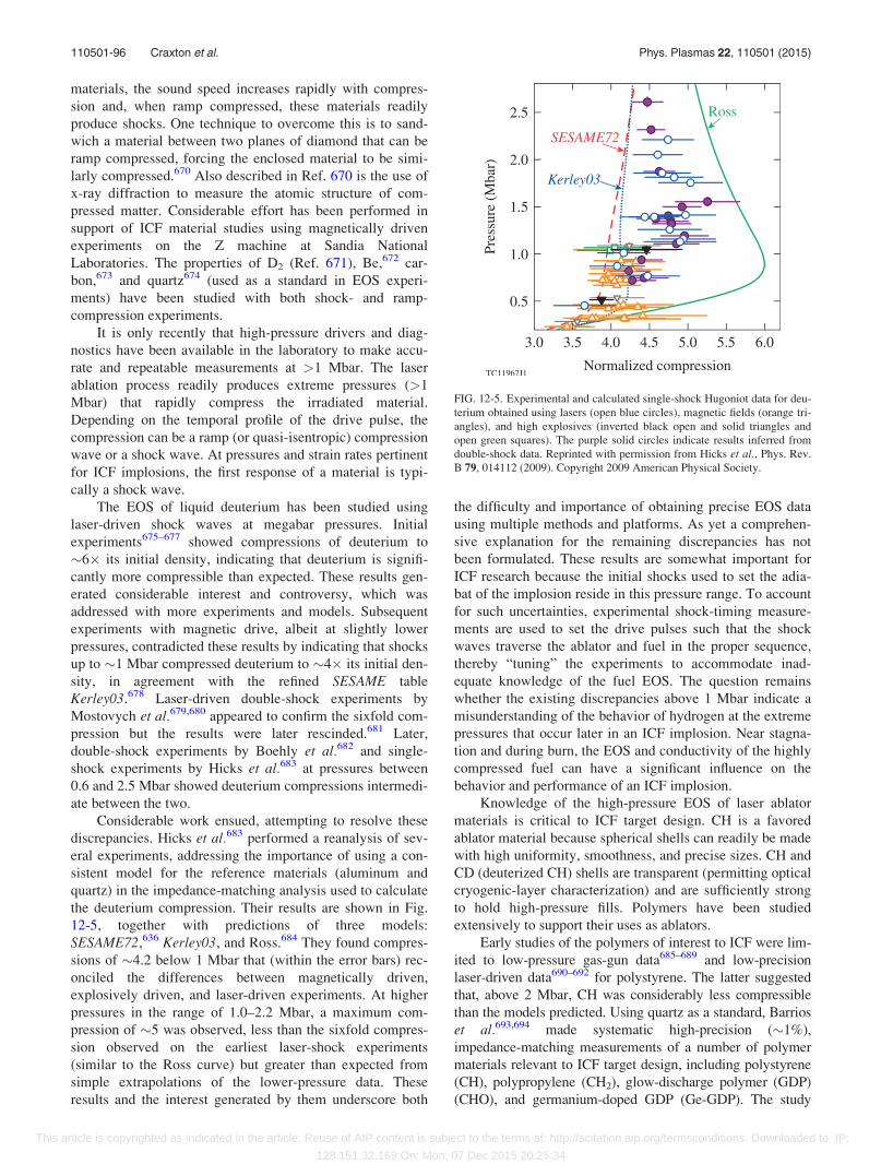
materials, the sound speed increases rapidly with compres-
sion and, when ramp compressed, these materials readily
produce shocks. One technique to overcome this is to sand-
wich a material between two planes of diamond that can be
ramp compressed, forcing the enclosed material to be simi-
larly compressed.670 Also described in Ref. 670 is the use of
x-ray diffraction to measure the atomic structure of com-
pressed matter. Considerable effort has been performed in
support of ICF material studies using magnetically driven
experiments on the Z machine at Sandia National
Laboratories. The properties of D2 (Ref. 671), Be,672 car-
bon,673 and quartz674 (used as a standard in EOS experi-
ments) have been studied with both shock- and ramp-
compression experiments.
It is only recently that high-pressure drivers and diag-
nostics have been available in the laboratory to make accu-
rate and repeatable measurements at >1 Mbar. The laser
ablation process readily produces extreme pressures (>1
Mbar) that rapidly compress the irradiated material.
Depending on the temporal profile of the drive pulse, the
compression can be a ramp (or quasi-isentropic) compression
wave or a shock wave. At pressures and strain rates pertinent
for ICF implosions, the first response of a material is typi-
cally a shock wave.
The EOS of liquid deuterium has been studied using
laser-driven shock waves at megabar pressures. Initial
experiments675–677 showed compressions of deuterium to
�6� its initial density, indicating that deuterium is signifi-
cantly more compressible than expected. These results gen-
erated considerable interest and controversy, which was
addressed with more experiments and models. Subsequent
experiments with magnetic drive, albeit at slightly lower
pressures, contradicted these results by indicating that shocks
up to �1 Mbar compressed deuterium to �4� its initial den-
sity, in agreement with the refined SESAME table
Kerley03.678 Laser-driven double-shock experiments by
Mostovych et al.679,680 appeared to confirm the sixfold com-
pression but the results were later rescinded.681 Later,
double-shock experiments by Boehly et al.682 and single-
shock experiments by Hicks et al.683 at pressures between
0.6 and 2.5 Mbar showed deuterium compressions intermedi-
ate between the two.
Considerable work ensued, attempting to resolve these
discrepancies. Hicks et al.683 performed a reanalysis of sev-
eral experiments, addressing the importance of using a con-
sistent model for the reference materials (aluminum and
quartz) in the impedance-matching analysis used to calculate
the deuterium compression. Their results are shown in Fig.
12-5, together with predictions of three models:
SESAME72,636 Kerley03, and Ross.684 They found compres-
sions of �4.2 below 1 Mbar that (within the error bars) rec-
onciled the differences between magnetically driven,
explosively driven, and laser-driven experiments. At higher
pressures in the range of 1.0–2.2 Mbar, a maximum com-
pression of �5 was observed, less than the sixfold compres-
sion observed on the earliest laser-shock experiments
(similar to the Ross curve) but greater than expected from
simple extrapolations of the lower-pressure data. These
results and the interest generated by them underscore both
the difficulty and importance of obtaining precise EOS data
using multiple methods and platforms. As yet a comprehen-
sive explanation for the remaining discrepancies has not
been formulated. These results are somewhat important for
ICF research because the initial shocks used to set the adia-
bat of the implosion reside in this pressure range. To account
for such uncertainties, experimental shock-timing measure-
ments are used to set the drive pulses such that the shock
waves traverse the ablator and fuel in the proper sequence,
thereby “tuning” the experiments to accommodate inad-
equate knowledge of the fuel EOS. The question remains
whether the existing discrepancies above 1 Mbar indicate a
misunderstanding of the behavior of hydrogen at the extreme
pressures that occur later in an ICF implosion. Near stagna-
tion and during burn, the EOS and conductivity of the highly
compressed fuel can have a significant influence on the
behavior and performance of an ICF implosion.
Knowledge of the high-pressure EOS of laser ablator
materials is critical to ICF target design. CH is a favored
ablator material because spherical shells can readily be made
with high uniformity, smoothness, and precise sizes. CH and
CD (deuterized CH) shells are transparent (permitting optical
cryogenic-layer characterization) and are sufficiently strong
to hold high-pressure fills. Polymers have been studied
extensively to support their uses as ablators.
Early studies of the polymers of interest to ICF were lim-
ited to low-pressure gas-gun data685–689 and low-precision
laser-driven data690–692 for polystyrene. The latter suggested
that, above 2 Mbar, CH was considerably less compressible
than the models predicted. Using quartz as a standard, Barrios
et al.693,694 made systematic high-precision (�1%),
impedance-matching measurements of a number of polymer
materials relevant to ICF target design, including polystyrene
(CH), polypropylene (CH2), glow-discharge polymer (GDP)
(CHO), and germanium-doped GDP (Ge-GDP). The study
FIG. 12-5. Experimental and calculated single-shock Hugoniot data for deu-
terium obtained using lasers (open blue circles), magnetic fields (orange tri-
angles), and high explosives (inverted black open and solid triangles and
open green squares). The purple solid circles indicate results inferred from
double-shock data. Reprinted with permission from Hicks et al., Phys. Rev.
B 79, 014112 (2009). Copyright 2009 American Physical Society.
110501-96 Craxton et al. Phys. Plasmas 22, 110501 (2015)
This article is copyrighted as indicated in the article. Reuse of AIP content is subject to the terms at: http://scitation.aip.org/termsconditions. Downloaded to IP:
128.151.32.169 On: Mon, 07 Dec 2015 20:25:34
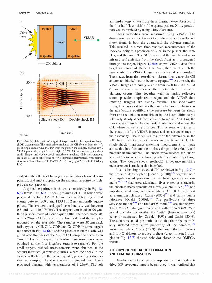
evaluated the effects of hydrogen:carbon ratio, chemical com-
position, and mid-Z doping on the material response to high-
pressure compression.
A typical experiment is shown schematically in Fig. 12-
6(a) (from Ref. 693). Shock pressures of 1–10 Mbar were
produced by 1–12 OMEGA laser beams delivering a total
energy between 200 J and 1130 J in 2-ns temporally square
pulses. The average overlapped laser intensity was between
0.3 and 1.1� 1014 W/cm2. The targets consisted of 90-lm-
thick pushers made of z-cut a quartz (the reference material),
with a 20-lm CH ablator on the laser side and the samples
mounted on the rear side. The samples were 50-lm-thick
foils, typically CH, CH2, GDP, and Ge-GDP. In some targets
(as shown in Fig. 12-6), a second piece of z-cut a quartz was
glued onto the back of the 50-lm CH sample to serve as an
“anvil.” For all targets, single-shock measurements were
obtained at the first interface (quartz-to-sample). For the
anvil targets, reshock measurements were obtained at the
second interface (sample-to-quartz), where the shock in the
sample reflected off the denser quartz, producing a double-
shocked sample. The shock waves originated from laser-
produced plasmas with temperatures of 1–2 keV. The soft
and mid-energy x rays from these plasmas were absorbed in
the first half (laser side) of the quartz pusher. X-ray produc-
tion was minimized by using a low-Z ablator.
Shock velocities were measured using VISAR. The
drive pressures were sufficient to produce optically reflective
shock fronts in both the quartz and the polymer samples.
This resulted in direct, time-resolved measurements of the
shock velocity to a precision of �1% in the pusher, the sam-
ples, and the anvil. The SOP measured the visible and near-
infrared self-emission from the shock front as it propagated
through the target. Figure 12-6(b) shows VISAR data for a
target with an anvil. Before time t¼ 0, the time at which the
laser starts, the VISAR fringes are horizontal and constant.
The x rays from the laser-driven plasma then cause the CH
ablator to “blank,” i.e., to become opaque.695 As a result, the
VISAR fringes are barely visible from t¼ 0 to �0.7 ns. At
0.7 ns the shock wave enters the quartz, where little or no
blanking occurs. This, together with the highly reflective
shock, provides ample return signal and the VISAR data
(moving fringes) are clearly visible. The shock-wave
strength decays as it transits the quartz but soon stabilizes as
the rarefactions equilibrate the pressure between the shock
front and the ablation front driven by the laser. Ultimately a
relatively steady shock forms from 2 to 4.3 ns. At 4.3 ns, the
shock wave transits the quartz–CH interface and enters the
CH, where its velocity changes. This is seen as a jump in
the position of the VISAR fringes and an abrupt change in
their intensity. The latter is a result of the difference in the
reflectivities of the shock waves in quartz and CH. The
single-shock impedance-matching measurement is made
across this interface and determines the particle velocity and
pressure in the sample. The shock wave reaches the quartz
anvil at 6.7 ns, when the fringe position and intensity change
again. The double-shock (reshock) impedance-matching
measurement is made at this interface.
Results for single-shocked CH are shown in Fig. 12-7 in
the pressure–density plane [Barrios (2010)]693 together with
a compilation of previous results from gas-gun experi-
ments685–689 that used aluminum flyer plates as standards,
the absolute measurements on Nova [Cauble (1997)],690 and
impedance-matching measurements on GEKKO using first
an aluminum reference [Ozaki (2005)]691 and then a quartz
reference [Ozaki (2009)].692 The predictions of three
SESAME models638 and the QEOS model639 are also shown.
The OMEGA data agree fairly well with the SESAME 7592
model and do not exhibit the “stiff” (less-compressible)
behavior suggested by Cauble (1997) and Ozaki (2005).
These authors stated, post publication, that their results prob-
ably suffered from x-ray preheating of the samples.696
Subsequent data [Ozaki (2009)] that used thicker pushers
and low-Z ablators to reduce preheat (green inverted trian-
gles in Fig. 12-7) showed behavior closer to the OMEGA
results.
XIII. CRYOGENIC TARGET FORMATIONAND CHARACTERIZATION
Development of cryogenic equipment for making direct-
drive ICF cryogenic targets began once it was realized that
FIG. 12-6. (a) Schematic of a typical target used in the equation-of-state
(EOS) experiments. The laser drive irradiates the CH ablator from the left,
producing a shock wave that traverses the pusher, the sample, and the anvil.
VISAR probes the target from the right. (b) VISAR data for a target with an
anvil. Single- and double-shock impedance-matching (IM) measurements
are made as the shock crosses the two interfaces. Reproduced with permis-
sion from Phys. Plasmas 17, 056307 (2010). Copyright 2010 AIP Publishing
LLC.
110501-97 Craxton et al. Phys. Plasmas 22, 110501 (2015)
This article is copyrighted as indicated in the article. Reuse of AIP content is subject to the terms at: http://scitation.aip.org/termsconditions. Downloaded to IP:
128.151.32.169 On: Mon, 07 Dec 2015 20:25:34
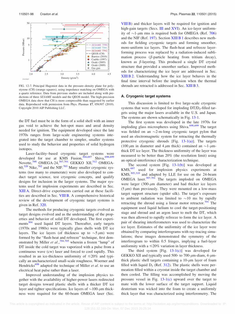
the DT fuel must be in the form of a solid shell with an inner
gas void to achieve the hot-spot mass and areal density
needed for ignition. The equipment developed since the late
1970s ranges from large-scale engineering systems inte-
grated into the target chamber to simpler, smaller systems
used to study the behavior and properties of solid hydrogen
isotopes.
Laser-facility–based cryogenic target systems were
developed for use at KMS Fusion,304,697 Shiva,698,699
Novette,700 OMEGA-24,307,701 GEKKO XII,312 OMEGA-
60,320 Nike,702 and the NIF.703 Many smaller cryogenic sys-
tems (too many to enumerate) were also developed to con-
duct target science, test cryogenic concepts, and qualify
designs for inclusion in the larger systems. The major sys-
tems used for implosion experiments are described in Sec.
XIII A. Direct-drive experiments carried out at these facili-
ties are described in Sec. VIII B. A comprehensive historical
review of the development of cryogenic target systems is
given in Ref. 320.
The methods for producing cryogenic targets evolved as
target designs evolved and as the understanding of the prop-
erties and behavior of solid DT developed. The first experi-
ments304 used liquid DT layers. Thereafter, early targets
(1970s and 1980s) were typically glass shells with DT ice
layers. The ice layers (of thickness up to �5 lm) were
formed by the “flash-heat and refreeze” technique, first dem-
onstrated by Miller et al.,704,705 wherein a frozen “lump” of
DT inside the cold target was vaporized with a pulse from a
continuous wave (cw) laser and forced to cool rapidly. This
resulted in an ice-thickness uniformity of �20% and typi-
cally an uncharacterized small-scale roughness. Woerner and
Hendricks698 adapted the technique of Miller et al. to use an
electrical heat pulse rather than a laser.
Improved understanding of the implosion physics to-
gether with the availability of higher-power lasers redirected
target designs toward plastic shells with a thicker DT ice
layer and tighter specifications. Ice layers of �100-lm thick-
ness were required for the 60-beam OMEGA laser (Sec.
VIII B) and thicker layers will be required for ignition and
high-gain targets (Secs. III and XVI). An ice-layer uniform-
ity of �1-lm rms is required both for OMEGA (Ref. 706)
and the NIF (Ref. 197). Section XIII B 1 describes new meth-
ods for fielding cryogenic targets and forming smoother,
more-uniform ice layers. The flash-heat and refreeze layer-
forming process was replaced by a radiation-induced subli-
mation process (b-particle heating from tritium decay),
known as b-layering. This produced a single DT crystal
structure that provided a smoother surface. Improved meth-
ods for characterizing the ice layer are addressed in Sec.
XIII B 2. Understanding how the ice layer behaves in the
final time interval before the implosion when the thermal
shrouds are retracted is addressed in Sec. XIII B 3.
A. Cryogenic target systems
This discussion is limited to five large-scale cryogenic
systems that were developed for imploding DT/D2-filled tar-
gets using the major lasers available in the U.S. and Japan.
The systems are shown schematically in Fig. 13-1.
The first system was developed in the late 1970s for
imploding glass microspheres using Shiva.698,699 The target
was fielded on an �2-m-long cryogenic target pylon that
used an electromagnetic system for retracting the thermally
protective cryogenic shrouds [Fig. 13-1(a)]. The targets
(100 lm in diameter and 4 lm thick) contained an �1-lm-
thick DT ice layer. The thickness uniformity of the layer was
measured to be better than 20% (the resolution limit) using
an optical-interference characterization technique.
The second system [Fig. 13-1(b)] was developed at
KMS,697 used for implosion physics experiments at
KMS,305,310 and adapted by LLE for use on the 24-beam
OMEGA laser.307,701 The targets imploded on OMEGA
were larger (300-lm diameter) and had thicker ice layers
(5 lm) than previously. They were mounted on a low-mass
target support structure (spider silk). The target’s exposure
to ambient radiation was limited to �10 ms by rapidly
retracting the shroud using a linear motor retractor.701 The
equipment used liquid helium to cool the target-positioning
stage and shroud and an argon laser to melt the DT, which
was then allowed to rapidly refreeze to form the ice layer. A
pair of shearing interferometers was used to characterize the
ice layer. Estimates of the uniformity of the ice layer were
obtained by comparing interferograms with ray-tracing simu-
lations; these images demonstrated the symmetry of the
interferogram to within 0.5 fringes, implying a fuel-layer
uniformity with a �20% variation in layer thickness.
The third system [Fig. 13-1(c)] was developed for
GEKKO XII and typically used 500- to 700-lm-diam, 4-lm-
thick plastic shell targets containing a 10-lm layer of foam
filled with liquid D2 (Ref. 312). The plastic shells were per-
meation filled within a cryostat inside the target chamber and
then cooled. The filling was accomplished by moving the
pressure vessel in Fig. 13-1(c) upward over the target to
mate with the lower surface of the target support. Liquid
deuterium was wicked into the foam to create a uniformly
thick layer that was characterized using interferometry. The
FIG. 12-7. Principal Hugoniot data in the pressure–density plane for poly-
styrene (CH) (orange squares), using impedance matching on OMEGA with
a quartz reference. Data from previous studies are included along with pre-
dictions of three SESAME models and the QEOS model. The high-precision
OMEGA data show that CH is more compressible than suggested by earlier
data. Reproduced with permission from Phys. Plasmas 17, 056307 (2010).
Copyright 2010 AIP Publishing LLC.
110501-98 Craxton et al. Phys. Plasmas 22, 110501 (2015)
This article is copyrighted as indicated in the article. Reuse of AIP content is subject to the terms at: http://scitation.aip.org/termsconditions. Downloaded to IP:
128.151.32.169 On: Mon, 07 Dec 2015 20:25:34
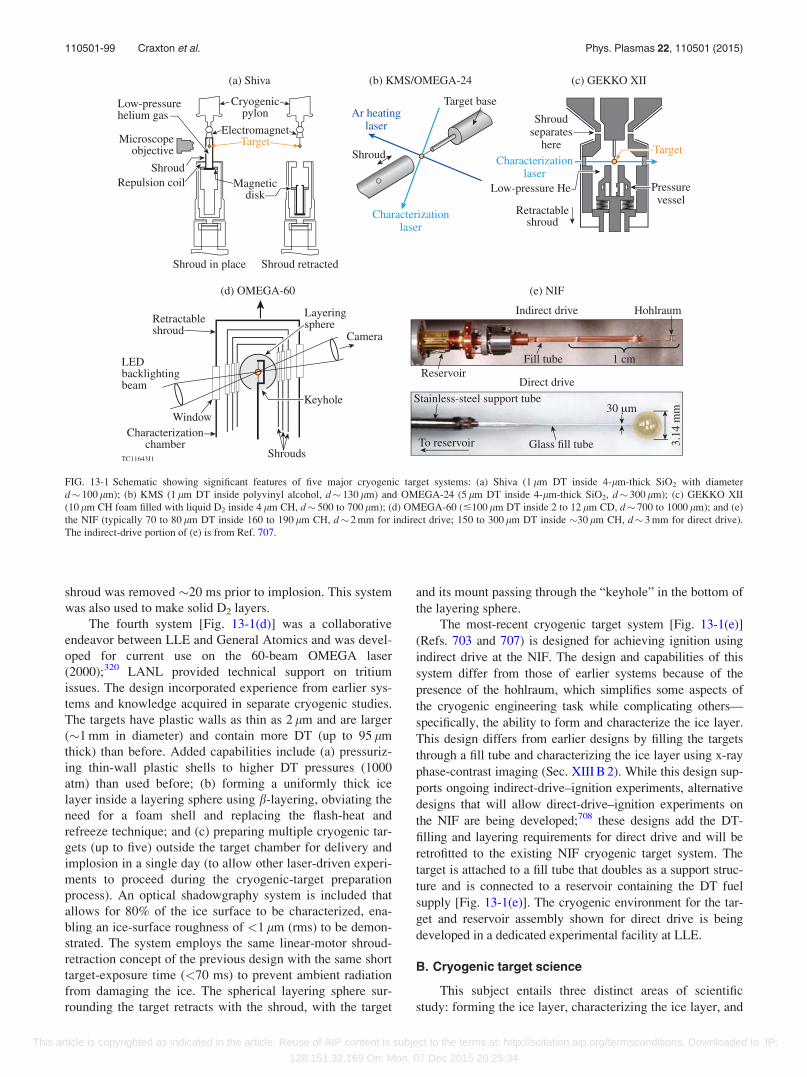
shroud was removed �20 ms prior to implosion. This system
was also used to make solid D2 layers.
The fourth system [Fig. 13-1(d)] was a collaborative
endeavor between LLE and General Atomics and was devel-
oped for current use on the 60-beam OMEGA laser
(2000);320 LANL provided technical support on tritium
issues. The design incorporated experience from earlier sys-
tems and knowledge acquired in separate cryogenic studies.
The targets have plastic walls as thin as 2 lm and are larger
(�1 mm in diameter) and contain more DT (up to 95 lm
thick) than before. Added capabilities include (a) pressuriz-
ing thin-wall plastic shells to higher DT pressures (1000
atm) than used before; (b) forming a uniformly thick ice
layer inside a layering sphere using b-layering, obviating the
need for a foam shell and replacing the flash-heat and
refreeze technique; and (c) preparing multiple cryogenic tar-
gets (up to five) outside the target chamber for delivery and
implosion in a single day (to allow other laser-driven experi-
ments to proceed during the cryogenic-target preparation
process). An optical shadowgraphy system is included that
allows for 80% of the ice surface to be characterized, ena-
bling an ice-surface roughness of <1 lm (rms) to be demon-
strated. The system employs the same linear-motor shroud-
retraction concept of the previous design with the same short
target-exposure time (<70 ms) to prevent ambient radiation
from damaging the ice. The spherical layering sphere sur-
rounding the target retracts with the shroud, with the target
and its mount passing through the “keyhole” in the bottom of
the layering sphere.
The most-recent cryogenic target system [Fig. 13-1(e)]
(Refs. 703 and 707) is designed for achieving ignition using
indirect drive at the NIF. The design and capabilities of this
system differ from those of earlier systems because of the
presence of the hohlraum, which simplifies some aspects of
the cryogenic engineering task while complicating others—
specifically, the ability to form and characterize the ice layer.
This design differs from earlier designs by filling the targets
through a fill tube and characterizing the ice layer using x-ray
phase-contrast imaging (Sec. XIII B 2). While this design sup-
ports ongoing indirect-drive–ignition experiments, alternative
designs that will allow direct-drive–ignition experiments on
the NIF are being developed;708 these designs add the DT-
filling and layering requirements for direct drive and will be
retrofitted to the existing NIF cryogenic target system. The
target is attached to a fill tube that doubles as a support struc-
ture and is connected to a reservoir containing the DT fuel
supply [Fig. 13-1(e)]. The cryogenic environment for the tar-
get and reservoir assembly shown for direct drive is being
developed in a dedicated experimental facility at LLE.
B. Cryogenic target science
This subject entails three distinct areas of scientific
study: forming the ice layer, characterizing the ice layer, and
FIG. 13-1 Schematic showing significant features of five major cryogenic target systems: (a) Shiva (1 lm DT inside 4-lm-thick SiO2 with diameter
d� 100 lm); (b) KMS (1 lm DT inside polyvinyl alcohol, d� 130 lm) and OMEGA-24 (5 lm DT inside 4-lm-thick SiO2, d� 300 lm); (c) GEKKO XII
(10 lm CH foam filled with liquid D2 inside 4 lm CH, d� 500 to 700 lm); (d) OMEGA-60 (�100 lm DT inside 2 to 12 lm CD, d� 700 to 1000 lm); and (e)
the NIF (typically 70 to 80 lm DT inside 160 to 190 lm CH, d� 2 mm for indirect drive; 150 to 300 lm DT inside �30 lm CH, d� 3 mm for direct drive).
The indirect-drive portion of (e) is from Ref. 707.
110501-99 Craxton et al. Phys. Plasmas 22, 110501 (2015)
This article is copyrighted as indicated in the article. Reuse of AIP content is subject to the terms at: http://scitation.aip.org/termsconditions. Downloaded to IP:
128.151.32.169 On: Mon, 07 Dec 2015 20:25:34
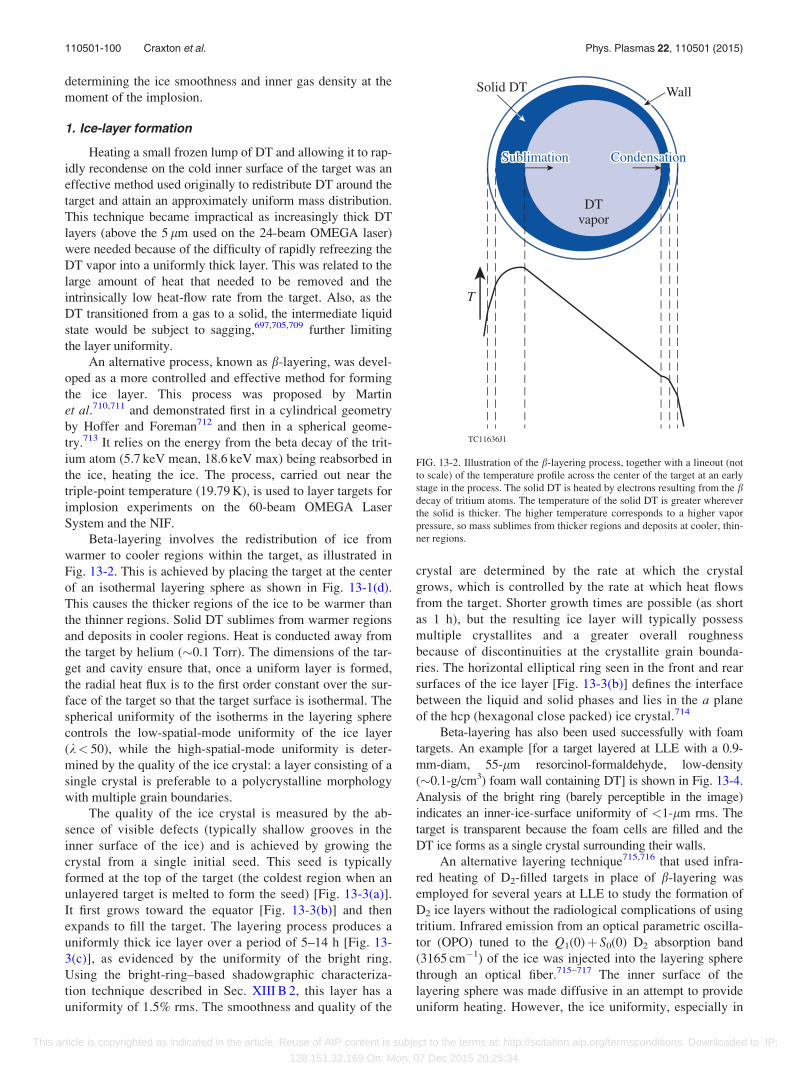
determining the ice smoothness and inner gas density at the
moment of the implosion.
1. Ice-layer formation
Heating a small frozen lump of DT and allowing it to rap-
idly recondense on the cold inner surface of the target was an
effective method used originally to redistribute DT around the
target and attain an approximately uniform mass distribution.
This technique became impractical as increasingly thick DT
layers (above the 5 lm used on the 24-beam OMEGA laser)
were needed because of the difficulty of rapidly refreezing the
DT vapor into a uniformly thick layer. This was related to the
large amount of heat that needed to be removed and the
intrinsically low heat-flow rate from the target. Also, as the
DT transitioned from a gas to a solid, the intermediate liquid
state would be subject to sagging,697,705,709 further limiting
the layer uniformity.
An alternative process, known as b-layering, was devel-
oped as a more controlled and effective method for forming
the ice layer. This process was proposed by Martin
et al.710,711 and demonstrated first in a cylindrical geometry
by Hoffer and Foreman712 and then in a spherical geome-
try.713 It relies on the energy from the beta decay of the trit-
ium atom (5.7 keV mean, 18.6 keV max) being reabsorbed in
the ice, heating the ice. The process, carried out near the
triple-point temperature (19.79 K), is used to layer targets for
implosion experiments on the 60-beam OMEGA Laser
System and the NIF.
Beta-layering involves the redistribution of ice from
warmer to cooler regions within the target, as illustrated in
Fig. 13-2. This is achieved by placing the target at the center
of an isothermal layering sphere as shown in Fig. 13-1(d).
This causes the thicker regions of the ice to be warmer than
the thinner regions. Solid DT sublimes from warmer regions
and deposits in cooler regions. Heat is conducted away from
the target by helium (�0.1 Torr). The dimensions of the tar-
get and cavity ensure that, once a uniform layer is formed,
the radial heat flux is to the first order constant over the sur-
face of the target so that the target surface is isothermal. The
spherical uniformity of the isotherms in the layering sphere
controls the low-spatial-mode uniformity of the ice layer
(k< 50), while the high-spatial-mode uniformity is deter-
mined by the quality of the ice crystal: a layer consisting of a
single crystal is preferable to a polycrystalline morphology
with multiple grain boundaries.
The quality of the ice crystal is measured by the ab-
sence of visible defects (typically shallow grooves in the
inner surface of the ice) and is achieved by growing the
crystal from a single initial seed. This seed is typically
formed at the top of the target (the coldest region when an
unlayered target is melted to form the seed) [Fig. 13-3(a)].
It first grows toward the equator [Fig. 13-3(b)] and then
expands to fill the target. The layering process produces a
uniformly thick ice layer over a period of 5–14 h [Fig. 13-
3(c)], as evidenced by the uniformity of the bright ring.
Using the bright-ring–based shadowgraphic characteriza-
tion technique described in Sec. XIII B 2, this layer has a
uniformity of 1.5% rms. The smoothness and quality of the
crystal are determined by the rate at which the crystal
grows, which is controlled by the rate at which heat flows
from the target. Shorter growth times are possible (as short
as 1 h), but the resulting ice layer will typically possess
multiple crystallites and a greater overall roughness
because of discontinuities at the crystallite grain bounda-
ries. The horizontal elliptical ring seen in the front and rear
surfaces of the ice layer [Fig. 13-3(b)] defines the interface
between the liquid and solid phases and lies in the a plane
of the hcp (hexagonal close packed) ice crystal.714
Beta-layering has also been used successfully with foam
targets. An example [for a target layered at LLE with a 0.9-
mm-diam, 55-lm resorcinol-formaldehyde, low-density
(�0.1-g/cm3) foam wall containing DT] is shown in Fig. 13-4.
Analysis of the bright ring (barely perceptible in the image)
indicates an inner-ice-surface uniformity of <1-lm rms. The
target is transparent because the foam cells are filled and the
DT ice forms as a single crystal surrounding their walls.
An alternative layering technique715,716 that used infra-
red heating of D2-filled targets in place of b-layering was
employed for several years at LLE to study the formation of
D2 ice layers without the radiological complications of using
tritium. Infrared emission from an optical parametric oscilla-
tor (OPO) tuned to the Q1(0)þ S0(0) D2 absorption band
(3165 cm�1) of the ice was injected into the layering sphere
through an optical fiber.715–717 The inner surface of the
layering sphere was made diffusive in an attempt to provide
uniform heating. However, the ice uniformity, especially in
FIG. 13-2. Illustration of the b-layering process, together with a lineout (not
to scale) of the temperature profile across the center of the target at an early
stage in the process. The solid DT is heated by electrons resulting from the bdecay of tritium atoms. The temperature of the solid DT is greater wherever
the solid is thicker. The higher temperature corresponds to a higher vapor
pressure, so mass sublimes from thicker regions and deposits at cooler, thin-
ner regions.
110501-100 Craxton et al. Phys. Plasmas 22, 110501 (2015)
This article is copyrighted as indicated in the article. Reuse of AIP content is subject to the terms at: http://scitation.aip.org/termsconditions. Downloaded to IP:
128.151.32.169 On: Mon, 07 Dec 2015 20:25:34
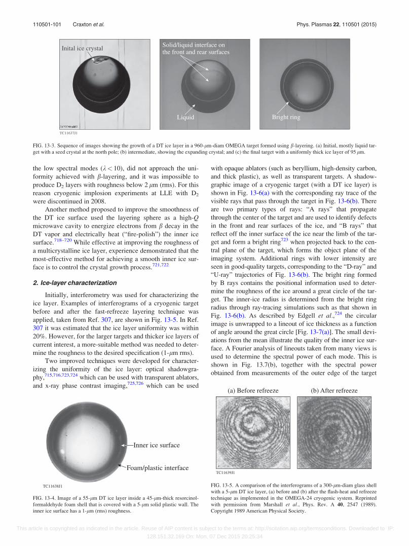
the low spectral modes (k< 10), did not approach the uni-
formity achieved with b-layering, and it was impossible to
produce D2 layers with roughness below 2 lm (rms). For this
reason cryogenic implosion experiments at LLE with D2
were discontinued in 2008.
Another method proposed to improve the smoothness of
the DT ice surface used the layering sphere as a high-Qmicrowave cavity to energize electrons from b decay in the
DT vapor and electrically heat (“fire-polish”) the inner ice
surface.718–720 While effective at improving the roughness of
a multicrystalline ice layer, experience demonstrated that the
most-effective method for achieving a smooth inner ice sur-
face is to control the crystal growth process.721,722
2. Ice-layer characterization
Initially, interferometry was used for characterizing the
ice layer. Examples of interferograms of a cryogenic target
before and after the fast-refreeze layering technique was
applied, taken from Ref. 307, are shown in Fig. 13-5. In Ref.
307 it was estimated that the ice layer uniformity was within
20%. However, for the larger targets and thicker ice layers of
current interest, a more-suitable method was needed to deter-
mine the roughness to the desired specification (1-lm rms).
Two improved techniques were developed for character-
izing the uniformity of the ice layer: optical shadowgra-
phy,715,716,723,724 which can be used with transparent ablators,
and x-ray phase contrast imaging,725,726 which can be used
with opaque ablators (such as beryllium, high-density carbon,
and thick plastic), as well as transparent targets. A shadow-
graphic image of a cryogenic target (with a DT ice layer) is
shown in Fig. 13-6(a) with the corresponding ray trace of the
visible rays that pass through the target in Fig. 13-6(b). There
are two primary types of rays: “A rays” that propagate
through the center of the target and are used to identify defects
in the front and rear surfaces of the ice, and “B rays” that
reflect off the inner surface of the ice near the limb of the tar-
get and form a bright ring723 when projected back to the cen-
tral plane of the target, which forms the object plane of the
imaging system. Additional rings with lower intensity are
seen in good-quality targets, corresponding to the “D-ray” and
“U-ray” trajectories of Fig. 13-6(b). The bright ring formed
by B rays contains the positional information used to deter-
mine the roughness of the ice around a great circle of the tar-
get. The inner-ice radius is determined from the bright ring
radius through ray-tracing simulations such as that shown in
Fig. 13-6(b). As described by Edgell et al.,724 the circular
image is unwrapped to a lineout of ice thickness as a function
of angle around the great circle [Fig. 13-7(a)]. The small devi-
ations from the mean illustrate the quality of the inner ice sur-
face. A Fourier analysis of lineouts taken from many views is
used to determine the spectral power of each mode. This is
shown in Fig. 13.7(b), together with the spectral power
obtained from measurements of the outer edge of the target
FIG. 13-3. Sequence of images showing the growth of a DT ice layer in a 960-lm-diam OMEGA target formed using b-layering. (a) Initial, mostly liquid tar-
get with a seed crystal at the north pole; (b) intermediate, showing the expanding crystal; and (c) the final target with a uniformly thick ice layer of 95 lm.
FIG. 13-4. Image of a 55-lm DT ice layer inside a 45-lm-thick resorcinol-
formaldehyde foam shell that is covered with a 5-lm solid plastic wall. The
inner ice surface has a 1-lm (rms) roughness.
FIG. 13-5. A comparison of the interferograms of a 300-lm-diam glass shell
with a 5-lm DT ice layer, (a) before and (b) after the flash-heat and refreeze
technique as implemented in the OMEGA-24 cryogenic system. Reprinted
with permission from Marshall et al., Phys. Rev. A 40, 2547 (1989).
Copyright 1989 American Physical Society.
110501-101 Craxton et al. Phys. Plasmas 22, 110501 (2015)
This article is copyrighted as indicated in the article. Reuse of AIP content is subject to the terms at: http://scitation.aip.org/termsconditions. Downloaded to IP:
128.151.32.169 On: Mon, 07 Dec 2015 20:25:34
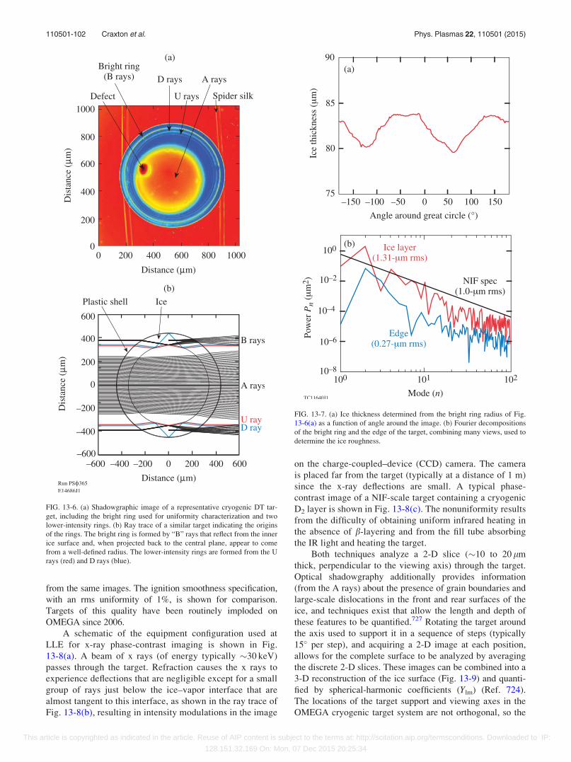
from the same images. The ignition smoothness specification,
with an rms uniformity of 1%, is shown for comparison.
Targets of this quality have been routinely imploded on
OMEGA since 2006.
A schematic of the equipment configuration used at
LLE for x-ray phase-contrast imaging is shown in Fig.
13-8(a). A beam of x rays (of energy typically �30 keV)
passes through the target. Refraction causes the x rays to
experience deflections that are negligible except for a small
group of rays just below the ice–vapor interface that are
almost tangent to this interface, as shown in the ray trace of
Fig. 13-8(b), resulting in intensity modulations in the image
on the charge-coupled–device (CCD) camera. The camera
is placed far from the target (typically at a distance of 1 m)
since the x-ray deflections are small. A typical phase-
contrast image of a NIF-scale target containing a cryogenic
D2 layer is shown in Fig. 13-8(c). The nonuniformity results
from the difficulty of obtaining uniform infrared heating in
the absence of b-layering and from the fill tube absorbing
the IR light and heating the target.
Both techniques analyze a 2-D slice (�10 to 20 lm
thick, perpendicular to the viewing axis) through the target.
Optical shadowgraphy additionally provides information
(from the A rays) about the presence of grain boundaries and
large-scale dislocations in the front and rear surfaces of the
ice, and techniques exist that allow the length and depth of
these features to be quantified.727 Rotating the target around
the axis used to support it in a sequence of steps (typically
15� per step), and acquiring a 2-D image at each position,
allows for the complete surface to be analyzed by averaging
the discrete 2-D slices. These images can be combined into a
3-D reconstruction of the ice surface (Fig. 13-9) and quanti-
fied by spherical-harmonic coefficients (Ylm) (Ref. 724).
The locations of the target support and viewing axes in the
OMEGA cryogenic target system are not orthogonal, so the
FIG. 13-6. (a) Shadowgraphic image of a representative cryogenic DT tar-
get, including the bright ring used for uniformity characterization and two
lower-intensity rings. (b) Ray trace of a similar target indicating the origins
of the rings. The bright ring is formed by “B” rays that reflect from the inner
ice surface and, when projected back to the central plane, appear to come
from a well-defined radius. The lower-intensity rings are formed from the U
rays (red) and D rays (blue).
FIG. 13-7. (a) Ice thickness determined from the bright ring radius of Fig.
13-6(a) as a function of angle around the image. (b) Fourier decompositions
of the bright ring and the edge of the target, combining many views, used to
determine the ice roughness.
110501-102 Craxton et al. Phys. Plasmas 22, 110501 (2015)
This article is copyrighted as indicated in the article. Reuse of AIP content is subject to the terms at: http://scitation.aip.org/termsconditions. Downloaded to IP:
128.151.32.169 On: Mon, 07 Dec 2015 20:25:34
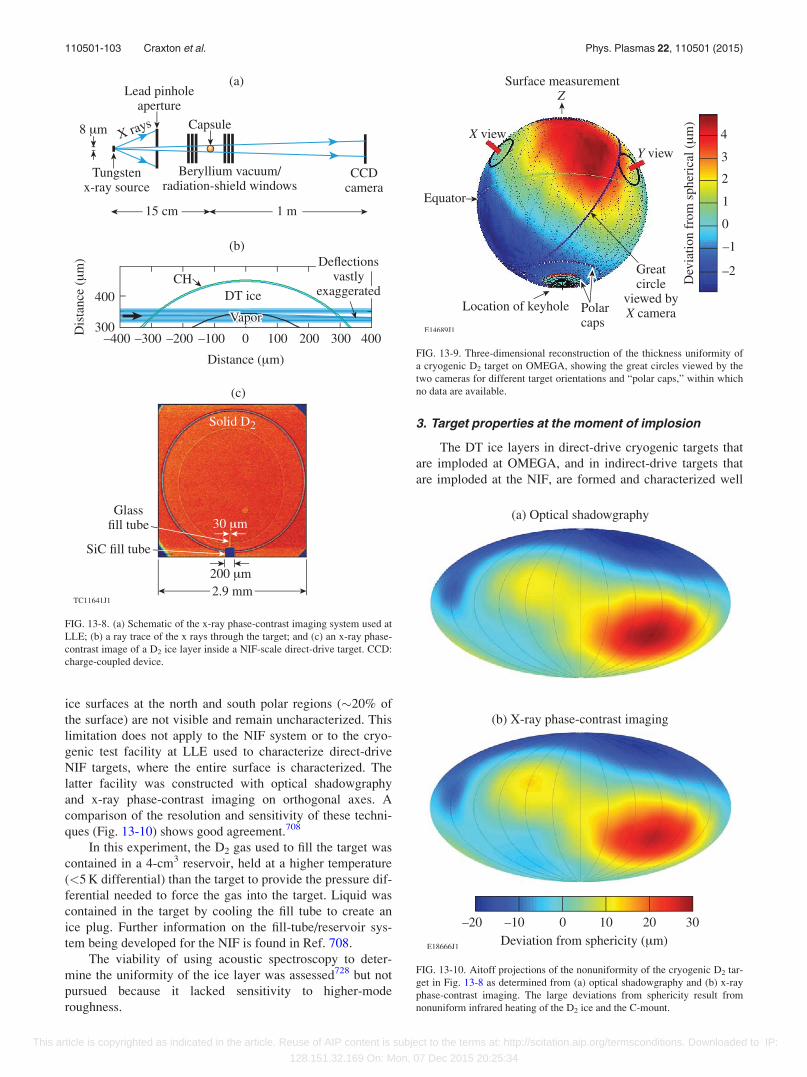
ice surfaces at the north and south polar regions (�20% of
the surface) are not visible and remain uncharacterized. This
limitation does not apply to the NIF system or to the cryo-
genic test facility at LLE used to characterize direct-drive
NIF targets, where the entire surface is characterized. The
latter facility was constructed with optical shadowgraphy
and x-ray phase-contrast imaging on orthogonal axes. A
comparison of the resolution and sensitivity of these techni-
ques (Fig. 13-10) shows good agreement.708
In this experiment, the D2 gas used to fill the target was
contained in a 4-cm3 reservoir, held at a higher temperature
(<5 K differential) than the target to provide the pressure dif-
ferential needed to force the gas into the target. Liquid was
contained in the target by cooling the fill tube to create an
ice plug. Further information on the fill-tube/reservoir sys-
tem being developed for the NIF is found in Ref. 708.
The viability of using acoustic spectroscopy to deter-
mine the uniformity of the ice layer was assessed728 but not
pursued because it lacked sensitivity to higher-mode
roughness.
3. Target properties at the moment of implosion
The DT ice layers in direct-drive cryogenic targets that
are imploded at OMEGA, and in indirect-drive targets that
are imploded at the NIF, are formed and characterized well
FIG. 13-8. (a) Schematic of the x-ray phase-contrast imaging system used at
LLE; (b) a ray trace of the x rays through the target; and (c) an x-ray phase-
contrast image of a D2 ice layer inside a NIF-scale direct-drive target. CCD:
charge-coupled device.
FIG. 13-9. Three-dimensional reconstruction of the thickness uniformity of
a cryogenic D2 target on OMEGA, showing the great circles viewed by the
two cameras for different target orientations and “polar caps,” within which
no data are available.
FIG. 13-10. Aitoff projections of the nonuniformity of the cryogenic D2 tar-
get in Fig. 13-8 as determined from (a) optical shadowgraphy and (b) x-ray
phase-contrast imaging. The large deviations from sphericity result from
nonuniform infrared heating of the D2 ice and the C-mount.
110501-103 Craxton et al. Phys. Plasmas 22, 110501 (2015)
This article is copyrighted as indicated in the article. Reuse of AIP content is subject to the terms at: http://scitation.aip.org/termsconditions. Downloaded to IP:
128.151.32.169 On: Mon, 07 Dec 2015 20:25:34
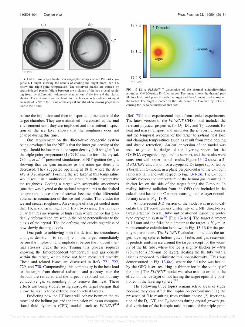
before the implosion and then transported to the center of the
target chamber. They are maintained in a controlled thermal
environment until they are imploded and intermittent inspec-
tion of the ice layer shows that the roughness does not
change during this time.
One requirement on the direct-drive cryogenic system
being developed for the NIF is that the inner gas density of the
target should be lower than the vapor density (�0.6 mg/cm3) at
the triple-point temperature (19.79 K) used to form the crystal.
Collins et al.197 presented simulations of NIF ignition designs
showing that the gain increases as the inner gas density is
decreased. They suggested operating at 18 K, where the den-
sity is 0.26 mg/cm2. Forming the ice layer at this temperature
would result in a multicrystalline structure with unacceptable
ice roughness. Cooling a target with acceptable smoothness
(one that was layered at the optimal temperature) to the desired
temperature induces thermal stresses because of the differential
volumetric contraction of the ice and plastic. This cracks the
ice and creates roughness. An example of a target cooled more
than 1 K is shown in Fig. 13-11 from two views. The faint cir-
cular features are regions of high strain where the ice has plas-
tically deformed and are seen in the plane perpendicular to the
c axis of the crystal. The ice deforms and cracks regardless of
how slowly the target cools.
One path to achieving both the desired ice smoothness
and gas density is to rapidly cool the target immediately
before the implosion and implode it before the induced ther-
mal stresses crack the ice. Timing this process requires
knowing the time-dependent temperature and gas density
within the target, which have not been measured directly.
These and related issues are discussed in Refs. 721, 722,
729, and 730. Compounding this complexity is the heat load
to the target from thermal radiation and b-decay once the
shrouds are retracted and the target is exposed without any
conductive gas surrounding it to remove this heat. These
effects are being studied using surrogate target designs that
allow the results to be extrapolated to actual targets.
Predicting how the DT layer will behave between the re-
moval of the helium gas and the implosion relies on computa-
tional fluid dynamics (CFD) models such as FLUENTTM
(Ref. 731) and experimental input from scaled experiments.
The latest version of the FLUENT CFD model includes the
relevant physical properties for D2, DT, and T2, accounts for
heat and mass transport, and simulates the b-layering process
and the temporal response of the target to radiant heat load
and changing temperatures (such as result from rapid cooling
and shroud retraction). An earlier version of the model was
used to guide the design of the layering sphere for the
OMEGA cryogenic target and its support, and the results were
consistent with experimental results. Figure 13-12 shows a 2-
D FLUENT calculation for a cryogenic D2 target supported by
a beryllium C-mount, in a plane perpendicular to the C-mount
[a horizontal plane with respect to Fig. 13-1(d)]. The C-mount
locally reduces the temperature of the helium gas, resulting in
thicker ice on the side of the target facing the C-mount. In
reality, infrared radiation from the OPO (not included in the
calculation) heated the C-mount, causing the ice-layer nonuni-
formity seen in Fig. 13-9.
A more-recent 3-D version of the model was used to cal-
culate the DT ice-thickness uniformity of a NIF direct-drive
target attached to a fill tube and positioned inside the proto-
type cryogenic system708 [Fig. 13-1(e)]. The target diameter
is 3.3 mm and the fill-tube diameter at the target is 30 lm. A
representative calculation is shown in Fig. 13-13 for the pro-
totype parameters. The FLUENT calculation includes the tar-
get, layering sphere, helium gas, fill tube, and gas reservoir.
It predicts uniform ice around the target except for the vicin-
ity of the fill tube, where the ice is slightly thicker by �8%
(28 lm for a 350-lm ice layer). Heating the fill tube with a
laser is proposed to eliminate this nonuniformity. [This was
demonstrated in Fig. 13-8(c), where the fill tube was heated
by the OPO laser, resulting in thinner ice in the vicinity of
the tube.] The FLUENT model was also used to evaluate the
effect on the ice layer of not having the target optimally posi-
tioned in the layering sphere.708
The following three topics remain active areas of study
because they can affect the implosion performance: (1) the
presence of 3He resulting from tritium decay; (2) fractiona-
tion of the D2, DT, and T2 isotopes during crystal growth (ra-
dial variation of the isotopic ratio because of the triple-point
FIG. 13-11. Two perpendicular shadowgraphic images of an OMEGA cryo-
genic DT target showing the results of cooling the target more than 1 K
below the triple-point temperature. The observed cracks are caused by
stress-induced plastic failure between the a planes of the hcp crystal result-
ing from the differential volumetric contraction of the ice and the plastic
ablator. These features are the faint circular lines seen (a) when looking at
an angle of �20� to the c axis of the crystal and (b) when looking perpendic-
ular to the c axis.
FIG. 13-12. A FLUENTTM calculation of the thermal nonuniformities
around an OMEGA-size D2-filled target. The image shows the thermal pro-
file in a horizontal plane through the target and the C-mount used to support
the target. The target is cooler on the side nearer the C-mount by 0.3 mK,
causing the ice to be thicker on that side.
110501-104 Craxton et al. Phys. Plasmas 22, 110501 (2015)
This article is copyrighted as indicated in the article. Reuse of AIP content is subject to the terms at: http://scitation.aip.org/termsconditions. Downloaded to IP:
128.151.32.169 On: Mon, 07 Dec 2015 20:25:34
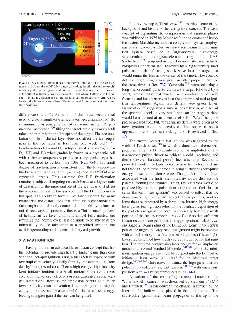
differences); and (3) formation of the initial seed crystal
used to grow a single-crystal ice layer. Accumulation of 3He
is minimized by purifying the tritium source using a Pd per-
meation membrane,329 filling the target rapidly through a fill
tube, and minimizing the life span of the target. The accumu-
lation of 3He in the ice layer does not affect the ice rough-
ness if the ice layer is less than one week old.732,733
Fractionation of H2 and D2 isotopes (used as a surrogate for
D2, DT, and T2) when gradually frozen in a cryogenic cell
with a similar temperature profile to a cryogenic target has
been measured to be less than 10% (Ref. 734); this small
degree of fractionation is consistent with the low-mode ice
thickness amplitude variation (�1 lm) seen in OMEGA-size
cryogenic targets. This estimate for D:T fractionation
remains a subject of ongoing research because a higher ratio
of deuterium at the inner surface of the ice layer will affect
the isotopic content of the gas void and the D:T ratio in the
hot spot. The ability to form an ice layer without the grain
boundaries and dislocations that affect the higher-mode sur-
face roughness is directly connected to the ability to form an
initial seed crystal; presently this is a “hit-or-miss” process
of heating an ice layer until it is almost fully melted and
reversing the thermal cycle. It is desirable to be able to deter-
ministically induce nucleation at a specified location and
avoid supercooling and uncontrolled crystal growth.
XIV. FAST IGNITION
Fast ignition is an advanced laser-fusion concept that has
the potential to provide significantly higher gains than con-
ventional hot-spot ignition. First, a fuel shell is imploded with
low implosion velocity, ideally forming an isochoric (uniform
density) compressed core. Then a high-energy, high-intensity
laser initiates ignition in a small region of the compressed
core with high-energy electrons or ions generated in laser–tar-
get interactions. Because the implosion occurs at a much
lower velocity than conventional hot-spot ignition, signifi-
cantly more mass can be assembled for the same laser energy,
leading to higher gain if the fuel can be ignited.
In a review paper, Tabak et al.735 described some of the
background and history of the fast-ignition concept. The basic
concept of separating the compression and ignition phases
was published in 1975 by Maschke736 in the context of heavy
ion fusion. Maschke mentions a compression system employ-
ing lasers, macro-particles, or heavy ion beams and an igni-
tion system based on a large-aperture, high-energy
superconductor storage/accelerator ring. In 1983,
Shcherbakov737 proposed using a low-intensity laser pulse to
compress a spherical shell followed by a high-intensity laser
pulse to launch a focusing shock wave into the target that
would ignite the fuel in the center of the target. However, no
detailed target designs were given in either proposal. Around
the same time as Ref. 737, Yamanaka738 proposed using a
long (nanosecond) pulse to compress a target followed by a
short, intense pulse that would use a combination of self-
focusing and hot electrons to heat the compressed fuel to igni-
tion temperatures. Again, few details were given. Later,
Basov et al.739 suggested a similar idea wherein, in place of
the spherical shock, a very small spot on the target surface
would be irradiated at an intensity of �1018 W/cm2 to ignite
precompressed fuel, but, yet again, no details were given as to
how ignition could be achieved. The spherical shock
approach, now known as shock ignition, is reviewed in Sec.
XV.
The current interest in fast ignition was triggered by the
work of Tabak et al.,740 in which a three-step scheme was
proposed. First, a DT capsule would be imploded with a
nanosecond pulsed driver to achieve a cold, isochoric, and
dense (several hundred g/cm3) fuel assembly. Second, a
powerful short-pulse laser would be injected to form a chan-
nel through the plasma corona to bring sufficient short-pulse
energy close to the dense core. The ponderomotive force
associated with the high laser intensity would displace the
plasma, forming the channel. Third, fast electrons would be
produced by the short-pulse laser to ignite the fuel. In that
sense the term “fast ignition” was coined to reflect that the
dense core is ignited by particles (electrons, protons, or other
ions) that are generated by a short, ultra-intense, high-energy
laser pulse. Fast ignition relies on the localized deposition of
the particle energy in the core, isochorically heating a small
portion of the fuel to temperatures �10 keV so that sufficient
fusion reactions are generated to trigger ignition. Tabak et al.envisaged a 10-lm radius of the DT at 300 g/cm3 in the central
part of the target and suggested that ignition might be possible
with a total energy of a few tens of kilojoules of laser light.
Later studies refined how much energy is required for fast igni-
tion. The required compression laser energy for an implosion
amounts to several hundred kilojoules,741,742 while the mini-
mum ignition energy that must be coupled into the DT fuel to
initiate a burn wave is �10 kJ for an idealized target
design.740,742,743 Gain curves illustrate the high gains that are
potentially available using fast ignition,741–746 with one exam-
ple from Ref. 741 being reproduced in Fig. 14-1.
A variant of the channeling concept, known as the
“cone-in-shell” concept, was described by Stephens et al.747
and Hatchett.748 In this concept, the channel is formed by the
interior of a hollow cone placed in the initial target. The
short-pulse ignitor laser beam propagates to the tip of the
FIG. 13-13. FLUENT simulation of the thermal profile of a NIF-size (3.3-
mm-diam) direct-drive DT-filled target (including the fill tube and reservoir)
inside a prototype cryogenic system that is being developed at LLE for use
at the NIF. The fill tube has a diameter of 30 lm where it attaches to the tar-
get. The slightly thicker ice at the fill tube can be effectively removed by
heating the fill tube using a laser. The target and fill tube are white to show
their positions.
110501-105 Craxton et al. Phys. Plasmas 22, 110501 (2015)
This article is copyrighted as indicated in the article. Reuse of AIP content is subject to the terms at: http://scitation.aip.org/termsconditions. Downloaded to IP:
128.151.32.169 On: Mon, 07 Dec 2015 20:25:34
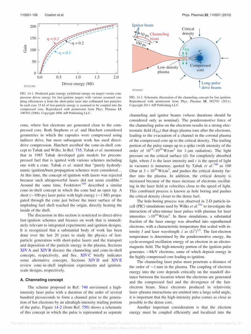
cone, where fast electrons are generated close to the com-
pressed core. Both Stephens et al. and Hatchett considered
geometries in which the capsules were compressed using
indirect drive, but most subsequent work has used direct-
drive compression. Hatchett ascribed the cone-in-shell con-
cept to Tabak and Wilks. In Ref. 735, Tabak et al. mentioned
that in 1985 Tabak developed gain models for precom-
pressed fuel that is ignited with various schemes including
one with a cone. Tabak et al. stated that “purely hydrody-
namic ignition/burn propagation schemes were considered…
At this time, the concept of ignition with lasers was rejected
because such ultrapowerful lasers did not seem credible.”
Around the same time, Feoktistov749 described a similar
cone-in-shell concept in which the cone had an open tip. A
short (�100-ps) laser pulse with high energy (�1 MJ) propa-
gated through the cone just before the inner surface of the
imploding fuel shell reached the origin, directly heating the
inside of the shell.
The discussion in this section is restricted to direct-drive
fast-ignition schemes and focuses on work that is immedi-
ately relevant to integrated experiments and ignition designs.
It is recognized that a substantial body of work has been
done over the last 20 years to study the physics of fast-
particle generation with short-pulse lasers and the transport
and deposition of the particle energy in the plasma. Sections
XIV A and XIV B discuss the channeling and cone-in-shell
concepts, respectively, and Sec. XIV C briefly indicates
some alternative concepts. Sections XIV D and XIV E
review cone-in-shell implosion experiments and ignition-
scale designs, respectively.
A. Channeling concept
The scheme proposed in Ref. 740 envisioned a high-
intensity laser pulse with a duration of the order of several
hundred picoseconds to form a channel prior to the genera-
tion of hot electrons by an ultrahigh-intensity trailing portion
of the pulse. Figure 14-2 (from Ref. 750) shows a schematic
of this concept in which the pulse is represented as separate
channeling and ignitor beams (whose durations should be
considered only as nominal). The ponderomotive force of
the channeling pulse on the electrons results in a strong elec-
trostatic field (EES) that drags plasma ions after the electrons,
leading to the evacuation of a channel in the coronal plasma
of the compressed core up to the critical density. The trailing
portion of the pulse ramps up to a spike (with intensity of the
order of 1019–1020 W/cm2 for 1-lm radiation). The light
pressure on the critical surface (I/c for completely absorbed
light, where I is the laser intensity and c is the speed of light
in vacuum) is immense, quoted by Tabak et al.740 as 100
Gbar at 3� 1020 W/cm2, and pushes the critical density far-
ther into the plasma. In addition, the critical density is
increased because of the mass increase of electrons oscillat-
ing in the laser field at velocities close to the speed of light.
This combined process is known as hole boring and pushes
the critical density closer to the dense fuel.
The hole-boring process was observed in 2-D particle-in-
cell (PIC) simulations used by Wilks et al.751 to investigate the
interaction of ultra-intense laser pulses with plasmas for laser
intensities >1018 W/cm2. In these simulations, a substantial
fraction of the laser energy was absorbed into suprathermal
electrons, with a characteristic temperature that scaled with in-
tensity I and laser wavelength k as (Ik2)1/2. The fast-electron
temperature is determined by the ponderomotive energy, the
cycle-averaged oscillation energy of an electron in an electro-
magnetic field. The high-intensity portion of the ignition pulse
generates �MeV electrons, some of which deposit energy in
the highly compressed core leading to ignition.
The channeling laser pulse must penetrate a distance of
the order of �1 mm in the plasma. The coupling of electron
energy into the core depends critically on the standoff dis-
tance between the location where the electrons are generated
and the compressed fuel and the divergence of the fast-
electron beam. Since electrons produced in relativistic
laser–plasma interactions are emitted into a large solid angle,
it is important that the high-intensity pulse comes as close as
possible to the dense core.
Another important consideration is that the electron
energy must be coupled efficiently and localized into the
FIG. 14-1. Predicted gain (energy yield/total energy on target) versus com-
pression driver energy for fast-ignition targets with various assumed cou-
pling efficiencies g from the short-pulse laser into collimated fast particles.
In each case 15 kJ of fast-particle energy is assumed to be coupled into the
compressed core. Reproduced with permission from Phys. Plasmas 13,
100703 (2006). Copyright 2006 AIP Publishing LLC.
FIG. 14-2. Schematic illustration of the channeling concept for fast ignition.
Reproduced with permission from Phys. Plasmas 18, 082703 (2011).
Copyright 2011 AIP Publishing LLC.
110501-106 Craxton et al. Phys. Plasmas 22, 110501 (2015)
This article is copyrighted as indicated in the article. Reuse of AIP content is subject to the terms at: http://scitation.aip.org/termsconditions. Downloaded to IP:
128.151.32.169 On: Mon, 07 Dec 2015 20:25:34
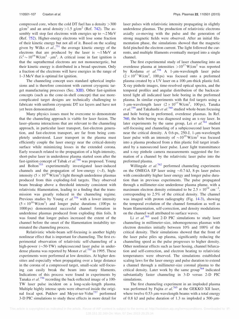
compressed core, where the cold DT fuel has a density >300
g/cm3 and an areal density>1.5 g/cm2 (Ref. 742). The as-
sembly will stop fast electrons with energies up to �2 MeV
(Ref. 752). Higher-energy electrons will lose some fraction
of their kinetic energy but not all of it. Based on the scaling
given by Wilks et al.,751 the average kinetic energy of the
electrons that are produced by the laser is �1 MeV at
Ik2� 1019 W/cm2 � lm2. A critical issue in fast ignition is
that the suprathermal electrons are not monoenergetic, but
their kinetic energy is distributed in a broad spectrum. Only
a fraction of the electrons will have energies in the range of
1–3 MeV that is optimal for ignition.
The channeling concept uses standard spherical implo-
sions and is therefore consistent with current cryogenic tar-
get manufacturing processes (Sec. XIII). Other fast-ignition
concepts (such as the cone-in-shell concept) that use more-
complicated target designs are technically challenging to
fabricate with uniform cryogenic DT ice layers and have not
yet been demonstrated.
Many physics issues must be overcome to demonstrate
that the channeling approach is viable for laser fusion. The
laser–plasma interactions that are relevant to the channeling
approach, in particular laser transport, fast-electron genera-
tion, and fast-electron transport, are far from being com-
pletely understood. Laser transport in the plasma must
efficiently couple the laser energy near the critical-density
surface while minimizing losses in the extended corona.
Early research related to the propagation of a high-intensity,
short-pulse laser in underdense plasma started soon after the
fast-ignition concept of Tabak et al.740 was proposed. Young
and Bolton753 experimentally investigated laser-induced
channels and the propagation of low-energy (�J), high-
intensity (5� 1018 W/cm2) light through underdense plasmas
produced from thin exploding-foil targets. They observed
beam breakup above a threshold intensity consistent with
relativistic filamentation, leading to a finding that the trans-
mission was greatly reduced in the channeling regime.
Previous studies by Young et al.754 with a lower intensity
(5� 1016 W/cm2) and longer pulse durations (100 ps to
1000 ps) demonstrated successful channel formation in
underdense plasmas produced from exploding thin foils. It
was found that longer pulses increased the extent of the
channel before the onset of the filamentation instability ter-
minated the channeling process.
Relativistic whole-beam self-focusing is another highly
nonlinear effect that is important for channeling. The first ex-
perimental observation of relativistic self-channeling of a
high-power (�50-TW) subpicosecond laser pulse in under-
dense plasma was reported by Monot et al.755 in 1995. These
experiments were performed at low densities. At higher den-
sities and especially when propagating over a large distance
in the corona of a compressed target, small-scale self-focus-
ing can easily break the beam into many filaments.
Indications of this process were found in experiments by
Tanaka et al.756 recording the back-reflected image of a 100-
TW laser pulse incident on a long-scale-length plasma.
Multiple highly intense spots were observed inside the origi-
nal focal spot. Pukhov and Meyer-ter-Vehn757 performed
3-D PIC simulations to study these effects in more detail for
laser pulses with relativistic intensity propagating in slightly
underdense plasmas. The production of relativistic electrons
axially co-moving with the pulse and the generation of
strong magnetic fields were observed. After an initial fila-
mentation phase, the simulations showed that the magnetic
field pinched the electron current. The light followed the cur-
rents, and multiple filaments eventually merged into a single
channel.
The first experimental study of laser channeling into an
overdense plasma at intensities >1017 W/cm2 was reported
by Kodama et al.758 A 1-lm-wavelength laser pulse
(2� 1017 W/cm2, 100 ps) was focused onto a preformed
plasma created by a UV laser on a 100-lm-thick plastic foil.
X-ray pinhole images, time-resolved optical spectra, and the
temporal profiles and angular distribution of the backscat-
tered light all indicated laser hole boring in the preformed
plasma. In similar experiments with flat foil targets using a
1-lm-wavelength laser (2� 1017 W/cm2, 100 ps), Tanaka
et al.759 and Takahashi et al.760 studied whole-beam focusing
and hole boring in preformed, overdense plasmas. In Ref.
760, the hole boring was diagnosed using an x-ray laser. In
later experiments by the same group, Lei et al.761 studied
self-focusing and channeling of a subpicosecond laser beam
near the critical density. A 0.6-ps, 250-J, 1-lm-wavelength
laser pulse with an intensity of �1019 W/cm2 was focused
into a plasma produced from a thin plastic foil target irradi-
ated by a nanosecond laser pulse. Laser light transmittance
and x-ray pinhole camera measurements suggested the for-
mation of a channel by the relativistic laser pulse into the
preformed plasma.
Willingale et al.762 performed channeling experiments
on the OMEGA EP laser using �0.7-kJ, 8-ps laser pulses
with considerably higher laser energy and longer pulse dura-
tion than in previous experiments. The pulse propagated
through a millimeter-size underdense plasma plume, with a
maximum electron density estimated to be 2.5� 1019 cm�3,
corresponding to 2.5% of the critical density. The channel
was imaged with proton radiography (Fig. 14-3), showing
the temporal evolution of the channel formation as well as
beam filamentation, self-correction, and density modulations
on the channel wall attributed to surface waves.
Li et al.763 used 2-D PIC simulations to study laser
channeling in millimeter-size, inhomogeneous plasmas with
electron densities initially between 10% and 100% of the
critical density. Their simulations showed that the front of
the laser pulse piles up plasma, significantly reducing the
channeling speed as the pulse progresses to higher density.
Other nonlinear effects such as laser hosing, channel bifurca-
tion and self-correction, and electron heating to relativistic
temperatures were observed. The simulations established
scaling laws for the laser energy and pulse duration to extend
a channel through a millimeter-size coronal plasma to the
critical density. Later work by the same group764 indicated
substantially faster channeling in 3-D versus 2-D PIC
simulations.
The first channeling experiment in an imploded plasma
was performed by Fujita et al.765 at the GEKKO XII laser,
where twelve 0.53-lm-wavelength beams with a total energy
of 0.8 kJ and pulse duration of 1.3 ns imploded a 500-lm-
110501-107 Craxton et al. Phys. Plasmas 22, 110501 (2015)
This article is copyrighted as indicated in the article. Reuse of AIP content is subject to the terms at: http://scitation.aip.org/termsconditions. Downloaded to IP:
128.151.32.169 On: Mon, 07 Dec 2015 20:25:34
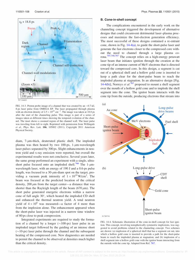
diam, 7-lm-thick, deuterated plastic shell. The imploded
plasma was then heated by two 100-ps, 1-lm-wavelength
laser pulses separated by 300 ps. Slight enhancements in neu-
tron yield and x-ray emission were reported, but overall the
experimental results were not conclusive. Several years later,
the same group performed an experiment with a single, ultra-
short pulse focused onto an imploded shell.766 The 1-lm-
wavelength laser, with an energy of 190 J and a 0.6-ps pulse
length, was focused to a 30-lm-diam spot on the target, pro-
viding a vacuum peak intensity of 1� 1019 W/cm2. The
beam was focused at the predicted location of the critical
density, 200 lm from the target center—a distance that was
shorter than the Rayleigh length of the beam (670 lm). The
short pulse generated energetic electrons within a narrow
cone of full angle 30�, which heated the imploded CD shell
and enhanced the thermal neutron yield. A total neutron
yield of 4� 106 was measured—a factor of 4 more than
from the implosion alone. The enhancement appeared when
the short-pulse laser was injected in a narrow time window
of 80 ps close to peak compression.
Integrated experiments are required to study the forma-
tion of a channel by a longer (�100-ps) laser pulse in an
imploded target followed by the guiding of an intense short
(�10-ps) laser pulse through the channel and the subsequent
heating of the compressed core. New diagnostics are needed
to permit the channel to be observed at densities much higher
than the critical density.
B. Cone-in-shell concept
The complications encountered in the early work on the
channeling concept triggered the development of alternative
designs that could circumvent detrimental laser–plasma proc-
esses and maximize the fast-electron generation efficiency.
The most successful of these designs contained a re-entrant
cone, shown in Fig. 14-4(a), to guide the short-pulse laser and
generate the fast electrons closer to the compressed core with-
out the need to channel through a large plasma co-
rona.747,748,767 The concept relies on a high-energy petawatt
laser beam that initiates ignition through the creation at the
cone tip of an intense current of MeV electrons that is directed
toward the compressed core. In this design, a segment is cut
out of a spherical shell and a hollow gold cone is inserted to
keep a path clear for the short-pulse beam to reach the
imploded plasma at stagnation. In an alternative design [Fig.
14-4(b)], Norreys et al.767 proposed to mount a shell segment
over the mouth of a hollow gold cone and to implode the shell
segment into the cone. The ignitor beam interacts with the
cone tip from the outside, producing electrons that stream into
FIG. 14-3. Proton probe image of a channel that was created by an �0.7-kJ,
8-ps laser pulse from OMEGA EP. The laser propagated through plasma
with an electron density of 2.5� 1019 cm�3. The image was taken at 18.8 ps
after the start of the channeling pulse. This image is part of a series of
images taken at different times showing the temporal evolution of the chan-
nel. The inset shows a zoomed region of the channel wall. The laser pulse
was traveling from left to right. Reprinted with permission from Willingale
et al., Phys. Rev. Lett. 106, 105002 (2011). Copyright 2011 American
Physical Society.
FIG. 14-4. Schematic illustration of the cone-in-shell concept for fast igni-
tion. This concept, involving nonspherically symmetric implosions, was sug-
gested to avoid problems related to the channeling concept. Two schemes
are shown: (a) implosion of a spherical shell that has a segment cut out, into
which a hollow gold cone is inserted to provide a path for the short-pulse
beam to reach the imploded plasma at stagnation; and (b) implosion of a
shell segment into a hollow gold cone with the ignitor beam interacting from
the outside with the cone tip. Adapted from Ref. 767.
110501-108 Craxton et al. Phys. Plasmas 22, 110501 (2015)
This article is copyrighted as indicated in the article. Reuse of AIP content is subject to the terms at: http://scitation.aip.org/termsconditions. Downloaded to IP:
128.151.32.169 On: Mon, 07 Dec 2015 20:25:34
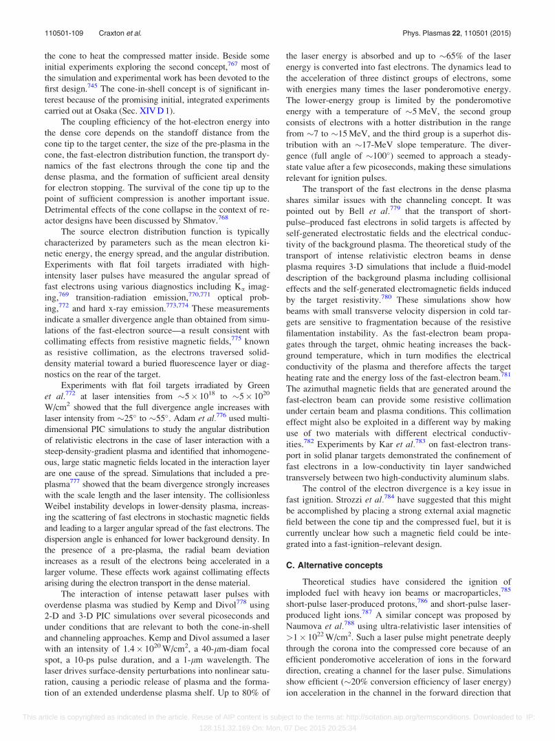
the cone to heat the compressed matter inside. Beside some
initial experiments exploring the second concept,767 most of
the simulation and experimental work has been devoted to the
first design.745 The cone-in-shell concept is of significant in-
terest because of the promising initial, integrated experiments
carried out at Osaka (Sec. XIV D 1).
The coupling efficiency of the hot-electron energy into
the dense core depends on the standoff distance from the
cone tip to the target center, the size of the pre-plasma in the
cone, the fast-electron distribution function, the transport dy-
namics of the fast electrons through the cone tip and the
dense plasma, and the formation of sufficient areal density
for electron stopping. The survival of the cone tip up to the
point of sufficient compression is another important issue.
Detrimental effects of the cone collapse in the context of re-
actor designs have been discussed by Shmatov.768
The source electron distribution function is typically
characterized by parameters such as the mean electron ki-
netic energy, the energy spread, and the angular distribution.
Experiments with flat foil targets irradiated with high-
intensity laser pulses have measured the angular spread of
fast electrons using various diagnostics including Ka imag-
ing,769 transition-radiation emission,770,771 optical prob-
ing,772 and hard x-ray emission.773,774 These measurements
indicate a smaller divergence angle than obtained from simu-
lations of the fast-electron source—a result consistent with
collimating effects from resistive magnetic fields,775 known
as resistive collimation, as the electrons traversed solid-
density material toward a buried fluorescence layer or diag-
nostics on the rear of the target.
Experiments with flat foil targets irradiated by Green
et al.772 at laser intensities from �5� 1018 to �5� 1020
W/cm2 showed that the full divergence angle increases with
laser intensity from �25� to �55�. Adam et al.776 used multi-
dimensional PIC simulations to study the angular distribution
of relativistic electrons in the case of laser interaction with a
steep-density-gradient plasma and identified that inhomogene-
ous, large static magnetic fields located in the interaction layer
are one cause of the spread. Simulations that included a pre-
plasma777 showed that the beam divergence strongly increases
with the scale length and the laser intensity. The collisionless
Weibel instability develops in lower-density plasma, increas-
ing the scattering of fast electrons in stochastic magnetic fields
and leading to a larger angular spread of the fast electrons. The
dispersion angle is enhanced for lower background density. In
the presence of a pre-plasma, the radial beam deviation
increases as a result of the electrons being accelerated in a
larger volume. These effects work against collimating effects
arising during the electron transport in the dense material.
The interaction of intense petawatt laser pulses with
overdense plasma was studied by Kemp and Divol778 using
2-D and 3-D PIC simulations over several picoseconds and
under conditions that are relevant to both the cone-in-shell
and channeling approaches. Kemp and Divol assumed a laser
with an intensity of 1.4� 1020 W/cm2, a 40-lm-diam focal
spot, a 10-ps pulse duration, and a 1-lm wavelength. The
laser drives surface-density perturbations into nonlinear satu-
ration, causing a periodic release of plasma and the forma-
tion of an extended underdense plasma shelf. Up to 80% of
the laser energy is absorbed and up to �65% of the laser
energy is converted into fast electrons. The dynamics lead to
the acceleration of three distinct groups of electrons, some
with energies many times the laser ponderomotive energy.
The lower-energy group is limited by the ponderomotive
energy with a temperature of �5 MeV, the second group
consists of electrons with a hotter distribution in the range
from �7 to �15 MeV, and the third group is a superhot dis-
tribution with an �17-MeV slope temperature. The diver-
gence (full angle of �100�) seemed to approach a steady-
state value after a few picoseconds, making these simulations
relevant for ignition pulses.
The transport of the fast electrons in the dense plasma
shares similar issues with the channeling concept. It was
pointed out by Bell et al.779 that the transport of short-
pulse–produced fast electrons in solid targets is affected by
self-generated electrostatic fields and the electrical conduc-
tivity of the background plasma. The theoretical study of the
transport of intense relativistic electron beams in dense
plasma requires 3-D simulations that include a fluid-model
description of the background plasma including collisional
effects and the self-generated electromagnetic fields induced
by the target resistivity.780 These simulations show how
beams with small transverse velocity dispersion in cold tar-
gets are sensitive to fragmentation because of the resistive
filamentation instability. As the fast-electron beam propa-
gates through the target, ohmic heating increases the back-
ground temperature, which in turn modifies the electrical
conductivity of the plasma and therefore affects the target
heating rate and the energy loss of the fast-electron beam.781
The azimuthal magnetic fields that are generated around the
fast-electron beam can provide some resistive collimation
under certain beam and plasma conditions. This collimation
effect might also be exploited in a different way by making
use of two materials with different electrical conductiv-
ities.782 Experiments by Kar et al.783 on fast-electron trans-
port in solid planar targets demonstrated the confinement of
fast electrons in a low-conductivity tin layer sandwiched
transversely between two high-conductivity aluminum slabs.
The control of the electron divergence is a key issue in
fast ignition. Strozzi et al.784 have suggested that this might
be accomplished by placing a strong external axial magnetic
field between the cone tip and the compressed fuel, but it is
currently unclear how such a magnetic field could be inte-
grated into a fast-ignition–relevant design.
C. Alternative concepts
Theoretical studies have considered the ignition of
imploded fuel with heavy ion beams or macroparticles,785
short-pulse laser-produced protons,786 and short-pulse laser-
produced light ions.787 A similar concept was proposed by
Naumova et al.788 using ultra-relativistic laser intensities of
>1� 1022 W/cm2. Such a laser pulse might penetrate deeply
through the corona into the compressed core because of an
efficient ponderomotive acceleration of ions in the forward
direction, creating a channel for the laser pulse. Simulations
show efficient (�20% conversion efficiency of laser energy)
ion acceleration in the channel in the forward direction that
110501-109 Craxton et al. Phys. Plasmas 22, 110501 (2015)
This article is copyrighted as indicated in the article. Reuse of AIP content is subject to the terms at: http://scitation.aip.org/termsconditions. Downloaded to IP:
128.151.32.169 On: Mon, 07 Dec 2015 20:25:34
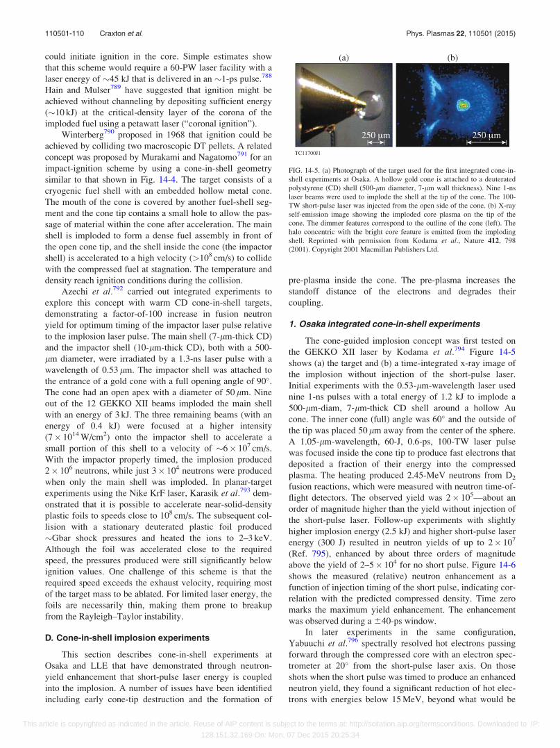
could initiate ignition in the core. Simple estimates show
that this scheme would require a 60-PW laser facility with a
laser energy of �45 kJ that is delivered in an �1-ps pulse.788
Hain and Mulser789 have suggested that ignition might be
achieved without channeling by depositing sufficient energy
(�10 kJ) at the critical-density layer of the corona of the
imploded fuel using a petawatt laser (“coronal ignition”).
Winterberg790 proposed in 1968 that ignition could be
achieved by colliding two macroscopic DT pellets. A related
concept was proposed by Murakami and Nagatomo791 for an
impact-ignition scheme by using a cone-in-shell geometry
similar to that shown in Fig. 14-4. The target consists of a
cryogenic fuel shell with an embedded hollow metal cone.
The mouth of the cone is covered by another fuel-shell seg-
ment and the cone tip contains a small hole to allow the pas-
sage of material within the cone after acceleration. The main
shell is imploded to form a dense fuel assembly in front of
the open cone tip, and the shell inside the cone (the impactor
shell) is accelerated to a high velocity (>108 cm/s) to collide
with the compressed fuel at stagnation. The temperature and
density reach ignition conditions during the collision.
Azechi et al.792 carried out integrated experiments to
explore this concept with warm CD cone-in-shell targets,
demonstrating a factor-of-100 increase in fusion neutron
yield for optimum timing of the impactor laser pulse relative
to the implosion laser pulse. The main shell (7-lm-thick CD)
and the impactor shell (10-lm-thick CD), both with a 500-
lm diameter, were irradiated by a 1.3-ns laser pulse with a
wavelength of 0.53 lm. The impactor shell was attached to
the entrance of a gold cone with a full opening angle of 90�.The cone had an open apex with a diameter of 50 lm. Nine
out of the 12 GEKKO XII beams imploded the main shell
with an energy of 3 kJ. The three remaining beams (with an
energy of 0.4 kJ) were focused at a higher intensity
(7� 1014 W/cm2) onto the impactor shell to accelerate a
small portion of this shell to a velocity of �6� 107 cm/s.
With the impactor properly timed, the implosion produced
2� 106 neutrons, while just 3� 104 neutrons were produced
when only the main shell was imploded. In planar-target
experiments using the Nike KrF laser, Karasik et al.793 dem-
onstrated that it is possible to accelerate near-solid-density
plastic foils to speeds close to 108 cm/s. The subsequent col-
lision with a stationary deuterated plastic foil produced
�Gbar shock pressures and heated the ions to 2–3 keV.
Although the foil was accelerated close to the required
speed, the pressures produced were still significantly below
ignition values. One challenge of this scheme is that the
required speed exceeds the exhaust velocity, requiring most
of the target mass to be ablated. For limited laser energy, the
foils are necessarily thin, making them prone to breakup
from the Rayleigh–Taylor instability.
D. Cone-in-shell implosion experiments
This section describes cone-in-shell experiments at
Osaka and LLE that have demonstrated through neutron-
yield enhancement that short-pulse laser energy is coupled
into the implosion. A number of issues have been identified
including early cone-tip destruction and the formation of
pre-plasma inside the cone. The pre-plasma increases the
standoff distance of the electrons and degrades their
coupling.
1. Osaka integrated cone-in-shell experiments
The cone-guided implosion concept was first tested on
the GEKKO XII laser by Kodama et al.794 Figure 14-5
shows (a) the target and (b) a time-integrated x-ray image of
the implosion without injection of the short-pulse laser.
Initial experiments with the 0.53-lm-wavelength laser used
nine 1-ns pulses with a total energy of 1.2 kJ to implode a
500-lm-diam, 7-lm-thick CD shell around a hollow Au
cone. The inner cone (full) angle was 60� and the outside of
the tip was placed 50 lm away from the center of the sphere.
A 1.05-lm-wavelength, 60-J, 0.6-ps, 100-TW laser pulse
was focused inside the cone tip to produce fast electrons that
deposited a fraction of their energy into the compressed
plasma. The heating produced 2.45-MeV neutrons from D2
fusion reactions, which were measured with neutron time-of-
flight detectors. The observed yield was 2� 105—about an
order of magnitude higher than the yield without injection of
the short-pulse laser. Follow-up experiments with slightly
higher implosion energy (2.5 kJ) and higher short-pulse laser
energy (300 J) resulted in neutron yields of up to 2� 107
(Ref. 795), enhanced by about three orders of magnitude
above the yield of 2–5� 104 for no short pulse. Figure 14-6
shows the measured (relative) neutron enhancement as a
function of injection timing of the short pulse, indicating cor-
relation with the predicted compressed density. Time zero
marks the maximum yield enhancement. The enhancement
was observed during a 640-ps window.
In later experiments in the same configuration,
Yabuuchi et al.796 spectrally resolved hot electrons passing
forward through the compressed core with an electron spec-
trometer at 20� from the short-pulse laser axis. On those
shots when the short pulse was timed to produce an enhanced
neutron yield, they found a significant reduction of hot elec-
trons with energies below 15 MeV, beyond what would be
FIG. 14-5. (a) Photograph of the target used for the first integrated cone-in-
shell experiments at Osaka. A hollow gold cone is attached to a deuterated
polystyrene (CD) shell (500-lm diameter, 7-lm wall thickness). Nine 1-ns
laser beams were used to implode the shell at the tip of the cone. The 100-
TW short-pulse laser was injected from the open side of the cone. (b) X-ray
self-emission image showing the imploded core plasma on the tip of the
cone. The dimmer features correspond to the outline of the cone (left). The
halo concentric with the bright core feature is emitted from the imploding
shell. Reprinted with permission from Kodama et al., Nature 412, 798
(2001). Copyright 2001 Macmillan Publishers Ltd.
110501-110 Craxton et al. Phys. Plasmas 22, 110501 (2015)
This article is copyrighted as indicated in the article. Reuse of AIP content is subject to the terms at: http://scitation.aip.org/termsconditions. Downloaded to IP:
128.151.32.169 On: Mon, 07 Dec 2015 20:25:34
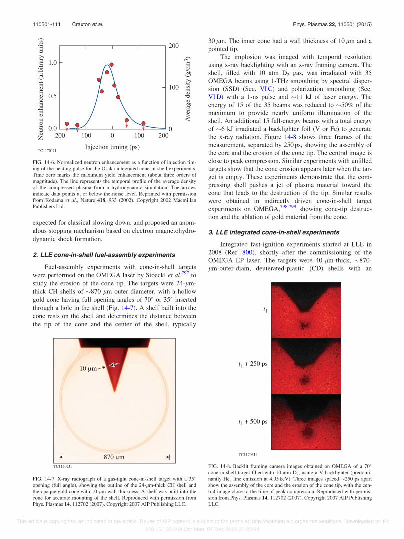
expected for classical slowing down, and proposed an anom-
alous stopping mechanism based on electron magnetohydro-
dynamic shock formation.
2. LLE cone-in-shell fuel-assembly experiments
Fuel-assembly experiments with cone-in-shell targets
were performed on the OMEGA laser by Stoeckl et al.797 to
study the erosion of the cone tip. The targets were 24-lm-
thick CH shells of �870-lm outer diameter, with a hollow
gold cone having full opening angles of 70� or 35� inserted
through a hole in the shell (Fig. 14-7). A shelf built into the
cone rests on the shell and determines the distance between
the tip of the cone and the center of the shell, typically
30 lm. The inner cone had a wall thickness of 10 lm and a
pointed tip.
The implosion was imaged with temporal resolution
using x-ray backlighting with an x-ray framing camera. The
shell, filled with 10 atm D2 gas, was irradiated with 35
OMEGA beams using 1-THz smoothing by spectral disper-
sion (SSD) (Sec. VI C) and polarization smoothing (Sec.
VI D) with a 1-ns pulse and �11 kJ of laser energy. The
energy of 15 of the 35 beams was reduced to �50% of the
maximum to provide nearly uniform illumination of the
shell. An additional 15 full-energy beams with a total energy
of �6 kJ irradiated a backlighter foil (V or Fe) to generate
the x-ray radiation. Figure 14-8 shows three frames of the
measurement, separated by 250 ps, showing the assembly of
the core and the erosion of the cone tip. The central image is
close to peak compression. Similar experiments with unfilled
targets show that the cone erosion appears later when the tar-
get is empty. These experiments demonstrate that the com-
pressing shell pushes a jet of plasma material toward the
cone that leads to the destruction of the tip. Similar results
were obtained in indirectly driven cone-in-shell target
experiments on OMEGA,798,799 showing cone-tip destruc-
tion and the ablation of gold material from the cone.
3. LLE integrated cone-in-shell experiments
Integrated fast-ignition experiments started at LLE in
2008 (Ref. 800), shortly after the commissioning of the
OMEGA EP laser. The targets were 40-lm-thick, �870-
lm-outer-diam, deuterated-plastic (CD) shells with an
FIG. 14-6. Normalized neutron enhancement as a function of injection tim-
ing of the heating pulse for the Osaka integrated cone-in-shell experiments.
Time zero marks the maximum yield enhancement (about three orders of
magnitude). The line represents the temporal profile of the average density
of the compressed plasma from a hydrodynamic simulation. The arrows
indicate data points at or below the noise level. Reprinted with permission
from Kodama et al., Nature 418, 933 (2002). Copyright 2002 Macmillan
Publishers Ltd.
FIG. 14-7. X-ray radiograph of a gas-tight cone-in-shell target with a 35�
opening (full angle), showing the outline of the 24-lm-thick CH shell and
the opaque gold cone with 10-lm wall thickness. A shelf was built into the
cone for accurate mounting of the shell. Reproduced with permission from
Phys. Plasmas 14, 112702 (2007). Copyright 2007 AIP Publishing LLC.
FIG. 14-8. Backlit framing camera images obtained on OMEGA of a 70�
cone-in-shell target filled with 10 atm D2, using a V backlighter (predomi-
nantly Hea line emission at 4.95 keV). Three images spaced �250 ps apart
show the assembly of the core and the erosion of the cone tip, with the cen-
tral image close to the time of peak compression. Reproduced with permis-
sion from Phys. Plasmas 14, 112702 (2007). Copyright 2007 AIP Publishing
LLC.
110501-111 Craxton et al. Phys. Plasmas 22, 110501 (2015)
This article is copyrighted as indicated in the article. Reuse of AIP content is subject to the terms at: http://scitation.aip.org/termsconditions. Downloaded to IP:
128.151.32.169 On: Mon, 07 Dec 2015 20:25:34
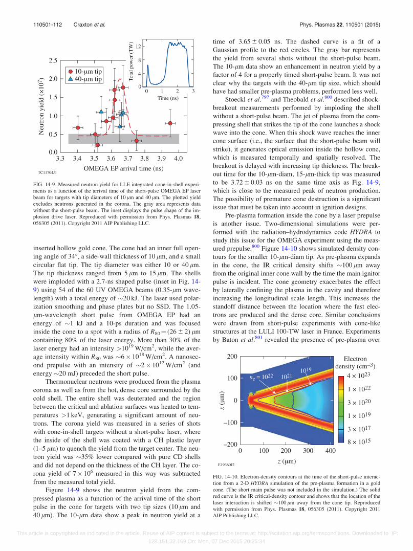
inserted hollow gold cone. The cone had an inner full open-
ing angle of 34�, a side-wall thickness of 10 lm, and a small
circular flat tip. The tip diameter was either 10 or 40 lm.
The tip thickness ranged from 5 lm to 15 lm. The shells
were imploded with a 2.7-ns shaped pulse (inset in Fig. 14-
9) using 54 of the 60 UV OMEGA beams (0.35-lm wave-
length) with a total energy of �20 kJ. The laser used polar-
ization smoothing and phase plates but no SSD. The 1.05-
lm-wavelength short pulse from OMEGA EP had an
energy of �1 kJ and a 10-ps duration and was focused
inside the cone to a spot with a radius of R80¼ (26 6 2) lm
containing 80% of the laser energy. More than 30% of the
laser energy had an intensity >1019 W/cm2, while the aver-
age intensity within R80 was �6� 1018 W/cm2. A nanosec-
ond prepulse with an intensity of �2� 1012 W/cm2 (and
energy �20 mJ) preceded the short pulse.
Thermonuclear neutrons were produced from the plasma
corona as well as from the hot, dense core surrounded by the
cold shell. The entire shell was deuterated and the region
between the critical and ablation surfaces was heated to tem-
peratures >1 keV, generating a significant amount of neu-
trons. The corona yield was measured in a series of shots
with cone-in-shell targets without a short-pulse laser, where
the inside of the shell was coated with a CH plastic layer
(1–5 lm) to quench the yield from the target center. The neu-
tron yield was �35% lower compared with pure CD shells
and did not depend on the thickness of the CH layer. The co-
rona yield of 7� 106 measured in this way was subtracted
from the measured total yield.
Figure 14-9 shows the neutron yield from the com-
pressed plasma as a function of the arrival time of the short
pulse in the cone for targets with two tip sizes (10 lm and
40 lm). The 10-lm data show a peak in neutron yield at a
time of 3.65 6 0.05 ns. The dashed curve is a fit of a
Gaussian profile to the red circles. The gray bar represents
the yield from several shots without the short-pulse beam.
The 10-lm data show an enhancement in neutron yield by a
factor of 4 for a properly timed short-pulse beam. It was not
clear why the targets with the 40-lm tip size, which should
have had smaller pre-plasma problems, performed less well.
Stoeckl et al.797 and Theobald et al.800 described shock-
breakout measurements performed by imploding the shell
without a short-pulse beam. The jet of plasma from the com-
pressing shell that strikes the tip of the cone launches a shock
wave into the cone. When this shock wave reaches the inner
cone surface (i.e., the surface that the short-pulse beam will
strike), it generates optical emission inside the hollow cone,
which is measured temporally and spatially resolved. The
breakout is delayed with increasing tip thickness. The break-
out time for the 10-lm-diam, 15-lm-thick tip was measured
to be 3.72 6 0.03 ns on the same time axis as Fig. 14-9,
which is close to the measured peak of neutron production.
The possibility of premature cone destruction is a significant
issue that must be taken into account in ignition designs.
Pre-plasma formation inside the cone by a laser prepulse
is another issue. Two-dimensional simulations were per-
formed with the radiation–hydrodynamics code HYDRA to
study this issue for the OMEGA experiment using the meas-
ured prepulse.800 Figure 14-10 shows simulated density con-
tours for the smaller 10-lm-diam tip. As pre-plasma expands
in the cone, the IR critical density shifts �100 lm away
from the original inner cone wall by the time the main ignitor
pulse is incident. The cone geometry exacerbates the effect
by laterally confining the plasma in the cavity and therefore
increasing the longitudinal scale length. This increases the
standoff distance between the location where the fast elec-
trons are produced and the dense core. Similar conclusions
were drawn from short-pulse experiments with cone-like
structures at the LULI 100-TW laser in France. Experiments
by Baton et al.801 revealed the presence of pre-plasma over
FIG. 14-9. Measured neutron yield for LLE integrated cone-in-shell experi-
ments as a function of the arrival time of the short-pulse OMEGA EP laser
beam for targets with tip diameters of 10 lm and 40 lm. The plotted yield
excludes neutrons generated in the corona. The gray area represents data
without the short-pulse beam. The inset displays the pulse shape of the im-
plosion drive laser. Reproduced with permission from Phys. Plasmas 18,
056305 (2011). Copyright 2011 AIP Publishing LLC.
FIG. 14-10. Electron-density contours at the time of the short-pulse interac-
tion from a 2-D HYDRA simulation of the pre-plasma formation in a gold
cone. (The short main pulse was not included in the simulation.) The solid
red curve is the IR critical-density contour and shows that the location of the
laser interaction is shifted �100 lm away from the cone tip. Reproduced
with permission from Phys. Plasmas 18, 056305 (2011). Copyright 2011
AIP Publishing LLC.
110501-112 Craxton et al. Phys. Plasmas 22, 110501 (2015)
This article is copyrighted as indicated in the article. Reuse of AIP content is subject to the terms at: http://scitation.aip.org/termsconditions. Downloaded to IP:
128.151.32.169 On: Mon, 07 Dec 2015 20:25:34
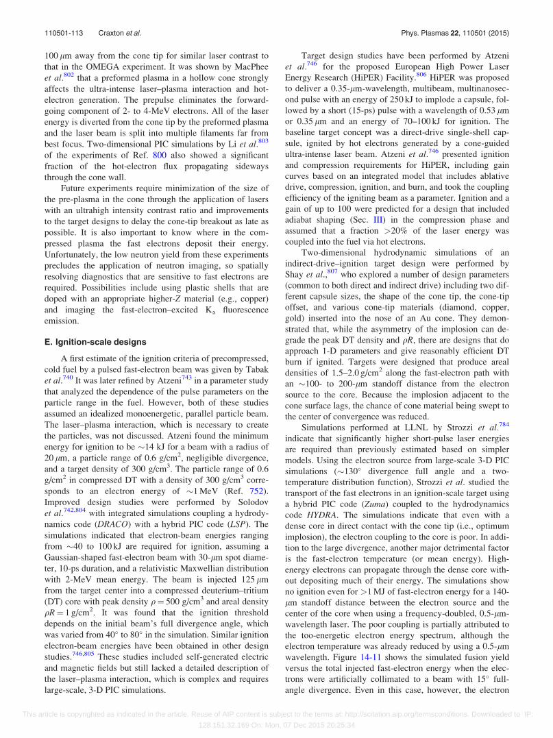
100 lm away from the cone tip for similar laser contrast to
that in the OMEGA experiment. It was shown by MacPhee
et al.802 that a preformed plasma in a hollow cone strongly
affects the ultra-intense laser–plasma interaction and hot-
electron generation. The prepulse eliminates the forward-
going component of 2- to 4-MeV electrons. All of the laser
energy is diverted from the cone tip by the preformed plasma
and the laser beam is split into multiple filaments far from
best focus. Two-dimensional PIC simulations by Li et al.803
of the experiments of Ref. 800 also showed a significant
fraction of the hot-electron flux propagating sideways
through the cone wall.
Future experiments require minimization of the size of
the pre-plasma in the cone through the application of lasers
with an ultrahigh intensity contrast ratio and improvements
to the target designs to delay the cone-tip breakout as late as
possible. It is also important to know where in the com-
pressed plasma the fast electrons deposit their energy.
Unfortunately, the low neutron yield from these experiments
precludes the application of neutron imaging, so spatially
resolving diagnostics that are sensitive to fast electrons are
required. Possibilities include using plastic shells that are
doped with an appropriate higher-Z material (e.g., copper)
and imaging the fast-electron–excited Ka fluorescence
emission.
E. Ignition-scale designs
A first estimate of the ignition criteria of precompressed,
cold fuel by a pulsed fast-electron beam was given by Tabak
et al.740 It was later refined by Atzeni743 in a parameter study
that analyzed the dependence of the pulse parameters on the
particle range in the fuel. However, both of these studies
assumed an idealized monoenergetic, parallel particle beam.
The laser–plasma interaction, which is necessary to create
the particles, was not discussed. Atzeni found the minimum
energy for ignition to be �14 kJ for a beam with a radius of
20 lm, a particle range of 0.6 g/cm2, negligible divergence,
and a target density of 300 g/cm3. The particle range of 0.6
g/cm2 in compressed DT with a density of 300 g/cm3 corre-
sponds to an electron energy of �1 MeV (Ref. 752).
Improved design studies were performed by Solodov
et al.742,804 with integrated simulations coupling a hydrody-
namics code (DRACO) with a hybrid PIC code (LSP). The
simulations indicated that electron-beam energies ranging
from �40 to 100 kJ are required for ignition, assuming a
Gaussian-shaped fast-electron beam with 30-lm spot diame-
ter, 10-ps duration, and a relativistic Maxwellian distribution
with 2-MeV mean energy. The beam is injected 125 lm
from the target center into a compressed deuterium–tritium
(DT) core with peak density q¼ 500 g/cm3 and areal density
qR¼ 1 g/cm2. It was found that the ignition threshold
depends on the initial beam’s full divergence angle, which
was varied from 40� to 80� in the simulation. Similar ignition
electron-beam energies have been obtained in other design
studies.746,805 These studies included self-generated electric
and magnetic fields but still lacked a detailed description of
the laser–plasma interaction, which is complex and requires
large-scale, 3-D PIC simulations.
Target design studies have been performed by Atzeni
et al.746 for the proposed European High Power Laser
Energy Research (HiPER) Facility.806 HiPER was proposed
to deliver a 0.35-lm-wavelength, multibeam, multinanosec-
ond pulse with an energy of 250 kJ to implode a capsule, fol-
lowed by a short (15-ps) pulse with a wavelength of 0.53 lm
or 0.35 lm and an energy of 70–100 kJ for ignition. The
baseline target concept was a direct-drive single-shell cap-
sule, ignited by hot electrons generated by a cone-guided
ultra-intense laser beam. Atzeni et al.746 presented ignition
and compression requirements for HiPER, including gain
curves based on an integrated model that includes ablative
drive, compression, ignition, and burn, and took the coupling
efficiency of the igniting beam as a parameter. Ignition and a
gain of up to 100 were predicted for a design that included
adiabat shaping (Sec. III) in the compression phase and
assumed that a fraction >20% of the laser energy was
coupled into the fuel via hot electrons.
Two-dimensional hydrodynamic simulations of an
indirect-drive–ignition target design were performed by
Shay et al.,807 who explored a number of design parameters
(common to both direct and indirect drive) including two dif-
ferent capsule sizes, the shape of the cone tip, the cone-tip
offset, and various cone-tip materials (diamond, copper,
gold) inserted into the nose of an Au cone. They demon-
strated that, while the asymmetry of the implosion can de-
grade the peak DT density and qR, there are designs that do
approach 1-D parameters and give reasonably efficient DT
burn if ignited. Targets were designed that produce areal
densities of 1.5–2.0 g/cm2 along the fast-electron path with
an �100- to 200-lm standoff distance from the electron
source to the core. Because the implosion adjacent to the
cone surface lags, the chance of cone material being swept to
the center of convergence was reduced.
Simulations performed at LLNL by Strozzi et al.784
indicate that significantly higher short-pulse laser energies
are required than previously estimated based on simpler
models. Using the electron source from large-scale 3-D PIC
simulations (�130� divergence full angle and a two-
temperature distribution function), Strozzi et al. studied the
transport of the fast electrons in an ignition-scale target using
a hybrid PIC code (Zuma) coupled to the hydrodynamics
code HYDRA. The simulations indicate that even with a
dense core in direct contact with the cone tip (i.e., optimum
implosion), the electron coupling to the core is poor. In addi-
tion to the large divergence, another major detrimental factor
is the fast-electron temperature (or mean energy). High-
energy electrons can propagate through the dense core with-
out depositing much of their energy. The simulations show
no ignition even for >1 MJ of fast-electron energy for a 140-
lm standoff distance between the electron source and the
center of the core when using a frequency-doubled, 0.5-lm-
wavelength laser. The poor coupling is partially attributed to
the too-energetic electron energy spectrum, although the
electron temperature was already reduced by using a 0.5-lm
wavelength. Figure 14-11 shows the simulated fusion yield
versus the total injected fast-electron energy when the elec-
trons were artificially collimated to a beam with 15� full-
angle divergence. Even in this case, however, the electron
110501-113 Craxton et al. Phys. Plasmas 22, 110501 (2015)
This article is copyrighted as indicated in the article. Reuse of AIP content is subject to the terms at: http://scitation.aip.org/termsconditions. Downloaded to IP:
128.151.32.169 On: Mon, 07 Dec 2015 20:25:34
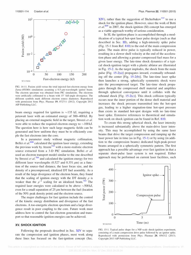
beam energy required for ignition is �135 kJ, requiring a
petawatt laser with an estimated energy of 300–400 kJ. By
placing an external magnetic field in the target, Strozzi et al.were able to reduce the required electron energy to �100 kJ.
The question here is how such large magnetic fields can be
generated and how uniform they must be to efficiently cou-
ple the fast electrons into the core.
In a parameter study without magnetic collimation,
Bellei et al.808 calculated the ignition laser energy, extending
the previous work by Atzeni743 with a more-realistic electron
source extracted from a 3-D PIC simulation. Bellei et al.used an electron transport model similar to the one described
by Strozzi et al.784 and calculated the ignition energy for two
different laser wavelengths (0.527 and 0.351 lm) as a func-
tion of the source–fuel distance, the laser focus size, and the
density of a precompressed, idealized DT fuel assembly. As a
result of the large divergence of the electron beam, they found
that the scaling of ignition energy with the DT density q is
weaker than the q–2 scaling for an idealized beam.743 The
required laser energies were calculated to be above �500 kJ,
even for a small separation of 25 lm between the fuel (location
of the 50% peak density point) and the electron source.
The major challenges for fast ignition include the control
of the kinetic energy distribution and divergence of the fast
electrons. A too-energetic electron spectrum and a large diver-
gence result in poor coupling to the core. Future work must
address how to control the fast-electron generation and trans-
port so that reasonable ignition energies can be achieved.
XV. SHOCK IGNITION
Following the proposals described in Sec. XIV to sepa-
rate the compression and ignition phases, most work along
these lines has focused on the fast-ignition concept (Sec.
XIV), rather than the suggestion of Shcherbakov737 to use a
shock for the ignition phase. However, since the work of Betti
et al.809 in 2007, the shock-ignition (SI) concept has emerged
as a viable approach worthy of serious consideration.
In SI, the ignition phase is accomplished through a mod-
ification of a typical hot-spot laser pulse design (such as that
described in Sec. III), adding a high-intensity spike pulse
(Fig. 15-1 from Ref. 810) to the end of the main compression
pulse. The main drive pulse is typically reduced in power,
resulting in a slower shell velocity at the end of the accelera-
tion phase and allowing a greater compressed fuel mass for a
given laser energy. The late-time shock dynamics of a typi-
cal shock-ignition target with a plastic ablator are illustrated
in Fig. 15-2. As the target implodes, the shock from the main
pulse [Fig. 15-2(a)] propagates inward, eventually rebound-
ing off the center [Fig. 15-2(b)]. The late-time laser spike
then launches a strong, spherically symmetric shock wave
into the precompressed target. The late-time shock propa-
gates through the compressed shell material and amplifies
through spherical convergence until it collides with the
rebound shock [Fig. 15-2(c)]. This shock collision typically
occurs near the inner portion of the dense shell material and
increases the shock pressure transmitted into the hot-spot
gas, leading to a higher stagnation-time hot-spot pressure
than exists in standard hot-spot designs with no late-time
laser spike. Extensive references to theoretical and simula-
tion work on shock ignition can be found in Ref. 810.
To create this strong spherical shock, the laser intensity
is increased substantially above the main-drive laser inten-
sity. This may be accomplished by using the same laser
beams that drive the target compression and ramping up the
laser power late in time (as in Fig. 15-1) or by using (in addi-
tion to the compression beams) dedicated high-peak-power
beams arranged in a spherically symmetric pattern. The first
approach has a possible advantage over fast ignition in that a
separate short-pulse laser system is not required. Either
approach may be performed on current laser facilities, such
FIG. 14-11. Fusion yield versus the total injected fast-electron energy from
Zuma–HYDRA simulations assuming a 0.5-lm-wavelength ignitor beam.
The electron spectrum was obtained from PIC simulations. The electrons
were artificially collimated to a beam with 15� full-angle divergence. The
different symbols mark different electron source diameters. Reproduced
with permission from Phys. Plasmas 19, 072711 (2012). Copyright 2012
AIP Publishing LLC.
FIG. 15-1. Typical pulse shape for a NIF-scale shock-ignition experiment,
consisting of a main compression drive pulse followed by an ignitor spike.
Reproduced with permission from Phys. Plasmas 20, 056312 (2013).
Copyright 2013 AIP Publishing LLC.
110501-114 Craxton et al. Phys. Plasmas 22, 110501 (2015)
This article is copyrighted as indicated in the article. Reuse of AIP content is subject to the terms at: http://scitation.aip.org/termsconditions. Downloaded to IP:
128.151.32.169 On: Mon, 07 Dec 2015 20:25:34
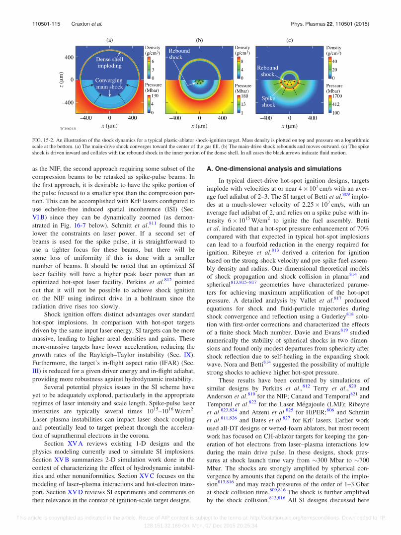
as the NIF, the second approach requiring some subset of the
compression beams to be retasked as spike-pulse beams. In
the first approach, it is desirable to have the spike portion of
the pulse focused to a smaller spot than the compression por-
tion. This can be accomplished with KrF lasers configured to
use echelon-free induced spatial incoherence (ISI) (Sec.
VI B) since they can be dynamically zoomed (as demon-
strated in Fig. 16-7 below). Schmitt et al.811 found this to
lower the constraints on laser power. If a second set of
beams is used for the spike pulse, it is straightforward to
use a tighter focus for these beams, but there will be
some loss of uniformity if this is done with a smaller
number of beams. It should be noted that an optimized SI
laser facility will have a higher peak laser power than an
optimized hot-spot laser facility. Perkins et al.812 pointed
out that it will not be possible to achieve shock ignition
on the NIF using indirect drive in a hohlraum since the
radiation drive rises too slowly.
Shock ignition offers distinct advantages over standard
hot-spot implosions. In comparison with hot-spot targets
driven by the same input laser energy, SI targets can be more
massive, leading to higher areal densities and gains. These
more-massive targets have lower acceleration, reducing the
growth rates of the Rayleigh–Taylor instability (Sec. IX).
Furthermore, the target’s in-flight aspect ratio (IFAR) (Sec.
III) is reduced for a given driver energy and in-flight adiabat,
providing more robustness against hydrodynamic instability.
Several potential physics issues in the SI scheme have
yet to be adequately explored, particularly in the appropriate
regimes of laser intensity and scale length. Spike-pulse laser
intensities are typically several times 1015–1016 W/cm2.
Laser–plasma instabilities can impact laser–shock coupling
and potentially lead to target preheat through the accelera-
tion of suprathermal electrons in the corona.
Section XV A reviews existing 1-D designs and the
physics modeling currently used to simulate SI implosions.
Section XV B summarizes 2-D simulation work done in the
context of characterizing the effect of hydrodynamic instabil-
ities and other nonuniformities. Section XV C focuses on the
modeling of laser–plasma interactions and hot-electron trans-
port. Section XV D reviews SI experiments and comments on
their relevance in the context of ignition-scale target designs.
A. One-dimensional analysis and simulations
In typical direct-drive hot-spot ignition designs, targets
implode with velocities at or near 4� 107 cm/s with an aver-
age fuel adiabat of 2–3. The SI target of Betti et al.809 implo-
des at a much-slower velocity of 2.25� 107 cm/s, with an
average fuel adiabat of 2, and relies on a spike pulse with in-
tensity 6� 1015 W/cm2 to ignite the fuel assembly. Betti
et al. indicated that a hot-spot pressure enhancement of 70%
compared with that expected in typical hot-spot implosions
can lead to a fourfold reduction in the energy required for
ignition. Ribeyre et al.813 derived a criterion for ignition
based on the strong-shock velocity and pre-spike fuel-assem-
bly density and radius. One-dimensional theoretical models
of shock propagation and shock collision in planar814 and
spherical813,815–817 geometries have characterized parame-
ters for achieving maximum amplification of the hot-spot
pressure. A detailed analysis by Vallet et al.817 produced
equations for shock and fluid-particle trajectories during
shock convergence and reflection using a Guderley818 solu-
tion with first-order corrections and characterized the effects
of a finite shock Mach number. Davie and Evans819 studied
numerically the stability of spherical shocks in two dimen-
sions and found only modest departures from sphericity after
shock reflection due to self-healing in the expanding shock
wave. Nora and Betti814 suggested the possibility of multiple
strong shocks to achieve higher hot-spot pressure.
These results have been confirmed by simulations of
similar designs by Perkins et al.,812 Terry et al.,820 and
Anderson et al.810 for the NIF; Canaud and Temporal821 and
Temporal et al.822 for the Laser M�egajoule (LMJ); Ribeyre
et al.823,824 and Atzeni et al.825 for HiPER;806 and Schmitt
et al.811,826 and Bates et al.827 for KrF lasers. Earlier work
used all-DT designs or wetted-foam ablators, but most recent
work has focused on CH-ablator targets for keeping the gen-
eration of hot electrons from laser–plasma interactions low
during the main drive pulse. In these designs, shock pres-
sures at shock launch time vary from �300 Mbar to �700
Mbar. The shocks are strongly amplified by spherical con-
vergence by amounts that depend on the details of the implo-
sion813,816 and may reach pressures of the order of 1–3 Gbar
at shock collision time.809,816 The shock is further amplified
by the shock collision.813,816 All SI designs discussed here
FIG. 15-2. An illustration of the shock dynamics for a typical plastic-ablator shock-ignition target. Mass density is plotted on top and pressure on a logarithmic
scale at the bottom. (a) The main-drive shock converges toward the center of the gas fill. (b) The main-drive shock rebounds and moves outward. (c) The spike
shock is driven inward and collides with the rebound shock in the inner portion of the dense shell. In all cases the black arrows indicate fluid motion.
110501-115 Craxton et al. Phys. Plasmas 22, 110501 (2015)
This article is copyrighted as indicated in the article. Reuse of AIP content is subject to the terms at: http://scitation.aip.org/termsconditions. Downloaded to IP:
128.151.32.169 On: Mon, 07 Dec 2015 20:25:34
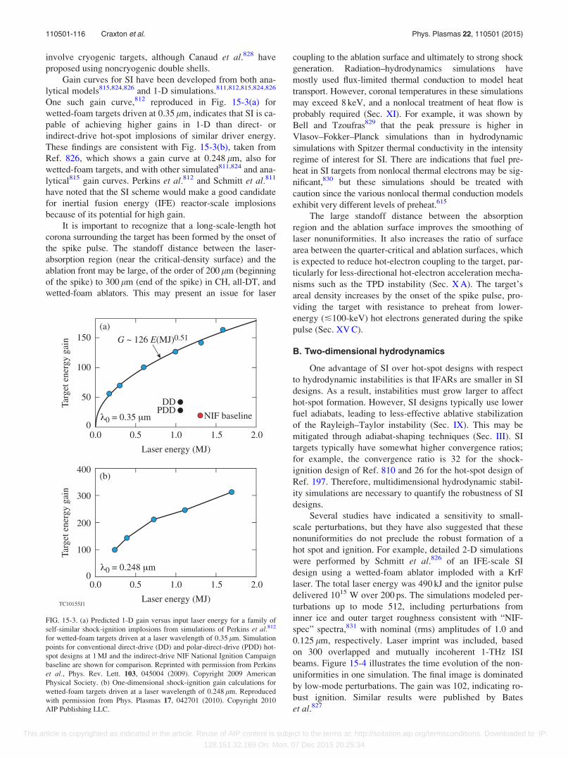
involve cryogenic targets, although Canaud et al.828 have
proposed using noncryogenic double shells.
Gain curves for SI have been developed from both ana-
lytical models815,824,826 and 1-D simulations.811,812,815,824,826
One such gain curve,812 reproduced in Fig. 15-3(a) for
wetted-foam targets driven at 0.35 lm, indicates that SI is ca-
pable of achieving higher gains in 1-D than direct- or
indirect-drive hot-spot implosions of similar driver energy.
These findings are consistent with Fig. 15-3(b), taken from
Ref. 826, which shows a gain curve at 0.248 lm, also for
wetted-foam targets, and with other simulated811,824 and ana-
lytical815 gain curves. Perkins et al.812 and Schmitt et al.811
have noted that the SI scheme would make a good candidate
for inertial fusion energy (IFE) reactor-scale implosions
because of its potential for high gain.
It is important to recognize that a long-scale-length hot
corona surrounding the target has been formed by the onset of
the spike pulse. The standoff distance between the laser-
absorption region (near the critical-density surface) and the
ablation front may be large, of the order of 200 lm (beginning
of the spike) to 300 lm (end of the spike) in CH, all-DT, and
wetted-foam ablators. This may present an issue for laser
coupling to the ablation surface and ultimately to strong shock
generation. Radiation–hydrodynamics simulations have
mostly used flux-limited thermal conduction to model heat
transport. However, coronal temperatures in these simulations
may exceed 8 keV, and a nonlocal treatment of heat flow is
probably required (Sec. XI). For example, it was shown by
Bell and Tzoufras829 that the peak pressure is higher in
Vlasov–Fokker–Planck simulations than in hydrodynamic
simulations with Spitzer thermal conductivity in the intensity
regime of interest for SI. There are indications that fuel pre-
heat in SI targets from nonlocal thermal electrons may be sig-
nificant,830 but these simulations should be treated with
caution since the various nonlocal thermal conduction models
exhibit very different levels of preheat.615
The large standoff distance between the absorption
region and the ablation surface improves the smoothing of
laser nonuniformities. It also increases the ratio of surface
area between the quarter-critical and ablation surfaces, which
is expected to reduce hot-electron coupling to the target, par-
ticularly for less-directional hot-electron acceleration mecha-
nisms such as the TPD instability (Sec. X A). The target’s
areal density increases by the onset of the spike pulse, pro-
viding the target with resistance to preheat from lower-
energy (�100-keV) hot electrons generated during the spike
pulse (Sec. XV C).
B. Two-dimensional hydrodynamics
One advantage of SI over hot-spot designs with respect
to hydrodynamic instabilities is that IFARs are smaller in SI
designs. As a result, instabilities must grow larger to affect
hot-spot formation. However, SI designs typically use lower
fuel adiabats, leading to less-effective ablative stabilization
of the Rayleigh–Taylor instability (Sec. IX). This may be
mitigated through adiabat-shaping techniques (Sec. III). SI
targets typically have somewhat higher convergence ratios;
for example, the convergence ratio is 32 for the shock-
ignition design of Ref. 810 and 26 for the hot-spot design of
Ref. 197. Therefore, multidimensional hydrodynamic stabil-
ity simulations are necessary to quantify the robustness of SI
designs.
Several studies have indicated a sensitivity to small-
scale perturbations, but they have also suggested that these
nonuniformities do not preclude the robust formation of a
hot spot and ignition. For example, detailed 2-D simulations
were performed by Schmitt et al.826 of an IFE-scale SI
design using a wetted-foam ablator imploded with a KrF
laser. The total laser energy was 490 kJ and the ignitor pulse
delivered 1015 W over 200 ps. The simulations modeled per-
turbations up to mode 512, including perturbations from
inner ice and outer target roughness consistent with “NIF-
spec” spectra,831 with nominal (rms) amplitudes of 1.0 and
0.125 lm, respectively. Laser imprint was included, based
on 300 overlapped and mutually incoherent 1-THz ISI
beams. Figure 15-4 illustrates the time evolution of the non-
uniformities in one simulation. The final image is dominated
by low-mode perturbations. The gain was 102, indicating ro-
bust ignition. Similar results were published by Bates
et al.827
FIG. 15-3. (a) Predicted 1-D gain versus input laser energy for a family of
self-similar shock-ignition implosions from simulations of Perkins et al.812
for wetted-foam targets driven at a laser wavelength of 0.35 lm. Simulation
points for conventional direct-drive (DD) and polar-direct-drive (PDD) hot-
spot designs at 1 MJ and the indirect-drive NIF National Ignition Campaign
baseline are shown for comparison. Reprinted with permission from Perkins
et al., Phys. Rev. Lett. 103, 045004 (2009). Copyright 2009 American
Physical Society. (b) One-dimensional shock-ignition gain calculations for
wetted-foam targets driven at a laser wavelength of 0.248 lm. Reproduced
with permission from Phys. Plasmas 17, 042701 (2010). Copyright 2010
AIP Publishing LLC.
110501-116 Craxton et al. Phys. Plasmas 22, 110501 (2015)
This article is copyrighted as indicated in the article. Reuse of AIP content is subject to the terms at: http://scitation.aip.org/termsconditions. Downloaded to IP:
128.151.32.169 On: Mon, 07 Dec 2015 20:25:34
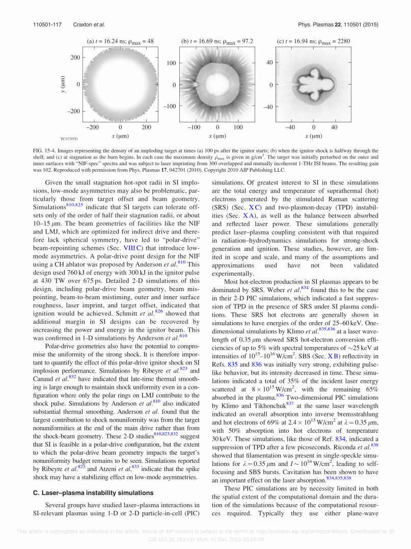
Given the small stagnation hot-spot radii in SI implo-
sions, low-mode asymmetries may also be problematic, par-
ticularly those from target offset and beam geometry.
Simulations810,825 indicate that SI targets can tolerate off-
sets only of the order of half their stagnation radii, or about
10–15 lm. The beam geometries of facilities like the NIF
and LMJ, which are optimized for indirect drive and there-
fore lack spherical symmetry, have led to “polar-drive”
beam-repointing schemes (Sec. VIII C) that introduce low-
mode asymmetries. A polar-drive point design for the NIF
using a CH ablator was proposed by Anderson et al.810 This
design used 760 kJ of energy with 300 kJ in the ignitor pulse
at 430 TW over 675 ps. Detailed 2-D simulations of this
design, including polar-drive beam geometry, beam mis-
pointing, beam-to-beam mistiming, outer and inner surface
roughness, laser imprint, and target offset, indicated that
ignition would be achieved. Schmitt et al.826 showed that
additional margin in SI designs can be recovered by
increasing the power and energy in the ignitor beam. This
was confirmed in 1-D simulations by Anderson et al.810
Polar-drive geometries also have the potential to compro-
mise the uniformity of the strong shock. It is therefore impor-
tant to quantify the effect of this polar-drive ignitor shock on SI
implosion performance. Simulations by Ribeyre et al.823 and
Canaud et al.832 have indicated that late-time thermal smooth-
ing is large enough to maintain shock uniformity even in a con-
figuration where only the polar rings on LMJ contribute to the
shock pulse. Simulations by Anderson et al.810 also indicated
substantial thermal smoothing. Anderson et al. found that the
largest contribution to shock nonuniformity was from the target
nonuniformities at the end of the main drive rather than from
the shock-beam geometry. These 2-D studies810,823,832 suggest
that SI is feasible in a polar-drive configuration, but the extent
to which the polar-drive beam geometry impacts the target’s
nonuniformity budget remains to be seen. Simulations reported
by Ribeyre et al.823 and Atzeni et al.833 indicate that the spike
shock may have a stabilizing effect on low-mode asymmetries.
C. Laser–plasma instability simulations
Several groups have studied laser–plasma interactions in
SI-relevant plasmas using 1-D or 2-D particle-in-cell (PIC)
simulations. Of greatest interest to SI in these simulations
are the total energy and temperature of suprathermal (hot)
electrons generated by the stimulated Raman scattering
(SRS) (Sec. X C) and two-plasmon-decay (TPD) instabil-
ities (Sec. X A), as well as the balance between absorbed
and reflected laser power. These simulations generally
predict laser–plasma coupling consistent with that required
in radiation–hydrodynamics simulations for strong-shock
generation and ignition. These studies, however, are lim-
ited in scope and scale, and many of the assumptions and
approximations used have not been validated
experimentally.
Most hot-electron production in SI plasmas appears to be
dominated by SRS. Weber et al.834 found this to be the case
in their 2-D PIC simulations, which indicated a fast suppres-
sion of TPD in the presence of SRS under SI plasma condi-
tions. These SRS hot electrons are generally shown in
simulations to have energies of the order of 25–60 keV. One-
dimensional simulations by Klimo et al.835,836 at a laser wave-
length of 0.35 lm showed SRS hot-electron conversion effi-
ciencies of up to 5% with spectral temperatures of �25 keV at
intensities of 1015–1016 W/cm2. SBS (Sec. X B) reflectivity in
Refs. 835 and 836 was initially very strong, exhibiting pulse-
like behavior, but its intensity decreased in time. These simu-
lations indicated a total of 35% of the incident laser energy
scattered at 8� 1015 W/cm2, with the remaining 65%
absorbed in the plasma.836 Two-dimensional PIC simulations
by Klimo and Tikhonchuk837 at the same laser wavelength
indicated an overall absorption into inverse bremsstrahlung
and hot electrons of 69% at 2.4� 1015 W/cm2 at k¼ 0.35 lm,
with 50% absorption into hot electrons of temperature
30 keV. These simulations, like those of Ref. 834, indicated a
suppression of TPD after a few picoseconds. Riconda et al.838
showed that filamentation was present in single-speckle simu-
lations for k¼ 0.35 lm and I� 1016 W/cm2, leading to self-
focusing and SBS bursts. Cavitation has been shown to have
an important effect on the laser absorption.834,835,838
These PIC simulations are by necessity limited in both
the spatial extent of the computational domain and the dura-
tion of the simulations because of the computational resour-
ces required. Typically they use either plane-wave
FIG. 15-4. Images representing the density of an imploding target at times (a) 100 ps after the ignitor starts; (b) when the ignitor shock is halfway through the
shell; and (c) at stagnation as the burn begins. In each case the maximum density qmax is given in g/cm3. The target was initially perturbed on the outer and
inner surfaces with “NIF-spec” spectra and was subject to laser imprinting from 300 overlapped and mutually incoherent 1-THz ISI beams. The resulting gain
was 102. Reproduced with permission from Phys. Plasmas 17, 042701 (2010). Copyright 2010 AIP Publishing LLC.
110501-117 Craxton et al. Phys. Plasmas 22, 110501 (2015)
This article is copyrighted as indicated in the article. Reuse of AIP content is subject to the terms at: http://scitation.aip.org/termsconditions. Downloaded to IP:
128.151.32.169 On: Mon, 07 Dec 2015 20:25:34

approximations834–836,838 for the laser field or model a single
speckle,834,838 ignoring speckle–speckle interaction, which
may be important.839 Whereas the spike-pulse duration for
typical SI implosions is of the order of 400–700 ps, PIC sim-
ulation times are generally between 20 and 60 ps for 1-D
simulations and �5 ps for 2-D simulations. It is unclear
whether the early-time plasma response in these simulations
is representative of the entire pulse.
The coupling of instability-generated hot electrons to
the capsule and shock has been studied numerically.
Generally, simulations indicate that ignition designs have
sufficient areal density during the spike laser pulse to resist
preheat from hot electrons with spectral temperatures of less
than 100 keV, stopping most electrons in the ablator or outer
portion of the fuel.810,840 Indeed, several researchers have
indicated that electrons of such energies may be beneficial to
SI since they deposit energy near the shock-formation region
and, therefore, may amplify the shock pressures above those
anticipated by including only inverse bremsstrahlung absorp-
tion and flux-limited thermal heat conduc-
tion.809,810,812,840–843 Some authors have gone further to
propose using hot electrons as the primary shock-launching
mechanism.844,845
D. Experiments
SI-relevant experiments have been performed at various
facilities, examining target stability and yield, strong-shock
generation, and laser–plasma interactions at spike-pulse laser
intensities. These experiments have shown enhanced fusion
reactions from the addition of an SI laser spike in subscale
SI implosions along with laser light scattering and hot-
electron temperatures within design constraints.
Symmetric SI implosions846 were carried out on
OMEGA and compared with similar no-spike implosions.
These experiments used all 60 OMEGA beams with the
same laser pulse shape for each beam [Fig. 15-5(a)]. The tar-
gets were 40-lm-thick, 860-lm-diam plastic shells filled
with D2. Implosions with a late-time spike pulse and with no
spike were compared at the same total laser energy. Results
showed that the spike-pulse shots had neutron yields up to
4� higher than those without a spike [Fig. 15-5(b)]. Shots
with two different picket timings (tp) were included in the
dataset, but the effect of picket timing was secondary. These
experiments showed higher ratios of the yield-over-clean
[(YOC), defined as the ratio of the experimental yield to the
simulated, 1-D yield] than their no-shock counterparts, par-
ticularly at a higher convergence ratio [Fig. 15-6(a)]. The
convergence ratio was varied by changing the pressure of the
gas fill. Higher areal densities were measured with the spike
pulses [Fig. 15-6(b)]. These results indicate that the targets
imploded with an intensity spike at the end of the pulse were
more stable than the no-spike targets. However, the late
shock was weak and the spike intensity was less than
1015 W/cm2, so potential problems with plasma instabilities
may have been avoided.
Spherical laser–plasma interaction experiments on
OMEGA at SI-relevant laser intensities847–849 were per-
formed using 40 beams to compress the target and 20 tightly
focused beams to generate a shock and to study laser–plasma
interactions. Results indicate that the main mechanism of
hot-electron acceleration is SRS, with SRS backscatter vary-
ing from �8% of the incident laser energy at 0.9� 1015 W/
cm2 up to �36% at 8� 1015 W/cm2. Suprathermal electron
temperatures inferred from hard x-ray signals were generally
�30 keV, which is not expected to be detrimental to SI. The
hot-electron temperature was insensitive to laser intensity.
SBS backscatter was also measured and found to vary from
�8% to 12% at high intensity. Cross-beam energy transfer
(Sec. X B) was unlikely to have been a factor during the
spike pulse since there was little to no overlap in the high-
intensity shock beams. No TPD 3/2-harmonic signature was
measured. However, the experiments did not use SSD beam
smoothing (Sec. VI C) and the tight-focus conditions may
not be representative (since the optimal geometry for shock
ignition will probably involve overlapping spike beams to
maximize spherical uniformity), so these results should be
treated with caution.
Several planar laser–plasma interaction experiments
have been performed at other facilities at wavelengths vary-
ing from 1 lm to 0.35 lm (Refs. 850–853). These experi-
ments generally produced SRS backscatter of up to 5% of
FIG. 15-5. (a) Target parameters and representative pulse shapes, with and
without spike, for shock-ignition implosion experiments on OMEGA. The
targets were typically filled with 25 atm of D2. (b) Measured neutron yield
as a function of the onset of the spike pulse for two different picket-pulse
timings tp. The pulse without a spike is shown as a reference and was shot
with tp¼�300 ps. Reproduced with permission from Phys. Plasmas 15,
056306 (2008). Copyright 2008 AIP Publishing LLC.
110501-118 Craxton et al. Phys. Plasmas 22, 110501 (2015)
This article is copyrighted as indicated in the article. Reuse of AIP content is subject to the terms at: http://scitation.aip.org/termsconditions. Downloaded to IP:
128.151.32.169 On: Mon, 07 Dec 2015 20:25:34
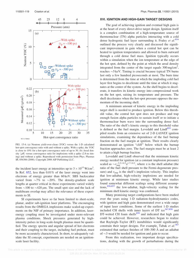
the incident laser energy at intensities up to 3� 1015 W/cm2.
In Ref. 852, less than 0.01% of the laser energy went into
electrons of energy greater than 60 keV. SBS backscatter
varied from �7% to �20%. The density-gradient scale
lengths at quarter critical in these experiments varied widely
from �100 to �420 lm. The small spot size and the lack of
multibeam overlap may affect the relevance of these experi-
ments to SI.
SI experiments have so far been limited to short-scale,
planar, and/or sub-ignition laser platforms. The encouraging
results from the OMEGA implosions make scaled-up experi-
ments on the NIF of primary importance. In addition, laser-
energy coupling must be investigated under more-relevant
plasma conditions. Shock pressures generated by high-
intensity pulses in long-scale-length plasmas must be quanti-
fied. The energy spectra and angular spread of hot electrons
and their coupling to the target, including fuel preheat, must
be more accurately characterized. In short, to adequately val-
idate the SI concept, experiments are needed on an ignition-
scale laser facility.
XVI. IGNITION AND HIGH-GAIN TARGET DESIGNS
The goal of achieving ignition and eventual high gain is
at the heart of every direct-drive target design. Ignition itself
is a complex combination of a high-temperature source of
thermonuclear (TN) alpha particles interacting with a cold
dense hydrogenic fuel layer surrounding it. Fraley et al.854
outlined the process very clearly and discussed the signifi-
cant improvement in gain when a central hot spot can be
heated to ignition temperatures and allowed to burn outward
through a cold dense fuel mass. Ignition typically occurs
within a simulation when the ion temperature at the edge of
the hot spot, defined by the point at which the areal density
integrated from the center of the target equals 300 mg/cm2,
reaches �5 keV. Timing is crucial because typical TN burns
last only a few hundred picoseconds at most. The burn time
is determined from the time at which the imploding cold fuel
layer first begins to decelerate until the time at which it stag-
nates at the center of the system. As the shell begins to decel-
erate, it transfers its kinetic energy into compressional work
on the hot spot, raising its temperature and pressure. The
shell decelerates when the hot-spot pressure opposes the mo-
mentum of the incoming shell.
A minimum amount of kinetic energy in the imploding
target shell is needed to produce ignition. Below this thresh-
old value, the central hot spot does not produce and trap
enough fusion alpha particles to sustain itself or to initiate a
thermonuclear burn wave into the surrounding dense fuel.
The ratio of the shell’s kinetic energy to this threshold value
is defined as the fuel margin. Levedahl and Lindl855 com-
piled results from an extensive set of 2-D LASNEX ignition
simulations, examining the dependence of the fuel burnup
fraction on the fuel margin at ignition. Their results clearly
demonstrated an ignition “cliff” below which the burnup
fraction approaches zero. The fuel margin must be at least 2
to attain a high burnup fraction.
Levedahl and Lindl observed that the minimum kinetic
energy needed for ignition (at a constant implosion pressure)
scaled as �v�5:560:5imp a1:760:2; where a is the shell adiabat (the
ratio of the fuel shell pressure to the Fermi-degenerate pres-
sure) and vimp is the shell’s implosion velocity. This implies
that low-adiabat, high-velocity implosions are needed for
ignition at minimum kinetic energy. While later studies
found somewhat different scalings using different assump-
tions,856,857 the low-adiabat, high-velocity scaling for the
minimum shell kinetic energy was confirmed.
Many promising target configurations have been studied
over the years using 1-D radiation–hydrodynamics codes,
with ignition and high gain demonstrated over a wide range
of input laser conditions. Some of the earliest 1-D studies
included CH shells with inner layers of DT ice367,858 and
DT-wetted CH foam shells859 and indicated that high gain
could be achieved. However, researchers began to realize
that Rayleigh–Taylor (RT) instabilities would significantly
constrain their target designs. For example, Tabak et al.367
estimated that surface finishes of 100–300 A and an adiabat
of �3 would be needed for ignition and gain to occur.
From this realization, two important design specifica-
tions, dealing with the growth of perturbations during the
FIG. 15-6. (a) Neutron yield-over-clean (YOC) versus the 1-D calculated
hot-spot convergence ratio with and without a spike. With a spike, the YOC
is close to 10% for a hot-spot convergence ratio of up to 30. (b) Areal den-
sity hqRi versus convergence ratio for implosions with a spike (2.8-ns tim-
ing) and without a spike. Reproduced with permission from Phys. Plasmas
15, 056306 (2008). Copyright 2008 AIP Publishing LLC.
110501-119 Craxton et al. Phys. Plasmas 22, 110501 (2015)
This article is copyrighted as indicated in the article. Reuse of AIP content is subject to the terms at: http://scitation.aip.org/termsconditions. Downloaded to IP:
128.151.32.169 On: Mon, 07 Dec 2015 20:25:34
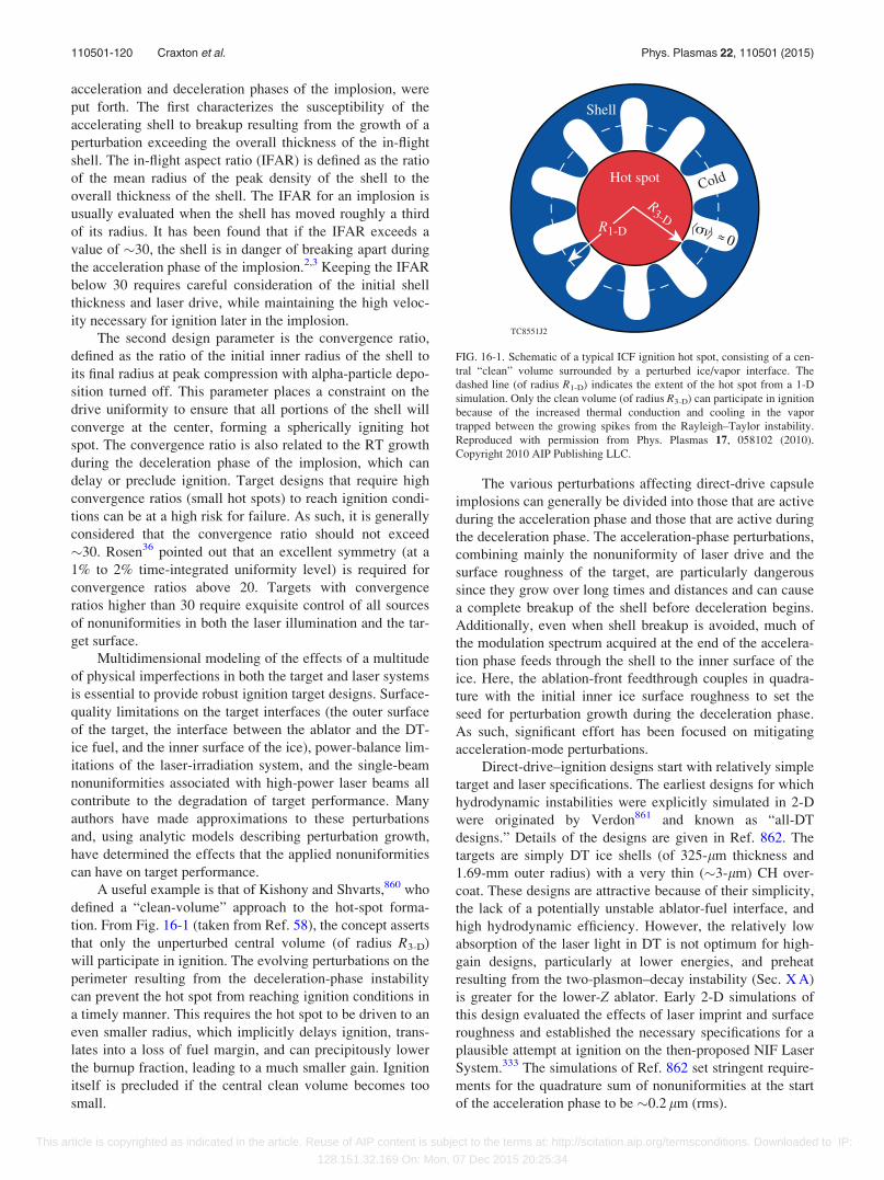
acceleration and deceleration phases of the implosion, were
put forth. The first characterizes the susceptibility of the
accelerating shell to breakup resulting from the growth of a
perturbation exceeding the overall thickness of the in-flight
shell. The in-flight aspect ratio (IFAR) is defined as the ratio
of the mean radius of the peak density of the shell to the
overall thickness of the shell. The IFAR for an implosion is
usually evaluated when the shell has moved roughly a third
of its radius. It has been found that if the IFAR exceeds a
value of �30, the shell is in danger of breaking apart during
the acceleration phase of the implosion.2,3 Keeping the IFAR
below 30 requires careful consideration of the initial shell
thickness and laser drive, while maintaining the high veloc-
ity necessary for ignition later in the implosion.
The second design parameter is the convergence ratio,
defined as the ratio of the initial inner radius of the shell to
its final radius at peak compression with alpha-particle depo-
sition turned off. This parameter places a constraint on the
drive uniformity to ensure that all portions of the shell will
converge at the center, forming a spherically igniting hot
spot. The convergence ratio is also related to the RT growth
during the deceleration phase of the implosion, which can
delay or preclude ignition. Target designs that require high
convergence ratios (small hot spots) to reach ignition condi-
tions can be at a high risk for failure. As such, it is generally
considered that the convergence ratio should not exceed
�30. Rosen36 pointed out that an excellent symmetry (at a
1% to 2% time-integrated uniformity level) is required for
convergence ratios above 20. Targets with convergence
ratios higher than 30 require exquisite control of all sources
of nonuniformities in both the laser illumination and the tar-
get surface.
Multidimensional modeling of the effects of a multitude
of physical imperfections in both the target and laser systems
is essential to provide robust ignition target designs. Surface-
quality limitations on the target interfaces (the outer surface
of the target, the interface between the ablator and the DT-
ice fuel, and the inner surface of the ice), power-balance lim-
itations of the laser-irradiation system, and the single-beam
nonuniformities associated with high-power laser beams all
contribute to the degradation of target performance. Many
authors have made approximations to these perturbations
and, using analytic models describing perturbation growth,
have determined the effects that the applied nonuniformities
can have on target performance.
A useful example is that of Kishony and Shvarts,860 who
defined a “clean-volume” approach to the hot-spot forma-
tion. From Fig. 16-1 (taken from Ref. 58), the concept asserts
that only the unperturbed central volume (of radius R3-D)
will participate in ignition. The evolving perturbations on the
perimeter resulting from the deceleration-phase instability
can prevent the hot spot from reaching ignition conditions in
a timely manner. This requires the hot spot to be driven to an
even smaller radius, which implicitly delays ignition, trans-
lates into a loss of fuel margin, and can precipitously lower
the burnup fraction, leading to a much smaller gain. Ignition
itself is precluded if the central clean volume becomes too
small.
The various perturbations affecting direct-drive capsule
implosions can generally be divided into those that are active
during the acceleration phase and those that are active during
the deceleration phase. The acceleration-phase perturbations,
combining mainly the nonuniformity of laser drive and the
surface roughness of the target, are particularly dangerous
since they grow over long times and distances and can cause
a complete breakup of the shell before deceleration begins.
Additionally, even when shell breakup is avoided, much of
the modulation spectrum acquired at the end of the accelera-
tion phase feeds through the shell to the inner surface of the
ice. Here, the ablation-front feedthrough couples in quadra-
ture with the initial inner ice surface roughness to set the
seed for perturbation growth during the deceleration phase.
As such, significant effort has been focused on mitigating
acceleration-mode perturbations.
Direct-drive–ignition designs start with relatively simple
target and laser specifications. The earliest designs for which
hydrodynamic instabilities were explicitly simulated in 2-D
were originated by Verdon861 and known as “all-DT
designs.” Details of the designs are given in Ref. 862. The
targets are simply DT ice shells (of 325-lm thickness and
1.69-mm outer radius) with a very thin (�3-lm) CH over-
coat. These designs are attractive because of their simplicity,
the lack of a potentially unstable ablator-fuel interface, and
high hydrodynamic efficiency. However, the relatively low
absorption of the laser light in DT is not optimum for high-
gain designs, particularly at lower energies, and preheat
resulting from the two-plasmon–decay instability (Sec. X A)
is greater for the lower-Z ablator. Early 2-D simulations of
this design evaluated the effects of laser imprint and surface
roughness and established the necessary specifications for a
plausible attempt at ignition on the then-proposed NIF Laser
System.333 The simulations of Ref. 862 set stringent require-
ments for the quadrature sum of nonuniformities at the start
of the acceleration phase to be �0.2 lm (rms).
FIG. 16-1. Schematic of a typical ICF ignition hot spot, consisting of a cen-
tral “clean” volume surrounded by a perturbed ice/vapor interface. The
dashed line (of radius R1-D) indicates the extent of the hot spot from a 1-D
simulation. Only the clean volume (of radius R3-D) can participate in ignition
because of the increased thermal conduction and cooling in the vapor
trapped between the growing spikes from the Rayleigh–Taylor instability.
Reproduced with permission from Phys. Plasmas 17, 058102 (2010).
Copyright 2010 AIP Publishing LLC.
110501-120 Craxton et al. Phys. Plasmas 22, 110501 (2015)
This article is copyrighted as indicated in the article. Reuse of AIP content is subject to the terms at: http://scitation.aip.org/termsconditions. Downloaded to IP:
128.151.32.169 On: Mon, 07 Dec 2015 20:25:34
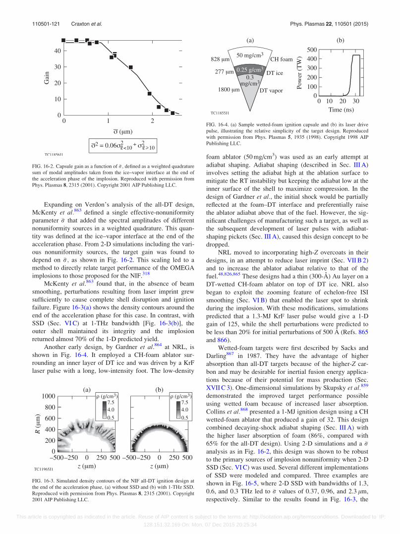
Expanding on Verdon’s analysis of the all-DT design,
McKenty et al.863 defined a single effective-nonuniformity
parameter �r that added the spectral amplitudes of different
nonuniformity sources in a weighted quadrature. This quan-
tity was defined at the ice–vapor interface at the end of the
acceleration phase. From 2-D simulations including the vari-
ous nonuniformity sources, the target gain was found to
depend on �r; as shown in Fig. 16-2. This scaling led to a
method to directly relate target performance of the OMEGA
implosions to those proposed for the NIF.318
McKenty et al.863 found that, in the absence of beam
smoothing, perturbations resulting from laser imprint grew
sufficiently to cause complete shell disruption and ignition
failure. Figure 16-3(a) shows the density contours around the
end of the acceleration phase for this case. In contrast, with
SSD (Sec. VI C) at 1-THz bandwidth [Fig. 16-3(b)], the
outer shell maintained its integrity and the implosion
returned almost 70% of the 1-D predicted yield.
Another early design, by Gardner et al.864 at NRL, is
shown in Fig. 16-4. It employed a CH-foam ablator sur-
rounding an inner layer of DT ice and was driven by a KrF
laser pulse with a long, low-intensity foot. The low-density
foam ablator (50 mg/cm3) was used as an early attempt at
adiabat shaping. Adiabat shaping (described in Sec. III A)
involves setting the adiabat high at the ablation surface to
mitigate the RT instability but keeping the adiabat low at the
inner surface of the shell to maximize compression. In the
design of Gardner et al., the initial shock would be partially
reflected at the foam–DT interface and preferentially raise
the ablator adiabat above that of the fuel. However, the sig-
nificant challenges of manufacturing such a target, as well as
the subsequent development of laser pulses with adiabat-
shaping pickets (Sec. III A), caused this design concept to be
dropped.
NRL moved to incorporating high-Z overcoats in their
designs, in an attempt to reduce laser imprint (Sec. VII B 2)
and to increase the ablator adiabat relative to that of the
fuel.48,826,865 These designs had a thin (300-A) Au layer on a
DT-wetted CH-foam ablator on top of DT ice. NRL also
began to exploit the zooming feature of echelon-free ISI
smoothing (Sec. VI B) that enabled the laser spot to shrink
during the implosion. With these modifications, simulations
predicted that a 1.3-MJ KrF laser pulse would give a 1-D
gain of 125, while the shell perturbations were predicted to
be less than 20% for initial perturbations of 500 A (Refs. 865
and 866).
Wetted-foam targets were first described by Sacks and
Darling867 in 1987. They have the advantage of higher
absorption than all-DT targets because of the higher-Z car-
bon and may be desirable for inertial fusion energy applica-
tions because of their potential for mass production (Sec.
XVII C 3). One-dimensional simulations by Skupsky et al.859
demonstrated the improved target performance possible
using wetted foam because of increased laser absorption.
Collins et al.868 presented a 1-MJ ignition design using a CH
wetted-foam ablator that produced a gain of 32. This design
combined decaying-shock adiabat shaping (Sec. III A) with
the higher laser absorption of foam (86%, compared with
65% for the all-DT design). Using 2-D simulations and a �ranalysis as in Fig. 16-2, this design was shown to be robust
to the primary sources of implosion nonuniformity when 2-D
SSD (Sec. VI C) was used. Several different implementations
of SSD were modeled and compared. Three examples are
shown in Fig. 16-5, where 2-D SSD with bandwidths of 1.3,
0.6, and 0.3 THz led to �r values of 0.37, 0.96, and 2.3 lm,
respectively. Similar to the results found in Fig. 16-3, the
FIG. 16-2. Capsule gain as a function of �r; defined as a weighted quadrature
sum of modal amplitudes taken from the ice–vapor interface at the end of
the acceleration phase of the implosion. Reproduced with permission from
Phys. Plasmas 8, 2315 (2001). Copyright 2001 AIP Publishing LLC.
FIG. 16-3. Simulated density contours of the NIF all-DT ignition design at
the end of the acceleration phase, (a) without SSD and (b) with 1-THz SSD.
Reproduced with permission from Phys. Plasmas 8, 2315 (2001). Copyright
2001 AIP Publishing LLC.
FIG. 16-4. (a) Sample wetted-foam ignition capsule and (b) its laser drive
pulse, illustrating the relative simplicity of the target design. Reproduced
with permission from Phys. Plasmas 5, 1935 (1998). Copyright 1998 AIP
Publishing LLC.
110501-121 Craxton et al. Phys. Plasmas 22, 110501 (2015)
This article is copyrighted as indicated in the article. Reuse of AIP content is subject to the terms at: http://scitation.aip.org/termsconditions. Downloaded to IP:
128.151.32.169 On: Mon, 07 Dec 2015 20:25:34
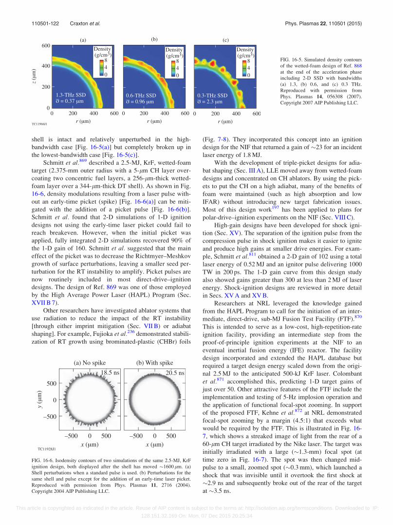
shell is intact and relatively unperturbed in the high-
bandwidth case [Fig. 16-5(a)] but completely broken up in
the lowest-bandwidth case [Fig. 16-5(c)].
Schmitt et al.869 described a 2.5-MJ, KrF, wetted-foam
target (2.375-mm outer radius with a 5-lm CH layer over-
coating two concentric fuel layers, a 256-lm-thick wetted-
foam layer over a 344-lm-thick DT shell). As shown in Fig.
16-6, density modulations resulting from a laser pulse with-
out an early-time picket (spike) [Fig. 16-6(a)] can be miti-
gated with the addition of a picket pulse [Fig. 16-6(b)].
Schmitt et al. found that 2-D simulations of 1-D ignition
designs not using the early-time laser picket could fail to
reach breakeven. However, when the initial picket was
applied, fully integrated 2-D simulations recovered 90% of
the 1-D gain of 160. Schmitt et al. suggested that the main
effect of the picket was to decrease the Richtmyer–Meshkov
growth of surface perturbations, leaving a smaller seed per-
turbation for the RT instability to amplify. Picket pulses are
now routinely included in most direct-drive–ignition
designs. The design of Ref. 869 was one of those employed
by the High Average Power Laser (HAPL) Program (Sec.
XVII B 7).
Other researchers have investigated ablator systems that
use radiation to reduce the impact of the RT instability
[through either imprint mitigation (Sec. VII B) or adiabat
shaping]. For example, Fujioka et al.236 demonstrated stabili-
zation of RT growth using brominated-plastic (CHBr) foils
(Fig. 7-8). They incorporated this concept into an ignition
design for the NIF that returned a gain of �23 for an incident
laser energy of 1.8 MJ.
With the development of triple-picket designs for adia-
bat shaping (Sec. III A), LLE moved away from wetted-foam
designs and concentrated on CH ablators. By using the pick-
ets to put the CH on a high adiabat, many of the benefits of
foam were maintained (such as high absorption and low
IFAR) without introducing new target fabrication issues.
Most of this design work197 has been applied to plans for
polar-drive–ignition experiments on the NIF (Sec. VIII C).
High-gain designs have been developed for shock igni-
tion (Sec. XV). The separation of the ignition pulse from the
compression pulse in shock ignition makes it easier to ignite
and produce high gains at smaller drive energies. For exam-
ple, Schmitt et al.811 obtained a 2-D gain of 102 using a total
laser energy of 0.52 MJ and an ignitor pulse delivering 1000
TW in 200 ps. The 1-D gain curve from this design study
also showed gains greater than 300 at less than 2 MJ of laser
energy. Shock-ignition designs are reviewed in more detail
in Secs. XV A and XV B.
Researchers at NRL leveraged the knowledge gained
from the HAPL Program to call for the initiation of an inter-
mediate, direct-drive, sub-MJ Fusion Test Facility (FTF).870
This is intended to serve as a low-cost, high-repetition-rate
ignition facility, providing an intermediate step from the
proof-of-principle ignition experiments at the NIF to an
eventual inertial fusion energy (IFE) reactor. The facility
design incorporated and extended the HAPL database but
required a target design energy scaled down from the origi-
nal 2.5 MJ to the anticipated 500-kJ KrF laser. Colombant
et al.871 accomplished this, predicting 1-D target gains of
just over 50. Other attractive features of the FTF include the
implementation and testing of 5-Hz implosion operation and
the application of functional focal-spot zooming. In support
of the proposed FTF, Kehne et al.872 at NRL demonstrated
focal-spot zooming by a margin (4.5:1) that exceeds what
would be required by the FTF. This is illustrated in Fig. 16-
7, which shows a streaked image of light from the rear of a
60-lm CH target irradiated by the Nike laser. The target was
initially irradiated with a large (�1.3-mm) focal spot (at
time zero in Fig. 16-7). The spot was then changed mid-
pulse to a small, zoomed spot (�0.3 mm), which launched a
shock that was invisible until it overtook the first shock at
�2.9 ns and subsequently broke out of the rear of the target
at �3.5 ns.
FIG. 16-5. Simulated density contours
of the wetted-foam design of Ref. 868
at the end of the acceleration phase
including 2-D SSD with bandwidths
(a) 1.3, (b) 0.6, and (c) 0.3 THz.
Reproduced with permission from
Phys. Plasmas 14, 056308 (2007).
Copyright 2007 AIP Publishing LLC.
FIG. 16-6. Isodensity contours of two simulations of the same 2.5-MJ, KrF
ignition design, both displayed after the shell has moved �1600 lm. (a)
Shell perturbations when a standard pulse is used. (b) Perturbations for the
same shell and pulse except for the addition of an early-time laser picket.
Reproduced with permission from Phys. Plasmas 11, 2716 (2004).
Copyright 2004 AIP Publishing LLC.
110501-122 Craxton et al. Phys. Plasmas 22, 110501 (2015)
This article is copyrighted as indicated in the article. Reuse of AIP content is subject to the terms at: http://scitation.aip.org/termsconditions. Downloaded to IP:
128.151.32.169 On: Mon, 07 Dec 2015 20:25:34
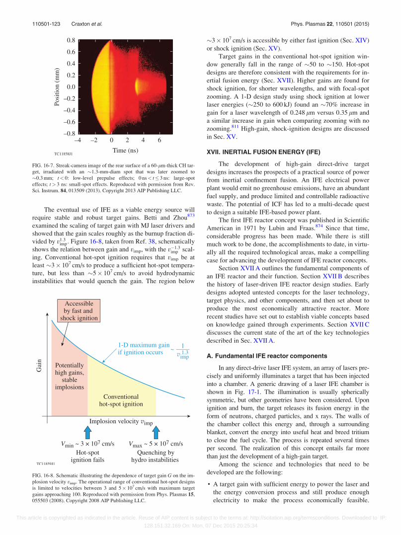
The eventual use of IFE as a viable energy source will
require stable and robust target gains. Betti and Zhou873
examined the scaling of target gain with MJ laser drivers and
showed that the gain scales roughly as the burnup fraction di-
vided by v1:3imp: Figure 16-8, taken from Ref. 38, schematically
shows the relation between gain and vimp, with the v�1:3imp scal-
ing. Conventional hot-spot ignition requires that vimp be at
least �3� 107 cm/s to produce a sufficient hot-spot tempera-
ture, but less than �5� 107 cm/s to avoid hydrodynamic
instabilities that would quench the gain. The region below
�3� 107 cm/s is accessible by either fast ignition (Sec. XIV)
or shock ignition (Sec. XV).
Target gains in the conventional hot-spot ignition win-
dow generally fall in the range of �50 to �150. Hot-spot
designs are therefore consistent with the requirements for in-
ertial fusion energy (Sec. XVII). Higher gains are found for
shock ignition, for shorter wavelengths, and with focal-spot
zooming. A 1-D design study using shock ignition at lower
laser energies (�250 to 600 kJ) found an �70% increase in
gain for a laser wavelength of 0.248 lm versus 0.35 lm and
a similar increase in gain when comparing zooming with no
zooming.811 High-gain, shock-ignition designs are discussed
in Sec. XV.
XVII. INERTIAL FUSION ENERGY (IFE)
The development of high-gain direct-drive target
designs increases the prospects of a practical source of power
from inertial confinement fusion. An IFE electrical power
plant would emit no greenhouse emissions, have an abundant
fuel supply, and produce limited and controllable radioactive
waste. The potential of ICF has led to a multi-decade quest
to design a suitable IFE-based power plant.
The first IFE reactor concept was published in Scientific
American in 1971 by Lubin and Fraas.874 Since that time,
considerable progress has been made. While there is still
much work to be done, the accomplishments to date, in virtu-
ally all the required technological areas, make a compelling
case for advancing the development of IFE reactor concepts.
Section XVII A outlines the fundamental components of
an IFE reactor and their function. Section XVII B describes
the history of laser-driven IFE reactor design studies. Early
designs adopted untested concepts for the laser technology,
target physics, and other components, and then set about to
produce the most economically attractive reactor. More
recent studies have set out to establish viable concepts based
on knowledge gained through experiments. Section XVII C
discusses the current state of the art of the key technologies
described in Sec. XVII A.
A. Fundamental IFE reactor components
In any direct-drive laser IFE system, an array of lasers pre-
cisely and uniformly illuminates a target that has been injected
into a chamber. A generic drawing of a laser IFE chamber is
shown in Fig. 17-1. The illumination is usually spherically
symmetric, but other geometries have been considered. Upon
ignition and burn, the target releases its fusion energy in the
form of neutrons, charged particles, and x rays. The walls of
the chamber collect this energy and, through a surrounding
blanket, convert the energy into useful heat and breed tritium
to close the fuel cycle. The process is repeated several times
per second. The realization of this concept entails far more
than just the development of a high-gain target.
Among the science and technologies that need to be
developed are the following:
• A target gain with sufficient energy to power the laser and
the energy conversion process and still produce enough
electricity to make the process economically feasible.
FIG. 16-7. Streak-camera image of the rear surface of a 60-lm-thick CH tar-
get, irradiated with an �1.3-mm-diam spot that was later zoomed to
�0.3 mm; t< 0: low-level prepulse effects; 0 ns< t 3 ns: large-spot
effects; t> 3 ns: small-spot effects. Reproduced with permission from Rev.
Sci. Instrum. 84, 013509 (2013). Copyright 2013 AIP Publishing LLC.
FIG. 16-8. Schematic illustrating the dependence of target gain G on the im-
plosion velocity vimp. The operational range of conventional hot-spot designs
is limited to velocities between 3 and 5� 107 cm/s with maximum target
gains approaching 100. Reproduced with permission from Phys. Plasmas 15,
055503 (2008). Copyright 2008 AIP Publishing LLC.
110501-123 Craxton et al. Phys. Plasmas 22, 110501 (2015)
This article is copyrighted as indicated in the article. Reuse of AIP content is subject to the terms at: http://scitation.aip.org/termsconditions. Downloaded to IP:
128.151.32.169 On: Mon, 07 Dec 2015 20:25:34
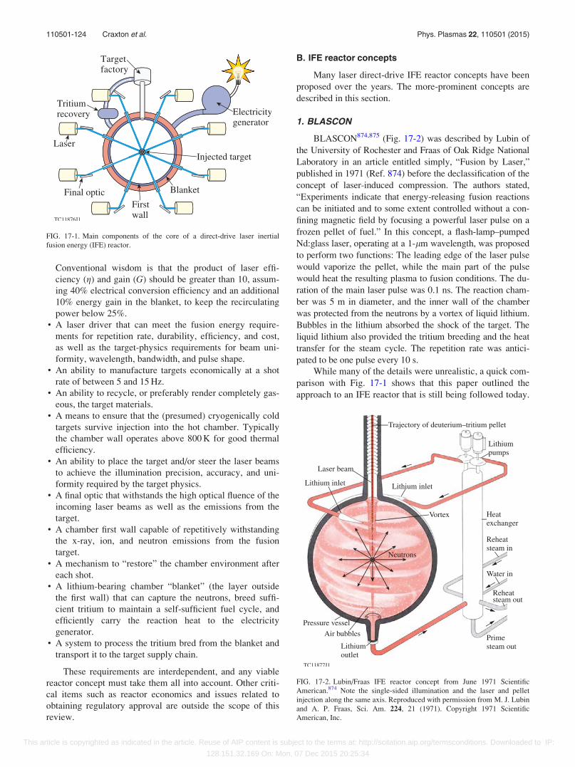
Conventional wisdom is that the product of laser effi-
ciency (g) and gain (G) should be greater than 10, assum-
ing 40% electrical conversion efficiency and an additional
10% energy gain in the blanket, to keep the recirculating
power below 25%.• A laser driver that can meet the fusion energy require-
ments for repetition rate, durability, efficiency, and cost,
as well as the target-physics requirements for beam uni-
formity, wavelength, bandwidth, and pulse shape.• An ability to manufacture targets economically at a shot
rate of between 5 and 15 Hz.• An ability to recycle, or preferably render completely gas-
eous, the target materials.• A means to ensure that the (presumed) cryogenically cold
targets survive injection into the hot chamber. Typically
the chamber wall operates above 800 K for good thermal
efficiency.• An ability to place the target and/or steer the laser beams
to achieve the illumination precision, accuracy, and uni-
formity required by the target physics.• A final optic that withstands the high optical fluence of the
incoming laser beams as well as the emissions from the
target.• A chamber first wall capable of repetitively withstanding
the x-ray, ion, and neutron emissions from the fusion
target.• A mechanism to “restore” the chamber environment after
each shot.• A lithium-bearing chamber “blanket” (the layer outside
the first wall) that can capture the neutrons, breed suffi-
cient tritium to maintain a self-sufficient fuel cycle, and
efficiently carry the reaction heat to the electricity
generator.• A system to process the tritium bred from the blanket and
transport it to the target supply chain.
These requirements are interdependent, and any viable
reactor concept must take them all into account. Other criti-
cal items such as reactor economics and issues related to
obtaining regulatory approval are outside the scope of this
review.
B. IFE reactor concepts
Many laser direct-drive IFE reactor concepts have been
proposed over the years. The more-prominent concepts are
described in this section.
1. BLASCON
BLASCON874,875 (Fig. 17-2) was described by Lubin of
the University of Rochester and Fraas of Oak Ridge National
Laboratory in an article entitled simply, “Fusion by Laser,”
published in 1971 (Ref. 874) before the declassification of the
concept of laser-induced compression. The authors stated,
“Experiments indicate that energy-releasing fusion reactions
can be initiated and to some extent controlled without a con-
fining magnetic field by focusing a powerful laser pulse on a
frozen pellet of fuel.” In this concept, a flash-lamp–pumped
Nd:glass laser, operating at a 1-lm wavelength, was proposed
to perform two functions: The leading edge of the laser pulse
would vaporize the pellet, while the main part of the pulse
would heat the resulting plasma to fusion conditions. The du-
ration of the main laser pulse was 0.1 ns. The reaction cham-
ber was 5 m in diameter, and the inner wall of the chamber
was protected from the neutrons by a vortex of liquid lithium.
Bubbles in the lithium absorbed the shock of the target. The
liquid lithium also provided the tritium breeding and the heat
transfer for the steam cycle. The repetition rate was antici-
pated to be one pulse every 10 s.
While many of the details were unrealistic, a quick com-
parison with Fig. 17-1 shows that this paper outlined the
approach to an IFE reactor that is still being followed today.
FIG. 17-1. Main components of the core of a direct-drive laser inertial
fusion energy (IFE) reactor.
FIG. 17-2. Lubin/Fraas IFE reactor concept from June 1971 Scientific
American.874 Note the single-sided illumination and the laser and pellet
injection along the same axis. Reproduced with permission from M. J. Lubin
and A. P. Fraas, Sci. Am. 224, 21 (1971). Copyright 1971 Scientific
American, Inc.
110501-124 Craxton et al. Phys. Plasmas 22, 110501 (2015)
This article is copyrighted as indicated in the article. Reuse of AIP content is subject to the terms at: http://scitation.aip.org/termsconditions. Downloaded to IP:
128.151.32.169 On: Mon, 07 Dec 2015 20:25:34
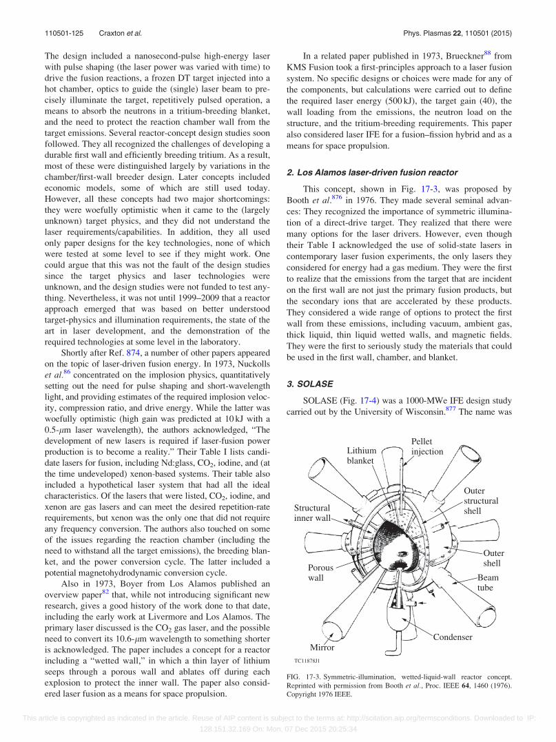
The design included a nanosecond-pulse high-energy laser
with pulse shaping (the laser power was varied with time) to
drive the fusion reactions, a frozen DT target injected into a
hot chamber, optics to guide the (single) laser beam to pre-
cisely illuminate the target, repetitively pulsed operation, a
means to absorb the neutrons in a tritium-breeding blanket,
and the need to protect the reaction chamber wall from the
target emissions. Several reactor-concept design studies soon
followed. They all recognized the challenges of developing a
durable first wall and efficiently breeding tritium. As a result,
most of these were distinguished largely by variations in the
chamber/first-wall breeder design. Later concepts included
economic models, some of which are still used today.
However, all these concepts had two major shortcomings:
they were woefully optimistic when it came to the (largely
unknown) target physics, and they did not understand the
laser requirements/capabilities. In addition, they all used
only paper designs for the key technologies, none of which
were tested at some level to see if they might work. One
could argue that this was not the fault of the design studies
since the target physics and laser technologies were
unknown, and the design studies were not funded to test any-
thing. Nevertheless, it was not until 1999–2009 that a reactor
approach emerged that was based on better understood
target-physics and illumination requirements, the state of the
art in laser development, and the demonstration of the
required technologies at some level in the laboratory.
Shortly after Ref. 874, a number of other papers appeared
on the topic of laser-driven fusion energy. In 1973, Nuckolls
et al.86 concentrated on the implosion physics, quantitatively
setting out the need for pulse shaping and short-wavelength
light, and providing estimates of the required implosion veloc-
ity, compression ratio, and drive energy. While the latter was
woefully optimistic (high gain was predicted at 10 kJ with a
0.5-lm laser wavelength), the authors acknowledged, “The
development of new lasers is required if laser-fusion power
production is to become a reality.” Their Table I lists candi-
date lasers for fusion, including Nd:glass, CO2, iodine, and (at
the time undeveloped) xenon-based systems. Their table also
included a hypothetical laser system that had all the ideal
characteristics. Of the lasers that were listed, CO2, iodine, and
xenon are gas lasers and can meet the desired repetition-rate
requirements, but xenon was the only one that did not require
any frequency conversion. The authors also touched on some
of the issues regarding the reaction chamber (including the
need to withstand all the target emissions), the breeding blan-
ket, and the power conversion cycle. The latter included a
potential magnetohydrodynamic conversion cycle.
Also in 1973, Boyer from Los Alamos published an
overview paper82 that, while not introducing significant new
research, gives a good history of the work done to that date,
including the early work at Livermore and Los Alamos. The
primary laser discussed is the CO2 gas laser, and the possible
need to convert its 10.6-lm wavelength to something shorter
is acknowledged. The paper includes a concept for a reactor
including a “wetted wall,” in which a thin layer of lithium
seeps through a porous wall and ablates off during each
explosion to protect the inner wall. The paper also consid-
ered laser fusion as a means for space propulsion.
In a related paper published in 1973, Brueckner88 from
KMS Fusion took a first-principles approach to a laser fusion
system. No specific designs or choices were made for any of
the components, but calculations were carried out to define
the required laser energy (500 kJ), the target gain (40), the
wall loading from the emissions, the neutron load on the
structure, and the tritium-breeding requirements. This paper
also considered laser IFE for a fusion–fission hybrid and as a
means for space propulsion.
2. Los Alamos laser-driven fusion reactor
This concept, shown in Fig. 17-3, was proposed by
Booth et al.876 in 1976. They made several seminal advan-
ces: They recognized the importance of symmetric illumina-
tion of a direct-drive target. They realized that there were
many options for the laser drivers. However, even though
their Table I acknowledged the use of solid-state lasers in
contemporary laser fusion experiments, the only lasers they
considered for energy had a gas medium. They were the first
to realize that the emissions from the target that are incident
on the first wall are not just the primary fusion products, but
the secondary ions that are accelerated by these products.
They considered a wide range of options to protect the first
wall from these emissions, including vacuum, ambient gas,
thick liquid, thin liquid wetted walls, and magnetic fields.
They were the first to seriously study the materials that could
be used in the first wall, chamber, and blanket.
3. SOLASE
SOLASE (Fig. 17-4) was a 1000-MWe IFE design study
carried out by the University of Wisconsin.877 The name was
FIG. 17-3. Symmetric-illumination, wetted-liquid-wall reactor concept.
Reprinted with permission from Booth et al., Proc. IEEE 64, 1460 (1976).
Copyright 1976 IEEE.
110501-125 Craxton et al. Phys. Plasmas 22, 110501 (2015)
This article is copyrighted as indicated in the article. Reuse of AIP content is subject to the terms at: http://scitation.aip.org/termsconditions. Downloaded to IP:
128.151.32.169 On: Mon, 07 Dec 2015 20:25:34
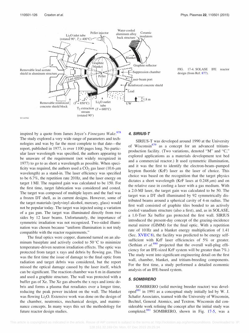
inspired by a quote from James Joyce’s Finnegans Wake.878
The study explored a very wide range of parameters and tech-
nologies and was by far the most complete to that date—the
report, published in 1977, is over 1100 pages long. No partic-
ular laser wavelength was specified, the authors appearing to
be unaware of the requirement (not widely recognized in
1977) to go to as short a wavelength as possible. When speci-
ficity was required, the authors used a CO2 gas laser (10.6-lm
wavelength) as a stand-in. The laser efficiency was specified
to be 6.7%, the repetition rate 20 Hz, and the laser energy on
target 1 MJ. The required gain was calculated to be 150. For
the first time, target fabrication was considered and costed.
The target was composed of multiple layers and the fuel was
a frozen DT shell, as in current designs. However, some of
the target materials (polyvinyl alcohol, mercury, glass) would
not be popular today. The target was injected using a variation
of a gas gun. The target was illuminated directly from two
sides by 12 laser beams. Unfortunately, the importance of
symmetric irradiation was not recognized. Two-sided illumi-
nation was chosen because “uniform illumination is not truly
compatible with the reactor requirements.”
The final optics were copper, diamond turned on an alu-
minum baseplate and actively cooled to 50 �C to minimize
temperature-driven neutron irradiation effects. The optic was
protected from target x rays and debris by flowing gas. This
was the first time the issue of damage to the final optic from
radiation and target debris was considered, but the report
missed the optical damage caused by the laser itself, which
can be significant. The reaction chamber was 6 m in diameter
and used a graphite structure. The wall was protected with a
buffer gas of Xe. The Xe gas absorbs the x rays and ionic de-
bris and forms a plasma that reradiates over a longer time,
reducing the peak power incident on the wall. The blanket
was flowing Li2O. Extensive work was done on the design of
the chamber, neutronics, mechanical design, and mainte-
nance concepts. In many ways this set the methodology for
future reactor design studies.
4. SIRIUS-T
SIRIUS-T was developed around 1990 at the University
of Wisconsin879 as a concept for an advanced tritium-
production facility. (Two variations, denoted “M” and “C,”
explored applications as a materials development test bed
and a commercial reactor.) It used symmetric illumination,
and it was the first to identify the electron-beam–pumped
krypton fluoride (KrF) laser as the laser of choice. This
choice was based on the recognition that the target physics
dictates a short wavelength (KrF lases at 0.248 lm) and on
the relative ease in cooling a laser with a gas medium. With
a 2.0-MJ laser, the target gain was calculated to be 50. The
target was a DT shell illuminated by 92 symmetrically dis-
tributed beams around a spherical cavity of 4-m radius. The
first wall consisted of graphite tiles bonded to an actively
cooled vanadium structure (also a first), and, as in SOLASE,
a 1.0-Torr Xe buffer gas protected the first wall. SIRIUS
introduced the present-day concept of the grazing-incidence
metal mirror (GIMM) for the final optic. With a repetition
rate of 10 Hz and a blanket energy multiplication of 1.41
(Sec. XVII C 8), the facility was predicted to be energy self-
sufficient with KrF laser efficiencies of 5% or greater.
(Sethian et al.880 projected that the overall wall-plug effi-
ciency for an IFE-sized KrF system will be greater than 7%.)
The study went into significant engineering detail on the first
wall, chamber, blanket, and tritium-breeding components.
For the first time, a study performed a detailed economic
analysis of an IFE-based system.
5. SOMBRERO
SOMBRERO (solid moving breeder reactor) was devel-
oped881 in 1991 as a conceptual study initially led by W. J.
Schafer Associates, teamed with the University of Wisconsin,
Bechtel, General Atomics, and Textron. Wisconsin did con-
siderable work refining the concept after the initial study was
completed.881 SOMBRERO, shown in Fig. 17-5, was a
FIG. 17-4. SOLASE IFE reactor
design (from Ref. 877).
110501-126 Craxton et al. Phys. Plasmas 22, 110501 (2015)
This article is copyrighted as indicated in the article. Reuse of AIP content is subject to the terms at: http://scitation.aip.org/termsconditions. Downloaded to IP:
128.151.32.169 On: Mon, 07 Dec 2015 20:25:34
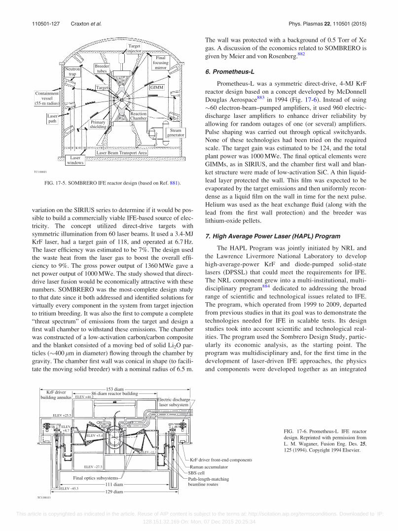
variation on the SIRIUS series to determine if it would be pos-
sible to build a commercially viable IFE-based source of elec-
tricity. The concept utilized direct-drive targets with
symmetric illumination from 60 laser beams. It used a 3.4-MJ
KrF laser, had a target gain of 118, and operated at 6.7 Hz.
The laser efficiency was estimated to be 7%. The design used
the waste heat from the laser gas to boost the overall effi-
ciency to 9%. The gross power output of 1360 MWe gave a
net power output of 1000 MWe. The study showed that direct-
drive laser fusion would be economically attractive with these
numbers. SOMBRERO was the most-complete design study
to that date since it both addressed and identified solutions for
virtually every component in the system from target injection
to tritium breeding. It was also the first to compute a complete
“threat spectrum” of emissions from the target and design a
first wall chamber to withstand these emissions. The chamber
was constructed of a low-activation carbon/carbon composite
and the blanket consisted of a moving bed of solid Li2O par-
ticles (�400 lm in diameter) flowing through the chamber by
gravity. The chamber first wall was conical in shape (to facili-
tate the moving solid breeder) with a nominal radius of 6.5 m.
The wall was protected with a background of 0.5 Torr of Xe
gas. A discussion of the economics related to SOMBRERO is
given by Meier and von Rosenberg.882
6. Prometheus-L
Prometheus-L was a symmetric direct-drive, 4-MJ KrF
reactor design based on a concept developed by McDonnell
Douglas Aerospace883 in 1994 (Fig. 17-6). Instead of using
�60 electron-beam–pumped amplifiers, it used 960 electric-
discharge laser amplifiers to enhance driver reliability by
allowing for random outages of one (or several) amplifiers.
Pulse shaping was carried out through optical switchyards.
None of these technologies had been tried on the required
scale. The target gain was estimated to be 124, and the total
plant power was 1000 MWe. The final optical elements were
GIMMs, as in SIRIUS, and the chamber first wall and blan-
ket structure were made of low-activation SiC. A thin liquid-
lead layer protected the wall. This film was expected to be
evaporated by the target emissions and then uniformly recon-
dense as a liquid film on the wall in time for the next pulse.
Helium was used as the heat exchange fluid (along with the
lead from the first wall protection) and the breeder was
lithium-oxide pellets.
7. High Average Power Laser (HAPL) Program
The HAPL Program was jointly initiated by NRL and
the Lawrence Livermore National Laboratory to develop
high-average-power KrF and diode-pumped solid-state
lasers (DPSSL) that could meet the requirements for IFE.
The NRL component grew into a multi-institutional, multi-
disciplinary program884 dedicated to addressing the broad
range of scientific and technological issues related to IFE.
The program, which operated from 1999 to 2009, departed
from previous studies in that its goal was to demonstrate the
technologies needed for IFE in scalable tests. Its design
studies took into account scientific and technological real-
ities. The program used the Sombrero Design Study, partic-
ularly its economic analysis, as the starting point. The
program was multidisciplinary and, for the first time in the
development of laser-driven IFE approaches, the physics
and components were developed together as an integrated
FIG. 17-5. SOMBRERO IFE reactor design (based on Ref. 881).
FIG. 17-6. Prometheus-L IFE reactor
design. Reprinted with permission from
L. M. Waganer, Fusion Eng. Des. 25,
125 (1994). Copyright 1994 Elsevier.
110501-127 Craxton et al. Phys. Plasmas 22, 110501 (2015)
This article is copyrighted as indicated in the article. Reuse of AIP content is subject to the terms at: http://scitation.aip.org/termsconditions. Downloaded to IP:
128.151.32.169 On: Mon, 07 Dec 2015 20:25:34
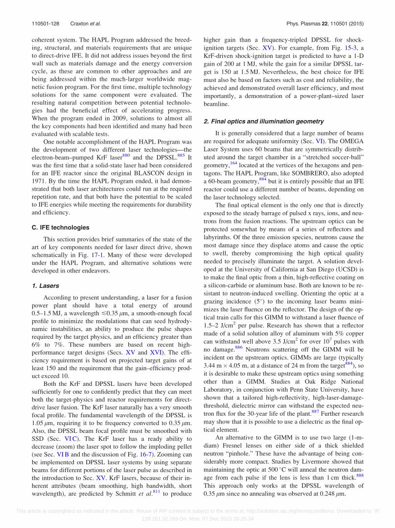
coherent system. The HAPL Program addressed the breed-
ing, structural, and materials requirements that are unique
to direct-drive IFE. It did not address issues beyond the first
wall such as materials damage and the energy conversion
cycle, as these are common to other approaches and are
being addressed within the much-larger worldwide mag-
netic fusion program. For the first time, multiple technology
solutions for the same component were evaluated. The
resulting natural competition between potential technolo-
gies had the beneficial effect of accelerating progress.
When the program ended in 2009, solutions to almost all
the key components had been identified and many had been
evaluated with scalable tests.
One notable accomplishment of the HAPL Program was
the development of two different laser technologies—the
electron-beam–pumped KrF laser880 and the DPSSL.885 It
was the first time that a solid-state laser had been considered
for an IFE reactor since the original BLASCON design in
1971. By the time the HAPL Program ended, it had demon-
strated that both laser architectures could run at the required
repetition rate, and that both have the potential to be scaled
to IFE energies while meeting the requirements for durability
and efficiency.
C. IFE technologies
This section provides brief summaries of the state of the
art of key components needed for laser direct drive, shown
schematically in Fig. 17-1. Many of these were developed
under the HAPL Program, and alternative solutions were
developed in other endeavors.
1. Lasers
According to present understanding, a laser for a fusion
power plant should have a total energy of around
0.5–1.5 MJ, a wavelength �0.35 lm, a smooth-enough focal
profile to minimize the modulations that can seed hydrody-
namic instabilities, an ability to produce the pulse shapes
required by the target physics, and an efficiency greater than
6% to 7%. These numbers are based on recent high-
performance target designs (Secs. XV and XVI). The effi-
ciency requirement is based on projected target gains of at
least 150 and the requirement that the gain–efficiency prod-
uct exceed 10.
Both the KrF and DPSSL lasers have been developed
sufficiently for one to confidently predict that they can meet
both the target-physics and reactor requirements for direct-
drive laser fusion. The KrF laser naturally has a very smooth
focal profile. The fundamental wavelength of the DPSSL is
1.05 lm, requiring it to be frequency converted to 0.35 lm.
Also, the DPSSL beam focal profile must be smoothed with
SSD (Sec. VI C). The KrF laser has a ready ability to
decrease (zoom) the laser spot to follow the imploding pellet
(see Sec. VI B and the discussion of Fig. 16-7). Zooming can
be implemented on DPSSL laser systems by using separate
beams for different portions of the laser pulse as described in
the introduction to Sec. XV. KrF lasers, because of their in-
herent attributes (beam smoothing, high bandwidth, short
wavelength), are predicted by Schmitt et al.811 to produce
higher gain than a frequency-tripled DPSSL for shock-
ignition targets (Sec. XV). For example, from Fig. 15-3, a
KrF-driven shock-ignition target is predicted to have a 1-D
gain of 200 at 1 MJ, while the gain for a similar DPSSL tar-
get is 150 at 1.5 MJ. Nevertheless, the best choice for IFE
must also be based on factors such as cost and reliability, the
achieved and demonstrated overall laser efficiency, and most
importantly, a demonstration of a power-plant–sized laser
beamline.
2. Final optics and illumination geometry
It is generally considered that a large number of beams
are required for adequate uniformity (Sec. VI). The OMEGA
Laser System uses 60 beams that are symmetrically distrib-
uted around the target chamber in a “stretched soccer-ball”
geometry,164 located at the vertices of the hexagons and pen-
tagons. The HAPL Program, like SOMBRERO, also adopted
a 60-beam geometry,884 but it is entirely possible that an IFE
reactor could use a different number of beams, depending on
the laser technology selected.
The final optical element is the only one that is directly
exposed to the steady barrage of pulsed x rays, ions, and neu-
trons from the fusion reactions. The upstream optics can be
protected somewhat by means of a series of reflectors and
labyrinths. Of the three emission species, neutrons cause the
most damage since they displace atoms and cause the optic
to swell, thereby compromising the high optical quality
needed to precisely illuminate the target. A solution devel-
oped at the University of California at San Diego (UCSD) is
to make the final optic from a thin, high-reflective coating on
a silicon-carbide or aluminum base. Both are known to be re-
sistant to neutron-induced swelling. Orienting the optic at a
grazing incidence (5�) to the incoming laser beams mini-
mizes the laser fluence on the reflector. The design of the op-
tical train calls for this GIMM to withstand a laser fluence of
1.5–2 J/cm2 per pulse. Research has shown that a reflector
made of a solid solution alloy of aluminum with 5% copper
can withstand well above 3.5 J/cm2 for over 107 pulses with
no damage.886 Neutrons scattering off the GIMM will be
incident on the upstream optics. GIMMs are large (typically
3.44 m� 4.05 m, at a distance of 24 m from the target884), so
it is desirable to make these upstream optics using something
other than a GIMM. Studies at Oak Ridge National
Laboratory, in conjunction with Penn State University, have
shown that a tailored high-reflectivity, high-laser-damage-
threshold, dielectric mirror can withstand the expected neu-
tron flux for the 30-year life of the plant.887 Further research
may show that it is possible to use a dielectric as the final op-
tical element.
An alternative to the GIMM is to use two large (1-m-
diam) Fresnel lenses on either side of a thick shielded
neutron “pinhole.” These have the advantage of being con-
siderably more compact. Studies by Livermore showed that
maintaining the optic at 500 �C will anneal the neutron dam-
age from each pulse if the lens is less than 1 cm thick.888
This approach only works at the DPSSL wavelength of
0.35 lm since no annealing was observed at 0.248 lm.
110501-128 Craxton et al. Phys. Plasmas 22, 110501 (2015)
This article is copyrighted as indicated in the article. Reuse of AIP content is subject to the terms at: http://scitation.aip.org/termsconditions. Downloaded to IP:
128.151.32.169 On: Mon, 07 Dec 2015 20:25:34
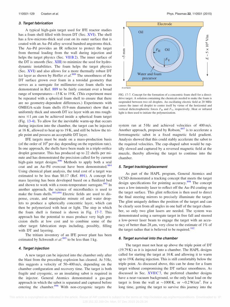
3. Target fabrication
A typical high-gain target used for IFE reactor studies
has a foam shell filled with frozen DT (Sec. XVI). The shell
has a few-microns-thick seal coat on its outer surface that is
coated with an Au–Pd alloy several hundred angstroms thick.
The Au–Pd provides an IR reflector to protect the target
from thermal loading from the wall during injection and
helps the target physics (Sec. VII B 2). The inner surface of
the DT is smooth (Sec. XIII) to minimize the seed for hydro-
dynamic instabilities. The foam helps the target physics
(Sec. XVI) and also allows for a more thermally robust DT
ice layer as shown by Hoffer et al.889 The smoothness of the
DT surface grown over foam in a toroidal geometry that
serves as a surrogate for millimeter-size foam shells was
demonstrated in Ref. 889 to be fairly constant over a broad
range of temperatures—15 K to 19 K. (This experiment must
be repeated with a spherical foam shell to ensure that there
are no geometry-dependent differences.) Experiments with
OMEGA-scale foam shells (0.9-mm diameter) show that a
uniformly thick and smooth DT ice layer with an rms rough-
ness �1 lm can be achieved inside a spherical foam target
(Fig. 13-4). To allow for the inevitable warm-up that occurs
during injection into the chamber, the target can be injected
at 16 K, allowed to heat up to 19 K, and still be below the tri-
ple point and possess an acceptable DT layer.
IFE targets must be made on a mass-production basis
(of the order of 106 per day depending on the repetition rate).
In one approach, the shells have been made in a triple-orifice
droplet generator. This has produced up to 22 shells per mi-
nute and has demonstrated the precision called for by current
high-gain target designs.890 Methods to apply both a seal
coat and an Au–Pd overcoat have been demonstrated.884
Using chemical plant analysis, the total cost of a target was
estimated to be less than $0.17 (Ref. 891). A concept for
mass layering has been developed based on a fluidized bed
and shown to work with a room-temperature surrogate.892 In
another approach, the science of microfluidics is used to
make the foam shells.893,894 Electric fields are used to dis-
pense, create, and manipulate minute oil and water drop-
lets to produce a spherically concentric layer, which can
then be polymerized with heat or light. The step in which
the foam shell is formed is shown in Fig. 17-7. This
approach has the potential to mass produce very high pre-
cision shells at low cost and to combine some of the
other target fabrication steps including, possibly, filling
with DT and layering.
The tritium inventory of an IFE power plant has been
estimated by Schwendt et al.895 to be less than 1 kg.
4. Target injection
A new target can be injected into the chamber only after
the blast from the preceding explosion has cleared. At 5 Hz,
this suggests a velocity of 50–400 m/s, depending on the
chamber configuration and recovery time. The target is both
fragile and cryogenic, so an insulating sabot is required in
the injector. General Atomics demonstrated a gas-gun
approach in which the sabot is separated and captured before
entering the chamber.896 With non-cryogenic targets the
system ran at 5 Hz and achieved velocities of 400 m/s.
Another approach, proposed by Robson,897 is to accelerate a
ferromagnetic sabot in a fixed magnetic field gradient.
Analysis showed that this could stably accelerate the sabot to
the required velocities. The cup-shaped sabot would be rap-
idly slowed and captured by a reversed magnetic field at the
muzzle, thereby allowing the target to continue into the
chamber.
5. Target tracking/placement
As part of the HAPL program, General Atomics and
UCSD demonstrated a tracking concept that meets the target
design specifications for pointing accuracy.898 The concept
uses a low-intensity laser to reflect off the Au–Pd coating on
the target surface. This glint reflection is then used to direct
the final steering mirrors to precisely illuminate the target.
The glint uniquely defines the position of the target and can
be clearly seen from all angles in one half of the target cham-
ber, so only two glint lasers are needed. The system was
demonstrated using a surrogate target in free fall and steered
a low-power laser beam to engage the target with an accu-
racy of better than 28 lm, very close to the estimate of 1% of
the target radius that is believed to be required.162
6. Target survival into the chamber
The target must not heat up above the triple point of DT
(19.79 K) as it is injected into a chamber. The HAPL designs
called for starting the target at 16 K and allowing it to warm
up to 19 K during injection. This is still comfortably below the
triple point. As discussed above, this can be done for a foam
target without compromising the DT surface smoothness. As
discussed in Sec. XVII C 7, the preferred chamber designs
have a near-vacuum background, so the only heat load on the
target is from the wall at �1000 K, or �0.2 W/cm2. For a
long time, getting the target to survive this journey into the
FIG. 17-7. Concept for the formation of a concentric foam shell for a direct-
drive target. A solution containing the chemicals needed to make the foam is
suspended between two oil droplets. An oscillating electric field at 20 MHz
causes the inner oil droplet to center itself by virtue of the horizontal and
vertical dielectrophoretic forces FH and FV, respectively. Heat or infrared
light is then used to initiate the polymerization.
110501-129 Craxton et al. Phys. Plasmas 22, 110501 (2015)
This article is copyrighted as indicated in the article. Reuse of AIP content is subject to the terms at: http://scitation.aip.org/termsconditions. Downloaded to IP:
128.151.32.169 On: Mon, 07 Dec 2015 20:25:34
chamber was considered quite daunting. However, simula-
tions from UCSD899 and experiments at Los Alamos900 sug-
gest that this is indeed feasible. These experiments used
cylindrical geometry as a surrogate for a spherical target and
applied a sudden heat flux (60% of the prototypical value) to a
DT ice layer. The initial target temperature was 19 K and the
target contained no foam (so was not as robust to temperature
swings). The layer did not degrade for over 20 ms, the time
that the target is expected to take to traverse the 5.5-m-radius
chamber. During this time, the target is expected to warm up
by 3 K. It is therefore expected that an IFE target in which the
DT is wicked into a foam shell and capable of starting at tem-
peratures as low as 16 K should survive injection into the
chamber.
7. First wall
The reaction chamber is one of the most challenging
aspects in developing any practical fusion power plant. It has
six primary functions: (1) ensure that the target survives
injection and/or placement (i.e., does not deform or melt);
(2) allow the driver energy to be coupled to the target with
the required precision; (3) repeatedly withstand the pulsed
emissions of x rays, ions, and neutrons from the fusion reac-
tions; (4) recover conditions to allow the next target to be
shot; (5) provide a means to convert heat to electrical power;
and (6) provide a means to breed and recover tritium.
A typical chamber design has a first wall that directly
sees the target emissions, an encasing lithium-bearing blan-
ket, and a structure to hold everything together. The chamber
and target design depend on each other since each target
design produces a distinct “threat spectrum” (energy parti-
tioning among the reaction products) that must be withstood
by the chamber’s first wall. In a direct-drive IFE power plant,
about 75% of the fusion energy is incident on the wall as
neutrons, about 23% as energetic ions, and the remaining 2%
as x rays.901 (See also Table I of Ref. 884.) The major chal-
lenge for short-term first wall survival is the heat loading
from x rays and ions, as these deposit their considerable
energy in a shallow depth (<5 lm) and in short periods of
time (<1 ls). Neutrons, while a long-term problem, deposit
their energy volumetrically throughout the wall and blanket
and therefore do not contribute to the instantaneous heat
load. The average neutron loading is similar to that of a mag-
netic fusion reactor, the main difference being that one is
pulsed and the other is continuous.
Five main chamber configurations have been considered
for direct-drive IFE (see Ref. 884 and references therein): (1)
solid wall—vacuum in chamber; (2) magnetic interven-
tion—vacuum in chamber; (3) solid wall—gas in chamber;
(4) replaceable solid wall—vacuum in chamber; and (5)
thick liquid walls (or thin liquid-protected walls). To date,
the first three configurations have had the most development.
The most appealing chamber configuration (option 1)
uses a solid wall and maintains the chamber in vacuum. This
ensures high-fidelity laser propagation, puts the least strain
on cryogenic target survival during injection, and is the easi-
est to restore to the same conditions before the next shot.
The major issues are the extreme cyclical heat loading on the
first wall and helium retention. The heat loading appears to
be solved by making the first wall from a 1-mm-thick tung-
sten armor layer bonded to a ferritic-steel substrate structure.
Experiments in subscale tests,899 backed with modeling,902
show that this morphology can survive the continual cyclical
heat load.
Helium retention occurs when the high-energy (several-
MeV) helium ions produced by the target are driven 2–5 lm
deep into the surface. Because the helium migration distance
is 50–100 nm, comparable to the grain dimensions, the he-
lium coalesces into bubbles at the grain boundaries. The
resulting buildup in helium pressure exfoliates the surface.
Experiments at Oak Ridge and the University of North
Carolina showed that the problem is somewhat mitigated
because the natural IFE cycle of pulsed implantation fol-
lowed by a high-temperature pulse can enhance the helium
diffusion.903 Another solution conceived by UCSD and
tested on a small-scale electrostatic trap at the University of
Wisconsin was to make the first wall of a fibrous tungsten
material whose diameter is smaller than the migration dis-
tance. Then, no matter where the helium is stopped, it is
always less than a migration length from a free surface.
Experiments showed that the expected mass loss from an
IFE-sized chamber would be only the equivalent of a 1-lm
layer of solid material over the equivalent of 450 days of
operation.904
8. Blanket
Both Pb-17Li (83% lead, 17% lithium) and FLIBE (fluo-
rine–lithium–beryllium) blankets have been evaluated specifi-
cally for laser-direct-drive IFE tritium breeding and power
conversion. Tritium is produced when the neutrons react with
lithium in one of two ways. One reaction is exothermic (i.e.,
boosts the fusion energy): 6Liþ n¼TþHe4þ 4.78 MeV.
The other is endothermic and results in a neutron n0 (of lower
energy) along with the triton: 7Liþ n¼TþHe4þ n0
– 2.47 MeV. Since the natural abundances are 7.42% 6Li,
92.58% 7Li, it might appear that the blanket will consume net
energy. However, because the cross sections are dramatically
different, there is a net energy release. The cross section for
the 6Li reaction increases with decreasing energy and is large
even at thermal energies, while the 7Li reaction is suppressed
below 2.5 MeV. Therefore, all the lower-energy daughter neu-
trons produced by the 7Li reaction will eventually take part in
subsequent 6Li reactions (Ref. 905 and references therein).
This means that the blanket can convert each 14-MeV neutron
into more than one triton, as well as increase the energy out-
put. Neutrons can be multiplied, to increase the tritium pro-
duction or boost the blanket energy, by adding Be or Pb to the
blanket and making use of the reaction nþ 9Beþ 3 MeV¼ 2
He4þ n0 þ n00, or nþPbþ 10 MeV¼ Pbþ n0 þ n00. Here n0
and n00 denote lower-energy neutrons.
Breeder systems are designed using simulation codes
that have been benchmarked with experiments with a neu-
tron emitter in the center of a lithium sphere.906 The goal is
to minimize the 14.1-MeV neutrons that are lost in the blan-
ket support structure, through optical ports, etc. In principle,
all that is needed is an average tritium-breeding ratio (TBR)
110501-130 Craxton et al. Phys. Plasmas 22, 110501 (2015)
This article is copyrighted as indicated in the article. Reuse of AIP content is subject to the terms at: http://scitation.aip.org/termsconditions. Downloaded to IP:
128.151.32.169 On: Mon, 07 Dec 2015 20:25:34
greater than 1, but more may be needed when fusion is first
introduced into the economy to provide a surplus of tritium
to fuel the startup of new reactors.907 In continuous opera-
tion, an average TBR of 1.05 should suffice. From the dis-
cussion above, a breeder can readily have a local TBR� 1.5
(Ref. 908) and, since the beam ports take up less than 2% of
the solid angle, there are generally no issues meeting this
requirement.909 A discussion of plasma, nuclear, material,
and technological conditions in which tritium self-
sufficiency can be obtained is given in Ref. 910. A complete
conceptual tritium recovery and purification system has been
designed for direct-drive IFE.911
In addition to the power conversion schemes from the
earlier studies, three new power conversion concepts have
recently been evaluated (Ref. 912 and references therein).
All are based on a three-compressor/two-intercooler Brayton
Cycle.912 One solid wall concept uses a more-conventional
reduced-activation F82H steel wall and tungsten armor. The
initial chamber temperature is 550 �C and the electrical con-
version efficiency is estimated to be 38%. A second solid-
wall concept uses a more-advanced ferritic steel wall and
tungsten armor. The chamber operates at 700 �C, and the
electrical conversion efficiency can be as high as 49%. For a
magnetic intervention chamber concept (in which magnetic
fields divert the ions away from the chamber first wall), the
first wall is a SiC/SiC composite, which runs at 1000 �C, and
the conversion efficiency is predicted to be 50%.
ACKNOWLEDGMENTS
The contributions of A. R. Bell, R. Epstein, D. H.
Froula, I. V. Igumenshchev, T. J. Kessler, R. H. Lehmberg,
C. K. Li, F. J. Marshall, P. M. Nilson, C. Ren, A. L.
Velikovich, S. C. Wilks, and M. D. Wittman in reviewing
portions of this manuscript and providing many valuable
suggestions are greatly appreciated. A useful discussion with
R. G. Evans is acknowledged. The authors appreciate the
considerable contributions of the referee in providing a very
thorough review and suggesting numerous improvements.
The authors are also very much aware of the efforts,
dedication, and ingenuity of many thousands of people over
many decades who have contributed to the growth of the
direct-drive ICF program.
This material is based upon work supported by the
Department of Energy National Nuclear Security
Administration under Award Number DE-NA0001944, the
University of Rochester, and the New York State Energy
Research and Development Authority. The support of the
DOE does not constitute an endorsement by the DOE of the
views expressed in this article.
1J. Nuckolls, L. Wood, A. Thiessen, and G. Zimmerman, “Laser compres-
sion of matter to super-high densities: Thermonuclear (CTR)
applications,” Nature 239, 139 (1972).2J. D. Lindl, “Development of the indirect-drive approach to inertial con-
finement fusion and the target physics basis for ignition and gain,” Phys.
Plasmas 2, 3933 (1995).3J. D. Lindl, Inertial Confinement Fusion: The Quest for Ignition andEnergy Gain Using Indirect Drive (Springer-Verlag, New York, 1998).
4D. R. Speck, E. S. Bliss, J. A. Glaze, J. W. Herris, F. W. Holloway, J. T.
Hunt, B. C. Johnson, D. J. Kuizenga, R. G. Ozarski, H. G. Patton, P. R.
Rupert, G. J. Suski, C. D. Swift, and C. E. Thompson, “The Shiva Laser-
Fusion Facility,” IEEE J. Quantum Electron. 17, 1599 (1981).5E. M. Campbell, J. T. Hunt, E. S. Bliss, D. R. Speck, and R. P. Drake,
“Nova experimental facility (invited),” Rev. Sci. Instrum. 57, 2101
(1986).6C. A. Haynam, P. J. Wegner, J. M. Auerbach, M. W. Bowers, S. N. Dixit,
G. V. Erbert, G. M. Heestand, M. A. Henesian, M. R. Hermann, K. S.
Jancaitis, K. R. Manes, C. D. Marshall, N. C. Mehta, J. Menapace, E.
Moses, J. R. Murray, M. C. Nostrand, C. D. Orth, R. Patterson, R. A.
Sacks, M. J. Shaw, M. Spaeth, S. B. Sutton, W. H. Williams, C. C.
Widmayer, R. K. White, S. T. Yang, and B. M. Van Wonterghem,
“National Ignition Facility laser performance status,” Appl. Opt. 46, 3276
(2007).7M. Lubin, E. Goldman, J. Soures, L. Goldman, W. Friedman, S. Letzring,
J. Albritton, P. Koch, and B. Yaakobi, “Single- and multi-beam laser pel-
let fusion experiments,” in Plasma Physics and Controlled NuclearFusion Research 1974 (IAEA, Vienna, 1975), Vol. II, pp. 459–477.
8J. M. Soures, T. C. Bristow, H. Deckman, J. Delettrez, A. Entenberg, W.
Friedman, J. Forsyth, Y. Gazit, G. Halpern, F. Kalk, S. Letzring, R.
McCrory, D. Peiffer, J. Rizzo, W. Seka, S. Skupsky, E. Thorsos, B.
Yaakobi, and T. Yamanaka, “A review of high density, laser driven, im-
plosion experiments at the Laboratory for Laser Energetics,” in LaserInteraction and Related Plasma Phenomena, edited by H. J. Schwarz, H.
Hora, M. J. Lubin, and B. Yaakobi (Plenum Press, New York, 1981), Vol.
5, pp. 463–481.9J. M. Soures, R. J. Hutchison, S. D. Jacobs, L. D. Lund, R. L. McCrory,
and M. C. Richardson, “OMEGA: A short-wavelength laser for fusion
experiments,” in Proceedings of the 10th IEEE/NPSS Symposium onFusion Engineering, SOFE’83 (IEEE, New York, 1983), pp. 1392–1397.
10T. R. Boehly, D. L. Brown, R. S. Craxton, R. L. Keck, J. P. Knauer, J. H.
Kelly, T. J. Kessler, S. A. Kumpan, S. J. Loucks, S. A. Letzring, F. J.
Marshall, R. L. McCrory, S. F. B. Morse, W. Seka, J. M. Soures, and C.
P. Verdon, “Initial performance results of the OMEGA laser system,”
Opt. Commun. 133, 495 (1997).11J. S. Ladish, “Helios, a 20 TW CO2 Laser Fusion Facility,” in Laser 79
Opto-Electronics: Proceedings of the Fourth Conference (IPC Science
and Technology Press, Ltd., Guildford, England, 1979), pp. 294–301.12C. Yamanaka, Y. Kato, Y. Izawa, K. Yoshida, T. Yamanaka, T. Sasaki,
M. Nakatsuka, T. Mochizuki, J. Kuroda, and S. Nakai, “Nd-doped phos-
phate glass laser systems for laser-fusion research,” IEEE J. Quantum
Electron. 17, 1639 (1981).13C. Yamanaka, S. Nakai, T. Yamanaka, Y. Izawa, K. Mima, K. Nishihara,
Y. Kato, T. Mochizuki, M. Yamanaka, M. Nakatsuka, and T. Yabe,
“Pellet implosion and interaction studies by GEKKO XII green laser,” in
Laser Interaction and Related Plasma Phenomena, edited by H. Hora and
G. H. Miley (Plenum Press, New York, 1986), Vol. 7, pp. 395–419.14I. Ross, M. White, J. Boon, D. Craddock, A. Damerell, R. Day, A. F.
Gibson, P. Gottfeldt, D. J. Nicholas, and C. Reason, “Vulcan—A versatile
high-power glass laser for multiuser experiments,” IEEE J. Quantum
Electron. 17, 1653 (1981).15M. Andre, J. C. Courteille, J. Y. Le Gall, and P. Rovati, “OCTAL: A new
neodymium glass laser built in the Centre d’Etudes de Limeil for laser
fusion experiments,” Proc. SPIE 164, 8–16 (1979).16N. G. Basov, O. N. Krokhin, G. V. Sklizkov, S. I. Fedotov, and A. S.
Shikanov, “A powerful laser setup and investigation of the efficiency of
high temperature heating of a plasma,” Sov. Phys.-JETP 35, 109 (1972).17N. Hopps, C. Danson, S. Duffield, D. Egan, S. Elsmere, M. Girling, E.
Harvey, D. Hillier, M. L. Norman, S. P. Parker, P. Treadwell, D. Winter,
and T. H. Bett, “Overview of laser systems for the Orion facility at the
AWE,” Appl. Opt. 52, 3597 (2013).18G. A. Kirillov, V. M. Murugov, V. T. Punin, and V. I. Shemyakin, “High
power laser system ISKRA V,” Laser Part. Beams 8, 827 (1990).19J. Ebrardt and J. M. Chaput, “LMJ project status,” J. Phys.: Conf. Ser.
112, 032005 (2008).20G. A. Kirillov, G. G. Kocheasov, A. V. Bessarab, S. G. Garanin, L. S.
Mkhitarian, V. M. Murugov, S. A. Sukharev, and N. V. Zhidkov, “Status
of laser fusion research at VNIIEF (Arzamas-16),” Laser Part. Beams 18,
219 (2000).21X. T. He, W. Y. Zhang, and the Chinese ICF team, “Advances in the
national inertial fusion program of China,” EPJ Web Conf. 59, 01009
(2013).22S. P. Obenschain, S. E. Bodner, D. Colombant, K. Gerber, R. H.
Lehmberg, E. A. McLean, A. N. Mostovych, M. S. Pronko, C. J. Pawley,
A. J. Schmitt, J. D. Sethian, V. Serlin, J. A. Stamper, C. A. Sullivan, J. P.
110501-131 Craxton et al. Phys. Plasmas 22, 110501 (2015)
This article is copyrighted as indicated in the article. Reuse of AIP content is subject to the terms at: http://scitation.aip.org/termsconditions. Downloaded to IP:
128.151.32.169 On: Mon, 07 Dec 2015 20:25:34
Dahlburg, J. H. Gardner, Y. Chan, A. V. Deniz, J. Hardgrove, T.
Lehecka, and M. Klapisch, “The Nike KrF Laser Facility: Performance
and initial target experiments,” Phys. Plasmas 3, 2098 (1996).23E. Fabre, F. Amiranoff, R. Fabbro, C. Garban-Labaune, J. Virmont, M.
Weinfeld, F. David, and R. Pellat, “Effect of laser wavelength on interac-
tion studies for inertial fusion,” in Plasma Physics and ControlledNuclear Fusion Research 1980 (IAEA, Vienna, 1981), Vol. 2, pp.
263–272.24G. Velarde and N. Carpintero-Santamar�ıa, Inertial Confinement Nuclear
Fusion: A Historical Approach by Its Pioneers (Foxwell & Davies (UK)
Ltd., London, 2007).25S. Atzeni and J. Meyer-ter-Vehn, The Physics of Inertial Fusion: Beam
Plasma Interaction, Hydrodynamics, Hot Dense Matter, International
Series of Monographs on Physics (Clarendon Press, Oxford, 2004).26La Fusion Thermonucl�eaire Inertielle par Laser (Part 1: L’Interaction
Laser-Matiere; Part 2: La Fusion par Confinement Inertiel; Part 3: Les
Techniques Exp �erimentales et Num�eriques), edited by R. Dautray and J.-
P. Watteau (Eyrolles, Paris, 1993).27J. J. Duderstadt and G. A. Moses, Inertial Confinement Fusion (Wiley,
New York, 1982).28W. L. Kruer, The Physics of Laser Plasma Interactions, Frontiers in
Physics Vol. 73, edited by D. Pines (Addison-Wesley, Redwood City,
CA, 1988).29C. Yamanaka, Introduction to Laser Fusion (Harwood Academic
Publishers, New York, 1991).30Nuclear Fusion by Inertial Confinement: A Comprehensive Treatise,
edited by G. Velarde, Y. Ronen, and J. M. Mart�ınez-Val (CRC Press,
Boca Raton, FL, 1993).31R. P. Drake, High-Energy-Density Physics: Fundamentals, Inertial
Fusion, and Experimental Astrophysics, Shock Wave and High PressurePhenomena (Springer, Berlin, 2006).
32S. Pfalzner, An Introduction to Inertial Confinement Fusion, Series in
Plasma Physics (Taylor & Francis, New York, 2006).33K. A. Brueckner and S. Jorna, “Laser-driven fusion,” Rev. Mod. Phys.
46, 325 (1974).34G. H. McCall, “Laser-driven implosion experiments,” Plasma Phys. 25,
237 (1983).35R. L. McCrory and J. M. Soures, “Inertially confined fusion,” in Laser-
Induced Plasmas and Applications, edited by L. J. Radziemski and D. A.
Cremers (Marcel Dekker, New York, 1989), pp. 207–268.36M. D. Rosen, “The physics issues that determine inertial confinement
fusion target gain and driver requirements: A tutorial,” Phys. Plasmas 6,
1690 (1999).37J. D. Lindl, P. Amendt, R. L. Berger, S. G. Glendinning, S. H. Glenzer, S.
W. Haan, R. L. Kauffman, O. L. Landen, and L. J. Suter, “The physics
basis for ignition using indirect-drive targets on the National Ignition
Facility,” Phys. Plasmas 11, 339 (2004).38R. L. McCrory, D. D. Meyerhofer, R. Betti, R. S. Craxton, J. A. Delettrez,
D. H. Edgell, V. Yu. Glebov, V. N. Goncharov, D. R. Harding, D. W.
Jacobs-Perkins, J. P. Knauer, F. J. Marshall, P. W. McKenty, P. B. Radha,
S. P. Regan, T. C. Sangster, W. Seka, R. W. Short, S. Skupsky, V. A.
Smalyuk, J. M. Soures, C. Stoeckl, B. Yaakobi, D. Shvarts, J. A. Frenje, C.
K. Li, R. D. Petrasso, and F. H. S�eguin, “Progress in direct-drive inertial
confinement fusion research,” Phys. Plasmas 15, 055503 (2008).39S. E. Bodner, “Critical elements of high gain laser fusion,” J. Fusion
Energy 1, 221 (1981).40J. D. Huba, “NRL Plasma Formulary,” Naval Research Laboratory,
Washington, DC, Report No. NRL/PU/6790–13-589 (2013).41H. Azechi, N. Miyanaga, R. O. Stapf, K. Itoga, H. Nakaishi, M.
Yamanaka, H. Shiraga, R. Tsuji, S. Ido, K. Nishihara, Y. Izawa, T.
Yamanaka, and C. Yamanaka, “Experimental determination of fuel
density-radius product of inertial confinement fusion targets using sec-
ondary nuclear fusion reactions,” Appl. Phys. Lett. 49, 555 (1986).42V. N. Goncharov, T. C. Sangster, T. R. Boehly, S. X. Hu, I. V.
Igumenshchev, F. J. Marshall, R. L. McCrory, D. D. Meyerhofer, P. B.
Radha, W. Seka, S. Skupsky, C. Stoeckl, D. T. Casey, J. A. Frenje, and R.
D. Petrasso, “Demonstration of the highest deuterium-tritium areal den-
sity using multiple-picket cryogenic designs on OMEGA,” Phys. Rev.
Lett. 104, 165001 (2010).43V. N. Goncharov, “Cryogenic deuterium and deuterium-tritium direct–
drive implosions on Omega,” in Laser-Plasma Interactions andApplications, Scottish Graduate Series, edited by P. McKenna, D. Neely,
R. Bingham, and D. A. Jaroszynski (Springer, Switzerland, 2013), Chap.
7, pp. 135–183.
44J. D. Lindl and W. C. Mead, “Two-dimensional simulation of fluid insta-
bility in laser-fusion pellets,” Phys. Rev. Lett. 34, 1273 (1975).45R. Betti, M. Umansky, V. Lobatchev, V. N. Goncharov, and R. L.
McCrory, “Hot-spot dynamics and deceleration-phase Rayleigh–Taylor
instability of imploding inertial confinement fusion capsules,” Phys.
Plasmas 8, 5257 (2001).46R. Betti, K. Anderson, V. N. Goncharov, R. L. McCrory, D. D.
Meyerhofer, S. Skupsky, and R. P. J. Town, “Deceleration phase of iner-
tial confinement fusion implosions,” Phys. Plasmas 9, 2277 (2002).47J. H. Gardner, S. E. Bodner, and J. P. Dahlburg, “Numerical simulation of
ablative Rayleigh–Taylor instability,” Phys. Fluids B 3, 1070 (1991).48S. E. Bodner, D. G. Colombant, J. H. Gardner, R. H. Lehmberg, S. P.
Obenschain, L. Phillips, A. J. Schmitt, J. D. Sethian, R. L. McCrory, W.
Seka, C. P. Verdon, J. P. Knauer, B. B. Afeyan, and H. T. Powell,
“Direct-drive laser fusion: Status and prospects,” Phys. Plasmas 5, 1901
(1998).49T. J. B. Collins, A. Poludnenko, A. Cunningham, and A. Frank, “Shock
propagation in deuterium-tritium-saturated foam,” Phys. Plasmas 12,
062705 (2005).50Ya. B. Zel’dovich and Yu. P. Ra K%zer, “Introduction to the gasdynamics
of shock waves,” in Physics of Shock Waves and High-TemperatureHydrodynamic Phenomena, edited by W. D. Hayes and R. F. Probstein
(Dover Publications, Mineola, NY, 2002), Vol. I, Chap. I, pp. 45–49.51V. N. Goncharov, J. P. Knauer, P. W. McKenty, P. B. Radha, T. C.
Sangster, S. Skupsky, R. Betti, R. L. McCrory, and D. D. Meyerhofer,
“Improved performance of direct-drive inertial confinement fusion target
designs with adiabat shaping using an intensity picket,” Phys. Plasmas
10, 1906 (2003).52K. Anderson and R. Betti, “Laser-induced adiabat shaping by relaxation
in inertial fusion implosions,” Phys. Plasmas 11, 5 (2004).53T. J. B. Collins, J. P. Knauer, R. Betti, T. R. Boehly, J. A. Delettrez, V.
N. Goncharov, D. D. Meyerhofer, P. W. McKenty, S. Skupsky, and R. P.
J. Town, “Reduction of the ablative Rayleigh–Taylor growth rate with
Gaussian picket pulses,” Phys. Plasmas 11, 1569 (2004).54J. P. Knauer, K. Anderson, R. Betti, T. J. B. Collins, V. N. Goncharov, P.
W. McKenty, D. D. Meyerhofer, P. B. Radha, S. P. Regan, T. C.
Sangster, V. A. Smalyuk, J. A. Frenje, C. K. Li, R. D. Petrasso, and F. H.
S�eguin, “Improved target stability using picket pulses to increase and
shape the ablator adiabat,” Phys. Plasmas 12, 056306 (2005).55M. Tabak, Lawrence Livermore National Laboratory, private communi-
cation (2005).56K. Anderson and R. Betti, “Theory of laser-induced adiabat shaping in in-
ertial fusion implosions: The decaying shock,” Phys. Plasmas 10, 4448
(2003).57R. Betti, K. Anderson, J. Knauer, T. J. B. Collins, R. L. McCrory, P. W.
McKenty, and S. Skupsky, “Theory of laser-induced adiabat shaping in
inertial fusion implosions: The relaxation method,” Phys. Plasmas 12,
042703 (2005).58R. Betti, P. Y. Chang, B. K. Spears, K. S. Anderson, J. Edwards, M.
Fatenejad, J. D. Lindl, R. L. McCrory, R. Nora, and D. Shvarts,
“Thermonuclear ignition in inertial confinement fusion and comparison
with magnetic confinement,” Phys. Plasmas 17, 058102 (2010).59C. D. Zhou and R. Betti, “Hydrodynamic relations for direct-drive fast-
ignition and conventional inertial confinement fusion implosions,” Phys.
Plasmas 14, 072703 (2007).60P. Franken, “Optical masers: Engineering phase beginning for lasers,”
Electronic Design (15 March 1962), pp. 24–26.61W. I. Linlor, “Plasmas produced by laser bursts,” Bull. Am. Phys. Soc. 7,
440 (1962).62J. M. Dawson, “On the production of plasma by giant pulse lasers,” Phys.
Fluids 7, 981 (1964).63J. Dawson, P. Kaw, and B. Green, “Optical absorption and expansion of
laser-produced plasmas,” Phys. Fluids 12, 875 (1969).64N. G. Basov and O. N. Krokhin, “The conditions of plasma heating by the
optical generator radiation,” in Quantum Electronics: Proceedings of theThird International Congress, edited by P. Grivet and N. Bloembergen
(Dunod �Editeur, Paris, 1964), Vol. 1, pp. 1373–1377.65N. G. Basov and O. N. Krokhin, “Conditions for heating up of a plasma
by the radiation from an optical generator,” Sov. Phys.-JETP 19, 123
(1964).66N. G. Basov, S. D. Zakharov, P. G. Kryukov, Yu. V. Senatskii, and S. V.
Chekalin, “Experiments of neutron observation by focusing power laser
emission on the surface of lithium deuteride,” JETP Lett. 8, 14 (1968).
110501-132 Craxton et al. Phys. Plasmas 22, 110501 (2015)
This article is copyrighted as indicated in the article. Reuse of AIP content is subject to the terms at: http://scitation.aip.org/termsconditions. Downloaded to IP:
128.151.32.169 On: Mon, 07 Dec 2015 20:25:34
67N. G. Basov, P. G. Kriukov, S. D. Zakharov, Yu. V. Senatsky, and S. V.
Tchekalin, “O-11–Experiments on the observation of neutron emission at
a focus of high-power laser radiation on a lithium deuteride surface,”
IEEE J. Quantum Electron. 4, 864 (1968).68G. W. Gobeli, J. C. Bushnell, P. S. Peercy, and E. D. Jones, “Observation
of neutrons produced by laser irradiation of lithium deuteride,” Phys.
Rev. 188, 300 (1969).69F. Floux, D. Cognard, L. G. Denoeud, G. Piar, D. Parisot, J. L. Bobin, F.
Delobeau, and C. Fauquignon, “Nuclear fusion reactions in solid-
deuterium laser-produced plasma,” Phys. Rev. A 1, 821 (1970).70N. G. Basov, V. A. Boiko, S. M. Zakharov, O. N. Krokhin, and G. V.
Sklizkov, “Generation of neutrons in a laser CD2 plasma heated by pulses
of nanosecond duration,” JETP Lett. 13, 489 (1971).71S. W. Mead, R. E. Kidder, J. E. Swain, F. Rainer, and J. Petruzzi,
“Preliminary measurements of x-ray and neutron emission from laser-
produced plasmas,” Appl. Opt. 11, 345 (1972).72K. B€uchl, K. Eidmann, P. Mulser, H. Salzmann, and R. Sigel, “Plasma
production with a Nd laser and non-thermal effects,” in Laser Interactionand Related Plasma Phenomena, edited by H. J. Schwarz and H. Hora
(Plenum Press, New York, 1972), Vol. 2, pp. 503–514.73F. Floux, J. F. Benard, D. Cognard, and A. Saleres, “Nuclear DD reac-
tions in solid deuterium laser created plasma,” in Laser Interaction andRelated Plasma Phenomena, edited by H. J. Schwarz and H. Hora
(Plenum Press, New York, 1972), Vol. 2, pp. 409–431.74J. W. Shearer and W. S. Barnes, “Mechanisms for production of neutron-
emitting plasma by subnanosecond laser-pulse heating,” Phys. Rev. Lett.
24, 92 (1970); 24, 432(E) (1970).75N. G. Basov, Yu. S. Ivanov, O. N. Krokhin, Yu. A. Mikhailov, G. V.
Sklizkov, and S. I. Fedotov, “Neutron generation in spherical irradiation
of a target by high-power laser radiation,” JETP Lett. 15, 417 (1972).76G. H. McCall, F. Young, A. W. Ehler, J. F. Kephart, and R. P. Godwin,
“Neutron emission from laser-produced plasmas,” Phys. Rev. Lett. 30,
1116 (1973).77C. Yamanaka, T. Yamanaka, T. Sasaki, K. Yoshida, M. Waki, and H. B.
Kang, “Anomalous heating of a plasma by a laser,” Phys. Rev. A 6, 2335
(1972).78N. G. Basov, V. A. Boiko, S. M. Zakharov, O. N. Krokhin, Yu. A.
Mikhailov, G. V. Sklizkov, and S. I. Fedotov, “Mechanisms of neutron
generation in a laser plasma,” JETP Lett. 18, 184 (1973).79J. Soures, L. M. Goldman, and M. Lubin, “Short-pulse-laser-heated
plasma experiments,” Nucl. Fusion 13, 829 (1973).80N. G. Basov, E. G. Gamaly, O. N. Krokhin, Yu. A. Mikhailov, G. V.
Sklizkov, and S. I. Fedotov, “Investigation of plasma parameters at the
spherical heating of the isolated solid target by high-power laser radi-
ation,” in Laser Interaction and Related Plasma Phenomena, edited by
H. J. Schwarz and H. Hora (Plenum Press, New York, 1974), Vol. 3B,
pp. 553–590.81S. E. Bodner, G. F. Chapline, and J. DeGroot, “Anomalous ion heating in
a laser heated plasma,” Plasma Phys. 15, 21 (1973).82K. Boyer, “Laser-initiated fusion—Key experiments looming,”
Astronaut. Aeronaut. 11, 28 (1973).83J. W. Daiber, A. Hertzberg, and C. E. Wittliff, “Laser-generated
implosions,” Phys. Fluids 9, 617 (1966).84R. E. Kidder, “Application of lasers to the production of high-
temperature and high-pressure plasma,” Nucl. Fusion 8, 3 (1968).85S. W. Mead, “Plasma production with a multibeam laser system,” Phys.
Fluids 13, 1510 (1970).86J. Nuckolls, J. Emmett, and L. Wood, “Laser-induced thermonuclear
fusion,” Phys. Today 26(8), 46 (1973).87M. N. Rosenbluth and R. Z. Sagdeev, “Laser fusion and parametric insta-
bilities,” Comments Plasma Phys. Controlled Fusion 1, 129 (1972).88K. A. Brueckner, “Laser driven fusion,” IEEE Trans. Plasma Sci. 1, 13
(1973).89R. R. Johnson, “Observation of D–T neutron production from laser driven
implosions,” Bull. Am. Phys. Soc. 19, 886 (1974).90G. Charatis, J. Downward, R. Goforth, B. Guscott, T. Henderson, S.
Hildum, R. Johnson, K. Moncur, T. A. Leonard, F. Mayer, S. Segall, L.
Siebert, D. Solomon, and C. Thomas, “Experimental study of laser driven
compression of spherical glass shells,” in Plasma Physics and ControlledNuclear Fusion Research 1974 (IAEA, Vienna, 1974), Vol. II, pp.
317–335.91C. E. Thomas, “Laser fusion target illumination system,” Appl. Opt. 14,
1267 (1975).
92P. M. Campbell, G. Charatis, and G. R. Montry, “Laser-driven compres-
sion of glass microspheres,” Phys. Rev. Lett. 34, 74 (1975).93V. W. Slivinsky, H. G. Ahlstrom, K. G. Tirsell, J. Larsen, S. Glaros, G.
Zimmerman, and H. Shay, “Measurement of the ion temperature in laser-
driven fusion,” Phys. Rev. Lett. 35, 1083 (1975).94N. M. Ceglio and L. W. Coleman, “Spatially resolved a emission from
laser fusion targets,” Phys. Rev. Lett. 39, 20 (1977).95R. A. Lerche, L. W. Coleman, J. W. Houghton, D. R. Speck, and E. K.
Storm, “Laser fusion ion temperatures determined by neutron time-of-
flight techniques,” Appl. Phys. Lett. 31, 645 (1977).96W. I. Linlor, “Ion energies produced by laser giant pulse,” Appl. Phys.
Lett. 3, 210 (1963).97P. Langer, G. Tonon, F. Floux, and A. Ducauze, “7A11–Laser induced
emission of electrons, ions, and x rays from solid targets,” IEEE J.
Quantum Electron. 2, 499 (1966).98J. W. Shearer, S. W. Mead, J. Petruzzi, F. Rainer, J. E. Swain, and C. E.
Violet, “Experimental indications of plasma instabilities induced by laser
heating,” Phys. Rev. A 6, 764 (1972).99J. N. Olsen, G. W. Kuswa, and E. D. Jones, “Ion-expansion energy spec-
tra correlated to laser plasma parameters,” J. Appl. Phys. 44, 2275 (1973).100A. W. Ehler, “High-energy ions from a CO2 laser-produced plasma,”
J. Appl. Phys. 46, 2464 (1975).101B. H. Ripin, P. G. Burkhalter, F. C. Young, J. M. McMahon, D. G.
Colombant, S. E. Bodner, R. R. Whitlock, D. J. Nagel, D. J. Johnson, N.
K. Winsor, C. M. Dozier, R. D. Bleach, J. A. Stamper, and E. A. McLean,
“X-ray emission spectra from high-power-laser-produced plasmas,” Phys.
Rev. Lett. 34, 1313 (1975).102N. K. Winsor and D. A. Tidman, “Laser target model,” Phys. Rev. Lett.
31, 1044 (1973).103R. E. Kidder and J. W. Zink, “Decoupling of corona and core of laser-
heated pellets,” Nucl. Fusion 12, 325 (1972).104J. S. Clarke, H. N. Fisher, and R. J. Mason, “Laser-driven implosion of
spherical DT targets to thermonuclear burn conditions,” Phys. Rev. Lett.
30, 89 (1973); 30, 249(E) (1973).105R. J. Mason, “The calculated performance of structured laser fusion pel-
lets,” Nucl. Fusion 15, 1031 (1975).106W. C. Mead, R. A. Haas, W. L. Kruer, D. W. Phillion, H. N. Kornblum, J.
D. Lindl, D. R. MacQuigg, and V. C. Rupert, “Observation and simulation
of effects on parylene disks irradiated at high intensities with a 1.06-lm
laser,” Phys. Rev. Lett. 37, 489 (1976).107V. W. Slivinsky, H. N. Kornblum, and H. D. Shay, “Determination of
suprathermal electron distributions in laser-produced plasmas,” J. Appl.
Phys. 46, 1973 (1975).108J. F. Kephart, R. P. Godwin, and G. H. McCall, “Bremsstrahlung emis-
sion from laser–produced plasmas,” Appl. Phys. Lett. 25, 108 (1974).109K. A. Brueckner, “Energy deposition in laser-heated plasmas,” Phys.
Rev. Lett. 36, 677 (1976).110K. A. Brueckner, “Fast-electron production in laser-heated plasma,”
Nucl. Fusion 17, 1257 (1977).111E. L. Lindman, “Absorption and transport in laser plasmas,” J. Phys. 38,
C6–9 (1977).112D. W. Forslund, J. M. Kindel, K. Lee, E. L. Lindman, and R. L. Morse,
“Theory and simulation of resonant absorption in a hot plasma,” Phys.
Rev. A 11, 679 (1975).113D. W. Forslund, J. M. Kindel, and K. Lee, “Theory of hot-electron spectra
at high laser intensity,” Phys. Rev. Lett. 39, 284 (1977).114K. Estabrook and W. L. Kruer, “Properties of resonantly heated electron
distributions,” Phys. Rev. Lett. 40, 42 (1978).115H. Hora, “Nonlinear confining and deconfining forces associated with the
interaction of laser radiation with plasma,” Phys. Fluids 12, 182 (1969).116K. G. Estabrook, E. J. Valeo, and W. L. Kruer, “Two-dimensional relativ-
istic simulations of resonance absorption,” Phys. Fluids 18, 1151 (1975).117N. M. Ceglio and J. T. Larsen, “Spatially resolved suprathermal x-ray
emission from laser-fusion targets,” Phys. Rev. Lett. 44, 579 (1980).118See National Technical Information Service Document No. UCRL79788
(E. K. Storm, J. T. Larsen, J. H. Nuckolls, H. G. Ahlstrom, and K. R.
Manes, “Simple scaling model for exploding pusher targets,” Lawrence
Livermore National Laboratory, Livermore, CA, UCRL-79788, 1977).
Copies may be obtained from the National Technical Information
Service, Springfield, VA 22161.119See National Technical Information Service Document No. LA7218MS
(D. V. Giovanielli and C. W. Cranfill, “Simple model for exploding
pusher targets,” Los Alamos National Laboratory, Los Alamos, NM, LA-
110501-133 Craxton et al. Phys. Plasmas 22, 110501 (2015)
This article is copyrighted as indicated in the article. Reuse of AIP content is subject to the terms at: http://scitation.aip.org/termsconditions. Downloaded to IP:
128.151.32.169 On: Mon, 07 Dec 2015 20:25:34
7218-MS, 1978). Copies may be obtained from the National Technical
Information Service, Springfield, VA 22161.120M. D. Rosen and J. H. Nuckolls, “Exploding pusher performance—A the-
oretical model,” Phys. Fluids 22, 1393 (1979).121B. Ahlborn and M. H. Key, “Scaling laws for laser driven exploding
pusher targets,” Plasma Phys. 23, 435 (1981).122N. G. Denisov, “On a singularity of the field of an electromagnetic wave
propagated in an inhomogeneous plasma,” Sov. Phys.-JETP 4, 544
(1957).123V. L. Ginzburg, Propagation of Electromagnetic Waves in Plasmas,
edited by W. L. Sadowski and D. M. Gallik (Gordon and Breach, New
York, 1961), Sec. 20, pp. 377–403.124J. P. Freidberg, R. W. Mitchell, R. L. Morse, and L. I. Rudsinski,
“Resonant absorption of laser light by plasma targets,” Phys. Rev. Lett.
28, 795 (1972).125K. R. Manes, V. C. Rupert, J. M. Auerbach, P. Lee, and J. E. Swain,
“Polarization and angular dependence of 1.06-lm laser-light absorption
by planar plasmas,” Phys. Rev. Lett. 39, 281 (1977).126See National Technical Information Service Document No.
UCRL5002177V2 [J. J. Thomson, W. L. Kruer, A. B. Langdon, C. E.
Max, and W. C. Mead, “Laser light absorption on a steepened, rippled
critical-density surface,” Laser Program Annual Report 1977, Lawrence
Livermore National Laboratory, Livermore, CA, UCRL-50021-77
(1978), Vol. 2, pp. 4-40–4-43]. Copies may be obtained from the
National Technical Information Service, Springfield, VA 22161.127R. P. Godwin, R. Sachsenmaier, and R. Sigel, “Angle-dependent reflec-
tance of laser-produced plasmas,” Phys. Rev. Lett. 39, 1198 (1977).128A. G. M. Maaswinkel, K. Eidmann, and R. Sigel, “Comparative reflec-
tance measurements on laser-produced plasmas at 1.06 and 0.53 lm,”
Phys. Rev. Lett. 42, 1625 (1979).129S. Jackel, B. Perry, and M. Lubin, “Dynamics of laser-produced plasmas
through time-resolved observations of the 2x0 and 3/2x0 harmonic light
emission,” Phys. Rev. Lett. 37, 95 (1976).130M. Decroisette, B. Meyer, and G. Piar, “Observation de l’harmonique 2
dans un plasma cr�e�e par laser,” J. Phys. Colloq. 32, C5b-119 (1971).131A. Saleres, M. Decroisette, and C. Patou, “Plasma density scale length
determination in a deuterium, laser generated plasma,” Opt. Commun. 13,
321 (1975).132D. T. Attwood, D. W. Sweeney, J. M. Auerbach, and P. H. Y. Lee,
“Interferometric confirmation of radiation-pressure effects in laser-
plasma interactions,” Phys. Rev. Lett. 40, 184 (1978).133R. Fedosejevs, I. V. Tomov, N. H. Burnett, G. D. Enright, and M. C.
Richardson, “Self-steepening of the density profile of a CO2-laser-pro-
duced plasma,” Phys. Rev. Lett. 39, 932 (1977).134W. Brown, “Reevaluation of interferometric plasma density profiles
incorporating refractive effects,” in 1993 Summer Research Program for
High School Juniors at the University of Rochester’s Laboratory for
Laser Energetics, Rochester, NY (1993).135D. T. Attwood, “Diagnostics for the laser fusion program—Plasma
physics on the scale of microns and picoseconds,” IEEE J. Quantum
Electron. 14, 909 (1978).136D. T. Attwood, L. W. Coleman, M. J. Boyle, J. T. Larsen, D. W. Phillion,
and K. R. Manes, “Space-time implosion characteristics of laser-
irradiated fusion targets,” Phys. Rev. Lett. 38, 282 (1977).137D. Billon, P. A. Holstein, J. Launspach, C. Patou, J. M. Reisse, and D.
Schirmann, “Laser driven implosion experiments at Limeil,” in LaserInteraction and Related Plasma Phenomena, edited by H. J. Schwarz and
H. Hora (Plenum Press, New York, 1977), Vol. 4A, pp. 503–534.138M. H. Key, C. L. S. Lewis, J. G. Lunney, A. Moore, T. A. Hall, and R. G.
Evans, “Pulsed-x-ray shadowgraphy of dense, cool, laser-imploded
plasma,” Phys. Rev. Lett. 41, 1467 (1978).139M. H. Key, P. T. Rumsby, R. G. Evans, C. L. S. Lewis, J. M. Ward, and
R. L. Cooke, “Study of ablatively imploded spherical shells,” Phys. Rev.
Lett. 45, 1801 (1980).140H. G. Ahlstrom, “Laser fusion experiments, facilities, and diagnostics at
Lawrence Livermore National Laboratory,” Appl. Opt. 20, 1902 (1981).141W. Seka, S. D. Jacobs, J. E. Rizzo, R. Boni, and R. S. Craxton,
“Demonstration of high efficiency third harmonic conversion of high
power Nd-glass laser radiation,” Opt. Commun. 34, 469 (1980).142R. S. Craxton, “Theory of high efficiency third harmonic generation of
high power Nd-glass laser radiation,” Opt. Commun. 34, 474 (1980).143J. M. Soures, R. L. McCrory, C. P. Verdon, A. Babushkin, R. E. Bahr, T.
R. Boehly, R. Boni, D. K. Bradley, D. L. Brown, R. S. Craxton, J. A.
Delettrez, W. R. Donaldson, R. Epstein, P. A. Jaanimagi, S. D. Jacobs, K.
Kearney, R. L. Keck, J. H. Kelly, T. J. Kessler, R. L. Kremens, J. P.
Knauer, S. A. Kumpan, S. A. Letzring, D. J. Lonobile, S. J. Loucks, L. D.
Lund, F. J. Marshall, P. W. McKenty, D. D. Meyerhofer, S. F. B. Morse,
A. Okishev, S. Papernov, G. Pien, W. Seka, R. Short, M. J. Shoup III, M.
Skeldon, S. Skupsky, A. W. Schmid, D. J. Smith, S. Swales, M. Wittman,
and B. Yaakobi, “Direct-drive laser-fusion experiments with the
OMEGA, 60-beam, >40-kJ, ultraviolet laser system,” Phys. Plasmas 3,
2108 (1996).144W. Seka, R. S. Craxton, J. Delettrez, L. Goldman, R. Keck, R. L.
McCrory, D. Shvarts, J. M. Soures, and R. Boni, “Measurements and
interpretation of the absorption of 0.35 lm laser radiation on planar
targets,” Opt. Commun. 40, 437 (1982).145S. R. Gunn and V. C. Rupert, “Calorimeters for measurement of ions,
x-rays, and scattered radiation in laser-fusion experiments,” Rev. Sci.
Instrum. 48, 1375 (1977).146C. Garban-Labaune, E. Fabre, C. E. Max, R. Fabbro, F. Amiranoff, J.
Virmont, M. Weinfeld, and A. Michard, “Effect of laser wavelength and
pulse duration on laser-light absorption and back reflection,” Phys. Rev.
Lett. 48, 1018 (1982).147C. Garban-Labaune, E. Fabre, C. Max, F. Amiranoff, R. Fabbro, J.
Virmont, and W. C. Mead, “Experimental results and theoretical analysis
of the effect of wavelength on absorption and hot-electron generation in
laser-plasma interaction,” Phys. Fluids 28, 2580 (1985).148W. C. Mead, E. M. Campbell, K. G. Estabrook, R. E. Turner, W. L.
Kruer, P. H. Y. Lee, B. Pruett, V. C. Rupert, K. G. Tirsell, G. L.
Stradling, F. Ze, C. E. Max, and M. D. Rosen, “Laser-plasma interactions
at 0.53 lm for disk targets of varying Z,” Phys. Rev. Lett. 47, 1289
(1981).149D. C. Slater, G. E. Busch, G. Charatis, R. R. Johnson, F. J. Mayer, R. J.
Schroeder, J. D. Simpson, D. Sullivan, J. A. Tarvin, and C. E. Thomas,
“Absorption and hot-electron production for 1.05 and 0.53 lm light on
spherical targets,” Phys. Rev. Lett. 46, 1199 (1981).150M. C. Richardson, R. S. Craxton, J. Delettrez, R. L. Keck, R. L.
McCrory, W. Seka, and J. M. Soures, “Absorption physics at 351 nm in
spherical geometry,” Phys. Rev. Lett. 54, 1656 (1985).151R. S. Craxton and R. L. McCrory, “Calculations of the wavelength de-
pendence of absorption,” Laboratory for Laser Energetics, University of
Rochester, Rochester, NY, LLE Report No. 108, 1980.152W. C. Mead, E. M. Campbell, K. G. Estabrook, R. E. Turner, W. L.
Kruer, P. H. Y. Lee, B. Pruett, V. C. Rupert, K. G. Tirsell, G. L.
Stradling, F. Ze, C. E. Max, M. D. Rosen, and B. F. Lasinski, “Laser irra-
diation of disk targets at 0.53 lm wavelength,” Phys. Fluids 26, 2316
(1983).153R. P. Drake, R. L. Kauffman, B. F. Lasinski, M. D. Cable, L. J. Suter, and
F. Ze, “The angular dependence of the absorption of 0.35 lm laser light
by high-Z, laser-produced plasmas,” Phys. Fluids B 3, 3477 (1991).154W. Seka, unpublished results (2006).155W. Seka, D. H. Edgell, J. P. Knauer, J. F. Myatt, A. V. Maximov, R. W.
Short, T. C. Sangster, C. Stoeckl, R. E. Bahr, R. S. Craxton, J. A.
Delettrez, V. N. Goncharov, I. V. Igumenshchev, and D. Shvarts, “Time-
resolved absorption in cryogenic and room-temperature direct-drive
implosions,” Phys. Plasmas 15, 056312 (2008).156T. Dewandre, J. R. Albritton, and E. A. Williams, “Doppler shift of laser
light reflected from expanding plasmas,” Phys. Fluids 24, 528 (1981).157V. N. Goncharov, O. V. Gotchev, E. Vianello, T. R. Boehly, J. P. Knauer,
P. W. McKenty, P. B. Radha, S. P. Regan, T. C. Sangster, S. Skupsky, V.
A. Smalyuk, R. Betti, R. L. McCrory, D. D. Meyerhofer, and C. Cherfils-
Cl�erouin, “Early stage of implosion in inertial confinement fusion: Shock
timing and perturbation evolution,” Phys. Plasmas 13, 012702 (2006).158I. V. Igumenshchev, D. H. Edgell, V. N. Goncharov, J. A. Delettrez, A.
V. Maximov, J. F. Myatt, W. Seka, A. Shvydky, S. Skupsky, and C.
Stoeckl, “Crossed-beam energy transfer in implosion experiments on
OMEGA,” Phys. Plasmas 17, 122708 (2010).159S. Skupsky and K. Lee, “Uniformity of energy deposition of laser driven
fusion,” J. Appl. Phys. 54, 3662 (1983).160L. Iwan, ed., “Illumination-uniformity considerations for direct-drive
fusion reactors,” LLE Review Quarterly Report 19, 120 (1984),
Laboratory for Laser Energetics, University of Rochester, Rochester, NY,
LLE Document No. DOE/DP/40124-43.161A. J. Schmitt, “Absolutely uniform illumination of laser fusion pellets,”
Appl. Phys. Lett. 44, 399 (1984).162A. J. Schmitt and J. H. Gardner, “Illumination uniformity of laser-fusion
pellets using induced spatial incoherence,” J. Appl. Phys. 60, 6 (1986).
110501-134 Craxton et al. Phys. Plasmas 22, 110501 (2015)
This article is copyrighted as indicated in the article. Reuse of AIP content is subject to the terms at: http://scitation.aip.org/termsconditions. Downloaded to IP:
128.151.32.169 On: Mon, 07 Dec 2015 20:25:34
163J. E. Howard, “Uniform illumination of spherical laser fusion targets,”
Appl. Opt. 16, 2764 (1977).164See National Technical Information Service Document No. DE92008915
[R. S. Craxton, ed., OMEGA Upgrade Preliminary Design, Laboratory
for Laser Energetics, University of Rochester, Rochester, NY, LLE
Document No. DOE/DP 40200-101 (1989)]. Copies may be obtained
from the National Technical Information Service, Springfield, VA 22161.165J. F. Holzrichter and D. R. Speck, “Laser focusing limitations from non-
linear beam instabilities,” J. Appl. Phys. 47, 2459 (1976).166S. Skupsky and T. Kessler, “A source of hot spots in frequency-tripled
laser light,” Opt. Commun. 70, 123 (1989).167Y. Kato and K. Mima, “Random phase shifting of laser beam for absorp-
tion profile smoothing and instability suppression in laser produced
plasmas,” Appl. Phys. B 29, 186 (1982).168Y. Kato, K. Mima, N. Miyanaga, S. Arinaga, Y. Kitagawa, M.
Nakatsuka, and C. Yamanaka, “Random phasing of high-power lasers for
uniform target acceleration and plasma-instability suppression,” Phys.
Rev. Lett. 53, 1057 (1984).169See National Technical Information Service Document No. DE88008065
[Laboratory for Laser Energetics, “OMEGA phase conversion with dis-
tributed phase plates,” Laboratory for Laser Energetics Review Quarterly
Report (University of Rochester, Rochester, NY, 1987), Vol. 33, p. 1,
LLE Document No. DOE/DP/40200-65]. Copies may be obtained from
the National Technical Information Service, Springfield, VA 22161.170T. J. Kessler, Y. Lin, J. J. Armstrong, and B. Velazquez, “Phase conver-
sion of lasers with low-loss distributed phase plates,” Proc. SPIE 1870,
95–104 (1993).171S. N. Dixit, I. M. Thomas, B. W. Woods, A. J. Morgan, M. A. Henesian,
P. J. Wegner, and H. T. Powell, “Random phase plates for beam smooth-
ing on the Nova laser,” Appl. Opt. 32, 2543 (1993).172S. N. Dixit, J. K. Lawson, K. R. Manes, H. T. Powell, and K. A. Nugent,
“Kinoform phase plates for focal plane irradiance profile control,” Opt.
Lett. 19, 417 (1994).173J. A. Menapace, S. N. Dixit, F. Y. Genin, and W. F. Brocious,
“Magnetorheological finishing for imprinting continuous-phase plate
structures onto optical surfaces,” Proc. SPIE 5273, 220–230 (2003).174X. Deng, X. Liang, Z. Chen, W. Yu, and R. Ma, “Uniform illumination of
large targets using a lens array,” Appl. Opt. 25, 377 (1986).175R. H. Lehmberg and S. P. Obenschain, “Use of induced spatial incoher-
ence for uniform illumination of laser fusion targets,” Opt. Commun. 46,
27 (1983).176R. H. Lehmberg, A. J. Schmitt, and S. E. Bodner, “Theory of induced spa-
tial incoherence,” J. Appl. Phys. 62, 2680 (1987).177S. P. Obenschain, J. Grun, M. J. Herbst, K. J. Kearney, C. K. Manka, E.
A. McLean, A. N. Mostovych, J. A. Stamper, R. R. Whitlock, S. E.
Bodner, J. H. Gardner, and R. H. Lehmberg, “Laser-target interaction
with induced spatial incoherence,” Phys. Rev. Lett. 56, 2807 (1986).178A. N. Mostovych, S. P. Obenschain, J. H. Gardner, J. Grun, K. J.
Kearney, C. K. Manka, E. A. McLean, and C. J. Pawley, “Brillouin-scat-
tering measurements from plasma irradiated with spatially and temporally
incoherent laser light,” Phys. Rev. Lett. 59, 1193 (1987).179T. A. Peyser, C. K. Manka, S. P. Obenschain, and K. J. Kearney, “Reduction
of 3x0/2 emission from laser-produced plasmas with broad bandwidth,
induced spatial incoherence at 0.53 lm,” Phys. Fluids B 3, 1479 (1991).180R. H. Lehmberg and J. Goldhar, “Use of incoherence to produce smooth
and controllable irradiation profiles with KrF fusion lasers,” Fusion
Technol. 11, 532 (1987).181H. Nakano, T. Kanabe, K. Yagi, K. Tsubakimoto, M. Nakatsuka, and S.
Nakai, “Amplification and propagation of partially coherent amplified
spontaneous emission from Nd:glass,” Opt. Commun. 78, 123 (1990).182H. Nakano, K. Tsubakimoto, N. Miyanaga, M. Nakatsuka, T. Kanabe, H.
Azechi, T. Jitsuno, and S. Nakai, “Spectrally dispersed amplified sponta-
neous emission for improving irradiation uniformity into high power
Nd:glass laser system,” J. Appl. Phys. 73, 2122 (1993).183H. Nakano, N. Miyanaga, K. Yagi, K. Tsubakimoto, T. Kanabe, M.
Nakatsuka, and S. Nakai, “Partially coherent light generated by using sin-
gle and multimode optical fibers in a high-power Nd:glass laser system,”
Appl. Phys. Lett. 63, 580 (1993).184D. V�eron, H. Ayral, C. Gouedard, D. Husson, J. Lauriou, O. Martin, B.
Meyer, M. Rostaing, and C. Sauteret, “Optical spatial smoothing of Nd-
glass laser beam,” Opt. Commun. 65, 42 (1988).185D. V�eron, G. Thiell, and C. Gouedard, “Optical smoothing of the high
power PHEBUS Nd-glass laser using the multimode optical fiber
technique,” Opt. Commun. 97, 259 (1993).
186S. Skupsky, R. W. Short, T. Kessler, R. S. Craxton, S. Letzring, and J. M.
Soures, “Improved laser-beam uniformity using the angular dispersion of
frequency-modulated light,” J. Appl. Phys. 66, 3456 (1989).187S. G. Glendinning, S. V. Weber, P. Bell, L. B. Da Silva, S. N. Dixit, M.
A. Henesian, D. R. Kania, J. D. Kilkenny, H. T. Powell, R. J. Wallace, P.
J. Wegner, J. P. Knauer, and C. P. Verdon, “Laser-driven planar
Rayleigh–Taylor instability experiments,” Phys. Rev. Lett. 69, 1201
(1992).188D. M. Pennington, S. N. Dixit, T. L. Weiland, R. B. Ehrlich, and J. E.
Rothenberg, “Implementation and performance of beam smoothing on 10
beams of the Nova laser,” Proc. SPIE 3047, 725–735 (1997).189D. Eimerl, J. M. Auerbach, C. E. Barker, D. Milam, and P. W. Milonni,
“Multicrystal designs for efficient third-harmonic generation,” Opt. Lett.
22, 1208 (1997).190A. Babushkin, R. S. Craxton, S. Oskoui, M. J. Guardalben, R. L. Keck,
and W. Seka, “Demonstration of the dual-tripler scheme for increased-
bandwidth third-harmonic generation,” Opt. Lett. 23, 927 (1998).191S. Skupsky and R. S. Craxton, “Irradiation uniformity for high-
compression laser-fusion experiments,” Phys. Plasmas 6, 2157 (1999).192S. P. Regan, J. A. Marozas, R. S. Craxton, J. H. Kelly, W. R. Donaldson,
P. A. Jaanimagi, D. Jacobs-Perkins, R. L. Keck, T. J. Kessler, D. D.
Meyerhofer, T. C. Sangster, W. Seka, V. A. Smalyuk, S. Skupsky, and J.
D. Zuegel, “Performance of 1-THz-bandwidth, two-dimensional smooth-
ing by spectral dispersion and polarization smoothing of high-power,
solid-state laser beams,” J. Opt. Soc. Am. B 22, 998 (2005).193G. Miyaji, N. Miyanaga, S. Urushihara, K. Suzuki, S. Matsuoka, M.
Nakatsuka, A. Morimoto, and T. Kobayashi, “Three-directional spectral
dispersion for smoothing of a laser irradiance profile,” Opt. Lett. 27, 725
(2002).194N. Miyanaga, M. Nakatsuka, H. Azechi, H. Shiraga, T. Kanabe, H.
Asahara, H. Daido, H. Fujita, K. Fujita, Y. Izawa, T. Jitsuno, T.
Kawasaki, H. Kitamura, S. Matsuo, K. Mima, N. Morio, M. Nakai, S.
Nakai, K. Nishihara, H. Nishimura, T. Sakamoto, K. Shigemori, K.
Sueda, K. Suzuki, K. Tsubakimoto, H. Takabe, S. Urushihara, H.
Yoshida, T. Yamanaka, and C. Yamanaka, “The GEKKO XII-HIPER
(high intensity plasma experimental research) system relevant to ignition
targets,” in Proceedings of the 18th International Conference on FusionEnergy (IAEA, Vienna, 2000), Paper No. IFP/14(R), IAEA-CN-77.
195J. E. Rothenberg, “Comparison of beam-smoothing methods for direct-
drive inertial confinement fusion,” J. Opt. Soc. Am. B 14, 1664 (1997).196See National Technical Information Service Document No.
DE2008935224 [Laboratory for Laser Energetics, “Multiple-FM smooth-
ing by spectral dispersion—An augmented laser speckle smoothing
scheme,” Laboratory for Laser Energetics Review Quarterly Report
(University of Rochester, Rochester, NY, 2008), Vol. 114, p. 73, LLE
Document No. DOE/NA/28302-826]. Copies may be obtained from the
National Technical Information Services, Springfield, VA 22161.197T. J. B. Collins, J. A. Marozas, K. S. Anderson, R. Betti, R. S. Craxton, J.
A. Delettrez, V. N. Goncharov, D. R. Harding, F. J. Marshall, R. L.
McCrory, D. D. Meyerhofer, P. W. McKenty, P. B. Radha, A. Shvydky,
S. Skupsky, and J. D. Zuegel, “A polar-drive–ignition design for the
National Ignition Facility,” Phys. Plasmas 19, 056308 (2012).198Y. Kato, unpublished notes from work at LLE, July 1984.199T. E. Gunderman, J.-C. Lee, T. J. Kessler, S. D. Jacobs, D. J. Smith, and
S. Skupsky, “Liquid crystal distributed polarization rotator for improved
uniformity of focused laser light,” in Conference on Lasers and Electro-Optics, Vol. 7, 1990 OSA Technical Digest Series (Optical Society of
America, Washington, DC, 1990), p. 354.200K. Tsubakimoto, M. Nakatsuka, H. Nakano, T. Kanabe, T. Jitsuno, and S.
Nakai, “Suppression of interference speckles produced by a random phase
plate, using a polarization control plate,” Opt. Commun. 91, 9 (1992).201See National Technical Information Service Document No. DE91010027
[Laboratory for Laser Energetics, “Phase conversion using distributed
polarization rotation,” Laboratory for Laser Energetics, Review Quarterly
Report (University of Rochester, Rochester, NY, 1990), Vol. 45, p. 1,
LLE Document No. DOE/DP40200-149]. Copies may be obtained from
the National Technical Information Service, Springfield, VA 22161.202T. R. Boehly, V. A. Smalyuk, D. D. Meyerhofer, J. P. Knauer, D. K.
Bradley, R. S. Craxton, M. J. Guardalben, S. Skupsky, and T. J. Kessler,
“Reduction of laser imprinting using polarization smoothing on a solid-
state fusion laser,” J. Appl. Phys. 85, 3444 (1999).203V. N. Goncharov, “Theory of the ablative Richtmyer–Meshkov insta-
bility,” Phys. Rev. Lett. 82, 2091 (1999).
110501-135 Craxton et al. Phys. Plasmas 22, 110501 (2015)
This article is copyrighted as indicated in the article. Reuse of AIP content is subject to the terms at: http://scitation.aip.org/termsconditions. Downloaded to IP:
128.151.32.169 On: Mon, 07 Dec 2015 20:25:34
204R. D. Richtmyer, “Taylor instability in shock acceleration of compressi-
ble fluids,” Commun. Pure Appl. Math. XIII, 297 (1960).205E. E. Meshkov, “Instability of the interface of two gases accelerated by a
shock wave,” Fluid Dyn. 4(5), 101 (1969).206R. Betti, V. Lobatchev, and R. L. McCrory, “Feedout and
Rayleigh–Taylor seeding induced by long wavelength perturbations in
accelerated planar foils,” Phys. Rev. Lett. 81, 5560 (1998).207Y. Aglitskiy, A. L. Velikovich, M. Karasik, N. Metzler, S. T. Zalesak, A.
J. Schmitt, L. Phillips, J. H. Gardner, V. Serlin, J. L. Weaver, and S. P.
Obenschain, “Basic hydrodynamics of Richtmyer–Meshkov-type growth
and oscillations in the inertial confinement fusion-relevant conditions,”
Philos. Trans. R. Soc. A 368, 1739 (2010).208R. Ishizaki and K. Nishihara, “Propagation of a rippled shock wave
driven by nonuniform laser ablation,” Phys. Rev. Lett. 78, 1920
(1997).209R. Ishizaki and K. Nishihara, “Model of hydrodynamic perturbation
growth in the start-up phase of laser implosion,” Phys. Rev. E 58, 3744
(1998).210V. N. Goncharov, S. Skupsky, T. R. Boehly, J. P. Knauer, P. McKenty,
V. A. Smalyuk, R. P. J. Town, O. V. Gotchev, R. Betti, and D. D.
Meyerhofer, “A model of laser imprinting,” Phys. Plasmas 7, 2062
(2000).211See National Technical Information Service Document No.
DE2001761211 [Laboratory for Laser Energetics, “Modeling laser
imprint for inertial confinement fusion targets,” Laboratory for Laser
Energetics Review Quarterly Report (University of Rochester, Rochester,
NY, 1999), Vol. 80, p. 185, LLE Document No. DOE/SF/19460-321].
Copies may be obtained from the National Technical Information
Service, Springfield, VA 22161.212J. Sanz, J. A. Nicolas, J. R. Sanmartin, and J. Hilario, “Nonuniform target
illumination in the deflagration regime: Thermal smoothing,” Phys.
Fluids 31, 2320 (1988).213J. Sanz, “Self-consistent analytical model of the Rayleigh–Taylor insta-
bility in inertial confinement fusion,” Phys. Rev. E 53, 4026 (1996).214V. N. Goncharov, R. Betti, R. L. McCrory, P. Sorotokin, and C. P.
Verdon, “Self-consistent stability analysis of ablation fronts with large
Froude numbers,” Phys. Plasmas 3, 1402 (1996).215R. J. Taylor, A. L. Velikovich, J. P. Dahlburg, and J. H. Gardner,
“Saturation of laser imprint on ablatively driven plastic targets,” Phys.
Rev. Lett. 79, 1861 (1997).216V. A. Smalyuk, T. R. Boehly, D. K. Bradley, V. N. Goncharov, J. A.
Delettrez, J. P. Knauer, D. D. Meyerhofer, D. Oron, D. Shvarts, Y.
Srebro, and R. P. J. Town, “Nonlinear evolution of broad-bandwidth,
laser-imprinted nonuniformities in planar targets accelerated by 351-nm
laser light,” Phys. Plasmas 6, 4022 (1999).217A. J. Cole, J. D. Kilkenny, P. T. Rumsby, R. G. Evans, C. J. Hooker, and
M. H. Key, “Measurement of Rayleigh–Taylor instability in a laser-
accelerated target,” Nature 299, 329 (1982).218D. H. Kalantar, M. H. Key, L. B. Da Silva, S. G. Glendinning, J. P.
Knauer, B. A. Remington, F. Weber, and S. V. Weber, “Measurement of
0.35 lm laser imprint in a thin Si foil using an x-ray laser backlighter,”
Phys. Rev. Lett. 76, 3574 (1996).219S. G. Glendinning, S. N. Dixit, B. A. Hammel, D. H. Kalantar, M. H.
Key, J. D. Kilkenny, J. P. Knauer, D. M. Pennington, B. A. Remington,
R. J. Wallace, and S. V. Weber, “Measurements of laser-speckle-induced
perturbations in laser-driven foils,” Phys. Rev. E 54, 4473 (1996).220C. J. Pawley, K. Gerber, R. H. Lehmberg, E. A. McLean, A. N.
Mostovych, S. P. Obenschain, J. D. Sethian, V. Serlin, J. A. Stamper, C.
A. Sullivan, S. E. Bodner, D. Colombant, J. P. Dahlburg, A. J. Schmitt, J.
H. Gardner, C. Brown, J. F. Seely, T. Lehecka, Y. Aglitskiy, A. V. Deniz,
Y. Chan, N. Metzler, and M. Klapisch, “Measurements of laser-imprinted
perturbations and Rayleigh–Taylor growth with the Nike KrF laser,”
Phys. Plasmas 4, 1969 (1997).221Y. Aglitskiy, T. Lehecka, S. Obenschain, S. Bodner, C. Pawley, K.
Gerber, J. Sethian, C. M. Brown, J. Seely, U. Feldman, and G. Holland,
“High-resolution monochromatic x-ray imaging system based on spheri-
cally bent crystals,” Appl. Opt. 37, 5253 (1998).222T. R. Boehly, V. N. Goncharov, O. Gotchev, J. P. Knauer, D. D.
Meyerhofer, D. Oron, S. P. Regan, Y. Srebro, W. Seka, D. Shvarts, S.
Skupsky, and V. A. Smalyuk, “Optical and plasma smoothing of laser
imprinting in targets driven by lasers with SSD bandwidths up to 1 THz,”
Phys. Plasmas 8, 2331 (2001).223M. Nakai, H. Azechi, N. Miyanaga, K. Shigemori, T. Kawasaki, T.
Nagaya, M. Nishikino, Y. Kanai, D. Ohnuki, H. Nishimura, H. Shiraga,
O. Maegawa, R. Ishizaki, K. Nishihara, H. Takabe, and T. Yamanaka,
“Single spatial mode experiments on initial laser imprint on direct-driven
planar targets,” Phys. Plasmas 9, 1734 (2002).224K. Okada, T. Mochizuki, S. Sakabe, H. Shiraga, T. Yabe, and C.
Yamanaka, “Laser implosion of thick low-Z foam coated glass micro-
balloon,” Appl. Phys. Lett. 42, 231 (1983).225M. H. Emery, J. H. Gardner, R. H. Lehmberg, and S. P. Obsenschain,
“Hydrodynamic target response to an induced spatial incoherence-
smoothed laser beam,” Phys. Fluids B 3, 2640 (1991).226M. Desselberger, M. W. Jones, J. Edwards, M. Dunne, and O. Willi, “Use
of x-ray preheated foam layers to reduce beam structure imprint in laser-
driven targets,” Phys. Rev. Lett. 74, 2961 (1995).227M. Dunne, M. Borghesi, A. Iwase, M. W. Jones, R. Taylor, O. Willi, R.
Gibson, S. R. Goldman, J. Mack, and R. G. Watt, “Evaluation of a foam
buffer target design for spatially uniform ablation of laser-irradiated
plasmas,” Phys. Rev. Lett. 75, 3858 (1995).228R. G. Watt, D. C. Wilson, R. E. Chrien, R. V. Hollis, P. L. Gobby, R. J.
Mason, R. A. Kopp, R. A. Lerche, D. H. Kalantar, B. MacGowan, M. B.
Nelson, T. Phillips, P. W. McKenty, and O. Willi, “Foam-buffered spheri-
cal implosions at 527 nm,” Phys. Plasmas 4, 1379 (1997).229R. G. Watt, J. Duke, C. J. Fontes, P. L. Gobby, R. V. Hollis, R. A. Kopp,
R. J. Mason, D. C. Wilson, C. P. Verdon, T. R. Boehly, J. P. Knauer, D.
D. Meyerhofer, V. Smalyuk, R. P. J. Town, A. Iwase, and O. Willi,
“Laser imprint reduction using a low-density foam buffer as a thermal
smoothing layer at 351-nm wavelength,” Phys. Rev. Lett. 81, 4644
(1998).230S. Depierreux, C. Labaune, D. T. Michel, C. Stenz, P. Nichola€ı, M.
Grech, G. Riazuelo, S. Weber, C. Riconda, V. T. Tikhonchuk, P. Loiseau,
N. G. Borisenko, W. Nazarov, S. H€uller, D. Pesme, M. Casanova, J.
Limpouch, C. Meyer, P. Di-Nicola, R. Wrobel, E. Alozy, P. Romary, G.
Thiell, G. Soulli�e, C. Reverdin, and B. Villette, “Laser smoothing and
imprint reduction with a foam layer in the multikilojoule regime,” Phys.
Rev. Lett. 102, 195005 (2009).231S. Yu. Gus’kov, J. Limpouch, Ph. Nicola€ı, and V. T. Tikhonchuk, “Laser-
supported ionization wave in under-dense gases and foams,” Phys.
Plasmas 18, 103114 (2011).232K. A. Tanaka, B. Boswell, R. S. Craxton, L. M. Goldman, F. Guglielmi,
W. Seka, R. W. Short, and J. M. Soures, “Brillouin scattering, two-
plasmon decay, and self-focusing in underdense ultraviolet laser-
produced plasmas,” Phys. Fluids 28, 2910 (1985).233J. L. Bocher, M. Decroisette, P. A. Holstein, M. Louis-Jacquet, B. Meyer,
A. Saleres, and G. Thiell, “Improvement of beam nonuniformity smooth-
ing due to x radiation in laser-driven layered targets,” Phys. Rev. Lett. 52,
823 (1984).234S. P. Obenschain, D. G. Colombant, M. Karasik, C. J. Pawley, V. Serlin,
A. J. Schmitt, J. L. Weaver, J. H. Gardner, L. Phillips, Y. Aglitskiy, Y.
Chan, J. P. Dahlburg, and M. Klapisch, “Effects of thin high-Z layers on
the hydrodynamics of laser-accelerated plastic targets,” Phys. Plasmas 9,
2234 (2002).235A. N. Mostovych, D. G. Colombant, M. Karasik, J. P. Knauer, A. J.
Schmitt, and J. L. Weaver, “Enhanced direct-drive implosions with thin
high-Z ablation layers,” Phys. Rev. Lett. 100, 075002 (2008).236S. Fujioka, A. Sunahara, K. Nishihara, N. Ohnishi, T. Johzaki, H.
Shiraga, K. Shigemori, M. Nakai, T. Ikegawa, M. Murakami, K. Nagai,
T. Norimatsu, H. Azechi, and T. Yamanaka, “Suppression of the
Rayleigh–Taylor instability due to self-radiation in a multiablation
target,” Phys. Rev. Lett. 92, 195001 (2004).237S. X. Hu, G. Fiksel, V. N. Goncharov, S. Skupsky, D. D. Meyerhofer, and
V. A. Smalyuk, “Mitigating laser imprint in direct-drive inertial confine-
ment fusion implosions with high-Z dopants,” Phys. Rev. Lett. 108,
195003 (2012).238G. Fiksel, S. X. Hu, V. N. Goncharov, D. D. Meyerhofer, T. C. Sangster,
V. A. Smalyuk, B. Yaakobi, M. J. Bonino, and R. Jungquist,
“Experimental reduction of laser imprinting and Rayleigh–Taylor growth
in spherically compressed, medium-Z-doped plastic targets,” Phys.
Plasmas 19, 062704 (2012).239V. A. Smalyuk, S. X. Hu, J. D. Hager, J. A. Delettrez, D. D. Meyerhofer,
T. C. Sangster, and D. Shvarts, “Rayleigh–Taylor growth measurements
in the acceleration phase of spherical implosions on OMEGA,” Phys.
Rev. Lett. 103, 105001 (2009).240H. Nishimura, H. Shiraga, H. Azechi, N. Miyanaga, M. Nakai, N. Izumi,
M. Nishikino, M. Heya, K. Fujita, Y. Ochi, K. Shigemori, N. Ohnishi, M.
Murakami, K. Nishihara, R. Ishizaki, H. Takabe, K. Nagai, T. Norimatsu,
M. Nakatsuka, T. Yamanaka, S. Nakai, C. Yamanaka, and K. Mima,
110501-136 Craxton et al. Phys. Plasmas 22, 110501 (2015)
This article is copyrighted as indicated in the article. Reuse of AIP content is subject to the terms at: http://scitation.aip.org/termsconditions. Downloaded to IP:
128.151.32.169 On: Mon, 07 Dec 2015 20:25:34
“Indirect-direct hybrid target experiments with the GEKKO XII laser,”
Nucl. Fusion 40, 547 (2000).241M. Nishikino, H. Shiraga, N. Miyanaga, H. Nishimura, K. Shigemori, M.
Heya, H. Azechi, M. Nakai, K. Mima, H. Takabe, S. Nakai, and T.
Yamanaka, “Indirect/direct-hybrid drive implosion experiments with
x-ray pre-irradiation,” Proc. SPIE 3886, 465–472 (2000).242M. Nishikino, H. Shiraga, N. Maiyanaga, N. Ohnishi, K. Shigemori, S.
Fujikoa, M. Nakai, H. Nishimura, H. Azechi, K. Mima, H. Takabe, S.
Nakai, and T. Yamanaka, “Imprint reduction in a plasma layer preformed
with x-ray irradiation,” Phys. Plasmas 9, 1381 (2002).243M. Desselberger, T. Afshar-rad, F. Khattak, S. Viana, and O. Willi,
“Nonuniformity imprint on the ablation surface of laser-irradiated
targets,” Phys. Rev. Lett. 68, 1539 (1992).244J. H. Nuckolls, “Laser-induced implosion and thermonuclear burn,” in
Laser Interaction and Related Plasma Phenomena, edited by H. J.
Schwarz and H. Hora (Plenum Press, New York, 1974), Vol. 3B, pp.
399–425.245A. B. Iskakov, V. F. Tishkin, I. G. Lebo, J. Limpouch, K. Ma�sek, and K.
Rohlena, “Two-dimensional model of thermal smoothing of laser imprint
in a double-pulse plasma,” Phys. Rev. E 61, 842 (2000).246E. Krousk�y, O. Renner, K. Ma�sek, M. Pfeiffer, O. Pacherov�a, B.
Kr�alikov�a, J. Sk�ala, and K. Rohlena, “Experimental evidence of thermal
smoothing in a double-pulse produced plasma,” Laser Part. Beams 18, 87
(2000).247T. J. B. Collins and S. Skupsky, “Imprint reduction using an intensity
spike in OMEGA cryogenic targets,” Phys. Plasmas 9, 275 (2002).248V. A. Smalyuk, V. N. Goncharov, K. S. Anderson, R. Betti, R. S.
Craxton, J. A. Delettrez, D. D. Meyerhofer, S. P. Regan, and T. C.
Sangster, “Measurements of the effects of the intensity pickets on laser
imprinting for direct-drive, adiabat-shaping designs on OMEGA,” Phys.
Plasmas 14, 032702 (2007).249L. D. Landau and E. M. Lifshitz, Fluid Mechanics, 2nd ed. (Butterworth-
Heinemann, Oxford, 1987), pp. 488–489.250A. R. Piriz and R. F. Portugues, “Landau–Darrieus instability in an abla-
tion front,” Phys. Plasmas 10, 2449 (2003).251P. Clavin and L. Masse, “Instabilities of ablation fronts in inertial confine-
ment fusion: A comparison with flames,” Phys. Plasmas 11, 690 (2004).252A. L. Velikovich, J. P. Dahlburg, A. J. Schmitt, J. H. Gardner, L. Phillips,
F. L. Cochran, Y. K. Chong, G. Dimonte, and N. Metzler,
“Richtmyer–Meshkov-like instabilities and early-time perturbation
growth in laser targets and Z-pinch loads,” Phys. Plasmas 7, 1662 (2000).253T. Endo, K. Shigemori, H. Azechi, A. Nishiguchi, K. Mima, M. Sate,
M. Nakai, S. Nakaji, N. Miyanaga, S. Matsuoka, A. Ando, K. A. Tanaka,
and S. Nakai, “Dynamic behavior of rippled shock waves and subse-
quently induced areal-density-perturbation growth in laser-irradiation
foils,” Phys. Rev. Lett. 74, 3608 (1995); 75, 2908(E) (1995).254N. Matsui, K. Mima, M. Honda, and A. Nishiguchi, “Analysis of rippled
shock-wave propagation and ablation-front stability by theory and hydro-
dynamic simulation,” J. Plasma Phys. 61, 43 (1999).255Y. Aglitskiy, A. L. Velikovich, M. Karasik, V. Serlin, C. J. Pawley, A. J.
Schmitt, S. P. Obenschain, A. N. Mostovych, J. H. Gardner, and N.
Metzler, “Direct observation of mass oscillations due to ablative
Richtmyer–Meshkov instability in plastic targets,” Phys. Rev. Lett. 87,
265001 (2001).256O. Gotchev, V. N. Goncharov, J. P. Knauer, T. R. Boehly, T. J. B.
Collins, R. Epstein, P. A. Jaanimagi, and D. D. Meyerhofer, “Test of ther-
mal transport models through dynamic overpressure stabilization of
ablation-front perturbation growth in laser-driven CH foils,” Phys. Rev.
Lett. 96, 115005 (2006).257K. O. Mikaelian, “Richtmyer-Meshkov instabilities in stratified fluids,”
Phys. Rev. A 31, 410 (1985).258A. L. Velikovich, A. J. Schmitt, J. H. Gardner, and N. Metzler, “Feedout
and Richtmyer–Meshkov instability at large density difference,” Phys.
Plasmas 8, 592 (2001).259A. Velikovich and L. Phillips, “Instability of a plane centered rarefaction
wave,” Phys. Fluids 8, 1107 (1996).260D. P. Smitherman, R. E. Chrien, N. M. Hoffman, and G. R. Magelssen,
“The feedout process: Rayleigh–Taylor and Richtmyer–Meshkov insta-
bilities in uniform, radiation-driven foils,” Phys. Plasmas 6, 932 (1999).261K. Shigemori, M. Nakai, H. Azechi, K. Nishihara, R. Ishizaki, T. Nagaya,
H. Nagatomo, and K. Mima, “Feed-out of rear surface perturbation due to
rarefaction wave in laser-irradiated targets,” Phys. Rev. Lett. 84, 5331
(2000).
262Y. Aglitskiy, A. L. Velikovich, M. Karasik, V. Serlin, C. J. Pawley, A. J.
Schmitt, S. P. Obenschain, A. N. Mostovych, J. H. Gardner, and N.
Metzler, “Direct observation of feedout-related mass oscillations in plas-
tic targets,” Phys. Rev. Lett. 87, 265002 (2001).263B. Yaakobi, D. Steel, E. Thorsos, A. Hauer, and B. Perry, “Direct mea-
surement of compression of laser-imploded targets using x-ray
spectroscopy,” Phys. Rev. Lett. 39, 1526 (1977).264B. Yaakobi, S. Skupsky, R. L. McCrory, C. F. Hooper, H. Deckman, P.
Bourke, and J. M. Soures, “Symmetric laser compression of argon-filled
glass shells to densities of 4–6 g/cm3,” Phys. Rev. Lett. 44, 1072 (1980).265S. P. Regan, B. Yaakobi, T. R. Boehly, R. Epstein, J. A. Delettrez, V. Yu.
Glebov, V. N. Goncharov, P. A. Jaanimagi, J. P. Knauer, F. J. Marshall,
R. L. McCrory, D. D. Meyerhofer, P. B. Radha, T. C. Sangster, V. A.
Smalyuk, J. Soures, C. Stoeckl, R. C. Mancini, D. A. Haynes, Jr., L.
Welser-Sherrill, J. A. Koch, R. Tommasini, and H. Sawada, “Applied
plasma spectroscopy: Laser-fusion experiments,” High Energy Density
Phys. 5, 234 (2009).266B. Yaakobi, I. Pelah, and J. Hoose, “Preheat by fast electrons in laser-
fusion experiments,” Phys. Rev. Lett. 37, 836 (1976).267J. D. Hares, J. D. Kilkenny, M. H. Key, and J. G. Lunney, “Measurement
of fast-electron energy spectra and preheating in laser-irradiated targets,”
Phys. Rev. Lett. 42, 1216 (1979).268J. M. Auerbach, W. C. Mead, E. M. Campbell, D. L. Matthews, D. S.
Bailey, C. W. Hatcher, L. N. Koppel, S. M. Lane, P. H. Y. Lee, K. R.
Manes, G. McClellan, D. W. Phillion, R. H. Price, V. C. Rupert, V. W.
Slivinsky, and C. D. Swift, “Compression of polymer-coated laser-fusion
targets to ten times liquid DT density,” Phys. Rev. Lett. 44, 1672 (1980).269D. W. Phillion, D. L. Banner, E. M. Campbell, R. E. Turner, and K. G.
Estabrook, “Stimulated Raman scattering in large plasmas,” Phys. Fluids
25, 1434 (1982).270G. B. Zimmerman and W. L. Kruer, “Numerical simulation of laser-
initiated fusion,” Comments Plasma Phys. Controlled Fusion 2, 51
(1975).271T. H. Tan, G. H. McCall, R. Kopp, T. Ganley, D. van Hulsteyn, A. Hauer,
A. Williams, K. Mitchell, J. S. Ladish, D. Giovanielli, E. Linnebur, and
R. J. Fries, “CO2 laser-driven high-density implosion experiments,” Phys.
Fluids 24, 754 (1981).272E. G. Gamali K%, S. Yu. Gus’kov, O. N. Krokhin, and V. B. Rozanov,
“Possibility of determining the characteristics of laser plasma by meas-
uring the neutrons of the DT-reaction,” JETP Lett. 21, 70 (1975).273H. Azechi, R. O. Stapf, N. Miyanaga, R. Tsuji, M. Yamanaka, S. Ido, K.
Nishihara, T. Yabe, and C. Yamanaka, “Study of fuel-pusher mixing in
laser-driven implosions, using secondary nuclear fusion reactions,” Phys.
Rev. Lett. 59, 2635 (1987).274H. Azechi, T. Jitsuno, T. Kanabe, M. Katayama, K. Mima, N. Miyanaga,
M. Nakai, S. Nakai, M. Nakatsuka, A. Nishiguchi, P. A. Norrays, Y.
Setsuhara, M. Takagi, M. Yamanaka, and C. Yamanaka, “High-density
compression experiments at ILE, Osaka,” Laser Part. Beams 9, 193
(1991).275E. M. Campbell, W. M. Ploeger, P. H. Lee, and S. M. Lane, “Exploding-
pusher-tamper areal density measurement by neutron activation,” Appl.
Phys. Lett. 36, 965 (1980).276S. Skupsky and S. Kacenjar, “Measuring fuel qR for inertial fusion
experiments using neutron elastic-scattering reactions,” J. Appl. Phys. 52,
2608 (1981).277S. Kacenjar, S. Skupsky, A. Entenberg, L. Goldman, and M. Richardson,
“Direct measurement of the fuel density-radius product in laser-fusion
experiments,” Phys. Rev. Lett. 49, 463 (1982).278D. K. Bradley, J. A. Delettrez, and C. P. Verdon, “Measurements of the
effect of laser beam smoothing on direct-drive inertial-confinement-
fusion capsule implosions,” Phys. Rev. Lett. 68, 2774 (1992).279M. Heya, H. Shiraga, A. Sunahara, M. Nakasuji, M. Nishikino, H. Honda,
N. Izumi, N. Miyanaga, H. Nishimura, H. Azechi, S. Naruo, H. Takabe,
T. Yamanaka, and K. Mima, “Implosion experiments of gas-filled plastic-
shell targets with ‘¼ 1 drive nonuniformity at the Gekko-XII glass laser,”
Laser Part. Beams 19, 267 (2001).280D. D. Meyerhofer, J. A. Delettrez, R. Epstein, V. Yu. Glebov, V. N.
Goncharov, R. L. Keck, R. L. McCrory, P. W. McKenty, F. J. Marshall,
P. B. Radha, S. P. Regan, S. Roberts, W. Seka, S. Skupsky, V. A.
Smalyuk, C. Sorce, C. Stoeckl, J. M. Soures, R. P. J. Town, B. Yaakobi,
J. D. Zuegel, J. Frenje, C. K. Li, R. D. Petrasso, D. G. Hicks, F. H.
S�eguin, K. Fletcher, S. Padalino, C. Freeman, N. Izumi, R. Lerche, T. W.
Phillips, and T. C. Sangster, “Core performance and mix in direct-drive
110501-137 Craxton et al. Phys. Plasmas 22, 110501 (2015)
This article is copyrighted as indicated in the article. Reuse of AIP content is subject to the terms at: http://scitation.aip.org/termsconditions. Downloaded to IP:
128.151.32.169 On: Mon, 07 Dec 2015 20:25:34
spherical implosions with high uniformity,” Phys. Plasmas 8, 2251
(2001).281D. D. Meyerhofer, J. A. Delettrez, R. Epstein, V. Yu. Glebov, V. N.
Goncharov, R. L. Keck, R. L. McCrory, P. W. McKenty, F. J. Marshall,
P. B. Radha, S. P. Regan, S. Roberts, W. Seka, S. Skupsky, V. A.
Smalyuk, C. Sorce, C. Stoeckl, J. M. Soures, R. P. J. Town, B. Yaakobi,
J. Frenje, C. K. Li, R. D. Petrasso, F. H. S�eguin, K. Fletcher, S. Padalino,
C. Freeman, N. Izumi, R. A. Lerche, T. W. Phillips, and T. C. Sangster,
“Inferences of mix in direct-drive spherical implosions with high uni-
formity,” Plasma Phys. Controlled Fusion 43, A277 (2001).282P. B. Radha, J. Delettrez, R. Epstein, V. Yu. Glebov, R. Keck, R. L.
McCrory, P. McKenty, D. D. Meyerhofer, F. Marshall, S. P. Regan, S.
Roberts, T. C. Sangster, W. Seka, S. Skupsky, V. Smalyuk, C. Sorce, C.
Stoeckl, J. Soures, R. P. J. Town, B. Yaakobi, J. Frenje, C. K. Li, R.
Petrasso, F. S�eguin, K. Fletcher, S. Padalino, C. Freeman, N. Izumi, R.
Lerche, and T. W. Phillips, “Inference of mix in direct-drive implosions
on OMEGA,” Phys. Plasmas 9, 2208 (2002).283C. K. Li, F. H. S�eguin, J. A. Frenje, S. Kurebayashi, R. D. Petrasso, D. D.
Meyerhofer, J. M. Soures, J. A. Delettrez, V. Yu. Glebov, P. B. Radha, F.
J. Marshall, S. P. Regan, S. Roberts, T. C. Sangster, and C. Stoeckl,
“Effects of fuel-shell mix upon direct-drive, spherical implosions on
OMEGA,” Phys. Rev. Lett. 89, 165002 (2002).284B. Yaakobi, F. J. Marshall, D. K. Bradley, J. A. Delettrez, R. S. Craxton,
and R. Epstein, “Signatures of target performance and mixing in
titanium-doped, laser-driven target implosions,” Phys. Plasmas 4, 3021
(1997).285D. K. Bradley, J. A. Delettrez, R. Epstein, R. P. J. Town, C. P. Verdon, B.
Yaakobi, S. Regan, F. J. Marshall, T. R. Boehly, J. P. Knauer, D. D.
Meyerhofer, V. A. Smalyuk, W. Seka, D. A. Haynes, Jr., M. Gunderson,
G. Junkel, C. F. Hooper, Jr., P. M. Bell, T. J. Ognibene, and R. A. Lerche,
“Measurements of core and pusher conditions in surrogate capsule implo-
sions on the OMEGA laser system,” Phys. Plasmas 5, 1870 (1998).286S. P. Regan, J. A. Delettrez, R. Epstein, P. A. Jaanimagi, B. Yaakobi, V.
A. Smalyuk, F. J. Marshall, D. D. Meyerhofer, W. Seka, D. A. Haynes,
Jr., I. E. Golovkin, and C. F. Hooper, Jr., “Characterization of direct-
drive-implosion core conditions on OMEGA with time-resolved Ar K-
shell spectroscopy,” Phys. Plasmas 9, 1357 (2002).287S. P. Regan, J. A. Delettrez, F. J. Marshall, J. M. Soures, V. A. Smalyuk,
B. Yaakobi, V. Yu. Glebov, P. A. Jaanimagi, D. D. Meyerhofer, P. B.
Radha, W. Seka, S. Skupsky, C. Stoeckl, R. P. J. Town, D. A. Haynes,
Jr., I. E. Golovkin, C. F. Hooper, Jr., J. A. Frenje, C. K. Li, R. D.
Petrasso, and F. H. S�eguin, “Shell mix in the compressed core of spheri-
cal implosions,” Phys. Rev. Lett. 89, 085003 (2002).288S. P. Regan, J. A. Delettrez, V. N. Goncharov, F. J. Marshall, J. M.
Soures, V. A. Smalyuk, P. B. Radha, B. Yaakobi, R. Epstein, V. Yu.
Glebov, P. A. Jaanimagi, D. D. Meyerhofer, T. C. Sangster, W. Seka, S.
Skupsky, C. Stoeckl, D. A. Haynes, Jr., J. A. Frenje, C. K. Li, R. D.
Petrasso, and F. H. S�eguin, “Dependence of shell mix on feedthrough in
direct drive inertial confinement fusion,” Phys. Rev. Lett. 92, 185002
(2004).289J. R. Rygg, J. A. Frenje, C. K. Li, F. H. S�eguin, R. D. Petrasso, V. Yu.
Glebov, D. D. Meyerhofer, T. C. Sangster, and C. Stoeckl, “Time-de-
pendent nuclear measurements of mix in inertial confinement fusion,”
Phys. Rev. Lett. 98, 215002 (2007).290D. C. Wilson, P. S. Ebey, T. C. Sangster, W. T. Shmayda, V. Yu. Glebov,
and R. A. Lerche, “Atomic mix in directly driven inertial confinement
implosions,” Phys. Plasmas 18, 112707 (2011).291P. B. Radha, C. Stoeckl, V. N. Goncharov, J. A. Delettrez, D. H. Edgell,
J. A. Frenje, I. V. Igumenshchev, J. P. Knauer, J. A. Marozas, R. L.
McCrory, D. D. Meyerhofer, R. D. Petrasso, S. P. Regan, T. C. Sangster,
W. Seka, and S. Skupsky, “Triple-picket warm plastic-shell implosions
on OMEGA,” Phys. Plasmas 18, 012705 (2011).292B. Yaakobi, V. A. Smalyuk, J. A. Delettrez, F. J. Marshall, D. D.
Meyerhofer, and W. Seka, “Measurement of areal density modulation of
laser-imploded shells through K-edge imaging,” Phys. Plasmas 7, 3727
(2000).293V. A. Smalyuk, B. Yaakobi, J. A. Delettrez, F. J. Marshall, and D. D.
Meyerhofer, “Compressed-shell integrity measurements in spherical im-
plosion experiments,” Phys. Plasmas 8, 2872 (2001).294V. A. Smalyuk, V. N. Goncharov, J. A. Delettrez, F. J. Marshall, D. D.
Meyerhofer, S. P. Regan, and B. Yaakobi, “Evolution of shell nonuni-
formities near peak compression of a spherical implosion,” Phys. Rev.
Lett. 87, 155002 (2001).
295V. A. Smalyuk, J. A. Delettrez, V. N. Goncharov, F. J. Marshall, D. D.
Meyerhofer, S. P. Regan, T. C. Sangster, R. P. J. Town, and B. Yaakobi,
“Rayleigh–Taylor instability in the deceleration phase of spherical implo-
sion experiments,” Phys. Plasmas 9, 2738 (2002).296V. A. Smalyuk, J. A. Delettrez, S. B. Dumanis, V. Yu. Glebov, V. N.
Goncharov, J. P. Knauer, F. J. Marshall, D. D. Meyerhofer, P. B. Radha,
S. P. Regan, S. Roberts, T. C. Sangster, S. Skupsky, J. M. Soures, C.
Stoeckl, R. P. J. Town, B. Yaakobi, J. A. Frenje, C. K. Li, R. D. Petrasso,
F. H. S�eguin, D. L. McCrorey, R. C. Mancini, and J. A. Koch,
“Hydrodynamic growth of shell modulations in the deceleration phase of
spherical direct-drive implosions,” Phys. Plasmas 10, 1861 (2003).297V. A. Smalyuk, T. R. Boehly, L. S. Iwan, T. J. Kessler, J. P. Knauer, F. J.
Marshall, D. D. Meyerhofer, C. Stoeckl, B. Yaakobi, and D. K. Bradley,
“Fourier-space image processing for spherical experiments on OMEGA,”
Rev. Sci. Instrum. 72, 635 (2001).298V. A. Smalyuk, S. B. Dumanis, F. J. Marshall, J. A. Delettrez, D. D.
Meyerhofer, S. P. Regan, T. C. Sangster, B. Yaakobi, and J. A. Koch,
“Radial structure of shell modulations near peak compression of spherical
implosions,” Phys. Plasmas 10, 830 (2003).299R. Tommasini, J. A. Koch, N. Izumi, L. A. Welser, R. C. Mancini, J.
Delettrez, S. Regan, and V. Smalyuk, “Multispectral x-ray imaging for
core temperature and density maps retrieval in direct drive implosions,”
Rev. Sci. Instrum. 77, 10E303 (2006).300T. Nagayama, R. C. Mancini, R. Florido, D. Mayes, R. Tommasini, J. A.
Koch, J. A. Delettrez, S. P. Regan, and V. A. Smalyuk, “Investigation of
a polychromatic tomography method for the extraction of the three-
dimensional spatial structure of implosion core plasmas,” Phys. Plasmas
19, 082705 (2012).301F. H. S�eguin, C. K. Li, J. A. Frenje, D. G. Hicks, K. M. Green, S.
Kurebayashi, R. D. Petrasso, J. M. Soures, D. D. Meyerhofer, V. Yu.
Glebov, P. B. Radha, C. Stoeckl, S. Roberts, C. Sorce, T. C. Sangster, M.
D. Cable, K. Fletcher, and S. Padalino, “Using secondary-proton spectra
to study the compression and symmetry of deuterium-filled capsules at
OMEGA,” Phys. Plasmas 9, 2725 (2002).302F. H. S�eguin, C. K. Li, J. A. Frenje, S. Kurebayashi, R. D. Petrasso, F. J.
Marshall, D. D. Meyerhofer, J. M. Soures, T. C. Sangster, C. Stoeckl, J.
A. Delettrez, P. B. Radha, V. A. Smalyuk, and S. Roberts,
“Measurements of qR asymmetries at burn time in inertial-confinement-
fusion capsules,” Phys. Plasmas 9, 3558 (2002).303C. K. Li, F. H. S�eguin, J. A. Frenje, R. D. Petrasso, J. A. Delettrez, P. W.
McKenty, T. C. Sangster, R. L. Keck, J. M. Soures, F. J. Marshall, D. D.
Meyerhofer, V. N. Goncharov, J. P. Knauer, P. B. Radha, S. P. Regan,
and W. Seka, “Effects of nonuniform illumination on implosion asymme-
try in direct-drive inertial confinement fusion,” Phys. Rev. Lett. 92,
205001 (2004).304T. M. Henderson and R. R. Johnson, “The implosion of cryogenic spheri-
cal shell targets,” Appl. Phys. Lett. 31, 18 (1977).305E. Storm and Technical Staff, “Laser fusion experiments at KMS,” in
Proceedings of the Japan-U.S. Seminar on Theory and Application ofMultiply-Ionized Plasmas Produced by Laser and Particle Beams, edited
by C. Yamanaka (Institute of Laser Engineering, Osaka University, Nara,
Japan, 1982), pp. 96–114.306R. L. McCrory, J. M. Soures, C. P. Verdon, F. J. Marshall, S. A. Letzring,
S. Skupsky, T. J. Kessler, R. L. Kremens, J. P. Knauer, H. Kim, J.
Delettrez, R. L. Keck, and D. K. Bradley, “Laser-driven implosion of
thermonuclear fuel to 20 to 40 g cm�3,” Nature 335, 225 (1988).307F. J. Marshall, S. A. Letzring, C. P. Verdon, S. Skupsky, R. L. Keck, J. P.
Knauer, R. L. Kremens, D. K. Bradley, T. Kessler, J. Delettrez, H. Kim,
J. M. Soures, and R. L. McCrory, “Cryogenic-laser-fusion target implo-
sion studies performed with the OMEGA UV-laser system,” Phys. Rev. A
40, 2547 (1989).308J. D. Kilkenny, P. M. Bell, B. A. Hammel, R. L. Hanks, O. L. Landen, T.
E. McEwan, D. S. Montgomery, R. E. Turner, J. D. Wiedwald, and D. K.
Bradley, “Sub 100 psec x-ray gating cameras for ICF imaging
applications,” Proc. SPIE 1358, 117–133 (1990).309J. D. Kilkenny, P. Bell, R. Hanks, G. Power, R. E. Turner, and J. D.
Wiedwald, “High-speed gated x-ray images,” Rev. Sci. Instrum. 59, 1793
(1988).310R. R. Johnson, L. V. Powers, B. H. Failor, E. F. Gabl, C. L. Shepard, Gar
E. Busch, P. Hammerling, J. T. Larsen, P. D. Rockett, R. J. Schroeder,
and D. Sullivan, “Low-preheat cryogenic implosion experiments with a
shaped 0.53-lm laser pulse,” Phys. Rev. A 41, 1058 (1990).311S. Nakai, K. Mima, M. Yamanaka, H. Azechi, N. Miyanaga, A.
Nishiguchi, H. Nakaishi, Y. W. Chen, Y. Setsuhara, P. A. Norreys, T.
110501-138 Craxton et al. Phys. Plasmas 22, 110501 (2015)
This article is copyrighted as indicated in the article. Reuse of AIP content is subject to the terms at: http://scitation.aip.org/termsconditions. Downloaded to IP:
128.151.32.169 On: Mon, 07 Dec 2015 20:25:34
Yamanaka, K. Nishihara, K. A. Tanaka, M. Nakai, R. Kodama, M.
Katayama, Y. Kato, H. Takabe, H. Nishimura, H. Shiraga, T. Endo, K.
Kondo, M. Nakatsuka, T. Sasaki, T. Jitsuno, K. Yoshida, T. Kanabe, A.
Yokotani, T. Norimatsu, M. Takagi, H. Katayama, Y. Izawa, and C.
Yamanaka, “High density compression of hollow-shell target by GEKKO
XII and laser fusion research at ILE, Osaka University,” in LaserInteraction and Related Plasma Phenomena, edited by H. Hora and G. H.
Miley (Plenum Press, New York, 1991), Vol. 9, pp. 25–67.312K. A. Tanaka, T. Yamanaka, K. Nishihara, T. Norimatsu, N. Miyanaga,
H. Shiraga, M. Nakai, Y. Kitagawa, R. Kodama, T. Kanabe, H. Azechi,
M. Heya, T. Jitsuno, M. Kado, K. Mima, M. Nakatsuka, A. Nishiguchi,
H. Takabe, M. Takagi, K. Tsubakimoto, M. Tsukamoto, Y. Kato, Y.
Izawa, and S. Nakai, “Cryogenic deuterium target experiments with the
GEKKO XII, green laser system,” Phys. Plasmas 2, 2495 (1995).313Y. Kitagawa, K. A. Tanaka, M. Nakai, T. Yamanaka, K. Nishihara, H.
Azechi, N. Miyanaga, T. Norimatsu, T. Kanabe, C. Chen, A. Richard, M.
Sato, H. Furukawa, and S. Nakai, “Areal density measurement of
imploded cryogenic target by energy peak shift of DD-produced protons,”
Phys. Rev. Lett. 75, 3130 (1995).314H. Azechi, M. D. Cable, and R. O. Stapf, “Review of secondary and terti-
ary reactions, and neutron scattering as diagnostic techniques for inertial
confinement fusion targets,” Laser Part. Beams 9, 119 (1991).315C. Stoeckl, C. Chiritescu, J. A. Delettrez, R. Epstein, V. Yu. Glebov, D.
R. Harding, R. L. Keck, S. J. Loucks, L. D. Lund, R. L. McCrory, P. W.
McKenty, F. J. Marshall, D. D. Meyerhofer, S. F. B. Morse, S. P. Regan,
P. B. Radha, S. Roberts, T. C. Sangster, W. Seka, S. Skupsky, V. A.
Smalyuk, C. Sorce, J. M. Soures, R. P. J. Town, J. A. Frenje, C. K. Li, R.
D. Petrasso, F. H. S�eguin, K. Fletcher, S. Padalino, C. Freeman, N. Izumi,
R. Lerche, and T. W. Phillips, “First results from cryogenic target implo-
sions on OMEGA,” Phys. Plasmas 9, 2195 (2002).316T. C. Sangster, J. A. Delettrez, R. Epstein, V. Yu. Glebov, V. N.
Goncharov, D. R. Harding, J. P. Knauer, R. L. Keck, J. D. Kilkenny, S. J.
Loucks, L. D. Lund, R. L. McCrory, P. W. McKenty, F. J. Marshall, D.
D. Meyerhofer, S. F. B. Morse, S. P. Regan, P. B. Radha, S. Roberts, W.
Seka, S. Skupsky, V. A. Smalyuk, C. Sorce, J. M. Soures, C. Stoeckl, K.
Thorp, J. A. Frenje, C. K. Li, R. D. Petrasso, F. H. S�eguin, K. A. Fletcher,
S. Padalino, C. Freeman, N. Izumi, J. A. Koch, R. A. Lerche, M. J.
Moran, T. W. Phillips, and G. J. Schmid, “Direct-drive cryogenic target
implosion performance on OMEGA,” Phys. Plasmas 10, 1937 (2003).317T. C. Sangster, V. N. Goncharov, R. Betti, T. R. Boehly, D. T. Casey, T.
J. B. Collins, R. S. Craxton, J. A. Delettrez, D. H. Edgell, R. Epstein, K.
A. Fletcher, J. A. Frenje, V. Yu. Glebov, D. R. Harding, S. X. Hu, I. V.
Igumenshchev, J. P. Knauer, S. J. Loucks, C. K. Li, J. A. Marozas, F. J.
Marshall, R. L. McCrory, P. W. McKenty, D. D. Meyerhofer, P. M.
Nilson, S. P. Padalino, R. D. Petrasso, P. B. Radha, S. P. Regan, F. H.
Seguin, W. Seka, R. W. Short, D. Shvarts, S. Skupsky, V. A. Smalyuk, J.
M. Soures, C. Stoeckl, W. Theobald, and B. Yaakobi, “Shock-tuned cryo-
genic-deuterium-tritium implosion performance on Omega,” Phys.
Plasmas 17, 056312 (2010).318P. W. McKenty, T. C. Sangster, M. Alexander, R. Betti, R. S. Craxton, J.
A. Delettrez, L. Elasky, R. Epstein, A. Frank, V. Yu. Glebov, V. N.
Goncharov, D. R. Harding, S. Jin, J. P. Knauer, R. L. Keck, S. J. Loucks,
L. D. Lund, R. L. McCrory, F. J. Marshall, D. D. Meyerhofer, S. P.
Regan, P. B. Radha, S. Roberts, W. Seka, S. Skupsky, V. A. Smalyuk, J.
M. Soures, K. A. Thorp, M. Wozniak, J. A. Frenje, C. K. Li, R. D.
Petrasso, F. H. S�eguin, K. A. Fletcher, S. Padalino, C. Freeman, N. Izumi,
J. A. Koch, R. A. Lerche, M. J. Moran, T. W. Phillips, G. J. Schmid, and
C. Sorce, “Direct-drive cryogenic target implosion performance on
OMEGA,” Phys. Plasmas 11, 2790 (2004).319F. J. Marshall, R. S. Craxton, J. A. Delettrez, D. H. Edgell, L. M. Elasky,
R. Epstein, V. Yu. Glebov, V. N. Goncharov, D. R. Harding, R. Janezic,
R. L. Keck, J. D. Kilkenny, J. P. Knauer, S. J. Loucks, L. D. Lund, R. L.
McCrory, P. W. McKenty, D. D. Meyerhofer, P. B. Radha, S. P. Regan,
T. C. Sangster, W. Seka, V. A. Smalyuk, J. M. Soures, C. Stoeckl, S.
Skupsky, J. A. Frenje, C. K. Li, R. D. Petrasso, and F. H. S�eguin, “Direct-
drive, cryogenic target implosions on OMEGA,” Phys. Plasmas 12,
056302 (2005).320T. C. Sangster, R. Betti, R. S. Craxton, J. A. Delettrez, D. H. Edgell, L.
M. Elasky, V. Yu. Glebov, V. N. Goncharov, D. R. Harding, D. Jacobs-
Perkins, R. Janezic, R. L. Keck, J. P. Knauer, S. J. Loucks, L. D. Lund, F.
J. Marshall, R. L. McCrory, P. W. McKenty, D. D. Meyerhofer, P. B.
Radha, S. P. Regan, W. Seka, W. T. Shmayda, S. Skupsky, V. A.
Smalyuk, J. M. Soures, C. Stoeckl, B. Yaakobi, J. A. Frenje, C. K. Li, R.
D. Petrasso, F. H. S�eguin, J. D. Moody, J. A. Atherton, B. D. MacGowan,
J. D. Kilkenny, T. P. Bernat, and D. S. Montgomery, “Cryogenic DT and
D2 targets for inertial confinement fusion,” Phys. Plasmas 14, 058101
(2007).321T. C. Sangster, V. N. Goncharov, P. B. Radha, V. A. Smalyuk, R. Betti,
R. S. Craxton, J. A. Delettrez, D. H. Edgell, V. Yu. Glebov, D. R.
Harding, D. Jacobs-Perkins, J. P. Knauer, F. J. Marshall, R. L. McCrory,
P. W. McKenty, D. D. Meyerhofer, S. P. Regan, W. Seka, R. W. Short, S.
Skupsky, J. M. Soures, C. Stoeckl, B. Yaakobi, D. Shvarts, J. A. Frenje,
C. K. Li, R. D. Petrasso, and F. H. S�eguin, “High-areal-density fuel as-
sembly in direct-drive cryogenic implosions,” Phys. Rev. Lett. 100,
185006 (2008).322V. N. Goncharov, T. C. Sangster, P. B. Radha, R. Betti, T. R. Boehly, T.
J. B. Collins, R. S. Craxton, J. A. Delettrez, R. Epstein, V. Yu. Glebov, S.
X. Hu, I. V. Igumenshchev, J. P. Knauer, S. J. Loucks, J. A. Marozas, F.
J. Marshall, R. L. McCrory, P. W. McKenty, D. D. Meyerhofer, S. P.
Regan, W. Seka, S. Skupsky, V. A. Smalyuk, J. M. Soures, C. Stoeckl, D.
Shvarts, J. A. Frenje, R. D. Petrasso, C. K. Li, F. S�eguin, W. Manheimer,
and D. G. Colombant, “Performance of direct-drive cryogenic targets on
OMEGA,” Phys. Plasmas 15, 056310 (2008).323V. A. Smalyuk, D. Shvarts, R. Betti, J. A. Delettrez, D. H. Edgell, V. Yu.
Glebov, V. N. Goncharov, R. L. McCrory, D. D. Meyerhofer, P. B.
Radha, S. P. Regan, T. C. Sangster, W. Seka, S. Skupsky, C. Stoeckl, B.
Yaakobi, J. A. Frenje, C. K. Li, R. D. Petrasso, and F. H. S�eguin, “Role
of hot-electron preheating in the compression of direct-drive imploding
targets with cryogenic D2 ablators,” Phys. Rev. Lett. 100, 185005 (2008).324V. A. Smalyuk, R. Betti, T. R. Boehly, R. S. Craxton, J. A. Delettrez, D.
H. Edgell, V. Yu. Glebov, V. N. Goncharov, D. R. Harding, S. X. Hu, J.
P. Knauer, F. J. Marshall, R. L. McCrory, P. W. McKenty, D. D.
Meyerhofer, P. B. Radha, S. P. Regan, T. C. Sangster, W. Seka, R. W.
Short, D. Shvarts, S. Skupsky, J. M. Soures, C. Stoeckl, B. Yaakobi, J. A.
Frenje, C. K. Li, R. D. Petrasso, and F. H. S�eguin, “Cryogenic-target per-
formance and implosion physics studies on OMEGA,” Phys. Plasmas 16,
056301 (2009).325J. A. Frenje, K. M. Green, D. G. Hicks, C. K. Li, F. H. S�eguin, R. D.
Petrasso, T. C. Sangster, T. W. Phillips, V. Yu. Glebov, D. D.
Meyerhofer, S. Roberts, J. M. Soures, C. Stoeckl, K. Fletcher, S.
Padalino, and R. J. Leeper, “A neutron spectrometer for precise measure-
ments of DT neutrons from 10 to 18 MeV at OMEGA and the National
Ignition Facility,” Rev. Sci. Instrum. 72, 854 (2001).326J. A. Frenje, D. T. Casey, C. K. Li, F. H. S�eguin, R. D. Petrasso, V. Yu.
Glebov, P. B. Radha, T. C. Sangster, D. D. Meyerhofer, S. P. Hatchett, S.
W. Haan, C. J. Cerjan, O. L. Landen, K. A. Fletcher, and R. J. Leeper,
“Probing high areal-density cryogenic deuterium-tritium implosions using
downscattered neutron spectra measured by the magnetic recoil
spectrometer,” Phys. Plasmas 17, 056311 (2010).327F. J. Marshall, R. S. Craxton, M. J. Bonino, R. Epstein, V. Yu. Glebov, D.
Jacobs-Perkins, J. P. Knauer, J. A. Marozas, P. W. McKenty, S. G.
Noyes, P. B. Radha, W. Seka, S. Skupsky, and V. A. Smalyuk, “Polar-
direct-drive experiments on OMEGA,” J. Phys. IV 133, 153 (2006).328I. V. Igumenshchev, F. J. Marshall, J. A. Marozas, V. A. Smalyuk, R.
Epstein, V. N. Goncharov, T. J. B. Collins, T. C. Sangster, and S.
Skupsky, “The effects of target mounts in direct-drive implosions on
OMEGA,” Phys. Plasmas 16, 082701 (2009).329T. C. Sangster, V. N. Goncharov, R. Betti, P. B. Radha, T. R. Boehly, D.
T. Casey, T. J. B. Collins, R. S. Craxton, J. A. Delettrez, D. H. Edgell, R.
Epstein, C. J. Forrest, J. A. Frenje, D. H. Froula, M. Gatu-Johnson, V.
Yu. Glebov, D. R. Harding, M. Hohenberger, S. X. Hu, I. V.
Igumenshchev, R. Janezic, J. H. Kelly, T. J. Kessler, C. Kingsley, T. Z.
Kosc, J. P. Knauer, S. J. Loucks, J. A. Marozas, F. J. Marshall, A. V.
Maximov, R. L. McCrory, P. W. McKenty, D. D. Meyerhofer, D. T.
Michel, J. F. Myatt, R. D. Petrasso, S. P. Regan, W. Seka, W. T.
Shmayda, R. W. Short, A. Shvydky, S. Skupsky, J. M. Soures, C. Stoeckl,
W. Theobald, V. Versteeg, B. Yaakobi, and J. D. Zuegel, “Improving
cryogenic deuterium–tritium implosion performance on OMEGA,” Phys.
Plasmas 20, 056317 (2013).330T. Ma, P. K. Patel, N. Izumi, P. T. Springer, M. H. Key, L. J. Atherton, L.
R. Benedetti, D. K. Bradley, D. A. Callahan, P. M. Celliers, C. J. Cerjan,
D. S. Clark, E. L. Dewald, S. N. Dixit, T. D€oppner, D. H. Edgell, R.
Epstein, S. Glenn, G. Grim, S. W. Haan, B. A. Hammel, D. Hicks, W. W.
Hsing, O. S. Jones, S. F. Khan, J. D. Kilkenny, J. L. Kline, G. A. Kyrala,
O. L. Landen, S. Le Pape, B. J. MacGowan, A. J. Mackinnon, A. G.
MacPhee, N. B. Meezan, J. D. Moody, A. Pak, T. Parham, H.-S. Park, J.
E. Ralph, S. P. Regan, B. A. Remington, H. F. Robey, J. S. Ross, B. K.
Spears, V. Smalyuk, L. J. Suter, R. Tommasini, R. P. Town, S. V. Weber,
110501-139 Craxton et al. Phys. Plasmas 22, 110501 (2015)
This article is copyrighted as indicated in the article. Reuse of AIP content is subject to the terms at: http://scitation.aip.org/termsconditions. Downloaded to IP:
128.151.32.169 On: Mon, 07 Dec 2015 20:25:34
J. D. Lindl, M. J. Edwards, S. H. Glenzer, and E. I. Moses, “Onset of
hydrodynamic mix in high-velocity, highly compressed inertial confine-
ment fusion implosions,” Phys. Rev. Lett. 111, 085004 (2013).331See National Technical Information Service Document No.
UCRL5002178V2 [K. R. Manes, “Laser irradiation on target (LITAR)
code,” Laser Program Annual Report 1978, Lawrence Livermore
National Laboratory, Livermore, CA, UCRL-50021-78 (1979), Vol. 2,
pp. 6-66–6-67]. Copies may be obtained from the National Technical
Information Service, Springfield, VA 22161.332D. Eimerl, J. Rothenberg, M. Key, S. Weber, C. Verdon, S. Skupsky, J.
Soures, and S. Craxton, “Configuring NIF for direct drive experiments,”
Proc. SPIE 2633, 170–182 (1995).333See National Technical Information Service Document No. DE95017854
(“Configuring the National Ignition Facility for direct-drive experiments,”
edited by D. Eimerl, Lawrence Livermore National Laboratory,
Livermore, CA, UCRL-ID-120758, 1995). Copies may be obtained from
the National Technical Information Service, Springfield, VA 22161.334R. S. Craxton, F. J. Marshall, M. J. Bonino, R. Epstein, P. W. McKenty,
S. Skupsky, J. A. Delettrez, I. V. Igumenshchev, D. W. Jacobs-Perkins, J.
P. Knauer, J. A. Marozas, P. B. Radha, and W. Seka, “Polar direct drive:
Proof-of-principle experiments on OMEGA and prospects for ignition on
the National Ignition Facility,” Phys. Plasmas 12, 056304 (2005).335J. D. Kilkenny, Lawrence Livermore National Laboratory, private com-
munication (2002).336R. S. Craxton, “Two-dimensional SAGE simulations of polar direct drive
on the NIF,” paper presented at the 33rd Anomalous Absorption
Conference, Lake Placid, NY, 22–27 June 2003, Paper No. WO3.337R. S. Craxton and R. L. McCrory, “Hydrodynamics of thermal self-
focusing in laser plasmas,” J. Appl. Phys. 56, 108 (1984).338A. M. Cok, R. S. Craxton, and P. W. McKenty, “Polar-drive designs for
optimizing neutron yields on the National Ignition Facility,” Phys.
Plasmas 15, 082705 (2008).339S. Skupsky, J. A. Marozas, R. S. Craxton, R. Betti, T. J. B. Collins, J. A.
Delettrez, V. N. Goncharov, P. W. McKenty, P. B. Radha, T. R. Boehly,
J. P. Knauer, F. J. Marshall, D. R. Harding, J. D. Kilkenny, D. D.
Meyerhofer, T. C. Sangster, and R. L. McCrory, “Polar direct drive on
the National Ignition Facility,” Phys. Plasmas 11, 2763 (2004).340S. G. Glendinning, Lawrence Livermore National Laboratory, private
communication (2003).341G. Kyrala, N. Delamater, D. Wilson, J. Guzik, D. Haynes, M. Gunderson,
K. Klare, R. W. Watt, W. M. Wood, and W. Varnum, “Direct drive dou-
ble shell target implosion hydrodynamics on OMEGA,” Laser Part.
Beams 23, 187 (2005).342J. J. MacFarlane, I. E. Golovkin, P. R. Woodruff, D. R. Welch, B. V.
Oliver, T. A. Mehlhorn, and R. B. Campbell, “Simulation of the ioniza-
tion dynamics of aluminum irradiated by intense short-pulse lasers,” in
Inertial Fusion Sciences and Applications 2003, edited by B. A. Hammel,
D. D. Meyerhofer, J. Meyer-ter-Vehn, and H. Azechi (American Nuclear
Society, La Grange Park, IL, 2004), pp. 457–460.343J. A. Marozas, F. J. Marshall, R. S. Craxton, I. V. Igumenshchev, S.
Skupsky, M. J. Bonino, T. J. B. Collins, R. Epstein, V. Yu. Glebov, D.
Jacobs-Perkins, J. P. Knauer, R. L. McCrory, P. W. McKenty, D. D.
Meyerhofer, S. G. Noyes, P. B. Radha, T. C. Sangster, W. Seka, and V.
A. Smalyuk, “Polar-direct-drive simulations and experiments,” Phys.
Plasmas 13, 056311 (2006).344P. B. Radha, F. J. Marshall, J. A. Marozas, A. Shvydky, I. Gabalski, T. R.
Boehly, T. J. B. Collins, R. S. Craxton, D. H. Edgell, R. Epstein, J. A.
Frenje, D. H. Froula, V. N. Goncharov, M. Hohenberger, R. L. McCrory,
P. W. McKenty, D. D. Meyerhofer, R. D. Petrasso, T. C. Sangster, and S.
Skupsky, “Polar-drive implosions on OMEGA and the National Ignition
Facility,” Phys. Plasmas 20, 056306 (2013).345F. J. Marshall, P. W. McKenty, J. A. Delettrez, R. Epstein, J. P. Knauer,
V. A. Smalyuk, J. A. Frenje, C. K. Li, R. D. Petrasso, F. H. S�eguin, and
R. C. Mancini, “Plasma-density determination from x-ray radiography of
laser-driven spherical implosions,” Phys. Rev. Lett. 102, 185004 (2009).346J. A. Cobble, T. J. Murphy, M. J. Schmitt, P. A. Bradley, N. S.
Krashenninikova, K. A. Obrey, S. C. Hsu, I. L. Tregillis, G. R.
Magelssen, F. J. Wysocki, and S. H. Batha, “Asymmetric directly driven
capsule implosions: Modeling and experiments—A requirement for the
National Ignition Facility,” Phys. Plasmas 19, 122713 (2012).347M. M. Marinak, R. E. Tipton, O. L. Landen, T. J. Murphy, P. Amendt, S.
W. Haan, S. P. Hatchett, C. J. Keane, R. McEachern, and R. Wallace,
“Three-dimensional simulations of Nova high growth factor capsule im-
plosion experiments,” Phys. Plasmas 3, 2070 (1996).
348S. Skupsky, R. S. Craxton, F. J. Marshall, R. Betti, T. J. B. Collins, R.
Epstein, V. N. Goncharov, I. V. Igumenshchev, J. A. Marozas, P. W.
McKenty, P. B. Radha, J. D. Kilkenny, D. D. Meyerhofer, T. C. Sangster,
and R. L. McCrory, “Polar direct drive—Ignition at 1 MJ,” J. Phys. IV
133, 233 (2006).349R. S. Craxton and D. W. Jacobs-Perkins, “The Saturn target for polar
direct drive on the National Ignition Facility,” Phys. Rev. Lett. 94,
095002 (2005).350M. J. Schmitt, P. A. Bradley, J. A. Cobble, J. R. Fincke, P. Hakel, S. C.
Hsu, N. S. Krasheninnikova, G. A. Kyrala, G. R. Magelssen, D. S.
Montgomery, T. J. Murphy, K. A. Obrey, R. C. Shah, I. L. Tregillis, J. A.
Baumgaertel, F. J. Wysocki, S. H. Batha, R. S. Craxton, P. W. McKenty,
P. Fitzsimmons, A. Nikroo, and R. Wallace, “Development of a polar
direct-drive platform for studying inertial confinement fusion implosion
mix on the National Ignition Facility,” Phys. Plasmas 20, 056310 (2013).351N. S. Krasheninnikova, S. M. Finnegan, and M. J. Schmitt, “An initial
assessment for three-dimensional polar direct drive capsule asymmetries
for implosions at the National Ignition Facility,” Phys. Plasmas 19,
012702 (2012).352P. B. Radha, J. A. Marozas, F. J. Marshall, A. Shvydky, T. J. B. Collins,
V. N. Goncharov, R. L. McCrory, P. W. McKenty, D. D. Meyerhofer, T.
C. Sangster, and S. Skupsky, “OMEGA polar-drive target designs,” Phys.
Plasmas 19, 082704 (2012).353Lord Rayleigh, “Investigation of the character of the equilibrium of an
incompressible heavy fluid of variable density,” in Scientific Papers(Cambridge University Press, Cambridge, England, 1900), Vol. II, pp.
200–207.354G. Taylor, “The instability of liquid surfaces when accelerated in a direc-
tion perpendicular to their planes. I,” Proc. R. Soc. London, Ser. A 201,
192 (1950).355J. D. Kilkenny, S. G. Glendinning, S. W. Haan, B. A. Hammel, J. D.
Lindl, D. Munro, B. A. Remington, S. V. Weber, J. P. Knauer, and C. P.
Verdon, “A review of the ablative stabilization of the Rayleigh–Taylor
instability in regimes relevant to inertial confinement fusion,” Phys.
Plasmas 1, 1379 (1994).356R. L. McCrory, L. Montierth, R. L. Morse, and C. P. Verdon, “Taylor
instability in fusion targets,” in Laser Interaction and Related PlasmaPhenomena, edited by H. J. Schwarz, H. Hora, M. Lubin, and B. Yaakobi
(Plenum Press, New York, 1981), Vol. 5, pp. 713–742.357J. N. Shiau, E. B. Goldman, and C. I. Weng, “Linear stability analysis of
laser-driven spherical implosions,” Phys. Rev. Lett. 32, 352 (1974).358D. B. Henderson and R. L. Morse, “Symmetry of laser-driven
implosions,” Phys. Rev. Lett. 32, 355 (1974).359S. E. Bodner, “Rayleigh–Taylor instability and laser-pellet fusion,” Phys.
Rev. Lett. 33, 761 (1974).360R. L. McCrory, L. Montierth, R. L. Morse, and C. P. Verdon, “Nonlinear
evolution of ablation-driven Rayleigh–Taylor instability,” Phys. Rev.
Lett. 46, 336 (1981).361C. P. Verdon, R. L. McCrory, R. L. Morse, G. R. Baker, D. I. Meiron,
and S. A. Orszag, “Nonlinear effects of multifrequency hydrodynamic
instabilities on ablatively accelerated thin shells,” Phys. Fluids 25, 1653
(1982).362H. Takabe and K. Mima, “Effects of thermal conduction and compressi-
bility on Rayleigh-Taylor instability,” J. Phys. Soc. Jpn. 48, 1793 (1980).363L. Baker, “Propagation and smoothing of nonuniform thermal fronts,”
Phys. Rev. A 26, 461 (1982).364M. H. Emery, J. H. Gardner, J. P. Boris, and A. L. Cooper, “Vortex shed-
ding due to laser ablation,” Phys. Fluids 27, 1338 (1984).365H. Takabe, L. Montierth, and R. L. Morse, “Self-consistent eigenvalue
analysis of Rayleigh–Taylor instability in an ablating plasma,” Phys.
Fluids 26, 2299 (1983).366H. Takabe, K. Mima, L. Montierth, and R. L. Morse, “Self-consistent
growth rate of the Rayleigh–Taylor instability in an ablatively accelerat-
ing plasma,” Phys. Fluids 28, 3676 (1985).367M. Tabak, D. H. Munro, and J. D. Lindl, “Hydrodynamic stability and the
direct drive approach to laser fusion,” Phys. Fluids B 2, 1007 (1990).368H. J. Kull, “Incompressible description of Rayleigh–Taylor instabilities
in laser-ablated plasmas,” Phys. Fluids B 1, 170 (1989).369M. A. Liberman, V. V. Bychkov, S. M. Golberg, and D. L. Book,
“Stability of a planar flame front in the slow-combustion regime,” Phys.
Rev. E 49, 445 (1994).370V. V. Bychkov, S. M. Golberg, and M. A. Liberman, “Self-consistent
model of the Rayleigh–Taylor instability in ablatively accelerated laser
plasma,” Phys. Plasmas 1, 2976 (1994).
110501-140 Craxton et al. Phys. Plasmas 22, 110501 (2015)
This article is copyrighted as indicated in the article. Reuse of AIP content is subject to the terms at: http://scitation.aip.org/termsconditions. Downloaded to IP:
128.151.32.169 On: Mon, 07 Dec 2015 20:25:34
371J. Sanz, “Self-consistent analytical model of the Rayleigh–Taylor insta-
bility in inertial confinement fusion,” Phys. Rev. Lett. 73, 2700 (1994).372R. Betti, V. N. Goncharov, R. L. McCrory, and C. P. Verdon, “Self-con-
sistent cutoff wave number of the ablative Rayleigh–Taylor instability,”
Phys. Plasmas 2, 3844 (1995).373V. N. Goncharov, R. Betti, R. L. McCrory, and C. P. Verdon, “Self-con-
sistent stability analysis of ablation fronts with small Froude numbers,”
Phys. Plasmas 3, 4665 (1996).374R. Betti, V. N. Goncharov, R. L. McCrory, P. Sorotokin, and C. P.
Verdon, “Self-consistent stability analysis of ablation fronts in inertial
confinement fusion,” Phys. Plasmas 3, 2122 (1996).375A. B. Bud’ko and M. A. Liberman, “Stabilization of the Rayleigh–Taylor
instability by convection in smooth density gradient: Wentzel–
Kramers–Brillouin analysis,” Phys. Fluids B 4, 3499 (1992).376R. Betti, V. N. Goncharov, R. L. McCrory, and C. P. Verdon, “Growth
rates of the ablative Rayleigh–Taylor instability in inertial confinement
fusion,” Phys. Plasmas 5, 1446 (1998).377J. Sanz and R. Betti, “Analytical model of the ablative Rayleigh–Taylor
instability in the deceleration phase,” Phys. Plasmas 12, 042704 (2005).378J. Sanz, J. Garnier, C. Cherfils, B. Canaud, L. Masse, and M. Temporal,
“Self-consistent analysis of the hot spot dynamics for inertial confinement
fusion capsules,” Phys. Plasmas 12, 112702 (2005).379R. Decoste, S. E. Bodner, B. H. Ripin, E. A. McLean, S. P. Obenschain,
and C. M. Armstrong, “Ablative acceleration of laser-irradiated thin-foil
targets,” Phys. Rev. Lett. 42, 1673 (1979).380S. P. Obenschain, J. Grun, B. H. Ripin, and E. A. McLean, “Uniformity
of laser-driven, ablatively accelerated targets,” Phys. Rev. Lett. 46, 1402
(1981); 48, 709(E) (1982).381J. Grun, S. P. Obenschain, B. H. Ripin, R. R. Whitlock, E. A. McLean, J.
Gardner, M. J. Herbst, and J. A. Stamper, “Ablative acceleration of planar
targets to high velocities,” Phys. Fluids 26, 588 (1983).382S. P. Obenschain, R. R. Whitlock, E. A. McLean, B. H. Ripin, R. H.
Price, D. W. Phillion, E. M. Campbell, M. D. Rosen, and J. M.
Auerbach, “Uniform ablative acceleration of targets by laser irradiation
at 1014 W/cm2,” Phys. Rev. Lett. 50, 44 (1983).383A. Raven, H. Azechi, T. Yamanaka, and C. Yamanaka, “Stability of abla-
tively accelerated thin foils,” Phys. Rev. Lett. 47, 1049 (1981).384J. Grun, M. E. Emery, C. K. Manka, T. N. Lee, E. A. McLean, A.
Mostovych, J. Stamper, S. Bodner, S. P. Obenschain, and B. H. Ripin,
“Rayleigh–Taylor instability growth rates in targets accelerated with a
laser beam smoothed by induced spatial incoherence,” Phys. Rev. Lett.
58, 2672 (1987).385M. Desselberger, O. Willi, M. Savage, and M. J. Lamb, “Measurement of
the Rayleigh–Taylor instability in targets driven by optically smoothed
laser beams,” Phys. Rev. Lett. 65, 2997 (1990).386J. P. Knauer, R. Betti, D. K. Bradley, T. R. Boehly, T. J. B. Collins, V. N.
Goncharov, P. W. McKenty, D. D. Meyerhofer, V. A. Smalyuk, C. P.
Verdon, S. G. Glendinning, D. H. Kalantar, and R. G. Watt, “Single-
mode, Rayleigh–Taylor growth-rate measurements on the OMEGA laser
system,” Phys. Plasmas 7, 338 (2000).387H. Azechi, T. Sakaiya, S. Fujioka, Y. Tamari, K. Otani, K. Shigemori, M.
Nakai, H. Shiraga, N. Miyanaga, and K. Mima, “Comprehensive diagno-
sis of growth rates of the ablative Rayleigh–Taylor instability,” Phys.
Rev. Lett. 98, 045002 (2007).388K. Shigemori, H. Azechi, M. Nakai, M. Honda, K. Meguro, N. Miyanaga,
H. Takabe, and K. Mimi, “Measurements of Rayleigh–Taylor growth rate
of planar targets irradiated directly by partially coherent light,” Phys.
Rev. Lett. 78, 250 (1997).389H. Azechi, M. Nakai, K. Shigemori, N. Miyanaga, H. Shiraga, H.
Nishimura, M. Honda, R. Ishizaki, J. G. Wouchuk, H. Takabe, K.
Nishihara, K. Mima, A. Nishiguchi, and T. Endo, “Direct-drive hydrody-
namic instability experiments on the GEKKO XII laser,” Phys. Plasmas
4, 4079 (1997).390R. R. Whitlock, M. H. Emery, J. A. Stamper, E. A. McLean, S. P.
Obenschain, and M. C. Peckerar, “Observation of Rayleigh-Taylor-like
structures in a laser-accelerated foil,” Phys. Rev. Lett. 52, 819 (1984).391J. Grun and S. Kacenjar, “Novel x-ray backlighting method for measuring
areal densities of Rayleigh–Taylor unstable, ablatively driven targets,”
Appl. Phys. Lett. 44, 497 (1984).392J. Grun, M. H. Emery, S. Kacenjar, C. B. Opal, E. A. McLean, S. P.
Obenschain, B. H. Ripin, and A. Schmitt, “Observation of the
Rayleigh–Taylor instability in ablatively accelerated foils,” Phys. Rev.
Lett. 53, 1352 (1984).
393S. G. Glendinning, S. N. Dixit, B. A. Hammel, D. H. Kalantar, M. H.
Key, J. D. Kilkenny, J. P. Knauer, D. M. Pennington, B. A. Remington,
R. J. Wallace, and S. V. Weber, “Measurement of a dispersion curve for
linear-regime Rayleigh–Taylor growth rates in laser-driven planar
targets,” Phys. Rev. Lett. 78, 3318 (1997).394T. Sakaiya, H. Azechi, M. Matsuoka, N. Izumi, M. Nakai, K. Shigemori,
H. Shiraga, A. Sunahara, H. Takabe, and T. Yamanaka, “Ablative
Rayleigh–Taylor instability at short wavelengths observed with moir�einterferometry,” Phys. Rev. Lett. 88, 145003 (2002).
395M. Matsuoka, H. Azechi, M. Nakai, N. Izumi, K. Shigemori, T. Nagaya,
and N. Miyanaga, “Moir�e interferometry of short wavelength
Rayleigh–Taylor growth,” Rev. Sci. Instrum. 70, 637 (1999).396K. Otani, K. Shigemori, T. Sakaiya, S. Fujioka, A. Sunahara, M. Nakai,
H. Shiraga, H. Azechi, and K. Mima, “Reduction of Rayleigh–Taylor
instability growth with cocktail color irradiation,” Phys. Plasmas 14,
122702 (2007).397C. J. Pawley, S. E. Bodner, J. P. Dahlburg, S. P. Obenschain, A. J.
Schmitt, J. D. Sethian, C. A. Sullivan, J. H. Gardner, Y. Aglitskiy, Y.
Chan, and T. Lehecka, “Observation of Rayleigh–Taylor growth to short
wavelengths on Nike,” Phys. Plasmas 6, 565 (1999).398V. A. Smalyuk, S. X. Hu, V. N. Goncharov, D. D. Meyerhofer, T. C.
Sangster, D. Shvarts, C. Stoeckl, B. Yaakobi, J. A. Frenje, and R. D.
Petrasso, “Rayleigh–Taylor growth stabilization in direct-drive plastic
targets at laser intensities of �1� 1015 W/cm2,” Phys. Rev. Lett. 101,
025002 (2008).399V. A. Smalyuk, S. X. Hu, V. N. Goncharov, D. D. Meyerhofer, T. C.
Sangster, C. Stoeckl, and B. Yaakobi, “Systematic study of
Rayleigh–Taylor growth in directly driven plastic targets in a laser-
intensity range of �2� 1014 W/cm2 to �1.5� 1015 W/cm2,” Phys.
Plasmas 15, 082703 (2008).400J. D. Hager, T. J. B. Collins, V. A. Smalyuk, J. P. Knauer, D. D.
Meyerhofer, and T. C. Sangster, “Study of Rayleigh–Taylor growth in
laser irradiated planar SiO2 targets at ignition-relevant conditions,” Phys.
Plasmas 20, 072707 (2013).401D. L. Tubbs, C. W. Barnes, J. B. Beck, N. M. Hoffman, J. A. Oertel, R.
G. Watt, T. Boehly, D. Bradley, P. Jaanimagi, and J. Knauer, “Cylindrical
implosion experiments using laser direct drive,” Phys. Plasmas 6, 2095
(1999).402M. V. Goldman, “Parametric plasmon-photon interactions: Part II.
Analysis of plasmon propagator and correlation functions,” Ann. Phys.
38, 117 (1966).403E. A. Jackson, “Parametric effects of radiation on a plasma,” Phys. Rev.
153, 235 (1967).404A. A. Galeev, V. N. Oraevskii, and R. Z. Sagdeev, “Anomalous absorp-
tion of electromagnetic radiation at double the plasma frequency,” JETP
Lett. 16, 136 (1972).405M. N. Rosenbluth, “Parametric instabilities in inhomogeneous media,”
Phys. Rev. Lett. 29, 565 (1972).406J. I. Katz, J. Weinstock, W. L. Kruer, J. S. DeGroot, and R. J. Faehl,
“Turbulently heated distribution functions and perturbed orbit theory,”
Phys. Fluids 16, 1519 (1973).407J. J. Thomson, R. J. Faehl, W. L. Kruer, and S. Bodner, “Electron heating
due to parametric-instability turbulence,” Phys. Fluids 17, 973 (1974).408J. M. Dawson, “Nonlinear electron oscillations in a cold plasma,” Phys.
Rev. 113, 383 (1959).409A. Simon, R. W. Short, E. A. Williams, and T. Dewandre, “On the inho-
mogeneous two-plasmon instability,” Phys. Fluids 26, 3107 (1983).410Y. C. Lee and P. K. Kaw, “Temporal electrostatic instabilities in inhomo-
geneous plasmas,” Phys. Rev. Lett. 32, 135 (1974).411C. S. Liu and M. N. Rosenbluth, “Parametric decay of electromagnetic
waves into two plasmons and its consequences,” Phys. Fluids 19, 967
(1976).412See National Technical Information Service Document No.
UCRL5002177V2 [B. F. Lasinski and A. B. Langdon, “Linear theory of
the 2xpe instability in inhomongeneous plasmas,” Laser Program Annual
Report 1977, Lawrence Livermore National Laboratory, Livermore, CA,
UCRL-50021-77 (1978), Vol. 2, pp. 4-49–4-51]. Copies may be obtained
from the National Technical Information Service, Springfield, VA 22161.413B. B. Afeyan and E. A. Williams, “A variational approach to parametric
instabilities in inhomogeneous plasmas III: Two-plasmon decay,” Phys.
Plasmas 4, 3827 (1997).414J. L. Bobin, M. Decroisette, B. Meyer, and Y. Vitel, “Harmonic genera-
tion and parametric excitation of waves in a laser-created plasma,” Phys.
Rev. Lett. 30, 594 (1973).
110501-141 Craxton et al. Phys. Plasmas 22, 110501 (2015)
This article is copyrighted as indicated in the article. Reuse of AIP content is subject to the terms at: http://scitation.aip.org/termsconditions. Downloaded to IP:
128.151.32.169 On: Mon, 07 Dec 2015 20:25:34

415H. C. Pant, K. Eidmann, P. Sachsenmaier, and R. Sigel, “Threshold of the
2xpe instability in a laser produced plasma,” Opt. Commun. 16, 396
(1976).416A. I. Avrov, V. Yu. Bychenkov, O. N. Krokhin, V. V. Pustovalov, A. A.
Rupasov, V. P. Silin, G. V. Sklizkov, V. T. Tikhonchuk, and A. S.
Shikanov, “Generation of the (3/2)x0 harmonic of the neodymium-laser
radiation during the heating of spherical targets,” Sov. Phys.-JETP 45,
507 (1977).417B. B. Afeyan and E. A. Williams, “Unified theory of stimulated Raman
scattering and two-plasmon decay in inhomogeneous plasmas: High fre-
quency hybrid instability,” Phys. Rev. Lett. 75, 4218 (1995).418J. J. Schuss, T. K. Chu, and L. C. Johnson, “Measurements of the para-
metric decay of CO2-laser radiation into plasma waves at quarter-critical
density using ruby-laser Thomson scattering,” Phys. Rev. Lett. 40, 27
(1978); 40, 350(E) (1978).419H. A. Baldis, J. C. Samson, and P. B. Corkum, “Two-plasmon decay and
profile modification produced by 10.6-lm radiation at quarter-critical
density,” Phys. Rev. Lett. 41, 1719 (1978).420N. A. Ebrahim, H. A. Baldis, C. Joshi, and R. Benesch, “Hot electron
generation by the two-plasmon decay instability in the laser-plasma inter-
action at 10.6 lm,” Phys. Rev. Lett. 45, 1179 (1980).421D. M. Villeneuve, R. L. Keck, B. B. Afeyan, W. Seka, and E. A.
Williams, “Production of hot electrons by two-plasmon decay instability
in UV laser plasmas,” Phys. Fluids 27, 721 (1984).422R. L. Keck, L. M. Goldman, M. C. Richardson, W. Seka, and K. Tanaka,
“Observations of high-energy electron distributions in laser plasmas,”
Phys. Fluids 27, 2762 (1984).423W. C. Mead, E. M. Campbell, W. L. Kruer, R. E. Turner, C. W. Hatcher,
D. S. Bailey, P. H. Y. Lee, J. Foster, K. G. Tirsell, B. Pruett, N. C.
Holmes, J. T. Trainor, G. L. Stradling, B. F. Lasinski, C. E. Max, and F.
Ze, “Characteristics of lateral and axial transport in laser irradiations of
layered-disk targets at 1.06 and 0.35 lm wavelengths,” Phys. Fluids B 27,
1301 (1984).424D. W. Phillion, E. M. Campbell, K. G. Estabrook, G. E. Phillips, and F.
Ze, “High-energy electron production by the Raman and 2xpe instabilities
in a 1.064-lm-laser-produced underdense plasma,” Phys. Rev. Lett. 49,
1405 (1982).425C. Stoeckl, R. E. Bahr, B. Yaakobi, W. Seka, S. P. Regan, R. S. Craxton,
J. A. Delettrez, R. W. Short, J. Myatt, A. V. Maximov, and H. Baldis,
“Multibeam effects on fast-electron generation from two-plasmon-decay
instability,” Phys. Rev. Lett. 90, 235002 (2003).426D. H. Froula, B. Yaakobi, S. X. Hu, P.-Y. Chang, R. S. Craxton, D. H.
Edgell, R. Follett, D. T. Michel, J. F. Myatt, W. Seka, R. W. Short, A.
Solodov, and C. Stoeckl, “Saturation of the two-plasmon decay instability
in long-scale-length plasmas relevant to direct-drive inertial confinement
fusion,” Phys. Rev. Lett. 108, 165003 (2012).427D. F. DuBois, B. Bezzerides, and H. A. Rose, “Collective parametric
instabilities of many overlapping laser beams with finite bandwidth,”
Phys. Fluids B 4, 241 (1992).428W. Seka, D. H. Edgell, J. F. Myatt, A. V. Maximov, R. W. Short, V. N.
Goncharov, and H. A. Baldis, “Two-plasmon-decay instability in direct-
drive inertial confinement fusion experiments,” Phys. Plasmas 16, 052701
(2009).429V. A. Smalyuk, R. Betti, J. A. Delettrez, V. Yu. Glebov, D. D.
Meyerhofer, P. B. Radha, S. P. Regan, T. C. Sangster, J. Sanz, W. Seka,
C. Stoeckl, B. Yaakobi, J. A. Frenje, C. K. Li, R. D. Petrasso, and F. H.
S�eguin, “Implosion experiments using glass ablators for direct-drive iner-
tial confinement fusion,” Phys. Rev. Lett. 104, 165002 (2010).430S. X. Hu, D. T. Michel, D. H. Edgell, D. H. Froula, R. K. Follett, V. N.
Goncharov, J. F. Myatt, S. Skupsky, and B. Yaakobi, “Hydrodynamic
simulations of long-scale-length two-plasmon–decay experiments at the
Omega Laser Facility,” Phys. Plasmas 20, 032704 (2013).431J. Meyer and Y. Zhu, “Measurement of two plasmon decay instability de-
velopment in k space of a laser produced plasma and its relation to 3/2-
harmonic generation,” Phys. Rev. Lett. 71, 2915 (1993).432B. Yaakobi, P.-Y. Chang, A. A. Solodov, C. Stoeckl, D. H. Edgell, R. S.
Craxton, S. X. Hu, J. F. Myatt, F. J. Marshall, W. Seka, and D. H. Froula,
“Fast-electron generation in long-scale-length plasmas,” Phys. Plasmas
19, 012704 (2012).433D. T. Michel, A. V. Maximov, R. W. Short, J. A. Delettrez, D. Edgell, S.
X. Hu, I. V. Igumenshchev, J. F. Myatt, A. A. Solodov, C. Stoeckl, B.
Yaakobi, and D. H. Froula, “Measured hot-electron intensity threshold
quantified by a two-plasmon-decay resonant common-wave gain in vari-
ous experimental configurations,” Phys. Plasmas 20, 055703 (2013).
434D. T. Michel, A. V. Maximov, R. W. Short, S. X. Hu, J. F. Myatt, W.
Seka, A. A. Solodov, B. Yaakobi, and D. H. Froula, “Experimental vali-
dation of the two-plasmon-decay common-wave process,” Phys. Rev.
Lett. 109, 155007 (2012).435B. Yaakobi, A. A. Solodov, J. F. Myatt, J. A. Delettrez, C. Stoeckl, and
D. H. Froula, “Measurements of the divergence of fast electrons in laser-
irradiated spherical targets,” Phys. Plasmas 20, 092706 (2013).436A. B. Langdon, B. F. Lasinski, and W. L. Kruer, “Nonlinear saturation
and recurrence of the two-plasmon decay instability,” Phys. Rev. Lett.
43, 133 (1979).437R. Yan, A. V. Maximov, C. Ren, and F. S. Tsung, “Growth and saturation
of convective modes of the two-plasmon decay instability in inertial con-
finement fusion,” Phys. Rev. Lett. 103, 175002 (2009).438H. X. Vu, D. F. DuBois, D. A. Russell, and J. F. Myatt, “The reduced-
description particle-in-cell model for the two plasmon decay instability,”
Phys. Plasmas 17, 072701 (2010).439D. F. DuBois, D. A. Russell, and H. A. Rose, “Saturation spectra of the
two-plasmon decay instability,” Phys. Rev. Lett. 74, 3983 (1995).440D. A. Russell and D. F. DuBois, “3/2x0 radiation from the laser-driven
two-plasmon decay instability in an inhomogeneous plasma,” Phys. Rev.
Lett. 86, 428 (2001).441J. F. Myatt, H. X. Vu, D. F. DuBois, D. A. Russell, J. Zhang, R. W. Short,
and A. V. Maximov, “Mitigation of two-plasmon decay in direct-drive in-
ertial confinement fusion through the manipulation of ion-acoustic and
Langmuir wave damping,” Phys. Plasmas 20, 052705 (2013).442R. Yan, C. Ren, J. Li, A. V. Maximov, W. B. Mori, Z.-M. Sheng, and F.
S. Tsung, “Generating energetic electrons through staged acceleration in
the two-plasmon-decay instability in inertial confinement fusion,” Phys.
Rev. Lett. 108, 175002 (2012).443H. X. Vu, D. F. DuBois, D. A. Russell, and J. F. Myatt, “Hot-electron
generation by “cavitating” Langmuir turbulence in the nonlinear stage of
the two-plasmon–decay instability,” Phys. Plasmas 19, 102708 (2012).444H. X. Vu, D. F. DuBois, J. F. Myatt, and D. A. Russell, “Hot-electron pro-
duction and suprathermal heat flux scaling with laser intensity from the
two-plasmon-decay instability,” Phys. Plasmas 19, 102703 (2012).445L. Brillouin, “Diffusion de la lumiere et des rayons x par un corps trans-
parent homogene: Influence de l’agitation thermique,” Ann. Phys.
(France) 17, 88 (1922).446N. M. Kroll, “Excitation of hypersonic vibrations by means of photoelas-
tic coupling of high-intensity light waves to elastic waves,” J. Appl. Phys.
36, 34 (1965).447C. S. Liu, M. N. Rosenbluth, and R. B. White, “Raman and Brillouin scat-
tering of electromagnetic waves in homogeneous plasmas,” Phys. Fluids
17, 1211 (1974).448D. W. Forslund, J. M. Kindel, and E. L. Lindman, “Theory of stimulated
scattering processes in laser-irradiated plasmas,” Phys. Fluids 18, 1002
(1975).449D. W. Forslund, J. M. Kindel, and E. L. Lindman, “Nonlinear behavior of
stimulated Brillouin and Raman scattering in laser-irradiated plasmas,”
Phys. Rev. Lett. 30, 739 (1973).450D. W. Forslund, J. M. Kindel, and E. L. Lindman, “Plasma simulation
studies of stimulated scattering processes in laser-irradiated plasmas,”
Phys. Fluids 18, 1017 (1975).451W. L. Kruer, K. G. Estabrook, and K. H. Sinz, “Instability-generated laser
reflection in plasmas,” Nucl. Fusion 13, 952 (1973).452A. A. Galeev, G. Laval, T. M. O’Neil, M. N. Rosenbluth, and R. Z.
Sagdeev, “Parametric back scattering of a linear electromagnetic wave in
a plasma,” JETP Lett. 17, 35 (1973).453K. Eidmann and R. Sigel, “Backscatter experiments,” in Laser
Interaction and Related Plasma Phenomena, edited by H. J. Schwarz and
H. Hora (Plenum Press, New York, 1974), Vol. 3B, pp. 667–690.454B. H. Ripin, F. C. Young, J. A. Stamper, C. M. Armstrong, R. Decoste, E.
A. McLean, and S. E. Bodner, “Enhanced backscatter with a structured
laser pulse,” Phys. Rev. Lett. 39, 611 (1977).455R. H. Lehmberg, “Theory of optical ray retracing in laser-plasma back-
scatter,” Phys. Rev. Lett. 41, 863 (1978).456R. A. Haas, H. D. Shay, W. L. Kruer, M. J. Boyle, D. W. Phillion, F.
Rainer, V. C. Rupert, and H. N. Kornblum, “Interaction of 1.06-lm laser
radiation with planar targets,” Phys. Rev. Lett. 39, 1533 (1977).457D. W. Phillion, W. L. Kruer, and V. C. Rupert, “Brillouin scatter in laser-
produced plasmas,” Phys. Rev. Lett. 39, 1529 (1977).458H. D. Shay, R. A. Haas, W. L. Kruer, M. J. Boyle, D. W. Phillion, V. C.
Rupert, H. N. Kornblum, F. Rainer, V. W. Slivinsky, L. N. Koppel,
110501-142 Craxton et al. Phys. Plasmas 22, 110501 (2015)
This article is copyrighted as indicated in the article. Reuse of AIP content is subject to the terms at: http://scitation.aip.org/termsconditions. Downloaded to IP:
128.151.32.169 On: Mon, 07 Dec 2015 20:25:34
L. Richards, and K. G. Tirsell, “Interaction of 1.06 lm laser radiation
with variable ~Z targets,” Phys. Fluids 21, 1634 (1978).459M. D. Rosen, D. W. Phillion, V. C. Rupert, W. C. Mead, W. L. Kruer, J.
J. Thomson, H. N. Kornblum, V. W. Slivinsky, G. J. Caporaso, M. J.
Boyle, and K. G. Tirsell, “The interaction of 1.06 lm laser radiation with
high Z disk targets,” Phys. Fluids 22, 2020 (1979).460L. M. Goldman, J. Soures, and M. J. Lubin, “Saturation of stimulated
backscattered radiation in laser plasmas,” Phys. Rev. Lett. 31, 1184
(1973).461K. B€uchl, K. Eidmann, H. Salzmann, and R. Sigel, “Spectral investigation
of light reflected from a laser-produced deuterium plasma,” Appl. Phys.
Lett. 20, 3 (1972).462J. A. Tarvin and R. J. Schroeder, “Time-resolved spectrum of light
reflected from laser-produced plasmas,” Phys. Rev. Lett. 47, 341 (1981).463S. P. Regan, D. K. Bradley, A. V. Chirokikh, R. S. Craxton, D. D.
Meyerhofer, W. Seka, R. W. Short, A. Simon, R. P. J. Town, B. Yaakobi,
J. J. Carroll III, and R. P. Drake, “Laser-plasma interactions in long-
scale-length plasmas under direct-drive National Ignition Facility con-
ditions,” Phys. Plasmas 6, 2072 (1999).464J. Myatt, A. V. Maximov, W. Seka, R. S. Craxton, and R. W. Short,
“Modeling stimulated Brillouin scattering in the underdense corona of a
direct drive inertial confinement fusion target,” Phys. Plasmas 11, 3394
(2004).465W. Seka, H. A. Baldis, J. Fuchs, S. P. Regan, D. D. Meyerhofer, C.
Stoeckl, B. Yaakobi, R. S. Craxton, and R. W. Short, “Multibeam stimu-
lated Brillouin scattering from hot, solid-target plasmas,” Phys. Rev. Lett.
89, 175002 (2002).466A. V. Maximov, J. Myatt, W. Seka, R. W. Short, and R. S. Craxton,
“Modeling of stimulated Brillouin scattering near the critical-density sur-
face in the plasmas of direct-drive inertial confinement fusion targets,”
Phys. Plasmas 11, 2994 (2004).467W. Seka, R. S. Craxton, R. L. Keck, J. P. Knauer, D. D. Meyerhofer, S. P.
Regan, C. Stoeckl, B. Yaakobi, R. E. Bahr, D. Montgomery, H. Baldis,
and R. Kirkwood, “Laser-plasma interaction diagnostics for ICF fusion
research,” in Advanced Diagnostics for Magnetic and Inertial Fusion,
edited by P. E. Stott, A. Wootton, G. Gorini, E. Sindoni, and D. Batani
(Kluwer Academic/Plenum Publishers, New York, 2002), pp. 27–30.468I. M. Begg and R. A. Cairns, “Enhanced reflection of laser light from an
expanding plasma,” J. Phys. D: Appl. Phys. 9, 2341 (1976).469C. J. Randall, J. J. Thomson, and K. G. Estabrook, “Enhancement of
stimulated Brillouin scattering due to reflection of light from plasma criti-
cal surface,” Phys. Rev. Lett. 43, 924 (1979).470W. L. Kruer, S. C. Wilks, B. B. Afeyan, and R. K. Kirkwood, “Energy
transfer between crossing laser beams,” Phys. Plasmas 3, 382 (1996).471R. K. Kirkwood, B. B. Afeyan, W. L. Kruer, B. J. MacGowan, J. D.
Moody, D. S. Montgomery, D. M. Pennington, T. L. Weiland, and S. C.
Wilks, “Observation of energy transfer between frequency-mismatched
laser beams in a large-scale plasma,” Phys. Rev. Lett. 76, 2065 (1996).472W. Seka, S. P. Regan, D. D. Meyerhofer, B. Yaakobi, C. Stoeckl, R. S.
Craxton, R. W. Short, H. Baldis, J. Fuchs, and C. Labaune, “Stimulated
Brillouin sidescatter and backscatter in NIF scale direct-drive plasmas,”
Bull. Am. Phys. Soc. 46, 283 (2001).473S. H. Glenzer, B. J. MacGowan, P. Michel, N. B. Meezan, L. J. Suter, S.
N. Dixit, J. L. Kline, G. A. Kyrala, D. K. Bradley, D. A. Callahan, E. L.
Dewald, L. Divol, E. Dzenitis, M. J. Edwards, A. V. Hamza, C. A.
Haynam, D. E. Hinkel, D. H. Kalantar, J. D. Kilkenny, O. L. Landen, J.
D. Lindl, S. LePape, J. D. Moody, A. Nikroo, T. Parham, M. B.
Schneider, R. P. J. Town, P. Wegner, K. Widmann, P. Whitman, B. K. F.
Young, B. Van Wonterghem, L. J. Atherton, and E. I. Moses, “Symmetric
inertial confinement fusion implosions at ultra-high laser energies,”
Science 327, 1228 (2010).474P. Michel, S. H. Glenzer, L. Divol, D. K. Bradley, D. Callahan, S. Dixit,
S. Glenn, D. Hinkel, R. K. Kirkwood, J. L. Kline, W. L. Kruer, G. A.
Kyrala, S. Le Pape, N. B. Meezan, R. Town, K. Widmann, E. A.
Williams, B. J. MacGowan, J. Lindl, and L. J. Suter, “Symmetry tuning
via controlled crossed-beam energy transfer on the National Ignition
Facility,” Phys. Plasmas 17, 056305 (2010).475I. V. Igumenshchev, W. Seka, D. H. Edgell, D. T. Michel, D. H. Froula,
V. N. Goncharov, R. S. Craxton, L. Divol, R. Epstein, R. Follett, J. H.
Kelly, T. Z. Kosc, A. V. Maximov, R. L. McCrory, D. D. Meyerhofer, P.
Michel, J. F. Myatt, T. C. Sangster, A. Shvydky, S. Skupsky, and C.
Stoeckl, “Crossed-beam energy transfer in direct-drive implosions,”
Phys. Plasmas 19, 056314 (2012).
476D. H. Froula, I. V. Igumenshchev, D. T. Michel, D. H. Edgell, R. Follett,
V. Yu. Glebov, V. N. Goncharov, J. Kwiatkowski, F. J. Marshall, P. B.
Radha, W. Seka, C. Sorce, S. Stagnitto, C. Stoeckl, and T. C. Sangster,
“Increasing hydrodynamic efficiency by reducing cross-beam energy
transfer in direct-drive implosion experiments,” Phys. Rev. Lett. 108,
125003 (2012).477R. K. Kirkwood, P. Michel, R. London, J. D. Moody, E. Dewald, L. Yin,
J. Kline, D. Hinkel, D. Callahan, N. Meezan, E. Williams, L. Divol, B. L.
Albright, K. J. Bowers, E. Bond, H. Rose, Y. Ping, T. L. Wang, C. Joshi,
W. Seka, N. J. Fisch, D. Turnbull, S. Suckewer, J. S. Wurtele, S. Glenzer,
L. Suter, C. Haynam, O. Landen, and B. J. Macgowan, “Multi-beam
effects on backscatter and its saturation in experiments with conditions
relevant to ignition,” Phys. Plasmas 18, 056311 (2011).478R. K. Kirkwood, J. D. Moody, J. Kline, E. Dewald, S. Glenzer, L. Divol,
P. Michel, D. Hinkel, R. Berger, E. Williams, J. Milovich, L. Yin, H.
Rose, B. MacGowan, O. Landen, M. Rosen, and J. Lindl, “A review of
laser–plasma interaction physics of indirect-drive fusion,” Plasma Phys.
Controlled Fusion 55, 103001 (2013).479A. Smekal, “Zur quantentheorie der dispersion,” Naturwissenschaften 11,
873 (1923).480C. V. Raman, “A new radiation,” Indian J. Phys. 2, 387 (1928).481G. Landsberg and L. Mandelstam, “Eine neue erscheinung bei der licht-
zerstreuung in krystallen,” Naturwissenschaften 16, 557 (1928).482R. W. Hellwarth, “Theory of stimulated Raman scattering,” Phys. Rev.
130, 1850 (1963).483G. G. Comisar, “Theory of the stimulated Raman effect in plasmas,”
Phys. Rev. 141, 200 (1966).484M. V. Goldman and D. F. Du Bois, “Stimulated incoherent scattering of
light from plasmas,” Phys. Fluids 8, 1404 (1965).485N. Bloembergen and Y. R. Shen, “Optical nonlinearities of a plasma,”
Phys. Rev. 141, 298 (1966).486See National Technical Information Service Document No. DE81026589
(D. W. Phillion and D. L. Banner, “Stimulated Raman scattering in large
plasmas,” Lawrence Livermore National Laboratory, Livermore, CA,
UCRL-84854, 1980). Copies may be obtained from the National
Technical Information Service, Springfield, VA 22161.487J. F. Drake and Y. C. Lee, “Temporally growing Raman backscattering
instabilities in an inhomogeneous plasma,” Phys. Rev. Lett. 31, 1197
(1973).488W. L. Kruer, K. Estabrook, B. F. Lasinski, and A. B. Langdon, “Raman
backscatter in high temperature, inhomogeneous plasmas,” Phys. Fluids
23, 1326 (1980).489K. Estabrook, W. L. Kruer, and B. F. Lasinski, “Heating by Raman back-
scatter and forward scatter,” Phys. Rev. Lett. 45, 1399 (1980).490C. E. Max, E. M. Campbell, W. C. Mead, W. L. Kruer, D. W. Phillion, R.
E. Turner, B. F. Lasinski, and K. G. Estabrook, “Scaling of laser-plasma
interactions with laser wavelength and plasma size,” in Laser Interactionand Related Plasma Phenomena, edited by H. Hora and G. H. Miley
(Plenum Press, New York, 1984), Vol. 6, pp. 507–526.491J. M. Manley and H. E. Rowe, “Some general properties of nonlinear ele-
ments—Part I. General energy relations,” Proc. IRE 44, 904 (1956).492W. Seka, B. B. Afeyan, R. Boni, L. M. Goldman, R. W. Short, K.
Tanaka, and T. W. Johnston, “Diagnostic value of odd-integer half-har-
monic emission from laser-produced plasmas,” Phys. Fluids 28, 2570
(1985).493R. L. Berger and L. V. Powers, “Emission of light at half-integer harmon-
ics of the laser frequency,” Phys. Fluids 28, 2895 (1985).494R. E. Turner, D. W. Phillion, E. M. Campbell, and K. G. Estabrook,
“Time-resolved observations of stimulated Raman scattering from laser-
produced plasmas,” Phys. Fluids 26, 579 (1983).495R. P. Drake, R. E. Turner, B. F. Lasinski, K. G. Estabrook, E. M.
Campbell, C. L. Wang, D. W. Phillion, E. A. Williams, and W. L. Kruer,
“Efficient Raman sidescatter and hot-electron production in laser-plasma
interaction experiments,” Phys. Rev. Lett. 53, 1739 (1984).496K. Tanaka, L. M. Goldman, W. Seka, M. C. Richardson, J. M. Soures,
and E. A. Williams, “Stimulated Raman scattering from UV-laser-pro-
duced plasmas,” Phys. Rev. Lett. 48, 1179 (1982).497R. P. Drake, E. A. Williams, P. E. Young, K. Estabrook, W. L. Kruer, D.
S. Montgomery, H. A. Baldis, and T. W. Johnston, “Narrow Raman spec-
tra: The competition between collisional and Landau damping,” Phys.
Fluids B 1, 2217 (1989).498H. Figueroa, C. Joshi, H. Azechi, N. A. Ebrahim, and K. Estabrook,
“Stimulated Raman scattering, two-plasmon decay, and hot electron
110501-143 Craxton et al. Phys. Plasmas 22, 110501 (2015)
This article is copyrighted as indicated in the article. Reuse of AIP content is subject to the terms at: http://scitation.aip.org/termsconditions. Downloaded to IP:
128.151.32.169 On: Mon, 07 Dec 2015 20:25:34
generation from underdense plasmas at 0.35 lm,” Phys. Fluids 27, 1887
(1984).499R. E. Turner, K. Estabrook, R. L. Kauffman, D. R. Bach, R. P. Drake, D.
W. Phillion, B. F. Lasinski, E. M. Campbell, W. L. Kruer, and E. A.
Williams, “Evidence for collisional damping in high-energy Raman-scat-
tering experiments at 0.26 lm,” Phys. Rev. Lett. 54, 189 (1985); 54,
1878(E) (1985).500R. W. Short, W. Seka, and R. Bahr, “Stimulated Raman scattering in self-
focused light filaments in laser-produced plasmas,” Phys. Fluids 30, 3245
(1987).501S. P. Obenschain, C. J. Pawley, A. N. Mostovych, J. A. Stamper, J. H.
Gardner, A. J. Schmitt, and S. E. Bodner, “Reduction of Raman scattering
in a plasma to convective levels using induced spatial incoherence,”
Phys. Rev. Lett. 62, 768 (1989).502S. E. Coe, T. Afshar-rad, M. Desselberger, F. Khattak, O. Willi, A.
Giulietti, Z. Q. Lin, W. Yu, and C. Danson, “Suppression of instabilities
in a long-scalelength preformed plasma,” Europhys. Lett. 10, 31 (1989).503W. Seka, R. E. Bahr, R. W. Short, A. Simon, R. S. Craxton, D. S.
Montgomery, and A. E. Rubenchik, “Nonlinear laser-matter interaction
processes in long-scale-length plasmas,” Phys. Fluids B 4, 2232 (1992).504W. Seka, unpublished results (2003).505W. Seka, D. H. Edgell, J. F. Myatt, R. S. Craxton, A. V. Maximov, and R.
W. Short, “SBS, SRS, and TPD in planar target experiments relevant to
direct-drive ICF,” paper presented at the 40th Annual Anomalous
Absorption Conference, Snowmass Village, CO, 13–18 June 2010.506C. B. Darrow, R. P. Drake, D. S. Montgomery, P. E. Young, K.
Estabrook, W. L. Kruer, and T. W. Johnston, “Experimental studies of
stimulated Raman scattering in reactor-size laser-produced plasmas,”
Phys. Fluids B 3, 1473 (1991).507G. A. Askar’yan, “Effects of the gradient of a strong electromagnetic
beam on electrons and atoms,” Sov. Phys.-JETP 15, 1088 (1962).508P. Kaw, G. Schmidt, and T. Wilcox, “Filamentation and trapping of elec-
tromagnetic radiation in plasmas,” Phys. Fluids 16, 1522 (1973).509F. W. Perkins and E. J. Valeo, “Thermal self-focusing of electromagnetic
waves in plasmas,” Phys. Rev. Lett. 32, 1234 (1974).510W. L. Kruer, “Ponderomotive and thermal filamentation of laser light,”
Comments Plasma Phys. Controlled Fusion 9, 63 (1985).511E. M. Epperlein, “Kinetic theory of laser filamentation in plasmas,” Phys.
Rev. Lett. 65, 2145 (1990).512P. E. Young, H. A. Baldis, R. P. Drake, E. M. Campbell, and K. G.
Estabrook, “Direct evidence of ponderomotive filamentation in a laser-
produced plasma,” Phys. Rev. Lett. 61, 2336 (1988).513P. E. Young, “Characterization of filamentation in laser-produced
plasmas,” Comments Plasma Phys. Controlled Fusion 12, 53 (1988).514H. A. Rose and D. F. DuBois, “Initial development of ponderomotive fila-
ments in plasma from intense hot spots produced by a random phase
plate,” Phys. Fluids B 5, 3337 (1993).515R. Y. Chiao, E. Garmire, and C. H. Townes, “Self-trapping of optical
beams,” Phys. Rev. Lett. 13, 479 (1964); 14, 1056(E) (1965).516K. Estabrook, W. L. Kruer, and D. S. Bailey, “Two-dimensional ray-trace
calculations of thermal whole beam self-focusing,” Phys. Fluids 28, 19
(1985).517D. J. Nicholas and S. G. Sajjadi, “Numerical simulation of filamentation
in laser-plasma interactions,” J. Phys. D: Appl. Phys. 19, 737 (1986).518A. J. Schmitt, “The effects of optical smoothing techniques on filamenta-
tion in laser plasmas,” Phys. Fluids 31, 3079 (1988).519R. Rankin, C. E. Capjack, and C. R. James, “Numerical simulations of
induced spatial incoherence laser light self-focusing,” Phys. Fluids B 1,
2437 (1989).520A. J. Schmitt, “Three-dimensional filamentation of light in laser
plasmas,” Phys. Fluids B 3, 186 (1991).521R. L. Berger, B. F. Lasinski, T. B. Kaiser, E. A. Williams, A. B. Langdon,
and B. I. Cohen, “Theory and three-dimensional simulation of light fila-
mentation in laser-produced plasma,” Phys. Fluids B 5, 2243 (1993).522A. J. Schmitt and B. B. Afeyan, “Time-dependent filamentation and
stimulated Brillouin forward scattering in inertial confinement fusion
plasmas,” Phys. Plasmas 5, 503 (1998).523R. L. Berger, C. H. Still, E. A. Williams, and A. B. Langdon, “On the
dominant and subdominant behavior of stimulated Raman and Brillouin
scattering driven by nonuniform laser beams,” Phys. Plasmas 5, 4337
(1998).524S. H€uller, Ph. Mounaix, and V. T. Tikhonchuk, “SBS reflectivity from
spatially smoothed laser beams: Random phase plates versus polarization
smoothing,” Phys. Plasmas 5, 2706 (1998).
525L. C. Johnson and T. K. Chu, “Measurements of electron density evolu-
tion and beam self-focusing in a laser-produced plasma,” Phys. Rev. Lett.
32, 517 (1974).526B. Grek, F. Martin, T. W. Johnston, H. P�epin, G. Mitchel, and F. Rheault,
“Fine-scale structures in plasmas stimulated by a CO2 laser,” Phys. Rev.
Lett. 41, 1811 (1978).527C. Joshi, C. E. Clayton, A. Yasuda, and F. F. Chen, “Direct observation
of laser beam filamentation in an underdense plasma,” J. Appl. Phys. 53,
215 (1982).528O. Willi, P. T. Rumsby, and S. Sartang, “Optical probe observations of
nonuniformities in laser-produced plasmas,” IEEE J. Quantum Electron.
17, 1909 (1981).529O. Willi and P. T. Rumsby, “Filamentation on laser irradiated spherical
targets,” Opt. Commun. 37, 45 (1981).530M. G. Haines, “Thermal instability and magnetic field generated by large
heat flow in a plasma, especially under laser-fusion conditions,” Phys.
Rev. Lett. 47, 917 (1981).531R. A. Haas, M. J. Boyle, K. R. Manes, and J. E. Swain, “Evidence of
localized heating in CO2-laser-produced plasmas,” J. Appl. Phys. 47,
1318 (1976).532O. Willi and P. H. Y. Lee, “Filamentation of an annular laser beam in a
short wavelength laser produced plasma,” Opt. Commun. 55, 120 (1985).533M. J. Herbst, J. A. Stamper, R. R. Whitlock, R. H. Lehmberg, and B. H.
Ripin, “Evidence from x-ray, 3/2 x0, and 2x0 emission for laser filamen-
tation in a plasma,” Phys. Rev. Lett. 46, 328 (1981).534M. J. Herbst, R. R. Whitlock, and F. C. Young, “Unusual structures
observed in x-ray emission from laser-irradiated targets,” Phys. Rev. Lett.
47, 91 (1981); 47, 1568(E) (1981).535Z. Xu, P. H. Y. Lee, Y. Xu, W. Zhang, and L. Wang, “Intense laser self-
focusing in plasmas,” Sci. Sin. Ser. A 26, 435 (1983).536J. A. Stamper, R. H. Lehmberg, A. Schmitt, M. J. Herbst, F. C. Young, J.
H. Gardner, and S. P. Obenschain, “Evidence in the second-harmonic
emission for self-focusing of a laser pulse in a plasma,” Phys. Fluids 28,
2563 (1985).537Z. Lin, O. Willi, and P. T. Rumsby, “Evidence for beam self-focusing in
the corona of laser-irradiated spherical targets,” J. Phys. D: Appl. Phys.
14, L35 (1981).538P. E. Young, “Experimental study of filamentation in laser-plasma inter-
actions,” Phys. Fluids B 3, 2331 (1991).539S. E. Coe, T. Afshar-rad, and O. Willi, “Direct observations of filamenta-
tion and self-focusing in a large underdense plasma,” Opt. Commun. 73,
299 (1989).540S. E. Coe, T. Afshar-rad, and O. Willi, “Experimental observations of
thermal whole beam self-focusing,” Europhys. Lett. 13, 251 (1990).541O. Willi, T. Afshar-rad, S. Coe, and A. Giulietti, “Study of instabilities in
long scale-length plasmas with and without laser-beam-smoothing
techniques,” Phys. Fluids B 2, 1318 (1990).542T. Afshar-rad, S. E. Coe, O. Willi, and M. Desselberger, “Evidence of
stimulated Raman scattering occurring in laser filaments in long-scale-
length plasmas,” Phys. Fluids B 4, 1301 (1992).543J. A. Armstrong, N. Bloembergen, J. Ducuing, and P. S. Pershan,
“Interactions between light waves in a nonlinear dielectric,” Phys. Rev.
127, 1918 (1962).544V. P. Silin, “Parametric resonance in a plasma,” Sov. Phys.-JETP 21,
1127 (1965).545D. F. DuBois and M. V. Goldman, “Radiation-induced instability of elec-
tron plasma oscillations,” Phys. Rev. Lett. 14, 544 (1965).546V. N. Oraevskii and R. Z. Sagdeev, “Stability of steady-state longitudinal
plasma oscillations,” Sov. Phys.-Tech. Phys. 7, 955 (1963).547M. V. Goldman, “Parametric plasmon-photon interaction: Part I.
Threshold for amplification of plasmons,” Ann. Phys. 38, 95 (1966).548R. A. Stern and N. Tzoar, “Parametric coupling between electron-plasma
and ion-acoustic oscillations,” Phys. Rev. Lett. 17, 903 (1966).549D. F. DuBois and M. V. Goldman, “Parametrically excited plasma
fluctuations,” Phys. Rev. 164, 207 (1967).550K. Nishikawa, “Parametric excitation of coupled waves. II. Parametric
plasmon-photon interaction,” J. Phys. Soc. Jpn. 24, 1152 (1968).551W. L. Kruer, P. K. Kaw, J. M. Dawson, and C. Oberman, “Anomalous
high-frequency resistivity and heating of a plasma,” Phys. Rev. Lett. 24,
987 (1970).552T. Amano and M. Okamoto, “Parametric effects of an alternating field on
inhomogeneous plasmas,” J. Phys. Soc. Jpn. 26, 529 (1969).553W. L. Kruer and J. M. Dawson, “Anomalous high-frequency resistivity of
a plasma,” Phys. Fluids 15, 446 (1972).
110501-144 Craxton et al. Phys. Plasmas 22, 110501 (2015)
This article is copyrighted as indicated in the article. Reuse of AIP content is subject to the terms at: http://scitation.aip.org/termsconditions. Downloaded to IP:
128.151.32.169 On: Mon, 07 Dec 2015 20:25:34
554A. Y. Wong, F. F. Chen, N. Booth, D. L. Jassby, R. Stenzel, D. Baker,
and C. S. Liu, “Remote plasma control, heating and measurements of
electron distribution and trapped particles by non-linear electromagnetic
interactions,” in Plasma Physics and Controlled Nuclear FusionResearch 1971 (IAEA, Vienna, 1971), Vol. I, pp. 335–342.
555K. Mizuno, J. S. DeGroot, and K. G. Estabrook, “Electron heating due to
s-polarized microwave (laser) driven parametric instabilities,” Phys. Rev.
Lett. 52, 271 (1984).556K. Mizuno, F. Kehl, and J. S. DeGroot, “Investigations of the angular dis-
tribution of parametrically driven ion acoustic waves,” Phys. Rev. Lett.
56, 2184 (1986).557K. Mizuno, P. E. Young, W. Seka, R. Bahr, J. S. De Groot, R. P. Drake,
and K. G. Estabrook, “Investigation of ion-acoustic-decay instability
thresholds in laser-plasma interactions,” Phys. Rev. Lett. 65, 428 (1990).558K. Mizuno, R. Bahr, B. S. Bauer, R. S. Craxton, J. S. DeGroot, R. P.
Drake, W. Seka, and B. Sleaford, “Direct measurements of the ion acous-
tic decay instability in a laser-produced, large-scale, hot plasma,” Phys.
Rev. Lett. 73, 2704 (1994).559V. V. Korobkin and R. V. Serov, “Investigation of the magnetic field of a
spark produced by focusing laser radiation,” JETP Lett. 4, 70 (1966).560G. A. Askar’yan, M. S. Rabinovich, A. D. Smirnova, and V. B. Studenov,
“Currents produced by light pressure when a laser beam acts on matter,”
JETP Lett. 5, 93 (1967).561J. A. Stamper, K. Papadopoulos, R. N. Sudan, S. O. Dean, E. A. McLean,
and J. M. Dawson, “Spontaneous magnetic fields in laser-produced
plasmas,” Phys. Rev. Lett. 26, 1012 (1971).562L. Biermann and A. Schl€uter, “Cosmic radiation and cosmic magnetic
fields. II. Origin of cosmic magnetic fields,” Phys. Rev. 82, 863 (1951).563M. G. Haines, “Magnetic-field generation in laser fusion and hot-electron
transport,” Can. J. Phys. 64, 912 (1986).564J. A. Stamper, “Review on spontaneous magnetic fields in laser-produced
plasmas: Phenomena and measurements,” Laser Part. Beams 9, 841
(1991).565F. Schwirzke, “Measurements of spontaneous magnetic fields in laser-
produced plasmas,” in Laser Interaction and Related PlasmaPhenomena, edited by H. J. Schwarz and H. Hora (Plenum Press, New
York, 1974), Vol. 3A, pp. 213–235.566J. A. Stamper and B. H. Ripin, “Faraday-rotation measurements of mega-
gauss magnetic fields in laser-produced plasmas,” Phys. Rev. Lett. 34,
138 (1975).567A. Raven, O. Willi, and P. T. Rumsby, “Megagauss magnetic field pro-
files in laser-produced plasmas,” Phys. Rev. Lett. 41, 554 (1978); 41,
1002(E) (1978).568J. A. Stamper, E. A. McLean, and B. H. Ripin, “Studies of spontaneous
magnetic fields in laser-produced plasmas by Faraday rotation,” Phys.
Rev. Lett. 40, 1177 (1978).569A. Raven, P. T. Rumsby, J. A. Stamper, O. Willi, R. Illingworth, and R.
Thareja, “Dependence of spontaneous magnetic fields in laser produced
plasmas on target size and structure,” Appl. Phys. Lett. 35, 526 (1979).570O. Willi, P. T. Rumsby, and C. Duncan, “Megagauss magnetic fields on
laser irradiated spherical targets,” Opt. Commun. 37, 40 (1981).571E. A. McLean, J. A. Stamper, C. K. Manka, H. R. Griem, D. W.
Droemer, and B. H. Ripin, “Observation of magnetic fields in laser-
produced plasma using the Zeeman effect,” Phys. Fluids 27, 1327 (1984).572M. A. Yates, D. B. van Hulsteyn, H. Rutkowski, G. Kyrala, and J. U.
Brackbill, “Experimental evidence for self-generated magnetic fields and
remote energy deposition in laser-irradiated targets,” Phys. Rev. Lett. 49,
1702 (1982).573D. W. Forslund and J. U. Brackbill, “Magnetic-field-induced surface
transport on laser-irradiated foils,” Phys. Rev. Lett. 48, 1614 (1982).574K. Mima, T. Tajima, and J. N. Leboeuf, “Magnetic field generation by
the Rayleigh–Taylor instability,” Phys. Rev. Lett. 41, 1715 (1978).575M. J.-E. Manuel, C. K. Li, F. H. S�eguin, J. Frenje, D. T. Casey, R. D.
Petrasso, S. X. Hu, R. Betti, J. D. Hager, D. D. Meyerhofer, and V. A.
Smalyuk, “First measurements of Rayleigh-Taylor-induced magnetic
fields in laser-produced plasmas,” Phys. Rev. Lett. 108, 255006 (2012).576M. J.-E. Manuel, C. K. Li, F. H. S�eguin, J. A. Frenje, D. T. Casey, R. D.
Petrasso, S. X. Hu, R. Betti, J. D. Hager, D. D. Meyerhofer, and V.
Smalyuk, “Rayleigh-Taylor-induced magnetic fields in laser-irradiated
plastic foils,” Phys. Plasmas 19, 082710 (2012).577L. Gao, P. M. Nilson, I. V. Igumenshchev, S. X. Hu, J. R. Davies, C.
Stoeckl, M. G. Haines, D. H. Froula, R. Betti, and D. D. Meyerhofer,
“Magnetic field generation by the Rayleigh-Taylor instability in laser-
driven planar plastic targets,” Phys. Rev. Lett. 109, 115001 (2012).
578L. Gao, P. M. Nilson, I. V. Igumenshchev, G. Fiksel, R. Yan, J. R.
Davies, D. Martinez, V. Smalyuk, M. G. Haines, E. G. Blackman, D. H.
Froula, R. Betti, and D. D. Meyerhofer, “Observation of self-similarity in
the magnetic fields generated by the ablative nonlinear Rayleigh-Taylor
instability,” Phys. Rev. Lett. 110, 185003 (2013).579L. Spitzer, Jr. and R. H€arm, “Transport phenomena in a completely ion-
ized gas,” Phys. Rev. 89, 977 (1953).580E. N. Parker, “Dynamical properties of stellar coronas and stellar winds.
II. Integration of the heat-flow equation,” Astrophys. J. 139, 93 (1964).581R. E. Harrington, “Application of the theory of heat conduction to the
absorption of blackbody radiation,” J. Appl. Phys. 38, 3266 (1967).582H. Salzmann, “The applicability of Fourier’s theory of heat conduction
on laser produced plasmas,” Phys. Lett. A 41, 363 (1972).583See National Technical Information Service Document No. UCID15745
(J. W. Shearer, “A survey of the physics of plasma heating by laser light,”
Lawrence Radiation Laboratory, University of California, Livermore,
CA, Report UCID-15745, 1970). Copies may be obtained from the
National Technical Information Service, Springfield, VA 22161.584D. R. Gray and J. D. Kilkenny, “The measurement of ion acoustic turbu-
lence and reduced thermal conductivity caused by a large temperature
gradient in a laser heated plasma,” Plasma Phys. 22, 81 (1980).585J. Delettrez, “Thermal electron transport in direct-drive laser fusion,”
Can. J. Phys. 64, 932 (1986).586R. L. Morse and C. W. Nielson, “Occurrence of high-energy electrons
and surface expansion in laser-heated target plasmas,” Phys. Fluids 16,
909 (1973).587R. J. Bickerton, “Thermal conduction limitations in laser fusion,” Nucl.
Fusion 13, 457 (1973).588D. W. Forslund, “Instabilities associated with heat conduction in the solar
wind and their consequences,” J. Geophys. Res, A, Space Phys. 75, 17
(1970).589C. T. Dum, “Anomalous electron transport equations for ion sound and
related turbulent spectra,” Phys. Fluids 21, 956 (1978).590See National Technical Information Service Document No. LA5611MS
(A. W. Ehler, D. V. Giovanielli, R. P. Godwin, G. H. McCall, R. L.
Morse, and S. D. Rockwood, “Evidence of anomalously reduced electron
thermal conduction in laser-produced plasmas,” Los Alamos Scientific
Laboratory, Los Alamos, NM, LA-5611-MS, 1974). Copies may be
obtained from the National Technical Information Service, Springfield,
VA 22161.591R. C. Malone, R. L. McCrory, and R. L. Morse, “Indications of strongly
flux-limited electron thermal conduction in laser-target experiments,”
Phys. Rev. Lett. 34, 721 (1975).592S. J. Gitomer and D. B. Henderson, “Re-examination of strongly flux lim-
ited thermal conduction in laser produced plasmas,” Phys. Fluids 22, 364
(1979).593D. R. Gray, J. D. Kilkenny, M. S. White, P. Blyth, and D. Hull,
“Observation of severe heat-flux limitation and ion-acoustic turbulence in
a laser-heated plasma,” Phys. Rev. Lett. 39, 1270 (1977).594M. S. White, J. D. Kilkenny, and A. E. Dangor, “Measurement of thermal
conductivity in a laser-heated plasma,” Phys. Rev. Lett. 35, 524 (1975).595A. R. Bell, R. G. Evans, and D. J. Nicholas, “Electron energy transport in
steep temperature gradients in laser-produced plasmas,” Phys. Rev. Lett.
46, 243 (1981).596D. Shvarts, J. Delettrez, R. L. McCrory, and C. P. Verdon, “Self-consist-
ent reduction of the Spitzer–H€arm electron thermal heat flux in steep tem-
perature gradients in laser-produced plasmas,” Phys. Rev. Lett. 47, 247
(1981).597S. A. Khan and T. D. Rognlien, “Thermal heat flux in a plasma for arbi-
trary collisionality,” Phys. Fluids 24, 1442 (1981).598M. H. Shirazian and L. C. Steinhauer, “Kinetic-theory description of elec-
tron heat transfer in a plasma,” Phys. Fluids 24, 843 (1981).599J. P. Matte and J. Virmont, “Electron heat transport down steep tempera-
ture gradients,” Phys. Rev. Lett. 49, 1936 (1982).600J. R. Albritton, “Laser absorption and heat transport by non-Maxwell-
Boltzmann electron distributions,” Phys. Rev. Lett. 50, 2078 (1983).601J. P. Matte, T. W. Johnston, J. Delettrez, and R. L. McCrory, “Electron
heat flow with inverse bremsstrahlung and ion motion,” Phys. Rev. Lett.
53, 1461 (1984).602J. F. Luciani, P. Mora, and J. Virmont, “Nonlocal heat transport due to
steep temperature gradients,” Phys. Rev. Lett. 51, 1664 (1983).603A. R. Bell, “Electron energy transport in ion waves and its relevance to
laser-produced plasmas,” Phys. Fluids 26, 279 (1983).
110501-145 Craxton et al. Phys. Plasmas 22, 110501 (2015)
This article is copyrighted as indicated in the article. Reuse of AIP content is subject to the terms at: http://scitation.aip.org/termsconditions. Downloaded to IP:
128.151.32.169 On: Mon, 07 Dec 2015 20:25:34

604J. F. Luciani, P. Mora, and R. Pellat, “Quasistatic heat front and delocal-
ized heat flux,” Phys. Fluids 28, 835 (1985).605T. J. Goldsack, J. D. Kilkenny, B. J. MacGowan, P. F. Cunningham, C. L.
S. Lewis, M. H. Key, and P. T. Rumsby, “Evidence for large heat fluxes
from the mass ablation rate of laser-irradiated spherical targets,” Phys.
Fluids 25, 1634 (1982).606W. B. Fechner, C. L. Shepard, Gar. E. Busch, R. J. Schroeder, and J. A.
Tarvin, “Analysis of plasma density profiles and thermal transport in
laser-irradiated spherical targets,” Phys. Fluids 27, 1552 (1984).607R. L. McCrory, J. M. Soures, C. Verdon, M. Richardson, P. Audebert, D.
Bradley, J. Delettrez, L. Goldman, R. Hutchison, S. Jacobs, P. Jaanimagi,
R. Keck, H. Kim, T. Kessler, J. Knauer, R. Kremens, S. Letzring, F.
Marshall, P. McKenty, W. Seka, S. Skupsky, and B. Yaakobi, “High-den-
sity laser-fusion experiments at the Laboratory for Laser Energetics,” in
Laser Interaction and Related Plasma Phenomena, edited by H. Hora and
G. H. Miley (Plenum Press, New York, 1988), Vol. 8, pp. 483–502.608E. M. Epperlein, “Kinetic simulations of laser filamentation in plasmas,”
Phys. Fluids B 3, 3082 (1991).609A. Nishiguchi, K. Mima, H. Azechi, N. Miyanaga, and S. Nakai, “Kinetic
effects of electron thermal conduction on implosion hydrodynamics,”
Phys. Fluids B 4, 417 (1992).610J. Li, B. Zhao, H. Li, and J. Zheng, “Study of flux limiter using
Fokker–Planck and fluid simulations of planar laser-driven ablation,”
Plasma Phys. Controlled Fusion 52, 085008 (2010).611P. L. Bhatnagar, E. P. Gross, and M. Krook, “A model for collision proc-
esses in gases. I. Small amplitude processes in charged and neutral one-
component systems,” Phys. Rev. 94, 511 (1954).612S. X. Hu, V. Smalyuk, V. N. Goncharov, S. Skupsky, T. C. Sangster, D.
D. Meyerhofer, and D. Shvarts, “Validation of thermal-transport model-
ing with direct-drive, planar-foil acceleration experiments on OMEGA,”
Phys. Rev. Lett. 101, 055002 (2008).613G. P. Schurtz, Ph. D. Nicola€ı, and M. Busquet, “A nonlocal electron con-
duction model for multidimensional radiation hydrodynamics codes,”
Phys. Plasmas 7, 4238 (2000).614A. Sunahara, J. A. Delettrez, C. Stoeckl, R. W. Short, and S. Skupsky,
“Time-dependent electron thermal flux inhibition in direct-drive laser
implosions,” Phys. Rev. Lett. 91, 095003 (2003).615A. Marocchino, M. Tzoufras, S. Atzeni, A. Schiavi, Ph. D. Nicola€ı, J.
Mallet, V. Tikhonchuk, and J.-L. Feugeas, “Comparison for non-local
hydrodynamic thermal conduction models,” Phys. Plasmas 20, 022702
(2013).616W. Manheimer, D. Colombant, and V. Goncharov, “The development of
a Krook model for nonlocal transport in laser produced plasmas. I. Basic
theory,” Phys. Plasmas 15, 083103 (2008).617D. Colombant and W. Manheimer, “The development of a Krook model
for nonlocal transport in laser produced plasmas. II. Application of the
theory and comparisons with other models,” Phys. Plasmas 15, 083104
(2008).618D. Colombant and W. Manheimer, “Krook model for nonthermal electron
energy transport. III. Spherical configurations,” Phys. Plasmas 16,
062705 (2009).619E. S. Weibel, “Spontaneously growing transverse waves in a plasma due
to an anisotropic velocity distribution,” Phys. Rev. Lett. 2, 83 (1959).620V. T. Tikhonchuk, W. Rozmus, V. Yu. Bychenkov, C. E. Capjack, and E.
Epperlein, “Return current instability in laser heated plasmas,” Phys.
Plasmas 2, 4169 (1995).621V. Yu Bychenkov, V. P. Silin, and S. A. Uryupin, “Ion-acoustic turbu-
lence and anomalous transport,” Phys. Rep. 164, 119 (1988).622A. B. Langdon, “Nonlinear inverse bremsstrahlung and heated-electron
distributions,” Phys. Rev. Lett. 44, 575 (1980).623G. J. Rickard, A. R. Bell, and E. M. Epperlein, “2D Fokker–Planck simu-
lations of short-pulse laser-plasma interactions,” Phys. Rev. Lett. 62,
2687 (1989).624P. M. Celliers, G. W. Collins, L. B. Da Silva, D. M. Gold, and R. Cauble,
“Accurate measurement of laser-driven shock trajectories with velocity
interferometry,” Appl. Phys. Lett. 73, 1320 (1998).625D. H. Munro, P. M. Celliers, G. W. Collins, D. M. Gold, L. B. Da Silva,
S. W. Haan, R. C. Cauble, B. A. Hammel, and W. W. Hsing, “Shock tim-
ing techniques for the National Ignition Facility,” Phys. Plasmas 8, 2245
(2001).626P. M. Celliers, D. K. Bradley, G. W. Collins, D. G. Hicks, T. R. Boehly,
and W. J. Armstrong, “Line-imaging velocimeter for shock diagnostics at
the Omega Laser Facility,” Rev. Sci. Instrum. 75, 4916 (2004).
627J. E. Miller, T. R. Boehly, A. Melchior, D. D. Meyerhofer, P. M. Celliers,
J. H. Eggert, D. G. Hicks, C. M. Sorce, J. A. Oertel, and P. M. Emmel,
“Streaked optical pyrometer system for laser-driven shock-wave experi-
ments on OMEGA,” Rev. Sci. Instrum. 78, 034903 (2007).628L. M. Barker and R. E. Hollenbach, “Laser interferometer for measuring
high velocities of any reflecting surface,” J. Appl. Phys. 43, 4669 (1972).629D. D. Bloomquist and S. A. Sheffield, “Optically recording interferometer
for velocity measurements with subnanosecond resolution,” J. Appl.
Phys. 54, 1717 (1983).630T. R. Boehly, D. H. Munro, P. M. Celliers, R. E. Olson, D. G. Hicks, V.
N. Goncharov, G. W. Collins, H. F. Robey, S. X. Hu, J. A. Marozas, T. C.
Sangster, O. L. Landen, and D. D. Meyerhofer, “Demonstration of the
shock-timing technique for ignition targets on the National Ignition
Facility,” Phys. Plasmas 16, 056302 (2009).631T. R. Boehly, V. N. Goncharov, W. Seka, M. A. Barrios, P. M. Celliers,
D. G. Hicks, G. W. Collins, S. X. Hu, J. A. Marozas, and D. D.
Meyerhofer, “Velocity and timing of multiple spherically converging
shock waves in liquid deuterium,” Phys. Rev. Lett. 106, 195005 (2011).632T. R. Boehly, V. N. Goncharov, W. Seka, S. X. Hu, J. A. Marozas, D. D.
Meyerhofer, P. M. Celliers, D. G. Hicks, M. A. Barrios, D. Fratanduono,
and G. W. Collins, “Multiple spherically converging shock waves in liq-
uid deuterium,” Phys. Plasmas 18, 092706 (2011).633H. F. Robey, T. R. Boehly, P. M. Celliers, J. H. Eggert, D. Hicks, R. F.
Smith, R. Collins, M. W. Bowers, K. G. Krauter, P. S. Datte, D. H.
Munro, J. L. Milovich, O. S. Jones, P. A. Michel, C. A. Thomas, R. E.
Olson, S. Pollaine, R. P. J. Town, S. Haan, D. Callahan, D. Clark, J.
Edwards, J. L. Kline, S. Dixit, M. B. Schneider, E. L. Dewald, K.
Widmann, J. D. Moody, T. D€oppner, H. B. Radousky, A. Throop, D.
Kalantar, P. DiNicola, A. Nikroo, J. J. Kroll, A. V. Hamza, J. B. Horner,
S. D. Bhandarkar, E. Dzenitis, E. Alger, E. Giraldez, C. Castro, K.
Moreno, C. Haynam, K. N. LaFortune, C. Widmayer, M. Shaw, K.
Jancaitis, T. Parham, D. M. Holungal, C. F. Walters, B. Haid, E. R.
Mapoles, J. Sater, C. R. Gibson, T. Malsbury, J. Fair, D. Trummer, K. R.
Coffee, B. Burr, L. V. Berzins, C. Choate, S. J. Brereton, S. Azevedo, H.
Chandrasekaran, D. C. Eder, N. D. Masters, A. C. Fisher, P. A. Sterne, B.
K. Young, O. L. Landen, B. M. Van Wonterghem, B. J. MacGowan, J.
Atherton, J. D. Lindl, D. D. Meyerhofer, and E. Moses, “Shock timing
experiments on the National Ignition Facility: Initial results and compari-
son with simulation,” Phys. Plasmas 19, 042706 (2012).634H. F. Robey, J. D. Moody, P. M. Celliers, J. S. Ross, J. Ralph, S. Le Pape,
L. Berzak Hopkins, T. Parham, J. Sater, E. R. Mapoles, D. M. Holunga,
C. F. Walters, B. J. Haid, B. J. Kozioziemski, R. J. Dylla-Spears, K. G.
Krauter, G. Frieders, G. Ross, M. W. Bowers, D. J. Strozzi, B. E. Yoxall,
A. V. Hamza, B. Dzenitis, S. D. Bhandarkar, B. Young, B. M. Van
Wonterghem, L. J. Atherton, O. L. Landen, M. J. Edwards, and T. R.
Boehly, “Measurement of high-pressure shock waves in cryogenic
deuterium-tritium ice layered capsule implosions on NIF,” Phys. Rev.
Lett. 111, 065003 (2013).635J. D. Moody, H. F. Robey, P. M. Celliers, D. H. Munro, D. A. Barker, K.
L. Baker, T. D€oppner, N. L. Hash, L. Berzak Hopkins, K. LaFortune, O.
L. Landen, S. LePape, B. J. MacGowan, J. E. Ralph, J. S. Ross, C.
Widmayer, A. Nikroo, E. Giraldez, and T. Boehly, “Early time implosion
symmetry from two-axis shock-timing measurements on indirect drive
NIF experiments,” Phys. Plasmas 21, 092702 (2014).636G. I. Kerley, “Equation of state and phase diagram of dense hydrogen,”
Phys. Earth Planet. Inter. 6, 78 (1972).637See National Technical Information Service Document No. LA7130 (B.
I. Bennett, J. D. Johnson, G. I. Kerley, and G. T. Rood, “Recent develop-
ment in the SESAME equation-of-state library,” Los Alamos National
Laboratory, Los Alamos, NM, LA-7130, 1978). Copies may be obtained
from the National Technical Information Service, Springfield, VA 22161.638S. P. Lyon and J. D. Johnson, “T-1 handbook of the SESAME equation of
state library,” Los Alamos National Laboratory, Los Alamos, NM, LA-
CP-98-100, 1998.639R. M. More, K. H. Warren, D. A. Young, and G. B. Zimmerman, “A new
quotidian equation of state (QEOS) for hot dense matter,” Phys. Fluids
31, 3059 (1988).640T. J. Lenosky, J. D. Kress, and L. A. Collins, “Molecular-dynamics mod-
eling of the Hugoniot of shocked liquid deuterium,” Phys. Rev. B 56,
5164 (1997).641Ya. B. Zel’dovich and Yu. P. Ra K%zer, “Hugoniot curves,” in Physics of
Shock Waves and High-Temperature Hydrodynamic Phenomena, edited
by W. D. Hayes and R. F. Probstein (Dover Publications, Mineola, NY,
2002), Vol. I, Chap. I, pp. 49–50.
110501-146 Craxton et al. Phys. Plasmas 22, 110501 (2015)
This article is copyrighted as indicated in the article. Reuse of AIP content is subject to the terms at: http://scitation.aip.org/termsconditions. Downloaded to IP:
128.151.32.169 On: Mon, 07 Dec 2015 20:25:34
642L. Collins, I. Kwon, J. Kress, N. Troullier, and D. Lynch, “Quantum mo-
lecular dynamics simulations of hot, dense hydrogen,” Phys. Rev. E 52,
6202 (1995).643T. J. Lenosky, S. R. Bickham, J. D. Kress, and L. A. Collins, “Density-
functional calculation of the Hugoniot of shocked liquid deuterium,”
Phys. Rev. B 61, 1 (2000).644L. A. Collins, S. R. Bickham, J. D. Kress, S. Mazevet, T. J. Lenosky, N.
J. Troullier, and W. Windl, “Dynamical and optical properties of warm
dense hydrogen,” Phys. Rev. B 63, 184110 (2001).645J. Cl�erouin and J.-F. Dufreche, “Ab initio study of deuterium in the disso-
ciating regime: Sound speed and transport properties,” Phys. Rev. E 64,
066406 (2001).646S. A. Bonev, B. Militzer, and G. Galli, “Ab initio simulations of dense liq-
uid deuterium: Comparison with gas-gun shock-wave experiments,”
Phys. Rev. B 69, 014101 (2004).647B. Holst, R. Redmer, and M. P. Desjarlais, “Thermophysical properties of
warm dense hydrogen using quantum molecular dynamics simulations,”
Phys. Rev. B 77, 184201 (2008).648M. P. Desjarlais, “Density-functional calculations of the liquid deuterium
Hugoniot, reshock, and reverberation timing,” Phys. Rev. B 68, 064204
(2003).649W. R. Magro, D. M. Ceperley, C. Pierleoni, and B. Bernu, “Molecular
dissociation in hot, dense hydrogen,” Phys. Rev. Lett. 76, 1240 (1996).650B. Militzer and D. M. Ceperley, “Path integral Monte Carlo calculation
of the deuterium Hugoniot,” Phys. Rev. Lett. 85, 1890 (2000).651B. Militzer, D. M. Ceperley, J. D. Kress, J. D. Johnson, L. A. Collins, and
S. Mazevet, “Calculation of a deuterium double shock Hugoniot from abinitio simulations,” Phys. Rev. Lett. 87, 275502 (2001).
652B. Militzer, W. Magro, and D. Ceperley, “Characterization of the state of
hydrogen at high temperature and density,” Contrib. Plasma Phys. 39,
151 (1999).653V. Bezkrovniy, V. S. Filinov, D. Kremp, M. Bonitz, M. Schlanges, W. D.
Kraeft, P. R. Levashov, and V. E. Fortov, “Monte Carlo results for the
hydrogen Hugoniot,” Phys. Rev. E 70, 057401 (2004).654V. S. Filinov, P. R. Levashov, M. Bonitz, and V. E. Fortov, “Calculation
of the shock Hugoniot of deuterium at pressures above 1 Mbar by the
path-integral Monte Carlo method,” Plasma Phys. Rep. 31, 700 (2005).655L. Caillabet, S. Mazevet, and P. Loubeyre, “Multiphase equation of state
of hydrogen from ab initio calculations in the range 0.2 to 5 g/cc up to 10
eV,” Phys. Rev. B 83, 094101 (2011).656M. A. Morales, L. X. Benedict, D. S. Clark, E. Schwegler, I. Tamblyn, S.
A. Bonev, A. A. Correa, and S. W. Haan, “Ab initio calculations of the
equation of state of hydrogen in a regime relevant for inertial fusion
applications,” High Energy Density Phys. 8, 5 (2012).657S. X. Hu, B. Militzer, V. N. Goncharov, and S. Skupsky, “First-principles
equation-of-state table of deuterium for inertial confinement fusion
applications,” Phys. Rev. B 84, 224109 (2011).658S. X. Hu, B. Militzer, V. N. Goncharov, and S. Skupsky, “Strong cou-
pling and degeneracy effects in inertial confinement fusion implosions,”
Phys. Rev. Lett. 104, 235003 (2010).659L. Caillabet, B. Canaud, G. Salin, S. Mazevet, and P. Loubeyre, “Change
in inertial confinement fusion implosions upon using an ab initio multi-
phase DT equation of state,” Phys. Rev. Lett. 107, 115004 (2011).660P. Loubeyre, P. M. Celliers, D. G. Hicks, E. Henry, A. Dewaele, J.
Pasley, J. Eggert, M. Koenig, F. Occelli, K. M. Lee, R. Jeanloz, D. Neely,
A. Benuzzi-Mounaix, D. Bradley, M. Bastea, S. Moon, and G. W.
Collins, “Coupling static and dynamic compressions: First measurements
in dense hydrogen,” High Press. Res. 24, 25 (2004).661R. Jeanloz, P. M. Celliers, G. W. Collins, J. H. Eggert, K. K. M. Lee, R.
S. McWilliams, S. Brygoo, and P. Loubeyre, “Achieving high-density
states through shock-wave loading of precompressed samples,” Proc.
Natl. Acad. Sci. U. S. A. 104, 9172 (2007).662K. K. M. Lee, L. R. Benedetti, A. Mackinnon, D. Hicks, S. J. Moon, P.
Loubeyre, F. Occelli, A. Dewaele, G. W. Collins, and R. Jeanloz,
“Taking thin diamonds to their limit: Coupling static-compression and
laser-shock techniques to generate dense water,” AIP Conf. Proc. 620,
1363 (2002).663K. K. M. Lee, L. R. Benedetti, R. Jeanloz, P. M. Celliers, J. H. Eggert, D.
G. Hicks, S. J. Moon, A. Mackinnon, L. B. Da Silva, D. K. Bradley, W.
Unites, G. W. Collins, E. Henry, M. Koenig, A. Benuzzi-Mounaix, J.
Pasley, and D. Neely, “Laser-driven shock experiments on precompressed
water: Implications for “icy” giant planets,” J. Chem. Phys. 125, 014701
(2006).
664J. Edwards, K. T. Lorenz, B. A. Remington, S. Pollaine, J. Colvin, D.
Braun, B. F. Lasinski, D. Reisman, J. M. McNaney, J. A. Greenough, R.
Wallace, H. Louis, and D. Kalantar, “Laser-driven plasma loader for
shockless compression and acceleration of samples in the solid state,”
Phys. Rev. Lett. 92, 075002 (2004).665D. C. Swift and R. P. Johnson, “Quasi-isentropic compression by ablative
laser loading: Response of materials to dynamic loading on nanosecond
time scales,” Phys. Rev. E 71, 066401 (2005).666D. C. Swift, R. G. Kraus, E. N. Loomis, D. G. Hicks, J. M. McNaney, and
R. P. Johnson, “Shock formation and the ideal shape of ramp compression
waves,” Phys. Rev. E 78, 066115 (2008).667D. E. Fratanduono, T. R. Boehly, M. A. Barrios, D. D. Meyerhofer, J. H.
Eggert, R. F. Smith, D. G. Hicks, P. M. Celliers, D. G. Braun, and G. W.
Collins, “Refractive index of lithium fluoride ramp compressed to 800
GPa,” J. Appl. Phys. 109, 123521 (2011).668D. E. Fratanduono, T. R. Boehly, P. M. Celliers, M. A. Barrios, J. H.
Eggert, R. F. Smith, D. G. Hicks, G. W. Collins, and D. D. Meyerhofer,
“The direct measurement of ablation pressure driven by 351-nm laser
radiation,” J. Appl. Phys. 110, 073110 (2011).669D. K. Bradley, J. H. Eggert, R. F. Smith, S. T. Prisbrey, D. G. Hicks, D.
G. Braun, J. Biener, A. V. Hamza, R. E. Rudd, and G. W. Collins,
“Diamond at 800 GPa,” Phys. Rev. Lett. 102, 075503 (2009).670J. R. Rygg, J. H. Eggert, A. E. Lazicki, F. Coppari, J. A. Hawreliak, D. G.
Hicks, R. F. Smith, C. M. Sorce, T. M. Uphaus, B. Yaakobi, and G. W.
Collins, “Powder diffraction from solids in the terapascal regime,” Rev.
Sci. Instrum. 83, 113904 (2012).671M. D. Knudson, D. L. Hanson, J. E. Bailey, C. A. Hall, J. R. Asay, and
W. W. Anderson, “Equation of state measurements in liquid deuterium to
70 GPa,” Phys. Rev. Lett. 87, 225501 (2001).672R. W. Lemke, M. R. Martin, R. D. McBride, J.-P. Davis, M. D. Knudson,
D. Sinars, I. C. Smith, M. Savage, W. Stygar, K. Killebrew, D. G.
Flicker, and M. Herrmann, “Determination of pressure and density of
shocklessly compressed beryllium from x-ray radiography of a magneti-
cally driven cylindrical liner implosion,” AIP Conf. Proc. 1426, 473
(2012).673M. D. Knudson, M. P. Desjarlais, and D. H. Dolan, “Shock-wave explora-
tion of the high-pressure phases of carbon,” Science 322, 1822 (2008).674M. D. Knudson and M. P. Desjarlais, “Adiabatic release measurements in
a-quartz between 300 and 1200 GPa: Characterization of a-quartz as a
shock standard in the multimegabar regime,” Phys. Rev. B 88, 184107
(2013).675L. B. Da Silva, P. Celliers, G. W. Collins, K. S. Budil, N. C. Holmes, T.
W. Barbee, Jr., B. A. Hammel, J. D. Kilkenny, R. J. Wallace, M. Ross, R.
Cauble, A. Ng, and G. Chiu, “Absolute equation of state measurements
on shocked liquid deuterium up to 200 GPa (2 Mbar),” Phys. Rev. Lett.
78, 483 (1997).676G. W. Collins, L. B. Da Silva, P. Celliers, D. M. Gold, M. E. Foord, R. J.
Wallace, A. Ng, S. V. Weber, K. S. Budil, and R. Cauble, “Measurements
of the equation of state of deuterium at the fluid insulator-metal transi-
tion,” Science 281, 1178 (1998).677G. W. Collins, P. Celliers, L. B. Da Silva, R. Cauble, D. Gold, M. Foord,
K. S. Budil, R. Stewart, N. C. Holmes, M. Ross, B. A. Hammel, J. D.
Kilkenny, R. J. Wallace, and A. Ng, “Equation of state measurements of
hydrogen isotopes on Nova,” Phys. Plasmas 5, 1864 (1998).678See Office of Scientific and Technical Information Document No. 917468
(G. I. Kerley, “Equations of state for hydrogen and deuterium,” Sandia
National Laboratory, Albuquerque, NM, SAND2003-3613, 2003). Copies
may be obtained from the Office of Scientific and Technical Information
at http://www.osti.gov/home/reportform.html.)679A. N. Mostovych, Y. Chan, T. Lehecha, A. Schmitt, and J. D. Sethian,
“Reflected shock experiments on the equation-of-state properties of liquid
deuterium at 100–600 GPa (1–6 Mbar),” Phys. Rev. Lett. 85, 3870
(2000).680A. N. Mostovych, Y. Chan, T. Lehecha, L. Phillips, A. Schmitt, and J. D.
Sethian, “Reflected shock experiments on the equation-of-state properties
of liquid deuterium at 100–600 GPa (1–6 Mbar),” Phys. Plasmas 8, 2281
(2001).681A. N. Mostovych, Naval Research Laboratory, private communication
(2004).682T. R. Boehly, D. G. Hicks, P. M. Celliers, T. J. B. Collins, R. Earley, J.
H. Eggert, D. Jacobs-Perkins, S. J. Moon, E. Vianello, D. D. Meyerhofer,
and G. W. Collins, “Properties of fluid deuterium under double-shock
compression to several Mbar,” Phys. Plasmas 11, L49 (2004).
110501-147 Craxton et al. Phys. Plasmas 22, 110501 (2015)
This article is copyrighted as indicated in the article. Reuse of AIP content is subject to the terms at: http://scitation.aip.org/termsconditions. Downloaded to IP:
128.151.32.169 On: Mon, 07 Dec 2015 20:25:34
683D. G. Hicks, T. R. Boehly, P. M. Celliers, J. H. Eggert, S. J. Moon, D. D.
Meyerhofer, and G. W. Collins, “Laser-driven single shock compression
of fluid deuterium from 45 to 220 GPa,” Phys. Rev. B 79, 014112 (2009);
85, 099901(E) (2012).684M. Ross, “Linear-mixing model for shock-compressed liquid deuterium,”
Phys. Rev. B 58, 669 (1998).685LASL Shock Hugoniot Data, Los Alamos Series on Dynamic Material
Properties, edited by S. P. Marsh (University of California Press,
Berkeley, CA, 1980).686I. P. Dudoladov, V. I. Rakitin, Yu. N. Sutulov, and G. S. Telegin, “Shock
compressibility of polystyrene with varying initial densities,” J. Appl.
Mech. Tech. Phys. 10, 673 (1969).687R. G. McQueen, S. P. Marsh, J. W. Taylor, J. N. Fritz, and W. J. Carter,
“The equation of state of solids from shock wave studies,” in High-Velocity Impact Phenomena, edited by R. Kinslow (Academic Press,
New York, 1970), Chap. VII, Sec. II, pp. 293–417.688See National Technical Information Service Document No.
UCRL50108V1 [M. van Thiel, J. Shaner, and E. Salinas, “Compendium
of shock wave data,” Lawrence Livermore National Laboratory,
Livermore, CA, UCRL-50108 (1977), Vol. 1, Rev. 1]. Copies may be
obtained from the National Technical Information Service, Springfield,
VA 22161.689A. V. Bushman, I. V. Lomonosov, V. E. Fortov, K. V. Khishchenko, M.
V. Zhernokletov, and Yu. N. Sutulov, “Experimental investigation of
phenylene and polystyrene under conditions of shock loading and isen-
tropic expansion. Equations of state of plastics at high energy densities,”
JETP Lett. 82, 895 (1996).690R. Cauble, L. B. Da Silva, T. S. Perry, D. R. Bach, K. S. Budil, P.
Celliers, G. W. Collins, A. Ng, T. W. Barbee, Jr., B. A. Hammel, N. C.
Holmes, J. D. Kilkenny, R. J. Wallace, G. Chiu, and N. C. Woolsey,
“Absolute measurements of the equations of state of low-Z materials in
the multi-Mbar regime using laser-driven shocks,” Phys. Plasmas 4, 1857
(1997).691N. Ozaki, T. Ono, K. Takamatsu, K. A. Tanaka, M. Nakano, T. Kataoka,
M. Yoshida, K. Wakabayashi, M. Nakai, K. Nagai, K. Shigemori, T.
Yamanaka, and K. Kondo, “Equation-of-state measurements for polysty-
rene at multi-TPa pressures in laser direct-drive experiments,” Phys.
Plasmas 12, 124503 (2005).692N. Ozaki, T. Sano, M. Ikoma, K. Shigemori, T. Kimura, K. Miyanishi, T.
Vinci, F. H. Ree, H. Azechi, T. Endo, Y. Hironaka, Y. Hori, A. Iwamoto,
T. Kadono, H. Nagatomo, M. Nakai, T. Norimatsu, T. Okuchi, K. Otani,
T. Sakaiya, K. Shimizu, A. Shiroshita, A. Sunahara, H. Takahashi, and R.
Kodama, “Shock Hugoniot and temperature data for polystyrene obtained
with quartz standard,” Phys. Plasmas 16, 062702 (2009).693M. A. Barrios, D. G. Hicks, T. R. Boehly, D. E. Fratanduono, J. H.
Eggert, P. M. Celliers, G. W. Collins, and D. D. Meyerhofer, “High-
precision measurements of the equation of state of hydrocarbons at
1–10 Mbar using laser-driven shock waves,” Phys. Plasmas 17,
056307 (2010).694M. A. Barrios, T. R. Boehly, D. G. Hicks, D. E. Fratanduono, J. H.
Eggert, G. W. Collins, and D. D. Meyerhofer, “Precision equation-of-
state measurements on National Ignition Facility ablator materials from 1
to 12 Mbar using laser-driven shock waves,” J. Appl. Phys. 111, 093515
(2012).695W. Theobald, J. E. Miller, T. R. Boehly, E. Vianello, D. D. Meyerhofer,
T. C. Sangster, J. Eggert, and P. M. Celliers, “X-ray preheating of win-
dow materials in direct-drive shock-wave timing experiments,” Phys.
Plasmas 13, 122702 (2006).696R. C. Cauble, Lawrence Livermore National Laboratory, private communi-
cation (2009); N. Ozaki, Institute of Laser Engineering, Osaka University,
private communication (2009).697D. L. Musinski, T. M. Henderson, R. J. Simms, T. R. Pattinson, and R. B.
Jacobs, “Technological aspects of cryogenic laser-fusion targets,”
J. Appl. Phys. 51, 1394 (1980).698See National Technical Information Service Document No. UCRL79442
(R. L. Woerner and C. D. Hendricks, “Fabrication of cryogenic laser
fusion targets,” Lawrence Livermore National Laboratory, Livermore,
CA, UCRL-79442, 1978). Copies may be obtained from the National
Technical Information Service, Springfield, VA 22161.699See National Technical Information Service Document No. UCRL80877
(R. L. Woerner, J. W. Bell, and W. G. Steward, “Fabrication and delivery
of cryogenic targets for laser fusion experiments,” Lawrence Livermore
National Laboratory, Livermore, CA, UCRL-80877, 1978). Copies may
be obtained from the National Technical Information Service,
Springfield, VA 22161.700See National Technical Information Service Document No. DE84017287
[T. Bernat, “Novette Cryogenic Target Support System,” Laser Program
Annual Report 1983, Lawrence Livermore National Laboratory,
Livermore, CA, UCRL-50021-83 (1984), pp. 4-5–4-7]. Copies may be
obtained from the National Technical Information Service, Springfield,
VA 22161.701See National Technical Information Service Document No. DE88008065
[Laboratory for Laser Energetics, “An advanced cryogenic target-
positioning system,” Laboratory for Laser Energetics Review Quarterly
Report (University of Rochester, Rochester, NY, 1987), Vol. 33, p. 11,
LLE Document No. DOE/DP/40200-65]. Copies may be obtained from
the National Technical Information Service, Springfield, VA 22161.702A. N. Mostovych, Y. Aglitskiy, S. E. Bodner, Y. Chan, D. G. Colombant,
A. V. Deniz, U. Feldman, J. H. Gardner, M. Karasik, M. Klapisch, R. H.
Lehmberg, E. A. McLean, S. P. Obenschain, C. J. Pawley, L. Phillips, A.
J. Schmitt, J. F. Seely, J. D. Sethian, J. A. Stamper, A. Velikovich, and J.
L. Weaver, “Nike direct-drive ICF program,” Proc. SPIE 4424, 15–22
(2001).703C. R. Gibson, D. P. Atkinson, J. A. Baltz, V. P. Brugman, F. E. Coffield,
O. D. Edwards, B. J. Haid, S. F. Locke, T. N. Malsbury, S. J. Shiromizu,
and K. M. Skulina, “Design of the NIF cryogenic target system,” Fusion
Sci. Technol. 55, 233 (2009).704J. R. Miller, “A new method for producing cryogenic laser fusion
targets,” in Advances in Cryogenic Engineering, edited by K. D.
Timmerhaus (Plenum Press, New York, 1978), Vol. 23, pp. 669–675.705J. R. Miller, R. J. Fries, and W. J. Press, “Cryogenic laser fusion target
material design considerations,” J. Nucl. Mater. 85–86, 121 (1979).706S. X. Hu, V. N. Goncharov, P. B. Radha, J. A. Marozas, S. Skupsky, T.
R. Boehly, T. C. Sangster, D. D. Meyerhofer, and R. L. McCrory, “Two-
dimensional simulations of the neutron yield in cryogenic deuterium-
tritium implosions on OMEGA,” Phys. Plasmas 17, 102706 (2010).707See National Technical Information Service Document No.
PB2009115568 (C. Gibson, J. Baltz, T. Malsbury, D. Atkinson, V.
Brugmann, F. Coffield, O. Edwards, B. Haid, S. Locke, S. Shiromizu, and
K. Skulina, “Design of the NIF cryogenic target system,” Lawrence
Livermore National Laboratory, Livermore, CA, LLNL-JRNL-404974,
2008). Copies may be obtained from the National Technical Information
Service, Springfield, VA 22161.708D. R. Harding, M. D. Wittman, and D. H. Edgell, “Considerations and
requirements for providing cryogenic targets for direct-drive inertial
fusion implosions at the National Ignition Facility,” Fusion Sci. Technol.
63, 95 (2013).709T. M. Henderson, R. J. Simms, and R. B. Jacobs, “Cryogenic pellets for
laser-fusion research—Theoretical and practical considerations,” in
Advances in Cryogenic Engineering, edited by K. D. Timmerhaus
(Plenum Press, New York, 1978), Vol. 23, pp. 682–689.710A. J. Martin, R. J. Simms, and D. L. Musinski, “Production of uniform
DT ice layers in large shells: Tritium b-decay heating model,” KMSAnnual Technical Report, 99–102, KMS Fusion, Inc., Ann Arbor, MI,
KMSF Report No. 1348 (1985).711A. J. Martin, R. J. Simms, and R. B. Jacobs, “Beta energy driven uniform
deuterium-tritium ice laser in reactor-size cryogenic inertial fusion
targets,” J. Vac. Sci. Technol. A 6, 1885 (1988).712J. K. Hoffer and L. R. Foreman, “Radioactively induced sublimation in
solid tritium,” Phys. Rev. Lett. 60, 1310 (1988).713J. K. Hoffer, L. R. Foreman, J. D. Simpson, and T. R. Pattinson, “The
effects of exchange gas temperature and pressure on the beta-layering
process in solid deuterium-tritium fusion fuel,” Physica B 165–166, 163
(1990).714A. A. Chernov, B. J. Kozioziemski, J. A. Koch, L. J. Atherton, M. A.
Johnson, A. V. Hamza, S. O. Kucheyev, J. B. Lugten, E. A. Mapoles, J.
D. Moody, J. D. Salmonson, and J. D. Sater, “Single crystal growth and
formation of defects in deuterium-tritium layers for inertial confinement
nuclear fusion,” Appl. Phys. Lett. 94, 064105 (2009).715G. W. Collins, D. N. Bittner, E. Monsler, S. Letts, E. R. Mapoles, and T.
P. Bernat, “Infrared redistribution of D2 and HD layers for inertial con-
finement fusion,” J. Vac. Sci. Technol. A 14, 2897 (1996).716D. N. Bittner, G. W. Collins, E. Monsler, and S. Letts, “Forming uniform
HD layers in shells using infrared radiation,” Fusion Technol. 35, 244
(1999).717D. R. Harding, D. D. Meyerhofer, S. J. Loucks, L. D. Lund, R. Janezic, L.
M. Elasky, T. H. Hinterman, D. H. Edgell, W. Seka, M. D. Wittman, R.
110501-148 Craxton et al. Phys. Plasmas 22, 110501 (2015)
This article is copyrighted as indicated in the article. Reuse of AIP content is subject to the terms at: http://scitation.aip.org/termsconditions. Downloaded to IP:
128.151.32.169 On: Mon, 07 Dec 2015 20:25:34
Q. Gram, D. Jacobs-Perkins, R. Earley, T. Duffy, and M. J. Bonino,
“Forming cryogenic targets for direct-drive experiments,” Phys. Plasmas
13, 056316 (2006).718C. M. Chen, T. Norimatsu, Y. Tsuda, T. Yamanaka, and S. Nakai,
“Redistribution of solid fuel in inertial confinement fusion target by
plasma,” J. Vac. Sci. Technol. A 11, 509 (1993).719C. M. Chen, T. Norimatsu, Y. Izawa, T. Yamanaka, and S. Nakai,
“Heating uniformity of a microwave discharge plasma to redistribute a
solid fuel layer inside a cryogenic target for inertial confinement fusion,”
J. Vac. Sci. Technol. A 13, 2908 (1995).720E. R. Mapoles, J. Sater, J. Pipes, and E. Monsler, “Smoothing of
deuterium-tritium ice by electrical heating of the saturated vapor,” Phys.
Rev. E 55, 3473 (1997).721See National Technical Information Service Document No.
DE2008935224 [Laboratory for Laser Energetics, “Cryogenic targets:
Current status and future development,” Laboratory for Laser Energetics
Review Quarterly Report (University of Rochester, Rochester, NY,
2008), Vol. 114, p. 57, LLE Document No. DOE/NA/28302/826]. Copies
may be obtained from the National Technical Information Service,
Springfield, VA 22161.722B. J. Kozioziemski, S. O. Kucheyev, J. B. Lugten, J. A. Koch, J. D.
Moody, A. A. Chernov, E. A. Mapoles, A. V. Hamza, and L. J. Atherton,
“Plastic deformation of solid hydrogen in fusion targets,” J. Appl. Phys.
105, 093512 (2009).723J. A. Koch, T. P. Bernat, G. W. Collins, B. A. Hammel, A. J. MacKinnon,
C. H. Still, J. D. Sater, and D. N. Bittner, “Numerical raytrace verification
of optical diagnostics of ice surface roughness for inertial confinement
fusion experiments,” Fusion Sci. Technol. 43, 55 (2003).724D. H. Edgell, W. Seka, R. S. Craxton, L. M. Elasky, D. R. Harding, R. L.
Keck, and M. D. Wittman, “Three-dimensional characterization of cryo-
genic target ice layers using multiple shadowgraph views,” Fusion Sci.
Technol. 49, 616 (2006).725D. S. Montgomery, A. Nobile, and P. J. Walsh, “Characterization of
National Ignition Facility cryogenic beryllium capsules using x-ray phase
contrast imaging,” Rev. Sci. Instrum. 75, 3986 (2004).726B. J. Kozioziemski, J. D. Sater, J. D. Moody, J. J. Sanchez, R. A. London,
A. Barty, H. E. Martz, and D. S. Montgomery, “X-ray imaging of cryo-
genic deuterium-tritium layers in a beryllium shell,” J. Appl. Phys. 98,
103105 (2005).727J. A. Koch, B. J. Kozioziemski, J. Salmonson, A. Chernov, L. J. Atherton,
E. Dewald, N. Izumi, M. A. Johnson, S. Kucheyev, J. Lugten, E.
Mapoles, J. D. Moody, J. W. Pipes, J. D. Sater, and D. Stefanescu,
“Optical and x-ray characterization of groove profiles in DT ice layers,”
Lawrence Livermore National Laboratory, Livermore, CA, Report No.
LLNL-PROC-405206 (2008).728T. J. Asaki, J. K. Hoffer, and J. D. Sheliak, “Characterization of inertial
confinement fusion targets,” J. Acoust. Soc. Am. 99, 2581 (1996).729M. Martin, C. Gauvin, A. Choux, P. Baclet, and G. Pascal, “The cryo-
genic target for ignition on the LMJ: Useful tools to achieve nominal tem-
perature and roughness conditions of the DT solid layer,” Fusion Sci.
Technol. 49, 600 (2006).730J. D. Moody, B. J. Kozioziemski, E. R. Mapoles, J. D. Sater, E. L.
Dewald, J. A. Koch, N. Izumi, A. Chernov, J. Salmonson, R. C.
Montesanti, L. J. Atherton, J. A. Burmann, J. W. Pipes, D. Stefanescu, K.
Salari, T. Weisgrabber, J. Reynolds, C. Castro, J. Klingmann, and B.
Dzenitis, “Status of cryogenic layering for NIF ignition targets,” J. Phys.:
Conf. Ser. 112, 032064 (2008).731W. Baumann, FLUENT 6.2 User’s Guide (Fluent USA, Inc., Lebanon,
NH 03766, 2003).732See National Technical Information Service Document No. DE91017920
[T. P. Bernat, E. R. Mapoles, and J. J. Sanchez, “Temperature- and age-
dependence of redistribution rates of frozen deuterium–tritium,” ICF
Quarterly Report (Lawrence Livermore National Laboratory, Livermore,
CA, 1991), Vol. 1, p. 57, UCRL-LR-105821-91-2]. Copies may be
obtained from the National Technical Information Service, Springfield,
VA 22161.733J. D. Simpson, J. K. Hoffer, and L. R. Foreman, “Beta-layering of solid
deuterium-tritium in a spherical polycarbonate shell,” Fusion Technol.
21, 330 (1992).734P. W. McKenty, M. D. Wittman, and D. R. Harding, “Effect of experi-
mentally observed hydrogenic fractionation on inertial confinement
fusion ignition target performance,” J. Appl. Phys. 100, 073302 (2006).735M. Tabak, D. Hinkel, S. Atzeni, E. M. Campbell, and K. Tanaka, “Fast igni-
tion: Overview and background,” Fusion Sci. Technol. 49, 254 (2006).
736A. W. Maschke, “Relativistic heavy ions for fusion applications,” IEEE
Trans. Nucl. Sci. NS-22, 1825 (1975).737V. A. Shcherbakov, “Ignition of a laser-fusion target by a focusing shock
wave,” Sov. J. Plasma Phys. 9, 240 (1983).738T. Yamanaka, “Additional heating by a picosecond pulse,” in Inertial
Confinement Fusion Research Plan—Kongo Plan (First Phase)Investigative Operation Separate Report, Osaka University Laser
Confinement Fusion Research Center, Suita, Japan (1983) (internal
report, unpublished).739N. G. Basov, S. Yu. Gus’kov, and L. P. Feokistov, “Thermonuclear gain
of ICF targets with direct heating of ignitor,” J. Sov. Laser Res. 13, 396
(1992).740M. Tabak, J. Hammer, M. E. Glinsky, W. L. Kruer, S. C. Wilks, J.
Woodworth, E. M. Campbell, M. D. Perry, and R. J. Mason, “Ignition
and high gain with ultrapowerful lasers,” Phys. Plasmas 1, 1626 (1994).741R. Betti, A. A. Solodov, J. A. Delettrez, and C. Zhou, “Gain curves for
direct-drive fast ignition at densities around 300 g/cc,” Phys. Plasmas 13,
100703 (2006).742A. A. Solodov, R. Betti, J. A. Delettrez, and C. D. Zhou, “Gain curves
and hydrodynamic simulations of ignition and burn for direct-drive fast-
ignition fusion targets,” Phys. Plasmas 14, 062701 (2007).743S. Atzeni, “Inertial fusion fast ignitor: Igniting pulse parameter window
vs the penetration depth of the heating particles and the density of the pre-
compressed fuel,” Phys. Plasmas 6, 3316 (1999).744M. Tabak, D. S. Clark, S. P. Hatchett, M. H. Key, B. F. Lasinski, R. A.
Snavely, R. Stephens, E. M. Campbell, R. Kodama, K. Mima, K. A.
Tanaka, S. Atzeni, and R. Freeman, “Review of progress in fast ignition,”
Phys. Plasmas 12, 057305 (2005).745M. H. Key, “Status of and prospects for the fast ignition inertial fusion
concept,” Phys. Plasmas 14, 055502 (2007).746S. Atzeni, A. Schiavi, J. J. Honrubia, X. Ribeyre, G. Schurtz, Ph. Nicola€ı,
M. Olazabal–Loum�e, C. Bellei, R. G. Evans, and J. R. Davies, “Fast igni-
tor target studies for the HiPER project,” Phys. Plasmas 15, 056311
(2008).747See National Technical Information Service Document No.
DE200114592 (R. B. Stephens, M. Key, W. Meier, R. Moir, and M.
Tabak, “The case for fast ignition as an IFE concept exploration pro-
gram,” Lawrence Livermore National Laboratory, Livermore, CA,
UCRL-JC-135800, 1999). Copies may be obtained from the National
Technical Information Service, Springfield, VA 22161.748S. Hatchett, “Cone-focussed target design for fast ignition,” paper pre-
sented at the 30th Anomalous Absorption Conference, Ocean City, MD,
21–26 2000.749L. P. Feoktistov, “Horizons of laser thermonuclear fusion,” in Budustchee
Nauki (Future of Science) (Znanie, Moscow, 1985), Vol. 18, pp. 168–182
(in Russian).750J.-H. Yang and R. S. Craxton, “An empirical model of collective electro-
static effects for laser-beam channeling in long-scale-length relativistic
plasmas,” Phys. Plasmas 18, 082703 (2011).751S. C. Wilks, W. L. Kruer, M. Tabak, and A. B. Langdon, “Absorption of
ultra-intense laser-pulses,” Phys. Rev. Lett. 69, 1383 (1992).752A. A. Solodov and R. Betti, “Stopping power and range of energetic elec-
trons in dense plasmas of fast-ignition fusion targets,” Phys. Plasmas 15,
042707 (2008).753P. E. Young and P. R. Bolton, “Propagation of subpicosecond laser pulses
through a fully ionized plasma,” Phys. Rev. Lett. 77, 4556 (1996).754P. E. Young, M. E. Foord, J. H. Hammer, W. L. Kruer, M. Tabak, and S.
C. Wilks, “Time-dependent channel formation in a laser-produced
plasma,” Phys. Rev. Lett. 75, 1082 (1995).755P. Monot, T. Auguste, P. Gibbon, F. Jakober, G. Mainfray, A. Dulieu, M.
Louis-Jacquet, G. Malka, and J. L. Miquel, “Experimental demonstration
of relativistic self-channeling of a multiterawatt laser pulse in an under-
dense plasma,” Phys. Rev. Lett. 74, 2953 (1995).756K. A. Tanaka, M. M. Allen, A. Pukhov, R. Kodama, H. Fujita, Y. Kato,
T. Kawasaki, Y. Kitagawa, K. Mima, N. Morio, H. Shiraga, M. Iwata, T.
Miyakoshi, and T. Yamanaka, “Evidence of relativistic laser beam fila-
mentation in back-reflected images,” Phys. Rev. E 62, 2672 (2000).757A. Pukhov and J. Meyer-ter-Vehn, “Relativistic magnetic self-channeling
of light in near-critical plasma: Three-dimensional particle-in-cell simu-
lation,” Phys. Rev. Lett. 76, 3975 (1996).758R. Kodama, K. Takahashi, K. A. Tanaka, M. Tsukamoto, H. Hashimoto,
Y. Kato, and K. Mima, “Study of laser-hole boring into overdense
plasmas,” Phys. Rev. Lett. 77, 4906 (1996).
110501-149 Craxton et al. Phys. Plasmas 22, 110501 (2015)
This article is copyrighted as indicated in the article. Reuse of AIP content is subject to the terms at: http://scitation.aip.org/termsconditions. Downloaded to IP:
128.151.32.169 On: Mon, 07 Dec 2015 20:25:34
759K. A. Tanaka, H. Hashimoto, R. Kodama, K. Mima, Y. Sentoku, and K.
Takahashi, “Performance comparison of self-focusing with 1053- and
351-nm laser pulses,” Phys. Rev. E 60, 3283 (1999).760K. Takahashi, R. Kodama, K. A. Tanaka, H. Hashimoto, Y. Kato, K.
Mima, F. A. Weber, T. W. Barbee, Jr., and L. B. Da Silva, “Laser-hole
boring into overdense plasma measured with soft x-ray laser probing,”
Phys. Rev. Lett. 84, 2405 (2000).761A. L. Lei, A. Pukhov, R. Kodama, T. Yabuuchi, K. Adumi, K. Endo, R.
R. Freeman, H. Habara, Y. Kitagawa, K. Kondo, G. R. Kumar, T.
Matsuoka, K. Mima, H. Nagatomo, T. Norimatsu, O. Shorokhov, R.
Snavely, X. Q. Yang, J. Zheng, and K. A. Tanaka, “Relativistic laser
channeling in plasmas for fast ignition,” Phys. Rev. E 76, 066403 (2007).762L. Willingale, P. M. Nilson, A. G. R. Thomas, J. Cobble, R. S. Craxton,
A. Maksimchuk, P. A. Norreys, T. C. Sangster, R. H. H. Scott, C.
Stoeckl, C. Zulick, and K. Krushelnick, “High-power, kilojoule class
laser channeling in millimeter-scale underdense plasma,” Phys. Rev. Lett.
106, 105002 (2011).763G. Li, R. Yan, C. Ren, T.-L. Wang, J. Tonge, and W. B. Mori, “Laser
channeling in millimeter-scale underdense plasma of fast-ignition
targets,” Phys. Rev. Lett. 100, 125002 (2008).764G. Li, R. Yan, C. Ren, J. Tonge, and W. B. Mori, “Three-dimensional
particle-in-cell simulations of laser channeling in fast ignition,” Phys.
Plasmas 18, 042703 (2011).765K. Fujita, A. Sunahara, K. A. Tanaka, N. Izumi, T. Jitsuno, N. Miyanaga,
T. Miyakoshi, H. Otani, M. Fukao, M. Heya, Y. Ochi, Y. Kitagawa, R.
Kodama, K. Mima, H. Nishimura, T. Norimatsu, Y. Sentoku, H. Takabe,
and T. Yamanaka, “Model experiments of fast ignition with coaxial high-
power laser beams,” Proc. SPIE 4424, 37–44 (2001).766Y. Kitagawa, Y. Sentoku, S. Akamatsu, W. Sakamoto, K. A. Tanaka, R.
Kodama, H. Nishimura, Y. Inubushi, M. Nakai, T. Watari, T. Norimatsu,
and A. Sunahara, “Petawatt-laser direct heating of uniformly imploded
deuterated-polystyrene shell target,” Phys. Rev. E 71, 016403 (2005).767P. A. Norreys, R. Allott, R. J. Clarke, J. Collier, D. Neely, S. J. Rose, M.
Zepf, M. Santala, A. R. Bell, K. Krushelnick, A. E. Dangor, N. C.
Woolsey, R. G. Evans, H. Habara, T. Norimatsu, and R. Kodama,
“Experimental studies of the advanced fast ignitor scheme,” Phys.
Plasmas 7, 3721 (2000).768M. L. Shmatov, “Some problems related to heating the compressed ther-
monuclear fuel through the cone,” Fusion Sci. Technol. 43, 456 (2003).769R. B. Stephens, R. A. Snavely, Y. Aglitskiy, F. Amiranoff, C. Andersen,
D. Batani, S. D. Baton, T. Cowan, R. R. Freeman, T. Hall, S. P. Hatchett,
J. M. Hill, M. H. Key, J. A. King, J. A. Koch, M. Koenig, A. J.
MacKinnon, K. L. Lancaster, E. Martinolli, P. Norreys, E. Perelli-Cippo,
M. Rabec Le Gloahec, C. Rousseaux, J. J. Santos, and F. Scianitti, “Ka
fluorescence measurement of relativistic electron transport in the context
of fast ignition,” Phys. Rev. E 69, 066414 (2004).770J. J. Santos, F. Amiranoff, S. D. Baton, L. Gremillet, M. Koenig, E.
Martinolli, M. Rabec Le Gloahec, C. Rousseaux, D. Batani, A.
Bernardinello, G. Greison, and T. Hall, “Fast electron transport in ultrain-
tense laser pulse interactions with solid targets by rear-side self-radiation
diagnostics,” Phys. Rev. Lett. 89, 025001 (2002).771M. Storm, A. A. Solodov, J. F. Myatt, D. D. Meyerhofer, C. Stoeckl, C.
Mileham, R. Betti, P. M. Nilson, T. C. Sangster, W. Theobald, and C.
Guo, “High-current, relativistic electron-beam transport in metals and the
role of magnetic collimation,” Phys. Rev. Lett. 102, 235004 (2009).772J. S. Green, V. M. Ovchinnikov, R. G. Evans, K. U. Akli, H. Azechi, F.
N. Beg, C. Bellei, R. R. Freeman, H. Habara, R. Heathcote, M. H. Key, J.
A. King, K. L. Lancaster, N. C. Lopes, T. Ma, A. J. MacKinnon, K.
Markey, A. McPhee, Z. Najmudin, P. Nilson, R. Onofrei, R. Stephens, K.
Takeda, K. A. Tanaka, W. Theobald, T. Tanimoto, J. Waugh, L. Van
Woerkom, N. C. Woolsey, M. Zepf, J. R. Davies, and P. A. Norreys,
“Effect of laser intensity on the fast-electron-beam divergence in solid-
density plasmas,” Phys. Rev. Lett. 100, 015003 (2008).773M. I. K. Santala, M. Zepf, I. Watts, F. N. Beg, E. Clark, M. Tatarakis, K.
Krushelnick, A. E. Dangor, T. McCanny, I. Spencer, R. P. Singhal, K. W.
D. Ledingham, S. C. Wilks, A. C. Machacek, J. S. Wark, R. Allott, R. J.
Clarke, and P. A. Norreys, “Effect of the plasma density scale length on
the direction of fast electrons in relativistic laser-solid interactions,”
Phys. Rev. Lett. 84, 1459 (2000).774S. P. Hatchett, C. G. Brown, T. E. Cowan, E. A. Henry, J. S. Johnson, M.
H. Key, J. A. Koch, A. B. Langdon, B. F. Lasinski, R. W. Lee, A. J.
MacKinnon, D. M. Pennington, M. D. Perry, T. W. Phillips, M. Roth, T.
C. Sangster, M. S. Singh, R. A. Snavely, M. A. Stoyer, S. C. Wilks, and
K. Yasuike, “Electron, photon, and ion beams from the relativistic
interaction of petawatt laser pulses with solid targets,” Phys. Plasmas 7,
2076 (2000).775A. R. Bell and R. J. Kingham, “Resistive collimation of electron beams in
laser-produced plasmas,” Phys. Rev. Lett. 91, 035003 (2003).776J. C. Adam, A. H�eron, and G. Laval, “Dispersion and transport of ener-
getic particles due to the interaction of intense laser pulses with overdense
plasmas,” Phys. Rev. Lett. 97, 205006 (2006).777A. Debayle, J. J. Honrubia, E. d’Humieres, and V. T. Tikhonchuk,
“Divergence of laser-driven relativistic electron beams,” Phys. Rev. E 82,
036405 (2010).778A. J. Kemp and L. Divol, “Interaction physics of multipicosecond peta-
watt laser pulses with overdense plasma,” Phys. Rev. Lett. 109, 195005
(2012).779A. R. Bell, J. R. Davies, S. Guerin, and H. Ruhl, “Fast-electron transport
in high-intensity short-pulse laser-solid experiments,” Plasma Phys.
Controlled Fusion 39, 653 (1997).780L. Gremillet, G. Bonnaud, and F. Amiranoff, “Filamented transport of
laser-generated relativistic electrons penetrating a solid target,” Phys.
Plasmas 9, 941 (2002).781J. R. Davies, “Electric and magnetic field generation and target heating
by laser-generated fast electrons,” Phys. Rev. E 68, 056404 (2003).782A. P. L. Robinson and M. Sherlock, “Magnetic collimation of fast elec-
trons produced by ultraintense laser irradiation by structuring the target
composition,” Phys. Plasmas 14, 083105 (2007).783S. Kar, A. P. L. Robinson, D. C. Carroll, O. Lundh, K. Markey, P.
McKenna, P. Norreys, and M. Zepf, “Guiding of relativistic electron
beams in solid targets by resistively controlled magnetic fields,” Phys.
Rev. Lett. 102, 055001 (2009).784D. J. Strozzi, M. Tabak, D. J. Larson, L. Divol, A. J. Kemp, C. Bellei, M.
M. Marinak, and M. H. Key, “Fast-ignition transport studies: Realistic
electron source, integrated particle-in-cell and hydrodynamic modeling,
imposed magnetic fields,” Phys. Plasmas 19, 072711 (2012).785A. Caruso and V. A. Pais, “The ignition of dense DT fuel by injected
triggers,” Nucl. Fusion 36, 745 (1996).786M. Roth, T. E. Cowan, M. H. Key, S. P. Hatchett, C. Brown, W.
Fountain, J. Johnson, D. M. Pennington, R. A. Snavely, S. C. Wilks, K.
Yasuike, H. Ruhl, E. Pegoraro, S. V. Bulanov, E. M. Campbell, M. D.
Perry, and H. Powell, “Fast ignition by intense laser-accelerated proton
beams,” Phys. Rev. Lett. 86, 436 (2001).787V. Yu. Bychenkov, W. Rozmus, A. Maksimchuk, D. Umstadter, and C.
E. Capjack, “Fast ignitor concept with light ions,” Plasma Phys. Rep. 27,
1017 (2001).788N. Naumova, T. Schlegel, V. T. Tikhonchuk, C. Labaune, I. V. Sokolov,
and G. Mourou, “Hole boring in a DT pellet and fast-ion ignition with
ultraintense laser pulses,” Phys. Rev. Lett. 102, 025002 (2009).789S. Hain and P. Mulser, “Fast ignition without hole boring,” Phys. Rev.
Lett. 86, 1015 (2001).790F. Winterberg, “Implosion of a dense plasma by hypervelocity impact,”
Plasma Phys. 10, 55 (1968).791M. Murakami and H. Nagatomo, “A new twist for inertial fusion energy:
Impact ignition,” Nucl. Instrum. Methods Phys. Res. A 544, 67 (2005).792H. Azechi, T. Sakaiya, T. Watari, M. Karasik, H. Saito, K. Ohtani, K.
Takeda, H. Hosoda, H. Shiraga, M. Nakai, K. Shigemori, S. Fujioka, M.
Murakami, H. Nagatomo, T. Johzaki, J. Gardner, D. G. Colombant, J. W.
Bates, A. L. Velikovich, Y. Aglitskiy, J. Weaver, S. Obenschain, S.
Eliezer, R. Kodama, T. Norimatsu, H. Fujita, K. Mima, and H. Kan,
“Experimental evidence of impact ignition: 100-fold increase of neutron
yield by impactor collision,” Phys. Rev. Lett. 102, 235002 (2009).793M. Karasik, J. L. Weaver, Y. Aglitskiy, T. Watari, Y. Arikawa, T.
Sakaiya, J. Oh, A. L. Velikovich, S. T. Zalesak, J. W. Bates, S. P.
Obenschain, A. J. Schmitt, M. Murakami, and H. Azechi, “Acceleration
to high velocities and heating by impact using Nike KrF laser,” Phys.
Plasmas 17, 056317 (2010).794R. Kodama, P. A. Norreys, K. Mima, A. E. Dangor, R. G. Evans, H.
Fujita, Y. Kitagawa, K. Krushelnick, T. Miyakoshi, N. Miyanaga, T.
Norimatsu, S. J. Rose, T. Shozaki, K. Shigemori, A. Sunahara, M.
Tampo, K. A. Tanaka, Y. Toyama, T. Yamanaka, and M. Zepf, “Fast
heating of ultrahigh-density plasma as a step towards laser fusion
ignition,” Nature 412, 798 (2001).795R. Kodama, H. Shiraga, K. Shigemori, Y. Toyama, S. Fujioka, H. Azechi,
H. Fujita, H. Habara, T. Hall, Y. Izawa, T. Jitsuno, Y. Kitagawa, K. M.
Krushelnick, K. L. Lancaster, K. Mima, K. Nagai, M. Nakai, H. Nishimura,
T. Norimatsu, P. A. Norreys, S. Sakabe, K. A. Tanaka, A. Youssef,
110501-150 Craxton et al. Phys. Plasmas 22, 110501 (2015)
This article is copyrighted as indicated in the article. Reuse of AIP content is subject to the terms at: http://scitation.aip.org/termsconditions. Downloaded to IP:
128.151.32.169 On: Mon, 07 Dec 2015 20:25:34
M. Zepf, and T. Yamanaka, “Nuclear fusion: Fast heating scalable to laser
fusion ignition,” Nature 418, 933 (2002).796T. Yabuuchi, A. Das, G. R. Kumar, H. Habara, P. K. Kaw, R. Kodama,
K. Mima, P. A. Norreys, S. Sengupta, and K. A. Tanaka, “Evidence of
anomalous resistivity for hot electron propagation through a dense fusion
core in fast ignition experiments,” New J. Phys. 11, 093031 (2009).797C. Stoeckl, T. R. Boehly, J. A. Delettrez, S. P. Hatchett, J. A. Frenje, V.
Yu. Glebov, C. K. Li, J. E. Miller, R. D. Petrasso, F. H. S�eguin, V. A.
Smalyuk, R. B. Stephens, W. Theobald, B. Yaakobi, and T. C. Sangster,
“Hydrodynamics studies of direct-drive cone-in-shell, fast-ignitor targets
on OMEGA,” Phys. Plasmas 14, 112702 (2007).798R. B. Stephens, S. P. Hatchett, R. E. Turner, K. A. Tanaka, and R.
Kodama, “Implosion of indirectly driven reentrant-cone shell target,”
Phys. Rev. Lett. 91, 185001 (2003).799S. P. Hatchett, D. Clark, M. Tabak, R. E. Turner, C. Stoeckl, R. B.
Stephens, H. Shiraga, and K. Tanaka, “Hydrodynamics of conically
guided fast ignition targets,” Fusion Sci. Technol. 49, 327 (2006).800W. Theobald, A. A. Solodov, C. Stoeckl, K. S. Anderson, R. Betti, T. R.
Boehly, R. S. Craxton, J. A. Delettrez, C. Dorrer, J. A. Frenje, V. Yu.
Glebov, H. Habara, K. A. Tanaka, J. P. Knauer, R. Lauck, F. J. Marshall,
K. L. Marshall, D. D. Meyerhofer, P. M. Nilson, P. K. Patel, H. Chen, T.
C. Sangster, W. Seka, N. Sinenian, T. Ma, F. N. Beg, E. Giraldez, and R.
B. Stephens, “Initial cone-in-shell fast-ignition experiments on
OMEGA,” Phys. Plasmas 18, 056305 (2011).801S. D. Baton, M. Koenig, J. Fuchs, A. Benuzzi-Mounaix, P. Guillou, B.
Loupias, T. Vinci, L. Gremillet, C. Rousseaux, M. Drouin, E. Lefebvre,
F. Dorchies, C. Fourment, J. J. Santos, D. Batani, A. Morace, R. Redaelli,
M. Nakatsutsumi, R. Kodama, A. Nishida, N. Ozaki, T. Norimatsu, Y.
Aglitskiy, S. Atzeni, and A. Schiavi, “Inhibition of fast electron energy
deposition due to preplasma filling of cone-attached targets,” Phys.
Plasmas 15, 042706 (2008).802A. G. MacPhee, L. Divol, A. J. Kemp, K. U. Akli, F. N. Beg, C. D. Chen,
H. Chen, D. S. Hey, R. J. Fedosejevs, R. R. Freeman, M. Henesian, M. H.
Key, S. Le Pape, A. Link, T. Ma, A. J. Mackinnon, V. M. Ovchinnikov,
P. K. Patel, T. W. Phillips, R. B. Stephens, M. Tabak, R. Town, Y. Y.
Tsui, L. D. Van Woerkom, M. S. Wei, and S. C. Wilks, “Limitation on
prepulse level for cone-guided fast-ignition inertial confinement fusion,”
Phys. Rev. Lett. 104, 055002 (2010).803J. Li, J. R. Davies, T. Ma, W. B. Mori, C. Ren, A. A. Solodov, W.
Theobald, and J. Tonge, “Hot-electron generation from laser–pre-plasma
interactions in cone-guided fast ignition,” Phys. Plasmas 20, 052706
(2013).804A. A. Solodov, K. S. Anderson, R. Betti, V. Gotcheva, J. Myatt, J. A.
Delettrez, S. Skupsky, W. Theobald, and C. Stoeckl, “Simulations of
electron transport and ignition for direct-drive fast-ignition targets,” Phys.
Plasmas 15, 112702 (2008).805J. J. Honrubia and J. Meyer-ter-Vehn, “Fast ignition of fusion targets by
laser-driven electrons,” Plasma Phys. Controlled Fusion 51, 014008
(2009).806M. Dunne, “A high-power laser fusion facility for Europe,” Nat. Phys. 2,
2 (2006).807H. D. Shay, P. Amendt, D. Clark, D. Ho, M. Key, J. Koning, M. Marinak,
D. Strozzi, and M. Tabak, “Implosion and burn of fast ignition capsu-
les—calculations with HYDRA,” Phys. Plasmas 19, 092706 (2012).808C. Bellei, L. Divol, A. J. Kemp, M. H. Key, D. J. Larson, D. J. Strozzi,
M. M. Marinak, M. Tabak, and P. K. Patel, “Fast ignition: Dependence of
the ignition energy on source and target parameters for particle-in-cell-
modelled energy and angular distributions of the fast electrons,” Phys.
Plasmas 20, 052704 (2013).809R. Betti, C. D. Zhou, K. S. Anderson, L. J. Perkins, W. Theobald, and A.
A. Solodov, “Shock ignition of thermonuclear fuel with high areal
density,” Phys. Rev. Lett. 98, 155001 (2007).810K. S. Anderson, R. Betti, P. W. McKenty, T. J. B. Collins, M.
Hohenberger, W. Theobald, R. S. Craxton, J. A. Delettrez, M. Lafon, J.
A. Marozas, R. Nora, S. Skupsky, and A. Shvydky, “A polar-drive shock-
ignition design for the National Ignition Facility,” Phys. Plasmas 20,
056312 (2013).811A. J. Schmitt, J. W. Bates, S. P. Obenschain, S. T. Zalesak, D. E. Fyfe,
and R. Betti, “Direct drive fusion energy shock ignition designs for sub-
MJ lasers,” Fusion Sci. Technol. 56, 377 (2009).812L. J. Perkins, R. Betti, K. N. LaFortune, and W. H. Williams, “Shock
ignition: A new approach to high gain inertial confinement fusion on the
National Ignition Facility,” Phys. Rev. Lett. 103, 045004 (2009).
813X. Ribeyre, V. T. Tikhonchuk, J. Breil, M. Lafon, and E. Le Bel,
“Analytic criteria for shock ignition of fusion reactions in a central hot
spot,” Phys. Plasmas 18, 102702 (2011).814R. Nora and R. Betti, “One-dimensional planar hydrodynamic theory of
shock ignition,” Phys. Plasmas 18, 082710 (2011).815M. Lafon, X. Ribeyre, and G. Schurtz, “Gain curves and hydrodynamic
modeling for shock ignition,” Phys. Plasmas 17, 052704 (2010).816M. Lafon, X. Ribeyre, and G. Schurtz, “Optimal conditions for shock
ignition of scaled cryogenic deuterium–tritium targets,” Phys. Plasmas
20, 022708 (2013).817A. Vallet, X. Ribeyre, and V. Tikhonchuk, “Finite Mach number spherical
shock wave, application to shock ignition,” Phys. Plasmas 20, 082702 (2013).818G. Guderley, “Starke kugelige und zylindrische verdichtungsst€oße in der
n€ahe des kugelmittelpunktes bzw. Der zylinderachse,” Luftfahrtforschung
19, 302 (1942).819C. J. Davie and R. G. Evans, “Symmetry of spherically converging shock
waves through reflection, relating to the shock ignition fusion energy
scheme,” Phys. Rev. Lett. 110, 185002 (2013).820M. R. Terry, L. J. Perkins, and S. M. Sepke, “Design of a deuterium and
tritium-ablator shock ignition target for the National Ignition Facility,”
Phys. Plasmas 19, 112705 (2012).821B. Canaud and M. Temporal, “High-gain shock ignition of direct-drive
ICF targets for the Laser M�egajoule,” New J. Phys. 12, 043037 (2010).822M. Temporal, R. Ramis, B. Canaud, V. Brandon, S. Laffite, and B. J. Le
Garrec, “Irradiation uniformity of directly driven inertial confinement
fusion targets in the context of the shock-ignition scheme,” Plasma Phys.
Controlled Fusion 53, 124008 (2011).823X. Ribeyre, G. Schurtz, M. Lafon, S. Galera, and S. Weber, “Shock igni-
tion: An alternative scheme for HiPER,” Plasma Phys. Controlled Fusion
51, 015013 (2009).824X. Ribeyre, M. Lafon, G. Schurtz, M. Olazabal-Loume, J. Breil, S.
Galera, and S. Weber, “Shock ignition: Modelling and target design
robustness,” Plasma Phys. Controlled Fusion 51, 124030 (2009).825S. Atzeni, A. Schiavi, and A. Marocchino, “Studies on the robustness of
shock-ignited laser fusion targets,” Plasma Phys. Controlled Fusion 53,
035010 (2011).826A. J. Schmitt, J. W. Bates, S. P. Obenschain, S. T. Zalesak, and D. E.
Fyfe, “Shock ignition target design for inertial fusion energy,” Phys.
Plasmas 17, 042701 (2010).827J. W. Bates, A. J. Schmitt, D. E. Fyfe, S. P. Obenschain, and S. T.
Zalesak, “Simulations of high-gain shock-ignited inertial-confinement-
fusion implosions using less than 1 MJ of direct KrF-laser energy,” High
Energy Density Phys. 6, 128 (2010).828B. Canaud, S. Laffite, and M. Temporal, “Shock ignition of direct-drive
double-shell targets,” Nucl. Fusion 51, 062001 (2011).829A. R. Bell and M. Tzoufras, “Electron transport and shock ignition,”
Plasma Phys. Controlled Fusion 53, 045010 (2011).830W. Manheimer, D. Colombant, and A. J. Schmitt, “Calculations of nonlo-
cal electron energy transport in laser produced plasmas in one and two
dimensions using the velocity dependent Krook model,” Phys. Plasmas
19, 056317 (2012).831A. Nikroo, J. Bousquet, R. Cook, B. W. McQuillan, R. Paguio, and M.
Takagi, “Progress in 2 mm glow discharge polymer mandrel development
for NIF,” Fusion Sci. Technol. 45, 165 (2004).832B. Canaud, S. Laffite, V. Brandon, and M. Temporal, “2D analysis of
direct-drive shock-ignited HiPER-like target implosions with the full
Laser Megajoule,” Laser Part. Beams 30, 183 (2012).833S. Atzeni, J. R. Davies, L. Hallo, J. J. Honrubia, P. H. Maire, M.
Olazabal-Loum�e, J. L. Feugeas, X. Ribeyre, A. Schiavi, G. Schurtz, J.
Breil, and P. Nicola€ı, “Studies on targets for inertial fusion ignition dem-
onstration at the HiPER facility,” Nucl. Fusion 49, 055008 (2009).834S. Weber, C. Riconda, O. Klimo, A. H�eron, and V. T. Tikhonchuk, “Fast
saturation of the two-plasmon-decay instability for shock-ignition con-
ditions,” Phys. Rev. E 85, 016403 (2012).835O. Klimo, S. Weber, V. T. Tikhonchuk, and J. Limpouch, “Particle-in-
cell simulations of laser-plasma interaction for the shock ignition
scenario,” Plasma Phys. Controlled Fusion 52, 055013 (2010).836O. Klimo, V. T. Tikhonchuk, X. Ribeyre, G. Schurtz, C. Riconda, S.
Weber, and J. Limpouch, “Laser plasma interaction studies in the context
of shock ignition—Transition from collisional to collisionless
absorption,” Phys. Plasmas 18, 082709 (2011).837O. Klimo and V. T. Tikhonchuk, “Laser–plasma interaction studies in the
context of shock ignition: The regime dominated by parametric insta-
bilities,” Plasma Phys. Controlled Fusion 55, 095002 (2013).
110501-151 Craxton et al. Phys. Plasmas 22, 110501 (2015)
This article is copyrighted as indicated in the article. Reuse of AIP content is subject to the terms at: http://scitation.aip.org/termsconditions. Downloaded to IP:
128.151.32.169 On: Mon, 07 Dec 2015 20:25:34
838C. Riconda, S. Weber, V. T. Tikhonchuk, and A. H�eron, “Kinetic simula-
tions of stimulated Raman backscattering and related processes for the
shock-ignition approach to inertial confinement fusion,” Phys. Plasmas
18, 092701 (2011).839L. Yin, B. J. Albright, H. A. Rose, K. J. Bowers, B. Bergen, and R. K.
Kirkwood, “Self-organized bursts of coherent stimulated Raman scatter-
ing and hot electron transport in speckled laser plasma media,” Phys.
Rev. Lett. 108, 245004 (2012).840R. Betti, W. Theobald, C. D. Zhou, K. S. Anderson, P. W. McKenty, S.
Skupsky, D. Shvarts, V. N. Goncharov, J. A. Delettrez, P. B. Radha, T. C.
Sangster, C. Stoeckl, and D. D. Meyerhofer, “Shock ignition of thermo-
nuclear fuel with high areal densities,” J. Phys.: Conf. Ser. 112, 022024
(2008).841A. R. Piriz, G. Rodriguez Prieto, N. A. Tahir, Y. Zhang, S. D. Liu, and Y.
T. Zhao, “Ablation driven by hot electrons generated during the ignitor
laser pulse in shock ignition,” Phys. Plasmas 19, 122705 (2012).842N. H. Burnett, G. Josin, B. Ahlborn, and R. Evans, “Generation of shock
waves by hot electron explosions driven by a CO2 laser,” Appl. Phys.
Lett. 38, 226 (1981).843S. Yu. Gus’kov, V. V. Zverev, and V. B. Rozanov, “Steady-state model
of the corona of spherical laser targets allowing for energy transfer by
fast electrons,” Sov. J. Quantum Electron. 13, 498 (1983).844S. Gus’kov, X. Ribeyre, M. Touati, J. L. Feugeas, Ph. Nicola€ı, and V.
Tikhonchuk, “Ablation pressure driven by an energetic electron beam in
a dense plasma,” Phys. Rev. Lett. 109, 255004 (2012).845X. Ribeyre, S. Gus’kov, J.-L. Feugeas, Ph. Nicola€ı, and V. T.
Tikhonchuk, “Dense plasma heating and Gbar shock formation by a high
intensity flux of energetic electrons,” Phys. Plasmas 20, 062705 (2013).846W. Theobald, R. Betti, C. Stoeckl, K. S. Anderson, J. A. Delettrez, V. Yu.
Glebov, V. N. Goncharov, F. J. Marshall, D. N. Maywar, R. L. McCrory,
D. D. Meyerhofer, P. B. Radha, T. C. Sangster, W. Seka, D. Shvarts, V.
A. Smalyuk, A. A. Solodov, B. Yaakobi, C. D. Zhou, J. A. Frenje, C. K.
Li, F. H. S�eguin, R. D. Petrasso, and L. J. Perkins, “Initial experiments on
the shock-ignition inertial confinement fusion concept,” Phys. Plasmas
15, 056306 (2008).847W. Theobald, K. S. Anderson, R. Betti, R. S. Craxton, J. A. Delettrez, J.
A. Frenje, V. Yu. Glebov, O. V. Gotchev, J. H. Kelly, C. K. Li, A. J.
Mackinnon, F. J. Marshall, R. L. McCrory, D. D. Meyerhofer, J. F.
Myatt, P. A. Norreys, P. M. Nilson, P. K. Patel, R. D. Petrasso, P. B.
Radha, C. Ren, T. C. Sangster, W. Seka, V. A. Smalyuk, A. A. Solodov,
R. B. Stephens, C. Stoeckl, and B. Yaakobi, “Advanced-ignition-concept
exploration on OMEGA,” Plasma Phys. Controlled Fusion 51, 124052
(2009).848W. Theobald, R. Nora, M. Lafon, A. Casner, X. Ribeyre, K. S. Anderson,
R. Betti, J. A. Delettrez, J. A. Frenje, V. Yu. Glebov, O. V. Gotchev, M.
Hohenberger, S. X. Hu, F. J. Marshall, D. D. Meyerhofer, T. C. Sangster,
G. Schurtz, W. Seka, V. A. Smalyuk, C. Stoeckl, and B. Yaakobi,
“Spherical shock-ignition experiments with the 40þ 20-beam configura-
tion on OMEGA,” Phys. Plasmas 19, 102706 (2012).849W. Theobald, A. Casner, R. Nora, X. Ribeyre, M. Lafon, K. S. Anderson,
R. Betti, R. S. Craxton, J. A. Delettrez, J. A. Frenje, V. Yu. Glebov, O. V.
Gotchev, M. Hohenberger, S. X. Hu, F. J. Marshall, R. L. McCrory, D. D.
Meyerhofer, L. J. Perkins, T. C. Sangster, G. Schurtz, W. Seka, V. A.
Smalyuk, C. Stoeckl, and B. Yaakobi, “Progress in the shock-ignition in-
ertial confinement fusion concept,” EPJ Web Conf. 59, 03001 (2013).850S. Depierreux, C. Goyon, K. Lewis, H. Bandulet, D. T. Michel, G. Loisel,
V. Yahia, V. Tassin, C. Stenz, N. G. Borisenko, W. Nazarov, J.
Limpouch, P. E. Masson Laborde, P. Loiseau, M. Casanova, Ph. Nicola€ı,S. H€uller, D. Pesme, C. Riconda, V. T. Tikhonchuk, and C. Labaune,
“Interaction physics for the shock ignition scheme of inertial confinement
fusion targets,” Plasma Phys. Controlled Fusion 53, 124034 (2011).851S. Depierreux, P. Loiseau, D. T. Michel, V. Tassin, C. Stenz, P. E.
Masson-Laborde, C. Goyon, V. Yahia, and C. Labaune, “Experimental
investigation of the stimulated Brillouin scattering growth and saturation
at 526 and 351 nm for direct drive and shock ignition,” Phys. Plasmas 19,
012705 (2012).852S. D. Baton, M. Koenig, E. Brambrink, H. P. Schlenvoigt, C. Rousseaux,
G. Debras, S. Laffite, P. Loiseau, F. Philippe, X. Ribeyre, and G. Schurtz,
“Experiment in planar geometry for shock ignition studies,” Phys. Rev.
Lett. 108, 195002 (2012).853D. Batani, G. Malka, G. Schurtz, X. Ribeyre, E. Lebel, L. Giuffrida, V.
Tikhonchuk, L. Volpe, A. Patria, P. Koester, L. Labate, L. A. Gizzi, L.
Antonelli, M. Richetta, J. Nejdl, M. Sawicka, D. Margarone, M. Krus, E.
Krousky, J. Skala, R. Dudzak, A. Velyhan, J. Ullshmied, O. Renner, M.
Smid, O. Klimo, S. Atzeni, A. Marocchino, A. Schiavi, C. Spindloe, T.
O’Dell, T. Vinci, J. Wolowski, J. Badziak, T. Pysarcizck, M. Rosinski, Z.
Kalinowska, and T. Chodukowski, “Preliminary results from recent
experiments and future roadmap to shock ignition of fusion targets,”
J. Phys.: Conf. Ser. 399, 012005 (2012).854G. S. Fraley, E. J. Linnebur, R. J. Mason, and R. L. Morse,
“Thermonuclear burn characteristics of compressed deuterium-tritium
microspheres,” Phys. Fluids 17, 474 (1974).855W. K. Levedahl and J. D. Lindl, “Energy scaling of inertial confinement
fusion targets for ignition and high gain,” Nucl. Fusion 37, 165 (1997).856M. C. Herrmann, M. Tabak, and J. D. Lindl, “Ignition scaling laws and
their application to capsule design,” Phys. Plasmas 8, 2296 (2001).857A. Kemp, J. Meyer-ter-Vehn, and S. Atzeni, “Stagnation pressure of
imploding shells and ignition energy scaling of inertial confinement
fusion targets,” Phys. Rev. Lett. 86, 3336 (2001).858S. M. Pollaine and J. D. Lindl, “Effect of capsule aspect ratio on hydrody-
namic efficiency,” Nucl. Fusion 26, 1719 (1986).859S. Skupsky, R. Betti, T. J. B. Collins, V. N. Goncharov, D. R. Harding, R.
L. McCrory, P. W. McKenty, D. D. Meyerhofer, and R. P. J. Town, “High-
gain direct-drive target designs for the National Ignition Facility,” in
Inertial Fusion Sciences and Applications 2001, edited by K. Tanaka, D. D.
Meyerhofer, and J. Meyer-ter-Vehn (Elsevier, Paris, 2002), pp. 240–245.860R. Kishony and D. Shvarts, “Ignition condition and gain prediction for
perturbed inertial confinement fusion targets,” Phys. Plasmas 8, 4925
(2001).861C. P. Verdon, “High-performance direct-drive capsule designs for the
National Ignition Facility,” Bull. Am. Phys. Soc. 38, 2010 (1993).862S. V. Weber, S. G. Glendinning, D. H. Kalantar, M. H. Key, B. A.
Remington, J. E. Rothenberg, E. Wolfrum, C. P. Verdon, and J. P.
Knauer, “Simulations of laser imprint for Nova experiments and for igni-
tion capsules,” Phys. Plasmas 4, 1978 (1997).863P. W. McKenty, V. N. Goncharov, R. P. J. Town, S. Skupsky, R. Betti,
and R. L. McCrory, “Analysis of a direct-drive ignition capsule designed
for the National Ignition Facility,” Phys. Plasmas 8, 2315 (2001).864J. H. Gardner, A. J. Schmitt, J. P. Dahlburg, C. J. Pawley, S. E. Bodner,
S. P. Obenschain, V. Serlin, and Y. Aglitskiy, “Computational modeling
of direct-drive fusion pellets and KrF-driven foil experiments,” Phys.
Plasmas 5, 1935 (1998).865S. E. Bodner, D. G. Colombant, A. J. Schmitt, and M. Klapisch, “High-
gain direct-drive target design for laser fusion,” Phys. Plasmas 7, 2298
(2000).866S. E. Bodner, D. G. Colombant, A. J. Schmitt, J. H. Gardner, R. H.
Lehmberg, and S. P. Obenschain, “Overview of new high gain target
design for a laser fusion power plant,” Fusion Eng. Des. 60, 93 (2002).867R. A. Sacks and D. H. Darling, “Direct drive cryogenic ICF capsules
employing DT wetted foam,” Nucl. Fusion 27, 447 (1987).868T. J. B. Collins, J. A. Marozas, R. Betti, D. R. Harding, P. W. McKenty,
P. B. Radha, S. Skupsky, V. N. Goncharov, J. P. Knauer, and R. L.
McCrory, “One-megajoule, wetted-foam target design performance for
the National Ignition Facility,” Phys. Plasmas 14, 056308 (2007).869A. J. Schmitt, D. G. Colombant, A. L. Velikovich, S. T. Zalesak, J. H.
Gardner, D. E. Fyfe, and N. Metzler, “Large-scale high-resolution simula-
tions of high gain direct-drive inertial confinement fusion targets,” Phys.
Plasmas 11, 2716 (2004).870S. P. Obenschain, D. G. Colombant, A. J. Schmitt, J. D. Sethian, and M.
W. McGeoch, “Pathway to a lower cost high repetition rate ignition facil-
ity,” Phys. Plasmas 13, 056320 (2006).871D. Colombant, A. J. Schmitt, S. P. Obenschain, S. T. Zalesak, A. L.
Velikovich, J. W. Bates, D. E. Fyfe, J. H. Gardner, and W. Manheimer,
“Direct-drive laser target designs for sub-megajoule energies,” Phys.
Plasmas 14, 056317 (2007).872D. M. Kehne, M. Karasik, Y. Aglitsky, Z. Smyth, S. Terrell, J. L.
Weaver, Y. Chan, R. H. Lehmberg, and S. P. Obenschain,
“Implementation of focal zooming on the Nike KrF laser,” Rev. Sci.
Instrum. 84, 013509 (2013).873R. Betti and C. Zhou, “High-density and high-qR fuel assembly for fast-
ignition inertial confinement fusion,” Phys. Plasmas 12, 110702 (2005).874M. J. Lubin and A. P. Fraas, “Fusion by laser,” Sci. Am. 224, 21 (1971).875See National Technical Information Service Document No.
ORNLTM3231 (A. P. Fraas, “The BLASCON—An exploding pellet
fusion reactor,” Oak Ridge National Laboratory, Oak Ridge, TN, ORNL-
TM-3231, 1971). Copies may be obtained from the National Technical
Information Service, Springfield, VA 22161.
110501-152 Craxton et al. Phys. Plasmas 22, 110501 (2015)
This article is copyrighted as indicated in the article. Reuse of AIP content is subject to the terms at: http://scitation.aip.org/termsconditions. Downloaded to IP:
128.151.32.169 On: Mon, 07 Dec 2015 20:25:34
876L. A. Booth, D. A. Freiwald, T. G. Frank, and F. T. Finch, “Prospects of
generating power with laser-driven fusion,” Proc. IEEE 64, 1460 (1976).877See National Technical Information Service Document No.
UWFDM220V1 and UWFDM220V2 (R. W. Conn, S. I. Abdel-Khalik,
G. A. Moses, F. Beranek, E. T. Cheng, G. W. Cooper, R. B. Droll, T.
Henderson, J. Howard, T. O. Hunter, E. M. Larsen, G. J. Kulcinski, E. G.
Lovell, G. R. Magelssen, C. W. Maynard, K. R. Okula, M. Ortman, M.
Ragheb, W. B. Rensel, D. Solomon, R. Spencer, I. N. Sviatoslavsky, W.
F. Vogelsang, R. D. Watson, and W. G. Wolfer, “SOLASE—A concep-
tual laser fusion reactor design,” The University of Wisconsin, Madison,
WI, UWFDM-220, 1977). Copies may be obtained from the National
Technical Information Service, Springfield, VA 22161.878“…in their solase in dorckaness, and splattering together, joyously the
plaps of their tappyhands as, with a cry of genuine distress, so prettly
prattly pollylogue, they viewed him, the just one, their darling, away.” J.
Joyce, Finnegans Wake (The Viking Press, New York, 1939), p. 470.879I. N. Sviatoslavsky, G. L. Kulcinski, G. A. Moses, M. E. Sawan, R. L.
Engelstad, E. Larsen, E. Lovell, J. MacFarlane, E. Mogahed, R. R.
Peterson, J. W. Powers, and L. J. Wittenberg, “SIRIUS-T, an advanced
tritium production facility utilizing symmetrically illuminated inertial
confinement fusion,” Fusion Sci. Technol. 19, 634 (1991).880J. D. Sethian, M. C. Myers, J. L. Giuliani, Jr., R. H. Lehmberg, P. C.
Kepple, S. P. Obenschain, F. Hegeler, M. Friedman, M. F. Wolford, R. V.
Smilgys, S. B. Swanekamp, D. Weidenheimer, D. Giorgi, D. R. Welch,
D. V. Rose, and S. Searles, “Electron beam pumped krypton fluoride
lasers for fusion energy,” Proc. IEEE 92, 1043 (2004).881I. N. Sviatoslavsky, M. E. Sawan, R. R. Peterson, G. L. Kulcinski, J. J.
MacFarlane, L. J. Wittenberg, E. A. Mogahed, S. C. Rutledge, S. Ghose,
and R. F. Bourque, “SOMBRERO—A solid breeder moving bed KrF
laser driven IFE power reactor,” in Proceedings of 14th IEEE/NPSSSymposium on Fusion Engineering, SOFE’91 (IEEE, New York, 1991),
Vol. 2, pp. 646–649.882W. R. Meier and C. W. von Rosenberg, Jr., “Economic modeling and
parametric studies for SOMBRERO—A laser-driven IFE power plant,”
Fusion Technol. 21, 1552 (1992).883L. M. Waganer, “Innovation leads the way to attractive inertial fusion
energy reactors–Prometheus-L and Prometheus-H,” Fusion Eng. Des. 25,
125 (1994).884J. D. Sethian, D. G. Colombant, Jr., J. L. Giuliani, R. H. Lehmberg, M. C.
Myers, S. P. Obenschain, A. J. Schmitt, J. Weaver, M. F. Wolford, F.
Hegeler, M. Friedman, A. E. Robson, A. Bayramian, J. Caird, C. Ebbers, J.
Latkowski, W. Hogan, W. R. Meier, L. J. Perkins, K. Schaffers, S. Abdel
Kahlik, K. Schoonover, D. Sadowski, K. Boehm, L. Carlson, J. Pulsifer, F.
Najmabadi, A. R. Raffray, M. S. Tillack, G. Kulcinski, J. P. Blanchard, T.
Heltemes, A. Ibrahim, E. Marriott, G. Moses, R. Radell, M. Sawan, J.
Santarius, G. Sviatoslavsky, S. Zenobia, N. M. Ghoniem, S. Sharafat, J. El-
Awady, Q. Hu, C. Duty, K. Leonard, G. Romanoski, L. L. Snead, S. J.
Zinkle, C. Gentile, W. Parsells, C. Prinksi, T. Kozub, T. Dodson, D. V.
Rose, T. Renk, C. Olson, N. Alexander, A. Bozek, G. Flint, D. T. Goodin,
J. Hund, R. Paguio, R. W. Petzoldt, D. G. Schroen, J. Sheliak, T. Bernat, D.
Bittner, J. Karnes, N. Petta, J. Streit, D. Geller, J. K. Hoffer, M. W.
McGeoch, S. C. Glidden, H. Sanders, D. Weidenheimer, D. Morton, I. D.
Smith, M. Bobecia, D. Harding, T. Lehecka, S. B. Gilliam, S. M. Gidcumb,
D. Forsythe, N. R. Parikh, S. O’Dell, and M. Gorensek, “The science and
technologies for fusion energy with lasers and direct-drive targets,” IEEE
Trans. Plasma Sci. 38, 690 (2010).885A. Bayramian, P. Armstrong, E. Ault, R. Beach, C. Bibeau, J. Caird, R.
Campbell, B. Chai, J. Dawson, C. Ebbers, A. Erlandson, Y. Fei, B.
Freitas, R. Kent, Z. Liao, T. Ladran, J. Menapace, B. Molander, S. Payne,
N. Peterson, M. Randles, K. Schaffers, S. Sutton, J. Tassano, S. Telford,
and E. Utterback, “The Mercury project: A high average power, gas-
cooled laser for inertial fusion energy development,” Fusion Sci.
Technol. 52, 383 (2007).886M. S. Tillack and J. E. Pulsifer, “Long-term survival of grazing-incidence
metal mirrors for laser fusion,” Fusion Sci. Technol. 56, 446 (2009).887L. L. Snead, K. J. Leonard, G. E. Jellison, Jr., M. Sawan, and T. Lehecka,
“Irradiation effects on dielectric mirrors for fusion power reactor
application,” Fusion Sci. Technol. 56, 1069 (2009).888J. F. Latkowski, A. Kubota, M. J. Caturla, S. N. Dixit, J. A. Speth, and S.
A. Payne, “Fused silica final optics for inertial fusion energy: Radiation
studies and system-level analysis,” Fusion Sci. Technol. 43, 540 (2003).889J. K. Hoffer, J. D. Sheliak, D. A. Geller, D. Schroen, and P. S. Ebey,
“Beta-layering in foam-lined surrogate IFE targets,” Fusion Sci. Technol.
50, 15 (2006).
890B. A. Vermillion, B. W. McQuillan, L. C. Brown, D. T. Goodin, R.
Paguio, J. E. Streit, D. G. Schroen, P. C. Goodman, and W.
Maksaereekul, “Mass production methods for IFE targets,” Fusion Sci.
Technol. 47, 1139 (2005).891D. T. Goodin, N. B. Alexander, L. C. Brown, D. T. Frey, R. Gallix, C. R.
Gibson, J. L. Maxwell, A. Nobile, C. Olson, R. W. Petzoldt, R. Raffray,
G. Rochau, D. G. Schroen, M. Tillack, W. S. Rickman, and B.
Vermillion, “A cost-effective target supply for inertial fusion energy,”
Nucl. Fusion 44, S254 (2004).892K. J. Boehm, A. R. Raffray, N. B. Alexander, D. T. Frey, and D. T.
Goodin, “Numerical and experimental analysis of a fluidized bed for IFE
target layering,” Fusion Sci. Technol. 56, 422 (2009).893W. Wang, T. B. Jones, and D. R. Harding, “On-chip double emulsion
droplet assembly using electrowetting-on-dielectric and dielec-
trophoresis,” Fusion Sci. Technol. 59, 240 (2011).894Z.-M. Bei, T. B. Jones, A. Tucker-Schwartz, and D. R. Harding, “Electric
field mediated droplet centering,” Appl. Phys. Lett. 93, 184101 (2008).895A. M. Schwendt, A. Nobile, P. L. Gobby, W. P. Steckle, Jr., D. G.
Colombant, J. D. Sethian, D. T. Goodin, and G. E. A. Besenbruch,
“Tritium inventory of inertial fusion energy target fabrication facilities:
Effect of foam density and consideration of target yield of direct drive
targets,” Fusion Sci. Technol. 43, 217 (2003).896D. T. Goodin, C. R. Gibson, R. W. Petzoldt, N. P. Siegel, L. Thompson,
A. Nobile, G. E. Besenbruch, and K. R. Schultz, “Developing the basis
for target injection and tracking in inertial fusion energy power plants,”
Fusion Eng. Des. 60, 27 (2002).897A. E. Robson, Consultant to Naval Research Laboratory, private commu-
nication (2007).898R. Petzoldt, N. Alexander, L. Carlson, G. Flint, D. Goodin, J. Spalding,
and M. Tillack, “A continuous, in-chamber target tracking and engage-
ment approach for laser fusion,” Fusion Sci. Technol. 52, 454 (2007).899A. R. Raffray and The HAPL Team, “Threats, design limits and design win-
dows for laser IFE dry wall chambers,” J. Nucl. Mater. 347, 178 (2005).900J. Hoffer, Los Alamos National Laboratory, private communication (2006).901L. J. Perkins, Lawrence Livermore National Laboratory, private commu-
nication (2005).902J. P. Blanchard, Q. Hu, and N. Ghoniem, “A unified model for ion deposi-
tion and theromomechanical response in dry wall laser IFE chambers,”
Fusion Sci. Technol. 56, 341 (2009).903N. Hashimoto, J. D. Hunn, N. Parikh, S. Gilliam, S. Gidcumb, B. Patnaik,
and L. L. Snead, “Microstructural analysis on helium retention of ion-
irradiated and annealed tungsten foils,” J. Nucl. Mater. 347, 307 (2005).904S. J. Zenobia and G. L. Kulcinski, “Retention and surface pore formation
in helium implanted tungsten as a fusion first wall material,” Fusion Sci.
Technol. 56, 352 (2009).905R. A. Gross, Fusion Energy (Wiley, New York, 1984), pp. 18–19.906H. Bachmann, U. Fritscher, F. W. Kappler, D. Rusch, H. Werle, and H.
W. Wiese, “Neutron spectra and tritium production measurements in a
lithium sphere to check fusion reaction blanket calculations,” Nucl. Sci.
Eng. 67, 74 (1978).907M. A. Abdou, “Tritium breeding in fusion reactors,” in Nuclear Data for
Science and Technology, edited by K. H. B€ockhoff (Springer,
Netherlands, 1983), pp. 293–312.908M. E. Sawan, I. N. Sviatoslavsky, A. R. Raffray, and X. Wang,
“Neutronics assessment of blanket options for the HAPL laser inertial
fusion energy chamber,” in Proceedings of the Twenty-First IEEE/NPSSSymposium on Fusion Engineering, SOFE’05 (IEEE, New York, 2005).
909S. Fukada, Y. Edao, S. Yamaguti, and T. Norimatsu, “Tritium recovery
system for Li–Pb loop of inertial fusion reactor,” Fusion Eng. Des. 83,
747 (2008).910M. E. Sawan and M. A. Abdou, “Physics and technology conditions for
attaining tritium self-sufficiency for the DT fuel cycle,” Fusion Eng. Des.
81, 1131 (2006).911C. A. Gentile, S. W. Langish, T. Kozub, C. Priniski, T. Dodson, G.
Gettelfinger, B. Paul, L. Ciebiera, J. Wermer, A. Nobile, K. Sessions, J.
Sethian, and A. E. Robson, “Conceptual design of a plasma exhaust and
fuel recovery system for an inertial fusion energy (IFE) power reactor,”
in Proceedings of the 22nd IEEE/NPSS Symposium on FusionEngineering, SOFE’07 (IEEE, New York, 2007).
912A. R. Raffray, A. E. Robson, M. E. Sawan, G. Sviatoslavsky, I. N.
Sviatoslavsky, and X. Wang, “A self-cooled liquid breeder blanket for a
laser IFE power plant with magnetic intervention,” Fusion Sci. Technol.
52, 603 (2007).
110501-153 Craxton et al. Phys. Plasmas 22, 110501 (2015)
This article is copyrighted as indicated in the article. Reuse of AIP content is subject to the terms at: http://scitation.aip.org/termsconditions. Downloaded to IP:
128.151.32.169 On: Mon, 07 Dec 2015 20:25:34


