Embed Size (px)
Citation preview

1280 Massachusetts AvenueCambridge, MA 02138
Business voice: (617) 576-2760Business fax: (617) 576-3609
Technical support: (617) 576-3066Tech support web: www.motu.com/support
Web site: www.motu.com
Title page
®Digital Performer 11Plug-in Guide

ABOUT THE MARK OF THE UNICORN LICENSE AGREEMENT AND LIMITED WARRANTY ON SOFTWARETO PERSONS WHO PURCHASE OR USE THIS PRODUCT: carefully read all the terms and conditions of the “click-wrap” license agreement presented to you when you install the software. Using the software or this documentation indicates your acceptance of the terms and conditions of that license agreement.
Mark of the Unicorn, Inc. (“MOTU”) owns both this program and its documentation. Both the program and the documentation are protected under applicable copyright, trademark, and trade-secret laws. Your right to use the program and the documentation are limited to the terms and conditions described in the license agreement.
REMINDER OF THE TERMS OF YOUR LICENSEThis summary is not your license agreement, just a reminder of its terms. The actual license can be read and printed by running the installation program for the software. That license agreement is a contract, and clicking “Accept” binds you and MOTU to all its terms and conditions. In the event anything contained in this summary is incomplete or in conflict with the actual click-wrap license agreement, the terms of the click-wrap agreement prevail.
YOU MAY: (a) use the enclosed program on a single computer; (b) physically transfer the program from one computer to another provided that the program is used on only one computer at a time and that you remove any copies of the program from the computer from which the program is being transferred; (c) make copies of the program solely for backup purposes. You must reproduce and include the copyright notice on a label on any backup copy.
YOU MAY NOT: (a) distribute copies of the program or the documentation to others; (b) rent, lease or grant sublicenses or other rights to the program; (c) provide use of the program in a computer service business, network, time-sharing, multiple CPU or multiple user arrangement without the prior written consent of MOTU; (d) translate, adapt, reverse engineer, decompile, disassemble, or otherwise alter the program or related documentation without the prior written consent of MOTU.
MOTU warrants to the original licensee that the disk(s) on which the program is recorded be free from defects in materials and workmanship under normal use for a period of ninety (90) days from the date of purchase as evidenced by a copy of your
receipt. If failure of the disk has resulted from accident, abuse or misapplication of the product, then MOTU shall have no responsibility to replace the disk(s) under this Limited Warranty.
THIS LIMITED WARRANTY AND RIGHT OF REPLACEMENT IS IN LIEU OF, AND YOU HEREBY WAIVE, ANY AND ALL OTHER WARRANTIES, BOTH EXPRESS AND IMPLIED, INCLUDING BUT NOT LIMITED TO WARRANTIES OF MERCHANTABILITY AND FITNESS FOR A PARTICULAR PURPOSE. THE LIABILITY OF MOTU PURSUANT TO THIS LIMITED WARRANTY SHALL BE LIMITED TO THE REPLACEMENT OF THE DEFECTIVE DISK(S), AND IN NO EVENT SHALL MOTU OR ITS SUPPLIERS, LICENSORS, OR AFFILIATES BE LIABLE FOR INCIDENTAL OR CONSEQUENTIAL DAMAGES, INCLUDING BUT NOT LIMITED TO LOSS OF USE, LOSS OF PROFITS, LOSS OF DATA OR DATA BEING RENDERED INACCURATE, OR LOSSES SUSTAINED BY THIRD PARTIES EVEN IF MOTU HAS BEEN ADVISED OF THE POSSIBILITY OF SUCH DAMAGES. THIS WARRANTY GIVES YOU SPECIFIC LEGAL RIGHTS WHICH MAY VARY FROM STATE TO STATE. SOME STATES DO NOT ALLOW THE LIMITATION OR EXCLUSION OF LIABILITY FOR CONSEQUENTIAL DAMAGES, SO THE ABOVE LIMITATION MAY NOT APPLY TO YOU.
UPDATE POLICYIn order to be eligible to obtain updates of the program, you must visit motu.com/registration and complete the on-line product registration form (or complete and return to MOTU the Competitive Upgrade envelope if you have purchased a Competitive Upgrade).
COPYRIGHT NOTICECopyright ©2022, 2021, 2020, 2019, 2018, 2017, 2016, 2015, 2014, 2013, 2012, 2011, 2010, 2009, 2008, 2007, 2006, 2005, 2004, 2003, 2002, 2001, 2000, 1999, 1998, 1997, 1996, 1995, 1994, 1993, 1992, 1991 by Mark of the Unicorn, Inc. All rights reserved. No part of this publication may be reproduced, transmitted, transcribed, stored in a retrieval system, or translated into any human or computer language, in any form or by any means whatsoever, without express written permission of Mark of the Unicorn, Inc., 1280 Massachusetts Avenue, Cambridge, MA, 02138, U.S.A.
Digital Performer, MOTU, Mark of the Unicorn and the unicorn silhouette logo are trademarks of Mark of the Unicorn, Inc. Other trademarks are the property of their respective owners.
Version 11.1

3
Contents
Part 1: Plug-ins
7 Audio Effects Plug-ins7 Overview
8 Channel configurations
8 Common settings
10 ACE-30
11 Analog Chorus
11 Analog Delay
12 Analog Flanger
13 Analog Phaser
13 Auto Pan
14 Bass Manager (surround only)
15 Calibration
16 Chorus
17 Clear Pebble
17 Custom ’59
19 D Plus
19 DC Notch
20 De-Esser
21 Delay
24 Delta Fuzz
24 Diamond Drive
25 Dynamic Equalizer
27 Dynamics
28 Dyna-Squash
28 Echo
29 Ensemble Chorus
30 eVerb
32 Flanger
32 Hardware Insert
33 Hi-Top Booster
33 Intelligent Noise Gate
34 Invert Phase
35 Live Room B
37 Live Room G
38 Live Stage
39 MasterWorks Compressor
41 MasterWorks EQ
49 MasterWorks FET-76
50 MasterWorks Gate
52 MasterWorks Leveler
55 MasterWorks Limiter
59 MegaSynth
62 MicroG and MicroB
63 MS Decoder
63 MultiFuzz
64 Multimode Filter
65 ParaEQ
67 Pattern Gate
68 Phaser
68 Plate
69 PreAmp-1
71 Precision Delay
73 ProVerb
76 Quan Jr.
77 Reverb
77 Reverse
77 Ring Modulator
79 RXT
79 SMPTE-Z
80 Soloist
81 Sonic Modulator
84 Spatial Maximizer
85 Springamabob
86 Subkick
87 Tremolo
88 Trigger
89 Trim
90 Tube Wailer
91 Tuner
92 Über Tube
92 Wah Pedal
Part 2: Instruments
97 Instrument Plug-ins97 Overview
98 BassLine
99 PolySynth
100 Nanosampler
4
107 Modulo
118 Model 12
123 MX4
124 Proton
127 MIDI Control of instrument settings
139 MOTU Instruments Soundbank139 Overview
139 How it works
139 Downloading the soundbank
140 Activating the soundbank
140 Installing UVI Workstation
140 Accessing sounds
141 A quick tour of UVIWorkstation
142 Soundbank preset list
Part 3: MX4 Multi-synth
145 About MX4
151 QuickStart Guide
153 MX4 Tutorial153 Overview
153 Load the tutorial preset
153 Enable an oscillator
153 Adjust a parameter
154 Modulate OSC1 symmetry
154 Contextual menus
155 Use a wavetable
156 Apply multiple modulation sources
156 Enable a filter
157 Add a second filter
158 Mixing and effects
158 Congratulations!
159 The MX4 Window159 Overview
160 The disclosure buttons
161 Presets
162 File
163 Master section
166 Status
166 Oscillators
171 Filters
173 Envelopes
174 LFOs
176 Modulation
180 Mods
186 Mixer
187 Effects
189 Random
191 Modifier key shortcuts
191 Contextual menus
193 Five Things To Know About MX4
Part 4: Appendices
197 MX4 Troubleshooting197 Overview
197 MX4 FAQ
198 Conserving CPU resources
198 General troubleshooting
199 MIDI troubleshooting
200 Audio troubleshooting
200 Preventing Catastrophe
200 Technical support
203 Glossary
207 MOTU Instrument presets
261 MX4 NRPN Mapping
268 Index

Part 1Plug-ins


CHAPTER
7
1 Audio Effects Plug-ins
OVERVIEWDigital Performer includes a variety of audio effects plug-ins. The following sections discuss the settings for each individual effect.
For general information about audio effects plug-ins, see chapter 75, “Audio Effects Processing” (page 911) in the DP User Guide.
Channel configurations. . . . . . . . . . . . . . . . . . . . . . . . . . . . . . . . . . 8Common settings . . . . . . . . . . . . . . . . . . . . . . . . . . . . . . . . . . . . . . . 8ACE-30 . . . . . . . . . . . . . . . . . . . . . . . . . . . . . . . . . . . . . . . . . . . . . . . . . 10Analog Chorus. . . . . . . . . . . . . . . . . . . . . . . . . . . . . . . . . . . . . . . . . . 11Analog Delay . . . . . . . . . . . . . . . . . . . . . . . . . . . . . . . . . . . . . . . . . . . 11Analog Flanger . . . . . . . . . . . . . . . . . . . . . . . . . . . . . . . . . . . . . . . . . 12Analog Phaser . . . . . . . . . . . . . . . . . . . . . . . . . . . . . . . . . . . . . . . . . . 13Auto Pan . . . . . . . . . . . . . . . . . . . . . . . . . . . . . . . . . . . . . . . . . . . . . . . 13Bass Manager (surround only) . . . . . . . . . . . . . . . . . . . . . . . . . . 14Calibration . . . . . . . . . . . . . . . . . . . . . . . . . . . . . . . . . . . . . . . . . . . . . 15Chorus . . . . . . . . . . . . . . . . . . . . . . . . . . . . . . . . . . . . . . . . . . . . . . . . . 16Clear Pebble . . . . . . . . . . . . . . . . . . . . . . . . . . . . . . . . . . . . . . . . . . . . 17Custom ’59 . . . . . . . . . . . . . . . . . . . . . . . . . . . . . . . . . . . . . . . . . . . . . 17D Plus . . . . . . . . . . . . . . . . . . . . . . . . . . . . . . . . . . . . . . . . . . . . . . . . . . 19DC Notch . . . . . . . . . . . . . . . . . . . . . . . . . . . . . . . . . . . . . . . . . . . . . . . 19De-Esser. . . . . . . . . . . . . . . . . . . . . . . . . . . . . . . . . . . . . . . . . . . . . . . . 20Delay . . . . . . . . . . . . . . . . . . . . . . . . . . . . . . . . . . . . . . . . . . . . . . . . . . . 21Delta Fuzz . . . . . . . . . . . . . . . . . . . . . . . . . . . . . . . . . . . . . . . . . . . . . . 24Diamond Drive . . . . . . . . . . . . . . . . . . . . . . . . . . . . . . . . . . . . . . . . . 24Dynamic Equalizer. . . . . . . . . . . . . . . . . . . . . . . . . . . . . . . . . . . . . .25Dynamics . . . . . . . . . . . . . . . . . . . . . . . . . . . . . . . . . . . . . . . . . . . . . . 27Dyna-Squash . . . . . . . . . . . . . . . . . . . . . . . . . . . . . . . . . . . . . . . . . . . 28Echo. . . . . . . . . . . . . . . . . . . . . . . . . . . . . . . . . . . . . . . . . . . . . . . . . . . . 28Ensemble Chorus . . . . . . . . . . . . . . . . . . . . . . . . . . . . . . . . . . . . . . . 29eVerb. . . . . . . . . . . . . . . . . . . . . . . . . . . . . . . . . . . . . . . . . . . . . . . . . . . 30Flanger . . . . . . . . . . . . . . . . . . . . . . . . . . . . . . . . . . . . . . . . . . . . . . . . . 32Hardware Insert . . . . . . . . . . . . . . . . . . . . . . . . . . . . . . . . . . . . . . . . 32Hi-Top Booster. . . . . . . . . . . . . . . . . . . . . . . . . . . . . . . . . . . . . . . . . . 33Intelligent Noise Gate . . . . . . . . . . . . . . . . . . . . . . . . . . . . . . . . . . 33Invert Phase . . . . . . . . . . . . . . . . . . . . . . . . . . . . . . . . . . . . . . . . . . . . 34
Live Room B. . . . . . . . . . . . . . . . . . . . . . . . . . . . . . . . . . . . . . . . . . . . 35Live Room G . . . . . . . . . . . . . . . . . . . . . . . . . . . . . . . . . . . . . . . . . . . 37Live Stage. . . . . . . . . . . . . . . . . . . . . . . . . . . . . . . . . . . . . . . . . . . . . . 38MasterWorks Compressor . . . . . . . . . . . . . . . . . . . . . . . . . . . . . . 39MasterWorks EQ . . . . . . . . . . . . . . . . . . . . . . . . . . . . . . . . . . . . . . . 41MasterWorks FET-76 . . . . . . . . . . . . . . . . . . . . . . . . . . . . . . . . . . . 49MasterWorks Gate . . . . . . . . . . . . . . . . . . . . . . . . . . . . . . . . . . . . . 50MasterWorks Leveler . . . . . . . . . . . . . . . . . . . . . . . . . . . . . . . . . . . 52MasterWorks Limiter . . . . . . . . . . . . . . . . . . . . . . . . . . . . . . . . . . . 55MegaSynth . . . . . . . . . . . . . . . . . . . . . . . . . . . . . . . . . . . . . . . . . . . . 59MicroG and MicroB. . . . . . . . . . . . . . . . . . . . . . . . . . . . . . . . . . . . . 62MS Decoder . . . . . . . . . . . . . . . . . . . . . . . . . . . . . . . . . . . . . . . . . . . . 63MultiFuzz . . . . . . . . . . . . . . . . . . . . . . . . . . . . . . . . . . . . . . . . . . . . . . 63Multimode Filter . . . . . . . . . . . . . . . . . . . . . . . . . . . . . . . . . . . . . . . 64ParaEQ . . . . . . . . . . . . . . . . . . . . . . . . . . . . . . . . . . . . . . . . . . . . . . . . . 65Pattern Gate . . . . . . . . . . . . . . . . . . . . . . . . . . . . . . . . . . . . . . . . . . . 67Phaser . . . . . . . . . . . . . . . . . . . . . . . . . . . . . . . . . . . . . . . . . . . . . . . . . 68Plate . . . . . . . . . . . . . . . . . . . . . . . . . . . . . . . . . . . . . . . . . . . . . . . . . . . 68PreAmp-1 . . . . . . . . . . . . . . . . . . . . . . . . . . . . . . . . . . . . . . . . . . . . . . 69Precision Delay. . . . . . . . . . . . . . . . . . . . . . . . . . . . . . . . . . . . . . . . . 71ProVerb . . . . . . . . . . . . . . . . . . . . . . . . . . . . . . . . . . . . . . . . . . . . . . . . 73Quan Jr. . . . . . . . . . . . . . . . . . . . . . . . . . . . . . . . . . . . . . . . . . . . . . . . . 76Reverb . . . . . . . . . . . . . . . . . . . . . . . . . . . . . . . . . . . . . . . . . . . . . . . . . 77Reverse . . . . . . . . . . . . . . . . . . . . . . . . . . . . . . . . . . . . . . . . . . . . . . . . 77Ring Modulator . . . . . . . . . . . . . . . . . . . . . . . . . . . . . . . . . . . . . . . . 77RXT . . . . . . . . . . . . . . . . . . . . . . . . . . . . . . . . . . . . . . . . . . . . . . . . . . . . 79SMPTE-Z . . . . . . . . . . . . . . . . . . . . . . . . . . . . . . . . . . . . . . . . . . . . . . . 79Soloist . . . . . . . . . . . . . . . . . . . . . . . . . . . . . . . . . . . . . . . . . . . . . . . . . 80Sonic Modulator . . . . . . . . . . . . . . . . . . . . . . . . . . . . . . . . . . . . . . . 81Spatial Maximizer . . . . . . . . . . . . . . . . . . . . . . . . . . . . . . . . . . . . . . 84Springamabob . . . . . . . . . . . . . . . . . . . . . . . . . . . . . . . . . . . . . . . . . 85Subkick . . . . . . . . . . . . . . . . . . . . . . . . . . . . . . . . . . . . . . . . . . . . . . . . 86Tremolo. . . . . . . . . . . . . . . . . . . . . . . . . . . . . . . . . . . . . . . . . . . . . . . . 87Trigger . . . . . . . . . . . . . . . . . . . . . . . . . . . . . . . . . . . . . . . . . . . . . . . . . 88Trim. . . . . . . . . . . . . . . . . . . . . . . . . . . . . . . . . . . . . . . . . . . . . . . . . . . . 89Tube Wailer . . . . . . . . . . . . . . . . . . . . . . . . . . . . . . . . . . . . . . . . . . . . 90Tuner . . . . . . . . . . . . . . . . . . . . . . . . . . . . . . . . . . . . . . . . . . . . . . . . . . 91Über Tube. . . . . . . . . . . . . . . . . . . . . . . . . . . . . . . . . . . . . . . . . . . . . . 92Wah Pedal . . . . . . . . . . . . . . . . . . . . . . . . . . . . . . . . . . . . . . . . . . . . . 92

A U D I O E F F E C T S P L U G - I N S8
CHANNEL CONFIGURATIONSDigital Performer allows you to configure your system with a combination of mono, stereo and n-channel signal paths. An n-channel signal path is a path where n equals the number of channels.
A signal can begin as mono and through a panner or processor end up as a stereo or multichannel signal. MOTU Audio System effects are designed to accommodate a wide variety of inputs and outputs.
The following shorthand is used to describe the available configurations of MOTU Audio System effects:
If a plug-in does not support the channel configuration for a track, it will not appear in the track’s plug-in menu. For example, plug-ins that do not support a stereo-to-stereo or stereo-to-n configuration will not appear in the plug-in menu for stereo tracks.
COMMON SETTINGSThis section describes some controls which are common between a number of plug-ins.
Expand buttonsSeveral plug-ins have sections that can be shown or hidden as desired using an expand button. Examples are eVerb (page 30) and ParaEQ (page 65).
The Mix settingFor effects that have it, the Mix setting controls how much of the effected signal is included. In most of the effect presets that are included with
Digital Performer, Mix is set to 100% for in-line use; if you are applying the effect to a dedicated bus/aux track, you should set the mix to 100%.
MIDI control of plug-in parametersSeveral audio plug-ins allow you to control their settings from MIDI note data, either from a MIDI track or from your controller keyboard. For details, see “Ring Modulator” on page 77 and “Multimode Filter” on page 64.
Tempo lockMany of Digital Performer’s included plug-ins allow you to lock certain parameters, such as their LFOs, to the tempo of your sequence. This allows the effect to stay in sync with the beat of your music, even if there are tempo changes.
Any plug-in that supports tempo-locked parameters will display the Tempo Lock menu. The Tempo Lock menu provides several different ways of synchronizing the plug-in parameter to the tempo, as demonstrated below in the Echo plug-in.
Figure 1-1: Choosing what type of tempo lock you would like.
The choices for tempo lock shown above in Figure 1-1 are explained below.
mono to mono M-Mmono to stereo M-Smono to n-channels M-nstereo to stereo S-Sstereo to n-channels S-nn-channels to n-channels n-n

A U D I O E F F E C T S P L U G - I N S9
Real timeLock to real time if you don’t need to synchronize the plug-in’s parameters to the tempo of your sequence and instead need to work with them in a real time format such as milliseconds.
BeatsLock to beats when you want the effect to follow the “pulse” of your music. Use this mode for 4/4-based dance music (or similar meters like 3/4, 2/4, etc.)
Figure 1-2: The beats menu displays note durations that are referenced to 4/4 time. A quarter note represents 1 beat; an eighth note represents a half a beat, and so on.
This mode is also ideal for tempo-based effects over music with meter changes because the automation will always follow the beat — even through your meter changes, as determined by the click value of each meter change. Remember, when you insert meter changes, you also choose what ‘gets the beat’. This is what we refer to as the click value. Beat-based automation always follows the click value of each meter change.
Here’s an example: let’s say that your sequence changes from 4/4 time to 6/8 time, and in the 6/8 section, a dotted quarter-note gets the beat. You then choose a quarter note from the Beats tempo lock menu. In this case, plug-in automation will follow “the beat” which, in 4/4 time is a quarter note pulse. In the 6/8 section, the automation will follow dotted quarter notes because the dotted quarter note is getting the beat (as prescribed by the 6/8 meter change click value).
The rule of thumb when using Beats mode is this: a quarter equals one beat, whatever the beat happens to be (as determined by the meter). It could be a dotted quarter (in 6/8 time) or a half note (in 4/2 time) and so on. Use Beats mode when you want automation to follow ‘the beat’, and the beat is changing from meter change to meter change.
Note valueLock to Note value when you want the plug-in to pulse at a particular note duration value, regardless of meter. For example, if you choose a 16th note, the effect will pulse to a 16th note pattern (120 ticks at 480 PPQ) regardless of any meter changes in the sequence.
BarsLock to Bars when you want an effect to pulse according to measure (bar) boundaries. This is a convenient way to align effects automation on a slightly larger musical scale than beats. For example, you might program a filter sweep to finish on the downbeat of every measure. This is particularly useful when you have meter changes because automation will speed up and slow down dynamically to maintain the measure-based relationship you specify.
The Bars menu has standard settings you’d expect, like 1 bar, half a bar, and two bars. But it also has fractional bar lengths that can produce very interesting syncopated and poly-rhythmic effects.
Figure 1-3: Specifying tempo-based automation by a number of bars, such as 1 bar, 2 bars or half a bar. Experiment with the fractional measure lengths for interesting effects.

A U D I O E F F E C T S P L U G - I N S10
ACE-30
The ACE-30 is an amp modeling plug-in that allows you to select various preamp circuits from both the vintage-style Vox® AC30/6®, as well as the more modern Vox ®AC30 CC2X®.
Input: the input jack array is similar to the Fender® Bassman®. The input matrix provides choices for the channel (horizontal) and input attenuation (vertical).
The vintage-style Vox AC30/6 originally had three different preamps and two impedance levels the amp drew from: Normal, Top Boost (Bright), and Tremolo, and High and Low impedance (thus the AC30/6 name).
In Digital Performer’s ACE-30 model, we have chosen to separate out the Tremolo circuit for more independent control and versatility of tone. This model is more similar to Vox (Korg)’s later model (the CC2X).
Normal: controls volume when the normal channel is selected (no tone stack).
Top Boost: provides an additional “bright” gain stage with tone control features.
Tone Stack: choose Vintage for a Gibson tone stack sound (including the notorious schematic error made by Gibson, but none-the-less copied by Vox). The Vintage setting has a much sharper EQ notch — at approximately 2k-4k — when the volume is turned up. The Modern setting is more similar to a Fender-style tone stack.
Vox’s later (most popular) AC30 models (from the mid 1960s) were copied from a Gibson GA-70/GA-77 schematic. The ACE-30 plug-in models incorporate even the smallest details of these amp designs.
Tremolo: use the switch to enable/disable tremolo.
Speed: controls the LFO frequency (2-8 Hz).
Depth: adjusts the depth of the tremolo (volume variance), where 0 is completely off.
M-M M-S M-n S-S S-n n-n
yes yes no yes no no Top Boost Setting Description
Volume Volume of Top Boost channel
Treble Treble tone stack control
Bass Bass tone stack control
A U D I O E F F E C T S P L U G - I N S11
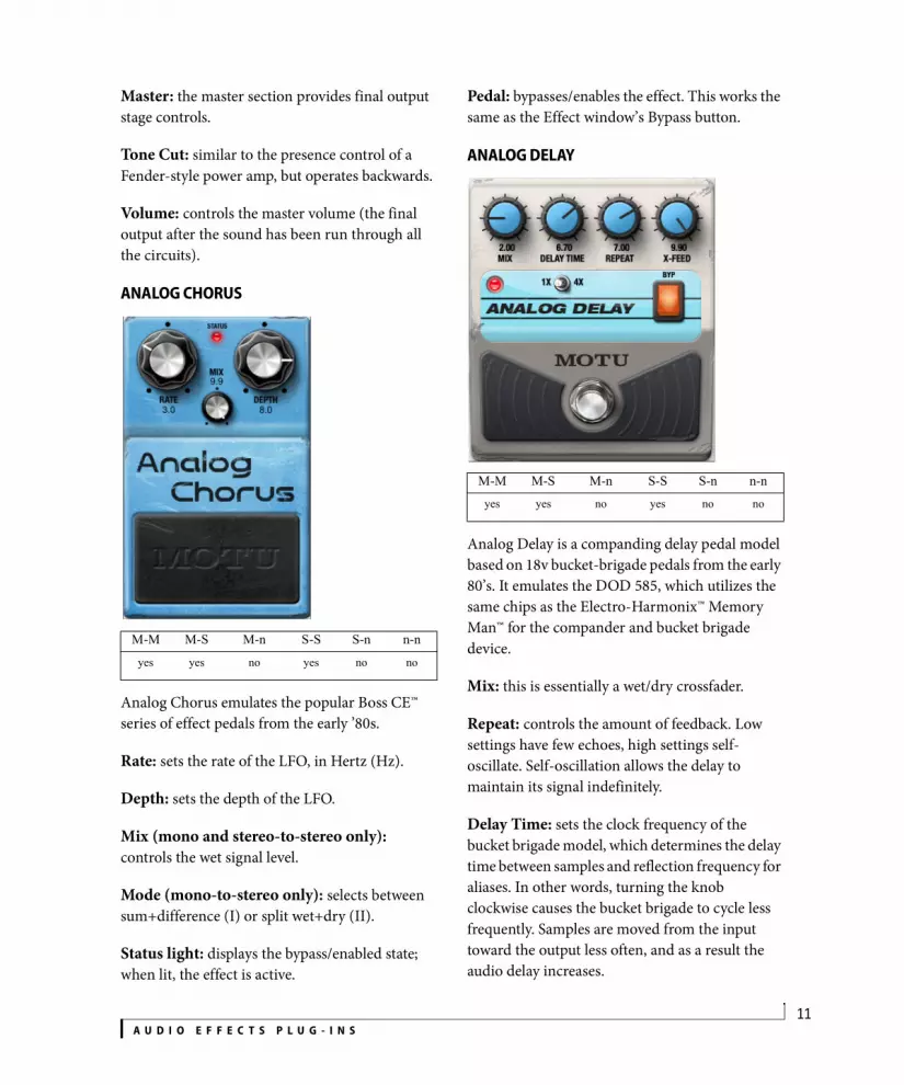
Master: the master section provides final output stage controls.
Tone Cut: similar to the presence control of a Fender-style power amp, but operates backwards.
Volume: controls the master volume (the final output after the sound has been run through all the circuits).
ANALOG CHORUS
Analog Chorus emulates the popular Boss CE™ series of effect pedals from the early ’80s.
Rate: sets the rate of the LFO, in Hertz (Hz).
Depth: sets the depth of the LFO.
Mix (mono and stereo-to-stereo only): controls the wet signal level.
Mode (mono-to-stereo only): selects between sum+difference (I) or split wet+dry (II).
Status light: displays the bypass/enabled state; when lit, the effect is active.
Pedal: bypasses/enables the effect. This works the same as the Effect window’s Bypass button.
ANALOG DELAY
Analog Delay is a companding delay pedal model based on 18v bucket-brigade pedals from the early 80’s. It emulates the DOD 585, which utilizes the same chips as the Electro-Harmonix™ Memory Man™ for the compander and bucket brigade device.
Mix: this is essentially a wet/dry crossfader.
Repeat: controls the amount of feedback. Low settings have few echoes, high settings self-oscillate. Self-oscillation allows the delay to maintain its signal indefinitely.
Delay Time: sets the clock frequency of the bucket brigade model, which determines the delay time between samples and reflection frequency for aliases. In other words, turning the knob clockwise causes the bucket brigade to cycle less frequently. Samples are moved from the input toward the output less often, and as a result the audio delay increases.
M-M M-S M-n S-S S-n n-n
yes yes no yes no no
M-M M-S M-n S-S S-n n-nyes yes no yes no no

A U D I O E F F E C T S P L U G - I N S12
Conversely, turning the Delay Time knob counter-clockwise corresponds to increasing the speed at which the “buckets” are transferred. þThe signal samples in the buckets take less time to be transferred from input to output, thus the delay time goes down.
X-Feed: this controls the stereo routing of the inputs and feedback loop within the delay circuit.
For a mono-stereo signal, 5 is equivalent to parallel mono, and 0 or 10 creates a ping-pong delay whose first echo follows the direction of the knob’s pointer.
For a stereo-stereo signal, the mono behavior is preserved for the left channel and mirrored by the right channel.
Pedal switch: the footswitch works like the STNDBY button on the MasterWorks Leveler. This forces the mix control to 0 internally while leaving the delay circuit alive, which allows self-oscillation to build up without being heard.
BYP: this switch controls the Bypass parameter, causing all model elements to be cleared and removed from the FX chain.
1X/4X: this switch selects a delay time multiplier that modifies the model delay time without affecting the clock effects. On 4X, the delay time is quadrupled. On 1X, the delay time is unaffected.
ANALOG FLANGER
Analog Flanger is inspired by the late 1970’s Electro Harmonix Deluxe Electric Mistress.
Pedal switch: bypasses/enables the effect. This works the same as the Effect window’s Bypass button.
Filter Matrix: this disconnects the LFO from the affected signal, allowing a freeze of the comb filter sweep. Try automating this parameter for custom filter sweep effects.
Color: controls the amount of global feedback of the flanger effect, and indirectly controls the distortion level of the bucket brigade.
Range: controls the “endpoints” of the sweep, or in Filter Matrix mode, the location of the comb filter notches.
Rate: controls the LFO frequency.
M-M M-S M-n S-S S-n n-nyes yes no yes no no

A U D I O E F F E C T S P L U G - I N S13
ANALOG PHASER
Analog Phaser is a model of the MXR '74 Vintage Phase 90 phaser. This pedal model produces the “dirty phaser” sound popularized by Eddie Van Halen.
Pedal switch: bypasses/enables the effect. This works the same as the Effect window’s Bypass button.
Speed: controls the LFO frequency.
AUTO PAN
How it worksAutoPan uses a low frequency oscillator (LFO) to automatically control the positioning of the input signal. Different LFO shapes can be applied to the movement and the frequency of the shifting can be synced to tempo if desired.
Tempo lock: pan can be specified in real-time or in one of several tempo-based modes which lock the LFO of the tempo of your sequence, even if there are tempo changes.
Waveform: determines the desired LFO wave (sine, triangle, etc.)
Rate: sets period in Hertz (Hz) in real-time mode, or note values or bars depending on tempo lock mode.
Center: the pan will rotate an equal amount clockwise and counterclockwise from the center angle.
Depth: number of rotations or partial rotations over which the pan varies each period.
The S-S and n-n versions of AutoPan feature an additional feature: Balance and spin modes. When AutoPan is in balance mode, distribution of the panned signal involves two consecutive surround channels as it rotates. Spin mode rotates each input consecutively.
M-M M-S M-n S-S S-n n-nyes yes no yes no no
M-M M-S M-n S-S S-n n-nno yes yes yes no yes

A U D I O E F F E C T S P L U G - I N S14
BASS MANAGER (SURROUND ONLY)
Bass Manager serves two roles. First, it helps to improve the bass response of your studio if you don’t have full range monitors. Second, it simulates consumer home theater bass management systems so you can be sure your surround mix will sound right in a variety of home situations.
Bass Manager extends the low frequency information of the full range channels to the LFE channel. If your studio monitors have poor response at low frequencies you can divert those frequencies from your main speakers to your LFE.
Consumer playback systems often lack a subwoofer for the LFE channel, and in this case they redirect the LFE channel into some of the main channels, typically left, center and right. Use Bass Manager to preview your mix under these suboptimal conditions.
The acoustic mixing of bass energy in your control room is very different from summing the same signals inside a mixer. Most consumer playback systems include built in bass managers that can cause phase cancellation that you will miss because the signals are summed electrically, not acoustically.
Bass Manager allows you to activate a low pass filter simulation on the LFE channel which emulates the anti-aliasing filter used by AC-3 or DTS encoders. It is recommended that you monitor your mix with this filter on, because your ultimate delivery system will likely use it.
ControlsInput: trims input signal of LFE or surround channels.
input mute: mutes input of LFE or surround channels.
HPF: high pass filter - sets the cutoff frequency for the high pass filter.
LPF: low pass filter - sets the cutoff frequency for the low pass filter.
Encoder filter simulation: simulates the effect of a 6th order filter used in consumer bass management filters.
Extend: sends that channel to the LFE.
Extend trim: trims the overall level of redirected signal sent to the LFE channel.
Redirect: sends LFE channel to that channel.
Redirect trim: trims the overall level of extended LFE sent to the surround channels.
Channel mute: each mute control mutes its respective channel.
input LFE -> encoder filter simulation-> redirect trim -> redirect switch -> channels.
input (normal) -> LPF -> extend trim -> extend switch -> LFE output/input: trims input signal of LFE.
M-M M-S M-n S-S S-n n-nno no no no no yes

A U D I O E F F E C T S P L U G - I N S15
CALIBRATION
Calibration helps accurately match the relative levels between the speakers in your mixing environment. In addition to calibrating levels, Calibration allows you to compensate differences in speaker distance with delay trims.
Warning: Calibration emits high energy noise out of your monitoring system. Take precautions in the form of ear protection and amplifier levels.
Auto calibrationSet up a full frequency omni directional mic at your mixing position. Plug the mic into a microphone pre-amp and the output of the mic preamp to an input on your audio interface. Be sure all monitors are on and set at unity gain. Create an input bundle (see chapter 14, “Bundles” (page 131) in the DP User Guide) for the microphone, select the mic bundle from the Mic Input pop up menu. This will connect the output of the microphone to the calibration input.
Be quiet. Any noise you make will throw off the calibration results, especially during the silences. Enable the auto calibrate button.
Calibration will send pink noise to each speaker in sequence. Calibration will read the levels and delay characteristics (except the delay of LFE(s)) of each speaker and configure itself. While the calibration sequence is running, you can make adjustments to your speaker system (such as input trims). Auto calibrate will continue looping until you cancel auto calibration mode. It may take a few passes through each monitor for Calibration to settle on an accurate setting.
Your system is now calibrated. At this point, save your calibrate setup. Under the Preset menu, select save presets. Name your preset “my studio” and hit the ok button. Now you can recall your studio preset at any time without running the calibration procedure each time you mix.
Manual calibrationAfter following the setup procedure for Auto Calibration, perform the following steps:
1 Determine your standard reference level (-12dB, for example) and solo the channel you want to calibrate.
2 Enable noise, Calibration will now send pink noise to the soloed speaker.
3 Adjust the trim for the channel you are calibrating until the VU meter reaches your reference level. If you wish to set all trims simultaneously, hold down the Option key.
4 Repeat for each speaker, taking care to only solo one channel at a time. When you are finished, disable noise.
M-M M-S M-n S-S S-n n-nno no no yes no yes
A U D I O E F F E C T S P L U G - I N S16
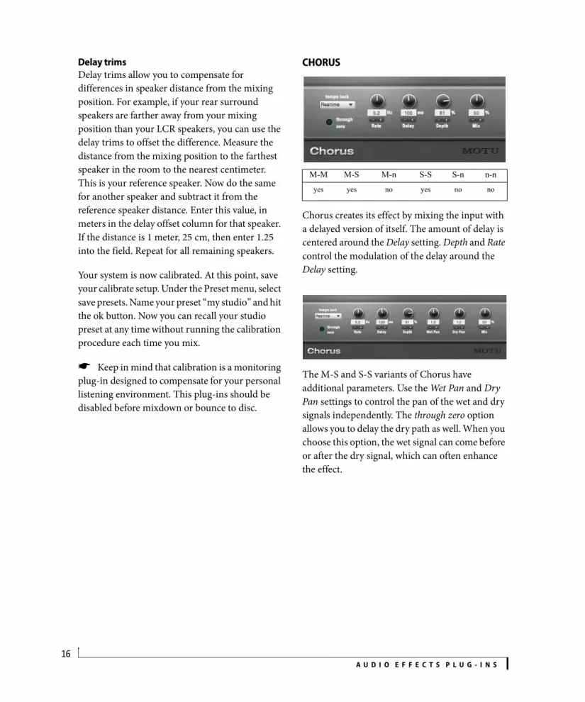
Delay trimsDelay trims allow you to compensate for differences in speaker distance from the mixing position. For example, if your rear surround speakers are farther away from your mixing position than your LCR speakers, you can use the delay trims to offset the difference. Measure the distance from the mixing position to the farthest speaker in the room to the nearest centimeter. This is your reference speaker. Now do the same for another speaker and subtract it from the reference speaker distance. Enter this value, in meters in the delay offset column for that speaker. If the distance is 1 meter, 25 cm, then enter 1.25 into the field. Repeat for all remaining speakers.
Your system is now calibrated. At this point, save your calibrate setup. Under the Preset menu, select save presets. Name your preset “my studio” and hit the ok button. Now you can recall your studio preset at any time without running the calibration procedure each time you mix.
Keep in mind that calibration is a monitoring plug-in designed to compensate for your personal listening environment. This plug-ins should be disabled before mixdown or bounce to disc.
CHORUS
Chorus creates its effect by mixing the input with a delayed version of itself. The amount of delay is centered around the Delay setting. Depth and Rate control the modulation of the delay around the Delay setting.
The M-S and S-S variants of Chorus have additional parameters. Use the Wet Pan and Dry Pan settings to control the pan of the wet and dry signals independently. The through zero option allows you to delay the dry path as well. When you choose this option, the wet signal can come before or after the dry signal, which can often enhance the effect.
M-M M-S M-n S-S S-n n-n
yes yes no yes no no

A U D I O E F F E C T S P L U G - I N S17
CLEAR PEBBLE
A model of the Electro-Harmonix™ Small Stone™ phaser with the Color switch set to the Off position. The color-off timbre is a classic jazzy phase sound.
Pedal switch: bypasses/enables the effect. This works the same as the Effect window’s Bypass button.
Rate: controls LFO frequency.
CUSTOM ’59
Custom ’59 is an amp modeling plug-in that lets you mix and match preamp tubes and circuits on-the-fly, with complete automation of all parameters.
Modeled ampsCustom ’59 models three renowned guitar amps: the original Fender® Bassman®, the Marshall® JTM45® and the Marshall® JCM800®.
Fender® Bassman®Originally designed for the Fender Precision Bass®, the Fender Bassman amp was quickly adopted by guitarists and eventually became perhaps the most famous and sought after guitar amp of all time. With its classic 4x10 design (four ten-inch speakers) and classic lacquered tweed cover, the Bassman sound is a bona fide icon among guitar tones and a must-have for any tone aficionado.
Marshall® JTM45®Introduced in the early 1960’s, the Marshall JTM45 was essentially a clone of the Fender Bassman. Made popular by Eric Clapton, the so-called “Bluesbreaker” amp is named after Clapton’s band at the time, in which he
M-M M-S M-n S-S S-n n-nyes yes no yes no no
M-M M-S M-n S-S S-n n-n
yes yes no yes no no

A U D I O E F F E C T S P L U G - I N S18
popularized the now signature sound of playing a Les Paul through the heavily distorted JTM45. Ever since, the JTM45 has been ensconced in the pantheon of world-famous guitar amplifiers.
Marshall® JCM800-1987®By the early ’80s, Marshall had developed the JCM800, with higher power tubes and a power boost from 50 to 100 watts. This amp produces perhaps the most widely recognized guitar tones of all time.
Create your own ampCustom ’59™ lets you play an extremely accurate reproduction of the sound of each of these three famous amps. But you can also mix and match the preamp tube, preamp circuit and tone stack from each model to create your own custom amp.
Input jacks: selects the input channel and impedance. Channel I and Channel II each have a high-Z input (1) and a low-Z input (2).
Vol I, Vol II: volume controls for each channel.
3-band EQ: cuts or boosts for low, mid, and high frequencies.
Master: output level.
Input Tube: selects a tube for the input stage. This determines headroom, first-stage gain, distortion characteristics and to some extent the frequency response of the volume control circuits.
Preamp Circuit: selects the volume control circuit model for the indicated amp.
Tone Stack: selects the tone control circuit model for the indicated amp.
Power AmpWhen Preamp is selected in the Power Amp menu, only the pre-amp stage of Custom ’59 is activated. When one of the other settings is chosen, both the
pre-amp stage and the power amp stage are activated. Additionally, the Presence control appears, which controls a progressive high frequency shelf (Figure 1-4).
Figure 1-4: Custom ’59 Power Amp settings.
Power Amp modelsEach Power Amp model has different character-istics.
Preamp: clean, high-fidelity solid-state power stage (no post-processing of pre-amp model beyond a simple gain control).
Vintage: spongy, touch-sensitive and loose to the point of sounding “flabby” at high distortion levels.
Classic: still touch-sensitive but with a more defined overdrive character.
Modern: tighter, sacrificing some touch-sensitivity for increased definition at maximum drive levels.

A U D I O E F F E C T S P L U G - I N S19
D PLUS
D Plus emulates the MXR Distortion+™ pedal; its crunchy sound has been widely used by Randy Rhoads, Jerry Garcia, Bob Mould, and many more.
Output: level of the output signal.
Distortion: amount of distortion.
Source Z: impedance of the input signal, which affects the high-frequency response. Turn all the way to the left to simulate a well-buffered pedal or active guitar, ~3–5 to simulate passive guitars at full volume, and 6–10 for simulating a passive guitar with its volume knobs turned down.
Load Z: impedance of the next device in the signal chain, which affects the high frequency response. A setting of zero models the low-impedance input of a typical combo amplifier, and 10 models the ubiquitous 1M¾ high-Z input impedance.
Status light: displays the bypass/enabled state; when lit, the effect is active.
Enable switch: bypasses/enables the effect.
DC NOTCH
The DC Notch plug-in helps eliminate DC offset.
DC offset is when an audio wave form has an average energy either above or below zero amplitude. This can be caused by low-quality A/D converters, as well as certain types of DSP processing. DC offset can cause clipping (and distortion), even when the signal does not have maximum gain. One easy way to tell if a signal has a DC offset is to look at a graphic representation of the wave form. If the waveform seems to either hover above or sag below zero amplitude, it has a DC offset.
The DC Notch is a simple plug-in. It has no controls. It is merely a special filter that returns the wave form to an even positive/negative strength. If there is no DC offset present in the signal, the DC Notch will do nothing.
M-M M-S M-n S-S S-n n-nyes yes no yes no no
M-M M-S M-n S-S S-n n-nyes no no yes no yes

A U D I O E F F E C T S P L U G - I N S20
DE-ESSER
The De-esser is based on a dynamic peaking EQ, which produces adaptive de-essing.
De-esser is also useful for selectively gating narrow-band noise and smoothing high-gain guitar tracks in the 2k-4k band.
Freq: center frequency of the bandpass/notch pair.
BW: bandwidth of the bandpass filter.
Sensitivity: sensitivity of the sibilance detector.
Attack: attack time constant of the compressor/expander.
Release: release time constant of the compressor/expander.
Ratio: ratio of the compressor/expander.
Look Ahead: shifts the detector envelope to anticipate fast sibilance.
Gain: gain of the EQ band, or makeup gain of the compressor.
Key Boost: extra gain applied while in solo mode.
M-M M-S M-n S-S S-n n-n
yes yes no yes no no
A U D I O E F F E C T S P L U G - I N S21
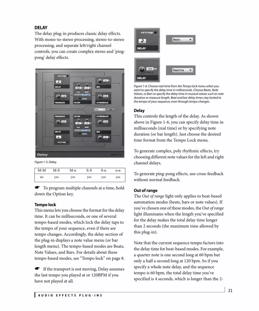
DELAYThe delay plug-in produces classic delay effects. With mono-to-stereo processing, stereo-to-stereo processing, and separate left/right channel controls, you can create complex stereo and ‘ping-pong’ delay effects.
Figure 1-5: Delay.
To program multiple channels at a time, hold down the Option key.
Tempo lockThis menu lets you choose the format for the delay time. It can be milliseconds, or one of several tempo-based modes, which lock the delay taps to the tempo of your sequence, even if there are tempo changes. Accordingly, the delay section of the plug-in displays a note value menu (or bar length menu). The tempo-based modes are Beats, Note Values, and Bars. For details about these tempo-based modes, see “Tempo lock” on page 8.
If the transport is not moving, Delay assumes the last tempo you played at or 120BPM if you have not played at all.
Figure 1-6: Choose real-time from the Tempo lock menu when you want to specify the delay time in milliseconds. Choose Beats, Note Values, or Bars to specify the delay time in musical values such as note duration or measure length. Beat and bar delay times stay locked to the tempo of your sequence, even through tempo changes.
DelayThis controls the length of the delay. As shown above in Figure 1-6, you can specify delay time in milliseconds (real time) or by specifying note duration (or bar length). Just choose the desired time format from the Tempo Lock menu.
To generate complex, poly rhythmic effects, try choosing different note values for the left and right channel delays.
To generate ping-pong effects, use cross-feedback without normal feedback.
Out of rangeThe Out of range light only applies to beat-based automation modes (beats, bars or note values). If you’ve chosen one of these modes, the Out of range light illuminates when the length you’ve specified for the delay makes the total delay time longer than 2 seconds (the maximum time allowed by this plug-in).
Note that the current sequence tempo factors into the delay time for beat-based modes. For example, a quarter note is one second long at 60 bpm but only a half a second long at 120 bpm. So if you specify a whole note delay, and the sequence tempo is 60 bpm, the total delay time you’ve specified is 4 seconds, which is longer than the 2-
M-M M-S M-n S-S S-n n-n
no yes yes yes yes yes

A U D I O E F F E C T S P L U G - I N S22
second maximum allowed by the plug-in. In this case, the Out of range light illuminates to alert you to this fact. To turn off the light, choose a shorter note, beat or bar value, or increase the tempo of the sequence.
MixControls the overall level of the delay echoes mixed with the original signal.
FilterThis is a standard EQ filter that you can apply to the signal before it is fed into the feedback and cross feedback processors. Filter types include low pass, high pass, notch and bandpass filters with appropriate frequency and width settings, where applicable. This is a great way to apply an ‘effected’ sound to the delay taps, which can add more interest and dimension to the overall delay effect.
Feedback and cross-feedbackWarning! Be very careful when working with
these controls, as they can quickly generate ear-splitting, speaker blowing feedback paths if you are not careful.
If you accidentally generate a feedback loop that is getting out of control, go for the panic button, and then stop playback or adjust the delay settings. Simply stopping playback won’t stop the feedback!
The feedback control adds feedback to the delay processor on the same channel. The cross-feedback control adds feedback to the opposite channel’s delay processor. Used sparingly, these controls can greatly add to the complexity of the delay effect.
cross feedback sends to remaining surround channels
currently edited channel
Feedback graph and surround channel selection buttons
Figure 1-7: The surround delay.

A U D I O E F F E C T S P L U G - I N S23
Delay - Surround VersionsThe Delay produces a wide variety of delay effects using a surround speaker matrix.
How it worksThe Feedback delay provides an independently programmable signal path for each (non-LFE) channel in your surround matrix. Therefore, if using a 5.1 surround matrix, you have a total of five channels of delay. The interface displays the parameters of a single channel of delay at a time. The display window in the upper left hand corner and the speaker radio buttons tell you which channel you are currently programming. Holding down the Option key programs all channels simultaneously.
To select a channel to edit, click a speaker icon on the circular display in the lower right hand corner of the display. The current channel name will be displayed in the upper left hand corner and the speaker icon will highlight.
Panic: because it is possible to send 100% of the signal to multiple destinations, which in turn are feeding back into a number of other destinations, delays can spiral out of control rather quickly. If this happens, the panic button will zero out all of the delay lines giving you enough time to stop playback or reduce the feedback gains. Remember, stopping playback will not stop DSP processing.
InputThe number of source channels determines the input behavior of the n-channel version of Delay.
Mono to n - One input gain knob is provided to control the amount of input signal sent to current delay channel.
Stereo to n - Two input knobs are provided representing the left and right sides of the source signal. The left and right inputs can be used independently or mixed to send signal to the current delay channel.
N to N - each input is hard-wired to its corresponding channel output. A knob is provided to trim the input.
Feedback ControlsThe Delay provides a feedback path from each non-LFE channel to every other non-LFE channel For example: if using a 7.1 surround matrix, a total of 49 independent feedback paths are available. In 10.2, there is a total of 100 feedback paths.
Feedback: controls how much post-delay, post-filtered signal is recirculated in the currently selected channel.
X Feedback: controls how much post-delay, post-filtered signal is sent to each other delay channel from the currently selected channel.
A U D I O E F F E C T S P L U G - I N S24
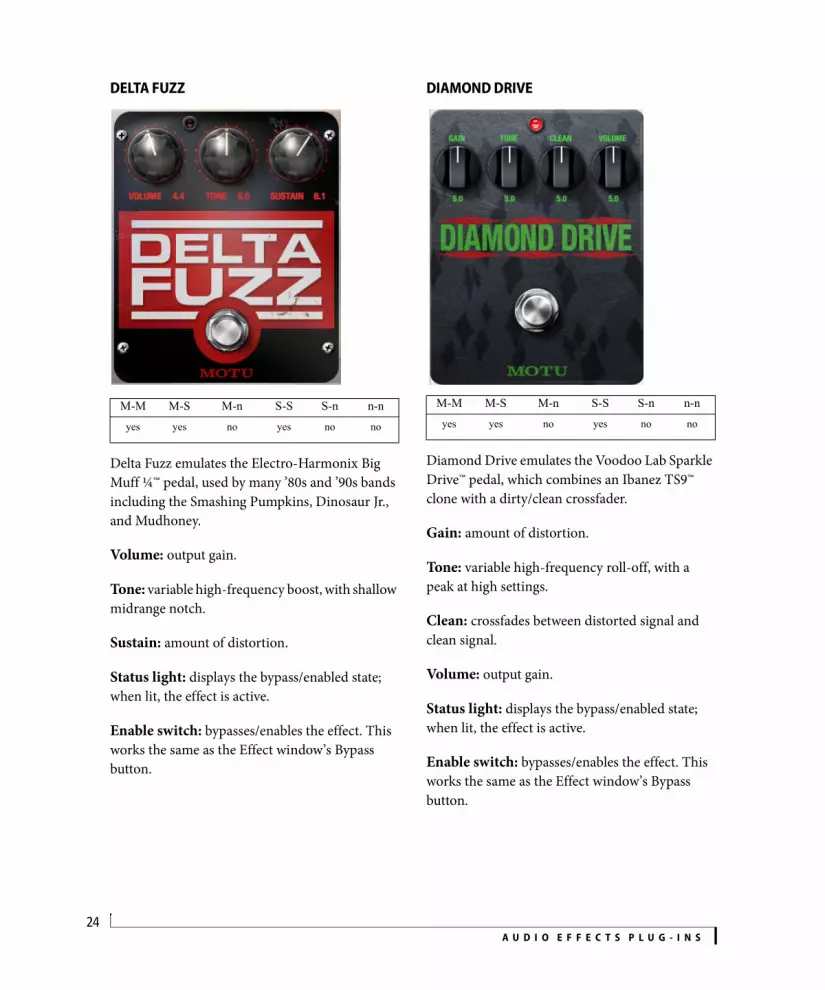
DELTA FUZZ
Delta Fuzz emulates the Electro-Harmonix Big Muff ¼™ pedal, used by many ’80s and ’90s bands including the Smashing Pumpkins, Dinosaur Jr., and Mudhoney.
Volume: output gain.
Tone: variable high-frequency boost, with shallow midrange notch.
Sustain: amount of distortion.
Status light: displays the bypass/enabled state; when lit, the effect is active.
Enable switch: bypasses/enables the effect. This works the same as the Effect window’s Bypass button.
DIAMOND DRIVE
Diamond Drive emulates the Voodoo Lab Sparkle Drive™ pedal, which combines an Ibanez TS9™ clone with a dirty/clean crossfader.
Gain: amount of distortion.
Tone: variable high-frequency roll-off, with a peak at high settings.
Clean: crossfades between distorted signal and clean signal.
Volume: output gain.
Status light: displays the bypass/enabled state; when lit, the effect is active.
Enable switch: bypasses/enables the effect. This works the same as the Effect window’s Bypass button.
M-M M-S M-n S-S S-n n-nyes yes no yes no no
M-M M-S M-n S-S S-n n-nyes yes no yes no no

A U D I O E F F E C T S P L U G - I N S25
DYNAMIC EQUALIZER
The Dynamic Equalizer offers precise control of frequency, volume and dynamics. A key filter related to the type of equalizer band feeds a gain computer, and the gain computer’s output signal controls the gain parameter of the band. Bandwidth and center frequency behave as they would for a regular EQ.
Band controlsThe Dynamic Equalizer has three parametric bands (Peak 1, 2 and 3) and two shelving bands (Low and High Shelf). The band controls let you select, solo, and enable/disable each band. The controls across the bottom of the window affect the currently selected band. Each band is represented by a unique color on the controls and in the graph.
EQ settingsEach band offers the standard parametric EQ controls, similar to the MasterWorks EQ (see “EQ filters” on page 44). For the three mid (peak)
bands, there are Gain, Frequency and Bandwidth (Q) controls. For the shelving bands, Gain and Frequency controls are available.
The EQ parameters can be controlled by editing their numeric values directly, or by dragging the corresponding filter handle and Bandwidth handles in the graphic display.
Band-specific compression/expansionEach EQ band feeds its own compressor, with standard Threshold, Attack, Release, and Ratio controls, as explained for the MasterWorks Compressor in “Controls” on page 40. The knobs for these compressor settings reflect the color of the currently selected EQ band (chosen with the band controls). Threshold can be controlled using the Threshold knob, or using the threshold controls to the right of the EQ graph. Each compressor also provides controls for minimum gain and lookahead:
Min Gain: sets a floor for the gain reduction. This is particularly useful for expansion.
M-M M-S M-n S-S S-n n-n
yes yes no yes no no
Band controls
dB scale range
Show/hide controls
Compressor/expander threshold controls
Filter handle
Bandwidth handles
FFT display
EQ settings
FFT controls
Control unit range
Gain dB -36.00 to +36.00
Frequency Hertz 10 Hz to 20 kHz
Bandwidth Octave 0.083 to 4.000

A U D I O E F F E C T S P L U G - I N S26
Look-ahead: shifts the detector envelope to anticipate fast transients (per band). Lookahead can be set to different values for each frequency band, and DP will automatically compensate for all delays in the audio patch.
Global settingsThere are two additional global settings, which are not band-specific:
Makeup Gain: global makeup gain.
Solo Boost: extra gain applied while in solo mode.
EQ graphThe EQ graph provides visual control over the five bands of EQ, similar to the MasterWorks EQ, as explained in “Frequency response display” on page 43. Drag the filter handles and bandwidth handles as desired. Use the dB scale range buttons to control the vertical (gain) range of the graphic display. The display includes a real-time FFT to show the frequency plot of the output signal in real time, either before or after it is processed by the plug-in (using the FFT pre/post switches). The FFT can be shown or hidden, along with several other items.
Show/hide buttonsThe four show/hide buttons (Figure 1-21) control the display of the following parameters:
Figure 1-8: Show/hide buttons.
Static response: shows the outline of the EQ curve as a green line (when the signal’s envelope is below the threshold).
Dynamic response: shows the current dynamic response of the EQ as a magenta line.
Band response plots: presents a visual represen-tation of individual response curves created by each peak/shelf point. The shape of the filter, according to its current settings, is shaded in the same color as the filter’s knob(s).
FFT analysis: frequency analysis of digital signal input, which dynamically updates when signal is fed to the plug-in. The FFT pre/post switch controls whether the FFT curve reflects any filtering being applied to the signal by Dynamic Equalizer.
Applications for the Dynamic EqualizerThe Dynamic Equalizer is most effective on a broadband signal such as a drum set or full mix. It works like other multi-band compressors, but because it has the additional control of parametric EQ for each frequency band, it can be much more precise than a standard multi-band compressor.
To hear the Dynamic Equalizer in action, run a full drum mix through it. Enable the low-shelf band and increase the gain. The bottom end of the drum set will be boosted. Now bring in the compression by lowering the threshold for the low shelf band. This will allow you to “tighten up” the low frequency, and set the level exactly where it needs to be. Do the same for the high-shelf filter to accentuate the top end of the kit while keeping the dynamic range under control. Use a mid-band filter to isolate the snare drum. Solo the filter to focus in on the resonant frequency of the snare. Compress and boost or cut to match the rest of the kit. Now bypass the plug-in and you will hear an obvious difference.
Static response
Dynamic response
Band response
FFT display

A U D I O E F F E C T S P L U G - I N S27
DYNAMICS
Figure 1-9: The Dynamics plug-in.
There are four types of Dynamics processors available: (downward) compressor, limiter, (downward) expander, and gate.
CompressorThe Compressor lowers the level of the input when it is above the threshold. The amount of attenuation is determined by the Ratio and the input level. If the input is 6 dB above the Threshold and the Ratio is 3:1, then the output will be 2 dB above the Threshold. When the input level goes above the threshold, the attenuation is added gradually to reduce distortion. The rate at which the attenuation is added is determined by the Attack parameter. Likewise, when the input level falls below the Threshold, the attenuation is removed gradually. The rate at which the attenuation is removed is determined by the Release parameter. Long Release times may cause
the audio to drop out briefly when a soft passage follows a loud passage. Short Release times may cause the attenuation to pump when the average input level quickly fluctuates above and below the Threshold.
LimiterThe Limiter is similar to the Compressor, except there is no Ratio control. When the input level goes above the Threshold, the output plateaus at the Threshold level.
ExpanderThe Expander is the opposite of the Compressor: it increases the dynamic range. Inputs under the threshold are attenuated, and inputs above the threshold are passed straight through.
GateWhen the input to the Gate falls below the threshold, the output is muted entirely.
Input levelThe Input Level meter displays the peaks of the input signal after the Input Gain is applied. The Threshold control is calibrated to 0 dB on the Input Level meter. Since the MOTU Audio System has virtually unlimited headroom without signal degradation, it is possible to have an input signal above 0 dB. Use the Input Gain to adjust the input level before adjusting the other controls.
The input level of the stereo dynamics processor is the maximum of the left and right channels.
Control levelThe Control Level displays the time averaged envelope of the control signal. The Control Envelope is compared to the Threshold by the processor to determine the attenuation. The Control Level meter range is -98 dB to 0 dB, the full range of the Threshold control.
M-M M-S M-n S-S S-n n-nyes no no yes no no
side chain input

A U D I O E F F E C T S P L U G - I N S28
AttenuationThis level meter displays the current amount of attenuation applied by the effect.
Output levelThe Output Level meter displays the peaks of the output signal. The Output Gain is applied before the Output Level meter. Use the Output Gain to compensate for the effect of the dynamics processing.
Side chain inputThe Dynamics plug-in has a side chain input for a control signal of your choice, a shown in Figure 1-9. Just route the desired control signal to a bus and then choose the bus from the side chain input menu. You can use the side chain control signal for any of the four dynamics processors (compressor, expander, limiter or gate).
DYNA-SQUASH
Modeled after the MXR “script-logo” Dyna-Comp™ compressor, the Dyna-Squash features an infinity-ratio limiter with 60dB maximum gain, a
0.7v absolute hard-knee limit, sub-millisecond attack dynamics, and painfully slow (>1s) release dynamics.
The original Dyna-Comp “script logo” was a staple in many famous guitar rigs, including those for Pete Townshend, David Gilmour and Eddie van Halen, among others. The most notable differences in the vintage script logo model versus the more modern block-lettered model(s), were the “metal can” CA3080 IC chips, and the carbon film resistors used throughout the circuit.
Output: controls output level from the pedal.
Sensitivity: adjusts the maximum gain of the automatic gain control. When turned up, this allows more transients like note attacks to come through.
Link (stereo-stereo only): links (or unlinks) the left and right channels’ compression.
ECHO
Figure 1-10: The Echo plug-in.
There are two serial stages to the Echo effect: the Delay Taps and the Feedback Path.
M-M M-S M-n S-S S-n n-nyes yes no yes no no M-M M-S M-n S-S S-n n-n
yes no no yes no no

A U D I O E F F E C T S P L U G - I N S29
Delay TapsEach of the Delay Taps creates a single repetition of the input signal at the specified delay and with the specified gain.
At least one of the Delay Taps must have a nonzero gain for the wet signal to be nonzero.
You can make a four echo pattern by setting each of the Delay Taps.
The maximum delay tap time is 2 seconds. If you choose a note value or bar length that exceeds 2 seconds, the colored box beneath the tap flashes to alert you that you’ve chosen a delay time that is out of range (longer than 2 seconds). To bring the delay time back into range, choose a shorter note (or bar) duration. Or speed up the tempo of the sequence. For a complete explanation of the impact of tempo on delay time, see “Delay” on page 21.
Feedback PathThe outputs of each of the Delay Taps are feed into the Feedback Path.
The Feedback Path creates a series of equally spaced echoes. Each successive echo is a scaled version of the previous echo. The scale factor is controlled by the Feedback value. When the Feedback value is zero, the output of the Delay Taps will pass straight through unaffected. When the Feedback value is one or negative one, the echoes will continue forever at a constant signal level.
ENSEMBLE CHORUS
The Ensemble Chorus simulates an ensemble of slightly randomized unison voices spread across the stereo soundstage. It is intended to be a modulator used with ProVerb (page 73), but it can
M-M M-S M-n S-S S-n n-nno yes no yes no no

A U D I O E F F E C T S P L U G - I N S30
also be used effectively as a standalone processor for thickening up a group of voices, making a guitar swirl, or other chorusing effects.
The Ensemble Chorus window includes a signal flow diagram, which displays how the left and right stereo signals are split, routed, and mixed. The center column of buttons lets you link or unlink parameters for the left and right channels, as desired.
Left, right and center channel controlsEach channel (left, right and center) has the following controls:
Delay: minimum delay path, in milliseconds.
Width: width of the modulator’s sweep, in milliseconds.
Rate: LFO sweep frequency, in Hz.
Symmetry: changes the response of the LFO signal. Imagine one complete sine wave cycle: the symmetry knob shifts the 90° points on the positive and negative waves. When turned to the left, the positive 90° point moves to the left, while the negative 90° point moves to the right. When turned to the right, the positive 90° point moves to the right, while the negative 90° point moves to the left.
Phase: controls the phase relationship of the three LFO’s at the start of processing (Square + Sine + Triangle only).
Mod Type: lets you choose type of modulator for the given delay path (random, square, sine, triangle).
Link Buttons: when enabled, the link buttons bind the applicable controls to both left and right channels.
Pan: set left-right panoramic position of the applicable signal path. Uses an equal-power law.
Gain: trims the level of the applicable signal path.
EVERBeVerb provides high-fidelity reverberation, numerous presets, and graphic control over the reverberator’s parameters.
Figure 1-11: eVerb has an expand button to show and hide the Initial Reflection and Delay/Level settings below the reverb shape.
MixThe Mix setting does what its name implies: it blends the original signal with the affected signal. If you use eVerb on a dedicated effects send, set the mix to 100%.
Reverb TimeThis setting is for the decay, or tail, of the reverb. There are three controls associated with the graphic display: Low Frequency Reverb Time, High Frequency Reverb Time, and Crossover Frequency. Use these three controls to specify the amount of
M-M M-S M-n S-S S-n n-nyes yes yes yes yes yes

A U D I O E F F E C T S P L U G - I N S31
low-end reverb, high-end reverb and the cutoff point between them. You can drag the handles to change settings, or type in precise values.
Hi-Q linkThe Hi-Q link button connects the High Frequency Reverb time control to the Shelf Filter (described below). When the box is checked, increasing High Frequency Reverb Time will result in more high frequency filtering and lower crossover points. The purpose of this button is to keep high frequency reverb sounding natural. Turning Hi-Q Link off will brighten the sound of the reverb—to the point of sounding unnatural, if you use extreme settings for the high end reverb time, diffusion and shelf filter.
Reverb shapeThe large display labelled Reverb Shape shows the character of the reverb. This display tells you at a glance what eVerb is doing with regard to Initial Reflections (the unique characteristics of the currently selected room type) and Reverb Tail (the decay of the reverb). The main settings for eVerb can be controlled with the handles on the edges of the display; you can also type values into the text boxes below.
Initial reflections and Room TypeInitial reflections give a space its unique sound. The shape of the room, the angles of the walls, even furniture in the room will produce a series of Initial Reflections. Think of the Room Type as the flavor of the reverb. You can choose between Concert Hall, Auditorium, Horseshoe, Small Room, and Club. These are acoustic models for simulating these different types of spaces. The Size and Level parameters (click the Expand button to reveal them) let you control the size of the room and the strength of the initial reflections.
Here’s a tip: try using initial reflections without any subsequent reverb (turn the reverb level down as far as it will go). You’ll hear interesting and unusual effects.
PreDelayPreDelay is the amount of time before you hear the very first reflections. If you are in a large room, it takes a while before the first reflections return. PreDelay is useful for clarifying the original sound. For example, with vocals, the reflections won’t start until after a word has been sung.
Reverb DelayThere are four additional settings for the Reverb Tail. The Delay control sets the amount of time after the first Initial Reflection before the Reverb Tail starts. For example, if you clap your hand in a large, tiled room (a train station perhaps), the first thing you hear is the splattering of the initial reflections. Then the reflections wash together into the tail of the reverb. With eVerb, you can set the relative levels and times of the Initial Reflections and the Reverb Tail.
ColorThe Color setting regenerates a small amount of the Initial Reflection into the Reverb Tail. This adds tonal coloration to the overall reverb.
DiffusionDiffusion increases the density of the Reverb Tail reflections. At low settings, individual echoes are discernible. At high settings, the Reverb Tail is very smooth. Drums typically benefit from more diffusion, whereas vocals often call for less diffusion.
Stereo widthStereo Width does what its name implies: if you turn this control down, the effect will become mono.

A U D I O E F F E C T S P L U G - I N S32
Shelf FilterThe Shelf Filter display at the bottom of the window and the two associated settings control the high frequency characteristics of the overall effect. High Cut sets the frequency. Hi Damp sets the amount of filter.
FLANGER
The Flanger creates its effect by mixing the input with a delayed version of itself. The amount of delay is centered around the Delay setting. Depth and Rate control the modulation of the delay around the Delay setting.
The Feedback control adds some of the output back into the input.
The M-S, S-S and M-n variations of the Flanger effect have an additional button labelled L/R In Phase. When this option is selected the amount of delay applied to both left and right channels is the same When this option is not selected, the large delays are applied to the left channel when small delays are applied to the right channel, and vice-versa.
HARDWARE INSERT
The Hardware Insert plug-in functions just like other DP effects plug-ins, but loops the channel’s audio signal to a piece of outboard hardware for external processing by the hardware. Audio is then returned to the plug-in, with latency compensation, if desired. It can be instantiated in line with other software plug-ins and even saved as part of an effect chain clipping. The hardware Insert plug-in allows you to easily incorporate outboard gear into your DP effects chains.
Send: Choose the output (or output pair) on your audio interface that is connected the input on your outboard gear. The choices in this menu are set up in DP’s Bundles window Outputs tab.
Use the volume slider to boost or attenuate the output signal.
Return: Choose the input (or input pair) on your audio interface connected to the output from your outboard gear. The choices in this menu are set up in DP’s Bundles window Inputs tab.
Use the volume slider to boost or attenuate the input signal.
M-M M-S M-n S-S S-n n-nyes yes no yes no yes
M-M M-S M-n S-S S-n n-nyes yes no yes no no

A U D I O E F F E C T S P L U G - I N S33
Latency: Click the Detect button to make the Hardware Insert plug-in detect the round trip latency to and from the outboard gear. The detected latency is displayed in the text box below (in samples). You can also enter the number of samples manually. When the samples text box has anything other than zero in it, latency compensation is employed to ensure that the audio signal returned from the outboard gear remains in phase with the rest of the channels in the mix.
HI-TOP BOOSTER
Hi-Top Booster is a model of the Dallas Rangemaster™ treble booster used by Eric Clapton, Brian May and others. This pedal has been cloned under a variety of names, including Strange-master™, Java Boost™, Brian May Treble Boost™, and several others. When used by itself, the Hi-Top Booster sounds like a cheap transistor radio, but when used to drive MOTU’s Custom ’59 and Live Room | G (with the Vintage 4 x 12 cabinet enabled), you can really achieve that 1970s “glam” guitar tone.
Volume: controls the output level.
Bias: adjusts the bias point of the transistor model. On an analog circuit, this is akin to changing voltages applied to a transistor amplifier model, which changes the symmetry of the distortion. A higher bias number on this pedal represents less voltage, thus a higher distortion level.
INTELLIGENT NOISE GATE
Intelligent Noise Gate is a noise gate designed specifically for recording instruments that are prone to AC mains interference.
In the stereo-to-stereo variant, the stereo channels are processed independently.
Threshold: trigger level that opens the gate.
Attack: rise time constant of the gate, in microseconds (μs).
M-M M-S M-n S-S S-n n-nyes yes no yes no no
M-M M-S M-n S-S S-n n-nyes yes no yes no no

A U D I O E F F E C T S P L U G - I N S34
Hold: minimum amount of time the gate will stay open once triggered, in milliseconds (ms). Decrease if noise overhanging the note is a problem.
Release: fall time constant of the gate, in milliseconds (ms).
Mains Frequency: tune this to your national power grid.
Noise Type: AC noise comes in two flavors: “Hum” is what gets picked up inside an amp using AC heated preamp tubes, and “Buzz” is due to ripple in poorly-regulated DC power supplies such as those for old stomp boxes. In North America, these correspond to approximately 60 Hz and 120 Hz fundamental frequencies, respectively. The switch should be set to match the dominant noise source in the input.
Status light: displays the bypass/enabled state; when lit, the effect is active.
Pedal: bypasses/enables the effect. This works the same as the Effect window’s Bypass button.
INVERT PHASE
Invert Phase flips the phase of the input signal. This is useful when you have recorded two out-of-phase signals, such as the top and bottom of a snare drum. Place the Invert Phase plug-in on one of the out-of-phase tracks to bring both tracks into phase.
M-M M-S M-n S-S S-n n-nyes no no yes no no

A U D I O E F F E C T S P L U G - I N S35
LIVE ROOM B
Live Room B models a loudspeaker cabinet in a physical space. As the name implies, the modeled characteristics of this plug-in are intended for bass guitar, although it can be successfully applied to many kinds of audio material.
Live Room B requires a library file containing data about these physical models. This file is placed by the Digital Performer installer here:
/Library/Application Support/MOTU/ LiveRoomG/LiveRoomB Data.bundle
ControlsCabinet Drive: amount of distortion provided by the cabinet.
Output Gain: output level.
Cab: selects the cabinet model. See “Cabinet models” on page 36.
Decay: applies a down-fade to the reverb portion of the response at the indicated rate, which simulates decreasing the reverb time of the room.
Damping: controls the high-frequency roll-off of the room, similar to hanging curtains or setting up gobos.
Display area: graphical representation of the cabinet selection, mic types, and mic positions. This is for display purposes only; the graphic cannot be edited.
Microphone mixerThere are four microphone channels: two mono (channels 1 and 2) and one stereo (channels 3 and 4), each with their own set of the following controls:
Mic: selects the microphone type and position. Several microphone models are provided:
M-M M-S M-n S-S S-n n-n
yes yes no yes no no

A U D I O E F F E C T S P L U G - I N S36
Close-mics:
AKG D 112
Sennheiser e602-II
Shure SM7B
Yamaha SubKick
M-Audio Sputnik
Matched pair:
Schoeps small diaphragm condensers
Channels 1 and 2 can be set to one of six mics with set positions: DYN112, DYN602, DYN7B, SubKick, Condenser, or Far Omni.
Channels 3 and 4 can be set to one of four mic options: XY, ORTF, Blumlein, or Wide Omni.
To disable a channel (or pair), choose None.
Pre-delay: advances or delays the signal to compensate for the time it takes for a signal to reach a microphone. The range corresponds to about +/- 10 feet, and the plug-in automatically adjusts the relative delay to prevent chopping off the direct sound and early reflections in close-mic responses.
3-band EQ: cuts or boosts up to 15 dB for low, mid, and high frequencies.
Pan / Width: (mono-to-stereo only) on channels 1 and 2, Pan controls the placement of the mono source in the stereo output signal; on channels 3 and 4,Width controls the width of the stereo signal.
Solo and Mute: solos or mutes the channel.
Fader: controls the output level.
Side chain outputsLive Room B provides a side chain output for each of its four channels. The side chain output signals are split before Live Room B’s EQ, solo/mute, pan, fader, and output gain controls. This enables you to take advantage of Digital Performer’s full mixing environment for each microphone channel, including plug-ins and automation.
These side chain outputs are configured in the same manner as multiple outputs from a virtual instrument. They can be accessed in the same way as any other audio input: in the Input menu in the Tracks window, from the Audio Input menu, underneath the fader in the Mixing Board (Figure 1-23), or in the Bundles window.
Figure 1-12: Accessing the Live Room B side chain inputs
Cabinet modelsThe following cabinet models are provided:
8x10 Fridge: modeled after a sealed Ampeg SVT-810.
4x10 Giant II: modeled after the rear-ported SWT Goliath II with the HF driver fully attenuated.
1x15 Ported: modeled after the front-ported Ampeg SVT-15.
1x18 Big Bear: modeled after the rear-ported SWR Big Ben.
A U D I O E F F E C T S P L U G - I N S37
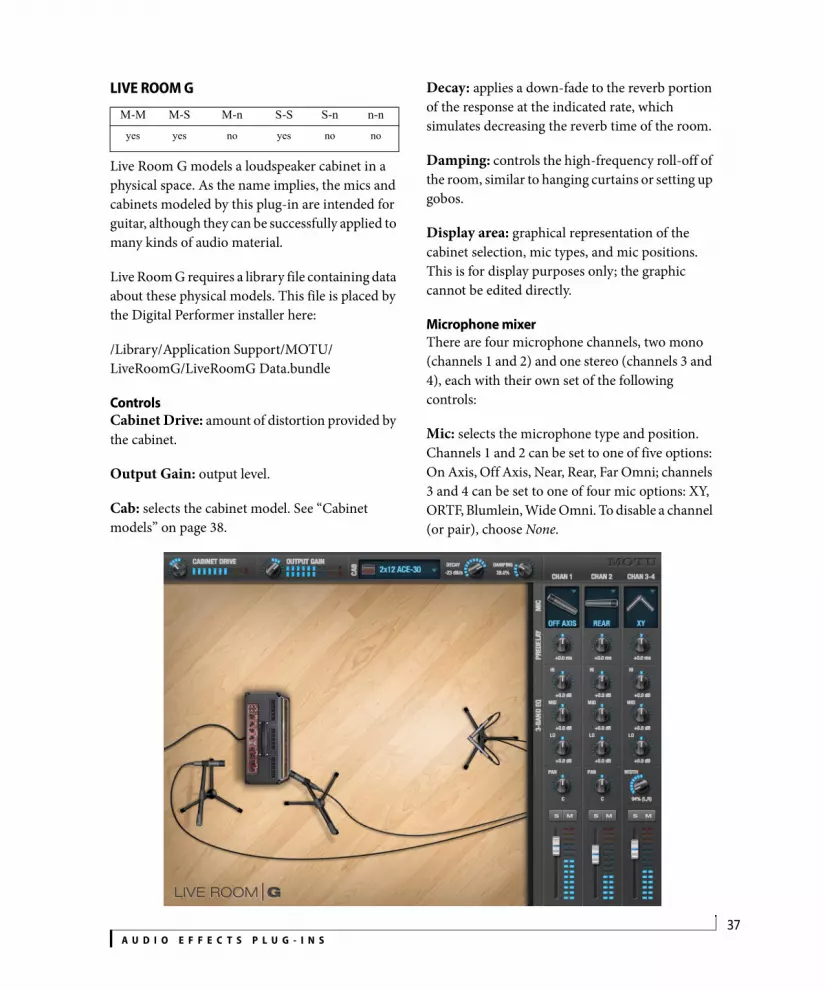
LIVE ROOM G
Live Room G models a loudspeaker cabinet in a physical space. As the name implies, the mics and cabinets modeled by this plug-in are intended for guitar, although they can be successfully applied to many kinds of audio material.
Live Room G requires a library file containing data about these physical models. This file is placed by the Digital Performer installer here:
/Library/Application Support/MOTU/LiveRoomG/LiveRoomG Data.bundle
ControlsCabinet Drive: amount of distortion provided by the cabinet.
Output Gain: output level.
Cab: selects the cabinet model. See “Cabinet models” on page 38.
Decay: applies a down-fade to the reverb portion of the response at the indicated rate, which simulates decreasing the reverb time of the room.
Damping: controls the high-frequency roll-off of the room, similar to hanging curtains or setting up gobos.
Display area: graphical representation of the cabinet selection, mic types, and mic positions. This is for display purposes only; the graphic cannot be edited directly.
Microphone mixerThere are four microphone channels, two mono (channels 1 and 2) and one stereo (channels 3 and 4), each with their own set of the following controls:
Mic: selects the microphone type and position. Channels 1 and 2 can be set to one of five options: On Axis, Off Axis, Near, Rear, Far Omni; channels 3 and 4 can be set to one of four mic options: XY, ORTF, Blumlein, Wide Omni. To disable a channel (or pair), choose None.
M-M M-S M-n S-S S-n n-n
yes yes no yes no no

A U D I O E F F E C T S P L U G - I N S38
Pre-delay: advances or delays the signal to compensate for the time it takes for a signal to reach a microphone.
3-band EQ: cuts or boosts up to 15 dB for low, mid, and high frequencies.
Pan / Width (mono-to-stereo only): on channels 1 and 2, Pan controls the placement of the mono source in the stereo output signal; on channels 3 and 4, Width controls the width of the stereo signal.
Solo and Mute: solos or mutes the channel.
Fader: output level.
Side chain outputsLive Room G provides a side chain output for each of its four channels. The side chain output signals are split before Live Room G’s EQ, solo/mute, pan, fader, and output gain controls. This enables you to take advantage of Digital Performer’s full mixing environment for each microphone channel, including plug-ins and automation.
These side chain outputs are configured in the same manner as multiple outputs from a virtual instrument — see “Multiple audio outputs” on page 165 in the DP User Guide.
Cabinet modelsThe following cabinet models are provided:
4x12 Modern: Intended for ultra-distorted chunks and sludge, yet versatile enough to handle smooth Santana-style leads.
4x12 Vintage: Based upon an aging, road-worn British monster held together with gaffer’s tape and AquaNet. Perfect for those ’80s hair-band tributes and ’70s proto-metal.
2x12 ACE-30: Based on an AC30 with carefully-aged Celestion “Alnico Blue” drivers for guitar tones that never go out of style.
2x12 Combo: For Muscle Shoals-style southern-rock and country guitar tones.
1x12 Combo: Based on a first-generation Boogie Mark IV with the original 12-inch Black Shadow driver in the finished walnut version of the open-back cabinet. This cabinet is a versatile tone machine.
1x12 Citrus: Based on an Orange 1x12-inch closed-back extension cabinet loaded with a Celestion Vintage 30 driver.
4x10 Combo: Tuned for blues, jazz, rock and country. Based on a classic.
2x10 Tilted: Based on a Fender Vibrolux 2x10-inch in the tilted-back configuration. This cabinet pairs well with single coil pickups.
1x8 Junior: This one was set up to record distorted rhythm guitar tones for rock and pop. If you like Eddie Money then this is your cabinet.
LIVE STAGE
M-M M-S M-n S-S S-n n-nyes yes no yes no no

A U D I O E F F E C T S P L U G - I N S39
Live Stage is a model of recording a signal reproduced by a loudspeaker cabinet in a studio. The cabinet and microphone settings offered by the plug-in are ideal for guitar and bass guitar tones. This is a great low-CPU direct box for live performance use: just choose a cabinet and a mic, adjust damping and decay, set your levels, and rock out!
Gain: adjusts level of the signal coming in and being fed through the effect.
Damping: controls the high-frequency roll off of the room, similar to using curtains or gobos.
Decay: applies a down-fade to the reverb portion of the response at the indicated rate, which effectively decreases the reverb time of the room.
MASTERWORKS COMPRESSOR The MasterWorks Compressor offers precise level control of specific frequency bands of a digital audio signal. This plug-in offers three separate
compressors with crossover controls, allowing you to set the frequency range and compression characteristics of each band.
The MasterWorks Compressor can be used to subtly control bass, mid-range or treble frequencies independently of each other. A wide band compressor will respond to the loudest parts of a signal regardless of its frequency. This can cause the kick drum to attenuate cymbal hits, for example. A multi-band compressor gives separate control of the three frequency bands, so — continuing with the same example — a loud, low-frequency signal will not trigger high-frequency compression. Another common use of frequency-specific compression is de-essing. You may want to control the sibilants of an audio signal without affecting lower frequencies. The MasterWorks compressor will allow you to get maximum punch on an individual track or the entire mix, while maintaining sonic clarity.
Figure 1-13: The MasterWorks MultiBand Compressor plug-in.
M-M M-S M-n S-S S-n n-nyes no no yes no no

A U D I O E F F E C T S P L U G - I N S40
Signal flowThe MasterWorks Compressor plug-in has the following signal flow:
Figure 1-14: MasterWorks Compressor signal flow.
How it worksThe MasterWorks Compressor works very much like a traditional wide band compressor. The difference is that the MasterWorks Compressor is actually three independent compressors that act upon differing frequency ranges of the incoming signal. These frequency ranges are set by the crossover controls.
Each compressor has a make-up gain control for adding gain to that frequency band to compensate for compressor attenuation. Additionally, there are global input and output gain controls for affecting the entire frequency range of the signal.
Soloing/mutingEach frequency band can be soloed or muted, allowing you to audition only the band you are working with. This can be very useful for tuning in on the exact frequencies you want to control.
Many instruments create a wide frequency range of sound, and the MasterWorks Compressor allows you to control each part of that sound with great precision. A good example of this is an electric bass guitar. The primary frequencies that
define the notes of this instrument are from around 250 Hertz (Hz) to 1500 Hz. Frequencies below 250 Hz are “felt” more than heard, and frequencies around 200 Hz are generally finger noise and string buzz. The MasterWorks Compressor allows you to control each aspect of the sound for a very even, easy-to-mix bass track.
De-essingBasic de-essing is easily achieved by compressing only the high frequency content of the mic signal. Use fast attack and release times. However, for advanced de-essing work, see “De-Esser” on page 20.
ControlsInput Gain: Boosts or attenuates the incoming signal.
Crossover: Two crossover points separate the frequency spectrum into three bands for separate compression.
Output Gain: Boosts or attenuates the global output of the plug-in.
Lo Band, Mid Band, Hi Band: Select among frequency bands for three separate compressors. The following controls are available for each compressor band.
Solo: Mutes the non-soloed frequency bands. Very useful for hearing what a specific frequency compressor is doing.
Bypass: Disables compression for the selected band.
Threshold: Determines the level above which the compressor will have an effect. Threshold can be set with the knob, slider that appears on the band input meter, and in the graph display.
Ratio: Determines the amount of compression on the signal over the threshold.
Input Gain
Crossover
Three Band Compressor
Output Gain

A U D I O E F F E C T S P L U G - I N S41
Make up: Adds gain to the signal after compression. Because compression attenuates a signal, it can be desirable to add gain to the signal after compression.
Attack: Determines the time it takes for the compressor to react after the signal has exceeded the threshold.
Release: Determines the time it takes for the compressor attenuation to return to zero after the input signal has dropped below the threshold level.
Clear: Clears peak meters for the chosen band.
RMS: Shows the Root Mean Square, or average level. Since the average level of a mix is usually well below any maximum peaks, it is useful to know what the average level is, as well as the loudest points. This is very helpful when matching the apparent levels of different frequency bands.
Compression Graph: Gives a graphic display of compression parameters and the actual signal level for each band. Any combination of bands can be viewed at the same time.
MasterWorks Compressor presetsThe MasterWorks Compressor presets (found in the MasterWorks window Preset menu) are designed for many common applications. Compression is a level-dependent effect. As a result, input level — both broadband and frequency specific — is critical to what the final output is. The presets will do different things depending on input level and bandwidth of the audio signal.
Compression can be used to make a signal more even or natural-sounding, or it can be used as an obvious special effect. Try putting a drum mix through the MasterWorks compressor, and listen to how the cymbals get “squeezed”. Add heavy
compression to the bottom end of a full mix, then increase the make up of that frequency for a tightly controlled kick drum and bass. Run a solo acoustic guitar or piano through even multi-band compression and hear how each part of the instrument is more present, without mix-ruining peaks.
You may only want to compress specific frequency bands, such as when you are de-essing, or you may want to compress the entire frequency spectrum of the audio signal. A major advantage of multiband compression is that frequency-specific peaks do not cause broad band compression. A good example of this is a slapped electric bass. The high frequency portion of the signal will not cause the low frequency to be limited. On a full mix, it is possible to have smooth control over lows, mids, and highs without “hole-punching”.
As in the case of any effect preset, these are starting points. Experiment! Your ears will be the final judge of the usefulness of the effect.
MASTERWORKS EQ
Inspired by legendary British large console EQs, the MasterWorks EQ gives you the look, feel and sound of the most sought-after classic equalizers. Five bands of EQ filtering are provided, each with four EQ types that provide current popular EQ styles and vintage analog EQ styles alike. Two mid bands (LMF and HMF) include shelf filtering. Two additional bands of variable slope low pass and high pass filtering are provided. The filter response display provides comprehensive control and visual feedback of the EQ curve being applied.
M-M M-S M-n S-S S-n n-nyes no no yes no yes

A U D I O E F F E C T S P L U G - I N S42
The MasterWorks EQ has been carefully crafted and meticulously engineered to produce musical results in a wide variety of applications.
Quick referenceFilter response display: Shows the response curve and frequency analysis for the current settings.
dB scale: Lets you specify the vertical scale (in dB) of the filter response display.
Parameter display: Shows the precise numbers of the parameter you are adjusting (or hovering over with the arrow cursor). The labels (frequency, gain, etc.) match the color of the filter being displayed.
EQ filter: one of five bands of EQ that can be independently enabled and programmed.
Filter type: Lets you choose from one of four or five EQ styles for each independent band of EQ.
Low Pass filter: Both a low pass and high pass filter are supplied with six different slope settings.
Filterhandle
Q handles (red lines)
Composite curve
Individual filter curve
Filter response display
dB scale
Parameterdisplay
Audition with noise
FFT display toggle
Filter curve toggle
Composite curve toggle
Filter enable/disable
EQ Filter types
slope
Shelf filter
Low Pass filter
EQ filter
Figure 1-15: MasterWorks EQ.

A U D I O E F F E C T S P L U G - I N S43
Slope: Lets you choose the slope (fall off) charac-teristics of the low pass and high pass filter.
Q handle: Drag the Q handle lines to graphically adjust the Q setting for the currently selected filter. To select the filter, click its filter handle.
Filter handle: Drag this handle to graphically adjust the filter’s boost/cut and/or frequency.
Composite curve: shows the overall response curve of the current settings in the window.
Individual filter curve: Each filter has a color (indicated by its knobs). When filter curves are being displayed (the filter curve option is turned on), each individual filter’s response curve is displayed in the filter’s color.
Composite curve toggle: Turns the composite curve display on or off.
Filter curve toggle: Turns the display of the filter curves on or off.
FFT display toggle: The filter display area can also produce an FFT display of the processed signal. Use this button to turn it on or off.
Audition with noise: When this option is enabled, and you adjust a parameter, you will hear a soft bit of pink noise so that you can hear the effect of the adjustment you are making. You only hear pink noise while actually dragging a knob or control point in the filter response display.
Filter enable/disable: Turns the filter on or off.
How it worksThe MasterWorks EQ operates like a standard EQ filter, but with much more sophisticated processing algorithms “under the hood”. There are
five bands of EQ, each with their own unique knob color, plus additional low pass and high pass filters. The five bands are labeled as follows:
These labels, along with the position of the filters in the window, are merely conceptual guides. In fact, each filter can be set to any center frequency you wish.
Each filter can be independently turned on or off with the enable/disable button shown in Figure 1-15 on page 42. Each filter can be set to one of four different filter types (I, II, III or IV). The LMF and HMF filters provide an extra low and high shelf setting, in addition to the four standard band settings.
The additional low pass and high pass filters have gray cutoff frequency knobs and six settings for slope (in octaves/dB).
Frequency response displayThe frequency response display at the top of the window displays the response curve of the current settings in the window. The (horizontal) frequency range is from 10 hertz to 20 KHz. The (vertical) amplitude scale is in dB and is adjustable between 3 and 24 dB using the four dB scale buttons (Figure 1-15 on page 42).
Showing and hiding filter curvesTo view a filter in the display, turn on the filter. The shape of the filter, according to its current settings, is shaded in the same color as the filter’s knob(s). For example, the MF filter is shaded in red, and the high pass filter is shaded in gray.
Filter Label
Low frequency LF
Mid frequency MF
High frequency HF
Low-mid frequency LMF
High-mid frequency HMF

A U D I O E F F E C T S P L U G - I N S44
Use the composite curve and filter curve buttons (Figure 1-15 on page 42) to show or hide them in the display.
Adjusting filters in the displayEach filter has a handle, displayed as shown below in Figure 1-16 (in the filter’s color), for adjusting its boost/cut and/or frequency:
Figure 1-16: Drag the filter handle to adjust its frequency and/or boost/cut. Drag the Filter Q handles to adjust the Q.
For the EQ filters, when you click the handle, you’ll also see lines on either side for adjusting the Q parameter, as shown above.
The FFT displayUse the FFT display button to show or hide the FFT display (Figure 1-17 below), which dynamically updates when signal is passed through the MasterWorks EQ plug-in. The shape of the FFT curve reflects any filtering being applied to the signal by MasterWorks EQ.
EQ filtersThe EQ filters have three parameters:
QThe Q setting does not have a unit of measurement. Rather, it is the ratio of the filter’s center frequency to the bandwidth of the filter. In addition, the actual Q value for the EQ curve being applied is dependent on three factors: the gain setting, the filter style, and the Q setting.
Filter typesEach filter can be independently set to one of four different filter types: I, II, III and IV. These, and the additional shelf filters for the LMF and HMF band, are discussed in the section “EQ filter styles”.
Fine-tune adjustmentHold down the Command key when turning a knob for fine-tuned adjustment of each parameter.
Returning to zero (or nominal frequency)To return a knob to zero, or it’s nominal frequency, double-click it.
Filter Q(red line)
Filter handle
Figure 1-17: FFT display. This example is also showing the composite curve.
Control unit range
Gain dB -20.00 to +20.00
Frequency Hertz 10 Hz to 20 kHz
Q n/a - see note below 0.64 to 16.00

A U D I O E F F E C T S P L U G - I N S45
EQ filter stylesEQ is one of the most widely used processing tools and can be applied to many different situations, from minor corrective tasks to highly creative applications. Over the years, many EQs have been engineered for specific applications or to achieve a certain sound. The MasterWorks EQ has been designed to be flexible enough to cover a broad range of applications. To that end, several different filter types are supplied, varying mostly in the way they handle the dynamic interaction between Gain and Q. This crucial relationship has been modeled to emulate the smooth and musical character of classic analog EQ circuits, in which the Gain/Q dependency was dictated by the actual circuit design and electrical components used.
The following sections describe the character of each type of EQ filter and their suggested applications. In the illustrations for each filter style (Figure 1-18 through Figure 1-21), the settings for the three example curves are the same for the purpose of comparison:
Frequency = 1.00 kHz
Q = 1
Gain = +3, +10 and +20 dB
Type I
Figure 1-18: Type I EQ filter style.
The Type I EQ filter has the least amount of Gain/Q interaction, providing the most precision and control of all the EQ filter types. Even small adjustments in gain or reduction produce relatively high Q. This EQ style is best for situations that call for precise EQ adjustments requiring the maximum amount of individual parameter control. For more general shaping (e.g. full mixes) or subtle control (e.g. vocals), the other styles discussed in the following sections might be more appropriate. This filter type is the most similar to Digital Performer’s standard parametric EQ.

A U D I O E F F E C T S P L U G - I N S46
Type II
Figure 1-19: Type II EQ filter style.
The Type II EQ filter produces constant Q response during boost or cut. The Type II style emulates several classic legacy EQs and produces good results for resonance control on drums and percussion because it provides relatively high Q values with more extreme gain or cut settings.
Type III
Figure 1-20: Type III EQ filter style.
The Type III EQ filter increases Q as boost is applied. Therefore, lower amounts of boost provide a softer, “wider” EQ effect (since the affected frequency range widens), whereas higher boost tends to sound louder and more “up front”, due to the increase in Q as the gain is increased. The more gentle Q curve at lower settings is well suited for overall EQ fills and more subtle corrections in instrument and vocal sources. Boosting or cutting by small amounts will seem to produce the effect that your ear expects, without the need to adjust Q. As a result, this filter style, and similar EQs with this characteristic behavior, are often referred to as being more “musical”. More specifically, this style emulates the classic Neve EQs, their modern derivatives and later SSL G series EQs. Many current popular outboard “boutique” EQs exhibit this same gain/Q relationship.
Type IV
Figure 1-21: Type IV EQ filter style.
The Type IV EQ filter is a more extreme form of the Type III filter. It exhibits a high degree of interaction between Q and gain in order to maintain as closely as possible an equal amount of area under the response curve as gain is adjusted.
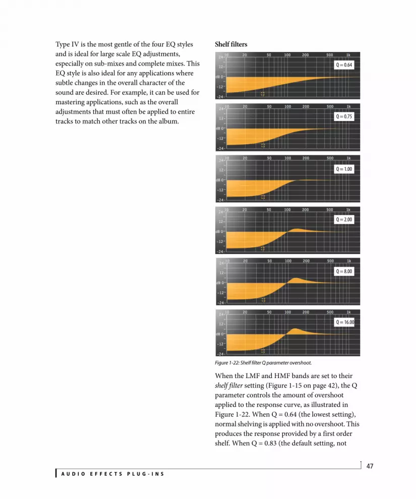
A U D I O E F F E C T S P L U G - I N S47
Type IV is the most gentle of the four EQ styles and is ideal for large scale EQ adjustments, especially on sub-mixes and complete mixes. This EQ style is also ideal for any applications where subtle changes in the overall character of the sound are desired. For example, it can be used for mastering applications, such as the overall adjustments that must often be applied to entire tracks to match other tracks on the album.
Shelf filters
Figure 1-22: Shelf filter Q parameter overshoot.
When the LMF and HMF bands are set to their shelf filter setting (Figure 1-15 on page 42), the Q parameter controls the amount of overshoot applied to the response curve, as illustrated in Figure 1-22. When Q = 0.64 (the lowest setting), normal shelving is applied with no overshoot. This produces the response provided by a first order shelf. When Q = 0.83 (the default setting, not
Q = 0.64
Q = 0.75
Q = 1.00
Q = 2.00
Q = 8.00
Q = 16.00

A U D I O E F F E C T S P L U G - I N S48
shown), the response corresponds to a second order shelf, still with no overshoot. This is the same response as Digital Performer’s parametric EQ and many hardware EQs. In some situations, this form of accurate, clean shelving can sound harsh, especially when compared to legacy analog EQs. To soften the results, the overshoot is increased as Q is increased, as shown Figure 1-22 for Q values of 1.00, 2.00, 8.00 and 16.00. This overshoot region produces a boost in frequencies just above the cutoff, which compensates in a smooth, more pleasing fashion for the perceived drop in low frequencies being cut.
Conversely, when shelving boost is being applied, overshoot cuts frequencies just above the cutoff to again compensate in a smooth and pleasing fashion for the perceived boost in low frequencies:
Figure 1-23: Overshoot when low shelf boost is applied.
Overshoot is also applied to high shelf boost and cut:
Figure 1-24: Overshoot when high shelf cut and boost is applied.
Overshoot tends to produce more of what one would expect to hear when applying shelving and is therefore considered to be more musical than shelving without overshoot. This effect, which has gained tremendous popularity among audio engineers, was first made popular in original Neve series EQs and later in the SSL G series.
At the maximum Q setting of 16.00, the overshoot region consists of half the total boosted (or cut) gain. For example, with a maximum gain setting of +20dB, the loss in the overshoot region is -10 dB.
Overshoot curves are symmetrical for both cut and boost.
Low pass and high pass filtersMasterWork EQ’s low pass and high pass filters are similar to those found in Digital Performer’s parametric EQ (which has a fixed slope of 12 dB per octave), except that MasterWorks EQ provides six different slope (roll off) settings: 6, 12, 18, 24, 30 and 36 dB per octave. This control over the shape of the “knee” gives you a great deal of flexibility and control for a wide variety of applications.
Figure 1-25: The low pass filter with three example slope settings.
Slope = 6
Slope = 18
Slope = 36
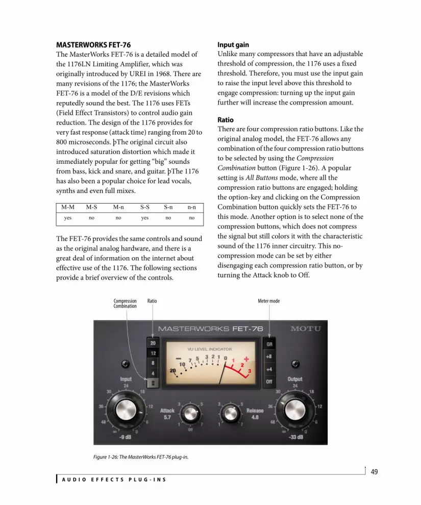
A U D I O E F F E C T S P L U G - I N S49
MASTERWORKS FET-76The MasterWorks FET-76 is a detailed model of the 1176LN Limiting Amplifier, which was originally introduced by UREI in 1968. There are many revisions of the 1176; the MasterWorks FET-76 is a model of the D/E revisions which reputedly sound the best. The 1176 uses FETs (Field Effect Transistors) to control audio gain reduction. The design of the 1176 provides for very fast response (attack time) ranging from 20 to 800 microseconds. þThe original circuit also introduced saturation distortion which made it immediately popular for getting “big” sounds from bass, kick and snare, and guitar. þThe 1176 has also been a popular choice for lead vocals, synths and even full mixes.
The FET-76 provides the same controls and sound as the original analog hardware, and there is a great deal of information on the internet about effective use of the 1176. The following sections provide a brief overview of the controls.
Input gainUnlike many compressors that have an adjustable threshold of compression, the 1176 uses a fixed threshold. Therefore, you must use the input gain to raise the input level above this threshold to engage compression: turning up the input gain further will increase the compression amount.
RatioThere are four compression ratio buttons. Like the original analog model, the FET-76 allows any combination of the four compression ratio buttons to be selected by using the Compression Combination button (Figure 1-26). A popular setting is All Buttons mode, where all the compression ratio buttons are engaged; holding the option-key and clicking on the Compression Combination button quickly sets the FET-76 to this mode. Another option is to select none of the compression buttons, which does not compress the signal but still colors it with the characteristic sound of the 1176 inner circuitry. This no-compression mode can be set by either disengaging each compression ratio button, or by turning the Attack knob to Off.
M-M M-S M-n S-S S-n n-nyes no no yes no no
Figure 1-26: The MasterWorks FET-76 plug-in.
RatioCompression Combination
Meter mode

A U D I O E F F E C T S P L U G - I N S50
Attack and ReleaseAttack and release knobs control the response time of the gain reduction circuit. þRelease time is variable between 50 milliseconds and 1.1 seconds. þ
OutputThe output knob allows you to trim the overall level of the signal, after being processed.
Meter modesThere are four Meter Mode buttons that determine what the meter is displaying. GR mode displays the gain reduction of the compressor. +8 and +4 modes show the level of the output signal where 0 on the meter corresponds to +8dB and +4dB, respectively. Off turns the meter off and bypasses the plug-in.
MASTERWORKS GATEThe MasterWorks Gate provides sophisticated gating effects with simple to use graphic controls.
Hold down the Option key while adjusting a parameter to program both sides of the stereo gate.
ControlsInput: boosts or attenuates the signal before going into the gate.
Threshold: sets the point at which the gate is triggered. Lowering the threshold causes the gate to be opened by a lower level signal. Threshold can also be set graphically by dragging the red control point at the bottom of the ratio graph.
M-M M-S M-n S-S S-n n-nyes no no yes no no
Figure 1-27: The MasterWorks Gate plug-in.
ratio graphs
threshold control

A U D I O E F F E C T S P L U G - I N S51
Range: sets the range of attenuation applied to the signal when the gate is closed. A setting of -inf causes the gate to close completely, which results in no signal being passed. Higher settings attenuate or ‘duck’ the signal. Range is displayed in the ratio graph as a diagonal line below the threshold point.
Attack: determines how quickly the gate opens after the signal has crossed the threshold.
Hold: determines how long the gate stays open after the signal has descended below the threshold.
Decay: determines how quickly the gate will close down after the hold period has elapsed.
Status lights: indicate current gate envelope status. Red=closed, green=open and yellow indicates the hold segment of the envelope is active.
Look-ahead: by looking for transients before they occur, the MasterWorks Gate can open the gate before the signal, thus preserving the attack transient.
The look-ahead parameter introduces a delay into the signal path for analysis purposes. Look-ahead analyzes the non-delayed signal and it tells the
gate when to open. You can avoid the look-ahead delay by setting look-ahead to zero or compensate by nudging the track ahead in the sequence editor by the exact amount of look-ahead you specify.
KeyingMasterWorks Gate can be keyed three ways: from the input signal, from a sidechain bus or by a MIDI signal.
The MasterWorks Gate publishes itself as a MIDI device to Digital Performer (and other CoreMIDI-compatible software). In Digital Performer, you can trigger MasterWorks Gate with MIDI notes. With automatable envelope parameters and MIDI triggering, the MasterWorks Gate works like a VCA on a modular synthesizer. When teamed with Multimode Filter, you now have a very flexible signal processing environment.
Key FiltersThe key filters can be used to isolate a specific frequency range of the key signal. This can be useful for preventing false triggering. The default setting of the key filter permits all frequencies to pass.
Key ListenIn Key Listen mode, MasterWorks Gate outputs the key signal instead of the gated input signal.
Figure 1-28: The MasterWorks Gate mono version.

A U D I O E F F E C T S P L U G - I N S52
Key listening is a valuable tool for tuning the gate. If your key signal is also the input signal, key listen allows you to audition the key filters to isolate a frequency range. If your key signal is a side chain bus, key listen will allow you to hear the sidechain input. If you are keying off a MIDI signal, MasterWorks Gate will play a tone representing the MIDI trigger.
Stereo: when stereo is enabled, the key source is a stereo bus.
MASTERWORKS LEVELER
The MasterWorks Leveler provides an accurate model of the legendary Teletronix™ LA-2A® optical compressor, known for its unique and highly sought-after Automatic Gain Control (AGC) characteristics.
A model of an optical compressorThe simplest description of an optical leveling amplifier device is a light shining on a photore-sistor. The intensity of the light source is proportional to the audio signal, and the resistance of the photoresistor is in turn inversely proportional to the intensity of the light. Photore-sistors respond quite quickly to increases in light intensity, yet return to their dark resistance very slowly. Thus, incorporation of the photoresistor into an attenuator followed by an amplifier which provides make-up gain produces a signal which maintains a constant overall loudness.
Automatic gain control using lightThe Automatic Gain Control (AGC) circuit of the LA-2A uses a vintage opto-coupler known by its model number (T4). The T4 contains an electrolu-minescent panel (ELP) and photoresistor mounted so that the emission of the panel modulates the resistance. An ELP consists of a thin layer of phosphorescent material sandwiched between two insulated electrodes to form a capacitor. Making one of the electrodes transparent allows the light to escape. These devices are essentially glow-in-the-dark paint on a piece of foil covered by metalized glass or plastic, and are the same devices used in low-power night lights. Unfortunately, these devices need high voltages to operate, and are best driven by tube circuits which can supply voltage swings of several hundred volts.
Response characteristicsWhen the light has faded away, the photoresistor then decays back to its dark state. The shape of the decay curve varies depending on how bright the light was and how long the light lasted. A general rule of thumb is that the louder the program, the slower the release. Typically, the release can take up to and over one minute. One thing to keep in mind when using these types of devices is that the typical concepts of compression ratio, attack, release, and threshold do not apply. The light
M-M M-S M-n S-S S-n n-nyes no no yes no no

A U D I O E F F E C T S P L U G - I N S53
intensity is determined by the highly non-linear interactions of the input signal, AGC circuit, and ELP, and thus exhibit a strong program dependence that is impossible to describe without the mind-numbing mathematics of statistical mechanics. The actual results, however, can be almost mystical: even when you feed the same material (a loop perhaps) through the Leveler twice, you’ll often see a new response the second time through a loop, complete with unique attack times, release times and compression ratios. Furthermore, two different input signals with the same RMS levels may be leveled in a drastically different manner.
It is precisely this self-adjusting behavior that makes optical compressors the tool of choice for smoothing out vocals, bass guitar and full-program mixes without destroying perceived dynamics.
On/Standby buttonThe Leveler models the LA-2A so closely, it also models the time it takes for an actual LA-2A to “wake up” after it is enabled. Therefore, when you first instantiate the Leveler, give it a moment to “settle” before you begin processing signals with it. If you wish to temporarily bypass it, without actually shutting down its “virtual circuits”, don’t use the plug-in window’s bypass button. Instead, enable the Leveler’s STNBY (Standby) button. To go back to a fully processed signal, disable the STNBY button. This allows you to do instant A/B comparisons, without having to wait a while for the Leveler to wake up each time it is engaged. Note, however, that the STNBY button does not release the system resources required to apply the Leveler processing, so if you wish to completely release them, use the plug-in window’s Bypass button instead of STNBY.
Compressor/Limit buttonsThe Comp and Limit buttons model the original LA-2A Limit/Compress mode switch. The effect is very subtle, with the Limit option behaving only slightly more like a limiter than a compressor. The switch increases the level of the input to the AGC model and runs the attenuator at a slightly lower level. The Leveler then responds more strongly to transients, but otherwise still behaves like a leveling amplifier.
Gain ReductionGain Reduction sets the strength of the signal sent to the AGC model.
Makeup GainMakeup gain amplifies the output signal to make up for gain reduction.
In/GR/OutThe In, GR and Out buttons choose which signal is measured by the meter. In measures input. GR reads the gain reduction of the T4 cell. OUT reads the output level.
Opto-coupler modelThe Opto-coupler Model buttons selects one of four personalities based on general characteristics exhibited by vintage and modern generations of the LA-2A.
ResponseThe Response knob adjusts the characteristics of the filter which feeds the photoresistor. This results in a subtle adjustment to the attack time.
The MasterWorks Leveler plug-in very accurately replicates the behavior of the LA-2A hardware. The initial conditions of the Leveler model are by default set to a state that resembles a hardware unit that has not been powered on during the last 24 hours.

A U D I O E F F E C T S P L U G - I N S54
With a real LA-2A, and by design in the Leveler, you can get different “warm state” behaviors depending on the audio material you run through the unit during its “waking” stage, a process known as priming the cell. In the Leveler, this warm state of the T4 cell can be saved and recalled, allowing you to immediately restore it, rather than going through the process of attempting to recreate it from a cold start.
Initially, however, to produce a warm state, you must let the Leveler plug-in go through the waking process the first time, just like the real hardware. Once you’ve done so, you can capture the state of the opto-coupler for future immediate recall.
Leveler plug-in initializationOnce a cell state has been saved, it will be used whenever the Leveler is initialized, which occurs at the following times:
When the host software audio engine first starts up
When the Leveler plug-in is first instantiated
When the opto-coupler model is changed
When the Leveler is un-bypassed
When the host software playback position changes in pre-rendering mode (Digital Performer only)
During Bounce-to-Disk operations
When manually recalling a saved state (see below)
If no cell state has been saved, the Leveler employs a cold-cell initialization that emulates a T4 cell that is essentially “sound asleep”. Therefore, it is always a good idea to save the cell state, once the desired warm state behavior has been achieved. This will produce predictable results in all of the initialization situations above.
The cell memory menuThe cell memory menu shown in Figure 1-29 lets you save the warm state for the above initialization situations, without re-training the cell model. Click on the meter to access the T4 cell memory management menu (Figure 1-29):
Figure 1-29: Saving the state of the T4 cell
Save current T4 Cell memory: Takes a snapshot of the current T4 cell state.
Undo last memory-saving operation: undoes the last save or erase operation.
Erase saved memory: each opto-coupler model (Fast Modern, Slow Modern, Fast Vintage, Slow Vintage) can have its own saved T4 cell state. Use this command to get rid of the current saved state for the chosen model.
Automatic Memory Restoration: when this menu item is checked, the saved T4 cell memory state will be immediately recalled (for the currently chosen opto-coupler model) when the Leveler plug-in is first activated (instantiated, un-bypassed, or the model is changed).
Re-load saved memory now: recalls the saved T4 cell memory state for the currently selected opto-coupler model.
Erase Saved Memory For All Models: gets rid of the saved memory states for all models at once.
Cell memory and presetsIf you save a Leveler preset, any currently saved T4 cell memory states are included in the preset.

A U D I O E F F E C T S P L U G - I N S55
MASTERWORKS LIMITERThe MasterWorks Limiter maximizes the apparent volume within the available dynamic range by reducing the distance between average program levels and their associated peaks.
MasterWorks Limiter allows for precise control of dynamics and output level of digital audio signals. It also includes quantization and dithering to preserve fidelity when changing bit resolution of digital audio samples.
MasterWorks Limiter processes audio at 64-bit floating point resolution, which provides the highest possible fidelity with no added noise. This means you can preserve the fidelity of your 24-bit audio files. In addition, MasterWorks will dither your final mix to any resolution you require, from 24-bit resolution for DVD to 8-bit resolution for internet and multimedia material. You can also apply unconventional bit depths for Special effects. (Ever tried 5-bit audio?) MasterWorks will maximize a signal for any available output resolution.
MasterWorks is designed primarily to process your final mix output, but it is also very useful for submixes. For example, use MasterWorks on your drum submix to fatten up its sound.
Figure 1-31: MasterWorks Limiter signal flow.
How it worksThe MasterWorks Limiter is a two part plug-in. It starts with a sophisticated level control section, then adds the ability to quantize and dither samples for the purpose of changing bit resolution.
M-M M-S M-n S-S S-n n-nyes no no yes no yes
Figure 1-30: The MasterWorks Limiter plug-in.
Input Gain
Limiter
Quantizer/Dither
Output Gain

A U D I O E F F E C T S P L U G - I N S56
Digital audio samples have a fixed dynamic range. Unlike analog media such as tape or vinyl, digital audio cannot be any louder than “0” VU. When mixing for digital media, it is important to keep the program material within the available dynamic range and below digital zero.
A related process, called normalization, finds the loudest sample in a region and increases its gain to the maximum available amplitude. All other samples in the region are increased by the same amount. The problem with normalization is that one loud spike in the mix will cause the rest of the mix to be at an apparently low level. Limiting allows you to increase the overall gain of the signal while limiting only signals that exceed “digital zero”. Limiting is “brick wall”, in that signals cannot be any louder than the set ceiling. As the average signal level is increased, and peaks are limited, there is less and less dynamic range to the program material. Too much limiting will sound very unnatural. Just the right amount of
maximization will make the program material seem loud without ever exceeding the available dynamic range.
Changing bit depth with ditherBit depth or resolution is the number of ones and zeros used to describe a digital audio sample. Commercial CDs use 16-bit samples. MOTU software has the ability to record 16 bit, 24 bit, or 32 bit floating point samples. Under some circum-stances, it may be desirable to have lower sample resolution, such as 8 bit web audio or 12 bit sampler playback.
It is possible to change the bit depth of digital audio. Reducing the bit depth adds quantization distortion. To overcome this, dither can be applied. Dither is a small bit of noise that is applied the digital audio as it is quantized. This actually reduces the amount of distortion introduced by quantization, and has a more pleasing sound, particularly for softer passages in material with a
Independent LFE controls
limiter and detector path enable/disable
metering options
adjust input gain with these controls or type a value e directly into the value box
Figure 1-32: MasterWorks Limiter Surround Edition.

A U D I O E F F E C T S P L U G - I N S57
wide dynamic range. The disadvantage of adding dither is an increased noise floor. Noise-shaping spectrally shapes the dither noise so that it is less noticeable.
ControlsInput Gain L/R: Boosts or attenuates the signal going into the limiter.
Link: Links left and right inputs. If left and right gain controls are set to different values, and then the link button is engaged, the relative difference between left and right is maintained while linked.
Threshold: Sets the point at which the limiter starts to affect the input signal. Lowering the threshold setting has the apparent effect of raising the output gain of the signal. What is actually happening is that the average level of the signal is increased while the limiter assures that the signal will not exceed the ceiling.
Threshold can be set three ways:
1 with the Threshold knob (and associated value box directly beneath)
2 with the slider on the compressor's input meter
3 with the handle located at the bottom of the input/output ratio graph.
Clear: Clears peak settings from the meters. Peak meters show the loudest that the signal has been detected.
RMS: Shows the average level of a signal. Since the average level of a mix is usually well below any maximum peaks, it is useful to know what the average level is as well as the loudest points. This is very helpful when matching the apparent levels of more than one mix.
Lookahead: Senses program material that exceeds the threshold before it actually occurs. By looking ahead for peaks, the Limiter can be ready for attenuation before the peak, giving a very smooth limiter attack.
The lookahead parameter introduces a delay into the signal path for analysis purposes. Lookahead analyzes the non-delayed signal and it tells the limiter how to process the delayed signal. This will help provide a more natural, smooth sounding final output. The more lookahead you specify, the smoother the limiter will sound. Be aware that if Digital Performer’s automatic plug-in delay compensation is not enabled and you combine the output of the lookahead limiter with the original signal, you will perceive a delay that directly corresponds to the amount you specified in the lookahead parameter box. In general, the lookahead should be short compared to the release.
Release: Controls how long it takes for the limiter to recover from attenuating the signal after the signal has dropped below the threshold.
Ceiling: Sets the maximum output of the limiter
Quantizer/16/24 Buttons: Easily sets output quantization. Other bit resolutions can be set by typing the number into the value box.
Dither: The final output can be dithered to any resolution from 24 bits to 1 bit. Dithering applies very small amounts of noise to the signal to reduce the quantization distortion that occurs at low levels.
Noiseshaping: Changes the characteristic of the dither noise, making it less noticeable. But don’t use noiseshaping if you plan to process your output further, such as in a sampler.
A U D I O E F F E C T S P L U G - I N S58
PresetsThe MasterWorks Limiter presets represent common applications. If you are changing bit depth, you'll see presets to go from 16 bits to 24 bits. For the bit depth changes, dither is part of the preset. If you are not changing bit resolution, don't add dither.
Compression and limiting are subjective effects. Sometimes you may want to hear the effect of the limiter. Other times, you may want a more subtle effect that is “invisible” and just catches the audio peaks. Input gain will have a strong bearing on what the MasterWorks Limiter actually does to the signal. Experiment with input gain and threshold to get the sounds that are most appropriate.
Masterworks Limiter (n-n channels)For surround mastering, the Masterworks Limiter Surround Edition (Figure 1-32 on page 56) provides an independent LFE channel and comprehensive control over the detector path.
MeteringThere are two slots for displaying peak and RMS values on input or output on every channel. You can set which values you are looking at by using the menus above the meter value bar.
The detector pathIn most limiters, the detector path and the input are the same thing. How the limiter reacts depends entirely on the input signal. Surround applications may require a bit more flexibility and that is why the detector path has been decoupled from the input. MasterWorks Limiter allows you to determine which inputs get sent to the detector path. In addition, you can exempt channels from the action of the limiter. For example, if you want to limit the left and right channels based on dialog in the center channel, you would enable only the center channel to the detector path and enable the limiter on the left and right channels.
LFE limiter modeIn linked mode, the LFE channel is treated like any surround channel, that is, the limiting of the limiter will be determined by the main detector path. In independent mode, the detector path for the LFE is unlinked from the other channels and operates independently on its own input. Three additional controls appear in independent mode: LFE Threshold, LFE Release and LFE ceiling. These controls work exactly like their counterparts in the main section of the limiter, but operate only on the LFE signal. The independent LFE controls have their own color coded display in the ratio graph and limiting display. Look-ahead still determines the Look-ahead (if any) on all channels regardless of the status of the LFE limiter mode.

A U D I O E F F E C T S P L U G - I N S59
MEGASYNTHMegaSynth is a subtractive synth processor intended primarily for guitar and bass, although you can certainly run any signal you wish through it. MegaSynth generates octave, sub-octave and square wave tones based on the input signal. You can mix, route and process the four signals (voices) in a virtually infinite number of ways. The router section of the window (Figure 1-33) contains the voices, filters and amp, along with the routings between them. Below are modulators and macro controls.
VoicesThe voices in MegaSynth (Figure 1-33) are generated from the input to the plug-in; in addition to the input audio itself, sub-octave, octave and square wave signals are created. The gain knob within each voice module controls the volume of that voice.
Low-pass filtersTo the right of the four voices are two low-pass filter modules, with cut-off frequency and Q-factor (resonance) settings for the filter.
M-M M-S M-n S-S S-n n-nyes yes no yes no no
Voices
Figure 1-33: The MegaSynth plug-in.
Router section
Modulators
Modulator and macro range

A U D I O E F F E C T S P L U G - I N S60
AmpBelow the filters is the amp module. In the mono version of MegaSynth, there is one knob in the Amp module, which controls the volume of anything going through it.
In the mono-to-stereo version there is an additional knob which controls the pan of the stereo output of the Amp Module. In the stereo version the additional knob controls the stereo width of the stereo output of the Amp module.
Pan versus stereo widthThe difference between pan and stereo width is that pan takes a mono input and produces a stereo output; stereo width takes a stereo input and produces a stereo output.
If you have a mono input, there is no reason to use the mono version instead of the mono-to-stereo version, which has the extra panning capability, unless you needed a mono output for a specific reason.
OutputOn the far right of the Routing section, you will see the OUT module. This is the output of MegaSynth; anything you want to hear must be connected to OUT.
Connecting modulesTo connect modules together, you need to create Routings. Routings are indicated by a red line that connects two modules. To create a Routing, drag from the source button of one module to the destination button of another. Source buttons have a “D-pad” type symbol. Destination buttons have a plus sign (+) symbol.
Not all sources can connect to all destinations; while you are dragging from a source button, the allowable destinations become highlighted; non-allowed destinations become greyed out.
Each source can connect to only one destination, but two or more sources can connect to the same destination.
To remove a routing, either connect that source to another destination, or simply click the source button. You will notice that the Amp can only connect to OUT, so that Routing cannot be altered.
When there is a routing from a voice to OUT, either directly or indirectly through filters and/or the amp, the border around the modules become highlighted to clarify that they are contributing to MegaSynth’s output.
Assigning modulators and macros to a module parameterThe modulator section (Figure 1-33) provides modulators and macros. Modulators and macros connect to and control module parameters (the large gray knobs) for the voice, filter and amp modules.
The modulator and macro range knobs (Figure 1-33) control the amount (the range over which) the modulator and/or macro connected to that module parameter can alter the parameter. A colored ring around the module parameter (that matches the color of the modulator or macro) visually indicates the range.
There are two ways to assign modulators and macros:
by dragging from the modulator/macro source button (next to its name) to the desired parameter knob, or
by using the menu next to the modulator/macro range knob.
To cancel a modulator/macro assignment, either connect a different modulator/macro to the same module parameter, or select the “-” menu item.
A U D I O E F F E C T S P L U G - I N S61
ModulatorsLike most subtractive synthesizers, parameters can be modulated. In MegaSynth, there are three types of modulators: envelopes, LFOs and pattern. Click their tabs in the Modulator section (Figure 1-33 on page 59) to access them.
When a modulator is assigned to a parameter, its range knob (Figure 1-33) turns the same color as the modulator, and the modulator name appears. Click the name to switch to a different modulator or macro.
EnvelopesThere are three envelope modulators. Env1 and Env2 are traditional ADSR envelopes. Env Follower is a signal related to the strength of the input signal to MegaSynth.
Env1/2The trigger parameter controls when the envelope signal begins its attack and release stages: when the input to MegaSynth rises above the trigger value, a green indicator appears above the trigger knob and the envelope proceeds through its attack, decay and sustain (ADS) stages. When the input signal strength drops below the trigger value, the release stage (R) is initiated and the green indicator above the trigger knob disappears.
To show which ADSR stage Env1 and Env2 are currently in, rectangular indicators appear below the appropriate ADSR knob of each envelope.
Env FollowerThe Env Follower has one parameter: Sensitivity. This is simply a gain applied to the signal obtained from the envelope of the input signal to MegaSynth.
LFOsThere are two LFOs in MegaSynth. Each LFO can be one of four possible waveforms: sine, square, triangle and saw. The frequency of the LFO is relative to Digital Performer’s tempo. Choose the desired metric division from the LFO speed menu.
PatternThere is one Pattern modulator. The Pattern Modulator consists of up to 16 stages. Click them to turn them on or off. Each stage has the same Attack and Release, and these are set by the A and R knobs in the Pattern tab. Use the menus provided to choose the desired number of steps and their speed relative to Digital Performer’s tempo.
MacrosMacro controls allow you to change several Parameters simultaneously. For example, increasing a Macro knob could simultaneously increase the cut-off frequency of Filter1, decrease the volume of the sub-octave voice and pan the Amp’s output to the left. Macros provide a convenient way of dramatically changing the sound of MegaSynth. Macros help with automation, too, because automating one macro is a lot simpler than automating many individual parameters. Macros are ideal for connecting to an external hardware controller knob using Digital Performer’s Learn Controller feature.
MegaSynth provides two macros. As with the modulators, each macro can be connected to multiple module parameters, but each module parameter may only be connected to one macro at a time.

A U D I O E F F E C T S P L U G - I N S62
MICROG AND MICROBMicroG and MicroB are subtractive synth processors based on the idea behind popular “polyphonic octave generator” (POG) guitar processors. These two plug-ins are similar to MegaSynth, except that each is streamlined significantly. Each can generate octave, sub-octave and square wave tones based on the input signal, combined with a gain-triggered filter sweep.
VoicesIn the center section of the plug-in, you can control the volume of the four voices generated by MicroG and MicroB: the input audio itself (Guitar or Bass Guitar), plus the generated Sub Octave, Octave and Square Wave signals. Control the relative levels of the four voices with their gain controls.
Master volumeThe Master volume control provides both cut and boost (up to +18 dB). This setting can be useful for managing the relative volume of the plug-in’s
M-M M-S M-n S-S S-n n-nyes no no yes no no
Figure 1-34: MicroG and MicroB plug-ins.
Voices
Filter settings

A U D I O E F F E C T S P L U G - I N S63
overall output, based on what might be happening as a result of the current filter settings, which can sometimes attenuate overall output level.
TriggerThe trigger section sets the input level required to trigger the filter sweep. With the trigger set low, all notes will trigger the sweep. With the trigger set high, only loud notes will trigger the sweep. The green LED indicates when the input level is above the trigger value; the filter sweep will not retrigger until the input signal has dropped below the trigger level first.
Filter settingsThe filter settings section provides Start and End frequencies which set the start and end frequencies of the filter sweep. If the start frequency is above the end frequency, the filter will sweep downwards, and vice versa. The Sweep Rate controls the speed of the filter frequency sweep, and filter Resonance injects attitude, as usual.
MS DECODER
Figure 1-35: MS Decoder.
The MS Decoder plug in is a handy tool for decoding a mid-side stereo mic setup.
MS Decoder is a S-S plug-in only. One side of the stereo track should contain the output of the cardioid mic, which is pointed directly at the source and the other side of the track should contain the output of the figure-eight mic which is positioned at a 90-degree angle to the cardioid. It does not matter which side is which, simply use the swap button to match the side to the proper mic. MS Decoder will properly matrix the stereo track and allow you to adjust the stereo image of the output with the stereo width control.
MULTIFUZZ
Figure 1-36: MultiFuzz.
MultiFuzz is a spot-on reproduction of Craig Anderton’s legendary QuadraFuzz mulitband distortion kit from decades past. Anderton developed a relatively straightforward concept that produces absolutely monster guitar tones: divide the input signal into four separate frequency bands and then apply distortion independently to each band. The results range from sublime warmth to absolute filth.
ControlsAttack: Controls the overall amount and character of the distortion, like a master pre-gain.
Lo/Mid1/Mid2/Hi: These are the four frequency bands, to which distortion is independently applied. Each band has its own gain and boost.
M-M M-S M-n S-S S-n n-n
no no no yes no no
M-M M-S M-n S-S S-n n-nyes no no yes no no

A U D I O E F F E C T S P L U G - I N S64
Boost: Adds more distortion, along with more pronounced filter response.
Tone: Varies the overall sound on a spectrum from dark to bright.
Output: Controls the overall output level of the plug-in.
MULTIMODE FILTER
The Multimode Filter lets you apply a filter (low pass, high pass, peak or notch) to mono or stereo tracks and then ‘sweep’ the filter in one of the following ways:
By plug-in automation
By MIDI note data (played live or from a track)
By LFO modulation
By envelope filter
LFO modulation can be specified in real-time or in one of several tempo-based modes, which lock the LFO to the tempo of your sequence, even if there are tempo changes. The envelope can be controlled by the plug-in input signal itself or via any audio signal bussed to the Multimode Filter's side-chain input.
OverviewChoose the desired filter at the top of the window and make the filter settings as desired. From there, you can sweep the Center frequency control (described below) in one of the four ways just described. To turn on automatic modulation, use the modulation button on the left. (When the light is green, modulation is on.) Use the yellow switch on the left to choose between LFO and envelope modulation. Make the LFO or envelope settings as described in the following sections. Manual modulation will be discussed last.
Filter settingsChoose the desired filter (low pass, high pass, bandpass or notch) and make the four filter settings as desired. Resonance emphasizes the cutoff frequency — or “Q” — of the filter shape. Center is the middle of the frequency range (in Hz) over which the filter will sweep. Center is also the ‘main attraction’ of the plug-in, as it is the parameter that is automated by the LFO, envelope, or MIDI data. Range is the extent of the filter’s sweep, expressed as a percentage of the center frequency. Mix is the ratio between the filtered and unfiltered signal.
LFO settingsChoose Real Time to specify the LFO oscillation rate in Hz. The phase sets the phase of the LFO in 45-degree increments relative to the start of the sequence. The Rate slider sets the frequency in Hertz (Hz). Choose the desired LFO waveform (sine, triangle, etc.) from the menu provided.
M-M M-S M-n S-S S-n n-nyes yes no yes no no

A U D I O E F F E C T S P L U G - I N S65
Figure 1-37: Setting the LFO rate in Hz (real time).
Choose Beats, Note Values or Bars to lock the LFO to the tempo of the sequence as shown below. The Phase and period controls turn into menus with note durations in them or bar (measure) lengths. These tempo-based modes make the LFO stay in tempo with your sequence, even through tempo changes.
Figure 1-38: Setting the LFO in beats or note values.
Envelope settings and the side chain inputThe envelope can be controlled by the plug-in’s main input or by any audio signal in the Digital Performer mixing environment bussed to the envelope as a side chain input. Just choose the desired bus from the menu provided. The arrow button is the envelope direction (up or down). Trigger is the retrigger sensitivity. Higher values let the envelope retrigger on smaller peaks in the input signal. Attack (the left side of the triangle graphic) is the attack time for the envelope in milliseconds. Release (the right side of the triangle graphic) is the release time of the envelope in milliseconds. Scale (the peak of the filter triangle graphic) scales the envelope for deeper or more shallow modulation.
Manual modulationTo manually modulate the Center frequency, you can either use plug-in automation or you can control it via MIDI notes from a MIDI track or
from your MIDI controller. For MIDI modulation, MIDI note A3 serves as a reference point at 440 Hz.
To use automation, be sure that automation is enabled for it (see chapter 71, “Mix Automation” (page 865) in the DP User Guide) and then simply record your moves of the Center frequency during playback. (You can also automate the other controls as desired.)
Modulation via MIDI notesTo modulate the Multimode Filter’s Center frequency via MIDI notes:
1 Add a MIDI track and assign its output to the Multimode Filter plug-in.
2 To trigger Multimode Filter from MIDI notes in the track, just insert or record notes into the track.
3 To trigger Multimode Filter from your controller keyboard, record-enable the track and make sure that Audio Patch Thru is enabled (in the Studio menu). If desired, you can record your patched thru performance into the track to preserve it and later edit it.
L/R phase (stereo versions only)Disable this option if you would like the left and right channels of the Multimode Filter’s output to be 180 degrees out of phase.
PARAEQ
The ParaEQ (parametric equalization) effect (Figure 1-39) comes in six variants: 2,4, and 8 bands of mono or stereo EQs. Regardless of how many bands you have displayed, only the non-bypassed bands cost processing power.
M-M M-S M-n S-S S-n n-nyes no no yes no yes
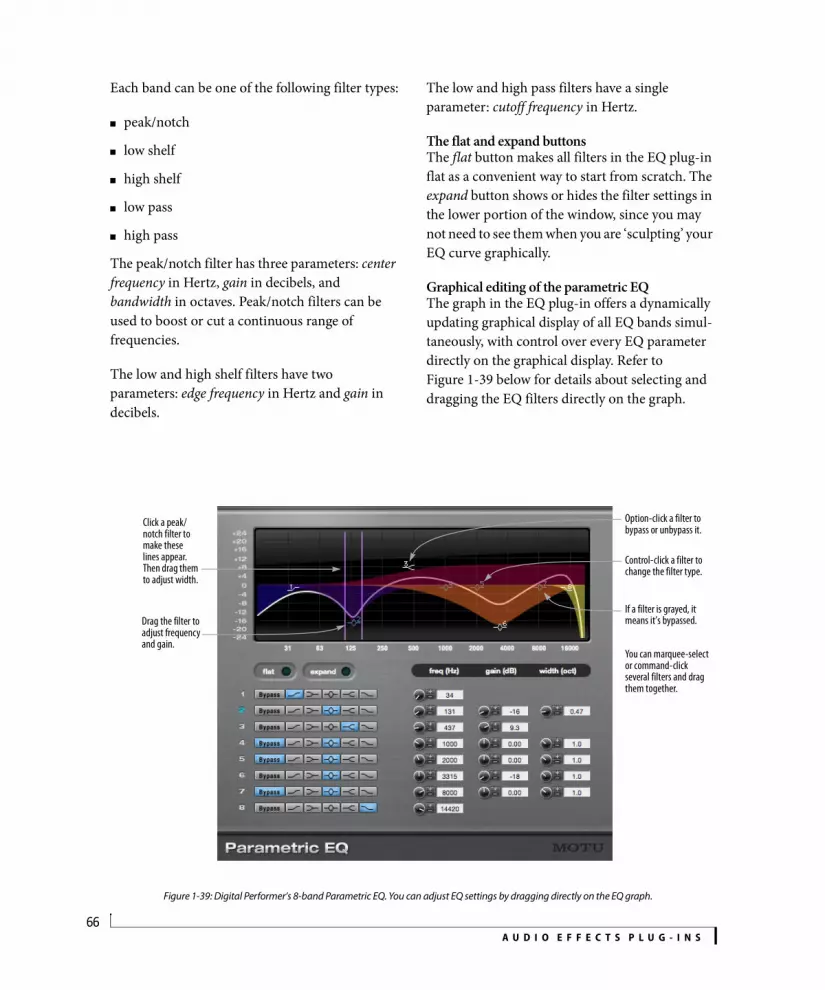
A U D I O E F F E C T S P L U G - I N S66
Each band can be one of the following filter types:
peak/notch
low shelf
high shelf
low pass
high pass
The peak/notch filter has three parameters: center frequency in Hertz, gain in decibels, and bandwidth in octaves. Peak/notch filters can be used to boost or cut a continuous range of frequencies.
The low and high shelf filters have two parameters: edge frequency in Hertz and gain in decibels.
The low and high pass filters have a single parameter: cutoff frequency in Hertz.
The flat and expand buttonsThe flat button makes all filters in the EQ plug-in flat as a convenient way to start from scratch. The expand button shows or hides the filter settings in the lower portion of the window, since you may not need to see them when you are ‘sculpting’ your EQ curve graphically.
Graphical editing of the parametric EQThe graph in the EQ plug-in offers a dynamically updating graphical display of all EQ bands simul-taneously, with control over every EQ parameter directly on the graphical display. Refer to Figure 1-39 below for details about selecting and dragging the EQ filters directly on the graph.
Figure 1-39: Digital Performer’s 8-band Parametric EQ. You can adjust EQ settings by dragging directly on the EQ graph.
Click a peak/notch filter to make these lines appear. Then drag them to adjust width.
Drag the filter to adjust frequency and gain.
If a filter is grayed, it means it’s bypassed.
You can marquee-select or command-click several filters and drag them together.
Option-click a filter to bypass or unbypass it.
Control-click a filter to change the filter type.

A U D I O E F F E C T S P L U G - I N S67
Surround (n-n) EQThe parametric EQ can be used on any multichannel signal path, including the master fader. There is no change to the interface. The EQ curve you create is applied to all non-LFE channels.
PATTERN GATE
The Pattern Gate (Figure 1-40) slices up the audio signal passing through it into pulses determined by the Speed menu, which displays metric divisions locked to the tempo of the sequence.
The pattern gate can be applied to just about any sound that sustains. Remember, however, that the tempo of the sequence plays an important role in the results.
Pulse shapeThe shape of each pulse is determined by the Pulse Shape graph (Figure 1-40), which represents 100% of the length of each pulse. Drag the handles to modify pulse Depth, Attack, Sustain and Decay. Or
edit the numeric values below the graph. Drag the Depth handle vertically to soften the gate, such as for a tremolo effect.
Pattern and LengthThe pattern itself is determined by the Pattern LED strip (Figure 1-40): click each pulse to toggle it on or off. Set the Length of the pattern (from 1-16 pulses) by dragging the Length handle.
Pattern Gate LFOThe Pattern Gate LFO (Figure 1-40) can be used to modulate the four pulse shape parameters (Depth, Attack, Sustain and Decay). Choose the desired LFO waveform (sine, sawtooth or rectangle) from the menu provided and set the desired Symmetry between 0 and 100, where 50 is normal symmetry. Then choose the desired Period, which is expressed in a number of pattern gate steps. The range is 0-256 steps. For example, if you choose a period of 110 steps, then the LFO will complete one cycle in 110 pattern gate steps.
After you’ve set up the Pattern Gate as desired, apply it to the desired pulse shape parameters using the LFO menus below each parameter. The range for the LFO setting is -100 to +100, where zero applies no LFO effect at all. +100 modulates
M-M M-S M-n S-S S-n n-n
yes no no yes no yes
Figure 1-40: The Pattern Gate plug-in.
Pulse shape
Pattern LEDs
Pattern Length
LFO

A U D I O E F F E C T S P L U G - I N S68
the setting from its current value all the way to the maximum possible setting. -100 modulates the setting from its current value all the way to the minimum possible setting.
SwingWhen the Swing parameter (Figure 1-40) is set to zero, the pattern gate plays in straight time (no swing). Other settings are as follows:
Negative values invert the ratio, which moves the swung note closer to the base note.
PHASER
The Phaser creates its effect by sweeping notches up and down the frequency spectrum. Rate controls the rate at which the notch center frequencies are modulated. Depth controls how far the notches sweep. Width controls the bandwidth of the notches, within a range determined internally. When Width is 100%, the bandwidth is set to the maximum allowed value.
The M-S, S-S and n-n Phasers have a check box to labelled L/R In Phase. When this option is checked, the center frequencies of the notches
applied to the left and right channels are the same. When it is not checked, high frequency notches are applied to the left channel while low frequency notches are applied to the right channel, and vice-versa.
PLATE
How it worksPlate produces the classic plate reverb effect. Plate can produce up to six seconds of reverb with detailed control over frequency distribution. The Plate interface has two modes of operation which can be accessed by clicking the expand triangle located in the upper right hand corner. The default mode displays the primary controls for tweaking the effect. Expert mode exposes advanced controls for shaping the characteristics of the plate.
ControlsReverb time: controls the overall length of the reverb time, in seconds
Swing amount Ratio Feel at 8th note speed
0 1 to 1 Straight 8ths
100 2 to 1 Triplet 8ths
125 2.5 to 1 Hard 8th swing
150 3 to 1 Hard 8th shuffle
M-M M-S M-n S-S S-n n-nyes yes no yes no yes
M-M M-S M-n S-S S-n n-nyes yes no yes no no
Stereo image controls only available on M-S or S-S versions.
Crossover graph
Control point
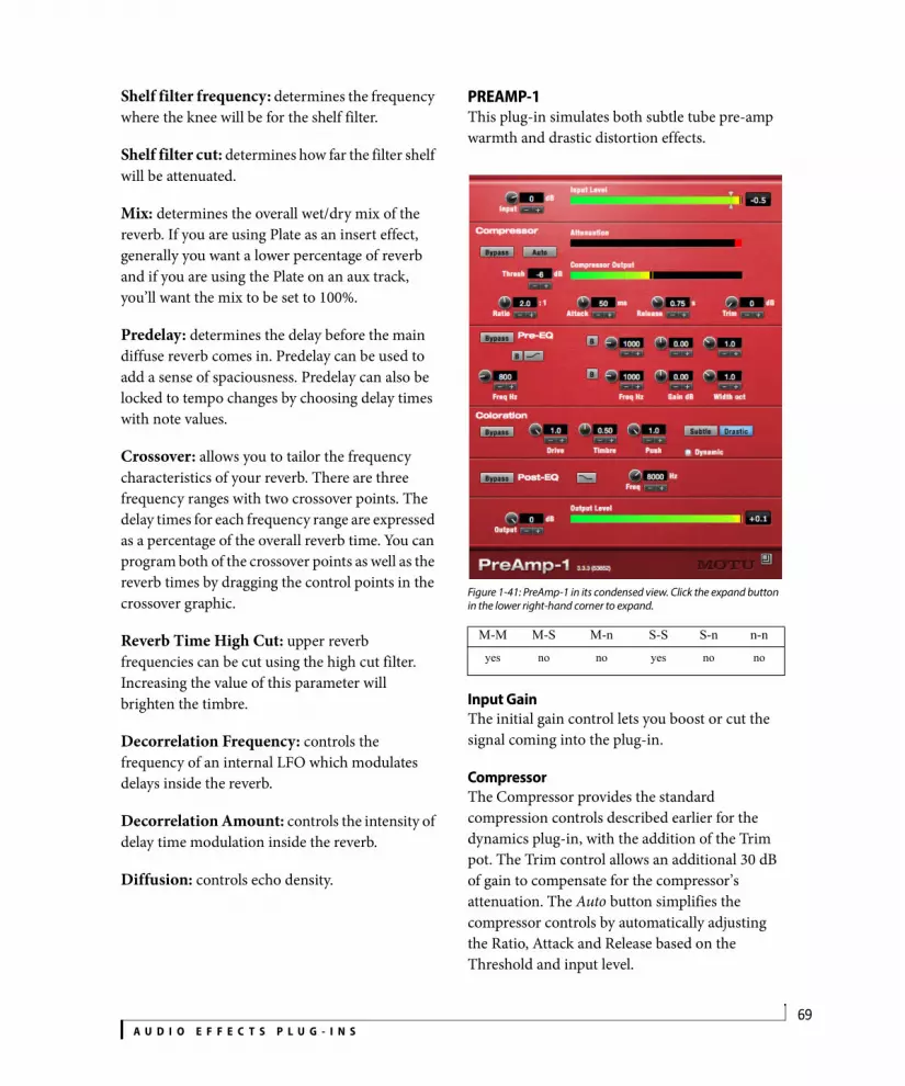
A U D I O E F F E C T S P L U G - I N S69
Shelf filter frequency: determines the frequency where the knee will be for the shelf filter.
Shelf filter cut: determines how far the filter shelf will be attenuated.
Mix: determines the overall wet/dry mix of the reverb. If you are using Plate as an insert effect, generally you want a lower percentage of reverb and if you are using the Plate on an aux track, you’ll want the mix to be set to 100%.
Predelay: determines the delay before the main diffuse reverb comes in. Predelay can be used to add a sense of spaciousness. Predelay can also be locked to tempo changes by choosing delay times with note values.
Crossover: allows you to tailor the frequency characteristics of your reverb. There are three frequency ranges with two crossover points. The delay times for each frequency range are expressed as a percentage of the overall reverb time. You can program both of the crossover points as well as the reverb times by dragging the control points in the crossover graphic.
Reverb Time High Cut: upper reverb frequencies can be cut using the high cut filter. Increasing the value of this parameter will brighten the timbre.
Decorrelation Frequency: controls the frequency of an internal LFO which modulates delays inside the reverb.
Decorrelation Amount: controls the intensity of delay time modulation inside the reverb.
Diffusion: controls echo density.
PREAMP-1This plug-in simulates both subtle tube pre-amp warmth and drastic distortion effects.
Figure 1-41: PreAmp-1 in its condensed view. Click the expand button in the lower right-hand corner to expand.
Input GainThe initial gain control lets you boost or cut the signal coming into the plug-in.
CompressorThe Compressor provides the standard compression controls described earlier for the dynamics plug-in, with the addition of the Trim pot. The Trim control allows an additional 30 dB of gain to compensate for the compressor’s attenuation. The Auto button simplifies the compressor controls by automatically adjusting the Ratio, Attack and Release based on the Threshold and input level.
M-M M-S M-n S-S S-n n-nyes no no yes no no

A U D I O E F F E C T S P L U G - I N S70
Pre-EQThis section of the plug-in allows you to apply three bands of EQ to the signal before the coloration section. This equalization can dramatically change the character of the coloration produced in the next section. The first band is limited to a low shelf or high pass filter. The second two bands are fully parametric peak/notch filters. The EQ controls are identical to the controls described earlier for the Parametric EQ plug-in.
ColorationThis section of the plug-in provides three main controls: Drive, Timbre and Push. Drive and Timbre affect the quality of the warmth (or distortion) being applied, and Push controls the amount of the affected signal present in the plug-in’s output. These knobs are affected by the Subtle/Drastic buttons (described next). The Dynamic button, when checked, automatically increases the Push when the input level rises above the Threshold (regardless of whether or not the compressor is bypassed).
Subtle/Drastic buttonsThese two buttons affect the Drive, Timbre, and Push controls. Subtle settings produce classic tube warmth; drastic controls provide heavy distortion effects.
Post-EQThis section of the plug-in offers one band of EQ after the coloration to further refine the output. This band is limited to a high shelf or low pass filter, and is useful for reducing the high frequency effects of the Coloration section.
Output gainProvides one final gain control.

A U D I O E F F E C T S P L U G - I N S71
PRECISION DELAY
Precision Delay produces sub-sample delays. Additionally, the plug-in works with DP’s latency compensation system to allow both positive and negative offsets.
Precision Delay is designed to be a problem-solving tool for the alignment of phase-related audio signals. The delay and phase parameters can be automated, making it the perfect tool for mixing techniques that require precise inter-channel delays.
Intelligent phase analysisThe key feature that sets the Precision Delay apart from other latency compensation products is its internal learning algorithm, which continually
analyzes the input signal in real time and compares it to a reference signal. When a phase comparison can be made, the Align button becomes active. Clicking this button sets the delay on the targeted input signal(s) to align it with the reference signal. If the All option is enabled, all non-reference signals are corrected.
OperationThe Precision Delay window consists of three regions. On the left side, graphical displays draw the reference and target waveforms. Controls for the learning module form a row beneath the graphical displays, which consists of reference/target selection menus and two buttons. Finally, each input-output channel has a delay section with coarse delay, fine delay, and phase inversion controls.
M-M M-S M-n S-S S-n n-n
yes no no yes no yes

A U D I O E F F E C T S P L U G - I N S72
Phase scopeThe two waveform scopes automatically synchronize to the strongest transient in the reference signal. The upper scope trace, drawn in blue, is fed by the currently-selected reference signal. The lower scope trace, drawn in green, shows the currently-selected target. When both signals are detected, the phase scope on the right becomes active, displaying a plot of the phase relationship between the two signals, along with an estimate of the delay and an indication of the phase relationship.
Reference signalOn all versions except mono-mono, there are two menus located below the display area. The Reference menu tells the learning algorithm which channel carries the reference input signal. This can be set to any input channel, or to Aux In, a mono side-chain input which is assigned in the menu bar above the plug-in. The menu labeled Target tells the learning module which channel should be considered the output channel.
Channel labelsThe channel labels on the delay strips (L and R) indicate the channel’s status. If green, the channel is the target. If blue, then the channel is the source. If a channel is neither source or target, or if it is the “C” channel on the mono variant, then the region is drawn in grey.
On non-mono variants of the plug-in, click the L and R channel labels to designate them as the target or reference:
Click designates the channel as the target
Shift-click designates the channel as the reference
If a channel assignment conflicts with another assignment, the roles are swapped, unless this would assign the side-chain input to be the target. In this case, the first un-assigned channel becomes the target.
Coarse and fine delayUse the Coarse and Fine delay controls to adjust the delay as follows:
PhaseChoose normal or inverted signal polarity.
TipsThe learning algorithm and real-time graphs
are computationally expensive. The plug-in is designed for set-it-and-forget-it use, so remember to close it once you’re finished with it.
It is normal to require more than one alignment, particularly on signals of an impulsive nature or for large latency problems.
The coarse and fine delay controls are two separate parameters for track automation.
Delay Range Precision
Coarse ± 30 milliseconds 1 millisecond
Fine ± 0.5 milliseconds 1 microsecond

A U D I O E F F E C T S P L U G - I N S73
PROVERB
ProVerb (Figure 1-42) is a convolution processor designed to be used as a reverb unit. Many factory-supplied impulse responses (sampled spaces) are provided, and you can load any audio file as an impulse response from your computer desktop, as long as it is in a standard audio file format (such as WAVE, AIFF, SDII, etc.).
The processing units model a matrix of mono reverb units on a dedicated bus, along with a highly configurable signal routing matrix designed to meet the needs of music production, foley and dialogue replacement. Additional features include a four-band graphic EQ and a dynamic mixing feature (ducker).
Choosing an impulse responseChoose the desired impulse response (acoustic space) from the Impulse Response menu.
This menu lets you choose both factory-supplied impulse responses and ones you have added to your library, and it operates similarly to Model 12’s Instrument menu. See “Instrument menu” on page 118.
Only impulse responses that match the current channel configuration will be shown. For example, when using the stereo-to-stereo variant of ProVerb, mono-to-mono and 5.1 surround impulse responses will not be shown.
Next/previous IR buttonsNext/previous buttons appear to the right of the currently loaded impulse response. When the last or first impulse response is reached, the next/previous buttons will wrap around to the other end of the list.
Figure 1-43: Next/previous impulse response arrows
M-M M-S M-n S-S S-n n-n
yes yes yes yes yes yes
Figure 1-42: ProVerb.
Non-automatedparameters
Impulse response menu
Meters
Dynamic mixing
Impulse response waveform
Automatedparameters
4-band EQ

A U D I O E F F E C T S P L U G - I N S74
Shortcut menuRight-click on the path of the current impulse response to display a shortcut menu containing the other impulse responses in the same submenu.
Figure 1-44: Impulse response shortcut menu
Importing your own impulse responsesProVerb can use any standard audio file as an impulse response. Most standard audio file formats are supported. Simply drag the audio file, or a folder of audio files, from the computer desktop and drop it into ProVerb’s waveform display (Figure 1-42).
You will then be prompted to select the installation location for the files. The files being imported can be copied to Shared, User, or Project, or any subfolder in one of those locations.
Figure 1-45: Importing impulse responses
While an import is in progress, a progress bar is shown . The import can be cancelled at any time with the Cancel button.
ProVerb impulse response managementProVerb organizes impulse responses into four categories:
Mac OS XThe Factory impulse responses are always available. User impulse responses are stored in your user directory and are therefore available only when you are the currently logged in user. You can use the user directory to protect your own impulse response content. Shared impulse responses are stored in the system application support folder and can therefore be made available to any users that you wish to share them with. Project impulse responses are stored with the host software project itself. By keeping them with the rest of the files associated with the project, you don’t have to worry about losing them when exchanging the project with a colleague, archiving the project, transferring it, etc.
Category Location on Mac
Factory In the MOTU application support folder:/Library/Application Support/MOTU/ProVerb/ProVerb Data.bundle
User In your user directory application support folder:User/Library/Application Support/MOTU/ProVerb/User
Shared In the shared user directory application support folder:/Users/Shared/Library/Application Support/MOTU/Plug-ins/ProVerb/Shared
Project In the Digital Performer project folder:Project/Plug-in Data/ProVerb/Project/
Category Location on Windows
Factory C:\Program Data\MOTU\Plug-ins\ProVerb\ProVerb Data.bundle
User C:\Users\[user name]\AppData\Roaming\MOTU\Plug-ins\ProVerb\User
Shared C:\Program Data\MOTU\Plug-ins\ProVerb\Shared
Project [DP project name]\Plug-in Data\ProVerb\Project

A U D I O E F F E C T S P L U G - I N S75
Figure 1-46: The Impulse Response menu.
To remove impulse responses from your ProVerb library:
1 Locate the desired category (Shared, User, or Project) in the Mac OS Finder or Windows desktop.
2 For Mac OS X: If you would like to remove the entire category, move the bundle to the Trash. If you would like to remove individual files or folders from that category, right-click the bundle file and choose Show Package Contents from the contextual menu. Select the desired folders and move them to the Trash.
For Windows: Go to Windows Explorer> Tools> Folder options > View tab and choose the Show hidden files, folders and drivers option under the Hidden files and folders category. To remove the entire category, move the folder to the Trash. To remove individual files or folders, browse and select the desired items and move them to the trash.
3 Choose Reload All Trees from ProVerb’s Impulse Response Menu, and the impulse response library will update to reflect the changes.
Non-automated settingsThe Predelay, Damping, and Length knobs (Figure 1-42) modify the impulse response during the loading process. Any change to these parameters necessitates a re-load of the impulse response. In conventional convolution processors, changing these parameters might take as long as 15-20 seconds to recalculate the impulse response.
In ProVerb, however, these parameters have been optimized so that they can be adjusted smoothly in real time. They cannot, however, be automated.
PredelayPredelay time-shifts the response function ± 99 milliseconds. Although this control is primarily intended to align the early reflections with the dry signal to eliminate comb filtering, it can also be used for artistic and sound design purposes.
LengthLength time-stretches the impulse response by resampling it. Use the length parameter to adjust the perceived size of the original space. Since resampling is applied, changing the length is also quite useful if you have a room response with a resonant frequency aligned with a frequency in the input signal: just resize the room slightly and the resonance will disappear — a technique that can be especially useful for kick drums and toms. This can be adjusted ± 4 times the original length.
DampingMost impulse responses are recorded in empty rooms. The Damping parameter simulates the effects of hanging curtains, changing atmospheric conditions, or adding people. It is simply a low-pass filter that simulates the effect of distance on high frequencies, and the Damping setting controls the rate at which the cutoff frequency decreases with distance.
Automated ParametersThe rest of ProVerb’s settings (below) can be fully automated.
Input/output routingThe input routing matrix is located just to the left of the Length knob. The Input gain and Output gain behave the same as those found on the front of a rackmount reverb processor patched into an

A U D I O E F F E C T S P L U G - I N S76
effects loop. Use them to control the level of the signal before it enters — and after it exits — ProVerb, respectively.
WidthWidth controls the stereo distribution of the input signal, and is thus disabled for the mono-mono variant.
In stereo-to-stereo mode, “hard left” maintains stereo routing and “hard right” feeds the left channel into the right input and the right input into the left channel. The dry signal is unaffected for the stereo variant.
In mono-to-stereo mode, Width is replaced by Pan, which sets the dry signal’s lateral placement within the mix. The wet signals are unaffected.
MixMix controls the ratio of wet signal to dry signal. Click the label above the knob readout to reveal a menu that lets you choose one of four options:
Four-band EQThe four-band EQ is derived from MasterWorks EQ (page 41). The first and fourth knob sets provide low and high shelving filters, respectively. The two center knob sets are typical boost/cut parametric EQ bands. The EQ section follows the reverb unit in the signal chain, and does not affect the dry signal.
Dynamic Mixing (ducker)The Dynamic Mixing section (Figure 1-42) follows the EQ in the signal chain and when enabled lowers the level of the reverb in the mix based on the level of the dry signal. Properly tuned, it allows a “wetter” mix while retaining intelligibility of the input signal. The signal chain model can be described as follows: a compressor after the reverb, but before the return, with its side chain input driven by the dry signal. The Threshold setting (Thresh) determines when the compressor kicks in, and Sensitivity (Sens) determines how strongly the compressor responds. The Comp knob defines the amount of gain reduction applied to the wet signal.
ProVerb meteringThe In meters read the input to the convolution unit after the Input gain is applied. The Out meter is computed before the Mix stage. These meters indicate signal energy or loudness, with a peak indicator that reads the true peak value of the signal. A significant difference in the peak indicator position and meter level is therefore normal. Clip warning indicators will illuminate if any overs occur.
QUAN JR.
Quan Jr. is a simple dithering and quantizing plug-in. It is useful if you want to use the dithering features of MasterWorks Limiter, but do not need
Mix option What it does
3 dB cross-fader Performs the mix using an equal-loudness cross-fader.
6 dB cross-fader Same as above, but with an equal-amplitude cross-fader. This option produces the “hole -in-the-middle” effect, but it is not as likely to generate overs.
Effect level Operates like the effect return level knob on a mixer. The dry signal gain remains constant, while the effected signal is fully attenuated at 0, not attenuated at 100%.
Dry level The effect return remains constant, while the dry signal level is attenuated.
M-M M-S M-n S-S S-n n-nyes no no yes no yes

A U D I O E F F E C T S P L U G - I N S77
the extra features and added overhead. This is especially important for mixing in surround if you are running low on CPU power.
Quan Jr. also makes a handy low resolution effects generator. Turn off dithering and set the quantization to three or four bits and get ready for some grunge.
For more information on dithering and quantization, “Changing bit depth with dither” on page 56.
REVERB
Predelay determines the time between the dry signal and the first echo in the wet signal.
Decay determines the length of the reverb tail.
Diffuse determines the smoothness of the rever-beration. Low Diffuse values create more distinct echoes in the reverberation.
Bright determines frequency dependence of the reverberation. High values of Brightness result in less reverberation of high frequencies. High value settings of this parameter increase the reverb time at high frequencies, resulting in a brighter timbre.
Reverb Gain is additional gain applied to the wet signal which can be used to compensate for the effects of the other controls.
REVERSE
Reverse is a available only as an offline operation; it is not available as a real-time plug-in in the Mixing Board or Effects window. When applied, it reverses the selected audio, just like playing a tape backwards.
RING MODULATOR
The Ring Modulator plug-in provides standard ring modulation, but with a few extra features that allow you to take full advantage of the Digital Performer plug-in automation and music sequencing environment.
A ring modulator accepts two input signals. If the two signals are pure tones, the ring modulator produces their sum and difference frequencies. With every-day audio material, however, the result is much more complex. Typically, ring modulators are used to add a metallic, clangy quality to a sound.
M-M M-S M-n S-S S-n n-nyes yes no yes no no
M-M M-S M-n S-S S-n n-nyes no no yes no yes
M-M M-S M-n S-S S-n n-n
yes no no yes no no

A U D I O E F F E C T S P L U G - I N S78
Modulation sourceWith Digital Performer’s Ring Modulator plug-in, one of the two source signals is, of course, the audio in the track you’ve assigned it to. The second source signal, the modulation source, can be one of the following:
The Ring Modulator’s built-in oscillator
The effect input itself (so it’s being modulated by itself)
Any audio signal bussed to the Ring Modulator’s side-chain input
Make your choice using the Modulation Source menu:
Figure 1-47: The Modulation Source menu.
OscillatorIf you have chosen to use the built-in oscillator (from the Modulation source menu), then choose the desired waveform (sine, square, etc.) and frequency (in Hz). You can leave the frequency at one setting, or you can modulate it in one of two ways:
By plug-in automation
By MIDI input from a track or controller
To use automation, be sure that automation is enabled for it (see chapter 71, “Mix Automation” (page 865) in the DP User Guide) and then simply record your moves of the frequency control during playback. (You can also automate the other controls as desired.)
To use MIDI input, from either a track or your MIDI controller, create a MIDI track and choose the Ring Modulator plug-in as the output device for the MIDI track in the Tracks window. For MIDI modulation, MIDI note A3 serves as a reference point at 440 Hz. For further details about setting up MIDI control of the Ring Modulator plug-in, follow the same procedure as outlined in “Modulation via MIDI notes” on page 65.
Modulation GainControls the apparent strength of the ring modulator effect.
LPF (Low Pass Filter) cutoffThe Low Pass Filter can be helpful for fine-tuning ring modulation effects and reducing the harshness of the sound. This control adjusts the cutoff frequency for the filter.
MixControls the mix between the plug-in output and the original dry signal.
MIDI control and Bounce to DiskIf you are modulating the oscillator with MIDI input from a track, select both the audio and MIDI tracks before using the Bounce To Disk command (File menu).

A U D I O E F F E C T S P L U G - I N S79
RXT
RXT is an emulation of ProCo’s The Rat™ distortion pedal.
Distortion: amount of distortion.
Filter: variable lowpass filter.
This knob operates in reverse when compared to the other pedal plug-ins.
Volume: output gain.
Status light: displays the bypass/enabled state; when lit, the effect is active.
Enable switch: bypasses/enables the effect. This works the same as the Effect window’s Bypass button.
SMPTE-Z
SMPTE-Z generates Longitudinal Time Code (LTC) while locked to DP’s time line or while running independently in Freewheel mode. The Stillframe option causes time code to continue to be generated even when DP’s transport is stopped (parked on one frame). Timecode can be routed anywhere via the audio track’s output assignment, allowing for accurate time code sync in a wide variety of situations.
Synchronize: Locks time code output to Digital Performer’s transport and time line. Use DP’s transport controls to start and stop time code, or cue to a certain time code location.
Stillframe: Same as Synchronize mode above, except that time code continues to be generated, even when DP’s transport is stopped. The time code frame displayed in SMPTE-Z is continuously generated while stopped.
Freewheel: Click Freewheel to begin generating time code independent of DP’s transport and time line. Time code starts at SMPTE-Z’s offset or the sequence start time, depending on whether the Use host offset option is enabled. To stop time code, click Synchronize.
M-M M-S M-n S-S S-n n-nyes yes no yes no no
M-M M-S M-n S-S S-n n-nyes no no no no no
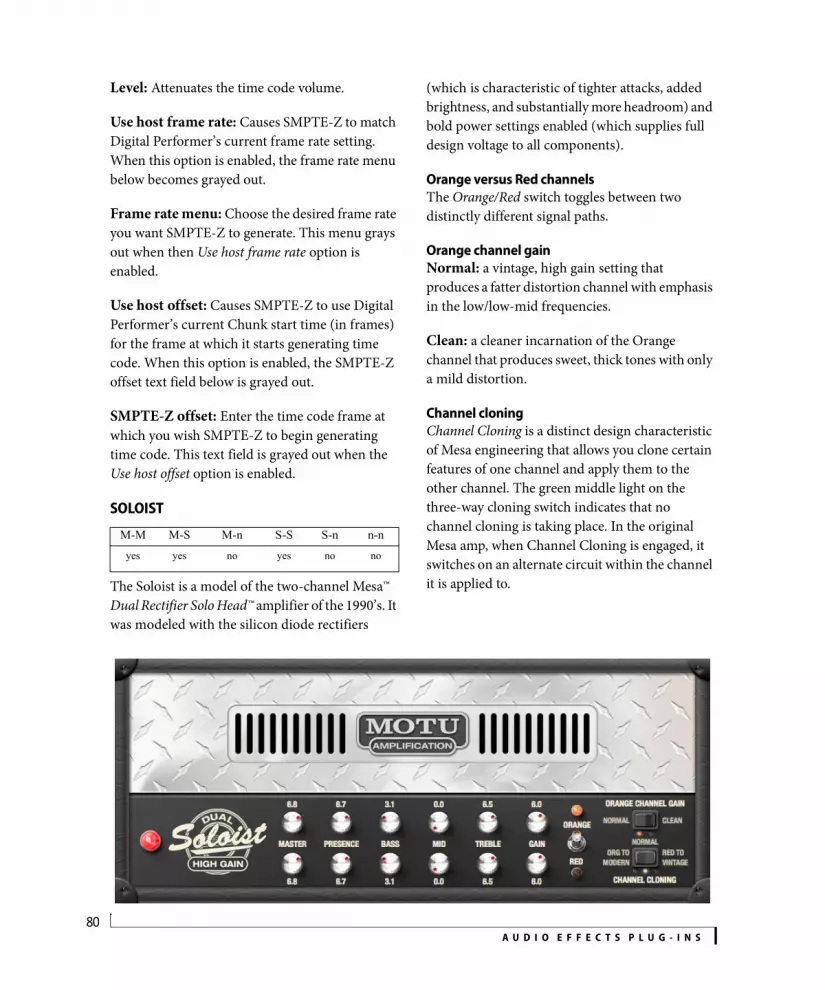
A U D I O E F F E C T S P L U G - I N S80
Level: Attenuates the time code volume.
Use host frame rate: Causes SMPTE-Z to match Digital Performer’s current frame rate setting. When this option is enabled, the frame rate menu below becomes grayed out.
Frame rate menu: Choose the desired frame rate you want SMPTE-Z to generate. This menu grays out when then Use host frame rate option is enabled.
Use host offset: Causes SMPTE-Z to use Digital Performer’s current Chunk start time (in frames) for the frame at which it starts generating time code. When this option is enabled, the SMPTE-Z offset text field below is grayed out.
SMPTE-Z offset: Enter the time code frame at which you wish SMPTE-Z to begin generating time code. This text field is grayed out when the Use host offset option is enabled.
SOLOIST
The Soloist is a model of the two-channel Mesa™ Dual Rectifier Solo Head™ amplifier of the 1990’s. It was modeled with the silicon diode rectifiers
(which is characteristic of tighter attacks, added brightness, and substantially more headroom) and bold power settings enabled (which supplies full design voltage to all components).
Orange versus Red channelsThe Orange/Red switch toggles between two distinctly different signal paths.
Orange channel gainNormal: a vintage, high gain setting that produces a fatter distortion channel with emphasis in the low/low-mid frequencies.
Clean: a cleaner incarnation of the Orange channel that produces sweet, thick tones with only a mild distortion.
Channel cloningChannel Cloning is a distinct design characteristic of Mesa engineering that allows you clone certain features of one channel and apply them to the other channel. The green middle light on the three-way cloning switch indicates that no channel cloning is taking place. In the original Mesa amp, when Channel Cloning is engaged, it switches on an alternate circuit within the channel it is applied to.
M-M M-S M-n S-S S-n n-nyes yes no yes no no
A U D I O E F F E C T S P L U G - I N S81
Org to modern: switches the Orange channel to the alternate circuit, which changes a few key features (such as Presence) to make the Orange channel sound more like the Red channel. Essentially, this is adding additional gain and higher frequencies to the Orange channel.
Red to vintage: switches the Red channel to the alternate circuit, which changes a few key features to make the Red channel sound more like the Orange channel. This rounds off some of the higher frequencies and additionally reduces gain, making it more of a “hot rhythm guitar” and less of an “extremely high gain lead guitar.”
ControlsMaster: controls the output level of each channel.
Presence: controls attack and brightness of the selected channel. This knob works in conjunction with the Bass, Mid, and Treble settings.
In the Red vintage configuration, the Orange channel Presence knob is fully active. This is an undocumented feature of the original Mesa Dual Rectifier Solo Head.
Bass: controls the amount of low frequencies factored into the final output of the signal.
Mid: determines the amount of midrange mixed into the final output of the signal.
Treble: this is an extremely powerful control, as the sound leaving the Treble stage is what feeds the Mid and Bass stages.
Gain: the ultimate tone shaping knob (and first stage of the amp). This determines how hot your signal is before traveling to the rest of the circuitry.
SONIC MODULATOR
Sonic Modulator (Figure 1-48 below) provides a wide range of modulation effects, numerous presets, and graphic control over many parameters. It features four phase-syncable LFOs (low frequency oscillators), an amplitude envelope generator, and modulators for pitch, filter (four different kinds), amplitude, and delay.
Two independent frequency bandsThe Sonic Modulator splits the input signal into two bands, a low band and a high band, so that you can apply separate settings to each band. The Low Band and High Band controls parallel each other across the bottom of the window. You can adjust the crossover between them with the Crossover control in the lower left corner.
A wide range of modulation effectsThe Sonic Modulator is capable of basic effects like vibrato, flanging, and tremolo. It is also capable of special effects, such as lush choruses, sample/hold, triggered filters, and rotary speaker effects.
Use the presets as a starting pointYou might find it useful to listen to the presets and choose an existing preset as a starting point for your own settings. The presets are conveniently organized into categories like Amplitude Effects, Pitch Effects, Delay Effects, and Filter Effects.
Low band/ high band bypassEach band can be bypassed by activating the bypass button in each section.
Filter modulation occurs before the cross-over, so it does not have separate low/high band bypassing.
M-M M-S M-n S-S S-n n-n
no yes no no no no

A U D I O E F F E C T S P L U G - I N S82
Low band/high band linkingThe Link buttons apply the current settings of each modulator to both the High and Low frequency bands. If you make a change in one band with this button activated, the change is mirrored in the other band. (The filter section does not have this button because it is not band-specific.)
Crossover Frequency The Crossover Frequency defines the split point between low and high band audio paths.
AmountThe amount controls the strength — or depth — of the modulator being applied.
Modulator BypassEach bypass button bypasses its respective processing block.
LFO Selection menuThe LFO selection menu lets you choose one of the four LFOs shown in the LFO portion of the window. The LFO you choose is applied to the modulator.
LFO DirectionThe direction (arrow) button sets the initial direction of the modulation wave.
Pitch modulationThe Pitch Amount control describes how far the pitch of the signal is modulated.
Delay modulationThe Delay depth control describes how far the delay of the signal is modulated.
The Stereo button inverts left and right signals, making them 180-degrees out of phase for a stereo effect. Mix blends the dry signal with the delayed
Figure 1-48: The Sonic Modulator plug-in.
Toggles between the large view shown here and the condensed view shown in Figure 1-50 on page 84.

A U D I O E F F E C T S P L U G - I N S83
signal. Center is 0%. Moving the control left or right introduces the delayed signal in phase or 180 degrees out of phase. Center selects the initial delay of the modulated signal. Feedback regenerates the modulated signal for a more complex effect. Center position is 0 feedback; moving the control to the left or right introduces in-phase or out-of-phase regeneration.
Amplitude modulationThe Amplitude Amount control describes how far the amplitude of the signal is modulated. The stereo button determines whether the amplitude modulation is panning or tremolo.
Filter modulationThere are four types of filter to work with: Low Pass, Band Pass, Notch (inverted Band Pass) and High Pass. The resonance (or Q) setting increases the sharpness of the filter curve. The Center control determines the center frequency of the filter. The range control sets how far the filter travels from the center frequency.
LFOs There are four independent LFOs. The selectable waveforms are as follows: Sine, Square, Triangle, Sawtooth and Random.
The phase buttons allow LFOs to have specific phase offsets from each other. Click them repeatedly to change the phase in 45-degree increments. The phase offset will only be noticeable if two or more LFOs were set at the same speed, unless the LFOs are in a beat-based tempo mode. In that case, the phase is relative to the beginning of the sequence.
Rate adjusts the speed at which the LFO oscillates.
Tempo locked, beat-based effectsSonic Modulator’s four LFOs can be locked to the tempo of your sequence. For example, an LFO can oscillate to 16th notes or relative to the downbeats of measures.
To enable beat-based automation in Sonic Modulator, choose Beats, Note Values or Bars from the Modulation section menu as shown below in Figure 1-38:
Figure 1-49: Locking Sonic Modulator’s LFOs to the tempo of your sequence.
For an explanation of the difference between locking to Beats, Note Values or Bars, see “Tempo lock” on page 8.
EnvelopeThe amplitude of the incoming signal is used to generate an envelope. The envelope can be used as a modulation source. The attack and release times can be varied, as well as the scaling of the envelope. The retriggering sensitivity can be adjusted.
Sonic Modulator condensed viewIf you would like to see a condensed view, click the button shown in Figure 1-48 on page 82 to switch to the condensed view shown below.
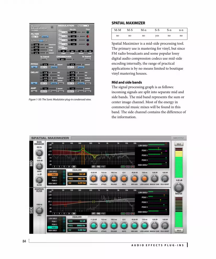
A U D I O E F F E C T S P L U G - I N S84
Figure 1-50: The Sonic Modulator plug-in condensed view.
SPATIAL MAXIMIZER
Spatial Maximizer is a mid-side processing tool. The primary use is mastering for vinyl, but since FM radio broadcasts and some popular lossy digital audio compression codecs use mid-side encoding internally, the range of practical applications is by no means limited to boutique vinyl mastering houses.
Mid and side bandsThe signal processing graph is as follows: incoming signals are split into separate mid and side bands. The mid band represents the sum or center image channel. Most of the energy in commercial music mixes will be found in this band. The side channel contains the difference of the information.
M-M M-S M-n S-S S-n n-n
no no no yes no no

A U D I O E F F E C T S P L U G - I N S85
Mid channel pre-processingOn the mid channel, the first processing step is a low-frequency distortion processor. Disabled by default, this is typically applied to make bass instruments audible on playback systems with poor low frequency response.
Side channel pre-processingDue to the way stereo phonograph recordings are cut into the physical media, excessive bass energy in the side channel can cause the needle of a player to jump out of the groove. Therefore, the first processing step performed on the side channel is a 12 dB/octave highpass filter that removes bass energy from this channel. This filter is on by default.
Dynamic EQAfter the pre-processing stages, each band passes through an independent, full-featured dynamic equalizer. This allows tweaking of both dynamics and frequency content. Particularly, corrections for lathe resonances and radius-dependent frequency response problems may be applied before the signals are recombined. The makeup gain controls also provide adjustment for stereo widening or narrowing.
Finally, the output mixer stage offers metering, a master makeup gain, and solo buttons. For maximum flexibility, these solo buttons are independent of the band solo buttons of each dynamic EQ stage.
Look-aheadSpatial Maximizer employs several milliseconds of latency to implement look-ahead. Make sure that latency compensation is enabled in Digital Performer.
ControlsBass EnhancerFreq: anti-aliasing cutoff filter frequency.
Drive: gain applied prior to distortion processor.
Blend: harmonic product blend level.
Highpass FilterFreq: highpass filter corner frequency.
Dynamic equalizerThe Dynamic Equalizer section for the mid and side bands (including the EQ graph and FFT display) works the same as the “Dynamic Equalizer” on page 25.
Master StageMaster: provides makeup gain for the plug-in’s master output.
Solo: the solo buttons in the master stage allow you to solo the mid band or side band.
SPRINGAMABOB
Springamabob is a virtual spring reverb effect. It allows for three different selections of spring tanks, and more traditional control over these tanks with Mix, Tone and Dwell knobs. These same control parameters were used in one of the
M-M M-S M-n S-S S-n n-nyes yes no yes no no
Spring model

A U D I O E F F E C T S P L U G - I N S86
first Spring reverbs used with guitars: the Fender™ 6G15 Reverb head, which was made popular by surf rock sounds of the 1960’s.
The physical concept of the spring reverb is a simple one: apply an alternating signal (such as a wailing guitar solo) to a transducer coil, which converts the audio waves to an electro-magnetic signal. The delay time is based on wire length, coil diameter, and wire substance.
Mix: controls the wet/dry blend of the signal.
Tone: adjusts the treble response of both the wet and dry signal paths.
Dwell: provides gain control for the amplifier driving the input to the spring. It can make the wet signal quite distorted, which is part of the charac-teristic timbre of these devices.
Spring model: choose one of three different spring tank models: long double, long triple, or short triple.
SUBKICK
Subkick is a kick drum enhancer plug-in meant to emulate the time-honored technique of using a junk speaker as a kick drum microphone. The input signal is fed into an adaptive beat/attack detector based upon a Schmitt trigger. The Schmitt trigger is a switch that has two thresholds: high and low. Traditionally, a Schmitt trigger will not react unless a signal is higher or lower than one of these thresholds. The difference between these two thresholds is, in analog terms, called hysteresis voltage.
How it worksSubkick uses the envelope signals instead of the peaks and valleys of each individual audio wave to trigger the kick drum: the rising edge of the trigger is interpreted as an attack, and it causes a digital impulse to be fed into the resonator simulation. The falling edge is simply ignored.
M-M M-S M-n S-S S-n n-n
yes yes no yes no no
Meters
Treadle

A U D I O E F F E C T S P L U G - I N S87
This system emulates the response of a cone woofer to the air pulse radiated from a kick drum when struck. The output is passed through a distortion model that emulates the mixer input. A mix control is provided for blending the raw kick microphone signal with the synthesized bump.
MeteringThe pink meter reads the input peak level. The purple meter reads the output level. The kick pedal indicates triggering. Click on or near the treadle to test the sound.
ControlsSens: controls the sensitivity of the attack detector. Turned down, it is less sensitive, turned up, it is more sensitive.
Retrigger: controls the hysteresis of the attack detector. When a signal causes multiple false triggers, turning it down can help. If the detector is missing the second hit of a fast double-hit articulation, turn it up.
Pitch: controls the frequency of the resonator.
Resonance: this is the height of the peak of the resonator. A higher resonance means longer delay times.
Drive: controls the gain applied to the signal ahead of the distortion model.
Trim: controls the gain applied to the signal after the distortion model.
Mix: this is essentially a wet/dry crossfader.
Gain: controls the gain for the final output mix.
TREMOLO
How it worksTremolo uses a low frequency oscillator (LFO) to automatically control the amplitude of the input signal.
Tempo lock: Tremolo can be specified in real-time or in one of several tempo-based modes which lock the LFO of the tempo of your sequence, even if there are tempo changes.
Waveform: determines the desired LFO wave (sine, triangle, etc.)
Rate: sets period in Hertz (Hz) in real-time mode, or note values or bars depending on tempo lock mode.
Depth: controls the depth of the tremolo effect.
M-M M-S M-n S-S S-n n-nyes no no yes no yes

A U D I O E F F E C T S P L U G - I N S88
TRIGGER
Trigger converts an audio pulse to a MIDI event. This can be useful for replacing or beefing up drum sounds with MIDI generated sounds.
How it worksOn an audio track, insert a Trigger plug-in. Make sure that Multi Record is enabled (see “Choosing a MIDI input source” on page 141 in the DP User Guide). Trigger will publish itself as a MIDI output device. Next, create a MIDI track and select Trigger as the input and set the output destination to a MIDI drum module. Record enable the MIDI track. Hit play. Gradually increase the threshold control until desired triggered output is achieved. Visual feedback of the trigger pulse is displayed in the MIDI output section of the Trigger plug-in window. You should also hear the results of the trigger on your MIDI module.
Audio InputTime units: menu option to change mode from real time to mensural unit display
Threshold: sets how much energy is required to trigger a pulse.
Retrigger delay: sets the minimum amount of time before another event trigger is allowed.
MIDI OutputTime units: menu option to change mode from real time to mensural unit display
Duration: determines the length of the MIDI note output.
MIDI note: determines which MIDI note will be sent from Trigger.
Faster trigger/more accurate trigger - determines how long before Trigger commits to a result. Faster triggers are better suited to real time operation but more accurate triggers will provide a better translation of velocities. M-M M-S M-n S-S S-n n-n
yes no no yes no no

A U D I O E F F E C T S P L U G - I N S89
TRIMTrim (Figure 1-51 below) provides simple gain and attenuation. but it offers a number of useful additional features, including long-throw, precise metering with an adjustable range, a phase invert, and left/right panning in the stereo version.
Trim uses very little processing power. Its main purpose is to be used at the end of a chain of effects or as part of the output stage for an auxiliary track, subgroup or master fader. Trim will help you control and monitor levels at all points of the mix.
Signal flow
Figure 1-52: Trim plug-in signal flow.
M-M M-S M-n S-S S-n n-nyes no no yes no yes
Figure 1-51: The mono, stereo and n-channel Trim plug-ins.
Phase Invert
Gain
Pan
Meter
Stereo version only

A U D I O E F F E C T S P L U G - I N S90
How it worksTrim can add up to 40 dB of gain or attenuation to a digital audio signal. The metering can be zoomed to show a close-up of any part of the signal range. The meter shows up to 20 dB over digital zero so you can see exactly how far you have exceeded the available dynamic range of the A/D converters or final 16 bit or 24 bit file. The meter shows real-time, average level, and peak/hold (click to clear).
The invert button inverts the phase of the signal by 180°. This can be useful if you have two mics recording a stereo image of a sound source. If the mics are out of phase or wired incorrectly, inverting the phase of one of the signals may improve the sound.
ControlsGain: Provides -/+ 40db of gain.
Link: (Stereo only) Links the left and right gain controls. If left and right are set to different levels and then Link is engaged, the difference between left and right is maintained when either is changed.
Pan controls: (Stereo only) The pan controls give you separate pan control of the left and right channels, allowing you to restrict — or even completely swap — the left/right channels. Zero (0.00) is hard left, 1.00 is hard right and 0.5 is mono.
By default, the pan controls are linked (as indicated by the green link light between them). Use the button between them to disable linking for independent pan control of the left and right signals.
Invert: Inverts the phase of the input signal by 180°.
Peak: Indicates the highest peak since the peak indicator has been cleared. Click it to clear it.
Range Adjust: Allows you to zoom in on any part of the meter range.
TUBE WAILER
Tube Wailer is an emulation of the venerated Ibanez TS-9 Tube Screamer™ overdrive pedal.
Drive: amount of distortion.
Tone: variable high-frequency roll-off, with upper midrange peak at high settings.
Level: output gain.
Diodes: simulates replacing the stock silicon clipper diodes with germanium diodes. This reduces distortion level but extends bandwidth.
Status light: displays the bypass/enabled state; when lit, the effect is active.
Pedal: bypasses/enables the effect. This works the same as the Effect window’s Bypass button.
M-M M-S M-n S-S S-n n-nyes yes no yes no no

A U D I O E F F E C T S P L U G - I N S91
TUNER
The Tuner plug-in is an accurate and easy to use tuner.
Detected frequency: fundamental frequency of the incoming signal, in Hertz (Hz).
Detected note: note name and octave that correspond to the detected fundamental frequency.
Meter: representation of the pitch difference between the detected note and the detected fundamental frequency. The horizontal position of the illuminated segments indicates how far the detected frequency is from the detected note. The number of illuminated segments indicates uncertainty or inharmonicity in the signal; a greater number of illuminated segments represents greater uncertainty. The color of the segments changes gradually from green (in tune) to yellow, orange, and red (progressively further out of tune).
Meter value: difference between the detected note and the detected frequency, in cents.
Arrows: the direction in which the detected frequency needs to move to match the frequency of the detected note. The color of the arrows changes progressively in the same manner as the meter segments. When the detected fundamental frequency matches the detected note within three cents, both arrows will be illuminated.
Reference frequency: sets the frequency reference for the pitch A4, between 400 and 480 Hz. The default frequency is 440 Hz. The reference frequency can be adjusted in increments as small as 0.01 Hz when Command-dragging on the bar below the number.
Reference generator: generates a tone at the reference frequency. Click the tuning fork button to toggle the generator. Click and drag on the bar below it to adjust the output level of the generator.
Tuning stereo signalsWhen tuning a stereo signal, the Tuner plug-in analyzes the sum of the two channels. If the channels are not phase coherent, the Tuner plug-in may not be able to measure the frequency of the signal.
M-M M-S M-n S-S S-n n-nyes yes no yes no no

A U D I O E F F E C T S P L U G - I N S92
ÜBER TUBE
Über Tube is an emulation of the Ibanez Super Tube™ overdrive pedal, a close but rare cousin of the Ibanez Tube Screamer™.
Drive: amount of distortion.
Bite: variable frequency mid-boost, like a “parked wah” mixed with the signal.
Level: output gain.
Bright: variable high-frequency roll-off, with upper midrange peak at high settings.
Diodes: simulates replacing the stock silicon clipper diodes with germanium diodes. This reduces distortion level but extends bandwidth.
Status light: displays the bypass/enabled state; when lit, the effect is active.
Pedal: bypasses/enables the effect. This works the same as the Effect window’s Bypass button.
WAH PEDAL
The Wah Pedal plug-in simulates “wah-wah” pedals used by guitarists, bassists and keyboard players.
Pedal Position: the position of the rocker pedal in percent of forward sweep. This can be adjusted with the Pedal Position knob, or by clicking the pedal graphic to the left and dragging up or down.
Sweep Start: the starting position of the pedal relative to the full range of the pedal’s sweep.
Sweep Range: specifies the sweep range as a percent of the distance from the sweep starting position to the end position.
Sweep Exponent: defines the curvature of the sweep response over the sweep range. This greatly affects the “feel” of the pedal. Most wah pedals use a negative exponent.
M-M M-S M-n S-S S-n n-nyes yes no yes no no
M-M M-S M-n S-S S-n n-n
yes yes no yes no no

A U D I O E F F E C T S P L U G - I N S93
Character: controls the relative amount of distortion, with zero being perfectly linear. Classic wah-wah pedals are discrete designs that use feedback, but the simplicity of the circuit allows some weak low-order harmonic distortion to find its way to the output.
Voicing: selects the frequency response model. “V846” represents a vintage ‘70s Vox 846™, “WhineBaby” a modern Dunlop CryBaby™.
Sweep Mode (mono-to-stereo or stereo-to-stereo only): chooses which channels are in phase with the effect: left, right or both. For the out-of-phase channel, the pedal position is inverted after applying the sweep range modifications but before the sweep curvature is applied to simulate playing an identical pedal that is “turned around.”
Sweep Control: selects whether automation ramp data or MIDI continuous controller (CC) messages should be used to automate the pedal position and effect bypass.
When MIDI is chosen, any ramp data in the track is overridden, and the pedal position knob and pedal graphic do not affect the pedal position value. You can use MIDI control to record automation, which is more convenient to edit.
Pedal CC: selects the MIDI continuous controller (CC) number assigned to the pedal.
Bypass CC: selects the MIDI continuous controller (CC) number assigned the bypass switch. Values 63 and higher will bypass the effect.

A U D I O E F F E C T S P L U G - I N S94
Part 2Instruments


CHAPTER
97
2 Instrument Plug-ins
OVERVIEWDigital Performer includes six instrument plug-ins: BassLine, PolySynth, Nanosampler, Modulo, Model 12 and Proton. The following sections discuss the settings for each individual instrument.
For general information about using virtual instruments, see chapter 17, “Instrument Tracks” (page 159) in the DP User Guide.
BassLine. . . . . . . . . . . . . . . . . . . . . . . . . . . . . . . . . . . . . . . . . . . . . . . . 98PolySynth . . . . . . . . . . . . . . . . . . . . . . . . . . . . . . . . . . . . . . . . . . . . . . 99Nanosampler. . . . . . . . . . . . . . . . . . . . . . . . . . . . . . . . . . . . . . . . . .100Modulo. . . . . . . . . . . . . . . . . . . . . . . . . . . . . . . . . . . . . . . . . . . . . . . .107Model 12 . . . . . . . . . . . . . . . . . . . . . . . . . . . . . . . . . . . . . . . . . . . . . .118MX4 . . . . . . . . . . . . . . . . . . . . . . . . . . . . . . . . . . . . . . . . . . . . . . . . . . .123Proton. . . . . . . . . . . . . . . . . . . . . . . . . . . . . . . . . . . . . . . . . . . . . . . . .124MIDI Control of instrument settings. . . . . . . . . . . . . . . . . . . .127

I N S T R U M E N T P L U G - I N S98
BASSLINEBassLine (Figure 2-1) is a monophonic, analog-modeled bass synth instrument plug-in.
Figure 2-1: BassLine.
OscillatorBassLine provides a single oscillator that can produce a sawtooth wave, square wave or a hybrid combination of the two by turning the Waveform knob (Figure 2-1) to a position somewhere in between the highest and lowest setting.
Use the Range knob to specify the octave. As was often the case on vintage analog synths, the three settings (8, 16 and 32) refer to the length (in feet) of organ pipes. A pipe twice as long produces notes an octave lower. Detune produces an increasingly fatter sound and widening stereo image.
Pitch modulationBend range (specified in half-steps from 1 to 12, where 12 is an octave) determines the response to pitch bend. Glide provides classic portamento from one note to the next.
FilterThis is a classic low-pass filter with cutoff frequency and filter resonance controls.
Filter modulationThe Filter Modulation section lets you apply a simple one-stage decay envelope to the filter frequency. Decay determines the speed of the envelope and Envelope Amount (Env Amt) determines the strength of the envelope applied to the filter. Velocity lets you control envelope amount via note-on velocity. A higher settings produces greater on-velocity response.
AmplifierControl the output level of the instrument with the Volume knob (which is mapped to controller #7). Overdrive produces classic analog-style signal overload effect.
Amplifier modulationControl the length of each note with Decay. Apply note-on velocity response with the Velocity knob.
LegatoBassLine is a monophonic instrument and can therefore only play one note at a time. When Legato mode is disabled, holding one note and then playing another note ends the first note and retriggers the amplitude envelope. When Legato is enabled, the transition to the second note is made with pitch glide from one to the other. In addition, the envelope is not retriggered, so the decay continues until all notes are released.

I N S T R U M E N T P L U G - I N S99
POLYSYNTHPolySynth (Figure 2-2) is a polyphonic synthesizer inspired by the Roland Juno 106 and other one-oscillator analog synths from the 1980’s.
DCOThe heart of PolySynth is the DCO (Digitally Controlled Oscillator) section. Here, you will find oscillator level controls for triangle, sawtooth, rectangle, sub-frequency 1 and sub-frequency 2 oscillators. You can also add Noise and adjust stereo Detune. Use the Range buttons to specify the octave. Bend range (specified in half-steps from 1 to 12, where 12 is an octave) determines the response to pitch bend.
LFOThe LFO (Low Frequency Oscillator) section allows you to apply periodic modulation effects. Speed controls LFO rate. PWM (Pulse Width Modulation) uses the LFO to change the shape of the rectangle and sub-frequency oscillators, resulting in cyclic timbral changes to the sound. The Vibrato/Wah slider uses the LFO to either modulate pitch for a vibrato effect or modulate the resonant low-pass filter for the classic “wah” sound.
FilterThis is a classic low-pass filter with cutoff frequency (FREQ) and filter resonance (RES) controls. Apply note-on velocity response with the velocity (VEL) control. Apply the ADSR envelope (or its inverse) to the filter with the envelope (ENV) control. Key Tracking makes the filter cutoff frequency change relative to the root
frequency of the note being played. Full (3/3) tracking produces a full range key tracking over the entire keyboard, where the 2/3 and 1/3 settings reduce the tracking effect by scaling the change proportionally as you move up the keyboard.
Envelope (ENV)The ADSR envelope (Attack, Decay, Sustain, and Release) controls the loudness of each note, and it can also modulate the filter. The Attack, Decay, and Release parameters are rate or time controls. Sustain controls amplitude (level). When a note is first triggered, the envelope generator will begin to rise to its full level at the rate set by the Attack. When it reaches the peak level it then falls at the rate set by the Decay parameter to the level set by the Sustain control. The envelope will remain at the sustain level as long as the key is held down. When a key is released, it will return to zero at the rate set by the Release parameter.
Amplifier (AMP)Control the output level of the instrument with the Volume slider (which is mapped to controller #7). Velocity (VEL) controls note-on velocity sensitivity. For example, if you set Velocity to zero, all notes will play at the same volume. Higher values cause notes played softly to sound at a low volume and notes played hard to sound at a higher volume.
EffectsAdd Chorus and Distortion (DIST) to the sound as desired.
Figure 2-2: PolySynth.

I N S T R U M E N T P L U G - I N S100
NANOSAMPLERNanosampler (Figure 2-3) is a sample player instrument. You can load a mono or stereo audio file of any length into one instance of Nanosampler and then play the sample, or individual slices of it, from a MIDI track or a MIDI controller. For longer samples, Nanosampler plays the first 20 seconds. Only one sample can be loaded at a time, but you can create and operate as many instances of Nanosampler as you need (and your computer processing resources allow).
Sample menuThe Sample menu (Figure 2-3) displays the currently loaded sample. Click to access the menu items explained below. These features work the same way as described for Model 12 in “Model 12 sample management” on page 121. You can assemble your own Nanosampler library by building it from your computer desktop, as explained in “Building your user library” on page 122.
Factory: This sub-menu provides access to DP’s included (factory) samples, which offer a broad, basic palette of instrument sounds for you to work with.
Shared: Use the Copy To menu command (see below) to copy a sample to this Shared sub-menu. Shared samples are stored in the system Library Application Support folder and can therefore be made available to any users that you wish to share them with. If this menu item is grayed out, there are no Shared samples yet.
User: Use the Copy To command (see below) to copy a sample to this User sub-menu. User samples are stored in your user directory and are therefore available only when you are currently logged in to your computer with your user account. You can use the user directory to protect your own sample content. If this menu item is grayed out, there are no User samples yet.
Project: Project samples are stored with the Digital Performer project itself. By keeping them with the rest of the files associated with the project, you don’t have to worry about losing them when exchanging the project with a colleague, archiving the project, transferring it, etc.
Open: Lets you load a sample from your hard drive.
Sample Start
Figure 2-3: Nanosampler.
Sample menu
Globalsettings
Sample settings
Synth settings
Fade In
Loop Start Loop
Loop Fade
Loop End
Fade Out
Sample End
Sample tab
Settings tab
Mini menu
Sample display area

I N S T R U M E N T P L U G - I N S101
Reveal In Finder/Explorer: Displays the audio file on the computer desktop.
Copy To: Lets you copy the current sample to the Shared, User or Project sub-menus.
Loading a sample using drag and dropTo load a sample into Nanosampler via drag and drop, drag a mono or stereo sample from your computer desktop, the Soundbites list, a clippings window or other draggable source into the Nanosampler sample display area (Figure 2-3).
Global settingsOnce a sample is loaded, the global settings (Figure 2-3) determine the overall operation of Nanosampler.
Classic modeIn Classic mode (Figure 2-3), Nanosampler acts like a traditional sampler, where the sample plays back at different pitches depending on the key pressed, with either Gate or Trigger playback (see “Gate/Trigger (Classic and Slice modes only)” on page 103).
1-shot1-shot mode (Figure 2-4) is similar to Classic, except that the sample plays in Trigger mode only, and polyphony is locked at one voice. All Trigger, Gate and Loop options are disabled. The result is
that the sample plays in its entirety as soon as it is triggered, unless it gets retriggered, which causes it to play from the beginning again.
SliceIn Slice mode (Figure 2-5), the sample is divided into individual slices triggered by a their own MIDI note. Unlike with Classic and 1-shot modes, the MIDI note does not affect the pitch of the slice but instead triggers the audio at its original pitch.
For more information about Slice mode, see “Editing slices in the waveform display” on page 103 and “Slice mode settings” on page 104.
StretchWhen Stretch (Figure 2-3 on page 100) is enabled, the sample will maintain its original duration at any pitch that you play.
When Stretch is disabled, the sample length becomes proportionally shorter or longer, respectively, as you go up or down from the root pitch.
LengthWhen Stretch (above) is enabled, the Length option becomes available (Figure 2-3 on page 100) and lets you choose from the menu a specific metric length for the sample (at all pitches). For example, if you choose 1 bar, the sample will become one measure long at whatever the
Figure 2-4: 1-shot mode.

I N S T R U M E N T P L U G - I N S102
sequence tempo is when the sample is triggered. This option is commonly used for drum loops and other rhythmic material.
ZTX Stretch modeWhen using the Stretch option (above), use the ZTX Stretch Mode menu (Figure 2-3 on page 100) to choose the desired time-stretching algorithm. Standard produces more of the conventional “sampler” effect, while Formant-corrected preserves the tonal characteristics at different pitches. For details, see “ZTX Formant-Corrected” on page 949 in the DP User Guide and “ZTX Standard” on page 950 in the DP User Guide.
VolumeControl the output level of Nanosampler with the Volume knob (Figure 2-3 on page 100), which is mapped to controller #7.
VoicesThe Voices setting (Figure 2-3 on page 100) lets you choose how many notes you can play at one time. For example, if you are playing a bass
sample, you can probably set the polyphony to 2, as you’ll likely never play more than two bass notes at the same time (perhaps only when they overlap a little bit from one to the next). On the other hand, if you are playing a keyboard pad sample, you might want as much as 10 or 12, depending on the length of the decay of the notes, the music you will be playing, and any other factor that might impact how many notes are sounding at one time.
BendBend range (Figure 2-3 on page 100) is specified in half-steps from 1 to 12, where 12 is an octave, and determines Nanosampler’s response to pitch bend.
Sample tabThe Sample tab (Figure 2-3 on page 100) displays the waveform and sample settings.
Waveform displayThe waveform display (Figure 2-3 on page 100) shows the currently loaded sample. Right-click (or Ctrl/Win-click) to quickly access the mini-menu commands (see “Mini-menu” below).
Figure 2-5: Slice mode.
SlicesSelected
Slice

I N S T R U M E N T P L U G - I N S103
Editing slices in the waveform displayIn Slice mode (Figure 2-5 on page 102), use the following techniques to edit slices:
Also see “Slice” on page 101 and “Slice mode settings” on page 104.
Mini-menuThe Nanosampler mini-menu (Figure 2-3 on page 100) has the following commands:
Reverse Sample: Plays the sample backwards.
Normalize Sample: Boosts the level of the entire sample by whatever amount is needed to make the loudest peak reach digital full scale (zero dB).
Show Separate Channels/Mono Sum: If the sample material consists of stereo audio, these two commands let you view it as separate side-by-side channels or as a single waveform that is a mono sum of the two channels.
Sample settingsThe sample settings (Figure 2-3 on page 100) are displayed below the waveform, where they can be edited numerically. There are graphic handles above the waveform (also shown in Figure 2-3) for basic settings such as sample start/end, fade in/out, loop start/end, etc.
Start/EndIf you would like to specify sample start/end times that differ from the very beginning and end of the sample, you can set them graphically in the LCD display or by numerically adjusting the sample start and end settings (Figure 2-3).
Fade In/OutThe Fade In and Fade Out points (Figure 2-3) are set relative to the Sample Start and End times and allow for a smooth fade of the desired length at the start or end of the sample.
GainUse Gain (Figure 2-3) to adjust the overall level of the sample in dB. Positive values raise the level; negative values lower it.
TuneThe Tune setting (Figure 2-3) lets you adjust the pitch of the note up or down. The adjustment is specified in semitones and cents (a hundredth of a semitone), so it can be very accurate. To adjust down, enter a negative number.
SnapWhen Snap is enabled (Figure 2-3), the sample start/end, loop start/end and slice start points will snap to the best value in the local range to prevent clicks.
Root (Classic and 1-shot modes only)The Root setting (Figure 2-3) determines which MIDI note (and therefore which key on your MIDI keyboard) triggers the original sample. Adjusting it lets you shift the root pitch of the sample up or down on the keyboard.
Gate/Trigger (Classic and Slice modes only)In Classic mode, you can choose between Gate or Trigger playback (Figure 2-3). Gate stops playback as soon as a MIDI key is released (after the amplitude envelope release finishes). Trigger
To do this Do this
To select a single slice Click its stem.
To select an adjacent slice Press the left/right arrow key.
To select multiple adjacent slices Shift-click them.
To select non-adjacent slices Command/Ctrl-click them.
To remove one or more slices Select them and press delete.
To add a slice Double-click on the waveform.
To move a slice Drag it.
To audition a slice Click its note name. The slice plays according to the sample settings (such as trigger/gate).

I N S T R U M E N T P L U G - I N S104
ignores note-off messages and always plays until the end of the sample, or until the sample is retriggered.
Repeat (Gate mode only)With Gate enabled, the Repeat option (Figure 2-3) causes sample playback to automatically play again after completing a full cycle, repeating the full cycle over and over for as long as the note is held. In Slice mode, each slice will repeat individually for as long as its note is held.
Loop (Gate mode only)If you would like the sample to sustain when you hold down keys, enable the Loop button (Figure 2-3). You can then set the loop Start and End points, either numerically or graphically using the handles above the waveform display, as shown in (Figure 2-3).
Use the Fade control (Figure 2-3) to create a smooth transition from the loop end to the loop start. You can save the loop in the audio file itself using the Save loop in sample command in the Settings menu. You can load a previously saved loop from the audio file using the Load loop from sample command in the same menu.
Slice mode settingsThe settings in this section are available in Slice mode only (Figure 2-5 on page 102). Also see “Slice” on page 101 and “Editing slices in the waveform display” on page 103.
Slice ByUse the Slice By menu (Figure 2-5) to choose how slice locations are determined, as follows:
If you edit slices while in Beats, Mensural or Division mode, the Slice By mode switches to Manual.
Play UntilWhen a slice is playing, the point it plays until depends on the Play Until setting (Figure 2-5), which has three options:
Final NoteThe Final Note setting plays slices sequentially in order of their assigned MIDI note. This produces the same result as the play until Sample End mode when the slices have the default ascending order. However, a completely different result can be obtained when the slice order is randomized (see below).
Slice By Setting Explanation
Beats Sensitivity Automatic beat detection finds slices by searching for transients in the audio. Adjust the Sensitivity setting to find more or fewer slices.
Mensural Length Slices are placed in even, metric increments determined by the Length setting (16th note, 8th note, etc.)
Division Number Slices are placed in equal increments, according to the Number specified.
Manual (None) Slices are placed manually. See “Editing slices in the waveform display” on page 103.
Play Until Explanation
Slice End The slice plays.
Sample End Playback begins at the start of the slice and proceeds all the way to the end of the sample.
Final Note The slice plays, and then each subsequent slice will play sequentially. (See below for more info.)

I N S T R U M E N T P L U G - I N S105
Base (Base Note)The Base (Base Note) option (Figure 2-5) lets you specify which MIDI key triggers the first slice. Subsequent slices are assigned to consecutive notes, according to the setting in the Keys menu: Chromatic, White or Black keys.
RandomizeThe Randomize button (Figure 2-5) randomizes the order of the MIDI notes assigned to the existing slices. No slices are added or removed; only the existing slices are shuffled. Clicking the Randomize button is a ‘one-shot’ operation: the result remains as is, unless you click the button again. (However, see “Auto Randomize” below.)
If you would like to limit the randomization to only certain slices, select them before clicking the Randomize button. For details about selecting slices, see “Editing slices in the waveform display” on page 103.
To get back to the default ascending MIDI note ordering (starting from the base note), click the Reset button.
Auto RandomizeThe Auto button connected to the Randomize button (Figure 2-5) automatically randomizes the slices after playback cycles through the number of periods specified by the Period setting. A new randomization occurs after each period reset.
For example, consider the following setup:
With the above settings, if you hold down a MIDI note, a slice will repeat two times before the randomization resets and then another random slice will repeat twice, and so on, until you release the key.
The Play Until Final Note setting is a lot of fun with Auto randomization because the sequence of slices will shuffle each time you complete a full note/slice sequence.
The Settings tabThe Settings tab (Figure 2-6 on page 106) provides graphic control of the Envelope, Filter and LFO settings. The settings across the bottom of the Nanosampler window can be accessed even when the Settings tab is hidden.
Amplitude EnvelopeTo apply the Amplitude Envelope (Figure 2-6), engage its button. Doing so applies a standard ADSR envelope to the sample. The ADSR envelope (Attack, Decay, Sustain, and Release) controls the loudness of each note over time. The Attack, Decay, and Release parameters are rate or time controls. Sustain controls amplitude (level). When a sample is first triggered, the envelope generator will begin to rise to its full level at the rate set by the Attack. When it reaches the peak level it then falls at the rate set by the Decay parameter to the level set by the Sustain control. The envelope will remain at the sustain level as long as the key is held down. When the key is released, volume will return to zero at the rate set by the Release parameter.
Velocity Tracking (Vel Track) allows you to apply the ADSR envelope to varying degrees, depending on MIDI note-on velocity (how hard you play notes). For example, if you set Velocity to zero, all notes will simply play at the volume set by the volume knob. Higher velocity values cause notes to be played louder, the harder you play.
Sample setting Set to
Repeat Enabled
Gate/Trigger Gate
Play Until Slice End
Randomize Auto
Period 2

I N S T R U M E N T P L U G - I N S106
FilterTo apply the Filter (Figure 2-6), click the Filter button to engage it. Choose the desired filter type from the menu and then adjust the cutoff frequency (Freq) and filter resonance (Res). Apply note-on velocity response with the velocity tracking (Vel Track) control. Key Tracking (Key Track) makes the filter cutoff frequency change relative to the root frequency of the note being played. Full tracking (100%) produces a full range key tracking over the entire keyboard, where lower settings reduce the tracking effect by scaling the change proportionally as you move away from the filter cutoff frequency on the keyboard.
Filter envelopeThe Filter Envelope (Filter Env in Figure 2-6) controls how the filter cutoff frequency evolves as a note sustains. When the envelope is disabled, the filter frequency remains constant, at its current setting, for as long as the note plays. If the Filter Envelope is enabled, the attack setting determines how long the cutoff frequency takes to reach its maximum value, as determined by the Filter Envelope Amount setting. The subsequent Decay (D), Sustain (S) and Release (R) settings control how the cutoff frequency returns to its original, specified value.
LFOThe Nanosampler LFO has the following settings:
Figure 2-6: The Settings tab.
Amplitude Envelope
Settings tab
Filter and Filter Envelope LFO
Setting Unit Explanation
Type Menu Lets you choose the wave shape of the LFO: Sine, Up/Down Sawtooth, Square, Sample & Hold, Sample & Ramp and Random Walk.
Sync Menu:Real timeMensural
Determines whether the LFO is locked to real time or tempo. Mensural makes the LFO synchronize to the tempo of the project’s time line.
Mensural Beats LFO rate is adjusted in beat values (whole note, half note, quarter note, etc.) A quarter note is equal to one beat.
Rate Hertz (Hz) The number of cycles per second at which the LFO oscillates.
Filter percent Modulates the filter cutoff frequency with the LFO.
Pitch percent Modulates the pitch of the sample with the LFO.
Detune Percent Changes the rate of the LFO based on the note pitch. (Has no effect when LFO is synced to tempo.)
Delay ms The amount of time before the LFO begins oscillating after being triggered.
Ramp Milliseconds (ms)
Applies an amplitude ramp (from zero to 100%) to the LFO.
Retrig(Retrigger)
On/off Enable retrigger to restart the LFO each time a note is played (polyphonic LFO); disable it to keep the LFO running from the first note played (monophonic LFO).

I N S T R U M E N T P L U G - I N S107
MODULOModulo (Figure 2-7) is a two-oscillator virtual synthesizer instrument, which features digital waveforms with a unique phase modulation system.
PatchesA patch is a snapshot of all the settings in the Modulo window. Modulo ships with dozens of useful presets organized by category in several dozen banks, such as Synths, Leads, Strings, etc. The Presets section at the bottom of the Modulo window (Figure 2-7) lets you choose, modify, compare, revert and save presets. Modulo can support an unlimited number of presets.
BankA bank can hold up to 128 presets. When you choose a bank, its patches (presets) are displayed in the Patch menu. Use the +/- buttons next to the menu to choose the next or previous bank in the list. To create, rename or delete banks, see “Managing patches and banks” on page 108.
PatchThe Patch menu displays all of the patches in the bank currently chosen in the Bank menu. When you choose a patch from the menu, its settings are loaded into the Modulo window. Use the +/- buttons next to the menu to choose the next or previous preset in the list. Hold down the Option key while clicking the +/- buttons to stay within the current bank when browsing presets. To create, rename, move, duplicate or delete patches, see “Managing patches and banks” on page 108.
SaveWhen you first choose a patch, the Save button is not available. As soon as you change any parameter in the Modulo window, Save becomes active, and the patch name becomes italic in the Patch menu to indicate that the patch has been modified. Click Save to store the changes you made to the patch (replacing the original version). If you wish to “save as” in order to preserve the original patch, see “Managing patches and banks” on page 108.
Figure 2-7: Modulo.

I N S T R U M E N T P L U G - I N S108
RevertWhen you first choose a patch, the Revert button is not available. As soon as you change any parameter in the Modulo window, Revert becomes active, and the patch name becomes italic in the Patch menu to indicate that the patch has been modified. Click the Revert button to permanently discard any changes you’ve made to the patch.
A/B (compare)When you first choose a patch, the A/B button is not available. As soon as you change any parameter in the Modulo window, Compare becomes active, and the patch name becomes italic in the Patch menu to indicate that the patch has been modified. Click the A/B button repeatedly to toggle between the original patch and the modified version. The original patch is indicated by non-italic text; the modified patch name is italic. Note that the modified patch gives you
access to the Save and Revert buttons, which do not apply to the original patch (since it is already saved).
Managing patches and banksClick the File button to display patch and bank management controls in the Modulo window, as shown in Figure 2-8. These controls let you manage Modulo banks and patches. Click the Edit button to return to the main Modulo window.
SourceThe Source section (Figure 2-8) lets you choose the patch you wish to work with. Click Delete to permanently remove the current source patch. Click Save to save any changes that have been made to the current source patch (such as any edits to the name, author or other patch text).
Figure 2-8: Click the File button to display the patch and bank management controls.
Sourcepatch
Destinationlocation
Bankmanagement
Patch text
Flips back to main window (Figure 2-7).Displays the controls shown here.
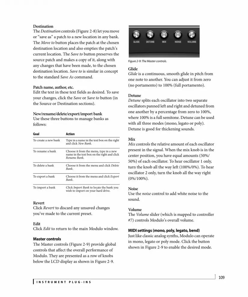
I N S T R U M E N T P L U G - I N S109
DestinationThe Destination controls (Figure 2-8) let you move or “save as” a patch to a new location in any bank. The Move to button places the patch at the chosen destination location and also empties the patch’s current location. The Save to button preserves the source patch and makes a copy of it, along with any changes that have been made, to the chosen destination location. Save to is similar in concept to the standard Save As command.
Patch name, author, etc.Edit the text in these text fields as desired. To save your changes, click the Save or Save to button (in the Source or Destination sections).
New/rename/delete/export/import bankUse these three buttons to manage banks as follows:
RevertClick Revert to discard any unsaved changes you’ve made to the current preset.
EditClick Edit to return to the main Modulo window.
Master controlsThe Master controls (Figure 2-9) provide global controls that affect the overall performance of Modulo. They are presented as a row of knobs below the LCD display as shown in Figure 2-9.
Figure 2-9: The Master controls.
GlideGlide is a continuous, smooth glide in pitch from one note to another. You can adjust it from zero (no portamento) to 100% (full portamento).
DetuneDetune splits each oscillator into two separate oscillators panned left and right and detuned from one another by a percentage from zero to 100%, where 100% is a full semitone. Detune can be used with all three modes (mono, legato or poly). Detune is good for thickening sounds.
MixMix controls the relative amount of each oscillator present in the signal. When the mix knob is in the center position, you have equal amounts (50%/50%) of each oscillator. To hear oscillator 1 only, turn the knob all the way left (100%/0%). To hear oscillator 2 only, turn the knob all the way right (0%/100%).
NoiseUse the noise control to add white noise to the sound.
VolumeThe Volume slider (which is mapped to controller #7) controls Modulo’s overall volume.
MIDI settings (mono, poly, legato, bend)Just like classic analog synths, Modulo can operate in mono, legato or poly mode. Click the button shown in Figure 2-9 to enable the desired mode.
Goal Action
To create a new bank Type in a name in the text box on the right and click New Bank.
To rename a bank Choose it from the menu, type in a new name in the text box on the right and click Rename Bank.
To delete a bank Choose it from the menu and click Delete Bank.
To export a bank Choose it from the menu and click Export Bank.
To import a bank Click Import Bank to locate the bank you wish to import on your hard drive.

I N S T R U M E N T P L U G - I N S110
Figure 2-10: MIDI settings.
In mono mode, only one note can be played at a time. Each new note will cut off the currently sustained note, if any.
Legato mode is an alternative form of mono mode where the envelope is not retriggered; only the pitch changes.
In poly mode, Modulo can play two or more notes simultaneously, up to the limit you select next to the poly button. For example, if polyphony is set to 16, Modulo can play and sustain up to 16 notes at a time.
PolyphonyThe polyphony setting determines how many notes can play at a time. The maximum allowed polyphony for one instance of Modulo is 16. Beware, however, that higher polyphony settings place higher demand on your host computer’s processing resources. Therefore, the ideal polyphony setting is that which matches the highest number of notes you will actually need (the highest number of notes you will play simul-taneously, taking into account their releases and any resulting overlapping).
BendThe bend parameters control how Modulo responds to pitch bend. The pitch bend range is split at zero into two pitch bend ranges: upper and lower. The upper range determines how much pitch bend occurs between the zero position on your pitch bend wheel (or other controller) and its highest position. The lower setting determines the range from zero to the pitch bend wheel’s lowest
position. By setting them to different values, you can more easily bend up and down by different amounts.
The upper and lower pitch bend ranges offer a maximum range of one octave (12 semitones) each, for a combined maximum of two octaves.
MIDI activity lightThe MIDI activity light illuminates when Modulo receives MIDI data. This can be a useful trouble-shooting tool. If Modulo is not making any sound when you play it, but the MIDI light does blink, then you can focus your troubleshooting efforts on the audio signal path.
StatusThe status LCD (Figure 2-11) displays information about the parameter you are currently modifying or targeting with the cursor. If you modify an oscillator setting, the LCD also displays the oscillator waveform.
Figure 2-11: The Status LCD.
OscillatorsModulo provides two oscillators (Figure 2-12).
Signal flowModulo’s overall signal flow bears a striking resemblance to a Prophet 5. But it is best not to think of each oscillator as a separate synthesizer. Instead, think of the oscillators as going into a mixer before being processed.
Polyphony

I N S T R U M E N T P L U G - I N S111
Figure 2-13: Modulo signal flow.
Oscillator MixTurn the Oscillator Mix knob to control how much of each oscillator is included in the signal (Figure 2-12). To completely turn off oscillator 1 or 2, turn the Mix knob all the way right or left, respectively.
WaveformsChoose the desired waveform for the oscillator from the menu, or use the +/- buttons to cycle through the list of waveforms. Each oscillator provides a variety of standard subtractive synthesis waveforms. An extensive library of waveshapes are also provided.
SineThis is a standard sinusoidal waveform.
SawtoothThis is a standard sawtooth wave. Use the symmetry parameter to morph the sawtooth waveform
between a downward triangle and an upward triangle waveform:
Figure 2-14: Use symmetry to morph between these three basic waveforms.
A sawtooth wave (50% symmetry) has energy at all harmonics, and the strength of higher partials falls off linearly. A triangle wave has less energy at high partials, and strength falls off exponentially as the square of the partial number.
RectangleThis is a standard square wave. The pulse width can be modified into a rectangle waveform using the
symmetry control (“Symmetry” on page 112).
Figure 2-15: Adjust the symmetry control to create a rectangular wave form.
Figure 2-12: The Oscillators.
Oscillator 1 Oscillator 2
Oscillator mix
Next/previous waveform
Waveform
0% 100%Symmetry
50%

I N S T R U M E N T P L U G - I N S112
WaveshapesWaveshapes are sets of complex waveforms that provide a rich assortment of harmonic content
and tone color for a sound. A wide variety of waveshapes are provided. Modulo waveshapes have adjustable symmetry, just like the pure waveforms (see “Symmetry” on page 112).
Waveshapes can produce spectra that differs greatly from standard subtractive synthesis waveforms. Changing waveshapes is an easy and rewarding way to get into patch programming. Simply find a patch you like, and audition different waveshapes.
Modulating the oscillator phase shift is an easy way to add movement to your patches. If you modulate the phase of oscillator 1, and modulate the phase of oscillator 2 at the same time, the combined effect is that the sound will never be quite the same at any given moment.
Because waveshapes can sound like filtered subtractive waveforms, sometimes you can use waveshapes without any filtering at all, which saves CPU overhead.
TuneUse the Tune knob to offset the pitch of the oscillator from key tracking. When the Track button (explained in the next section) is disabled, the range is expressed in absolute frequency (Hz or kHz); the range is from 8.2 Hz to 22.1 kHz.
When the Track button is enabled, the pitch is expressed in semitones relative to the root pitch of the note being played. The range is from -60.00 semitones to +84.00 semitones.
TrackingWhen the Track button is enabled, the oscillator adjusts its frequency relative to the note being played. Accordingly, when tracking is enabled, the
pitch of the oscillator is expressed in the number of semitones relative to the root pitch of the note being played.
SymmetryThe symmetry knob adjusts pulse width on rectangle waves, but symmetry can also be applied to sine waves, sawtooths and even waveshapes. Doing so produces interesting changes in harmonic content. Further interesting effects can be achieved by modulating the symmetry (see “Modulation” on page 115).
Figure 2-16: Symmetry.
PhaseThree phase shift modes are provided: off (0), subtract (-) and multiply (x). When engaged, the oscillator is split into two separate oscillators that can be offset from one another by the phase knob from 0 to 180 degrees, and then either subtracted from each other or multiplied by each other. The results can produce significant timbral differences, depending on the chosen waveform. As you turn the Phase knob, you’ll often discover “sweet spots” where significant timbral change occurs.
Modulating oscillator settingsOscillator pitch, phase shift and symmetry can be modulated. For further details, see “Modulation” on page 115.
Sine
0% 100%
Sawtooth
Rectangle
Symmetry
Waveshape
50%

I N S T R U M E N T P L U G - I N S113
FilterModulo provides a multimode filter.
Figure 2-17: The filter.
Filter typeThe filter can be assigned to one of four different filter types (shown below) using the illuminated buttons along the bottom of the filter graph:
Enabling/disabling the filterIn accordance with classic analog synthesizer design, the filter is always present in the signal path. However, you can “disable” it by choosing one of the low pass filters and turning the cutoff frequency all the way up (to 22.1kHz). Alterna-tively, you could choose the high pass filter and turn the cutoff frequency all the way down (to 8 Hz).
Cutoff frequencyThe Cutoff knob determines the filter’s cutoff or center frequency, which can be set as a number of cycles per second (Hz or kHz) when key tracking is disabled. When key tracking is enabled, Hz and kHz are not meaningful because the filter’s center frequency is not fixed at an absolute frequency; instead, it is relative to the note being played. Therefore, Modulo expresses filter cutoff/center frequency in semitones relative to the pitch being played.
Resonance (RES)Resonance emphasizes the cutoff/center frequency of the filter.
TrackingThe filter is equipped with key tracking (the track button), which causes the cutoff frequency to “track” (change relative to) the frequency of the note being played. Key tracking helps avoid undesirable artifacts. For example, a lowpass filter will cause notes to get more dull as you play higher pitches (which have higher frequencies).
Using the filter graphUse the control point on the filter graph to adjust the frequency and resonance graphically.
Envelope Amount (ENV AMT)The filter has a dedicated envelope for sweeping the cutoff frequency (see “Filter envelope” on page 114). The envelope amount knob controls the
Symbol Filter type Sample
LP12 Lowpass12dB slope
LP24 Lowpass24dB slope
BP Bandpass
HP Highpass

I N S T R U M E N T P L U G - I N S114
range of frequencies, specified in semitones, over which the cutoff frequency is modulated by the envelope.
Modulating filter settingsFilter cutoff frequency and resonance can be further modulated. For details, see “Modulation” on page 115.
EnvelopesModulo provides three dedicated four-stage ADSR (Attack, Decay, Sustain, and Release) envelopes for amplitude, filter and general purpose parameter modulation. The three envelopes share the same graph and controls, so to choose one for viewing and programming, click the desired selector button just below the graph (Figure 2-18).
Figure 2-18: Envelopes.
The four envelope stagesThe envelope graph provides a visual indication of the four stages for each envelope:
Amplitude envelopeModulo’s amplifier is not presented graphically in the Modulo window. Instead, there is a dedicated overall volume control (Figure 2-9 on page 109), a dedicated velocity > volume slider (see “MIDI note-on velocity (VEL)” on page 116) and the amplitude envelope, which is dedicated to overall amplitude modulation.
The amplitude envelope triggers polyphonically. That is, each separate note that is played is given its own unique envelope cycle. The only exception is when Legato mode (“MIDI settings (mono, poly, legato, bend)” on page 109) is engaged. In this case, the envelope is applied only to the first held note and it is not retriggered until the held note is released and a new note is played.
Filter envelopeThe Filter envelope can be applied to the filter cutoff frequency. Set the filter envelope shape as desired and then use the Envelope Amount (ENV AMT) knob in the filter section (Figure 2-17) to control the range over which the cutoff frequency is modulated by the envelope.
LFOsModulo provides two LFOs (Low Frequency Oscillators), which can be used to modulate filter cutoff frequency and all continuously variable oscillator parameters. The two LFOs share the same graph and controls, so to choose one for viewing and programming, click the desired selector button just below the graph.
Figure 2-19: The LFOs.
Symbol Stage Explanation
A Attack The initial stage of the envelope, specified in the amount of time for it to fully open up.
D Decay The amount of time between the end of the attack and the beginning of the sustain.
S Sustain level
The level at which the envelope remains open, where zero is completely closed and 1.00 is fully open.
R Release The final stage of the envelope, where it closes down to zero, specified in the length of time from the end of the hold to the moment when it reaches zero.
Envelope selector buttons.
LFO selector buttons
LFO wave shape menu

I N S T R U M E N T P L U G - I N S115
LFO wave shapeChoose the desired LFO wave shape from the wave shape menu (Figure 2-19):
LFO rateThe LFO rate knob controls the number of cycles per second at which the LFO oscillates. The range is from 0.0001 Hz to 25 Hz.
Polyphonic LFO triggeringLFO 1 is polyphonic. This means that each note is given its own unique LFO onset when it is played.
LFO 2 is monophonic. This means that an initial held note determines the LFO onset, but it is not retriggered by subsequent notes until the original held note is released.
LFO syncThe sync button (Figure 2-19), when enabled, makes the LFO synchronize to the tempo of the sequence time line. Accordingly, when sync is enabled, the LFO rate parameter is expressed in beat values (whole note, half note, quarter note, etc.)
ModulationModulo has a powerful modulation architecture. The modulation section (Figure 2-20) is most easily understood if you think of it as a modular synthesizer that uses control voltages to manipulate the sound.
Figure 2-20: The modulation section.
Modulation sourcesThere are five modulation sources (buttons) in the modulation section (Figure 2-20). Click each source button to view its possible destinations above (the parameters that it can modulate).
Assigning a source to a destinationTo assign the modulation source to a destination, click the source button, and then click and drag on the touch-sensitive LED graph to the right of the destination you wish to modulate.
LFO wave shape Example
Sine
Triangle
Up Saw
Down Saw
Square
Sample and hold
Sample and ramp
Random walk
Modulation sources
Destinations

I N S T R U M E N T P L U G - I N S116
Assigning a source to multiple destinationsIn Modulo, sources can modulate multiple destinations simultaneously. LFO 1 could modulate all seven of its destinations at once.
Source highlightingSource buttons have three illumination states:
LFO 1 and 2LFO 1 can modulate filter cutoff frequency, individual oscillator pitch, individual oscillator phase shift, and oscillator frequency.
LFO 2 can modulate oscillator mix (“Oscillator Mix” on page 111), oscillator 1 & 2 pitch (both at the same time), oscillator phase shift and oscillator symmetry. Note that phase shift and symmetry can be modulated by both LFO1 and 2 at the same time.
The modulation envelope (MOD ENV)The envelope can modulate oscillator mix, pitch, phase shift and symmetry.
Mod wheel (WHEEL)Click the wheel button (Figure 2-21) to assign the mod wheel of your MIDI controller as a modulation source to filter cutoff frequency, filter resonance, oscillator phase or oscillator symmetry. You can also assign it to control the amplitude of LFO 1 as a modulation source for the filter cutoff frequency. In effect, you are manually controlling the strength of the effect of the LFO on the cutoff frequency. Similarly, mod wheel can control LFO 1 as a modulation source for oscillator pitch (Figure 2-21). These modulations can be used together with the modulations from LFO 1.
Figure 2-21: The mod wheel modulation destinations.
MIDI note-on velocity (VEL)Click the VEL button to assign MIDI note-on velocity as a modulation source for any combination of the following destination parameters: overall volume, oscillator mix, oscillator phase, oscillator symmetry and/or filter cutoff frequency.
Figure 2-22: Note-on velocity modulation destinations.
Host application plug-in automationModulo fully supports the plug-in automation features of Digital Performer. Each parameter in Modulo has its own dedicated automation input. This automation operates independently from Modulo’s modulation section, although it can be combined with any modulation sources.
Contextual menusHold down the Control key (or the right-hand button your dual-button mouse) and click on am item in the Modulo window to view a contextual menu of additional options for that item. What appears in the contextual menu depends on what
Illumination state Meaning
Dark The source is not being used in the current preset.
Red The source is currently being viewed.
Orange The source is not currently being viewed, but it has destination assignments.

I N S T R U M E N T P L U G - I N S117
you Control-click. Here is a brief summary of the various commands you will see in the contextual menus.
Copy this item to all othersApplies all settings from the source oscillator, envelope or LFO to all of the others. For example, if you Control-click oscillator 1 and choose Copy this oscillator to all others, then oscillator 1’s settings are applied to oscillators 2.
Learn controller mappingLets you assign any external MIDI controller to the parameter. To do so, choose this command and send the controller message you wish to use (move the knob or slider).
Forget controller mappingIf the parameter is currently assigned to a MIDI controller for external control, you’ll see this menu item, which clears the MIDI controller (and disconnects the external control). You can then reassign it, if you wish.
Copy this setting to all othersApplies the setting from the source parameter to all other similar parameters. For example, if you Control-click the Symmetry parameter for oscillator 1 and choose Copy this setting to all others, then oscillator 1’s Symmetry value is applied to the Symmetry parameter for oscillators 2.

I N S T R U M E N T P L U G - I N S118
MODEL 12Model 12 (Figure 2-23) is a twelve-part virtual drum module. Hundreds of drum sounds and dozens of preset drum kits are included.
Drum kitsTo load a preset drum kit, choose it from the plug-in window Preset menu. You can also use the plug-in preset management features in the Preset menu to create your own drum kit presets and otherwise manage them.
Master volume, tune and stretchUse the master volume, tune and stretch knobs (Figure 2-23) to adjust the overall volume, pitch and sample length of all the instrument sounds in the drum kit. As you adjust each parameter, the LCD display shows its current settings, as shown in Figure 2-23. Master volume is mapped to controller #7.
PartsThere are twelve parts in Model 12 (Figure 2-23). Each part (Figure 2-24) can load a single drum sound (sample), such as kick, snare, hi-hat, etc. which you then trigger by playing the part’s associated MIDI pitch (such A1, B1, etc.) Each part has the following controls:
Figure 2-24: A Model 12 part.
Instrument menuChoose the desired instrument from the Instrument menu (Figure 2-24). Or click the Next/previous instrument buttons to browse. The
Figure 2-23: Model 12.
Part select buttons
Parts
Part settings
LCD DisplayMaster level meter
Master volume
Master tune and stretch
Instrument menu
Next/previousinstrument
Drum pad
MIDI pitchmenu
Audio output
Audio output menu
Link
Mute/solo

I N S T R U M E N T P L U G - I N S119
Instrument menu provides the options explained below. For further details, see “Model 12 sample management” on page 121.
Drum padClick the drum pad (Figure 2-24) to trigger the sample. The drum pad also illuminates whenever it is triggered via MIDI.
MIDI pitch menuChoose the MIDI pitch (Figure 2-24) you wish to assign to the instrument by clicking on the MIDI pitch menu, typing the desired MIDI pitch and hitting enter. Sharps can be entered with the hash (#) key, and flats with lowercase b. Alternatively you can click and drag on the MIDI pitch menu to scroll through the options. The MIDI pitch is the MIDI note you will play to trigger the sample.
Audio outputEach part can be assigned to one of several different audio output destinations. By default, each parts is assigned to Main, which is the audio output of the Digital Performer instrument track on which Model 12 is instantiated. Alternatively, you can use the audio output menu (Figure 2-24) to assign each part to one of six auxiliary (aux) stereo output bundles. See “Send and Aux output mapping” on page 121.
LinkClick the link button (Figure 2-24) on two or more parts to link them together. The classic use for this feature is open and closed hi-hat sounds. The closed hat sound will cut off the open hat sound, and vice versa. In other words, linked instruments can’t play at the same time.
Mute/soloThe Mute and Solo buttons (Figure 2-24) mute and solo the individual part.
Part settingsClick a Part Select button (Figure 2-23) to view settings for the part in the main portion of the window as shown in Figure 2-25.
Figure 2-25: Part settings.
Menu item Explanation
Factory Lets you choose factory sounds from sub-menus organized by instrument category.
Shared This menu item appears after you first use the Copy to Shared command (explained below), which copies samples to a shared directory. For example, you might have several networked computers at your studio, and you would like to provide shared Model 12 samples to all of the computers.
User Lets you access sounds located in your own user sounds, as you’ve organized them. See “Model 12 sample management” on page 121.
Project Lets you choose any sound that has been saved with the project.
Open Loads any audio file from your hard drive.
Reveal in Finder/Reveal in Explorer
Displays the audio file on the computer desktop.
Copy to User Copies the currently loaded sample to your user directory, displayed in the User sub-menu (explained below). This menu item is grayed out when a factory sample is loaded, since factory samples are always available in the Factory sub-menu.
Copy to Project Copies the currently loaded instrument sound to the project folder to consolidate the audio for archiving purposes, transfer, exchanging the project with other users, etc. This menu item is grayed out when a factory sample is loaded, since factory samples are always available in the Factory sub-menu.
Copy to Shared Copies the currently loaded instrument sound to a shared (public) sample directory which can be made accessible to other users. This menu item is grayed out when a factory sample is loaded, since factory samples are always available in the Factory sub-menu.
Clear Sample Removes the current sample from the part.
Audition on Load Plays the sample when you load or browse it.
Sample adjust Volume, pan, sends Release Filter
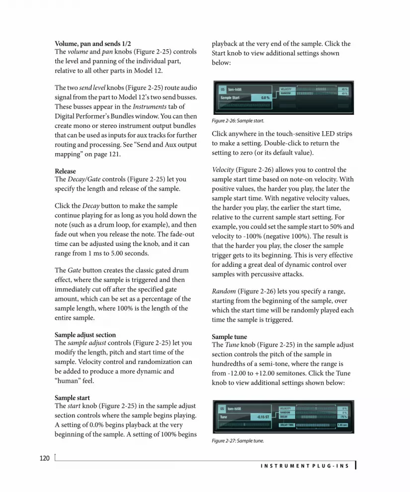
I N S T R U M E N T P L U G - I N S120
Volume, pan and sends 1/2The volume and pan knobs (Figure 2-25) controls the level and panning of the individual part, relative to all other parts in Model 12.
The two send level knobs (Figure 2-25) route audio signal from the part to Model 12’s two send busses. These busses appear in the Instruments tab of Digital Performer’s Bundles window. You can then create mono or stereo instrument output bundles that can be used as inputs for aux tracks for further routing and processing. See “Send and Aux output mapping” on page 121.
ReleaseThe Decay/Gate controls (Figure 2-25) let you specify the length and release of the sample.
Click the Decay button to make the sample continue playing for as long as you hold down the note (such as a drum loop, for example), and then fade out when you release the note. The fade-out time can be adjusted using the knob, and it can range from 1 ms to 5.00 seconds.
The Gate button creates the classic gated drum effect, where the sample is triggered and then immediately cut off after the specified gate amount, which can be set as a percentage of the sample length, where 100% is the length of the entire sample.
Sample adjust sectionThe sample adjust controls (Figure 2-25) let you modify the length, pitch and start time of the sample. Velocity control and randomization can be added to produce a more dynamic and “human” feel.
Sample startThe start knob (Figure 2-25) in the sample adjust section controls where the sample begins playing. A setting of 0.0% begins playback at the very beginning of the sample. A setting of 100% begins
playback at the very end of the sample. Click the Start knob to view additional settings shown below:
Figure 2-26: Sample start.
Click anywhere in the touch-sensitive LED strips to make a setting. Double-click to return the setting to zero (or its default value).
Velocity (Figure 2-26) allows you to control the sample start time based on note-on velocity. With positive values, the harder you play, the later the sample start time. With negative velocity values, the harder you play, the earlier the start time, relative to the current sample start setting. For example, you could set the sample start to 50% and velocity to -100% (negative 100%). The result is that the harder you play, the closer the sample trigger gets to its beginning. This is very effective for adding a great deal of dynamic control over samples with percussive attacks.
Random (Figure 2-26) lets you specify a range, starting from the beginning of the sample, over which the start time will be randomly played each time the sample is triggered.
Sample tuneThe Tune knob (Figure 2-25) in the sample adjust section controls the pitch of the sample in hundredths of a semi-tone, where the range is from -12.00 to +12.00 semitones. Click the Tune knob to view additional settings shown below:
Figure 2-27: Sample tune.

I N S T R U M E N T P L U G - I N S121
Velocity (Figure 2-27) modifies the tuning of the sample based on MIDI note-on velocity, where positive values make the pitch go higher as you play harder, and negative values make the pitch go lower as you play harder.
Random (Figure 2-27) lets you specify a range, extending from the root pitch of the sample, over which the tuning will be randomly played each time the sample is triggered
Decay (Figure 2-27) causes the pitch modulation to decay over the time period specified by Decay Time. Positive decay values start high at the initial attack and then “bend” down to the root pitch; negative decay values start low and bend up to the root. Use decay time to control the length of the bend.
Sample stretchThe Stretch knob (Figure 2-25) lets you lengthen the sample up to 100% of its original length or shorten it to 50% of its original length. Choose either Standard or PureDSP time-stretching. Standard time-stretching causes the pitch to go up when you shorten the sample and down when you lengthen it. PureDSP maintains the original pitch.
FilterThe optional Filter section for each part (Figure 2-25) provides four filter types: a lowpass (LPF) with 12dB slope, lowpass with 24dB slope, high pass (HPF) with 12dB slope and band pass (BPF) with 12dB slope. Click the button for the desired filter type to activate the filter. If you do not want the part to pass through the filter, simply ensure that none of the buttons are selected (you can click the currently selected button to deselect it).
Filter cutoff (center) frequency (Cutoff), resonance (Res) and Drive all provide velocity and random controls, similar to those explained earlier
for Sample Tune. In addition, cutoff frequency provides Decay and Decay Time similar to the Sample Tune decay features explained earlier.
Send and Aux output mappingThe send and aux output mapping for Model 12 is as follows:
Model 12 sample managementModel 12 organizes samples into four categories:
The Factory samples are always available. User samples are stored in your user directory and are therefore available only when you are the currently logged in user. You can use the user directory to protect your own sample content. Shared samples are stored in the system library application support folder and can therefore be made available to any users that you wish to share them with. Project samples are stored with the
Send/aux Model 12 mapping
Send 1 Model12 3-4
Send 2 Model12 5-6
Aux 1 Model12 7-8
Aux 2 Model12 9-10
Aux 3 Model12 11-12
Aux 4 Model12 13-14
Aux 5 Model12 15-16
Aux 6 Model12 17-18
SampleCategory Where the samples are stored
Factory In the Model 12 plug-in bundle: Model12.bundle/Contents/Resources/Samples
User In your user directory application support folder:User/Library/Application Support/MOTU/Model 12/Samples/
Shared In the MOTU application support folder:/Library/Application Support/MOTU/Model 12/Shared/Samples/
Project In the Digital Performer project folder:Project/Plug-in Data/Model 12/Samples/

I N S T R U M E N T P L U G - I N S122
Digital Performer project itself. By keeping them with the rest of the files associated with the project, you don’t have to worry about losing them when exchanging the project with a colleague, archiving the project, transferring it, etc.
Figure 2-28: The Model 12 Instrument menu.
Building your user libraryTo add a single sample to your user library, load it and then choose Copy to User from the instrument menu (Figure 2-28). To view the folder on the computer desktop, load a user sample (if one is not currently loaded) into a part and then choose Reveal in Finder/Explorer from the instrument menu (Figure 2-28). To add many samples at once, you can simply place them in the User folder in the Finder.
Figure 2-29: Organizing the Model 12 sample library on the computer desktop.
You can organize them into folders and sub-folders as desired (Figure 2-29), which then appear as sub-menus in the instrument menu (Figure 2-30):
Figure 2-30: Organizing user samples into sub-folders causes them to appear as sub-menus in the Model 12 instrument menu.
Using aliases or shortcutsIf you wish to include audio files that you prefer to store elsewhere on your hard drive(s), make Mac aliases or Windows shortcuts of them and place them in the Model 12 sample library folder(s).

I N S T R U M E N T P L U G - I N S123
MX4MX4 (Figure 2-31) features a unique, hybrid synthesis engine that combines several forms of synthesis, including subtractive, wavetable, frequency modulation (FM), amplitude modulation (AM) and analog emulation. MX4’s flexible programming and advanced modulation architecture provide the intimacy of a vintage synth, the flexibility of a modular synth, and the innovation of a virtual synth. For complete details, see Part 3, “MX4 Multi-synth” (page 137).
Figure 2-31: MX4.

I N S T R U M E N T P L U G - I N S124
PROTONProton (Figure 2-32) is a two-operator FM (frequency modulation) synth. The frequency of the Carrier signal (sine wave) is modulated by the Modulator oscillator. Additional controls allow you to program a wide variety of classic FM sounds, including gongs, bells, Rhodes pianos, plucked strings and many others.
About FM synthesisIf you modulate an oscillator’s frequency with the output of another oscillator at sub-audible rates (below approximately 80 Hz), the resulting effect on the signal is vibrato. As you raise the modulator’s frequency into the audible range (above approximately 80 Hz), the vibrato’s character transforms into a change of timbre. At
that point, it becomes frequency modulation instead of vibrato. Different frequency ratios of modulator and carrier produce a variety of interesting timbres. Proton provides controls for easily applying frequency multipliers (harmonics) to both the carrier and the modulator signal. The graphic display in the center of the window can show the resulting spectra or periodic waveform in real time.
The Carrier and ModulatorThe Carrier signal (Figure 2-32) is a sine wave equal to the frequency of the note being played. (For example, the A above middle C has a frequency of 440 Hz.) The Modulator modulates
Figure 2-32: Proton.
Modulator Carrier
Modulator harmonicmultiplier
Carrier harmonicmultiplier
Main volume

I N S T R U M E N T P L U G - I N S125
the Carrier signal. In its most basic form, the Modulator is also a sine wave that is based on the frequency of the note being played.
Harmonic multipliersHarmonic frequencies are the frequencies you get when you multiply a base frequency by integers. The Harmonic knobs allow you to multiply the modulator and the carrier frequencies by whole integer multiples. For example, a harmonic multiplier of 1 (01) simply produces the base frequency of the note being played. If you set the modulator harmonic to 1 and the carrier harmonic to zero (with all other controls disabled), the result is a sine wave at the base frequency. (Note that Proton does not allow you to set the modulator harmonic to zero, as this would zero out the modulator’s effect and produce no frequency modulation at all — with the result being just a simple sine wave. If both the modulator and carrier harmonic multipliers were set to zero, the result would be silence: a “direct current” flat-line signal with no modulation at all.)
If you set both the modulator and carrier harmonic multipliers to 1, you get a signal being modulated at its own frequency, and things start to get interesting. As you adjust the modulator and carrier harmonic multipliers to different ratios (such as 1:3, 1:4, 2:5, 4:3, etc.), the resulting harmonic content becomes increasingly more complex and interesting.
Modulator and Carrier Fine controlsBoth the modulator and carrier supply a Fine knob (Figure 2-32), which lets you fine-tune their frequency over a range from half a harmonic below (-0.5) to half a harmonic above (+0.5) their base frequency.
WaveThe modulator Wave knob (Figure 2-32) provides an interesting twist to conventional FM synthesis, which customarily uses sine waves as the basic
waveform for both the modulator and the carrier. Proton’s Wave knob, however, changes the waveshape of the modulator to a special-purpose wavetable, which you can index as you turn the knob. This specialized modulator waveform provides a rich variety of timbres to work with, all within Proton’s simple and intuitive two-operator design.
FMUse the FM knob (Figure 2-32) to control the amount of frequency modulation being applied — essentially it controls the strength of the modulator’s affect on the carrier. The amount of frequency modulation can also by controlled with MIDI note-on velocity. See “Velocity” below.
Fixed frequency carrierEnabled the Fixed frequency button (Figure 2-32) to disable key tracking of the carrier up and down the keyboard. When disabled, the carrier frequency remains proportional to the pitch of the note being played.
The Spectra/Waveform displayIn the Spectra/Waveform display (Figure 2-33), click the Spectra button to view a spectral graph of the frequencies being produced by the current settings in the plug-in. Blue lines represent components that are harmonic and pink lines represent components that are enharmonic. Click

I N S T R U M E N T P L U G - I N S126
Waveform to see one cycle of the periodic waveform being produced by the current settings in the plug-in.
Figure 2-33: The Spectra/Waveform display.
GlideGlide (Figure 2-32) is a continuous, smooth glide in pitch from one note to another. When the polyphony setting is set to 1, you can adjust Glide from zero (no portamento) to 100% (full portamento).
TransposeTranspose (Figure 2-32) lets you transpose the MIDI input of Proton by a number of half-steps. The range is two octaves (-24 to +24).
VolumeVolume (Figure 2-32) controls the overall level of Proton’s output. It is mapped to controller #7.
PolyphonyThe Polyphony (Figure 2-32) setting determines how many notes can play at a time. The maximum allowed polyphony for one instance of Proton is 16. Beware, however, that higher polyphony settings place higher demand on your host computer’s processing resources. Therefore, the ideal polyphony setting is that which matches the highest number of notes you will actually need
(the highest number of notes you will play simul-taneously, taking into account their releases and any resulting overlapping).
BendBend range (Figure 2-32) is specified in half-steps from 1 to 12, where 12 is an octave, and it determines Proton’s response to pitch bend.
VelocityVelocity (Figure 2-32) lets you control the overall loudness of each note, as well as the amount of FM applied, via note-on velocity. A higher settings produces greater on-velocity response.
FM LFOThe FM LFO (Figure 2-32) lets you control the amount of FM applied with an adjustable LFO. Rate controls the speed of the LFO and Amount controls how much FM is applied.
VibratoThe Vibrato controls (Figure 2-32) allow you to apply vibrato. Rate controls the speed of the vibrato and Amount controls the depth.
DetuneDetune (Figure 2-32) splits the carrier into two separate oscillators panned left and right and detuned from one another slightly. Detune is good for thickening sounds.
Modulation Pitch EnvelopeThe Modulation Pitch Envelope (Figure 2-34) applies a standard ADSR (attack, decay, sustain, release) envelope to modulator frequency. Attack, decay and release are expressed as amounts of time, whereas sustain is expressed as a percent of the envelope amount. The envelope range is +/- one octave. You can either drag the control points to adjust all ADSR values, or you can click each ADSR text field to edit the value directly. Use
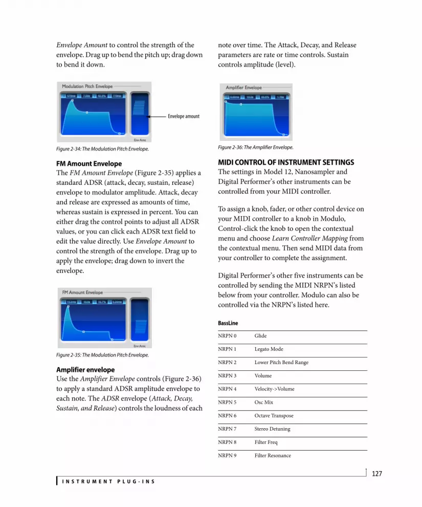
I N S T R U M E N T P L U G - I N S127
Envelope Amount to control the strength of the envelope. Drag up to bend the pitch up; drag down to bend it down.
Figure 2-34: The Modulation Pitch Envelope.
FM Amount EnvelopeThe FM Amount Envelope (Figure 2-35) applies a standard ADSR (attack, decay, sustain, release) envelope to modulator amplitude. Attack, decay and release are expressed as amounts of time, whereas sustain is expressed in percent. You can either drag the control points to adjust all ADSR values, or you can click each ADSR text field to edit the value directly. Use Envelope Amount to control the strength of the envelope. Drag up to apply the envelope; drag down to invert the envelope.
Figure 2-35: The Modulation Pitch Envelope.
Amplifier envelopeUse the Amplifier Envelope controls (Figure 2-36) to apply a standard ADSR amplitude envelope to each note. The ADSR envelope (Attack, Decay, Sustain, and Release) controls the loudness of each
note over time. The Attack, Decay, and Release parameters are rate or time controls. Sustain controls amplitude (level).
Figure 2-36: The Amplifier Envelope.
MIDI CONTROL OF INSTRUMENT SETTINGSThe settings in Model 12, Nanosampler and Digital Performer’s other instruments can be controlled from your MIDI controller.
To assign a knob, fader, or other control device on your MIDI controller to a knob in Modulo, Control-click the knob to open the contextual menu and choose Learn Controller Mapping from the contextual menu. Then send MIDI data from your controller to complete the assignment.
Digital Performer’s other five instruments can be controlled by sending the MIDI NRPN’s listed below from your controller. Modulo can also be controlled via the NRPN’s listed here.
Envelope amount
BassLine
NRPN 0 Glide
NRPN 1 Legato Mode
NRPN 2 Lower Pitch Bend Range
NRPN 3 Volume
NRPN 4 Velocity->Volume
NRPN 5 Osc Mix
NRPN 6 Octave Transpose
NRPN 7 Stereo Detuning
NRPN 8 Filter Freq
NRPN 9 Filter Resonance

I N S T R U M E N T P L U G - I N S128
NRPN 10 Filter Env Decay
NRPN 11 Filter Modulation
NRPN 12 Filter Velocity Modulation
NRPN 13 Overdrive
NRPN 14 Amp Env Decay
PolySynth
NRPN 0 Pitch Bend Range
NRPN 1 Volume
NRPN 2 Velocity->Volume
NRPN 3 Triangle Oscillator Level
NRPN 4 Sawtooth Oscillator Level
NRPN 5 Rectangle Oscillator Level
NRPN 6 Sub 1 Oscillator Level
NRPN 7 Sub 2 Oscillator Level
NRPN 8 Noise Level
NRPN 9 Octave Transpose
NRPN 10 Stereo Detuning
NRPN 11 LFO Rate
NRPN 12 PWM Modulation
NRPN 13 Vibrato/Wah-Wah
NRPN 14 Filter Keyfollow
NRPN 15 Filter Freq
NRPN 16 Filter Resonance
NRPN 17 Filter Envelope Modulation
NRPN 18 Filter Velocity Modulation
NRPN 19 Attack
NRPN 20 Decay
NRPN 21 Sustain Level
NRPN 22 Release
NRPN 23 Distortion
NRPN 24 Chorus
Modulo
NRPN 0 Polyphony
NRPN 1 Lower Pitch Bend Range
NRPN 2 Upper Pitch Bend Range
NRPN 3 Polyphonic Mode
NRPN 4 Legato Mode
NRPN 5 Portamento Time
NRPN 100 Osc Mix
NRPN 101 Noise Level
NRPN 200 Osc 1 Waveform
NRPN 201 Osc 1 Key-Follow
NRPN 202 Osc 1 Phase Mode
NRPN 203 Osc 1 Pitch Offset
NRPN 204 Osc 1 Phase Shift
NRPN 205 Osc 1 Symmetry
NRPN 220 Osc 2 Waveform
NRPN 221 Osc 2 Key-Follow
NRPN 222 Osc 2 Phase Mode
NRPN 223 Osc 2 Pitch Offset
NRPN 224 Osc 2 Phase Shift
NRPN 225 Osc 2 Symmetry
NRPN 300 Filter Mode
NRPN 301 Filter Freq
NRPN 302 Filter Resonance
NRPN 303 Filter Key-Follow
NRPN 400 Amp Env Attack
NRPN 401 Amp Env Decay
NRPN 402 Amp Env Sustain Level
NRPN 403 Amp Env Release
NRPN 410 Filter Env Attack
NRPN 411 Filter Env Decay

I N S T R U M E N T P L U G - I N S129
NRPN 412 Filter Env Sustain Level
NRPN 413 Filter Env Release
NRPN 420 Mod Env Attack
NRPN 421 Mod Env Decay
NRPN 422 Mod Env Sustain Level
NRPN 423 Mod Env Release
NRPN 500 LFO 1 Waveform
NRPN 501 LFO 1 Sync Mode
NRPN 502 LFO 1 Rate
NRPN 503 LFO 1 Sync Period
NRPN 520 LFO 2 Waveform
NRPN 521 LFO 2 Sync Mode
NRPN 522 LFO 2 Rate
NRPN 523 LFO 2 Sync Period
NRPN 600 Filter Env->Filter Freq
NRPN 700 Mod Env->Osc Mix
NRPN 701 Mod Env->Osc 1 Freq
NRPN 702 Mod Env->Osc 2 Freq
NRPN 703 Mod Env->Osc 1 Phase Shift
NRPN 704 Mod Env->Osc 2 Phase Shift
NRPN 705 Mod Env->Osc 1 Sym
NRPN 706 Mod Env->Osc 2 Sym
NRPN 800 LFO 1->Filter Freq
NRPN 801 LFO 1->Osc 1 Pitch
NRPN 802 LFO 1->Osc 2 Pitch
NRPN 803 LFO 1->Osc 1 Phase Shift
NRPN 804 LFO 1->Osc 2 Phase Shift
NRPN 805 LFO 1->Osc 1 Sym
NRPN 806 LFO 1->Osc 2 Sym
NRPN 900 LFO 2->Filter Freq
NRPN 901 LFO 2->Osc Mix
NRPN 902 LFO 2->Osc 1 & 2 Pitch
NRPN 903 LFO 2->Osc 1 Phase Shift
NRPN 904 LFO 2->Osc 2 Phase Shift
NRPN 905 LFO 2->Osc 1 Sym
NRPN 906 LFO 2->Osc 2 Sym
NRPN 1000 Velocity->Volume
NRPN 1001 Velocity->Osc Mix
NRPN 1002 Velocity->Osc 1 & 2 Phase Shift
NRPN 1003 Velocity->Osc 1 & 2 Sym
NRPN 1004 Velocity->Filter Freq
NRPN 1100 Wheel->Filter Freq
NRPN 1101 Wheel->Filter Res
NRPN 1102 Wheel->Osc 1 & 2 Phase Shift
NRPN 1103 Wheel->Osc 1 & 2 Sym
NRPN 1104 Wheel->LFO 1->Filter Freq
NRPN 1105 Wheel->LFO 1->Osc Pitch
NRPN 1200 Stereo Detuning
NRPN 1201 Volume
Nanosampler
NRPN 0 Polyphony
NRPN 1 Pitch Bend Range
NRPN 2 Volume
NRPN 3 Velocity Sensitivity
NRPN 4 Tuning
NRPN 5 Sample Start
NRPN 6 Sample End
NRPN 7 Loop Enable
NRPN 8 Loop Start
NRPN 9 Loop End
NRPN 10 Loop Crossfade
NRPN 11 LFO Trigger Mode

I N S T R U M E N T P L U G - I N S130
NRPN 12 LFO Sync Mode
NRPN 13 LFO Waveform
NRPN 14 LFO Rate
NRPN 15 LFO Synced Rate
NRPN 16 LFO Delay
NRPN 17 LFO Fade
NRPN 18 LFO Detuning
NRPN 19 LFO Pitch Modulation
NRPN 20 Amp Env Attack
NRPN 21 Amp Env Decay
NRPN 22 Amp Env Sustain Level
NRPN 23 Amp Env Release
NRPN 24 Filter Env Attack
NRPN 25 Filter Env Decay
NRPN 26 Filter Env Sustain Level
NRPN 27 Filter Env Release
NRPN 28 Filter Enable
NRPN 29 Filter Mode
NRPN 30 Filter Frequency
NRPN 31 Filter Resonance
NRPN 32 Filter Key-Follow
NRPN 33 LFO Filter Modulation
NRPN 34 Filter Velocity Tracking
NRPN 35 Envelope Filter Modulation
Proton
NRPN 0 Polyphony
NRPN 1 Pitch Bend Range
NRPN 2 Glide
NRPN 3 Transpose
NRPN 4 Velocity->Volume
NRPN 5 Volume
NRPN 6 Stereo Detuning
NRPN 7 Carrier Harmonic
NRPN 8 Carrier Fine Tuning
NRPN 9 Carrier Key Follow
NRPN 10 Modulator Harmonic
NRPN 11 Modulator Fine Tuning
NRPN 12 Modulator Waveform
NRPN 13 FM Amount
NRPN 14 Modulator Pitch Envelope Modulation
NRPN 15 FM Envelope Modulation
NRPN 16 FM LFO Rate
NRPN 17 FM LFO Modulation
NRPN 18 Vibrato LFO Rate
NRPN 19 Vibrato Amount
NRPN 20 Modulator Freq Attack
NRPN 21 Modulator Freq Decay
NRPN 22 Modulator Freq Sustain Level
NRPN 23 Modulator Freq Release
NRPN 24 FM Attack
NRPN 25 FM Decay
NRPN 26 FM Sustain Level
NRPN 27 FM Release
NRPN 28 Amp Attack
NRPN 29 Amp Decay
NRPN 30 Amp Sustain Level
NRPN 31 Amp Release
Model 12
NRPN 0 Master Volume
NRPN 1 Master Tune
NRPN 2 Master Stretch
NRPN 3 Voice Selection

I N S T R U M E N T P L U G - I N S131
NRPN 101 Part 1 Mute
NRPN 102 Part 1 Solo
NRPN 103 Part 1 Link
NRPN 104 Part 1 Output Assignment
NRPN 105 Part 1 Output Assignment
NRPN 106 Part 1 Sample Start
NRPN 107 Part 1 Sample Start Velocity Mod
NRPN 108 Part 1 Sample Start Random Mod
NRPN 109 Part 1 Standard Tune
NRPN 110 Part 1 Tune Velocity Mod
NRPN 111 Part 1 Tune Random Mod
NRPN 112 Part 1 Tune Decay Amount
NRPN 113 Part 1 Tune Decay Time
NRPN 114 Part 1 Tune Mode
NRPN 115 Part 1 Stretch
NRPN 116 Part 1 PureDSP Tune
NRPN 117 Part 1 Filter Frequency
NRPN 118 Part 1 Filter Frequency Velocity Mod
NRPN 119 Part 1 Filter Frequency Random Mod
NRPN 120 Part 1 Filter Frequency Decay Amount
NRPN 121 Part 1 Filter Frequency Decay Time
NRPN 122 Part 1 Filter Mode
NRPN 123 Part 1 Resonance
NRPN 124 Part 1 Resonance Velocity Mod
NRPN 125 Part 1 Resonance Random Mod
NRPN 126 Part 1 Drive
NRPN 127 Part 1 Drive Velocity Mod
NRPN 128 Part 1 Drive Random Mod
NRPN 129 Part 1 Sample End
NRPN 130 Part 1 Decay Time
NRPN 131 Part 1 Decay Mode
NRPN 132 Part 1 Volume
NRPN 133 Part 1 Volume Velocity Mod
NRPN 134 Part 1 Pan
NRPN 135 Part 1 Pan Velocity Mod
NRPN 136 Part 1 Pan Random Mod
NRPN 137 Part 1 Send 1 Level
NRPN 138 Part 1 Send 2 Level
NRPN 201 Part 2 Mute
NRPN 202 Part 2 Solo
NRPN 203 Part 2 Link
NRPN 204 Part 2 Output Assignment
NRPN 205 Part 2 Output Assignment
NRPN 206 Part 2 Sample Start
NRPN 207 Part 2 Sample Start Velocity Mod
NRPN 208 Part 2 Sample Start Random Mod
NRPN 209 Part 2 Standard Tune
NRPN 210 Part 2 Tune Velocity Mod
NRPN 211 Part 2 Tune Random Mod
NRPN 212 Part 2 Tune Decay Amount
NRPN 213 Part 2 Tune Decay Time
NRPN 214 Part 2 Tune Mode
NRPN 215 Part 2 Stretch
NRPN 216 Part 2 PureDSP Tune
NRPN 217 Part 2 Filter Frequency
NRPN 218 Part 2 Filter Frequency Velocity Mod
NRPN 219 Part 2 Filter Frequency Random Mod
NRPN 220 Part 2 Filter Frequency Decay Amount
NRPN 221 Part 2 Filter Frequency Decay Time
NRPN 222 Part 2 Filter Mode
NRPN 223 Part 2 Resonance
NRPN 224 Part 2 Resonance Velocity Mod

I N S T R U M E N T P L U G - I N S132
NRPN 225 Part 2 Resonance Random Mod
NRPN 226 Part 2 Drive
NRPN 227 Part 2 Drive Velocity Mod
NRPN 228 Part 2 Drive Random Mod
NRPN 229 Part 2 Sample End
NRPN 230 Part 2 Decay Time
NRPN 231 Part 2 Decay Mode
NRPN 232 Part 2 Volume
NRPN 233 Part 2 Volume Velocity Mod
NRPN 234 Part 2 Pan
NRPN 235 Part 2 Pan Velocity Mod
NRPN 236 Part 2 Pan Random Mod
NRPN 237 Part 2 Send 1 Level
NRPN 238 Part 2 Send 2 Level
NRPN 301 Part 3 Mute
NRPN 302 Part 3 Solo
NRPN 303 Part 3 Link
NRPN 304 Part 3 Output Assignment
NRPN 305 Part 3 Output Assignment
NRPN 306 Part 3 Sample Start
NRPN 307 Part 3 Sample Start Velocity Mod
NRPN 308 Part 3 Sample Start Random Mod
NRPN 309 Part 3 Standard Tune
NRPN 310 Part 3 Tune Velocity Mod
NRPN 311 Part 3 Tune Random Mod
NRPN 312 Part 3 Tune Decay Amount
NRPN 313 Part 3 Tune Decay Time
NRPN 314 Part 3 Tune Mode
NRPN 315 Part 3 Stretch
NRPN 316 Part 3 PureDSP Tune
NRPN 317 Part 3 Filter Frequency
NRPN 318 Part 3 Filter Frequency Velocity Mod
NRPN 319 Part 3 Filter Frequency Random Mod
NRPN 320 Part 3 Filter Frequency Decay Amount
NRPN 321 Part 3 Filter Frequency Decay Time
NRPN 322 Part 3 Filter Mode
NRPN 323 Part 3 Resonance
NRPN 324 Part 3 Resonance Velocity Mod
NRPN 325 Part 3 Resonance Random Mod
NRPN 326 Part 3 Drive
NRPN 327 Part 3 Drive Velocity Mod
NRPN 328 Part 3 Drive Random Mod
NRPN 329 Part 3 Sample End
NRPN 330 Part 3 Decay Time
NRPN 331 Part 3 Decay Mode
NRPN 332 Part 3 Volume
NRPN 333 Part 3 Volume Velocity Mod
NRPN 334 Part 3 Pan
NRPN 335 Part 3 Pan Velocity Mod
NRPN 336 Part 3 Pan Random Mod
NRPN 337 Part 3 Send 1 Level
NRPN 338 Part 3 Send 2 Level
NRPN 401 Part 4 Mute
NRPN 402 Part 4 Solo
NRPN 403 Part 4 Link
NRPN 404 Part 4 Output Assignment
NRPN 405 Part 4 Output Assignment
NRPN 406 Part 4 Sample Start
NRPN 407 Part 4 Sample Start Velocity Mod
NRPN 408 Part 4 Sample Start Random Mod
NRPN 409 Part 4 Standard Tune
NRPN 410 Part 4 Tune Velocity Mod
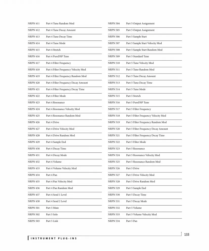
I N S T R U M E N T P L U G - I N S133
NRPN 411 Part 4 Tune Random Mod
NRPN 412 Part 4 Tune Decay Amount
NRPN 413 Part 4 Tune Decay Time
NRPN 414 Part 4 Tune Mode
NRPN 415 Part 4 Stretch
NRPN 416 Part 4 PureDSP Tune
NRPN 417 Part 4 Filter Frequency
NRPN 418 Part 4 Filter Frequency Velocity Mod
NRPN 419 Part 4 Filter Frequency Random Mod
NRPN 420 Part 4 Filter Frequency Decay Amount
NRPN 421 Part 4 Filter Frequency Decay Time
NRPN 422 Part 4 Filter Mode
NRPN 423 Part 4 Resonance
NRPN 424 Part 4 Resonance Velocity Mod
NRPN 425 Part 4 Resonance Random Mod
NRPN 426 Part 4 Drive
NRPN 427 Part 4 Drive Velocity Mod
NRPN 428 Part 4 Drive Random Mod
NRPN 429 Part 4 Sample End
NRPN 430 Part 4 Decay Time
NRPN 431 Part 4 Decay Mode
NRPN 432 Part 4 Volume
NRPN 433 Part 4 Volume Velocity Mod
NRPN 434 Part 4 Pan
NRPN 435 Part 4 Pan Velocity Mod
NRPN 436 Part 4 Pan Random Mod
NRPN 437 Part 4 Send 1 Level
NRPN 438 Part 4 Send 2 Level
NRPN 501 Part 5 Mute
NRPN 502 Part 5 Solo
NRPN 503 Part 5 Link
NRPN 504 Part 5 Output Assignment
NRPN 505 Part 5 Output Assignment
NRPN 506 Part 5 Sample Start
NRPN 507 Part 5 Sample Start Velocity Mod
NRPN 508 Part 5 Sample Start Random Mod
NRPN 509 Part 5 Standard Tune
NRPN 510 Part 5 Tune Velocity Mod
NRPN 511 Part 5 Tune Random Mod
NRPN 512 Part 5 Tune Decay Amount
NRPN 513 Part 5 Tune Decay Time
NRPN 514 Part 5 Tune Mode
NRPN 515 Part 5 Stretch
NRPN 516 Part 5 PureDSP Tune
NRPN 517 Part 5 Filter Frequency
NRPN 518 Part 5 Filter Frequency Velocity Mod
NRPN 519 Part 5 Filter Frequency Random Mod
NRPN 520 Part 5 Filter Frequency Decay Amount
NRPN 521 Part 5 Filter Frequency Decay Time
NRPN 522 Part 5 Filter Mode
NRPN 523 Part 5 Resonance
NRPN 524 Part 5 Resonance Velocity Mod
NRPN 525 Part 5 Resonance Random Mod
NRPN 526 Part 5 Drive
NRPN 527 Part 5 Drive Velocity Mod
NRPN 528 Part 5 Drive Random Mod
NRPN 529 Part 5 Sample End
NRPN 530 Part 5 Decay Time
NRPN 531 Part 5 Decay Mode
NRPN 532 Part 5 Volume
NRPN 533 Part 5 Volume Velocity Mod
NRPN 534 Part 5 Pan

I N S T R U M E N T P L U G - I N S134
NRPN 535 Part 5 Pan Velocity Mod
NRPN 536 Part 5 Pan Random Mod
NRPN 537 Part 5 Send 1 Level
NRPN 538 Part 5 Send 2 Level
NRPN 601 Part 6 Mute
NRPN 602 Part 6 Solo
NRPN 603 Part 6 Link
NRPN 604 Part 6 Output Assignment
NRPN 605 Part 6 Output Assignment
NRPN 606 Part 6 Sample Start
NRPN 607 Part 6 Sample Start Velocity Mod
NRPN 608 Part 6 Sample Start Random Mod
NRPN 609 Part 6 Standard Tune
NRPN 610 Part 6 Tune Velocity Mod
NRPN 611 Part 6 Tune Random Mod
NRPN 612 Part 6 Tune Decay Amount
NRPN 613 Part 6 Tune Decay Time
NRPN 614 Part 6 Tune Mode
NRPN 615 Part 6 Stretch
NRPN 616 Part 6 PureDSP Tune
NRPN 617 Part 6 Filter Frequency
NRPN 618 Part 6 Filter Frequency Velocity Mod
NRPN 619 Part 6 Filter Frequency Random Mod
NRPN 620 Part 6 Filter Frequency Decay Amount
NRPN 621 Part 6 Filter Frequency Decay Time
NRPN 622 Part 6 Filter Mode
NRPN 623 Part 6 Resonance
NRPN 624 Part 6 Resonance Velocity Mod
NRPN 625 Part 6 Resonance Random Mod
NRPN 626 Part 6 Drive
NRPN 627 Part 6 Drive Velocity Mod
NRPN 628 Part 6 Drive Random Mod
NRPN 629 Part 6 Sample End
NRPN 630 Part 6 Decay Time
NRPN 631 Part 6 Decay Mode
NRPN 632 Part 6 Volume
NRPN 633 Part 6 Volume Velocity Mod
NRPN 634 Part 6 Pan
NRPN 635 Part 6 Pan Velocity Mod
NRPN 636 Part 6 Pan Random Mod
NRPN 637 Part 6 Send 1 Level
NRPN 638 Part 6 Send 2 Level
NRPN 701 Part 7 Mute
NRPN 702 Part 7 Solo
NRPN 703 Part 7 Link
NRPN 704 Part 7 Output Assignment
NRPN 705 Part 7 Output Assignment
NRPN 706 Part 7 Sample Start
NRPN 707 Part 7 Sample Start Velocity Mod
NRPN 708 Part 7 Sample Start Random Mod
NRPN 709 Part 7 Standard Tune
NRPN 710 Part 7 Tune Velocity Mod
NRPN 711 Part 7 Tune Random Mod
NRPN 712 Part 7 Tune Decay Amount
NRPN 713 Part 7 Tune Decay Time
NRPN 714 Part 7 Tune Mode
NRPN 715 Part 7 Stretch
NRPN 716 Part 7 PureDSP Tune
NRPN 717 Part 7 Filter Frequency
NRPN 718 Part 7 Filter Frequency Velocity Mod
NRPN 719 Part 7 Filter Frequency Random Mod
NRPN 720 Part 7 Filter Frequency Decay Amount

I N S T R U M E N T P L U G - I N S135
NRPN 721 Part 7 Filter Frequency Decay Time
NRPN 722 Part 7 Filter Mode
NRPN 723 Part 7 Resonance
NRPN 724 Part 7 Resonance Velocity Mod
NRPN 725 Part 7 Resonance Random Mod
NRPN 726 Part 7 Drive
NRPN 727 Part 7 Drive Velocity Mod
NRPN 728 Part 7 Drive Random Mod
NRPN 729 Part 7 Sample End
NRPN 730 Part 7 Decay Time
NRPN 731 Part 7 Decay Mode
NRPN 732 Part 7 Volume
NRPN 733 Part 7 Volume Velocity Mod
NRPN 734 Part 7 Pan
NRPN 735 Part 7 Pan Velocity Mod
NRPN 736 Part 7 Pan Random Mod
NRPN 737 Part 7 Send 1 Level
NRPN 738 Part 7 Send 2 Level
NRPN 801 Part 8 Mute
NRPN 802 Part 8 Solo
NRPN 803 Part 8 Link
NRPN 804 Part 8 Output Assignment
NRPN 805 Part 8 Output Assignment
NRPN 806 Part 8 Sample Start
NRPN 807 Part 8 Sample Start Velocity Mod
NRPN 808 Part 8 Sample Start Random Mod
NRPN 809 Part 8 Standard Tune
NRPN 810 Part 8 Tune Velocity Mod
NRPN 811 Part 8 Tune Random Mod
NRPN 812 Part 8 Tune Decay Amount
NRPN 813 Part 8 Tune Decay Time
NRPN 814 Part 8 Tune Mode
NRPN 815 Part 8 Stretch
NRPN 816 Part 8 PureDSP Tune
NRPN 817 Part 8 Filter Frequency
NRPN 818 Part 8 Filter Frequency Velocity Mod
NRPN 819 Part 8 Filter Frequency Random Mod
NRPN 820 Part 8 Filter Frequency Decay Amount
NRPN 821 Part 8 Filter Frequency Decay Time
NRPN 822 Part 8 Filter Mode
NRPN 823 Part 8 Resonance
NRPN 824 Part 8 Resonance Velocity Mod
NRPN 825 Part 8 Resonance Random Mod
NRPN 826 Part 8 Drive
NRPN 827 Part 8 Drive Velocity Mod
NRPN 828 Part 8 Drive Random Mod
NRPN 829 Part 8 Sample End
NRPN 830 Part 8 Decay Time
NRPN 831 Part 8 Decay Mode
NRPN 832 Part 8 Volume
NRPN 833 Part 8 Volume Velocity Mod
NRPN 834 Part 8 Pan
NRPN 835 Part 8 Pan Velocity Mod
NRPN 836 Part 8 Pan Random Mod
NRPN 837 Part 8 Send 1 Level
NRPN 838 Part 8 Send 2 Level
NRPN 901 Part 9 Mute
NRPN 902 Part 9 Solo
NRPN 903 Part 9 Link
NRPN 904 Part 9 Output Assignment
NRPN 905 Part 9 Output Assignment
NRPN 906 Part 9 Sample Start

I N S T R U M E N T P L U G - I N S136
NRPN 907 Part 9 Sample Start Velocity Mod
NRPN 908 Part 9 Sample Start Random Mod
NRPN 909 Part 9 Standard Tune
NRPN 910 Part 9 Tune Velocity Mod
NRPN 911 Part 9 Tune Random Mod
NRPN 912 Part 9 Tune Decay Amount
NRPN 913 Part 9 Tune Decay Time
NRPN 914 Part 9 Tune Mode
NRPN 915 Part 9 Stretch
NRPN 916 Part 9 PureDSP Tune
NRPN 917 Part 9 Filter Frequency
NRPN 918 Part 9 Filter Frequency Velocity Mod
NRPN 919 Part 9 Filter Frequency Random Mod
NRPN 920 Part 9 Filter Frequency Decay Amount
NRPN 921 Part 9 Filter Frequency Decay Time
NRPN 922 Part 9 Filter Mode
NRPN 923 Part 9 Resonance
NRPN 924 Part 9 Resonance Velocity Mod
NRPN 925 Part 9 Resonance Random Mod
NRPN 926 Part 9 Drive
NRPN 927 Part 9 Drive Velocity Mod
NRPN 928 Part 9 Drive Random Mod
NRPN 929 Part 9 Sample End
NRPN 930 Part 9 Decay Time
NRPN 931 Part 9 Decay Mode
NRPN 932 Part 9 Volume
NRPN 933 Part 9 Volume Velocity Mod
NRPN 934 Part 9 Pan
NRPN 935 Part 9 Pan Velocity Mod
NRPN 936 Part 9 Pan Random Mod
NRPN 937 Part 9 Send 1 Level
NRPN 938 Part 9 Send 2 Level
NRPN 1001 Part 10 Mute
NRPN 1002 Part 10 Solo
NRPN 1003 Part 10 Link
NRPN 1004 Part 10 Output Assignment
NRPN 1005 Part 10 Output Assignment
NRPN 1006 Part 10 Sample Start
NRPN 1007 Part 10 Sample Start Velocity Mod
NRPN 1008 Part 10 Sample Start Random Mod
NRPN 1009 Part 10 Standard Tune
NRPN 1010 Part 10 Tune Velocity Mod
NRPN 1011 Part 10 Tune Random Mod
NRPN 1012 Part 10 Tune Decay Amount
NRPN 1013 Part 10 Tune Decay Time
NRPN 1014 Part 10 Tune Mode
NRPN 1015 Part 10 Stretch
NRPN 1016 Part 10 PureDSP Tune
NRPN 1017 Part 10 Filter Frequency
NRPN 1018 Part 10 Filter Frequency Velocity Mod
NRPN 1019 Part 10 Filter Frequency Random Mod
NRPN 1020 Part 10 Filter Frequency Decay Amount
NRPN 1021 Part 10 Filter Frequency Decay Time
NRPN 1022 Part 10 Filter Mode
NRPN 1023 Part 10 Resonance
NRPN 1024 Part 10 Resonance Velocity Mod
NRPN 1025 Part 10 Resonance Random Mod
NRPN 1026 Part 10 Drive
NRPN 1027 Part 10 Drive Velocity Mod
NRPN 1028 Part 10 Drive Random Mod
NRPN 1029 Part 10 Sample End
NRPN 1030 Part 10 Decay Time

I N S T R U M E N T P L U G - I N S137
NRPN 1031 Part 10 Decay Mode
NRPN 1032 Part 10 Volume
NRPN 1033 Part 10 Volume Velocity Mod
NRPN 1034 Part 10 Pan
NRPN 1035 Part 10 Pan Velocity Mod
NRPN 1036 Part 10 Pan Random Mod
NRPN 1037 Part 10 Send 1 Level
NRPN 1038 Part 10 Send 2 Level
NRPN 1101 Part 11 Mute
NRPN 1102 Part 11 Solo
NRPN 1103 Part 11 Link
NRPN 1104 Part 11 Output Assignment
NRPN 1105 Part 11 Output Assignment
NRPN 1106 Part 11 Sample Start
NRPN 1107 Part 11 Sample Start Velocity Mod
NRPN 1108 Part 11 Sample Start Random Mod
NRPN 1109 Part 11 Standard Tune
NRPN 1110 Part 11 Tune Velocity Mod
NRPN 1111 Part 11 Tune Random Mod
NRPN 1112 Part 11 Tune Decay Amount
NRPN 1113 Part 11 Tune Decay Time
NRPN 1114 Part 11 Tune Mode
NRPN 1115 Part 11 Stretch
NRPN 1116 Part 11 PureDSP Tune
NRPN 1117 Part 11 Filter Frequency
NRPN 1118 Part 11 Filter Frequency Velocity Mod
NRPN 1119 Part 11 Filter Frequency Random Mod
NRPN 1120 Part 11 Filter Frequency Decay Amount
NRPN 1121 Part 11 Filter Frequency Decay Time
NRPN 1122 Part 11 Filter Mode
NRPN 1123 Part 11 Resonance
NRPN 1124 Part 11 Resonance Velocity Mod
NRPN 1125 Part 11 Resonance Random Mod
NRPN 1126 Part 11 Drive
NRPN 1127 Part 11 Drive Velocity Mod
NRPN 1128 Part 11 Drive Random Mod
NRPN 1129 Part 11 Sample End
NRPN 1130 Part 11 Decay Time
NRPN 1131 Part 11 Decay Mode
NRPN 1132 Part 11 Volume
NRPN 1133 Part 11 Volume Velocity Mod
NRPN 1134 Part 11 Pan
NRPN 1135 Part 11 Pan Velocity Mod
NRPN 1136 Part 11 Pan Random Mod
NRPN 1137 Part 11 Send 1 Level
NRPN 1138 Part 11 Send 2 Level
NRPN 1201 Part 12 Mute
NRPN 1202 Part 12 Solo
NRPN 1203 Part 12 Link
NRPN 1204 Part 12 Output Assignment
NRPN 1205 Part 12 Output Assignment
NRPN 1206 Part 12 Sample Start
NRPN 1207 Part 12 Sample Start Velocity Mod
NRPN 1208 Part 12 Sample Start Random Mod
NRPN 1209 Part 12 Standard Tune
NRPN 1210 Part 12 Tune Velocity Mod
NRPN 1211 Part 12 Tune Random Mod
NRPN 1212 Part 12 Tune Decay Amount
NRPN 1213 Part 12 Tune Decay Time
NRPN 1214 Part 12 Tune Mode
NRPN 1215 Part 12 Stretch
NRPN 1216 Part 12 PureDSP Tune

I N S T R U M E N T P L U G - I N S138
NRPN 1217 Part 12 Filter Frequency
NRPN 1218 Part 12 Filter Frequency Velocity Mod
NRPN 1219 Part 12 Filter Frequency Random Mod
NRPN 1220 Part 12 Filter Frequency Decay Amount
NRPN 1221 Part 12 Filter Frequency Decay Time
NRPN 1222 Part 12 Filter Mode
NRPN 1223 Part 12 Resonance
NRPN 1224 Part 12 Resonance Velocity Mod
NRPN 1225 Part 12 Resonance Random Mod
NRPN 1226 Part 12 Drive
NRPN 1227 Part 12 Drive Velocity Mod
NRPN 1228 Part 12 Drive Random Mod
NRPN 1229 Part 12 Sample End
NRPN 1230 Part 12 Decay Time
NRPN 1231 Part 12 Decay Mode
NRPN 1232 Part 12 Volume
NRPN 1233 Part 12 Volume Velocity Mod
NRPN 1234 Part 12 Pan
NRPN 1235 Part 12 Pan Velocity Mod
NRPN 1236 Part 12 Pan Random Mod
NRPN 1237 Part 12 Send 1 Level
NRPN 1238 Part 12 Send 2 Level

CHAPTER
139
3 MOTU Instruments Soundbank
OVERVIEWThe MOTU Instruments soundbank provides approximately 5.5 GB of multi-sample instruments, loops, phrases, and synth instruments. You’ll find plenty of drum loops, acoustic drum kits, electronic drum kits, acoustic pianos, electric pianos, church organs, electric organs, acoustic guitars, electric guitars, strings, brass, woodwinds, synths, ethnic instruments, voices, percussion, sound design, sound effects, and more.
This versatile collection of sounds spans a wide variety of musical genres, eras, geographical regions, and cultural styles.
How it works . . . . . . . . . . . . . . . . . . . . . . . . . . . . . . . . . . . . . . . . . .139Downloading the soundbank. . . . . . . . . . . . . . . . . . . . . . . . . .139Activating the soundbank . . . . . . . . . . . . . . . . . . . . . . . . . . . . .140Installing UVI Workstation . . . . . . . . . . . . . . . . . . . . . . . . . . . . .140Accessing sounds. . . . . . . . . . . . . . . . . . . . . . . . . . . . . . . . . . . . . .140A quick tour of UVIWorkstation . . . . . . . . . . . . . . . . . . . . . . . .141Soundbank preset list . . . . . . . . . . . . . . . . . . . . . . . . . . . . . . . . .142
HOW IT WORKSTo use the MOTU Instruments soundbank, you must load it into the free UVIWorkstation application, which runs either as a stand-alone virtual instrument or as an instrument plug-in within Digital Performer.
If you own UVI’s Falcon universal sampler, you can load the soundbank into Falcon directly, just like other UFS soundbanks.
If you own MOTU’s MachFive 3, the MOTU Instruments soundbank is incompatible. However, you can simply use the MachFive 3 Universal Loops & Instruments soundbank, which has the same sounds.
DOWNLOADING THE SOUNDBANKThe MOTU Instruments soundbank file can be downloaded from your motu.com account page, once you’ve registered your copy of Digital Performer. You must create an account at motu.com and register your copy of Digital Performer to access the soundbank download link.
If you purchased Digital Performer 10 (or later) as an upgrade from a previous version, your account registration is automatically updated with immediate access to the download link.
1 Go to motu.com and log in to your account. If you don’t yet have an account, create one.
2 Go My Registrations.
3 If you haven’t already done so, register your copy of Digital Performer. If you upgraded from a previous version of DP, it is already registered, and you are all set.
4 Scroll to the Free Software section in the list of your registered products and click the Free virtual instruments tab.
5 Click the download link for the soundbank.
The soundbank is a zipped archive, but it is still very large (over 2 GB), so the download may take a while, depending on the speed of your internet connection.
6 Click the Activate Now link to initiate the activation process, as explained in the next section.

M O T U I N S T R U M E N T S S O U N D B A N K140
ACTIVATING THE SOUNDBANKThe MOTU Instruments soundbank requires iLok activation. This process requires that you create a free account at ilok.com.
1 If you haven’t already done so, click the Activate Now link as explained in the previous section and follow the on-screen instructions.
2 Visit ilok.com and create a free account.
3 Download and install the free iLok License Manager app.
4 Launch the iLok License Manager app.
5 Click the Available tab.
6 In the list, drag and drop the MOTU Instruments soundbank activation to your computer or your iLok USB key, as desired.
7 For your convenience, there is a second activation, which you can use to activate a second computer or iLok.
The MOTU Instruments soundbank is now activated on your computer or iLok, and you are ready to begin using it, as explained in the following sections.
INSTALLING UVI WORKSTATIONIf you have UVI Falcon, you can now load the MOTU Instruments UFS soundbank as usual. If not, the next step of the process is to install the UVIWorkstation app.
1 Google UVI Workstation and find the UVIWorkstation web page.
2 Go to the Download tab and download the Mac or Windows installer and the PDF manual.
3 Run the installer and following the on-screen instructions.
For further details about installing and using UVIWorkstation, please refer to the PDF manual.
ACCESSING SOUNDS1 Launch the UVIWorkstation app, or create a UVIWorkstation instrument track in Digital Performer, as usual: choose Project menu > Add Track > Instrument Track > UVI > UVIWorkstation (stereo).
2 Double-click the browser bar at the top of the window to open the browser.
3 Navigate to the location on your hard drive where you placed the MOTU Instruments.UFS soundbank file.
The soundbank UFS file can reside anywhere you wish on your computer’s hard drive.
4 Double-click the UFS file to open it, and then navigate through the preset menus.
5 Double-click the preset you wish to load.
The Soundbanks section of the browserFor your convenience, the Soundbanks section of the UVIWorkstation browser will display any UFS soundbank files placed in the following location:
macOS: /library/Application Support/UVISoundbanks
Windows: /Program Files/ UVISoundbanks
Simply place the MOTU Instruments.UFS file in this location and restart UVIWorkstation. The soundbank will automatically appear in the Soundbanks section of the browser.
You can also customize this location. For details, see the UVIWorkstation PDF manual.

M O T U I N S T R U M E N T S S O U N D B A N K141
A QUICK TOUR OF UVIWORKSTATIONFor complete information about UVIWorkstation, please refer to the UIVWorkstation PDF manual. This section provides a quick tour to get you started.
The UVIWorkstation windowWhen you load a MOTU Instruments soundbank preset in UVIWorkstation, you’ll see something similar to Figure 3-1, which shows the Edit tab for the Twelve String guitar preset.
Browsing presetsClick the Browser button or double-click the preset to browse other presets in the soundbank. For details about using the browser see the UVIWorkstation manual.
The Edit tab and macro controlsThe Edit tab displays Macro controls (knobs and buttons) that let you modify the sound of the preset. The Macro Help section provides tips for using the macro controls for each preset.
The Effects tabClick the Effects tab (Figure 3-1) to gain access to the effects rack for the preset (Figure 3-2 on page 142). This gives you more detailed control over the effects being used for the preset. Here, you can add, remove and modify effects from UVIWorkstation’s considerable arsenal of effects processors.
Figure 3-1: A twelve-string guitar preset from the MOTU Instruments soundbank.
Browser Multi menu
Main/Multi view toggle
Show/hide keyboard
Main volume fader
Show/hide transports
Preset
Edit tab
Effects tab
Arp tab
Reverb macro
Keyboard
Macros
Macro help
MIDI and partmenus

M O T U I N S T R U M E N T S S O U N D B A N K142
Figure 3-2: The Effects tab.
Multi viewMulti view (Figure 3-1) allows you to load up to four different presets simultaneously and then assign them to either different MIDI channels (for multi-timbral operation), or the same MIDI channel, where you can then map them to different regions on your controller keyboard to mix and blend them. For further details, please refer to the UVIWorkstation PDF manual.
On-screen keyboardUse the on-screen keyboard (Figure 3-1) to be able to play the preset using your on-screen cursor.
Other featuresTo learn about other features in UVIWorkstation, including the Preset Browser, Transport Bar and Arp (Arpeggiator) Tab, please refer to the UVI Workstation manual.
SOUNDBANK PRESET LISTFor a complete list of MOTU Instrument soundbank presets, see Appendix C, “MOTU Instrument presets” page (207).

Part 3MX4 Multi-synth


CHAPTER
145
4 About MX4
MX4 is a virtual instrument plug-in that features a unique, hybrid synthesis engine that combines several forms of synthesis, including subtractive, wavetable, frequency modulation (FM), amplitude modulation (AM) and analog emulation. MX4’s flexible programming and advanced modulation architecture provide the intimacy of a vintage synth, the flexibility of a modular synth, and the innovation of a virtual synth.
Born from synth legendsOur inspiration for MX4 came from legendary subtractive synthesizers like the Prophet-5, PPG Wave and Moog Modular, but then we took the concept further using today’s powerful computer software technology. The result is a unique, hybrid synthesis engine that delivers both fresh and vintage synths sounds alike. Fat basses, nasty leads, analog pads, vintage electronica — it’s all at your fingertips and conveniently saved with your Digital Performer projects for instant recall. Whether you’re looking for killer synth presets or intense synth programming, MX4 is for you.
A flexible and convenient plug-inYou can employ MX4 as a flexible, state-of-the-art sound source directly within your projects and then save all MX4 settings with the project for instant and total recall. Since all MX4 settings are saved with your Digital Performer session, you enjoy the highest degree of convenience and speed because there is no separate application or associated documents to manage.
Tweaking sounds is fast and easy with clearly presented controls in one window — but with a depth and sophistication true synth programmers will appreciate.
Professional performanceMX4 operates efficiently and provides unlimited voices and instantiations (subject to the processing resources of the host computer). Playback is sample-accurate. MX4’s 32-bit internal resolution provides wide dynamic range, and it supports all standard sample rates up to 192kHz. You can work fast and intuitively in a single, efficiently organized window labeled with real-world values like semitones, decibels, etc. All settings are saved with your Digital Performer projects for instant recall.
A flexible, hybrid synthesis engineMX4’s basic synthesis architecture provides three oscillators with modulatable waveform symmetry and hard sync, two variable topology multimode filters, six variable waveshape LFO’s and four ADSHR envelopes.
OscillatorsMX4 provides all standard analog synthesizer waveforms, but every waveform has adjustable symmetry. This allows you to create standard pulse width modulation effects, as well as waveform “morphing” effects, such as smoothly changing from a triangle waveform to a sawtooth. Changing the symmetry of simple sine waves can even create interesting and unique spectra.
Each of the three oscillators can use a wavetable instead of a standard waveform. Dozens of wavetables are supplied, in two forms (classic and anti-aliased) that give you the best of both worlds: classic wavetables that are perfect for that sought-after, searing aliasing effect and anti-aliased wavetables that give you pure, pristine sound, even in the highest registers. The wavetable on each

A B O U T M X 4146
oscillator can be individually indexed, and symmetry can be applied to wavetables as well, for a wide array of timbres.
Oscillators 1 and 2 can be synced together to create the same hard sync effects found on classic analog polysynths such as the Sequential Circuits Prophet-5 and Moog Memorymoog.
Oscillator 3 serves as a frequency modulation (FM) source for other oscillators — or the filter cutoff frequency. Because oscillator 3 includes all waveforms, as well as the wavetable and symmetry features found on the other oscillators, it can produce a wide array of modulation effects that extend from LFO rates into the audible range.
In addition to the three oscillators, an independent fundamental-tone oscillator and ring modulator are also included to further extend the oscillator section.
FiltersTwo resonant multimode filters (with modulatable overdrive) provide low-pass, high-pass, band-pass and notch filters with independent slope specified as 6, 12, 18 or 24dB per octave for a total of 16 different filter types. As a result, you can create a wide variety of vintage keyboard sounds. Both filters can also be stacked, combining them for a total of 48dB per octave.
MX4’s unique Variable Filter Topology™ allows you to easily and intuitively arrange the two filters and overdrive (distortion) unit in 14 different configurations that produce over 3,000 different filter topologies. You can then further adjust the filter settings, providing a very wide range of filter effects to explore.
Modulation architectureThe six variable waveshape LFOs include adjustable symmetry, rate delay, fade and phase. Four ADSHR envelopes are also provided, with graphic controls for intuitive programming. All parameters can be modulated.
Fully programmable modulation matrixFlexible modulation routings are essential for expanding the sonic palette of a subtractive synthesizer such as MX4. All continuously variable parameters, including LFO’s and envelopes, can be modulated by many sources, including track automation, MIDI controllers, LFO’s and envelopes. They can even be modulated by multiple sources simultaneously.
Conversely, each modulation source in MX4 can modulate an unlimited number of destinations simultaneously, with the modulation range independently scaled at each destination. This provides modulation flexibility rarely seen outside of a modular synthesizer - but without the associated complexity. You can point at a modulation source, and MX4 highlights all of the parameters it is modulating. The filters and envelopes display the modulation range both on the knob itself and on the graphical represen-tation. Modulation routings are clearly displayed in the MX4 window so you do not have to search through multiple pages or windows.
Programmable modulatorsPulsating, rhythmic, hypnotic, groovetronic—these are just some of the words that can be used to describe the rhythm-based effects in MX4. MX4’s Mods page represents an entirely new dimension in multi-synth programming. You now have unprecedented control over the sounds you can sculpt and design in MX4, all just a click away.
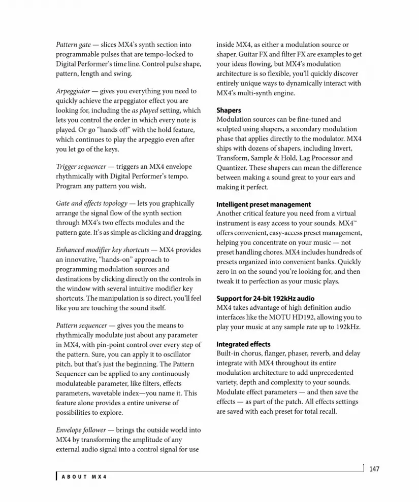
A B O U T M X 4147
Pattern gate — slices MX4’s synth section into programmable pulses that are tempo-locked to Digital Performer’s time line. Control pulse shape, pattern, length and swing.
Arpeggiator — gives you everything you need to quickly achieve the arpeggiator effect you are looking for, including the as played setting, which lets you control the order in which every note is played. Or go “hands off” with the hold feature, which continues to play the arpeggio even after you let go of the keys.
Trigger sequencer — triggers an MX4 envelope rhythmically with Digital Performer’s tempo. Program any pattern you wish.
Gate and effects topology — lets you graphically arrange the signal flow of the synth section through MX4’s two effects modules and the pattern gate. It’s as simple as clicking and dragging.
Enhanced modifier key shortcuts — MX4 provides an innovative, “hands-on” approach to programming modulation sources and destinations by clicking directly on the controls in the window with several intuitive modifier key shortcuts. The manipulation is so direct, you’ll feel like you are touching the sound itself.
Pattern sequencer — gives you the means to rhythmically modulate just about any parameter in MX4, with pin-point control over every step of the pattern. Sure, you can apply it to oscillator pitch, but that’s just the beginning. The Pattern Sequencer can be applied to any continuously modulateable parameter, like filters, effects parameters, wavetable index—you name it. This feature alone provides a entire universe of possibilities to explore.
Envelope follower — brings the outside world into MX4 by transforming the amplitude of any external audio signal into a control signal for use
inside MX4, as either a modulation source or shaper. Guitar FX and filter FX are examples to get your ideas flowing, but MX4’s modulation architecture is so flexible, you’ll quickly discover entirely unique ways to dynamically interact with MX4’s multi-synth engine.
ShapersModulation sources can be fine-tuned and sculpted using shapers, a secondary modulation phase that applies directly to the modulator. MX4 ships with dozens of shapers, including Invert, Transform, Sample & Hold, Lag Processor and Quantizer. These shapers can mean the difference between making a sound great to your ears and making it perfect.
Intelligent preset managementAnother critical feature you need from a virtual instrument is easy access to your sounds. MX4™ offers convenient, easy-access preset management, helping you concentrate on your music — not preset handling chores. MX4 includes hundreds of presets organized into convenient banks. Quickly zero in on the sound you’re looking for, and then tweak it to perfection as your music plays.
Support for 24-bit 192kHz audioMX4 takes advantage of high definition audio interfaces like the MOTU HD192, allowing you to play your music at any sample rate up to 192kHz.
Integrated effectsBuilt-in chorus, flanger, phaser, reverb, and delay integrate with MX4 throughout its entire modulation architecture to add unprecedented variety, depth and complexity to your sounds. Modulate effect parameters — and then save the effects — as part of the patch. All effects settings are saved with each preset for total recall.
A B O U T M X 4148
External audio inputProcess any audio through MX4’s synthesizer architecture. Use the FM filter effects, note triggering and effects. With its oscillators, filters, envelopes, LFOs, and flexible modulation, MX4 will become one of the most powerful effects processors in your arsenal.
Hundreds of factory presetsMX4 provides hundreds of factory presets, many of which take full advantage of MX4’s deep programming features, such as the pattern gate, arpeggiator and pattern sequencer. Be sure to explore the presets, as they serve as a great point of departure for programming many new and unique sounds of your own.

149
MX4 Quick Reference
Presets are organized into banks. Use the +/- buttons to browse the lists in the menus.
Dynamically updates to show the number of voices currently playing.
The LCD display shows the name of the current parameter you are adjusting, along with its current value.
Choose a preset from the patch menu, or use the +/- buttons to browse the presets in the current bank.
If the parameter is being modulated, the source and range are shown here.
Saves changes you’ve made to a preset, or compare/revert back to the original.
These four buttons act like tabs, flipping the MX4 window among different pages of controls: the main controls (shown here), mods (modulators), file (management) and random(ization of parameters).
Blinks when MX4 receives MIDI data.
Collapses the window to a compact strip.
MX4 provides three wavetable oscillators with adjustable waveform symmetry. Click the oscillator number to enable/disable it. Choose the desired waveform from the menu.
To enable one or both filters, with or without the distortion module, choose the desired filter configuration from the topology menu.
The mixer section controls the mix of the fundamental, ring modulation external audio input and stereo panning for the oscillators during stereo operation.
Access the settings for each of the four envelopes with these buttons. The six-stage DADSHR envelopes can be used as a modulation source for any modulatable parameter.
Access the six LFOs with these buttons.
The master section provides global settings.Use the disclosure triangle (at far right) to display the effects
section with chorus, phaser, flanger, delay and reverb.
Click this button to select the modulation source. Then option-drag any continuously variable parameter to control it with this source.

150

CHAPTER
151
5 QuickStart Guide
Open MX41 Launch Digital Performer.
2 Open MX4 in the standard fashion for instrument plug-ins. For details, see chapter 17, “Instrument Tracks” (page 159) in the DP User Guide.
Figure 5-1: Opening MX4 in Digital Performer.
3 Create a MIDI track in the usual fashion and assign it to MX4’s MIDI input (labeled MX4-1-in as demonstrated below in Figure 5-2; MX4-1 is the track name for the MX4 instrument track.)
Figure 5-2: Assigning the output of a MIDI track in Digital Performer to MX4.
4 Set up patch thru from your MIDI controller in the usual fashion (record-enable the MIDI track to begin playing MX4 from your controller).
5 Choose a bank and preset in the MX4 window.
Figure 5-3: Choosing a bank and preset.
6 That’s it! You are ready to experiment with MX4.

Q U I C K S T A R T G U I D E152

CHAPTER
153
6 MX4 Tutorial
OVERVIEWThis brief tour of MX4 will show you how easy it is to program your own MX4 presets.
Load the tutorial preset. . . . . . . . . . . . . . . . . . . . . . . . . . . . . . . .153Enable an oscillator . . . . . . . . . . . . . . . . . . . . . . . . . . . . . . . . . . . .153Adjust a parameter . . . . . . . . . . . . . . . . . . . . . . . . . . . . . . . . . . . .153Modulate OSC1 symmetry. . . . . . . . . . . . . . . . . . . . . . . . . . . . .154Contextual menus . . . . . . . . . . . . . . . . . . . . . . . . . . . . . . . . . . . . .154Use a wavetable . . . . . . . . . . . . . . . . . . . . . . . . . . . . . . . . . . . . . . .155Apply multiple modulation sources. . . . . . . . . . . . . . . . . . . .156Enable a filter. . . . . . . . . . . . . . . . . . . . . . . . . . . . . . . . . . . . . . . . . .156Add a second filter. . . . . . . . . . . . . . . . . . . . . . . . . . . . . . . . . . . . .157Mixing and effects . . . . . . . . . . . . . . . . . . . . . . . . . . . . . . . . . . . . .158Congratulations!. . . . . . . . . . . . . . . . . . . . . . . . . . . . . . . . . . . . . . .158
LOAD THE TUTORIAL PRESET1 Choose the Tutorial Patches bank and the Movie Demo patch.
ENABLE AN OSCILLATOR2 Confirm that oscillator 1 is enabled. The number “1” is green when it is enabled. If it is white, click the “1” button to enable oscillator 1.
3 Hold down middle C on your MIDI controller to play the preset.
You should hear a plain square wave sound. If not, check your MIDI and audio connections. If you still don’t hear anything, be sure you’ve set up Digital Performer as described in chapter 5, “QuickStart Guide” (page 151).
ADJUST A PARAMETER4 Adjust the course pitch of the oscillator.
While holding down middle C on your keyboard, move the pitch slider back and forth. This lets you control the base pitch of the oscillator. Course adjustment is made in semitones.
5 Notice that the LCD displays your course pitch adjustments.
6 Fine-tune the pitch of the oscillator.
To do so, hold down the command key while dragging the slider. If you can manage to hold down both the command key on you computer keyboard and middle C on your MIDI controller at the same time, you’ll hear the pitch bend as you drag the slider.
7 Return the pitch slider to zero by double-clicking the slider handle.

M X 4 T U T O R I A L154
8 Adjust the symmetry of the square wave by moving the symmetry slider.
With a square wave, adjusting the symmetry slider produces pulse width modulation effects. Try moving the slider as you once again hold down middle C on your controller.
MODULATE OSC1 SYMMETRYModulate oscillator 1’s symmetry slider with LFO 2.
9 Click the button next to LFO 2 in the modulation Source section, as shown below:
10Option-drag oscillator 1’s symmetry slider to create the modulation range.
Notice that as you drag, the handle splits in two over a highlighted (green) range. This indicates that the parameter is being modulated over this range. Notice also that if you position the cursor over the symmetry slider, the LFO 2 modulation source highlights in the Source section:
In addition, the LCD displays the modulation source and range on the right-hand side:
11Hold down middle C to audition the pulse width modulation you’ve just created.
CONTEXTUAL MENUSIf you change your mind, you can easily disconnect a modulation source. Let’s try it. To do so, control-click on the symmetry slider to open a contextual menu for the slider. This menu provides many additional operations for the symmetry parameter.
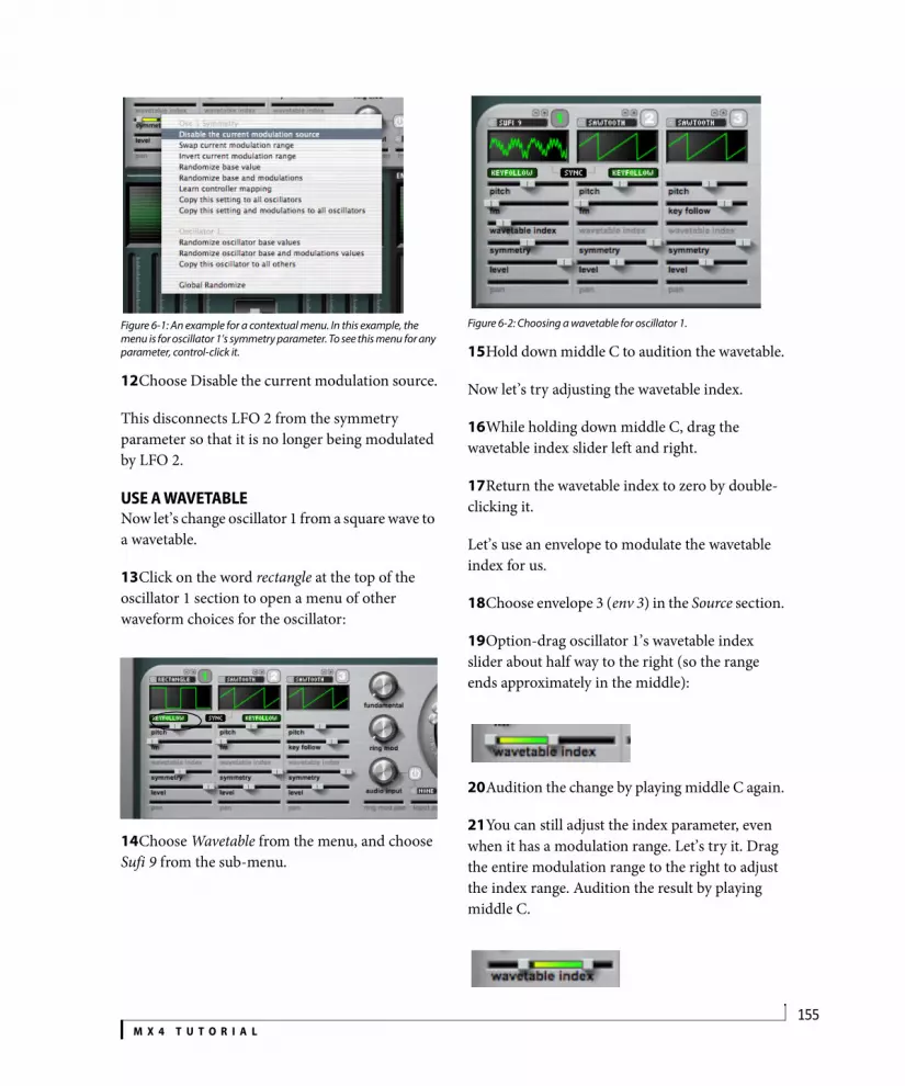
M X 4 T U T O R I A L155
Figure 6-1: An example for a contextual menu. In this example, the menu is for oscillator 1’s symmetry parameter. To see this menu for any parameter, control-click it.
12Choose Disable the current modulation source.
This disconnects LFO 2 from the symmetry parameter so that it is no longer being modulated by LFO 2.
USE A WAVETABLENow let’s change oscillator 1 from a square wave to a wavetable.
13Click on the word rectangle at the top of the oscillator 1 section to open a menu of other waveform choices for the oscillator:
14Choose Wavetable from the menu, and choose Sufi 9 from the sub-menu.
Figure 6-2: Choosing a wavetable for oscillator 1.
15Hold down middle C to audition the wavetable.
Now let’s try adjusting the wavetable index.
16While holding down middle C, drag the wavetable index slider left and right.
17Return the wavetable index to zero by double-clicking it.
Let’s use an envelope to modulate the wavetable index for us.
18Choose envelope 3 (env 3) in the Source section.
19Option-drag oscillator 1’s wavetable index slider about half way to the right (so the range ends approximately in the middle):
20Audition the change by playing middle C again.
21You can still adjust the index parameter, even when it has a modulation range. Let’s try it. Drag the entire modulation range to the right to adjust the index range. Audition the result by playing middle C.

M X 4 T U T O R I A L156
APPLY MULTIPLE MODULATION SOURCESThis envelope modulation is a good start, but the preset could use a bit more modulation to be more interesting as a sound. Let’s add some LFO modulation as well.
22Choose LFO 2 in the Source section.
23Option-drag the wavetable index slider to apply a modulation range for LFO 2.
Don’t worry if you see red numbers in the LCD when you option-drag. This just means that the modulation range you’ve specified is out of range, so that the LFO will peg at one end of the range and/or the other. But no harm is done. To bring it back within range, option-drag back the other way until the numbers turn green again.
24Audition the result.
The wavetable index parameter now has two modulation sources operating on it.
25To confirm this, roll the cursor over the slider (without clicking).
As you do so, both modulation sources light up in the Source section:
Now let’s add some symmetry modulation for a little extra motion.
26Choose LFO 3 in the Source section.
27Option-drag oscillator 1’s symmetry slider.
28Audition the result.
ENABLE A FILTERNow let’s enable a filter.
29Choose the filter configuration shown below from the filter Topology menu.
30Confirm that the LP (lowpass) and 24 (24dB slope) lights are illuminated for Filter 1, as shown above.
31Open the filter by increasing the cutoff frequency.
32Hold down middle C as you drag the cutoff frequency slider up and down to audition the effect.
Topology menu

M X 4 T U T O R I A L157
33Move the resonance (res) slider up to add a little resonance.
Now let’s modulate the filter cutoff frequency with an envelope.
34Choose envelope 4 (env 4) in the Source section.
35Option-drag Filter 1’s cutoff frequency (freq) slider.
Because the modulation range is above the base value, the envelope is being applied inverted. We can swap the modulation range by using the cutoff frequency’s contextual menu.
36Control-click Filter 1’s freq slider and choose Swap current modulation range from the menu.
37Audition the result.
Notice that the filter closes down as you hold the note, rather than opening up, as it did before.
Now let’s try using MIDI note-on velocity to control the attack of envelope 4.
38Choose On Velocity in the Source section.
39Choose Envelope 4 by clicking its button, as shown below:
40Option-drag the envelope Attack slider (labeled A) to assign the on-velocity modulation range.
41Audition the result, striking your MIDI controller key with varying strength.
Notice that when you now strike the key softly, the envelope opens more slowly; when you strike the key harder, the envelope opens more quickly.
ADD A SECOND FILTERNow let’s add Filter 2 for additional complexity. We’ll add it as a highpass filter in parallel with Filter 1.
42Choose the parallel setting from the Topology menu as shown below.
43Confirm that Filter two is a highpass (hp) filter with 24 dB slope (24).
Cutoff frequency

M X 4 T U T O R I A L158
44Use the Filter Mix knob to adjust the mix of the two filters, playing a note on your MIDI controller while you turn the knob to audition the effect.
Turning the knob all the way counter clockwise gives you 100% of Filter 1 and 0% Filter 2. Turning the knob all the way clockwise gives you the opposite (100% Filter 2 and 0% Filter 1). Settings in the middle provide a mix of both filters.
Now let’s modulate the filter mix with MIDI note-on velocity, so that the mix changes depending on how hard you strike the key.
45Confirm that On Velocity is still chosen in the modulation Source section.
46Option-drag the Filter Mix knob to apply the on-velocity modulation range.
47Control-click the Filter Mix knob and choose Swap current modulation range.
Now, the harder you hit your MIDI keys, the more filter 1 you hear. The more lightly you play, the more filter 2 you hear.
MIXING AND EFFECTSLet’s finish the preset by mixing in some of the fundamental and adding some chorus and delay effects processing.
48Turn the Fundamental knob to the 2 o’clock position (a setting of approximately 0.75).
49Click the disclosure triangle to open the Effects section.
50Click the “Power” buttons for the Chorus and Delay to enable them. When enabled, the power buttons turn green.
CONGRATULATIONS!You’ve just created your first MX4 preset. Try playing it in a variety of octaves on your MIDI controller, as it takes on a unique character at the low, mid and high ranges of the keyboard.
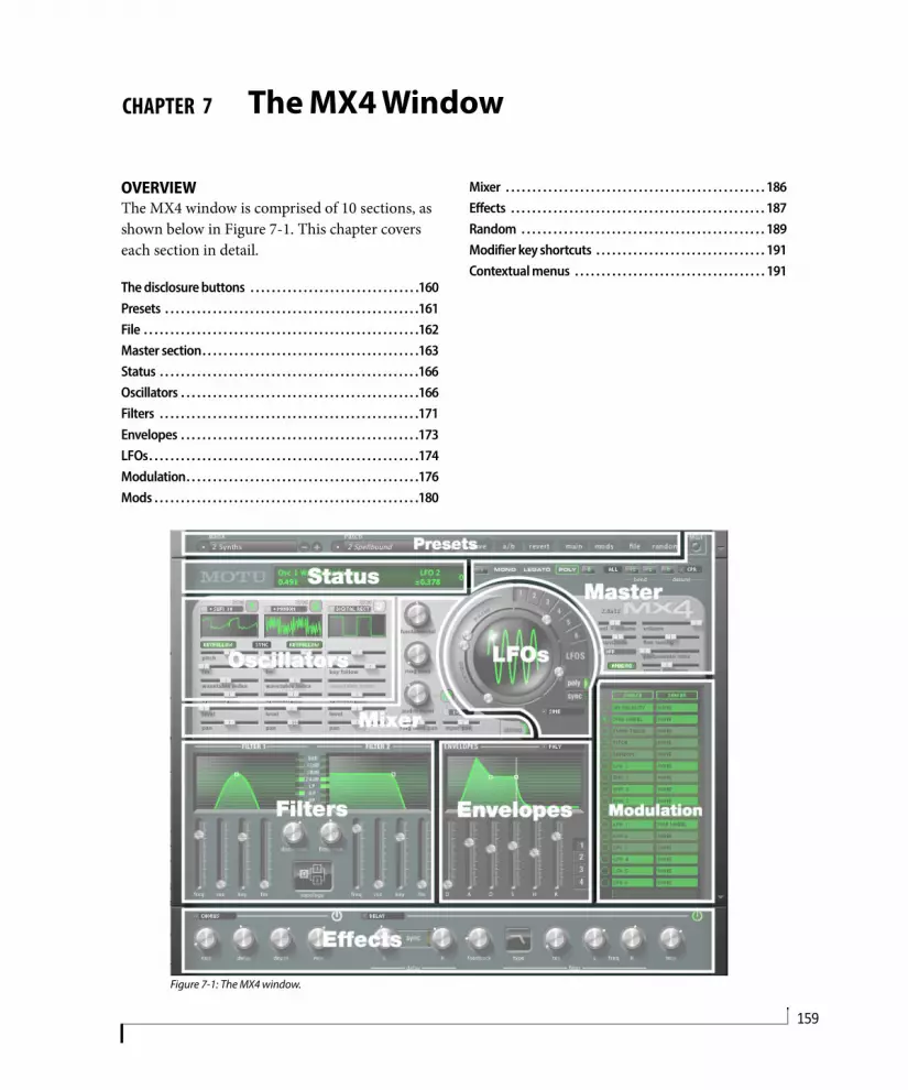
CHAPTER
159
7 The MX4 Window
OVERVIEWThe MX4 window is comprised of 10 sections, as shown below in Figure 7-1. This chapter covers each section in detail.
The disclosure buttons . . . . . . . . . . . . . . . . . . . . . . . . . . . . . . . .160Presets . . . . . . . . . . . . . . . . . . . . . . . . . . . . . . . . . . . . . . . . . . . . . . . .161File . . . . . . . . . . . . . . . . . . . . . . . . . . . . . . . . . . . . . . . . . . . . . . . . . . . .162Master section. . . . . . . . . . . . . . . . . . . . . . . . . . . . . . . . . . . . . . . . .163Status . . . . . . . . . . . . . . . . . . . . . . . . . . . . . . . . . . . . . . . . . . . . . . . . .166Oscillators . . . . . . . . . . . . . . . . . . . . . . . . . . . . . . . . . . . . . . . . . . . . .166Filters . . . . . . . . . . . . . . . . . . . . . . . . . . . . . . . . . . . . . . . . . . . . . . . . .171Envelopes . . . . . . . . . . . . . . . . . . . . . . . . . . . . . . . . . . . . . . . . . . . . .173LFOs. . . . . . . . . . . . . . . . . . . . . . . . . . . . . . . . . . . . . . . . . . . . . . . . . . .174Modulation. . . . . . . . . . . . . . . . . . . . . . . . . . . . . . . . . . . . . . . . . . . .176Mods . . . . . . . . . . . . . . . . . . . . . . . . . . . . . . . . . . . . . . . . . . . . . . . . . .180
Mixer . . . . . . . . . . . . . . . . . . . . . . . . . . . . . . . . . . . . . . . . . . . . . . . . . 186Effects . . . . . . . . . . . . . . . . . . . . . . . . . . . . . . . . . . . . . . . . . . . . . . . . 187Random . . . . . . . . . . . . . . . . . . . . . . . . . . . . . . . . . . . . . . . . . . . . . . 189Modifier key shortcuts . . . . . . . . . . . . . . . . . . . . . . . . . . . . . . . . 191Contextual menus . . . . . . . . . . . . . . . . . . . . . . . . . . . . . . . . . . . . 191
Figure 7-1: The MX4 window.

T H E M X 4 W I N D O W160
THE DISCLOSURE BUTTONSClick the disclosure buttons to show and hide sections of the MX4 window, as demonstrated below in Figure 7-2. When the window is fully
collapsed, it displays only the most essential controls (such as preset selection, preset compare/save, and MIDI activity) in a compact, screen-efficient strip.
Figure 7-2: The Expand buttons.

T H E M X 4 W I N D O W161
PRESETSA preset is a snapshot of all the settings in the MX4 window. MX4 ships with hundreds of useful presets organized by category in several dozen banks, such as Synths, Leads, Strings, etc. The Presets section at the top of the MX4 window (Figure 7-3) lets you choose, modify, save, compare and otherwise manage presets. MX4 can support an unlimited number of presets.
BankA bank can hold up to 128 presets. When you choose a bank, its patches (presets) are displayed in the Patch menu. Use the +/- buttons next to the menu to choose the next or previous bank in the list. To create, rename or delete banks, see “File” on page 162.
PatchThe Patch menu displays all of the presets in the bank currently chosen in the Bank menu. When you choose a preset from the menu, its settings are loaded into the MX4 window. Use the +/- buttons next to the menu to choose the next or previous preset in the list. Hold down the option key while clicking the +/- buttons to stay within the current bank when browsing presets. To create, rename, move, duplicate or delete patches, see “File” on page 162.
SaveWhen you first choose a patch, the Save button is not available. As soon as you change any parameter in the MX4 window, Save becomes active, and the patch name becomes italic in the Patch menu to indicate that the patch has been modified. Click Save to store the changes you made to the patch (replacing the original version). If you wish to “save as” in order to preserve the original patch, see “File” on page 162.
a/bWhen you first choose a patch, the a/b button is not available. As soon as you change any parameter in the MX4 window, a/b becomes active, and the patch name becomes italic in the Patch menu to indicate that the patch has been modified. Click the a/b button repeatedly to toggle between the original patch and the modified version. The original patch is indicated by non-italic text; the modified patch name is italic. Note that the modified patch gives you access to the Save and Revert buttons, which do not apply to the original patch (since it is already saved).
RevertWhen you first choose a patch, the Revert button is not available. As soon as you change any parameter in the MX4 window, Revert becomes active, and the patch name becomes italic in the Patch menu to indicate that the patch has been modified. Click the Revert button to permanently discard any changes you’ve made to the patch.
Figure 7-3: The Preset section.
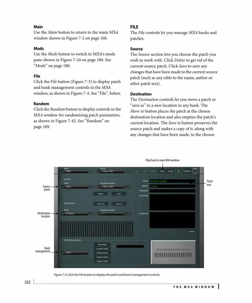
T H E M X 4 W I N D O W162
MainUse the Main button to return to the main MX4 window shown in Figure 7-2 on page 160.
ModsUse the Mods button to switch to MX4’s mods pane shown in Figure 7-24 on page 180. See “Mods” on page 180.
FileClick the File button (Figure 7-3) to display patch and bank management controls in the MX4 window, as shown in Figure 7-4. See “File”, below.
RandomClick the Random button to display controls in the MX4 window for randomizing patch parameters, as shown in Figure 7-42. See “Random” on page 189.
FILEThe File controls let you manage MX4 banks and patches.
SourceThe Source section lets you choose the patch you wish to work with. Click Delete to get rid of the current source patch. Click Save to save any changes that have been made to the current source patch (such as any edits to the name, author or other patch text).
DestinationThe Destination controls let you move a patch or “save as” to a new location in any bank. The Move to button places the patch at the chosen destination location and also empties the patch’s current location. The Save to button preserves the source patch and makes a copy of it, along with any changes that have been made, to the chosen
Figure 7-4: Click the File button to display the patch and bank management controls.
Sourcepatch
Destinationlocation
Bankmanagement
Patch text
Flips back to main MX4 window

T H E M X 4 W I N D O W163
destination location. Save to is similar in concept to the standard Save As command in Digital Performer.
Patch name, author, etc.Edit the text in these text fields as desired. To save your changes, click the Save or Save to button (in the Source or Destination sections).
New/rename/delete/export/import bankUse these three buttons to manage banks as follows:
DoneClick Done to return to the main MX4 window.
MASTER SECTIONThe Master section (Figure 7-5) provides global controls that affect the overall performance of the instance of MX4.
MIDI activity lightThe MIDI activity light blinks when MX4 receives MIDI data. This can be a useful troubleshooting tool. If MX4 is not making any sound when you play it, but the MIDI light does blink, then you can focus your troubleshooting efforts on the audio signal path.
Mono/legato/poly modesJust like classic analog synths, MX4 can operate in mono, legato or poly mode. Click the button shown in Figure 7-5 below to enable the desired mode.
In mono mode, only one note can be played at a time. Each new note will cut off the currently sustained note, if any.
Legato mode is an alternative form of mono mode where the envelope is not retriggered; only the pitch changes.
In poly mode, MX4 can play two or more notes simultaneously, up to the limit you type in next to the poly button. For example, if polyphony is set to 16, MX4 can play and sustain up to 16 notes at a time.
PolyphonyThe polyphony setting determines how many notes can play at a time. The maximum allowed polyphony for one instance of MX4 is 256. Beware, however, that higher polyphony settings
Goal Action
To create a new bank Type in a name in the text box on the right and click New Bank.
To rename a bank Choose it from the menu, type in a new name in the text box on the right and click Rename Bank.
To delete a bank Choose it from the menu and click Delete Bank.
To export a bank Choose it from the menu and click Export Bank.
To import a bank Click import bank and locate the desired bank file on your hard drive.
Figure 7-5: The Master section.
Unison multiplier Polyphony
T H E M X 4 W I N D O W164
place higher demand on your host computer’s processing resources. Therefore, the ideal polyphony setting is that which matches the highest number of notes you will actually need (the highest number of notes you will play simul-taneously). Use the active voice display (“Active voices” on page 166) to determine how many voices a passage of music requires.
Unison multiplierThe unison multiplier multiplies each note played. For example, if you set the unison multiplier to 2, each time you play a note, you’ll actually be triggering two notes in unison. If the unison multiplier is set to 4, each note played actually triggers four unison notes. The unison multiplier can be used with all three modes (mono, legato or poly). The unison multiplier is good for thickening sounds, especially when used with the detune feature. See the section called “Detune” below.
The unison multiplier is governed by the polyphony setting. For example, if the multiplier is set to 2 and you play one note, you are using 2 voices. So with a polyphony setting of 16, the maximum number of notes you can play in poly mode would be 8 (since each note is being doubled). In mono mode, MX4 automatically sets the polyphony for the multiplier.
BendThe bend parameters control how MX4 responds to pitch bend.
Bend modeWhen All is chosen, pitch bend data bends all notes. When Held is chosen, MX4 only bends notes for which a note-off has not yet been received. Notes that have received a note-off but that are currently being sustained with a sustain pedal will not bend. Click the bend mode button to toggle between these two modes.
Bend rangeThe pitch bend range is split at zero into two pitch bend ranges: upper and lower. The upper range determines how much pitch bend occurs between the zero position on your pitch bend wheel (or other controller) and its highest position. The lower setting determines the range from zero to the pitch bend wheel’s lowest position. By setting them to different values, you can more easily bend up and down by different amounts.
The upper and lower pitch bend ranges offer a maximum range of four octaves (4800 cents) each, for a combined maximum of eight octaves.
DetuneDetune allows you to determine how much pitch variation there will be on unison triggered notes. The amount of detune is specified in Hz or cents, depending on the detune mode you specify. MX4 provides three detune modes, discussed below.
NoneDetune is turned off.
Constant beat frequencyConstant beat frequency allows you to express detune in hertz (Hz). The result is that the phasing (“beating”) effect between the two slightly detuned unison pitches remains constant (it “beats” at the same rate) across the entire keyboard. In addition, detuning becomes more apparent as you move lower on the keyboard because the frequency offset becomes less perceptible at higher frequencies.
Constant pitch ratioConstant Pitch Ratio (CPR) mode allows you to express detune in cents (100ths of a semitone). The result is that the amount of detune is relative to the frequency of the pitches being played. Higher notes produce higher frequency “beating” while lower notes produce slower “beating”. Therefore, higher notes will likely be perceived as being more out of tune than lower notes. With

T H E M X 4 W I N D O W165
lower notes, the effect sounds more like an LFO. Be careful with when using Constant Pitch Ratio with higher amounts of detune because bass notes can become too far out of tune.
Vel > Volume (Velocity sensitivity)This setting controls the degree to which MIDI no-on velocity affects the amplitude of envelope 1. Higher values make sounds more responsive to how hard you play the keys on your controller; lower values make it less responsive. As demonstrated below (Figure 7-6), a setting of zero (0%) normalizes all note-on velocities to 64 (the middle of the velocity range), regardless of how hard you strike a key. A setting of 100% triggers the full amplitude range over the 0-127 MIDI velocity range. A setting of 50% limits the MIDI velocity range (0-127) to the middle portion of the amplitude range (from 25% to 75%).
Figure 7-6: The affect of velocity sensitivity on sustain level.
VolumeThe Volume slider controls MX4’s overall volume.
Transpose (coarse tuning)The Transpose setting transposes MX4 globally by the number of semitones that you specify. Use the command key to change the value in one-semitone increments.
Fine tuningThe Fine Tuning setting transposes MX4 globally by the number of cents (100ths of a semitone) that you specify. Use the command key to change the value in one-cent increments.
PortamentoPortamento is a continuous, smooth glide in pitch from one note to another. Use the slider to choose a value from zero (no portamento) to 100% (full portamento). MX4 offers three portamento modes, discussed below.
OffPortamento is turned off.
Constant portamento timeWhen Constant portamento time is chosen, the length of time for the glide between notes is the same, regardless of the interval between pitches.
Constant portamento time per octaveWhen Constant portamento time per octave is chosen, the length of time for the glide between notes is determined by the interval between the two notes: the farther the interval, the longer the glide. Conversely, shorter intervals produce shorter (faster) glides.
Stereo DetuneThe Stereo Detune parameter is a stereo effect that is disabled when Stereo mode (see “Stereo mode” on page 186) is turned off. When Stereo mode is turned on, and Stereo Detune is adjusted to any value other than zero, a second oscillator is engaged for each of MX4’s three oscillators, and each oscillator pair is then panned hard left and hard right. The result is a significant increase in the presence and stereo spread of the sound. Moving the slider to the right increases the pitch deviation to further enhance the effect.
Tip: increase MX4’s Unison Multiplier to further enhance Stereo Detune.
Amplitude
On-velocity
Sensitivity = 1 00%
Sensitivity = 50%
Sensitivity = 0%

T H E M X 4 W I N D O W166
Analog modeThe analog mode button, when enabled, generates slight pitch variations for each note, but does not allow the notes to drift out of pitch once they are started.
STATUSThe status LCD (Figure 7-7) displays information about the parameter you are currently modifying or targeting with the cursor. On the left, it shows the parameter name and its current value. If the parameter is being modulated, the modulation source and range is displayed on the right-hand side.
Active voicesOn the far right of the status LCD, MX4 displays the number of currently active voices (notes) it is playing. You can use this display to determine how many voices a passage of music requires, so that you can adjust the polyphony setting (“Polyphony” on page 163) to be equal to (or just above) the required number of voices for the music MX4 is playing. This conserves your computer’s processing resources by limiting MX4’s polyphony to only the number of voices your music actually requires.
OSCILLATORSMX4 provides three oscillators.
Figure 7-8: The Oscillators.
Signal flowMX4’s overall signal flow bears a striking resemblance to a Memorymoog (three oscillators, mixer, filter, amplifier.) But it is best not to treat each oscillator as a separate synthesizer. This is not really the intended operation of MX4 (although this can be accomplished to a limited degree with careful modulation of the individual oscillator level controls). Instead, think of the oscillators as going into a mixer before being processed, because that is exactly what is happening, as shown in Figure 7-9:
Figure 7-7: The Status LCD.
Number of active voices
Modulation source
Modulation range
Parameter name
Parameter value
OscillatorEnable/disable
Next/previous waveform
Waveform

T H E M X 4 W I N D O W167
Oscillator enable/disableClick the enable/disable button (Figure 7-8) to turn the oscillator on or off.
WaveformsChoose the desired waveform for the oscillator from the menu, or use the +/- buttons to cycle through the list of waveforms. (If a wavetable is currently selected, hold down the option key while clicking the +/- buttons to cycle out of the wavetable sub-menu and return to the main waveform menu.)
Each oscillator provides a variety of standard subtractive synthesis waveforms. An extensive library of wavetable waveshapes are also provided.
Figure 7-10: Oscillator waveforms.
SineThis is a standard sinusoidal waveform.
SawtoothThis is a standard sawtooth wave. Use the symmetry parameter to morph the sawtooth waveform
between a downward triangle and an upward triangle waveform:
Figure 7-11: Use symmetry to morph between these three basic waveforms.
A sawtooth wave (50% symmetry) has energy at all harmonics, and the strength of higher partials falls off linearly. A triangle wave has less energy at high partials, and strength falls off exponentially as the square of the partial number.
Figure 7-9: MX4 signal flow.
OSC 1
OSC 2
OSC 3
RING
FUNDAMENTAL
AUDIO INPUT
MIXER
PAN
PAN
PAN
PAN
PAN
DISTORTION/ FILTER AMP
ENV 1
EFFECTS /PATTERN GATE
VARIABLE TOPOLOGY VARIABLE TOPOLOGY
0% 100%
Symmetry
50%
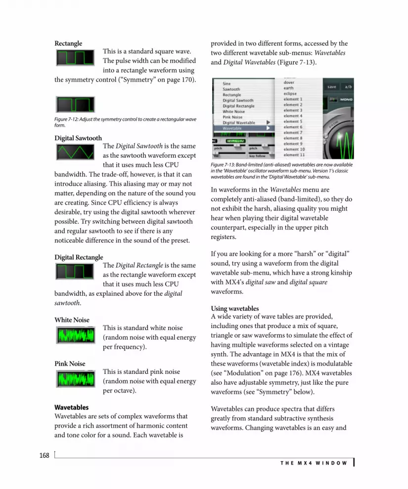
T H E M X 4 W I N D O W168
RectangleThis is a standard square wave. The pulse width can be modified into a rectangle waveform using
the symmetry control (“Symmetry” on page 170).
Figure 7-12: Adjust the symmetry control to create a rectangular wave form.
Digital SawtoothThe Digital Sawtooth is the same as the sawtooth waveform except that it uses much less CPU
bandwidth. The trade-off, however, is that it can introduce aliasing. This aliasing may or may not matter, depending on the nature of the sound you are creating. Since CPU efficiency is always desirable, try using the digital sawtooth wherever possible. Try switching between digital sawtooth and regular sawtooth to see if there is any noticeable difference in the sound of the preset.
Digital RectangleThe Digital Rectangle is the same as the rectangle waveform except that it uses much less CPU
bandwidth, as explained above for the digital sawtooth.
White NoiseThis is standard white noise (random noise with equal energy per frequency).
Pink NoiseThis is standard pink noise (random noise with equal energy per octave).
WavetablesWavetables are sets of complex waveforms that provide a rich assortment of harmonic content and tone color for a sound. Each wavetable is
provided in two different forms, accessed by the two different wavetable sub-menus: Wavetables and Digital Wavetables (Figure 7-13).
Figure 7-13: Band-limited (anti-aliased) wavetables are now available in the ‘Wavetable’ oscillator waveform sub-menu. Version 1’s classic wavetables are found in the ‘Digital Wavetable’ sub-menu.
In waveforms in the Wavetables menu are completely anti-aliased (band-limited), so they do not exhibit the harsh, aliasing quality you might hear when playing their digital wavetable counterpart, especially in the upper pitch registers.
If you are looking for a more “harsh” or “digital” sound, try using a waveform from the digital wavetable sub-menu, which have a strong kinship with MX4’s digital saw and digital square waveforms.
Using wavetablesA wide variety of wave tables are provided, including ones that produce a mix of square, triangle or saw waveforms to simulate the effect of having multiple waveforms selected on a vintage synth. The advantage in MX4 is that the mix of these waveforms (wavetable index) is modulatable (see “Modulation” on page 176). MX4 wavetables also have adjustable symmetry, just like the pure waveforms (see “Symmetry” below).
Wavetables can produce spectra that differs greatly from standard subtractive synthesis waveforms. Changing wavetables is an easy and

T H E M X 4 W I N D O W169
rewarding way to get into patch programming. Simply find a patch you like, and audition different wavetable waveforms.
Each wavetable is actually a collection of many different waveforms. Some wavetables morph smoothly, and others are collections of many completely unrelated waves. The bosch wavetable, for example, is a single wavetable containing 256 individual waveforms!
Modulating the wavetable index is an easy way to add movement to your patches. If you modulate the wavetable index with one LFO, and modulate waveform symmetry with another LFO, the combined effect is that the waveform will never be quite the same at any given moment - and that is just with a single oscillator.
Because wavetables can sound like filtered subtractive waveforms, sometimes you can use wavetables without any filtering at all, which saves CPU overhead.
Oscillator keyfollowWhen the keyfollow button is enabled, the oscillator adjusts its frequency relative to the note being played. Accordingly, when keyfollow is enabled, the pitch of the oscillator is expressed in the number of semitones relative to the root pitch of the note being played, as explained later.
Oscillator three offers adjustable key follow via the Key Follow slider, providing even more expression. The range can be summarized as follows:
To take full advantage of oscillator 3’s variable keyfollow feature, set the key tracking to zero and listen to how the pitch is fixed across the keyboard. Then adjust the key tracking to see how it changes.
Oscillator syncClick the Sync button to sync the frequency of oscillator 2 to oscillator 1. This forces oscillator 2 to restart at the beginning of its phase cycle when oscillator 1 reaches the beginning of its phase cycle. Within the middle of each oscillator 1 phase cycle, oscillator 2 runs freely.
Oscillator sync usually produces useful results when oscillator 2 is running at a frequency that is significantly higher (2 or more times) than oscillator 1.
To produce classic Prophet Five synced oscillator sounds, turn on oscillator 2 only (by itself), enable sync, and modulate the pitch of oscillator 2 with an envelope or LFO.
Key follow value
-200% Oscillator frequency offset is double the interval from the root pitch and inverted. For example, when you play an octave above middle C, the oscillator plays two octaves down.
-100% Oscillator frequency is fully inverted for each pitch. For example, playing C below middle C on your keyboard produces the pitch that is one octave above middle C.
0% The keyboard has no effect on the pitch of the oscillator. The fixed pitch of the oscillator is determined entirely by the pitch parameter.
100% Oscillator frequency offset remains fixed across all pitches (just like the keyfollow buttons for oscillators 1 & 2).
+200% Oscillator frequency offset is double the interval from the root pitch. When you play an octave above middle C, the oscillator plays two octaves up.

T H E M X 4 W I N D O W170
PitchUse the Pitch slider to offset the pitch of the oscillator from key tracking. When the keyfollow button is disabled, the range is expressed in absolute frequency (Hz or kHz); the range is from 8.2 Hz to 22.1 kHz.
When the keyfollow button is enabled, the pitch is expressed in semitones relative to the root pitch of the note being played. The range is from -60.00 semitones to +84.00 semitones.
Frequency modulationOscillator 3 can serve as an FM source for the pitch of oscillator 1 and 2, as well as the frequency of filters 1 and 2. All of these components (oscillator 1, oscillator 2, filter 1 and filter 2) have an FM slider, which brings in oscillator 3 as an FM source and allows you to choose the amount of frequency modulation to apply in each case.
Using oscillator 3 as an LFO with key trackingThe pitch slider of oscillator 3 has a very wide range, allowing you to use oscillator 3 as an LFO source. With access to adjustable key tracking (normal LFOs cannot track the keyboard), and wavetables (which produce very interesting LFO shapes), oscillator 3 can produce truly unique periodic modulation effects.
Frequency modulation tipsIn the audible range, oscillator 3 is the modulation source for two operators. The operator structure would look like this:
Figure 7-14: Frequency modulation operator structure.
FM is most predictable when using sine waves. Modulate the pitch of oscillator 3 and the FM sliders on oscillator 1 and 2 to create interesting FM sounds. After you’re familiar with sine waves, try experimenting with the symmetry parameter and different waveforms.
Using velocity as a modulation source for FM amount or oscillator pitch provides a rich range of expression.
Simple structure FM sounds are very useful for synthetic percussion.
Wavetable indexThe wavetable index allows you to specify any desired waveform in a wavetable for the oscillator. By modulating the wavetable index parameter, you can achieve a wide variety dynamic sounds, depending on the waveforms in the table.
SymmetryThe symmetry parameter adjusts pulse width on rectangle waves, but symmetry can also be applied to sine waves, sawtooths and even wavetables. Doing so produces interesting changes in harmonic content. Further interesting effects can be achieved by modulating the symmetry (see “Modulation” on page 176).
Figure 7-15: Symmetry.
1
3
2
Sine
0% 100%
Sawtooth
Rectangle
Symmetry
Wavetable
50%

T H E M X 4 W I N D O W171
Level and PanEach oscillator has its own independent level and pan going into the mixer. See “Mixer” on page 186.
Modulating oscillator settingsAll continuously variable oscillator settings (ones that have a value slider) can be modulated. Option drag the control to set the modulation range. For further details, see “Modulation” on page 176.
FILTERSMX4 provides two multimode variable-slope filters.
Figure 7-16: the filter section.
Filter topologyThe signal path for the two filters, plus the additional distortion unit, can be configured with the topology menu.
Figure 7-17: The filter topology menu.
The “D” box represents distortion. The boxes labeled 1 and 2 represent Filters 1 and 2. Signal flow proceeds from left to right.
Enabling/disabling filters and distortionTo enable one or both of the filters, choose the desired signal path from the topology menu, as shown in Figure 7-17.
To turn off both filters, choose the first topology assignment (distortion only) and turn the distortion volume all the way down. No distortion is applied when distortion is set to zero.
The most classic configuration here is the distortion module, plus one filter.
Filter typeEach filter can be assigned to one of four different filter types (shown below) and four different slopes (6, 12, 18 and 24dB per octave), using the illuminated buttons between the two filter graphs:
To achieve more extreme slope effects, choose a filter topology that puts the two filters in series, and then apply the same settings to both filters. (See “Copy this item to all others” on page 191.) In this configuration, their slope values combine to
Distortion unit
Key:
Filter 11
Filter 22
D
Symbol Filter type Sample
LP Lowpass
BP Bandpass
HP Highpass
BR Band reject(notch)

T H E M X 4 W I N D O W172
achieve values greater than 24dB. For example, if you set them both to 24dB, the combined effect is 48dB of slope.
Filter mixUse the Filter Mix knob to control the gain (amount) for each filter effect for parallel topology settings (where the signal is split and fed to each filter independently). For serial and stereo filter topology settings, the filter mix control is disabled.
The mix range is from 0% to 100%, where the amount of each filter is as follows:
If you set one filter to lowpass and the other to highpass, use the filter mix control to attenuate the “buzz” effect of highpass filter.
If you set each filter to a different filter type, routing mod wheel to the filter mix knob often produces interesting results.
DistortionTo apply distortion (also commonly referred to as drive), choose a topology that includes distortion (Figure 7-17) and then use the Distortion knob to adjust the amount.
FrequencyThe frequency slider determines the filter’s cutoff or center frequency. Most synthesizers express cutoff/center frequency as a number of cycles per second (Hz or kHz). However, most of the time, key tracking is applied to filters to avoid undesirable artifacts. For example, a lowpass filter will cause notes to get more dull as you play higher
pitches (which have higher frequencies). With key tracking, Hz and kHz are not meaningful because the filter’s center frequency is not fixed at an absolute frequency; instead, it is relative to the note being played. Therefore, MX4 expresses filter cutoff/center frequency in semitones relative to the pitch being played.
ResonanceResonance emphasizes the cutoff/center frequency of the filter.
Filter Key followBoth filters are equipped with adjustable key follow. This feature works similarly to oscillator 3’s key follow. See “Oscillator keyfollow” on page 169.
Filter frequency modulationOscillator 3 can serve as an FM (frequency modulation) source for the frequency of each filter. Use the FM slider to bring in oscillator 3 as an FM source at the desired amount.
Try setting the frequency of oscillator 3 to a harmonic of oscillator 1 (such as +12 or +19 semitones). Doing so locks in the filter at that frequency to produce harmonic results.
Modulating filter settingsAll of the filter settings, including filter mix and distortion, can be modulated. Option drag the control to set the modulation range. For further details, see “Modulation” on page 176.
Using the filter graphsUse the control point on the filter graph to adjust the frequency and resonance graphically. When modulating the filter frequency, a secondary (dashed) frequency plot indicates the lowest frequency in the modulation range, as demonstrated below in Figure 7-18:
Filter mix setting Amount of Filter 1 Amount of Filter 2
0% 100% 0%
25% 75% 25%
50% 50% 50%
75% 25% 75%
100% 0% 100%

T H E M X 4 W I N D O W173
Figure 7-18: Adjusting the frequency modulation range in the filter graph.
ENVELOPESMX4 provides four six-stage DADSHR envelopes, which can be used as a modulation source for any modulatable parameter.
Figure 7-19: Envelopes.
Choosing an envelopeTo choose one of the four envelopes, click the desired selector button as shown above.
The envelope graphThe envelope graph provides a visual indication of the six stages for each envelope. These stages are described in the next section. The vertical white line in the middle of the graph represents the MIDI note-off event (when you release the key). For a further explanation, see “The hold stage” on page 173.
The six envelope stagesMX4 envelopes provide the following six stages:
Envelope 1 and amplitude modulationMX4’s amplifier is not presented graphically in the MX4 window. Instead, there is a dedicated overall volume control and dedicated velocity > volume slider (see “Vel > Volume (Velocity sensitivity)” on page 165). However, envelope 1 is “hardwired” to overall amplitude modulation.
All envelopes, including envelope 1, are freely assignable modulation sources.
The hold stageThe hold stage can be specified in three different possible ways:
Graphically, this is represented by the relationship between the hold parameter handle (Figure 7-19 on page 173) and the note-off line (also shown in
Envelope selector buttons.
Hold parameter handle
Note-off
Envelope trigger mode
Symbol Stage Explanation
D Delay The amount of time before the attack beings.
A Attack The initial stage of the envelope, specified in the amount of time for it to fully open up.
D Decay The amount of time between the end of the attack and the beginning of the sustain.
S Sustain level
The level at which the envelope remains open, where zero is completely closed and 1.00 is fully open.
H Hold The length of time the sustain level is maintained. (See “The hold stage” below.)
R Release The final stage of the envelope, where it closes down to zero, specified in the length of time from the end of the hold to the moment when it reaches zero.
Method for specifying hold time
What to do in the envelope graph
As a finite amount of time after the decay
Drag the hold handle to the left of the note-off line (Figure 7-19).
Indefinitely, until a MIDI note-off message is received
Option-double-click the hold (“H”) slider.
As a finite amount of time after a MIDI note-off message is received
Drag the hold handle to the right of the note-off line (Figure 7-19).

T H E M X 4 W I N D O W174
Figure 7-19). Drag the handle to the left of the note-off line to specify the hold stage as a finite amount of time after the decay. Drag it to the right of the note-off line to specify the hold stage as a finite amount of time after a MIDI note-off message is received. To hold indefinitely until a note-off is received, option-double-click the hold (“H”) slider (so that the status LCD reads until note off). Doing so turns off the hold stage to create a standard ADSR envelope.
Envelope trigger modeEach envelope can be uniquely assigned to one of the following trigger modes, chosen from the trigger mode menu (Figure 7-19 on page 173):
When an envelope is polyphonic, and it is applied to a polyphonic modulation destination, each “voice” (note) has its own dedicated envelope onset. This is especially useful for polyphonic modulation destinations like those found in the oscillator and filter sections. For mono destinations, such as the parameters in the effects section, best results can be obtained with one of the mono envelope trigger modes.
External triggeringChoosing the External trigger mode allows you to trigger envelopes via a MIDI note played from your MIDI controller. Use MX4’s extra MIDI input to route the external MIDI signal to MX4. In Digital Performer’s list of MIDI destinations, it appears as MX4 Trigger.
Once you’ve routed your live MIDI controller signal to the MX4 trigger input via Digital Performer’s patch thru feature, press the following keys to trigger envelopes 1 through 4:
LFOSMX4 provides six LFOs (Low Frequency Oscillators), which can be used as a modulation source for any modulatable parameter. LFOs can modulate other LFOs, and they can even self-modulate.
Figure 7-20: The LFOs.
Choosing an LFOTo choose one of the six LFOs, click the desired selector button as shown above.
Trigger mode Explanation
Poly Each separate note that is played is given its own unique envelope cycle.
Poly release Same as above, except the envelope is triggered by the note-off (instead of note-on). This is useful for envelopes 2-4 because you can have an entirely different envelope effect during the release phase.
Mono All notes share the same envelope.
Mono retrigger Same as above, except that every time you play a new note, the envelope is retriggered.
External Allows you to trigger the envelope with MIDI notes from a MIDI controller or another MIDI track (using the MX4 trigger input).
Sequenced Available for LFOS 2-4 only. See “Trigger sequencer” on page 185.
Note (any octave) Triggered envelope
C Envelope 1
D Envelope 2
E Envelope 3
F Envelope 4
LFO selector buttons
LFO wave shape menu

T H E M X 4 W I N D O W175
LFO wave shapeChoose the desired LFO wave shape from the wave shape menu (Figure 7-20):
LFO parametersLFOs have the following modulatable parameters:
Random phaseTo make the phase of an LFO random (each time it is triggered), move the Phase slider almost all of the way to the right. The second to last setting is Random. The last setting is Free (described below).
Free-running phaseWhen you move the Phase slider all the way to the right, you’ll see a setting called Free. With this setting, the LFO runs freely and continuously, on its own, regardless of whether notes are being triggered or not. The result is that the LFO runs completely independently of the notes you are playing. For example, you could apply the LFO to filter cutoff frequency and play a series of notes where the resulting filter cutoff sweep effect is applied across the notes you are playing, independently of the actual notes.
LFO wave shape Example
Sine
Saw
Rectangle
Sample and hold
Sample and ramp
Random walk
LFO parameter Unit Explanation
Rate Hertz (Hz) The number of cycles per second at which the LFO oscillates. The range is from 0.0001 Hz to 25 Hz.
Fade (In) Milliseconds (ms) Applies an amplitude ramp (from zero to 100%) to the LFO.
Delay ms The amount of time before the LFO begins oscillating after being triggered.
Phase (Start Phase)
Degrees Controls the point during the LFO cycle at which the LFO begins oscillating when first triggered. For random phase, move the slider all the way to the right.
Symmetry percent Symmetry applies a non-linear transform to the waveform that skews the axis of the cycle, as demonstrated in Figure 7-15 on page 170. For a rectangle, this is equivalent of its duty cycle, or “pulse width”. For a sawtooth wave, symmetry changes from a triangle with a downward ramp to a triangle with an upward ramp. For sine waves, the effect is similar to the triangle.

T H E M X 4 W I N D O W176
SymmetrySymmetry does not apply to (and is therefore disabled for) the following LFO wave shapes: Sample and hold, Sample and ramp, and Random walk.
For further information about modulating these LFO parameters, see “Modulation” on page 176.
Polyphonic LFO triggeringEach LFO can operate as either a mono or a polyphonic modulation source. When a LFO is polyphonic, and it is applied to a polyphonic modulation destination, each “voice” (note) is given its own unique LFO onset when it is played. This is especially useful for polyphonic modulation destinations like those found in the oscillator and filter sections. For mono destinations, such as the parameters in the effects section, best results can be obtained with mono LFO triggering (turn poly mode off).
LFO syncThe sync button (Figure 7-20), when enabled, makes the LFO synchronize to the tempo of Digital Performer’s time line. Accordingly, when sync is enabled, the LFO rate parameter is expressed in beat values (whole note, half note, quarter note, etc.)
The sync button is actually a 3-way button. Click it once to enable LFO rate sync (green). Click it again to enable both rate and phase sync (orange). In this mode, the phase is also synchronized to tempo. Click a third time to turn off sync (dark). Click repeatedly to cycle through these three modes.
MODULATIONMX4 has a flexible and powerful modulation architecture. The modulation section (Figure 7-21) is most easily understood if you think of it as a modular synthesizer that uses control voltages to manipulate the sound.
Figure 7-21: The modulation section.
Modulation sourcesThere are 16 modulation sources (rows) in the modulation section. Each modulation source row includes a selection radio button, a Source menu and a Shaper menu. Choose the desired source and shaper (if any) from the menus. To select a modulation source, click its radio button. Only one modulation source can be selected for destination assignment at any given time.
Assigning a source to a destinationOnce you’ve selected a modulation source (by clicking its radio button), assign it to any continuously variable parameter in the MX4 window by option-dragging the handle of the parameter’s slider. As you do so, you’ll see the handle split in half to cover a range over which the parameter will be modulated by the source. In addition, the modulation range will glow green.
Modulation meter
The currently selected modulation source

T H E M X 4 W I N D O W177
You can option-drag as many different parameters as you like. A source can modulate any number of destinations simultaneously (as explained further in the next section).
Here’s an example: select the route filter modulation preset (patch) from the Tutorial Patches bank. Select the modulation source containing LFO 1. Now locate the filter cutoff frequency for filter 1 (labeled freq), hold down the option key and drag. You should see an illuminated modulation range for that modulator. Trigger a note and listen. Now change the rate of LFO 1 in the LFO section and listen to the change.
Assigning a source to multiple destinationsIn MX4, a source can modulate any number of destinations simultaneously. When you’ve selected a modulation source (by clicking its radio button), you can assign it to multiple MX4 parameters by option-drag the slider handle of each parameter.
Assigning multiple sources to one destinationUp to 16 modulations (all of them) can be applied to any single modulation destination. Modulation sources are summed at the destination, so be careful. Similar to mixing audio tracks, it is possible to exceed the overall allowable modulation range (similar to the way an audio signal can clip when it reaches zero dB). Unlike audio clipping, however, exceeding the modulation range has no negative effect on the sound. However, the modulation might get “pinned” to one end of the range or the other, preventing a smooth swing through the full modulation range. So, if you intend to have multiple modulators modify a single destination, be aware of the total amount of modulation you are applying.
Daisy-chaining sourcesNotice that you can modulate one source with another. For example, you could modulate LFO 2 with LFO 1, while using LFO 2 as a source for
modulating other parameters. Daisy-chaining sources in this manner can be done with any internal source (LFO, envelope or ramp), as well as external sources.
Self-modulationSources can modulate themselves. For example, you could choose LFO 3 in the Source list, and then option-drag LFO 3’s rate slider to modulate the rate with itself.
Source highlightingSource slots (menus) have three illumination states:
As you glide the cursor over parameters that currently have a modulation range assigned to them (a green track beneath the slider or around the knob), the source for that modulation will light up in the Source section so you can clearly see what which source is modulating the parameter.
SourcesModulation sources fall into three general categories:
Internal modulators (MX4’s own LFOs, envelopes, ramps and modulators)
External modulators (MIDI controllers)
Digital Performer plug-in automation
Illumination state Meaning
Dark The source is not being used in the current preset.
Glowing The source is modulating at least one parameter in the preset.
Lit up The source is modulating the parameter currently beneath the cursor.

T H E M X 4 W I N D O W178
Figure 7-22: The source menu shows external sources (MIDI controllers) and internal sources (LFOs, envelopes, ramps and programmable modulators).
LFOs and envelopesYou can use MX4’s six LFOs and four envelopes as modulation sources. Each LFO and envelope (or other source) should only be chosen in one source menu at a time, as you can easily map that single source to multiple destinations as described earlier. Choosing a source in more than one source menu at a time doesn’t really serve any useful purpose, and it unnecessarily uses up source slots.
Plug-in automationMX4 fully supports the plug-in automation features in Digital Performer. Each parameter in MX4 has its own dedicated automation input. This automation operates independently from MX4’s modulation section, although it can be combined with any modulation sources.
RampsThe Source menu provides eight general-purpose ramps. The ramps exist as a level of indirection between Digital Performer’s automation system and the MX4 parameter being automated. For example, you may wish to automate the cutoff
frequency of both filters simultaneously. You could use the dedicated automation controls and duplicate the automation data, but a more elegant solution is to use a ramp, assign the ramp to the parameters you wish to automate, and then create a single automation stream in Digital Performer for the ramp. This technique has the added benefit of providing the ability to remap the automation into a performance control with a single modulation reassignment: in the modulation section, simply change the ramp to mod wheel (or other MIDI controller).
Pattern SequencerThe Pattern Sequencer in the modulation source menu (Figure 7-22) is programmed on the Mods page (Figure 7-24 on page 180). It provides a means to modulate (or shape the modulation of) MX4 parameters in a stepped fashion. See “Pattern Sequencer” on page 182.
Envelope FollowerThe Envelope Follower in the modulation source menu (Figure 7-22) is programmed on the Mods page (Figure 7-24 on page 180). It transforms the amplitude of an audio input into a control signal for use inside MX4, as either a modulation source or a shaper. See “Envelope Follower” on page 183.
Bipolar sourcesMost modulators, like MIDI controllers and envelopes, are unipolar (i.e. they have a scale that extends either positively or negatively in one direction). LFOs are bipolar (i.e. they have a scale that extends both positively and negatively from a zero point). Therefore, when assigning an LFO, the modulation range extends symmetrically from the zero point, which is defined as the value of the slider at the moment you assigned the LFO source.
Inverting the modulation rangeIn some situations, you may want to swap the end points of a modulation range. MX4 has a handy function to swap the endpoints of the current

T H E M X 4 W I N D O W179
modulation range. This is accessed via the contextual menu. You can also invert the current modulation range from the contextual menu. For details, see “Contextual menus” on page 191.
ShapersEach modulation source is optionally followed by a shaper, much like the Minimoog® Voyager™. A shaper multiplies the output of the modulation source by the shaper output. A common use of a shaper would be to limit the output of an LFO through the mod wheel. When the mod wheel is down, the LFO has no effect. The LFO is gradually felt as the mod wheel is brought up.
Figure 7-23: Shapers multiply the output of the modulation source by the shaper output
MX4 graphically displays the sum total of modulation and shaper at the destination as a moving bar when a voice is active, so it is easy for you to inspect the cumulative modulation. See the next section for details.
The modulation meterThe output of the currently selected (active) modulation source can be viewed in the modulation meter (Figure 7-21). For voice dependent modulators, the meter displays activity when you play notes (voices) that are being modulated by the source. For example, if you select an LFO as a modulation source and then play a note, the modulation meter (Figure 7-21) provides a visual representation of the output of the LFO while the note is sustained.
Non-voice dependent modulators, like pitch bend, are always active. In other words, a voice does not need to be triggered to see the modulator’s activity in the meter.
For details about these programmable shapers, see “Mods” on page 180.
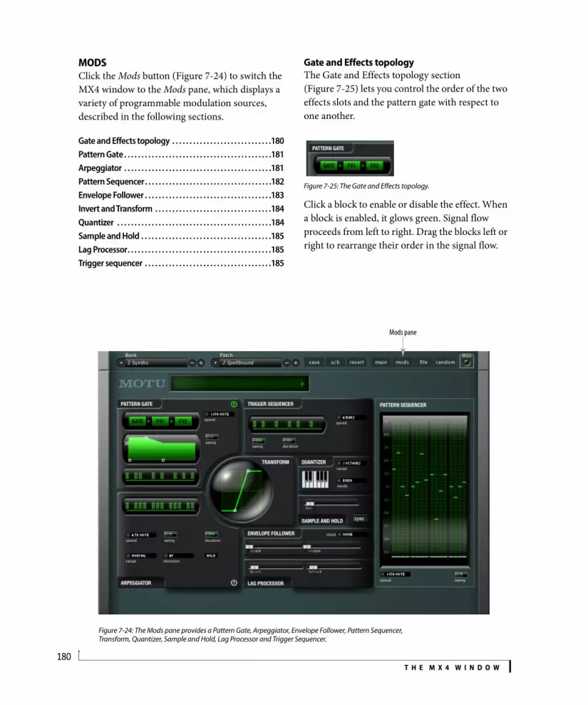
T H E M X 4 W I N D O W180
MODSClick the Mods button (Figure 7-24) to switch the MX4 window to the Mods pane, which displays a variety of programmable modulation sources, described in the following sections.
Gate and Effects topology . . . . . . . . . . . . . . . . . . . . . . . . . . . . .180Pattern Gate. . . . . . . . . . . . . . . . . . . . . . . . . . . . . . . . . . . . . . . . . . .181Arpeggiator . . . . . . . . . . . . . . . . . . . . . . . . . . . . . . . . . . . . . . . . . . .181Pattern Sequencer. . . . . . . . . . . . . . . . . . . . . . . . . . . . . . . . . . . . .182Envelope Follower . . . . . . . . . . . . . . . . . . . . . . . . . . . . . . . . . . . . .183Invert and Transform . . . . . . . . . . . . . . . . . . . . . . . . . . . . . . . . . .184Quantizer . . . . . . . . . . . . . . . . . . . . . . . . . . . . . . . . . . . . . . . . . . . . .184Sample and Hold . . . . . . . . . . . . . . . . . . . . . . . . . . . . . . . . . . . . . .185Lag Processor. . . . . . . . . . . . . . . . . . . . . . . . . . . . . . . . . . . . . . . . . .185Trigger sequencer . . . . . . . . . . . . . . . . . . . . . . . . . . . . . . . . . . . . .185
Gate and Effects topologyThe Gate and Effects topology section (Figure 7-25) lets you control the order of the two effects slots and the pattern gate with respect to one another.
Figure 7-25: The Gate and Effects topology.
Click a block to enable or disable the effect. When a block is enabled, it glows green. Signal flow proceeds from left to right. Drag the blocks left or right to rearrange their order in the signal flow.
Figure 7-24: The Mods pane provides a Pattern Gate, Arpeggiator, Envelope Follower, Pattern Sequencer, Transform, Quantizer, Sample and Hold, Lag Processor and Trigger Sequencer.
Mods pane

T H E M X 4 W I N D O W181
Pattern GateThe Pattern Gate (Figure 7-26) slices up the output of MX4’s synth section into pulses determined by the Speed menu, which displays metric divisions locked to Digital Performer’s tempo.
Figure 7-26: Pattern Gate.
The pattern gate can be applied to just about any sound that sustains. Remember, however, that Digital Performer’s tempo plays an important role in the results.
Pulse shapeThe shape of each pulse is determined by the Pulse Shape graph (Figure 7-27), which represents 100% of the length of each pulse. Drag the handles to modify pulse depth, attack, release and sustain. Drag the Depth handle vertically to soften the gate, such as for a tremolo effect.
Figure 7-27: Pulse shape.
Pattern and LengthThe pattern itself is determined by the Pattern LED graph (Figure 7-26): click each pulse to toggle it on or off. Set the Length of the pattern (from 1-16 pulses) by dragging the small line under the pattern. You can invert and/or reverse the Pattern Gate by control-clicking it and
choosing the Invert and Reverse contextual menu items. Inverting causes steps that are enabled to become disabled, and vice versa.
SwingWhen the Swing parameter (Figure 7-26) is set to zero, the pattern gate plays in straight time (no swing). Other settings are as follows:
Negative values invert the ratio, which moves the swung note closer to the base note.
ArpeggiatorThe Arpeggiator (Figure 7-28) watches what notes are sounding (being held) and then arpeggiates them (plays them one at a time) at a tempo determined by the Speed menu, which displays metric divisions locked to Digital Performer’s tempo. If you play a single note, by itself, you’ll hear an effect similar to the gate. However, if you play a chord (two or more notes at the same time), the arpeggiator cycles through them one at a time.
Figure 7-28: Arpeggiator.
Speed
Swing
Pulse Shape
Pattern
Length
On/off
Depth
Attack
Sustain Release
Swing amount Ratio Feel at 8th note speed
0 1 to 1 Straight 8ths
100 2 to 1 Triplet 8ths
125 2.5 to 1 Hard 8th swing
150 3 to 1 Hard 8th shuffle
Pattern
Length
On/off

T H E M X 4 W I N D O W182
DurationSet the Duration of each note (in percent of the metric value chosen in the Speed menu). 100% equals the chosen metric value (sixteenth note or eighth note, for example). Values less than 100% create shorter note and a more staccato effect.
Pattern and LengthSpecify a pattern to be repeated by the predicator using the Pattern LED graph: click each pulse to toggle it on or off. Set the Length of the arpeggiator (from 1-16 notes) by dragging the small line under the pattern. You can invert and/or reverse the Arpeggiator by control-clicking it and choosing the Invert and Reverse contextual menu items. Inverting causes steps that are enabled to become disabled, and vice versa.
RangeRange lets you arpeggiate across a specified number of extra octaves. You can choose Normal (no additional octaves) or +1, +2, or +3 octaves. Octaves are added above the octave range in which you play.
DirectionDirection determines the order that the notes play in, as follows:
HoldWhen the Hold light is enabled, notes continue to arpeggiate, even after you release them. They continue to arpeggiate until you play a new note, disable the Hold feature or turn off the arpeggiator.
Pattern SequencerThe Pattern Sequencer provides a means to modulate (or shape the modulation of) MX4 parameters in a stepped fashion. For example, you could create a sample-and-hold type of effect, except one that is not random but instead programmed and cyclic (repeating).
Figure 7-29: Pattern Sequencer.
LengthSet the Length (Figure 7-29) of the pattern, from 1-16 steps, by dragging the right-hand end of the line under the pattern. The pattern proceeds from left to right.
Step valuesEach step can be set to one of 120 possible discrete values (from -60 to +60), where zero (0) equals the base value for the modulation range. Click in the column for each step to specify the value for that step (indicated by the illuminated LED). You can
Direction Explanation
Up Plays the notes in order, starting with the lowest, and moving to the highest. Note order: 1,2,3,4,5,6.
Down Plays the notes in order, starting with the highest and moving to the lowest. Note order: 6,5,4,3,2,1.
Up/Down First plays Up, then plays Down. Note order: 1,2,3,4,5,6,5,4,3,2.
As Played Takes into account the order in which you play the notes of a chord and plays them back in the same order as played. The pattern is repeated for each additional octave (if any) specified by the Range option.
Step values
Length

T H E M X 4 W I N D O W183
invert and/or reverse the entire step grid by control-clicking it and choosing the Invert and Reverse contextual menu items.
Speed and SwingThe Speed and Swing parameters operate similarly to their counterparts in the Pattern Gate and Arpeggiator (as discussed on page 181 and page 181).
Using the Pattern SequencerThe most obvious use of the pattern sequencer is to send notes to an oscillator. If key follow is on, it might be best to constrain the pattern sequence to highly consonant intervals (like octaves, 5ths, etc.)
Keep in mind, however, that the Pattern Sequencer can be applied to parameters anywhere in MX4, like the filters, effects parameters, wavetable index, etc. Overall, the result often sounds similar to a sample and hold LFO, but the effect is cyclical. Adrenalinn-like guitar effects can be achieved by applying the Pattern Sequencer to the filter for an external input, like a guitar. MX4 can also be used to process the output of another synthesizer or virtual instrument. MX4 can also track your keyboard playing and adjust (in a monophonic way).
Mapping equal-tempered pitchesTo map equal-tempered pitches to an oscillator using the Pattern Sequencer:
1 Choose the Pattern Sequencer as modulation source (and make sure its button is enabled).
2 Control-click on the oscillator’s pitch slider, and choose Enable the current modulation source from the contextual menu, if it is not already enabled.
3 Control-click the pitch slider again and choose Set the modulation range for quantizing.
If you wish to apply the setting to the other oscillators, control-click again and choose Copy this setting and modulations to all oscillators.
Additional modulation sources are added at the destination (post quantization), so don’t apply both the Pattern Sequencer and Quantizer shaper (page 184) to a single destination if you need equal-tempered results.
Envelope FollowerThe Envelope Follower transforms the amplitude of an audio input into a control signal for use inside MX4, as either a modulation source or a shaper.
Figure 7-30: Envelope Follower.
Audio InputChoose the desired audio input from the Input menu. The inputs that appear in this menu are provided by Digital Performer’s bundles. Therefore, you’ll need to route the audio signal from the physical input of your audio hardware to the Envelope follower via a virtual bus supplied by Digital Performer.
Attack and ReleaseUse the Attack (from 1 ms to 1 sec) and Release (2 ms to 4 sec) sliders to control the smoothness of the envelope and the speed at which the envelope reacts when the input signal starts and stops.
Using the Envelope FollowerThe Envelope Follower can be used for a wide variety of applications. For example, it can be used to create all sorts of guitar and filter effects, which can be further enhanced with the effects section (including the pattern gate). But there are some other unusual applications. For example, consult the patch called Sub kick on 1 and 3 in the External Processing bank, which adds a tone on those beats,

T H E M X 4 W I N D O W184
whenever the amplitude is present. As another example, try using a microphone to control wavetable index.
Invert and TransformThe Invert and Transform shapers (Figure 7-31) allow you to invert the modulation source. In its default configuration, the Transform shaper (Figure 7-31) has no effect. You can customize the response by dragging the handles provided, as demonstrated in Figure 7-31 with the modified Transform in the center. For example, you could modify the response curve of incoming continuous MIDI controller data. Completely reversing the handles as shown on the right is identical to Invert.
Figure 7-31: The Transform shaper.
Tip: Transform can be used to create asymmetrical pitch bend modulation, which can be applied independently per oscillator.
Using Invert when using MIDI volume as a modulation sourceWhen you modulate a parameter in MX4, the modulation range includes a base value. If you use MIDI volume as a modulation source, you can create a range from the base value down, which causes your MIDI slider (or other controller) to work backwards (moving it down increases the volume, instead of decreasing it). If you invert the modulation range, the slider now maps correctly (moving it up increases volume), but the base value is now at zero, which means that when you save the preset, it won’t make a noise until you move your MIDI controller slider. To address this issue, add the Invert shaper after the MIDI volume controller modulation source. Doing so causes
your MIDI slider to behave correctly, and the base value can be saved at a reasonable (non zero) position.
QuantizerThe Quantizer shaper (Figure 7-32) constrains a modulation source to pitch values.
Figure 7-32: The Quantizer shaper.
RangeThe Range setting (Figure 7-32) lets you specify the number of octaves that the modulation range will be divided into. Octaves are applied evenly across the entire modulation range.
Pitch SelectorClick the keys on the one-octave Pitch Selector to include (blue) or exclude (white) them. This one-octave map is then applied to all octaves specified in the Range (above).
ModeThe Mode menu has two settings:
The Quantizer does not sync to Digital Performer’s tempo. Instead, it quantizes to a pitch when a modulating parameter value comes into range for that pitch.
Default(does nothing)
Modified Transform
Same as Invert
Mode setting Explanation
Nearest Pitch Each octave is divided into 12 steps. As the modulation cycles through the octave range, changes only occur on selected notes and are held until the next selected note. This mode can produce uneven, choppy modulation changes, depending on what notes are selected and the intervals between them.
Evenly spaced pitches
Unselected notes are ignored and each octave is divided evenly by the number of pitches you have selected. For example, if you select 4 pitches, you’ll hear four changes per octave. Modulation changes occur at evenly spaced intervals throughout each octave, producing a continuous stream of changes that occur smoothly and evenly over time.
Range
Pitch SelectorMode

T H E M X 4 W I N D O W185
Sample and HoldThe Sample and Hold shaper (Figure 7-33) quantizes modulation transitions to a specific rate or metric duration (if sync is on).
Figure 7-33: The Sample and Hold shaper.
Sync and RateIf Sync (Figure 7-33) is disabled (dark), then the Sample and Hold Rate is specified in Hertz. If Sync is enabled (illuminated green), then Rate is specified in metric divisions (sixteenth note, eighth note, etc.), which lock to Digital Performer’s tempo.
Using the Sample and Hold shaperMX4’s sample and hold LFOs provide the classic sample-and-hold LFO effect, but when you would like a similar but less random effect, try applying the Sample and Hold shaper to the output of a shaped LFO, such as a triangle wave.
Lag ProcessorThe Lag Processor shaper (Figure 7-34) lets you specify different response times for the Attack and Release of a modulation source. The range for both Attack and Release is 0.1 ms to 1 second.
Figure 7-34: The Lag Processor shaper.
Using the Lag ProcessorYou can insert the Lag Processor as a shaper after any modulator. For example, you can use it to smooth out aftertouch response. It is also useful when applied to the output of the Pattern Sequencer for portamento, or simply to make the transitions less abrupt. For example, it can make filter transitions “slide” to each new pattern point.
Trigger sequencerThe Trigger Sequencer (Figure 7-24 on page 180) lets you trigger an envelope in a stepped, rhythmic fashion as determined by the Speed menu (Figure 7-35), which displays metric divisions locked to Digital Performer’s tempo.
Figure 7-35: The Trigger Sequencer.
Pattern, Length and SwingThe Pattern, Length and Swing parameters (Figure 7-35) operate in a similar fashion as those for the Pattern Gate. See “Pattern and Length” on page 181 and “Swing” on page 181.
DurationThe Duration parameter (Figure 7-35) controls the length of the envelope, where 100 produces the full length of the envelope. Settings lower than 100 will start the envelope release before the end of the metric division (set by Speed).
Applying the Trigger Sequence to an envelopeTo apply the Trigger Sequencer to one of MX4’s DADSHR envelopes (2, 3 or 4), set up the envelope as desired and choose Sequenced from the Envelope Trigger Mode menu as shown below:
Figure 7-36: Applying the Trigger Sequencer to an envelope.
Pattern
Length
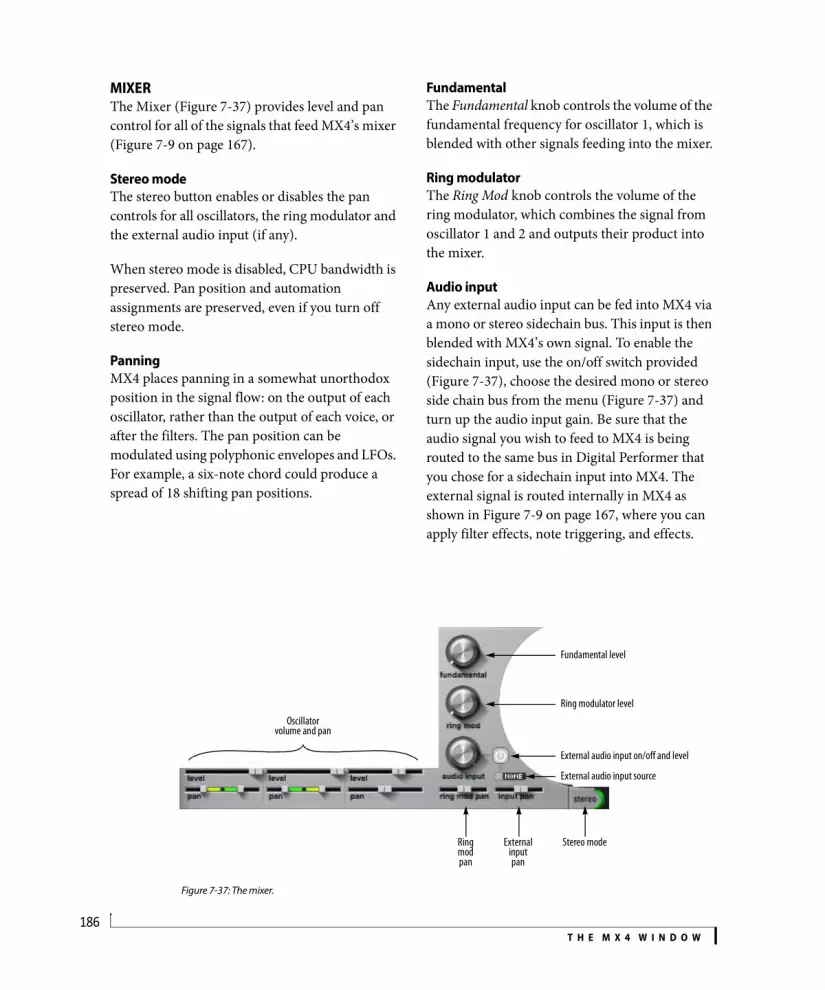
T H E M X 4 W I N D O W186
MIXERThe Mixer (Figure 7-37) provides level and pan control for all of the signals that feed MX4’s mixer (Figure 7-9 on page 167).
Stereo modeThe stereo button enables or disables the pan controls for all oscillators, the ring modulator and the external audio input (if any).
When stereo mode is disabled, CPU bandwidth is preserved. Pan position and automation assignments are preserved, even if you turn off stereo mode.
PanningMX4 places panning in a somewhat unorthodox position in the signal flow: on the output of each oscillator, rather than the output of each voice, or after the filters. The pan position can be modulated using polyphonic envelopes and LFOs. For example, a six-note chord could produce a spread of 18 shifting pan positions.
FundamentalThe Fundamental knob controls the volume of the fundamental frequency for oscillator 1, which is blended with other signals feeding into the mixer.
Ring modulatorThe Ring Mod knob controls the volume of the ring modulator, which combines the signal from oscillator 1 and 2 and outputs their product into the mixer.
Audio inputAny external audio input can be fed into MX4 via a mono or stereo sidechain bus. This input is then blended with MX4’s own signal. To enable the sidechain input, use the on/off switch provided (Figure 7-37), choose the desired mono or stereo side chain bus from the menu (Figure 7-37) and turn up the audio input gain. Be sure that the audio signal you wish to feed to MX4 is being routed to the same bus in Digital Performer that you chose for a sidechain input into MX4. The external signal is routed internally in MX4 as shown in Figure 7-9 on page 167, where you can apply filter effects, note triggering, and effects.
Figure 7-37: The mixer.
Fundamental level
Stereo mode
Oscillatorvolume and pan
Ring mod pan
Ring modulator level
External audio input on/off and level
External audio input source
External input pan

T H E M X 4 W I N D O W187
EFFECTSTo view the effects section, click its disclosure triangle (Figure 7-38).
Effects menusThe effects section provides two effects “slots” in its signal chain for each preset:
a modulation effect slot that provides chorus, phaser or flanger
a time effect modulation that provides reverb or delay
Five effects are provided: Delay, Chorus, Flanger, Phaser and Reverb. Choose the desired effects from the two menus shown in Figure 7-38. The topology of the effects (their placement in MX4’s signal chain) can be determined on the mods page. See “Gate and Effects topology” on page 180.
Effect slot Enable buttonUse the Enable button (Figure 7-38) for each effects slot to enable the effect for that slot. When the button is green, the effect slot is enabled.
ChorusChorus achieves its effect by mixing the input signal with a slightly delayed version of itself. Standard rate, delay, depth and mix controls are provided:
FlangerThe Flanger creates its effect by mixing the input with a delayed version of itself.
Figure 7-39: Flanger.
Rate and Depth Depth and Rate (Figure 7-39) control the modulation of the delay around 2 ms.
FeedbackThe Feedback control (Figure 7-39) adds some of the output back into the input.
Figure 7-38: The Effects section.
Modulation slot Time Effect Modulation slot Show/hide effectsEffect slot menu
Effect slot Enable
Parameter Unit Range Explanation
Rate Hz 0.01-2.00 Modulates the delayed signal.
Delay ms 0-20 Controls the delay time.
Depth Percent 0-100 Controls the modulation of the delay within the range of the delay setting.
Mix Percent 0-100 Amount of blend with dry signal.

T H E M X 4 W I N D O W188
MixMix (Figure 7-39) controls the overall level of the Flanger effect mixed with the original signal.
PhaserThe phaser creates its effect by sweeping notches up and down the frequency spectrum.
Figure 7-40: Phaser.
RateRate (Figure 7-40) controls the rate at which the notch center frequencies are modulated.
WidthWidth (Figure 7-40) controls the bandwidth of the notches, within a range determined internally. When Width is 100%, the bandwidth is set to the maximum allowed value.
DepthDepth (Figure 7-40) controls how far the notches sweep.
MixMix (Figure 7-40) controls the overall level of the Phaser effect mixed with the original signal.
DelayUse the enable/disable button (Figure 7-38) to add delay. The delay plug-in produces classic delay effects. With stereo processing and separate left/right channel controls, you can create complex stereo and ‘ping-pong’ delay effects that are saved with the preset.
Left/Right DelayThese settings control the length of the delay independently for the left and right channel. You can specify delay time in milliseconds or, if the Sync button is engaged, by specifying note duration (or bar length).
To generate complex, poly rhythmic effects, try choosing different note values for the left and right channel delays.
SyncEngage the Sync button to specify the left channel (L) and right channel (R) delay amount in beats and bars. This causes the delay taps will stay in tempo with Digital Performer.
Out of rangeIf sync is engaged, the Sync light blinks when the delay length you’ve specified makes the total delay time longer than 2 seconds (the maximum time allowed by this plug-in).
Note that the current sequence tempo factors into the delay time for sync-based delays. For example, a quarter note is one second long at 60 bpm but only a half a second long at 120 bpm. So if you specify a whole note delay, and the sequence tempo is 60 bpm, the total delay time you’ve specified is 4 seconds, which is longer than the 2-second maximum allowed by the plug-in. In this case, the Sync light blinks to alert you to this fact. To turn off the light, choose a shorter beat or bar value. Or increase the tempo of the sequence.
FeedbackThe feedback setting controls how much post-delay, post-filtered signal is re-injected back into the delay processor. Used sparingly, these controls can greatly add to the complexity of the delay effect.
Warning! Be very careful when working with feedback, as it can quickly generate ear-splitting, speaker blowing feedback if you are not careful. When you combine feedback with the highpass or lowpass filter, and then add resonance, the result is instant runaway feedback. The only way to stop this feedback is with Digital Performer’s Stop Sounding MIDI Notes command (Studio menu).

T H E M X 4 W I N D O W189
One way to prevent this sort of feed back is to apply LFO modulation to the filter frequency. This modulates the feedback path and keeps it in check.
FilterThis is a standard EQ filter that you can apply to the signal before it is fed into the feedback processor. Filter types include low pass, high pass, notch and bandpass filters with appropriate L/R frequency, width and resonance settings, where applicable. This is a great way to apply an ‘effected’ sound to the delay taps, which can add more interest and dimension to the overall delay effect.
MixControls the overall level of the delay echoes mixed with the original signal.
ReverbMX4’s reverb provides several basic controls:
Figure 7-41: Reverb.
TimeTime (Figure 7-41) controls the length of the reverb tail.
Cut frequencyThe Cut Frequency (Figure 7-41) provides high-frequency damping.
SpreadSpread (Figure 7-41) controls the amount of stereo spread for the reverb.
MixMix (Figure 7-41) controls the overall level of the Reverb effect mixed with the original signal.
RANDOMThe Random controls let you generate new patches by randomizing parameters of your choice.
Choose any desired patch as a starting point. Then check the parameters you wish to randomize (see “Randomizing tips” below). When you are ready to go, click Apply, and then play the patch to listen to the results. To try again, simply click Apply.
Randomizing tipsOverly randomized presets that include modulation assignments can produce rather disturbing results. MX4 includes several useful options for constraining randomization within a preset. For example, you can randomize oscillator parameters, but exclude pitch. Or you can at least constrain pitch randomization to consonant intervals such as octaves or 4ths/5ths.
You might also experience better results by excluding filter topology and filter frequency modulation. Changing the filter topology can change the fundamental nature of the preset. Similarly, filter frequency modulation can easily produce sonic chaos.
If you like the way a patch responds to external control, but you’d like to try variations on how it sounds, then exclude (uncheck) modulation ranges and enables.

T H E M X 4 W I N D O W190
Modifier key legendThe modifier key legend (Figure 7-42) shows you various shortcuts for adjusting the MX4 parameter controls in the main MX4 window.
Signal path block diagramThe signal path block diagram (Figure 7-42) shows the basic signal path layout of MX4.
Rear panel grillDo not attempt to service MX4. Servicing should only be performed by an authorized MX4 service center.
ApplyClick Apply to randomize the current path. Click the Main button to return to the main MX4 window.
Figure 7-42: The Random options.
Signal pathblock
diagram
Modifier key legend Randomize options
Randomizes the current patch
Flips back to main MX4 window

T H E M X 4 W I N D O W191
MODIFIER KEY SHORTCUTSMX4 provides the following modifier key shortcuts:
CONTEXTUAL MENUSHold down the control key (or the right-click button on a multi-button mouse) and click on any item in the MX4 window to view a contextual menu of additional options for that item. What appears in the contextual menu depends on what you control-click.
Contextual menu items that apply to the entire oscillator, filter, envelope or LFOFor oscillators, filters, envelopes and LFOs, control-click the graphic to see menu items that apply to the entire oscillator, filter envelope or LFO. Control-click a slider to see additional menu items that apply only to the individual parameter.
Randomize base valuesApplies a random value to the base setting for every parameter of the oscillator, filter, envelope or LFO.
Randomize base values and modulation valuesSame as Randomize base values, with this addition: if a parameter currently has a modulation range, the upper and lower limit of the range are also changed to a random value.
Copy this item to all othersApplies all settings from the source oscillator, filter, envelope or LFO to all of the others. For example, if you control-click oscillator 1 and choose Copy this oscillator to all others, then oscillator 1’s settings are applied to oscillators 2 and 3.
Individual parametersControl-click an individual parameter (slider or knob) to see additional menu items that apply only to the individual parameter.
Enable the current modulation sourceCauses the parameter to be modulated by the currently selected modulation source (in the Source section).
Disable the current modulation sourceDisconnects the parameter from the currently selected modulation source (in the Source section).
Disable all modulation sourcesIf the parameter is currently being controlled by several modulation sources, this command Disconnects the parameter from all current modulation sources.
Swap current modulation rangeIf the parameter is currently being controlled by a modulation source, you’ll see this menu item, which swaps the base value with the endpoint of the modulation range. For bipolar modulation ranges (which swing between a positive and negative limit above and below the base value), the base value jumps to one of the original range endpoints and the size of the range stays the same. For example, if the base is 50% and the range is
Modifier key Target Operation Explanation
command any parameter
fine value adjust
Provides fine-tuned adjustment of any parameter.
control any parameter
contextual menu
Opens a menu of additional options for the item that you control-click (see the next section).
option parameter without modulation
add modulation
Applies the currently selected modulation source to the parameter.
option parameter with modulation
modify modulation range
Adjusts the range of modulation.
option parameter with bipolarmodulation
modify modulation range end points
Adjusts both the top and bottom of the modulation range simultaneously.
shift parameter withmodulation
modify base value
Adjusts the base value of the modulation range.

T H E M X 4 W I N D O W192
+/- 25%, the new base is 75% and the range stays at +/- 25%. If the original range was -/+ 25% (where -25% is first instead of +25%), then the base will jump to 25%.
Invert current modulation rangeIf the parameter is currently being controlled by a modulation source, you’ll see this menu item, which inverts the modulation range using the base value as the axis for inversion. As a result, the base value remains the same, acting as a “mirror point” for reflecting the modulation range endpoint to the other side of the range. For bipolar modulation ranges (which swing between a positive and negative limit above and below the base value), the modulation range endpoints are inverted.
Invert all modulation rangesIf the parameter is currently being controlled by several modulation sources, this command inverts all of their modulation ranges, as described above.
Invert and ReverseThe contextual menus for the Pattern Gate, Arpeggiator, Pattern Sequencer and Trigger Sequencer have Invert and Reverse items. See their respect sections earlier in this chapter for details.
Randomize base valueApplies a random value to the base setting for the parameter.
Randomize base and modulationsSame as Randomize base value, with this addition: if the parameter currently has a modulation range, the upper and lower limit of the range are also changed to a random value.
Learn controller mappingLets you assign any external MIDI controller to the parameter. To do so, choose this command and send the controller message you wish to use (move the knob or slider).
Forget controller mappingIf the parameter is currently assigned to a MIDI controller for external control, you’ll see this menu item, which clears the MIDI controller (and disconnects the external control). You can then reassign it, if you wish.
Copy this setting to all othersApplies the setting from the source parameter to all other similar parameters. For example, if you control-click the Symmetry parameter for oscillator 1 and choose Copy this setting to all others, then oscillator 1’s Symmetry value is applied to the Symmetry parameters for oscillators 2 and 3.
Copy this setting and modulations to all othersSame as Copy this setting to all others, with this addition: if the parameter currently has a modulation range, the upper and lower limit of the range are also applied to the other parameters, regardless of whether they are turned on or not.
Set the modulation range for quantizingThis contextual menu command applies to the oscillator pitch sliders. See “Mapping equal-tempered pitches” on page 183 for details.
Global randomizeTo randomize all parameters in the MX4 window in one operation, control-click anywhere in the MX4 window and choose Global Randomize.

CHAPTER
193
8 Five Things To Know About MX4
MX4 is perhaps the most powerful and flexible synthesizer of its kind ever devised, due in large part to its powerful modulation system. If each modulation routing had a dedicated knob, the MX4 interface would have over 3500 knobs. To efficiently represent this modulation system on a computer screen, we devised a few, simple user interface metaphors. The power of MX4’s interface is its ability to distill its flexible modulation system into a handful of simple gestures. So, even if you are a synthesis guru, here are the Five Things You Need To Know About MX4 to quickly unleash its potential.
1. What is a base value?The base value is the nominal setting of a parameter without any modulation applied to it. Any modulation sets forth from the base value. If a modulation source is not selected, when you move a slider or knob in MX4, you’re adjusting the base value. If a modulation source is selected, another way of moving the base value is by using the shift key.
2. Modifier keysThe command key invokes a ‘fine’ adjust mode. For example, the oscillator pitch slider adjusts in semitone increments. If you hold down the command key, you now have resolution in 1 cent increments.
With a modulation source selected, the option key allows you to create a modulation range, or modify an existing range. This modifier key can be held down together with the command key for fine adjustment of the modulation range.
If you have a modulation range assigned, you can move the defined range using the shift key. What you’re essentially doing is moving the base value
only, which you can also do when no modulation source is selected. The modulation range always keeps its position relative to the base value.
Control-click any parameter to reveal a contextual menu of additional parameter-specific operations.
If you forget which key command is which, the random pane provides a handy crib-sheet.
3. Bipolar and unipolar modulation sourcesThere are two kinds of modulation sources in MX4:
bipolar (LFOs, pattern sequencer)
unipolar (envelopes, most MIDI controllers)
Bipolar means that the modulation range extends both above and below the base value. Unipolar means that the modulation range extends only in one direction (either above or below the base value). Another way to understand the difference is to think of a pitch bend wheel and a modulation wheel. The nominal position of a pitch bend wheel is centered, and modulation can occur above and below the nominal value, making it a bipolar range. On the other hand, a mod wheel’s nominal value is all the way down, or zero, and modulation occurs up from zero only, making it unipolar.
MX4 operates in the same way. Modulation ranges behave slightly differently depending on the kind of modulation source you have selected. If you select an LFO, which is a bipolar modulation source, the modulation range extends two end points, center-justified from the base value. If you select an envelope, a unipolar modulation source, the modulation range extends in a single direction away from the base value.

F I V E T H I N G S T O K N O W A B O U T M X 4194
MX4 allows you to directly manipulate modulation range end point handles independently. If you’re editing a single endpoint of a bipolar modulation range, be aware you’re actually doing two things: editing the modulation range and changing the base value. (Hint: If you just want to edit the modulation range and not the base value, hold down the option key.)
4. The initial modulation gesture is meaningfulConsider a low pass filter: as you move up its frequency slider, the filter opens. If you move the slider down, the filter closes. Let’s say that you want an envelope to control the filter cutoff frequency. When you create the modulation range, your initial gesture determines the direction of the range. If you drag the modulation range up from the base value, the envelope will open the filter as the envelope progresses, just as if you were moving the filter knob up manually. If you drag the modulation range down from the base value, the envelope will close the filter as the envelope progresses. If you accidentally drag in the wrong direction, don’t worry. Control-click the parameter and choose the contextual menu option called Invert modulation range to switch it.
The same holds true for bipolar modulation sources. Your initial gesture can phase invert the output of the LFO. For example, if you want an LFO to pan an oscillator from the center off to the right, your initial modulation gesture should move from the base value to the right. Now, with the same LFO, you can create a mirror version of the LFO on another oscillator by dragging left from the base value.
5. What is the white block with the ‘D’ in it in the topology diagram?The white block represents how distortion is positioned in the filter topology. The block labeled ‘1’ is filter 1 and the block labeled ‘2’ is filter 2. The filters are disabled if they are not present in the
topology diagram. Distortion is turned off when the knob is all the way off (in the left most position).

Part 4Appendices


APPENDIX
197
A MX4 Troubleshooting
OVERVIEWMX4 FAQ . . . . . . . . . . . . . . . . . . . . . . . . . . . . . . . . . . . . . . . . . . . . . .197Conserving CPU resources . . . . . . . . . . . . . . . . . . . . . . . . . . . . .198General troubleshooting . . . . . . . . . . . . . . . . . . . . . . . . . . . . . .198MIDI troubleshooting. . . . . . . . . . . . . . . . . . . . . . . . . . . . . . . . . .199Audio troubleshooting . . . . . . . . . . . . . . . . . . . . . . . . . . . . . . . .200Preventing Catastrophe . . . . . . . . . . . . . . . . . . . . . . . . . . . . . . .200Technical support . . . . . . . . . . . . . . . . . . . . . . . . . . . . . . . . . . . . .200
MX4 FAQ
I have a preset loaded, but I don't hear anything.If you are playing notes from an external controller, make sure the MIDI track or instrument track in Digital Performer is record-enabled. For other MIDI troubleshooting tips, see “MIDI troubleshooting” on page 199.
MX4’s MIDI activity LED is flashing, so it’s receiving MIDI data successfully, but I still don’t hear any sound.It’s time to check audio. See “Audio trouble-shooting” on page 200.
When I play on my keyboard, there's a delay before I hear a note.In order to get the fastest possible response from MX4, you’ll need to set the sample buffer of your audio hardware driver to a low number. Experiment with this setting to get the best response and computer performance. For complete details, see “Buffer Size” on page 30 in the DP Getting Started Guide.
How do I get MX4 to play multiple different sounds?Each “instance” of MX4 plays one preset. If you want to play two or more presets at the same time, just open additional instances of MX4, each on its own track.
When I move the cutoff frequency knob for the Filter, nothing happens.Make sure the envelope depth in the filter section is set to a value where you can actually hear the envelope. For example, if you have set the depth to a value of 1 and the attack of the envelope is 0.00, the filter will have no effect at all.
Why is the output of MX4 is distorted?It is possible for MX4 to output more than unity gain. This can happen, for example, if you use resonant filters that add gain. Keep an eye on the output level of the MX4 track and attenuate that signal if it gets too hot.
How do I record the audio output of MX4? Digital Performer can bounce your project to disk without first rendering virtual instruments as audio. Simply include MX4 in your selection of tracks to be bounced.
Alternately, you can manually bus the output of the MX4 track to another audio track, and record the audio output of MX4 onto that track. Here is a step by step procedure:
1 Create a new stereo audio track (not the one where MX4 is used) and name it Record MX4.
2 Route the MX4 track to an unused bus (e.g.: Bus 1-2).
3 Select Bus 1-2 as the input pair for your Record MX4 track.
4 Record-arm the Record MX4 track, and start recording.
If you wish to hear MX4 while recording, engage Studio menu>Audio Patch Thru> Auto. In addition, choose Setup menu> Configure Audio

A P P E N D I X A : M X 4 T R O U B L E S H O O T I N G198
System> Input Monitoring Mode and choose the Monitor record-enabled inputs through effects option.
That’s it! MX4 audio output will be recorded into the new track.
Everything is working fine, except that intermit-tently, notes don’t play for no apparent reason. Why?Check your polyphony setting for the part to make sure that MX4 has more than enough voices to play the notes you are feeding it.
CONSERVING CPU RESOURCESMX4 provides several settings that are crucial for managing your computer’s precious processing (CPU) resources. Another setting, Digital Performer’s buffer size setting (“Buffer Size” on page 30 in the DP Getting Started Guide), can also dramatically impact MX4 performance. In general, settings of 256, 128 or 64 samples produce better latency performance. But lower settings place higher demand on your computer’s processor.
The Polyphony settingThe Polyphony setting (see “Polyphony” on page 163) lets you control the maximum allowed number of stereo notes that can be played simultaneous by MX4. The upper limit is 256. The more notes that MX4 plays simultaneously, the more work you computer does. The Polyphony settings lets you put a ceiling on the number of notes that will play simultaneously to conserve CPU bandwidth. For further details, see page 163.
Other ways to optimize MX4 performanceHere are three additional ways you can optimize MX4 performance:
1. Filters require processing bandwidth because they are applied per voice. So be prudent in your sound design when employing one or both filters. Band-pass filters are particularly more “CPU-expensive” than highpass or lowpass filters.
2. Long envelope times can increase the polyphony count — without being obvious. Make sure your amplitude envelope is set only as long as is necessary. For details, see “Envelopes” on page 173.
3. MX4’s built-in effect processing will increase the CPU load.
4. Stereo mode doubles the effect of filters because in MX4, the signal is split into stereo before the filters, so be mindful of stereo operation with filters (and lots of polyphony).
5. Polyphony affects CPU bandwidth. In other words, the more notes that MX4 plays simultane-ously, the more load is placed on your computers’ CPU. You can cap polyphony to limit CPU loading.
6. The unison multiplier multiplies the number of voices you use per note, so only use it if your patch requires it. For details, see “Unison multiplier” on page 164.
7. The digital rectangle and digital sawtooth oscillator waveforms are more CPU-efficient than their non-digital counterparts. Use them whenever possible (when the slight aliasing that can occur with these waveforms is masked by other components of the sound). For details, see “Waveforms” on page 167.
In summary, you can conserve CPU processing in a preset by using only one — or zero — filters, turning off stereo mode, turning off chorus and delay and capping the polyphony.
GENERAL TROUBLESHOOTINGTroubleshooting is always simplest and most effective when the exact problem can be specified clearly and concisely. If you are surprised by an error message or by seemingly erratic behavior in the program, take a moment to jot down the relevant details: exactly what the error message said (including any error ID numbers), what

A P P E N D I X A : M X 4 T R O U B L E S H O O T I N G199
actions were done on-screen just before the problem occurred, what kind of file you were working with, how you recovered from the problem, and any unusual conditions applying during the occurrence of the problem. This may not enable you to solve the problem at once, but will greatly aid in isolating the problem should it reoccur.
If the problem you are encountering seems inconsistent, try to determine what the necessary pattern of actions are that will cause it to occur. Genuine bugs in application software like MX4 are almost always consistent in their manifestation: the same set of actions under the same conditions invariably brings about the same results. Determining the exact cause of a bug often requires experiments which replicate the problem situation with one factor changed: choosing a different (smaller) preset, turning off 32-bit mode, etc.
If the problem is truly inconsistent, then it is likely to be a hardware problem: a faulty hard drive, a failing computer motherboard, a loose connection, etc.
Isolate the problem…One of the best troubleshooting techniques is to try to isolate the problem. If you can whittle down a complicated setup or scenario to a much simpler case, chances are you’ll zero in on the problem more quickly.
Simplify your setup…One of the most common causes of problems is a conflict with other software in the system. Run MX4 by itself, with no other plug-ins or virtual instruments, and see if the problem you are having still happens.
Check the ‘Read Me First’…It’s human nature to blow right past the Read Me First, but you’ll probably be glad you took the time. If you experience problems with MX4, check the Read Me notes that ship with the current version you are using.
If you cannot open a particular MX4 project or session in Digital Performer…First try opening other existing files, or a new file, to be sure MX4 is working at all. If other files work fine, try temporarily removing the MX4 plug-in, or disable audio in Digital Performer. If other files also exhibit similar behavior, then you know that the problem is not specific to one file.
MIDI TROUBLESHOOTINGThe most important tool for tracking down MIDI input problems is the MIDI Activity LEDs for each part. If there is a hardware problem, or if your channel assignments are wrong, the problem should be apparent by looking at the MIDI LEDs.
In order for external MIDI to get to MX4, the MIDI track or instrument track must be record-enabled. A quick test to determine whether MIDI is reaching the track is to hit record and tap a few notes on your controller. If no MIDI appears in the track, check that your controller and MIDI interface are set up properly. If MIDI data does show up in the track, and your sequencer uses a separate MIDI and instrument track for virtual instruments, make sure the MIDI track output is assigned to MX4 and is assigned to a part that has a preset sound ready to go.
If MX4 is unable to play any MIDI data…Does Digital Performer receive MIDI data from your MIDI controller? Does MIDI play back successfully to other MIDI instruments? If the answer is no to either question, double-check your cable connections and MIDI controller settings. See if your controller registers in Audio MIDI Setup.

A P P E N D I X A : M X 4 T R O U B L E S H O O T I N G200
If you are trying to play MX4 from your MIDI controller, make sure that the MX4 MIDI track or instrument track in Digital Performer is record-enabled.
Often only A/B tests will reveal the source of the problem. It may be necessary to switch your MIDI cables, and if possible, to try using a different MIDI interface or synthesizer for input/output. The easiest way to test if MIDI data is actually getting to MX4 is to look at the MIDI activity LEDs in the Parts section.
AUDIO TROUBLESHOOTINGIn order for audio to be heard from MX4, the output of the audio or instrument track in Digital Performer must be sent to an output that is connected to speakers or headphones. Can you play back any pre-recorded audio? That’s always a good way to check that the rest of the audio system is set up correctly. In some cases, a sequencer requires an available voice for MX4 playback. Make sure all outputs and voice assignments are correct for the MX4 track.
If you still don’t hear sound, check the following things:
Make sure the volume is turned up on the part you are playing, as well as MX4’s global volume setting.
Make sure that the appropriate faders are up in Digital Performer’s Mixing Board.
Make sure you have cables connected to the correct plugs on the outputs of your audio hardware.
PREVENTING CATASTROPHEKeep up-to-date backups of your MX4 patches file, so that you always have copies of the most recent work you have done. Almost any software problem is survivable as long as you have kept backups of your work.
Keep plenty of free space on your hard drives. This will prevent the Mac from running out of disk space.
TECHNICAL SUPPORTWe are happy to provide customer support to our registered users. If you haven’t already done so, please take a moment to complete the registration card in the front of the manual and send it in to us. When we receive your card, you’ll be properly registered for technical support.
Registered users who are unable, with their dealer’s help, to solve problems they are encountering with MX4 may contact our technical support department in one of the following ways:
Technical support phone: (617) 576-3066
Tech support fax: (617) 354-3068
Tech support on line: motu.com/support
Web site (for information, tech support database and downloads): www.motu.com
Technical support is staffed Monday through Friday 9 AM to 6 PM, Eastern Time.
If you decide to contact technical support, please have your MX4 manual at hand, and be prepared to provide the following information to help us solve your problem as quickly as possible:
The version of MX4 you are working with. This is displayed to the left of the MX4 logo.
A brief explanation of the problem, including the exact sequence of actions which cause it, and the contents of any error messages which appear on the screen. It is often very helpful to have brief written notes to refer to.
The pages in the manual which refer to the parts of the program which you are having trouble with.

A P P E N D I X A : M X 4 T R O U B L E S H O O T I N G201
We’re not able to solve every problem immediately, but a quick call to us may yield a suggestion for a problem which you might otherwise spend hours trying to track down.
Our technical support telephone line is dedicated to helping registered users solve their problems quickly. In the past, many people have also taken the time to write to us with their comments, criticism and suggestions for improved versions of our software. We thank them; many of those ideas have been addressed in this version of MX4. If you have features or ideas you would like to see implemented in our music software, we’d like to hear from you. Please send email to [email protected], or write to the MX4 Development Team, MOTU Inc., 1280 Massachusetts Avenue, Cambridge, MA 02138.
Although we do not announce release dates and features of new versions of our software in advance, we will notify all registered users immediately by mail as soon as new releases become available. If you move or otherwise change your mailing address, please send us a note with your change of address so that we can keep you informed of future upgrades and releases.

A P P E N D I X A : M X 4 T R O U B L E S H O O T I N G202
APPENDIX
203
B Glossary
32-bit: Refers to the number of bits used to describe an individual sample. MX4 audio is generated internally at 32-bit resolution (32 bits to describe each sample).
Amplitude envelope: Also see Envelope. Modulates the volume of a sound over time according to the settings of each envelope stage. Four of the six stages in the MX4 envelope are specified in units of time, and the sustain stage is specified in level (amplitude).
Audio Unit (AU): A standard Mac OS X plug-in format. Programs like Digital Performer can host AU plug-ins.
Automation: The process of changing a plug-in parameter over time. For example, MX4’s filter cutoff frequency can be automated by sending a stream of automation data values that change over time.
Bend: The process of changing the pitch of a note smoothly, or the range over which such a change can occur.
Buffer: A small portion of computer memory that is used to temporarily store audio data as it is being moved or processed. Larger buffer sizes can increase system latency. See “Buffer Size” on page 30 in the DP Getting Started Guide.
Bus: A connection from one point in a mixing environment to another.
Cents: a unit of measurement for pitch transpo-sition. There are 100 cents in a semitone and twelve semitones in a octave. 50 cents is a quarter of a tone.
CoreAudio: The term used to refer collectively to the built-in audio services provided by Mac OS X.
CoreMIDI: The term used to refer collectively to the built-in MIDI services provided by Mac OS X.
CPU: Central Processing Unit. This is the “brain” of a computer, where the majority of the computing is done.
Cutoff frequency: The frequency above or below which a digital signal processing filter is applied.
Effects: Signal processing applied to an audio signal. MX4 has five effects: chorus , flanger, phaser, delay, and reverb.
Envelope: A modulation profile that changes over time, applied to an audio signal. For example, in samplers, amplitude envelopes are applied to samples to produce more dynamic-sounding notes, with distinct attack, sustain and release characteristics.
Filter: An audio signal processor that modifies an incoming signal in some way. MX4 provides two classic filters, along with a wide variety of ways to program, modify and modulate them. See “Filters” on page 171.
Filter modulation: The process of changing the filter cutoff frequency over time. For details, see “Modulation” on page 176.
Fine-tune: A pitch control setting that allows you to change pitch in cents (a hundredth of a semitone). Also see cents.
Frequency: The rate at which an audio signal oscillates. Also see cutoff frequency.

A P P E N D I X B : G L O S S A R Y204
Gain: Volume, amplitude.
General MIDI: A standardized, basic sound set with a standard organization adopted by the electronic music instrument industry to provide users with a familiar sound set, regardless of the instrument being used to produce the sounds.
Hardware buffer size: The size of a small amount of computer memory used to transfer digital audio data to and from external audio hardware. See “Buffer Size” on page 30 in the DP Getting Started Guide.
High Pass Filter: A signal processor that allows frequencies above its threshold to go through and mutes frequencies below its threshold.
HPF: See High Pass Filter.
Instance: An instantiated MX4 plug-in (see Instantiate below).
Instantiate: Specifically in regards to MX4, this term refers to the process of opening MX4 within Digital Performer as the host software.
Insert: A point in a signal chain where an additional signal path loop (out and then back in again) can be added. More specifically, in MX4, an insert is a place where an effect can be added.
I/O buffer size: See Buffer.
Key follow: The amount of keyboard tracking that can be applied to an oscillator. For details, see “Oscillator keyfollow” on page 169.
Layer: Multiple presets (patches) that are played simultaneously by the same note.
Latency: a very short delay that can occur between when a MIDI note is played and the resulting MX4 sound is triggered. See “Buffer Size” on page 30 in the DP Getting Started Guide for further information.
LFO: See Low Frequency Oscillator.
Low Frequency Oscillator: A low frequency signal that is used as a control signal for a signal processor (such as a filter).
Low Pass Filter: A signal processor that allows frequencies below its threshold to go through and mutes frequencies above its threshold.
LPF: See Low Pass Filter.
MAS: A plug-in format for Digital Performer.
MIDI: Musical Instrument Digital Interface. A command and control protocol for electronic musical instruments and software.
Modulation: The process of modifying a signal over time.
Mono: One channel.
Multi-timbral: Producing (or the ability to produce) more than one type of instrument or sound at a time.
Normalize: To boost the amplitude of an audio signal by whatever constant amount is needed to make the loudest peak reach digital full scale (zero dB).
Note-on/off velocity: A parameter of MIDI note data event that specifies the strength of the attack and release of the note.

A P P E N D I X B : G L O S S A R Y205
Octave: A frequency that is higher or lower by a factor of 2. For example, the A above middle C is 440 Hz. An octave higher is 880 Hz. Two octaves higher is 1760 Hz.
Off-velocity: See Note-on/off velocity.
On-velocity: See Note-on/off velocity.
Parallel filters/effects: Two or more signal processors that can be applied independently to the same input signal.
Plug-in: A piece of software that operates within a host application.
Polyphony: The characteristic of sounding two or more notes at the same time. More specifically, this MX4 setting determines the maximum number of notes a part can play simultaneously. See “Polyphony” on page 163.
Preset: A reference to a patch, which is a “snapshot” of all of the settings in the MX4.
RAM: Random Access Memory. This is the portion of a computer where data is temporarily stored during the computer’s operation. When you restart or shut off the computer, RAM is flushed.
Release velocity: See note-off velocity.
Resonance: A boost in amplitude around the cutoff frequency. Also see cutoff frequency.
Serial effects: Two or more signal processors that can be applied one after the other to an audio signal.
Stack: Multiple presets (patches) that are played simultaneously by the same note.
Threshold: A specific frequency, amplitude or other audio signal characteristic that is used as a trigger.
Trigger: Something that initiates something else. For example, a MIDI note-on event can trigger a sound.
Velocity: See note-on/off velocity.
Virtual instrument: Software that produces sounds in a similar fashion to real acoustic or electronic instruments.

A P P E N D I X B : G L O S S A R Y206
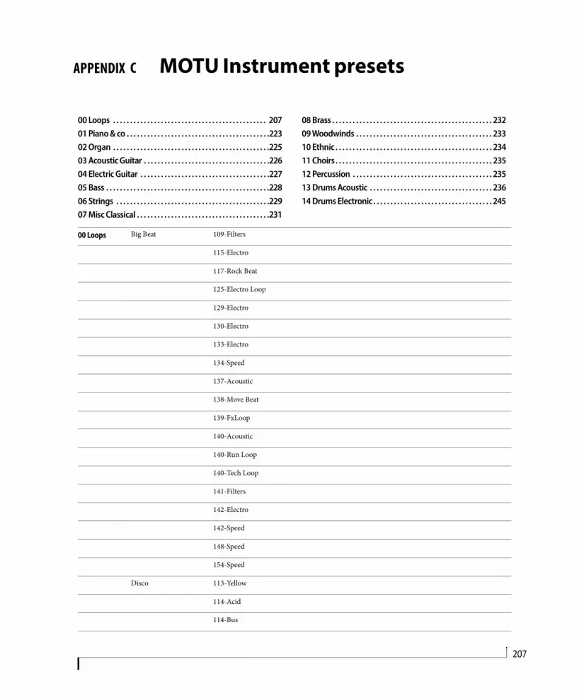
APPENDIX
207
C MOTU Instrument presets
00 Loops . . . . . . . . . . . . . . . . . . . . . . . . . . . . . . . . . . . . . . . . . . . . . 20701 Piano & co . . . . . . . . . . . . . . . . . . . . . . . . . . . . . . . . . . . . . . . . . .22302 Organ . . . . . . . . . . . . . . . . . . . . . . . . . . . . . . . . . . . . . . . . . . . . . .22503 Acoustic Guitar . . . . . . . . . . . . . . . . . . . . . . . . . . . . . . . . . . . . .22604 Electric Guitar . . . . . . . . . . . . . . . . . . . . . . . . . . . . . . . . . . . . . .22705 Bass . . . . . . . . . . . . . . . . . . . . . . . . . . . . . . . . . . . . . . . . . . . . . . . .22806 Strings . . . . . . . . . . . . . . . . . . . . . . . . . . . . . . . . . . . . . . . . . . . . .22907 Misc Classical . . . . . . . . . . . . . . . . . . . . . . . . . . . . . . . . . . . . . . .231
08 Brass . . . . . . . . . . . . . . . . . . . . . . . . . . . . . . . . . . . . . . . . . . . . . . . 23209 Woodwinds . . . . . . . . . . . . . . . . . . . . . . . . . . . . . . . . . . . . . . . . 23310 Ethnic . . . . . . . . . . . . . . . . . . . . . . . . . . . . . . . . . . . . . . . . . . . . . . 23411 Choirs. . . . . . . . . . . . . . . . . . . . . . . . . . . . . . . . . . . . . . . . . . . . . . 23512 Percussion . . . . . . . . . . . . . . . . . . . . . . . . . . . . . . . . . . . . . . . . . 23513 Drums Acoustic . . . . . . . . . . . . . . . . . . . . . . . . . . . . . . . . . . . . 23614 Drums Electronic. . . . . . . . . . . . . . . . . . . . . . . . . . . . . . . . . . . 245
00 Loops Big Beat 109-Filters
115-Electro
117-Rock Beat
125-Electro Loop
129-Electro
130-Electro
133-Electro
134-Speed
137-Acoustic
138-Move Beat
139-FxLoop
140-Acoustic
140-Run Loop
140-Tech Loop
141-Filters
142-Electro
142-Speed
148-Speed
154-Speed
Disco 113-Yellow
114-Acid
114-Bus

A P P E N D I X C : M O T U I N S T R U M E N T P R E S E T S208
114-Retro
115-Phazing
115-Pick
116-Tribal
117-Jumping
117-Trash
118-Clavi
118-Laughing
122-In Car
122-Nice
122-One
123-Alpha
124-Funkytar
130-Hot
131-Waynes
Drum & Bass 140-Loop 1
140-Loop 2
143-Loop
150-Loop 1
150-Loop 2
150-Loop 3
151-Loop 1
151-Loop 2
160-Loop 1
160-Loop 2
160-Loop 3
160-Loop 4
160-Loop 5
160-Loop 6
169-Loop 1
169-Loop 2

A P P E N D I X C : M O T U I N S T R U M E N T P R E S E T S209
169-Loop 3
170-Loop 1
170-Loop 2
171-Loop
Drumloops Brushed 076-HRoad Beat
076-Hroad Var
080-GVibes Beat
080-GVibes Var
092-GVibes Beat
092-GVibes Var
092-HRoad Beat
092-Jazzy Beat
092-Jazzy Var
096-HRoad Beat
096-Hroad Var
097-HRoad Beat
104-GVibes Beat
106-Hot Road
116-Hot Road
126-GVibes Var 1
126-GVibes Var 2
145-Gvibes Beat
Drumloops Funk 097-Funky Beat
097-Funky Var 1
097-Funky Var 2
119-Funky Beat 1
119-Funky Beat 2
119-Funky Var 1
119-Funky Var 2
121-Funky Beat 1
121-Funky Beat 2

A P P E N D I X C : M O T U I N S T R U M E N T P R E S E T S210
121-Funky Var 1
121-Funky Var 2
128-Funky Beat
128-Funky Var
Drumloops Premium 100-GT Funk B 1
100-GT Funk B 2
116-GT Brush A
120-GT Brush A 1
120-GT Brush A 2
120-GT Brush A 3
120-GT Brush A 4
121-GT Brush A 1
121-GT Brush A 2
121-GT Brush B 1
121-GT Brush B 2
125-GT PopRock C 1
125-GT PopRock C 2
134-GT Brush C
Drumloops Rock 096-Classic Beat
096-Classic Var
096-Pop Beat
096-Pop Var
120-Pop Beat
120-Pop Var
120-Speed Beat
120-Speed Var
126-Classic Beat
126-Classic Var
152-Pop Beat
152-Pop Var
152-Speed Beat

A P P E N D I X C : M O T U I N S T R U M E N T P R E S E T S211
153-Speed Tom
Electro 119-Bonus Loop
120-Bonus Loop 1
120-Bonus Loop 2
120-Elephant
120-Train 1
120-train 2
120-Wasch 1
120-Wasch 2
121-Bonus Loop
121-Elephant
124-Dry
124-Fat 1
124-Fat 2
124-Intestinal
124-Skip
125-Intestinal
125-Skip
126-Dry
135-Crunchy
Funk 069-Cully 1
069-Cully 2
085-Caste 1
085-Caste 2
089-Kool 1
089-Kool 2
092-S Again 1
092-S Again 2
093-Strack
095-Funky 1
095-Funky 2

A P P E N D I X C : M O T U I N S T R U M E N T P R E S E T S212
098-Organic 1
100-Babe 1
100-Babe 2
102-Road 1
102-Road 2
103-Shafty
107-Mirwo 1
107-Mirwo 2
Industrial 070-Fabrik
078-Xenon
080-Jerikan
080-Risk
083-Triphase
087-Vrac
088-Cat
098-Halt 1
098-Halt 2
098-Wagon
100-Interval
100-Large 3-4
100-Maarto
101-Anklum
104-Plastic
104-Work
110-Uzine
115-Sector
119-York
120-Van 5-4
120-York
120-Zink
130-Neon 7-8

A P P E N D I X C : M O T U I N S T R U M E N T P R E S E T S213
132-Brite 1
132-Brite 2
143-Electrik 5-4
145-Crak
145-Electrik 5-4
174-Quartz 1
174-Quartz 2
Instruments Bass Loops 074-G-Green
086-C-Touch
094-C-Strange
098-A-Light
098-C-Nuts
098-D-Smooth
100-D-Soul
102-D-Bounce
106-A#-Wall
111-A-Free
115-A#-Phazing
118-A-Grunge
120-G-Pop
123-A-Walter
126-F-Night
Brass 063-C-Sax Riff
063-Sax Riff 1
063-Sax Riff 2
063-Sax Riff 3
108-Barytone Riff
108-D#-Sax Riff
108-D#-Trumpets Riff
108-Sax Riff 1
108-Sax Riff 2
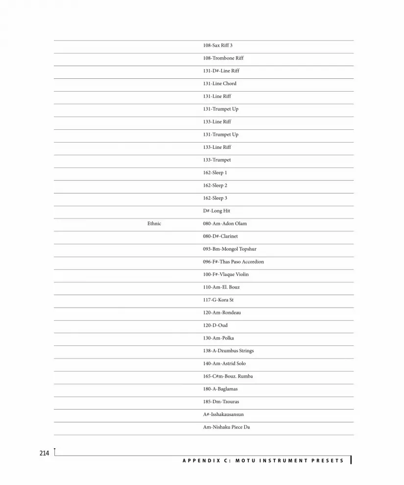
A P P E N D I X C : M O T U I N S T R U M E N T P R E S E T S214
108-Sax Riff 3
108-Trombone Riff
131-D#-Line Riff
131-Line Chord
131-Line Riff
131-Trumpet Up
133-Line Riff
131-Trumpet Up
133-Line Riff
133-Trumpet
162-Sleep 1
162-Sleep 2
162-Sleep 3
D#-Long Hit
Ethnic 080-Am-Adon Olam
080-D#-Clarinet
093-Bm-Mongol Topshur
096-F#-Thas Paso Accordion
100-F#-Vlaque Violin
110-Am-El. Bouz
117-G-Kora St
120-Am-Rondeau
120-D-Oud
130-Am-Polka
138-A-Dzumbus Strings
140-Am-Astrid Solo
165-C#m-Bouz. Rumba
180-A-Baglamas
185-Dm-Tzouras
A#-Isshakausansun
Am-Nishaku Piece Da

A P P E N D I X C : M O T U I N S T R U M E N T P R E S E T S215
D-Bagl. Solo
D-er Hu
Dm-Shaku Cicada
Guitar 080-C-TripHop
089-Bm-Groovywah
092-Dm-Funky
110-A-Pick
110-Bm-12 Strings
110-Cm-Pick
110-F-12 Strings
120-Am-T-Wah
120-Am-WahWah
120-Dm-Blues Rock
120-E-Jazz Dark
120-Em-Guitar Solo
120-Em-Jazz clear
160-C#-Jazz
Vocal Hooks Baby Let
Check This
Dont want
Ha Ha
Han
Hey Hi Hey
Hey Yaa
Hi
Hm Hm
Mm Ah Mm
Na Ha
Old Ragga
Ooh
Ow Yeah
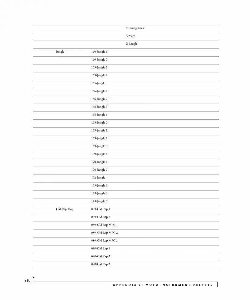
A P P E N D I X C : M O T U I N S T R U M E N T P R E S E T S216
Running Back
Scream
U Laugh
Jungle 160-Jungle 1
160-Jungle 2
163-Jungle 1
163-Jungle 2
165-Jungle
166-Jungle 1
166-Jungle 2
166-Jungle 3
168-Jungle 1
168-Jungle 2
169-Jungle 1
169-Jungle 2
169-Jungle 3
169-Jungle 4
170-Jungle 1
170-Jungle 2
172-Jungle
173-Jungle 1
173-Jungle 2
173-Jungle 3
Old Hip-Hop 089-Old Rap 1
089-Old Rap 2
089-Old Rap MPC 1
089-Old Rap MPC 2
089-Old Rap MPC 3
090-Old Rap 1
090-Old Rap 2
090-Old Rap 3
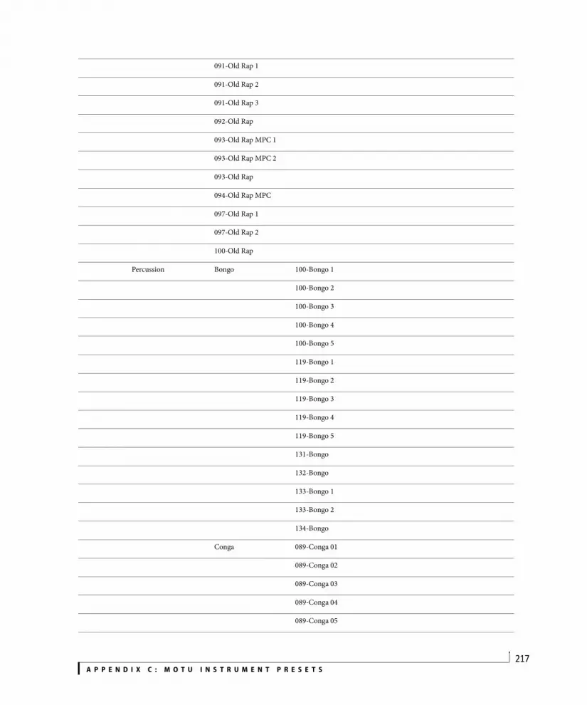
A P P E N D I X C : M O T U I N S T R U M E N T P R E S E T S217
091-Old Rap 1
091-Old Rap 2
091-Old Rap 3
092-Old Rap
093-Old Rap MPC 1
093-Old Rap MPC 2
093-Old Rap
094-Old Rap MPC
097-Old Rap 1
097-Old Rap 2
100-Old Rap
Percussion Bongo 100-Bongo 1
100-Bongo 2
100-Bongo 3
100-Bongo 4
100-Bongo 5
119-Bongo 1
119-Bongo 2
119-Bongo 3
119-Bongo 4
119-Bongo 5
131-Bongo
132-Bongo
133-Bongo 1
133-Bongo 2
134-Bongo
Conga 089-Conga 01
089-Conga 02
089-Conga 03
089-Conga 04
089-Conga 05

A P P E N D I X C : M O T U I N S T R U M E N T P R E S E T S218
089-Conga 06
089-Conga 07
089-Conga 08
089-Conga 09
089-Conga 10
100-Conga 01
100-Conga 02
100-Conga 03
100-Conga 04
100-Conga 05
100-Conga 06
100-Conga 07
100-Conga 08
100-Conga 09
100-Conga 10
100-Conga 11
100-Conga 12
100-Conga 13
100-Conga 14
100-Conga 15
100-Conga 16
100-Conga 17
100-Conga 18
100-Conga 19
100-Conga 20
100-Conga 21
100-Conga 22
100-Conga 23
119-Conga 1
119-Conga 2
119-Conga 3
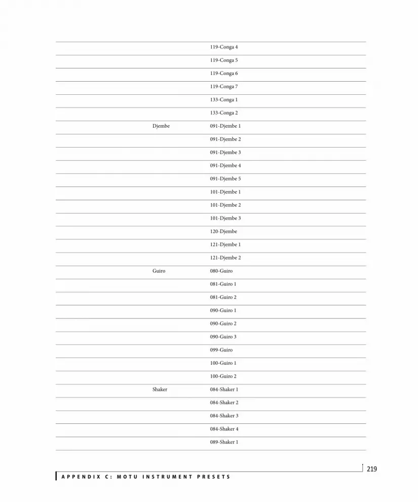
A P P E N D I X C : M O T U I N S T R U M E N T P R E S E T S219
119-Conga 4
119-Conga 5
119-Conga 6
119-Conga 7
133-Conga 1
133-Conga 2
Djembe 091-Djembe 1
091-Djembe 2
091-Djembe 3
091-Djembe 4
091-Djembe 5
101-Djembe 1
101-Djembe 2
101-Djembe 3
120-Djembe
121-Djembe 1
121-Djembe 2
Guiro 080-Guiro
081-Guiro 1
081-Guiro 2
090-Guiro 1
090-Guiro 2
090-Guiro 3
099-Guiro
100-Guiro 1
100-Guiro 2
Shaker 084-Shaker 1
084-Shaker 2
084-Shaker 3
084-Shaker 4
089-Shaker 1

A P P E N D I X C : M O T U I N S T R U M E N T P R E S E T S220
089-Shaker 2
089-Shaker 3
089-Shaker 4
089-Shaker 5
089-Shaker 6
089-Shaker 7
089-Shaker 8
094-Shaker 1
094-Shaker 2
094-Shaker 3
094-Shaker 4
094-Shaker 5
094-Shaker 6
100-Shaker 1
100-Shaker 2
100-Shaker 3
Tambourine 085-Tambourine
089-Tambourine
094-Tambourine
095-Tambourine
119-Tambourine 1
119-Tamboruine 2
134-Tambourine
Triangle 089-Triangle 1
089-Triangle 2
089-Triangle 3
089-Triangle 4
100-Triangle 1
100-Triangle 2
100-Triangle 3
101-Triangle

A P P E N D I X C : M O T U I N S T R U M E N T P R E S E T S221
119-Triangle 1
119-Triangle 2
119-Triangle 3
119-Triangle 4
Reggae-Dub 063-Rasatafari
080-Digi Soul
080-Roots
080-Stylee
080-United
086-Loop
098-Loop 1
098-Loop 2
098-RaggaUK
101-Loop
108-Loop
110-Tripragga 1
110-Tripragga 2
113-RaggaUK
116-N.Jamaican
126-Freaks
131-Jamaican 1
133-Ragga2000 1
133-Raggadance 2
136-Loop 1
136-Loop 2
150-Jamaican 1
150-Jamaican 2
150-Jamaican 3
152-Jamaican 1
152-Jamaican 2
157-Tripragga 1

A P P E N D I X C : M O T U I N S T R U M E N T P R E S E T S222
157-Tripragga 2
160-Bill
160-Future Jazz
160-Organic
160-Raggadance
160-Strangled
170-Futuragga
175-Futuragga
Trip Hop 056-Brush
062-Bizar
063-Overdoze
063-Phaser
064-Big
064-Out
065-Dead
065-Making
065-Mil. Polic
065-Strange
066-Cow Boy
066-Filter
066-Zeus
068-Dark
068-Sea
070-Mother
070-Shadow
071-Regret
072-PackMan
074-Devil
Big Beat Scene
Disco Scene
Drum & Bass Scene

A P P E N D I X C : M O T U I N S T R U M E N T P R E S E T S223
Drumloops Brushed Scene
Drumloops Funk Scene
Drumloops Premium Scene
Drumloops Rock Scene
Electro Scene
Funk Scene
Industrial Scene
Instruments Scene
Jungle Scene
Old Hip-Hop Scene
Percussion Scene
Reggae-Dub Scene
Trip-Hop Scene
01 Piano & co Acoustic pianos Concert Grnd Piano
Concert Grnd PianoFX
Concert Grnd Pno Classical
Concert Grnd Pno Dark
Concert Grnd Pno Prepared
Concert Grnd Pno Rock
Concert Grnd Pno Ultra Rock
Real Detuned Piano
Virtual Detuned Piano
Electric pianos Classic EP Di
Classic EP DiSoft
Classic EP DiTremoHard
Classic EP with Amp
Classic EP with AmpChorus
Classic EP with AmpMedium
Classic EP with AmpTremolo
Jojo Electric Piano
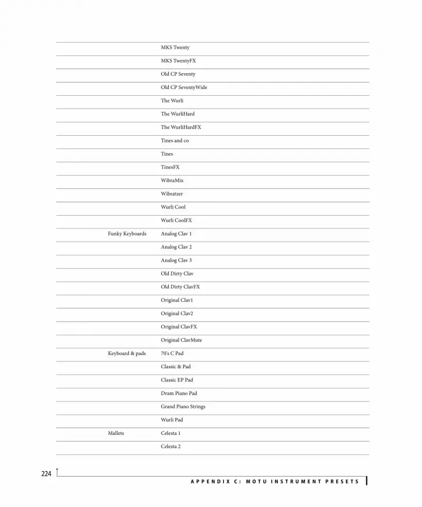
A P P E N D I X C : M O T U I N S T R U M E N T P R E S E T S224
MKS Twenty
MKS TwentyFX
Old CP Seventy
Old CP SeventyWide
The Wurli
The WurliHard
The WurliHardFX
Tines and co
Tines
TinesFX
WibraMix
Wibratzer
Wurli Cool
Wurli CoolFX
Funky Keyboards Analog Clav 1
Analog Clav 2
Analog Clav 3
Old Dirty Clav
Old Dirty ClavFX
Original Clav1
Original Clav2
Original ClavFX
Original ClavMute
Keyboard & pads 70's C Pad
Classic & Pad
Classic EP Pad
Dram Piano Pad
Grand Piano Strings
Wurli Pad
Mallets Celesta 1
Celesta 2

A P P E N D I X C : M O T U I N S T R U M E N T P R E S E T S225
Glockenspiel
Marimba
Music Box
Vibraphone 1
Vibraphone 2
Xylophone
02 Organ Church Clarinet
Cornet
Flute-Gedeckt
Foundation 8-4-1
Gedeckt 8
Medium Church Organ
Pedal-18-8-4
Pedal-Tutti
Plein Jeux 16 Great Organ
Principal
Trombone 16
Trompette
Unda Maris
Viol 8-4-2
Electric Baby Jazz
Best Regards
Black Fading
Convention
Deep & sweet
El Organ
Eye K up
Fruity Flute
Hard Pop
Intimate
Italian Organ

A P P E N D I X C : M O T U I N S T R U M E N T P R E S E T S226
Jazz DI
M hundred
Mistycal
Mr Fletcher
Old Fashion
On the Beach
Over the moon
Pollux
Really Full
Seventies
Standard Jazz
Suitcase Perc
The H 1
The H 2
The H 3
Vibration
03 Acoustic Guitar Classical Guitar Classical Guitar
Classical GuitarHard
Classical GuitarWide
Guild Guild
GuildHard
GuildMedium
GuildSoft
GuildWide
Martin Martin
MartinHard
MartinMedium
MartinSoft
MartinWide
Misc Dobro
DobroSoft

A P P E N D I X C : M O T U I N S T R U M E N T P R E S E T S227
Gerome
GeromeHard
Pads Guitar 12 Strings Pad
Classical New Age
Guildy Pad
Marhu Pad
Martin Aubry Pad
Spanish Guitar Mahura
MahuraHard
MahuraMedium
MahuraSoft
MahuraWide
Spanish Guitar
Spanish GuitarHard
Twelve Strings Twelve Strings
Twelve StringsHard
Twelve StringsSoft
Twelve StringsWide
04 Electric Guitar Clean LesP Twin
LesP TwinHard
Strat DI
Strat DIHard
Strat DIMedium
Strat DISoft
Strat Jazz Chrs
Strat St Rev
Strat St RevHard
Strat Twin Reverb
Crunch & Distortion LesP Marschall
LesP TwinFX
Strat Crunch

A P P E N D I X C : M O T U I N S T R U M E N T P R E S E T S228
Strat CrunchHard
Strat CrunchMedium
Strat CrunchSoft
Strat DI FX1
Strat DI FX2
Strat with Distortion 1
Strat with Distortion 2
Jazz Guitar Jazz Guitar 1
Jazz Guitar 1Oct
Jazz Guitar 2
Jazz Guitar 2Oct
Jazz Mix
Jazz MixOct
Mute Gibs 335 Autowah 1
Gibs 335 Autowah 2
Gibs 335 Twin 1
Gibs 335 Twin 2
Strat DI Hush 1
Strat DI Hush 2
Strat Fuzzface 1
Strat Fuzzface 2
Strat Twin 1
Strat Twin 2
05 Bass Acoustic Bass Acoustic Bass
Acoustic BassFX
Acoustic BassHard
Acoustic BassHardFX
Dark Double Bass
Dark Double BassFX
Electric Bass Fretless Fretless Normal
Fretless NormalFX
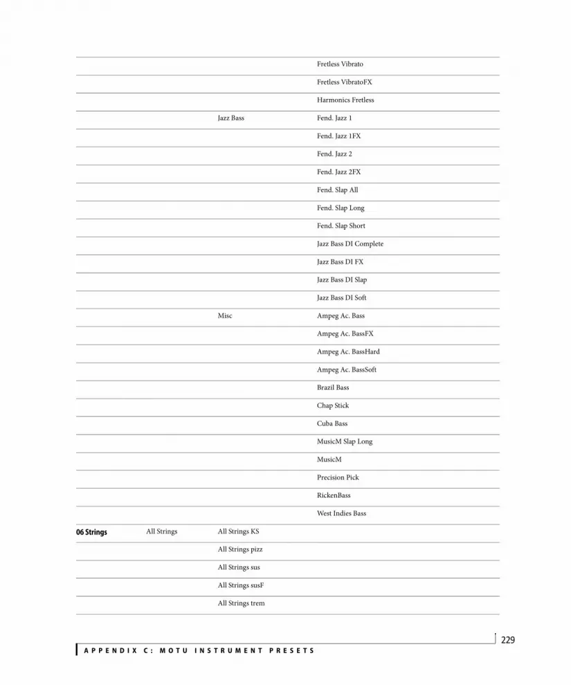
A P P E N D I X C : M O T U I N S T R U M E N T P R E S E T S229
Fretless Vibrato
Fretless VibratoFX
Harmonics Fretless
Jazz Bass Fend. Jazz 1
Fend. Jazz 1FX
Fend. Jazz 2
Fend. Jazz 2FX
Fend. Slap All
Fend. Slap Long
Fend. Slap Short
Jazz Bass DI Complete
Jazz Bass DI FX
Jazz Bass DI Slap
Jazz Bass DI Soft
Misc Ampeg Ac. Bass
Ampeg Ac. BassFX
Ampeg Ac. BassHard
Ampeg Ac. BassSoft
Brazil Bass
Chap Stick
Cuba Bass
MusicM Slap Long
MusicM
Precision Pick
RickenBass
West Indies Bass
06 Strings All Strings All Strings KS
All Strings pizz
All Strings sus
All Strings susF
All Strings trem

A P P E N D I X C : M O T U I N S T R U M E N T P R E S E T S230
Quartet
QuartetPad
Strings Ensemble 1
Strings Ensemble 2
Tutti Strings sus
Tutti Strings susF
tutti Strings susP
Celli Celli sus all
Celli sus f
Celli sus p
Cello KS
Cello marc
Cello pizz
Cello sus all
Cello sus f
Cello sus mf
Cello sus p
Contrabasses Contrabass KS
Contrabass marc
Contrabass sus all
Contrabass sus f
Contrabass sus p
Contrabass KS
Contrabasses pizz
Contrabasses sus all
Contrabasses sus f
Contrabasses sus p
Violas Viola KS
Viola marc
Viola pizz
Viola sus all

A P P E N D I X C : M O T U I N S T R U M E N T P R E S E T S231
Viola sus f
Viola sus p
Violas KS
Violas pizz
Violas sus all
Violas sus f
Violas sus p
Violins Violin KS
Violin marc
Violin pizz
Violin sus all
Violin sus f
Violin sus p
Violins KS
Violins pizz
Violins sus all
Violins sus f
Violins sus p
07 Misc Classical Classical Cymbals
Classical Gran cassa
Classical Snare Drums
Harp Classical
Harp Koto
Harp Soft
Harp Wide
Harpsichord 1
Harpsichord 2
Timpani hits
Timpani roll
Tutti Orchestra stac
Tutti Orchestra sus

A P P E N D I X C : M O T U I N S T R U M E N T P R E S E T S232
08 Brass French Horns French Horn sus all
French Horn sus f
French Horn sus mf
French Horn sus p
French Horns stac 1
French Horns stac 2
French Horns sus all
French Horns sus f
French Horns sus p
Misc Tuba sus all
Tuba sus f
Tuba sus p
Tutti Brass stac
Tutti Brass stac
Tutti Brass sus
Riffs Brass Riff 091 Bpm
Brass Riff 108 Bpm A
Brass Riff 108 Bpm B
Brass Riff 111 Bpm
Brass Riff 131 Bpm
Saxophones Sax Alto
Sax Baritone
Sax Bass
Sax Soprano
Sax Tenor
Trombones Trombone mute all
Trombone mute f
Trombone mute p
Trombone sus all
Trombone sus f
Trombone sus p

A P P E N D I X C : M O T U I N S T R U M E N T P R E S E T S233
Trombones stac
Trombones sus
Trumpets Trumpet 1
Trumpet 2
Trumpet 3
Trumpet mute all
Trumpet mute f
Trumpet mute p
Trumpets accent all
Trumpets accent f
Trumpets accent mf
Trumpets accent p
Trumpets stac all
Trumpets stac f
Trumpets stac mf
Trumpets stac p
Trumpets sus all
Trumpets sus f
Trumpets sus mf
Trumpets sus p
09 Woodwinds Bassoon all
Bassoon f
Bassoon p
Clarinet all
Clarinet f
Clarinet p
English Horn all
English Horn f
English Horn p
Flute all
Flute f

A P P E N D I X C : M O T U I N S T R U M E N T P R E S E T S234
Flute p
Oboe all
Oboe f
Oboe p
Piccolo all
Piccolo f
Piccolo p
10 Ethnic Accordion 1
Accordion 2
Accordion 3
Accordion Bandoneon
Accordion Musette
Baglamas sus
Baglamas trem
Balafon 1
Balafon 2
Bamboo Flute 1
Bamboo Flute 2
Banjo 1
Banjo 2
Cymbalum 1
Cymbalum 2
Flute Indouh
Harmonica 1
Harmonica 2
Indian Harmonium
Koto 1
Koto 2
Koto 3
Mandolin
Ocarina

A P P E N D I X C : M O T U I N S T R U M E N T P R E S E T S235
Oud sus
Pan Flute 1
Pan Flute 2
Recorder
Sanza 1
Sanza 2
Sanza Luba 1
Sanza Luba 2
Shakuhachi 1
Shakuhachi 2
Shamisen 1
Shamisen 2
Sitar 1
Sitar 2
Sitar Hybrid
Steel Drums
Tambura
Whistle
11 Choirs Male Ahs sus
Male Ohs sus
Mixed Choirs Ahs sus 1
Mixed Choirs Ahs sus 2
Religious Fem Ahs sus
Religious Fem Ohs sus
Religious Mix Ahs sus
12 Percussion Agogos
Berimbau
Bongos
Cabassa
Cajon
Castanets
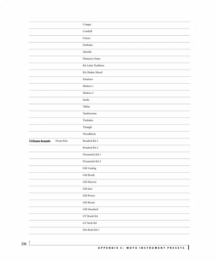
A P P E N D I X C : M O T U I N S T R U M E N T P R E S E T S236
Congas
Cowbell
Cuicas
Darbuka
Djembe
Flamenco Steps
Kit-Latin Tradition
Kit-Shaker Mood
Pandeiro
Shakers 1
Shakers 2
Surdo
Tablas
Tambourine
Timbales
Triangle
Woodblock
13 Drums Acoustic Drum Kits Brushed Kit 1
Brushed Kit 2
Drumstick Kit 1
Drumstick Kit 2
GM Analog
GM Brush
GM Electric
GM Jazz
GM Power
GM Room
GM Standard
GT Brush Kit
GT Stick Kit
Hot Rods Kit 1

A P P E N D I X C : M O T U I N S T R U M E N T P R E S E T S237
Hot Rods Kit 2
Jazz Kit
Raw Kit 01
Raw Kit 02
Raw Kit 03
Raw Kit 04
Raw Kit 05
Raw Kit 06
Raw Kit 07
Raw Kit 08
Raw Kit 09
Raw Kit 10
Raw Kit 11
Raw Kit 12
Sorted Elements Bass Drum B0-C1 BD Brushed Kit 1
BD Brushed Kit 2
BD Drumstick Kit 1
BD Drumstick Kit 2
BD GM Analog
BD GM Brush
BD GM Electric
BD GM Jazz
BD GM Power
BD GM Room
BD GM Standard
BD GT Brush Kit
BD GT Stick Kit
BD Hot Rods Kit 1
BD Hot Rods Kit 2
BD Jazz Kit
BD Raw Kit 01

A P P E N D I X C : M O T U I N S T R U M E N T P R E S E T S238
BD Raw Kit 02
BD Raw Kit 03
BD Raw Kit 04
BD Raw Kit 05
BD Raw Kit 06
BD Raw Kit 07
BD Raw Kit 08
BD Raw Kit 09
BD Raw Kit 10
BD Raw Kit 11
BD Raw Kit 12
Crash C#2 CC Brushed Kit 1
CC Brushed Kit 2
CC Drumstick Kit 1
CC Drumstick Kit 2
CC GM Analog
CC GM Brush
CC GM Electric
CC GM Jazz
CC GM Power
CC GM Room
CC GM Standard
CC GT Brush Kit
CC GT Stick Kit
CC Hot Rods Kit 1
CC Hot Rods Kit 2
CC Jazz Kit
CC Raw Kit 01
CC Raw Kit 02
CC Raw Kit 03
CC Raw Kit 04
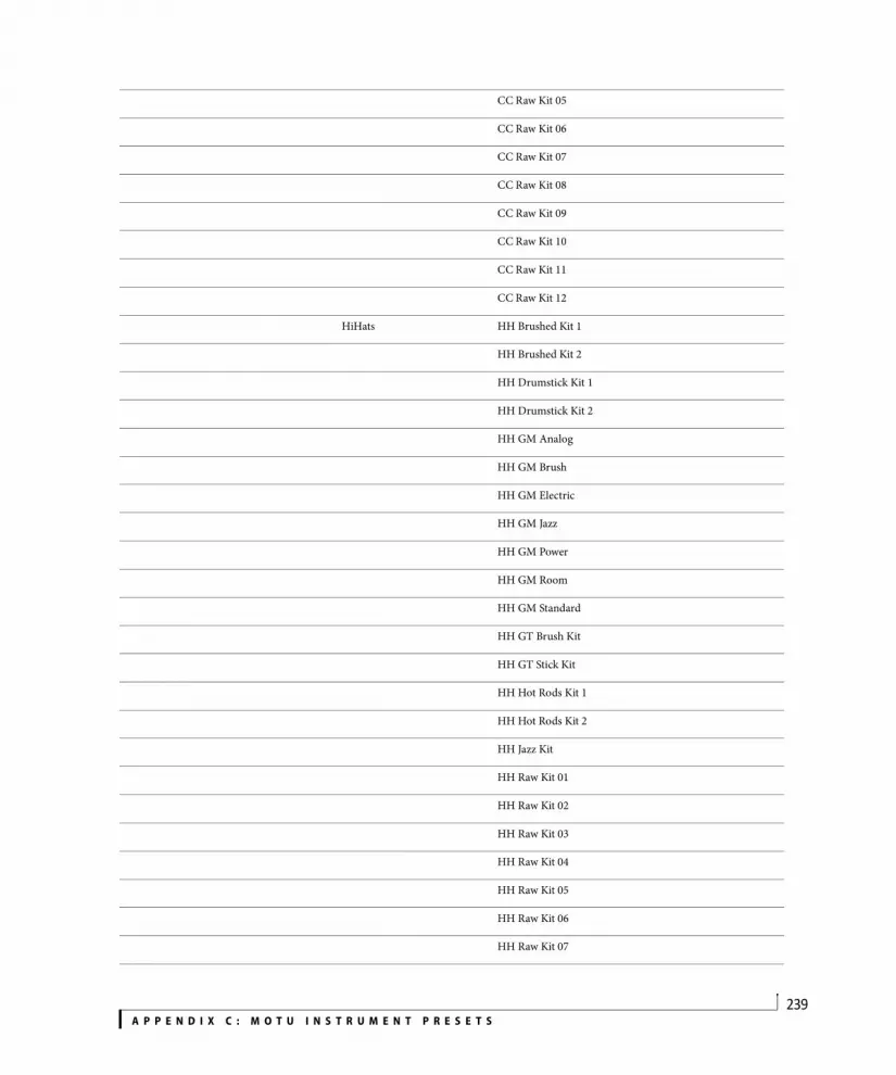
A P P E N D I X C : M O T U I N S T R U M E N T P R E S E T S239
CC Raw Kit 05
CC Raw Kit 06
CC Raw Kit 07
CC Raw Kit 08
CC Raw Kit 09
CC Raw Kit 10
CC Raw Kit 11
CC Raw Kit 12
HiHats HH Brushed Kit 1
HH Brushed Kit 2
HH Drumstick Kit 1
HH Drumstick Kit 2
HH GM Analog
HH GM Brush
HH GM Electric
HH GM Jazz
HH GM Power
HH GM Room
HH GM Standard
HH GT Brush Kit
HH GT Stick Kit
HH Hot Rods Kit 1
HH Hot Rods Kit 2
HH Jazz Kit
HH Raw Kit 01
HH Raw Kit 02
HH Raw Kit 03
HH Raw Kit 04
HH Raw Kit 05
HH Raw Kit 06
HH Raw Kit 07

A P P E N D I X C : M O T U I N S T R U M E N T P R E S E T S240
HH Raw Kit 08
HH Raw Kit 09
HH Raw Kit 10
HH Raw Kit 11
HH Raw Kit 12
Ride D#2 RIDE Brushed Kit 1
RIDE Brushed Kit 2
RIDE Drumstick Kit 1
RIDE Drumstick Kit 2
RIDE GM Analog
RIDE GM Brush
RIDE GM Electric
RIDE GM Jazz
RIDE GM Power
RIDE GM Room
RIDE GM Standard
RIDE GT Brush Kit
RIDE GT Stick Kit
RIDE Hot Rods Kit 1
RIDE Hot Rods Kit 2
RIDE Jazz Kit
RIDE Raw Kit 01
RIDE Raw Kit 02
RIDE Raw Kit 03
RIDE Raw Kit 04
RIDE Raw Kit 05
RIDE Raw Kit 06
RIDE Raw Kit 07
RIDE Raw Kit 08
RIDE Raw Kit 09
RIDE Raw Kit 10

A P P E N D I X C : M O T U I N S T R U M E N T P R E S E T S241
RIDE Raw Kit 11
RIDE Raw Kit 12
Rim C#1 RIM Brushed Kit 1
RIM Brushed Kit 2
RIM Drumstick Kit 1
RIM Drumstick Kit 2
RIM GM Analog
RIM GM Brush
RIM GM Electric
RIM GM Jazz
RIM GM Power
RIM GM Room
RIM GM Standard
RIM GT Brush Kit
RIM GT Stick Kit
RIM Hot Rods Kit 1
RIM Hot Rods Kit 2
RIM Jazz Kit
RIM Raw Kit 01
RIM Raw Kit 02
RIM Raw Kit 03
RIM Raw Kit 04
RIM Raw Kit 05
RIM Raw Kit 06
RIM Raw Kit 07
RIM Raw Kit 08
RIM Raw Kit 09
RIM Raw Kit 10
RIM Raw Kit 11
RIM Raw Kit 12
Rim D#1 CLAP Brushed Kit 1

A P P E N D I X C : M O T U I N S T R U M E N T P R E S E T S242
CLAP Brushed Kit 2
CLAP Drumstick Kit 1
CLAP Drumstick Kit 2
CLAP GM Analog
CLAP GM Brush
CLAP GM Electric
CLAP GM Jazz
CLAP GM Power
CLAP GM Room
CLAP GM Standard
CLAP GT Brush Kit
CLAP GT Stick Kit
CLAP Hot Rods Kit 1
CLAP Hot Rods Kit 2
CLAP Jazz Kit
CLAP Raw Kit 01
CLAP Raw Kit 02
CLAP Raw Kit 03
CLAP Raw Kit 04
CLAP Raw Kit 05
CLAP Raw Kit 06
CLAP Raw Kit 07
CLAP Raw Kit 08
CLAP Raw Kit 09
CLAP Raw Kit 10
CLAP Raw Kit 11
CLAP Raw Kit 12
Snares D1 SD1 Brushed Kit 1
SD1 Brushed Kit 2
SD1 Drumstick Kit 1
SD1 Drumstick Kit 2

A P P E N D I X C : M O T U I N S T R U M E N T P R E S E T S243
SD1 GM Analog
SD1 GM Brush
SD1 GM Electric
SD1 GM Jazz
SD1 GM Power
SD1 GM Room
SD1 GM Standard
SD1 GT Brush Kit
SD1 GT Stick Kit
SD1 Hot Rods Kit 1
SD1 Hot Rods Kit 2
SD1 Jazz Kit
SD1 Raw Kit 01
SD1 Raw Kit 02
SD1 Raw Kit 03
SD1 Raw Kit 04
SD1 Raw Kit 05
SD1 Raw Kit 06
SD1 Raw Kit 07
SD1 Raw Kit 08
SD1 Raw Kit 09
SD1 Raw Kit 10
SD1 Raw Kit 11
SD1 Raw Kit 12
Snares E1 SD2 Brushed Kit 1
SD2 Brushed Kit 2
SD2 Drumstick Kit 1
SD1 Drumstick Kit 2
SD2 GM Analog
SD2 GM Brush
SD2 GM Electric

A P P E N D I X C : M O T U I N S T R U M E N T P R E S E T S244
SD2 GM Jazz
SD2 GM Power
SD2 GM Room
SD2 GM Standard
SD2 GT Brush Kit
SD2 GT Stick Kit
SD2 Hot Rods Kit 1
SD2 Hot Rods Kit 2
SD2 Jazz Kit
SD2 Raw Kit 01
SD2 Raw Kit 02
SD2 Raw Kit 03
SD2 Raw Kit 04
SD2 Raw Kit 05
SD2 Raw Kit 06
SD2 Raw Kit 07
SD2 Raw Kit 08
SD2 Raw Kit 09
SD2 Raw Kit 10
SD2 Raw Kit 11
SD2 Raw Kit 12
Toms TOM Brushed Kit 1
TOM Brushed Kit 2
TOM Drumstick Kit 1
SD1 Drumstick Kit 2
TOM GM Analog
TOM GM Brush
TOM GM Electric
TOM GM Jazz
TOM GM Power
TOM GM Room

A P P E N D I X C : M O T U I N S T R U M E N T P R E S E T S245
TOM GM Standard
TOM GT Brush Kit
TOM GT Stick Kit
TOM Hot Rods Kit 1
TOM Hot Rods Kit 2
TOM Jazz Kit
TOM Raw Kit 01
TOM Raw Kit 02
TOM Raw Kit 03
TOM Raw Kit 04
TOM Raw Kit 05
TOM Raw Kit 06
TOM Raw Kit 07
TOM Raw Kit 08
TOM Raw Kit 09
TOM Raw Kit 10
TOM Raw Kit 11
TOM Raw Kit 12
All BD
All CC
All HH
All Rides
All SD
All Toms
14 Drums Electronic Electronic & Machines 6 Months Kit
80's Drum Kit
400 Kit
500 Kit
600 Kit
800 Kit
900 Kit
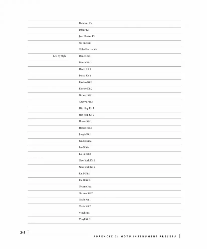
A P P E N D I X C : M O T U I N S T R U M E N T P R E S E T S246
D-tation Kit
Dfour Kit
Jam Electro Kit
SD one Kit
Tribe Electro Kit
Kits by Style Dance Kit 1
Dance Kit 2
Disco Kit 1
Disco Kit 2
Electro Kit 1
Electro Kit 2
Groove Kit 1
Groove Kit 2
Hip Hop Kit 1
Hip Hop Kit 2
House Kit 1
House Kit 2
Jungle Kit 1
Jungle Kit 2
Lo-Fi Kit 1
Lo-Fi Kit 2
New York Kit 1
New York Kit 2
R'n B Kit 1
R'n B Kit 2
Techno Kit 1
Techno Kit 2
Trash Kit 1
Trash Kit 2
Vinyl Kit 1
Vinyl Kit 2

A P P E N D I X C : M O T U I N S T R U M E N T P R E S E T S247
Process Drums FX Kit 1
FX Kit 2
Mpc Percs
T-Air Percs
Vinyl Kit
Vinyl Sounds
Sorted Elements Bass Drum B0-C1 BD Electronic & Machines
BD 6 Months Kit
BD 80's Drum Kit
BD 400 Kit
BD 500 Kit
BD 600 Kit
BD 800 Kit
BD 900 Kit
BD D-tation Kit
BD Dfour Kit
BD Jam Electro Kit
BD SD one Kit
BD Tribe Electro Kit
BD Hip Hop Kits BD 01-Timba Maxi Kit 01
BD 02-Timba Maxi Kit 02
BD 03-Timba Maxi Kit 03
BD 04-Funk Maxi Kit 01
BD 05-M&M Maxi Kit 01
BD 06-R'n B Maxi Kit 01
BD 07-R'n B Maxi Kit 02
BD 08-R'n B Maxi Kit 03
BD 09-Hip Hop Maxi Kit 01
BD 10-Hip Hop Maxi Kit 02
BD 11-Hip Hop Maxi Kit 03
BD 12-Hip Hop Maxi Kit 04
BD Kits by Style BD Dance Kit 1

A P P E N D I X C : M O T U I N S T R U M E N T P R E S E T S248
BD Dance Kit 2
BD Disco Kit 1
BD Disco Kit 2
BD Electro Kit 1
BD Electro Kit 2
BD Groove Kit 1
BD Groove Kit 2
BD Hip Hop Kit 1
BD Hip Hop Kit 2
BD House Kit 1
BD House Kit 2
BD Jungle Kit 1
BD Jungle Kit 2
BD Lo-Fi Kit 1
BD Lo-Fi Kit 2
BD New York Kit 1
BD New York Kit 2
BD R'n B Kit 1
BD R'n B Kit 2
BD Techno Kit 1
BD Techno Kit 2
BD Trash Kit 1
BD Trash Kit 2
BD Vinyl Kit 1
BD Vinyl Kit 2
BD Synth Bonus BD Fx Kit 1
BD FX Kit 2
BD Vinyl Kit
Crash C#2 CC Electronic & Machines
CC 6 Months Kit
CC 80's Drum Kit
CC 400 Kit

A P P E N D I X C : M O T U I N S T R U M E N T P R E S E T S249
CC 500 Kit
CC 600 Kit
CC 800 Kit
CC 900 Kit
CC D-tation Kit
CC Dfour Kit
CC Jam Electro Kit
CC Tribe Electro Kit
CC Hip Hop Kits CC 01-Timba Maxi Kit 01
CC 02-Timba Maxi Kit 02
CC 03-Timba Maxi Kit 03
CC 04-Funk Maxi Kit 01
CC 06-R'n B Maxi Kit 01
CC 07-R'n B Maxi Kit 02
CC 09-Hip Hop Maxi Kit 01
CC 10-Hip Hop Maxi Kit 02
CC 11-Hip Hop Maxi Kit 03
CC 12-Hip Hop Maxi Kit 04
CC Kits by Style CC Dance Kit 1
CC Dance Kit 2
CC Electro Kit 1
CC Electro Kit 2
CC Groove Kit 1
CC Groove Kit 2
CC Hip Hop Kit 1
CC House Kit 1
CC House Kit 2
CC R'n B Kit 1
CC Techno Kit 1
CC Techno Kit 2
CC Trash Kit 1

A P P E N D I X C : M O T U I N S T R U M E N T P R E S E T S250
CC Trash Kit 2
CC Synth Bonus CC Fx Kit 1
CC Fx Kit 2
CC Vinyl Kit
HiHats HH Electronic & Machines
HH 6 Months Kit
HH 80's Drum Kit
HH 400 Kit
HH 500 Kit
HH 600 Kit
HH 800 Kit
HH 900 Kit
HH D-tation Kit
HH Dfour Kit
HH Jam Electro Kit
HH SD one Kit
HH Tribe Electro Kit
HH Hip Hop Kits HH 01-Timba Maxi Kit 01
HH 02-Timba Maxi Kit 02
HH 03-Timba Maxi Kit 03
HH 04-Funk Maxi Kit 01
HH 05-M&M Maxi Kit 01
HH 06-R'n B Maxi Kit 01
HH 08-R'n B Maxi Kit 03
HH 09-Hip Hop Maxi Kit 01
HH 10-Hip Hop Maxi Kit 02
HH 11-Hip Hop Maxi Kit 03
HH 12-Hip Hop Maxi Kit 04
HH Kits by Style HH Dance Kit 1
HH Dance Kit 2
HH Disco Kit 1
HH Disco Kit 2

A P P E N D I X C : M O T U I N S T R U M E N T P R E S E T S251
HH Electro Kit 1
HH Electro Kit 2
HH Groove Kit 1
HH Groove Kit 2
HH Hip Hop Kit 1
HH Hip Hop Kit 2
HH House Kit 1
HH House Kit 2
HH Jungle Kit 1
HH Jungle Kit 2
HH Lo-Fi Kit 1
HH Lo-Fi Kit 2
HH New York Kit 1
HH New York Kit 2
HH R'n B Kit 1
HH R'n B Kit 2
HH Techno Kit 1
HH Techno Kit 2
HH Trash Kit 1
HH Trash Kit 2
HH Vinyl Kit 1
HH Vinyl Kit 2
HH Synth Bonus HH Fx Kit 1
HH Fx Kit 2
HH Vinyl Kit
HH Vinyl Sounds
Ride D#2 RIDE Electronic & Machines
RIDE 6 Months Kit
RIDE 80's Drum Kit
RIDE 400 Kit
RIDE 500 Kit
RIDE 600 Kit

A P P E N D I X C : M O T U I N S T R U M E N T P R E S E T S252
RIDE 800 Kit
RIDE 900 Kit
RIDE D-tation Kit
RIDE Dfour Kit
RIDE Jam Electro Kit
RIDE SD one Kit
RIDE Tribe Electro Kit
RIDE Hip Hop Kits RIDE 02-Timba Maxi Kit 02
RIDE 04-Funk Maxi Kit 01
RIDE 05-M&M Maxi Kit 01
RIDE 11-Hip Hop Maxi Kit 03
RIDE 12-Hip Hop Maxi Kit 04
RIDE Kits by Style RIDE Dance Kit 1
RIDE Dance Kit 2
RIDE Electro Kit 1
RIDE Electro Kit 2
RIDE Groove Kit 1
RIDE Groove Kit 2
RIDE Hip Hop Kit 2
RIDE House Kit 1
RIDE House Kit 2
RIDE R'n B Kit 2
RIDE Techno Kit 1
RIDE Techno Kit 2
RIDE Trash Kit 1
RIDE Trash Kit 2
RIDE Synth Bonus RIDE Fx Kit 1
RIDE Fx Kit 2
RIDE Vinyl Kit
Rim C#1 RIM Electronic & Machines
RIM 6 Months Kit
RIM 80's Drum Kit

A P P E N D I X C : M O T U I N S T R U M E N T P R E S E T S253
RIM 400 Kit
RIM 500 Kit
RIM 600 Kit
RIM 800 Kit
RIM 900 Kit
RIM D-tation Kit
RIM Dfour Kit
RIM Jam Electro Kit
RIM SD one Kit
RIM Tribe Electro Kit
RIM Hip Hop Kits RIM 03-Timba Maxi Kit 03
RIM 05-M&M Maxi Kit 01
RIM 06-R'n B Maxi Kit 01
RIM Kits by Style RIM Dance Kit 1
RIM Dance Kit 2
RIM Electro Kit 1
RIM Electro Kit 2
RIM Groove Kit 1
RIM Groove Kit 2
RIM House Kit 1
RIM House Kit 2
RIM Techno Kit 1
RIM Techno Kit 2
RIM Trash Kit 1
RIM Trash Kit 2
RIM Synth Bonus RIM Fx Kit 1
RIM Fx Kit 2
RIM Vinyl Kit
RIM Vinyl Sounds
Rim D#1 CLAP Electronic & Machines
CLAP 6 Months Kit
CLAP 80's Drum Kit
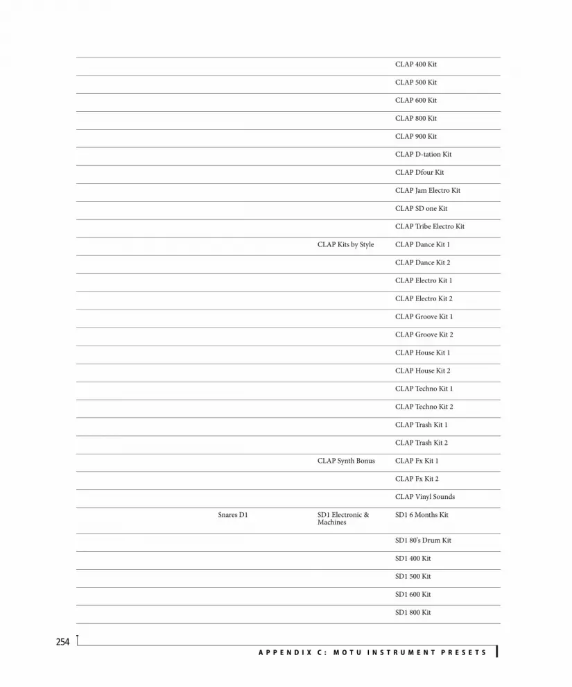
A P P E N D I X C : M O T U I N S T R U M E N T P R E S E T S254
CLAP 400 Kit
CLAP 500 Kit
CLAP 600 Kit
CLAP 800 Kit
CLAP 900 Kit
CLAP D-tation Kit
CLAP Dfour Kit
CLAP Jam Electro Kit
CLAP SD one Kit
CLAP Tribe Electro Kit
CLAP Kits by Style CLAP Dance Kit 1
CLAP Dance Kit 2
CLAP Electro Kit 1
CLAP Electro Kit 2
CLAP Groove Kit 1
CLAP Groove Kit 2
CLAP House Kit 1
CLAP House Kit 2
CLAP Techno Kit 1
CLAP Techno Kit 2
CLAP Trash Kit 1
CLAP Trash Kit 2
CLAP Synth Bonus CLAP Fx Kit 1
CLAP Fx Kit 2
CLAP Vinyl Sounds
Snares D1 SD1 Electronic & Machines
SD1 6 Months Kit
SD1 80's Drum Kit
SD1 400 Kit
SD1 500 Kit
SD1 600 Kit
SD1 800 Kit

A P P E N D I X C : M O T U I N S T R U M E N T P R E S E T S255
SD1 900 Kit
SD1 D-tation Kit
SD1 Dfour Kit
SD1 Jam Electro Kit
SD1 SD one Kit
SD1 Tribe Electro Kit
SD1 Hip Hop Kits SD1 01-Timba Maxi Kit 01
SD1 02-Timba Maxi Kit 02
SD1 03-Timba Maxi Kit 03
SD1 04-Funk Maxi Kit 01
SD1 05-M&M Maxi Kit 01
SD1 06-R'n B Maxi Kit 01
SD1 07-R'n B Maxi Kit 02
SD1 08-R'n B Maxi Kit 03
SD1 09-Hip Hop Maxi Kit 01
SD1 10-Hip Hop Maxi Kit 02
SD1 11-Hip Hop Maxi Kit 03
SD1 12-Hip Hop Maxi Kit 04
SD1 Kits by Style SD1 Dance Kit 1
SD1 Dance Kit 2
SD1 Disco Kit 1
SD1 Disco Kit 2
SD1 Electro Kit 1
SD1 Electro Kit 2
SD1 Groove Kit 1
SD1 Groove Kit 2
SD1 Hip Hop Kit 1
SD1 Hip Hop Kit 2
SD1 House Kit 1
SD1 House Kit 2
SD1 Jungle Kit 1

A P P E N D I X C : M O T U I N S T R U M E N T P R E S E T S256
SD1 Jungle Kit 2
SD1 Lo-Fi Kit 1
SD1 Lo-Fi Kit 2
SD1 New York Kit 1
SD1 New York Kit 2
SD1 R'n B Kit 1
SD1 R'n B Kit 2
SD1 Techno Kit 1
SD1 Techno Kit 2
SD1 Trash Kit 1
SD1 Trash Kit 2
SD1 Vinyl Kit 1
SD1 Vinyl Kit 2
SD1 Synth Bonus SD1 Fx Kit 1
SD1 Fx Kit 2
Snares E1 SD2 Electronic & Machines
SD2 6 Months Kit
SD2 80's Drum Kit
SD2 400 Kit
SD2 500 Kit
SD2 600 Kit
SD2 800 Kit
SD2 900 Kit
SD2 D-tation Kit
SD2 Dfour Kit
SD2 Jam Electro Kit
SD2 SD one Kit
SD2 Tribe Electro Kit
SD2 Hip Hop Kits SD2 01-Timba Maxi Kit 01
SD2 02-Timba Maxi Kit 02
SD2 03-Timba Maxi Kit 03
SD2 04-Funk Maxi Kit 01

A P P E N D I X C : M O T U I N S T R U M E N T P R E S E T S257
SD2 05-M&M Maxi Kit 01
SD2 06-R'n B Maxi Kit 01
SD2 07-R'n B Maxi Kit 02
SD2 08-R'n B Maxi Kit 03
SD2 09-Hip Hop Maxi Kit 01
SD2 10-Hip Hop Maxi Kit 02
SD2 11-Hip Hop Maxi Kit 03
SD2 12-Hip Hop Maxi Kit 04
SD2 Kits by Style SD2 Dance Kit 1
SD2 Dance Kit 2
SD2 Disco Kit 1
SD2 Disco Kit 2
SD2 Electro Kit 1
SD2 Electro Kit 2
SD2 Groove Kit 1
SD2 Groove Kit 2
SD2 House Kit 1
SD2 House Kit 2
SD2 Jungle Kit 1
SD2 Jungle Kit 2
SD2 Lo-Fi Kit 1
SD2 Lo-Fi Kit 2
SD2 New York Kit 1
SD2 New York Kit 2
SD2 R'n B Kit 1
SD2 R'n B Kit 2
SD2 Techno Kit 1
SD2 Techno Kit 2
SD2 Trash Kit 1
SD2 Trash Kit 2
SD2 Vinyl Kit 1

A P P E N D I X C : M O T U I N S T R U M E N T P R E S E T S258
SD2 Vinyl Kit 2
SD2 Synth Bonus SD2 Fx Kit 1
SD2 FX Kit 2
SD2 Vinyl Kit
Toms TOM Electronic & Machines
TOM 6 Months Kit
TOM 80's Drum Kit
TOM 400 Kit
TOM 500 Kit
TOM 600 Kit
TOM 800 Kit
TOM 900 Kit
TOM D-tation Kit
TOM Dfour Kit
TOM Jam Electro Kit
TOM SD one Kit
TOM Tribe Electro Kit
TOM Kits by Style TOM Dance Kit 1
TOM Dance Kit 2
TOM Electro Kit 1
TOM Electro Kit 2
TOM Groove Kit 1
TOM Groove Kit 2
TOM House Kit 1
TOM House Kit 2
TOM Techno Kit 1
TOM Techno Kit 2
TOM Trash Kit 1
TOM Trash Kit 2
TOM Synth Bonus TOM Fx Kit 1
TOM Fx Kit 2
All BD

A P P E N D I X C : M O T U I N S T R U M E N T P R E S E T S259
All CC
All HH
All Rides
All SD
All Toms

A P P E N D I X C : M O T U I N S T R U M E N T P R E S E T S260

APPENDIX
261
D MX4 NRPN Mapping
MX4 parameters can be remotely controlled by MIDI continuous controller data with the following non-registered parameter numbers:
NRPN MX4 parameter that it controls
NRPN 0 Polyphony
NRPN 2 Unison Detuning Mode
NRPN 3 Unison Linear Detuning
NRPN 4 Unison Logarithmic Detuning
NRPN 7 Lower Pitch Bend Range
NRPN 8 Upper Pitch Bend Range
NRPN 9 Polyphonic Mode
NRPN 10 Legato Mode
NRPN 11 Portamento On/Off
NRPN 12 Portamento Mode
NRPN 13 Portamento Time
NRPN 14 Unison Multiplier
NRPN 15 Arpeggiator Enable
NRPN 16 Arpeggiator Pattern
NRPN 17 Arpeggiator Pattern Length
NRPN 18 Arpeggiator Speed
NRPN 19 Arpeggiator Swing
NRPN 20 Arpeggiator Duration
NRPN 21 Arpeggiator Range
NRPN 22 Arpeggiator Direction
NRPN 23 Arpeggiator Hold
NRPN 1000 Osc 1 Waveform
NRPN 1001 Osc 1 Wavetable Index
NRPN 1002 Osc 1 Key-Follow
NRPN 1003 Osc 1 Pitch Offset
NRPN 1004 Osc 1 FM
NRPN 1005 Osc 1 Symmetry
NRPN 1006 Osc 1 Gain
NRPN 1007 Osc 1 Pan
NRPN 1008 Osc 1 Enable
NRPN 1009 Osc 1 Wavetable
NRPN 1020 Osc 2 Waveform
NRPN 1021 Osc 2 Wavetable Index
NRPN 1022 Osc 2 Key-Follow
NRPN 1023 Osc 2 Pitch Offset
NRPN 1024 Osc 2 FM
NRPN 1025 Osc 2 Symmetry
NRPN 1026 Osc 2 Gain
NRPN 1027 Osc 2 Pan
NRPN 1028 Osc 2 Enable
NRPN 1029 Osc 2 Wavetable
NRPN 1040 Osc 3 Waveform
NRPN 1041 Osc 3 Wavetable Index
NRPN 1042 Osc 3 Key-Follow
NRPN 1043 Osc 3 Pitch Offset
NRPN 1044 Osc 3 FM
NRPN 1045 Osc 3 Symmetry
NRPN 1046 Osc 3 Gain
NRPN 1047 Osc 3 Pan
NRPN 1048 Osc 3 Enable
NRPN 1049 Osc 3 Wavetable
NRPN 1100 Pitch Bend Mode
NRPN 1101 Stereo Detuning

A P P E N D I X D : M X 4 N R P N M A P P I N G262
NRPN 1102 Osc Analog Drift Mode
NRPN 1103 Osc 2 Sync
NRPN 1104 Ring Modulation
NRPN 1105 Ring Modulation Pan
NRPN 1106 Fundamental Blend
NRPN 1107 Volume
NRPN 1108 Audio Input Gain
NRPN 1109 Audio Input Enable
NRPN 1110 Audio Input Pan
NRPN 1111 Velocity Sensitivity
NRPN 1112 Filter Layout
NRPN 1113 Distortion Level
NRPN 1114 Filter Mix
NRPN 1115 Stereo Mode
NRPN 1116 Transform 1
NRPN 1117 Transform 2
NRPN 1118 Sample and Hold Rate
NRPN 1119 Sample and Hold Mensural rate
NRPN 1120 Sample and Hold Sync
NRPN 1121 Lag Attack Time
NRPN 1122 Lag Release Time
NRPN 1123 Pattern Seq Speed
NRPN 1124 Pattern Seq Swing
NRPN 1125 Pattern Seq Length
NRPN 1126 Pattern Seq Step 1 Level
NRPN 1127 Pattern Seq Step 2 Level
NRPN 1128 Pattern Seq Step 3 Level
NRPN 1129 Pattern Seq Step 4 Level
NRPN 1130 Pattern Seq Step 5 Level
NRPN 1131 Pattern Seq Step 6 Level
NRPN 1132 Pattern Seq Step 7 Level
NRPN 1133 Pattern Seq Step 8 Level
NRPN 1134 Pattern Seq Step 9 Level
NRPN 1135 Pattern Seq Step 10 Level
NRPN 1136 Pattern Seq Step 11 Level
NRPN 1137 Pattern Seq Step 12 Level
NRPN 1138 Pattern Seq Step 13 Level
NRPN 1139 Pattern Seq Step 14 Level
NRPN 1140 Pattern Seq Step 15 Level
NRPN 1141 Pattern Seq Step 16 Level
NRPN 1142 Quantizer Pitches
NRPN 1143 Quantizer Range
NRPN 1144 Quantizer Mode
NRPN 1145 Envelope Follower Attack
NRPN 1146 Envelope Follower Release
NRPN 1147 Trigger Seq Speed
NRPN 1148 Trigger Seq Swing
NRPN 1149 Trigger Seq Duration
NRPN 1150 Trigger Seq Length
NRPN 1151 Trigger Seq Pattern
NRPN 1200 Filter 1 Mode
NRPN 1201 Filter 1 Order
NRPN 1202 Filter 1 Key-Follow
NRPN 1203 Filter 1 Freq
NRPN 1204 Filter 1 Resonance
NRPN 1205 Filter 1 FM
NRPN 1210 Filter 2 Mode
NRPN 1211 Filter 2 Order
NRPN 1212 Filter 2 Key-Follow
NRPN 1213 Filter 2 Freq
NRPN 1214 Filter 2 Resonance
NRPN 1215 Filter 2 FM
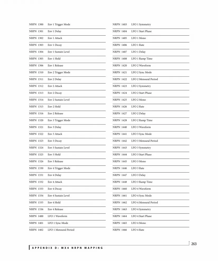
A P P E N D I X D : M X 4 N R P N M A P P I N G263
NRPN 1300 Env 1 Trigger Mode
NRPN 1301 Env 1 Delay
NRPN 1302 Env 1 Attack
NRPN 1303 Env 1 Decay
NRPN 1304 Env 1 Sustain Level
NRPN 1305 Env 1 Hold
NRPN 1306 Env 1 Release
NRPN 1310 Env 2 Trigger Mode
NRPN 1311 Env 2 Delay
NRPN 1312 Env 2 Attack
NRPN 1313 Env 2 Decay
NRPN 1314 Env 2 Sustain Level
NRPN 1315 Env 2 Hold
NRPN 1316 Env 2 Release
NRPN 1320 Env 3 Trigger Mode
NRPN 1321 Env 3 Delay
NRPN 1322 Env 3 Attack
NRPN 1323 Env 3 Decay
NRPN 1324 Env 3 Sustain Level
NRPN 1325 Env 3 Hold
NRPN 1326 Env 3 Release
NRPN 1330 Env 4 Trigger Mode
NRPN 1331 Env 4 Delay
NRPN 1332 Env 4 Attack
NRPN 1333 Env 4 Decay
NRPN 1334 Env 4 Sustain Level
NRPN 1335 Env 4 Hold
NRPN 1336 Env 4 Release
NRPN 1400 LFO 1 Waveform
NRPN 1401 LFO 1 Sync Mode
NRPN 1402 LFO 1 Mensural Period
NRPN 1403 LFO 1 Symmetry
NRPN 1404 LFO 1 Start Phase
NRPN 1405 LFO 1 Mono
NRPN 1406 LFO 1 Rate
NRPN 1407 LFO 1 Delay
NRPN 1408 LFO 1 Ramp Time
NRPN 1420 LFO 2 Waveform
NRPN 1421 LFO 2 Sync Mode
NRPN 1422 LFO 2 Mensural Period
NRPN 1423 LFO 2 Symmetry
NRPN 1424 LFO 2 Start Phase
NRPN 1425 LFO 2 Mono
NRPN 1426 LFO 2 Rate
NRPN 1427 LFO 2 Delay
NRPN 1428 LFO 2 Ramp Time
NRPN 1440 LFO 3 Waveform
NRPN 1441 LFO 3 Sync Mode
NRPN 1442 LFO 3 Mensural Period
NRPN 1443 LFO 3 Symmetry
NRPN 1444 LFO 3 Start Phase
NRPN 1445 LFO 3 Mono
NRPN 1446 LFO 3 Rate
NRPN 1447 LFO 3 Delay
NRPN 1448 LFO 3 Ramp Time
NRPN 1460 LFO 4 Waveform
NRPN 1461 LFO 4 Sync Mode
NRPN 1462 LFO 4 Mensural Period
NRPN 1463 LFO 4 Symmetry
NRPN 1464 LFO 4 Start Phase
NRPN 1465 LFO 4 Mono
NRPN 1466 LFO 4 Rate
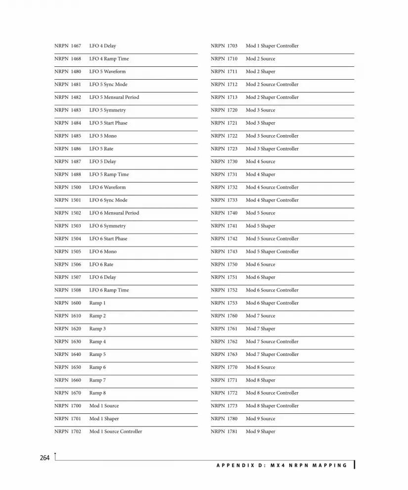
A P P E N D I X D : M X 4 N R P N M A P P I N G264
NRPN 1467 LFO 4 Delay
NRPN 1468 LFO 4 Ramp Time
NRPN 1480 LFO 5 Waveform
NRPN 1481 LFO 5 Sync Mode
NRPN 1482 LFO 5 Mensural Period
NRPN 1483 LFO 5 Symmetry
NRPN 1484 LFO 5 Start Phase
NRPN 1485 LFO 5 Mono
NRPN 1486 LFO 5 Rate
NRPN 1487 LFO 5 Delay
NRPN 1488 LFO 5 Ramp Time
NRPN 1500 LFO 6 Waveform
NRPN 1501 LFO 6 Sync Mode
NRPN 1502 LFO 6 Mensural Period
NRPN 1503 LFO 6 Symmetry
NRPN 1504 LFO 6 Start Phase
NRPN 1505 LFO 6 Mono
NRPN 1506 LFO 6 Rate
NRPN 1507 LFO 6 Delay
NRPN 1508 LFO 6 Ramp Time
NRPN 1600 Ramp 1
NRPN 1610 Ramp 2
NRPN 1620 Ramp 3
NRPN 1630 Ramp 4
NRPN 1640 Ramp 5
NRPN 1650 Ramp 6
NRPN 1660 Ramp 7
NRPN 1670 Ramp 8
NRPN 1700 Mod 1 Source
NRPN 1701 Mod 1 Shaper
NRPN 1702 Mod 1 Source Controller
NRPN 1703 Mod 1 Shaper Controller
NRPN 1710 Mod 2 Source
NRPN 1711 Mod 2 Shaper
NRPN 1712 Mod 2 Source Controller
NRPN 1713 Mod 2 Shaper Controller
NRPN 1720 Mod 3 Source
NRPN 1721 Mod 3 Shaper
NRPN 1722 Mod 3 Source Controller
NRPN 1723 Mod 3 Shaper Controller
NRPN 1730 Mod 4 Source
NRPN 1731 Mod 4 Shaper
NRPN 1732 Mod 4 Source Controller
NRPN 1733 Mod 4 Shaper Controller
NRPN 1740 Mod 5 Source
NRPN 1741 Mod 5 Shaper
NRPN 1742 Mod 5 Source Controller
NRPN 1743 Mod 5 Shaper Controller
NRPN 1750 Mod 6 Source
NRPN 1751 Mod 6 Shaper
NRPN 1752 Mod 6 Source Controller
NRPN 1753 Mod 6 Shaper Controller
NRPN 1760 Mod 7 Source
NRPN 1761 Mod 7 Shaper
NRPN 1762 Mod 7 Source Controller
NRPN 1763 Mod 7 Shaper Controller
NRPN 1770 Mod 8 Source
NRPN 1771 Mod 8 Shaper
NRPN 1772 Mod 8 Source Controller
NRPN 1773 Mod 8 Shaper Controller
NRPN 1780 Mod 9 Source
NRPN 1781 Mod 9 Shaper

A P P E N D I X D : M X 4 N R P N M A P P I N G265
NRPN 1782 Mod 9 Source Controller
NRPN 1783 Mod 9 Shaper Controller
NRPN 1790 Mod 10 Source
NRPN 1791 Mod 10 Shaper
NRPN 1792 Mod 10 Source Controller
NRPN 1793 Mod 10 Shaper Controller
NRPN 1800 Mod 11 Source
NRPN 1801 Mod 11 Shaper
NRPN 1802 Mod 11 Source Controller
NRPN 1803 Mod 11 Shaper Controller
NRPN 1810 Mod 12 Source
NRPN 1811 Mod 12 Shaper
NRPN 1812 Mod 12 Source Controller
NRPN 1813 Mod 12 Shaper Controller
NRPN 1820 Mod 13 Source
NRPN 1821 Mod 13 Shaper
NRPN 1822 Mod 13 Source Controller
NRPN 1823 Mod 13 Shaper Controller
NRPN 1830 Mod 14 Source
NRPN 1831 Mod 14 Shaper
NRPN 1832 Mod 14 Source Controller
NRPN 1833 Mod 14 Shaper Controller
NRPN 1840 Mod 15 Source
NRPN 1841 Mod 15 Shaper
NRPN 1842 Mod 15 Source Controller
NRPN 1843 Mod 15 Shaper Controller
NRPN 1850 Mod 16 Source
NRPN 1851 Mod 16 Shaper
NRPN 1852 Mod 16 Source Controller
NRPN 1853 Mod 16 Shaper Controller
NRPN 1900 Effect 1 Enable
NRPN 1901 Chorus Rate
NRPN 1902 Chorus Delay
NRPN 1903 Chorus Depth
NRPN 1904 Chorus Mix
NRPN 1905 Effect 2 Enable
NRPN 1906 Delay Left Delay Time
NRPN 1907 Delay Right Delay Time
NRPN 1908 Delay Feedback
NRPN 1909 Delay Filter Mode
NRPN 1910 Delay Resonance
NRPN 1911 Delay Left Freq
NRPN 1912 Delay Right Freq
NRPN 1913 Delay Mix
NRPN 1914 Delay Left Mensural Time
NRPN 1915 Delay Right Mensural Time
NRPN 1916 Delay Mensural Mode
NRPN 1917 Effect 1 Mode
NRPN 1918 Effect 2 Mode
NRPN 1919 Flanger Rate
NRPN 1920 Flanger Depth
NRPN 1921 Flanger Feedback
NRPN 1922 Flanger Mix
NRPN 1923 Phaser Rate
NRPN 1924 Phaser Depth
NRPN 1925 Phaser Width
NRPN 1926 Phaser Mix
NRPN 1927 Pattern Gate Enable
NRPN 1928 Pattern Gate Depth
NRPN 1929 Pattern Gate Speed
NRPN 1930 Pattern Gate Swing
NRPN 1931 Pattern Gate Length

A P P E N D I X D : M X 4 N R P N M A P P I N G266
NRPN 1932 Pattern Gate Pattern
NRPN 1933 Pattern Gate Attack
NRPN 1934 Pattern Gate Sustain
NRPN 1935 Pattern Gate Decay
NRPN 1936 Reverb Cut Freq
NRPN 1937 Reverb Time
NRPN 1938 Reverb Spread
NRPN 1939 Reverb Mix
NRPN 1940 Effects Layout
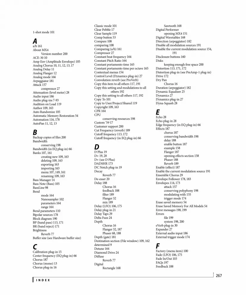
I N D E X267
1-shot mode 101
Aa/b 161About MX4
Version number 200ACE-30 10Amp Env (Amplitude Envelope) 105Analog Chorus 10, 11, 12, 13, 17Analog Delay 11Analog Flanger 12Analog mode 166Arpeggiator 181Attack 157
compressor 27Attenuation (level meter) 28Audio input 186Audio plug-ins 7-93Audition on Load 119Author 109, 163Auto Randomize 105Automatic Memory Restoration 54Automation 116, 178AutoPan 11, 12, 13
BBackup copies of files 200Bandwidth
conserving 198Bandwidth (in EQ plug-in) 66Banks 107, 161
creating new 109, 163deleting 109, 163exporting 163importing 163menu 107, 149, 161renaming 109, 163
Bass Manager 14Bass Note (Bass) 105BassLine 98Bend
mode 164Nanosampler 102parameters 164range 164
Bend parameters 110Bipolar sources 178Block diagram 190BP (band pass) 113, 171BR (band reject) 171Brightness
Reverb 77Buffer size (see Hardware buffer size)
CCalibration plug-in 15Center frequency (EQ plug-in) 66Chorus 187Chorus (mono) 13Chorus plug-in 16
Classic mode 101Clear Pebble 17Clear Sample 119Comp button 53Compare 108comparing 108Comparing (a/b) 161Compressor 27Constant beat frequency 164Constant Pitch Ratio 164Constant portamento time 165Constant portamento time per octave 165Contextual menus 154Control Level (Dynamics plug-in) 27Convolution reverb (see ProVerb)Copy this item to all others 117, 191Copy this setting and modulations to all
others 192Copy this setting to all others 117, 192Copy To 101Copy to User/Project/Shared 119Copyright 109, 163CPR 164CPU
conserving resources 198Custom ’59 17Customer support 200Cut Frequency (reverb) 189Cutoff frequency 113, 172Cutoff frequency (in EQ plug-in) 66
DD Plus 19D+ 19, 28D+ (see D Plus)DADSHR 173DC Notch plug-in 19Decay
Reverb 77De-esser 20Delay 188
Chorus 16feedback 188filter 189Flanger 32mix 189
Delay (LFO) 106, 175Delay plug-in 21Delay Taps 29Delta Fuzz 24Depth
Chorus 16Flanger 32, 187Phaser 68, 188
Depth (gate) 181Destination section (File window) 109, 162determined 9Detune 164Diamond Drive 24Diffuse
Reverb 77Digital
Rectangle 168
Sawtooth 168Digital Performer
opening MX4 151Digital Wavetables 168Direction (arpeggiator) 182Disable all modulation sources 191Disable the current modulation source 154,
191Disclosure buttons 160Disks
keeping enough free space 200Distortion 113, 171, 172Distortion plug-in (see PreAmp-1 plug-in)Drive 172Dry Pan
Chorus 16Duration (arpeggiator) 182Dynamic Equalizer 25Dynamics 27Dynamics plug-in 27Dyna-Squash 28
EEcho 28Echo plug-in 28Edge frequency (in EQ plug-in) 66Effects 187
chorus 187conserving bandwidth 198delay 188enable button 187example 158Flanger 187opening effects section 158Phaser 188Reverb 189
Enable (effect) 187Enable the current modulation source 191Ensemble Chorus 29Envelope Follower 178, 183Envelopes 114, 173
attack 157conserving polyphony 198modulating with 155trigger mode 174
Erase saved memory 54Erase Saved Memory For All Models 54Error messages 198, 199Errors
file 199system 198, 200
eVerb plug-in 30Expander 27External audio input 186External trigger mode 174
FFactory (menu item) 100Fade (LFO) 106, 175Fade In/Out 103FAQs 197Feedback 188
Index
I N D E X268
Flanger 32, 187Feedback Delay plug-in 21Feedback Path 29FET-76 49File button 108, 149, 162Files
errors 199Filter (delay) 189Filter (Nanosampler) 106Filter Envelope 106Filters 113, 171
attack 157conserving bandwidth 198cutoff frequency 113, 157, 172distortion 113, 171, 172enabling 156frequency modulation 172low pass 156mix 158, 172resonance 113, 172topology 171topology menu 156types 113, 171
Final Note 104, 105Fine Tuning 165Flanger 32, 187FM 170Forget controller mapping 117, 192Free-running phase 175Freewheel 79Frequency
filter cutoff 113, 172Frequency modulation 170, 172Fundamental 186
example of using 158
GGain
EQ 66Nanosampler 103reduction (Leveler) 53
Gate 27Gate and Effects topology 180Gate mode (Nanosampler) 103Glide
Proton 126Global randomize 192
HHardware buffer size 198Hardware Insert 32Held 164HF 43High pass filter (EQ) 66High shelf filter (EQ) 66Hi-Top Booster 33HMF 43Hold 173Hold light (arpeggiator) 182HP (high pass) 113, 171
II/O buffer size (see Hardware buffer size)Input level meter (Dynamics plug-in) 27Instrument plug-ins
Bassline 98Model 12 118Modulo 107Nanosampler 100PolySynth 99Proton 124
Intelligent Noise Gate 33Invert all modulation ranges 192Invert current modulation range 192Invert Phase 34Invert shaper 184Inverting modulation 178
KKey follow
filter 113, 172Key Track (Tracking) 106Keyboard shortcuts 191Keyfollow 112, 169Keywords 109, 163
LL/R In Phase
Flanger 32Phaser 68
Lag Processor shaper 185LCD 110, 149, 166
red numbers 156Learn controller mapping 117, 192Legato mode 109, 163Legend 190Length 101Level 171LF 43LFO 114, 174
free-running phase 175modulating symmetry with 154Nanosampler 106polyphonic retriggering 115, 176randomizing phase 175sync 106, 115, 176type 106
Limit button 53Limiter 27Live Room B 35Live Room G 37Live Stage 39LMF 43Load loop from sample 104Loop 104Low pass filter (EQ) 66Low shelf filter (EQ) 66LP (low pass) 156, 171LP (lowpass) 113
MMain button 149, 162
Makeup gain 53Master section 109, 163MasterWorks Compressor plug-in 39MasterWorks EQ plug-in 41MasterWorks Gate plug-in 50MasterWorks Leveler 52MasterWorks Limiter 55MegaSynth 59MF 43MicroB 62MicroG 62MIDI
activity light 149, 163status light 149
MIDI activity light 110MIDI Monitor window 199Mix (delay) 189Mix (filters) 172Mix (reverb) 189Mix setting (in plug-ins) 8Mixer 186Model 12 118Modifier keys 190Mods 180-185Mods button 149, 162Modulation 115, 176
inverting 178meter 179multiple sources 156oscillator settings 112, 171symmetry with LFO 154wavetable with envelope 155
Modulo 107Mono mode 109, 163Mono retrigger mode 174Mono trigger mode 174MOTU
Instruments soundbank 139MS Decoder plug-in 63MultiFuzz 63Multimode Filter plug-in 64MW Compressor (see MasterWorks
Compressor)MW EQ (see MasterWorks EQ)MW Gate (see MasterWorks Gate)MW Leveler (see MasterWorks Leveler)MW Limiter (see MasterWorks Limiter)MX4 123
expanding the window 160overview 145-148, 193-194tutorial 153-158window 159-192
collapsing 149
NNanosampler 100, 103
1-shot 101amp env 105auto randomize 105bass (note) 105bend 102Classic 101Copy To 101

I N D E X269
Factory 100fade in/out 103filter 106filter envelope 106final note 104, 105gain 103Gate 103length 101LFO 106LFO sync 106LFO type 106loading a sample 101loop 104normalize sample 103Play Until 104, 105Project 100randomize 105repeat 104retrig (retrigger) 106Reveal In Finder/Explorer 101reverse sample 103root 103Sample End 104sample start/end 103sample tab 102, 103settings tab 105Shared 100show mono sum 103show separate channels 103Slice 101, 103, 104slice by 104slice end 104stretch 101Trigger 103tune 103User 100vel track 105voices 102ZTX Stretch mode 102
Normalize Sample 103
OOptimizing performance 198Oscillator 110, 166
enabling 153fine-tune 153frequency modulation 170level 171pan 171pitch 112, 153, 170symmetry 112, 154, 170sync 169waveforms 111, 167
Out of range 188Output level (meter in Dynamics plug-in) 28
PPan 171, 186Parameters
displaying 110, 149, 166modulating 154, 155returning to zero 153
Parametric EQ plug-in 65Patch menu 107, 161Patches 108, 161
explained 107, 161managing 108, 162naming 109, 163reverting 108, 161saving 107, 161selecting 149
Pattern Gate 181Pattern Gate plug-in 67Pattern Sequencer 178, 182Peak/notch filter (EQ) 66Phase (LFO) 106, 175Phaser 68, 188Phaser plug-in 68Pink noise 168Pitch 112, 170Plate plug-in 68Play Unitl 104, 105Plug-ins
ACE-30 10Analog Chorus 10, 11, 12, 13, 17Analog Delay 11Analog Flanger 12AutoPan 13Bass Manager 14Calibration 15Chorus 16Clear Pebble 17Custom ’59 17D Plus 19D+ 19, 28DC Notch 19De-esser 20Delay 21Delta Fuzz 24Diamond Drive 24Dynamic Equalizer 25Dynamics 27Dyna-Squash 28Echo 28Ensemble Chorus 29eVerb 30FET-76 49Flanger 32Hardware Insert 32Hi-Top Booster 33Intelligent Noise Gate 33Invert Phase 34Live Room B 35Live Room G 37Live Stage 39MasterWorks Compressor 39MasterWorks EQ 41MasterWorks Gate 50MasterWorks Leveler 52MasterWorks Limiter 55MegaSynth 59MicroB 62MicroG 62MS Decoder 63MultiFuzz 63
Multimode Filter 64Parametric EQ 65Pattern Gate 67Phaser 68Plate 68PreAmp-1Precision Delay 71ProVerb 73Quan Jr. 76Reverb 77Reverse 77Ring Modulator 77RXT 79SMPTE-Z 79Soloist 80Sonic Modulator 81Spatial Maximizer 84Springamabob 85Subkick 86Tremolo 87Trigger 88Trim 89Tube Wailer 90Tuner 91Über Tube 92Wah Pedal 92
Poly mode 109, 163Poly release trigger mode 174Poly trigger mode 174Polyphonic LFO retriggering 115, 176Polyphony 110, 163, 198
display of used 149, 166PolySynth 99Portamento 109, 165
Proton 126PreAmp-1 plug-in 69Precision Delay plug-in 71Predelay
Reverb 77Presets 107, 161
Banks 149comparing 108comparing (a/b) 149, 161explained 107, 161managing 108, 162naming 109, 163reverting 108, 161saving 107, 149, 161selecting 149
Project (menu item) 100Proton 124
glide 126ProVerb 73Pulse Shape 181Pulse width 111, 168Pulse width modulation 154
QQuan Jr. plug-in 76Quantizer shaper 184

I N D E X270
RRamps 178Random button 162Randomize base and modulations 192Randomize base value 192Randomize base values 191Randomize base values and modulation
values 191Randomize button 105Randomizing 189
button 149LFO phase 175tips 189
Range (arpeggiator) 182Rate
Chorus 16Flanger 32, 187Phaser 68, 188
Rate (LFO) 106, 175Ratio
compressor 27Rectangle wave 111, 155, 168Red numbers 156Release
Dynamics 27Re-load saved memory now 54Repeat 104Resonance 113, 172Retrig (Retrigger) 106Reveal In Finder/Explorer 101, 119Reverb 77, 189
convolution (see ProVerb)eVerb plug-in 30Gain 77Plate plug-in 68ProVerb 73
Reverb plug-in 77Reverse 77Reverse Sample 103Revert (presets) 108, 161Ring Modulation 186Ring Modulator plug-in 77Root 103RXT 79
SSample and Hold shaper 185Sample End 104Sample Start/End 103Sample tab 102, 103Save
loop in sample 104presets 107
Save (presets) 161Save current T4 Cell memory 54Sawtooth wave 111, 167Self-modulation 177Sequenced trigger mode 174Set the modulation range for quantizing 192Settings tab (Nanosampler) 105Shapers 179Shared (menu item) 100
Shortcuts 191Show
Mono Sum 103Separate Channels 103
Signal path 110, 166, 190Sine wave 111, 167Slice By 104Slice End 104Slice mode 101, 103, 104SMPTE-Z 79Snap 103Soloist plug-in 80Sonic Modulator plug-in 81Soundbanks
MOTU Instruments 139Source 115, 154, 176
bipolar 178on velocity 157
Source section (File window) 108, 162Spatial Maximizer plug-in 84Spread (reverb) 189Springamabob plug-in 85Square wave 111, 154, 168Status LCD 110, 149, 166
red numbers 156Stereo Detune 165Stereo mode 186
conserving bandwidth 198Stillframe option 79Stretch 101Subkick plug-in 86Surround
Delay plug-in 22MasterWorks Limiter plug-in
Surround Edition 56Swap current modulation 157Swap current modulation range 191Swing parameter 181Symmetry 112, 154, 170
LFO 175, 176modulating 154
Syncdelay 188LFOs 106, 115, 176light (blinking) 188Nanosampler LFO 106oscillator 169out of range 188
Synchronize option 79System
troubleshooting 199System errors 198, 200
TTechnical support 200Threshold
dynamics 27Through zero option 16Time (reverb) 189Topology 171
menu 156Transform shaper 184Transpose 165
Tremolo plug-in 87Triangle wave 111, 167Trigger mode 174Trigger mode (Nanosampler) 103Trigger plug-in 88Trigger Sequencer 185Trim plug-in 89Troubleshooting 197, 198
disk errors 200error messages 198, 200file errors 199MIDI status light 149system errors 198, 200
Tube plug-in (see PreAmp-1 plug-in)Tube Wailer 90Tune (Nanosampler) 103Tuner plug-in 91Tutorial 153-158
UÜber Tube 92UFS files
MOTU Instruments 139Undo last memory-saving operation 54Unison Multiplier 164, 165
CPU bandwidth requirements 198Unison multiplier 109Until note off 174Use host frame rate 80Use host offset 79, 80User (menu item) 100
VVel Track (Velocity Tracking) 105, 106Vel>Volume (Velocity Sensitivity) 165Velocity sensitivity 165Virtual instruments
BassLine 98Model 12 118Modulo 107Nanosampler 100PolySynth 99Proton 124
Voicesdisplay of used 149, 166Nanosampler 102setting the maximum number of 110,
163Volume 109, 165
WWah Pedal 92Waveforms 111, 167Wavetables 112, 155, 168
index 170Wet Pan
Chorus 16White noise 168Width
Phaser 68, 188

I N D E X271
ZZTX Stretch mode 102

I N D E X272


