Embed Size (px)
Citation preview
Work-hour for installation
Series
Integrated Type Remote Type
Basic type PF3WB Series Straight type PF3WC Series Supply type
PF3WS Series
Return type
PF3WR Series
Rated flow range [L/min] 0.5 to 4, 2 to 16, 5 to 40
Port size 3/8 (Up to 4 L/min), 1/2 (Up to 16 L/min), 3/4 (Up to 40 L/min)
Unit components
Flow switch V V — V
Stop valve V V V V
Flow adjustmentvalve V V V V
IP65
Piping port
Flow range (Single unit)
0.5 to 4 L/min, 2 to 16 L/min, 5 to 40 L/min
Number of stations
1 to 10 stations ∗ Max. 5 stations for flow range symbol 40 (5 to 40 L/min)
∗ Comparison based on integrated type with existing piping material
Max. 85% reduction
Max. 65% reductionWeight
Footprint
Space saving
∗ Comparison based on integrated type with existing piping work
Max. 45% reduction
Needs no piping
Stop valve Flow adjustment valve
∗1 Only compatible with the integrated display type
Flow switch
Digital Flow SwitchManifold for Water
CAT.ES100-130A
PF3WB/C/S/R Series
Compatible∗1
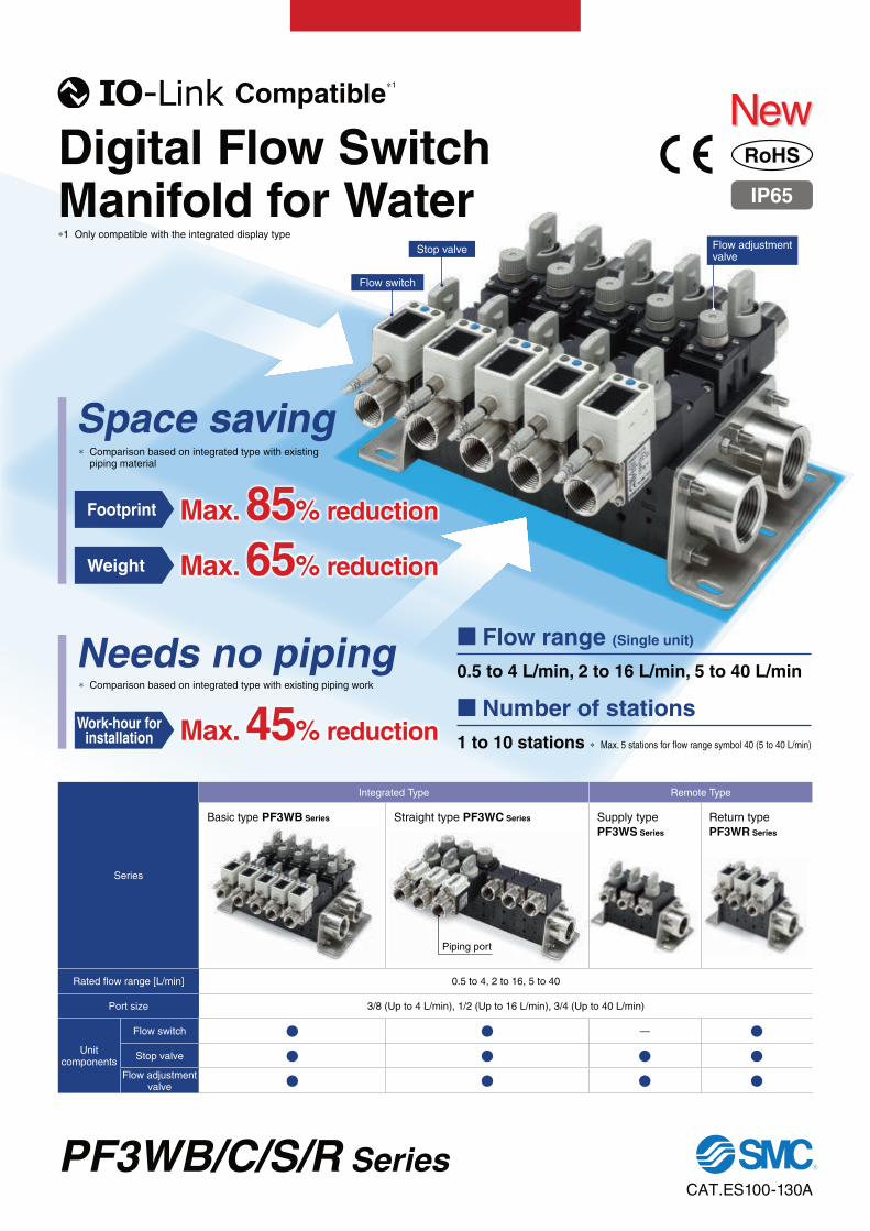
Basic type PF3WB
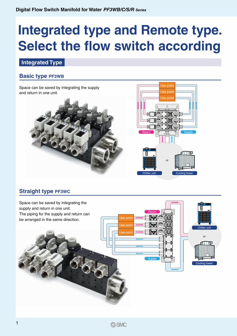
Straight type PF3WC
Space can be saved by integrating the supply
and return in one unit.
Space can be saved by integrating the
supply and return in one unit.
The piping for the supply and return can
be arranged in the same direction.
Integrated Type
Use point
Use point
Return Supply
Use point
Use point
Use point
Use point
Supply
Return
or
Cooling tower
Chiller unit
Integrated type and Remote type.
Select the flow switch according
or
Cooling towerChiller unit
1
Digital Flow Switch Manifold for Water PF3WB/C/S/R Series
3-color/2-screen display
Digital Flow Switch Manifold for Water PF3WB/C/S/R Series
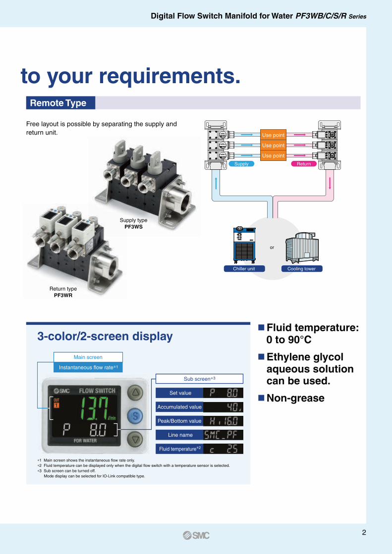
Free layout is possible by separating the supply and
return unit.
Supply type
PF3WS
Return type
PF3WR
Remote Type
Use point
Use point
Use point
Supply Return
to your requirements.
or
Cooling towerChiller unit
Fluid temperature: 0 to 90°C
Ethylene glycol aqueous solution can be used.
Non-grease
Fluid temperature∗2
Sub screen∗3
Line name
Peak/Bottom value
Accumulated value
Set value
Main screen
Instantaneous flow rate∗1
∗1 Main screen shows the instantaneous flow rate only.
∗2 Fluid temperature can be displayed only when the digital flow switch with a temperature sensor is selected.
∗3 Sub screen can be turned off.
Mode display can be selected for IO-Link compatible type.
2
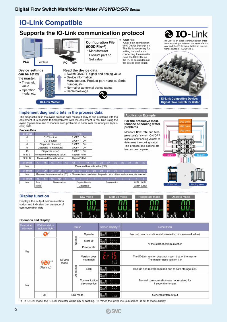
Implement diagnostic bits in the process data.
Supports the IO-Link communication protocolIO-Link is an open communication inter-face technology between the sensor/actu-ator and the I/O terminal that is an interna-tional standard, IEC61131-9.
IO-Link Master
Fieldbus
Device settings can be set by
the master.• Threshold
value
• Operation mode, etc.
Read the device data.• Switch ON/OFF signal and analog value• Device information:
Manufacturer, Product part number, Serial number, etc.
• Normal or abnormal device status• Cable breakage
Configuration File
(IODD File∗1). Manufacturer. Product part no.. Set value
∗1 IODD File:IODD is an abbreviation of IO Device Description. This file is necessary for setting the device and connecting it to a master. Save the IODD file on the PC to be used to set the device prior to use.
Monitors flow rate and tem-
perature’s “switch ON/OFF
signals” and “analog values” to
determine the cooling status
The process and cooling sta-
tus can be compared.
For the predictive main-tenance of cooling water problems
IO-Link Compatible Device:
Digital Flow Switch for Water
Display function
Displays the output communication
status and indicates the presence of
communication data
SIO mode Start-up mode Preoperate mode Operate mode
Process Data
Bit offset Item Note
0 OUT1 output 0: OFF 1: ON
1 OUT2 output 0: OFF 1: ON
8 Diagnosis (flow rate) 0: OFF 1: ON
9 Diagnosis (temperature) 0: OFF 1: ON
15 Diagnosis (error) 0: OFF 1: ON
16 to 31 Measured temperature value Signed 16 bit
32 to 47 Measured flow rate value Signed 16 bit
Bit offset 47 46 45 44 43 42 41 40 39 38 37 36 35 34 33 32
Item Measured flow rate value (PD)
Bit offset 31 30 29 28 27 26 25 24 23 22 21 20 19 18 17 16
Item Measured temperature value (PD) ∗ The area is not used when the product without temperature sensor is selected.
Bit offset 15 14 13 12 11 10 9 8 7 6 5 4 3 2 1 0
Item Error Reservation Temperature Flow rate Reservation OUT2 OUT1
Diagnosis Diagnosis Switch output
The diagnostic bit in the cyclic process data makes it easy to find problems with the equipment. It is possible to find problems with the equipment in real time using the cyclic (cycle) data and to monitor such problems in detail with the noncyclic (aperi-odic) data.
Application Example
or
Cooling towerChiller unit
Return Supply
Use point
Use point
Use point
PLC PC
IO-Link Compatible
Operation and Display
Communication with master
IO-Link status indicator light
Status Screen display∗2 Description
Yes
∗1
IO-Link mode
Norm
al
Operate Normal communication status (readout of measured value)
(Flashing)
Start up
At the start of communication
Preoperate
Abnorm
al
Version doesnot match
The IO-Link version does not match that of the master.The master uses version 1.0.
Lock Backup and restore required due to data storage lock.
No
Communicationdisconnection
Normal communication was not received for 1 second or longer.
OFF SIO mode General switch output
∗1 In IO-Link mode, the IO-Link indicator will be ON or flashing. ∗2 When the lower line (sub screen) is set to mode display
∗1
3
Digital Flow Switch Manifold for Water PF3WB/C/S/R Series
Supply: O
UT
Digital Flow Switch Manifold for Water PF3WB/C/S/R Series
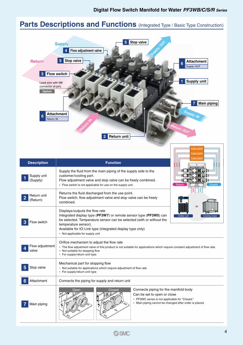
Description Function
1Supply unit
(Supply)
Supply the fluid from the main piping of the supply side to the
customer/cooling part.
Flow adjustment valve and stop valve can be freely combined.
∗ Flow switch is not applicable for use on the supply unit.
2Return unit
(Return)
Returns the fluid discharged from the use point.
Flow switch, flow adjustment valve and stop valve can be freely
combined.
3 Flow switch
Displays/outputs the flow rate
Integrated display type (PF3W7) or remote sensor type (PF3W5) can
be selected. Temperature sensor can be selected (with or without the
temperature sensor).
Available for IO-Link type (integrated display type only)
∗ Not applicable for supply unit
4Flow adjustment
valve
Orifice mechanism to adjust the flow rate
∗ The flow adjustment valve of this product is not suitable for applications which require constant adjustment of flow rate.
∗ Not suitable for stopping flow
∗ For supply/return unit type
5 Stop valveMechanical part for stopping flow
∗ Not suitable for applications which require adjustment of flow rate
∗ For supply/return unit type
6 Attachment Connects the piping for supply and return unit
7 Main piping
Open Closed Connects piping for the manifold body
Can be set to open or close
∗ PF3WC series is not applicable for “Closed.”
∗ Main piping cannot be changed after order is placed.
Supply unit1
Attachment6
Supply: OUT
Lead wire with M8
connector (4-pin)
Option
Flow switch3
Flow adjustment valve4
Stop valve5
Stop valve5
Attachment6
Return: IN
Return unit2
Main piping7
Ret
urn: I
N
Supply: IN
Return: OUT
or
Cooling towerChiller unit
Return Supply
Use point
Use point
Use point
Supply
Return
Parts Descriptions and Functions (Integrated Type / Basic Type Construction)
4

5
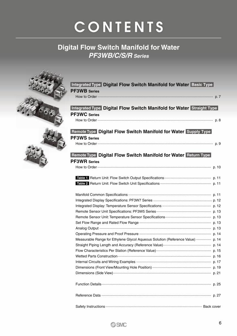
Digital Flow Switch Manifold for Water
PF3WB/C/S/R Series
C O N T E N T S
Integrated Type Digital Flow Switch Manifold for Water Basic Type
PF3WB Series
How to Order .................................................................................................................... p. 7
Integrated Type Digital Flow Switch Manifold for Water Straight Type
PF3WC Series
How to Order .................................................................................................................... p. 8
Remote Type Digital Flow Switch Manifold for Water Supply Type
PF3WS Series
How to Order .................................................................................................................... p. 9
Remote Type Digital Flow Switch Manifold for Water Return Type
PF3WR Series
How to Order .................................................................................................................. p. 10
Table 1 Return Unit: Flow Switch Output Specifications ............................................... p. 11
Table 2 Return Unit: Flow Switch Unit Specifications ................................................... p. 11
Manifold Common Specifications ................................................................................... p. 11
Integrated Display Specifications: PF3W7 Series ........................................................... p. 12
Integrated Display: Temperature Sensor Specifications ................................................. p. 12
Remote Sensor Unit Specifications: PF3W5 Series ....................................................... p. 13
Remote Sensor Unit: Temperature Sensor Specifications .............................................. p. 13
Set Flow Range and Rated Flow Range ........................................................................ p. 13
Analog Output ................................................................................................................ p. 13
Operating Pressure and Proof Pressure ........................................................................ p. 14
Measurable Range for Ethylene Glycol Aqueous Solution (Reference Value) ............... p. 14
Straight Piping Length and Accuracy (Reference Value) ................................................ p. 14
Flow Characteristics Per Station (Reference Value) ....................................................... p. 15
Wetted Parts Construction.............................................................................................. p. 16
Internal Circuits and Wiring Examples ........................................................................... p. 17
Dimensions (Front View/Mounting Hole Position) ........................................................... p. 19
Dimensions (Side View) .................................................................................................. p. 21
Function Details .............................................................................................................. p. 25
Reference Data .............................................................................................................. p. 27
Safety Instructions ................................................................................................. Back cover
6
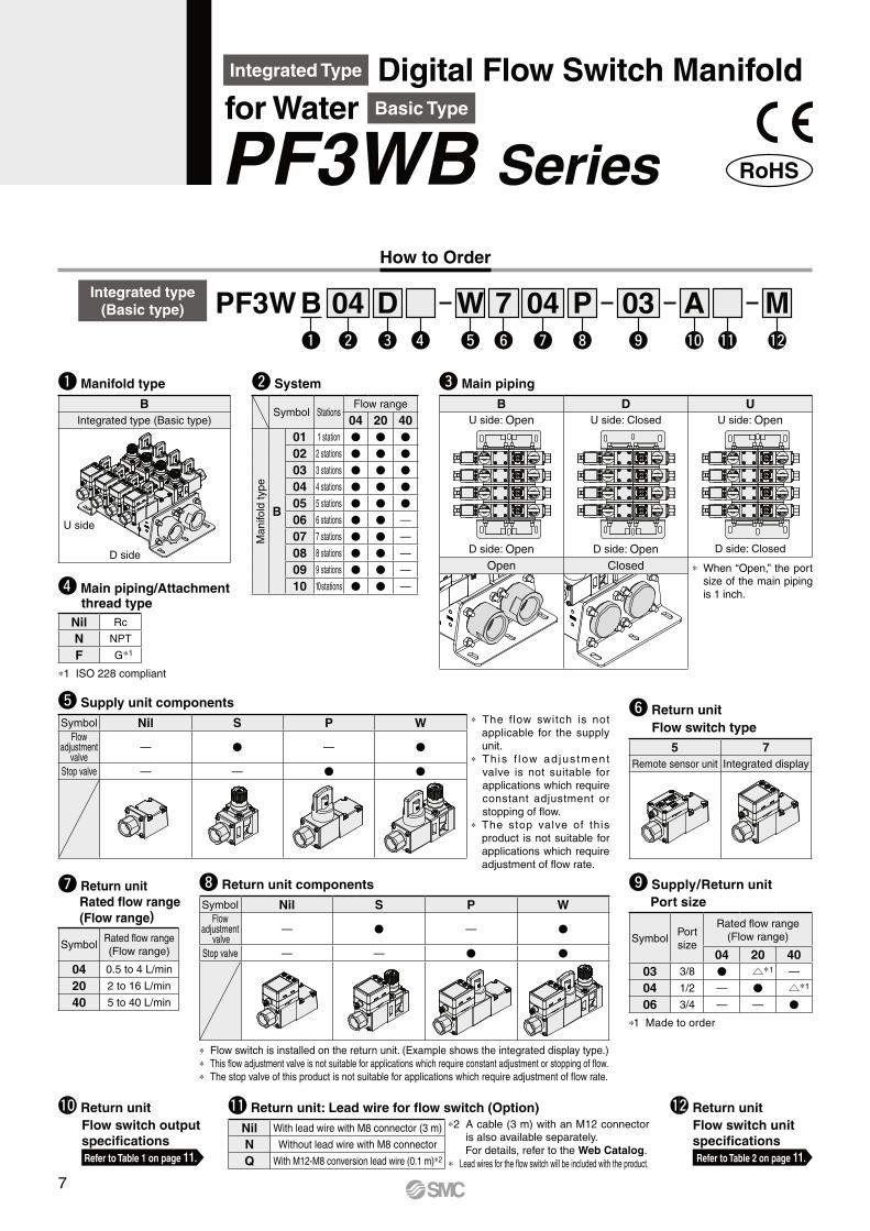
Integrated Type Digital Flow Switch Manifold for Water Basic Type
PF3WB Series
How to Order
y Return unit
Flow switch type
5 7
Remote sensor unit Integrated display
Nil Rc
N NPT
F G∗1
∗1 ISO 228 compliant
r Main piping/Attachment thread type
∗ The flow switch is not
applicable for the supply
unit.
∗ Th is f low ad jus tment
valve is not suitable for
applications which require
constant adjustment or
stopping of flow.
∗ The stop valve of this
product is not suitable for
applications which require
adjustment of flow rate.
t Supply unit components
Symbol Nil S P WFlow
adjustment valve
— V — V
Stop valve — — V V
i Return unit components
Symbol Nil S P WFlow
adjustment valve
— V — V
Stop valve — — V V
∗ Flow switch is installed on the return unit. (Example shows the integrated display type.)
∗ This flow adjustment valve is not suitable for applications which require constant adjustment or stopping of flow.
∗ The stop valve of this product is not suitable for applications which require adjustment of flow rate.
o Supply/Return unit
Port size
SymbolPort
size
Rated flow range
(Flow range)
04 20 40
03 3/8 V u∗1 —
04 1/2 — V u∗1
06 3/4 — — V
∗1 Made to order
u Return unit
Rated flow range
(Flow range)
SymbolRated flow range
(Flow range)
04 0.5 to 4 L/min
20 2 to 16 L/min
40 5 to 40 L/min
w System
Symbol StationsFlow range
04 20 40
Manifo
ld type
B
01 1 station V V V
02 2 stations V V V
03 3 stations V V V
04 4 stations V V V
05 5 stations V V V
06 6 stations V V —
07 7 stations V V —
08 8 stations V V —
09 9 stations V V —
10 10 stations V V —
w y !0i oe r t u !1 !2
04 D W 7 04 P 03 A Mq
BPF3WIntegrated type
(Basic type)
!1 Return unit: Lead wire for flow switch (Option)
Nil With lead wire with M8 connector (3 m)
N Without lead wire with M8 connector
Q With M12-M8 conversion lead wire (0.1 m)∗2
!2 Return unit
Flow switch unit
specifications
Refer to Table 2 on page 11.
!0 Return unit
Flow switch output
specifications
Refer to Table 1 on page 11.
q Manifold type
B
Integrated type (Basic type)
e Main piping
B D U
U side: Open
D side: Open
U side: Closed
D side: Open
U side: Open
D side: Closed
Open Closed ∗ When “Open,” the port size of the main piping
is 1 inch.
U side
D side
∗2 A cable (3 m) with an M12 connector is also available separately.
For details, refer to the Web Catalog.
∗ Lead wires for the flow switch will be included with the product.
7
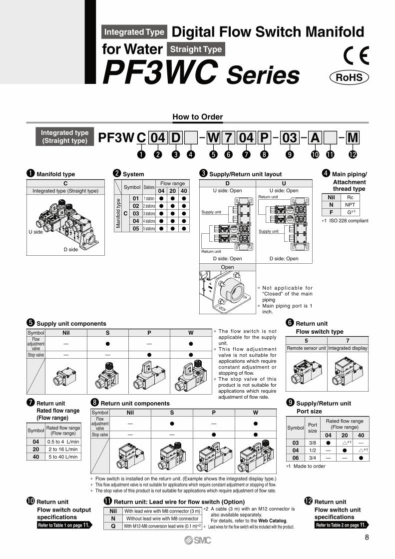
Integrated Type Digital Flow Switch Manifold for Water Straight Type
PF3WC Series
How to Order
Nil Rc
N NPT
F G∗1
∗1 ISO 228 compliant
r Main piping/
Attachmentthread type
w System
Symbol StationsFlow range
04 20 40
Manifo
ld type
C
01 1 station V V V
02 2 stations V V V
03 3 stations V V V
04 4 stations V V V
05 5 stations V V V
w y !0i oe r t u !1 !2
04 D W 7 04 P 03 A Mq
CPF3WIntegrated type
(Straight type)
y Return unit
Flow switch type
5 7
Remote sensor unit Integrated display
∗ The f low switch is not
applicable for the supply
unit.
∗ Th is f low ad jus tment
valve is not suitable for
applications which require
constant adjustment or
stopping of flow.
∗ The stop valve of this
product is not suitable for
applications which require
adjustment of flow rate.
t Supply unit components
Symbol Nil S P WFlow
adjustment valve
— V — V
Stop valve — — V V
i Return unit components
Symbol Nil S P WFlow
adjustment valve
— V — V
Stop valve — — V V
∗ Flow switch is installed on the return unit. (Example shows the integrated display type.)
∗ This flow adjustment valve is not suitable for applications which require constant adjustment or stopping of flow.
∗ The stop valve of this product is not suitable for applications which require adjustment of flow rate.
o Supply/Return unit
Port size
SymbolPort
size
Rated flow range
(Flow range)
04 20 40
03 3/8 V u∗1 —
04 1/2 — V u∗1
06 3/4 — — V
∗1 Made to order
u Return unit
Rated flow range
(Flow range)
SymbolRated flow range
(Flow range)
04 0.5 to 4 L/min
20 2 to 16 L/min
40 5 to 40 L/min
∗2 A cable (3 m) with an M12 connector is also available separately.
For details, refer to the Web Catalog.
∗ Lead wires for the flow switch will be included with the product.
!1 Return unit: Lead wire for flow switch (Option)
Nil With lead wire with M8 connector (3 m)
N Without lead wire with M8 connector
Q With M12-M8 conversion lead wire (0.1 m)∗2
!2 Return unit
Flow switch unit
specifications
Refer to Table 2 on page 11.
!0 Return unit
Flow switch output
specifications
Refer to Table 1 on page 11.
e Supply/Return unit layout
D U
U side: Open
D side: Open
U side: Open
D side: Open
Open
∗ No t app l i cable fo r “Closed” of the main
piping
∗ Main piping port is 1 inch.
U side
D side
q Manifold type
C
Integrated type (Straight type)
Supply unit
Supply unit
Return unit
Return unit
8
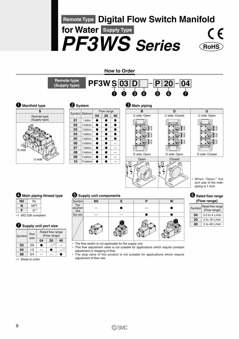
How to Order
Remote type
(Supply type)
w e r tq
PF3Wy u
P03 D 20 04S
e Main piping
B D U
U side: Open
D side: Open
U side: Closed
D side: Open
U side: Open
D side: Closed
Open Closed
∗ When “Open,” the port size of the main
piping is 1 inch.
q Manifold type
S
Remote type(Supply type)
w System
Symbol StationsFlow range
04 20 40
01 1 station V V V
02 2 stations V V V
03 3 stations V V V
04 4 stations V V V
05 5 stations V V V
06 6 stations V V —
07 7 stations V V —
08 8 stations V V —
09 9 stations V V —
10 10 stations V V —
Remote Type Digital Flow Switch Manifold for Water Supply Type
PF3WS Series
u Supply unit port size
SymbolPort
size
Rated flow range
(Flow range)
04 20 40
03 3/8 V u∗1 —
04 1/2 — V u∗1
06 3/4 — — V
∗1 Made to order
Nil Rc
N NPT
F G∗1
∗1 ISO 228 compliant
r Main piping thread type y Rated flow range
(Flow range)
SymbolRated flow range
(Flow range)
04 0.5 to 4 L/min
20 2 to 16 L/min
40 5 to 40 L/min
∗ The flow switch is not applicable for the supply unit.
∗ This flow adjustment valve is not suitable for applications which require constant
adjustment or stopping of flow.
∗ The stop valve of this product is not suitable for applications which require
adjustment of flow rate.
t Supply unit components
Symbol Nil S P WFlow
adjustment valve
— V — V
Stop valve — — V V
D side
U side
9
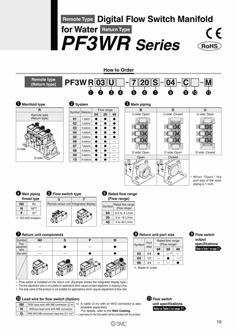
How to Order
q Manifold type
R
Remote type(Return type)
w System
Symbol StationsFlow range
04 20 40
01 1 station V V V
02 2 stations V V V
03 3 stations V V V
04 4 stations V V V
05 5 stations V V V
06 6 stations V V —
07 7 stations V V —
08 8 stations V V —
09 9 stations V V —
10 10 stations V V —
Remote Type Digital Flow Switch Manifold for Water Return Type
PF3WR Series
U side
D side
Remote type
(Return type) PF3W 03 U 7 20 S 04 C MR
Nil Rc
N NPT
F G∗1
∗1 ISO 228 compliant
r Main piping
thread type
t Flow switch type
5 7
Remote sensor unit Integrated display
y Rated flow range
(Flow range)
SymbolRated flow range
(Flow range)
04 0.5 to 4 L/min
20 2 to 16 L/min
40 5 to 40 L/min
!1 Flow switch
unit specifications
Refer to Table 2 on page 11.
∗2 A cable (3 m) with an M12 connector is also available separately.
For details, refer to the Web Catalog.
∗ Lead wires for the flow switch will be included with the product.
!0 Lead wire for flow switch (Option)
Nil With lead wire with M8 connector (3 m)
N Without lead wire with M8 connector
Q With M12-M8 conversion lead wire (0.1 m)∗2
o Flow switch
output
specifications
Refer to Table 1 on page 11.
i Return unit port size
SymbolPort
size
Rated flow range
(Flow range)
04 20 40
03 3/8 V u∗1 —
04 1/2 — V u∗1
06 3/4 — — V
∗1 Made to order
u Return unit components
Symbol Nil S P WFlow
adjustment valve
— V — V
Stop valve — — V V
∗ Flow switch is installed on the return unit. (Example shows the integrated display type.)
∗ This flow adjustment valve is not suitable for applications which require constant adjustment or stopping of flow.
∗ The stop valve of this product is not suitable for applications which require adjustment of flow rate.
w e r t ou iy !0 !1q
e Main piping
B D U
U side: Open
D side: Open
U side: Closed
D side: Open
U side: Open
D side: Closed
Open Closed
∗ When “Open,” the port size of the main
piping is 1 inch.
10
PF3W Series
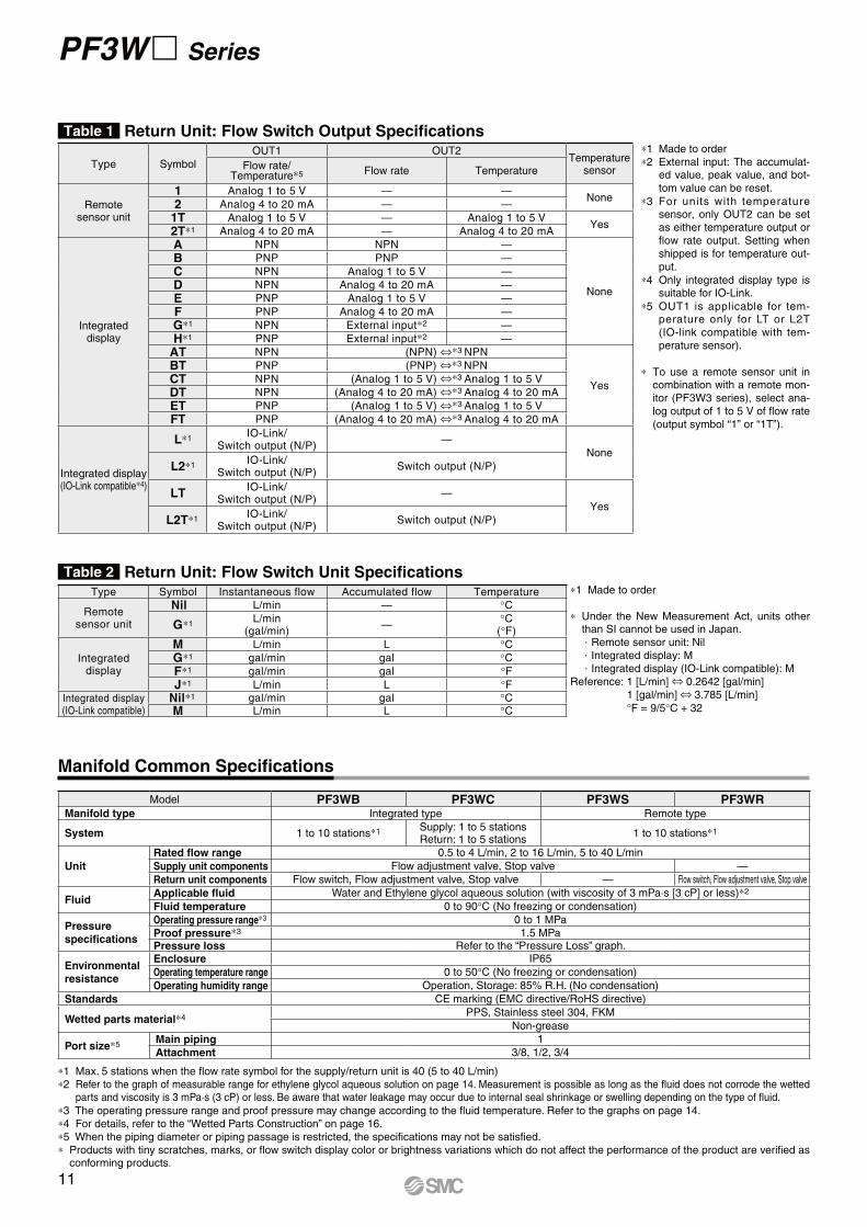
Type Symbol
OUT1 OUT2Temperature
sensorFlow rate/Temperature∗5 Flow rate Temperature
Remotesensor unit
1 Analog 1 to 5 V — —None
2 Analog 4 to 20 mA — —
1T Analog 1 to 5 V — Analog 1 to 5 VYes
2T∗1 Analog 4 to 20 mA — Analog 4 to 20 mA
Integrated display
A NPN NPN —
None
B PNP PNP —
C NPN Analog 1 to 5 V —
D NPN Analog 4 to 20 mA —
E PNP Analog 1 to 5 V —
F PNP Analog 4 to 20 mA —
G∗1 NPN External input∗2 —
H∗1 PNP External input∗2 —
AT NPN (NPN) ⇔∗3 NPN
Yes
BT PNP (PNP) ⇔∗3 NPN
CT NPN (Analog 1 to 5 V) ⇔∗3 Analog 1 to 5 V
DT NPN (Analog 4 to 20 mA) ⇔∗3 Analog 4 to 20 mA
ET PNP (Analog 1 to 5 V) ⇔∗3 Analog 1 to 5 V
FT PNP (Analog 4 to 20 mA) ⇔∗3 Analog 4 to 20 mA
Integrated display(IO-Link compatible∗4)
L∗1IO-Link/
Switch output (N/P)—
None
L2∗1IO-Link/
Switch output (N/P)Switch output (N/P)
LTIO-Link/
Switch output (N/P)—
Yes
L2T∗1IO-Link/
Switch output (N/P)Switch output (N/P)
Manifold Common Specifications
Model PF3WB PF3WC PF3WS PF3WRManifold type Integrated type Remote type
System 1 to 10 stations∗1 Supply: 1 to 5 stationsReturn: 1 to 5 stations
1 to 10 stations∗1
Unit
Rated flow range 0.5 to 4 L/min, 2 to 16 L/min, 5 to 40 L/min
Supply unit components Flow adjustment valve, Stop valve —
Return unit components Flow switch, Flow adjustment valve, Stop valve — Flow switch, Flow adjustment valve, Stop valve
FluidApplicable fluid Water and Ethylene glycol aqueous solution (with viscosity of 3 mPa·s [3 cP] or less)∗2
Fluid temperature 0 to 90°C (No freezing or condensation)
Pressure
specifications
Operating pressure range∗3 0 to 1 MPa
Proof pressure∗3 1.5 MPaPressure loss Refer to the “Pressure Loss” graph.
Environmental
resistance
Enclosure IP65
Operating temperature range 0 to 50°C (No freezing or condensation)
Operating humidity range Operation, Storage: 85% R.H. (No condensation)
Standards CE marking (EMC directive/RoHS directive)
Wetted parts material∗4PPS, Stainless steel 304, FKM
Non-grease
Port size∗5Main piping 1
Attachment 3/8, 1/2, 3/4
∗1 Max. 5 stations when the flow rate symbol for the supply/return unit is 40 (5 to 40 L/min)
∗2 Refer to the graph of measurable range for ethylene glycol aqueous solution on page 14. Measurement is possible as long as the fluid does not corrode the wetted parts and viscosity is 3 mPa·s (3 cP) or less. Be aware that water leakage may occur due to internal seal shrinkage or swelling depending on the type of fluid.
∗3 The operating pressure range and proof pressure may change according to the fluid temperature. Refer to the graphs on page 14.
∗4 For details, refer to the “Wetted Parts Construction” on page 16.
∗5 When the piping diameter or piping passage is restricted, the specifications may not be satisfied.
∗ Products with tiny scratches, marks, or flow switch display color or brightness variations which do not affect the performance of the product are verified as conforming products.
Table 1 Return Unit: Flow Switch Output Specifications∗1 Made to order
∗2 External input: The accumulat-ed value, peak value, and bot-
tom value can be reset.
∗3 For units with temperature sensor, only OUT2 can be set
as either temperature output or
flow rate output. Setting when
shipped is for temperature out-
put.
∗4 Only integrated display type is suitable for IO-Link.
∗5 OUT1 is applicable for tem-perature only for LT or L2T
(IO-link compatible with tem-
perature sensor).
∗ To use a remote sensor unit in combination with a remote mon-
itor (PF3W3 series), select ana-
log output of 1 to 5 V of flow rate
(output symbol “1” or “1T”).
∗1 Made to order
∗ Under the New Measurement Act, units other than SI cannot be used in Japan.. Remote sensor unit: Nil. Integrated display: M. Integrated display (IO-Link compatible): M
Reference: 1 [L/min] ⇔ 0.2642 [gal/min]
1 [gal/min] ⇔ 3.785 [L/min]
°F = 9/5°C + 32
Table 2 Return Unit: Flow Switch Unit SpecificationsType Symbol Instantaneous flow Accumulated flow Temperature
Remotesensor unit
Nil L/min — °C
G∗1L/min
(gal/min)—
°C(°F)
Integrateddisplay
M L/min L °C
G∗1 gal/min gal °C
F∗1 gal/min gal °F
J∗1 L/min L °F
Integrated display(IO-Link compatible)
Nil∗1 gal/min gal °C
M L/min L °C
11
Digital Flow Switch Manifold for Water PF3W Series
For detailed specifications of flow switches, refer to the PF3W series in the Web Catalog or the Operation Manual.
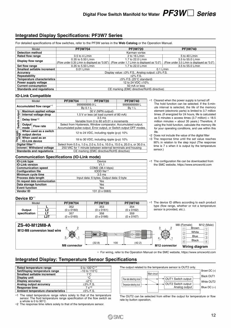
Integrated Display Specifications: PF3W7 Series
Integrated Display: Temperature Sensor Specifications
Model PF3W704 PF3W720 PF3W740Detection method Karman vortexRated flow range 0.5 to 4 L/min 2 to 16 L/min 5 to 40 L/min
Display flow range0.35 to 5.50 L/min
(Flow under 0.35 L/min is displayed as “0.00”)1.7 to 22.0 L/min
(Flow under 1.7 L/min is displayed as “0.0”)3.5 to 55.0 L/min
(Flow under 3.5 L/min is displayed as “0.0”)Set flow range 0.35 to 5.50 L/min 1.7 to 22.0 L/min 3.5 to 55.0 L/minSmallest settable increment 0.01 L/min 0.1 L/minAccuracy Display value: ±3% F.S., Analog output: ±3% F.S.Repeatability ±2% F.S.Temperature characteristics ±5% F.S. (25°C standard)Power supply voltage 12 to 24 VDC ±10%Current consumption 50 mA or lessStandards and regulations CE marking (EMC directive/RoHS directive)
IO-Link Compatible
∗1 The device ID differs according to each product type (flow range, whether or not a temperature
sensor is provided, etc.).
Device ID∗1
Model PF3W704 PF3W720 PF3W740
Output specification
L 352(0 x 0160)
353(0 x 0161)
354(0 x 0162)L2
LT 357(0 x 0165)
358(0 x 0166)
359(0 x 0167)L2T
∗1 The rated temperature range refers solely to that of the temperature sensor. The fluid temperature range specification of the flow switch as a whole is 0 to 90°C.
∗2 The response time refers solely to that of the temperature sensor.
The OUT2 can be selected from either the output for temperature or flow rate by button operation.
The output related to the temperature sensor is OUT2 only.
Flow rate detecting circuit OUT1 Switch output
OUT2 Switch outputAnalog output
Main circuit
Temperature detecting circuit
Brown DC (+)
Black OUT1
White OUT2
Blue DC (–)
Rated temperature range 0 to 100°C∗1
Set/Display temperature range –10 to 110°CSmallest settable increment 1°CDisplay unit °CDisplay accuracy ±2°CAnalog output accuracy ±3% F.S.Response time 7 s∗2
Ambient temperature characteristics ±5% F.S.
Model PF3W704 PF3W720 PF3W740
Accumulated flow range∗1 999999999.9 L 9999999999 LBy 0.1 L By 1 L
Sw
itch
ou
tpu
t Maximum applied voltage 30 V (NPN output)Internal voltage drop 1.5 V or less (at load current of 80 mA)
Delay time∗2 3.5 msVariable from 0 to 60 s/0.01 s increments
Output mode
Flow rateSelect from Hysteresis, Window comparator, Accumulated output,
Accumulated pulse output, Error output, or Switch output OFF modes.
Powe
r sup
ply
volta
ge
When used as a switch output device
12 to 24 VDC, including ripple (p-p) 10%
When used as an IO-Link device
18 to 30 VDC, including ripple (p-p) 10%
Digital filter∗3 Select from 0.5 s, 1.0 s, 2.0 s, 5.0 s, 10.0 s, 15.0 s, 20.0 s, or 30.0 s.Environment Withstand voltage 250 VAC for 1 minute between external terminals and housingStandards and regulations CE marking (EMC directive/RoHS directive)
∗1 Cleared when the power supply is turned offThe hold function can be selected. If the 5-min-
ute interval is selected, the life of the memory
element (electronic parts) is limited to 3.7 million
times. (If energized for 24 hours, life is calculated
as 5 minutes x access times (3.7 million) = 18.5
million minutes = about 35 years.) Therefore, if
using the hold function, calculate the memory life
for your operating conditions, and use within this
life.
∗2 Does not include the value of the digital filter
∗3 The response time until the set value reaches 90% in relation to the step input (The response
time is 7 s when it is output by the temperature
sensor.)
∗1 The configuration file can be downloaded from the SMC website, https://www.smcworld.com
Communication Specifications (IO-Link mode)IO-Link type DeviceIO-Link version V1.1Communication speed COM2 (38.4 kbps)Configuration file IODD file∗1
Minimum cycle time 3.5 msProcess data length Input data: 6 bytes, Output data: 0 byteOn request data communication YesData storage function YesEvent function YesVendor ID 131 (0 x 0083)
(42.2)100(32.8)
3
4 2
1
2
14
3M8 (Female)
Wiring diagramM12 connectorM8 connector
M12 (Male)Brown
Whiteq
w
e
r
q
w
e
r
Blue
Black
∗ For wiring, refer to the Operation Manual on the SMC website, https://www.smcworld.com
ZS-40-M12M8-AM12-M8 conversion lead wire
12
PF3W Series
For detailed specifications of flow switches, refer to the PF3W series in the Web Catalog or the Operation Manual.
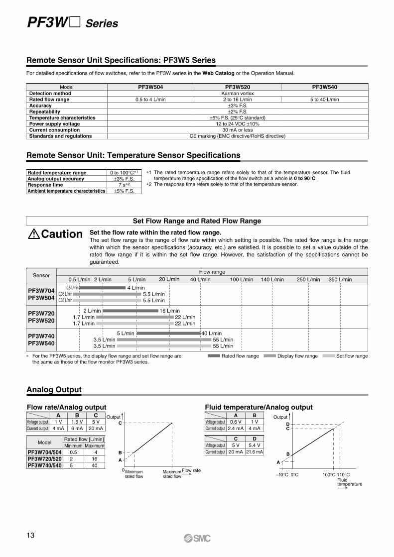
Remote Sensor Unit Specifications: PF3W5 Series
Remote Sensor Unit: Temperature Sensor Specifications
Model PF3W504 PF3W520 PF3W540Detection method Karman vortex
Rated flow range 0.5 to 4 L/min 2 to 16 L/min 5 to 40 L/min
Accuracy ±3% F.S.
Repeatability ±2% F.S.
Temperature characteristics ±5% F.S. (25°C standard)
Power supply voltage 12 to 24 VDC ±10%
Current consumption 30 mA or less
Standards and regulations CE marking (EMC directive/RoHS directive)
Set the flow rate within the rated flow range.The set flow range is the range of flow rate within which setting is possible. The rated flow range is the range
within which the sensor specifications (accuracy, etc.) are satisfied. It is possible to set a value outside of the
rated flow range if it is within the set flow range. However, the satisfaction of the specifications cannot be
guaranteed.
Caution
Set Flow Range and Rated Flow Range
4 L/min
Rated flow range Display flow range Set flow range∗ For the PF3W5 series, the display flow range and set flow range are
the same as those of the flow monitor PF3W3 series.
SensorFlow range
0.5 L/min 2 L/min 5 L/min 20 L/min 40 L/min 250 L/min140 L/min100 L/min 350 L/min
PF3W704
PF3W504
PF3W720
PF3W520
PF3W740
PF3W540
0.5 L/min
2 L/min
5 L/min3.5 L/min3.5 L/min
1.7 L/min1.7 L/min
0.35 L/min
0.35 L/min5.5 L/min5.5 L/min
16 L/min22 L/min22 L/min
40 L/min55 L/min55 L/min
∗1 The rated temperature range refers solely to that of the temperature sensor. The fluid
temperature range specification of the flow switch as a whole is 0 to 90°C.
∗2 The response time refers solely to that of the temperature sensor.
Rated temperature range 0 to 100°C∗1
Analog output accuracy ±3% F.S.
Response time 7 s∗2
Ambient temperature characteristics ±5% F.S.
Analog Output
A B CVoltage output 1 V 1.5 V 5 V
Current output 4 mA 6 mA 20 mA
ModelRated flow [L/min]
Minimum Maximum
PF3W704/504 0.5 4
PF3W720/520 2 16
PF3W740/540 5 40
Flow rate/Analog output Fluid temperature/Analog output
0
Output
Minimumrated flow
Maximumrated flow
Flow rate
A
C
B
Output
Fluidtemperature
CD
B
A
100°C0°C–10°C 110°C
A B
Voltage output 0.6 V 1 V
Current output 2.4 mA 4 mA
C D
Voltage output 5 V 5.4 V
Current output 20 mA 21.6 mA
13
Fluid temperature [°C]
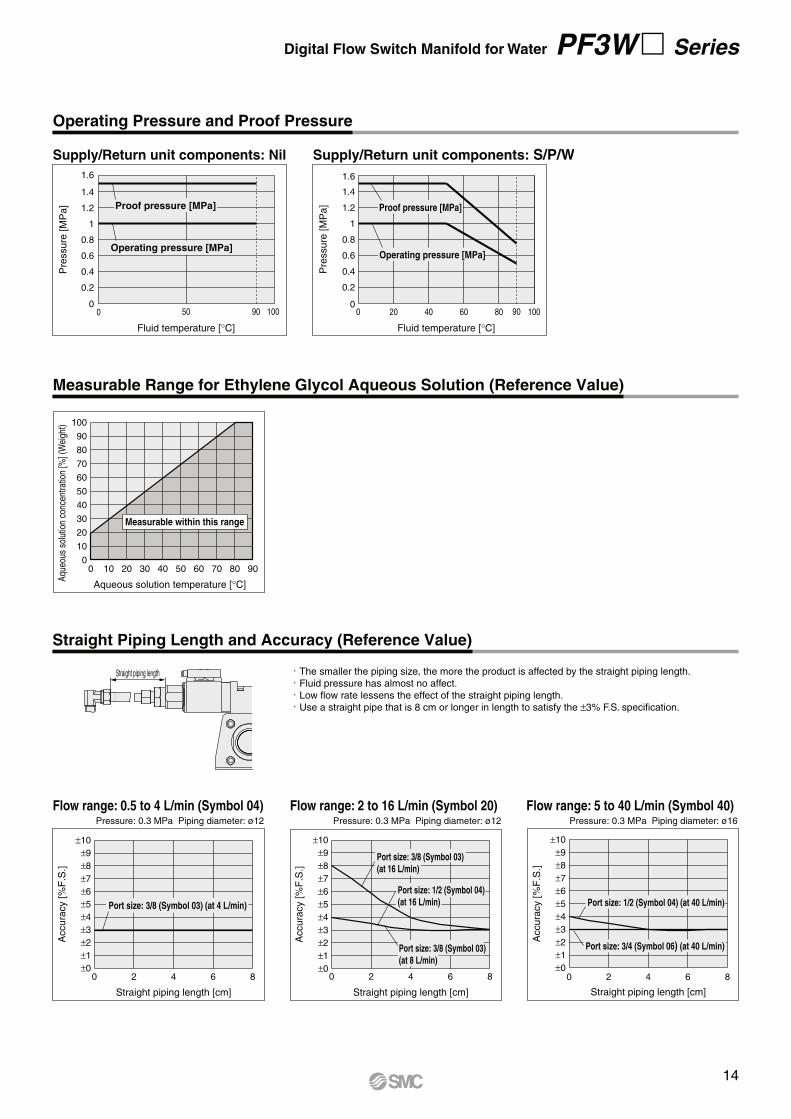
Supply/Return unit components: S/P/W
0
1
0 20 40 60 80 100P
ressure
[M
Pa]
1.6
1.4
1.2
0.8
0.6
0.4
0.2
Operating pressure [MPa]
Proof pressure [MPa]
0
0.2
0.4
0.6
0.8
1
1.2
1.4
1.6
0 50 90 100
Fluid temperature [°C]
Pre
ssure
[M
Pa]
Supply/Return unit components: Nil
Proof pressure [MPa]
Operating pressure [MPa]
90
Measurable Range for Ethylene Glycol Aqueous Solution (Reference Value)
Digital Flow Switch Manifold for Water PF3W Series
Operating Pressure and Proof Pressure
Accura
cy [%
F.S
.]
±10
±9
±8
±7
±6
±5
±4
±3
±2
±1
±0
Straight piping length [cm]
0 2 4 6 8
Port size: 3/8 (Symbol 03) (at 4 L/min)
Accura
cy [%
F.S
.]
±10
±9
±8
±7
±6
±5
±4
±3
±2
±1
±0
Straight piping length [cm]
0 2 4 6 8
Port size: 3/8 (Symbol 03)
(at 16 L/min)
Port size: 1/2 (Symbol 04)
(at 16 L/min)
Port size: 3/8 (Symbol 03)
(at 8 L/min)
Accura
cy [%
F.S
.]
±10
±9
±8
±7
±6
±5
±4
±3
±2
±1
±0
Straight piping length [cm]
0 2 4 6 8
Port size: 1/2 (Symbol 04) (at 40 L/min)
Port size: 3/4 (Symbol 06) (at 40 L/min)
Flow range: 0.5 to 4 L/min (Symbol 04) Flow range: 2 to 16 L/min (Symbol 20) Flow range: 5 to 40 L/min (Symbol 40)Pressure: 0.3 MPa Piping diameter: ø12 Pressure: 0.3 MPa Piping diameter: ø12 Pressure: 0.3 MPa Piping diameter: ø16
Straight piping length · The smaller the piping size, the more the product is affected by the straight piping length.· Fluid pressure has almost no affect.· Low flow rate lessens the effect of the straight piping length.· Use a straight pipe that is 8 cm or longer in length to satisfy the ±3% F.S. specification.
Straight Piping Length and Accuracy (Reference Value)
Aqu
eous
sol
utio
n co
ncen
trat
ion
[%] (
Wei
ght) 100
90
80
70
60
50
40
30
20
10
0
Aqueous solution temperature [°C]
0 10 20 30 40 50 60 70 80 90
Measurable within this range
14
PF3W Series
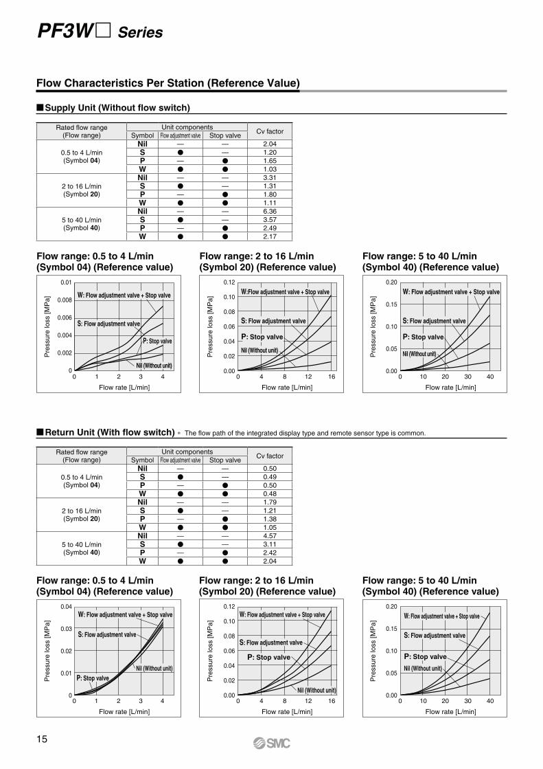
Flow Characteristics Per Station (Reference Value)
Supply Unit (Without flow switch)
Rated flow range(Flow range)
Unit componentsCv factor
Symbol Flow adjustment valve Stop valve
0.5 to 4 L/min(Symbol 04)
Nil — — 2.04
S V — 1.20
P — V 1.65
W V V 1.03
2 to 16 L/min(Symbol 20)
Nil — — 3.31
S V — 1.31
P — V 1.80
W V V 1.11
5 to 40 L/min(Symbol 40)
Nil — — 6.36
S V — 3.57
P — V 2.49
W V V 2.17
0 4 8 12 16
Pre
ssure
loss [M
Pa]
0.01
0.008
0.006
0.004
0.002
0
Flow rate [L/min]
0 1 2 3 4
Pre
ssure
loss [M
Pa]
0.12
0.10
0.08
0.06
0.04
0.02
0.00
0.20
0.15
0.10
0.05
0.00
Flow rate [L/min]
Pre
ssure
loss [M
Pa]
Flow rate [L/min]
0 10 20 30 40
Flow range: 0.5 to 4 L/min(Symbol 04) (Reference value)
P: Stop valve
S: Flow adjustment valve
W: Flow adjustment valve + Stop valve
Nil (Without unit)
Flow range: 2 to 16 L/min(Symbol 20) (Reference value)
Flow range: 5 to 40 L/min(Symbol 40) (Reference value)
S: Flow adjustment valve
P: Stop valve
Nil (Without unit)
W: Flow adjustment valve + Stop valve
S: Flow adjustment valve
P: Stop valve
Nil (Without unit)
W:Flow adjustment valve + Stop valve
Rated flow range(Flow range)
Unit componentsCv factor
Symbol Flow adjustment valve Stop valve
0.5 to 4 L/min(Symbol 04)
Nil — — 0.50
S V — 0.49
P — V 0.50
W V V 0.48
2 to 16 L/min(Symbol 20)
Nil — — 1.79
S V — 1.21
P — V 1.38
W V V 1.05
5 to 40 L/min(Symbol 40)
Nil — — 4.57
S V — 3.11
P — V 2.42
W V V 2.04
Return Unit (With flow switch) ∗ The flow path of the integrated display type and remote sensor type is common.
0 4 8 12 16
Pre
ssure
loss [M
Pa]
0.04
0.03
0.02
0.01
0
Flow rate [L/min]
0 1 2 3 4
Pre
ssure
loss [M
Pa]
0.12
0.10
0.08
0.06
0.04
0.02
0.00
0.20
0.15
0.10
0.05
0.00
Flow rate [L/min]
Pre
ssure
loss [M
Pa]
Flow rate [L/min]
0 10 20 30 40
W: Flow adjustment valve + Stop valve
S: Flow adjustment valve
W: Flow adjustment valve + Stop valve
S: Flow adjustment valve
P: Stop valve
P: Stop valve
Nil (Without unit)
Nil (Without unit)
W: Flow adjustment valve + Stop valve
S: Flow adjustment valve
Nil (Without unit)
P: Stop valve
Flow range: 0.5 to 4 L/min(Symbol 04) (Reference value)
Flow range: 2 to 16 L/min(Symbol 20) (Reference value)
Flow range: 5 to 40 L/min(Symbol 40) (Reference value)
15
iq r w t w
y uw e w w
w !0 !1 !2 o w
!3
w
!4
w
w
!5
!6
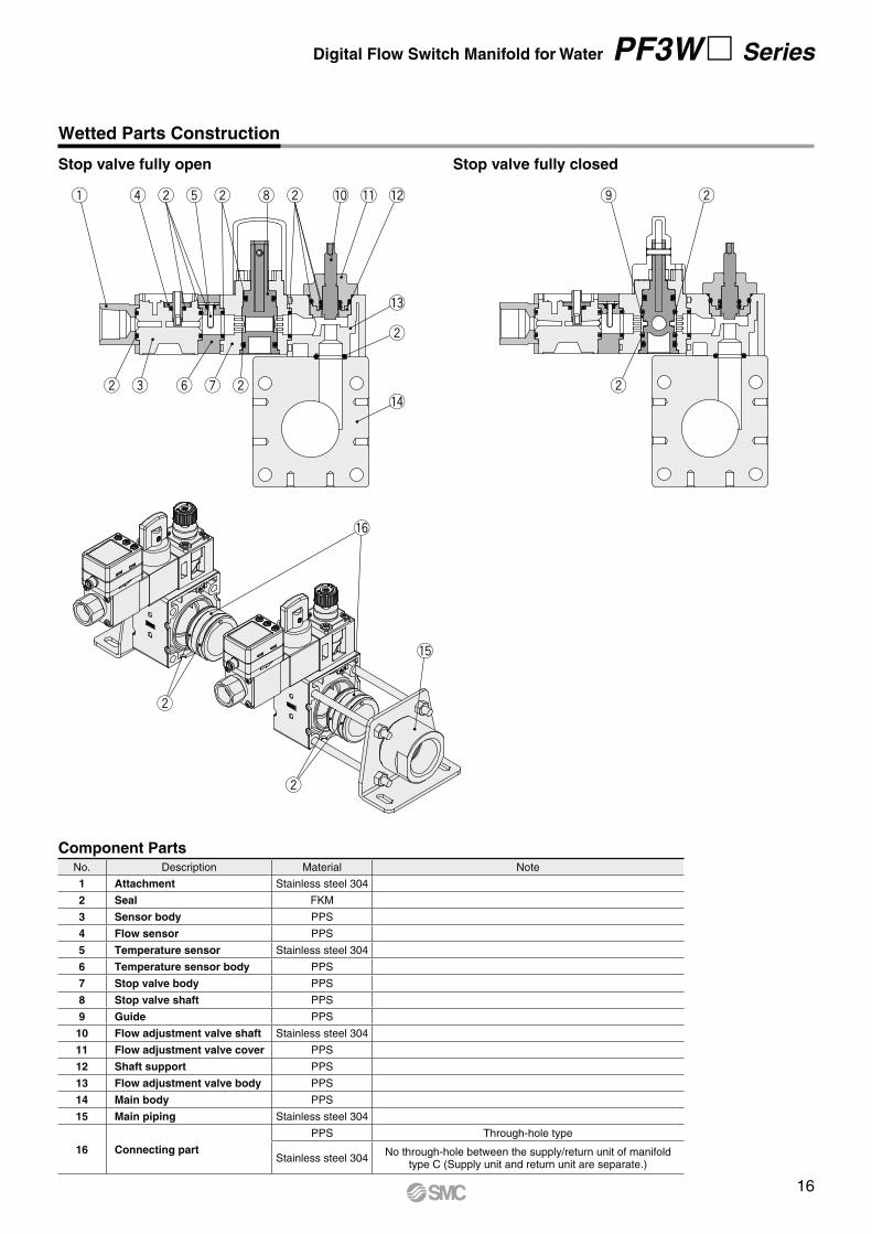
Digital Flow Switch Manifold for Water PF3W Series
Stop valve fully open Stop valve fully closed
Wetted Parts Construction
Component PartsNo. Description Material Note
1 Attachment Stainless steel 304
2 Seal FKM
3 Sensor body PPS
4 Flow sensor PPS
5 Temperature sensor Stainless steel 304
6 Temperature sensor body PPS
7 Stop valve body PPS
8 Stop valve shaft PPS
9 Guide PPS
10 Flow adjustment valve shaft Stainless steel 304
11 Flow adjustment valve cover PPS
12 Shaft support PPS
13 Flow adjustment valve body PPS
14 Main body PPS
15 Main piping Stainless steel 304
16 Connecting part
PPS Through-hole type
Stainless steel 304No through-hole between the supply/return unit of manifold
type C (Supply unit and return unit are separate.)
16
Brown
Black
White
Blue
DC(+)
OUT1
Analog output
DC(–)
12 to 24 VDC+
–
Main
circuit
Load
Load
Brown
Black
White
Blue
DC(+)
OUT1
OUT2
DC(–)
12 to 24 VDC+
–
Main
circuit
Load
Load
Brown
Black
White
Blue
DC(+)
OUT1
OUT2
DC(–)
12 to 24 VDC+
–
Main
circuit
Load
Load
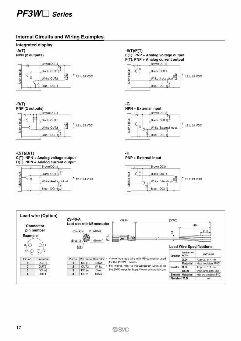
PF3W Series
Internal Circuits and Wiring Examples
Integrated display
Lead wire (Option)
∗ 4-wire type lead wire with M8 connector used
for the PF3W series
∗ For wiring, refer to the Operation Manual on
the SMC website, https://www.smcworld.com
Connector
pin number
13
24
Example
Pin no. Pin name
1 DC (+)
2 OUT2
3 DC (–)
4 OUT1
Lead Wire Specifications
ø4
ø10
(15)
(45)
(3000)(32.8)
Pin no. Pin name Wire color
1 DC (+) Brown
2 OUT2 White
3 DC (–) Blue
4 OUT1 Black
ZS-40-A
Lead wire with M8 connector
Brown
Black
White
Blue
DC(+)
OUT1
Analog output
DC(–)
12 to 24 VDC+
–
Main
circuit
Load
Load
Brown
Black
White
Blue
DC(+)
OUT1
External input
DC(–)
12 to 24 VDC
U
+
–M
ain
circuit
Load
Brown
Black
White
Blue
DC(+)
OUT1
External input
DC(–)
12 to 24 VDC
U
+
–
Main
circuit
Load
-A(T)NPN (2 outputs)
-B(T)
PNP (2 outputs)
-GNPN + External input
-HPNP + External input
-C(T)/D(T)
C(T): NPN + Analog voltage output
D(T): NPN + Analog current output
-E(T)/F(T)
E(T): PNP + Analog voltage output
F(T): PNP + Analog current output
1 (Brown)
2 (White)(Black) 4
(Blue) 3
M8
ConductorNominal crosssection
AWG 23
O.D. Approx. 0.7 mm
Insulator
Material Heat-resistant PVC
O.D. Approx. 1.1 mm
Color Brown, White, Black, Blue
Sheath Material Heat- and oil-resistant PVC
Finished O.D. ø4
17
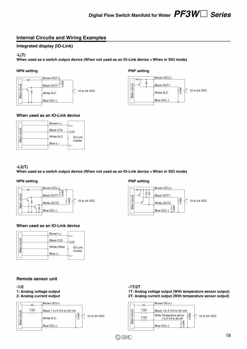
Digital Flow Switch Manifold for Water PF3W Series
-L2(T)
When used as a switch output device (When not used as an IO-Link device = When in SIO mode)
Brown L+L+
C/O
L−
Black C/Q
White Other IO-Link
masterBlue L−
Main
circuit
When used as an IO-Link device
-L(T)
When used as a switch output device (When not used as an IO-Link device = When in SIO mode)
Brown L+L+
C/O
L−
Black C/Q
White N.C. IO-Linkmaster
Blue L−
Main
circuit
When used as an IO-Link device
Brown DC(+)
Black OUT1
White N.C.
Blue DC(−)
12 to 24 VDC+
−
Main
circuit
Load
NPN setting
Brown DC(+)
Black OUT1
White N.C.
Blue DC(−)
12 to 24 VDC+
−
Main
circuit
Load
PNP setting
Brown DC(+)
Black OUT1
White OUT2
Blue DC(−)
12 to 24 VDC+
−
Main
circuit
Load
Load
NPN setting
Brown DC(+)
Black OUT1
White OUT2
Blue DC(−)
12 to 24 VDC+
−
Main
circuit
Load
Load
PNP setting
Internal Circuits and Wiring Examples
Integrated display (IO-Link)
Brown DC(+)
Black 1 to 5 V/4 to 20 mA
White N.C.
Blue DC(−)
12 to 24 VDC+
−
1 kΩ
Load
Main
circuit
Brown DC(+)
Black 1 to 5 V/4 to 20 mA
White Temperature sensor1 to 5 V/4 to 20 mA
Blue DC(−)
12 to 24 VDC+
−
1 kΩ
1 kΩ Load
Load
Main
circuit
-1/21: Analog voltage output
2: Analog current output
-1T/2T1T: Analog voltage output (With temperature sensor output)
2T: Analog current output (With temperature sensor output)
Remote sensor unit
18
10
10
Mounting hole position
8
6.5
125
6.5
8
a x
n +
56
a x
n +
48
6.5
Mounting hole position
10
10
a x
2n +
38
65
6.56.5
85
65
6.5
a x
2n +
66
a x
2n +
68
33
a
6.5
10
a33
34
n: Stations
n: Stations
PF3W Series
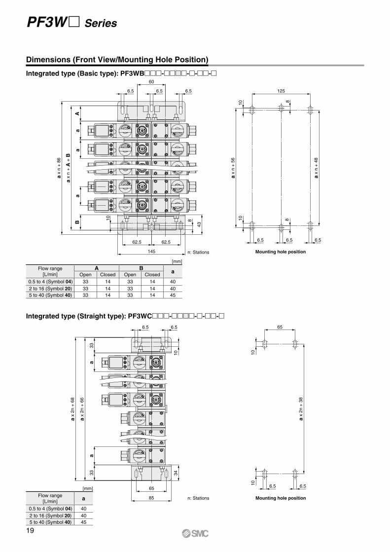
Integrated type (Straight type): PF3WC----
Dimensions (Front View/Mounting Hole Position)
[mm]
Flow range
[L/min]
A Ba
Open Closed Open Closed
0.5 to 4 (Symbol 04) 33 14 33 14 40
2 to 16 (Symbol 20) 33 14 33 14 40
5 to 40 (Symbol 40) 33 14 33 14 45
[mm]
Flow range
[L/min]a
0.5 to 4 (Symbol 04) 40
2 to 16 (Symbol 20) 40
5 to 40 (Symbol 40) 45
6.5 6.5
10
60
6.5
Aa
B
62.5
a x
n +
86
a x
n +
A +
B
a
62.5
145
8
43
aIntegrated type (Basic type): PF3WB----
19
65
6.5
Mounting hole position10
10
6.5
a x
n +
38
85
65
6.56.510
aa
B34
a
a x
n +
68
a x
n +
A +
B
A
6.5
B 34
aa
a
10
6.5
85
65
a x
n +
A +
B
a x
n +
68
A
Mounting hole position
10
6.56.5
10
a x
n +
38
65
n: Stations
n: Stations
Digital Flow Switch Manifold for Water PF3W Series
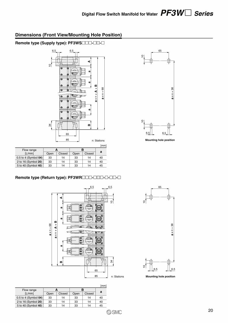
Remote type (Return type): PF3WR----
Dimensions (Front View/Mounting Hole Position)
Remote type (Supply type): PF3WS--
Flow range
[L/min]
A Ba
Open Closed Open Closed
0.5 to 4 (Symbol 04) 33 14 33 14 40
2 to 16 (Symbol 20) 33 14 33 14 40
5 to 40 (Symbol 40) 33 14 33 14 45
[mm]
Flow range
[L/min]
A Ba
Open Closed Open Closed
0.5 to 4 (Symbol 04) 33 14 33 14 40
2 to 16 (Symbol 20) 33 14 33 14 40
5 to 40 (Symbol 40) 33 14 33 14 45
[mm]
20
1.4
3
141.7
127.9
(M
ax. 132.9
)
102.6
87.5
34.5
4141
60 BA
87.5112.9
132.3
3
102.6
87.5
34.5
4141
117.9
112.9
87.5
A 60 B
127.9
(M
ax. 132.9
)
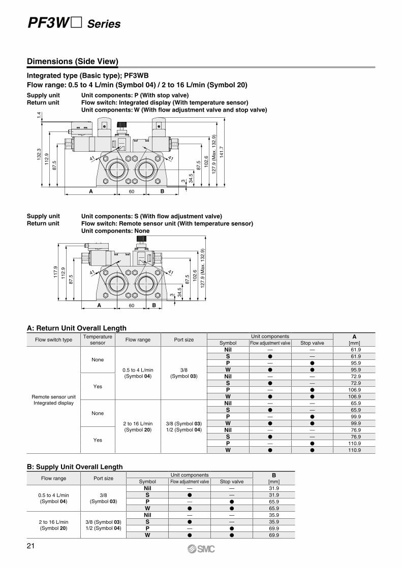
PF3W Series
Integrated type (Basic type); PF3WB
Flow range: 0.5 to 4 L/min (Symbol 04) / 2 to 16 L/min (Symbol 20)
Dimensions (Side View)
Supply unit
Return unit
Supply unit
Return unit
Unit components: P (With stop valve)
Flow switch: Integrated display (With temperature sensor)
Unit components: W (With flow adjustment valve and stop valve)
Unit components: S (With flow adjustment valve)
Flow switch: Remote sensor unit (With temperature sensor)
Unit components: None
A: Return Unit Overall Length
Flow switch typeTemperature
sensorFlow range Port size
Unit components A[mm]Symbol Flow adjustment valve Stop valve
Remote sensor unit
Integrated display
None
0.5 to 4 L/min
(Symbol 04)
3/8
(Symbol 03)
Nil — — 61.9
S V — 61.9
P — V 95.9
W V V 95.9
Yes
Nil — — 72.9
S V — 72.9
P — V 106.9
W V V 106.9
None
2 to 16 L/min
(Symbol 20)
3/8 (Symbol 03)
1/2 (Symbol 04)
Nil — — 65.9
S V — 65.9
P — V 99.9
W V V 99.9
Yes
Nil — — 76.9
S V — 76.9
P — V 110.9
W V V 110.9
B: Supply Unit Overall Length
Flow range Port sizeUnit components B
[mm]Symbol Flow adjustment valve Stop valve
0.5 to 4 L/min
(Symbol 04)
3/8
(Symbol 03)
Nil — — 31.9
S V — 31.9
P — V 65.9
W V V 65.9
2 to 16 L/min
(Symbol 20)
3/8 (Symbol 03)
1/2 (Symbol 04)
Nil — — 35.9
S V — 35.9
P — V 69.9
W V V 69.9
21
1.4
3 34.5
4141
91.31
20.7
140.1
A 60 B
151.2
137.5
(M
ax. 143.2
)
91.3
3 34.5
4141
91.31
20.7
125.7
60
137.5
(M
ax. 143.2
)
91.3
BA
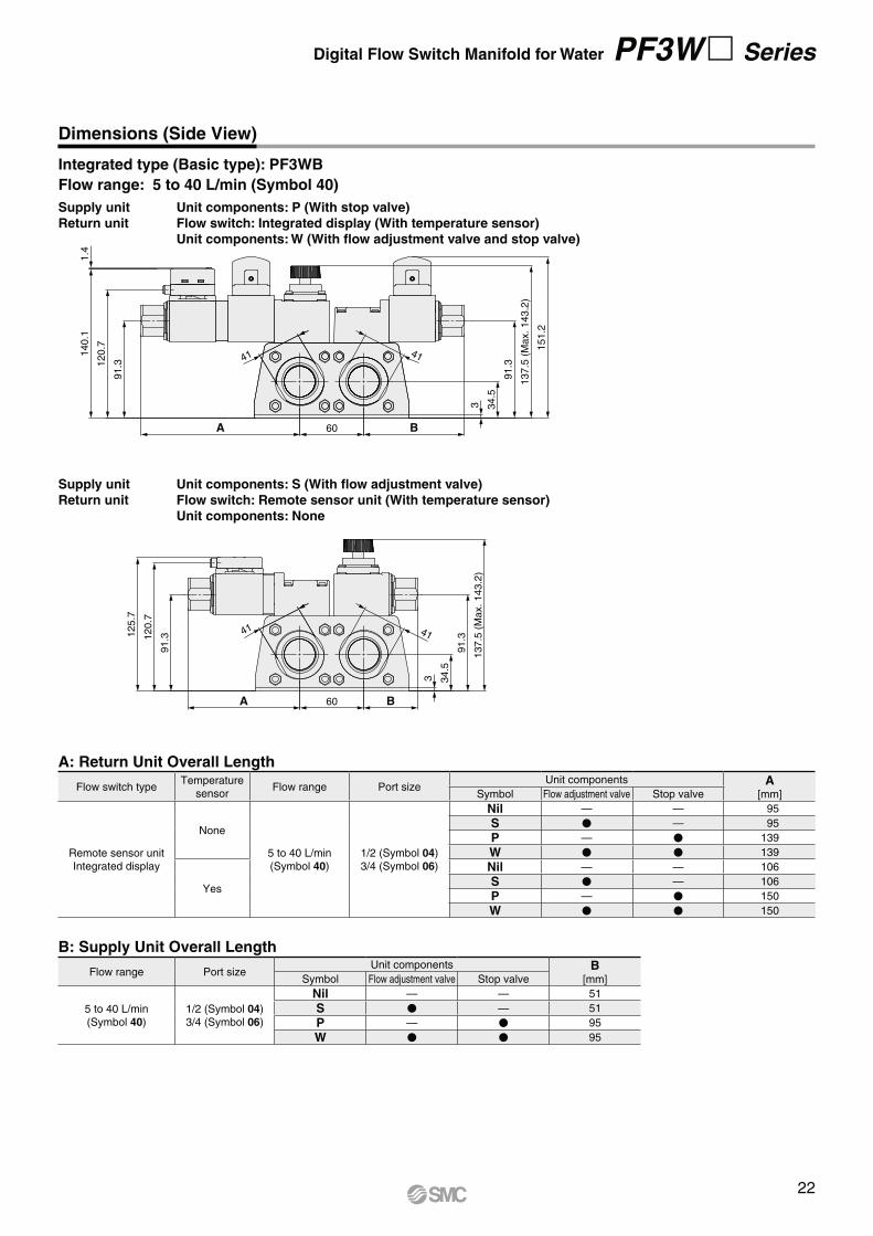
Digital Flow Switch Manifold for Water PF3W Series
Dimensions (Side View)
Integrated type (Basic type): PF3WB
Flow range: 5 to 40 L/min (Symbol 40)
Supply unit
Return unit
Supply unit
Return unit
Unit components: P (With stop valve)
Flow switch: Integrated display (With temperature sensor)
Unit components: W (With flow adjustment valve and stop valve)
Unit components: S (With flow adjustment valve)
Flow switch: Remote sensor unit (With temperature sensor)
Unit components: None
A: Return Unit Overall Length
Flow switch typeTemperature
sensorFlow range Port size
Unit components A[mm]Symbol Flow adjustment valve Stop valve
Remote sensor unit
Integrated display
None
5 to 40 L/min
(Symbol 40)
1/2 (Symbol 04)
3/4 (Symbol 06)
Nil — — 95
S V — 95
P — V 139
W V V 139
Yes
Nil — — 106
S V — 106
P — V 150
W V V 150
B: Supply Unit Overall Length
Flow range Port sizeUnit components B
[mm]Symbol Flow adjustment valve Stop valve
5 to 40 L/min
(Symbol 40)
1/2 (Symbol 04)
3/4 (Symbol 06)
Nil — — 51
S V — 51
P — V 95
W V V 95
22
3 3
A
B
C
41
D
41
34.5
F
34.5
E
A
PF3W Series
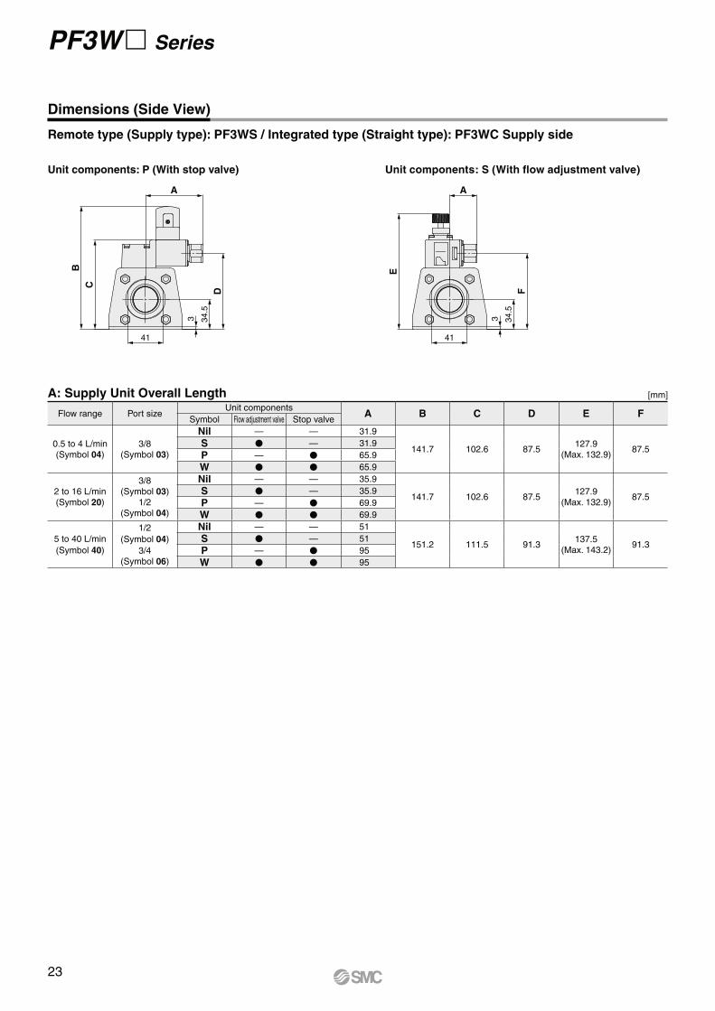
Remote type (Supply type): PF3WS / Integrated type (Straight type): PF3WC Supply side
Unit components: S (With flow adjustment valve)Unit components: P (With stop valve)
Dimensions (Side View)
A: Supply Unit Overall Length
Flow range Port sizeUnit components
A B C D E FSymbol Flow adjustment valve Stop valve
0.5 to 4 L/min
(Symbol 04)
3/8
(Symbol 03)
Nil — — 31.9
141.7 102.6 87.5127.9
(Max. 132.9)87.5
S V — 31.9
P — V 65.9
W V V 65.9
2 to 16 L/min
(Symbol 20)
3/8
(Symbol 03)
1/2
(Symbol 04)
Nil — — 35.9
141.7 102.6 87.5127.9
(Max. 132.9)87.5
S V — 35.9
P — V 69.9
W V V 69.9
5 to 40 L/min
(Symbol 40)
1/2
(Symbol 04)
3/4
(Symbol 06)
Nil — — 51
151.2 111.5 91.3137.5
(Max. 143.2)91.3
S V — 51
P — V 95
W V V 95
[mm]
23
1.4
334.5
3 34.5
E
A
GF
D
C
B
A
D
CH I
41 41
Digital Flow Switch Manifold for Water PF3W Series
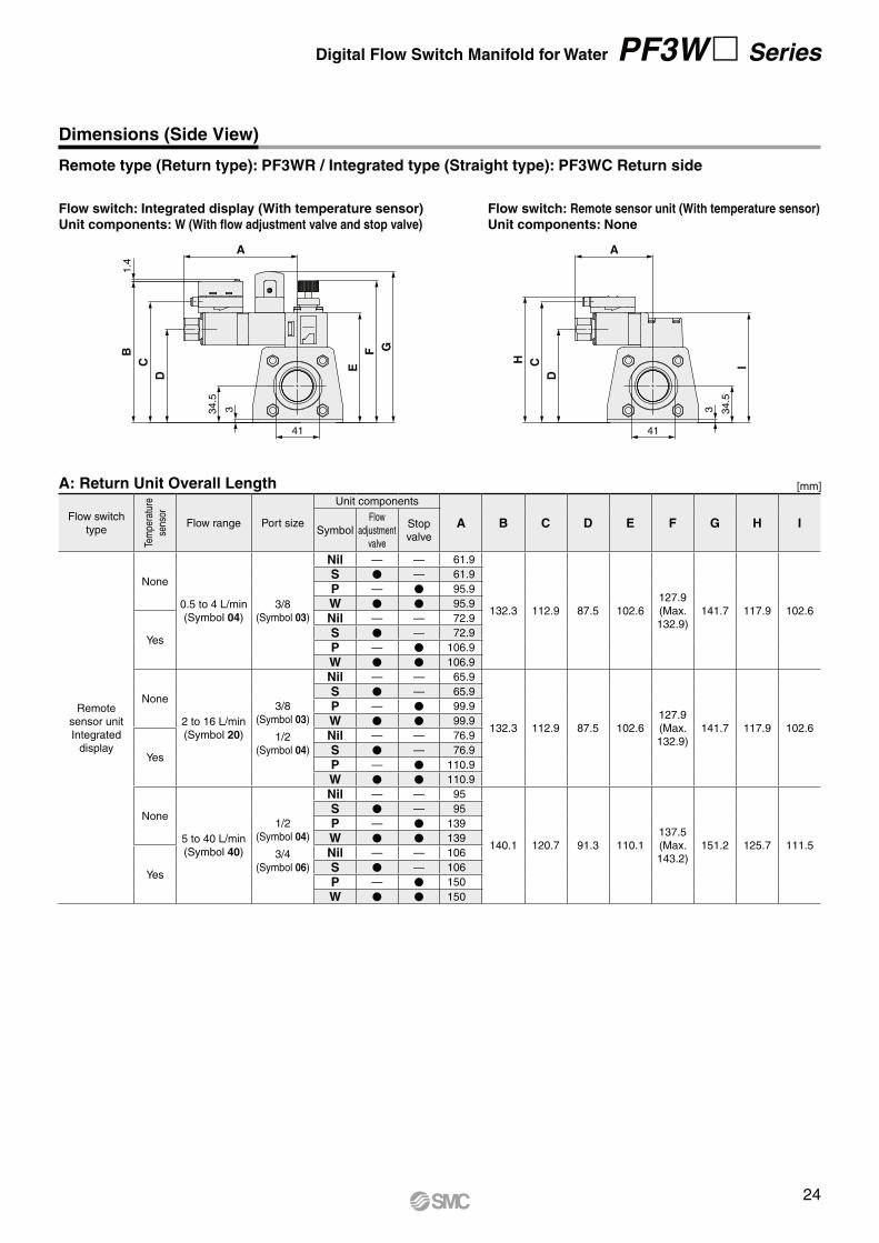
Remote type (Return type): PF3WR / Integrated type (Straight type): PF3WC Return side
Dimensions (Side View)
Flow switch: Remote sensor unit (With temperature sensor)
Unit components: None
Flow switch: Integrated display (With temperature sensor)
Unit components: W (With flow adjustment valve and stop valve)
A: Return Unit Overall Length
Flow switch
type
Tem
pera
ture
sens
or
Flow range Port size
Unit components
A B C D E F G H ISymbol
Flow
adjustment
valve
Stop
valve
Remote
sensor unit
Integrated
display
None
0.5 to 4 L/min
(Symbol 04)
3/8
(Symbol 03)
Nil — — 61.9
132.3 112.9 87.5 102.6
127.9
(Max.
132.9)
141.7 117.9 102.6
S V — 61.9
P — V 95.9
W V V 95.9
Yes
Nil — — 72.9
S V — 72.9
P — V 106.9
W V V 106.9
None
2 to 16 L/min
(Symbol 20)
3/8
(Symbol 03)
1/2
(Symbol 04)
Nil — — 65.9
132.3 112.9 87.5 102.6
127.9
(Max.
132.9)
141.7 117.9 102.6
S V — 65.9
P — V 99.9
W V V 99.9
Yes
Nil — — 76.9
S V — 76.9
P — V 110.9
W V V 110.9
None
5 to 40 L/min
(Symbol 40)
1/2
(Symbol 04)
3/4
(Symbol 06)
Nil — — 95
140.1 120.7 91.3 110.1
137.5
(Max.
143.2)
151.2 125.7 111.5
S V — 95
P — V 139
W V V 139
Yes
Nil — — 106
S V — 106
P — V 150
W V V 150
[mm]
24
PF3W Series
Function Details
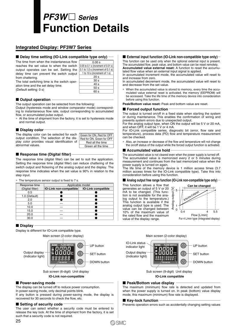
Response time (Digital filter)
The response time (digital filter) can be set to suit the application.
Setting the response time (digital filter) can reduce chattering of the
switch output and flickering of the analog output and the display. The
response time indicates when the set value is 90% in relation to the
step input.
∗ The temperature sensor output is fixed to 7 s.
Response time
(Digital filter)
Applicable model
IO-Link non-compatible IO-Link compatible
0.5 V V
1.0 (Default) V V
2.0 V V
5.0 — V
10.0 — V
15.0 — V
20.0 — V
30.0 — V
Integrated Display: PF3W7 Series
Delay time setting (IO-Link compatible type only)
The time from when the instantaneous flow
reaches the set value to when the switch
output operates can be set. Setting the
delay time can prevent the switch output
from chattering.
The total switching time is the switch oper-
ation time and the set delay time.
(Default setting: 0 s)
0.00 s
0.05 to 0.1 s (increment of 0.01 s)
0.1 to 1.0 s (increment of 0.1 s)
1 to 10 s (increment of 1 s)
20 s
30 s
40 s
50 s
60 s
Display
Display is different for IO-Link compatible type.
IO-Link compatibleIO-Link non-compatible
UP button
Main screen (2-color display)
Sub screen (9-digit) Unit display
IO-Link status
indicator light
Output display
(Indicator light)SET button
DOWN button
UP button
Main screen (2-color display)
Sub screen (6-digit) Unit display
Output display
(Indicator light)SET button
DOWN button
Analog output free range function (IO-Link non-compatible type only)
This function allows a flow that generates an output of 5 V or 20 mA to be changed. (This func-tion is not available for the ana-log output to the temperature.) This function is available if the analog output type is used. The value can be changed between 10% of the maximum value of the rated flow and the maximum value of the display range.
Flow [L/min]For 4 L/min type (Integrated display)
Can be changed
5
1
0Analo
g o
utp
ut [V
]
4 5.50.4
At the time of shipment
Output operationThe output operation can be selected from the following:Output (hysteresis mode and window comparator mode) correspond-ing to instantaneous flow rate, output corresponding to accumulated flow, or accumulated pulse output.∗ At the time of shipment from the factory, it is set to hysteresis mode
and normal output.
Display colorThe display color can be selected for each output condition. The selection of the dis-play color provides visual identification of abnormal values.
Green for ON, Red for OFF
Red for ON, Green for OFF
Red all the time
Green all the time
Peak/Bottom value displayThe maximum (minimum) flow rate is detected and updated from when the power supply is turned on. In peak (bottom) value display mode, this maximum (minimum) flow rate is displayed.
Setting of security codeThe user can select whether a security code must be entered to release the key lock. At the time of shipment from the factory, it is set such that a security code is not required.
Power-saving modeThe display can be turned off to reduce power consumption.In power-saving mode, only decimal points blink.If any button is pressed during power-saving mode, the display is recovered for 30 seconds to check the flow, etc.
Key-lock functionPrevents operation errors such as accidentally changing setting values
External input function (IO-Link non-compatible type only) This function can be used only when the optional external input is present. The accumulated flow, peak value, and bottom value can be reset remotely.Accumulated value external reset: A function to reset the accumu-lated flow value when an external input signal is applied.In accumulated increment mode, the accumulated value will reset to and increase from zero.In accumulated decrement mode, the accumulated value will reset to and decrease from the set value.
∗ When the accumulated value is stored to memory, every time the accu-mulated value external reset is activated, the memory (EEPROM) will be accessed. Take the life time of the memory device into consideration before using this function.
Peak/Bottom value reset: Peak and bottom value are reset.
Forced output functionThe output is turned on/off in a fixed state when starting the system or during maintenance. This enables the confirmation of wiring and prevents system errors due to unexpected output.For the analog output type, when ON the output will be 5 V or 20 mA, and when OFF, it will be 1 V or 4 mA.For IO-Link compatible series, diagnostic bit (error, flow rate and temperature), process data (PD) flow and temperature measurement can be checked.
∗ Also, an increase or decrease of the flow and temperature will not change the on/off status of the output while the forced output function is activated.
Accumulated value holdThe accumulated value is not cleared even when the power supply is turned off.The accumulated value is memorized every 2 or 5 minutes during measurement and continues from the last memorized value when the power supply is turned on again.The life time of the memory device is 1 million access times (3.7 million access times for the IO-Link compatible type). Take this into consideration before using this function.
25
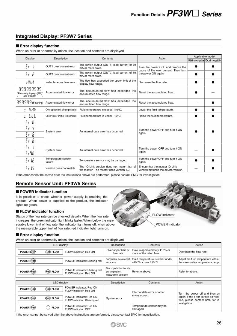
Function Details PF3W Series
Integrated Display: PF3W7 Series
Remote Sensor Unit: PF3W5 Series
POWER indicator
FLOW indicator
Error display function
When an error or abnormality arises, the location and contents are displayed.
If the error cannot be solved after the above instructions are performed, please contact SMC for investigation.
LED display Description Contents Action
Over upper limit of flow rate
Flow is approximately 110% or more of the rated flow.
Decrease the flow rate.
Temperature measurement range error
Fluid temperature is either under –10°C or over 110°C.
Adjust the fluid temperature within the measurable temperature range.
Over upper limit of flow rate and temperature measurement range error
Refer to above. Refer to above.
LED display Description Contents Action
System error
Internal data error or other errors occur.
Turn the power off and then on again. If the error cannot be recti-fied, please contact SMC for in-vestigation.
Temperature sensor may be damaged.
POWER FLOW FLOW indicator: Red ONGreen Red
POWER POWER indicator: Blinking redRed
POWER FLOWPOWER indicator: Blinking red
FLOW indicator: Red ONRed Red
POWER FLOWPOWER indicator: Red ON
FLOW indicator: Red ONRed Red
POWER FLOWPOWER indicator: Red ON
FLOW indicator: Blinking redRed Red
POWER FLOWPOWER indicator: Red ON
FLOW indicator: OFFRed
Display Description Contents ActionApplicable model
IO-Link non-compatible IO-Link compatible
OUT1 over current errorThe switch output (OUT1) load current of 80 mA or more flows. Turn the power OFF and remove the
cause of the over current. Then turn the power ON again.
V V
OUT2 over current errorThe switch output (OUT2) load current of 80 mA or more flows.
V V
Instantaneous flow errorThe flow has exceeded the upper limit of the display flow range.
Decrease the flow rate. V V
Alternately displays [999]and [999999]
Accumulated flow errorThe accumulated flow has exceeded the accumulated flow range.
Reset the accumulated flow. V —
(Flashing) Accumulated flow errorThe accumulated flow has exceeded the accumulated flow range.
Reset the accumulated flow. — V
Over upper limit of temperature Fluid temperature exceeds 110°C. Lower the fluid temperature. V V
Under lower limit of temperature Fluid temperature is under –10°C. Raise the fluid temperature. V V
System error An internal data error has occurred.Turn the power OFF and turn it ON again.
V V
System error An internal data error has occurred.Turn the power OFF and turn it ON again.
— V
Temperature sensor
failureTemperature sensor may be damaged.
Turn the power OFF and turn it ON again.
V V
Version does not matchThe IO-Link version does not match that of the master. The master uses version 1.0.
Ensure that the master IO-Link version matches the device version.
— V
Error display function
When an error or abnormality arises, the location and contents are displayed.
If the error cannot be solved after the instructions above are performed, please contact SMC for investigation.
FLOW indicator function
Status of the flow rate can be checked visually. When the flow rate
increases, the green indicator light blinks faster. When below the mea-
surable lower limit of flow rate, the indicator light turns off, when above
the measurable upper limit of flow rate, red indicator light turns on.
POWER indicator function
It is possible to check whether power supply is reaching the
product. When power is supplied to the product, the indicator
lights up green.
26
PF3WB/C/S/R Series
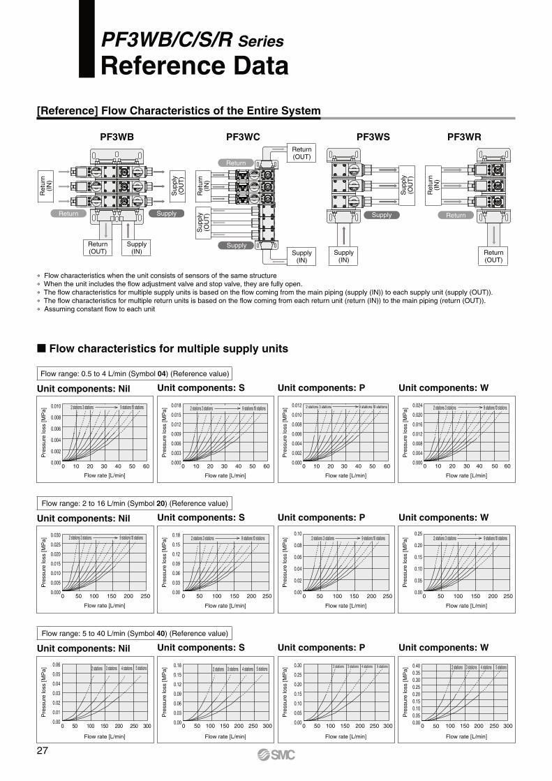
Reference Data
[Reference] Flow Characteristics of the Entire System
Flow characteristics for multiple supply units
∗ Flow characteristics when the unit consists of sensors of the same structure
∗ When the unit includes the flow adjustment valve and stop valve, they are fully open.
∗ The flow characteristics for multiple supply units is based on the flow coming from the main piping (supply (IN)) to each supply unit (supply (OUT)).
∗ The flow characteristics for multiple return units is based on the flow coming from each return unit (return (IN)) to the main piping (return (OUT)).
∗ Assuming constant flow to each unit
Supply Return
Supply(IN)
Return(OUT)
Return
SupplySupply
(IN)
Return(OUT)
Return Supply
Supply(IN)
Retu
rn(I
N)
Retu
rn(I
N)
Supply
(OU
T)
Supply
(OU
T)
Supply
(OU
T)
Retu
rn(I
N)
Return(OUT)
PF3WB PF3WC PF3WS PF3WR
Pre
ssure
loss [M
Pa]
Pre
ssure
loss [M
Pa]
Flow rate [L/min]
0.06
0.05
0.04
0.03
0.02
0.01
0.000 50 100 150 200 250 300
2 stations 3 stations 4 stations 5 stations
Pre
ssure
loss [M
Pa]
Flow rate [L/min]
0.18
0.15
0.12
0.09
0.06
0.03
0.000 50 100 150 200 250 300
2 stations 3 stations 4 stations 5 stations
Pre
ssure
loss [M
Pa]
Flow rate [L/min]
0.30
0.25
0.20
0.15
0.10
0.05
0.000 50 100 150 200 250 300
2 stations 3 stations 4 stations 5 stations
Flow rate [L/min]
0.40
0.35
0.30
0.25
0.20
0.15
0.10
0.05
0.000 50 100 150 200 250 300
2 stations 3 stations 4 stations 5 stations
Flow range: 5 to 40 L/min (Symbol 40) (Reference value)
Unit components: Nil Unit components: S Unit components: P Unit components: W
Pre
ssure
loss [M
Pa]
Flow rate [L/min]
2 stations 3 stations 9 stations 10 stations 0.10
0.08
0.06
0.04
0.02
0.000 50 100 150 200 250
Pre
ssure
loss [M
Pa]
Flow rate [L/min]
0.030
0.025
0.020
0.015
0.010
0.005
0.0000 50 100 150 200 250
2 stations 3 stations 9 stations 10 stations
Pre
ssure
loss [M
Pa]
Flow rate [L/min]
9 stations 10 stations 0.25
0.20
0.15
0.10
0.05
0.000 50 100 150 200 250
2 stations 3 stations
Flow rate [L/min]
2 stations 3 stations 0.18
0.15
0.12
0.09
0.06
0.03
0.000 50 100 150 200 250
9 stations 10 stations
Pre
ssure
loss [M
Pa]
Flow range: 2 to 16 L/min (Symbol 20) (Reference value)
Unit components: Nil Unit components: S Unit components: P Unit components: W
0.010
0.008
0.006
0.004
0.002
0.0000 10 20 30 40 50 60
Pre
ssure
loss [M
Pa]
Flow rate [L/min]
2 stations 3 stations 9 stations 10 stations
Pre
ssure
loss [M
Pa]
Flow rate [L/min]
0.018
0.015
0.012
0.009
0.006
0.003
0.0000 10 20 30 40 50 60
2 stations 3 stations 9 stations 10 stations
Pre
ssure
loss [M
Pa]
Flow rate [L/min]
0.012
0.010
0.008
0.006
0.004
0.002
0.0000 10 20 30 40 50 60
2 stations 3 stations 9 stations 10 stations 0.024
0.020
0.016
0.012
0.008
0.004
0.0000 10 20 30 40 50 60
Pre
ssure
loss [M
Pa]
Flow rate [L/min]
2 stations 3 stations 9 stations 10 stations
Flow range: 0.5 to 4 L/min (Symbol 04) (Reference value)
Unit components: Nil Unit components: S Unit components: P Unit components: W
27
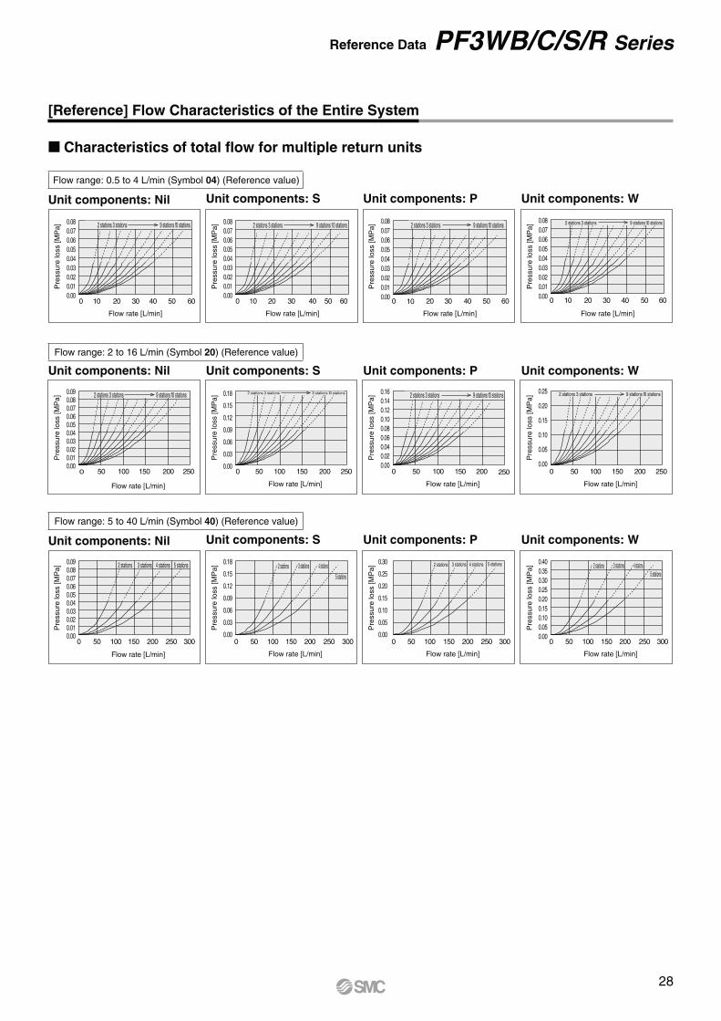
Reference Data PF3WB/C/S/R Series
[Reference] Flow Characteristics of the Entire System
Characteristics of total flow for multiple return units
Pre
ssure
loss [M
Pa]
0.08
0.07
0.06
0.05
0.04
0.03
0.02
0.01
0.000 10 20 30 40 50 60
Flow rate [L/min]
Pre
ssure
loss [M
Pa]
Flow rate [L/min]
50 60
0.08
0.07
0.06
0.05
0.04
0.03
0.02
0.01
0.000 10 20 30 40
2 stations 3 stations 9 stations 10 stations
Pre
ssure
loss [M
Pa]
Flow rate [L/min]
0.08
0.07
0.06
0.05
0.04
0.03
0.02
0.01
0.000 10 20 30 40 50 60
2 stations 3 stations 9 stations 10 stations
Pre
ssure
loss [M
Pa]
Flow rate [L/min]
0.08
0.07
0.06
0.05
0.04
0.03
0.02
0.01
0.000 10 20 30 40 50 60
2 stations 3 stations 9 stations 10 stations 2 stations 3 stations 9 stations 10 stations
Flow range: 0.5 to 4 L/min (Symbol 04) (Reference value)
Unit components: Nil Unit components: S Unit components: P Unit components: W
Pre
ssure
loss [M
Pa]
Flow rate [L/min]
0.090.080.070.060.050.040.030.020.010.00
0 50 100 150 200 250 300
Pre
ssure
loss [M
Pa]
Flow rate [L/min]
0.40
0.35
0.30
0.25
0.20
0.15
0.10
0.05
0.000 50 100 150 200 250 300
2 stations 3 stations 4 stations 5 stations
Pre
ssure
loss [M
Pa]
Flow rate [L/min]
0.30
0.25
0.20
0.15
0.10
0.05
0.000 50 100 150 200 250 300
2 stations 3 stations 4 stations 5 stations
Pre
ssure
loss [M
Pa]
Flow rate [L/min]
0.18
0.15
0.12
0.09
0.06
0.03
0.000 50 100 150 200 250 300
2 stations 3 stations 4 stations
5 stations
2 stations 3 stations 4 stations 5 stations
Flow range: 5 to 40 L/min (Symbol 40) (Reference value)
Unit components: Nil Unit components: S Unit components: P Unit components: W
Pre
ssure
loss [M
Pa]
Flow rate [L/min]
0.090.080.070.060.050.040.030.020.010.00
0 50 100 150 200 250
2 stations 3 stations 9 stations 10 stations
Pre
ssure
loss [M
Pa]
Flow rate [L/min]
0.18
0.15
0.12
0.09
0.06
0.03
0.000 50 100 150 200 250
2 stations 3 stations 9 stations 10 stations
Pre
ssure
loss [M
Pa]
Flow rate [L/min]
0.16
0.14
0.12
0.10
0.08
0.06
0.04
0.02
0.000 50 100 150 200 250
9 stations 10 stations 2 stations 3 stations
Pre
ssure
loss [M
Pa]
Flow rate [L/min]
0.25
0.20
0.15
0.10
0.05
0.000 50 100 150 200 250
9 stations 10 stations 2 stations 3 stations
Flow range: 2 to 16 L/min (Symbol 20) (Reference value)
Unit components: Nil Unit components: S Unit components: P Unit components: W
28
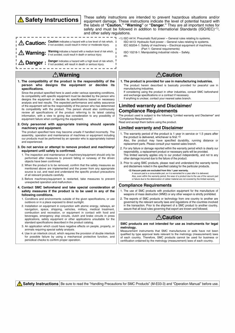
Safety Instructions Be sure to read the “Handling Precautions for SMC Products” (M-E03-3) and “Operation Manual” before use.
CautionSMC products are not intended for use as instruments for legal metrology.Measurement instruments that SMC manufactures or sells have not been qualified by type approval tests relevant to the metrology (measurement) laws of each country. Therefore, SMC products cannot be used for business or certification ordained by the metrology (measurement) laws of each country.
Compliance Requirements
∗1) ISO 4414: Pneumatic fluid power – General rules relating to systems.
ISO 4413: Hydraulic fluid power – General rules relating to systems.
IEC 60204-1: Safety of machinery – Electrical equipment of machines.
(Part 1: General requirements)
ISO 10218-1: Manipulating industrial robots – Safety.
etc.
Caution indicates a hazard with a low level of risk which, if not avoided, could result in minor or moderate injury.Caution:
Warning indicates a hazard with a medium level of risk which, if not avoided, could result in death or serious injury.Warning:
Danger : Danger indicates a hazard with a high level of risk which, if not avoided, will result in death or serious injury.
Warning Caution1. The compatibility of the product is the responsibility of the
person who designs the equipment or decides itsspecifications.
Since the product specified here is used under various operating conditions, its compatibility with specific equipment must be decided by the person whodesigns the equipment or decides its specifications based on necessaryanalysis and test results. The expected performance and safety assuranceof the equipment will be the responsibility of the person who has determined its compatibility with the product. This person should also continuouslyreview all specifications of the product referring to its latest cataloginformation, with a view to giving due consideration to any possibility ofequipment failure when configuring the equipment.
2. Only personnel with appropriate training should operatemachinery and equipment.
The product specified here may become unsafe if handled incorrectly. Theassembly, operation and maintenance of machines or equipment includingour products must be performed by an operator who is appropriately trainedand experienced.
3. Do not service or attempt to remove product and machinery/equipment until safety is confirmed.
1. The inspection and maintenance of machinery/equipment should only beperformed after measures to prevent falling or runaway of the drivenobjects have been confirmed.
2. When the product is to be removed, confirm that the safety measures asmentioned above are implemented and the power from any appropriatesource is cut, and read and understand the specific product precautionsof all relevant products carefully.
3. Before machinery/equipment is restarted, take measures to preventunexpected operation and malfunction.
4. Contact SMC beforehand and take special consideration ofsafety measures if the product is to be used in any of thefollowing conditions.
1. Conditions and environments outside of the given specifications, or useoutdoors or in a place exposed to direct sunlight.
2. Installation on equipment in conjunction with atomic energy, railways, airnavigation, space, shipping, vehicles, military, medical treatment,combustion and recreation, or equipment in contact with food andbeverages, emergency stop circuits, clutch and brake circuits in pressapplications, safety equipment or other applications unsuitable for thestandard specifications described in the product catalog.
3. An application which could have negative effects on people, property, oranimals requiring special safety analysis.
4. Use in an interlock circuit, which requires the provision of double interlock for possible failure by using a mechanical protective function, andperiodical checks to confirm proper operation.
1. The product is provided for use in manufacturing industries.
The product herein described is basically provided for peaceful use inmanufacturing industries. If considering using the product in other industries, consult SMC beforehandand exchange specifications or a contract if necessary. If anything is unclear, contact your nearest sales branch.
Limited warranty and Disclaimer/Compliance RequirementsThe product used is subject to the following “Limited warranty and Disclaimer” and
“Compliance Requirements”.
Read and accept them before using the product.
Limited warranty and Disclaimer
1. The warranty period of the product is 1 year in service or 1.5 years afterthe product is delivered, whichever is first.∗2)
Also, the product may have specified durability, running distance or replacement parts. Please consult your nearest sales branch.
2. For any failure or damage reported within the warranty period which is clearly our responsibility, a replacement product or necessary parts will be provided. This limited warranty applies only to our product independently, and not to anyother damage incurred due to the failure of the product.
3. Prior to using SMC products, please read and understand the warranty termsand disclaimers noted in the specified catalog for the particular products.
∗2) Vacuum pads are excluded from this 1 year warranty.
A vacuum pad is a consumable part, so it is warranted for a year after it is delivered.
Also, even within the warranty period, the wear of a product due to the use of the vacuum pad
or failure due to the deterioration of rubber material are not covered by the limited warranty.
1. The use of SMC products with production equipment for the manufacture ofweapons of mass destruction (WMD) or any other weapon is strictly prohibited.
2. The exports of SMC products or technology from one country to another aregoverned by the relevant security laws and regulations of the countries involved in the transaction. Prior to the shipment of a SMC product to another country,assure that all local rules governing that export are known and followed.
These safety instructions are intended to prevent hazardous situations and/or equipment damage. These instructions indicate the level of potential hazard with the labels of “Caution,” “Warning” or “Danger.” They are all important notes for safety and must be followed in addition to International Standards (ISO/IEC)∗1), and other safety regulations.
Safety Instructions