Embed Size (px)
Citation preview

Seediscussions,stats,andauthorprofilesforthispublicationat:https://www.researchgate.net/publication/43121173
DevelopmentofaSwirlingFlowControlTechniqueforFrancisTurbinesOperatedatPartialDischarge
ARTICLE
Source:OAI
CITATIONS
2
READS
22
5AUTHORS,INCLUDING:
SebastianMuntean
RomanianAcademy
139PUBLICATIONS498CITATIONS
SEEPROFILE
AlbertRuprecht
UniversitätStuttgart
63PUBLICATIONS176CITATIONS
SEEPROFILE
RomeoResiga
PolytechnicUniversityofTimisoara
168PUBLICATIONS663CITATIONS
SEEPROFILE
SandorBernad
RomanianAcademy
97PUBLICATIONS186CITATIONS
SEEPROFILE
Availablefrom:SebastianMuntean
Retrievedon:03February2016

Scientific Bulletin of the “Politehnica” University of Timisoara
Transactions on Mechanics Tom 52(66), Fascicola 3, 2007
3rd Workshop on Vortex Dominated Flows
Timisoara, Romania June 1 - 2, 2007
DEVELOPMENT OF A SWIRLING FLOW CONTROL TECHNIQUE FOR FRANCIS TURBINES OPERATED AT PARTIAL DISCHARGE
Romeo SUSAN-RESIGA, Professor Department of Hydraulic Machinery “Politehnica” University of Timişoara
Sebastian MUNTEAN, Senior Researcher * Center of Advanced Research in Engineering Sciences
Romanian Academy – Timisoara Branch
Vlad HASMATUCHI, Stud., Research Assistent Department of Hydraulic Machinery “Politehnica” University of Timişoara
Sandor BERNAD, Senior Researcher * Center of Advanced Research in Engineering Sciences
Romanian Academy – Timisoara Branch
*Corresponding author: Bd Mihai Viteazul no. 24, RO-300223, Timisoara, Romania Tel.: (+40) 256-403692, Fax: (+40) 256-403692, Email: [email protected]
ABSTRACT
The paper presents a novel flow control technique for mitigating the vortex breakdown and associated pressure fluctuations in the draft tube cone of Francis turbines operated at partial discharge. We develop a swirling flow apparatus to be used for experimental investigations of the jet control techniques. This appara-tus generates a swirling flow configuration similar to the one encountered downstream the Francis turbine runner. It is shown numerically that the jet injected axially from the hub can prevent the vortex breakdown. Our main result is a novel flow feedback technique, where the control jet is supplied with a fraction fo the discharge collected at the end of the diffuser cone. We show that this flow control approach successfully removes the vortex breakdown and significantly decreases the over-all hydraulic losses in the conical diffuser with swirl.
KEYWORDS Swirling flow, jet control, flow feedback
1. INTRODUCTION The variable demand on the energy market, as well
as the limited energy storage capabilities, requires a great flexibility in operating hydraulic turbines. As a result, turbines tend to be operated over an extended range of regimes quite far from the best efficiency point. In particular, Francis turbines operated at partial discharge have a high level of residual swirl at the draft tube inlet as a result of the mismatch between the swirl generated by the guide vanes and the angular momentum extracted by the turbine runner. Further downstream, the decelerated swirling flow in the draft tube cone often results in vortex breakdown, which is recognized now as the main cause of severe flow
instabilities and pressure fluctuations experienced by hydraulic turbines operated at part load.
In an analysis of the swirling flow downstream a Francis turbine runner [6] we have found that the flow stability characteristics change when decreasing the discharge. It is shown that the swirling flow in the survey section downstream the runner, in the draft tube cone, reaches a critical state in the neighborhood of the best efficiency operating point. For larger discharge, the swirling flow is supercritical, and thus it is not able to sustain axisymmetrical perturbations. However, at partial discharge the flow becomes sub-critical and it is able to sustain axisymmetric pertur-bations. Further investigations [7] revealed that the axial velocity and specific energy deficit in the central region are responsible for the helical vortex break-down, also known as „precessing vortex rope”. This conclusion led to the idea of using a water jet injected axially, from the runner crown downstream along the axis of the draft tube cone, to reduce or eliminate the pressure fluctuations associated with the vortex rope, as shown in Figure 1.
The present paper presents our ongoing develop-ments of the jet control technique for swirling flows in hydraulic turbines. In order to determine the best jet configuration for mitigating the vortex rope we have developed a special swirling jet apparatus able to generate swirling flows similar to the ones down-stream Francis turbine runner operated at partial discharge. Numerical experiments have shown that the control jet discharge must be as high as 10% of the incoming main flow. This conclusion requires a new approach for supplying the jet, since the solution of using a fraction of the turbine discharge from upstream the spiral case leads to an inacceptable decrease of the overall efficiency. We show that the control jet can be supplied with water from the down-

Proceedings of the 3rd Workshop on Vortex Dominated Flows. Achievements and Open Problems, Timisoara, Romania, June 1 - 2, 2007 2
stream end of the discharge cone, thus introducing a novel flow-feedback method which eliminates the vortex rope and associated pressure fluctuations
without reducing the turbine efficiency. In fact, by significantly reducing the losses in the draft tube we expect an increase in the overall turbine efficiency.
Figure 1. Jet control technique for swirling flow in the discharge cone of Francis turbines, [7].
2. SWIRLING FLOW APPARATUS In order to design a swirling flow apparatus to be
used for turbomachinery swirling flow investigations, we first review several draft tube computations with respect to the flow conditions at runner outlet / draft tube inlet. Zhou et al. [8] compute the vortex rope in a draft tube using the velocity components profile at the runner blades trailing edge as shown in Figure 2.
Stein et al. [5] investigate numerically the cavitating vortex rope in the FLINDT Francis turbine [1], using the computed velocity components at the runner blade trailing edge, circumferentially averaged, as shown in Figure 3. The same test case has been used in the computational experiment of Vu et al. [7] to test the effectiveness of the jet control technique.
It is obvious that draft tube computations should be performed by coupling the runner domain with the draft tube domain. Neubauer [3] computes the unsteady vortex rope for a pump-turbine using this approach. A simplified approach has been successfully
used by Ruprecht et al. [4] to compute simulate the precessing vortex rope. In this case, a circumferentially averaged velocity profile is used as inlet condition for both a simplified straight conical diffuser and for a real draft tube, Figure 4.
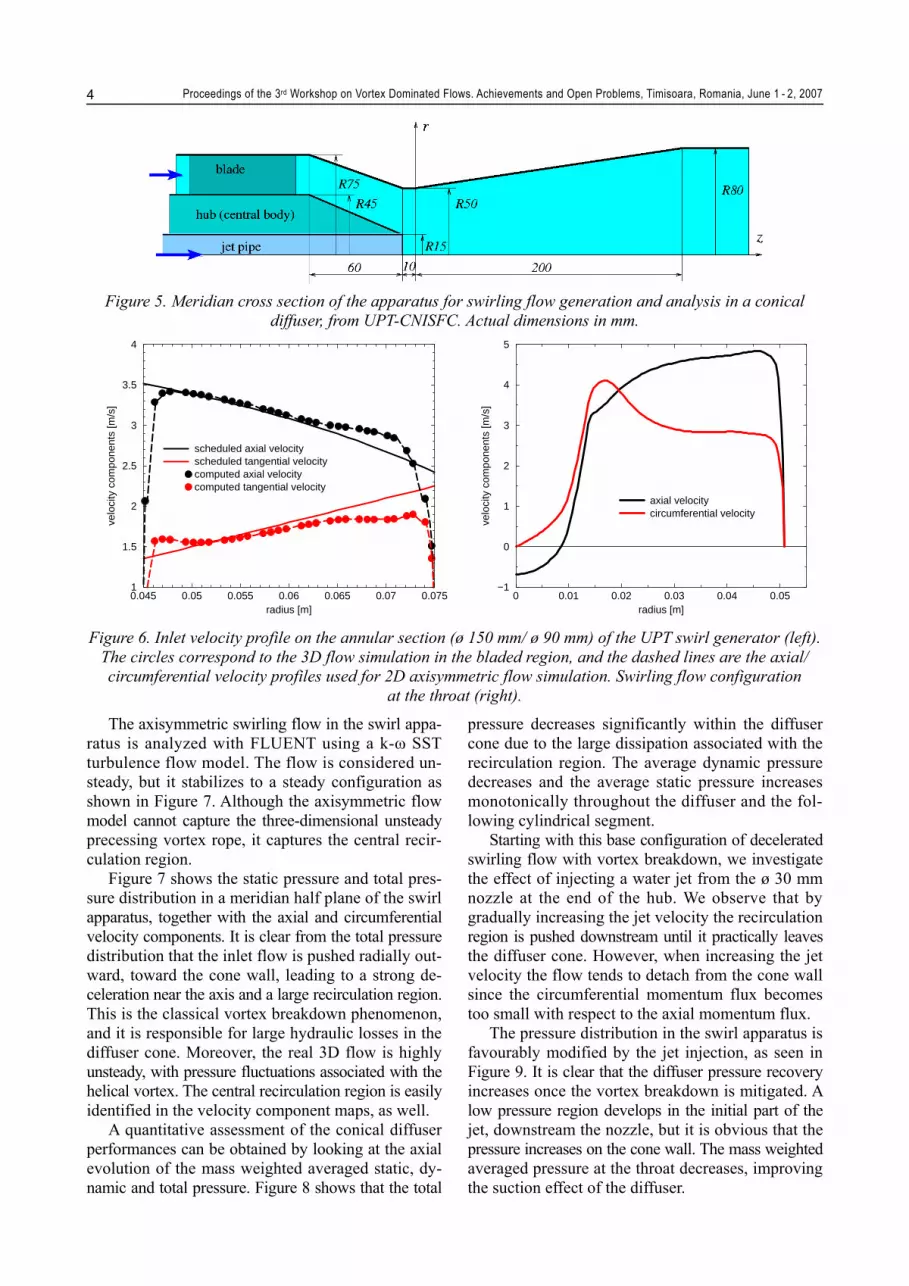
The above analysis led to the design of a swirling flow apparatus with a meridian cross-section as shown in Figure 5. The inlet annular section has a shroud diameter of ø 150 mm, and a hub with ø 90 mm. A set of 12 guide vanes is designed to produced a swirl configuration as shown in the left picture of Figure 6. Within the convergent section the swirling flow is accelerated and results in axial and circumferential velocity profiles as in Figure 6 (right picture) at the throat section with ø 100 mm. One can easily note the similarity of this swirl configuration and the one used by Ruprecht et al. [4] to compute the unsteady vortex rope, Figure 4. An average axial velocity of 3 m/s is considered at the inlet of the swirl apparatus, futher accelerated to an average axial velocity at the throat of 4.3 m/s and a Reynolds number.
Figure 2. Inlet velocity profile for cavitating vortex rope computations of Zhou et al. [8], with r5 the draft
tube inlet radius, at 80% optimum guide vane opening.

Proceedings of the 3rd Workshop on Vortex Dominated Flows. Achievements and Open Problems, Timisoara, Romania, June 1 - 2, 2007
3
Figure 3. Inlet velocity profile for cavitating vortex rope computations of Stein et al. [5], with the FLINDT draft tube [1]. The velocity coefficients are defined as and , respectively. The Francis turbine model was
operated at 70% of the BEP discharge.
Figure 4. Inlet velocity profile for vortex rope computations of Ruprecht et al. [4]. Upper pictures: straight conical diffuser. Lower pictures: Francis turbine draft tube.
Proceedings of the 3rd Workshop on Vortex Dominated Flows. Achievements and Open Problems, Timisoara, Romania, June 1 - 2, 2007 4
Figure 5. Meridian cross section of the apparatus for swirling flow generation and analysis in a conical
diffuser, from UPT-CNISFC. Actual dimensions in mm.
0.045 0.05 0.055 0.06 0.065 0.07 0.075radius [m]
1
1.5
2
2.5
3
3.5
4
velo
city
com
pone
nts
[m/s
]
scheduled axial velocityscheduled tangential velocitycomputed axial velocitycomputed tangential velocity
0 0.01 0.02 0.03 0.04 0.05
radius [m]
−1
0
1
2
3
4
5
velo
city
com
pone
nts
[m/s
]
axial velocitycircumferential velocity
Figure 6. Inlet velocity profile on the annular section (ø 150 mm/ ø 90 mm) of the UPT swirl generator (left).
The circles correspond to the 3D flow simulation in the bladed region, and the dashed lines are the axial/ circumferential velocity profiles used for 2D axisymmetric flow simulation. Swirling flow configuration
at the throat (right).
The axisymmetric swirling flow in the swirl appa-ratus is analyzed with FLUENT using a k-ω SST turbulence flow model. The flow is considered un-steady, but it stabilizes to a steady configuration as shown in Figure 7. Although the axisymmetric flow model cannot capture the three-dimensional unsteady precessing vortex rope, it captures the central recir-culation region.
Figure 7 shows the static pressure and total pres-sure distribution in a meridian half plane of the swirl apparatus, together with the axial and circumferential velocity components. It is clear from the total pressure distribution that the inlet flow is pushed radially out-ward, toward the cone wall, leading to a strong de-celeration near the axis and a large recirculation region. This is the classical vortex breakdown phenomenon, and it is responsible for large hydraulic losses in the diffuser cone. Moreover, the real 3D flow is highly unsteady, with pressure fluctuations associated with the helical vortex. The central recirculation region is easily identified in the velocity component maps, as well.
A quantitative assessment of the conical diffuser performances can be obtained by looking at the axial evolution of the mass weighted averaged static, dy-namic and total pressure. Figure 8 shows that the total
pressure decreases significantly within the diffuser cone due to the large dissipation associated with the recirculation region. The average dynamic pressure decreases and the average static pressure increases monotonically throughout the diffuser and the fol-lowing cylindrical segment.
Starting with this base configuration of decelerated swirling flow with vortex breakdown, we investigate the effect of injecting a water jet from the ø 30 mm nozzle at the end of the hub. We observe that by gradually increasing the jet velocity the recirculation region is pushed downstream until it practically leaves the diffuser cone. However, when increasing the jet velocity the flow tends to detach from the cone wall since the circumferential momentum flux becomes too small with respect to the axial momentum flux.
The pressure distribution in the swirl apparatus is favourably modified by the jet injection, as seen in Figure 9. It is clear that the diffuser pressure recovery increases once the vortex breakdown is mitigated. A low pressure region develops in the initial part of the jet, downstream the nozzle, but it is obvious that the pressure increases on the cone wall. The mass weighted averaged pressure at the throat decreases, improving the suction effect of the diffuser.

Proceedings of the 3rd Workshop on Vortex Dominated Flows. Achievements and Open Problems, Timisoara, Romania, June 1 - 2, 2007
5
Figure 7. Flow analysis in the swirl apparatus from Figure 5, with inlet velocity components from Figure 6 ,
without flow control.
−50 0 50 100 150 200 250 300 350 400 450 500axial coordinate [mm]
−1.0e+04
−5.0e+03
0.0e+00
5.0e+03
1.0e+04
1.5e+04
pres
sure
[Pa]
static pressuredynamic pressuretotal pressure
Figure 8. Mass-weighted averaged static/dynamic/total pressure on transversal cross-sections of the swirling
flow apparatus.

Proceedings of the 3rd Workshop on Vortex Dominated Flows. Achievements and Open Problems, Timisoara, Romania, June 1 - 2, 2007 6
No jet injection.
Jet velocity 4.25 /m s (8.9% inlet discharge).
Jet velocity 4.50 /m s (9.4% inlet discharge).
Jet velocity 4.75 /m s (9.9% inlet discharge).
Figure 9. Static pressure distribution the meridian half-plane of the swirl apparatus, without and with control jet injection.
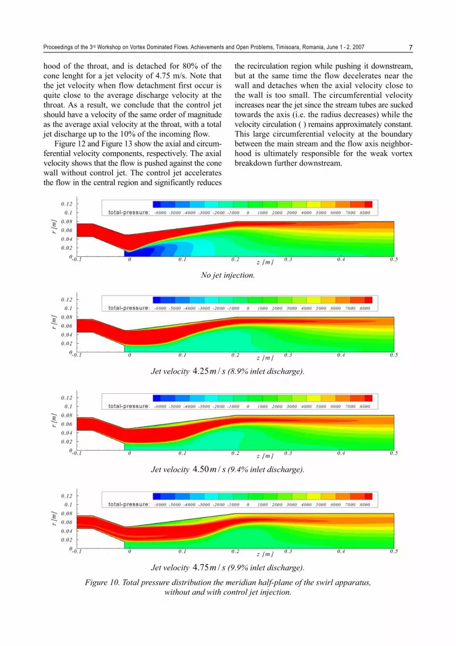
The total pressure distribution, shown in Figure 10 reveals the evolution of the main flow stream with a quasi-constant high total pressure in the case of our apparatus. Without jet injection the flow is pushed centrifugally against the cone/pipe wall, and there is no flow detachment. However, the strong axial deceleration generates a large „dead-water” region associated with vortex breakdown. As the jet velocity increases, one can easily see the occurence and development of flow detachment. As a result, an optimum jet velocity should correspond to a weak detachment at the cone wall with vortex breakdown
mitigation. We note that in our case, increasing the jet discharge from 9% to 10% from the inlet discharge triggers a severe flow detachment in the cone.
The flow detachment can be easily detected by examining the meridian component of the wall shear stress, Figure 11. When the flow is attached the wall shear stress is positive, and it becomes negative when the flow detaches from the wall. One can see in Figure 11 that the swirling flow remains attached when there is no control jet. This is actually the main role of the swirl in the conical diffuser. At jet velocity 4.25 m/s the flow begins to detach in the neighbor-
Proceedings of the 3rd Workshop on Vortex Dominated Flows. Achievements and Open Problems, Timisoara, Romania, June 1 - 2, 2007
7
hood of the throat, and is detached for 80% of the cone lenght for a jet velocity of 4.75 m/s. Note that the jet velocity when flow detachment first occur is quite close to the average discharge velocity at the throat. As a result, we conclude that the control jet should have a velocity of the same order of magnitude as the average axial velocity at the throat, with a total jet discharge up to the 10% of the incoming flow.
Figure 12 and Figure 13 show the axial and circum-ferential velocity components, respectively. The axial velocity shows that the flow is pushed against the cone wall without control jet. The control jet accelerates the flow in the central region and significantly reduces
the recirculation region while pushing it downstream, but at the same time the flow decelerates near the wall and detaches when the axial velocity close to the wall is too small. The circumferential velocity increases near the jet since the stream tubes are sucked towards the axis (i.e. the radius decreases) while the velocity circulation ( ) remains approximately constant. This large circumferential velocity at the boundary between the main stream and the flow axis neighbor-hood is ultimately responsible for the weak vortex breakdown further downstream.
No jet injection.
Jet velocity 4.25 /m s (8.9% inlet discharge).
Jet velocity 4.50 /m s (9.4% inlet discharge).
Jet velocity 4.75 /m s (9.9% inlet discharge).
Figure 10. Total pressure distribution the meridian half-plane of the swirl apparatus, without and with control jet injection.

Proceedings of the 3rd Workshop on Vortex Dominated Flows. Achievements and Open Problems, Timisoara, Romania, June 1 - 2, 2007 8
0 0.05 0.1 0.15 0.2axial coordinate [m]
−10
0
10
20
30
40
50
mer
idia
n w
all s
hrea
r st
ress
[Pa]
no jetjet 4.25 m/sjet 4.5 m/sjet 4.75 m/s
Figure 11. Meridian wall shear stress on the conical diffuser wall, without and with control jet injection.
No jet injection.
Jet velocity 4.25 /m s (8.9% inlet discharge).
Jet velocity 4.50 /m s (9.4% inlet discharge).

Proceedings of the 3rd Workshop on Vortex Dominated Flows. Achievements and Open Problems, Timisoara, Romania, June 1 - 2, 2007
9
Jet velocity 4.75 /m s (9.9% inlet discharge).
Figure 12. Axial velocity distribution the meridian half-plane of the swirl apparatus, without and with control jet injection.
No jet injection.
Jet velocity 4.25 /m s (8.9% inlet discharge).
Jet velocity 4.50 /m s (9.4% inlet discharge).
Jet velocity 4.75 /m s (9.9% inlet discharge).
Figure 13. Circumferential velocity distribution the meridian half-plane of the swirl apparatus, without and with control jet injection.

Proceedings of the 3rd Workshop on Vortex Dominated Flows. Achievements and Open Problems, Timisoara, Romania, June 1 - 2, 2007 10
Static pressure.
Total pressure.
Axial velocity.
Circumferential velocity.
Figure 14. Flow analysis for swirling flow apparatus with feedback flow control.
The analysis of vortex breakdown mitigation with control jet reveals that a rather large jet discharge (up to 10% of the incoming discharge) is required.
Taking the jet discharge from upstream the turbine, and thus bypassing the runner, will obviously reduce significantly the overall turbine efficiency. However, the present investigations show that effective vortex breakdown mitigation can be achieved with moderate jet velocity. This sparks the idea of supplying the jet with water taken from downstream the diffuser cone, where the pressure is large enough with respect to the pressure at the nozzle outlet to generate a control jet. This idea is investigated in Figure 14, where an
annular slit collects a fraction of the discharge at the end of the cone and redirects it toward the nozzle. This flow-feedback mechanism has the advantage of combining the suction at the cone wall (favourable for re-attachment) with the jet injection (for mitigating the vortex breakdown). The jet velocity adjusts itself to a value as required for effective swirling flow control. If the velocity is too large then the flow detaches severely from the wall and automatically reduces the discharge through the annular slit. We see that we may even need to throttle-down the jet discharge in order to avoid the flow separation at the cone wall. The vortex breakdown mitigation reduces the dissi

Proceedings of the 3rd Workshop on Vortex Dominated Flows. Achievements and Open Problems, Timisoara, Romania, June 1 - 2, 2007
11
−50 0 50 100 150 200 250 300 350 400 450 500axial coordinate [mm]
−1.0e+04
−5.0e+03
0.0e+00
5.0e+03
1.0e+04
1.5e+04
pres
sure
[Pa]
static pressuredynamic pressuretotal pressure
Figure 15. Mass-weighted averaged static/dynamic/total pressure on transversal cross-sections of the
swirling flow apparatus with feedback flow control. Dashed lines correspond to throttle-down the control jet from 8.8% to 8.3% of inlet discharge.
pation associated with the dead-water region, and the averaged total pressure does not decrease abruptly in the cone as seen in Figure 15. Moreover, the pressure recovery improves significantly in the cone compared with the original situation. This will also increase the overall turbine efficiency by increasing the suction effect at the runner outlet.
3. CONCLUSIONS A new flow control technique for decelerated
swirling flows is proposed and analysed numerically. It is found that a jet injected axially at the conical diffuser inlet effectively suppress the vortex break-down. However, if the jet velocity is too large the flow detaches from the cone wall. It is found that the required control jet discharge reaches 10% of the incoming discharge. As a result, in order to effi-ciently apply the jet control technique to hydraulic turbines a flow-feedback approach is proposed. The feedback technique uses a fraction of the discharge taken through an annular slit at the end of the dif-fuser cone, and directs it to the jet nozzle. It is shown numerically that this flow feedback can remove the vortex breakdown and significantly improve the pressure recovery in the conical diffuser.
ACKNOWLEDGEMENTS The present reasearch has been supported by the
Romanian National University Research Council under consortium grant No. 33, „Vortex Dominated Flows and Applications”, by the Swiss National Science Foundation under the Joint Research Project IB7320-110942/1, and by the Romanian National Authority for Scientific Research through the CEEX-C2-M1-1185 „iSMART-Flow” project.
REFERENCES 1. Avellan, F., 2000, „Flow Investigation in a Francis
Draft Tube: The FLINDT Project”, Proceedings of the 20th IAHR Symposium on Hydraulic Machinery and Systems, Charlotte, Alabama, U.S.A., Paper DY-03.
2. Miyagawa, K., Sano, T., Kunimatsu, N., Aki, T., and Nishi, M., 2006, „Mitigation of Draft Tube Flow Insta-bility with Auxiliary Parts in High Head Pump-turbines”, Proceedings of the 23rd IAHR Symposium on Hydraulic Machinery and Systems, Yokohama, Japan, Paper 307.
3. Neubauer, R., 2007, „Simulation of the unsteady Vortex Rope in the Draft Tube coupled with a Pump-Turbine Runner”, German-Romanian Workshop on Turbomachin-ery Hydrodynamics, Timisoara, May 10-12, 2007.
4. Ruprecht, A., Helmrich, T., Aschenbrenner, T., and Scherer, T., 2002, „Simulation of Vortex Rope in a Turbine Draft Tube”, Proceedings of the 21st IAHR Symposium on Hydraulic Machinery and Systems, Lausanne, Switzerland.

Proceedings of the 3rd Workshop on Vortex Dominated Flows. Achievements and Open Problems, Timisoara, Romania, June 1 - 2, 2007 12
5. Stein, P., Sick, M., Doerfler, P., White, P., and Braune, A., 2006, „Numerical Simulation of the Cavitating Draft Tube Vortex in a Francis Turbine”, Proceedings of the 23rd IAHR Symposium on Hydraulic Machinery and Systems, Yokohama, Japan, Paper 228.
6. Susan-Resiga, R., Ciocan, G.D., Anton, I., and Avellan, F., 2006, „Analysis of the Swirling Flow Downstream a Francis Turbine Runner”, Journal of Fluids Engineering, 128, pp.177-189.
7. Susan-Resiga, R., Vu, T.C., Muntean, S., Ciocan, G.D., and Nennemann, B., 2006, „Jet Control of the Draft Tube Vortex Rope in Francis Turbines at Partial Discharge”, Proceedings of the 23rd IAHR Symposium on Hydraulic Machinery and Systems, Yokohama, Japan, Paper 192.
8. Zhou, L., Wang, Z., and Tian, Y., 2006, „Numerical Simulation of Vortex Cavitation in Draft Tube”, Pro-ceedings of the 23rd IAHR Symposium on Hydraulic Machinery and Systems, Yokohama, Japan, Paper 102.


