Embed Size (px)
Citation preview
Journal of Ocean and Wind Energy (ISSN 2310-3604) http://www.isope.org/publications/publications.htmCopyright © by The International Society of Offshore and Polar EngineersVol. 2, No. 3, August 2015, pp. 182–192; http://dx.doi.org/10.17736/jowe.2015.jcr40
Development of a Motion Stabilizer for a Shallow-Sea-Area Spar Buoy in Wind,Tidal Current and Waves
Toru Katayama and Kazuki HashimotoGraduate School of Engineering, Osaka Prefecture University
Osaka, Japan
Hiroshi AsouZeni Lite Buoy Co., Ltd.
Okayama, Japan
Shigenori KomoriZeni Lite Buoy Co., Ltd.
Tokyo, Japan
In this study, the performance of a spar buoy with a motion stabilizer and an airfoil as a platform of wind state observationand with a Doppler Lidar for a bottom-mounted offshore wind farm project in the shallow sea area of less than 50 m in depthis investigated. Model tests in steady flow and in waves demonstrate the effectiveness of the motion stabilizer. The effectivenessof the airfoil is also confirmed by model tests in wind. In order to understand the mechanisms of the model-test stabilizerresults, a time-domain motion simulation program is developed. Finally, the particulars of the stabilizer and shape of the airfoilare optimized based on the simulation results.
INTRODUCTION
Renewable energy technology is developed to create a sustainablesociety. Offshore wind farms are generally viewed as one of themost important energy supply resources.
Before construction of an offshore wind farm, a continuousmeasurement of upper wind field (wind direction and speed) forone year at the planned construction location is required. Formeasurement in past investigations, an upper wind field observationtower or platform for a Doppler Lidar or a Doppler Sodar as aremote sensing technique on the sea bottom was usually built. If amoored floating structure can be used as its platform, its foundationconstruction is lighter than these structures, and its environmentalimpact is smaller. However, in the case of a floating structure, itwill oscillate in waves, and this oscillation affects the measurementaccuracy.
In order to achieve accurate measurements, motion reduction ofthe buoy is important. Therefore, a motion stabilizer composed offour disk-fins and struts (they are called arms here) is proposed toreduce the motion of the buoy in waves and keep it upright in tidalcurrent by using the hydrodynamic forces acting on it. Moreover,to reduce inclination of the buoy in wind, an airfoil is attached tothe top of the buoy.
To understand the oscillation reduction, the authors used modeltests in steady flow and in waves. The motion stabilizer effectivenessis confirmed from comparisons of the measured motions with andwithout the motion stabilizer. It is observed that the buoy withoutthe motion stabilizer causes large-amplitude pitching motion when
Received April 14, 2015; updated and further revised manuscript receivedby the editors July 15, 2015. The original version (prior to the finalupdated and revised manuscript) was presented at the Twenty-fifthInternational Ocean and Polar Engineering Conference (ISOPE-2015),Kona, Hawaii, June 21–26, 2015.
KEY WORDS: Spar buoy, motion stabilizer, airfoil, steady flow, wind,waves, lift and drag forces.
the incident wave period is half of the natural pitch period of thebuoy.
In order to understand the mechanisms of motion reduction andof the large-amplitude pitching motion, a time-domain motionsimulation is developed. From the calculated results in steady flow,it is understood that the lift forces acting on the fins of the motionstabilizer cause an inclining moment on the upstream side, and thedrag forces acting on the fins cause an inclining moment on thedownstream side when the fins are located above the mooring pointof the buoy. When the fins are located below the mooring point,the drag forces cause an inclining moment to the upstream side.From the calculated results in waves, it is also understood thatwhen the direction of a relative flow of water to the surface of thefins is normal, the effects of motion reduction are maximum by thedrag force caused by the fins.
The simulation shows the occurrence of the above-mentionedlarge-amplitude pitching motion. Namely, the analysis of thecalculated moments in the simulation shows that the large-amplitudepitching is caused by the variation of the pitch-restoring momentcaused by the change in draft of the buoy at every time step. Fromthese calculated results, the particulars of the stabilizer and shapeof the airfoil are optimized.
Since the tidal current and wave directions are not always thesame, the hydrodynamic forces to reduce the motion of the buoycannot be very effective when they come from different directions.Therefore, an improved device, a motion stabilizer composed ofa ring-fin and arms, is proposed, and the effects of the motionstabilizer are confirmed by the model tests. Finally, in order tocalculate the motion of the buoy with the motion stabilizer, thehydrodynamic forces acting on the motion stabilizer in steady floware accurately measured.
MODEL AND COORDINATE SYSTEM
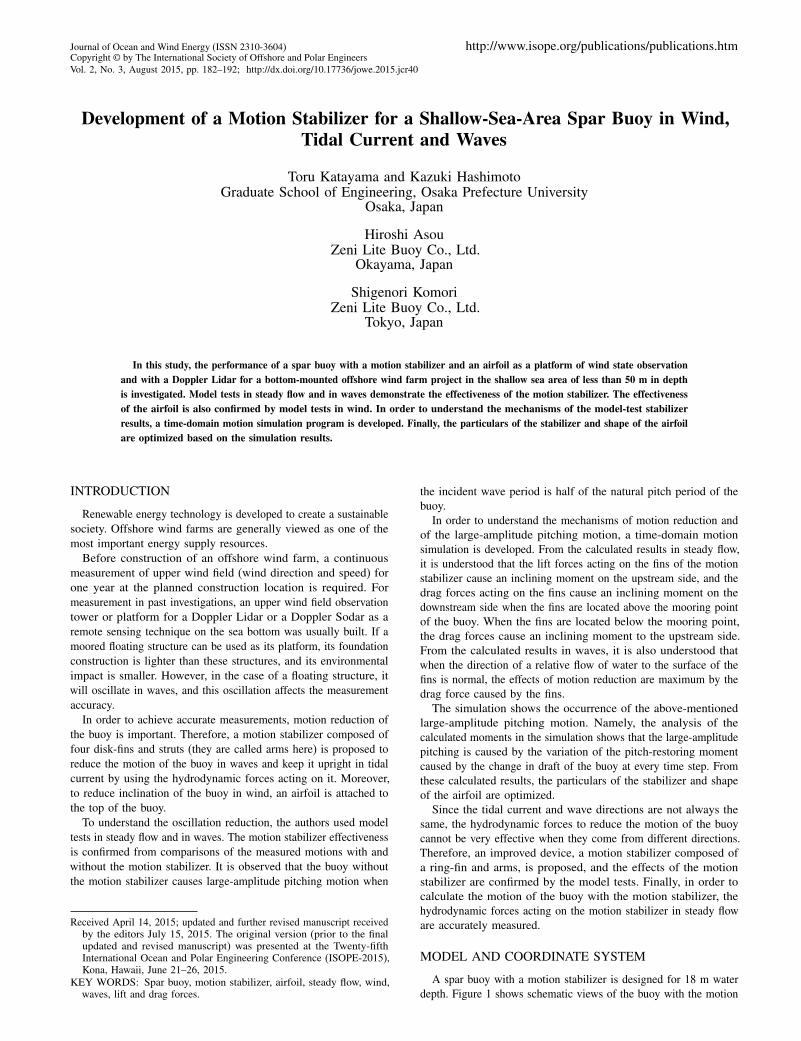
A spar buoy with a motion stabilizer is designed for 18 m waterdepth. Figure 1 shows schematic views of the buoy with the motion
Journal of Ocean and Wind Energy, Vol. 2, No. 3, August 2015, pp. 182–192 183
Fig. 1 Schematic views of the buoy with the motion stabilizer andcoordinate system
stabilizer and coordinate system. The earth-fixed coordinate systemis defined as O-X0Y0Z0, and the body-fixed coordinate system isdefined as O-x0y0z0. H is water depth, h0 is the distance fromthe sea bottom to O, U (Z05 and UWIND are the velocities of tidalcurrent and wind, respectively, and Tw and �w are period andamplitude of the regular wave, respectively.
Figure 2 shows a schematic view of the motion stabilizer (armand fin). The angles of the arms and fins (�Arm [�] and �F in [�])can be changed. The zero values of the angles are defined as thecondition where they are perpendicular to the center pipe of thespar buoy. Table 1 shows the principal particulars of the model(�Arm = 20� and �F in = 15�).
Fig. 2 Schematic view of the fin and arm of the motion stabilizer
Scale of model: 1/S 1/20.32Overall length: LOA [m] 1.25Height of the center of gravity: KG [m] 0.284Overall weight: W [kgf] 3.71Buoyancy: ï [kgf] 7.76Roll & pitch natural period with and w/o 4.5, 4.0
motion stabilizer: TnF & Tn[s]
Table 1 Principal particulars of the model
MODEL TEST
In order to investigate the effectiveness of the motion stabilizer,model tests of the buoy with and without the motion stabilizer arecarried out in steady flow (tidal current) and waves. The motionis recorded by a video camera (Power Shot G1X, Canon) andanalyzed with motion capture software (TEMA, Photron).
Motion Measurement in Steady Flow
The motion measurement in steady flow is carried out in thecirculating water channel of Osaka Prefecture University (sizeof observation section: length = 6 m, breadth = 1.5 m, depth= 1.09 m). Table 2 shows the measurement conditions in steadyflow. The flow velocities are 1, 2, and 3 kts in real scale. For eachflow velocity, the measurements for the buoy with and without themotion stabilizer are carried out.
In the measurements, the buoy without the motion stabilizerinclines to the downstream ward and causes periodic pitching androlling. In contrast, the buoy with the motion stabilizer does notcause pitching and rolling.
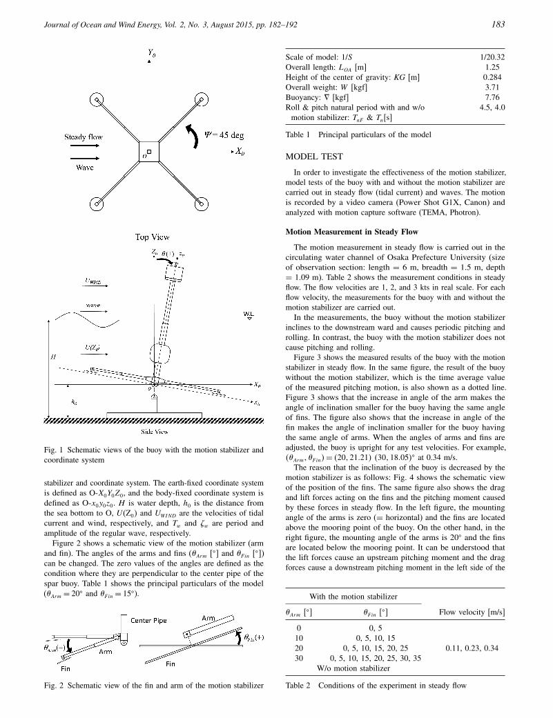
Figure 3 shows the measured results of the buoy with the motionstabilizer in steady flow. In the same figure, the result of the buoywithout the motion stabilizer, which is the time average valueof the measured pitching motion, is also shown as a dotted line.Figure 3 shows that the increase in angle of the arm makes theangle of inclination smaller for the buoy having the same angleof fins. The figure also shows that the increase in angle of thefin makes the angle of inclination smaller for the buoy havingthe same angle of arms. When the angles of arms and fins areadjusted, the buoy is upright for any test velocities. For example,4�Arm1 �F in5= 4201210215 4301180055� at 0.34 m/s.
The reason that the inclination of the buoy is decreased by themotion stabilizer is as follows: Fig. 4 shows the schematic viewof the position of the fins. The same figure also shows the dragand lift forces acting on the fins and the pitching moment causedby these forces in steady flow. In the left figure, the mountingangle of the arms is zero (= horizontal) and the fins are locatedabove the mooring point of the buoy. On the other hand, in theright figure, the mounting angle of the arms is 20� and the finsare located below the mooring point. It can be understood thatthe lift forces cause an upstream pitching moment and the dragforces cause a downstream pitching moment in the left side of the
With the motion stabilizer
�Arm [�] �F in [�] Flow velocity [m/s]
0 0, 5
0.11, 0.23, 0.3410 0, 5, 10, 1520 0, 5, 10, 15, 20, 2530 0, 5, 10, 15, 20, 25, 30, 35
W/o motion stabilizer
Table 2 Conditions of the experiment in steady flow
184 Development of a Motion Stabilizer for a Shallow-Sea-Area Spar Buoy in Wind, Tidal Current and Waves
Fig. 3 Measured angle of inclination in pitching in steady flow
figure. On the other hand, the drag forces also cause an upstreampitching moment in the right side of the figure. When the mountingangle of the arms increases, the levers of the upstream pitchingmoment caused by lift forces decrease, the direction of the pitchingmoment caused by drag forces is changed from downstream toupstream, and the total upstream pitching moment increases. Itcan be understood that the inclination of the buoy decreases. Inthe right side of Fig. 4, the larger attack angles of the fins tosteady flow result in larger drag and lift forces, which reduce thebuoy inclination. If the upstream ward pitching moment caused bydrag and lift forces acting on the fin equals the downstream wardpitching moment caused by drag forces acting on the buoy, then thebuoy can be upright. Moreover, if the hydrodynamic coefficientsacting on the fin and the buoy are constant regardless of Reynoldsnumber, then the buoy can be upright regardless of flow velocity.
Motion Measurement in Waves
The motion measurement in irregular waves is carried out atthe towing tank of Osaka Prefecture University (length = 70 m,breadth = 3 m, depth = 1.5 m). The Bretschneider-Mitsuyasuspectrum, as shown in Eq. 1, is used (Mitsuyasu, 1970). For thewave making, this spectrum is divided into 100 equally, from0.2 to 2.0 Hz. The sinusoidal waves at each frequency are thensuperposed. The phase difference at each frequency component is
Fig. 4 Schematic view of the fin and hydrodynamic force in steadyflow
given as random numbers, and motion measurement is then carriedout for more than 200 encounter waves.
S4f 5= 00257H21/3T1/34T1/3f 5
−5 exp8−10034T1/3f 5−49 (1)
Table 3 summarizes the measurement conditions in irregular waves.The full-scale significant wave height is 2 m and the average waveperiod is 12 s. Similar to the measurement in steady flow, themeasurements in irregular waves for the buoy with and withoutthe motion stabilizer are carried out. The data sampling is startedbefore the wavemaker waves reach the position of the buoy. Thedata sampling is finished before the reflected wave from the wallof the tank end reaches the buoy.
Table 4 shows the significant peak-to-peak values of measuredpitching in irregular waves, which are obtained by the zero-down-cross method. First, from Table 4, the effect of the motion stabilizeris confirmed. Second, when the mounting angle of the arms is 20�,the amplitude is the smallest at 15� of the mounting angle of thefins; when the mounting angle of the fins is 15�, the amplitude isthe smallest at 10� of the mounting angle of the arms.
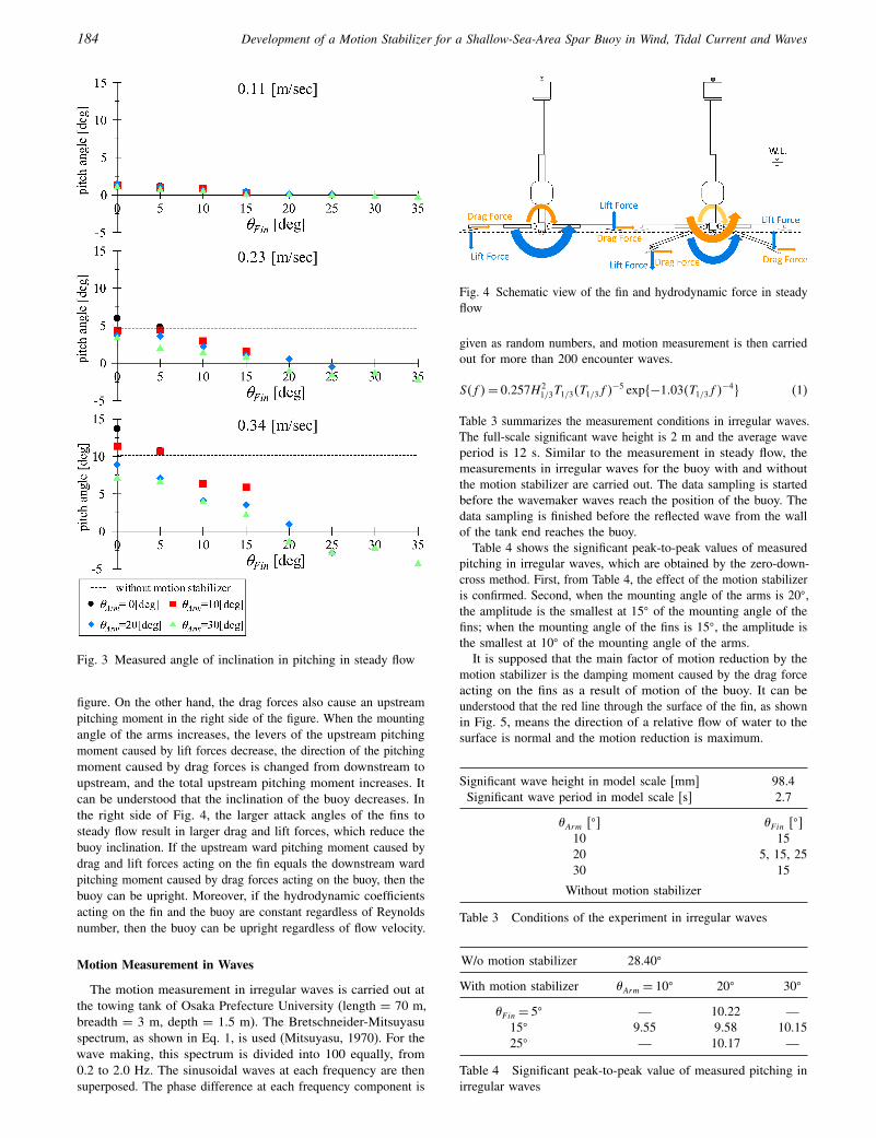
It is supposed that the main factor of motion reduction by themotion stabilizer is the damping moment caused by the drag forceacting on the fins as a result of motion of the buoy. It can beunderstood that the red line through the surface of the fin, as shownin Fig. 5, means the direction of a relative flow of water to thesurface is normal and the motion reduction is maximum.
Significant wave height in model scale [mm] 98.4Significant wave period in model scale [s] 2.7
�Arm [�] �F in [�]10 1520 5, 15, 2530 15
Without motion stabilizer
Table 3 Conditions of the experiment in irregular waves
W/o motion stabilizer 28.40�
With motion stabilizer �Arm = 10� 20� 30�
�F in = 5� — 10.22 —15� 9.55 9.58 10.1525� — 10.17 —
Table 4 Significant peak-to-peak value of measured pitching inirregular waves
Journal of Ocean and Wind Energy, Vol. 2, No. 3, August 2015, pp. 182–192 185
Fig. 5 Schematic view of the fin and hydrodynamic force withpitching
Fig. 6 Relative position of fin to mooring point
Figure 6 shows the relative position of the fins to the mooringpoint in the conditions given in Table 3. In the same figure, the reddotted line through the surface of the fin is also shown. When themounting angle of the arms is 20�, the distance between the redline and the mooring point is the nearest at 15� of the mountingangle of the fins. When the mounting angle of the fins is 15�, thedistance between the red line and the mooring point is the nearestat 20� of the mounting angle of the arms. But when the mountingangle of the arms is 10�, the effect of motion reduction is themaximum because the distance between the fin and the mooringpoint is at its greatest. Consequently, for each mounting angleof the arm, an optimized mounting angle of the fin (�DMAX5 canbe estimated that results in maximum motion reduction. Table 5presents an example of this optimized mounting angle.
Motion Measurement in Wind
The motion measurement in wind is carried out by using thewind fan at the towing tank of Osaka Prefecture University. For the
�Arm [�] 10 20 30�DMAX [�] 6.59 16.06 25.70
Table 5 Optimized angle of attachment of the fin in wave
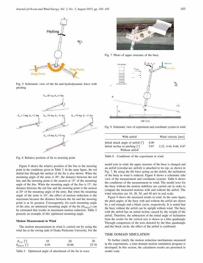
Fig. 7 Photo of upper structure of the buoy
Fig. 8 Schematic view of experiment and coordinate system in wind
With airfoil Wind velocity [m/s]
Initial attack angle of airfoil [�] 6.002.22, 4.44, 6.66, 8.87Initial incline in pitching [�] 5.67
Without airfoil
Table 6 Conditions of the experiment in wind
model tests in wind, the upper structure of the buoy is changed andan airfoil (circular-arc airfoil) is attached to its top, as shown inFig. 7. By using the lift force acting on the airfoil, the inclinationof the buoy in wind is reduced. Figure 8 shows a schematic sideview of the measurement and coordinate systems. Table 6 showsthe conditions of the measurement in wind. The model tests forthe buoy without the motion stabilizer are carried out in order tocompare the measured motions with and without the airfoil. Thewind velocities are 10, 20, 30, and 40 m/s in real scale.
Figure 9 shows the measured results in wind. In the same figure,the pitch angles of the buoy with and without the airfoil are shownby a red triangle and a black circle, respectively. It is noted thatthe buoy without the airfoil can be upright without wind. The buoywith the airfoil has an initial incline caused by the weight of theairfoil. Therefore, the subtraction of the initial angle of inclinationfrom the results for the vertical axis is shown as a blue quadrangle.Through comparison of the tests denoted by the blue quadrangleand the black circle, the effect of the airfoil is confirmed.
TIME DOMAIN SIMULATION
To further clarify the motion reduction mechanisms measuredin the experiments, a time-domain motion simulation program isdeveloped. In this section, the calculation results are presented inmodel scale.
186 Development of a Motion Stabilizer for a Shallow-Sea-Area Spar Buoy in Wind, Tidal Current and Waves
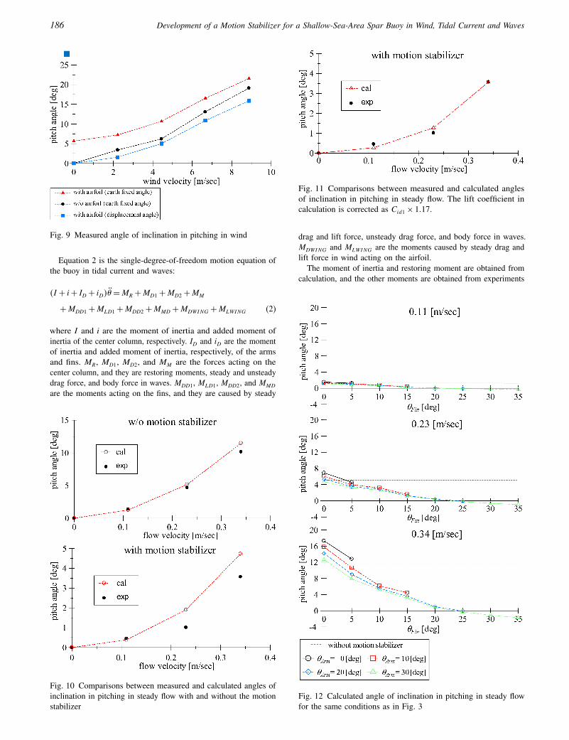
Fig. 9 Measured angle of inclination in pitching in wind
Equation 2 is the single-degree-of-freedom motion equation ofthe buoy in tidal current and waves:
4I + i+ ID + iD5� =MR +MD1 +MD2 +MM
+MDD1 +MLD1 +MDD2 +MMD +MDWING +MLWING (2)
where I and i are the moment of inertia and added moment ofinertia of the center column, respectively. ID and iD are the momentof inertia and added moment of inertia, respectively, of the armsand fins. MR, MD1, MD2, and MM are the forces acting on thecenter column, and they are restoring moments, steady and unsteadydrag force, and body force in waves. MDD1, MLD1, MDD2, and MMD
are the moments acting on the fins, and they are caused by steady
Fig. 10 Comparisons between measured and calculated angles ofinclination in pitching in steady flow with and without the motionstabilizer
Fig. 11 Comparisons between measured and calculated anglesof inclination in pitching in steady flow. The lift coefficient incalculation is corrected as Cid1 × 1017.
drag and lift force, unsteady drag force, and body force in waves.MDWING and MLWING are the moments caused by steady drag andlift force in wind acting on the airfoil.
The moment of inertia and restoring moment are obtained fromcalculation, and the other moments are obtained from experiments
Fig. 12 Calculated angle of inclination in pitching in steady flowfor the same conditions as in Fig. 3
Journal of Ocean and Wind Energy, Vol. 2, No. 3, August 2015, pp. 182–192 187
and existing data (Otsuka et al., 1997; Sarpkaya, 2010). Equation 2is calculated by the fourth-order Runge-Kutta method.
In addition, free decay tests of the model are carried out. In thesimulation for the buoy without the motion stabilizer, the momentof inertia and unsteady drag force acting on the center column areadjusted by the results. On the other hand, in the simulation forthe buoy with the motion stabilizer, the moment of inertia andunsteady drag force acting on the fins are adjusted by the results.
Motion Calculation in Steady Flow
Figure 10 shows the measured and calculated inclinations insteady flow for the buoy with and without the motion stabilizer.This figure shows that the calculated results for the buoy withoutthe motion stabilizer agree with the measured results. On theother hand, the calculated results for the buoy with the motionstabilizer are larger than the measured results. In order to get betteragreement with the measured results, as shown in Fig. 11, the liftcoefficient of the fin of the motion stabilizer is multiplied by 1.17.
Figure 12 shows the calculated inclination in steady flow for thesame conditions as in Fig. 3. From the results, it is confirmed thatthe buoy can be upright at any velocity when the mounting angleof the arms is 20� or 30� and one of the fins is 15�~25�.
Motion Calculation in Waves
Table 7 shows the calculated pitch amplitudes in regular wavesat Tw = 2066 s and Hw = 9804 mm (Tw = 12 s and Hw = 200 m inreal scale). The results show the effect of the motion stabilizer. It
With motion stabilizer �Arm = 10� 20� 30�
�F in = 5� — 8.42 —15� 5.27 5.38 5.4325� — 5.42 —
Table 7 Calculated pitch amplitude in regular waves
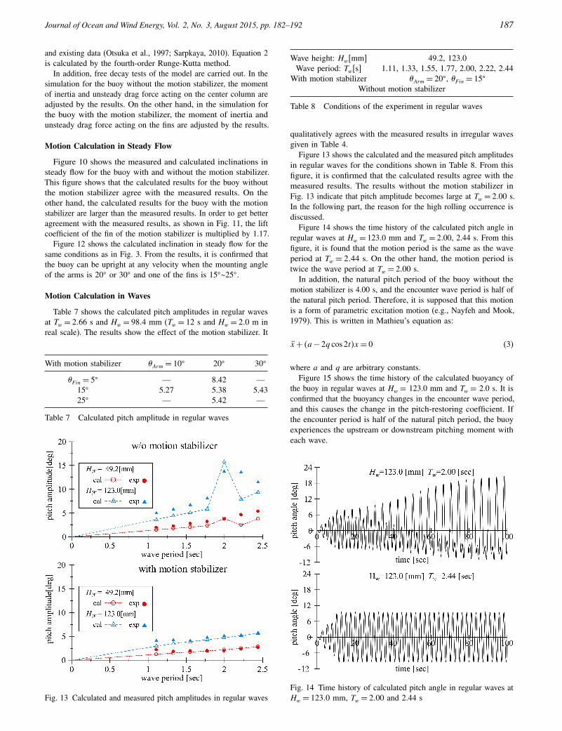
Fig. 13 Calculated and measured pitch amplitudes in regular waves
Wave height: Hw[mm] 49.2, 123.0Wave period: Tw[s] 1.11, 1.33, 1.55, 1.77, 2.00, 2.22, 2.44
With motion stabilizer �Arm = 20�, �F in = 15�
Without motion stabilizer
Table 8 Conditions of the experiment in regular waves
qualitatively agrees with the measured results in irregular wavesgiven in Table 4.
Figure 13 shows the calculated and the measured pitch amplitudesin regular waves for the conditions shown in Table 8. From thisfigure, it is confirmed that the calculated results agree with themeasured results. The results without the motion stabilizer inFig. 13 indicate that pitch amplitude becomes large at Tw = 2000 s.In the following part, the reason for the high rolling occurrence isdiscussed.
Figure 14 shows the time history of the calculated pitch angle inregular waves at Hw = 12300 mm and Tw = 2000, 2.44 s. From thisfigure, it is found that the motion period is the same as the waveperiod at Tw = 2044 s. On the other hand, the motion period istwice the wave period at Tw = 2000 s.
In addition, the natural pitch period of the buoy without themotion stabilizer is 4.00 s, and the encounter wave period is half ofthe natural pitch period. Therefore, it is supposed that this motionis a form of parametric excitation motion (e.g., Nayfeh and Mook,1979). This is written in Mathieu’s equation as:
x+ 4a− 2q cos 2t5x = 0 (3)
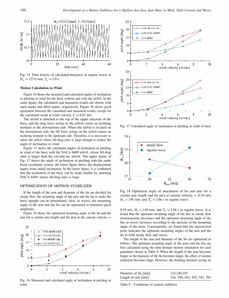
where a and q are arbitrary constants.Figure 15 shows the time history of the calculated buoyancy of
the buoy in regular waves at Hw = 123.0 mm and Tw = 2.0 s. It isconfirmed that the buoyancy changes in the encounter wave period,and this causes the change in the pitch-restoring coefficient. Ifthe encounter period is half of the natural pitch period, the buoyexperiences the upstream or downstream pitching moment witheach wave.
Fig. 14 Time history of calculated pitch angle in regular waves atHw = 12300 mm, Tw = 2000 and 2.44 s
188 Development of a Motion Stabilizer for a Shallow-Sea-Area Spar Buoy in Wind, Tidal Current and Waves
Fig. 15 Time history of calculated buoyancy in regular waves atHw = 12300 mm, Tw = 200 s
Motion Calculation in Wind
Figure 16 shows the measured and calculated angles of inclinationin pitching in wind for the buoy without and with the airfoil. In thesame figure, the calculated and measured results are shown withopen marks and filled marks, respectively. Figure 16 shows goodagreement between the calculated and measured results, except forthe calculated result at wind velocity U = 8087 m/s.
The airfoil is attached to the top of the upper structure of thebuoy, and the drag force acting on the airfoil causes an incliningmoment to the downstream side. When the airfoil is located onthe downstream side, the lift force acting on the airfoil causes aninclining moment to the upstream side. Therefore, it is necessary toselect the airfoil whose lift-drag ratio is large enough to reduce theangle of inclination in wind.
Figure 17 shows the calculated angles of inclination in pitchingin wind of the buoy with the NACA 6409 airfoil, whose lift-dragratio is larger than the circular-arc airfoil. The upper figure ofFig. 17 shows the angle of inclination in pitching with the earth-fixed coordinate system; the lower figure shows the displacementangles from initial inclination. In the lower figure, it is confirmedthat the inclination of the buoy can be made smaller by attachingNACA 6409, whose lift-drag ratio is large.
OPTIMIZATION OF MOTION STABILIZER
If the length of the arm and diameter of the fin are decided forsteady flow, the mounting angle of the arm and the fin to make thebuoy upright can be determined. Also, in waves, the mountingangle of the arm and the fin can be optimized to minimize pitchamplitude.
Figure 18 shows the optimized mounting angle of the fin and thearm for a certain arm length and fin area at the current velocity =
Fig. 16 Measured and calculated angle of inclination in pitching inwind
Fig. 17 Calculated angle of inclination in pitching in wind of buoy
Fig. 18 Optimized angle of attachment of fin and arm for acertain arm length and fin area at current velocity = 0.34 m/s,Hw = 148 mm, and Tw = 2066 s in regular waves
0.34 m/s, Hw = 148 mm, and Tw = 2066 s in regular waves. It isfound that the optimum mounting angle of the fins in steady flowmonotonously decreases and the optimum mounting angle of thefins in waves increases according to the increase in the mountingangle of the arms. Consequently, we found that the intersectionpoint indicates the optimum mounting angles of the arm and thefin in both steady flow and waves.
The length of the arm and diameter of the fin are optimized asfollows: The optimum mounting angle of the arms and the fins arefirst calculated using the time-domain motion simulation for eachparameter shown in Table 9. When the length of the arm becomeslonger or the diameter of the fin becomes larger, the effect of motionreduction becomes large. However, the bending moment acting on
Diameter of fin [mm] 123,140,155Length of arm [mm] 344, 394, 443, 492, 541, 591
Table 9 Conditions of motion stabilizer
Journal of Ocean and Wind Energy, Vol. 2, No. 3, August 2015, pp. 182–192 189
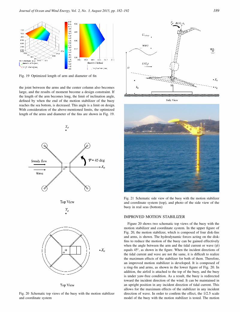
Fig. 19 Optimized length of arm and diameter of fin
the joint between the arms and the center column also becomeslarge, and the results of moment become a design constraint. Ifthe length of the arm becomes long, the limit of inclination angle,defined by when the end of the motion stabilizer of the buoyreaches the sea bottom, is decreased. This angle is a limit on design.With consideration of the above-mentioned limits, the optimizedlength of the arms and diameter of the fins are shown in Fig. 19.
Fig. 20 Schematic top views of the buoy with the motion stabilizerand coordinate system
Fig. 21 Schematic side view of the buoy with the motion stabilizerand coordinate system (top), and photo of the side view of thebuoy in real seas (bottom)
IMPROVED MOTION STABILIZER
Figure 20 shows two schematic top views of the buoy with themotion stabilizer and coordinate system. In the upper figure ofFig. 20, the motion stabilizer, which is composed of four disk-finsand arms, is shown. The hydrodynamic forces acting on the disk-fins to reduce the motion of the buoy can be gained effectivelywhen the angle between the arm and the tidal current or wave (�)equals 45�, as shown in the figure. When the incident directions ofthe tidal current and wave are not the same, it is difficult to realizethe maximum effects of the stabilizer for both of them. Therefore,an improved motion stabilizer is developed. It is composed ofa ring-fin and arms, as shown in the lower figure of Fig. 20. Inaddition, the airfoil is attached to the top of the buoy, and the buoyis under yaw-free condition. As a result, the buoy is redirectedtoward the incident direction of the wind. It can be maintained inan upright position in any incident direction of tidal current. Thisallows for the maximum effects of the stabilizer in any incidentdirection of wave. In order to confirm the effect, the 1/2.5 scalemodel of the buoy with the motion stabilizer is tested. The motion
190 Development of a Motion Stabilizer for a Shallow-Sea-Area Spar Buoy in Wind, Tidal Current and Waves
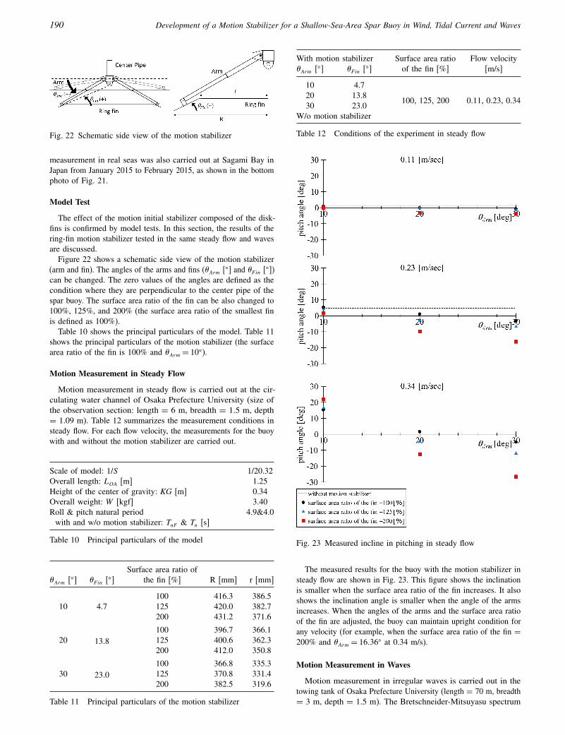
Fig. 22 Schematic side view of the motion stabilizer
measurement in real seas was also carried out at Sagami Bay inJapan from January 2015 to February 2015, as shown in the bottomphoto of Fig. 21.
Model Test
The effect of the motion initial stabilizer composed of the disk-fins is confirmed by model tests. In this section, the results of thering-fin motion stabilizer tested in the same steady flow and wavesare discussed.
Figure 22 shows a schematic side view of the motion stabilizer(arm and fin). The angles of the arms and fins (�Arm [�] and �F in [�])can be changed. The zero values of the angles are defined as thecondition where they are perpendicular to the center pipe of thespar buoy. The surface area ratio of the fin can be also changed to100%, 125%, and 200% (the surface area ratio of the smallest finis defined as 100%).
Table 10 shows the principal particulars of the model. Table 11shows the principal particulars of the motion stabilizer (the surfacearea ratio of the fin is 100% and �Arm = 10�).
Motion Measurement in Steady Flow
Motion measurement in steady flow is carried out at the cir-culating water channel of Osaka Prefecture University (size ofthe observation section: length = 6 m, breadth = 1.5 m, depth= 1.09 m). Table 12 summarizes the measurement conditions insteady flow. For each flow velocity, the measurements for the buoywith and without the motion stabilizer are carried out.
Scale of model: 1/S 1/20.32Overall length: LOA [m] 1.25Height of the center of gravity: KG [m] 0.34Overall weight: W [kgf] 3.40Roll & pitch natural period 4.9&4.0
with and w/o motion stabilizer: TnF & Tn [s]
Table 10 Principal particulars of the model
Surface area ratio of�Arm [�] �F in [�] the fin [%] R [mm] r [mm]
10 4.7100 416.3 386.5125 420.0 382.7200 431.2 371.6
20 13.8100 396.7 366.1125 400.6 362.3200 412.0 350.8
30 23.0100 366.8 335.3125 370.8 331.4200 382.5 319.6
Table 11 Principal particulars of the motion stabilizer
With motion stabilizer Surface area ratio Flow velocity�Arm [�] �F in [�] of the fin [%] [m/s]
10 4.7
100, 125, 200 0.11, 0.23, 0.3420 13.830 23.0
W/o motion stabilizer
Table 12 Conditions of the experiment in steady flow
Fig. 23 Measured incline in pitching in steady flow
The measured results for the buoy with the motion stabilizer insteady flow are shown in Fig. 23. This figure shows the inclinationis smaller when the surface area ratio of the fin increases. It alsoshows the inclination angle is smaller when the angle of the armsincreases. When the angles of the arms and the surface area ratioof the fin are adjusted, the buoy can maintain upright condition forany velocity (for example, when the surface area ratio of the fin =
200% and �Arm = 16036� at 0.34 m/s).
Motion Measurement in Waves
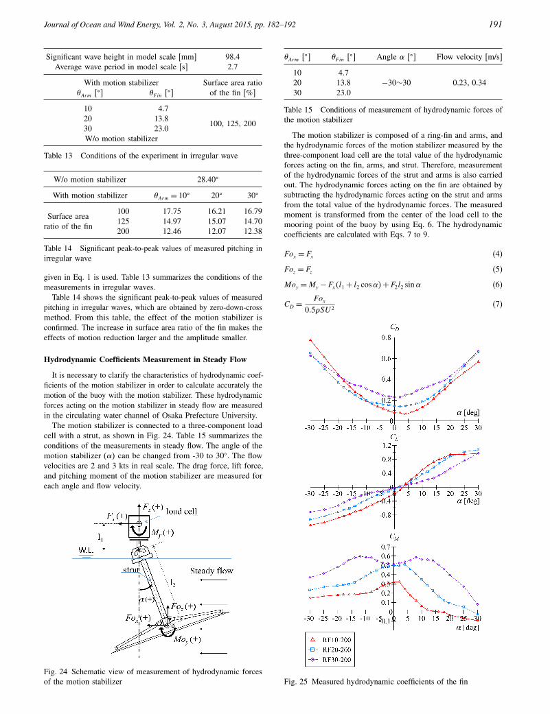
Motion measurement in irregular waves is carried out in thetowing tank of Osaka Prefecture University (length = 70 m, breadth= 3 m, depth = 1.5 m). The Bretschneider-Mitsuyasu spectrum
Journal of Ocean and Wind Energy, Vol. 2, No. 3, August 2015, pp. 182–192 191
Significant wave height in model scale [mm] 98.4Average wave period in model scale [s] 2.7
With motion stabilizer Surface area ratio�Arm [�] �F in [�] of the fin [%]
10 4.7
100, 125, 20020 13.830 23.0W/o motion stabilizer
Table 13 Conditions of the experiment in irregular wave
W/o motion stabilizer 28.40�
With motion stabilizer �Arm = 10� 20� 30�
Surface area100 17.75 16.21 16.79
ratio of the fin125 14.97 15.07 14.70200 12.46 12.07 12.38
Table 14 Significant peak-to-peak values of measured pitching inirregular wave
given in Eq. 1 is used. Table 13 summarizes the conditions of themeasurements in irregular waves.
Table 14 shows the significant peak-to-peak values of measuredpitching in irregular waves, which are obtained by zero-down-crossmethod. From this table, the effect of the motion stabilizer isconfirmed. The increase in surface area ratio of the fin makes theeffects of motion reduction larger and the amplitude smaller.
Hydrodynamic Coefficients Measurement in Steady Flow
It is necessary to clarify the characteristics of hydrodynamic coef-ficients of the motion stabilizer in order to calculate accurately themotion of the buoy with the motion stabilizer. These hydrodynamicforces acting on the motion stabilizer in steady flow are measuredin the circulating water channel of Osaka Prefecture University.
The motion stabilizer is connected to a three-component loadcell with a strut, as shown in Fig. 24. Table 15 summarizes theconditions of the measurements in steady flow. The angle of themotion stabilizer (�5 can be changed from -30 to 30�. The flowvelocities are 2 and 3 kts in real scale. The drag force, lift force,and pitching moment of the motion stabilizer are measured foreach angle and flow velocity.
Fig. 24 Schematic view of measurement of hydrodynamic forcesof the motion stabilizer
�Arm [�] �F in [�] Angle � [�] Flow velocity [m/s]
10 4.720 13.8 −30∼30 0.23, 0.3430 23.0
Table 15 Conditions of measurement of hydrodynamic forces ofthe motion stabilizer
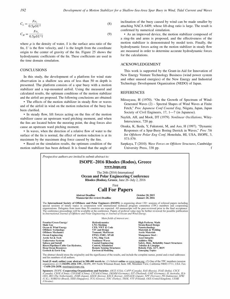
The motion stabilizer is composed of a ring-fin and arms, andthe hydrodynamic forces of the motion stabilizer measured by thethree-component load cell are the total value of the hydrodynamicforces acting on the fin, arms, and strut. Therefore, measurementof the hydrodynamic forces of the strut and arms is also carriedout. The hydrodynamic forces acting on the fin are obtained bysubtracting the hydrodynamic forces acting on the strut and armsfrom the total value of the hydrodynamic forces. The measuredmoment is transformed from the center of the load cell to themooring point of the buoy by using Eq. 6. The hydrodynamiccoefficients are calculated with Eqs. 7 to 9.
Fox = Fx (4)
Foz = Fz (5)
Moy =My − Fx4l1 + l2 cos�5+ F2l2 sin� (6)
CD =Fox
005�SU 2(7)
Fig. 25 Measured hydrodynamic coefficients of the fin
192 Development of a Motion Stabilizer for a Shallow-Sea-Area Spar Buoy in Wind, Tidal Current and Waves
CL =Foz
005�SU 2(8)
CM =Foy
005�SU 2l(9)
where � is the density of water, S is the surface area ratio of thefin, U is the flow velocity, and l is the length from the coordinateorigin to the center of gravity of the fin. Figure 25 shows thehydrodynamic coefficients of the fin. These coefficients are used inthe time domain simulation.
CONCLUSIONS
In this study, the development of a platform for wind stateobservation in a shallow sea area of less than 50 m depth ispresented. The platform consists of a spar buoy with a motionstabilizer and a top-mounted airfoil. Using the measured andcalculated results, the optimum conditions of the motion stabilizerand the airfoil are proposed. The following conclusions are obtained:
• The effects of the motion stabilizer in steady flow or wavesand of the airfoil in wind on the motion reduction of the buoy hasbeen clarified.
• In steady flow, lift forces acting on the fins of the motionstabilizer cause an upstream ward pitching moment, and whenthe fins are located below the mooring point, the drag forces alsocause an upstream ward pitching moment.
• In waves, when the direction of a relative flow of water to thesurface of the fin is normal, the effect of motion reduction is at itsmaximum by the maximum drag force caused by the fins.
• Based on the simulation results, the optimum condition of themotion stabilizer has been defined. It is found that the angle of
inclination of the buoy caused by wind can be made smaller byattaching NACA 6409, whose lift-drag ratio is large. The result isconfirmed by numerical simulation.
• As an improved device, the motion stabilizer composed ofa ring-fin and arms is proposed, and the effectiveness of themotion stabilizer is demonstrated by model tests. Finally, thehydrodynamic forces acting on the motion stabilizer in steady floware measured in order to determine accurate hydrodynamic forcesfor the calculations.
ACKNOWLEDGEMENT
This work is supported by the Grant-in-Aid for Innovation ofNew Energy Venture Technology Business (wind power systemand other unused energies) of the New Energy and IndustrialTechnology Development Organization (NEDO) of Japan.
REFERENCES
Mitsuyasu, H (1970). “On the Growth of Spectrum of Wind-Generated Waves (2) – Spectral Shapes of Wind Waves at FiniteFetch,” Proc Japanese Conf Coastal Eng, Niigata, Japan, JapanSociety of Civil Engineers, 17, 1—7 (in Japanese).
Nayfeh, AH, and Mook, DT (1979). Nonlinear Oscillations, Wiley-Interscience, 720 pp.
Otsuka, K, Ikeda, Y, Fukutomi, M, and Aso, H (1997). “DynamicResponses of a Spar-Buoy Boring Derrick in Waves,” Proc 7thInt Offshore Polar Eng Conf, Honolulu, HI, USA, ISOPE, 3,573-579.
Sarpkaya, T (2010). Wave Forces on Offshore Structures, CambridgeUniversity Press, 338 pp.
Prospective authors are invited to submit abstract to: ISOPE–2016 Rhodes (Rodos), Greece
www.isope.org
The 26th (2016) International Ocean and Polar Engineering Conference
Rhodes (Rodos), Greece, June 26�July 2, 2016 First
Call For Papers
Abstract Deadline Manuscript (for review) Deadline
October 20, 2015 January 20, 2016
The International Society of Offshore and Polar Engineers (ISOPE) is organizing about 130+ sessions of refereed papers including special sessions of timely topics in cooperation with international technical program committee (TPC) members and cooperating organizations. Delegates from more than 50 countries are expected. All manuscripts will be peer-reviewed prior to the final acceptance. The conference proceedings will be available at the conference. Papers of archival value may be further reviewed for possible publication in International Journal of Offshore and Polar Engineering or Journal of Ocean and Wind Energy.
Main fields of interest are:
The abstract should stress the originality and the significance of the results, and include the complete names, postal and e-mail addresses and fax numbers of all authors. Send (E-mail, online) your abstract in 300-400 words to: (1) Submit online on www.isope.org ; (2) One of the TPC members (session organizers); or (3) ISOPE-2016 TPC, ISOPE, 495 North Whisman Road, Suite 300, Mountain View, California 94043-5711, USA: Fax: +1-650-254-2038; [email protected]. Sponsors: ISOPE. Cooperating Organizations and Societies: ASCE (USA), CAPP (Canada), RAS (Russia), INAE (India), CSCE (Canada), CSOE (China), CSNAME (China), CSTAM (China), DKMM (Germany), EIT (Thailand), GMT (Germany), IE Australia, IEA-OES, IRO (The Netherlands), JSMS (Japan), KSOE (Korea), KSCE (Korea); JASNAOE (Japan), NPF (Norway), PII (Indonesia), SPRI (U.K.), SOBENA (Brazil), SSSS (Singapore), TCG (Greece), TOC (Turkey), TSOE, VTT (Finland), OES (United Kingdom), USME (Ukraine).
Frontier/Green Energy/ Shale Gas
Hydrodynamics LNG Sloshing
High Perform. Matls Strain-Based Design
Ocean & Wind Energy Offshore Technology
CFD, NWT & Code VIV and Design
Nanotechnology Materials & Welding
Offshore Mechanics Tsunami, MetOcean Arctic Materials Ocean Engineering FPSO, FSRU, SPAR Manganese Steel : Arctic Sci & Tech LNG, Ship Tech Asset Integrity Underwater Systems Subsea and Install Risers/Pipelines/Cable Gas Hydrates, Deep Ocean Resources
Nonlinear Waves Coastal Engineering Control, Simulation Remote Sensing Structures
Additive Mfg Safety, Risk , Reliability Smart Structures Tubular & Linepipe Robotic Fish, AUV, ROV
Geotech & Envir Eng Environ &Modeling Emerging Topics
f


