Embed Size (px)
Citation preview
DETERMINATION OF MINIMUM DOUBLER LENGTH FOR TAPERED SANDWICH STRUCTURES
A THESIS SUBMITTED TO THE GRADUATE SCHOOL OF NATURAL AND APPLIED SCIENCES
OF MIDDLE EAST TECHNICAL UNIVERSITY
BY
ASLIHAN ALTUN
IN PARTIAL FULFILLMENT OF THE REQUIREMENTS FOR
THE DEGREE OF MASTER OF SCIENCE IN
AEROSPACE ENGINEERING
AUGUST 2019

Approval of the thesis:
DETERMINATION OF MINIMUM DOUBLER LENGTH FOR TAPERED
SANDWICH STRUCTURES
submitted by ASLIHAN ALTUN in partial fulfillment of the requirements for the degree of Master of Science in Aerospace Engineering Department, Middle East
Technical University by, Prof. Dr. Halil Kalıpçılar Dean, Graduate School of Natural and Applied Sciences
Prof. Dr. İsmail Hakkı Tuncer Head of Department, Aerospace Engineering
Prof. Dr. YavuzYaman Supervisor, Aerospace Engineering, METU
Examining Committee Members:
Assist. Prof. Dr. Tuncay Yalçınkaya Aerospace Engineering, METU
Prof. Dr. YavuzYaman Aerospace Engineering, METU
Assist. Prof. Dr. Mustafa Perçin Aerospace Engineering, METU
Assist. Prof. Dr. Mustafa Kaya Aerospace Engineering, Ankara Yildirim Beyazit U.
Assist. Prof. Dr. Munir Elfarra Aerospace Engineering, Ankara Yildirim Beyazit U.
Date: 29.08.2019

iv
I hereby declare that all information in this document has been obtained and
presented in accordance with academic rules and ethical conduct. I also declare
that, as required by these rules and conduct, I have fully cited and referenced all
material and results that are not original to this work.
Name, Surname:
Signature:
Aslıhan Altun
v
ABSTRACT
DETERMINATION OF MINIMUM DOUBLER LENGTH FOR TAPERED
SANDWICH STRUCTURES
Altun, Aslıhan Master of Science, Aerospace Engineering
Supervisor: Prof. Dr. YavuzYaman
August 2019, 108 pages
Sandwich structures are widely used in aerospace industry due to their structural
efficiency. In order to connect the sandwich structures to the adjacent parts,
monolithic region is necessary. Because of the design requirements and strength
necessities, this monolithic region must be strengthened. This reinforcement is
provided by doublers [26]. In order to retain the weight advantage of sandwich
structures, doubler span length must be minimum that keeps the core flatwise tension
stress below the core allowable. In this thesis sandwich structures with different
materials and different geometries under bending load are analyzed and the geometry
of the doubler is designated such that minimum weight of the sandwich structure is
obtained. ABAQUS Standard solver is used for the analyses. In the first part of the
study after the determination of the mesh size, the effects of the friction coefficient
between the parts in contact and the value of tightening torque of the bolts that
connects the sandwich structure to adjacent parts are investigated. The effects of
geometric and material nonlinearity are also examined in this part. Second part of the
thesis covers the finite element model verification done by using tests and analytical
approaches. At the final phase of the thesis, failure types of the sandwich structures
are investigated and minimum failure load among these failure criteria is determined.
The effect of doubler geometry on the failure mechanism is studied for several

vi
sandwich structures with specified geometry and materials. Doubler geometry is
specified by doing a parametric study. This parametric study is performed by running
Python scripts in ABAQUS Standard.
Keywords: Sandwich Structures, Tapered Sandwich Structures, Honeycomb, Finite
Element Analysis, Sandwich Panel Local Reinforcements
vii
ÖZ
KONİK UÇLU SANDVİÇ YAPILARIN MİNİMUM DUBLİN PARÇASI
UZUNLUĞUNUN BELİRLENMESİ
Altun, Aslıhan Yüksek Lisans, Havacılık ve Uzay Mühendisliği
Tez Danışmanı: Prof. Dr. YavuzYaman
Ağustos 2019, 108 sayfa
Sandviç yapılar yapısal etkinliklerinden dolayı havacılık endüstrisinde yaygın olarak
kullanılmaktadır. Sandviç yapılarda monolitik bölge, komşu parçalar ile bağlantının
yapılabilmesi için gereklidir. Tasarım gereksinimleri ve mukavemet ihtiyaçları,
monolitik bölgenin güçlendirilmesini gerekli hale getirmektedir. Bu güçlendirme
dublin parçası ile sağlanmaktadır [26]. Sandviç yapıların ağırlık kazanımlarını
sürdürebilmek için dublin parçalarının geometrilerinin balpeteği çekme gerilimini
balpeteğinin müsaade edilen geriliminden düşük tutacak şekilde olması
gerekmektedir. Bu tezde, bükülme yükü altındaki farklı malzeme ve geometrik
özelliklere sahip sandviç yapıların analizleri yapılacak ve dublin parçasının
geometrisi, asgari ağırlık sağlanacak şekilde elde edilecektir. Sonlu elemanlar
analizleri ABAQUS sonlu elemanlar programında yapılmıştır. Çalışmanın ilk
bölümünde, çözüm ağı boyutuna karar verilmesinin ardından, birbiri ile konuşan
yüzeyler arasındaki sürtünme katsayıları ile sandviç yapıyı komşu parçalara bağlayan
bağlayıcılar üzerindeki sıkma momentinin etkileri incelenmiştir. Tezin ikinci aşaması
testler ve çözümsel yaklaşımlar kullanılarak sonlu elemanlar modelinin
doğrulanmasını içermektedir. Tezin son bölümünde sandviç yapıların kırılma tipleri
incelenmiş ve bu kırılma tipleri için asgari kırılma yükü belirlenmiştir. Dublin
yapısının geometrik karakteristiğinin kırılma mekanizmasına olan etkisi, farklı

viii
geometrik ve mekanik özelliklere sahip çeşitli sandviç yapıları üzerinde çalışılmıştır.
Dublin yapısının geometrisi değiştirgesel bir çalışma ile belirlenmiştir. Bu
değiştirgesel çalışmalar ABAQUS sonlu elemanlar programında Python komut
dosyasının çalıştırılması ile yapılmıştır.
Anahtar Kelimeler: Sandviç yapılar, Konik Uçlu Sandviç Yapılar, Balpeteği
Malzeme, Sonlu Elemanlar Analizi, Bölgesel Sandviç Panel Güçlendirmeleri

ix
To My Family

x
ACKNOWLEDGEMENTS
I would like to express my special thanks of gratitude to Prof. Dr. Yavuz Yaman for
his advice, criticism, and excellent guidance throughout the study.
My heartful thanks also to my dear parents and my little brother not just during
finishing this thesis but also during my all studies. Without their constructive
comments and warm encouragements, this study would not have been possible.
My deepest appreciation goes to my beloved husband, Akif. His support, patience,
unconditional love and hand-made fruit soda have been the greatest contributors in the
completion of the thesis.
Finally, grateful acknowledgment to all my friends for their understanding. Although
I could not have enough time for them during studying this thesis, I felt their support
all this time. I am very lucky to have such friends.
xi
TABLE OF CONTENTS
ABSTRACT ................................................................................................................. v
ÖZ... .......................................................................................................................... vii
ACKNOWLEDGEMENTS ......................................................................................... x
TABLE OF CONTENTS ........................................................................................... xi
LIST OF TABLES ................................................................................................... xiv
LIST OF FIGURES ................................................................................................... xv
LIST OF ABBREVIATIONS .................................................................................. xix
LIST OF SYMBOLS ................................................................................................. xx
CHAPTERS
1. INTRODUCTION ................................................................................................ 1
1.1. Scope of the Study ............................................................................................. 3
1.2. Summary of Thesis Plan .................................................................................... 3
2. LITERATURE SURVEY AND THEORETICAL BACKGROUND ................. 5
2.1. Sandwich Structures and Failure Types ............................................................ 6
2.1.1. Intracell Buckling ..................................................................................... 10
2.1.2. Facesheet Wrinkling ................................................................................. 11
2.1.3. Facesheet Tension Failure ........................................................................ 12
2.1.4. Core Shear Failure .................................................................................... 12
2.1.5. Core Flatwise Tension Failure .................................................................. 14
2.1.6. Shear Crimping ......................................................................................... 15
2.2. Ramp-down Region of the Sandwich Structures............................................. 15
2.3. Beam Theory for Sandwich Structures ........................................................... 17
xii
2.4. ABAQUS Finite Element Model .................................................................... 21
2.4.1. Sandwich Panel Modelling Techniques and Equivalent Modeling .......... 21
2.4.2. Tie Constraint ........................................................................................... 25
3. METHODOLOGY ............................................................................................. 27
3.1. Finite Element Model Validation .................................................................... 27
3.1.1. Test 1: Finite Element Model Correlation with Three Point Bending Test
of Sandwich Panels with Aluminum Skins and Nomex Honeycomb Core ....... 27
3.1.1.1. Finite Element Model Description..................................................... 28
3.1.1.2. Results................................................................................................ 31
3.1.2. Test 2: Three Point Bending Test of Tapered Sandwich Panels with
Aluminum Skins and Aluminum Honeycomb Core .......................................... 33
3.1.2.1. Finite Element Description ................................................................ 33
3.1.2.2. Simplified Finite Element Model ...................................................... 42
4. FINITE ELEMENT MODEL ............................................................................ 45
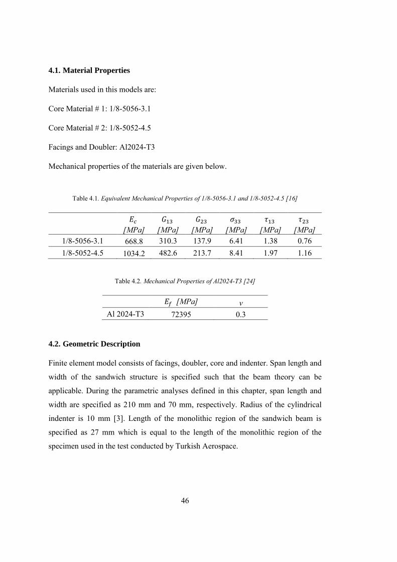
4.1. Material Properties .......................................................................................... 46
4.2. Geometric Description .................................................................................... 46
4.3. Loads and Boundary Conditions ..................................................................... 47
4.4. Python Script ................................................................................................... 47
4.5. Design of Experiment ..................................................................................... 48
4.6. Results ............................................................................................................. 51
4.6.1. Simply Supported Boundary Condition ................................................... 51
4.6.2. Fixed Boundary Condition ....................................................................... 56
4.6.3. Minimum Doubler Length of Design of Experiment Sets for Fixed
Boundary Conditions .......................................................................................... 64
5. DISCUSSION AND CONCLUSION ................................................................ 65

xiii
REFERENCES ........................................................................................................... 69 APPENDICES
A. RESULTS OF PARAMETRIC STUDY ............................................................ 73
B. SCRIPT FOR FIXED BOUNDARY CONDITION .......................................... 85
C. SCRIPT FOR SIMPLY SUPPORTED BOUNDARY CONDITION ................ 97
xiv
LIST OF TABLES
TABLES
Table 2.1. Coefficients for Facesheet Wrinkling Calculation [28] ............................ 12
Table 2.2. Geometric Constants for Sandwich Beam Theory [32] ............................ 21
Table 2.3. Orthotropic Material Definitions for Equivalent Modeling [4] ................ 24
Table 3.1. Equivalent Mechanical Properties of HRH 10-3/16-2 [16] ...................... 29
Table 3.2. Geometrical and mechanical properties of the tested sandwich panels and
of their components [14] ............................................................................................ 29
Table 3.3. Literature Correction Mesh Sets ............................................................... 31
Table 3.4. Equivalent Mechanical Properties of HRH 10-3/16-2 [16] ...................... 33
Table 3.5. Geometrical and mechanical properties of the tested sandwich panels and
of their components [33] ............................................................................................ 34
Table 3.6. Mesh Size Sets for First Mesh Sensitivity Study (Glass is Included) ...... 36
Table 3.7. Element Type and Total Element Number of Mesh Sets (Glass is Included)
................................................................................................................................... 36
Table 3.8. Results of the First Mesh Sensitivity Study (Glass is Included) .............. 36
Table 3.9. Mesh Size Sets for Second Mesh Sensitivity Study (Glass is Excluded) . 37
Table 3.10. Element Type and Total Element Number of Mesh Sets (Glass is
Excluded) ................................................................................................................... 38
Table 3.11. Results of the Second Mesh Sensitivity Study (Glass is Excluded) ....... 38
Table 4.1. Equivalent Mechanical Properties of 1/8-5056-3.1 and 1/8-5052-4.5 [16]
................................................................................................................................... 46
Table 4.2. Mechanical Properties of Al2024-T3 [24] ................................................ 46
Table 4.3. Design of Experiment of Parametric Study .............................................. 49
Table 4.4. Minimum Doubler Length of Sets for Fixed Boundary Condition .......... 64
xv
LIST OF FIGURES
FIGURES
Figure 2.1. Taper Configurations of Sandwich Constructions Tested under Tensile
Load [27] ...................................................................................................................... 5
Figure 2.2. Sandwich Construction [26] ...................................................................... 7
Figure 2.3. Core Forms [6] ........................................................................................... 7
Figure 2.4. Corrugation Fabrication Process [5] .......................................................... 8
Figure 2.5. Ribbon and Transverse Directions of Honeycomb Cores [11] .................. 8
Figure 2.6. Analogy between the Sandwich Structure and I-beam [17] ...................... 9
Figure 2.7. Intracell Buckling [28] ............................................................................. 10
Figure 2.8. Facesheet Wrinkling [28] ........................................................................ 11
Figure 2.9. Facesheet Tension Failure [28] ................................................................ 12
Figure 2.10.Core Shear Failure [28] .......................................................................... 13
Figure 2.11. Core Shear Strength Correction Factor [26] .......................................... 13
Figure 2.12. Flatwise Tension Test Setup [5] ............................................................ 14
Figure 2.13. Shear Crimping [6] ................................................................................ 15
Figure 2.14. Ramp-down Region of the Sandwich Structure [19] ............................. 16
Figure 2.15. Doublers in the Ramp-down Region [26] .............................................. 16
Figure 2.16. Core Flatwise Tension Failure [33] ....................................................... 17
Figure 2.17. Sandwich Beam Definition [4] .............................................................. 18
Figure 2.18. Actual and Approximate Stress Distribution [32] ................................. 20
Figure 2.19. Full 2D Modeling [4] ............................................................................. 22
Figure 2.20. Mixed Modeling [4] ............................................................................... 22
Figure 2.21. Equivalent Model Simplifications [4] ................................................... 23
Figure 3.1. Test Set-up for TPBT [14] ....................................................................... 30
Figure 3.2. Load and Boundary Condition of Test-1 ................................................. 31
Figure 3.3. Load & Displacement Curve of Test Adapted from [14] ........................ 32
xvi
Figure 3.4. Load & Displacement Curve –Test-1 ...................................................... 32
Figure 3.5. Test Set-up for Tapered Sandwich Structure [33] .................................. 34
Figure 3.6. Load and Boundary Condition of Test-2 ................................................. 35
Figure 3.7. Change in Core Flatwise Tension Stress According to Mesh Size (Glass is
Included) .................................................................................................................... 37
Figure 3.8. Change in Core Flatwise Tension Stress According to Mesh Size (Glass is
Excluded) ................................................................................................................... 38
Figure 3.9. Effect of Glass on Load vs Displacement Results .................................. 39
Figure 3.10. Effect of Friction Coefficient ................................................................ 40
Figure 3.11. Bolt Preload Simulation in FEM [18] ................................................... 41
Figure 3.12. Effect of Bolt Preload ............................................................................ 41
Figure 3.13. Fixed Boundary Condition .................................................................... 42
Figure 3.14. Simply Supported Boundary Condition ................................................ 43
Figure 4.1. Python Script Scheme ............................................................................. 47
Figure 4.2. Numbering Methodology of the Sets ...................................................... 49
Figure 4.3. Displacement Plot of Set-00010 With 60 mm Doubler Length for Simply
Supported Boundary Condition ................................................................................. 52
Figure 4.4. Core Normal Stress Plot of Set-00010 With 60 mm Doubler Length for
Simply Supported Boundary Condition..................................................................... 52
Figure 4.5. Core Flatwise Tension Stress vs Doubler Length Graphs for Set-00000 and
Set-00010 with Simply Supported Boundary Condition ........................................... 53
Figure 4.6. Core Flatwise Tension Stress vs Doubler Length Graphs for Set-00011 and
Set-00110 with Simply Supported Boundary Condition ........................................... 53
Figure 4.7. Core Flatwise Tension Stress vs Doubler Length Graphs for Set-01010 and
Set-10010 with Simply Supported Boundary Condition ........................................... 53
Figure 4.8. Effect of Doubler Thickness for Simply Supported Boundary Conditions
................................................................................................................................... 54
Figure 4.9. Effect of Core Material for Simply Supported Boundary Conditions .... 54
Figure 4.10. Effect of Facing Thickness for Simply Supported Boundary Conditions
................................................................................................................................... 55
xvii
Figure 4.11. Effect of Ramp Angle for Simply Supported Boundary Conditions ..... 55
Figure 4.12. Effect of Core Thickness for Simply Supported Boundary Conditions 56
Figure 4.13. Displacement Plot of Set-00010 With 60 mm Doubler Length for Simply
Supported Boundary Condition.................................................................................. 57
Figure 4.14. Core Normal Stress Plot of Set-00010 With 60 mm Doubler Length for
Simply Supported Boundary Condition ..................................................................... 57
Figure 4.15. Core Flatwise Tension Stress vs Doubler Length Graphs for Set-00000
and Set-00001 with Fixed Boundary Condition ........................................................ 58
Figure 4.16. Core Flatwise Tension Stress vs Doubler Length Graphs for Set-00010
and Set-00100 with Fixed Boundary Condition ........................................................ 58
Figure 4.17. Core Flatwise Tension Stress vs Doubler Length Graphs for Set-01000
and Set-10000 with Fixed Boundary Condition ........................................................ 58
Figure 4.18. Effect of Ramp Angle for Fixed Boundary Conditions ......................... 59
Figure 4.19. Effect of Core Thickness for Fixed Boundary Conditions .................... 59
Figure 4.20. Effect of Facing Thickness for Fixed Boundary Conditions ................. 60
Figure 4.21. Effect of Doubler Thickness for Fixed Boundary Conditions ............... 60
Figure 4.22. Effect of Core Material for Fixed Boundary Conditions ....................... 61
Figure 4.23. Core Flatwise Tension Stress Change According to Sandwich Structure’s
Zone............................................................................................................................ 62
Figure 4.24. Comparison of Fixed and Simply Supported Boundary Conditions ..... 63
Figure A.1. Core Flatwise Stress vs Doubler Length of Set-00000 ........................... 73
Figure A.2. Core Flatwise Stress vs Doubler Length of Set-00001 ........................... 73
Figure A.3. Core Flatwise Stress vs Doubler Length of Set-00010 ........................... 74
Figure A.4. Core Flatwise Stress vs Doubler Length of Set-00011 ........................... 74
Figure A.5. Core Flatwise Stress vs Doubler Length of Set-00100 ........................... 74
Figure A.6. Core Flatwise Stress vs Doubler Length of Set-00101 ........................... 75
Figure A.7. Core Flatwise Stress vs Doubler Length of Set-00110 ........................... 75
Figure A.8. Core Flatwise Stress vs Doubler Length of Set-00111 ........................... 75
Figure A.9. Core Flatwise Stress vs Doubler Length of Set-01000 ........................... 76
Figure A.10. Core Flatwise Stress vs Doubler Length of Set-01001 ......................... 76
xviii
Figure A.11. Core Flatwise Stress vs Doubler Length of Set-01010 ........................ 76
Figure A.12. Core Flatwise Stress vs Doubler Length of Set-01011 ........................ 77
Figure A.13. Core Flatwise Stress vs Doubler Length of Set-01100 ........................ 77
Figure A.14. Core Flatwise Stress vs Doubler Length of Set-01101 ........................ 77
Figure A.15. Core Flatwise Stress vs Doubler Length of Set-01110 ........................ 78
Figure A.16. Core Flatwise Stress vs Doubler Length of Set-01111 ........................ 78
Figure A.17. Core Flatwise Stress vs Doubler Length of Set-10000 ........................ 78
Figure A.18. Core Flatwise Stress vs Doubler Length of Set-10001 ........................ 79
Figure A.19. Core Flatwise Stress vs Doubler Length of Set-10010 ........................ 79
Figure A.20. Core Flatwise Stress vs Doubler Length of Set-10011 ........................ 79
Figure A.21. Core Flatwise Stress vs Doubler Length of Set-10100 ........................ 80
Figure A.22. Core Flatwise Stress vs Doubler Length of Set-10101 ........................ 80
Figure A.23. Core Flatwise Stress vs Doubler Length of Set-10110 ........................ 80
Figure A.24. Core Flatwise Stress vs Doubler Length of Set-10111 ........................ 81
Figure A.25. Core Flatwise Stress vs Doubler Length of Set-11000 ........................ 81
Figure A.26. Core Flatwise Stress vs Doubler Length of Set-11001 ........................ 81
Figure A.27. Core Flatwise Stress vs Doubler Length of Set-11010 ........................ 82
Figure A.28. Core Flatwise Stress vs Doubler Length of Set-11011 ........................ 82
Figure A.29. Core Flatwise Stress vs Doubler Length of Set-11100 ........................ 82
Figure A.30. Core Flatwise Stress vs Doubler Length of Set-11101 ........................ 83
Figure A.31. Core Flatwise Stress vs Doubler Length of Set-11110 ........................ 83
Figure A.32. Core Flatwise Stress vs Doubler Length of Set-11111 ........................ 83
xix
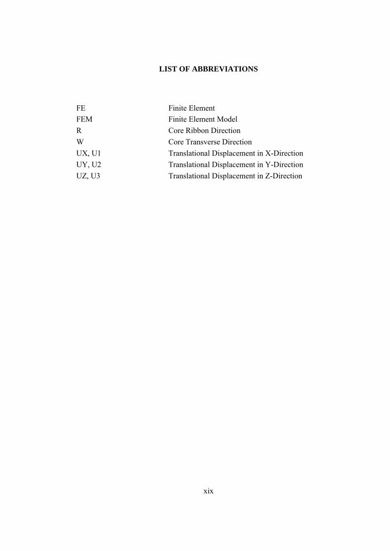
LIST OF ABBREVIATIONS
FE Finite Element FEM Finite Element Model R Core Ribbon Direction W Core Transverse Direction UX, U1 Translational Displacement in X-Direction UY, U2 Translational Displacement in Y-Direction UZ, U3 Translational Displacement in Z-Direction
xx
LIST OF SYMBOLS
𝐴 Deformed Area 𝐴0 Initial Area 𝑏 Beam Width 𝐷 Flexural Rigidity of Sandwich Construction 𝐸𝑐 Core Compressive Modulus of Elasticity 𝐸𝑓 Modulus of Elasticity of Facing and Doubler
𝐺𝑐 Minimum of Core Shear Modulus in Ribbon and Transverse Directions
𝐺13 Core Shear Modulus in Ribbon Direction 𝐺23 Core Shear Modulus in Transverse Direction ℎ Distance between Facing Skin Centers 𝐼 Second Moment of Area of Sandwich Beam
𝐼𝑓 Second Moment of Area of the Skins with respect to Their own Centroidal
𝐿 Span of the Sandwich Beam 𝐿𝑑 Doubler Span 𝑙 Deformed Length 𝑙0 Initial Length 𝑀 Maximum Bending Moment 𝑃 Applied Load 𝑠 Cell Size 𝑡𝑐 Core Thickness 𝑡𝑑 Doubler Thickness 𝑡𝑓 Facing Thickness 𝑡′ Foil Thickness 𝑄 Applied Load per Unit Width 𝛼 Core Ramp Angle
𝜀𝑛𝑜𝑚 Nominal Strain 𝜀𝑡𝑟 True Strain 𝜎𝑐𝑡 Core Flatwise Tension Stress 𝜎𝑓𝑡 Facing Tension Stress 𝜎𝑛𝑜𝑚 Nominal Stress 𝜎𝑠𝑐𝑟 Critical Shear Crimping Stress 𝜎𝑡𝑟 True Stress

xxi
𝜎𝑡𝑢 Tensile Ultimate Allowable Stress 𝜎𝑤𝑟 Critical Wrinkling Stress 𝜎33 Core Flatwise Tension Allowable Stress 𝜏𝑐,𝑟𝑖𝑏𝑏𝑜𝑛 Core Shear Stress in Ribbon Direction 𝜏𝑐,𝑡𝑟𝑎𝑛𝑠𝑣𝑒𝑟𝑠𝑒 Core Shear Stress in Transverse Direction 𝜏13 Core Shear Allowable in Ribbon Direction 𝜏23 Core Shear Allowable in Transverse Direction 𝜈 Poisson’s Ratio of Facing and Doubler

1
CHAPTER 1
1. INTRODUCTION
Sandwich structures are widely used in aerospace field due to their good flexural
stiffness, strength, smooth skins, excellent fatigue resistance and low weight [5]. By
increasing the weight in 6%, 37 times more rigid and 9.25 times stronger structures
can be designed by using the thickness of the honeycomb in sandwich constructions
compared to the solid metal sheet [7]. Together with its benefits, that sandwich
constructions cannot be manufactured in every shape is the one of the disadvantages
of these constructions. A sandwich structure is mainly composed of facings, core and
core-to-face bonding materials. The function of sandwich construction is very similar
to an “I-beam” structure. Facings of the sandwich structure carry axial loads while
core carries the shear loads and increases the stiffness of the structure by holding the
facing skins apart [16]. In this manner, facings of the sandwich panel correspond to
the flanges while core corresponds to the web of the I-beam in terms of their functions
under loading [26].
In general, materials of the facings can be selected as metal sheet or reinforced plastic
laminate. Also, metallic or non-metallic materials can be used for core. Non-metallic
cores have, in general, low strength compared to the metallic cores. However due to
their high thermal insulation capabilities non-metallic cores are also very useful in
certain applications. Other than the material, cores are grouped in terms of their forms.
The most widely used core type is honeycomb which is divided into two groups
according to core cell shape: square and hexagonal cells. The corrugated or truss core
is another type which is also used in aircraft design [6].
It is a necessity to connect sandwich structures to the adjacent parts with reduced grip
length for the fasteners and increased clamp-up in the aircraft structure [19]. To do
2
so, tapered transition type of sandwich ending is widely used. Tapered transition
region is required to fasten sandwich structures to other parts because sandwich
constructions are difficult to fasten support structures due to their low transverse
compression strength [34]. This tapered area must be designed to:
- resist the shear loads caused by static, dynamic or sonic loads
- meet the tension allowable strength for the fastener pull-through failure that connects the sandwich structure to adjacent parts
- prevent the knife-edge condition in case of the usage of countersunk fasteners to joint the sandwich structure to adjacent parts
To meet these requirements without unnecessary weight increase, doublers are used
in the ramp-down region of the sandwich structures [26].
Failure mechanism and prediction of the failure load of the sandwich structure is more
complex compared to the isotropic materials. Other than the material failures such as
facesheet tension failure, core tension, shear and compression failures; local instability
failures are also faced with in the sandwich structures which are facesheet wrinkling,
intracell buckling and shear crimping [34]. These failure mechanisms are formulated
for the constant thickness region in the literature and the failure load of the sandwich
structure can be calculated by only considering the constant thickness region [19],[26].
However, experiences have shown that, the ramp-down region is the weakest part of
the sandwich structure [19]. Improper geometrical design of the ramp-down region
causes the local stress concentrations [34]. Therefore, to prevent an early-failure under
a load less than the failure load calculated for the constant thickness region, failure
load for the ramp-down region must also be investigated.
Three-point bending tests of sandwich structures show that the design of the doublers
has a remarkable effect on the failure load of the sandwich structures [33].
3
1.1. Scope of the Study
The experiences show that the sandwich structures with shorter doubler length face
with the core net tension failure around the tapering region below the expected failure
load.
The objective of this thesis is to find the effect of the doubler geometry on the core
flatwise tension stress for specified sandwich panel designs under bending. The main
point is that the minimum doubler length that prevents the core net tension failure
around the tapering region must be selected to keep the weight as low as possible.
In the first part of the study the finite element model is verified by two different test
results.
Within the frame of the modelling methodology used in the verified model, a
parametric finite element model is prepared in ABAQUS by using Python.
Sandwich panel allowable load for the constant-thickness region is specified as the
applied load.
For each run, while keeping all the geometrical and material parameters constant,
doubler span length is slightly increased until the core net tension stress becomes
stable.
The calculations conducted in this study has no safety factor.
1.2. Summary of Thesis Plan
Chapter 1 of the thesis includes the introduction part. In the introduction, a general
information about sandwich structures is presented and problem is defined. In Chapter
2, theoretical background and literature survey are given. In this part, analysis
techniques of sandwich structures, beam theory and sandwich panel finite element
modeling techniques are described. Finite element model verification and
simplification are done in Chapter 3. Verification is done by using two different test
results. One of these test results is obtained from a study in literature and the other test

4
is conducted in Turkish Aerospace. Mesh sensitivity study is also conducted in this
chapter. According to the results of the studies presented in this chapter, a new
modeling strategy is created for the rest of the thesis. In Chapter 4, analysis sets used
in this study are defined. To create and analyze these sets automatically, a Python code
is developed. This Python code and the results of these analyses are also explained
and interpreted in this chapter. Finally, Chapter 7 is devoted to discussion, conclusion
remarks and possible future work.
5
CHAPTER 2
2. LITERATURE SURVEY AND THEORETICAL BACKGROUND
In [2], the ramp-down region is specified as the most critical region of the sandwich
structures. According to [22], tapered area causes significant stress distribution
changes. In this tapered region, core shear stress, axial forces in facesheets, and local
bending shows a significant increase. Kassapoglou [19] examines the stress
distribution of ramp-down region under bending moments or transverse shear loads.
In this study, facesheets are selected as three fabric plies. The aim of this study is to
predict the applied load at which core will fail. According to [19], core thickness and
ramp angle have a significant effect on this failure load.
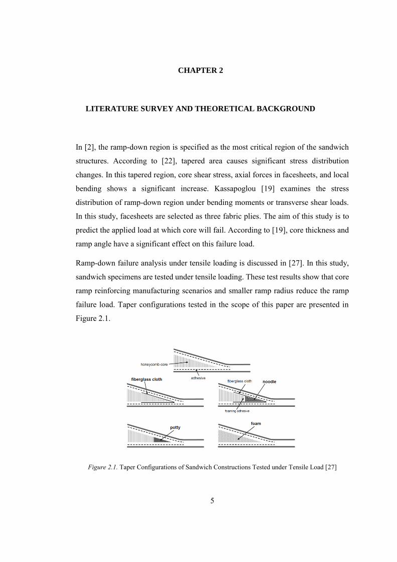
Ramp-down failure analysis under tensile loading is discussed in [27]. In this study,
sandwich specimens are tested under tensile loading. These test results show that core
ramp reinforcing manufacturing scenarios and smaller ramp radius reduce the ramp
failure load. Taper configurations tested in the scope of this paper are presented in
Figure 2.1.
Figure 2.1. Taper Configurations of Sandwich Constructions Tested under Tensile Load [27]

6
Other than the ramp down failure analysis, constant thickness failure types of
sandwich constructions are investigated in [27] and [17] in detail. These failure modes
are expressed in the following sub-titles of this chapter.
In [27] and [6] core flatwise tension failure mode and honeycomb flatwise tensile
strength property is not published. In [5], flatwise tensile strengths of some of the core
types obtained by conduction flatwise tension test are presented.
In [14], three point bending test results and numerical investigation of sandwich
construction with aluminum skins and Nomex honeycomb is studied. By this study, a
finite element model with high accuracy and capability of local behavior of cell
crushing is developed.
Finite element modeling of sandwich constructions and mechanical property
definitions of core are examined in detail by Ilke [4]. Details of this study are
explicated in the next sub-titles of this chapter.
In this study, minimum doubler length for specified sandwich construction geometries
are determined to prevent any unnecessary weight increase.
2.1. Sandwich Structures and Failure Types
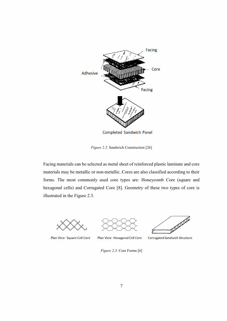
Sandwich structures are mainly composed of two facings and a core between these
facings. The bonding between the facings and the core is provided by adhesives. A
symbolic presentation of sandwich structures is illustrated in Figure 2.2.
7
Figure 2.2. Sandwich Construction [26]
Facing materials can be selected as metal sheet of reinforced plastic laminate and core
materials may be metallic or non-metallic. Cores are also classified according to their
forms. The most commonly used core types are: Honeycomb Core (square and
hexagonal cells) and Corrugated Core [8]. Geometry of these two types of core is
illustrated in the Figure 2.3.
Figure 2.3. Core Forms [6]
8
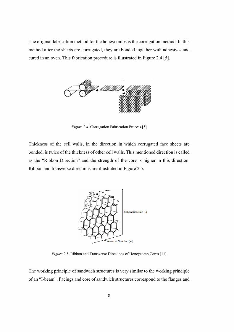
The original fabrication method for the honeycombs is the corrugation method. In this
method after the sheets are corrugated, they are bonded together with adhesives and
cured in an oven. This fabrication procedure is illustrated in Figure 2.4 [5].
Figure 2.4. Corrugation Fabrication Process [5]
Thickness of the cell walls, in the direction in which corrugated face sheets are
bonded, is twice of the thickness of other cell walls. This mentioned direction is called
as the “Ribbon Direction” and the strength of the core is higher in this direction.
Ribbon and transverse directions are illustrated in Figure 2.5.
Figure 2.5. Ribbon and Transverse Directions of Honeycomb Cores [11]
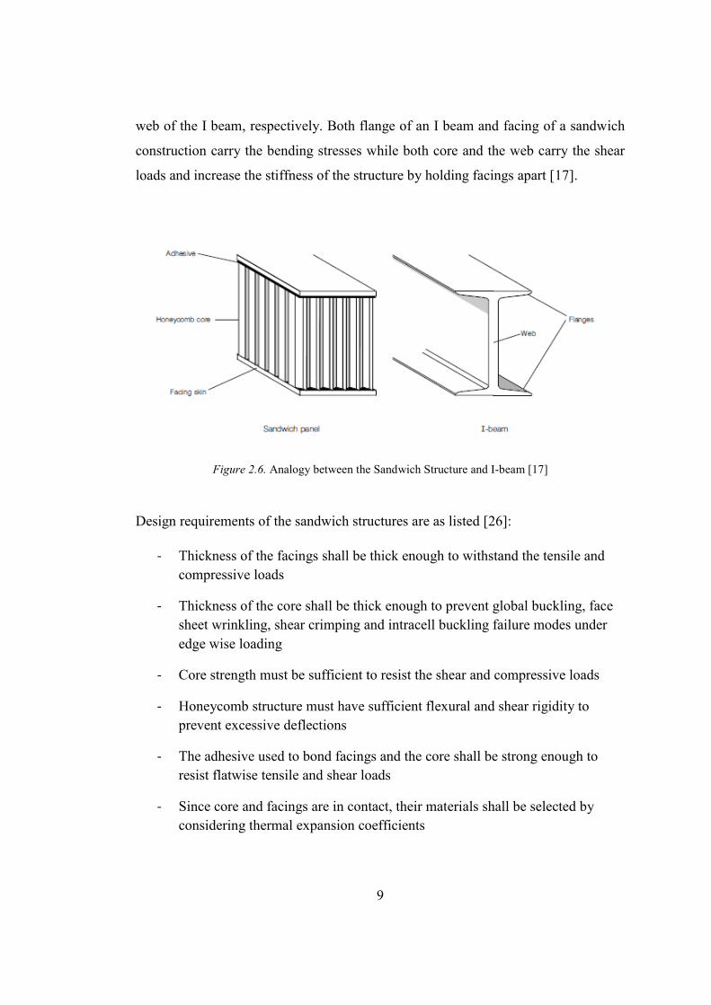
The working principle of sandwich structures is very similar to the working principle
of an “I-beam”. Facings and core of sandwich structures correspond to the flanges and
9
web of the I beam, respectively. Both flange of an I beam and facing of a sandwich
construction carry the bending stresses while both core and the web carry the shear
loads and increase the stiffness of the structure by holding facings apart [17].
Figure 2.6. Analogy between the Sandwich Structure and I-beam [17]
Design requirements of the sandwich structures are as listed [26]:
- Thickness of the facings shall be thick enough to withstand the tensile and compressive loads
- Thickness of the core shall be thick enough to prevent global buckling, face sheet wrinkling, shear crimping and intracell buckling failure modes under edge wise loading
- Core strength must be sufficient to resist the shear and compressive loads
- Honeycomb structure must have sufficient flexural and shear rigidity to prevent excessive deflections
- The adhesive used to bond facings and the core shall be strong enough to resist flatwise tensile and shear loads
- Since core and facings are in contact, their materials shall be selected by considering thermal expansion coefficients
10
The allowable loads of a sandwich panel designed in the frame of these requirements
can be calculated for the specified failure modes in the literature. These failure modes
can be grouped as skin and core failures [28].
Skin failures are:
- intracell buckling
- face sheet wrinkling
- face sheet tension failure
Core failures are:
- core flatwise tension failure
- core shear failure
In addition to core and skin failures, shear crimping which is a global instability failure
is also observed in the sandwich structures.
For the constant core thickness region of the sandwich structures, theory of the
calculation of critical stress levels for these failure modes are described under the
following sub-chapters.
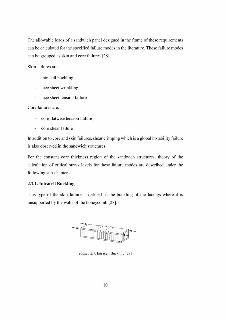
2.1.1. Intracell Buckling
This type of the skin failure is defined as the buckling of the facings where it is
unsupported by the walls of the honeycomb [28].
Figure 2.7. Intracell Buckling [28]
11
The stress at which intracell buckling occurs in the skins are calculated by using the
following relation [28]:
𝜎𝑖𝑏 =2𝐸𝑓
1 − 𝜈𝑓2 (
𝑡
𝑠)
2
(2.1)
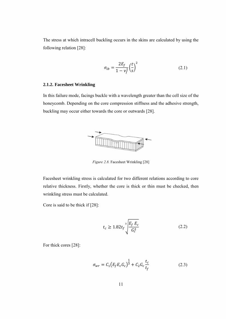
2.1.2. Facesheet Wrinkling
In this failure mode, facings buckle with a wavelength greater than the cell size of the
honeycomb. Depending on the core compression stiffness and the adhesive strength,
buckling may occur either towards the core or outwards [28].
Figure 2.8. Facesheet Wrinkling [28]
Facesheet wrinkling stress is calculated for two different relations according to core
relative thickness. Firstly, whether the core is thick or thin must be checked, then
wrinkling stress must be calculated.
Core is said to be thick if [28]:
𝑡𝑐 ≥ 1.82𝑡𝑓 √𝐸𝑓 𝐸𝑐
𝐺𝑐2
3
(2.2)
For thick cores [28]:
𝜎𝑤𝑟 = 𝐶1(𝐸𝑓𝐸𝑐𝐺𝑐)13 + 𝐶2𝐺𝑐
𝑡𝑐
𝑡𝑓 (2.3)
12
For thin cores [28]:
𝜎𝑤𝑟 = 𝐶3√𝑡𝑓
𝑡𝑐𝐸𝑐𝐸𝑓 + 𝐶4𝐺𝑐
𝑡𝑐
𝑡𝑓 (2.4)
The coefficients can be conservatively selected as:
Table 2.1. Coefficients for Facesheet Wrinkling Calculation [28]
𝐶1 𝐶2 𝐶3 𝐶4 0.247 0.078 0.330 0.00
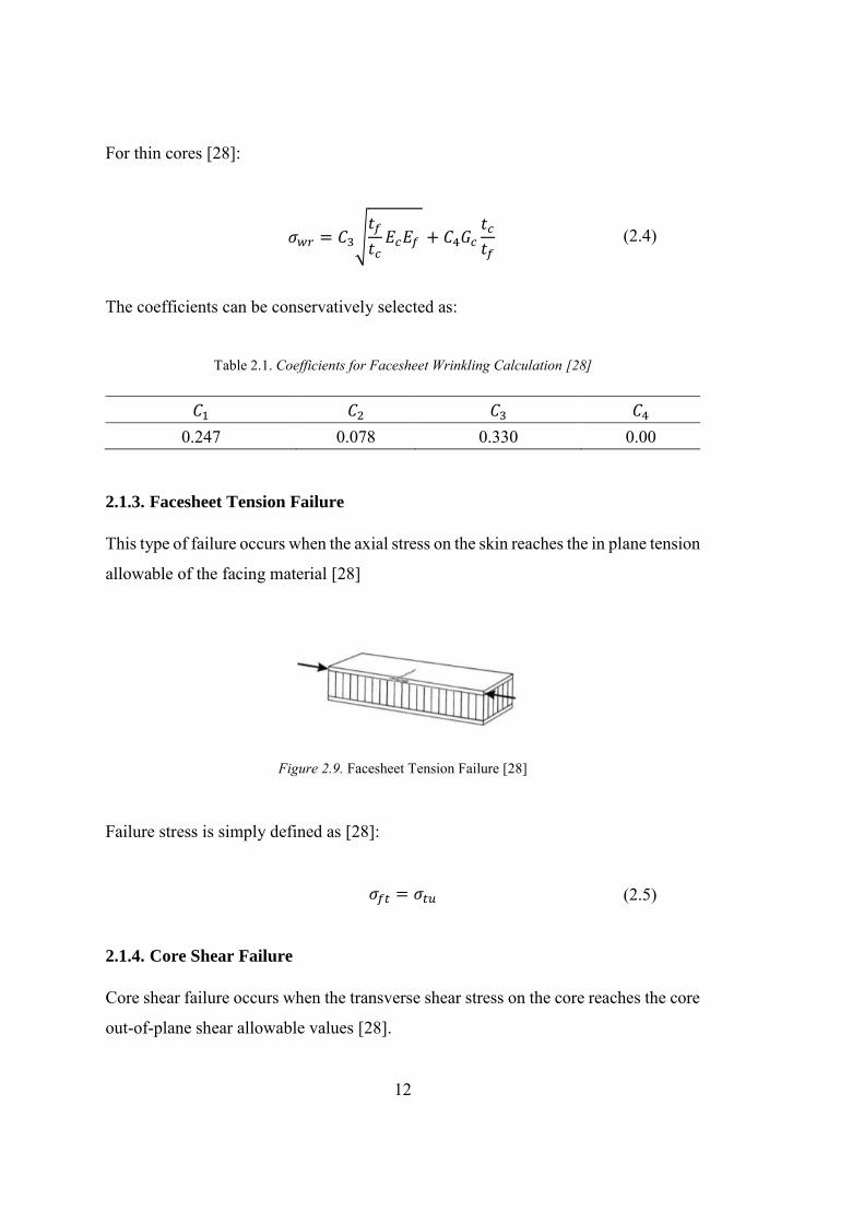
2.1.3. Facesheet Tension Failure
This type of failure occurs when the axial stress on the skin reaches the in plane tension
allowable of the facing material [28]
Figure 2.9. Facesheet Tension Failure [28]
Failure stress is simply defined as [28]:
𝜎𝑓𝑡 = 𝜎𝑡𝑢 (2.5)
2.1.4. Core Shear Failure
Core shear failure occurs when the transverse shear stress on the core reaches the core
out-of-plane shear allowable values [28].
13
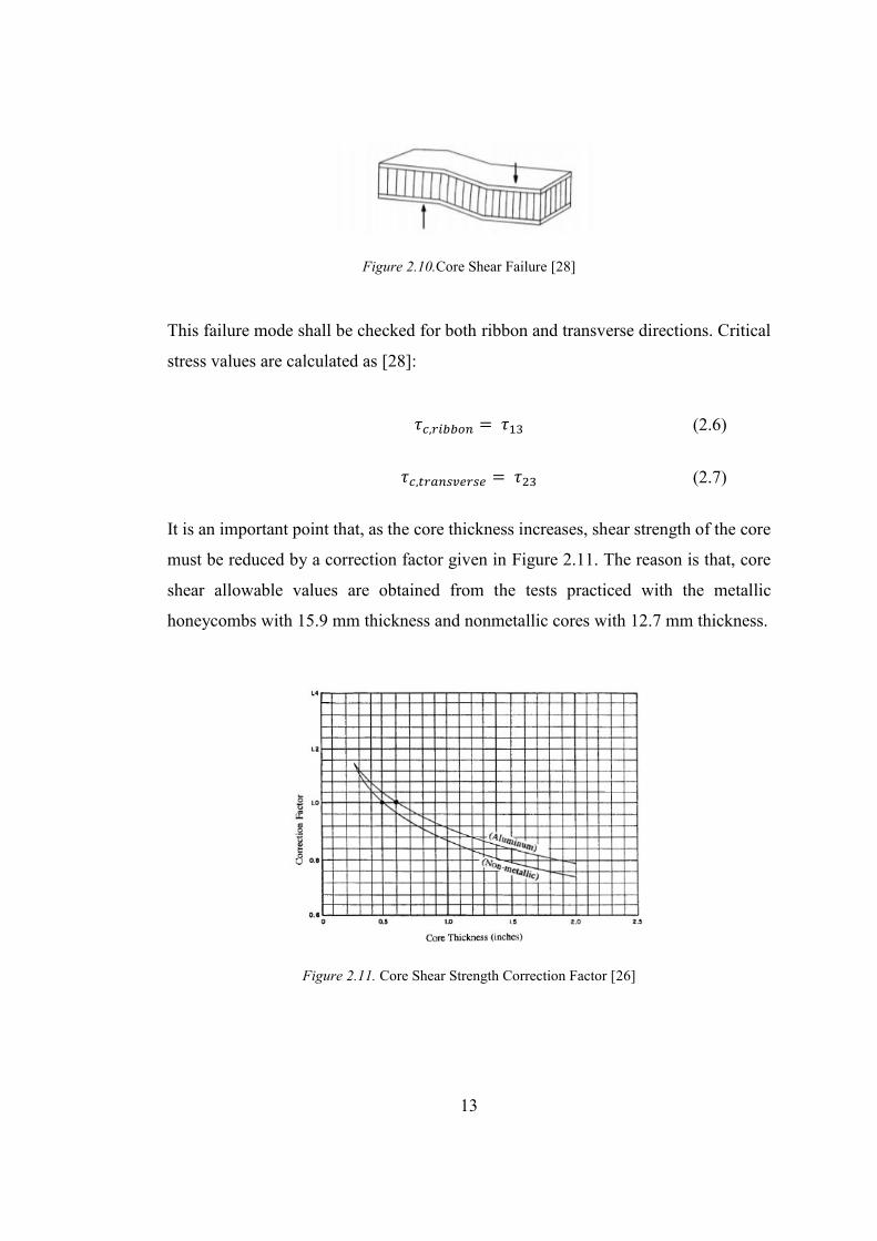
Figure 2.10.Core Shear Failure [28]
This failure mode shall be checked for both ribbon and transverse directions. Critical
stress values are calculated as [28]:
𝜏𝑐,𝑟𝑖𝑏𝑏𝑜𝑛 = 𝜏13 (2.6)
𝜏𝑐,𝑡𝑟𝑎𝑛𝑠𝑣𝑒𝑟𝑠𝑒 = 𝜏23 (2.7)
It is an important point that, as the core thickness increases, shear strength of the core
must be reduced by a correction factor given in Figure 2.11. The reason is that, core
shear allowable values are obtained from the tests practiced with the metallic
honeycombs with 15.9 mm thickness and nonmetallic cores with 12.7 mm thickness.
Figure 2.11. Core Shear Strength Correction Factor [26]

14
2.1.5. Core Flatwise Tension Failure
Like core shear failure, core flatwise tension failure occurs when the flatwise tension
stress on the core reaches the core flatwise tension allowable value.
Flatwise tension allowable of honeycombs are not often published. This property of
honeycombs is obtained by attaching the core between two blocks and then pulling
the one of the blocks. In [5] honeycomb flatwise tension allowable values which are
tested in room temperature is given.
Figure 2.12. Flatwise Tension Test Setup [5]
The critical stress at which core flatwise tension failure occurs can be calculated by
using the relation [5]:
𝜎𝑐𝑡 = 𝜎33 (2.8)
15
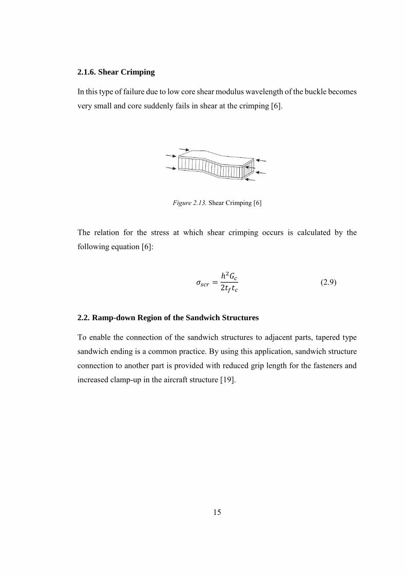
2.1.6. Shear Crimping
In this type of failure due to low core shear modulus wavelength of the buckle becomes
very small and core suddenly fails in shear at the crimping [6].
Figure 2.13. Shear Crimping [6]
The relation for the stress at which shear crimping occurs is calculated by the
following equation [6]:
𝜎𝑠𝑐𝑟 =ℎ2𝐺𝑐
2𝑡𝑓𝑡𝑐 (2.9)
2.2. Ramp-down Region of the Sandwich Structures
To enable the connection of the sandwich structures to adjacent parts, tapered type
sandwich ending is a common practice. By using this application, sandwich structure
connection to another part is provided with reduced grip length for the fasteners and
increased clamp-up in the aircraft structure [19].
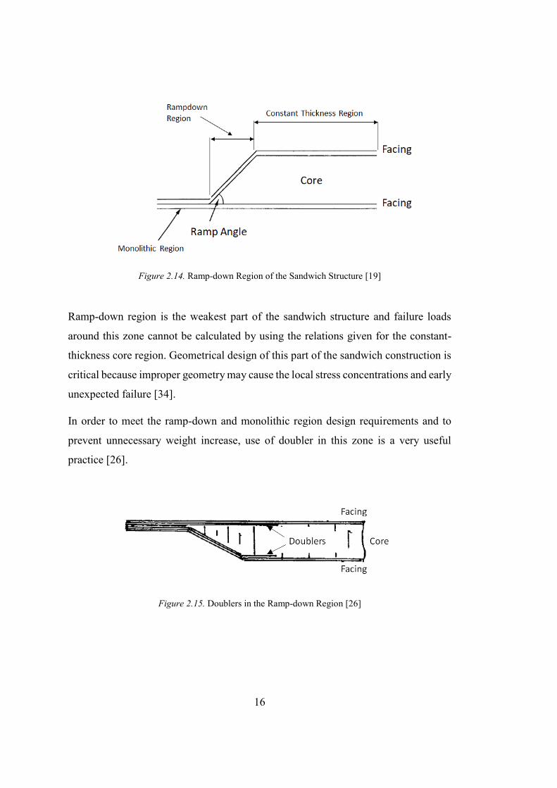
16
Figure 2.14. Ramp-down Region of the Sandwich Structure [19]
Ramp-down region is the weakest part of the sandwich structure and failure loads
around this zone cannot be calculated by using the relations given for the constant-
thickness core region. Geometrical design of this part of the sandwich construction is
critical because improper geometry may cause the local stress concentrations and early
unexpected failure [34].
In order to meet the ramp-down and monolithic region design requirements and to
prevent unnecessary weight increase, use of doubler in this zone is a very useful
practice [26].
Figure 2.15. Doublers in the Ramp-down Region [26]
17
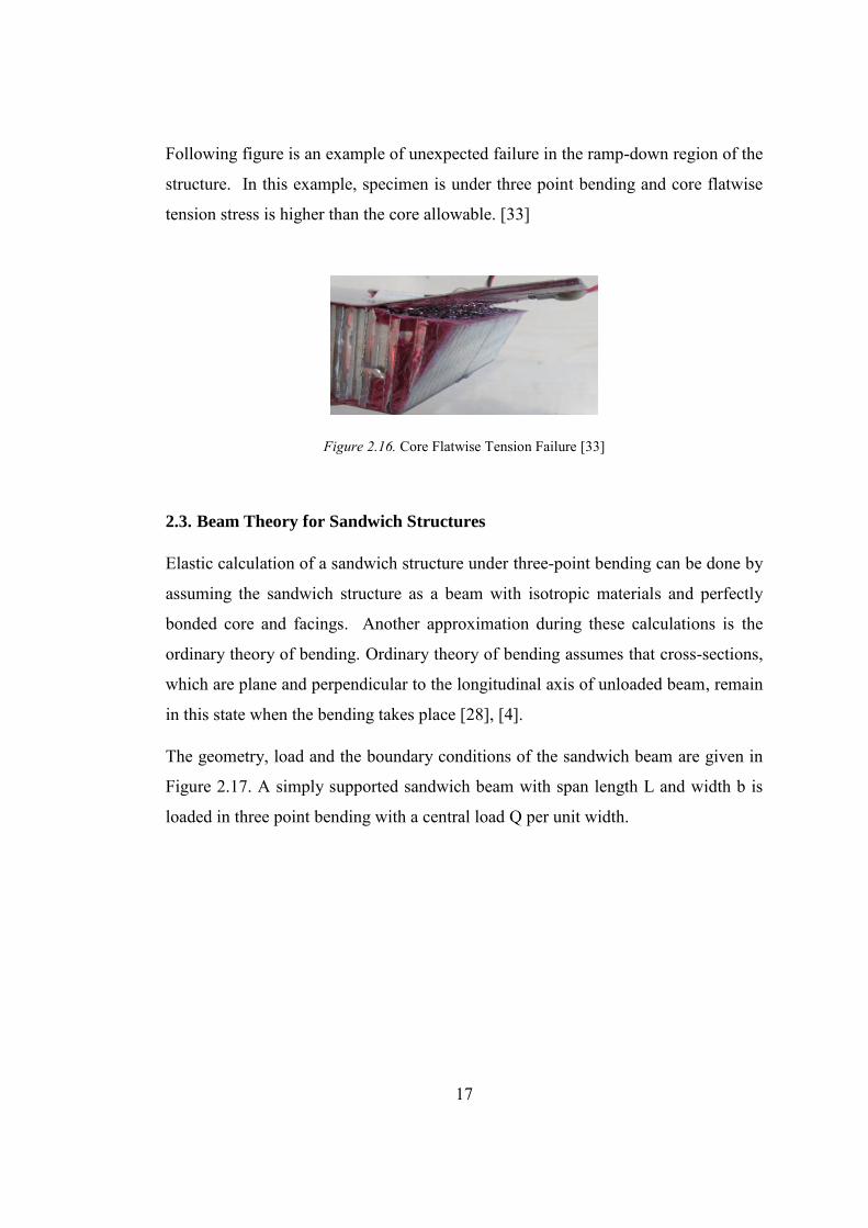
Following figure is an example of unexpected failure in the ramp-down region of the
structure. In this example, specimen is under three point bending and core flatwise
tension stress is higher than the core allowable. [33]
Figure 2.16. Core Flatwise Tension Failure [33]
2.3. Beam Theory for Sandwich Structures
Elastic calculation of a sandwich structure under three-point bending can be done by
assuming the sandwich structure as a beam with isotropic materials and perfectly
bonded core and facings. Another approximation during these calculations is the
ordinary theory of bending. Ordinary theory of bending assumes that cross-sections,
which are plane and perpendicular to the longitudinal axis of unloaded beam, remain
in this state when the bending takes place [28], [4].
The geometry, load and the boundary conditions of the sandwich beam are given in
Figure 2.17. A simply supported sandwich beam with span length L and width b is
loaded in three point bending with a central load Q per unit width.

18
Figure 2.17. Sandwich Beam Definition [4]
In order to analyze a sandwich structure in the aspect of the behavior of the beam,
following relation must be satisfied. If this relation is not satisfied or the panel is
supported by more than two edges, it must be analyzed as a panel [29].
𝑏
𝐿≤ 0.3 (2.10)
The flexural rigidity of the sandwich beam is given by the following equation [29].
𝐷 =𝐸𝑓𝑏𝑡𝑓
3
6+
𝐸𝑓𝑏𝑡𝑓ℎ2
2+
𝐸𝑐𝑏𝑡𝑐3
12 (2.11)
Axial stresses occur at the facings under maximum bending moment, M, is given by
the following relation [29].
𝜎𝑓 =𝑀𝐸𝑓ℎ
2𝐷=
𝑄𝐿
4ℎ𝑡𝑓 (2.12)
19
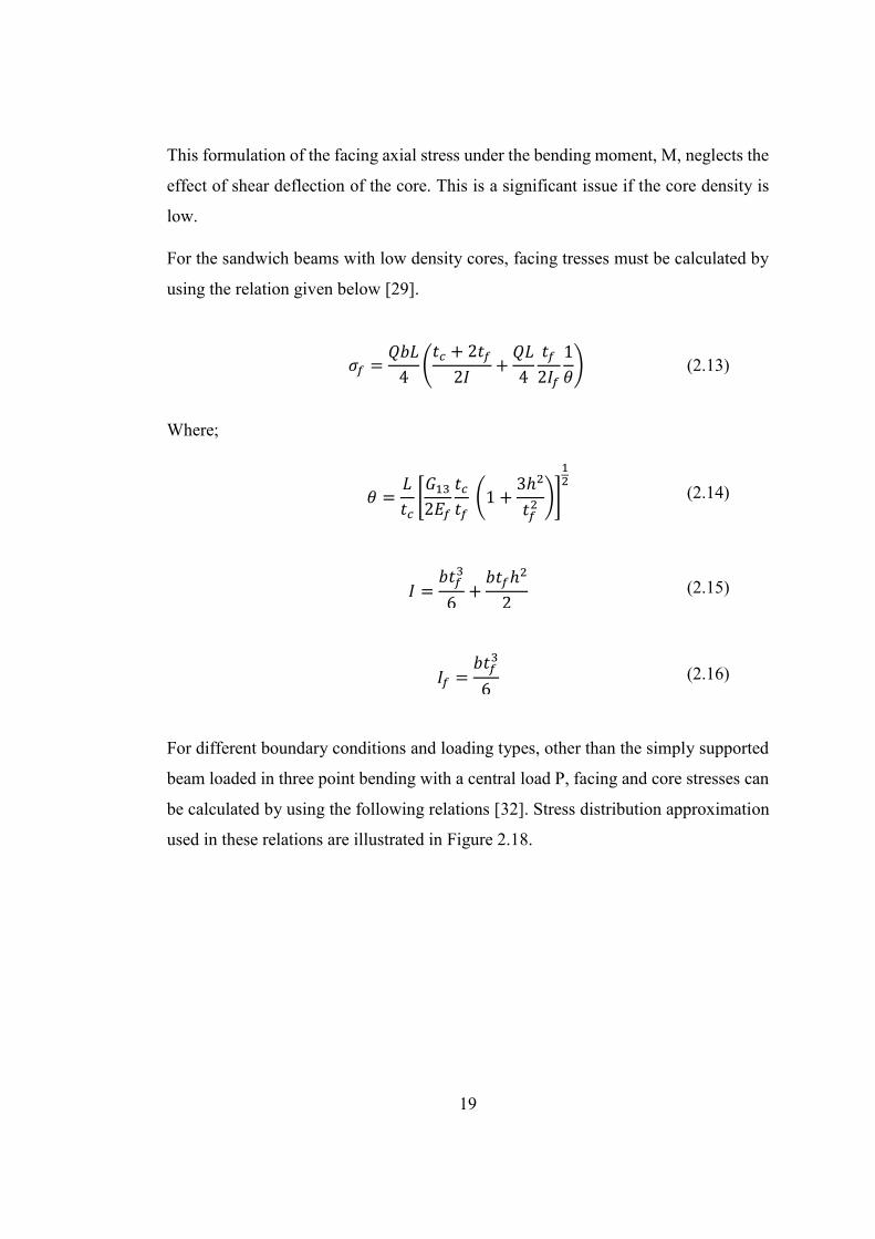
This formulation of the facing axial stress under the bending moment, M, neglects the
effect of shear deflection of the core. This is a significant issue if the core density is
low.
For the sandwich beams with low density cores, facing tresses must be calculated by
using the relation given below [29].
𝜎𝑓 =𝑄𝑏𝐿
4(
𝑡𝑐 + 2𝑡𝑓
2𝐼+
𝑄𝐿
4
𝑡𝑓
2𝐼𝑓
1
𝜃) (2.13)
Where;
𝜃 =𝐿
𝑡𝑐[𝐺13
2𝐸𝑓
𝑡𝑐
𝑡𝑓 (1 +
3ℎ2
𝑡𝑓2 )]
12
(2.14)
𝐼 =𝑏𝑡𝑓
3
6+
𝑏𝑡𝑓ℎ2
2 (2.15)
𝐼𝑓 =𝑏𝑡𝑓
3
6 (2.16)
For different boundary conditions and loading types, other than the simply supported
beam loaded in three point bending with a central load P, facing and core stresses can
be calculated by using the following relations [32]. Stress distribution approximation
used in these relations are illustrated in Figure 2.18.
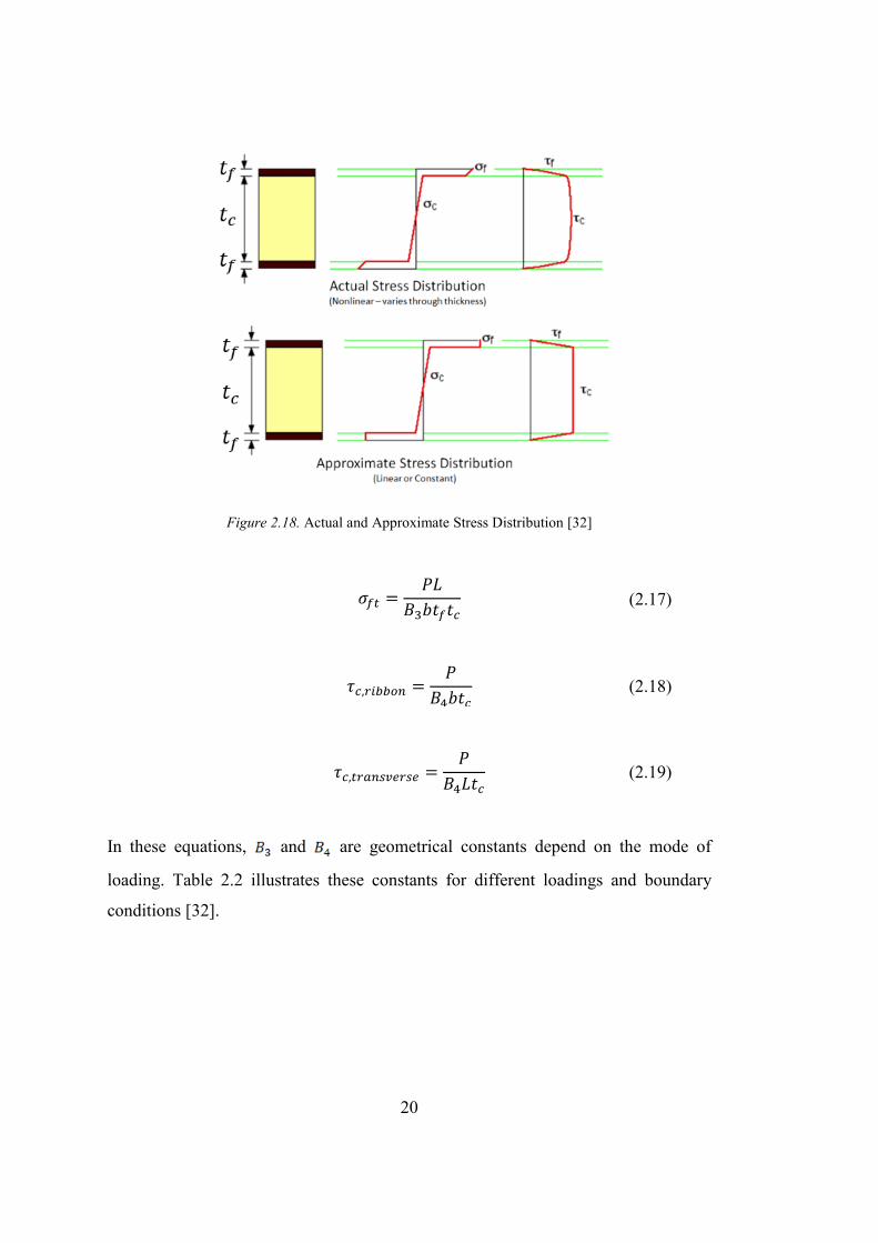
20
Figure 2.18. Actual and Approximate Stress Distribution [32]
𝜎𝑓𝑡 =𝑃𝐿
𝐵3𝑏𝑡𝑓𝑡𝑐 (2.17)
𝜏𝑐,𝑟𝑖𝑏𝑏𝑜𝑛 =𝑃
𝐵4𝑏𝑡𝑐 (2.18)
𝜏𝑐,𝑡𝑟𝑎𝑛𝑠𝑣𝑒𝑟𝑠𝑒 =𝑃
𝐵4𝐿𝑡𝑐 (2.19)
In these equations, and are geometrical constants depend on the mode of
loading. Table 2.2 illustrates these constants for different loadings and boundary
conditions [32].
21
Table 2.2. Geometric Constants for Sandwich Beam Theory [32]
Mode of Loading B3 B4
Cantilever, end load (P) 1 1 Cantilever, uniformly distributed load (P/L) 2 1
Three point bending, central load (P) 4 2 Three point bending, uniformly distributed load (P/L) 8 2
Ends built in, central load (P) 8 2 Ends built in, uniformly distributed load (P/L) 12 2
2.4. ABAQUS Finite Element Model
2.4.1. Sandwich Panel Modelling Techniques and Equivalent Modeling
Finite element model of a sandwich structure can be created in several ways. These
methods are listed below [4]:
1- Full 2D modeling with a Single Shell Geometry
In this technique, sandwich panel is defined by a single shell and property of
the sandwich structure is assigned to this shell geometry via “Composite Lay-
up” tool in ABAQUS.
2- Full 2D modeling
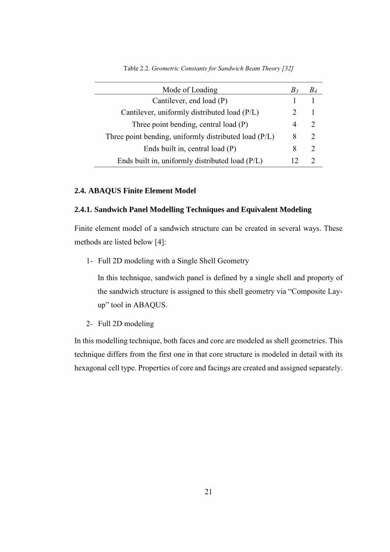
In this modelling technique, both faces and core are modeled as shell geometries. This
technique differs from the first one in that core structure is modeled in detail with its
hexagonal cell type. Properties of core and facings are created and assigned separately.
22
Figure 2.19. Full 2D Modeling [4]
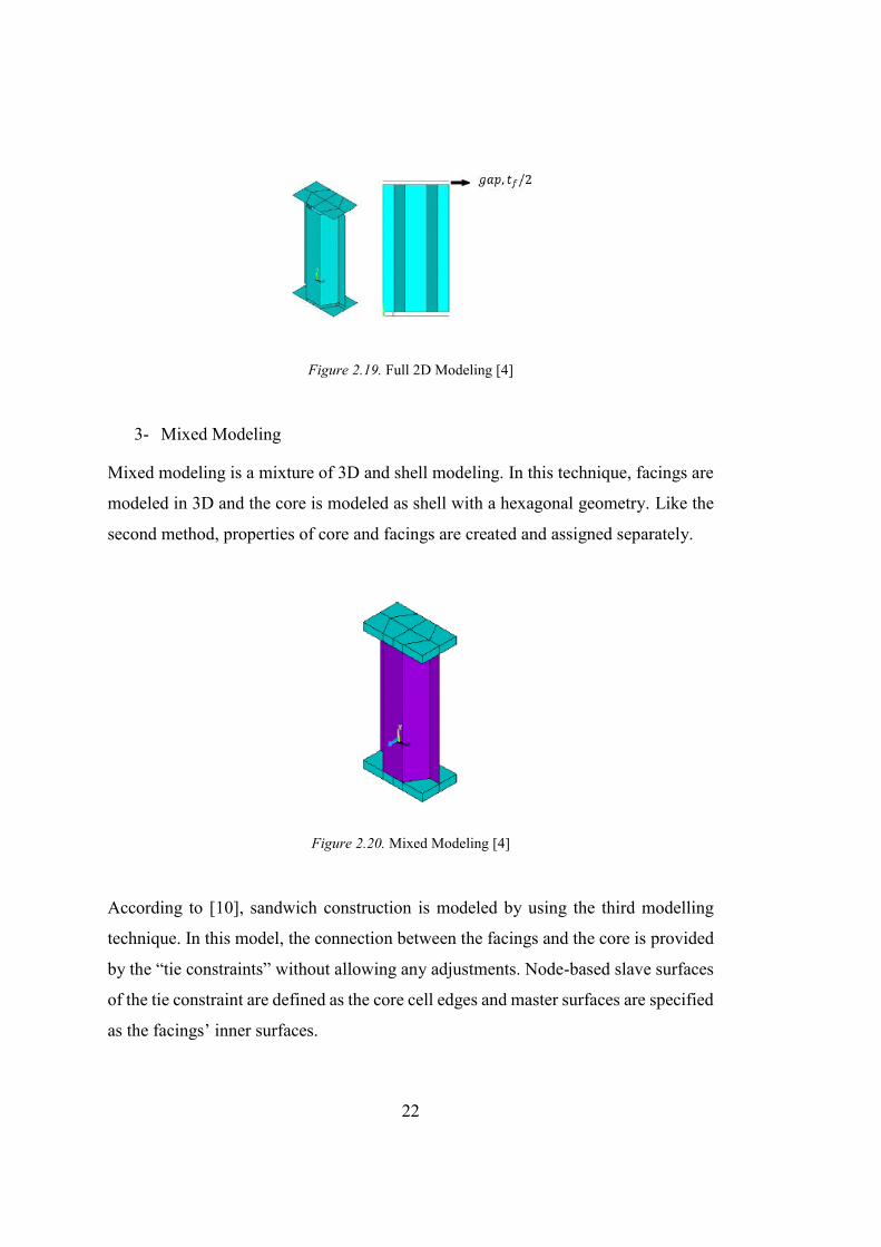
3- Mixed Modeling
Mixed modeling is a mixture of 3D and shell modeling. In this technique, facings are
modeled in 3D and the core is modeled as shell with a hexagonal geometry. Like the
second method, properties of core and facings are created and assigned separately.
Figure 2.20. Mixed Modeling [4]
According to [10], sandwich construction is modeled by using the third modelling
technique. In this model, the connection between the facings and the core is provided
by the “tie constraints” without allowing any adjustments. Node-based slave surfaces
of the tie constraint are defined as the core cell edges and master surfaces are specified
as the facings’ inner surfaces.
23
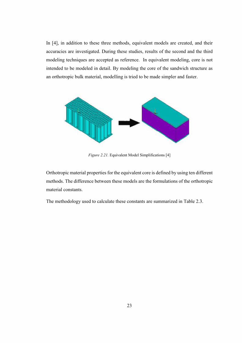
In [4], in addition to these three methods, equivalent models are created, and their
accuracies are investigated. During these studies, results of the second and the third
modeling techniques are accepted as reference. In equivalent modeling, core is not
intended to be modeled in detail. By modeling the core of the sandwich structure as
an orthotropic bulk material, modelling is tried to be made simpler and faster.
Figure 2.21. Equivalent Model Simplifications [4]
Orthotropic material properties for the equivalent core is defined by using ten different
methods. The difference between these models are the formulations of the orthotropic
material constants.
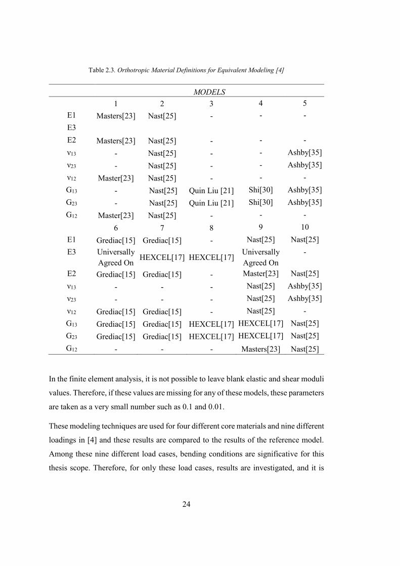
The methodology used to calculate these constants are summarized in Table 2.3.
24
Table 2.3. Orthotropic Material Definitions for Equivalent Modeling [4]
MODELS 1 2 3 4 5
E1 Masters[23] Nast[25] - - - E3 E2 Masters[23] Nast[25] - - - ν13 - Nast[25] - - Ashby[35] ν23 - Nast[25] - - Ashby[35] ν12 Master[23] Nast[25] - - - G13 - Nast[25] Quin Liu [21] Shi[30] Ashby[35] G23 - Nast[25] Quin Liu [21] Shi[30] Ashby[35] G12 Master[23] Nast[25] - - -
6 7 8 9 10 E1 Grediac[15] Grediac[15] - Nast[25] Nast[25] E3 Universally
Agreed On HEXCEL[17] HEXCEL[17]
Universally Agreed On
-
E2 Grediac[15] Grediac[15] - Master[23] Nast[25] ν13 - - - Nast[25] Ashby[35] ν23 - - - Nast[25] Ashby[35] ν12 Grediac[15] Grediac[15] - Nast[25] - G13 Grediac[15] Grediac[15] HEXCEL[17] HEXCEL[17] Nast[25] G23 Grediac[15] Grediac[15] HEXCEL[17] HEXCEL[17] Nast[25] G12 - - - Masters[23] Nast[25]
In the finite element analysis, it is not possible to leave blank elastic and shear moduli
values. Therefore, if these values are missing for any of these models, these parameters
are taken as a very small number such as 0.1 and 0.01.
These modeling techniques are used for four different core materials and nine different
loadings in [4] and these results are compared to the results of the reference model.
Among these nine different load cases, bending conditions are significative for this
thesis scope. Therefore, for only these load cases, results are investigated, and it is
25
seen that the maximum difference between the Model-8 and the reference model is
15.86%.
Since 15.86% is a reasonable error for this study, core of the sandwich construction
model suggested in the [10] is modeled as orthotropic bulk material with HEXCEL
properties. Slave surfaces of the tie constraint are defined as the core surfaces instead
of edges of the core cells.
2.4.2. Tie Constraint
Tie constraint are used to connect two different surfaces such that no relative motion
is allowed between them. Tie constraints can be used even though the meshes of the
connected surfaces are dissimilar. Also, between the edges of a surface or between the
faces of solids or shells tie constraints can also be defined.
In the tie constraint definition, master and slave surfaces are expected to be specified.
In order to carry all the nodes of the slave surfaces on the master surface in the
beginning of the analysis, there is an “Adjust slave surface initial position” option
available in the tie constraint dialog box [13].

27
CHAPTER 3
3. METHODOLOGY
In this chapter, finite element modeling technique which is going to be used in this
thesis is validated by using two different test results. According to the verification
results, it is aimed to simplify finite element model to reduce the computation time.
Moreover, mesh convergence study is also done in this chapter and mesh sizes of each
instance in the model is determined.
3.1. Finite Element Model Validation
To be able to correlate finite element model used in this study, results of the finite
element analyses are compared to the results of a test conducted by another study [14]
and a test conducted by Turkish Aerospace. The sandwich structure tested in [14] has
no ramp-down region and the structure is under three-point bending. However, a
tapered sandwich structure fastened to adjacent parts with fasteners is tested under
bending load in the test conducted by Turkish Aerospace. The reason why two
different tests are used to validate the model is that, the first test does not cover the
ramp-down region of the finite element model. The second test covers the ramp-down
region but there are some uncertainties in this test such as friction coefficient between
the parts in contact, bolt preload and manufacturing uncertainties.
3.1.1. Test 1: Finite Element Model Correlation with Three Point Bending Test
of Sandwich Panels with Aluminum Skins and Nomex Honeycomb Core
In this chapter of the study, description of the finite element model created to validate
the test and the results of the analyses are given.
28
3.1.1.1. Finite Element Model Description
Finite element model created in ABAQUS by using equivalent modeling is intended
to be validate by comparing the deflection results of the model and the test data. Test
data for this study is taken from another research. Therefore, to be able to do the
comparison, a finite element model is created for the validation purpose only by using
the same modeling methodology defined in Chapter 2.4. Cylindrical supports and the
indenter are modelled in 3D and steel is assumed as the material.
To be able to simulate the test properly, numerical contact definition is required
between the upper face of the sandwich structure and indenter, and also between the
lower face of the sandwich structure and roller supports. To define the surface-to-
surface contact in ABAQUS “Penalty” tangential behavior and “Hard Contact”
normal behavior is preferred. Friction coefficient in the Penalty definition is specified
approximately as 0.5 for the aluminum on mild steel combination [13].
All parts in the model (cylindrical supports, indenter, core and facings) are modelled
in 3D with linear element. 8-node brick, C3D8.
The test data given in [14] is referred as the reference to validate the methodology of
finite element model in this thesis. Test is, generally, conducted according to ASTM
C393 [3]. The difference between the test and the standard is that, this test has been
carried out until the failure of the sandwich structure, to be able to understand the non-
linear behavior after the fraction.
Material Properties
Materials used in this test are:
Core: HRH 10-3/16-2
Facings: Al2024-T3
Core mechanical properties for equivalent model, recommended by [16], and facing
mechanical properties are given in Table 3.1 and Table 3.2.
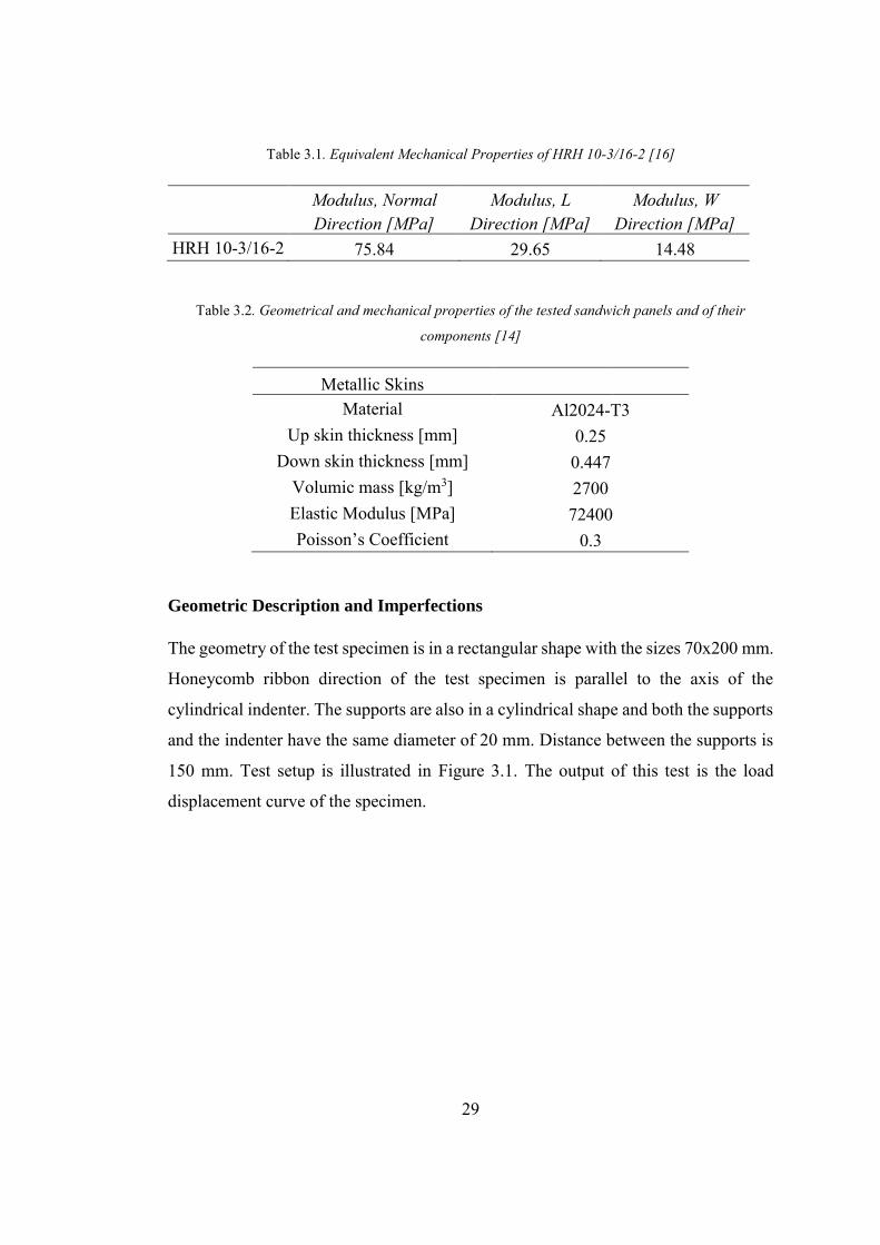
29
Table 3.1. Equivalent Mechanical Properties of HRH 10-3/16-2 [16]
Modulus, Normal Direction [MPa]
Modulus, L Direction [MPa]
Modulus, W Direction [MPa]
HRH 10-3/16-2 75.84 29.65 14.48
Table 3.2. Geometrical and mechanical properties of the tested sandwich panels and of their
components [14]
Metallic Skins Material Al2024-T3
Up skin thickness [mm] 0.25 Down skin thickness [mm] 0.447
Volumic mass [kg/m3] 2700 Elastic Modulus [MPa] 72400 Poisson’s Coefficient 0.3
Geometric Description and Imperfections
The geometry of the test specimen is in a rectangular shape with the sizes 70x200 mm.
Honeycomb ribbon direction of the test specimen is parallel to the axis of the
cylindrical indenter. The supports are also in a cylindrical shape and both the supports
and the indenter have the same diameter of 20 mm. Distance between the supports is
150 mm. Test setup is illustrated in Figure 3.1. The output of this test is the load
displacement curve of the specimen.
30
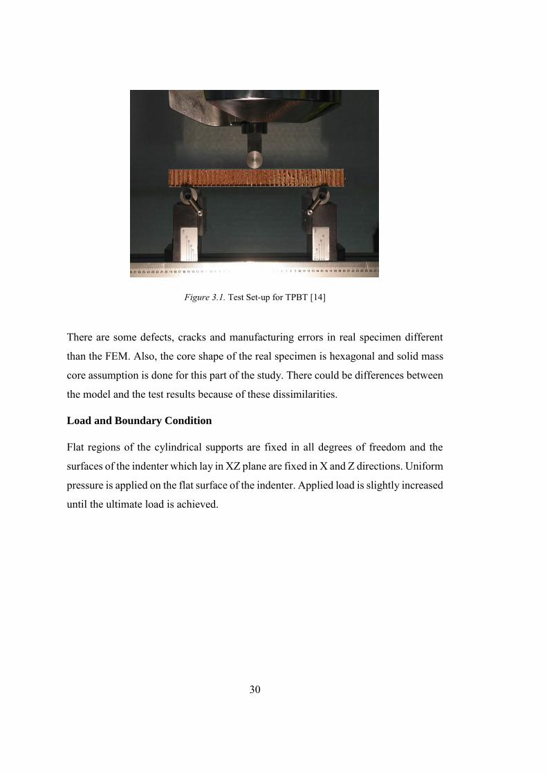
Figure 3.1. Test Set-up for TPBT [14]
There are some defects, cracks and manufacturing errors in real specimen different
than the FEM. Also, the core shape of the real specimen is hexagonal and solid mass
core assumption is done for this part of the study. There could be differences between
the model and the test results because of these dissimilarities.
Load and Boundary Condition
Flat regions of the cylindrical supports are fixed in all degrees of freedom and the
surfaces of the indenter which lay in XZ plane are fixed in X and Z directions. Uniform
pressure is applied on the flat surface of the indenter. Applied load is slightly increased
until the ultimate load is achieved.
31
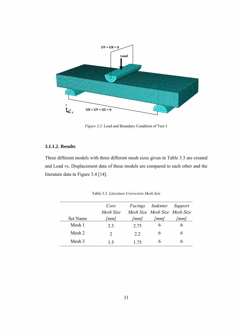
Figure 3.2. Load and Boundary Condition of Test-1
3.1.1.2. Results
Three different models with three different mesh sizes given in Table 3.3 are created
and Load vs. Displacement data of these models are compared to each other and the
literature data in Figure 3.4 [14].
Table 3.3. Literature Correction Mesh Sets
Set Name
Core Mesh Size
[mm]
Facings Mesh Size
[mm]
Indenter Mesh Size
[mm]
Support Mesh Size
[mm] Mesh 1 2.5 2.75 6 6
Mesh 2 2 2.2 6 6
Mesh 3 1.5 1.75 6 6
32
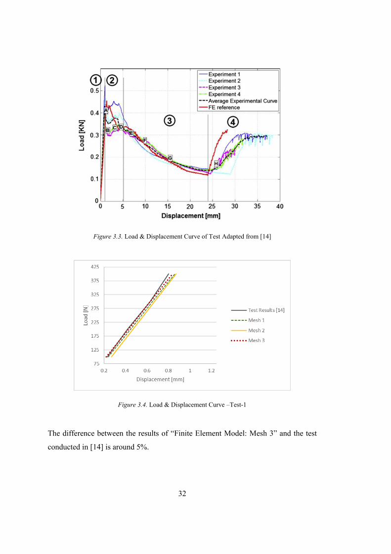
Figure 3.3. Load & Displacement Curve of Test Adapted from [14]
Figure 3.4. Load & Displacement Curve –Test-1
The difference between the results of “Finite Element Model: Mesh 3” and the test
conducted in [14] is around 5%.
33
3.1.2. Test 2: Three Point Bending Test of Tapered Sandwich Panels with
Aluminum Skins and Aluminum Honeycomb Core
Ramp-down region of the finite element model with equivalent modeling technique is
correlated by using the test conducted by Turkish Aerospace [33].
3.1.2.1. Finite Element Description
Finite element model that simulates the “Test 2” is created by using equivalent
modelling technique.
In order to simulate the test correctly, contact is defined between the parts in contact.
Bolt-nut and nut-angle connections are provided by tie constraint.
All parts in the model (cylindrical supports, indenter, core and facings) are modelled
in 3D with linear element. 8-node brick, C3D8.
Material Properties
Materials used in this test are:
Core: CR-III – 1/8 – 5056 – 4.5
Facing: Al2024-T3
Core mechanical properties for equivalent model and facing mechanical properties are
given as:
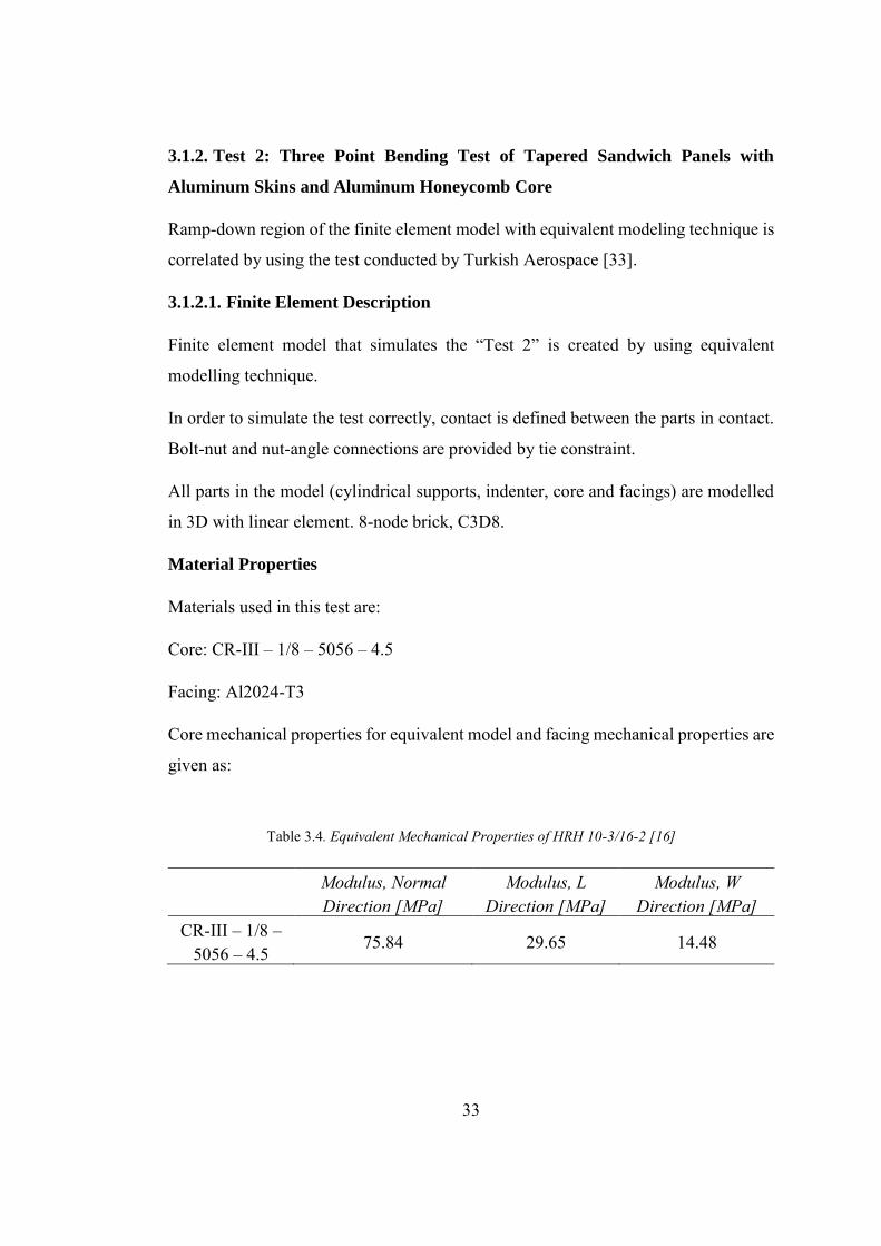
Table 3.4. Equivalent Mechanical Properties of HRH 10-3/16-2 [16]
Modulus, Normal Direction [MPa]
Modulus, L Direction [MPa]
Modulus, W Direction [MPa]
CR-III – 1/8 – 5056 – 4.5
75.84 29.65 14.48
34
Table 3.5. Geometrical and mechanical properties of the tested sandwich panels and of their
components [33]
Metallic Skins Material Al2024-T3
Up skin thickness [mm] 0.25 Down skin thickness [mm] 0.447
Volumic mass [kg/m3] 2700 Elastic Modulus [MPa] 72400 Poisson’s Coefficient 0.3
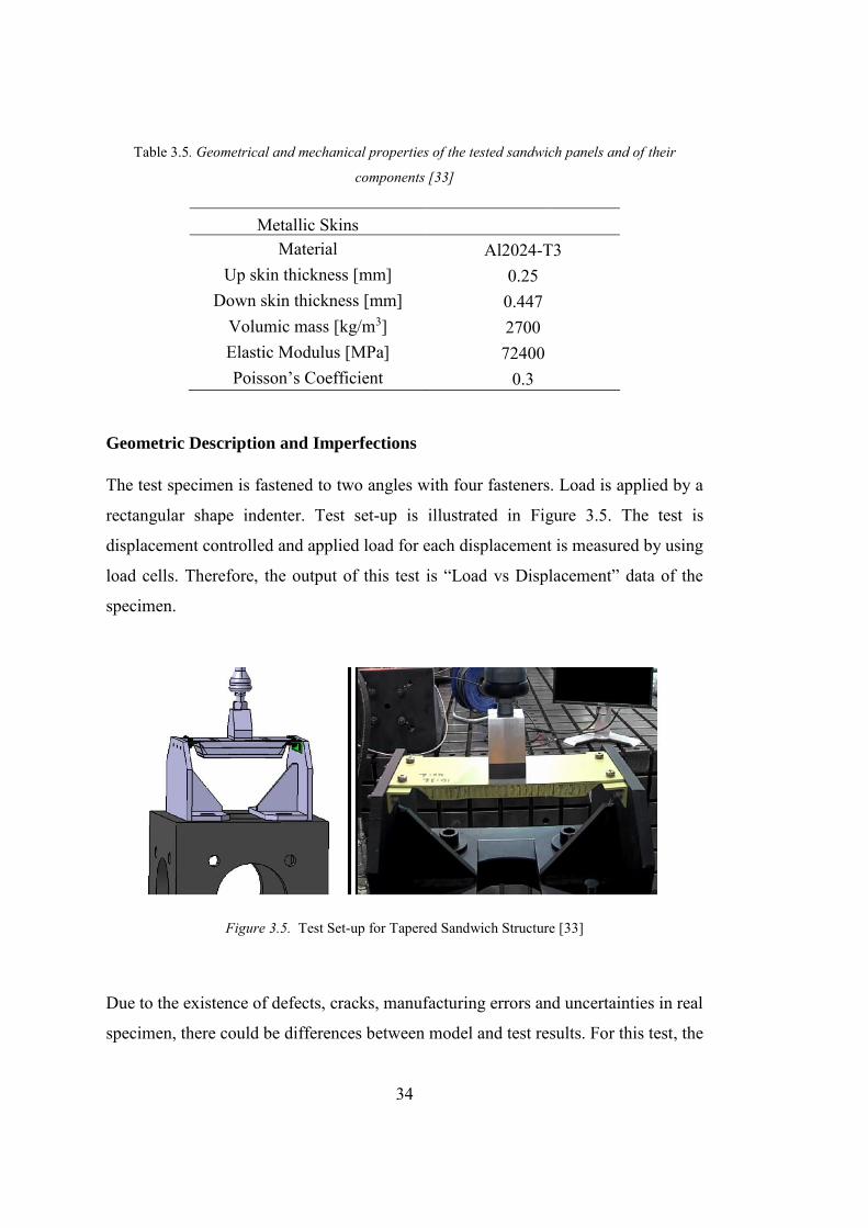
Geometric Description and Imperfections
The test specimen is fastened to two angles with four fasteners. Load is applied by a
rectangular shape indenter. Test set-up is illustrated in Figure 3.5. The test is
displacement controlled and applied load for each displacement is measured by using
load cells. Therefore, the output of this test is “Load vs Displacement” data of the
specimen.
Figure 3.5. Test Set-up for Tapered Sandwich Structure [33]
Due to the existence of defects, cracks, manufacturing errors and uncertainties in real
specimen, there could be differences between model and test results. For this test, the
35
friction coefficient between the parts and the tightening torque of the bolt that connects
the angles and the sandwich structure to each other are uncertain. To understand the
effect of the preload and the friction coefficient on the analysis and to determine the
values of these two parameters, a parametric study is carried out after the mesh
sensitivity part.
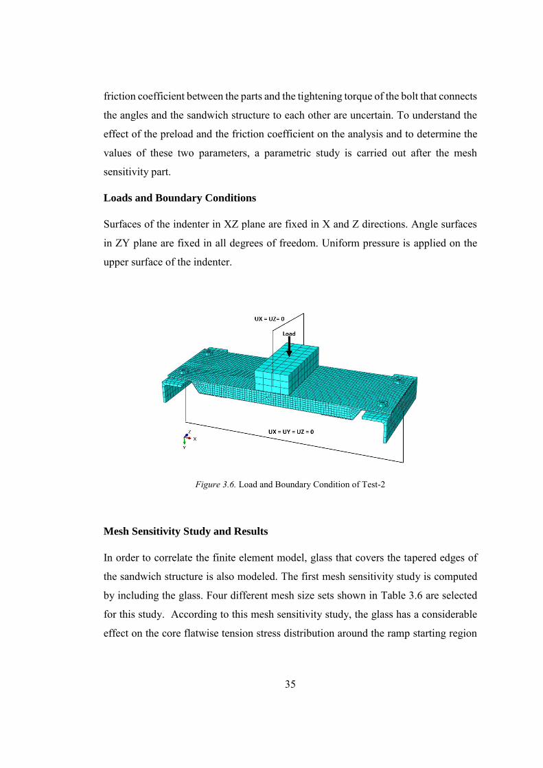
Loads and Boundary Conditions
Surfaces of the indenter in XZ plane are fixed in X and Z directions. Angle surfaces
in ZY plane are fixed in all degrees of freedom. Uniform pressure is applied on the
upper surface of the indenter.
Figure 3.6. Load and Boundary Condition of Test-2
Mesh Sensitivity Study and Results
In order to correlate the finite element model, glass that covers the tapered edges of
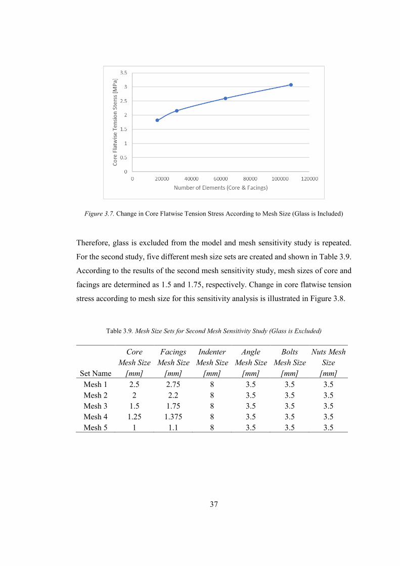
the sandwich structure is also modeled. The first mesh sensitivity study is computed
by including the glass. Four different mesh size sets shown in Table 3.6 are selected
for this study. According to this mesh sensitivity study, the glass has a considerable
effect on the core flatwise tension stress distribution around the ramp starting region
36
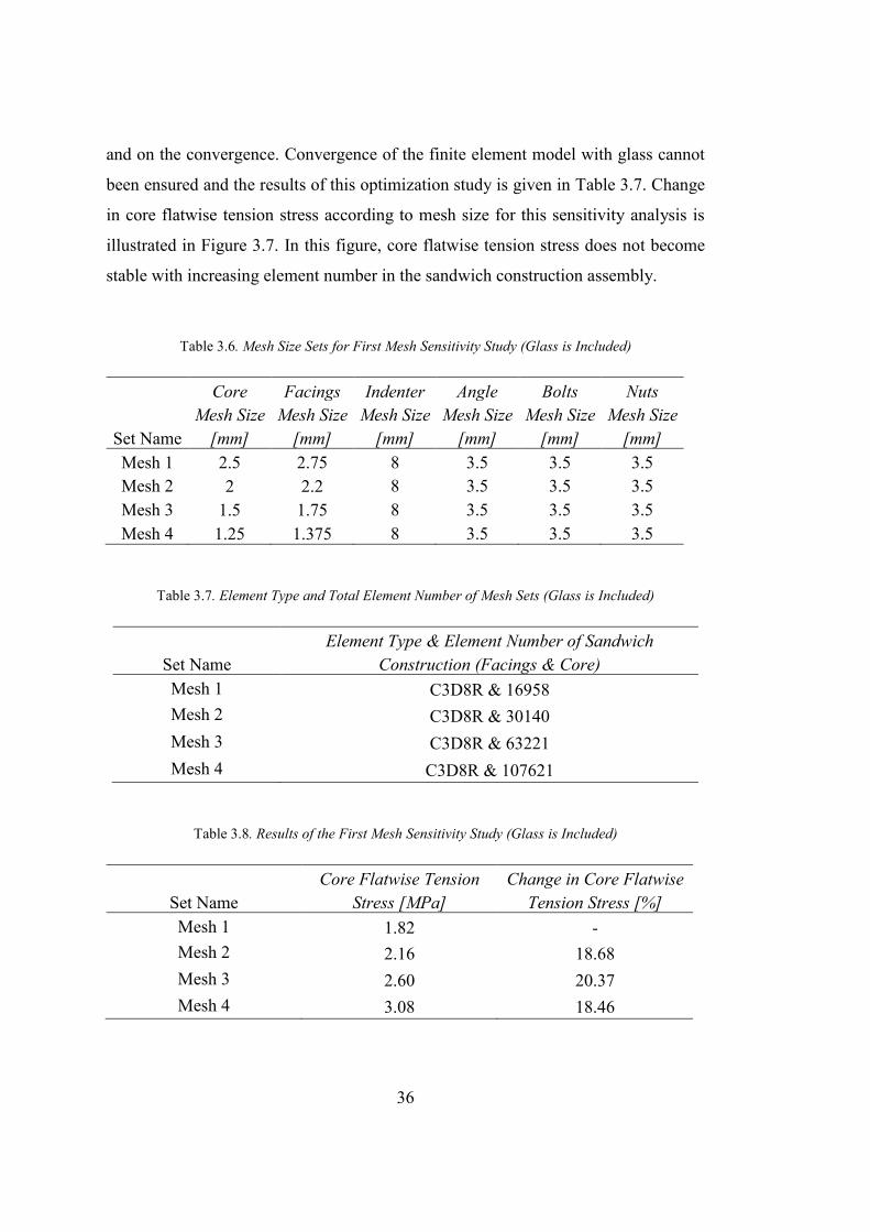
and on the convergence. Convergence of the finite element model with glass cannot
been ensured and the results of this optimization study is given in Table 3.7. Change
in core flatwise tension stress according to mesh size for this sensitivity analysis is
illustrated in Figure 3.7. In this figure, core flatwise tension stress does not become
stable with increasing element number in the sandwich construction assembly.
Table 3.6. Mesh Size Sets for First Mesh Sensitivity Study (Glass is Included)
Set Name
Core Mesh Size
[mm]
Facings Mesh Size
[mm]
Indenter Mesh Size
[mm]
Angle Mesh Size
[mm]
Bolts Mesh Size
[mm]
Nuts Mesh Size
[mm] Mesh 1 2.5 2.75 8 3.5 3.5 3.5 Mesh 2 2 2.2 8 3.5 3.5 3.5 Mesh 3 1.5 1.75 8 3.5 3.5 3.5 Mesh 4 1.25 1.375 8 3.5 3.5 3.5
Table 3.7. Element Type and Total Element Number of Mesh Sets (Glass is Included)
Set Name Element Type & Element Number of Sandwich
Construction (Facings & Core) Mesh 1 C3D8R & 16958 Mesh 2 C3D8R & 30140 Mesh 3 C3D8R & 63221 Mesh 4 C3D8R & 107621
Table 3.8. Results of the First Mesh Sensitivity Study (Glass is Included)
Set Name Core Flatwise Tension
Stress [MPa] Change in Core Flatwise
Tension Stress [%] Mesh 1 1.82 - Mesh 2 2.16 18.68 Mesh 3 2.60 20.37 Mesh 4 3.08 18.46
37
Figure 3.7. Change in Core Flatwise Tension Stress According to Mesh Size (Glass is Included)
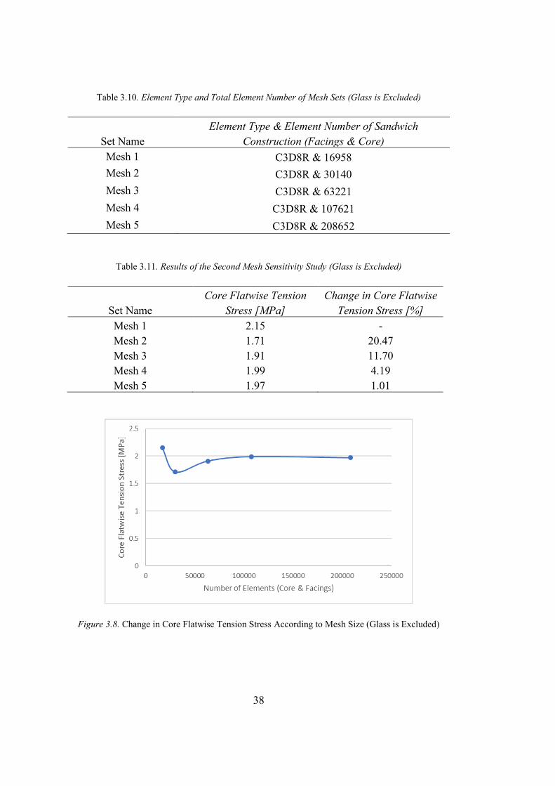
Therefore, glass is excluded from the model and mesh sensitivity study is repeated.
For the second study, five different mesh size sets are created and shown in Table 3.9.
According to the results of the second mesh sensitivity study, mesh sizes of core and
facings are determined as 1.5 and 1.75, respectively. Change in core flatwise tension
stress according to mesh size for this sensitivity analysis is illustrated in Figure 3.8.
Table 3.9. Mesh Size Sets for Second Mesh Sensitivity Study (Glass is Excluded)
Set Name
Core Mesh Size
[mm]
Facings Mesh Size
[mm]
Indenter Mesh Size
[mm]
Angle Mesh Size
[mm]
Bolts Mesh Size
[mm]
Nuts Mesh Size
[mm] Mesh 1 2.5 2.75 8 3.5 3.5 3.5 Mesh 2 2 2.2 8 3.5 3.5 3.5 Mesh 3 1.5 1.75 8 3.5 3.5 3.5 Mesh 4 1.25 1.375 8 3.5 3.5 3.5 Mesh 5 1 1.1 8 3.5 3.5 3.5
38
Table 3.10. Element Type and Total Element Number of Mesh Sets (Glass is Excluded)
Set Name Element Type & Element Number of Sandwich
Construction (Facings & Core) Mesh 1 C3D8R & 16958 Mesh 2 C3D8R & 30140 Mesh 3 C3D8R & 63221 Mesh 4 C3D8R & 107621 Mesh 5 C3D8R & 208652
Table 3.11. Results of the Second Mesh Sensitivity Study (Glass is Excluded)
Set Name Core Flatwise Tension
Stress [MPa] Change in Core Flatwise
Tension Stress [%] Mesh 1 2.15 - Mesh 2 1.71 20.47 Mesh 3 1.91 11.70 Mesh 4 1.99 4.19 Mesh 5 1.97 1.01
Figure 3.8. Change in Core Flatwise Tension Stress According to Mesh Size (Glass is Excluded)
39
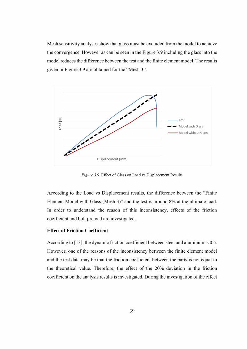
Mesh sensitivity analyses show that glass must be excluded from the model to achieve
the convergence. However as can be seen in the Figure 3.9 including the glass into the
model reduces the difference between the test and the finite element model. The results
given in Figure 3.9 are obtained for the “Mesh 3”.
Figure 3.9. Effect of Glass on Load vs Displacement Results
According to the Load vs Displacement results, the difference between the “Finite
Element Model with Glass (Mesh 3)” and the test is around 8% at the ultimate load.
In order to understand the reason of this inconsistency, effects of the friction
coefficient and bolt preload are investigated.
Effect of Friction Coefficient
According to [13], the dynamic friction coefficient between steel and aluminum is 0.5.
However, one of the reasons of the inconsistency between the finite element model
and the test data may be that the friction coefficient between the parts is not equal to
the theoretical value. Therefore, the effect of the 20% deviation in the friction
coefficient on the analysis results is investigated. During the investigation of the effect
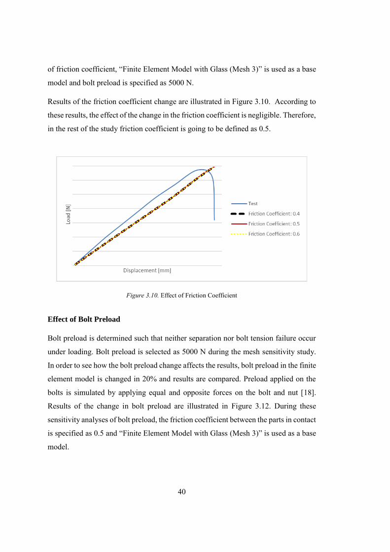
40
of friction coefficient, “Finite Element Model with Glass (Mesh 3)” is used as a base
model and bolt preload is specified as 5000 N.
Results of the friction coefficient change are illustrated in Figure 3.10. According to
these results, the effect of the change in the friction coefficient is negligible. Therefore,
in the rest of the study friction coefficient is going to be defined as 0.5.
Figure 3.10. Effect of Friction Coefficient
Effect of Bolt Preload
Bolt preload is determined such that neither separation nor bolt tension failure occur
under loading. Bolt preload is selected as 5000 N during the mesh sensitivity study.
In order to see how the bolt preload change affects the results, bolt preload in the finite
element model is changed in 20% and results are compared. Preload applied on the
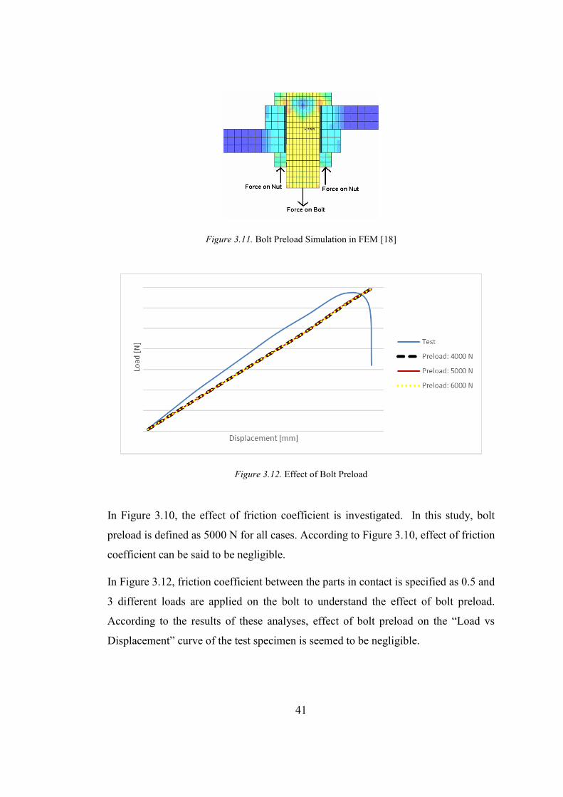
bolts is simulated by applying equal and opposite forces on the bolt and nut [18].
Results of the change in bolt preload are illustrated in Figure 3.12. During these
sensitivity analyses of bolt preload, the friction coefficient between the parts in contact
is specified as 0.5 and “Finite Element Model with Glass (Mesh 3)” is used as a base
model.
41
Figure 3.11. Bolt Preload Simulation in FEM [18]
Figure 3.12. Effect of Bolt Preload
In Figure 3.10, the effect of friction coefficient is investigated. In this study, bolt
preload is defined as 5000 N for all cases. According to Figure 3.10, effect of friction
coefficient can be said to be negligible.
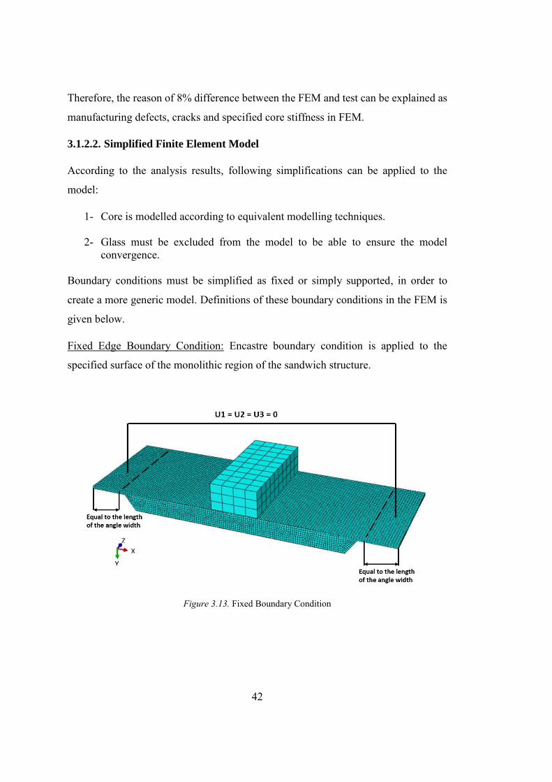
In Figure 3.12, friction coefficient between the parts in contact is specified as 0.5 and
3 different loads are applied on the bolt to understand the effect of bolt preload.
According to the results of these analyses, effect of bolt preload on the “Load vs
Displacement” curve of the test specimen is seemed to be negligible.
42
Therefore, the reason of 8% difference between the FEM and test can be explained as
manufacturing defects, cracks and specified core stiffness in FEM.
3.1.2.2. Simplified Finite Element Model
According to the analysis results, following simplifications can be applied to the
model:
1- Core is modelled according to equivalent modelling techniques.
2- Glass must be excluded from the model to be able to ensure the model convergence.
Boundary conditions must be simplified as fixed or simply supported, in order to
create a more generic model. Definitions of these boundary conditions in the FEM is
given below.
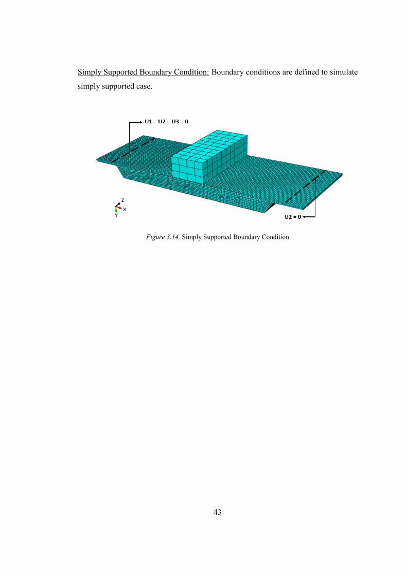
Fixed Edge Boundary Condition: Encastre boundary condition is applied to the
specified surface of the monolithic region of the sandwich structure.
Figure 3.13. Fixed Boundary Condition
43
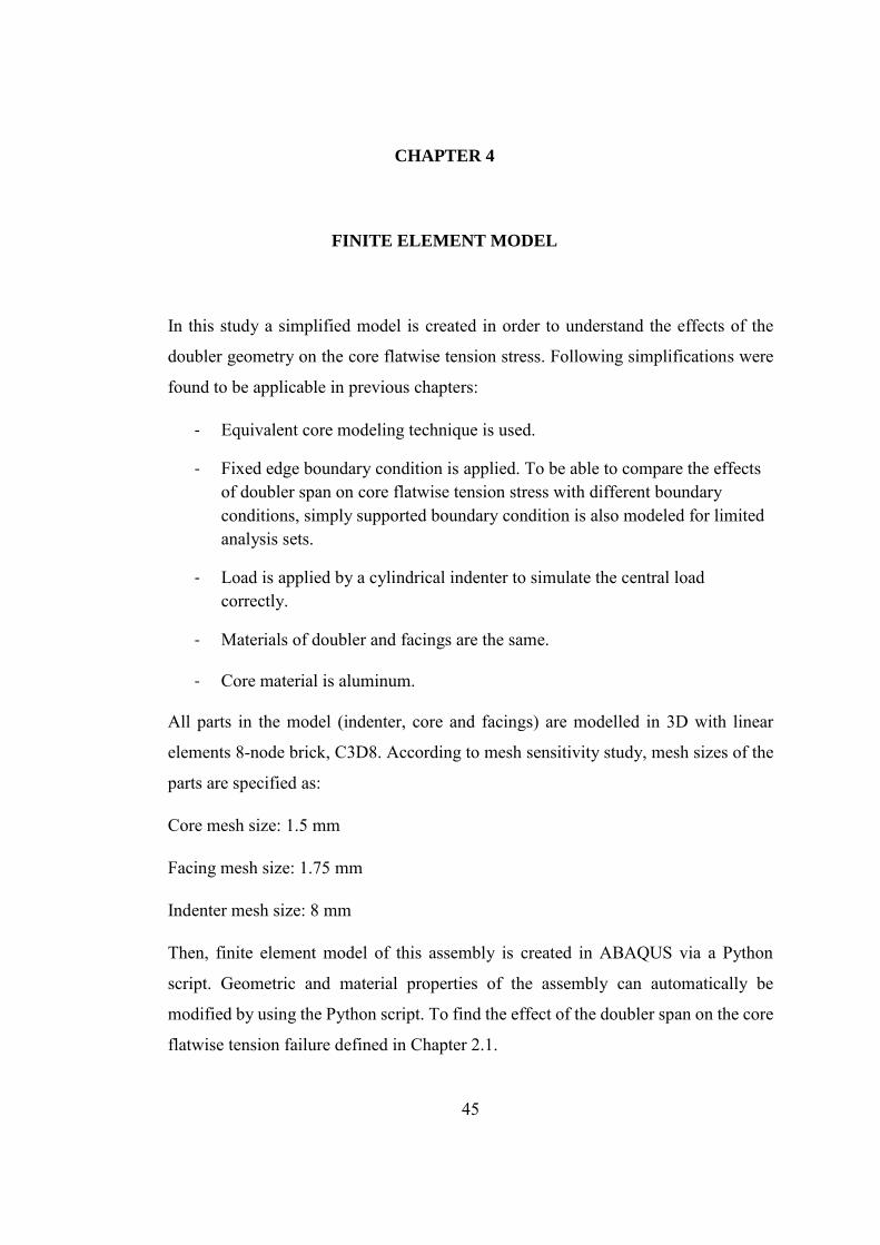
Simply Supported Boundary Condition: Boundary conditions are defined to simulate
simply supported case.
Figure 3.14. Simply Supported Boundary Condition

45
CHAPTER 4
4. FINITE ELEMENT MODEL
In this study a simplified model is created in order to understand the effects of the
doubler geometry on the core flatwise tension stress. Following simplifications were
found to be applicable in previous chapters:
- Equivalent core modeling technique is used.
- Fixed edge boundary condition is applied. To be able to compare the effects of doubler span on core flatwise tension stress with different boundary conditions, simply supported boundary condition is also modeled for limited analysis sets.
- Load is applied by a cylindrical indenter to simulate the central load correctly.
- Materials of doubler and facings are the same.
- Core material is aluminum. All parts in the model (indenter, core and facings) are modelled in 3D with linear
elements 8-node brick, C3D8. According to mesh sensitivity study, mesh sizes of the
parts are specified as:
Core mesh size: 1.5 mm
Facing mesh size: 1.75 mm
Indenter mesh size: 8 mm
Then, finite element model of this assembly is created in ABAQUS via a Python
script. Geometric and material properties of the assembly can automatically be
modified by using the Python script. To find the effect of the doubler span on the core
flatwise tension failure defined in Chapter 2.1.
46
4.1. Material Properties
Materials used in this models are:
Core Material # 1: 1/8-5056-3.1
Core Material # 2: 1/8-5052-4.5
Facings and Doubler: Al2024-T3
Mechanical properties of the materials are given below.
Table 4.1. Equivalent Mechanical Properties of 1/8-5056-3.1 and 1/8-5052-4.5 [16]
𝐸𝑐
[MPa] 𝐺13
[MPa] 𝐺23
[MPa] 𝜎33
[MPa] 𝜏13
[MPa] 𝜏23
[MPa] 1/8-5056-3.1 668.8 310.3 137.9 6.41 1.38 0.76 1/8-5052-4.5 1034.2 482.6 213.7 8.41 1.97 1.16
Table 4.2. Mechanical Properties of Al2024-T3 [24]
𝐸𝑓 [MPa] ν Al 2024-T3 72395 0.3
4.2. Geometric Description
Finite element model consists of facings, doubler, core and indenter. Span length and
width of the sandwich structure is specified such that the beam theory can be
applicable. During the parametric analyses defined in this chapter, span length and
width are specified as 210 mm and 70 mm, respectively. Radius of the cylindrical
indenter is 10 mm [3]. Length of the monolithic region of the sandwich beam is
specified as 27 mm which is equal to the length of the monolithic region of the
specimen used in the test conducted by Turkish Aerospace.
47
4.3. Loads and Boundary Conditions
Loads and boundary conditions are applied as described in Chapter 3.1.2.2. Two
different boundary conditions are defined for this thesis: Fixed and Simply Supported.
Central load is applied for both boundary conditions. To distribute the load
accordingly, load is applied by a cylindrical support.
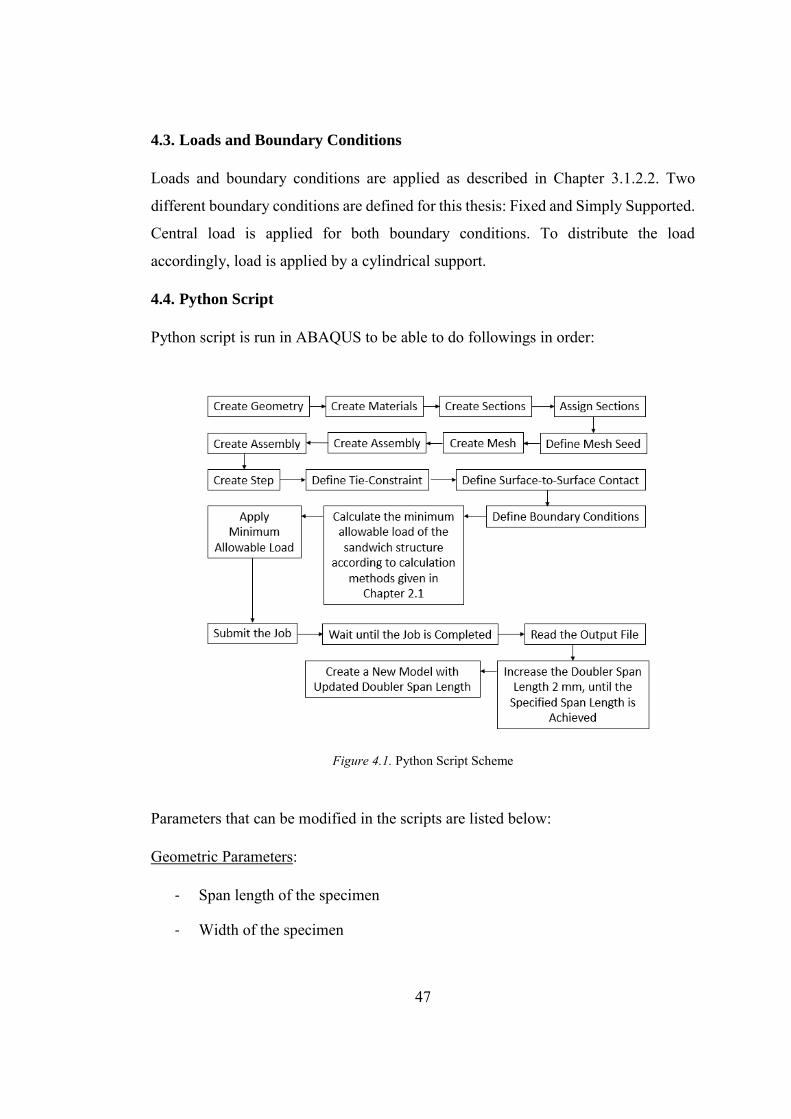
4.4. Python Script
Python script is run in ABAQUS to be able to do followings in order:
Figure 4.1. Python Script Scheme
Parameters that can be modified in the scripts are listed below:
Geometric Parameters:
- Span length of the specimen
- Width of the specimen

48
- Length of the monolithic region
- Upper face thickness
- Lower face thickness
- Doubler thickness
- Core thickness
- Indenter radius
- Doubler span length
- Core ramp angle
- Core cell size
Mechanical Properties:
- Young’s modulus of the metallic parts (facings, doubler, indenter)
- Poisson’s ratio of the metallic parts (facings, doubler, indenter)
- Core flatwise modulus
- Core shear modulus in ribbon and transverse directions
- Core shear strength in ribbon and transverse directions
- Core flatwise tension allowable
- Compressive yield strength of the facings
- Tensile ultimate strength of the facings
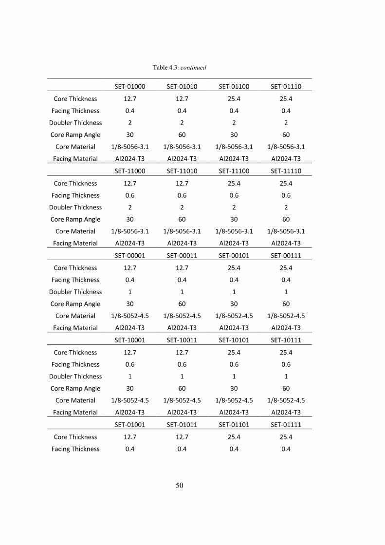
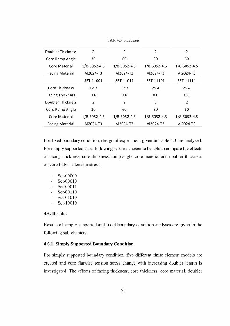
Thirty-two different combinations of these parameters are created. These sets are described in Table 4.3.
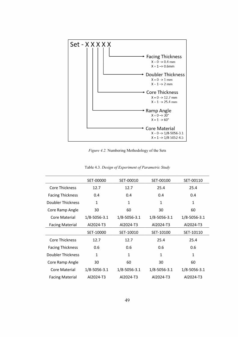
4.5. Design of Experiment
The logic behind the numbering of each set given in Table 4.3 is explained in Figure
4.2.
49
Figure 4.2. Numbering Methodology of the Sets
Table 4.3. Design of Experiment of Parametric Study
SET-00000 SET-00010 SET-00100 SET-00110 Core Thickness 12.7 12.7 25.4 25.4
Facing Thickness 0.4 0.4 0.4 0.4 Doubler Thickness 1 1 1 1 Core Ramp Angle 30 60 30 60
Core Material 1/8-5056-3.1 1/8-5056-3.1 1/8-5056-3.1 1/8-5056-3.1 Facing Material Al2024-T3 Al2024-T3 Al2024-T3 Al2024-T3
SET-10000 SET-10010 SET-10100 SET-10110
Core Thickness 12.7 12.7 25.4 25.4
Facing Thickness 0.6 0.6 0.6 0.6
Doubler Thickness 1 1 1 1
Core Ramp Angle 30 60 30 60
Core Material 1/8-5056-3.1 1/8-5056-3.1 1/8-5056-3.1 1/8-5056-3.1
Facing Material Al2024-T3 Al2024-T3 Al2024-T3 Al2024-T3
50
Table 4.3. continued
SET-01000 SET-01010 SET-01100 SET-01110
Core Thickness 12.7 12.7 25.4 25.4
Facing Thickness 0.4 0.4 0.4 0.4
Doubler Thickness 2 2 2 2
Core Ramp Angle 30 60 30 60
Core Material 1/8-5056-3.1 1/8-5056-3.1 1/8-5056-3.1 1/8-5056-3.1
Facing Material Al2024-T3 Al2024-T3 Al2024-T3 Al2024-T3
SET-11000 SET-11010 SET-11100 SET-11110
Core Thickness 12.7 12.7 25.4 25.4
Facing Thickness 0.6 0.6 0.6 0.6
Doubler Thickness 2 2 2 2
Core Ramp Angle 30 60 30 60
Core Material 1/8-5056-3.1 1/8-5056-3.1 1/8-5056-3.1 1/8-5056-3.1
Facing Material Al2024-T3 Al2024-T3 Al2024-T3 Al2024-T3
SET-00001 SET-00011 SET-00101 SET-00111
Core Thickness 12.7 12.7 25.4 25.4
Facing Thickness 0.4 0.4 0.4 0.4
Doubler Thickness 1 1 1 1
Core Ramp Angle 30 60 30 60
Core Material 1/8-5052-4.5 1/8-5052-4.5 1/8-5052-4.5 1/8-5052-4.5
Facing Material Al2024-T3 Al2024-T3 Al2024-T3 Al2024-T3
SET-10001 SET-10011 SET-10101 SET-10111
Core Thickness 12.7 12.7 25.4 25.4
Facing Thickness 0.6 0.6 0.6 0.6
Doubler Thickness 1 1 1 1
Core Ramp Angle 30 60 30 60
Core Material 1/8-5052-4.5 1/8-5052-4.5 1/8-5052-4.5 1/8-5052-4.5
Facing Material Al2024-T3 Al2024-T3 Al2024-T3 Al2024-T3
SET-01001 SET-01011 SET-01101 SET-01111
Core Thickness 12.7 12.7 25.4 25.4
Facing Thickness 0.4 0.4 0.4 0.4
51
Table 4.3. continued
Doubler Thickness 2 2 2 2
Core Ramp Angle 30 60 30 60
Core Material 1/8-5052-4.5 1/8-5052-4.5 1/8-5052-4.5 1/8-5052-4.5
Facing Material Al2024-T3 Al2024-T3 Al2024-T3 Al2024-T3
SET-11001 SET-11011 SET-11101 SET-11111
Core Thickness 12.7 12.7 25.4 25.4
Facing Thickness 0.6 0.6 0.6 0.6
Doubler Thickness 2 2 2 2
Core Ramp Angle 30 60 30 60
Core Material 1/8-5052-4.5 1/8-5052-4.5 1/8-5052-4.5 1/8-5052-4.5
Facing Material Al2024-T3 Al2024-T3 Al2024-T3 Al2024-T3
For fixed boundary condition, design of experiment given in Table 4.3 are analyzed.
For simply supported case, following sets are chosen to be able to compare the effects
of facing thickness, core thickness, ramp angle, core material and doubler thickness
on core flatwise tension stress.
- Set-00000 - Set-00010 - Set-00011 - Set-00110 - Set-01010 - Set-10010
4.6. Results
Results of simply supported and fixed boundary condition analyses are given in the
following sub-chapters.
4.6.1. Simply Supported Boundary Condition
For simply supported boundary condition, five different finite element models are
created and core flatwise tension stress change with increasing doubler length is
investigated. The effects of facing thickness, core thickness, core material, doubler
52
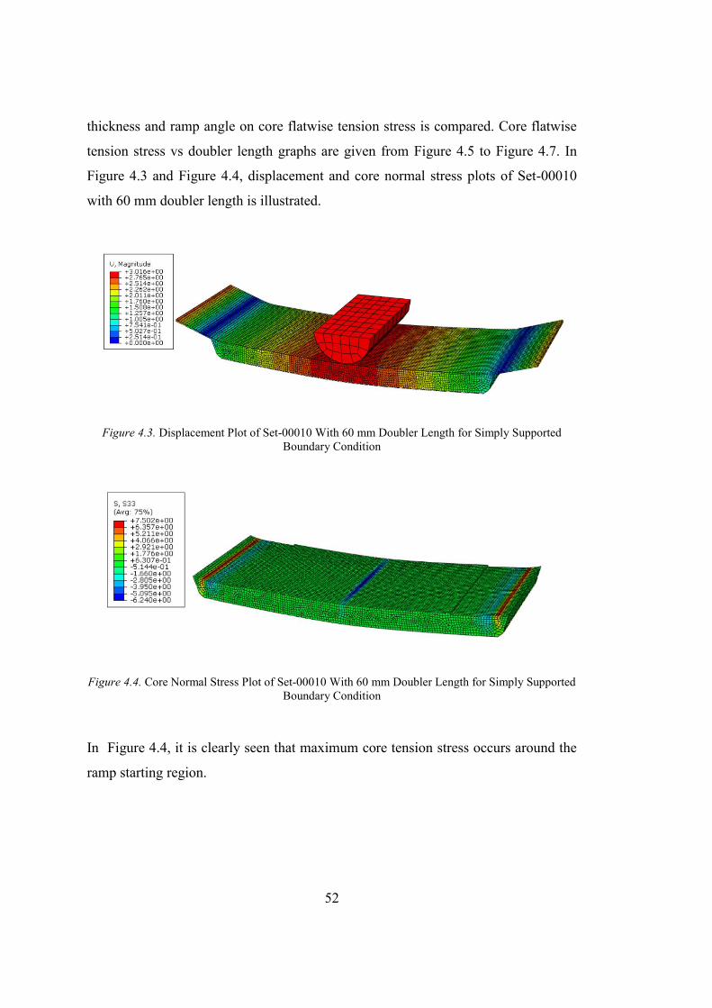
thickness and ramp angle on core flatwise tension stress is compared. Core flatwise
tension stress vs doubler length graphs are given from Figure 4.5 to Figure 4.7. In
Figure 4.3 and Figure 4.4, displacement and core normal stress plots of Set-00010
with 60 mm doubler length is illustrated.
Figure 4.3. Displacement Plot of Set-00010 With 60 mm Doubler Length for Simply Supported Boundary Condition
Figure 4.4. Core Normal Stress Plot of Set-00010 With 60 mm Doubler Length for Simply Supported Boundary Condition
In Figure 4.4, it is clearly seen that maximum core tension stress occurs around the
ramp starting region.
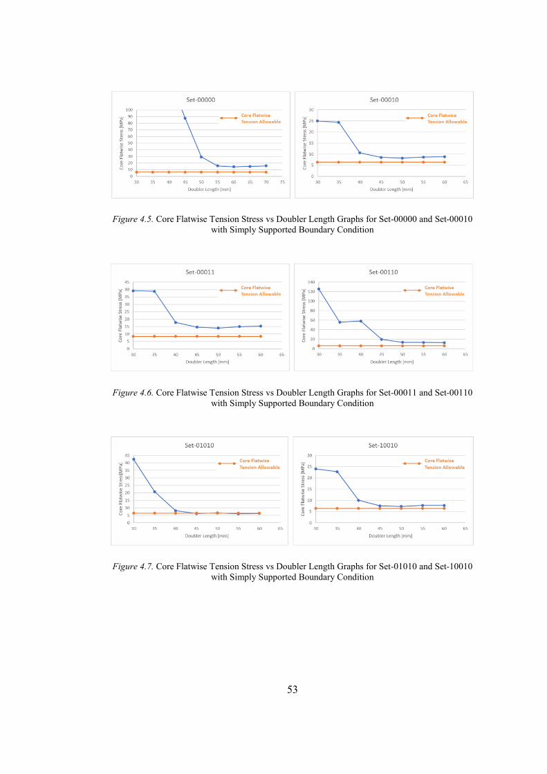
53
Figure 4.5. Core Flatwise Tension Stress vs Doubler Length Graphs for Set-00000 and Set-00010 with Simply Supported Boundary Condition
Figure 4.6. Core Flatwise Tension Stress vs Doubler Length Graphs for Set-00011 and Set-00110 with Simply Supported Boundary Condition
Figure 4.7. Core Flatwise Tension Stress vs Doubler Length Graphs for Set-01010 and Set-10010 with Simply Supported Boundary Condition
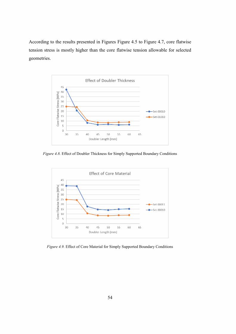
54
According to the results presented in Figures Figure 4.5 to Figure 4.7, core flatwise
tension stress is mostly higher than the core flatwise tension allowable for selected
geometries.
Figure 4.8. Effect of Doubler Thickness for Simply Supported Boundary Conditions
Figure 4.9. Effect of Core Material for Simply Supported Boundary Conditions
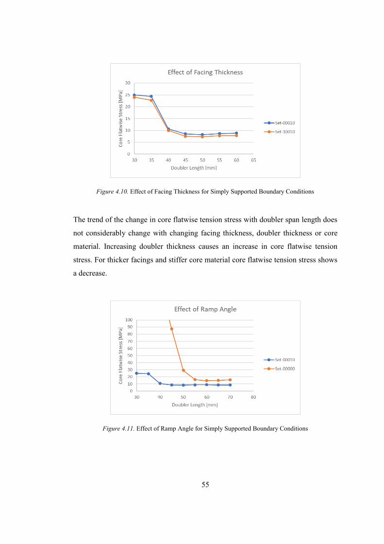
55
Figure 4.10. Effect of Facing Thickness for Simply Supported Boundary Conditions
The trend of the change in core flatwise tension stress with doubler span length does
not considerably change with changing facing thickness, doubler thickness or core
material. Increasing doubler thickness causes an increase in core flatwise tension
stress. For thicker facings and stiffer core material core flatwise tension stress shows
a decrease.
Figure 4.11. Effect of Ramp Angle for Simply Supported Boundary Conditions
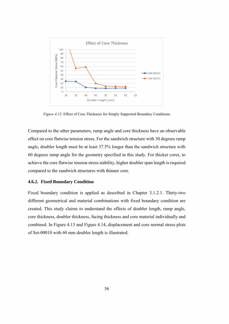
56
Figure 4.12. Effect of Core Thickness for Simply Supported Boundary Conditions
Compared to the other parameters, ramp angle and core thickness have an observable
effect on core flatwise tension stress. For the sandwich structure with 30 degrees ramp
angle, doubler length must be at least 37.5% longer than the sandwich structure with
60 degrees ramp angle for the geometry specified in this study. For thicker cores, to
achieve the core flatwise tension stress stability, higher doubler span length is required
compared to the sandwich structures with thinner core.
4.6.2. Fixed Boundary Condition
Fixed boundary condition is applied as described in Chapter 3.1.2.1. Thirty-two
different geometrical and material combinations with fixed boundary condition are
created. This study claims to understand the effects of doubler length, ramp angle,
core thickness, doubler thickness, facing thickness and core material individually and
combined. In Figure 4.13 and Figure 4.14, displacement and core normal stress plots
of Set-00010 with 60 mm doubler length is illustrated.
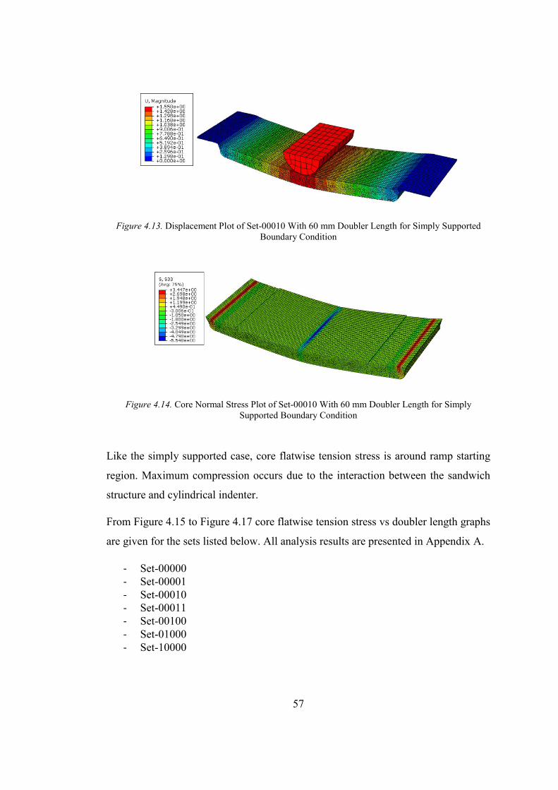
57
Figure 4.13. Displacement Plot of Set-00010 With 60 mm Doubler Length for Simply Supported Boundary Condition
Figure 4.14. Core Normal Stress Plot of Set-00010 With 60 mm Doubler Length for Simply Supported Boundary Condition
Like the simply supported case, core flatwise tension stress is around ramp starting
region. Maximum compression occurs due to the interaction between the sandwich
structure and cylindrical indenter.
From Figure 4.15 to Figure 4.17 core flatwise tension stress vs doubler length graphs
are given for the sets listed below. All analysis results are presented in Appendix A.
- Set-00000 - Set-00001 - Set-00010 - Set-00011 - Set-00100 - Set-01000 - Set-10000
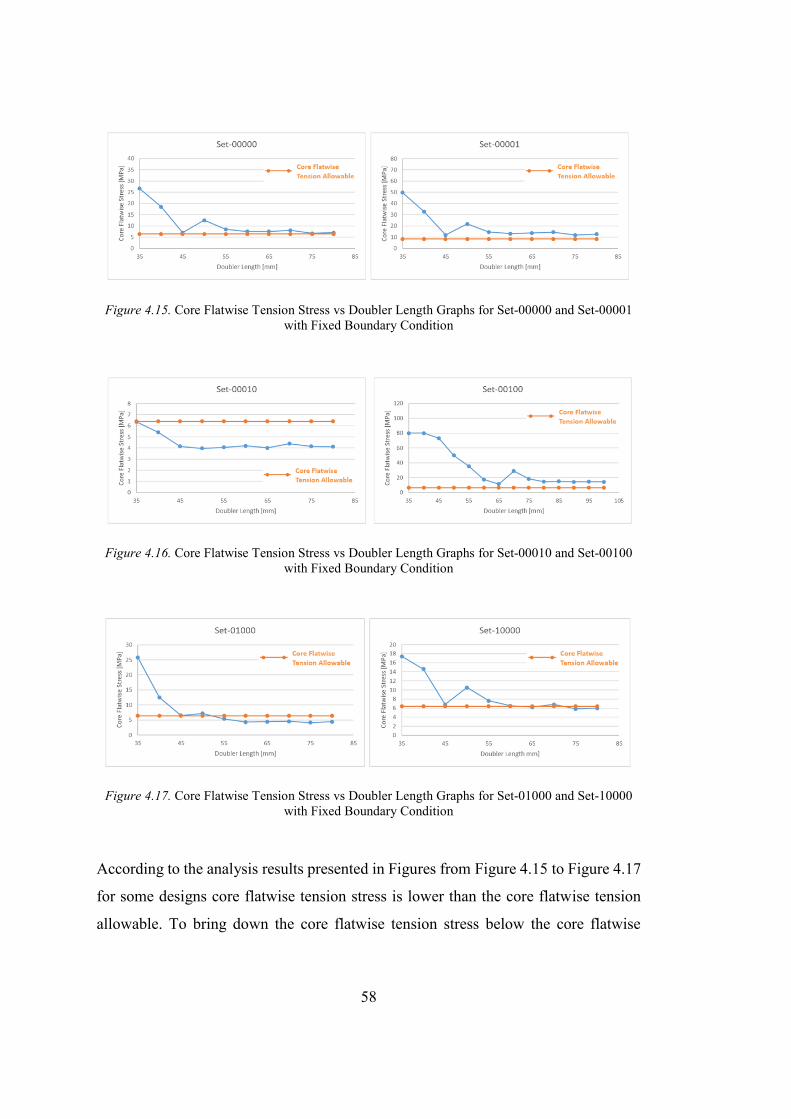
58
Figure 4.15. Core Flatwise Tension Stress vs Doubler Length Graphs for Set-00000 and Set-00001 with Fixed Boundary Condition
Figure 4.16. Core Flatwise Tension Stress vs Doubler Length Graphs for Set-00010 and Set-00100 with Fixed Boundary Condition
Figure 4.17. Core Flatwise Tension Stress vs Doubler Length Graphs for Set-01000 and Set-10000 with Fixed Boundary Condition
According to the analysis results presented in Figures from Figure 4.15 to Figure 4.17
for some designs core flatwise tension stress is lower than the core flatwise tension
allowable. To bring down the core flatwise tension stress below the core flatwise
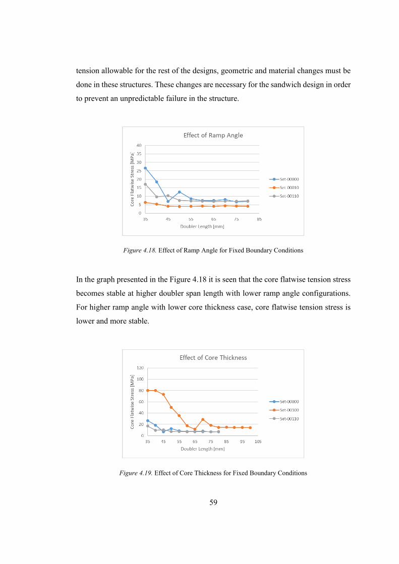
59
tension allowable for the rest of the designs, geometric and material changes must be
done in these structures. These changes are necessary for the sandwich design in order
to prevent an unpredictable failure in the structure.
Figure 4.18. Effect of Ramp Angle for Fixed Boundary Conditions
In the graph presented in the Figure 4.18 it is seen that the core flatwise tension stress
becomes stable at higher doubler span length with lower ramp angle configurations.
For higher ramp angle with lower core thickness case, core flatwise tension stress is
lower and more stable.
Figure 4.19. Effect of Core Thickness for Fixed Boundary Conditions
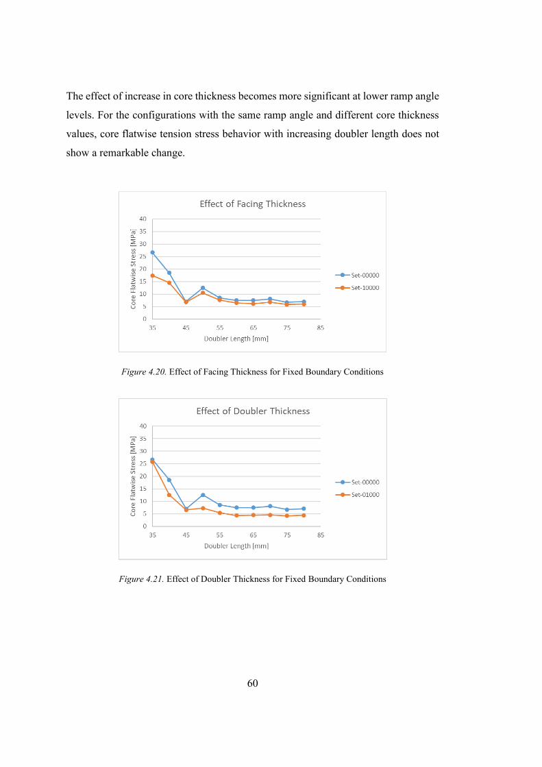
60
The effect of increase in core thickness becomes more significant at lower ramp angle
levels. For the configurations with the same ramp angle and different core thickness
values, core flatwise tension stress behavior with increasing doubler length does not
show a remarkable change.
Figure 4.20. Effect of Facing Thickness for Fixed Boundary Conditions
Figure 4.21. Effect of Doubler Thickness for Fixed Boundary Conditions
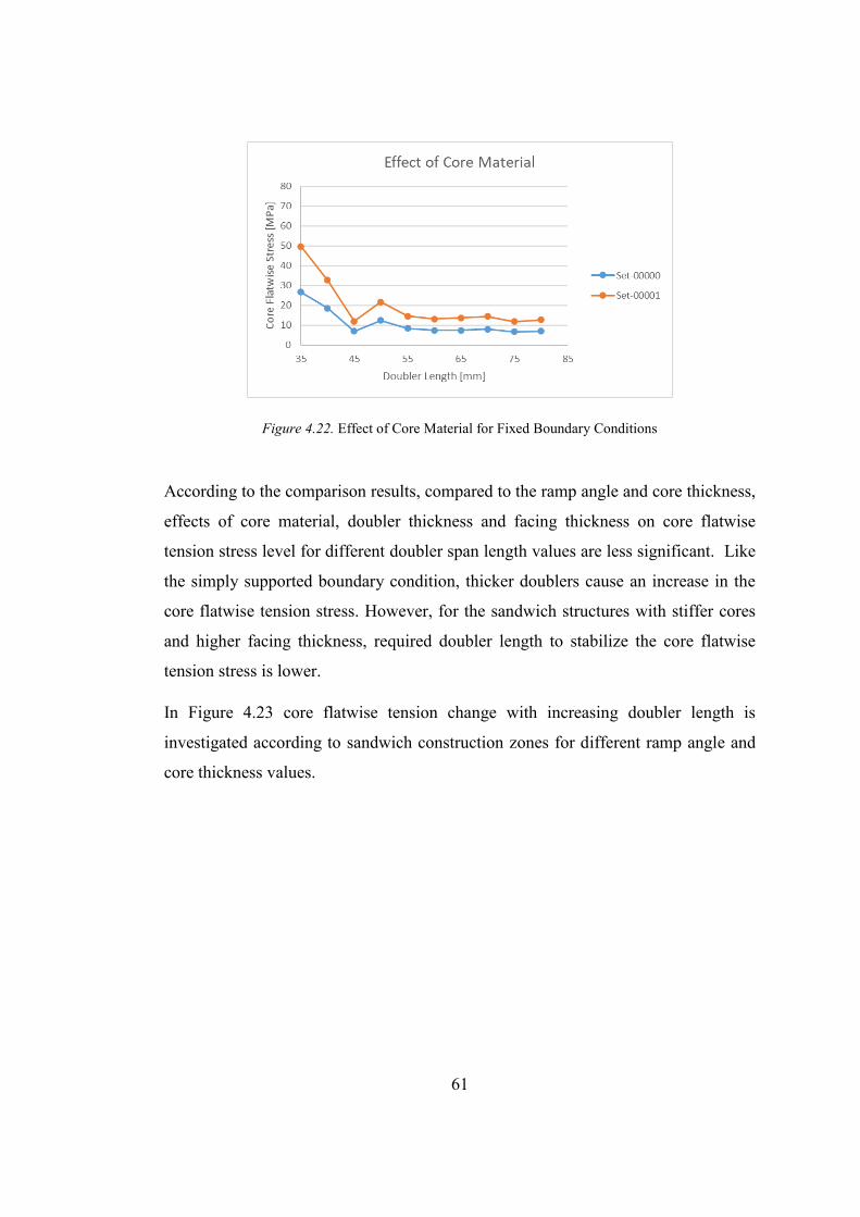
61
Figure 4.22. Effect of Core Material for Fixed Boundary Conditions
According to the comparison results, compared to the ramp angle and core thickness,
effects of core material, doubler thickness and facing thickness on core flatwise
tension stress level for different doubler span length values are less significant. Like
the simply supported boundary condition, thicker doublers cause an increase in the
core flatwise tension stress. However, for the sandwich structures with stiffer cores
and higher facing thickness, required doubler length to stabilize the core flatwise
tension stress is lower.
In Figure 4.23 core flatwise tension change with increasing doubler length is
investigated according to sandwich construction zones for different ramp angle and
core thickness values.
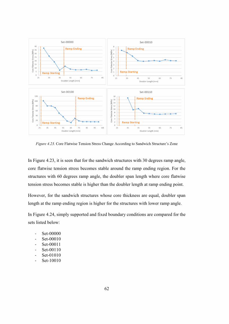
62
Figure 4.23. Core Flatwise Tension Stress Change According to Sandwich Structure’s Zone
In Figure 4.23, it is seen that for the sandwich structures with 30 degrees ramp angle,
core flatwise tension stress becomes stable around the ramp ending region. For the
structures with 60 degrees ramp angle, the doubler span length where core flatwise
tension stress becomes stable is higher than the doubler length at ramp ending point.
However, for the sandwich structures whose core thickness are equal, doubler span
length at the ramp ending region is higher for the structures with lower ramp angle.
In Figure 4.24, simply supported and fixed boundary conditions are compared for the
sets listed below:
- Set-00000 - Set-00010 - Set-00011 - Set-00110 - Set-01010 - Set-10010
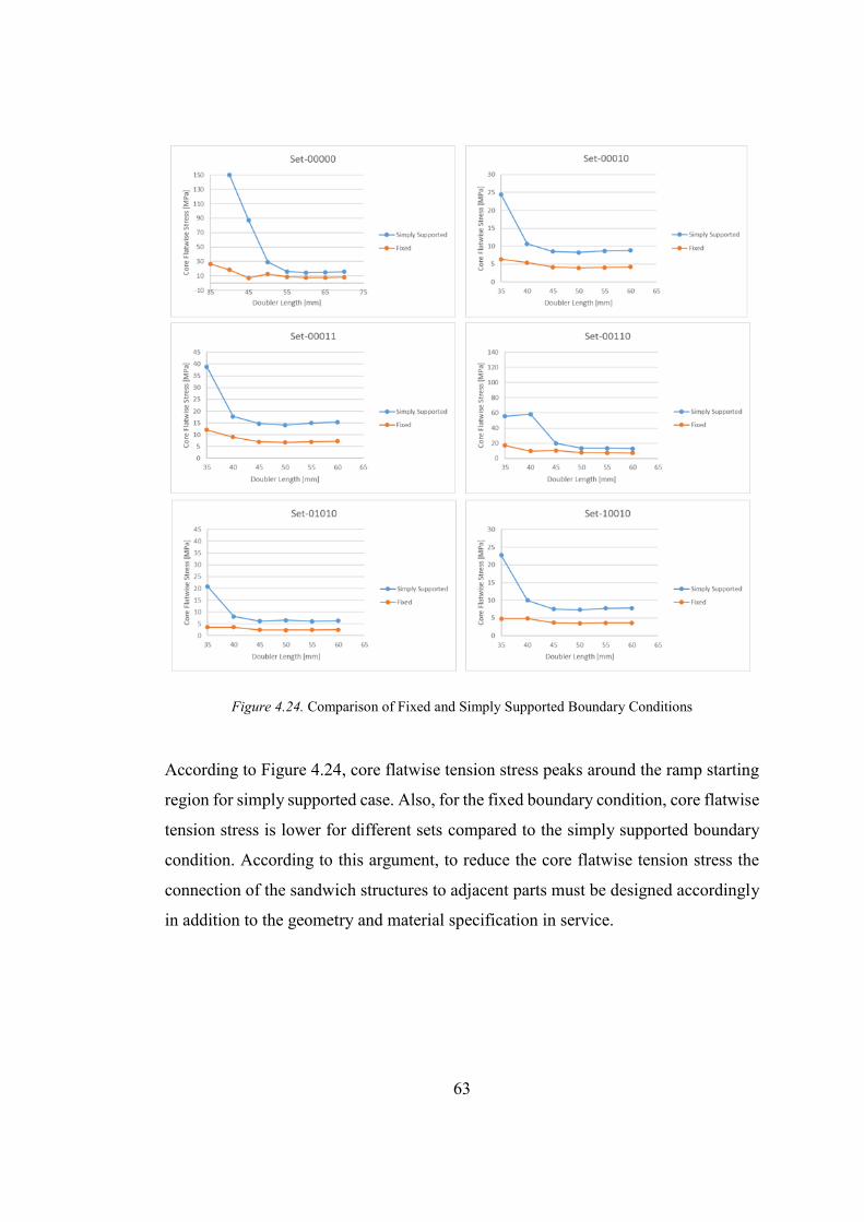
63
Figure 4.24. Comparison of Fixed and Simply Supported Boundary Conditions
According to Figure 4.24, core flatwise tension stress peaks around the ramp starting
region for simply supported case. Also, for the fixed boundary condition, core flatwise
tension stress is lower for different sets compared to the simply supported boundary
condition. According to this argument, to reduce the core flatwise tension stress the
connection of the sandwich structures to adjacent parts must be designed accordingly
in addition to the geometry and material specification in service.
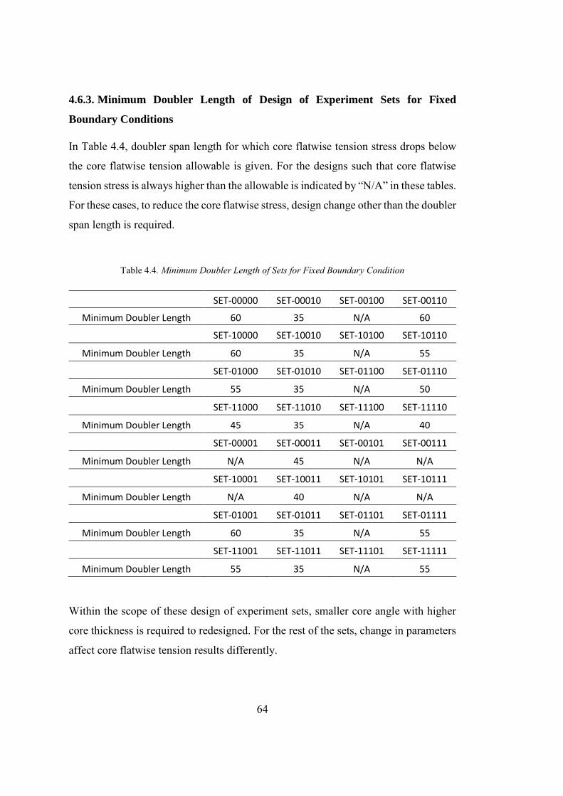
64
4.6.3. Minimum Doubler Length of Design of Experiment Sets for Fixed
Boundary Conditions
In Table 4.4, doubler span length for which core flatwise tension stress drops below
the core flatwise tension allowable is given. For the designs such that core flatwise
tension stress is always higher than the allowable is indicated by “N/A” in these tables.
For these cases, to reduce the core flatwise stress, design change other than the doubler
span length is required.
Table 4.4. Minimum Doubler Length of Sets for Fixed Boundary Condition
SET-00000 SET-00010 SET-00100 SET-00110 Minimum Doubler Length 60 35 N/A 60
SET-10000 SET-10010 SET-10100 SET-10110
Minimum Doubler Length 60 35 N/A 55
SET-01000 SET-01010 SET-01100 SET-01110
Minimum Doubler Length 55 35 N/A 50
SET-11000 SET-11010 SET-11100 SET-11110
Minimum Doubler Length 45 35 N/A 40
SET-00001 SET-00011 SET-00101 SET-00111
Minimum Doubler Length N/A 45 N/A N/A
SET-10001 SET-10011 SET-10101 SET-10111
Minimum Doubler Length N/A 40 N/A N/A
SET-01001 SET-01011 SET-01101 SET-01111
Minimum Doubler Length 60 35 N/A 55
SET-11001 SET-11011 SET-11101 SET-11111
Minimum Doubler Length 55 35 N/A 55
Within the scope of these design of experiment sets, smaller core angle with higher
core thickness is required to redesigned. For the rest of the sets, change in parameters
affect core flatwise tension results differently.
65
CHAPTER 5
5. DISCUSSION AND CONCLUSION
This thesis determined minimum doubler length of tapered sandwich structures with
metallic facings and honeycomb. Analyses are conducted in ABAQUS via Python.
The main point while determination of the minimum doubler length is to avoid any
unpredictable failure around ramp-down region. Unpredictable failure can be
explained as, the failure occurs at a load below the expected load calculated by
considering failure types defined in the literature. These failure loads are explained in
Chapter 2 in detail. To be able to calculate and apply the critical load under which a
failure in core or facings is faced with, sandwich beam theory is used. Beam theory is
applicable for the geometries with the width less than three times of the span length.
The model developed and used in the analyses of this study is verified by the test
results conducted in [14] and [33]. The test given in [14], used to correlate sandwich
structure without ramp-down region. This correlation is necessary, because there are
fewer uncertainties in this test compared to the test conducted in [33]. The effects of
uncertainties in [33] is aimed to be understood by using the correlation study done
with the test results presented. Effects of bolt preload and friction coefficient between
the parts in contact are investigated and their effects are determined to be negligible.
During the correlation study, glass that cover the ramp-down region of the sandwich
structure is modelled. Effects of mesh size on the core flatwise stress results are
analyzed. Firstly, mesh sensitivity study of the finite element model including glass is
done. Results of these analyses show that the mesh convergence cannot be ensured
when the glass is included into the finite element model. Therefore, glass is omitted
from the further analyses, and mesh convergence study is repeated. According to
results of these analyses, mesh size of each component in the assembly is determined.
66
Since the mesh convergence is supplied when glass is not included into finite element
model, the load vs. displacement results of the model without glass is compared to the
test results. This comparison shows that glass is necessary to represent the overall
stiffness of the sandwich structure. However, to be sure of the accuracy of the core
flatwise tension stress results, glass is not modeled in this thesis study. Based on the
sandwich panel modeling techniques comparison given in [4], equivalent core
modeling with solid facings and doubler is decided to be used. A new simplified finite
element model is created to use in this thesis in consideration of these results. In this
simplified model, adjacent parts are cancelled, and the glass is excluded. In order to
understand the effects of connection type of the sandwich structures to adjacent parts
two different finite element models are created with fixed and simply supported
boundary conditions. The results of these two different boundary conditions are
compared and it is seen that, the maximum core flatwise tension stress is higher for
fixed boundary condition compared to the simply supported boundary condition under
equal loading.
Effects of facing thickness, doubler thickness, core thickness, core material and ramp
angle on maximum core flatwise tension stress are examined for varying doubler span
length. To cover all combinations of these parameters thirty-two different finite
element models with fixed boundary condition are created via Python code. For simply
supported boundary condition six of these combinations are selected such that effects
of all parameters can be investigated separately. The results of the analyses are
presented in the form of “Core Flatwise Stress vs Doubler Length” graphs. These
graphs indicate that, core flatwise tension stress decreases with increasing doubler
length. At some point, core flatwise stress does not decrease and becomes stable. The
doubler length at this point is optimum because it creates the minimum core flatwise
tension stress and keeps the weight of the sandwich structure minimum. The optimum
doubler length changes by changing sandwich designs. For some designs, the stress
level at which core flatwise tension stress converges is higher than the core tension
allowable. For these cases design of the sandwich structure must be changed. The most
67
distinct recommended design change is the use of lower ramp angle with thinner cores.
Also, comparison of the results of finite element analyses with fixed and simply
supported boundary conditions show that, core flatwise stress level is higher for
simply supported boundary condition compared to the fixed ended case. Therefore, to
reduce the core flatwise tension stress and prevent an unpredictable failure, connection
type of the sandwich construction to adjacent parts may be changed in addition to
design change.
These results explained under this title are acceptable for the sandwich construction
designs given in this thesis. The design of experiment used in this study is created in
consideration of the specimen geometry used in the test conducted by Turkish
Aerospace. Within the scope of these results for specified sandwich designs, lighter
sandwich structures are aimed to be designed without any unpredictable failure around
the ramp down region.
Scope and the accuracy presented in this thesis could increase with further
investigations. To lookout for future works can be summarized as follows,
- In this study materials of facings and doubler are both aluminum. Core material
is also selected as two different alloys of aluminum. Sandwich structures with
different materials and material combinations could be modeled in further
studies.
- In order to provide the mesh convergence, glass is excluded from the finite
element model in this thesis. Glass may be included into the model to simulate
the sandwich structures used in the industry with higher accuracy.
- In real life usage of sandwich structure, potting compound is also used in the
ramp-down region. Effect of potting compound on the doubler span length and
core flatwise tension stress may be investigated.

69
REFERENCES
[1] Akiwate, S. B., & Shinde, V. D. 2017. Experimental investigation of bending behavior of aluminum alloy honeycomb sandwich structure using four point bending Tests. International Journal for Innovative Research in Science & Technology, 4(1).
[2] Allen, H. G. 1969. Analysis and design of structural sandwich panels.
[3] ASTM C393/C 393M-06, Standard test method core shear properties of sandwich constructions by beam flexure.
[4] Aydıncak, I. 2007. Investigation of design and analyses principles of honeycomb structures (MS Thesis). METU.
[5] Bitzer, T. 1997. Honeycomb technology: Materials, Design, Manufacturing, Applications and Testing.
[6] Bruhn, E. F. 1997. Analysis and design of flight vehicle structures. Tri-State Offset Company.
[7] Christensen, A. L., Brett, T. S., James, S. P., & Venkataraman, S. 2013. Testing of sandwich composite edge closeouts with functionally graded honeycomb cores. 54th AIAA/ASME/ASCE/AHS/ASC Structures, Structural Dynamics, and Materials Conference.
[8] Crump, D., Dulieu-Barton, J., & Savage, J. 2009. The manufacturing procedure for aerospace secondary sandwich structure panels. Journal of Sandwich Structures & Materials, 12(4).
70
[9] Crupi, V., Epasto, G., Guglielmino, E., Mozafari, H., & Najafian, S. 2014. Computed tomography-based reconstruction and finite element modelling of honeycomb sandwiches under low-velocity impacts. Journal of Sandwich Structures & Materials, 16(4).
[10] Dassault Systèmes. 2014. Abaqus analysis user’s manuel. Retrieved from Dassault Systèmes: Abaqus Version 6.14.
[11] Feichtinger, K. A. 1989. Test methods and performance of structural core materials. Journal of Reinforced Plastics and Composites, 8(4).
[12] Fogarty, J. H. 2009. Honeycomb core and the myths of moisture ingression. Applied Composite Materials, 17(3).
[13] Fuller, D. D. Coefficients of friction. https://web.mit.edu/8.13/8.13c/references- fall/aip/aip-handbook-section2d.pdf
[14] Giglio, M., Gilioli, A., & Manes, A. 2012. Numerical investigation of a three point bending test on sandwich panels with aluminum skins and Nomex™ honeycomb core. Computational Materials Science, 56.
[15] Grediac, M. 1993. A finite element study of the transverse shear in honeycomb cores. International Journal of Solids and Structures, 30(13).
[16] Hexcel Corporation. 2016. Aramid fiber/phenolic resin honeycomb. https://www.hexcel.com/user_area/content_media/raw/HexWeb_HRH10_Da taSheet_us(1).pdf
[17] Hexcel Corporation., Honeycomb attributes and properties handbook.
71
[18] Karpanan, K., Brendan, O., & Feghhi, M. 2006. Experimental and finite element analysis of preloaded bolted joints under impact loading. 47th AIAA/ASME/ASCE/AHS/ASC Structures, Structural Dynamics, and Materials Conference.
[19] Kassapoglou, C. 1996. Stress determination and core failure analysis in sandwich ramp-down structures under bending loads. Key Engineering Materials.
[20] Lister, J. M. 2014. Study the effects of core orientation and different face thicknesses on mechanical behavior of honeycomb sandwich structures under three point bending (MS Thesis). California Polytechnic State University.
[21] Liu, Q., & Zhao, Y. 2007. Effect of soft honeycomb core on flexural vibration of sandwich panel using low order and high order shear deformation models. Journal of Sandwich Structures & Materials, 9(1).
[22] Löffelmann, F. 2017. Stress distribution investigation at the tapered sandwich endings. Transactions on Aerospace Research, 2017(4).
[23] Masters, I., & Evans, K. 1996. Models for the elastic deformation of honeycombs. Composite Structures, 35(4).
[24] MMPDS-08: Metallic material properties development and standardization. Washington, D.C: Federal Aviation Administration, 2013.
[25] Nast, E. 1997. On honeycomb-type core moduli. 38th Structures, Structural Dynamics, and Materials Conference.
[26] Niu, C. 1997. Airframe stress analysis and sizing. Hong Kong: Conmilit Press.
[27] Paris, I. L. 2009. Characterization of composites sandwich ramp failure under tensile loading. 17th International Conference on Composite Material, Edinburgh.
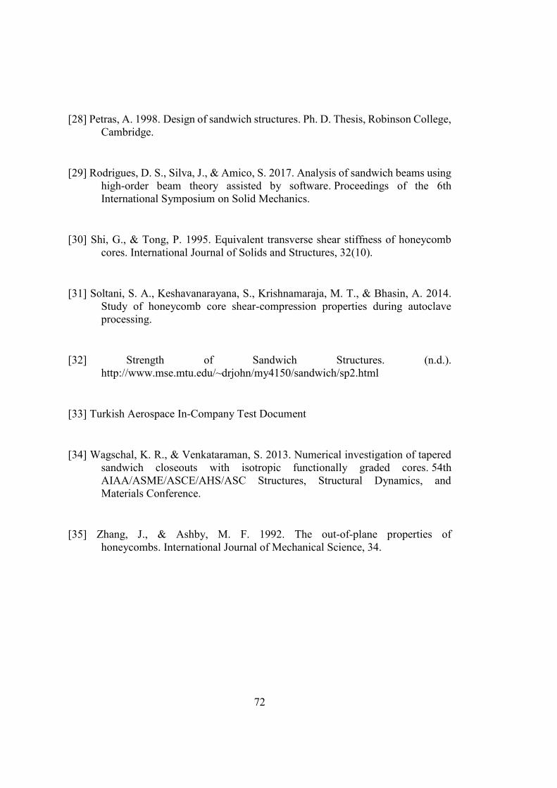
72
[28] Petras, A. 1998. Design of sandwich structures. Ph. D. Thesis, Robinson College, Cambridge.
[29] Rodrigues, D. S., Silva, J., & Amico, S. 2017. Analysis of sandwich beams using high-order beam theory assisted by software. Proceedings of the 6th International Symposium on Solid Mechanics.
[30] Shi, G., & Tong, P. 1995. Equivalent transverse shear stiffness of honeycomb cores. International Journal of Solids and Structures, 32(10).
[31] Soltani, S. A., Keshavanarayana, S., Krishnamaraja, M. T., & Bhasin, A. 2014. Study of honeycomb core shear-compression properties during autoclave processing.
[32] Strength of Sandwich Structures. (n.d.). http://www.mse.mtu.edu/~drjohn/my4150/sandwich/sp2.html
[33] Turkish Aerospace In-Company Test Document
[34] Wagschal, K. R., & Venkataraman, S. 2013. Numerical investigation of tapered sandwich closeouts with isotropic functionally graded cores. 54th AIAA/ASME/ASCE/AHS/ASC Structures, Structural Dynamics, and Materials Conference.
[35] Zhang, J., & Ashby, M. F. 1992. The out-of-plane properties of honeycombs. International Journal of Mechanical Science, 34.
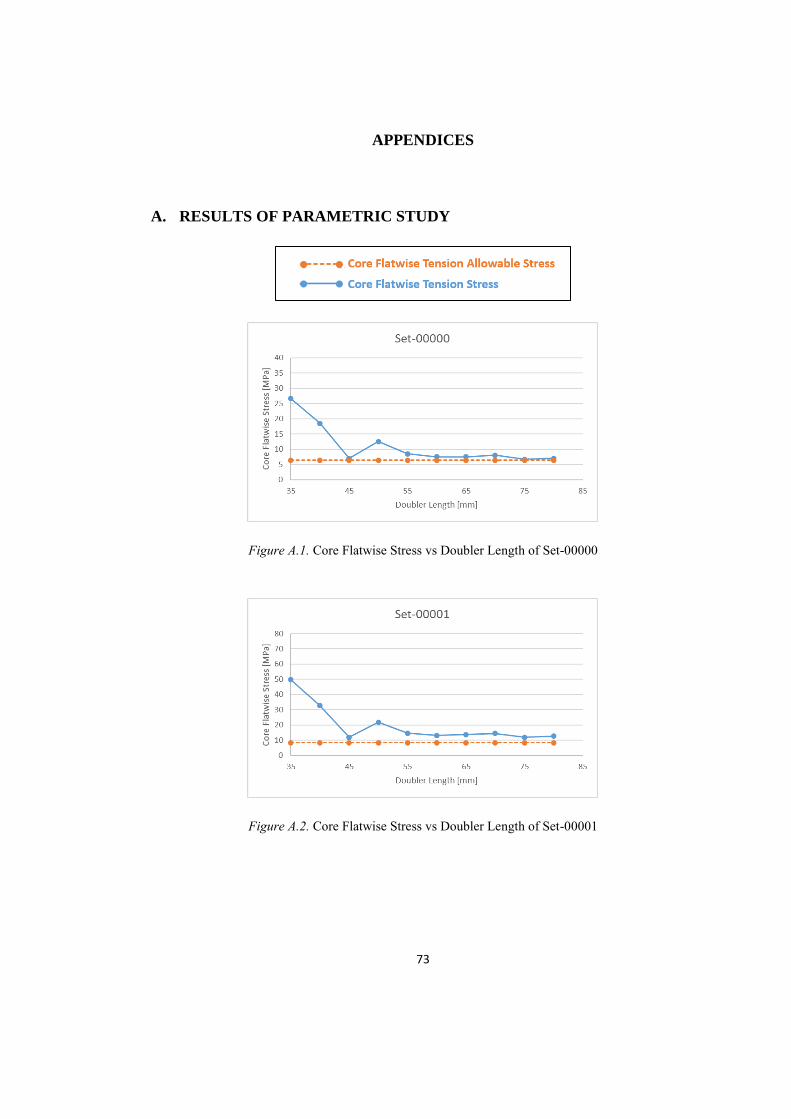
73
APPENDICES
A. RESULTS OF PARAMETRIC STUDY
Figure A.1. Core Flatwise Stress vs Doubler Length of Set-00000
Figure A.2. Core Flatwise Stress vs Doubler Length of Set-00001
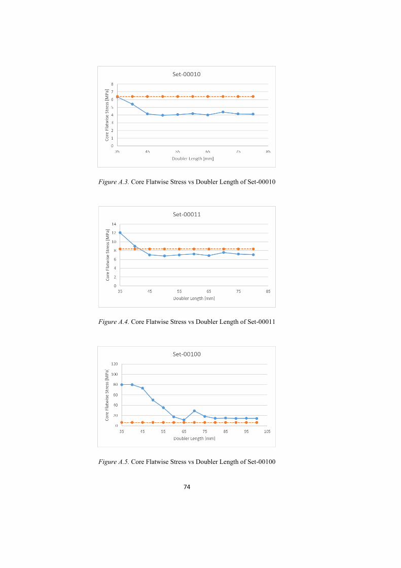
74
Figure A.3. Core Flatwise Stress vs Doubler Length of Set-00010
Figure A.4. Core Flatwise Stress vs Doubler Length of Set-00011
Figure A.5. Core Flatwise Stress vs Doubler Length of Set-00100
75
Figure A.6. Core Flatwise Stress vs Doubler Length of Set-00101
Figure A.7. Core Flatwise Stress vs Doubler Length of Set-00110
Figure A.8. Core Flatwise Stress vs Doubler Length of Set-00111
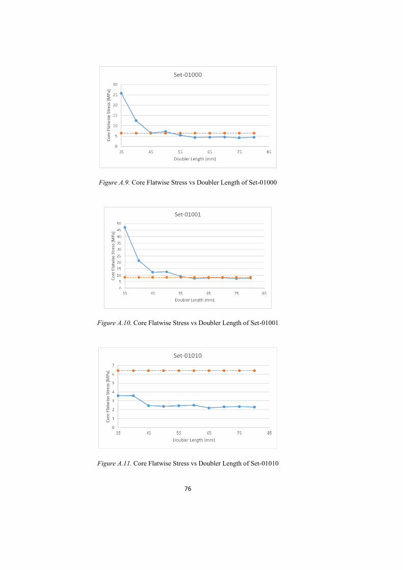
76
Figure A.9. Core Flatwise Stress vs Doubler Length of Set-01000
Figure A.10. Core Flatwise Stress vs Doubler Length of Set-01001
Figure A.11. Core Flatwise Stress vs Doubler Length of Set-01010
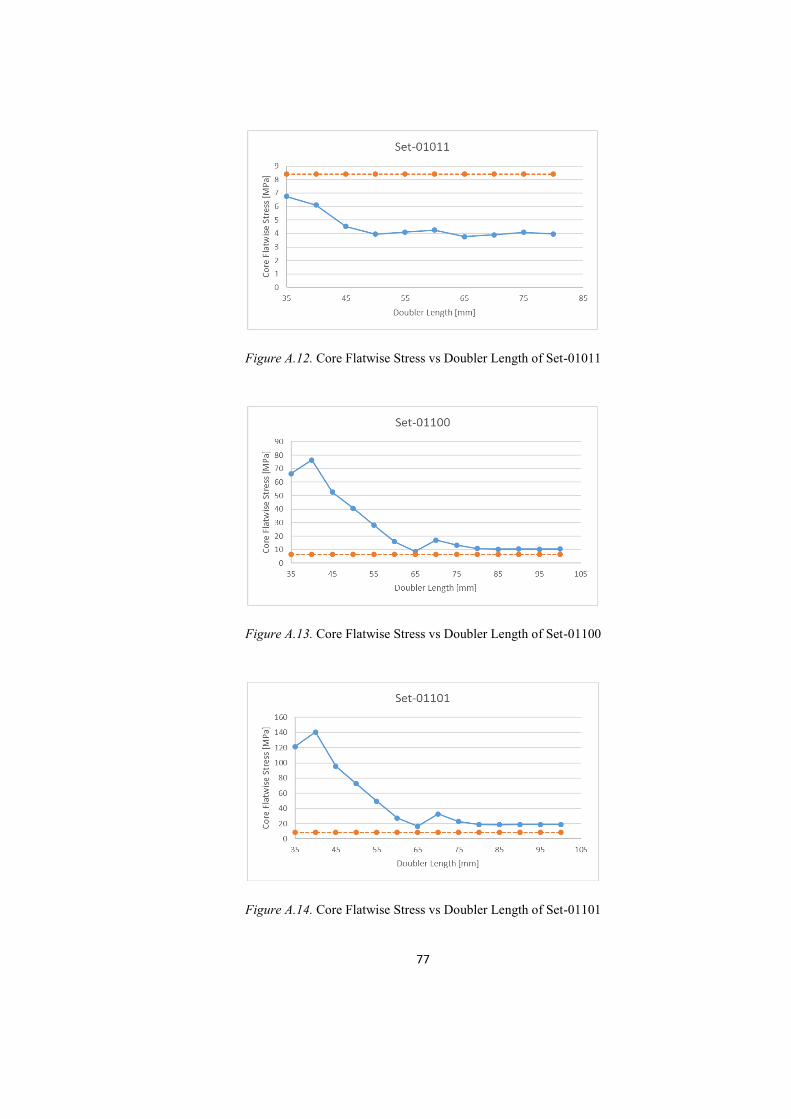
77
Figure A.12. Core Flatwise Stress vs Doubler Length of Set-01011
Figure A.13. Core Flatwise Stress vs Doubler Length of Set-01100
Figure A.14. Core Flatwise Stress vs Doubler Length of Set-01101
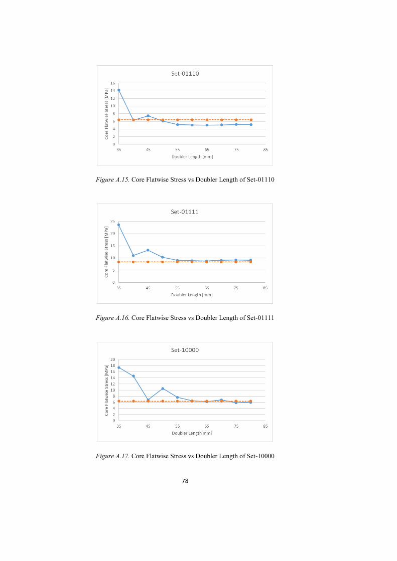
78
Figure A.15. Core Flatwise Stress vs Doubler Length of Set-01110
Figure A.16. Core Flatwise Stress vs Doubler Length of Set-01111
Figure A.17. Core Flatwise Stress vs Doubler Length of Set-10000
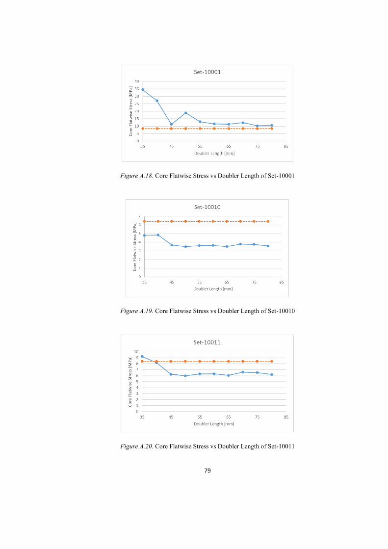
79
Figure A.18. Core Flatwise Stress vs Doubler Length of Set-10001
Figure A.19. Core Flatwise Stress vs Doubler Length of Set-10010
Figure A.20. Core Flatwise Stress vs Doubler Length of Set-10011
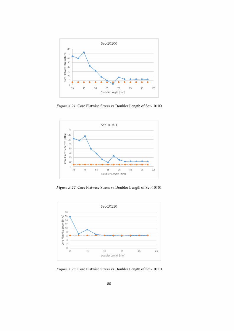
80
Figure A.21. Core Flatwise Stress vs Doubler Length of Set-10100
Figure A.22. Core Flatwise Stress vs Doubler Length of Set-10101
Figure A.23. Core Flatwise Stress vs Doubler Length of Set-10110
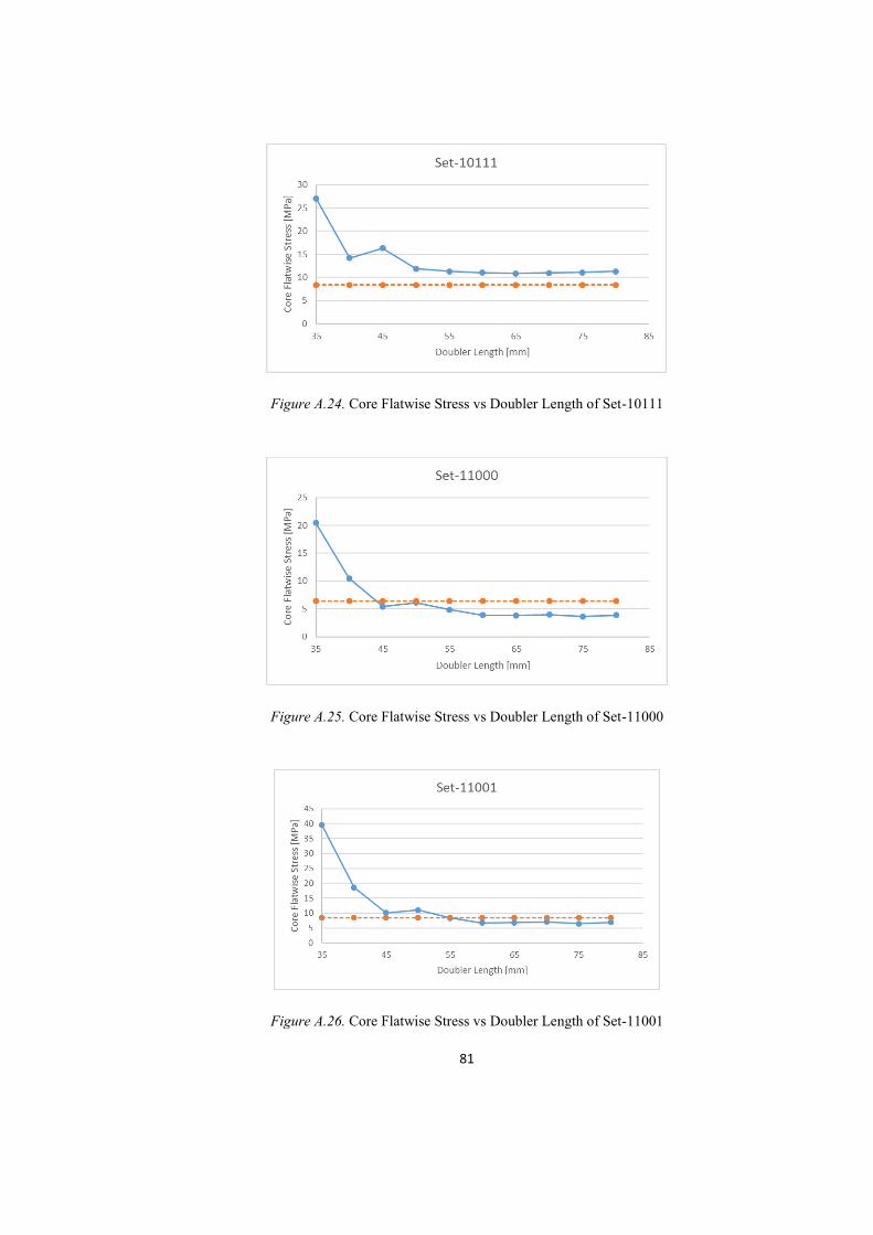
81
Figure A.24. Core Flatwise Stress vs Doubler Length of Set-10111
Figure A.25. Core Flatwise Stress vs Doubler Length of Set-11000
Figure A.26. Core Flatwise Stress vs Doubler Length of Set-11001
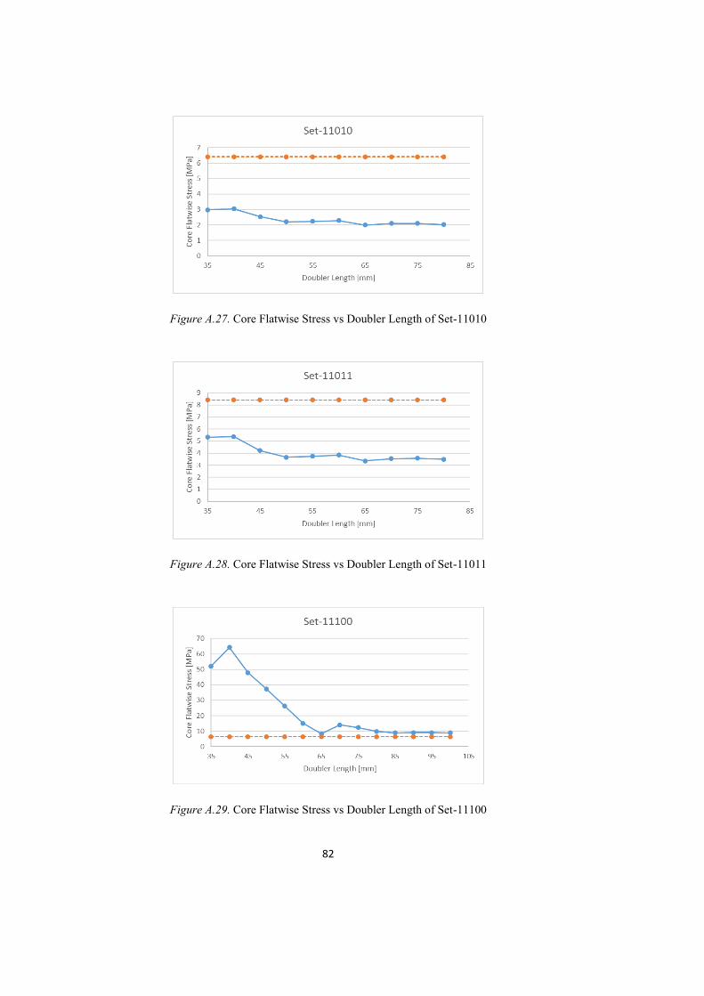
82
Figure A.27. Core Flatwise Stress vs Doubler Length of Set-11010
Figure A.28. Core Flatwise Stress vs Doubler Length of Set-11011
Figure A.29. Core Flatwise Stress vs Doubler Length of Set-11100
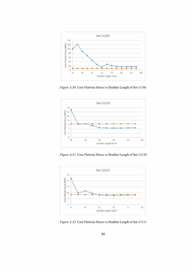
83
Figure A.30. Core Flatwise Stress vs Doubler Length of Set-11101
Figure A.31. Core Flatwise Stress vs Doubler Length of Set-11110
Figure A.32. Core Flatwise Stress vs Doubler Length of Set-11111

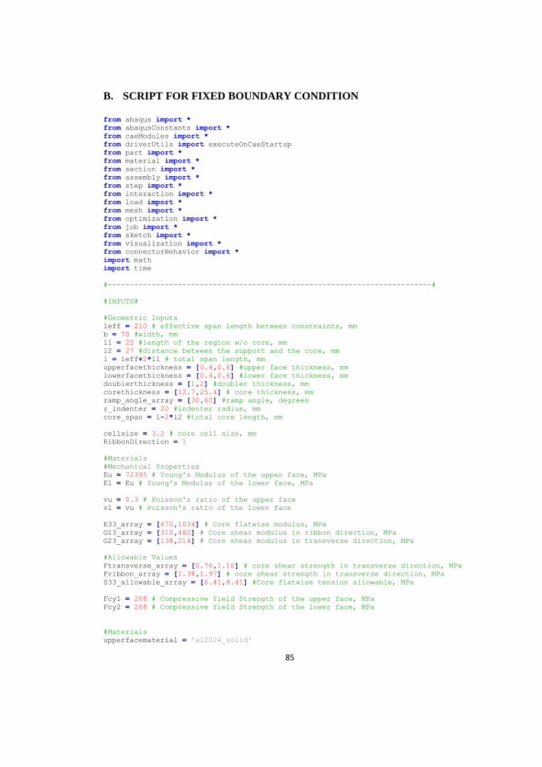
85
B. SCRIPT FOR FIXED BOUNDARY CONDITION
from abaqus import *
from abaqusConstants import *
from caeModules import *
from driverUtils import executeOnCaeStartup
from part import *
from material import *
from section import *
from assembly import *
from step import *
from interaction import *
from load import *
from mesh import *
from optimization import *
from job import *
from sketch import *
from visualization import *
from connectorBehavior import *
import math
import time
#--------------------------------------------------------------------------#
#INPUTS#
#Geometric Inputs
leff = 210 # effective span length between constraints, mm
b = 70 #width, mm
l1 = 22 #length of the region w/o core, mm
l2 = 27 #distance between the support and the core, mm
l = leff+2*l1 # total span length, mm
upperfacethickness = [0.4,0.6] #upper face thickness, mm
lowerfacethickness = [0.4,0.6] #lower face thickness, mm
doublerthickness = [1,2] #doubler thickness, mm
corethickness = [12.7,25.4] # core thickness, mm
ramp_angle_array = [30,60] #ramp angle, degrees
r_indenter = 20 #indenter radius, mm
core_span = l-2*l2 #total core length, mm
cellsize = 3.2 # core cell size, mm
RibbonDirection = 1
#Materials
#Mechanical Properties
Eu = 72395 # Young's Modulus of the upper face, MPa
El = Eu # Young's Modulus of the lower face, MPa
vu = 0.3 # Poisson's ratio of the upper face
vl = vu # Poisson's ratio of the lower face
E33_array = [670,1034] # Core flatwise modulus, MPa
G13_array = [310,482] # Core shear modulus in ribbon direction, MPa
G23_array = [138,214] # Core shear modulus in transverse direction, MPa
#Allowable Values
Ftransverse_array = [0.76,1.16] # core shear strength in transverse direction, MPa
Fribbon_array = [1.38,1.97] # core shear strength in transverse direction, MPa
S33_allowable_array = [6.41,8.41] #Core flatwise tension allowable, MPa
Fcy1 = 268 # Compressive Yield Strength of the upper face, MPa
Fcy2 = 268 # Compressive Yield Strength of the lower face, MPa
#Materials
upperfacematerial = 'al2024_solid'
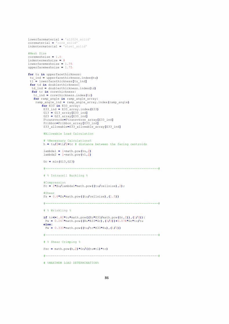
86
lowerfacematerial = 'al2024_solid'
corematerial = 'core_solid'
indentermaterial = 'steel_solid'
#Mesh Size
coremeshsize = 1.5
indentermeshsize = 8
lowerfacemeshsize = 1.75
upperfacemeshsize = 1.75
for tu in upperfacethickness:
tu_ind = upperfacethickness.index(tu)
tl = lowerfacethickness[tu_ind]
for td in doublerthickness:
td_ind = doublerthickness.index(td)
for tc in corethickness:
tc_ind = corethickness.index(tc)
for ramp_angle in ramp_angle_array:
ramp_angle_ind = ramp_angle_array.index(ramp_angle)
for E33 in E33_array:
E33_ind = E33_array.index(E33)
G13 = G13_array[E33_ind]
G23 = G23_array[E33_ind]
Ftransverse=Ftransverse_array[E33_ind]
Fribbon=Fribbon_array[E33_ind]
S33_allowable=S33_allowable_array[E33_ind]
#Allowable Load Calculation
# %Necessary Calculations%
h = tu/2+tl/2+tc # distance between the facing centroids
lambda1 = 1-math.pow(vu,2)
lambda2 = 1-math.pow(vl,2)
Gc = min(G13,G23)
#-------------------------------------------------------------#
# % Intracell Buckling %
#Compression
Fc = 2*Eu/lambda1*math.pow((tu/cellsize),2);
#Shear
Fs = 0.6*Eu*math.pow((tu/cellsize),(1.5))
#-------------------------------------------------------------#
# % Wrinkling %
if tc<=1.82*tu*math.pow((Eu*E33/math.pow(Gc,2)),(1/3)):
Fw = 0.247*math.pow((Eu*E33*Gc),(1/3))+0.078*Gc*tc/tu
else:
Fw = 0.333*math.pow((tu/tc*E33*Eu),(1/2))
#-------------------------------------------------------------#
# % Shear Crimping %
Fsc = math.pow(h,2)*Gc/((tu+tl)*tc)
#-------------------------------------------------------------#
# %MAXIMUM LOAD DETERMINATION%
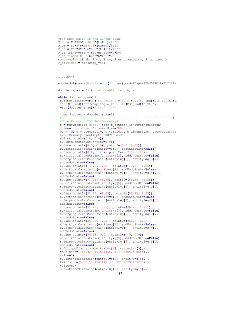
87
#For Ends Built-in and Center Load
P_ib = Fc*8*b*tc*0.5*(tu+tl)/leff
P_wr = Fs*8*b*tc*0.5*(tu+tl)/leff
P_sc = Fsc*8*b*tc*0.5*(tu+tl)/leff
P_cs_transverse = Ftransverse*h*b*2
P_cs_ribbon = Fribbon*h*leff*2
comp_vec1 = [P_ib, P_wr, P_sc, P_cs_transverse, P_cs_ribbon]
P_critical = min(comp_vec1)
i_count=1
mdb.Model(name='Model-'+str(i_count),modelType=STANDARD_EXPLICIT)
doubler_span = 35 #total doubler length, mm
while doubler_span<81:
parameterstore=open('PARAMETERS'+'Set-'+str(tu_ind)+str(td_ind)\
+str(tc_ind)+str(ramp_angle_ind)+str(E33_ind)+'_UL_'\
+str(doubler_span)+'.txt', "a+")
core_doubler = doubler_span-l2
#-------------------------------------------------------------#
#Upperface and Doubler Geometry#
s = mdb.models['Model-'+str(i_count)].ConstrainedSketch\
(name='__profile__', sheetSize=200.0)
g, v, d, c = s.geometry, s.vertices, s.dimensions, s.constraints
s.setPrimaryObject(option=STANDALONE)
s.Spot(point=(0.0, 0.0))
s.FixedConstraint(entity=v[0])
s.Line(point1=(0.0, 0.0), point2=(0.0, 1.25))
s.VerticalConstraint(entity=g[2], addUndoState=False)
s.Line(point1=(0.0, 1.25), point2=(-17.5, 1.25))
s.HorizontalConstraint(entity=g[3], addUndoState=False)
s.PerpendicularConstraint(entity1=g[2], entity2=g[3],\
addUndoState=False)
s.Line(point1=(-17.5, 1.25), point2=(-17.5, -1.25))
s.VerticalConstraint(entity=g[4], addUndoState=False)
s.PerpendicularConstraint(entity1=g[3], entity2=g[4], \
addUndoState=False)
s.Line(point1=(-17.5, -1.25), point2=(51.25, -1.25))
s.HorizontalConstraint(entity=g[5], addUndoState=False)
s.PerpendicularConstraint(entity1=g[4], entity2=g[5],\
addUndoState=False)
s.Line(point1=(51.25, -1.25), point2=(51.25, 1.25))
s.VerticalConstraint(entity=g[6], addUndoState=False)
s.PerpendicularConstraint(entity1=g[5], entity2=g[6],\
addUndoState=False)
s.Line(point1=(51.25, 1.25), point2=(36.25, 1.25))
s.HorizontalConstraint(entity=g[7], addUndoState=False)
s.PerpendicularConstraint(entity1=g[6], entity2=g[7],\
addUndoState=False)
s.Line(point1=(36.25, 1.25), point2=(36.25, 0.0))
s.VerticalConstraint(entity=g[8], addUndoState=False)
s.PerpendicularConstraint(entity1=g[7], entity2=g[8],\
addUndoState=False)
s.Line(point1=(36.25, 0.0), point2=(0.0, 0.0))
s.HorizontalConstraint(entity=g[9], addUndoState=False)
s.PerpendicularConstraint(entity1=g[8], entity2=g[9],\
addUndoState=False)
s.ObliqueDimension(vertex1=v[4], vertex2=v[5],\
textPoint=(-14.9218101501465,-4.77973556518555),\
value=l)
s.DistanceDimension(entity1=g[9], entity2=g[5], \
textPoint=(5.05195045471191,-0.771825790405273),\
value=tu)
s.DistanceDimension(entity1=g[3], entity2=g[5],\
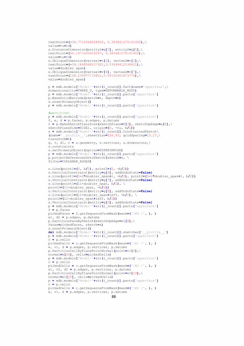
88
textPoint=(-34.7716369628906, 0.383661270141602),\
value=tu+td)
s.DistanceDimension(entity1=g[7], entity2=g[5],\
textPoint=(40.1471405029297, 0.383661270141602),\
value=tu+td)
s.ObliqueDimension(vertex1=v[2], vertex2=v[3],\
textPoint=(-39.1848068237305,3.53499412536621),\
value=doubler_span)
s.ObliqueDimension(vertex1=v[6], vertex2=v[7],\
textPoint=(108.235977172852,5.95101451873779),\
value=doubler_span)
p = mdb.models['Model-'+str(i_count)].Part(name='upperface',\
dimensionality=THREE_D, type=DEFORMABLE_BODY)
p = mdb.models['Model-'+str(i_count)].parts['upperface']
p.BaseSolidExtrude(sketch=s, depth=b)
s.unsetPrimaryObject()
p = mdb.models['Model-'+str(i_count)].parts['upperface']
#partition1
p = mdb.models['Model-'+str(i_count)].parts['upperface']
f, e, d = p.faces, p.edges, p.datums
t = p.MakeSketchTransform(sketchPlane=f[3], sketchUpEdge=e[8],\
sketchPlaneSide=SIDE1, origin=(0, -tu, b/2))
s = mdb.models['Model-'+str(i_count)].ConstrainedSketch\
(name='__profile__',sheetSize=526.93, gridSpacing=13.17,\
transform=t)
g, v, d1, c = s.geometry, s.vertices, s.dimensions,\
s.constraints
s.setPrimaryObject(option=SUPERIMPOSE)
p = mdb.models['Model-'+str(i_count)].parts['upperface']
p.projectReferencesOntoSketch(sketch=s, \
filter=COPLANAR_EDGES)
s.Line(point1=(0, b/2), point2=(0, -b/2))
s.VerticalConstraint(entity=g[6], addUndoState=False)
s.Line(point1=(0-2*doubler_span+l, -b/2), point2=(0-2*doubler_span+l, b/2))
s.VerticalConstraint(entity=g[7], addUndoState=False)
s.Line(point1=(l1-doubler_span, b/2), \
point2=(l1-doubler_span, -b/2))
s.VerticalConstraint(entity=g[8], addUndoState=False)
s.Line(point1=(l1-doubler_span+leff, -b/2), \
point2=(l1-doubler_span+leff, b/2))
s.VerticalConstraint(entity=g[9], addUndoState=False)
p = mdb.models['Model-'+str(i_count)].parts['upperface']
f = p.faces
pickedFaces = f.getSequenceFromMask(mask=('[#8 ]', ), )
e1, d2 = p.edges, p.datums
p.PartitionFaceBySketch(sketchUpEdge=e1[8],\
faces=pickedFaces, sketch=s)
s.unsetPrimaryObject()
del mdb.models['Model-'+str(i_count)].sketches['__profile__']
p = mdb.models['Model-'+str(i_count)].parts['upperface']
c = p.cells
pickedCells = c.getSequenceFromMask(mask=('[#1 ]', ), )
e, v1, d = p.edges, p.vertices, p.datums
p.PartitionCellByPlanePointNormal(point=v1[9],\
normal=e[24], cells=pickedCells)
p = mdb.models['Model-'+str(i_count)].parts['upperface']
c = p.cells
pickedCells = c.getSequenceFromMask(mask=('[#2 ]', ), )
e1, v2, d2 = p.edges, p.vertices, p.datums
p.PartitionCellByPlanePointNormal(point=v2[19],\
normal=e1[25], cells=pickedCells)
p = mdb.models['Model-'+str(i_count)].parts['upperface']
c = p.cells
pickedCells = c.getSequenceFromMask(mask=('[#4 ]', ), )
e, v1, d = p.edges, p.vertices, p.datums
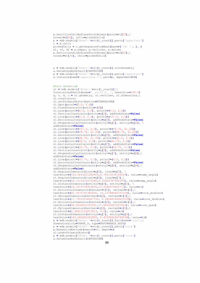
89
p.PartitionCellByPlanePointNormal(point=v1[20],\
normal=e[30], cells=pickedCells)
p = mdb.models['Model-'+str(i_count)].parts['upperface']
c = p.cells
pickedCells = c.getSequenceFromMask(mask=('[#1 ]', ), )
e1, v2, d2 = p.edges, p.vertices, p.datums
p.PartitionCellByPlanePointNormal(point=v2[20],\
normal=e1[34], cells=pickedCells)
a = mdb.models['Model-'+str(i_count)].rootAssembly
a.DatumCsysByDefault(CARTESIAN)
p = mdb.models['Model-'+str(i_count)].parts['upperface']
a.Instance(name='upperface-1', part=p, dependent=ON)
#Core Geometry#
s1 = mdb.models['Model-'+str(i_count)].\
ConstrainedSketch(name='__profile__', sheetSize=200.0)
g, v, d, c = s1.geometry, s1.vertices, s1.dimensions,\
s1.constraints
s1.setPrimaryObject(option=STANDALONE)
s1.Spot(point=(0.0, 0.0))
s1.FixedConstraint(entity=v[0])
s1.Line(point1=(0.0, 0.0), point2=(0.0, 2.5))
s1.VerticalConstraint(entity=g[2], addUndoState=False)
s1.Line(point1=(0.0, 2.5), point2=(-27.5, 2.5))
s1.HorizontalConstraint(entity=g[3], addUndoState=False)
s1.PerpendicularConstraint(entity1=g[2], entity2=g[3], \
addUndoState=False)
s1.Line(point1=(-27.5, 2.5), point2=(-8.75, 21.25))
s1.Line(point1=(-8.75, 21.25), point2=(48.75, 21.25))
s1.HorizontalConstraint(entity=g[5], addUndoState=False)
s1.Line(point1=(48.75, 21.25), point2=(62.5, 2.5))
s1.Line(point1=(62.5, 2.5), point2=(43.75, 2.5))
s1.HorizontalConstraint(entity=g[7], addUndoState=False)
s1.Line(point1=(43.75, 2.5), point2=(43.75, 0.0))
s1.VerticalConstraint(entity=g[8], addUndoState=False)
s1.PerpendicularConstraint(entity1=g[7], entity2=g[8],\
addUndoState=False)
s1.Line(point1=(43.75, 0.0), point2=(0.0, 0.0))
s1.HorizontalConstraint(entity=g[9], addUndoState=False)
s1.PerpendicularConstraint(entity1=g[8], entity2=g[9],\
addUndoState=False)
s1.AngularDimension(line1=g[4], line2=g[3], \
textPoint=(-15.9243221282959,6.78413534164429), value=ramp_angle)
s1.AngularDimension(line1=g[6], line2=g[7],\
textPoint=(56.1013412475586,6.55285787582397), value=ramp_angle)
s1.DistanceDimension(entity1=g[9], entity2=g[5], \
textPoint=(18.3919734954834,15.4184970855713), value=tc)
s1.HorizontalDimension(vertex1=v[7], vertex2=v[6],\
textPoint=(62.3476791381836, -3.23788666725159), value=core_doubler)
s1.ObliqueDimension(vertex1=v[2], vertex2=v[3],\
textPoint=(-7.75010108947754, 0.385461449623108), value=core_doubler)
s1.HorizontalDimension(vertex1=v[3], vertex2=v[6],\
textPoint=(58.9546051025391,-7.86343622207642), value=core_span)
s1.ObliqueDimension(vertex1=v[2], vertex2=v[0],\
textPoint=(2.99417114257813, 0.0), value=td)
s1.DistanceDimension(entity1=g[7], entity2=g[9],\
textPoint=(143.669281005859, 0.470926284790039), value=td)
p = mdb.models['Model-'+str(i_count)].Part(name='core',\
dimensionality=THREE_D, type=DEFORMABLE_BODY)
p = mdb.models['Model-'+str(i_count)].parts['core']
p.BaseSolidExtrude(sketch=s1, depth=b)
s1.unsetPrimaryObject()
p = mdb.models['Model-'+str(i_count)].parts['core']
a.DatumCsysByDefault(CARTESIAN)
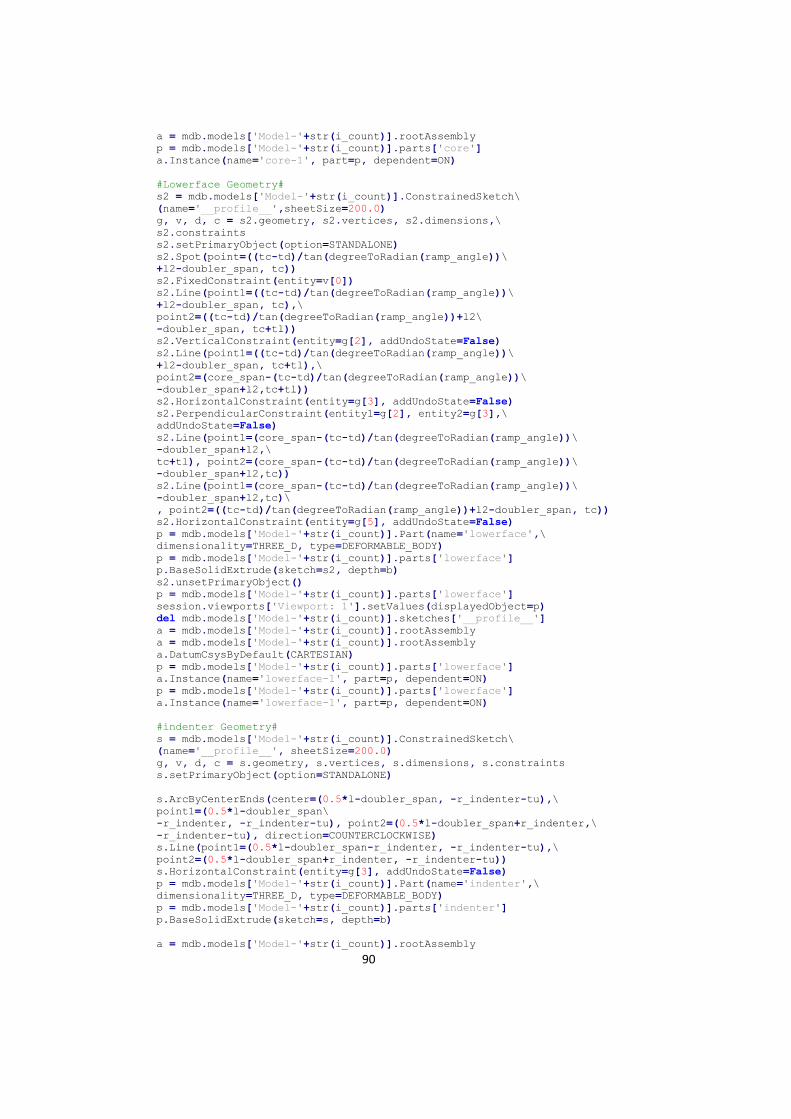
90
a = mdb.models['Model-'+str(i_count)].rootAssembly
p = mdb.models['Model-'+str(i_count)].parts['core']
a.Instance(name='core-1', part=p, dependent=ON)
#Lowerface Geometry#
s2 = mdb.models['Model-'+str(i_count)].ConstrainedSketch\
(name='__profile__',sheetSize=200.0)
g, v, d, c = s2.geometry, s2.vertices, s2.dimensions,\
s2.constraints
s2.setPrimaryObject(option=STANDALONE)
s2.Spot(point=((tc-td)/tan(degreeToRadian(ramp_angle))\
+l2-doubler_span, tc))
s2.FixedConstraint(entity=v[0])
s2.Line(point1=((tc-td)/tan(degreeToRadian(ramp_angle))\
+l2-doubler_span, tc),\
point2=((tc-td)/tan(degreeToRadian(ramp_angle))+l2\
-doubler_span, tc+tl))
s2.VerticalConstraint(entity=g[2], addUndoState=False)
s2.Line(point1=((tc-td)/tan(degreeToRadian(ramp_angle))\
+l2-doubler_span, tc+tl),\
point2=(core_span-(tc-td)/tan(degreeToRadian(ramp_angle))\
-doubler_span+l2,tc+tl))
s2.HorizontalConstraint(entity=g[3], addUndoState=False)
s2.PerpendicularConstraint(entity1=g[2], entity2=g[3],\
addUndoState=False)
s2.Line(point1=(core_span-(tc-td)/tan(degreeToRadian(ramp_angle))\
-doubler_span+l2,\
tc+tl), point2=(core_span-(tc-td)/tan(degreeToRadian(ramp_angle))\
-doubler_span+l2,tc))
s2.Line(point1=(core_span-(tc-td)/tan(degreeToRadian(ramp_angle))\
-doubler_span+l2,tc)\
, point2=((tc-td)/tan(degreeToRadian(ramp_angle))+l2-doubler_span, tc))
s2.HorizontalConstraint(entity=g[5], addUndoState=False)
p = mdb.models['Model-'+str(i_count)].Part(name='lowerface',\
dimensionality=THREE_D, type=DEFORMABLE_BODY)
p = mdb.models['Model-'+str(i_count)].parts['lowerface']
p.BaseSolidExtrude(sketch=s2, depth=b)
s2.unsetPrimaryObject()
p = mdb.models['Model-'+str(i_count)].parts['lowerface']
session.viewports['Viewport: 1'].setValues(displayedObject=p)
del mdb.models['Model-'+str(i_count)].sketches['__profile__']
a = mdb.models['Model-'+str(i_count)].rootAssembly
a = mdb.models['Model-'+str(i_count)].rootAssembly
a.DatumCsysByDefault(CARTESIAN)
p = mdb.models['Model-'+str(i_count)].parts['lowerface']
a.Instance(name='lowerface-1', part=p, dependent=ON)
p = mdb.models['Model-'+str(i_count)].parts['lowerface']
a.Instance(name='lowerface-1', part=p, dependent=ON)
#indenter Geometry#
s = mdb.models['Model-'+str(i_count)].ConstrainedSketch\
(name='__profile__', sheetSize=200.0)
g, v, d, c = s.geometry, s.vertices, s.dimensions, s.constraints
s.setPrimaryObject(option=STANDALONE)
s.ArcByCenterEnds(center=(0.5*l-doubler_span, -r_indenter-tu),\
point1=(0.5*l-doubler_span\
-r_indenter, -r_indenter-tu), point2=(0.5*l-doubler_span+r_indenter,\
-r_indenter-tu), direction=COUNTERCLOCKWISE)
s.Line(point1=(0.5*l-doubler_span-r_indenter, -r_indenter-tu),\
point2=(0.5*l-doubler_span+r_indenter, -r_indenter-tu))
s.HorizontalConstraint(entity=g[3], addUndoState=False)
p = mdb.models['Model-'+str(i_count)].Part(name='indenter',\
dimensionality=THREE_D, type=DEFORMABLE_BODY)
p = mdb.models['Model-'+str(i_count)].parts['indenter']
p.BaseSolidExtrude(sketch=s, depth=b)
a = mdb.models['Model-'+str(i_count)].rootAssembly
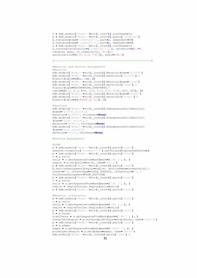
91
a = mdb.models['Model-'+str(i_count)].rootAssembly
p = mdb.models['Model-'+str(i_count)].parts['indenter']
a.Instance(name='indenter-1', part=p, dependent=ON)
a.Instance(name='indenter-1', part=p, dependent=ON)
a = mdb.models['Model-'+str(i_count)].rootAssembly
a.rotate(instanceList=('indenter-1', ), axisPoint=(0.5*l
-doubler_span, -r_indenter-tu, 70.0),\
axisDirection=(0.0, 0.0, -70.0), angle=180.0)
#-------------------------------------------------------------#
#Material and Section Assignments
#Material
mdb.models['Model-'+str(i_count)].Material(name='al2024')
mdb.models['Model-'+str(i_count)].materials['al2024'].\
Elastic(table=((Eu, vu), ))
mdb.models['Model-'+str(i_count)].Material(name='core')
mdb.models['Model-'+str(i_count)].materials['core'].\
Elastic(type=ENGINEERING_CONSTANTS,\
table=((0.1, 0.1, E33, 0.0, 0.0, 0.0, 0.01, G13, G23), ))
mdb.models['Model-'+str(i_count)].Material(name='steel')
mdb.models['Model-'+str(i_count)].materials['steel'].\
Elastic(table=((196000.0, 0.3), ))
#Sections
mdb.models['Model-'+str(i_count)].HomogeneousSolidSection\
(name='al2024_solid',\
material='al2024', thickness=None)
mdb.models['Model-'+str(i_count)].HomogeneousSolidSection\
(name='steel_solid', \
material='steel', thickness=None)
mdb.models['Model-'+str(i_count)].HomogeneousSolidSection\
(name='core_solid',\
material='core', thickness=None)
#Section Assignments
#CORE
p = mdb.models['Model-'+str(i_count)].parts['core']
session.viewports['Viewport: 1'].setValues(displayedObject=p)
p = mdb.models['Model-'+str(i_count)].parts['core']
c = p.cells
cells = c.getSequenceFromMask(mask=('[#1 ]', ), )
region = p.Set(cells=cells, name='Set-1')
p = mdb.models['Model-'+str(i_count)].parts['core']
p.SectionAssignment(region=region, sectionName=corematerial,\
offset=0.0, offsetType=MIDDLE_SURFACE, offsetField='', \
thicknessAssignment=FROM_SECTION)
p = mdb.models['Model-'+str(i_count)].parts['core']
c = p.cells
cells = c.getSequenceFromMask(mask=('[#1 ]', ), )
region = regionToolset.Region(cells=cells)
p = mdb.models['Model-'+str(i_count)].parts['core']
#Material orientation
p = mdb.models['Model-'+str(i_count)].parts['core']
c = p.cells
cells = c.getSequenceFromMask(mask=('[#1 ]', ), )
region = regionToolset.Region(cells=cells)
p = mdb.models['Model-'+str(i_count)].parts['core']
s = p.faces
side1Faces = s.getSequenceFromMask(mask=('[#8 ]', ), )
normalAxisRegion = p.Surface(side1Faces=side1Faces, name='Surf-2')
p = mdb.models['Model-'+str(i_count)].parts['core']
e = p.edges
edges = e.getSequenceFromMask(mask=('[#100 ]', ), )
primaryAxisRegion = p.Set(edges=edges, name='Set-4')
mdb.models['Model-'+str(i_count)].parts['core'].\
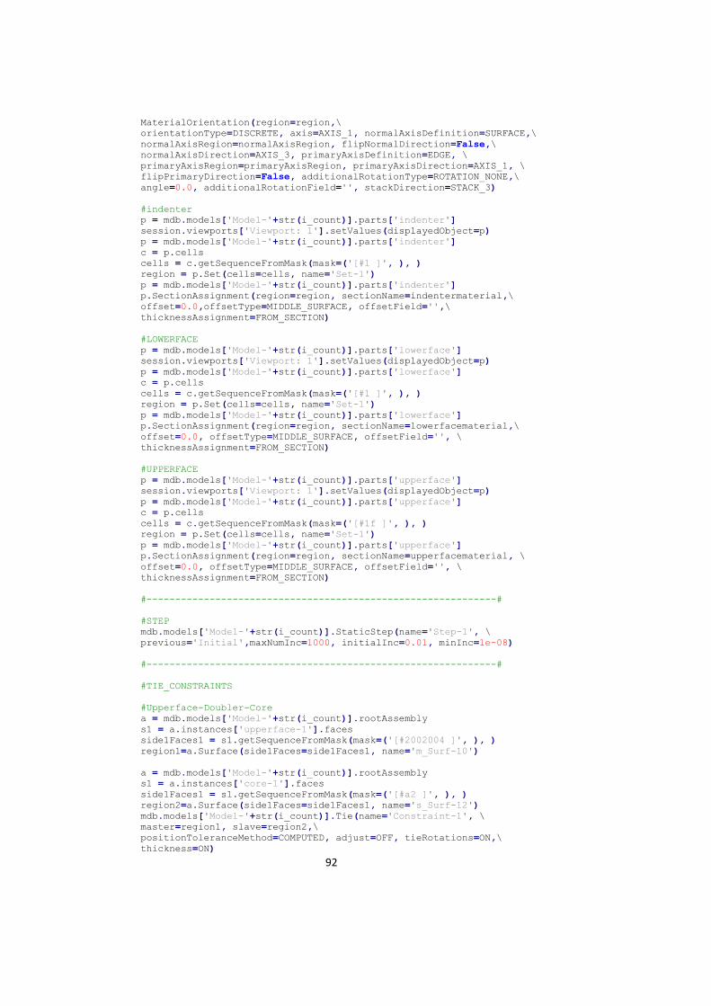
92
MaterialOrientation(region=region,\
orientationType=DISCRETE, axis=AXIS_1, normalAxisDefinition=SURFACE,\
normalAxisRegion=normalAxisRegion, flipNormalDirection=False,\
normalAxisDirection=AXIS_3, primaryAxisDefinition=EDGE, \
primaryAxisRegion=primaryAxisRegion, primaryAxisDirection=AXIS_1, \
flipPrimaryDirection=False, additionalRotationType=ROTATION_NONE,\
angle=0.0, additionalRotationField='', stackDirection=STACK_3)
#indenter
p = mdb.models['Model-'+str(i_count)].parts['indenter']
session.viewports['Viewport: 1'].setValues(displayedObject=p)
p = mdb.models['Model-'+str(i_count)].parts['indenter']
c = p.cells
cells = c.getSequenceFromMask(mask=('[#1 ]', ), )
region = p.Set(cells=cells, name='Set-1')
p = mdb.models['Model-'+str(i_count)].parts['indenter']
p.SectionAssignment(region=region, sectionName=indentermaterial,\
offset=0.0,offsetType=MIDDLE_SURFACE, offsetField='',\
thicknessAssignment=FROM_SECTION)
#LOWERFACE
p = mdb.models['Model-'+str(i_count)].parts['lowerface']
session.viewports['Viewport: 1'].setValues(displayedObject=p)
p = mdb.models['Model-'+str(i_count)].parts['lowerface']
c = p.cells
cells = c.getSequenceFromMask(mask=('[#1 ]', ), )
region = p.Set(cells=cells, name='Set-1')
p = mdb.models['Model-'+str(i_count)].parts['lowerface']
p.SectionAssignment(region=region, sectionName=lowerfacematerial,\
offset=0.0, offsetType=MIDDLE_SURFACE, offsetField='', \
thicknessAssignment=FROM_SECTION)
#UPPERFACE
p = mdb.models['Model-'+str(i_count)].parts['upperface']
session.viewports['Viewport: 1'].setValues(displayedObject=p)
p = mdb.models['Model-'+str(i_count)].parts['upperface']
c = p.cells
cells = c.getSequenceFromMask(mask=('[#1f ]', ), )
region = p.Set(cells=cells, name='Set-1')
p = mdb.models['Model-'+str(i_count)].parts['upperface']
p.SectionAssignment(region=region, sectionName=upperfacematerial, \
offset=0.0, offsetType=MIDDLE_SURFACE, offsetField='', \
thicknessAssignment=FROM_SECTION)
#-------------------------------------------------------------#
#STEP
mdb.models['Model-'+str(i_count)].StaticStep(name='Step-1', \
previous='Initial',maxNumInc=1000, initialInc=0.01, minInc=1e-08)
#-------------------------------------------------------------#
#TIE_CONSTRAINTS
#Upperface-Doubler-Core
a = mdb.models['Model-'+str(i_count)].rootAssembly
s1 = a.instances['upperface-1'].faces
side1Faces1 = s1.getSequenceFromMask(mask=('[#2002004 ]', ), )
region1=a.Surface(side1Faces=side1Faces1, name='m_Surf-10')
a = mdb.models['Model-'+str(i_count)].rootAssembly
s1 = a.instances['core-1'].faces
side1Faces1 = s1.getSequenceFromMask(mask=('[#a2 ]', ), )
region2=a.Surface(side1Faces=side1Faces1, name='s_Surf-12')
mdb.models['Model-'+str(i_count)].Tie(name='Constraint-1', \
master=region1, slave=region2,\
positionToleranceMethod=COMPUTED, adjust=OFF, tieRotations=ON,\
thickness=ON)
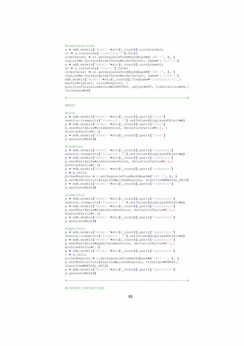
93
#Lowerface-Core
a = mdb.models['Model-'+str(i_count)].rootAssembly
s1 = a.instances['lowerface-1'].faces
side1Faces1 = s1.getSequenceFromMask(mask=('[#8 ]', ), )
region1=a.Surface(side1Faces=side1Faces1, name='m_Surf-3')
a = mdb.models['Model-'+str(i_count)].rootAssembly
s1 = a.instances['core-1'].faces
side1Faces1 = s1.getSequenceFromMask(mask=('[#8 ]', ), )
region2=a.Surface(side1Faces=side1Faces1, name='s_Surf-3')
mdb.models['Model-'+str(i_count)].Tie(name='Constraint-2',\
master=region1, slave=region2, \
positionToleranceMethod=COMPUTED, adjust=OFF, tieRotations=ON,\
thickness=ON)
#-------------------------------------------------------------#
#MESH
#core
p = mdb.models['Model-'+str(i_count)].parts['core']
session.viewports['Viewport: 1'].setValues(displayedObject=p)
p = mdb.models['Model-'+str(i_count)].parts['core']
p.seedPart(size=coremeshsize, deviationFactor=0.1, \
minSizeFactor=0.1)
p = mdb.models['Model-'+str(i_count)].parts['core']
p.generateMesh()
#indenter
p = mdb.models['Model-'+str(i_count)].parts['indenter']
session.viewports['Viewport: 1'].setValues(displayedObject=p)
p = mdb.models['Model-'+str(i_count)].parts['indenter']
p.seedPart(size=indentermeshsize, deviationFactor=0.1,\
minSizeFactor=0.1)
p = mdb.models['Model-'+str(i_count)].parts['indenter']
c = p.cells
pickedRegions = c.getSequenceFromMask(mask=('[#1 ]', ), )
p.setMeshControls(regions=pickedRegions, algorithm=MEDIAL_AXIS)
p = mdb.models['Model-'+str(i_count)].parts['indenter']
p.generateMesh()
#lowerface
p = mdb.models['Model-'+str(i_count)].parts['lowerface']
session.viewports['Viewport: 1'].setValues(displayedObject=p)
p = mdb.models['Model-'+str(i_count)].parts['lowerface']
p.seedPart(size=lowerfacemeshsize, deviationFactor=0.1,\
minSizeFactor=0.1)
p = mdb.models['Model-'+str(i_count)].parts['lowerface']
p.generateMesh()
#upperface
p = mdb.models['Model-'+str(i_count)].parts['upperface']
session.viewports['Viewport: 1'].setValues(displayedObject=p)
p = mdb.models['Model-'+str(i_count)].parts['upperface']
p.seedPart(size=upperfacemeshsize, deviationFactor=0.1,\
minSizeFactor=0.1)
p = mdb.models['Model-'+str(i_count)].parts['upperface']
c = p.cells
pickedRegions = c.getSequenceFromMask(mask=('[#1f ]', ), )
p.setMeshControls(regions=pickedRegions, technique=SWEEP,\
algorithm=MEDIAL_AXIS)
p = mdb.models['Model-'+str(i_count)].parts['upperface']
p.generateMesh()
#-------------------------------------------------------------#
#CONTACT_DEFINITIONS
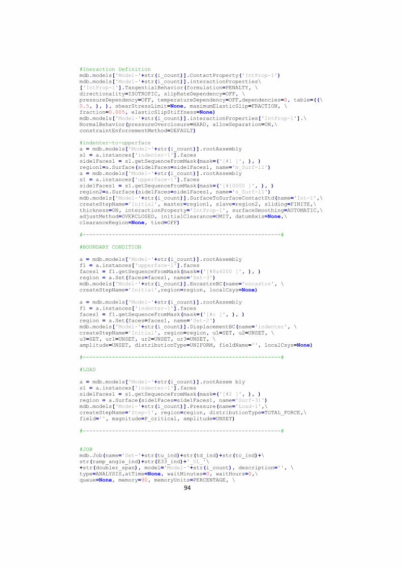
94
#Ineraction Definition
mdb.models['Model-'+str(i_count)].ContactProperty('IntProp-1')
mdb.models['Model-'+str(i_count)].interactionProperties\
['IntProp-1'].TangentialBehavior(formulation=PENALTY, \
directionality=ISOTROPIC, slipRateDependency=OFF, \
pressureDependency=OFF, temperatureDependency=OFF,dependencies=0, table=((\
0.5, ), ), shearStressLimit=None, maximumElasticSlip=FRACTION, \
fraction=0.005, elasticSlipStiffness=None)
mdb.models['Model-'+str(i_count)].interactionProperties['IntProp-1'].\
NormalBehavior(pressureOverclosure=HARD, allowSeparation=ON,\
constraintEnforcementMethod=DEFAULT)
#indenter-to-upperface
a = mdb.models['Model-'+str(i_count)].rootAssembly
s1 = a.instances['indenter-1'].faces
side1Faces1 = s1.getSequenceFromMask(mask=('[#1 ]', ), )
region1=a.Surface(side1Faces=side1Faces1, name='m_Surf-11')
a = mdb.models['Model-'+str(i_count)].rootAssembly
s1 = a.instances['upperface-1'].faces
side1Faces1 = s1.getSequenceFromMask(mask=('[#10000 ]', ), )
region2=a.Surface(side1Faces=side1Faces1, name='s_Surf-11')
mdb.models['Model-'+str(i_count)].SurfaceToSurfaceContactStd(name='Int-1',\
createStepName='Initial', master=region1, slave=region2, sliding=FINITE,\
thickness=ON, interactionProperty='IntProp-1', surfaceSmoothing=AUTOMATIC,\
adjustMethod=OVERCLOSED, initialClearance=OMIT, datumAxis=None,\
clearanceRegion=None, tied=OFF)
#-------------------------------------------------------------#
#BOUNDARY CONDITION
a = mdb.models['Model-'+str(i_count)].rootAssembly
f1 = a.instances['upperface-1'].faces
faces1 = f1.getSequenceFromMask(mask=('[#8a4000 ]', ), )
region = a.Set(faces=faces1, name='Set-3')
mdb.models['Model-'+str(i_count)].EncastreBC(name='encastre', \
createStepName='Initial',region=region, localCsys=None)
a = mdb.models['Model-'+str(i_count)].rootAssembly
f1 = a.instances['indenter-1'].faces
faces1 = f1.getSequenceFromMask(mask=('[#c ]', ), )
region = a.Set(faces=faces1, name='Set-2')
mdb.models['Model-'+str(i_count)].DisplacementBC(name='indenter', \
createStepName='Initial', region=region, u1=SET, u2=UNSET, \
u3=SET, ur1=UNSET, ur2=UNSET, ur3=UNSET, \
amplitude=UNSET, distributionType=UNIFORM, fieldName='', localCsys=None)
#-------------------------------------------------------------#
#LOAD
a = mdb.models['Model-'+str(i_count)].rootAssem bly
s1 = a.instances['indenter-1'].faces
side1Faces1 = s1.getSequenceFromMask(mask=('[#2 ]', ), )
region = a.Surface(side1Faces=side1Faces1, name='Surf-31')
mdb.models['Model-'+str(i_count)].Pressure(name='Load-1',\
createStepName='Step-1', region=region, distributionType=TOTAL_FORCE,\
field='', magnitude=P_critical, amplitude=UNSET)
#-------------------------------------------------------------#
#JOB
mdb.Job(name='Set-'+str(tu_ind)+str(td_ind)+str(tc_ind)+\
str(ramp_angle_ind)+str(E33_ind)+'_UL_'\
+str(doubler_span), model='Model-'+str(i_count), description='', \
type=ANALYSIS,atTime=None, waitMinutes=0, waitHours=0,\
queue=None, memory=90, memoryUnits=PERCENTAGE, \
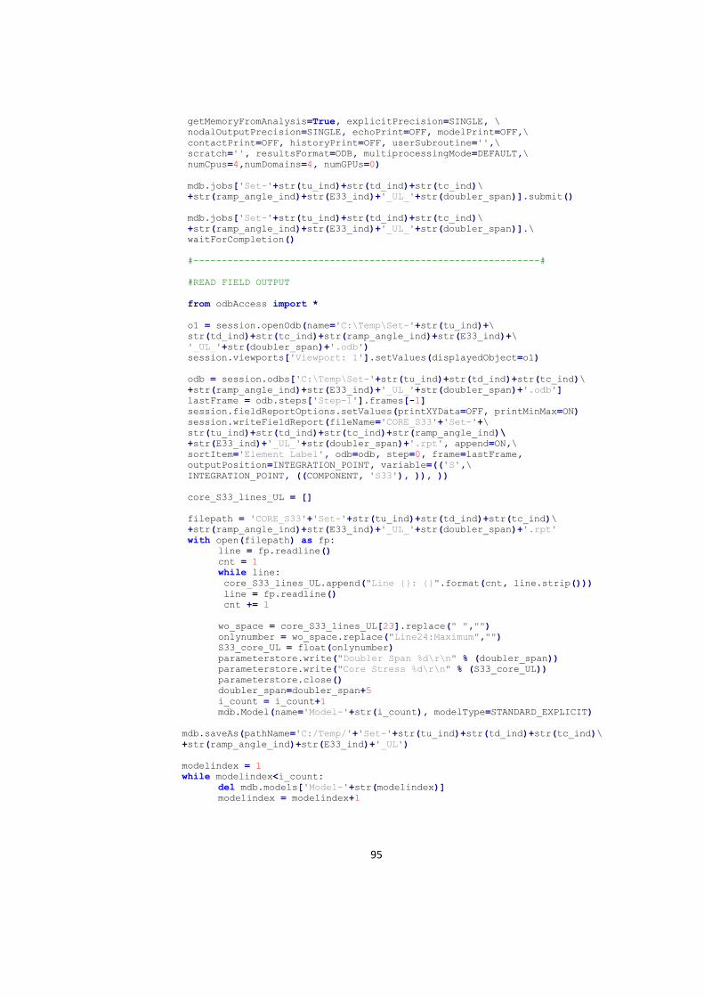
95
getMemoryFromAnalysis=True, explicitPrecision=SINGLE, \
nodalOutputPrecision=SINGLE, echoPrint=OFF, modelPrint=OFF,\
contactPrint=OFF, historyPrint=OFF, userSubroutine='',\
scratch='', resultsFormat=ODB, multiprocessingMode=DEFAULT,\
numCpus=4,numDomains=4, numGPUs=0)
mdb.jobs['Set-'+str(tu_ind)+str(td_ind)+str(tc_ind)\
+str(ramp_angle_ind)+str(E33_ind)+'_UL_'+str(doubler_span)].submit()
mdb.jobs['Set-'+str(tu_ind)+str(td_ind)+str(tc_ind)\
+str(ramp_angle_ind)+str(E33_ind)+'_UL_'+str(doubler_span)].\
waitForCompletion()
#-------------------------------------------------------------#
#READ FIELD OUTPUT
from odbAccess import *
o1 = session.openOdb(name='C:\Temp\Set-'+str(tu_ind)+\
str(td_ind)+str(tc_ind)+str(ramp_angle_ind)+str(E33_ind)+\
'_UL_'+str(doubler_span)+'.odb')
session.viewports['Viewport: 1'].setValues(displayedObject=o1)
odb = session.odbs['C:\Temp\Set-'+str(tu_ind)+str(td_ind)+str(tc_ind)\
+str(ramp_angle_ind)+str(E33_ind)+'_UL_'+str(doubler_span)+'.odb']
lastFrame = odb.steps['Step-1'].frames[-1]
session.fieldReportOptions.setValues(printXYData=OFF, printMinMax=ON)
session.writeFieldReport(fileName='CORE_S33'+'Set-'+\
str(tu_ind)+str(td_ind)+str(tc_ind)+str(ramp_angle_ind)\
+str(E33_ind)+'_UL_'+str(doubler_span)+'.rpt', append=ON,\
sortItem='Element Label', odb=odb, step=0, frame=lastFrame,
outputPosition=INTEGRATION_POINT, variable=(('S',\
INTEGRATION_POINT, ((COMPONENT, 'S33'), )), ))
core_S33_lines_UL = []
filepath = 'CORE_S33'+'Set-'+str(tu_ind)+str(td_ind)+str(tc_ind)\
+str(ramp_angle_ind)+str(E33_ind)+'_UL_'+str(doubler_span)+'.rpt'
with open(filepath) as fp:
line = fp.readline()
cnt = 1
while line:
core_S33_lines_UL.append("Line {}: {}".format(cnt, line.strip()))
line = fp.readline()
cnt += 1
wo_space = core_S33_lines_UL[23].replace(" ","")
onlynumber = wo_space.replace("Line24:Maximum","")
S33_core_UL = float(onlynumber)
parameterstore.write("Doubler Span %d\r\n" % (doubler_span))
parameterstore.write("Core Stress %d\r\n" % (S33_core_UL))
parameterstore.close()
doubler_span=doubler_span+5
i_count = i_count+1
mdb.Model(name='Model-'+str(i_count), modelType=STANDARD_EXPLICIT)
mdb.saveAs(pathName='C:/Temp/'+'Set-'+str(tu_ind)+str(td_ind)+str(tc_ind)\
+str(ramp_angle_ind)+str(E33_ind)+'_UL')
modelindex = 1
while modelindex<i_count:
del mdb.models['Model-'+str(modelindex)]
modelindex = modelindex+1

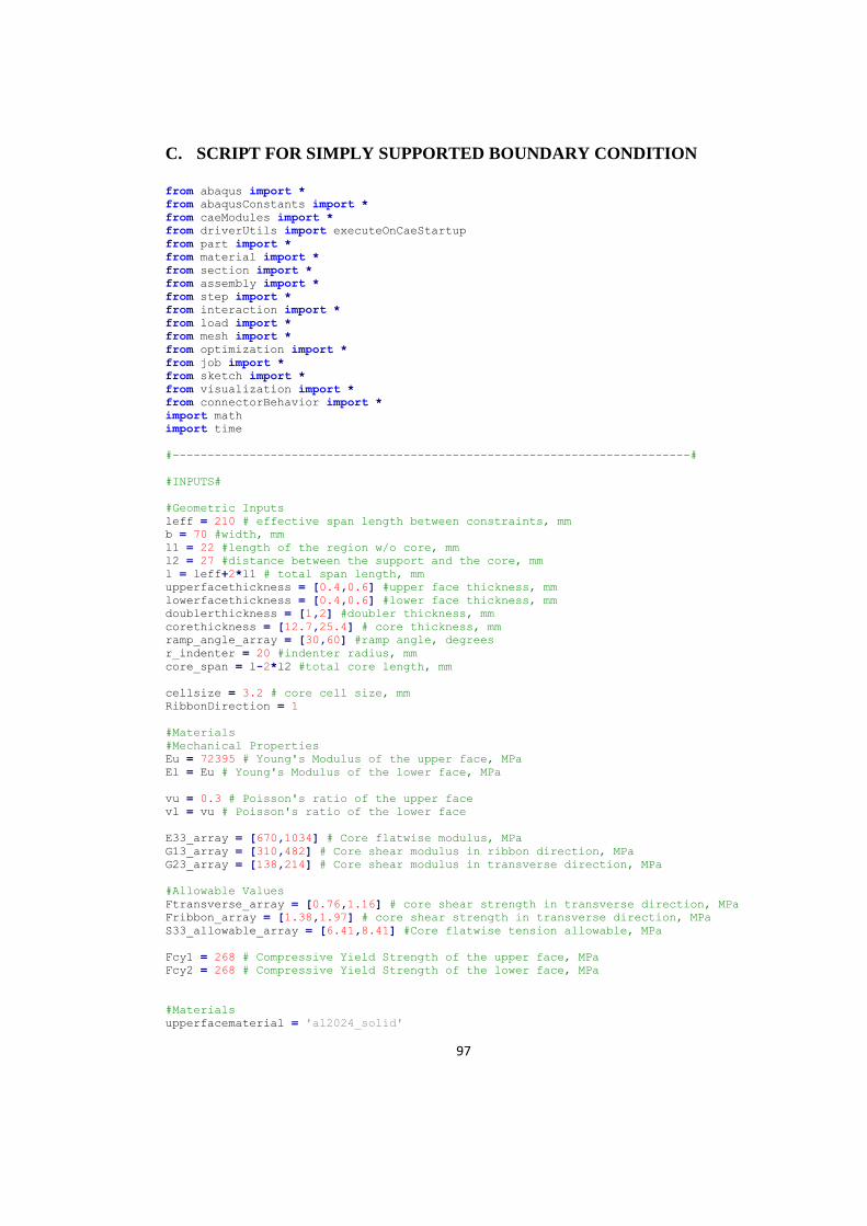
97
C. SCRIPT FOR SIMPLY SUPPORTED BOUNDARY CONDITION
from abaqus import *
from abaqusConstants import *
from caeModules import *
from driverUtils import executeOnCaeStartup
from part import *
from material import *
from section import *
from assembly import *
from step import *
from interaction import *
from load import *
from mesh import *
from optimization import *
from job import *
from sketch import *
from visualization import *
from connectorBehavior import *
import math
import time
#--------------------------------------------------------------------------#
#INPUTS#
#Geometric Inputs
leff = 210 # effective span length between constraints, mm
b = 70 #width, mm
l1 = 22 #length of the region w/o core, mm
l2 = 27 #distance between the support and the core, mm
l = leff+2*l1 # total span length, mm
upperfacethickness = [0.4,0.6] #upper face thickness, mm
lowerfacethickness = [0.4,0.6] #lower face thickness, mm
doublerthickness = [1,2] #doubler thickness, mm
corethickness = [12.7,25.4] # core thickness, mm
ramp_angle_array = [30,60] #ramp angle, degrees
r_indenter = 20 #indenter radius, mm
core_span = l-2*l2 #total core length, mm
cellsize = 3.2 # core cell size, mm
RibbonDirection = 1
#Materials
#Mechanical Properties
Eu = 72395 # Young's Modulus of the upper face, MPa
El = Eu # Young's Modulus of the lower face, MPa
vu = 0.3 # Poisson's ratio of the upper face
vl = vu # Poisson's ratio of the lower face
E33_array = [670,1034] # Core flatwise modulus, MPa
G13_array = [310,482] # Core shear modulus in ribbon direction, MPa
G23_array = [138,214] # Core shear modulus in transverse direction, MPa
#Allowable Values
Ftransverse_array = [0.76,1.16] # core shear strength in transverse direction, MPa
Fribbon_array = [1.38,1.97] # core shear strength in transverse direction, MPa
S33_allowable_array = [6.41,8.41] #Core flatwise tension allowable, MPa
Fcy1 = 268 # Compressive Yield Strength of the upper face, MPa
Fcy2 = 268 # Compressive Yield Strength of the lower face, MPa
#Materials
upperfacematerial = 'al2024_solid'
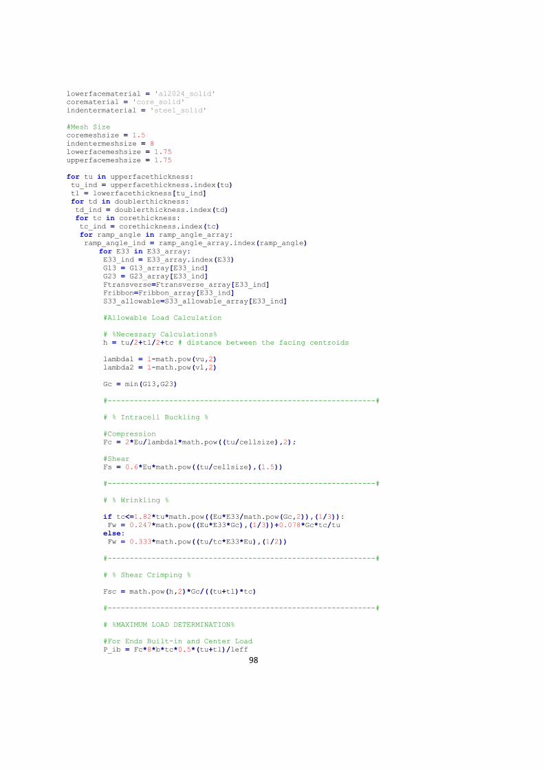
98
lowerfacematerial = 'al2024_solid'
corematerial = 'core_solid'
indentermaterial = 'steel_solid'
#Mesh Size
coremeshsize = 1.5
indentermeshsize = 8
lowerfacemeshsize = 1.75
upperfacemeshsize = 1.75
for tu in upperfacethickness:
tu_ind = upperfacethickness.index(tu)
tl = lowerfacethickness[tu_ind]
for td in doublerthickness:
td_ind = doublerthickness.index(td)
for tc in corethickness:
tc_ind = corethickness.index(tc)
for ramp_angle in ramp_angle_array:
ramp_angle_ind = ramp_angle_array.index(ramp_angle)
for E33 in E33_array:
E33_ind = E33_array.index(E33)
G13 = G13_array[E33_ind]
G23 = G23_array[E33_ind]
Ftransverse=Ftransverse_array[E33_ind]
Fribbon=Fribbon_array[E33_ind]
S33_allowable=S33_allowable_array[E33_ind]
#Allowable Load Calculation
# %Necessary Calculations%
h = tu/2+tl/2+tc # distance between the facing centroids
lambda1 = 1-math.pow(vu,2)
lambda2 = 1-math.pow(vl,2)
Gc = min(G13,G23)
#-------------------------------------------------------------#
# % Intracell Buckling %
#Compression
Fc = 2*Eu/lambda1*math.pow((tu/cellsize),2);
#Shear
Fs = 0.6*Eu*math.pow((tu/cellsize),(1.5))
#-------------------------------------------------------------#
# % Wrinkling %
if tc<=1.82*tu*math.pow((Eu*E33/math.pow(Gc,2)),(1/3)):
Fw = 0.247*math.pow((Eu*E33*Gc),(1/3))+0.078*Gc*tc/tu
else:
Fw = 0.333*math.pow((tu/tc*E33*Eu),(1/2))
#-------------------------------------------------------------#
# % Shear Crimping %
Fsc = math.pow(h,2)*Gc/((tu+tl)*tc)
#-------------------------------------------------------------#
# %MAXIMUM LOAD DETERMINATION%
#For Ends Built-in and Center Load
P_ib = Fc*8*b*tc*0.5*(tu+tl)/leff
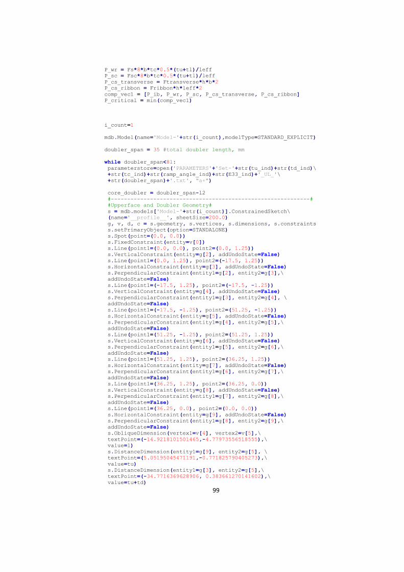
99
P_wr = Fs*8*b*tc*0.5*(tu+tl)/leff
P_sc = Fsc*8*b*tc*0.5*(tu+tl)/leff
P_cs_transverse = Ftransverse*h*b*2
P_cs_ribbon = Fribbon*h*leff*2
comp_vec1 = [P_ib, P_wr, P_sc, P_cs_transverse, P_cs_ribbon]
P_critical = min(comp_vec1)
i_count=1
mdb.Model(name='Model-'+str(i_count),modelType=STANDARD_EXPLICIT)
doubler_span = 35 #total doubler length, mm
while doubler_span<81:
parameterstore=open('PARAMETERS'+'Set-'+str(tu_ind)+str(td_ind)\
+str(tc_ind)+str(ramp_angle_ind)+str(E33_ind)+'_UL_'\
+str(doubler_span)+'.txt', "a+")
core_doubler = doubler_span-l2
#-------------------------------------------------------------#
#Upperface and Doubler Geometry#
s = mdb.models['Model-'+str(i_count)].ConstrainedSketch\
(name='__profile__', sheetSize=200.0)
g, v, d, c = s.geometry, s.vertices, s.dimensions, s.constraints
s.setPrimaryObject(option=STANDALONE)
s.Spot(point=(0.0, 0.0))
s.FixedConstraint(entity=v[0])
s.Line(point1=(0.0, 0.0), point2=(0.0, 1.25))
s.VerticalConstraint(entity=g[2], addUndoState=False)
s.Line(point1=(0.0, 1.25), point2=(-17.5, 1.25))
s.HorizontalConstraint(entity=g[3], addUndoState=False)
s.PerpendicularConstraint(entity1=g[2], entity2=g[3],\
addUndoState=False)
s.Line(point1=(-17.5, 1.25), point2=(-17.5, -1.25))
s.VerticalConstraint(entity=g[4], addUndoState=False)
s.PerpendicularConstraint(entity1=g[3], entity2=g[4], \
addUndoState=False)
s.Line(point1=(-17.5, -1.25), point2=(51.25, -1.25))
s.HorizontalConstraint(entity=g[5], addUndoState=False)
s.PerpendicularConstraint(entity1=g[4], entity2=g[5],\
addUndoState=False)
s.Line(point1=(51.25, -1.25), point2=(51.25, 1.25))
s.VerticalConstraint(entity=g[6], addUndoState=False)
s.PerpendicularConstraint(entity1=g[5], entity2=g[6],\
addUndoState=False)
s.Line(point1=(51.25, 1.25), point2=(36.25, 1.25))
s.HorizontalConstraint(entity=g[7], addUndoState=False)
s.PerpendicularConstraint(entity1=g[6], entity2=g[7],\
addUndoState=False)
s.Line(point1=(36.25, 1.25), point2=(36.25, 0.0))
s.VerticalConstraint(entity=g[8], addUndoState=False)
s.PerpendicularConstraint(entity1=g[7], entity2=g[8],\
addUndoState=False)
s.Line(point1=(36.25, 0.0), point2=(0.0, 0.0))
s.HorizontalConstraint(entity=g[9], addUndoState=False)
s.PerpendicularConstraint(entity1=g[8], entity2=g[9],\
addUndoState=False)
s.ObliqueDimension(vertex1=v[4], vertex2=v[5],\
textPoint=(-14.9218101501465,-4.77973556518555),\
value=l)
s.DistanceDimension(entity1=g[9], entity2=g[5], \
textPoint=(5.05195045471191,-0.771825790405273),\
value=tu)
s.DistanceDimension(entity1=g[3], entity2=g[5],\
textPoint=(-34.7716369628906, 0.383661270141602),\
value=tu+td)
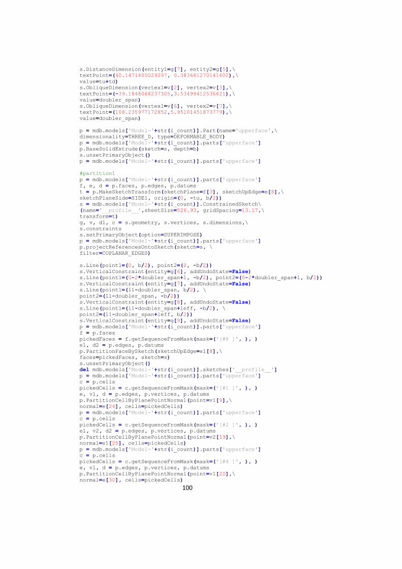
100
s.DistanceDimension(entity1=g[7], entity2=g[5],\
textPoint=(40.1471405029297, 0.383661270141602),\
value=tu+td)
s.ObliqueDimension(vertex1=v[2], vertex2=v[3],\
textPoint=(-39.1848068237305,3.53499412536621),\
value=doubler_span)
s.ObliqueDimension(vertex1=v[6], vertex2=v[7],\
textPoint=(108.235977172852,5.95101451873779),\
value=doubler_span)
p = mdb.models['Model-'+str(i_count)].Part(name='upperface',\
dimensionality=THREE_D, type=DEFORMABLE_BODY)
p = mdb.models['Model-'+str(i_count)].parts['upperface']
p.BaseSolidExtrude(sketch=s, depth=b)
s.unsetPrimaryObject()
p = mdb.models['Model-'+str(i_count)].parts['upperface']
#partition1
p = mdb.models['Model-'+str(i_count)].parts['upperface']
f, e, d = p.faces, p.edges, p.datums
t = p.MakeSketchTransform(sketchPlane=f[3], sketchUpEdge=e[8],\
sketchPlaneSide=SIDE1, origin=(0, -tu, b/2))
s = mdb.models['Model-'+str(i_count)].ConstrainedSketch\
(name='__profile__',sheetSize=526.93, gridSpacing=13.17,\
transform=t)
g, v, d1, c = s.geometry, s.vertices, s.dimensions,\
s.constraints
s.setPrimaryObject(option=SUPERIMPOSE)
p = mdb.models['Model-'+str(i_count)].parts['upperface']
p.projectReferencesOntoSketch(sketch=s, \
filter=COPLANAR_EDGES)
s.Line(point1=(0, b/2), point2=(0, -b/2))
s.VerticalConstraint(entity=g[6], addUndoState=False)
s.Line(point1=(0-2*doubler_span+l, -b/2), point2=(0-2*doubler_span+l, b/2))
s.VerticalConstraint(entity=g[7], addUndoState=False)
s.Line(point1=(l1-doubler_span, b/2), \
point2=(l1-doubler_span, -b/2))
s.VerticalConstraint(entity=g[8], addUndoState=False)
s.Line(point1=(l1-doubler_span+leff, -b/2), \
point2=(l1-doubler_span+leff, b/2))
s.VerticalConstraint(entity=g[9], addUndoState=False)
p = mdb.models['Model-'+str(i_count)].parts['upperface']
f = p.faces
pickedFaces = f.getSequenceFromMask(mask=('[#8 ]', ), )
e1, d2 = p.edges, p.datums
p.PartitionFaceBySketch(sketchUpEdge=e1[8],\
faces=pickedFaces, sketch=s)
s.unsetPrimaryObject()
del mdb.models['Model-'+str(i_count)].sketches['__profile__']
p = mdb.models['Model-'+str(i_count)].parts['upperface']
c = p.cells
pickedCells = c.getSequenceFromMask(mask=('[#1 ]', ), )
e, v1, d = p.edges, p.vertices, p.datums
p.PartitionCellByPlanePointNormal(point=v1[9],\
normal=e[24], cells=pickedCells)
p = mdb.models['Model-'+str(i_count)].parts['upperface']
c = p.cells
pickedCells = c.getSequenceFromMask(mask=('[#2 ]', ), )
e1, v2, d2 = p.edges, p.vertices, p.datums
p.PartitionCellByPlanePointNormal(point=v2[19],\
normal=e1[25], cells=pickedCells)
p = mdb.models['Model-'+str(i_count)].parts['upperface']
c = p.cells
pickedCells = c.getSequenceFromMask(mask=('[#4 ]', ), )
e, v1, d = p.edges, p.vertices, p.datums
p.PartitionCellByPlanePointNormal(point=v1[20],\
normal=e[30], cells=pickedCells)
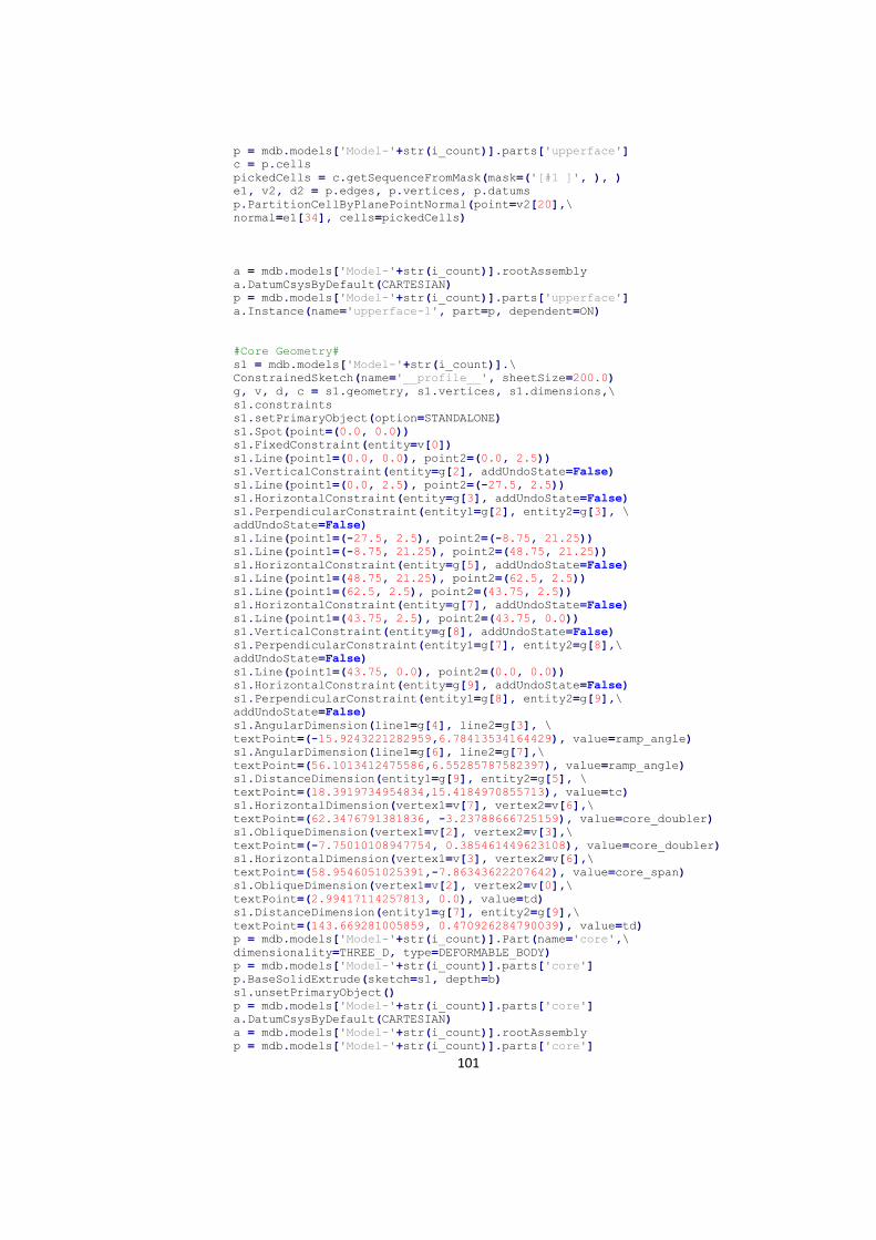
101
p = mdb.models['Model-'+str(i_count)].parts['upperface']
c = p.cells
pickedCells = c.getSequenceFromMask(mask=('[#1 ]', ), )
e1, v2, d2 = p.edges, p.vertices, p.datums
p.PartitionCellByPlanePointNormal(point=v2[20],\
normal=e1[34], cells=pickedCells)
a = mdb.models['Model-'+str(i_count)].rootAssembly
a.DatumCsysByDefault(CARTESIAN)
p = mdb.models['Model-'+str(i_count)].parts['upperface']
a.Instance(name='upperface-1', part=p, dependent=ON)
#Core Geometry#
s1 = mdb.models['Model-'+str(i_count)].\
ConstrainedSketch(name='__profile__', sheetSize=200.0)
g, v, d, c = s1.geometry, s1.vertices, s1.dimensions,\
s1.constraints
s1.setPrimaryObject(option=STANDALONE)
s1.Spot(point=(0.0, 0.0))
s1.FixedConstraint(entity=v[0])
s1.Line(point1=(0.0, 0.0), point2=(0.0, 2.5))
s1.VerticalConstraint(entity=g[2], addUndoState=False)
s1.Line(point1=(0.0, 2.5), point2=(-27.5, 2.5))
s1.HorizontalConstraint(entity=g[3], addUndoState=False)
s1.PerpendicularConstraint(entity1=g[2], entity2=g[3], \
addUndoState=False)
s1.Line(point1=(-27.5, 2.5), point2=(-8.75, 21.25))
s1.Line(point1=(-8.75, 21.25), point2=(48.75, 21.25))
s1.HorizontalConstraint(entity=g[5], addUndoState=False)
s1.Line(point1=(48.75, 21.25), point2=(62.5, 2.5))
s1.Line(point1=(62.5, 2.5), point2=(43.75, 2.5))
s1.HorizontalConstraint(entity=g[7], addUndoState=False)
s1.Line(point1=(43.75, 2.5), point2=(43.75, 0.0))
s1.VerticalConstraint(entity=g[8], addUndoState=False)
s1.PerpendicularConstraint(entity1=g[7], entity2=g[8],\
addUndoState=False)
s1.Line(point1=(43.75, 0.0), point2=(0.0, 0.0))
s1.HorizontalConstraint(entity=g[9], addUndoState=False)
s1.PerpendicularConstraint(entity1=g[8], entity2=g[9],\
addUndoState=False)
s1.AngularDimension(line1=g[4], line2=g[3], \
textPoint=(-15.9243221282959,6.78413534164429), value=ramp_angle)
s1.AngularDimension(line1=g[6], line2=g[7],\
textPoint=(56.1013412475586,6.55285787582397), value=ramp_angle)
s1.DistanceDimension(entity1=g[9], entity2=g[5], \
textPoint=(18.3919734954834,15.4184970855713), value=tc)
s1.HorizontalDimension(vertex1=v[7], vertex2=v[6],\
textPoint=(62.3476791381836, -3.23788666725159), value=core_doubler)
s1.ObliqueDimension(vertex1=v[2], vertex2=v[3],\
textPoint=(-7.75010108947754, 0.385461449623108), value=core_doubler)
s1.HorizontalDimension(vertex1=v[3], vertex2=v[6],\
textPoint=(58.9546051025391,-7.86343622207642), value=core_span)
s1.ObliqueDimension(vertex1=v[2], vertex2=v[0],\
textPoint=(2.99417114257813, 0.0), value=td)
s1.DistanceDimension(entity1=g[7], entity2=g[9],\
textPoint=(143.669281005859, 0.470926284790039), value=td)
p = mdb.models['Model-'+str(i_count)].Part(name='core',\
dimensionality=THREE_D, type=DEFORMABLE_BODY)
p = mdb.models['Model-'+str(i_count)].parts['core']
p.BaseSolidExtrude(sketch=s1, depth=b)
s1.unsetPrimaryObject()
p = mdb.models['Model-'+str(i_count)].parts['core']
a.DatumCsysByDefault(CARTESIAN)
a = mdb.models['Model-'+str(i_count)].rootAssembly
p = mdb.models['Model-'+str(i_count)].parts['core']
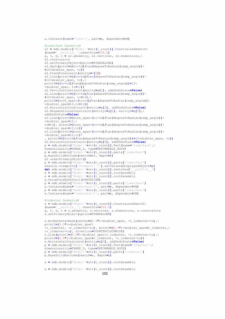
102
a.Instance(name='core-1', part=p, dependent=ON)
#Lowerface Geometry#
s2 = mdb.models['Model-'+str(i_count)].ConstrainedSketch\
(name='__profile__',sheetSize=200.0)
g, v, d, c = s2.geometry, s2.vertices, s2.dimensions,\
s2.constraints
s2.setPrimaryObject(option=STANDALONE)
s2.Spot(point=((tc-td)/tan(degreeToRadian(ramp_angle))\
+l2-doubler_span, tc))
s2.FixedConstraint(entity=v[0])
s2.Line(point1=((tc-td)/tan(degreeToRadian(ramp_angle))\
+l2-doubler_span, tc),\
point2=((tc-td)/tan(degreeToRadian(ramp_angle))+l2\
-doubler_span, tc+tl))
s2.VerticalConstraint(entity=g[2], addUndoState=False)
s2.Line(point1=((tc-td)/tan(degreeToRadian(ramp_angle))\
+l2-doubler_span, tc+tl),\
point2=(core_span-(tc-td)/tan(degreeToRadian(ramp_angle))\
-doubler_span+l2,tc+tl))
s2.HorizontalConstraint(entity=g[3], addUndoState=False)
s2.PerpendicularConstraint(entity1=g[2], entity2=g[3],\
addUndoState=False)
s2.Line(point1=(core_span-(tc-td)/tan(degreeToRadian(ramp_angle))\
-doubler_span+l2,\
tc+tl), point2=(core_span-(tc-td)/tan(degreeToRadian(ramp_angle))\
-doubler_span+l2,tc))
s2.Line(point1=(core_span-(tc-td)/tan(degreeToRadian(ramp_angle))\
-doubler_span+l2,tc)\
, point2=((tc-td)/tan(degreeToRadian(ramp_angle))+l2-doubler_span, tc))
s2.HorizontalConstraint(entity=g[5], addUndoState=False)
p = mdb.models['Model-'+str(i_count)].Part(name='lowerface',\
dimensionality=THREE_D, type=DEFORMABLE_BODY)
p = mdb.models['Model-'+str(i_count)].parts['lowerface']
p.BaseSolidExtrude(sketch=s2, depth=b)
s2.unsetPrimaryObject()
p = mdb.models['Model-'+str(i_count)].parts['lowerface']
session.viewports['Viewport: 1'].setValues(displayedObject=p)
del mdb.models['Model-'+str(i_count)].sketches['__profile__']
a = mdb.models['Model-'+str(i_count)].rootAssembly
a = mdb.models['Model-'+str(i_count)].rootAssembly
a.DatumCsysByDefault(CARTESIAN)
p = mdb.models['Model-'+str(i_count)].parts['lowerface']
a.Instance(name='lowerface-1', part=p, dependent=ON)
p = mdb.models['Model-'+str(i_count)].parts['lowerface']
a.Instance(name='lowerface-1', part=p, dependent=ON)
#indenter Geometry#
s = mdb.models['Model-'+str(i_count)].ConstrainedSketch\
(name='__profile__', sheetSize=200.0)
g, v, d, c = s.geometry, s.vertices, s.dimensions, s.constraints
s.setPrimaryObject(option=STANDALONE)
s.ArcByCenterEnds(center=(0.5*l-doubler_span, -r_indenter-tu),\
point1=(0.5*l-doubler_span\
-r_indenter, -r_indenter-tu), point2=(0.5*l-doubler_span+r_indenter,\
-r_indenter-tu), direction=COUNTERCLOCKWISE)
s.Line(point1=(0.5*l-doubler_span-r_indenter, -r_indenter-tu),\
point2=(0.5*l-doubler_span+r_indenter, -r_indenter-tu))
s.HorizontalConstraint(entity=g[3], addUndoState=False)
p = mdb.models['Model-'+str(i_count)].Part(name='indenter',\
dimensionality=THREE_D, type=DEFORMABLE_BODY)
p = mdb.models['Model-'+str(i_count)].parts['indenter']
p.BaseSolidExtrude(sketch=s, depth=b)
a = mdb.models['Model-'+str(i_count)].rootAssembly
a = mdb.models['Model-'+str(i_count)].rootAssembly
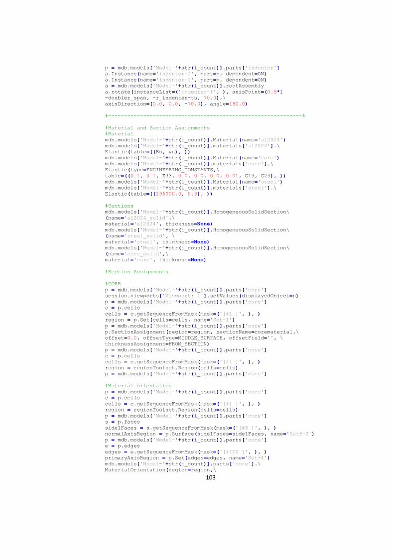
103
p = mdb.models['Model-'+str(i_count)].parts['indenter']
a.Instance(name='indenter-1', part=p, dependent=ON)
a.Instance(name='indenter-1', part=p, dependent=ON)
a = mdb.models['Model-'+str(i_count)].rootAssembly
a.rotate(instanceList=('indenter-1', ), axisPoint=(0.5*l
-doubler_span, -r_indenter-tu, 70.0),\
axisDirection=(0.0, 0.0, -70.0), angle=180.0)
#-------------------------------------------------------------#
#Material and Section Assignments
#Material
mdb.models['Model-'+str(i_count)].Material(name='al2024')
mdb.models['Model-'+str(i_count)].materials['al2024'].\
Elastic(table=((Eu, vu), ))
mdb.models['Model-'+str(i_count)].Material(name='core')
mdb.models['Model-'+str(i_count)].materials['core'].\
Elastic(type=ENGINEERING_CONSTANTS,\
table=((0.1, 0.1, E33, 0.0, 0.0, 0.0, 0.01, G13, G23), ))
mdb.models['Model-'+str(i_count)].Material(name='steel')
mdb.models['Model-'+str(i_count)].materials['steel'].\
Elastic(table=((196000.0, 0.3), ))
#Sections
mdb.models['Model-'+str(i_count)].HomogeneousSolidSection\
(name='al2024_solid',\
material='al2024', thickness=None)
mdb.models['Model-'+str(i_count)].HomogeneousSolidSection\
(name='steel_solid', \
material='steel', thickness=None)
mdb.models['Model-'+str(i_count)].HomogeneousSolidSection\
(name='core_solid',\
material='core', thickness=None)
#Section Assignments
#CORE
p = mdb.models['Model-'+str(i_count)].parts['core']
session.viewports['Viewport: 1'].setValues(displayedObject=p)
p = mdb.models['Model-'+str(i_count)].parts['core']
c = p.cells
cells = c.getSequenceFromMask(mask=('[#1 ]', ), )
region = p.Set(cells=cells, name='Set-1')
p = mdb.models['Model-'+str(i_count)].parts['core']
p.SectionAssignment(region=region, sectionName=corematerial,\
offset=0.0, offsetType=MIDDLE_SURFACE, offsetField='', \
thicknessAssignment=FROM_SECTION)
p = mdb.models['Model-'+str(i_count)].parts['core']
c = p.cells
cells = c.getSequenceFromMask(mask=('[#1 ]', ), )
region = regionToolset.Region(cells=cells)
p = mdb.models['Model-'+str(i_count)].parts['core']
#Material orientation
p = mdb.models['Model-'+str(i_count)].parts['core']
c = p.cells
cells = c.getSequenceFromMask(mask=('[#1 ]', ), )
region = regionToolset.Region(cells=cells)
p = mdb.models['Model-'+str(i_count)].parts['core']
s = p.faces
side1Faces = s.getSequenceFromMask(mask=('[#8 ]', ), )
normalAxisRegion = p.Surface(side1Faces=side1Faces, name='Surf-2')
p = mdb.models['Model-'+str(i_count)].parts['core']
e = p.edges
edges = e.getSequenceFromMask(mask=('[#100 ]', ), )
primaryAxisRegion = p.Set(edges=edges, name='Set-4')
mdb.models['Model-'+str(i_count)].parts['core'].\
MaterialOrientation(region=region,\
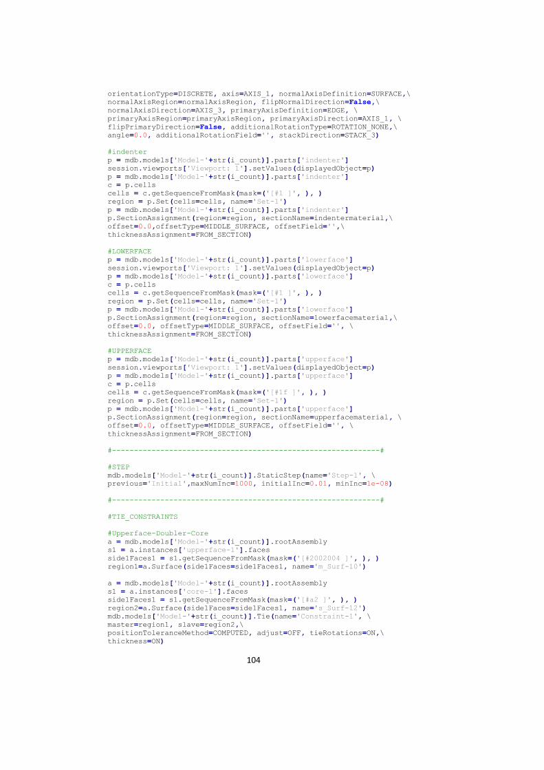
104
orientationType=DISCRETE, axis=AXIS_1, normalAxisDefinition=SURFACE,\
normalAxisRegion=normalAxisRegion, flipNormalDirection=False,\
normalAxisDirection=AXIS_3, primaryAxisDefinition=EDGE, \
primaryAxisRegion=primaryAxisRegion, primaryAxisDirection=AXIS_1, \
flipPrimaryDirection=False, additionalRotationType=ROTATION_NONE,\
angle=0.0, additionalRotationField='', stackDirection=STACK_3)
#indenter
p = mdb.models['Model-'+str(i_count)].parts['indenter']
session.viewports['Viewport: 1'].setValues(displayedObject=p)
p = mdb.models['Model-'+str(i_count)].parts['indenter']
c = p.cells
cells = c.getSequenceFromMask(mask=('[#1 ]', ), )
region = p.Set(cells=cells, name='Set-1')
p = mdb.models['Model-'+str(i_count)].parts['indenter']
p.SectionAssignment(region=region, sectionName=indentermaterial,\
offset=0.0,offsetType=MIDDLE_SURFACE, offsetField='',\
thicknessAssignment=FROM_SECTION)
#LOWERFACE
p = mdb.models['Model-'+str(i_count)].parts['lowerface']
session.viewports['Viewport: 1'].setValues(displayedObject=p)
p = mdb.models['Model-'+str(i_count)].parts['lowerface']
c = p.cells
cells = c.getSequenceFromMask(mask=('[#1 ]', ), )
region = p.Set(cells=cells, name='Set-1')
p = mdb.models['Model-'+str(i_count)].parts['lowerface']
p.SectionAssignment(region=region, sectionName=lowerfacematerial,\
offset=0.0, offsetType=MIDDLE_SURFACE, offsetField='', \
thicknessAssignment=FROM_SECTION)
#UPPERFACE
p = mdb.models['Model-'+str(i_count)].parts['upperface']
session.viewports['Viewport: 1'].setValues(displayedObject=p)
p = mdb.models['Model-'+str(i_count)].parts['upperface']
c = p.cells
cells = c.getSequenceFromMask(mask=('[#1f ]', ), )
region = p.Set(cells=cells, name='Set-1')
p = mdb.models['Model-'+str(i_count)].parts['upperface']
p.SectionAssignment(region=region, sectionName=upperfacematerial, \
offset=0.0, offsetType=MIDDLE_SURFACE, offsetField='', \
thicknessAssignment=FROM_SECTION)
#-------------------------------------------------------------#
#STEP
mdb.models['Model-'+str(i_count)].StaticStep(name='Step-1', \
previous='Initial',maxNumInc=1000, initialInc=0.01, minInc=1e-08)
#-------------------------------------------------------------#
#TIE_CONSTRAINTS
#Upperface-Doubler-Core
a = mdb.models['Model-'+str(i_count)].rootAssembly
s1 = a.instances['upperface-1'].faces
side1Faces1 = s1.getSequenceFromMask(mask=('[#2002004 ]', ), )
region1=a.Surface(side1Faces=side1Faces1, name='m_Surf-10')
a = mdb.models['Model-'+str(i_count)].rootAssembly
s1 = a.instances['core-1'].faces
side1Faces1 = s1.getSequenceFromMask(mask=('[#a2 ]', ), )
region2=a.Surface(side1Faces=side1Faces1, name='s_Surf-12')
mdb.models['Model-'+str(i_count)].Tie(name='Constraint-1', \
master=region1, slave=region2,\
positionToleranceMethod=COMPUTED, adjust=OFF, tieRotations=ON,\
thickness=ON)
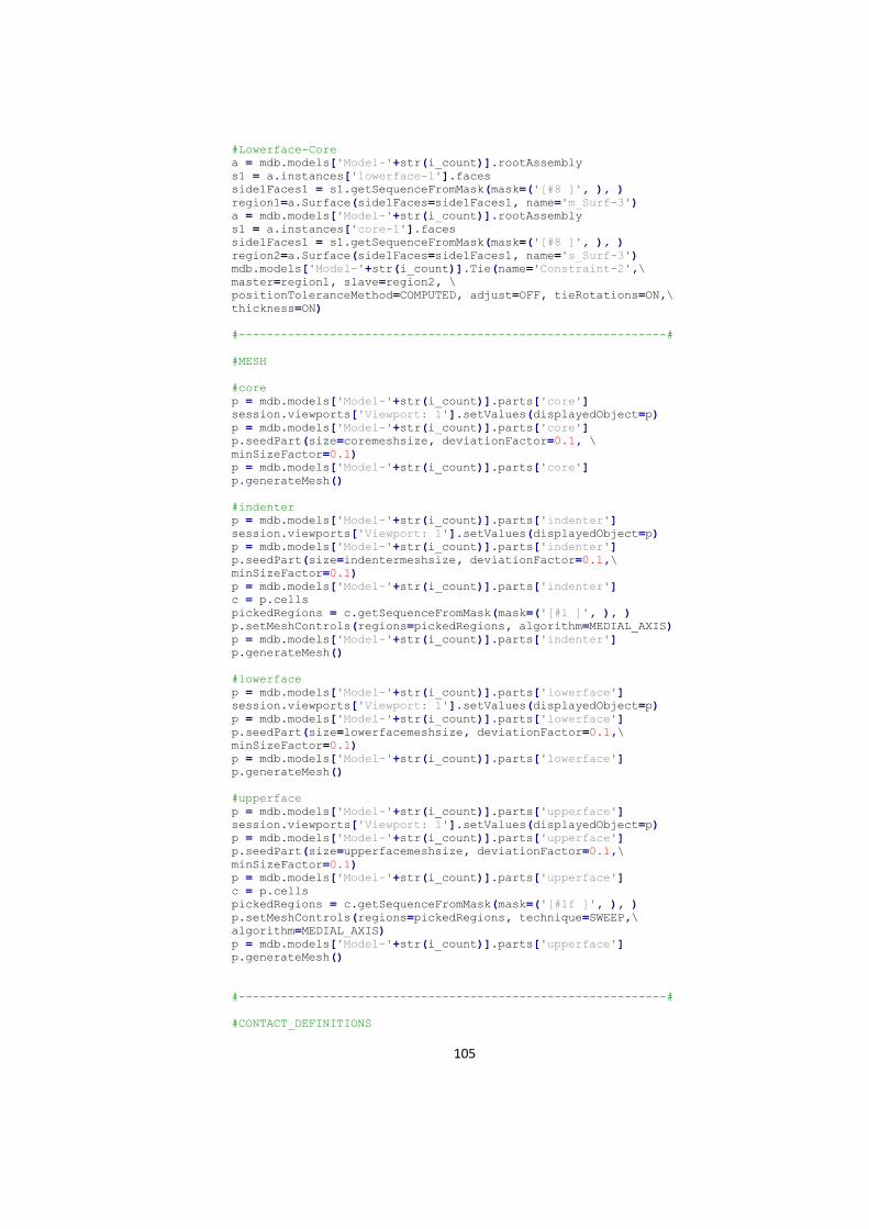
105
#Lowerface-Core
a = mdb.models['Model-'+str(i_count)].rootAssembly
s1 = a.instances['lowerface-1'].faces
side1Faces1 = s1.getSequenceFromMask(mask=('[#8 ]', ), )
region1=a.Surface(side1Faces=side1Faces1, name='m_Surf-3')
a = mdb.models['Model-'+str(i_count)].rootAssembly
s1 = a.instances['core-1'].faces
side1Faces1 = s1.getSequenceFromMask(mask=('[#8 ]', ), )
region2=a.Surface(side1Faces=side1Faces1, name='s_Surf-3')
mdb.models['Model-'+str(i_count)].Tie(name='Constraint-2',\
master=region1, slave=region2, \
positionToleranceMethod=COMPUTED, adjust=OFF, tieRotations=ON,\
thickness=ON)
#-------------------------------------------------------------#
#MESH
#core
p = mdb.models['Model-'+str(i_count)].parts['core']
session.viewports['Viewport: 1'].setValues(displayedObject=p)
p = mdb.models['Model-'+str(i_count)].parts['core']
p.seedPart(size=coremeshsize, deviationFactor=0.1, \
minSizeFactor=0.1)
p = mdb.models['Model-'+str(i_count)].parts['core']
p.generateMesh()
#indenter
p = mdb.models['Model-'+str(i_count)].parts['indenter']
session.viewports['Viewport: 1'].setValues(displayedObject=p)
p = mdb.models['Model-'+str(i_count)].parts['indenter']
p.seedPart(size=indentermeshsize, deviationFactor=0.1,\
minSizeFactor=0.1)
p = mdb.models['Model-'+str(i_count)].parts['indenter']
c = p.cells
pickedRegions = c.getSequenceFromMask(mask=('[#1 ]', ), )
p.setMeshControls(regions=pickedRegions, algorithm=MEDIAL_AXIS)
p = mdb.models['Model-'+str(i_count)].parts['indenter']
p.generateMesh()
#lowerface
p = mdb.models['Model-'+str(i_count)].parts['lowerface']
session.viewports['Viewport: 1'].setValues(displayedObject=p)
p = mdb.models['Model-'+str(i_count)].parts['lowerface']
p.seedPart(size=lowerfacemeshsize, deviationFactor=0.1,\
minSizeFactor=0.1)
p = mdb.models['Model-'+str(i_count)].parts['lowerface']
p.generateMesh()
#upperface
p = mdb.models['Model-'+str(i_count)].parts['upperface']
session.viewports['Viewport: 1'].setValues(displayedObject=p)
p = mdb.models['Model-'+str(i_count)].parts['upperface']
p.seedPart(size=upperfacemeshsize, deviationFactor=0.1,\
minSizeFactor=0.1)
p = mdb.models['Model-'+str(i_count)].parts['upperface']
c = p.cells
pickedRegions = c.getSequenceFromMask(mask=('[#1f ]', ), )
p.setMeshControls(regions=pickedRegions, technique=SWEEP,\
algorithm=MEDIAL_AXIS)
p = mdb.models['Model-'+str(i_count)].parts['upperface']
p.generateMesh()
#-------------------------------------------------------------#
#CONTACT_DEFINITIONS
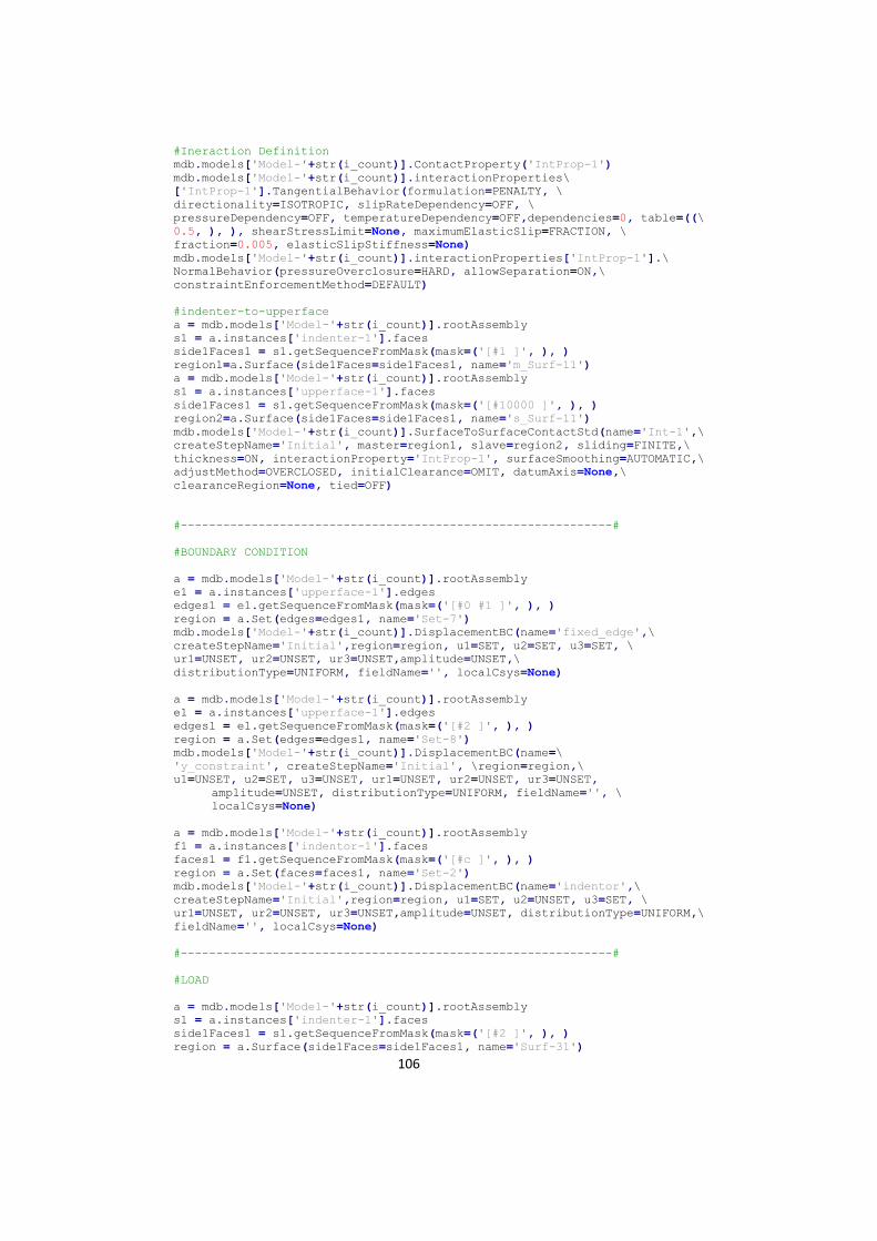
106
#Ineraction Definition
mdb.models['Model-'+str(i_count)].ContactProperty('IntProp-1')
mdb.models['Model-'+str(i_count)].interactionProperties\
['IntProp-1'].TangentialBehavior(formulation=PENALTY, \
directionality=ISOTROPIC, slipRateDependency=OFF, \
pressureDependency=OFF, temperatureDependency=OFF,dependencies=0, table=((\
0.5, ), ), shearStressLimit=None, maximumElasticSlip=FRACTION, \
fraction=0.005, elasticSlipStiffness=None)
mdb.models['Model-'+str(i_count)].interactionProperties['IntProp-1'].\
NormalBehavior(pressureOverclosure=HARD, allowSeparation=ON,\
constraintEnforcementMethod=DEFAULT)
#indenter-to-upperface
a = mdb.models['Model-'+str(i_count)].rootAssembly
s1 = a.instances['indenter-1'].faces
side1Faces1 = s1.getSequenceFromMask(mask=('[#1 ]', ), )
region1=a.Surface(side1Faces=side1Faces1, name='m_Surf-11')
a = mdb.models['Model-'+str(i_count)].rootAssembly
s1 = a.instances['upperface-1'].faces
side1Faces1 = s1.getSequenceFromMask(mask=('[#10000 ]', ), )
region2=a.Surface(side1Faces=side1Faces1, name='s_Surf-11')
mdb.models['Model-'+str(i_count)].SurfaceToSurfaceContactStd(name='Int-1',\
createStepName='Initial', master=region1, slave=region2, sliding=FINITE,\
thickness=ON, interactionProperty='IntProp-1', surfaceSmoothing=AUTOMATIC,\
adjustMethod=OVERCLOSED, initialClearance=OMIT, datumAxis=None,\
clearanceRegion=None, tied=OFF)
#-------------------------------------------------------------#
#BOUNDARY CONDITION
a = mdb.models['Model-'+str(i_count)].rootAssembly
e1 = a.instances['upperface-1'].edges
edges1 = e1.getSequenceFromMask(mask=('[#0 #1 ]', ), )
region = a.Set(edges=edges1, name='Set-7')
mdb.models['Model-'+str(i_count)].DisplacementBC(name='fixed_edge',\
createStepName='Initial',region=region, u1=SET, u2=SET, u3=SET, \
ur1=UNSET, ur2=UNSET, ur3=UNSET,amplitude=UNSET,\
distributionType=UNIFORM, fieldName='', localCsys=None)
a = mdb.models['Model-'+str(i_count)].rootAssembly
e1 = a.instances['upperface-1'].edges
edges1 = e1.getSequenceFromMask(mask=('[#2 ]', ), )
region = a.Set(edges=edges1, name='Set-8')
mdb.models['Model-'+str(i_count)].DisplacementBC(name=\
'y_constraint', createStepName='Initial', \region=region,\
u1=UNSET, u2=SET, u3=UNSET, ur1=UNSET, ur2=UNSET, ur3=UNSET,
amplitude=UNSET, distributionType=UNIFORM, fieldName='', \
localCsys=None)
a = mdb.models['Model-'+str(i_count)].rootAssembly
f1 = a.instances['indentor-1'].faces
faces1 = f1.getSequenceFromMask(mask=('[#c ]', ), )
region = a.Set(faces=faces1, name='Set-2')
mdb.models['Model-'+str(i_count)].DisplacementBC(name='indentor',\
createStepName='Initial',region=region, u1=SET, u2=UNSET, u3=SET, \
ur1=UNSET, ur2=UNSET, ur3=UNSET,amplitude=UNSET, distributionType=UNIFORM,\
fieldName='', localCsys=None)
#-------------------------------------------------------------#
#LOAD
a = mdb.models['Model-'+str(i_count)].rootAssembly
s1 = a.instances['indenter-1'].faces
side1Faces1 = s1.getSequenceFromMask(mask=('[#2 ]', ), )
region = a.Surface(side1Faces=side1Faces1, name='Surf-31')
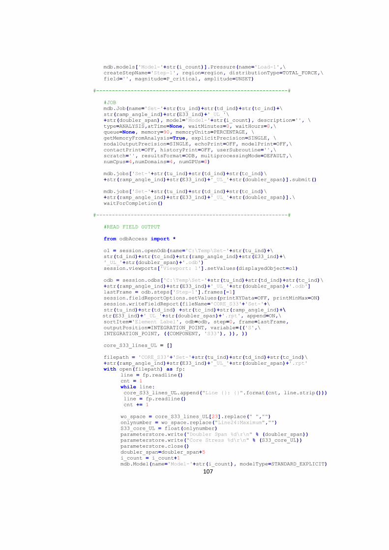
107
mdb.models['Model-'+str(i_count)].Pressure(name='Load-1',\
createStepName='Step-1', region=region, distributionType=TOTAL_FORCE,\
field='', magnitude=P_critical, amplitude=UNSET)
#-------------------------------------------------------------#
#JOB
mdb.Job(name='Set-'+str(tu_ind)+str(td_ind)+str(tc_ind)+\
str(ramp_angle_ind)+str(E33_ind)+'_UL_'\
+str(doubler_span), model='Model-'+str(i_count), description='', \
type=ANALYSIS,atTime=None, waitMinutes=0, waitHours=0,\
queue=None, memory=90, memoryUnits=PERCENTAGE, \
getMemoryFromAnalysis=True, explicitPrecision=SINGLE, \
nodalOutputPrecision=SINGLE, echoPrint=OFF, modelPrint=OFF,\
contactPrint=OFF, historyPrint=OFF, userSubroutine='',\
scratch='', resultsFormat=ODB, multiprocessingMode=DEFAULT,\
numCpus=4,numDomains=4, numGPUs=0)
mdb.jobs['Set-'+str(tu_ind)+str(td_ind)+str(tc_ind)\
+str(ramp_angle_ind)+str(E33_ind)+'_UL_'+str(doubler_span)].submit()
mdb.jobs['Set-'+str(tu_ind)+str(td_ind)+str(tc_ind)\
+str(ramp_angle_ind)+str(E33_ind)+'_UL_'+str(doubler_span)].\
waitForCompletion()
#-------------------------------------------------------------#
#READ FIELD OUTPUT
from odbAccess import *
o1 = session.openOdb(name='C:\Temp\Set-'+str(tu_ind)+\
str(td_ind)+str(tc_ind)+str(ramp_angle_ind)+str(E33_ind)+\
'_UL_'+str(doubler_span)+'.odb')
session.viewports['Viewport: 1'].setValues(displayedObject=o1)
odb = session.odbs['C:\Temp\Set-'+str(tu_ind)+str(td_ind)+str(tc_ind)\
+str(ramp_angle_ind)+str(E33_ind)+'_UL_'+str(doubler_span)+'.odb']
lastFrame = odb.steps['Step-1'].frames[-1]
session.fieldReportOptions.setValues(printXYData=OFF, printMinMax=ON)
session.writeFieldReport(fileName='CORE_S33'+'Set-'+\
str(tu_ind)+str(td_ind) +str(tc_ind)+str(ramp_angle_ind)+\
str(E33_ind)+'_UL_'+str(doubler_span)+'.rpt', append=ON,\
sortItem='Element Label', odb=odb, step=0, frame=lastFrame,
outputPosition=INTEGRATION_POINT, variable=(('S',\
INTEGRATION_POINT, ((COMPONENT, 'S33'), )), ))
core_S33_lines_UL = []
filepath = 'CORE_S33'+'Set-'+str(tu_ind)+str(td_ind)+str(tc_ind)\
+str(ramp_angle_ind)+str(E33_ind)+'_UL_'+str(doubler_span)+'.rpt'
with open(filepath) as fp:
line = fp.readline()
cnt = 1
while line:
core_S33_lines_UL.append("Line {}: {}".format(cnt, line.strip()))
line = fp.readline()
cnt += 1
wo_space = core_S33_lines_UL[23].replace(" ","")
onlynumber = wo_space.replace("Line24:Maximum","")
S33_core_UL = float(onlynumber)
parameterstore.write("Doubler Span %d\r\n" % (doubler_span))
parameterstore.write("Core Stress %d\r\n" % (S33_core_UL))
parameterstore.close()
doubler_span=doubler_span+5
i_count = i_count+1
mdb.Model(name='Model-'+str(i_count), modelType=STANDARD_EXPLICIT)

108
mdb.saveAs(pathName='C:/Temp/'+'Set-'+str(tu_ind)+str(td_ind)+str(tc_ind)\
+str(ramp_angle_ind)+str(E33_ind)+'_UL')
modelindex = 1
while modelindex<i_count:
del mdb.models['Model-'+str(modelindex)]
modelindex = modelindex


