Embed Size (px)
Citation preview

Detection of Mechanical Load Faults in InductionMotors at Variable Speed Using Stator Current
Time-Frequency Analysis
Martin Blodtl , Marie Chabert2, Jeremi Regnierl , Jean Faucherl and Bruno Daguesl
1Laboratoire d 'Electrotechnique et d 'Electronique Industrielle (LEEI)Unite mixte de recherche INPT-ENSEEIHT / CNRS No. 5828
2ENSEEIHT / IRIT / TeSA2, Rue C. Camichel BP 7122
31071 Toulouse Cedex 7, FranceEmail: [email protected]@enseeiht.fr.
[email protected], [email protected], [email protected]
constant. Examples for such faults causing torque oscillationsinclude:
• general fault in the load part of the drive system e.g. loadimbalance, shaft misalignment
• gearbox faults e.g. broken tooth• bearing faults
Torque oscillations already exist in a healthy motor due tospace and time harmonics of the airgap field, but the considered fault related torque oscillations are present at particularfrequencies, often related to the mechanical motor speed.
Thomson mentioned in [1] that mechanical problems in theload may cause speed oscillations that modulate the motorinput current and lead to additional frequencies in the currentspectrum. Schoen et. al. have shown in [2] that load torqueoscillations appearing at multiples of the rotational speed leadto frequencies in the stator current given by :
where Is is the stator supply frequency, Ir the rotationalfrequency and n == 1,2,3, ... The proposed fault detectionschemes (e.g. [3]) may only be applied in steady motoroperation i.e. at constant supply frequency. In this paper, thestator current is analyzed during transients i.e. variable supplyfrequencies using time-frequency signal analysis.
In section II, the considered signal model for the stator current under fault is shortly presented. Different signal processing methods for detection such as instantaneous frequencyestimation and the Wigner Distribution are discussed in sectionIII. In section IV, these methods are applied to experimentalsignals in order to show their effectiveness.
II. STATOR CURRENT SIGNAL MODEL UNDER
MECHANICAL FAULT
The method used to study the influence of the load torqueoscillation on the stator current is based on the magnetomotiveforce (MMF) and permeance wave approach [4] [5]. This approach is traditionally used for the calculation of the magnetic
Abstract- This paper examines the detection of mechanicalload faults in induction motors during speed transients by statorcurrent analysis. Mechanical load faults generally lead to loadtorque oscillations at specific frequencies. these frequencies arerelated to the mechanical rotor speed. The torque oscillationsproduce a characteristic sinusoidal phase modulation of thestator current. Speed transients result in time-varYing supplyfrequencies that prevent the classical, Fourier transform basedspectral estimation. This problem can be overcome using timefrequency signal analysis. The methods applied in this paper areinstantaneous frequency estimation and the Wigner Distribution.Furthermore, an adaptive demodulation method is proposed. Thetheoretical considerations are validated on signals obtained froman experimental setup.
I. INTRODUCTION
Induction motors are nowadays used in a wide variety ofindustrial applications. In order to increase the productivity,reliability and safety of an installation containing inductionmotors, permanent and automatic motor condition monitoringis desired.
Stator current based condition monitoring is often desirabledue to easy and economical implementation. The monitoringis in most cases done in steady operation state using classicalspectral analysis tools. However, a lot of drives are adjustablespeed drives where mechanical speed transients may be presentduring a long time period. The speed transients are oftenlinear and lead therefore to a linear evolution of the supplyfrequency. The time-varying supply frequency prevents the useof classical spectral analysis. The application of other signalprocessing methods like time-frequency analysis overcomesthis problem and makes condition monitoring possible duringspeed transients.
This paper investigates the detection of torque oscillationscaused by mechanical faults in induction machines using statorcurrent time-frequency analysis. In a general way, a fault in theload part of the drive will be seen from the induction machineby a periodic variation of the load torque that is no longer
07803-9124-1/05/$20.00 ©2005 IEEE
Iload == Is ± nIr (1)
with:
(7)
(8)
(9)
(12)
(11 )
(10)
ws(t) == 211" (as + f3st)
wc(t) == 211" (ac+ f3ct)
z(t) == x(t) + jH {x(t)}
fi,i(t)healthy(t) == Q s + 2f3st
i(t) == 1st exp j [21rIs (t)t + 'Ps]
+ I rt exp j [21rIs (t)t + f3 cos (211"I c (t)t) ]
leads to the following stator current expression (for an arbitrarymachine phase):
III. SIGNAL PROCESSING METHODS
The previous section has shown that the load torque oscillations cause a phase modulation on one stator currentcomponent (6). When variable speed is considered, the supplyfrequency and the fault frequency vary with respect to time.Traditional methods of spectral analysis [10] using the Fouriertransform on a long observation window, e.g. the periodogram,can therefore not be applied.
In the following, for a proper instantaneous frequencydefinition, all signals will be considered in their complex form,the so-called analytical signal [11] [12]. The analytical signalz (t) is related to the real signal x (t) via the Hilbert TransformH{.}:
where cp(t) is the instantaneous phase and a(t) the instantaneous amplitude of the analytical signal z(t).
In the healthy case, the stator current IF is directly obtainedfrom applying (11) to the complex current signal (10) with(3 == 0:
For the sake of simplicity, the time harmonics of rotor MMFand the non-uniform airgap permeance have not been considered. However, the harmonics of supply frequency fs andthe rotor slot harmonics theoretically show the same phasemodulation as the fundamental stator current component.
The analytical signal contains the same information as the realsignal but its Fourier transform is zero at negative frequencies.The analytical form of the current signal is therefore:
i (t) == i st (t) + irt (t)== 1st sin [ws(t)t + CPs] (6)
+ lrt sin [ws(t)t + f3 cos (wc(t)t) ]
i st (t) and irt (t) denote the stator current components resultingfrom the stator and rotor MMF. The amplitudes 1st and lrtare supposed quasi-constant. The healthy case is obtainedconsidering f3 == O. The supply and fault frequencies aremodelled as affine time functions as a consequence of typicallinear speed profiles:
A. Instantaneous Frequency
For a complex monocomponent signal z(t) == a(t)ej<p(t),the instantaneous frequency (IF) fi (t) is defined by [11]:
1 dli(t) == 211" dt cp(t)
(4)
(2)
where CPs denotes the initial phase angle between rotor andstator MMF.
The total magnetic flux density is obtained by the multiplication of the total MMF with the airgap permeance, which issupposed constant. The induced voltage in a machine windingis related to the magnetic airgap field, so that the phasemodulation is preserved. Consequently, a mechanical load fault
airgap field with respect to rotor and stator slotting or staticand dynamic eccentricity [6] [7].
The detailed theoretical development for the stator current incase of load torque oscillation has been given in [8] to identifythe consequence of bearing faults and in [9] for the generalcase. The results will be shortly resumed in the following.
As this paper considers variable speed drives, the supplyfrequency f s and the fault frequency f c can be consideredvariable. Note than fc can be for example the time-varyingrotational frequency fr. The theoretical analysis of the statorcurrent under fault, however, is identical to the steady state ifrelatively slow frequency variations are considered.
Under a mechanical fault, the load torque as a function oftime is assumed to be described by a constant componentrcanst and an additional component varying at the faultcharacteristic frequency fc. The first term of the variablecomponent Fourier series is a cosine with frequency fc. Forthe sake of clarity, higher order terms are neglected in thefollowing and only the fundamental term is considered. Theload torque can therefore be described by:
where p is the pole pair number, J the total inertia andW s == 21rIs. The fault effect on the rotor MMF can be seenas a sinusoidal phase modulation at the characteristic faultfrequency.
The stator MMF Fs ( (), t) does not change and takes thesame expression as in the healthy case:
where r c is the amplitude of the load torque oscillation andWc == 21r fc.
Considering the mechanical equation of the machine, theoscillating load torque leads to periodic oscillations at fc ofthe mechanical rotor speed. The consequence is an oscillationat the same frequency on the mechanical rotor position. If thefundamental rotor MMF is calculated in the stator referenceframe by using the transformation between the two referenceframes, the oscillating mechanical rotor position producesan oscillating rotor MMF Fr ( (), t) that can be expressed asfollows:
In this case, the stator current IF corresponds to the instantaneous supply frequency.
In the faulty case ({3 =I 0), the stator current IF calculationleads to:
fi,i(t)(t) == (as + 2{3st)+(ac+ 2{3ct ) (3a(t) sin [wc(t)t] (13)
with
I;t + IstIrt cos ({3 cos (wc(t)t) - «Js) (14)a(t) ==
I;t + I;t + 2Ist Irt cos ((3 cos (wc(t)t) - «Js)
Using a series development of cos ({3 cos wct) and commonsimplifications of higher order Bessel functions for small {3[13], a(t) can be approximated by:
( )I;'t + IstIrt [cos <{Js + {3 cos (wc(t)t) sin <{Js]
a t ~ - I;t + I;t + 2Ist Irt [cos <{Js + {3 cos (wc(t)t) sin <{Js1(1))
For small {3 and 0 < <(Js < 1r/2, the time-varying componentof a(t) is relatively small compared to its constant component.This has also been verified by numerical evaluation of equation(14) for reasonable parameter values. Hence, a(t) is supposedconstant in the following (a(t) ~ C) and the followingexpression is obtained for the stator current IF:
with, == -2{3sin (21r (ac + {3ct) t). The approximation considers a small modulation index {3 and small variation ofthe fault frequency ({3c small). More details concerning thecalculation in the case of constant supply frequency can befound in [9].
The WD of the considered faulty current signal is therefore a central frequency at fi,i(t)healthy(t) with sidebands atfi,i(t)healthy(t) ± fc(t)/2. The sidebands are the fault signatureand their amplitude is related to the magnitude of the torqueoscillations through the modulation index {3. All the components have time-varying amplitudes at frequency fc(t) as ,is a function of time. It is important to notice that the lowersideband has the opposed sign to the upper sideband.
In practice, the Pseudo Wigner Distribution (PWD), asmoothed version of the WD, is often used. The PWD isdefined as follows [12]:
PWx(t, f) = 1:00
p(T)X (t + i) x' (t - i) e-j21T!TdT
(19)where p(T ) is the smoothing window which reduces theamplitudes of the interference terms.
IV. EXPERIMENTAL RESULTS
A. Experimental Setup
Tests have been conducted on a test rig with a 5.5 kWLeroy Somer induction machine (see Fig. 1). The machine is
The signal x (t) can be demodulated according to thefollowing law in order to obtain a signal at a desired constantfrequency fo:
Xmod(t) == x(t) ej21r(fo-nx-{3xt)t == ej21ffot (22)
A small time-varying modulation term in the phase of x(t),e.g. the previously considered phase modulation, will not beaffected by the adaptive demodulation but the modulation termaffects the previous IF estimation. Therefore, a linear IF approximation is necessary in order to preserve any modulationthat may contain information about a fault.
C. Adaptive Demodulation
The presence of the fundamental stator current componentat variable frequency fs (t) prevents the use of classicalspectral analysis tools as the power spectral density (PSD).However, the stator current can be demodulated according toa time-varying law in order to obtain a constant fundamentalfrequency. The time-varying law is obtained from an IFestimation followed by a linear approximation. This signalmay further be processed using spectral analysis tools forstationary signals.
Considering a signal x(t) with a linear frequency evolution:
x(t) == ej21r(nx+f3xt)t (20)
fi,i(t)(t) ~ (as + 2{3st) + (ac + 2{3ct )C{3sin [21r(ac + (3ct )t](16)
This expression shows the fault effect on the stator current IF:In the healthy case (12), the IF is linear without oscillations;in the faulty case, an additional oscillating component withvariable amplitude and frequency appears. Its time-varyingfrequency corresponds to the evolution of the fault frequencyfc(t).
B. Wigner Distribution
The Wigner Distribution (WD) was historically the firstproposed time-frequency distribution. It is defined as follows[12]:
Wx(t,j) = 1:00
x(t+~)x'(t-~)e-j21T!TdT (17)
Basically, the WD can be interpreted as a distribution of thesignal energy with respect to time and frequency.
An interesting property of the WD is its perfect concentration on the instantaneous frequency for linear frequencymodulations. However, it does not perfectly represent othertypes of modulation e.g. as in our case sinusoidal phasemodulations. Other types of modulations produce so calledinner interference terms in the distribution [14]. These termsmay however be used for detection purposes as will be shownin the following.
The WD of the stator current according to (6) is approximately of the following form:
Wi(t, f) ~ (I;tJo(,) + I;t) 6 (f - (as + 2{3st))
+ I;tJl('Y) 6 (I - (as + 2f3st) - (~c + f3c t ))
- I;tJl("() 6 (I - (as + 2f3st) + (~c + f3ct))(18)
Its instantaneous frequency is given by:
fi,x == ax + 2{3xt (21)

4.53.52 2.5Time rsl
1.50.5
40
Fig. 3. Spectrogram of measured transient torque signal with load torqueoscillation
II I
I '- -,I I
1------- 1 I
I :
----------, ' I
: : : Function GeneratorNCO, i __t _i _, \
:Data Acquisition ~ - -\ >:24 bit 25 kHz ~ - -1\ - - - - - _'- - - - - - - - - - , I
InductionMotor5,5 kW
Inverter(open loop)
Fig. 1. Scheme of experimental setup70 ,---.,---------r---,-------r-------r---~
2.51.5Time rsl
0.5
Fig. 4. Pseudo Wigner Distribution of measured transient current signalwithout load torque oscillation
1OlL.L------L.------L-__..l..--__--L-__-...l --l......-J
Nts.~g 40eug.~~ 30
20
60
Lowpass filterDownsampling (4fsmax)
Hilbert transform
Fig. 2. Stator current processing scheme
supplied by a standard industrial inverter operating in openloop condition with a constant voltage to frequency ratio. Thespeed profiles are linear. A voltage controlled oscillator (YCO)coupled to a function generator with at its input the measuredmotor speed provides a signal with oscillations proportional tomotor speed. This signal is amplified and supplies a magneticpowder brake which acts as a load for the motor. Therefore,the system generates load torque oscillations proportional tothe rotational frequency as can be found in the case of a realmechanical load fault.
The load torque is measured by a rotating torque transducer.The torque signal, voltage and current measurements areacquired at a sampling rate of 25 kHz by a 24 bit dataacquisition board. The further signal processing is done usingMatlab and the Time-Frequency Toolbox [15]. The differentsteps of the signal processing are displayed in Fig. 2. Thecurrent signal is filtered and downsampled to fsample = 200Hz. The analytical signal is then obtained using the Hilberttransform. The resulting complex current signal is analyzedusing the previously described 3 methods.
During the tests, an average load torque of about 8 Nmhas been imposed. The amplitude of the torque oscillationsproportional to motor speed is approximately r e ~ 0.5 Nm(i.e. re/reonst ~ 6 %) during the motor startup according tothe measurements. Signals are acquired during a speed cyclewith an acceleration phase, constant speed and braking. Allthe speed profiles are linear.
In order to validate the presence of the torque oscillation,the measured torque can be analyzed using the spectrogram,a time-frequency analysis based on a short-time Fourier transform [12]. The result is shown in Fig. 3 during motor startup.A strong DC component is visible which corresponds to theaverage load torque. Furthermore, an additional oscillatingcomponent resulting from the fault is present. Its frequencyevolves linearly and it is proportional to motor speed.
B. Analysis using the Pseudo Wigner Distribution
First, the Pseudo Wigner Distribution (PWD) is used toanalyze a transient current signal without torque oscillations(see Fig. 4). As expected, a strong component at the stator current fundamental frequency is visible with a linear frequencyincrease during the startup.
2.51.5
-2.5 L-- ---' ______L --.J
1Time rsl
2.5,--------------,r------------,---------::l
2.51.5Time rsl
70.--------.----------,------,-----------r----.-----------,.".rTTTl
50
60
1OlL-LL__---..L...-__--i ----l.-__-----L --L-____'_----'
20
N~>.g 40l1)
&~
~ 30
Fig. 5. Pseudo Wigner Distribution of measured transient current signal withload torque oscillation
Fig. 7. Estimated oscillating component of stator current instantaneousfrequency for healthy and faulty case during speed transient
20
1.50.5 1Time [s]
(b) faulty
N40b~30()
~
~ 20~.._"" --~
l1)
~ 10
50r--~--~----",-
1.50.5 1Time [s]
(a) healthy
50r--~----.----",.•
N40b>. 30()
~
~ 20C'"l1)
~1O
40
N 35ES
g30~•••••••••••••••••••~~ I~ 25
15~-~-~-~-~-~---'--------L--~-~~ fl~& S~ctro~m~pro~~~s~ocrum~~~nta~o~~q~~yfur1 1.02 1.04 1.06 1.08 1.1 1.12 1.14 1.16 1.18 1.2 healthy and faulty signal
Time rsl
Fig. 6. Zoom on Pseudo Wigner Distribution of measured transient currentsignal with load torque oscillation
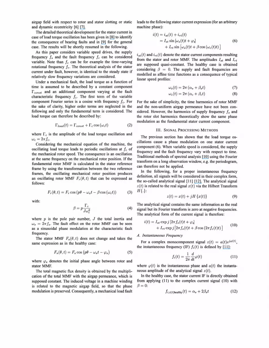
The stator current PWD with load torque oscillations duringstartup is shown in Fig. 5. The fault produces a characteristicsignature on the PWD at frequencies fs(t) ± fc(t)/2 ~
fs (t) ± fT (t) as predicted by the theoretical approach. A zoomaround the fundamental (see Fig. 6) confinns the presence ofenergy at the predicted frequencies (~ 30 ± 7.5 Hz). Theupper and lower sideband have opposed amplitudes for a giventime instant. Their oscillating nature at fault frequency (fc ~
15 Hz) is also verified.
C. Analysis using Instantaneous Frequency
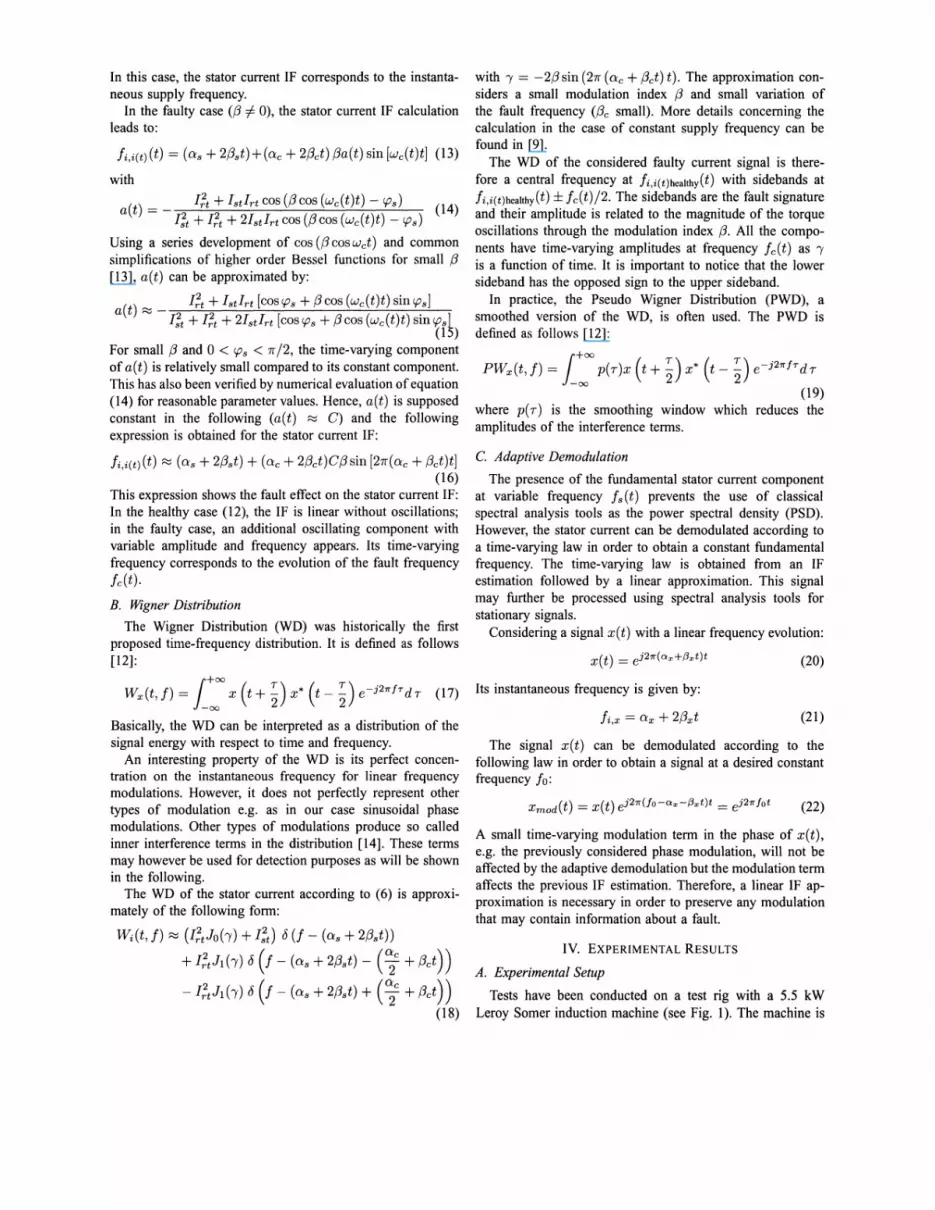
The instantaneous frequency (IF) of the healthy and faultytransient current signals has been calculated using a phasedifference estimator. The resulting time-varying IF has a largelinear evolving part corresponding to Os +2{3st which containsno relevant information about the fault (see (16)). Therefore,using a linear least squares approximation, the linear IFcomponent has been removed. The resulting processed IFcontains only the oscillating part and it is displayed on Fig.7. A difference concerning the amplitudes is visible but theexact nature of the oscillations cannot be seen.
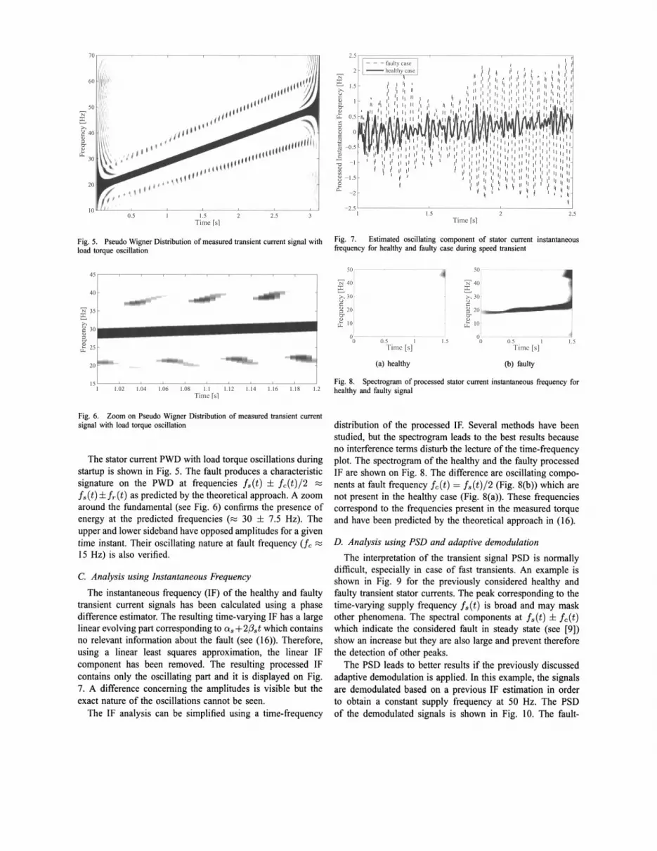
The IF analysis can be simplified using a time-frequency
distribution of the processed IF. Several methods have beenstudied, but the spectrogram leads to the best results becauseno interference terms disturb the lecture of the time-frequencyplot. The spectrogram of the healthy and the faulty processedIF are shown on Fig. 8. The difference are oscillating components at fault frequency fc(t) == fs(t)/2 (Fig. 8(b)) which arenot present in the healthy case (Fig. 8(a)). These frequenciescorrespond to the frequencies present in the measured torqueand have been predicted by the theoretical approach in (16).
D. Analysis using PSD and adaptive demodulation
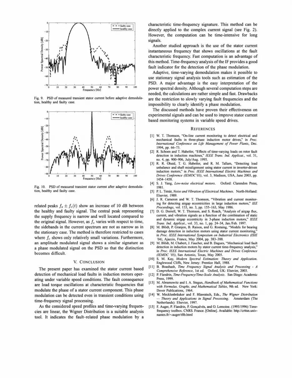
The interpretation of the transient signal PSD is normallydifficult, especially in case of fast transients. An example isshown in Fig. 9 for the previously considered healthy andfaulty transient stator currents. The peak corresponding to thetime-varying supply frequency fs (t) is broad and may maskother phenomena. The spectral components at f s ( t) ± f c ( t)which indicate the considered fault in steady state (see [9])show an increase but they are also large and prevent thereforethe detection of other peaks.
The PSD leads to better results if the previously discussedadaptive demodulation is applied. In this example, the signalsare demodulated based on a previous IF estimation in orderto obtain a constant supply frequency at 50 Hz. The PSDof the demodulated signals is shown in Fig. 10. The fault-
-70 l--._l--._L--_L-----l_---l_----'_----'_............_---L_----l
o 10 20 30 40 50 60 70 80 90 100Frequency rHz1
Fig. 10. PSD of measured transient stator current after adaptive demodulation, healthy and faulty case.
[1] W. T. Thomson, "On-line current monitoring to detect electrical andmechanical faults in three-phase induction motor drives," in Proc.International Conference on Life Management of Power Plants, Dec.1994, pp. 66-73.
[2] R. Schoen and T. Habetler, "Effects of time-varying loads on rotor faultdetection in induction machines," IEEE Trans. Ind. Applicat., vol. 31,no. 4, pp. 900-906, July/Aug. 1995.
[3] R. R. Obaid, T. G. Habetler, and R. M. Tallam, "Detecting loadunbalance and shaft misalignment using stator current in inverter-driveninduction motors," in Proc. IEEE International Electric Machines andDrives Conference (IEMDC'03), vol. 3, Madison, USA, June 2003, pp.1454-1458.
[4] S. J. Yang, Low-noise electrical motors. Oxford: Clarendon Press,1981.
[5] P. L. Timar, Noise and Vibration ofElectrical Machines. North-Holland:Elsevier, 1989.
[6] 1. R. Cameron and W. T. Thomson, "Vibration and current monitoring for detecting airgap eccentricities in large induction motors," lEEProceedings, vol. 133, no. 3, pp. 155-163, May 1986.
[7] D. G. Dorrell, W. T. Thomson, and S. Roach, "Analysis of airgap flux,current, and vibration signals as a function of the combination of staticand dynamic airgap eccentricity in 3-phase induction motors," IEEETrans. Ind. Applicat., vol. 33, no. 1, pp. 24-34, Jan./Feb. 1997.
[8] M. Bladt, P. Granjon, B. Raison, and G. Rostaing, "Models for bearingdamage detection in induction motors using stator current monitoring,"in Proc. IEEE International Symposium on Industrial Electronics (ISlE'04), Ajaccio, France, May 2004, pp. 383-388.
[9] M. Bladt, M. Chabert, J. Faucher, and B. Dagues, "Mechanical load faultdetection in induction motors by stator current time-frequency analysis,"in Proc. IEEE International Electric Machines and Drives Conference(IEMDC '05), San Antonio, Texas, May 2005.
[10] S. M. Kay, Modern Spectral Estimation: Theory and Application.Englewood Cliffs, New Jersey: Prentice Hall, 1988.
[11] B. Boashash, Time Frequency Signal Analysis and Processing - AComprehensive Reference, 1st ed. Oxford, UK: Elsevier, 2003.
[12] P. Flandrin, Time-Frequency/Time-Scale Analysis. San Diego: AcademicPress, 1999.
[13] M. Abramowitz and I. A. Stegun, Handbook ofMathematical Functionswith Formulas, Graphs, and Mathematical Tables, 9th ed. New York:Dover Publications, 1964.
[14] W. Mecklenbdiuker and F. Hlawatsch, Eds., The Wigner Distribution- Theory and Applications in Signal Processing. Amsterdam (TheNetherlands): Elsevier, 1997.
[15] F. Auger, P. Flandrin, P. Gon~alves, and O. Lemoine. (1995/1996) Timefrequency toolbox. CNRS. France. [Online]. Available: http://crttsn.univnantes.fr/rvauger/tftb.html
characteristic time-frequency signature. This method can bedirectly applied to the complex current signal (see Fig. 2).However, the computation can be time-intensive for longsignals.
Another studied approach is the use of the stator currentinstantaneous frequency that shows oscillations at the faultcharacteristic frequency. Fast computation is an advantage ofthis method. Time-frequency analysis of the IF provides a goodfault indicator for the detection of the phase modulation.
Adaptive, time-varying demodulation makes it possible touse stationary signal analysis tools such as estimation of thePSD. A major advantage is the easy interpretation of thepower spectral density. Although several computation steps areneeded, the calculations are rather simple and fast. Drawbacksare the restriction to slowly varying fault frequencies and theimpossibility to clearly identify a phase modulation.
The discussed methods have proven their effectiveness onexperimental signals and can be used to improve stator currentbased monitoring systems in variable speed drives.
REFERENCES
10 20 30 40 50 60 70 80 90 100Frequency rHzl
related peaks is ± ie(t) show an increase of 10 dB betweenthe healthy and faulty signal. The central peak representingthe supply frequency is narrow and well located compared tothe original signal. However, as ie varies with respect to time,the sidebands in the current spectrum are not as narrow as inthe stationary case. The method is therefore restricted to caseswhere Ie shows only relatively small variations. Furthermore,an amplitude modulated signal shows a similar signature asa phase modulated signal on the PSD so that the distinctionbecomes difficult.
~ -20
.£5-30oca.:=~ -40~
(/)
~~ -50o
tl..
-20
i~-30'§o -40
Cd~ -50
~~ -60
~tl.. -70
-10
V. CONCLUSION
The present paper has examined the stator current baseddetection of mechanical load faults in induction motors operating under variable speed conditions. The fault consequenceare load torque oscillations at characteristic frequencies thatmodulate the phase of a stator current component. This phasemodulation can be detected even in transient conditions usingtime-frequency signal processing.
As the considered speed profiles and time-varying frequencies are linear, the Wigner Distribution is a suitable analysistool. It indicates the fault-related phase modulation by a
Fig. 9. PSD of measured transient stator current before adaptive demodulation, healthy and faulty case.


