Embed Size (px)
Citation preview
International Journal of CrashworthinessVol. 13, No. 3, June 2008, 265–278
Design of ventilated helmets: computational fluid and impact dynamics studies
Praveen K. Pinnoji, Zafar Haider and Puneet Mahajan∗
Department of Applied Mechanics, Indian Institute of Technology Delhi, New Delhi, India
(Received 13 December 2007; final version received 14 January 2008)
The existing motorcycle helmets are thermally uncomfortable as there is no provision for air flow inside the helmet. A newdesign of helmet, with grooves in the liner foam and slot in the outer shell and liner foam to improve the ventilation, isproposed. Computational fluid dynamics studies show considerable improvement in air velocities inside the helmet in thepresence of grooves and slot. Impact dynamics and biomechanics studies on various motorcycle helmets with deformableand rigid head show that the proposed design meets the requirements of the standards in the drop test. The optimum size ofthe groove and number of grooves for a motorcycle helmet are decided on the basis of the above studies.
Keywords: helmets; design; fluid flow; impact; finite element; biomechanics
1. IntroductionA well-designed motorcycle crash helmet has proved to be avery good protection device for the rider to prevent or min-imise the head injuries in road accidents. If a helmet is notworn, the head impact with any object would cause localisedhigh pressure on the skull, which leads to brain injury. Thehelmet design can be divided into functional (like shock-absorbing capability, penetration resistance, retention andreliability) and non-functional (like low cost, good aesthet-ics, comfort, light weight and good thermal characteristics)categories. Though a helmet is well-designed for functionalcharacteristics, because of weak non-functional character-istics drivers sometimes dislike wearing it while riding. InSouth Asia, excessive sweating and resulting discomfortdue to hot and humid weather conditions discourage mo-torcycle riders from using helmets unless it is mandatoryby law. The space between the head and helmet is small,and both mass flow and air velocities in this gap are alsolow; as a result, the sweat is unable to evaporate making therider uncomfortable. The discomfort caused by sweatingcan be reduced by increasing the air velocities inside thehelmet so as to enhance the sweat evaporation rate. Air flowin helmet can be improved by large ventilation openingsas in bicycle helmets, but unfortunately such ventilationopenings may be detrimental to the safety and structuralintegrity of the helmet. Most of the studies on motorcy-cle helmets are based on the material and biomechanicsaspects, and few studies exist which investigate the effectof ventilation on air flow inside the helmet or effect ofthis (or ventilation openings) on the dynamic performanceof helmet. It is possible that helmets with ventilation are
∗Corresponding author. Email: [email protected]
available in the market, but systematic studies on theseare not available in the literature. In first part of the pa-per, we investigate air velocities inside the helmet, withand without ventilation using computational fluid dynam-ics (CFD) techniques. The fluid flow study was carried outto examine the possibility of improving the ventilation inmotorcycle helmets. In second part of the paper, the biome-chanics characteristics of head impact were studied for hel-mets with and without ventilation using finite element (FE)analysis.
In a motorcycle helmet, the comfort foam apparentlyhelps in fitting the helmet on heads of different sizes, al-though it is rarely used in bicycle helmets. Because thecomfort foam always rests on the head and gives resistanceto air flow, it has not been included in the helmet designsstudied here. We found that, without comfort foam and iftied properly, the helmet sits on the head and does not move.Even without comfort foam, however, there are regions inthe central plane of the head, where this helmet rests onthe head, and there is no space for air to circulate. It wasdecided to support the helmet on the head by comfort foamof 2 mm thickness provided on the sides of the helmet only(but not on the top). A groove was made in the central planeto provide space for air to flow, and a slot was provided infront of the helmet for air to enter. The groove and slotin the helmet are shown in Figure 1. Flow velocity insidethe helmet was determined by varying the depth and widthof the groove keeping slot dimensions fixed. Four differentsizes of groove, listed in Table 1, were investigated. The di-mensions of the slot present in the outer shell and liner foamwere fixed at 48 mm × 7 mm. These helmets did not have
ISSN: 1358-8265Copyright C© 2008 Taylor & FrancisDOI: 10.1080/13588260801933626http://www.informaworld.com
266 P.K. Pinnoji et al.
Figure 1. Three parallel grooves of 14 mm × 7 mm with slot in liner foam.
a visor. Studies were also performed on helmets without aslot. However, velocities inside the helmet were generallylower than those observed with a slot, and therefore, onlythe latter case is discussed here.
2. Fluid flow analysis
Reischl [20] carried out an investigation of helmet ventila-tion designs for firefighter helmets and found that a helmetwith side ventilation holes was cooler than unventilatedhelmet, and increasing the gap between helmet and headalso enhanced the cooling action due to the improved aircirculation. Abeysekera and Shanavaz [2] investigated thepotential benefits of helmets with ventilation holes for in-dustrial workers both in laboratory and field settings. Bruh-wiler et al. [4] studied the heat transfer variations of bicyclehelmets. They carried out experiments in water channelto study the efficiency and placement of vents in bicyclehelmets. They concluded that there is significant potential
Table 1. Various ventilation designs.
No. of Groove width Groove depth SlotDesign grooves (mm) (mm) (mm)
1 1 14 7 48 × 72 1 28 7 48 × 73 1 42 7 48 × 74 1 14 14 48 × 75 3 14 7 48 × 7
within the basic helmet structure for improving the heattransfer.
The above studies except that of Bruhwiler et al. [4]were mainly in conditions where the velocities of air werevery small. All the above studies were experimental, andno CFD analysis had been done for fluid flow inside thehelmet. Here we study air flow inside a motorcycle helmetusing CFD where the relative velocity of air outside thehelmet is about 15 m s−1. Inside the helmet the air gapvaries from approximately 0 mm (where the helmet touchesthe head) to 10 mm, and the velocities are small. One ofthe ways of improving these velocities and resulting heattransfer is by providing grooves in the central plane of thehelmet. This leads to increased evaporation of the sweat.The present study used CFD to investigate air flow insidethe gap between the helmet and head. To get an idea ofhow well CFD is able to simulate the air flow in a gap of10 mm, experiments were performed in a wind tunnel ontwo concentric cylinders with a gap of 10 mm between thecylinders and then simulated with CFD. Such experimentswith a helmet can be performed, but measurements in smallgap regions would be difficult with the Pitot tube used here.
2.1. Experiments in wind tunnel and validationof CFD
Experiments were performed on concentric cylinders inthe wind tunnel of cross section 450 mm × 750 mm. Thecylindrical model was mounted with axis of the cylinders

International Journal of Crashworthiness 267
Figure 2. Schematic view of two concentric cylinders model.
perpendicular to the direction of flow as seen in Figure2. The diameter of the inner cylinder is approximatelythe same as that of the actual head, i.e. 140 mm, and thediameter of the outer cylinder was 160 mm. Six pressuretabs were placed on the surface of the inner cylinder, andvelocity within the gap at various points along the y-axiswas measured using a three-hole velocity probe connectedto the micro-manometer. Velocity of the wind at inlet wasmeasured by a Pitot-static tube. Experiments were carriedout at three different speeds of the wind, 11 m s−1, 15.7m s−1 and 23.5 m s−1 although only results for 15.7 m s−1
are shown here.Fluid flow analysis for the above concentric cylindrical
model was carried out through CFD using FLUENT [6].The upstream length was four times the diameter of theinner cylinder, and downstream length was 20 times thediameter of inner cylinder. The downstream length waskept large to ensure that the flow was fully developed. Fluidinside the gap was air with density of 1.225 kg m−3 andviscosity of 1.789 × 10⁻⁵ kg (m s)−1.
For numerical simulations the inlet velocity was takenas 15.7 m s−1, and outflow condition available in FLUENTwas used at the outlet. No slip condition was assumed atthe walls. Fluid flow was assumed as steady and incom-pressible. The standard k − ε model [7] was used as theturbulence model with standard wall functions. Here ‘k’ isthe kinetic energy of the particle and ‘ε’ is its dissipationrate. Segregated solver, which solves the non-linear equa-tion set sequentially, was used. Convergence criteria weredefined by specifying a tolerance on all FLUENT residualssuch as velocities, turbulence kinetic energy and dissipationrate, which appear while solving the transport equations.
The air velocities along a vertical section on the centralplane of the cylinder (i.e. from top to bottom of the gap
at the central plane) in CFD simulations and wind tunnelexperiments are compared and depicted in Figure 3. The airvelocities in this gap are relatively lower on top and bottomof the gap compared to the centre. It can be observed fromthis figure that the experimental and numerical results showa reasonable match, thus validating the CFD results.
3. CFD analysis for air flow inside the helmetswith ventilation
FLUENT was next used to study the flow between the headand various ventilated helmets. Geometry of the head was
Figure 3. Comparison of air velocities with computational fluiddynamics and wind tunnel experiments.
268 P.K. Pinnoji et al.
the same as the one used later in impact dynamics analysis.The helmet geometry was taken from a commercially avail-able helmet and had a liner foam thickness of 32 mm. Thecomputational domain was 4750-mm length and 600-mmhigh. The upstream and the downstream lengths were 750and 4000 mm, respectively. It was assumed that helmet andhead are symmetrical with respect to the central plane. Onaccount of symmetry one half of the domain was modelled.Tetrahedral grid was used for meshing and the minimumgrid size was 1.2 mm. The total number of elements indifferent models was approximately 750,000.
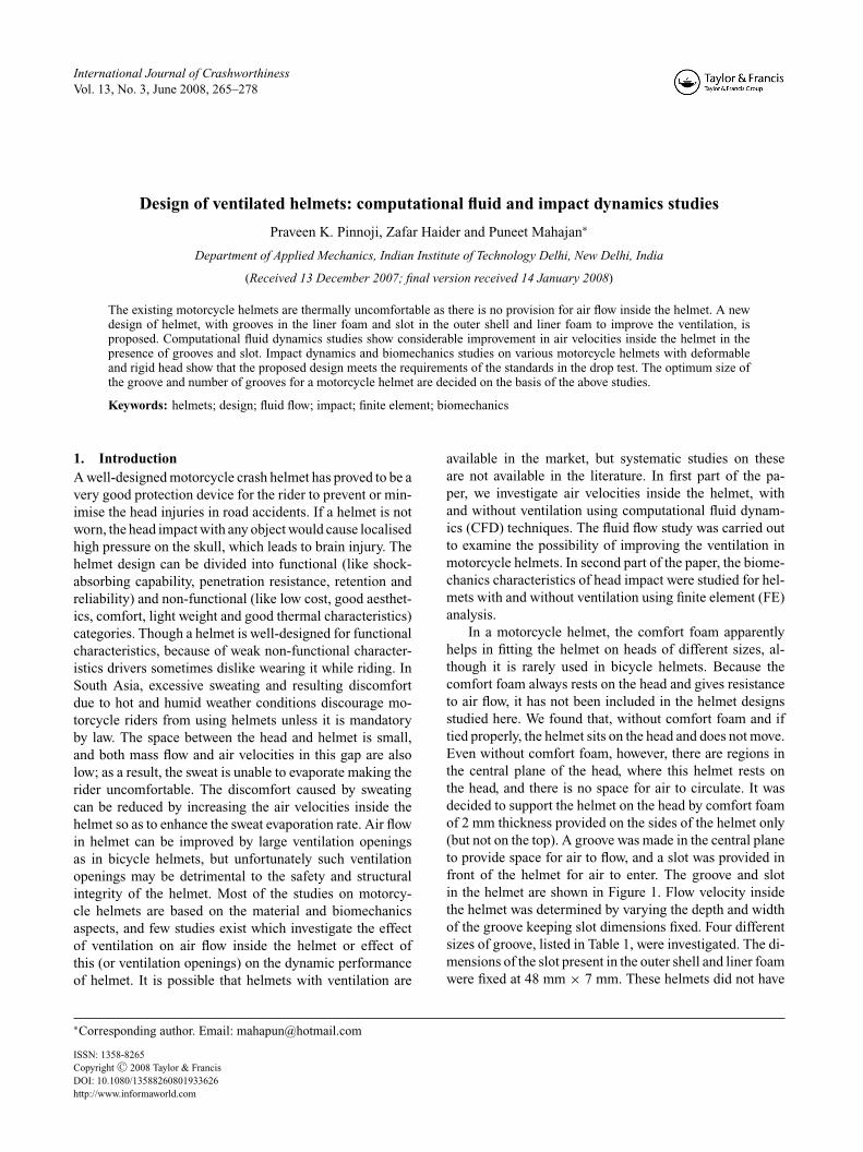
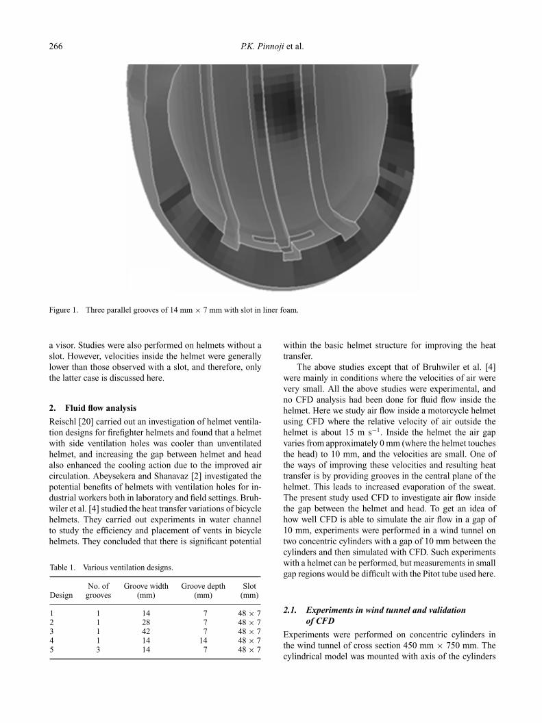
Boundary conditions, turbulent models and conver-gence criteria, here, are the same as used in the Section2. The helmet without ventilation had regions touching thehead where the air velocity is zero as air could not circulate.Figure 4 shows the velocity contours in three dimensionswithin the helmet–head gap with 14 mm × 14 mm grooveand 48 mm × 7 mm slot. Here air velocities in the centralplane are improved to 8 m s−1 near the slot, 6 m s−1 on topand 5 m s−1 at the end of the groove. In a helmet with agroove of 42 mm × 7 mm in the central plane and a slot of48 mm × 7 mm, air velocities in the central plane whichcan be seen in Figure 5 are further improved to 11 m s−1
near the slot, 5 m s−1 on top and 5 m s−1 at the end ofthe groove. With these ventilation models, air velocities areenhanced not only in the central plane of the groove butalso in other regions such as C and D in Figures 4 and 5,respectively. The air velocities in other regions are higherin the 42 mm × 7 mm groove helmet than in the 14 mm ×14 mm groove helmet. A comparison with Figure 4 shows
Figure 4. Velocity contour values within the foam-head gap withhalf symmetry in a helmet of 14 mm × 14 mm groove and a slotof 48 mm × 7 mm.
Figure 5. Velocity contour values within the foam-head gap withhalf symmetry in a helmet of 42 mm × 7 mm groove and a slotof 48 mm × 7 mm.
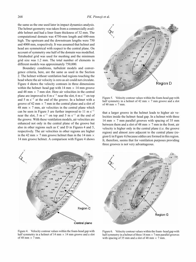
that a larger groove in the helmet leads to higher air ve-locities inside the helmet–head gap. In a helmet with three14 mm × 7 mm parallel grooves with spacing of 35 mmbetween them and a slot of 48 mm × 7 mm in the front, airvelocity is higher only in the central plane (i.e. the grooveregion) and almost zero adjacent to the central plane (re-gion G in Figure 6) because eddies are formed in this region.It, therefore, seems that for ventilation purposes providingthree grooves is not very advantageous.
Figure 6. Velocity contour values within the foam–head gap withhalf symmetry in a helmet of three 14 mm × 7 mm parallel grooveswith spacing of 35 mm and a slot of 48 mm × 7 mm.
International Journal of Crashworthiness 269
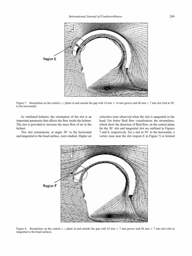
Figure 7. Streamlines on the central x–z plane in and outside the gap with 14 mm × 14 mm groove and 48 mm × 7 mm slot (slot at 30◦
to the horizontal).
In ventilated helmets, the orientation of the slot is animportant parameter that affects the flow inside the helmet.The slot is provided to increase the mass flow of air in thehelmet.
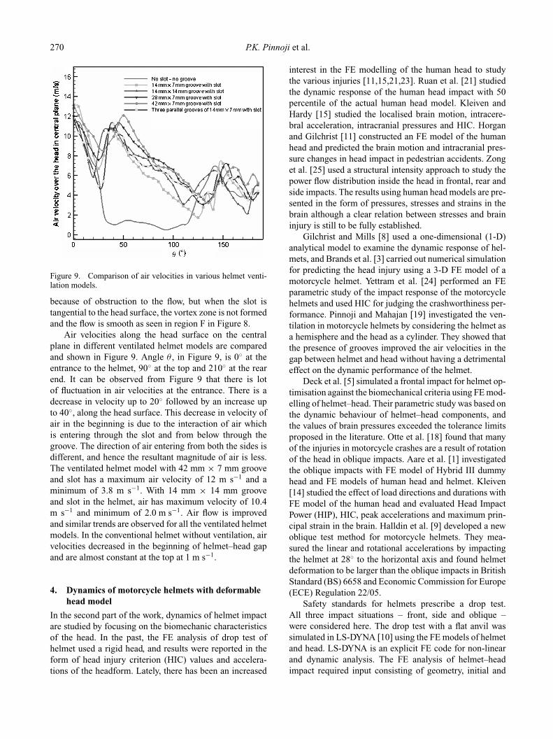
Two slot orientations, at angle 30◦ to the horizontaland tangential to the head surface, were studied. Higher air
Figure 8. Streamlines on the central x–z plane in and outside the gap with 42 mm × 7 mm groove and 48 mm × 7 mm slot (slot attangential to the head surface).
velocities were observed when the slot is tangential to thehead. For better fluid flow visualisation, the streamlines,which show the direction of fluid flow, on the central planefor the 30◦ slot and tangential slot are outlined in Figures7 and 8, respectively. For a slot at 30◦ to the horizontal, avortex zone near the slot (region E in Figure 7) is formed
270 P.K. Pinnoji et al.
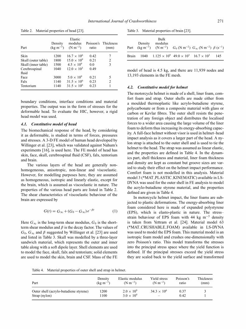
Figure 9. Comparison of air velocities in various helmet venti-lation models.
because of obstruction to the flow, but when the slot istangential to the head surface, the vortex zone is not formedand the flow is smooth as seen in region F in Figure 8.
Air velocities along the head surface on the centralplane in different ventilated helmet models are comparedand shown in Figure 9. Angle θ , in Figure 9, is 0◦ at theentrance to the helmet, 90◦ at the top and 210◦ at the rearend. It can be observed from Figure 9 that there is lotof fluctuation in air velocities at the entrance. There is adecrease in velocity up to 20◦ followed by an increase upto 40◦, along the head surface. This decrease in velocity ofair in the beginning is due to the interaction of air whichis entering through the slot and from below through thegroove. The direction of air entering from both the sides isdifferent, and hence the resultant magnitude of air is less.The ventilated helmet model with 42 mm × 7 mm grooveand slot has a maximum air velocity of 12 m s−1 and aminimum of 3.8 m s−1. With 14 mm × 14 mm grooveand slot in the helmet, air has maximum velocity of 10.4m s−1 and minimum of 2.0 m s−1. Air flow is improvedand similar trends are observed for all the ventilated helmetmodels. In the conventional helmet without ventilation, airvelocities decreased in the beginning of helmet–head gapand are almost constant at the top at 1 m s−1.
4. Dynamics of motorcycle helmets with deformablehead model
In the second part of the work, dynamics of helmet impactare studied by focusing on the biomechanic characteristicsof the head. In the past, the FE analysis of drop test ofhelmet used a rigid head, and results were reported in theform of head injury criterion (HIC) values and accelera-tions of the headform. Lately, there has been an increased
interest in the FE modelling of the human head to studythe various injuries [11,15,21,23]. Ruan et al. [21] studiedthe dynamic response of the human head impact with 50percentile of the actual human head model. Kleiven andHardy [15] studied the localised brain motion, intracere-bral acceleration, intracranial pressures and HIC. Horganand Gilchrist [11] constructed an FE model of the humanhead and predicted the brain motion and intracranial pres-sure changes in head impact in pedestrian accidents. Zonget al. [25] used a structural intensity approach to study thepower flow distribution inside the head in frontal, rear andside impacts. The results using human head models are pre-sented in the form of pressures, stresses and strains in thebrain although a clear relation between stresses and braininjury is still to be fully established.
Gilchrist and Mills [8] used a one-dimensional (1-D)analytical model to examine the dynamic response of hel-mets, and Brands et al. [3] carried out numerical simulationfor predicting the head injury using a 3-D FE model of amotorcycle helmet. Yettram et al. [24] performed an FEparametric study of the impact response of the motorcyclehelmets and used HIC for judging the crashworthiness per-formance. Pinnoji and Mahajan [19] investigated the ven-tilation in motorcycle helmets by considering the helmet asa hemisphere and the head as a cylinder. They showed thatthe presence of grooves improved the air velocities in thegap between helmet and head without having a detrimentaleffect on the dynamic performance of the helmet.
Deck et al. [5] simulated a frontal impact for helmet op-timisation against the biomechanical criteria using FE mod-elling of helmet–head. Their parametric study was based onthe dynamic behaviour of helmet–head components, andthe values of brain pressures exceeded the tolerance limitsproposed in the literature. Otte et al. [18] found that manyof the injuries in motorcycle crashes are a result of rotationof the head in oblique impacts. Aare et al. [1] investigatedthe oblique impacts with FE model of Hybrid III dummyhead and FE models of human head and helmet. Kleiven[14] studied the effect of load directions and durations withFE model of the human head and evaluated Head ImpactPower (HIP), HIC, peak accelerations and maximum prin-cipal strain in the brain. Halldin et al. [9] developed a newoblique test method for motorcycle helmets. They mea-sured the linear and rotational accelerations by impactingthe helmet at 28◦ to the horizontal axis and found helmetdeformation to be larger than the oblique impacts in BritishStandard (BS) 6658 and Economic Commission for Europe(ECE) Regulation 22/05.
Safety standards for helmets prescribe a drop test.All three impact situations – front, side and oblique –were considered here. The drop test with a flat anvil wassimulated in LS-DYNA [10] using the FE models of helmetand head. LS-DYNA is an explicit FE code for non-linearand dynamic analysis. The FE analysis of helmet–headimpact required input consisting of geometry, initial and
International Journal of Crashworthiness 271
Table 2. Material properties of head [23].
ElasticDensity modulus Poisson’s Thickness
Part (kg m−3) (N m−2) ratio (mm)
Skin 1200 16.7 × 10⁶ 0.42 7Skull (outer table) 1800 15.0 × 10⁹ 0.21 2Skull (inner table) 1500 4.5 × 10⁹ 0.0 3Cerebrospinal 1040 12.0 × 10³ 0.49fluidFace 3000 5.0 × 10⁹ 0.21 5Falx 1140 31.5 × 10⁶ 0.23 2Tentorium 1140 31.5 × 10⁶ 0.23 1
boundary conditions, interface conditions and materialproperties. The output was in the form of stresses for thedeformable head. To evaluate the HIC, however, a rigidhead model was used.
4.1. Constitutive model of head
The biomechanical response of the head, by consideringit as deformable, is studied in terms of forces, pressuresand stresses. A 3-D FE model of human head developed byWillinger et al. [23], which was validated against Nahum’sexperiments [16], is used here. The FE model of head hasskin, face, skull, cerebrospinal fluid (CSF), falx, tentoriumand brain.
The various layers of the head are generally non-homogeneous, anisotropic, non-linear and viscoelastic.However, for modelling purposes here, they are assumedas homogeneous, isotropic and linearly elastic, except forthe brain, which is assumed as viscoelastic in nature. Theproperties of the various head parts are listed in Table 2.The shear characteristics of viscoelastic behaviour of thebrain are expressed by
G(t) = G∞ + (G0 −G∞) e−βt (1)
Here G∞ is the long-term shear modulus, G0 is the short-term shear modulus and β is the decay factor. The values ofG0, G∞ and β suggested by Willinger et al. [23] are usedand listed in Table 3. Skull was modelled by a three-layersandwich material, which represents the outer and innertable along with a soft dipole layer. Shell elements are usedto model the face, skull, falx and tentorium; solid elementsare used to model the skin, brain and CSF. Mass of the FE
Table 4. Material properties of outer shell and strap in helmet.
Density Elastic modulus Yield stress Poisson’s ThicknessPart (kg m−3) (N m−2) (N m−2) ratio (mm)
Outer shell (acrylo-butadiene styrene) 1200 2.0 × 10⁹ 34.3 × 10⁶ 0.37 3Strap (nylon) 1100 3.0 × 10⁹ – 0.42 1
Table 3. Material properties of brain [23].
BulkDensity modulus
Part (kg m−3) (N m−2) G0 (N m−2) G∞ (N m−2) β (s−1)
Brain 1040 1.125 × 10⁹ 49.0 × 10³ 16.7 × 10³ 145
model of head is 4.5 kg, and there are 11,939 nodes and13,193 elements in the FE mesh.
4.2. Constitutive model for helmet
The motorcycle helmet is made of a shell, liner foam, com-fort foam and strap. Outer shells are made either froma moulded thermoplastic like acrylo-butadiene styrene,polycarbonate or from a composite material with glass orcarbon or Kevlar fibres. The outer shell resists the pene-tration of any foreign object and distributes the localisedforces to a wider area causing the large volume of the linerfoam to deform thus increasing its energy-absorbing capac-ity. A full-face helmet without visor is used in helmet–headimpact analysis as it covers a larger part of the head. A ny-lon strap is attached to the outer shell and is used to tie thehelmet to the head. The strap was assumed as linear elastic,and the properties are defined in Table 4. In the dynam-ics part, shell thickness and material, liner foam thicknessand density are kept as constant but groove sizes are var-ied to study their effect on the helmet impact performance.Comfort foam is not modelled in this analysis. Materialmodel 3 (*MAT PLASTIC KINEMATIC) available in LS-DYNA was used for the outer shell in FE analysis to modelthe acrylo-butadiene styrene material, and the propertiesdefined are given in Table 4.
In motorcycle helmet impact, the liner foams are sub-jected to plastic deformations. The energy-absorbing linerfoam considered here is made of expanded polystyrene(EPS), which is elasto-plastic in nature. The stress–strain behaviour of EPS foam with 44 kg m−3 densityis taken from Yettram et al. [24]. Material model 63(*MAT CRUSHABLE FOAM) available in LS-DYNAwas used to model the EPS foam. This material model is anisotropic foam model and crushes one-dimensionally withzero Poisson’s ratio. This model transforms the stressesinto the principal stress space where the yield function isdefined. If the principal stresses exceed the yield stressthey are scaled back to the yield surface and transformed
272 P.K. Pinnoji et al.
back to the original stress space. The yield surface andits evolution are defined by the Equations (2) and (3),respectively, given below.
ft = |σi| − Y = 0 (2)
Y = Y0 +H (ev)
Yt = Y0t (3)
Here Y is the yield stress, Y ◦ is initial compressive yieldstress, Yt is tensile cut off stress, σ i is the principal stressesand H is strain hardening, which is a function of the vol-umetric strain, ev, defined by natural logarithm of relativevolume. An associative flow rule for a flow surface, whichis same as yield surface, is assumed and the plastic strainsare derived from Equation (4)
ε·pij = ·
λ∂F
∂ σij
(4)
ε·pij is the plastic flow rate tensor, and
·λ is the plasticity
consistency parameter.In LS-DYNA, the stress versus volumetric strain data
for the liner foam is given in tabular form and it fits thematerial model 63 to this curve. The EPS foam has Young’smodulus of 1.8 × 10⁷ N m−2 with zero Poisson’s ratio anda compressive yield stress (Y ◦) of 0.6 × 10⁶ N m−2.
4.3. Finite element mesh and injury criteria
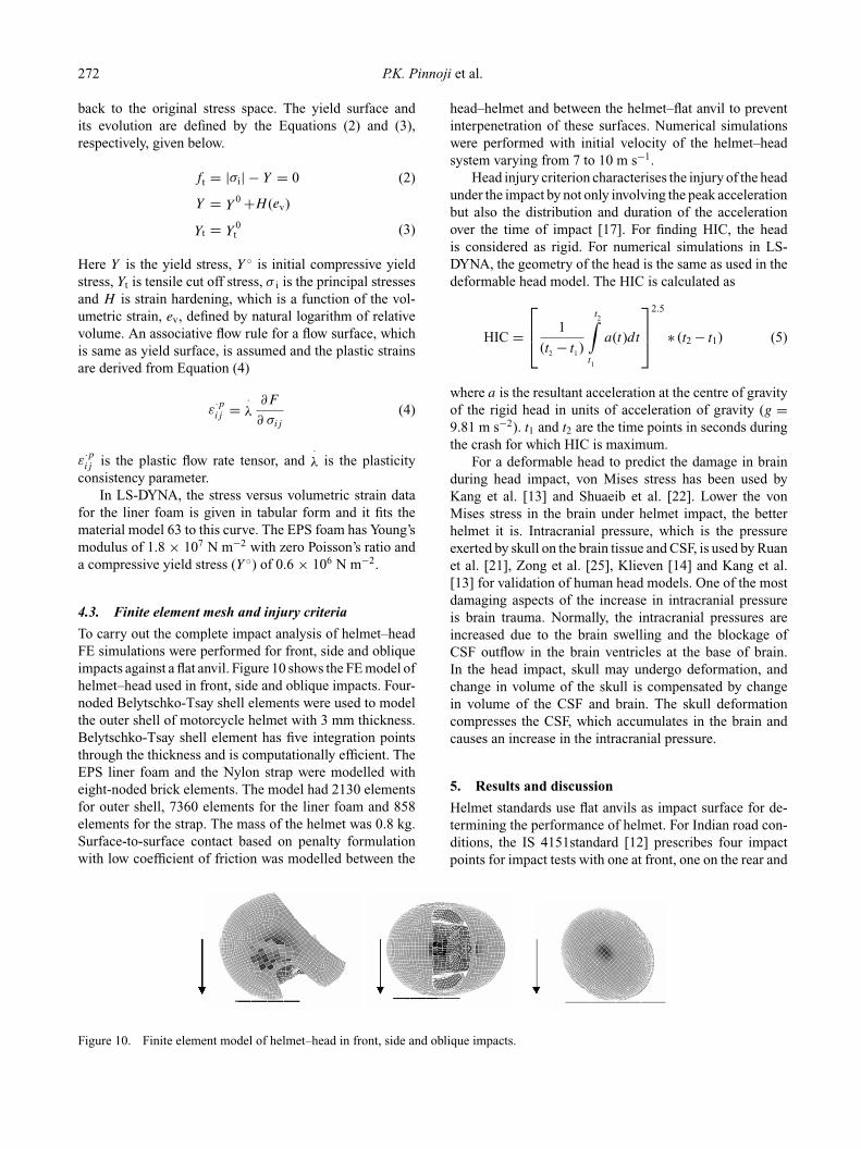
To carry out the complete impact analysis of helmet–headFE simulations were performed for front, side and obliqueimpacts against a flat anvil. Figure 10 shows the FE model ofhelmet–head used in front, side and oblique impacts. Four-noded Belytschko-Tsay shell elements were used to modelthe outer shell of motorcycle helmet with 3 mm thickness.Belytschko-Tsay shell element has five integration pointsthrough the thickness and is computationally efficient. TheEPS liner foam and the Nylon strap were modelled witheight-noded brick elements. The model had 2130 elementsfor outer shell, 7360 elements for the liner foam and 858elements for the strap. The mass of the helmet was 0.8 kg.Surface-to-surface contact based on penalty formulationwith low coefficient of friction was modelled between the
Figure 10. Finite element model of helmet–head in front, side and oblique impacts.
head–helmet and between the helmet–flat anvil to preventinterpenetration of these surfaces. Numerical simulationswere performed with initial velocity of the helmet–headsystem varying from 7 to 10 m s−1.
Head injury criterion characterises the injury of the headunder the impact by not only involving the peak accelerationbut also the distribution and duration of the accelerationover the time of impact [17]. For finding HIC, the headis considered as rigid. For numerical simulations in LS-DYNA, the geometry of the head is the same as used in thedeformable head model. The HIC is calculated as
HIC =
1
(t2 − t1 )
t2∫
t1
a(t)dt
2.5
∗ (t2 − t1) (5)
where a is the resultant acceleration at the centre of gravityof the rigid head in units of acceleration of gravity (g =9.81 m s−2). t1 and t2 are the time points in seconds duringthe crash for which HIC is maximum.
For a deformable head to predict the damage in brainduring head impact, von Mises stress has been used byKang et al. [13] and Shuaeib et al. [22]. Lower the vonMises stress in the brain under helmet impact, the betterhelmet it is. Intracranial pressure, which is the pressureexerted by skull on the brain tissue and CSF, is used by Ruanet al. [21], Zong et al. [25], Klieven [14] and Kang et al.[13] for validation of human head models. One of the mostdamaging aspects of the increase in intracranial pressureis brain trauma. Normally, the intracranial pressures areincreased due to the brain swelling and the blockage ofCSF outflow in the brain ventricles at the base of brain.In the head impact, skull may undergo deformation, andchange in volume of the skull is compensated by changein volume of the CSF and brain. The skull deformationcompresses the CSF, which accumulates in the brain andcauses an increase in the intracranial pressure.
5. Results and discussion
Helmet standards use flat anvils as impact surface for de-termining the performance of helmet. For Indian road con-ditions, the IS 4151standard [12] prescribes four impactpoints for impact tests with one at front, one on the rear and
International Journal of Crashworthiness 273
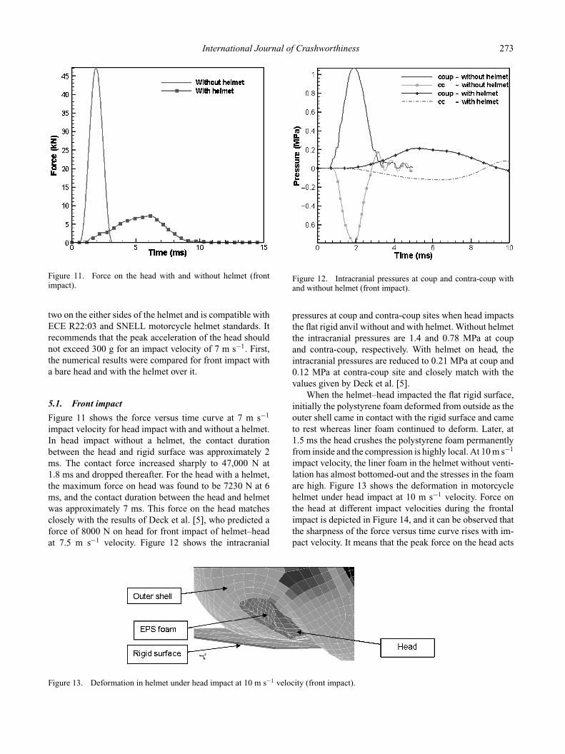
Figure 11. Force on the head with and without helmet (frontimpact).
two on the either sides of the helmet and is compatible withECE R22:03 and SNELL motorcycle helmet standards. Itrecommends that the peak acceleration of the head shouldnot exceed 300 g for an impact velocity of 7 m s−1. First,the numerical results were compared for front impact witha bare head and with the helmet over it.
5.1. Front impact
Figure 11 shows the force versus time curve at 7 m s−1
impact velocity for head impact with and without a helmet.In head impact without a helmet, the contact durationbetween the head and rigid surface was approximately 2ms. The contact force increased sharply to 47,000 N at1.8 ms and dropped thereafter. For the head with a helmet,the maximum force on head was found to be 7230 N at 6ms, and the contact duration between the head and helmetwas approximately 7 ms. This force on the head matchesclosely with the results of Deck et al. [5], who predicted aforce of 8000 N on head for front impact of helmet–headat 7.5 m s−1 velocity. Figure 12 shows the intracranial
Figure 13. Deformation in helmet under head impact at 10 m s−1 velocity (front impact).
Figure 12. Intracranial pressures at coup and contra-coup withand without helmet (front impact).
pressures at coup and contra-coup sites when head impactsthe flat rigid anvil without and with helmet. Without helmetthe intracranial pressures are 1.4 and 0.78 MPa at coupand contra-coup, respectively. With helmet on head, theintracranial pressures are reduced to 0.21 MPa at coup and0.12 MPa at contra-coup site and closely match with thevalues given by Deck et al. [5].
When the helmet–head impacted the flat rigid surface,initially the polystyrene foam deformed from outside as theouter shell came in contact with the rigid surface and cameto rest whereas liner foam continued to deform. Later, at1.5 ms the head crushes the polystyrene foam permanentlyfrom inside and the compression is highly local. At 10 m s−1
impact velocity, the liner foam in the helmet without venti-lation has almost bottomed-out and the stresses in the foamare high. Figure 13 shows the deformation in motorcyclehelmet under head impact at 10 m s−1 velocity. Force onthe head at different impact velocities during the frontalimpact is depicted in Figure 14, and it can be observed thatthe sharpness of the force versus time curve rises with im-pact velocity. It means that the peak force on the head acts
274 P.K. Pinnoji et al.
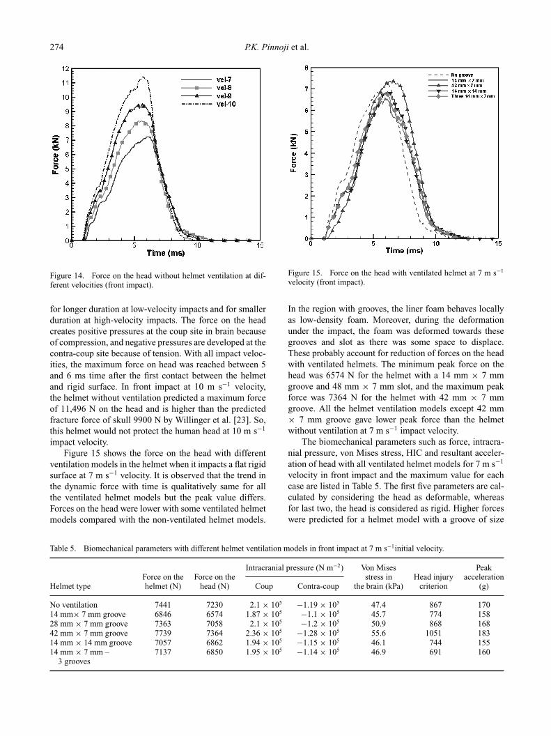
Figure 14. Force on the head without helmet ventilation at dif-ferent velocities (front impact).
for longer duration at low-velocity impacts and for smallerduration at high-velocity impacts. The force on the headcreates positive pressures at the coup site in brain becauseof compression, and negative pressures are developed at thecontra-coup site because of tension. With all impact veloc-ities, the maximum force on head was reached between 5and 6 ms time after the first contact between the helmetand rigid surface. In front impact at 10 m s−1 velocity,the helmet without ventilation predicted a maximum forceof 11,496 N on the head and is higher than the predictedfracture force of skull 9900 N by Willinger et al. [23]. So,this helmet would not protect the human head at 10 m s−1
impact velocity.Figure 15 shows the force on the head with different
ventilation models in the helmet when it impacts a flat rigidsurface at 7 m s−1 velocity. It is observed that the trend inthe dynamic force with time is qualitatively same for allthe ventilated helmet models but the peak value differs.Forces on the head were lower with some ventilated helmetmodels compared with the non-ventilated helmet models.
Table 5. Biomechanical parameters with different helmet ventilation models in front impact at 7 m s−1initial velocity.
Intracranial pressure (N m−2) Von Mises PeakForce on the Force on the stress in Head injury acceleration
Helmet type helmet (N) head (N) Coup Contra-coup the brain (kPa) criterion (g)
No ventilation 7441 7230 2.1 × 10⁵ −1.19 × 10⁵ 47.4 867 17014 mm× 7 mm groove 6846 6574 1.87 × 10⁵ −1.1 × 10⁵ 45.7 774 15828 mm × 7 mm groove 7363 7058 2.1 × 10⁵ −1.2 × 10⁵ 50.9 868 16842 mm × 7 mm groove 7739 7364 2.36 × 10⁵ −1.28 × 10⁵ 55.6 1051 18314 mm × 14 mm groove 7057 6862 1.94 × 10⁵ −1.15 × 10⁵ 46.1 744 15514 mm × 7 mm – 7137 6850 1.95 × 10⁵ −1.14 × 10⁵ 46.9 691 160
3 grooves
Figure 15. Force on the head with ventilated helmet at 7 m s−1
velocity (front impact).
In the region with grooves, the liner foam behaves locallyas low-density foam. Moreover, during the deformationunder the impact, the foam was deformed towards thesegrooves and slot as there was some space to displace.These probably account for reduction of forces on the headwith ventilated helmets. The minimum peak force on thehead was 6574 N for the helmet with a 14 mm × 7 mmgroove and 48 mm × 7 mm slot, and the maximum peakforce was 7364 N for the helmet with 42 mm × 7 mmgroove. All the helmet ventilation models except 42 mm× 7 mm groove gave lower peak force than the helmetwithout ventilation at 7 m s−1 impact velocity.
The biomechanical parameters such as force, intracra-nial pressure, von Mises stress, HIC and resultant acceler-ation of head with all ventilated helmet models for 7 m s−1
velocity in front impact and the maximum value for eachcase are listed in Table 5. The first five parameters are cal-culated by considering the head as deformable, whereasfor last two, the head is considered as rigid. Higher forceswere predicted for a helmet model with a groove of size
International Journal of Crashworthiness 275
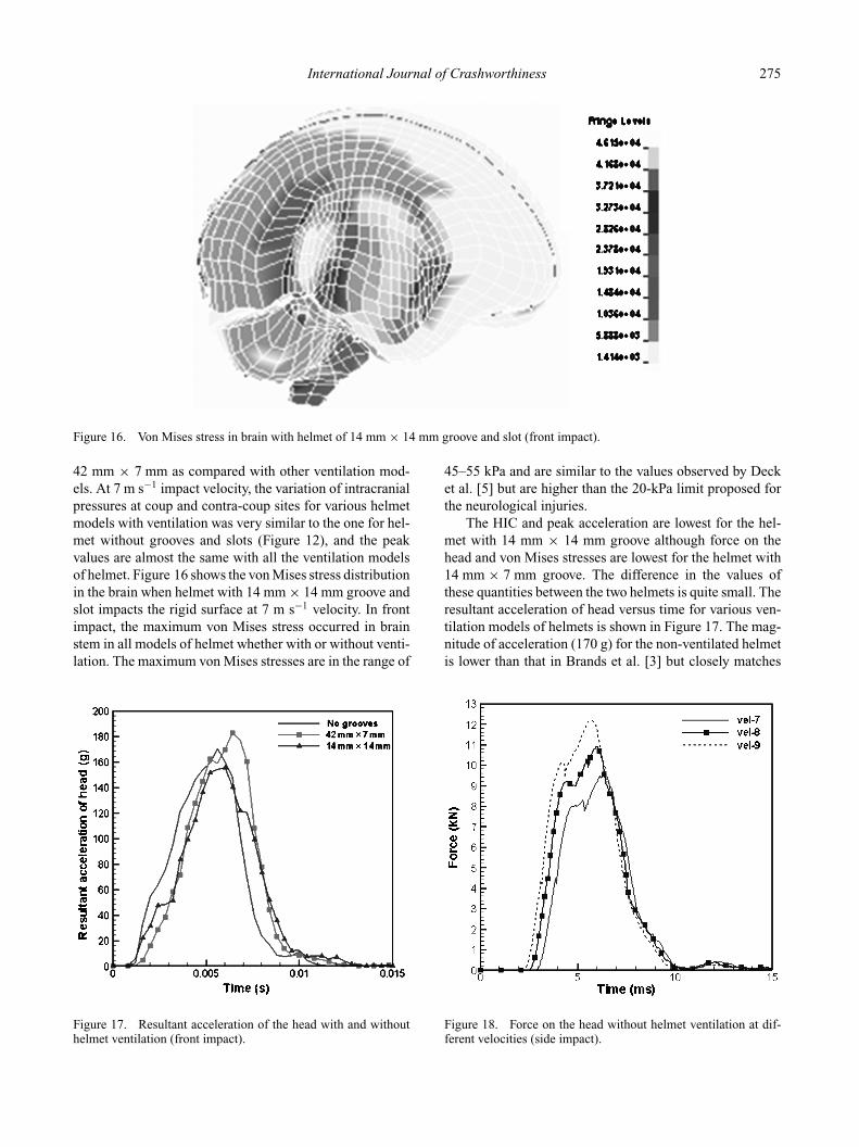
Figure 16. Von Mises stress in brain with helmet of 14 mm × 14 mm groove and slot (front impact).
42 mm × 7 mm as compared with other ventilation mod-els. At 7 m s−1 impact velocity, the variation of intracranialpressures at coup and contra-coup sites for various helmetmodels with ventilation was very similar to the one for hel-met without grooves and slots (Figure 12), and the peakvalues are almost the same with all the ventilation modelsof helmet. Figure 16 shows the von Mises stress distributionin the brain when helmet with 14 mm × 14 mm groove andslot impacts the rigid surface at 7 m s−1 velocity. In frontimpact, the maximum von Mises stress occurred in brainstem in all models of helmet whether with or without venti-lation. The maximum von Mises stresses are in the range of
Figure 17. Resultant acceleration of the head with and withouthelmet ventilation (front impact).
45–55 kPa and are similar to the values observed by Decket al. [5] but are higher than the 20-kPa limit proposed forthe neurological injuries.
The HIC and peak acceleration are lowest for the hel-met with 14 mm × 14 mm groove although force on thehead and von Mises stresses are lowest for the helmet with14 mm × 7 mm groove. The difference in the values ofthese quantities between the two helmets is quite small. Theresultant acceleration of head versus time for various ven-tilation models of helmets is shown in Figure 17. The mag-nitude of acceleration (170 g) for the non-ventilated helmetis lower than that in Brands et al. [3] but closely matches
Figure 18. Force on the head without helmet ventilation at dif-ferent velocities (side impact).
276 P.K. Pinnoji et al.
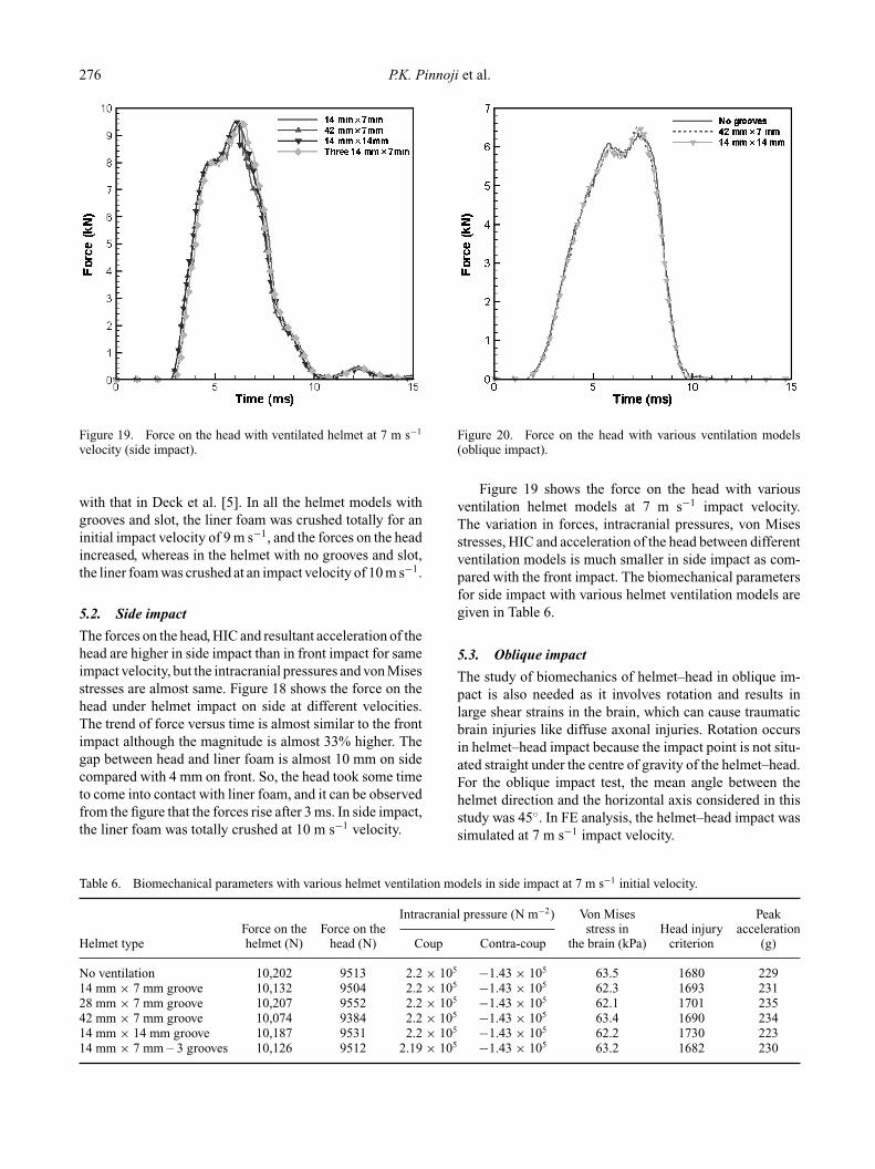
Figure 19. Force on the head with ventilated helmet at 7 m s−1
velocity (side impact).
with that in Deck et al. [5]. In all the helmet models withgrooves and slot, the liner foam was crushed totally for aninitial impact velocity of 9 m s−1, and the forces on the headincreased, whereas in the helmet with no grooves and slot,the liner foam was crushed at an impact velocity of 10 m s−1.
5.2. Side impact
The forces on the head, HIC and resultant acceleration of thehead are higher in side impact than in front impact for sameimpact velocity, but the intracranial pressures and von Misesstresses are almost same. Figure 18 shows the force on thehead under helmet impact on side at different velocities.The trend of force versus time is almost similar to the frontimpact although the magnitude is almost 33% higher. Thegap between head and liner foam is almost 10 mm on sidecompared with 4 mm on front. So, the head took some timeto come into contact with liner foam, and it can be observedfrom the figure that the forces rise after 3 ms. In side impact,the liner foam was totally crushed at 10 m s−1 velocity.
Table 6. Biomechanical parameters with various helmet ventilation models in side impact at 7 m s−1 initial velocity.
Intracranial pressure (N m−2) Von Mises PeakForce on the Force on the stress in Head injury acceleration
Helmet type helmet (N) head (N) Coup Contra-coup the brain (kPa) criterion (g)
No ventilation 10,202 9513 2.2 × 10⁵ −1.43 × 10⁵ 63.5 1680 22914 mm × 7 mm groove 10,132 9504 2.2 × 10⁵ −1.43 × 10⁵ 62.3 1693 23128 mm × 7 mm groove 10,207 9552 2.2 × 10⁵ −1.43 × 10⁵ 62.1 1701 23542 mm × 7 mm groove 10,074 9384 2.2 × 10⁵ −1.43 × 10⁵ 63.4 1690 23414 mm × 14 mm groove 10,187 9531 2.2 × 10⁵ −1.43 × 10⁵ 62.2 1730 22314 mm × 7 mm – 3 grooves 10,126 9512 2.19 × 10⁵ −1.43 × 10⁵ 63.2 1682 230
Figure 20. Force on the head with various ventilation models(oblique impact).
Figure 19 shows the force on the head with variousventilation helmet models at 7 m s−1 impact velocity.The variation in forces, intracranial pressures, von Misesstresses, HIC and acceleration of the head between differentventilation models is much smaller in side impact as com-pared with the front impact. The biomechanical parametersfor side impact with various helmet ventilation models aregiven in Table 6.
5.3. Oblique impact
The study of biomechanics of helmet–head in oblique im-pact is also needed as it involves rotation and results inlarge shear strains in the brain, which can cause traumaticbrain injuries like diffuse axonal injuries. Rotation occursin helmet–head impact because the impact point is not situ-ated straight under the centre of gravity of the helmet–head.For the oblique impact test, the mean angle between thehelmet direction and the horizontal axis considered in thisstudy was 45◦. In FE analysis, the helmet–head impact wassimulated at 7 m s−1 impact velocity.
International Journal of Crashworthiness 277
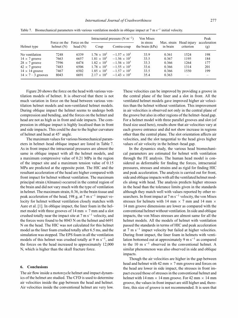
Table 7. Biomechanical parameters with various ventilation models in oblique impact at 7 m s−1 initial velocity.
Intracranial pressure (N m−2) Von Mises PeakForce on the Force on the in stress Max. strain Head injury acceleration
Helmet type helmet (N) head (N) Coup Contra-coup the brain (kPa) in brain criterion (g)
No ventilation 7248 6339 1.76 × 10⁵ −1.57 × 10⁵ 33.9 0.361 1524 19814 × 7 groove 7663 6657 1.81 × 10⁵ −1.56 × 10⁵ 33.5 0.367 1195 18428 × 7 groove 7596 6474 1.82 × 10⁵ −1.56 × 10⁵ 33.3 0.366 1264 17742 × 7 groove 7483 6506 1.78 × 10⁵ −1.55 × 10⁵ 33.6 0.366 1314 20114 × 14 groove 7467 6502 1.85 × 10⁵ −1.57 × 10⁵ 33.5 0.366 1550 19914 × 7 – 3 grooves 8043 6691 2.17 × 10⁵ −1.43 × 10⁵ 35.4 0.363 – –
Figure 20 shows the force on the head with various ven-tilation models of helmet. It is observed that there is notmuch variation in force on the head between various ven-tilation helmet models and non-ventilated helmet models.During oblique impact the helmet seems to undergo bothcompression and bending, and the forces on the helmet andhead are not as high as in front and side impacts. The com-pression in oblique impact is highly localised than in frontand side impacts. This could be due to the higher curvatureof helmet and head at 45◦ angle.
The maximum values for various biomechanical param-eters in helmet–head oblique impact are listed in Table 7.As in front impact the intracranial pressures are almost thesame in oblique impact with all the helmet models, anda maximum compressive value of 0.21 MPa in the regionof the impact site and a maximum tension value of 0.15MPa are predicted at the opposite point. The HIC and theresultant acceleration of the head are higher compared withfront impact for helmet without ventilation. The maximumprincipal strain (Almansi) occurred in the central region ofthe brain and did not vary much with the type of ventilationin helmet. The maximum strain, 0.36, in the brain tissue andpeak acceleration of the head, 198 g, at 7 m s−1 impact ve-locity for helmet without ventilation closely matches withAare et al. [1]. In oblique impact, the liner foam in the hel-met model with three grooves of 14 mm × 7 mm and a slotcrushed totally near the impact site at 7 m s−1 velocity, andthe forces were found to be 8043 N on the helmet and 6691N on the head. The HIC was not calculated for this helmetmodel as the liner foam crushed totally after 6.5 ms, and thesimulation was stopped. The EPS foam in all the ventilationmodels of this helmet was crushed totally at 9 m s−1, andthe forces on the head increased to approximately 12,000N, which is higher than the skull fracture force.
6. Conclusions
The air flow inside a motorcycle helmet and impact dynam-ics of the helmet are studied. The CFD is used to determineair velocities inside the gap between the head and helmet.Air velocities inside the conventional helmet are very low.
These velocities can be improved by providing a groove inthe central plane of the liner and a slot in front. All theventilated helmet models gave improved higher air veloci-ties than the helmet without ventilation. This improvementin air velocities is observed not only in the central plane ofthe groove but also in other regions of the helmet–head gap.For a helmet model with three parallel grooves and slot (offixed size used here), results show that air velocities vary ateach groove entrance and did not show increase in regionsother than the central plane. The slot orientation affects airvelocities, and the slot tangential to the head gives highervalues of air velocity in the helmet–head gap.
In the dynamics study, the various head biomechani-cal parameters are estimated for helmet with ventilationthrough the FE analysis. The human head model is con-sidered as deformable for finding the forces, intracranialpressures, stresses and strains and as rigid for finding HICand peak acceleration. The analysis is carried out for front,side and oblique impacts with all the ventilated helmet mod-els along with head. The analysis predicts higher stressesin the head than the tolerance limits given in the standardsalthough they match well with values reported by other re-searchers. In front impact at 7 m s−1 velocity, the von Misesstresses for helmets with 14 mm × 7 mm and 14 mm ×14 mm groove dimensions are lower as compared with theconventional helmet without ventilation. In side and obliqueimpacts, the von Mises stresses are almost same for all thehelmet models. All the models of helmet with ventilationpassed the standards in terms of HIC and peak accelerationat 7 m s−1 impact velocity but failed at higher velocities.During front impact, the liner foam in helmets with venti-lation bottomed out at approximately 9 m s−1 as comparedto the 10 m s−1 observed in the conventional helmet. Asimilar phenomenon was also observed in side and obliqueimpacts.
Though the air velocities are higher in the gap betweenhead and helmet with 42 mm × 7 mm groove and forces onthe head are lower in side impact, the stresses in front im-pact exceed those of stresses in the conventional helmet andhelmet with 14 mm × 14 mm groove. For 42 mm × 14 mmgroove, the values in front impact are still higher and, there-fore, this size of groove is not recommended. It is seen that
278 P.K. Pinnoji et al.
higher groove size gives higher air velocities inside the hel-met but at the same time results in higher stresses in thebrain if the groove width and depth exceed a certain size.The compromise design is to minimise the injury or harm tothe helmet wearers while providing ventilation. Among thevarious helmet ventilation models, the one with a grooveof 14 mm × 14 mm along with a slot of 48 mm × 7 mmis preferable at 7 m s−1 impact velocity as it enhances theaverage air velocities in the helmet–head gap, and the headexperiences lower forces and stresses. As no literature isavailable on the optimisation of ventilation in motorcyclehelmets, it is recommended that further studies should becarried out to improve the ventilation as well as dynamicsperformance of ventilated helmet impact.
AcknowledgmentThe authors express gratitude to the Transportation Research andInjury Prevention Programme, IIT-Delhi, India, for assistance andfinancial support provided through a sponsored research project.
References[1] M. Aare, S. Kleiven, and P. Halldin, Injury tolerances for
oblique impact helmet testing, Int. J. Crashworthiness 9(2004), pp. 15–23.
[2] J.D.A. Abeysekera and H. Shanavaz, Ergonomic eval-uation of modified industrial helmets for use in trop-ical environments, Ergonomics 31 (1988), pp. 1317–1329.
[3] D.W.A. Brands, J.G.M. Thunnissen, and J.S.H.M. Wis-mans, Modelling head injury countermeasures: A 3D hel-met model, AGARD Specialists’ Meeting on Impact HeadInjury: Responses, Mechanisms, Tolerance, Treatment andCountermeasures, New Mexico, 7–9 November 1996.
[4] P.A. Bruhwiler, M. Buyan, R. Huber, C.P. Bogerd, J. Sznit-man, S.F. Graf, and T. Rosgen, Heat transfer variations ofbicycle helmets, J. Sports Sci. 24 (2006), pp. 999–1011.
[5] C. Deck, D. Baumgartner, and R. Willinger, Helmet opti-mization based on head-helmet impact modeling, 8th In-ternational Conference on Computer Aided Optimum De-sign of Structures, OPTI VIII, MNP, Michigan, USA, 2003,pp. 319–328.
[6] FLUENT 6.2 User’s Guide, FLUENT Inc., 2005.[7] J.H. Ferziger and H. Peric, Computational Methods for Fluid
Dynamics, 3rd ed., Springer, Berlin, 2002.[8] A. Gilchrist and N.J. Mills, Modelling of the impact perfor-
mance of motorcycle helmets, Int. J. Impact Eng. 15 (1994),pp. 201–218.
[9] P. Halldin, A. Gilchrist, and N.J. Mills, A new oblique impacttest for motorcycle helmets, IRCOBI Conference, Isle ofMan, UK, 2001, pp. 343–345.
[10] J.O. Hallquist, LS-DYNA Theoretical Manual, LivermoreSoftware Technology Corporation, 1998.
[11] T.J. Horgan and M.D. Gilchrist, Influence of FE model vari-ability in predicting brain motion and intracranial pressurechanges in head impact simulations, Int. J. Crashworthiness9 (2004), pp. 401–418.
[12] IS 4151, Indian standard specification for motorcycle helmetusers, Bureau of Indian Standards, New Delhi, 1993.
[13] H. Kang, R. Willinger, B.M. Diaw, and B. Chinn, Valida-tion of a 3D anatomic human head model and replication ofhead impact in motorcycle accident by finite element mod-eling, SAE Transactions, Paper No. 973339, 1997, pp. 329–338.
[14] S. Kleiven, Evaluation of head injury criteria using an FEmodel validated against experiments on localized brain mo-tion, intra-cerebral acceleration, and intra-cranial pressure,Int. J. Crashworthiness 11 (2006), pp. 65–79.
[15] S. Kleiven and W.N. Hardy, Correlation of an FE Model ofhuman head with experiments on localized motion of brain –consequences for injury prediction, Society for AutomotiveEngineers, 46th Stapp Car Crash Journal, 2002, SAE PaperNo. 02S-76.
[16] A.M. Nahum, R. Smith, and C.C. Ward, Intracranial pres-sure dynamics during head impact, Proceedings of 21stStapp Car Crash Conference, New Orleans, USA, 1977,pp. 339–366.
[17] J.A. Newman, Head injury criteria in automotive crashtesting, Society of Automotive Engineers, Warrendale, PA,1970, SAE 700426.
[18] D. Otte, B. Chinn, D. Doyle, S. Makitupa, K. Sturrock, and E.Schuller, Contribution to Final Report of COST 327 Project,University of Hanover, Germany, 1999.
[19] P.K. Pinnoji and P. Mahajan, Impact analysis of helmets forimproved ventilation with deformable head model, IRCOBIConference, Madrid, 2006, pp. 159–170.
[20] U. Reischl, Fire fighter helmet ventilation analysis, Am. Ind.Hyg. Assoc. J. 47 (1986), pp. 546–551.
[21] J.S. Ruan, T.B. Khalil , and A.I. King, Dynamic responseof the human head impact by three-dimensional finite ele-ment analysis, J. Biomech. Eng. Trans. ASME 116 (1994),pp. 44–50.
[22] F.M. Shuaeib, A.M.S. Hamouda, R.S. Radin Umar, M.M.Hamdan, and M.S.J. Hashmi, Motorcycle helmet Part 1:Biomechanics and computational issues, J. Mater. Process.Technol. 123 (2002), pp. 406–421.
[23] R. Willinger, B.M. Diaw, and H.-S. Kang, Finite elementmodeling of skull fractures caused by direct impact, Int. J.Crashworthiness 5 (2000), pp. 249–258.
[24] A.L. Yettram, N.P.M. Godfrey, and B.P. Chinn, Materialsfor motorcycle crash helmets – a finite element parametricstudy, Plastics Rubber Compos. Process. Appl. 22 (1994),pp. 215–221.
[25] Z. Zong, H. Lee, and C. Lu, A three-dimensional humanhead finite element model and power flow in a humanhead subjected to impact loading, J. Biomech. 39 (2006),pp. 284–292.