Embed Size (px)
Citation preview

Massachusetts Institute of Technology 2.017
Design for the Ocean Environment
Massachusetts Institute of Technology 2.017
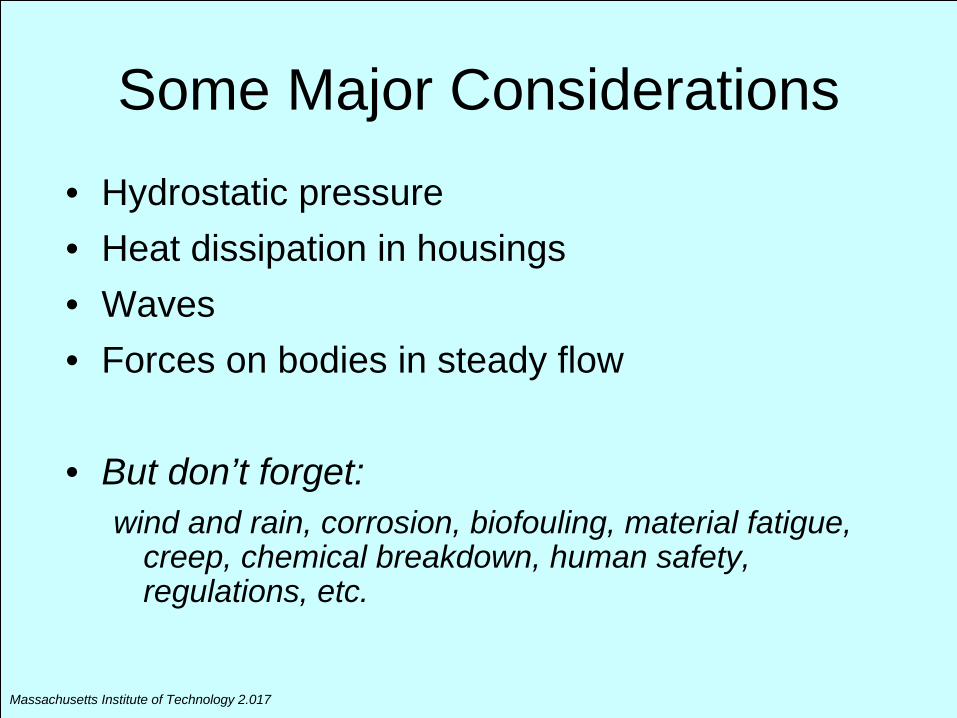
Some Major Considerations• Hydrostatic pressure• Heat dissipation in housings• Waves• Forces on bodies in steady flow
• But don’t forget: wind and rain, corrosion, biofouling, material fatigue,
creep, chemical breakdown, human safety, regulations, etc.
Massachusetts Institute of Technology 2.017
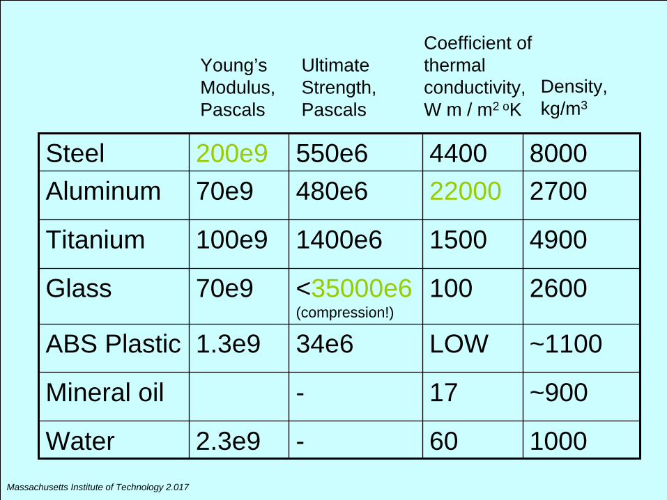
Steel 200e9 550e6 4400 8000Aluminum 70e9 480e6 22000 2700
Titanium 100e9 1400e6 1500 4900
Glass 70e9 <35000e6 (compression!)
100 2600
ABS Plastic 1.3e9 34e6 LOW ~1100
Mineral oil - 17 ~900
Water 2.3e9 - 60 1000
Young’s Modulus,Pascals
UltimateStrength, Pascals
Coefficient of thermal conductivity, W m / m2 oK
Density, kg/m3
Massachusetts Institute of Technology 2.017
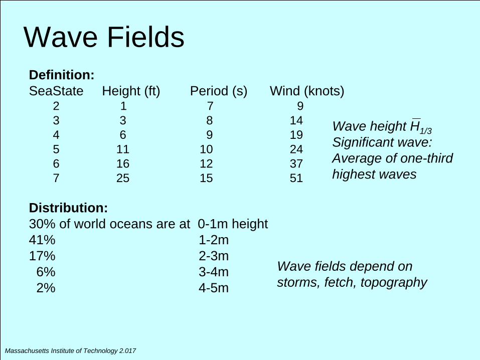
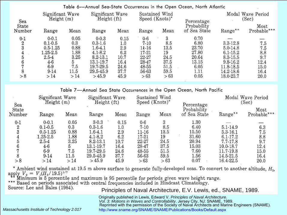
Wave FieldsDefinition:SeaState Height (ft) Period (s) Wind (knots)
2 1 7 93 3 8 144 6 9 195 11 10 246 16 12 377 25 15 51
Distribution:30% of world oceans are at 0-1m height41% 1-2m 17% 2-3m6% 3-4m2% 4-5m
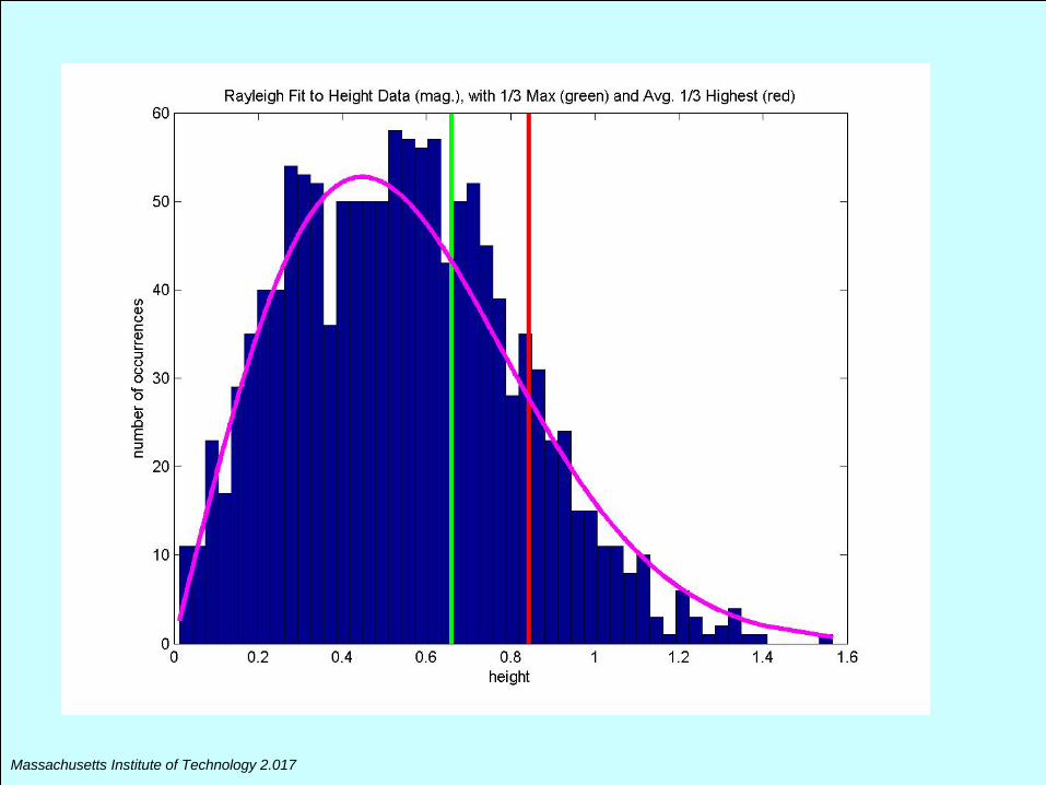
Wave height H1/3Significant wave: Average of one-third highest waves
Wave fields depend on storms, fetch, topography
Massachusetts Institute of Technology 2.017
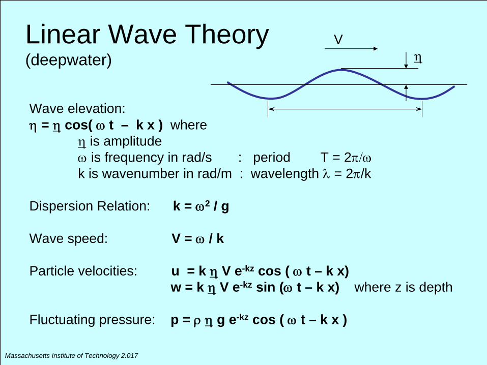
Linear Wave Theory (deepwater)
Wave elevation:
=
cos( t – k x ) where
is amplitude
is frequency in rad/s : period T = 2k is wavenumber in rad/m : wavelength
= 2/k
Dispersion Relation: k = 2 / g
Wave speed: V =
/ k
Particle velocities: u = k
V e-kz cos (
t – k x)w = k
V e-kz sin (
t – k x) where z is depth
Fluctuating pressure: p =
g e-kz cos (
t – k x )
V
Massachusetts Institute of Technology 2.017
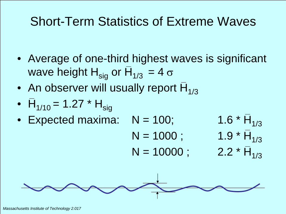
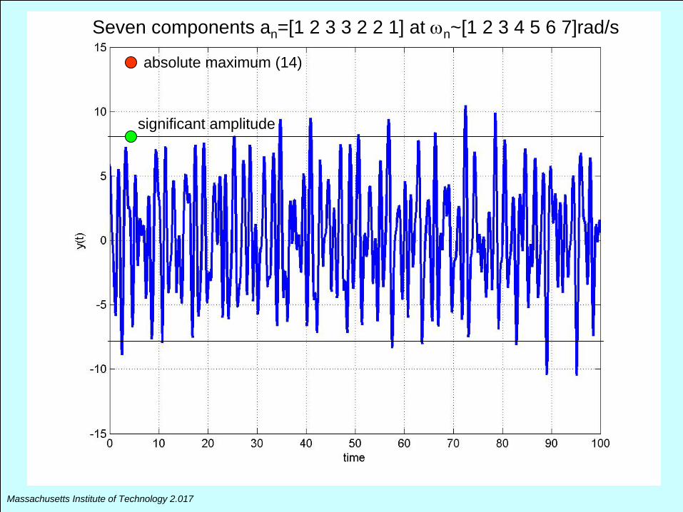
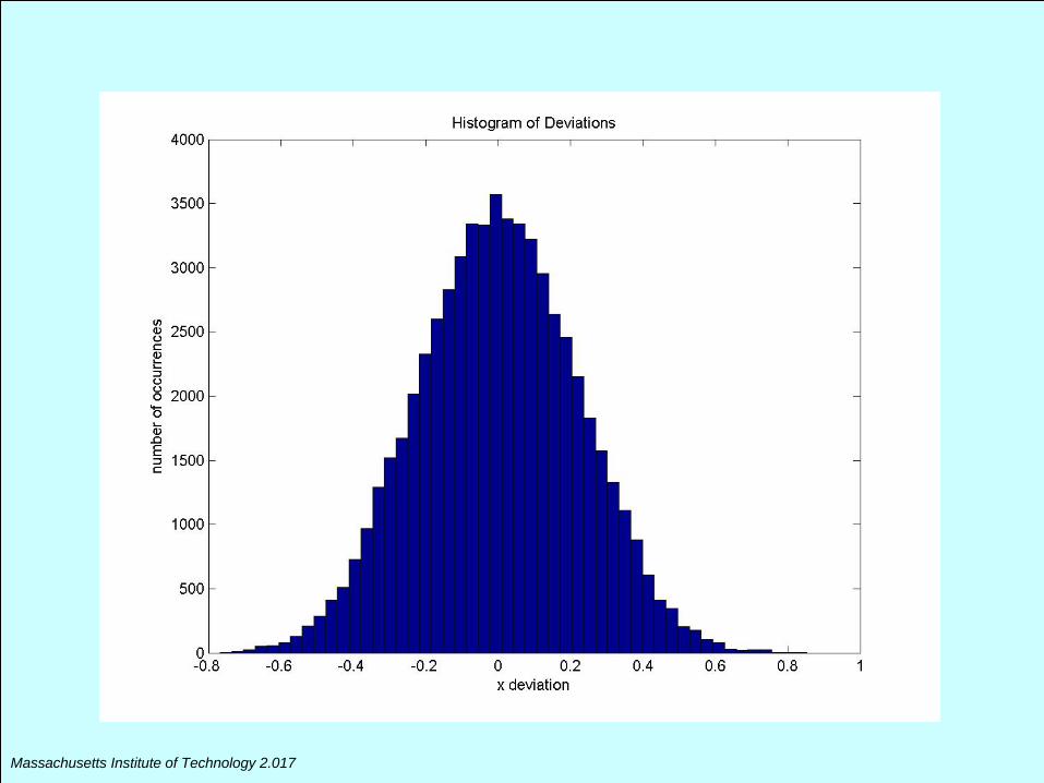
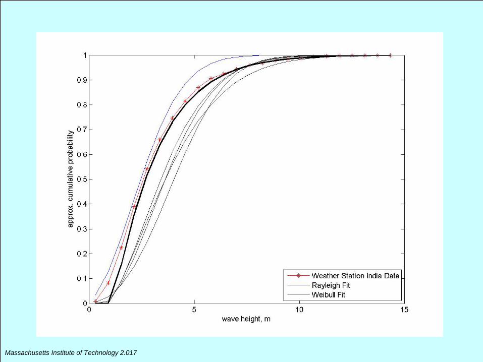
Short-Term Statistics of Extreme Waves
• Average of one-third highest waves is significant wave height Hsig or H1/3 = 4
• An observer will usually report H1/3
• H1/10 = 1.27 * Hsig
• Expected maxima: N = 100; 1.6 * H1/3
N = 1000 ; 1.9 * H1/3
N = 10000 ; 2.2 * H1/3
Massachusetts Institute of Technology 2.017
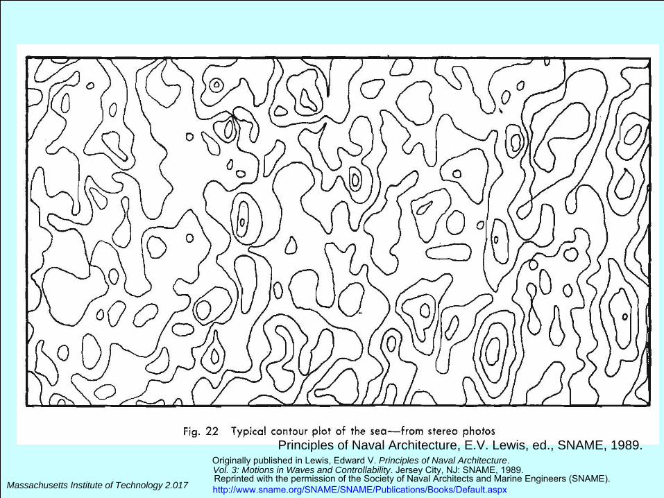
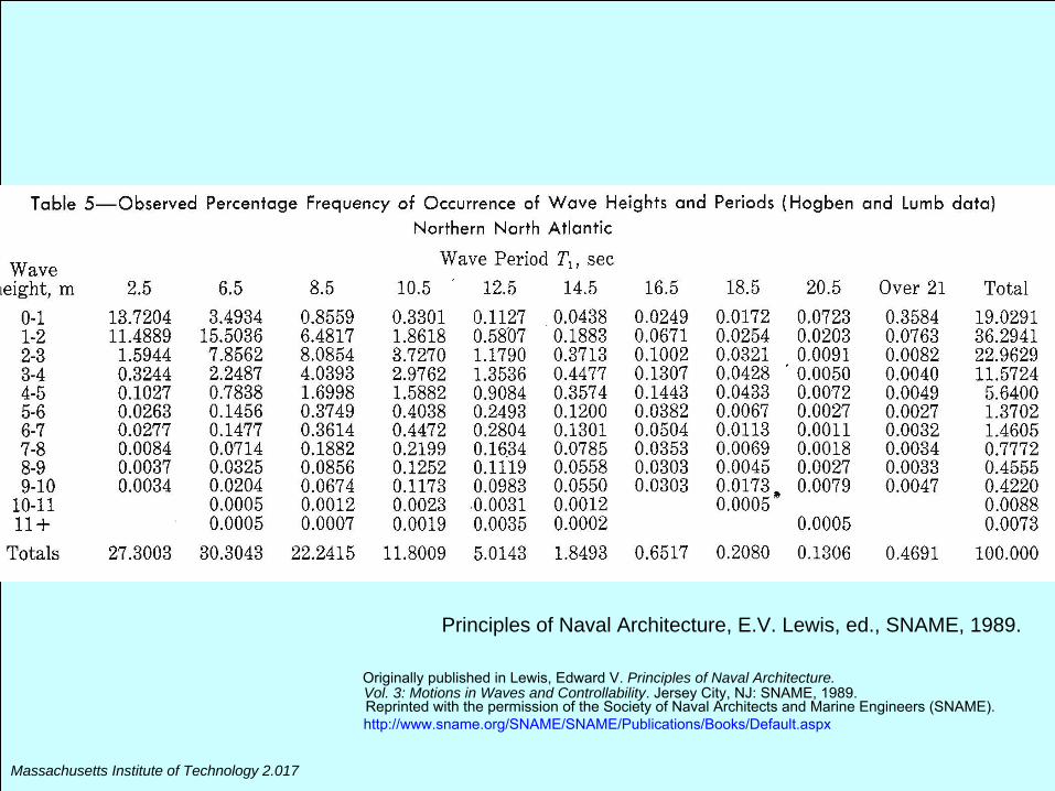
Principles of Naval Architecture, E.V. Lewis, ed., SNAME, 1989.Originally published in Lewis, Edward V. Principles of Naval Architecture.Vol. 3: Motions in Waves and Controllability. Jersey City, NJ: SNAME, 1989.Reprinted with the permission of the Society of Naval Architects and Marine Engineers (SNAME).http://www.sname.org/SNAME/SNAME/Publications/Books/Default.aspx
Massachusetts Institute of Technology 2.017
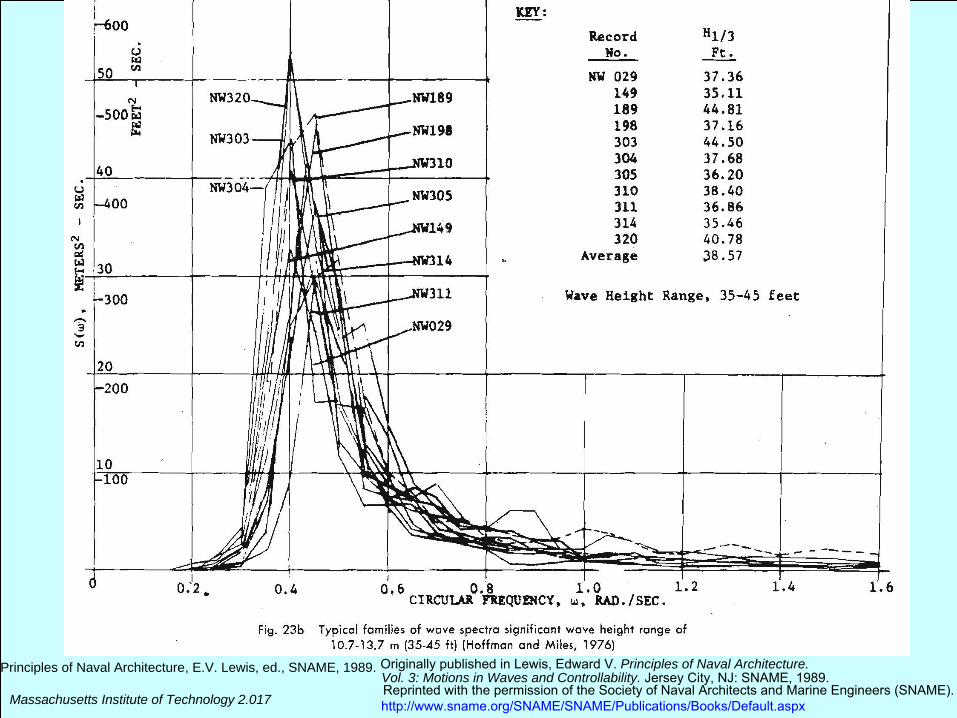
Principles of Naval Architecture, E.V. Lewis, ed., SNAME, 1989. Originally published in Lewis, Edward V. Principles of Naval Architecture.Vol. 3: Motions in Waves and Controllability. Jersey City, NJ: SNAME, 1989.Reprinted with the permission of the Society of Naval Architects and Marine Engineers (SNAME).http://www.sname.org/SNAME/SNAME/Publications/Books/Default.aspx
M
Principles of Naval Architecture, E.V. Lewis, ed., SNAME, 1989.Originally published in Lewis, Edward V. Principles of Naval Architecture.Vol. 3: Motions in Waves and Controllability. Jersey City, NJ: SNAME, 1989.Reprinted with the permission of the Society of Naval Architects and Marine Engineers (SNAME).
assachusetts Institute of Technology 2.017 http://www.sname.org/SNAME/SNAME/Publications/Books/Default.aspx
Principles of Naval Architecture, E.V. Lewis, ed., SNAME, 1989.
Originally published in Lewis, Edward V. Principles of Naval Architecture.Vol. 3: Motions in Waves and Controllability. Jersey City, NJ: SNAME, 1989.Reprinted with the permission of the Society of Naval Architects and Marine Engineers (SNAME).http://www.sname.org/SNAME/SNAME/Publications/Books/Default.aspx
Massachusetts Institute of Technology 2.017
Massachusetts Institute of Technology 2.017
Seven components an =[1 2 3 3 2 2 1] at n ~[1 2 3 4 5 6 7]rad/s
significant amplitude
absolute maximum (14)
Massachusetts Institute of Technology 2.017
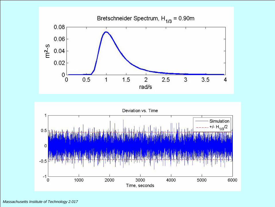
m2 -
s
Massachusetts Institute of Technology 2.017
Massachusetts Institute of Technology 2.017
Massachusetts Institute of Technology 2.017
Massachusetts Institute of Technology 2.017
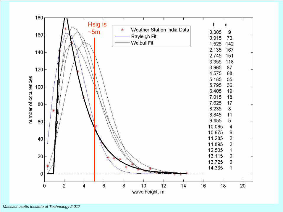
Hsig is ~5m
Massachusetts Institute of Technology 2.017
Massachusetts Institute of Technology 2.017
Massachusetts Institute of Technology 2.017
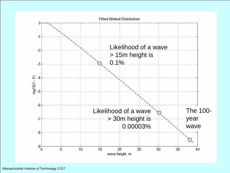
Likelihood of a wave > 15m height is 0.1%
Likelihood of a wave > 30m height is
0.00003%
The 100- year wave
Massachusetts Institute of Technology 2.017
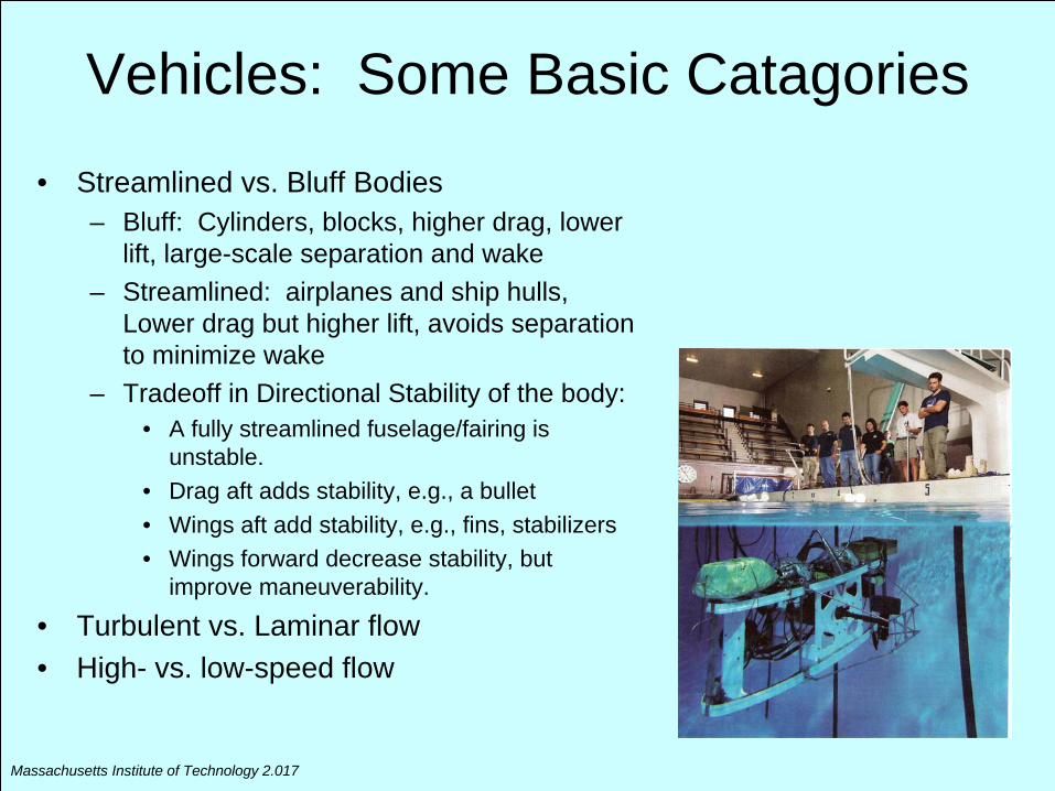
Vehicles: Some Basic Catagories
• Streamlined vs. Bluff Bodies– Bluff: Cylinders, blocks, higher drag, lower
lift, large-scale separation and wake– Streamlined: airplanes and ship hulls,
Lower drag but higher lift, avoids separation to minimize wake
– Tradeoff in Directional Stability of the body: • A fully streamlined fuselage/fairing is
unstable.• Drag aft adds stability, e.g., a bullet• Wings aft add stability, e.g., fins, stabilizers• Wings forward decrease stability, but
improve maneuverability.
• Turbulent vs. Laminar flow• High- vs. low-speed flow
Massachusetts Institute of Technology 2.017
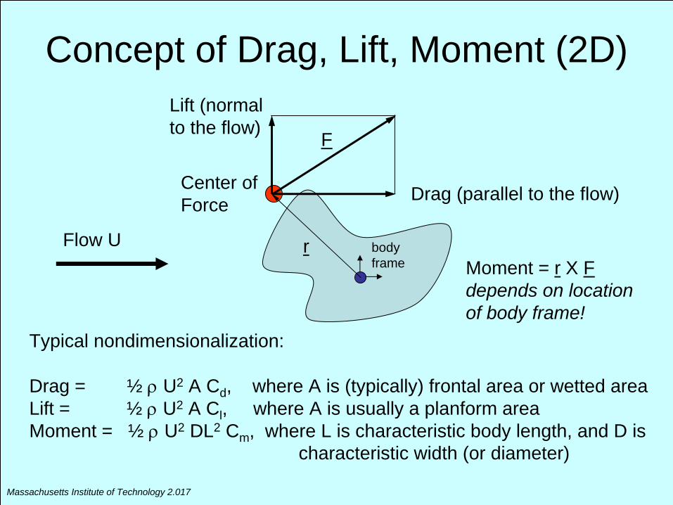
Concept of Drag, Lift, Moment (2D)
Flow U
Lift (normal to the flow)
Drag (parallel to the flow)
F
rMoment = r X F depends on location of body frame!
body frame
Typical nondimensionalization:
Drag = ½
U2 A Cd , where A is (typically) frontal area or wetted areaLift = ½
U2 A Cl , where A is usually a planform areaMoment = ½
U2 DL2 Cm , where L is characteristic body length, and D ischaracteristic width (or diameter)
Center of Force
Massachusetts Institute of Technology 2.017
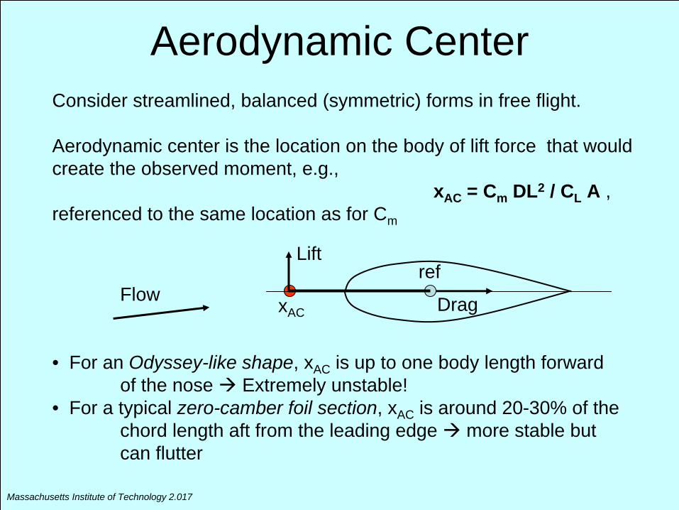
Aerodynamic CenterConsider streamlined, balanced (symmetric) forms in free flight.
Aerodynamic center is the location on the body of lift force that would create the observed moment, e.g.,
xAC = Cm DL2 / CL A ,referenced to the same location as for Cm
xAC
refLift
Drag
• For an Odyssey-like shape, xAC is up to one body length forward of the nose Extremely unstable!
• For a typical zero-camber foil section, xAC is around 20-30% of the chord length aft from the leading edge more stable but can flutter
Flow
Massachusetts Institute of Technology 2.017
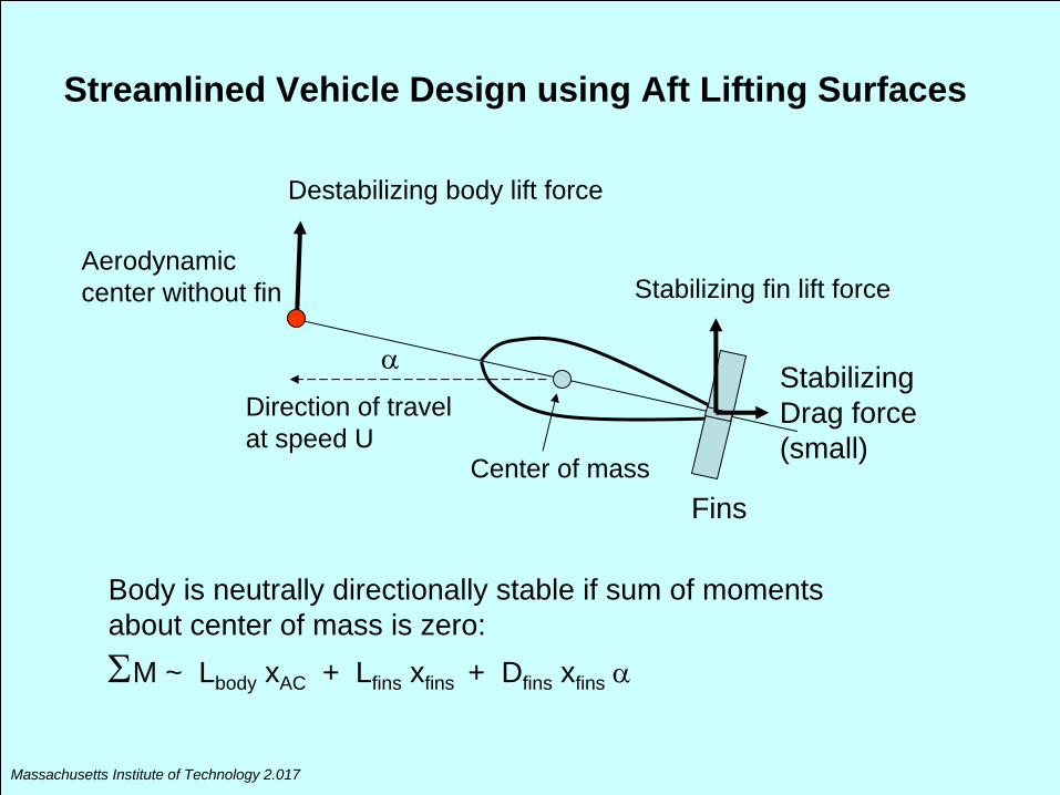
Destabilizing body lift force
Stabilizing fin lift force
Center of mass
Direction of travel at speed U
Aerodynamic center without fin
Fins
Body is neutrally directionally stable if sum of moments about center of mass is zero:M ~ Lbody xAC + Lfins xfins + Dfins xfins
StabilizingDrag force (small)
Streamlined Vehicle Design using Aft Lifting Surfaces
Massachusetts Institute of Technology 2.017
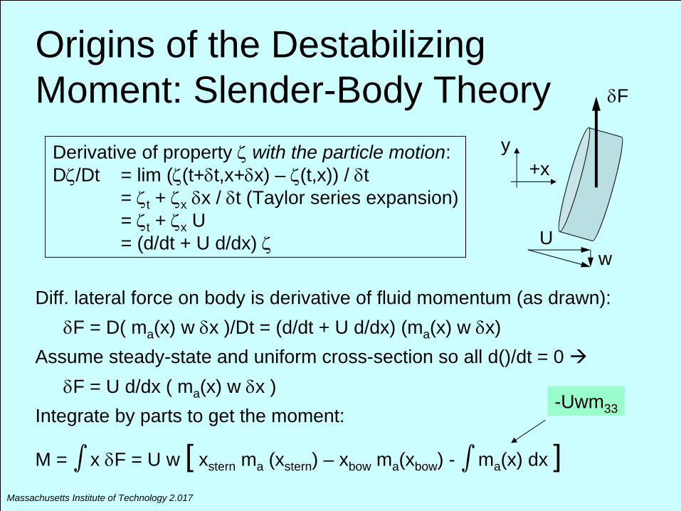
Origins of the Destabilizing Moment: Slender-Body Theory
Diff. lateral force on body is derivative of fluid momentum (as drawn):F = D( ma (x) w x )/Dt = (d/dt + U d/dx) (ma (x) w x)
Assume steady-state and uniform cross-section so all d()/dt = 0 F = U d/dx ( ma (x) w x )
Integrate by parts to get the moment:
M = ∫
x F = U w [ xstern ma (xstern ) – xbow ma (xbow ) - ∫
ma (x) dx ]
Derivative of property
with the particle motion:D/Dt = lim ((t+t,x+x) – (t,x)) / t
= t + x x / t (Taylor series expansion)= t + x U = (d/dt + U d/dx)
wU
F
+xy
-Uwm33
Massachusetts Institute of Technology 2.017
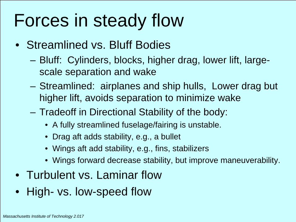
Forces in steady flow• Streamlined vs. Bluff Bodies
– Bluff: Cylinders, blocks, higher drag, lower lift, large- scale separation and wake
– Streamlined: airplanes and ship hulls, Lower drag but higher lift, avoids separation to minimize wake
– Tradeoff in Directional Stability of the body: • A fully streamlined fuselage/fairing is unstable.• Drag aft adds stability, e.g., a bullet• Wings aft add stability, e.g., fins, stabilizers• Wings forward decrease stability, but improve maneuverability.
• Turbulent vs. Laminar flow• High- vs. low-speed flow
Massachusetts Institute of Technology 2.017
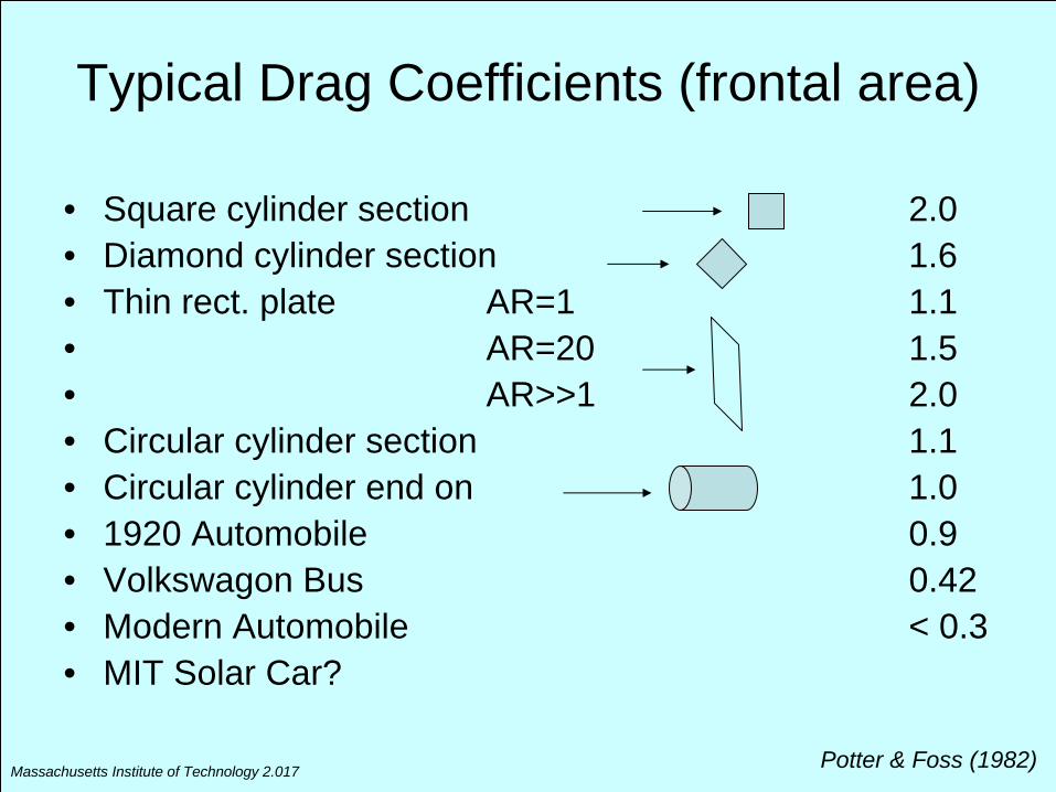
Typical Drag Coefficients (frontal area)
• Square cylinder section 2.0• Diamond cylinder section 1.6• Thin rect. plate AR=1 1.1• AR=20 1.5• AR>>1 2.0• Circular cylinder section 1.1• Circular cylinder end on 1.0• 1920 Automobile 0.9• Volkswagon Bus 0.42• Modern Automobile < 0.3• MIT Solar Car?
Potter & Foss (1982)
Massachusetts Institute of Technology 2.017
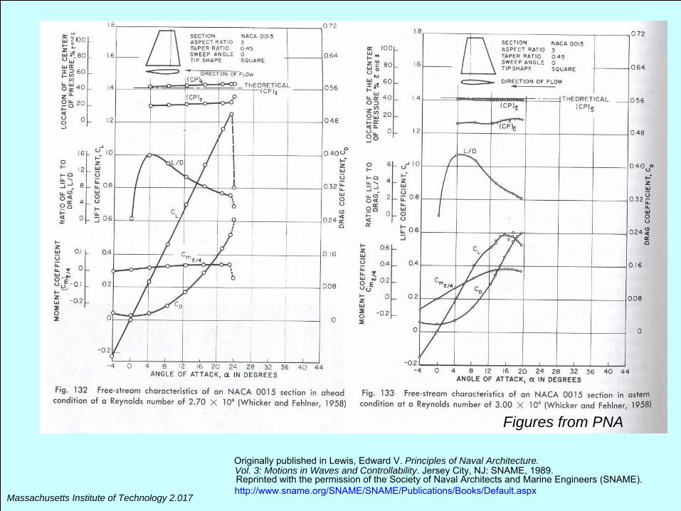
Figures from PNA
Originally published in Lewis, Edward V. Principles of Naval Architecture.Vol. 3: Motions in Waves and Controllability. Jersey City, NJ: SNAME, 1989.Reprinted with the permission of the Society of Naval Architects and Marine Engineers (SNAME).http://www.sname.org/SNAME/SNAME/Publications/Books/Default.aspx
Massachusetts Institute of Technology 2.017
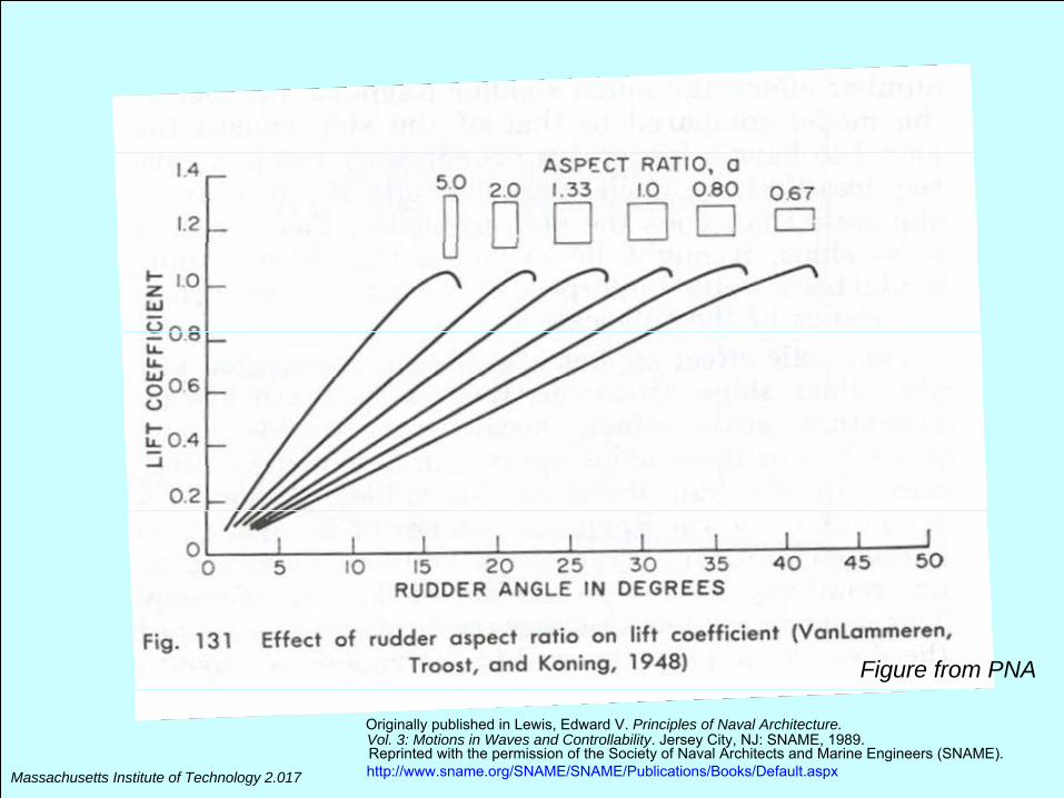
Figure from PNA
Originally published in Lewis, Edward V. Principles of Naval Architecture.Vol. 3: Motions in Waves and Controllability. Jersey City, NJ: SNAME, 1989.Reprinted with the permission of the Society of Naval Architects and Marine Engineers (SNAME).http://www.sname.org/SNAME/SNAME/Publications/Books/Default.aspx
Massachusetts Institute of Technology 2.017
Images removed due to copyright restrictions. Please see Fig. 30-33 in Hoerner,Sighard F., and Henry V. Borst. Fluid-Dynamic Lift. Bakersfield, CA: Hoerner Fluid Dynamics.
Massachusetts Institute of Technology 2.017
Recommended References
• Fluid-Dynamic Lift. S.F. Hoerner, 1975, Hoerner Fluid Dynamics, Bakersfield, CA.
• Principles of Naval Architecture, Volume III (Motions in Waves and Controllability), E.V. Lewis, ed., 1989, SNAME, Jersey City, NJ.
• Fluid Mechanics, M.C. Potter and J.F. Foss, 1982, Great Lakes Press, Okemo, MI.
• Theory of Flight, R. von Mises, 1945, Dover, New York.• http://naca.larc.nasa.gov/: NACA reports on bodies and
surfaces
MIT OpenCourseWarehttp://ocw.mit.edu
2.017J Design of Electromechanical Robotic SystemsFall 2009 For information about citing these materials or our Terms of Use, visit: http://ocw.mit.edu/terms.