Embed Size (px)
Citation preview
University of Pennsylvania University of Pennsylvania
ScholarlyCommons ScholarlyCommons
Theses (Historic Preservation) Graduate Program in Historic Preservation
1999
Design and Evaluation of Acrylic-Based Grouts for Earthen Design and Evaluation of Acrylic-Based Grouts for Earthen
Plasters Plasters
Kecia Lee Fong University of Pennsylvania
Follow this and additional works at: https://repository.upenn.edu/hp_theses
Part of the Historic Preservation and Conservation Commons
Fong, Kecia Lee, "Design and Evaluation of Acrylic-Based Grouts for Earthen Plasters" (1999). Theses (Historic Preservation). 461. https://repository.upenn.edu/hp_theses/461
Copyright note: Penn School of Design permits distribution and display of this student work by University of Pennsylvania Libraries. Suggested Citation: Fong, Kecia Lee (1999). Design and Evaluation of Acrylic-Based Grouts for Earthen Plasters. (Masters Thesis). University of Pennsylvania, Philadelphia, PA.
This paper is posted at ScholarlyCommons. https://repository.upenn.edu/hp_theses/461 For more information, please contact [email protected].
Design and Evaluation of Acrylic-Based Grouts for Earthen Plasters Design and Evaluation of Acrylic-Based Grouts for Earthen Plasters
Disciplines Disciplines Historic Preservation and Conservation
Comments Comments Copyright note: Penn School of Design permits distribution and display of this student work by University of Pennsylvania Libraries.
Suggested Citation:
Fong, Kecia Lee (1999). Design and Evaluation of Acrylic-Based Grouts for Earthen Plasters. (Masters Thesis). University of Pennsylvania, Philadelphia, PA.
This thesis or dissertation is available at ScholarlyCommons: https://repository.upenn.edu/hp_theses/461


UNivERsmryPENNSYLVANIA.
UBRARIES


DESIGN AND EVALUATION OF ACRYLIC-BASED GROUTSFOR EARTHEN PLASTERS
Kecia Lee Fong
A THESIS
Historic Preservation
Presented to the Faculties of the University of Pennsylvania in Partial
Fulfillment of the Requirements for the Degree of
MASTER OF SCIENCE
1999
M^^^LtxO?
Su^jervisi;
Frank G. Matero
Associate Professor of Architecture
Reader
Robert L. Hartzler
Exhibit Specialist, Conservator
OAAd^i^HTp^iGraduate Group Chair
David G. De Long
Professor of Architecture
UNIVERSITYOF
PENNSYLVANIALIBRARIES
ACKNOWLEDGMENTS
/ am I plus my surroundings and if I do not preserve the latter, I do not preserve myself.
-Jose Ortega Y Gasset [Meditations on Quixote] (1883-1955)
All knowledge and discovery is built upon that which precedes it and all current conditions
both tangible and intangible, are evidence of this principle of interdependent nature.
Conservation embodies these principles of causation and interdependency in its embrace and
integration of multiple disciplines. It recognises the inherent relationships between the
extrinsic and the intrinsic, between the physical and the immaterial. It realises these principles
in the thoughtful practice of its etiological and hermeneutic investigations. The philosophy
and theory provide the framework for the praxis. This perspective and ultimate material
contribution are manifested in the extension of the life of the 'thing,' (object, structure, site,
place). This act is founded on the belief that the past and context are profound agents of who
and what we are and what we envision ourselves to be. Like the quote by Jose Ortega Y
Gasset acknowledges, we do not exist alone as singular, contained entities but rather are
creations of a continuum.
This work is a result of that continuum. Special recognition is due to those who provided
generous contributions of advice, guidance and materials. TTie research was sponsored by the
University of Pennsylvania and the United States National Park Service.
The inexpressibilitv of one's gratitude is most keenly felt when attempting to articulate the
indebtedness to one's teachers. A special thanks is due to the irrepayable generosity and

guidance of my advisor Frank Matero, Chairman of the Graduate Program in Historic
Preservation, University of Pennsylvania. He is a treasured mentor and endless source of
inspiration.
I would like to thank Jake Barrow of the United States Department of the Interior, National
Park Service, Intermountain Region, Santa Fe Support Office, Architectural Conservation
Projects Program for his assistance, encouragement and support. He was greatly responsible
for the organisation of the field research, served as ally and liaison between the parks and the
University, and was a valuable source of NPS park history (administrative and conservation
practice). His patience, faith and support are duly appreciated.
Robert Hartzler, Exhibit Specialist, Conservator of Fort Union National Monument, Watrous,
New Mexico served as critical reader, offered expertise and insight into the site and the
materials under investigation, engaged in discussion and the exchange of ideas, and shared
useful materials.
Also of the NPS, Superintendent Donald Spencer of Casa Grande Ruins National Monument,
Coolidge, Arizona and his staff for their support and assistance during the field research
component of this work.
At the University of Pennsylvania, Dr. Omar Gomaa of the Department of Earth and
Environmental Science assisted in the micromorphoiogica! analysis of the materials. Dr. Alex
Radin in the Materials Testing Laboratory of the Laboratory for Research on the Structure of

Matter (LRSM), assisted in the development and critique of the strength tests. Dr. Elena
Charola, of the Graduate Department of Historic Preservation, provided constructive
comments and advice during the testing programme.
Rohm and Haas and 3M and Zeelan Industries, Inc. both provided materials for the laboratory
component. Their contributions are appreciated.
And none of this would have been possible without the love and encouragement of my friends
and family. I would like to thank them for their boundless belief, support and confidence,
especially my Grandmother, my mother and Annalisa.
Kecia L. Fong
Philadelphia, PAApril 1999

CONTENTS
Acknowledgments ii
List of Figures vii
List of Tables ix
Preface x
1.0 INTRODUCTION 1
2.0 THE CASA GRANDE 4
2.1 Site Summary 4
2.1.1 Conservation History 8
2.2 Field Observations/Site Condition 11
2.3 Material Characterisation and Analysis 21
2.3.1 Sampling 22
2.3.2 Bulk Analysis 23
2.3.3 Cross Section Examination 26
2.3.4 Thin Section Examination 30
3.0 TREATMENT REQUIREMENTS 36
3.1 Identification of the Conservation Problem 36
3.2 Mechanisms of Deterioration and Detachment 39
3.3 Treatment Requirements 42
4.0 MATERIAL SELECTION 48
4.1 Aqueous Adhesive Emulsions 49
4.1.1 Acrylic vs. Polyvinyl Acetate Resin 51
4.1.2 Rhoplex® E-330 53
4.2 Binder Concentration 55
4.3 Fillers 56
4.4 Thickeners 59
5.0 TESTING PROGRAMME 61
5.1 Flow 65
5.2 Shrinkage 67
5.3 Dispersion 69
5.4 Shear Strength Under Compressive Force 70
5.5 Water Vapor Transmission 76
6.0 TEST DATA AND RESULTS 79
6.1 Flow 80
6.2 Shrinkage 84
6.3 Dispersion 90
6.4 Shear Strength Under Compressive Force 91
6.5 Water Vapor Transmission 98
6.6 Laboratory Conclusions 104
7.0 FIELD TESTS 105
8.0 CONCLUSIONS 108
9.0 RECOMMENDATIONS 112
9.1 Specific Treatment Recommendations 113
9.2 Future Research 114
10.0 APPENDICES 116
10.1 Sample Location Map 117
10.2 Literature Review of Polyvinyl Acetate and Acrylic Emulsion in
Conservation 128
10.3 Product Specifications & Material Safety Data Sheets (MSDS) 136
11.0 SELECTED BIBLIOGRAPHY 174
12.0 INDEX 181
LIST OF FIGURES
Chapter 2
2.1 NFS site map, (Clemensen) 4
2.2 1878 View of the Casa Grande, (Clemensen) 5
2.3 1891 View of Mindeleff stabilisation, (Clemensen) 8
2.4 1902 View of Mindeleff stabilisation from the south, (Clemensen) 9
2.5 1903 Shelter, (Clemensen) 10
2.6 1932 Shelter (Fong) 11
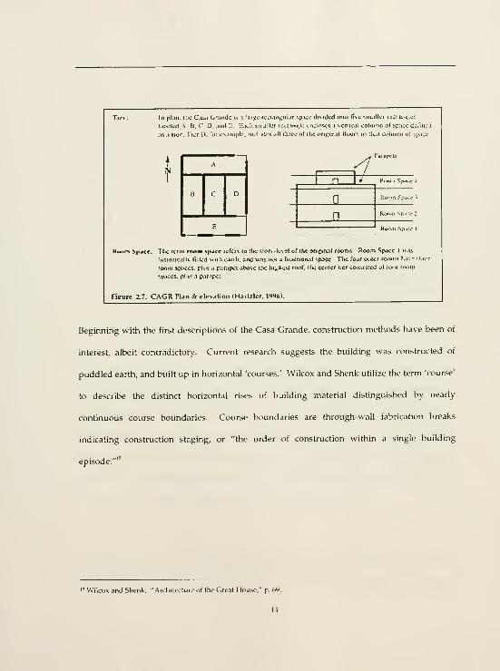
2.7 Plan and elevation of the Casa Grande, (Hartzler) 14
2.8 Construction course boundaries, (Wilcox & Shenk) 15
2.9 Wall layer construction, (Fong) 17
2.10 Sketch cross-section of wall layer construction (2 layers), (Fong) 18
2.11 Sketch cross-section of wall layer construction (3 layers), (Fong) 18
2.12 Bulk sample, (Fong) 24
2.13 Channel voids, (Courty) 27
2.14 Sample 12 cross section, (Fong) 29
2.15 Thin section, wash in cross-polarized light, (Fong) 31
2.16 TTiin section, wash in plane polarized light, (Fong) 31
2.17 Thin section, micromorphology in cross-polarized light, (Fong) 33
2.18 Thin section, micromorphology in cross-polarized light, (Fong) 34
Chapter 3
3.1 Type A detachment, (Fong) 36
3.2 Type A detachment detail, (Fong) 37
3.3 Type B detachment, (Fong) 37
3.4 Type B detachment, (Fong) 37
Chapter 4
4.1 Emulsion film formation, (Hartzler) 49
Chapter 5
5.1 Grout materials, (Fong) 63
5.2 Flow test, (Fong) 66
5.3 Spot plate shrinkage disks, (Fong) 68
5.4 Ceramic shrinkage disks, (Fong) 69
5.5 Cut ceramic shrinkage disks for dispersion investigation, (Fong) 69
5.6 Strength test block fabrication, in mold, (Fong) 71
5.7 Strength test block fabrication, tented, (Fong) 71
5.8 Strength test assembly fabrication, (Fong) 72
5.9 Strength test assembly fabrication, (Fong) 72
5.10 Strength test with Instron machine, (Fong) 74
5.11 Strength test with Instron machine detail, (Fong) 75
5.12 Water vapor transmission disk fabrication, (Fong) 77
5.13 Water vapor transmission test, (Fong) 78
Chapter 6
6.1 Spot plate sink holes, (Fong) 85
6.2 Strength test failure, nos. 55 and 79, (Fong) 95
6.3 Strength test failure, nos. 56 and 80, (Fong) 95
6.4 Strength test failure, no. 81, (Fong) 96

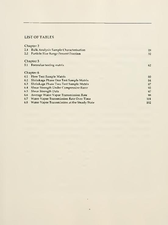
LIST OF TABLES
Chapter 2
2.1 Bulk Analysis Sample Characterisation 28
2.2 Particle Size Range Percent Fraction 32
Chapter 5
5.1 Formulae testing matrix 62
Chapter 6
6.1 Flow Test Sample Matrix 80
6.2 Shrinkage Phase One Test Sample Matrix 84
6.3 Shrinkage Phase Two Test Sample Matrix 87
6.4 Shear Strength Under Compressive Force 92
6.5 Shear Strength Data 97
6.6 Average Water Vapor Transmission Rate 98
6.7 Water Vapor Transmission Rate Over Time 101
6.8 Water Vapor Transmission at the Steady State 102
PREFACE
The United States National Park Service (NPS) is responsible for a significant collection of our
nation's architectural heritage. Classified as sites, monuments, and parks, these structures
exist primarily out of doors in uncontrolled environments. In an agreement initiated in 1991,
the National Park Service and the University of Pennsylvania embarked on what is now an
eight-year cooperative research and training agreement in the conservation of historic
structures and sites in the American Southwest. Much of the architecture of this region is built
of earth, as it was the most available and renewable resource. Adobe blocks, puddled earth,
and earthen mortars and plasters are some of the many forms in which this pliable and
expressive material has been used. Maintenance is an inherent activity in the renewal and
continuation of any structure, culture, and tradition. Now belonging to the public domain,
these 'properties' are no longer inhabited. As such, the cycles and activity of maintenance
have taken on a different pace and significance, no longer an act of distinct cultural continuity,
the lifespan demands of these maintenance actions present greater challenges. What was once
renewed on an annual or use-related basis, such as the act of plastering, must now be
preserved in a primarily as is state. The challenge is how to prolong the life of buildings or
sites that are now divorced from their original context. The history of these structures is
renewed through the act of visitor interpretation multiple times each day, but the tangible
forms are engaged in an irreversible cycle of existence. The conservation programme does not
attempt to restore the physical forms, but rather to preserve and extend the life of these forms
towards an enhanced comprehension of the physical fabric as an inextricable component of the

whole - site, place, history. Together, the NPS and the University of Pennsylvania are joined in
their commitment for the care of this invaluable cultural heritage.
The research of this project is a result of this cooperative agreement and shared interest. Its
case study site, Casa Grande Ruins National Monument is America's first nationally
designated prehistoric reserve. Its 'Great House' was first stabilized by Cosmos Mindeleff in
1892 with 'public funds expended by an appropriation from Congress.'' The National Park
Service assumed management of the site in 1917, and so began a long and continuing tradition
of preservation.
The issues of heritage management are multi-faceted and constantly changing. These changes
in perspectives will always reflect the cultural, social and political concerns of the moment.
The material issues of conservation are perhaps less socially respondent, matter deteriorates
and is transformed in an endless cycle. Weather will always contribute to this process for
outdoor structures and unless maintained, they will deteriorate. Change is immutable. It is
our perspective, approach, knowledge, and technology that are mutable.
Originally functioning as renewable architectural elements and dispensable in past
preservation efforts, surface finishes are now regarded as integral components of the
architectural composition. Thev are the skins of a structure, often the last application in
construction and, the first thing to alter through weathering. Surface finishes often carry the
most detailed messages found in the forms of painted, incised or polished applications. As the

outermost surface they offer protection to the rest and by their nature tend to be the most
temporal of the architectural elements. As a protective, sacrificial coat they are frequently
renewed. These multiple applications, layered one upon another, are like the pages of a book,
each layer reveals a piece of the story; a change in perspective visible through changes in
materials, techniques, colors, patterns, or physico-chemical transformation. We may no longer
fully know what these ephemeral components signify but we have determined that they are of
importance to us. Bound by history and the desire to make sense of ourselves and our
surroundings we continue to leave our messages whether we are creating entirely new ones or
reinterpreting the old.
' Jake Barrow and Frank Matero, Preface to Acryhc-Moilifial Enrlhcn Morlin, by Robert Hartzler, (Santa Fe; United
States National Park Service Department of the Interior, 1W6), p. xiii.

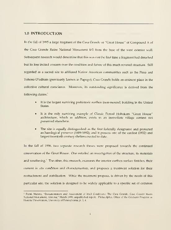
1.0 INTRODUCTION
In the fall of 1995 a large fragment of the Casa Grande or "Great House" of Compound A of
the Casa Grande Ruins National Monument fell from the base of the west exterior wall.
Subsequent research would determine that this was not the first time a fragment had detached
but its loss incited concern over the condition and future of this much revered structure. Still
regarded as a sacred site to affiliated Native American communities such as the Pima and
Tohono O'odham (previously known as Papago), Casa Grande holds an eminent place in the
collective cultural conscience. Moreover, its outstanding significance is derived from the
following claims:'
• It is the largest surviving prehistoric earthen (non-mound) building in the United
States.
• It is the only surviving example of Classic Period Hohokam "Great House"architecture, which in addition, exists in an immediate village context not
preserved elsewhere.
• The site is equally distinguished as the first federally designated and protected
archaeological preserve (1889-1892); and it possess one of the earliest (1932) andlargest twentieth century shelters erected to date.
In the fall of 1996, two separate research theses were proposed towards the continued
conservation of the Great House. One entailed an investigation of the structure, its materials
and weathering." The other, this research, examines the interior earthen surface finishes, their
current m situ condition and characterisation, and proposes a treatment solution for their
reattachment and stabilisation. While the treatment proposal is driven by the needs of this
particular site, the solution is designed to be widely applicable to a specific set of common
' Frank Matero, "Documentation and Assessment of Wall Conditions; The Casa Grande, Casa Grande Ruins
National Monument, Arizona," March 1*^99, unpublished report. Philadelphia, Office of the Graduate Program in
Historic Presen.ation, University of Pennsylvania, p. 3, 4.

variables; finish plaster reattachment, and gap filling of a certain measured detachment (~3 - 5
Much has been written about materials and methods for the reattachment and stabilisation of
lime plasters. As well, there is a measurable amount of literature on the preservation of
earthen architecture particularly in the area of adobe amendments. However, very little has
been published on the topic of the reattachment of earthen plasters and even less about the
reattachment and stabilisation of earthen plasters in situ. A few germane studies on this topic
are available in both published and unpublished form by Watson Smith, Giacomo Chiari,
Constance Silver, and Paul Schwartzbaum. These carefully researched studies were used as
the starting point for this report whose investigation extended into adobe amendment studies,
the adhesives and concrete amendments industries, plaster and mural reattachment, grouting,
and museum object adhesive studies.
Constance Silver performed extensive research into in fitti earthen plaster reattachment with a
focus on Ancestral Puebloan sites in the American Southwest in the early 1980's. She
experimented with different polymer emulsion adhesives of varying concentrations. Morgan
Phillips published some of the earliest innovations in the use of filled and unfilled acrylic
emulsion-based grouts for lime plaster reattachment and gap filling. More recently, Frank
Matero and Angelyn Bass have published on hydraulic lime-based grouts that utilize small
percentages of acrylic emulsion as the system dispersant for the reattachment and stabilisation
of lime plasters to earth. Each of these contributions refined a pre\ious system and responded
- See Elisa Del Bono, "CharactenzJtion and Analysis of the Caliche Walls ot the 'Great Hou.se,' Casa Grande Rums

to its respective set of contextual variables and criteria. Phillips developed his system
primarily for interior environments of lime plaster to wood lath. Matero and Bass were
concerned with the issues surrounding uncontrolled exterior environments of lime plaster to
earthen supports and relatively large scale voids. These studies served as models for the
present research that involves elements of each respective program yet whose specific
requirements could not wholly be fulfilled by either one alone.
All intervention begins with the identification of a problem. In this case, the detachment of
large expanses of surface finish and intermediary finish (or leveling) layers of earthen
architecture. Treatment options can only be derived from knowledge of the site materials,
architectural function, and environmental factors. Through use history and environment,
mechanisms of deterioration can be understood. Cultural, social, economic, political and
administrative considerations comprise another layer of contextual definition. This last
grouping is considered beyond the immediate scope of this research but cannot be ignored.
Sound methodology is the process by which problem identification and treatment options are
developed. This process is arranged in the following sequence, archival documentation, field
recordation, site sampling, material characterisation, identification of the mechanisms of
deterioration, definition of the conservation treatment problem, material literature research,
laboratory testing programme, data interpretation, and recommendations.
National Monument, Casa Grande, Arizona," Master's thesis. University of Pennsylvania, 1999.

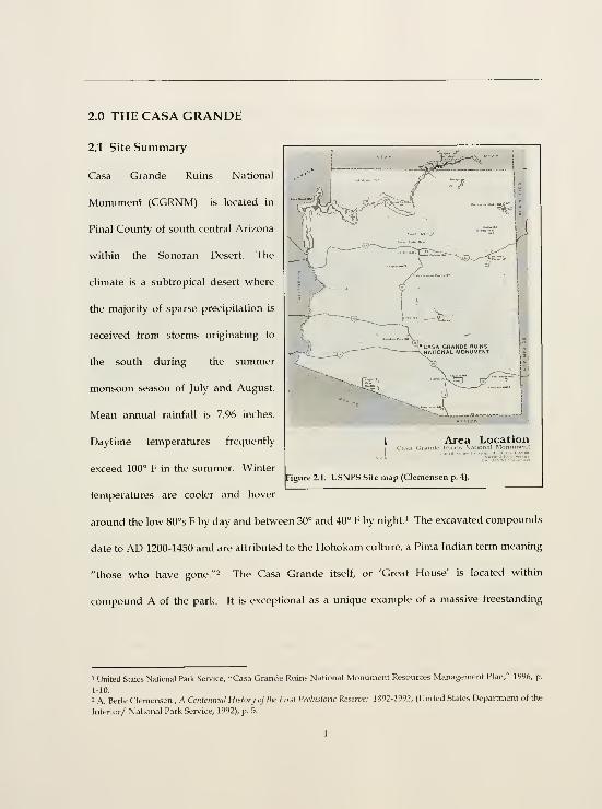
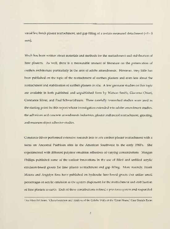
2.0 THE CASA GRANDE
2.1 Site Summary
Casa Grande Ruins National
Monument (CGRNM) is located in
Pinal County of south central Arizona
within the Sonoran Desert. The
climate is a subtropical desert where
the majority of sparse precipitation is
received from storms originating to
the south during the summer
monsoon season of July and August.
Mean annual rainfall is 7.96 inches.
Daytime temperatures frequently
exceed 100° F in the summer. Winter
temperatures are cooler and hover
around the low 80°s F by day and between 30° and 40° F by night.' The excavated compounds
date to AD 1200-1450 and are attributed to the Hohokam culture, a Pima Indian term meaning
"those who have gone."^ The Casa Grande itself, or 'Great House' is located within
compound A of the park. It is exceptional as a unique example of a massive freestanding
Area LocationCasn GraiicU- Ruins N.itional Monument
Figure 2.1. USNPS Site map (Clemensen p. 4).
1 United Stales National Park Service. -Casa Grande Ruins National Monument Resources Management Plan," 1996, p.
1-10.
2 A. Berle Clemensen , A CenWiimnl Htstonj of the First Prehistoric Reserve: 1892-1992, (United States Department of the
Interior/ National Park Service, 1992), p. 5.

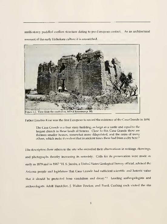
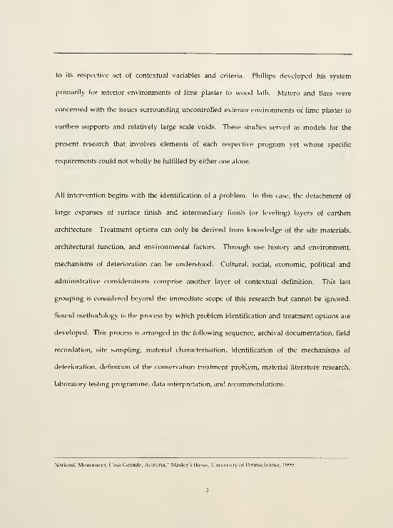
multi-storey puddled earthen structure dating to pre-European contact. As an architectural
remnant of the early Hohokam culture it is unmatched.
Figure 2.2. View from the southwest, 1878 (Clemcnsen p W)
rJ
Father Eusebio Kino was the first European to record the existence of the Casa Grande in 1694.
The Casa Grande is a four story building, as large as a castle and equal to the
largest church in these lands of Sonora. Close to this Casa Grande there are
thirteen smaller houses, somewhat more dilapidated, and the ruins of many
others, which make it evident that in ancient times there had been a city here.'
His description drew others to the site who recorded their observations in writings, drawings,
and photographs thereby increasing its notoriety. Calls for its preservation were made as
early as 1879 and in 1887 "H. S. Jacobs, a United States Geological Survey official, advised the
Arizona people and legislature that Casa Grande had sufficient scientific and historic value
that it should be protected from vandalism and decay. "^ Leading anthropologists and
archaeologists Adolf Bandelier, J. Walter Fewkes, and Frank Gushing each visited the site
through the 1880s and 1890s. Bandelier submitted the first formal anthropological study of
the site." Fewkes in his survey of the structure assigned letter designations to the tiers of
rooms." This system of organization is still in use today. Gushing submitted an archaeological
report to the Secretary of the Interior as supporting evidence to the significance and value of
the ruin. In 1889 money was appropriated from Congress
...to enable the Secretary of the Interior to repair and protect the ruin of Casa
Grande, situated in Pinal Gounty, near Florence, Arizona, two thousand
dollars; and the President is authorized to reserve from settlement and sale
the land on which said ruin is situated and so much for the public land
adjacent thereto as in his judgment may be necessary for the protection of said
ruin and of the ancient city of which it is a part.
In 1890 Victor and Gosmos Mindeleff prepared the first condition survey and list of
recommendations for the preservation of the 'Great House.' The list included the following
recommendations.
"
1. Fence the ruins area
2. Provide a permanent on-site custodian
3. Glean the debris from the Great House4. Underpin the Great House walls with brick
5. Remove several inches of material from the wall tops to provide a good
bearing surface and then cap the walls with concrete
6. Reinforce the walls with tie-rods and beams, replace broken and missing
lintels, and fill cavities above the lintels.
7. Erect a roof shelter over the structure
While not all recommendations were performed (items number two and seven would not be
realized for many years and number five has never been performed), this initial preservation
campaign represents the single largest structural intervention to date. In 1892 President
Clemensen, Centcnrunl Hisfory, p. 28-29.
' Clemensen, Centennial History, p. 29.
' David R. Wilcox and Lynettc O. Shenk, "The Architecture of the Great House and its Interpretation," (Tucson,
Arizona: United States National Park Ser\'ice, 1977), p. 29.
' Clemensen, Centennial Hit-tcry, p. 33.

Benjamin Harrison designated 480 acres as the Casa Grande Reservation thereby establishing
it as the first federal preserve set aside to protect an archaeological resource. The site
remained under the immediate jurisdiction of the General Land Office until it passed to the
newly established United States National Park Service in 1917 making it the fifth park to enter
the system.
Frank Pinkley was the first resident custodian assigned to the Casa Grande Ruins in 1901. This
move signified the importance of the site. In 1918 President Woodrow Wilson proclaimed
Casa Grande a national monument. " In 1903 the first shelter was erected over the Casa
Grande, a small redwood and corrugated metal roof structure. This overly cramped shelter
was replaced in 1932 by a more permanent shelter designed by Frederick Law Olmsted, Jr. and
Thomas Vint of the NPS. This structure remains today and is itself now included on the
National Register of Historic Places.
The Casa Grande Ruins site benefits from early recognition as a valuable cultural and historic
resource. The earliest documentation begun by Father Kino and continued by others in
writings, drawings and photographs, provides a useful, nearly continuous record of the site's
condition over time. Recently, the University of Pennsylvania, Graduate Department of
Historic Preservation in conjunction with CGRNM and the NPS Intermountain Support Office
in Santa Fe, Architectural Conservation Projects Program, conducted an in depth 'Wall
Condition Assessment Survey' of the Casa Grande. This collection of documentation provides
an invaluable resource by which to gauge the integrity and stability of the Casa Grande over
" See Clemensen Cfntcnnml Hulcry, p. 35.

an invaluable resource by which to gauge the integrity and stabihty of the Casa Grande over
time and is a base reference point upon which the current conservation programmes for the
Casa Grande are developed.
' ''%
'^
2.1.1 Conservation History
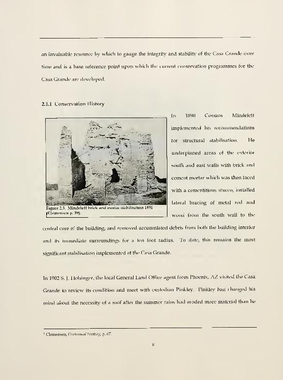
In 1890 Cosmos Mmdeleff
implemented his recommendations
for structural stabilisation. He
underpinned areas of the exterior
south and east walls with brick and
cement mortar which was then faced
with a cementidous stucco, installed
lateral bracing of metal rod and
wood from the south wall to the
central core of the building, and removed accumulated debris from both the building interior
and its immediate surroundings for a ten foot radius. To date, this remains the most
significant stabilisation implemented at the Casa Grande.
''^'.I
' ri'ii'i'lWlKiiiii
Figure 2.3. Mindelett brick and mortai stabihsatiun Ihyi
(Clemensen p. 39).
In 1902 S. J.Holsinger, the local General Land Office agent from Phoenix, AZ visited the Casa
Grande to review its condition and meet with custodian Pinkley. Pinkley had changed his
mind about the necessity of a roof after the summer rains had eroded more material than he
' Clemensen, Centennial Histonj, p. 67.

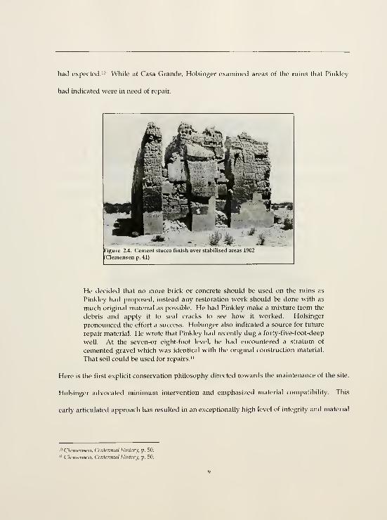
had expected.'" While at Casa Grande, Holsinger examined areas of the ruins that Pinkley
had indicated were in need of repair.
Figure 2.4. Cement stucco tinisn over staDilisea areas l^u2
(Clemensen p. 41).
He decided that no more brick or concrete should be used on the ruins as
Pinkley had proposed, instead any restoration work should be done with as
much original material as possible. He had Pinkley make a mixture from the
debris and apply it to seal cracks to see how it worked. Holsinger
pronounced the effort a success. Holsinger also indicated a source for future
repair material. He wrote that Pinkley had recently dug a forty-five-foot-deep
well. At the seven-or eight-foot level, he had encountered a stratum of
cemented gravel which was identical with the original construction material.
That soil could be used for repairs. i^
Here is the first explicit conservation philosophy directed towards the maintenance of the site.
Holsinger advocated minimum intervention and emphasized material compatibility. This
early articulated approach has resulted in an exceptionally high level of integrity and material
10 Clemensen, Centennial History, p. 50.
" Clemensen, Centennial Histonj, p. 50.
authenticity at the Casa Grande. Since then, the structure has been subjected to few direct
conservation interventions.
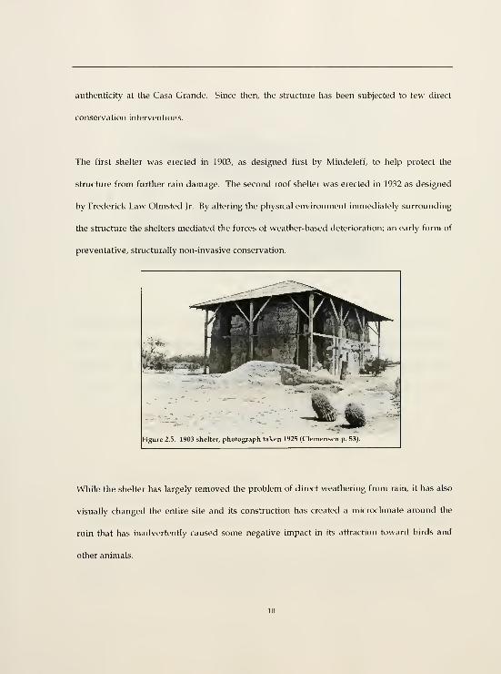
The first shelter was erected in 1903, as designed first by Mindeleff, to help protect the
structure from further rain damage. The second roof shelter was erected in 1932 as designed
by Frederick Law Olmsted Jr. By altering the physical environment immediately surrounding
the structure the shelters mediated the forces of weather-based deterioration; an early form of
preventative, structurally non-invasive conservation.
While the shelter has largely removed the problem of direct weathering from rain, it has also
visually changed the entire site and its construction has created a microclimate around the
ruin that has inadvertently caused some negative impact in its attraction toward birds and
other animals.

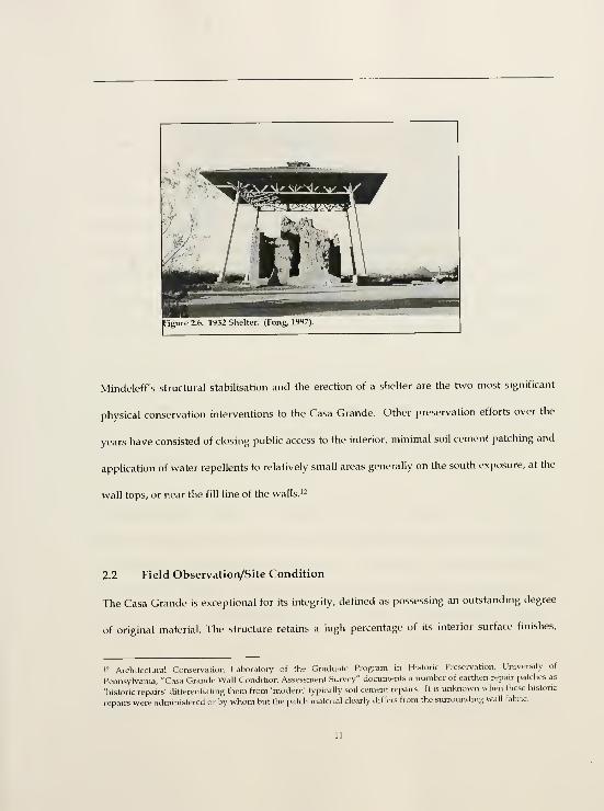
Mindeleff's structural stabilisation and the erection of a shelter are the two most significant
physical conservation interventions to the Casa Grande. Other preservation efforts over the
years have consisted of closing public access to the interior, minimal soil cement patching and
application of water repellents to relatively small areas generally on the south exposure, at the
wall tops, or near the fill line of the walls. '^
2.2 Field Observation/Site Condition
The Casa Grande is excepHonal for its integrity, defined as possessing an outstanding degree
of original material. The structure retains a high percentage of its interior surface finishes.
12 Architectural Conservation Laboratory of the Graduate Program in Historic Preservation, University of
Pennsylvania, "Casa Grande Wall CondiHon Assessment Survey" documents a number of earthen repair patches as
'historic repairs' differentiahng them from 'modem' typically soil cement repairs. It is unknown when these historic
repairs were admmistered or by whom but the patch material clearly differs from the surrounding wall fabric.

which are in a predominantly stable condiHon. According to documentation, little material
has been lost since Mindeleff's 1890 initial stabilisation. It has received minimal intervention
since its early identification by the United States federal government as a site worthy of
recognition and preservation. This federal recognition, along with the early establishment of a
conservation methodology of minimal intervention and material compatibility put forth by S.J.
Holsinger in 1902, and the erection of protective shelters are the three most significant acts of
preservation implemented for the Casa Grande. The original fabrication and construction of
the structure, its surrounding climate and the subsequent physico-chemical transformations
provide the strong base material to which our material conservation efforts are directed.
Field recordation occurred on three visits to the site, October 1996, December 1996 - January
1997, and August - September 1998. Areas of significant building material loss are not
discussed as the focus of this study is the interior surface finish layers, their characterisation,
condition assessment, and treatment methods for their stabilisation and reattachment."
The Casa Grande is a massive free standing earthen caliche structure. The term caliche
identifies a calcium carbonate-based soil. It is believed that the calcareous content contributes
to the durability of the Casa Grande through a combination of chemical and physical
transformations over time in conjunction with original manufacture and building construction
techniques to produce an effect referred to as 'case hardening.' This description indicates an
'^ For a graphic condition survey of the structure see Architectural Coasen'ation Laboratory of the GraduateProgram in Historic Preser\'ation, University of Pennsylvania, "Casa Grande Wall Condition Assessment Survey,"
1997-1999.

extremely hard and dense calcium rich zone on the exposed surface of the building material
that has developed over time."
The Casa Grande measures approximately 60 feet (north-south) by 40 feet (east-west). Its
outer walls rise to an average of 25 feet and the inner walls of the central core rise to an
average of 30 feet. The average wall base thickness is 4 feet. This tapers to an average of 2 feet
at the wall top. The building is essentially a large multi-storey rectangular space divided into
five smaller rectangular spaces. The central core of the structure rises to a height of three
stories and is surrounded by adjoining rooms of two stories. These multi-storey rectangular
spaces are organized into Tiers.' Nothing remains of the wooden beams (vigas) that once
supported the earthen floors and divided the vertical spaces. Traces of their existence are still
visible as pockets in the walls and wall surface texture differentiation at floor levels. The
division of vertical space as would have been defined by floor and roof elements is referred to
as 'Room Spaces.'
'* For further discussion of this phenomenon see Del Bono, "Characterisation of the Caliche.'
13

Tici
:
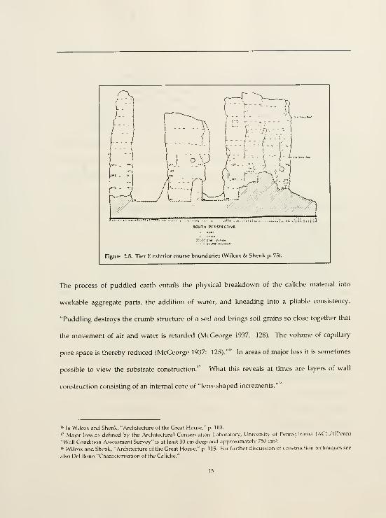
Figure 2.8. Tier E exterior course boundaries (Wilcox & Shenk p. 75).
The process of puddled earth entails the physical breakdown of the caliche material into
workable aggregate parts, the addition of water, and kneading into a pliable consistency.
"Puddling destroys the crumb structure of a soil and brings soil grains so close together that
the movement of air and water is retarded (McGeorge 1937: 128). The volume of capillary
pore space is thereby reduced (McGeorge 1937: 128)."" In areas of major loss it is sometimes
possible to view the substrate construction." What this reveals at times are layers of wall
construction consisting of an internal core of "lens-shaped increments.""
'" In Wilcox and Shenk, "Architecture of the Great House," p. 103
'" Major loss as defined by the Architectural Conser\-ation Laboraton,-, University of Pennsyhania (ACL/UPenn)
"Wall Condition Assessment Survey" is at least 10 cm deep and approximately 730 cm\
'"Wilcox and Shenk, "Architecture of the Great House," p. 115. For hirther discussion of construction techniques see
also Del Bono "Characterisation of the Caliche."
15

The wall courses in both the foundations and the upper walls in the Casa
Grande were built up with lens-shaped increments of soil. They often display
a curved or "turtle-backed" shape in the upper walls. Their curvature is
clearly seen in the wall cross sections and in an especially instructive exposure
inside the north wall of her A. There several facets mark the surface of each
lens, and the "dented" appearance of each facet could easily be due to palm
impressions resulting from the batches of soil being pressed into place.'^
Hand impressions inside the wall are clearly visible at numerous locations: Tier C, north wall,
room space three, and Tier D, east wall, south facing cross section, room space three. Such
imprints contribute to the theory of a puddled earth construction.
Another visible construction phenomenon is the occurrence of interior planar wall layers.
These layers appear inconsistently throughout the interior of the Casa Grande. They vary in
number, (one to three) and thickness 0.16 - 10.16 cm (1/16 - 4 inches). No pattern of their use
has yet been identified although such a determination would be difficult to make without
cutting into the wall. At present, the wall layers are visible from exposed broken edges of wall
and surface finish (areas of loss). They are clearly a separate application to the interior
surfaces of the monolithic wall construction concealing the coursing evident on the exterior by
its seams.
What makes both these construction phenomena apparent is their separation or detachment
from the surrounding building fabric. The visibility of a soil lens is principally due to loss.
Usually, a gap of detachment averaging 3 mm occurs over a visible lens. This indicates a weak
interface joint attributable to construction techniques and subsequent shrinkage. Likewise,
wall layer construction is observed by the separation of a layer from adjacent building fabric.
' Wilcox and Shenk, "Architecture of the Great House," p. 115.
16

building fabric, (other layers or the building substrate). The average separation between
layers or layer and substrate measures 3-5 mm.
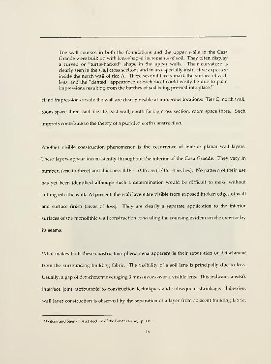
The exterior of the Casa Grande reveals exposed caliche substrate. There is no apparent
vertical planar layer construction to the exterior facade. The interior spaces of the structure
are finished with one to three layers of surface finish comprised of 'intermediary' (leveling)
and 'finish' layers. The intermediary layers can number between one and two. As the layers
progress outward from the wall substrate towards the surface their aggregate size decreases.
This is also reflected in the layer thickness. The final finish layer is always the thinnest and
r.-^
1 ^^-^-^^ « ,-v.
Figure 2.9. liii IJ inteiiui, »all t'lnishes layer structure (Foiig. 1997).
composed of the finest aggregate. Intermediary layers vary ui thickness from 0.6 - 10.16 cm
(1/4 - 4 inches). Finish layer thickness range from 0.16 - 0.6 cm (1/16 to 1/4 inch) with an
average thickness of 0.16 cm.

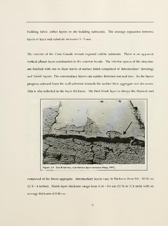
The finish layer is a largely intact continuous plane of
caliche plaster with good internal cohesion. Unlike the
smooth, polished surface of the finish layer, the
intermediary layer is slightly uneven and rough, useful as
a key to the final finish coat. This study focuses on the
outermost 1.5 cm of finish (average thickness of samples)
with special attention paid to the final 0.16 cm finish layer
- as observed in the field - for material characterisation
and conservation treatment however, it considers the
whole planar construction system as a fundamental factor
in understanding the causes of detachment. The final
surface finish is a monochromatic pink/reddish wash.
The colored wash is not considered to be part of the wall
layer construction but applied separately in some cases as
several discreet layers, probably over time.
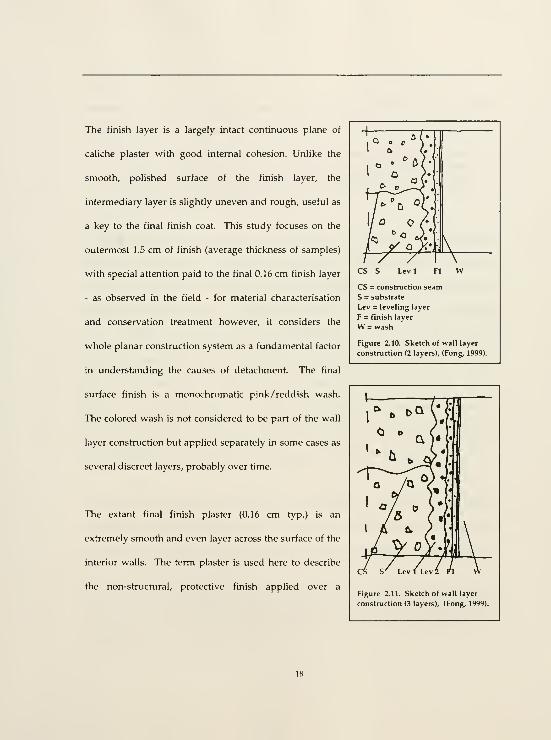
The extant final finish plaster (0.16 cm typ.) is an
extremely smooth and even layer across the surface of the
interior walls. Tlie term plaster is used here to describe
the non-structural, protective finish applied over a
cs s Levi
CS = construction seam
S = substrate
Lev = leveling layer
F = finish layer
W = wash
Figure 2.10. Sketch of wall layer
construction (2 layers), (Fong, 1999).
Figure 2.11. Sketch of wall layer
construction (3 layers), (Fong, 1999).
building's substrate core.'" No application marks are visible. In 1697, three years after Father
Kino's first visit to the site. Captain Juan Mateo Manje noted these finishes,
There was one great edifice with the principal room in the middle of four
stories, and the adjoining rooms on its four sides of three stories, with the
walls five and one-half feet in thickness, of strong mortar and clay, so smooth
and shining within that they appear like burnished tables, and so polished
that they shine like the earthware of Puebla."'
Some color variation (hereafter referred to as 'darkening') of the finish layer occurs throughout
the Casa Grande. There is no pattern to this variation. Darkening is found on continuous
surface planes absent of any water activity, and along cracks or edges that possibly served as
conduits for water at one time. It is likely that these are two separate conditions. Darkening is
characterized as an integral color change in the surface finish layer. It is not an applied or a
deposited coating such as fire sooting. Areas of darkening around edges and cracks typically
lack their final coat of color wash possibly due to water erosion. In these locations, darkening
may be caused by biological growth. However, darkening that is found within a continuous
surface plane is often covered by the final pinkish /reddish colored wash, the same wash that
covers what have been identified as "historic repairs" or subsequent finishes."
Two types of detachment are evident in the Casa Grande. The first type is an endemic
detachment condiHon characterised by a fairly even continuous plane of detachment
measuring an average of 3 - 5 mm between two fairly even, continuous adherend surface
^" Frank Matero offers the following definition of the term plaster: "...any inorganic binder such as clay, lime,
gypsum, natural or artificial cement used alone or in combination with aggregates that when mixed with a suitable
amount of water forms a plastic mass which when applied to an interior or exterior surface adheres to it and
subsequently sets or hardens, preser\ing in a rigid state the form or texture imposed during the period of plasticity."
For further discussion of the term, see Frank Matero, "The Conservation of Plasters in Archaeological Sites," CRM,
forthcoming.
-' Clemensen, Centennial Hillary, p. 12.
planes. The condition does not appear active and both adherends appear relatively stable.
The second type of detachment is less common in the Casa Grande. It is a small scale/flaking
condition typically recognized by an actual deformation in the outermost finish plaster layer,
frequently accompanied by cracking, and now exaggerated by extrinsic forces such as the pull
of gravity, accumulation of debris or animal activity. This type of detachment is the more
critical of the two (termed active) as the now deformed fragment hangs in a precarious state.
(The possible mechanisms of detachment and deterioration are discussed in Chapter 3.)
Tier C is distinguished from the four other tiers by possessing the highest integrity of surface
finish. Integrity is measured by the amount and condition of extant finish. The outstanding
condition of Tier C is attributable to its protected location at the core of the building.
Tiers A, B, D, and E all display a fine particulate dust coating on their surface. It is unclear
what the origins of this fine matter are. Probably it is a result of wind blown deposits or
decomposition of the wash layer as it loses its internal cohesion, or a combination of both. Tier
C is sheltered from extrinsic environmental forces by its central location. This not only shields
it from windblown deposits but from the erosive forces that deteriorate the cohesive strength
of the finish.
Tier E suffers less from detachment than from surface erosion. This is the southernmost tier
and is subjected to the greatest force of the weather that typically approaches from the
— See ACL/UPenn, "Wall Condition Assessment Sun-ey."
20

southwest. Much of the pink/reddish color wash of Tier E has eroded off of the finish plaster
layer.
Tier B exhibits the greatest amount of detachment of all five tiers. The reasons for this are
unclear. Tiers A and D are fairly comparable in the condition and characterisation of the
surface finishes. The surface finishes in these tiers are largely intact except for areas of major
loss, with occasional areas of detachment. Tiers B and D retain evidence of active liquid water
ingress. It is uncertain when this occurred although it most likely predates the present shelter.
Evidence of animal activity is present throughout the Casa Grande in the form of spider webs,
(intricate networks of spider webs are frequently found in and around cracks and holes),
guano and traces of rodent hjnnels previous to the debris/fill removal. These tunnels are
visible on the surfaces of a few of the walls, just below the fill lines. Animal activity poses a
threat to areas of detachment. Burrowing or nesting in detachment gaps exacerbates the active
or potential instability of the detached plaster.
2.3 Material Characterisation
The purpose of material characterisation is manifold. It is one critical step in the
documentation and investigation of a site or structure. Materials are characterised physically
and chemically. Material characterisation informs a comprehension of the historic structure as
it yields the potential to reveal buildmg sequence, design, fabrication, methods of application,
and occasionally material provenience when matched with archaeological research.

Knowledge of material characteristics is essential for the development of an appropriate
treatment programme. In this investigation, material characterisation was performed
primarily for documentation, treatment, and architectural comprehension purposes. Of the
latter, the small size of the samples removed from the site greatly limited the information that
could be gleaned but used in conjunction with past and possible future studies it can provide
valuable corroborating information. Sample size and availability also limited the methods of
material characterisation investigation. All characterisation was performed via visual bulk
and microscopic analysis.
The laboratory material characterisation process was divided into three steps; bulk analysis
and micromorphological analysis - cross section and thin section.
2.3.1 Sampling
The goal of the sampling programme was to evaluate and determine the finish plaster layer
construction, microfabric structure, and an assessment of similarities and differences amongst
room spaces and tiers. A sampling strategy was carefully planned that would accomplish
these goals with the minimum amount of extraction and intrusion. Tier, room space,
orientation (north, south, east, west), elevation (wall top, middle, base), and architectural
location (wall surface, inside doorway, door plug, solstice hole) were amongst the
considerations in the design of the sampling programme. Interior samples were selected to
represent the various conditions found in the Casa Grande, both typical and extreme. These
included what was perceived to be the most intact surface - that with a strong cohesive wash;
finish layers of apparent varying thickness; darkened and non-darkened areas, and areas of
historic repair. The average size of each sample was approximately 2.5 x 1.5 x 2 cm or 7.5 cm\

Forty samples of the finished interior walls were taken Ln the fall and winter of 1996. Samples
were taken by the author, Robert Hartzler (NFS) and Frank Matero (UPenn). A large portion
of the fallen exterior wall fragment was also packed and sent to the Architectural Conservation
Laboratory (ACL) at the University of Pennsylvania for characterisation and testing."' The
exterior wall fragment was used exclusively to fabricate assemblies for treatment testing of
adhesive grouts. (See Appendix 10.1 Sample Map)
Selection was always based upon the potential or ability to yield useful information. What is
deemed useful information is entirely dependent upon the questions posed. Here, the critical
questions identified were:
• What is the physical, micromorphological structure of the fabric?
• What is the mineralogical composition of the material?
• Is there a distinct layer structure visible within the sample?
• What are the characteristics of the perceived 'darkened zone?'
• Is it a distinct layer?
• Is there a difference in material and micromorphological structure of the finish
layer amongst room spaces and /or tiers?
• Are there multiple layers of color wash?
• Is there a distinct difference in material and structure between the finish layer and
the building material?
' See Del Bono, "Characterisation of the Caliche."

2.3.2 Bulk Analysis
All samples were bulk analyzed and examined visually with a stereo binocular microscope
(Nikon SMZ-U) under quartz halogen reflected light illumination at a total magnification of
7.5x unless otherwise specified. Bulk analysis produced a gross physical characterisation of
the samples and allowed sample comparisons and selection for subsequent analysis. The
questions posed were;
• What is the layer structure?
• Is there a wash layer?
• What is its condition?
• Is there a darkened zone?
• What is the aggregate profile (shape, size and general distribution)?
• What is the matrix profile?
KODAK Coler Conirel PatctiM
rAtsz. U^^ajI)
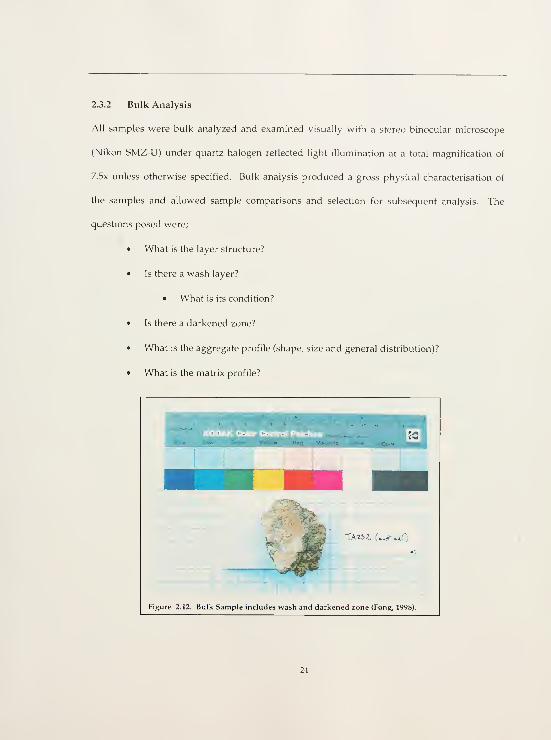
Figure 2.12. Bulk Sample includes wash and darkened zone (Fong, 1998).

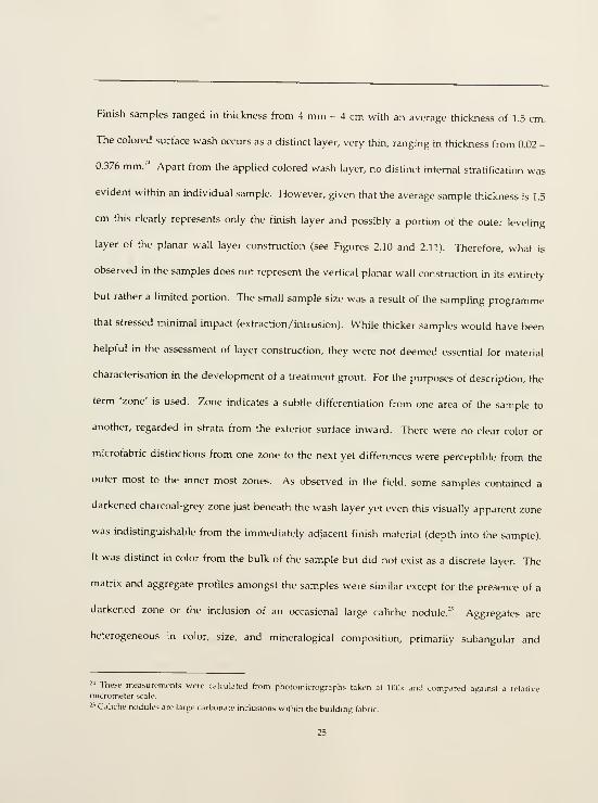
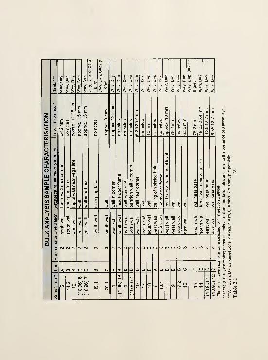
Finish samples ranged in thickness from 4 mm - 4 cm with an average thickness of 1.5 cm.
The colored surface wash occurs as a distinct layer, very thin, ranging in thickness from 0.02 -
0.376 mm.-' Apart from the applied colored wash layer, no distinct internal stratification was
evident within an individual sample. However, given that the average sample thickness is 1.5
cm this clearly represents only the finish layer and possibly a portion of the outer leveling
layer of the planar wall layer construction (see Figures 2.10 and 2.11). Therefore, what is
observed in the samples does not represent the vertical planar wall construction in its entirety
but rather a limited portion. The small sample size was a result of the sampling programme
that stressed minimal impact (extraction /inhoision). While thicker samples would have been
helpful in the assessment of layer construction, they were not deemed essential for material
characterisation in the development of a treatment grout. For the purposes of description, the
term 'zone' is used. Zone indicates a subtle differentiation from one area of the sample to
another, regarded in strata from the exterior surface inward. There were no clear color or
microfabric distinctions from one zone to the next yet differences were perceptible from the
outer most to the inner most zones. As observed in the field, some samples contained a
darkened charcoal-grey zone just beneath the wash layer yet even this visually apparent zone
was indistinguishable from the immediately adjacent finish material (depth into the sample).
It was distinct in color from the bulk of the sample but did not exist as a discrete layer. The
matrix and aggregate profiles amongst the samples were similar except for the presence of a
darkened zone or the inclusion of an occasional large caliche nodule.^' Aggregates are
heterogeneous in color, size, and mineralogical composition, primarily subangular and
'' These measurements were calculated from photomicrographs taken at lOlK and compared against a relativemicrometer scale.
^•^ Caliche nodules are large carbonate inclusions within the building fabric.
25


subround in shape, and poorly sorted. The fine matrix was typically a brown to brownish
grey color. Twenty-four samples were selected from the original 40 for cross section analysis.
These twenty-four samples were embedded in an acrylic polyester resin (Bioplast^"), cut into
cross sections with a Beuhler Isomet' and polished for further microscopical analysis. (See
Table 2.1 Bulk Analysis Sample Characterisation.)
2.3.3 Cross Section Analysis
Cross section analysis was performed using a Nikon AFXIIA with quartz halogen fiber optic
reflected light illumination at a total magnification of 40x unless otherwise specified. An initial
cross section test sample revealed that the samples would first have to be consolidated in
order to withstand the friction and constant wetting during the cross section cutting process.
This initial sample crumbled and disintegrated during the process. All twenty-four samples
were consolidated with a 5% solution of Acryloid B72 in acetone w/w (i.e. 5g B72 -t- 95g
acetone). The samples were set in a flat dish on a bed of glass beads. The B72 solution rose to
just beneath the top of the glass beads. The samples were allowed to absorb the solution
through capillary rise over a period of 36 hours. Samples were turned and the consolidant
solution replenished every 12 hours. Once dry, the twenty-four samples were embedded in
Bioplast and cut on a Beuhler Isomet* low speed saw. The first cut revealed that the
consolidant had not fully penetrated into the center of the samples. Each sample was therefore
cut open and consolidant solution dropped onto the newly exposed surface to the point of
complete saturation. Samples were again cut to form cross sections and polished with
Stoddard solvent on 400 and 600 grit polishing strips and Beuhler 'microcloth' polishing cloth
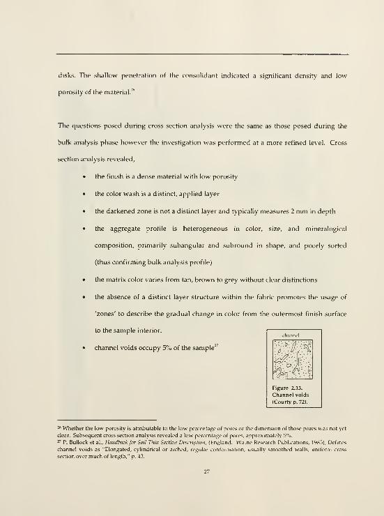
disks. The shallow penetration of the consolidant indicated a significant density and low
porosity of the material.""
The questions posed during cross secHon analysis were the same as those posed during the
bulk analysis phase however the investigation was performed at a more refined level. Cross
section analysis revealed,
• the finish is a dense material with low porosity
• the color wash is a distinct, applied layer
• the darkened zone is not a distinct layer and typically measures 2 mm in depth
• the aggregate profile is heterogeneous in color, size, and mineralogical
composition, primarily subangular and subround in shape, and poorly sorted
(thus confirming bulk analysis profile)
• the matrix color varies from tan, brown to grey without clear distinctions
• the absence of a distinct layer structure within the fabric promotes the usage of
'zones' to describe the gradual change in color from the outermost finish surface
to the sample interior.
• channel voids occupy 5% of the sample"

5^
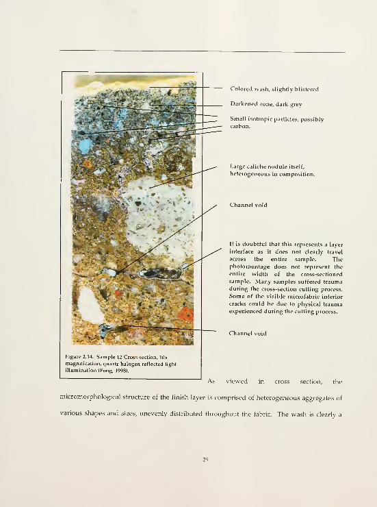
Figure 2.14. Sample 12 Cross section, lOx
magnification, quartz halogen reflected light
illumination (Fong, 1998).
Colored wash, slightly blistered
Darkened zone, dark grey
Small isotropic particles, possibly
carbon.
Large caliche nodule itself,
heterogeneous in composition.
Channel void
It is doubtful that this represents a layer
interface as it does not clearly travel
across the entire sample. Thephotomontage does not represent the
entire width of the cross-sectioned
sample. Many samples suffered trauma
during the cross-section cutting process.
Some of the visible microfabric interior
cracks could be due to physical trauma
experienced during the cutting process.
Channel void
As viewed in cross section, the
micromorphological structure of the finish layer is comprised of heterogeneous aggregates of
various shapes and sizes, unevenly distributed throughout the fabric. The wash is clearly a

very thin applied layer. The darkened zone is not a specific layer but rather an intrinsic
coloration within the finish layer.
From the twenty-four samples surveyed in cross section, seven were selected for thin section
analysis (TARS2 no. 5, TBRS2 no. 14.2, TBRS2 no. 12, TCRS2 (10.96) no. 6, TCRS2 (10.96) no. 7,
TBRS3 no. 19.1, and TCRS3 (10.96) no. 20.1). Bulk and cross section analysis revealed more
similarities than differences amongst the samples. Micromorphological characteristics - color
wash, darkened zone, calcite nodules - as well as architectural context served as the guidelines
for final thin section selection.
2.3.4 Thin Section Analysis
The selected seven samples were sent to Spectrum Petrographies, Inc. for thin section
production. All samples were vacuum impregnated with clear epoxy, cut to standard
thickness (30nm); half of each sample was stained for calcite with alazarin red, and affixed
with permanent glass coverslips. Microscopic analysis was conducted with a Zeiss Axiophot
under plane polarized and cross polarized light at 25x, 40x and lOOx magnification at the
University of Pennsylvania, Department of Earth and Environmental Science.
Photomicrographs were taken at 25x and lOOx.
Thin section analysis permits a more detailed investigation into the qualitative and
quantitative characteristics of the microfabric of a material. Particle size analysis and
mineralogical identification were performed during this phase of characterisation.

Observations made during the different phases of material characterisation can serve to
corroborate and/or challenge hypotheses and assumptions.
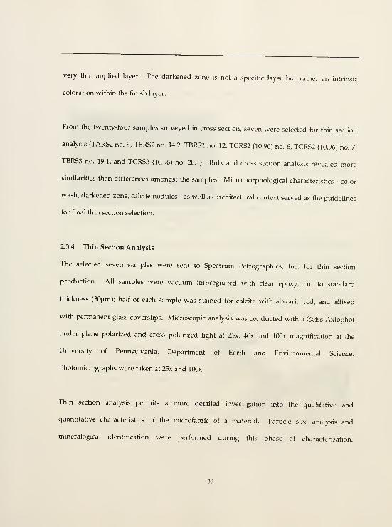
Figure 2.15. Sample 12 VV.ish layer in cross-polarized
light illumination, lOOx magnification (Fong, 1998).
Wash layer distinct however, multiple
layers not visible.
Poorly sorted heterogeneous aggregates.
Small isotropic particles, possibly
carbon.
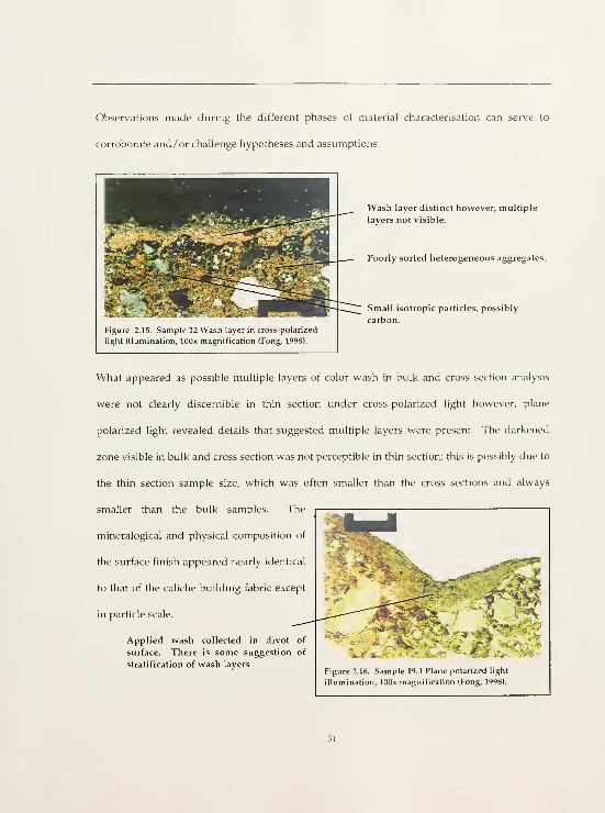
What appeared as possible multiple layers of color wash in bulk and cross section analysis
were not clearly discernible in thin section under cross-polarized light however, plane
polarized light revealed details that suggested multiple layers were present. The darkened
zone visible in bulk and cross section was not perceptible in thin section; this is possibly due to
the thin section sample size, which was often smaller than the cross sections and always
smaller than the bulk samples. The
mineralogical and physical composition of
the surface finish appeared nearly identical
to that of the caliche building fabric except
in particle scale.
Applied wash collected in divot of
surface. There is some suggestion of
stratification of wash layersFigure 2.16. Sample 19.1 Plane polarized light
illumination, lOOx magnification (Fong, 1998).

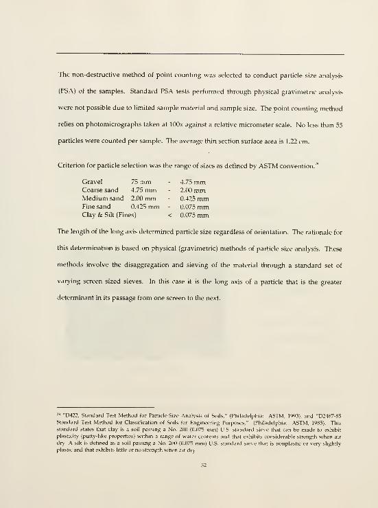
The non-destructive method of point counting was selected to conduct particle size analysis
(PSA) of the samples. Standard PSA tests performed through physical gravimetric analysis
were not possible due to limited sample material and sample size. The point counting method
relies on photomicrographs taken at lOOx against a relative micrometer scale. No less than 55
particles were counted per sample. The average thin section surface area is 1.22 cm.
Criterion for particle selechon was the range of sizes as defined by ASTM convention."
Gravel 75 mm - 4.75 mmCoarse sand 4.75 mm - 2.00 mmMedium sand 2.00 mm - 0.425 mmFine sand 0.425 mm - 0.075 mmClay & Silt (Fines) < 0.075 mm
The length of the long axis determined particle size regardless of orientation. The rationale for
this determination is based on physical (gravimetric) methods of particle size analysis. These
methods involve the disaggregation and sieving of the material through a standard set of
varying screen sized sieves. In this case it is the long axis of a particle that is the greater
determinant in its passage from one screen to the next.
™ "D422, Standard Test Method for Particle-Size Analysis of Soils," (Philadelpfiia: ASTM, 1993); and "D2487-85Standard Test Method for Classification of Soils for Engineenng Purposes," (Philadelphia: ASTM, 1985). This
standard states that clay is a soil passing a No. 200 (0.075 mm) U.S. standard sieve that can be made to exhibit
plasticity (putty-like properties) within a range of water contents and that exhibits considerable strength when air
dry. A silt is defined as a soil passing a No. 200 (0.075 mm) U.S. standard sieve that is nonplastic or very slightly
plastic and that exhibits little or no strength when air dry.
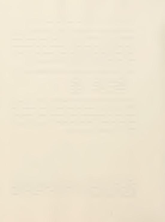
Particle Size Range Percent Fraction

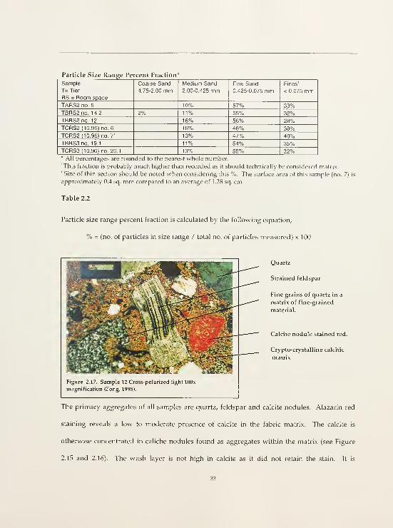
composed of extremely fine particles, possibly composed of mineralogical clays (see Figures
2.13 and 2.14).
Channel
voids
Figure 2.18. Sample 12 Cross-polarized light illumination, 25x
magnification, 2/3 of sample in photo is stained with alazarin red for
calcite. (Fong, 1998).
Dark red
.staining of
caliche nodule
indicates high
calcite content
unlike the low-
mediumstaining of
surrounding
matrix.
Micromorpfiological analysis produced the following characterisation."''
• The finish is a fairly dense caliche material containing approximately 5% voids in
primarily channel form.
• The material is constituted of approximately 28% aggregate (fine and mediumsands fraction).'*'
• The aggregate fraction is comprised of an average of 53% fine sand and 13%
medium sand.
• The primary aggregates are quartz, feldspar and calcite nodules.
-'' This characterisation represents a typical sample. The following characterisation percentages are therefore
averages of the samples analysed.
'" This percentage was determined by comparing photomicrographs of samples taken at 25x magnification and
viewing thin sections at 40x magnification against a standard chart "to estimate the abundance of objects seen in the
Microscopic field." See Marie Agnes Courty et al.. Soils and Micwnwrplwlog]/ m Archaeology, (Cambridge: Cambridge
University Press, 1989), p. 69

• The aggregates are poorly sorted throughout the matrix.
• Calcite is found within the matrix in a low to moderate amount.
• The majority of calcite is located within calcite nodules found as aggregates
lodged within the matrix, but also exists as crypto-crystalline calcite in the matrix.
• The color wash is not calcific, is very fine, and is most likely comprised of
mineralogical clays.
• There is no distinct layer structure within the outermost 1.5 cm.
• At this point, the darkened zone is visible as a chromatic change only in bulk and
cross section analysis. Two possible causes of this integral and subtle color change
gradation of the finish layer are physico-chemical transformation as induced by
high heat (fire) or fabrication methods.
• There does not appear to be a difference of material amongst tiers nor room
spaces.
• The mineralogical and physical composition of the surface finish appears nearly
identical to that of the caliche building fabric except in particle scale.".
" See Wilcox and Shenk, "Architecture of the Great House," p. 93-97 for Edwin R. Littmann's analysis of Casa
Grande soil samples. Littmann's 1967 study reached the same conclusion regarding the physico-chemical
similarities between the finish and building material.

3.0 TREATMENT REQUIREMENTS
3.1 Identification of the Conservation Problem
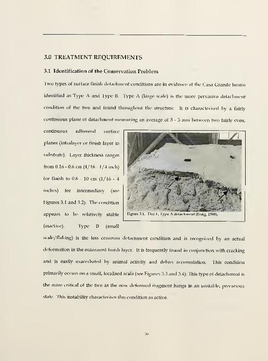
Two types of surface finish detachment conditions are in evidence at the Casa Grande herein
identified as Type A and Type B. Type A (large scale) is the more pervasive detachment
condition of the two and found throughout the structure. It is characterised by a fairly
continuous plane of detachment measuring an average of 3 - 5 mm between two fairly even,
continuous adherend surface
f '^'Jr'-''^^
Figure ^ 1 I icr h, lype A detachment (Fong, 1998)
planes (intralayer or finish layer to
substrate). Layer thickness ranges
from 0.16 - 0.6 cm (1/16 - 1/4 inch)
for finish to 0.6 - 10 cm (1/16 - 4
inches) for intermediary (see
Figures 3.1 and 3.2). The condition
appears to be relatively stable
(inactive). Type B (small
scale/ flaking) is the less common detachment condition and is recognized by an actual
deformation in the outermost finish layer. It is frequently found in conjunction with cracking
and is easily exacerbated by animal activity and debris accumulation. This condition
primarily occurs on a small, localised scale (see Figures 3.3 and 3.4). This type of detachment is
the more critical of the two as the now deformed fragment hangs in an unstable, precarious
state. This instabihty characterises this condition as active.

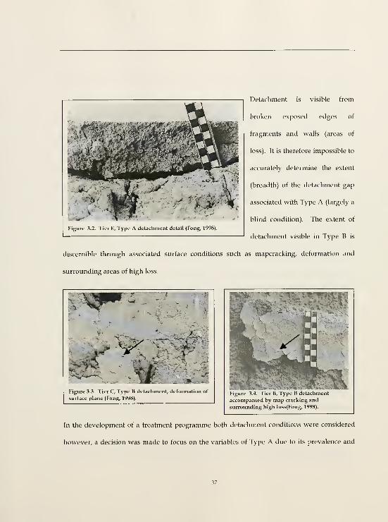
Detachment is visible from
broken exposed edges of
fragments and walls (areas of
loss). It is therefore impossible to
accurately determine the extent
(breadth) of the detachment gap
associated with Type A (largely a
blind condition). The extent of
detachment visible in Type B is
discernible through associated surface conditions such as mapcracking, deformation and
surrounding areas of high loss.
Figure 3.2. Tier E, Type A detachment detail (Fong, 1998).
Figure 3.3. Tier C, Type B detachment, deformation of
surface plane (Pong, 1998).Figure 3.4. Tier B, Type B detachment
accompanied by map cracking andsurrounding high loss(Fong, 1998).
In the development of a treatment programme both detachment conditions were considered
however, a decision was made to focus on the variables of Type A due to its prevalence and

unusual nature. Treatment methods have already been developed and successhjlly
implemented for the small-scale detachment of earthen plasters (Type B). If the gap of
detachment and the thickness of the detached layer are small enough, very often the most
successful method of reattachment is rehydration of the earthen material. Water is the natural
plasticizer of clay. Treatment is effectively administered by misting or injection of a mixture of
ethanol and water and gently pressing the detached area back into alignment with the plaster
plane. In arid environments, small earthen fragments of narrow detachment gaps have also
been reattached using a low concentration of gelatine (1.25 °o w/v). An obvious concern
asscxriated with this method is biosusceptibility. Both of these methods, water and ethanol,
and gelatine have been successfully used on thin earthen finishes at Mesa Verde National
Park.' If the gap of detachment is too great or the finish layer too thick to be pressed back into
alignment, then an adhesive with gap filling properties becomes necessary. This latter case
presents the treatment requirements of Type A. Therefore, if Type B cannot be treated with
known methods then the results of an investigation for Type A condition could prove useful.
Type A is unusual in the expanse and regularity of the detachment gap and the regularity and
thickness of the adherends. The seemingly large, continuous expanses of detachment and /or
the thickness of the detached layer(s) defy typical rehydration reattachment methods of
realignment. The nature of the detachment raises a number of conservation treatment issues.
(The possible causes of the condition are discussed below in 3.2 Mechanisms of Deterioration
and Detachment.)
' See Architectural Conser\ation Laboratory (ACL), University of Pennsylvania, "Condition Assessment of
Architectural Finishes, Mug House, Mesa Verde National Park, Mesa Verde, Colorado," 1995-1996, documentation

What causes this condition and when did it occur?
Is the condition active?
Is the condition stable?
Does the situation require stabilisation and /or reattachment?
Is it desirable to fill the gap with a continuous film or is it preferable to "spot
weld"?
• What are the points of access and how will treatment be administered /applied?
3.2 Mechanisms of Deterioration and Detachment
Detachment is typically observed at exposed broken wall or fragment edges (areas of loss);
otherwise it is blind. The causes for loss and the causes of detachment are not necessarily one
and the same. The majority of visible surface finish loss probably predates 20th century
shelters for the causes of this condition are almost certainly related to abandonment and lack
of maintenance resulting in unmitigated exposure to wind and rain, extraction of wood
members (vigas and lintels), floor/roof collapse, removal of fill and subsequent climatic
change resulting in basal erosion, animal activity, and vandalism. There has been occasional
but minimal loss of material since the erection of the shelters, however some areas remain
vulnerable due to their precarious state created by earlier damage. Type B detachment is
almost always directly related to these factors.
drawings. ACL, University of Pennsylvania.

The highly regular and even nahjre of Type A detachment suggests that it is a result of
original construction techniques (see Figures 3.1 and 3.2). The perceived planar detachment
may in fact be a separation induced by shrinkage rather than post construction trauma such as
that caused by seismic vibrations. The same phenomenon of shrinkage is what permits us to
view the lens and layer construction of the wall substrate and is a contributing factor to the
subsequent loss of fabric. The gap of detachment is visible as a result of loss. Loss has
occurred at that location in part because of the lack of support evidenced by the gap. These
are mutually descriptive and dependent conditions. What might have previously passed
undetected or otherwise noted as a blind void /detachment now becomes visible and
susceptible to extrinsic mechanisms of decay. If in fact, as it appears to be, the detachment is a
result of construction technique then it is an original condition, clearly inactive, and therefore
stable. However, while the condition may be relatively stable, it still presents an extensive
plane of discontinuity within the walls. With loss, exposed broken edges become points of
vulnerability for further loss induced by such agents as water penetration, debris
accumulation, insect and animal activity and physical/mechanical impact caused by visitor
intervention.
Shrinkage between two layers of like material occurs when the moisture contents of those two
layers are too dissimilar. The imbalance of moisture levels induces rapid evaporation caused
by suction of the moisture out of that material with the higher moisture content by and into
the adjacent less hydrated material. Rapid evaporation inhibits the bondmg process between
the two surfaces and frequently results in shrinkage (contraction and consequent reduction of
interfacial contact) and cracking. Clearly, the intra layer separation is not continuous

otherwise wholesale failure would result. There is no evidence of mechanical bonding
between layers although surface roughness may have been intentional in order to induce
keying. Type B failure is probably due to a finer texture and less well graded aggregate
component in the outer finish layer (compared to the adjacent layer) combined with the
stresses caused by wetting and drying after abandonment and exposure.
Type B detachment is clearly a subsequent aberration that has increased in extent and severity
over time. Its current active and unstable condition is identifiable as failure. By contrast. Type
A detachment may have existed since the point of original construction, in which case it is not
an aberration. Its condition is inactive, has not increased, and therefore is not necessarily
definable as failure by the same process of reasoning. However, the pervasive nature of Type
A detachment does pose potential of extensive failure (loss). Extrinsic factors such as seismic
tremors could cause widespread failure for this currently inactive condition. As previously
mentioned. Type B detachment should immediately be addressed and treated. A policy of
treatment for Type A will require consideration of many factors specific to the site. For Casa
Grande these include:
• The statistical possibility of seismic tremors
• The high integrity and original material authenticity of the Casa Grande
• The opportunity to monitor and assess trial treatments if administered.
All factors must be balanced and their relative benefits weighed against the potential
disadvantages of intervention to such a stable condition when moti\ated by a statistical
unknown (likelihood of seismic tremors). Preventative maintenance is indisputably valuable.

the points of and occasions for interventions must be wisely and discretely selected and
limited to those of maximum affect with minimum impact upon the site and structure.
3.3 Treatment Requirements
The conservation problem is the in situ stabilisation and reattachment of the finish layer(s) in
the Casa Grande. The variables are caliche fabric (for both adherends), an average detachment
gap of 3 mm and limited points of access. The majority of exposed gaps are accessible from the
bottom edge upwards. Upward facing edges are typically covered over and/or filled in with
debris carried downwards by gravitational force. What is desired is an injectible adhesive
with gap-filling properties (grout) that is chemically, physically and mechanically compatible
with the original fabric. Philosophical and theoretical criteria of intervention advocate
minimum intervention towards the maximum retention of original fabric.
The ideal grout fulfills the following criteria,
• Compatibility
• Stability
• Adhesive bond strength
• Cohesive strength
• Minimal shrinkage
• Water vapor permeability
• Low biosusceptibility
Minimal weight
Injectibility
Flow
TTiixotropy
Working time
Ease of use and disposal
Retreatability

Compatihilih/
The selected grout must be chemically, physically and mechanically compatible with the
surrounding original fabric. It should not drastically alter the inherent properties of the
adherends nor should it pose too foreign a barrier within the existing system. Chemical
compatibiUty implies a sympathetic bond of materials on the chemical level, both initially and
over time. The aim is to work with the nature of the original material, not to change it unless
it is inherently compromised. Ideally, the chemical composition of the treatment material
should share the fundamental chemical characteristics of the original fabric. Given the high
CaCOs content of the adherends, a lime-based grout would be appropriate; however the
detachment is too narrow to use lime based grouts which require a minimal aggregate size
still too large for injection into these narrow voids. Physical compatibility indicates a
sympathetic relationship between the original fabric and the treatment material such as
porosity and permeability. Mechanical compatibility refers to functional operations in a
systemic or compositional form such as bond strength. Does the treatment perform its
mechanical function in a manner that is effective and beneficial to the original system? The
treatment must perform its desired purpose without causing additional stress or undue
chemical and/ or physical change to the existing fabric and system.
Stabilihj
The treatment material should be stable over time in an uncontrolled exterior environment
(i.e. one subjected to temperature and humidity fluctuations). It should perform its function

in the state in which it was designed. Adhesive bond failure, creep, flex, and/or change in pH
are examples of instability and indicate a degradation and weakening of the system.
Adhesive Bond Strength
Proper adhesive bond strength provides adhesion and associative support but is never
stronger than the original fabric itself. The point of failure under load for any reattachment
adhesive conservation treatment should be at the interface between adhesive and original
fabric or preferably within the treatment material itself. These points of failure are designed
to prevent further loss or harm to original fabric. The system is only as strong as its weakest
member.
Cohesive Strength
Cohesive strength describes the internal strength of the treatment material. The treatment
material must have good cohesive strength before it can offer adhesive strength. Good
cohesive strength is a result of even particle distribution and a strong network of physical and
chemical bonding.
Minimal Slirinkage
The treatment material should display mmimal shrinkage. It must retain its form in order to
maintain mterfacial contact and adhesive bonding with the surrounding fabric as well as
cohesive strength. Too much shrmkage is a failure of the system.

Water Vapor Permeability
Water vapor permeability is the ability of a material to permit the passage of water vapor.
This is an essential property. Any impermeable barrier will have deleterious effects, causing
greater damage than benefit. Trapped liquid water or condensation at the interface can lead
to softening or collapse/ failure of the earthen material, formation of salts, biological growth,
and damage due to freeze/ thaw. Any or all of these effects can cause further detachment or
deterioration amounting to loss.
Biosusceptibility
The grout should have zero to low biosusceptibility. There is no evidence of microflora on site
given the low moisture levels and shelter protection.
Minimal Weight
The grout, while not structural is intended to provide a measure of support by providing a
backing for the detached layer. It must have sufficient cohesive strength in order to offer
support however, it must be light in weight to avoid contributing undesired additional weight
to the already vulnerable system.
Creep
The grout should not experience creep. Creep is "the dimensional change with time of a
material under load, following the initial instantaneous elastic or rapid deformation."' While
''D907, Standard Terminolog)' ot Adhesives," (Philadelphia: ASTM, 1990), p. 35.

it is virtually impossible for plastic materials to be absolutely free of creep, the degree to
which they do exhibit this characteristic should be negligible. A degree of flexibility is
desirable yet the grout should not 'sag' from its original location. This issue is initially
addressed in the design of a thixotropic grout. Creep primarily addresses dimensional change
as a result of load however dimensional change can also be induced by a rise or drop in
temperature. An expansion of the grout will exert stress upon the adherends resulting in
eventual cracking, (failure) and future loss; contraction of form is addressed in 'shrinkage.'
Injectibility
Injectibility, flow and thixotropy are characteristics related to application. Limited access to
detachment gaps requires a highly injectible grout. The 3 mm size of the typical gap requires
injection through a hypodermic syringe and gauge 16 needle (1.65 mm outside diameter).
Any adhesive formulation must be fluid enough to pass through these tools.
Flmv
The grout must have good flow. Flow is the movement ease and ability of a liquid or semi-
liquid material. This is directly related to the viscosity and surface tension of the adhesive
formula and adherend surfaces. Once injected, the grout must flow far into the space and
then it must remain in place. Flow is further characterised by ease of injection. Ease of
injection is dependent upon even dispersion of filler particles within the emulsion, solids
content and the lubricity of the mixture.

Thixotropy
The grout must be thixotropic. Thixotropy is the property of a fluid to display low viscosity
under shear force and to set when shear is removed.
Working Time
Working time refers to the time period in which the grout remains in a workable/ usable state.
It must not set too quickly nor separate out into its constituent components. A desirable
working time would be a minimum of 45 minutes to an hour.
Ease of Use and Disposal
The grout should be simple enough to be made on site, require a minimal amount of
equipment, and should be easy to clean and dispose. It should be safe both for the applicator
and the environment, be low in toxicity and cost (affordable).
Collectively these properties share symbiotic relationships and must be carefully balanced in
the design of a treatment proposal. The goal is minimum but opportune intervention towards
a reasonable amount of durability and a maximum amount of compatibility. The aim is not to
avoid change but rather to manage that which already occurs and induce that which one
believes to be beneficial.

4.0 MATERIAL SELECTION
Filled adhesive grouts are comprised of three basic elements, binder, filler, and dispersant
(water). Occasionally, an additional element, a thickener is necessary. The formulahon of a
grout is a balancing of these elements in the correct proportions to achieve the desirable
properties as established by the context and the critical performance properties (see 3.3
Treatment Requirements).
As the finish layers at the Casa Grande are clay-based (with lime), an aqueous system was
identified as a highly desirable and compatible adhesive option. A water-based grout is
fundamentally compatible with the rheological properties of clay allowing wetting and
reactivation of both adherend surfaces. Given the criteria of injectibility, two adhesive systems
were initially considered: solutions and emulsions. Solutions are a fine even distribution of
one substance in another at a molecular level thereby creating a homogeneous mixture in
which the separate components are no longer recognizable.' The complete dissolution of one
material into another offers good depth of penetration, an ideal vehicle for consolidation. In
general, the finish layers of the Casa Grande retain good cohesive strength. Consolidation of
the matrix is unnecessary. In order to minimize change to the original fabric, the minimum
amount of penetration is sought to produce a successful bond between the adhesive and the
adherends. Emulsions by their nature are less penetrating than solutions as the solids
component within them is essentially immiscible and the resin polymer molecule relatively
large. Emulsions were therefore selected over solutions.
' H. Kiihn, Consen-'atwn and Restoration of Works of Art and Antiquities vol. 1, A. Trone trans. (London: Butterworths,
1986), p. 193.

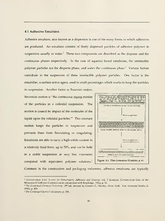
4.1 Adhesive Emulsion
Adhesive emulsion, also known as a dispersion is one of the many forms in which adhesives
are produced. An emulsion consists of finely dispersed particles of adhesive polymer in
suspension usually in water.' These two components are described as the disperse and the
continuous phases respectively. In the case of aqueous based emulsions, the immiscible
polymer particles are the disperse phase, and water the continuous phase.' Various factors
contribute to the suspension of these immiscible polymer particles. One factor is the
emulsifier, a surface-active agent, used in small percentages which works to keep the particles
in suspension. Another factor is Broivnian motion.
Brownian motion is "the continuous zigzag motion
of the particles in a colloidal suspension. The
motion is caused by impact of the molecules of the
liquid upon the colloidal particles."* This constant
motion keeps the particles in suspension and
prevents them from flocculating or coagulating.
Emulsions are able to carry a high solids content in
a relatively fluid form, up to 70%, and can be held
in a stable suspension at very low viscosities
compared with equivalent polymer solutions.^
'OrPS' o c^op^oD o noo o oc^^°^Oo o o o oopon^'q q o o.
T/77/m//7;;n//ynf777?AOjtC'J^ 0:3^IIS;OM orfOjuCO O?* IC'i'ACt
T/jmrmnrmrr,iC'.r rACKfft Jfrffll5 WITM WiTft lilllNC vo-[
jrmm
Figure 4.1. Film formation (Hartzler, p. 6).
Common in the construction and packaging industries, adhesive emulsions are typically
- Conser\ation Unit, Science jot Consenmtors; Adhesiz'es and Coatings vol. 3 (London: Consen-ation Unit of the
Museums & Galleries Commission in conjunction with Routledge, 1992), p. 51.
3 The Condensed Chemical Dictionary, W*' ed., revised by Gessner G. Hawley, (New York: Van Nostrand Reinhold,
1981), p. 409.
* The Condensed Chemical Dictionary, p. 154.
utilized as concrete admixtures and sealants respectively. Adhesives may be categorized by
mode of application and setting as either 'thermoplastic' or 'thermoset.' Thermoplastics are
predominantly linear macromolecules (polymers) that can be dissolved in solvents and will
melt v^fhen heated." Thermoplastic resins, such as polyvinyl acetate (PVA) and various
acrylates consist of long-chain molecules. In general, the longer the molecule, the stronger the
material. Thermoplastic resin adhesive emulsions set by a purely physical, non-chemical
process. These emulsions harden by evaporation of their dispersant, water." Once the
dispersant evaporates, the particles are forced together to coalesce into a coherent film." Film-
forming materials which are useful as coatings, consolidants or adhesives all have large
molecular size as a common factor.'" These polymers do not cross-link during cure so they can
be re-softened repeatedly with heat and usually retain their solubility as they age." Their
aqueous base and the absence of cross-linking offer a degree of resolubility (reversibility).
Thermoplastic resins are widely used in conservation because of the degree of reversibility
and stability that they offer.'"
Thermoset adhesives densely cross-link upon cure and therefore cannot be heated and
softened repeatedly. This dense cross linking renders the hard adhesive film insoluble.
Curing takes place by chemical reactions at room or elevated temperature depending upon the
^ C.V. Horie, Malermk for Conserimtwn (Oxford: Butterworth-Heinemann, 1995), p. 29.
' Hone, Mntcrmk for Conscnmtwn, p. 12.
'' Horie, Materials for Comen'ation, p. 11.
* Arthur H. Landrock, Adhenves Technology Handbook (New Jersey: Noyes Publications, 1985), p. 129, 181.* Horie, Materials for Conservation, p. 29.
'" Horie, Materials for Conservation, p. 29.
" Kiihn, Conservation and Restoration vol. 1, p. 161.
'- Constance S. Silver, "Architectural Finishes of the Prehistoric Southwest: A Study of the Cultural Resource andProspects for its Conservation," 1987, unpublished report. Philadelphia, University of Pennsylvania. Architectural
Conser\ation Laboratorv, p. 133.
50

type. Thermoset adhesives are commonly available as solventless liquids, pastes, and solids."
The chemical and physical transformation of thermoset adhesives upon cure and the
subsequent insolubility (irreversibility), make these less desirable as a conservation option.
Aqueous adhesive emulsions are made from materials that can be dispersed in water alone.
Aqueous based emulsions are lower in cost than the equivalent organic solvent-based systems.
In contrast to organic solvent adhesives, their use eliminates health hazards and the danger of
fire or explosion. However, in most cases water-based adhesives must be kept from freezing
during shipment and storage because of permanent damage to both the container and
contents."
4.1.1 Acrylic vs. Polyvinyl Acetate Resin
A search was performed on the history and uses of adhesive emulsions in the field of
conservation, with particular regard but not limited to earthen architecture. The questions
posed within the search were,
• Type of emulsion (resin)
• Use/delivery
• Concentration
• Context (Location/site)
(See Appendix 10.2 Literature Review of Polyvinyl Acetate and Acrylic Emulsions in
Conservation.)
" Landrock/\i/;it's;t'e.s Teclmobgy, p. 128.

The oft cited and commonly agreed upon earliest published account of the use of polyvinyl
acetate (PVA) in conservation is by Rutherford Gettens and George Stout in 1929.'' Gettens
and Stout utilised polyvinyl acetate as a fixative for the transfer of Oriental wall paintings.
Acrylic and polyvinyl acetate emulsions have been used in varying concentrations ranging
from 2% to neat (undiluted) for plaster consolidation and reattachment, and adobe
amendments according to various published and unpublished accounts. One of the problems
encountered in this literature search was the lack of clarity, consistency, and standardisation in
specifications. Percentages were frequently mentioned without reference to measure (parts
per weight or parts per volume), or to original percent solids as manufactured, and often not
specified at all. Ratio interpretations (x:n) varied in meaning from .v parts to n parts, to x parts
in n parts. Total percent resin available was often never stated. Acrylic emulsions are almost
exclusively utilised for exterior applications. Their superiority over polyvinyl acetates for
exterior applications was very early remarked by Rutherford Gettens in 1935 and continues to
be echoed today as expressed in the current body of literature and in interviews conducted of
polymer chemists and conservators for this research. PVAs are regarded as less desirable for
exterior environments due to their water and ultra violet light (UV) sensitivity and their low
pH (acidity) which decreases (becomes more acidic) over time. They tend to be higher in
strength and lower in flexibility compared to acrylics.
The polyvinyl resins are not a cure for all ills. Their use as an impregnating
material for stone surfaces exposed to out-of-door weathering has been
suggested and tried, but they have not been found suitable for this purposebecause of lack of penetration and the tendency to absorb water, as has
already been mentioned.'"
'• Irving Skeist, ed., Hamihook of Aiilwsivci, 3rd ed., (New York: Van Nostrand Reinhold, 1977), p. 183-185.
'^ Rutherford Gettens, "Polymerized Vinyl Acetate and Related Compounds m the Restoration of Objects of Art,"
Tixluucal Studies in the Fu'hl of Ike Fine Arts IV (1935): 15-28
"~ Gettens, "Polymerized Vinyl Acetate and Related Compounds in the Restoration of Objects of Art," p. 24.
The superior water resistance of acrylic resins, as compared to polyvinyl
acetate, is well known in the masonry field.'
Of the acrylic emulsions, Rhoplex" AC-33 (Primal" in Europe and Canada) has been most often
selected in conservation for plaster reattachment and stabilisation. Rhoplex'' E-330 is most
often utilised for adobe and earthen mortar amendment purposes, at least in the United States.
It is not clear why Rhoplex AC-33 has been favored by conservators except perhaps for
reasons of familiarity. One of the earliest cited usages of AC-33 for conservation purposes is
by Giacomo Chiari for the in situ reattachment of earthen plasters in Peru, 1975-1977'" (see
Appendix 10.2 Literature Review of Polyvinyl Acetate and Acrylic Emulsion in
Conservation). Product specifications of both products reveal almost identical composihon
and properties (See Appendix 10.3 Product Specifications & Material Safety Data Sheets
(MSDS)). During the course of this research, it was discovered that Rohm and Haas, the
maker of Rhoplex, plans to discontinue AC-33. Recent research on the history and uses of
adhesive emulsions in the field of conservation, an assessment of their performance over time,
fulfillment of the desired criteria, and product availability - clearly suggest Rhoplex E-330 as
the most desirable candidate for further investigation.'^
4.1.2 Rhoplex* E-330
Rhoplex E-330 Cement Mortar Modifier by Rohm and Haas is a copolymer, a
combination of methyl methacrylate and ethyl acrylate, dispersed in an
aqueous medium. Created by a process of emulsion polymerization, the
1" Morgan Phillips, "Adhesives for the Reattachment of Loose Plaster," APT Bulletin 12 (1980): 42.
'* Giacomo Chian, "Treatment of Adobe Friezes in Peru," Third Inlernalioml Symposnim on Miidbnck (adobe)
Presen'atwn , p. 39-47.
'" See Robert Hartzler, Acryhc-Modifieii Earthen Mortar, (Santa Fe: United States National Park Ser\'ice, 1996).
53

resulting product consists of a proprietary blend of the two monomers with
other minor constituents, with a small particle size, < 1.0|im. These particles
are so small that Brownian forces keep them in suspension. Unlike polymers
dissolved in solvents (true solutions), polymer emulsions can support high
concentrations of polymers of high molecular weight (up to 70°o) without
becoming unworkably viscous.""
Rhoplex E-330 is a milky white liquid, slightly ammonia in odor, containing 47% solids by
weight in an alkaline water base. It has a pH of 9.5 - 10.5, and a specific gravity, and melting
and boiling points similar to that of water. It will remain stable through five cycles of
freeze/thaw at -15° C to 25° C. Its recommended storage temperature range is 1°C to 49° C.''
E-330 was designed for the construction industry as an amendment for Portland cement.
Rohm and Haas claims that,
...cement mortars modified with Rhoplex E-330 are hard, tough, and durable.
...polymerized modified [cement] mortars have superior flexural, adhesive,
and impact strengths, as well as excellent abrasion resistance. They possess
excellent resistance to ultraviolet light and heat, dry to a uniform color, and
offer excellent adhesion to a variety of surfaces, such as concrete, masonry,
brick, wood, and metals."
Chief applications of E-330 modified cement mortar include patching and resurfacing, floor
underlayments, terrazzo flooring, spray and fill coats, precast architectural building panels,
stucco, industrial cement floors, and highway and bridge deck repair.''
-" Hartzler, Acrylic-Mcdificil Earthen Mprtar, p. 5.
-' Rohm and Haas, "Material Safety Data Sheet, Rhoplex* E-330," (Philadelphia: Rohm and Haas, 11 July 1990).
Water has a specific gravity of 1.0.
— Rohm and Haas, 'Rhoplex' E-330 Cement Mortar Modifier" (Rohm and Haas Company, 1995), p. 1.
^^ Rohm and Haas, "Rhoplex- E-330 Cement Mortar Modifier," p 1.

E-330 has been used by the United States National Park Service as an adobe and earthen
mortar amendment since 1975. At that time Dennis Fenn ran a series of tests on modified
earthen mortars at Chaco Canyon. His work was a continuation of earlier work on E-330
begun by Darrel J. Butterbaugh in 1972. Concentrations of use have varied over time from site
to site. As an earthen amendment, E-330 contributes strength, some measure of flexibility and
an increased resistance to water the latter extremely important for earthen materials. The
increase in hydrophibicity is in direct proportion to a decrease in water vapor permeability.
The greater the amount and the higher the concentration of the amendment, the greater the
strength and lower the permeability. The emulsion has a minimal affect on the color and
texture of the original earthen material and is acceptably stable in exterior environments.
4.2 Binder Concentration
Three percentages of binder concentration were selected for the testing programme, 20%, 40%
and neat (undiluted). These concentrations were selected based on the literature review of the
use history of adhesive emulsions in conservation applications, the proposed site requirements
in this research, and the inherent viscosity of the selected emulsion.
The neat formulation contains the highest resin solids content (47"o by weight). In general,
viscosity is directly related to resin content whereupon increased resin particle concentration
induces higher viscosity due to restricted molecular mobility. Higher viscosity results in

greater surface tension thereby decreasing contact (flow), diffusion and penetration ability.''
However, what is lost in surface contact is gained in internal film strength (cohesion).
Strength, contact, diffusion, and penetration ability are all commensurate with resin solids
content. Dilute emulsions raise wettability yet lower strength (adhesive and cohesive). The
more dilute the emulsion the lower the percent solids of resin. A 40% binder concentration of
E-330 contains 18.8% solids and a 20°o binder concentration retains 9.4% solids (by
calculation). These figures are critical in understanding the physical effects of resin content
alone and in conjunction with a filler fraction (see 4.3 Fillers, below).
4.3 Fillers
"Fillers are added to polymers for many reasons. A filler reduces the volume and cost of
polymer used in a formulation. "'" They reduce shrinkage, impart strength and affect viscosity
and flow. Microspheres and fumed silica can reduce the weight of an adhesive layer while
larger aggregates such as sand contribute strength and hardness. In all cases, fillers decrease
the need for the polymer resin content, advantageous in conservation applications. TTie ideal
fillers will be light in weight, aid in shrinkage control and impart strength. In 1980 Morgan
Phillips published his findings on filled acrylic emulsion grouts for the reattachment of lime
plaster.^'' His system consisted of a combination of reactive and non-reactive fillers, hydrated
- "The polymer is not limited in molecular weight since the viscosity does not depend on what is contamed within
the discrete particles. The viscosity of a latex (emulsion) depends primarily on solids content and the composition of
the aqueous phase " Skeist also goes on to mention the relationship between critical surface tensions of adhesive and
adherend and the .subsequent effect upon wettability. Wettability is the ability of the adhesive to wet the substrate
and the ability of the substrate to be wetted. Skeist, Handbook of Aiiheswes, p. 6.
^ Horie, Motermk for Consen'titwn, p. 178-179.
-" See Phillips "Adhesives for the Reattachment of Loose Plaster."

lime, fluid coke, and microballoons. Each flller ingredient contributed towards an ideal
particle size range for the application. Matero and Bass combined hydrated lime, ceramic
microspheres and fine silica sand for grouts designed for earth-lime adherends." Both
formulations utilised hydrated lime for its physicochemical and mechanical compatibility with
the original fabric, strength, controlled shrinkage, and its particle size range. In both cases,
microspheres were included for their mid-range particle size, lightweight, non-reactivity and
the lubricity or injectibility they imparted to the mix. Phillips selected fluid coke for its larger
particle size and assistance in shrinkage control as a reactive expansive filler through the
generation of CO, gas. Matero and Bass chose a fine silica sand as the larger particle size
fraction and for the mechanical strength and shrinkage control it offered. These ingredients
were selected based on treatment criteria, context and research objectives.
This investigation focuses on inorganic, non-reactive fillers. The selection of fillers was based
on previous usage according to conservation literature and the desire to isolate the physical
relationships and limits of the various components individually and collectively. Three fillers
were selected for testing, fumed silica, glass microballoons, and fine silica sand.
Fumed silica was initially considered a clear choice for a filler because of its ability to fulfill the
criteria of thixotropy, low shrinkage, even solids dispersion, compatible strength, injectibility,
water vapor permeability, light weight and low cost."" Initial tests of emulsions filled with
-" Frank G. Matero and Angelvn Bass, "Design and Evaluation of Hydraulic Lime Grouts for the Reattachment of
Lime Plasters on Earthen Walls," Con^cmilipn ami Manugcmeul pf Archaeolp\;ical Sita 1 (1495); 97-1118.
^ For other studies of fumed silica as an adhesive filler see Phillips "Adhesives for the Reattachment of Loose
Plaster," and Dawn Melbourne, "A Comparative Study of Epoxide Resin and Cementitious Grouts for the
Delamination of Sandstone at El Morro National Monument, New Mexico," Master's thesis, Unwersity of Pennsylvania,
1994.
57

varying degrees of fumed silica revealed significant problems witfi cohesive strengtfi. When
sufficient amounts of fumed silica were added to the emulsion in order to achieve the desired
viscosity, the mixture lost all internal cohesion. Lack of cohesion is synonymous with lack of
strength. Fumed silica was eliminated as a filler option for the emulsion concentrations tested.
Quartz sand is an inert common filler known to provide strength and aid in shrinkage,
however sand alone does not meet the required criteria of injectibility and minimal weight. A
combination of sand and microspheres was identified as a possible option."^ The combination
of two fillers introduced a new ratio of solid to solid (microspheres to sand). A range of ratios
was specified in order to isolate the contribution of individual solid components and thereby
determine the effects of each solid on the character of the mixture in relation to the binder and
to one another (see Table 5.1 Test Sample Matrix).
The particle size range of the sand (<300|Lim) was selected to pass through a 16 gauge needle,
the necessary orifice to deliver the grout in the Casa Grande detachment gap. The sand
contributes strength by its large particle size, surface area and sub-angular shape.
Microspheres offer lightweight and lubricity due to their hollow spherical form and lend body
to an emulsion, augmenting viscosity thereby decreasing the need for resin beyond what has
been determined to be sufficient for bonding strength and thickener. Glass microballoons
were selected over ceramic microspheres for their availability in smaller particle size (30-
llOum). The extended particle size range of the solids fraction offers greater strength and
shrinkage control. Ideally, the correct combination of these fillers will reduce the need for

resin by providing some of the internal physical struchire otherwise provided by the polymer
molecules. The filler fraction contributes infrastructure to the grout through a measure of
mechanical bonding and increased surface area or points of contact onto which the polymer
molecules can attach themselves. A reducHon in resin means a lower binder concentration,
which is criHcal in reducing strength and increasing water vapor permeability. Clearly, a
balance must be struck in identifying the optimum resin content (as available solids) necessary
for strength without imparting water vapor impermeability.
The ideal grout formula lies in a balance of liquid to solid (binder to filler) and solid to solid
(microballoons to sand) so that the stated criteria are achieved: good injectibility, flow,
minimal shrinkage and weight, good adhesion, bond strength and cohesion, reasonable water
vapor permeability, and good stability
4.4 Thickeners
The function of thickeners is twofold: one, it augments the viscosity, and two, it is critical in
maintaining suspension and even dispersion of the solids fraction. Laboratory and field tests
revealed that without the thickener, the filler solids fraction quickly separated out from the
binder and from its own constituent components (microballoons from sand). Only one
thickener was selected for use, Acrysol' 6038A. Acrysol 6038A is a sodium polyacrylate
thickener recommended by Rohm and Haas as a rheology modifier (viscosity) for use with
Rhoplex AC-33 and other latex compounds. It is produced in a gel form, and is relatively clear
-'' This consideration of this combination was based on previous research conducted by Matero and Bass. See
59

in color. It has a pH of 8.0 - 9.5, a specific gravity of 1.0 - 1.2 and a viscosity of 18000 - 25000 (as
is, cps Brookfield RV, spindle #6, 20 rpm, 25° C). It is considered stable, and recommended for
use within the temperahjre range of 1° - 49° C."' It is dilutable in water and described as
"especially stable to viscosity drift with time in a wide variety of compounds."" Undiluted
Acrysol 6038A contains 13 - 13.5% solids. The manufachjrer recommends cutting this with
water at a 1:1 ratio for easier incorporation into the emulsion system. This concentration yields
an approximate solids content of 6.5%."
"Design and Evaluation of Hydraulic Lime Grouts."3" Rohm and Haas, "Material Safety Data Sheet Acrysol« 6038A Emulsion," 1998.3' Rohm and Haas, "Acrysol® 6038A," product literature, 1992.'2 Temperature had a distinct affect upon the thixotropy and dispersion of the grout formula. The average ambientlaboratory temperature dunng the testing program was 25° C. The average temperature on site at Fort DavisNational Historic Site where the grout was field tested dunng the summer of 1998 following the laborator>' test
program, was 35° C. In the laboratory a 1;2 ratio of Acrysol:H;0 (approximately 4.3% solids) was found to be aworkable concentration. This concentration was easily measured and distributed through a hypodermic syringe andwas dilute enough so as not to drastically alter the inherent characteristics of the grout formulation. Thickener wasused as an enhancer not as a base ingredient. The high temperatures experienced on site raised the viscosity andthixotropy of the grout. The grout set much more quickly in the high heat resulting in an impractical short workingtime. The thickener was still neces.sary for even solids dispersion however not at such a high concentration. TheAcrysol ratio was decreased to 1:2.5 AcrysolrHjO (approximately 3.7% solids) in response to the uncontrollable highheat experienced in the field.

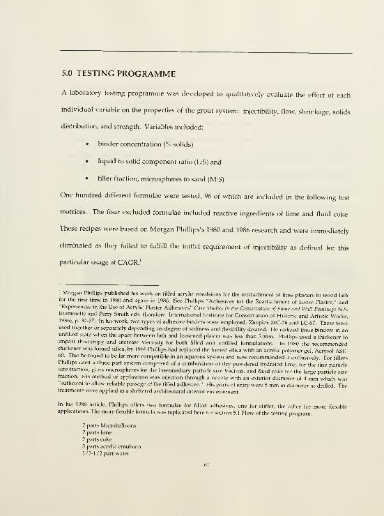
5.0 TESTING PROGRAMME
A laboratory testing programme was developed to qualitatively evaluate the effect of each
individual variable on the properties of the grout system: injectibility, flow, shrinkage, solids
distribution, and strength. Variables included:
• binder concentration (% solids)
• liquid to solid component ratio (L:S) and
• filler fraction, microspheres to sand (M:S).
One hundred different formulae were tested, 96 of which are included in the following test
matrices. The four excluded formulae included reactive ingredients of lime and fluid coke.
These recipes were based on Morgan Phillips's 1980 and 1986 research and were immediately
eliminated as they failed to fulfill the initial requirement of injectibility as defined for this
particular usage at CAGR.'
' Morgan Phillips published his work on filled acrylic emulsions for the reattachment of lime plasters to wood lathfor the first time in 1980 and again in 1986. (See Phillips "Adhesives for the Reattachment of Loose Pla.ster," and"Experiences in the Use of Acrylic Plaster Adhesives" Case Stiulics in the Consen'atwn of Stone ami Wall Paintings N.S.Brommelle and Perry Smith eds. (London: International Institute for Consen-ation of Historic and Artistic Works,1986), p. 34-37. In his work, two types of adhesive binders were employed, Rhoplex MC-76 and LC-67. These wereused together or separately depending on degree of stifhiess and flexibility desired. He utilized these binders in anunfilled state when the space between lath and loosened plaster was less than 3 mm. Phillips u.sed a thickener toimpart thixotropy and increase viscosity for both filled and unfilled formulations. In 1980 the recommendedthickener was fumed silica, by 1986 Phillips had replaced the hjmed silica with an acrylic polymer gel, Acrysol ASE-60. This he found to be far more compatible in an aqueous system and now recommended it exclusively. For fillersPhillips used a three part system comprised of a combination of dry powdered hydrated lime, for the fine particlesize fraction, glass microspheres for the intermediary particle size fraction, and fluid coke for the large particle sizefraction. His method of application was injection through a nozzle with an exterior diameter of 4 mm which was"sufflcient to allow reliable passage of the fllled adhesive." His ports of entry were 5 mm in diameter as drilled. Thetreatments were applied in a sheltered architectural interior environment.
In his 1986 article, Phillips offers two formulae for fllled adhesives, one for stiffer, the other for more flexibleapplications. The more flexible formula was replicated here for section 5.1 Flow of the testing program.
2 parts Microballoons
2 parts lime
2 parts coke
3 parts acrylic emulsion
1/3-1/2 part water
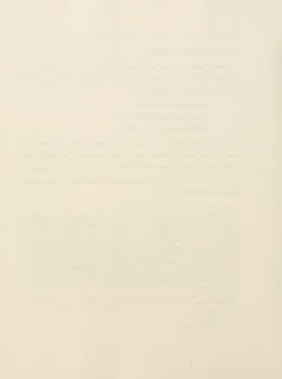
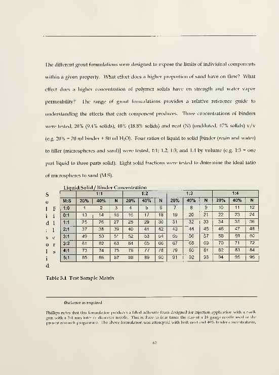
The different grout formulations were designed to expose tlie limits of individual components
within a given property. What effect does a higher proportion of sand have on flow? What
effect does a higher concentration of polymer solids have on strength and water vapor
permeability? The range of grout formulations provides a relative reference guide to
understanding the effects that each component produces. Three concentrations of binders
were tested, 20% (9.4% solids), 40% (18.8% sohds) and neat (N) (undiluted, 47% solids) v/v
(e.g. 20% = 20 ml binder + 80 ml H2O). Four ratios of liquid to solid [binder (resin and water)
to filler (microspheres and sand)] were tested, 1:1; 1:2; 1:3; and 1:4 by volume (e.g. 1:3 = one
part liquid to three parts solid). Eight solid fractions were tested to determine the ideal ratio
of microspheres to sand (M:S).
Liquid:Solid/ Binder Concentration
S
o
1
i
d

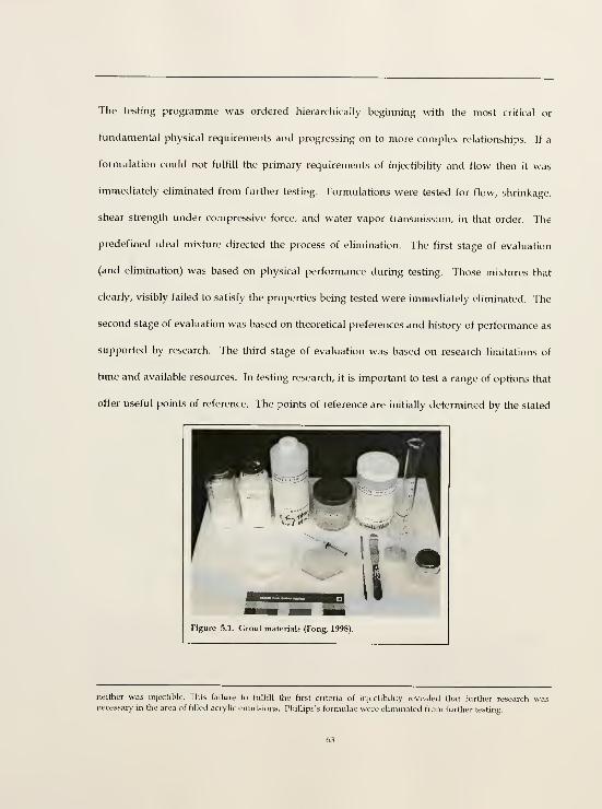
The testing programme was ordered hierarchically beginning with the most critical or
fundamental physical requirements and progressing on to more complex relationships. If a
formulation could not fulfill the primary requirements of injectibility and flow then it was
immediately eliminated from further testing. Formulations were tested for flow, shrinkage,
shear strength under compressive force, and water vapor transmission, in that order. The
predefined ideal mixture directed the process of elimination. The first stage of evaluation
(and elimination) was based on physical performance during testing. Those mixtures that
clearly, visibly failed to satisfy the properties being tested were immediately eliminated. The
second stage of evaluation was based on theoretical preferences and history of performance as
supported by research. The third stage of evaluation was based on research limitations of
time and available resources. In testing research, it is important to test a range of options that
offer useful points of reference. The points of reference are initially determined by the stated
neither was injectible. This faihire to fulfill the first criteria of injectibility revealed that further research wasnecessary in the area of filled acrylic emulsions. Phillips's formulae were eliminated from further teshng.

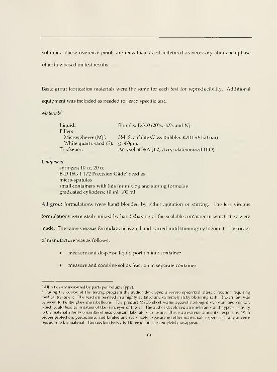
solution. TTiese reference points are reevaluated and redefined as necessary after each phase
of testing based on test results.
Basic grout fabrication materials were the same for each test for reproducibility. Additional
equipment was included as needed for each specific test.
Materials'
Liquid: Rhoplex E-330 (20%, 40'^o and N)
Fillers
Microspheres (M)': 3M Scotchlite Glass Bubbles K20 (30-110 pm)White quartz sand (S): < 300)jm.
Thickener: Acrysol 6038A (1:2, Acrysol;deionized H-,0)
Equipment
syringes; 10 cc, 20 cc
B-D 16G 1 1/2 Precision Glide' needles
micro-spatulas
small containers with lids for mixing and storing formulae
graduated cylinders; 10 ml, 100 ml
All grout formulations were hand blended by either agitation or stirring. The less viscous
formulations were easily mixed by hand shaking of the scalable container in which they were
made. The more viscous formulations were hand stirred until thoroughly blended. The order
of manufacture was as follows,
• measure and dispense liquid portion into container
• measure and combine solids fraction in separate container
- All ratios arc measured by parts per volume (ppv).
' During the course of the testing program the author developed a severe epidermal allergic reaction requiring
medical treatment. The reaction resulted in a highly agitated and extremely itchy blistermg rash. The irritant wasbelieved to be the glass microballoons. The product MSIDS sheet warns against prolonged exposure and contact,
which could lead to irritation of the skin, eyes or throat. The author developed an intolerance and hypersensitivity
to the material after two months of near constant laboratory exposure This is an extreme amount of exposure. With
proper protection, precautions, and limited and reasonable exposure no other individuals experienced any adverse
reactions to the material. The reaction took a full three months to completely disappear.

pour solids fraction into liquid fraction
mix thoroughly to the point of even distribution
add thickener as needed and mix thoroughly
5.1 Flow
Purpose
This test was designed to measure the properties of flow and injectibility. One hundred grout
formulations were tested. 1 cc of each grout formulation was injected with a hypodermic
syringe through a 16 gauge needle onto a vertically positioned wood board. Wood was used
due to its semi-absorbent surface in simulation of the water absorbency of the earthen
adherends. Formulations were eliminated based on their failure to,
• pass through the needle, and
• poor flow.
Poor flow was defined as either,
• too high resulting in failure to flow down the board to at least 2.5 cm the vertical
distance,
• too low yielding an uncontrolled flow of liquid down the board to at least 9.5 cm
the vertical distance.
The flow test was conducted in conjunction with the shrinkage tests for expediency's sake.
One batch of grout formula was easily distributed between the two tests.

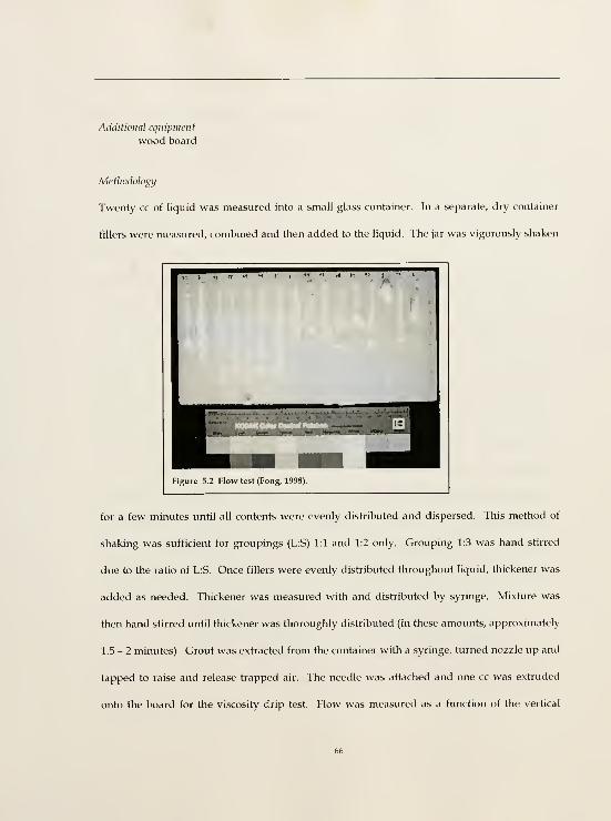
Additional cqiiipinciit
wood board
Metliodolog}/
Twenty cc of liquid was measured into a small glass container. In a separate, dry container
fillers were measured, combined and then added to the liquid. The jar was vigorously shaken
1 •! T
Figure 5.2 Flow test (Fong, 1998).
for a few minutes until all contents were evenly distributed and dispersed. This method of
shaking was sufficient for groupings (L;S) 1:1 and 1:2 only. Grouping 1:3 was hand stirred
due to the ratio of L:S. Once fillers were evenly distributed throughout liquid, thickener was
added as needed. Thickener was measured with and distributed by syringe. Mixture was
then hand stirred until thickener was thoroughly distributed (in these amounts, approximately
1.5-2 minutes). Grout was extracted from the container with a syringe, turned nozzle up and
tapped to raise and release trapped air. The needle was attached and one cc was extruded
onto the board for the viscosity drip test. Flow was measured as a function of the vertical

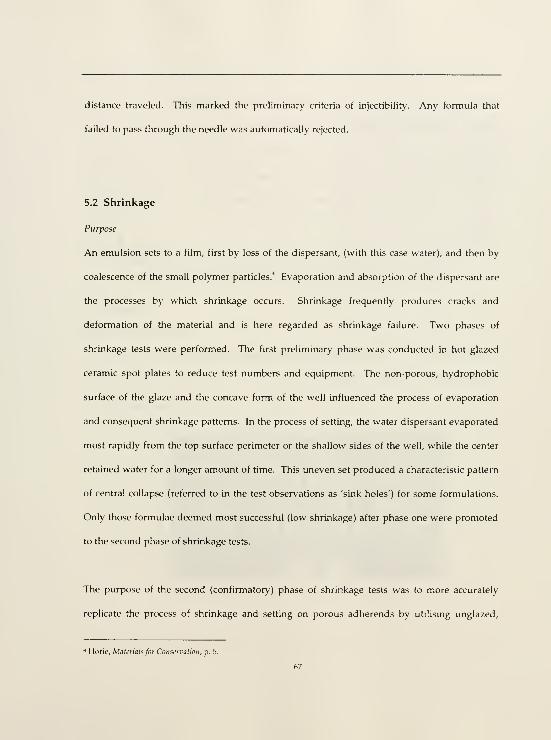
distance traveled. This marked the preliminary criteria of injectibility. Any formula that
failed to pass through the needle was automatically rejected.
5.2 Shrinkage
Purpose
An emulsion sets to a film, first by loss of the dispersant, (with this case water), and then by
coalescence of the small polymer particles.' Evaporation and absorption of the dispersant are
the processes by which shrinkage occurs. Shrinkage frequently produces cracks and
deformation of the material and is here regarded as shrinkage failure. Two phases of
shrinkage tests were performed. The first preliminary phase was conducted in hot glazed
ceramic spot plates to reduce test numbers and equipment. The non-porous, hydrophobic
surface of the glaze and the concave form of the well influenced the process of evaporation
and consequent shrinkage patterns. In the process of setting, the water dispersant evaporated
most rapidly from the top surface perimeter or the shallow sides of the well, while the center
retained water for a longer amount of time. This uneven set produced a characteristic pattern
of central collapse (referred to in the test observations as 'sink holes') for some formulations.
Only those formulae deemed most successful (low shrinkage) after phase one were promoted
to the second phase of shrinkage tests.
The purpose of the second (confirmatory) phase of shrinkage tests was to more accurately
replicate the process of shrinkage and setting on porous adherends by utilising unglazed.
* Horie, Materials for Conservation, p. 5.

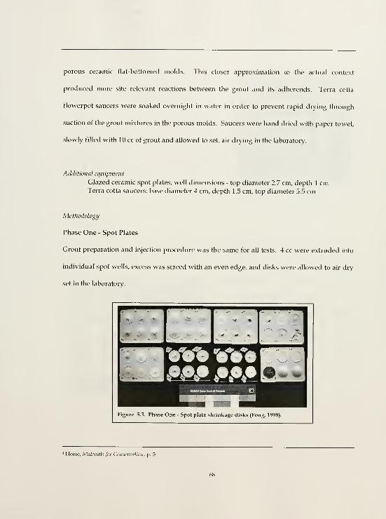
porous ceramic flat-bottomed molds. This closer approximation to the actual context
produced more site relevant reactions between the grout and its adherends. Terra cotta
flowerpot saucers were soaked overnight in water in order to prevent rapid drying through
suction of the grout mixtures in the porous molds. Saucers were hand dried with paper towel,
slowly filled with 10 cc of grout and allowed to set, air drying in the laboratory.
Additional eqtiipviicnt
Glazed ceramic spot plates; well dimensions - top diameter 2.7 cm, depth 1 cmTerra cotta saucers; base diameter 4 cm, depth 1.5 cm, top diameter 5.5 cm
Mctliodology
Phase One - Spot Plates
Grout preparation and injection procedure was the same for all tests. 4 cc were extruded into
individual spot wells, excess was screed with an even edge, and disks were allowed to air dry
set in the laboratory.
W^^

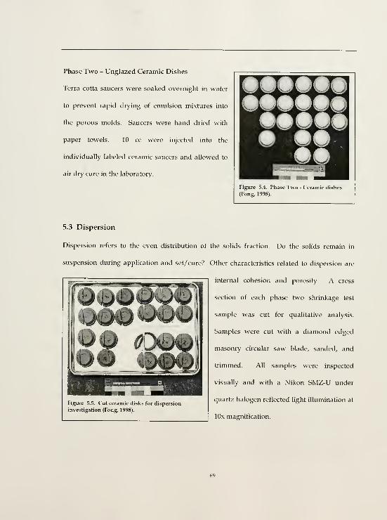
Phase Two - Unglazed Ceramic Dishes
Terra cotta saucers were soaked overnight in water
to prevent rapid drying of emulsion mixtures into
the porous molds. Saucers were hand dried with
paper towels. 10 cc were injected into the
individually labeled ceramic saucers and allowed to
air dry cure in the laboratory.
Figure 5.4. Phase Two - Ceramic dishes
(Fong, 1998).
5.3 Dispersion
Dispersion refers to the even distribution of the solids fraction. Do the solids remain in
suspension during application and set/ cure? Other characteristics related to dispersion are
internal cohesion and porosity. A cross
section of each phase two shrinkage test
sample was cut for qualitative analysis.
Samples were cut with a diamond edged
masonry circular saw blade, sanded, and
trimmed. All samples were inspected
visually and with a Nikon SMZ-U under
quartz halogen reflected light illumination at
lOx magnification.
Figure 5.5. Cut ceramic disks for dispersion
investigation (Fong, 1998).
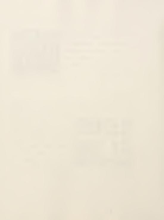
5.4 Shear Strength Under Compressive Force
Purpose
To measure adhesive bond strength and reveal point of failure. The ideal point of failure is
within the adhesive itself or at the interface between adhesive and adherend, but never within
the adherend. ASTM D3931 - Standard Test Method for Determining Strength of Gap-filling
Adhesive Bonds in Shear by Compression Loading was used as a model for assembly
fabrication and test method.^
Additional materials
Release agent: Mineral oil
Assemblies: Site soil; original fabric < 2.36 mm particle size
3 mm X 3 mm bass wood spacers
Plasteline modeling material
Duco cement
Rags
Additional equipment
Wooden molds 9 cm x 9 cm x 2.5 cm"
Plastic wrapWood board
1/4" X 1/4" wood strips
Cotton
Plastic straw or other similarly sized cylinder
Methodology
Nineteen assemblies were produced from the original Casa Grande wall loss fragment. The
dense caliche was rehydrated for 24 hours, mechanically broken down by hand, air and heat
'' "D3931, Standard Test Method for Deteimining Strength of Gap-filhng Adhesive Bonds in Shear by Compression
Loading," (Philadelphia: ASTM, 1990). Modified by author.
" Coupon dimensions are modified from original test dimensions.
^ A section of the 1995 exterior wall loss fragment from the Casa Grande was sent to the ACL/UPenn, for research
and testing. Available quantity of the wall loss fragment dictated that six different formulae could be tested for
strength and water vapor permeability These six were selected based on their abilitv to meet the three previously
tested criteria of flow, shrinkage, and dispersion.
70

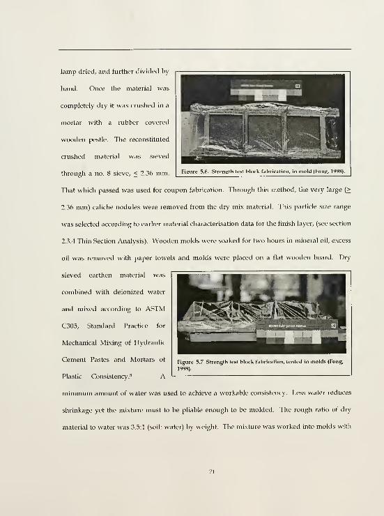
lamp dried, and further divided by
hand. Once the material was
completely dry it was crushed in a
mortar with a rubber covered
wooden pestle. The reconstituted
crushed material was sieved
through a no. 8 sieve, < 2.36 mm.
That which passed was used for coupon fabrication. Through this method, the very large (>
2.36 mm) caliche nodules were removed from the dry mix material. This particle size range
was selected according to earlier material characterisation data for the finish layer, (see section
2.3.4 Thin Section Analysis). Wooden molds were soaked for two hours in mineral oil, excess
oil was removed with paper towels and molds were placed on a flat wooden board. Dry
sieved earthen material was
combined with deionized water
and mixed according to ASTM
C305, Standard Practice for
Mechanical Mixing of Hydraulic
Cement Pastes and Mortars of
Plastic Consistency.^ A
minimum amount of water was used to achieve a workable consistency. Less water reduces
shrinkage yet the mixture must to be pliable enough to be molded. The rough ratio of dry
material to water was 3.5:1 (soil: water) by weight. The mixture was worked into molds with

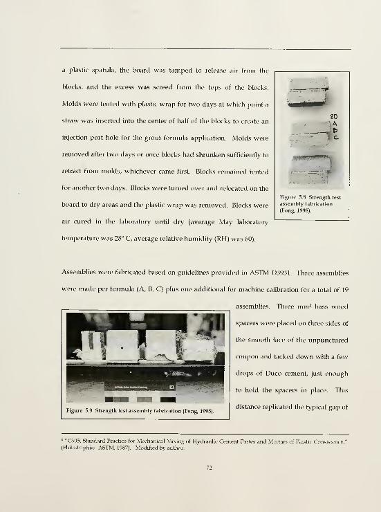
a plastic spatula, the board was tamped to release air from the
blocks, and the excess was screed from the tops of the blocks.
Molds were tented with plastic wrap for two days at which point a
straw was inserted into the center of half of the blocks to create an
injection port hole for the grout formula application. Molds were
removed after two days or once blocks had shrunken sufficiently to
retract from molds, whichever came first. Blocks remained tented
for another two days. Blocks were turned over and relocated on the
board to dry areas and the plastic wrap was removed. Blocks were
air cured in the laboratory until dry (average May laboratory
temperature was 28° C, average relative humidity (RH) was 60).
30A
-, t>
Figure 5.8 Strength test
assembly fabrication
(Fong, 1998).
Assemblies were fabricated based on guidelines provided in ASTM D3931. Three assemblies
were made per formula (A, B, C) plus one additional for machine calibration for a total of 19
assemblies. Three mm- bass wood
spacers were placed on three sides of
the smooth face of the unpunctured
coupon and tacked down with a few
drops of Duco cement, just enough
to hold the spacers in place. This
distance replicated the typical gap of
8 "C305, Standard Practice for Mechanical Mixing of Hydraulic Cement Pastes and Mortars of Plastic Consistency,"
(Philadelphia: ASTM, 1987). Modified by author.
Type A detachment. The punctured coupon was placed atop the coupon with spacers, smooth
side facing spacers (smooth face to smooth face), and offset by 1 /4 inch. Coupon sides with
spacers were sealed with Plasteline modeling material. The top edge was left open for visual
access and air displacement during grout injection. The assembly was further secured by a
fabric swath tied in a secure knot beneath the port hole.
Grouts were made in batches of 140 cc. These larger quantities required less amounts of
thickener proportionately compared to the smaller batches produced for the flow and
shrinkage tests. After five minutes in a sealed container, the surface of the grout formulae
solidified yet all easily reliquified with active stirring, (a demonstration of thixotropy).
Grout application followed standard methodology of prewetting with a dilute solution of the
emulsion, here a 10°o concentration of E-330 in water. Prewetting is a critical step in the
treatment process. It prepares the adherends by reducing suction/rapid absorption,
decreasing friction thereby increasing flow and adhesion of the grout, and subsequently aids
in controlling shrinkage. Prewetting with a dilute solution of emulsion creates a bridge/key
between the grout and the adherends. The low (4.7% solids) resin content of the 10%
concenh-ation provides low viscosity, and consequent rapid distribution and absorption.
However, the polymer molecule size remains the same and it is the size of the molecule and
the porosity of the adherend that limit the molecule's penetration. In this specific case, deep
penetration of the resin was unnecessary. The original building fabric is extremely dense and
in no need of consolidation. Minimal penetration provides a key into the surface of the
adherend. The porthole of each assembly was plugged with Plasteline and the gap filled from

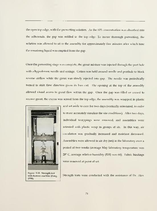
the open top edge, with the prewetting solution. As the 10% concentration was absorbed into
the adherends, the gap was refilled to the top edge. To insure thorough prewetting, the
solution was allowed to sit in the assembly for approximately five minutes after which time
the remaining liquid was emptied from the gap.
Once the prewetting stage was complete, the grout mixture was injected through the port hole
with a hypodermic needle and syringe. Cotton was held around needle and porthole to block
reverse airflow while the grout was slowly injected into gap. The needle was periodically
turned to shift flow direction given its bias cut. The opening at the top of the assembly
allowed visual access to grout flow within the gap. Once the gap was filled or ceased to
receive grout, the excess was screed from the top edge, the assembly was wrapped in plastic
and set aside to cure for two days (vertically orientated, in order
to more accurately simulate the site conditions). After two days,
individual wrappings were removed, and assemblies were
retented with plastic wrap in groups of six. In this way, air
circulation was gradually increased and moisture decreased.
Assemblies were allowed to air dry (set) in the laboratory over a
period of two weeks (average May laboratory temperature was
28° C, average relative humidity (RH) was 60). Fabric bindings
were removed at point of set.
Figure 5.10. Strength test
with Instron machine (Fong,
1998).
Strength tests were conducted with the assistance of Dr. Alex

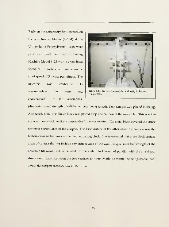
Radin at the Laboratory for Research on
the Structure of Matter (LRSM) at the
University of Pennsylvania. Tests were
performed with an Instron Testing
Machine Model 1125 with a cross head
speed of 0.1 inches per minute and a
chart speed of 5 inches per minute. The
machine was calibrated to
accommodate the form and
characteristics of the assemblies.
Figure 5.11. Strength assembly held in jig in Instron
(Fong, 1998).
(dimensions and strength of caliche material being tested). Each sample was placed in the jig.
A squared, metal rectilinear block was placed atop one coupon of the assembly. This was the
surface upon which vertical compressive force was exerted. The metal block covered the entire
top cross section area of the coupon. The base surface of the other assembly coupon was the
bottom cross section area of the parallel resting block. It was essential that these block surface
areas of contact did not include any surface area of the wooden spacers or the strength of the
adhesive fill would not be isolated. If the metal block was not parallel with the crosshead,
shims were placed between the two surfaces to more evenly distribute the compressive force
across the coupon cross section surface area.

5.5 Water Vapor Transmission (WVT)
Purpose
To assess the relative water vapor permeability of a 3 mm layer of the grout on the earthen
adherend. The ideal formulation is that with the highest or most similar WVT to that of the
original fabric. ASTM E96 - Standard Test Methods for Water Vapor Transmission of
Materials and NORMAL 21/85 Water Vapor Permeability were used as guidelines in the
assembly fabrication, data calculation and interpretation of the test.^ NORMAL defines water
vapor permeability as,
TTie amount of water vapor, per unit time and surface, that flows through a
material of parallel surfaces and a given thickness due to a water vapor
pressure difference between the two surfaces.'"
Additional materials
Assemblies: Site soil; original fabric < 2.36 mm particle size
Additional equipment
pvc pipe section molds, 7 cm interior diameter x 2 cm height
disk diameter" = 6.7 cmdisk area = 35.27 cm"
electrical tape
wax250 ml beakers
lab counter paper (one side absorbent, one side hydrophobic)
plexi-board or other hydrophobic surface
Drying rack
desiccation chamber
desiccant
cotton
" "E%, Standard Test Methods for Water Vapor Transmission of Materials," (Pfiiladelpfiia: ASTM, 1996) and
"NORMAL, 21/85 Water Vapor Permeability," draft translation photocopy. Architectural Conser\ation Laboratory,
University of Pennsylvania.
1'' "NORMAL, 21 /85 Water Vapor Permeability."
" As per NORMAL 21/85 and ASTM E96, disks were formed to a uniform thickness at least five times greater than
the deepest pit size and three times the thickness of the largest grain.
76

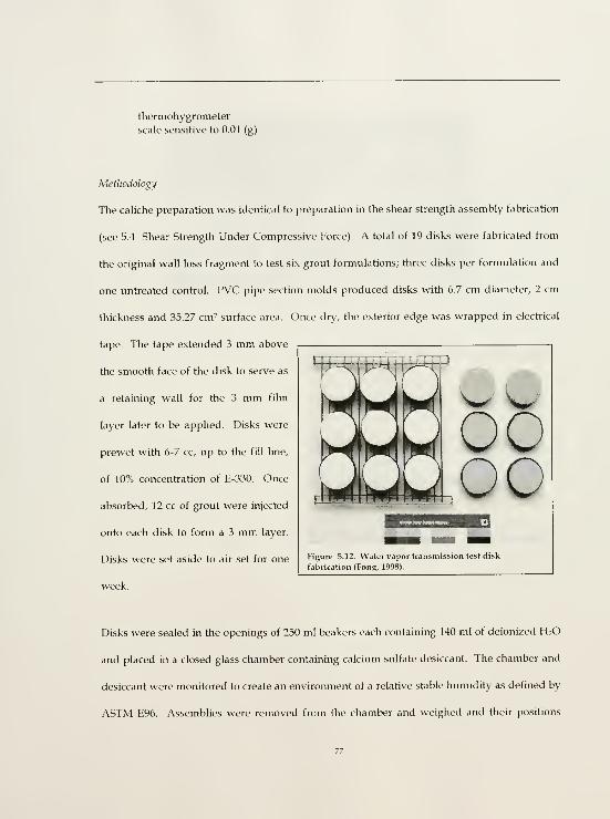
thermohygrometer
scale sensitive to 0.01 (g)
Metliodolog]/
The caliche preparation was identical to preparation in the shear strength assembly fabrication
(see 5.4 Shear Strength Under Compressive Force). A total of 19 disks were fabricated from
the original wall loss fragment to test six grout formulations; three disks per formulation and
one untreated control. PVC pipe section molds produced disks with 6.7 cm diameter, 2 cm
thickness and 35.27 cm- surface area. Once dry, the exterior edge was wrapped in electrical
tape. The tape extended 3 mm above
the smooth face of the disk to serve as
a retaining wall for the 3 mm film
layer later to be applied. Disks were
prewet with 6-7 cc, up to the fill line,
of 10% concentration of E-330. Once
absorbed, 12 cc of grout were injected
onto each disk to form a 3 mm layer.
Disks were set aside to air set for one
week.
Figure 5.12. Water vapor transmission test disk
fabrication (Fona, 1998).
Disks were sealed in the openings of 250 ml beakers each containing 140 ml of deionized H2O
and placed in a closed glass chamber containing calcium sulfate desiccant. The chamber and
desiccant were monitored to create an environment of a relative stable humidity as defined by
ASTM E96. Assemblies were removed from the chamber and weighed and their positions

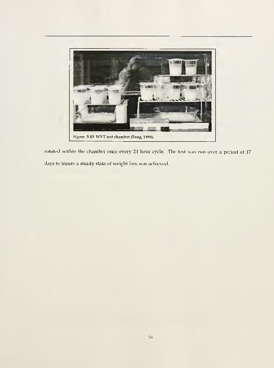
Figure 5.13 WVT test chamber (Fong, 1998).
rotated within the chamber once every 24 hour cycle. The test was run over a period of 17
days to insure a steady state of weight loss was achieved.

6.0 TEST DATA RESULTS AND OBSERVATIONS
The testing programme was designed to isolate specific aspects and properties of each grout
formulation. Standard tests such as those provided by ASTM were often adapted in order to
accommodate the tested materials, here earth and filled acrylic grout, and the desired
properties. Where tests did not exist, they were created or adapted from others, such as those
used for flow and shrinkage. The limitations of material resources (original caliche building
material) and time limited the precision, accuracy and absolute reliability of the test data
however general qualitative and approximate quantitative conclusions were possible.'
The greatest strength of a well-conceived testing programme is its ability to measure the
inherent properties of the material as well as reveal inaccurate assumptions regarding those
characteristics and attributes. This is achieved through a rigorous, methodical programme
that produces cross-referential and reproducible data. Results of the combined tests revealed
inherent characteristics, which were then interpreted as strengths and weaknesses, and
collectively corroborated or challenged existing hypotheses. This process directed each
subsequent phase of investigation. The flow and shrinkage tests performed this function
vividly. Observations of unacceptable levels of aeration or speculation on disproportionate
levels of sand in one test were frequently confirmed in the other. This cross referencing of
data resulted in more thorough and accurate conclusions.
' Assemblies for the strength and water vapor transmission tests were made of earthen material from the site. Alimited amount of this material was offered for research use from CAGRNM. The amount of material available
dictated the number of assemblies produced. This in turn, dictated the number of mixtures which could be tested.

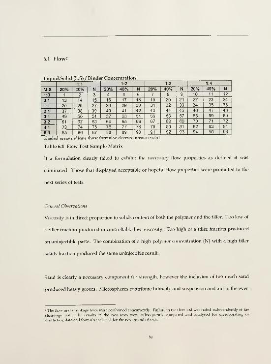
6.1 Flow2
Liqui

dispersion of solids. A low microsphere to sand ratio lacked the necessary support to carry
and distribute the sand fraction. Too high a microsphere fraction resulted in poor strength.
Aeration is in direct relation to the filler fraction. Formulae with low solids contents (1:1 and
1:2 L:S) exhibited high aeration during mixing manifested as a thick layer of foam. Aeration
became air entrainment with the incorporation of thickener. A noticeable decrease in aeration
was observed at the 1:3 L:S grouping. High air entrainment increases porosity and decreases
weight, but it greatly reduces strength. The level of aeration visible in the 1:1 and 1:2
groupings was undesirable.
The amount of thickener required to achieve a desired viscosity was most directly related to
binder concentration. Thickener amount was relatively consistent within a category of binder
concentration within an L:S grouping. Within any L:S grouping, the lower the concentration
of binder, the greater the amount of thickener necessary to achieve the desired viscosity.
However, the filler content of the L:S ratio also affected the thickener fraction. This became
apparent in the 1:3 L:S grouping where the higher filler fraction required less thickener than
the 1:1 and 1:2 groupings and the 1:3 L:S, Neat category required the least amount of thickener
of all categories. The thickener fraction was a result first, of binder concentration (percent
solids) and second, of L:S ratio. M:S, solid:solid ratio had little noticeable affect on the
thickener fraction.
conflicting data and formulae selected for the next round of tests.

Liquid:Solid Ratios (L:S)
L:S 1:1
The low solids content in this grouping resulted in a high level of aeration and an
uncontrollable low viscosity. The low 20°o binder concentration coupled with the low filler
solids content produced an irreconcilably low viscosity. The 20°o category was eliminated
from further testing.
L:S 1:2
Formulae from this grouping still displayed undesirable levels of aeration. Viscosity was
slightly improved due to the increase in filler solids, especially at the 40°o binder concentration
level however the degree of aeration compromised the strength properties. As with L:S 1:1,
the 20% binder concentration category produced an uncontrollable low viscosity. The 20%
category was eliminated from further testing.
L:S 1:3
This category produced the most promising results. The increase in filler solids dramatically
decreased aeration and increased viscosity to a desirable level, including the 20°o binder
concentration category.
L:S 1:4
The ratio of filler solids to binder content was too high producing an uninjectible paste. This
grouping was immediately eliminated from further testing.

Filler Ratios, Microspheres:Sand (M:S)
The 1:0 M:S category revealed that sand is a necessary component for strength. Dried rivulets
of this solidrsolid ratio all easily yielded beneath fingernail pressure. The 0:1 and 1:1 categories
revealed that the sand content must be a fraction of the microsphere content in order to remain
in suspension and/or pass through the needle. The 2:1 and 3:2 categories further revealed that
the sand fraction must be less than 2/5 of the total filler content. The 20% and 40% formulae
of these M:S filler fractions, while injectible produced heavy mixtures which quickly ran down
the board due to their weight thereby failing to fulfill the stated ideal properties of appropriate
strength and minimum weight. The combination of a high polymer solids content (N) with
the 2:1 and 3:2 M:S sand fraction in the 1:2 and 1:3 L:S groupings produced uninjectible
mixtures, (42, 45, 66 and 69).
Binder Concentration (%}
All 20% binder concentration formulae in the 1:1 and 1:2 L:S categories displayed unacceptably
low viscosity levels. These formulae were eliminated from further testing. Lower filler
fractions require higher concentrations of polymer solids in order to provide the overall solids
content and adhesion necessary for viscosity and strength. A 1:3 L:S ratio contained a high
enough filler solids content to tolerate a low binder concentration.

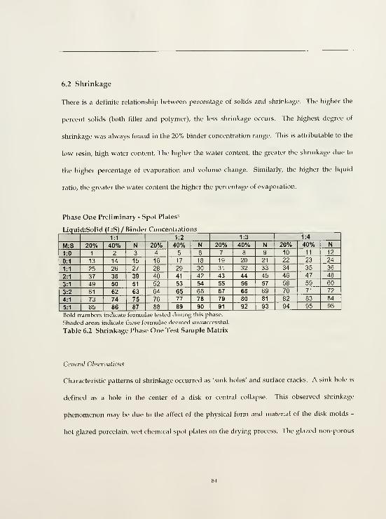
6.2 Shrinkage
There is a definite relationship between percentage of soUds and shrinkage. The higher the
percent sohds (both filler and polymer), the less shrinkage occurs. The highest degree of
shrinkage was always found in the 20% binder concentration range. This is attributable to the
low resin, high water content. The higher the water content, the greater the shrinkage due to
the higher percentage of evaporation and volume change. Similarly, the higher the liquid
ratio, the greater the water content the higher the percentage of evaporation.
Phase One Preliminary - Spot Plates'
Liqui

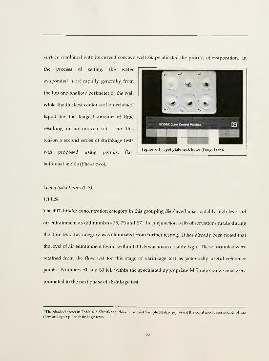
surface combined with its curved concave well shape affected the process of evaporation. In
the process of setting, the water
evaporated most rapidly generally from
the top and shallow perimeter of the well
while the thickest center section retained
liquid for the longest amount of time
resulting in an uneven set. For this
reason a second series of shrinkage tests
was proposed using porous, flat-
bottomed molds (Phase two).
Figure 6.1. Spot pUtc sink holes (long, 1998).
LiquidiSolid Ratios (L:S)
1:1 L:S
The 40% binder concentration category in this grouping displayed unacceptably high levels of
air entrainment as did numbers 39, 75 and 87. In conjunction with observations made during
the flow test, this category was ehminated from further testing. It has already been noted that
the level of air entrainment found within 1:1 L:S was unacceptably high. These formulae were
retained from the flow test for this stage of shrinkage test as potentially useful reference
points. Numbers 51 and 63 fell within the speculated appropriate M:S ratio range and were
promoted to the next phase of shrinkage test.
' The shaded areas in Table 6.2 Shrinkage Phase One Test Sample Matrix represent the combined assessments of the
flow and spot plate shrinkage tests.

1:2 L:S
In the 40% concentration category shrinkage failure and air entrainment slightly decreased.
Number 65 was eliminated from further testing for the combined factors of excessive air
entrainment and weight as observed in the flow test (longest drip of this category - 1:2 L:S,
40°o). In the neat concentration (N) viscosity improved and air entrainment again decreased,
although not completely. These formulae were free of shrinkage failure and cured the
quickest. No other formulae were eliminated from this category.
1:3 L:S
These formulae displayed the least shrinkage of all L:S groupings judging from their
dimensional stability. The 40°o concentration category exhibited minimal shrinkage. The neat
formulations were free from shrinkage failure - their surfaces level and free from cracking -
and set the quickest of all categories.
In light of the uneven evaporation as caused by the spot plate mold shape and hydrophobic
glazed surface, the neat (N) results reveal that high polymer solids content decreases the rate
of shrinkage.

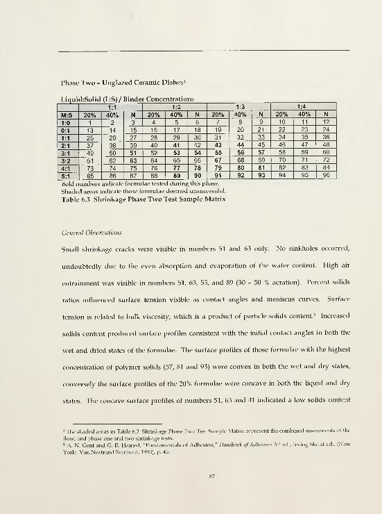
Phase Two - Unglazed Ceramic Dishes^
Liqui

and associated shrinkage. The surface profile appeared even at number 43 in both the wet and
dry states. It is worth noting that this was the first formula of the 1:3 L:S grouping tested at
this stage, further supporting the speculation that the ideal L:S ratio was 1:3. As the solids
content increased so too did the viscosity (as evidenced in section 6.1 Flow) which in turn
affected surface tension, evidenced in surface profile and subsequent shrinkage.
Solids and liquid contents are in inverse proportion to one another. A high solids fraction
(both polymer and filler) increases viscosity and decreases shrinkage. An increase in viscosity
also increases surface tension and lowers wettability of the grout.
Liquid:Solid Ratios (L:S)
L:S 1:1
Formulae 51 and 63 displayed small shrinkage cracks and high degrees of aeration (50%).
These two were eliminated from further testing based on the combined results of the flow and
shrinkage tests.
L:S 1:2
All mixtures from this grouping were eliminated from further testing due to unacceptable
levels of air entrainment observed in both flow and shrinkage tests (30°n).
^ A. N. Gent and G. R. Hamed, "Fundamentals of Adhesion," Haiulhook of Adlieswcf 3"^ ed., Irving Skeist ed., (NewYork: Van Nostrand Reinhold, 1990), p. 45.

L:S 1:3
Six mixtures were selected for further testing, numbers 55, 79, 56, 80, 57 and 81. This selection
provided a range of comparable mixtures from each binder concentration from the most
successful filler ratio combinations. Numbers 91, 92 and 93 were eliminated from further
testing for their low sand fraction. Previous research has established that sand is a critical
element in imparting strength to filled adhesive systems." Numbers 67 and 68 were eliminated
for their high sand fraction which flow tests revealed produced a heavy grout and
consequently failed to fulfill the criteria of appropriate strength and light weight.
The collective results of the flow and shrinkage tests indicate that the ideal mixture will be
located in the 1:3, L:S grouping at either the 20°o or 40°o binder concentrations. While the neat
category may offer minimum shrinkage, high strength, cohesion and adhesion, the high resin
content will result in low (poor) water vapor permeability, a very important property and
greater flex that may not be desirable.
Maloni and Bass, "Design and E\ aluatmn,"

6.3 Dispersion
Dispersion observations were made from cross sections of the unglazed ceramic dish samples.
General Observations
All samples exhibited even dispersion of solids and good adhesion and cohesion. There were
no visible voids between the grouts and the ceramic dishes. It is clear that the sand
component has a direct affect upon aeration. Its presence inhibits air entrainment. As noted
before, the higher the solids content, the lower the shrinkage and degree of aeration.
Liquid:SoUd Ratios (L:S)
1:1 L:S
As expected, numbers 51 and 63 experienced the most shrinkage and highest degree of
aeration (50%). This was visible in the thinness of the dried grout layer as observed in cross
section. These two formulae were eliminated from further testing.
1:2 L:S
Number 41 displayed a distinct decrease in air entrainment (to a final fraction of
approximately 30%) from formulae in the 1:1 L:S grouping (average aeration 50%). Air
entrainment increased again in number 53 due to the reduction in sand. Air entrainment
decreased in number 77 where it was less than number 53 and more than number 41. Number
89 displayed a higher degree of aeration than number 77. These four formulae (41, 53, 77 and
89) clearly exemplified the relationship between filler solids and air entrainment. The effect of

the sand fraction was easily isolated in this instance where the L:S ratio and binder
concentrations were constant. The size, weight and presence of the sand inhibited aeration in
the grout mixture. This pattern was repeated to a slightly lesser degree in the neat formulae,
(54, 78 and 90).
1:3 L:S
All formulae in this grouping exhibited good even texture, minimal aeration and minimal or
no shrinkage.
6.4 Shear Strength Under Compressive Force
Assembly Fabrication
Observations
Grout surface tension became a practical issue during this test. Surface tension is an important
characteristic of the grout related to viscosity and thixotropy and relevant to the mode of
application. A grout lacking thixotropic properties (low viscosity and surface tension) will run
and fail to fill the identified gap. A grout with too high a surface tension will experience
difficulty flowing into the narrow space of the gap. The flow test tested unrestricted flow
however the grout will be constrained by two surfaces of friction. Application method will
also influence the design of appropriate surface tension. Full film fills will require a lower
surface tension than spot welds. These factors must be taken into consideration when making
a final decision on a grout formula. The average amount of grout fill per strength test

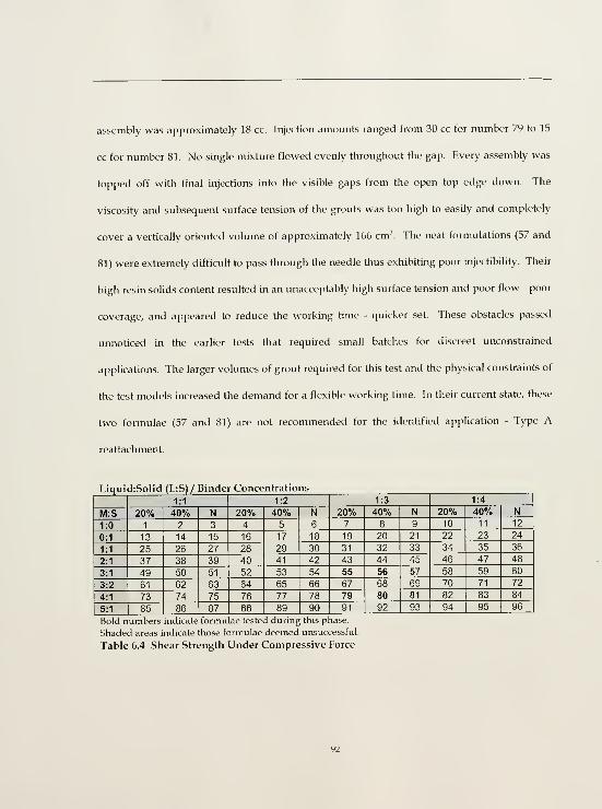
assembly was approximately 18 cc. Injection amounts ranged from 30 cc for number 79 to 15
cc for number 81. No single mixture flowed evenly throughout the gap. Every assembly was
topped off with final injections into the visible gaps from the open top edge down. The
viscosity and subsequent surface tension of the grouts was too high to easily and completely
cover a vertically oriented volume of approximately 166 cm'. The neat formulations (57 and
81) were extremely difficult to pass through the needle thus exhibiting poor injectibihty. Their
high resin solids content resulted in an unacceptably high surface tension and poor flow - poor
coverage, and appeared to reduce the working time - quicker set. These obstacles passed
unnoticed in the earlier tests that required small batches for discreet unconstrained
applications. The larger volumes of grout required for this test and the physical constraints of
the test models increased the demand for a flexible working time. In their current state, these
two formulae (57 and 81) are not recommended for the identified application - Type A
reattachment.
Liqui

Test Results
The limited amount of available building material yielded three assemblies per formula. This
presented distinct limitations on the reliability and accuracy of the data. However, given the
limitations, the six tested formulae did produce a pattern of logical results.
It can generally be stated that there is an inverse relationship between the
flexibility and film strength of the adhesive - the higher the strength, the lower
the flexibility... TTius most conservation applications benefit from flexible or
semi-flexible adhesives.
General Observations
The results of this test confirmed that resin content is the most influential factor in determining
strength, and that a higher sand ratio proportionately also contributes to increased strength."
The neat formulae exhibited the greatest strength and the higher sand fraction consistently
provided the higher strength value for each binder concentration tested. The patterns of
failure confirmed theories regarding the effect of solids content of both polymer concentration
and filler fraction on,
• cohesion
• adhesion
• surface tension /flow, and
• penetration/wettability.
Inherently, emulsions possess limited pore penetration ability due to their large molecular
size. These resin particle droplets are long, large polymer molecules. The size of the molecule
|.L, Down, M.A. MacDonald, ]. Tetreault and R.S. Williams "Adhesive Testing at the Canadian Consenation
Institute- an Evaluation of Selected Poly(vinyl acetate) and Acrylic Adhesues," Stmlies m Consi'ri'atwn 41 (1996): p.
30.
limits the space through which it can fit or its ability to penetrate another material. The large
polymer molecules are dependent upon the water fraction to carry them into the adjacent
material, particularly when encountered with material of low porosity such as the caliche. The
very small molecule size of water results in excellent penetration ability (high wettability).
Increased resin particle concentration/low water content induces higher viscosity. High
viscosity produces high surface tension, which reduces flow (coverage). These factors have a
direct affect upon adhesive strength where surface contact and penetration are essential in
establishing good adhesive bond.
In short,
• high polymer content increases cohesive strength and viscosity (surface tension)
this is turn,
• decreases flow (coverage), penetration/wettability thereby reducing points of
contact for adhesive bonding.
" See Matero and Bass, "Design and Evaluation." That the sand ratio has a direct effect upon strength is consistent
with the findings of Matero and Bass in their development and evaluation of hydraulic lime grouts.

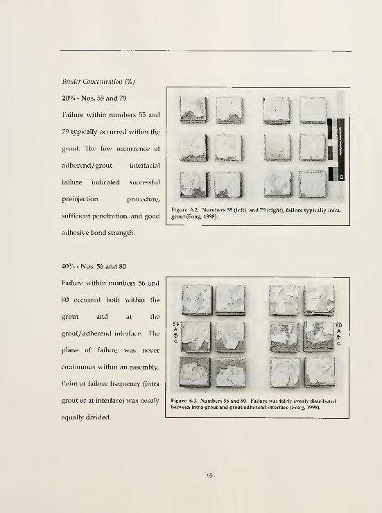
Binder Concentration (%)
20"/,. - Nos. 55 and 79
Failure within numbers 55 and
79 typically occurred within the
grout. The low occurrence of
adherend/ grout interfacial
failure indicated successful
preinjection procedure,
sufficient penetration, and good
adhesive bond strength.
^.-d'l-.iVW^
U
Figure 6.2. Numbers 55 (left) and 79 (right), failure typically intra-
grout (Fong, 1998).
40% - Nos. 56 and 80
Failure within numbers 56 and
80 occurred both within the
grout and at the
grout/ adherend interface. The
plane of failure was never
continuous within an assembly.
Point of failure frequency (intra
grout or at interface) was nearly
equally divided.
A i

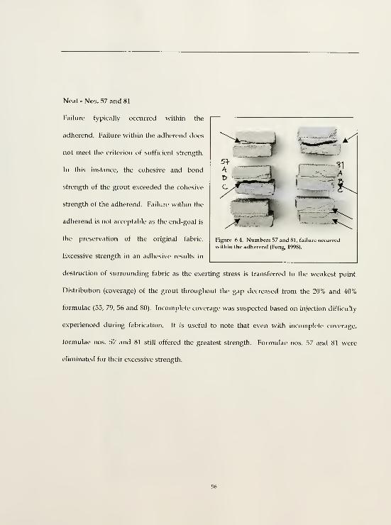
.^
?1
KI
Neat - Nos. 57 and 81
Failure typically occurred within the
adherend. Failure within the adherend does
not meet the criterion of sufficient strength.
In this instance, the cohesive and bond
strength of the grout exceeded the cohesive
strength of the adherend. Failure within the
adherend is not acceptable as the end-goal is
the preservation of the original fabric.
Excessive strength in an adhesive results in
destruction of surrounding fabric as the exerting stress is transferred to the weakest point.
Distribution (coverage) of the grout throughout the gap decreased from the 20% and 40%
formulae (55, 79, 56 and 80). Incomplete coverage was suspected based on injection difficulty
experienced during fabrication. It is useful to note that even with incomplete coverage,
formulae nos. 57 and 81 still offered the greatest strength. Formulae nos. 57 and 81 were
eliminated for their excessive strength.
Figure 6.4. Numbers 57 and 81, failure occurred
within the adherend (Fong, 1998).

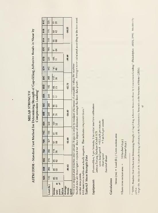
toc
U

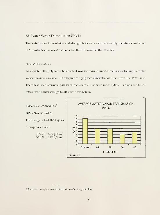
6.5 Water Vapor Transmission (WVT)
The water vapor transmission and strength tests were run concurrently therefore elimination
of formulae from one test did not affect their inclusion in the other test.
General Observations
As expected, the polymer solids content was the most influential factor in affecting the water
vapor transmission rate. The higher the polymer concentration, the lower the WVT rate.
Tliere was no discernible pattern in the effect of the filler ratios (M:S). Perhaps the tested
ratios were similar enough to offer little distinction.
Binder Concentration (%)
20% - Nos. 55 and 79
This category had the highest
average WVT rate.
No. 55 4.96g/h-m'
No. 79 4.82 g/h-m'
AVERAGE WATER VAPOR TRANSMISSION
RATE
9
8
7
6
H 5
< 4
3
2
1
Control 79
FORMULAE
80
Table 6.6
' The control sample was untreated earth, (without a grout film)

40% - Nos. 56 and 80
As anticipated, the WVT rate decreased with the increase in polymer solids content.
No. 56 3.12 g/hm'No. 80 3.83 g/h-m'
Neat - Nos. 57 and 81
The data in this category did not follow the same pattern of progressive weight loss observed
in the 20% and 40% categories. For reasons not yet clear, the neat formulations occasionally
gained weight. There was no discernible pattern to the weight gain. Due to these as yet
inexplicable consistencies, the neat formulations were excluded from further calculations.
However, available data revealed rates of at T6 for both numbers 57 and 81 and 0.57 at T7.
These rates are unacceptably low. The high resin solids content effectively created a near
impermeable barrier. The low WVT rate failed to fulfill the criterion of water vapor
permeability. An impermeable barrier is materially and functionally incompatible with the
original earthen fabric. This barrier would trap internal moisture within the substrate creating
adverse environmental conditions for the building material. Water is the most powerful
deteriorating force upon earthen material. It induces both physical and chemical effects.
Trapped moisture accelerates the natural rate of decay. It is essential that proposed
conservation solutions do not create nor contribute to accelerated decay of the structure.
Based on the results of this test, neat formulae numbers 57 and 81 were eliminated.

Calculations
Water vapor transmission rates were calculated according to the following methodology and
equations.
According to guidelines provided by both ASTM and NORMAL, calculations for WVT are
based on figures from the steady state. The steady state is that period of time in the test where
weight loss between intervals reaches its most consistent level. This point is identified by
plotting AM / At. At least two points are necessary from the steady state in order to calculate
WVT.
Where M = average weight difference of formula n between each interval
t = time in hours of each interval
T« = point (date and time) of weighing
ex.) no. 55
AM at T6 = weight of sample at T6 from weight of sample at T5
The average weight of 55 A, B and C at T6 is 0.44g
At at T6 = time interval from last weighing
The time interval from T5 to T6 is 23.95 hours
Tlierefore,
AM / At = 0.44 g / 23.95 h = 0.018 g/h

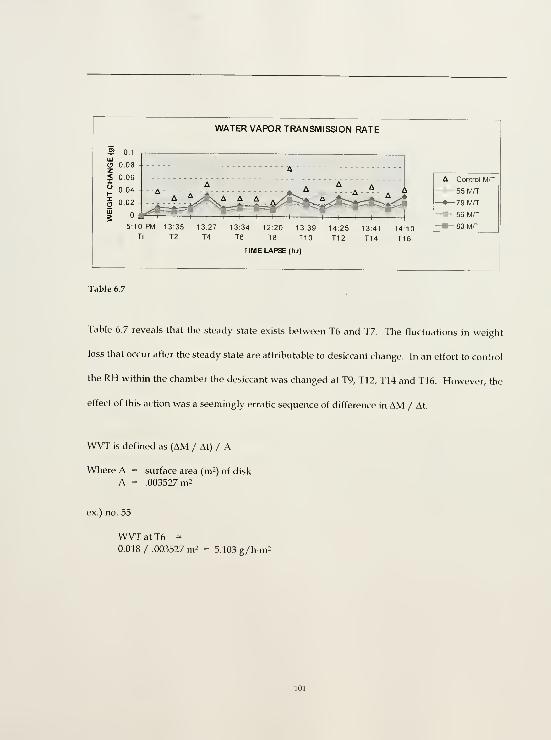
WATER VAPOR TRANSMISSION RATE
S 0.1111
O 0.08z< 06
^ 0.04
O 0.02
g
[

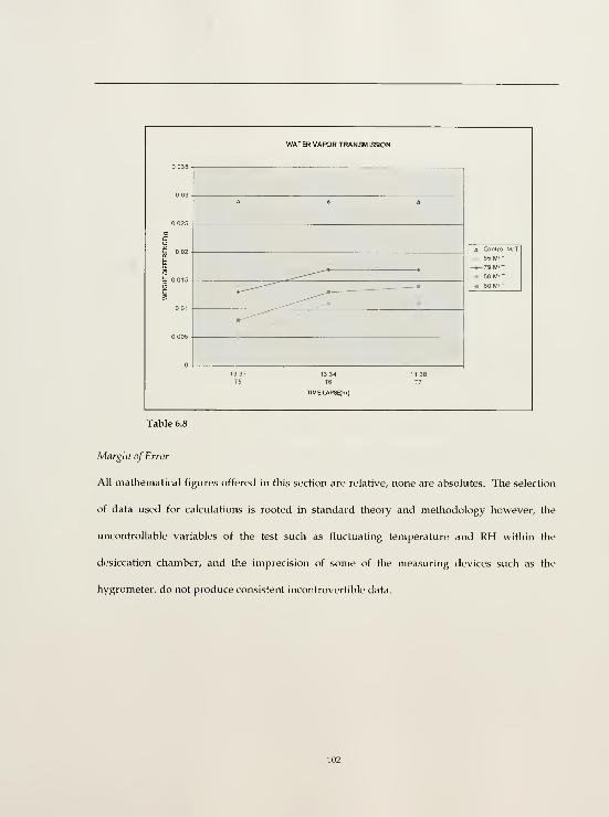

Cotidusion
The relative performance results were entirely consistent and useful. All resultant data was
relative to the control (untreated) sample and the percent solids of resin. This test revealed
that of the six formulae tested numbers 55 and 79 had the highest WVT rate and are therefore
the most desirable. However, 'high' is a relative term. The WVT must be similar enough to
the original material to be viewed as an acceptable treatment option. The viability of this
option will also depend upon method of application (i.e. full film or spot weld).
The difference in WVT rates between numbers 55 and 79, and numbers 56 and 80 were
significant. Number 55 produced a relative WVT rate 22°o higher than that of number 56 and
number 79 produced a relative rate 12°o higher than that of number 80. The higher WVT rates
of numbers 55 and 79 (20°o binder concentrations) can be attributed to their reduced polymer
solids contents. The test also revealed that within the steady state, the difference in WVT rates
between numbers 55 and 79 was so slight as to be negligible (less than 2°o with number 55
producing the higher rate). TTiis indicates that all other cohorts being consistent, (binder
concentration - %, L:S ratio, amount used and application method) the difference between a
3:1 and a 4:1 M:S ratio upon WVT is minimal.
This outcome was reversed between numbers 56 and 80 where number 80 produced a relative
WVT rate approximately 8.5"o higher than number 56. Is there a relationship between
polymer resin content and filler ratio which can reverse results of WVT rates from formulae of
identical proportions but differing resm contents, or is this just an anomaly due to an
inconsistency in the test? Further testing and research could answer these questions.

6.6 Laboratory Conclusions
Of the 100 grout formulations tested number 55 performed best in each property assessment
for flow, shrinkage, strength, dispersion and water vapor transmission. Formula number 79
exhibited a comparable water vapor transmission rate to that of number 55 however its
strength performance was much lower than number 55. For this reason, number 55 was
selected for final trial field tests. The issue of treatment compatibility remains depending
upon what are acceptable values or limits for each property. Flow, shrinkage and dispersion
are properties that can be internally assessed relative to the other grout formulations. Strength
and water vapor transmission must be assessed relative to the whole system (earthen
materials, detachment gaps, and method of application).
• How much strength is necessary?
• How porous are the adherends?
• What are the ambient weather conditions of the site, (temperature and moisture
cycles)?
The answers to these questions will influence the final assessment of the grout performance. It
is clear from the laboratory testing programme that number 55 produced the best relative
performance results given the identified criteria. However, relative and acceptable are two
distinctly different assessments. When possible, it is always desirable to implement a pilot
field test to more fully assess a treatment's actual performance. The uncontrollable features of
a site and the passage of time can never fullv nor accurately be replicated in a laboratory
environment, although they can be artificially simulated to a certain degree.

7.0 FIELD TESTS
This section offers very brief descriptive, qualitative assessments of grout number 55 trial tests
at four different field sites. These trial tests were conducted during the summer of 1998.
These four sites were:
• The Solitude, Philadelphia, Pennsylvania
• Kiva Q, Cliff Palace, Mesa Verde National Park, Mesa Verde, Colorado
• Historic Building 15, Fort Davis National Historic Site, Fort Davis, Texas, and
• TTie Casa Grande, Casa Grande Ruins National Monument, Coolidge, Arizona.
Not all of these tests were performed by the author and some of the following information was
gathered from conversations between the author and those conservators who performed the
treatment applications.
The Solitude, Philadelphia, Pennsylvania- Late 18'" century residence of Thomas Perm
The grout was used for an interior application at the wall and ceiling juncture. It was injected
between the wood substrate wall and a plaster molding. The grout was injected behind the
molding according to standard procedure. The grout was administered June 1998. As of
September of the same year it was deemed successful in application and as cured treatment.
Cliff Palace, Mesa Verde National Park, Mesa Verde, Colorado - 13'" century alcove dwellings
The grout was used for an exterior application. It was injected behind layers of thin, highly
absorbent earthen plasters. The plasters immediately absorbed the liquid emulsion. This
produced two undesirable results; one - the solids fraction remained as an ineffectual

segregated component, two - the emulsion stained (darkened) the plasters. The grout was
deemed an inappropriate treatment for the thin finish (wash) context.
Historic Building 15, Fort Davis National Historic Site, Fort Davis, Texas -
Mid 19'*' century officer's quarters
The grout was used for an unprotected exterior application. It was injected behind thin layers
of lime plaster against an intermediary lime scratch coat. The treatment was used throughout
the structure. It was found to be useful in areas too thin/fine for the lime grout. Grout was
recessed from the exposed plaster edge by approximately 0.6 cm and capped with a fine
edging material of fine silica sand, hydraulic lime and water. It was during these field trials
that the grout viscosity was found to be respondent to heat.
The Casa Grande, Casa Grande Ruins National Monument, Coolidge, Arizona -
Prehistoric (possibly 13* - M"" century) freestanding four storey structure
The grout was used in a sheltered exterior application. A small area in Tier B, room space 2
was selected for a trial treatment. This involved the cleaning and reattachment of a detached
earthen layer of approximately 0.16 - 0.6 cm thickness and 20 cm^ (sub-circular shape). The
treatment attempt failed. Failure may be attributed to a number of reasons, individual or
combined. The degree of deformation (planar discontinuity) of the detached fragment was
pronounced and the surrounding area suffered from cracking. These two factors presented a
fragment in a highly precarious state. It is possible that the detached layer was over-saturated
with moisture from both the flushing and prewetting preparatory procedures. Over-
saturation of earthen material can easily result in loss of internal cohesion and excessive

weight. The facing was not sufficiently adhered to support the combination of the now
moisture saturated plaster and the additional stress presented by the grout. Consequently, the
fragment collapsed.

8.0 CONCLUSIONS
The Casa Grande appears to be of relatively stable condition. The rate of deterioration has
been greatly mitigated since the initial stabilisation efforts of Cosmos Mindeleff and the
erection of the protective shelter (1902, 1932). The policy of minimum intervention for the site,
adopted at the turn of the 19th century has resulted in a structure of exceptional integrity.
Climate, building material and original construction techniques are the primary reasons for the
monument's impressive longevity. Policy and restraint are the reasons for its largely
unaltered current condition and degree of integrity. Unless the state of deterioration is active
and poses an eminent threat to the physical integrity of the Casa Grande, a continued
conservative approach to its preservation is strongly advocated. It is this approach which
today presents us with such an exceptional example of the past.
Since 1697 when Captain Juan Mateo Manje compared the interior plastered walls of the Casa
Grande to polished Puebla pottery these earthen plaster finishes have been recognised for
their outstanding quality, condition and extent. They offer a unique glimpse (it is the only
example of its type in the region - free standing, monumental plastered caliche construction)
into the built world of the region's early inhabitants. The plasters exist in a relatively stable
condition in great part due to the protection afforded by the shelter.
The phenomenon of loss is uniform in its effect but multifarious in its causes. Initially distinct
and simple causes (mechanisms of decay) are at second glance mere components of a cycle of
interdependent and overlapping relationships. Loss attributed to mechanical damage such as

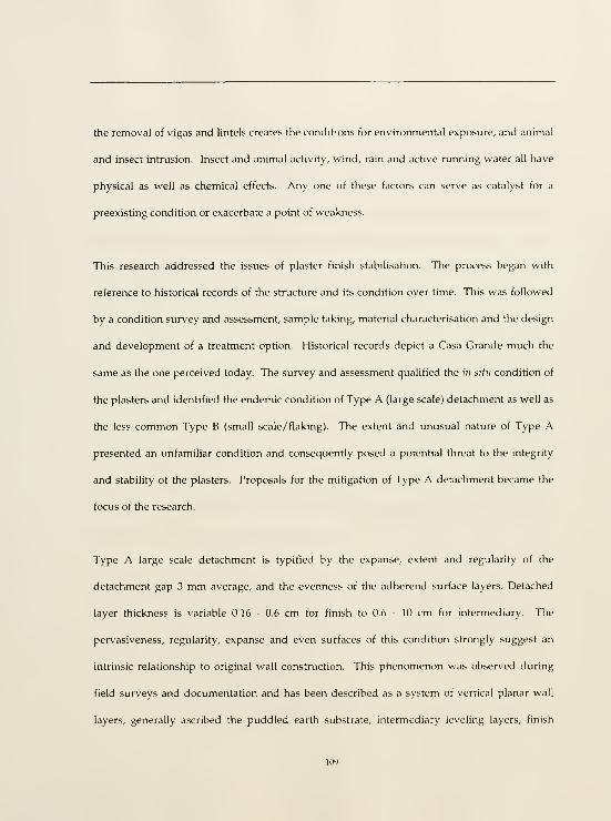
the removal of vigas and lintels creates the conditions for environmental exposure, and animal
and insect intrusion. Insect and animal activity, wind, rain and active running water all have
physical as well as chemical effects. Any one of these factors can serve as catalyst for a
preexisting condition or exacerbate a point of weakness.
This research addressed the issues of plaster finish stabilisation. The process began with
reference to historical records of the structure and its condition over time. This was followed
by a condition survey and assessment, sample taking, material characterisation and the design
and development of a treatment option. Historical records depict a Casa Grande much the
same as the one perceived today. The survey and assessment qualified the in situ condition of
the plasters and identified the endemic condition of Type A (large scale) detachment as well as
the less common Type B (small scale/flaking). The extent and unusual nature of Type A
presented an unfamiliar condition and consequently posed a potential threat to the integrity
and stability of the plasters. Proposals for the mitigation of Type A detachment became the
focus of the research.
Type A large scale detachment is typified by the expanse, extent and regularity of the
detachment gap 3 mm average, and the evenness of the adherend surface layers. Detached
layer thickness is variable 0.16 - 0.6 cm for finish to 0.6 - 10 cm for intermediary. The
pervasiveness, regularity, expanse and even surfaces of this condition strongly suggest an
intrinsic relationship to original wall construction. This phenomenon was observed during
field surveys and documentation and has been described as a system of vertical planar wall
layers; generally ascribed the puddled earth substrate, intermediary leveling layers, finish

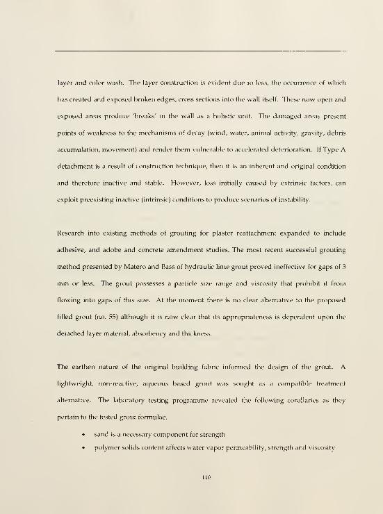
layer and color wash. The layer construction is evident due to loss, the occurrence of which
has created and exposed broken edges, cross sections into the wall itself. These now open and
exposed areas produce 'breaks' in the wall as a holistic unit. The damaged areas present
points of weakness to the mechanisms of decay (wind, water, animal activity, gravity, debris
accumulation, movement) and render them vulnerable to accelerated deterioration. If Type A
detachment is a result of construction technique, then it is an inherent and original condition
and therefore inactive and stable. However, loss initially caused by extrinsic factors, can
exploit preexisting inactive (intrinsic) conditions to produce scenarios of instability.
Research into existing methods of grouting for plaster reattachment expanded to include
adhesive, and adobe and concrete amendment studies. The most recent successful grouting
method presented by Matero and Bass of hydraulic lime grout proved ineffective for gaps of 3
mm or less. The grout possesses a particle size range and viscosity that prohibit it from
flowing into gaps of this size. At the moment there is no clear alternative to the proposed
filled grout (no. 55) although it is now clear that its appropriateness is dependent upon the
detached layer material, absorbency and thickness.
The earthen nature of the original building fabric informed the design of the grout. A
lightweight, non-reactive, aqueous based grout was sought as a compatible treatment
alternative. The laboratory testing programme revealed the following corollaries as they
pertain to the tested grout formulae,
• sand is a necessary component for strength
• polymer solids content affects water vapor permeability, strength and viscosity

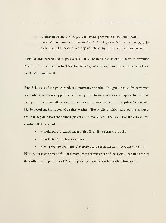
• solids content and shrinkage are in inverse proportion to one another, and
• the sand component must be less than 2/5 and greater than 1/6 of the total filler
content to fulfill the criteria of appropriate strength, flow and minimum weight.
Formulae numbers 55 and 79 produced the most desirable results of all 100 tested formulae.
Number 55 was chosen for final selection for its greater strength over the incrementally lower
WVT rate of number 79.
Pilot field tests of the grout produced informative results. The grout has so far performed
successfully for interior applications of lime plaster to wood and exterior applications of thin
lime plaster to intermediary scratch lime plaster. It was deemed inappropriate for use with
highly absorbent thin layers of earthen washes. The acrylic emulsion resulted in staining of
the thin, highly absorbent earthen plasters of Mesa Verde. The results of these field tests
conclude that the grout
• is useful for the reattachment of fine finish lime plasters to adobe
• is useful for lime plasters to wood
• is inappropriate for highly absorbent thin earthen plasters (< 0.32 cm = 1/8 inch).
However, it may prove useful for circumstances characteristic of the Type A condition where
the earthen finish plaster is > 0.32 cm depending upon the level of plaster absorbency.

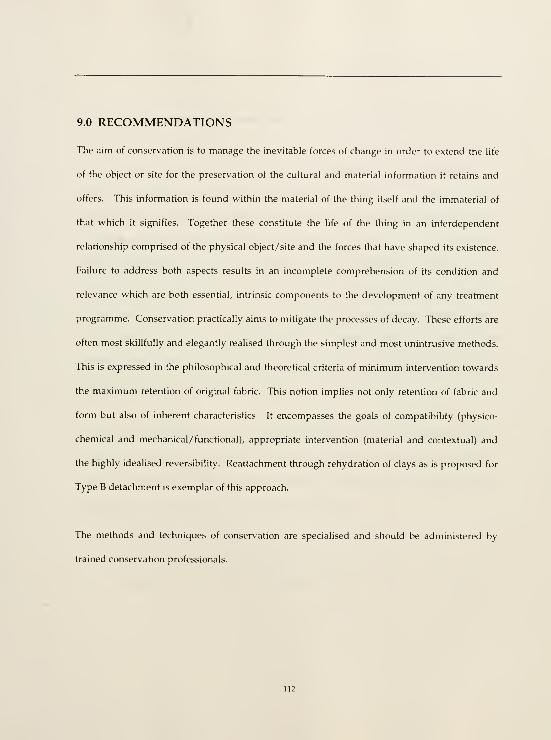
9.0 RECOMMENDATIONS
The aim of conservation is to manage the inevitable forces of change in order to extend the life
of the object or site for the preservation of the cultural and material information it retains and
offers. This information is found within the material of the thing itself and the immaterial of
that which it signifies. Together these constitute the life of the thing in an interdependent
relationship comprised of the physical object/site and the forces that have shaped its existence.
Failure to address both aspects results in an incomplete comprehension of its condition and
relevance which are both essential, intrinsic components to the development of any treatment
programme. Conservation practically aims to mitigate the processes of decay. These efforts are
often most skillfully and elegantly realised through the simplest and most unintrusive methods.
This is expressed in the philosophical and theoretical criteria of minimum intervention towards
the maximum retention of original fabric. This notion implies not only retention of fabric and
form but also of inherent characteristics. It encompasses the goals of compatibility (physico-
chemical and mechanical/functional), appropriate intervention (material and contextual) and
the highly idealised reversibility. Reattachment through rehydration of clays as is proposed for
Type B detachment is exemplar of this approach.
The methods and techniques of conservation are specialised and should be administered by
trained conservation professionals.

9.1 Specific Treatment Recommendations
Type A (large scale) Detachment
Type A detachment requires a grout with gap filling properties. Injection grouting is the
advocated material and method in areas of instability only. Areas of instability are easily
identified by bulges or planar discontinuities in the finish layer caused by excessive erosion, loss
or the accumulation of debris; cracks; and /or continual direct exposure to extrinsic mechanisms
of decay. In these instances, localised, full film grouting is recommended. Full film grouting is
not recommended for large expanses. It is not advisable to interject a foreign film between two
like materials where none previously existed - even though the film possesses a degree of water
vapor permeability - especially where it is not necessary. Until evidence proves otherwise, the
condition of the plasters has been identified as generally stable. Treatment should only be
administered in those localised areas of instability.
Areas of potential instability should be monitored for change and if possible, the causes of decay
alleviated (the purpose of the shelter). Spot welding could be advocated as a preventative
measure in areas lacking sufficient structural support. This will require a slight elevation in
grout viscosity. This could be achieved by the following means,
• slight increase in filler ratio
• slight increase in binder concentration, or
• slight increase in thickener (concentration or ratio).

The application of treatment (injection grouting) should follow standard protocol as outlined
below.
Survey and assessment
Documentation
Mechanical cleaning
Flushing/prewetting with water:ethanol (1:1)
Preinjection with 10°o E-330 in water
Injection grouting
Capping where necessary (exposed edges)
Type B (small scale/flaking) Detachment
Rehydration with a 1:1 watenethanol mix, administered through spray and/or injection with the
aid of cosmetic sponges and /or wet strength tissue. This has already proven successful at the
Casa Grande in Tier D, north wall (Matero, 1997).'
9.2 Future Research
No research program can address and investigate all of the relevant questions. Instead each
program defines its scope and attempts to respond to a series of identified unknowns. In the
process of investigation and discovery, invariably unexpected issues are encountered which
Frank Matero, personal communication with author, 1998.

raise new questions. Recommendations for future research include the following research
questions,
• What effects, both short and long term, does thickener have upon the grout
stability, strength and water vapor permeability?
• How does the grout perform over time? This requires return visits to the original
trial field treatments.
• What can other instrumental analyses reveal about
• the finish plaster
• the grout
• the plaster/grout interface?
• How can the working time be extended /made more flexible?
• Is the darkened zone a transformation of applied high heat or absorption of fine
surface particulates from burning? Subject samples to fire.
• Is it possible to develop an inorganic grout that works with the inherent properties
of calcium carbonate?


10.0 APPENDICES

10.1 Sample Location Map
Sample locations are mapped on the following elevations. These represent the twenty-tour
samples selected for cross section analysis. The sample identification numbers reflect the
original sample numbering system of the original forty samples (see Table 2.1 Bulk Analysis
Sample Characterisation for sample descriptions).

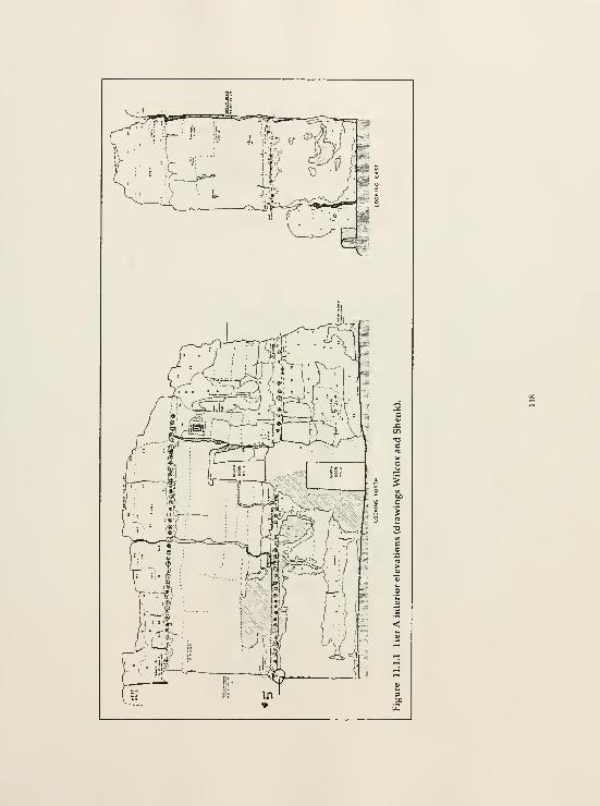
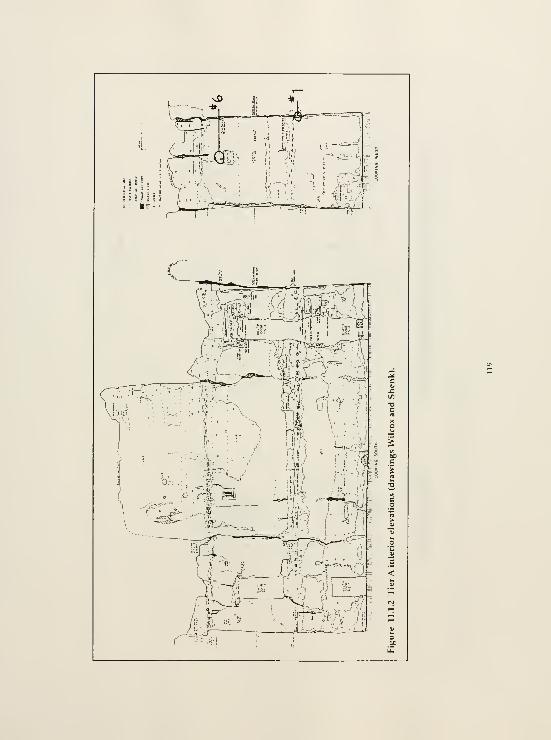
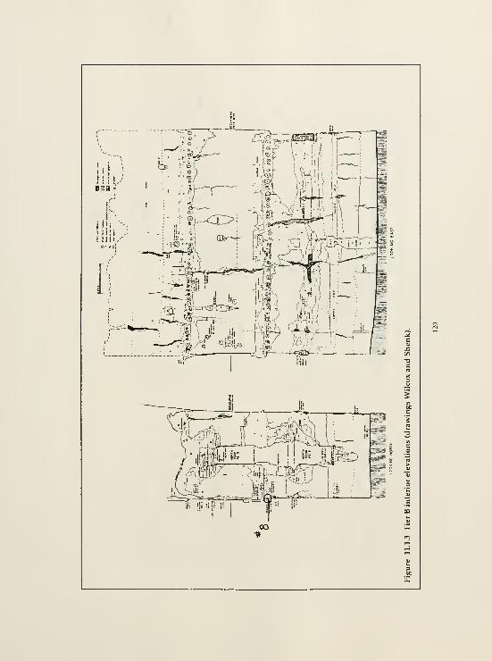
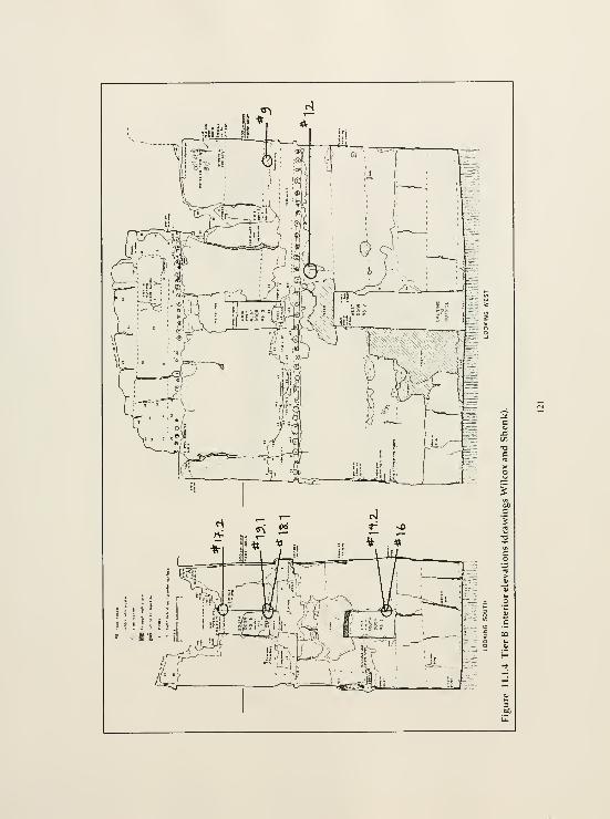
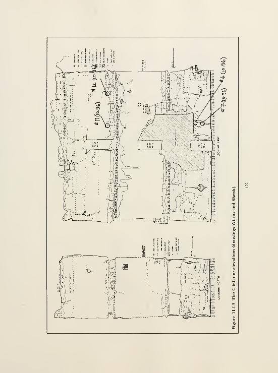
I n If f I Is ! ii
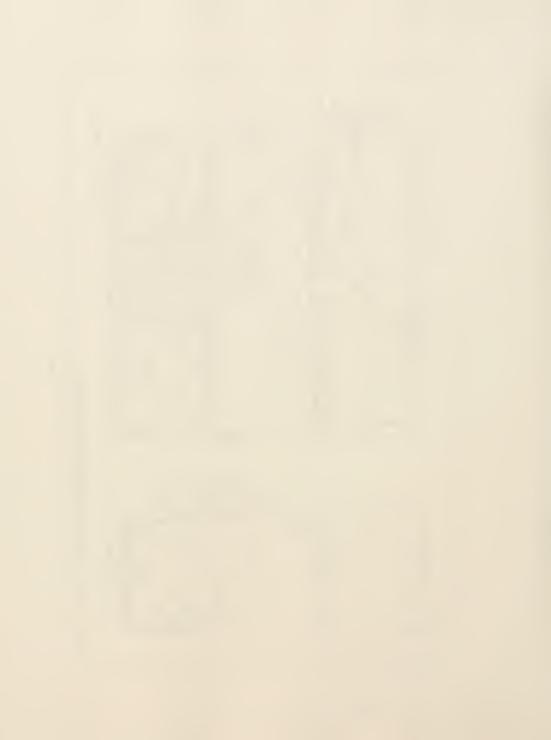
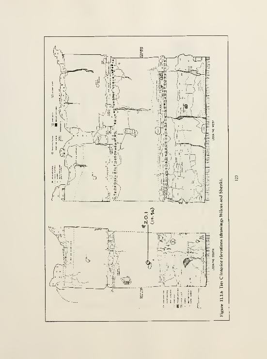

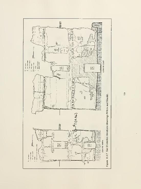
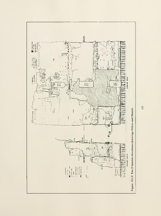
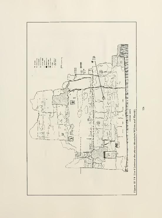
liii hllf I I

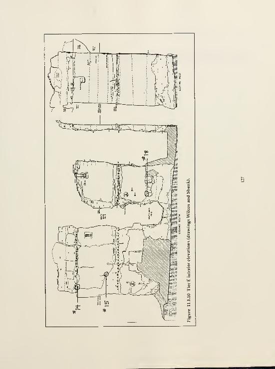
10.2 Literature Review of Polyvinyl Acetate and Acrylic Emulsion in Conservation

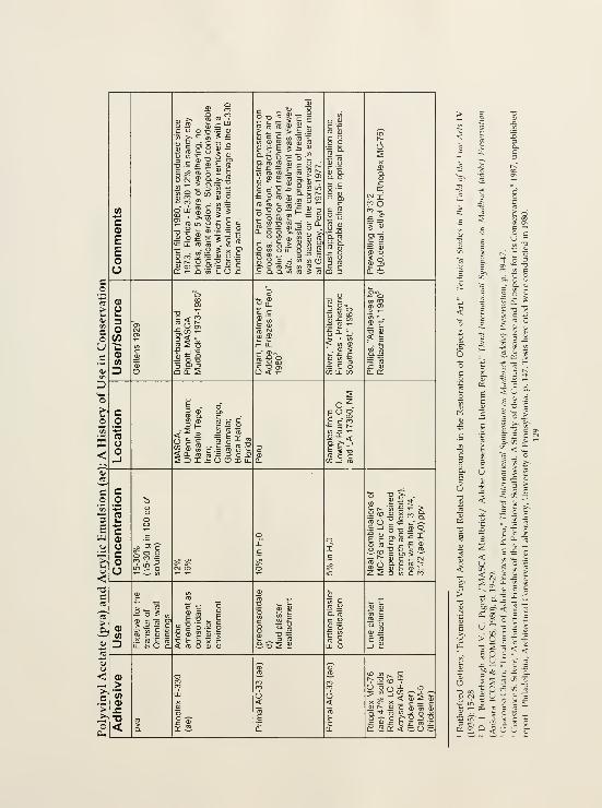
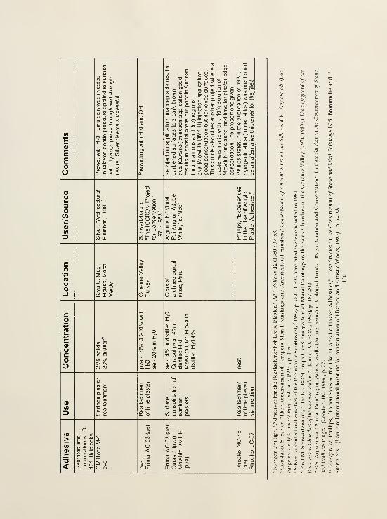
(A
C0)
EEoo

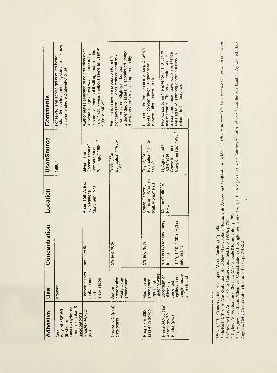
wc0)
EEoo
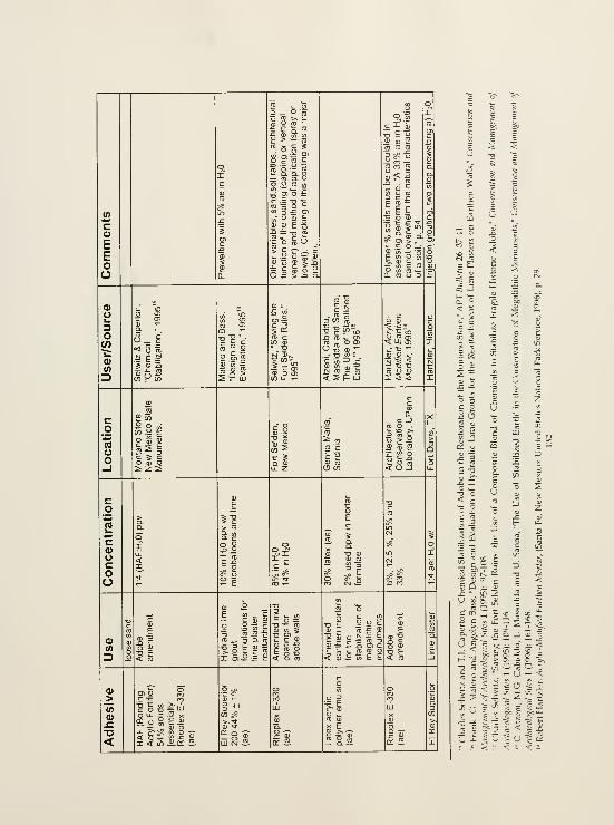
(A*•>
CoEEoo
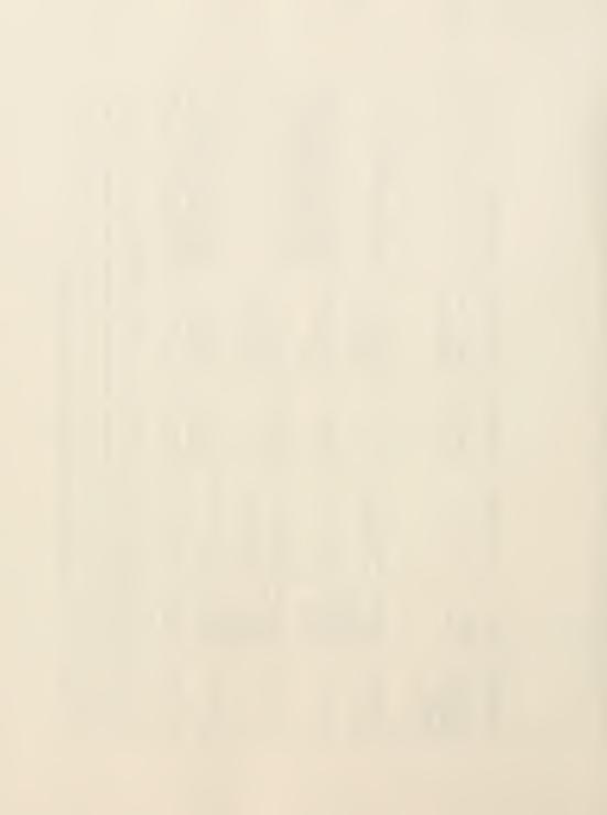

oo
ou
o(O*£0)(A
3
CucoO
I* 2E 2 -3
^ TD Oro ^ cn
"=; E
c

6=
UiZ, s c
04
.5 O
o.
ca;
o
oU
i: V.
ja c ji
^^ej

10.3 Product Specifications & Material Safety Data Sheets (MSDS)

TTLEPKONf :3'5! 5?? jCCC CJ3.J aCOOfSS HCI-MHA43 ZPtrBii. fH' :2\i\ iSi 3M
Febniiiry9. 1998 ROHMmnnsCOMPANY
We «t Rohm »nd Hais arc undertaking a series of product rationalizations in ta effort to
streamline our operations. Our goal is to maintain a product line that offers:
• high quality frroducts
• eflicient outomer servicer
• maximum production capacity and cost effectiv-ness
While we understand the frustrations involved when qualifying replacement prtjducts, we believe
ultimately we will !je a better supplier to you by offering higher value products and services.
We plan to discontinue jelling Rhoplex AC-33 by October 1, 1999. We suggest
Rhoplex B-60A as a possible replacement. Rhoplex B-60A is similar in composition and solids,
with the excBption of i different biocide and without the aicorporation of a theology modifier.
To achieve similar rtieology with Rhoplex B-60A, we suggest mcorporating 0.6% Aciysol G-1
U
or 0.5% Acrysol 6038A as a starting point.
Samples and literature are available for your evaluation. Please contact us at
800-423-0886 to order them. We regret any incoDvcmencc chu discontiauation may cause you.
Sincarely,
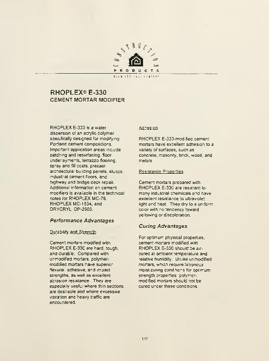
^PRODUCTSn J <( (11 H u s f 1 Pi 1
'
RHOPLEX® E.330CEMENT MORTAR MODIFIER
RHOPLEX E-330 is a water
dispersion of an acrylic polymer
specifically designed for modifying
Portland cement compositions.
Important application areas include
patching and resurfacing, floor
underlayments, terrazzo flooring,
spray and fill coats, precast
architectural building panels, stucco,
industrial cement floors, and
highway and bndge deck repair
Additional information on cementmodifiers is available in the technical
notes for RHOPLEX fv1C-76,
RHOPLEX MC-1 834, and
DRYCRYL DP-2903.
Performance Advantages
Durability and Strength
Cement mortars modified with
RHOPLEX E-330 are hard, tough,
and durable. Compared with
unmodified mortars, polymer-
modified mortars have supenor
flexural, adhesive, and impact
strengths, as well as excellent
abrasion resistance They are
especially useful where thin sections
are desirable and where excessive
vibration and heavy traffic are
encountered.
Adhesion
RHOPLEX E-330-modified cement
mortars have excellent adhesion to a
variety of surfaces, such as
concrete, masonry, bnck, wood, and
metals
Resistance Properties
Cement mortars prepared with
RHOPLEX E-330 are resistant to
many industrial chemicals and have
excellent resistance to ultraviolet
light and heat. They dry to a uniform
color with no tendency toward
yellowing or discoloration.
Curing Advantages
For optimum physical properties,
cement mortars modified with
RHOPLEX E-330 should be air-
cured at ambient temperature and
relative humidity Unlike unmodified
mortars, which require labonous
moist cunng conditions for optimumstrength properties, polymer-
modified mortars should not be
cured under these conditions

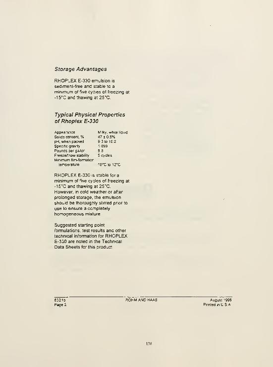
storage Advantages
RHOPLEX E-330 emulsion is
sediment-free and stable to a
minimum of five cycles of freezing at
-IS'C and thawing at 25°C.
Typical Physical Properties
of Rhoplex E-330
Appearance Milky, white liquid
Solids content % 47 ± 0.5%
pH. when packed 9 3 to 10.2
Specific gravity 1 059
Pounds per gallon 8 8
Freeze/thaw stability 5 cycles
Minimum film-formation
temperature 10"C to 12''C
RHOPLEX E-330 is stable for a
minimum of five cycles of freezing at
-15°C and thawing at 25°C.
However, in cold weather or after
prolonged storage, the emulsion
should be thoroughly stirred prior to
use to ensure a completely
homogeneous mixture.
Suggested starting point
formulations, test results and other
technical information for RHOPLEXE-330 are noted in the Technical
Data Sheets for this product.
83D1b ROHM AND HAAS August 1995
Page 2 Pnnted in USA,

that you may need to protect your
employees and customers against
any known health or safety hazards
associated with our products.
The Rohm and Haas Companyrecommends that you obtain copies
of our Matenal Safety Data Sheets
from your local Rohm and Haas
representative on each of our
products prior to its use in your
facilities. We also suggest that you
contact your supplier of other
matenals recommended for use with
our products for appropnate health
and safety precautions prior to their
use.
Safe Handling Information
Animal toxicity screening tests
conducted on closely related
analogs of RHOPLEX E-330 suggest
that this product should be
essentially non-toxic by single acute
oral or dermal exposure and that it
may also be a mild to moderate skin
and eye irntant. In addition, many of
the components of cement used in
conjunction with RHOPLEX E-330
may also possess significant skin
and eye irntation potential.
The Rohm and Haas Companymaintains comprehensive and up-to-
date Material Safety Data Sheets
(MSDS) on all of its products. These
sheets contain pertinent information
ROHMniHnnsE^PHILADELPHIA. PA 19106
ACRYLOID. ACRYSOL. ACUSOL, AQUAPLUS. DURAPLUS. ELASTENE, KATHON, MAINCOTE.
PARAPLEX. RHOPLEX, ROBOND, ROPAQUE, ROVACE. SEALER-HEALER, SKANE. SKANE
AND TAMOL are registered trademarks of Rohm and Haas Company or of its subsidianes or
affiliates.
These suggestions and data are based on information we believe to be reliable. They are offered in
good faith, but without guarantee, as conditions and method of use of our products are beyond our
control We recommend that the prospectrve user determine the suitability of our matenals and
suggestions before adopting them on a commercial basis
Suggestions for uses of our products or the inclusion of descnptive matenal from patents and the
citation of specific patents in this publication should not be understood as recommending the use of
our products in violation of any patent or as permission or license to use any patents of the Rohm
and Haas Company
83D1bPage 3
ROHM AND HAAS August 1995
Pnnted in U S A
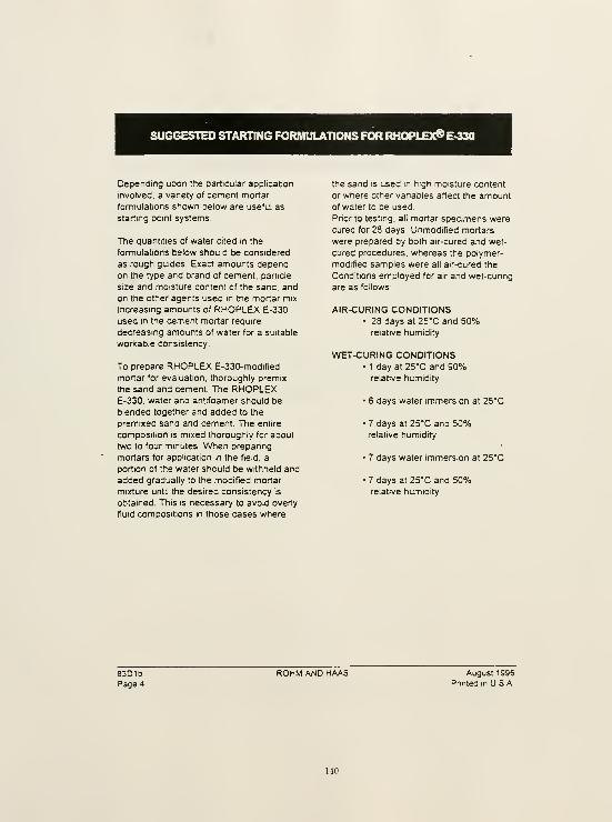
SUGGESTED STARTING FORMULATIONS FOR RHOPLEX® E-330
Depending upon the particular application
Involved, a vanety of cement mortar
formulations shown below are useful as
starting point systems.
The quantities of water cited in the
fonnulations below should be considered
as rough guides. Exact amounts depend
on the type and brand of cement, particle
size and moisture content of the sand, and
on the other agents used in the mortar mix.
increasing amounts of RHOPLEX E-330
used in the cement mortar require
decreasing amounts of water for a suitable
wortcable consistency.
To prepare RHOPLEX E-330-modlfied
mortar for evaluation, thoroughly premix
the sand and cement. The RHOPLEXE-330. water and antlfoamer should be
blended together and added to the
premixed sand and cement. The entire
composition is mixed thoroughly for about
two to four minutes. When prepanng
mortars for application in the field, a
portion of the water should be withheld and
added gradually to the modified mortar
mixture until the desired consistency is
obtained. This is necessary to avoid overly
fluid compositions in those cases where
the sand is used m high moisture content
or where other vanables affect the amountof water to be used
Pnor to testing, all mortar specimens were
cured for 28 days. Unmodified mortars
were prepared by both air-cured and wet-
cured procedures, whereas the polymer-
modified samples were all air-cured the
Conditions employed for air and wet-cunng
are as follows:
AIR-CURING CONDITIONS• 28 days at 25°C and 50%
relative humidity
WET-CURING CONDITIONS• 1 day at 25°C and 90%
relative humidity
• 6 days water immersion at 25°C
• 7 days at 25°C and 50%relative humidity
• 7 days water immersion at 25°C
• 7 days at 25°C and 50%relative humidity
83016Page 4
ROHM AND HAAS August 1995
Pnnted in USA.
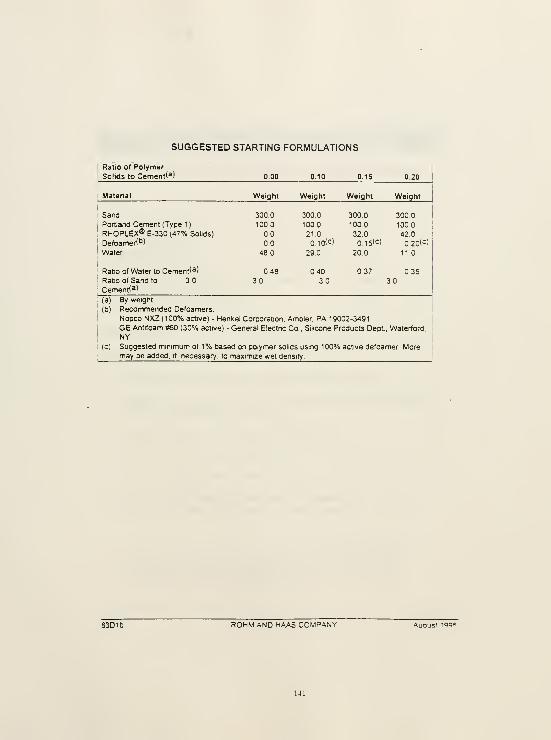
SUGGESTED STARTING FORMULATIONS
Ratio of Polymer
Solids to Cement(^)
!
Matenal Weight Weight Weight Weight
SandPortland Cement (Type 1)
RHOPLEX® E-330 (47% Solids)
DefoameH'')
Water
Ratio of Water to Cement'^)
Ratio of Sand to 3
Cement<3)
3000

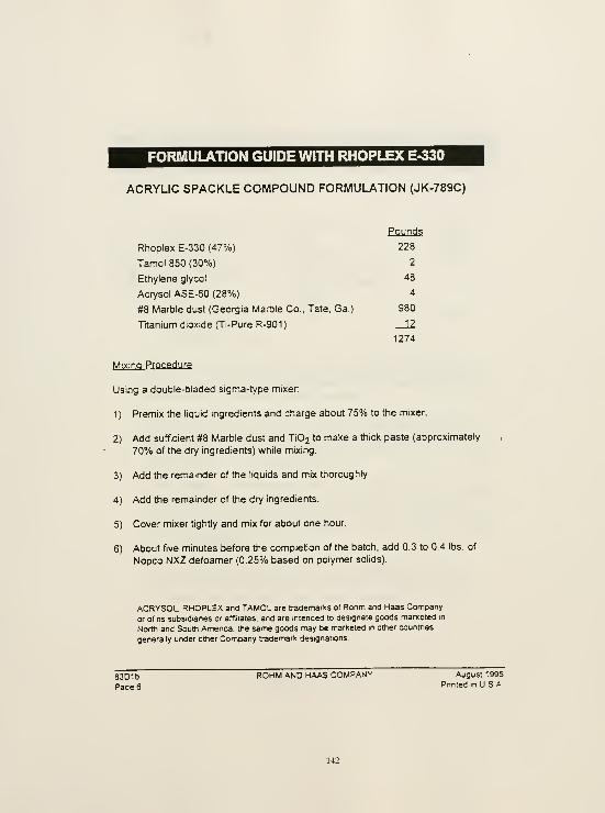
FORMULATION GUIDE WITH RHOPLEX E-330
ACRYLIC SPACKLE COMPOUND FORMULATION (JK-789C)
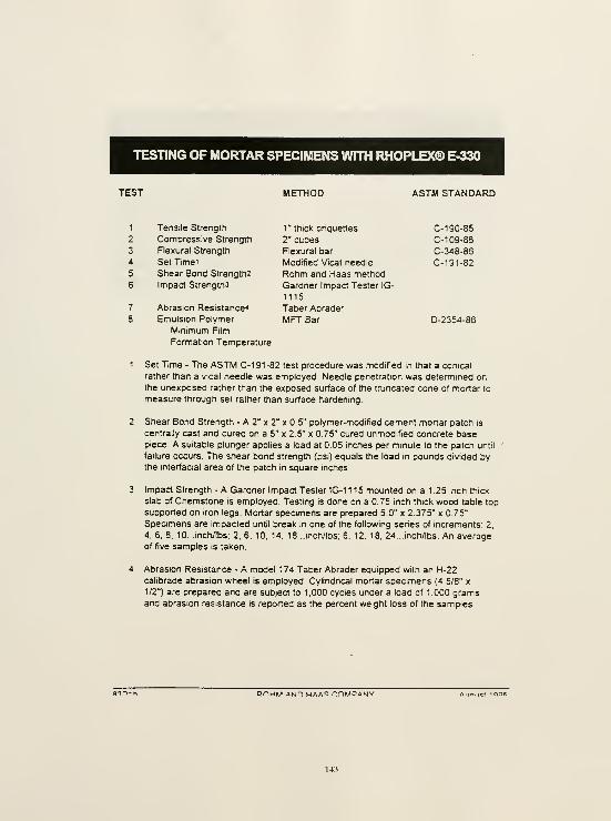
TESTING OF MORTAR SPECIMENS WITH RHOPLEX® E-330
TEST METHOD ASTM STANDARD
1 Tensile Strength
2 Compressive Strength
3 Flexural Strength
4 Set Time'
5 Shear Bond Strength2
6 Impact Strengths
7 Abrasion Resistance^
8 Emulsion Polymer
Minimum Film
Formation Temperature
1" thick bnquettes
2" cubes
Flexural bar
Modified Vicat needle
Rohm and Haas method
Gardner Impact Tester IG-
1115
Taber Abrader
MFTBar
C- 190-85
C-1 09-88
C-348-86
C-191-82
D-2354-86
Set Time - The ASTM 0-191-82 test procedure was modified in that a conical
rather than a vicat needle was employed. Needle penetration was determined onthe unexposed rather than the exposed surface of the tnjncated cone of mortar to
measure through set rather than surface hardening.
Shear Bond Strength - A 2" x 2" x 0.5" polymer-modified cement mortar patch is
centrally cast and cured on a 5" x 2.5" x 0.75" cured unmodified concrete basepiece. A suitable plunger applies a load at 0.05 inches per minute to the patch until '
failure occurs. The shear bond strength (psi) equals the load in pounds divided bythe interfacial area of the patch in square inches.
Impact Strength - A Gardner Impact Tester IG-1 1 1 5 mounted on a 1 .25 inch thick
slab of Chemstone is employed. Testing is done on a 0.75 inch thick wood table top
supported on iron legs. Mortar speamens are prepared 5.0" x 2.375" x 75"
Speamens are impacted until break in one of the following senes of increments: 2.
4. 6, 8, 10. ..inch/lbs; 2. 6. 10. 14, 18 ..inch/lbs: 6. 12, 18, 24. ..inch/lbs An averageof five samples is taken.
Abrasion Resistance - A model 174 Taber Abrader equipped with an H-22calibrade abrasion wheel is employed. Cylindncal mortar specimens (4 5/8" x
1/2") are prepared and are subject to 1,000 cycles under a load of 1,000 gramsand abrasion resistance is reported as the percent weight loss of the samples
ROHM AND MAi<^ mMDAMV
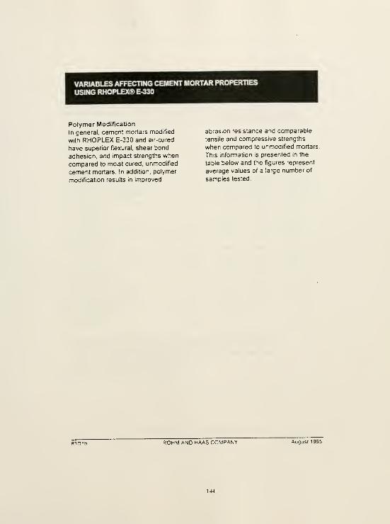
VARIABLES AFFECTING CEMENT MORTAR PROPERTIESUSING RHOPLEX® E-330
Polymer Modification
In general, cement mortars modified
with RHOPLEX E-330 and air-cured
have superior flexural, shear bond
adhesion, and impact strengths when
compared to moist cured, unmodified
cement mortars. In addition, polymer
modification results in improved
abrasion resistance and comparable
tensile and compressive strengths
when compared to unmodified mortars.
This information is presented in the
table below and the figures represent
average values of a large number of
samples tested.
ROHM AND HAAS COMPANY August 1995
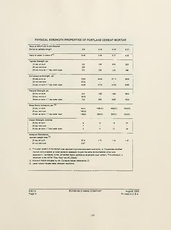
PHYSICAL STRENGTH PROPERTIES OF PORTLAND CEMENT MORTAR
Rauo of RHOPLEX E-330 Polym»r

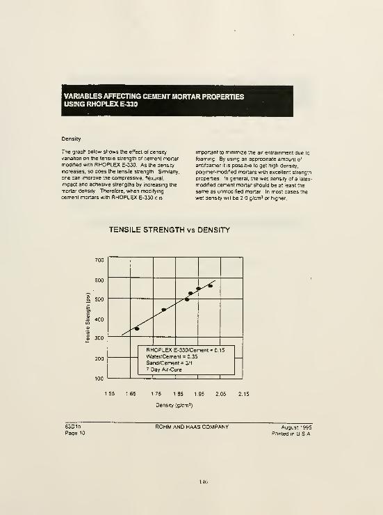
VARIABLES AFFECTING CEMENT MORTAR PROPERTIESUSING RHOPLEXE-330
Density
The graph below shows the effect of density
variation on the tensile strength of cement mortar
modified with RHOPLEX E-330 As the density
increases, so does the tensile strength. Similarly,
one can improve the compressive, tiexural,
impact and adhesive strengths by increasing the
mortar density Therefore, when modifying
cement mortars with RHOPLEX E-330 it is
important to minimize the air entrainment due to
foaming. By using an appropriate amount of
antifoamer it is possible to get high density,
polymer-modified mortars with excellent strength
properties In general, the wet density of a latex-
modified cement mortar should be at least the
same as unmodified mortar In most cases the
wet density will be 2 g/cm^ or higher.
TENSILE STRENGTH vs DENSITY
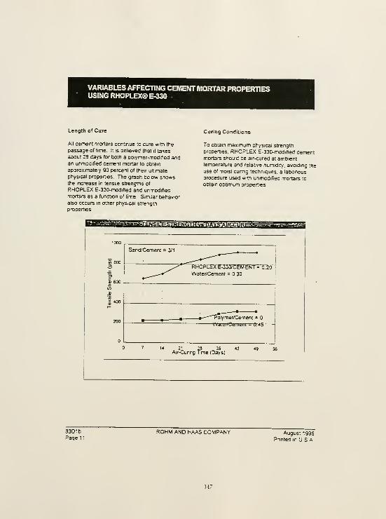
VARIABLES AFFECTING CEMENTMORTAR PROPERTIESUSING RHOPLEX® E-330
Length of Cure
All cement mortars continue to cure with the
passage of time It is believed that it takes
about 28 days for both a polymer-modified andan unmodified cement mortar to obtain
approximately 90 percent of their ultimate
physical properties The graph below showsthe increase in tensile strengths of
RHOPLEX E-330-modified and unmodified
mortars as a fijnction of time Similar behavior
also occurs in other physical strength
properties
Curing Conditions
To obtain maximum physical strength
properties, RHOPLEX E-330-modified cementmortars should be air<ured at ambienttemperature and relative humidity, avoiding the
use of moist cunng techniques, a labonousprocedure used with unmodified mortars to
obtain optimum properties
^^^l!7@IMl?^i33JPefns^TRS'»S3tJK«j3^^1
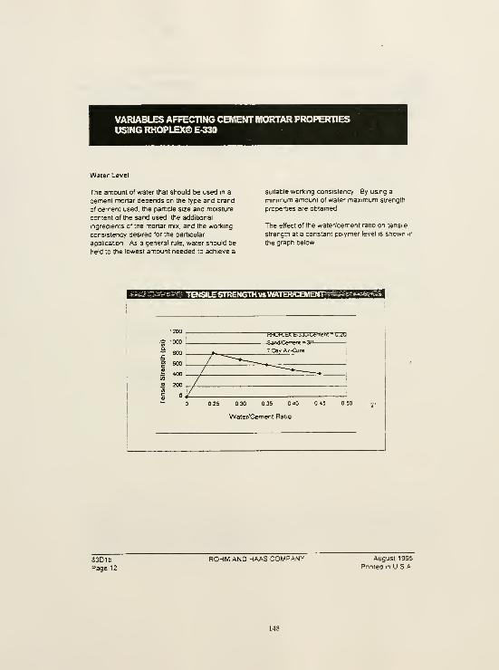
VARIABLES AFFECTING CEMENTMORTAR PROPERTIESUSING RHOPI.EX®E-330
Water Level
The amount of water that should be used in a
cement mortar depends on the type and brand
of cement used, the particle size and moisture
content of the sand used, the additional
ingredients of the mortar mix. and the working
consistency desired for the particular
application As a general rule, water should be
held to the lowest amount needed to achieve a
suitable working consistency By using a
minimum amount of water maximum strength
properties are obtained
The effect of the water/cement ratio on tensile
strength at a constant polymer level is shown in
the graph below.
TENSILESTRENGTH VSWKTERICBKOmP^-
HHUH-bX bJJU/LemenI = U7U
SaneKCwrenl - 3/1 '
30 0.36 40
Water/Cement Ratio
83D1bPage 12
ROHM AND HAAS COMPANY August 1995
Pnnted in U S A

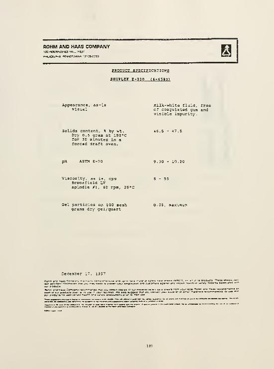
ROHM AIMO HAAS COMPANY
DHtiCeU^'ia D€NJ*TT.V4AUA l9'C6-2399
PRODOCT SPECI?ICATI0N3
BHOPLEX g-330 («-<580l
Appearance, as-is MilJt-uhita fluid, freevisual of coagulated gum and
pH ASTM E-70
Viscosity, as is, cpsBrookfield Lvspindle /I, 60 rpm, ZS'C
visible iapurity.
Solids content, % by wt. 46.5 - 47.5Dry 0.6 graa at 150 'Cfor 20 minutes in aforced draft oven.
Gel particles on 100 mesh 0.05, maximuaigrams dry gel/quart
December 17, 1997
w. aiaa lugg*

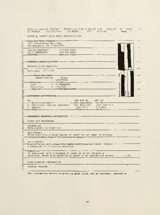
TEXTILE CHEr.ICAL CC.*^PAm':' PCTTS'.'IILE f
TC MSDS-s.
flATERIAL SAFETY DATA SHEET RHOPLEX E-310
i?o.';iu BiiJ ilaaj Cj iiipany
: 00 Independence Mall West
Phi laoeipfija , PA i91Cib-;?9S
HEALTH Zy.ZRZZnZISPILL EnERGENCY
2:5-E9:-300O215-SO2-300O
-P«OBUCT 1 DENT! ri cat: O N
RHOPLEX E-330 Eisuiiioti
- r- fKT'^S dsve
Rohn and Haa s
Hazard Raring ScaleEXTREME
^ 3 - HiGHF I re 2' MODERATE
- IN?I^NIF1GANT
-eW^PQHCNT I N rORMAT'.OW-
CAS REG NO. A.Tr. (X)So t Haz-aT^d<>u3 u»—u8
—
—
t
Acry lic po i y w. i
2 Individual residual .Bonomers Mot. Required ; S33 t-ftan 3.1
3 .Mnaonia 7664-«l-7 0.2 !"-AX.
-<i Wa-trer 773; 1 9 5 'y^-SM
-6^E«€&!»eV-R€-5P0«SE—I-NFORM.ATl ON
FiRil AID PROCEDURES
InhalationHove S'jtject to .'.-es.l ai;
Eye Contact.Flush eyes with a large amount of water for at least 15 ainutes.
-Consult t ;jfiySTi:tan—rf iMiLdtluii p 'ri hist g .
Skin Contact-Ua ah arret l e d 3^1.11] j ! e-as—ttig-ro ugtil y
—ui li: 303p a nd Jdte i -—Co-nsul t
a physician ir Irritation persists.
-iTTj-eirtlcin — •
If suailoued. elve 2 glasses of water to drink. Consuit 3
physician. Never give anything by mouth to an unconscious person.
IRE FICHTiNC INFORfWTION
Unusu«l Hazards
The iaforaatioD hcreia is slvea in good faith, but no warranty, express or
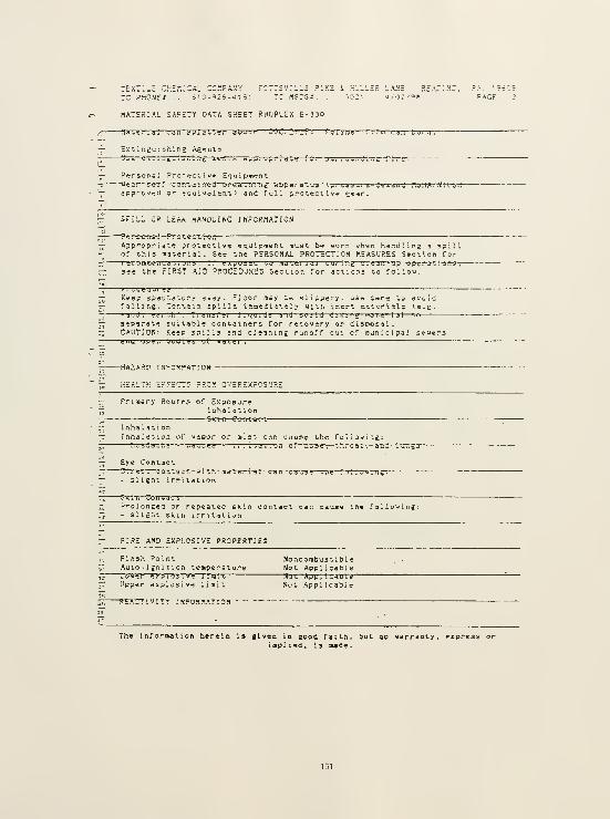
?o:i
MATERIAL SAFETY DATA SHEET RHOPLEX E-330
Mjue.' 1 jl Lju i:i>)j ji i,ei—jl^uve ^ 09?.'!:: JP .
—
Ex^ingu lining Agrnls
Pi^rsoral Protective ETiipwrnl
approvird or -qu i«i) 1 ent ) and full protective £'?«'".
i.VE P,£A-:Na, ?A. '?
02 /^a PAGF
-L OR LEAK nAKDLINC f N'rOSMATiON
roiec-tTon—Approprie'^ protective equipraent must be uorp '.-hen handling g spillor this arterial. See the PERSONAL PROTECTION MEASURES Section for-r-^rnnmeiiJdt iuiis .—If ei,;u3:iJ
—
tj md tei i Ji—ju. In,; '. J e j u "j li \juc i jii-c \ ! ^ .
see the FIRST AID PROCEDURES Section Tor acf.ons to follow.
r'l vteuui e?Keep spec»a"i.or5 a^^ay. Floor Bay ie slippery- vjs= cars to avulifalling. CoT.tsin jpills inaeilitely with inert oit^rlilc <e.g.a. j ii J .—ecT".-!! ' .
—
T; aii s r e i
—1 m u ; j?
—
ind MjiiO Oikinu nj t.g i Ijl—en
separat't luitable containers for recovery or iijpoial.CAUTION: Keep ipllls 3nd cleanine runoff out of launicipal seue-sdiid u^<e.i 'juOiei uf
—
wdi e i .
-HAtAi«^rwPOR"AT ! ON
77 HEALTH EF-ECTS "RCK OVEREXPOSURE
Frj.-sary Routes of E.sposureInhal at ionSlrrn
—
Coir ta i. t
inhalati onInhdidtion of viaoor cr nisr can cause the foiiouine:
?r?^"iaTTre~'-~ ..a -w g3~^
—
. . . tat. u n of—n-'se-;— t-^.roflt-.— a'nd--i--jr.23
rTolonced or repeatec sK;n con-.»ct can cauE<- sll£ht skill irrititiuii
FIRE AND EXPLOSIVE PROPERTIES
Flash PointAuto- i jn 1 ti on temperature
Noncombust i Dl e
Not Appl icaM e
Upper explusivp 1 i mi
t
Not Appllc«Dl?~Nut Appl i cabl
e
KhAC! I VIT'
ioi t
INrORrt'TtOM
The inforaation herein is elveo in good faith, but ao warranty, express oriopl 1 ed , is lude .

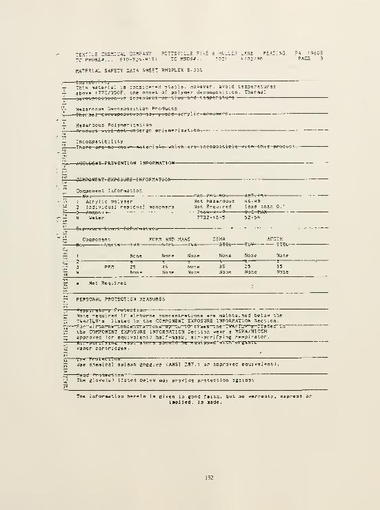
TEXTILE CHH^::cnL zzy.pf.N'^ ?cttsv:lle =
TC PHONE*... ei O-'JS-u '. 51 TC «SDi-».
nATERIAL SAFETY DATA SHEET RHOPLEX E-JiO
i HULLE.P LA.N'r ."^EAriVC. ?A. 19605?0:i U/02/9P PACE 3
r-' Iji.i.!.abil 1 1;— This roat-erial is cor.siierec s'-aai;. nouever, avoid i-ip^raturesh-, abov* 177C/350F. the nnset of polyaer decomposition. Thermal^^^^ (hiii oitrp er-i ti o n—r?--Jc<>cn<t^frt—
j
n ti me—*?m*—t-e^»f>«ratM*f^ .
miardoua D^romposi'-iori ProductsTh cTiaq^—
d
ee o a pos-t-t-i-OTt—o»y yi - >4—acr-y H-c—mCM>om<^»»5^
ACCIOEHT f' fcEVENTlOH I HPORMA^H-Qlt-
H4?« S<jfl€—t-Nr -0 fi rtA «-J f*-
Componint Inforraat
fkt.— '. Acrylic polyci-r
^ 2 Individual resid'jal aonouers^^^ 3 AratQo rr i a
ii « Water
~A C- PEG Ne^ AM- (.1
Not Haiardous ii6-«8
Not Required lisr ttian 0.1—7f.. fcM Ml 7 9^^_nA«
tin p f? ju r fi Fpr-t—r-r>^-orfl»'*<-t-c?n
Coffipo.'^ent R0H.1 AND HAAS&=6t TAJA-
ACCIH-^L-V STet-
Ncne None
2?None
Not Required
NoneNone
p PERSCNAl, PROTECTION MEASURES
35None
None required if airborne concentrations are namtained belok !,^e
T-iJA/TUV's Usted in the COMPONENT EXPO.SURE INFORMATION Section,-f 01—a i I Liui ii'B~C"DTrceii >-! a'TtoTis—op—Co—I'D" T."i"iie3—tn e ' TVA/ Tf^'S 1 Is ted i
the COilPONENT E'/IPOSUKE INFORMATION Section -ear a -.SHA/NIOtHapproved 'or equivalent) half-uask, a i r-piiri fy i ng respirator.
i

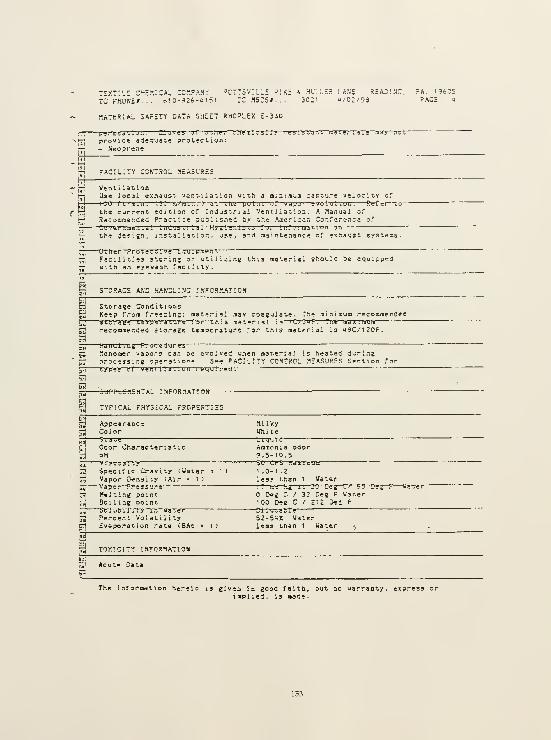
T£XT:'.£ CyiHr.iCAl COMPAM:-
rC PHONE/. - .6!0-92p-';i?1
IT'SVIL'^E P:Ki 4 HUILES LANE READING, ?A. 196C5rc Hsps*... 30:1 u/o;/98 pace »
MATERIAL SAFETY DATA SHEET RHOPLEX E-330
<" (^ Ventilation^ H Use local exhaust ventilation uitn a ninimua capture velocity of
H 1-0 f i.'' B.;i.—
r
^ ;a/'
iuiLi -)--3t~m-e pul;ii ^ f
—
u j^u '—-volut ioi:
.
S^>;i—tc
f-^ the current edition oT Industrial Ventilation: A Manual of
jp^ Recommendec Practice puSlished by the Aaericar. Ca'Tereinci of
:u 'J«i u;ne.i -d!—Iiid '.:? ti . j i~H y tf l e i i i!; t^ rm—iur.'i mjt1.-rm—on
tjign, installation, use, and riaintenance of exnaust systems.
IT

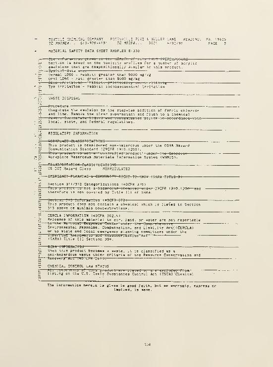
TEXT'.-i CHEKICAl CC?!PANY PCTTSV.L.E ?;X; i H'JL.ER LANE SHADING. PA. 19605TCPHOHEt... eiO-??*-"!?' 7C.1SDSJ... 3021 <*/o;/-9e .CAGE 5
MATERIAL SAFETY DATA SHEET RHOPLcX E-3J0
Tii g
—
irifurne U. uu jl:>. i» ii—. I'l llie—
r
X.°i..^l ! I.'TlCIj rSO.". J ' ZRZJiPOC'URZSeci-ion IS basec on zne tox;c:iy orofiiss for a nji«bt:r oT acryiicemujsion? that are coopos i M onai ly siallar ^c ihis produc-.Ty? l-cai--<i-»ta—arc-:
Pi.-ma; LCiSO - rabbit: e.'~eater than 5000 m^'kgQr^l LD50 - rat: gr-ot»r than 5000 mg.'keOki n
—
ill 1 tat.un 1 aOUi I
.
—pr-a^-t-r^rai I y .ion—j-rr~rtati-t^e
Eye irritation - ra&Dit: inconsequential irritation
UASTE DISPOSAL
— Coagulate the enulsion by the stepwise addition of Ferric chloride-^ and Use. Rirniove the clear supernatant and flush to a chemicalr^. je w e.- .
—jin. i rierate liquid and n oii taiu.iiBtgU juIiOj—re—»c-c<y^r^am^e—u-r^,77, local, state, and federal regulations.
- RECULATrSY INTCR.'tATl
."onKPL A C' CLAS5I~I C->V=-KIN5
This product i3 consid'ered non-haiardcus under the OSHA HazardCcramunication Standard (29CFR 1910.1200).This product 19 n o t a—"-c-on-tr-oi-l td— prodac-t-"—om^ei—
t
he Canadi an—Workplace Hazardous Materials Infornatlon SysteQ (WHfllS).
FJ»A-N-:. .-'0 >?TA~: ON GLAfrS I f I CAT! Q N G
: v'S CCT Hararl Class MC.fHHSL'LATEE
-—£Mn«G=«€Y-PfcAN»I HG-S, COMMUNIT'i' RI GlC - TO - KJiOU CJAiTiA TITLC 3)
ff Section 311/312 Categorizations (UOCFR 370)
~i This p r oduct is n o t a haiai t±ous ch tni i.jl ui i<^e^-29CF-ff-l 91-0-. i 200, a nd
jj ttier-fore u not cov-red by Title 1 1 1 of SARA.
;;;Ogttiuii JO liiTui indtiuii—mOCrR 372)
Tj This product does not co.-.tain a che.mcal v.hich ;s listed in Section~ 313 above de ninimis concentrations.
— CERCLA INFORMATION (QOCFR 302."*)
^ Releases of this material to air, land, or water are not reportableZi '•"O—cn^ National—R-<;ap»nbg Ca ntin—on-d^i
—
llig Cumpi g lie nai v i-
3 Environmental Response, Compensation, and Liability Act; (CERCLA)~i or to state and local energency planning conmittees und-sr the
;uBerr'j:iU A.ie,T aiiB]its jric R ad>i„. !;rlzatluii AlifS.'.RA) Title III Section 301.
SCX A f WPJ1?fW7-ro«^ Uhe.T this product becomes a -aste, it is classified »3 e
T. non-harardous vasle under criteria of the Resource Conservation and^ Rer-jve r y Ac l. t u Cr CFi?-C-6-r)-:
— CHSniCAL CONTROL LAU STATUSr KTi—
f
u ta^u n yi i tb u.''
—
tin b ^i t uuul i
listing on the U.S. Toilc Substances Control Act CTSCA) 'Cherai cal
The inroraation herein is glvea in good faith, but no warranty, express orinplied, is imade
.

"X-ILE CHEMICAL CCWANY PCTTSVILLE PIKE i H-ILER L^NE PEAnTNG, ?A. '9f05
fcPHOME---- 6;c-9rs-''!?t rc.rsDS*... ?o:i «/02/9e ''ace e
MATERIAL SAFETY DATA SHEET RHOPLEX EO'JO
— STATE SIGHT-TO-KNOU LA'-iS_ _
'4-Ai;t iidt e-m-a-i—H-s-trd-^? Nu i. Hdz-arao-as^^ 1.. .,,t CAC ::_C ;;C ^^:-— .
I7J -.he Ct3r.?0NENT :tiFORnATIOS Sec'.lor. of '.Ms nSD" ii trsle recret'— under tn; provi-icns of t h? P-nn* yi van; a Work-er and Coraniunity
'-; fti v) la - t.u - Kiim Att :^
•li R HOPtCX" iy J L I Jd e maj-k j f— 3oha-and Hadi Guiupdiiy ji—OTif uf 1 Ls
rr! su6siaiari»i or affiliates.
-T«91?eVtAT«W*^
'r. ACGIH. ^Aaericsn Cor.rtrinct of Ccvar:iaer.--al ladus'.rlal Hy2i*nis*-s'—' OSHA • Occup-atiotnl ^ef-ity ^rd Health Admi ni s t.ratioti ^i-^i rtv =—T tr-e a iig lu l.:Bi. Vdiuti——— " "
'• "d PEL • Permissible Exposure Limil"
cd TUA Tia« Ueight-ed Average'^. ST?t—»~SlTDrt-Term E.\,JUb„rK L.m:-!:
^
'^53 BAc " Butyl acetat-e
The inrorBation herein is given in good faith, but no warranty, express or
iaplied, is sade

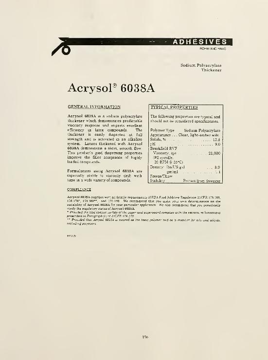
ROHM AND HAAS
Sodium Polyacrylate
Thickener
AcrysoP 6038A
TtTICAX PROPERTIESGENER.\L INFORM.ATION
Acrysol 6038A is a sodium polyacrylate
thickener which demonstrates predictable
viscosity response and imparts excellent
efficiency in latex compounds. Thethickener is easily dispersed at full
strength and is activated in an alkaline
system. Latices thickened with Acrysol6038A demonstrate a short, smooth flow
This product's good dispersing properties
improve the filler acceptance of highly
loaded compounds.
Formulations using Acrysol 6038A are
especially stable to viscosity drift with
time in a wide variety of compounds.
COMPLIANCE
Acrysol 6038A complies with appbcable requirements of FDA Food .Additive Regulation 21CFR 175 105.
176 170*, 175 300". and 176 ISO We recommend that you make your own determination on the
suitabihty of Acrysol 6038A for your particular application We also recommend that you penodicallyvenfy the regulatory status of Acrysol 6038A.• ProuLded ihe food contact surface of the paper aiid paperboard complies trith the extractives limitations
prescribed in Paragraph (c) of 2ICFR I TS 1 TO.
" ProLided that Acrysol 603SA is cleared as the basic polymer and as a modifier for oils and alkyds.including polyesters-
The following properties are typical andshould not be considered specifications.
Polymer Type ... Sodium Polyacrylate
Appearance . . Clear, hght-amber soln.
Sohds. % 13.5
pH 9.0
Brookfield RVTViscosity, cps 21,000
(#2 spindle,
20 RPM @ 25°C)
Density: lbs/X,'S gal 8.9
gia/ml 1.1
Freeze/Thaw
Stabibtv Protect from freezing

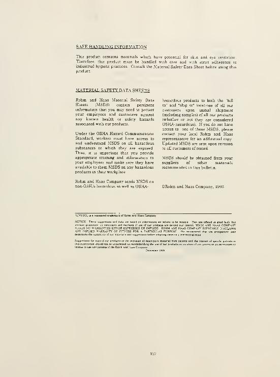
SAFE H.\.\DLI\G INFOR.\LATION
This product contains materials which have potential for skin and eye irritation.
Therefore, this product must be handled with care and with stnct adherence to
industrial hygiene practices. Consult the Material Safety Data Sheet before using this
product.
MATERL\L SAFETY' DATA SHEETS
Rohm and Haas Material Safety DataSheets (MSDS) contain pertinent
information that you may need to protect
your employees and customers against
any known health or safety hazards
associated with our products.
Under the OSHA Hazard CommunicationStandard, workers must have access to
and understand MSDS on all hazardoussubstances to which they are exposed.
Thus. It IS important that you provide
appropnate training and information to
your employees and make sure they haveavailable to them MSDS on any hazardousproducts in their workplace.
hazardous products to both the "bill
to" and "ship to" locations of all our
customers upon initial shipment(including samples) of all our products
(whether or not they are considered
OSH-A-hazardous). If you do not have
access to one of these MSDS, please
contact your local Rohm and Haasrepresentative for an additional copy
Updated MSDS are sent upon revision
to all customers of record
MSDS should be obtained from your
suppliers of other materials
recommended in this bulletin.
Rohm and Haas Company sends MSDS on
non-OSHA-hazardous as well as OSH.\- ©Rohm and Haas Company, 1995
.ACRYSOL u
SOTICE Th.».
lofRolim and Hals Comp
ons and data are bawd on information we briievr to !>• niiable They are offered .n jood faith, butwithout guarante. as conditions and methods of use of our producta are bevond our control. ROHM .\ND KA.\S COMP.^NYM-U<£S NO WAjiR.AjMTlES EITHER EXPRESSED OR IMPLIED ROHM .VJD H.\.\S C0MP.\NY E.XPRESSLY DISCLAIMS.\S\' IMPLIED W.aRRaMTY' of FITNESS FOR ^ P.\RTICLL.\R PURPOSE We recommend that the prospective userdetermine the suiubilily of our matenals and suggestions before adopting them on a commercial scale
Sug 1 for t of our produi le inclusion of descriptive matei
as recommending the use of our
1 Haas CompanyDecember 1996
1 from :ificI
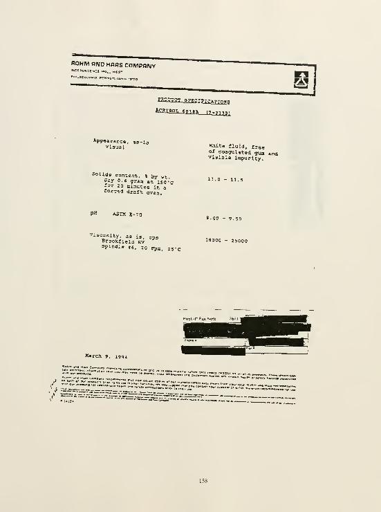
Appearance, aa-iavisual WUta fluid, frBo
of coagulated gua andvisibla inpurity.
Solids content, » by wtDry o.s graa at 150 -'c-" 20 ninutes in arorc-d draft oven.
13-0 - 13.5
PH ASTM B-70S.OO - g.so
Viscosity, as i,, cps3r=ck«ieid Rv 18000 - 25000
MarcJi 9, 1994
'•co«M«*MAa*« •

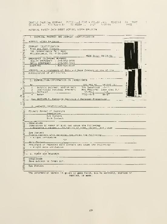
TEXTI'-H CriMICAL COMPANY POTTiV;.^! ?::<c i h'uL^^n .;
r.A'lP.lAL SAfEir TATA SHEET ACPrSOL 6-"?SA E,1')Lr;;0N
I . CHEMICAL PRODUCT AND COnPANt I OHNT"i F'.CAT'. ON
ACRYSOL •>0?6A £in'.il si o:-. ._
:o;ipa:.'v ise.vtifxaticn
'00 Tr.'J'ipen'lence "^si i 'J*?"-
Phi ladcipnla. FA 19106-2399
EMERGENCY TELEPHONE NUMBESiHEALTH £.-!£RC£NCY : 215-592-3000SPILL c^.cSCeNCt : 215-592-3000CHEMTSEC
*.C?.Y5CL 13 ~V. cf P.oh'^ sn-^ Ha^s Con\p3r. v or
l;ij subJid::
,1;^, 2. COnPOSITlON/INFOP.MATION CN INCREOiENTS
1 Acrylic polyiiicr , sodi.ua salt,
2 Iniii-iS'jai .-s?;d'J3i soncaor; Net R?qu:r-i ]?«3 thsn 0.
3 M^-.bariol .7-5'',-
u Uater 7732-18-5 56-
S*? SECTION 6, Exposu rg Coritroli / P'irsonil PrOveeiion
_?--^iAZA8 L' 5 I Pc ""
Pr:=iry ?.C'-:tes of Ex?oc'jre_! LnhaI..\t.L".n
Eye ContactSkin Contact
Inb.jl'St ionInnaiation of vapor or mist can cause the fojiouing;- r.qnua;:rii' - nausea - irritat-. on .-.r no.^ff. throat. ?.,-d _:.jr.£3
Uirprr. rnntfirt. w'.th m.itrri.ll Cjin_c_5iii»_the_;- slight irritation
tl^
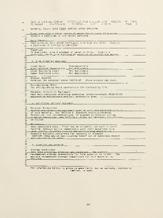
THXTiuC ^.-.rniCAL COHfANr ?CTT5v;_L; ?;k£ »_H>Ji,_£
.lATHStAI. JAFET':' O.-'-TA 'H5ET ACRY5C". 60??A HMDL^inN

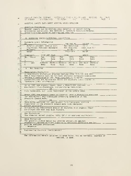
i=x:":
TC r-
'.AT = ?.1AL SAFETY DATA SHfrT ACRY'OL hC33A EMULSION
^pri ! ng P-oi-f'J'jr°^J
rtonoraer vapors caa be "volved -jhen ria-erlai is heatei i'jrlnj-procesEins opera'. vofj3 3ee SECTION a, Exposure Control s^'PersonalProtect 1 on ^ for types o f venti 1 at ion requ i re d .
C^^NT^CS /P^'SOM^L ?ROT"iTT10N
Exposure Limit InformationNo. .: ._
Acrylic polyn<»r. sodium seltInOlvlaual resiaual raonomersMethanoJ
Not na^^rdous 10-11
Not Required iesy tiian
Uater ?73r-IS-? SS-37
Conp^nenj!, ROHM AND HAAS QSHA ACGIHTUANone
STELNone
STELNone
200S;<'.n 250Sk:n 200Sl<i
None None N'oiic
250 Sum 200 iitm 250SKinNone None None
Respiratory Protection _
,^ A respiratory protection prosrara raeetins OSHA IS'O.IJU and ANS!^ Z38.2 requirements must be followed whenever workplace conditionsi_'.
warrant 3 rerpirator'j uae. None require d 1:' airbo rne, i^ ;oncentr3t ions are maintained beiow tne exposure limit, listed in
il, 'Exposure Halt Inrormatl on' .
t_ Up to 100c ppn irsan'.c -/apor: U'eer a MSHA/NIOSH approved Co-
ir equivalent) f uJ l-faciolec? , air-ounfyin? respirator,'2 USii full facepiece. air line respirator in the demand node.
'* AhQV» I nop jnm nrg;<n:r vapor nr llnltnnwn: . _y.e ar n WSHA/NIHSM annrnv»f1
il (or equivalent) self-contained breatning apparatus in the111 pressure demdnd mode,^ : 9511 MSHA/NIOSH app-oved (or equivalent) ful 1 -f^cepi ece . airiirii respirator in the pressure demand mode with emerjencviil sJLZAPjf. sroYisian.ii Air-purify i nE reapirators should be equipped witli oreanic vapor"' cartridges and du3t and i»ist filters.
.!^ Eye ProtectionID 'Jsfe cheniical splash josjles (ANSI Z57.'. or spprjvei eq-i valer.t ;
^'-1

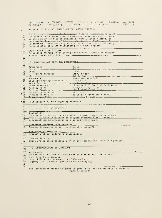
:ext!L£ chemical cckpanyre PHONE*. . .
610-926-U151TSV'.LLE P::<c 4 HULLEf?
IC .".SDSJt. . . M :'
MATEaiAL 3AFETV 0A7A SHEET ACSYnCL oC3dA :-.UL.';ON
ii..> I..-..1 »..>. ». ..jr I.--. » i 1 T < nr m>h .- mlT'fniiii r.^.Tiirr jr'nr-r,,v n*"
'00 rt'rei:!. (0.5 n/^ec . ' at I.h» point of v^por -vq ; ijt i ijr.. R'jfer
to the currient edition oT Industrial V»nt i la t lor. : A Manual of
ffi».-/^-.mpnriPrt Prarr.ir.f nuhl Lsliad_rty Ihf
—
^mf r
i
Cdn-Conf f rTnr ^ ^T
Covernaental Industnii rfygier.ists for > nf or.-nat : on on tne aesien.1 nrtal 1 ation , use. and maint»n.5nce of sxnaust syst^as.
Ol.^e^ Protective EquipmentFic - 1 . t i»G 5tor:r.s cr ut:!: ";jl rno'ji'l b» «q'..ipp';'i
_! DidiSi-CAi iiiO-
Appearanc-
—P-AOPEgTlFS
Ch3r3C t eri
!
Acryi Ic odo-_a-jD_.lo.3_5__
Specific Gravity (WaterVapnr Dpn*; i t y
Vapor Pressure?1eitina Point
SoJuSiiity :r. UarerPercent Volat i ! i tv
OSKKSffii T-!» J^JxOi* C7tr
! .0 to 1.2l».5g r.han 1 Uar.r-r
? m™ He 2 20 Dee C.'od DegF uaterOe,;C/32 De^F '.'atrr
,A r,.^r--T? -,.-: u^---r
CiJ'JtjSJe86 to 87 T. 'Jater and alcoholI.,, t.h.-n 1 ..Ua^t::
See SECTION 5, Fire Fiahtinc MeasureE
;o. STASiLiTY A.'ic .°e.ict:v;ty
Iristabi 1 i ty
T.113 material is considered stable. However, avoid tenperatures»hnv- t 77r/'^'^0F, th- nrti--' of on'vmfr derompo£ i ti an Ibfmm I
decomposition i? dependent on tine and temperature
^ararrinu'^ DiT Trapn-. i t i on pTnlurl.-: .
rrierii\3l decomposition may yield acrylic mononers.
viaTarrin'.r- Po 1 vm«-r i rat i onProduct will not undergo po 1 ytaeri za L i on .
Laconpalihi 1 i Ui" r.*jere are no Icno'jn raalenali Jhicn are inco™p3ti&l< 1 tn irii ? proi'jct
LOCICM ISrOR-ATTOM
naf.a
No toxicity data are available for this roiterialdata listed are typical._.0raL.lP50 .- rat.: greater tnan 5000 ae^Lk^
Derraal LD50 - raooit; ereoter than 5C00 ng/kg
The toxicity
laforiaatioa hereia Is eiven In good faith, but no warranty,i mpl i ed , i .n onde .

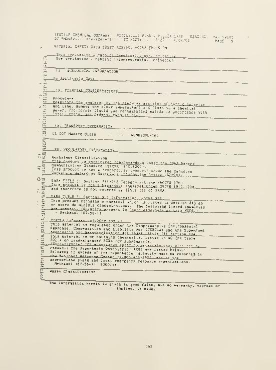
TEXTILE CHcMICAl. CO^'.?A^^ POTTSV; L.E rIKE i h'JL-Hrc PHONE;... o; v>-92is.Mi;i 7C flsosj . .s^tt"
1A-5R:.^L S.'.-ETV DAT.^ sheet .AC^YSOL iO?>iA EflUL-^.Tnm
I;. Ey* trrliation - rabbU: Inconsequenriai irrlt,.ition
12. tOOLUClCAL iNrOR.iATluN
No Ac.
»
1 i i:_a!i_l » ".i r ;i
.)_?,-- CISf?OaAL_rjlitSJ.DEP.ATIONS_
U_' Procitil»r»
•"S. CodZMjjJ.t t ,1g gn' ;', ffi_or'. Oy -.n; yiepvi^P pr-.r^^n of f-rriccrUor. ;:i, ana iime. Remove \X^-. cl<r«r 3.jpr:rnd!.anT. if.c riusTT-.o'a (.h*n.u'.ji
Ifl11, 'RAN5.£QfiI I NFOR-rATrON
z2 l^'S DOT Hazard Class nunkegulated
iCiiL? .TO. ?;'_!. »J F.0?.SAT'n 5!_
':li Workplace Claisif lean on
^7y-i-S-P-Coa^C-t : cnnii cierPd nnn -hanarrio .,^ >J n d : i^Jthfi_a5 rlAJiaj- a - d
., ;i Comraijn-.cation Standard '.29CFR 1910. i:ob)."
" ^ .^"'.^ product 15 not a ' cor.'.ro i ed product' unoer the Car.^aiar.; -^r^pi »<-; n..;jX!Jous rUvsjLljI i I :if cr^^ t -.on .Sv?;t?.-j : L'H?1[':j
__ J.JT.1 .. ,1. s...>or> ?n/3i2 Cat-?2ori3,3tiop; ("OCrR 3701-: *-O.^J-J.''-flJug!. 13 not => ha:^^--^n p. - htm^C 3X_and^ 29 CFR 1910 : 700
,
._ _ and ther.rore is not covered by Title III of SARA."
7*—SARA TlTi; "v 5TTiQn ,?i)1 nr^LCm3ja.iij_L"QCE.B-aZ2J
_ Thi J product contains a cnemical which is listed In Section 315 .at_ or above de raininiis concentr itions. Th^ fuiiowmg listed chemic— a rf pr'^tT' —Lai^ n.Ul.^_pr.eaen t. .ia rour.fi .^i-^y h.^-? p- t,.-: ; --__,>;5"3__;
ti r'F?r! A rr. rr>--n»' - qn f UOTFP TO? u;li This material i, reeulated under the ComprenensTve eIiv fronisental_ Response. Compensation and Liability Act (CERCLA) and the SuperfundAiinntlB-nT
, n inn Br.xu:tJiariiza.tAo.i-act_l.SARA i r^r. |. ,,, ^o.- ; pj_ijvj-• ihi3 material is or contains themicai '.s ) listed m i-O Z??, Taol-"rt '^i,'
°'" "°"'i'^''2"'3t.ed nCRA ;Cn Substance;?;.
il reused.; The .'Jeporr-sSle Oui.-M ty (^^"^RqT^^re 1 isled'bero-."
•- ,!''u'*''" «''*59 or it, reportable quantity must ne reooi-ted to
75;' - hf flliirmnwl ffr'rnnn^r ren-tarL_(.L^aQ^k2ii-SSQ 7 ) inri t n -h,appropriate state and local eoergency response orgsnizations.
lZ netnanol (67-56-1) SOOOibs.
p Uaste Classification
The inrorwatlon herem is given in good faith, but no w.rraniy, express orimplied, is made.
TEXTILE C'-:E^:CAL COr-PANV PCTTSViL.E FIKE i hoLLES LA,\'= .'.Enj-N'o
TC FHONE*... s-0-9;f-u:5i il MSi?S-s . . .3':" u/Oo/rr
MATCkIAL safety 2ATA SHEET ACKY'OL SOiSA EJ'.l.'LS :0,1
rr 3
—
'^»f -a • n-^ -a.'ulf £.0 -'•»-»-'' Tin r p - 1°' n - riinrl.
!' does no^ ra^et RCRA' s ch^racler islic deT ; .-li t. ion of i ir.itat; i i ty .
Li; corrosi -/iiy, or re-acLivity, anC i^ not l;st-a ;r. "C CTR ;61.33.
-i oy tne Toxicity Cnarac teris'.i !cnine Kroceuure
'.]n-. •^,1 '•.r-t'f'
:; proiuc- s.-s • ?. cospi : i.ic- w;t!; th; i.i"!or tti* U.S. Tor.lc Substiincea Control Act
3.t3in:e I ay.ajil.ocy — ,
r-i

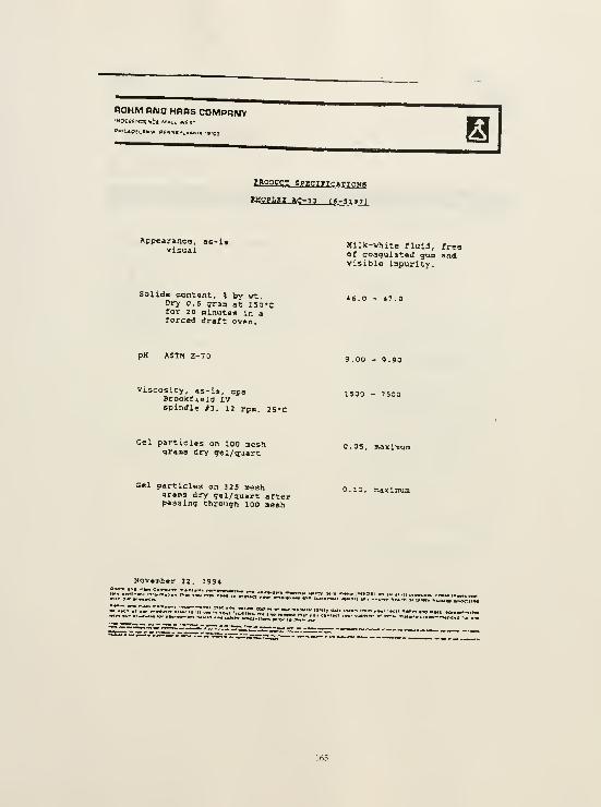
ROHM HMD HOBS COMPRIUY'"OCBfNCTNCS Man. WES' 3
Appearance, as-isvisual
Mil)c-white fluid, freeof coagulated gua andvisible impurity.
SolldE content, i by vt.Dry O.S graa at ISO'Cfor 20 minutea in aforced draft oven.
46.0 - 47.0
pH ASTM E-70 9.00 - 9.90
Viscosity, as-is, cpaBrooKfieid LVspindle ^3, 12 rpn, 25»c
1500 - 7500
Gel particles on 100 neshgraas dry gei/quart
O.OS, maxlTBun
Gel particles on 325 neshgrama dry gal/quart afterpassing through lOO mesh
O.ia, sixisma
November 22. 199«

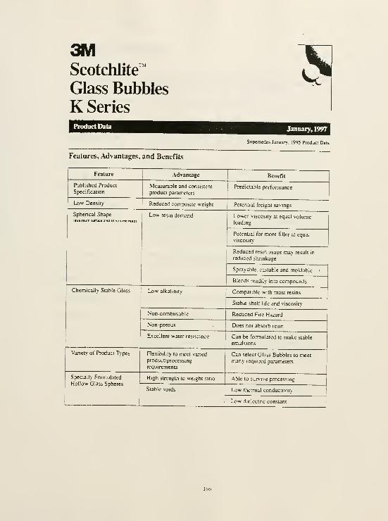
3MScotchlite™
Glass Bubbles
K Series
sProduct Data January, 1997
Supersedes January. 1995 Product Data
Features, Advantages, and Benefits
Feature
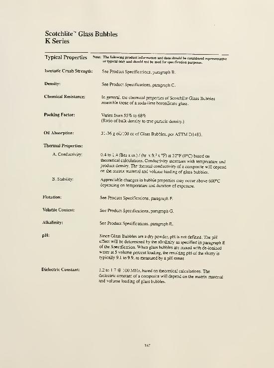
Scotchlite"' Glass BubblesK Series
Typical Properties Note: The foUowlng product information and dau should be considered represenutiveor typical oniy and shouJd not be used for specificadon purposes.
Isostatic Crush Strength: See Product Specifications, paragraph B.
Density:
Chemical Resistance:
Packing Factor:
Oil Absorption:
Thermal Properties:
A. Conductivity:
B. Stability:
Flotation:
Volatile Content:
Alkalinity:
pH:
Dielectric Constant:
See Product Specifications, paragraph C.
In general, the chemical properties of Scotchlite Glass Bubblesresemble those of a soda-Lime borosilicate glass.
Varies from 55% to 68%(Ratio of bulk density to true particle density.)
31-36 g oiyiOO cc of Glass Bubbles, per ASTM D1483.
0.4 to 1 .4 (Btu X in.) / (hr. x ft.= x °F) at 32°F (0°C) based ontheoretical calculations. Conductivity increases with temperature andproduct density. The thermal conductivity of a composite will dependon the matrix material and volume loading of glass bubbles.
Appreciable changes in bubble propemes may occur above 600°Cdepending on temperature and duration of exposure.
See Product Specifications, paragraph F.
See Product Specifications, paragraph G.
See Product Specifications, paragraph E.
Since Glass Bubbles are a dry powder, pH is not defined. The pHeffect will be determined by the alkalmity as specified in paragraph Eof the Specification. When glass bubbles are mixed with de-iomzedwater at 5 volume percent loading, the resultmg pH of the slurry is
typically 9.1 to 9.9, as measured by a pH meter.
1 2 to 1 .7 @ 100 MHz, based on theoretical calculations. Thedielectnc constant of a composite will depend on the matrix matenaiand volume loadmg of glass bubbles.
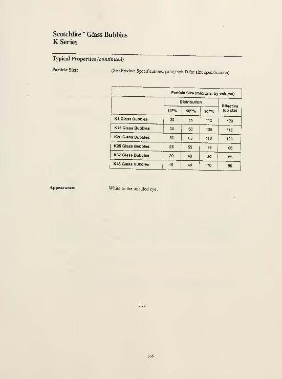
Scotchlite™ Glass BubblesK Series
Typical Properties (continued)
Particle Size: (See Product Specifications, paragraph D for size specification)

Scotchlite''
K Series
Glass Bubbles
Product Specifications
This specification covers hollow, unicellular glass rmcrospheres, hereafter referred to as Glass
Bubbles. Glass Bubbles are composed of a water resistant and chemically stable soda-lime-
borosilicate glass.
Requirements:
A representative sample of Glass Bubbles will conform to the foUowmg requirements:
A. Isostatic Crush Strength:
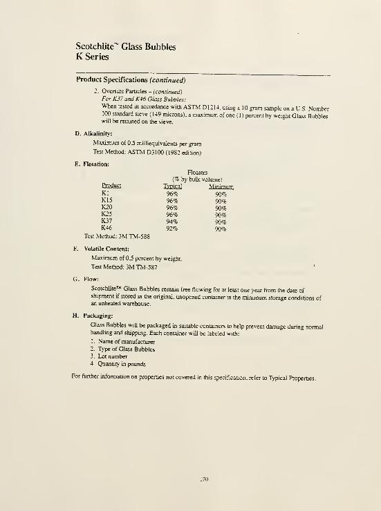
Scotchlite™ Glass BubblesK Series
Product Specifications (continued)
2. Oversize Particles - (continued)
For K37 and K46 Glass Bubbles:
When tested in accordance with ASTM D1214. using a 10 gram sample on a U.S. Number100 standard sieve (149 microns), a maximum of one (1) percent by weight Glass Bubbleswill be retamed on the sieve.
D. Alkalinity:
Maximum of J miUiequivalents per gram
Test Method: ASTM D3 100 (1982 edition)
E. Flotation:
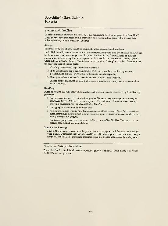
Scotchlite^ Glass Bubbles
K Series
Storage and Handling
To help ensure ease of storage and handling while maintaining free flowing properaes, ScotchUte""
Glass Bubbles have been niade from a chemically stable glass and are packaged in a heavy duty
polyethylene bag within a cardboard container.
Storage:
Minimum storage condinons should be unopened cartons in an unheated warehouse.
Under high humidity condiQons with the ambient temperanire cycling over a wide range, moisture canbe drawn into the bag as the temperature drops and the air contracts. The result may be moisture
condensation within the bag. Extended exposure to these conditions may result m "calang" of the
Glass Bubbles to vanous degrees. To minimize the potenQal for '"caicing" and prolong the storage life,
the following suggestions are made:
1
.
Carefully re-ne opened bags unmediately after use.
2. If the polyethylene bag is punctured durmg shippmg or handling, use this bag as soon as
possible, patch the hole, or uisert the contents mto an undamaged bag.
3. Durmg hurmd summer months, store in the dnest, coolest space available.
4 If good storage condioons are unavailable, carry a minimum mventory. and process on a first
in/fiist out basis.
Handling:
Dustmg problems that may occur while handling and processmg can be minimized by the foUowmgprocedures:
1 For eye protection wear chemical safety goggles. For respu^tory system protection wear an
appropriate NIOSH/MSHA approved respirator. (For additional information about personal
protecave equipment, refer to .Material Safety Data Sheet.)
2. Use appropnate ventilation m the work area.
3. PneumaDc conveyor systems have been used successfully to transport Glass Bubbles without
dustmg from shippmg containers to batch mixing equipment. Staac elirmnators should be used
to help prevent static charges.
Diaphragm pumps have been used successfully to convey Glass Bubbles. Vendors should be
consulted for specific recommendations.
Glass Bubble Breakage:
Glass bubble breakage may occur if the product is improperly processed. To minimize breakage,
avoid high shear processes such as high speed Cowels Dissolvers. point contact shear such as gear
pumps or 3-roll mills, and processmg pressures above the strength test pressure for each product.
Health and Safety Information
For product Health and Safety Information, refer to product label and .Matenal Safety Data Sheet
(MSDS) before using product.
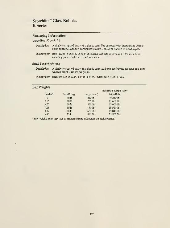
Scotchlite™ Glass Bubbles
K Series
Packaging Information
Large Box (50 cubk ft.)
DescripQon: A single corrugated box with a plastic liner. Top enclosed with interlocking double
cover banded. Bottom is normal box closure, entire box banded to wooden pallet.
Dimensions: Box ID. of 48 in. x 42 m. x 44 m. overall load size is 48V4 in. x 42Va in. x 50 in.
including pallet. Pallet size is 42 m. x 48 in.
Small Box (10 cubic ft.)
Description: A single corrugated box with a plastic liner. All boxes are bjuided together and to the
wooden pallet. 4 Boxes per pallet.
Dimensions: Eac
Scotchlite"^
K Series
Glass Bubbles
For Additional
Information or
Sales Assistance
3M SpccialtT Additives
l-800-367-a905 • Fax 612-736-1133In Canada. 1-8OO-410-68S0, Ext 6019.
In Pueno Hico. 809-750-3000,
Important Notice TTie staiwnefits ana tectmcaJ intonnaoon pressmea here are based o<i issts ana data »»nic3i 3M oeiievasto be reiiaWe, but ffie accuracy w compteteoess of sucti statenients and fecnmcai information is notguaranteed. 3M MAKES NO WARRANTIES, EXPRESS OR IMPUED. INCLUDING, BUT NOT UMITEDTO, ANY IMPUED WARRANTY OF MEBCHANTAfllUTY OR FITNESS FOR A PARTICULARPDRPOSE, User 19 resoonsib*e tor deterrnining wtietnef the 3M product is ftt tor a particular purpose andsujtaDie tor user's rnetnod ot appttcation.
Limitation of Remediesand Liability
If the 3M product is proved to be defective, THE EXCLUSIVE REMEDY. AT 3M-S OPTION. SHALL BETO REFUND THE PURCHASE PRICE OF OR TO REPAIR OR REPb*CE THE DEFECTIVE 3MPRODUCT, 3M snail not otfierwae be liable ft>r loss or damages, wfielhef direct, indirect. speciaJ,
incMjeotai. or consequenoaj, regardless ot ttie legal theory asserted, inctuoing negligence, warranty, orstnct llabilrty.
3MSpecialty Additives
3MC£mCT, BIdg rO-8E-04PC Box 33220Si. Paul..MN 53 133-3220
RfcvcUd Paptr
40% pre-consumgr
10% posi-consumer S3M '9»« 70-0702-0182-0

11.0 SELECTED BIBLIOGRAPHY

SELECTED BIBLIOGRAPHY
Argumedo, R.S. "Mural Painting on Adobe Walls During Peruvian Colonial Times - Its
Restoration and Conservation." Case Studies m the Coiisenmttou of Stone and Wall
Panitings N.S. Brommelle and P. Smith eds. International Institute for Conservation of
Historic and Artistic Works: London, 1986.
Atzeni, Cirillo; Cabiddu, Maria Grazia; Massidda, Luigi; and Sanna, Ulrico. "The Use of
'Stabilized Earth' in the Conservation of Megalithic Monuments." Conservation and
Management ofArchaeological Sites, 1:161-168.
Bohnert, Allen. "The Preservation of Prehistoric Mud Plaster at Mesa Verde National Park."
6th International Conference on the Conscnrntion of Earthen Architecture: Adobe 90
preprints: October 24-19, 1990, Las Cnices, Neiv Mexico, USA Getty Conservation
Institute: Los Angeles, 1990
Boustead, W. "The Conservation of Works of Art in Tropical and Sub-Tropical Zones." Recent
li; Co)ist'rz'af((i« G. Thomson ed. Butterworths: London, 1963.
Brommelle, N.S. and Smith, P. eds. Case Studies in the Conservation of Stone and Wall Paintings;
Preprints of the Contnbutions to the Bologna Congress, 21-26 September 1986. IIC:
London, 1986.
Bullock, P. et al. Handbook for Soil Thin Section Description. Waine Research Publications:
England, 1985.
Butterbaugh, D.J. and Pigott, V.C. "MASCA Mudbrick/ Adobe Conservation Interim
Report." Third International S]fmposium on Mudbnck (adobe) Preservation. ICOM &ICOMOS: Ankara, 1980.
Butts, George T. "Polyvinyl Acetate Copolymers for Adhesives." Adliesives Age 1 (1959): 20-24.
Chiari, Giacomo. "Treatment of Adobe Friezes in Peru." Tliird International Symposium on
Mudbrick (adobe) Presenmtion. ICOM & ICOMOS: Ankara, 1980.
Clemensen, A. Berle. A Centennial Histon/ of the First Prehistoric Reseri'c: 1892-1992. United
States Department of the Interior/ National Park Service, 1992.
Conservation Unit. Science for Coiisennitors, vol. 1, An Introduction to Materials. Conservation
Science Teaching Series. The Conservation Unit of the Museums & Galleries
Commission in conjunction with Routledge: London, 1992

. Science for Conservators, vol. 3, Adhesives and Coatings. Conservation Science TeachingSeries. The Conservation Unit of the Museums & Galleries Commission mconjunction with Routledge: London, 1992.
Court^', Marie Agnes; Goldberg, Paul; Macphail, Richard. Soils and Micromorpholog]/ in
Archaeology/. Cambridge University Press: Cambridge, 1989.
Gushing, Frank H. "Itinerary of Reconnaissance to Casa Grande Ruins, December 31, 1887 to
January 4, 1888." journal of the Southwest Joseph Carleton Wilder ed. 37 (1995):591-604.
Del Bono, Elisa. "Characterization and Analysis of the Caliche Walls of the 'Great House,'
Casa Grande Ruins National Monument, Casa Grande, Arizona." Master's thesis,
University of Pennsylvania, 1999.
Dix, Linnea. "Characterization and Analysis of Prehistoric Earthen Plasters, Mortars, andPaints from Mug House Mesa Verde National Park Colorado." Master's thesis.
University of Pennsylvania, 1997.
Down, J.L.; MacDonald, M.A.; Tetreault, J.; and Williams R.S. "Adhesive Testing at the
Canadian Conservation Institute - An Evaluation of Selected Poly (vinyl acetate) andAcrylic Adhesives." Studies in Conservation 41 (1996): 9-45.
Feller, Robert. "New Solvent-Type Varnishes." Recent Advances m Conservation. G. Thomsoned. Butterworths: London, 1963.
Feller, Robert L.; Stolow, Nathan; and Jones, Elizabeth H. On Picture Varntslies and Their
Solvents rev. and enlarged ed. National Gallery of Art: Washington, 1985.
Fewkes, J. Walter. "On the Present Condition of a Ruin in Arizona Called Casa Grande." Ajournal ofAmerican Ethnolog]/ and Archaeology II: 178-193.
Gettens, Rutherford. "Polymerized Vinyl Acetate and Related Compounds in the Restoration
of Objects of Art." Technical Studies in the Field of the Fine Arts. IV (1935):15-28.
Gettens, Rutherford and Stout, George. Painting Materials; A Short Encyclopaedia DoverPublications Inc.: New York, 1966.
Gift, Andrea. "Casa Grande a Preliminary Structural Review"(unpublished graduate paper).
University of Pennsylvania.
Glusker, Donald. Research Associate for the Museum Applied Science Center for
Archaeology, University of Pennsylvania. Interview by author, 17 January 1998.
Hartzler, Robert. Acnjlic-Modified Earthen Mortar. United States National Park Service,
Department of the Interior: Santa Fe, 1996.
Horie, C.V. Materials for Conservation. Butterworth-Heinemann Ltd.: Oxford, 1995.
Jones, Elizabeth H. "The Effect of Aging and Re-forming on the Ease of Solubihty of Certain
Resins." Recent Advances m Conservation. G. Thomson ed. Butterworths: London,1963.
Kriegh, James D. and Sultan, Hassan. "Final Report, Feasibility Study in Adobe Preservation:
Casa Grande National Monument and Fort Bowie National Historic Site."
(unpublished report) Tucson: University of Arizona, College of Engineering, 1974.
. "Restoration and Preservation of the Casa Grande Ruins." (unpublished report)
Tucson: University of Arizona, College of Engineering, 1974.
Kiihn, H. Conservation and Restoration of Works of Art and Antiquities vol. 1 A. Trone trans.
Butterworths: London, 1986.
Landrock, Arthur H. Adhesives Technologx/ Handbook. Noyes Publications: New Jersey, 1985.
Li, Agnew and Lin. "Chemical Consolidation of Conglomerate and Sand at the MogaoGrottoes." Conservation of Ancient Sites on the Silk Road N. Agnew ed. Getty
Conservation Institute: Los Angeles, 1997.
Lide, D. R. ed. CRC Handbook of Chemistn/ and Physics, 75"' edition. CRC Press: Boca Raton,
1994.
Luk, C; Neuman, I.; Martin, J.; Berry, C.K.; and Greenfield, J. "The Treatment of Two Chinese
Wall Painting Fragments." Conservation of Ancient Sites on the Silk Road N. Agnew ed.
Getty Conservation Institute: Los Angeles, 1997.
Matero, Frank. "Documentation and Assessment of Wall Conditions The Casa Grande, CasaGrande Ruins National Monument." Conservation and Management of Archaeological
Sites, in press.
Matero, Frank and Bass, Angelyn. "Design and Evaluation of Hydraulic Lime Grouts for the
Reattachment of Lime Plasters on Earthen Walls." Conservation and Management of
Archaeological Sites, 1:97-108.
Melbourne, Dawn M. "A Comparative Study of Epoxide Resin and Cementitious Grouts for
the Delamination of Sandstone at EI Morro National Monument, New Mexico,"
Master's thesis. University of Pennsylvania, 1994.

Mindeleff, Cosmos. "The Repair of Casa Grande Ruin, Arizona, in 1891." In Smithsonian
Institution. Bureau of American Ethnology. Annual Report. U.S. Government Printing
Office: Washington, 1897.
Murray, J.A. Letter to Lee S. Trainor June 21 1933 re: plaster from Casea [sic] Grande Ruins,
Arizona. In Southwestern Monuments Monthly Report. United States Department of the
Interior, August 1940.
Nichipor, Alexander A. "A Guide to the Formulation of Successful Emulsion Adhesives."
Adhcsivcs Age 1 (1958): 16-20.
Phillips, Morgan. "Adhesives for the Reattachment of Loose Plaster." APT Bulletin 12:37-63.
. "Experiences in the Use of Plaster Adhesives." Conscnrntion of Ancient Sites on the
Silk Road N. Agnew ed. Getty Conservation Institute: Los Angeles, 1997.
Pinkley, Frank. "Rums Talk Casa Grande National Monument." 1938-1939.
Pinkley, Frank and Pinkley, Edna Townsley. The Casa Grande National Monument in Arizona.
n.p.,1931.
Rohm and Haas. "AcrysoP 6038A." Rohm and Haas, 1992.
. "Rhoplex- E-330 Cement Mortar Modifier." Rohm and Haas, 1995.
Roy, D.M. and Langton, C.A. "Longevity of Borehole and Shaft Sealing Materials:
Characterization of Cement-Based Ancient Building Materials." Materials Research
Laboratory, Pennsylvania State University: University Park, Pennsylvania, 1980.
Schwartzbaum, Paul M. "The Conservation and Restoration of the Fire-Damaged Paintings of
the Dome of the AI Aqsa Mosque, Jerusalem" In International Symposium on the
'Conservation and Restoration of Cultural Property November 18-21, 19S5, Tokyo, japan
Organizing Committee of the International Symposium on the Conservation and
Restoration of Cultural Property: Tokyo, 1985.
. "The ICCROM Project for Conservation of Mural Pamtings \n the Rock Churches of
the Goreme Valley (1971-1983)." The Safeguard of the Rock-Hewn Churches of the Goreme
Valley. ICCROM: Rome, 1995.
Selwitz, Charles. "Saving the Fort Selden Ruins: the Use of a Composite Blend of Chemicals
to Stabilize Fragile Historic Adobe." Consen>ation and Management of Archaeological
Sites, l:W9-Ub.

Selwitz, Charles and Thomas J. Caperton. "Chemical Stabilization of Adobe in the Restoration
of the Montafio Store." APT Bulletin 26 (1995):37-41.
Silver, Constance S. "Architectural Finishes of the Prehistoric Southwest: A Study of the
Cultural Resource and Prospects for its Conservation " 1987 Unpublished report.
Philadelphia. University of Pennsylvania. Architectural Conservation Laboratory.
. "The Conservation of Tempera Mural Paintings and Architectural Finishes."
Consenrntiou of Ancient Sites on the Silk Road N. Agnew ed. Getty Conservation
Institute: Los Angeles, 1997.
Skeist, Irving, ed. Handbook of Adhesives, third edition. Van Nostrand Reinhold: New York,
1990.
Smith, Watson. "Kiva Mural Decorations at Awatovi and Kawaika-a; with a Survey of Other
Wall Paintings in the Pueblo Southwest." In Papers of the Peabody Museum ofAmerican
Archaeology and Ethnology, Harvard Universit]/ vol. XXXVII. Peabody Museum of
American Archaeology and Ethnology, Harvard University: Cambridge,
Massachusetts, 1952.
Soil Resources, Management and Conservation Service Land and Water DevelopmentDivision. "Soil Survey Investigations for Irrigation." FAO Soils Bulletin. Food andAgriculture Organization of the United Nations: Rome, 1979.
Southern Arizona Testing Laboratory. "Investigation and Study of Materials; Casa GrandeRuins National Monument." (unpublished study) prepared for United States
Department of the Interior National Park Service Arizona Archeological Center. 1973.
Southwestern National Monuments Ruins Stabilization Unit. Stabilization Record Compound A,
Casa Grande National Monument, Coolidge, Arizona. June 1956.
Taylor, Michael. "An Evaluation of the New Mexico State Monuments Adobe Test Walls at
Fort Selden." Sixth International Conference on the Conservation of Earthen Architecture
Getty Conservation Institute: Los Angeles, 1990.
Thomson, Garry. "New Picture Varnishes." Recent Advances in Consenmtion. G. Thomson ed.
Butterworths: London, 1963.
UNESCO. The Consenmtion of Cultural Property. UNESCO: Paris, 1968.
United States National Park Service. "Casa Grande Ruins National Monument Resources
Management Plan." 1996.

Wilcox, David. R. and Shenk, Lynette O. "The Architecture of the Great House and Its
Interpretation" United States National Park Service: Tucson, Arizona, 1977.
Zeelan Industries, Inc. Microspheres 3M and Zeelan Industries, Inc., 1994.

12.0 INDEX

12.0 INDEX
AC-33: 53,59
Acrylic; 3, 26, 51-53, 56, 79, 111
Acrysol: 59,60,64
Adhesive bond strength; 42, 44, 70, 95
Biosusceptibility: 38, 42, 45
Brownian motion: 49
Calcite: 30,33-35
Caliche: 12, 15, 17, 18, 25, 29, 31, 33-35, 42, 70, 71, 75, 77, 79, 94, 108
Case hardening: 12
Channel voids: 27,29,34
Cohesive strength: 20, 42, 44, 45, 48, 57
CompaHbility: 9, 11, 42, 43, 47, 57, 80, 104, 112
Course: 14, 16, 53
Creep: 44-46
Darkening: 18,19
Detachment
Type A: 36-38, 40, 41, 73, 92, 110, 111
TypeB: 36-39,41,112,114
Dispersion: 46, 49, 57, 59, 69, 81, 90, 104
Emulsion: 3, 46, 49, 50-58, 67, 69, 73, 93, 105, 106, 111
Disperse phase: 49
Continuous phase: 49
Filler: 46, 48, 56, 57-59, 61, 62, 64, 66, 80-84, 89, 90, 93, 98, 103, 111, 113
Flow: 42, 46, 61-63, 65, 66, 73, 74, 76, 92-94, 104
Fumed silica: 55, 56, 59
InjecHbility: 42, 46, 48, 57-59, 61, 63, 65, 67, 92
Microballoons / Microspheres: 53, 56-59, 61, 62, 64, 80, 81, 83
Plaster: 2, 3, 18, 20- 22, 38, 52, 53, 56, 105-111, 113, 115
Point counting: 32
Polyvinyl acetate; 50-53
Primal; 53
Rhoplex E-330: 53, 54, 59, 64
Shrinkage: 16, 40, 42, 44, 46, 56-59, 61, 63, 65, 67, 69, 71, 73, 79, 84-91, 104
Stability; 7, 21, 42, 43, 50, 59, 86
Thermoplastic: 50
Thermoset; 50, 51
Thickener: 48, 58, 59, 64-66, 73, 81, 113, 115
Thixotropy; 42, 47, 57, 73, 91
Viscosit>'; 46, 55, 56, 58-60, 66, 73, 80-83, 86-88, 91, 92, 94, 106,110, 113
Wash layer: 20, 24, 25, 31- 33
Water vapor permeabilit>': 42, 45, 55, 57, 59, 62, 76, 89, 99, 113, 115
Water vapor transmission: 63, 76, 98, 100, 104


Wettability: 56,88,93,94
Working time: 42,47,92
Zone: 13, 23-25, 27, 29, 30, 31, 35


Anne & Jerome Fisher
FINE ARTS LIBRARY
University of Pennsylvania
Please return this book as soon as you have finished with
it. liunust be r^kumed by the latest date stamped,below.
FISHER
MAR 3 ] ?0G0
UNlV. Of fmMA.

N/infl/DatSl/7lbMX

![Synthesis and characterization of cassava starch graft poly(acrylic acid) and poly[(acrylic acid)-co-acrylamide] and polymer flocculants for wastewater treatment](https://img.dokumen.tips/doc/110x75/631d2b5f1c5736defb027b35/synthesis-and-characterization-of-cassava-starch-graft-polyacrylic-acid-and-polyacrylic.jpg)


