Embed Size (px)
Citation preview

Page 117
Design, Analysis and 3D Printing of Bellows Coupling
Kedarisetti Gowthami
Machine Design,
Department Mechanical Engineering,
Kakinada Institute of Engineering and Technology.
Mrs.D.Shakeena, M.Tech
Assistant Professor,
Department Mechanical Engineering,
Kakinada Institute of Engineering and Technology.
ABSTRACT:
Bellows couplings combine stainless steel bellows
and black anodized aluminum hubs to offer superior
performance in motion control applications. The
bellows are made of stainless steel, which makes them
ideal for transmitting torque. Due to the bellows' thin
walls, the coupling is able to flex easily while
remaining rigid under torsional loads. Parallel
misalignment, angular misalignment and axial motion
are accommodated by the bellows coupling. The
combination of aluminum hubs with the bellows
results in an extremely lightweight, low inertia
coupling. Zero backlashes and a long, maintenance-
free life are assured since the bellows coupling has no
moving parts. An important feature of the bellows
coupling is a balanced design to reduce vibration in
high rpm applications of up to 10,000 rpm. Bellows
couplings are especially suited for high-end servo,
stepper, encoder and positioning applications. The
present work is directed towards the modeling of
Bellows coupling in a 3D CAD tool called
SOLIDWORKS .The von misses stresses, resultant
deformation, strain and areas below factor of safety
has been displayed. The analysis was carrying out
using Finite Elements software, Meshing tools
simulation tool and Modeling on SOLIDWORKS.
This analysis is a partial work of a major project
wherein the bellows coupling will be subjected to
load by applying three different materials. Rapid
Prototyping (RP) can be defined as a group of
techniques used to quickly fabricate a scale model of
a part or assembly using three-dimensional computer
aided design (CAD) data. What is commonly
considered to be the first RP technique, Stereo-
lithography, was developed by 3D Systems of
Valencia, CA, USA. The company was founded in
1986, and since then, a number of different RP
techniques have become available. From the results
ABS material has induced more stresses i.e., 10.4Mpa
than remaining materials stainless steel and plain
carbon steel 9.5817Mpa each. But the plain carbon
steel has induced less stresses i.e. 9.58165Mpa than
its material yield strength of 220Mpa.It has generated
less stresses compared to remaining other two
materials. Even plain carbon steel material has the
less displacement compared to ABS and stainless
steel material. Therefore plain carbon steel material is
the best suitable material for BELLOWS coupling
among the other two materials namely ABS and
stainless steel. The Rapid Prototyping of Bellows
coupling has been by using FDM machine. The
Prototype has been used as pattern for limited volume
of production.
I. INTRODUCTION:
A coupling is a device used to connect two shafts
together at their ends for the purpose of transmitting
power. Couplings do not normally allow disconnection
of shafts during operation, however there are torque
limiting couplings which can slip or disconnect when
some torque limit is exceeded. The primary purpose of
couplings is to join two pieces of rotating equipment
while permitting some degree of misalignment or end
movement or both.
Page 118
By careful selection, installation and maintenance of
couplings, substantial savings can be made in reduced
maintenance costs and downtime.
BELLOWS COUPLINGS
A beam coupling, also known as helical coupling, is a
flexible coupling for transmitting torque between two
shafts while allowing for angular misalignment,
parallel offset and even axial motion, of one shaft
relative to the other. This design utilizes a single piece
of material and becomes flexible by removal of
material along a spiral path resulting in a curved
flexible beam of helical shape. Since it is made from a
single piece of material, the Beam Style coupling does
not exhibit the backlash found in some multi-piece
couplings. Another advantage of being an all machined
coupling is the possibility to incorporate features into
the final product while still keeps the single piece
integrity.
Fig.1.6.1. Bellows
I. MODELING OF BELLOWS COUPLING
For the connection of two shafts of 7mm diameter and
12mm diameter respectively Bellows coupling have
been modeled. The bellows, clamps of 7mm and
12mm have been modeled and assembled using
fasteners.
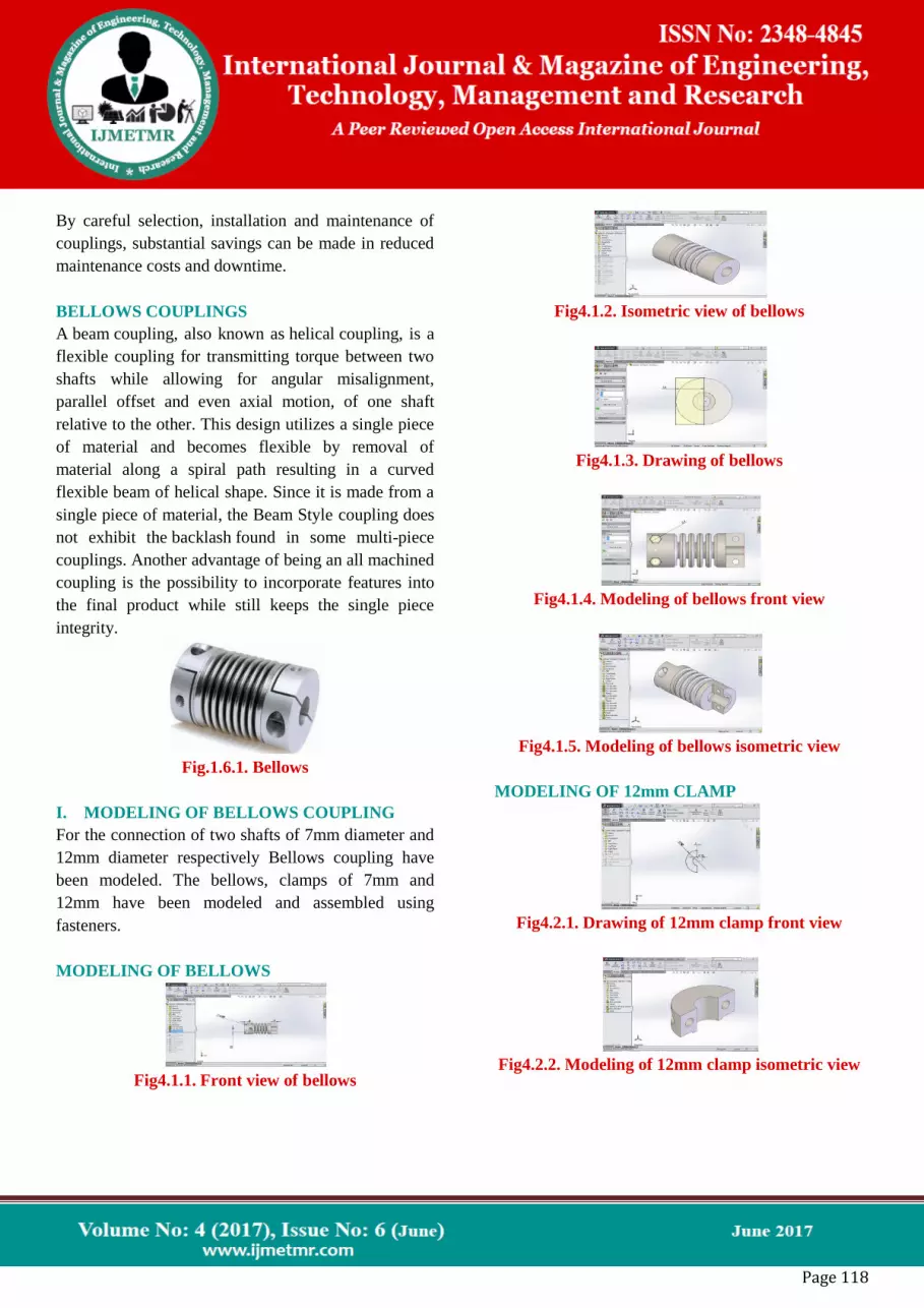
MODELING OF BELLOWS
Fig4.1.1. Front view of bellows
Fig4.1.2. Isometric view of bellows
Fig4.1.3. Drawing of bellows
Fig4.1.4. Modeling of bellows front view
Fig4.1.5. Modeling of bellows isometric view
MODELING OF 12mm CLAMP
Fig4.2.1. Drawing of 12mm clamp front view
Fig4.2.2. Modeling of 12mm clamp isometric view

Page 119
MODELING OF 7mm CLAMP
Fig4.3.1. Drawing of 7mm clamp front view
Fig 4.3.2. Modeling of 12mm clamp isometric view
MODELING OF 7mm SHAFT
Fig4.4.1. Modeling of 7mm shaft
MODELING OF 12mm SHAFT
Fig4.5.1. Modeling of 12mm shaft
ASSEMBLY OF BELLOWS COUPLING WITH
SHAFTS
Fig4.6.1. Assembly of bellows coupling with shafts
Fig4.6.2. Four views of bellows coupling with shafts
Modeling
Fig4.6.3. Four views of bellows coupling with shafts
drawing
II. STRUCTURAL AND DYNAMIC ANALYSIS
OF BELLOWS COUPLING
The structural analysis of bellows coupling is carried
by applying three different materials namely ABS,
stainless steel and plain carbon steel to bellows. The
loading condition of 20N is applied to the bellows for
three materials and will select the best performing
material among them.

Page 120
STRUCTURAL ANALYSIS OF BELLOWS
COUPLING BY APPLYING PLAIN CARBON
STEEL MATERIAL TO BELLOWS
Page 121
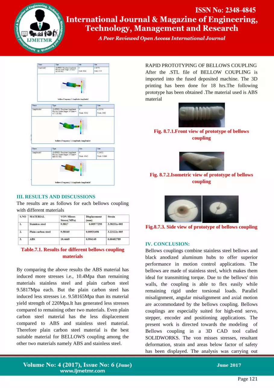
III. RESULTS AND DISCUSSIONS
The results are as follows for each bellows coupling
with different materials
Table.7.1. Results for different bellows coupling
materials
By comparing the above results the ABS material has
induced more stresses i.e., 10.4Mpa than remaining
materials stainless steel and plain carbon steel
9.5817Mpa each. But the plain carbon steel has
induced less stresses i.e. 9.58165Mpa than its material
yield strength of 220Mpa.It has generated less stresses
compared to remaining other two materials. Even plain
carbon steel material has the less displacement
compared to ABS and stainless steel material.
Therefore plain carbon steel material is the best
suitable material for BELLOWS coupling among the
other two materials namely ABS and stainless steel.
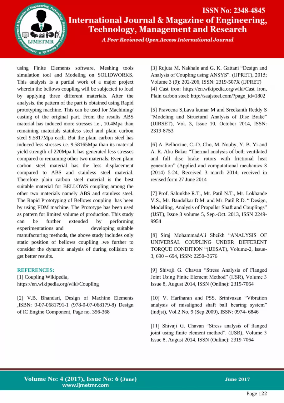
RAPID PROTOTYPING OF BELLOWS COUPLING
After the .STL file of BELLOW COUPLING is
imported into the fused deposited machine. The 3D
printing has been done for 18 hrs.The following
prototype has been obtained .The material used is ABS
material
Fig. 8.7.1.Front view of prototype of bellows
coupling
Fig. 8.7.2.Isometric view of prototype of bellows
coupling
Fig.8.7.3. Side view of prototype of bellows coupling
IV. CONCLUSION:
Bellows couplings combine stainless steel bellows and
black anodized aluminum hubs to offer superior
performance in motion control applications. The
bellows are made of stainless steel, which makes them
ideal for transmitting torque. Due to the bellows' thin
walls, the coupling is able to flex easily while
remaining rigid under torsional loads. Parallel
misalignment, angular misalignment and axial motion
are accommodated by the bellows coupling. Bellows
couplings are especially suited for high-end servo,
stepper, encoder and positioning applications. The
present work is directed towards the modeling of
Bellows coupling in a 3D CAD tool called
SOLIDWORKS. The von misses stresses, resultant
deformation, strain and areas below factor of safety
has been displayed. The analysis was carrying out
Page 122
using Finite Elements software, Meshing tools
simulation tool and Modeling on SOLIDWORKS.
This analysis is a partial work of a major project
wherein the bellows coupling will be subjected to load
by applying three different materials. After the
analysis, the pattern of the part is obtained using Rapid
prototyping machine. This can be used for Machining/
casting of the original part. From the results ABS
material has induced more stresses i.e., 10.4Mpa than
remaining materials stainless steel and plain carbon
steel 9.5817Mpa each. But the plain carbon steel has
induced less stresses i.e. 9.58165Mpa than its material
yield strength of 220Mpa.It has generated less stresses
compared to remaining other two materials. Even plain
carbon steel material has the less displacement
compared to ABS and stainless steel material.
Therefore plain carbon steel material is the best
suitable material for BELLOWS coupling among the
other two materials namely ABS and stainless steel.
The Rapid Prototyping of Bellows coupling has been
by using FDM machine. The Prototype has been used
as pattern for limited volume of production. This study
can be further extended by performing
experimentations and developing suitable
manufacturing methods, the above study includes only
static position of bellows couplling .we further to
consider the dynamic analysis of during collision to
get better results.
REFERENCES:
[1] Coupling Wikipedia,
https://en.wikipedia.org/wiki/Coupling
[2] V.B. Bhandari, Design of Machine Elements
,ISBN: 0-07-0681791-1 (978-0-07-068179-8) Design
of IC Engine Component, Page no. 356-368
[3] Rujuta M. Nakhale and G. K. Gattani “Design and
Analysis of Coupling using ANSYS”. (IJPRET), 2015;
Volume 3 (9): 202-206, ISSN: 2319-507X (IJPRET)
[4] Cast iron: https://en.wikipedia.org/wiki/Cast_iron,
Plain carbon steel: http://saajsteel.com/?page_id=1802
[5] Praveena S,Lava kumar M and Sreekanth Reddy S
“Modeling and Structural Analysis of Disc Brake”
(IJIRSET), Vol. 3, Issue 10, October 2014, ISSN:
2319-8753
[6] A. Belhocine, C.-D. Cho, M. Nouby, Y. B. Yi and
A. R. Abu Bakar “Thermal analysis of both ventilated
and full disc brake rotors with frictional heat
generation” (Applied and computational mechanics 8
(2014) 5-24, Received 3 march 2014; received in
revised form 27 June 2014
[7] Prof. Salunkhe R.T., Mr. Patil N.T., Mr. Lokhande
V.S., Mr. Bandelkar D.M. and Mr. Patil R.D. “ Design,
Modelling, Analysis of Propeller Shaft and Couplings”
(IJST), Issue 3 volume 5, Sep.-Oct. 2013, ISSN 2249-
9954
[8] Siraj MohammadAli Sheikh “ANALYSIS OF
UNIVERSAL COUPLING UNDER DIFFERENT
TORQUE CONDITION “(IJESAT), Volume-2, Issue-
3, 690 – 694, ISSN: 2250–3676
[9] Shivaji G. Chavan “Stress Analysis of Flanged
Joint Using Finite Element Method” (IJSR), Volume 3
Issue 8, August 2014, ISSN (Online): 2319-7064
[10] V. Hariharan and PSS. Srinivasan “Vibration
analysis of misaligned shaft ball bearing system”
(indjst), Vol.2 No. 9 (Sep 2009), ISSN: 0974- 6846
[11] Shivaji G. Chavan “Stress analysis of flanged
joint using finite element method”. (IJSR), Volume 3
Issue 8, August 2014, ISSN (Online): 2319-7064

Page 123
[12] Kondru Nagendra Babu and Dr. D Sunnel
“Failure analysis of flange coupling with two different
materials”. (IJERT), Vol. 4 Issue 04, April- 2015,
ISSN: 2278-0181
[13] V. G. Vijaya “Analysis of rigid flange coupling”.
(IJIRSET), ISO 3297: 2007, Vol. 2, Issue 12,
December 2013, ISSN: 2319-8753
[14] P.C. Gope, Machine Design Fundamentals and
Application, Page 687-694 [15] V.B. Bhandari,
Machine Design Data Book, ISBN: 93-5134-284-0
(978-93-5134-284-7) Chapter 9.6 Coupling
[15]Boyle, B. (2008). "Tracking the causes of coupling
failure". Plantservices.com. Retrieved 7
January 2015. Explore coupling maintenance and the
telltale signs of failure to maximize coupling life and
ensure reliable system operation.


