Embed Size (px)
Citation preview
Democratic Socialist Republic of Sri Lanka Telecommunications Regulatory Commission
Special Assistance for Project
Implementation of Digitalization of
Terrestrial Television Broadcasting Project
in
the Democratic Socialist Republic of Sri Lanka
Final Report
August 2018
Japan International Cooperation Agency
Yachiyo Engineering Co., Ltd.
EI
JR
18-058
Democratic Socialist Republic of Sri Lanka Telecommunications Regulatory Commission
Special Assistance for Project Implementation of Digitalization of
Terrestrial Television Broadcasting Project in the Democratic Socialist Republic of Sri Lanka
Final Report
August 2018
Japan International Cooperation Agency
Yachiyo Engineering Co., Ltd.
Contents
Background and outline of the survey .................................................................................. 1-1 Outline of migration into DTTB in Sri Lanka ................................................................... 1-1 Background of dispatching JICA Survey Team ................................................................ 1-2 JICA Survey Team experts/members ................................................................................. 1-3 Survey schedule ................................................................................................................... 1-4 Surveyed organisations ........................................................................................................ 1-6
Governmental agencies ..................................................................................................... 1-6 Terrestrial broadcasting stations ....................................................................................... 1-7 DBNO foundation support .................................................................................................... 2-1
Status of examination of government policies for DBNO foundation and private broadcasters' intention of participation .................................................................................................. 2-1
Status of examination of government policies ................................................................ 2-1 Private broadcasters' intention of participation ................................................................ 2-4
Organisational structure and staff plan of DBNO .............................................................. 2-5 Service forms (forms of participation by private broadcasters, procurement of
equipment, and operation method) .................................................................................................... 2-5 Personnel plan of DBNO .................................................................................................. 2-9 Re-examination of DBNO operational expenses .......................................................... 2-11 Usage fees and financial analysis ................................................................................... 2-22
Examination of solvency of private broadcasters ............................................................ 2-24 Revenue status of broadcasters in Sri Lanka ................................................................. 2-24 Scale of advertising market of Sri Lanka ....................................................................... 2-26 Religious broadcasters .................................................................................................... 2-27 Capacity to Pay DBNO Usage Charges ........................................................................ 2-28 Formulation of draft for technical standards for transmitter and receiver .......................... 3-1
Formulation of Draft for technical standards for transmitter and receiver ....................... 3-1 Policy for creating technical standards ............................................................................. 3-1 Method of creation ............................................................................................................ 3-1 Comments from Sri Lankan side ...................................................................................... 3-5 Characteristics of the draft for technical standards (summary) ...................................... 3-6
Formulation of draft of STB technical specifications ...................................................... 3-12 Policy for creating draft of STB technical specifications ............................................. 3-12 Method for creation ......................................................................................................... 3-12 Comments from Sri Lankan side .................................................................................... 3-12
Producing draft of Guideline for importers ...................................................................... 3-15 Policy for creating Guideline .......................................................................................... 3-15 Organisations related to importing ................................................................................. 3-17 Outline of procedures for importing ............................................................................... 3-18 Formulation of migration plan into DTTB .......................................................................... 4-1
Overall process ..................................................................................................................... 4-1 Outline of migration plan into DTTB .............................................................................. 4-1
Work items in period A (until DSO-SD in Greater Colombo) ...................................... 4-2 Work items in period B (until DSO-SD in whole Sri Lanka) ........................................ 4-5 Work items in period C (ASO) ......................................................................................... 4-5 Work items in period D (migration into HD broadcasting) ............................................ 4-6 Possibility of assistance from Japan ................................................................................. 4-6
Band Plan ............................................................................................................................. 4-7 Channel plan ...................................................................................................................... 4-7 Programme multiplexing and channel assignment ......................................................... 4-9 Revision of channel assignment for SD broadcasting .................................................. 4-10 DSO planning .................................................................................................................. 4-26 Antenna system ............................................................................................................... 4-29 ASO planning .................................................................................................................. 4-48 Multiplexing for HD broadcasting programme ............................................................. 4-52 Channel assignment for HD broadcasting ..................................................................... 4-53 Reconsideration on transmission link ............................................................................ 4-57 Overall Band Plan ........................................................................................................... 4-68
HD Roadmap ..................................................................................................................... 4-86 HD Roadmap for state-run broadcasting stations ......................................................... 4-86 HD Roadmap for private broadcasting stations ............................................................ 4-86
Proposed investment plan for upgrade of equipment to HD broadcasting .................... 4-87 Art TV .............................................................................................................................. 4-88 Buddhist TV .................................................................................................................... 4-90 CSN .................................................................................................................................. 4-91 Derana TV ....................................................................................................................... 4-93 EAP .................................................................................................................................. 4-94 Hiru TV ............................................................................................................................ 4-96 Max TV ............................................................................................................................ 4-98 MTV ................................................................................................................................. 4-99 Rangiri TV ..................................................................................................................... 4-101 Shraddha TV .................................................................................................................. 4-103 TNL ................................................................................................................................ 4-105 VIS Broadcasting .......................................................................................................... 4-105 Voice of Asia ................................................................................................................. 4-106 Outline of HD broadcasting equipment ....................................................................... 4-107
Optimization for antenna mast of Lotus Tower ................................................................... 5-1 Outline of Lotus Tower ....................................................................................................... 5-1 Points of change from original design ................................................................................ 5-2
Outline of Tower Mast and T1 Section............................................................................ 5-2 Activities before starting survey in Sri Lanka ................................................................. 5-2 Activities in Sri Lanka ....................................................................................................... 5-2
Result of inspection on T1 Section implemented in China ............................................... 5-3
Result of inspection on T1 Section implemented at Lotus Tower .................................... 5-4 Points indicated by JICA Survey Team in previous inspection ..................................... 5-4 Confirmed points and additionally indicated points by JICA Survey Team ................. 5-4
Result of re-inspection on T1 Section and inspection on space for installation of cables 5-5 Result of re-inspection on T1 Section .............................................................................. 5-5 Result of inspection on space for installation of cables in Lotus Tower ........................ 5-5
Summary of the result of inspection of Lotus Tower ........................................................ 5-7 Recommendations on Matters to be Implemented by the Government of Sri Lanka....... 6-1
Finalisation and release of roadmap for migration into DTTB and ISDB-T technical standards 6-1
Legislation related to establishment of DBNO .................................................................. 6-2 DBNO usage fees ................................................................................................................ 6-3 Guidelines on issuance of digital terrestrial broadcasting licenses ................................... 6-4 Appropriate radio wave supervision ................................................................................... 6-5 System review of EWBS operation .................................................................................... 6-7 Consideration of Policy on dissemination of receivers, support for viewers and measures
for disadvantaged groups ....................................................................................................................... 6-7
Figures
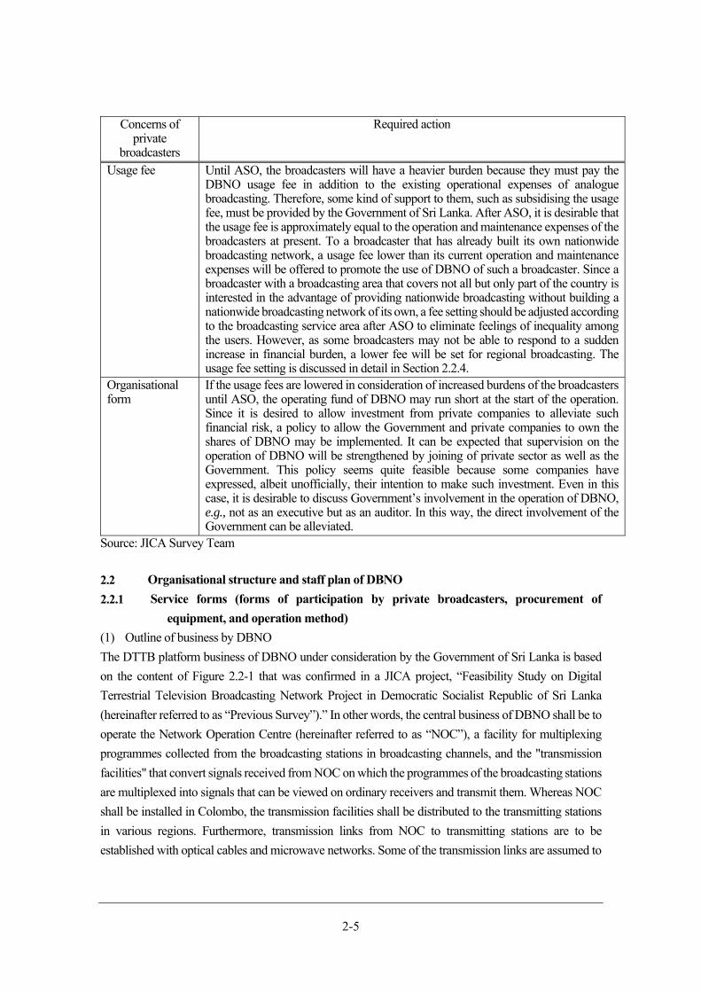
Figure 2.2-1 Outline of platform business ................................................................................................. 2-6 Figure 2.2-2 Models for the procurement of broadcasting equipment of DBNO .................................. 2-7 Figure 3.1-1 Correspondence between the individual standards used as the reference standards of the
draft for technical standards in Sri Lanka ......................................................................................... 3-4 Figure 3.3-1 Procedures for the import of STBs and relationships among relevant organisations ..... 3-18 Figure 3.3-2 Workflow of importing STBs ............................................................................................. 3-19 Figure 4.1-1 Milestones of migration into DTTB ..................................................................................... 4-1 Figure 4.2-1 Example of analogue images received through field strength of about 40dBμv/m ........ 4-23 Figure 4.2-2 Blocks for channel assignment ........................................................................................... 4-25
Figure 4.2-3 Coverage areas at each stage of DSO-SD ............................................................... 4-29 Figure 4.2-4 Policy for design of combiner ............................................................................................. 4-32 Figure 4.2-5 Procedure of ASO implementation .................................................................................... 4-51 Figure 4.2-6 Transmission link for programme transmission between each broadcaster and NOC ... 4-58 Figure 4.2-7 Interface between DBNO and telecommunication providers .......................................... 4-60 Figure 4.2-8 Interface between DBNO and telecommunication providers (Type in transmitting TS
signal of each broadcasting) ............................................................................................................. 4-61 Figure 4.2-9 Interface between transmission link of telecommunication providers and transmitting
station of DBNO ............................................................................................................................... 4-61 Figure 4.2-10 Example of device configuration for microwave link with backup route ..................... 4-62 Figure 4.2-11 Configuration of transmission link as of Previous Survey ............................................. 4-63 Figure 4.2-12 Transmission link consisting of microwave link of DBNO and LankaCom ................ 4-65 Figure 4.2-13 Case of using transmission link network of SLT ............................................................ 4-66 Figure 4.2-14 Case of using transmission link network of LankaCom ................................................. 4-67 Figure 4.2-15 Outline of municipal disaster prevention information media ......................................... 4-72 Figure 4.2-16 Conventional measures for reception ............................................................................... 4-74 Figure 4.2-17 Interference from i-dio to ILS ........................................................................................... 4-75 Figure 4.2-18 Example of interference trouble caused by 700 LTE ..................................................... 4-77 Figure 4.2-19 Experiment for interference of signal input to antenna ................................................... 4-78 Figure 4.2-20 Experiment for interference of direct signal input to equipment .................................... 4-79 Figure 4.3-1 Flow of upgrade to HD at Broadcasters which have not introduced MCR for HD
broadcasting ...................................................................................................................................... 4-86 Figure 4.3-2 Flow of upgrade to HD at Broadcasters which have installed MCR for HD broadcasting
or started upgrade ............................................................................................................................. 4-87 Figure 5.1-1 Schematic view of Lotus Tower ........................................................................................... 5-1 Figure 6.5-1 Interference outside analogue broadcasting coverage area ................................................. 6-6
Tables
Table 1.1-1 Disaster damage in Sri Lanka in Recent Years (2009 to 2017) ........................................... 1-2 Table 1.3-1 JICA Survey Team experts/members .................................................................................. 1-3 Table 1.4-1 Description of Work in Sri Lanka ........................................................................................ 1-4
Table 1.5-1 Governmental agencies with which discussion and hearing survey was conducted .......................................................................................................................................... 1-6
Table 1.5-2 Terrestrial broadcasting stations at which hearing survey was conducted .......................... 1-7 Table 1.5-3 Broadcasting-related companies at which hearing survey was conducted ......................... 1-9 Table 2.1-1 Topics to Be Examined on DBNO ....................................................................................... 2-2 Table 2.1-2 Concerns of the private broadcasters and required actions for them .................................. 2-4 Table 2.2-1 Comparison of broadcasting equipment procurement models ............................................ 2-8 Table 2.2-2 DBNO staff assignment (draft) .............................................................................................. 2-9 Table 2.2-3 Necessary number of synthesized frequencies for combiners ........................................... 2-13 Table 2.2-4 Backup method types and corresponding sites .................................................................. 2-14 Table 2.2-5 Result of recalculation of the total cost of Yen Loan Project ........................................... 2-16 Table 2.2-6 Changes of the calculation of the operational expenses from the Previous Survey ........ 2-19 Table 2.2-7 DBNO operational expenses (2020 - 2029) ....................................................................... 2-20 Table 2.2-8 Calculation of personnel fee ................................................................................................ 2-20 Table 2.2-9 Calculation of antenna tower rental fee .............................................................................. 2-21 Table 2.2-10 Transmission link usage fees ............................................................................................ 2-22 Table 2.2-11 Repayment amount for Yen Loan Project ....................................................................... 2-23 Table 2.2-12 Monthly usage fees of services (per programme) ............................................................ 2-24 Table 2.3-1 Profit-and-loss statements of four TV broadcasters in Sri Lanka (FY 2015) .................. 2-25 Table 2.3-2 Net income to sales ratios of four TV broadcasters in Sri Lanka (FY 2015) .................... 2-25 Table 2.3-3 Breakdown of sales of four TV broadcasters in Sri Lanka (FY 2015) ............................. 2-26 Table 2.3-4 Advertising market scale in Sri Lanka (2005 to 2012) ..................................................... 2-26 Table 2.3-5 Advertising revenues by broadcaster in Sri Lanka in 2016 .............................................. 2-27 Table 2.3-6 Sri Lankan religious broadcasters ....................................................................................... 2-27 Table 2.3-7 Redundant expenses after complete migration into DTTB .............................................. 2-29 Table 2.3-8 Estimated annual expenses for broadcasters ...................................................................... 2-29 Table 2.3-9 Estimated redundant expenses according to the scale of the broadcaster ........................ 2-30 Table 2.3-10 DBNO usage fees .............................................................................................................. 2-30 Table 3.1-1 Composition of the ARIB standards and the ABNT NBR and correspondence between
them ..................................................................................................................................................... 3-3 Table 3.1-2 The main comments and policies for the use of digital broadcasting obtained at the ISDB-T
Technical standards Seminar ............................................................................................................. 3-6 Table 3.1-3 Main differences in transmission parameters between the draft Sri Lanka transmission
standard and ABNT NBR 15601 ...................................................................................................... 3-8 Table 3.1-4 Modifications from ABNT NBR15602-1............................................................................. 3-8
Table 3.1-5 Video coding parameters for Full-Segment services............................................................ 3-9 Table 3.2-1 The main comment regarding the recommended STB specifications obtained at the ISDB-
T Technical Standards Seminar and policy to be used for responding to the comment .............. 3-13 Table 3.2-2 Summary of the performance and functions stated in the STB specifications (original texts
and outline explanation) ................................................................................................................... 3-14 Table 3.2-3 Summary of technical specifications for STB .................................................................... 3-14 Table 3.3-1 Duties of the relevant organisations ..................................................................................... 3-17 Table 3.3-2 Customs duty and other tax rates for import of reception apparatus ................................ 3-20 Table 4.1-1 Procedure of test broadcasting .................................................................................................. 4-4 Table 4.1-2 Estimated expense for dissemination of DTTB receivers ................................................... 4-7 Table 4.2-1 Standard values for simulation ............................................................................................... 4-8 Table 4.2-2 Outline for result of investigation regarding existing antenna tower ................................ 4-11 Table 4.2-3 Result of survey in Kanduboda ............................................................................................ 4-12 Table 4.2-4 Result of survey in Gongala ................................................................................................ 4-13 Table 4.2-5 Result of survey in Nayabedda ........................................................................................... 4-14 Table 4.2-6 Result of survey in Badulla ................................................................................................. 4-15 Table 4.2-7 Result of survey in Namunukula ........................................................................................ 4-16 Table 4.2-8 Result of survey in Madukanda .......................................................................................... 4-17 Table 4.2-9 Result of survey in Jaffna .................................................................................................... 4-18 Table 4.2-10 Result of survey in Kurunegala ......................................................................................... 4-19 Table 4.2-11 Result of survey in Hantana .............................................................................................. 4-20 Table 4.2-12 Result of survey in Elpitiya ............................................................................................... 4-21 Table 4.2-13 Result of survey in Vayuniya ............................................................................................ 4-22 Table 4.2-14 SD channel assignment during period of simultaneous broadcasting ............................. 4-24 Table 4.2-15 Comparison of nationwide broadcasting using single wave and broadcasting in blocks .. 4-
26
Table 4.2-16 DSO-SD planning in stages ........................................................................................ 4-27 Table 4.2-17 Transmitter Outputs and Sizes of Coaxial Feeder Cables ................................................ 4-33 Table 4.2-18 Remaining work items at transmitting stations ................................................................. 4-44 Table 4.2-19 Conditions for implementation of ASO (comparison with Previous Survey) ................ 4-49 Table 4.2-20 Basic parameter for transmission ....................................................................................... 4-53 Table 4.2-21 Data size per 1 programme (for each programme type) .................................................. 4-53 Table 4.2-22 Channel assignment for HD broadcasting ........................................................................ 4-54 Table 4.2-23 Overall channel assignment as of HD broadcasting ......................................................... 4-56 Table 4.2-24 Result of review regarding development of transmission link network ......................... 4-59 Table 4.2-25 Transmission standards for digital broadcasting signals in the broadcasting transmission
network .............................................................................................................................................. 4-59 Table 4.2-26 Channel and VHF bandwidth for analogue broadcasting ................................................ 4-68 Table 4.2-27 Channel and UHF bandwidth ............................................................................................ 4-69 Table 4.2-28 Frequency assigned for IMT .............................................................................................. 4-69
Table 4.2-29 Channel and digital broadcasting frequency bandwidth .................................................. 4-70 Table 4.2-30 Plan for analogue frequency digital dividend based on APT agreement ........................ 4-70 Table 4.2-31 Situation of digital dividend in Japan ................................................................................ 4-71 Table 4.2-32 Promotion activity for each method .................................................................................. 4-73 Table 4.2-33 Rough fee estimation of conventional measures for reception ........................................ 4-74 Table 4.2-34 Estimated situation of interference related to 700 LTE in Sri Lanka .............................. 4-76 Table 4.2-35 Interference troubles on TV reception facilities and others caused by 700 LTE ........... 4-76 Table 4.2-36 Unit price regarding countermeasure for common parts against interference ................ 4-80 Table 4.2-37 Unit price of materials for countermeasure against interference in Sri Lanka ............... 4-80 Table 4.2-38 Rough estimation for countermeasures against interference ........................................... 4-82 Table 4.2-39 Example of rough estimation for countermeasures against interference at detached houses
........................................................................................................................................................... 4-82 Table 4.2-40 Example of rough estimation for countermeasures against interference at facilities sharing
equipment for reception ................................................................................................................... 4-84 Table 4.4-1 Situation regarding the upgrade of existing equipment for HD broadcasting (Art TV) .. 4-88 Table 4.4-2 Condition of facilities that need to be upgraded to HD and estimates of expenses (Art TV)
........................................................................................................................................................... 4-89 Table 4.4-3 Situation regarding the upgrade of existing equipment for HD broadcasting (Buddhist TV)
........................................................................................................................................................... 4-90 Table 4.4-4 Situation regarding the upgrade of existing equipment for HD broadcasting (CSN) ...... 4-91 Table 4.4-5 Condition of facilities that need to be upgraded to HD and estimates of expenses (CSN) .. 4-
92 Table 4.4-6 Situation regarding the upgrade of existing equipment for HD broadcasting (Derana TV) 4-
94 Table 4.4-7 Situation regarding the upgrade of existing equipment for HD broadcasting (EAP)....... 4-95 Table 4.4-8 Condition of facilities that need to be upgraded to HD and estimates of expenses (EAP) .. 4-
96 Table 4.4-9 Situation regarding the upgrade of existing equipment for HD broadcasting (Hiru TV) 4-97 Table 4.4-10 Condition of facilities that need to be upgraded to HD and estimates of expenses
(HiruTV) ........................................................................................................................................... 4-97 Table 4.4-11 Situation regarding the upgrade of existing equipment for HD broadcasting (Max TV) .. 4-
98 Table 4.4-12 Situation regarding the upgrade of existing equipment for HD broadcasting (MTV) . 4-100 Table 4.4-13 Condition of facilities that need to be upgraded to HD and estimates of expenses (MTV)
......................................................................................................................................................... 4-101 Table 4.4-14 Situation regarding the upgrade of existing equipment for HD broadcasting (Rangiri TV)
......................................................................................................................................................... 4-102 Table 4.4-15 Condition of facilities that need to be upgraded to HD and estimates of expenses (Rangiri
TV) .................................................................................................................................................. 4-103
Table 4.4-16 Situation regarding the upgrade of existing equipment for HD broadcasting (Shraddha
TV) .................................................................................................................................................. 4-104 Table 4.4-17 Condition of the facilities that need to be upgraded to HD and estimates of expenses
(Shraddha TV) ................................................................................................................................ 4-104 Table 4.4-18 Situation regarding the upgrade of existing equipment for HD broadcasting (Voice of
Asia) ................................................................................................................................................ 4-106 Table 4.4-19 Outline of the situation regarding HD broadcasting equipment of private broadcasting
stations ............................................................................................................................................. 4-108 Table 5.2-1 Requested points regarding design of T1 Section from JICA Survey Team to CEIEC .... 5-2 Table 5.2-2 Specification of T1 Section .................................................................................................... 5-3 Table 5.3-1 Requested points about manufacturing of T1 Section from JICA Survey Team to CEIEC 5-
4 Table 5.5-1 Inspected points and the result after Tower Mast was installed........................................... 5-5 Table 5.5-2 Requested points regarding cable laying ............................................................................... 5-6 Table 5.5-3 Requested points assuming work items in Yen Loan Project .............................................. 5-7 Table 5.6-1 Summary of the result of inspection of Lotus Tower ........................................................... 5-8 Table 6.3-1 DBNO usage fees by region based on population coverage ratio ....................................... 6-4
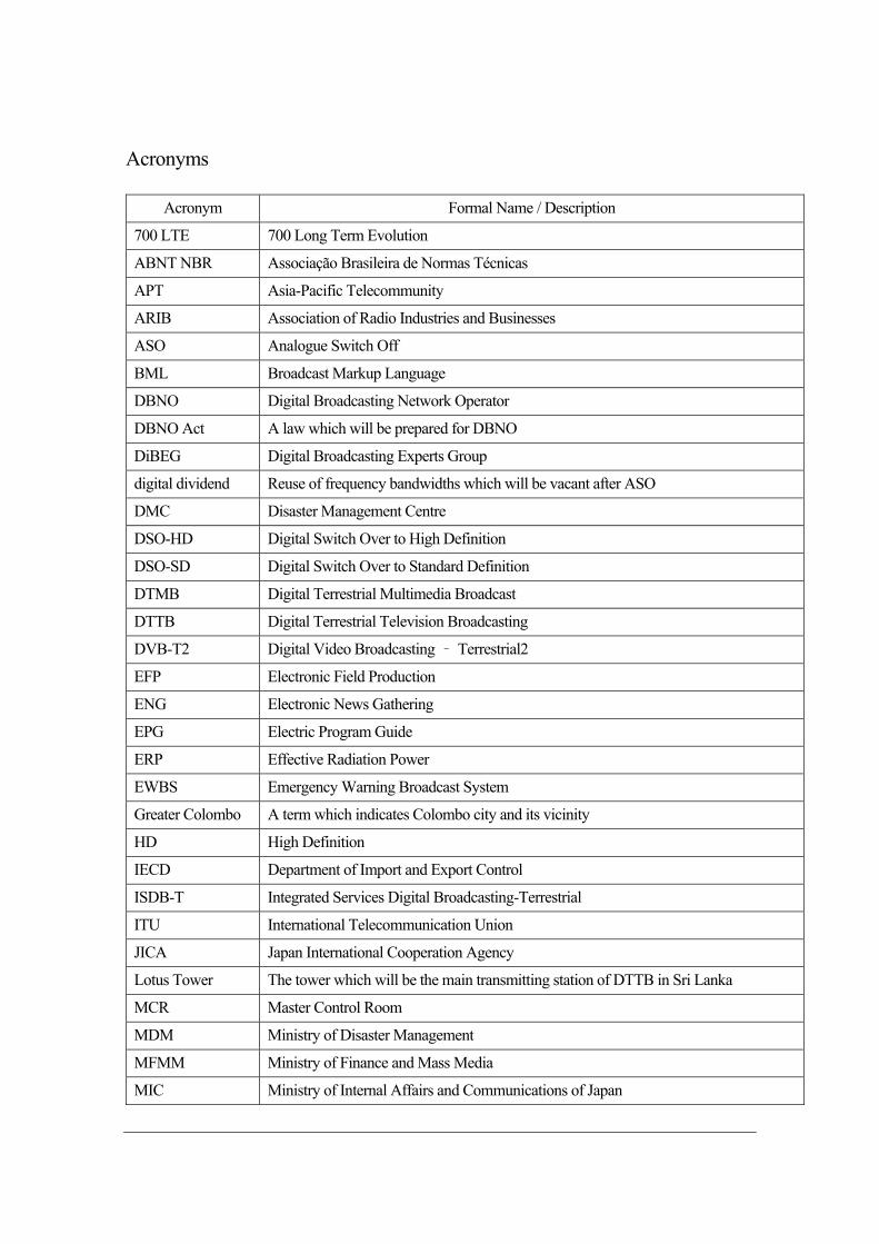
Acronyms
Acronym Formal Name / Description
700 LTE 700 Long Term Evolution
ABNT NBR Associação Brasileira de Normas Técnicas
APT Asia-Pacific Telecommunity
ARIB Association of Radio Industries and Businesses
ASO Analogue Switch Off
BML Broadcast Markup Language
DBNO Digital Broadcasting Network Operator
DBNO Act A law which will be prepared for DBNO
DiBEG Digital Broadcasting Experts Group
digital dividend Reuse of frequency bandwidths which will be vacant after ASO
DMC Disaster Management Centre
DSO-HD Digital Switch Over to High Definition
DSO-SD Digital Switch Over to Standard Definition
DTMB Digital Terrestrial Multimedia Broadcast
DTTB Digital Terrestrial Television Broadcasting
DVB-T2 Digital Video Broadcasting – Terrestrial2
EFP Electronic Field Production
ENG Electronic News Gathering
EPG Electric Program Guide
ERP Effective Radiation Power
EWBS Emergency Warning Broadcast System
Greater Colombo A term which indicates Colombo city and its vicinity
HD High Definition
IECD Department of Import and Export Control
ISDB-T Integrated Services Digital Broadcasting-Terrestrial
ITU International Telecommunication Union
JICA Japan International Cooperation Agency
Lotus Tower The tower which will be the main transmitting station of DTTB in Sri Lanka
MCR Master Control Room
MDM Ministry of Disaster Management
MFMM Ministry of Finance and Mass Media
MIC Ministry of Internal Affairs and Communications of Japan
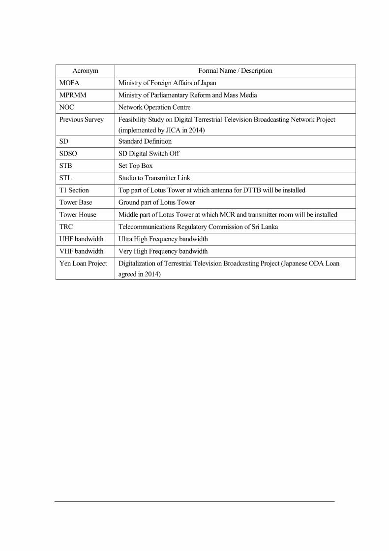
Acronym Formal Name / Description
MOFA Ministry of Foreign Affairs of Japan
MPRMM Ministry of Parliamentary Reform and Mass Media
NOC Network Operation Centre
Previous Survey Feasibility Study on Digital Terrestrial Television Broadcasting Network Project
(implemented by JICA in 2014)
SD Standard Definition
SDSO SD Digital Switch Off
STB Set Top Box
STL Studio to Transmitter Link
T1 Section Top part of Lotus Tower at which antenna for DTTB will be installed
Tower Base Ground part of Lotus Tower
Tower House Middle part of Lotus Tower at which MCR and transmitter room will be installed
TRC Telecommunications Regulatory Commission of Sri Lanka
UHF bandwidth Ultra High Frequency bandwidth
VHF bandwidth Very High Frequency bandwidth
Yen Loan Project Digitalization of Terrestrial Television Broadcasting Project (Japanese ODA Loan
agreed in 2014)
i
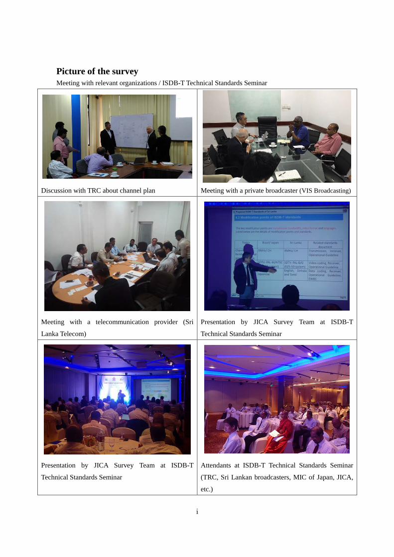
Picture of the survey Meeting with relevant organizations / ISDB-T Technical Standards Seminar
Discussion with TRC about channel plan
Meeting with a private broadcaster (VIS Broadcasting)
Meeting with a telecommunication provider (Sri
Lanka Telecom)
Presentation by JICA Survey Team at ISDB-T
Technical Standards Seminar
Presentation by JICA Survey Team at ISDB-T
Technical Standards Seminar
Attendants at ISDB-T Technical Standards Seminar
(TRC, Sri Lankan broadcasters, MIC of Japan, JICA,
etc.)
ii
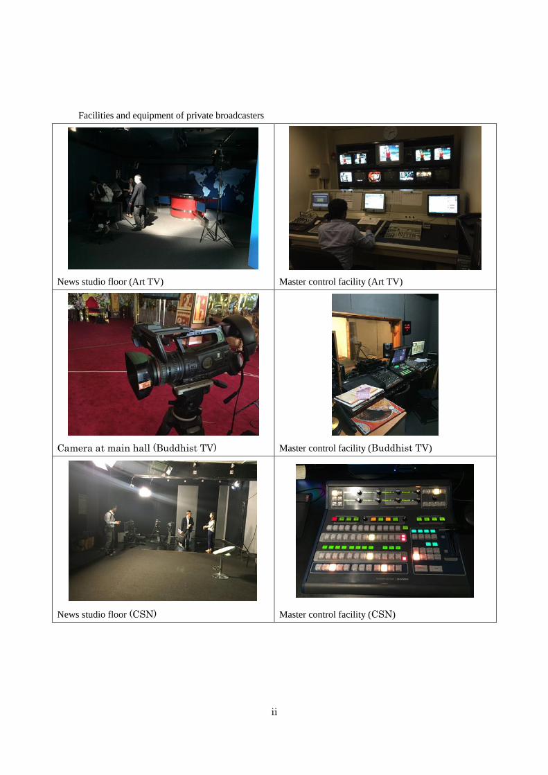
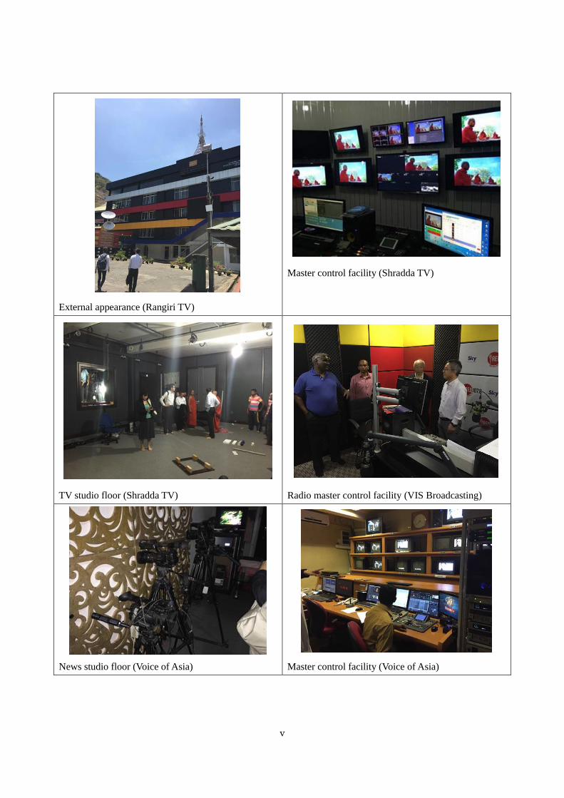
Facilities and equipment of private broadcasters
News studio floor (Art TV)
Master control facility (Art TV)
Camera at main hall (Buddhist TV)
Master control facility (Buddhist TV)
News studio floor (CSN)
Master control facility (CSN)
iii
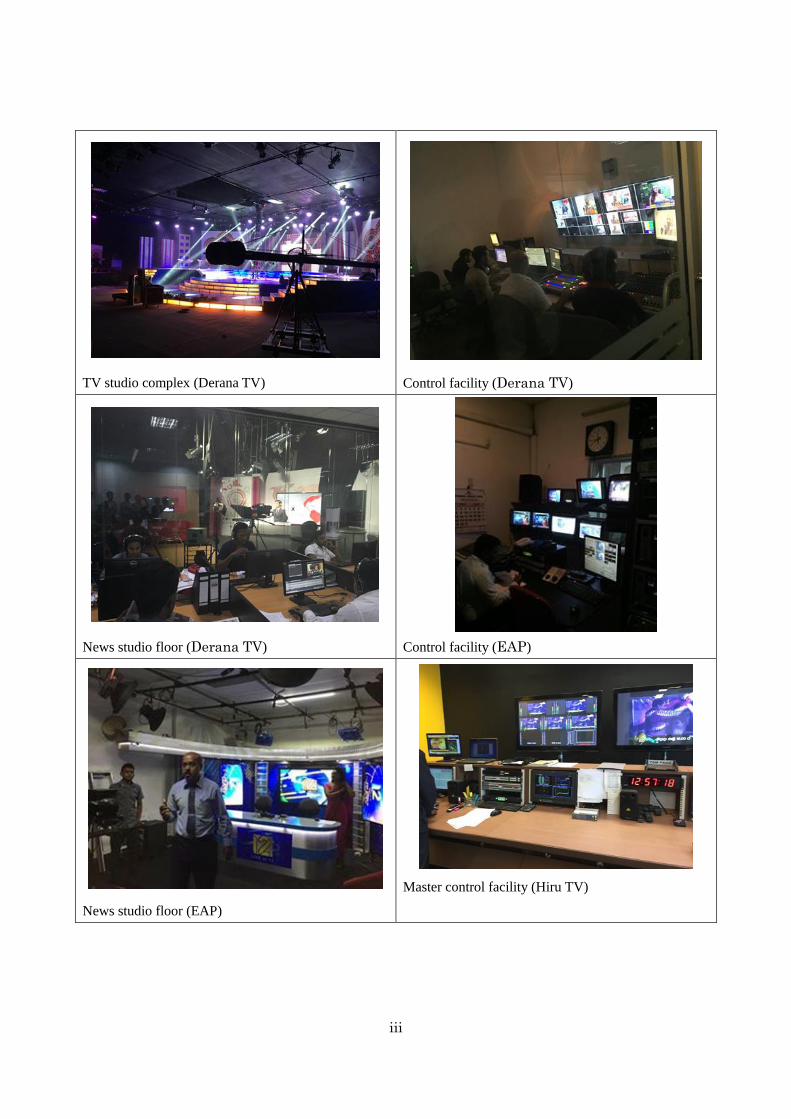
TV studio complex (Derana TV)
Control facility (Derana TV)
News studio floor (Derana TV)
Control facility (EAP)
News studio floor (EAP)
Master control facility (Hiru TV)
iv
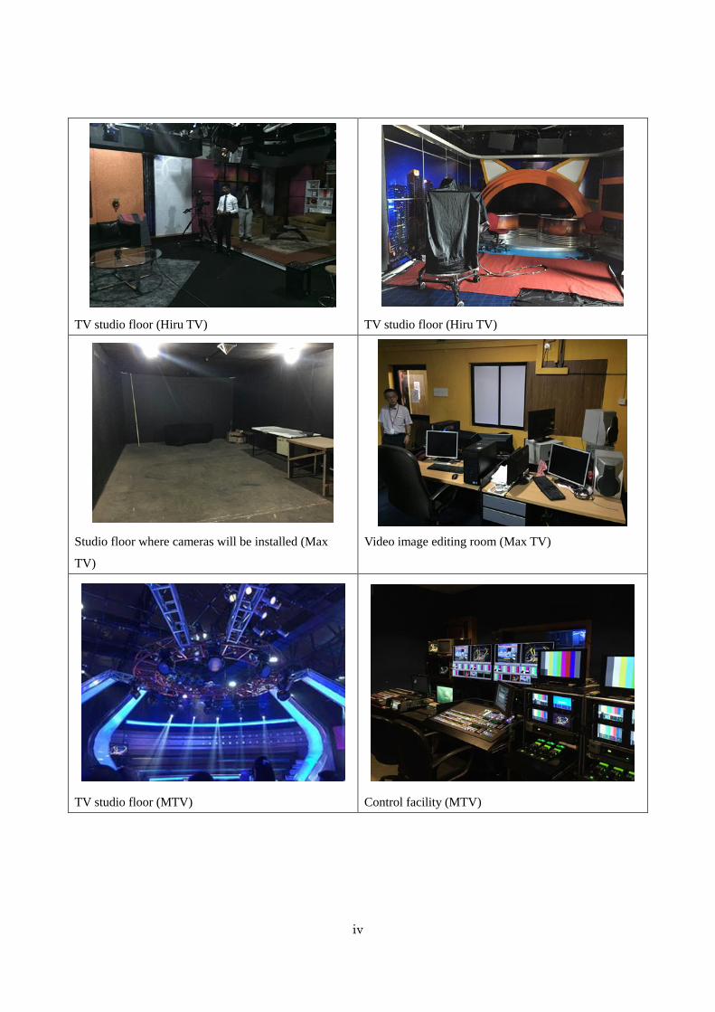
TV studio floor (Hiru TV)
TV studio floor (Hiru TV)
Studio floor where cameras will be installed (Max
TV)
Video image editing room (Max TV)
TV studio floor (MTV)
Control facility (MTV)
v
External appearance (Rangiri TV)
Master control facility (Shradda TV)
TV studio floor (Shradda TV)
Radio master control facility (VIS Broadcasting)
News studio floor (Voice of Asia)
Master control facility (Voice of Asia)
vi
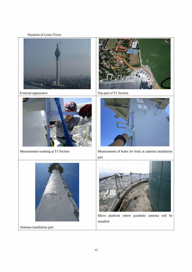
Situation of Lotus Tower
External appearance
Top part of T1 Section
Measurement working at T1 Section
Measurement of holes for bolts at antenna installation
part
Antenna installation part
Micro platform where parabolic antenna will be
installed
vii
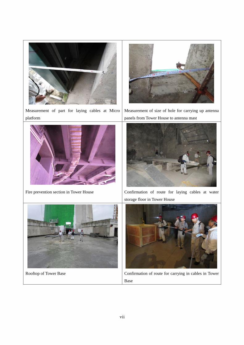
Measurement of part for laying cables at Micro
platform
Measurement of size of hole for carrying up antenna
panels from Tower House to antenna mast
Fire prevention section in Tower House
Confirmation of route for laying cables at water
storage floor in Tower House
Rooftop of Tower Base
Confirmation of route for carrying in cables in Tower
Base

viii
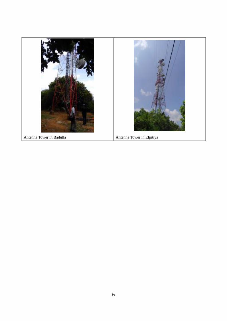
Site survey of existing antenna towers
Antenna tower in Jaffna
Antenna tower and station building in Vayuniya
Antenna tower in Kurunegala
Antenna tower in Hantana
ix
Antenna Tower in Badulla
Antenna Tower in Elpitiya

Chapter 1 Background and outline of the survey
1-1
Background and outline of the survey Outline of migration into DTTB in Sri Lanka
In the Democratic Socialist Republic of Sri Lanka (hereinafter referred to as “Sri Lanka”), after the civil
war ended in 2009, frequency usage has increased rapidly due to the spread of mobile phone and the
Internet as well as significant increase in the number of TV and radio channels. Back in May 2006, at
the International Telecommunication Union (hereinafter referred to as “ITU”) meeting, it was agreed
that migration into Digital Terrestrial Television Broadcasting (hereinafter referred to as “DTTB”) would
be implemented by 2015. In 2010, with the advice and support from ITU, the Roadmap for the Transition
from Analogue to Digital Terrestrial Television Broadcasting in Sri Lanka (hereinafter referred to as
“ITU Roadmap”) was created. Discussions started on measures and means for effectively allocating
frequencies for TV broadcasting which had been overcrowded.
The basic DTTB systems recognized by ITU as the international standards for DTTB are the Japanese
DTTB standard developed in Japan, called Integrated Services Digital Broadcasting (hereinafter referred
to as “ISDB-T”), the EU standard (including the first generation called Digital Video Broadcasting
(hereinafter referred to as “DVB-T”) and the second generation called “DVB-T2”), the American
standard called Advanced Television Systems Committee, and the Chinese standard called Digital
Terrestrial Multimedia Broadcast. The Government of Sri Lanka carefully examined which of these
basic systems should be introduced to Sri Lanka and decided on the adoption of the ISDB-T system in
2014. Thereafter the Government of Sri Lanka concluded a Loan Agreement (hereinafter referred to as
“L/A”) with Japan International Cooperation Agency (hereinafter referred to as JICA) to receive
assistance on the migration into DTTB through the Digitalization of Terrestrial Television Broadcasting
Project (hereinafter referred to as “Yen Loan Project”). Loan amount of the said Yen Loan Project is
13.717 billion yen.
One determinant factor for adopting ISDB-T was that Emergency Warning Broadcast System
(hereinafter referred to as “EWBS”) was available as a characteristic feature of ISDB-T. Sri Lanka, an
island country surrounded by the ocean like Japan, is susceptible to natural disasters such as sediment
disasters, cyclones, tsunami, and tidal waves, which have given significant impacts on the economic and
social activities of people. In recent years, heavy rain caused floods in 2009, 2011, and 2014 and a
torrential downpour caused floods and landslides in the southwestern part of Sri Lanka in May 2017.
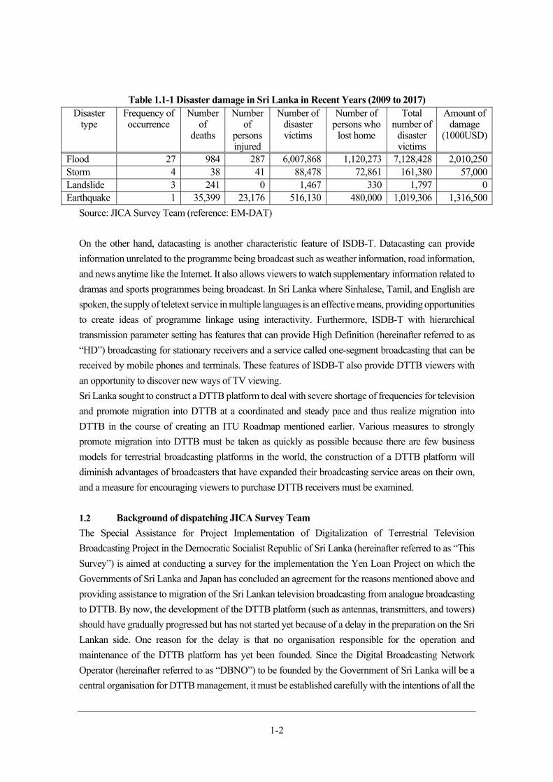
Table 1.1-1 shows the disaster damage in Sri Lanka in recent years (2009 to 2017).
EWBS can transmit an early warning to viewers through broadcasting in collaboration with the agency
regarding disaster management and is expected to contribute to disaster mitigation.
1-2
Table 1.1-1 Disaster damage in Sri Lanka in Recent Years (2009 to 2017) Disaster
type Frequency of occurrence
Number of
deaths
Number of
persons injured
Number of disaster victims
Number of persons who
lost home
Total number of
disaster victims
Amount of damage
(1000USD)
Flood 27 984 287 6,007,868 1,120,273 7,128,428 2,010,250Storm 4 38 41 88,478 72,861 161,380 57,000Landslide 3 241 0 1,467 330 1,797 0Earthquake 1 35,399 23,176 516,130 480,000 1,019,306 1,316,500
Source: JICA Survey Team (reference: EM-DAT)
On the other hand, datacasting is another characteristic feature of ISDB-T. Datacasting can provide
information unrelated to the programme being broadcast such as weather information, road information,
and news anytime like the Internet. It also allows viewers to watch supplementary information related to
dramas and sports programmes being broadcast. In Sri Lanka where Sinhalese, Tamil, and English are
spoken, the supply of teletext service in multiple languages is an effective means, providing opportunities
to create ideas of programme linkage using interactivity. Furthermore, ISDB-T with hierarchical
transmission parameter setting has features that can provide High Definition (hereinafter referred to as
“HD”) broadcasting for stationary receivers and a service called one-segment broadcasting that can be
received by mobile phones and terminals. These features of ISDB-T also provide DTTB viewers with
an opportunity to discover new ways of TV viewing.
Sri Lanka sought to construct a DTTB platform to deal with severe shortage of frequencies for television
and promote migration into DTTB at a coordinated and steady pace and thus realize migration into
DTTB in the course of creating an ITU Roadmap mentioned earlier. Various measures to strongly
promote migration into DTTB must be taken as quickly as possible because there are few business
models for terrestrial broadcasting platforms in the world, the construction of a DTTB platform will
diminish advantages of broadcasters that have expanded their broadcasting service areas on their own,
and a measure for encouraging viewers to purchase DTTB receivers must be examined.
Background of dispatching JICA Survey Team
The Special Assistance for Project Implementation of Digitalization of Terrestrial Television
Broadcasting Project in the Democratic Socialist Republic of Sri Lanka (hereinafter referred to as “This
Survey”) is aimed at conducting a survey for the implementation the Yen Loan Project on which the
Governments of Sri Lanka and Japan has concluded an agreement for the reasons mentioned above and
providing assistance to migration of the Sri Lankan television broadcasting from analogue broadcasting
to DTTB. By now, the development of the DTTB platform (such as antennas, transmitters, and towers)
should have gradually progressed but has not started yet because of a delay in the preparation on the Sri
Lankan side. One reason for the delay is that no organisation responsible for the operation and
maintenance of the DTTB platform has yet been founded. Since the Digital Broadcasting Network
Operator (hereinafter referred to as “DBNO”) to be founded by the Government of Sri Lanka will be a
central organisation for DTTB management, it must be established carefully with the intentions of all the
1-3
broadcasters taken into account and therefore the foundation of it is taking time. Likewise, there is also
a delay in the establishment of technical standards for transmitters and receivers, examination of the
migration plan into DTTB (including establishment of a frequency plan), and construction of Lotus
Tower from which radio waves of DBNO will be transmitted, resulting in a delay in the overall process
of mitigation into DTTB. Therefore, the JICA Survey Team is required to conduct additional survey in
Sri Lanka and discuss with the relevant organisations to make up for the delay in work and promote the
migration into DTTB.
JICA Survey Team experts/members
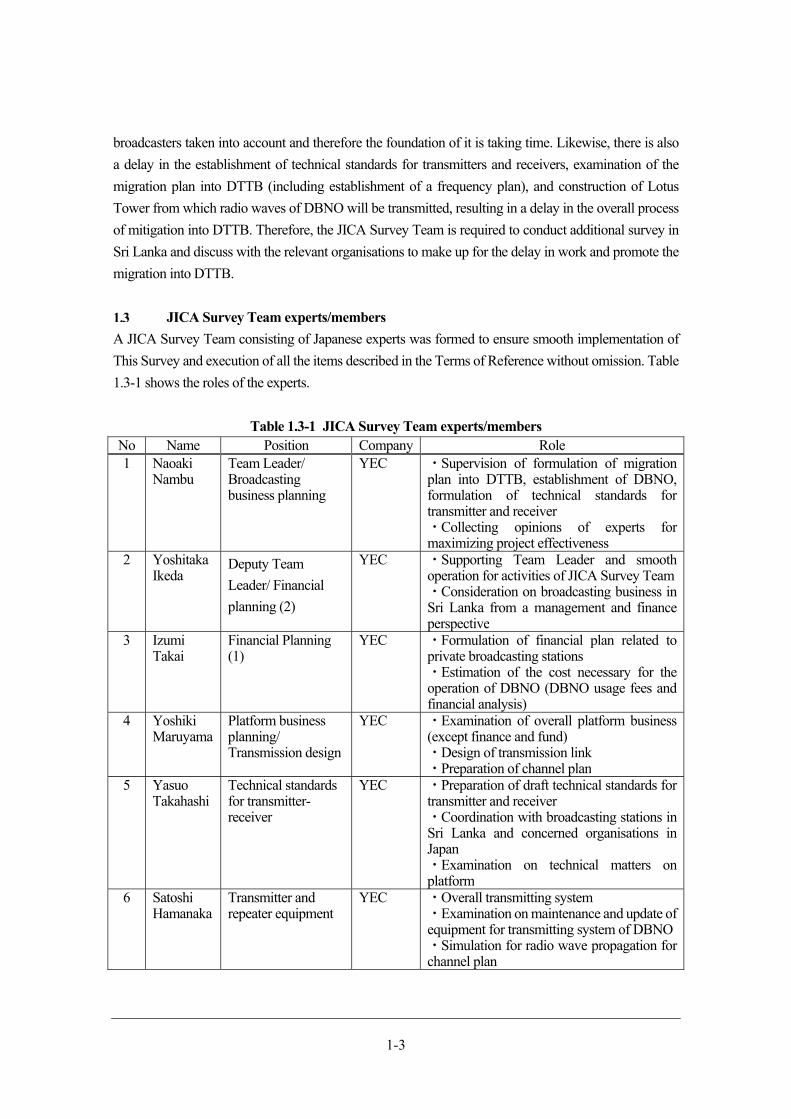
A JICA Survey Team consisting of Japanese experts was formed to ensure smooth implementation of
This Survey and execution of all the items described in the Terms of Reference without omission. Table
1.3-1 shows the roles of the experts.
Table 1.3-1 JICA Survey Team experts/members No Name Position Company Role 1 Naoaki
Nambu Team Leader/ Broadcasting business planning
YEC ・Supervision of formulation of migration plan into DTTB, establishment of DBNO, formulation of technical standards for transmitter and receiver ・Collecting opinions of experts for maximizing project effectiveness
2 Yoshitaka Ikeda
Deputy Team
Leader/ Financial
planning (2)
YEC ・Supporting Team Leader and smooth operation for activities of JICA Survey Team・Consideration on broadcasting business in Sri Lanka from a management and finance perspective
3 Izumi Takai
Financial Planning (1)
YEC ・Formulation of financial plan related to private broadcasting stations ・Estimation of the cost necessary for the operation of DBNO (DBNO usage fees and financial analysis)
4 Yoshiki Maruyama
Platform business planning/ Transmission design
YEC ・Examination of overall platform business (except finance and fund) ・Design of transmission link ・Preparation of channel plan
5 Yasuo Takahashi
Technical standards for transmitter-receiver
YEC ・Preparation of draft technical standards for transmitter and receiver ・Coordination with broadcasting stations in Sri Lanka and concerned organisations in Japan ・Examination on technical matters on platform
6 Satoshi Hamanaka
Transmitter and repeater equipment
YEC ・Overall transmitting system ・Examination on maintenance and update of equipment for transmitting system of DBNO・Simulation for radio wave propagation for channel plan
1-4
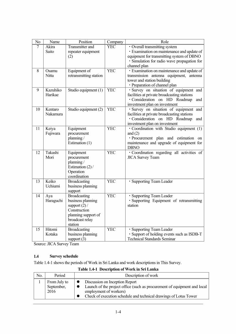
No Name Position Company Role 7 Akira
Saito Transmitter and repeater equipment (2)
YEC ・Overall transmitting system ・Examination on maintenance and update of equipment for transmitting system of DBNO・Simulation for radio wave propagation for channel plan
8 Osamu Nitta
Equipment of retransmitting station
YEC ・Examination on maintenance and update of transmission antenna equipment, antenna tower and station building ・Preparation of channel plan
9 Kazuhiko Harikae
Studio equipment (1) YEC ・Survey on situation of equipment and facilities at private broadcasting stations ・Consideration on HD Roadmap and investment plan on investment
10 Kentaro Nakamura
Studio equipment (2) YEC ・Survey on situation of equipment and facilities at private broadcasting stations ・Consideration on HD Roadmap and investment plan on investment
11 Keiya Fujiwara
Equipment procurement planning / Estimation (1)
YEC ・Coordination with Studio equipment (1) and (2) ・Procurement plan and estimation on maintenance and upgrade of equipment for DBNO
12 Takashi Mori
Equipment procurement planning / Estimation (2) / Operation coordination
YEC ・Coordination regarding all activities of JICA Survey Team
13 Keiko Uchiumi
Broadcasting business planning support
YEC ・Supporting Team Leader
14 Aya Haraguchi
Broadcasting business planning support (2) / Construction planning support of broadcast relay station
YEC ・Supporting Team Leader ・Supporting Equipment of retransmitting station
15 Hitomi Kotaka
Broadcasting business planning support (3)
YEC ・Supporting Team Leader ・Support of holding events such as ISDB-T Technical Standards Seminar
Source: JICA Survey Team
Survey schedule
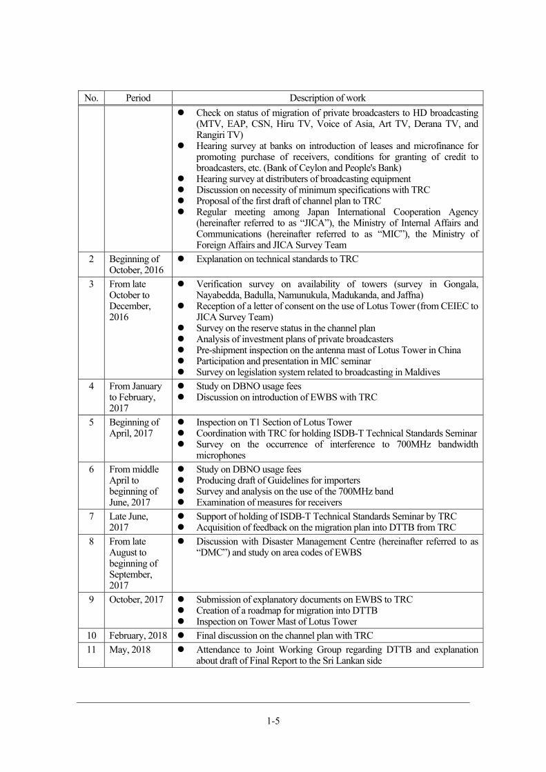
Table 1.4-1 shows the periods of Work in Sri Lanka and work descriptions in This Survey.
Table 1.4-1 Description of Work in Sri Lanka
No. Period Description of work
1 From July to September, 2016
Discussion on Inception Report Launch of the project office (such as procurement of equipment and local
employment of workers) Check of execution schedule and technical drawings of Lotus Tower
1-5
No. Period Description of work
Check on status of migration of private broadcasters to HD broadcasting (MTV, EAP, CSN, Hiru TV, Voice of Asia, Art TV, Derana TV, and Rangiri TV)
Hearing survey at banks on introduction of leases and microfinance for promoting purchase of receivers, conditions for granting of credit to broadcasters, etc. (Bank of Ceylon and People's Bank)
Hearing survey at distributers of broadcasting equipment Discussion on necessity of minimum specifications with TRC Proposal of the first draft of channel plan to TRC Regular meeting among Japan International Cooperation Agency
(hereinafter referred to as “JICA”), the Ministry of Internal Affairs and Communications (hereinafter referred to as “MIC”), the Ministry of Foreign Affairs and JICA Survey Team
2 Beginning of October, 2016
Explanation on technical standards to TRC
3 From late October to December, 2016
Verification survey on availability of towers (survey in Gongala, Nayabedda, Badulla, Namunukula, Madukanda, and Jaffna)
Reception of a letter of consent on the use of Lotus Tower (from CEIEC to JICA Survey Team)
Survey on the reserve status in the channel plan Analysis of investment plans of private broadcasters Pre-shipment inspection on the antenna mast of Lotus Tower in China Participation and presentation in MIC seminar Survey on legislation system related to broadcasting in Maldives
4 From January to February, 2017
Study on DBNO usage fees Discussion on introduction of EWBS with TRC
5 Beginning of April, 2017
Inspection on T1 Section of Lotus Tower Coordination with TRC for holding ISDB-T Technical Standards Seminar Survey on the occurrence of interference to 700MHz bandwidth
microphones
6 From middle April to beginning of June, 2017
Study on DBNO usage fees Producing draft of Guidelines for importers Survey and analysis on the use of the 700MHz band Examination of measures for receivers
7 Late June, 2017
Support of holding of ISDB-T Technical Standards Seminar by TRC Acquisition of feedback on the migration plan into DTTB from TRC
8 From late August to beginning of September, 2017
Discussion with Disaster Management Centre (hereinafter referred to as “DMC”) and study on area codes of EWBS
9 October, 2017 Submission of explanatory documents on EWBS to TRC Creation of a roadmap for migration into DTTB Inspection on Tower Mast of Lotus Tower
10 February, 2018 Final discussion on the channel plan with TRC
11 May, 2018 Attendance to Joint Working Group regarding DTTB and explanation about draft of Final Report to the Sri Lankan side

1-6
No. Period Description of work
Consideration on allocation of area codes to the list of area classification received from TRC, coordination with DiBEG, and finalization of draft on area codes
12 June, 2018 Updating documents for EWBS explanation, and submission to TRC
Source: JICA Survey Team
Surveyed organisations
Governmental agencies
At the conclusion of L/A for the Yen Loan Project in 2004, the executing agency of the Yen Loan Project
was the Ministry of Mass Media and Information, currently the Ministry of Finance and Mass Media. At
present, however, the Government of Sri Lanka is advancing the internal process to change it to the
Telecommunications Regulatory Commission of Sri Lanka (hereinafter referred to as “TRC”).
Since the cooperation of the Ministry of Disaster Management (hereinafter referred to as “MDM”) and
DMC in charge of the operations of disaster management under the control of MDM is required, JICA
Survey Team discussed with DMC on the operation of EWBS, a feature of ISDB-T. In particular,
consent of both the agencies regarding disaster management is required for the area codes to be used in
DTTB, which must be determined before the technical standards for DTTB are released.
Furthermore, as set top boxes (hereinafter referred to as “STBs”) required for viewing of DTTB are more
likely to be imported from other countries, rather than manufactured in Sri Lanka, JICA Survey Team
discussed with the Import & Export Control Department (hereinafter referred to as “IECD”), Sri Lanka
Standard Institution (hereinafter referred to as “SLSI”) and other relevant governmental agencies in order
to create import guidelines of the said products in compliance with the laws and regulations on import
procedures of Sri Lanka.
Table 1.5-1 describes the above-mentioned government agencies.
Table 1.5-1 Governmental agencies with which discussion and hearing survey was conducted
No. Governmental agency Outline, etc. 1 TRC A regulatory agency for communications and broadcasting and a
regulatory organisation on the management of frequencies of a DTTB platform. TRC will be specified as the executing agency of the Yen Loan Project through cabinet decision in Sri Lanka.
2 DMC Conduct disaster responses and disaster management in Sri Lanka, collaborate also with local and community disaster control organisations, formulate and execute a national disaster management plan and disaster-time execution plans and also conduct educational activities for disaster management.
3 IECD Control import and export, create standards, and issues licences. Involved in the project on the import of STBs.
4 SLSI An organisation that issue specification and standard compliance certificates for electronic equipment.
1-7
Source: JICA Survey Team
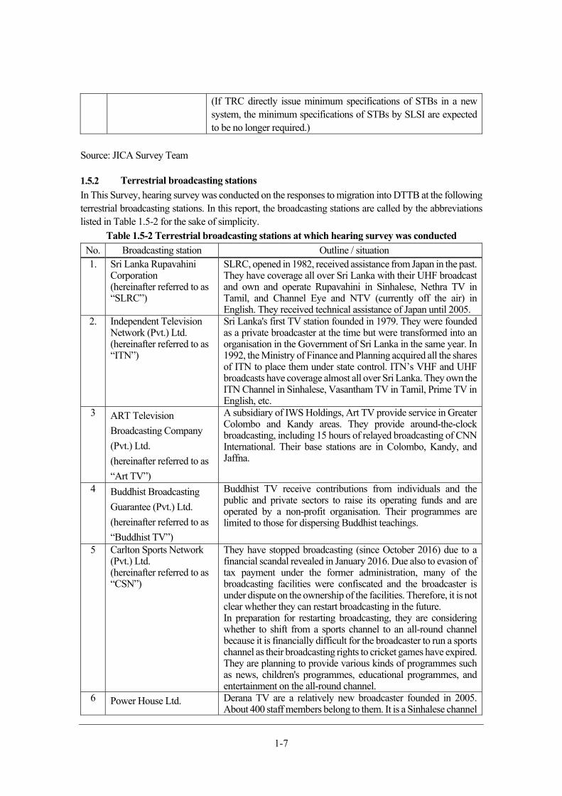
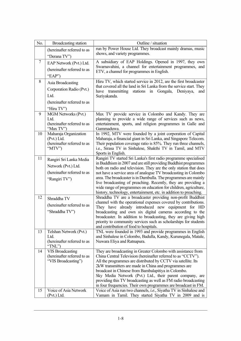
Terrestrial broadcasting stations
In This Survey, hearing survey was conducted on the responses to migration into DTTB at the following terrestrial broadcasting stations. In this report, the broadcasting stations are called by the abbreviations listed in Table 1.5-2 for the sake of simplicity.
Table 1.5-2 Terrestrial broadcasting stations at which hearing survey was conducted
No. Broadcasting station Outline / situation 1. Sri Lanka Rupavahini
Corporation (hereinafter referred to as “SLRC”)
SLRC, opened in 1982, received assistance from Japan in the past. They have coverage all over Sri Lanka with their UHF broadcast and own and operate Rupavahini in Sinhalese, Nethra TV in Tamil, and Channel Eye and NTV (currently off the air) in English. They received technical assistance of Japan until 2005.
2. Independent Television Network (Pvt.) Ltd. (hereinafter referred to as “ITN”)
Sri Lanka's first TV station founded in 1979. They were founded as a private broadcaster at the time but were transformed into an organisation in the Government of Sri Lanka in the same year. In 1992, the Ministry of Finance and Planning acquired all the shares of ITN to place them under state control. ITN’s VHF and UHF broadcasts have coverage almost all over Sri Lanka. They own the ITN Channel in Sinhalese, Vasantham TV in Tamil, Prime TV in English, etc.
3 ART Television
Broadcasting Company
(Pvt.) Ltd.
(hereinafter referred to as
“Art TV”)
A subsidiary of IWS Holdings, Art TV provide service in Greater Colombo and Kandy areas. They provide around-the-clock broadcasting, including 15 hours of relayed broadcasting of CNN International. Their base stations are in Colombo, Kandy, and Jaffna.
4 Buddhist Broadcasting
Guarantee (Pvt.) Ltd.
(hereinafter referred to as
“Buddhist TV”)
Buddhist TV receive contributions from individuals and the public and private sectors to raise its operating funds and are operated by a non-profit organisation. Their programmes are limited to those for dispersing Buddhist teachings.
5 Carlton Sports Network (Pvt.) Ltd. (hereinafter referred to as “CSN”)
They have stopped broadcasting (since October 2016) due to a financial scandal revealed in January 2016. Due also to evasion of tax payment under the former administration, many of the broadcasting facilities were confiscated and the broadcaster is under dispute on the ownership of the facilities. Therefore, it is not clear whether they can restart broadcasting in the future. In preparation for restarting broadcasting, they are considering whether to shift from a sports channel to an all-round channel because it is financially difficult for the broadcaster to run a sports channel as their broadcasting rights to cricket games have expired. They are planning to provide various kinds of programmes such as news, children's programmes, educational programmes, and entertainment on the all-round channel.
6 Power House Ltd. Derana TV are a relatively new broadcaster founded in 2005. About 400 staff members belong to them. It is a Sinhalese channel
(If TRC directly issue minimum specifications of STBs in a new system, the minimum specifications of STBs by SLSI are expected to be no longer required.)
1-8
No. Broadcasting station Outline / situation
(hereinafter referred to as
“Derana TV”)
run by Power House Ltd. They broadcast mainly dramas, music shows, and variety programmes.
7 EAP Network (Pvt.) Ltd.
(hereinafter referred to as
“EAP”)
A subsidiary of EAP Holdings. Opened in 1997, they own Swarnavahini, a channel for entertainment programmes, and ETV, a channel for programmes in English.
8 Asia Broadcasting
Corporation Radio (Pvt.)
Ltd.
(hereinafter referred to as
“Hiru TV”)
Hiru TV, which started service in 2012, are the first broadcaster that covered all the land in Sri Lanka from the service start. They have transmitting stations in Gongala, Deniyaya, and Suriyakanda.
9 MGM Networks (Pvt.) Ltd. (hereinafter referred to as “Max TV”)
Max TV provide service in Colombo and Kandy. They are planning to provide a wide range of services such as news, entertainment, sports, and religion programmes in Galle and Gammaduwa.
10 Maharaja Organization (Pvt.) Ltd. (hereinafter referred to as “MTV”)
In 1992, MTV were founded by a joint corporation of Capital Maharaja, a financial giant in Sri Lanka, and Singapore Telecom. Their population coverage ratio is 85%. They run three channels, i.e., Sirasa TV in Sinhalese, Shakthi TV in Tamil, and MTV Sports in English.
11 Rangiri Sri Lanka Media
Network (Pvt.) Ltd.
(hereinafter referred to as
“Rangiri TV”)
Rangiri TV started Sri Lanka's first radio programme specialised in Buddhism in 2007 and are still providing Buddhist programmes both on radio and television. They are the only station that does not have a service area of analogue TV broadcasting in Colombo area. The broadcaster is in Dambulla. The programmes are mainly live broadcasting of preaching. Recently, they are providing a wide range of programmes on education for children, agriculture, history, technology, entertainment, etc. in addition to preaching.
12 Shraddha TV
(hereinafter referred to as
“Shraddha TV”)
Shraddha TV are a broadcaster providing non-profit Buddhist channel with the operational expenses covered by contributions. They have already introduced new equipment for HD broadcasting and own six digital cameras according to the broadcaster. In addition to broadcasting, they are giving high priority to community services such as scholarships for students and contribution of food to hospitals.
13 Telshan Network (Pvt.) Ltd. (hereinafter referred to as “TNL”)
TNL were founded in 1993 and provide programmes in English and Sinhalese in Colombo, Badulla, Kandy, Kurunegala, Matale, Nuwara Eliya and Ratnapura.
14 VIS Broadcasting (hereinafter referred to as “VIS Broadcasting”)
They are broadcasting in Greater Colombo with assistance from China Central Television (hereinafter referred to as “CCTV”). All the programmes are distributed by CCTV via satellite. Its 2kW transmitters are made in China and programmes are broadcast in Chinese from Bambalapitiya in Colombo. Sky Media Network (Pvt.) Ltd., their parent company, are providing this TV broadcasting as well as FM radio broadcasting in four frequencies. Their own programmes are broadcast in FM.
15 Voice of Asia Network (Pvt.) Ltd.
Voice of Asia run two channels, i.e., Siyatha TV in Sinhalese and Vamam in Tamil. They started Siyatha TV in 2009 and is
1-9
No. Broadcasting station Outline / situation (hereinafter referred to as “Voice of Asia”)
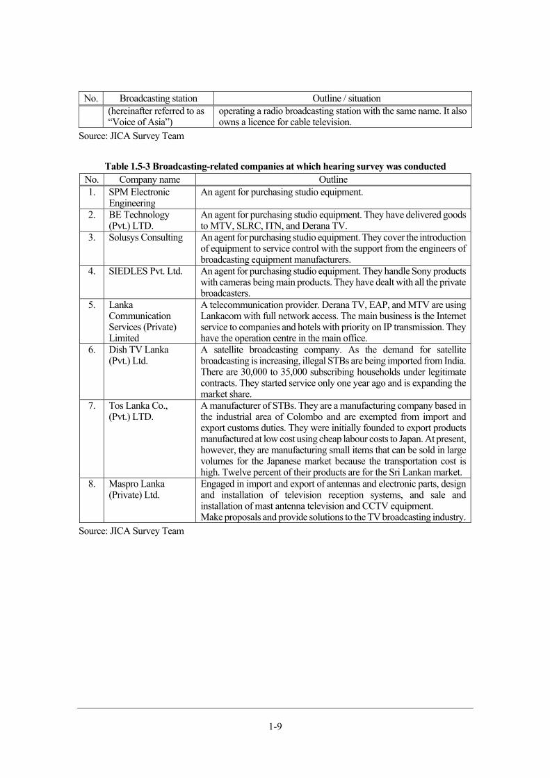
operating a radio broadcasting station with the same name. It also owns a licence for cable television.
Source: JICA Survey Team
Table 1.5-3 Broadcasting-related companies at which hearing survey was conducted No. Company name Outline 1. SPM Electronic
Engineering An agent for purchasing studio equipment.
2. BE Technology (Pvt.) LTD.
An agent for purchasing studio equipment. They have delivered goods to MTV, SLRC, ITN, and Derana TV.
3. Solusys Consulting An agent for purchasing studio equipment. They cover the introduction of equipment to service control with the support from the engineers of broadcasting equipment manufacturers.
4. SIEDLES Pvt. Ltd. An agent for purchasing studio equipment. They handle Sony products with cameras being main products. They have dealt with all the private broadcasters.
5. Lanka Communication Services (Private) Limited
A telecommunication provider. Derana TV, EAP, and MTV are using Lankacom with full network access. The main business is the Internet service to companies and hotels with priority on IP transmission. They have the operation centre in the main office.
6. Dish TV Lanka (Pvt.) Ltd.
A satellite broadcasting company. As the demand for satellite broadcasting is increasing, illegal STBs are being imported from India. There are 30,000 to 35,000 subscribing households under legitimate contracts. They started service only one year ago and is expanding the market share.
7. Tos Lanka Co., (Pvt.) LTD.
A manufacturer of STBs. They are a manufacturing company based in the industrial area of Colombo and are exempted from import and export customs duties. They were initially founded to export products manufactured at low cost using cheap labour costs to Japan. At present, however, they are manufacturing small items that can be sold in large volumes for the Japanese market because the transportation cost is high. Twelve percent of their products are for the Sri Lankan market.
8. Maspro Lanka (Private) Ltd.
Engaged in import and export of antennas and electronic parts, design and installation of television reception systems, and sale and installation of mast antenna television and CCTV equipment. Make proposals and provide solutions to the TV broadcasting industry.
Source: JICA Survey Team
Chapter 2 DBNO foundation support
2-1
DBNO foundation support Status of examination of government policies for DBNO foundation and private
broadcasters' intention of participation
Status of examination of government policies
In Sri Lanka, the Digital Broadcasting Network Operator (hereinafter referred to as “DBNO”) will be
founded to run the DTTB platform. Whereas broadcasting stations have produced and broadcast TV
programmes, DBNO will take over the broadcasting of all broadcasting stations, broadcasting their
programmes on behalf of them. Therefore, the foundation of DBNO will eliminate the need of
broadcasting stations to make direct investment in digital transmission equipment and promote
coordinated smooth migration into DTTB of all stations. However, the foundation of DBNO is delayed
and no specific discussion on the foundation has been held yet.
The Government of Sri Lanka assumes that the foundation of DBNO will be achieved in stages including
examination of a business model, necessary revision of laws and regulations, securing of running costs,
acquisition of necessary licences, securing of offices, and employment of staff.
Furthermore, the Government of Sri Lanka and stakeholders hope that DBNO must be founded as a
neutral organisation to which no excess governmental restriction will be applied because DBNO will be
used by broadcasting stations that should function as news media and the freedom of press must not be
violated. Therefore, in consideration with cases worldwide, it will be necessary to define the legal
standing and organisational form of a new, neutral, and independent public organisation to be founded,
conduct a study on a business model suitable for the organisation, and ensure soundness and transparency
of their business activities in compliance with the DBNO Act (a law stipulating the founding and
operation of DBNO).
DBNO, as one of the broadcasting stations that provide terrestrial broadcasting services, must have a
business licence (as stipulated in the DBNO Act) and a licence for frequency usage according to the
existing laws of Sri Lanka in the broadcasting and telecommunication sector. A business licence can be
issued when the DBNO Act takes effect. A licence for frequency usage must be issued according to the
channel plan of DTTB. Although the JICA Survey Team is having discussion specifically on the matters
concerning these licences with TRC that conducts radio wave supervision, TRC will not able to issue a
licence for frequency usage to DBNO before a channel plan is approved.
On the other hand, the responsibility of DBNO for the operation of the DTTB network that extends over
the entire country will be heavy because any failure of their facilities may make it suddenly impossible
to view any of the broadcasting programmes. Furthermore, as a neutral organisation, DBNO must
prevent any trouble from occurring only on the programmes of a certain broadcasting station. Therefore,
it is the greatest responsibility of DBNO to ensure stable operation of their facilities and equipment. It is
a must to secure staff and establish a management structure for the sustainable and stable operation of
the facilities and equipment.
The Government of Sri Lanka established the DTTB Steering Committee (headed by the TRC
chairperson and consisting of the secretaries and directors of the Ministry of Finance and Mass Media,
Ministry of Telecommunication and Digital Infrastructure, Department of External Resources, Ministry
2-2
of National Policies and Economic Affairs, and TRC). The committee is to examine and prepare the
policies on DBNO.
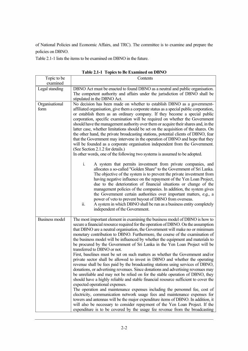
Table 2.1-1 lists the items to be examined on DBNO in the future.
Table 2.1-1 Topics to Be Examined on DBNO
Topic to be examined
Contents
Legal standing DBNO Act must be enacted to found DBNO as a neutral and public organisation. The competent authority and affairs under the jurisdiction of DBNO shall be stipulated in the DBNO Act.
Organisational form
No decision has been made on whether to establish DBNO as a government-affiliated organisation, give them a corporate status as a special public corporation, or establish them as an ordinary company. If they become a special public corporation, specific examination will be required on whether the Government should have the management authority over them or acquire their shares and, in the latter case, whether limitations should be set on the acquisition of the shares. On the other hand, the private broadcasting stations, potential clients of DBNO, fear that the Government may intervene in the operation of DBNO and hope that they will be founded as a corporate organisation independent from the Government. (See Section 2.1.2 for details.) In other words, one of the following two systems is assumed to be adopted.
i. A system that permits investment from private companies, and allocates a so-called "Golden Share" to the Government of Sri Lanka. The objective of the system is to prevent the private investment from having negative influence on the repayment of the Yen Loan Project, due to the deterioration of financial situations or change of the management policies of the companies. In addition, the system gives the Government certain authorities over important matters, e.g., a power of veto to prevent buyout of DBNO from overseas.
ii. A system in which DBNO shall be run as a business entity completely independent of the Government.
Business model The most important element in examining the business model of DBNO is how to secure a financial resource required for the operation of DBNO. On the assumption that DBNO are a neutral organisation, the Government will make no or minimum monetary contribution to DBNO. Furthermore, the course of the examination of the business model will be influenced by whether the equipment and materials to be procured by the Government of Sri Lanka in the Yen Loan Project will be transferred to DBNO or not. First, baselines must be set on such matters as whether the Government and/or private sector shall be allowed to invest in DBNO and whether the operating revenue shall be fees paid by the broadcasting stations using services of DBNO, donations, or advertising revenues. Since donations and advertising revenues may be unreliable and may not be relied on for the stable operation of DBNO, they should have a highly reliable and stable financial resource sufficient to cover the expected operational expenses. The operation and maintenance expenses including the personnel fee, cost of electricity, communication network usage fees and maintenance expenses for towers and antennas will be the major expenditure items of DBNO. In addition, it will also be necessary to consider repayment of the Yen Loan Project. If the expenditure is to be covered by the usage fee revenue from the broadcasting
2-3
Topic to be examined
Contents
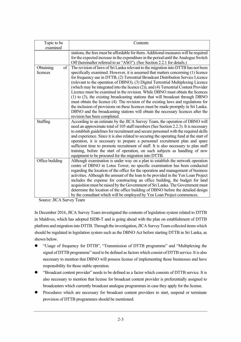
stations, the fees must be affordable for them. Additional measures will be required for the expected increase in the expenditure in the period until the Analogue Switch Off (hereinafter referred to as “ASO”). (See Section 2.2.1 for details.)
Obtaining of licences
The revision of laws of Sri Lanka relevant to the migration into DTTB has not been specifically examined. However, it is assumed that matters concerning (1) licence for frequency use in DTTB, (2) Terrestrial Broadcast Distribution Service Licence (relevant to the operation of DBNO), (3) Digital Terrestrial Multiplexing Licence (which may be integrated into the licence (2)), and (4) Terrestrial Content Provider Licence must be examined in the revision. While DBNO must obtain the licences (1) to (3), the existing broadcasting stations that will broadcast through DBNO must obtain the licence (4). The revision of the existing laws and regulations for the inclusion of provisions on these licences must be made promptly in Sri Lanka. DBNO and the broadcasting stations will obtain the necessary licences after the revision has been completed.
Staffing According to an estimate by the JICA Survey Team, the operation of DBNO will need an approximate total of 105 staff members (See Section 2.2.3). It is necessary to establish guidelines for recruitment and secure personnel with the required skills and experience. Since it is also related to securing the operating fund at the start of operation, it is necessary to prepare a personnel recruitment plan and spare sufficient time to promote recruitment of staff. It is also necessary to plan staff training, before the start of operation, on such subjects as handling of new equipment to be procured for the migration into DTTB.
Office building Although examination is under way on a plan to establish the network operation centre of DBNO in Lotus Tower, no specific examination has been conducted regarding the location of the office for the operation and management of business activities. Although the amount of the loan to be provided in the Yen Loan Project includes the expense for constructing an office building, the budget for land acquisition must be raised by the Government of Sri Lanka. The Government must determine the location of the office building of DBNO before the detailed design by the consultant which will be employed by Yen Loan Project commences.
Source: JICA Survey Team
In December 2016, JICA Survey Team investigated the contents of legislation system related to DTTB
in Maldives, which has adopted ISDB-T and is going ahead with the plan on establishment of DTTB
platform and migration into DTTB. Through the investigation, JICA Survey Team collected items which
should be regulated in legislation system such as the DBNO Act before starting DTTB in Sri Lanka, as
shown below.
“Usage of frequency for DTTB”, “Transmission of DTTB programme” and “Multiplexing the
signal of DTTB programme” need to be defined as factors which consist of DTTB service. It is also
necessary to mention that DBNO will possess license of implementing those businesses and have
responsibility for those stable operation.
“Broadcast content provider” needs to be defined as a factor which consists of DTTB service. It is
also necessary to mention that license for broadcast content provider is preferentially assigned to
broadcasters which currently broadcast analogue programmes in case they apply for the license.
Procedures which are necessary for broadcast content providers to start, suspend or terminate
provision of DTTB programmes should be mentioned.
2-4
Matters regarding license cancellation need to be written in legislation system. For example, the
period until broadcasters, which have the license for broadcast content provider, actually start
provision of DTTB programmes should be determined. The license will be revoked in case
broadcasters do not provide programmes during the period.
Private broadcasters' intention of participation
In the hearing survey conducted at all the private broadcasters except TNL, JICA Survey Team
confirmed their attitude to the participation in DBNO while explaining the concept of DBNO. Some
broadcasters were positive about the participation, thinking about the advantages such as availability of
nationwide broadcasting expected from it, whereas others were concerned about the participation. The
Government have not yet made any official announcement about the migration into DTTB or explained
to them about the policies on the migration into DTTB, timing of ASO, period of simultaneous
broadcasting, relationship between the existing broadcasting stations and DBNO to be founded, and
availability of a scheme of assistance to the broadcasters. This lack of appropriate communications
between the Government and private broadcasters is the biggest reason for the concern of the
broadcasters because they cannot make individual decisions about participation in DBNO without the
information mentioned above. There are two points of serious concern of the private broadcasters
regarding the foundation of DBNO: (1) Whether appropriate charges will be set for the use of DTTB
platform and (2) whether DBNO will be founded as an organisation independent from and uninfluenced
or minimally influenced by the Government.
Since the private broadcasters will have a heavier financial burden until ASO because the usage fee of
DBNO will be added to the current expenses for analogue broadcasting, they are highly interested in the
usage fee. Therefore, some kind of support to the private broadcasters, such as preferential tax measures
and reduction in the usage fees, until ASO must be considered by the Government of Sri Lanka.
Furthermore, some private broadcasters have misgivings that DBNO may be completely controlled by
and its operation may be interfered with by the Government using its control over DBNO in such forms
as intentionally interrupting broadcasting of specific programmes when they are inconvenient for the
Government or during elections. In short, the private broadcasters think it desirable that DBNO to be
founded is an organisation independent from the Government and financed partly with private capital
provided by private investors.
Table 2.1-2 summarises the concerns of the private broadcasters and required actions for them.
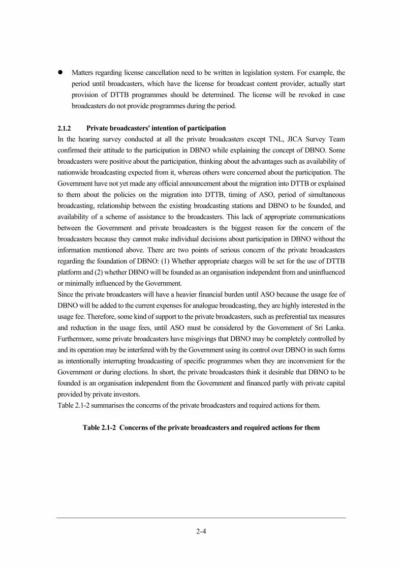
Table 2.1-2 Concerns of the private broadcasters and required actions for them
2-5
Concerns of private
broadcasters
Required action
Usage fee Until ASO, the broadcasters will have a heavier burden because they must pay the DBNO usage fee in addition to the existing operational expenses of analogue broadcasting. Therefore, some kind of support to them, such as subsidising the usage fee, must be provided by the Government of Sri Lanka. After ASO, it is desirable that the usage fee is approximately equal to the operation and maintenance expenses of the broadcasters at present. To a broadcaster that has already built its own nationwide broadcasting network, a usage fee lower than its current operation and maintenance expenses will be offered to promote the use of DBNO of such a broadcaster. Since a broadcaster with a broadcasting area that covers not all but only part of the country is interested in the advantage of providing nationwide broadcasting without building a nationwide broadcasting network of its own, a fee setting should be adjusted according to the broadcasting service area after ASO to eliminate feelings of inequality among the users. However, as some broadcasters may not be able to respond to a sudden increase in financial burden, a lower fee will be set for regional broadcasting. The usage fee setting is discussed in detail in Section 2.2.4.
Organisational form
If the usage fees are lowered in consideration of increased burdens of the broadcasters until ASO, the operating fund of DBNO may run short at the start of the operation. Since it is desired to allow investment from private companies to alleviate such financial risk, a policy to allow the Government and private companies to own the shares of DBNO may be implemented. It can be expected that supervision on the operation of DBNO will be strengthened by joining of private sector as well as the Government. This policy seems quite feasible because some companies have expressed, albeit unofficially, their intention to make such investment. Even in this case, it is desirable to discuss Government’s involvement in the operation of DBNO, e.g., not as an executive but as an auditor. In this way, the direct involvement of the Government can be alleviated.
Source: JICA Survey Team
Organisational structure and staff plan of DBNO
Service forms (forms of participation by private broadcasters, procurement of
equipment, and operation method)
(1) Outline of business by DBNO
The DTTB platform business of DBNO under consideration by the Government of Sri Lanka is based
on the content of Figure 2.2-1 that was confirmed in a JICA project, “Feasibility Study on Digital
Terrestrial Television Broadcasting Network Project in Democratic Socialist Republic of Sri Lanka
(hereinafter referred to as “Previous Survey”).” In other words, the central business of DBNO shall be to
operate the Network Operation Centre (hereinafter referred to as “NOC”), a facility for multiplexing
programmes collected from the broadcasting stations in broadcasting channels, and the "transmission
facilities" that convert signals received from NOC on which the programmes of the broadcasting stations
are multiplexed into signals that can be viewed on ordinary receivers and transmit them. Whereas NOC
shall be installed in Colombo, the transmission facilities shall be distributed to the transmitting stations
in various regions. Furthermore, transmission links from NOC to transmitting stations are to be
established with optical cables and microwave networks. Some of the transmission links are assumed to
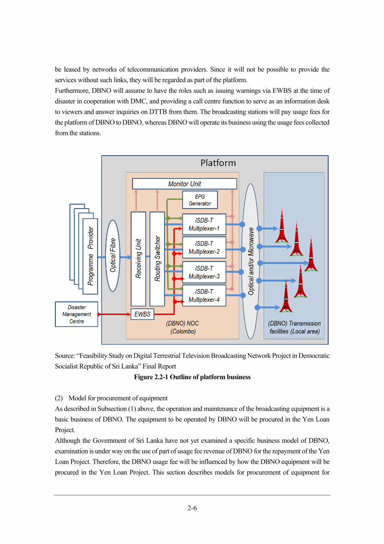
2-6
be leased by networks of telecommunication providers. Since it will not be possible to provide the
services without such links, they will be regarded as part of the platform.
Furthermore, DBNO will assume to have the roles such as issuing warnings via EWBS at the time of
disaster in cooperation with DMC, and providing a call centre function to serve as an information desk
to viewers and answer inquiries on DTTB from them. The broadcasting stations will pay usage fees for
the platform of DBNO to DBNO, whereas DBNO will operate its business using the usage fees collected
from the stations.
Source: “Feasibility Study on Digital Terrestrial Television Broadcasting Network Project in Democratic
Socialist Republic of Sri Lanka” Final Report
Figure 2.2-1 Outline of platform business
(2) Model for procurement of equipment
As described in Subsection (1) above, the operation and maintenance of the broadcasting equipment is a
basic business of DBNO. The equipment to be operated by DBNO will be procured in the Yen Loan
Project.
Although the Government of Sri Lanka have not yet examined a specific business model of DBNO,
examination is under way on the use of part of usage fee revenue of DBNO for the repayment of the Yen
Loan Project. Therefore, the DBNO usage fee will be influenced by how the DBNO equipment will be
procured in the Yen Loan Project. This section describes models for procurement of equipment for
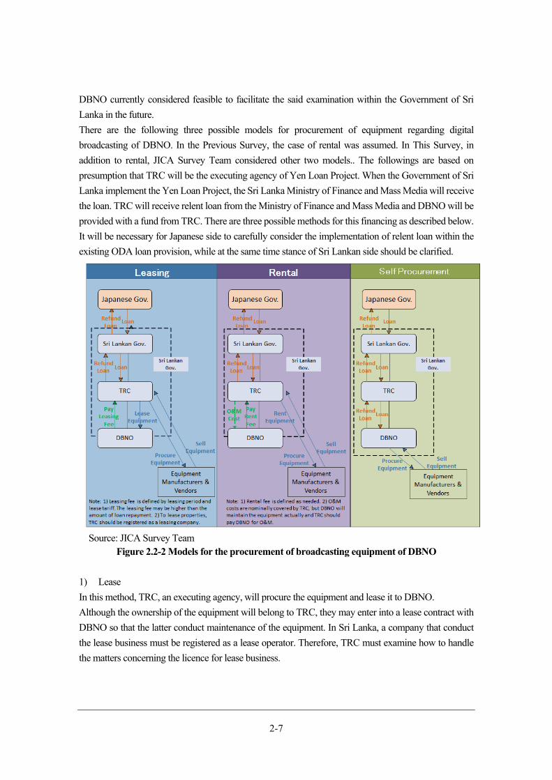
2-7
DBNO currently considered feasible to facilitate the said examination within the Government of Sri
Lanka in the future.
There are the following three possible models for procurement of equipment regarding digital
broadcasting of DBNO. In the Previous Survey, the case of rental was assumed. In This Survey, in
addition to rental, JICA Survey Team considered other two models.. The followings are based on
presumption that TRC will be the executing agency of Yen Loan Project. When the Government of Sri
Lanka implement the Yen Loan Project, the Sri Lanka Ministry of Finance and Mass Media will receive
the loan. TRC will receive relent loan from the Ministry of Finance and Mass Media and DBNO will be
provided with a fund from TRC. There are three possible methods for this financing as described below.
It will be necessary for Japanese side to carefully consider the implementation of relent loan within the
existing ODA loan provision, while at the same time stance of Sri Lankan side should be clarified.
Source: JICA Survey Team
Figure 2.2-2 Models for the procurement of broadcasting equipment of DBNO
1) Lease
In this method, TRC, an executing agency, will procure the equipment and lease it to DBNO.
Although the ownership of the equipment will belong to TRC, they may enter into a lease contract with
DBNO so that the latter conduct maintenance of the equipment. In Sri Lanka, a company that conduct
the lease business must be registered as a lease operator. Therefore, TRC must examine how to handle
the matters concerning the licence for lease business.

2-8
2) Rental
In this method, TRC, an executing agency, will procure equipment and rent it to DBNO. This method is
not so different from the lease method except that TRC will be responsible for the maintenance. In fact,
TRC do not seem to have a capability to maintain equipment. Therefore, TRC will pays for the
maintenance to DBNO, which will conduct the maintenance on behalf of TRC.
3) Self-procurement
In this method, DBNO will procure equipment directly from manufacturers and distributers with a fund
borrowed from TRC. The flow of a fund is as follows: First, the Government of Sri Lanka will relend
the loan provided in the Yen Loan Project to TRC, an executing agency of the Yen Loan Project, and
TRC will relend the fund received from the Government to DBNO. DBNO will pay back the loan with
the DBNO usage fees received from the broadcasting stations. The interest to be charged on this
relending has not been discussed yet in Sri Lanka. There is a possibility that interest may be charged
twice, when a loan is provided by the Ministry of Finance and Mass Media to TRC and by TRC to
DBNO. Therefore, the DBNO usage fees may be higher than in the other models.
Since DBNO will procure equipment by themselves, the ownership of the equipment will belong to
DBNO and, therefore, DBNO must carry out maintenance of the equipment by themselves. On the other
hand, the fact that the ownership of the equipment belongs to DBNO complies with the intention of the
private broadcasting stations that seek to minimize the involvement of the Government. However, it has
been already organised that when implementing Yen Loan Project, the executing agency (Ministry of
Mass Media and Information at the time of conclusion of the project) will own the equipment and
facilities of DTTB and DBNO will lease the facilities from the Government and will be responsible for
the operation and maintenance. As of This Survey, the organisation in charge of the operation and
maintenance will also be supposed to play a main role of procurement of facilities and have the right of
possession of those facilities in Yen Loan Project. The validity of roles of that organisation should be
considered by Sri Lankan side again, involving the Government of Japan, because those are greatly
different with that estimated at the time of conclusion of the project.
Table 2.2-1 Comparison of broadcasting equipment procurement models Item Leasing Rental Self-procurement
Equipment ownership
TRC TRC DBNO
Midterm cancellation
Not allowed (All the remaining lease charge must be paid in case of midterm cancellation.)
Allowed -
Maintenance DBNO TRC DBNO Contract DBNO TRC -Licence TRC needs to acquire licence for
lease business. Not required
Not required
Source: JICA Survey Team
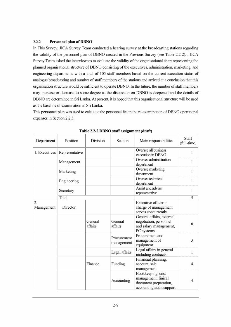
2-9
Personnel plan of DBNO
In This Survey, JICA Survey Team conducted a hearing survey at the broadcasting stations regarding
the validity of the personnel plan of DBNO created in the Previous Survey (see Table 2.2-2). , JICA
Survey Team asked the interviewees to evaluate the validity of the organisational chart representing the
planned organisational structure of DBNO consisting of the executives, administration, marketing, and
engineering departments with a total of 105 staff members based on the current execution status of
analogue broadcasting and number of staff members of the stations and arrived at a conclusion that this
organisation structure would be sufficient to operate DBNO. In the future, the number of staff members
may increase or decrease to some degree as the discussion on DBNO is deepened and the details of
DBNO are determined in Sri Lanka. At present, it is hoped that this organisational structure will be used
as the baseline of examination in Sri Lanka.
This personnel plan was used to calculate the personnel fee in the re-examination of DBNO operational
expenses in Section 2.2.3.
Table 2.2-2 DBNO staff assignment (draft)
Department Position Division Section Main responsibilities Staff (full-time)
1. Executives Representative Oversee all business execution in DBNO 1
Management Oversee administration department 1
Marketing Oversee marketing department 1
Engineering Oversee technical department 1
Secretary Assist and advise representative 1
Total 52. Management Director
Executive officer in charge of management serves concurrently
General affairs
General affairs
General affairs, external negotiation, personnel and salary management, PC systems
6
Procurement management
Procurement and management of equipment
3
Legal affairs Legal affairs in general including contracts 1
Finance Funding Financial planning, account, sale management
4
Accounting
Bookkeeping, cost management, finical document preparation, accounting audit support
4
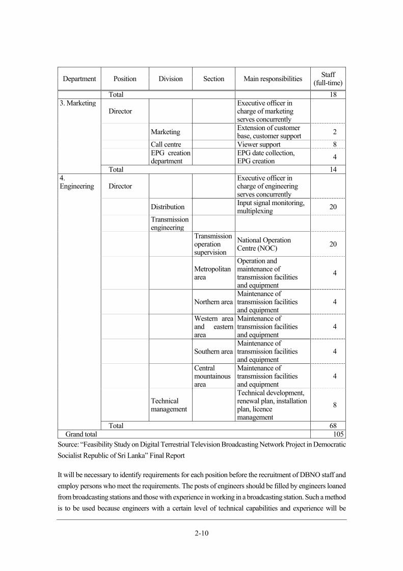
2-10
Department Position Division Section Main responsibilities Staff (full-time)
Total 183. Marketing
Director Executive officer in charge of marketing serves concurrently
Marketing Extension of customer base, customer support 2
Call centre Viewer support 8
EPG creation department EPG date collection,
EPG creation 4
Total 144. Engineering Director
Executive officer in charge of engineering serves concurrently
Distribution Input signal monitoring, multiplexing 20
Transmission engineering
Transmission operation supervision
National Operation Centre (NOC) 20
Metropolitan area
Operation and maintenance of transmission facilities and equipment
4
Northern areaMaintenance of transmission facilities and equipment
4
Western area and eastern area
Maintenance of transmission facilities and equipment
4
Southern areaMaintenance of transmission facilities and equipment
4
Central mountainous area
Maintenance of transmission facilities and equipment
4
Technical management
Technical development, renewal plan, installation plan, licence management
8
Total 68Grand total 105
Source: “Feasibility Study on Digital Terrestrial Television Broadcasting Network Project in Democratic
Socialist Republic of Sri Lanka” Final Report
It will be necessary to identify requirements for each position before the recruitment of DBNO staff and
employ persons who meet the requirements. The posts of engineers should be filled by engineers loaned
from broadcasting stations and those with experience in working in a broadcasting station. Such a method
is to be used because engineers with a certain level of technical capabilities and experience will be
2-11
required at the foundation of DBNO as there is no time to foster new engineers and the actual operation
is assumed to be started as soon as DBNO is founded and equipment is procured.
The equipment design of DBNO is being prepared based on the concept of manned monitoring at
important transmitting stations and unmanned monitoring for transmitting stations that receive signals
from a master station and broadcast them to their service areas. In the future, the manned monitoring will
be replaced by unmanned monitoring in stages to reduce the operation and maintenance costs of
transmitting stations. Some private broadcasting stations have already taken actions to prevent the
increase in the number of personnel by, for example, outsourcing the operation and maintenance of
regional transmitting stations to telecommunication providers. The reduction of personnel at transmitting
stations has also been an issue to be solved for DBNO. It is too early to adopt unmanned operation at all
the transmitting stations in Sri Lanka because of the need for emergency responses required by the current
status of power infrastructures. However, the organisational structure must be designed in consideration
of the adoption of the unmanned operation in future.
Note that it is fully possible to lower the failure risks such as transmitter stoppage if preventive
maintenance is conducted thoroughly through periodical inspection.
In Sri Lanka, it is examined whether DBNO should operate a call centre. It is clear that, in the period
before and after ASO, a huge number of inquiries will be received from people from the experience of
Japan and other countries. Therefore, considering the number of households in Sri Lanka, it is desirable
to acquire 100 or so call centre operators through outsourcing in this transition period to answer inquiries
from people, based on the example in Japan.
Re-examination of DBNO operational expenses
Re-examination and changes of components
The channel plan (which shows usable frequencies, effective radiation powers, etc. at each transmitting
stations), an essence of the migration into DTTB, was examined in detail and proposed in the Previous
Survey. However, a new frequency allocation was introduced in Sri Lanka later, making it necessary
to review the channel plan. It became also necessary to re-examine the feasibility of using the existing
antenna towers, which was confirmed in the Previous Survey, by including the existing antenna towers
of private broadcasting stations and to review the components and project cost of the Yen Loan Project,
operational expenses of DBNO, and DBNO usage fees based on the results of the re-examination to
alleviate the burden of operational expenses of the broadcasting stations until ASO and facilitate the
progress of the migration plan into DTTB.
The following describes the changes of the components of the Yen Loan Project according to the
review results.
a. Review of the channel plan (See Section 4.2.1 for details.)
The Previous Survey assumed construction of 10 new towers, but This Survey assumes
construction of six towers.
On the other hand, land expropriation of 5 sites assumed in the Previous Survey has been be
changed to that of 4 sites in This Survey.
2-12
b. Review of the antenna configuration (See Section 4.2.5 for details.)
Due to the review of the channel plan, the antenna configuration in Gongala Station must be
changed. As a result of changing the channel plan, interference will occur in the eastern and
western parts of the coverage area of Gongola Station where the coverage area overlaps with those
of Nayabedda and Elpitiya Stations, respectively. Until the expansion of the coverage area after
ASO, the occurrence of the interference will be prevented by using the design including parabolic
antennas, etc. that will only allow the station to cover a belt-shaped area in part of southwestern
Sri Lanka. Therefore, parabolic antennas, etc. need to be added to the antenna configuration of the
Previous Survey.
c. Review of the combiner to synthesize radio waves (See Section 4.2.3 for details)
Due to the change of the channel assignment status, the number of channels to be synthesized by
a combiner to synthesize radio waves (hereinafter referred to as “combiner”) needs to be changed.
The Previous Survey adopted combiners that could synthesize four radio waves for digital
broadcasting (or five radio waves for the existing sites that conducted analogue broadcasting).
Due to the re-examination of the channel assignment, however, channel repacking will be required
for multiple sites in the future. Therefore, the combiners will be changed to those which can
synthesize four channels for digital broadcasting and frequencies for channel repacking at the time
of Digital Switch Over (hereinafter referred to as “DSO”).
For Kokavil, furthermore, a combiner to synthesize five radio waves (synthesis of four channels
for digital broadcasting and one channel for analogue broadcasting currently unused) has been
selected. Note that this analogue channel is for the Tamil broadcasting planned by SLRC. Since
one more radio wave for channel repacking needs to be added, a combiner to synthesize six radio
waves will be required. For Jaffna and Vayuniya, too, as one more radio wave for repacking needs
to be added, a combiner to synthesize five radio waves will be adopted.
Table 2.2-3 shows the required number of combiner-synthesized frequencies at the transmitting
stations after the above-mentioned review. For the sites requiring seven or more synthesized
frequencies such as Hunnasgiriya and Gongala, two combiners will be procured in the Yen Loan
Project and one will be installed. The other combiner must be installed by DBNO at the stage of
channel repacking. The reason why two combiners are to be procured for these four sites rather
than a combiner that can synthesize seven or more radio waves is the total procurement cost can
be decreased. If the combiner which can deal with more than seven radio waves is adopted, it will
affect the specifications of other equipment such as transmitters, power supply facilities, and so
on, which might result in the increase of cost.
For sites requiring less than seven synthesized radio waves, on the other hand, designs that allows
one combiner to synthesize all the necessary channels will be adopted.

2-13
Table 2.2-3 Necessary number of synthesized frequencies for combiners
No.
Site of
transmitting
station
Number of synthesized
frequencies Configuration of device
Previous
Survey
This
Survey
1 Jaffna 4 5 Combiner to synthesize five radio
waves
2 Kokavil 5 6 Combiner to synthesize six radio
waves
3 Vayuniya 4 5 Combiner to synthesize five radio
waves
4 Trincomalee 4 5 Combiner to synthesize five radio
waves
5 Karagahatenna 4 6 Combiner to synthesize six radio
waves
6 Kurunegala 4 6 Combiner to synthesize six radio
waves
7 Colombo 4 5 Combiner to synthesize five radio
waves
8 Yatiyantota 4 5 Combiner to synthesize five radio
waves
9 Hunnasgiriya 5 9 Combiner to synthesize five radio
waves+combiner to synthesize four
radio waves
10 Pidurutalagala 4 5 Combiner to synthesize five radio
waves
11 Hantana 4 5 Combiner to synthesize five radio
waves
12 Badulla 4 5 Combiner to synthesize five radio
waves
13 Nayabedda 4 5 Combiner to synthesize five radio
waves
14 Gongala 4 8 Combiner to synthesize four radio
waves×2
15 Suriyakanda 4 8 Combiner to synthesize four radio
waves×2
16 Elpitiya 4 8 Combiner to synthesize four radio
waves×2
Source: JICA Survey Team
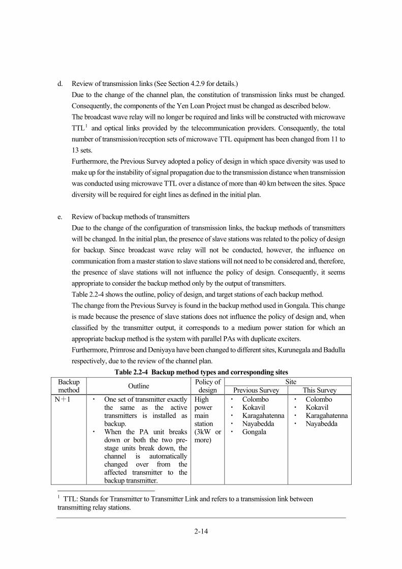
2-14
d. Review of transmission links (See Section 4.2.9 for details.)
Due to the change of the channel plan, the constitution of transmission links must be changed.
Consequently, the components of the Yen Loan Project must be changed as described below.
The broadcast wave relay will no longer be required and links will be constructed with microwave
TTL1 and optical links provided by the telecommunication providers. Consequently, the total
number of transmission/reception sets of microwave TTL equipment has been changed from 11 to
13 sets.
Furthermore, the Previous Survey adopted a policy of design in which space diversity was used to
make up for the instability of signal propagation due to the transmission distance when transmission
was conducted using microwave TTL over a distance of more than 40 km between the sites. Space
diversity will be required for eight lines as defined in the initial plan.
e. Review of backup methods of transmitters
Due to the change of the configuration of transmission links, the backup methods of transmitters
will be changed. In the initial plan, the presence of slave stations was related to the policy of design
for backup. Since broadcast wave relay will not be conducted, however, the influence on
communication from a master station to slave stations will not need to be considered and, therefore,
the presence of slave stations will not influence the policy of design. Consequently, it seems
appropriate to consider the backup method only by the output of transmitters.
Table 2.2-4 shows the outline, policy of design, and target stations of each backup method.
The change from the Previous Survey is found in the backup method used in Gongala. This change
is made because the presence of slave stations does not influence the policy of design and, when
classified by the transmitter output, it corresponds to a medium power station for which an
appropriate backup method is the system with parallel PAs with duplicate exciters.
Furthermore, Primrose and Deniyaya have been changed to different sites, Kurunegala and Badulla
respectively, due to the review of the channel plan.
Table 2.2-4 Backup method types and corresponding sites Backup method Outline Policy of
design Site
Previous Survey This SurveyN+1 ・ One set of transmitter exactly
the same as the active transmitters is installed as backup.
・ When the PA unit breaks down or both the two pre-stage units break down, the channel is automatically changed over from the affected transmitter to the backup transmitter.
High power main station (3kW or more)
・ Colombo・ Kokavil ・ Karagahatenna ・ Nayabedda ・ Gongala
・ Colombo ・ Kokavil ・ Karagahatenna・ Nayabedda
1 TTL: Stands for Transmitter to Transmitter Link and refers to a transmission link between transmitting relay stations.
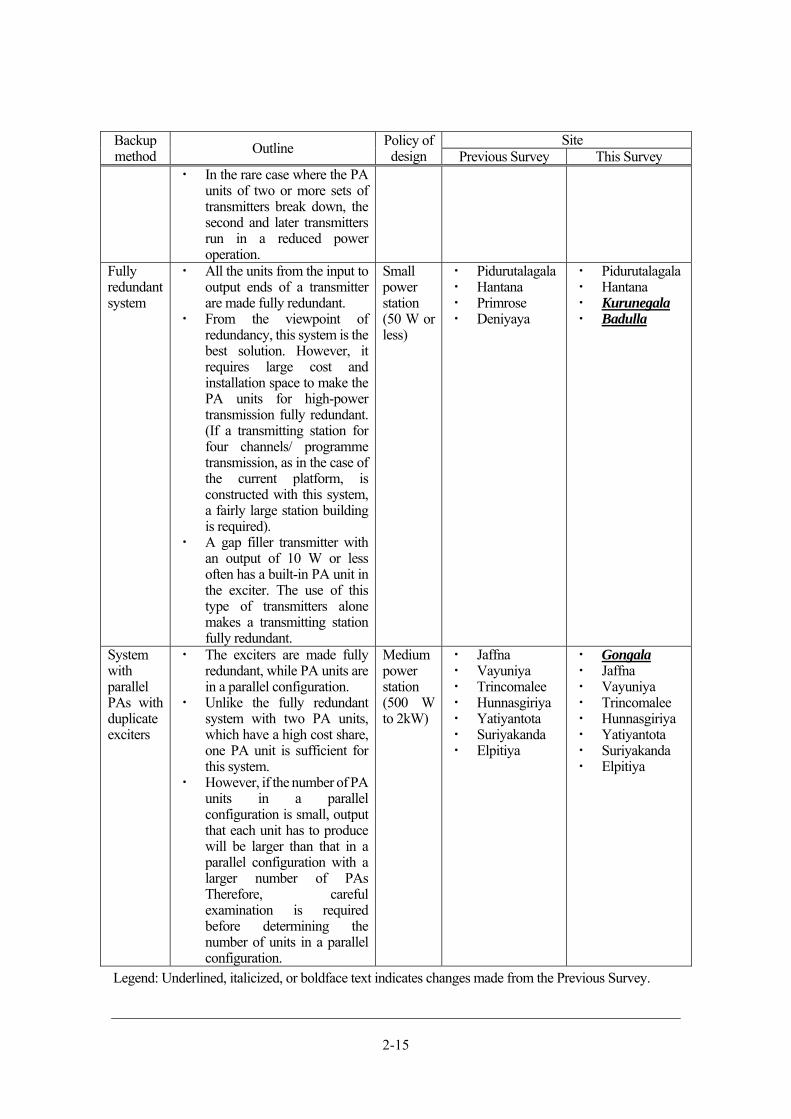
2-15
Backup method Outline Policy of
design Site
Previous Survey This Survey・ In the rare case where the PA
units of two or more sets of transmitters break down, the second and later transmitters run in a reduced power operation.
Fully redundant system
・ All the units from the input to output ends of a transmitter are made fully redundant.
・ From the viewpoint of redundancy, this system is the best solution. However, it requires large cost and installation space to make the PA units for high-power transmission fully redundant. (If a transmitting station for four channels/ programme transmission, as in the case of the current platform, is constructed with this system, a fairly large station building is required).
・ A gap filler transmitter with an output of 10 W or less often has a built-in PA unit in the exciter. The use of this type of transmitters alone makes a transmitting station fully redundant.
Small power station (50 W or less)
・ Pidurutalagala・ Hantana ・ Primrose ・ Deniyaya
・ Pidurutalagala・ Hantana ・ Kurunegala ・ Badulla
System with parallel PAs with duplicate exciters
・ The exciters are made fully redundant, while PA units are in a parallel configuration.
・ Unlike the fully redundant system with two PA units, which have a high cost share, one PA unit is sufficient for this system.
・ However, if the number of PA units in a parallel configuration is small, output that each unit has to produce will be larger than that in a parallel configuration with a larger number of PAs Therefore, careful examination is required before determining the number of units in a parallel configuration.
Medium power station (500 W to 2kW)
・ Jaffna・ Vayuniya ・ Trincomalee ・ Hunnasgiriya ・ Yatiyantota ・ Suriyakanda ・ Elpitiya
・ Gongala ・ Jaffna ・ Vayuniya ・ Trincomalee ・ Hunnasgiriya ・ Yatiyantota ・ Suriyakanda ・ Elpitiya
Legend: Underlined, italicized, or boldface text indicates changes made from the Previous Survey.

2-16
Source: JICA Survey Team
f. Review of the transmitter output (See Section 4.2.3 for details)
The transmitter output at Pidurutalagala designed at 300 W in the initial plan has been changed to
50 W due to the review of the channel plan.
g. Checking of the project cost of the Yen Loan Project
The total cost of Yen Loan Project was recalculated based on the above-mentioned changes of
components. The recalculation was aimed at checking whether the project budget for the Yen Loan
Project stated in the concluded L/A would be sufficient for implementing the project. Table 2.2-5
summarises the result of recalculation. Expenses for A-1.Antenna tower construction cost, B-1.d
Transmitter (microwave link line type), and D-1 Compulsory land purchase cost changed.
Meanwhile, each item needs to offset the difference by adjusting the associated preliminary
expenses because total budget of the project is fixed. Consequently, the total project cost in Japanese
yen is 17,437 million yen, staying same as that of Previous Survey.
Table 2.2-5 Result of recalculation of the total cost of Yen Loan Project
Before change After change
Item
Price (million) Price (million)
Overseas
procurement
(JPY)
Local
procurement
(Rs.)
Overseas
procurement
(JPY)
Local
procurement
(Rs.)
A Civil engineering cost (A-6) 60 2,095 60 1,973
1 Civil engineering 1 (DTTB platform
construction) 1,372
1,250
a Antenna tower construction cost 367 245
b Station building construction cost 461 461
c Electric facilities work cost 544 544
2 Civil engineering 2 (digital broadcasting
centre) 525
525
a Station building construction cost 350 350
b Electric facilities work cost 175 175
3 Civil engineering cost (A1 + A2) 1,897 1,775
4 Civil engineering: Dispute Adjudication
Board cost 60
60
5 Civil engineering: Price escalation 198 198
6 Civil engineering cost including price
escalation (A3 + A5) 2,095
1,973
B Equipment and materials (B7) 8,904 8,948
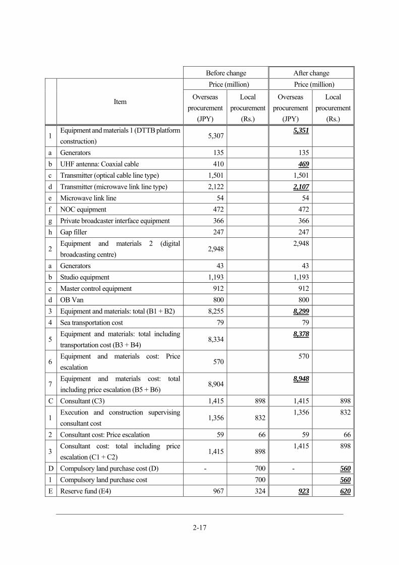
2-17
Before change After change
Item
Price (million) Price (million)
Overseas
procurement
(JPY)
Local
procurement
(Rs.)
Overseas
procurement
(JPY)
Local
procurement
(Rs.)
1 Equipment and materials 1 (DTTB platform
construction) 5,307
5,351
a Generators 135 135
b UHF antenna: Coaxial cable 410 469
c Transmitter (optical cable line type) 1,501 1,501
d Transmitter (microwave link line type) 2,122 2,107
e Microwave link line 54 54
f NOC equipment 472 472
g Private broadcaster interface equipment 366 366
h Gap filler 247 247
2 Equipment and materials 2 (digital
broadcasting centre) 2,948
2,948
a Generators 43 43
b Studio equipment 1,193 1,193
c Master control equipment 912 912
d OB Van 800 800
3 Equipment and materials: total (B1 + B2) 8,255 8,299
4 Sea transportation cost 79 79
5 Equipment and materials: total including
transportation cost (B3 + B4) 8,334
8,378
6 Equipment and materials cost: Price
escalation 570
570
7 Equipment and materials cost: total
including price escalation (B5 + B6) 8,904
8,948
C Consultant (C3) 1,415 898 1,415 898
1 Execution and construction supervising
consultant cost 1,356 832
1,356 832
2 Consultant cost: Price escalation 59 66 59 66
3 Consultant cost: total including price
escalation (C1 + C2) 1,415 898
1,415 898
D Compulsory land purchase cost (D) - 700 - 560
1 Compulsory land purchase cost 700 560
E Reserve fund (E4) 967 324 923 620

2-18
Before change After change
Item
Price (million) Price (million)
Overseas
procurement
(JPY)
Local
procurement
(Rs.)
Overseas
procurement
(JPY)
Local
procurement
(Rs.)
1 Equipment and materials and land
construction: Reserve fund 896 209 852*1 365*1
2 Consultant: Reserve fund 71 45 71 45
3 Compulsory land purchase: Reserve fund 70 210*1
4 Reserve fund: total 967 324 923 620
F Administrative cost (PMU) (F) - 924 - 908
1 Administrative cost 924 908
G Customs duties (G3) 2 2,752 2 2,734
1 Value-added tax 2 2,124 2 2,106
2 Import tax, etc. 628 628
H Initial cost 28 - 28 -
1 Initial cost 28 28
I Interest during construction (I) 22 - 22 -
1 Interest during construction 21 21
2 Consultant: Interest during construction 1 1
J
Total by currency: JPY
(A+B+C+E+G+H+I)/Rs.
(A+C+D+E+F+G)
11,398 7,693 11,398 7,693
K Amount in Sri Lanka rupee converted to
JPY (JPY conversion rate: 0.785*2) 6,039
6,039
Grand total in JPY 17,437 17,437
Legend: Underlined, italicized, or boldface text indicates changes made from the Previous Survey.
*1: Since the related expenses fluctuated, thereby differences are offset by adjusting the corresponding
preliminary expense.
*2: Rs. 1 = JPY 0.785 (The conversion rate used in the Previous Survey is used.)
Source: JICA Survey Team
Recalculation of operational expenses
The operational expenses of DBNO were calculated in the Previous Survey. However, due to the above-
mentioned changes of the components, the contents and amounts of the operational expenses calculated
in the Previous Survey were reviewed.
They were divided into eight items and each of them was examined respectively.
Specifically, the expenses were divided into 1. Personnel fee, 2. Cost of electricity, 3. Repair and
maintenance fee (maintenance work and procurement of goods, tower painting work and overhaul), 4.
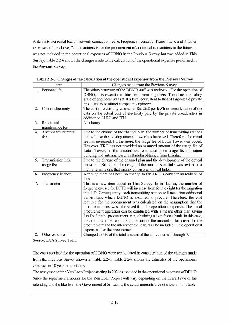
2-19
Antenna tower rental fee, 5. Network connection fee, 6. Frequency licence, 7. Transmitters, and 8. Other
expenses. of the above, 7. Transmitters is for the procurement of additional transmitters in the future. It
was not included in the operational expenses of DBNO in the Previous Survey but was added in This
Survey. Table 2.2-6 shows the changes made to the calculation of the operational expenses performed in
the Previous Survey.
Table 2.2-6 Changes of the calculation of the operational expenses from the Previous Survey Item Changes made from the Previous Survey
1. Personnel fee The salary structure of the DBNO staff was reviewed. For the operation of DBNO, it is essential to hire competent engineers. Therefore, the salary scale of engineers was set at a level equivalent to that of large-scale private broadcasters to attract competent engineers.
2. Cost of electricity The cost of electricity was set at Rs. 26.8 per kWh in consideration of the data on the actual cost of electricity paid by the private broadcasters in addition to SLRC and ITN.
3. Repair and maintenance fee
No change
4. Antenna tower rental fee
Due to the change of the channel plan, the number of transmitting stations that will use the existing antenna tower has increased. Therefore, the rental fee has increased. Furthermore, the usage fee of Lotus Tower was added. However, TRC has not provided an assumed amount of the usage fee of Lotus Tower, so the amount was estimated from usage fee of station building and antenna tower in Badulla obtained from Etisalat.
5. Transmission link usage fee
Due to the change of the channel plan and the development of the optical network in Sri Lanka, the design of the transmission links was revised to a highly reliable one that mainly consists of optical links.
6. Frequency licence Although there has been no change so far, TRC is considering revision of fees.
7. Transmitter This is a new item added in This Survey. In Sri Lanka, the number of frequencies used for DTTB will increase from four to eight for the migration into HD. Consequently, each transmitting station will need four additional transmitters, which DBNO is assumed to procure. Therefore, the cost required for the procurement was calculated on the assumption that the procurement cost was to be saved from the operational expenses. The actual procurement operation can be conducted with a means other than saving fund before the procurement, e.g., obtaining a loan from a bank. In this case, the amounts to be repaid, i.e., the sum of the amount of loan used for the procurement and the interest of the loan, will be included in the operational expenses after the procurement.
8. Other expenses Changed to 5% of the total amount of the above items 1 through 7. Source: JICA Survey Team
The costs required for the operation of DBNO were recalculated in consideration of the changes made
from the Previous Survey shown in Table 2.2-6. Table 2.2-7 shows the estimates of the operational
expenses in 10 years in the future.
The repayment of the Yen Loan Project starting in 2024 is included in the operational expenses of DBNO.
Since the repayment amounts for the Yen Loan Project will vary depending on the interest rate of the
relending and the like from the Government of Sri Lanka, the actual amounts are not shown in this table.
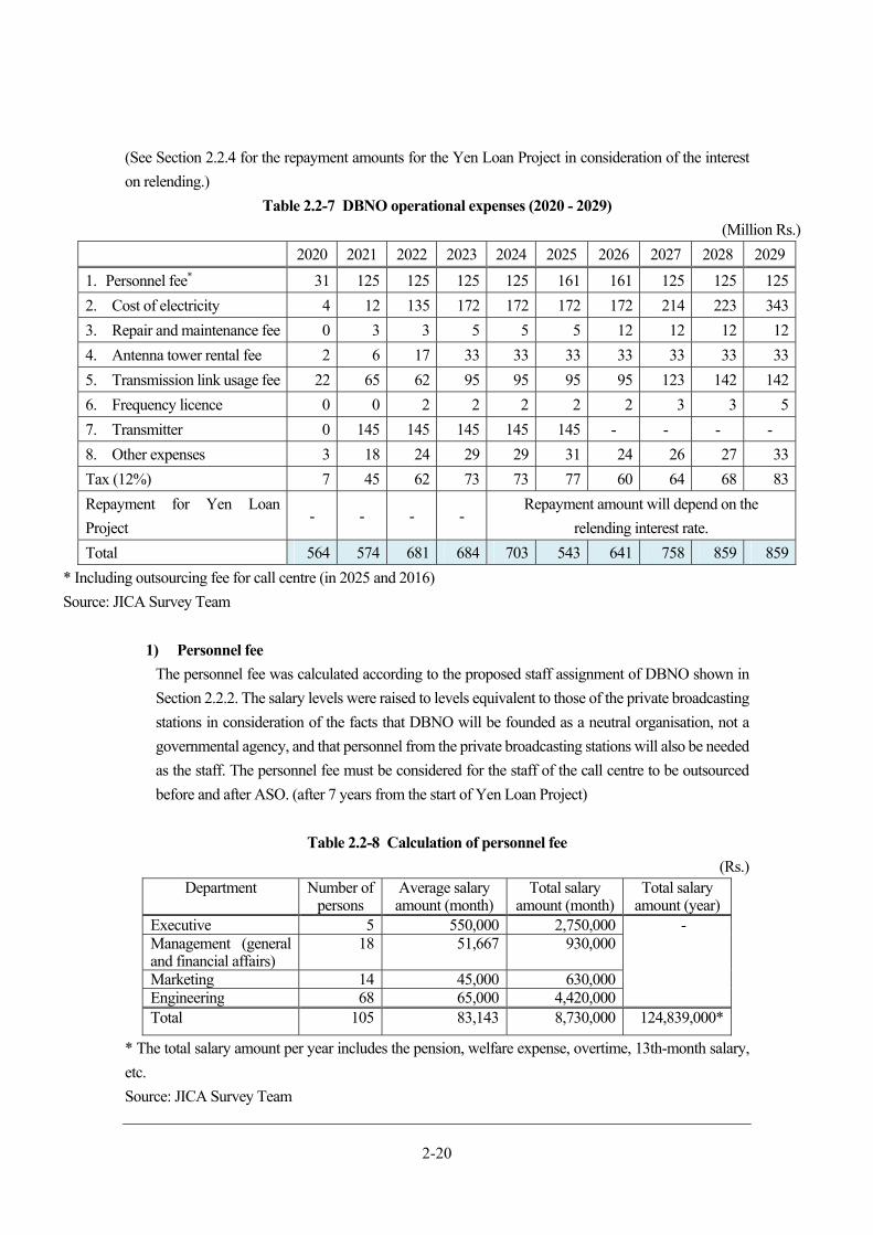
2-20
(See Section 2.2.4 for the repayment amounts for the Yen Loan Project in consideration of the interest
on relending.)
Table 2.2-7 DBNO operational expenses (2020 - 2029)
(Million Rs.)
2020 2021 2022 2023 2024 2025 2026 2027 2028 2029
1. Personnel fee* 31 125 125 125 125 161 161 125 125 125
2. Cost of electricity 4 12 135 172 172 172 172 214 223 343
3. Repair and maintenance fee 0 3 3 5 5 5 12 12 12 12
4. Antenna tower rental fee 2 6 17 33 33 33 33 33 33 33
5. Transmission link usage fee 22 65 62 95 95 95 95 123 142 142
6. Frequency licence 0 0 2 2 2 2 2 3 3 5
7. Transmitter 0 145 145 145 145 145 - - - -
8. Other expenses 3 18 24 29 29 31 24 26 27 33
Tax (12%) 7 45 62 73 73 77 60 64 68 83
Repayment for Yen Loan
Project - - - -
Repayment amount will depend on the
relending interest rate.
Total 564 574 681 684 703 543 641 758 859 859
* Including outsourcing fee for call centre (in 2025 and 2016)
Source: JICA Survey Team
1) Personnel fee
The personnel fee was calculated according to the proposed staff assignment of DBNO shown in
Section 2.2.2. The salary levels were raised to levels equivalent to those of the private broadcasting
stations in consideration of the facts that DBNO will be founded as a neutral organisation, not a
governmental agency, and that personnel from the private broadcasting stations will also be needed
as the staff. The personnel fee must be considered for the staff of the call centre to be outsourced
before and after ASO. (after 7 years from the start of Yen Loan Project)
Table 2.2-8 Calculation of personnel fee
(Rs.) Department Number of
personsAverage salary amount (month)
Total salary amount (month)
Total salary amount (year)
Executive 5 550,000 2,750,000 - Management (general and financial affairs)
18 51,667 930,000
Marketing 14 45,000 630,000Engineering 68 65,000 4,420,000Total 105 83,143 8,730,000 124,839,000*
* The total salary amount per year includes the pension, welfare expense, overtime, 13th-month salary,
etc.
Source: JICA Survey Team
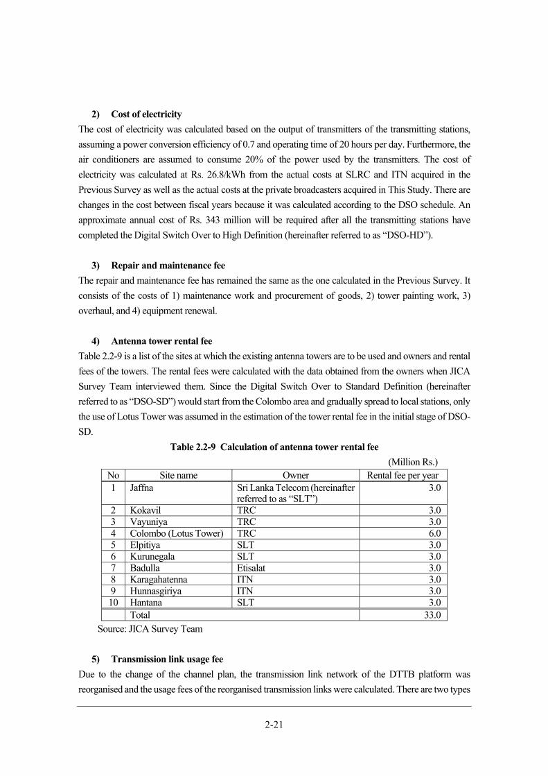
2-21
2) Cost of electricity
The cost of electricity was calculated based on the output of transmitters of the transmitting stations,
assuming a power conversion efficiency of 0.7 and operating time of 20 hours per day. Furthermore, the
air conditioners are assumed to consume 20% of the power used by the transmitters. The cost of
electricity was calculated at Rs. 26.8/kWh from the actual costs at SLRC and ITN acquired in the
Previous Survey as well as the actual costs at the private broadcasters acquired in This Study. There are
changes in the cost between fiscal years because it was calculated according to the DSO schedule. An
approximate annual cost of Rs. 343 million will be required after all the transmitting stations have
completed the Digital Switch Over to High Definition (hereinafter referred to as “DSO-HD”).
3) Repair and maintenance fee
The repair and maintenance fee has remained the same as the one calculated in the Previous Survey. It
consists of the costs of 1) maintenance work and procurement of goods, 2) tower painting work, 3)
overhaul, and 4) equipment renewal.
4) Antenna tower rental fee
Table 2.2-9 is a list of the sites at which the existing antenna towers are to be used and owners and rental
fees of the towers. The rental fees were calculated with the data obtained from the owners when JICA
Survey Team interviewed them. Since the Digital Switch Over to Standard Definition (hereinafter
referred to as “DSO-SD”) would start from the Colombo area and gradually spread to local stations, only
the use of Lotus Tower was assumed in the estimation of the tower rental fee in the initial stage of DSO-
SD.
Table 2.2-9 Calculation of antenna tower rental fee
(Million Rs.) No Site name Owner Rental fee per year 1 Jaffna Sri Lanka Telecom (hereinafter
referred to as “SLT”)3.0
2 Kokavil TRC 3.0 3 Vayuniya TRC 3.0 4 Colombo (Lotus Tower) TRC 6.0 5 Elpitiya SLT 3.0 6 Kurunegala SLT 3.0 7 Badulla Etisalat 3.0 8 Karagahatenna ITN 3.0 9 Hunnasgiriya ITN 3.0 10 Hantana SLT 3.0 Total 33.0
Source: JICA Survey Team
5) Transmission link usage fee
Due to the change of the channel plan, the transmission link network of the DTTB platform was
reorganised and the usage fees of the reorganised transmission links were calculated. There are two types
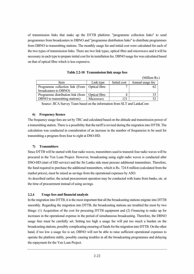
2-22
of transmission links that make up the DTTB platform: "programme collection links" to send
programmes from broadcasters to DBNO and "programme distribution links" to distribute programmes
from DBNO to transmitting stations. The monthly usage fee and initial cost were calculated for each of
the two types of transmission links. There are two link types, optical fibre and microwave and it will be
necessary in each type to prepare initial cost for its installation fee. DBNO usage fee was calculated based
on that of optical fibre which is less expensive.
Table 2.2-10 Transmission link usage fees
(Million Rs.) Item Link type Initial cost Annual usage fee
Programme collection link (From broadcasters to DBNO)
Optical fibre 7 62
Programme distribution link (from DBNO to transmitting stations)
Optical fibre 4 33 Microwave 121 52
Source: JICA Survey Team based on the information from SLT and LankaCom
6) Frequency licence
The frequency usage fees are set by TRC and calculated based on the altitude and transmission power of
a transmitting station. There is a possibility that the tariff is revised during the migration into DTTB. The
calculation was conducted in consideration of an increase in the number of frequencies to be used for
transmitting a program from four to eight at DSO-HD.
7) Transmitters
Since DTTB will be started with four radio waves, transmitters used to transmit four radio waves will be
procured in the Yen Loan Project. However, broadcasting using eight radio waves is conducted after
DSO-HD (start of HD service) and the Sri Lanka side must procure additional transmitters. Therefore,
the fund required to purchase the additional transmitters, which is Rs. 724.8 million (calculated from the
market prices), must be raised as savings from the operational expenses by ASO.
As described earlier, the actual procurement operation may be conducted with loans from banks, etc. at
the time of procurement instead of using savings.
Usage fees and financial analysis
In the migration into DTTB, it is the most important that all the broadcasting stations migrate into DTTB
smoothly. Regarding the migration into DTTB, the broadcasting stations are troubled the most by two
things: (1) Acquisition of the cost for procuring DTTB equipment and (2) Financing to make up for
increases in the operational expense in the period of simultaneous broadcasting. Therefore, the DBNO
usage fees must be carefully set. Setting too high a usage fee will put too much a burden on the
broadcasting stations, possibly complicating ensuring of funds for the migration into DTTB. On the other
hand, if too low a usage fee is set, DBNO will not be able to raise sufficient operational expenses to
operate the platform stably, possibly causing troubles in all the broadcasting programmes and delaying
the repayment for the Yen Loan Project.
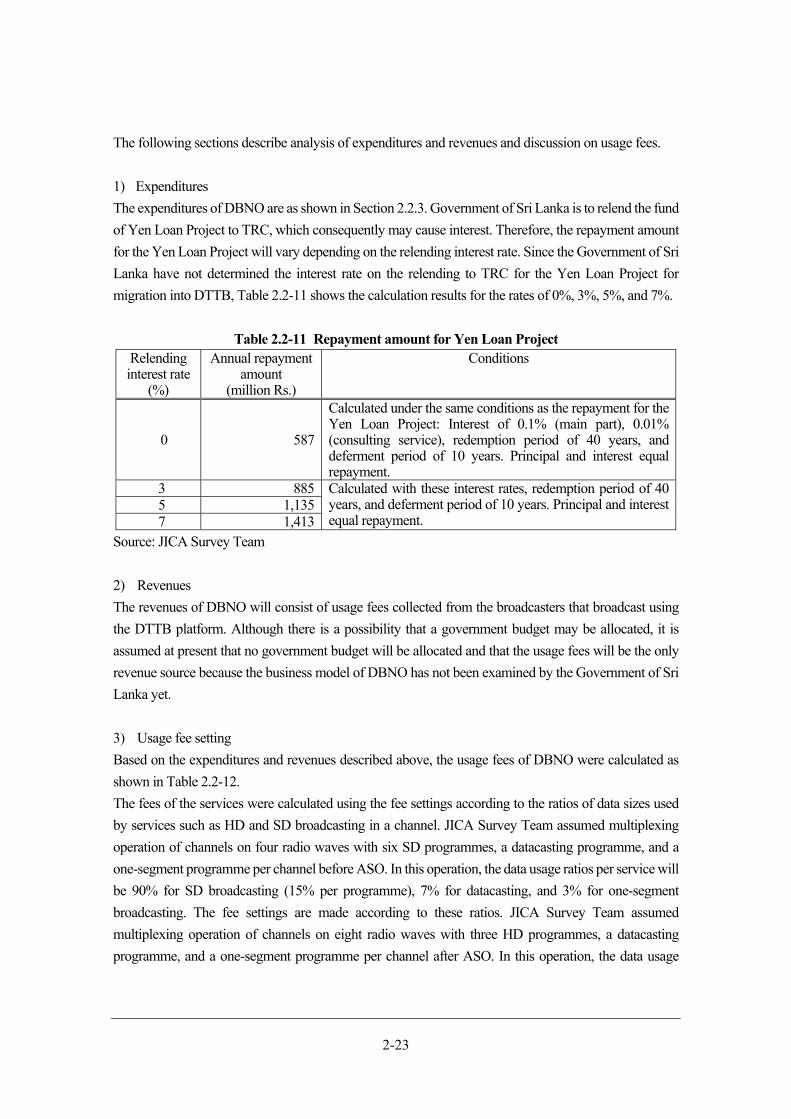
2-23
The following sections describe analysis of expenditures and revenues and discussion on usage fees.
1) Expenditures
The expenditures of DBNO are as shown in Section 2.2.3. Government of Sri Lanka is to relend the fund
of Yen Loan Project to TRC, which consequently may cause interest. Therefore, the repayment amount
for the Yen Loan Project will vary depending on the relending interest rate. Since the Government of Sri
Lanka have not determined the interest rate on the relending to TRC for the Yen Loan Project for
migration into DTTB, Table 2.2-11 shows the calculation results for the rates of 0%, 3%, 5%, and 7%.
Table 2.2-11 Repayment amount for Yen Loan Project Relending interest rate
(%)
Annual repayment amount
(million Rs.)
Conditions
0 587
Calculated under the same conditions as the repayment for the Yen Loan Project: Interest of 0.1% (main part), 0.01% (consulting service), redemption period of 40 years, and deferment period of 10 years. Principal and interest equal repayment.
3 885 Calculated with these interest rates, redemption period of 40 years, and deferment period of 10 years. Principal and interest equal repayment.
5 1,135 7 1,413
Source: JICA Survey Team
2) Revenues
The revenues of DBNO will consist of usage fees collected from the broadcasters that broadcast using
the DTTB platform. Although there is a possibility that a government budget may be allocated, it is
assumed at present that no government budget will be allocated and that the usage fees will be the only
revenue source because the business model of DBNO has not been examined by the Government of Sri
Lanka yet.
3) Usage fee setting
Based on the expenditures and revenues described above, the usage fees of DBNO were calculated as
shown in Table 2.2-12.
The fees of the services were calculated using the fee settings according to the ratios of data sizes used
by services such as HD and SD broadcasting in a channel. JICA Survey Team assumed multiplexing
operation of channels on four radio waves with six SD programmes, a datacasting programme, and a
one-segment programme per channel before ASO. In this operation, the data usage ratios per service will
be 90% for SD broadcasting (15% per programme), 7% for datacasting, and 3% for one-segment
broadcasting. The fee settings are made according to these ratios. JICA Survey Team assumed
multiplexing operation of channels on eight radio waves with three HD programmes, a datacasting
programme, and a one-segment programme per channel after ASO. In this operation, the data usage
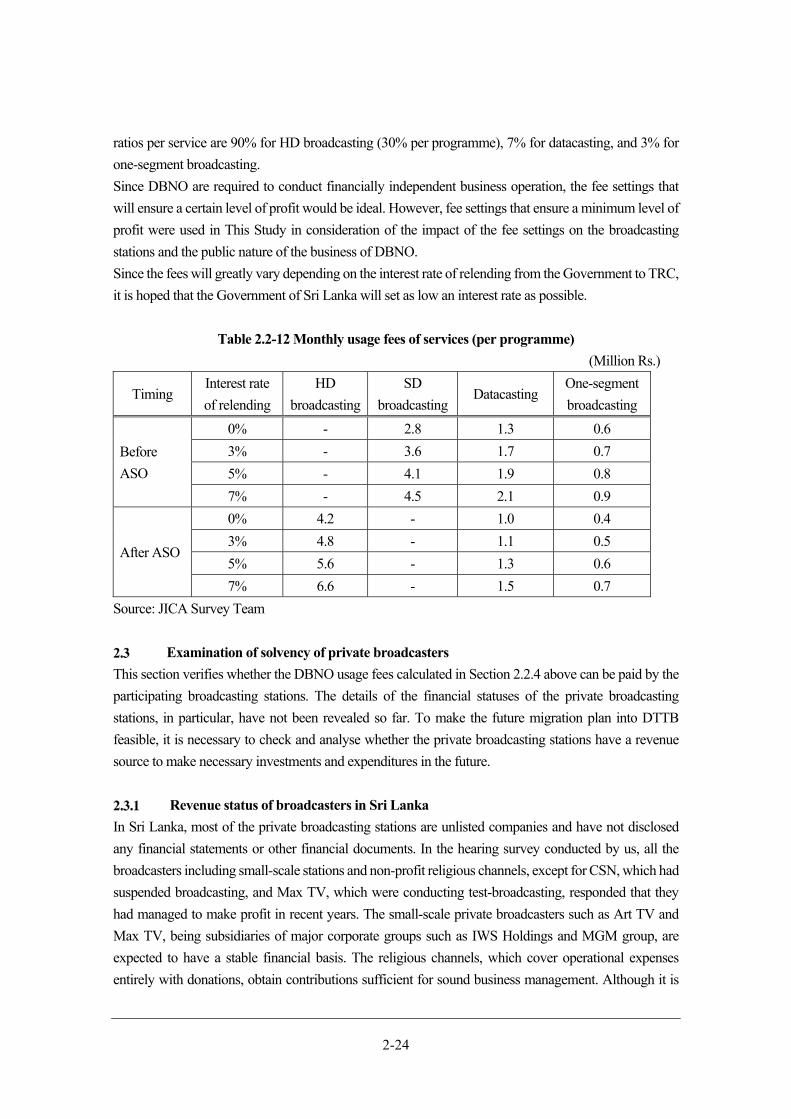
2-24
ratios per service are 90% for HD broadcasting (30% per programme), 7% for datacasting, and 3% for
one-segment broadcasting.
Since DBNO are required to conduct financially independent business operation, the fee settings that
will ensure a certain level of profit would be ideal. However, fee settings that ensure a minimum level of
profit were used in This Study in consideration of the impact of the fee settings on the broadcasting
stations and the public nature of the business of DBNO.
Since the fees will greatly vary depending on the interest rate of relending from the Government to TRC,
it is hoped that the Government of Sri Lanka will set as low an interest rate as possible.
Table 2.2-12 Monthly usage fees of services (per programme)
(Million Rs.)
Timing Interest rate
of relending
HD
broadcasting
SD
broadcastingDatacasting
One-segment
broadcasting
Before
ASO
0% - 2.8 1.3 0.6
3% - 3.6 1.7 0.7
5% - 4.1 1.9 0.8
7% - 4.5 2.1 0.9
After ASO
0% 4.2 - 1.0 0.4
3% 4.8 - 1.1 0.5
5% 5.6 - 1.3 0.6
7% 6.6 - 1.5 0.7
Source: JICA Survey Team
Examination of solvency of private broadcasters
This section verifies whether the DBNO usage fees calculated in Section 2.2.4 above can be paid by the
participating broadcasting stations. The details of the financial statuses of the private broadcasting
stations, in particular, have not been revealed so far. To make the future migration plan into DTTB
feasible, it is necessary to check and analyse whether the private broadcasting stations have a revenue
source to make necessary investments and expenditures in the future.
Revenue status of broadcasters in Sri Lanka
In Sri Lanka, most of the private broadcasting stations are unlisted companies and have not disclosed
any financial statements or other financial documents. In the hearing survey conducted by us, all the
broadcasters including small-scale stations and non-profit religious channels, except for CSN, which had
suspended broadcasting, and Max TV, which were conducting test-broadcasting, responded that they
had managed to make profit in recent years. The small-scale private broadcasters such as Art TV and
Max TV, being subsidiaries of major corporate groups such as IWS Holdings and MGM group, are
expected to have a stable financial basis. The religious channels, which cover operational expenses
entirely with donations, obtain contributions sufficient for sound business management. Although it is
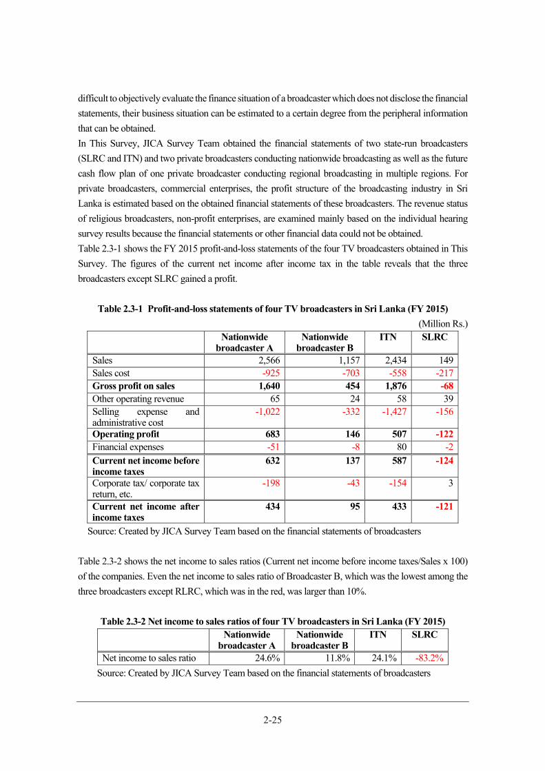
2-25
difficult to objectively evaluate the finance situation of a broadcaster which does not disclose the financial
statements, their business situation can be estimated to a certain degree from the peripheral information
that can be obtained.
In This Survey, JICA Survey Team obtained the financial statements of two state-run broadcasters
(SLRC and ITN) and two private broadcasters conducting nationwide broadcasting as well as the future
cash flow plan of one private broadcaster conducting regional broadcasting in multiple regions. For
private broadcasters, commercial enterprises, the profit structure of the broadcasting industry in Sri
Lanka is estimated based on the obtained financial statements of these broadcasters. The revenue status
of religious broadcasters, non-profit enterprises, are examined mainly based on the individual hearing
survey results because the financial statements or other financial data could not be obtained.
Table 2.3-1 shows the FY 2015 profit-and-loss statements of the four TV broadcasters obtained in This
Survey. The figures of the current net income after income tax in the table reveals that the three
broadcasters except SLRC gained a profit.
Table 2.3-1 Profit-and-loss statements of four TV broadcasters in Sri Lanka (FY 2015)
(Million Rs.) Nationwide
broadcaster A Nationwide
broadcaster B ITN SLRC
Sales 2,566 1,157 2,434 149Sales cost -925 -703 -558 -217Gross profit on sales 1,640 454 1,876 -68Other operating revenue 65 24 58 39Selling expense and administrative cost
-1,022 -332 -1,427 -156
Operating profit 683 146 507 -122Financial expenses -51 -8 80 -2Current net income before income taxes
632 137 587 -124
Corporate tax/ corporate tax return, etc.
-198 -43 -154 3
Current net income after income taxes
434 95 433 -121
Source: Created by JICA Survey Team based on the financial statements of broadcasters
Table 2.3-2 shows the net income to sales ratios (Current net income before income taxes/Sales x 100)
of the companies. Even the net income to sales ratio of Broadcaster B, which was the lowest among the
three broadcasters except RLRC, which was in the red, was larger than 10%.
Table 2.3-2 Net income to sales ratios of four TV broadcasters in Sri Lanka (FY 2015) Nationwide
broadcaster A Nationwide
broadcaster BITN SLRC
Net income to sales ratio 24.6% 11.8% 24.1% -83.2%
Source: Created by JICA Survey Team based on the financial statements of broadcasters
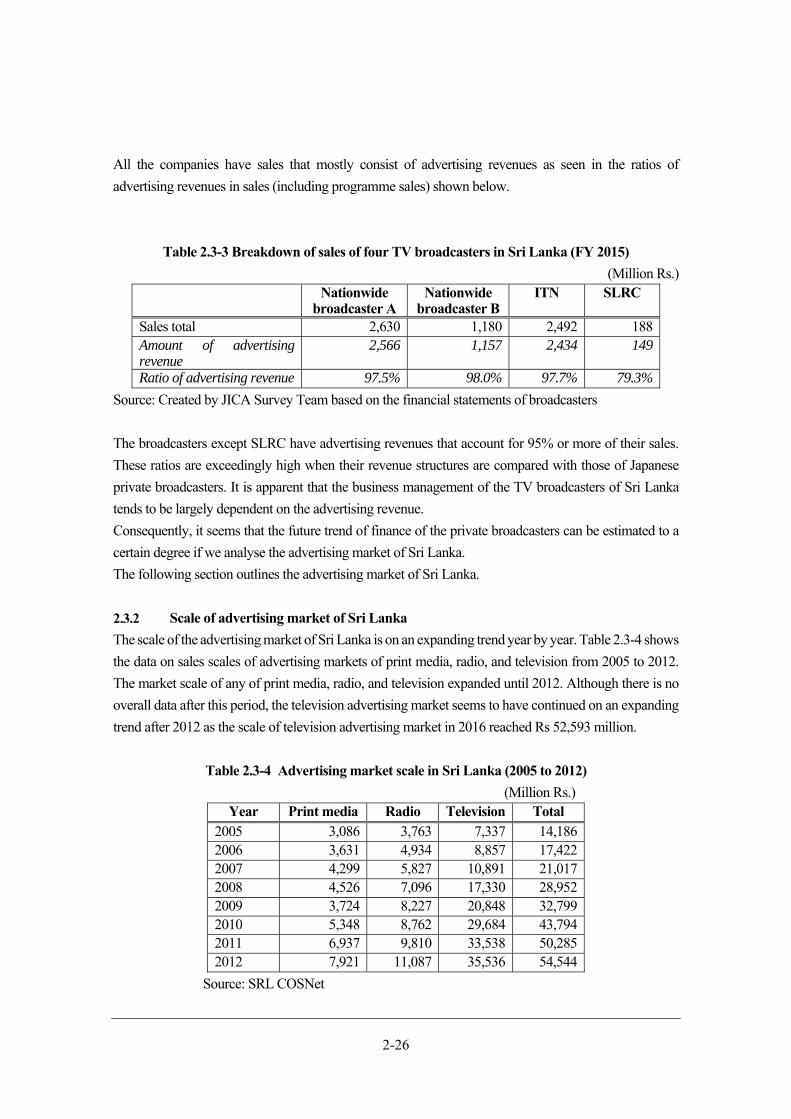
2-26
All the companies have sales that mostly consist of advertising revenues as seen in the ratios of
advertising revenues in sales (including programme sales) shown below.
Table 2.3-3 Breakdown of sales of four TV broadcasters in Sri Lanka (FY 2015)
(Million Rs.) Nationwide
broadcaster ANationwide
broadcaster BITN SLRC
Sales total 2,630 1,180 2,492 188 Amount of advertising revenue
2,566 1,157 2,434 149
Ratio of advertising revenue 97.5% 98.0% 97.7% 79.3%
Source: Created by JICA Survey Team based on the financial statements of broadcasters
The broadcasters except SLRC have advertising revenues that account for 95% or more of their sales.
These ratios are exceedingly high when their revenue structures are compared with those of Japanese
private broadcasters. It is apparent that the business management of the TV broadcasters of Sri Lanka
tends to be largely dependent on the advertising revenue.
Consequently, it seems that the future trend of finance of the private broadcasters can be estimated to a
certain degree if we analyse the advertising market of Sri Lanka.
The following section outlines the advertising market of Sri Lanka.
Scale of advertising market of Sri Lanka
The scale of the advertising market of Sri Lanka is on an expanding trend year by year. Table 2.3-4 shows
the data on sales scales of advertising markets of print media, radio, and television from 2005 to 2012.
The market scale of any of print media, radio, and television expanded until 2012. Although there is no
overall data after this period, the television advertising market seems to have continued on an expanding
trend after 2012 as the scale of television advertising market in 2016 reached Rs 52,593 million.
Table 2.3-4 Advertising market scale in Sri Lanka (2005 to 2012)
(Million Rs.) Year Print media Radio Television Total
2005 3,086 3,763 7,337 14,186 2006 3,631 4,934 8,857 17,422 2007 4,299 5,827 10,891 21,017 2008 4,526 7,096 17,330 28,952 2009 3,724 8,227 20,848 32,799 2010 5,348 8,762 29,684 43,794 2011 6,937 9,810 33,538 50,285 2012 7,921 11,087 35,536 54,544
Source: SRL COSNet

2-27
Survey Research Lanka Pvt. Ltd. (SRL), a company in Colombo that collect and sell media-related data,
have created a database on annual advertising fees by sponsor and broadcaster. Table 2.3-5 shows the
data for 2016.
Table 2.3-5 Advertising revenues by broadcaster in Sri Lanka in 2016
(Rs.) Broadcaster Total annual advertising revenue
from major clients Company C 14,664,321,473Company D 12,599,068,234Company E 8,263,431,200Company F 6,175,221,604Company G 5,115,859,855Company H 4,329,051,087Company I 644,090,957Company J 486,155,316Company K 218,611,548Company L 98,219,524Total 52,594,030,798
Source: SRL
If these data cover all the advertising revenues of the broadcasters, their revenue amounts in 2016 can be
estimated roughly on the assumption that the advertising revenues account for more than 90% of sales,
as indicated in Table 2.3-3.
Religious broadcasters
In Sri Lanka, apart from the national broadcasting and private broadcasting stations, there are three
broadcasting stations operated by Buddhist religious organisations. All of them are small-scale local
broadcasters with transmitting stations at only one or two locations. Table 2.3-6 shows an outline of the
religious broadcasting.
Table 2.3-6 Sri Lankan religious broadcasters Company M Company N Company O
No. transmitting stations
1 2 1
Service area Matale District Greater Colombo Greater Colombo Source: JICA Survey Team
A broadcaster operated by a religious organisation with donations is exempt from corporate and other
taxes as it is considered a specified non-profit corporation. The above three stations meet all their
2-28
operational expenses with donations from their supporters and viewers. They are supposed to be able to
purchase almost all the equipment for DTTB with donations.
However, since 2016 Company M has been operating on revenue from advertisements and sponsors, so
they are no longer eligible for the favourable tax treatment. In an interview with Rangiri TV, JICA Survey
Team learned that the operational expenses for TV broadcasts alone were about Rs three million per
month and, when the TV advertising revenue was insufficient, they supplemented it with revenue from
radio broadcasts and obtained short-term loans from a bank. This information suggests that at present it
is difficult for the station to obtain sufficient revenue only from TV broadcasting advertisement to cover
the operational expenses. The service area of the terrestrial broadcasts of Company M is only the Matale
District of Sri Lanka, but their programmes can be viewed in the whole country through Dialog TV, a
satellite broadcaster, and PEO TV, an IPTV operated by SLT.
Company N are the oldest religious TV channel, which have been operating since 2007. Their
programmes can also be viewed via the satellite broadcast Dialogue TV and Dish TV and PEO TV, an
IPTV. JICA Survey Team learned that their annual donation revenue was about Rs 200 million, which
was sufficient to cover the operational expenses. The operation and maintenance costs including those
for the equipment are about Rs 150 to 170 million per year.
Company O are the newest of the religious broadcasting stations, which were established in 2012.
Company O also distribute its programmes via Dialog TV and PEO TV. According to the information
obtained in an interview their annual donation revenue is about Rs 24 million. So far, they have managed
to cover the operation and maintenance expenses with this revenue, but they have some concerns over
insufficient funds.
Capacity to Pay DBNO Usage Charges
(1) Study of broadcasters’ transmitting station operation and maintenance costs
After the migration into DTTB has been completed, the transmission facilities currently maintained by
each broadcasting station will become unnecessary, so the operation and maintenance expenses for the
transmission facilities borne by the stations will become unnecessary. The usage fee of transmission links
between transmission stations and between the stations and studios and frequency license charge will
also be unnecessary. The amount that broadcasting stations are currently paying for these expenses can
be allocated to the DBNO usage charge after the complete migration into DTTB, so this amount can be
considered to be the minimum amount that the stations can pay as the DBNO usage charge. Table 2.3-7
below shows the breakdown of the expenses that it is considered will no longer be necessary for the
broadcasting stations to bear after the complete migration into DTTB. (In this document, the above
expenses that will become unnecessary in the future are referred to as redundant expenses.)
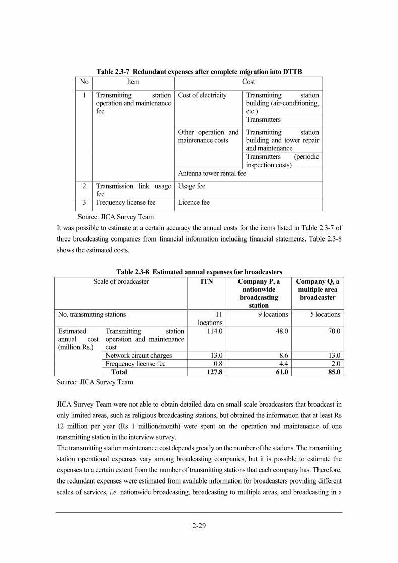
2-29
Table 2.3-7 Redundant expenses after complete migration into DTTB No Item Cost
1 Transmitting station operation and maintenance fee
Cost of electricity Transmitting station building (air-conditioning, etc.)Transmitters
Other operation and maintenance costs
Transmitting station building and tower repair and maintenance Transmitters (periodic inspection costs)
Antenna tower rental fee
2 Transmission link usage fee
Usage fee
3 Frequency license fee Licence fee
Source: JICA Survey Team
It was possible to estimate at a certain accuracy the annual costs for the items listed in Table 2.3-7 of
three broadcasting companies from financial information including financial statements. Table 2.3-8
shows the estimated costs.
Table 2.3-8 Estimated annual expenses for broadcasters Scale of broadcaster ITN Company P, a
nationwide broadcasting
station
Company Q, a multiple area broadcaster
No. transmitting stations 11 locations
9 locations 5 locations
Estimated annual cost (million Rs.)
Transmitting stationoperation and maintenance cost
114.0 48.0 70.0
Network circuit charges 13.0 8.6 13.0Frequency license fee 0.8 4.4 2.0
Total 127.8 61.0 85.0Source: JICA Survey Team
JICA Survey Team were not able to obtain detailed data on small-scale broadcasters that broadcast in
only limited areas, such as religious broadcasting stations, but obtained the information that at least Rs
12 million per year (Rs 1 million/month) were spent on the operation and maintenance of one
transmitting station in the interview survey.
The transmitting station maintenance cost depends greatly on the number of the stations. The transmitting
station operational expenses vary among broadcasting companies, but it is possible to estimate the
expenses to a certain extent from the number of transmitting stations that each company has. Therefore,
the redundant expenses were estimated from available information for broadcasters providing different
scales of services, i.e. nationwide broadcasting, broadcasting to multiple areas, and broadcasting in a
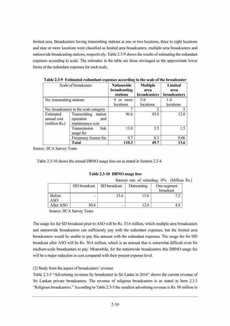
2-30
limited area. Broadcasters having transmitting stations at one or two locations, three to eight locations
and nine or more locations were classified as limited area broadcasters, multiple area broadcasters and
nationwide broadcasting stations, respectively. Table 2.3-9 shows the results of estimating the redundant
expenses according to scale. The estimates in the table are those envisaged as the approximate lower
limits of the redundant expenses for each scale.
Table 2.3-9 Estimated redundant expenses according to the scale of the broadcaster Scale of broadcaster Nationwide
broadcasting stations
Multiple area
broadcasters
Limited area
broadcasters No. transmitting stations 9 or more
locations5-8 locations
1-4 locations
No. broadcasters in the scale category 7 2 5 Estimated annual cost (million Rs.)
Transmitting station operation and maintenance cost
96.6 45.9 12.0
Transmission link usage fee
13.0 3.5 1.5
Frequency license fee 0.7 0.3 0.06 Total 110.3 49.7 13.6
Source: JICA Survey Team
Table 2.3-10 shows the annual DBNO usage fees set as stated in Section 2.2-4.
Table 2.3-10 DBNO usage fees
Interest rate of relending: 0% (Million Rs.) HD broadcast SD broadcast Datacasting One-segment
broadcast Before ASO
- 33.6 15.6 7.2
After ASO 50.4 - 12.0 4.8 Source: JICA Survey Team
The usage fee for SD broadcast prior to ASO will be Rs. 33.6 million, which multiple area broadcasters
and nationwide broadcasters can sufficiently pay with the redundant expenses, but the limited area
broadcasters would be unable to pay this amount with the redundant expenses. The usage fee for HD
broadcast after ASO will be Rs. 50.4 million, which is an amount that is somewhat difficult even for
medium-scale broadcasters to pay. Meanwhile, for the nationwide broadcasters this DBNO usage fee
will be a major reduction in cost compared with their present expense level.
(2) Study from the aspect of broadcasters’ revenue
Table 2.3-5 “Advertising revenues by broadcaster in Sri Lanka in 2016” shows the current revenue of
Sri Lankan private broadcasters. The revenue of religious broadcasters is as stated in Item 2.3.3
“Religious broadcasters.” According to Table 2.3-5 the smallest advertising revenue is Rs. 98 million in
2-31
2016. After the commencement of digital broadcasting, all broadcasters can broadcast nationwide if they
join DBNO, so there is a possibility that broadcasters that are currently broadcast limited area will benefit
from a boost to their revenue including advertising revenue. The extent of this boost in revenue is unclear.
At the nationwide broadcaster with the lowest advertising revenue at present, the revenue is Rs 644
million/year. If it is assumed that the net profit to sales percentage is about 10%, by reference to Table
2.3-2 “Net income to sales ratios of four TV broadcasters in Sri Lanka (FY 2015)”, then the profit of a
broadcasting station with revenue of Rs 644 million /year is estimated at Rs 64 million/year, which would
enable payment of the usage fees of Rs 50.4 million /year for HD broadcasts after ASO.
It is considered that for religious broadcasters, which are the smallest, it would be difficult to pay the
DBNO fees stated above from their annual revenue unless their revenue from donations greatly increases.
Therefore, it is necessary to consider providing a certain amount of support for religious broadcasting.
(See Section 6.8 “DBNO usage fee”)
Chapter 3 Formulation of draft for technical standards
for transmitter and receiver

3-1
Formulation of draft for technical standards for transmitter and receiver
Formulation of Draft for technical standards for transmitter and receiver
Policy for creating technical standards
The draft technical standards for the ISDB-T-based DTTB system in Sri Lanka were formulated based
on the following policies.
(1) The draft for technical standards developed in the ISDB-T international extension from 2006
onwards shall be introduced into Sri Lanka and assistance shall be provided for the adoption of
the draft as the technical standards of Sri Lanka.
(2) The draft formulated by MIC of Japan and the Digital Broadcasting Experts Group (hereinafter
referred to as DiBEG), the section responsible for DTTB in the Association of Radio Industries
and Businesses (hereinafter referred to as ARIB), commissioned by MIC to formulate the draft
shall be presented and explained to the Sri Lankan organisation responsible for the technical
standards (TRC) and stakeholders and support shall be provided for the formulation of the
technical standards by the Sri Lankan side.
(3) Support shall be provided for improving the technical standards to make them more suitable for
Sri Lanka by responding to the questions and comments produced at the stage of formulation of
the technical standards on the Sri Lankan side.
In other words, JICA Survey Team supported the preparation of the technical standards utilizing the
existing technical standards to the maximum extent and including some standards specifically developed
for specific circumstances of Sri Lanka so that the import of broadcast equipment, etc. from overseas
could be facilitated and the availability of receivers, etc. that can be used by the viewers without
inconvenience could be increased.
Note that DBNO and each broadcasting station will make specific DTTB system facility and operation
plans based on the technical standards that are to be adopted in Sri Lanka.
Method of creation
The following is an explanation of the details of the method used at each stage of the preparation
Creation of foundation of draft for technical standards
As stated previously the draft for technical standards was prepared mainly by MIC and DiBEG
by reference to the technical standards in Japan and the countries adopting ISDB-T. Since 2012,
MIC and ARIB-DiBEG have supported standardisation of DTTB in the countries adopting
ISDB-T by preparing a draft for technical standards for each country and presenting it to the
main regulatory authorities and stakeholders in the country concerned so that such a country
could prepare ISDB-T technical standards that were suitable for it in a short period. In
preparing the draft for technical standards for each country adopting ISDB-T, the basic policy
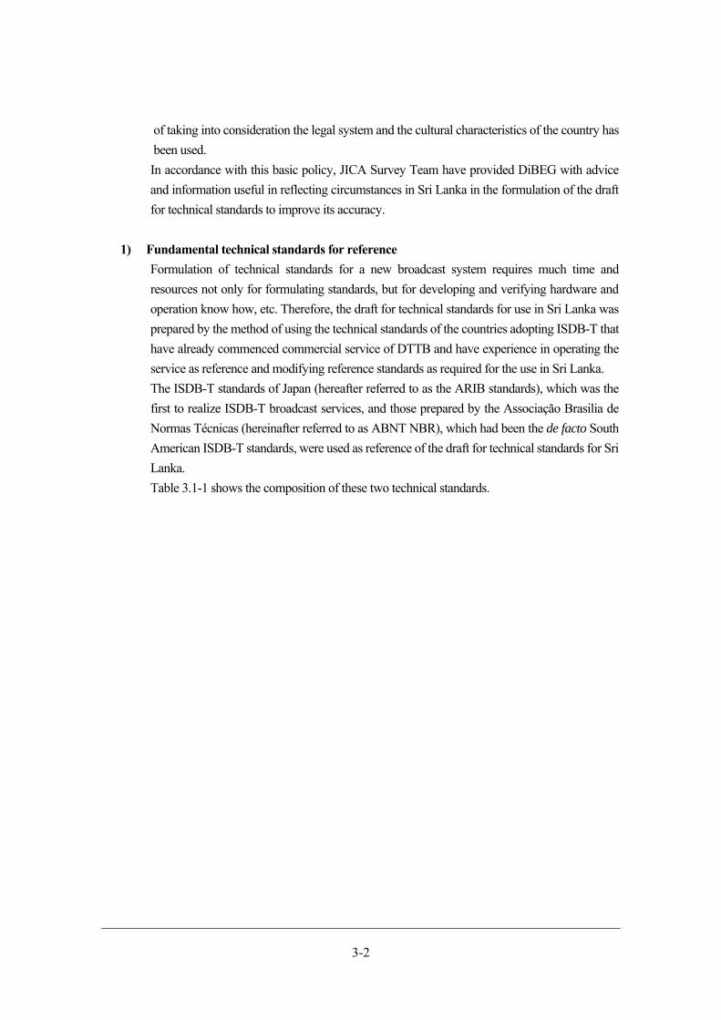
3-2
of taking into consideration the legal system and the cultural characteristics of the country has
been used.
In accordance with this basic policy, JICA Survey Team have provided DiBEG with advice
and information useful in reflecting circumstances in Sri Lanka in the formulation of the draft
for technical standards to improve its accuracy.
1) Fundamental technical standards for reference
Formulation of technical standards for a new broadcast system requires much time and
resources not only for formulating standards, but for developing and verifying hardware and
operation know how, etc. Therefore, the draft for technical standards for use in Sri Lanka was
prepared by the method of using the technical standards of the countries adopting ISDB-T that
have already commenced commercial service of DTTB and have experience in operating the
service as reference and modifying reference standards as required for the use in Sri Lanka.
The ISDB-T standards of Japan (hereafter referred to as the ARIB standards), which was the
first to realize ISDB-T broadcast services, and those prepared by the Associação Brasilia de
Normas Técnicas (hereinafter referred to as ABNT NBR), which had been the de facto South
American ISDB-T standards, were used as reference of the draft for technical standards for Sri
Lanka.
Table 3.1-1 shows the composition of these two technical standards.

3-3
Table 3.1-1 Composition of the ARIB standards and the ABNT NBR and correspondence
between them Item ARIB Standards ABNT NBR
Transmission ARIB STD- B31 ABNT NBR 15601
Video coding ARIB STD- B32 ABNT NBR 15602-1
Audio coding ARIB STD- B32 ABNT NBR 15602-2
Multiplexing ARIB STD- B32 ABNT NBR 15602-3
Structure of service information ARIB STD- B10 ABNT NBR 15603-1
Basic information of service information ARIB STD- B10 ABNT NBR 15603-2
Extension information of service information
ARIB STD- B10 ABNT NBR 15603-3
Receivers ARIB STD- B21 ABNT NBR 15604
Security issues ARIB STD- B10,21,25 ABNT NBR 15605
Data Coding and transmission specification for digital broadcasting
ARIB STD- B24 ABNT NBR 15606
Interactive channel ARIB STD- B21, B23, 24 ABNT NBR 15607
Operational Guideline ARIB TR-B14 ABNT NBR 15608
EWBS ISDB-T Harmonization Document PART3: Emergency Warning Broadcast System (EWBS)
(Note) The individual standards used as the reference standards of the draft for technical standards in Sri
Lanka are indicated with underlined, italic, and bold characters. Source: JICA Survey Team
The ABNT NBR is the standard based on the ARIB standards adapted for the use of new technologies
and technologies developed in Brazil and to Brazil’s unique cultural and legal environments. It was
judged desirable to use the ABNT NBR as the reference standard of the technical standards in Sri Lanka
as they have adopted a new technology of high-efficiency coding format (H.264). However, for the
datacasting standard, it was judged that the ARIB standard (ARIB STD-B24) was advantageous in
software development and creation and operation of contents. This is because it has compatibility with
the next generation datacasting standard, HTML5, and is simpler and has been used more than the
corresponding ANBR NBR standard. The individual standards used as the reference standards of the
draft for technical standards in Sri Lanka are indicated in Table 3.1-1 with underlined, italic, and bold
characters.
Figure 3.1-1 shows the correspondence between the individual standards in the ARIB and ABNT NBR
to illustrate the relationship between these technical standards.
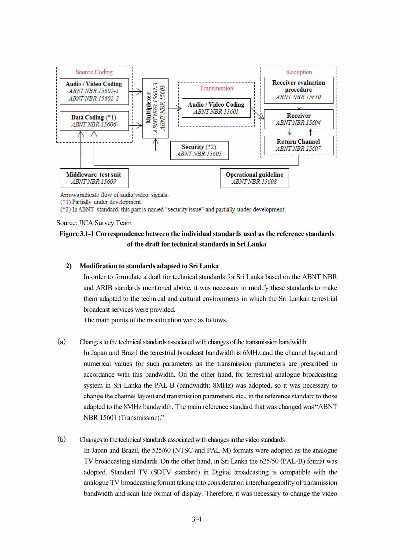
3-4
Source: JICA Survey Team
Figure 3.1-1 Correspondence between the individual standards used as the reference standards
of the draft for technical standards in Sri Lanka
2) Modification to standards adapted to Sri Lanka
In order to formulate a draft for technical standards for Sri Lanka based on the ABNT NBR
and ARIB standards mentioned above, it was necessary to modify these standards to make
them adapted to the technical and cultural environments in which the Sri Lankan terrestrial
broadcast services were provided.
The main points of the modification were as follows.
(a) Changes to the technical standards associated with changes of the transmission bandwidth
In Japan and Brazil the terrestrial broadcast bandwidth is 6MHz and the channel layout and
numerical values for such parameters as the transmission parameters are prescribed in
accordance with this bandwidth. On the other hand, for terrestrial analogue broadcasting
system in Sri Lanka the PAL-B (bandwidth: 8MHz) was adopted, so it was necessary to
change the channel layout and transmission parameters, etc., in the reference standard to those
adapted to the 8MHz bandwidth. The main reference standard that was changed was “ABNT
NBR 15601 (Transmission).”
(b) Changes to the technical standards associated with changes in the video standards
In Japan and Brazil, the 525/60 (NTSC and PAL-M) formats were adopted as the analogue
TV broadcasting standards. On the other hand, in Sri Lanka the 625/50 (PAL-B) format was
adopted. Standard TV (SDTV standard) in Digital broadcasting is compatible with the
analogue TV broadcasting format taking into consideration interchangeability of transmission
bandwidth and scan line format of display. Therefore, it was necessary to change the video
3-5
standards in the reference standard to those based on the 625/50 format. The main reference
standard that was changed was “ABNT NBR 15602-1 (Video coding).”
(c) Change of languages used
It is necessary to amend the technical standards for DTTB to use the languages and characters
used in the respective countries in the broadcasting. In Sri Lanka there are three official
languages in use, Sinhalese, Tamil, and English, so it was necessary to change the relevant
standards accordingly. The main reference standards that were modified were “ARIB STD
B-24 (Datacasting)”, and “ISDB-T Harmonization Document PART 3: Emergency Warning
Broadcast System (EWBS)”2.
(d) Changes to the standards relating to the above-mentioned changes and changes to items to be prescribed
by each country
The changes mentioned in (a) to (c) necessitates partial modification of “ABNT NBR 15603
(Service information)” which prescribes descriptors, and “ARIB STD-B24 (Datacasting)”
which deals with datacasting and captions. Also, items relating to each country’s legal system
and items that are uniquely prescribed in each country such as area codes must be changed.
Note that “ABNT NBR 15604 (Receiver)” and “ABNT NBR 15608 (Operational guideline)”
are associated with all the prescribed items, so they must be modified on all of these change
items.
The details of the changes outlined above have been incorporated into “(Draft) ISDB-T Standards of
Sri Lanka (ver. 2.0)” prepared separately from this document. When a matter that is not prescribed in
the standards arises, see the reference standards, i.e. the ARIB standards and ABNT NBR.
Comments from Sri Lankan side
Comments from TRC
The details of the technical standards have been intermittently explained to the persons in charge of
DTTB in TRC, the main government department responsible for the technical standards on the Sri
Lankan side, as part of this survey that has been conducted since July 2016. However, although there
were questions and answers regarding the content of the explanations, there were no comments relating
to specific modifications or improvement to the draft for technical standards.
Comments from stakeholders
On 23rd June 2017 “ISDB-T Technical Standards Seminar” was held in Colombo by TRC with support
from us, to which stakeholders including relevant officials of the Government of Sri Lanka, broadcasting
stations, telecommunications providers and companies manufacturing and selling broadcasting 2The ISDB-T Harmonization Document is controlled by the ISDB-T International Forum, so after formulating the relevant standards for Sri Lanka it is necessary to notify the Forum of the changes to modify the document.
3-6
equipment were invited. The objective of the seminar was to explain the contents of the draft for ISDB-
T Technical standards and the draft of Technical Specification for STBs to the stakeholders including
TRC, the sponsor of the seminar, to obtain comments on each draft from the stakeholders and to reflect
these comments in the drafts.
Table 3.1-2 shows the results of the questionnaire survey of the participants at the ISDB-T Technical
Standards Seminar and a summary of their comments, etc.
Table 3.1-2 The main comments and policies for the use of digital broadcasting obtained at the
ISDB-T Technical standards Seminar Topic Outline of
comments Service Result of answer to questionnaire
Scheduled to be used
Not scheduled to be used
No reply
Terrestrial digital service
Most of the participants are scheduled to provide the services indicated on the right
One-segmentbroadcast
76.0% 8.0% 16.0%
Datacasting 64.0% 8.0% 28.0%Local broadcasts 76.0% 8.0% 16.0%
Topic Outline of comments Milestone Questionnaire response result
Early Appropriate Late No replyTiming of milestones such as ASO and DSO
Most of the responses were that the timing of ASO and DSO-SD was appropriate, but for DSO-HD the percentages for appropriate and late were equal (suggesting their expectation for early commencement of HD broadcasts).
DSO-SD 0% 52.0% 28.0% 20.0%ASO 4% 68.0% 12.0% 16.0%DSO-HD 0% 40.0% 40.0% 20.0%
Topic Outline of comments
EWBS For emergency broadcasts and disaster broadcasts, it is more appropriate to use FM radio or community broadcasts than television. It is necessary to determine in detail the organisation issuing EWBS warnings and the powers of such organisation.
Others Would like to know detailed technical information (OFDM, interleave, Single Frequency Network, etc.)
Source: JICA Survey Team
Characteristics of the draft for technical standards (summary)
The draft for technical standards proposed for Sri Lanka was prepared by modifying the individual
reference technical standards indicated with underlined, italic, and bold characters in Table 3.1-1
described previously to make them adapted to the circumstances and environment in Sri Lanka as

3-7
described in Section 3.1.2 Item 2). Its details are provided in “(Draft) ISDB-T Standards of Sri Lanka
(ver. 2.0).” The summary of the draft for technical standards is explained in the following.
(1) Transmission
The transmission parameters adopted in the 6MHz countries such as Japan and Brazil have been
modified for the use at 8MHz bandwidth. “ABNT NBR 15601” was used as the reference standard.
Main parameters that have been changed are shown below.
- Symbol duration be 6/8 shorter than 6MHz/ch
- Bandwidth be 8/6 wider than 6MHz/ch
- IFFT sample clock be 8/6 faster than 6MHz/ch
- Transmission bitrate be 8/6 faster than 6MHz/ch
- Guard interval length be 6/8 shorter than 6MHz/ch
- Channels be set by every 8MHz and 1/7MHz frequency shift3 not be used
Table 3.1-3 shows the changes of the system transmission parameters as representative examples of the
change in specific transmission parameters.
For details of other changes to parameters relating to frequencies including segment parameters and
parameters for transmission rates, channel frequencies and transmission spectrum mask, see “(Draft)
ISDB-T Standards of Sri Lanka (ver. 2.0)” Annex 1.
3 The 1/7 MHz shift in the central frequency was a measure to reduce interference to analogue TV broadcast on a lower adjacent frequency taken at the commencement of DTTB in Japan. This measure is not necessary for 8 MHz analog TV broadcasting.
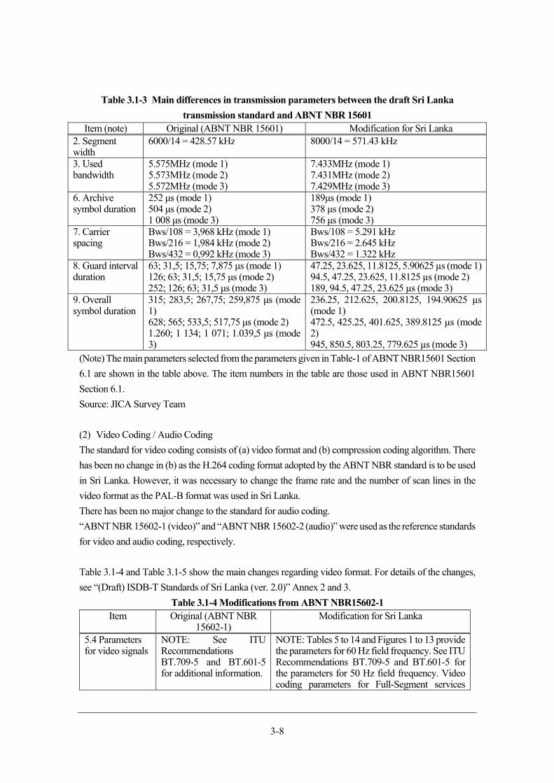
3-8
Table 3.1-3 Main differences in transmission parameters between the draft Sri Lanka
transmission standard and ABNT NBR 15601 Item (note) Original (ABNT NBR 15601) Modification for Sri Lanka
2. Segment width
6000/14 = 428.57 kHz 8000/14 = 571.43 kHz
3. Used bandwidth
5.575MHz (mode 1) 5.573MHz (mode 2) 5.572MHz (mode 3)
7.433MHz (mode 1)7.431MHz (mode 2) 7.429MHz (mode 3)
6. Archive symbol duration
252 μs (mode 1) 504 μs (mode 2) 1 008 μs (mode 3)
189μs (mode 1)378 μs (mode 2) 756 μs (mode 3)
7. Carrier spacing
Bws/108 = 3,968 kHz (mode 1) Bws/216 = 1,984 kHz (mode 2) Bws/432 = 0,992 kHz (mode 3)
Bws/108 = 5.291 kHz Bws/216 = 2.645 kHz Bws/432 = 1.322 kHz
8. Guard interval duration
63; 31,5; 15,75; 7,875 μs (mode 1)126; 63; 31,5; 15,75 μs (mode 2) 252; 126; 63; 31,5 μs (mode 3)
47.25, 23.625, 11.8125, 5.90625 µs (mode 1)94.5, 47.25, 23.625, 11.8125 µs (mode 2) 189, 94.5, 47.25, 23.625 µs (mode 3)
9. Overall symbol duration
315; 283,5; 267,75; 259,875 μs (mode 1) 628; 565; 533,5; 517,75 μs (mode 2) 1.260; 1 134; 1 071; 1.039,5 μs (mode 3)
236.25, 212.625, 200.8125, 194.90625 µs (mode 1) 472.5, 425.25, 401.625, 389.8125 µs (mode 2) 945, 850.5, 803.25, 779.625 µs (mode 3)
(Note) The main parameters selected from the parameters given in Table-1 of ABNT NBR15601 Section
6.1 are shown in the table above. The item numbers in the table are those used in ABNT NBR15601
Section 6.1.
Source: JICA Survey Team
(2) Video Coding / Audio Coding
The standard for video coding consists of (a) video format and (b) compression coding algorithm. There
has been no change in (b) as the H.264 coding format adopted by the ABNT NBR standard is to be used
in Sri Lanka. However, it was necessary to change the frame rate and the number of scan lines in the
video format as the PAL-B format was used in Sri Lanka.
There has been no major change to the standard for audio coding.
“ABNT NBR 15602-1 (video)” and “ABNT NBR 15602-2 (audio)” were used as the reference standards
for video and audio coding, respectively.
Table 3.1-4 and Table 3.1-5 show the main changes regarding video format. For details of the changes,
see “(Draft) ISDB-T Standards of Sri Lanka (ver. 2.0)” Annex 2 and 3.
Table 3.1-4 Modifications from ABNT NBR15602-1 Item Original (ABNT NBR
15602-1)Modification for Sri Lanka
5.4 Parameters for video signals
NOTE: See ITU Recommendations BT.709-5 and BT.601-5 for additional information.
NOTE: Tables 5 to 14 and Figures 1 to 13 provide the parameters for 60 Hz field frequency. See ITU Recommendations BT.709-5 and BT.601-5 for the parameters for 50 Hz field frequency. Video coding parameters for Full-Segment services
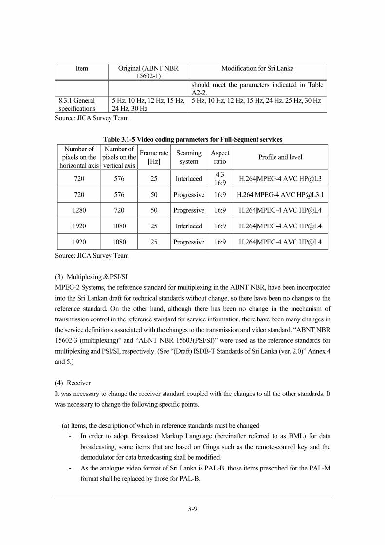
3-9
Item Original (ABNT NBR 15602-1)
Modification for Sri Lanka
should meet the parameters indicated in Table A2-2.
8.3.1 General specifications
5 Hz, 10 Hz, 12 Hz, 15 Hz, 24 Hz, 30 Hz
5 Hz, 10 Hz, 12 Hz, 15 Hz, 24 Hz, 25 Hz, 30 Hz
Source: JICA Survey Team
Table 3.1-5 Video coding parameters for Full-Segment services Number of
pixels on the horizontal axis
Number of pixels on the vertical axis
Frame rate [Hz]
Scanning system
Aspect ratio
Profile and level
720 576 25 Interlaced4:3 16:9
H.264|MPEG-4 AVC HP@L3
720 576 50 Progressive 16:9 H.264|MPEG-4 AVC [email protected]
1280 720 50 Progressive 16:9 H.264|MPEG-4 AVC HP@L4
1920 1080 25 Interlaced 16:9 H.264|MPEG-4 AVC HP@L4
1920 1080 25 Progressive 16:9 H.264|MPEG-4 AVC HP@L4
Source: JICA Survey Team
(3) Multiplexing & PSI/SI
MPEG-2 Systems, the reference standard for multiplexing in the ABNT NBR, have been incorporated
into the Sri Lankan draft for technical standards without change, so there have been no changes to the
reference standard. On the other hand, although there has been no change in the mechanism of
transmission control in the reference standard for service information, there have been many changes in
the service definitions associated with the changes to the transmission and video standard. “ABNT NBR
15602-3 (multiplexing)” and “ABNT NBR 15603(PSI/SI)” were used as the reference standards for
multiplexing and PSI/SI, respectively. (See “(Draft) ISDB-T Standards of Sri Lanka (ver. 2.0)” Annex 4
and 5.)
(4) Receiver
It was necessary to change the receiver standard coupled with the changes to all the other standards. It
was necessary to change the following specific points.
(a) Items, the description of which in reference standards must be changed
- In order to adopt Broadcast Markup Language (hereinafter referred to as BML) for data
broadcasting, some items that are based on Ginga such as the remote-control key and the
demodulator for data broadcasting shall be modified.
- As the analogue video format of Sri Lanka is PAL-B, those items prescribed for the PAL-M
format shall be replaced by those for PAL-B.
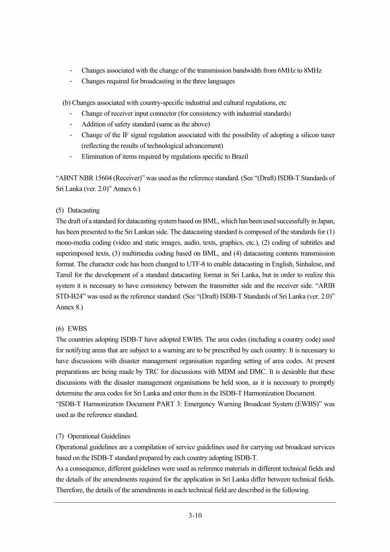
3-10
- Changes associated with the change of the transmission bandwidth from 6MHz to 8MHz
- Changes required for broadcasting in the three languages
(b) Changes associated with country-specific industrial and cultural regulations, etc
- Change of receiver input connector (for consistency with industrial standards)
- Addition of safety standard (same as the above)
- Change of the IF signal regulation associated with the possibility of adopting a silicon tuner
(reflecting the results of technological advancement)
- Elimination of items required by regulations specific to Brazil
“ABNT NBR 15604 (Receiver)” was used as the reference standard. (See “(Draft) ISDB-T Standards of
Sri Lanka (ver. 2.0)” Annex 6.)
(5) Datacasting
The draft of a standard for datacasting system based on BML, which has been used successfully in Japan,
has been presented to the Sri Lankan side. The datacasting standard is composed of the standards for (1)
mono-media coding (video and static images, audio, texts, graphics, etc.), (2) coding of subtitles and
superimposed texts, (3) multimedia coding based on BML, and (4) datacasting contents transmission
format. The character code has been changed to UTF-8 to enable datacasting in English, Sinhalese, and
Tamil for the development of a standard datacasting format in Sri Lanka, but in order to realize this
system it is necessary to have consistency between the transmitter side and the receiver side. “ARIB
STD-B24” was used as the reference standard. (See “(Draft) ISDB-T Standards of Sri Lanka (ver. 2.0)”
Annex 8.)
(6) EWBS
The countries adopting ISDB-T have adopted EWBS. The area codes (including a country code) used
for notifying areas that are subject to a warning are to be prescribed by each country. It is necessary to
have discussions with disaster management organisation regarding setting of area codes. At present
preparations are being made by TRC for discussions with MDM and DMC. It is desirable that these
discussions with the disaster management organisations be held soon, as it is necessary to promptly
determine the area codes for Sri Lanka and enter them in the ISDB-T Harmonization Document.
“ISDB-T Harmonization Document PART 3: Emergency Warning Broadcast System (EWBS)” was
used as the reference standard.
(7) Operational Guidelines
Operational guidelines are a compilation of service guidelines used for carrying out broadcast services
based on the ISDB-T standard prepared by each country adopting ISDB-T.
As a consequence, different guidelines were used as reference materials in different technical fields and
the details of the amendments required for the application in Sri Lanka differ between technical fields.
Therefore, the details of the amendments in each technical field are described in the following.
3-11
(a) Transmission
In addition to the changes described in (1), changes in the frequency bandwidth to be used (limited to
UHF bandwidth only) and standard modulation system (adoption of QPSK), etc. have been added to the
guidelines. “ABNT NBR 15608-1” was used as the reference standard. (See “(Draft) ISDB-T Standards
of Sri Lanka (ver. 2.0)” Appendix 1.)
(b) Video Coding / Audio Coding
In addition to the changes described in (2), there is an addition to the guidelines indicating that the full
segment coding parameters shall not be applied to the partial reception hierarchy. “ABNT NBR 15608-
2” was used as the reference standard. (See “(Draft) ISDB-T Standards of Sri Lanka (ver. 2.0)” Appendix
2 and 3.)
(c) Multiplexing & PSI/SI
In addition to the changes described in (3), some of the items prescribing service information in the
reference guidelines have been changed. “ABNT NBR 15608-3” was used as the reference standard.
(See “(Draft) ISDB-T Standards of Sri Lanka (ver. 2.0)” Appendix 4 and 5.)
(d) Receiver
The guidelines regarding receivers are “ISDB-T HARMONIZATION DOCUMENT PART 1:
HARDWARE.”
(e) Datacasting
Changes have been made to the guidelines for datacasting based on the description in (5) above to make
them compliant with the Sri Lankan standards, including those for the languages to be used. “ARIB TR-
B14 VOL. 3” was used as the reference standard. See Appendix 8 of (Draft) ISDB-T Standards of Sri
Lanka (ver. 2.0) for details of the changes made to TR-B-14.
(f) EWBS
JICA Survey Team has proposed the application of the standard described in (6) and the draft area codes
prepared by them to the Sri Lankan side. “ISDB-T Harmonization Document PART 3: Emergency
Warning Broadcast System (EWBS)” was used as the reference standard.
(g) Parameters for operation
In the draft for technical standards, a wide range of parameters are prescribed, so an example of parameter
setting appropriate for the actual operation of DTTB has been shared with TRC and included in the
guidelines. (See “(Draft) ISDB-T Standards of Sri Lanka (ver. 2.0)” Appendix 11.)
3-12
Formulation of draft of STB technical specifications
Policy for creating draft of STB technical specifications
The draft of Technical Specifications for STBs is a technical document that is required to ensure quality
of imported STBs in countries that do not have sufficient domestic production capability for digital
broadcasting receivers and must rely on imports. Among the Countries Adopting ISDB-1, Botswana was
the first to prepare this document and it was applied as the guidelines for the import of STBs. In Botswana
there is a legal obligation to perform minimum specification. The Government of Botswana intend to
ensure the quality of imported products reliably by performing the minimum specification using the
technical specifications mentioned above. It is anticipated that in Sri Lanka most of DTTB receivers will
have to be imported. The simple minimum specification has been performed in the country. Therefore,
JICA decided to prepare a draft of recommended STB technical specifications and submit it to the Sri
Lankan side. The draft of recommended specifications complies with the requirements of TRC.
The following points were taken into consideration in its preparation.
(a) The draft of Technical Specifications for STBs submitted to the Government of Botswana is to be
used as a reference in the preparation of the draft of Technical Specifications for STBs for Sri Lanka
and the prepared draft is to be submitted to the Sri Lanka side. Support will be provided to the Sri
Lankan side for its adoption as the guidelines for the simple minimum specification of STBs.
(b) A draft of recommended specifications formulated by MIC of Japan and DiBEG under
commission from MIC based on the draft specifications for Botswana will be presented and an
explanation on the draft will be provided to TRC and other stakeholders and support will be
provided to the Sri Lankan side for the preparation of the recommended STB specifications.
(c) Support will be provided for the improvement of the technical standards to make them more
suitable for Sri Lanka in response to questions and comments produced at the stage of the
formulation of the recommended STB specification by the Sri Lankan side.
Method for creation
As stated previously, the draft STB specifications were mainly prepared by MIC and DiBEG mainly
with reference to the draft of Technical Specifications for Botswana. In order to reflect the circumstances
in Sri Lanka in the draft, JICA Survey Team provided them with appropriate advice and information to
improve the accuracy of the draft of recommended specifications.
Comments from Sri Lankan side
(a) Comments from TRC
TRC have been performing the minimum specification of equipment for telecommunications
including smartphones recently. The minimum specification has not been carried out for all the
equipment for telecommunications and it seems to be carried out for wireless communication
equipment and products in which new technologies are applied. TRC have not identified the products
subject to the minimum specification because of the shortage of manpower. However, the person in
charge of DTTB in TRC suggested that the simple minimum specification (a simple method for
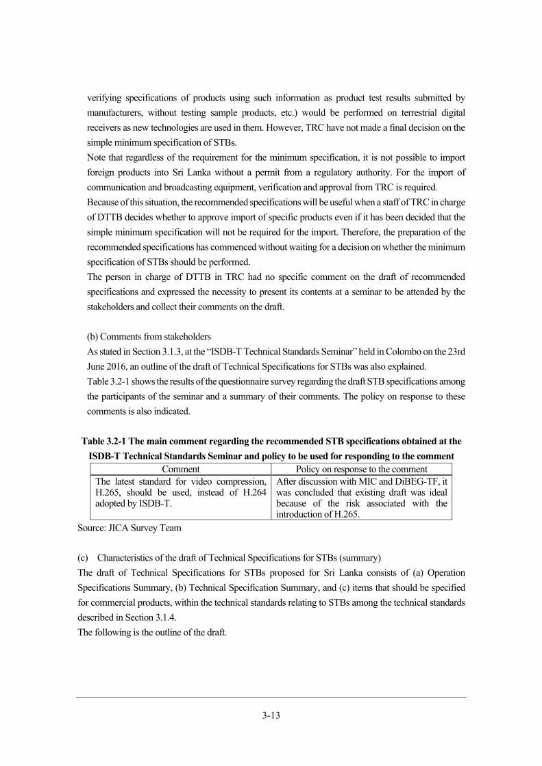
3-13
verifying specifications of products using such information as product test results submitted by
manufacturers, without testing sample products, etc.) would be performed on terrestrial digital
receivers as new technologies are used in them. However, TRC have not made a final decision on the
simple minimum specification of STBs.
Note that regardless of the requirement for the minimum specification, it is not possible to import
foreign products into Sri Lanka without a permit from a regulatory authority. For the import of
communication and broadcasting equipment, verification and approval from TRC is required.
Because of this situation, the recommended specifications will be useful when a staff of TRC in charge
of DTTB decides whether to approve import of specific products even if it has been decided that the
simple minimum specification will not be required for the import. Therefore, the preparation of the
recommended specifications has commenced without waiting for a decision on whether the minimum
specification of STBs should be performed.
The person in charge of DTTB in TRC had no specific comment on the draft of recommended
specifications and expressed the necessity to present its contents at a seminar to be attended by the
stakeholders and collect their comments on the draft.
(b) Comments from stakeholders
As stated in Section 3.1.3, at the “ISDB-T Technical Standards Seminar” held in Colombo on the 23rd
June 2016, an outline of the draft of Technical Specifications for STBs was also explained.
Table 3.2-1 shows the results of the questionnaire survey regarding the draft STB specifications among
the participants of the seminar and a summary of their comments. The policy on response to these
comments is also indicated.
Table 3.2-1 The main comment regarding the recommended STB specifications obtained at the
ISDB-T Technical Standards Seminar and policy to be used for responding to the comment Comment Policy on response to the comment
The latest standard for video compression, H.265, should be used, instead of H.264 adopted by ISDB-T.
After discussion with MIC and DiBEG-TF, it was concluded that existing draft was ideal because of the risk associated with the introduction of H.265.
Source: JICA Survey Team
(c) Characteristics of the draft of Technical Specifications for STBs (summary)
The draft of Technical Specifications for STBs proposed for Sri Lanka consists of (a) Operation
Specifications Summary, (b) Technical Specification Summary, and (c) items that should be specified
for commercial products, within the technical standards relating to STBs among the technical standards
described in Section 3.1.4.
The following is the outline of the draft.
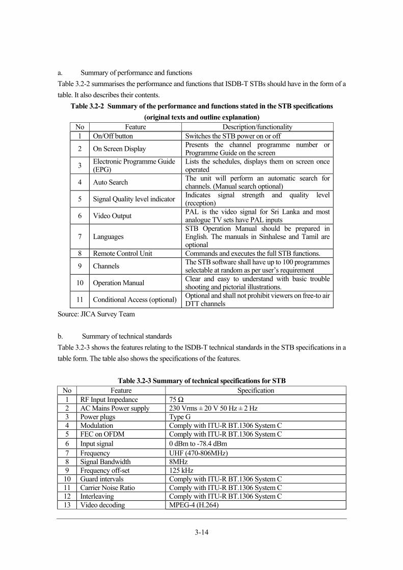
3-14
a. Summary of performance and functions
Table 3.2-2 summarises the performance and functions that ISDB-T STBs should have in the form of a
table. It also describes their contents.
Table 3.2-2 Summary of the performance and functions stated in the STB specifications
(original texts and outline explanation) No Feature Description/functionality 1 On/Off button Switches the STB power on or off
2 On Screen Display Presents the channel programme number or Programme Guide on the screen
3 Electronic Programme Guide (EPG)
Lists the schedules, displays them on screen once operated
4 Auto Search The unit will perform an automatic search for channels. (Manual search optional)
5 Signal Quality level indicator Indicates signal strength and quality level (reception)
6 Video Output PAL is the video signal for Sri Lanka and most analogue TV sets have PAL inputs
7 Languages STB Operation Manual should be prepared in English. The manuals in Sinhalese and Tamil are optional
8 Remote Control Unit Commands and executes the full STB functions.
9 Channels The STB software shall have up to 100 programmes selectable at random as per user’s requirement
10 Operation Manual Clear and easy to understand with basic trouble shooting and pictorial illustrations.
11 Conditional Access (optional) Optional and shall not prohibit viewers on free-to air DTT channels
Source: JICA Survey Team
b. Summary of technical standards
Table 3.2-3 shows the features relating to the ISDB-T technical standards in the STB specifications in a
table form. The table also shows the specifications of the features.
Table 3.2-3 Summary of technical specifications for STB No Feature Specification1 RF Input Impedance 75 Ω2 AC Mains Power supply 230 Vrms ± 20 V 50 Hz ± 2 Hz3 Power plugs Type G4 Modulation Comply with ITU-R BT.1306 System C5 FEC on OFDM Comply with ITU-R BT.1306 System C6 Input signal 0 dBm to -78.4 dBm 7 Frequency UHF (470-806MHz)8 Signal Bandwidth 8MHz9 Frequency off-set 125 kHz10 Guard intervals Comply with ITU-R BT.1306 System C11 Carrier Noise Ratio Comply with ITU-R BT.1306 System C12 Interleaving Comply with ITU-R BT.1306 System C13 Video decoding MPEG-4 (H.264)
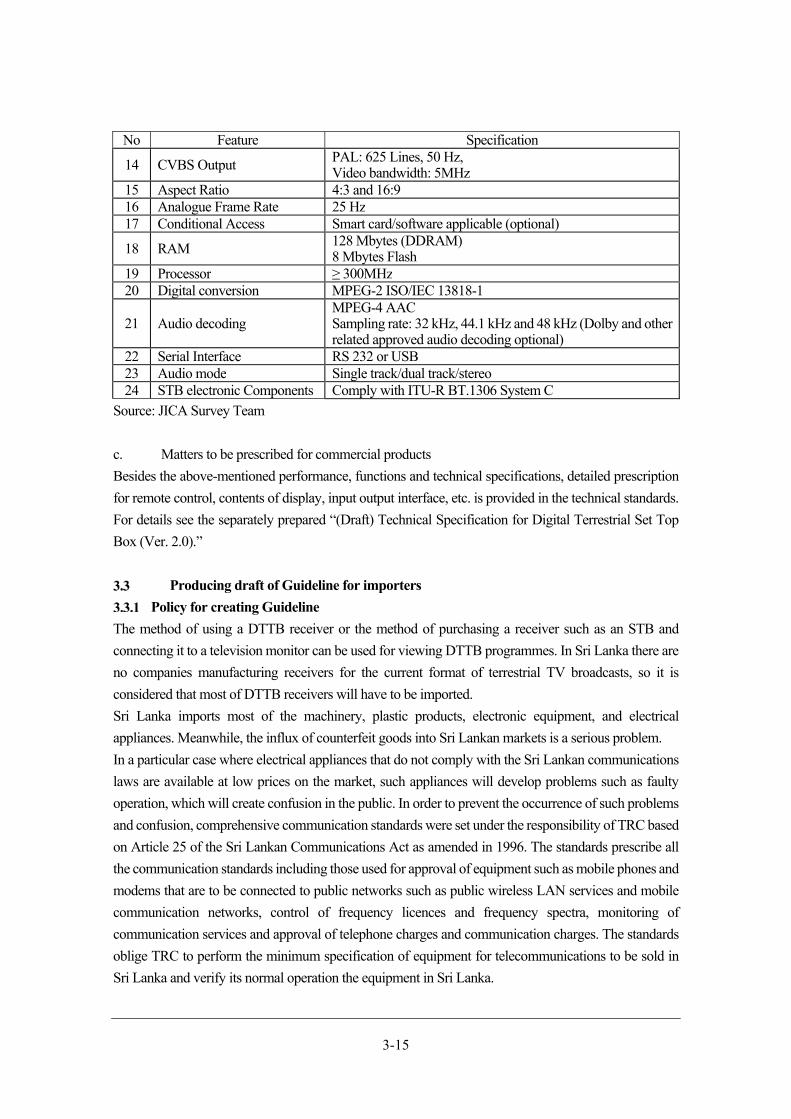
3-15
No Feature Specification
14 CVBS Output PAL: 625 Lines, 50 Hz,Video bandwidth: 5MHz
15 Aspect Ratio 4:3 and 16:916 Analogue Frame Rate 25 Hz17 Conditional Access Smart card/software applicable (optional)
18 RAM 128 Mbytes (DDRAM)8 Mbytes Flash
19 Processor ≥ 300MHz20 Digital conversion MPEG-2 ISO/IEC 13818-1
21 Audio decoding MPEG-4 AACSampling rate: 32 kHz, 44.1 kHz and 48 kHz (Dolby and other related approved audio decoding optional)
22 Serial Interface RS 232 or USB23 Audio mode Single track/dual track/stereo24 STB electronic Components Comply with ITU-R BT.1306 System C
Source: JICA Survey Team
c. Matters to be prescribed for commercial products
Besides the above-mentioned performance, functions and technical specifications, detailed prescription
for remote control, contents of display, input output interface, etc. is provided in the technical standards.
For details see the separately prepared “(Draft) Technical Specification for Digital Terrestrial Set Top
Box (Ver. 2.0).”
Producing draft of Guideline for importers
Policy for creating Guideline
The method of using a DTTB receiver or the method of purchasing a receiver such as an STB and
connecting it to a television monitor can be used for viewing DTTB programmes. In Sri Lanka there are
no companies manufacturing receivers for the current format of terrestrial TV broadcasts, so it is
considered that most of DTTB receivers will have to be imported.
Sri Lanka imports most of the machinery, plastic products, electronic equipment, and electrical
appliances. Meanwhile, the influx of counterfeit goods into Sri Lankan markets is a serious problem.
In a particular case where electrical appliances that do not comply with the Sri Lankan communications
laws are available at low prices on the market, such appliances will develop problems such as faulty
operation, which will create confusion in the public. In order to prevent the occurrence of such problems
and confusion, comprehensive communication standards were set under the responsibility of TRC based
on Article 25 of the Sri Lankan Communications Act as amended in 1996. The standards prescribe all
the communication standards including those used for approval of equipment such as mobile phones and
modems that are to be connected to public networks such as public wireless LAN services and mobile
communication networks, control of frequency licences and frequency spectra, monitoring of
communication services and approval of telephone charges and communication charges. The standards
oblige TRC to perform the minimum specification of equipment for telecommunications to be sold in
Sri Lanka and verify its normal operation the equipment in Sri Lanka.
3-16
In some of the countries from which Sri Lanka imports goods, legal restrictions on the control of
manufacture of counterfeit goods may not function. This lack of restriction is one of the causes of the
availability of counterfeit goods in Sri Lanka. Also, counterfeit goods are manufactured in neighbouring
countries. Problems that can be caused by influx of counterfeit goods include damage to the brand image
and price collapse. Most of the counterfeit goods are inferior products and the availability of such inferior
counterfeit goods on the market will lead to damage to brand image of genuine goods. Also, counterfeit
goods are usually cheaper than genuine goods, so the availability of such goods can result in collapse of
prices. In the particular case of electrical appliances, unapproved counterfeit goods or pirated goods
frequently do not operate properly and the availability of such goods on the market may cause confusion
among the public.
In order to prevent the influx of counterfeit goods, it is considered that the most effective method to
reduce the availability of counterfeit goods in Sri Lanka would be for the Government to prevent the
influx of such goods in Sri Lanka. Therefore, Sri Lanka has mechanisms of import licencing and issuance
of an import permit for each product to be imported after the verification of the quality of the product by
the regulatory authority. The minimum specification can be considered a measure focused on eliminating
counterfeit goods and inferior goods.
The purpose of preparing the draft Guidelines for Importers is to promote sales/purchase of DTTB
receivers by enabling smooth import by importers of products to which the minimum specification has
been issued in compliance with Sri Lankan laws and participation of many companies that are interested
in exporting DTTB receivers to Sri Lanka in the market. The formal import procedures are described in
the following section. The procedures require many documents to be prepared and approval to be
received from multiple organisations. These complex import procedures could hinder the participation
of companies that are not familiar with procedures in the import business. Clarifying the procedures for
exporting products to Sri Lanka will improve the business environment for overseas manufacturers by
enabling them to understand in advance the series of processes including product manufacture,
acquisition of minimum specification, transport, customs clearance and sales and estimate the time
required for their products to enter the market. Increasing the household penetration ratio of DTTB
receivers to a sufficient level is an indispensable factor for the success of the migration into DTTB, which
is a national project in the broadcasting and communication sector. Therefore, it is important to develop
the import environment for DTTB receivers.
The policies for the preparation of the import guidelines based on the above-mentioned and other
circumstances are as follows.
I. The guidelines will strictly adhere to the procedures for importing equipment for
telecommunication and broadcasting implemented by TRC in accordance with laws currently in
force in Sri Lanka
II. The guidelines will be compliant, in principle, with the concepts of “Route to Type Approval”,
“Vendor Licence Procedure”, and “Route to Get Vendor Licence” for equipment for
telecommunication shown on the TRC homepage
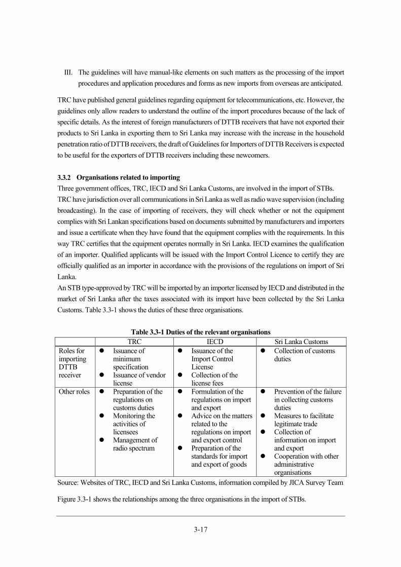
3-17
III. The guidelines will have manual-like elements on such matters as the processing of the import
procedures and application procedures and forms as new imports from overseas are anticipated.
TRC have published general guidelines regarding equipment for telecommunications, etc. However, the
guidelines only allow readers to understand the outline of the import procedures because of the lack of
specific details. As the interest of foreign manufacturers of DTTB receivers that have not exported their
products to Sri Lanka in exporting them to Sri Lanka may increase with the increase in the household
penetration ratio of DTTB receivers, the draft of Guidelines for Importers of DTTB Receivers is expected
to be useful for the exporters of DTTB receivers including these newcomers.
Organisations related to importing
Three government offices, TRC, IECD and Sri Lanka Customs, are involved in the import of STBs.
TRC have jurisdiction over all communications in Sri Lanka as well as radio wave supervision (including
broadcasting). In the case of importing of receivers, they will check whether or not the equipment
complies with Sri Lankan specifications based on documents submitted by manufacturers and importers
and issue a certificate when they have found that the equipment complies with the requirements. In this
way TRC certifies that the equipment operates normally in Sri Lanka. IECD examines the qualification
of an importer. Qualified applicants will be issued with the Import Control Licence to certify they are
officially qualified as an importer in accordance with the provisions of the regulations on import of Sri
Lanka.
An STB type-approved by TRC will be imported by an importer licensed by IECD and distributed in the
market of Sri Lanka after the taxes associated with its import have been collected by the Sri Lanka
Customs. Table 3.3-1 shows the duties of these three organisations.
Table 3.3-1 Duties of the relevant organisations TRC IECD Sri Lanka Customs
Roles for importing DTTB receiver
Issuance of minimum specification
Issuance of vendor license
Issuance of the Import Control License
Collection of the license fees
Collection of customs duties
Other roles Preparation of the regulations on customs duties
Monitoring the activities of licensees
Management of radio spectrum
Formulation of the regulations on import and export
Advice on the matters related to the regulations on import and export control
Preparation of the standards for import and export of goods
Prevention of the failure in collecting customs duties
Measures to facilitate legitimate trade
Collection of information on import and export
Cooperation with other administrative organisations
Source: Websites of TRC, IECD and Sri Lanka Customs, information compiled by JICA Survey Team
Figure 3.3-1 shows the relationships among the three organisations in the import of STBs.
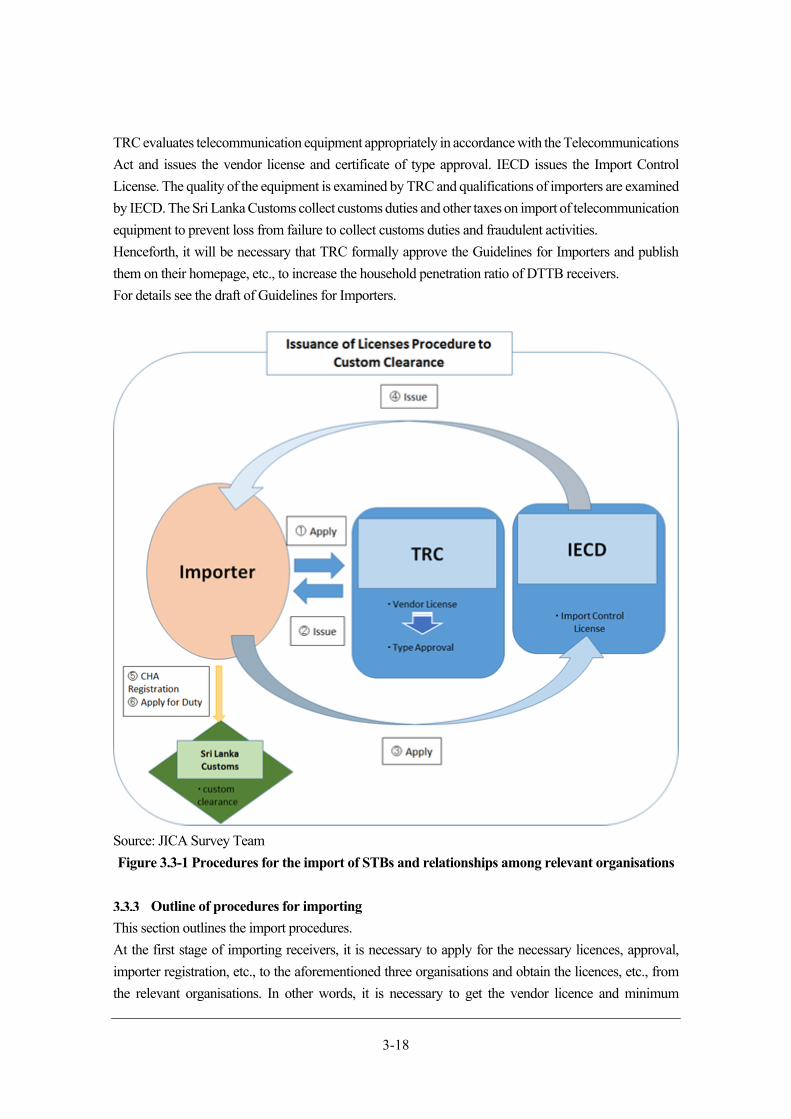
3-18
TRC evaluates telecommunication equipment appropriately in accordance with the Telecommunications
Act and issues the vendor license and certificate of type approval. IECD issues the Import Control
License. The quality of the equipment is examined by TRC and qualifications of importers are examined
by IECD. The Sri Lanka Customs collect customs duties and other taxes on import of telecommunication
equipment to prevent loss from failure to collect customs duties and fraudulent activities.
Henceforth, it will be necessary that TRC formally approve the Guidelines for Importers and publish
them on their homepage, etc., to increase the household penetration ratio of DTTB receivers.
For details see the draft of Guidelines for Importers.
Source: JICA Survey Team
Figure 3.3-1 Procedures for the import of STBs and relationships among relevant organisations
Outline of procedures for importing
This section outlines the import procedures.
At the first stage of importing receivers, it is necessary to apply for the necessary licences, approval,
importer registration, etc., to the aforementioned three organisations and obtain the licences, etc., from
the relevant organisations. In other words, it is necessary to get the vendor licence and minimum
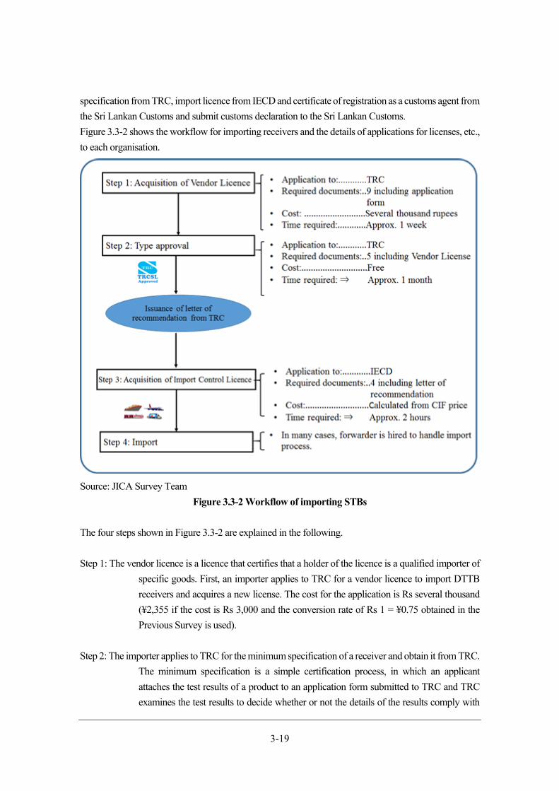
3-19
specification from TRC, import licence from IECD and certificate of registration as a customs agent from
the Sri Lankan Customs and submit customs declaration to the Sri Lankan Customs.
Figure 3.3-2 shows the workflow for importing receivers and the details of applications for licenses, etc.,
to each organisation.
Source: JICA Survey Team
Figure 3.3-2 Workflow of importing STBs
The four steps shown in Figure 3.3-2 are explained in the following.
Step 1: The vendor licence is a licence that certifies that a holder of the licence is a qualified importer of
specific goods. First, an importer applies to TRC for a vendor licence to import DTTB
receivers and acquires a new license. The cost for the application is Rs several thousand
(¥2,355 if the cost is Rs 3,000 and the conversion rate of Rs 1 = ¥0.75 obtained in the
Previous Survey is used).
Step 2: The importer applies to TRC for the minimum specification of a receiver and obtain it from TRC.
The minimum specification is a simple certification process, in which an applicant
attaches the test results of a product to an application form submitted to TRC and TRC
examines the test results to decide whether or not the details of the results comply with
3-20
the recommended specifications for receivers. There is a possibility that TRC may request
submission of a small number of sample products, but a formal decision has not been
made on this matter. The application is expected to be free of charge. It will take about a
month for the specification to be issued. The minimum specification is a certificate that
certifies that TRC has certified the compliance of equipment for telecommunication with
the legal, technical, and safety requirements with its authority.
Step 3: When the vendor license and the minimum specification have been acquired, the importer can
obtain a letter of recommendation required for obtaining an import licence from IECD
from TRC. The import licence will be issued in a week of the application. The application
fee will be invoiced later.
Step 4: Receivers will be imported. In most cases importers use specialist forwarders for the import
because many tax-related matters including payment of customs duties are involved in
the import procedures. An importer may ask a forwarder to carry out both the
international transport and customs clearance.
The import procedures are complex, as mentioned above, and many documents must be submitted.
Therefore, it is anticipated that time will be required in particular when importing receivers for the first
time. Inadequate documentation or non-payment of customs duties may delay the delivery of imported
products. Therefore, sufficient time should be allowed for these procedures.
Note that, according to the information obtained in an interview at IECD, the HS code (the item number
in the import and export statistics used for classifying goods when importing or exporting cargo) of the
receivers is “HS 8525.60: Transmission apparatus incorporating reception apparatus.” Table 3.3-2 shows
the current customs duty and tax rates in Sri Lanka for the product of this HS code. It will be necessary
for importers to prepare a procurement plan with the payment of these customs duties and taxes at the
time of the delivery taken into consideration.
Table 3.3-2 Customs duty and other tax rates for import of reception apparatus HS Code Description Duty VAT PAL NBT
8525.60 Transmission apparatus incorporating reception apparatus
15% 12% 5% 2%
Source: Prepared by JICA Survey Team based on materials of Sri Lanka Customs
Chapter 4 Formulation of migration plan into DTTB
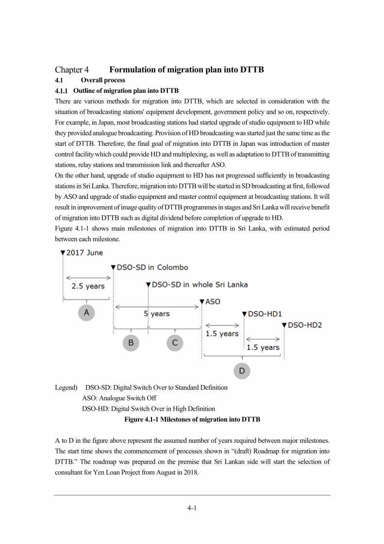
4-1
Formulation of migration plan into DTTB Overall process
Outline of migration plan into DTTB
There are various methods for migration into DTTB, which are selected in consideration with the
situation of broadcasting stations' equipment development, government policy and so on, respectively.
For example, in Japan, most broadcasting stations had started upgrade of studio equipment to HD while
they provided analogue broadcasting. Provision of HD broadcasting was started just the same time as the
start of DTTB. Therefore, the final goal of migration into DTTB in Japan was introduction of master
control facility which could provide HD and multiplexing, as well as adaptation to DTTB of transmitting
stations, relay stations and transmission link and thereafter ASO.
On the other hand, upgrade of studio equipment to HD has not progressed sufficiently in broadcasting
stations in Sri Lanka. Therefore, migration into DTTB will be started in SD broadcasting at first, followed
by ASO and upgrade of studio equipment and master control equipment at broadcasting stations. It will
result in improvement of image quality of DTTB programmes in stages and Sri Lanka will receive benefit
of migration into DTTB such as digital dividend before completion of upgrade to HD.
Figure 4.1-1 shows main milestones of migration into DTTB in Sri Lanka, with estimated period
between each milestone.
Legend) DSO-SD: Digital Switch Over to Standard Definition
ASO: Analogue Switch Off
DSO-HD: Digital Switch Over in High Definition
Figure 4.1-1 Milestones of migration into DTTB
A to D in the figure above represent the assumed number of years required between major milestones.
The start time shows the commencement of processes shown in “(draft) Roadmap for migration into
DTTB.” The roadmap was prepared on the premise that Sri Lankan side will start the selection of
consultant for Yen Loan Project from August in 2018.
4-2
Period A shows the years necessary for the start of DTTB in Greater Colombo with SD quality.
Preparation and installation of equipment for the start of DTTB will be assisted by Yen Loan Project,
and it is estimated to take about 2 and half years from the selection of consultant. DSO-SD in Greater
Colombo will be started in December 2019.
Period B shows the years from DSO-SD in Greater Colombo to DSO-SD in Sri Lanka nationwide, which
is estimated to take 2 years. DSO-SD in the whole of Sri Lanka means the completion of Yen Loan
Project.
The third stage will come as period C, which means the years from DSO-SD throughout Sri Lanka to
ASO. Period C should be as short as possible in order to lessen expenses of broadcasting stations during
the period of simultaneous broadcasting, in consideration with the idea of the Government of Sri Lanka
and broadcasting stations as of Previous Survey. It is planned to take 5 years from DSO-SD in Greater
Colombo to ASO, which is based on the concept that dissemination of DTTB receiver will be easy to
promote in consideration with sentiment of Sri Lankan citizens, current situation of television receiver
dissemination, coverage of existing analogue broadcasting network of broadcasting stations and
penetration of satellite broadcasting and IPTV. Meanwhile, effective measures such as policy for
dissemination of DTTB receivers will be necessary to be considered. TRC and related agencies of the
Government of Sri Lanka are examining the policy.
The period D shown as the final stage represents the period of migration into HD after ASO in 2 steps.
As of DSO-SD in the whole of Sri Lanka, DTTB platform operated by DBNO will provide 4 waves in
each transmitting station for SD broadcasting, in which total 24 SD programmes will be broadcast. On
the other hand, HD broadcasting needs twice the data capacity of SD, which means only a total of 12
programmes will be available in 4 waves. In order to provide 24 HD programmes, it will be necessary
for transmitting stations to be upgraded for operation of 8 waves, which means additional 4 transmitters
should be procured at each transmitting station. The upgrade of transmitting stations is planned to be
implemented in stages considering financing; 24 SD programmes will be provided as of ASO. Thereafter
SD programmes will decrease to 12 and 12 HD programmes will be provided in DSO-HD1. Finally the
number of HD programmes will be 24 in DSO-HD2.
As stated above, it will take about at least 10 years to complete migration into DTTB in Sri Lanka. The
details are indicated in “Draft of Roadmap for migration into DTTB.”
Work items in period A (until DSO-SD in Greater Colombo)
(1) Approval of ISDB-T technical standards and technical specification for receivers
The draft for technical standards stated in Chapter 3 needs to be approved soon. The area code of EWBS
has to be decided through discussion among related agencies such as MDM and DMC and then draft for
technical standards and technical specification for receivers should be finalised. DBNO will also be a
main stakeholder, therefore comments and opinions should be collected from DBNO about technical
standards and technical specification. Unless official publication of technical standards and technical
specification are done, manufacturers will not be able to start producing equipment for Sri Lanka and
tenderers will not be able to complete tender documents for DTTB platform equipment, which will be
assisted by consultant of Yen Loan Project.
4-3
In the “Draft of Roadmap for migration into DTTB,” period A will last until November 2019, when
DSO-SD will start in Greater Colombo. In order to meet the deadline of DSO-SD, technical standards
and technical specification need to be officially published.
(2) Establishment of DBNO
It is an urgent matter to establish DBNO which will operate DTTB platform. There will be a high
possibility that legislative system should be formulated for DBNO in consideration with receiving fund
as a highly-public organisation from the Government of Sri Lanka and operation of equipment procured
through Yen Loan Project, etc. Preparation of legislative system requires a long period, therefore
provisional organisation on behalf of DBNO has to be launched for determination regarding specification
of equipment, procurement of DTTB platform and other practical work items. It is estimated to take
about 1 and half years for completion of legislative system after launch of provisional organisation,
thereafter DBNO will be established as official organisation before DSO-SD in Greater Colombo.
(3) Installation of transmitting equipment and facilities for DTTB in Greater Colombo
Transmitting equipment and facilities for digital broadcasting in Greater Colombo are planned to be
installed in Lotus Tower which is currently under construction in Colombo. In parallel, NOC of DTTB
platform will be installed and its operation will be started for multiplexing and transmitting programmes
from broadcasting stations. Network communication lines between each broadcasting station and NOC
should be developed as well.
This work item is planned to complete in October 2020 for DSO-SD in Greater Colombo.
(4) Development of network communication line for programme transmission between broadcasters
and DBNO
Signals between the NOC and each broadcasting station will transmit programmes to the NOC via
network of telecommunication providers and others. Therefore, it will be necessary for DBNO to ensure
transmission link between MCR of broadcasting stations and NOC. The transmission link has to be
completed and prepared for operation 1 month before DSO-SD in Greater Colombo at the latest.
(5) Consideration of EWBS operation regulations and preparation of EWBS operation plans
There are two major work items in order to operate EWBS, one of the features of ISDB-T. One is
examination of EWBS operating system, other is formulation of specific operation plan for introducing
EWBS. Cooperation with the disaster management institution is essential for EWBS operation, therefore
operational guideline for EWBS should be formulated after examination based on legal grounds such as
responsibility assignment of each institution. The guideline needs to be decided before the bidding on
the procurement of equipment of Yen Loan Project is started because it may affect the location of EWBS
equipment etc.
Meanwhile, it is desirable that the operation plan be specifically examined after the specification of the
EWBS and peripheral equipment has been decided. Therefore, it should be decided before the start of
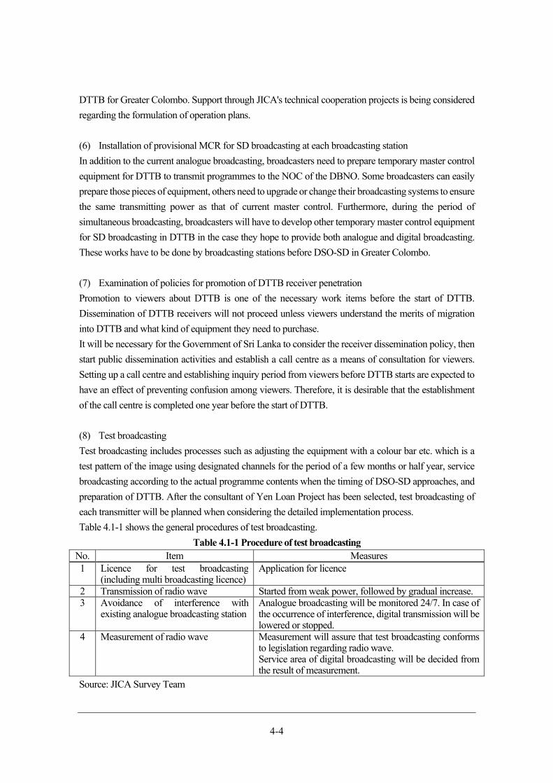
4-4
DTTB for Greater Colombo. Support through JICA's technical cooperation projects is being considered
regarding the formulation of operation plans.
(6) Installation of provisional MCR for SD broadcasting at each broadcasting station
In addition to the current analogue broadcasting, broadcasters need to prepare temporary master control
equipment for DTTB to transmit programmes to the NOC of the DBNO. Some broadcasters can easily
prepare those pieces of equipment, others need to upgrade or change their broadcasting systems to ensure
the same transmitting power as that of current master control. Furthermore, during the period of
simultaneous broadcasting, broadcasters will have to develop other temporary master control equipment
for SD broadcasting in DTTB in the case they hope to provide both analogue and digital broadcasting.
These works have to be done by broadcasting stations before DSO-SD in Greater Colombo.
(7) Examination of policies for promotion of DTTB receiver penetration
Promotion to viewers about DTTB is one of the necessary work items before the start of DTTB.
Dissemination of DTTB receivers will not proceed unless viewers understand the merits of migration
into DTTB and what kind of equipment they need to purchase.
It will be necessary for the Government of Sri Lanka to consider the receiver dissemination policy, then
start public dissemination activities and establish a call centre as a means of consultation for viewers.
Setting up a call centre and establishing inquiry period from viewers before DTTB starts are expected to
have an effect of preventing confusion among viewers. Therefore, it is desirable that the establishment
of the call centre is completed one year before the start of DTTB.
(8) Test broadcasting
Test broadcasting includes processes such as adjusting the equipment with a colour bar etc. which is a
test pattern of the image using designated channels for the period of a few months or half year, service
broadcasting according to the actual programme contents when the timing of DSO-SD approaches, and
preparation of DTTB. After the consultant of Yen Loan Project has been selected, test broadcasting of
each transmitter will be planned when considering the detailed implementation process.
Table 4.1-1 shows the general procedures of test broadcasting.
Table 4.1-1 Procedure of test broadcasting No. Item Measures1 Licence for test broadcasting
(including multi broadcasting licence)Application for licence
2 Transmission of radio wave Started from weak power, followed by gradual increase. 3 Avoidance of interference with
existing analogue broadcasting stationAnalogue broadcasting will be monitored 24/7. In case of the occurrence of interference, digital transmission will be lowered or stopped.
4 Measurement of radio wave Measurement will assure that test broadcasting conformsto legislation regarding radio wave. Service area of digital broadcasting will be decided from the result of measurement.
Source: JICA Survey Team
4-5
Work items in period B (until DSO-SD in whole Sri Lanka)
(1) Start of operation of transmitting stations assisted by Yen Loan Project
Operation of transmitting stations at 15 sites except for Greater Colombo will be started using equipment
and facilities which will be procured with the assistance of Yen Loan Project. DTTB will be started
intermittently at 4 times in each site from February 2021, and period B will be completed at the same
time as DSO-SD in November 2022.
(2) Ensuring transmission link from NOC to each transmitting station
Along with (1), transmission link from NOC to each transmitting station has to be ensured in order to
provide programmes. DTTB programmes will be delivered to transmitting stations through the
transmission link through the signals multiplexed at NOC. Transmission link has to be prepared for
operation 1 month before start of each transmitting station mentioned in (1).
Work items in period C (ASO)
(1) Upgrade of broadcasting stations for HD broadcasting
The period of simultaneous broadcasting will be also a preparatory period of upgrade for HD
broadcasting after ASO. Broadcasting stations must proceed with upgrading equipment for master
control, TV studio and other peripheral equipment to HD by 2nd quarter of 2025. In case some
broadcasting stations are late to upgrade equipment to HD broadcasting, broadcasting stations or NOC
will have to upconvert signals to HD quality. However, in some broadcasters, programmes will be
provided in SD image quality in spite of transmitting using HD signal, and there will be the risk of
occurrence of difference in programme quality among broadcasters, which may result in decreasing the
number of viewers of some programmes. Upgrading of equipment to HD broadcasting should be kept at
a similar pace among broadcasters. However, it is difficult to make the pace mandatory because financial
situation at each broadcasting station differs.
(2) Promotion of DTTB receiver penetration
Promotion of DTTB receiver penetration is the most important process after starting DTTB. ASO will
be done based on the implementation conditions set in advance. In current policy for ASO in Sri Lanka,
ASO will be implemented in areas where population coverage ratio of DTTB and household penetration
ratio of receivers reach their goals. (Details are shown in 0). In case all areas satisfy the conditions, ASO
is supposed to be implemented at the same time over the whole Sri Lanka. Appropriate and various
activities should be done such as thorough promotion about DTTB receiver dissemination by the
Government of Sri Lanka, appropriate and frequent update by DBNO about the progress of migration
into DTTB, demonstration of DTTB receiver, public announcement in programmes by each broadcaster,
holding campaigns related to migration into DTTB and so on. Activities mentioned above should be
carried out not only in urban areas but also in rural areas because it is considered that many households
do not recognize their own viewing environment well, especially in rural areas.
4-6
Work items in period D (migration into HD broadcasting)
(1) Consideration of analogue digital dividend
Among conventional frequency bandwidth used for analogue TV broadcasting, 700MHz bandwidth and
VHF bandwidth will be available for other services when analogue TV broadcasting stops. Therefore, it
will be necessary to determine what kind of services are allocated to those bandwidths, thereafter
necessary technical standards for the services, followed by discussion about interference with
broadcasting facilities and its countermeasures. After that, base stations for the corresponding services
will be established. TRC is keeping in mind that 700MHz bandwidth will be used in mobile business, in
accordance with the agreement of Asia Pacific Telecommunity (hereinafter referred to as “APT”).
According to draft for technical standards in Sri Lanka, DTTB receivers would be available for 700MHz
bandwidth at the beginning, there would be a risk that interference between mobile phone and DTTB
receivers could occur in the case strength of radio wave is high, which may result in disturbance of screen.
In order to avoid this kind of trouble, it will be necessary to consider countermeasures such as band
elimination filter.
Meanwhile, in Japan and other countries implementing ASO, there are examples of using VHF for public
radio and so on. In future, it is desirable to thoroughly examine needs within Sri Lanka and to consider
services that can be used effectively.
(2) Expansion of operation channel for DTTB platform
As stated in 4.1.1 above, it will be necessary to increase the operation channel of DTTB platform in order
to migrate DTTB from SD broadcasting to HD broadcasting. It is planned that the process after ASO
will be divided into 2 stages, and 2 channels will be added at each stage, so that total 8 channels will be
finally operated. Each stage is estimated to take 1 and half years considering procurement of fund for
additional transmitters, which will result in a total of 3 years after ASO for completion of upgrading to
HD. During the process of increasing HD channels to 8, programmes for SD and HD will be provided
at the same time. Therefore, DBNO and broadcasting stations will have to reach an agreement in advance
about which programmes will be firstly broadcast in HD quality.
Possibility of assistance from Japan
Subsidiary project with Yen Loan Project
Preparation for technical cooperation which will be incidental to Yen Loan Project is proceeded. One is
a project for promotion of migration into DTTB, such as establishment of call centre. It is assumed to
assist formulation of comprehensive policy for dissemination and technical advice when implementing
the policy. In addition, a project for capacity building on data casting programme is planned, including
training for production of data casting programme and utilization of data casting, as well as capacity
building for broadcasting in case of disaster occurrence.
Assistance for dissemination of DTTB receivers
In order to smoothly proceed the migration into DTTB in Sri Lanka, dissemination of DTTB receivers
is essential. “Verification Survey with the Private Sector for Disseminating Japanese Technologies for
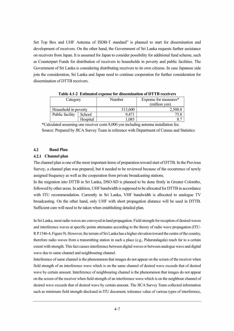
4-7
Set Top Box and UHF Antenna of ISDB-T standard” is planned to start for dissemination and
development of receivers. On the other hand, the Government of Sri Lanka requests further assistance
on receivers from Japan. It is assumed for Japan to consider possibility for additional fund scheme, such
as Counterpart Funds for distribution of receivers to households in poverty and public facilities. The
Government of Sri Lanka is considering distributing receivers to its own citizens. In case Japanese side
join the consideration, Sri Lanka and Japan need to continue cooperation for further consideration for
dissemination of DTTB receivers.
Table 4.1-2 Estimated expense for dissemination of DTTB receivers Category Number Expense for measures*
(million yen) Household in poverty 313,600 2,508.8 Public facility School 9,471 75.8
Hospital 1,085 8.7 *Calculated assuming one receiver costs 8,000 yen including antenna installation fee. Source: Prepared by JICA Survey Team in reference with Department of Census and Statistics
Band Plan
Channel plan
The channel plan is one of the most important items of preparation toward start of DTTB. In the Previous
Survey, a channel plan was prepared, but it needed to be reviewed because of the occurrence of newly
assigned frequency as well as the cooperation from private broadcasting stations.
In the migration into DTTB in Sri Lanka, DSO-SD is planned to be done firstly in Greater Colombo,
followed by other areas. In addition, UHF bandwidth is supposed to be allocated for DTTB in accordance
with ITU recommendation. Currently in Sri Lanka, VHF bandwidth is allocated to analogue TV
broadcasting. On the other hand, only UHF with short propagation distance will be used in DTTB.
Sufficient care will need to be taken when establishing detailed plan.
In Sri Lanka, most radio waves are conveyed in land propagation. Field strength for reception of desired waves
and interference waves at specific points attenuates according to the theory of radio wave propagation (ITU-
R P.1546-4, Figure 9). However, the terrain of Sri Lanka has a higher elevation toward the centre of the country,
therefore radio waves from a transmitting station in such a place (e.g., Pidurutalagala) reach far to a certain
extent with strength. This fact causes interference between digital waves or between analogue wave and digital
wave due to same channel and neighbouring channel.
Interference of same channel is the phenomenon that images do not appear on the screen of the receiver when
field strength of an interference wave which is on the same channel of desired wave exceeds that of desired
wave by certain amount. Interference of neighbouring channel is the phenomenon that images do not appear
on the screen of the receiver when field strength of an interference wave which is on the neighbour channel of
desired wave exceeds that of desired wave by certain amount. The JICA Survey Team collected information
such as minimum field strength disclosed in ITU document, tolerance value of various types of interference,

4-8
situation of radio waves in Sri Lanka and standard values used in Japan, thereafter decided the standard value
for simulation of radio wave propagation.
Table 4.2-1 shows the standard values.
Table 4.2-1 Standard values for simulation No. Name of standard value Standard value Explanation 1 Minimum Field Strength 51 dBμV/m This value is set higher a little than ITU
standard, 47.2dBμV/m, because performance of the local general receiving equipment is low in many cases.
2 Time rate for calculation of cover area
50% This value is not 99% adopted in Japan, but the same value of analogue broadcasting, in consideration with certainty of broadcasting service required in Sri Lanka and the economics of system construction.
3 Time rate for calculation of interfered areas
1% This value is the most stringent value which is also used in Japan, in consideration with preventing interference with existing analogue broadcasting and increasing the reliability of digital broadcasting. (It ranges from 1 to 10.)
4 Coverage rate of co-channel interference from digital to digital
20 dB Same as the value of ITU-R BT.1368-13,Table 68.
5 Coverage rate of co-channel interference from digital to analogue
34 dB Same as the most stringent value of ITU-RBT.1368-13, Table 78 Tropospheric, in order to prevent interference with existing analogue broadcasting.
6 Coverage rate of co-channel interference from analogue to digital
5 dB Same as the value of ITU-R BT.1368-13,Table 72.
7 Coverage rate of adjacent channel from digital to analogue
-5 dB Same as the most stringent value of ITU-R BT.1368-13, Table 79, Continuous, in order to prevent interference with existing analogue broadcasting.
8 Coverage rate of adjacent channel from analogue to digital
-32 dB Same as the value of ITU-R BT.1368-13,Table 74.
9 Front-to-back rate of reception antenna
16 dB The direction adjustment of the reception antenna is effective for avoidance of interference. ITU-R BT.419-3 is the reference as the standard of antenna characteristic, which is generally used in Sri Lanka.
Source: ITU
Taking the above into account, the policy plan for reviewing the channel plan is described below.
4-9
Use of Existing Transmitting Stations
The construction of a new transmitting station requires a huge amount of time and money. The use of
existing transmitting facilities is a very cost-effective way to establish a DTTB transmitting station. In
addition, there is a high possibility that work such as logging, cutting, rounding, etc. for using new land
will be unnecessary, which will lead to shortening construction work of transmitting stations. Therefore,
the use of existing transmitting stations is highly recommended in order to plan developing DTTB
network as early as possible.
Consideration of Topographic Features
As radio waves travel in a straight line, topographic features such as mountains and hills can obstruct
their path. The radio wave from a transmitting station may not reach certain areas behind mountains
because of the obstruction by the mountains of the path of the radio wave. This kind of poor reception
area can be improved by the installation of gap-fillers, consisting of low power transmitters and small
transmitting antennas. In other words, taking into consideration the topographic features of Sri Lanka, it
is difficult to cover the entire country with one or two large-output transmitting stations. It will be
necessary to develop an efficient DTTB network by dividing the country into area blocks.
Promotion of local broadcasting service
In the digital era, with access to a highly-developed Internet and mobile phone networks, diversification
in TV programming is necessary for the acquisition of information and meets the needs of TV viewers.
In general, national news broadcasts and programmes targeting a wide viewer base are to be provided
nationwide. Meanwhile, broadcasts targeting individual municipalities and communities should be
provided only to related areas. Multi-ethnic Sri Lanka, with its regionally diverse natural and social
(industrial and economic) conditions, will need channel planning that incorporates special measures to
promote the provision of community-based programmes in the near future.
It will be extremely difficult and cost a large amount of additional money to migrate from a broadcasting
network which can only deal with uniform programme set nationwide to a network that can promote
regional broadcasting. Meanwhile, a channel plan based on the policy of implementing regional
broadcasting will realize not only provision of uniform programme nationwide but also effective
equipment procurement by avoiding duplication. Therefore, the channel plan for DTTB is based on
implementing regional broadcasting, in consideration with the situation of society in Sri Lanka and the
flexibility of regional broadcasting.
Programme multiplexing and channel assignment
Programme multiplexing, which allows simultaneous transmission of multiple programmes on a single
frequency, is a distinctive characteristic of DTTB. Programme multiplexing enables the effective use of
frequencies. At present, as a large number of frequencies are allocated to analogue broadcasting, there
are only a small number of vacant channels available for DTTB in Greater Colombo area. Therefore,
programme multiplexing is a very effective technique during the period of simultaneous broadcasting
when a large number of frequencies are required for the analogue and digital broadcasting. The JICA

4-10
Survey Team created a plan for frequency allocation considering the following points while supporting
the creation of migration plan into DTTB.
From 4.2.3, the result of consideration for channel assignment for SD broadcasting is stated.
Channel assignment during the period of simultaneous broadcasting
On the basis of the results of the subjective picture quality evaluation conducted in Previous Survey, the
six-programme multiplexing system will be used in channel assignment plan. It is planned that all 24
licensed TV channels will be transited to DTTB. Therefore, four frequency bandwidths need to be
assured at DTTB platform and each transmitting station during the period of simultaneous broadcasting.
The way of thinking for operation of HD broadcasting
Multiplexing of HD programmes will start at the same time as when HD broadcasting starts. As data size
of HD programme is bigger than SD, the number of programmes multiplexed in 1 channel will decrease
to 3. Channel assignment plan for HD broadcasting is based on above.
Blocks set for promoting regional broadcasting in future
7 blocks will be set to divide Sri Lanka for channel assignment based on geographical situation, in order
to promote regional broadcasting in future, as stated in 4.2.1. It was especially focused on eliminating
interference between neighbouring blocks when considering channel assignment for each block.
Revision of channel assignment for SD broadcasting
Survey on existing antenna tower
In the Previous Survey, existing antenna towers of state-run broadcasting stations were investigated
regarding the possibility of their usage for digital broadcasting. In This Survey, JICA Survey Team
additionally investigated the possibility of usage of existing antenna towers owned by private
broadcasters, after most of them agreed on cooperation with This Survey. The objective was to reduce
the expenses on private broadcasting stations during the period of simultaneous broadcasting of DTTB.
The JICA Survey Team received lists of existing antenna towers from private broadcasting stations and
telecommunication providers in advance. Thereafter antenna towers were extracted as the candidate of
transmitting stations for DTTB in consideration with their locations. The Survey Team requested detailed
information of the candidate towers from broadcasting stations and telecommunication providers who
own those towers for further table top investigation (*). They visited the sites which were judged not to
be difficult to be the transmitting station and looked into actual situations there.
Table 4.2-2 shows the list of existing antenna towers investigated in This Survey and the details of each
tower are indicated further below.
(*) Table top investigation included image analysis using pictures of the towers, judgement of existence
of space for installing additional antenna for DTTB, consideration on strength of the towers and so on.
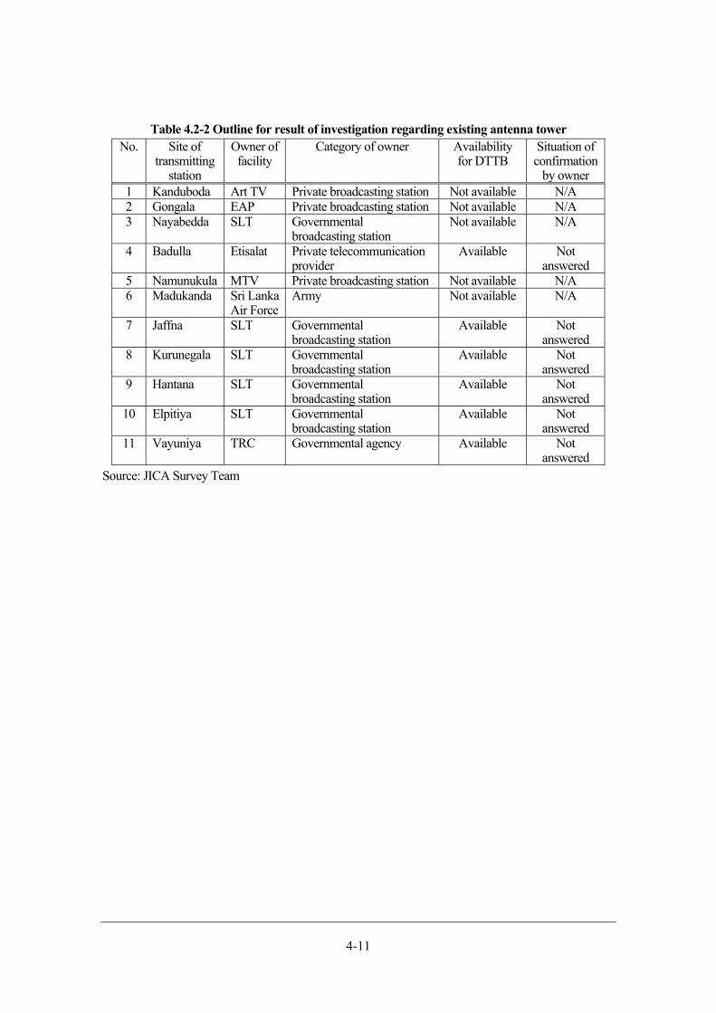
4-11
Table 4.2-2 Outline for result of investigation regarding existing antenna tower No. Site of
transmitting station
Owner of facility
Category of owner Availability for DTTB
Situation of confirmation
by owner 1 Kanduboda Art TV Private broadcasting station Not available N/A 2 Gongala EAP Private broadcasting station Not available N/A 3 Nayabedda SLT Governmental
broadcasting stationNot available N/A
4 Badulla Etisalat Private telecommunication provider
Available Not answered
5 Namunukula MTV Private broadcasting station Not available N/A 6 Madukanda Sri Lanka
Air Force Army Not available N/A
7 Jaffna SLT Governmentalbroadcasting station
Available Not answered
8 Kurunegala SLT Governmentalbroadcasting station
Available Not answered
9 Hantana SLT Governmentalbroadcasting station
Available Not answered
10 Elpitiya SLT Governmentalbroadcasting station
Available Not answered
11 Vayuniya TRC Governmental agency Available Not answered
Source: JICA Survey Team
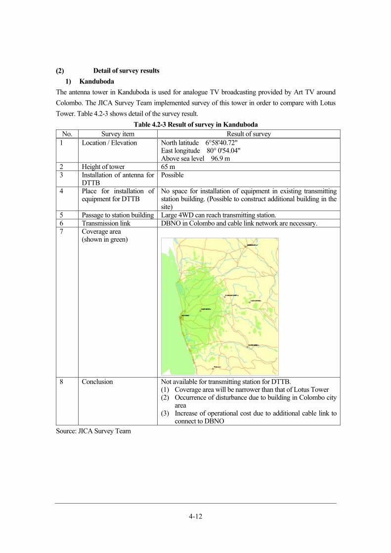
4-12
Detail of survey results
1) Kanduboda
The antenna tower in Kanduboda is used for analogue TV broadcasting provided by Art TV around
Colombo. The JICA Survey Team implemented survey of this tower in order to compare with Lotus
Tower. Table 4.2-3 shows detail of the survey result.
Table 4.2-3 Result of survey in Kanduboda No. Survey item Result of survey
1 Location / Elevation North latitude 6°58'40.72" East longitude 80° 0'54.04" Above sea level 96.9 m
2 Height of tower 65 m3 Installation of antenna for
DTTB Possible
4 Place for installation of equipment for DTTB
No space for installation of equipment in existing transmitting station building. (Possible to construct additional building in the site)
5 Passage to station building Large 4WD can reach transmitting station. 6 Transmission link DBNO in Colombo and cable link network are necessary. 7 Coverage area
(shown in green)
8 Conclusion Not available for transmitting station for DTTB.
(1) Coverage area will be narrower than that of Lotus Tower (2) Occurrence of disturbance due to building in Colombo city
area (3) Increase of operational cost due to additional cable link to
connect to DBNO Source: JICA Survey Team
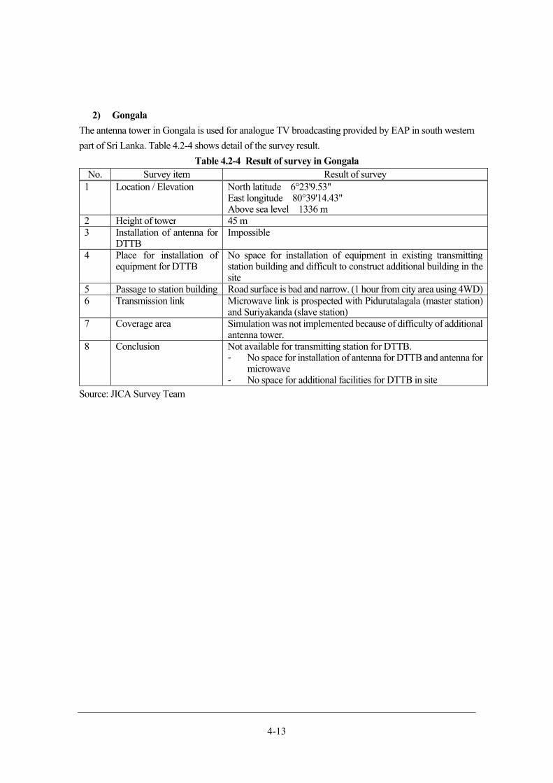
4-13
2) Gongala
The antenna tower in Gongala is used for analogue TV broadcasting provided by EAP in south western
part of Sri Lanka. Table 4.2-4 shows detail of the survey result.
Table 4.2-4 Result of survey in Gongala No. Survey item Result of survey
1 Location / Elevation North latitude 6°23'9.53"East longitude 80°39'14.43" Above sea level 1336 m
2 Height of tower 45 m3 Installation of antenna for
DTTB Impossible
4 Place for installation of equipment for DTTB
No space for installation of equipment in existing transmittingstation building and difficult to construct additional building in the site
5 Passage to station building Road surface is bad and narrow. (1 hour from city area using 4WD)6 Transmission link Microwave link is prospected with Pidurutalagala (master station)
and Suriyakanda (slave station)7 Coverage area Simulation was not implemented because of difficulty of additional
antenna tower.8 Conclusion Not available for transmitting station for DTTB.
- No space for installation of antenna for DTTB and antenna for microwave
- No space for additional facilities for DTTB in site Source: JICA Survey Team
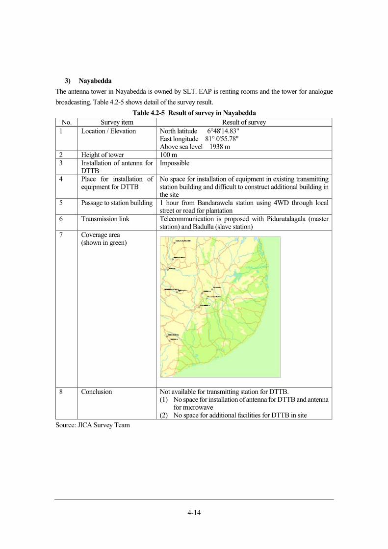
4-14
3) Nayabedda
The antenna tower in Nayabedda is owned by SLT. EAP is renting rooms and the tower for analogue
broadcasting. Table 4.2-5 shows detail of the survey result.
Table 4.2-5 Result of survey in Nayabedda No. Survey item Result of survey
1 Location / Elevation North latitude 6°48'14.83"East longitude 81° 0'55.78" Above sea level 1938 m
2 Height of tower 100 m3 Installation of antenna for
DTTB Impossible
4 Place for installation of equipment for DTTB
No space for installation of equipment in existing transmitting station building and difficult to construct additional building in the site
5 Passage to station building 1 hour from Bandarawela station using 4WD through local street or road for plantation
6 Transmission link Telecommunication is proposed with Pidurutalagala (master station) and Badulla (slave station)
7 Coverage area(shown in green)
8 Conclusion Not available for transmitting station for DTTB. (1) No space for installation of antenna for DTTB and antenna
for microwave (2) No space for additional facilities for DTTB in site
Source: JICA Survey Team
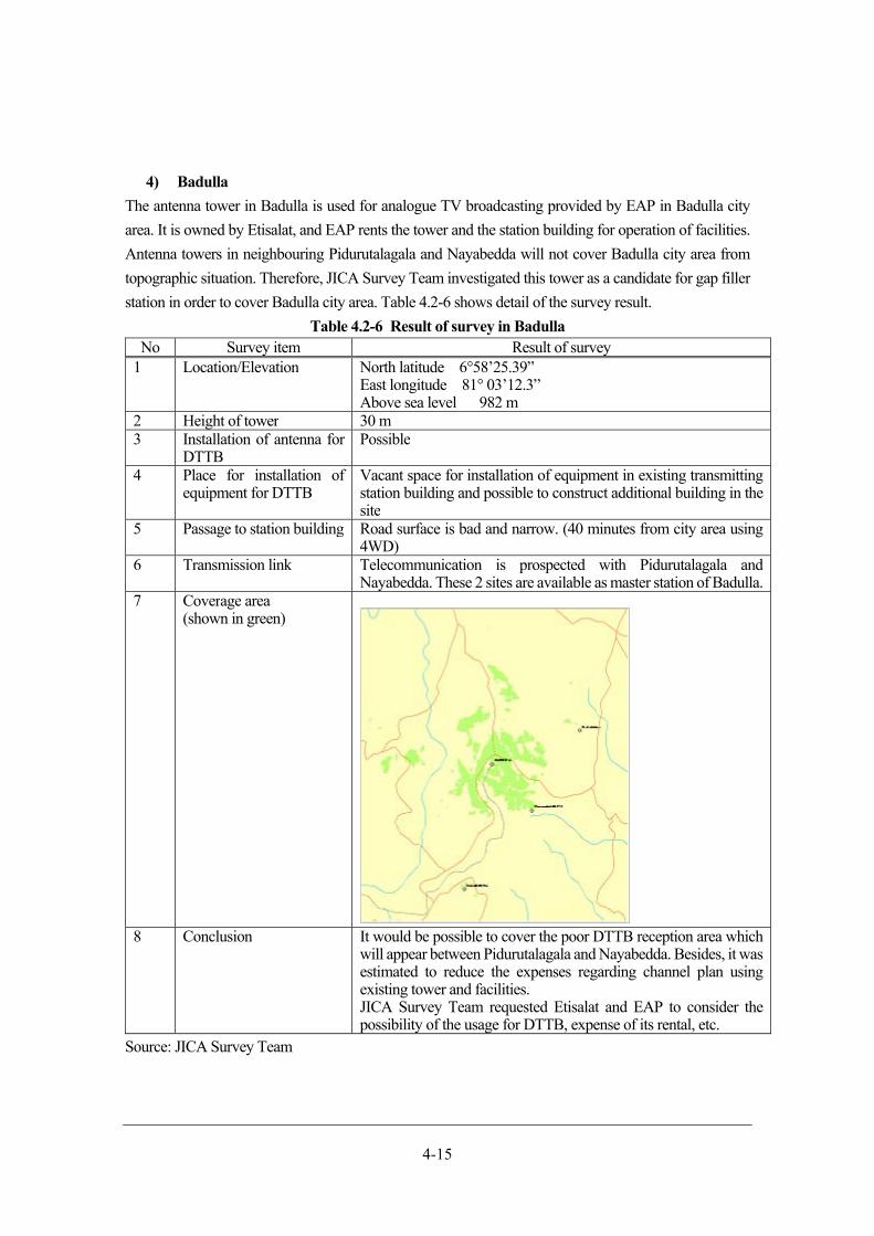
4-15
4) Badulla
The antenna tower in Badulla is used for analogue TV broadcasting provided by EAP in Badulla city
area. It is owned by Etisalat, and EAP rents the tower and the station building for operation of facilities.
Antenna towers in neighbouring Pidurutalagala and Nayabedda will not cover Badulla city area from
topographic situation. Therefore, JICA Survey Team investigated this tower as a candidate for gap filler
station in order to cover Badulla city area. Table 4.2-6 shows detail of the survey result.
Table 4.2-6 Result of survey in Badulla No Survey item Result of survey
1 Location/Elevation North latitude 6°58’25.39”East longitude 81° 03’12.3” Above sea level 982 m
2 Height of tower 30 m3 Installation of antenna for
DTTB Possible
4 Place for installation of equipment for DTTB
Vacant space for installation of equipment in existing transmitting station building and possible to construct additional building in the site
5 Passage to station building Road surface is bad and narrow. (40 minutes from city area using 4WD)
6 Transmission link Telecommunication is prospected with Pidurutalagala and Nayabedda. These 2 sites are available as master station of Badulla.
7 Coverage area(shown in green)
8 Conclusion It would be possible to cover the poor DTTB reception area which
will appear between Pidurutalagala and Nayabedda. Besides, it was estimated to reduce the expenses regarding channel plan using existing tower and facilities. JICA Survey Team requested Etisalat and EAP to consider the possibility of the usage for DTTB, expense of its rental, etc.
Source: JICA Survey Team
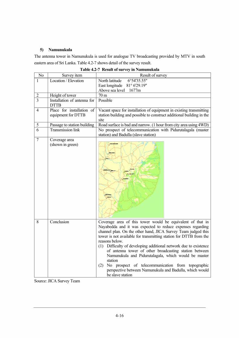
4-16
5) Namunukula
The antenna tower in Namunukula is used for analogue TV broadcasting provided by MTV in south
eastern area of Sri Lanka. Table 4.2-7 shows detail of the survey result.
Table 4.2-7 Result of survey in Namunukula No Survey item Result of survey
1 Location / Elevation North latitude 6°54'35.55"East longitude 81° 6'29.19" Above sea level 1677m
2 Height of tower 70 m3 Installation of antenna for
DTTB Possible
4 Place for installation of equipment for DTTB
Vacant space for installation of equipment in existing transmitting station building and possible to construct additional building in the site
5 Passage to station building Road surface is bad and narrow. (1 hour from city area using 4WD)6 Transmission link No prospect of telecommunication with Pidurutalagala (master
station) and Badulla (slave station)7 Coverage area
(shown in green)
8 Conclusion Coverage area of this tower would be equivalent of that in Nayabedda and it was expected to reduce expenses regarding channel plan. On the other hand, JICA Survey Team judged this tower is not available for transmitting station for DTTB from the reasons below. (1) Difficulty of developing additional network due to existence
of antenna tower of other broadcasting station between Namunukula and Pidurutalagala, which would be master station
(2) No prospect of telecommunication from topographic perspective between Namunukula and Badulla, which would be slave station
Source: JICA Survey Team
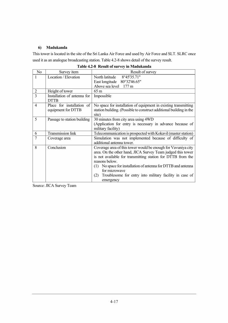
4-17
6) Madukanda
This tower is located in the site of the Sri Lanka Air Force and used by Air Force and SLT. SLRC once
used it as an analogue broadcasting station. Table 4.2-8 shows detail of the survey result.
Table 4.2-8 Result of survey in Madukanda No Survey item Result of survey
1 Location / Elevation North latitude 8°45'35.71"East longitude 80°32'46.65" Above sea level 177 m
2 Height of tower 65 m3 Installation of antenna for
DTTB Impossible
4 Place for installation of equipment for DTTB
No space for installation of equipment in existing transmitting station building. (Possible to construct additional building in the site)
5 Passage to station building 30 minutes from city area using 4WD(Application for entry is necessary in advance because of military facility)
6 Transmission link Telecommunication is prospected with Kokavil (master station)7 Coverage area Simulation was not implemented because of difficulty of
additional antenna tower.8 Conclusion Coverage area of this tower would be enough for Vavuniya city
area. On the other hand, JICA Survey Team judged this tower is not available for transmitting station for DTTB from the reasons below. (1) No space for installation of antenna for DTTB and antenna
for microwave (2) Troublesome for entry into military facility in case of
emergencySource: JICA Survey Team
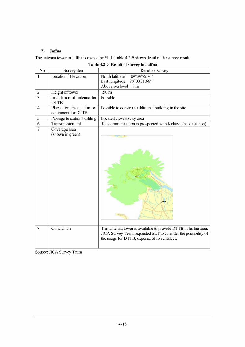
4-18
7) Jaffna
The antenna tower in Jaffna is owned by SLT. Table 4.2-9 shows detail of the survey result.
Table 4.2-9 Result of survey in Jaffna No Survey item Result of survey
1 Location / Elevation North latitude 09°39'55.76"East longitude 80°00'21.66" Above sea level 5 m
2 Height of tower 150 m3 Installation of antenna for
DTTB Possible
4 Place for installation of equipment for DTTB
Possible to construct additional building in the site
5 Passage to station building Located close to city area6 Transmission link Telecommunication is prospected with Kokavil (slave station) 7 Coverage area
(shown in green)
8 Conclusion This antenna tower is available to provide DTTB in Jaffna area. JICA Survey Team requested SLT to consider the possibility of the usage for DTTB, expense of its rental, etc.
Source: JICA Survey Team
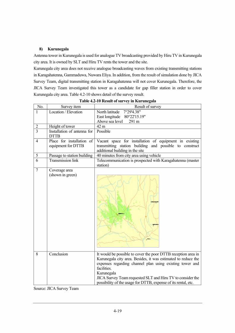
4-19
8) Kurunegala
Antenna tower in Kurunegala is used for analogue TV broadcasting provided by Hiru TV in Kurunegala
city area. It is owned by SLT and Hiru TV rents the tower and the site.
Kurunegala city area does not receive analogue broadcasting waves from existing transmitting stations
in Karagahatenna, Gammaduwa, Nuwara Eliya. In addition, from the result of simulation done by JICA
Survey Team, digital transmitting station in Karagahatenna will not cover Kurunegala. Therefore, the
JICA Survey Team investigated this tower as a candidate for gap filler station in order to cover
Kurunegala city area. Table 4.2-10 shows detail of the survey result.
Table 4.2-10 Result of survey in Kurunegala No. Survey item Result of survey
1 Location / Elevation North latitude 7°29'4.38"East longitude 80°22'15.19" Above sea level 291 m
2 Height of tower 42 m3 Installation of antenna for
DTTB Possible
4 Place for installation of equipment for DTTB
Vacant space for installation of equipment in existing transmitting station building and possible to construct additional building in the site
5 Passage to station building 40 minutes from city area using vehicle6 Transmission link Telecommunication is prospected with Karagahatenna (master
station)7 Coverage area
(shown in green)
8 Conclusion It would be possible to cover the poor DTTB reception area in Kurunegala city area. Besides, it was estimated to reduce the expenses regarding channel plan using existing tower and facilities. Kurunegala JICA Survey Team requested SLT and Hiru TV to consider the possibility of the usage for DTTB, expense of its rental, etc.
Source: JICA Survey Team
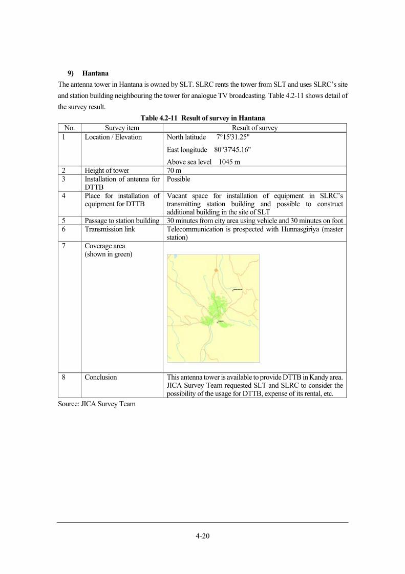
4-20
9) Hantana
The antenna tower in Hantana is owned by SLT. SLRC rents the tower from SLT and uses SLRC’s site
and station building neighbouring the tower for analogue TV broadcasting. Table 4.2-11 shows detail of
the survey result.
Table 4.2-11 Result of survey in Hantana No. Survey item Result of survey
1 Location / Elevation North latitude 7°15'31.25"
East longitude 80°37'45.16"
Above sea level 1045 m2 Height of tower 70 m3 Installation of antenna for
DTTB Possible
4 Place for installation of equipment for DTTB
Vacant space for installation of equipment in SLRC’s transmitting station building and possible to construct additional building in the site of SLT
5 Passage to station building 30 minutes from city area using vehicle and 30 minutes on foot6 Transmission link Telecommunication is prospected with Hunnasgiriya (master
station)7 Coverage area
(shown in green)
8 Conclusion This antenna tower is available to provide DTTB in Kandy area. JICA Survey Team requested SLT and SLRC to consider the possibility of the usage for DTTB, expense of its rental, etc.
Source: JICA Survey Team

4-21
10) Elpitiya
The antenna tower in Elpitiya is owned by SLT. (It is called Pathirajakanda by SLT.) Table 4.2-12 shows
detail of the survey result.
Table 4.2-12 Result of survey in Elpitiya No. Survey item Result of survey
1 Location / Elevation North latitude 6°15'33.20"East longitude 80° 8'39.00" Above sea level 33 m
2 Height of tower 80 m3 Installation of antenna for
DTTB Possible
4 Place for installation of equipment for DTTB
Vacant space for installation of equipment in existing transmitting station building. (Impossible to construct additional building in the site)
5 Passage to station building Located close to city area6 Transmission link Telecommunication is prospected with Gongala (master
station)7 Coverage area
(shown in green)
8 Conclusion This antenna tower is available to provide DTTB in Elpitiya area. JICA Survey Team requested SLT to consider the possibility of the usage for DTTB, expense of its rental, etc.
Source: JICA Survey Team
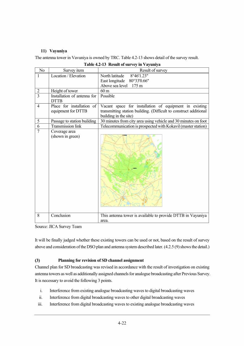
4-22
11) Vayuniya
The antenna tower in Vavuniya is owned by TRC. Table 4.2-13 shows detail of the survey result.
Table 4.2-13 Result of survey in Vayuniya No Survey item Result of survey
1 Location / Elevation North latitude 8°46'1.23"East longitude 80°33'0.66" Above sea level 175 m
2 Height of tower 60 m3 Installation of antenna for
DTTB Possible
4 Place for installation of equipment for DTTB
Vacant space for installation of equipment in existing transmitting station building. (Difficult to construct additional building in the site)
5 Passage to station building 30 minutes from city area using vehicle and 30 minutes on foot6 Transmission link Telecommunication is prospected with Kokavil (master station)7 Coverage area
(shown in green)
8 Conclusion This antenna tower is available to provide DTTB in Vayuniyaarea.
Source: JICA Survey Team
It will be finally judged whether these existing towers can be used or not, based on the result of survey
above and consideration of the DSO plan and antenna system described later. (4.2.5 (9) shows the detail.)
Planning for revision of SD channel assignment
Channel plan for SD broadcasting was revised in accordance with the result of investigation on existing
antenna towers as well as additionally assigned channels for analogue broadcasting after Previous Survey.
It is necessary to avoid the following 3 points.
i. Interference from existing analogue broadcasting waves to digital broadcasting waves
ii. Interference from digital broadcasting waves to other digital broadcasting waves
iii. Interference from digital broadcasting waves to existing analogue broadcasting waves
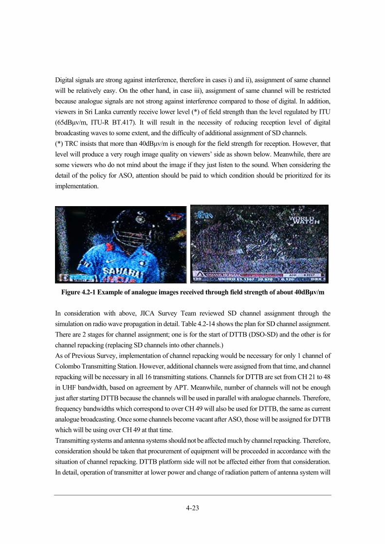
4-23
Digital signals are strong against interference, therefore in cases i) and ii), assignment of same channel
will be relatively easy. On the other hand, in case iii), assignment of same channel will be restricted
because analogue signals are not strong against interference compared to those of digital. In addition,
viewers in Sri Lanka currently receive lower level (*) of field strength than the level regulated by ITU
(65dBμv/m, ITU-R BT.417). It will result in the necessity of reducing reception level of digital
broadcasting waves to some extent, and the difficulty of additional assignment of SD channels.
(*) TRC insists that more than 40dBμv/m is enough for the field strength for reception. However, that
level will produce a very rough image quality on viewers’ side as shown below. Meanwhile, there are
some viewers who do not mind about the image if they just listen to the sound. When considering the
detail of the policy for ASO, attention should be paid to which condition should be prioritized for its
implementation.
Figure 4.2-1 Example of analogue images received through field strength of about 40dBμv/m
In consideration with above, JICA Survey Team reviewed SD channel assignment through the
simulation on radio wave propagation in detail. Table 4.2-14 shows the plan for SD channel assignment.
There are 2 stages for channel assignment; one is for the start of DTTB (DSO-SD) and the other is for
channel repacking (replacing SD channels into other channels.)
As of Previous Survey, implementation of channel repacking would be necessary for only 1 channel of
Colombo Transmitting Station. However, additional channels were assigned from that time, and channel
repacking will be necessary in all 16 transmitting stations. Channels for DTTB are set from CH 21 to 48
in UHF bandwidth, based on agreement by APT. Meanwhile, number of channels will not be enough
just after starting DTTB because the channels will be used in parallel with analogue channels. Therefore,
frequency bandwidths which correspond to over CH 49 will also be used for DTTB, the same as current
analogue broadcasting. Once some channels become vacant after ASO, those will be assigned for DTTB
which will be using over CH 49 at that time.
Transmitting systems and antenna systems should not be affected much by channel repacking. Therefore,
consideration should be taken that procurement of equipment will be proceeded in accordance with the
situation of channel repacking. DTTB platform side will not be affected either from that consideration.
In detail, operation of transmitter at lower power and change of radiation pattern of antenna system will
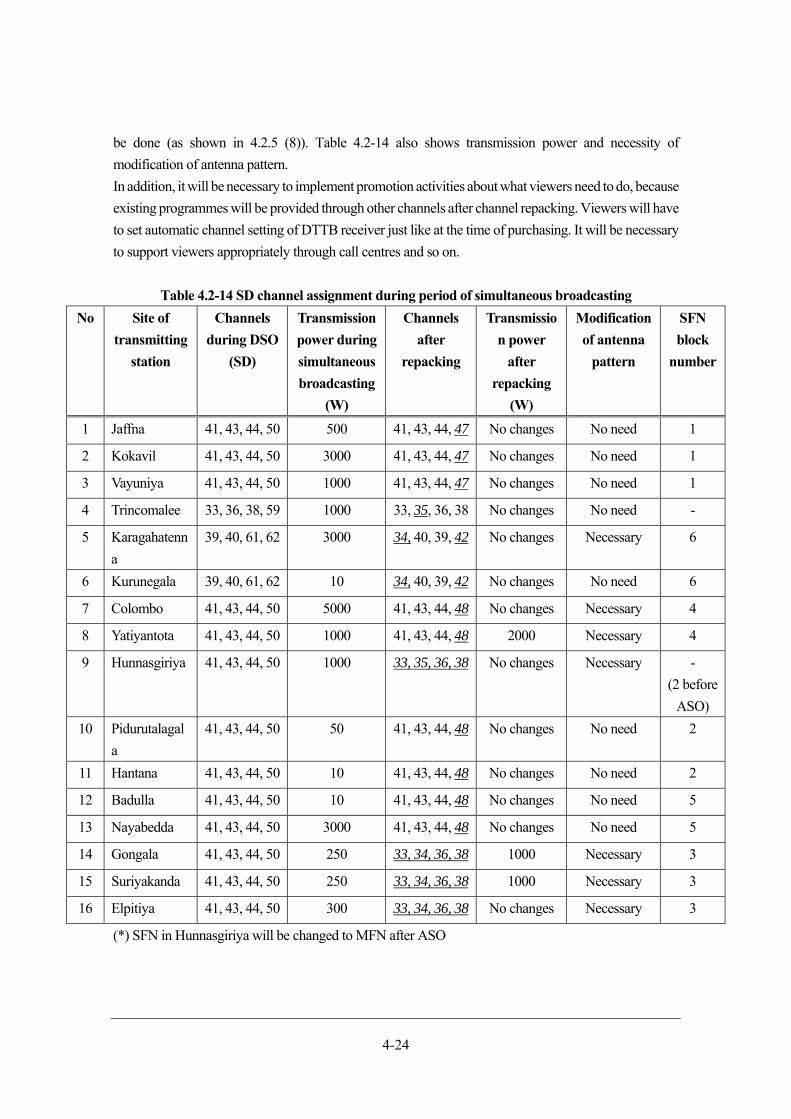
4-24
be done (as shown in 4.2.5 (8)). Table 4.2-14 also shows transmission power and necessity of
modification of antenna pattern.
In addition, it will be necessary to implement promotion activities about what viewers need to do, because
existing programmes will be provided through other channels after channel repacking. Viewers will have
to set automatic channel setting of DTTB receiver just like at the time of purchasing. It will be necessary
to support viewers appropriately through call centres and so on.
Table 4.2-14 SD channel assignment during period of simultaneous broadcasting
No Site of
transmitting
station
Channels
during DSO
(SD)
Transmission
power during
simultaneous
broadcasting
(W)
Channels
after
repacking
Transmissio
n power
after
repacking
(W)
Modification
of antenna
pattern
SFN
block
number
1 Jaffna 41, 43, 44, 50 500 41, 43, 44, 47 No changes No need 1
2 Kokavil 41, 43, 44, 50 3000 41, 43, 44, 47 No changes No need 1
3 Vayuniya 41, 43, 44, 50 1000 41, 43, 44, 47 No changes No need 1
4 Trincomalee 33, 36, 38, 59 1000 33, 35, 36, 38 No changes No need -
5 Karagahatenn
a
39, 40, 61, 62 3000 34, 40, 39, 42 No changes Necessary 6
6 Kurunegala 39, 40, 61, 62 10 34, 40, 39, 42 No changes No need 6
7 Colombo 41, 43, 44, 50 5000 41, 43, 44, 48 No changes Necessary 4
8 Yatiyantota 41, 43, 44, 50 1000 41, 43, 44, 48 2000 Necessary 4
9 Hunnasgiriya 41, 43, 44, 50 1000 33, 35, 36, 38 No changes Necessary -
(2 before
ASO)
10 Pidurutalagal
a
41, 43, 44, 50 50 41, 43, 44, 48 No changes No need 2
11 Hantana 41, 43, 44, 50 10 41, 43, 44, 48 No changes No need 2
12 Badulla 41, 43, 44, 50 10 41, 43, 44, 48 No changes No need 5
13 Nayabedda 41, 43, 44, 50 3000 41, 43, 44, 48 No changes No need 5
14 Gongala 41, 43, 44, 50 250 33, 34, 36, 38 1000 Necessary 3
15 Suriyakanda 41, 43, 44, 50 250 33, 34, 36, 38 1000 Necessary 3
16 Elpitiya 41, 43, 44, 50 300 33, 34, 36, 38 No changes Necessary 3
(*) SFN in Hunnasgiriya will be changed to MFN after ASO
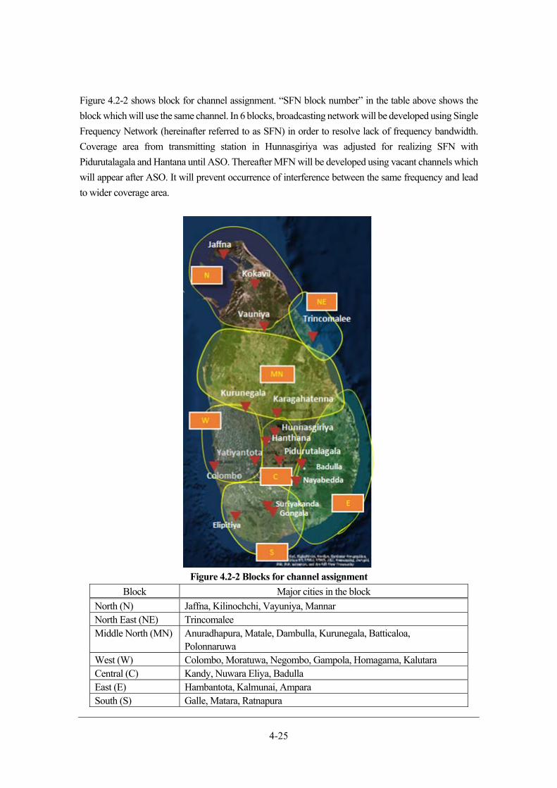
4-25
Figure 4.2-2 shows block for channel assignment. “SFN block number” in the table above shows the
block which will use the same channel. In 6 blocks, broadcasting network will be developed using Single
Frequency Network (hereinafter referred to as SFN) in order to resolve lack of frequency bandwidth.
Coverage area from transmitting station in Hunnasgiriya was adjusted for realizing SFN with
Pidurutalagala and Hantana until ASO. Thereafter MFN will be developed using vacant channels which
will appear after ASO. It will prevent occurrence of interference between the same frequency and lead
to wider coverage area.
Figure 4.2-2 Blocks for channel assignment
Block Major cities in the block
North (N) Jaffna, Kilinochchi, Vayuniya, Mannar North East (NE) Trincomalee Middle North (MN) Anuradhapura, Matale, Dambulla, Kurunegala, Batticaloa,
Polonnaruwa West (W) Colombo, Moratuwa, Negombo, Gampola, Homagama, Kalutara Central (C) Kandy, Nuwara Eliya, Badulla East (E) Hambantota, Kalmunai, Ampara South (S) Galle, Matara, Ratnapura
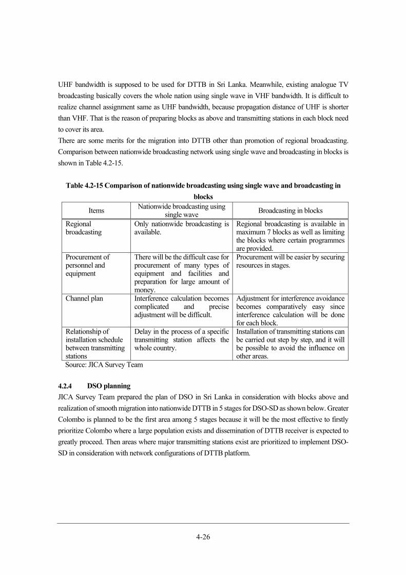
4-26
UHF bandwidth is supposed to be used for DTTB in Sri Lanka. Meanwhile, existing analogue TV
broadcasting basically covers the whole nation using single wave in VHF bandwidth. It is difficult to
realize channel assignment same as UHF bandwidth, because propagation distance of UHF is shorter
than VHF. That is the reason of preparing blocks as above and transmitting stations in each block need
to cover its area.
There are some merits for the migration into DTTB other than promotion of regional broadcasting.
Comparison between nationwide broadcasting network using single wave and broadcasting in blocks is
shown in Table 4.2-15.
Table 4.2-15 Comparison of nationwide broadcasting using single wave and broadcasting in
blocks
Items Nationwide broadcasting using single wave Broadcasting in blocks
Regional broadcasting
Only nationwide broadcasting is available.
Regional broadcasting is available in maximum 7 blocks as well as limiting the blocks where certain programmes are provided.
Procurement of personnel and equipment
There will be the difficult case for procurement of many types of equipment and facilities and preparation for large amount of money.
Procurement will be easier by securing resources in stages.
Channel plan Interference calculation becomes complicated and precise adjustment will be difficult.
Adjustment for interference avoidance becomes comparatively easy since interference calculation will be done for each block.
Relationship of installation schedule between transmitting stations
Delay in the process of a specific transmitting station affects the whole country.
Installation of transmitting stations can be carried out step by step, and it will be possible to avoid the influence on other areas.
Source: JICA Survey Team
DSO planning
JICA Survey Team prepared the plan of DSO in Sri Lanka in consideration with blocks above and
realization of smooth migration into nationwide DTTB in 5 stages for DSO-SD as shown below. Greater
Colombo is planned to be the first area among 5 stages because it will be the most effective to firstly
prioritize Colombo where a large population exists and dissemination of DTTB receiver is expected to
greatly proceed. Then areas where major transmitting stations exist are prioritized to implement DSO-
SD in consideration with network configurations of DTTB platform.

4-27
Table 4.2-16 DSO-SD planning in stages
Sites of
transmitting
station
Population
coverage
ratio
Explanation
First
stage
-Colombo
(1kW)
21% It is planned to install a transmitting system at Colombo
Transmitting Station using 5kW transmitter, which will be
produced by manufacturer who will receive orders from the
Government of Sri Lanka. It is estimated to take 6 months for the
production of 5kW transmitter after decision of supplier by
tendering. Meanwhile, transmitting system using 1kW transmitter
is expected to be available because suppliers usually stock that kind
of equipment. Therefore, DTTB can be started earlier by
transmitting system using 1kW transmitter at first in Greater
Colombo, without waiting for production of 5kW transmitter. The
method above makes sense because it is necessary to ascertain how
radio waves propagate comparing with values of design during the
earlier stage of DTTB. Generally, operation at lower power rather
than regular power will be done to carefully confirm digital
broadcasting does not interfere with existing analogue
broadcasting.
1kW transmitter mentioned above will be relocated and used at
another station after 5kW transmitter is installed at Colombo
Transmitting Station.
Second
stage
-Colombo
(5kW)
-Kokavil
-Yatiyantota
-Jaffna
41% 5kW transmitter will be installed instead of that of 1kW at
Colombo Transmitting Station in February in 2021. This will
enable covering the service area as planned. The strength of radio
waves from the transmitter will be increased gradually based on the
situation regarding occurrence of interference in order to expand
the service area.
In February in 2021, installation of equipment at transmitting
stations in Kokavil, Yatiyantota and Jaffna will also be completed
and radio wave transmission will start. In this stage, service area
will be expanded mainly in northern and middle areas. Meanwhile,
southward radio wave transmission needs to be weakened at
Colombo Transmitting Station and Yatiyantota station in order to
avoid interference with transmitting stations in southern area.
Third
stage
-Pidurutalagala
-Hunnasgiriya
-Nayabedda
49% Installation of equipment at transmitting stations will be completed
in May 2021 in areas of third stage and radio waves transmission
will start. South-eastern areas will also be covered at this stage and
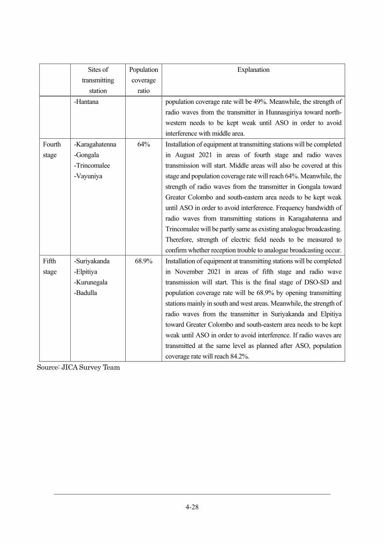
4-28
Sites of
transmitting
station
Population
coverage
ratio
Explanation
-Hantana population coverage rate will be 49%. Meanwhile, the strength of
radio waves from the transmitter in Hunnasgiriya toward north-
western needs to be kept weak until ASO in order to avoid
interference with middle area.
Fourth
stage
-Karagahatenna
-Gongala
-Trincomalee
-Vayuniya
64% Installation of equipment at transmitting stations will be completed
in August 2021 in areas of fourth stage and radio waves
transmission will start. Middle areas will also be covered at this
stage and population coverage rate will reach 64%. Meanwhile, the
strength of radio waves from the transmitter in Gongala toward
Greater Colombo and south-eastern area needs to be kept weak
until ASO in order to avoid interference. Frequency bandwidth of
radio waves from transmitting stations in Karagahatenna and
Trincomalee will be partly same as existing analogue broadcasting.
Therefore, strength of electric field needs to be measured to
confirm whether reception trouble to analogue broadcasting occur.
Fifth
stage
-Suriyakanda
-Elpitiya
-Kurunegala
-Badulla
68.9% Installation of equipment at transmitting stations will be completed
in November 2021 in areas of fifth stage and radio wave
transmission will start. This is the final stage of DSO-SD and
population coverage rate will be 68.9% by opening transmitting
stations mainly in south and west areas. Meanwhile, the strength of
radio waves from the transmitter in Suriyakanda and Elpitiya
toward Greater Colombo and south-eastern area needs to be kept
weak until ASO in order to avoid interference. If radio waves are
transmitted at the same level as planned after ASO, population
coverage rate will reach 84.2%.
Source: JICA Survey Team
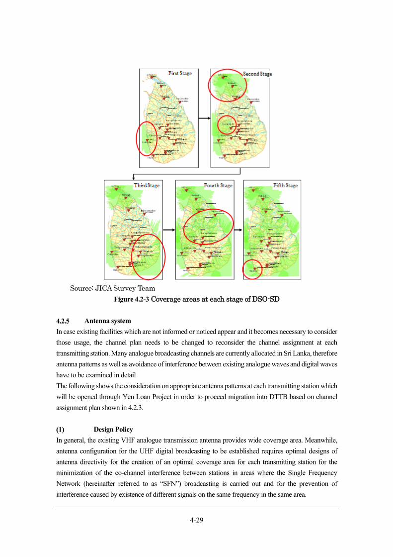
4-29
Source: JICA Survey Team
Figure 4.2-3 Coverage areas at each stage of DSO-SD
Antenna system
In case existing facilities which are not informed or noticed appear and it becomes necessary to consider
those usage, the channel plan needs to be changed to reconsider the channel assignment at each
transmitting station. Many analogue broadcasting channels are currently allocated in Sri Lanka, therefore
antenna patterns as well as avoidance of interference between existing analogue waves and digital waves
have to be examined in detail
The following shows the consideration on appropriate antenna patterns at each transmitting station which
will be opened through Yen Loan Project in order to proceed migration into DTTB based on channel
assignment plan shown in 4.2.3.
Design Policy
In general, the existing VHF analogue transmission antenna provides wide coverage area. Meanwhile,
antenna configuration for the UHF digital broadcasting to be established requires optimal designs of
antenna directivity for the creation of an optimal coverage area for each transmitting station for the
minimization of the co-channel interference between stations in areas where the Single Frequency
Network (hereinafter referred to as “SFN”) broadcasting is carried out and for the prevention of
interference caused by existence of different signals on the same frequency in the same area.

4-30
A broadband antenna system for the four-channel broadcasting in the UHF Band after the launch of
DTTB (broadcasting of multiplexed 24 SD programmes on four frequencies) and the eight-channel HD
broadcasting after ASO and DSO-HD (broadcasting of multiplexed 24 HD programmes on eight
frequencies – in this basic design) will have to be designed. It is desirable to have small deviation in
reception field strength between channels in the coverage area created by the antenna system, because
big deviation will cause the risk to create channels which are available for some households but not for
others. It is important to select an antenna with small deviation in directivity in a wide band range.
Therefore, a 4L stacked loop antenna which is widely used in Japan will be adopted as the basic antenna.
Use of products which allow inspection and maintenance of component parts which compose a
transmitting antenna system including an antenna element is recommended for their long-term use. In
this aspect, use of 4L stacked loop antennas is recommended because they have been used stably for a
long period of time with a regular basis of internal inspection and repainting.
The antenna and main feeder system will be configured with the high power appropriate for the extended
eight-channel operation in future. Combiner to be installed in the station buildings will be composed of
suitable components which enable the eight-channel operation.
Features of 4L Stacked Loop Antenna
The features of 4L stacked loop antenna to be adopted in the transmitting antenna system are as follows:
i. 4 loop antenna has four stacked loop elements (a type of directional antenna with vertical
arrayed elements), and gain is high.
ii. Deviation of the radiation pattern of antenna unit and the composed some antenna units are
small in the frequency range.
iii. Deviation of the gain is small in the above-mentioned frequency band.
iv. Because of its small deviation of radiation pattern and gain, the use of this type of antenna
in multiple channels use makes it possible to have an identical coverage area.
v. Because the antenna cover is easily removable, the maintenance of the inside part of cover
is easy.
vi. The wind pressure area is small; therefore, it is possible to reduce the wind load of an antenna
mounting post and tower.
Decision on Antenna radiation pattern
The interference between transmitter stations has to be minimized for DTTB. To satisfy this request,
simulation on the synthetic horizontal and vertical directivity with simulation software was conducted
repeatedly with different conditions, such as number of faces, directions and tilt angles of antenna panels
and finally most appropriate condition was identified.
The channel planning began with the policy of using existing towers of broadcasting stations, however
some interference between transmitter stations caused by long distance propagation from higher point to
lower point may be estimated. Therefore, simulation on the directivity of antennas installed at
transmitting stations in the mountains aiming at reduction of interference was conducted repeatedly with

4-31
different sets of conditions, including direction, tilt angle and power, of individual stations and the set of
conditions which gave the best result was identified.
Modification of design policy for combiner
1) Modification of design policy for combiner due to channel repacking
In the Previous Survey, design and cost estimation of combiner was implemented based on the premise
of synthesizing 4 waves into 1.
During This Survey, it was revealed that situation of frequency usage changed and vacant frequency
bandwidth corresponding to below CH 48 will not be enough. Therefore, in the channel plan of This
Survey, CH 49 to 62 scheduled for future use by mobile phone etc. will be temporarily used for DTTB
during the period of simultaneous broadcasting and those channels will be assigned below CH 48, which
will become vacant after ASO. Along with assignment above, additional expense due to constitution of
device and additional works of channel repacking will occur. When implementing channel repacking,
each broadcasting station using concerned channel will have to stop its operation. Figure 4.2-4 shows the
change of design policy for combiner in consideration with lowering additional expense and period of
channel repacking.
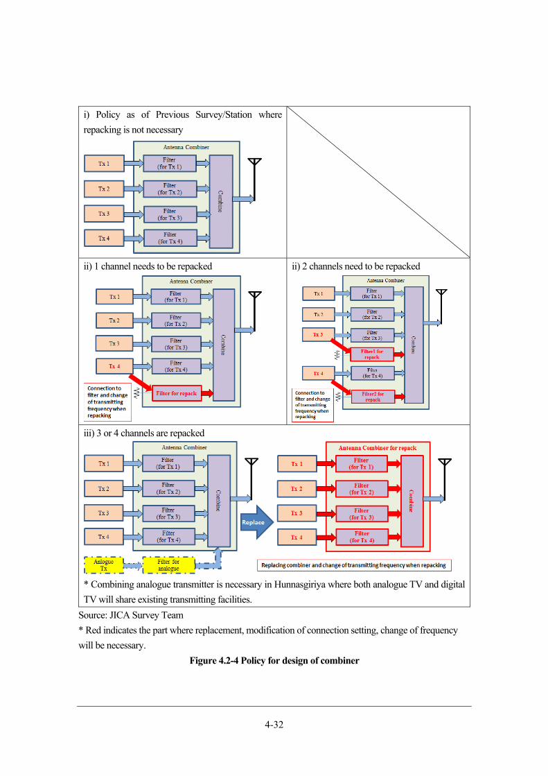
4-32
i) Policy as of Previous Survey/Station where
repacking is not necessary
ii) 1 channel needs to be repacked ii) 2 channels need to be repacked
iii) 3 or 4 channels are repacked
* Combining analogue transmitter is necessary in Hunnasgiriya where both analogue TV and digital
TV will share existing transmitting facilities.
Source: JICA Survey Team
* Red indicates the part where replacement, modification of connection setting, change of frequency
will be necessary.
Figure 4.2-4 Policy for design of combiner
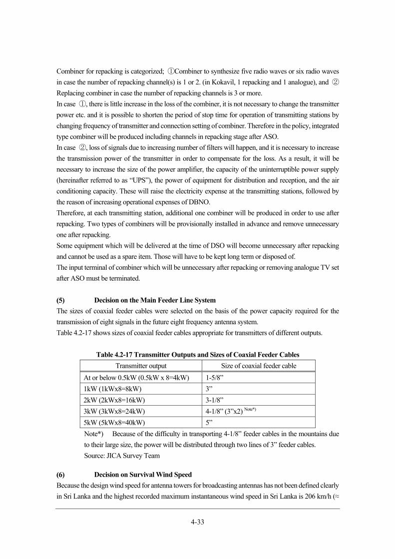
4-33
Combiner for repacking is categorized; ①Combiner to synthesize five radio waves or six radio waves
in case the number of repacking channel(s) is 1 or 2. (in Kokavil, 1 repacking and 1 analogue), and ②
Replacing combiner in case the number of repacking channels is 3 or more.
In case ①, there is little increase in the loss of the combiner, it is not necessary to change the transmitter
power etc. and it is possible to shorten the period of stop time for operation of transmitting stations by
changing frequency of transmitter and connection setting of combiner. Therefore in the policy, integrated
type combiner will be produced including channels in repacking stage after ASO.
In case ②, loss of signals due to increasing number of filters will happen, and it is necessary to increase
the transmission power of the transmitter in order to compensate for the loss. As a result, it will be
necessary to increase the size of the power amplifier, the capacity of the uninterruptible power supply
(hereinafter referred to as “UPS”), the power of equipment for distribution and reception, and the air
conditioning capacity. These will raise the electricity expense at the transmitting stations, followed by
the reason of increasing operational expenses of DBNO.
Therefore, at each transmitting station, additional one combiner will be produced in order to use after
repacking. Two types of combiners will be provisionally installed in advance and remove unnecessary
one after repacking.
Some equipment which will be delivered at the time of DSO will become unnecessary after repacking
and cannot be used as a spare item. Those will have to be kept long term or disposed of.
The input terminal of combiner which will be unnecessary after repacking or removing analogue TV set
after ASO must be terminated.
Decision on the Main Feeder Line System
The sizes of coaxial feeder cables were selected on the basis of the power capacity required for the
transmission of eight signals in the future eight frequency antenna system.
Table 4.2-17 shows sizes of coaxial feeder cables appropriate for transmitters of different outputs.
Table 4.2-17 Transmitter Outputs and Sizes of Coaxial Feeder Cables
Transmitter output Size of coaxial feeder cable
At or below 0.5kW (0.5kW x 8=4kW) 1-5/8”
1kW (1kWx8=8kW) 3”
2kW (2kWx8=16kW) 3-1/8”
3kW (3kWx8=24kW) 4-1/8” (3”x2) Note*)
5kW (5kWx8=40kW) 5”
Note*) Because of the difficulty in transporting 4-1/8” feeder cables in the mountains due
to their large size, the power will be distributed through two lines of 3” feeder cables.
Source: JICA Survey Team
Decision on Survival Wind Speed
Because the design wind speed for antenna towers for broadcasting antennas has not been defined clearly
in Sri Lanka and the highest recorded maximum instantaneous wind speed in Sri Lanka is 206 km/h (≈
4-34
57.2 m/sec) recorded at the time of a cyclone, the survival wind speed used by Japanese broadcasting
organisations will be used as the design standard. The deflection angle (an angle of the change in direction
of an antenna caused by wind) of a transmitting antenna installed on a tower at the wind speed of 30
m/sec should be less than 0.5 degrees, in order not to cause fluctuation of field strength in the coverage
area.
Other Conditions and Design Specifications for Each Station
The result of the field study of the site of each station and the compositions and specifications of the
transmitting antenna system used in the simulation of the coverage area are described in the following
by transmitting station. For the setting of specification values, frequency of 650MHz and the common
environmental conditions mentioned below were used.
Environmental conditions:
- Ambient temperature: -30 to 50 °C
- Relative humidity: maximum of 100%
1) Jaffna
JICA Survey Team has considered to install an antenna at the top of the 150 m tower of SLT in Jaffna
located in the central part of the planned coverage area.
Four-stage two-face and two-stage two-face antenna array will be installed at the top of existing antenna
tower to create an antenna system with a peanut-shaped horizontal radiation pattern similar in shape to
the coverage area. A system configuration in which the ratio of power distributed to the upper and lower
stages can be changed will be used to enable null-fill (to make a signal reach a point where it has not
reached) of null points (places in the direction of a two-stage panel where signal cannot be received) on
the vertical plane.
Filter part will have to combine total 5 waves due to channel repacking. Although it will cost a little, it
will not lead to such a large cost increase.
Appendix 1 and 2 show specification of antenna system of transmitting station in Jaffna, diagram of
horizontal radiation pattern and diagram of vertical radiation pattern.
2) Kokavil
An 8-stage 4-face analogue UHF antenna array of SLRC is installed on the 172m-high tower owned by
TRC. Since this antenna has extra power capacity, the existing antenna will be converted to a multi-
frequency analogue/digital antenna system with addition of a combiner for the use in a wide frequency
range. The existing system uses vertically separated two-line feed system. It is possible to feed all power
for the transmission of eight digital signals (3kW x 8) through a single feed line at the time of abnormality.
Filter part will have to combine total 6 waves due to channel repacking. Although it will cost a little, it
will not lead to such a large cost increase.
Appendix 3 and 4 show specification of antenna system of transmitting station in Kokavil, diagram of
horizontal radiation pattern and diagram of vertical radiation pattern.

4-35
3) Vayuniya
Vavuniya is located halfway between the edges of the coverage areas of Kokavil and Karagahatenna
Transmitting Stations. A four-stage two-face and two-stage two-face antenna array has been selected as
the basic design configuration for the prevention of interference with the coverage area of those two
stations. This antenna will be installed in such a way that a peanut-shaped horizontal plane directionality
with main lobes in the east-west direction is created. The JICA Survey Team requested installation of
the antenna at the top of the tower of SLT. However, it was revealed that it was not possible to install the
antenna at the top of the tower because of insufficient structural strength. Therefore, the Team conducted
a study on installation of multi-face antenna array in the mid-section of the tower. The study showed that
such a multi-face antenna array was not capable of transmitting signals on eight channels because the
multi-face installation would make the usable frequency band narrow. Accordingly,, a new tower will
be constructed on a lot nearby.
A vertically separated power feed system will be used, in order to eliminate the first null point (the first
point at which the first null, or large dip in the field strength in the direction from the horizontal plane to
the angle of depression, occurs) in the vertical radiation pattern in the direction of a panel with two
elements in the four-stage two-face and two-stage two-face configuration.
Filter part will have to combine total 5 waves due to channel repacking. Although it will cost a little, it
will not lead to such a large cost increase.
Appendix 5 and 6 show specification of antenna system of transmitting station in Vayuniya, diagram of
horizontal radiation pattern and diagram of vertical radiation pattern.
4) Trincomalee
Trincomalee Transmitting Station is located in the eastern coastal area outside the coverage areas of
Kokavil and Karagahatenna Transmitting Stations. The possibility of installing an antenna on the existing
tower of SLT was examined. The examination revealed that there was no installation space on the tower
because many parabolic antennas had been installed on it and the structural strength of the tower was not
sufficient. Therefore, a 75m-high tower will be constructed on a lot in the north of the planned coverage
area and an antenna will be installed at the top of the tower. (The lot is within the premises of a temple.
The Survey Team has confirmed the positive attitude of the temple to the construction.)
The antenna array will have two faces, one facing to the south and the other to the northwest, and four
stages in each direction. The coverage area to the southwest will be created as the composited radiation
pattern between two direction antenna panels.
The premises of the temple, the candidate construction site of the new transmitting station, will be
surveyed. Final confirmation of the design drawings of the tower and station building to be constructed
and permission to use the land concerned will be required.
Filter part will have to combine total 5 waves due to channel repacking. Although it will cost a little, it
will not lead to such a large cost increase.
Appendix 7 and 8 show specification of antenna system of transmitting station in Trincomalee, diagram
of horizontal radiation pattern and diagram of vertical radiation pattern.
4-36
5) Karagahatenna
Karagahatenna Transmitting Station is located in the north of the mountainous area. As the plains to the
east, west and north can be seen from the site of the station, the station at this site can create a large
coverage area. Since there are mountains to the south direction which will obstruct propagation of the
signal, a five-stage three-face directional antenna will be arranged at the right angles.
In order to suppress overshoot radio wave interference (a phenomenon that a radio wave propagates very
far in a certain direction and causes interference where it has reached), the three-face antenna array will
be installed in such a way that its directionality will be 35 degrees from the true north. The new antenna
will be installed at the top of the existing 65m-high tower. The main feeder system will have power
capacity of 24kW to allow extra capacity for the addition of transmitters in future. Although 4-1/8” cables
satisfy the required power capacity, the packaging drum of a cable of this large size is so large that it is
difficult to transport them to the site of the station. Therefore, two-line feeder system with 3” coaxial
cables will be used instead. This is not an actual dual feeder system; two-way dividers will be installed
on the outputs from the coaxial switch.
Until the ASO of neighbouring stations is completed, the directional pattern will be narrowed in order to
prevent interference with the peripheral analogue stations and prevent radio waves from propagating
widely.
Filter part will have to combine total 6 waves due to channel repacking. Although it will cost a little, it
will not lead to such a large cost increase.
Appendix 9 and 10 show specification of antenna system of transmitting station in Karagahatenna,
diagram of horizontal radiation pattern and diagram of vertical radiation pattern.
6) Hunnasgiriya
Hunnasgiriya is located in the mountains in the northeast of Kandy. Since Kandy area is covered by the
station at the site, the eighth-stage three-face directional antenna facing to the north, south and west will
be installed.
The analogue UHF antenna installed on the upper part of the existing stayed tower of ITN will be
replaced by a digital/analogue multi-frequency antenna system. As only limited space is available for
installation of antennas, 4 dipole antennas used in the existing system will be installed. Metal fitting at
the antenna mount will also be replaced.
The tilt angles will be increased in order to prevent overshoot interference in the area outside the coverage
area. There will be a need to study the effect of changes in the tilt angles on the existing analogue
coverage area.
When ASO of the peripheral station is completed, all channels for DTTB will be changed for expansion
of service area and tilt angle will be smaller in order to propagate radio waves to distant area. Combiner
will be replaced in order to deal with total 9 waves due to channel repacking.
Appendix 11 and 12 show specification of antenna system of transmitting station in Hunnasgiriya,
diagram of horizontal radiation pattern and diagram of vertical radiation pattern.
4-37
7) Yatiyantota
Yatiyantota Transmitting Station is located in the mountains east of Colombo and covers the Greater
Colombo and surrounding areas. Since the Colombo Transmitting Station to be installed on the Lotus
Tower will be the main transmitting station for the Greater Colombo, transmission westward toward
Colombo from this station will be suppressed. A directional antenna will be composed with installation
of three faces covering area in the north-south direction and part in the east.
There is no installation space on the sides of the existing 50m-high tower because the VHF antenna and
the FM antenna are installed on the side and at the top of the tower. In the beginning, a plan to replace
the FM antenna installed at the top with a digital UHF antenna and mounting the FM antenna on top of
the UHF antenna was considered. However, a field reconnaissance revealed that many parabolic
antennas were installed on the tower, that the structural strength of the tower was insufficient and that the
tower was so dilapidated that it was difficult to reinforce it. Therefore, a 75m-high tower will be
constructed at the halfway point between ITN tower and SLBC tower, which are in the same lot, and a
digital UHF antenna will be installed at the top of the new tower. In this case, the new tower should be
taller than the existing antennas to reduce the influence of the existing towers on the directionalities of
the signal. The new tower will change the directionalities of the existing VHF and FM antennas slightly.
However, since the change will be less than 1 dB, the tower has little influence on the coverage areas of
those antennas.
Until channel repacking of neighbouring digital broadcasting stations is completed, the directional
pattern will be narrowed in order to prevent interference with those digital stations. In addition,
directional pattern will be broadened in order to propagate radio waves for satisfying the initial goal of
service area.
Filter part will have to combine total 5 waves due to channel repacking. Although it will cost a little, it
will not lead to such a large cost increase.
Appendix 13 and 14 show specification of antenna system of transmitting station in Yatiyantota, diagram
of horizontal radiation pattern and diagram of vertical radiation pattern.
8) Nayabedda
Nayabedda is located in the mountains in the southeast. The coverage area of Nayabedda Transmitting
Station will be in the south, east and southeast. Therefore, a directional antenna will be composed with
installation of two faces, each consisting of six stages. A study was conducted on installation of antenna
on the sides of the existing tower of ITN. As the drawings of the tower were not available, actual
measurements of some of the steel members of the tower were taken. The measurements were used for
the calculation of the structural strength of the tower. The result of the calculation revealed that the tower
was not strong enough to install the new antenna system, because the wind load on the existing VHF
omni-directional antenna was large. A candidate site for the installation of an antenna was sought in the
neighbourhood.
The candidate site found is located along a road in a tea plantation approx. 200m south of the ITN tower.
A 75m-high tower and a station building will be constructed on the site. The coverage area will be in the
direction between northeast and southeast and the line of sight in the direction is good.
4-38
The main feeder system will have power capacity of 24kW to allow extra capacity for the addition of
transmitters in future. Although 4-1/8” cables satisfy the required power capacity, the packaging drum
of a cable of this large size is so large that it is difficult to transport them to the site of the station. Therefore,
two-line feeder system with 3” coaxial cables will be used instead. This is not an actual dual feeder
system; two-way dividers will be installed on the outputs from the coaxial switch.
Filter part will have to combine total 5 waves due to channel repacking. Although it will cost a little, it
will not lead to such a large cost increase.
Appendix 15 and 16 show specification of antenna system of transmitting station in Nayabedda, diagram
of horizontal radiation pattern and diagram of vertical radiation pattern.
9) Pidurutalagala
Pidurutalagala Transmitting Station is located in the highland on the highest mountain in Sri Lanka, Mt.
Pidurutalagala (altitude of approx. 2,500m). Since its coverage area is in the mountains, a directional
antenna will be composed with installation of two-stage one-face antenna array in the direction of
Nuwara Eliya because it is difficult to prevent interference on peripheral area by increasing tilt angle on
vertical plane.
In the beginning, installation of the antenna on the sides of the existing tower of SLRC was considered.
However, as the condition of the tower (which was constructed in 1981) is dilapidated and it is difficult
to reinforce it for a long-term use, a new tower will be constructed near the existing tower.
The only lot where a new tower can be constructed is a vacant lot by the side of the existing tower. A
75m-high tower, which is taller than the existing tower, will be constructed and a station building will be
constructed in the space within the four legs of the tower. As the close proximity of the two towers will
generate Candelabra Effect (branched dispersion of directionality), countermeasures will have to be
developed.
Filter part will have to combine total 5 waves due to channel repacking. Although it will cost a little, it
will not lead to such a large cost increase.
Appendix 17 and 18 show specification of antenna system of transmitting station in Pidurutalagala,
diagram of horizontal radiation pattern and diagram of vertical radiation pattern.
10) Gongala
Gongala is located in the mountains in the south. The coverage area of the transmitting station at Gongala
is the south and southwest. In order to reduce interference with Elpitiya Transmitting Station to be
constructed, a directional antenna will be composed with installation of two faces, each with four stages,
and one face with two stages. A study on the existing tower revealed that it did not have space to install
a transmitting antenna. Therefore, the antenna will be installed at the top of a new 70m-high tower.
Meanwhile the radar of the Meteorological Agency is in the proximity, the lot for the new tower should
be acquired in coordination with the relevant organisation.
Until the ASO of neighbouring stations is completed, the directional pattern will be narrowed in order to
prevent interference with the peripheral analogue stations. When ASO of the peripheral station is
completed, all channels for DTTB will be changed for expansion of service area and directional pattern
4-39
will be broadened in order to propagate radio waves for satisfying the initial goal of service area.
Combiner will be replaced in order to deal with total 8 waves due to channel repacking.
Appendix 19 and 20 show specification of antenna system of transmitting station in Gongala, diagram
of horizontal radiation pattern and diagram of vertical radiation pattern.
11) Suriyakanda
Suriyakanda is located in the mountains in the south. As the transmitting station at the site will have the
coverage area to the north and northwest, a directional antenna will be composed with installation of two
faces each with four stages. In the beginning, installation of an antenna on the sides of the existing 75m-
high tower of ITN was considered. However, because of the need for reinforcement for the insufficient
structural strength of the tower and the difficulty in reinforcement because of the existence of the stays
installed to prevent wind from causing vibration of the tower, though it is a self-standing four-legged
tower, it has been decided to construct a new tower in the vicinity.
An area of flat land approx. 100m east of the tower of SLRC was selected as the candidate new tower
construction site. The coverage area of the station will be in the north from the northwest to the northeast,
the existing tower will not be an obstacle.
Until the ASO of neighbouring stations is completed, the directional pattern will be narrowed in order to
prevent interference with the peripheral analogue stations. When ASO of the peripheral station is
completed, all channels for DTTB will be changed for expansion of service area and directional pattern
will be broadened in order to propagate radio waves for satisfying the initial goal of service area.
Combiner will be replaced in order to deal with total 8 waves due to channel repacking.
Appendix 21 and 22 show specification of antenna system of transmitting station in Suriyakanda,
diagram of horizontal radiation pattern and diagram of vertical radiation pattern.
12) Elpitiya
Since the coverage area of Elpitiya Transmitting Station is the southwest, antenna constitution and
directionality will be; four-stage antenna array to north and south with maximum transmission power,
two-stage antenna array to east mountain area, three-stage antenna array to west coastal area. There exists
an 80m SLT tower in the vicinity and its top part is available.
As a large proportion of the coverage area of Elpitiya Transmitting Station is in the mountains,
installation of gap-fillers for the increase in the population coverage in the coverage area should be
considered in a separate project in future.
Until the ASO of neighbouring stations is completed, the directional pattern will be narrowed in order to
prevent interference with the peripheral analogue stations. When ASO of the peripheral station is
completed, all channels for DTTB will be changed for expansion of service area and directional pattern
will be broadened in order to propagate radio waves for satisfying the initial goal of service area.
Combiner will be replaced in order to deal with total 8 waves due to channel repacking.
Appendix 23 and 24 show specification of antenna system of transmitting station in Elpitiya, diagram of
horizontal radiation pattern and diagram of vertical radiation pattern.
4-40
13) Colombo
An antenna configuration required to create a coverage area including the central part of the Greater
Colombo will be used. The antenna system is to have directionality with main lobes in the directions of
north, east and south and weaker signal in the direction of west, where the sea is, by having fewer faces
on this direction. In order not to generate areas with weak field strength in the coverage area, null-fill in
the vertical plane will be carried out. A 40kW antenna system of eight-stage three-face and four-stage
one-face configuration will be used so that it will be possible to use the system in future when 5kW
signals will be transmitted on eight channels simultaneously.
The antenna will be installed on a steel-pipe column for mounting antennas on the upper part of the
350m-high Lotus Tower, which is under construction. The dual feeding system will be used in the
antenna system for redundancy. The Lotus Tower Project changed the design of the tower so that the
transmitting antenna being designed by JICA Survey Team can be mounted on it after several technical
consultations between the two parties. However, JICA Survey Team adopted the 4 dipole antenna system
for the period of design changes takes too much to change the length for mounting gain tower of the 4
stacked Loop antenna system conclusion.
Until channel repacking of neighbouring digital broadcasting stations is completed, the directional
pattern will be narrowed in order to prevent interference with those digital stations. In addition,
directional pattern will be broadened in order to propagate radio waves for satisfying the initial goal of
service area.
Filter part will have to combine total 5 waves due to channel repacking. Although it will cost a little, it
will not lead to such a large cost increase.
Appendix 25 and 26 show specification of antenna system of Colombo Transmitting Station, diagram of
horizontal radiation pattern and diagram of vertical radiation pattern.
14) Hantana
At the transmitting station in Hantana, a ring antenna will be installed as a gap filler station to cover south
western part of Kandy. The antenna will be installed at 60m high on existing 70m antenna tower of SLT
and will cover northern, western and eastern area of Hantana which cannot be covered from station in
Hunnasgiriya.
Ring antenna does not affect antenna tower so much because of its light weight and low wind load.
Depression angle will be bigger by the antenna consisting of four-stage. The constitution is four-stage
and depression angle is large in order to reduce interference toward long distance. The constitution will
be four-stage and depression angle will be large in order to reduce interference toward long distance area.
Filter part will have to combine total 5 waves due to channel repacking. Although it will cost a little, it
will not lead to such a large cost increase.
Appendix 27 and 28 show specification of antenna system of transmitting station in Hantana, diagram
of horizontal radiation pattern and diagram of vertical radiation pattern.

4-41
15) Kurunegala
At the transmitting station in Kurunegala, 4 dipole antenna will be installed on 2 sides on SLT tower
located on Athugala rock in the centre of Kurunegala city area as a gap filler station to cover Kurunegala,
which cannot be covered from the station in Karagahatenna. The antenna will be installed at 10m high
of leg part on south western side of 42m tower and will cover northern, western and southern area.
Depression angle will be bigger by 4 dipole antenna consisting of one-stage two-face.
Filter part will have to combine total 6 waves due to channel repacking. Although it will cost a little, it
will not lead to such a large cost increase.
Appendix 29 and 30 show specification of antenna system of transmitting station in Kurunegala, diagram
of horizontal radiation pattern and diagram of vertical radiation pattern.
16) Badulla
At the transmitting station in Badulla, a ring antenna will be installed as a gap filler station to cover
Badulla city area. The antenna will be installed at 18m high of existing 30m antenna tower of Etisalat
and will cover northern, and eastern area of the station in Badulla.
Ring antenna does not affect antenna tower so much because of its light weight and low wind load.
Depression angle will be bigger by the antenna consisting of two-stage two-face.
Filter part will have to combine total 5 waves due to channel repacking. Although it will cost a little, it
will not lead to such a large cost increase.
Appendix 31 and 32 show specification of antenna system of transmitting station in Badulla, diagram of
horizontal radiation pattern and diagram of vertical radiation pattern.
Provisional antenna parameter until channel repacking
It will be necessary to implement channel repacking, which will move channels used from just after the
start of DTTB into the ones vacant after ASO, in order to compensate for lack of frequency bandwidths,
as stated in 4.2.3 (3). A digital wave will easily interfere with analogue waves or other digital waves until
completion of channel repacking. Therefore, transmitter power should be reduced than that of its regular
operation or range of digital wave propagation should be narrow by adjusting antenna pattern. That kind
of measures will also be available after channel repacking and will not waste equipment procured in
DTTB platform.
The following shows provisional antenna parameters until channel repacking. There are 6 transmitting
stations which will be operated using provisional antenna patterns. Measures shown below will
temporarily reduce coverage area by reducing propagation range of digital waves, however the coverage
rates will become broader to its designated values by adjusting radiation pattern of the antennas soon
after ASO.
1) Colombo
During DSO, field strength will be reduced by setting southward (259 degrees from the true north)
antenna tilt at 3 degrees in order to avoid interference with Elpitiya. The angle is supposed to be changed
to 0.5 degrees after ASO in order to cover areas at far distances.
4-42
Appendix 33 and 34 show provisional specification of antenna system of Colombo Transmitting Station,
diagram of horizontal radiation pattern and diagram of vertical radiation pattern.
2) Yatiyantota
Southward waves from Yatiyantota (190 degrees from the true north) will produce interference with
Elpitiya area, therefore its broadcasting area is supposed to be set only in a north western direction (340
degrees from the true North) using SFN with Colombo area. Soon after ASO, southern area will be
covered by changing channels and adjusting antenna direction to include southern area. In the beginning,
transmitter power is supposed to be set at 1kW, thereafter 2kW after ASO.
Appendix 35 and 36 show provisional specification of antenna system of transmitting station in
Yatiyantota, diagram of horizontal radiation pattern and diagram of vertical radiation pattern.
3) Karagahatenna
Digital wave toward north western (300 degrees from the true north) from Karagahatenna will overlap
the northern area of Yatiyantota. In order to avoid the overlap, antenna direction is supposed to be turned
northward a little (320 degrees from the true north), which will lead to enhance efficiency of coverage
area. In addition, antenna pattern will be changed for avoiding interference with analogue broadcasting
waves from Nayabedda. Soon after ASO, service area will be expanded by changing channels and
adjusting antenna direction.
Appendix 37 and 38 show provisional specification of antenna system of transmitting station in
Karagahatenna, diagram of horizontal radiation pattern and diagram of vertical radiation pattern.
4) Elpitiya
Northern area of broadcasting from Elpitiya will cause interference with Colombo, therefore field
strength to far distance should be reduced by setting northward (340 degrees from the true north) tilt
angle at 2.5 degrees. After ASO, the angle will be set at 1 degree to increase field strength in order to
expand service area.
Appendix 39 and 40 show provisional specification of antenna system of transmitting station in Elpitiya,
diagram of horizontal radiation pattern and diagram of vertical radiation pattern.
5) Suriyakanda
North eastern area (50 degrees from the true north) of broadcasting from Suriyakanda will cause
interference with Nayabedda, therefore radio waves must not propagate in that direction. In addition,
radio waves toward north western area (320 degrees from the true north) will interfere with areas of
Colombo and Yatiyantota, therefore tilt angle of antenna should be set at 4 degrees in order to reduce
interference. Soon after ASO, channels should be changed, tilt angle be set at 1.5 degrees and
transmission toward north eastern area be started, in order to ensure service area. In the beginning,
transmitter power is supposed to be set at 250W, thereafter 1kW after ASO.
Appendix 41 and 42 show provisional specification of antenna system of transmitting station in
Suriyakanda, diagram of horizontal radiation pattern and diagram of vertical radiation pattern.
4-43
6) Gongala
Eastern area (40 and 130 degrees from the true north) of broadcasting from Gongala will cause
interference with Nayabedda, and western area (220 degrees from the true north) will cause interference
with Elpitiya. Therefore, belt-shaped part of south western area should be covered by parabolic antenna
(or equivalent with directional antenna), not by 4 stacked Loop antenna. The parabolic antenna will be
installed on the side of the tower. Soon after ASO, channels will be changed and the parabolic antenna
is supposed to be replaced by 4 stacked Loop antenna consisting of 3 planes in order to expand the service
area. In the beginning, transmitter power is supposed to be set at 250W, thereafter 1kW after ASO.
Appendix 43 and 44 show provisional specification of antenna system of transmitting station in Gongala,
diagram of horizontal radiation pattern and diagram of vertical radiation pattern.
7) Hunnasgiriya
Western area from Hunnasgiriya (245 degrees from the true north) will cause interference with
Yatiyantota, and northern area (335 degrees from the true north) will cause interference with Vavuniya,
therefore field strength should be reduced by setting tilt angle at 8 degrees. Soon after ASO, channels
should be changed, tilt angle of western direction be set at 4.5 degrees and tilt angle of northern direction
be set at 3.5, in order to ensure service area.
Appendix 44 and 45 show provisional specification of antenna system of transmitting station in
Hunnasgiriya, diagram of horizontal radiation pattern and diagram of vertical radiation pattern.
Remaining work items at transmitting stations
Table 4.2-18 summarizes issues at each transmitting station which are considered to be used for DTTB
in future, based on the result above and the Previous Survey. It is hoped that these issues will be resolved
before starting detailed design by consultant who will be employed in Yen Loan Project.
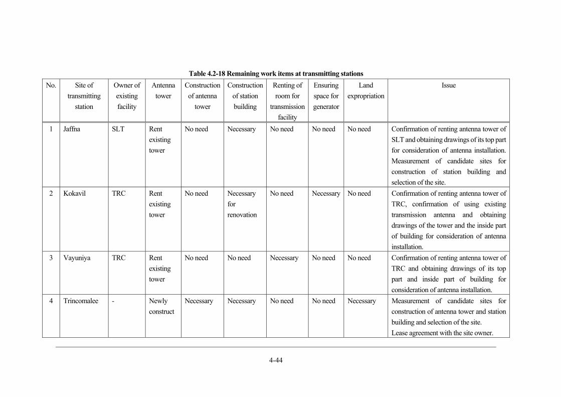
4-44
Table 4.2-18 Remaining work items at transmitting stations
No. Site of
transmitting
station
Owner of
existing
facility
Antenna
tower
Construction
of antenna
tower
Construction
of station
building
Renting of
room for
transmission
facility
Ensuring
space for
generator
Land
expropriation
Issue
1 Jaffna SLT Rent
existing
tower
No need Necessary No need No need No need Confirmation of renting antenna tower of
SLT and obtaining drawings of its top part
for consideration of antenna installation.
Measurement of candidate sites for
construction of station building and
selection of the site.
2 Kokavil TRC Rent
existing
tower
No need Necessary
for
renovation
No need Necessary No need Confirmation of renting antenna tower of
TRC, confirmation of using existing
transmission antenna and obtaining
drawings of the tower and the inside part
of building for consideration of antenna
installation.
3 Vayuniya TRC Rent
existing
tower
No need No need Necessary No need No need Confirmation of renting antenna tower of
TRC and obtaining drawings of its top
part and inside part of building for
consideration of antenna installation.
4 Trincomalee - Newly
construct
Necessary Necessary No need No need Necessary Measurement of candidate sites for
construction of antenna tower and station
building and selection of the site.
Lease agreement with the site owner.
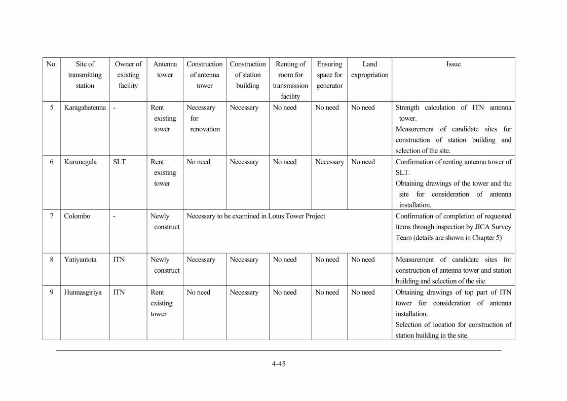
4-45
No. Site of
transmitting
station
Owner of
existing
facility
Antenna
tower
Construction
of antenna
tower
Construction
of station
building
Renting of
room for
transmission
facility
Ensuring
space for
generator
Land
expropriation
Issue
5 Karagahatenna - Rent
existing
tower
Necessary
for
renovation
Necessary No need No need No need Strength calculation of ITN antenna
tower.
Measurement of candidate sites for
construction of station building and
selection of the site.
6 Kurunegala SLT Rent
existing
tower
No need Necessary No need Necessary No need Confirmation of renting antenna tower of
SLT.
Obtaining drawings of the tower and the
site for consideration of antenna
installation.
7 Colombo - Newly
construct
Necessary to be examined in Lotus Tower Project Confirmation of completion of requested
items through inspection by JICA Survey
Team (details are shown in Chapter 5)
8 Yatiyantota ITN Newly
construct
Necessary Necessary No need No need No need Measurement of candidate sites for
construction of antenna tower and station
building and selection of the site
9 Hunnasgiriya ITN Rent
existing
tower
No need Necessary No need No need No need Obtaining drawings of top part of ITN
tower for consideration of antenna
installation.
Selection of location for construction of
station building in the site.
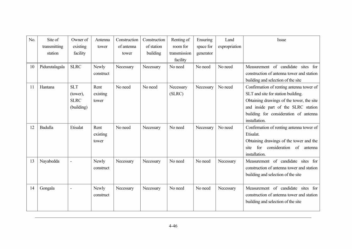
4-46
No. Site of
transmitting
station
Owner of
existing
facility
Antenna
tower
Construction
of antenna
tower
Construction
of station
building
Renting of
room for
transmission
facility
Ensuring
space for
generator
Land
expropriation
Issue
10 Pidurutalagala SLRC Newly
construct
Necessary Necessary No need No need No need Measurement of candidate sites for
construction of antenna tower and station
building and selection of the site
11 Hantana SLT
(tower),
SLRC
(building)
Rent
existing
tower
No need No need Necessary
(SLRC)
Necessary No need Confirmation of renting antenna tower of
SLT and site for station building.
Obtaining drawings of the tower, the site
and inside part of the SLRC station
building for consideration of antenna
installation.
12 Badulla Etisalat Rent
existing
tower
No need Necessary No need Necessary No need Confirmation of renting antenna tower of
Etisalat.
Obtaining drawings of the tower and the
site for consideration of antenna
installation.
13 Nayabedda - Newly
construct
Necessary Necessary No need No need Necessary Measurement of candidate sites for
construction of antenna tower and station
building and selection of the site
14 Gongala - Newly
construct
Necessary Necessary No need No need Necessary Measurement of candidate sites for
construction of antenna tower and station
building and selection of the site
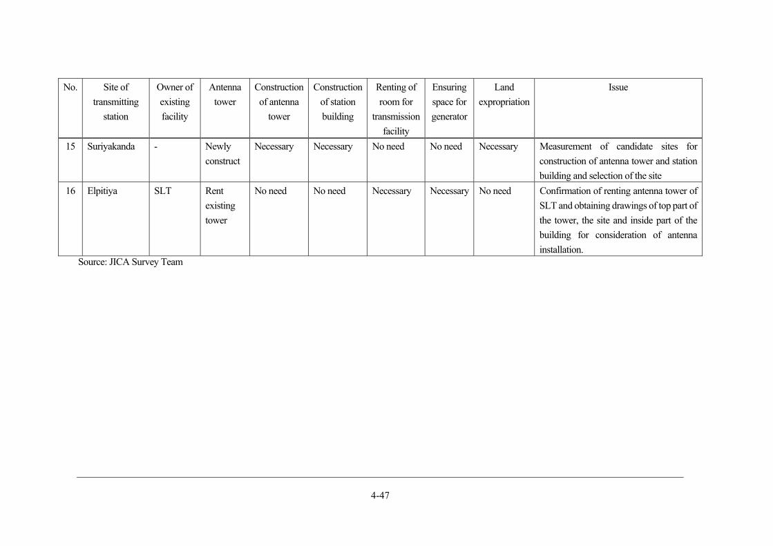
4-47
No. Site of
transmitting
station
Owner of
existing
facility
Antenna
tower
Construction
of antenna
tower
Construction
of station
building
Renting of
room for
transmission
facility
Ensuring
space for
generator
Land
expropriation
Issue
15 Suriyakanda - Newly
construct
Necessary Necessary No need No need Necessary Measurement of candidate sites for
construction of antenna tower and station
building and selection of the site
16 Elpitiya SLT Rent
existing
tower
No need No need Necessary Necessary No need Confirmation of renting antenna tower of
SLT and obtaining drawings of top part of
the tower, the site and inside part of the
building for consideration of antenna
installation. Source: JICA Survey Team
4-48
ASO planning
It is supposed that ASO will have a bigger influence on viewers than starting DTTB. In case viewers
have not purchased the DTTB receiver, they will not be able to see the TV broadcasting programmes
which are available until the time of ASO. There will happen the case that viewers cannot watch
programmes due to weak DTTB waves even though they have receivers.
ASO has to be carried out carefully due to its crucial social influence. It is essential to decide conditions
for implementation of ASO and formulate regulations that ASO will not be done unless those conditions
are accomplished. Initiatives by both public and private sector to meet conditions for implementation of
ASO are required. It will be necessary to judge postpone ASO in case those conditions are not be
accomplished.
The following shows the conditions for implementation of ASO, its procedure and rehearsal.
Revision of conditions for implementing ASO
In the Previous Survey, DTTB receiver household penetration ratio and population coverage ratio were
set as conditions for implementation of ASO, in order to reduce social impact of terrestrial broadcasting
not being unavailable. These two index values are adopted in Japan and many countries where migration
into DTTB is proceeded and can be regarded valid considering basis for judgement to minimize impact
to viewers.
Meanwhile, individual factors that will make DTTB unavailable include individual phenomena such as
radio interference and building shadows, and countermeasures to deal with those factors will be
necessary to be considered. Countermeasures for individual cases often become complex and
compounded and similar troubles are derived from individual cases. Considering those concerns, it will
be required to pay attention to the state of migration into DTTB and flexibly deal with it. Therefore,
individual cases should be excluded from conditions for ASO implementation and it will be significant
to consider not to slow down the progress of overall ASO processes.
JICA Survey Team virtually divided Sri Lanka into 3 areas from the perspective of implementing ASO,
in consideration with current TV household penetration ratio, poverty rate and rate of dissemination of
electric appliances. Each area follows the results of the Previous Survey which defined conditions for
ASO implementation. On the other hand, values of population coverage ratio as of starting DTTB were
changed due to change of channel plan. Along this revision, conditions for implementation of ASO are
set as shown in Table 4.2-19.
The period until implementation of ASO is estimated to be 5 years from DSO-SD by Colombo
Transmitting Station and 3 or 4 years from DSO-SD by other transmitting stations, by making use of
various examples of ASO in Japan and other countries.
In the table below, values of proportion of households with DTTB receivers show the result of calculation
for coverage population and coverage ratio in each area. These were obtained from overlapping cover
area map through radio wave simulation of This Survey and population distribution map based on census
of Sri Lanka.
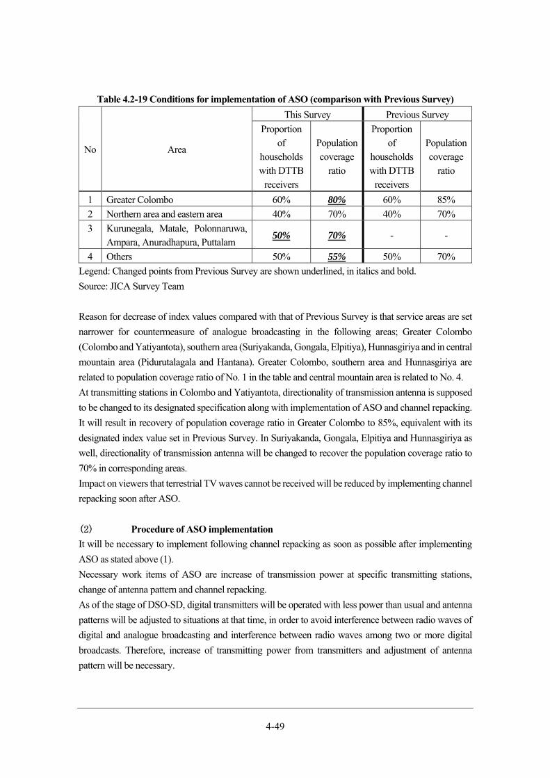
4-49
Table 4.2-19 Conditions for implementation of ASO (comparison with Previous Survey)
No Area
This Survey Previous Survey
Proportion of
households with DTTB
receivers
Population coverage
ratio
Proportion of
households with DTTB
receivers
Population coverage
ratio
1 Greater Colombo 60% 80% 60% 85%
2 Northern area and eastern area 40% 70% 40% 70%
3 Kurunegala, Matale, Polonnaruwa, Ampara, Anuradhapura, Puttalam
50% 70% - -
4 Others 50% 55% 50% 70%
Legend: Changed points from Previous Survey are shown underlined, in italics and bold.
Source: JICA Survey Team
Reason for decrease of index values compared with that of Previous Survey is that service areas are set
narrower for countermeasure of analogue broadcasting in the following areas; Greater Colombo
(Colombo and Yatiyantota), southern area (Suriyakanda, Gongala, Elpitiya), Hunnasgiriya and in central
mountain area (Pidurutalagala and Hantana). Greater Colombo, southern area and Hunnasgiriya are
related to population coverage ratio of No. 1 in the table and central mountain area is related to No. 4.
At transmitting stations in Colombo and Yatiyantota, directionality of transmission antenna is supposed
to be changed to its designated specification along with implementation of ASO and channel repacking.
It will result in recovery of population coverage ratio in Greater Colombo to 85%, equivalent with its
designated index value set in Previous Survey. In Suriyakanda, Gongala, Elpitiya and Hunnasgiriya as
well, directionality of transmission antenna will be changed to recover the population coverage ratio to
70% in corresponding areas.
Impact on viewers that terrestrial TV waves cannot be received will be reduced by implementing channel
repacking soon after ASO.
Procedure of ASO implementation
It will be necessary to implement following channel repacking as soon as possible after implementing
ASO as stated above (1).
Necessary work items of ASO are increase of transmission power at specific transmitting stations,
change of antenna pattern and channel repacking.
As of the stage of DSO-SD, digital transmitters will be operated with less power than usual and antenna
patterns will be adjusted to situations at that time, in order to avoid interference between radio waves of
digital and analogue broadcasting and interference between radio waves among two or more digital
broadcasts. Therefore, increase of transmitting power from transmitters and adjustment of antenna
pattern will be necessary.
4-50
During this DSO-SD, frequency bandwidth which will be used for mobile phone business in future will
be temporarily allocated to digital broadcasting to compensate for lack of frequency resource. It will be
necessary to transfer the frequency bandwidth to the ranges prepared for digital broadcasting by
executing channel repacking, which will lead to create vacant frequency bandwidth for mobile phone
business in future.
Figure 4.2-5 shows the procedures of ASO. Blue circles indicate digital TV transmitting stations which
will be installed during Yen Loan Project, red circles with solid line indicate analogue TV transmitting
stations and red circles with wavy line indicate analogue TV transmitting stations where digital
broadcasting stations will not be installed. Letters in each circle show abbreviation of each transmitting
station and letters under each circle show necessary work items. There are some arrows connecting the
circles. Each arrow indicates that work items at its end edge can be executed after those at its start edge
are completed. In current plan, it is assumed that 5 stages are necessary to complete work items of ASO
in the whole country.
In the 1st stage, ASO will be implemented at transmitting station in Pidurutalagala, followed by channel
repacking in Pidurutalagala and Hantana. After that, channel repacking in Jaffna, Kokavil, Vavuniya and
ASO in Hantana and Nuwara Eliya will be done.
In the 2nd stage, channel repacking and modification of radiation pattern of transmitting antenna will be
implemented in Gongala, Suriyakanda and Elpitiya. After channel repacking in Gongala, ASO will be
implemented in Gongala and Deniyaya. After channel repacking in Suriyakanda and Elpitiya, ASO will
be done in Colombo, Suriyakanda and Ratnapura. ASO can be implemented also in Yatiyantota during
this stage because radio wave of DTTB in Yatiyantota will not interfere with that of analogue TV
broadcasting currently provided in VHF bandwidth. If provision of analogue broadcasting to viewers
continues long, DTTB dissemination will be late. Therefore it is recommended to implement ASO in
this stage in consideration with schedule of ASO and channel repacking at other transmitting stations.
In the 3rd stage, ASO will be implemented in Kilinochchi, followed by channel repacking in
Hunnasgiriya, Karagahatenna and Kurunegala. After that, ASO will be done in Hunnasgiriya,
Gammaduwa, Karagahatenna and Kurunegala.
In the 4th stage, channel repacking and ASO will be implemented in Nayabedda and Badulla. In addition,
ASO will be done in Jaffna and Kokavil, followed by channel repacking in Trincomalee.
In the last 5th stage, ASO will be implemented in remaining transmitting stations.
During the period of ASO, it will be necessary to implement channel repacking many times. On the other
hand, it is expected that designated population coverage ratio can be ensured by promptly completing 5
stages mentioned above.
Figure 4.2-5 shows the detail of procedures for ASO implementation.

4-51
Source: JICA Survey Team
Figure 4.2-5 Procedure of ASO implementation
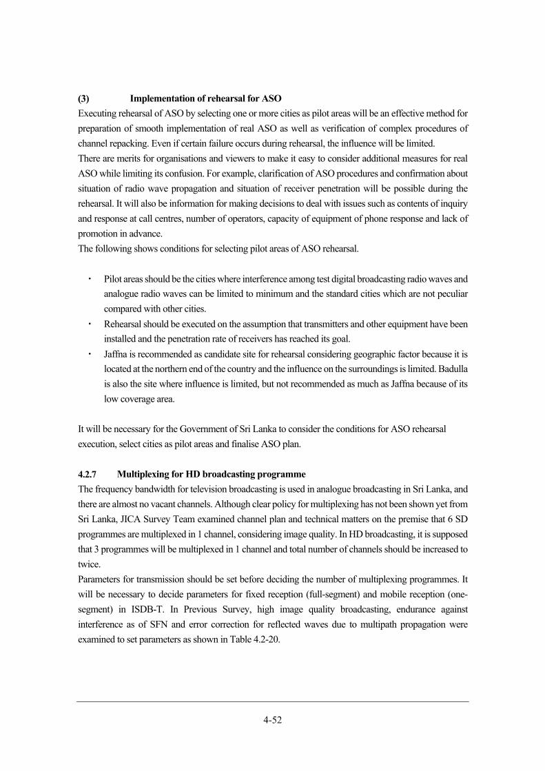
4-52
Implementation of rehearsal for ASO
Executing rehearsal of ASO by selecting one or more cities as pilot areas will be an effective method for
preparation of smooth implementation of real ASO as well as verification of complex procedures of
channel repacking. Even if certain failure occurs during rehearsal, the influence will be limited.
There are merits for organisations and viewers to make it easy to consider additional measures for real
ASO while limiting its confusion. For example, clarification of ASO procedures and confirmation about
situation of radio wave propagation and situation of receiver penetration will be possible during the
rehearsal. It will also be information for making decisions to deal with issues such as contents of inquiry
and response at call centres, number of operators, capacity of equipment of phone response and lack of
promotion in advance.
The following shows conditions for selecting pilot areas of ASO rehearsal.
・ Pilot areas should be the cities where interference among test digital broadcasting radio waves and
analogue radio waves can be limited to minimum and the standard cities which are not peculiar
compared with other cities.
・ Rehearsal should be executed on the assumption that transmitters and other equipment have been
installed and the penetration rate of receivers has reached its goal.
・ Jaffna is recommended as candidate site for rehearsal considering geographic factor because it is
located at the northern end of the country and the influence on the surroundings is limited. Badulla
is also the site where influence is limited, but not recommended as much as Jaffna because of its
low coverage area.
It will be necessary for the Government of Sri Lanka to consider the conditions for ASO rehearsal
execution, select cities as pilot areas and finalise ASO plan.
Multiplexing for HD broadcasting programme
The frequency bandwidth for television broadcasting is used in analogue broadcasting in Sri Lanka, and
there are almost no vacant channels. Although clear policy for multiplexing has not been shown yet from
Sri Lanka, JICA Survey Team examined channel plan and technical matters on the premise that 6 SD
programmes are multiplexed in 1 channel, considering image quality. In HD broadcasting, it is supposed
that 3 programmes will be multiplexed in 1 channel and total number of channels should be increased to
twice.
Parameters for transmission should be set before deciding the number of multiplexing programmes. It
will be necessary to decide parameters for fixed reception (full-segment) and mobile reception (one-
segment) in ISDB-T. In Previous Survey, high image quality broadcasting, endurance against
interference as of SFN and error correction for reflected waves due to multipath propagation were
examined to set parameters as shown in Table 4.2-20.
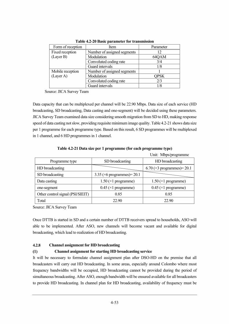
4-53
Table 4.2-20 Basic parameter for transmission Form of reception Item Parameter
Fixed reception (Layer B)
Number of assigned segments 12Modulation 64QAM Convoluted coding rate 3/4Guard intervals 1/8
Mobile reception (Layer A)
Number of assigned segments 1Modulation QPSK Convoluted coding rate 2/3Guard intervals 1/8
Source: JICA Survey Team
Data capacity that can be multiplexed per channel will be 22.90 Mbps. Data size of each service (HD
broadcasting, SD broadcasting, Data casting and one-segment) will be decided using these parameters.
JICA Survey Team examined data size considering smooth migration from SD to HD, making response
speed of data casting not slow, providing requisite minimum image quality. Table 4.2-21 shows data size
per 1 programme for each programme type. Based on this result, 6 SD programmes will be multiplexed
in 1 channel, and 6 HD programmes in 1 channel.
Table 4.2-21 Data size per 1 programme (for each programme type)
Unit: Mbps/programme
Programme type SD broadcasting HD broadcasting
HD broadcasting 6.70 (×3 programmes)= 20.1
SD broadcasting 3.35 (×6 programmes)= 20.1
Data casting 1.50 (×1 programme) 1.50 (×1 programme)
one-segment 0.45 (×1 programme) 0.45 (×1 programme)
Other control signal (PSI/SIEIT) 0.85 0.85
Total 22.90 22.90
Source: JICA Survey Team
Once DTTB is started in SD and a certain number of DTTB receivers spread to households, ASO will
able to be implemented. After ASO, new channels will become vacant and available for digital
broadcasting, which lead to realization of HD broadcasting.
Channel assignment for HD broadcasting
Channel assignment for starting HD broadcasting service
It will be necessary to formulate channel assignment plan after DSO-HD on the premise that all
broadcasters will carry out HD broadcasting. In some areas, especially around Colombo where most
frequency bandwidths will be occupied, HD broadcasting cannot be provided during the period of
simultaneous broadcasting. After ASO, enough bandwidth will be ensured available for all broadcasters
to provide HD broadcasting. In channel plan for HD broadcasting, availability of frequency must be
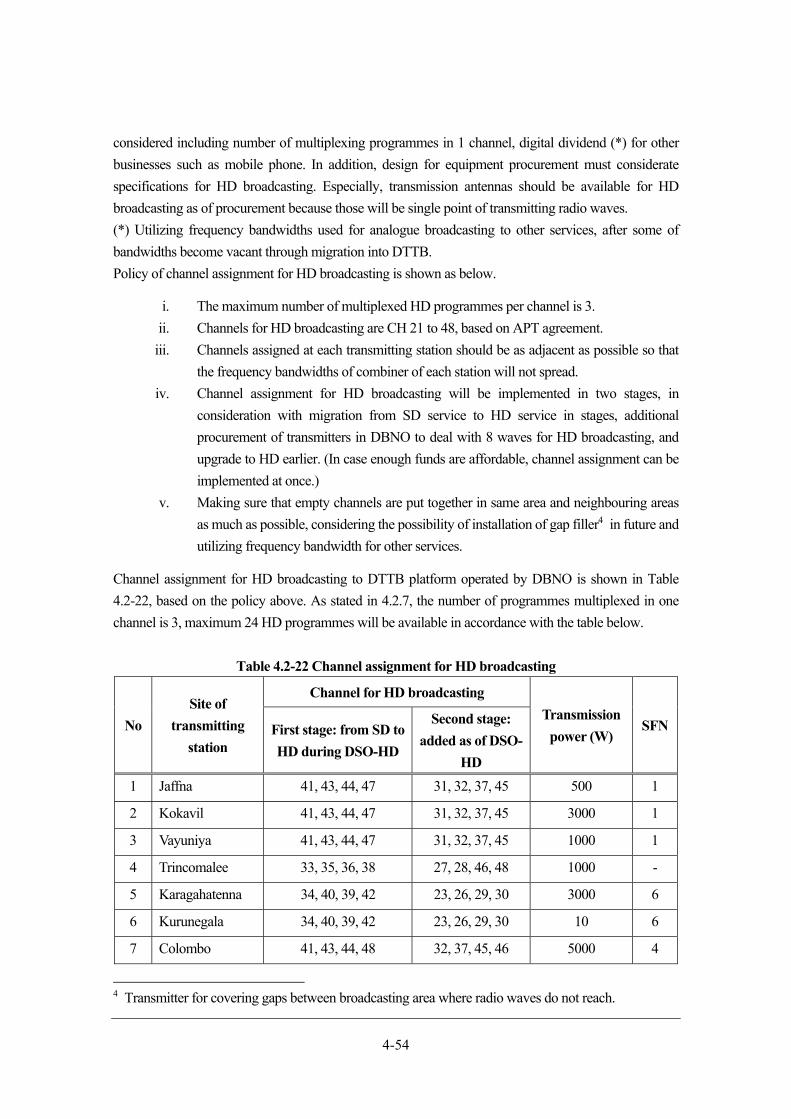
4-54
considered including number of multiplexing programmes in 1 channel, digital dividend (*) for other
businesses such as mobile phone. In addition, design for equipment procurement must considerate
specifications for HD broadcasting. Especially, transmission antennas should be available for HD
broadcasting as of procurement because those will be single point of transmitting radio waves.
(*) Utilizing frequency bandwidths used for analogue broadcasting to other services, after some of
bandwidths become vacant through migration into DTTB.
Policy of channel assignment for HD broadcasting is shown as below.
i. The maximum number of multiplexed HD programmes per channel is 3.
ii. Channels for HD broadcasting are CH 21 to 48, based on APT agreement.
iii. Channels assigned at each transmitting station should be as adjacent as possible so that
the frequency bandwidths of combiner of each station will not spread.
iv. Channel assignment for HD broadcasting will be implemented in two stages, in
consideration with migration from SD service to HD service in stages, additional
procurement of transmitters in DBNO to deal with 8 waves for HD broadcasting, and
upgrade to HD earlier. (In case enough funds are affordable, channel assignment can be
implemented at once.)
v. Making sure that empty channels are put together in same area and neighbouring areas
as much as possible, considering the possibility of installation of gap filler4 in future and
utilizing frequency bandwidth for other services.
Channel assignment for HD broadcasting to DTTB platform operated by DBNO is shown in Table
4.2-22, based on the policy above. As stated in 4.2.7, the number of programmes multiplexed in one
channel is 3, maximum 24 HD programmes will be available in accordance with the table below.
Table 4.2-22 Channel assignment for HD broadcasting
No
Site of
transmitting
station
Channel for HD broadcasting
Transmission
power (W) SFNFirst stage: from SD to
HD during DSO-HD
Second stage:
added as of DSO-
HD
1 Jaffna 41, 43, 44, 47 31, 32, 37, 45 500 1
2 Kokavil 41, 43, 44, 47 31, 32, 37, 45 3000 1
3 Vayuniya 41, 43, 44, 47 31, 32, 37, 45 1000 1
4 Trincomalee 33, 35, 36, 38 27, 28, 46, 48 1000 -
5 Karagahatenna 34, 40, 39, 42 23, 26, 29, 30 3000 6
6 Kurunegala 34, 40, 39, 42 23, 26, 29, 30 10 6
7 Colombo 41, 43, 44, 48 32, 37, 45, 46 5000 4
4 Transmitter for covering gaps between broadcasting area where radio waves do not reach.
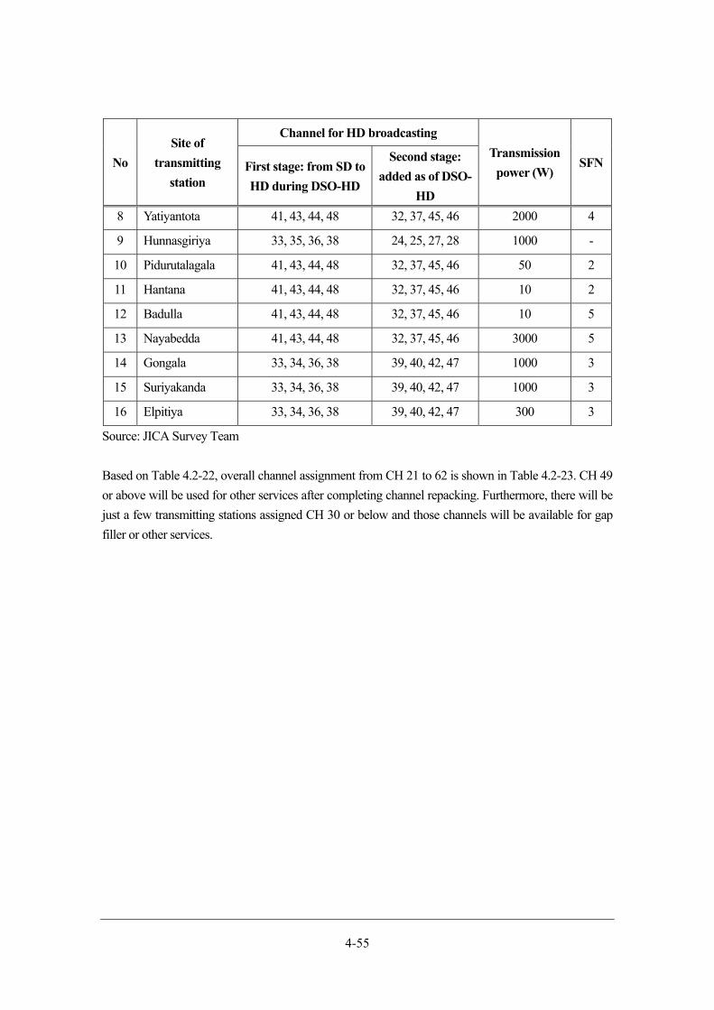
4-55
No
Site of
transmitting
station
Channel for HD broadcasting
Transmission
power (W) SFNFirst stage: from SD to
HD during DSO-HD
Second stage:
added as of DSO-
HD
8 Yatiyantota 41, 43, 44, 48 32, 37, 45, 46 2000 4
9 Hunnasgiriya 33, 35, 36, 38 24, 25, 27, 28 1000 -
10 Pidurutalagala 41, 43, 44, 48 32, 37, 45, 46 50 2
11 Hantana 41, 43, 44, 48 32, 37, 45, 46 10 2
12 Badulla 41, 43, 44, 48 32, 37, 45, 46 10 5
13 Nayabedda 41, 43, 44, 48 32, 37, 45, 46 3000 5
14 Gongala 33, 34, 36, 38 39, 40, 42, 47 1000 3
15 Suriyakanda 33, 34, 36, 38 39, 40, 42, 47 1000 3
16 Elpitiya 33, 34, 36, 38 39, 40, 42, 47 300 3
Source: JICA Survey Team
Based on Table 4.2-22, overall channel assignment from CH 21 to 62 is shown in Table 4.2-23. CH 49
or above will be used for other services after completing channel repacking. Furthermore, there will be
just a few transmitting stations assigned CH 30 or below and those channels will be available for gap
filler or other services.

4-56
Table 4.2-23 Overall channel assignment as of HD broadcasting
<Legend>
Green: Channels which will be migrated from SD service to HD service.
Green and “After ASO”: Channel repacking will be done after ASO, thereafter those channels will be migrated to HD service.
Orange and “Repack CH”: Channels which will be changed during SD service after ASO.
Yellow: Channels which will not be used during SD. (Including the period of channel repacking)
Black: Channels which will be used newly after starting HD broadcasting.
<Area>
N: North, NE: North East, MN: Middle North, W: West, C: Central, E: East, S: South
Source: JICA Survey Team
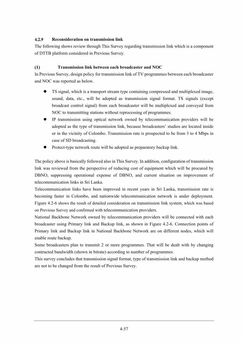
4-57
Reconsideration on transmission link
The following shows review through This Survey regarding transmission link which is a component
of DTTB platform considered in Previous Survey.
Transmission link between each broadcaster and NOC
In Previous Survey, design policy for transmission link of TV programmes between each broadcaster
and NOC was reported as below.
TS signal, which is a transport stream type containing compressed and multiplexed image,
sound, data, etc., will be adopted as transmission signal format. TS signals (except
broadcast control signal) from each broadcaster will be multiplexed and conveyed from
NOC to transmitting stations without reprocessing of programmes.
IP transmission using optical network owned by telecommunication providers will be
adopted as the type of transmission link, because broadcasters’ studios are located inside
or in the vicinity of Colombo. Transmission rate is prospected to be from 3 to 4 Mbps in
case of SD broadcasting.
Protect-type network route will be adopted as preparatory backup link.
The policy above is basically followed also in This Survey. In addition, configuration of transmission
link was reviewed from the perspective of reducing cost of equipment which will be procured by
DBNO, suppressing operational expense of DBNO, and current situation on improvement of
telecommunication links in Sri Lanka.
Telecommunication links have been improved in recent years in Sri Lanka, transmission rate is
becoming faster in Colombo, and nationwide telecommunication network is under deployment.
Figure 4.2-6 shows the result of detailed consideration on transmission link system, which was based
on Previous Survey and confirmed with telecommunication providers.
National Backbone Network owned by telecommunication providers will be connected with each
broadcaster using Primary link and Backup link, as shown in Figure 4.2-6. Connection points of
Primary link and Backup link in National Backbone Network are on different nodes, which will
enable route backup.
Some broadcasters plan to transmit 2 or more programmes. That will be dealt with by changing
contracted bandwidth (shown in bitrate) according to number of programmes.
This survey concludes that transmission signal format, type of transmission link and backup method
are not to be changed from the result of Previous Survey.
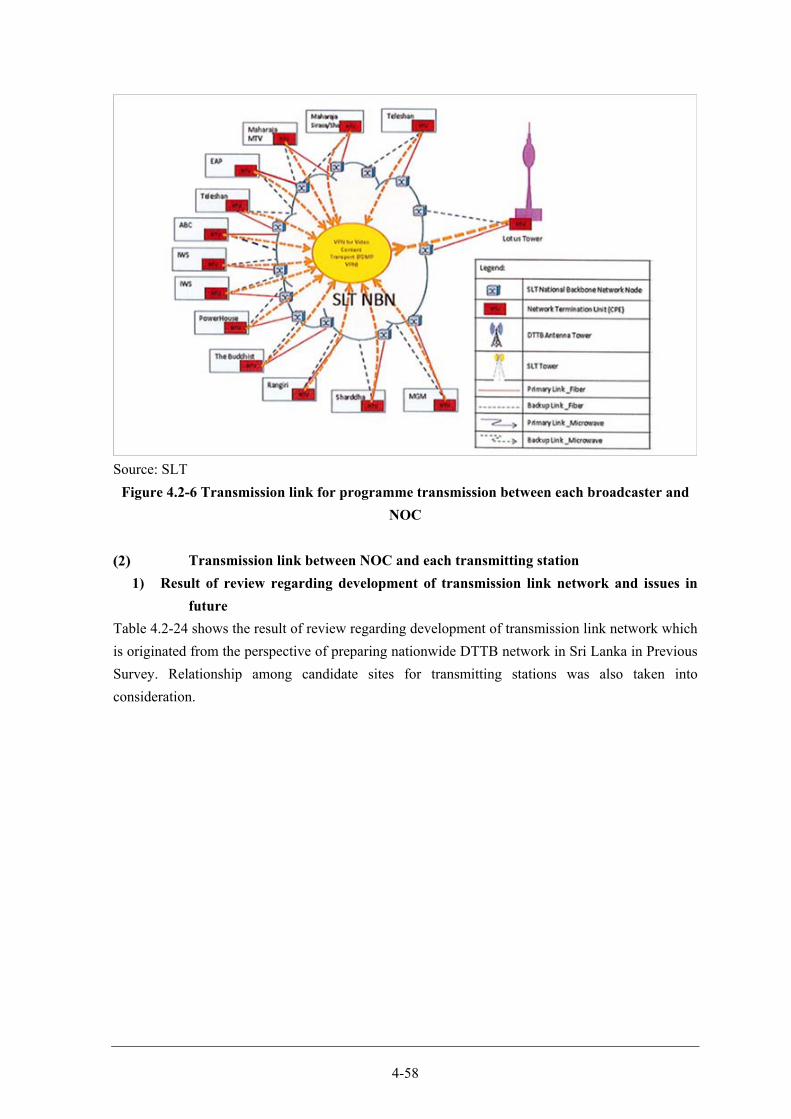
4-58
Source: SLT
Figure 4.2-6 Transmission link for programme transmission between each broadcaster and
NOC
Transmission link between NOC and each transmitting station
1) Result of review regarding development of transmission link network and issues in
future
Table 4.2-24 shows the result of review regarding development of transmission link network which
is originated from the perspective of preparing nationwide DTTB network in Sri Lanka in Previous
Survey. Relationship among candidate sites for transmitting stations was also taken into
consideration.
4-59
Table 4.2-24 Result of review regarding development of transmission link network
No. Reviewed item Result of Previous Survey Result of review of This Survey
1 Type of
transmission link
Network system of providers
(optical fibre and microwave) +
microwave line owned by DBNO
+ relaying of broadcasting waves
Network system of providers
(optical fibre and microwave) +
microwave line owned by DBNO
2 Transmission
signal format (*1)
STM-1 (Multiplexing 4 TS
signals for broadcasting)
IP transmission by TS signal of
each broadcasting was also
considered in addition to STM-1.
3 Network (*2) Network consisting of 16
transmitting stations (including
gap filler station)
Network consisting of 16
transmitting stations (*2)
(*1) Reference: 4.2.9 (2) 1) (a)
(*2) Reference: 4.2.9 (2) 2)
Policy items which became necessary after the review to be changed or added are described as below.
(a) Result of review regarding transmission signal format and issues in future
In Previous Survey, transmission signal format was suggested as shown in Table 4.2-25. In addition,
interface system among NOC of DBNO, each transmitting station, and transmission link network
operated by telecommunication providers was suggested as shown in Figure 4.2-7. The network
adapter shown in the figure will be installed as equipment of DBNO in order to multiplex 4
broadcasting TS line systems and transmit the signals to transmission link through STM-1 network.
Table 4.2-25 Transmission standards for digital broadcasting signals in the broadcasting
transmission network
No Item Standard Remarks
1 Transmission signal Broadcast TS (BTS) signal
2 Transmission bit rate 43.34Mbps / 1 BTS signal(Note 1) Standards for the
8MHz RF bandwidth
3 Standards for the
interface used in the
distribution network
Multiple BTS signals will be
multiplexed and the multiplexed
signal will be connected to a high-
speed digital link.(Note 2)
4 Usable
communication
network
STM-1 (155.2 Mbps)
5 Standards for signals DVB-ASI
4-60
No Item Standard Remarks
6 PSI/SI function Rewriting of NIT and relevant
data(Note 3)
Source: “Feasibility Study on Digital Terrestrial Television Broadcasting Network Project in
Democratic Socialist Republic of Sri Lanka” Final Report
(Note 1) Sample clock of 8MHz bandwidth ISDB-T signal (= 10.836MHz x 4)
(Note 2) BTS signals can be compressed (to approx. 29 Mbps in the 8MHz system) when they
are multiplexed and transmitted. Therefore, the use of a compression/decompression
system enables a maximum of four BTS signals (corresponding to four RF channels)
to be transmitted via an STM-1 link.
(Note 3) As control information on broadcasting physical channels (frequencies) is included in
the PSI/SI signal in a BTS signal, the information has to be replaced with information
applicable to the broadcasting frequencies of the individual transmitting station.
Source: JICA Survey Team
Figure 4.2-7 Interface between DBNO and telecommunication providers
The JICA Survey Team exchanged sufficient opinions with Sri Lankan telecommunication providers
about network construction using the IP transmission method, in consideration with practical
realization trend of IP transmission technology after Previous Survey. As a result, it was found
feasible that interface system can connect with transmission link network using transmitting TS
signal (or compressed TS signal) of each broadcasting as shown in Figure 4.2-8. In this case, Layer
2 IP-Multicast5 and Layer 3 VLL (Virtual Leased Line)6 are available as interface signal format.
5 Communication method that transmits the same data all at once to multiple parties according to the IP protocol operated in 2nd layer (data link layer) 6 Data communication method by virtual leased line operated in 3rd layer (network layer)
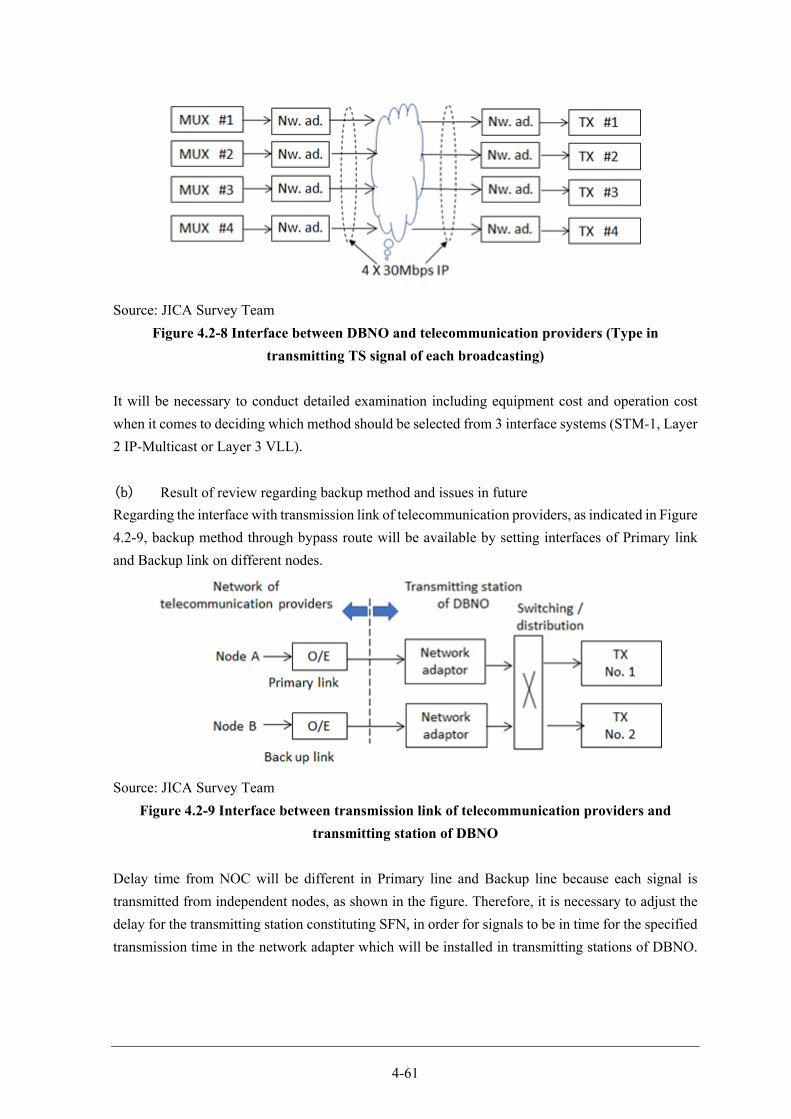
4-61
Source: JICA Survey Team
Figure 4.2-8 Interface between DBNO and telecommunication providers (Type in
transmitting TS signal of each broadcasting)
It will be necessary to conduct detailed examination including equipment cost and operation cost
when it comes to deciding which method should be selected from 3 interface systems (STM-1, Layer
2 IP-Multicast or Layer 3 VLL).
(b) Result of review regarding backup method and issues in future
Regarding the interface with transmission link of telecommunication providers, as indicated in Figure
4.2-9, backup method through bypass route will be available by setting interfaces of Primary link
and Backup link on different nodes.
Source: JICA Survey Team
Figure 4.2-9 Interface between transmission link of telecommunication providers and
transmitting station of DBNO
Delay time from NOC will be different in Primary line and Backup line because each signal is
transmitted from independent nodes, as shown in the figure. Therefore, it is necessary to adjust the
delay for the transmitting station constituting SFN, in order for signals to be in time for the specified
transmission time in the network adapter which will be installed in transmitting stations of DBNO.
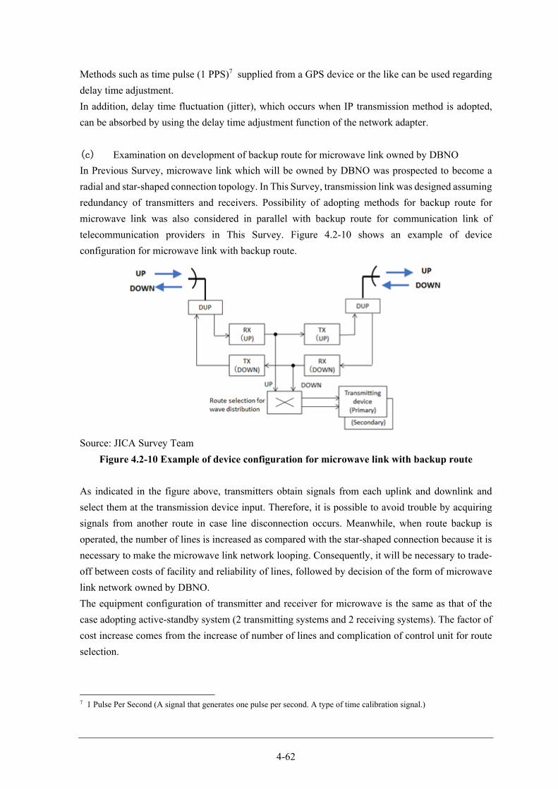
4-62
Methods such as time pulse (1 PPS)7 supplied from a GPS device or the like can be used regarding
delay time adjustment.
In addition, delay time fluctuation (jitter), which occurs when IP transmission method is adopted,
can be absorbed by using the delay time adjustment function of the network adapter.
(c) Examination on development of backup route for microwave link owned by DBNO
In Previous Survey, microwave link which will be owned by DBNO was prospected to become a
radial and star-shaped connection topology. In This Survey, transmission link was designed assuming
redundancy of transmitters and receivers. Possibility of adopting methods for backup route for
microwave link was also considered in parallel with backup route for communication link of
telecommunication providers in This Survey. Figure 4.2-10 shows an example of device
configuration for microwave link with backup route.
Source: JICA Survey Team
Figure 4.2-10 Example of device configuration for microwave link with backup route
As indicated in the figure above, transmitters obtain signals from each uplink and downlink and
select them at the transmission device input. Therefore, it is possible to avoid trouble by acquiring
signals from another route in case line disconnection occurs. Meanwhile, when route backup is
operated, the number of lines is increased as compared with the star-shaped connection because it is
necessary to make the microwave link network looping. Consequently, it will be necessary to trade-
off between costs of facility and reliability of lines, followed by decision of the form of microwave
link network owned by DBNO.
The equipment configuration of transmitter and receiver for microwave is the same as that of the
case adopting active-standby system (2 transmitting systems and 2 receiving systems). The factor of
cost increase comes from the increase of number of lines and complication of control unit for route
selection.
7 1 Pulse Per Second (A signal that generates one pulse per second. A type of time calibration signal.)
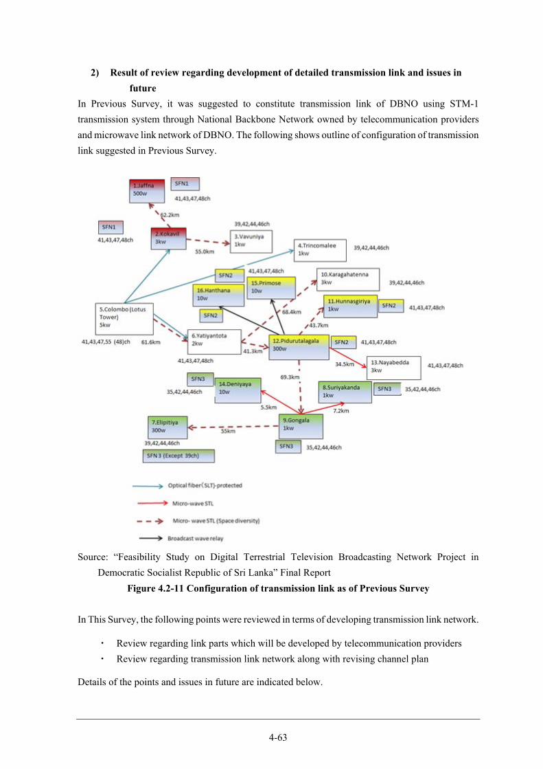
4-63
2) Result of review regarding development of detailed transmission link and issues in
future
In Previous Survey, it was suggested to constitute transmission link of DBNO using STM-1
transmission system through National Backbone Network owned by telecommunication providers
and microwave link network of DBNO. The following shows outline of configuration of transmission
link suggested in Previous Survey.
Source: “Feasibility Study on Digital Terrestrial Television Broadcasting Network Project in
Democratic Socialist Republic of Sri Lanka” Final Report
Figure 4.2-11 Configuration of transmission link as of Previous Survey
In This Survey, the following points were reviewed in terms of developing transmission link network.
・ Review regarding link parts which will be developed by telecommunication providers
・ Review regarding transmission link network along with revising channel plan
Details of the points and issues in future are indicated below.
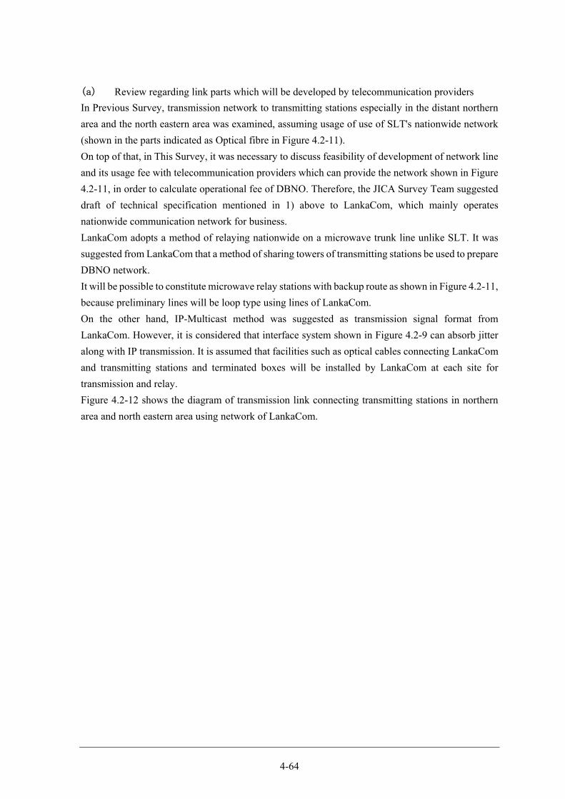
4-64
(a) Review regarding link parts which will be developed by telecommunication providers
In Previous Survey, transmission network to transmitting stations especially in the distant northern
area and the north eastern area was examined, assuming usage of use of SLT's nationwide network
(shown in the parts indicated as Optical fibre in Figure 4.2-11).
On top of that, in This Survey, it was necessary to discuss feasibility of development of network line
and its usage fee with telecommunication providers which can provide the network shown in Figure
4.2-11, in order to calculate operational fee of DBNO. Therefore, the JICA Survey Team suggested
draft of technical specification mentioned in 1) above to LankaCom, which mainly operates
nationwide communication network for business.
LankaCom adopts a method of relaying nationwide on a microwave trunk line unlike SLT. It was
suggested from LankaCom that a method of sharing towers of transmitting stations be used to prepare
DBNO network.
It will be possible to constitute microwave relay stations with backup route as shown in Figure 4.2-11,
because preliminary lines will be loop type using lines of LankaCom.
On the other hand, IP-Multicast method was suggested as transmission signal format from
LankaCom. However, it is considered that interface system shown in Figure 4.2-9 can absorb jitter
along with IP transmission. It is assumed that facilities such as optical cables connecting LankaCom
and transmitting stations and terminated boxes will be installed by LankaCom at each site for
transmission and relay.
Figure 4.2-12 shows the diagram of transmission link connecting transmitting stations in northern
area and north eastern area using network of LankaCom.
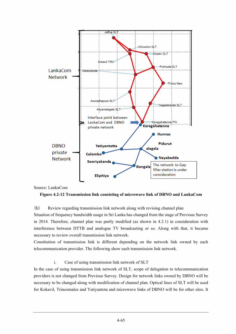
4-65
Source: LankaCom
Figure 4.2-12 Transmission link consisting of microwave link of DBNO and LankaCom
(b) Review regarding transmission link network along with revising channel plan
Situation of frequency bandwidth usage in Sri Lanka has changed from the stage of Previous Survey
in 2014. Therefore, channel plan was partly modified (as shown in 4.2.1) in consideration with
interference between DTTB and analogue TV broadcasting or so. Along with that, it became
necessary to review overall transmission link network.
Constitution of transmission link is different depending on the network link owned by each
telecommunication provider. The following show each transmission link network.
i. Case of using transmission link network of SLT
In the case of using transmission link network of SLT, scope of delegation to telecommunication
providers is not changed from Previous Survey. Design for network links owned by DBNO will be
necessary to be changed along with modification of channel plan. Optical lines of SLT will be used
for Kokavil, Trincomalee and Yatiyantota and microwave links of DBNO will be for other sites. It
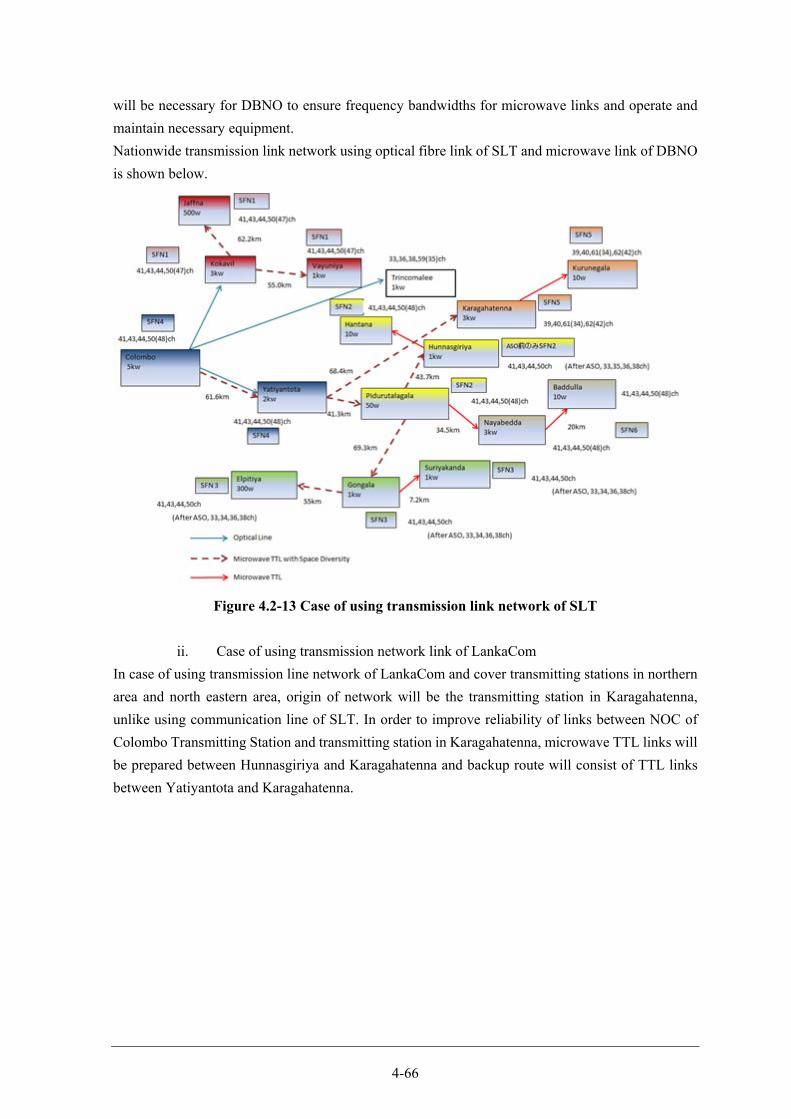
4-66
will be necessary for DBNO to ensure frequency bandwidths for microwave links and operate and
maintain necessary equipment.
Nationwide transmission link network using optical fibre link of SLT and microwave link of DBNO
is shown below.
Figure 4.2-13 Case of using transmission link network of SLT
ii. Case of using transmission network link of LankaCom
In case of using transmission line network of LankaCom and cover transmitting stations in northern
area and north eastern area, origin of network will be the transmitting station in Karagahatenna,
unlike using communication line of SLT. In order to improve reliability of links between NOC of
Colombo Transmitting Station and transmitting station in Karagahatenna, microwave TTL links will
be prepared between Hunnasgiriya and Karagahatenna and backup route will consist of TTL links
between Yatiyantota and Karagahatenna.
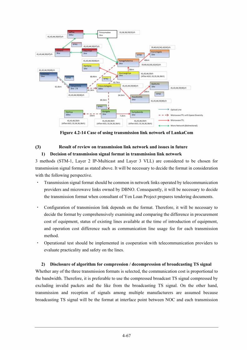
4-67
Figure 4.2-14 Case of using transmission link network of LankaCom
Result of review on transmission link network and issues in future
1) Decision of transmission signal format in transmission link network
3 methods (STM-1, Layer 2 IP-Multicast and Layer 3 VLL) are considered to be chosen for
transmission signal format as stated above. It will be necessary to decide the format in consideration
with the following perspective.
・ Transmission signal format should be common in network links operated by telecommunication
providers and microwave links owned by DBNO. Consequently, it will be necessary to decide
the transmission format when consultant of Yen Loan Project prepares tendering documents.
・ Configuration of transmission link depends on the format. Therefore, it will be necessary to
decide the format by comprehensively examining and comparing the difference in procurement
cost of equipment, status of existing lines available at the time of introduction of equipment,
and operation cost difference such as communication line usage fee for each transmission
method.
・ Operational test should be implemented in cooperation with telecommunication providers to
evaluate practicality and safety on the lines.
2) Disclosure of algorithm for compression / decompression of broadcasting TS signal
Whether any of the three transmission formats is selected, the communication cost is proportional to
the bandwidth. Therefore, it is preferable to use the compressed broadcast TS signal compressed by
excluding invalid packets and the like from the broadcasting TS signal. On the other hand,
transmission and reception of signals among multiple manufacturers are assumed because
broadcasting TS signal will be the format at interface point between NOC and each transmission
4-68
station. Consequently in that case, it will be necessary to disclose compression algorithm and enable
entry by multiple manufacturers.8
3) Confirmation of transmission network and SFN operation through transmitter
It will be necessary to manage delay time through transmission link network and transmitters, in
order to ensure SFN. Especially as for network, there is a difference in the delay time between
Primary line and Backup line and jitter and the like on the line. Therefore, it should be confirmed
that SFN network will be operated stably in comprehensive test before starting its operation. These
have to be dealt with at the time of preliminary examination and evaluation on transmission link
network and equipment of each transmitting station (review on preliminary usage fee) during detailed
design by consultant.
Thereafter processes such as selection of telecommunication providers, procurement of equipment
in Yen Loan Project, preparation of tender documents and tendering for the procurement will be
proceeded. The Government of Sri Lanka will conduct the selection of telecommunication providers
and equipment for each transmitting station will be procured through Yen Loan Project. It should be
considered that policy for procurement be modified as necessary based on the result of the
comprehensive test.
Overall Band Plan
Band Plan for frequency bandwidth
The Overall Band Plan of Sri Lanka is based on ITU recommendation or APT agreement. Merits of
Overall Band Plan are creation of commonality on frequency usage plan with other countries
technology to be used, which will lead to reduction of costs when developing new wireless
communication infrastructure and opportunity for users to purchase equipment at reasonable price.
Frequency bandwidths currently assigned for analogue TV broadcasting in Sri Lanka are as follows.
From CH 2 to 12 are allocated to bandwidths whose central frequencies are from 50.5MHz to
226.5MHz in 7MHz width. Broadcasting stations which VHF bandwidth is currently assigned are
only state-run SLRC and ITN.
Table 4.2-26 Channel and VHF bandwidth for analogue broadcasting CH 2 3 4 5 6 7 8 9 10 11 12
Central frequency (MHz) 50.5 57.5 64.5 177.5 184.5 191.5 198.5 205.5 212.5 219.5 226.5
Source: TRC
On the other hand, UHF bandwidth is allocated as TV broadcasting channel, from CH 21 to 62 whose
central frequencies are from 474MHz to 802MHz in 8MHz width, as shown in the table below.
8 Standards for digital broadcasting do not regulate compression method. Each manufacturer uses its own algorithm for broadcasting TS signal. Therefore, it will be necessary to disclose compression algorithm in advance in order to make it feasible to procure and adopt studio equipment and transmitters from different manufacturers.
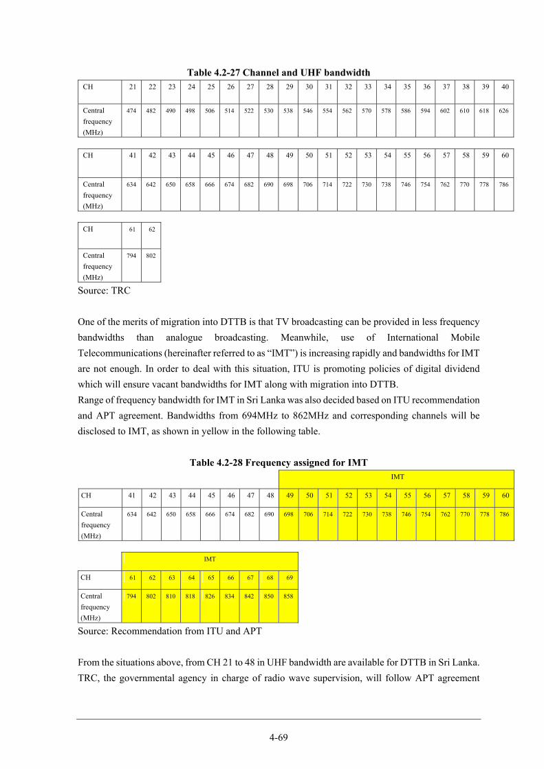
4-69
Table 4.2-27 Channel and UHF bandwidth CH 21 22 23 24 25 26 27 28 29 30 31 32 33 34 35 36 37 38 39 40
Central
frequency
(MHz)
474 482 490 498 506 514 522 530 538 546 554 562 570 578 586 594 602 610 618 626
CH 41 42 43 44 45 46 47 48 49 50 51 52 53 54 55 56 57 58 59 60
Central
frequency
(MHz)
634 642 650 658 666 674 682 690 698 706 714 722 730 738 746 754 762 770 778 786
CH 61 62
Central
frequency
(MHz)
794 802
Source: TRC
One of the merits of migration into DTTB is that TV broadcasting can be provided in less frequency
bandwidths than analogue broadcasting. Meanwhile, use of International Mobile
Telecommunications (hereinafter referred to as “IMT”) is increasing rapidly and bandwidths for IMT
are not enough. In order to deal with this situation, ITU is promoting policies of digital dividend
which will ensure vacant bandwidths for IMT along with migration into DTTB.
Range of frequency bandwidth for IMT in Sri Lanka was also decided based on ITU recommendation
and APT agreement. Bandwidths from 694MHz to 862MHz and corresponding channels will be
disclosed to IMT, as shown in yellow in the following table.
Table 4.2-28 Frequency assigned for IMT IMT
CH 41 42 43 44 45 46 47 48 49 50 51 52 53 54 55 56 57 58 59 60
Central
frequency
(MHz)
634 642 650 658 666 674 682 690 698 706 714 722 730 738 746 754 762 770 778 786
IMT
CH 61 62 63 64 65 66 67 68 69
Central
frequency
(MHz)
794 802 810 818 826 834 842 850 858
Source: Recommendation from ITU and APT
From the situations above, from CH 21 to 48 in UHF bandwidth are available for DTTB in Sri Lanka.
TRC, the governmental agency in charge of radio wave supervision, will follow APT agreement
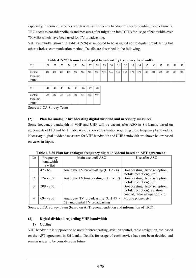
4-70
especially in terms of services which will use frequency bandwidths corresponding those channels.
TRC needs to consider policies and measures after migration into DTTB for usage of bandwidth over
700MHz which have been used for TV broadcasting.
VHF bandwidth (shown in Table 4.2-26) is supposed to be assigned not to digital broadcasting but
other wireless communication method. Details are described in the following.
Table 4.2-29 Channel and digital broadcasting frequency bandwidth CH 21 22 23 24 25 26 27 28 29 30 31 32 33 34 35 36 37 38 39 40
Central
frequency
(MHz)
474 482 490 498 506 514 522 530 538 546 554 562 570 578 586 594 602 610 618 626
CH 41 42 43 44 45 46 47 48
Central
frequency
(MHz)
634 642 650 658 666 674 682 690
Source: JICA Survey Team
Plan for analogue broadcasting digital dividend and necessary measures
Some frequency bandwidth in VHF and UHF will be vacant after ASO in Sri Lanka, based on
agreements of ITU and APT. Table 4.2-30 shows the situation regarding those frequency bandwidths.
Necessary digital dividend measures for VHF bandwidth and UHF bandwidth are shown below based
on cases in Japan.
Table 4.2-30 Plan for analogue frequency digital dividend based on APT agreement No Frequency
bandwidth (MHz)
Main use until ASO Use after ASO
1 47 - 68 Analogue TV broadcasting (CH 2 - 4) Broadcasting (fixed reception, mobile reception), etc.
2 174 - 209 Analogue TV broadcasting (CH 5 - 12) Broadcasting (fixed reception, mobile reception), etc.
3 209 - 230 Broadcasting (fixed reception, mobile reception), aviation control, radio navigation, etc.
4 694 - 806 Analogue TV broadcasting (CH 49 -62) and digital TV broadcasting
Mobile phone, etc.
Source: JICA Survey Team (based on APT recommendation and information of TRC)
Digital dividend regarding VHF bandwidth
1) Outline
VHF bandwidth is supposed to be used for broadcasting, aviation control, radio navigation, etc. based
on the APT agreement in Sri Lanka. Details for usage of each service have not been decided and
remain issues to be considered in future.
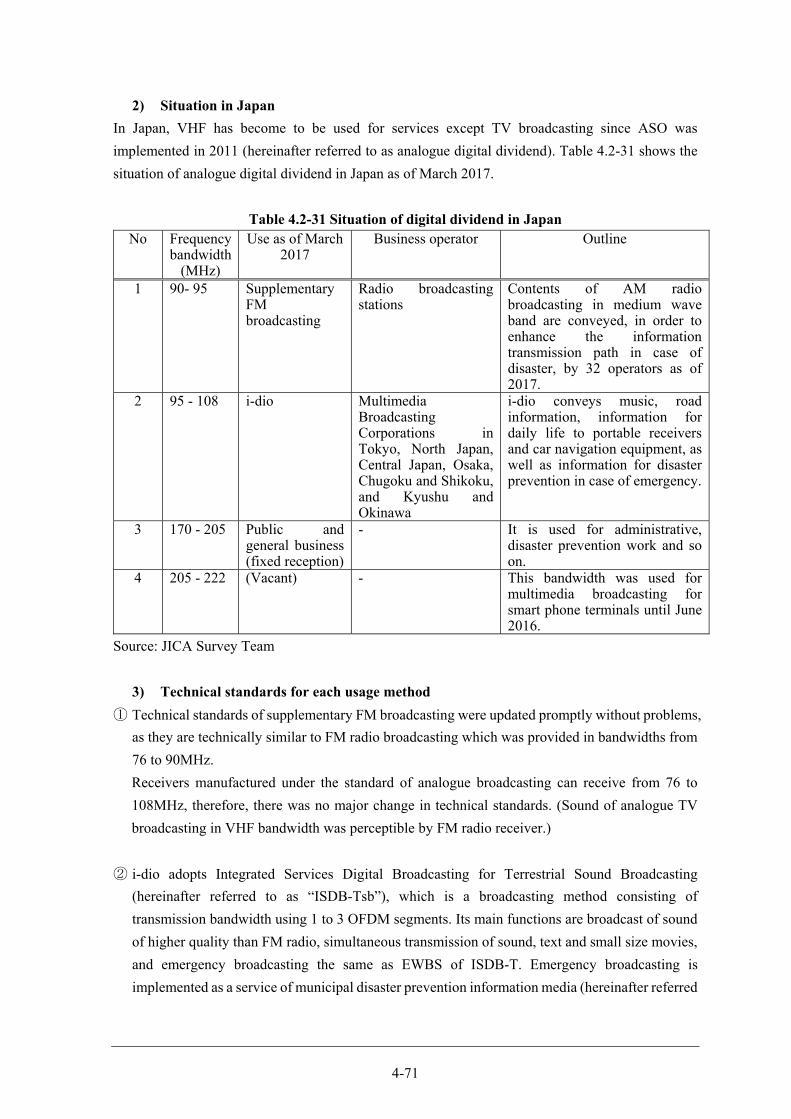
4-71
2) Situation in Japan
In Japan, VHF has become to be used for services except TV broadcasting since ASO was
implemented in 2011 (hereinafter referred to as analogue digital dividend). Table 4.2-31 shows the
situation of analogue digital dividend in Japan as of March 2017.
Table 4.2-31 Situation of digital dividend in Japan No Frequency
bandwidth (MHz)
Use as of March 2017
Business operator Outline
1 90- 95 Supplementary FM broadcasting
Radio broadcasting stations
Contents of AM radio broadcasting in medium wave band are conveyed, in order to enhance the information transmission path in case of disaster, by 32 operators as of 2017.
2 95 - 108 i-dio Multimedia Broadcasting Corporations in Tokyo, North Japan, Central Japan, Osaka, Chugoku and Shikoku, and Kyushu and Okinawa
i-dio conveys music, road information, information for daily life to portable receivers and car navigation equipment, as well as information for disaster prevention in case of emergency.
3 170 - 205 Public and general business (fixed reception)
- It is used for administrative, disaster prevention work and so on.
4 205 - 222 (Vacant) - This bandwidth was used for multimedia broadcasting for smart phone terminals until June 2016.
Source: JICA Survey Team
3) Technical standards for each usage method
① Technical standards of supplementary FM broadcasting were updated promptly without problems,
as they are technically similar to FM radio broadcasting which was provided in bandwidths from
76 to 90MHz.
Receivers manufactured under the standard of analogue broadcasting can receive from 76 to
108MHz, therefore, there was no major change in technical standards. (Sound of analogue TV
broadcasting in VHF bandwidth was perceptible by FM radio receiver.)
② i-dio adopts Integrated Services Digital Broadcasting for Terrestrial Sound Broadcasting
(hereinafter referred to as “ISDB-Tsb”), which is a broadcasting method consisting of
transmission bandwidth using 1 to 3 OFDM segments. Its main functions are broadcast of sound
of higher quality than FM radio, simultaneous transmission of sound, text and small size movies,
and emergency broadcasting the same as EWBS of ISDB-T. Emergency broadcasting is
implemented as a service of municipal disaster prevention information media (hereinafter referred
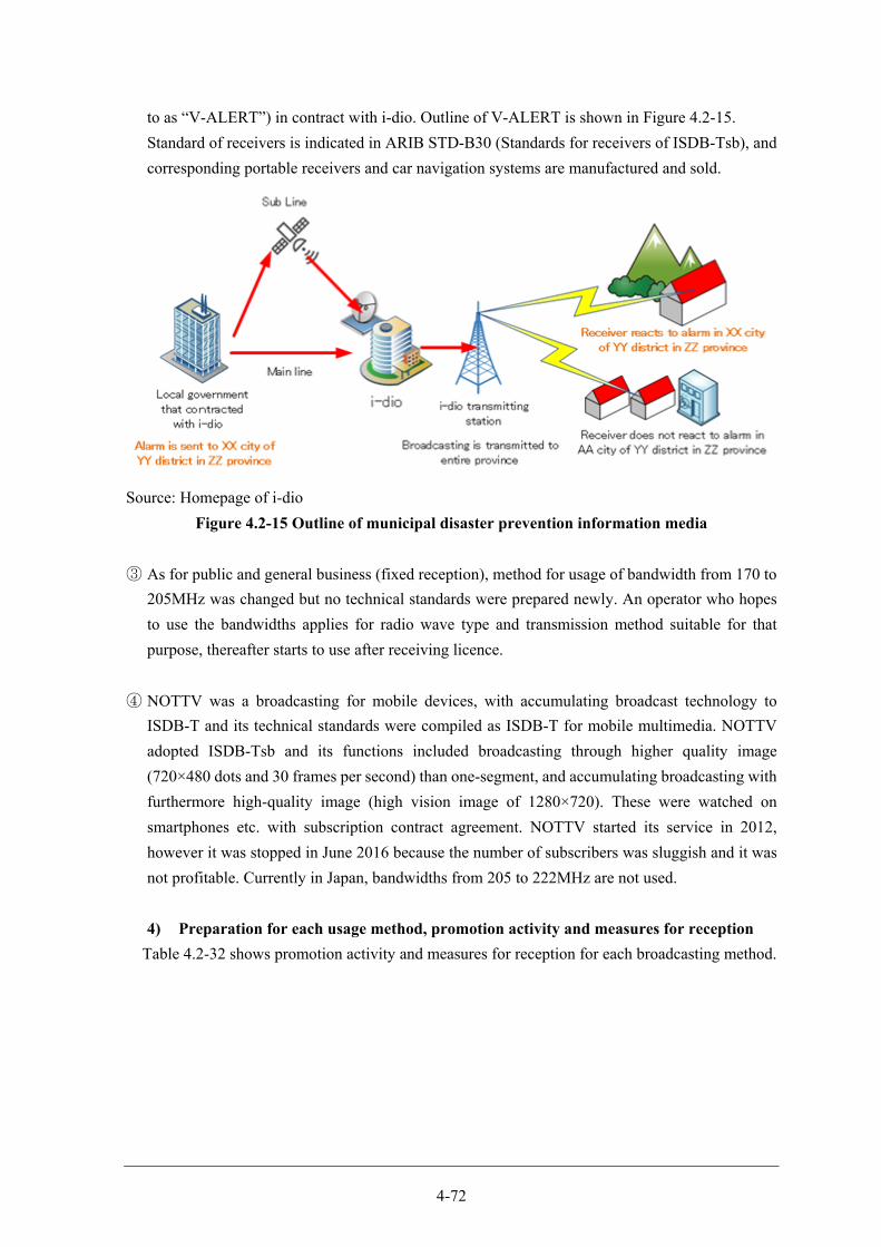
4-72
to as “V-ALERT”) in contract with i-dio. Outline of V-ALERT is shown in Figure 4.2-15.
Standard of receivers is indicated in ARIB STD-B30 (Standards for receivers of ISDB-Tsb), and
corresponding portable receivers and car navigation systems are manufactured and sold.
Source: Homepage of i-dio
Figure 4.2-15 Outline of municipal disaster prevention information media
③ As for public and general business (fixed reception), method for usage of bandwidth from 170 to
205MHz was changed but no technical standards were prepared newly. An operator who hopes
to use the bandwidths applies for radio wave type and transmission method suitable for that
purpose, thereafter starts to use after receiving licence.
④ NOTTV was a broadcasting for mobile devices, with accumulating broadcast technology to
ISDB-T and its technical standards were compiled as ISDB-T for mobile multimedia. NOTTV
adopted ISDB-Tsb and its functions included broadcasting through higher quality image
(720×480 dots and 30 frames per second) than one-segment, and accumulating broadcasting with
furthermore high-quality image (high vision image of 1280×720). These were watched on
smartphones etc. with subscription contract agreement. NOTTV started its service in 2012,
however it was stopped in June 2016 because the number of subscribers was sluggish and it was
not profitable. Currently in Japan, bandwidths from 205 to 222MHz are not used.
4) Preparation for each usage method, promotion activity and measures for reception
Table 4.2-32 shows promotion activity and measures for reception for each broadcasting method.
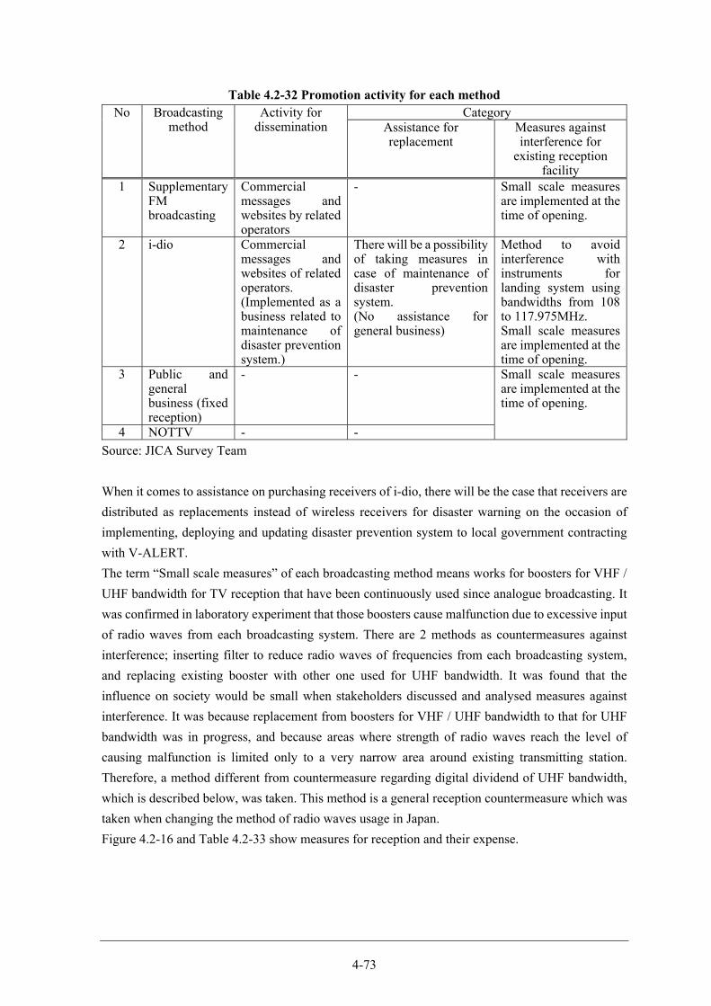
4-73
Table 4.2-32 Promotion activity for each method No Broadcasting
method Activity for
dissemination Category
Assistance for replacement
Measures against interference for
existing reception facility
1 Supplementary FM broadcasting
Commercial messages and websites by related operators
- Small scale measures are implemented at the time of opening.
2 i-dio Commercial messages and websites of related operators. (Implemented as a business related to maintenance of disaster prevention system.)
There will be a possibility of taking measures in case of maintenance of disaster prevention system. (No assistance for general business)
Method to avoid interference with instruments for landing system using bandwidths from 108 to 117.975MHz. Small scale measures are implemented at the time of opening.
3 Public and general business (fixed reception)
- - Small scale measures are implemented at the time of opening.
4 NOTTV - -
Source: JICA Survey Team
When it comes to assistance on purchasing receivers of i-dio, there will be the case that receivers are
distributed as replacements instead of wireless receivers for disaster warning on the occasion of
implementing, deploying and updating disaster prevention system to local government contracting
with V-ALERT.
The term “Small scale measures” of each broadcasting method means works for boosters for VHF /
UHF bandwidth for TV reception that have been continuously used since analogue broadcasting. It
was confirmed in laboratory experiment that those boosters cause malfunction due to excessive input
of radio waves from each broadcasting system. There are 2 methods as countermeasures against
interference; inserting filter to reduce radio waves of frequencies from each broadcasting system,
and replacing existing booster with other one used for UHF bandwidth. It was found that the
influence on society would be small when stakeholders discussed and analysed measures against
interference. It was because replacement from boosters for VHF / UHF bandwidth to that for UHF
bandwidth was in progress, and because areas where strength of radio waves reach the level of
causing malfunction is limited only to a very narrow area around existing transmitting station.
Therefore, a method different from countermeasure regarding digital dividend of UHF bandwidth,
which is described below, was taken. This method is a general reception countermeasure which was
taken when changing the method of radio waves usage in Japan.
Figure 4.2-16 and Table 4.2-33 show measures for reception and their expense.
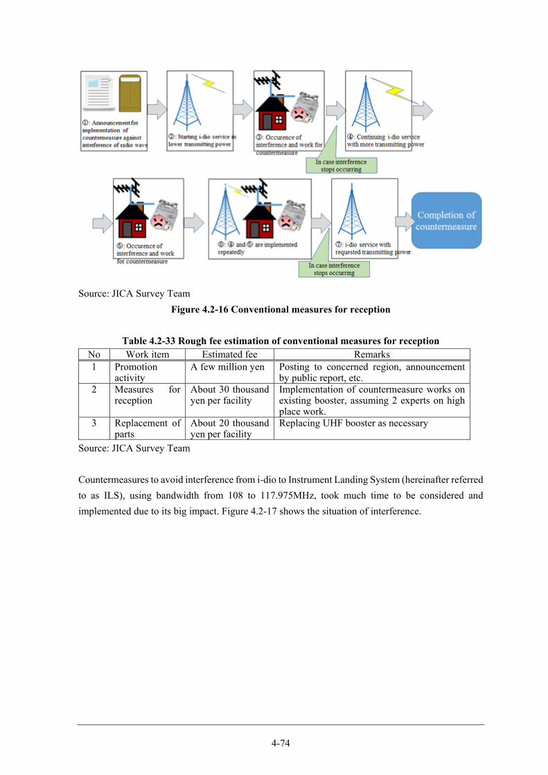
4-74
Source: JICA Survey Team
Figure 4.2-16 Conventional measures for reception
Table 4.2-33 Rough fee estimation of conventional measures for reception No Work item Estimated fee Remarks 1 Promotion
activity A few million yen Posting to concerned region, announcement
by public report, etc. 2 Measures for
reception About 30 thousand yen per facility
Implementation of countermeasure works on existing booster, assuming 2 experts on high place work.
3 Replacement of parts
About 20 thousand yen per facility
Replacing UHF booster as necessary
Source: JICA Survey Team
Countermeasures to avoid interference from i-dio to Instrument Landing System (hereinafter referred
to as ILS), using bandwidth from 108 to 117.975MHz, took much time to be considered and
implemented due to its big impact. Figure 4.2-17 shows the situation of interference.
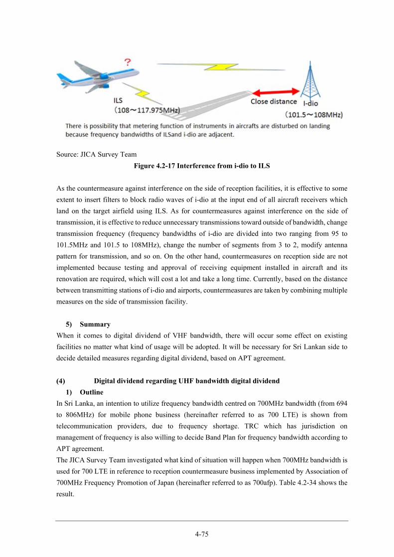
4-75
Source: JICA Survey Team
Figure 4.2-17 Interference from i-dio to ILS
As the countermeasure against interference on the side of reception facilities, it is effective to some
extent to insert filters to block radio waves of i-dio at the input end of all aircraft receivers which
land on the target airfield using ILS. As for countermeasures against interference on the side of
transmission, it is effective to reduce unnecessary transmissions toward outside of bandwidth, change
transmission frequency (frequency bandwidths of i-dio are divided into two ranging from 95 to
101.5MHz and 101.5 to 108MHz), change the number of segments from 3 to 2, modify antenna
pattern for transmission, and so on. On the other hand, countermeasures on reception side are not
implemented because testing and approval of receiving equipment installed in aircraft and its
renovation are required, which will cost a lot and take a long time. Currently, based on the distance
between transmitting stations of i-dio and airports, countermeasures are taken by combining multiple
measures on the side of transmission facility.
5) Summary
When it comes to digital dividend of VHF bandwidth, there will occur some effect on existing
facilities no matter what kind of usage will be adopted. It will be necessary for Sri Lankan side to
decide detailed measures regarding digital dividend, based on APT agreement.
Digital dividend regarding UHF bandwidth digital dividend
1) Outline
In Sri Lanka, an intention to utilize frequency bandwidth centred on 700MHz bandwidth (from 694
to 806MHz) for mobile phone business (hereinafter referred to as 700 LTE) is shown from
telecommunication providers, due to frequency shortage. TRC which has jurisdiction on
management of frequency is also willing to decide Band Plan for frequency bandwidth according to
APT agreement.
The JICA Survey Team investigated what kind of situation will happen when 700MHz bandwidth is
used for 700 LTE in reference to reception countermeasure business implemented by Association of
700MHz Frequency Promotion of Japan (hereinafter referred to as 700afp). Table 4.2-34 shows the
result.
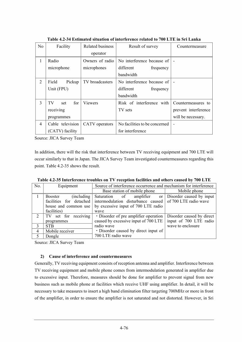
4-76
Table 4.2-34 Estimated situation of interference related to 700 LTE in Sri Lanka
No Facility Related business
operator
Result of survey Countermeasure
1 Radio
microphone
Owners of radio
microphones
No interference because of
different frequency
bandwidth
-
2 Field Pickup
Unit (FPU)
TV broadcasters No interference because of
different frequency
bandwidth
-
3 TV set for
receiving
programmes
Viewers Risk of interference with
TV sets
Countermeasures to
prevent interference
will be necessary.
4 Cable television
(CATV) facility
CATV operators No facilities to be concerned
for interference
-
Source: JICA Survey Team
In addition, there will the risk that interference between TV receiving equipment and 700 LTE will
occur similarly to that in Japan. The JICA Survey Team investigated countermeasures regarding this
point. Table 4.2-35 shows the result.
Table 4.2-35 Interference troubles on TV reception facilities and others caused by 700 LTE No. Equipment Source of interference occurrence and mechanism for interference
Base station of mobile phone Mobile phone1 Booster (including
facilities for detached house and common use facilities)
Saturation of amplifier or intermodulation disturbance caused by excessive input of 700 LTE radio wave
Disorder caused by input of 700 LTE radio wave
2 TV set for receiving programmes
・Disorder of pre amplifier operation caused by excessive input of 700 LTE radio wave ・Disorder caused by direct input of 700 LTE radio wave
Disorder caused by direct input of 700 LTE radio wave to enclosure 3 STB
4 Mobile receiver5 Dongle
Source: JICA Survey Team
2) Cause of interference and countermeasures
Generally, TV receiving equipment consists of reception antenna and amplifier. Interference between
TV receiving equipment and mobile phone comes from intermodulation generated in amplifier due
to excessive input. Therefore, measures should be done for amplifier to prevent signal from new
business such as mobile phone at facilities which receive UHF using amplifier. In detail, it will be
necessary to take measures to insert a high band elimination filter targeting 700MHz or more in front
of the amplifier, in order to ensure the amplifier is not saturated and not distorted. However, in Sri
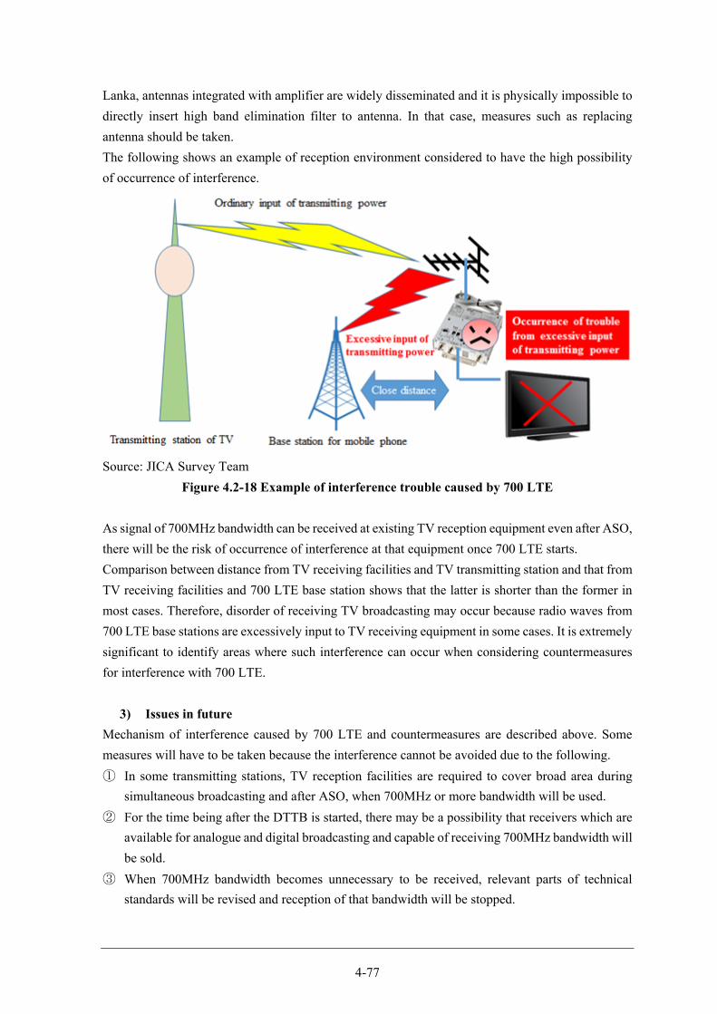
4-77
Lanka, antennas integrated with amplifier are widely disseminated and it is physically impossible to
directly insert high band elimination filter to antenna. In that case, measures such as replacing
antenna should be taken.
The following shows an example of reception environment considered to have the high possibility
of occurrence of interference.
Source: JICA Survey Team
Figure 4.2-18 Example of interference trouble caused by 700 LTE
As signal of 700MHz bandwidth can be received at existing TV reception equipment even after ASO,
there will be the risk of occurrence of interference at that equipment once 700 LTE starts.
Comparison between distance from TV receiving facilities and TV transmitting station and that from
TV receiving facilities and 700 LTE base station shows that the latter is shorter than the former in
most cases. Therefore, disorder of receiving TV broadcasting may occur because radio waves from
700 LTE base stations are excessively input to TV receiving equipment in some cases. It is extremely
significant to identify areas where such interference can occur when considering countermeasures
for interference with 700 LTE.
3) Issues in future
Mechanism of interference caused by 700 LTE and countermeasures are described above. Some
measures will have to be taken because the interference cannot be avoided due to the following.
① In some transmitting stations, TV reception facilities are required to cover broad area during
simultaneous broadcasting and after ASO, when 700MHz or more bandwidth will be used.
② For the time being after the DTTB is started, there may be a possibility that receivers which are
available for analogue and digital broadcasting and capable of receiving 700MHz bandwidth will
be sold.
③ When 700MHz bandwidth becomes unnecessary to be received, relevant parts of technical
standards will be revised and reception of that bandwidth will be stopped.
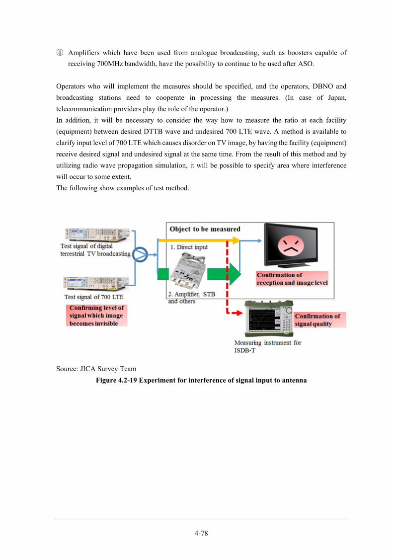
4-78
④ Amplifiers which have been used from analogue broadcasting, such as boosters capable of
receiving 700MHz bandwidth, have the possibility to continue to be used after ASO.
Operators who will implement the measures should be specified, and the operators, DBNO and
broadcasting stations need to cooperate in processing the measures. (In case of Japan,
telecommunication providers play the role of the operator.)
In addition, it will be necessary to consider the way how to measure the ratio at each facility
(equipment) between desired DTTB wave and undesired 700 LTE wave. A method is available to
clarify input level of 700 LTE which causes disorder on TV image, by having the facility (equipment)
receive desired signal and undesired signal at the same time. From the result of this method and by
utilizing radio wave propagation simulation, it will be possible to specify area where interference
will occur to some extent.
The following show examples of test method.
Source: JICA Survey Team
Figure 4.2-19 Experiment for interference of signal input to antenna
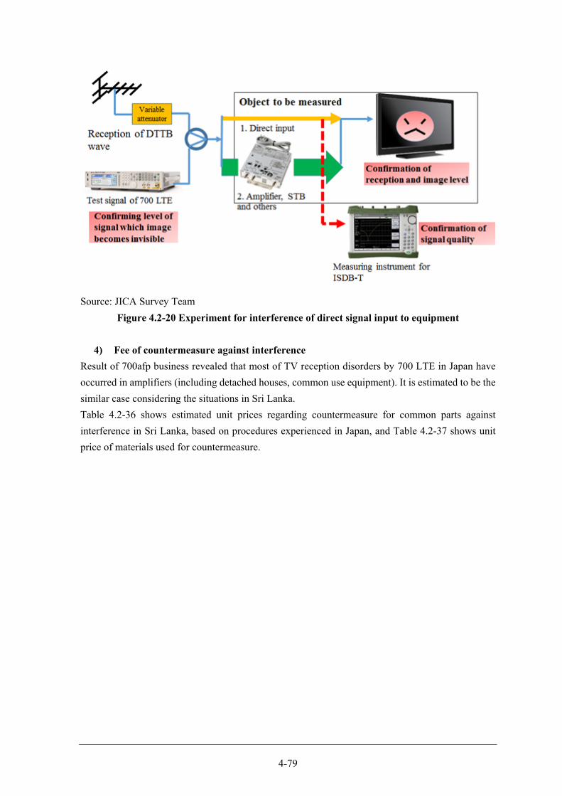
4-79
Source: JICA Survey Team
Figure 4.2-20 Experiment for interference of direct signal input to equipment
4) Fee of countermeasure against interference
Result of 700afp business revealed that most of TV reception disorders by 700 LTE in Japan have
occurred in amplifiers (including detached houses, common use equipment). It is estimated to be the
similar case considering the situations in Sri Lanka.
Table 4.2-36 shows estimated unit prices regarding countermeasure for common parts against
interference in Sri Lanka, based on procedures experienced in Japan, and Table 4.2-37 shows unit
price of materials used for countermeasure.
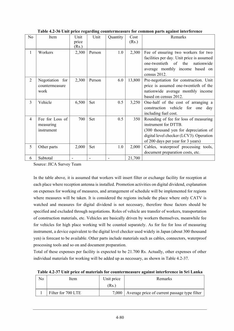
4-80
Table 4.2-36 Unit price regarding countermeasure for common parts against interference No Item Unit
price (Rs.)
Unit Quantity Cost (Rs.)
Remarks
1 Workers 2,300 Person 1.0 2,300 Fee of ensuring two workers for two facilities per day. Unit price is assumed one-twentieth of the nationwide average monthly income based on census 2012.
2 Negotiation for countermeasure work
2,300 Person 6.0 13,800 Pre-negotiation for construction. Unit price is assumed one-twentieth of the nationwide average monthly income based on census 2012.
3 Vehicle 6,500 Set 0.5 3,250 One-half of the cost of arranging a construction vehicle for one day including fuel cost.
4 Fee for Loss of measuring instrument
700 Set 0.5 350 Rounding of fee for loss of measuring instrument for DTTB. (300 thousand yen for depreciation of digital level checker (LCV3). Operation of 200 days per year for 3 years)
5 Other parts 2,000 Set 1.0 2,000 Cables, waterproof processing tools, document preparation costs, etc.
6 Subtotal - - - 21,700
Source: JICA Survey Team
In the table above, it is assumed that workers will insert filter or exchange facility for reception at
each place where reception antenna is installed. Promotion activities on digital dividend, explanation
on expenses for working of measures, and arrangement of schedule will be implemented for regions
where measures will be taken. It is considered the regions include the place where only CATV is
watched and measures for digital dividend is not necessary, therefore those factors should be
specified and excluded through negotiations. Roles of vehicle are transfer of workers, transportation
of construction materials, etc. Vehicles are basically driven by workers themselves, meanwhile fee
for vehicles for high place working will be counted separately. As for fee for loss of measuring
instrument, a device equivalent to the digital level checker used widely in Japan (about 300 thousand
yen) is forecast to be available. Other parts include materials such as cables, connectors, waterproof
processing tools and so on and document preparation.
Total of these expenses per facility is expected to be 21.700 Rs. Actually, other expenses of other
individual materials for working will be added up as necessary, as shown in Table 4.2-37.
Table 4.2-37 Unit price of materials for countermeasure against interference in Sri Lanka
No Item Unit price
(Rs.)
Remarks
1 Filter for 700 LTE 7,000 Average price of current passage type filter
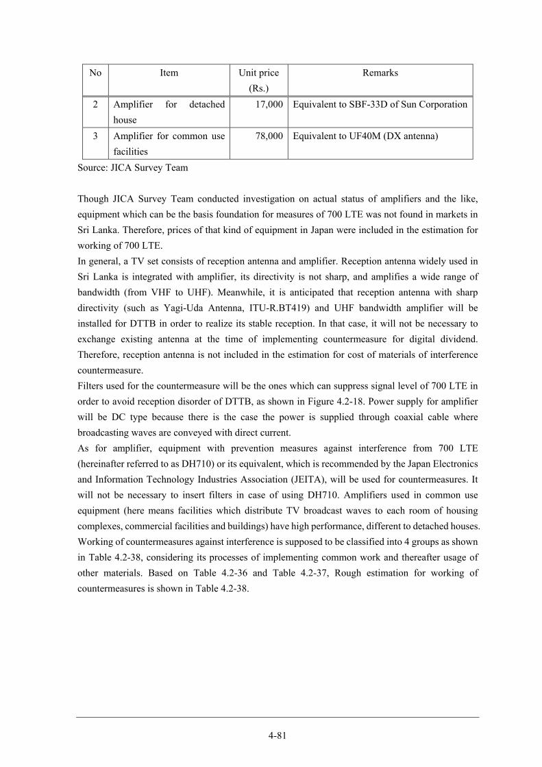
4-81
No Item Unit price
(Rs.)
Remarks
2 Amplifier for detached
house
17,000 Equivalent to SBF-33D of Sun Corporation
3 Amplifier for common use
facilities
78,000 Equivalent to UF40M (DX antenna)
Source: JICA Survey Team
Though JICA Survey Team conducted investigation on actual status of amplifiers and the like,
equipment which can be the basis foundation for measures of 700 LTE was not found in markets in
Sri Lanka. Therefore, prices of that kind of equipment in Japan were included in the estimation for
working of 700 LTE.
In general, a TV set consists of reception antenna and amplifier. Reception antenna widely used in
Sri Lanka is integrated with amplifier, its directivity is not sharp, and amplifies a wide range of
bandwidth (from VHF to UHF). Meanwhile, it is anticipated that reception antenna with sharp
directivity (such as Yagi-Uda Antenna, ITU-R.BT419) and UHF bandwidth amplifier will be
installed for DTTB in order to realize its stable reception. In that case, it will not be necessary to
exchange existing antenna at the time of implementing countermeasure for digital dividend.
Therefore, reception antenna is not included in the estimation for cost of materials of interference
countermeasure.
Filters used for the countermeasure will be the ones which can suppress signal level of 700 LTE in
order to avoid reception disorder of DTTB, as shown in Figure 4.2-18. Power supply for amplifier
will be DC type because there is the case the power is supplied through coaxial cable where
broadcasting waves are conveyed with direct current.
As for amplifier, equipment with prevention measures against interference from 700 LTE
(hereinafter referred to as DH710) or its equivalent, which is recommended by the Japan Electronics
and Information Technology Industries Association (JEITA), will be used for countermeasures. It
will not be necessary to insert filters in case of using DH710. Amplifiers used in common use
equipment (here means facilities which distribute TV broadcast waves to each room of housing
complexes, commercial facilities and buildings) have high performance, different to detached houses.
Working of countermeasures against interference is supposed to be classified into 4 groups as shown
in Table 4.2-38, considering its processes of implementing common work and thereafter usage of
other materials. Based on Table 4.2-36 and Table 4.2-37, Rough estimation for working of
countermeasures is shown in Table 4.2-38.

4-82
Table 4.2-38 Rough estimation for countermeasures against interference
No Category Cost (Rs.) Detail
1 Confirmation and arrangement for
works at detached houses and
common use facilities
21,700 Works for common use parts
2 Inserting filters at facilities of
detached houses and common use
facilities
28,700 Works for common use parts and
700 LTE filters
3 Replacing amplifier at detached
houses
38,700 Works for common use parts and
amplifiers of detached houses
4 Replacing amplifier of common
use facilities
99,700 Works for common use parts and
amplifiers of common use facilities
Source: JICA Survey Team
Selling, general and administrative expenses and taxes are not included in each cost in the table above.
Item No. 1 shows the cost which materials for countermeasures are not used and the cost for facilities
of no necessity for implementing countermeasure. It is hoped that the latter case does not occur,
therefore, necessity of countermeasure should be judged through negotiation and the actual work be
executed. Meanwhile, as with the case of Japan, there will occur the situation that necessity cannot
be judged through negotiation, or the case of judging that there is no need for countermeasures, even
if it is not the defect of the parties or operators of countermeasure. Item No. 1 guarantees the
minimum operating cost of workers in order to avoid the risk that workers cannot be secured in case
of not defining that kind of cost. Items No. 2 and 3 show the case of the largest number of works
occurring, based on analysing the performance of countermeasure in Japan.
Based on information above, Table 4.2-39 and Table 4.2-40 show examples of rough estimation for
countermeasures against interference at detached houses and facilities sharing equipment for
reception.
Table 4.2-39 Example of rough estimation for countermeasures against interference at
detached houses
No Item Estimated quantity Remarks
1 Number of detached houses 4,872,426 Based on Census 2010
2 Rate of TV dissemination 80% Based on Census 2010
3 Probability of locating in
areas where interference
prevention measures are
necessary
10% Threshold of field strength for
reception in Japan is 85dBμV/m.
This percentage is equivalent with
the area where field strength is
estimated to be more than the
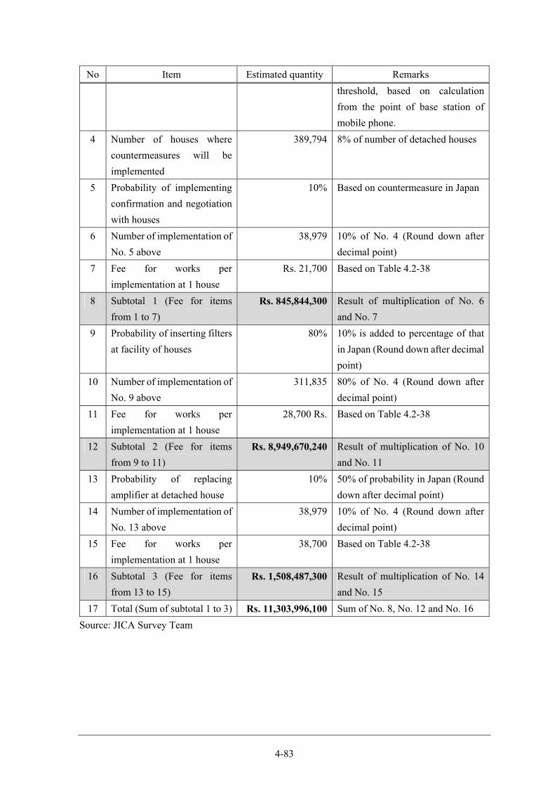
4-83
No Item Estimated quantity Remarks
threshold, based on calculation
from the point of base station of
mobile phone.
4 Number of houses where
countermeasures will be
implemented
389,794 8% of number of detached houses
5 Probability of implementing
confirmation and negotiation
with houses
10% Based on countermeasure in Japan
6 Number of implementation of
No. 5 above
38,979 10% of No. 4 (Round down after
decimal point)
7 Fee for works per
implementation at 1 house
Rs. 21,700 Based on Table 4.2-38
8 Subtotal 1 (Fee for items
from 1 to 7)
Rs. 845,844,300 Result of multiplication of No. 6
and No. 7
9 Probability of inserting filters
at facility of houses
80% 10% is added to percentage of that
in Japan (Round down after decimal
point)
10 Number of implementation of
No. 9 above
311,835 80% of No. 4 (Round down after
decimal point)
11 Fee for works per
implementation at 1 house
28,700 Rs. Based on Table 4.2-38
12 Subtotal 2 (Fee for items
from 9 to 11)
Rs. 8,949,670,240 Result of multiplication of No. 10
and No. 11
13 Probability of replacing
amplifier at detached house
10% 50% of probability in Japan (Round
down after decimal point)
14 Number of implementation of
No. 13 above
38,979 10% of No. 4 (Round down after
decimal point)
15 Fee for works per
implementation at 1 house
38,700 Based on Table 4.2-38
16 Subtotal 3 (Fee for items
from 13 to 15)
Rs. 1,508,487,300 Result of multiplication of No. 14
and No. 15
17 Total (Sum of subtotal 1 to 3) Rs. 11,303,996,100 Sum of No. 8, No. 12 and No. 16
Source: JICA Survey Team
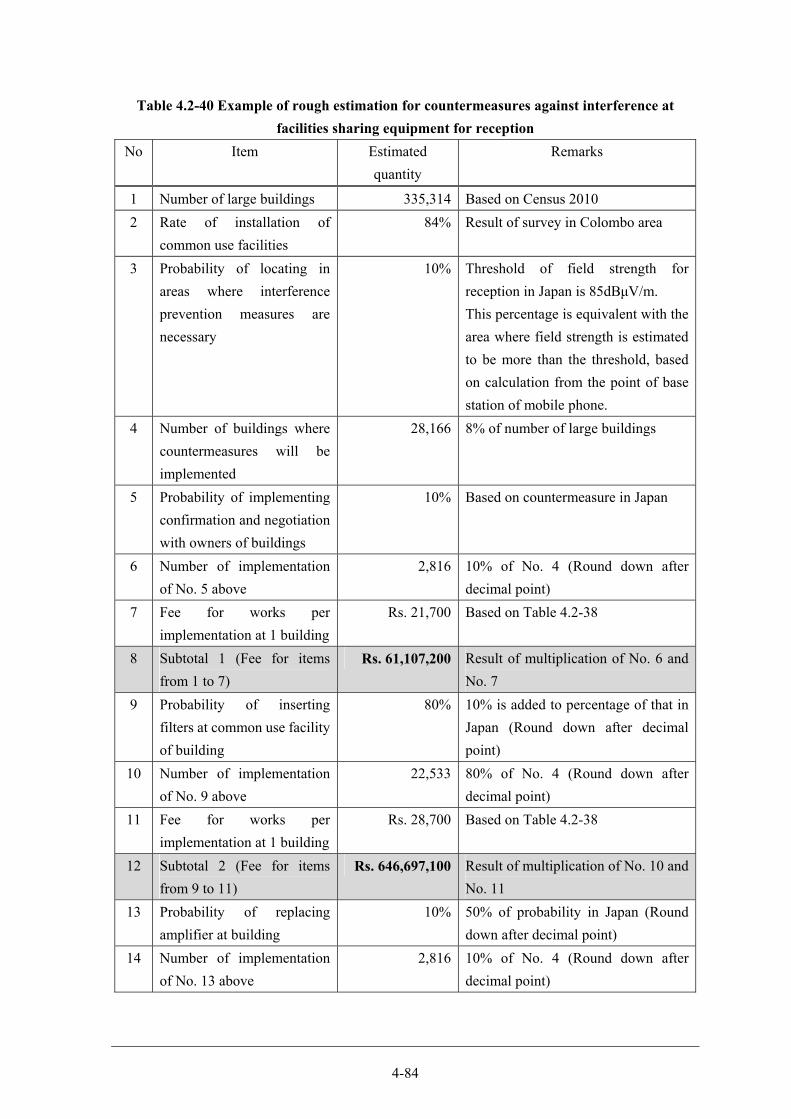
4-84
Table 4.2-40 Example of rough estimation for countermeasures against interference at
facilities sharing equipment for reception
No Item Estimated
quantity
Remarks
1 Number of large buildings 335,314 Based on Census 2010
2 Rate of installation of
common use facilities
84% Result of survey in Colombo area
3 Probability of locating in
areas where interference
prevention measures are
necessary
10% Threshold of field strength for
reception in Japan is 85dBμV/m.
This percentage is equivalent with the
area where field strength is estimated
to be more than the threshold, based
on calculation from the point of base
station of mobile phone.
4 Number of buildings where
countermeasures will be
implemented
28,166 8% of number of large buildings
5 Probability of implementing
confirmation and negotiation
with owners of buildings
10% Based on countermeasure in Japan
6 Number of implementation
of No. 5 above
2,816 10% of No. 4 (Round down after
decimal point)
7 Fee for works per
implementation at 1 building
Rs. 21,700 Based on Table 4.2-38
8 Subtotal 1 (Fee for items
from 1 to 7)
Rs. 61,107,200 Result of multiplication of No. 6 and
No. 7
9 Probability of inserting
filters at common use facility
of building
80% 10% is added to percentage of that in
Japan (Round down after decimal
point)
10 Number of implementation
of No. 9 above
22,533 80% of No. 4 (Round down after
decimal point)
11 Fee for works per
implementation at 1 building
Rs. 28,700 Based on Table 4.2-38
12 Subtotal 2 (Fee for items
from 9 to 11)
Rs. 646,697,100 Result of multiplication of No. 10 and
No. 11
13 Probability of replacing
amplifier at building
10% 50% of probability in Japan (Round
down after decimal point)
14 Number of implementation
of No. 13 above
2,816 10% of No. 4 (Round down after
decimal point)
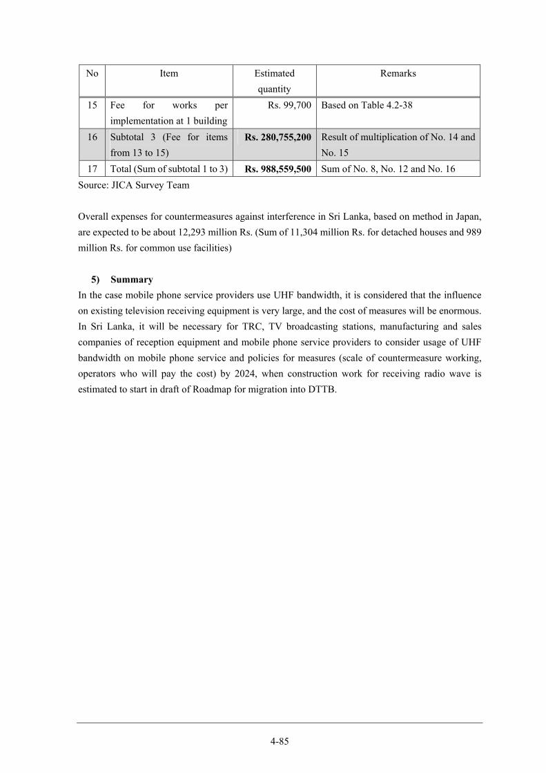
4-85
No Item Estimated
quantity
Remarks
15 Fee for works per
implementation at 1 building
Rs. 99,700 Based on Table 4.2-38
16 Subtotal 3 (Fee for items
from 13 to 15)
Rs. 280,755,200 Result of multiplication of No. 14 and
No. 15
17 Total (Sum of subtotal 1 to 3) Rs. 988,559,500 Sum of No. 8, No. 12 and No. 16
Source: JICA Survey Team
Overall expenses for countermeasures against interference in Sri Lanka, based on method in Japan,
are expected to be about 12,293 million Rs. (Sum of 11,304 million Rs. for detached houses and 989
million Rs. for common use facilities)
5) Summary
In the case mobile phone service providers use UHF bandwidth, it is considered that the influence
on existing television receiving equipment is very large, and the cost of measures will be enormous.
In Sri Lanka, it will be necessary for TRC, TV broadcasting stations, manufacturing and sales
companies of reception equipment and mobile phone service providers to consider usage of UHF
bandwidth on mobile phone service and policies for measures (scale of countermeasure working,
operators who will pay the cost) by 2024, when construction work for receiving radio wave is
estimated to start in draft of Roadmap for migration into DTTB.
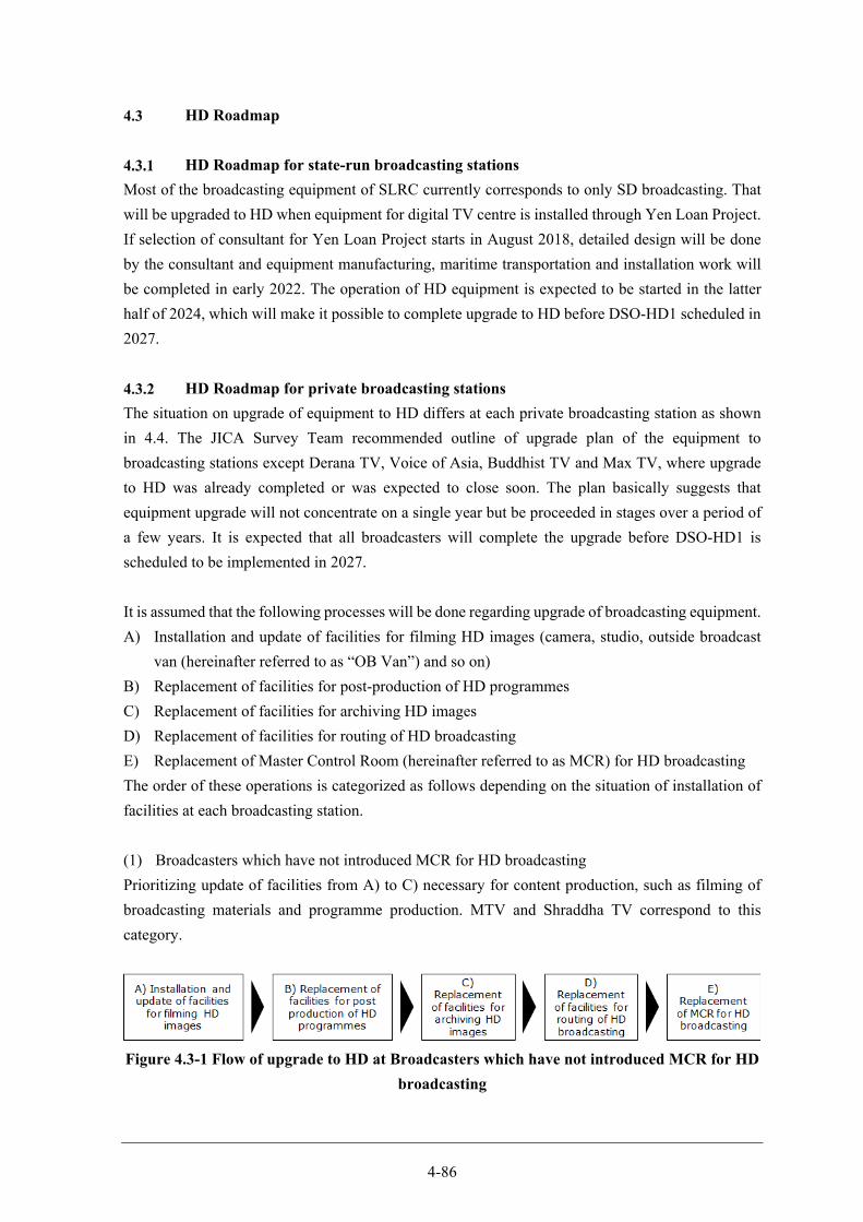
4-86
HD Roadmap
HD Roadmap for state-run broadcasting stations
Most of the broadcasting equipment of SLRC currently corresponds to only SD broadcasting. That
will be upgraded to HD when equipment for digital TV centre is installed through Yen Loan Project.
If selection of consultant for Yen Loan Project starts in August 2018, detailed design will be done
by the consultant and equipment manufacturing, maritime transportation and installation work will
be completed in early 2022. The operation of HD equipment is expected to be started in the latter
half of 2024, which will make it possible to complete upgrade to HD before DSO-HD1 scheduled in
2027.
HD Roadmap for private broadcasting stations
The situation on upgrade of equipment to HD differs at each private broadcasting station as shown
in 4.4. The JICA Survey Team recommended outline of upgrade plan of the equipment to
broadcasting stations except Derana TV, Voice of Asia, Buddhist TV and Max TV, where upgrade
to HD was already completed or was expected to close soon. The plan basically suggests that
equipment upgrade will not concentrate on a single year but be proceeded in stages over a period of
a few years. It is expected that all broadcasters will complete the upgrade before DSO-HD1 is
scheduled to be implemented in 2027.
It is assumed that the following processes will be done regarding upgrade of broadcasting equipment.
A) Installation and update of facilities for filming HD images (camera, studio, outside broadcast
van (hereinafter referred to as “OB Van”) and so on)
B) Replacement of facilities for post-production of HD programmes
C) Replacement of facilities for archiving HD images
D) Replacement of facilities for routing of HD broadcasting
E) Replacement of Master Control Room (hereinafter referred to as MCR) for HD broadcasting
The order of these operations is categorized as follows depending on the situation of installation of
facilities at each broadcasting station.
(1) Broadcasters which have not introduced MCR for HD broadcasting
Prioritizing update of facilities from A) to C) necessary for content production, such as filming of
broadcasting materials and programme production. MTV and Shraddha TV correspond to this
category.
Figure 4.3-1 Flow of upgrade to HD at Broadcasters which have not introduced MCR for HD
broadcasting
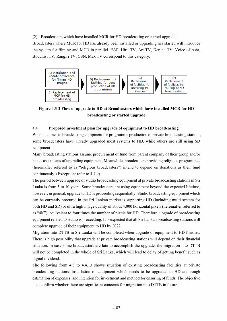
4-87
(2) Broadcasters which have installed MCR for HD broadcasting or started upgrade
Broadcasters where MCR for HD has already been installed or upgrading has started will introduce
the system for filming and MCR in parallel. EAP, Hiru TV, Art TV, Derana TV, Voice of Asia,
Buddhist TV, Rangiri TV, CSN, Max TV correspond to this category.
Figure 4.3-2 Flow of upgrade to HD at Broadcasters which have installed MCR for HD
broadcasting or started upgrade
Proposed investment plan for upgrade of equipment to HD broadcasting
When it comes to broadcasting equipment for programme production of private broadcasting stations,
some broadcasters have already upgraded most systems to HD, while others are still using SD
equipment.
Many broadcasting stations assume procurement of fund from parent company of their group and/or
banks as a means of upgrading equipment. Meanwhile, broadcasters providing religious programmes
(hereinafter referred to as “religious broadcasters”) intend to depend on donations as their fund
continuously. (Exception: refer to 4.4.9)
The period between upgrade of studio broadcasting equipment at private broadcasting stations in Sri
Lanka is from 5 to 10 years. Some broadcasters are using equipment beyond the expected lifetime,
however, in general, upgrade to HD is proceeding sequentially. Studio broadcasting equipment which
can be currently procured in the Sri Lankan market is supporting HD (including multi system for
both HD and SD) or ultra high image quality of about 4,000 horizontal pixels (hereinafter referred to
as “4K”), equivalent to four times the number of pixels for HD. Therefore, upgrade of broadcasting
equipment related to studio is proceeding. It is expected that all Sri Lankan broadcasting stations will
complete upgrade of their equipment to HD by 2022.
Migration into DTTB in Sri Lanka will be completed when upgrade of equipment to HD finishes.
There is high possibility that upgrade at private broadcasting stations will depend on their financial
situation. In case some broadcasters are late to accomplish the upgrade, the migration into DTTB
will not be completed in the whole of Sri Lanka, which will lead to delay of getting benefit such as
digital dividend.
The following from 4.3 to 4.4.13 shows situation of existing broadcasting facilities at private
broadcasting stations, installation of equipment which needs to be upgraded to HD and rough
estimation of expenses, and intention for investment and method for ensuring of funds. The objective
is to confirm whether there are significant concerns for migration into DTTB in future.
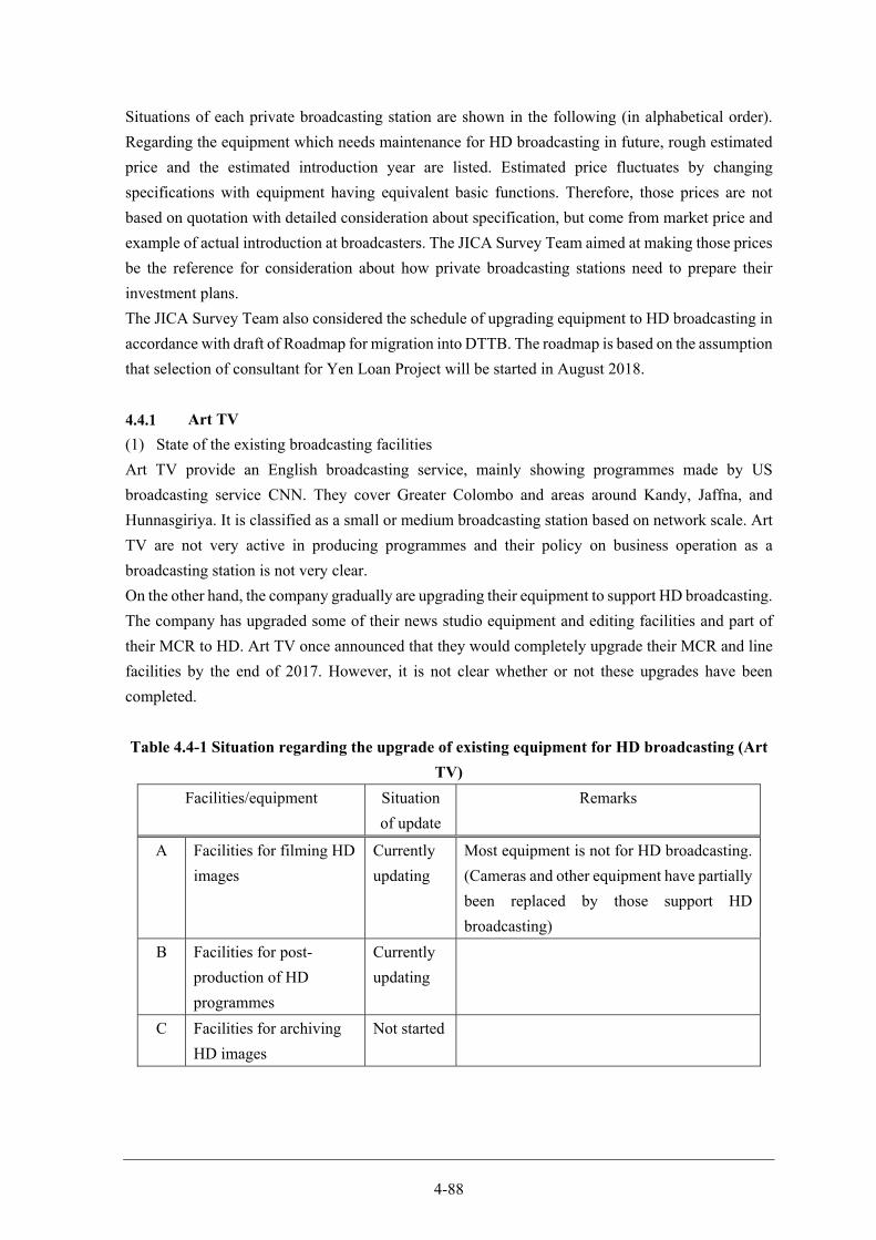
4-88
Situations of each private broadcasting station are shown in the following (in alphabetical order).
Regarding the equipment which needs maintenance for HD broadcasting in future, rough estimated
price and the estimated introduction year are listed. Estimated price fluctuates by changing
specifications with equipment having equivalent basic functions. Therefore, those prices are not
based on quotation with detailed consideration about specification, but come from market price and
example of actual introduction at broadcasters. The JICA Survey Team aimed at making those prices
be the reference for consideration about how private broadcasting stations need to prepare their
investment plans.
The JICA Survey Team also considered the schedule of upgrading equipment to HD broadcasting in
accordance with draft of Roadmap for migration into DTTB. The roadmap is based on the assumption
that selection of consultant for Yen Loan Project will be started in August 2018.
Art TV
(1) State of the existing broadcasting facilities
Art TV provide an English broadcasting service, mainly showing programmes made by US
broadcasting service CNN. They cover Greater Colombo and areas around Kandy, Jaffna, and
Hunnasgiriya. It is classified as a small or medium broadcasting station based on network scale. Art
TV are not very active in producing programmes and their policy on business operation as a
broadcasting station is not very clear.
On the other hand, the company gradually are upgrading their equipment to support HD broadcasting.
The company has upgraded some of their news studio equipment and editing facilities and part of
their MCR to HD. Art TV once announced that they would completely upgrade their MCR and line
facilities by the end of 2017. However, it is not clear whether or not these upgrades have been
completed.
Table 4.4-1 Situation regarding the upgrade of existing equipment for HD broadcasting (Art
TV)
Facilities/equipment Situation
of update
Remarks
A Facilities for filming HD
images
Currently
updating
Most equipment is not for HD broadcasting.
(Cameras and other equipment have partially
been replaced by those support HD
broadcasting)
B Facilities for post-
production of HD
programmes
Currently
updating
C Facilities for archiving
HD images
Not started

4-89
Facilities/equipment Situation
of update
Remarks
D Facilities for routing of
HD broadcasting
Currently
updating
Expected to complete upgrade to HD in
2017.
E MCR for HD Currently
updating
Expected to complete upgrade to HD in
2017.
Legend: The alphabetical characters in the table indicate the categories of the equipment as
described in 4.3.2.
Source: JICA Survey Team
(2) Condition of the equipment that needs to be upgraded to HD and estimates of expenses
Based on the company’s business scale, the steps for the migration into HD were projected in three
stages of three years. In the initial stage, the facilities for editing programmes will be upgraded to
HD. Since the videos provided by CNN are already in HD, employing an HD editing system will
enable HD broadcasting of CNN programmes. Then, the news studio equipment will be replaced
with HD equipment, and finally, the video archiving facilities will be replaced. A total of
approximately USD 200,000 in funding will be needed.
Table 4.4-2 Condition of facilities that need to be upgraded to HD and estimates of expenses
(Art TV)
No Facilities / equipment Quantity
Estimated expenses (thousand
USD)
Scheduled year of
completion
1 A Facilities for filming HD images (news studio equipment)
1 lot 79 2019
2 B Facilities for post-production of HD programmes
1 lot 91 2018
3 C Facilities for archiving HD images 1 lot 36 2020
Total 206
(See Appendix 47 for breakdown of facilities/equipment and expenses)
Legend: The alphabetical characters in the table indicate the categories of the equipment as
described in 4.3.2.
Source: JICA Survey Team
(3) Plans for investment and methods to secure funds
Funding for purchasing HD equipment is self-funding and the company sometimes receive funding
from their parent company, IWS Holdings. Bank loans can also be considered. The creditworthiness
of the loan is usually evaluated for the entire IWS Group, so the company are expected to receive
loans without problems.
Appendix 54 shows the draft of the schedule for migration into HD proposed to Art TV in This
Survey.
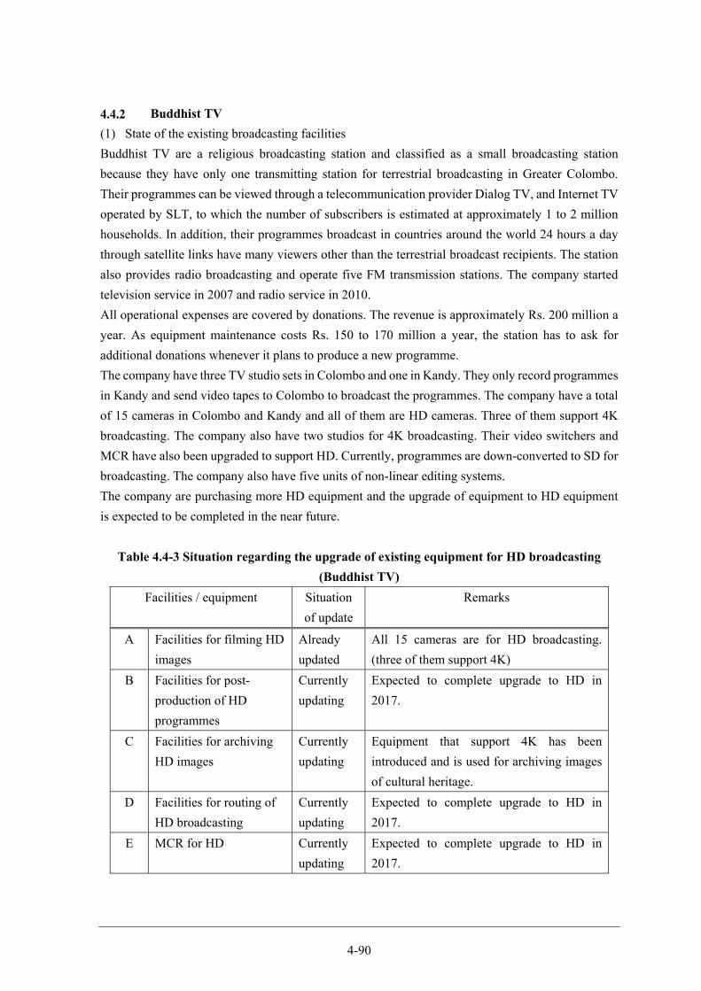
4-90
Buddhist TV
(1) State of the existing broadcasting facilities
Buddhist TV are a religious broadcasting station and classified as a small broadcasting station
because they have only one transmitting station for terrestrial broadcasting in Greater Colombo.
Their programmes can be viewed through a telecommunication provider Dialog TV, and Internet TV
operated by SLT, to which the number of subscribers is estimated at approximately 1 to 2 million
households. In addition, their programmes broadcast in countries around the world 24 hours a day
through satellite links have many viewers other than the terrestrial broadcast recipients. The station
also provides radio broadcasting and operate five FM transmission stations. The company started
television service in 2007 and radio service in 2010.
All operational expenses are covered by donations. The revenue is approximately Rs. 200 million a
year. As equipment maintenance costs Rs. 150 to 170 million a year, the station has to ask for
additional donations whenever it plans to produce a new programme.
The company have three TV studio sets in Colombo and one in Kandy. They only record programmes
in Kandy and send video tapes to Colombo to broadcast the programmes. The company have a total
of 15 cameras in Colombo and Kandy and all of them are HD cameras. Three of them support 4K
broadcasting. The company also have two studios for 4K broadcasting. Their video switchers and
MCR have also been upgraded to support HD. Currently, programmes are down-converted to SD for
broadcasting. The company also have five units of non-linear editing systems.
The company are purchasing more HD equipment and the upgrade of equipment to HD equipment
is expected to be completed in the near future.
Table 4.4-3 Situation regarding the upgrade of existing equipment for HD broadcasting
(Buddhist TV)
Facilities / equipment Situation
of update
Remarks
A Facilities for filming HD
images
Already
updated
All 15 cameras are for HD broadcasting.
(three of them support 4K)
B Facilities for post-
production of HD
programmes
Currently
updating
Expected to complete upgrade to HD in
2017.
C Facilities for archiving
HD images
Currently
updating
Equipment that support 4K has been
introduced and is used for archiving images
of cultural heritage.
D Facilities for routing of
HD broadcasting
Currently
updating
Expected to complete upgrade to HD in
2017.
E MCR for HD Currently
updating
Expected to complete upgrade to HD in
2017.
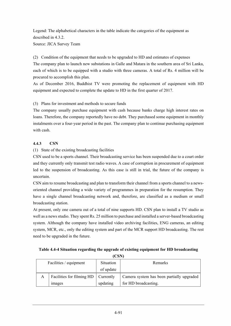
4-91
Legend: The alphabetical characters in the table indicate the categories of the equipment as
described in 4.3.2.
Source: JICA Survey Team
(2) Condition of the equipment that needs to be upgraded to HD and estimates of expenses
The company plan to launch new substations in Galle and Matara in the southern area of Sri Lanka,
each of which is to be equipped with a studio with three cameras. A total of Rs. 4 million will be
procured to accomplish this plan.
As of December 2016, Buddhist TV were promoting the replacement of equipment with HD
equipment and expected to complete the update to HD in the first quarter of 2017.
(3) Plans for investment and methods to secure funds
The company usually purchase equipment with cash because banks charge high interest rates on
loans. Therefore, the company reportedly have no debt. They purchased some equipment in monthly
instalments over a four-year period in the past. The company plan to continue purchasing equipment
with cash.
CSN
(1) State of the existing broadcasting facilities
CSN used to be a sports channel. Their broadcasting service has been suspended due to a court order
and they currently only transmit test radio waves. A case of corruption in procurement of equipment
led to the suspension of broadcasting. As this case is still in trial, the future of the company is
uncertain.
CSN aim to resume broadcasting and plan to transform their channel from a sports channel to a news-
oriented channel providing a wide variety of programmes in preparation for the resumption. They
have a single channel broadcasting network and, therefore, are classified as a medium or small
broadcasting station.
At present, only one camera out of a total of nine supports HD. CSN plan to install a TV studio as
well as a news studio. They spent Rs. 25 million to purchase and installed a server-based broadcasting
system. Although the company have installed video archiving facilities, ENG cameras, an editing
system, MCR, etc., only the editing system and part of the MCR support HD broadcasting. The rest
need to be upgraded in the future.
Table 4.4-4 Situation regarding the upgrade of existing equipment for HD broadcasting
(CSN)
Facilities / equipment Situation
of update
Remarks
A Facilities for filming HD
images
Currently
updating
Camera system has been partially upgraded
for HD broadcasting.

4-92
Facilities / equipment Situation
of update
Remarks
B Facilities for post-
production of HD
programmes
Currently
updating
C Facilities for archiving
HD images
Not started
D Facilities for routing of
HD broadcasting
Not started
E MCR for HD Already
updated
Legend: The alphabetical characters in the table indicate the categories of the equipment as
described in 4.3.2.
Source: JICA Survey Team
(2) Condition of the equipment that needs to be upgraded to HD and estimates of expenses
Although it is uncertain whether CSN can restart broadcasting, the migration into HD of CSN by
DSO-HD of DBNO can be performed in five stages as shown in the table below.
First of all, the TV studio will be upgraded to HD and the editing system will follow suit at a later
date. Then, the news studio, video archiving facilities and routing facilities will be upgraded to HD
in this order. With this schedule, the upgrading will be completed by DSO-HD. JICA Survey Team
estimated the cost of the upgrade at USD 500,000, while CSN estimate it at Rs. 200 million, implying
that CSN’s estimate is approximately twice JICA Survey Team’s estimates. It has not been possible
to conclude that CSN’s estimate is too much without knowledge of the contents and range of the
upgrade considered by CSN in the estimation. It is necessary to continue monitoring if the
broadcasting will be restarted.
Table 4.4-5 Condition of facilities that need to be upgraded to HD and estimates of expenses
(CSN)
No Facilities / equipment Quantity
Estimated expenses (thousand
USD)
Scheduled year of
completion
1 A Facilities for filming HD images (news studio equipment)
1 lot 155 2020
2 A Facilities for filming HD images (TV studio equipment)
1 lot 205 2018
3 B Facilities for post-production of HD programmes
1 lot 91 2019
4 C Facilities for archiving HD images 1 lot 36 2021 5 D Facilities for routing of HD
broadcasting 1 lot 27 2022
Total 514
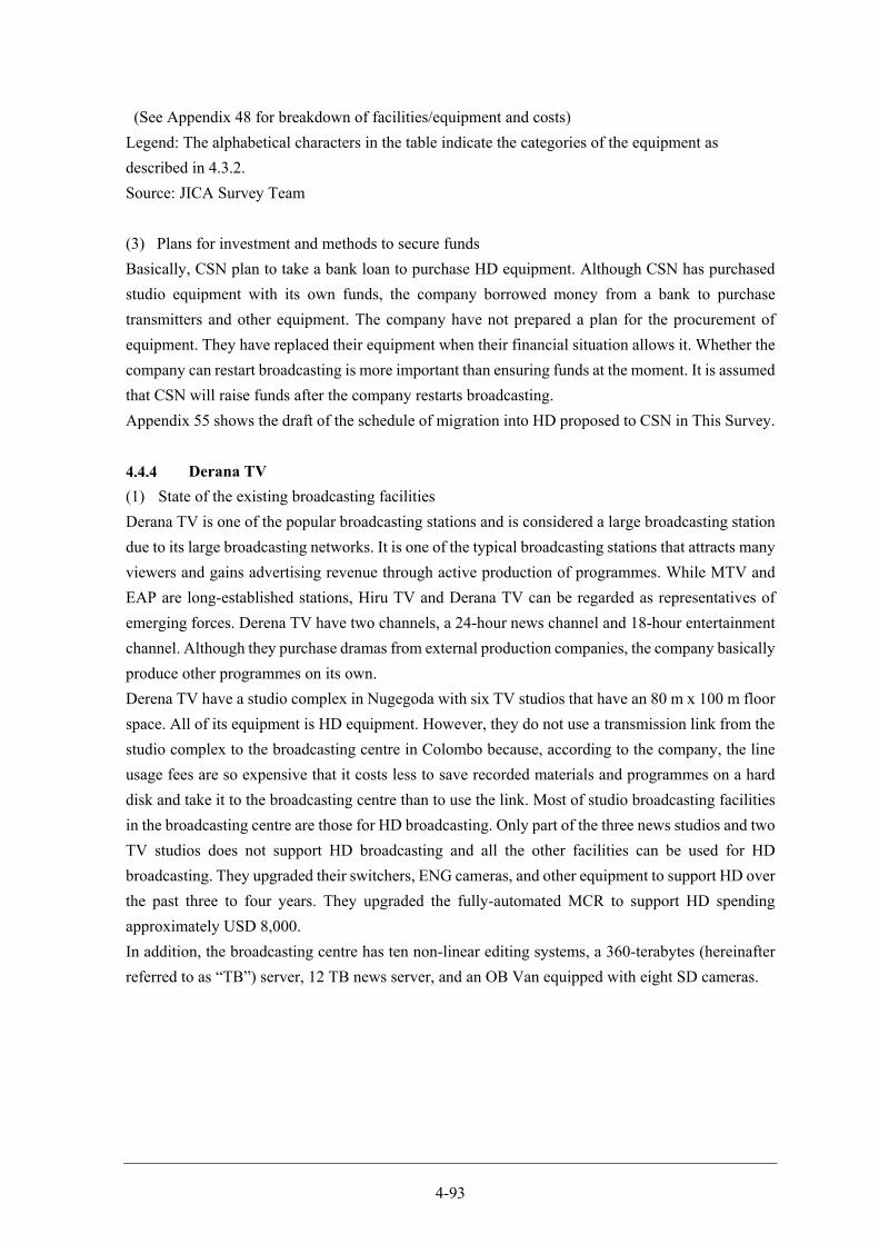
4-93
(See Appendix 48 for breakdown of facilities/equipment and costs)
Legend: The alphabetical characters in the table indicate the categories of the equipment as
described in 4.3.2.
Source: JICA Survey Team
(3) Plans for investment and methods to secure funds
Basically, CSN plan to take a bank loan to purchase HD equipment. Although CSN has purchased
studio equipment with its own funds, the company borrowed money from a bank to purchase
transmitters and other equipment. The company have not prepared a plan for the procurement of
equipment. They have replaced their equipment when their financial situation allows it. Whether the
company can restart broadcasting is more important than ensuring funds at the moment. It is assumed
that CSN will raise funds after the company restarts broadcasting.
Appendix 55 shows the draft of the schedule of migration into HD proposed to CSN in This Survey.
Derana TV
(1) State of the existing broadcasting facilities
Derana TV is one of the popular broadcasting stations and is considered a large broadcasting station
due to its large broadcasting networks. It is one of the typical broadcasting stations that attracts many
viewers and gains advertising revenue through active production of programmes. While MTV and
EAP are long-established stations, Hiru TV and Derana TV can be regarded as representatives of
emerging forces. Derena TV have two channels, a 24-hour news channel and 18-hour entertainment
channel. Although they purchase dramas from external production companies, the company basically
produce other programmes on its own.
Derena TV have a studio complex in Nugegoda with six TV studios that have an 80 m x 100 m floor
space. All of its equipment is HD equipment. However, they do not use a transmission link from the
studio complex to the broadcasting centre in Colombo because, according to the company, the line
usage fees are so expensive that it costs less to save recorded materials and programmes on a hard
disk and take it to the broadcasting centre than to use the link. Most of studio broadcasting facilities
in the broadcasting centre are those for HD broadcasting. Only part of the three news studios and two
TV studios does not support HD broadcasting and all the other facilities can be used for HD
broadcasting. They upgraded their switchers, ENG cameras, and other equipment to support HD over
the past three to four years. They upgraded the fully-automated MCR to support HD spending
approximately USD 8,000.
In addition, the broadcasting centre has ten non-linear editing systems, a 360-terabytes (hereinafter
referred to as “TB”) server, 12 TB news server, and an OB Van equipped with eight SD cameras.
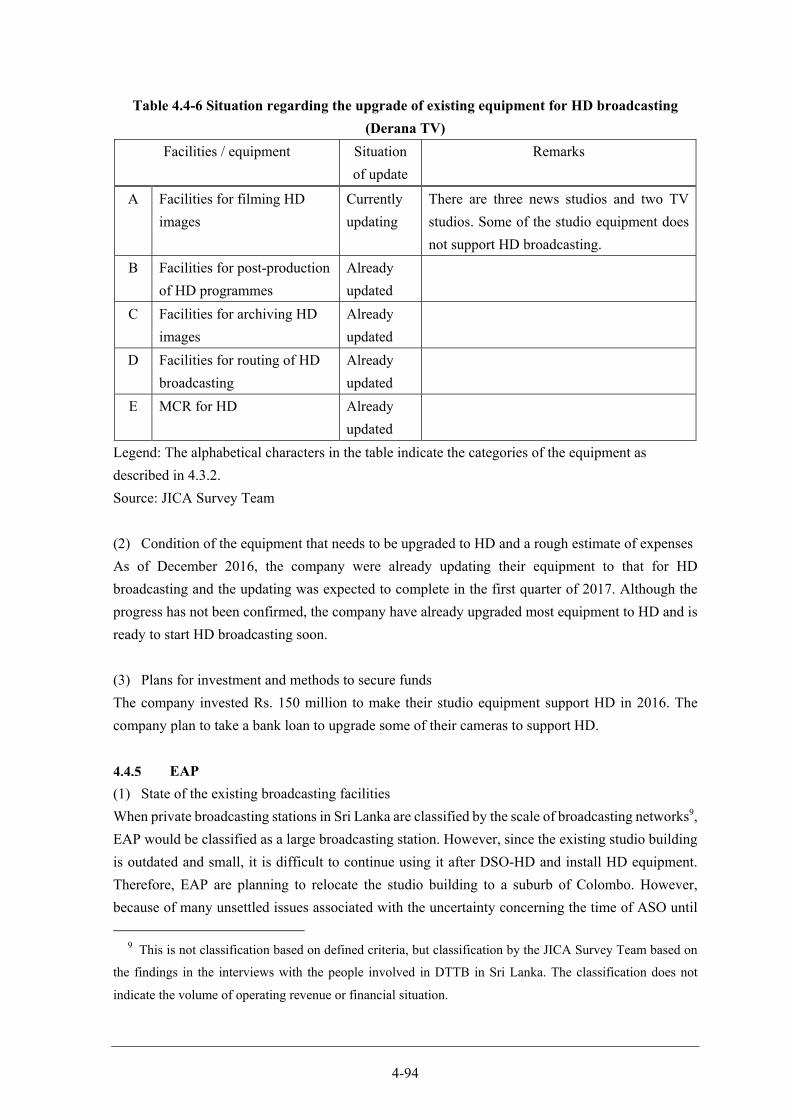
4-94
Table 4.4-6 Situation regarding the upgrade of existing equipment for HD broadcasting
(Derana TV)
Facilities / equipment Situation
of update
Remarks
A Facilities for filming HD
images
Currently
updating
There are three news studios and two TV
studios. Some of the studio equipment does
not support HD broadcasting.
B Facilities for post-production
of HD programmes
Already
updated
C Facilities for archiving HD
images
Already
updated
D Facilities for routing of HD
broadcasting
Already
updated
E MCR for HD Already
updated
Legend: The alphabetical characters in the table indicate the categories of the equipment as
described in 4.3.2.
Source: JICA Survey Team
(2) Condition of the equipment that needs to be upgraded to HD and a rough estimate of expenses
As of December 2016, the company were already updating their equipment to that for HD
broadcasting and the updating was expected to complete in the first quarter of 2017. Although the
progress has not been confirmed, the company have already upgraded most equipment to HD and is
ready to start HD broadcasting soon.
(3) Plans for investment and methods to secure funds
The company invested Rs. 150 million to make their studio equipment support HD in 2016. The
company plan to take a bank loan to upgrade some of their cameras to support HD.
EAP
(1) State of the existing broadcasting facilities
When private broadcasting stations in Sri Lanka are classified by the scale of broadcasting networks9,
EAP would be classified as a large broadcasting station. However, since the existing studio building
is outdated and small, it is difficult to continue using it after DSO-HD and install HD equipment.
Therefore, EAP are planning to relocate the studio building to a suburb of Colombo. However,
because of many unsettled issues associated with the uncertainty concerning the time of ASO until
9 This is not classification based on defined criteria, but classification by the JICA Survey Team based on
the findings in the interviews with the people involved in DTTB in Sri Lanka. The classification does not
indicate the volume of operating revenue or financial situation.
4-95
which the period of simultaneous broadcasting lasts, the scale of investment required for the
migration into DTTB, and the business model of DBNO, the company have been unable to determine
the time of relocation.
For this reason, as shown in Table 4.4-7, only the MCR has been upgraded to support HD. EAP
operate two studios: a news studio and a TV studio. Equipment required for filming HD images in
these studio is being purchased. The time of the installation of the rest of equipment in the studios
has not been decided yet.
Table 4.4-7 Situation regarding the upgrade of existing equipment for HD broadcasting
(EAP)
Facilities / equipment Situation
of update
Remarks
A Facilities for filming HD
images
Currently
updating
B Facilities for post-
production of HD
programmes
Not started Six sets of non-linear editing systems for SD
broadcasting are used. (three sets of an online
editing system connected to a server, and three
sets of an offline stand-alone system)
C Facilities for archiving
HD images
Not started
D Facilities for routing of
HD broadcasting
Not started
E MCR for HD Already
updated
An automatic transmission system with a
server ready for HD broadcasting has already
been introduced.
Legend: The alphabetical characters in the table indicate the categories of the equipment as
described in 4.3.2.
Source: JICA Survey Team
(2) Condition of the equipment that needs to be upgraded to HD and a rough estimate of expenses
EAP will need to procure various HD equipment in the future, for example, news and TV studio
facilities, HD cameras for field reporting, editing system, video archiving facilities, and routing
facilities.
First, the TV studio facilities will be upgraded to support HD. Then, equipment for field reporting,
editing equipment, and routing facilities will be upgraded. This upgrading will enable the minimum
required production and broadcasting of HD programmes. Then the news studio will be upgraded to
support HD and finally the video archiving facilities will be upgraded to complete the migration to
HD.
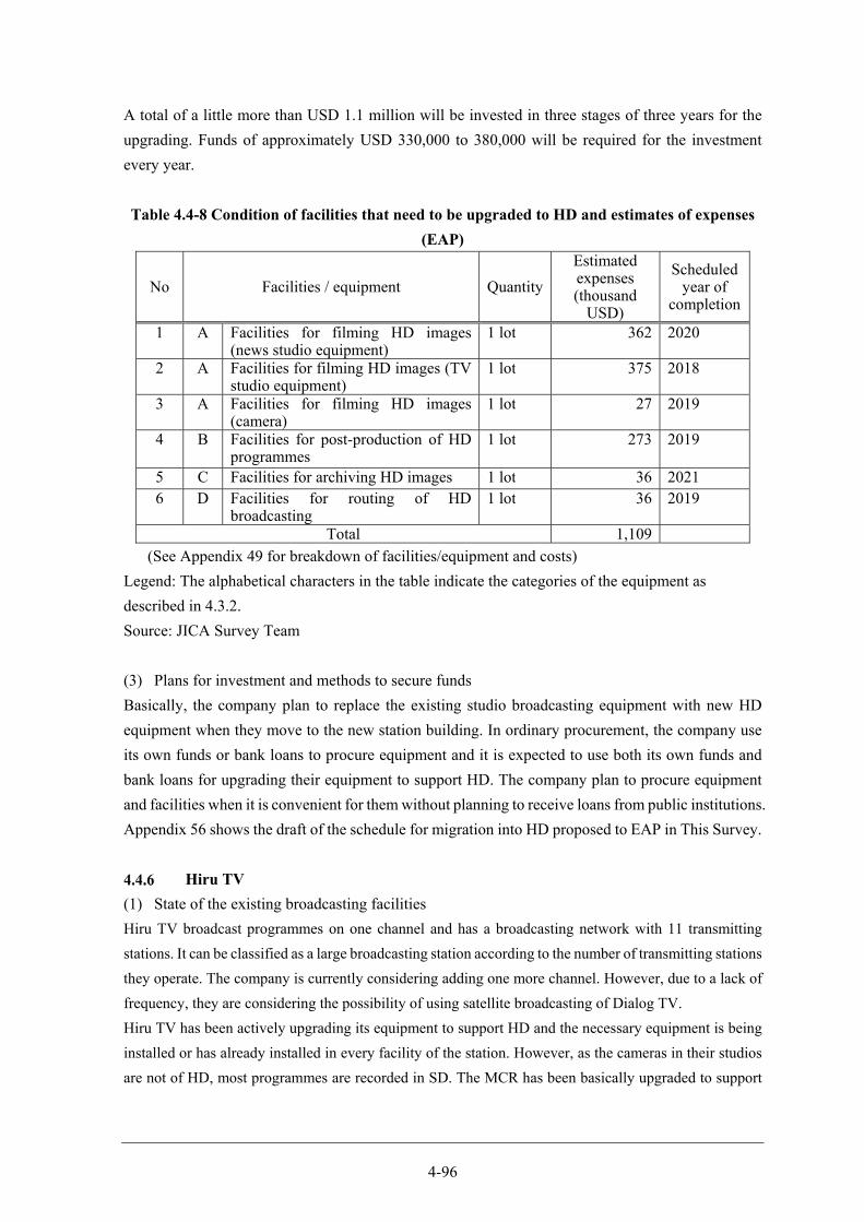
4-96
A total of a little more than USD 1.1 million will be invested in three stages of three years for the
upgrading. Funds of approximately USD 330,000 to 380,000 will be required for the investment
every year.
Table 4.4-8 Condition of facilities that need to be upgraded to HD and estimates of expenses
(EAP)
No Facilities / equipment Quantity
Estimated expenses (thousand
USD)
Scheduled year of
completion
1 A Facilities for filming HD images (news studio equipment)
1 lot 362 2020
2 A Facilities for filming HD images (TV studio equipment)
1 lot 375 2018
3 A Facilities for filming HD images (camera)
1 lot 27 2019
4 B Facilities for post-production of HD programmes
1 lot 273 2019
5 C Facilities for archiving HD images 1 lot 36 2021 6 D Facilities for routing of HD
broadcasting 1 lot 36 2019
Total 1,109
(See Appendix 49 for breakdown of facilities/equipment and costs)
Legend: The alphabetical characters in the table indicate the categories of the equipment as
described in 4.3.2.
Source: JICA Survey Team
(3) Plans for investment and methods to secure funds
Basically, the company plan to replace the existing studio broadcasting equipment with new HD
equipment when they move to the new station building. In ordinary procurement, the company use
its own funds or bank loans to procure equipment and it is expected to use both its own funds and
bank loans for upgrading their equipment to support HD. The company plan to procure equipment
and facilities when it is convenient for them without planning to receive loans from public institutions.
Appendix 56 shows the draft of the schedule for migration into HD proposed to EAP in This Survey.
Hiru TV
(1) State of the existing broadcasting facilities
Hiru TV broadcast programmes on one channel and has a broadcasting network with 11 transmitting
stations. It can be classified as a large broadcasting station according to the number of transmitting stations
they operate. The company is currently considering adding one more channel. However, due to a lack of
frequency, they are considering the possibility of using satellite broadcasting of Dialog TV.
Hiru TV has been actively upgrading its equipment to support HD and the necessary equipment is being
installed or has already installed in every facility of the station. However, as the cameras in their studios
are not of HD, most programmes are recorded in SD. The MCR has been basically upgraded to support
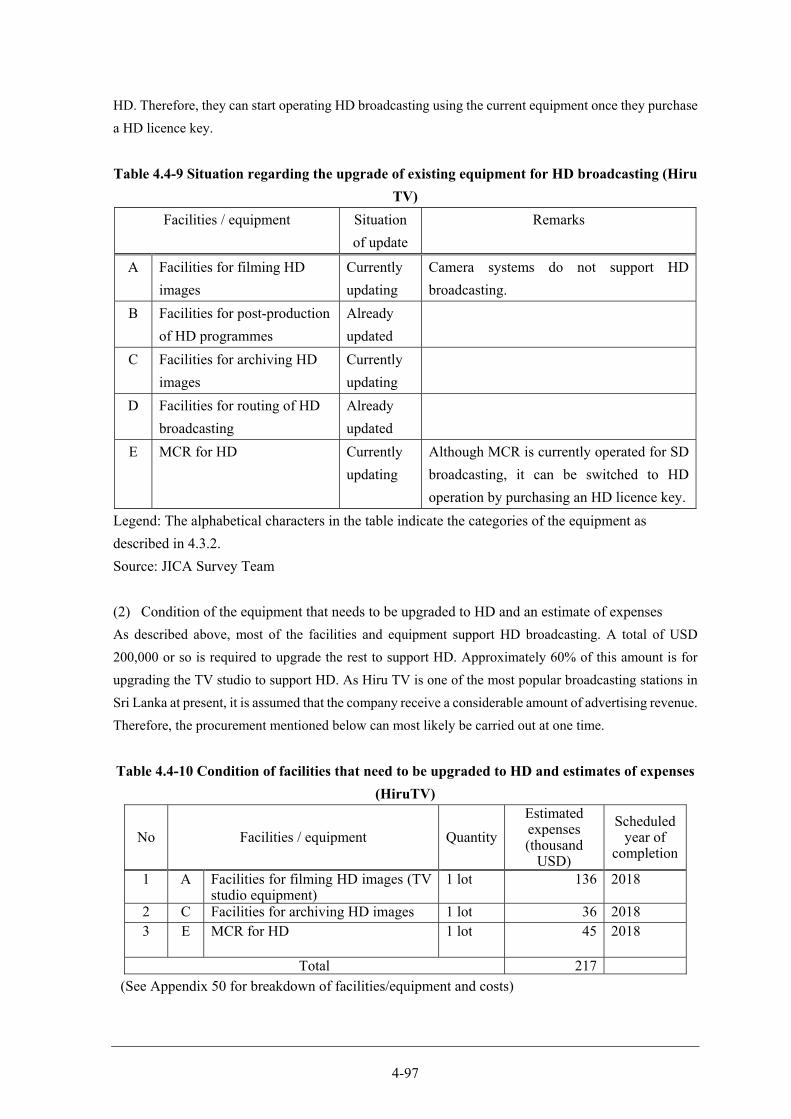
4-97
HD. Therefore, they can start operating HD broadcasting using the current equipment once they purchase
a HD licence key.
Table 4.4-9 Situation regarding the upgrade of existing equipment for HD broadcasting (Hiru
TV)
Facilities / equipment Situation
of update
Remarks
A Facilities for filming HD
images
Currently
updating
Camera systems do not support HD
broadcasting.
B Facilities for post-production
of HD programmes
Already
updated
C Facilities for archiving HD
images
Currently
updating
D Facilities for routing of HD
broadcasting
Already
updated
E MCR for HD Currently
updating
Although MCR is currently operated for SD
broadcasting, it can be switched to HD
operation by purchasing an HD licence key.
Legend: The alphabetical characters in the table indicate the categories of the equipment as
described in 4.3.2.
Source: JICA Survey Team
(2) Condition of the equipment that needs to be upgraded to HD and an estimate of expenses
As described above, most of the facilities and equipment support HD broadcasting. A total of USD
200,000 or so is required to upgrade the rest to support HD. Approximately 60% of this amount is for
upgrading the TV studio to support HD. As Hiru TV is one of the most popular broadcasting stations in
Sri Lanka at present, it is assumed that the company receive a considerable amount of advertising revenue.
Therefore, the procurement mentioned below can most likely be carried out at one time.
Table 4.4-10 Condition of facilities that need to be upgraded to HD and estimates of expenses
(HiruTV)
No Facilities / equipment Quantity
Estimated expenses (thousand
USD)
Scheduled year of
completion
1 A Facilities for filming HD images (TV studio equipment)
1 lot 136 2018
2 C Facilities for archiving HD images 1 lot 36 2018 3 E MCR for HD 1 lot 45 2018
Total 217
(See Appendix 50 for breakdown of facilities/equipment and costs)
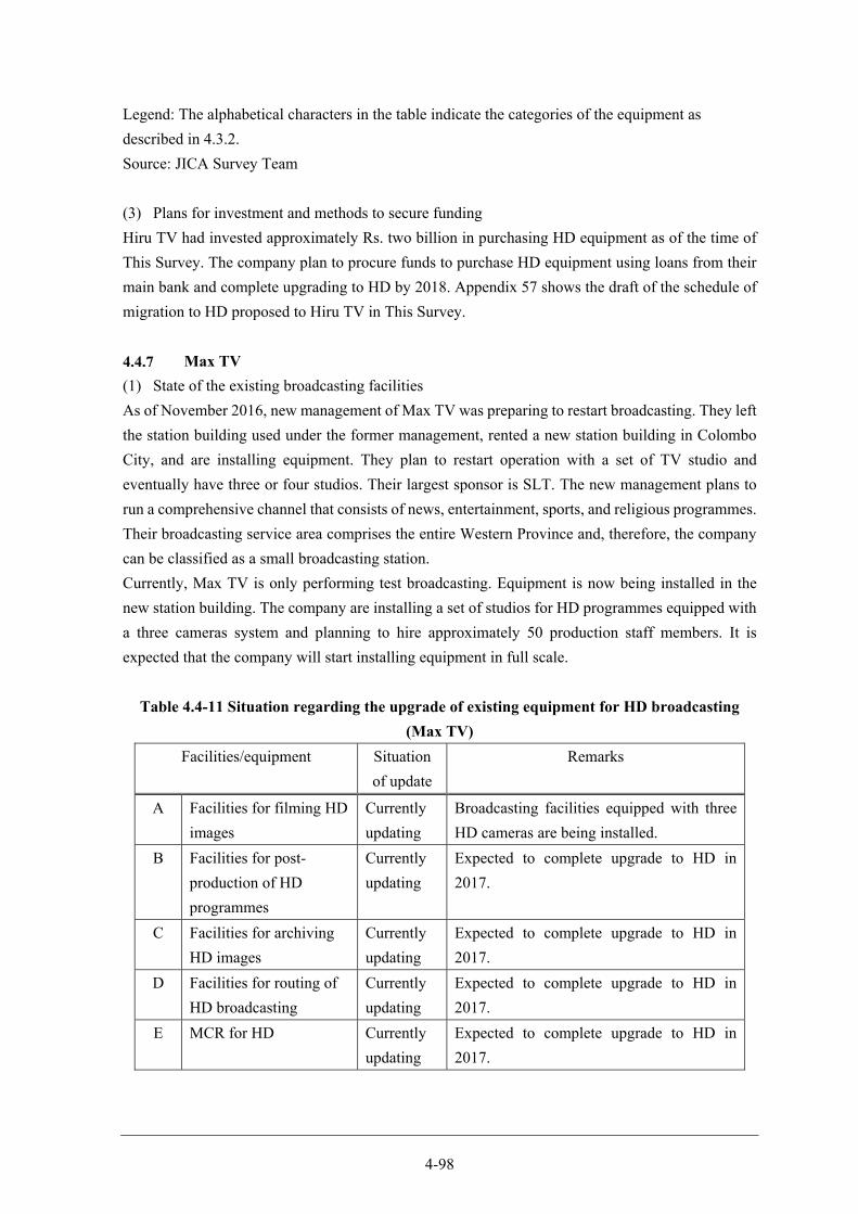
4-98
Legend: The alphabetical characters in the table indicate the categories of the equipment as
described in 4.3.2.
Source: JICA Survey Team
(3) Plans for investment and methods to secure funding
Hiru TV had invested approximately Rs. two billion in purchasing HD equipment as of the time of
This Survey. The company plan to procure funds to purchase HD equipment using loans from their
main bank and complete upgrading to HD by 2018. Appendix 57 shows the draft of the schedule of
migration to HD proposed to Hiru TV in This Survey.
Max TV
(1) State of the existing broadcasting facilities
As of November 2016, new management of Max TV was preparing to restart broadcasting. They left
the station building used under the former management, rented a new station building in Colombo
City, and are installing equipment. They plan to restart operation with a set of TV studio and
eventually have three or four studios. Their largest sponsor is SLT. The new management plans to
run a comprehensive channel that consists of news, entertainment, sports, and religious programmes.
Their broadcasting service area comprises the entire Western Province and, therefore, the company
can be classified as a small broadcasting station.
Currently, Max TV is only performing test broadcasting. Equipment is now being installed in the
new station building. The company are installing a set of studios for HD programmes equipped with
a three cameras system and planning to hire approximately 50 production staff members. It is
expected that the company will start installing equipment in full scale.
Table 4.4-11 Situation regarding the upgrade of existing equipment for HD broadcasting
(Max TV)
Facilities/equipment Situation
of update
Remarks
A Facilities for filming HD
images
Currently
updating
Broadcasting facilities equipped with three
HD cameras are being installed.
B Facilities for post-
production of HD
programmes
Currently
updating
Expected to complete upgrade to HD in
2017.
C Facilities for archiving
HD images
Currently
updating
Expected to complete upgrade to HD in
2017.
D Facilities for routing of
HD broadcasting
Currently
updating
Expected to complete upgrade to HD in
2017.
E MCR for HD Currently
updating
Expected to complete upgrade to HD in
2017.

4-99
Legend: The alphabetical characters in the table indicate the categories of the equipment as
described in 4.3.2.
Source: JICA Survey Team
(2) Condition of the equipment that needs to be upgraded to HD and estimates of expenses
As of February 2017, the company had already started to the replacement with HD equipment and
this process was expected to be completed in the third quarter of 2017. However, it is uncertain
whether this process can be achieved as expected because of large uncertainty concerning their staff
employment and fund raising. The status of management operations needs to be monitored
continuously.
(3) Plans for investment and methods to secure funding
Although the company plan to purchase HD equipment with its own funds, it is not known whether
they have a practical method for ensuring the funds.
MTV
(1) State of the existing broadcasting facilities
MTV have three channels and are classified as a large broadcasting station for their wide
broadcasting network. They are also Sri Lanka's representative broadcasting station and very popular
among viewers.
The company have two broadcasting facilities outside their head office in the suburb of Colombo.
The facilities in the Pannipitiya Broadcasting Centre located in the inland east of Colombo city are
somewhat old. The company also have the Stein Studio Complex in the south of Colombo. They
have ten TV studios in total and six of them are operated in the studio complex. Some facilities in
the Stein Studio Complex are equipped with SD-HD switchable cameras and switchers. However,
all facilities including MRC in the Pannipitiya Broadcasting Centre are for SD broadcasting. MTV
replace their studio equipment in an eight- to ten-year cycle. The currently used equipment does not
support HD and is becoming outdated. The company own 27 cameras in total and all of its
programmes are currently filmed and produced in SD.
In addition to these studio facilities, MTV own two OB Vans. Each OB Van is equipped with four
HD cameras. However, all the other equipment on the vans is of SD and the entire system including
equipment on OB Vans needs to be upgraded to support HD.
Although MTV operates three channels and have more facilities than other broadcasting companies,
most of its existing facilities is for SD broadcasting as shown in Table 4.4-12. MTV cannot achieve
full-HD operation unless the company upgrades these facilities and equipment to support HD.
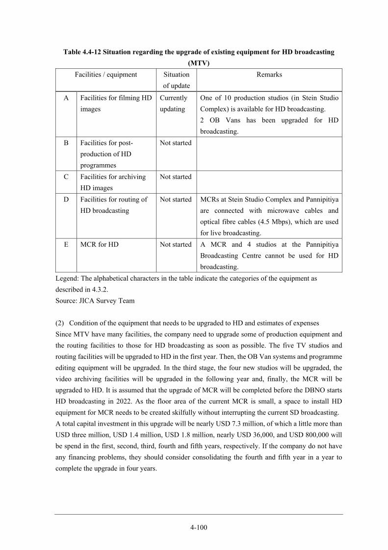
4-100
Table 4.4-12 Situation regarding the upgrade of existing equipment for HD broadcasting
(MTV)
Facilities / equipment Situation
of update
Remarks
A Facilities for filming HD
images
Currently
updating
One of 10 production studios (in Stein Studio
Complex) is available for HD broadcasting.
2 OB Vans has been upgraded for HD
broadcasting.
B Facilities for post-
production of HD
programmes
Not started
C Facilities for archiving
HD images
Not started
D Facilities for routing of
HD broadcasting
Not started MCRs at Stein Studio Complex and Pannipitiya
are connected with microwave cables and
optical fibre cables (4.5 Mbps), which are used
for live broadcasting.
E MCR for HD Not started A MCR and 4 studios at the Pannipitiya
Broadcasting Centre cannot be used for HD
broadcasting.
Legend: The alphabetical characters in the table indicate the categories of the equipment as
described in 4.3.2.
Source: JICA Survey Team
(2) Condition of the equipment that needs to be upgraded to HD and estimates of expenses
Since MTV have many facilities, the company need to upgrade some of production equipment and
the routing facilities to those for HD broadcasting as soon as possible. The five TV studios and
routing facilities will be upgraded to HD in the first year. Then, the OB Van systems and programme
editing equipment will be upgraded. In the third stage, the four new studios will be upgraded, the
video archiving facilities will be upgraded in the following year and, finally, the MCR will be
upgraded to HD. It is assumed that the upgrade of MCR will be completed before the DBNO starts
HD broadcasting in 2022. As the floor area of the current MCR is small, a space to install HD
equipment for MCR needs to be created skilfully without interrupting the current SD broadcasting.
A total capital investment in this upgrade will be nearly USD 7.3 million, of which a little more than
USD three million, USD 1.4 million, USD 1.8 million, nearly USD 36,000, and USD 800,000 will
be spend in the first, second, third, fourth and fifth years, respectively. If the company do not have
any financing problems, they should consider consolidating the fourth and fifth year in a year to
complete the upgrade in four years.
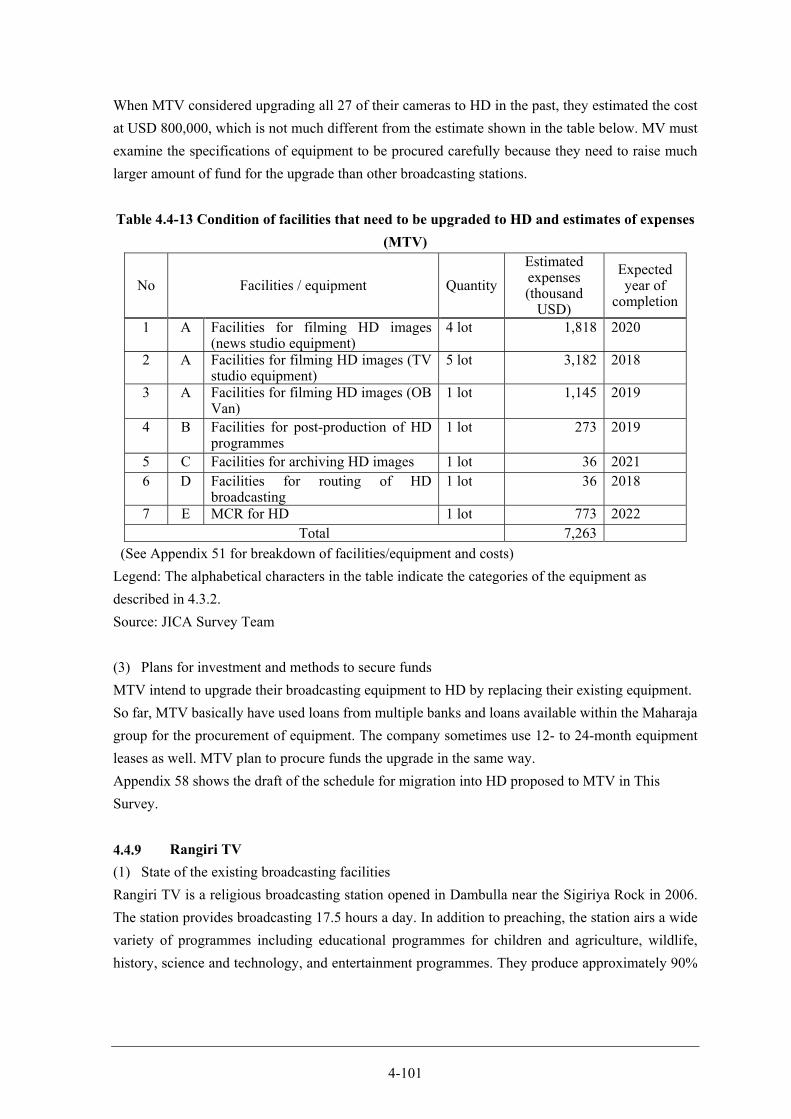
4-101
When MTV considered upgrading all 27 of their cameras to HD in the past, they estimated the cost
at USD 800,000, which is not much different from the estimate shown in the table below. MV must
examine the specifications of equipment to be procured carefully because they need to raise much
larger amount of fund for the upgrade than other broadcasting stations.
Table 4.4-13 Condition of facilities that need to be upgraded to HD and estimates of expenses
(MTV)
No Facilities / equipment Quantity
Estimated expenses (thousand
USD)
Expected year of
completion
1 A Facilities for filming HD images (news studio equipment)
4 lot 1,818 2020
2 A Facilities for filming HD images (TV studio equipment)
5 lot 3,182 2018
3 A Facilities for filming HD images (OB Van)
1 lot 1,145 2019
4 B Facilities for post-production of HD programmes
1 lot 273 2019
5 C Facilities for archiving HD images 1 lot 36 2021 6 D Facilities for routing of HD
broadcasting 1 lot 36 2018
7 E MCR for HD 1 lot 773 2022 Total 7,263
(See Appendix 51 for breakdown of facilities/equipment and costs)
Legend: The alphabetical characters in the table indicate the categories of the equipment as
described in 4.3.2.
Source: JICA Survey Team
(3) Plans for investment and methods to secure funds
MTV intend to upgrade their broadcasting equipment to HD by replacing their existing equipment.
So far, MTV basically have used loans from multiple banks and loans available within the Maharaja
group for the procurement of equipment. The company sometimes use 12- to 24-month equipment
leases as well. MTV plan to procure funds the upgrade in the same way.
Appendix 58 shows the draft of the schedule for migration into HD proposed to MTV in This
Survey.
Rangiri TV
(1) State of the existing broadcasting facilities
Rangiri TV is a religious broadcasting station opened in Dambulla near the Sigiriya Rock in 2006.
The station provides broadcasting 17.5 hours a day. In addition to preaching, the station airs a wide
variety of programmes including educational programmes for children and agriculture, wildlife,
history, science and technology, and entertainment programmes. They produce approximately 90%
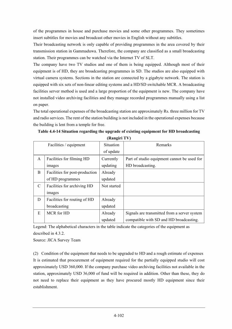
4-102
of the programmes in house and purchase movies and some other programmes. They sometimes
insert subtitles for movies and broadcast other movies in English without any subtitles.
Their broadcasting network is only capable of providing programmes in the area covered by their
transmission station in Gammaduwa. Therefore, the company are classified as a small broadcasting
station. Their programmes can be watched via the Internet TV of SLT.
The company have two TV studios and one of them is being equipped. Although most of their
equipment is of HD, they are broadcasting programmes in SD. The studios are also equipped with
virtual camera systems. Sections in the station are connected by a gigabyte network. The station is
equipped with six sets of non-linear editing systems and a HD/SD switchable MCR. A broadcasting
facilities server method is used and a large proportion of the equipment is new. The company have
not installed video archiving facilities and they manage recorded programmes manually using a list
on paper.
The total operational expenses of the broadcasting station are approximately Rs. three million for TV
and radio services. The rent of the station building is not included in the operational expenses because
the building is lent from a temple for free.
Table 4.4-14 Situation regarding the upgrade of existing equipment for HD broadcasting
(Rangiri TV)
Facilities / equipment Situation
of update
Remarks
A Facilities for filming HD
images
Currently
updating
Part of studio equipment cannot be used for
HD broadcasting.
B Facilities for post-production
of HD programmes
Already
updated
C Facilities for archiving HD
images
Not started
D Facilities for routing of HD
broadcasting
Already
updated
E MCR for HD Already
updated
Signals are transmitted from a server system
compatible with SD and HD broadcasting.
Legend: The alphabetical characters in the table indicate the categories of the equipment as
described in 4.3.2.
Source: JICA Survey Team
(2) Condition of the equipment that needs to be upgraded to HD and a rough estimate of expenses
It is estimated that procurement of equipment required for the partially equipped studio will cost
approximately USD 360,000. If the company purchase video archiving facilities not available in the
station, approximately USD 36,000 of fund will be required in addition. Other than these, they do
not need to replace their equipment as they have procured mostly HD equipment since their
establishment.
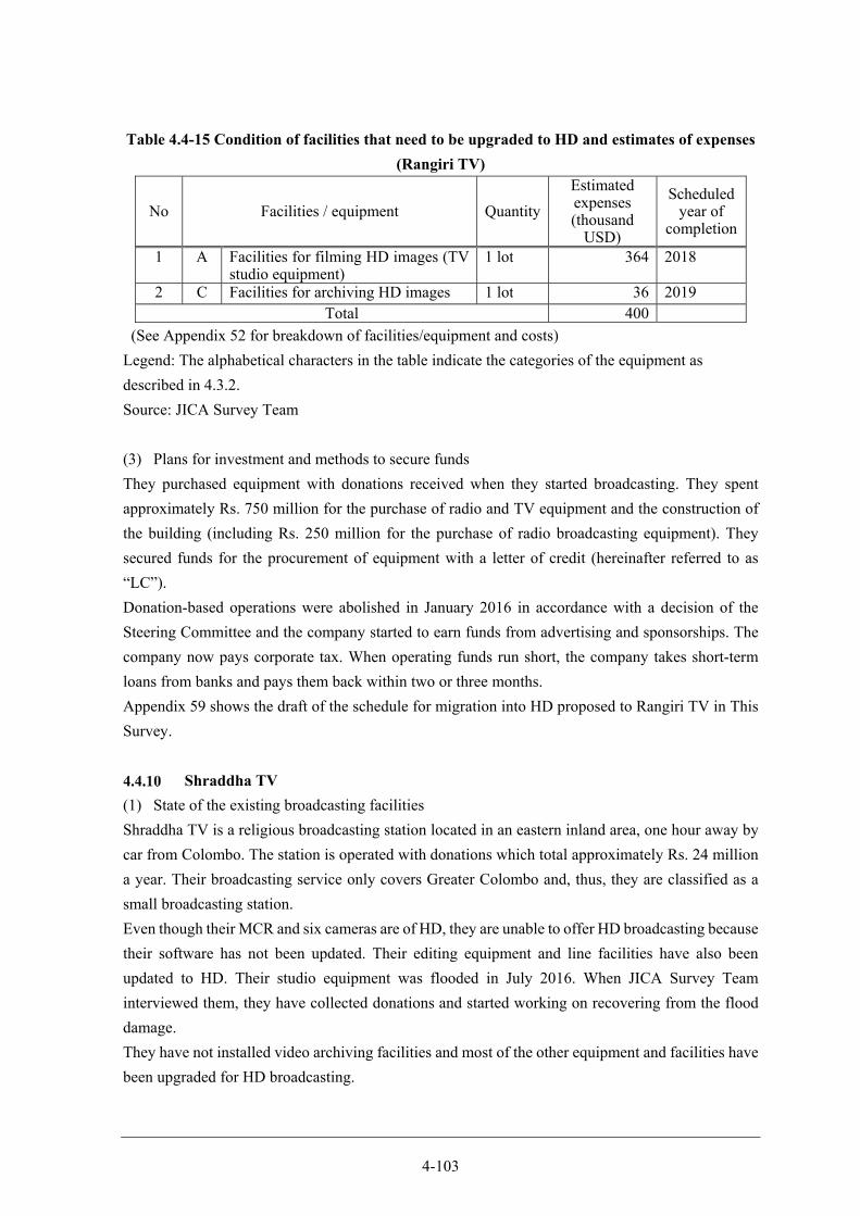
4-103
Table 4.4-15 Condition of facilities that need to be upgraded to HD and estimates of expenses
(Rangiri TV)
No Facilities / equipment Quantity
Estimated expenses (thousand
USD)
Scheduled year of
completion
1 A Facilities for filming HD images (TV studio equipment)
1 lot 364 2018
2 C Facilities for archiving HD images 1 lot 36 2019 Total 400
(See Appendix 52 for breakdown of facilities/equipment and costs)
Legend: The alphabetical characters in the table indicate the categories of the equipment as
described in 4.3.2.
Source: JICA Survey Team
(3) Plans for investment and methods to secure funds
They purchased equipment with donations received when they started broadcasting. They spent
approximately Rs. 750 million for the purchase of radio and TV equipment and the construction of
the building (including Rs. 250 million for the purchase of radio broadcasting equipment). They
secured funds for the procurement of equipment with a letter of credit (hereinafter referred to as
“LC”).
Donation-based operations were abolished in January 2016 in accordance with a decision of the
Steering Committee and the company started to earn funds from advertising and sponsorships. The
company now pays corporate tax. When operating funds run short, the company takes short-term
loans from banks and pays them back within two or three months.
Appendix 59 shows the draft of the schedule for migration into HD proposed to Rangiri TV in This
Survey.
Shraddha TV
(1) State of the existing broadcasting facilities
Shraddha TV is a religious broadcasting station located in an eastern inland area, one hour away by
car from Colombo. The station is operated with donations which total approximately Rs. 24 million
a year. Their broadcasting service only covers Greater Colombo and, thus, they are classified as a
small broadcasting station.
Even though their MCR and six cameras are of HD, they are unable to offer HD broadcasting because
their software has not been updated. Their editing equipment and line facilities have also been
updated to HD. Their studio equipment was flooded in July 2016. When JICA Survey Team
interviewed them, they have collected donations and started working on recovering from the flood
damage.
They have not installed video archiving facilities and most of the other equipment and facilities have
been upgraded for HD broadcasting.
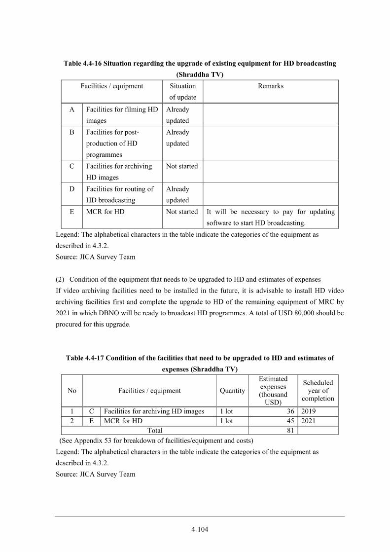
4-104
Table 4.4-16 Situation regarding the upgrade of existing equipment for HD broadcasting
(Shraddha TV)
Facilities / equipment Situation
of update
Remarks
A Facilities for filming HD
images
Already
updated
B Facilities for post-
production of HD
programmes
Already
updated
C Facilities for archiving
HD images
Not started
D Facilities for routing of
HD broadcasting
Already
updated
E MCR for HD Not started It will be necessary to pay for updating
software to start HD broadcasting.
Legend: The alphabetical characters in the table indicate the categories of the equipment as
described in 4.3.2.
Source: JICA Survey Team
(2) Condition of the equipment that needs to be upgraded to HD and estimates of expenses
If video archiving facilities need to be installed in the future, it is advisable to install HD video
archiving facilities first and complete the upgrade to HD of the remaining equipment of MRC by
2021 in which DBNO will be ready to broadcast HD programmes. A total of USD 80,000 should be
procured for this upgrade.
Table 4.4-17 Condition of the facilities that need to be upgraded to HD and estimates of
expenses (Shraddha TV)
No Facilities / equipment Quantity
Estimated expenses (thousand
USD)
Scheduled year of
completion
1 C Facilities for archiving HD images 1 lot 36 2019 2 E MCR for HD 1 lot 45 2021
Total 81
(See Appendix 53 for breakdown of facilities/equipment and costs)
Legend: The alphabetical characters in the table indicate the categories of the equipment as
described in 4.3.2.
Source: JICA Survey Team
4-105
(3) Plans for investment and methods to secure funds
Shraddha TV is registered as a non-profit organisation. The cost of electricity and rent for the tower
lent from SLT are practically their only major operational expenses. The rent for the tower is
approximately Rs. 300,000 per month. The company is facing severe financial difficulties to pay this
rent.
They mentioned that they had invested approximately Rs. 50 million to procure studio equipment.
In principle, no tax will be charged on purchase of equipment, but value-added tax (hereinafter
referred to as VAT) will applied to the equipment. The company plans to fund purchase of HD
broadcasting equipment and facilities with donations.
Appendix 60 shows the draft of the schedule for migration into HD proposed to Shraddha TV in This
Survey.
TNL
TNL broadcast programmes using one channel and have a broadcasting network including ten
transmitting stations. For the coverage of this network, TNL can be classified as a medium-size
broadcasting station.
As JICA Survey Team could not conduct an interview with them in This Survey, the status of operation
of the station or activities for the migration into DTTB are not clear.
VIS Broadcasting
(1) State of the existing broadcasting facilities
VIS Broadcasting, with assistance from CCTV, broadcast CCTV’s programmes in Colombo using
their terrestrial analogue TV broadcasting network. All expenses to purchase transmitters and
operation costs are provided by CCTV. The company do not provide nationwide broadcasting
because there is no frequency available for television broadcasting in Sri Lanka. They use 3kW
transmitters in a fully redundant configuration.
They also provide FM radio broadcasting as a member of the Sky Media Group.
(2) Condition of the equipment that needs to be upgraded to HD and a rough estimate of expenses
VIS Broadcasting have no equipment that needs to be upgraded to HD because they do not produce
any programmes. The initial investment to establish the current operations was Rs. 10 million and
the current monthly revenue is Rs. 1.8 million.
(3) Plans for investment and methods to secure funds
Expenses for the transmission facilities for terrestrial analogue TV broadcasting are paid in full by
CCTV. For this reason, VIS Broadcasting think that they will need to produce their own programmes
and broadcast them nationwide, if they decide to provide DTTB service.
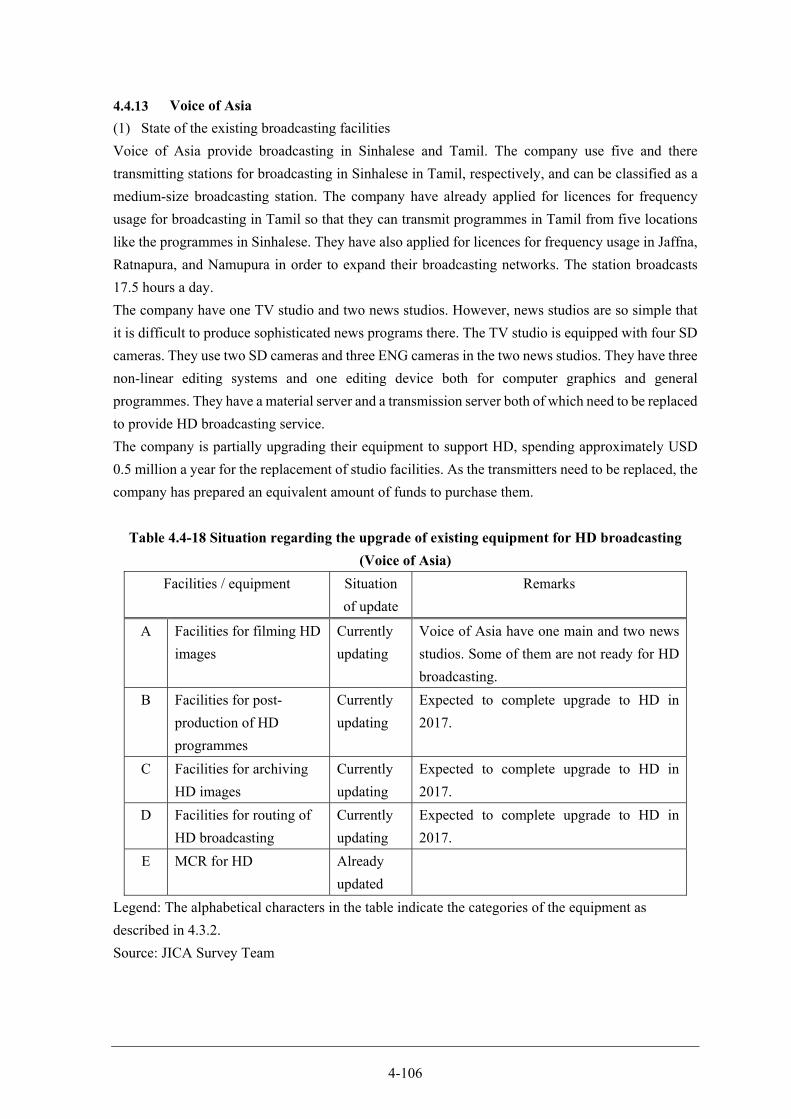
4-106
Voice of Asia
(1) State of the existing broadcasting facilities
Voice of Asia provide broadcasting in Sinhalese and Tamil. The company use five and there
transmitting stations for broadcasting in Sinhalese in Tamil, respectively, and can be classified as a
medium-size broadcasting station. The company have already applied for licences for frequency
usage for broadcasting in Tamil so that they can transmit programmes in Tamil from five locations
like the programmes in Sinhalese. They have also applied for licences for frequency usage in Jaffna,
Ratnapura, and Namupura in order to expand their broadcasting networks. The station broadcasts
17.5 hours a day.
The company have one TV studio and two news studios. However, news studios are so simple that
it is difficult to produce sophisticated news programs there. The TV studio is equipped with four SD
cameras. They use two SD cameras and three ENG cameras in the two news studios. They have three
non-linear editing systems and one editing device both for computer graphics and general
programmes. They have a material server and a transmission server both of which need to be replaced
to provide HD broadcasting service.
The company is partially upgrading their equipment to support HD, spending approximately USD
0.5 million a year for the replacement of studio facilities. As the transmitters need to be replaced, the
company has prepared an equivalent amount of funds to purchase them.
Table 4.4-18 Situation regarding the upgrade of existing equipment for HD broadcasting
(Voice of Asia)
Facilities / equipment Situation
of update
Remarks
A Facilities for filming HD
images
Currently
updating
Voice of Asia have one main and two news
studios. Some of them are not ready for HD
broadcasting.
B Facilities for post-
production of HD
programmes
Currently
updating
Expected to complete upgrade to HD in
2017.
C Facilities for archiving
HD images
Currently
updating
Expected to complete upgrade to HD in
2017.
D Facilities for routing of
HD broadcasting
Currently
updating
Expected to complete upgrade to HD in
2017.
E MCR for HD Already
updated
Legend: The alphabetical characters in the table indicate the categories of the equipment as
described in 4.3.2.
Source: JICA Survey Team
4-107
(2) Condition of the equipment that needs to be upgraded to HD
As of April 2017, the company had already started to replace their equipment with HD equipment
and the migration into HD was expected to be completed by the end of 2017. However, the progress
of the replacement has not been confirmed. At the time of the survey in August 2016, the company
planned to spend USD 4 to 5 million to upgrade their equipment to HD. However, their business
situation seems to have changed and their progress cannot be confirmed.
(3) Plans for investment and methods to secure funds
According to the company, they replaced their equipment with HD equipment using USD 2 to 3
million bank loans. They plan to use bank loans as the main funding source for the purchase of
equipment in the future while considering the use monthly instalment schemes offered by
manufacturers.
Outline of HD broadcasting equipment
Some of the large broadcasters such as EAP and MTV for which the timing of equipment replacement
will coincide with the migration into DTTB will conduct replacement of equipment for HD
broadcasting in full scale. On the other hand, as newly-established broadcasters seem to have started
installing new equipment, some or a large portion of their equipment is already of HD.
Many broadcasters plan to use bank loans or their own funds to finance purchase of HD equipment
and facilities. Therefore, there is no necessity for a special financing scheme for private broadcasting
stations.
Table 4.4-19 outlines the preparation for DSO-HD of the private broadcasting stations.

4-108
Table 4.4-19 Outline of the situation regarding HD broadcasting equipment of private
broadcasting stations

Chapter 5 Optimization for antenna mast of Lotus Tower
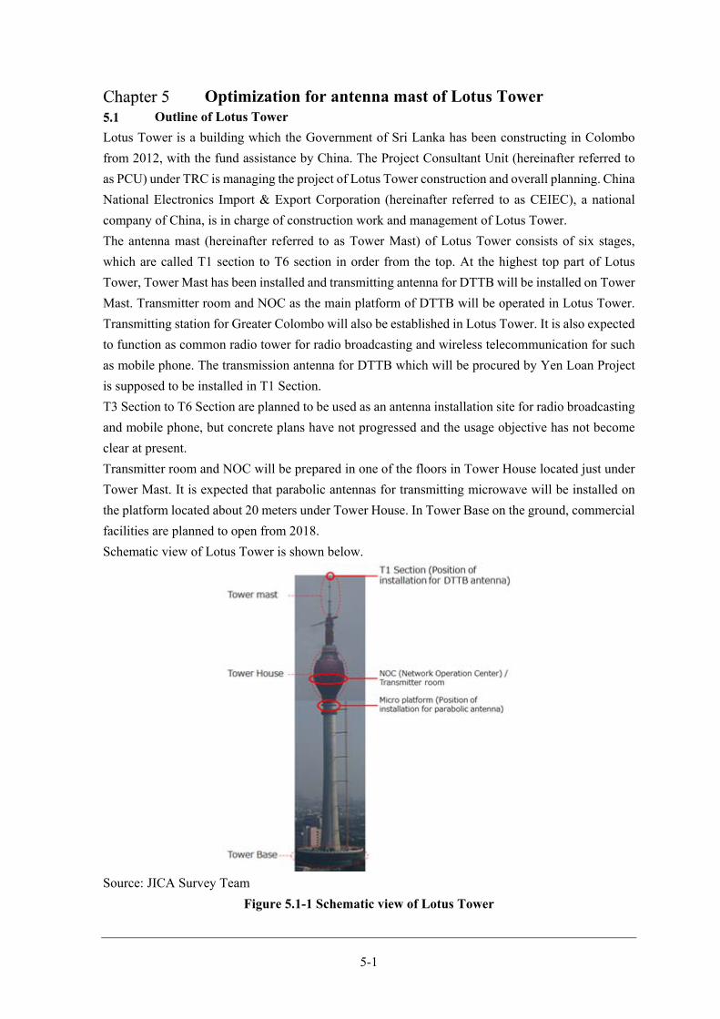
5-1
Optimization for antenna mast of Lotus Tower Outline of Lotus Tower
Lotus Tower is a building which the Government of Sri Lanka has been constructing in Colombo
from 2012, with the fund assistance by China. The Project Consultant Unit (hereinafter referred to
as PCU) under TRC is managing the project of Lotus Tower construction and overall planning. China
National Electronics Import & Export Corporation (hereinafter referred to as CEIEC), a national
company of China, is in charge of construction work and management of Lotus Tower.
The antenna mast (hereinafter referred to as Tower Mast) of Lotus Tower consists of six stages,
which are called T1 section to T6 section in order from the top. At the highest top part of Lotus
Tower, Tower Mast has been installed and transmitting antenna for DTTB will be installed on Tower
Mast. Transmitter room and NOC as the main platform of DTTB will be operated in Lotus Tower.
Transmitting station for Greater Colombo will also be established in Lotus Tower. It is also expected
to function as common radio tower for radio broadcasting and wireless telecommunication for such
as mobile phone. The transmission antenna for DTTB which will be procured by Yen Loan Project
is supposed to be installed in T1 Section.
T3 Section to T6 Section are planned to be used as an antenna installation site for radio broadcasting
and mobile phone, but concrete plans have not progressed and the usage objective has not become
clear at present.
Transmitter room and NOC will be prepared in one of the floors in Tower House located just under
Tower Mast. It is expected that parabolic antennas for transmitting microwave will be installed on
the platform located about 20 meters under Tower House. In Tower Base on the ground, commercial
facilities are planned to open from 2018.
Schematic view of Lotus Tower is shown below.
Source: JICA Survey Team
Figure 5.1-1 Schematic view of Lotus Tower
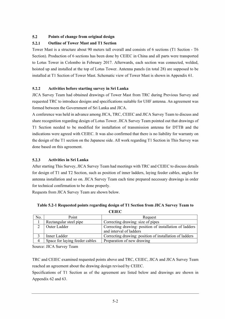
5-2
Points of change from original design
Outline of Tower Mast and T1 Section
Tower Mast is a structure about 90 meters tall overall and consists of 6 sections (T1 Section - T6
Section). Production of 6 sections has been done by CEIEC in China and all parts were transported
to Lotus Tower in Colombo in February 2017. Afterwards, each section was connected, welded,
hoisted up and installed at the top of Lotus Tower. Antenna panels (in total 28) are supposed to be
installed at T1 Section of Tower Mast. Schematic view of Tower Mast is shown in Appendix 61.
Activities before starting survey in Sri Lanka
JICA Survey Team had obtained drawings of Tower Mast from TRC during Previous Survey and
requested TRC to introduce designs and specifications suitable for UHF antenna. An agreement was
formed between the Government of Sri Lanka and JICA.
A conference was held in advance among JICA, TRC, CEIEC and JICA Survey Team to discuss and
share recognition regarding design of Lotus Tower. JICA Survey Team pointed out that drawings of
T1 Section needed to be modified for installation of transmission antenna for DTTB and the
indications were agreed with CEIEC. It was also confirmed that there is no liability for warranty on
the design of the T1 section on the Japanese side. All work regarding T1 Section in This Survey was
done based on this agreement.
Activities in Sri Lanka
After starting This Survey, JICA Survey Team had meetings with TRC and CEIEC to discuss details
for design of T1 and T2 Section, such as position of inner ladders, laying feeder cables, angles for
antenna installation and so on. JICA Survey Team each time prepared necessary drawings in order
for technical confirmation to be done properly.
Requests from JICA Survey Team are shown below.
Table 5.2-1 Requested points regarding design of T1 Section from JICA Survey Team to
CEIEC No. Point Request1 Rectangular steel pipe Correcting drawing: size of pipes 2 Outer Ladder Correcting drawing: position of installation of ladders
and interval of ladders3 Inner Ladder Correcting drawing: position of installation of ladders4 Space for laying feeder cables Preparation of new drawing
Source: JICA Survey Team
TRC and CEIEC examined requested points above and TRC, CEIEC, JICA and JICA Survey Team
reached an agreement about the drawing design revised by CEIEC.
Specifications of T1 Section as of the agreement are listed below and drawings are shown in
Appendix 62 and 63.

5-3
Table 5.2-2 Specification of T1 Section
No. Item Dimension Remarks
1 Height of Lotus Tower 350 m Height from ground
2 Height of T1 Section 10.5 m
3 External form of T1
Section
650 mm (Wall thickness of
rectangular steel pipe: 30
mm
Including scaffold steps for
outside work and inside work
4 Antenna model 4 dipole antenna
5 Antenna panel 8.8.4.8 Number of antenna panel for
each direction
6 Direction of antenna 79,169,259,349 Angle from true north
7 Kind of cables HF- 120D 2
HF- 20D 28
Main feeder cable /
Branch feeder cable
8 2 distributer 120D- 77D (4:3) 2
9 6 distributer 77D- 20D 2
10 8 distributer 77D- 20D 2
Source: JICA Survey Team
Result of inspection on T1 Section implemented in China
From 17th to 22nd December 2016, JICA Survey Team implemented an inspection of T1 Section at
CEIEC’s factory in Langfang, China, as an opportunity of confirmation before transport to Colombo.
The purpose of this inspection was to confirm whether the contents agreed in Table 5.2-2 were
accurately reflected in the T1 section manufacturing as well as existence of trouble which were not
be found from the drawings. This inspection was also implemented as the opportunity to correct the
parts which might be able to be dealt with only in the factory before shipment.
In the presence of engineers of PCU as owner and staff of CEIEC, JICA Survey Team measured
parts which were ready to be measured in T1 Section and confirmed whether manufacturing works
were implemented within the tolerance range, based on the drawings.
JICA Survey Team judged that there was no problem concerning the height, the outer shape and the
number of antenna stages of the T1 section. Meanwhile, JICA Survey Team pointed out that several
points were different from those of the drawings and TRC and CEIEC confirmed to implement
correction.
Table 5.3-1 shows requested points from JICA Survey Team. A picture of T1 Section as of the
inspection is shown in Appendix 64.
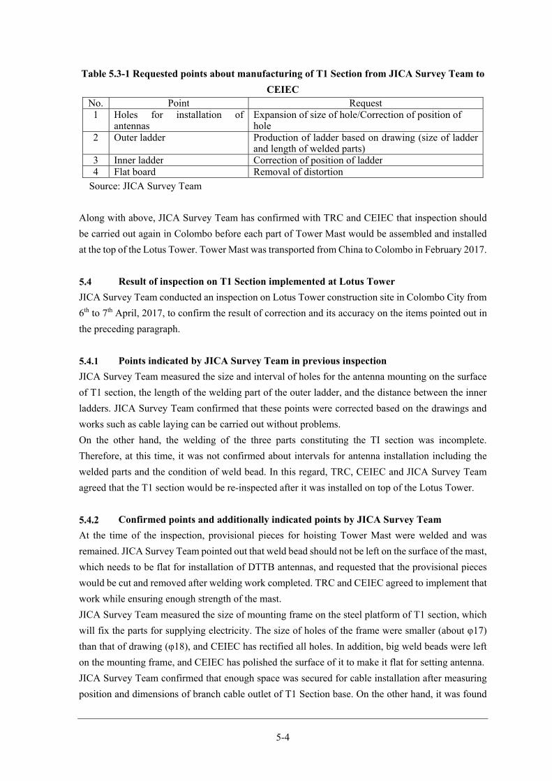
5-4
Table 5.3-1 Requested points about manufacturing of T1 Section from JICA Survey Team to
CEIEC No. Point Request1 Holes for installation of
antennas Expansion of size of hole/Correction of position of hole
2 Outer ladder Production of ladder based on drawing (size of ladder and length of welded parts)
3 Inner ladder Correction of position of ladder4 Flat board Removal of distortion
Source: JICA Survey Team
Along with above, JICA Survey Team has confirmed with TRC and CEIEC that inspection should
be carried out again in Colombo before each part of Tower Mast would be assembled and installed
at the top of the Lotus Tower. Tower Mast was transported from China to Colombo in February 2017.
Result of inspection on T1 Section implemented at Lotus Tower
JICA Survey Team conducted an inspection on Lotus Tower construction site in Colombo City from
6th to 7th April, 2017, to confirm the result of correction and its accuracy on the items pointed out in
the preceding paragraph.
Points indicated by JICA Survey Team in previous inspection
JICA Survey Team measured the size and interval of holes for the antenna mounting on the surface
of T1 section, the length of the welding part of the outer ladder, and the distance between the inner
ladders. JICA Survey Team confirmed that these points were corrected based on the drawings and
works such as cable laying can be carried out without problems.
On the other hand, the welding of the three parts constituting the TI section was incomplete.
Therefore, at this time, it was not confirmed about intervals for antenna installation including the
welded parts and the condition of weld bead. In this regard, TRC, CEIEC and JICA Survey Team
agreed that the T1 section would be re-inspected after it was installed on top of the Lotus Tower.
Confirmed points and additionally indicated points by JICA Survey Team
At the time of the inspection, provisional pieces for hoisting Tower Mast were welded and was
remained. JICA Survey Team pointed out that weld bead should not be left on the surface of the mast,
which needs to be flat for installation of DTTB antennas, and requested that the provisional pieces
would be cut and removed after welding work completed. TRC and CEIEC agreed to implement that
work while ensuring enough strength of the mast.
JICA Survey Team measured the size of mounting frame on the steel platform of T1 section, which
will fix the parts for supplying electricity. The size of holes of the frame were smaller (about φ17)
than that of drawing (φ18), and CEIEC has rectified all holes. In addition, big weld beads were left
on the mounting frame, and CEIEC has polished the surface of it to make it flat for setting antenna.
JICA Survey Team confirmed that enough space was secured for cable installation after measuring
position and dimensions of branch cable outlet of T1 Section base. On the other hand, it was found
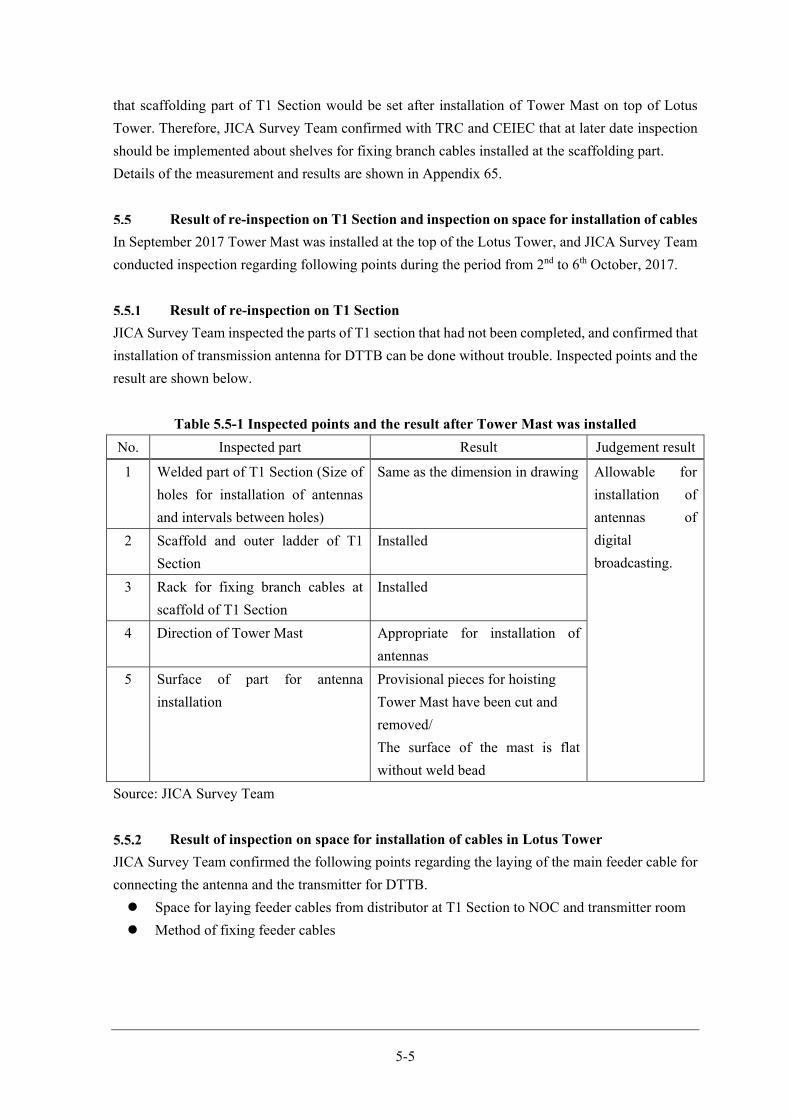
5-5
that scaffolding part of T1 Section would be set after installation of Tower Mast on top of Lotus
Tower. Therefore, JICA Survey Team confirmed with TRC and CEIEC that at later date inspection
should be implemented about shelves for fixing branch cables installed at the scaffolding part.
Details of the measurement and results are shown in Appendix 65.
Result of re-inspection on T1 Section and inspection on space for installation of cables
In September 2017 Tower Mast was installed at the top of the Lotus Tower, and JICA Survey Team
conducted inspection regarding following points during the period from 2nd to 6th October, 2017.
Result of re-inspection on T1 Section
JICA Survey Team inspected the parts of T1 section that had not been completed, and confirmed that
installation of transmission antenna for DTTB can be done without trouble. Inspected points and the
result are shown below.
Table 5.5-1 Inspected points and the result after Tower Mast was installed
No. Inspected part Result Judgement result
1 Welded part of T1 Section (Size of
holes for installation of antennas
and intervals between holes)
Same as the dimension in drawing Allowable for
installation of
antennas of
digital
broadcasting.
2 Scaffold and outer ladder of T1
Section
Installed
3 Rack for fixing branch cables at
scaffold of T1 Section
Installed
4 Direction of Tower Mast Appropriate for installation of
antennas
5 Surface of part for antenna
installation
Provisional pieces for hoisting
Tower Mast have been cut and
removed/
The surface of the mast is flat
without weld bead
Source: JICA Survey Team
Result of inspection on space for installation of cables in Lotus Tower
JICA Survey Team confirmed the following points regarding the laying of the main feeder cable for
connecting the antenna and the transmitter for DTTB.
Space for laying feeder cables from distributor at T1 Section to NOC and transmitter room
Method of fixing feeder cables
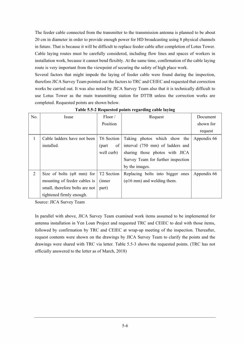
5-6
The feeder cable connected from the transmitter to the transmission antenna is planned to be about
20 cm in diameter in order to provide enough power for HD broadcasting using 8 physical channels
in future. That is because it will be difficult to replace feeder cable after completion of Lotus Tower.
Cable laying routes must be carefully considered, including flow lines and spaces of workers in
installation work, because it cannot bend flexibly. At the same time, confirmation of the cable laying
route is very important from the viewpoint of securing the safety of high place work.
Several factors that might impede the laying of feeder cable were found during the inspection,
therefore JICA Survey Team pointed out the factors to TRC and CEIEC and requested that correction
works be carried out. It was also noted by JICA Survey Team also that it is technically difficult to
use Lotus Tower as the main transmitting station for DTTB unless the correction works are
completed. Requested points are shown below.
Table 5.5-2 Requested points regarding cable laying
No. Issue Floor /
Position
Request Document
shown for
request
1 Cable ladders have not been
installed.
T6 Section
(part of
well curb)
Taking photos which show the
interval (750 mm) of ladders and
sharing those photos with JICA
Survey Team for further inspection
by the images.
Appendix 66
2 Size of bolts (φ8 mm) for
mounting of feeder cables is
small, therefore bolts are not
tightened firmly enough.
T2 Section
(inner
part)
Replacing bolts into bigger ones
(φ16 mm) and welding them.
Appendix 66
Source: JICA Survey Team
In parallel with above, JICA Survey Team examined work items assumed to be implemented for
antenna installation in Yen Loan Project and requested TRC and CEIEC to deal with those items,
followed by confirmation by TRC and CEIEC at wrap-up meeting of the inspection. Thereafter,
request contents were shown on the drawings by JICA Survey Team to clarify the points and the
drawings were shared with TRC via letter. Table 5.5-3 shows the requested points. (TRC has not
officially answered to the letter as of March, 2018)
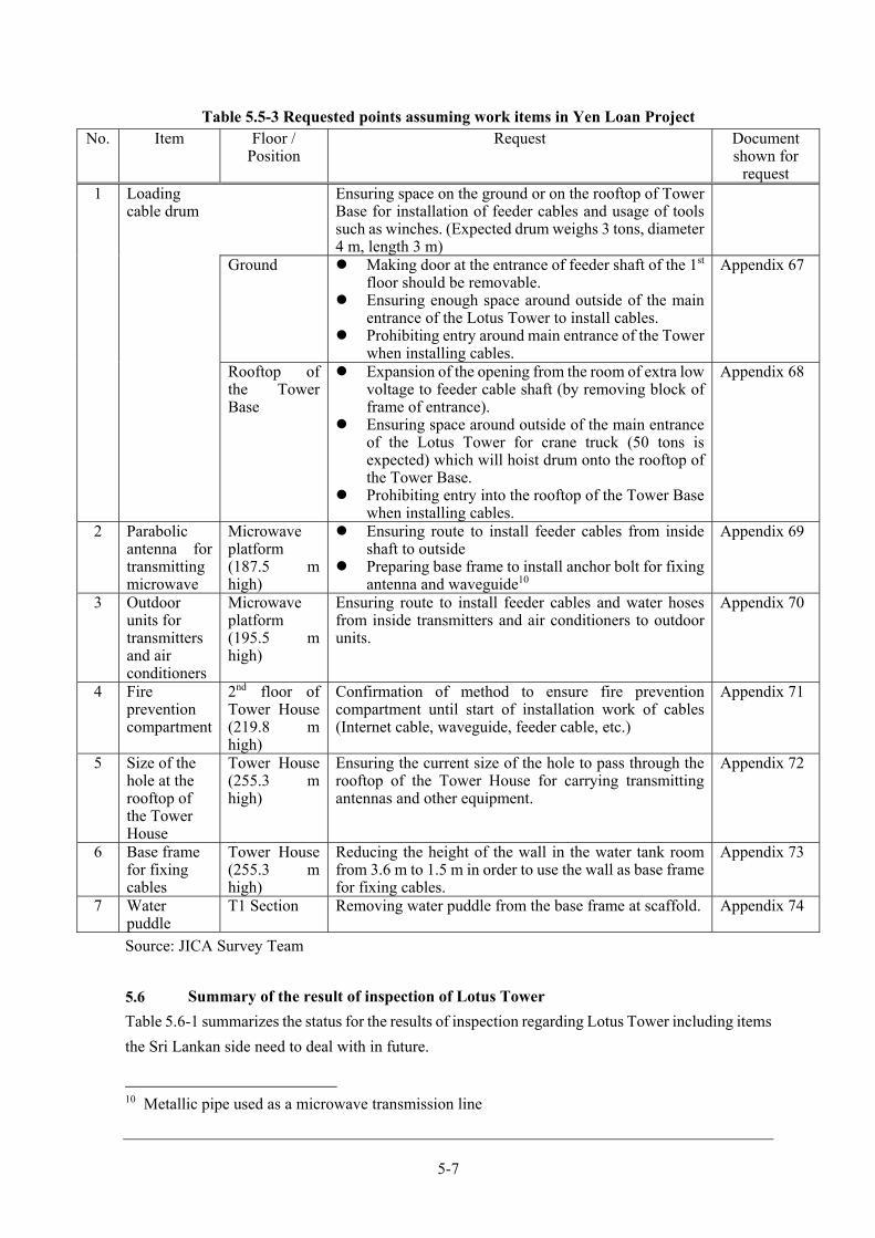
5-7
Table 5.5-3 Requested points assuming work items in Yen Loan Project No. Item Floor /
Position Request Document
shown for request
1 Loading cable drum
Ensuring space on the ground or on the rooftop of Tower Base for installation of feeder cables and usage of tools such as winches. (Expected drum weighs 3 tons, diameter 4 m, length 3 m)
Ground Making door at the entrance of feeder shaft of the 1st floor should be removable.
Ensuring enough space around outside of the main entrance of the Lotus Tower to install cables.
Prohibiting entry around main entrance of the Tower when installing cables.
Appendix 67
Rooftop of the Tower Base
Expansion of the opening from the room of extra low voltage to feeder cable shaft (by removing block of frame of entrance).
Ensuring space around outside of the main entrance of the Lotus Tower for crane truck (50 tons is expected) which will hoist drum onto the rooftop of the Tower Base.
Prohibiting entry into the rooftop of the Tower Base when installing cables.
Appendix 68
2 Parabolic antenna for transmitting microwave
Microwave platform (187.5 m high)
Ensuring route to install feeder cables from inside shaft to outside
Preparing base frame to install anchor bolt for fixing antenna and waveguide10
Appendix 69
3 Outdoor units for transmitters and air conditioners
Microwave platform (195.5 m high)
Ensuring route to install feeder cables and water hoses from inside transmitters and air conditioners to outdoor units.
Appendix 70
4 Fire prevention compartment
2nd floor of Tower House (219.8 m high)
Confirmation of method to ensure fire prevention compartment until start of installation work of cables (Internet cable, waveguide, feeder cable, etc.)
Appendix 71
5 Size of the hole at the rooftop of the Tower House
Tower House (255.3 m high)
Ensuring the current size of the hole to pass through the rooftop of the Tower House for carrying transmitting antennas and other equipment.
Appendix 72
6 Base frame for fixing cables
Tower House (255.3 m high)
Reducing the height of the wall in the water tank room from 3.6 m to 1.5 m in order to use the wall as base frame for fixing cables.
Appendix 73
7 Water puddle
T1 Section Removing water puddle from the base frame at scaffold. Appendix 74
Source: JICA Survey Team
Summary of the result of inspection of Lotus Tower
Table 5.6-1 summarizes the status for the results of inspection regarding Lotus Tower including items
the Sri Lankan side need to deal with in future.
10 Metallic pipe used as a microwave transmission line
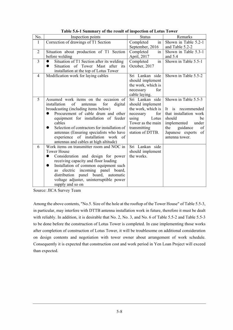
5-8
Table 5.6-1 Summary of the result of inspection of Lotus Tower No. Inspection points Status Remarks 1 Correction of drawings of T1 Section Completed in
September, 2016Shown in Table 5.2-1and Table 5.2-2
2 Situation about production of T1 Section before welding
Completed in April, 2017
Shown in Table 5.3-1and 5.4
3 Situation of T1 Section after its welding Situation of Tower Mast after its
installation at the top of Lotus Tower
Completed in October, 2017
Shown in Table 5.5-1
4 Modification work for laying cables Sri Lankan side should implement the work, which is necessary for cable laying.
Shown in Table 5.5-2
5 Assumed work items on the occasion of installation of antennas for digital broadcasting (including items below) Procurement of cable drum and other
equipment for installation of feeder cables
Selection of contractors for installation of antennas (Ensuring specialists who have experience of installation work of antennas and cables at high altitude)
Sri Lankan side should implement the work, which is necessary for using Lotus Tower as the main transmitting station of DTTB.
Shown in Table 5.5-3 It is recommended that installation work should be implemented under the guidance of Japanese experts of antenna tower.
6 Work items on transmitter room and NOC in Tower House Consideration and design for power
receiving capacity and floor loading Installation of common equipment such
as electric incoming panel board, distribution panel board, automatic voltage adjuster, uninterruptible power supply and so on
Sri Lankan side should implement the works.
Source: JICA Survey Team
Among the above contents, "No.5. Size of the hole at the rooftop of the Tower House" of Table 5.5-3,
in particular, may interfere with DTTB antenna installation work in future, therefore it must be dealt
with reliably. In addition, it is desirable that No. 2, No. 3, and No. 6 of Table 5.5-2 and Table 5.5-3
to be done before the construction of Lotus Tower is completed. In case implementing those works
after completion of construction of Lotus Tower, it will be troublesome on additional consideration
on design contents and negotiation with tower owner about arrangement of work schedule.
Consequently it is expected that construction cost and work period in Yen Loan Project will exceed
than expected.

Chapter 6 Recommendations on Matters to be Implemented
by the Government of Sri Lanka
6-1
Recommendations on Matters to be Implemented by the Government of Sri Lanka
Finalisation and release of roadmap for migration into DTTB and ISDB-T technical
standards
Migration into DTTB involves not only the relevant governmental agencies and broadcasting stations,
but also business operators engaged in the replacement of receivers for viewers, the beneficiaries of
broadcasting services, and the production, sale and distribution of DTTB receivers. In the case of Sri
Lanka, it is highly likely that the digital dividend of frequencies freed up by migration into DTTB
will be used by telecommunication providers, therefore they too will be impacted by migration into
DTTB. In addition, business operators that develop, produce, sell and distribute products involved in
telecommunications operations, companies that use telecommunications networks and the general
public will also be affected.
Most countries that have migrated or are in the process of migrating into DTTB prepare a roadmap
for migration into DTTB, share information and awareness of the problems involved adequately with
the above-mentioned stakeholders and devote their efforts to successfully accomplishing migration
as a national project.
The roadmap for migration into DTTB not only shows the timing of DSO and ASO, but also
exhaustively covers the procedures for preparing laws, guidelines and standards, the time required
for installing the equipment and facilities, the timing of public awareness activities aimed at viewers
and other stakeholders, and discussion and implementation of measures to manage the digital
dividend. The schedule is reviewed regularly or as appropriate, leading to smooth migration into
DTTB overall while limiting the impact on other work.
Until now Sri Lanka had no roadmap for migration into DTTB. In interviews with the broadcasting
stations, several commented that they were unable to set up concrete financial arrangements
necessary for migration into DTTB, such as investment in high-definition equipment, because the
timing of migration was uncertain. Despite the fact that Sri Lanka’s plans lack total clarity, the JICA
Survey Team has prepared a draft roadmap for Sri Lanka’s migration into DTTB based on basic
concepts. The Government of Sri Lanka must first build a framework for dealing with various issues
flexibly and individually, and then finalise the roadmap for migration into DTTB and publicise it
widely to the general public. As mentioned above, migration into DTTB will be advanced based on
stakeholder consensus while revising the roadmap, so it is important that the Government manifests
its current thinking as soon as possible and publicizes the roadmap for migration into DTTB. Release
of the roadmap is the first step in full-scale migration into DTTB.
On the other hand, ISDB-T technical standards have already been drafted with assistance from
relevant organisations on the Japanese side. Sri Lanka’s area codes, which are closely involved in
operation of the emergency warning broadcast system (EWBS), are currently under review.
Technical standards are essential for the manufacture of transmitters and receivers, and
manufacturers of broadcasting equipment and receivers will develop and manufacture products based
on these standards. As the transmitters and receivers include those customized for Sri Lanka, specific
product development is necessary.
6-2
As Sri Lanka has no companies that develop or manufacture broadcasting equipment, it basically
relies on imports. Foreign companies do not necessarily develop or manufacture the products in
question and they weigh profitability against business risk. Seeking a profit bearing in mind the costs
incurred from the development stage, each manufacturer may naturally consider to what extent
development is necessary by referring to the technical standards.
With no alternative but to rely on imports for part of its migration into DTTB, Sri Lanka must first
publish ISDB-T technical standards as soon as possible in order to motivate overseas manufacturers
to develop and produce the equipment. Publication will enable the Government of Sri Lanka to find
companies that are interested in exporting to Sri Lanka and ensure enough time for development and
manufacturing. In particular, as the spread of receivers will impact the timing of ASO, it is important
that receivers are already manufactured for distribution to the market at the time of DSO. The area
codes should be discussed with the relevant agencies and the technical standards released as soon as
possible.
Legislation related to establishment of DBNO
When migration into DTTB with aid from ITU was first discussed, a DTTB platform to meet the
shortage of frequencies was built by representatives from the Government of Sri Lanka and the
broadcasting stations. As a result, the broadcasting stations came into line with each other and
migration into DTTB was authorized. The various tasks and challenges involved in Sri Lanka’s
migration into DTTB are being considered and discussed based on the DTTB platform. Moreover, it
was confirmed at the outset that a digital broadcasting network operator (DBNO) would be
established as an independent and impartial organisation to manage the DTTB platform. Since then,
however, no progress has been made in studying business models for DBNO nor have preparations
been made for the establishment of DBNO.
Considering that DBNO will be an independent and impartial operator and that it will be financially
supported under Yen Loan Project by the Government of Japan, the prevailing opinion is that DBNO
will be a public organisation. Government regulations will be on a par with those governing ordinary
broadcasters and its establishment is sought within the framework of ensuring its independence as a
broadcasting station in order to guarantee reporting freedom. On the other hand, the establishment
of DBNO will be made by public financial support under Yen Loan Project by the Government of
Japan, so when establishing DBNO it is expected that the Act for Establishment of DBNO will be
required unless it is established as an independent private business that is free from outside control.
DBNO must be established and operated based on a legal framework prior to DSO. The Government
of Sri Lanka should start preparing the DBNO Act as soon as possible. The following basic items
should be incorporated in the DBNO Act.
(1) Purpose of establishment of DBNO, business content, and laws and regulations governing
business
(2) Voting rights of DBNO and guidelines on voting rights

6-3
(3) Method of electing members of the board of directors and management organisation, number
of persons, term of office and possibility of reappointment
(4) Accountability to citizens and users, and method of accountability
(5) Financing guidelines, compliance with laws and ministerial ordinances, and guidelines on
returning profits to users
(6) Regulatory guidelines on financing, including restrictions on foreign investment
(7) Obligation to disclose financial statements
(8) Obligation to undertake business and accounting audits, compliance with laws and ministerial
ordinances, and obligation to release business and accounting audit reports
(9) Responsibilities to users and prohibited matters
(10) Guidelines on setting, approval and revision of usage fees
Based on the determined business model, attention will focus on the business content, voting rights
and method of electing the board members, but discussion of exclusive ownership of broadcasting
business and exclusive media ownership based on ownership of different kinds of media is also
required. With regard to funds, consideration must be given to transparency, including audits if public
funds are utilized. With regard to usage fees collected from users, consideration must be given, such
as regulation using ministerial ordinance, in order to prevent arbitrary decisions by DBNO.
To enable rapid migration into DTTB, after DBNO has been established, instead of commencing
procurement of platform equipment, it is desirable that work is performed by utilising the Project
Management Unit (hereinafter referred to as PMU) of the Yen Loan Project as originally planned, or
interim organisation which the Government of Sri Lanka will regard necessary and establish.
DBNO usage fees
In advance of the Government of Sri Lanka studying the DBNO business model, the JICA Survey
Team performed a simulation of DBNO usage fees and in the process has raised the following two
issues as items for discussion when the Government of Sri Lanka determines the fees.
(1) Measures for exemption from usage fees for religious corporations
Of the broadcasting stations expected to use DBNO following migration into DTTB, only Buddhist
TV and Shraddha TV will continue to maintain their religious corporate status, but in view of the
financial situation of the two broadcasting stations concerned which are run solely on donations, it
is thought that they will find it difficult to pay the fees as currently set. If it is desirable that
consideration be given to the continued existence of broadcasting stations run by religious
corporations, measures for exemption from usage fees for religious corporations must be considered.
(2) Setting of fees by region
In the estimation of usage fees by the JICA Survey Team, the actual costs borne by most of the big
broadcasting stations will be greatly reduced compared to their current operating expenses by
transferring to DBNO. Conversely, the costs of small broadcasting stations will increase. While on
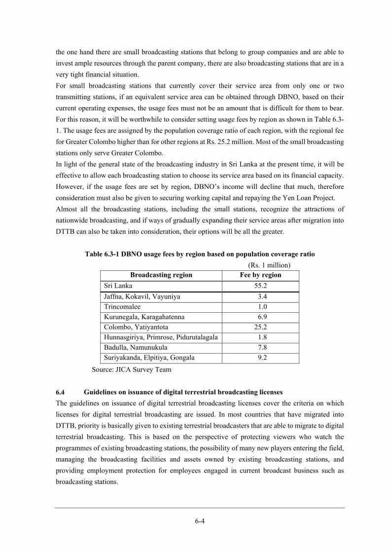
6-4
the one hand there are small broadcasting stations that belong to group companies and are able to
invest ample resources through the parent company, there are also broadcasting stations that are in a
very tight financial situation.
For small broadcasting stations that currently cover their service area from only one or two
transmitting stations, if an equivalent service area can be obtained through DBNO, based on their
current operating expenses, the usage fees must not be an amount that is difficult for them to bear.
For this reason, it will be worthwhile to consider setting usage fees by region as shown in Table 6.3-
1. The usage fees are assigned by the population coverage ratio of each region, with the regional fee
for Greater Colombo higher than for other regions at Rs. 25.2 million. Most of the small broadcasting
stations only serve Greater Colombo.
In light of the general state of the broadcasting industry in Sri Lanka at the present time, it will be
effective to allow each broadcasting station to choose its service area based on its financial capacity.
However, if the usage fees are set by region, DBNO’s income will decline that much, therefore
consideration must also be given to securing working capital and repaying the Yen Loan Project.
Almost all the broadcasting stations, including the small stations, recognize the attractions of
nationwide broadcasting, and if ways of gradually expanding their service areas after migration into
DTTB can also be taken into consideration, their options will be all the greater.
Table 6.3-1 DBNO usage fees by region based on population coverage ratio
(Rs. 1 million) Broadcasting region Fee by region
Sri Lanka 55.2
Jaffna, Kokavil, Vayuniya 3.4
Trincomalee 1.0
Kurunegala, Karagahatenna 6.9
Colombo, Yatiyantota 25.2
Hunnasgiriya, Primrose, Pidurutalagala 1.8
Badulla, Namunukula 7.8
Suriyakanda, Elpitiya, Gongala 9.2
Source: JICA Survey Team
Guidelines on issuance of digital terrestrial broadcasting licenses
The guidelines on issuance of digital terrestrial broadcasting licenses cover the criteria on which
licenses for digital terrestrial broadcasting are issued. In most countries that have migrated into
DTTB, priority is basically given to existing terrestrial broadcasters that are able to migrate to digital
terrestrial broadcasting. This is based on the perspective of protecting viewers who watch the
programmes of existing broadcasting stations, the possibility of many new players entering the field,
managing the broadcasting facilities and assets owned by existing broadcasting stations, and
providing employment protection for employees engaged in current broadcast business such as
broadcasting stations.

6-5
Firstly, Sri Lanka has no clear guidelines on priority accompanying migration into DTTB. Priority
is not granted infinitely. In most cases, it depends on confirmation of whether or not migration into
DTTB is feasible and is based on approval of appropriate business plans. In addition, priority does
not prevent new entry into the field. As long as channels can be assigned, new entry is allowed in
order to increase the benefits to the beneficiaries.
Until now terrestrial broadcasting stations in Sri Lanka required a broadcasting station licence and a
broadcast channel license for radio wave emissions. In future, the latter broadcast channel licence
will be assigned to DBNO, but the license for broadcasters using DBNO is vague. For this reason, a
new license will be required for digital terrestrial programme providers to provide DTTB through
DBNO. The Government of Sri Lanka must clarify the qualifications of digital terrestrial programme
providers and ensure that the necessary licenses can be issued without delay.
If the Government of Sri Lanka basically adheres to the previous basic framework with regard to
broadcasting stations, digital terrestrial programme providers will be roughly on a par with current
broadcasting stations, but it is reasonable to expect that operation and maintenance of the
transmission and relay equipment will not be included. If it is necessary to review the positioning,
social contribution, responsibilities and role of the broadcasting sector anew, this may not be the case.
However, as a new review will prompt a shake-up of the broadcasting industry and implementation
at the same time as migration into DTTB may cause confusion, the matter needs to be handled with
care.
Appropriate radio wave supervision
Until now, there existed no clear definition of a broadcasting service area for analogue terrestrial
broadcasting in Sri Lanka. Normally, as in the example of Japan, the definition of a broadcasting
service area should be created by the broadcasting stations, transmitter and receiver manufacturers
and radio wave supervising organisations based on ITU minimum field strength standards and issued
as a ministerial ordinance. In Sri Lanka, however, as there is no definition of a service area, each
broadcasting station asserts its service areas groundlessly. On the other hand, the
Telecommunications Regulatory Commission of Sri Lanka (TRC), which is responsible for radio
wave supervision, has no clear grasp of service area or regulations regarding such.
The problem of interference between multiple analogue broadcasting signals currently exists in Sri
Lanka. Interference is caused by two or more broadcasting signals in the area concerned, and the
signal that causes the interference is distinguished from the signal that is subjected to interference.
When interference occurs, normally some kind of response is required of the side that emitted the
later radio wave. However, it is possible for Broadcaster B to obtain a broadcasting service area
outside the service area of Broadcaster A that started broadcasting first. At this time, even if
Broadcaster A’s programs cannot be viewed by viewers in Broadcaster B’s service area, basically it
is recognized as Broadcaster B’s service area and in general no measures are required. This situation
is shown in Figure 6.5-1.
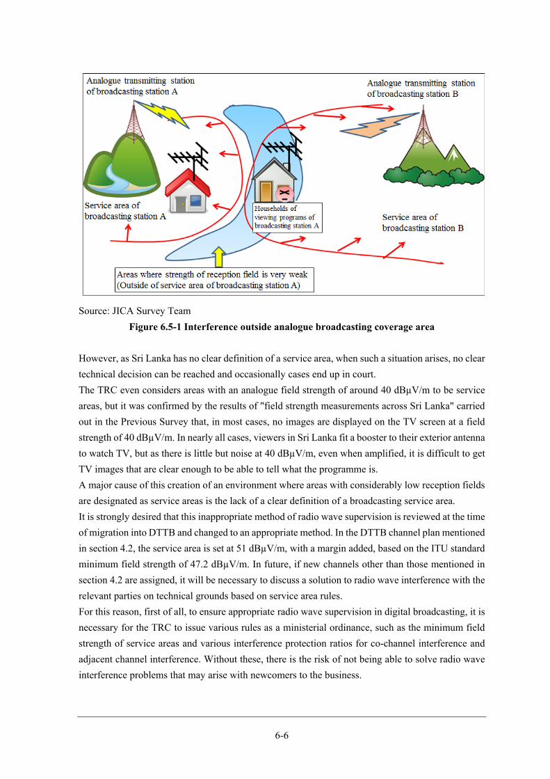
6-6
Source: JICA Survey Team
Figure 6.5-1 Interference outside analogue broadcasting coverage area
However, as Sri Lanka has no clear definition of a service area, when such a situation arises, no clear
technical decision can be reached and occasionally cases end up in court.
The TRC even considers areas with an analogue field strength of around 40 dBµV/m to be service
areas, but it was confirmed by the results of "field strength measurements across Sri Lanka" carried
out in the Previous Survey that, in most cases, no images are displayed on the TV screen at a field
strength of 40 dBµV/m. In nearly all cases, viewers in Sri Lanka fit a booster to their exterior antenna
to watch TV, but as there is little but noise at 40 dBµV/m, even when amplified, it is difficult to get
TV images that are clear enough to be able to tell what the programme is.
A major cause of this creation of an environment where areas with considerably low reception fields
are designated as service areas is the lack of a clear definition of a broadcasting service area.
It is strongly desired that this inappropriate method of radio wave supervision is reviewed at the time
of migration into DTTB and changed to an appropriate method. In the DTTB channel plan mentioned
in section 4.2, the service area is set at 51 dBµV/m, with a margin added, based on the ITU standard
minimum field strength of 47.2 dBµV/m. In future, if new channels other than those mentioned in
section 4.2 are assigned, it will be necessary to discuss a solution to radio wave interference with the
relevant parties on technical grounds based on service area rules.
For this reason, first of all, to ensure appropriate radio wave supervision in digital broadcasting, it is
necessary for the TRC to issue various rules as a ministerial ordinance, such as the minimum field
strength of service areas and various interference protection ratios for co-channel interference and
adjacent channel interference. Without these, there is the risk of not being able to solve radio wave
interference problems that may arise with newcomers to the business.
6-7
This inappropriate method of radio wave supervision has created frequency shortages, especially in
Greater Colombo. Appropriate radio wave supervision will boost development of the broadcasting
sector, narrow the digital divide between urban and rural areas and provide the foundation for
building a rich and sound broadcasting culture. Migration into DTTB is an excellent opportunity to
optimize radio wave supervision, introduce policies to avoid political channel assignment and
implement fair and open radio wave administration.
System review of EWBS operation
EWBS (Emergency Warning Broadcast System), an important feature of the ISDB-T system, is
expected to play an important role in Sri Lanka where natural disasters occur frequently. EWBS can
communicate warnings to viewers rapidly by broadcasts through collaboration with disaster
monitoring agencies, and with the ISDB-T system, mobile phones and mobile band receivers can
receive warnings by broadcasts even outdoors. With the recent development of mobile phones,
warnings can be received through the mobile phone Short Message Service (SMS). The merits of
receiving warnings through broadcasts are assumed to be that there is no risk of not being able to
receive a warning due to sudden deterioration of the communication situation as a result of excessive
communications within a certain area (as long as broadcast waves can be received, there is no
dependence on the communication situation), the broadcasting station will continue to provide
follow-up reports, and following the warnings, reliable information can be obtained.
As the broadcasting stations are not disaster monitoring organisations or disaster management
organisations, collaboration with disaster-related organisations is essential for operation of EWBS.
Rules must be systematically created on who activates EWBS warnings and how. As it is assumed
that creation of such rules will affect the specifications of the equipment to be procured by DBNO,
in order to promote migration into DTTB, the Government of Sri Lanka should establish an EWBS
system review committee including disaster-related organisations as soon as possible.
Consideration of Policy on dissemination of receivers, support for viewers and
measures for disadvantaged groups
If the DTTB population coverage ratio and dissemination of DTTB receivers are taken as the
requirements for implementing ASO as in most countries, since the Yen Loan Project will lead to
achievement of the goal for DTTB coverage if the project is appropriately implemented,
dissemination of receivers and the implementation of ASO are the issues facing the Government of
Sri Lanka.
Measures to motivate viewers to replace their receivers are necessary for dissemination of the
receivers.
Motivation includes, for example, direct giving-back plans for viewers, such as VAT reduction
within a certain period and reward points. Digital terrestrial broadcasting has a value-added service,
but examples in Japan and other countries of adding some kind of incentive for viewers to replace
the TV receiver that they have been using up till then with a new one or to have to buy a set-top box
(STB) have been shown to boost the spread of receivers.
6-8
Such direct giving-back measures are not the only motivation. Viewers are also motivated by ample
provision of information, such as PR regarding the DTTB migration schedule, information on when
DTTB will be available in each area and what kind of products it will be necessary to buy.
For this to happen, it is important to create and implement PR measures aimed at viewers. At the
same time, it will also be effective to set up a call centre to answer questions and inquiries from
viewers about migration into DTTB and enable viewers to easily seek advice.
Support for the creation of PR plans, including measures for dissemination of receivers and support
for establishment of a call centre by a JICA technical cooperation project, has already been
considered based on a request from the Government of Sri Lanka. As mentioned in section 6.1, it is
necessary to publicise the roadmap for migration into DTTB and consider measures for dissemination
of receivers and PR plans as soon as possible based on the roadmap.
In addition, it is also necessary to consider support measures for households where viewing may be
difficult because of migration into DTTB, such as measures for difficult viewing areas and measures
for poor households. First of all, individuals should be encouraged to replace their receivers by fully
explaining the merits of migration into DTTB to viewers and obtaining people’s understanding of
the need for migration. Then, feasible support must be considered for residents in difficult viewing
areas and for poor households. The Government of Sri Lanka must organise its thinking, including
carefully examining the risks that could hinder ASO and considering a government response in the
event that the risks cannot be removed by individual response. Measures to support receiver
replacement by all viewers is unlikely to be a feasible step and migration into DTTB must be
advanced while confronting the issue of people’s understanding. The merit of the digital dividend
for ordinary people is not just greater convenience for mobile phone users, and it is desirable to
consider ways of giving back the economic benefits generated by the digital dividend. The
Government of Sri Lanka must organise its thinking as soon as possible, such as asking people to
bear direct costs by utilising these economic benefits to promote substantial information and
communication policies.

Appendix
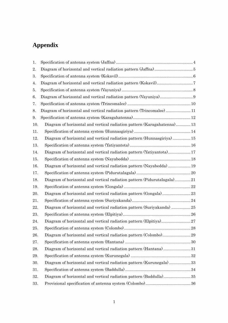
1
Appendix
1. Specification of antenna system (Jaffna) .................................................................... 4
2. Diagram of horizontal and vertical radiation pattern (Jaffna) .................................. 5
3. Specification of antenna system (Kokavil) .................................................................. 6
4. Diagram of horizontal and vertical radiation pattern (Kokavil) ................................ 7
5. Specification of antenna system (Vayuniya) ............................................................... 8
6. Diagram of horizontal and vertical radiation pattern (Vayuniya) ............................. 9
7. Specification of antenna system (Trincomalee) ........................................................ 10
8. Diagram of horizontal and vertical radiation pattern (Trincomalee) ...................... 11
9. Specification of antenna system (Karagahatenna) ................................................... 12
10. Diagram of horizontal and vertical radiation pattern (Karagahatenna) ............. 13
11. Specification of antenna system (Hunnasgiriya) .................................................. 14
12. Diagram of horizontal and vertical radiation pattern (Hunnasgiriya) ................ 15
13. Specification of antenna system (Yatiyantota) ...................................................... 16
14. Diagram of horizontal and vertical radiation pattern (Yatiyantota) .................... 17
15. Specification of antenna system (Nayabedda) ...................................................... 18
16. Diagram of horizontal and vertical radiation pattern (Nayabedda) .................... 19
17. Specification of antenna system (Pidurutalagala) ................................................ 20
18. Diagram of horizontal and vertical radiation pattern (Pidurutalagala) .............. 21
19. Specification of antenna system (Gongala) ........................................................... 22
20. Diagram of horizontal and vertical radiation pattern (Gongala) ......................... 23
21. Specification of antenna system (Suriyakanda) .................................................... 24
22. Diagram of horizontal and vertical radiation pattern (Suriyakanda) ................. 25
23. Specification of antenna system (Elpitiya) ............................................................ 26
24. Diagram of horizontal and vertical radiation pattern (Elpitiya) .......................... 27
25. Specification of antenna system (Colombo) ........................................................... 28
26. Diagram of horizontal and vertical radiation pattern (Colombo) ......................... 29
27. Specification of antenna system (Hantana) .......................................................... 30
28. Diagram of horizontal and vertical radiation pattern (Hantana) ........................ 31
29. Specification of antenna system (Kurunegala) ..................................................... 32
30. Diagram of horizontal and vertical radiation pattern (Kurunegala) ................... 33
31. Specification of antenna system (Baddulla) .......................................................... 34
32. Diagram of horizontal and vertical radiation pattern (Baddulla) ........................ 35
33. Provisional specification of antenna system (Colombo) ........................................ 36
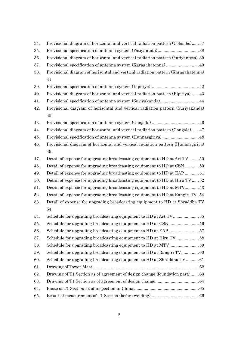
2
34. Provisional diagram of horizontal and vertical radiation pattern (Colombo) ...... 37
35. Provisional specification of antenna system (Yatiyantota) ................................... 38
36. Provisional diagram of horizontal and vertical radiation pattern (Yatiyantota) . 39
37. Provisional specification of antenna system (Karagahatenna) ............................ 40
38. Provisional diagram of horizontal and vertical radiation pattern (Karagahatenna)
41
39. Provisional specification of antenna system (Elpitiya) ......................................... 42
40. Provisional diagram of horizontal and vertical radiation pattern (Elpitiya) ....... 43
41. Provisional specification of antenna system (Suriyakanda) ................................. 44
42. Provisional diagram of horizontal and vertical radiation pattern (Suriyakanda)
45
43. Provisional specification of antenna system (Gongala) ........................................ 46
44. Provisional diagram of horizontal and vertical radiation pattern (Gongala) ...... 47
45. Provisional specification of antenna system (Hunnasgiriya) ............................... 48
46. Provisional diagram of horizontal and vertical radiation pattern (Hunnasgiriya)
49
47. Detail of expense for upgrading broadcasting equipment to HD at Art TV ......... 50
48. Detail of expense for upgrading broadcasting equipment to HD at CSN ............ 50
49. Detail of expense for upgrading broadcasting equipment to HD at EAP ............ 51
50. Detail of expense for upgrading broadcasting equipment to HD at Hiru TV ...... 52
51. Detail of expense for upgrading broadcasting equipment to HD at MTV ............ 53
52. Detail of expense for upgrading broadcasting equipment to HD at Rangiri TV . 54
53. Detail of expense for upgrading broadcasting equipment to HD at Shraddha TV
54
54. Schedule for upgrading broadcasting equipment to HD at Art TV ...................... 55
55. Schedule for upgrading broadcasting equipment to HD at CSN ......................... 56
56. Schedule for upgrading broadcasting equipment to HD at EAP .......................... 57
57. Schedule for upgrading broadcasting equipment to HD at Hiru TV ................... 58
58. Schedule for upgrading broadcasting equipment to HD at MTV ......................... 59
59. Schedule for upgrading broadcasting equipment to HD at Rangiri TV ............... 60
60. Schedule for upgrading broadcasting equipment to HD at Shraddha TV ........... 61
61. Drawing of Tower Mast .......................................................................................... 62
62. Drawing of T1 Section as of agreement of design change (foundation part) ....... 63
63. Drawing of T1 Section as of agreement of design change ..................................... 64
64. Photo of T1 Section as of inspection in China ....................................................... 65
65. Result of measurement of T1 Section (before welding) ......................................... 66
3
66 Requested points regarding cable laying………………………………………………. 67
67 Drawing of cable drum loading (Ground)……………………………………………….69
68 Drawing of cable drum loading (Tower Base)………………………………………….70
69 Drawing of Tower House (Microwave platform at 187.5m high)……………………73
70 Drawing of Tower House (Microwave platform, at 195.5m high)……………………74
71 Photo of Tower House (Fire prevention compartment)………………………………..75
72 Drawing of Tower House (Size of the hole for carrying in equipment, at 253.3m
high)…76
73 Drawing of Tower House (Base frame for fixing cables, at 253.3m high)………….77
74 Photo of T1 Section……………………………….........................................................78
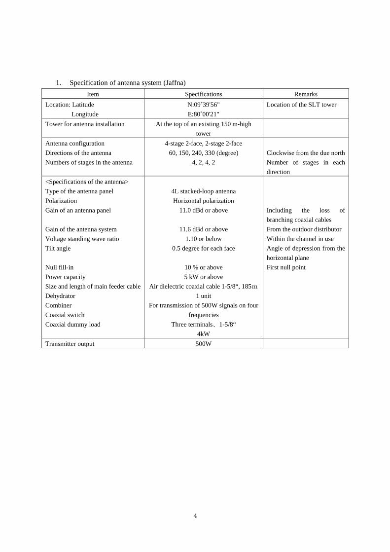
4
1. Specification of antenna system (Jaffna)
Item Specifications Remarks
Location: Latitude
Longitude
N:09˚39'56"
E:80˚00'21"
Location of the SLT tower
Tower for antenna installation At the top of an existing 150 m-high
tower
Antenna configuration
Directions of the antenna
Numbers of stages in the antenna
4-stage 2-face, 2-stage 2-face
60, 150, 240, 330 (degree)
4, 2, 4, 2
Clockwise from the due north
Number of stages in each
direction
<Specifications of the antenna>
Type of the antenna panel
Polarization
Gain of an antenna panel
Gain of the antenna system
Voltage standing wave ratio
Tilt angle
Null fill-in
Power capacity
Size and length of main feeder cable
Dehydrator
Combiner
Coaxial switch
Coaxial dummy load
4L stacked-loop antenna
Horizontal polarization
11.0 dBd or above
11.6 dBd or above
1.10 or below
0.5 degree for each face
10 % or above
5 kW or above
Air dielectric coaxial cable 1-5/8“, 185m
1 unit
For transmission of 500W signals on four
frequencies
Three terminals、1-5/8“
4kW
Including the loss of
branching coaxial cables
From the outdoor distributor
Within the channel in use
Angle of depression from the
horizontal plane
First null point
Transmitter output 500W
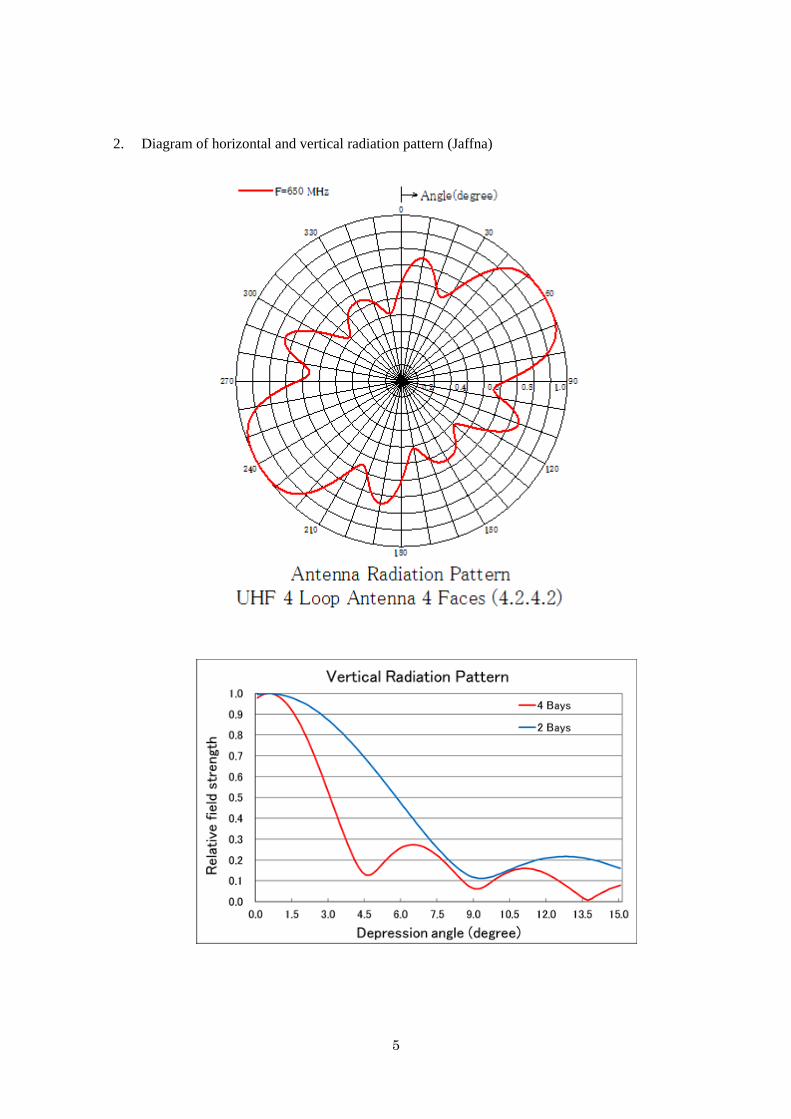
5
2. Diagram of horizontal and vertical radiation pattern (Jaffna)
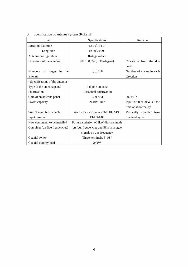
6
3. Specification of antenna system (Kokavil)
Item Specifications Remarks
Location: Latitude
Longitude
N: 09˚16'11"
E: 80˚24'29"
Antenna configuration
Directions of the antenna
Numbers of stages in the
antenna
8-stage 4-face
60, 150, 240, 330 (degree)
8, 8, 8, 8
Clockwise from the due
north
Number of stages in each
direction
<Specifications of the antenna>
Type of the antenna panel
Polarization
Gain of an antenna panel
Power capacity
Size of main feeder cable
Input terminal
4 dipole antenna
Horizontal polarization
12.9 dBd
24 kW / line
Air dielectric coaxial cable HCA495
EIA 3-1/8”
600MHz
Input of 8 x 3kW at the
time of abnormality
Vertically separated two-
line feed system
New equipment to be installed
Combiner (on five frequencies)
Coaxial switch
Coaxial dummy load
For transmission of 3kW digital signals
on four frequencies and 3kW analogue
signals on one frequency
Three terminals, 3-1/8“
24kW
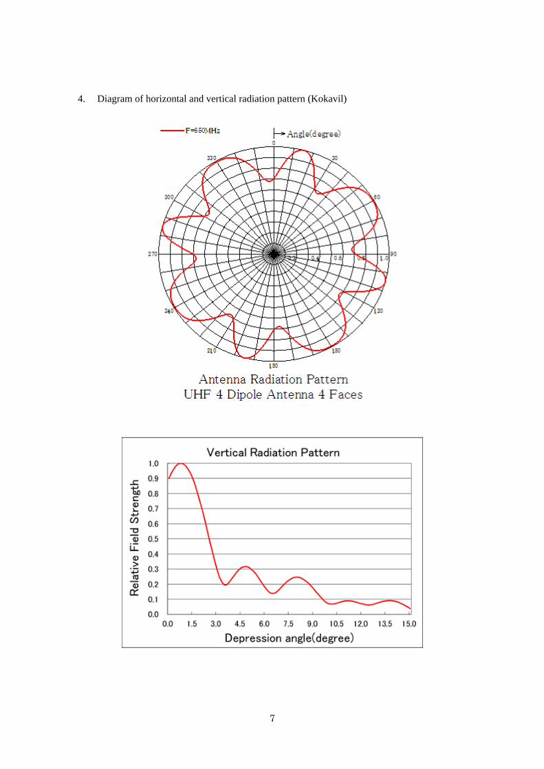
7
4. Diagram of horizontal and vertical radiation pattern (Kokavil)
8
5. Specification of antenna system (Vayuniya)
Item Specifications Remarks
Location: Latitude
Longitude
N: 08˚46'1.23"
E:80˚33'0.66"
Location of the SLT
tower
Tower for antenna installation At the top of an existing 60 m-high
tower
Antenna configuration
Directions of the antenna
Numbers of stages in the antenna
4-stage 2-face, 2-stage 2-face
0, 90, 180, 270 (degree)
2, 4, 2, 4
Clockwise from the due
north
Number of stages in each
direction
<Specifications of the antenna>
Type of the antenna panel
Polarization
Gain of an antenna panel
Gain of the antenna system
Voltage standing wave ratio
Tilt angle
Null fill-in
Power capacity
Size and length of main feeder cable
Dehydrator
Combiner
Coaxial switch
Coaxial dummy load
4L stacked-loop antenna
Horizontal polarization
11.0 dBd or above
11.6 dBd or above
1.10 or below
0.5 degree for each face
10 % or above
10 kW or above
Air dielectric coaxial cable 3“, 100m
1 unit
For transmission of 1kW signals on
four frequencies
Three terminals, 1-5/8“
8kW
Including the loss of
branching coaxial cables
From the outdoor
distributor
Within the channel in use
Angle of depression from
the horizontal plane
First null point
Transmitter output 1kW
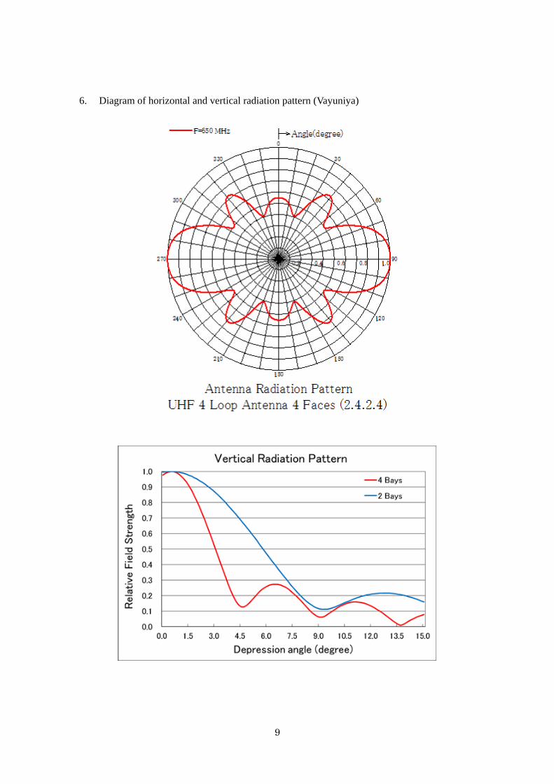
9
6. Diagram of horizontal and vertical radiation pattern (Vayuniya)
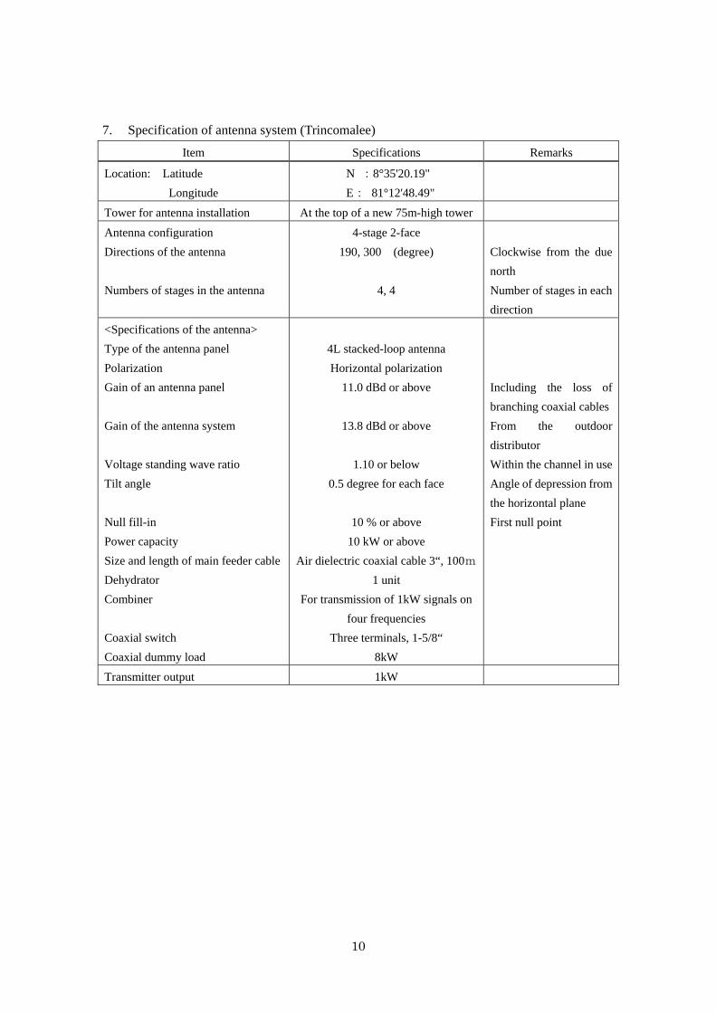
10
7. Specification of antenna system (Trincomalee)
Item Specifications Remarks
Location: Latitude
Longitude
N :8°35'20.19"
E: 81°12'48.49"
Tower for antenna installation At the top of a new 75m-high tower
Antenna configuration
Directions of the antenna
Numbers of stages in the antenna
4-stage 2-face
190, 300 (degree)
4, 4
Clockwise from the due
north
Number of stages in each
direction
<Specifications of the antenna>
Type of the antenna panel
Polarization
Gain of an antenna panel
Gain of the antenna system
Voltage standing wave ratio
Tilt angle
Null fill-in
Power capacity
Size and length of main feeder cable
Dehydrator
Combiner
Coaxial switch
Coaxial dummy load
4L stacked-loop antenna
Horizontal polarization
11.0 dBd or above
13.8 dBd or above
1.10 or below
0.5 degree for each face
10 % or above
10 kW or above
Air dielectric coaxial cable 3“, 100m
1 unit
For transmission of 1kW signals on
four frequencies
Three terminals, 1-5/8“
8kW
Including the loss of
branching coaxial cables
From the outdoor
distributor
Within the channel in use
Angle of depression from
the horizontal plane
First null point
Transmitter output 1kW
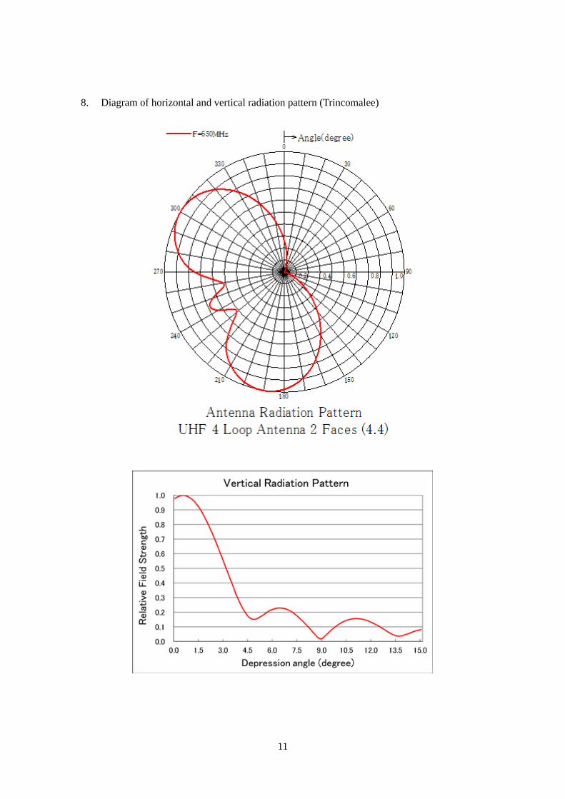
11
8. Diagram of horizontal and vertical radiation pattern (Trincomalee)
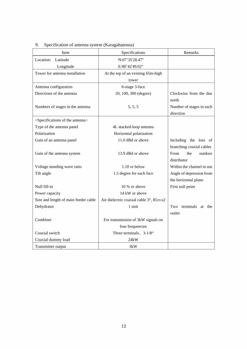
12
9. Specification of antenna system (Karagahatenna)
Item Specifications Remarks
Location: Latitude
Longitude
N:07˚35'28.47"
E:80˚42'49.02"
Tower for antenna installation At the top of an existing 65m-high
tower
Antenna configuration
Directions of the antenna
Numbers of stages in the antenna
6-stage 3-face
20, 100, 300 (degree)
5, 5, 5
Clockwise from the due
north
Number of stages in each
direction
<Specifications of the antenna>
Type of the antenna panel
Polarization
Gain of an antenna panel
Gain of the antenna system
Voltage standing wave ratio
Tilt angle
Null fill-in
Power capacity
Size and length of main feeder cable
Dehydrator
Combiner
Coaxial switch
Coaxial dummy load
4L stacked-loop antenna
Horizontal polarization
11.0 dBd or above
13.9 dBd or above
1.10 or below
1.5 degree for each face
10 % or above
14 kW or above
Air dielectric coaxial cable 3“, 85mx2
1 unit
For transmission of 3kW signals on
four frequencies
Three terminals、3-1/8“
24kW
Including the loss of
branching coaxial cables
From the outdoor
distributor
Within the channel in use
Angle of depression from
the horizontal plane
First null point
Two terminals at the
outlet
Transmitter output 3kW
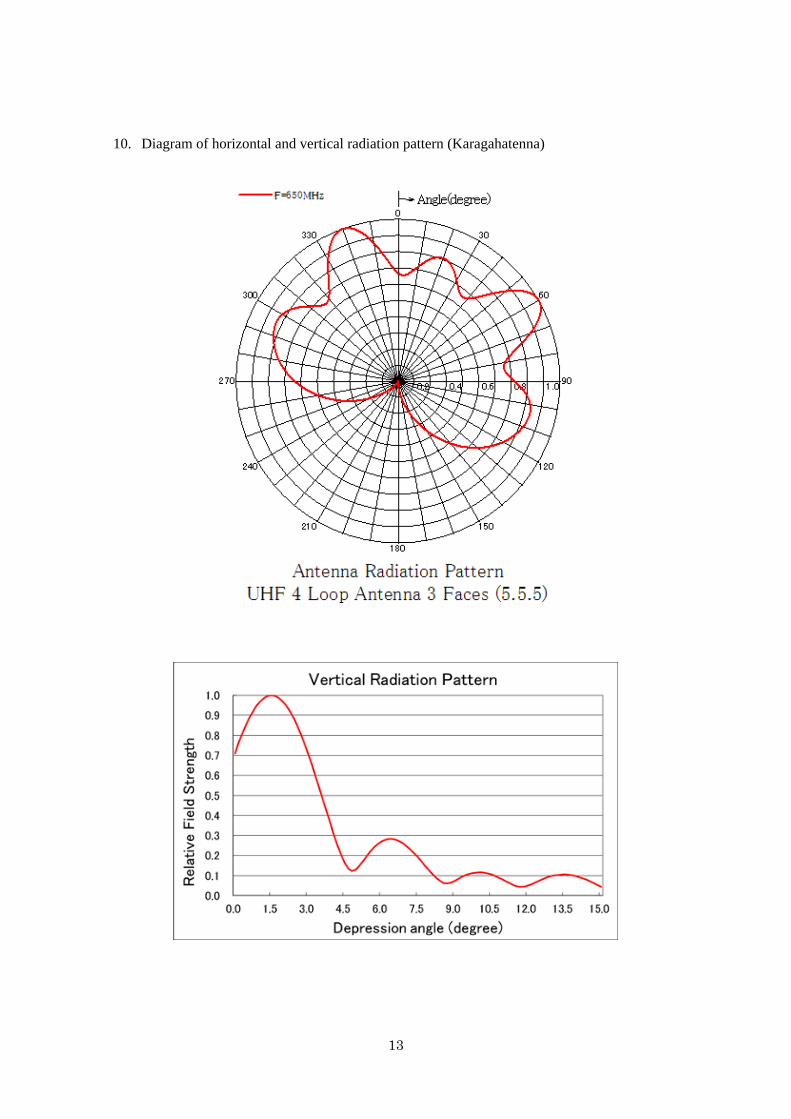
13
10. Diagram of horizontal and vertical radiation pattern (Karagahatenna)
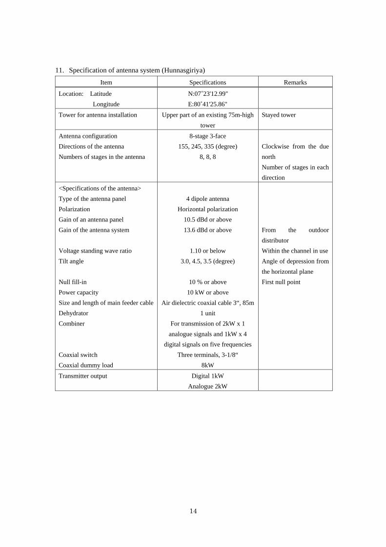
14
11. Specification of antenna system (Hunnasgiriya)
Item Specifications Remarks
Location: Latitude
Longitude
N:07˚23'12.99"
E:80˚41'25.86"
Tower for antenna installation Upper part of an existing 75m-high
tower
Stayed tower
Antenna configuration
Directions of the antenna
Numbers of stages in the antenna
8-stage 3-face
155, 245, 335 (degree)
8, 8, 8
Clockwise from the due
north
Number of stages in each
direction
<Specifications of the antenna>
Type of the antenna panel
Polarization
Gain of an antenna panel
Gain of the antenna system
Voltage standing wave ratio
Tilt angle
Null fill-in
Power capacity
Size and length of main feeder cable
Dehydrator
Combiner
Coaxial switch
Coaxial dummy load
4 dipole antenna
Horizontal polarization
10.5 dBd or above
13.6 dBd or above
1.10 or below
3.0, 4.5, 3.5 (degree)
10 % or above
10 kW or above
Air dielectric coaxial cable 3“, 85m
1 unit
For transmission of 2kW x 1
analogue signals and 1kW x 4
digital signals on five frequencies
Three terminals, 3-1/8“
8kW
From the outdoor
distributor
Within the channel in use
Angle of depression from
the horizontal plane
First null point
Transmitter output Digital 1kW
Analogue 2kW
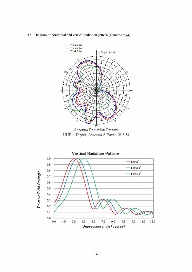
15
12. Diagram of horizontal and vertical radiation pattern (Hunnasgiriya)
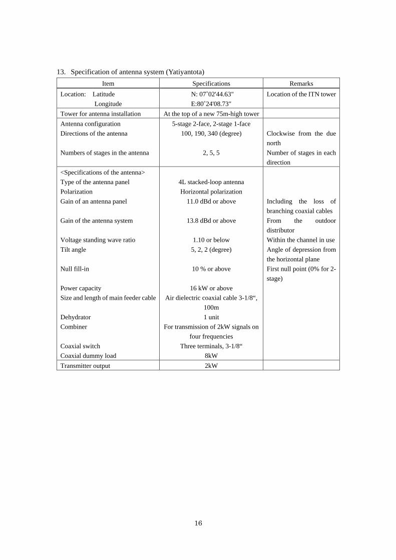
16
13. Specification of antenna system (Yatiyantota)
Item Specifications Remarks
Location: Latitude
Longitude
N: 07˚02'44.63"
E:80˚24'08.73"
Location of the ITN tower
Tower for antenna installation At the top of a new 75m-high tower
Antenna configuration
Directions of the antenna
Numbers of stages in the antenna
5-stage 2-face, 2-stage 1-face
100, 190, 340 (degree)
2, 5, 5
Clockwise from the due
north
Number of stages in each
direction
<Specifications of the antenna>
Type of the antenna panel
Polarization
Gain of an antenna panel
Gain of the antenna system
Voltage standing wave ratio
Tilt angle
Null fill-in
Power capacity
Size and length of main feeder cable
Dehydrator
Combiner
Coaxial switch
Coaxial dummy load
4L stacked-loop antenna
Horizontal polarization
11.0 dBd or above
13.8 dBd or above
1.10 or below
5, 2, 2 (degree)
10 % or above
16 kW or above
Air dielectric coaxial cable 3-1/8“,
100m
1 unit
For transmission of 2kW signals on
four frequencies
Three terminals, 3-1/8“
8kW
Including the loss of
branching coaxial cables
From the outdoor
distributor
Within the channel in use
Angle of depression from
the horizontal plane
First null point (0% for 2-
stage)
Transmitter output 2kW
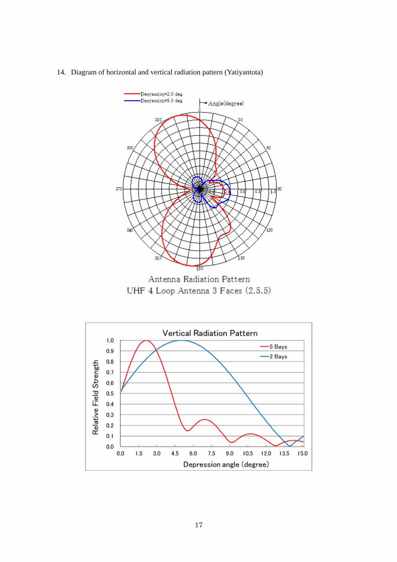
17
14. Diagram of horizontal and vertical radiation pattern (Yatiyantota)
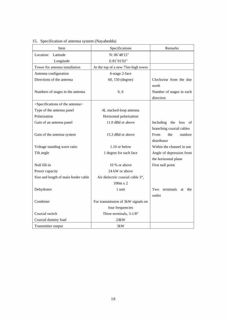
18
15. Specification of antenna system (Nayabedda)
Item Specifications Remarks
Location: Latitude
Longitude
N: 06˚48'15"
E:81˚01'02"
Tower for antenna installation At the top of a new 75m-high tower
Antenna configuration
Directions of the antenna
Numbers of stages in the antenna
6-stage 2-face
60, 150 (degree)
6, 6
Clockwise from the due
north
Number of stages in each
direction
<Specifications of the antenna>
Type of the antenna panel
Polarization
Gain of an antenna panel
Gain of the antenna system
Voltage standing wave ratio
Tilt angle
Null fill-in
Power capacity
Size and length of main feeder cable
Dehydrator
Combiner
Coaxial switch
Coaxial dummy load
4L stacked-loop antenna
Horizontal polarization
11.0 dBd or above
15.3 dBd or above
1.10 or below
1 degree for each face
10 % or above
24 kW or above
Air dielectric coaxial cable 3“,
100m x 2
1 unit
For transmission of 3kW signals on
four frequencies
Three terminals, 3-1/8“
24kW
Including the loss of
branching coaxial cables
From the outdoor
distributor
Within the channel in use
Angle of depression from
the horizontal plane
First null point
Two terminals at the
outlet
Transmitter output 3kW
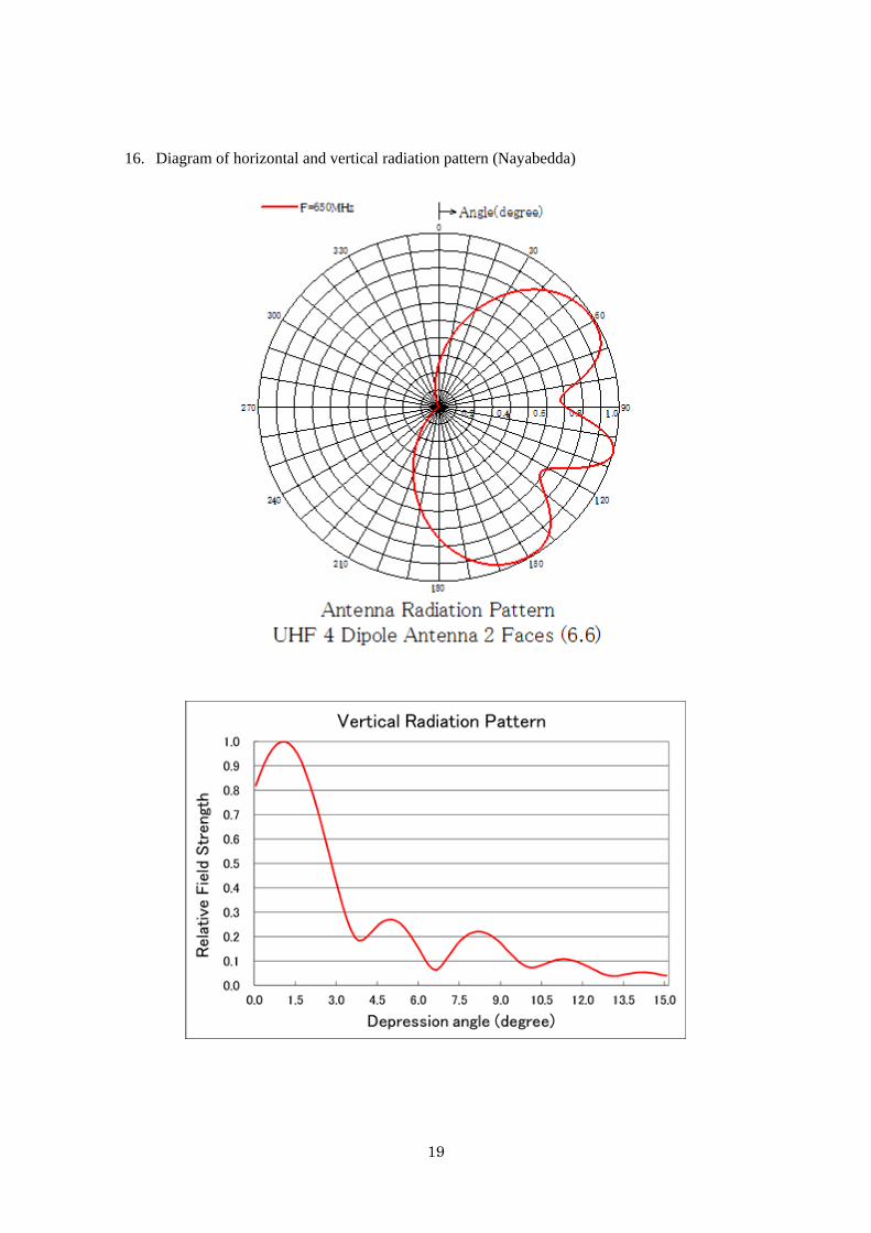
19
16. Diagram of horizontal and vertical radiation pattern (Nayabedda)

20
17. Specification of antenna system (Pidurutalagala)
Item Specifications Remarks
Location: Latitude
Longitude
N: 07˚00'01"
E:80˚46'26"
Location of the SLRC
tower
Tower for antenna installation At the top of a new 75m-high
tower
Antenna configuration
Directions of the antenna
Numbers of stages in the antenna
2-stage 1-face
170 (degree)
2
Clockwise from the due
north
Number of stages in each
direction
<Specifications of the antenna>
Type of the antenna panel
Polarization
Gain of an antenna panel
Gain of the antenna system
Voltage standing wave ratio
Tilt angle
Null fill-in
Power capacity
Size and length of main feeder cable
Dehydrator
Combiner
Coaxial switch
Coaxial dummy load
4L stacked-loop antenna
Horizontal polarization
11.0 dBd or above
13.8 dBd or above
1.10 or below
8 (degree)
10 % or above
0.4 kW or above
Air dielectric coaxial cable 1-5/8“,
100m
1 unit
For transmission of 0.05kW signals
on four frequencies
Three terminals, 7/8“ or equivalent
0.4kW
Including the loss of
branching coaxial cables
From the outdoor
distributor
Within the channel in use
Angle of depression from
the horizontal plane
First null point
Transmitter output 0.05kW
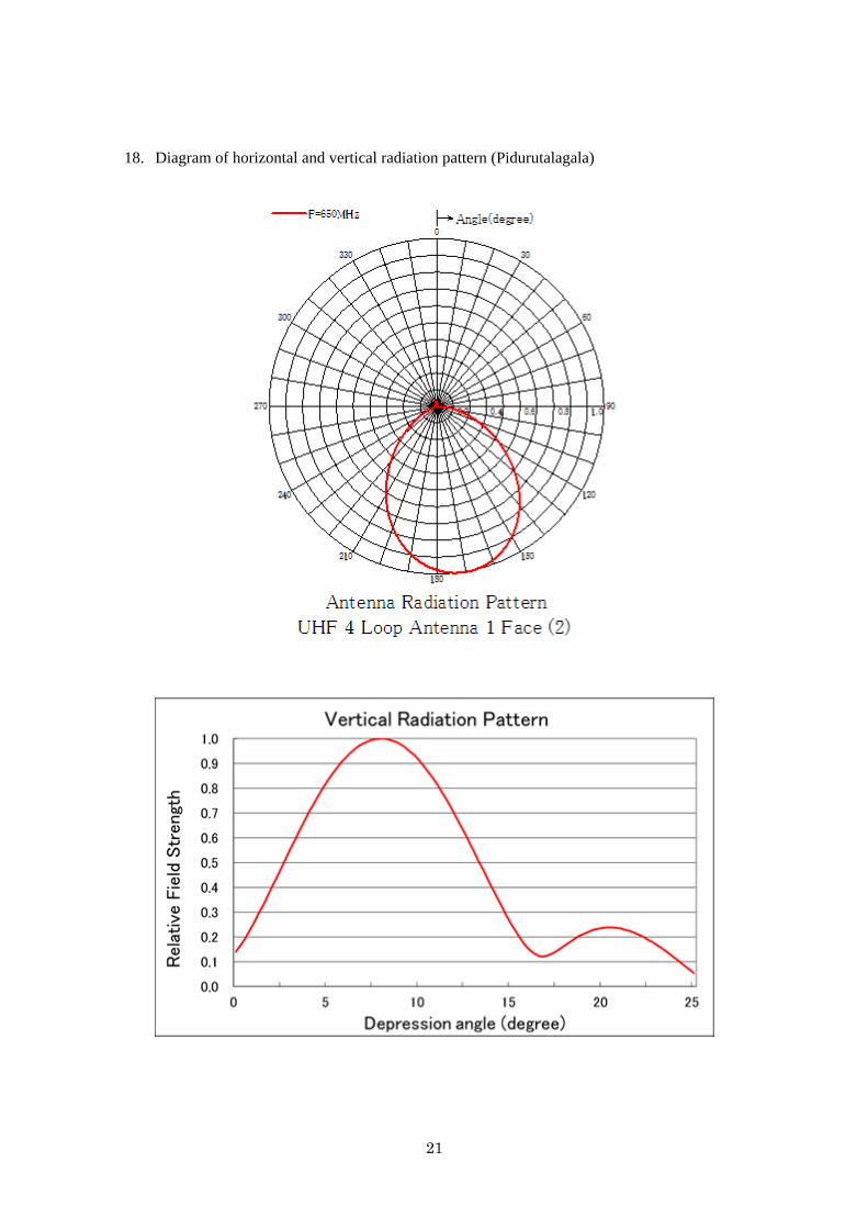
21
18. Diagram of horizontal and vertical radiation pattern (Pidurutalagala)
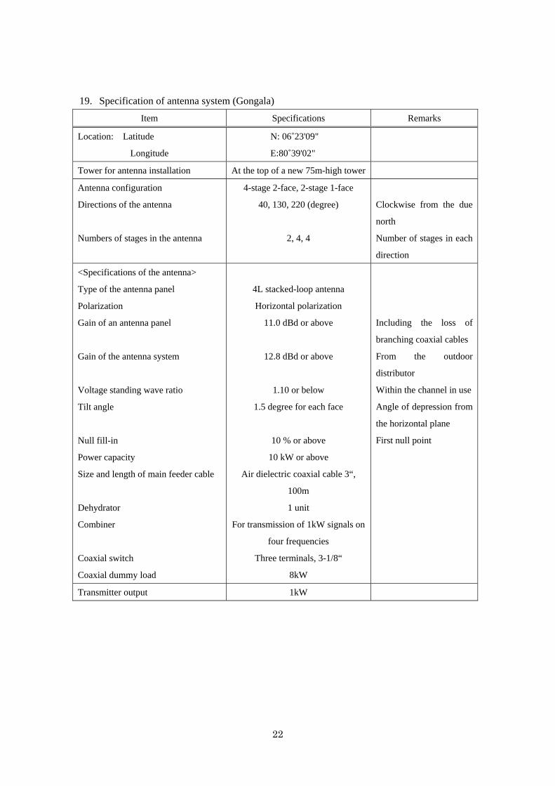
22
19. Specification of antenna system (Gongala)
Item Specifications Remarks
Location: Latitude
Longitude
N: 06˚23'09"
E:80˚39'02"
Tower for antenna installation At the top of a new 75m-high tower
Antenna configuration
Directions of the antenna
Numbers of stages in the antenna
4-stage 2-face, 2-stage 1-face
40, 130, 220 (degree)
2, 4, 4
Clockwise from the due
north
Number of stages in each
direction
<Specifications of the antenna>
Type of the antenna panel
Polarization
Gain of an antenna panel
Gain of the antenna system
Voltage standing wave ratio
Tilt angle
Null fill-in
Power capacity
Size and length of main feeder cable
Dehydrator
Combiner
Coaxial switch
Coaxial dummy load
4L stacked-loop antenna
Horizontal polarization
11.0 dBd or above
12.8 dBd or above
1.10 or below
1.5 degree for each face
10 % or above
10 kW or above
Air dielectric coaxial cable 3“,
100m
1 unit
For transmission of 1kW signals on
four frequencies
Three terminals, 3-1/8“
8kW
Including the loss of
branching coaxial cables
From the outdoor
distributor
Within the channel in use
Angle of depression from
the horizontal plane
First null point
Transmitter output 1kW
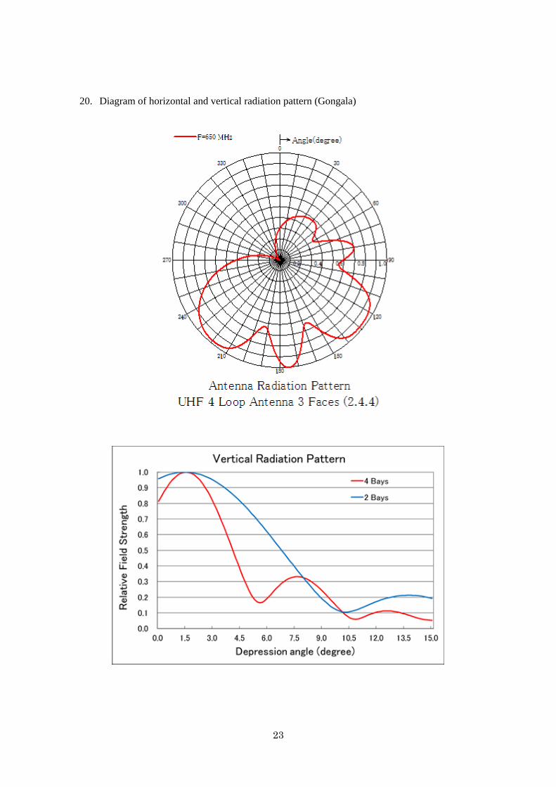
23
20. Diagram of horizontal and vertical radiation pattern (Gongala)
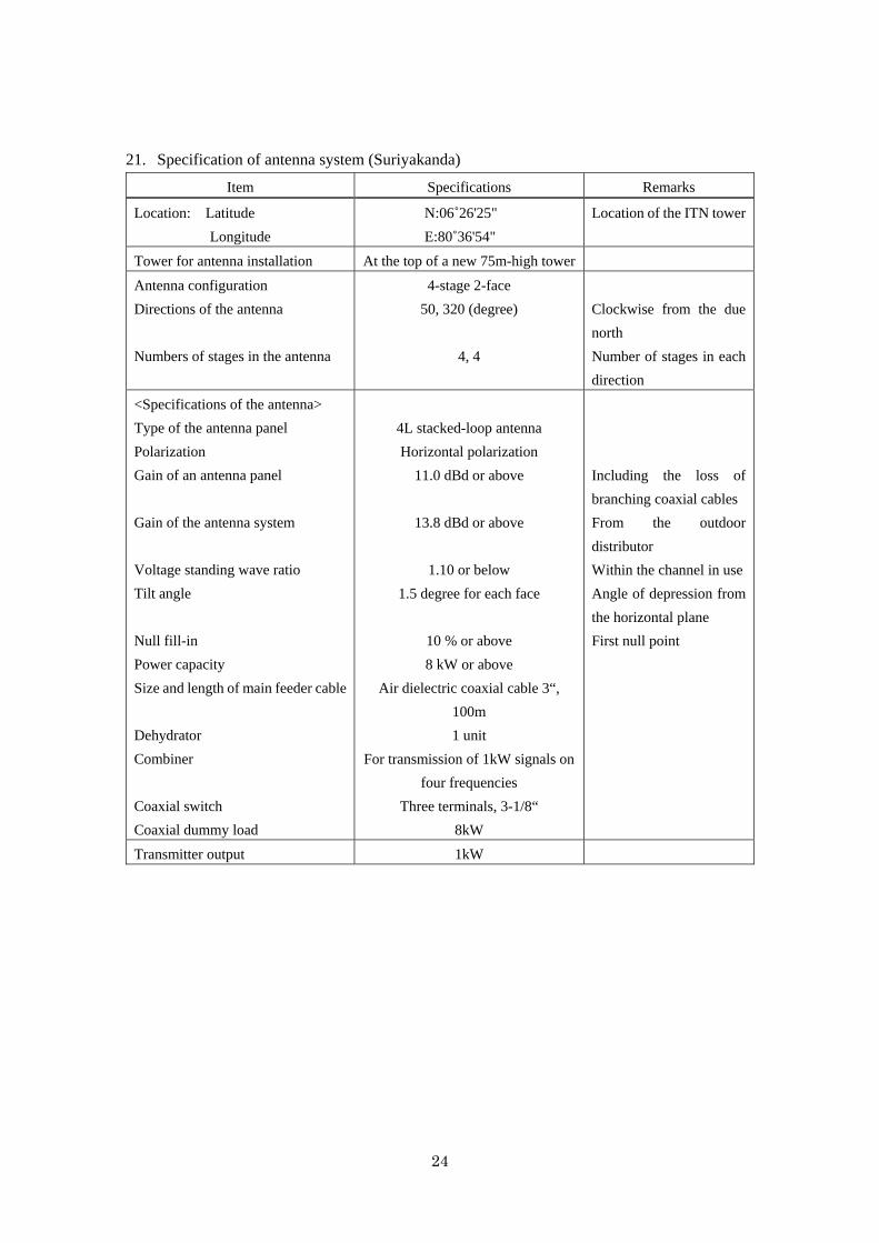
24
21. Specification of antenna system (Suriyakanda)
Item Specifications Remarks
Location: Latitude
Longitude
N:06˚26'25"
E:80˚36'54"
Location of the ITN tower
Tower for antenna installation At the top of a new 75m-high tower
Antenna configuration
Directions of the antenna
Numbers of stages in the antenna
4-stage 2-face
50, 320 (degree)
4, 4
Clockwise from the due
north
Number of stages in each
direction
<Specifications of the antenna>
Type of the antenna panel
Polarization
Gain of an antenna panel
Gain of the antenna system
Voltage standing wave ratio
Tilt angle
Null fill-in
Power capacity
Size and length of main feeder cable
Dehydrator
Combiner
Coaxial switch
Coaxial dummy load
4L stacked-loop antenna
Horizontal polarization
11.0 dBd or above
13.8 dBd or above
1.10 or below
1.5 degree for each face
10 % or above
8 kW or above
Air dielectric coaxial cable 3“,
100m
1 unit
For transmission of 1kW signals on
four frequencies
Three terminals, 3-1/8“
8kW
Including the loss of
branching coaxial cables
From the outdoor
distributor
Within the channel in use
Angle of depression from
the horizontal plane
First null point
Transmitter output 1kW
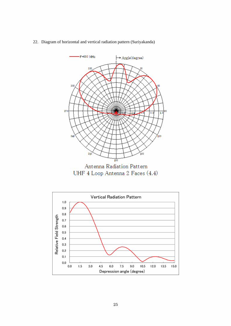
25
22. Diagram of horizontal and vertical radiation pattern (Suriyakanda)
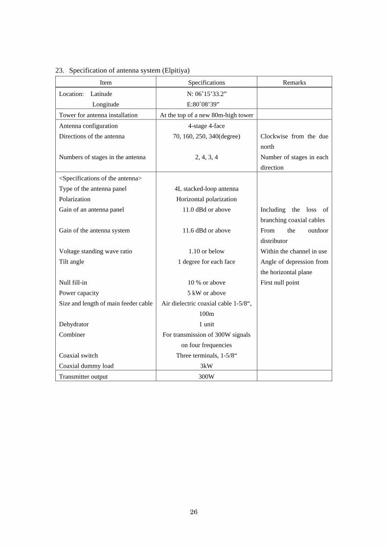
26
23. Specification of antenna system (Elpitiya)
Item Specifications Remarks
Location: Latitude
Longitude
N: 06˚15’33.2”
E:80˚08’39”
Tower for antenna installation At the top of a new 80m-high tower
Antenna configuration
Directions of the antenna
Numbers of stages in the antenna
4-stage 4-face
70, 160, 250, 340(degree)
2, 4, 3, 4
Clockwise from the due
north
Number of stages in each
direction
<Specifications of the antenna>
Type of the antenna panel
Polarization
Gain of an antenna panel
Gain of the antenna system
Voltage standing wave ratio
Tilt angle
Null fill-in
Power capacity
Size and length of main feeder cable
Dehydrator
Combiner
Coaxial switch
Coaxial dummy load
4L stacked-loop antenna
Horizontal polarization
11.0 dBd or above
11.6 dBd or above
1.10 or below
1 degree for each face
10 % or above
5 kW or above
Air dielectric coaxial cable 1-5/8“,
100m
1 unit
For transmission of 300W signals
on four frequencies
Three terminals, 1-5/8“
3kW
Including the loss of
branching coaxial cables
From the outdoor
distributor
Within the channel in use
Angle of depression from
the horizontal plane
First null point
Transmitter output 300W
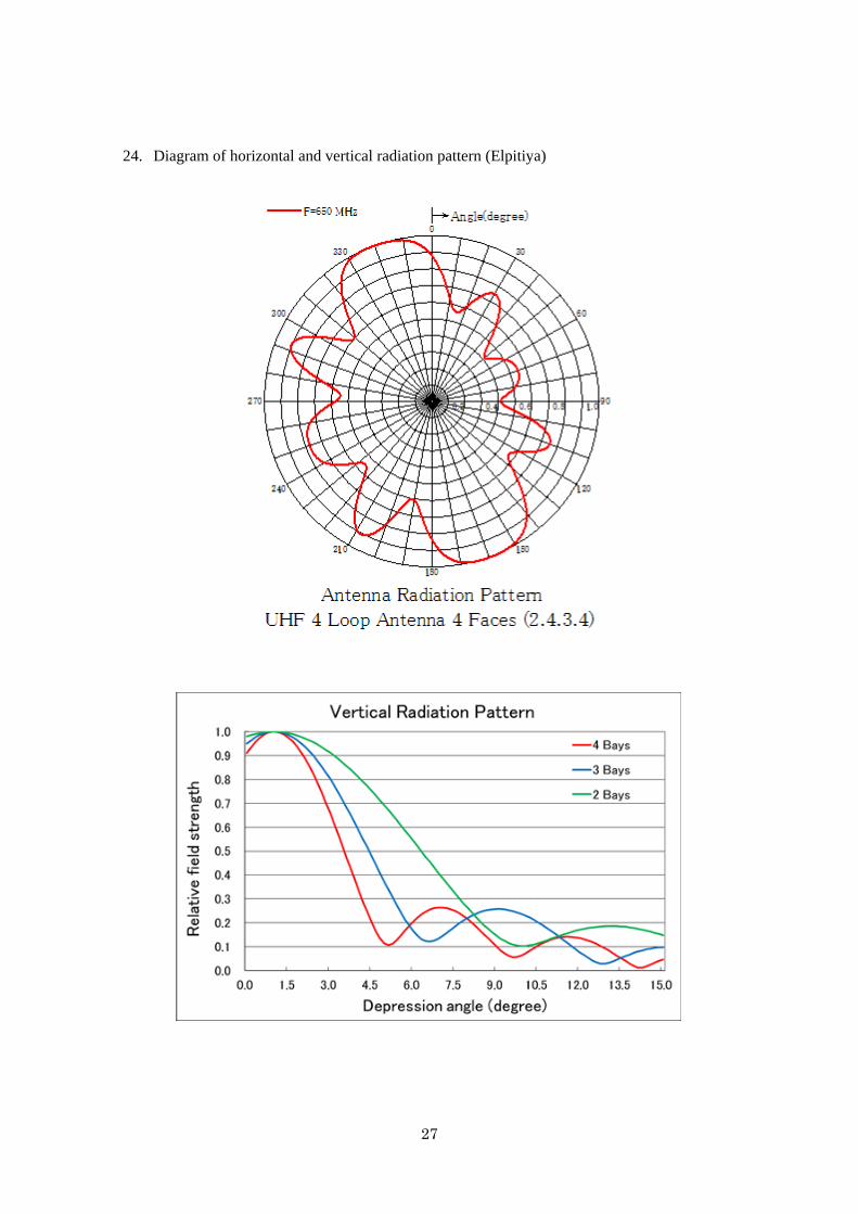
27
24. Diagram of horizontal and vertical radiation pattern (Elpitiya)
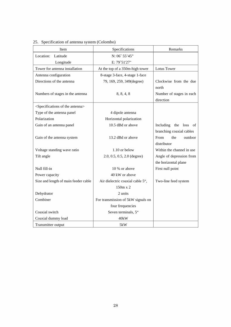
28
25. Specification of antenna system (Colombo)
Item Specifications Remarks
Location: Latitude
Longitude
N: 06˚ 55’45”
E: 79˚51'27"
Tower for antenna installation At the top of a 350m-high tower Lotus Tower
Antenna configuration
Directions of the antenna
Numbers of stages in the antenna
8-stage 3-face, 4-stage 1-face
79, 169, 259, 349(degree)
8, 8, 4, 8
Clockwise from the due
north
Number of stages in each
direction
<Specifications of the antenna>
Type of the antenna panel
Polarization
Gain of an antenna panel
Gain of the antenna system
Voltage standing wave ratio
Tilt angle
Null fill-in
Power capacity
Size and length of main feeder cable
Dehydrator
Combiner
Coaxial switch
Coaxial dummy load
4 dipole antenna
Horizontal polarization
10.5 dBd or above
13.2 dBd or above
1.10 or below
2.0, 0.5, 0.5, 2.0 (degree)
10 % or above
40 kW or above
Air dielectric coaxial cable 5“,
150m x 2
2 units
For transmission of 5kW signals on
four frequencies
Seven terminals, 5“
40kW
Including the loss of
branching coaxial cables
From the outdoor
distributor
Within the channel in use
Angle of depression from
the horizontal plane
First null point
Two-line feed system
Transmitter output 5kW
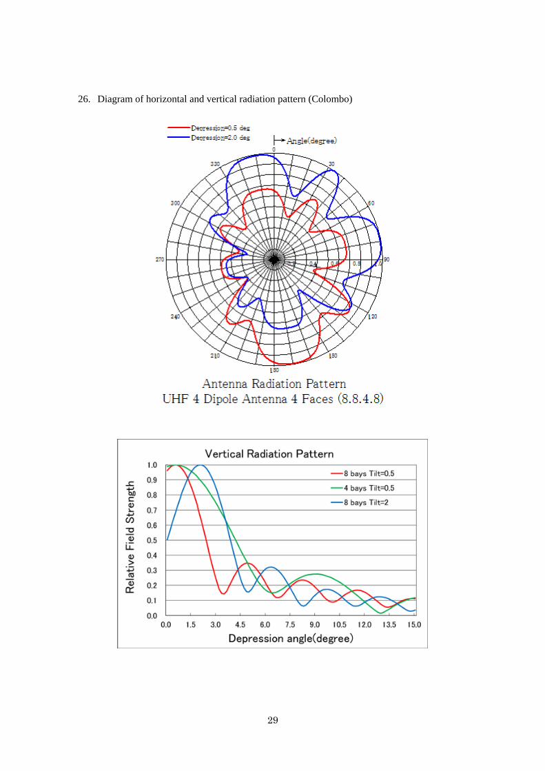
29
26. Diagram of horizontal and vertical radiation pattern (Colombo)
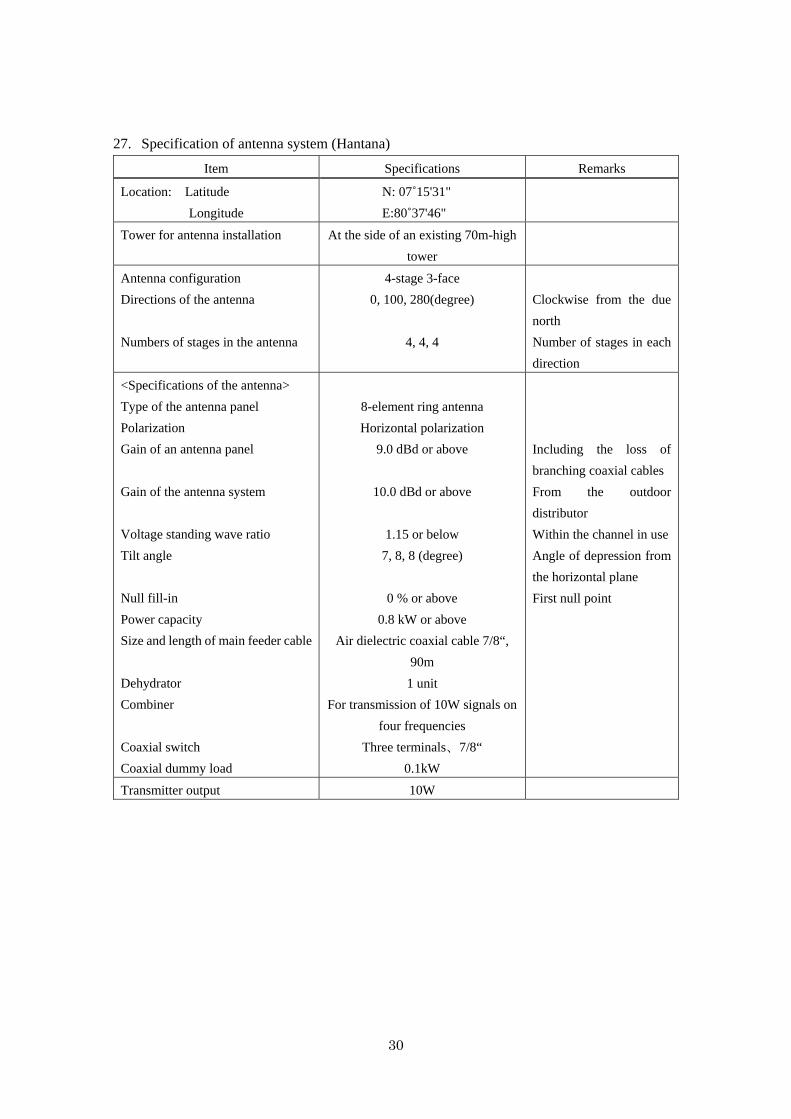
30
27. Specification of antenna system (Hantana)
Item Specifications Remarks
Location: Latitude
Longitude
N: 07˚15'31"
E:80˚37'46"
Tower for antenna installation At the side of an existing 70m-high
tower
Antenna configuration
Directions of the antenna
Numbers of stages in the antenna
4-stage 3-face
0, 100, 280(degree)
4, 4, 4
Clockwise from the due
north
Number of stages in each
direction
<Specifications of the antenna>
Type of the antenna panel
Polarization
Gain of an antenna panel
Gain of the antenna system
Voltage standing wave ratio
Tilt angle
Null fill-in
Power capacity
Size and length of main feeder cable
Dehydrator
Combiner
Coaxial switch
Coaxial dummy load
8-element ring antenna
Horizontal polarization
9.0 dBd or above
10.0 dBd or above
1.15 or below
7, 8, 8 (degree)
0 % or above
0.8 kW or above
Air dielectric coaxial cable 7/8“,
90m
1 unit
For transmission of 10W signals on
four frequencies
Three terminals、7/8“
0.1kW
Including the loss of
branching coaxial cables
From the outdoor
distributor
Within the channel in use
Angle of depression from
the horizontal plane
First null point
Transmitter output 10W
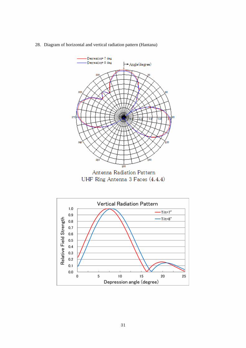
31
28. Diagram of horizontal and vertical radiation pattern (Hantana)

32
29. Specification of antenna system (Kurunegala)
Item Specifications Remarks
Location: Latitude
Longitude
N: 07˚29'04"
E:80˚22'15"
Tower for antenna installation At the side of an existing 42m-high
tower
Antenna configuration
Directions of the antenna
Numbers of stages in the antenna
1-stage 2-face
135, 255(degree)
1, 1
Clockwise from the due
north
Number of stages in each
direction
<Specifications of the antenna>
Type of the antenna panel
Polarization
Gain of an antenna panel
Gain of the antenna system
Voltage standing wave ratio
Tilt angle
Null fill-in
Power capacity
Size and length of main feeder cable
Dehydrator
Combiner
Coaxial switch
Coaxial dummy load
4 dipole antenna
Horizontal polarization
10.5 dBd or above
7.3 dBd or above
1.15 or below
4 (degree)
0 % or above
0.1 kW or above
Air dielectric coaxial cable 7/8“,
25m
1 unit
For transmission of 10W signals on
four frequencies
Three terminals, 1-5/8“
0.1kW
Including the loss of
branching coaxial cables
From the outdoor
distributor
Within the channel in use
Angle of depression from
the horizontal plane
First null point
Transmitter output 10W
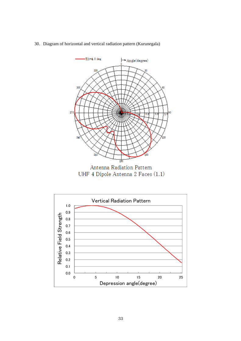
33
30. Diagram of horizontal and vertical radiation pattern (Kurunegala)

34
31. Specification of antenna system (Baddulla)
Item Specifications Remarks
Location: Latitude
Longitude
N: 06˚58'25"
E:81˚03'12"
Tower for antenna installation At the side of an existing 30m-high
tower
Antenna configuration
Directions of the antenna
Numbers of stages in the antenna
2-stage 2-face
0, 90 (degree)
2, 2
Clockwise from the due
north
Number of stages in each
direction
<Specifications of the antenna>
Type of the antenna panel
Polarization
Gain of an antenna panel
Gain of the antenna system
Voltage standing wave ratio
Tilt angle
Null fill-in
Power capacity
Size and length of main feeder cable
Dehydrator
Combiner
Coaxial switch
Coaxial dummy load
8-element ring antenna
Horizontal polarization
9.0 dBd or above
9.0 dBd or above
1.15 or below
6, 9 (degree)
0 % or above
0.1 kW or above
Air dielectric coaxial cable 7/8“,
35m
1 unit
For transmission of 10W signals on
four frequencies
Three terminals, 7/8“
0.1kW
Including the loss of
branching coaxial cables
From the outdoor
distributor
Within the channel in use
Angle of depression from
the horizontal plane
First null point
Transmitter output 10W

35
32. Diagram of horizontal and vertical radiation pattern (Baddulla)
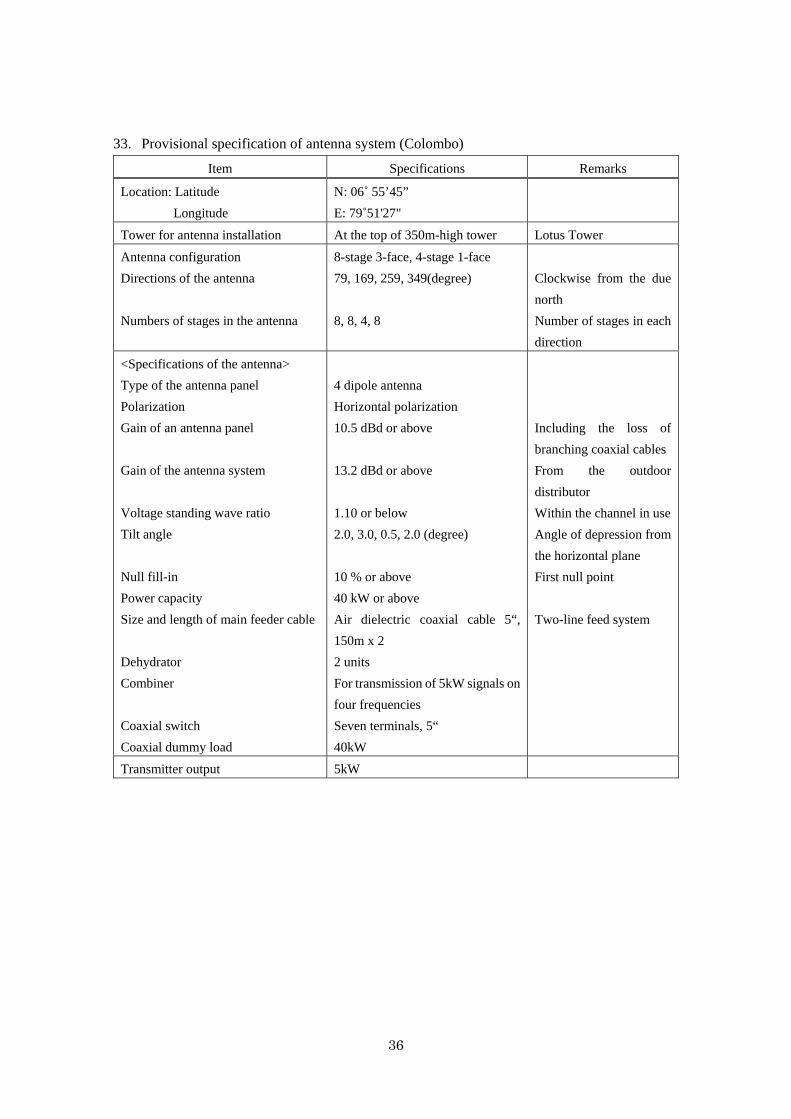
36
33. Provisional specification of antenna system (Colombo)
Item Specifications Remarks
Location: Latitude
Longitude
N: 06˚ 55’45”
E: 79˚51'27"
Tower for antenna installation At the top of 350m-high tower Lotus Tower
Antenna configuration
Directions of the antenna
Numbers of stages in the antenna
8-stage 3-face, 4-stage 1-face
79, 169, 259, 349(degree)
8, 8, 4, 8
Clockwise from the due
north
Number of stages in each
direction
<Specifications of the antenna>
Type of the antenna panel
Polarization
Gain of an antenna panel
Gain of the antenna system
Voltage standing wave ratio
Tilt angle
Null fill-in
Power capacity
Size and length of main feeder cable
Dehydrator
Combiner
Coaxial switch
Coaxial dummy load
4 dipole antenna
Horizontal polarization
10.5 dBd or above
13.2 dBd or above
1.10 or below
2.0, 3.0, 0.5, 2.0 (degree)
10 % or above
40 kW or above
Air dielectric coaxial cable 5“,
150m x 2
2 units
For transmission of 5kW signals on
four frequencies
Seven terminals, 5“
40kW
Including the loss of
branching coaxial cables
From the outdoor
distributor
Within the channel in use
Angle of depression from
the horizontal plane
First null point
Two-line feed system
Transmitter output 5kW

37
34. Provisional diagram of horizontal and vertical radiation pattern (Colombo)
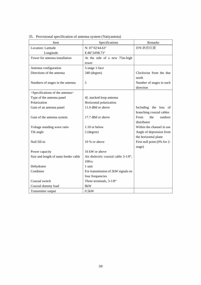
38
35. Provisional specification of antenna system (Yatiyantota)
Item Specifications Remarks
Location: Latitude
Longitude
N: 07˚02'44.63"
E:80˚24'08.73"
ITN 鉄塔位置
Tower for antenna installation At the side of a new 75m-high
tower
Antenna configuration
Directions of the antenna
Numbers of stages in the antenna
5-stage 1-face
340 (degree)
5
Clockwise from the due
north
Number of stages in each
direction
<Specifications of the antenna>
Type of the antenna panel
Polarization
Gain of an antenna panel
Gain of the antenna system
Voltage standing wave ratio
Tilt angle
Null fill-in
Power capacity
Size and length of main feeder cable
Dehydrator
Combiner
Coaxial switch
Coaxial dummy load
4L stacked-loop antenna
Horizontal polarization
11.0 dBd or above
17.7 dBd or above
1.10 or below
2 (degree)
10 % or above
16 kW or above
Air dielectric coaxial cable 3-1/8“,
100m
1 unit
For transmission of 2kW signals on
four frequencies
Three terminals, 3-1/8“
8kW
Including the loss of
branching coaxial cables
From the outdoor
distributor
Within the channel in use
Angle of depression from
the horizontal plane
First null point (0% for 2-
stage)
Transmitter output 0.5kW
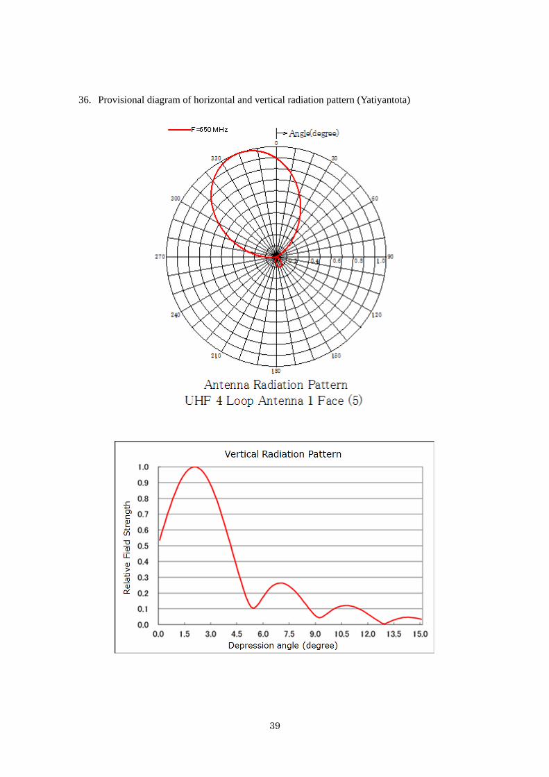
39
36. Provisional diagram of horizontal and vertical radiation pattern (Yatiyantota)
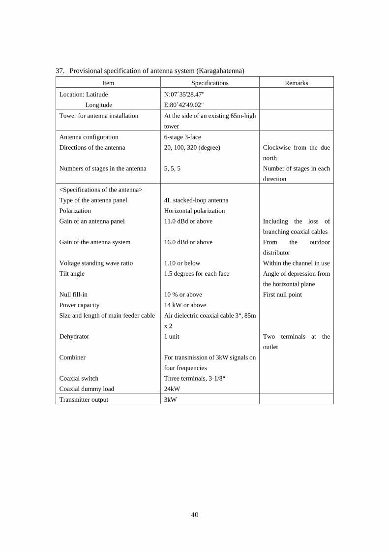
40
37. Provisional specification of antenna system (Karagahatenna)
Item Specifications Remarks
Location: Latitude
Longitude
N:07˚35'28.47"
E:80˚42'49.02"
Tower for antenna installation At the side of an existing 65m-high
tower
Antenna configuration
Directions of the antenna
Numbers of stages in the antenna
6-stage 3-face
20, 100, 320 (degree)
5, 5, 5
Clockwise from the due
north
Number of stages in each
direction
<Specifications of the antenna>
Type of the antenna panel
Polarization
Gain of an antenna panel
Gain of the antenna system
Voltage standing wave ratio
Tilt angle
Null fill-in
Power capacity
Size and length of main feeder cable
Dehydrator
Combiner
Coaxial switch
Coaxial dummy load
4L stacked-loop antenna
Horizontal polarization
11.0 dBd or above
16.0 dBd or above
1.10 or below
1.5 degrees for each face
10 % or above
14 kW or above
Air dielectric coaxial cable 3“, 85m
x 2
1 unit
For transmission of 3kW signals on
four frequencies
Three terminals, 3-1/8“
24kW
Including the loss of
branching coaxial cables
From the outdoor
distributor
Within the channel in use
Angle of depression from
the horizontal plane
First null point
Two terminals at the
outlet
Transmitter output 3kW
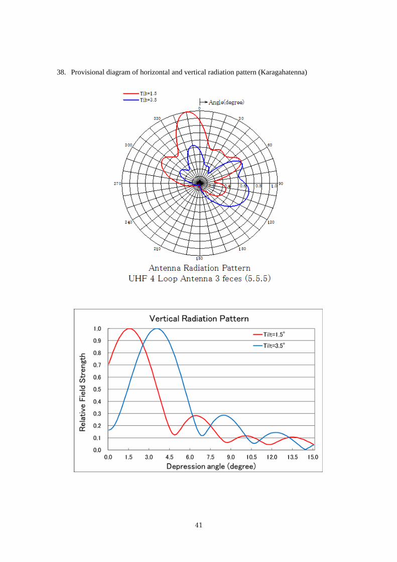
41
38. Provisional diagram of horizontal and vertical radiation pattern (Karagahatenna)
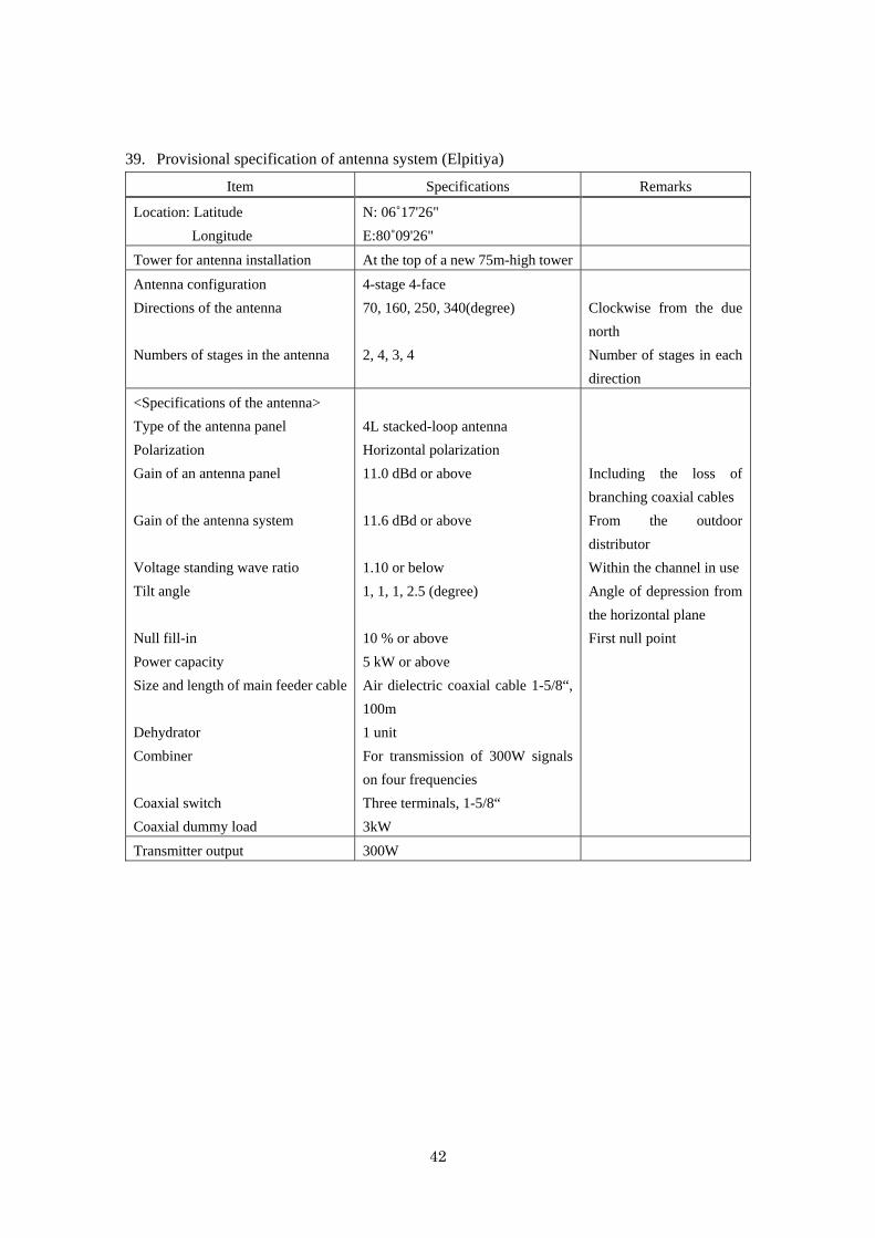
42
39. Provisional specification of antenna system (Elpitiya)
Item Specifications Remarks
Location: Latitude
Longitude
N: 06˚17'26"
E:80˚09'26"
Tower for antenna installation At the top of a new 75m-high tower
Antenna configuration
Directions of the antenna
Numbers of stages in the antenna
4-stage 4-face
70, 160, 250, 340(degree)
2, 4, 3, 4
Clockwise from the due
north
Number of stages in each
direction
<Specifications of the antenna>
Type of the antenna panel
Polarization
Gain of an antenna panel
Gain of the antenna system
Voltage standing wave ratio
Tilt angle
Null fill-in
Power capacity
Size and length of main feeder cable
Dehydrator
Combiner
Coaxial switch
Coaxial dummy load
4L stacked-loop antenna
Horizontal polarization
11.0 dBd or above
11.6 dBd or above
1.10 or below
1, 1, 1, 2.5 (degree)
10 % or above
5 kW or above
Air dielectric coaxial cable 1-5/8“,
100m
1 unit
For transmission of 300W signals
on four frequencies
Three terminals, 1-5/8“
3kW
Including the loss of
branching coaxial cables
From the outdoor
distributor
Within the channel in use
Angle of depression from
the horizontal plane
First null point
Transmitter output 300W
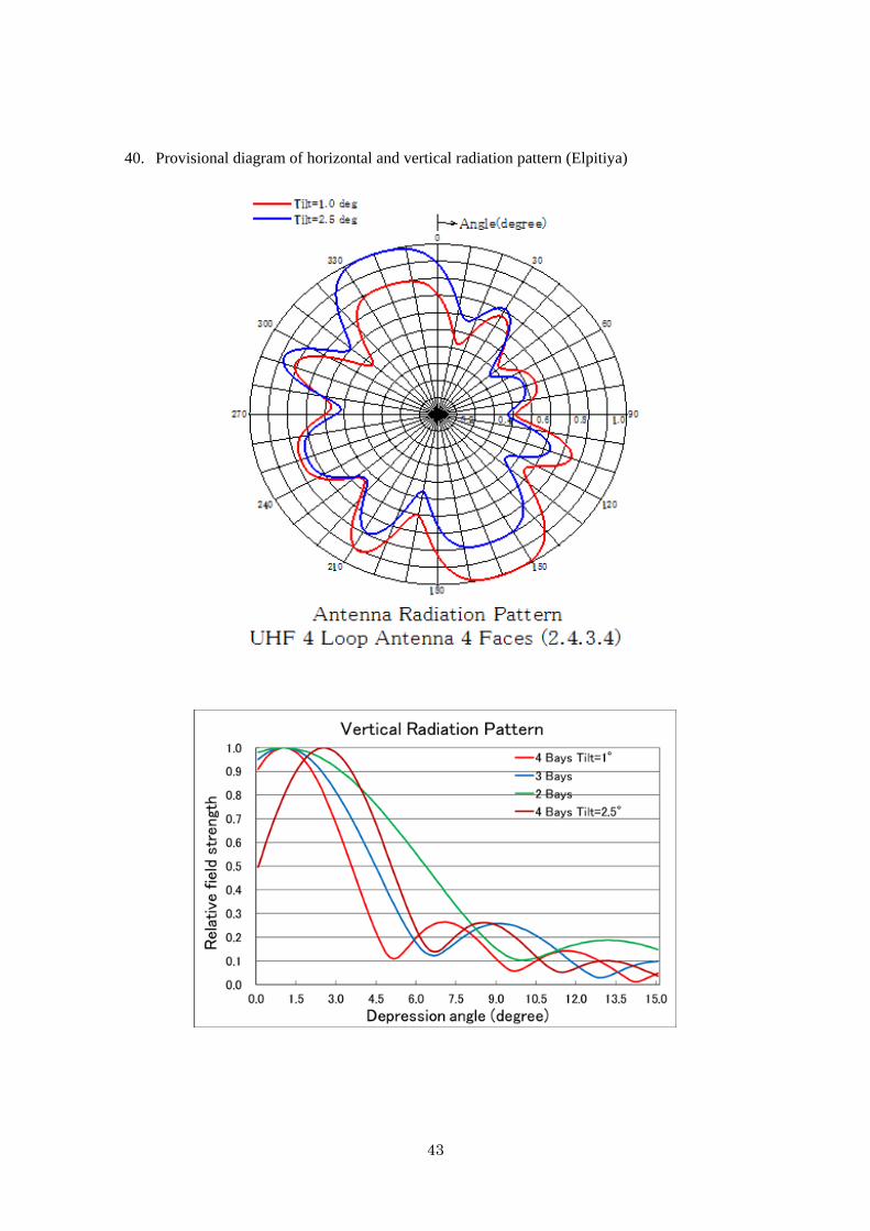
43
40. Provisional diagram of horizontal and vertical radiation pattern (Elpitiya)

44
41. Provisional specification of antenna system (Suriyakanda)
Item Specifications Remarks
Location: Latitude
Longitude
N:06˚26'25"
E:80˚36'54"
ITN 鉄塔位置
Tower for antenna installation At the top of a new 75m-high tower
Antenna configuration
Directions of the antenna
Numbers of stages in the antenna
4-stage 1-face
320 (degree)
4
Clockwise from the due
north
Number of stages in each
direction
<Specifications of the antenna>
Type of the antenna panel
Polarization
Gain of an antenna panel
Gain of the antenna system
Voltage standing wave ratio
Tilt angle
Null fill-in
Power capacity
Size and length of main feeder cable
Dehydrator
Combiner
Coaxial switch
Coaxial dummy load
4L stacked-loop antenna
Horizontal polarization
11.0 dBd or above
16.8 dBd or above
1.10 or below
4 (degree)
10 % or above
8 kW or above
Air dielectric coaxial cable 3“,
100m
1 unit
For transmission of 1kW signals on
four frequencies
Three terminals, 3-1/8“
8kW
Including the loss of
branching coaxial cables
From the outdoor
distributor
Within the channel in use
Angle of depression from
the horizontal plane
First null point
Transmitter output 0.2kW
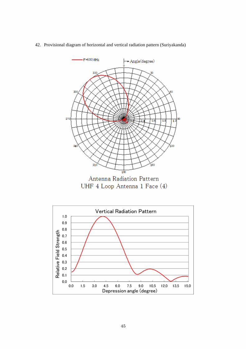
45
42. Provisional diagram of horizontal and vertical radiation pattern (Suriyakanda)
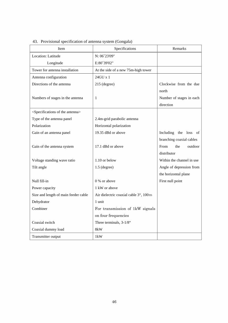
46
43. Provisional specification of antenna system (Gongala)
Item Specifications Remarks
Location: Latitude
Longitude
N: 06˚23'09"
E:80˚39'02"
Tower for antenna installation At the side of a new 75m-high tower
Antenna configuration
Directions of the antenna
Numbers of stages in the antenna
24GU x 1
215 (degree)
1
Clockwise from the due
north
Number of stages in each
direction
<Specifications of the antenna>
Type of the antenna panel
Polarization
Gain of an antenna panel
Gain of the antenna system
Voltage standing wave ratio
Tilt angle
Null fill-in
Power capacity
Size and length of main feeder cable
Dehydrator
Combiner
Coaxial switch
Coaxial dummy load
2.4m-grid parabolic antenna
Horizontal polarization
19.35 dBd or above
17.1 dBd or above
1.10 or below
1.5 (degree)
0 % or above
1 kW or above
Air dielectric coaxial cable 3“, 100m
1 unit
For transmission of 1kW signals
on four frequencies
Three terminals, 3-1/8“
8kW
Including the loss of
branching coaxial cables
From the outdoor
distributor
Within the channel in use
Angle of depression from
the horizontal plane
First null point
Transmitter output 1kW
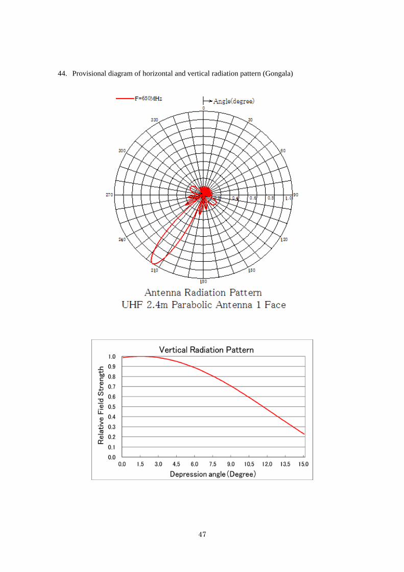
47
44. Provisional diagram of horizontal and vertical radiation pattern (Gongala)
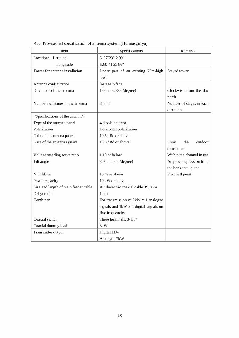
48
45. Provisional specification of antenna system (Hunnasgiriya)
Item Specifications Remarks
Location: Latitude
Longitude
N:07˚23'12.99"
E:80˚41'25.86"
Tower for antenna installation Upper part of an existing 75m-high
tower
Stayed tower
Antenna configuration
Directions of the antenna
Numbers of stages in the antenna
8-stage 3-face
155, 245, 335 (degree)
8, 8, 8
Clockwise from the due
north
Number of stages in each
direction
<Specifications of the antenna>
Type of the antenna panel
Polarization
Gain of an antenna panel
Gain of the antenna system
Voltage standing wave ratio
Tilt angle
Null fill-in
Power capacity
Size and length of main feeder cable
Dehydrator
Combiner
Coaxial switch
Coaxial dummy load
4 dipole antenna
Horizontal polarization
10.5 dBd or above
13.6 dBd or above
1.10 or below
3.0, 4.5, 3.5 (degree)
10 % or above
10 kW or above
Air dielectric coaxial cable 3“, 85m
1 unit
For transmission of 2kW x 1 analogue
signals and 1kW x 4 digital signals on
five frequencies
Three terminals, 3-1/8“
8kW
From the outdoor
distributor
Within the channel in use
Angle of depression from
the horizontal plane
First null point
Transmitter output Digital 1kW
Analogue 2kW
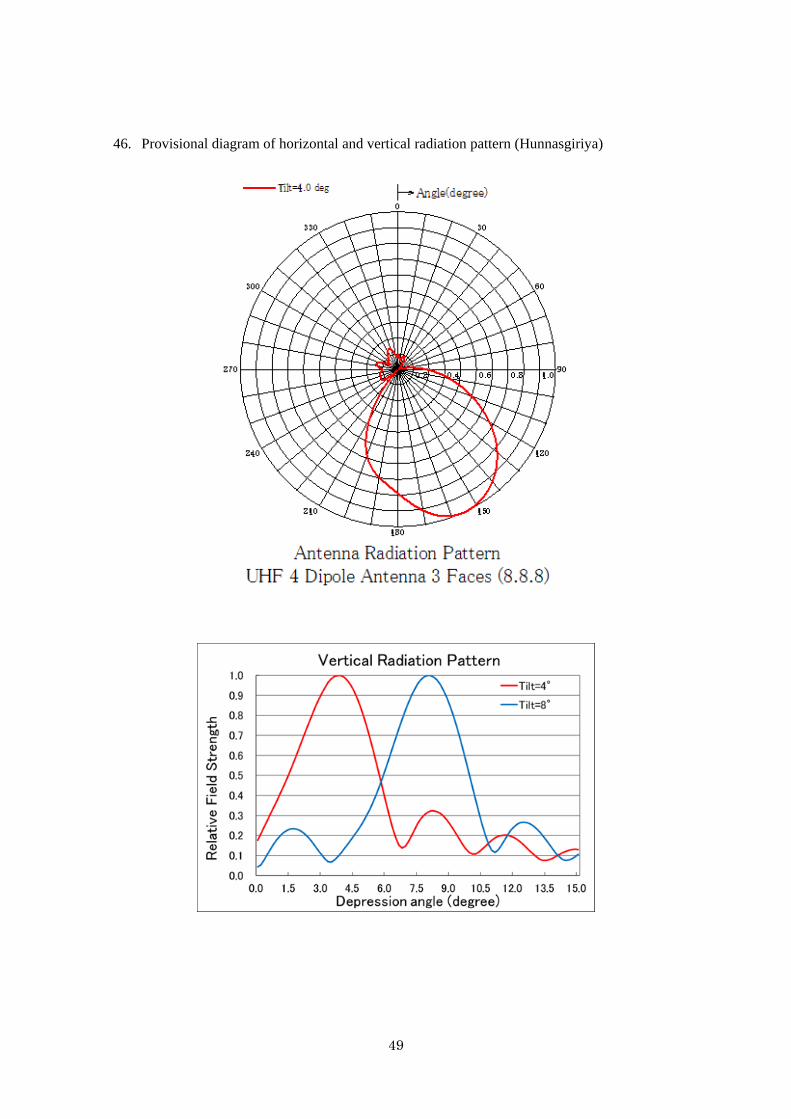
49
46. Provisional diagram of horizontal and vertical radiation pattern (Hunnasgiriya)
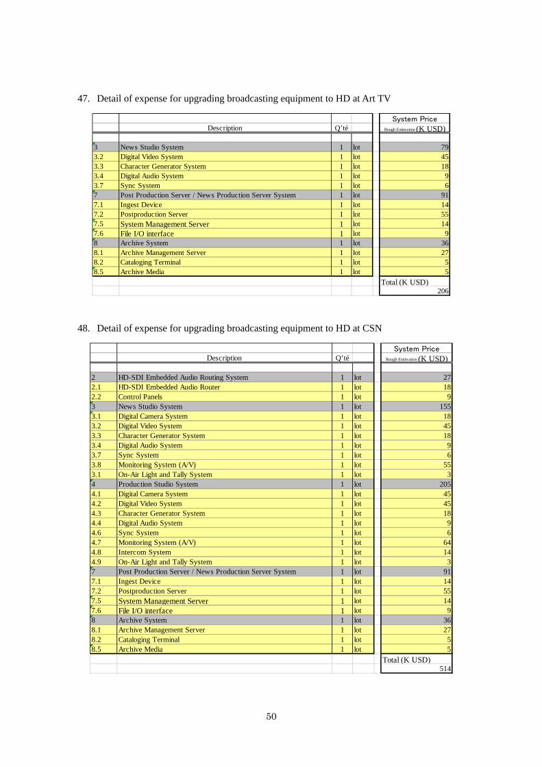
50
47. Detail of expense for upgrading broadcasting equipment to HD at Art TV
48. Detail of expense for upgrading broadcasting equipment to HD at CSN
System PriceDescription Q’té Rough Estimation (K USD)
1103 News Studio System 1 lot 793.2 Digital Video System 1 lot 453.3 Character Generator System 1 lot 183.4 Digital Audio System 1 lot 93.7 Sync System 1 lot 67 Post Production Server / News Production Server System 1 lot 917.1 Ingest Device 1 lot 147.2 Postproduction Server 1 lot 557.5 System Management Server 1 lot 147.6 File I/O interface 1 lot 98 Archive System 1 lot 368.1 Archive Management Server 1 lot 278.2 Cataloging Terminal 1 lot 58.5 Archive Media 1 lot 5
Total (K USD)206
System PriceDescription Q’té Rough Estimation (K USD)
1102 HD-SDI Embedded Audio Routing System 1 lot 272.1 HD-SDI Embedded Audio Router 1 lot 182.2 Control Panels 1 lot 93 News Studio System 1 lot 1553.1 Digital Camera System 1 lot 183.2 Digital Video System 1 lot 453.3 Character Generator System 1 lot 183.4 Digital Audio System 1 lot 93.7 Sync System 1 lot 63.8 Monitoring System (A/V) 1 lot 553.1 On-Air Light and Tally System 1 lot 34 Production Studio System 1 lot 2054.1 Digital Camera System 1 lot 454.2 Digital Video System 1 lot 454.3 Character Generator System 1 lot 184.4 Digital Audio System 1 lot 94.6 Sync System 1 lot 64.7 Monitoring System (A/V) 1 lot 644.8 Intercom System 1 lot 144.9 On-Air Light and Tally System 1 lot 37 Post Production Server / News Production Server System 1 lot 917.1 Ingest Device 1 lot 147.2 Postproduction Server 1 lot 557.5 System Management Server 1 lot 147.6 File I/O interface 1 lot 98 Archive System 1 lot 368.1 Archive Management Server 1 lot 278.2 Cataloging Terminal 1 lot 58.5 Archive Media 1 lot 5
Total (K USD)514
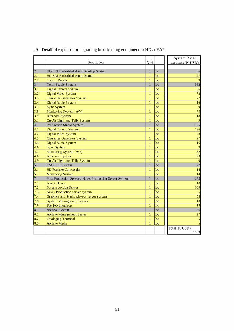
51
49. Detail of expense for upgrading broadcasting equipment to HD at EAP
System PriceDescription Q’té Rough Estimation (K USD)
1102 HD-SDI Embedded Audio Routing System 1 lot 362.1 HD-SDI Embedded Audio Router 1 lot 272.2 Control Panels 1 lot 93 News Studio System 1 lot 3623.1 Digital Camera System 1 lot 1363.2 Digital Video System 1 lot 733.3 Character Generator System 1 lot 273.4 Digital Audio System 1 lot 163.7 Sync System 1 lot 93.8 Monitoring System (A/V) 1 lot 733.9 Intercom System 1 lot 183.1 On-Air Light and Tally System 1 lot 94 Production Studio System 1 lot 3754.1 Digital Camera System 1 lot 1364.2 Digital Video System 1 lot 734.3 Character Generator System 1 lot 274.4 Digital Audio System 1 lot 164.6 Sync System 1 lot 94.7 Monitoring System (A/V) 1 lot 824.8 Intercom System 1 lot 234.9 On-Air Light and Tally System 1 lot 95 ENG/EFP System 1 lot 275.1 HD Portable Camcorder 1 lot 145.2 Monitoring System 1 lot 147 Post Production Server / News Production Server System 1 lot 2737.1 Ingest Device 1 lot 187.2 Postproduction Server 1 lot 1097.3 News Production server system 1 lot 557.4 Graphics and Studio playout server system 1 lot 557.5 System Management Server 1 lot 187.6 File I/O interface 1 lot 188 Archive System 1 lot 368.1 Archive Management Server 1 lot 278.2 Cataloging Terminal 1 lot 58.5 Archive Media 1 lot 5
Total (K USD)1109

52
50. Detail of expense for upgrading broadcasting equipment to HD at Hiru TV
System PriceDescription Q’té Rough Estimation (K USD)
1101 Master Control Room 1 lot 454 Production Studio System 1 lot 1364.1 Digital Camera System 1 lot 1368 Archive System 1 lot 368.1 Archive Management Server 1 lot 278.2 Cataloging Terminal 1 lot 58.5 Archive Media 1 lot 5
Total (K USD)217

53
51. Detail of expense for upgrading broadcasting equipment to HD at MTV
System PriceDescription Q’té Rough Estimation (K USD)
1101 Master Control Room 1 lot 7731.1 Integrated Control systemwith Playout Automation System 1 lot 1641.2 Playout Server 1 lot 2731.3 Character Generator 1 set 361.4 Network system peripherals 1 set 181.5 Baseband Video System peripherals 1 set 271.6 Test Signal Generator 1 set 91.7 Sync Signal System 1 lot 361.8 Monitor System (A/V) 1 lot 911.9 Room to Room Intercom System 1 lot 451.10 Master Clock 1 set 181.11 OA Tally System 1 lot 361.12 Alarm Monitoring System 1 lot 182 HD-SDI Embedded Audio Routing System 1 lot 362.1 HD-SDI Embedded Audio Router 1 lot 272.2 Control Panels 1 lot 93 News Studio System 4 lot 18183.1 Digital Camera System 1 lot 2113.2 Digital Video System 1 lot 913.3 Character Generator System 1 lot 273.4 Digital Audio System 1 lot 163.7 Sync System 1 lot 93.8 Monitoring System (A/V) 1 lot 733.9 Intercom System 1 lot 183.1 On-Air Light and Tally System 1 lot 94 Production Studio System 5 lot 31824.1 Digital Camera System 1 lot 3974.2 Digital Video System 1 lot 734.3 Character Generator System 1 lot 274.4 Digital Audio System 1 lot 164.6 Sync System 1 lot 94.7 Monitoring System (A/V) 1 lot 824.8 Intercom System 1 lot 234.9 On-Air Light and Tally System 1 lot 96 OB VAN 1 lot 11456.1 Digital Camera System 1 lot 4556.2 Digital Video System 1 lot 1826.3 Character Generator System 1 lot 366.4 Digital Audio System 1 lot 1826.6 Sync System 1 lot 186.7 Monitoring System (A/V) 1 lot 916.8 Intercom System 1 lot 456.9 OB VAN with Engine Generator 1 lot 1367 Post Production Server / News Production Server System 1 lot 2737.1 Ingest Device 1 lot 187.2 Postproduction Server 1 lot 1097.3 News Production server system 1 lot 557.4 Graphics and Studio playout server system 1 lot 557.5 System Management Server 1 lot 187.6 File I/O interface 1 lot 188 Archive System 1 lot 368.1 Archive Management Server 1 lot 278.2 Cataloging Terminal 1 lot 58.5 Archive Media 1 lot 5
Total (K USD)7263
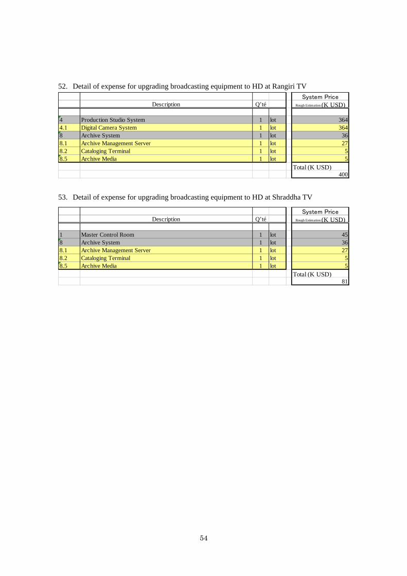
54
52. Detail of expense for upgrading broadcasting equipment to HD at Rangiri TV
53. Detail of expense for upgrading broadcasting equipment to HD at Shraddha TV
System PriceDescription Q’té Rough Estimation (K USD)
1104 Production Studio System 1 lot 3644.1 Digital Camera System 1 lot 3648 Archive System 1 lot 368.1 Archive Management Server 1 lot 278.2 Cataloging Terminal 1 lot 58.5 Archive Media 1 lot 5
Total (K USD)400
System PriceDescription Q’té Rough Estimation (K USD)
1101 Master Control Room 1 lot 458 Archive System 1 lot 368.1 Archive Management Server 1 lot 278.2 Cataloging Terminal 1 lot 58.5 Archive Media 1 lot 5
Total (K USD)81
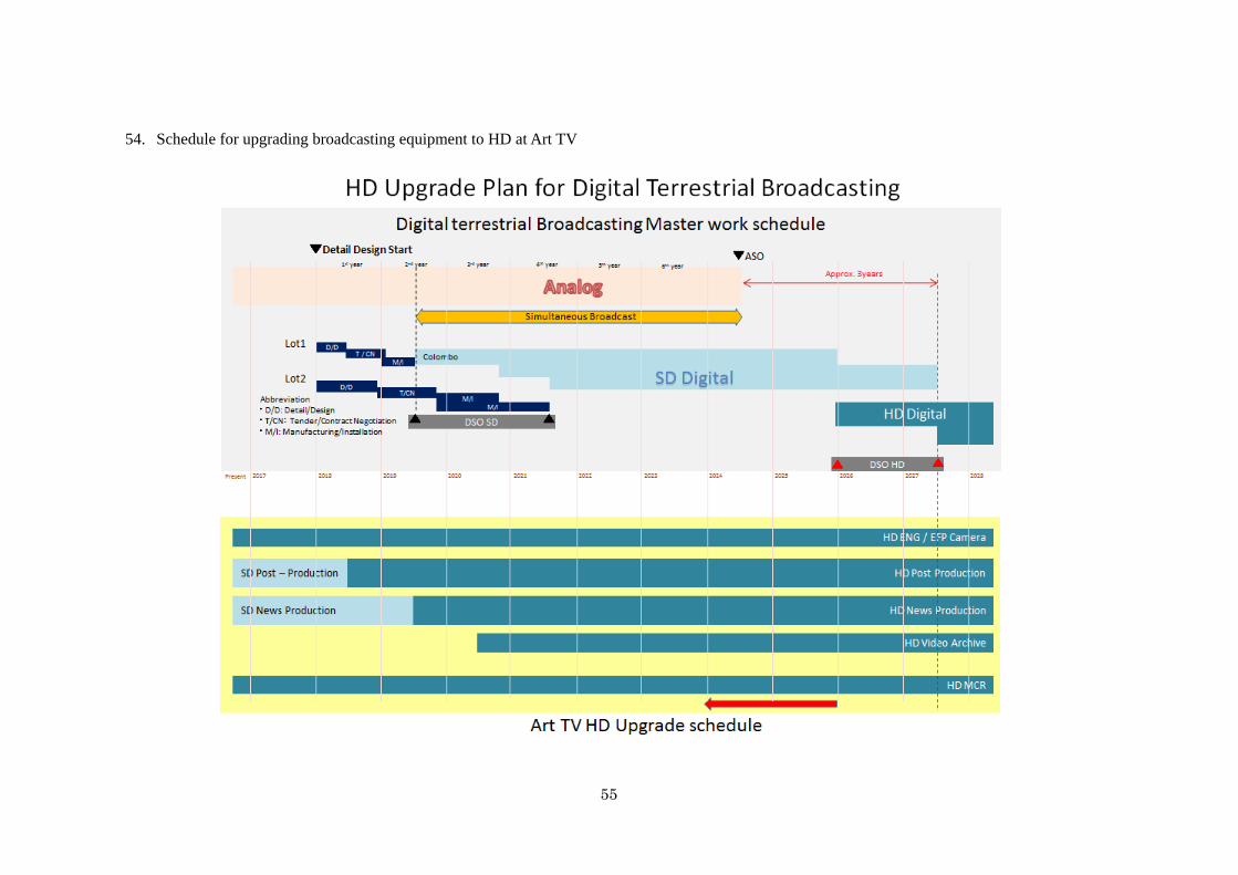
55
54. Schedule for upgrading broadcasting equipment to HD at Art TV
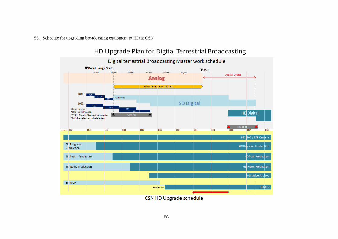
56
55. Schedule for upgrading broadcasting equipment to HD at CSN
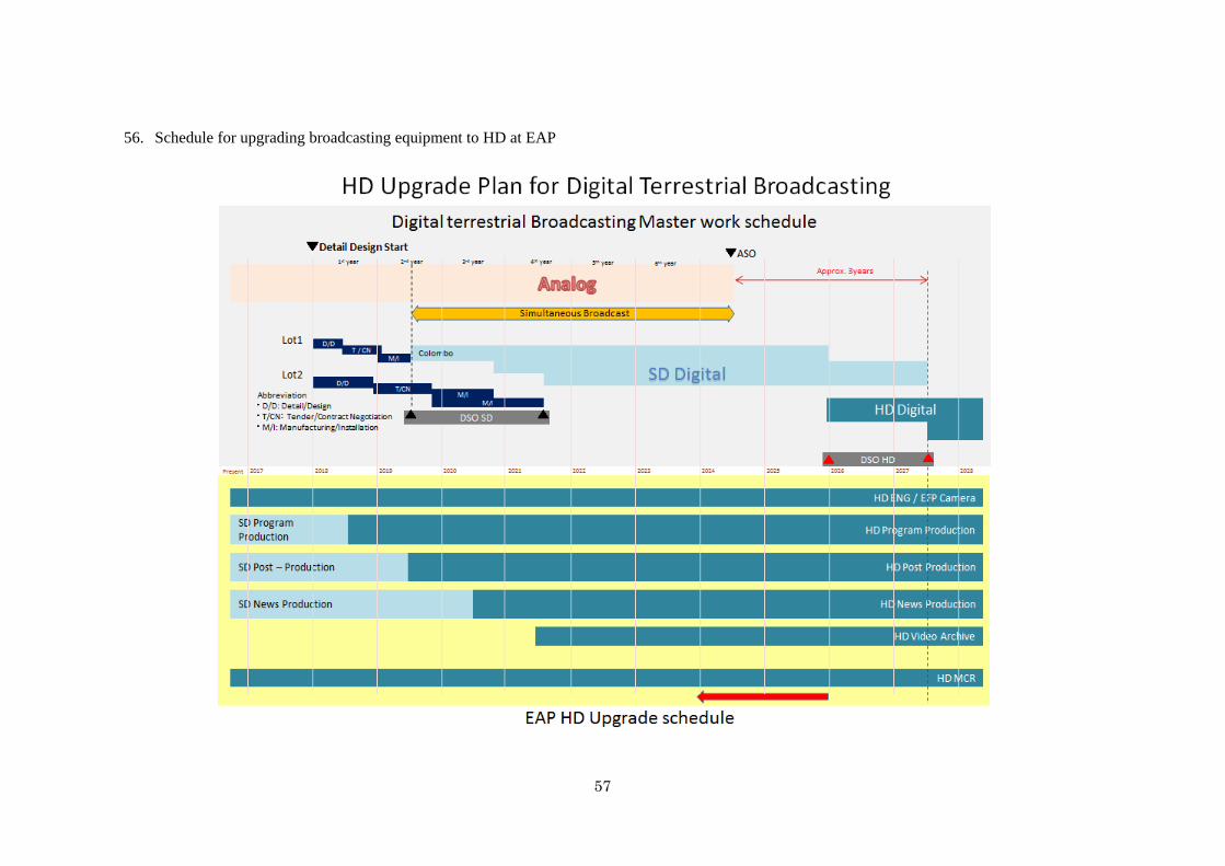
57
56. Schedule for upgrading broadcasting equipment to HD at EAP
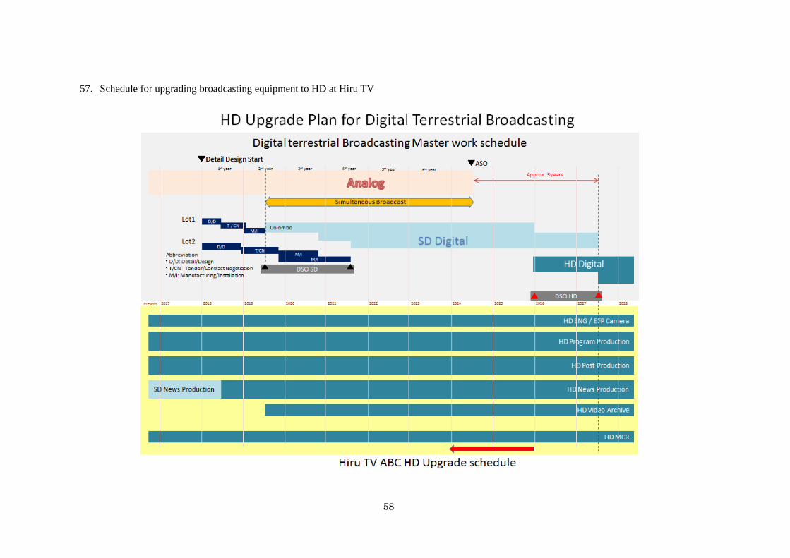
58
57. Schedule for upgrading broadcasting equipment to HD at Hiru TV

59
58. Schedule for upgrading broadcasting equipment to HD at MTV
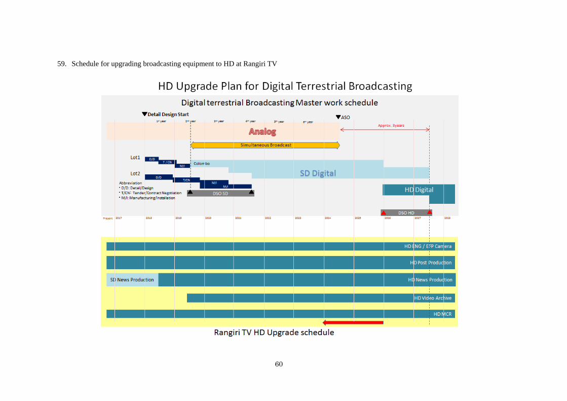
60
59. Schedule for upgrading broadcasting equipment to HD at Rangiri TV
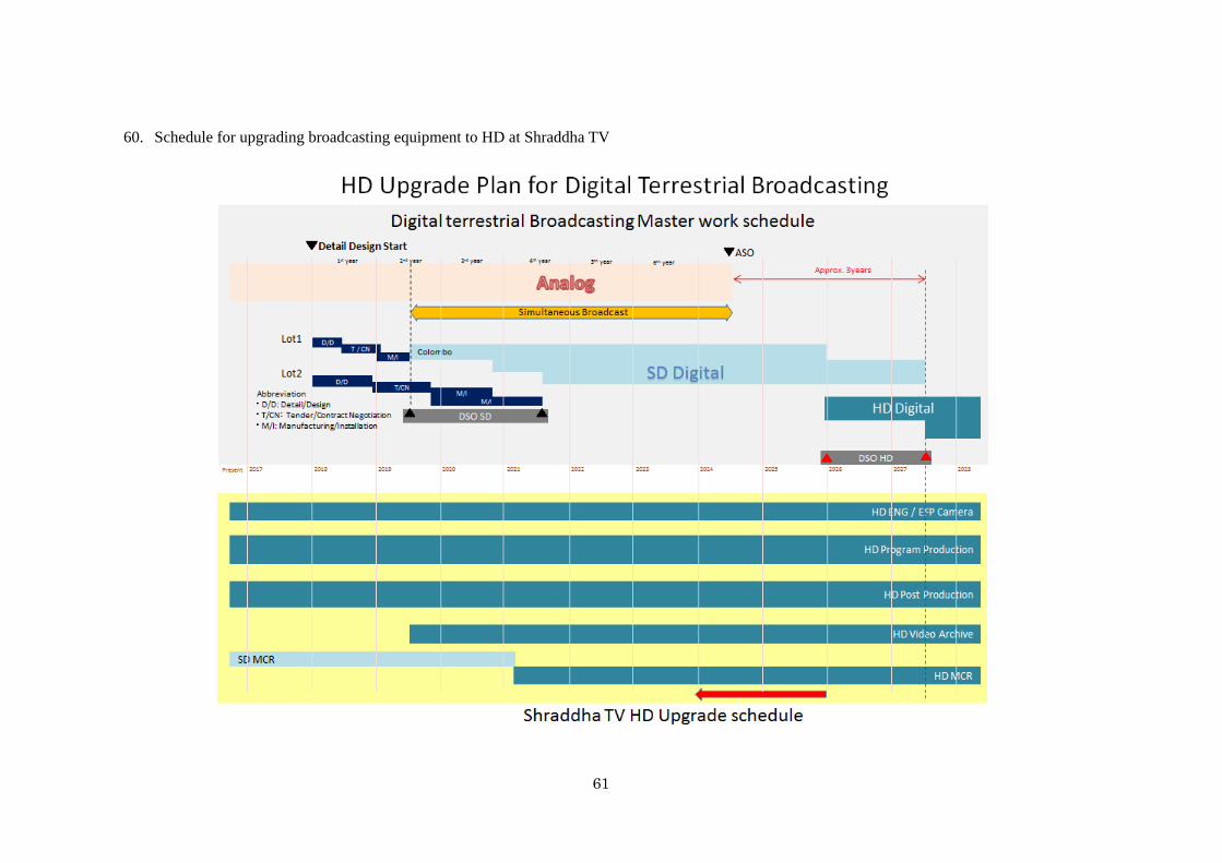
61
60. Schedule for upgrading broadcasting equipment to HD at Shraddha TV
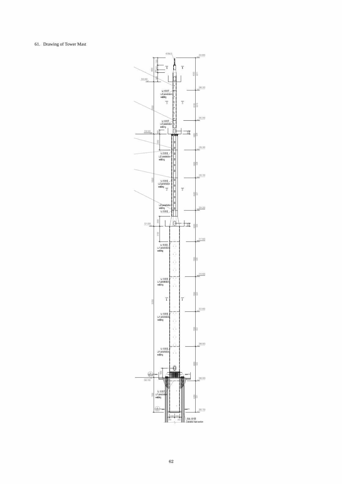
62
61. Drawing of Tower Mast
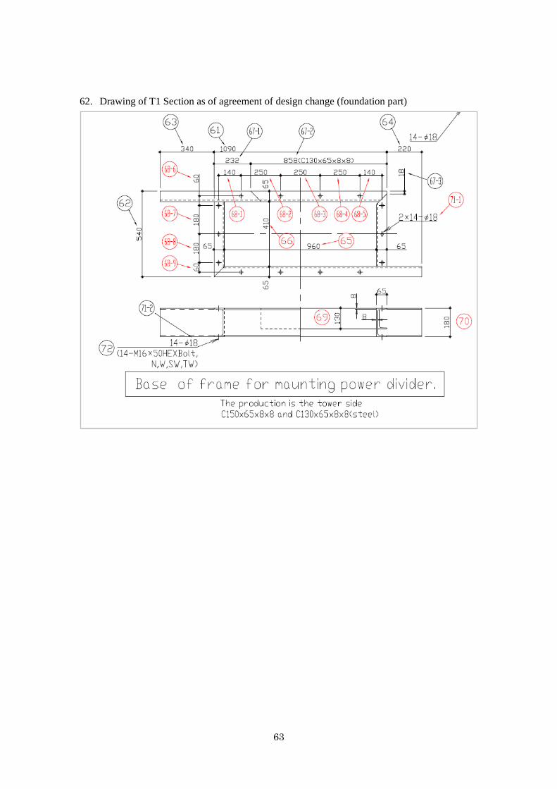
63
62. Drawing of T1 Section as of agreement of design change (foundation part)
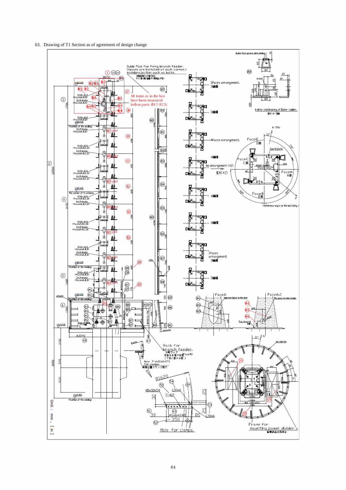
64
63. Drawing of T1 Section as of agreement of design change
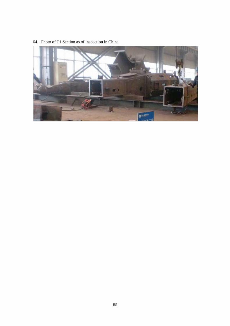
65
64. Photo of T1 Section as of inspection in China
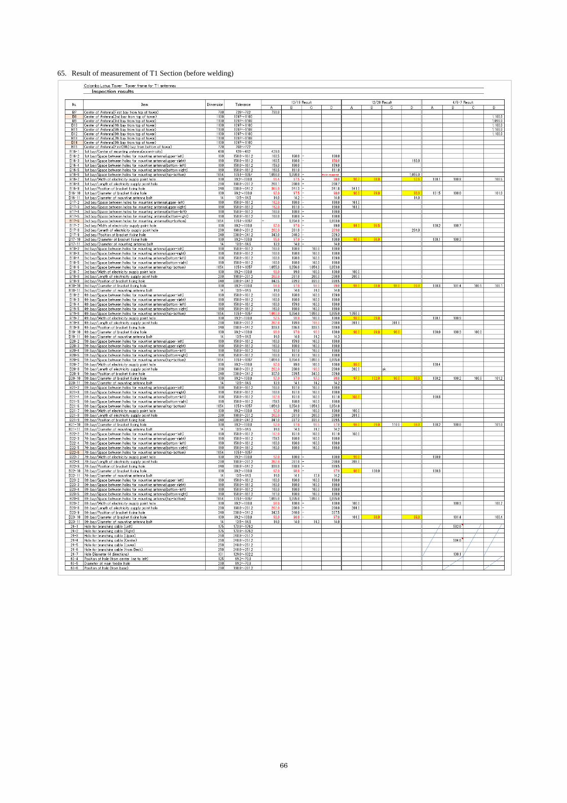
66
65. Result of measurement of T1 Section (before welding)
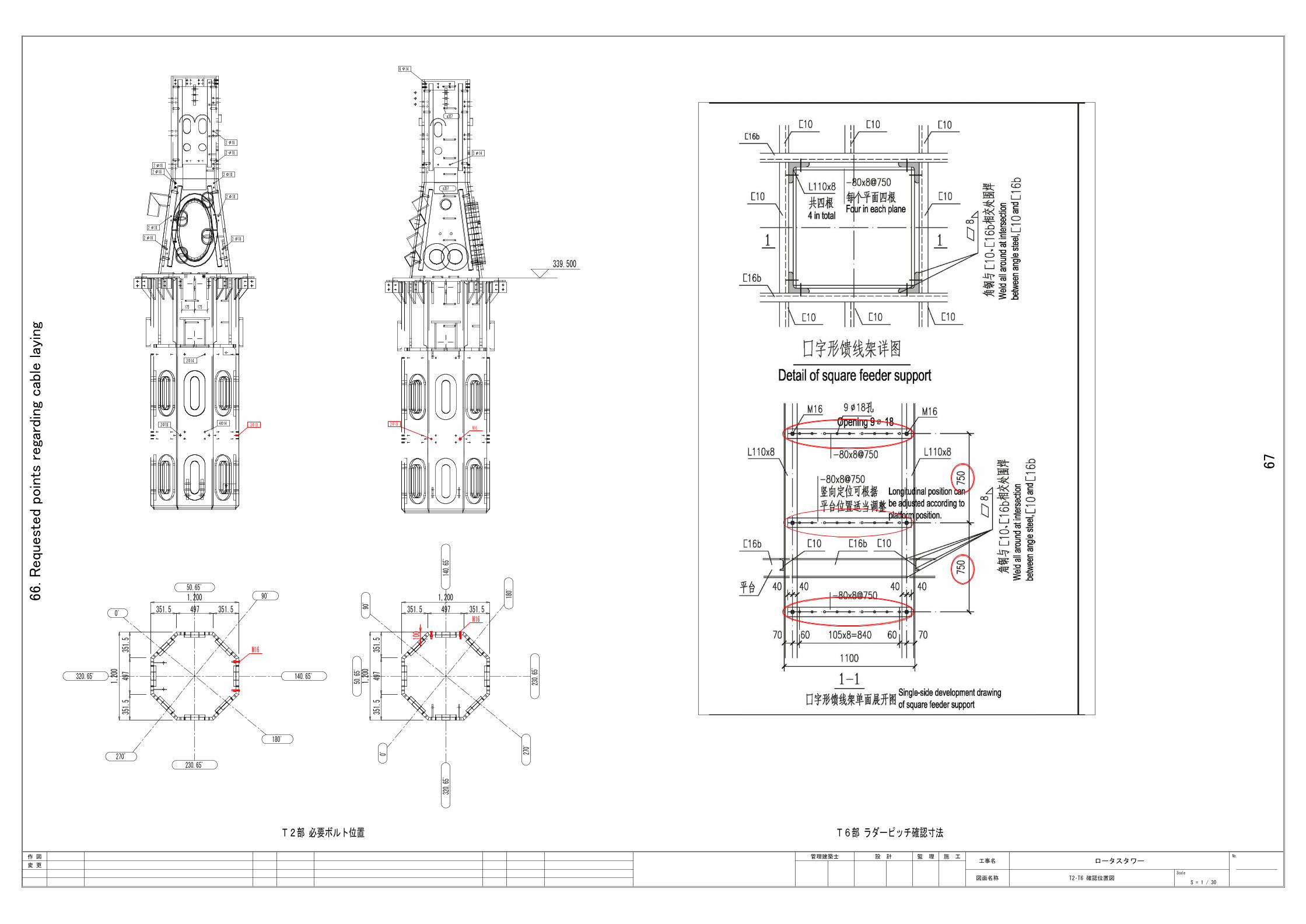
66.R
equ
est
ed
poin
ts r
ega
rdin
g cab
le lay
ing
67
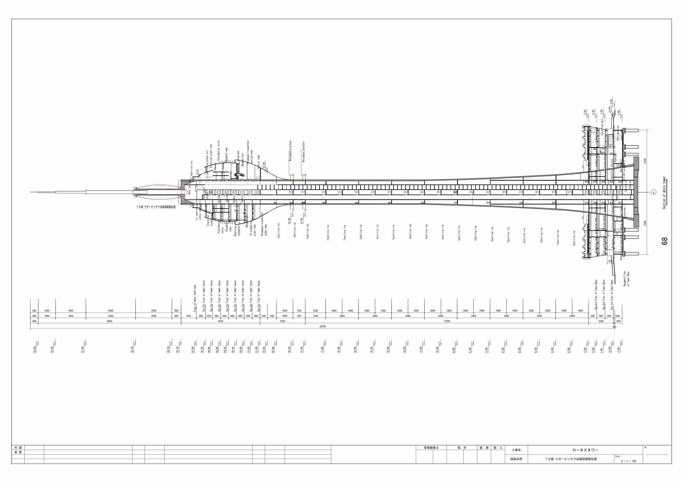
68
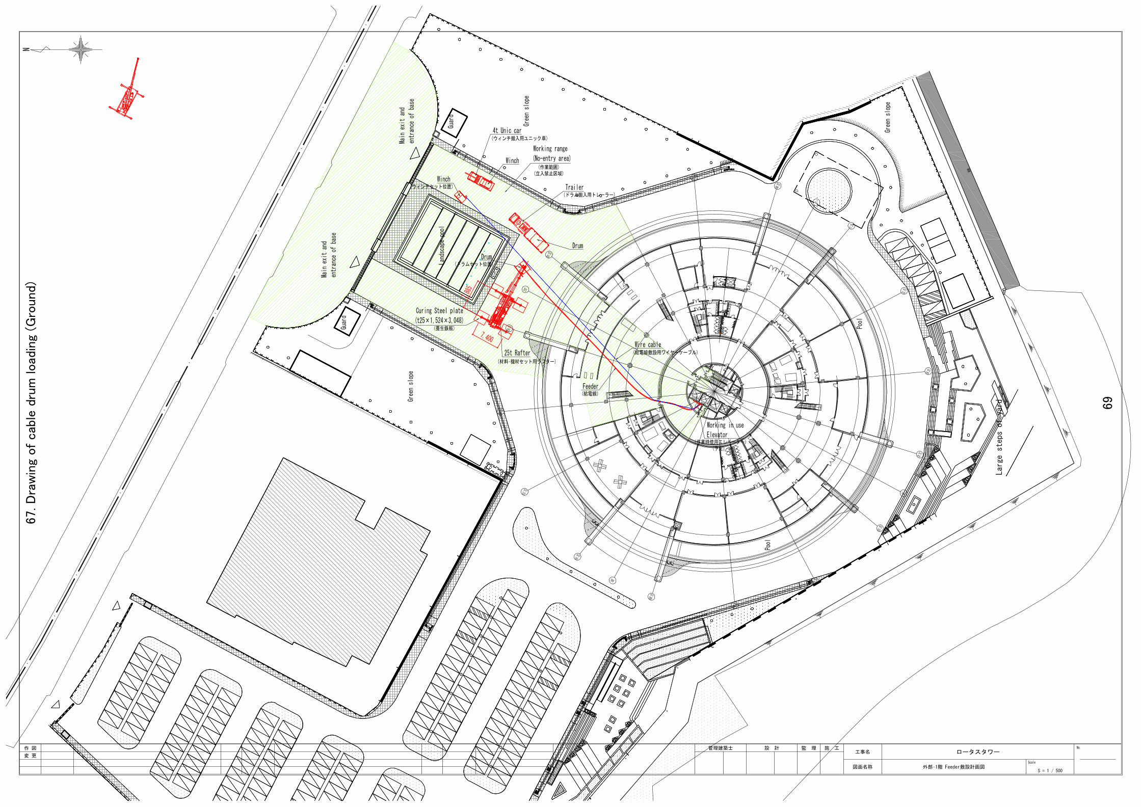
67.D
raw
ing
of cab
le d
rum
load
ing
(Gro
und)
69

68.D
raw
ing
of cab
le d
rum
load
ing
(Tow
er
Bas
e)
70
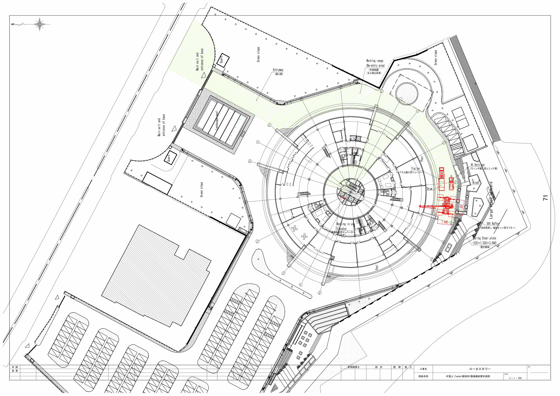
71
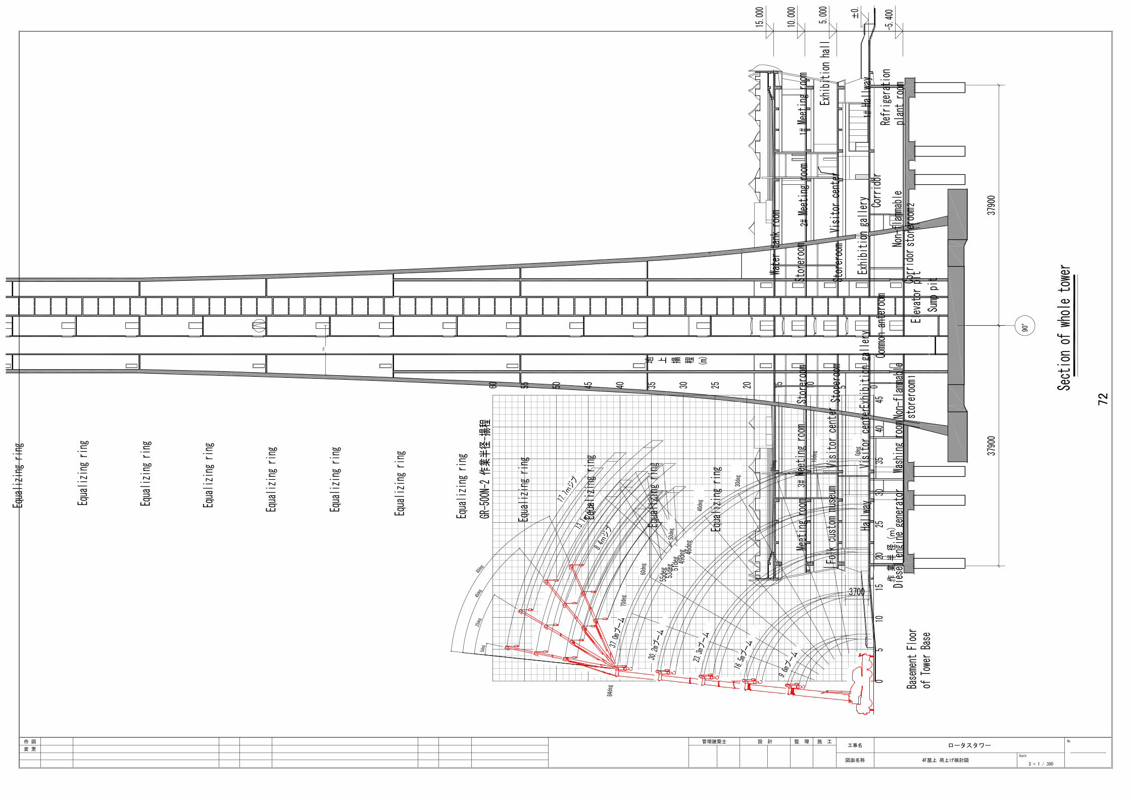
72
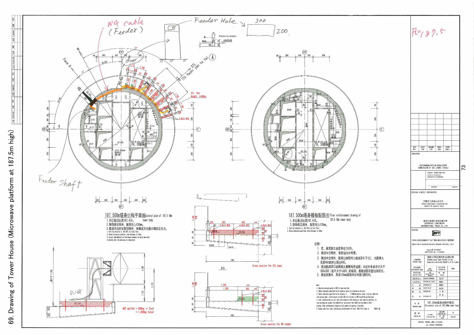
69.D
raw
ing
of Tow
er
House
(M
icro
wav
e p
latf
orm
at
187.5
m h
igh)
73

70.D
raw
ing
of Tow
er
House
(M
icro
wav
e p
latf
orm
, at
195.5
m h
igh)
74
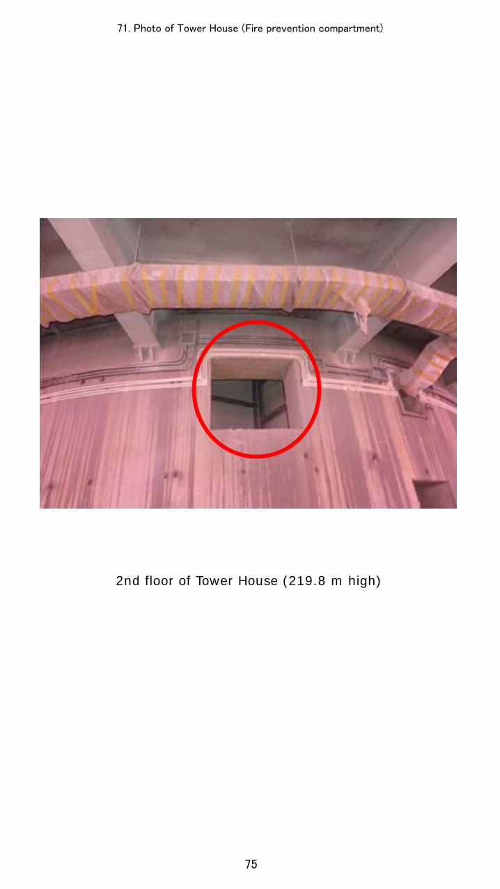
2nd floor of Tower House (219.8 m high)
71. Photo of Tower House (Fire prevention compartment)
75

72.D
raw
ing
of Tow
er
House
(Siz
e o
f th
e h
ole
for
car
ryin
g in
equ
ipm
ent, a
t 253.3
m h
igh)
76
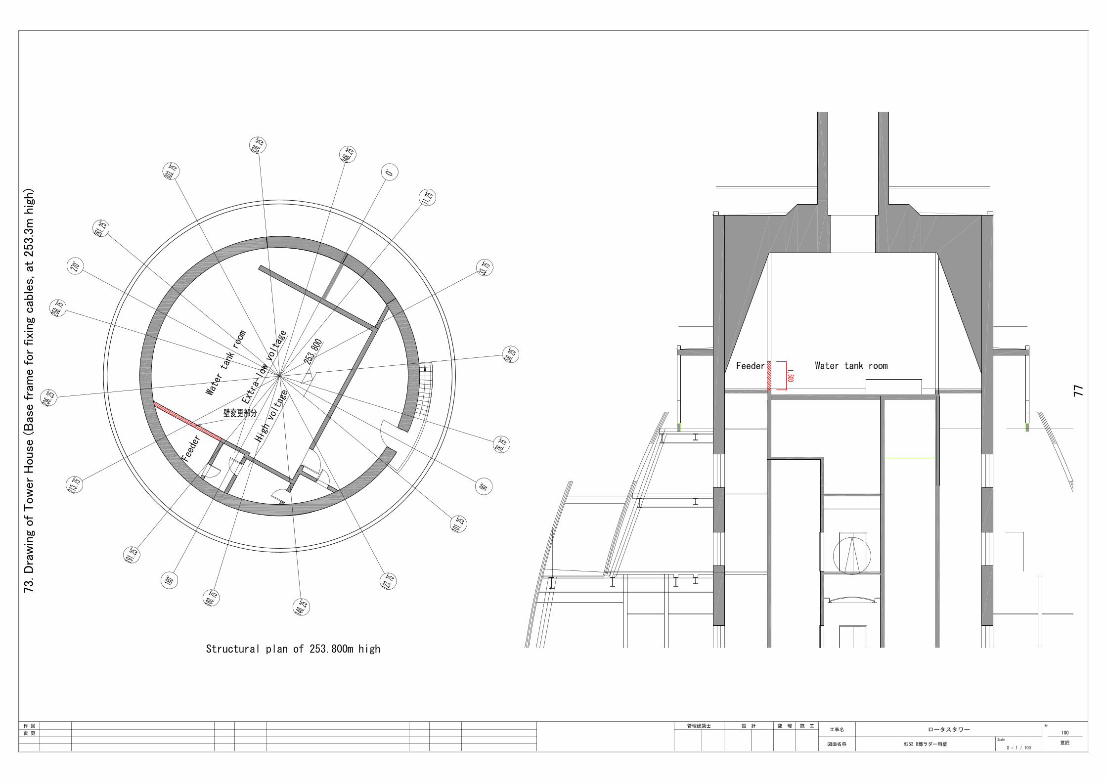
73.D
raw
ing
of Tow
er
House
(B
ase fra
me for
fixi
ng
cab
les,
at
253.3
m h
igh)
77
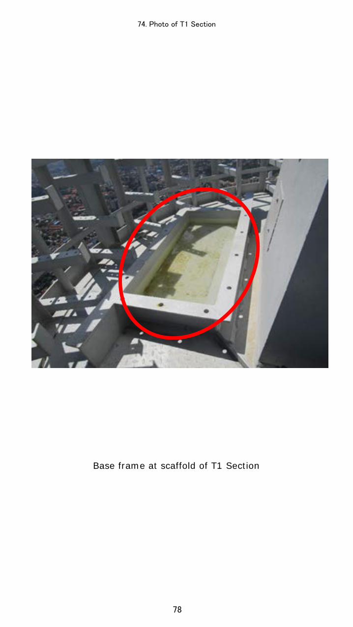
Base frame at scaffold of T1 Section
74. Photo of T1 Section
78


![PARLIAMENT OF THE DEMOCRATIC SOCIALIST REPUBLIC OF SRI LANKA [Certified on 07th March, 2015] Printed on the Order of Government ASSISTANCE TO AND PROTECTION OF VICTIMS OF CRIME AND](https://img.dokumen.tips/doc/110x75/635b5c2d4028fc5adf01a7de/parliament-of-the-democratic-socialist-republic-of-sri-lanka-certified-on-07th.jpg)