Embed Size (px)
Citation preview
Delft University of Technology
Magnetic fluid bearings & sealsMethods, design & applicationLampaert, S.G.E.
DOI10.4233/uuid:361ba18e-298a-483c-bfb9-0528a4ee6119Publication date2020Document VersionFinal published versionCitation (APA)Lampaert, S. G. E. (2020). Magnetic fluid bearings & seals: Methods, design & application.https://doi.org/10.4233/uuid:361ba18e-298a-483c-bfb9-0528a4ee6119
Important noteTo cite this publication, please use the final published version (if applicable).Please check the document version above.
CopyrightOther than for strictly personal use, it is not permitted to download, forward or distribute the text or part of it, without the consentof the author(s) and/or copyright holder(s), unless the work is under an open content license such as Creative Commons.
Takedown policyPlease contact us and provide details if you believe this document breaches copyrights.We will remove access to the work immediately and investigate your claim.
This work is downloaded from Delft University of Technology.For technical reasons the number of authors shown on this cover page is limited to a maximum of 10.
Magnetic Fluid Bearings & Seals:
Methods, Design & Application
Stefan G.E. Lampaert
Part 1: Main matter

ii
iii
Magnetic Fluid Bearings & Seals:
Methods, Design & Application
Dissertation
for the purpose of obtaining the degree of doctor
at Delft University of Technology
by the authority of the Rector Magnificus Prof.dr.ir. T.H.J.J. van der Hagen,
Chair of the Board for Doctorates
to be defended publicly on
Wednesday 30 September 2020 at 15:00 o’clock
by
Stefan Georges Emile LAMPAERT
Master of Science in Mechanical Engineering,
Delft University of Technology, The Netherlands
born in Terneuzen, The Netherlands
iv
This dissertation has been approved by the promotor[s].
Composition of the doctoral committee:
Rector Magnificus, chairperson
Dr.ir. R.A.J. van Ostayen Delft University of Technology, promotor
Ir. J.W. Spronck Delft University of Technology, copromotor
Independent members:
Prof.dr. P.C. Rem Delft University of Technology
Prof.dr. I. Sherrington University of Central Lancashire
Prof.dr.-ing. I.F. Santos Technical University of Denmark
Prof.dr.ir. M.B. de Rooij University of Twente
Prof.dr.ir. J.L. Herder Delft University of Technology
Keywords: ferrofluid, magnetorheological fluids, rheology, lubrication theory, self-healing,
load capacity, stiffness, friction, hydrodynamic bearing, hydrostatic bearing.
Published by: TU Delft Library
Printed by: Gildeprint Enschede
Copyright © 2020 by Stefan G.E. Lampaert
Email: [email protected]
ISBN: 9789464190427
An electronic copy of this dissertation is available at the TU Delft Repository
v
“He achieved success who has lived well, laughed often, and loved much;
Who has enjoyed the trust of pure women, the respect of intelligent men and the
love of little children;
Who has filled his niche and accomplished his task;
Who has never lacked appreciation of Earth's beauty or failed to express it;
Who has left the world better than he found it,
Whether an improved poppy, a perfect poem, or a rescued soul;
Who has always looked for the best in others and given them the best he had;
Whose life was an inspiration;
Whose memory a benediction. “
Bessie Anderson Stanley, 1904, What is success?

vi
vii
Table of contents ...................................................................................................................... vii
Summary ................................................................................................................................... ix
Samenvatting ............................................................................................................................ xi
Prologue ................................................................................................................................... xiii
1 Introduction ...................................................................................................................... 1
2 Ferrofluid bearings ........................................................................................................... 7
3 Ferrofluid gas/liquid seals .............................................................................................. 13
4 Basics of rheological textures ......................................................................................... 17
5 Rheological textures in thrust bearings ........................................................................ 21
6 Rheological textures in journal bearings ...................................................................... 25
7 A lubrication theory for Bingham plastics .................................................................... 29
8 Self-healing bearings ...................................................................................................... 33
9 Rheological characterization of magnetic fluids ........................................................... 37
10 Conclusions ..................................................................................................................... 41
11 Recommendations ........................................................................................................... 45
References ................................................................................................................................. 47
Personal reflection ................................................................................................................... 57
Acknowledgements .................................................................................................................. 59
Curriculum vitae ...................................................................................................................... 61
Thesis project output ............................................................................................................... 63
Appendices ................................................................................................................................ 69
Table of contents

viii
ix
The bearing and the seal are two commonly used tribological components since nearly all
moving machinery relies on them for proper operation. Even a small improvement in these
components can have a big impact on both the market and the environment. The two main
problems of these components are wear and friction. In addition, seals suffer from the problem
of leakage which is fundamental to both their functioning as well as their performance.
The application of magnetic fluids has the potential to be beneficial for these systems.
Magnetic fluids consist of a suspension of magnetic particles in a carrier fluid. This gives them
the unique properties of being attracted to a magnetic field and changing their rheological
behaviour in the presence of a magnetic field. These special properties can give these bearing
and sealing systems unique behaviour, potentially improving their performance.
Therefore, this thesis has two main objectives. The first objective is to further investigate
the potential of magnetic fluids in bearing and sealing system. This part consists of exploratory,
fundamental and early stage research. The unique properties of magnetic fluids are eventually
used in ferrofluid bearings, ferrofluid seals, bearings with rheological textures and self-healing
bearings. The second objective is to develop the necessary knowledge to bring these concepts
to society in the form of applications.
The research on ferrofluid bearings as described in this thesis consists of different
experimentally validated models for the load capacity, torque capacity, out of plane stiffness,
rotational stiffness, friction and operational range for both ferrofluid pocket bearings and
ferrofluid pressure bearings. These models are suitable to determine the most important
bearing parameters which makes it possible to design a bearing system according to desired
specifications. The most recent demonstrator shows specifications that are competitive with
conventional bearing systems.
The research on ferrofluid seals as described in this thesis has resulted in the first seal
concept that does not show any leakage over time. The concept relies on a replenishment
system that makes sure that that degraded ferrofluid is removed and replaced by fresh
ferrofluid. This gives the system a theoretical infinite lifetime, as long as the replenishment
system continues to work.
The research on bearings with magnetorheological fluids as described in this thesis has
resulted in the new design concept of rheological textures. A rheological texture is defined to
be a local change in the rheological behaviour of the lubricant in the lubricating film such that
a local change in lubricant transport and flow resistance occurs. The idea is to replace
geometrical surface textures of more traditional bearings with these rheological textures to
enhance the performance of the bearing. This work has in addition provided a new lubrication
theory for Bingham plastics that properly models the behaviour. Furthermore, a new
Summary
x
experimental method is developed to characterize the rheology of magnetic fluids at high shear
rates.
The last significant result of this research is the new concept of a self-healing bearing using
a lubricant with a suspension of magnetic particles: the application of a local magnetic field
with high gradients in the lubricating film causes the particles to settle at locations where the
magnetic field gradient is high. This creates geometrical surface textures that will regrow when
worn away. In this way we have a bearing with a surface texture that has a theoretical infinite
lifetime.
xi
De lager en de afdichting zijn twee veel gebruikte tribologische componenten doordat vrijwel
alle bewegende machines op ze vertrouwen voor een juiste werking. Zelfs een kleine
verbetering in deze componenten kan een grote impact hebben op zowel de markt als het
milieu. De twee voornaamste problemen van deze componenten zijn slijtage en wrijving. Daar
bovenop lijden afdichten onder het probleem van lekkage welke fundamenteel is voor zowel
hun functioneren als hun prestaties.
De toepassing van magnetische vloeistoffen heeft de potentie om voordelig te zijn voor deze
systemen. Magnetische vloeistoffen bestaan uit een suspensie van magnetische deeltjes en een
drager vloeistof. Dit geeft ze de unieke eigenschap om aangetrokken te zijn door een
magnetisch veld en om van reologisch gedrag te veranderen in reactie tot een magnetisch veld.
Deze special eigenschappen kunnen lagers en afdichtingen uniek gedrag geven dat potentieel
hun gedrag bevorderd.
Daarom heeft deze thesis twee hoofddoelen. Het eerste doel is om verder de potentie van
magnetische vloeistoffen in lager en afdichtingsystemen te onderzoeken. Dit deel bestaat uit
exploraties, fundamenteel en vroege fase onderzoek. De unieke eigenschappen van
magnetische vloeistoffen zijn uiteindelijk gebruikt in ferrofluid lagers, ferrofluid afdichtingen,
lagers met reologische texturen en zelf genezende lagers. Het tweede doel is om alle benodigde
kennis te ontwikkelen om deze concepten naar de maatschappij te kunnen brengen in de vorm
van applicaties.
Het onderzoek naar ferrofluid lagers zoals beschreven in deze thesis bestaat uit
verschillende experimenteel gevalideerde modellen voor de draagkracht, momentcapaciteit,
stijfheid uit het vlak, rationele stijfheid, wrijving en operationeel bereik voor zowel ferrofluid
pocket lagers en ferrofluid druk lagers. Deze modellen zijn bruikbaar om de belangrijkste lager
parameters vast te stellen welke het mogelijk maakt om een lager naar gewenste specificaties
te ontwerpen. De meest recente demonstratie opstelling laat specificaties zien die vergelijkbaar
zijn met conventionele lager systemen.
Het onderzoek naar ferrofluid afdichtingen zoals beschreven in deze thesis heeft
geresulteerd in het eerste concept dat geen enkele vorm van lekkage vertoont over tijd. Het
concept vertrouwd op een verversingsysteem dat ervoor zorgt dat de gedegradeerde ferrofluid
wordt verwijderd en vervangen door verse ferrofluid. Dit geeft het systeem een theoretisch
oneindige levensduur, zoals het verversingsysteem blijft werken.
Het onderzoek aan lagers met magnetorheologische vloeistoffen zoals beschreven in deze
thesis heeft geresulteerd in het nieuwe concept van reologische texturen. Een reologische
textuur is gedefinieerd als een lokale verandering in het reologische gedrag van het
smeermiddel in de smeerfilm zodat een lokale verandering in smeermiddel transport en stroom
weerstand ontstaat. Het idee is om geometrische texturen van traditionele lagers te vervangen
Samenvatting
xii
met deze reologische texturen zodat de prestaties van het lager verbeteren. Dit werk heeft ook
een nieuwe smeringstheorie voor Bingham vloeistoffen opgeleverd welke het gedrag op een
juiste manier beschrijft. Daarbovenop is een nieuwe experimentele methode ontwikkeld om de
reologie van magnetische vloeistoffen te karakteriseren op hoge afschuifsnelheden.
Het laatste significante resultaat van dit onderzoek is het nieuwe concept van zelf
genezende lagers gebruikmakend van een suspensie van magnetische deeltjes: de applicatie
van een lokaal magnetisch veld met een hoog gradiënt in de smeringsfilm zorgt ervoor dat de
deeltjes neerslaan op de locaties waar de veldsterkte hoog is. Dit creëert geometrische
oppervlakte texturen die terugroeien als ze wegslijten. Op deze manier hebben we een lager
met een oppervlakte textuur die een theoretisch oneindige levensduur heeft.
xiii
“Innovation is more than having new ideas: it includes the process of
successfully introducing them or making things happen in a new way.
It turns ideas into useful, practicable and commercial products or
services.”
― John Adair, 2009
What does it mean to innovate? According to the Oxford dictionary it means to make
changes in something established, especially by introducing new methods, ideas or products.
In practise, this means that innovation happens at the frontier of the advancement of our
society. It is the process that brought us from the hunter-gatherer society to the society we live
in nowadays. Over the history of humankind, we worked to advance ourselves and improve our
quality of living. For example, life expectancy increased from around 40 years in the 14th
century up to around 80 years nowadays [1], [2], the global happiness increased significantly
over the last three decades [3] and archeologic data shows that in the prehistoric times the
level of violence was much higher than in the modern era [4]. Society has come a long way by
innovation, but there is still a lot to improve: there are still people that are unhappy, die from
disease and suffer from violence.
The noble thing of working on a PhD thesis is that one takes a few years the time to
contribute to this advancement of humankind. The work of one person over the period of four
years is in most cases too limited in scope to have a significant impact on the big topics
mentioned earlier but it is a good opportunity to have a significant impact on a small field. And
then eventually, a lot of small steps result in one big leap altogether.
Prologue

xiv
1. Introduction
1
“From cardboard and duct tape to ABS polycarbonate, it took 5,127
prototypes and 15 years to get it right.
― James Dyson, 2011
The bearing is a machine component that has made significant progress compared to the
early days: its lifetime has increased considerably, while at the same time friction has
decreased significantly [5], [6]. Still, there is room for improvement as energy losses due to
friction and system failures due to wear, cost society significant amounts of money and CO2
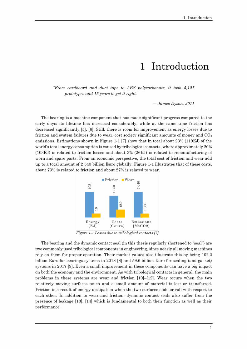
emissions. Estimations shown in Figure 1-1 [7] show that in total about 23% (119EJ) of the
world’s total energy consumption is caused by tribological contacts, where approximately 20%
(103EJ) is related to friction losses and about 3% (26EJ) is related to remanufacturing of
worn and spare parts. From an economic perspective, the total cost of friction and wear add
up to a total amount of 2 540 billion Euro globally. Figure 1-1 illustrates that of these costs,
about 73% is related to friction and about 27% is related to wear.
The bearing and the dynamic contact seal (in this thesis regularly shortened to “seal”) are
two commonly used tribological components in engineering, since nearly all moving machines
rely on them for proper operation. Their market values also illustrate this by being 102.2
billion Euro for bearings systems in 2018 [8] and 59.6 billion Euro for sealing (and gasket)
systems in 2017 [9]. Even a small improvement in these components can have a big impact
on both the economy and the environment. As with tribological contacts in general, the main
problems in these systems are wear and friction [10]–[12]. Wear occurs when the two
relatively moving surfaces touch and a small amount of material is lost or transferred.
Friction is a result of energy dissipation when the two surfaces slide or roll with respect to
each other. In addition to wear and friction, dynamic contact seals also suffer from the
presence of leakage [13], [14] which is fundamental to both their function as well as their
performance.
1 Introduction
Figure 1-1 Losses due to tribological contacts [7].
103
1 8
60
7 0
40
16
680
1 0
80
E n e r g y
[ E J ]
C o s t s
[ G e u r o ]
E m i s s i o n s
[ M t C O 2 ]
Friction Wear
1. Introduction
2
Planar Ferrofluid Bearings Modelling and Design Principles
Stefan Lampaert 2015
Designs for rotary shaft fluid seals in an aqueous environment using ferrofluid
Olivier Potma2017
Ferrofluid Rotary Seal with Replenishment System for Sealing Liquids
Karoen van der Wal2019
Validation of in-plane friction behaviour of a ferrofluid bearing
Bas Fellinger2017
Long stroke linear ferrofluid stage
Stefan van den Toorn2019
A new concept in bearing technology: Magnetorheological texturing
Marc de graaf2019
Microcapillary magnetorheometerSander Allebrandi
2018
Nanometer precision Six Degrees of Freedom Planar Motion Stage
with Ferrofluid BearingsMax Cafe
2014
Planar Ferrofluid Bearings for Precision Stages
Simon van Veen2013
The design of a planar precision stage using cost effective optical mouse sensors
Gihin Mok2015
Design of a three Degrees of Freedom planar precision stage using a single
Position Sensitive DetectorHaris Habib
2015
A planar precision stage using a single image sensor
Len van Moorsel2017
Optimization of the synthesis of Ferrofluid
2018
Increasing the load capacity of planar ferrofluid bearings
by the addition of ferromagnetic material
2019
Operational range of a ferrofluid pocket bearing
Jelle Boots2018
Operational range of a ferrofluid pocket bearing
2019
Capillary rheometer for magnetorheological fluids
2018
Capillary rheometer for magnetorheological fluids
2020
In-plane friction behaviour of a ferrofluid bearing
2018
XY360 planar positioning stage
with ferrofluid bearings
2016
Friction and trail formation of a planar
ferrofluid bearing2016
Load and Stiffness of a Ferrofluid Pocket Bearing
2018
(2+4) DOF precision motion stage with ferrofluid bearings
2016
Hydrostatic bearing with MR texturing
2017
Virtual textured hybrid bearings
2017
Methods for Variable Bearing Properties
using Magnetic Fluids2018
Method for transport of Ferrofluid in a liquid
contactless rotational seal2018
Lubricated Sliding Bearing With Adjustment Of The Properties Of The Lubricant In Certain
Parts Of The Bearing Gap2018
Predicting the behaviour of magnetorheological
textured bearings2018
Ferrofluids in Precision Bearing Technology
2018
Load and Stiffness of a Hydrostatic Bearing Lubricated
with a Bingham Plastic Fluid2019
Experimental validation of self-healing surface textures
Bas Lucieer2020
Self healing bearing2019
Experimental Results on a Hydrostatic Bearing Lubricated with aMagnetorheological Fluid
2019
200mm bearing test setup
Lubrication theory of
Bingham Plastics2020
Rheological textures in a journal bearing with
magnetorheological fluids2019
Rheological textures in a bearing system with parallel surfaces
2019
Ontwerp van een Microscooptafel
2011
A Load and Stiffness Improvement of Planar Ferrofluid Bearings by
adding Steel2016
Influence of a MRF on friction in hydrodynamic
bearings2017
Design, control and evaluation of a magnetorheological damper
to realise constant deceleration2017
Motion energy harvester optimization by
implementing ferrofluid2018
Development of a magneto-active polymer and its
application in a pneumatic valve2017
Ferrofluid Lagering met
grote draagkracht2012
Ferrofluid trail formation on ferrofluidphobic
surfaces2016
Horizontale trillingsisolatie met
behulp van een ferrofluid vlaklager
2013
Vertikale trillingsdemping
voor precisie onderzoek
2013
Casting rubber with magnetic properties
2017
Design of a ferrofluid vacuum pump
2020
Working principle of a multiple drop ferrofluid
pump2019
Modelling magnetorheological fluids for self-healing bearing surface textures
Gerben Van Der Meer2020
Ferrofluid Rotary Seal with Replenishment System for Sealing Liquids
2020
Design of a passive alternative for long stroke linear aerostatic stages based
on ferrofluid bearings2020
A self-healing hydrodynamic thrust bearing using a
magnetorheological fluidn.a.
200mm sealing setup 20mm sealing setup
BSc MSc
Publication without peer review
Peer reviewed publication
Project at industrial partnetPatent
Part of this projectNot part of this project
Project still going
Design considerations for ferrofluid pressure
bearing pads2020
1. Introduction
3
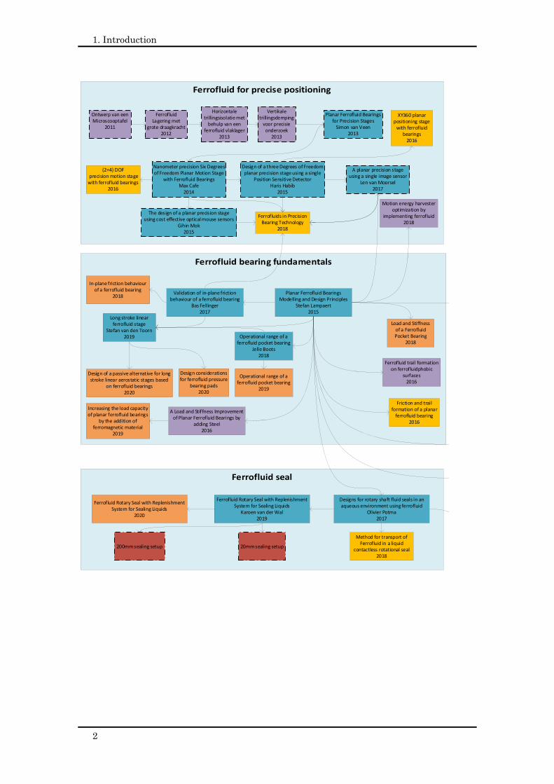
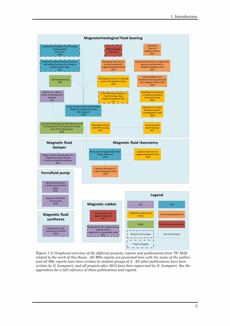
Figure 1-2: Graphical overview of the different projects, reports and publications from TU Delft
related to the work of this thesis. All MSc reports are presented here with the name of the author,
and all BSc reports have been written by student groups of 4. All other publications have been
written by S. Lampaert, and all projects after 2015 have been supervised by S. Lampaert. See the
appendices for a full reference of these publications and reports.
Planar Ferrofluid Bearings Modelling and Design Principles
Stefan Lampaert 2015
Designs for rotary shaft fluid seals in an aqueous environment using ferrofluid
Olivier Potma2017
Ferrofluid Rotary Seal with Replenishment System for Sealing Liquids
Karoen van der Wal2019
Validation of in-plane friction behaviour of a ferrofluid bearing
Bas Fellinger2017
Long stroke linear ferrofluid stage
Stefan van den Toorn2019
A new concept in bearing technology: Magnetorheological texturing
Marc de graaf2019
Microcapillary magnetorheometerSander Allebrandi
2018
Nanometer precision Six Degrees of Freedom Planar Motion Stage
with Ferrofluid BearingsMax Cafe
2014
Planar Ferrofluid Bearings for Precision Stages
Simon van Veen2013
The design of a planar precision stage using cost effective optical mouse sensors
Gihin Mok2015
Design of a three Degrees of Freedom planar precision stage using a single
Position Sensitive DetectorHaris Habib
2015
A planar precision stage using a single image sensor
Len van Moorsel2017
Optimization of the synthesis of Ferrofluid
2018
Increasing the load capacity of planar ferrofluid bearings
by the addition of ferromagnetic material
2019
Operational range of a ferrofluid pocket bearing
Jelle Boots2018
Operational range of a ferrofluid pocket bearing
2019
Capillary rheometer for magnetorheological fluids
2018
Capillary rheometer for magnetorheological fluids
2020
In-plane friction behaviour of a ferrofluid bearing
2018
XY360 planar positioning stage
with ferrofluid bearings
2016
Friction and trail formation of a planar
ferrofluid bearing2016
Load and Stiffness of a Ferrofluid Pocket Bearing
2018
(2+4) DOF precision motion stage with ferrofluid bearings
2016
Hydrostatic bearing with MR texturing
2017
Virtual textured hybrid bearings
2017
Methods for Variable Bearing Properties
using Magnetic Fluids2018
Method for transport of Ferrofluid in a liquid
contactless rotational seal2018
Lubricated Sliding Bearing With Adjustment Of The Properties Of The Lubricant In Certain
Parts Of The Bearing Gap2018
Predicting the behaviour of magnetorheological
textured bearings2018
Ferrofluids in Precision Bearing Technology
2018
Load and Stiffness of a Hydrostatic Bearing Lubricated
with a Bingham Plastic Fluid2019
Experimental validation of self-healing surface textures
Bas Lucieer2020
Self healing bearing2019
Experimental Results on a Hydrostatic Bearing Lubricated with aMagnetorheological Fluid
2019
200mm bearing test setup
Lubrication theory of
Bingham Plastics2020
Rheological textures in a journal bearing with
magnetorheological fluids2019
Rheological textures in a bearing system with parallel surfaces
2019
Ontwerp van een Microscooptafel
2011
A Load and Stiffness Improvement of Planar Ferrofluid Bearings by
adding Steel2016
Influence of a MRF on friction in hydrodynamic
bearings2017
Design, control and evaluation of a magnetorheological damper
to realise constant deceleration2017
Motion energy harvester optimization by
implementing ferrofluid2018
Development of a magneto-active polymer and its
application in a pneumatic valve2017
Ferrofluid Lagering met
grote draagkracht2012
Ferrofluid trail formation on ferrofluidphobic
surfaces2016
Horizontale trillingsisolatie met
behulp van een ferrofluid vlaklager
2013
Vertikale trillingsdemping
voor precisie onderzoek
2013
Casting rubber with magnetic properties
2017
Design of a ferrofluid vacuum pump
2020
Working principle of a multiple drop ferrofluid
pump2019
Modelling magnetorheological fluids for self-healing bearing surface textures
Gerben Van Der Meer2020
Ferrofluid Rotary Seal with Replenishment System for Sealing Liquids
2020
Design of a passive alternative for long stroke linear aerostatic stages based
on ferrofluid bearings2020
A self-healing hydrodynamic thrust bearing using a
magnetorheological fluidn.a.
200mm sealing setup 20mm sealing setup
BSc MSc
Publication without peer review
Peer reviewed publication
Project at industrial partnetPatent
Part of this projectNot part of this project
Project still going
Design considerations for ferrofluid pressure
bearing pads2020
1. Introduction
4
Even the correct working of a dynamic contact seal relies on a small lubricating film
between the moving surfaces. As a result, dynamic contact seals always show some amount
of leakage, without which the seal would suffer from excessive wear.
The question thus arises: how can we improve upon these systems? The application of
magnetic fluids has proven to be beneficial for bearing [15]–[24] and sealing systems [25]–
[33], but also in plenty of other applications like recycling [34]–[36], sensing [37]–[39],
actuation [40]–[43], pumping [44]–[46], damping [47]–[49], cooling [45], [46], oil spill cleaning
[50]–[52], wastewater treatment [53]–[55], medical MRI imaging [56]–[58], drug targeting
[59]–[65] and cancer treatment [66]–[69]. Magnetic fluids consist of a suspension of magnetic
particles in a carrier fluid. This gives them the unique properties of being attracted to a
magnetic field and changing their rheological behaviour in reaction to a magnetic field. The
attracting force is the result of the magnetic particles being attracted in the direction of the
positive gradient of the magnetic field while taking the carrier liquid with them. The change
in rheology is generally the effect of two phenomena that make the fluid effectively more
viscous. The first is that the magnetic particles are unable to rotate in the magnetic field
since they want to stay aligned with the magnetic field lines. The second is that the magnetic
particles cluster together forming chains or other complex structures. These special
properties of magnetic fluids can be used to give bearing and the sealing machine components
unique behaviour that could potentially improve the performance.
The thesis has two main objectives. The first objective is to further investigate the
potential of magnetic fluids in bearing and sealing components. This consists of
exploratory, fundamental and early stage research. The unique properties of magnetic fluids
are eventually used in ferrofluid bearings, ferrofluid seals, bearings with rheological textures
and self-healing bearings. All of these concepts have resulted in fundamental new insights,
resulting in various patents and publications in scientific journals.
The second objective is to develop the necessary knowledge to bring these
concepts to society in the form of applications. This ended up in the development of
different methods, models, and experimental setups each discussed extensively within this
thesis.
In this thesis the term “magnetic fluids” is used as a general definition that includes both
ferrofluids and magnetorheological fluids. Literature generally speaks of ferrofluid as a
colloidal suspension of magnetic nanoparticles such that it is attracted by a magnetic field
[70]–[75]. Magnetorheological fluids are generally defined by literature as suspensions of
ferromagnetic micro particles such that they show a strong change in rheological behaviour
in response to a magnetic field [75]–[79]. In practice, there is a large grey area between
ferrofluids and magnetorheological fluids since colloidal suspensions exist which are both
attracted to a magnetic field and strongly change rheology in response to a magnetic field
[80], [81]. Therefore, this thesis chooses to use a slightly different definition. The work defines
a fluid as a ferrofluid when the application predominantly uses the attracting force between
the magnet and the fluids for achieving the desired performance. In contrast, this work talks
about magnetorheological fluids when the change in rheological behaviour is predominantly
used in the application. So, the application of the fluid defines the type of fluid, not what it
is made of. In addition, most of the theory on magnetorheological fluids in this thesis is also
applicable to electrorheological fluids.
Chapter 2 to 9 deal with the six different focus areas of this thesis: ferrofluid bearings,
ferrofluid gas/fluid seals, rheological textures, lubrication theory for Bingham plastics, self-
healing bearings and rheological characterization of magnetic fluids. Chapter 10 gathers all

1. Introduction
5
the conclusions and chapter 11 gathers all recommendations of the different focus areas. The
appendices contain all relevant publications made during this PhD research [82]–[96]. The
main part of this thesis reuses some of the material of these appendices. Figure 1-3 displays
the thesis structure in a graphical way. Figure 1-2 presents an overview of all the projects,
reports and publications from Delft University of Technology related to this thesis.
Figure 1-3: Thesis structure.
IntroductionChapter 1
Ferrofluid bearingsChapter 2Appendix A1 – A7
Ferrofluid sealsChapter 3Appendix A7 – A9
Rheological texturesChapter 4 - 7Appendix A10 – A14
Self-healing bearingsChapter 8Appendix A15
Rheometry Chapter 9Appendix A16
ConclusionChapter 10
RecommendationsChapter 11

1. Introduction
6
2. Ferrofluid bearings
7
“Leadership is not about being in charge. Leadership is about taking care
of those in your charge”
― Simon Sinek, 2015
Subjecting a ferrofluid to a magnetic field results in an
internal pressure in the fluid that is capable of carrying a
load [97]. This pressure is used to generate the load carrying
capacity of a ferrofluid bearing, which as a result can be
categorized as a type of hydrostatic bearing since it does not
need a relative motion to maintain a lubricating film [98],
[99]. The bearing distinguishes itself from other concepts by
its low price, compactness, inherent stability, low (viscous) friction, absence of pumps and
absence of stick-slip. This makes the bearing an interesting alternative to, for example, air
bearings and magnetic bearings.
The maximum pressure developed within the fluid due to an external magnetic field
typically can reach up to one bar, depending on the magnetic field strength and the type of
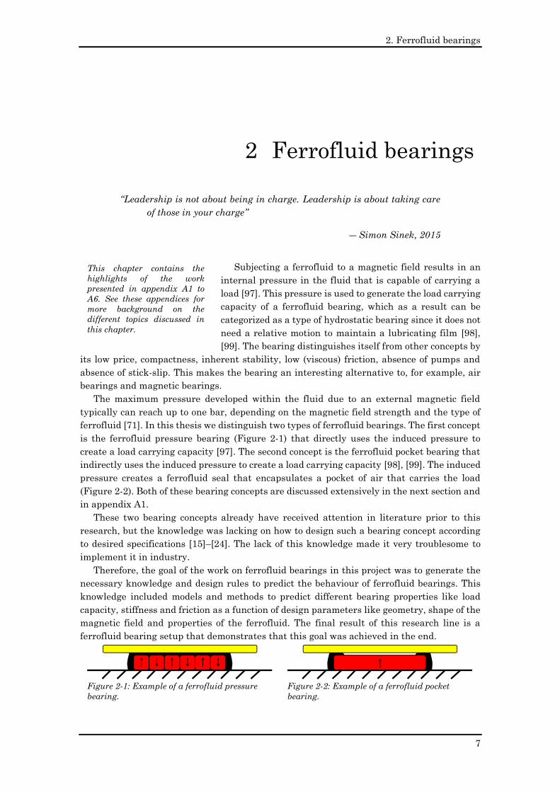
ferrofluid [71]. In this thesis we distinguish two types of ferrofluid bearings. The first concept
is the ferrofluid pressure bearing (Figure 2-1) that directly uses the induced pressure to
create a load carrying capacity [97]. The second concept is the ferrofluid pocket bearing that
indirectly uses the induced pressure to create a load carrying capacity [98], [99]. The induced
pressure creates a ferrofluid seal that encapsulates a pocket of air that carries the load
(Figure 2-2). Both of these bearing concepts are discussed extensively in the next section and
in appendix A1.
These two bearing concepts already have received attention in literature prior to this
research, but the knowledge was lacking on how to design such a bearing concept according
to desired specifications [15]–[24]. The lack of this knowledge made it very troublesome to
implement it in industry.
Therefore, the goal of the work on ferrofluid bearings in this project was to generate the
necessary knowledge and design rules to predict the behaviour of ferrofluid bearings. This
knowledge included models and methods to predict different bearing properties like load
capacity, stiffness and friction as a function of design parameters like geometry, shape of the
magnetic field and properties of the ferrofluid. The final result of this research line is a
ferrofluid bearing setup that demonstrates that this goal was achieved in the end.
2 Ferrofluid bearings
Figure 2-1: Example of a ferrofluid pressure
bearing.
Figure 2-2: Example of a ferrofluid pocket
bearing.
This chapter contains the
highlights of the work
presented in appendix A1 to
A6. See these appendices for
more background on the
different topics discussed in
this chapter.
2. Ferrofluid bearings
8
2.1 Load capacity & stiffness
A ferrofluid subjected to a magnetic field develops a magnetic body force that creates a
pressure inside the fluid [70]. This effect is comparable to the gravity force on a body of fluid;
at the upper surface of the fluid there is only ambient pressure, but at the bottom of the fluid
there can be a very high pressure resulting from the gravity acting on the water column
sitting on this location. The ferrofluid is distributed in a similar way across the magnet as
the water in the oceans is distributed across earth. The load capacity of a ferrofluid pressure
bearing is the result of this internal pressure created by the magnetic body force. One may
say that the bearing is floating on top of a volume of ferrofluid. The total force developed by
this effect increases closer to the magnet since the body force is larger there due to the
distribution of the magnetic field around the magnet. This change in pressure and thus load
capacity as a function of the displacement defines the stiffness of the bearing.
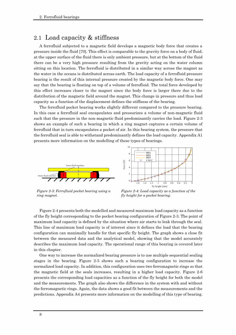
The ferrofluid pocket bearing works slightly different compared to the pressure bearing.
In this case a ferrofluid seal encapsulates and pressurizes a volume of non-magnetic fluid
such that the pressure in the non-magnetic fluid predominantly carries the load. Figure 2-3
shows an example of such a bearing in which a ring magnet captures a certain volume of
ferrofluid that in turn encapsulates a pocket of air. In this bearing system, the pressure that
the ferrofluid seal is able to withstand predominantly defines the load capacity. Appendix A1
presents more information on the modelling of these types of bearings.
Figure 2-4 presents both the modelled and measured maximum load capacity as a function
of the fly height corresponding to the pocket bearing configuration of Figure 2-3. The point of
maximum load capacity is defined by the situation where air starts to leak through the seal.
This line of maximum load capacity is of interest since it defines the load that the bearing
configuration can maximally handle for that specific fly height. The graph shows a close fit
between the measured data and the analytical model, showing that the model accurately
describes the maximum load capacity. The operational range of this bearing is covered later
in this chapter.
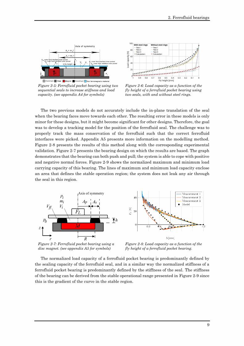
One way to increase the normalized bearing pressure is to use multiple sequential sealing
stages in the bearing. Figure 2-5 shows such a bearing configuration to increase the
normalized load capacity. In addition, this configuration uses two ferromagnetic rings so that
the magnetic field at the seals increases, resulting in a higher load capacity. Figure 2-6
presents the corresponding load capacities as a function of the fly height for both the model
and the measurements. The graph also shows the difference in the system with and without
the ferromagnetic rings. Again, the data shows a good fit between the measurements and the
predictions. Appendix A4 presents more information on the modelling of this type of bearing.
Figure 2-3: Ferrofluid pocket bearing using a
ring magnet.
Inner fluid interface
Outer fluid interface
Figure 2-4: Load capacity as a function of the
fly height for a pocket bearing.
00.20.40.60.811.21.41.6
fly height [mm]
0
2
4
6
8
10
forc
e[N
]
M01M02M03CALC
2. Ferrofluid bearings
9
The two previous models do not accurately include the in-plane translation of the seal
when the bearing faces move towards each other. The resulting error in these models is only
minor for these designs, but it might become significant for other designs. Therefore, the goal
was to develop a tracking model for the position of the ferrofluid seal. The challenge was to
properly track the mass conservation of the ferrofluid such that the correct ferrofluid
interfaces were picked. Appendix A5 presents more information on the modelling method.
Figure 2-8 presents the results of this method along with the corresponding experimental
validation. Figure 2-7 presents the bearing design on which the results are based. The graph
demonstrates that the bearing can both push and pull; the system is able to cope with positive
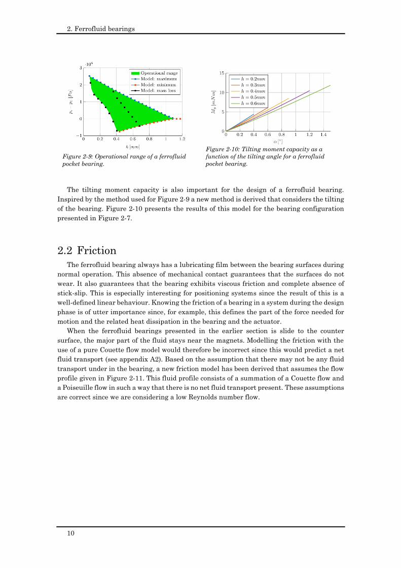
and negative normal forces. Figure 2-9 shows the normalized maximum and minimum load
carrying capacity of this bearing. The lines of maximum and minimum load capacity enclose
an area that defines the stable operation region; the system does not leak any air through
the seal in this region.
The normalized load capacity of a ferrofluid pocket bearing is predominantly defined by
the sealing capacity of the ferrofluid seal, and in a similar way the normalized stiffness of a
ferrofluid pocket bearing is predominantly defined by the stiffness of the seal. The stiffness
of the bearing can be derived from the stable operational range presented in Figure 2-9 since
this is the gradient of the curve in the stable region.
Figure 2-5: Ferrofluid pocket bearing using two
sequential seals to increase stiffness and load
capacity. (see appendix A4 for symbols)
Figure 2-6: Load capacity as a function of the
fly height of a ferrofluid pocket bearing using
two seals, with and without steel rings.
Figure 2-7: Ferrofluid pocket bearing using a
disc magnet. (see appendix A5 for symbols)
Figure 2-8: Load capacity as a function of the
fly height of a ferrofluid pocket bearing.
2. Ferrofluid bearings
10
The tilting moment capacity is also important for the design of a ferrofluid bearing.
Inspired by the method used for Figure 2-9 a new method is derived that considers the tilting
of the bearing. Figure 2-10 presents the results of this model for the bearing configuration
presented in Figure 2-7.
2.2 Friction
The ferrofluid bearing always has a lubricating film between the bearing surfaces during
normal operation. This absence of mechanical contact guarantees that the surfaces do not
wear. It also guarantees that the bearing exhibits viscous friction and complete absence of
stick-slip. This is especially interesting for positioning systems since the result of this is a
well-defined linear behaviour. Knowing the friction of a bearing in a system during the design
phase is of utter importance since, for example, this defines the part of the force needed for
motion and the related heat dissipation in the bearing and the actuator.
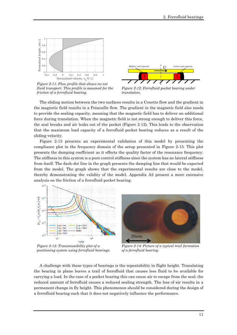
When the ferrofluid bearings presented in the earlier section is slide to the counter
surface, the major part of the fluid stays near the magnets. Modelling the friction with the
use of a pure Couette flow model would therefore be incorrect since this would predict a net
fluid transport (see appendix A2). Based on the assumption that there may not be any fluid
transport under in the bearing, a new friction model has been derived that assumes the flow
profile given in Figure 2-11. This fluid profile consists of a summation of a Couette flow and
a Poiseuille flow in such a way that there is no net fluid transport present. These assumptions
are correct since we are considering a low Reynolds number flow.
Figure 2-9: Operational range of a ferrofluid
pocket bearing.
Figure 2-10: Tilting moment capacity as a
function of the tilting angle for a ferrofluid
pocket bearing.
2. Ferrofluid bearings
11
The sliding motion between the two surfaces results in a Couette flow and the gradient in
the magnetic field results in a Poiseuille flow. The gradient in the magnetic field also needs
to provide the sealing capacity, meaning that the magnetic field has to deliver an additional
force during translation. When the magnetic field is not strong enough to deliver this force,
the seal breaks and air leaks out of the pocket (Figure 2-12). This leads to the observation
that the maximum load capacity of a ferrofluid pocket bearing reduces as a result of the
sliding velocity.
Figure 2-13 presents an experimental validation of this model by presenting the
compliance plot in the frequency domain of the setup presented in Figure 2-15. This plot
presents the damping coefficient as it effects the quality factor of the resonance frequency.
The stiffness in this system is a pure control stiffness since the system has no lateral stiffness
from itself. The dash-dot line in the graph presents the damping line that would be expected
from the model. The graph shows that the experimental results are close to the model,
thereby demonstrating the validity of the model. Appendix A2 present a more extensive
analysis on the friction of a ferrofluid pocket bearing.
A challenge with these types of bearings is the repeatability in flight height. Translating
the bearing in plane leaves a trail of ferrofluid that causes less fluid to be available for
carrying a load. In the case of a pocket bearing this can cause air to escape from the seal; the
reduced amount of ferrofluid causes a reduced sealing strength. The loss of air results in a
permanent change in fly height. This phenomenon should be considered during the design of
a ferrofluid bearing such that it does not negatively influence the performance.
Figure 2-11: Flow profile that shows no net
fluid transport. This profile is assumed for the
friction of a ferrofluid bearing.
Figure 2-12: Ferrofluid pocket bearing under
translation.
UHigher seal capacity Lower seal capacity
Figure 2-13: Transmissibility plot of a
positioning system using ferrofluid bearings.
Figure 2-14: Picture of a typical trail formation
of a ferrofluid bearing.
20mm
2. Ferrofluid bearings
12
2.3 Ferrofluids for precise positioning
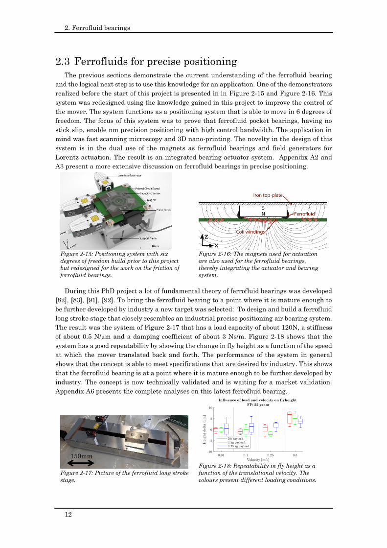
The previous sections demonstrate the current understanding of the ferrofluid bearing
and the logical next step is to use this knowledge for an application. One of the demonstrators
realized before the start of this project is presented in in Figure 2-15 and Figure 2-16. This
system was redesigned using the knowledge gained in this project to improve the control of
the mover. The system functions as a positioning system that is able to move in 6 degrees of
freedom. The focus of this system was to prove that ferrofluid pocket bearings, having no
stick slip, enable nm precision positioning with high control bandwidth. The application in
mind was fast scanning microscopy and 3D nano-printing. The novelty in the design of this
system is in the dual use of the magnets as ferrofluid bearings and field generators for
Lorentz actuation. The result is an integrated bearing-actuator system. Appendix A2 and
A3 present a more extensive discussion on ferrofluid bearings in precise positioning.
During this PhD project a lot of fundamental theory of ferrofluid bearings was developed
[82], [83], [91], [92]. To bring the ferrofluid bearing to a point where it is mature enough to
be further developed by industry a new target was selected: To design and build a ferrofluid
long stroke stage that closely resembles an industrial precise positioning air bearing system.
The result was the system of Figure 2-17 that has a load capacity of about 120N, a stiffness
of about 0.5 N/µm and a damping coefficient of about 3 Ns/m. Figure 2-18 shows that the
system has a good repeatability by showing the change in fly height as a function of the speed
at which the mover translated back and forth. The performance of the system in general
shows that the concept is able to meet specifications that are desired by industry. This shows
that the ferrofluid bearing is at a point where it is mature enough to be further developed by
industry. The concept is now technically validated and is waiting for a market validation.
Appendix A6 presents the complete analyses on this latest ferrofluid bearing.
Figure 2-15: Positioning system with six
degrees of freedom build prior to this project
but redesigned for the work on the friction of
ferrofluid bearings.
Figure 2-16: The magnets used for actuation
are also used for the ferrofluid bearings,
thereby integrating the actuator and bearing
system.
x
z
Figure 2-17: Picture of the ferrofluid long stroke
stage.
Figure 2-18: Repeatability in fly height as a
function of the translational velocity. The
colours present different loading conditions.
150mm
3. Ferrofluid gas/liquid seals
13
“Only those who dare to fail greatly can ever achieve greatly.”
― Robert F. Kennedy, 1966
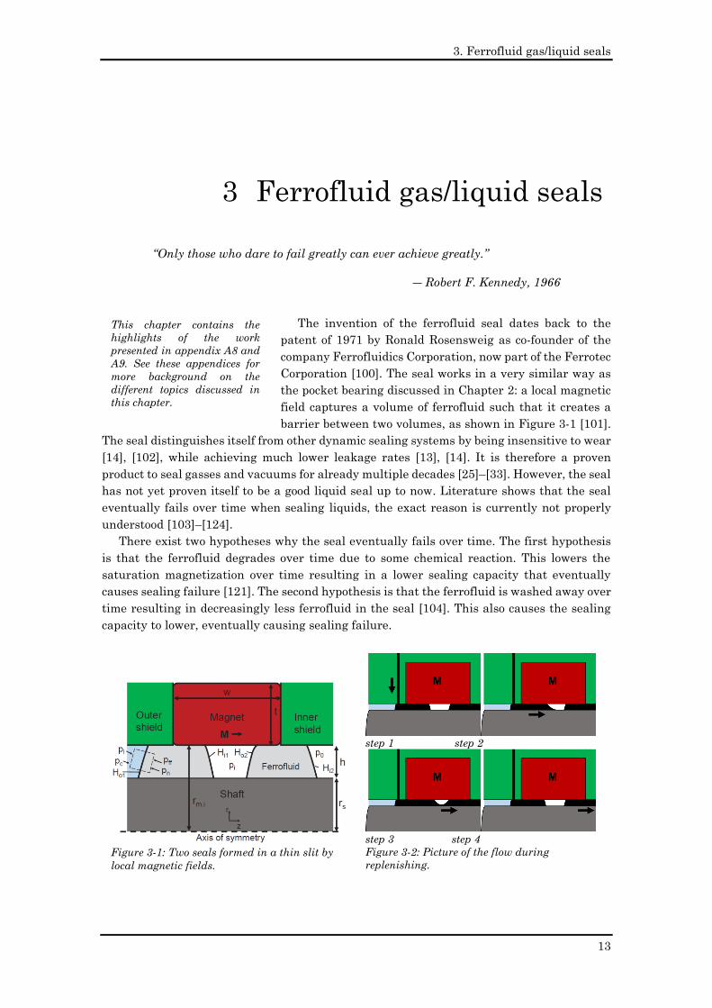
The invention of the ferrofluid seal dates back to the
patent of 1971 by Ronald Rosensweig as co-founder of the
company Ferrofluidics Corporation, now part of the Ferrotec
Corporation [100]. The seal works in a very similar way as
the pocket bearing discussed in Chapter 2: a local magnetic
field captures a volume of ferrofluid such that it creates a
barrier between two volumes, as shown in Figure 3-1 [101].
The seal distinguishes itself from other dynamic sealing systems by being insensitive to wear
[14], [102], while achieving much lower leakage rates [13], [14]. It is therefore a proven
product to seal gasses and vacuums for already multiple decades [25]–[33]. However, the seal
has not yet proven itself to be a good liquid seal up to now. Literature shows that the seal
eventually fails over time when sealing liquids, the exact reason is currently not properly
understood [103]–[124].
There exist two hypotheses why the seal eventually fails over time. The first hypothesis
is that the ferrofluid degrades over time due to some chemical reaction. This lowers the
saturation magnetization over time resulting in a lower sealing capacity that eventually
causes sealing failure [121]. The second hypothesis is that the ferrofluid is washed away over
time resulting in decreasingly less ferrofluid in the seal [104]. This also causes the sealing
capacity to lower, eventually causing sealing failure.
3 Ferrofluid gas/liquid seals
Figure 3-1: Two seals formed in a thin slit by
local magnetic fields.
step 1 step 2
step 3 step 4
Figure 3-2: Picture of the flow during
replenishing.
This chapter contains the
highlights of the work
presented in appendix A8 and
A9. See these appendices for
more background on the
different topics discussed in
this chapter.
3. Ferrofluid gas/liquid seals
14
3.1 Replenishing system
To solve this, the idea was developed to replenish the ferrofluid during operation.
Whatever the root cause (ferrofluid removal or ferrofluid degradation), constantly adding new
ferrofluid to the system theoretically solves the problem. This idea seems trivial but it is not
since the ferrofluid must be able to flow between the different sealing steps in a multi stage
seal without simultaneously leaking the medium that it tries to seal. Figure 3-2 illustrates
the process of replenishing the ferrofluid. Step 1 contains the normal condition of the
ferrofluid seal. At step 2, some ferrofluid enters the first seal by an external supply. When
the volume of the ferrofluid exceeds a threshold value, some volume leaks to the second seal
as shown at step 3. This happens without any leakage of the fluid that is being sealed. Then
the system goes to step 4 where the system is back at rest and where fresh ferrofluid is at
the first seal.
The replenishment of the ferrofluid creates a sealing system where the conditions are kept
close to the initial conditions. This practically means that when the system is able to work at
the initial stage, the system keeps on working from that time on. Appendix A8 and A9 contain
more detailed information on this sealing technology.
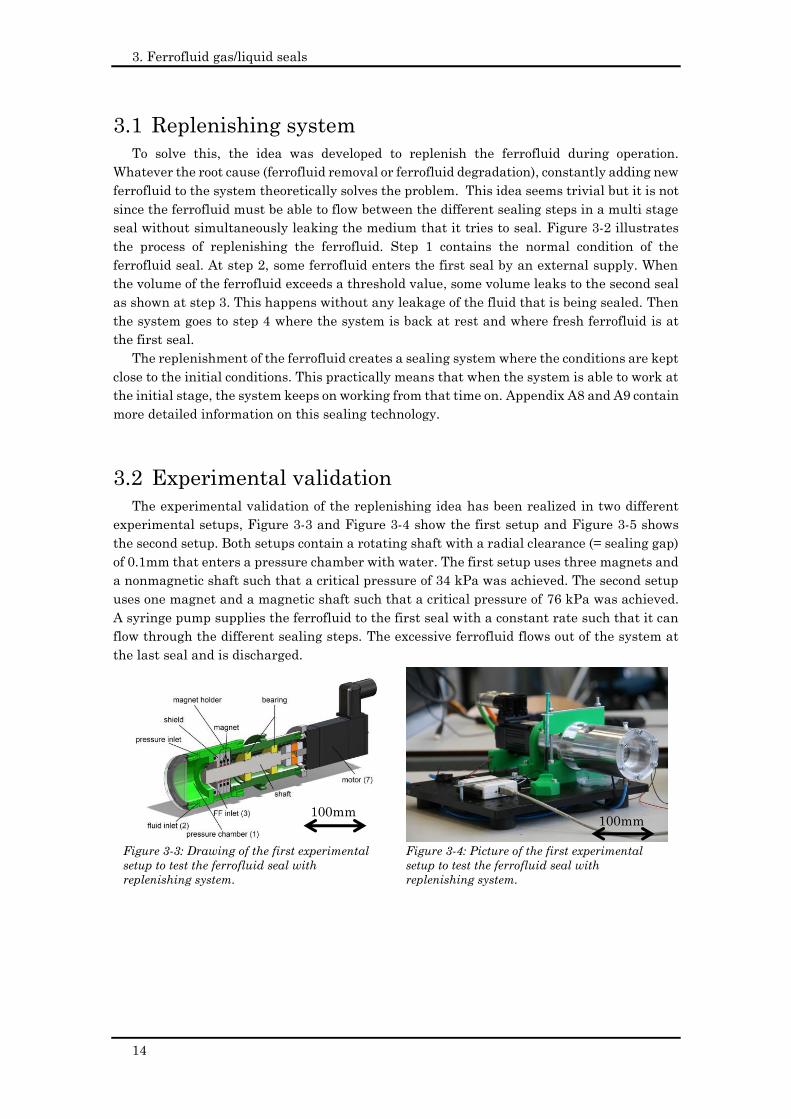
3.2 Experimental validation
The experimental validation of the replenishing idea has been realized in two different
experimental setups, Figure 3-3 and Figure 3-4 show the first setup and Figure 3-5 shows
the second setup. Both setups contain a rotating shaft with a radial clearance (= sealing gap)
of 0.1mm that enters a pressure chamber with water. The first setup uses three magnets and
a nonmagnetic shaft such that a critical pressure of 34 kPa was achieved. The second setup
uses one magnet and a magnetic shaft such that a critical pressure of 76 kPa was achieved.
A syringe pump supplies the ferrofluid to the first seal with a constant rate such that it can
flow through the different sealing steps. The excessive ferrofluid flows out of the system at
the last seal and is discharged.
Figure 3-3: Drawing of the first experimental
setup to test the ferrofluid seal with
replenishing system.
Figure 3-4: Picture of the first experimental
setup to test the ferrofluid seal with
replenishing system.
100mm 100mm
3. Ferrofluid gas/liquid seals
15
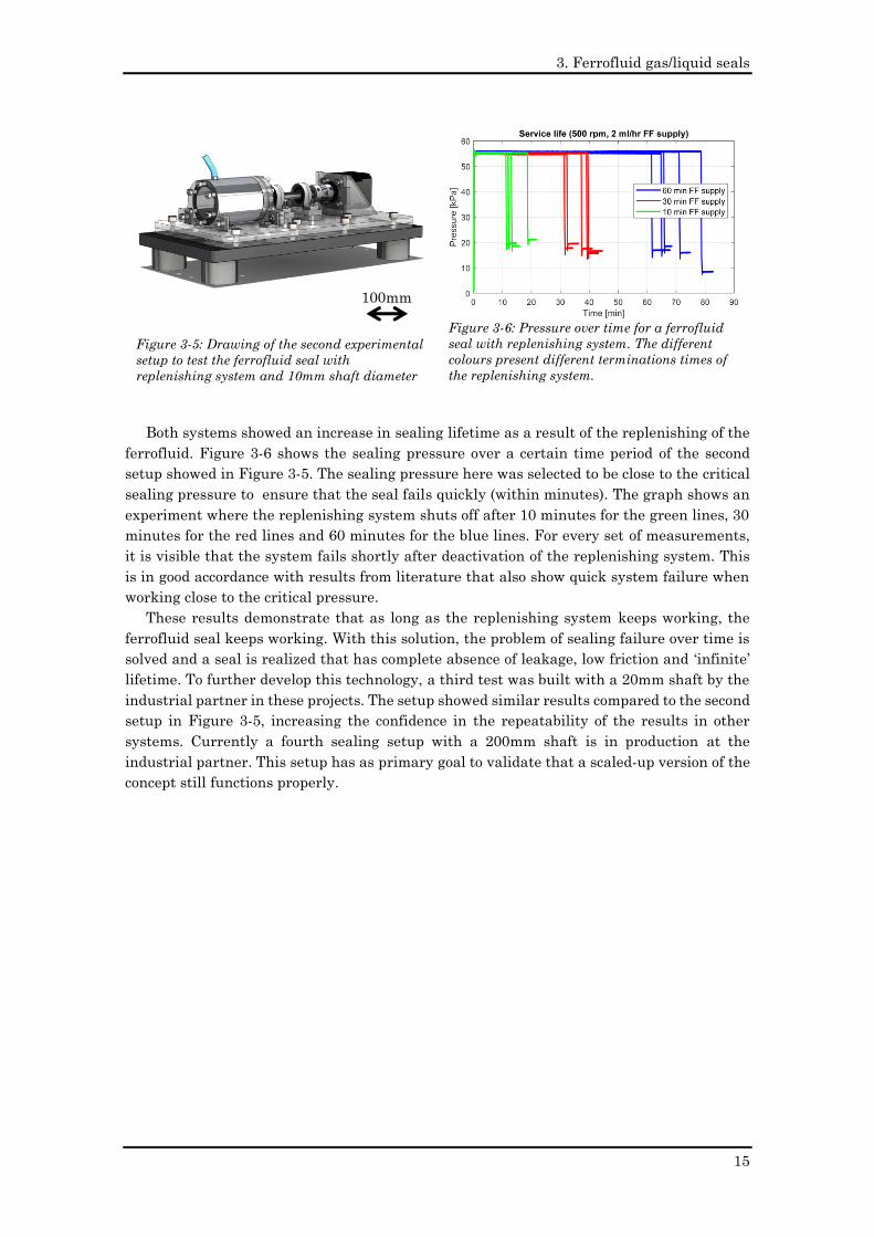
Both systems showed an increase in sealing lifetime as a result of the replenishing of the
ferrofluid. Figure 3-6 shows the sealing pressure over a certain time period of the second
setup showed in Figure 3-5. The sealing pressure here was selected to be close to the critical
sealing pressure to ensure that the seal fails quickly (within minutes). The graph shows an
experiment where the replenishing system shuts off after 10 minutes for the green lines, 30
minutes for the red lines and 60 minutes for the blue lines. For every set of measurements,
it is visible that the system fails shortly after deactivation of the replenishing system. This
is in good accordance with results from literature that also show quick system failure when
working close to the critical pressure.
These results demonstrate that as long as the replenishing system keeps working, the
ferrofluid seal keeps working. With this solution, the problem of sealing failure over time is
solved and a seal is realized that has complete absence of leakage, low friction and ‘infinite’
lifetime. To further develop this technology, a third test was built with a 20mm shaft by the
industrial partner in these projects. The setup showed similar results compared to the second
setup in Figure 3-5, increasing the confidence in the repeatability of the results in other
systems. Currently a fourth sealing setup with a 200mm shaft is in production at the
industrial partner. This setup has as primary goal to validate that a scaled-up version of the
concept still functions properly.
Figure 3-5: Drawing of the second experimental
setup to test the ferrofluid seal with
replenishing system and 10mm shaft diameter
Figure 3-6: Pressure over time for a ferrofluid
seal with replenishing system. The different
colours present different terminations times of
the replenishing system.
100mm

3. Ferrofluid gas/liquid seals
16
4. Basics of rheological textures
17
The critical ingredient is getting off your butt and doing something. It's as
simple as that. A lot of people have ideas, but there are few who decide
to do something about them now. Not tomorrow. Not next week. But
today. The true entrepreneur is a doer, not a dreamer.
― Nolan K. Bushnell, 2004
When one designs a bearing, generally, one mainly
designs the geometry of the bearing faces [11], [125]. The
separation between the bearing surfaces varies from one
point to the other, resulting in a non-uniform height
distribution of the lubricating film. This non-uniform
distribution causes a certain pressure distribution and
friction force, defining the characteristics of the bearing. An example is a journal bearing that
has a converging wedge and a diverging wedge that causes respectively a high pressure
region and a low pressure or even cavitation region. Another example is a hydrostatic bearing
that uses a recess area where the pressure will be uniform and a land area with a pressure
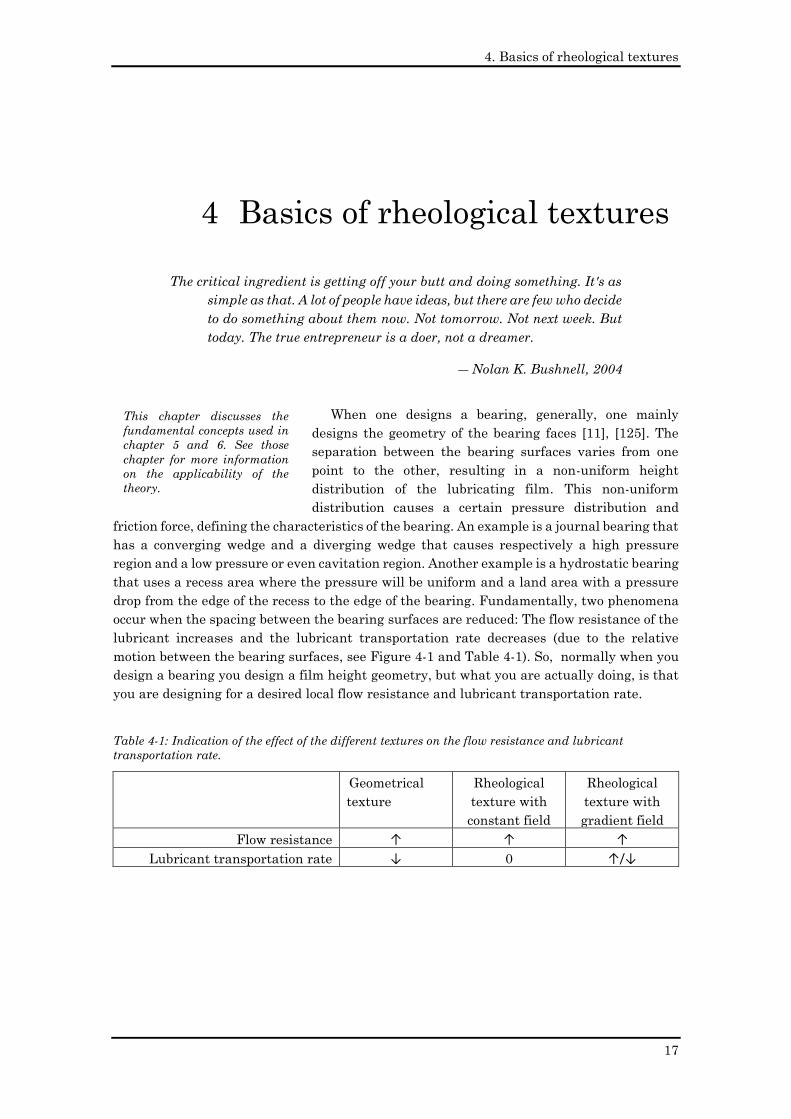
drop from the edge of the recess to the edge of the bearing. Fundamentally, two phenomena
occur when the spacing between the bearing surfaces are reduced: The flow resistance of the
lubricant increases and the lubricant transportation rate decreases (due to the relative
motion between the bearing surfaces, see Figure 4-1 and Table 4-1). So, normally when you
design a bearing you design a film height geometry, but what you are actually doing, is that
you are designing for a desired local flow resistance and lubricant transportation rate.
Table 4-1: Indication of the effect of the different textures on the flow resistance and lubricant
transportation rate.
Geometrical
texture
Rheological
texture with
constant field
Rheological
texture with
gradient field
Flow resistance ↑ ↑ ↑
Lubricant transportation rate ↓ 0 ↑/↓
4 Basics of rheological textures
This chapter discusses the
fundamental concepts used in
chapter 5 and 6. See those
chapter for more information
on the applicability of the
theory.
4. Basics of rheological textures
18
Starting from this point of view, one can also think of other methods to achieve a variation
of lubricant flow resistance and lubricant transportation rate. The three methods that can
be varied to change the system performance are the geometry of the channel, the rheological
behaviour of the fluid and the interface between the lubricant and bearing surface. The work
in this chapter focuses predominantly on the potential of a change in the rheological
behaviour of the lubrication fluid to achieve a desired behaviour, further referred to as
“rheological textures”. The work in this thesis considers three different choices to change the
rheological behaviour: magnetorheological fluids with a magnetic field [126]–[130],
electrorheological fluids [131], [132] with an electric field and conventional lubricants with a
change in temperature [125]. The theory of this chapter is explained in the context of
magnetorheological fluids and a local magnetic field, but is also equally applicable to
electrorheological fluids and local electric fields [133]. The scientific literature already
contains an extensive discussion on the applications of smart fluids (magnetorheological and
electrorheological fluids [79], [133]) in bearing systems, but most of the literature focusses on
changing the rheology of the lubricant in the bearing system as a whole, not just locally [134]–
[150].
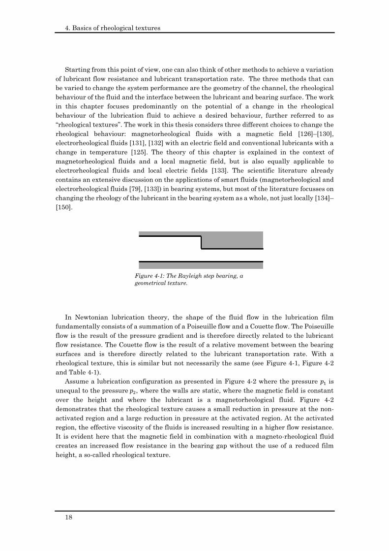
In Newtonian lubrication theory, the shape of the fluid flow in the lubrication film
fundamentally consists of a summation of a Poiseuille flow and a Couette flow. The Poiseuille
flow is the result of the pressure gradient and is therefore directly related to the lubricant
flow resistance. The Couette flow is the result of a relative movement between the bearing
surfaces and is therefore directly related to the lubricant transportation rate. With a
rheological texture, this is similar but not necessarily the same (see Figure 4-1, Figure 4-2
and Table 4-1).
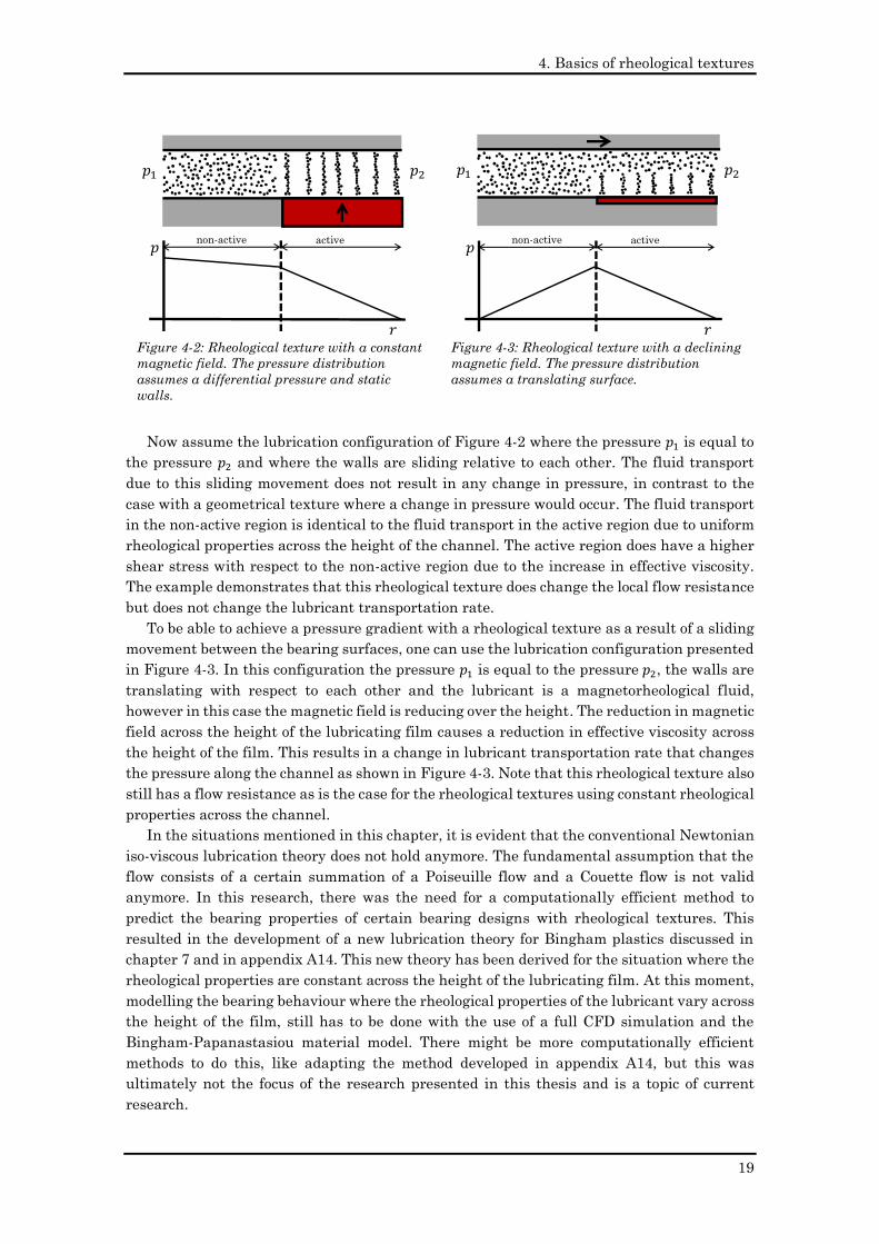
Assume a lubrication configuration as presented in Figure 4-2 where the pressure 𝑝1 is
unequal to the pressure 𝑝2, where the walls are static, where the magnetic field is constant
over the height and where the lubricant is a magnetorheological fluid. Figure 4-2
demonstrates that the rheological texture causes a small reduction in pressure at the non-
activated region and a large reduction in pressure at the activated region. At the activated
region, the effective viscosity of the fluids is increased resulting in a higher flow resistance.
It is evident here that the magnetic field in combination with a magneto-rheological fluid
creates an increased flow resistance in the bearing gap without the use of a reduced film
height, a so-called rheological texture.
Figure 4-1: The Rayleigh step bearing, a
geometrical texture.
4. Basics of rheological textures
19
Now assume the lubrication configuration of Figure 4-2 where the pressure 𝑝1 is equal to
the pressure 𝑝2 and where the walls are sliding relative to each other. The fluid transport
due to this sliding movement does not result in any change in pressure, in contrast to the
case with a geometrical texture where a change in pressure would occur. The fluid transport
in the non-active region is identical to the fluid transport in the active region due to uniform
rheological properties across the height of the channel. The active region does have a higher
shear stress with respect to the non-active region due to the increase in effective viscosity.
The example demonstrates that this rheological texture does change the local flow resistance
but does not change the lubricant transportation rate.
To be able to achieve a pressure gradient with a rheological texture as a result of a sliding
movement between the bearing surfaces, one can use the lubrication configuration presented
in Figure 4-3. In this configuration the pressure 𝑝1 is equal to the pressure 𝑝2, the walls are
translating with respect to each other and the lubricant is a magnetorheological fluid,
however in this case the magnetic field is reducing over the height. The reduction in magnetic
field across the height of the lubricating film causes a reduction in effective viscosity across
the height of the film. This results in a change in lubricant transportation rate that changes
the pressure along the channel as shown in Figure 4-3. Note that this rheological texture also
still has a flow resistance as is the case for the rheological textures using constant rheological
properties across the channel.
In the situations mentioned in this chapter, it is evident that the conventional Newtonian
iso-viscous lubrication theory does not hold anymore. The fundamental assumption that the
flow consists of a certain summation of a Poiseuille flow and a Couette flow is not valid
anymore. In this research, there was the need for a computationally efficient method to
predict the bearing properties of certain bearing designs with rheological textures. This
resulted in the development of a new lubrication theory for Bingham plastics discussed in
chapter 7 and in appendix A14. This new theory has been derived for the situation where the
rheological properties are constant across the height of the lubricating film. At this moment,
modelling the bearing behaviour where the rheological properties of the lubricant vary across
the height of the film, still has to be done with the use of a full CFD simulation and the
Bingham-Papanastasiou material model. There might be more computationally efficient
methods to do this, like adapting the method developed in appendix A14, but this was
ultimately not the focus of the research presented in this thesis and is a topic of current
research.
Figure 4-2: Rheological texture with a constant
magnetic field. The pressure distribution
assumes a differential pressure and static
walls.
𝑝1 𝑝2
𝑝
activenon-active
Figure 4-3: Rheological texture with a declining
magnetic field. The pressure distribution
assumes a translating surface.
𝑝1 𝑝2
𝑝
activenon-active
4. Basics of rheological textures
20
The concept of rheological textures challenges the idea that the performance of a bearing
can only be optimal for one certain bearing speed together with one certain loading condition.
By using external activation of the rheological textures, optimal performance is achievable
for a complete range of speeds together with a complete range of loading conditions. Using
magnetic fluids in combination with an active field creates the possibility of adding active
control to the bearing to increase bearing properties like stiffness, damping and film height,
something already discussed extensively in literature [17], [133], [143], [147], [148], [151]–
[159].
Based on the philosophy of designing for flow resistance variations and lubricant
transportation rate variations, the project patented a multitude of new bearing designs,
demonstrating the novelty of rheological textures [87].
5. Rheological textures in thrust bearings
21
“When it comes to taking risks, I believe there are two kinds of people: those
who don't dare try new things, and those who don't dare miss them.”
― John C. Maxwell, Failing Forward: How to Make the Most of Your Mistakes
This chapter discusses the applications of rheological
textures in two different thrust bearing designs. The first
design is a hydrostatic bearing that uses rheological
textures with a constant magnetic field across the film. The
second design is a hydrodynamic thrust bearing that uses a
gradient magnetic field across the height of the film.
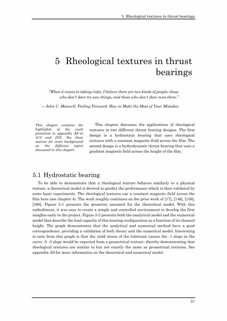
5.1 Hydrostatic bearing
To be able to demonstrate that a rheological texture behaves similarly to a physical
texture, a theoretical model is derived to predict the performance which is then validated by
some basic experiments. The rheological textures use a constant magnetic field across the
film here (see chapter 4). The work roughly continues on the prior work of [17], [146], [158],
[160]. Figure 5-1 presents the geometry assumed for the theoretical model. With this
embodiment, it was easy to create a simple and controlled environment to develop the first
insights early in the project. Figure 5-2 presents both the analytical model and the numerical
model that describe the load capacity of this bearing configuration as a function of its channel
height. The graph demonstrates that the analytical and numerical method have a good
correspondence, providing a validation of both theory and the numerical model. Interesting
to note from this graph is that the yield stress of the lubricant causes the -1 slope in the
curve. A -3 slope would be expected from a geometrical texture, thereby demonstrating that
rheological textures are similar to but not exactly the same as geometrical textures. See
appendix A9 for more information on the theoretical and numerical model.
5 Rheological textures in thrust
bearings
This chapter contains the
highlights of the work
presented in appendix A9 to
A12 and [87]. See these
sources for more background
on the different topics
discussed in this chapter.
5. Rheological textures in thrust bearings
22
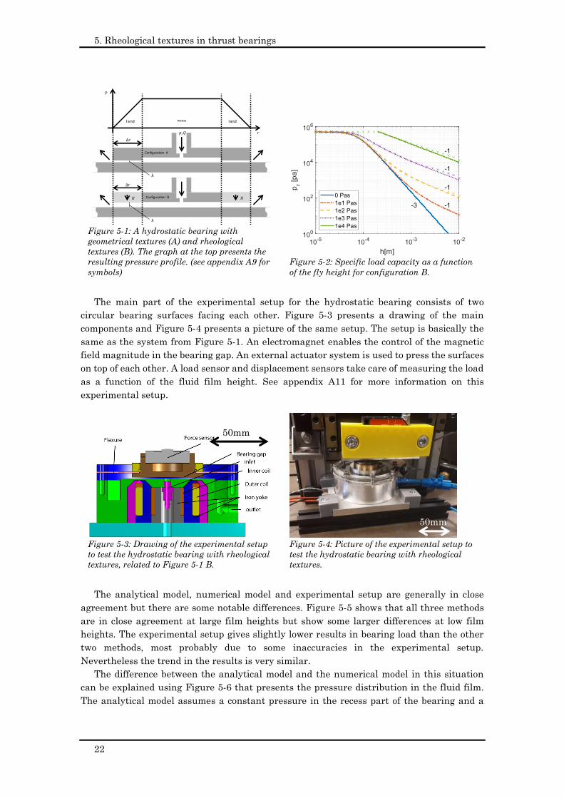
The main part of the experimental setup for the hydrostatic bearing consists of two
circular bearing surfaces facing each other. Figure 5-3 presents a drawing of the main
components and Figure 5-4 presents a picture of the same setup. The setup is basically the
same as the system from Figure 5-1. An electromagnet enables the control of the magnetic
field magnitude in the bearing gap. An external actuator system is used to press the surfaces
on top of each other. A load sensor and displacement sensors take care of measuring the load
as a function of the fluid film height. See appendix A11 for more information on this
experimental setup.
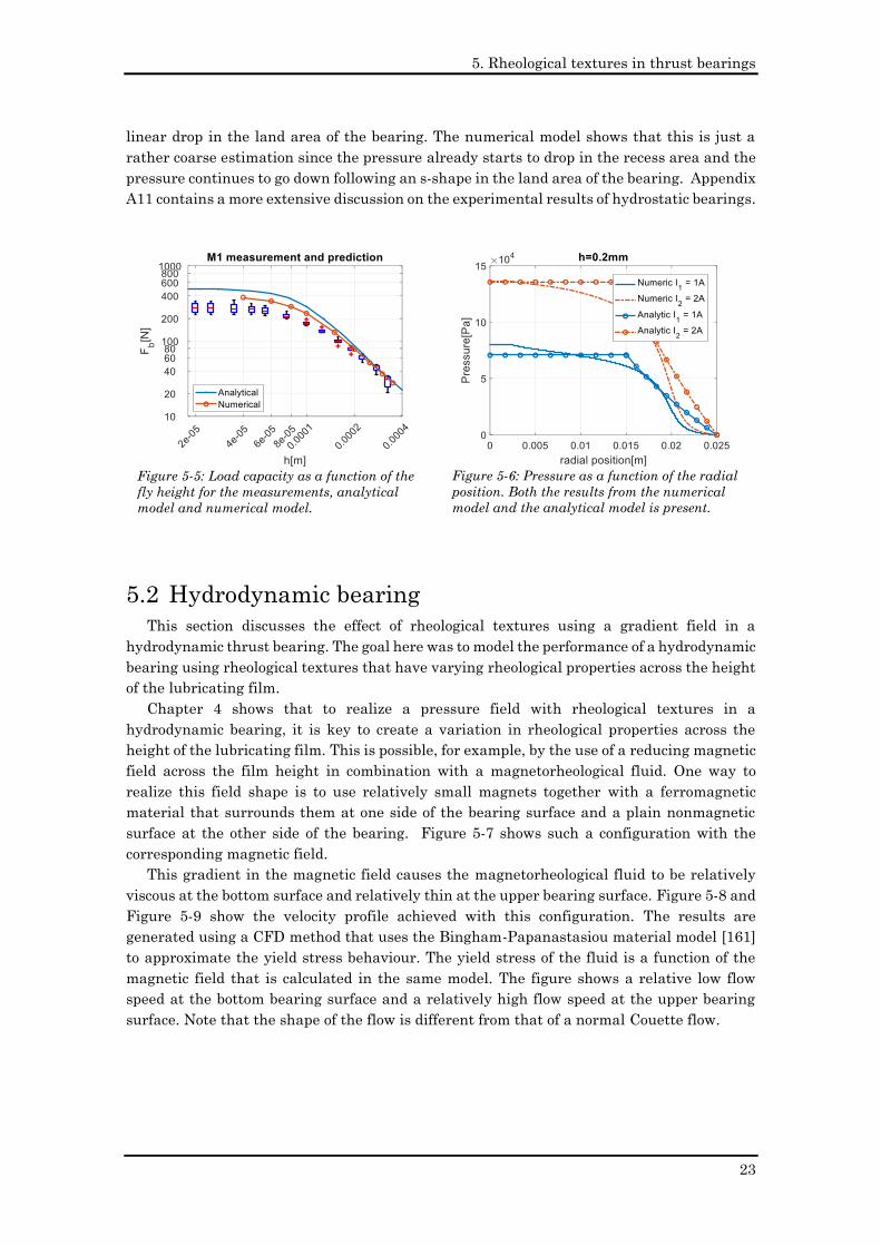
The analytical model, numerical model and experimental setup are generally in close
agreement but there are some notable differences. Figure 5-5 shows that all three methods
are in close agreement at large film heights but show some larger differences at low film
heights. The experimental setup gives slightly lower results in bearing load than the other
two methods, most probably due to some inaccuracies in the experimental setup.
Nevertheless the trend in the results is very similar.
The difference between the analytical model and the numerical model in this situation
can be explained using Figure 5-6 that presents the pressure distribution in the fluid film.
The analytical model assumes a constant pressure in the recess part of the bearing and a
Figure 5-1: A hydrostatic bearing with
geometrical textures (A) and rheological
textures (B). The graph at the top presents the
resulting pressure profile. (see appendix A9 for
symbols)
𝑝
𝑝
land landrecess
Configuration A
Configuration B
Figure 5-2: Specific load capacity as a function
of the fly height for configuration B.
Figure 5-3: Drawing of the experimental setup
to test the hydrostatic bearing with rheological
textures, related to Figure 5-1 B.
Figure 5-4: Picture of the experimental setup to
test the hydrostatic bearing with rheological
textures.
50mm
50mm
5. Rheological textures in thrust bearings
23
linear drop in the land area of the bearing. The numerical model shows that this is just a
rather coarse estimation since the pressure already starts to drop in the recess area and the
pressure continues to go down following an s-shape in the land area of the bearing. Appendix
A11 contains a more extensive discussion on the experimental results of hydrostatic bearings.
5.2 Hydrodynamic bearing
This section discusses the effect of rheological textures using a gradient field in a
hydrodynamic thrust bearing. The goal here was to model the performance of a hydrodynamic
bearing using rheological textures that have varying rheological properties across the height
of the lubricating film.
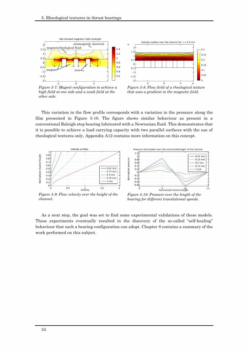
Chapter 4 shows that to realize a pressure field with rheological textures in a
hydrodynamic bearing, it is key to create a variation in rheological properties across the
height of the lubricating film. This is possible, for example, by the use of a reducing magnetic
field across the film height in combination with a magnetorheological fluid. One way to
realize this field shape is to use relatively small magnets together with a ferromagnetic
material that surrounds them at one side of the bearing surface and a plain nonmagnetic
surface at the other side of the bearing. Figure 5-7 shows such a configuration with the
corresponding magnetic field.
This gradient in the magnetic field causes the magnetorheological fluid to be relatively
viscous at the bottom surface and relatively thin at the upper bearing surface. Figure 5-8 and
Figure 5-9 show the velocity profile achieved with this configuration. The results are
generated using a CFD method that uses the Bingham-Papanastasiou material model [161]
to approximate the yield stress behaviour. The yield stress of the fluid is a function of the
magnetic field that is calculated in the same model. The figure shows a relative low flow
speed at the bottom bearing surface and a relatively high flow speed at the upper bearing
surface. Note that the shape of the flow is different from that of a normal Couette flow.
Figure 5-5: Load capacity as a function of the
fly height for the measurements, analytical
model and numerical model.
Figure 5-6: Pressure as a function of the radial
position. Both the results from the numerical
model and the analytical model is present.
5. Rheological textures in thrust bearings
24
This variation in the flow profile corresponds with a variation in the pressure along the
film presented in Figure 5-10. The figure shows similar behaviour as present in a
conventional Raleigh step bearing lubricated with a Newtonian fluid. This demonstrates that
it is possible to achieve a load carrying capacity with two parallel surfaces with the use of
rheological textures only. Appendix A12 contains more information on this concept.
As a next step, the goal was set to find some experimental validations of these models.
These experiments eventually resulted in the discovery of the so-called “self-healing”
behaviour that such a bearing configuration can adopt. Chapter 8 contains a summary of the
work performed on this subject.
Figure 5-7: Magnet configuration to achieve a
high field at one side and a weak field at the
other side.
magnet iron
nonmagnetic material
magnetorheological fluid
Figure 5-8: Flow field of a rheological texture
that uses a gradient in the magnetic field.
Figure 5-9: Flow velocity over the height of the
channel.
Figure 5-10: Pressure over the length of the
bearing for different translational speeds.
6. Rheological textures in journal bearings
25
“We do not believe it will ever be a commercial vehicle at all. We do not
believe it will find any very large place in the world of sport. We do not
believe its military importance is as great as commonly supposed, or will
extend (except accidentally) beyond the range of scouting and courier
service.”
― “The Value of the Aeroplane”, The Engineering Magazine, Nov 1909
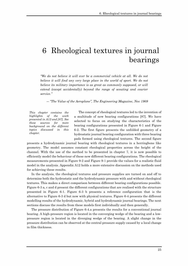
The concept of rheological textures led to the invention of
a multitude of new bearing configurations [87]. We have
selected to focus on studying the characteristics of the
bearing configurations presented in Figure 6-1 and Figure
6-2. The first figure presents the unfolded geometry of a
hydrostatic journal bearing configuration with three bearing
pads formed using rheological textures. The second figure
presents a hydrodynamic journal bearing with rheological textures in a herringbone like
geometry. The model assumes constant rheological properties across the height of the
channel. With the use of the method to be presented in chapter 7, it is now possible to
efficiently model the behaviour of these new different bearing configurations. The rheological
measurements presented in Figure 9-2 and Figure 9-1 provide the values for a realistic fluid
model in the analysis. Appendix A12 holds a more extensive discussion on the methods used
for achieving these results.
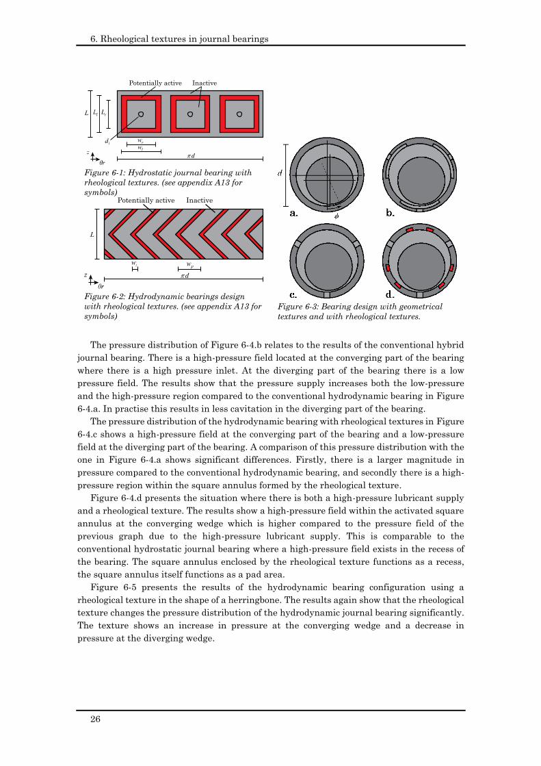
In the analysis, the rheological textures and pressure supplies are turned on and off to
determine both the hydrostatic and the hydrodynamic pressure with and without rheological
textures. This makes a direct comparison between different bearing configurations possible.
Figure 6-3 a, c and d present the different configurations that are realised with the structure
presented in Figure 6-1. Figure 6-3 b presents a reference configuration that is the
alternative to Figure 6-3 d but now with physical textures. Figure 6-4 presents the different
modelling results of the hydrodynamic, hybrid and hydrodynamic journal bearings. The next
sections discuss the results from these models first individually and then generally.
The pressure distribution of Figure 6-4.a presents the results for a conventional journal
bearing. A high-pressure region is located in the converging wedge of the bearing and a low-
pressure region is located in the diverging wedge of the bearing. A slight change in the
pressure distribution can be observed at the central pressure supply caused by a local change
in film thickness.
6 Rheological textures in journal
bearings
This chapter contains the
highlights of the work
presented in A12 and [87]. See
these sources for more
background on the different
topics discussed in this
chapter.
6. Rheological textures in journal bearings
26
The pressure distribution of Figure 6-4.b relates to the results of the conventional hybrid
journal bearing. There is a high-pressure field located at the converging part of the bearing
where there is a high pressure inlet. At the diverging part of the bearing there is a low
pressure field. The results show that the pressure supply increases both the low-pressure
and the high-pressure region compared to the conventional hydrodynamic bearing in Figure
6-4.a. In practise this results in less cavitation in the diverging part of the bearing.
The pressure distribution of the hydrodynamic bearing with rheological textures in Figure
6-4.c shows a high-pressure field at the converging part of the bearing and a low-pressure
field at the diverging part of the bearing. A comparison of this pressure distribution with the
one in Figure 6-4.a shows significant differences. Firstly, there is a larger magnitude in
pressure compared to the conventional hydrodynamic bearing, and secondly there is a high-
pressure region within the square annulus formed by the rheological texture.
Figure 6-4.d presents the situation where there is both a high-pressure lubricant supply
and a rheological texture. The results show a high-pressure field within the activated square
annulus at the converging wedge which is higher compared to the pressure field of the
previous graph due to the high-pressure lubricant supply. This is comparable to the
conventional hydrostatic journal bearing where a high-pressure field exists in the recess of
the bearing. The square annulus enclosed by the rheological texture functions as a recess,
the square annulus itself functions as a pad area.
Figure 6-5 presents the results of the hydrodynamic bearing configuration using a
rheological texture in the shape of a herringbone. The results again show that the rheological
texture changes the pressure distribution of the hydrodynamic journal bearing significantly.
The texture shows an increase in pressure at the converging wedge and a decrease in
pressure at the diverging wedge.
Figure 6-1: Hydrostatic journal bearing with
rheological textures. (see appendix A13 for
symbols)
Figure 6-2: Hydrodynamic bearings design
with rheological textures. (see appendix A13 for
symbols)
InactivePotentially active
InactivePotentially active
Figure 6-3: Bearing design with geometrical
textures and with rheological textures.
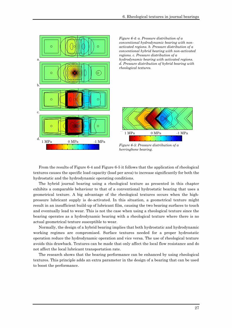
6. Rheological textures in journal bearings
27
From the results of Figure 6-4 and Figure 6-5 it follows that the application of rheological
textures causes the specific load capacity (load per area) to increase significantly for both the
hydrostatic and the hydrodynamic operating conditions.
The hybrid journal bearing using a rheological texture as presented in this chapter
exhibits a comparable behaviour to that of a conventional hydrostatic bearing that uses a
geometrical texture. A big advantage of the rheological textures occurs when the high-
pressure lubricant supply is de-activated. In this situation, a geometrical texture might
result in an insufficient build-up of lubricant film, causing the two bearing surfaces to touch
and eventually lead to wear. This is not the case when using a rheological texture since the
bearing operates as a hydrodynamic bearing with a rheological texture where there is no
actual geometrical texture susceptible to wear.
Normally, the design of a hybrid bearing implies that both hydrostatic and hydrodynamic
working regimes are compromised. Surface textures needed for a proper hydrostatic
operation reduce the hydrodynamic operation and vice versa. The use of rheological texture
avoids this drawback. Textures can be made that only affect the local flow resistance and do
not affect the local lubricant transportation rate.
The research shows that the bearing performance can be enhanced by using rheological
textures. This principle adds an extra parameter in the design of a bearing that can be used
to boost the performance.
1 MPa 0 MPa -1 MPa
a.
b.
c.
d.
Figure 6-4: a. Pressure distribution of a
conventional hydrodynamic bearing with non-
activated regions. b. Pressure distribution of a
conventional hybrid bearing with non-activated
regions. c. Pressure distribution of a
hydrodynamic bearing with activated regions.
d. Pressure distribution of hybrid bearing with
rheological textures.
Figure 6-5: Pressure distribution of a
herringbone bearing.
1 MPa 0 MPa -1 MPa
a.
b.
c.
d.

6. Rheological textures in journal bearings
28
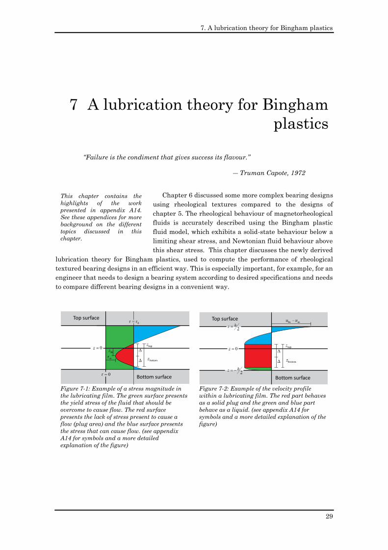
7. A lubrication theory for Bingham plastics
29
“Failure is the condiment that gives success its flavour.”
― Truman Capote, 1972
Chapter 6 discussed some more complex bearing designs
using rheological textures compared to the designs of
chapter 5. The rheological behaviour of magnetorheological
fluids is accurately described using the Bingham plastic
fluid model, which exhibits a solid-state behaviour below a
limiting shear stress, and Newtonian fluid behaviour above
this shear stress. This chapter discusses the newly derived
lubrication theory for Bingham plastics, used to compute the performance of rheological
textured bearing designs in an efficient way. This is especially important, for example, for an
engineer that needs to design a bearing system according to desired specifications and needs
to compare different bearing designs in a convenient way.
7 A lubrication theory for Bingham
plastics
Figure 7-1: Example of a stress magnitude in
the lubricating film. The green surface presents
the yield stress of the fluid that should be
overcome to cause flow. The red surface
presents the lack of stress present to cause a
flow (plug area) and the blue surface presents
the stress that can cause flow. (see appendix
A14 for symbols and a more detailed
explanation of the figure)
Top surface
Bottom surface
Figure 7-2: Example of the velocity profile
within a lubricating film. The red part behaves
as a solid plug and the green and blue part
behave as a liquid. (see appendix A14 for
symbols and a more detailed explanation of the
figure)
Top surface
Bottom surface
This chapter contains the
highlights of the work
presented in appendix A14.
See these appendices for more
background on the different
topics discussed in this
chapter.
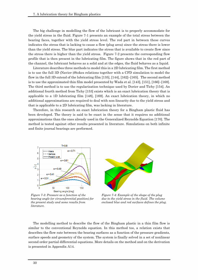
7. A lubrication theory for Bingham plastics
30
The big challenge in modelling the flow of the lubricant is to properly accommodate for
the yield stress in the fluid. Figure 7-1 presents an example of the total stress between the
bearing faces, together with the yield stress level. The red part in between these curves
indicates the stress that is lacking to cause a flow (plug area) since the stress there is lower
than the yield stress. The blue part indicates the stress that is available to create flow since
the stress there is higher than the yield stress. Figure 7-2 presents the corresponding flow
profile that is then present in the lubricating film. The figure shows that in the red part of
the channel, the lubricant behaves as a solid and at the edges, the fluid behaves as a liquid.
Literature describes three methods to model this in a 2D lubricating film. The first method
is to use the full 3D (Navier-)Stokes relations together with a CFD simulation to model the
flow in the full 3D extend of the lubricating film [135], [144], [162]–[165]. The second method
is to use the approximated thin film model presented by Wada et al. [143], [151], [166]–[168].
The third method is to use the regularization technique used by Dorier and Tichy [154]. An
additional fourth method from Tichy [153] exists which is an exact lubrication theory that is
applicable to a 1D lubricating film [148], [169]. An exact lubrication theory, in which no
additional approximations are required to deal with non-linearity due to the yield stress and
that is applicable to a 2D lubricating film, was lacking in literature.
Therefore, in this research an exact lubrication theory for a Bingham plastic fluid has
been developed. The theory is said to be exact in the sense that it requires no additional
approximations than the ones already used in the Generalized Reynolds Equation [170]. The
method is tested against other results presented in literature. Simulations on both infinite
and finite journal bearings are performed.
The modelling method to describe the flow of the Bingham plastic in a thin film flow is
similar to the conventional Reynolds equation. In this method too, a relation exists that
describes the flow rate between the bearing surfaces as a function of the pressure gradients,
surface speeds and geometry of the system. The system is finally solved in a set of nonlinear
second order partial differential equations. More details on the method and on the derivation
is presented in Appendix A14.
Figure 7-3: Pressure as a function of the
bearing angle (or circumferential position) for
the present study and some results from
literature.
Figure 7-4: Example of the shape of the plug
due to the yield stress in the fluid. The volume
enclosed blue and red surfaces defines the plug.
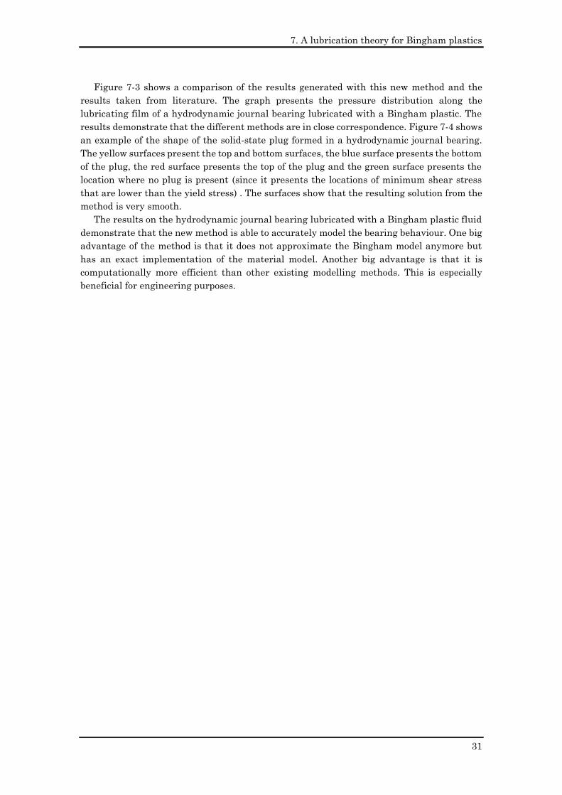
7. A lubrication theory for Bingham plastics
31
Figure 7-3 shows a comparison of the results generated with this new method and the
results taken from literature. The graph presents the pressure distribution along the
lubricating film of a hydrodynamic journal bearing lubricated with a Bingham plastic. The
results demonstrate that the different methods are in close correspondence. Figure 7-4 shows
an example of the shape of the solid-state plug formed in a hydrodynamic journal bearing.
The yellow surfaces present the top and bottom surfaces, the blue surface presents the bottom
of the plug, the red surface presents the top of the plug and the green surface presents the
location where no plug is present (since it presents the locations of minimum shear stress
that are lower than the yield stress) . The surfaces show that the resulting solution from the
method is very smooth.
The results on the hydrodynamic journal bearing lubricated with a Bingham plastic fluid
demonstrate that the new method is able to accurately model the bearing behaviour. One big
advantage of the method is that it does not approximate the Bingham model anymore but
has an exact implementation of the material model. Another big advantage is that it is
computationally more efficient than other existing modelling methods. This is especially
beneficial for engineering purposes.
7. A lubrication theory for Bingham plastics
32
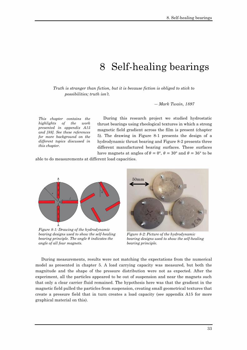
8. Self-healing bearings
33
Truth is stranger than fiction, but it is because fiction is obliged to stick to
possibilities; truth isn’t.
― Mark Twain, 1897
During this research project we studied hydrostatic
thrust bearings using rheological textures in which a strong
magnetic field gradient across the film is present (chapter
5). The drawing in Figure 8-1 presents the design of a
hydrodynamic thrust bearing and Figure 8-2 presents three
different manufactured bearing surfaces. These surfaces
have magnets at angles of 𝜃 = 0°, 𝜃 = 30° and 𝜃 = 36° to be
able to do measurements at different load capacities.
During measurements, results were not matching the expectations from the numerical
model as presented in chapter 5. A load carrying capacity was measured, but both the
magnitude and the shape of the pressure distribution were not as expected. After the
experiment, all the particles appeared to be out of suspension and near the magnets such
that only a clear carrier fluid remained. The hypothesis here was that the gradient in the
magnetic field pulled the particles from suspension, creating small geometrical textures that
create a pressure field that in turn creates a load capacity (see appendix A15 for more
graphical material on this).
8 Self-healing bearings
Figure 8-1: Drawing of the hydrodynamic
bearing designs used to show the self-healing
bearing principle. The angle 𝜃 indicates the
angle of all four magnets.
Figure 8-2: Picture of the hydrodynamic
bearing designs used to show the self-healing
bearing principle.
This chapter contains the
highlights of the work
presented in appendix A15
and [88]. See these references
for more background on the
different topics discussed in
this chapter.
50mm
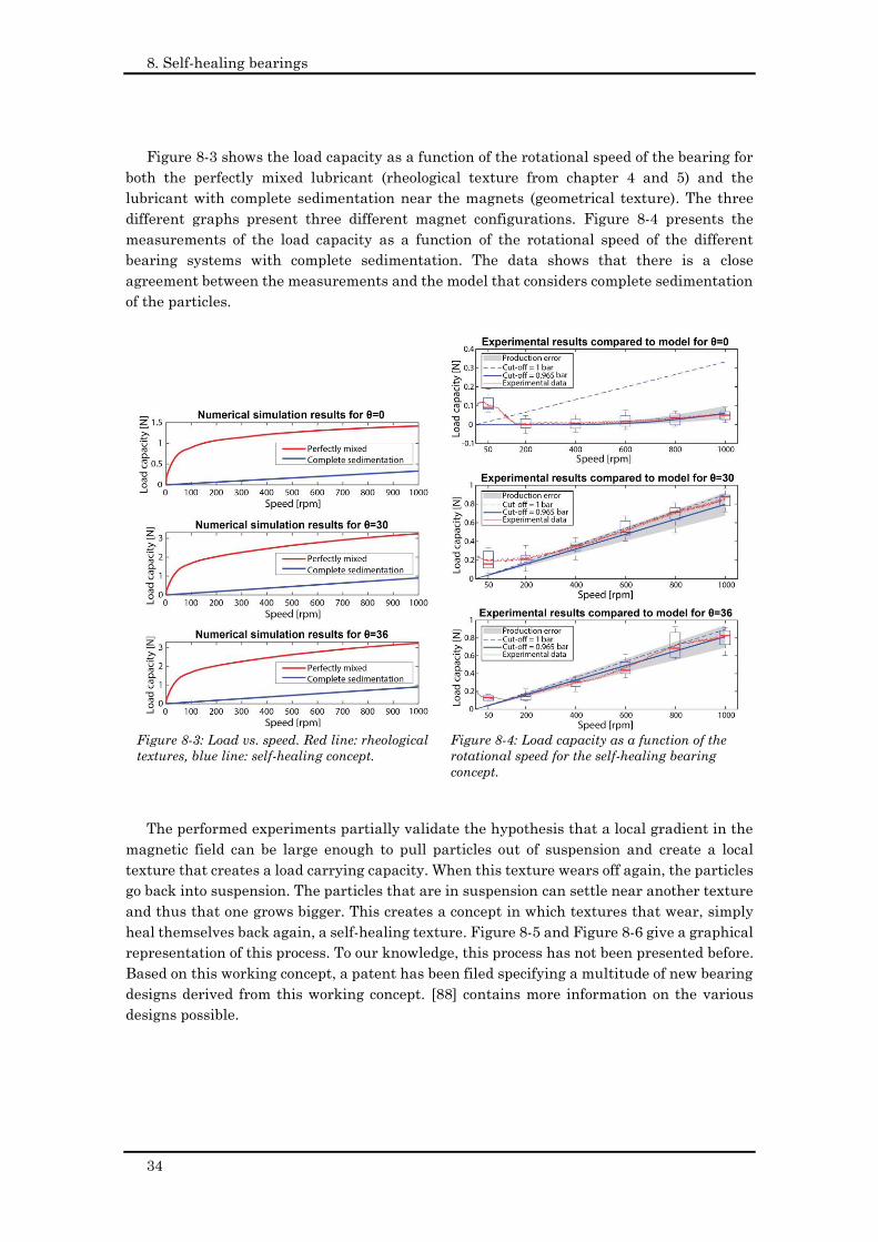
8. Self-healing bearings
34
Figure 8-3 shows the load capacity as a function of the rotational speed of the bearing for
both the perfectly mixed lubricant (rheological texture from chapter 4 and 5) and the
lubricant with complete sedimentation near the magnets (geometrical texture). The three
different graphs present three different magnet configurations. Figure 8-4 presents the
measurements of the load capacity as a function of the rotational speed of the different
bearing systems with complete sedimentation. The data shows that there is a close
agreement between the measurements and the model that considers complete sedimentation
of the particles.
The performed experiments partially validate the hypothesis that a local gradient in the
magnetic field can be large enough to pull particles out of suspension and create a local
texture that creates a load carrying capacity. When this texture wears off again, the particles
go back into suspension. The particles that are in suspension can settle near another texture
and thus that one grows bigger. This creates a concept in which textures that wear, simply
heal themselves back again, a self-healing texture. Figure 8-5 and Figure 8-6 give a graphical
representation of this process. To our knowledge, this process has not been presented before.
Based on this working concept, a patent has been filed specifying a multitude of new bearing
designs derived from this working concept. [88] contains more information on the various
designs possible.
Figure 8-3: Load vs. speed. Red line: rheological
textures, blue line: self-healing concept.
Figure 8-4: Load capacity as a function of the
rotational speed for the self-healing bearing
concept.
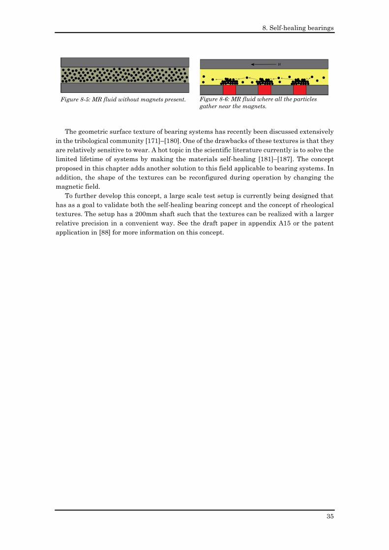
8. Self-healing bearings
35
The geometric surface texture of bearing systems has recently been discussed extensively
in the tribological community [171]–[180]. One of the drawbacks of these textures is that they
are relatively sensitive to wear. A hot topic in the scientific literature currently is to solve the
limited lifetime of systems by making the materials self-healing [181]–[187]. The concept
proposed in this chapter adds another solution to this field applicable to bearing systems. In
addition, the shape of the textures can be reconfigured during operation by changing the
magnetic field.
To further develop this concept, a large scale test setup is currently being designed that
has as a goal to validate both the self-healing bearing concept and the concept of rheological
textures. The setup has a 200mm shaft such that the textures can be realized with a larger
relative precision in a convenient way. See the draft paper in appendix A15 or the patent
application in [88] for more information on this concept.
Figure 8-5: MR fluid without magnets present.
Figure 8-6: MR fluid where all the particles
gather near the magnets.
8. Self-healing bearings
36
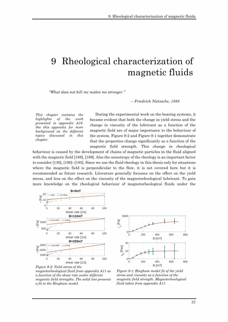
9. Rheological characterization of magnetic fluids
37
“What does not kill me makes me stronger.”
― Friedrich Nietzsche, 1888
During the experimental work on the bearing systems, it
became evident that both the change in yield stress and the
change in viscosity of the lubricant as a function of the
magnetic field are of major importance to the behaviour of
the system. Figure 9-2 and Figure 9-1 together demonstrate
that the properties change significantly as a function of the
magnetic field strength. This change in rheological
behaviour is caused by the development of chains of magnetic particles in the fluid aligned
with the magnetic field [188], [189]. Also the anisotropy of the rheology is an important factor
to consider [130], [190]–[195]. Since we use the fluid rheology in this thesis only for situations
where the magnetic field is perpendicular to the flow, it is not covered here but it is
recommended as future research. Literature generally focusses on the effect on the yield
stress, and less on the effect on the viscosity of the magnetorheological lubricant. To gain
more knowledge on the rheological behaviour of magnetorheological fluids under the
9 Rheological characterization of
magnetic fluids
This chapter contains the
highlights of the work
presented in appendix A16.
See this appendix for more
background on the different
topics discussed in this
chapter.
Figure 9-2: Yield stress of the
magnetorheological fluid from appendix A11 as
a function of the shear rate under different
magnetic field strengths. The solid line presents
a fit to the Bingham model.
0 20 40 60 80 100
shear rate [1/s]
0
10
20
[P
a]
B=0mT
0 20 40 60 80 100
shear rate [1/s]
500
1000
[P
a]
B=110mT
0 20 40 60 80 100
shear rate [1/s]
1500
2000
2500
[P
a]
B=225mT
= 10Pa = 0.073Pas
= 8.1e+02Pa = 4.4Pas
= 1.8e+03Pa = 8.1Pas
Figure 9-1: Bingham model fit of the yield
stress and viscosity as a function of the
magnetic field strength. Magnetorheological
fluid taken from appendix A11.
0 200 400 600 800
B [mT]
0
5000
y [P
a]
0 200 400 600 800
B [mT]
0
10
20
0 [P
as]
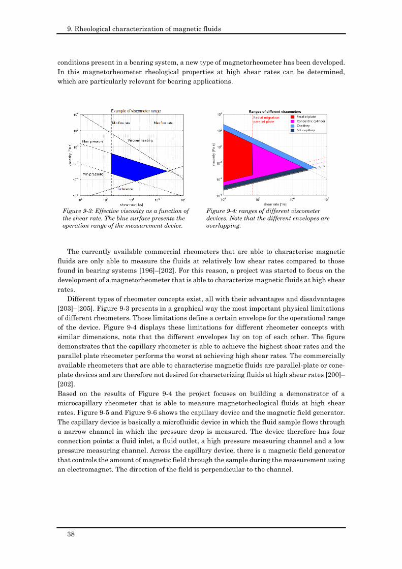
9. Rheological characterization of magnetic fluids
38
conditions present in a bearing system, a new type of magnetorheometer has been developed.
In this magnetorheometer rheological properties at high shear rates can be determined,
which are particularly relevant for bearing applications.
The currently available commercial rheometers that are able to characterise magnetic
fluids are only able to measure the fluids at relatively low shear rates compared to those
found in bearing systems [196]–[202]. For this reason, a project was started to focus on the
development of a magnetorheometer that is able to characterize magnetic fluids at high shear
rates.
Different types of rheometer concepts exist, all with their advantages and disadvantages
[203]–[205]. Figure 9-3 presents in a graphical way the most important physical limitations
of different rheometers. Those limitations define a certain envelope for the operational range
of the device. Figure 9-4 displays these limitations for different rheometer concepts with
similar dimensions, note that the different envelopes lay on top of each other. The figure
demonstrates that the capillary rheometer is able to achieve the highest shear rates and the
parallel plate rheometer performs the worst at achieving high shear rates. The commercially
available rheometers that are able to characterise magnetic fluids are parallel-plate or cone-
plate devices and are therefore not desired for characterizing fluids at high shear rates [200]–
[202].
Based on the results of Figure 9-4 the project focuses on building a demonstrator of a
microcapillary rheometer that is able to measure magnetorheological fluids at high shear
rates. Figure 9-5 and Figure 9-6 shows the capillary device and the magnetic field generator.
The capillary device is basically a microfluidic device in which the fluid sample flows through
a narrow channel in which the pressure drop is measured. The device therefore has four
connection points: a fluid inlet, a fluid outlet, a high pressure measuring channel and a low
pressure measuring channel. Across the capillary device, there is a magnetic field generator
that controls the amount of magnetic field through the sample during the measurement using
an electromagnet. The direction of the field is perpendicular to the channel.
Figure 9-3: Effective viscosity as a function of
the shear rate. The blue surface presents the
operation range of the measurement device.
Figure 9-4: ranges of different viscometer
devices. Note that the different envelopes are
overlapping.
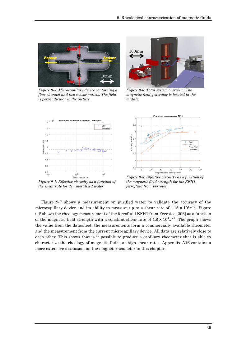
9. Rheological characterization of magnetic fluids
39
Figure 9-7 shows a measurement on purified water to validate the accuracy of the
microcapillary device and its ability to measure up to a shear rate of 1.16 × 10⁶𝑠−1. Figure
9-8 shows the rheology measurement of the ferrofluid EFH1 from Ferrotec [206] as a function
of the magnetic field strength with a constant shear rate of 1.8 × 10⁴𝑠−1. The graph shows
the value from the datasheet, the measurements form a commercially available rheometer
and the measurement from the current microcapillary device. All data are relatively close to
each other. This shows that is it possible to produce a capillary rheometer that is able to
characterize the rheology of magnetic fluids at high shear rates. Appendix A16 contains a
more extensive discussion on the magnetorheometer in this chapter.
Figure 9-5: Microcapillary device containing a
flow channel and two sensor outlets. The field
is perpendicular to the picture.
Figure 9-6: Total system overview. The
magnetic field generator is located in the
middle.
Figure 9-7: Effective viscosity as a function of
the shear rate for demineralized water.
Figure 9-8: Effective viscosity as a function of
the magnetic field strength for the EFH1
ferrofluid from Ferrotec.
10mm
100mm
9. Rheological characterization of magnetic fluids
40
10. Conclusions
41
Don’t worry about people stealing an idea. If it’s original, you will have to
ram it down their throats.
As quoted, without citation, in Robert Slater, Portraits in Silicon (1987).
Howard H. Aiken in reply to a student expressing concern that his
own ideas might be stolen before he had published his own thesis.
This chapter gathers all the main conclusions of the six focus areas within this research.
The ambition we had within the thesis project was to develop technology that could
eventually serve society. To indicate the technology matureness of the different focus areas
we use the Technology Readiness Level (TRL) scale as defined in [207] and presented in Table
10-1.
10.1 Ferrofluid bearings
Ferrofluid bearings are interesting due to their pure viscous friction and simplicity. At the
start of the project, little knowledge existed on how to make a certain design according to
specifications. So, within this project the goal became to develop the necessary knowledge to
design a ferrofluid bearing according to desired specifications.
The main contributions of this thesis on ferrofluid bearing design are as follows:
• This is to our knowledge the first significant work on the modelling of ferrofluid pocket
bearings.
• The work provides different experimentally validated models for the load capacity,
torque capacity, out of plane stiffness, rotational stiffness, friction and operational
range for both ferrofluid pocket bearings and ferrofluid pressure bearings.
• The models provide the most important bearing parameters with relevant accuracy
for engineering purposes. This allows the user to design a bearing system according
to a desired set of specifications.
• The different bearing systems that have been designed, built, and tested show that
ferrofluid bearings can be used in a linear guidance to make long stokes.
• The latest demonstrator shows to have specifications that are competitive with
conventional bearing systems.
• The technology has been demonstrated in a relevant industrial environment which
brings the technology to a TRL of 6.
10 Conclusions
10. Conclusions
42
10.2 Ferrofluid seals
Ferrofluid seals have proven themselves in the design of commercial machines to be a
good gas/gas seal due to their near zero leakage, low friction and long lifetime. Problem is
that this is not yet true for ferrofluid seals that seal an gas/liquid interface. Multiple sources
from literature show that these systems inevitably show a system failure over time. The goal
of the work in this thesis on ferrofluid seals can be described as the development of a
ferrofluid gas/liquid seal that has an infinite lifetime.
The main contributions of this thesis on the gas/liquid ferrofluid seals are as follows:
• The project invented the concept of replenishing the ferrofluid such that there always
is fresh ferrofluid in the seal.
• Experimental results show that the replenishing system solves the seal failure. The
seal system design ensures that degraded ferrofluid is removed and replaced by fresh
ferrofluid. This gives the system a theoretical infinite lifetime, as long as the
replenishing system is active. If a failure in the replenishing system occurs, this is
easy to fix since the replenishment system is located outside the sealing system.
• Replenishing the ferrofluid has been shown to work even over multiple sealing steps.
The ferrofluid flows from seal to seal without leaking the medium that it is sealing.
The sealing capacity is not negatively affected by the process of replenishment.
• Similar to the ferrofluid bearing, the technology has been demonstrated in an
industrial relevant environment which brings the technology to a TRL of 6.
10.3 Rheological textures
The property of magnetorheological fluids to change their rheological behaviour in
response to a magnetic field make these fluids of interest for multiple applications. Within
this research, we investigated the potential of using them to improve bearings systems. This
eventually led to the invention of rheological textures. The goal of the research on rheological
textures thus became the investigation into the potential of this new invention.
The main contributions of this thesis on rheological textures are as follows:
• During this project the concept of rheological textures was invented. This is a local
change in rheological properties of the lubricant such that there is a local change in
flow resistance and/or a local change in fluid transportation rate in the lubricating
film.
• A local magnetic field interacting with a magnetorheological lubricant is able to
generate a rheological texture in a lubricating film geometry.
• There are different methods of creating rheological textures. One can make textures
in which the rheological properties of the lubricant are uniform across the height of
the channel or one can make textures in which the rheological properties across the
height the channel.
• Rheological textures with uniform rheological properties across the channel affect the
local flow resistance and do not affect the local lubricant transportation rate.
• A rheological texture in which the rheological properties vary across the channel can
affect both the local flow resistance and the local lubricant transportation rate.
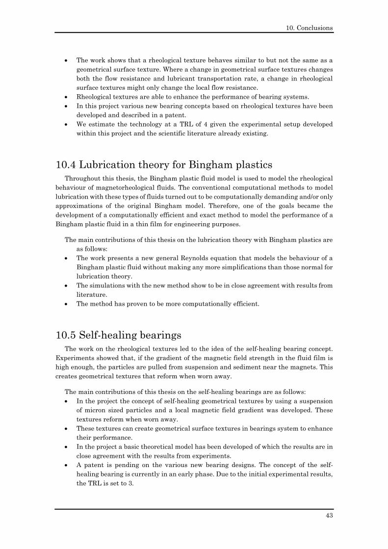
10. Conclusions
43
• The work shows that a rheological texture behaves similar to but not the same as a
geometrical surface texture. Where a change in geometrical surface textures changes
both the flow resistance and lubricant transportation rate, a change in rheological
surface textures might only change the local flow resistance.
• Rheological textures are able to enhance the performance of bearing systems.
• In this project various new bearing concepts based on rheological textures have been
developed and described in a patent.
• We estimate the technology at a TRL of 4 given the experimental setup developed
within this project and the scientific literature already existing.
10.4 Lubrication theory for Bingham plastics
Throughout this thesis, the Bingham plastic fluid model is used to model the rheological
behaviour of magnetorheological fluids. The conventional computational methods to model
lubrication with these types of fluids turned out to be computationally demanding and/or only
approximations of the original Bingham model. Therefore, one of the goals became the
development of a computationally efficient and exact method to model the performance of a
Bingham plastic fluid in a thin film for engineering purposes.
The main contributions of this thesis on the lubrication theory with Bingham plastics are
as follows:
• The work presents a new general Reynolds equation that models the behaviour of a
Bingham plastic fluid without making any more simplifications than those normal for
lubrication theory.
• The simulations with the new method show to be in close agreement with results from
literature.
• The method has proven to be more computationally efficient.
10.5 Self-healing bearings
The work on the rheological textures led to the idea of the self-healing bearing concept.
Experiments showed that, if the gradient of the magnetic field strength in the fluid film is
high enough, the particles are pulled from suspension and sediment near the magnets. This
creates geometrical textures that reform when worn away.
The main contributions of this thesis on the self-healing bearings are as follows:
• In the project the concept of self-healing geometrical textures by using a suspension
of micron sized particles and a local magnetic field gradient was developed. These
textures reform when worn away.
• These textures can create geometrical surface textures in bearings system to enhance
their performance.
• In the project a basic theoretical model has been developed of which the results are in
close agreement with the results from experiments.
• A patent is pending on the various new bearing designs. The concept of the self-
healing bearing is currently in an early phase. Due to the initial experimental results,
the TRL is set to 3.
10. Conclusions
44
10.6 Rheological characterization
In full film fluid bearings and seals fluids are used at relatively high shear rates. This is
a region where the fluid properties of magnetic fluids are not well known yet. To our
knowledge, there are no commercially available rheometers that can characterise these fluids
at the shear rates found in full film bearing systems. Therefore, the goal was set to develop
such a rheometer.
The main contribution of this thesis on rheological characterization is as follows:
• The work developed a concept for a micro capillary rheometer that is able to
characterize magnetic fluids at shear rates generally found in bearing systems.
Table 10-1: Technology readiness level of the different focus areas.
TRL
Ferrofluid bearings 1 2 3 4 5 6 7 8 9
Ferrofluid gas/liquid seals 1 2 3 4 5 6 7 8 9
Rheological textures 1 2 3 4 5 6 7 8 9
Self-healing bearings 1 2 3 4 5 6 7 8 9
Rheological characterization 1 2 3 4 5 6 7 8 9
Legend: Before project
During project
TRL 1: basic principles observed
TRL 2: technology concept formulated
TRL 3: experimental proof of concept
TRL 4: technology validated in lab
TRL 5: technology validated in relevant environment
(industrially relevant environment in the case of key
enabling technologies)
TRL 6: technology demonstrated in relevant environment
(industrially relevant environment in the case of key
enabling technologies)
TRL 7: system prototype demonstration in operational
environment
TRL 8: system complete and qualified
TRL 9: actual system proven in operational environment
(competitive manufacturing in the case of key enabling
technologies; or in space)
This table summarizes the TRL of the different concepts developed within this project
from the moment just prior to the start of the project and now at the time of writing. The
table demonstrates that the different concepts have made a significant step to commercial
TRL levels.
11. Recommendations
45
“Because the people who are crazy enough to think they can change the
world, are the ones who do.”
― Rob Siltanen, 1997
In this thesis, we made a lot of progress on bearing and sealing systems using magnetic
fluids. Though, the more we know, the clearer the yet unknown is defined. The different
sections below present the recommendations of the different topics in this research, it uses
the same structure as in the conclusions chapter.
11.1 Ferrofluid bearings
The work in this project brought the understanding of the ferrofluid bearing to a level
such that the ferrofluid bearing can be designed according to desired specifications. A
demonstrator has been built that shows that the performance can be made similar to that of
conventional precise positioning bearing systems. Still, there is room for improvement in the
bearing system. The technology is currently relatively immature compared to conventional
systems, so there is a lot of potential to boost the performance even further.
One of the promising topics to focus on in the future is the friction behaviour of the
bearing. Making a translational motion with a ferrofluid bearing leaves behind a trail of
ferrofluid that affects the fly height of the bearing. Using the knowledge developed in this
research, a proper design can be made that keeps this effect within specifications. However,
further development of this aspect of the ferrofluid bearing is recommended.
Another promising development topic is the addition of an actuator system to the
ferrofluid long stroke stage. In this research program we already demonstrated that the
magnet used for the ferrofluid bearing can also be used for Lorentz actuation. For now, this
was only shown for relatively short strokes. Precise positioning stages in industry often have
the bearing and actuation system integrated into the product, the same can be done here.
11.2 Ferrofluid seals
The replenishing concept developed within this project generates a sealing solution that
has a theoretical infinite lifetime. Still, there is room for improvement. For instance, it is
currently unclear what exactly is causing the degradation of the ferrofluid seal. It may be
degradation of the fluid or diffusion of the ferrofluid out of the seal. Generating more
knowledge on this subject will give more insight in which refresh rate is sufficient to
guarantee infinite lifetime.
11 Recommendations
11. Recommendations
46
Another thing that is still unclear is the reduction of sealing capacity in function of the
rotational speed of the shaft. A better understanding of this will most probably lead to an
improved seal design.
11.3 Rheological textures
The work in this project has resulted in the invention of rheological textures. Up to this
moment the concept is mainly validated by computer models that are only partly validated
by experimental setups. The logical next step here would be to generate more experimental
data that validates the findings from the computer models up to now.
The predicted performance of the rheological textures using magnetorheological fluids is
very dependent on the material model that is assumed. Currently there is not much
knowledge on which material model best describes a real magnetorheological fluid.
Generating more knowledge in this field leads to closer fit between the theoretical models
and the experimental results. Following that, a new generation of bearings using rheological
textures can be developed.
11.4 Lubrication theory for bingham plastics
This thesis provides a computational efficient general Reynolds equation to model a
Bingham plastic in a thin film flow with no other approximations than the normal thin film
flow approximations. An interesting next step here would be to extend the method to more
complex material models with a yield stress, such as the Herschel-Bulkley model. This would
give the method a closer fit to the real material behaviour of, for example, bearings with
magnetorheological fluids.
11.5 Self-healing bearings
The concept of the self-healing bearing has up to now only been validated in one single
case by means of a computer model and an experimental setup. The logical next step here is
to generate more experimental data to validate the self-healing concept in other test setups.
Also, the validation of the concept can be strengthened by the development of a more
extensive theoretical model that includes the sedimentation of magnetic particles.
11.6 Rheological characterization
The work on the rheological characterization of magnetic fluids has resulted in the
realisation of a capillary rheometer that is able to characterize magnetic fluids up to shear
rates of 106s-1. Since the device is only a first iteration of the concept, there is room for
improvement. The most important improvement is to reduce measurement time. To this end,
it is recommended to further improve the design such that also small volume quantities are
measurable.
References
47
[1] R. Zijdeman and F. R. da Silva, “Life Expectancy at Birth (Total),” 2015.
[2] M. Roser, “Life Expectancy,” Our World Data, 2019.
[3] E. Ortiz-Ospina and M. Roser, “Happiness and Life Satisfaction,” Our World Data,
2019.
[4] M. Roser, “Ethnographic and Archaeological Evidence on Violent Deaths,” Our World
Data, 2019.
[5] S. S. Perry and W. T. Tysoe, “Frontiers of fundamental tribological research,” Tribol.
Lett., vol. 19, no. 3, pp. 151–161, 2005.
[6] N. K. Myshkin and I. G. Goryacheva, “Tribology: Trends in the half-century
development,” J. Frict. Wear, vol. 37, no. 6, pp. 513–516, 2016.
[7] K. Holmberg and A. Erdemir, “Influence of tribology on global energy consumption,
costs and emissions,” Friction, vol. 5, no. 3, pp. 263–284, 2017.
[8] Grandviewresearch, “Bearings Market Size, Share & Trends Analysis Report By
Product (Ball, Roller), By Application (Automotive, Agriculture, Electrical, Mining &
Construction, Railway & Aerospace), And Segment Forecasts, 2019 - 2025,” 2019.
[9] Grandviewresearch, “Gaskets and Seals Market Size, Share & Trends Analysis Report
By Product, By End Use, By Application (Automotive, Electrical & Electronics,
Aerospace, Oil & Gas), By Region, And Segment Forecasts, 2019 - 2025,” 2019.
[10] A. Singh and S. S. Waydande, “A Review Paper on Performance analysis of
Hydrodynamic Journal Bearing with Various Types of Lubricant for Pressure
Distribution and Cavitation,” Int. J. Adv. Eng. Res. Dev., vol. 4, no. 8, pp. 347–354,
2017.
[11] Z. Liu, Y. Wang, L. Cai, Y. Zhao, Q. Cheng, and X. Dong, “A review of hydrostatic
bearing system: Researches and applications,” Adv. Mech. Eng., vol. 9, no. 10, pp. 1–
27, 2017.
[12] H. Cao, L. Niu, S. Xi, and X. Chen, “Mechanical model development of rolling bearing-
rotor systems: A review,” Mech. Syst. Signal Process., vol. 102, pp. 37–58, 2018.
[13] P. Baart, P. M. Lugt, and B. Prakash, “Review of the lubrication, sealing, and pumping
mechanisms in oil- and grease-lubricated radial lip seals,” Proc. Inst. Mech. Eng. Part
J J. Eng. Tribol., vol. 223, no. 3, pp. 347–358, 2009.
[14] R. Flitney, Seals and Sealing Handbook. 2014.
[15] K. D. Ridler, A. B. Gosling, and G. M. Edge, “Linear bearing for parallel tracking arm,”
U.S. Patent 4,065,188, 1977.
[16] S. Sudo, Y. Takaki, Y. Hashiguchi, and H. Nishiyama, “Magnetic Fluid Devices for
Driving Micro Machines,” JSME Int. J. Ser. B, vol. 48, no. 3, pp. 464–470, 2005.
[17] J. M. Guldbakke and J. Hesselbach, “Development of bearings and a damper based on
magnetically controllable fluids,” J. Phys. Condens. Matter, vol. 18, no. 38, pp. S2959–
S2972, 2006.
[18] E. Uhlmann and N. Bayat, “High precision positioning with ferrofluids as an active
medium,” CIRP Ann. - Manuf. Technol., vol. 55, no. 1, pp. 415–418, 2006.
[19] G. Millet and A. Hubert, “Design of a 3 DOF displacement stage based on ferrofluids.,”
ACTUATORS’06, pp. 656–659, 2006.
[20] S. van Veen, “Planar Ferrofluid Bearings for Precision Stages,” MSc thesis, Delft
University of Technology, 2013.
References
References
48
[21] M. Café, “Nanometer precision Six Degrees of Freedom Planar Motion Stage with
Ferrofluid Bearings,” Delft University of Technology, 2014.
[22] B. Assadsangabi, M. H. Tee, and K. Takahata, “Ferrofluid-Assisted Levitation
Mechanism for Micromotor Applications,” Transducers Eurosensors XXVII 17th Int.
Conf. Solid-State Sensors, Actuators Microsystems, pp. 2720–2723, 2013.
[23] G. Mok, “The design of a planar precision stage using cost effective optical mouse
sensors,” Delft University of Technology, 2015.
[24] H. Habib, “Design of a three Degrees of Freedom planar precision stage using a single
Position Sensitive Detector,” Delft University of Technology, 2015.
[25] K. Raj and R. J. Boulton, “Ferrofluids — Properties and applications,” Mater. Des.,
vol. 8, no. 4, pp. 233–236, Jul. 1987.
[26] K. Raj and R. Moskowitz, “Compact Ferrofluidic Electrically conducting sealed
bearing,” 1989.
[27] K. Raj, J. Bonvouloir, R. Moskowitz, and F. Bloom, “Long-Life Multi-Stage Ferrofluid
Seals Incorporating a Ferrofluid Reservoir,” US4,865,334, 1989.
[28] K. Raj and R. Moskowitz, “Commercial applications of ferrofluids,” J. Magn. Magn.
Mater., vol. 85, no. 1–3, pp. 233–245, 1990.
[29] K. Raj, B. Moskowitz, and R. Casciari, “Advances in ferrofluid technology,” J. Magn.
Magn. Mater., vol. 149, no. 1–2, pp. 174–180, 1995.
[30] K. Raj and A. F. Chorney, “Ferrofluid technology - An overview,” Indian J. Eng. Mater.
Sci., vol. 5, no. December, pp. 372–389, 1998.
[31] K. Raj, Ferrofluids: Applications. Elsevier, 2001.
[32] A. V. Radionov, “Application of Magnetic Fluid Seals for Improving Reliability of Air
Coolers,” Chem. Pet. Eng., vol. 51, no. 7–8, pp. 481–486, 2015.
[33] Z. Wang and D. Li, “Theoretical analysis and experimental study on loading process
among stages of magnetic fluid seal,” Int. J. Appl. Electromagn. Mech., vol. 48, no. 1,
pp. 101–110, 2015.
[34] V. Luciani, G. Bonifazi, P. Rem, and S. Serranti, “Upgrading of PVC rich wastes by
magnetic density separation and hyperspectral imaging quality control,” Waste
Manag., vol. 45, pp. 118–125, 2015.
[35] S. Serranti, V. Luciani, G. Bonifazi, B. Hu, and P. C. Rem, “An innovative recycling
process to obtain pure polyethylene and polypropylene from household waste,” Waste
Manag., vol. 35, pp. 12–20, 2015.
[36] E. J. Bakker, P. Rem, A. J. Berkhout, and L. Hartmann, “Turning Magnetic Density
Separation into Green Business Using the Cyclic Innovation Model,” Open Waste
Manag. J., vol. 3, no. 1, pp. 99–116, 2014.
[37] T. I. Volkova et al., “A ferrofluid based artificial tactile sensor with magnetic field
control,” J. Magn. Magn. Mater., vol. 431, no. July 2016, pp. 277–280, 2017.
[38] R. E. Musumeci, V. Marletta, A. Sanchez-Arcilla, and E. Foti, “A ferrofluid-based
sensor to measure bottom shear stresses under currents and waves,” J. Hydraul. Res.,
vol. 56, no. 5, pp. 630–647, 2018.
[39] S. Pathak, K. Jain, Noorjahan, V. Kumar, and R. P. Pant, “Magnetic fluid based high
precision temperature sensor,” IEEE Sens. J., vol. 17, no. 9, pp. 2670–2675, 2017.
[40] R. Olaru, a. Salceanu, D. Calarasu, and C. Cotae, “Magnetic fluid actuator,” Sensors
Actuators, A Phys., vol. 81, no. 1, pp. 290–293, 2000.
[41] R. Olaru, C. Petrescu, and R. Hertanu, “Magnetic actuator with ferrofluid and non-
magnetic disc,” Int. J. Appl. Electromagn. Mech., vol. 32, no. 4, pp. 267–274, 2010.
[42] R. Olaru, C. Petrescu, and R. Hertanu, “A novel double-action actuator based on
ferrofluid and permanent magnets,” J. Intell. Mater. Syst. Struct., vol. 23, no. 14, pp.
1623–1630, 2012.
[43] R. Olaru and C. Petrescu, “Simplified Approach for Calculating the Force of a
Ferrofluidic Actuator,” Rev. Roum. des Sci. Tech., vol. 53, no. 4, pp. 435–443, 2008.
[44] L. Mao and H. Koser, “Ferrohydrodynamic pumping in spatially traveling sinusoidally
time-varying magnetic fields,” J. Magn. Magn. Mater., vol. 289, pp. 199–202, 2005.
[45] V. Chaudhary, Z. Wang, A. Ray, I. Sridhar, and R. V. Ramanujan, “Self pumping
References
49
magnetic cooling,” J. Phys. D. Appl. Phys., vol. 50, no. 3, 2017.
[46] L. J. Love, J. F. Jansen, T. E. McKnight, Y. Roh, and T. J. Phelps, “A magnetocaloric
pump for microfluidic applications,” IEEE Trans. Nanobioscience, vol. 3, no. 2, pp.
101–110, 2004.
[47] H. M. Bajaj, G. S. Birdi, and B. A. Ugale, “Application of Magneto Rheological ( Mr )
Fluid,” Int. J. Mech. Prod. Eng., vol. 02, no. February, pp. 83–87, 2014.
[48] Z. Jiang and R. E. Christenson, “A fully dynamic magneto-rheological fluid damper
model,” Smart Mater. Struct., vol. 21, no. 6, p. 065002, 2012.
[49] S. A. Khan, A. Suresh, and N. SeethaRamaiah, “Principles, Characteristics and
Applications of Magneto Rheological Fluid Damper in Flow and Shear Mode,”
Procedia Mater. Sci., vol. 6, no. Icmpc, pp. 1547–1556, 2014.
[50] Robert Kaiser, “Process for cleaing up oil spills,” US3635819A, 1972.
[51] K. N. Krishnakumar and V. Yuvaraj, “Clearing Of Oil Spills by Magnetic Separation
Method,” Imp. J. Interdiscip. Res., vol. 3, no. 3, pp. 156–158, 2017.
[52] M. Zahn, T. A. Hatton, and S. R. Kuhrshall, “Magnetic colloid petroleum oil spill clean-
up of ocean surface, depth, and shore regions,” 2012.
[53] C. Nadejde, M. Neamtu, and D. Creanga, “Environment-friendly magnetic fluids for
wastewater remediation - Synthesis and characterization,” Acta Phys. Pol. A, vol. 127,
no. 2, pp. 647–649, 2015.
[54] B. A. Bolto, “Magnetic particle technology for wastewater treatment,” Waste Manag.,
vol. 10, no. 1, pp. 11–21, 1990.
[55] C.-C. Yang, X.-F. Bian, and J.-F. Yang, “Enhancing the efficiency of wastewater
treatment by addition of Fe-based amorphous alloy powders with H2O2 in ferrofluid,”
Funct. Mater. Lett., vol. 7, no. 3, 2014.
[56] M. F. Casula et al., “Design of water-based ferrofluids as contrast agents for magnetic
resonance imaging,” J. Colloid Interface Sci., vol. 357, no. 1, pp. 50–55, 2011.
[57] M. F. Casula et al., “Magnetic resonance imaging contrast agents based on iron oxide
superparamagnetic ferrofluids,” Chem. Mater., vol. 22, no. 5, pp. 1739–1748, 2010.
[58] E. H. Kim, H. S. Lee, B. K. Kwak, and B. K. Kim, “Synthesis of ferrofluid with
magnetic nanoparticles by sonochemical method for MRI contrast agent,” J. Magn.
Magn. Mater., vol. 289, pp. 328–330, 2005.
[59] S. Odenbach, “Fluid mechanics aspects of magnetic drug targeting,” Biomed. Tech.,
vol. 60, no. 5, pp. 477–483, 2015.
[60] J. L. Arias, V. Gallardo, F. Linares-Molinero, and A. V. Delgado, “Preparation and
characterization of carbonyl iron/poly(butylcyanoacrylate) core/shell nanoparticles,”
J. Colloid Interface Sci., vol. 299, no. 2, pp. 599–607, 2006.
[61] C. Alexiou et al., “Magnetic drug targeting - Biodistribution of the magnetic carrier
and the chemotherapeutic agent mitoxantrone after locoregional cancer treatment,”
J. Drug Target., vol. 11, no. 3, pp. 139–149, 2003.
[62] C. Alexiou et al., “Cancer therapy with drug loaded magnetic nanoparticlesmagnetic
drug targeting,” J. Magn. Magn. Mater., vol. 323, no. 10, pp. 1404–1407, 2011.
[63] P. Kheirkhah et al., “Magnetic Drug Targeting: A Novel Treatment for Intramedullary
Spinal Cord Tumors,” Sci. Rep., vol. 8, no. 1, pp. 1–9, 2018.
[64] P. M. Price, W. E. Mahmoud, A. A. Al-Ghamdi, and L. M. Bronstein, “Magnetic drug
delivery: Where the field is going,” Front. Chem., vol. 6, no. DEC, pp. 1–7, 2018.
[65] T. Vangijzegem, D. Stanicki, and S. Laurent, “Magnetic iron oxide nanoparticles for
drug delivery: applications and characteristics,” Expert Opin. Drug Deliv., vol. 16, no.
1, pp. 69–78, 2019.
[66] D. Chang et al., “Biologically targeted magnetic hyperthermia: Potential and
limitations,” Front. Pharmacol., vol. 9, no. AUG, 2018.
[67] M. M. Cruz et al., Nanoparticles for Magnetic Hyperthermia Chapter Outline. Elsevier
Inc., 2017.
[68] P. Das, M. Colombo, and D. Prosperi, “Recent advances in magnetic fluid
hyperthermia for cancer therapy,” Colloids Surfaces B Biointerfaces, vol. 174, no. July
2018, pp. 42–55, 2019.
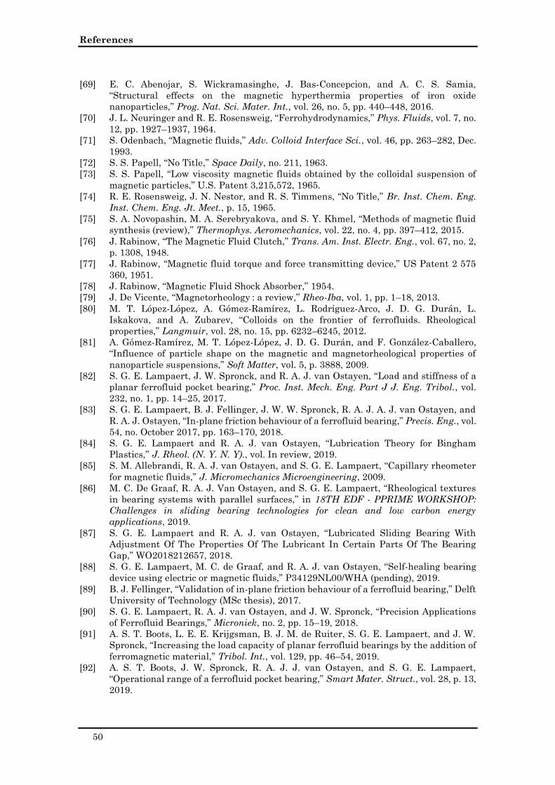
References
50
[69] E. C. Abenojar, S. Wickramasinghe, J. Bas-Concepcion, and A. C. S. Samia,
“Structural effects on the magnetic hyperthermia properties of iron oxide
nanoparticles,” Prog. Nat. Sci. Mater. Int., vol. 26, no. 5, pp. 440–448, 2016.
[70] J. L. Neuringer and R. E. Rosensweig, “Ferrohydrodynamics,” Phys. Fluids, vol. 7, no.
12, pp. 1927–1937, 1964.
[71] S. Odenbach, “Magnetic fluids,” Adv. Colloid Interface Sci., vol. 46, pp. 263–282, Dec.
1993.
[72] S. S. Papell, “No Title,” Space Daily, no. 211, 1963.
[73] S. S. Papell, “Low viscosity magnetic fluids obtained by the colloidal suspension of
magnetic particles,” U.S. Patent 3,215,572, 1965.
[74] R. E. Rosensweig, J. N. Nestor, and R. S. Timmens, “No Title,” Br. Inst. Chem. Eng.
Inst. Chem. Eng. Jt. Meet., p. 15, 1965.
[75] S. A. Novopashin, M. A. Serebryakova, and S. Y. Khmel, “Methods of magnetic fluid
synthesis (review),” Thermophys. Aeromechanics, vol. 22, no. 4, pp. 397–412, 2015.
[76] J. Rabinow, “The Magnetic Fluid Clutch,” Trans. Am. Inst. Electr. Eng., vol. 67, no. 2,
p. 1308, 1948.
[77] J. Rabinow, “Magnetic fluid torque and force transmitting device,” US Patent 2 575
360, 1951.
[78] J. Rabinow, “Magnetic Fluid Shock Absorber,” 1954.
[79] J. De Vicente, “Magnetorheology : a review,” Rheo-Iba, vol. 1, pp. 1–18, 2013.
[80] M. T. López-López, A. Gómez-Ramírez, L. Rodríguez-Arco, J. D. G. Durán, L.
Iskakova, and A. Zubarev, “Colloids on the frontier of ferrofluids. Rheological
properties,” Langmuir, vol. 28, no. 15, pp. 6232–6245, 2012.
[81] A. Gómez-Ramírez, M. T. López-López, J. D. G. Durán, and F. González-Caballero,
“Influence of particle shape on the magnetic and magnetorheological properties of
nanoparticle suspensions,” Soft Matter, vol. 5, p. 3888, 2009.
[82] S. G. E. Lampaert, J. W. Spronck, and R. A. J. van Ostayen, “Load and stiffness of a
planar ferrofluid pocket bearing,” Proc. Inst. Mech. Eng. Part J J. Eng. Tribol., vol.
232, no. 1, pp. 14–25, 2017.
[83] S. G. E. Lampaert, B. J. Fellinger, J. W. W. Spronck, R. A. J. A. J. van Ostayen, and
R. A. J. Ostayen, “In-plane friction behaviour of a ferrofluid bearing,” Precis. Eng., vol.
54, no. October 2017, pp. 163–170, 2018.
[84] S. G. E. Lampaert and R. A. J. van Ostayen, “Lubrication Theory for Bingham
Plastics,” J. Rheol. (N. Y. N. Y)., vol. In review, 2019.
[85] S. M. Allebrandi, R. A. J. van Ostayen, and S. G. E. Lampaert, “Capillary rheometer
for magnetic fluids,” J. Micromechanics Microengineering, 2009.
[86] M. C. De Graaf, R. A. J. Van Ostayen, and S. G. E. Lampaert, “Rheological textures
in bearing systems with parallel surfaces,” in 18TH EDF - PPRIME WORKSHOP:
Challenges in sliding bearing technologies for clean and low carbon energy
applications, 2019.
[87] S. G. E. Lampaert and R. A. J. van Ostayen, “Lubricated Sliding Bearing With
Adjustment Of The Properties Of The Lubricant In Certain Parts Of The Bearing
Gap,” WO2018212657, 2018.
[88] S. G. E. Lampaert, M. C. de Graaf, and R. A. J. van Ostayen, “Self-healing bearing
device using electric or magnetic fluids,” P34129NL00/WHA (pending), 2019.
[89] B. J. Fellinger, “Validation of in-plane friction behaviour of a ferrofluid bearing,” Delft
University of Technology (MSc thesis), 2017.
[90] S. G. E. Lampaert, R. A. J. van Ostayen, and J. W. Spronck, “Precision Applications
of Ferrofluid Bearings,” Microniek, no. 2, pp. 15–19, 2018.
[91] A. S. T. Boots, L. E. E. Krijgsman, B. J. M. de Ruiter, S. G. E. Lampaert, and J. W.
Spronck, “Increasing the load capacity of planar ferrofluid bearings by the addition of
ferromagnetic material,” Tribol. Int., vol. 129, pp. 46–54, 2019.
[92] A. S. T. Boots, J. W. Spronck, R. A. J. J. van Ostayen, and S. G. E. Lampaert,
“Operational range of a ferrofluid pocket bearing,” Smart Mater. Struct., vol. 28, p. 13,
2019.
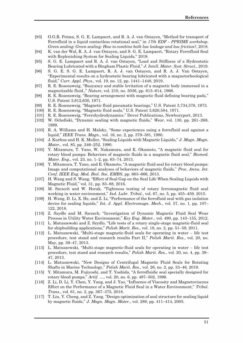
References
51
[93] O.G.R. Potma, S. G. E. Lampaert, and R. A. J. van Ostayen, “Method for transport of
Ferrofluid in a liquid contactless rotational seal,” in 17th EDF – PPRIME workshop.
Green sealing: Green sealing: How to combine both low leakage and low friction?, 2018.
[94] K. van der Wal, R. A. J. van Ostayen, and S. G. E. Lampaert, “Rotary Ferrofluid Seal
with Replenishing System for Sealing Liquids,” 2019.
[95] S. G. E. Lampaert and R. A. J. van Ostayen, “Load and Stiffness of a Hydrostatic
Bearing Lubricated with a Bingham Plastic Fluid,” J. Intell. Mater. Syst. Struct., 2019.
[96] S. G. E. S. G. E. Lampaert, R. A. J. van Ostayen, and R. A. J. Van Ostayen,
“Experimental results on a hydrostatic bearing lubricated with a magnetorheological
fluid,” Curr. Appl. Phys., vol. 19, no. 12, pp. 1441–1448, 2019.
[97] R. E. Rosensweig, “Buoyancy and stable levitation of a magnetic body immersed in a
magnetizable fluid.,” Nature, vol. 210, no. 5036, pp. 613–614, 1966.
[98] R. E. Rosensweig, “Bearing arrangement with magnetic fluid defining bearing pads,”
U.S. Patent 3,612,630, 1971.
[99] R. E. Rosensweig, “Magnetic fluid pneumatic bearings,” U.S. Patent 3,734,578, 1973.
[100] R. E. Rosensweig, “Magnetic fluid seals,” U.S. Patent 3,620,584, 1971.
[101] R. E. Rosensweig, “Ferrohydrodynamics.” Dover Publications, Newburyport, 2013.
[102] W. Ochofiski, “Dynamic sealing with magnetic fluids,” Wear, vol. 130, pp. 261–268,
1989.
[103] R. A. Williams and H. Malsky, “Some experiences using a ferrofluid seal against a
liquid,” IEEE Trans. Magn., vol. 16, no. 2, pp. 379–381, 1980.
[104] J. Kurfess and H. K. Muller, “Sealing Liquids with Magnetic Liquids,” J. Magn. Magn.
Mater., vol. 85, pp. 246–252, 1990.
[105] Y. Mitamura, T. Yano, W. Nakamura, and E. Okamoto, “A magnetic fluid seal for
rotary blood pumps: Behaviors of magnetic fluids in a magnetic fluid seal,” Biomed.
Mater. Eng., vol. 23, no. 1–2, pp. 63–74, 2013.
[106] Y. Mitamura, T. Yano, and E. Okamoto, “A magnetic fluid seal for rotary blood pumps:
Image and computational analyses of behaviors of magnetic fluids,” Proc. Annu. Int.
Conf. IEEE Eng. Med. Biol. Soc. EMBS, pp. 663–666, 2013.
[107] H. Wang and S. Wang, “Effect of Seal Gap on the Seal Life When Sealing Liquids with
Magnetic Fluid,” vol. 31, pp. 83–88, 2016.
[108] M. Szczech and W. Horak, “Tightness testing of rotary ferromagnetic fluid seal
working in water environment,” Ind. Lubr. Tribol., vol. 67, no. 5, pp. 455–459, 2015.
[109] H. Wang, D. Li, X. He, and Z. Li, “Performance of the ferrofluid seal with gas isolation
device for sealing liquids,” Int. J. Appl. Electromagn. Mech., vol. 57, no. 1, pp. 107–
122, 2018.
[110] Z. Szydło and M. Szczech, “Investigation of Dynamic Magnetic Fluid Seal Wear
Process in Utility Water Environment,” Key Eng. Mater., vol. 490, pp. 143–155, 2012.
[111] L. Matuszewski and Z. Szydlo, “Life tests of a rotary single-stage magnetic-fluid seal
for shipbuilding applications,” Polish Marit. Res., vol. 18, no. 2, pp. 51–59, 2011.
[112] L. Matuszewski, “Multi-stage magnetic-fluid seals for operating in water – life test
procedure, test stand and research results Part II,” Polish Marit. Res., vol. 20, no.
May, pp. 39–47, 2013.
[113] L. Matuszewski, “Multi-stage magnetic-fluid seals for operating in water – life test
procedure, test stand and research results,” Polish Marit. Res., vol. 20, no. 4, pp. 39–
47, 2013.
[114] L. Matuszewski, “New Designs of Centrifugal Magnetic Fluid Seals for Rotating
Shafts in Marine Technology,” Polish Marit. Res., vol. 26, no. 2, pp. 33–46, 2019.
[115] Y. Mitamura, M. Fujiyoshi, and T. Yoshida, “A ferrofluidic seal specially designed for
rotary blood pumps,” Artif. …, vol. 20, no. 6, pp. 497–502, 1996.
[116] Z. Li, D. Li, Y. Chen, Y. Yang, and J. Yao, “Influence of Viscosity and Magnetoviscous
Effect on the Performance of a Magnetic Fluid Seal in a Water Environment,” Tribol.
Trans., vol. 61, no. 2, pp. 367–375, 2018.
[117] T. Liu, Y. Cheng, and Z. Yang, “Design optimization of seal structure for sealing liquid
by magnetic fluids,” J. Magn. Magn. Mater., vol. 289, pp. 411–414, 2005.
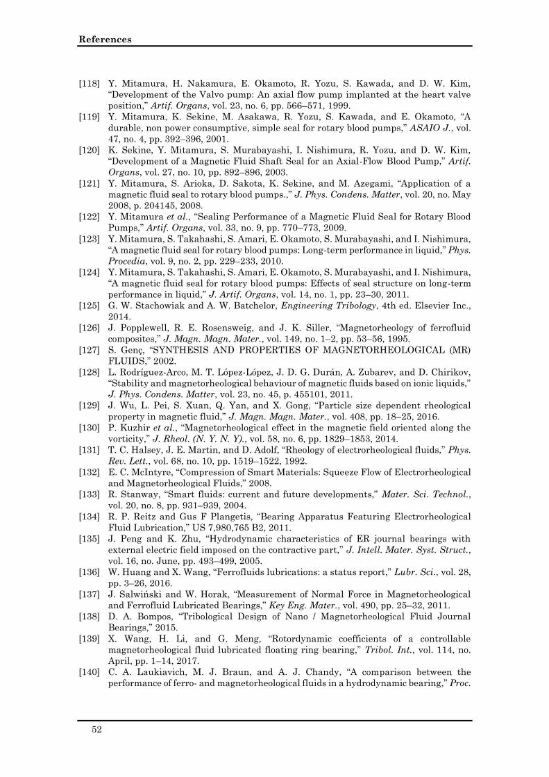
References
52
[118] Y. Mitamura, H. Nakamura, E. Okamoto, R. Yozu, S. Kawada, and D. W. Kim,
“Development of the Valvo pump: An axial flow pump implanted at the heart valve
position,” Artif. Organs, vol. 23, no. 6, pp. 566–571, 1999.
[119] Y. Mitamura, K. Sekine, M. Asakawa, R. Yozu, S. Kawada, and E. Okamoto, “A
durable, non power consumptive, simple seal for rotary blood pumps,” ASAIO J., vol.
47, no. 4, pp. 392–396, 2001.
[120] K. Sekine, Y. Mitamura, S. Murabayashi, I. Nishimura, R. Yozu, and D. W. Kim,
“Development of a Magnetic Fluid Shaft Seal for an Axial-Flow Blood Pump,” Artif.
Organs, vol. 27, no. 10, pp. 892–896, 2003.
[121] Y. Mitamura, S. Arioka, D. Sakota, K. Sekine, and M. Azegami, “Application of a
magnetic fluid seal to rotary blood pumps.,” J. Phys. Condens. Matter, vol. 20, no. May
2008, p. 204145, 2008.
[122] Y. Mitamura et al., “Sealing Performance of a Magnetic Fluid Seal for Rotary Blood
Pumps,” Artif. Organs, vol. 33, no. 9, pp. 770–773, 2009.
[123] Y. Mitamura, S. Takahashi, S. Amari, E. Okamoto, S. Murabayashi, and I. Nishimura,
“A magnetic fluid seal for rotary blood pumps: Long-term performance in liquid,” Phys.
Procedia, vol. 9, no. 2, pp. 229–233, 2010.
[124] Y. Mitamura, S. Takahashi, S. Amari, E. Okamoto, S. Murabayashi, and I. Nishimura,
“A magnetic fluid seal for rotary blood pumps: Effects of seal structure on long-term
performance in liquid,” J. Artif. Organs, vol. 14, no. 1, pp. 23–30, 2011.
[125] G. W. Stachowiak and A. W. Batchelor, Engineering Tribology, 4th ed. Elsevier Inc.,
2014.
[126] J. Popplewell, R. E. Rosensweig, and J. K. Siller, “Magnetorheology of ferrofluid
composites,” J. Magn. Magn. Mater., vol. 149, no. 1–2, pp. 53–56, 1995.
[127] S. Genç, “SYNTHESIS AND PROPERTIES OF MAGNETORHEOLOGICAL (MR)
FLUIDS,” 2002.
[128] L. Rodríguez-Arco, M. T. López-López, J. D. G. Durán, A. Zubarev, and D. Chirikov,
“Stability and magnetorheological behaviour of magnetic fluids based on ionic liquids,”
J. Phys. Condens. Matter, vol. 23, no. 45, p. 455101, 2011.
[129] J. Wu, L. Pei, S. Xuan, Q. Yan, and X. Gong, “Particle size dependent rheological
property in magnetic fluid,” J. Magn. Magn. Mater., vol. 408, pp. 18–25, 2016.
[130] P. Kuzhir et al., “Magnetorheological effect in the magnetic field oriented along the
vorticity,” J. Rheol. (N. Y. N. Y)., vol. 58, no. 6, pp. 1829–1853, 2014.
[131] T. C. Halsey, J. E. Martin, and D. Adolf, “Rheology of electrorheological fluids,” Phys.
Rev. Lett., vol. 68, no. 10, pp. 1519–1522, 1992.
[132] E. C. McIntyre, “Compression of Smart Materials: Squeeze Flow of Electrorheological
and Magnetorheological Fluids,” 2008.
[133] R. Stanway, “Smart fluids: current and future developments,” Mater. Sci. Technol.,
vol. 20, no. 8, pp. 931–939, 2004.
[134] R. P. Reitz and Gus F Plangetis, “Bearing Apparatus Featuring Electrorheological
Fluid Lubrication,” US 7,980,765 B2, 2011.
[135] J. Peng and K. Zhu, “Hydrodynamic characteristics of ER journal bearings with
external electric field imposed on the contractive part,” J. Intell. Mater. Syst. Struct.,
vol. 16, no. June, pp. 493–499, 2005.
[136] W. Huang and X. Wang, “Ferrofluids lubrications: a status report,” Lubr. Sci., vol. 28,
pp. 3–26, 2016.
[137] J. Salwiński and W. Horak, “Measurement of Normal Force in Magnetorheological
and Ferrofluid Lubricated Bearings,” Key Eng. Mater., vol. 490, pp. 25–32, 2011.
[138] D. A. Bompos, “Tribological Design of Nano / Magnetorheological Fluid Journal
Bearings,” 2015.
[139] X. Wang, H. Li, and G. Meng, “Rotordynamic coefficients of a controllable
magnetorheological fluid lubricated floating ring bearing,” Tribol. Int., vol. 114, no.
April, pp. 1–14, 2017.
[140] C. A. Laukiavich, M. J. Braun, and A. J. Chandy, “A comparison between the
performance of ferro- and magnetorheological fluids in a hydrodynamic bearing,” Proc.
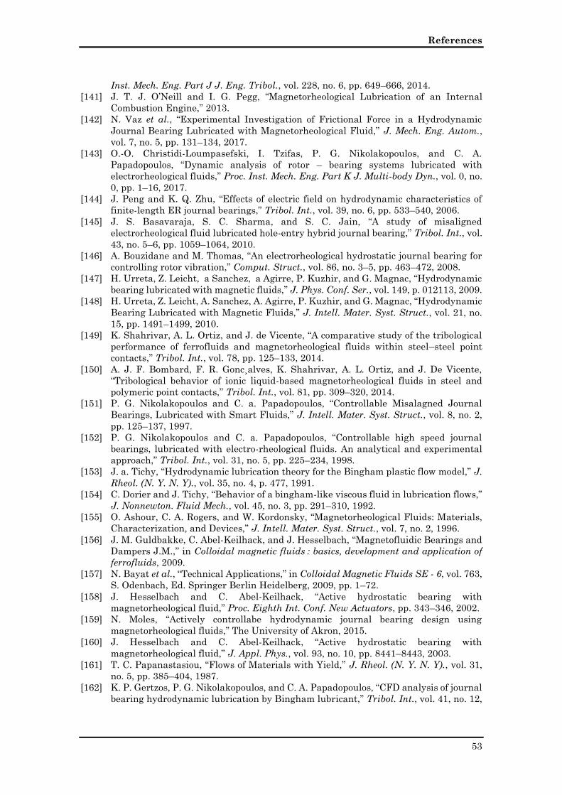
References
53
Inst. Mech. Eng. Part J J. Eng. Tribol., vol. 228, no. 6, pp. 649–666, 2014.
[141] J. T. J. O’Neill and I. G. Pegg, “Magnetorheological Lubrication of an Internal
Combustion Engine,” 2013.
[142] N. Vaz et al., “Experimental Investigation of Frictional Force in a Hydrodynamic
Journal Bearing Lubricated with Magnetorheological Fluid,” J. Mech. Eng. Autom.,
vol. 7, no. 5, pp. 131–134, 2017.
[143] O.-O. Christidi-Loumpasefski, I. Tzifas, P. G. Nikolakopoulos, and C. A.
Papadopoulos, “Dynamic analysis of rotor – bearing systems lubricated with
electrorheological fluids,” Proc. Inst. Mech. Eng. Part K J. Multi-body Dyn., vol. 0, no.
0, pp. 1–16, 2017.
[144] J. Peng and K. Q. Zhu, “Effects of electric field on hydrodynamic characteristics of
finite-length ER journal bearings,” Tribol. Int., vol. 39, no. 6, pp. 533–540, 2006.
[145] J. S. Basavaraja, S. C. Sharma, and S. C. Jain, “A study of misaligned
electrorheological fluid lubricated hole-entry hybrid journal bearing,” Tribol. Int., vol.
43, no. 5–6, pp. 1059–1064, 2010.
[146] A. Bouzidane and M. Thomas, “An electrorheological hydrostatic journal bearing for
controlling rotor vibration,” Comput. Struct., vol. 86, no. 3–5, pp. 463–472, 2008.
[147] H. Urreta, Z. Leicht, a Sanchez, a Agirre, P. Kuzhir, and G. Magnac, “Hydrodynamic
bearing lubricated with magnetic fluids,” J. Phys. Conf. Ser., vol. 149, p. 012113, 2009.
[148] H. Urreta, Z. Leicht, A. Sanchez, A. Agirre, P. Kuzhir, and G. Magnac, “Hydrodynamic
Bearing Lubricated with Magnetic Fluids,” J. Intell. Mater. Syst. Struct., vol. 21, no.
15, pp. 1491–1499, 2010.
[149] K. Shahrivar, A. L. Ortiz, and J. de Vicente, “A comparative study of the tribological
performance of ferrofluids and magnetorheological fluids within steel–steel point
contacts,” Tribol. Int., vol. 78, pp. 125–133, 2014.
[150] A. J. F. Bombard, F. R. Gonc¸alves, K. Shahrivar, A. L. Ortiz, and J. De Vicente,
“Tribological behavior of ionic liquid-based magnetorheological fluids in steel and
polymeric point contacts,” Tribol. Int., vol. 81, pp. 309–320, 2014.
[151] P. G. Nikolakopoulos and C. a. Papadopoulos, “Controllable Misalagned Journal
Bearings, Lubricated with Smart Fluids,” J. Intell. Mater. Syst. Struct., vol. 8, no. 2,
pp. 125–137, 1997.
[152] P. G. Nikolakopoulos and C. a. Papadopoulos, “Controllable high speed journal
bearings, lubricated with electro-rheological fluids. An analytical and experimental
approach,” Tribol. Int., vol. 31, no. 5, pp. 225–234, 1998.
[153] J. a. Tichy, “Hydrodynamic lubrication theory for the Bingham plastic flow model,” J.
Rheol. (N. Y. N. Y)., vol. 35, no. 4, p. 477, 1991.
[154] C. Dorier and J. Tichy, “Behavior of a bingham-like viscous fluid in lubrication flows,”
J. Nonnewton. Fluid Mech., vol. 45, no. 3, pp. 291–310, 1992.
[155] O. Ashour, C. A. Rogers, and W. Kordonsky, “Magnetorheological Fluids: Materials,
Characterization, and Devices,” J. Intell. Mater. Syst. Struct., vol. 7, no. 2, 1996.
[156] J. M. Guldbakke, C. Abel-Keilhack, and J. Hesselbach, “Magnetofluidic Bearings and
Dampers J.M.,” in Colloidal magnetic fluids : basics, development and application of
ferrofluids, 2009.
[157] N. Bayat et al., “Technical Applications,” in Colloidal Magnetic Fluids SE - 6, vol. 763,
S. Odenbach, Ed. Springer Berlin Heidelberg, 2009, pp. 1–72.
[158] J. Hesselbach and C. Abel-Keilhack, “Active hydrostatic bearing with
magnetorheological fluid,” Proc. Eighth Int. Conf. New Actuators, pp. 343–346, 2002.
[159] N. Moles, “Actively controllabe hydrodynamic journal bearing design using
magnetorheological fluids,” The University of Akron, 2015.
[160] J. Hesselbach and C. Abel-Keilhack, “Active hydrostatic bearing with
magnetorheological fluid,” J. Appl. Phys., vol. 93, no. 10, pp. 8441–8443, 2003.
[161] T. C. Papanastasiou, “Flows of Materials with Yield,” J. Rheol. (N. Y. N. Y)., vol. 31,
no. 5, pp. 385–404, 1987.
[162] K. P. Gertzos, P. G. Nikolakopoulos, and C. A. Papadopoulos, “CFD analysis of journal
bearing hydrodynamic lubrication by Bingham lubricant,” Tribol. Int., vol. 41, no. 12,
References
54
pp. 1190–1204, 2008.
[163] D. A. Bompos and P. G. Nikolakopoulos, “CFD simulation of magnetorheological fluid
journal bearings,” Simul. Model. Pract. Theory, vol. 19, no. 4, pp. 1035–1060, 2011.
[164] D. A. Bompos and P. G. Nikolakopoulos, “Rotordynamic Analysis of a Shaft Using
Magnetorheological and Nanomagnetorheological Fluid Journal Bearings,” Tribol.
Trans., vol. 59, no. 1, pp. 108–118, 2016.
[165] P. Kim, J. I. Lee, and J. Seok, “Analysis of a viscoplastic flow with field-dependent
yield stress and wall slip boundary conditions for a magnetorheological (MR) fluid,” J.
Nonnewton. Fluid Mech., vol. 204, pp. 72–86, 2014.
[166] S. Wada, H. Hayashi, and K. Haga, “Behavior of a Bingham solid in hydrodynamic
lubrication (Part 1, General Theory),” Bull. JSME, vol. 16, no. 92, pp. 422–431, 1973.
[167] S. Wada, H. Hayahsi, and K. Haga, “Behavior of a Bingham solid in hydrodynamic
lubrication (Part 2, Application to Step Bearing),” Bull. JSME, vol. 16, no. 92, pp. 432–
440, 1973.
[168] S. Wada, H. Hayahsi, and K. Haga, “Behavior of a Bingham Solid in Hydrodynamic
Lubrication (Part 3, Application to Journal Bearing),” Bull. JSME, no. September, p.
1182, 1974.
[169] P. Forte, M. Paternò, and E. Rustighi, “A magnetorheological fluid damper for rotor
applications,” Int. J. Rotating Mach., vol. 10, no. 3, pp. 175–182, 2004.
[170] D. Dowson, “A generalized Reynolds equation for fluid-film lubrication,” Int. J. Mech.
Sci., vol. 4, no. 2, pp. 159–170, 1962.
[171] A. Guzek, “Optimization of Surface Texture Shapes in Hydrodynamic Contacts,” 2012.
[172] T. Ibatan, M. S. Uddin, and M. A. K. Chowdhury, “Recent development on surface
texturing in enhancing tribological performance of bearing sliders,” Surf. Coatings
Technol., vol. 272, pp. 102–120, 2015.
[173] R. Wahl, J. Schneider, and P. Gumbsch, “Influence of the real geometry of the
protrusions in micro textured surfaces on frictional behaviour,” Tribol. Lett., vol. 47,
no. 3, pp. 447–453, 2012.
[174] M. Wakuda, Y. Yamauchi, S. Kanzaki, and Y. Yasuda, “Effect of surface texturing on
friction reduction between ceramic and steel materials under lubricated sliding
contact,” Wear, vol. 254, no. 3–4, pp. 356–363, 2003.
[175] N. Sarang, S. Lyndon, C. Philip, and B. Ravinder, “Manufacturing of microasperities
on thrust surfaces using ultraviolet photolithography,” Winter Top. Meet., vol. 28, no.
859, pp. 148–153, 2003.
[176] U. Pettersson and S. Jacobson, “Friction and wear properties of micro textured DLC
coated surfaces in boundary lubricated sliding,” Tribol. Lett., vol. 17, no. 3, pp. 553–
559, 2004.
[177] C. Shen and M. M. Khonsari, “Numerical optimization of texture shape for parallel
surfaces under unidirectional and bidirectional sliding,” Tribol. Int., vol. 82, no. PA,
pp. 1–11, 2015.
[178] D. Gropper, T. J. Harvey, and L. Wang, “Numerical analysis and optimization of
surface textures for a tilting pad thrust bearing,” Tribol. Int., vol. 124, no. March, pp.
134–144, 2018.
[179] Y. Henry, J. Bouyer, and M. Fillon, “Experimental analysis of the hydrodynamic effect
during start-up of fixed geometry thrust bearings,” Tribol. Int., vol. 120, no. December
2017, pp. 299–308, 2018.
[180] C. Gachot, A. Rosenkranz, S. M. Hsu, and H. L. Costa, “A critical assessment of surface
texturing for friction and wear improvement,” Wear, vol. 372–373, pp. 21–41, 2017.
[181] M. D. Bartlett, M. D. Dickey, and C. Majidi, “Self-healing materials for soft-matter
machines and electronics,” NPG Asia Mater., vol. 11, no. 1, pp. 19–22, 2019.
[182] D. G. Bekas, K. Tsirka, D. Baltzis, and A. S. Paipetis, “Self-healing materials: A review
of advances in materials, evaluation, characterization and monitoring techniques,”
Compos. Part B Eng., vol. 87, pp. 92–119, 2016.
[183] R. P. Wool, “Self-healing materials: A review,” Soft Matter, vol. 4, no. 3, pp. 400–418,
2008.
References
55
[184] S. R. Madara, N. S. Sarath Raj, and C. P. Selvan, “Review of research and
developments in self healing composite materials,” IOP Conf. Ser. Mater. Sci. Eng.,
vol. 346, no. 1, 2018.
[185] N. N. Sitnikov, I. A. Khabibullina, V. I. Mashchenko, and R. N. Rizakhanov,
“Prospects of Application of Self-Healing Materials and Technologies Based on Them,”
Inorg. Mater. Appl. Res., vol. 9, no. 5, pp. 785–793, 2018.
[186] R. V. S. P. Sanka, B. Krishnakumar, Y. Leterrier, S. Pandey, S. Rana, and V. Michaud,
“Soft Self-Healing Nanocomposites,” Front. Mater., vol. 6, no. June, pp. 1–20, 2019.
[187] Y. Wang, D. T. Pham, and C. Ji, “Self-healing composites: A review,” Cogent Eng., vol.
2, no. 1, pp. 1–28, 2015.
[188] H. E. Horng, C. Hong, S. Y. Yang, and H. C. Yang, “Novel properties and applications
in magnetic fluids,” J. Phys. Chem. Solids, vol. 62, pp. 1749–1764, 2001.
[189] C.-Y. Hong, “Field-induced structural anisotropy in magnetic fluids,” J. Appl. Phys.,
vol. 85, no. 8, pp. 5962–5964, 1999.
[190] H. Wang, C. Bi, J. Kan, C. Gao, and W. Xiao, “The mechanical property of
magnetorheological fluid under compression, elongation, and shearing,” J. Intell.
Mater. Syst. Struct., vol. 22, no. 8, pp. 811–816, 2011.
[191] E. Dohmen, N. Modler, and M. Gude, “Anisotropic characterization of
magnetorheological materials,” J. Magn. Magn. Mater., vol. 431, pp. 107–109, 2017.
[192] E. Dohmen, D. Borin, and A. Zubarev, “Magnetic field angle dependent hysteresis of
a magnetorheological suspension,” J. Magn. Magn. Mater., vol. 443, pp. 275–280,
2017.
[193] P. Kuzhir, G. Bossis, V. Bashtovoi, and O. Volkova, “Effect of the orientation of the
magnetic field on the flow of magnetorheological fluid. II. Cylindrical channel,” J.
Rheol. (N. Y. N. Y)., vol. 47, no. 6, p. 1385, 2003.
[194] P. Kuzhir, G. Bossis, and V. Bashtovoi, “Effect of the orientation of the magnetic field
on the flow of a magnetorheological fluid. I. Plane channel,” J. Rheol. (N. Y. N. Y)., vol.
47, no. 6, pp. 1373–1384, 2003.
[195] J. Takimoto, H. Takeda, Y. Masubuchi, and K. Koyama, “Stress Rectification in MR
Fluids under Tilted Magnetic Field,” Int. J. Mod. Phys. B, vol. 13, no. 14, 15 & 16, pp.
2028–2035, 1999.
[196] X. Wang and F. Gordaninejad, “Study of magnetorheological fluids at high shear
rates,” Rheol. Acta, vol. 45, no. 6, pp. 899–908, 2006.
[197] F. D. Goncalves, “Characterizing the Behavior of Magnetorheological Fluids at High
Velocities and High Shear Rates,” Virginia Polytechnic Institute and State University,
2005.
[198] A. C. Becnel, W. Hu, and N. M. Wereley, “Measurement of magnetorheological fluid
properties at shear rates of up to 25000 s -1,” IEEE Trans. Magn., vol. 48, no. 11, pp.
3525–3528, 2012.
[199] H. Hezaveh, A. Fazlali, and I. Noshadi, “Synthesis, rheological properties and
magnetoviscos effect of Fe2O3/paraffin ferrofluids,” J. Taiwan Inst. Chem. Eng., vol.
43, no. 1, pp. 159–164, 2012.
[200] Anton Paar, “Application specific accessories for additional parameter setting,” 2016.
[201] Anton Paar, “The Modular Compact Rheometer Series.”
[202] TA Instruments, “Discovery Hybrid Rheometers Temperature Systems and
Accessories,” 2014.
[203] C. W. Macosko, Rheology: Principles, Measurements, and Applications. John Wiley &
Sons, 1994.
[204] H. P. Sdougos, S. R. Bussolari, and C. F. Dewey, “Secondary flow and turbulence in a
cone-and-plate device,” J. Fluid Mech., vol. 138, pp. 379–404, 1984.
[205] R. W. Connelly and J. Greener, “High‐Shear Viscometry with a Rotational Parallel‐
Disk Device,” J. Rheol. (N. Y. N. Y)., vol. 29, no. 2, pp. 209–226, 1985.
[206] Ferrotec, “Ferrofluid data sheet EFH series,” 2011.
[207] EU Commission, “HORIZON 2020 – WORK PROGRAMME 2014-2015,” 2014.
References
56
Personal reflection
57
Your happiness on the job has very little to do with the work itself. On Dirty
Jobs, I remember a very successful septic tank cleaner, a multi-millionaire,
who told me the secret to his success: “I looked around to see where everyone
else was headed and then I went the opposite way. Then I got good at my
work. Then I began to prosper. And then one day, I realized I was
passionate about other people’s crap.” I’ve heard that same basic story from
welders, plumbers, carpenters, electricians, HVAC professionals, hundreds
of other skilled tradesmen who followed opportunity – not passion – and
prospered as a result.
Don’t Follow Your Passion, Mike Rowe, 2016
Somewhere halfway through 2015, AEGIR came to the university in search of technology
that could deliver them the next generation stern tube seal. The main problems of this seal
are that they suffer from wear and that they discharge oil into the environment during
operation. We were at that moment working of the ferrofluid pocket bearing which was
basically a seal in disguise. The big advantage of this sealing concept is that it does not wear
down and that is does not suffer from leakage. The idea was mentioned to explore using this
seal concept in stern tube systems, which in the end lead to a PhD project. Since I was
working on the modelling and design principles of ferrofluid pocket bearings, I was a
convenient candidate for the position and so they asked me.
Working four years alone on one single project. One must be crazy doing something like
that, absolutely nothing for me, so I thought... Though, I really liked doing my graduation
project, I didn’t really feel like working yet and I wanted to do a sort of technical traineeship.
A PhD project seemed to be a good opportunity to follow, but only if I would do it differently.
I divided the projects into different smaller project that could be done by a student as a
MSc graduation project. In this way I could recruit a group of students around such that we
could do the work as a team together. The projects that were not chosen by students I took
myself and I made sure that the gaps between the projects were filled up. This strategy
proved to be successful looking at the scientific output of the project: 11 journal papers and 2
patents (one pending).
This project is the greatest adventure I ever experienced, it was the most exciting period
of my life, I was able to work in this project with intense passion. In hindsight, I see that my
initial impression of a PhD project was utterly wrong, in the same way I was utterly wrong
with some of the initial assumptions in the research. It makes me think about how utterly
wrong we must be with so many things we believe in right now. Think of Columbus who was
convinced he found a new way to India, never knowing he found a completely new continent
instead. I think this very beautifully illustrates the process of research and the need for it in
society.
Personal reflection
Personal reflection
58
Acknowledgements
59
Together everyone achieves more. This PhD thesis is used to assess whether I am worth the
title Doctor of Philosophy. This does not mean that I am the sole contributor to the results in
this thesis. For the four years, I have been surrounded by a team of colleagues and students
who worked very hard to generate the results presented with this document.
The first people I want to thank are the large group of MSc graduation students I worked
with. In chronological order this is Olivier Potma, Bas Fellinger, Sander Allebrandi, Sem van
Aefst, Marc de Graaf, Jelle Boots, Karoen van der Wal, Stefan van den Toorn, Bas Lucieer
and Gerben van der Meer. I was a real pleasure seeing you develop from insecure students
that didn’t really knew what they were doing to professionals that confidently and proudly
presented their work they were working on for over a year. The many discussions I had with
you were my biggest source of education in this project.
I was also privileged to supervise different BSc student groups in their graduation project.
I am very thankful for the interesting and inspiring discussions we had. This really helped
me either directly or indirectly in my research. One of the papers in this thesis is written by
some bachelor students who were so enthusiastic about their research that they continued it
in their free time to push it to a journal paper. Laurens Krijgsman and Bram de Ruiter, it
was a real honour working with such enthusiastic people as you.
Then I want to thank my fellow PhD students of the department departments for the great
time we had together and for all the fascinating discussions. In particular I want to thank
Joep Nijssen who I worked with closely with. The discussions we had on bearing systems
really helped me in my work, especially at the moments that I became blind for other solution.
As a PhD student you are very capable in developing new theoretical knowledge, but you
are generally not so capable in making experimental setups for validating those theories. For
this I want to thank the (lab) support staff Patrick van Holst, Spiridon van Veldhoven, Harry
Jansen, Rob Luttjeboer, Jan van Frankenhuyzen and Reinier van Antwerpen. You really
helped me out with all the practical issues of experimental setups and measurement systems.
With this I also want to thank Anton Lefering of the Reactor Institute Delft for doing
magnetic characterization of the magnetic fluids we used. For using the workshop at the
faculty I want to thank Gerard van Vliet and Rene van Ommen.
Within the project I had the privilege to cooperate with the company AEGIR Marine. I
want to thank the people Ruud Muis, Hans Dekker, Robert van Herwaarden, Roy van den
Nieuwendijk and Federico Quinci for the great work we did together.
The last people I want to thank are Ron van Ostayen and Jo Spronck respectively my
promotor and co-promotor but also supervisors of my master thesis. I cannot describe the
huge amount of knowledge and expertise you taught me. You two played a very significant
role in developing me into the person I am today. Especially Ron, I cannot imagine a better
daily supervisor than you. In German they say “doctor-father” to their promotor, this is
exactly what you were to me at the university. I am happy that you were always there for me
when there were both technical and personal issues.
Acknowledgements
Acknowledgements
60
Curriculum vitae
61
General
1991, April 4th Born in Terneuzen
Education
2003 – 2009 VWO, Science and Engineering + Science and Health, Reynaertcollege
2009 – 2013 BSc, Mechanical Engineering, TU Delft
2011 – 2012 Minor, D:Dream, TU Delft
Mechanical design of the electric motors of a Formula Student race car
2013 – 2015 MSc, Mechanical Engineering, TU Delft (cum laude)
Precision and Microsystems Engineering - Mechatronic system design
Topic: Magnetic fluid bearings
2016 – Present PhD, Mechanical Engineering, TU Delft
Precision and Microsystems Engineering - Mechatronic system design
Topic: Magnetic Fluid Bearings & Seals: Methods, Design & Application
Curriculum vitae
Curriculum vitae
62
Thesis project output
63
Presentations at international conferences
2019 Presentation
Bearings with rheological texturing
18th EDF – PPRIME workshop. Challenges in sliding bearing
technologies for clean and low carbon energy applications
2019 Presentation
Hydrodynamic lubrication theory for an exact Bingham
plastic fluid model.
Leeds-Lyon Symposium on Tribology 2019
2019 Poster
Modelling a hybrid journal bearing with
magnetorheological fluids using the ideal Bingham model.
International Conference on Magnetic Fluids
2019 Poster +
Demo
A ferrofluid bearing: Just like an air bearing, but different
Gas Bearing Workshop 2019
2018 Presentation
Zero leakage and low friction with ferrofluid seals
17th EDF – PPRIME workshop. Green sealing: Green sealing:
How to combine both low leakage and low friction?
2018 Presentation
Methods for Variable Bearing Properties using Magnetic
Fluids
45th Leeds-Lyon Symposium on Tribology “Smart Tribology
Systems”
2018 Poster Microcapillary Magnetorheometer
17th German Ferrofluid Workshop
2018 Demo Magnetic fluid bearings
17th German Ferrofluid Workshop
2018 Presentation
Predicting the behaviour of magnetorheological textured
bearings
The 18th Nordic Symposium on Tribology - NORDTRIB 2018
2017 Presentation
Virtual Textured Hybrid Bearings
44rd Leeds-Lyon Symposium on Tribology
Tribomotion, where Performance and Motion meet Friction
2017 Presentation Hydrostatic bearing with MR texturing
16th German Ferrofluid Workshop
2017 Poster Hydrostatic bearing with MR texturing
16th German Ferrofluid Workshop
2016 Presentation XY360 planar positioning stage with ferrofluid bearings
DSPE conference 2016, Conference on Precision Mechatronics
Thesis project output
Thesis project output
64
2016 Poster +
Demo
Modelling and design principles of planar ferrofluid
bearings
DSPE conference 2016, Conference on Precision Mechatronics
2016 Presentation
Friction and Trail Formation of a Planar Ferrofluid Bearing
43rd Leeds-Lyon Symposium on Tribology
Tribology (The Jost Report) – 50 years on
2016 Presentation Load and Stiffness of a Ferrofluid Pocket Bearing
The 17th Nordic Symposium on Tribology - NORDTRIB 2016
2016 Presentation
(2+4)DOF precision motion stage with ferrofluid bearings
2016 Spring Meeting: Precision Mechatronic System Design and
Control
American Society for Precision Engineers (ASPE)
Conference papers
2016
(2+4) DOF precision motion stage with
ferrofluid bearings
S. G. E. Lampaert, J. W. Spronck, R. A. J. van
Ostayen
2016 Spring Meeting: Precision
Mechatronic System Design and
Control
American Society for Precision
Engineers (ASPE)
2016
Load and Stiffness of a Ferrofluid
Pocket Bearing
S. G. E. Lampaert, M. Café, R. A. J. van
Ostayen, and J. W. Spronck
The 17th Nordic Symposium on
Tribology - NORDTRIB 2016
2016
XY360 planar positioning stage with
ferrofluid bearings
S. G. E. Lampaert, H. Habib, J. W. Spronck
DSPE conference 2016,
Conference on Precision
Mechatronics
2018
Method for transport of Ferrofluid in a
liquid contactless rotational seal
O.G.R. Potma, S. G. E. Lampaert, and R. A.
J. van Ostayen
17th EDF – PPRIME workshop:
Green sealing: Green sealing:
How to combine both low leakage
and low friction?
2019
Rheological textures in bearing systems
with parallel surfaces
M.C. de Graaf, R.A.J. van Ostayen, S.G.E.
Lampaert
18th EDF - PPRIME workshop:
Challenges in sliding bearing
technologies for clean and low
carbon energy applications
Thesis project output
65
Journal papers
2018
Load and stiffness of a planar ferrofluid pocket
bearing
S.G.E. Lampaert, J.W. Spronck, R.A.J. van Ostayen
Journal of
Engineering
Tribology
2018
In-plane friction behaviour of a ferrofluid
bearing
S.G.E. Lampaert, B.J. Fellinger, J.W. Spronck, R.A.J.
van Ostayen
Precision
Engineering
2019
Increasing the load capacity of planar ferrofluid
bearings by the addition of ferromagnetic
material
A.S.T. Boots, L.E. Krijgsman, B.J.M. de Ruiter, S.G.E.
Lampaert, J.W. Spronck
Tribology
International
2019
Operational range of a ferrofluid pocket bearing
A.S.T. Boots, R.A.J. van Ostayen, J.W. Spronck, S.G.E.
Lampaert
Journal of Physics D:
Applied Physics.
2019
Capillary Rheometer for Magnetorheological
Fluids
S.M. Allebrandi, R.A.J. van Ostayen, S.G.E. Lampaert
Journal of
Micromechanics and
Microengineering
2019
Load and Stiffness of a Hydrostatic Bearing
Lubricated with a Bingham Plastic Fluid
S.G.E. Lampaert, R.A.J. van Ostayen
Journal of Intelligent
Material Systems
and Structures
2019
Hydrostatic Bearing Lubricated with a
Magnetorheological Fluid
S.G.E. Lampaert, R.A.J. van Ostayen
Current Applied
Physics
2019 A Lubrication Theory for Bingham Plastics
S.G.E. Lampaert, R.A.J. van Ostayen
Tribology
International
2019
Rheological textures in a journal bearing with
magnetorheological fluids
S.G.E. Lampaert, R.A.J. van Ostayen
Journal of
Magnetism and
Magnetic Materials
2020
Ferrofluid Rotary Seal with Replenishment
System for Sealing Liquids
K. van der Wal, R.A.J. van Ostayen, S.G.E. Lampaert
Tribology
International
2020
Design of a passive alternative for long stroke
linear aerostatic stages based on ferrofluid
bearings (in review)
S. van den Toorn, Jo W. Spronck, R.A.J. van Ostayen,
S.G.E. Lampaert
Precision
Engineering
2020
Design considerations for ferrofluid pressure
bearing pads (in review)
S. van den Toorn, Jo W. Spronck, R.A.J. van Ostayen,
S.G.E. Lampaert
Results in
Engineering
Thesis project output
66
Patents
2018
Lubricated Sliding Bearing With Adjustment Of
The Properties Of The Lubricant In Certain
Parts Of The Bearing Gap
S.G.E. Lampaert, R.A.J. van Ostayen
WO2018212657
2019 Self-healing bearing (patent pending)
M.C. de Graaf, R.A.J. van Ostayen, S.G.E. Lampaert nl 2023974
Awards
2017 3rd poster price Hydrostatic bearing with MR texturing
16th German Ferrofluid Workshop
2016 DSPE best demonstration
Modelling and design principles of
planar ferrofluid bearings
DSPE conference 2016, Conference on
Precision Mechatronics
2016 PME best poster presentation
Modelling and design principles of
planar ferrofluid bearings
PME internal poster presentation
MSc thesis students supervised 2019 - Present Gerben van der Meer: Theoretical methods for self-healing bearings
2019 - Present Bas Lucier: Experimental validation of self-healing bearing model
2018 - 2019 Stefan van den Toorn: Ferrofluid bearings for precise positioning
2017 - 2019 Karoen van der Wall: Ferrofluid seals to seal liquids
2017 - 2019 Marc de Graaf: Magnetorheological texturing in hydrodynamic
bearings
2017 - 2018 Jelle Boots: Ferrofluid bearings for precise positioning
2016 - 2018 Sander Allebrandi: Microcapillary Magnetorheometer
2016 - 2017 Olivier Potma: Designs for rotary shaft fluid seals in an aqueous
environment using ferrofluid
BSc thesis projects supervised 2019 Magnetocaloric pump
2018 Motion energy harvester optimized by implementing ferrofluid
2017 Design, control and evaluation of a magnetorheological damper to realise
constant deceleration
2017 Influence of a MRF on friction in hydrodynamic bearings
2016 A Load and Stiffness Improvement of Planar Ferrofluid Bearings
2016 Ferrofluid trail formation on ferrofluidphobic surfaces
Thesis project output
67
Thesis result metrics:
• 5 conference papers published
• 9 journal papers published
• 3 journal papers in review
• 1 journal papers still to be submitted
• 1 patent accepted
• 1 patent pending
• 6 MSc students supervised (2 additional still being supervised)
• 6 BSc thesis groups supervised
• 17 contributions to international conferences:
o 11 oral presentations
o 6 poster presentations / demonstrations
• 3 demonstrations at Exhibition/fairs
• 3 awards for presenting the research
Thesis project output
68
Appendices
69
Below follows an overview of the different publications that followed from this project. The
different papers are accessible online through the different DOI links but are also appended
as part two of this thesis.
A1. Load and Stiffness of a Planar Ferrofluid Pocket Bearing (2018)
Stefan G.E. Lampaert, Jo W. Spronck, Ron A.J. van Ostayen
Proceedings of the Institution of Mechanical Engineers, Part J: Journal of
Engineering Tribology, 232(1)
https://doi.org/10.1177/1350650117739200
A2. In-Plane Friction Behaviour of a Ferrofluid Bearing (2018)
Stefan G.E. Lampaert, Bas J. Fellinger, Jo W. Spronck, Ron A.J. van
Ostayen,
Precision Engineering, 54(1)
https://doi.org/10.1016/j.precisioneng.2018.05.013
A3. Precision Applications of Ferrofluid Bearings (2018)
Stefan G.E. Lampaert, Ron A.J. van Ostayen, Jo W. Spronck
Microniek, (2)
https://www.dspe.nl/mikroniek/archive/
A4. Increasing the Load Capacity of Planar Ferrofluid Bearings by the
Addition of Ferromagnetic Material (2019)
Adriaan S.T. Boots, Laurens E. Krijgsman, Bram J.M. de Ruiter, Stefan
G.E. Lampaert, Jo W. Spronck,
Tribology International, 129(1)
https://doi.org/10.1016/j.triboint.2018.07.048
A5. Operational Range of a Ferrofluid Pocket Bearing (2019)
Adriaan S.T. Boots, Jo W. Spronck, Ron A.J. van Ostayen, Stefan G.E.
Lampaert
Smart Materials and Structures, 28(11)
https://doi.org/10.1088/1361-665X/ab2b60
Appendices
Appendices
70
A6. Design of a passive alternative for long stroke linear aerostatic
stages based on ferrofluid bearings (2020)
Stefan van den Toorn, Jo W. Spronck, Ron A.J. van Ostayen, Stefan G.E.
Lampaert
In review at Precision Engineering
A7. Design considerations for ferrofluid pressure bearing pads
Stefan van den Toorn, Jo W. Spronck, Ron A.J. van Ostayen, Stefan G.E.
Lampaert
In review at Results in Engineering
A8. Method for Transport of Ferrofluid in a Liquid Contactless
Rotational Seal (2018)
Olivier G.R. Potma, Stefan G.E. Lampaert, Ron A.J. van Ostayen
17th EDF/Pprime Workshop: “Green sealing: How to combine both low
leakage and low friction?”
Paris Saclay, October 4, 2018
https://doi.org/10.1016/S1350-4789(18)30397-0
A9. Ferrofluid Rotary Seal with Replenishment System for Sealing
Liquids (2020)
Karoen van der Wal, Ron A.J. van Ostayen, Stefan G.E. Lampaert
Tribology International, 150
https://doi.org/10.1016/j.triboint.2020.106372
A10. Load and Stiffness of a Hydrostatic Bearing Lubricated with a
Bingham Plastic Fluid (2019)
Stefan G.E. Lampaert, Ron van Ostayen
Journal of Intelligent Material Systems and Structures, 30(20)
https://doi.org/10.1177/1045389X19873426
A11. Experimental Results on a Hydrostatic Bearing Lubricated with a
Magnetorheological Fluid (2019)
Stefan G.E. Lampaert, Ron A.J. van Ostayen
Current Applied Physics, 19(12)
https://doi.org/10.1016/j.cap.2019.09.004
A12. Rheological Textures in Bearing Systems with Parallel Surfaces
(2019)
Maarten C. de Graaf, Ron A.J. van Ostayen, Stefan G.E. Lampaert
18th EDF/Pprime Workshop: “Challenges in Sliding Bearing Technologies
for Clean and Low Carbon Energy Applications”
EDF Lab Paris-Saclay, October 10 & 11
Appendices
71
A13. Rheological texture in a journal bearing with magnetorheological
fluids (2019)
Stefan G.E. Lampaert, Federico Quinci, Ron A.J. van Ostayen
Journal of Magnetism and Magnetic Materials, 499(1)
https://doi.org/10.1016/j.jmmm.2019.166218
A14. Lubrication Theory for Bingham Plastics (2020)
Stefan G.E. Lampaert, Ron A.J. van Ostayen
Tribology International
https://doi.org/10.1016/j.triboint.2020.106160
A15. A Self-Healing Hydrodynamic Thrust Bearing Using a
Magnetorheological Fluid
Maarten C. de Graaf, Ron A.J. van Ostayen, Stefan G.E. Lampaert
Paper to be finalized.
A16. Capillary Rheometer for Magnetic Fluids (2020)
Sander M. Allebrandi, Ron A.J. van Ostayen and Stefan G.E. Lampaert
Journal of Micromechanics and Microengineering, 30(1)
https://doi.org/10.1088/1361-6439/ab3f4c

Appendices
72


