Embed Size (px)
Citation preview
Delft University of Technology
Biometric palmprint verificationA dynamical system approachPalma, David; Montessoro, Pier Luca; Giordano, Giulia; Blanchini, Franco
DOI10.1109/TSMC.2017.2771232Publication date2017Document VersionAccepted author manuscriptPublished inIEEE Transactions on Systems, Man, and Cybernetics: Systems
Citation (APA)Palma, D., Montessoro, P. L., Giordano, G., & Blanchini, F. (2017). Biometric palmprint verification: Adynamical system approach. IEEE Transactions on Systems, Man, and Cybernetics: Systems, 49 (Dec.2019)(12), 2676-2787. https://doi.org/10.1109/TSMC.2017.2771232
Important noteTo cite this publication, please use the final published version (if applicable).Please check the document version above.
CopyrightOther than for strictly personal use, it is not permitted to download, forward or distribute the text or part of it, without the consentof the author(s) and/or copyright holder(s), unless the work is under an open content license such as Creative Commons.
Takedown policyPlease contact us and provide details if you believe this document breaches copyrights.We will remove access to the work immediately and investigate your claim.
This work is downloaded from Delft University of Technology.For technical reasons the number of authors shown on this cover page is limited to a maximum of 10.
This article has been accepted for inclusion in a future issue of this journal. Content is final as presented, with the exception of pagination.
IEEE TRANSACTIONS ON SYSTEMS, MAN, AND CYBERNETICS: SYSTEMS 1
Biometric Palmprint Verification: ADynamical System Approach
David Palma, Pier Luca Montessoro , Giulia Giordano, and Franco Blanchini
Abstract—Most of the existing techniques for palmprint recog-nition rely on metrics, typically based on static functions, whichevaluate the distance between a pair of features. In this paper,we propose a new technique for palmprint verification based ona dynamical system approach for principal palm lines matching.The proposed dynamic algorithm is recursive and involves a pos-itive linear dynamical system, whose evolution depends on thematching level between the two input images. In a preprocessingphase, the procedure iteratively erodes both of the images to becompared, by eliminating points in each image that do not haveenough close neighboring points both in the image itself and thecomparison image. As a result of the iterations, only the pointsthat have enough neighboring points in both the image itself andin the comparison image can survive. Thus, the output of thedynamical system converges either to zero, when a deep mis-match exists between the two images, or to a high value, when agood matching is observed. The results, in terms of verification,are in line with the state-of-the-art results in the current litera-ture. The main advantage of the approach is its robustness whendealing with low-resolution and noisy images. The impact of noise(e.g., salt and pepper noise) is effectively reduced: images cor-rupted with such noise are easily recognized, while a randomlygenerated image is rejected even when compared with itself.
Index Terms—Biometrics, dynamic algorithm, dynamical sys-tem, line matching, palmprint, principal lines.
I. INTRODUCTION
W ITH the increasing demand of automated systemsbased on person identification, the importance of bio-
metric systems is growing. These systems are based onthe measurable biological (anatomical and physiological) orbehavioral characteristics used for the identification of an indi-vidual. Different features are used in biometric systems, suchas fingerprints [20], [23], palmprint [4], [7]–[9], [12]–[14],[16], [17], [19], [21], [24], [25], [28]–[32], [35]–[42], [44],[46], [47], [52]–[63], hand geometry [26], [31], [45], [49],iris [1], [10], [51], and face [11], [18], [33], [48], [50]. Unlike
Manuscript received January 16, 2017; revised May 2, 2017; acceptedOctober 12, 2017. This paper was recommended by Associate EditorD. Zhang. (Corresponding author: Pier Luca Montessoro.)
D. Palma and P. L. Montessoro are with the Polytechnic Departmentof Engineering and Architecture, University of Udine, 33100 Udine, Italy(e-mail: [email protected]; [email protected]).
G. Giordano is with the Delft Center for Systems and Control,Delft University of Technology, 2628 Delft, The Netherlands (e-mail:[email protected]).
F. Blanchini is with the Department of Mathematics, ComputerScience and Physics, University of Udine, 33100 Udine, Italy (e-mail:[email protected]).
Color versions of one or more of the figures in this paper are availableonline at http://ieeexplore.ieee.org.
Digital Object Identifier 10.1109/TSMC.2017.2771232
conventional methods for personal identification, such as per-sonal identification number, password, and key, these featurescannot be duplicated, lost or stolen. Hence, biometric systemsare suitable to be used in various fields, such as high security,forensic, and commercial applications.
Palmprint recognition, a relatively novel but promising bio-metric technology, has recently received considerable interest,mostly for its importance in forensics [7] (about 30% of thelatents found in crime scenes are from palms [22]) and for sev-eral potential civil applications [27]. Compared with the otherphysical biometric characteristics, palmprint authentication hasseveral advantages: low-resolution imaging, low-intrusiveness,stable line features, and low-cost capturing device. Indeed,since the principal lines and wrinkles can be observed underlow-resolution images (e.g., 100 dpi or lower), palmprint sys-tems do not require high resolution capturing devices [42].However, palmprint recognition techniques based on both low-and high-resolution features are proposed in the literature (seethe survey in Section II); such methods use as local fea-tures, respectively, principal lines and ridges. The approachdiscussed in this paper is based on low-resolution features,since it uses as local features the principal lines of the palm,which are very important physiological characteristics to dis-tinguish between different individuals because of their stabilityand uniqueness. Compared with ridges and wrinkles, principallines are usually the consequence of genetic effects: there-fore, they are the most significant features in palmprint imagesand have good permanence. However, principal lines may besimilar in different individuals, which makes their distinctive-ness relatively low; for this reason, palmprint recognition is achallenging problem [60].
To address this challenge, we propose a method consistingof the following.
1) A region of interest (ROI) extraction phase, which fol-lows the typical sequence of steps used in [35] and [60],to face different issues mainly due to nonlinear distor-tion, such as rotation and translation of the palm withrespect to the image and nonuniform illumination.
2) An unconventional feature extraction phase based on theprincipal lines of the palmprint [63].
3) A novel approach to palmprint matching based on adynamic algorithm. The algorithm involves a positivelinear dynamical system [3], whose evolution is deter-mined by the matching level between the two inputimages: its output converges to zero when the twoimages have a deep mismatch, while it reaches a highvalue in the case of good matching.
2168-2216 c© 2017 IEEE. Personal use is permitted, but republication/redistribution requires IEEE permission.See http://www.ieee.org/publications_standards/publications/rights/index.html for more information.
This article has been accepted for inclusion in a future issue of this journal. Content is final as presented, with the exception of pagination.
2 IEEE TRANSACTIONS ON SYSTEMS, MAN, AND CYBERNETICS: SYSTEMS
Methods based on dynamical systems have been successfullyexploited to improve the performance of algorithms (see [2]).Here, we show that the proposed dynamic algorithm, includedas a step in the matching phase, confers more robustnessto palmprint recognition techniques, especially when low-resolution and noisy images are involved: the impact of noise,such as salt and pepper noise, is effectively reduced, avoidingboth false rejection of images corrupted by noise and falseacceptance of randomly generated images.
The results obtained by means of this novel algorithm arepromising, and comparable to existing palmprint recognitionalgorithms. Furthermore, in order to allow implementation onmobile devices for online user authentication, each step hasbeen specifically designed to limit memory requirement andcomputational complexity.
Section II of this paper provides an overview of the relatedwork. Then, Section III presents the new approach to palmprintverification based on a noise-rejecting dynamic algorithm,while Section IV describes the main steps of the preprocessingphase and feature extraction phase that is based on the princi-pal lines of the palmprint. Section V reports and discusses theexperimental results of the developed palmprint verificationsystem. Section VI draws conclusions.
II. RELATED WORK
In recent years, palmprints have been investigated exten-sively in automated personal authentication, because of theiradvantages with respect to other physical biometric character-istics. Therefore, a number of interesting palmprint recognitiontechniques have been proposed in the literature, which canbe grouped in two categories: 1) approaches based on low-resolution features and 2) approaches based on high-resolutionfeatures, which use creases and ridges, respectively, as localfeatures. The former approach analyzes the structure of thepalmprint, where generally only principal lines, wrinkles, andtexture are well evident, while the latter approach tries to findthe ridges or minutiae-like point features to represent the palmpattern. Palm lines include both principal lines and wrinkles,but principal lines get more attention because of their stableand highly distinctive nature [5], [34]. Hence, most authorsfocus on palm lines when analyzing palmprint images, andwe will also focus on low-resolution methods in the following.In line-based approaches, the extracted palm lines are eithermatched directly or represented in other formats through somefeature transformations for matching.
Zhang and Shu [62] used the datum point invariant prop-erty and the line feature matching technique to conduct theverification process via the palmprint features. This approach,in which the authors inked the palmprints on to paper andthen scanned them to obtain images, is not suitable for manyonline security systems. Wu et al. [54] used the Canny oper-ator [6] to detect palm lines and the orientations of the edgepoints are passed into four membership functions representingfour directions. For each direction the energy is computed,then the feature value is normalized. Finally, Euclidean dis-tance is used for matching. Wu et al. [57] also proposedan algorithm based on the hidden Markov models (HMMs).
This approach uses Sobel masks to compute the magnitudeof palm lines, then the projections along both x and y direc-tions are used to obtain the inputs of the HMMs. A thirdapproach proposed by Wu et al. [55] is based on the design oftwo masks which compute the vertical first- and second-orderderivatives obtained by rotating the two standard masks. Theyidentify the edge points and corresponding directions by usingthe zero-crossing of the first-order derivative, then the pos-itive magnitude of the corresponding second-order derivativeis considered as the magnitude of the lines. The feature vector,consisting of the weighted sum of the local directional magni-tude, is normalized by its maximum and minimum elements.Finally, as in [54], Euclidean distance is used for matching.Boles and Chu [4] used Sobel masks and thresholds to con-struct binary edge images and then the Hough transform todetect the palm features as approximated straight lines formatching. Huang et al. [21] and Jia et al. [25] used the mod-ified finite Radon transform (MFRAT) to extract the principallines, then a matching algorithm based on pixel-to-area com-parison measures the similarity between two palmprint images.Fei et al. [16] used a double half-orientation-based methodfor feature extraction and palmprint recognition, while in [17]they propose a double-orientation code (DOC) algorithm torepresent the orientation of palmprint features, evaluatingthe similarity between the DOC through a nonlinear angularmatching scheme. Gao and Leung [18] and Leung et al. [36]made use of Sobel masks to extract line-like features fromthe palmprints and then of line segment Hausdorff distanceto compare two palmprints. Han et al. [19] employed Sobeland morphological operations to extract line-like features frompalmprint images obtained using a scanner, and then a cor-relation function to measure the similarity between the twofeature vectors. Similarly, for verification, Kumar et al. [31]used other directional masks to extract line-like features fromthe palmprints captured using a digital camera, then use anormalized correlation for matching. Diaz et al. [12] usedSobel masks and morphologic operator as two separated fea-ture extractors to obtain the gradient of the images, which arethen classified by neural networks. Kung et al. [33] designed adecision-based neural network classifier and applied it to facerecognition and to palmprint verification. Other approachesbased on low-resolution features are named subspace-basedapproaches, which usually adopt principal component analysis(PCA), linear discriminant analysis (LDA), and indepen-dent component analysis (ICA). Zhang et al. [60] used 2-DGabor filters to extract texture features from low-resolutionpalmprint images captured using a CCD camera: two palm-print images are compared in terms of their Hamming dis-tance. Connie et al. [8] made use of PCA and ICA toextract the palmprint texture features, then compare palm-prints based on three types of classifiers: 1) Euclidean distance;2) cosine measure; and 3) probabilistic neural network meth-ods. Ekinci and Aykut [14] used a wavelet-based kernel PCAmethod by integrating the Daubechies wavelet representationof palm images and the kernel PCA method for palmprintrecognition; similarity measurement is accomplished by usinga weighted Euclidean linear distance-based nearest neighborclassifier.
This article has been accepted for inclusion in a future issue of this journal. Content is final as presented, with the exception of pagination.
PALMA et al.: BIOMETRIC PALMPRINT VERIFICATION: DYNAMICAL SYSTEM APPROACH 3
Apart from neural networks, to the best of the authors’knowledge, dynamic algorithms have never been employed forpalmprint matching. The novel method we propose is basedon the evolution of a suitable dynamical system that erodesnonmatching features and enhances matching features.
III. DYNAMIC ALGORITHM FOR MATCHING
This section highlights the main idea of the proposed noise-rejecting dynamic (iterative) algorithm for palmprint matching.
Given two images (matrices of Boolean values) X, Y ∈{0, 1}s×s, of equal dimensions, we consider the operator
(X′, Y ′) = f (X, Y) (1)
which provides two new images X′, Y ′ ∈ {0, 1}s×s, having thesame size as X and Y . For our palmprint verification purposes,the operator f must be chosen to assess the “matching level”between the two initial images. To simply explain the idea,let us consider a simple (non dynamic) mismatch function.Denoting by �(·) the number of 1 (active) pixels in an image,we define the matching index between X and Y as
α(X, Y) = γ (X, Y)
2
[�
(X′)
�(X)+ �
(Y ′)
�(Y)
]
(2)
where the coefficient γ is lower when the difference of activepixels in the input images is higher
γ (X, Y) =
⎧⎪⎪⎨
⎪⎪⎩
1 − logs
(�(X)
�(Y)
)if �(X) ≥ �(Y)
1 + logs
(�(X)
�(Y)
)otherwise.
(3)
With this choice of γ , for large differences in the number ofactive pixels between the two initial images, the coefficientquickly tends to a low value, thus reducing α(X, Y).
To assess the matching level of two images, a simple optionis to consider the intersection X′ = Y ′ = X∩Y , associated withthe AND logic function
[X
⋂Y]
ij= xij AND yij.
However, the approach based on this choice of (1) is clearlynot noise-rejecting, since it evaluates the correspondencebetween single pixels (isolated from their context), which maybe noisy. Conversely, to avoid a misleading recognition, noisypixels that are accidentally matching in the two images shouldnot provide a positive contribution to the matching index.
We pursue an approach that rejects noise and, to this aim,we assume that the matching of “isolated spots” is not as sig-nificant as the matching of wide “stripes” or “islands,” evenif the number of matching isolated spots is very high. Theoperator f must then be chosen so as to set to 0 all the pixelswithout a sufficient number of neighboring 1 pixels, both inthe image itself and in the comparison image: only signifi-cant clusters of pixels that have a corresponding cluster in thecomplementary image must remain active.
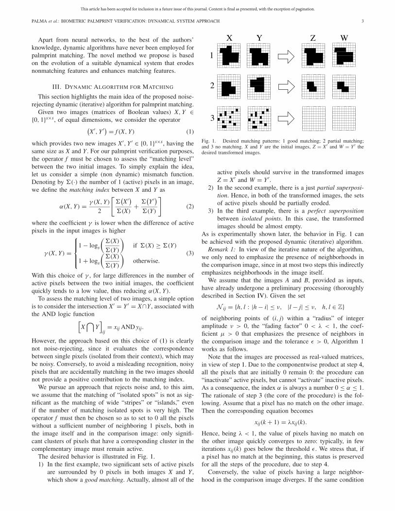
The desired behavior is illustrated in Fig. 1.1) In the first example, two significant sets of active pixels
are surrounded by 0 pixels in both images X and Y ,which show a good matching. Actually, almost all of the
Fig. 1. Desired matching patterns: 1 good matching; 2 partial matching;and 3 no matching. X and Y are the initial images, Z = X′ and W = Y ′ thedesired transformed images.
active pixels should survive in the transformed imagesZ = X′ and W = Y ′.
2) In the second example, there is a just partial superposi-tion. Hence, in both of the transformed images, the setsof active pixels should be partially eroded.
3) In the third example, there is a perfect superpositionbetween isolated points. In this case, the transformedimages should be almost empty.
As is experimentally shown later, the behavior in Fig. 1 canbe achieved with the proposed dynamic (iterative) algorithm.
Remark 1: In view of the iterative nature of the algorithm,we only need to emphasize the presence of neighborhoods inthe comparison image, since in at most two steps this indirectlyemphasizes neighborhoods in the image itself.
We assume that the images A and B, provided as inputs,have already undergone a preliminary processing (thoroughlydescribed in Section IV). Given the set
N ij = {h, l : |h − i| ≤ ν, |l − j| ≤ ν, h, l ∈ Z}of neighboring points of (i, j) within a “radius” of integeramplitude ν > 0, the “fading factor” 0 < λ < 1, the coef-ficient μ > 0 that emphasizes the presence of neighbors inthe comparison image and the tolerance ε > 0, Algorithm 1works as follows.
Note that the images are processed as real-valued matrices,in view of step 1. Due to the componentwise product at step 4,all the pixels that are initially 0 remain 0: the procedure can“inactivate” active pixels, but cannot “activate” inactive pixels.As a consequence, the index α is always a number 0 ≤ α ≤ 1.The rationale of step 3 (the core of the procedure) is the fol-lowing. Assume that a pixel has no match on the other image.Then the corresponding equation becomes
xij(k + 1) = λxij(k).
Hence, being λ < 1, the value of pixels having no match onthe other image quickly converges to zero: typically, in fewiterations xij(k) goes below the threshold ε. We stress that, ifa pixel has no match at the beginning, this status is preservedfor all the steps of the procedure, due to step 4.
Conversely, the value of pixels having a large neighbor-hood in the comparison image diverges. If the same condition
This article has been accepted for inclusion in a future issue of this journal. Content is final as presented, with the exception of pagination.
4 IEEE TRANSACTIONS ON SYSTEMS, MAN, AND CYBERNETICS: SYSTEMS
Algorithm 1 Matching Index ComputationInput: Boolean images A and B.Parameters: Number of steps N, positive constants λ < 1 andμ, integer neighborhood amplitude ν > 0, a small toleranceε > 0.Outputs: Matching index α(A, B).
1) Convert the two input images from boolean into realmatrices X := A and Y := B.
2) Set k = 0.3) At each iteration, compute the updated values for each
pixel in both images
xij(k + 1) = λxij(k) + μ∑
hl∈Nij
yhl(k) (4)
yij(k + 1) = λyij(k) + μ∑
hl∈Nij
xhl(k) (5)
4) At each iteration, set X := X × A, Y := Y × B, where ×denotes the componentwise product (i.e., xij := xij × aij
for all i, j).5) Set k = k + 1 and, IF k < N, GOTO step 3.6) Convert the matrices to boolean, [A′, B′] = logic(X, Y),
as follows: IF xij < ε, THEN a′ij := 0; ELSE a′
ij := 1(resp. IF yij < ε, THEN b′
ij := 0; ELSE b′ij := 1).
7) Compute the matching index α as in (2).
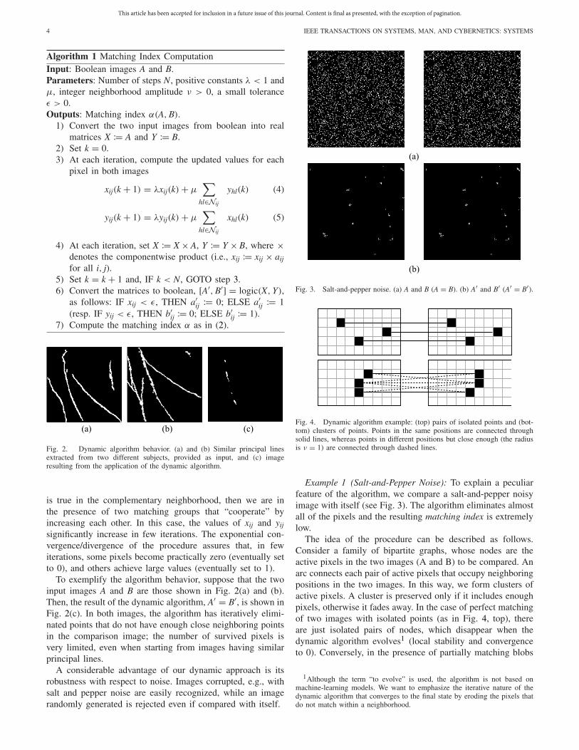
(a) (b) (c)
Fig. 2. Dynamic algorithm behavior. (a) and (b) Similar principal linesextracted from two different subjects, provided as input, and (c) imageresulting from the application of the dynamic algorithm.
is true in the complementary neighborhood, then we are inthe presence of two matching groups that “cooperate” byincreasing each other. In this case, the values of xij and yij
significantly increase in few iterations. The exponential con-vergence/divergence of the procedure assures that, in fewiterations, some pixels become practically zero (eventually setto 0), and others achieve large values (eventually set to 1).
To exemplify the algorithm behavior, suppose that the twoinput images A and B are those shown in Fig. 2(a) and (b).Then, the result of the dynamic algorithm, A′ = B′, is shown inFig. 2(c). In both images, the algorithm has iteratively elimi-nated points that do not have enough close neighboring pointsin the comparison image; the number of survived pixels isvery limited, even when starting from images having similarprincipal lines.
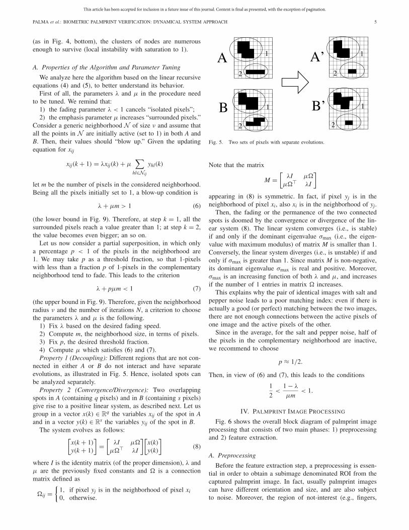
A considerable advantage of our dynamic approach is itsrobustness with respect to noise. Images corrupted, e.g., withsalt and pepper noise are easily recognized, while an imagerandomly generated is rejected even if compared with itself.
(a)
(b)
Fig. 3. Salt-and-pepper noise. (a) A and B (A = B). (b) A′ and B′ (A′ = B′).
Fig. 4. Dynamic algorithm example: (top) pairs of isolated points and (bot-tom) clusters of points. Points in the same positions are connected throughsolid lines, whereas points in different positions but close enough (the radiusis ν = 1) are connected through dashed lines.
Example 1 (Salt-and-Pepper Noise): To explain a peculiarfeature of the algorithm, we compare a salt-and-pepper noisyimage with itself (see Fig. 3). The algorithm eliminates almostall of the pixels and the resulting matching index is extremelylow.
The idea of the procedure can be described as follows.Consider a family of bipartite graphs, whose nodes are theactive pixels in the two images (A and B) to be compared. Anarc connects each pair of active pixels that occupy neighboringpositions in the two images. In this way, we form clusters ofactive pixels. A cluster is preserved only if it includes enoughpixels, otherwise it fades away. In the case of perfect matchingof two images with isolated points (as in Fig. 4, top), thereare just isolated pairs of nodes, which disappear when thedynamic algorithm evolves1 (local stability and convergenceto 0). Conversely, in the presence of partially matching blobs
1Although the term “to evolve” is used, the algorithm is not based onmachine-learning models. We want to emphasize the iterative nature of thedynamic algorithm that converges to the final state by eroding the pixels thatdo not match within a neighborhood.
This article has been accepted for inclusion in a future issue of this journal. Content is final as presented, with the exception of pagination.
PALMA et al.: BIOMETRIC PALMPRINT VERIFICATION: DYNAMICAL SYSTEM APPROACH 5
(as in Fig. 4, bottom), the clusters of nodes are numerousenough to survive (local instability with saturation to 1).
A. Properties of the Algorithm and Parameter Tuning
We analyze here the algorithm based on the linear recursiveequations (4) and (5), to better understand its behavior.
First of all, the parameters λ and μ in the procedure needto be tuned. We remind that:
1) the fading parameter λ < 1 cancels “isolated pixels”;2) the emphasis parameter μ increases “surrounded pixels.”
Consider a generic neighborhood N of size ν and assume thatall the points in N are initially active (set to 1) in both A andB. Then, their values should “blow up.” Given the updatingequation for xij
xij(k + 1) = λxij(k) + μ∑
hl∈Nij
yhl(k)
let m be the number of pixels in the considered neighborhood.Being all the pixels initially set to 1, a blow-up condition is
λ + μm > 1 (6)
(the lower bound in Fig. 9). Therefore, at step k = 1, all thesurrounded pixels reach a value greater than 1; at step k = 2,the value becomes even bigger; an so on.
Let us now consider a partial superposition, in which onlya percentage p < 1 of the pixels in the neighborhood are1. We may take p as a threshold fraction, so that 1-pixelswith less than a fraction p of 1-pixels in the complementaryneighborhood tend to fade. This leads to the criterion
λ + pμm < 1 (7)
(the upper bound in Fig. 9). Therefore, given the neighborhoodradius ν and the number of iterations N, a criterion to choosethe parameters λ and μ is the following.
1) Fix λ based on the desired fading speed.2) Compute m, the neighborhood size, in terms of pixels.3) Fix p, the desired threshold fraction.4) Compute μ which satisfies (6) and (7).Property 1 (Decoupling): Different regions that are not con-
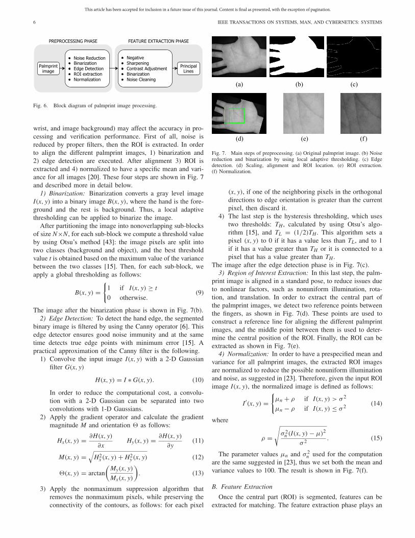
nected in either A or B do not interact and have separateevolutions, as illustrated in Fig. 5. Hence, isolated spots canbe analyzed separately.
Property 2 (Convergence/Divergence): Two overlappingspots in A (containing q pixels) and in B (containing s pixels)give rise to a positive linear system, as described next. Let usgroup in a vector x(k) ∈ R
q the variables xij of the spot in Aand in a vector y(k) ∈ R
s the variables yij of the spot in B.The system evolves as follows:
[x(k + 1)
y(k + 1)
]=
[λI μ�
μ�� λI
][x(k)y(k)
](8)
where I is the identity matrix (of the proper dimension), λ andμ are the previously fixed constants and � is a connectionmatrix defined as
�ij ={
1, if pixel yj is in the neighborhood of pixel xi
0, otherwise.
Fig. 5. Two sets of pixels with separate evolutions.
Note that the matrix
M =[
λI μ�
μ�� λI
]
appearing in (8) is symmetric. In fact, if pixel yj is in theneighborhood of pixel xi, also xi is in the neighborhood of yj.
Then, the fading or the permanence of the two connectedspots is doomed by the convergence or divergence of the lin-ear system (8). The linear system converges (i.e., is stable)if and only if the dominant eigenvalue σmax (i.e., the eigen-value with maximum modulus) of matrix M is smaller than 1.Conversely, the linear system diverges (i.e., is unstable) if andonly if σmax is greater than 1. Since matrix M is non-negative,its dominant eigenvalue σmax is real and positive. Moreover,σmax is an increasing function of both λ and μ, and increasesif the number of 1 entries in matrix � increases.
This explains why the pair of identical images with salt andpepper noise leads to a poor matching index: even if there isactually a good (or perfect) matching between the two images,there are not enough connections between the active pixels ofone image and the active pixels of the other.
Since in the average, for the salt and pepper noise, half ofthe pixels in the complementary neighborhood are inactive,we recommend to choose
p ≈ 1/2.
Then, in view of (6) and (7), this leads to the conditions
1
2<
1 − λ
μm< 1.
IV. PALMPRINT IMAGE PROCESSING
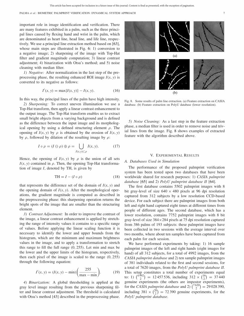
Fig. 6 shows the overall block diagram of palmprint imageprocessing that consists of two main phases: 1) preprocessingand 2) feature extraction.
A. Preprocessing
Before the feature extraction step, a preprocessing is essen-tial in order to obtain a subimage denominated ROI from thecaptured palmprint image. In fact, usually palmprint imagescan have different orientation and size, and are also subjectto noise. Moreover, the region of not-interest (e.g., fingers,
This article has been accepted for inclusion in a future issue of this journal. Content is final as presented, with the exception of pagination.
6 IEEE TRANSACTIONS ON SYSTEMS, MAN, AND CYBERNETICS: SYSTEMS
Fig. 6. Block diagram of palmprint image processing.
wrist, and image background) may affect the accuracy in pro-cessing and verification performance. First of all, noise isreduced by proper filters, then the ROI is extracted. In orderto align the different palmprint images, 1) binarization and2) edge detection are executed. After alignment 3) ROI isextracted and 4) normalized to have a specific mean and vari-ance for all images [20]. These four steps are shown in Fig. 7and described more in detail below.
1) Binarization: Binarization converts a gray level imageI(x, y) into a binary image B(x, y), where the hand is the fore-ground and the rest is background. Thus, a local adaptivethresholding can be applied to binarize the image.
After partitioning the image into nonoverlapping sub-blocksof size N×N, for each sub-block we compute a threshold valueby using Otsu’s method [43]: the image pixels are split intotwo classes (background and object), and the best thresholdvalue t is obtained based on the maximum value of the variancebetween the two classes [15]. Then, for each sub-block, weapply a global thresholding as follows:
B(x, y) ={
1 if I(x, y) ≥ t
0 otherwise.(9)
The image after the binarization phase is shown in Fig. 7(b).2) Edge Detection: To detect the hand edge, the segmented
binary image is filtered by using the Canny operator [6]. Thisedge detector ensures good noise immunity and at the sametime detects true edge points with minimum error [15]. Apractical approximation of the Canny filter is the following.
1) Convolve the input image I(x, y) with a 2-D Gaussianfilter G(x, y)
H(x, y) = I ∗ G(x, y). (10)
In order to reduce the computational cost, a convolu-tion with a 2-D Gaussian can be separated into twoconvolutions with 1-D Gaussians.
2) Apply the gradient operator and calculate the gradientmagnitude M and orientation as follows:
Hx(x, y) = ∂H(x, y)
∂xHy(x, y) = ∂H(x, y)
∂y(11)
M(x, y) =√
H2x (x, y) + H2
y (x, y) (12)
(x, y) = arctan
(My(x, y)
Mx(x, y)
). (13)
3) Apply the nonmaximum suppression algorithm thatremoves the nonmaximum pixels, while preserving theconnectivity of the contours, as follows: for each pixel
(a) (b) (c)
(d) (e) (f )
Fig. 7. Main steps of preprocessing. (a) Original palmprint image. (b) Noisereduction and binarization by using local adaptive thresholding. (c) Edgedetection. (d) Scaling, alignment and ROI location. (e) ROI extraction.(f) Normalization.
(x, y), if one of the neighboring pixels in the orthogonaldirections to edge orientation is greater than the currentpixel, then discard it.
4) The last step is the hysteresis thresholding, which usestwo thresholds: TH , calculated by using Otsu’s algo-rithm [15], and TL = (1/2)TH . This algorithm sets apixel (x, y) to 0 if it has a value less than TL, and to 1if it has a value greater than TH or it is connected to apixel that has a value greater than TH .
The image after the edge detection phase is in Fig. 7(c).3) Region of Interest Extraction: In this last step, the palm-
print image is aligned in a standard pose, to reduce issues dueto nonlinear factors, such as nonuniform illumination, rota-tion, and translation. In order to extract the central part ofthe palmprint images, we detect two reference points betweenthe fingers, as shown in Fig. 7(d). These points are used toconstruct a reference line for aligning the different palmprintimages, and the middle point between them is used to deter-mine the central position of the ROI. Finally, the ROI can beextracted as shown in Fig. 7(e).
4) Normalization: In order to have a prespecified mean andvariance for all palmprint images, the extracted ROI imagesare normalized to reduce the possible nonuniform illuminationand noise, as suggested in [23]. Therefore, given the input ROIimage I(x, y), the normalized image is defined as follows:
I′(x, y) ={
μn + ρ if I(x, y) > σ 2
μn − ρ if I(x, y) ≤ σ 2 (14)
where
ρ =√
σ 2n (I(x, y) − μ)2
σ 2. (15)
The parameter values μn and σ 2n used for the computation
are the same suggested in [23], thus we set both the mean andvariance values to 100. The result is shown in Fig. 7(f).
B. Feature Extraction
Once the central part (ROI) is segmented, features can beextracted for matching. The feature extraction phase plays an
This article has been accepted for inclusion in a future issue of this journal. Content is final as presented, with the exception of pagination.
PALMA et al.: BIOMETRIC PALMPRINT VERIFICATION: DYNAMICAL SYSTEM APPROACH 7
important role in image identification and verification. Thereare many features exhibited in a palm, such as the three princi-pal lines caused by flexing hand and wrist in the palm, whichare denominated as heart line, head line, and life line, respec-tively. We use a principal line extraction method based on [63],whose main steps are illustrated in Fig. 6: 1) conversion toa negative image; 2) sharpening of the image with Top-Hatfilter and gradient magnitude computation; 3) linear contrastadjustment; 4) binarization with Otsu’s method; and 5) noisecleaning with median filter.
1) Negative: After normalization in the last step of the pre-processing phase, the resulting enhanced ROI image I(x, y) isconverted to its negative as follows:
I′(x, y) = max{I(x, y)} − I(x, y). (16)
In this way, the principal lines of the palm have high intensity.2) Sharpening: To correct uneven illumination we use a
Top-Hat transform, then apply a linear contrast enhancement tothe output image. The Top-Hat transform enables us to extractsmall bright objects from a varying background and is definedas the difference between the input image and its morpholog-ical opening by using a defined structuring element ρ. Theopening of I(x, y) by ρ is obtained by the erosion of I(x, y)by ρ, followed by dilation of the resulting image by ρ:
I ◦ ρ = (I � ρ) ⊕ ρ =⋃
I(x,y)⊂ρ
I(x, y). (17)
Hence, the opening of I(x, y) by ρ is the union of all setsI(x, y) contained in ρ. Then, the opening Top-Hat transforma-tion of image I, denoted by TH, is given by
TH = I − (I ◦ ρ) (18)
that represents the difference set of the domain of I(x, y) andthe opening domain of I(x, y). After the morphological oper-ations, the gradient magnitude is computed as described inthe preprocessing phase: this sharpening operation returns thebright spots of the image that are smaller than the structuringelement.
3) Contrast Adjustment: In order to improve the contrast ofthe image, a linear contrast enhancement is applied by stretch-ing the range of intensity values it contains to a specific rangeof values. Before applying the linear scaling function it isnecessary to identify the lower and upper bounds from thehistogram, which are the minimum and maximum brightnessvalues in the image, and to apply a transformation to stretchthis range to fill the full range (0, 255). Let min and max bethe lower and the upper limits of the histogram, respectively,then each pixel of the image is scaled to the range (0, 255)
through the following equation:
I′(x, y) = (I(x, y) − min)
(255
max − min
). (19)
4) Binarization: A global thresholding is applied at thegray level image resulting from the previous sharpening fil-ter and linear contrast adjustment. The threshold is calculatedwith Otsu’s method [43] described in the preprocessing phase.
(a)
(b)
Fig. 8. Some results of palm line extraction. (a) Feature extraction on CASIAdatabase. (b) Feature extraction on PolyU database (lower resolution).
5) Noise Cleaning: As a last step in the feature extractionphase, a median filter is used in order to remove noise and triv-ial lines from the image. Fig. 8 shows examples of extractedfeature with the algorithm described above.
V. EXPERIMENTAL RESULTS
A. Databases Used in Simulation
The performance of the proposed palmprint verificationsystem has been tested upon two databases that have beenworldwide shared for research purposes: 1) CASIA palmprintdatabase [65] and 2) PolyU palmprint database II [64].
The first database contains 5502 palmprint images with 8bit gray-level of size 640 × 480 pixels at 96 dpi resolutioncaptured from 312 subjects by a low resolution CCD-baseddevice. For each subject there are palmprint images from bothleft and right hand captured eight times at different times frompeople of different ages. The second database, which has alower resolution, contains 7752 palmprint images with 8 bitgray-level of size 384×284 pixels at 75 dpi resolution capturedfrom 386 palms of 193 subjects: these palmprint images havebeen collected in two sessions with the average interval overtwo months, where about ten samples have been captured fromeach palm for each session.
We have performed experiments by taking: 1) 16 samplepalmprint images of the left and right hands (eight images forhand) of all 312 subjects, for a total of 4992 images, from theCASIA palmprint database and 2) ten sample palmprint imagesof 381 individuals related to the first and second sessions, fora total of 7620 images, from the PolyU palmprint database II.This setup constitutes a total number of experiments equalto: 1)
(4 9922
) = 12 457 536, including 312 × (162
) = 37 440genuine experiments (the others are impostor experiments),for the CASIA palmprint database and 2)
(7 6202
) = 29 028 390,including 381 × (20
2
) = 72 390 genuine experiments, for thePolyU palmprint database.
This article has been accepted for inclusion in a future issue of this journal. Content is final as presented, with the exception of pagination.
8 IEEE TRANSACTIONS ON SYSTEMS, MAN, AND CYBERNETICS: SYSTEMS
B. Criteria for Performance Evaluation
To evaluate the verification accuracy of the proposedmethod, each palmprint image in the database has beenmatched against the other palmprint images. The matchingbetween palmprints captured from the same palm is definedas a genuine matching or intraclass matching, otherwise as animpostor matching or interclass matching.
The general method to evaluate the performance of a palm-print authentication system is based on the false acceptancerate (FAR) and the false rejection rate (FRR) [41]. The FARis defined as the percentage of invalid inputs which are incor-rectly accepted and is computed as the number of acceptedimposter claims over the total number of imposter accesses.The FRR is defined as the percentage of valid inputs which areincorrectly rejected and is computed as the number of rejectedgenuine claims over the total number of genuine accesses. FARand FRR are closely related because the increase of the oneimplies the decrease of the other. Mathematically these twoindices are expressed as follows:
FAR = 1
N
N∑
k=1
FAR(k) (20)
FRR = 1
N
N∑
k=1
FRR(k) (21)
where
FAR(k) = number of FARs
number of impostor accesses(22)
FRR(k) = number of FRRs
number of genuine accesses. (23)
Other evaluation parameters are as follows.1) Receiver Operating Characteristic (ROC): A graphical
plot that illustrates the tradeoff between the FAR andthe FRR.
2) Equal Error Rate (EER): The error rate at the spe-cific threshold s for which both acceptance and rejectionerrors are equal, which can be easily obtained from theROC curve.
3) Genuine Acceptance Rate (GAR):
GAR = 1 − FRR. (24)
4) GAR at a Specific FAR (GARx):
GARx = GAR∣∣FAR=10−x (25)
for example, considered an FAR = 0.01, then GAR2 =GAR
∣∣FAR.
C. Parameter Tuning for Performance Evaluation
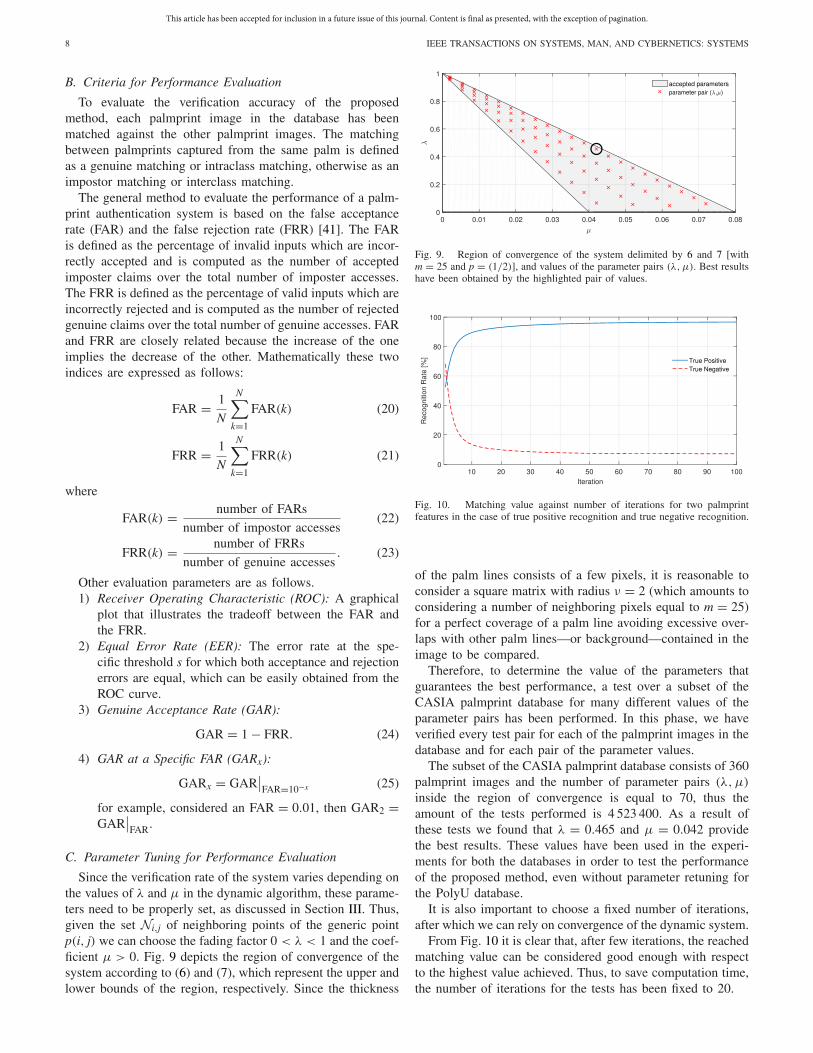
Since the verification rate of the system varies depending onthe values of λ and μ in the dynamic algorithm, these parame-ters need to be properly set, as discussed in Section III. Thus,given the set Ni,j of neighboring points of the generic pointp(i, j) we can choose the fading factor 0 < λ < 1 and the coef-ficient μ > 0. Fig. 9 depicts the region of convergence of thesystem according to (6) and (7), which represent the upper andlower bounds of the region, respectively. Since the thickness
Fig. 9. Region of convergence of the system delimited by 6 and 7 [withm = 25 and p = (1/2)], and values of the parameter pairs (λ, μ). Best resultshave been obtained by the highlighted pair of values.
Fig. 10. Matching value against number of iterations for two palmprintfeatures in the case of true positive recognition and true negative recognition.
of the palm lines consists of a few pixels, it is reasonable toconsider a square matrix with radius ν = 2 (which amounts toconsidering a number of neighboring pixels equal to m = 25)for a perfect coverage of a palm line avoiding excessive over-laps with other palm lines—or background—contained in theimage to be compared.
Therefore, to determine the value of the parameters thatguarantees the best performance, a test over a subset of theCASIA palmprint database for many different values of theparameter pairs has been performed. In this phase, we haveverified every test pair for each of the palmprint images in thedatabase and for each pair of the parameter values.
The subset of the CASIA palmprint database consists of 360palmprint images and the number of parameter pairs (λ, μ)
inside the region of convergence is equal to 70, thus theamount of the tests performed is 4 523 400. As a result ofthese tests we found that λ = 0.465 and μ = 0.042 providethe best results. These values have been used in the experi-ments for both the databases in order to test the performanceof the proposed method, even without parameter retuning forthe PolyU database.
It is also important to choose a fixed number of iterations,after which we can rely on convergence of the dynamic system.
From Fig. 10 it is clear that, after few iterations, the reachedmatching value can be considered good enough with respectto the highest value achieved. Thus, to save computation time,the number of iterations for the tests has been fixed to 20.
This article has been accepted for inclusion in a future issue of this journal. Content is final as presented, with the exception of pagination.
PALMA et al.: BIOMETRIC PALMPRINT VERIFICATION: DYNAMICAL SYSTEM APPROACH 9
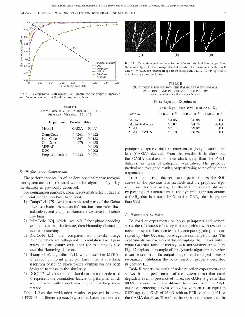
Fig. 11. Comparative GAR against FAR graphs, for the proposed approachand for other methods on PolyU palmprint database.
TABLE ICOMPARISON OF VERIFICATION RESULTS FOR
DIFFERENT METHODS [16], [40]
D. Performance Comparison
The performance results of the developed palmprint recogni-tion system are here compared with other algorithms by usingthe datasets as previously described.
For comparison purposes, some representative techniques inpalmprint recognition have been used.
1) CompCode [29], which uses six real parts of the Gaborfilters to obtain orientation information from palm linesand subsequently applies Hamming distance for featurematching.
2) PalmCode [60], which uses 2-D Gabor phase encodingscheme to extract the feature, then Hamming distance isused for matching.
3) OrdiCode [52], that compares two line-like imageregions, which are orthogonal in orientation and it gen-erates one bit feature code, then for matching is alsoused the Hamming distance.
4) Huang et al. algorithm [21], which uses the MFRATto extract palmprint principal lines, then a matchingalgorithm based on pixel-to-area comparison has beendesigned to measure the similarity.
5) DOC [17] which stands for double-orientation code usedto represent the orientation feature of palmprint whichare compared with a nonlinear angular matching scoremethod.
Table I lists the verification results, expressed in termsof EER, for different approaches, on databases that contain
(a) (b) (c)
Fig. 12. Dynamic algorithm behavior on different principal line images fromthe same subject. (a) First image affected by white Gaussian noise with μ = 0and σ 2 = 0.05, (b) second image to be compared, and (c) surviving pointsafter the algorithm evolution.
TABLE IIROC COMPARISON ON BOTH THE DATABASES WITH NORMAL
PALMPRINTS AND PALMPRINTS CORRUPTED BY
ADDITIVE WHITE GAUSSIAN NOISE
palmprints captured through touch-based (PolyU) and touch-less (CASIA) devices. From the results, it is clear thatthe CASIA database is more challenging than the PolyUdatabase in terms of palmprint verification. The proposedmethod achieves good results, outperforming some of the otherapproaches.
To better illustrate the verification performances, the ROCcurves of the previous five methods and the proposed algo-rithm are illustrated in Fig. 11: the ROC curves are obtainedby plotting GAR against FAR. The dynamic algorithm obtainsa GAR2 that is almost 100% and a GAR3 that is greaterthan 97%.
E. Robustness to Noise
To conduct experiments on noisy palmprints and demon-strate the robustness of the dynamic algorithm with respect tonoise, the system has been tested by comparing palmprints cor-rupted by white Gaussian noise against normal palmprints. Theexperiments are carried out by corrupting the images with awhite Gaussian noise of mean μ = 0 and variance σ 2 = 0.05.Fig. 12 depicts an example of the dynamic algorithm behavior:it can be seen from the output image that the subject is easilyrecognized, validating the noise rejection property describedin Section III.
Table II reports the result of noise rejection experiments andshows that the performance of the system is not that muchdegraded: even in presence of noise, the GAR1 is greater than98.6%. However, we have obtained better results on the PolyUdatabase achieving a GAR of 97.8% with an EER equal to0.022 against a GAR of 96.9% with an EER equal to 0.031 onthe CASIA database. Therefore, the experiments show that the
This article has been accepted for inclusion in a future issue of this journal. Content is final as presented, with the exception of pagination.
10 IEEE TRANSACTIONS ON SYSTEMS, MAN, AND CYBERNETICS: SYSTEMS
proposed algorithm can recognize palmprints even in presenceof a reasonable amount of noise.
F. Computation Time
The experiments for the proposed approach have been con-ducted on a virtualized machine equipped with two dedicatedprocessors and 2048 MB RAM hosted on an Intel Core i7-4510U CPU (2.6 GHz), 8 GB RAM running a 32-bit MicrosoftWindows 10. The code has been implemented using MATLAB8.0 and to get the following results each part of code hasbeen performed for 200 times, then the average time has beenconsidered. Thus, the computational times required for pre-processing, palm line extraction, and palmprint matching are376, 49, and 295 ms, respectively, thus the average responsetime for verification is about 0.72 s, which is more suitablefor a real-time biometric verification system rather than a real-time biometric identification system. However, it is possible tofurther reduce the computation time, since the program codeshave not completely optimized.
VI. CONCLUSION
In this paper, a novel approach has been presented to authen-ticate individuals based on their palmprint features. As a maincontribution, a new recursive, dynamic algorithm has beenapplied for the matching of features. A noticeable advantageof such an approach is its robustness with respect to noise:for instance, images corrupted with salt and pepper noise areeasily recognized, whereas an image randomly generated isrejected even when compared with itself [44]. The images pro-vided as an input to the dynamic algorithm have undergone animage processing based on two phases: the first involving pre-processing operations to make the system invariant to rotationand translation of the palm with respect to the image and thesecond consisting of a sequence of robust feature extractionsteps that allow to detect the principal lines of the palm withoutintroducing noise. Extensive experiments have been conductedto evaluate the performance of the system and the resultsobtained from the tests clearly demonstrate the effectivenessof the proposed technique, which is able to produce promisingresult. As a matter of fact, the experimental results presentedin Section V show that the level of GAR1 obtained is 100% onboth the databases, whereas in the noisy test GAR1 can stillbe considered greater than 98.6% for the CASIA database andequal to 100% for the PolyU database. Thus, the system iscomparable with existing biometric recognition systems basedon palmprint recognition and other hand-based biometric tech-nologies, including hand geometry and fingerprint verification.In particular, the achieved level of GAR is compliant with thestrict requirements of high security applications.
REFERENCES
[1] S. Alkassar, W. L. Woo, S. S. Dlay, and J. A. Chambers, “Robustsclera recognition system with novel sclera segmentation and valida-tion techniques,” IEEE Trans. Syst., Man, Cybern., Syst., vol. 47, no. 3,pp. 474–486, Mar. 2016.
[2] F. Blanchini, D. de Caneva, P. L. Montessoro, and D. Pierattoni,“Control-based p-persistent adaptive communication protocol,” ACMTrans. Auton. Adapt. Syst., vol. 7, no. 2, pp. 1–18, 2012.
[3] F. Blanchini and S. Miani, Set-Theoretic Methods in Control (Systems &Control: Foundations & Applications). Boston, MA, USA: Birkhäuser,2008.
[4] W. W. Boles and S. Y. T. Chu, “Personal identification using imagesof the human palm,” in Proc. IEEE Reg. 10 Annu. Conf. Speech ImageTechnol. Comput. Telecommun., vol. 1. Brisbane, QLD, Australia, 1997,pp. 295–298.
[5] A. Bruno, P. Carminetti, V. Gentile, M. La Cascia, and E. Mancino,“Palmprint principal lines extraction,” in Proc. IEEE Biometric Meas.Syst. Security Med. Appl., Rome, Italy, 2014, pp. 50–56.
[6] J. Canny, “A computational approach to edge detection,” IEEE Trans.Pattern Anal. Mach. Intell., vol. PAMI-8, no. 6, pp. 679–698, Nov. 1986.
[7] R. Cappelli, M. Ferrara, and D. Maio, “A fast and accurate palmprintrecognition system based on minutiae,” IEEE Trans. Syst., Man, Cybern.B, Cybern., vol. 42, no. 3, pp. 956–962, Jun. 2012.
[8] T. Connie, A. Teoh, M. Goh, and D. Ngo, “Palmprint recognition withPCA and ICA,” in Proc. Image Vis. Comput., 2003, pp. 227–232.
[9] T. Connie, A. T. B. Jin, M. G. K. Ong, and D. N. C. Ling, “An auto-mated palmprint recognition system,” Image Vis. Comput., vol. 23, no. 5,pp. 501–515, 2005.
[10] J. Daugman, “The importance of being random: Statistical principles ofiris recognition,” Pattern Recognit., vol. 36, no. 2, pp. 279–291, 2003.
[11] M. De Marsico, M. Nappi, D. Riccio, and H. Wechsler, “Robust facerecognition for uncontrolled pose and illumination changes,” IEEETrans. Syst., Man, Cybern., Syst., vol. 43, no. 1, pp. 149–163, Jan. 2013.
[12] M. R. Diaz, C. M. Travieso, J. B. Alonso, and M. A. Ferrer, “Biometricsystem based in the feature of hand palm,” in Proc. 38th Annu. Int.Carnahan Conf. Security Technol., Albuquerque, NM, USA, 2004,pp. 136–139.
[13] N. Duta, A. K. Jain, and K. V. Mardia, “Matching of palmprints,” PatternRecognit., vol. 23, no. 4, pp. 477–485, 2002.
[14] M. Ekinci and M. Aykut, “Palmprint recognition by applying wavelet-based kernel PCA,” J. Comput. Sci. Technol., vol. 23, no. 5, pp. 851–861,2008.
[15] M. Fang, G. Yue, and Q. Yu, “The study on an application of Otsumethod in canny operator,” in Proc. Int. Symp. Inf. Process. (ISIP), 2009,pp. 109–112.
[16] L. Fei, Y. Xu, and D. Zhang, “Half-orientation extraction of palmprintfeatures,” Pattern Recognit. Lett., vol. 69, pp. 35–41, Jan. 2016.
[17] L. Fei, Y. Xu, W. Tang, and D. Zhang, “Double-orientation codeand nonlinear matching scheme for palmprint recognition,” PatternRecognit., vol. 49, pp. 89–101, Jan. 2016.
[18] Y. Gao and M. K. H. Leung, “Face recognition using line edge map,”IEEE Trans. Pattern Anal. Mach. Intell., vol. 24, no. 6, pp. 764–779,Jun. 2002.
[19] C.-C. Han, H.-L. Cheng, C.-L. Lin, and K.-C. Fan, “Personal authen-tication using palm-print features,” Pattern Recognit., vol. 36, no. 2,pp. 371–381, 2003.
[20] L. Hong, Y. Wan, and A. Jain, “Fingerprint image enhancement:Algorithm and performance evaluation,” IEEE Trans. Pattern Anal.Mach. Intell., vol. 20, no. 8, pp. 777–789, Aug. 1998.
[21] D.-S. Huang, W. Jia, and D. Zhang, “Palmprint verification based onprincipal lines,” Pattern Recognit., vol. 41, no. 4, pp. 1316–1328, 2008.
[22] A. K. Jain and J. Feng, “Latent palmprint matching,” IEEE Trans.Pattern Anal. Mach. Intell., vol. 31, no. 6, pp. 1032–1047, Jun. 2009.
[23] A. K. Jain, S. Prabhakar, L. Hong, and S. Pankanti, “Filterbank-based fingerprint matching,” IEEE Trans. Image Process., vol. 9, no. 5,pp. 846–859, May 2000.
[24] W. Jia, R.-X. Hu, Y.-K. Lei, Y. Zhao, and J. Gui, “Histogram of orientedlines for palmprint recognition,” IEEE Trans. Syst., Man, Cybern., Syst.,vol. 44, no. 3, pp. 385–395, Mar. 2014.
[25] W. Jia, D.-S. Huang, and D. Zhang, “Palmprint verification basedon robust line orientation code,” Pattern Recognit., vol. 41, no. 5,pp. 1504–1513, 2008.
[26] W. Kang and Q. Wu, “Pose-invariant hand shape recognition based onfinger geometry,” IEEE Trans. Syst., Man, Cybern., Syst., vol. 44, no. 11,pp. 1510–1521, Nov. 2014.
[27] A. W. K. Kong, D. Zhang, and M. Kamel, “A survey of palmprintrecognition,” Pattern Recognit., vol. 42, no. 7, pp. 1408–1418, 2009.
[28] A. W. K. Kong, D. Zhang, and W. Li, “Palmprint feature extraction using2-D Gabor filters,” Pattern Recognit., vol. 36, no. 10, pp. 2339–2347,2003.
[29] A. W.-K. Kong and D. Zhang, “Competitive coding scheme for palm-print verification,” in Proc. 17th Int. Conf. Pattern Recognit. (ICPR),vol. 1. Cambridge, U.K., 2004, pp. 520–523.
This article has been accepted for inclusion in a future issue of this journal. Content is final as presented, with the exception of pagination.
PALMA et al.: BIOMETRIC PALMPRINT VERIFICATION: DYNAMICAL SYSTEM APPROACH 11
[30] K. Krishneswari and S. Arumugam, “Intramodal feature fusion basedon PSO for palmprint authentication,” J. Image Video Process., vol. 2,no. 4, pp. 435–440, 2012.
[31] A. Kumar, D. C. M. Wong, H. C. Shen, and A. K. Jain, PersonalVerification Using Palmprint and Hand Geometry Biometric (LectureNotes in Computer Science). vol. 2688. Berlin, Germany: Springer,2003, pp. 668–678.
[32] A. Kumar and D. Zhang, “Personal authentication using multiple palm-print representation,” Pattern Recognit., vol. 38, no. 10, pp. 1695–1704,2005.
[33] S. Y. Kung, S.-H. Lin, and M. Fang, “A neural network approach toface/palm recognition,” in Proc. IEEE Workshop Neural Netw. SignalProcess., Cambridge, MA, USA, 1995, pp. 323–332.
[34] V. Laxmi, “Palmprint matching using LBP,” in Proc. IEEE Int. Conf.Comput. Sci. (ICCS), 2012, pp. 110–115.
[35] M. A. L. Vijilious and V. S. Bharathi, “Texture feature extractionapproach to palmprint using nonsubsampled contourlet transform andorthogonal moments,” Int. J. Future Comput. Commun., vol. 1, no. 3,pp. 298–301, 2012.
[36] M. K. H. Leung, A. C. M. Fong, and S. C. Hui, “Palmprint verificationfor controlling access to shared computing resources,” IEEE PervasiveComput., vol. 6, no. 4, pp. 40–47, Oct./Dec. 2007.
[37] F. Li, M. K. H. Leung, and X. Yu, “Palmprint identification usingHausdorff distance,” in Proc. Int. Workshop Biomed. Circuits Syst.,Singapore, 2004, pp. 1–6.
[38] G. Lu, D. Zhang, and K. Wang, “Palmprint recognition using eigenpalmsfeatures,” Pattern Recognit. Lett., vol. 24, nos. 9–10, pp. 1463–1467,2003.
[39] Y.-T. Luo et al., “Local line directional pattern for palmprint recogni-tion,” Pattern Recognit., vol. 50, pp. 26–44, Feb. 2016.
[40] A. Nigam and P. Gupta, “Palmprint recognition using geometrical andstatistical constraints,” in Proc. 2nd Int. Conf. Soft Comput. ProblemSolving (SocProS), Jaipur, India, 2014, pp. 1303–1315.
[41] J. S. Noh and K. H. Rhee, “Palmprint identification algorithm using Huinvariant moments and Otsu binarization,” in Proc. 4th Annu. ACIS Int.Conf. Comput. Inf. Sci., 2005, pp. 94–99.
[42] G. K. O. Michael, T. Connie, and A. B. J. Teoh, “Touch-less palmprint biometrics: Novel design and implementation,” Image Vis. Comput.,vol. 26, no. 12, pp. 1551–1560, 2008.
[43] N. Otsu, “A threshold selection method from gray-level histograms,”IEEE Trans. Syst., Man, Cybern., vol. SMC-9, no. 1, pp. 62–66,Jan. 1979.
[44] D. Palma, P. L. Montessoro, G. Giordano, and F. Blanchini, “A dynamicalgorithm for palmprint recognition,” in Proc. IEEE Conf. Commun.Netw. Security (IEEE CNS) 1st Workshop Security Privacy Cybermatics(SPiCy), Florence, Italy, 2015, pp. 623–626.
[45] C. Phromsuthirak, S. Suwan, A. Sanpanich, and C. Pintavirooj, “Handshape identification using palmprint alignment based on intrinsic localaffine-invariant fiducial points,” in Proc. Biomed. Eng. Int. Conf.(BMEiCON), Fukuoka, Japan, 2014, pp. 1–5.
[46] X. Pin and Q.-Q. Ruan, “Palmprint recognition using Gaborfeature-based (2D)2PCA,” Neurocomputing, vol. 71, nos. 13–15,pp. 3032–3036, 2008.
[47] R. Raghavendra, B. Dorizzi, A. Rao, and G. H. Kumar, “PSO versusadaboost for feature selection in multimodal biometrics,” in Proc. 3rdIEEE Int. Conf. Biometrics Theory Appl. Syst., Washington, DC, USA,2009, pp. 238–244.
[48] S. Ribaric, I. Fratric, and K. Kis, “A biometric verification system basedon the fusion of palmprint and face features,” in Proc. 4th Int. Symp.Image Signal Process. Anal., Zagreb, Croatia, 2005, pp. 12–17.
[49] R. Sanchez-Reillo, C. Sanchez-Avilla, and A. Gonzalez-Marcos,“Biometric identification through hand geometry measurements,” IEEETrans. Pattern Anal. Mach. Intell., vol. 22, no. 10, pp. 1168–1171,Oct. 2000.
[50] L. Shengcai, A. K. Jain, and S. Z. Li, “Partial face recognition:Alignment-free approach,” IEEE Trans. Pattern Anal. Mach. Intell.,vol. 35, no. 5, pp. 1193–1205, May 2013.
[51] Z. Sun, Y. Wang, T. Tan, and J. Cui, “Robust direction estimation ofgradient vector field for iris recognition,” in Proc. 17th Int. Conf. PatternRecognit., Cambridge, U.K., 2004, pp. 783–786.
[52] Z. Sun, T. Tan, Y. Wang, and S.Z. Li, “Ordinal palmprint represention forpersonal identification [represention read representation],” in Proc. IEEEComput. Soc. Conf. Comput. Vis. Pattern Recognit., vol. 1. San Diego,CA, USA, 2005, pp. 279–284.
[53] J. A. Wincy and J. G. C. Chandran “Palmprint recognition using PCFand SURF,” Int. J. Adv. Res. Comput. Sci. Softw. Eng., vol. 3, no. 10,pp. 996–1001, 2013.
[54] X. Wu, K. Wang, and D. Zhang, “Fuzzy directional element energy fea-ture (FDEEF) based palmprint identification,” in Proc. Int. Conf. PatternRecognit., vol. 1. Quebec City, QC, Canada, 2002, pp. 95–98.
[55] X. Wu, K. Wang, and D. Zhang, “Line feature extraction and matchingin palmprint,” in Proc. 2nd Int. Conf. Image Graph., 2002, pp. 583–590.
[56] X. Wu, D. Zhang, K. Wang, and B. Huang, “Palmprint classificationusing principal lines,” Pattern Recognit., vol. 37, no. 10, pp. 1987–1998,2004.
[57] X. Wu, K. Wang, and D. Zhang, HMMs Based Palmprint Identification(Lecture Notes in Computer Science), vol. 3072. Berlin, Germany:Springer, 2004, pp. 775–781.
[58] X. Wu, D. Zhang, and K. Wang, “Palm line extraction and matchingfor personal authentication,” IEEE Trans. Syst., Man, Cybern. A, Syst.,Humans, vol. 36, no. 5, pp. 978–987, Sep. 2006.
[59] J. You, W. Li, and D. Zhang, “Hierarchical palmprint identificationvia multiple feature extraction,” Pattern Recognit., vol. 35, no. 4,pp. 847–859, 2002.
[60] D. Zhang, A. W.-K. Kong, J. You, and M. Wong, “Online palmprintidentification,” IEEE Trans. Pattern Anal. Mach. Intell., vol. 25, no. 9,pp. 1041–1050, Sep. 2003.
[61] B. Zhang, W. Li, P. Qing, and D. Zhang, “Palm-print classification byglobal features,” IEEE Trans. Syst., Man, Cybern., Syst., vol. 43, no. 2,pp. 370–378, Mar. 2003.
[62] D. Zhang and W. Shu, “Two novel characteristics in palmprint ver-ification: Datum point invariance and line feature matching,” PatternRecognit., vol. 32, no. 4, pp. 691–702, 1999.
[63] Z.J. Zia-uddin, Z. Jan, J. Ahmad, and A. Abbasi, “A novel techniquefor principal lines extraction in palmprint using morphological top-hatfiltering,” World Appl. Sci. J., vol. 31, no. 12, pp. 2010–2014, 2014.
[64] PolyU Palmprint Database, Biometric Res. Center Hong KongPolytech. Univ., Hong Kong, 2003. [Online]. Available:http://www.comp.polyu.edu.hk/∼biometrics/
[65] CASIA Palmprint Image Database, Chin. Acad. Sci. Inst. Autom.,Beijing, China, 2005. [Online]. Available: http://biometrics.idealtest.org/
David Palma received the B.Sc. degree ininformation engineering and management and theM.Sc. degree in electronic engineering from theUniversity of Udine, Udine, Italy, in 2014 and2017, respectively, where he is currently pursuingthe Ph.D. degree with the Polytechnic Departmentof Engineering and Architecture.
From 2014 to 2017, he was with the Departmentof Electrical, Mechanical and ManagementEngineering, University of Udine, where he wasa Research Assistant in biometric authentication,
cybersecurity, and pervasive computing. His current research interests includebiometric authentication, pervasive computing, and cybersecurity.
Pier Luca Montessoro was born in Turin, Italy, in1961. He received the Dr.Eng. degree in electronicengineering from the Polytechnic of Turin, Turin, in1986.
He is currently a Full Professor of computer sci-ence with the University of Udine, Udine, Italy.He has been with the Italian National Council forScientific Research, Rome, Italy, and a ScientificConsultant with Digital Equipment Corporation,Maynard, MA, USA (currently Compaq) in the fieldof simulation for very large scale integration design.
His research interests, after several years spent on CAD systems for digitalcircuits design and on multimedia systems for e-learning. His current researchinterests include computer networks, ICT security and pervasive computing,in particular distributed controls and algorithms for agents-based systems.
He has been the Chair and an Organizer of the WCC 2013 work-shop “International Workshop on Cloud Convergence: Challenges for FutureInfrastructures and Services,” hosted in the IEEE ICC conference and chairof the 30th edition of the Didamatica conference, held in Udine.
This article has been accepted for inclusion in a future issue of this journal. Content is final as presented, with the exception of pagination.
12 IEEE TRANSACTIONS ON SYSTEMS, MAN, AND CYBERNETICS: SYSTEMS
Giulia Giordano received the B.Sc. and M.Sc.degrees (summa cum laude) and the Ph.D. degreefrom the University of Udine, Udine, Italy, in 2010,2012, and 2016, respectively.
She was with the Department of AutomaticControl, Lund University, Lund, Sweden. She iscurrently an Assistant Professor with the DelftCenter for Systems and Control, Delft Universityof Technology, Delft, The Netherlands. She vis-ited the California Institute of Technology, Pasadena,CA, USA, in 2012 and the University of Stuttgart,
Stuttgart, Germany, in 2015. Her current research interests include analysisof biological systems and the control of networked systems.
Dr. Giordano was a recipient of the EECI Ph.D. Award 2016 for her doctoralthesis and the NAHS Best Paper Award 2017.
Franco Blanchini was born in Legnano, Italy, in1959. He received the Laurea degree in electricalengineering from the University of Trieste, Trieste,Italy, in 1984.
He is the Director of the Laboratory of SystemDynamics, University of Udine, Udine, Italy. He hasco-authored the book entitled Set Theoretic Methodsin Control (Birkhäuser).
Mr. Blanchini was a recipient of the 2001 ASMEOil and Gas Application Committee Best PaperAward, the 2017 NAHS Best Paper Award, and the
2002 IFAC Prize Survey Paper Award and the High Impact Paper Award2017 for his article Set Invariance in Control—A Survey, Automatica, 1999.He was an Associate Editor of Automatica, from 1996 to 2006 and the IEEETRANSACTIONS ON AUTOMATIC CONTROL, from 2012 to 2016. Since 2017,he has been an Associate Editor of Automatica. He is a Senior Editor of theIEEE CONTROL SYSTEMS LETTERS. He has been involved in the organi-zation of several international events: he was the Program Vice-Chairman ofIEEE CDC-ECC 2005, Seville, Spain, the Program Vice-Chairman of IEEECDC 2008, Cancun, Mexico, the Program Chairman of IFAC ROCOND 2012,Aalborg, Denmark, and the Program Vice-Chairman of IEEE CDC 2013,Florence, Italy.


