Embed Size (px)
Citation preview
Debugging Model-Transformation Failures Using
Dynamic Tainting
Pankaj Dhoolia, Senthil Mani, Vibha Singhal Sinha, and Saurabh Sinha
IBM Research – India{pdhoolia,sentmani,vibha.sinha,saurabhsinha}@in.ibm.com
Abstract. Model-to-text (M2T) transforms are a class of software ap-plications that translate a structured input into text output. The inputmodels to such transforms are complex, and faults in the models thatcause an M2T transform to generate an incorrect or incomplete out-put can be hard to debug. We present an approach based on dynamictainting to assist transform users in debugging input models. The ap-proach instruments the transform code to associate taint marks with theinput-model elements, and propagate the marks to the output text. Thetaint marks identify the input-model elements that either contribute toan output string, or cause potentially incorrect paths to be executedthrough the transform, which results in an incorrect or a missing stringin the output. We implemented our approach for XSL-based transformsand conducted empirical studies. Our results illustrate that the approachcan significantly reduce the fault search space and, in many cases, pre-cisely identify the input-model faults. The main benefit of our approachis that it automates, with a high degree of accuracy, a debugging taskthat can be tedious to perform manually.
Keywords: Model-driven engineering, input-model faults, fault local-ization, dynamic tainting.
1 Introduction
Model-Driven Engineering (MDE) [20] is the paradigm of software developmentthat uses formal models, at different abstraction levels, to represent the systemunder development, and uses automated transforms to convert one model to an-other model or text.1 A model is typically represented using a structured format(e.g., XML or UML). A significant class of model transforms, called model-to-text (M2T) transforms, generate text output (e.g., code, configuration files, orHTML/JSP files) from an input model. The input models to the transforms areoften large and complex. Therefore, the models can contain faults, such as amissing element or an incorrect value of an attribute, that cause a transforma-tion to fail: the transformation either generates no output (i.e., it terminateswith an exception) or generates an incorrect output.1 We follow the terminology introduced by Baxter [4]. A transform is a function, or
a program, that maps one model to another model or text. A transformation is theapplication, or the execution, of a transform on a model instance.
T. D’Hondt (Ed.): ECOOP 2010, LNCS 6183, pp. 26–51, 2010.c© Springer-Verlag Berlin Heidelberg 2010
Debugging Model-Transformation Failures Using Dynamic Tainting 27
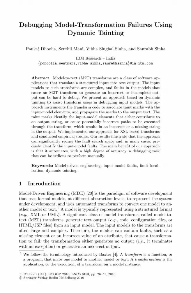
Fig. 1. Example of an input-model fault that causes an incorrect output
The structure of a model is defined by a metamodel. In many cases, a meta-model also specifies the semantic constraints that a model must satisfy. Forexample, to be a valid instance, a UML model may have to satisfy OCL con-straints. A model can contain faults that violate such syntactic and semanticwell-formedness properties. Such faults can be detected easily using automatedvalidators that check whether a model conforms to the metamodel constraints.
However, a large class of faults may violate no constraints and yet cause atransformation to fail; such faults cannot be detected using model validators.To illustrate, consider the model and output fragments shown in Figure 1. Theleft side of the figure shows a correct input model to a transform that generatesa configuration file consisting of name-value pairs. (We present the transformcode in Section 2.) The input model on the right contains a fault: the isGen
attribute of the second property has an incorrect value. This fault causes a wrongtransform path to be executed and, consequently, the incorrect substring “NIL”to be generated in the output. However, the value of isGen is not constrained tobe “nameValue” and a different value is, in fact, valid in cases where the userexpects “NIL” to be generated. Thus, the interpretation of whether the isGen
value represents a fault depends on what the user expects in the output. In thiscase, the value is a fault, but no automated validator can detect it. In a largeand complex model, consisting of thousands of elements and attributes, locatingsuch subtle faults can be difficult and time-consuming.
Although a transformation failure can be caused by faults in the transform,the goal of our work is to develop techniques for investigating failures causedby input-model faults. In MDE, it is a common practice for transform users touse transforms that are not written by them (e.g., many tools provide standardbuilt-in transforms). Thus, a user’s knowledge of the transform is limited to theinformation available from documentation and example models. Even if the codeis available, the end-users often lack the technical expertise to debug the problemby examining the code. Thus, when a transformation fails, the pertinent taskfor transform users is to understand the input space, how it maps to the output,and identify faults in the input; investigating the transform code is irrelevant,and, in the absence of access to the transform implementation, impossible.
28 P. Dhoolia et al.
Most of the existing research in fault localization focuses on identifying faultsin the program. The goal of these approaches is to narrow down the searchspace of program statements that should be examined to locate the fault; theyuse different techniques, such as program slicing (e.g., [2,8]) or spectra compar-isons for passing and failing executions (e.g., [13,19]). These approaches are notapplicable to localizing input-model faults. Some researchers (e.g., [6,23]) haveinvestigated ways to extend the statement-centric view of debugging to consideralso the subset of the input that is relevant for investigating a failure. For ex-ample, given an input i that causes a failure, delta debugging [23] identifies theminimal subset of i that would also cause the failure. Similarly, the penum-bra tool [6] identifies the subset of i that is relevant for investigating the failure.These approaches could conceivably be used for debugging input models becausethe failure-relevant subset of the input model is likely to contain the fault. How-ever, because these techniques are not targeted toward detecting input-modelfaults, in practice, they may perform poorly when applied to model debugging.For the example in Figure 1, delta debugging would fail to identify a minimalfailure-inducing input, whereas penumbra could identify the entire input modelas being failure-relevant.
Model-tracing techniques [7] create links between input-model and output-model entities, which can be useful for supporting fault localization in caseswhere an incorrect value of an input-model entity flows to the output throughvalue propagation. However, for faults such as the one illustrated in Figure 1,tracing techniques can provide no assistance in localizing the faults. Similarly, ifthe fault is a missing entity in the input or the manifested failure is a missingsubstring in the output, tracing techniques cannot assist with fault localization.
In this paper, we present an approach for assisting transform users in locatingfaults in input models that cause a model-to-text transformation to fail. Thegoal of the approach is to narrow down the fault search space in a failure-inducing input model. The approach uses dynamic tainting [5] (or information-flow analysis [16]) to track the flow of data from input-model entities to theoutput string of a model-to-text transform. Given the input model I for a failingexecution of a transform program P , the approach instruments P to associatetaint marks with the elements of I and propagate the marks to the outputstring. The execution of the instrumented program generates a taint log, inwhich substrings of the output string have taint marks associated with them.The taint marks associated with a substring indicate the elements of I thatinfluenced the generation of the substring. To locate the faults in I, the userfirst identifies the point in the output string at which a substring is missing oran incorrect substring is generated. Next, using the taint marks, the user cannavigate back to entities of I, which constitute the search space for the fault.
A key feature of our approach is that, in addition to identifying input-modelentities from which data flows to the output, the taint marks also identify the en-tities that determine whether an alternative substring could have been generatedat a particular point in the output string, had the failing execution traverseda different path through the transform. We call such taint marks “control-taint

Debugging Model-Transformation Failures Using Dynamic Tainting 29
marks” and distinguish them from “data-taint marks.” Unlike data-taint marks,which are propagated at assignment statements and statements that constructthe output string, a control-taint mark is propagated to the output string at con-ditional statements. The propagation of control taints lets our approach identifyfaults that cause an incorrect path to be taken through the transform, whichresults in a missing or an incorrect substring in the output. The control taintsare similar to the notion of control-flow-based tainting [5] and, as our empiricalresults indicate, are essential for the application of dynamic tainting to debug-ging model-transformation failures. We also introduce the notion of “loop-taintmarks,” which, intuitively, scope out the execution of a loop. These taints helpin locating faults that cause an incorrect number of loop iterations.
We implemented the approach for XSL-based model transforms that generateconfiguration files, Java programs, and XML files as output. Using the imple-mentation, we conducted empirical studies to investigate the effectiveness ofthe technique in reducing the fault search space. For our subjects and failure-inducing inputs, the approach significantly reduced the fault search space: for51% of our faulty input models, the fault was identified precisely; for remaining49% of the faults, the fault-space reduction was greater than 94%. These resultsindicate that the approach can be highly effective in assisting transform users inlocating input-model faults.
The main benefit of our approach is that it can automate, with a high degreeof accuracy, a debugging task that can be tedious and time-consuming to performmanually. It is especially useful for localizing faults that cause an incorrect pathto be executed or an incorrect number of iterations of a loop. Although wepresent the approach in the context of model-to-text transforms, it is applicablemore generally in cases where the programs take large structured inputs andgenerate structured output, and where the goal of investigating a failure is tolocate faults in the inputs.
The contributions of the paper include
– A novel dynamic-tainting-based approach for localizing input-model faultsthat cause model-transformation failures
– The description of an implementation of the approach for XSL-based model-to-text transforms
– The results of empirical evaluation, conducted using real subjects, whichillustrate the effectiveness of the approach
2 Background and Illustration of the Problem
In this section, we briefly discuss model-to-text transforms and illustrate theproblem using a sample transform.
Model-to-text transforms are a special class of software applications that trans-form a complex input model into text-based files. Examples of such transformsinclude UML-to-Java code generators and XML-to-HTML format converters. Amodel-to-text transform can be coded using a general-purpose programming lan-guage, such as Java. Such a transform reads content from input files, performs the
30 P. Dhoolia et al.
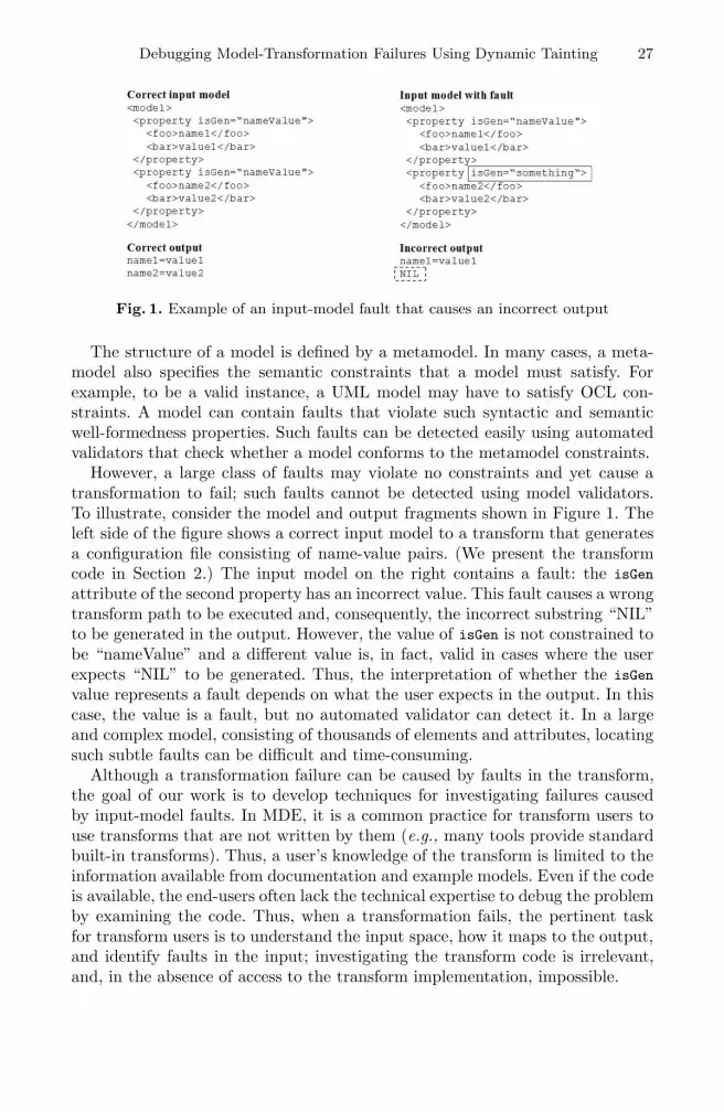
Fig. 2. Illustration of input model faults, fault propagation through the transform, andresulting failures
transformation logic, and writes the output to a file as a text string. Alternatively,a transform can be implemented using specialized templating languages, such asXSLT (Extensible Stylesheet Language Transformation) and JET (Java EmitterTemplates),2 that let developers code the transform logic in the form of a tem-plate. The associated frameworks—Xalan3 for XSLT and the Eclipse ModelingFramework (EMF)4 for JET—provide the functionality to read the input into astructured format and write the output to a text file.
A model is a collection of elements (that have attributes) and relations be-tween the elements. (We use the term entity to refer to either an element or anattribute.) A model is based on a well-defined notation that governs the schemaand the syntax of how the model is represented as a physical file, and how thefile can be read in a structured way. XML and UML are examples of commonlyused notations to define a model. Figure 1 shows an example of a model definedusing XML. The model contains instances of property elements. Each property
has an attribute isGen and contains elements foo and bar.Figure 2 presents an intuitive illustration of the propagation of input-model
faults through a transform, and the manifested failures. A fault can be a missingentity or an incorrect value of an entity. A missing entity can cause a wrong pathto be traversed through the transform. An incorrect entity value can cause eithera wrong path or the propagation of the incorrect value along a correct path. Anincorrect path through the transform manifests as either a missing substringor an incorrect substring in the output. The propagation of an incorrect valuethrough the transform results in an incorrect string or a missing string (in caseswhere the incorrect value is an empty string).
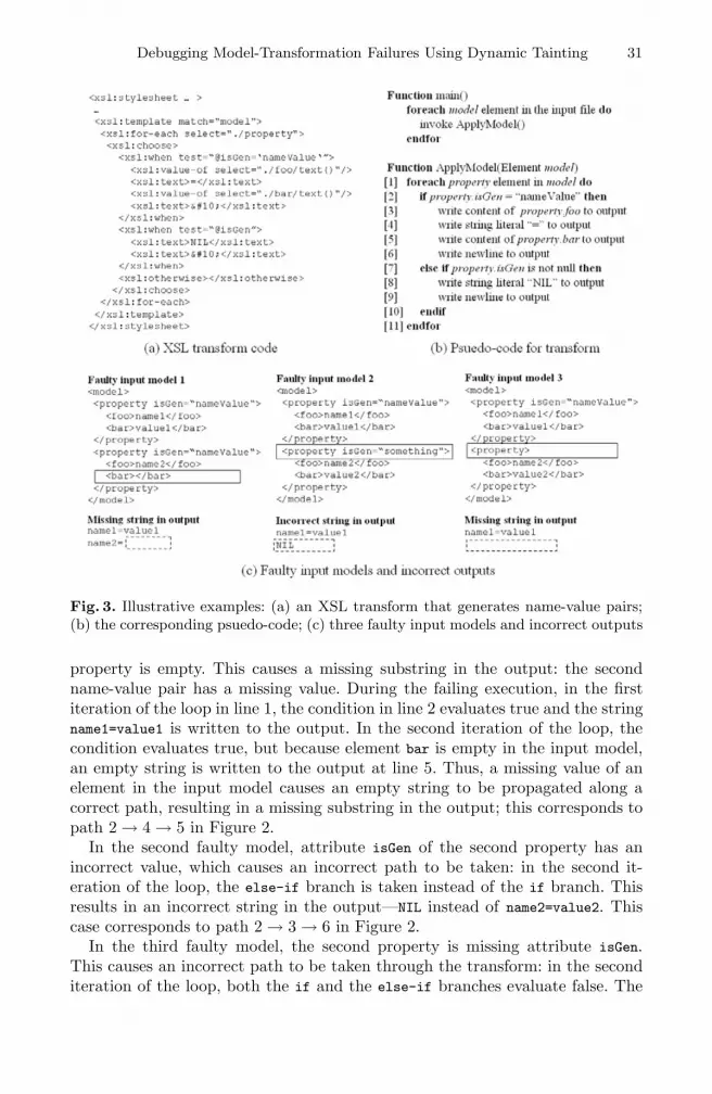
To illustrate these scenarios using a concrete example, consider Figure 3,which elaborates upon the example from Figure 1. Figure 3(a) shows a sampletransform, written using XSL, that generates name-value pairs from the model.Part (b) of the figure shows the transformation logic in the form of proceduralpsuedo-code that could be implemented using a general-purpose programminglanguage. The transform iterates over each property element in the input modeland, based on the value of isGen, writes name-value pairs to the output file.
Part (c) of Figure 3 shows three faulty models and the generated incorrectoutputs. The solid boxes highlight the faults, whereas the dashed boxes highlightthe incorrect parts of the output. In the first model, element bar for the second
2 http://wiki.eclipse.org/M2T-JET3 http://xml.apache.org/xalan-j4 http://www.eclipse.org/modeling/emf
Debugging Model-Transformation Failures Using Dynamic Tainting 31
Fig. 3. Illustrative examples: (a) an XSL transform that generates name-value pairs;(b) the corresponding psuedo-code; (c) three faulty input models and incorrect outputs
property is empty. This causes a missing substring in the output: the secondname-value pair has a missing value. During the failing execution, in the firstiteration of the loop in line 1, the condition in line 2 evaluates true and the stringname1=value1 is written to the output. In the second iteration of the loop, thecondition evaluates true, but because element bar is empty in the input model,an empty string is written to the output at line 5. Thus, a missing value of anelement in the input model causes an empty string to be propagated along acorrect path, resulting in a missing substring in the output; this corresponds topath 2 → 4 → 5 in Figure 2.
In the second faulty model, attribute isGen of the second property has anincorrect value, which causes an incorrect path to be taken: in the second it-eration of the loop, the else-if branch is taken instead of the if branch. Thisresults in an incorrect string in the output—NIL instead of name2=value2. Thiscase corresponds to path 2 → 3 → 6 in Figure 2.
In the third faulty model, the second property is missing attribute isGen.This causes an incorrect path to be taken through the transform: in the seconditeration of the loop, both the if and the else-if branches evaluate false. The
32 P. Dhoolia et al.
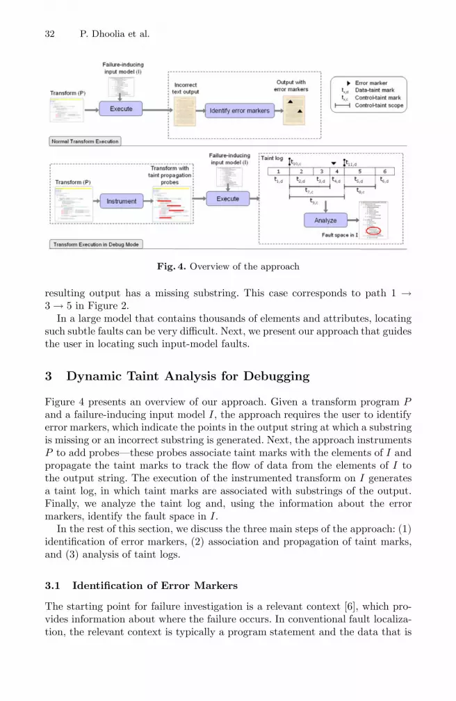
Fig. 4. Overview of the approach
resulting output has a missing substring. This case corresponds to path 1 →3 → 5 in Figure 2.
In a large model that contains thousands of elements and attributes, locatingsuch subtle faults can be very difficult. Next, we present our approach that guidesthe user in locating such input-model faults.
3 Dynamic Taint Analysis for Debugging
Figure 4 presents an overview of our approach. Given a transform program Pand a failure-inducing input model I, the approach requires the user to identifyerror markers, which indicate the points in the output string at which a substringis missing or an incorrect substring is generated. Next, the approach instrumentsP to add probes—these probes associate taint marks with the elements of I andpropagate the taint marks to track the flow of data from the elements of I tothe output string. The execution of the instrumented transform on I generatesa taint log, in which taint marks are associated with substrings of the output.Finally, we analyze the taint log and, using the information about the errormarkers, identify the fault space in I.
In the rest of this section, we discuss the three main steps of the approach: (1)identification of error markers, (2) association and propagation of taint marks,and (3) analysis of taint logs.
3.1 Identification of Error Markers
The starting point for failure investigation is a relevant context [6], which pro-vides information about where the failure occurs. In conventional fault localiza-tion, the relevant context is typically a program statement and the data that is
Debugging Model-Transformation Failures Using Dynamic Tainting 33
observed to be incorrect at that statement. In contrast, the relevant context inour approach is a location in the output string at which a missing substring or anincorrect substring (i.e., the failure) is observed. For a model-to-text transform,such a relevant context is appropriate because a transform typically builds theoutput text in a string buffer b that is printed out to a file at the end of thetransformation. If the fault localization were to start at the output statementand the string buffer b as the relevant variable—for example, as the penumbratool would do—the entire input model would be identified as the fault space.
In our approach, the relevant context for fault localization is an error marker.An error marker is an index into the output string at which a substring is missingor an incorrect substring is generated. In most cases, the user would examine theoutput text and manually identify the error marker. However, for certain typesof output texts, the error-marker identification can be partially automated. Forexample, if the output is a Java program, compilation errors can be identifiedautomatically using a compiler; these errors can be used to specify the errormarker. Similarly, for an XML output, error markers can be identified using awell-formedness checker.
Identification of error markers can be complex. In some cases, a failure maynot be observable by examining the output string: the failure may manifest onlywhere the output is used or accessed in certain ways. In other cases, a failuremay not be identifiable as a fixed index into the output string. In our currentapproach, we assume that the failure can be observed by examining the outputstring and that the error marker can be specified as a fixed index. Our focus inthis paper is on the core analysis for fault localization; we leave it to future workto address the complexity in the identification of error markers.
3.2 Taint Association and Propagation
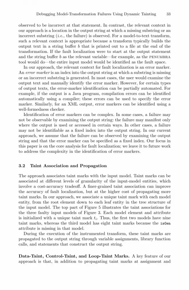
The approach associates taint marks with the input model. Taint marks can beassociated at different levels of granularity of the input-model entities, whichinvolve a cost-accuracy tradeoff. A finer-grained taint association can improvethe accuracy of fault localization, but at the higher cost of propagating moretaint marks. In our approach, we associate a unique taint mark with each modelentity, from the root element down to each leaf entity in the tree structure ofthe input model. The top part of Figure 5 illustrates the taint associations forthe three faulty input models of Figure 3. Each model element and attributeis initialized with a unique taint mark ti. Thus, the first two models have ninetaint marks, whereas the third model has eight taint marks because the isGen
attribute is missing in that model.During the execution of the instrumented transform, these taint marks are
propagated to the output string through variable assignments, library functioncalls, and statements that construct the output string.
Data-Taint, Control-Taint, and Loop-Taint Marks. A key feature of ourapproach is that, in addition to propagating taint marks at assignment and
34 P. Dhoolia et al.
Fig. 5. Taint associations with the three faulty input models and the output texts ofthe example from Figure 3
string-manipulation statements, our approach propagates taint marks at con-ditional statements.5 We classify such taint marks as control-taint marks, anddistinguish them from data-taint marks, which are propagated at non-conditionalstatements. In addition, we propagate taints marks at looping constructs to scopeout, in the output string, the beginning and end of each loop; we call these taintmarks loop-taint marks.
Intuitively, a control-taint mark identifies the input-model elements that affectthe outcome of a condition in a failing execution E . Such taint marks assistwith identifying the faults that cause an incorrect path to be taken through thetransform code in E . At a conditional statement c, the taint marks {t} associatedwith the variables used at c are propagated to the output string and classifiedas control-taint marks. In the output string, the taints in {t} identify locationsat which an alternative substring would have been generated had c evaluateddifferently (e.g., “true” instead of “false”) during the execution. (The control-taint marks are based on the notion of control-flow-based tainting [5]. We discussrelated work further in Section 6.)
A loop taint is a further categorization of control taints; it bounds the scope ofa loop. Loop taints are useful for locating faults that cause an incorrect numberof iterations of a loop. In cases where an instance of an iterating input-modelelement is missing and the user of the transform is able only to point vaguely toa range as an error marker, the loop bounds allow the analysis to identify theinput-model element that represents the collection with a missing element.
Figure 5 presents an intuitive illustration of the taint log that is generated bythe execution of the instrumented transform. In the taint log, substrings (other
5 We use the term “conditional” to refer to the different language constructs thatprovide for conditional execution of statements, such as if statements, looping con-structs, and switch statements.
Debugging Model-Transformation Failures Using Dynamic Tainting 35
than string literals) of the output string have taint marks associated with them,and each taint mark is classified as a data taint, a control taint, or a loop taint.Consider the taint log for the first faulty model, shown on the left in the figure.Data taint t4,d is associated with substring name1, which indicates that the name1
is constructed from the input-model element that was initialized with taint t4(element foo of the first property). A data taint may be associated with an emptysubstring, as illustrated by t9,d. This indicates that element bar of the secondproperty, which was initialized with t9, is empty.
A control taint has a scope that is bound by a start location and an endlocation in the output string. The scope of control taint t3,c indicates thatname1=value1 was generated under the conditional c at which t3 was propagatedto the output string; and, therefore, that the substring would not have beengenerated had c evaluated differently. In the psuedo-code shown in 3, c corre-sponds to the conditional in line 2. Also, attribute isGen of the first propertywas initialized with t3; thus, that attribute determined that name1=value1 wasgenerated. A different value for that attribute could have caused conditional 2to evaluate differently and, consequently, the generation of an alternative sub-string. A control taint may have an empty scope: this occurs when no outputstring is generated along the “taken branch” from a conditional. In the taint logfor the third faulty model, control taint t6,c has an empty scope. This happensbecause in the second iteration of the loop in 3, the conditionals 2 and 7 eval-uated false, and along the taken branch, no string was generated. Loop-taintmark t1,L scopes out the loop iterations; a control taint is generated for eachiteration of the loop.
To summarize, data taints are propagated at each assignment statement andeach statement that manipulates or constructs the output string. At a conditionalstatement s that uses model entity e, the data taints associated with e arepropagated, as control taints, to bound the output substring generated withinthe scope of s. Similarly, at a loop header L that uses entity e, the data taintsassociated with e are propagated, as loop taints, to bound the output stringgenerated within the body of L.
Computation of Control- and Loop-Taint Propagation Points. Control-taints have a scope, defined by a start index and an end index, in the outputstring. To propagate the start and end control-taints to the output string, ourapproach identifies the program points at which conditionals occur and the joinpoints for those conditionals. For each conditional c, the approach propagatesthe taint marks associated with the variables used at c to the output string,and classifies the taint marks as control-taints. Similarly, it propagates the cor-responding end control-taints before the join point of c.
To explain the computation of control-taint propagation points, we providesome definitions. A control-flow graph (CFG) contains nodes that represent state-ments, and edges that represent potential flow of control among the statements;a CFG has a unique entry node, which has no predecessors, and a uniqueexit node, which has no successors. A node v in the CFG postdominates anode u if and only if each path from u to the exit node contains v. v is the
36 P. Dhoolia et al.
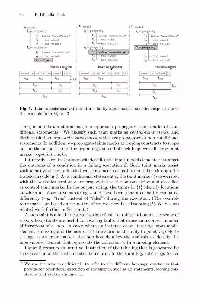
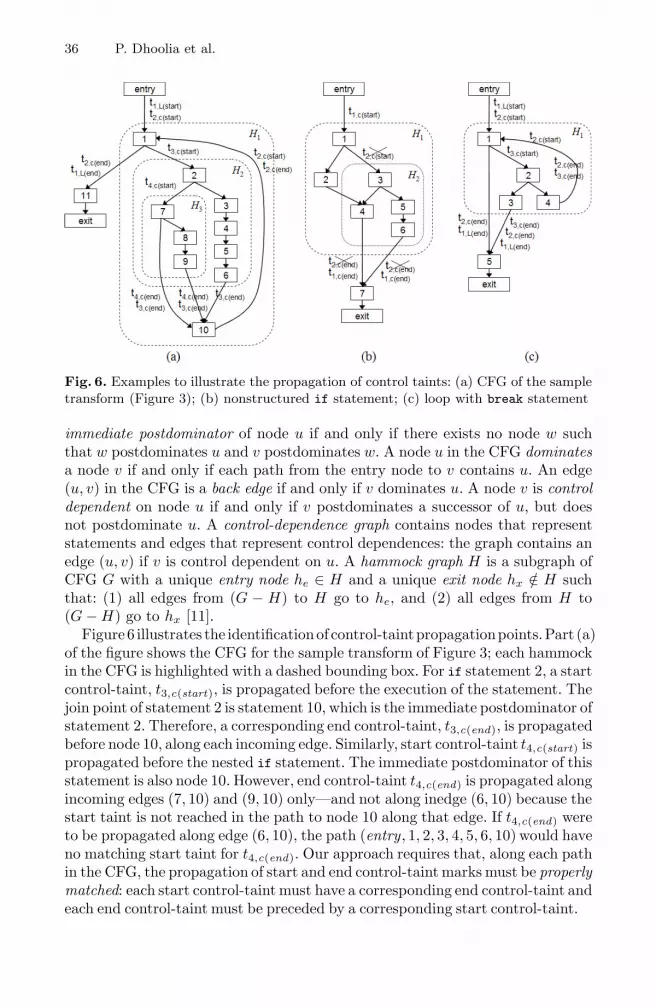
Fig. 6. Examples to illustrate the propagation of control taints: (a) CFG of the sampletransform (Figure 3); (b) nonstructured if statement; (c) loop with break statement
immediate postdominator of node u if and only if there exists no node w suchthat w postdominates u and v postdominates w. A node u in the CFG dominatesa node v if and only if each path from the entry node to v contains u. An edge(u, v) in the CFG is a back edge if and only if v dominates u. A node v is controldependent on node u if and only if v postdominates a successor of u, but doesnot postdominate u. A control-dependence graph contains nodes that representstatements and edges that represent control dependences: the graph contains anedge (u, v) if v is control dependent on u. A hammock graph H is a subgraph ofCFG G with a unique entry node he ∈ H and a unique exit node hx /∈ H suchthat: (1) all edges from (G − H) to H go to he, and (2) all edges from H to(G − H) go to hx [11].
Figure 6 illustrates the identificationof control-taintpropagationpoints.Part (a)of the figure shows the CFG for the sample transform of Figure 3; each hammockin the CFG is highlighted with a dashed bounding box. For if statement 2, a startcontrol-taint, t3,c(start), is propagated before the execution of the statement. Thejoin point of statement 2 is statement 10, which is the immediate postdominator ofstatement 2. Therefore, a corresponding end control-taint, t3,c(end), is propagatedbefore node 10, along each incoming edge. Similarly, start control-taint t4,c(start) ispropagated before the nested if statement. The immediate postdominator of thisstatement is also node 10. However, end control-taint t4,c(end) is propagated alongincoming edges (7, 10) and (9, 10) only—and not along inedge (6, 10) because thestart taint is not reached in the path to node 10 along that edge. If t4,c(end) wereto be propagated along edge (6, 10), the path (entry, 1, 2, 3, 4, 5, 6, 10) would haveno matching start taint for t4,c(end). Our approach requires that, along each pathin the CFG, the propagation of start and end control-taint marks must be properlymatched: each start control-taint must have a corresponding end control-taint andeach end control-taint must be preceded by a corresponding start control-taint.
Debugging Model-Transformation Failures Using Dynamic Tainting 37
For loop header 1, start loop-taint t1,L(start) and start control-taint t2,c(start)
are propagated before the loop header; corresponding end taints (t1,L(end) andt2,c(end)) are propagated before node 11, the immediate postdominator of node 1.In addition, control taints are also propagated along the back edge, which ensuresthat each iteration of the loop generates a new control-taint scope.
Part (b) Figure 6 illustrates a nonstructured if statement: the nested if
statement is nonstructured because its else block has an incoming jump fromoutside the block (through edge (2, 4)). For such if statements, start and endtaint propagation can result in the taints not being properly matched alongsome path in the CFG. If t2,c(start) and t2,c(end) were propagated as shown inthe figure, path (entry, 2, 4, 7) contains an unmatched end taint: t2,c(end). Toavoid such cases and ensure that may taints are properly matched along allpaths, our approach performs taint propagation for only those conditionals thatform a hammock graph. A hammock graph H has the property that no pathenters H at a node other than he and no path exits H at a node other thanhx. Therefore, propagating a start control-taint before he and an end control-taint before after each predecessor of hx guarantees that the control taints areproperly matched through H . In the CFG shown in Figure 6(b), because thenested if statement does not form a hammock, no control-taint propagation isperformed (shown as the crossed-out control-taints).
Part (c) of Figure 6 shows a loop L with a break statement: node 3 representsa break statement that transfers control outside L. In this case, as illustrated,end control-taints need to be propagated along the edge that breaks out ofthe loop. Moreover, conditional statements within L that directly or indirectlycontrol a break statement do not induce hammocks: e.g., if statement 2 doesnot form a hammock. For such statements, control taints need to be propagatedappropriately, as illustrated in Figure 6(c). Because of space constraints, we omitthe details of the algorithm for propagating the control taints.
Similar to nonstructured if statements, a loop may be nonreducible: controlmay jump into the body of the loop from outside of the loop without goingthrough the loop header [3]. Our analysis performs no control-taint propagationfor such loops because matched control-taints cannot be created along all pathsthrough the loop.
3.3 Analysis of Taint Logs for Fault Localization
The execution of the instrumented transform generates a taint log, in whichsubstrings of the output string have taint marks associated with them. Thethird step of our approach analyzes the taint log to identify the fault space inthe input model. Overall, the log analysis performs a backward traversal of theannotated output string, and iteratively expands the fault space, until the faultis located. To start the analysis, the user specifies an error marker and whetherthe error is an incorrect substring or a missing substring.
The bottom part of Figure 5 shows the taint logs, the error markers, andthe computed fault spaces for the three failure-inducing models of the sample
38 P. Dhoolia et al.
transform (Figure 3). The first and the third faulty models cause missing stringsin the output, whereas the second faulty model causes an incorrect substring inthe output.
Missing Substrings. A failing transformation that results in a missing sub-string could be caused by the incorrect empty value of an element or attribute.The first faulty model in Figure 5 illustrates this. Alternatively, a missing sub-string could be caused by a wrong path through the transformation: i.e., a con-ditional along the traversed path could have evaluated incorrectly, which causedthe substring to not be generated along the taken-path. The third faulty modelin Figure 5 illustrates this.
To compute the fault space for missing substrings, the log analysis identifiesempty data taints and empty control taints, if any, that occur at the error marker,and forms the first approximation of the fault space, which consists of the input-model entities that were initialized with these taints. If the initial fault spacedoes not contain the fault, the analysis identifies the enclosing control taints,starting with the innermost scope and proceeding outward, to expand the initialfault space iteratively, until the fault is located.
For the first faulty model in Figure 5, the analysis identifies empty data taintt9,d and sets the initial fault space to contain element bar of the second property.Because the fault space contains the fault, the analysis terminates. Similarly, forthe third faulty model, the analysis identifies empty control taint t6,c and setsthe initial fault space to the second property element, which contains the fault.Thus, in both the cases, the analysis precisely identifies the fault in the firstapproximation of the fault space.
Incorrect Substrings. An incorrect substring could be generated from theincorrect value of an input-model entity; alternatively, the incorrect string couldbe generated along a wrong path traversed through the transform. To computethe fault space for incorrect substrings, the log analysis identifies the data taintassociated with the substring at the error marker. For the second faulty model inFigure 5, the analysis looks for data taints. Because no data taints are associatedwith the output string at the error marker, the analysis considers the enclosingcontrol taint, t7,c, and adds the input-model element initialized with t7 to thefault space. This fault space contains the second property element; thus, theanalysis identifies the fault.
Summary. To summarize, for a missing substring, the log analysis starts atan empty data taint or an empty control taint, and computes the initial faultspace. For an incorrect substring, the analysis starts at a non-empty data taintto compute the initial fault space. Next, for either case, the analysis traversesbackward to identify enclosing control taints—in reverse order of scope nesting—and incrementally expands the fault space. The successive inclusion of controltaints lets the user investigate whether a fault causes an incorrect branch to betaken at a conditional, which results in an incorrect string or a missing string atthe error marker.
Debugging Model-Transformation Failures Using Dynamic Tainting 39
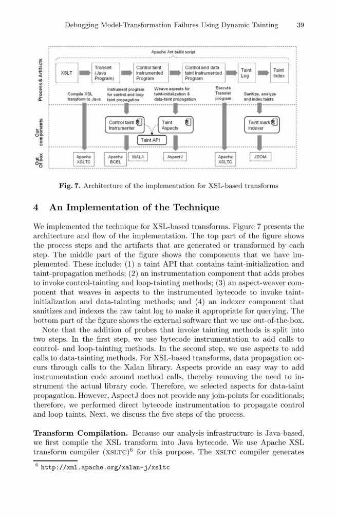
Fig. 7. Architecture of the implementation for XSL-based transforms
4 An Implementation of the Technique
We implemented the technique for XSL-based transforms. Figure 7 presents thearchitecture and flow of the implementation. The top part of the figure showsthe process steps and the artifacts that are generated or transformed by eachstep. The middle part of the figure shows the components that we have im-plemented. These include: (1) a taint API that contains taint-initialization andtaint-propagation methods; (2) an instrumentation component that adds probesto invoke control-tainting and loop-tainting methods; (3) an aspect-weaver com-ponent that weaves in aspects to the instrumented bytecode to invoke taint-initialization and data-tainting methods; and (4) an indexer component thatsanitizes and indexes the raw taint log to make it appropriate for querying. Thebottom part of the figure shows the external software that we use out-of-the-box.
Note that the addition of probes that invoke tainting methods is split intotwo steps. In the first step, we use bytecode instrumentation to add calls tocontrol- and loop-tainting methods. In the second step, we use aspects to addcalls to data-tainting methods. For XSL-based transforms, data propagation oc-curs through calls to the Xalan library. Aspects provide an easy way to addinstrumentation code around method calls, thereby removing the need to in-strument the actual library code. Therefore, we selected aspects for data-taintpropagation. However, AspectJ does not provide any join-points for conditionals;therefore, we performed direct bytecode instrumentation to propagate controland loop taints. Next, we discuss the five steps of the process.
Transform Compilation. Because our analysis infrastructure is Java-based,we first compile the XSL transform into Java bytecode. We use Apache XSLtransform compiler (xsltc)6 for this purpose. The xsltc compiler generates
6 http://xml.apache.org/xalan-j/xsltc
40 P. Dhoolia et al.
an equivalent bytecode program (called translet) for the XSL. This transformprogram can be executed using the xsltc runtime API.
Bytecode Instrumentation. The instrumentation component of our imple-mentation adds probes to the translet bytecode to propagate control and looptaints. The component consists of a taint-location analyzer and a bytecode in-strumenter. The taint-location analyzer is developed using the walaanalysis infrastructure.7 It uses wala to perform control-flow analysis anddominance/postdominance analysis. Using these, it identifies loops and loopback-edges8 and, for each conditional c, checks whether c is the entry nodeof a hammock graph. The analyzer identifies all taint-propagation locations ac-cording to the algorithm presented in Section 3.2. Each taint location is specifiedusing a bytecode offset and information about what instrumentation action toperform at that offset.
The instrumenter processes the taint locations, and uses bcel9 to add byte-code instructions and modify existing instructions. The instrumenter performsthree types of actions: (1) add calls to the tainting methods; (2) redirect existingbranch and goto instructions, and (3) add new goto instructions. The followingcode fragments illustrate these actions.
0: iload_11: istore_32: iload_2
3: ifne 96: iinc 3 1
9: return
0: iload_11: istore_32: iload_23: invokestatic markStartControlTaint()V // added invoke6: ifne 16 // redirected branch9: iinc 3 112: goto 22 // added goto15: return16: invokestatic markEndControlTaint()V // new jump target19: goto 1522: invokestatic markEndControlTaint()V // new jump target25: goto 15
The fragment on the left shows the original bytecode (P ) that encodes anif-then statement; the fragment on the right shows the instrumented bytecode(P ′), in which calls to tainting methods (from our taint API) have been added.In P ′, at offset 3, a call to tainting method markStartControlTaint() has beenadded. In P , the if statement at offset 3 transfers control to offset 9, whichis the end of the if-then block. In P ′, the branch has been redirected to firstinvoke (at offset 16) the end control-taint method markEndControlTaint(), andthen jump to the original target (offset 9 in P , offset 15 in P ′) of the branch. Atthe end of the then branch (offset 6 in P , offset 9 in P ′), a goto instruction hasbeen added to ensure that the end control-taint method is called before controlflows out of the then block.
Aspect Weaving. The aspect-weaver component defines abstract aspects fortaint initialization and data-taint propagation. We implement these abstract7 http://wala.sourceforge.net8 Because the analysis is performed on bytecode, which encode loops using if andgoto instructions, loop detection is based on the identification of back-edges.
9 http://jakarta.apache.org/bcel
Debugging Model-Transformation Failures Using Dynamic Tainting 41
aspects by providing a set of specific point-cut definitions and correspondingadvices. The advices invoke tainting methods from the taint API. The taint-initialization aspect, woven to the XML parser, assigns a unique taint mark toeach element, and for each element, to each of its attributes and content. Thepoint-cuts and advices of the data-taint-propagation aspect, are implementedbased on an understanding of the general profile of transform programs generatedby the xsltc compiler.
Translet Execution. Next, we execute the fully instrumented translet (instru-mented for taint initialization, data-taint propagation, and control-taint propa-gation) on the faulty input. We use the xsltc command-line API. The executionof the instrumented translet produces an annotated taint log. For a data-tainttag, the taint information contains either a taint mark, or an association to anintermediate variable created and used in the XSL transform. The taint infor-mation for a variable tag may itself contain either taint marks, or associationsto other intermediate variables. A control-taint tag may contain a taint mark oran association to an intermediate variable, and/or the conditions. The conditiontag may contain a taint mark or variable associations for both the left-hand andright-hand expressions of the conditional statement, along with the conditionaloperand. For loop constructs, the annotations contain just the loop tag.
Taint Log Indexing. Finally, the indexer component sanitizes, analyzes, andindexes the taint-marks associations with the output substrings. It performs thetwo steps.
First, we sanitize the taint the log to process it as an XML document. However,the actual output of the transform may either itself be an XML (leading to apossible interleaving of its tags with ours) or it may contain special characters(e.g., the greater-than comparison operator in an output Java program). Eitherof these cases can make the taint log an invalid xml. To avoid this, we sanitizethe taint log by encapsulating all the actual output chunks between our tags asCDATA sections. In XML, a CDATA section is a section of element content thatis marked for the parser to interpret as only character data, not markup.
Second, the indexer analyzes and indexes the sanitized taint log. It usesJDOM10 and XML processing to traverse the sanitized taint log as an XMLdocument. It processes the special CDATA sections, created during the sanitiz-ing pass, sequentially in the order of their occurrence. It associates the parenttaint element tags with the ranges of the output segments bounded within theCDATA sections. For the CDATA ranges associated with intermediate variables,the indexer keeps a temporary mapping of variables with taint marks, which ituses for resolving tainted ranges associated with the use of those variables. Fur-ther, based on the containment hierarchy of taint tags, a list of taint marksrepresenting an iterative expansion of the fault space is indexed for relevantranges in the output. Finally, the indexer provides an API on the taint indexthat supports queries for taint marks (or probable taint marks) associated with
10 http://www.jdom.org
42 P. Dhoolia et al.
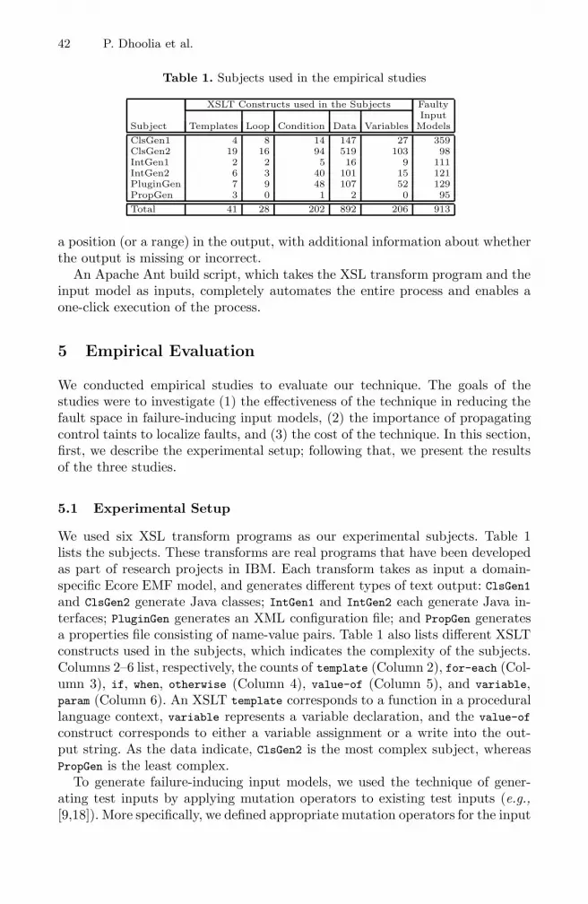
Table 1. Subjects used in the empirical studies
XSLT Constructs used in the Subjects FaultyInput
Subject Templates Loop Condition Data Variables Models
ClsGen1 4 8 14 147 27 359ClsGen2 19 16 94 519 103 98IntGen1 2 2 5 16 9 111IntGen2 6 3 40 101 15 121PluginGen 7 9 48 107 52 129PropGen 3 0 1 2 0 95
Total 41 28 202 892 206 913
a position (or a range) in the output, with additional information about whetherthe output is missing or incorrect.
An Apache Ant build script, which takes the XSL transform program and theinput model as inputs, completely automates the entire process and enables aone-click execution of the process.
5 Empirical Evaluation
We conducted empirical studies to evaluate our technique. The goals of thestudies were to investigate (1) the effectiveness of the technique in reducing thefault space in failure-inducing input models, (2) the importance of propagatingcontrol taints to localize faults, and (3) the cost of the technique. In this section,first, we describe the experimental setup; following that, we present the resultsof the three studies.
5.1 Experimental Setup
We used six XSL transform programs as our experimental subjects. Table 1lists the subjects. These transforms are real programs that have been developedas part of research projects in IBM. Each transform takes as input a domain-specific Ecore EMF model, and generates different types of text output: ClsGen1and ClsGen2 generate Java classes; IntGen1 and IntGen2 each generate Java in-terfaces; PluginGen generates an XML configuration file; and PropGen generatesa properties file consisting of name-value pairs. Table 1 also lists different XSLTconstructs used in the subjects, which indicates the complexity of the subjects.Columns 2–6 list, respectively, the counts of template (Column 2), for-each (Col-umn 3), if, when, otherwise (Column 4), value-of (Column 5), and variable,param (Column 6). An XSLT template corresponds to a function in a procedurallanguage context, variable represents a variable declaration, and the value-of
construct corresponds to either a variable assignment or a write into the out-put string. As the data indicate, ClsGen2 is the most complex subject, whereasPropGen is the least complex.
To generate failure-inducing input models, we used the technique of gener-ating test inputs by applying mutation operators to existing test inputs (e.g.,[9,18]). More specifically, we defined appropriate mutation operators for the input
Debugging Model-Transformation Failures Using Dynamic Tainting 43
models of our subjects, and generated faulty models (i.e., mutants) by applyingthe operators to a valid input model. Specifically, we used four mutation op-erators: (1) DeleteElement deletes a model element, (2) DeleteAttribute deletes amodel attribute; (3) EnumerateAttribute modifies the value of an attribute basedon a predefined enumeration of values for the attribute; and (4) EmptyAttribute
sets an attribute to empty. Each faulty model was generated by applying onemutation operator; therefore, each faulty model had one fault only.
We used two valid input models; the sizes of these models, measured as thetotal number of elements and attributes, are approximately 38,100 and 40,500.For each input, we generated a different set of mutants. Together, the two setsof mutants formed the total pool of mutants If , which we used to constructfaulty input models I(f,P ) ⊆ If for each subject P . For each P and pair (i, if),where i is a valid input and if is a mutant generated from i, we executed Pon i and if and compared the outputs. If the outputs differed, we added if toI(f,P ); otherwise, we ignored if because it was an equivalent mutant with respectto P . The last column of Table 1 lists the size of I(f,P ) (the number of faultyinput models) for each subject. Over the six subjects, there were a total of 913faulty models. Of these, 30% of the faults were created by the application of theDeleteElement mutation operator; another 30% were created by the applicationof the DeleteAttribute operator; EnumerateAttribute and EmptyAttribute contributedto 14% and 26% of the faults, respectively.
To automate the step of computing the error markers, we implemented adifferencing component, filediff. filediff compares the output generated bya program P on a valid input i with the output generated by P on a faultyinput if (derived from i) to identify the first point (line and column numbers)at which the two outputs differ. This point is specified as the error marker forthe failing execution of P on if .
5.2 Study 1: Effectiveness of the Technique
Goals and method. The goal of the first study was to evaluate the effective-ness of our technique in reducing the fault search space. We define fault spacereduction as:
FSreduction =FStotal − FSanalysis
FStotal× 100
FStotal is the total fault space (i.e., the size of the faulty input model); FSanalysis
is the number of elements/attributes computed by the analysis (i.e., the subsetof the faulty model that must be examined to identify the fault).11 The maxi-mum reduction occurs when FSanalysis = 1, which depends on the type of faultor mutation operator. For the EnumerateAttribute and EmptyAttribute operators,FSanalysis = 1 if the analysis computes only the modified attribute. For the Dele-
teElement and DeleteAttribute operators, FSanalysis = 1 if the analysis computesonly the parent element of the deleted element/attribute.
The entire execution and data collection was automated using an Ant buildscript (as discussed in Section 4). We compiled each XSL subject program to11 FSanalysis represents the complete fault space computed by the analysis, after per-
forming all iterative expansions.
44 P. Dhoolia et al.
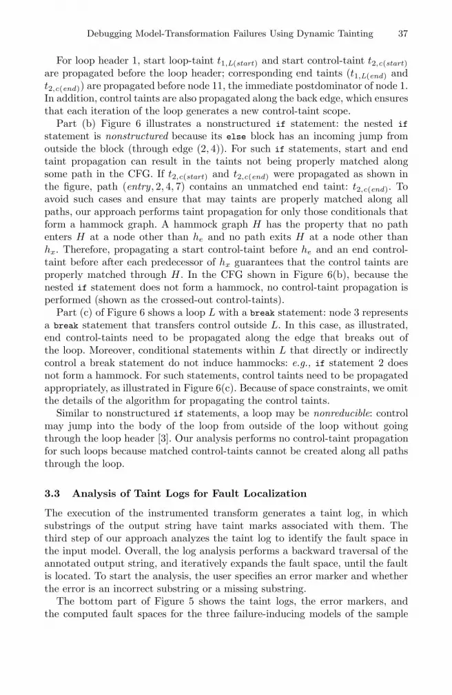
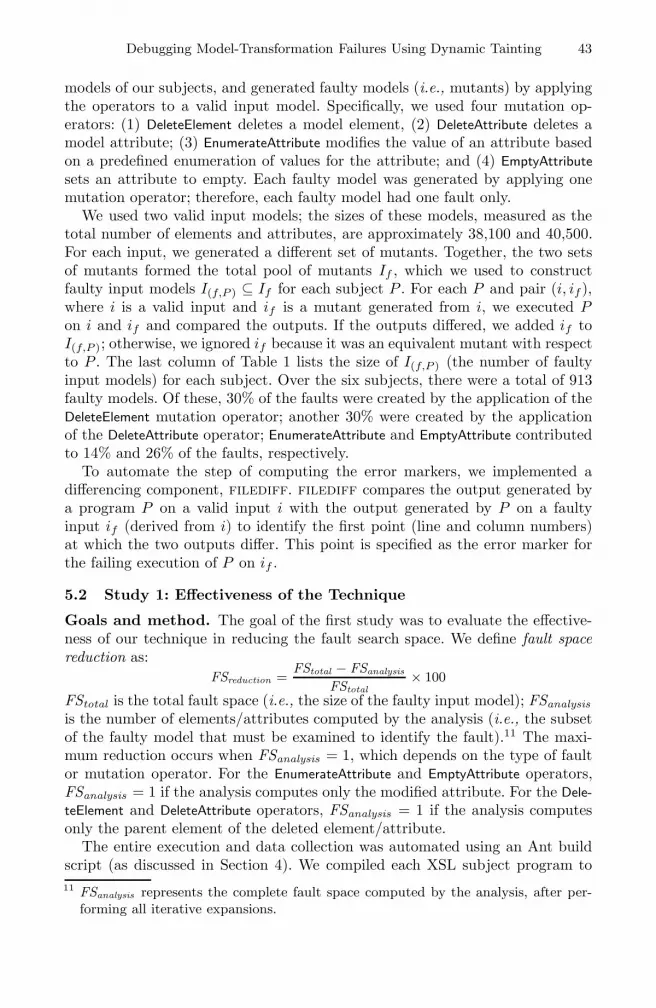
Fig. 8. Fault-space reduction attained by our approach. The chart on the left showsthe percentage of faults for which different ranges of reduction were attained. The tableof the right shows the absolute sizes of the fault spaces.
get the corresponding Java translet. We executed translet on the valid input i tocompute the valid output Ovalid . Next, we instrumented the translet, weaved inaspects, and executed the modified translet on each input if ∈ I(f,P ) to computethe incorrect output Oi,incorrect . We used filediff compute the error marker forOi,incorrect , and then queried the taint indexer to compute FSanalysis . Finally,we determined whether the fault in if occurred in FSanalysis (which was the casefor all the faults) and computed FSreduction .
Results and analysis. Figure 8 presents data to illustrate the fault-spacereduction achieved by our technique: the segmented-bar chart on the left showsthe percentage fault reduction, whereas the table on the right shows the absolutesizes of the fault spaces. For each subject, the chart contains a segmented bar, inwhich the segments represents different ranges of FSreduction . The vertical axisrepresents 100% of the faulty models for a subject; the number at the top of abar is the number of faulty models for that subject. The data demonstrate thatour approach can be highly effective in reducing the fault space. For example, forClsGen1, the maximum reduction was attained for 56% of the faults, a reductionof 98% or better was attained for another 26% of the faults; for the remainingfaults, a reduction of at least 94% was achieved. For four of the subjects, theapproach attained the maximum reduction for at least 50% of the faulty inputsin those subjects. Over all subjects, the technique accomplished the maximumreduction for 468 (51%) of the 913 faulty models, and at least a 98% reductionfor another 378 (41%) of the faults.
The table on the right in Figure 8 presents a different view of the fault-reduction data: it shows the number of faults for which the fault-space sizeswere in the different ranges. For example, consider ClsGen1. For 222 of the 359faulty inputs, FSanalysis = 1; for 16 of the faults, FSanalysis is between 2 and 100;
Debugging Model-Transformation Failures Using Dynamic Tainting 45
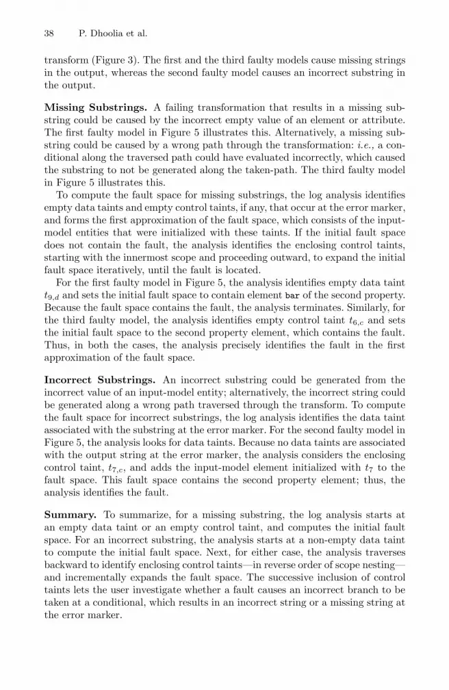
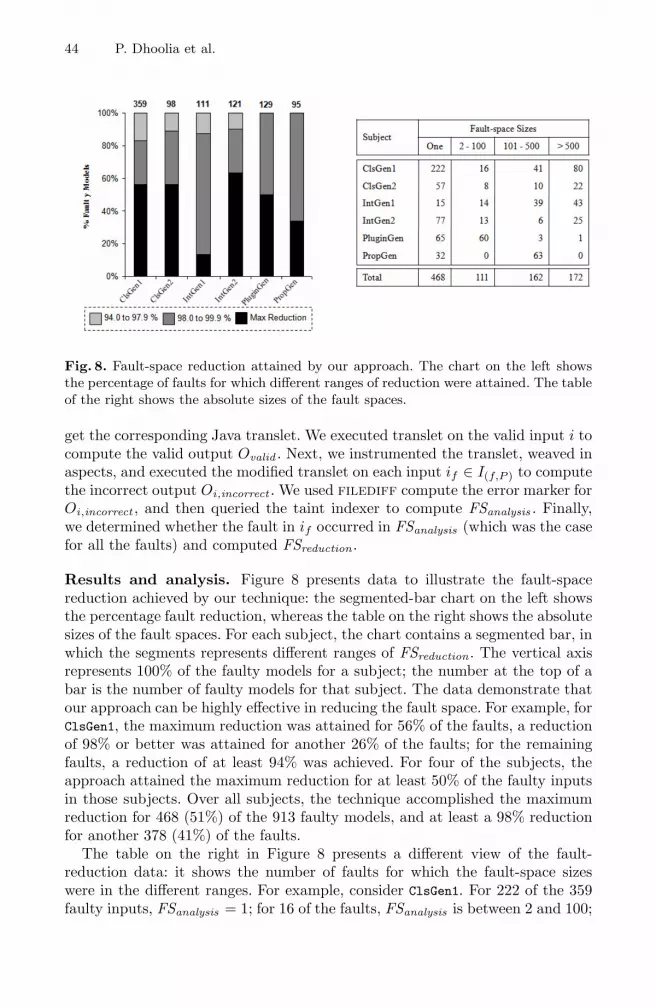
Fig. 9. Data to illustrate the significance of using control taints for fault localization
for another 41 faults, FSanalysis is between 101 and 500; and for the remaining 80faults, FSanalysis contains more than 500 entities. The data show that the sizes ofthe fault spaces can be quite large. However, this should be interpreted keeping inview the sizes of our input models, which are very large: the faulty models derivedfrom one valid model contain about 38,100 elements and attributes, whereas thefaulty models derived from the other input model contain about 40,500 elementsand attributes. Thus, although a fault space of 500 elements/attributes appearsquite large, it is substantially smaller than the complete fault space, which iswhat the user might have to examine to identify the fault, if no fault-spacereduction were performed.
5.3 Significance of Control-Taint Tags
Goals and Method. One of the key features of our approach is the propagationof control taints. The goal of the second study was to evaluate the importanceof using control taints. In general, propagation of control taints is necessary toenable the approach to compute the fault space (FSanalysis ), conservatively—i.e., to ensure that FSanalysis contains the fault. Stated differently, exclusion ofcontrol taints can cause FSanalysis to not contain the fault. Thus, to measure thesignificance of control taints, we collected data about the percentage of faultymodels for which FSanalysis would not contain the fault if control taints were notpropagated.
Results and Analysis. Figure 9 presents the data to illustrate the impor-tance of control taints. The figure contains one segmented bar per subject. Thesegments indicate the percentage of faulty models for which control taints werenecessary for locating the fault, and the remaining faulty models for which datataints alone were sufficient for locating the fault. As the data illustrate, for asubstantial percentage of the faulty inputs, control taints were necessary forlocating the faults. For example, for ClasGen1, control taints were required forlocating the faults for 80% of the faulty inputs; data taints were sufficient for only20% of the faults. For IntGen1, none of the faults could be localized using data
46 P. Dhoolia et al.
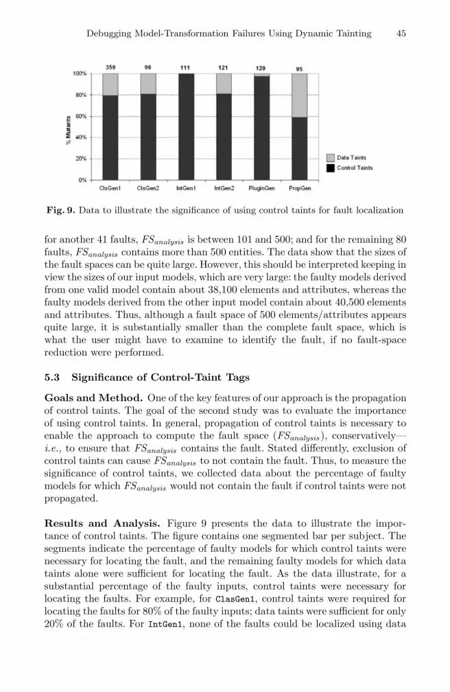
Table 2. Cost of the approach in terms of the execution and instrumentation overheads
Average Execution Time (s) Translet InstructionsWith control With control
Subject Original Instrumented × Increase Original taints and data taints
ClsGen1 3.62 28.5 8 3722 3911 15783ClsGen2 3.2 91.88 28 13270 14120 58326IntGen1 1.75 28.73 16 938 999 2644IntGen2 2.02 18.04 9 3264 3521 14129PluginGen 1.71 12.71 7 5888 6359 12013PropGen 0.22 1.03 5 376 404 698
taints alone—all the faults required control-taint propagation. Data taints weremost effective for PropGen, for which 41% of the faults could be localized withoutcontrol taints. Over all subjects, 83% of the faults required the propagation ofcontrol taints, and only 17% could be localized using data taints alone.
The data indicate that for debugging model transforms, propagation of controltaints is essential. A technique that does not perform control-taint propagationcan very often fail to compute the fault space conservatively, and may be oflimited value.
5.4 Cost of Analysis
Goals and Method. In the final study, we evaluated the cost of the tech-nique in terms of the execution overhead incurred because of the instrumentationfor propagating data and control taints. (The instrumented code refers to thetranslet code after bcel instrumentation and aspect weaving.) We measured theaverage execution time over all the faulty input models on the original transletand the instrumented translet. We also measured the instrumentation overheadin terms of the sizes of the original and the instrumented translets.
Results and Analysis. Table 2 presents data to illustrate the cost of our tech-nique. It shows the average execution times (in seconds), and the increase inthe sizes of the translets (measured as bytecode instructions) caused by instru-mentation. As might be expected, code instrumentation incurs a heavy cost: theaverage increase in execution time varies from five times to 28 times. In absolutevalues, the execution times are reasonable for our subjects and acceptable foron-line execution of the instrumented transform within an interactive debuggingenvironment. For longer-running transforms, this may not be practical. However,with appropriately designed usage scenarios, the execution overhead would notbe a mitigating factor that limits the use of our approach. In practice, the instru-mented code can be executed off-line or as a background process to generate thetaint logs, which can then be queried in an interactive debugging environment.
Columns 5–7 of the table show the increase in the number of bytecode in-structions in the translet after the addition of probes for propagating controland data taints. As the data illustrate, the addition of probes for control-taintpropagation causes a moderate increase in the number of bytecode instructions:
Debugging Model-Transformation Failures Using Dynamic Tainting 47
on average, less than 4% increase. However, the weaving of aspects for data-taint propagation causes a significant increase in the number of instructions.For example, the number of instructions increases about four times for ClsGen1,ClsGen2, and IntGen2.
5.5 Threats to Validity
Our evaluation shows that, for the subjects and faulty inputs that we studied, ourapproach for fault localization can be very effective in reducing the fault searchspace in the input models. Moreover, our results indicate that the propagation ofcontrol taints is essential for conservative fault localization. Unlike the results ofClause and Orso [6] which did not indicate any significant benefit accruing fromcontrol-flow-based taint propagation, our results suggest that, in the domain ofmodel transforms, control taints have a significant role to play; therefore, anapproach that does not perform such propagation would be little value.
Our results are preliminary and there are several threats to the validity ofour observations. Threats to external validity arise when the results of the ex-periment cannot be generalized to other situations. Our evaluation is limited tosix subjects, and thus, we cannot conclude whether our results might hold forgeneral transforms. However, our transforms are varied in that they generatedifferent types of outputs (code, properties, and configuration files), which givesus confidence that the results might apply to different types of model-to-texttransforms. Another threat to validity is the representativeness of the faultyinput models. We used mutation analysis to generate the faulty models, whichmay not represent the types of faults that occur frequently in practice; moreover,each faulty model contained only one fault. However, based on our experiencewith developing transforms, we designed our mutation operators to capture thecommonly occurring faults. This threat is further mitigated by the fact thatdifferent types of faults were well-represented in our set of faulty models.
Threats to internal validity arise when factors affect the dependent variableswithout the researchers’ knowledge. In our case, our implementation and datacollection could have flaws that would affect the accuracy of the results weobtained. To alleviate this threat, we manually verified a random sampling ofthe results.
Construct threats to validity arise when the measures do not adequately cap-ture the concepts they are intended to measure. Our FSreduction measure is de-fined such that, for a deleted element, maximum reduction occurs if the parentelement of the deleted element is identified by the analysis. This is somewhatcoarse-grained because the user might have to examine several elements in theparent element to identify the missing element. However, we think that such achoice is a reasonable one. In theory, the most precise solution would point outexactly the missing element; in practice, this may not be possible in every case.We leave it to future work to investigate ways to improve the accuracy of ourapproach for faults that involve deletions of elements.
48 P. Dhoolia et al.
6 Related Work
There is much research in the area of fault localization. However, most of theexisting research focuses on identifying faults in the program. The goal of thesetechniques is to narrow down the search space of program statements that shouldbe examined to locate the fault.
The most widely studied among these are based on dynamic program slic-ing [15]. A dynamic slice, computed with respect to an input i, a set of variablesV , and a statement occurrence s in the execution trace induced by i, identifiesthe statements that affect the value of the variables in V on execution againsti. In addition to investigating the use of dynamic slicing, in its basic form, fordebugging [1], researchers have presented many extensions to, and variants, ofdynamic slicing (e.g., [2,8]). Slicing-based techniques do not trace the incorrectoutput values, observed in a failing execution, back to program inputs; there-fore, they are inappropriate for model debugging. Dynamic tainting [5], whichtracks the flow of data from inputs to outputs during an execution, naturallyfits the requirements of model debugging. Dynamic tainting has been exploredextensively for identifying security vulnerabilities (e.g., [12,17]).
More recently, Clause and Orso [6] investigated the use of dynamic taintingfor identifying a failure-relevant subset of a failure-inducing input. Their workis the one that is most closely related to ours. Given information about the pro-gram statement and data involved in a failure, their technique performs taintpropagation over data and control flow to identify the subset of input that is rel-evant for investigating the failure. We apply dynamic-tainting-based debuggingto a new domain—i.e., model transformation—and our goal is to identify faultsin the transform inputs. To apply dynamic tainting effectively in this domain,we made several adaptations and extensions to Clause and Orso’s technique. Inour approach, the relevant context is a location in the output string of a model-to-text transform, which differs from the starting point of failure investigation ofexisting techniques. Our control taints are an adaptation of “taint propagationover control flow,” discussed by Clause and Orso (and also discussed as “implicitinformation flow” by Masri and colleagues [16]). The distinguishing aspect of ouruse of control taints is that we formulate control taints as first-class entities, andwe track the nesting scope of control taints (including empty scopes). This letsour approach perform an incremental expansion of the fault space and identifyfaults that cause the execution of an incorrect path through the transform. Theempirical results presented by Clause and Orso did not illustrate any substantialgain from propagating taints over control flow. In contrast, our results indicatethat for model-to-text transforms, tracking control taints is absolutely essential.
Model-tracing techniques [7] infer links between input-model and output-model entities. Recent work in the areas of traceability metamodels [10], model-comparison languages [14], and higher-order transformations [22] can be appliedto analyze model transforms and trace backward from error markers to input-model entities. However, tracing techniques can support fault localization onlyin cases where an incorrect value of an input-model entity flows to the outputthrough value propagation; thus, traceability links provide a capability similar to
Debugging Model-Transformation Failures Using Dynamic Tainting 49
what the data taints provide in our approach. However, in cases where the faultis a missing model entity or the failure is a missing output substring, tracingtechniques cannot be applied because no links are created. Moreover, for faultsthat cause the execution of an incorrect path, traceability links cannot guide theuser to the relevant input-model entities.
Delta debugging [23] is a technique that identifies a minimal subset of a failure-inducing input i that also causes the failure: i.e., removing this subset wouldcause the failure to not occur. Delta debugging repeatedly executes the programwith different subsets of i until it finds such a subset. In cases where the fault isa missing input-model element (which is common for model transforms), deltadebugging would fail to identify a minimal subset because no subset causesthe failure to not occur—the failure would not be observed only if the missingelement were to be added to the input model; and delta debugging performs noaugmentation of the input. Additionally, delta debugging has efficiency issues asobserved in Reference [6] and requires a passing execution.
Other classes of fault-localization techniques compare the spectra of passingand failing test executions (e.g., [13,19]), or create program variants via state-ment removal [21], to identify suspicious statements. These approaches are notapplicable to debugging model-transformation failures where the goal is to iden-tify faults in the input models and not in the transforms.
7 Conclusions and Future Work
In this paper, we presented an approach for assisting transform users with de-bugging their input models. Unlike conventional fault-localization techniques,our approach focuses on the identification of input-model faults, which, fromthe perspective of transform users, is the relevant debugging task. Our approachuses dynamic tainting to track information flow from input models to the outputtext. The taints associated with the output text guide the user in incrementallyexploring the fault space to locate the fault. A novel feature of our approach isthat it distinguishes between different types of taint marks (data, control, andloop), which enables it to identify effectively the faults that cause the traversalof incorrect paths and incorrect number of loop iterations. Our empirical studies,conducted using an implementation for XSL-based transforms, indicate that theapproach can be very effective in reducing the fault space substantially.
There are several areas of future work that we plan to conduct that willlet us perform additional studies, including user studies, to assess the benefitsof our approach. Our current implementation analyzes XSL-based transforms.Extensions to accommodate other types of model-to-text transforms, such asJET-based transforms, and even general-purpose programs (for which the goalof debugging is to locate faults in inputs) would enable us to evaluate the widerapplicability of our approach.
Currently, our debugging approach focuses on fault localization. A useful ex-tension of our approach would be to support fault repair as well. Such a techniquecould recommend fixes by performing pattern analysis on taint logs collected for
50 P. Dhoolia et al.
model elements that generate correct substrings in the output text. Anothertechnique (applicable for missing substrings) could be to force the execution ofnot-taken branches in the transform to show to the user potential alternativestrings that would have been generated had those paths been traversed.
Our approach assumes that the transform user can identify the error markersin the output string. However, identifying the error markers can be challengingin some cases. For example, the failure may not be obvious by examining theoutput—e.g., the failure may manifest only when the output is used in othercomputations. In such cases, an approach that helps the user trace back fromthe observed failure to an error marker in the output text would be useful.
Often in MDE, a sequence of transforms are chained together such that theuser-provided input goes through multiple transformations before generating anoutput. It would be interesting to explore how the proposed approach can beextended to debug inputs for chained transformations.
Acknowledgements. We would like to thank the anonymous reviewers forhelpful comments, which have improved the presentation of the work.
References
1. Agrawal, H., DeMillo, R.A., Spafford, E.H.: Debugging with dynamic slicing andbacktracking. Software—Practice and Experience 23(6), 589–616 (1993)
2. Agrawal, H., Horgan, J.R., London, S., Wong, W.E.: Fault localization using exe-cution slices and dataflow tests. In: Proc. of the Intl. Symp. on Softw. ReliabilityEng., pp. 143–151 (1995)
3. Aho, A.V., Sethi, R., Ullman, J.D.: Compilers, Principles, Techniques, and Tools.Addison-Wesley Publishing Company, Reading (1986)
4. Baxter, I.D.: Design maintenance systems. ACM Commun. 35(4), 73–89 (1992)5. Clause, J., Li, W., Orso, A.: Dytan: A generic dynamic taint analysis framework.
In: Proc. of the Intl. Symp. on Softw. Testing and Analysis, pp. 196–206 (2007)6. Clause, J., Orso, A.: Penumbra: Automatically identifying failure-relevant inputs
using dynamic tainting. In: Proc. of the Intl. Symp. on Softw. Testing and Analysis,pp. 249–259 (2009)
7. Czarnecki, K., Helsen, S.: Classification of model transformation approaches. In:Proc. of the OOPSLA 2003 Workshop on Generative Techniques in the Context ofModel-Driven Architecture (2003)
8. DeMillo, R.A., Pan, H., Spafford, E.H.: Critical slicing for software fault local-ization. In: Proc. of the Intl. Symp. on Softw. Testing and Analysis, pp. 121–134(1996)
9. Dinh-Trong, T., Ghosh, S., France, R., Baudry, B., Fleury, F.: A taxonomy of faultsfor UML models. In: Proc. of the 2nd Workshop on Model Design and Validation(2005)
10. Drivalos, N., Kolovos, D., Paige, R., Fernandes, K.: Engineering a DSL for softwaretraceability. Software Language Engineering, 151–167 (2009)
11. Ferrante, J., Ottenstein, K.J., Warren, J.D.: The program dependence graph andits use in optimization. ACM Trans. Progr. Lang. Syst. 9(3), 319–349 (1987)
12. Halfond, W., Orso, A., Manolios, P.: Using positive tainting and syntax-awareevaluation to counter SQL injection attacks. In: Proc. of the ACM SIGSOFT Symp.on the Foundations of Softw. Eng., pp. 175–185 (November 2006)
Debugging Model-Transformation Failures Using Dynamic Tainting 51
13. Jones, J.A., Harrold, M.J., Stasko, J.: Visualization of test information to assistfault localization. In: Proc. of the 24th Intl. Conf. on Softw. Eng., pp. 467–477(May 2002)
14. Kolovos, D.: Establishing correspondences between models with the epsilon com-parison language. In: Model Driven Architecture-Foundations and Applications,pp. 146–157
15. Korel, B., Laski, J.: Dynamic program slicing. Information Processing Let-ters 29(3), 155–163 (1988)
16. Masri, W., Podgurski, A., Leon, D.: Detecting and debugging insecure informationflows. In: Proc. of the Intl. Symp. on Softw. Reliability Eng., pp. 198–209 (2004)
17. Newsome, J., Song, D.X.: Dynamic taint analysis for automatic detection, analy-sis, and signature generation of exploits on commodity software. In: Proc. of theNetwork and Distributed System Security Symp. (2005)
18. Offutt, J., Xu, W.: Generating test cases for web services using data perturbation.Softw. Eng. Notes 29(5), 1–10 (2004)
19. Renieres, M., Reiss, S.P.: Fault localization with nearest neighbor queries. In: Proc.of the 18th Intl. Conf. on Automated Softw. Eng., pp. 30–39 (2003)
20. Schmidt, D.C.: Model-driven engineering. IEEE Computer 39(2), 25–31 (2006)21. Sterling, C.D., Olsson, R.A.: Automated bug isolation via program chipping.
Software—Practice and Experience 37(10), 1061–1086 (2007)22. Van Gorp, P., Keller, A., Janssens, D.: Transformation language integration based
on profiles and higher order transformations. In: Gasevic, D., Lammel, R., VanWyk, E. (eds.) SLE 2008. LNCS, vol. 5452, pp. 208–226. Springer, Heidelberg(2009)
23. Zeller, A., Hildebrandt, R.: Simplifying and isolating failure-inducing input. IEEETrans. Software Eng. 28(2), 183–200 (2002)


