Embed Size (px)
Citation preview
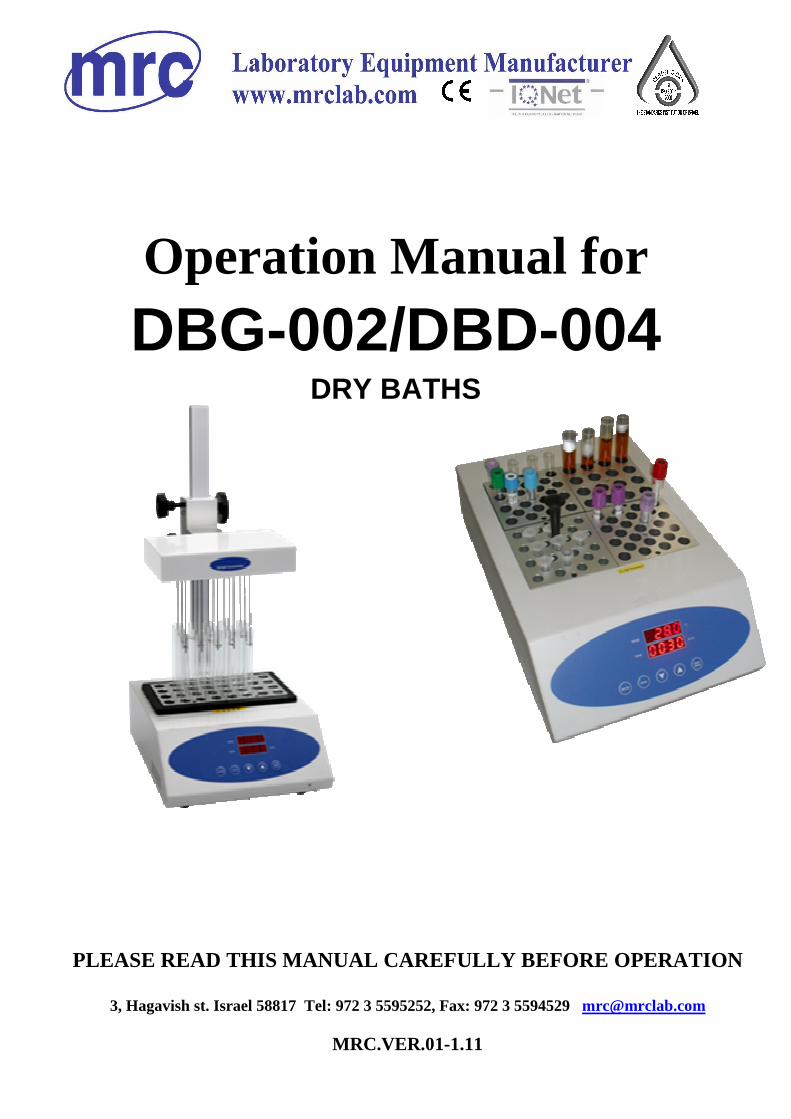
PLEASE READ THIS MANUAL CAREFULLY BEFORE OPERATION
3, Hagavish st. Israel 58817 Tel: 972 3 5595252, Fax: 972 3 5594529 [email protected]
MRC.VER.01-1.11
Operation Manual for
DBG-002/DBD-004 DRY BATHS
Foreword
Thank you for purchasing our Products: Sample Conce ntrator. This
Manual for users contains function and operation of the Instrument. In
order to use the instrument properly, please read t his manual carefully
before using the Instrument.
Opening Check
Please check the Instrument and Appendix with the p acking list when
you first open the instrument packing case. If you find there is something
wrong with the Instrument and the Appendix, do cont act the vendor or
the producer.
Safety Warnings and Guidelines
1. Important operation information of the security:
Before the users’ operation, they should have a per fect conception of how to use the Instrument. Therefore, read this Manual car efully before using it.
2. Security:
The operation, maintenance and repair of the Instru ment should comply with the basic guidelines and the remarked warning below . If you don’t comply with them, it will have effect on the scheduled using li fe of the Instrument and the protection provided.
Operation before reading the Manual is forbidden. R ead the guidelines and directions below and carry out the c ountermeasure according to them.
This product is a normal and an indoor Instrument.
Read the Manual carefully before operation, The expert of wiring
equipment can operate this Instrument.
The operator should not open or repair the Instrume nt by himself, which will result in losing the qualificat ion of repair guarantee or occur accident. If there is some wrong with the Instrument, the company will repair it.
Read the Manual carefully before operation, The expert of wiring
equipment can operate this Instrument. Read the Manual carefully before operation, The expert of wiring
equipment can operate this Instrument. Read the Manual carefully before operation, The expert of wiring
equipment can operate this Instrument. Read the Manual carefully before operation, The exp ert of
wiring equipment can operate this Instrument.
A.C. power’s grounding should be reliable to safegu ard against an electric shock. The 3-pin plug supplied with thermo-shaker’s power cable is a safety device that should be matched with a suitable grounded socket.
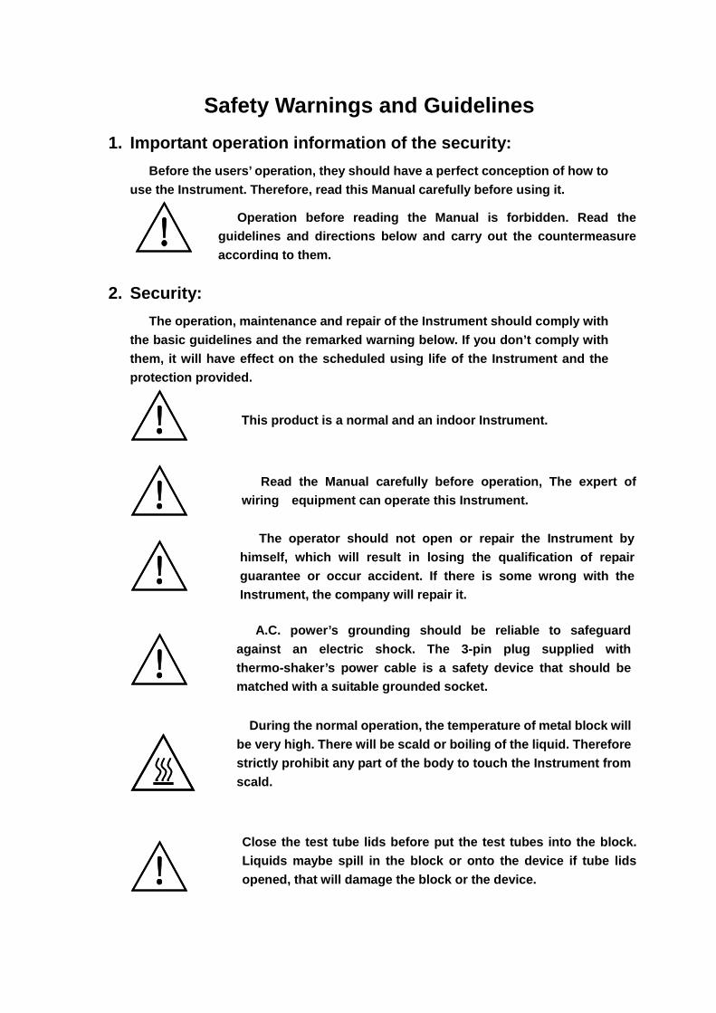
During the normal operation, the temperature of met al block will be very high. There will be scald or boiling of the liquid. Therefore strictly prohibit any part of the body to touch the Instrument from scald.
Close the test tube lids before put the test tubes into the block. Liquids maybe spill in the block or onto the device if tube lids opened, that will damage the block or the device.
3. The maintenance of Instrument
The well in the block should be cleaned by the clot h stained with alcohol to assure good heat translation between the block and the test tube and no pollution. If there are smutches on the Instrument, clean them with cloth.
Before power on, guarantee the voltage used should be accordant to the voltage needed, and the rated load of electrical outlet should not lower than the demand. If the ele ctric line is damaged, you should replace it with the same type. You should assure there’s nothing on the electric line and you should not put the electric line in the ambulatory place. Hold the jack when you pull out the electric line, and don’t pull the elec tric line.
The Instrument should be put in the place of low te mperature, little dust, no water and no sun or strong lamp. Wh at’s more, the place should be good aeration, no corrosively gas o r strong disturbing magnetic field, far away from central he ating, camp stove and other hot resource. Don't put the Instrum ent in wet and dusty place. The vent on the Instrument is designed for aeration. Don’t wall up or cover the vent in order to keep fr om high temperature. If you use the more than one Instrumen t the same time, the distance between them should be more than 100cm.
Power off when you finish your work. Pull off the c onnector plug when there’s long time no use of the Instrumen t and cover it with a cloth or plastic paper to prevent from dust.
Pull the connector plug from the jack at once in th e following case, and contact the vendor: � There is some liquid flowing into the Instrument; � Drenched or fire burned. � Abnormal operation: such as abnormal sound or smel l. � Instrument dropping or outer shell damaged. � The function has obviously changed.
Power off when cleaning the Instrument. When cleaning the well, don’t drop the cleaning liq uid in the well. Corrosive cleaning liquid is strongly prohibited.
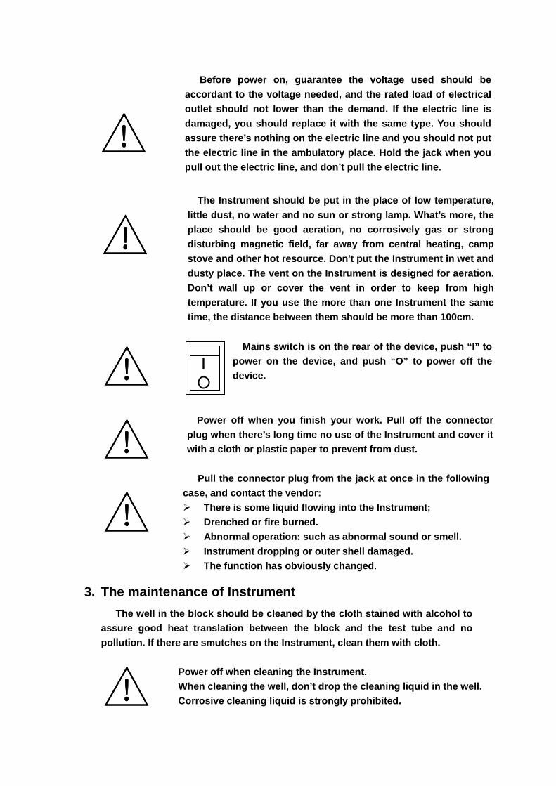
Mains switch is on the rear of the device, push “I” to power on the device, and push “O” to power off the device.
Contents
Chapter 1 Introduction ............................. ...............................................2
Chapter 2 Specifications........................... ..............................................2
1. The normal operating condition:................. .................................2
2. The basic parameters and the function........... ............................2
3. Insert Block……………………………………………………………..3
Chapter 3 Preparations ............................. ..............................................4
1. Structure Description........................... .......................................4
2. Installation…………………………………………………………….5 2.1 Installing gas distribution system…… ……………………...5 2.2 Installing the needles…………………………………… ……..6
3. Keyboard and display panel...................... .................................9
4. Key functions ................................... ...........................................9
Chapter 4 Operation Guide…………………………………………………10
1. Temperature and time set…………………………………………...10
2. Operation and Stop…………………………………………………..11
3. Temperature Calibration…………………………………………….12
4. The exchange of the metal block…………………………………..14
5. The exchange of the sealing pad…………………………………..15
Chapter 5 Failure analysis and troubleshooting..... ............................16
Annex 1 ::::Wiring Diagram for DBG-002/DBD-004 ................. .............17
DBG-002/DBD-004 Operations Manual Chapter 1 Introduction
1
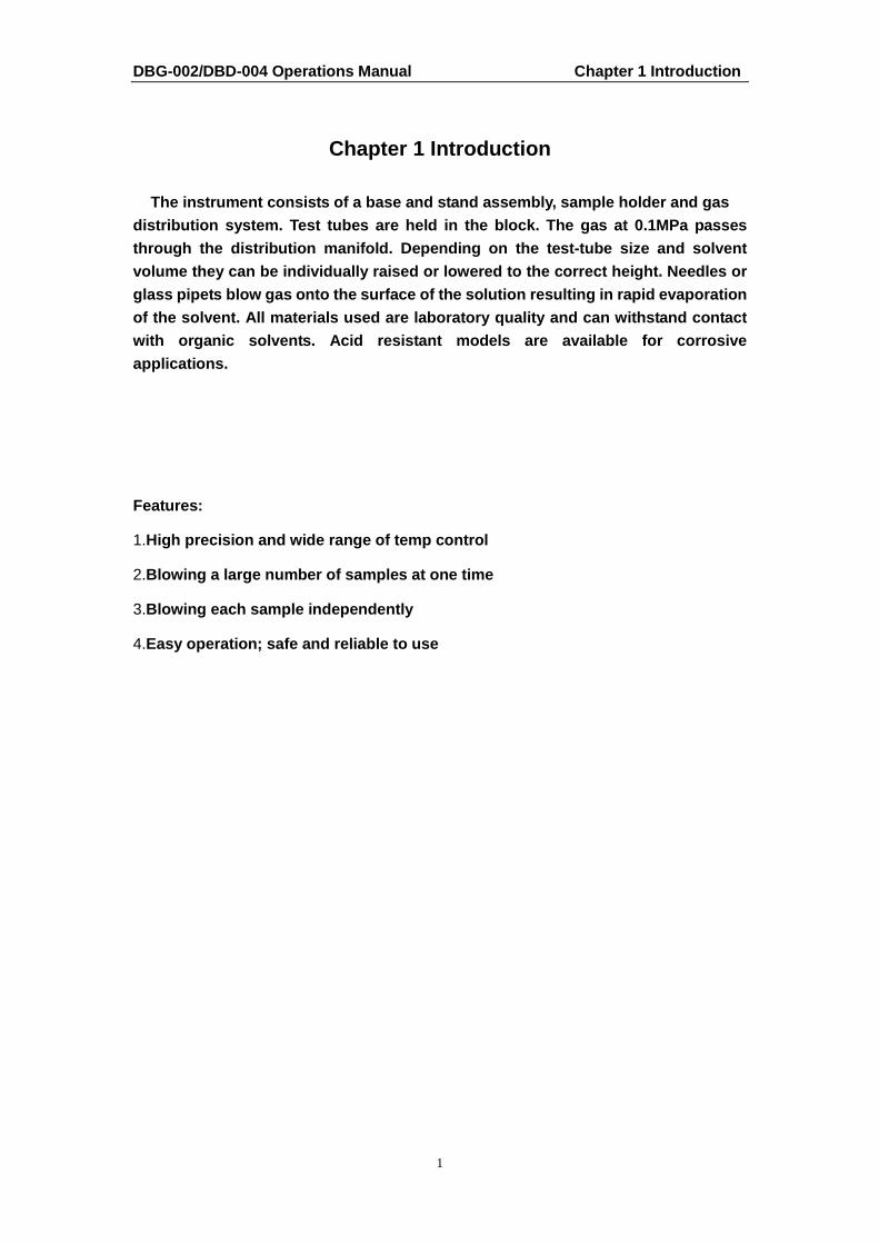
Chapter 1 Introduction
The instrument consists of a base and stand assembl y, sample holder and gas distribution system. Test tubes are held in the blo ck. The gas at 0.1MPa passes through the distribution manifold. Depending on the test-tube size and solvent volume they can be individually raised or lowered t o the correct height. Needles or glass pipets blow gas onto the surface of the solut ion resulting in rapid evaporation of the solvent. All materials used are laboratory q uality and can withstand contact with organic solvents. Acid resistant models are av ailable for corrosive applications.
Features:
1.High precision and wide range of temp control
2.Blowing a large number of samples at one time
3.Blowing each sample independently
4.Easy operation; safe and reliable to use

DBG-002/DBD-004 Operations Manual Chapter 2 Specifications
2
Chapter 2 Specifications
1. The normal operating condition:
Ambient temperature ::::5°°°°C ~~~~ 30°°°°C The relative humidity: ≤70% Power supply ::::220V~~~~ 2.0A 50-60Hz
2. Insert block
Type Tube diameter Capcity Dimension (mm)
301-1-111201 6mm 49 96X96X49
301-1-111202 7mm 49 96X96X49
301-1-111203 10mm 25 96X96X49
301-1-111204 12mm 25 96X96X49
301-1-111205 13mm 25 96X96X49
301-1-111206 15mm 12 96X96X49
301-1-111207 15mm 16 96X96X49
301-1-111208 16mm 12 96X96X49
301-1-111209 16mm 16 96X96X49
301-1-111210 19mm 12 96X96X49
301-1-111211 19mm 16 96X96X49
301-1-111212 20mm 9 96X96X49
301-1-111213 26mm 9 96X96X49
301-1-111214 28mm 4 96X96X49
301-1-111215 40mm 4 96X96X49
301-1-111216 0.5ml 49 96X96X49
301-1-111217 1.5ml 25 96X96X49
301-1-111218 2.0ml 25 96X96X49
DBG-002/DBD-004 Operations Manual Chapter 3 Preparations
4
Chapter 3 Preparations
This chapter is introduces Sample Concentrator’s me chanical structure, the
keyboard and each key’s functions and some preparat ions before power-on.
You should be familiar with this chapter before the Sample Concentrator is first
operated 。。。。
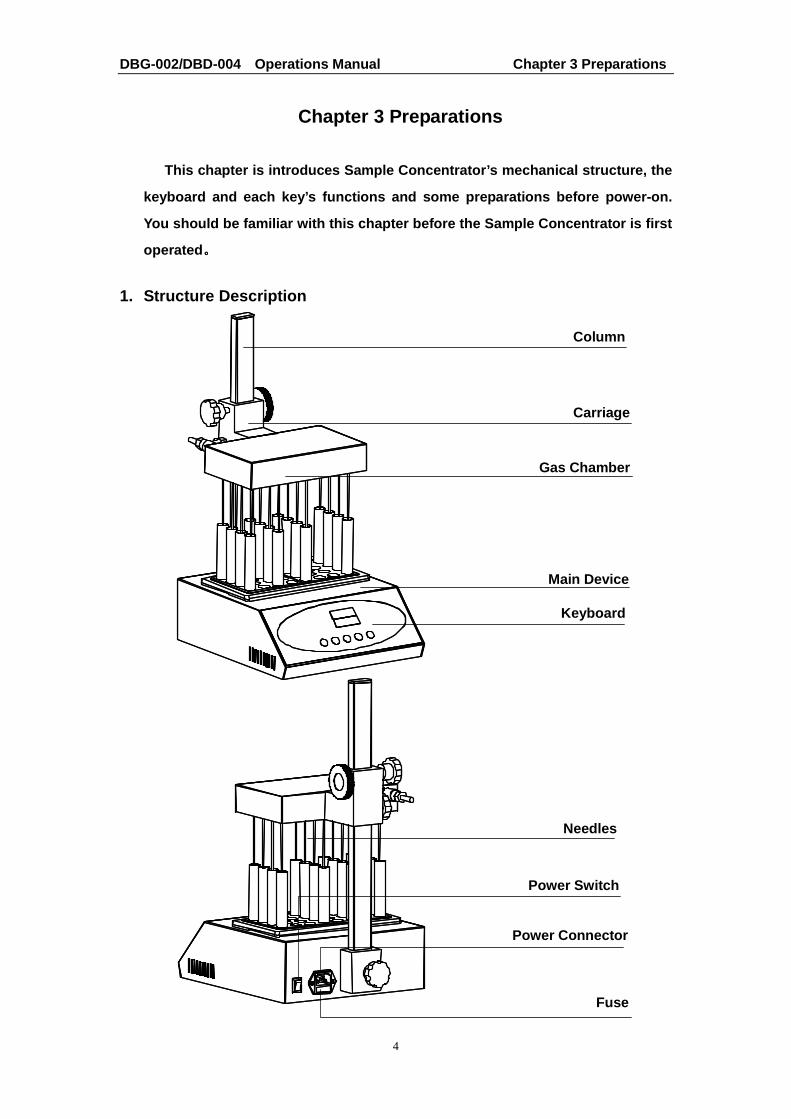
1. Structure Description
Column
Keyboard
Power Connector
Fuse
Power Switch
Carriage
Gas Chamber
Main Device
Needles
DBG-002/DBD-004 Operations Manual Chapter 3 Preparations
5
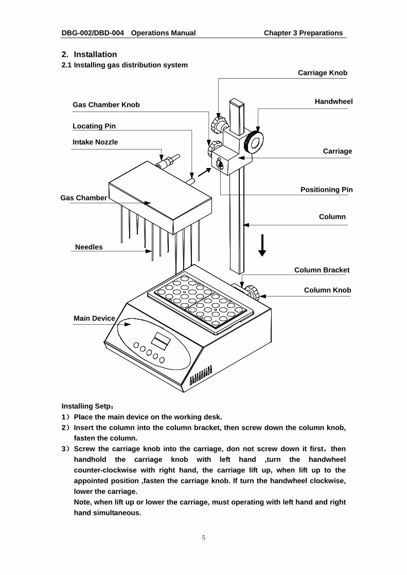
2. Installation 2.1 Installing gas distribution system Installing Setp ::::
1)))) Place the main device on the working desk. 2)))) Insert the column into the column bracket, then sc rew down the column knob,
fasten the column. 3)))) Screw the carriage knob into the carriage, don not screw down it first ,,,,then
handhold the carriage knob with left hand ,turn the handwheel counter-clockwise with right hand, the carriage lif t up, when lift up to the appointed position ,fasten the carriage knob. If tu rn the handwheel clockwise, lower the carriage. Note, when lift up or lower the carriage, must oper ating with left hand and right hand simultaneous.
Carriage Knob
Handwheel
Carriage
Positioning Pin
Column
Column Knob
Column Bracket
Main Device
Needles
Gas Chamber
Intake Nozzle
Locating Pin
Gas Chamber Knob
DBG-002/DBD-004 Operations Manual Chapter 3 Preparations
6
4)))) Screw gas chamber knob into the carriage, don not screw down it first ,,,,then insert the gas chamber onto the carriage, and faste n the gas chamber knob.
2.2 Installing the needles 1)))) Loosen the gas chamber knob ,,,,take out the gas chamber ,overturn the gas
chamber, and place the gas chamber on the working d esk.
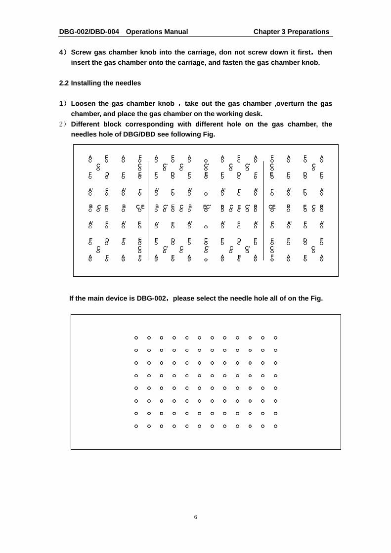
2) Different block corresponding with different hole o n the gas chamber, the needles hole of DBG/DBD see following Fig.
If the main device is DBG-002 ,,,,please select the needle hole all of on the Fig.
A'
AF AA
C
F
A'
D F
F A'
FF A
F
A'
C
E
F
D
C' C
F
D
A'
B
F
F A'
C E B
F
C
A F A
DE
B
F
A'F
C E
F
EC' C
A
C
F F
C' C
C'
FA
F
C'
E
C
F D
A' F
FFA A
F
C
E
A' F
F D
A' F
A
C
F
A'
C'
C'
DE
A'
B C'E
F
FA'
CB E
F
A
C' C
A F
DE
FA'
B CE
F
FA'
B E
F
A
C
F A F
A'
C B
F
C
A
A'
AF AA
C
F
A'
D F
F A'
FF A
F
A'
C
E
F
D
C' C
F
D
A'
B
F
F A'
C E B
F
C
A F A
DE
B
F
A'F
C E
F
EC' C
A
C
F F
C' C
C'
FA
F
C'
E
C
F D
A' F
FFA A
F
C
E
A' F
F D
A' F
A
C
F
A'
C'
C'
DE
A'
B C'E
F
FA'
CB E
F
A
C' C
A F
DE
FA'
B CE
F
FA'
B E
F
A
C
F A F
A'
C B
F
C
A

DBG-002/DBD-004 Operations Manual Chapter 3 Preparations
7
3)))) Needles hole label with different insert block
Block Type Tube Size Hole Label
301-1-111201 6mmX49 A, A’, B, D, E&F
301-1-111202 7mmX49 A, A’, B, D, E&F
301-1-111203 10mmX25 A, A’, D& E
301-1-111204 12mmX25 A, A’, D& E
301-1-111205 13mmX25 A, A’, D& E
301-1-111206 15mmX12 A & B
301-1-111207 15mmX16 A & A’
301-1-111208 16mmX12 A & B
301-1-111209 16mmX16 A & A’
301-1-111210 19mmX12 A & B
301-1-111211 19mmX16 A & A’
301-1-111212 20mmX9 C
301-1-111213 26mmX9 C
301-1-111214 28mmX4 D
301-1-111215 40mmX4 D
301-1-111216 0.5mlX49 A, A’, D, E&F
301-1-111217 1.5mlX25 A, A’, D& E
301-1-111218 2.0mlX25 A, A’, D& E
DBG-002/DBD-004 Operations Manual Chapter 3 Preparations
8
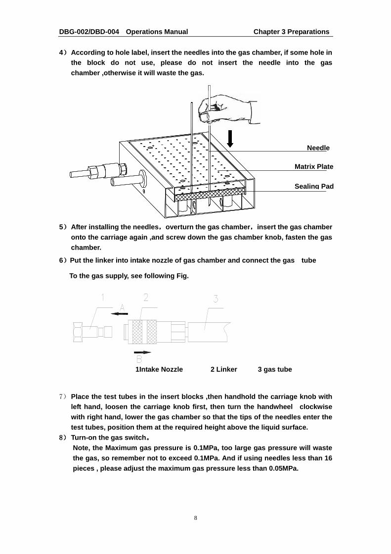
4)))) According to hole label, insert the needles into t he gas chamber, if some hole in the block do not use, please do not insert the need le into the gas chamber ,otherwise it will waste the gas.
5)))) After installing the needles ,,,,overturn the gas chamber ,,,,insert the gas chamber
onto the carriage again ,and screw down the gas cha mber knob, fasten the gas chamber.
6))))Put the linker into intake nozzle of gas chamber an d connect the gas tube
To the gas supply, see following Fig.
7) Place the test tubes in the insert blocks ,then han dhold the carriage knob with left hand, loosen the carriage knob first, then tur n the handwheel clockwise with right hand, lower the gas chamber so that the tips of the needles enter the test tubes, position them at the required height ab ove the liquid surface.
8888)))) Turn-on the gas switch 。。。。 Note, the Maximum gas pressure is 0.1MPa, too large gas pressure will waste the gas, so remember not to exceed 0.1MPa. And if u sing needles less than 16 pieces , please adjust the maximum gas pressure les s than 0.05MPa.
Needle
Matrix Plate
Sealing Pad
1Intake Nozzle 2 Linker 3 gas tube
DBG-002/DBD-004 Operations Manual Chapter 3 Preparations
9
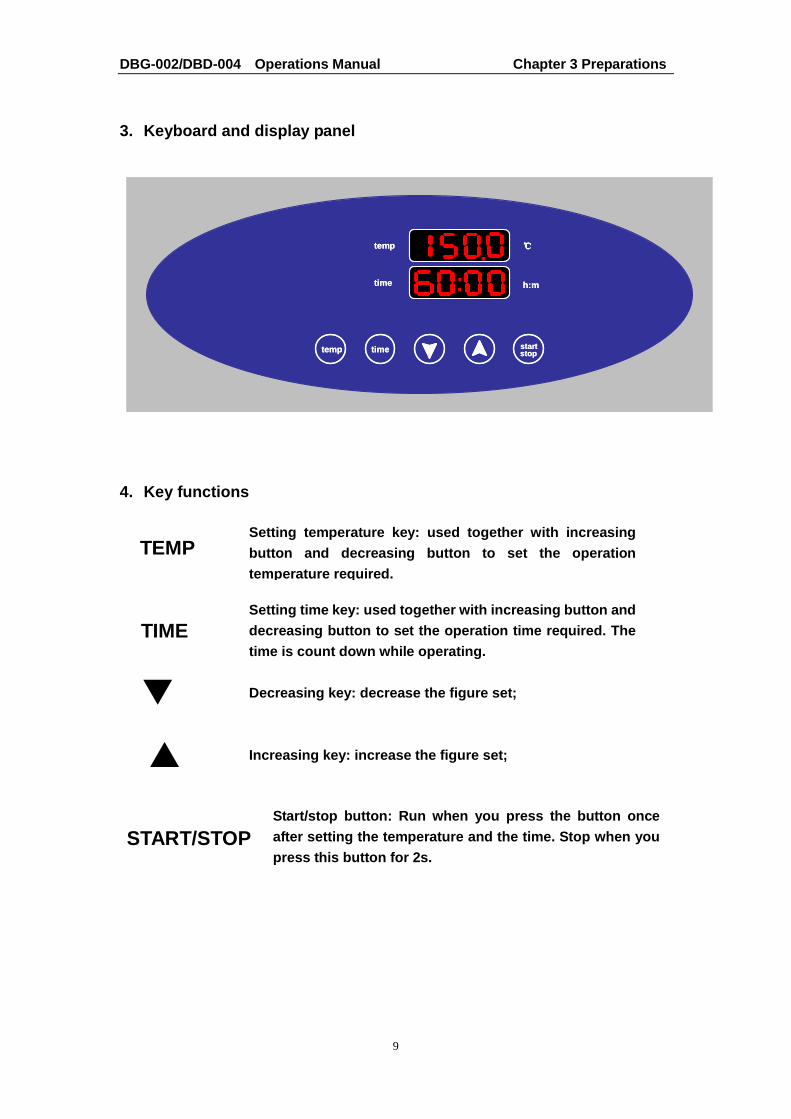
3. Keyboard and display panel
4. Key functions
TEMP
TIME
�
�
START/STOP
Setting temperature key: used together with increas ing button and decreasing button to set the operation temperature required.
Setting time key: used together with increasing but ton and decreasing button to set the operation time require d. The time is count down while operating.
Decreasing key: decrease the figure set;
Increasing key: increase the figure set;
Start/stop button: Run when you press the button on ce after setting the temperature and the time. Stop wh en you press this button for 2s.
temp
time
℃℃℃℃
h:m
temp time stopstart
temp
time
℃℃℃℃
h:m
temp time stopstart

DBG-002/DBD-004 Operations Manual Chapter 4 Operation Guide
10
Chapter 4 Operation Guide
1. Temperature and time set
a). The LED will display “ ” as the chart when the In strument
powers on and the Instrument goes into the initial state with
the sound of “du…”.
b). About 2s later, the figure 28.5 is the block’s current
temperature; 00:35 in the time display is the last set time.
c). Press the button of “TEMP” and keep off at once. No w, the
value in the temperature display is the former sett ing
temperature. As shown in the left drawing, the last digital of
the setting temperature is flickering. If you want to set the
temperature to 55.5 ℃,,,,do as follows:
The flickering digital can be changed. Press “ ����” or “ ����” to
turn “0”to“5”. Then press “TEMP”once and the flicke ring
digital skip to first one.
Pressing “TEMP”another time, then the flickering di gital skips
to the second one, and you can turn“4”to“5”by press ing “ ����”
Press “TEMP” a third time. After the flickering dig ital skip to
the third one, you can change “0”to“5”. Here the se tting
temperature is 55.5 ℃. The system will accept the new setting
temperature after 8s.
d). Press “TIME” and keep off at once, the value in the time
display is the former setting time. Shown in the le ft drawing is
00:35(35minites). At same time, the last digital is flickering. If
you want to change the time to 01:20, do as follows :
The flicker digital can be changed. Press “ ����” or “ ����” to chage
the last digital from “5” to “0”.
Press “TIME” once and the flickering digital skips to the first
one. Press “TIME” once more and the flickering dig ital skips
to the second one. Then press “ ����” to turn “0” to “1
DBG-002/DBD-004 Operations Manual Chapter 4 Operation Guide
11
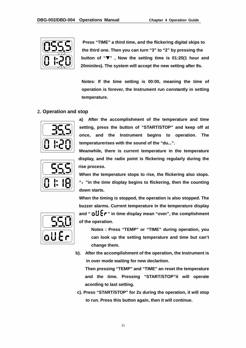
Press “TIME” a third time, and the flickering digit al skips to
the third one. Then you can turn “3” to “2” by pres sing the
button of “ ����” , Now the setting time is 01:20(1 hour and
20minites). The system will accept the new setting after 8s.
Notes: If the time setting is 00:00, meaning the ti me of
operation is forever, the Instrument run constantly in setting
temperature.
2. Operation and stop a) After the accomplishment of the temperature and time
setting, press the button of “START/STOP” and keep off at
once, and the Instrument begins to operation. The
temperaturerises with the sound of the “du...”.
Meanwhile, there is current temperature in the temp erature
display, and the radix point is flickering regularl y during the
rise process.
When the temperature stops to rise, the flickering also stops.
“::::”in the time display begins to flickering, then the counting
down starts.
When the timing is stopped, the operation is also s topped. The
buzzer alarms. Current temperature in the temperatu re display
and “ ” in time display mean “over”, the com plishment
of the operation.
Notes : Press “TEMP” or “TIME” during operation, yo u
can look up the setting temperature and time but ca n’t
change them.
b). After the accomplishment of the operation, the Instrument is
in over mode waiting for new declartion.
Then pressing “TEMP” and “TIME” an reset the temper ature
and the time. Pressing “START/STOP”it will operate
acording to last setting.
c). Press “START/STOP” for 2s during the operation, it will stop
to run. Press this button again, then it will conti nue.

DBG-002/DBD-004 Operations Manual Chapter 4 Operation Guide
12
3. Temperature Calibration
The temperature of the Instrument has been adjusted before it is sold out. But if there is deviation between the actual temperature a nd the displayed temperature due to some reasons, you can do as foll ows to correct the error. Notes: The Instrument uses double temperatures adju stment to ensure its veracity. This means it is linearly adjusted on 40 ℃ and 100℃ two points. The temperature veracity will be within ±0.5 ℃ after the double temperature adjustment. Both the circumstances and the block temperature sh ould be lower than 35 ℃.
Adjustment methods as follows: a). After the startup of the Instrument, it enters waiting interface. Make sure the
temperature in display is below 35 ℃. If the temperature is higher than 35 ℃, you should wait until the temperature is below 35 ℃.
b). Inject olefin oil into one of the cone-shaped w ells, and then put a thermometer
into this well (Make sure the precision of the ther mometer should be within 0.1 ℃ and the temperature ball should be absolutely immer ged into the cone-shaped well). Heat insulation material is needed on the bl ock to separate it from the circumstance. Seeing from Fig a.
Chart a
Fig a
Thermometer
Adiabatic Board
Olefin oil
cone-shaped
DBG-002/DBD-004 Operations Manual Chapter 4 Operation Guide
13
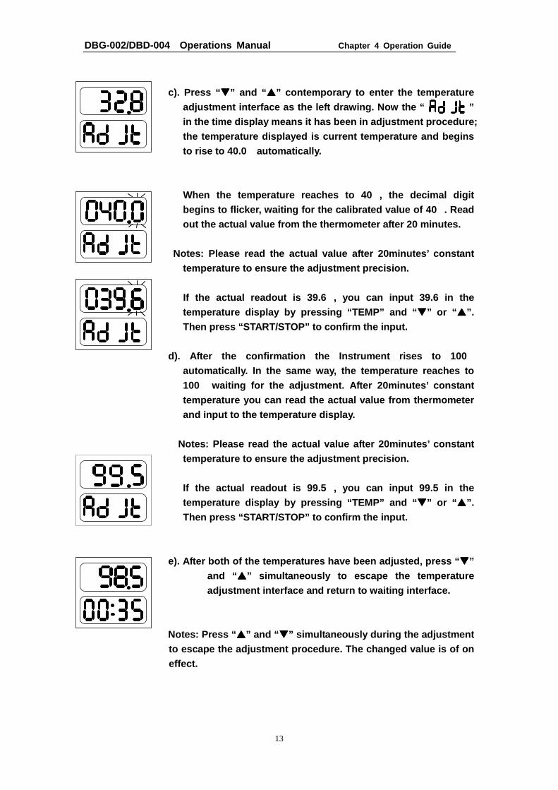
c). Press “ ����” and “ ����” contemporary to enter the temperature adjustment interface as the left drawing. Now the “ ” in the time display means it has been in adjustment procedure; the temperature displayed is current temperature an d begins to rise to 40.0 ℃ automatically.
When the temperature reaches to 40 ℃, the decimal digit begins to flicker, waiting for the calibrated value of 40℃. Read out the actual value from the thermometer after 20 minutes.
Notes: Please read the actual value after 20minute s’ constant
temperature to ensure the adjustment precision. If the actual readout is 39.6 ℃, you can input 39.6 in the
temperature display by pressing “TEMP” and “ ����” or “ ����”. Then press “START/STOP” to confirm the input.
d). After the confirmation the Instrument rises to 100℃
automatically. In the same way, the temperature rea ches to 100℃ waiting for the adjustment. After 20minutes’ const ant temperature you can read the actual value from ther mometer and input to the temperature display.
Notes: Please read the actual value after 20minut es’ constant
temperature to ensure the adjustment precision.
If the actual readout is 99.5 ℃, you can input 99.5 in the temperature display by pressing “TEMP” and “ ����” or “ ����”. Then press “START/STOP” to confirm the input.
e). After both of the temperatures have been adjust ed, press “ ����”
and “ ����” simultaneously to escape the temperature adjustment interface and return to waiting interfac e.
Notes: Press “ ����” and “ ����” simultaneously during the adjustment to escape the adjustment procedure. The changed val ue is of on effect.
DBG-002/DBD-004 Operations Manual Chapter 4 Operation Guide
14
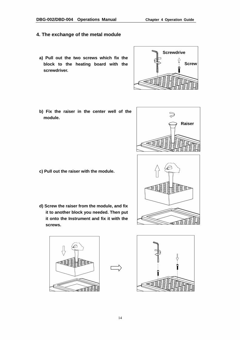
4. The exchange of the metal module
a) Pull out the two screws which fix the block to the heating board with the screwdriver.
b) Fix the raiser in the center well of the module.
c) Pull out the raiser with the module.
d) Screw the raiser from the module, and fix it to another block you needed. Then put it onto the Instrument and fix it with the screws.
Screw
Raiser
Screwdrive
DBG-002/DBD-004 Operations Manual Chapter 4 Operation Guide
15
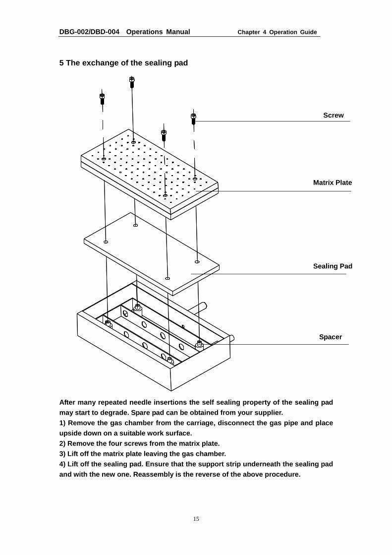
5 The exchange of the sealing pad
After many repeated needle insertions the self seal ing property of the sealing pad may start to degrade. Spare pad can be obtained fro m your supplier. 1) Remove the gas chamber from the carriage, discon nect the gas pipe and place upside down on a suitable work surface. 2) Remove the four screws from the matrix plate. 3) Lift off the matrix plate leaving the gas chambe r. 4) Lift off the sealing pad. Ensure that the suppor t strip underneath the sealing pad and with the new one. Reassembly is the reverse of the above procedure.
Screw
Matrix Plate
Sealing Pad
Spacer
DBG-002/DBD-004 Operations Manual ter 5 Failure analysis and troubleshooting
16
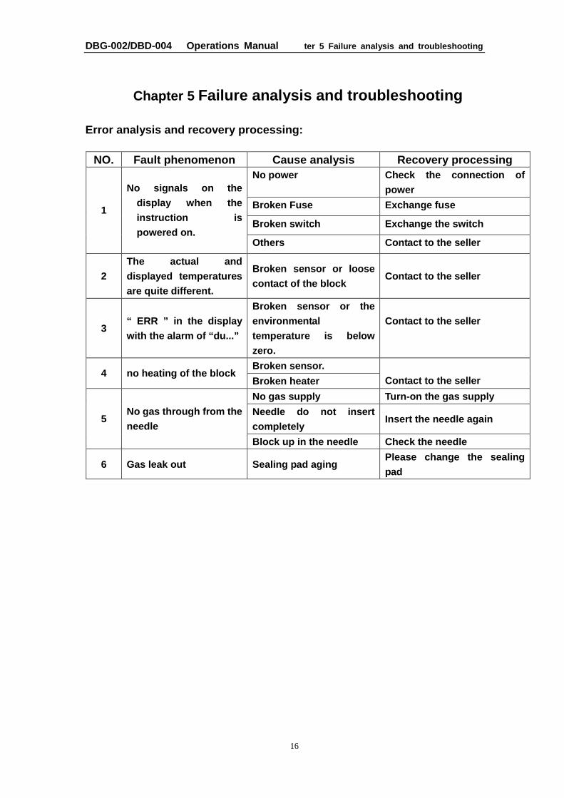
Chapter 5 Failure analysis and troubleshooting
Error analysis and recovery processing:
NO. Fault phenomenon Cause analysis Recovery processing No power Check the connection of
power
Broken Fuse Exchange fuse
Broken switch Exchange the switch 1
No signals on the display when the instruction is powered on.
Others Contact to the seller
2 The actual and displayed temperatures are quite different.
Broken sensor or loose contact of the block
Contact to the seller
3 “ ERR ” in the display with the alarm of “du...”
Broken sensor or the environmental temperature is below zero.
Contact to the seller
Broken sensor. 4 no heating of the block
Broken heater
Contact to the seller
No gas supply Turn-on the gas supply
Needle do not insert completely
Insert the needle again 5 No gas through from the needle
Block up in the needle Check the needle
6 Gas leak out Sealing pad aging Please change the sealing pad
DBG-002/DBD-004 Operations Manual Annex
17
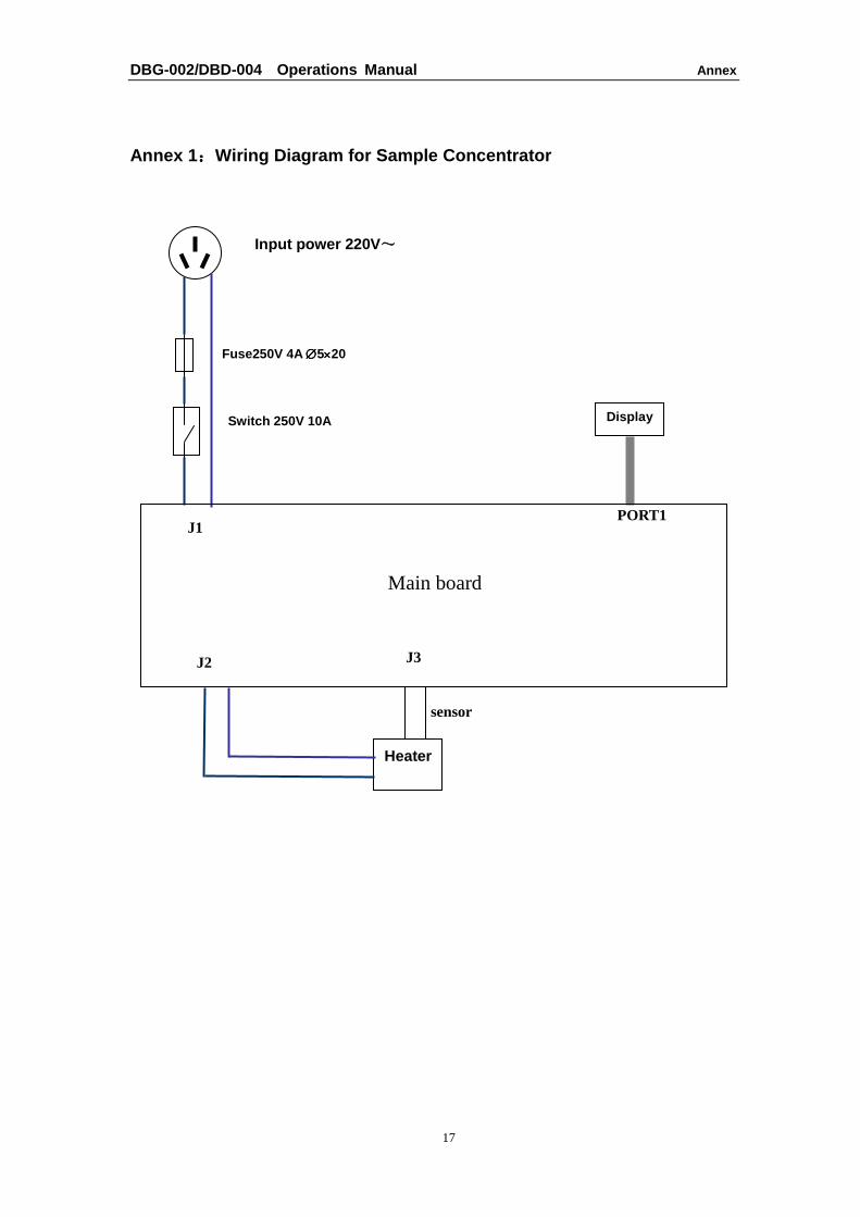
Annex 1 ::::Wiring Diagram for Sample Concentrator
Input power 220V ~~~~
Heater
Fuse250V 4A ∅∅∅∅5××××20
Switch 250V 10A
J2
Main board
PORT1
Display
J1
J3
sensor


