Embed Size (px)
Citation preview
National Park Service
U.S. Department of the Interior
I 29.86/4- S a <;
3 1604 019 613 795
Cultural Landscape Reportfor the Sandy HookCoastal Defense BatteriesGateway National Recreation Area

Digitized by the Internet Archive
in 2012 with funding from
LYRASIS Members and Sloan Foundation
http://archive.org/details/culturallandscapOOIayt
"New York City can be
satisfactorily defended, if
the outer defenses are
placed at Sandy Hook. .
.
"
Commander W. T.
Sampson, U. S. Navy,
Report ofthe Board on
Fortifications or Other
Defenses, 1886.
Cultural Landscape Reportfor the Sandy HookCoastal Defense Batteries
Gateway National Recreation Area
Fort Hancock, NewJersey
Site History
Existing Conditions
Analysis and Evaluation
Treatment
Prepared by
Timothy W. Layton, ASLA
Historical Landscape Architect
H. Eliot Foulds
Senior Project Manager
Olmsted Center for Landscape Preservation
National Park Service, Boston, Massachusetts, 2010

Cultural Landscape Report for the Sandy Hook Coastal Defense Batteries
The Olmsted Center for Landscape Preservation promotes the stewardship of significant
landscapes through research, planning, and sustainable preservation maintenance. The Center
accomplishes its mission in collaboration with a network of partners including national parks,
universities, government agencies, and private nonprofit organizations. Techniques and
principles of preservation practice are made available through training and publications.
Olmsted Center for Landscape Preservation
Boston National Historical Park
Charlestown Navy Yard, Quarters C
Boston, MA 02129
www.nps.gov/oclp/
Publication Credits: Graphics from sources other than federal repositories may not be
reproduced without the permission of the owners noted in the captions. Other information in
this publication may be copied and used with the condition that full credit be given to the authors
and publisher. Appropriate citations and bibliographic credits should be made for each use.
National Park Service, Denver Technical Information Center Report NPS 646/104869
Library of Congress Cataloging-in-Publication Data
Layton, Timothy W. (Timothy William), 1974-
Culrural landscape report for the Sandy Hook coastal defense batteries, Gateway National
Recreation Area / Timothy W. Layton, H. Eliot Foulds.
p. cm. — (National Park Service, Denver Technical Information Center report ; NPS
646/104869)
"Olmsted Center for Landscape Preservation, National Park Service"—T.p. verso.
Includes bibliographical references.
1. Sandy Hook Unit of Gateway National Recreation Area (N.J.)-Antiquities. 2. Gateway
National Recreation Area (N.J. and N.Y.)~Antiquities. 3. Coast defenses-New Jersey-Sandy
Hook Unit of Gateway National Recreation Area. 4. Batteries (Ordnance)-New Jersey—Sandy
Hook Unit of Gateway National Recreation Area—History. 5. Historic buildings—Conservation
and restoration—New Jersey—Sandy Hook Unit of Gateway National Recreation Area. 6.
Military architecture—New Jersey—Sandy Hook Unit of Gateway National Recreation Area. 7.
Landscape protection—New Jersey—Sandy Hook Unit of Gateway National Recreation Area. 8.
Sandy Hook Unit of Gateway National Recreation Area (N.J.)-History. 9. Sandy Hook Unit of
Gateway National Recreation Area (N.J.)-Management. 10. Sandy Hook (N.J.)—History,
Military. I. Foulds, H. Eliot, 1960- II. Olmsted Center for Landscape Preservation (U.S.) III. Title.
F142.G37L39 2010
974.9'46-dc22
2010033060
Cover Photograph: Detail of a color photograph of Fort Hancock's "Nine Gun" battery in
operation, circa 1940s. Gateway National Recreation Area Museum Collection #685.12
Title Page: Hercules missiles at the NIKE launch site, circa 1958. Gateway National Recreation
Area Museum Collection #8067

Table of Contents
TABLE OF CONTENTS
LIST OF ILLUSTRATIONS
FOREWORD x,x
ACKNOWLEDGMENTS XXI
INTRODUCTION 1
Project Methodology and Objectives 1
Project Setting and Geographic Scope 3
Summary of Findings 3
SITE HISTORY 7
Pre-History and European Contact-1859 7
Expansion of Coastal Defenses 1859-1919 35
Caretaker Status and World War II 1919-1945 81
NIKE Missile Systems and the Cold War 1945-1974 121
National Park Service Administration 1975-Present 161
EXISTING CONDITIONS 177
Physical Setting 178
Battery Urmston 179
Battery Morris 180
Batteries Engle and Peck 182
Nine Gun Battery 184
Battery Potter 186
Battery Granger 188
Mortar Battery 1 89
Battery Gunnison 191
Batteries Kingman and Mills 193
NIKE Radar Site 195
NIKE Launch Site 197
Existing Conditions Mapping 241
ANALYSIS AND EVALUATION 255
National Register Status 255
Statement of Significance 256
Evaluation of Integrity 257
Evaluation of Landscape Characteristics and Features 260
Cultural Landscape Report for the Sandy Hook Coastal Defense Batteries
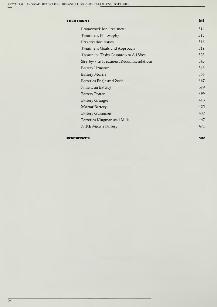
TREATMENT 313
Framework for Treatment 314
Treatment Philosophy 315
Preservation Issues 316
Treatment Goals and Approach 317
Treatment Tasks Common to All Sites 323
Site-by-Site Treatment Recommendations 343
Battery Urmston 343
Battery Morris 355
Batteries Engle and Peck 367
Nine Gun Battery 379
Battery Potter 399
Battery Granger 413
Mortar Battery 425
Battery Gunnison 437
Batteries Kingman and Mills 447
NIKE Missile Battery 471
REFERENCES 507

List of Illustrations
LIST OF ILLUSTRATIONS
FIGURES
INTRODUCTION
1 . 1 Gateway National Recreation Area Location Map 5
SITE HISTORY
2.1 Formation of Sandy Hook 19
2.2 Sandy Hook Lighthouse 19
2.3 A Plan of Fort Gates Erected on Sandy Hook, 1813 20
2.4 Spermaceti Cove Lifeboat Station, circa 1930 20
2.5 Detail of Sandy Hook from "Portions of Middletown and Ocean
Townships," in Beers, Comstock and Cline Atlas of Monmouth
County, New Jersey, 1873 21
2.6 Detail ofThe Port ofNew York: Birds Eye View From Battery,
Looking South 22
2.7 The Ordnance Department dock or wharf, circa 1900-10 22
2.8 Diagram of Sandy Hook landform, shipping channel, and Fort 23
2.9 View looking west at the Fort at Sandy Hook, circa 1880-85 24
2.10 Fort Sumter, South Carolina, September 8, 1863 24
2.11 Section of masonry fort and smooth-bore cannons 25
2.12 Section of disappearing gun in concrete and earth-shielded battery 25
2.13 Annotated isometric view of Battery Potter 26
2.14 Lift Gun Battery No. 1 at Sandy Hook, N.J.June 30, 1892 26
2.15 Battery Potter's north emplacement, September 12, 1892 27
2.16 Proposed Main Entrance to the Lift Gun Battery at Sandy Hook,
N.J., January 14, 1892 27
2.17 West elevation of Battery Porter, circa 1893 28
2.18 Four mortars mounted in a mortar pit, the Mortar Battery,
June 30, 1894 29
2.19 Illustration of projectile trajectory from the Mortar Battery 29
2.20 Plan for counterscarp gallery, 1895 30
2.21 Placing sand around the northwest mortar pit, the Mortar
Battery, 1893 30
2.22 Plan for concrete plant at the Mortar Battery, 1892 31
2.23 Plan of sand borrow pit and relationship to the Mortar Battery 3
1
2.24 HMS Dreadnought, circa 1906-07 55
2.25 Interior of Battery Potter plotting room, circa 1907 55
2.26 Battery commander's station for Fort Tilden's Battery Harris, 1927 56
2.27 View looking northeast at Battery Potter, circa 1906 56
Cultural Landscape Report for the Sandy Hook Coastal Defense Batteries
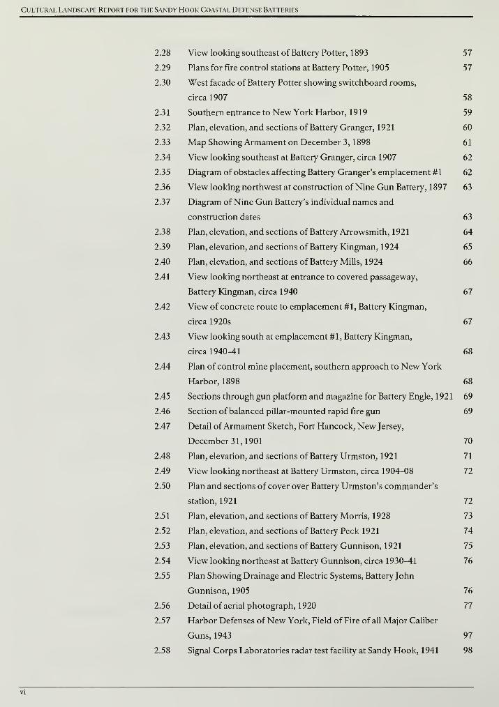
2.28 View looking southeast of Battery Potter, 1893 57
2.29 Plans for fire control stations at Battery Potter, 1905 57
2.30 West facade of Battery Potter showing switchboard rooms,
circa 1907 58
2.31 Southern entrance to New York Harbor, 1919 59
2.32 Plan, elevation, and sections of Battery Granger, 1921 60
2.33 Map Showing Armament on December 3, 1898 61
2.34 View looking southeast at Battery Granger, circa 1907 62
2.35 Diagram of obstacles affecting Battery Granger's emplacement #1 62
2.36 View looking northwest at construction of Nine Gun Battery, 1 897 63
2.37 Diagram of Nine Gun Battery's individual names and
construction dates 63
2.38 Plan, elevation, and sections of Battery Arrowsmith, 1921 64
2.39 Plan, elevation, and sections of Battery Kingman, 1924 65
2.40 Plan, elevation, and sections of Battery Mills, 1924 66
2.41 View looking northeast at entrance to covered passageway,
Battery Kingman, circa 1940 67
2.42 View of concrete route to emplacement #1, Battery Kingman,
circa 1920s 67
2.43 View looking south at emplacement #1, Battery Kingman,
circa 1940-41 68
2.44 Plan of control mine placement, southern approach to New York
Harbor, 1898 68
2.45 Sections through gun platform and magazine for Battery Engle, 1921 69
2.46 Section of balanced pillar-mounted rapid fire gun 69
2.47 Detail ofArmament Sketch, Fort Hancock, New Jersey,
December 31, 1901 70
2.48 Plan, elevation, and sections of Battery Urmston, 1921 71
2.49 View looking northeast at Battery Urmston, circa 1904-08 72
2.50 Plan and sections of cover over Battery Urmston's commander's
station, 1921 72
2.51 Plan, elevation, and sections of Battery Morris, 1928 73
2.52 Plan, elevation, and sections of Battery Peck 1921 74
2.53 Plan, elevation, and sections of Battery Gunnison, 1921 75
2.54 View looking northeast at Battery Gunnison, circa 1930-41 76
2.55 Plan Showing Drainage and Electric Systems, Battery John
Gunnison, 1905 76
2.56 Detail of aerial photograph, 1920 77
2.57 Harbor Defenses ofNew York, Field of Fire of all Major Caliber
Guns, 1943 97
2.58 Signal Corps Laboratories radar test facility at Sandy Hook, 1941 98
List of Illustrations
2.59 Harbor Defenses ofNew York, Area of Detection of SCR Units &
Primary Assignments, 1943 99
2.60 Elevation of SCR-682 radar installation, 1 944 1 00
2.61 Elevation ofSCR-296 radar installation, 1943 100
2.62 Location of Firing Tracks, 1931 101
2.63 8-inch caliber railway artillery, circa 1939 101
2.64 Detail of plan showing railroad spurs for mobile artillery, 1944 102
2.65 Collapsible searchlight on railway car, no date 102
2.66 Construction of cantonments at Camp Low, circa 1940 103
2.67 Harbor Defenses of New York, Underwater Defenses New York
Harbor and Vicinity, 1943 104
2.68 Plan of anti-aircraft guns on top of the Mortar Battery, 1944 105
2.69 View looking southwest at anti-aircraft gun on top of the Mortar
Battery, circa 1941 105
2.70 Plan and section of switchboard for fire control
communications, 1936 106
2.71 Room assignments for the Harbor Defense Command Post at the
Mortar Battery, circa 1 943 106
2.72 View looking southeast at the Mortar Battery, 1 943 107
2.73 Elevation and plan for fire control station serving Batteries Kingman
and Mills, 1922 107
2.74 Elevation and plan for fire control station serving Battery
Harris, 1927 108
2.75 View of the fire control tower for Battery Harris, circa 1940 108
2.76 Plan of casemated guns at Battery Kingman, 1944 109
2.77 Plan of casemated guns at Battery Mills, 1944 110
2.78 Section through Battery Kingman's emplacement #2, 1944 111
2.79 Plan of power room at Battery Kingman, 1944 111
2.80 Coincidence range finding station for Battery Peck constructed on
Battery Engle, 1927 112
2.81 Open battery commander's station at Battery Peck, circa 1905-10 113
2.82 Covered battery commander's station at Battery Peck, 192
1
113
2.83 New 90 mm - Battery No. 8 (Old Battery Peck), circa 1943 1 14
2.84 Plan for relocating Battery Urmston's guns, circa 1942 115
2.85 Plan for coincidence range finding station at Battery Morris, 1921 115
2.86 View looking northwest at coincidence range finder station east
of Battery Morris, circa 1921 116
2.87 New Battery Peck, Alterations & Additions (Old Battery
Gunnison), 1943 117
2.88 Detail of Fort Hancock Map, 1944 118
2.89 NIKE Ajax missile flight diagram 1 3
5
2.90 Warhead location in NIKE Ajax missile 135
Cultural Landscape Report for the Sandy Hook Coastal Defense Batteries
2.91 "NIKE" Project, Topographical Plan Between Control and
Launching Areas, 1954 136
2.92 "NIKE" Project, Profile Between Control and Launch Area, 1954 137
2.93 Overlay of NIKE sites and 1945 Period Plan 138
2.94 "NIKE" Project, Control Area Site Plan, 1954 139
2.95 Detail of acquisition radar and control trailers, "NIKE" Project,
Control Area Site Plan, 1954 140
2.96 Detail of visual cones to bore sighting mast, "NIKE" Project,
Control Area Site Plan, 1954 141
2.97 Detail of proposed walk to bore sighting mast, Special AAA
Facilities, Site Plan and Water Line, 1955 142
2.98 Section of perimeter fence, "NIKE" Project, Control Area Site
Plan, 1954 143
2.99 Limit of vegetation clearing, "NIKE" Project, Control Area Site
Plan, 1954 144
2.100 Pole-mounted light fixtures, "NIKE" Project, Control Area Electrical
Distribution Plan, 1954 145
2.101 Detail of basketball court, "NIKE" Project, Control Area Electrical
Distribution Plan, 1954 146
2.102 Battery Control Area Site Plan, NIKE Missile Base SL-40, Monroe
County, Illinois 146
2. 103 Detail of HIPAR radar installations, Site Plan, Control Area, Fort
Hancock, 1962 147
2.104 Site Plan, Control Area, Fort Hancock, 1962 148
2.105 Overall site configuration of NIKE launch site, 1962 149
2.106 Engineered plateau, "NIKE" Project, Launching Area, Launching
Area Site Plan 150
2.107 Detail of perimeter fence and firebreak, "NIKE" Project, Launching
Area, Launching Area Site Plan 151
2.108 Detail of earth mounds in Missile Maintenance Area, "NIKE"
Project, Launching Area, Launching Area Site Plan 151
2.109 Missile Assembly and Test Building and Warheading Area, Site
Plan; Paving and Sewage Disposal, 1958 152
2.110 Detail of missile dolly walk, Missile Assembly and Test Building
and Missile Maintenance Area, Site Plan; Paving and Sewage
Disposal, 1958 153
2.111 Detail of floodlight, Launching Area Plan, Electrical, 1958 153
2.112 Detail of floodlights along inner perimeter fence, Launching Area
Plan, Electrical, 1958 154
2.113 NIKE sentry dog 155
2.114 Launch Area Site Plan, NIKE Missile Base SL-40, Monroe
County, Illinois 155
List of Illustrations
2.115 Proposed and revised kennel locations, Launching Area Plan,
Electrical, 1958 156
2.116 View looking north at New Jersey State Park entrance, 1967 157
2.117 View looking northwest at beach usage, 1967 157
2.118 Map of leased land, 1967 158
2.119 Development Concept Sandy Hook / South Beach 165
2.120 Multi-use path map 166
2.121 Map of partner facilities 167
2.122 Detail of Harbor Defenses of New York, Battery Gunnison,
Alterations and Additions, Fort Hancock, New Jersey, 1 943 1 67
EXISTING CONDITIONS
3.1 View looking west at gun platform #5, Battery Urmston 203
3.2 View looking northeast at stairwells to magazines, Battery Urmston 203
3.3 View looking northwest at gun platform #3, Battery Urmston 204
3.4 View looking northeast from gun platform #4, Battery Urmston 204
3.5 View looking west at U. S. Coast Guard fence and Battery Morris 205
3.6 View looking north at emplacement #2, Battery Morris 205
3.7 View looking southeast, Battery Morris 206
3.8 View looking northeast at gun platform #1, Battery Morris 206
3.9 View looking northeast at corner of structure, Battery Peck 207
3.10 View of guardrail south of emplacement #1, Battery Peck 207
3.11 View looking northwest at Battery Engle (CRF Station Peck) 208
3.12 View looking north at a post World War II trailer, Batteries Engle
and Peck 208
3.13 View looking northeast at observation platform 209
3.14 View looking northwest at Battery Peck 209
3.15 Diagram of Nine Gun Battery's individual names and
construction dates 210
3.16 Granite blocks northeast of emplacement #8, Nine Gun Battery 210
3.17 View of failing metal door, Nine Gun Battery 211
3.18 View looking west at battery commander's station Halleck,
Nine Gun Battery 211
3.19 View looking south at existing guardrail, Nine Gun Battery 212
3.20 View looking northwest at the concrete ramp to gun platform #1,
Nine Gun Battery 212
3.21 View looking west toward battery commander's station
Bloomfield, Nine Gun Battery 213
3.22 View looking west at emplacement #7, Nine Gun Battery 213
3.23 View looking north at main entry, Battery Potter 214
3.24 View looking west at entry to parking area, Battery Potter 214
3.25 View looking northeast across superior slope, Battery Potter 215

Cultural Landscape Report for the Sandy Hook Coastal Defense Batteries
3.26 View looking north across chemin de ronde, Battery Potter 215
3.27 Fire control stations, Battery Potter 216
3.28 View looking northwest at concrete pillars, Battery Potter 216
3.29 View looking south at guardrails, Battery Potter 217
3.30 View looking north across terreplein, Battery Potter 217
3.31 View looking northwest at metal pole, Battery Potter 218
3.32 View looking northeast at foundation, Hudson Drive, and
Battery Potter 218
3.33 View looking east from access stairs, Battery Potter 219
3.34 View looking east at the chemin de ronde, Battery Potter 219
3.35 Close-up view of concrete terreplein, Battery Granger 220
3.36 View looking northwest at engineered slope, Battery Granger 220
3.37 View looking west across southwest mortar pit, the Mortar Battery 221
3.38 View looking north along perimeter wall, the Mortar Battery 221
3.39 View looking northeast at toe of engineered earthwork, the
Mortar Battery 222
3.40 View near top of southwest mortar pit, the Mortar Battery 222
3.41 View looking east at wayside, the Mortar Battery 223
3.42 View looking northeast at emplacement #2, Battery Gunnison 223
3.43 View looking north from emplacement #1 to emplacement #2,
Battery Gunnison 224
3.44 View looking southeast at emplacement #2, Battery Gunnison 224
3.45 View looking south at eroded vehicular route, Battery Mills 225
3.46 View looking northeast at Battery Kingman 225
3.47 View looking east at entry to emplacement #1, Battery Mills 226
3.48 View looking southwest at emplacement #2, Battery Kingman 226
3.49 View looking west at emplacement #2, Battery Mills 227
3.50 View looking north from the top of Battery Kingman 227
3.51 Concrete pipe, Battery Kingman 228
3.52 View looking northwest from the top of Battery Mills 228
3.53 Concrete pipe, Battery Mills 229
3.54 View looking south from the top of Battery Kingman 229
3.55 Scrub pine south of emplacement #1, Battery Mills 230
3.56 Post and wire fence, Battery Kingman 230
3.57 View looking east at collapsed wood guardrail, Battery Kingman 231
3.58 View looking east at wood guardrail, Battery Mills 231
3.59 View looking southeast from vehicular route to Control Area #1,
NIKE radar site 232
3.60 View looking north at walkway, Control Area #2, NIKE radar site 232
3.61 View looking north at HIPAR foundation, NIKE radar site 233
3.62 View looking north along walkway to Ready Barracks, NIKE
radar site 233
List of Illustrations
3.63 View looking northwest at the Ready Barracks, NIKE radar site 234
3.64 View looking west at elevator to missile magazine (425), NIKE
launch site 234
3.65 View looking west along central access road, NIKE launch site 235
3.66 View looking south at engineered earthwork, NIKE launch site 235
3.67 View looking north at firearms range, NIKE launch site 236
3.68 View looking southeast at engineered earthwork, NIKE
launch site 236
3.69 Outer fence, NIKE launch site 237
3.70 Outer fence, NIKE launch site 237
3.71 Floodlight, NIKE launch site 238
3.72 Spotlights, NIKE launch site 238
3.73 View looking east at antenna, NIKE launch site 239
3.74 View looking northeast at antenna, NIKE launch site 239
ANALYSIS AMD EVALUATION
4.1 The Fort Hancock and Sandy Hook Proving Ground Historic
District, 1980 297
4.2 View looking east at the south earthwork, Missile Maintenance Area,
NIKE launch site 298
4.3 Railroad tracks crossing asphalt road near Nine Gun Battery 298
4.4 View looking northwest at Battery Kingman 299
4.5 Conceptual section through a disappearing gun battery 300
4.6 Blue print map showing construction of gravel roads at Ft. Hancock,
N.J., August 31, 1907 301
4.7 Oblique aerial photograph of Nine Gun Battery, 1942 301
4.8 View looking southeast at artillery firing, Battery Richardson, Nine
Gun Battery, circa 1 905-10 302
4.9 View looking north at Battery Potter, 1951 302
4.10 View looking northeast at emplacement #1, Battery Granger, 1899 303
4.11 View looking northwest at trail north of the Mortar Battery 303
4.12 Aerial photograph of Battery Gunnison, 1962 304
4.13 View looking north from emplacement #1 at commander's station,
shell hoist, and central structure, Battery Gunnison, circa 1940 304
4.14 View looking northeast at central structure, Battery Gunnison, 1956 305
4.15 Aerial photograph of Batteries Kingman and Mills, 1 962 305
4.16 Oblique aerial of the NIKE radar site, circa 1962 306
4.17 View looking northwest at pedestrian walkway, Control Area # 1
,
NIKE radar site 306
4.18 View looking west at target tracking radars (417 and 473), Control
Area # 1 , NIKE radar site, circa 1962 307

Cultural Landscape Report for the Sandy Hook Coastal Defense Batteries
4.19 View looking northwest at the Missile Magazines, NIKE launch
site, circa 1958 307
4.20 View from Hartshorne Drive looking east at Ready Barracks,
NIKE launch site, circa 1958 308
4.21 View looking east at the Missile Magazines and Missile Maintenance
Area, circa 1958 308
4.22 Site plan for Missile Maintenance Area, 1958 309
4.23 "NIKE" Project, Launching Area, Access Road to Launching Area 309
4.24 Aerial view of the Ready Barracks, NIKE launch site, circa 1958 310
4.25 View looking northeast at the Missile Magazines, NIKE launch site,
circa 1968 310
4.26 View looking northeast at access gate to Missile Magazines and
Missile Maintenance Area, NIKE launch site 311
4.27 Aerial photograph of the NIKE launch site, 1962 311
4.28 View looking southeast across Missile Magazines, NIKE launch site 312
TREATMENT
5.
1
Aerial photograph of Sandy Hook landform, 2006 319
5.2 Mobile railway gun, circa 1939-40 320
5.3 Collapsible railway searchlight, no date 320
5.4 View looking northwest at Battery Arrowsmith 321
5.5 Sand being hauled into place in front of the terreplein, Nine Gun
Battery, 1928 335
5.6 Storm-thrown tree, Union Fort Fisher, Petersburg National
Battlefield 335
5.7 Ailanthus stump at Battery Mills 336
5.8 Application of triclopyr herbicide to a cut stump 336
5.9 View looking northwest across gun platform #4, Battery Urmston 337
5.10 Concrete separation at unreinforced steps 337
5.11 View east from south gun platform, Battery Gunnison 338
5.12 View looking west at safety railings, Battery Granger 338
5.13 Example of the infill approach to retrofitting railing systems 339
5.14 Cross-section, new railing installation 339
5.15 Safety railing infill elevations 340
5.16 Off-site repair of historic metal door for Battery Worth, Fort
Casey, Washington 340
5.17 Typical revegetation detail to close an existing social trail 341
5.18 Typical repair of spalling concrete surface 341
5.19 Typical concrete cracks 342
5.20 Oblique aerial view of Nine Gun Battery, 1942 342
5.21 View looking northeast at Battery Urmston, circa 1900 349
5.22 View looking west at gun platforms #5 and #6, Battery Urmston 349

List of Illustrations
5.23 View looking northwest, Battery Urmston, circa 1906 350
5.24 View looking east toward water from Battery Urmston 350
5.25 U. S. Coast Guard perimeter fence south of batteries
Urmston and Morris 351
5.26 Existing historic safety railing at Battery Urmston 351
5.27 View looking down at gun platform #5, Battery Urmston 352
5.28 Aerial photograph of Batteries Urmston and Morris, January 1933 352
5.29 Coincidence range finder station, Battery Morris, circa 1920 361
5.30 View looking northeast at Battery Morris 361
5.31 Large hackberry growing on top of Battery Morris 362
5.32 View looking northwest at south facade, Battery Morris 362
5.33 Wood guard panels at Battery Morris 363
5.34 Wood picket fence on top of Battery Morris 363
5.35 Batteries Engle and Peck circa 1920 373
5.36 View looking northwest at Battery Engle (CRF Station Peck) 373
5.37 Blocked downrange view looking northwest from the Battery Peck
battery commander's station 374
5.38 View looking northwest at Battery Peck, circa 1905-10 374
5.39 View looking northwest at Battery Peck 375
5.40 View of historic guardrail south of emplacement #1, Battery Peck 375
5.41 View of northwest facade of Battery Peck's commander station 376
5.42 View looking north at a post World War II trailer located near
Batteries Peck and Engle 376
5.43 Aerial photograph of Nine Gun Battery, January 1933 389
5.44 View looking west toward battery commander's station Bloomfield,
Nine Gun Battery 389
5.45 Conceptual section through Nine Gun Battery 390
5.46 View of phragmites in gun well #6, Nine Gun Battery 391
5.47 View of failing metal door, Nine Gun Battery 391
5.48 View of shell hoist metal door, Nine Gun Battery 392
5.49 View looking northwest at the concrete ramp to gun platform #1,
Nine Gun Battery 392
5.50 Conceptual section through Nine Gun Battery and boardwalk 393
5.51 Detail section of decking and handrails, Nine Gun Battery 393
5.52 Aerial photograph of Nine Gun Battery, January 1933 394
5.53 View of extant railroad track, Nine Gun Battery 394
5.54 Construction of Nine Gun Battery, 1897 395
5.55 Site plan of Fort Hancock, 1967 395
5.56 Portion of northeast curtain wall belonging to former granite fort 396
5.57 View looking southeast at Battery Potter, 1893 407
5.58 View looking north at defensible main entry, Battery Potter 407
5.59 View looking east at the chemin de ronde, Battery Potter 408
Cultural Landscape Report for the Sandy Hook Coastal Defense Batteries
5.60 Conceptual section through Battery Potter 409
5.61 Recently installed contemporary safety railing, Battery Potter 410
5.62 Plotting rooms, Battery Potter 410
5.63 Battery Granger, circa 1900 419
5.64 View looking north at emplacement #1 and battery commander's
station, Battery Granger 419
5.65 Aerial photograph of Battery Granger, January 1933 420
5.66 View looking northwest at engineered slope to rear of
Battery Granger 420
5.67 View looking southeast at Battery Granger 421
5.68 Blocked view northeastward from the battery commander's station
at Battery Granger 42
1
5.69 Existing safety railings, Battery Granger 422
5.70 Close-up view of existing concrete terreplein, Battery Granger 422
5.71 Oblique aerial photograph of the Mortar Battery, circa 1917, taken
from an Army Signal Corps balloon 43
1
5.72 View looking northwest above mortar pit, the Mortar Battery 43
1
5.73 View looking northeast along interior trail, the Mortar Battery 432
5.74 View looking northwest along interior trail, the Mortar Battery 432
5.75 View looking southeast at concrete glacis, the Mortar Battery 433
5.76 View looking northwest at trail north of the Mortar Battery 433
5.77 Battery Gunnison, circa 1941 prior to converting the battery to
barbette mounted guns 443
5.78 View looking northeast at emplacement #2, Battery Gunnison 443
5.79 View looking north of gun emplacements at Batteries Kingman
and Mills 459
5.80 View looking southwest at gun emplacement, Battery Kingman,
circa 1940s 459
5.81 View looking northeast at Battery Kingman engineered landform 460
5.82 View looking south atop of the engineered slope, Battery Kingman 460
5.83 North gun emplacement, Battery Kingman, circa 1940s 461
5.84 View looking northwest at the south gun emplacement,
Battery Kingman 461
5.85 View looking southwest at north gun emplacement,
Battery Kingman 462
5.86 Concrete pipe on north slope of Battery Kingman 462
5.87 Installation of cap over concrete pipe and ABS plastic
ventilation cap 463
5.88 Animal burrow on north slope of Battery Kingman 463
5.89 View looking east at southern end of Battery Mills 464
5.90 View looking east at a bulkhead entry, Battery Mills 464
5.91 Japanese knotweed growing on western side of Battery Mills 465

List of Illustrations
5.92 Injection tool for delivering herbicide to Japanese knotweed 465
5.93 Concrete pipe on southern slope of Battery Mills 466
5.94 Eroded loop road on western side of Battery Mills 466
5.95 View looking northeast at the western side of Battery Mills,
circa 1950s 467
5.96 View looking northwest at the missile magazines, NIKE launch site,
circa 1958 489
5.97 Oblique aerial view, NIKE radar site, circa 1 962 489
5.98 View looking southeast at the Generator Building (414), Control
Area #1, NIKE radar site 490
5.99 View looking northwest at pedestrian walkway, Control Area #1,
NIKE radar site 490
5.100 View looking southeast at engineered earthwork, NIKE launch site 491
5.101 View looking north at the firearms range, NIKE launch site 491
5.102 View looking northeast at CODAR antenna, NIKE launch site 492
5.103 View looking west at target tracking radars (417 and 473), Control
Area #1, NIKE radar site, circa 1962 492
5.104 View looking north of sidewalk from Control Area #2 to the Ready
Barracks, NIKE radar site 493
5.105 Existing perimeter fence, NIKE launch site 493
5. 106 Plan of proposed access stairs to acquisition radar tower (Building
421), NIKE radar site 494
5.107 Existing expanded metal mesh on guardrails at radar tower, NIKE
radar site 494
5.108 Plan of the Ready Barracks, NIKE radar site, 1962 495
5.109 Section of the perimeter fence, NIKE radar site, 1954 495
5.110 Existing light fixture, NIKE radar site 496
5.111 Existing light fixture between building 404 and 405, NIKE radar site 496
5.112 View looking northeast at the missile magazines, NIKE launch site,
circa 1968 497
5.113 View looking northwest toward Ready Barracks, NIKE launch site 497
5.1 14 Oblique aerial view of the Ready Barracks, NIKE launch site,
circa 1958 498
5.115 View looking northwest at the kennel buildings, NIKE launch site 498
5.116 View looking southeast at Missile Maintenance Area historic
earthwork, NIKE launch site 499
5.117 View looking east at the missile magazines, NIKE launch site 499
5.118 Site plan for Missile Maintenance Area, 1958 500
5.119 View looking east at Missile Maintenance Area historic earthwork,
NIKE launch site 500
5.120 View looking southeast at Missile Maintenance Area historic
earthwork, NIKE launch site 501
Cultural Landscape Report for the Sandy Hook Coastal Defense Batteries
5.121 View looking northwest at Warhead Building (450), NIKE
launch site 501
5.122 View looking northeast across missile magazines, NIKE
launch site 502
5.123 Elevation of floodlight, NIKE launch site, 1958 502
5.124 Plan for reconfigured visitor parking lot, NIKE launch site 503
5.125 View looking northwest toward the Ready Barracks, NIKE
launch site 503
5.126 Example of a cut and cover tunnel, Minute Man National
Historical Park 504
TABLES
ANALYSIS AND EVALUATION
4.1 Battery Urmston
4.2 Battery Morris
4.3 Batteries Engle and Peck
4.4 Nine Gun Battery
4.5 Battery Potter
4.6 Battery Granger
4.7 Mortar Battery
4.8 Battery Gunnison
4.9 Battery Kingman
4.10 Battery Mills
4.11 NIKE Radar Site
4.12 NIKE Launch Site
268
270
272
274
276
279
280
282
284
286
288
291
TREATMENT
5.1 Summary of Treatment Recommendations, Battery Urmston 348
5.2 Summary of Treatment Recommendations, Battery Morris 360
5.3 Summary of Treatment Recommendations, Batteries Engle
and Peck 372
5.4 Summary of Treatment Recommendations, Nine Gun Battery 388
5.5 Summary of Treatment Recommendations, Battery Potter 405
5.6 Summary of Treatment Recommendations, Battery Granger 418
5.7 Summary of Treatment Recommendations, Mortar Battery 430
5.8 Summary of Treatment Recommendations, Battery Gunnison 441
5.9 Summary of Treatment Recommendations, Battery Kingman 456
5.10 Summary of Treatment Recommendations, Battery Mills 457
5.11 Summary of Treatment Recommendations, NIKE Radar Site 484
5.12 Summary of Treatment Recommendations, NIKE Launch Site 485
XVI
List of Illustrations
DRAWINGS
INTRODUCTION
1.1 Study Area Battery Locations 6
SITE HISTORY
2.1 1895 Period Plan Site Wide 33
2.2 1895 Period Plan Sandy Hook Batteries 34
2.3 1919 Period Plan Site Wide 79
2.4 1919 Period Plan Sandy Hook Batteries 80
2.5 1945 Period Plan Site Wide 119
2.6 1945 Period Plan Sandy Hook Batteries 120
2.7 1974 Period Plan Site Wide 159
2.8 1974 Period Plan Sandy Hook Batteries 160
EXISTING CONDITIONS
3.1 Existing Conditions Site Wide 241
3.2 Existing Conditions Sandy Hook Batteries 242
3.3 Battery Urmston 243
3.4 Battery Morris 244
3.5 Batteries Engle and Peck 245
3.6 Nine Gun Battery 246
3.7 Battery Potter 247
3.8 Battery Granger 248
3.9 Mortar Battery 249
3.10 Battery Gunnison 250
3.11 Battery Kingman 251
3.12 Battery Mills 252
3.13 NIKE Radar Site 253
3.14 NIKE Launch Site 254
TREATMENT
5.1 Battery Urmston
5.2 Battery Morris
5.3 Batteries Engle and Peck
5.4 Nine Gun Battery
5.5 Battery Potter
5.6 Battery Granger
5.7 Mortar Battery
5.8 Battery Gunnison
5.9 Battery Kingman
353
365
377
397
411
423
435
445
469

Cultural Landscape Report for the Sandy Hook Coastal Defense Batteries
5.10 Battery Mills 470
5.11 NIKE Radar Site 505
5.12 NIKE Launch Site 506
Foreword
FOREWORD
Starting in 1893, Sandy Hook represented the first line of defense of America's
most important seaport. Large caliber and rapid fire gun batteries, such as
Batteries Gunnison, Potter and Mortar, played an important part of an ever
changing coastal fortification strategy which kept the United States an arm's
length from its enemies. The defensive strategy shifted focus, but continued into
the Cold War-era with the installation of a NIKE missile battery at Sandy Hook.
The following report details the present conditions for these significant batteries
within Fort Hancock, part of the Sandy Hook Unit within Gateway National
Recreation Area. As the park moves forward in developing more comprehensive
planning and treatment strategies in preserving these facilities, this plan will keep
us headed in the right direction.
The Olmsted Center for Landscape Preservation has done a great job in
organizing the details through attainable objectives for the park to build upon in
future preservation and rehabilitation efforts. As we move forward in our efforts
to fulfill the NPS mission, this document will provide the needed guidance and
documentation to reach that goal.
Pete McCarthy
Unit Coordinator
Sandy Hook Unit Gateway NRA

Cultural Landscape Report for the Sandy Hook Coastal Defense Batteries

Acknowledgments
ACKNOWLEDGMENTS
This report represents a collaborative effort between the Olmsted Center for
Landscape Preservation and the Sandy Hook Unit of Gateway National
Recreation Area. At the Olmsted Center, Lisa Nowak and Allison Crosbie,
Historical Landscape Architects, conducted research at the National Archives
and the Center for Military History. Timothy W. Layton, Historical Landscape
Architect, served as lead author with guidance and contributions from Eliot
Foulds, Senior Project Manager. Margie Coffin Brown, Senior Project Manager,
reviewed draft documents and Robert Page, Director, provided project oversight
and reviewed draft documents.
At the Sandy Hook Unit, Pete McCarthy, Unit Coordinator, and Lou Venuto,
former Chief of Interpretation and Cultural Resources, participated in the
formulation, coordination, and review of this project. Brian Forseth, Chief of
Maintenance, participated in identifying and reviewing treatment tasks. Mike
Thomas, Park Ranger, assisted in the on-site documentation of the coastal
defense batteries during several bitterly cold January days. Thomas Hoffman,
Interpretative Ranger, graciously dialogued with the authors, reviewed draft
documents, and shared his wealth of knowledge about the park's coastal
defenses. Mary Rasa, former Museum Curator, provided digital copies of images
from the park's collection and Mark Christiano, GIS Specialist, shared GIS and
orthophoto data.
Additionally, this report was aided by contributions from Wade Myers, Technical
Information Specialist at the Harpers Ferry Center, who provided digital copies
of images from the center's Commissioned Art Collection. The authors greatly
benefitted from conversations with Boiling Smith and Mark Berhow and
direction to the Coastal Defense Study Group's e-library of Report ofCompleted
Works and NIKE missile documentation. Finally, the Historic Fortification
Preservation Handbook prepared through a partnership between the National
Park Service, the University of Oregon, and the Washington State Parks and
Recreation Commission, served as an invaluable guide to preparing treatment
recommendations for Sandy Hook's coastal defense batteries.
XXI

Cultural Landscape Report for the Sandy Hook Coastal Defense Batteries
Introduction
INTRODUCTION
This report recounts the past, documents the present and prescribes an
appropriate future for the essential surviving elements of Sandy Hook's historic
coastal defense batteries. Over the course of more than one-hundred years,
facilities at Sandy Hook have had major roles in the testing and deployment of
weapons systems including nearly every kind of seacoast artillery, harbor mines,
searchlights and RADAR systems, of which there is little tangible evidence
remaining above ground. The purpose of this report is to provide park managers
with preservation measures focused on the surviving and visible coastal defense
infrastructure and the associated landscape characteristics and features that since
1975 have been the responsibility of the National Park Service.
To aid in navigation and defend the metropolitan New York area, public and
government agencies have been present on Sandy Hook since the late eighteenth
century. Most recently, the U. S. Army used the peninsula as a missile defense
site until the mid-1970s when the missile system was deemed obsolete and the
Army's land was transferred to the National Park Service. Prior to that time, the
gun batteries built between 1893 and 1917 had been disarmed and mothballed by
the Army following the end of World War II. The Army then briefly took Fort
Hancock off-line until the onset of the Korean Conflict in 1950, and soon
thereafter used the property to locate missile defenses protecting the New York,
New Jersey metropolitan area against bombardment by high-altitude aircraft and
intercontinental missiles. When the Department of Defense transferred the
property to the National Park Service, the extant missile defense infrastructure
remained sound, while the former gun batteries had been deteriorating in
obsolescence for nearly thirty years.
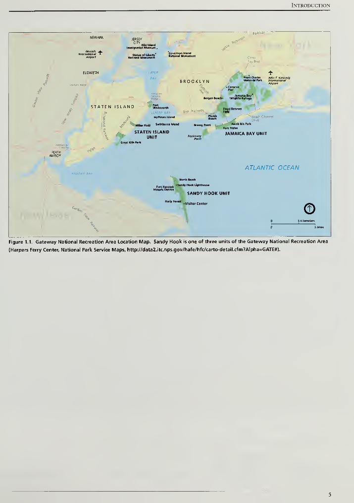
Gateway National Recreation Area's Sandy Hook Unit, provides opportunities
for outdoor recreation and enjoyment of natural and cultural resources that are
unusually accessible to large urban populations (Figure 1.1). The park's
successful new Multi-Use Path (MUP) has begun attracting visitors beyond the
popular ocean beaches, introducing thousands to the peninsula's diverse natural
and cultural environments and broadening the typical visitor experience. As the
Sandy Hook Multi-Use Path continues to attract visitors, the park anticipates that
many will become interested in learning more of Sandy Hook's military history,
and the historic purpose of the coastal defenses arranged along its length.
PROJECT METHODOLOGY AND OBJECTIVES
The scope of this report includes a brief site history, a description of existing
conditions, and a landscape analysis based on National Register of Historic
Places definitions and criteria. The final chapter of the report concludes with
Cultural Landscape Report for the Sandy Hook Coastal Defense Batteries
treatment recommendations intending to preserve the characteristics and
features of the landscape that give the property historical significance.
As Sandy Hook's complex history has been well examined in research presented
by others, the purpose of this report is not to retell the comprehensive history of
Sandy Hook's coastal defenses. Rather, the purpose of this report is to supply
background information and to organize a logical framework supporting
recommendations for the preservation of the most tangible remnants of the
former defensive system. Relying on comprehensive histories prepared by
others, the preparers of this report have focused new research efforts entirely
upon the question of vegetation management. Work has also been focused on
providing graphic "period-plans" of the coastal defense system as it developed
and evolved, and providing adequate mapping to guide and illustrate treatment
recommendations. Given that coastal defense infrastructure is primarily
structural, prior National Park Service reports and documents give scant
attention to the historic role of vegetation. Yet, the engineering of these concrete
structures relied fundamentally on the cushioning effect of sand and soil to
absorb the explosive force of munitions. Vegetation was encouraged, even
cultivated, on these engineered landforms in order to protect the steep
engineered slopes against erosion and to protect the batteries from detection by
hostile parties.
As more definitive histories are available elsewhere, this report provides a brief
historical overview of the development of the coastal defense system sufficient to
provide a sound basis for choosing appropriate preservation treatments. This
overview is followed by an inventory and assessment of existing landscape
conditions. This in turn is followed by an analysis and evaluation of the historical
significance of the military landscape and the relative contribution of its surviving
elements in conveying that significance. This analysis provides base inventory
data and cultural resource evaluations for use in managing these landscape
resources. This report concludes with landscape treatment recommendation.
Regarding the NIKE missile battery sites, recommendations include site-planning
intending to sensitively accommodate visitation and interpretation. Elsewhere
within the various earth-sheltered coastal battery sites, treatment
recommendations center upon management strategies for treating the vegetation
growing on the earthen slopes integral to the coastal defense sites.
The objectives of this report include the following:
1 . To provide additional details needed to both preserve, make accessible, and
to interpret Sandy Hook's surviving coastal defense sites. The identification
and preservation of significant downrange views and views between
rangefinding stations are of particular interest in helping to interpret the
coastal defenses as an integrated system.
Introduction
2. To guide the preservation and accessibility modifications of the Sandy Hook
coastal fortifications insuring that proposed alterations to the historic
landscape meet the Secretary of the Interior's Standardsfor the Treatment of
Historic Properties: Rehabilitation.
3. To organize and present the proposed treatment of the Sandy Hook coastal
defenses landscape to facilitate consultation and to satisfy Gateway National
Recreation Area's responsibilities under Section 106 of the National Historic
Preservation Act of 1966.
PROJECT SETTING AND GEOGRAPHIC SCOPE
Fort Hancock, the historic Sandy Hook Proving Ground, and the accompanying
coastal defense batteries are located near the northern tip of the Sandy Hook
peninsula at the mouth of New York City's outer harbor. Fort Hancock was
established in 1895 as part of a new nationwide system of coastal fortifications
proposed in the 1880's by the Endicott Board. Acquired by the National Park
Service in 1975 for use as part of the Gateway National Recreation Area, the
Sandy Hook Unit is comprised of the greater part of a narrow 2,000 acre
peninsula extending north from coastal New Jersey. The park lies at the
northern end of the New Jersey barrier island system. More than two million
people visit the Sandy Hook Unit each year. While this cultural landscape report
documents a dozen military fortifications made up of discontinuous sites, the
historic fortification system at Sandy Hook is unified by other surviving base
infrastructure, including roads, railroad rights-of-way, and utility corridors. This
report does not report upon or make recommendations for coastal batteries that
currently lie within the boundaries of the U. S. Coast Guard Reservation at the
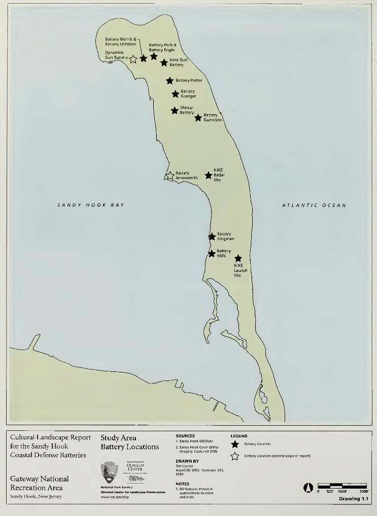
northern extremity of the Sandy Hook peninsula (Drawing 1.1).
SUMMARY OF FINDINGS
This report has defined working boundaries for each of Sandy Hook's coastal
battery sites, excluding Battery Arrowsmith, a structural fragment occupying an
unstable site undermined by water. These working battery site boundaries
extend beyond the above-ground masonry battery features to include engineered
slopes in front of the masonry structures, and battery service areas to the rear of
the masonry structures. Originally designed to be indistinguishable at a distance
from the surrounding naturalized landscape, it is understandable that park
visitors and staff unfamiliar with the historic function of the batteries might
mistake the engineered landforms for naturally occurring sand dunes. The
battery site boundaries defined in this report are both minimal and reasonable
boundaries sufficient to protect and preserve these cultural resources for the
enjoyment of future generations. Within these boundaries, cultural resource

Cultural Landscape Report for the Sandy Hook Coastal Defense Batteries
values, and the preservation of cultural resources should be well understood as
fundamental to the National Park Service mission at the Sandy Hook Unit of the
Gateway National Recreation Area.
This report recommends that effective management of vegetation growing within
each of these working battery site boundaries is critical to both short and long
term preservation of the historic resources. A mix of woody and herbaceous
vegetation were historically encouraged to grow on the engineered landforms to
prevent soil erosion and to conceal the batteries from view. Soil erosion
continues to be an issue affecting the preservation of these resources, and the
park should avoid the removal of large areas of vegetation from battery slopes
without a robust corresponding plan for immediately revegetating cleared areas
with plantings known for their ability to protect against soil erosion.
However, the presence of large trees growing on battery slopes presents a threat
to the preservation of Sandy Hook's coastal batteries because large trees have the
potential to uproot during storm events and displace large volumes of soil that
make up the historic engineered landforms. Woody vegetation of any size should
also not be permitted to become established in cracks and voids in the historic
concrete structures, or otherwise allowed to take root in accumulated organic
matter on concrete battery surfaces. Historically inappropriate growths of tall
vegetation should not be permitted to block historic downrange views that were
critical to the historic operation of the ordnance as well as to a contemporary
understanding of the operation of the historic defenses.
Providing park managers with a useful rule-of-thumb, this report presents
vegetation management recommendations that might be conveniently
remembered as "4-by-4-by-Fore." The first of the two "4's" representing the
elimination of all trees greater than four-inches , in diameter measured at breast
height, growing upon engineered landforms; the second of the two "4's"
representing elimination of woody vegetation of any size growing within four-
feet of buildings and structures or masonry battery features. The third "Fore"
representing the effective management of vegetation forward of battery sites in
perpetuation of historic downrange views and enhancing public interpretation
and understanding of these sites.
Introduction
JERSEYCITY
Ellis IslandImmigration Museum ,
BAYBROOKLYN
STATEN ISLAND
Hoffman Island
Miller FitW Sw*n*»um» Wand
STATEN ISLANDUNIT
Great KiNs Park
John F. KennedyInternationalAirport
Jamaica BayWildllft Refuge
Bennett *n^Beach Channel
\^^t Drive
Jacob Riis Park
Fort Tilden
JAMAICA BAY UNIT
PERTHAMBOY
ATLANTIC OCEAN
Fort Hancock-Sandy Hook Lkjhthous.
Historic District
SANDY HOOK UNIT
Holly Forest ...Visitor Center
U^, ©
Figure 1.1. Gateway National Recreation Area Location Map. Sandy Hook is one of three units of the Gateway National Recreation Area
(Harpers Ferry Center, National Park Service Maps, http://data2.itc.nps.gov/hafe/hfc/carto-detail.cfm?Alpha=GATE#).
ATLANTIC OCEAN
Cultural Landscape Report
for the Sandy HookCoastal Defense Batteries
Gateway National
Recreation AreaSandy Hook, New Jersey
Study Area
Battery Locations
OlmstedCenter
National Park Service
Olmsted Center for Landscape Preservation
www.nps.gov/oclp
SOURCES1. Sandy Hook GIS Data
2. Sandy Hook Color OrthoImagery, Captured 2006
DRAWN BYTim Layton
AutoCAD 2002, Illustrator CS3,
2009
NOTES1 . All features shown in
approximate location
and scale
LEGEND
^V Battery Location
Battery Location (beyond scope of report)
© 0' 825' 1650- 3300*
Drawing 1.1
Site History
SITE HISTORY
PRE-HISTORY AMD EUROPEAN COIUTACT-1859
Located in the northeast corner of Monmouth County, New Jersey, Sandy Hook
extends six and a half miles from the town of Highlands into lower New York
Harbor. The landform parallels the primary deep water channel into New York
Harbor and is nineteen miles south of the southern tip of Manhattan.
Approximately 10,000 years ago during the late Pleistocene epoch, glaciers
covered northern New Jersey and Long Island, but did not extend south to Sandy
Hook. Sea levels rose as the glaciers melted and about 8,000 years ago, a south to
north littoral drift began depositing sand and forming a spit between the
Navesink River and Atlantic Ocean. The currents continued to shape an
elongated landform with major deposits accumulating at the northern end of the
peninsula creating a recurved or hook-shaped formation (Figure 2.1).1
Based on archeological data, the earliest Native Americans arrived in New Jersey
from 12,000 to 10,000 years ago. Settlements were located along major rivers and
competing theories assert that either these base camps were occupied for long
periods throughout the year or seasonally, when food resources were available.
Archeological surveys at Sandy Hook have identified Native American artifacts
and possible sites on the southern portion of the peninsula away from recent
littoral deposits at the northern end of the peninsula and inland from the
dynamically changing shoreline.2
The first European encounters with the Sandy Hook landscape occurred in the
sixteenth century as countries vied for western trade routes to Asia. Italian
explorer Giovanni da Verrazano sailed past Sandy Hook in 1524 and was
followed the next year by Estevan Gomez. Although born in Portugal, Gomez
sailed for Spain and by 1529 a Spanish map recorded the peninsula as "Cabo de
Arenas" or Cape of Sands.3
Sailing on behalf of the Dutch United East India Company, English explorer
Henry Hudson sailed along the Atlantic coast and anchored in the Sandy Hook
Bay in 1609. Given its proximity to the shipping channel, the Dutch and English
disputed claims over Sandy Hook through the mid-seventeenth century until
Dutch governor Peter Stuyvesant surrendered all Dutch New World lands to the
English in 1663.4
In the early 1600s, the Unami branch of the Lenni Lenape occupied central New
Jersey. The Lenape were part of the Algonquian language group and were
dispersed throughout New Jersey in autonomous bands. European contact
brought warfare, disease, and alcoholism that decimated the Lenape population.
Cultural Landscape Report for the Sandy Hook Coastal Defense Batteries
By 1759, estimates placed the Lenape population at 300 for all ofNew Jersey with
few remaining in the state by the start of the nineteenth century.5
EARLY DEVELOPMENTS AMD FORTIFICATIONS
From the colonial era to the mid-nineteenth century, Sandy Hook lacked
permanent coastal defenses. Early developments on the peninsula focused on
maritime safety, transportation, and temporary fortifications. One of the first
permanent structures on Sandy Hook provided navigational assistance to ships in
the narrow channel to New York Harbor. After several shipwrecks in 1761,
merchants pressured the New York Assembly to purchase a four-acre site on
Sandy Hook in order to construct a lighthouse. For the next three years, Isaac
Contro led the building effort to erect an octagonal, masonry structure that rose
to 105 feet in height. The beacon was lit on June 11, 1764 and became the fifth
operational lighthouse in the thirteen original colonies (Figure 2.2).6
During the Revolutionary War, the lighthouse aided friend and foe alike
including British troops navigating the waters off of Sandy Hook. Recognizing
the importance of the lighthouse, the British occupied the peninsula during the
war and constructed a stockade around the structure to deter an attack. In
addition, the British Army used Sandy Hook as a secure staging ground to
disembark from after the Battle of Monmouth in 1778.7
During the War of 1812, American troops were stationed on the peninsula to
prevent British reoccupation and to secure naval access to New York City. A half
mile north of the lighthouse, a wooden stockade called Fort Gates was
constructed and armed with cannon (Figure 2.3). After the war, American troops
were withdrawn from Sandy Hook and the stockade and other temporary
structures deteriorated. Playing a role in the young nation's first wars, the
strategic importance of Sandy Hook was well established and the United States
purchased two large parcels of land comprising most of the peninsula in 181 7.8
After the War of 1812, the government continued development on Sandy Hook
in support of maritime activities. Although the lighthouse aided navigation,
violent storms punished mariners along Sandy Hook and the New Jersey coast
prompting Congress to pass a bill in 1848 for a series of lifeboat stations between
Sandy Hook and Little Egg Harbor. By May 1849, the U. S. Treasury
Department's Revenue Marine Board completed eight stations, set at ten-mile
intervals, from Spermaceti Cove on Sandy Hook south to Long Beach Island near
Little Egg Harbor.9 The Spermaceti Cove station was located three miles south of
the Sandy Hook Lighthouse (Figure 2.4).
In 1855, the Revenue Marine Board constructed a second station on Sandy Hook
northeast of the lighthouse.10 New stations were constructed in 1872 at both
Site History
Sandy Hook locations and the northern station was designated Station No. 1
while the Spermaceti Cove station was designated Station No. 2. In subsequent
decades, conflicts arose between the Sandy Hook Proving Ground and the
location of both stations. In 1891, a new station was completed northwest of the
Sandy Hook Lighthouse along the bay and in 1894, a new station was completed
232 yards west of the 1872 station at Spermaceti Cove.11
As early as 1759, commercial ferry service operated between New York City and
Sandy Hook.12 The Raritan and Delaware Bay Railroad Company, a predecessor
of the New Jersey Southern Railroad, created a ferry and railroad service between
New York City and Long Branch, New Jersey in 1860. New York passengers first
traveled on a ferry to Port Monmouth, New Jersey and then transferred to a train
for the remainder of the trip to Long Branch. Five years later, the company
established a shorter route from Sandy Hook to Long Branch. Ferries arrived at a
wharf on Spermaceti Cove and proceeded south along the coast making stops at
towns growing with recreational amenities.13 The wharf was relocated to
Horseshoe Cove in 1870 and rail service did not extend north of the cove until
the Army Ordnance Department established a line in 1889 (Figure 2.5).14
THE FORT AT SANDY HOOK 1859-1895
By the early 1800s, permanent stone fortifications such as Fort Wadsworth on
Staten Island and Castle Clinton at the southern end of Manhattan guarded
upper New York Harbor and the city (Figure 2.6). Mindful of Sandy Hook's role
in the Revolutionary War and War of 1812, the Army Corps of Engineers
prepared plans in 1857 for a fort to protect the lower harbor shipping channel
and prevent an enemy force from anchoring and staging an attack from the
peninsula. Work began the same year with the construction of a dock near the
northwest tip of Sandy Hook. With a facility established to receive material and
laborers, construction began on a large, five-bastioned granite fort in 1859
(Figure 2.7).
Known as the Fort at Sandy Hook, the pentagonal structure stood at the north
end of the peninsula and enclosed approximately eighteen and a half acres. The
north and east facade of the fort paralleled the shipping channel along Sandy
Hook's Atlantic coastline where it northwest into the lower harbor (Figure 2.8).
Construction accelerated with the start of the Civil War in 1861 but halted in
1868 before the entire fort was completed (Figure 2.9).15 The defenses offered by
the fort, and other stone and masonry fortifications, were surpassed by Civil
War-era artillery improvements. With construction stopped on the fort, a cycle
began at Sandy Hook that would last throughout the Cold War of new defensive
structures and technologies being implemented just as offensive capabilities
advanced that rendered the prior generation of defenses obsolete.
Cultural Landscape Report for the Sandy Hook Coastal Defense Batteries
CIVIL WAR-ERA ARTILLERY ADVANCEMENTS
The Civil War allowed emerging artillery technologies to be battle tested and
conclusions about the effectiveness of rifled bores and pointed projectiles
changed the design of coastal defense batteries at Sandy Hook and across the
country. Prior to the Civil War, major artillery on land, at sea, and at coastal
fortifications consisted of cast iron, smooth bore guns with spherical projectiles.
Coastal fortifications, like the Fort at Sandy Hook, were not immune to damage
from this type of artillery. However, the projectiles were being fired from a ship,
moving under sail power, making it difficult to obtain repeated direct hits
necessary to destroy a stone and masonry wall.
The first Civil War-era innovation in artillery was the successful implementation
of pointed projectiles. Spherical projectiles, or cannonballs, could do more
damage if they were increased in size and had a corresponding larger barreled
gun. A pointed projectile could be designed with the same diameter as a sphere,
but with more mass and less drag as it traveled through the air. Fired from the
same caliber gun, pointed projectiles were heavier and faster moving, resulting in
more damage upon impact.
The superior pointed projectiles were coupled with an innovation in producing
rifled bores. Rifling is a term describing the spiral grooves on the inside of a gun's
bore that spin the projectile. As the projectile travels, the spin stabilizes its
trajectory and results in faster speeds, longer range, and improved accuracy.
Artillery with rifled bores and pointed projectiles could have more destructive
power at a greater distance than earlier ordnance. A single direct hit from this
new weaponry could obliterate a rigid stone and masonry wall (Figure 2.10).
Coastal defense batteries were also made more vulnerable by steam-powered
ships that had better maneuverability and could be equipped with defensive
metal plating.
In response to the powerful impacts of this new artillery, Civil War troops
discovered that earthen embankments, often reinforced by wood pilings,
provided better protection and the promise of easier repairs compared to stone
and masonry construction. Unlike shattering stone, the earth could absorb the
projectile's force and the resulting crater could be readily filled with nearby earth
and sand.16
Observation and experience with defensive earthen structures in the
Civil War would influence the design of coastal defense batteries during the
second half of the nineteenth century.
SANDY HOOK PROVING GROUND
Civil War artillery advancements harkened the beginning of a new generation of
armaments, but did not address what the United States should do with over a
thousand existing smooth bore guns. Congress concurred with the need to test
10
Site History
the conversion of smooth bore to rifled artillery and appropriations were signed
into law in 1872 to facilitate the tests.17
Various locations along the eastern
seaboard of the United States were considered for establishing a new proving
ground with a seven to eight mile uninhabited range. While potential locations
and their acquisition were debated, the military reservation at Sandy Hook was
selected as a temporary facility in 1874. The Army hastily constructed wood
platforms and carriages and the first test fire of a converted smooth bore gun
occurred in October 1874.18 The temporary facility became more permanent in
1881 with the construction of a Proof Battery and concrete platforms for
mounting and testing guns.19 The Sandy Hook Proving Ground, with a proof
battery and supporting, auxiliary structures, was the first development on the
peninsula that responded to artillery advancements from the Civil War era. A
new generation of coastal defenses would join the granite fort and Proving
Ground within the next decade.
THE EMDICOTT BOARD
As experts debated the location for a permanent proving ground site, an economic
crisis started with the Panic of 1873 and lasted until 1878. As a result, Congress
reduced coastal defense spending and ultimately stopped its funding in 1875.21
Pressure for a new generation of coastal defenses came from the public, officers
in the Army and Navy, and members of Congress who were concerned about the
advancement of foreign navies and the lack of maintenance on existing defenses.
During President Grover Cleveland's first term, in 1885 tol889, Secretary of War
William C. Endicott convened a board comprised ofArmy and Navy personnel
and knowledgeable civilians to study locations, fortification types, armament,
and protective materials for coastal defenses. The Endicott Board met in 1885
and early the following year released findings that called for defensive structures
at twenty-six coastal locations, including Sandy Hook, and three additional sites
along the Great Lakes.22
Prior to the Endicott Board, coastal defenses placed canons within parapet
openings and on top of stone and masonry forts (Figure 2.11). In contrast to this
approach and to address the threat posed by improved artillery, the Endicott
Board recommended that new coastal defenses utilize rifled artillery emplaced in
concrete platforms. The platforms would be shielded by a concrete wall and
from the top of the wall, additional concrete would slope away and then be
covered with earth for impact absorption and concealment into the surrounding
landscape (Figure 2.12). As a result of the Endicott Board's recommendations,
the first steam-powered, gun-lift battery and the first concrete mortar battery in
the nation would be constructed at Sandy Hook.
11
Cultural Landscape Report for the Sandy Hook Coastal Defense Batteries
BATTERY POTTER (GUM LIFT BATTERY #1)
In advance of constructing two new batteries, the Army upgraded transportation
and housing facilities. The wharf near the northwest point of the peninsula,
primarily used by the Ordnance Department to receive artillery for the Proving
Ground, was extended in 1891 to receive cement, broken stone, and lumber for
the battery projects. Narrow gauge railroad lines were installed on the wharf and
laid out to the proposed battery sites for delivering materials. The Army also
constructed temporary buildings to house a civilian workforce needed on Sandy
Hook for the new battery projects.23
Excavations began for the Mortar Battery in November 1890 and were followed
three months later by the groundbreaking for Battery Potter. Construction on
both batteries occurred simultaneously throughout the early 1890s. Battery
Potter has the distinction of being the first completed, partially armed, and tested
battery following the Endicott Board's recommendations and therefore, the
discussion will now focus on Battery Potter and be followed by the Mortar Battery.
Prior to its designation as Battery Potter, Sandy Hook's first coastal defense
battery utilizing concrete construction and rifled guns was referred to as the Gun
Lift Battery #1. In addition to incorporating new materials and artillery, the
battery's innovative design featured a steam-powered hydraulic lift that raised the
guns up into firing position after they had been loaded within a protective
structure. Viewed from above, the Gun Lift Battery was D-shaped with the
straight segment of the "D" facing west and a curving facade facing the Atlantic to
the east. The terreplein stood approximately forty feet above surrounding grades
and contained two openings for raising and lowering the 12-inch caliber guns.
East of the guns, a concrete superior slope gently descended to a sentry route
known as a chemin de ronde that was fronted by a parapet wall. A concrete slope
angled away from the parapet and met an engineered earthwork that continued
to slope down to surrounding grades and blended the massive concrete structure
with the surrounding dune landforms (Figure 2.13).
Before excavating for the Gun Lift Battery, the Army constructed temporary
storage facilities and installed mixing equipment to the west of the battery site for
concrete production. Rail cars transported cement and broken stone from the
wharf to the construction site, which were mixed with water and sand to produce
concrete in close proximity to the building site. Sand was excavated and brought
to the production site from nearby pits (Figure 2.14).
In April 1891, two months after excavation work began, workers started placing
concrete for the Gun Lift Battery.24
Construction continued until winter weather
slowed concrete production. By June 1892, a majority of the battery's northern
section was complete and the boiler, gun lift mechanism, and carriage were
installed at the north emplacement. Two months later, the first 12-inch gun was
12
Site History
raised to the terreplein and mounted at the north emplacement. Two rounds
were test fired in September 1892 inaugurating a new era of coastal defense for
metropolitan New York (Figure 2.15).25
As winter approached, colder weather again slowed concrete production and
work crews focused on creating the engineered earthwork around the exterior
walls of the battery. From December until June 1893, over 5,000 cubic yards of
sand were added around the structure to a height of twenty feet above the
surrounding grades.26 The Army placed sand at a 2:3 slope resulting in a steep
finished surface that was susceptible to erosion. In order to limit erosion and
camouflage the earthwork with the surrounding dunes, the north, south, and east
facing slopes were planted with cedar trees and small shrubs. The plant material
was likely obtained from other locations on the peninsula and transplanted to the
engineered earthwork.27
The west facing slope was also planted, however, this earthwork was part of a
defensible entrance for the Gun Lift Battery and received low growing sod instead
of small cedars and shrubs. Concerned about a land-based assault on the battery,
the Army Corps of Engineers designed a castellated entry that extended west
from the main concrete structure. The entry was constructed with granite blocks
salvaged from the Fort at Sandy Hook. Two octagonal towers flanked either side
of a main door. The door and first and second stories of the towers contained
gun loop slots so machine guns could fire on potential attackers (Figure 2.16). As
part of the defensive scheme, vegetation on the west slope needed to be low
growing in order to permit an unobstructed field of fire (Figure 2.17).
By the end of 1893, the Gun Lift Battery was essentially complete with masonry
construction finished, the engineered earthwork installed, and plant material
added to the steep, sandy slopes. However at this time, the battery only had one
12-inch gun emplaced. The gun lift mechanism for the south emplacement was
installed in February 1894 and then delays in manufacturing the gun carriage
hindered the full operational start of the battery.28 Over a year later, the carriage
was delivered and installed and the second 12-inch gun emplaced. After
successfully test firing ten alternating shots from the two guns, the Gun Lift
Battery was cleared for service in August 1895.
MORTAR BATTERY
Complementing the capabilities of the artillery at the Gun Lift Battery was a
battery of sixteen mortars, recessed in a massive earthen landform, just south of
the Sandy Hook lighthouse. Compared to the long-barreled guns at the Gun Lift
Battery, mortars were stubby and set at steep angles to fire their projectiles in a
high, arcing trajectory. A group of eight or sixteen mortars was planned to fire
together and their respective 700-pound projectiles would collectively descend
13
Cultural Landscape Report for the Sandy Hook Coastal Defense Batteries
on the decks of ships like oversized pellets from a shotgun blast (Figure 2.18). To
achieve high arcing trajectories that struck ships in the channel, Sandy Hook's
Mortar Battery had to be located further away from the shoreline than the Gun
Lift Battery (Figure 2.19).30
Construction began in 1890 on the Mortar Battery. The battery contained four
concrete platforms that were recessed in a protective mound of earth and sand
that rose to almost thirty-five feet. A rectangular concrete wall bounded the
earthen mound, the longer legs of which were oriented in a southeast to
northwest direction. At the wall's southwest and northeast corners, the Army
constructed counterscarp galleries to defend against a land-based attack. If
enemy forces ever penetrated the Mortar Battery's perimeter wall, machine
gunners stationed in the counterscarp galleries had unobstructed lines of fire
along the face of the wall (Figure 2.20).
Given the orientation of the battery, recessed platforms were located in the
southwest, southeast, northwest, and northeast portions of the structure.
Vertical retaining walls rose up from each platform and met a concrete blast slope
that tapered to a wider opening and held back the mounded earth (Figure 2.21).
The southwest and northwest platforms were entered through a concrete gallery
featuring high, concrete retaining walls. Passageways to access the southeast and
northeast platforms, as well as ammunition magazines, were located under the
protective cover of the built up earthwork.
The first step in constructing Mortar Battery was excavating a stable base for each
mortar platform, then pouring a concrete slab for the base. Similar to the work
undertaken at the Gun Lift Battery, concrete was produced on site with
dedicated storage space for broken stone and cement. Ships transported both
products to Sandy Hook and then rail cars brought stone and cement to a site
southwest of the Mortar Battery (Figure 2.22). The Army excavated sand from
nearby pits and mixed with the other two components in close proximity to
where the final concrete was placed.
In addition to the concrete facility, rail lines were installed to three sand pits near
the Mortar Battery in order to transport sand for the battery's mounded,
protective covering (Figure 2.23). When temperatures were too cold to mix and
place concrete, laborers began filling rail cars by hand with sand. When the cars
arrived at Mortar Battery, derricks hoisted a removable container and dumped
the sand around the finished concrete work. The sand filling progressed slowly
and during the winter months of 1892 and 1893, steam-powered shovels were
brought to the site to improve the quantity and speed of the excavation and
placing work.31
Over 150,000 cubic yards of sand were placed at Mortar Battery and settling and
high winds displaced some of the material.32 To better secure the fill material and
14
Site History
protect their tremendous construction expenditures, site engineer Lt. James G.
Warren directed the planting of sod, cut from a marsh south of the battery, on the
slopes rising form the concrete blast slopes to the top of the mound. The
remainder of the mound was covered in native heather and cedar boughs that
were tolerant of dry and sunny conditions. Additionally, records show that oats
were sown on the slopes to help deter erosion.
Masonry construction was completed at Mortar Battery in 1893 and a year later,
each of the four platforms was armed with four 12-inch guns. The guns were test
fired in June 1894 and Sandy Hook's Mortar Battery became the first completed
and operational concrete mortar battery in United States.
THE ESTABLISHMENT OF FORT HANCOCK
The creation of the Sandy Hook Proving Ground and the construction of new
coastal defense batteries brought personnel from the Army Ordnance
Department and the Army Corps of Engineers respectively to the peninsula. In
addition to Battery Potter and the Mortar Battery, the Army constructed an
experimental Dynamite Gun Battery in 1893. Located at the northern end of the
peninsula, the battery utilized compressed air to fire projectiles instead of
gunpowder.34 With three batteries completed, additional personnel from the
Army Corps of Artillery were needed for fulltime operation and maintenance of
the new structures.
In order to provide housing and support facilities for the Army Corps of Artillery,
the Secretary ofWar issued a general order establishing Fort Hancock on
October 30, 1895. The Army designated the fort in honor of Major General
Winfield Scott Hancock, a veteran of the Mexican and Civil Wars, who rose to
national recognition for his heroics during the Civil War.35 The Army Corps of
Engineers, based out of New York City, would be on Sandy Hook as needed for
battery construction and shoreline stabilization projects. The Ordnance
Department and Corps of Artillery would have permanent facilities but each
would retain separate and distinct identities under the supervision of their own
commanding officers.36
At the time Fort Hancock was established, the Army Ordnance Department,
Army Corps of Engineers, and Army Corps of Artillery shared the peninsula with
federal personnel for the U. S. Lighthouse Service, the U. S. Lifesaving Service,
and Western Union Telegraph Company. 37All of these organizations shaped and
modified the landscape in performing their duties.
15
Cultural Landscape Report for the Sandy Hook Coastal Defense Batteries
LANDSCAPE SUMMARY - 1895
The general arrangement of developed versus non-developed areas at Sandy
Hook appeared by 1895. Development was concentrated at the northern end of
the peninsula with the former granite fort, wharf, lifesaving station, lighthouse,
Proving Ground, and coastal defense batteries all north of Horseshoe Cove
(Drawing 2.2). The railroad bisected the middle section of the peninsula which
was primarily undeveloped except for a wharf and ice houses near Horseshoe
Cove (Drawing 2.2). The southern portion of the peninsula contained limited
development but was marked by the Spermaceti Cove lifesaving station and a
dike south of the cove that sheltered it from the currents of the Navesink River
(Drawing 2.1).
An 1889 map prepared by the Army Corps of Engineers shows the overall
composition of vegetation and natural features several years prior to Fort
Hancock's establishment. Large woody vegetation covered the undeveloped,
middle section of the peninsula. Sand dune and beach areas were wider on the
Atlantic side and narrower along Sandy Hook Bay. A relatively large marsh
extended north of Horseshoe Cove and a tidal marsh bordered the edges of
Spermaceti Cove. A string of long, narrow ponds punctuated the middle of the
peninsula east of a primary north-south circulation route. Vegetation cover was
sparse and clearing occurred around the Ordnance Department quarters and the
Sandy Hook Lighthouse. Additional cleared areas appeared in association with
the newly constructed batteries and the railroad lines (Drawings 2.1-2.2).
At the northern end of Sandy Hook, the pentagonal outline of the Fort at Sandy
Hook dominated the landscape. Never completed, the Army removed portions
of the Fort's exterior walls by the 1890s and reused the massive granite blocks for
shoreline stabilization and new projects such as Battery Potter's defensible west
facade. The southwest bastion of the Fort served as a control and observation
facility for underwater mines. A storage building for the mines stood
immediately south of the bastion. West of the Fort, the Dynamite Gun Battery
stood isolated near the extreme northwest tip of the peninsula. The battery was
oriented to engage enemy ships as they headed west in the main channel across
the northern tip of the peninsula (Drawing 2.2).
East of the Fort, the Sandy Hook Proving Ground consisted of concrete
platforms, a Machine Shop, and smaller supporting structures to store and
observe ordnance tests. North of the Proving Ground, Western Union
established a telegraph station. The Ordnance Department housed personnel
south of the Fort and west of the Proving Ground. South of this housing, the
Army constructed Battery Potter and the Mortar Battery, emplaced their guns,
and prepared the batteries to defend the southern approach to New York.
Construction was ongoing at Battery Granger and would be finalized in 1896
(Drawing 2.2).
16
Site History
Immediately north of the Mortar Battery, the 1764 lighthouse continued to warn
mariners of the shallow waters around the peninsula. A keeper's house was
located west of the lighthouse and secondary beacons were positioned north of
the Fort and along Sandy Hook Bay. To further aid sea travel, lifesaving stations
were established northwest of the Sandy Hook Lighthouse and at Spermaceti
Cove (Drawings 2.1-2.2).
Access to and from the peninsula was by ships arriving at one of two wharves or
via the railroad that stretched down the coastline to Long Branch, New Jersey. A
wharf near the northern end of the peninsula featured separate docks for the
Ordnance Department and Army Corps of Engineers. Another wharf, originally
constructed for New Jersey Southern Railroad, was located at Horseshoe Cove.
Three railroad lines originated from the northern wharf and branched off to
separate destinations. The northern line covered the shortest distance and
terminated at a storage building for underwater mines near the southwest bastion
of the Fort. The central line carried ordnance east to the Proving Ground and a
branch off this line continued south across the entire length of the peninsula.
The southern line from the wharf divided into three separate branches that
served construction efforts and later munitions delivery to Battery Potter, the
Mortar Battery, and Battery Granger (Drawing 2.2).
An east-west roadway paralleled the rail line from the northern wharf to the
Proving Ground and secondary branches off of this road provided access to the
Officers' Quarters. Also branching off of this east-west road was a north-south
road that began east of the Ordnance Department Wharf and extended south to
Spermaceti Cove. In addition to the roadways, the Ordnance Department
constructed a wood plank walk from the Proving Ground south along the
Atlantic coastline to the 3,000 yard target. The walk allowed ordnance officers to
easily make their way across the dunes and evaluate shell impacts (Drawing 2.2).
17

Cultural Landscape Report for the Sandy Hook Coastal Defense Batteries
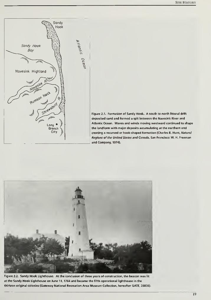
Site History
Long • j?
Branch \City |
Q3
ooQ•3
Figure 2.1. Formation of Sandy Hook. A south to north littoral drift
deposited sand and formed a spit between the Navesink River and
Atlantic Ocean. Waves and winds moving westward continued to shape
the landform with major deposits accumulating at the northern end
creating a recurved or hook-shaped formation (Charles B. Hunt, Natural
Regions of the United States and Canada, San Francisco: W. H. Freeman
and Company, 1974).
Figure 2.2. Sandy Hook Lighthouse. At the conclusion of three years of construction, the beacon was lit
at the Sandy Hook Lighthouse on June 11, 1764 and became the fifth operational lighthouse in the
thirteen original colonies (Gateway National Recreation Area Museum Collection, hereafter GATE, 28836).
19
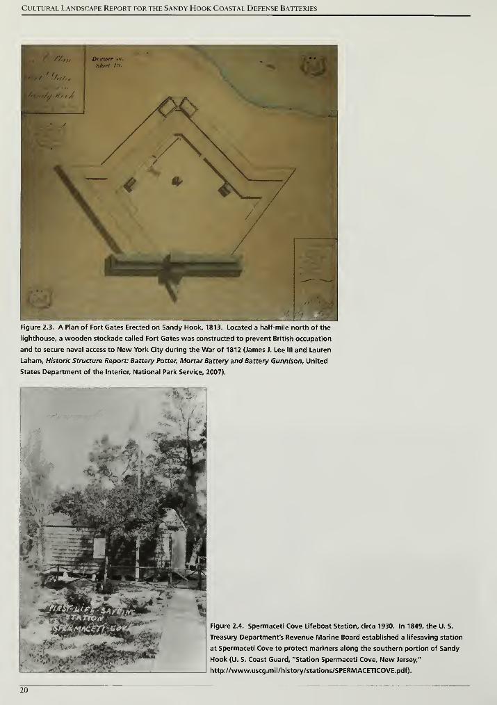
Cultural Landscape Report for the Sandy Hook Coastal Defense Batteries
Figure 2.3. A Plan of Fort Gates Erected on Sandy Hook, 1813. Located a half-mile north of the
lighthouse, a wooden stockade called Fort Gates was constructed to prevent British occupation
and to secure naval access to New York City during the War of 1812 (James J. Lee III and Lauren
Laham, Historic Structure Report: Battery Potter, Mortar Battery and Battery Gunnison, United
States Department of the Interior, National Park Service, 2007).
Figure 2.4. Spermaceti Cove Lifeboat Station, circa 1930. In 1849, the U. S.
Treasury Department's Revenue Marine Board established a lifesaving station
at Spermaceti Cove to protect mariners along the southern portion of Sandy
Hook (U. S. Coast Guard, "Station Spermaceti Cove, New Jersey,"
http://www.uscg.mil/history/stations/SPERMACETICOVE.pdf).
20
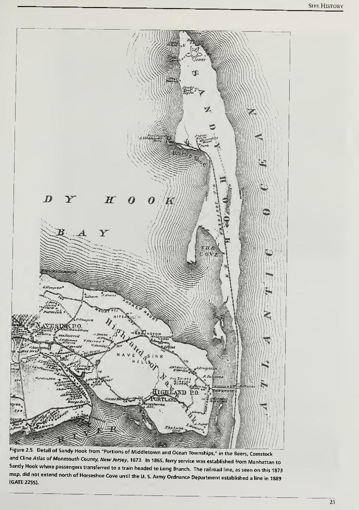
Site History
Figure 2.5. Detail of Sandy Hook from "Portions of Middletown and Ocean Townships." in the Beers. Comstockand Cline Atlas of Monmouth County, New Jersey. 1873. In 1865. ferry service was established from Manhattan toSandy Hook where passengers transferred to a train headed to Long Branch. The railroad line, as seen on this 1873map, did not extend north of Horseshoe Cove until the U. S. Army Ordnance Department established a line in 1889(GATE 2255).
21
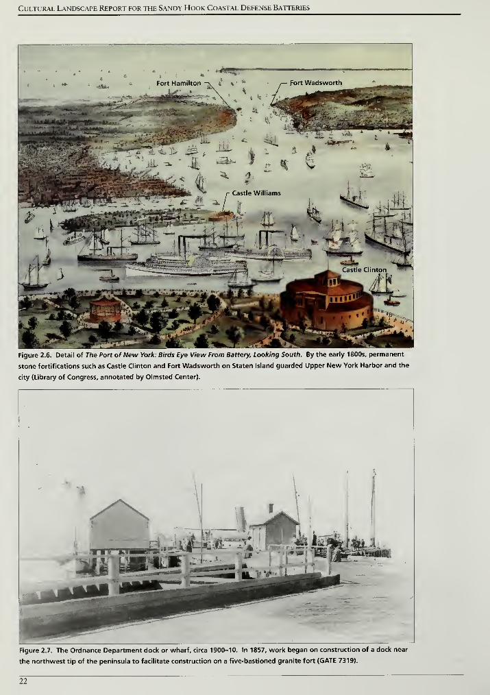
Cultural Landscape Report for the Sandy Hook Coastal Defense Batteries
Figure 2.6. Detail of The Port of New York: Birds Eye View From Battery, Looking South. By the early 1800s, permanent
stone fortifications such as Castle Clinton and Fort Wadsworth on Staten Island guarded Upper New York Harbor and the
city (Library of Congress, annotated by Olmsted Center).
Figure 2.7. The Ordnance Department dock or wharf, circa 1900-10. In 1857, work began on construction of a dock near
the northwest tip of the peninsula to facilitate construction on a five-bastioned granite fort (GATE 7319).
22
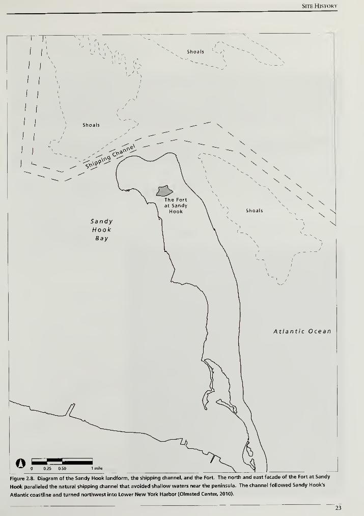
Site History
0.25 0.50 1 mile
Figure 2.8. Diagram of the Sandy Hook landform, the shipping channel, and the Fort. The north and east facade of the Fort at Sandy
Hook paralleled the natural shipping channel that avoided shallow waters near the peninsula. The channel followed Sandy Hook's
Atlantic coastline and turned northwest into Lower New York Harbor (Olmsted Center, 2010).
23
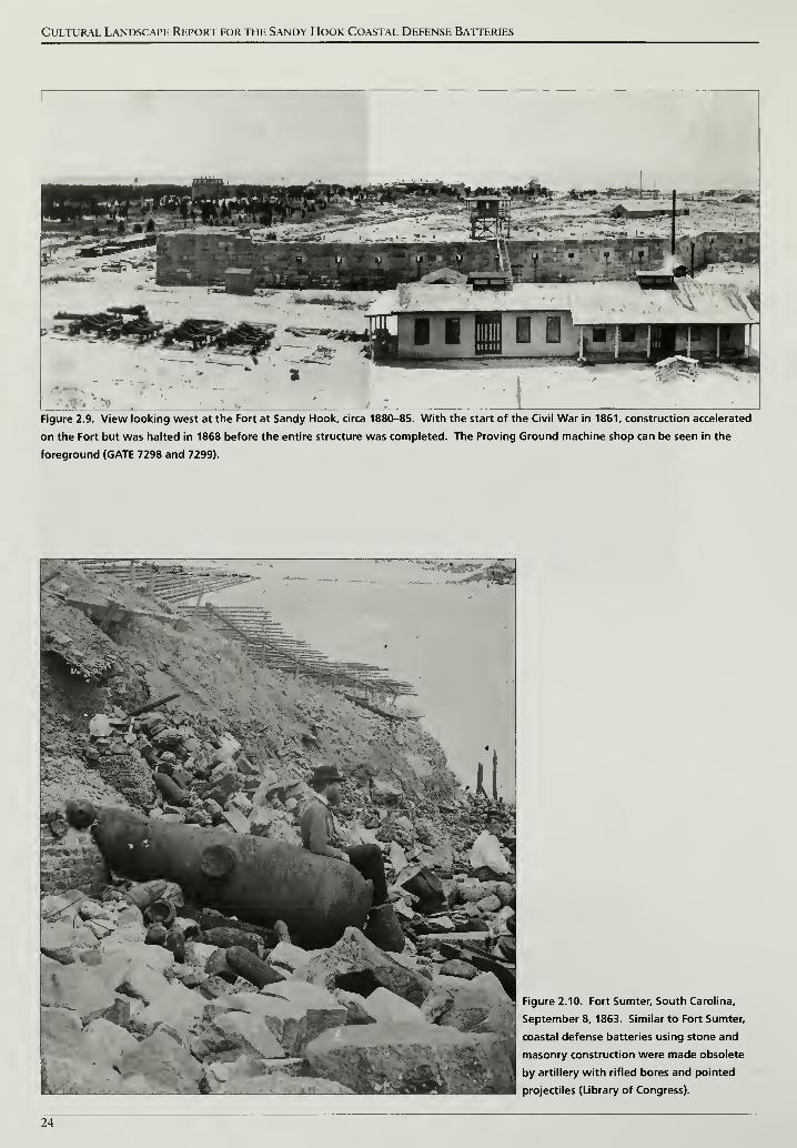
Cultural Landscape Report for the Sandy Hook Coastal Defense Batteries
Figure 2.9. View looking west at the Fort at Sandy Hook, circa 1880-85. With the start of the Civil War in 1861, construction accelerated
on the Fort but was halted in 1868 before the entire structure was completed. The Proving Ground machine shop can be seen in the
foreground (GATE 7298 and 7299).
Figure 2.10. Fort Sumter, South Carolina,
jSeptember 8, 1863. Similar to Fort Sumter,
J
coastal defense batteries using stone and
masonry construction were made obsolete
by artillery with rifled bores and pointed
projectiles (Library of Congress).
24
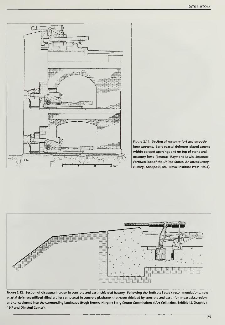
Site History
QT^T
-,ff .Kt—i—i—i—i—i-
Figure 2.11. Section of masonry fort and smooth-
bore cannons. Early coastal defenses placed canons
within parapet openings and on top of stone and
masonry forts (Emanuel Raymond Lewis, Seacoast
Fortifications of the United States: An Introductory
History, Annapolis, MD: Naval Institute Press, 1993).
Figure 2.12. Section of disappearing gun in concrete and earth-shielded battery. Following the Endicott Board's recommendations, new
coastal defenses utilized rifled artillery emplaced in concrete platforms that were shielded by concrete and earth for impact absorption
and concealment into the surrounding landscape (Hugh Brown, Harpers Ferry Center Commissioned Art Collection, Exhibit 12/Graphic #
12-7 and Olmsted Center).
25
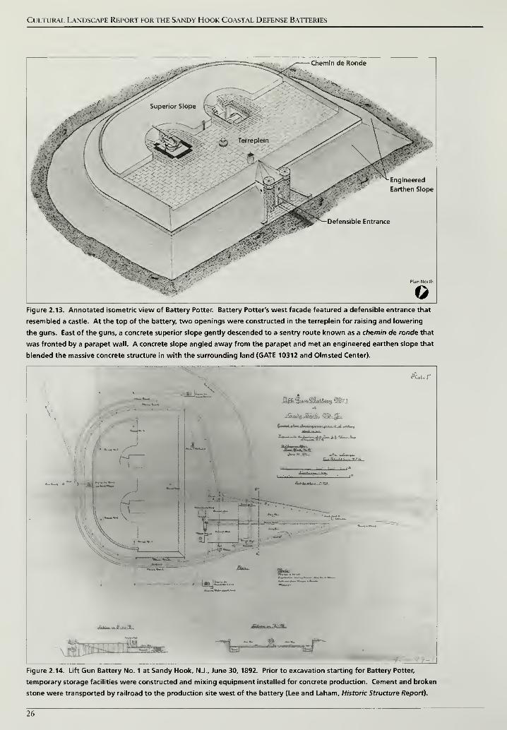
Cultural Landscape Report for the Sandy Hook Coastal Defense Batteries
Chemin de Ronde
Earthen Slope
Defensible Entrance
©Figure 2.13. Annotated isometric view of Battery Potter. Battery Potter's west facade featured a defensible entrance that
resembled a castle. At the top of the battery, two openings were constructed in the terreplein for raising and lowering
the guns. East of the guns, a concrete superior slope gently descended to a sentry route known as a chemin de ronde that
was fronted by a parapet wall. A concrete slope angled away from the parapet and met an engineered earthen slope that
blended the massive concrete structure in with the surrounding land (GATE 10312 and Olmsted Center).
e'uun
*—»;*£=.*»<?-•>* «—»-
iff
iW_ SUu.
tf=*"
nfal-.^ffnT fittNhm3e2
Figure 2.14. Lift Gun Battery No. 1 at Sandy Hook, N.J., June 30, 1892. Prior to excavation starting for Battery Potter,
temporary storage facilities were constructed and mixing equipment installed for concrete production. Cement and broken
stone were transported by railroad to the production site west of the battery (Lee and Laham, Historic Structure Report).
26
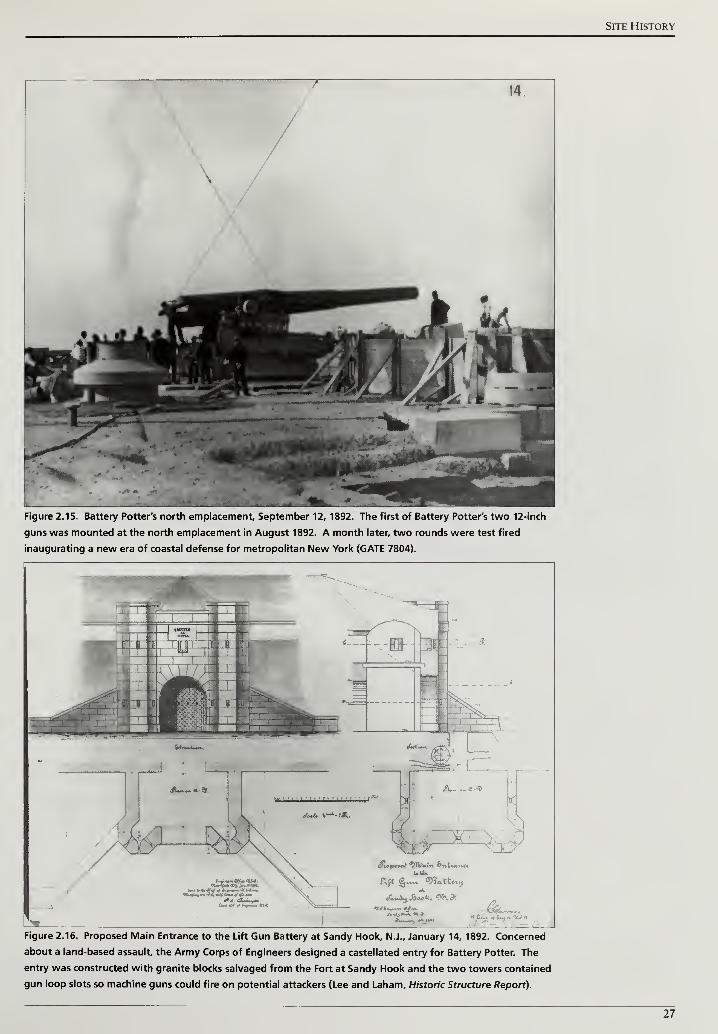
Site History
14
\
Figure 2.15. Battery Potter's north emplacement, September 12, 1892. The first of Battery Potter's two 12-inch
guns was mounted at the north emplacement in August 1892. A month later, two rounds were test fired
inaugurating a new era of coastal defense for metropolitan New York (GATE 7804).
Figure 2.16. Proposed Main Entrance to the Lift Gun Battery at Sandy Hook, N.J., January 14, 1892. Concerned
about a land-based assault, the Army Corps of Engineers designed a castellated entry for Battery Potter. The
entry was constructed with granite blocks salvaged from the Fort at Sandy Hook and the two towers contained
gun loop slots so machine guns could fire on potential attackers (Lee and Laham, Historic Structure Report).
27
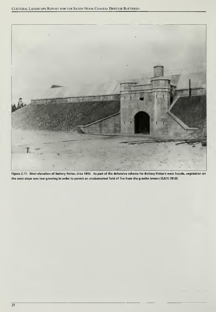
Cultural Landscape Report for the Sandy Hook Coastal Defense Batteries
Figure 2.17. West elevation of Battery Potter, circa 1893. As part of the defensive scheme for Battery Potter's west facade, vegetation on
the west slope was low growing in order to permit an unobstructed field of fire from the granite towers (GATE 7813).
28
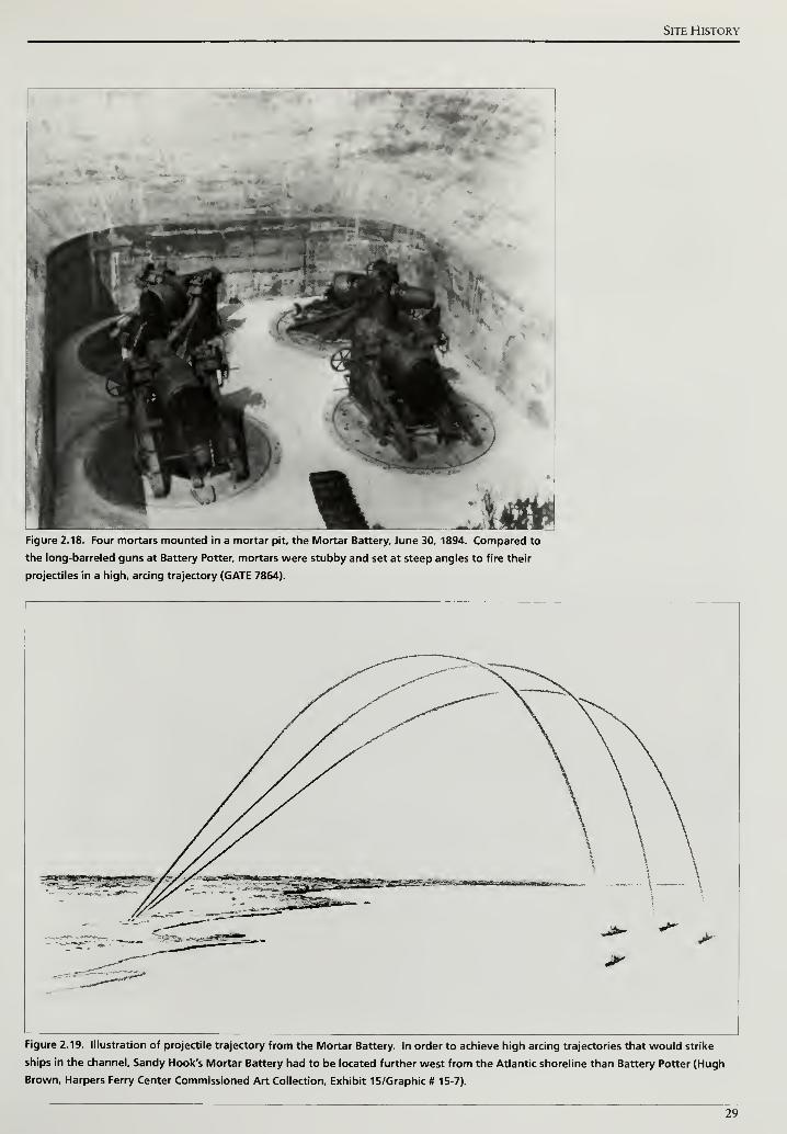
Site History
Figure 2.18. Four mortars mounted in a mortar pit, the Mortar Battery, June 30, 1894. Compared to
the long-barreled guns at Battery Potter, mortars were stubby and set at steep angles to fire their
projectiles in a high, arcing trajectory (GATE 7864).
Figure 2.19. Illustration of projectile trajectory from the Mortar Battery. In order to achieve high arcing trajectories that would strike
ships in the channel, Sandy Hook's Mortar Battery had to be located further west from the Atlantic shoreline than Battery Potter (Hugh
Brown, Harpers Ferry Center Commissioned Art Collection, Exhibit 15/Graphic # 15-7).
29
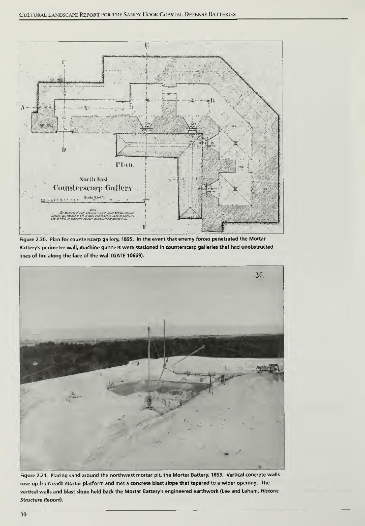
Cultural Landscape Report for the Sandy Hook Coastal Defense Batteries
HfcW 4'fc-jJw. rf » « Iq—afc^fc^ 4rt»« , ,«l»i - Hi IIIM>H» i M>l> ll
:»>" V t
*r -v
A—H '( -•'-: -
;ft- :-- -«
J"i
i' '
:
Nmtli Knst
Count trsnup Gn!lci*y
ttj fmj :;„:,:Sc.lt Mt4ft
1
Figure 2.20. Plan for counterscarp gallery, 1895. In the event that enemy forces penetrated the Mortar
Battery's perimeter wall, machine gunners were stationed in counterscarp galleries that had unobstructed
lines of fire along the face of the wall (GATE 10669).
36.
Figure 2.21. Placing sand around the northwest mortar pit, the Mortar Battery, 1893. Vertical concrete walls
rose up from each mortar platform and met a concrete blast slope that tapered to a wider opening. The
vertical walls and blast slope held back the Mortar Battery's engineered earthwork (Lee and Laham, Historic
Structure Report).
30
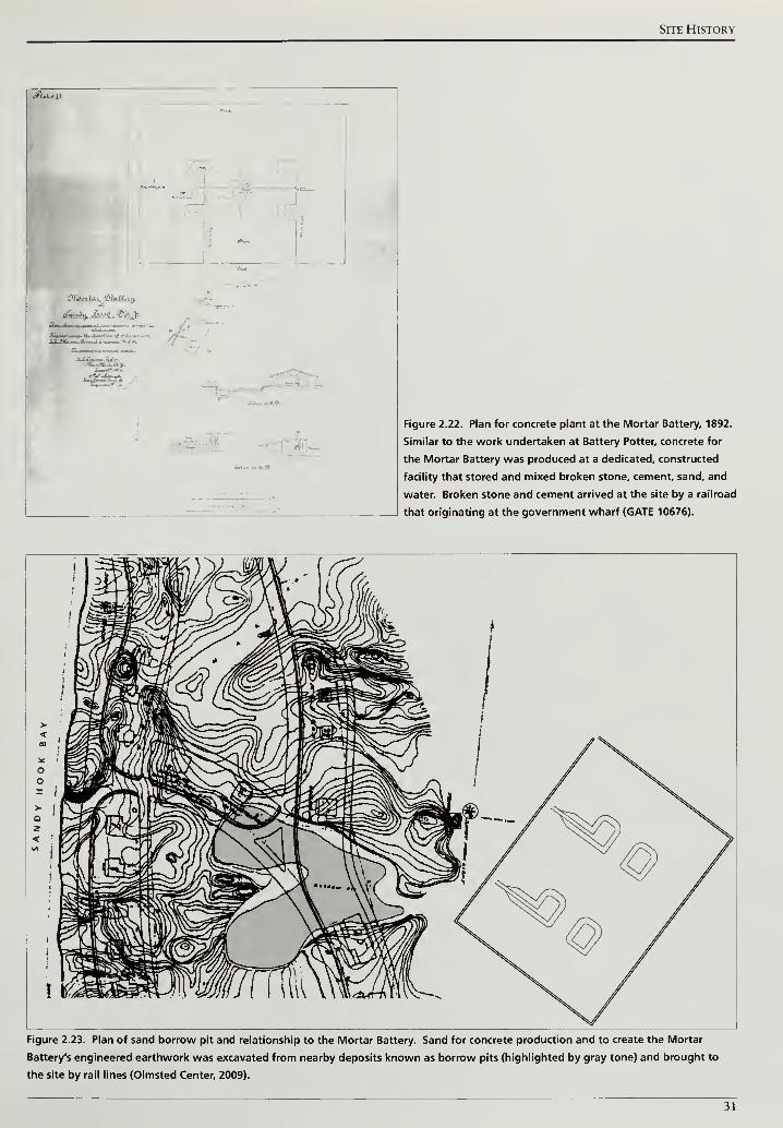
Site History
*
*-£-' '
I
I
1
#b»I
.fin gT«.«^m
Figure 2.22. Plan for concrete plant at the Mortar Battery, 1892.
Similar to the work undertaken at Battery Potter, concrete for
the Mortar Battery was produced at a dedicated, constructed
facility that stored and mixed broken stone, cement, sand, and
water. Broken stone and cement arrived at the site by a railroad
that originating at the government wharf (GATE 10676).
Figure 2.23. Plan of sand borrow pit and relationship to the Mortar Battery. Sand for concrete production and to create the Mortar
Battery's engineered earthwork was excavated from nearby deposits known as borrow pits (highlighted by gray tone) and brought to
the site by rail lines (Olmsted Center, 2009).
31

Cultural Landscape Report for the Sandy Hook Coastal Defense Batteries
32
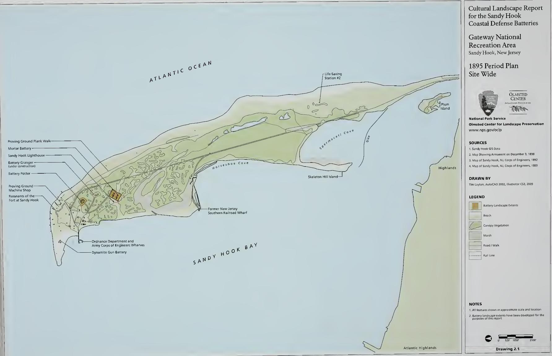
Cultural Landscape Report
for the Sandy HookCoastal Defense Batteries
Gateway National
Recreation AreaSandy Hook, New Jersey
1895 Period Plan
Site Wide
OlmstedCenter
National Park Service
Olmsted Center for Landscape Preservation
www.nps.gov/oclp
SOURCES
1. Sandy Hook GIS Data
2. Map Showing Armament on December 3, 1898
3. Map of Sandy Hook, NJ, Corps of Engineers. 1892
4. Map of Sandy Hook, NJ, Corps of Engineers, 1889
DRAWN BY
Tim Layton, AutoCAD 2002, Illustrator CS3, 2009
LEGEND
< Battery Landscape Extents
Beach
\f J Canopy Vegetation
Marsh
NOTES
1 . All features shown in approxi e scale and location
2. Battery landscape extents have been developed for the
purposes of this report
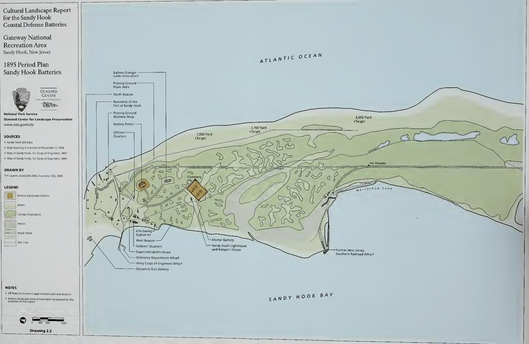
Cultural Landscape Report
for the Sandy HookCoastal Defense Batteries
Gateway National
Recreation AreaSandy Hook, New Jersey
1895 Period Plan
Sandy Hook Batteries
OlmstedCenter
1S£National Park Service
Olmsted Center for Landscape Preservation
www.nps.gov/oclp
SOURCES
1 Sandy Hook GIS Data
2 Map Showing Armament on December 3, 1898
3. Map of Sandy Hook, NJ, Corps of Engineers, 1892
4. Map of Sandy Hook, NJ, Corps of Engineers, 1889
DRAWN BY
Tim Layton, AutoCAD 2002, Illustrator CS3, 2009
LEGEND
Battery Landscape Extents
Beach
Canopy Vegetation
Marsh
'
'
Hr~~i
Road /Walk
NOTES
l All features shown m approximate scale and locatio
. m t / c OCEANa tlanti
<-
West Beacon
L Soldiers' Quarters
1 Superintendent's House
- Ordnance Department Wharf
- Army Corps of Engineers Wharf
- Dynamite Gun Battery
Former New Jersey
Southern Railroad Wharf
SAND Y HOOK BAY
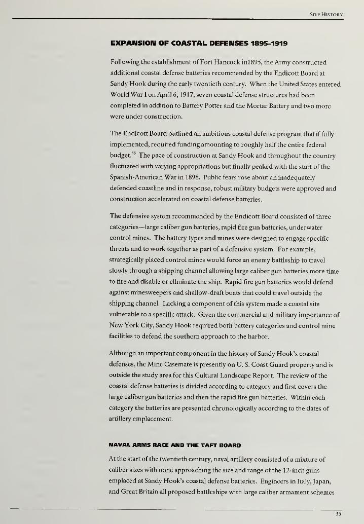
Site History
EXPANSION OF COASTAL DEFENSES 1895-1919
Following the establishment of Fort Hancock inl895, the Army constructed
additional coastal defense batteries recommended by the Endicott Board at
Sandy Hook during the early twentieth century. When the United States entered
World War I on April 6, 1917, seven coastal defense structures had been
completed in addition to Battery Potter and the Mortar Battery and two more
were under construction.
The Endicott Board outlined an ambitious coastal defense program that if fully
implemented, required funding amounting to roughly half the entire federal
budget.38 The pace of construction at Sandy Hook and throughout the country
fluctuated with varying appropriations but finally peaked with the start of the
Spanish-American War in 1898. Public fears rose about an inadequately
defended coastline and in response, robust military budgets were approved and
construction accelerated on coastal defense batteries.
The defensive system recommended by the Endicott Board consisted of three
categories—large caliber gun batteries, rapid fire gun batteries, underwater
control mines. The battery types and mines were designed to engage specific
threats and to work together as part of a defensive system. For example,
strategically placed control mines would force an enemy battleship to travel
slowly through a shipping channel allowing large caliber gun batteries more time
to fire and disable or eliminate the ship. Rapid fire gun batteries would defend
against minesweepers and shallow-draft boats that could travel outside the
shipping channel. Lacking a component of this system made a coastal site
vulnerable to a specific attack. Given the commercial and military importance of
New York City, Sandy Hook required both battery categories and control mine
facilities to defend the southern approach to the harbor.
Although an important component in the history of Sandy Hook's coastal
defenses, the Mine Casemate is presently on U. S. Coast Guard property and is
outside the study area for this Cultural Landscape Report. The review of the
coastal defense batteries is divided according to category and first covers the
large caliber gun batteries and then the rapid fire gun batteries. Within each
category the batteries are presented chronologically according to the dates of
artillery emplacement.
NAVAL ARMS RACE AMD THE TAFT BOARD
At the start of the twentieth century, naval artillery consisted of a mixture of
caliber sizes with none approaching the size and range of the 12-inch guns
emplaced at Sandy Hook's coastal defense batteries. Engineers in Italy, Japan,
and Great Britain all proposed battleships with large caliber armament schemes
35

Cultural Landscape Report for the Sandy Hook Coastal Defense Batteries
and the British completed the first such vessel with the successful launching of
the HMS Dreadnought in 1906. The Dreadnought's launch and early trials were
closely observed as the ship combined large caliber armament, electronic range
finding system, and faster steam-powered propulsion (Figure 2.24). The ship's
design was groundbreaking and nations raced to build comparable battleships of
their own that were generally categorized as dreadnoughts while all earlier ships
were disparagingly referred to as pre-dreadnoughts.39
For the battleship's armament, the Dreadnought replaced a mixture of caliber
sizes with ten 12-inch guns arranged as pairs on five separate turrets. When a
pre-dreadnought ship fired mixed-caliber artillery at a target and missed, it was
difficult to identify the different projectiles and make adjustments to the
corresponding guns. Dreadnought's uniform-sized artillery simplified
adjustments and resulted in volleys of projectiles with increased precision.40
Following Dreadnoughts launch, the United States and other world powers
strategically shifted from naval defense to offensive capabilities at sea. In an
effort to display United States naval power, President Theodore Roosevelt
ordered four squadrons of battleships and escorts on a tour around the world in
December 1907. The touring squadrons were popularly called the Great White
Fleet due to their brightly painted hulls.
As the Navy's role changed to engaging an enemy force hundreds of miles away
from the United States, coastal defense systems required reevaluation yet again.
In similar fashion to the Endicott Board, Roosevelt convened military and civilian
experts headed by Secretary of War William Howard Taft to review the nation's
coastal defenses in 1905. In addition to reviewing Endicott Board
recommendations, the Taft Board sought to incorporate technological changes
made during the twenty-year period.41
The Taft Board did not alter the armament and defensive recommendations
made by the Endicott Board. Instead, the Taft Board reinforced and accelerated
the implementation of new technology including searchlights to illuminate
channels and harbors at nighttime and the general electrification of coastal
defenses.42
In 1913, an approved project called for thirteen 60-inch searchlights
and two 36-inch searchlights at several locations guarding the southern entrance
to New York Harbor. Five of the 60-inch searchlights were designated to go to
Sandy Hook, and by November 1916, the peninsula's first searchlight was
operational at a location 1,000 feet south of Battery Gunnison.43
By March 1918,
the Army installed the remaining four searchlights with one located at the
northwest point of the peninsula, one directly east of the Mine Casemate, and
two approximately a mile south of Battery Gunnison.44 The Taft Board also
addressed coastal defenses for American territories acquired from Spain at the
conclusion of the Spanish-American War. Except for six batteries at Fort
36
Site History
MacArthur near Los Angeles, new coastal defenses built after the Taft Board
report were outside the continental United States in Hawaii, the Philippines, and
at the Panama Canal.45
Part of the Taft Board's recommendations addressed improving fire control—the
process of acquiring and firing on enemy ships. Available land to construct
multiple observation points as well as advances in optical instruments and
electronic communications among the observation points, plotting rooms, and
batteries resulted in the continued superiority of land artillery over naval artillery
through the early part of the twentieth century. Target systems were established
that used both single and two observation points equipped with precise optical
instruments. With two observations points, called base end stations, a ship and
its distance from each station would be identified simultaneously. The readings
would be communicated to a plotting room and triangulated to find the ship's
position and projected course. After calculating this information, instructions
would be relayed for aiming and firing the artillery. The communications
between observation, plotting, and firing were increasingly handled by telephone
(Figure 2.25). In addition to using two observation points, single observation
points were installed in elevated structures and towers. Using this system, the
distance to a ship was calculated based on the known height of an optical
instrument and the angle it was depressed to sight the target. The Army used
both systems for the coastal defense batteries at Sandy Hook and the systems,
".. .represented the most significant advance to be made in harbor defense fire
control until the introduction of radar during World War II."46
The accuracy of triangulation improved with greater distance between two
observation points. The Army's ability to locate stations at greater distances on
land than between ships at sea gave coastal defense artillery an advantage over
naval artillery. The coastal defense batteries at Sandy Hook were one component
of a system that guarded the southern approach to New York Harbor. Batteries
were also constructed at Fort Tilden on the Rockaway peninsula and at Fort
Wadsworth and Fort Hamilton guarding the Narrows between the lower and
upper harbor. In order to improve triangulation accuracy, the Army constructed
an observation tower for Fort Tilden at Sandy Hook (Figure 2.26).47
For the
high-angle gun carriage batteries built on Sandy Hook's western coast, a pair of
observation stations stood a mile north of the batteries and another pair stood
south of the peninsula in the Navesink Highlands. Electronic communication
among the stations, batteries, and forts permitted targeting and firing information
to be shared across greater distances.
Controlling new territories, specifically Hawaii and the Philippines, allowed
American military personnel to observe former coastal defense batteries
constructed and maintained by the British and Japanese. An April 1910
37

Cultural Landscape Report for the Sandy Hook Coastal Defense Batteries
memorandum notes a difference in the design of earthworks and the use of
vegetation and camouflage to conceal these batteries. Specifically, the author cites:
. . .the great care that had evidently been taken by each of these governments
to conceal the gun batteries and positions finder stations by means of screens
of trees and shrubbery, and also, in case of English barbette batteries, by
painting both guns and carriages in splotched or splashed colors of the varied
hues of the surrounding landscape. In contrast with this I was equally
impressed with the lack of concealment of our own coast defenses on the
Pacific Coast and the way the batteries and position finder stations on that
coast are exposed. The smooth geometrical slopes or our batteries, differing
entirely from the rough natural slopes of the English and Japanese batteries,
showed their locations at once, - making them stand out in bold relief against
the natural background.
Planting efforts to conceal or obscure coastal defense batteries at Sandy Hook
and other American locations were not an innovation of the Taft Board. Before
the Taft Board convened, the Army completed Battery Potter and the Mortar
Battery and added vegetation in order to limit erosion and blend the batteries
into the adjacent landscape. Following the increase in naval power around the
world and the Taft Board report, the Army was more formal in articulating the
need for vegetation to conceal coastal defense batteries from detection at sea.
Three weeks after highlighting the differences between American and foreign
coastal defense batteries, the Army's Office of the Chief of Coast Artillery issued a
memorandum instructing that new batteries should be constructed while
minimizing the number of existing trees removed and with engineered slopes that
"conform in appearance" to the surrounding landscape and avoid "geometric
contours."49 The instructions also call for a general planting scheme composed
of, "tall trees as a rule, should be planted in rear or and between adjacent
batteries and in rear and on the sides of stations; low trees at the foot of batteries,
bushes and shrubs on the superior slopes of batteries and low shrubs in irregular
splotches between guns." The memorandum acknowledges that effective
concealment cannot be achieved in a single planting effort and that one week
every spring and fall should be devoted to planting on and around the batteries.
The instructions also cite the need for future replacement plantings and routine
watering.50
Using vegetation to conceal batteries from ships was deemed so
important that in 1914, the Army assigned a forester to examine batteries and
recommend tree planting.51
LARGE CALIBER GUN BATTERIES
Sandy Hook's coastal defense batteries were constructed, armed, and modified in
response to the needs identified by the Endicott and Taft boards. As part of the
strategy articulated by the boards, coastal defenses were comprised of large
caliber gun batteries, rapid fire gun batteries, and underwater mines. Sandy
Hook's first batteries, Battery Potter and the Mortar Battery, were both large
38
Site History
caliber gun batteries. From their initial construction to the World War I
armistice, these two would be joined by other large caliber gun batteries designed
to engage enemy ships in the narrow channel north and east of the peninsula.
The additional large caliber batteries at Sandy Hook were developed in response
to technological improvements in artillery design, particularly the gun carriages,
but also to provide a more effective defensive system. Test firing of Battery
Potter's two guns in 1895 demonstrated an average firing rate of three and a half
minutes per shot.52
Improvements in steam-powered propulsion meant enemy
ships would spend less time in a battery's field of fire. The Army countered
increased ship speed by placing control mines along the channel and also by
constructing successive large caliber batteries. Located from south to north
along Sandy Hook, the successive batteries provided a greater field of fire against
faster ships.
Improvements in artillery design also resulted in a cycle of construction and
disarmament for Sandy Hook's large caliber gun batteries during the first two
decades of the twentieth century. In addition to the main shipping channel,
defenses at Sandy Hook could fire on a ship on the western or bay side of the
peninsula beginning with Battery Potter's 360-degree field of fire. When new
artillery made Battery Potter's steam-powered gun lifts obsolete and the guns
were disarmed, the Army constructed Battery Arrowsmith was constructed on
the western shoreline. The cycle repeated when longer-range guns at Batteries
Kingman and Mills lead to the disarmament of Battery Arrowsmith.
Battery Potter
In 1896, one year after emplacing the second gun at Battery Potter, the Army
successfully tested the Buffington-Croizer counterweight gun carriage at the
Sandy Hook Proving Ground. After loading a gun mounted on this new carriage,
a counterweight raised the gun barrel into firing position above a concrete
structure. The recoil from firing the gun brought the barrel back down below the
structure to conceal it and provided cover to the artillerymen reloading the gun.
A trained crew could fire two rounds per minute with a counterweight carriage
gun compared to a single round every three a half minutes with the steam-
powered gun lift at Battery Potter.53
Just as advances in artillery during the Civil
War eclipsed the defensive capabilities of the Fort at Sandy Hook, the new
carriage produced in the closing years of the nineteenth century made Battery
Potter's steam-powered gun lifts obsolete.
Although its gun lift mechanism was inferior, Battery Potter's contribution to
coastal defenses at Sandy Hook continued for another fifty years. Early
modifications at Battery Potter focused on improved target identification and
new utilities for the entire fort. In 1899, the Army built a sixty foot tall range-
39
Cultural Landscape Report for the Sandy Hook Coastal Defense Batteries
finder tower west of Battery Potter. The steel tower supported a wood
observation shelter sheathed with galvanized iron.54
Between 1901 and 1902, the Army constructed a central powerhouse for Fort
Hancock's lighting system near the northwest corner of Battery Potter. The one-
story brick building with a slate roof housed the lighting system's boilers and
transformers. In addition, the Army constructed a coal shed to store fuel for the
boilers north of the powerhouse in 1903.55
The powerhouse stood several feet west of Battery Potter's defensible, west
facade. Given its proximity to the facade, the Army removed a portion of the
grass-planted earthen slope to accommodate the building (Figure 2.27). The
engineered slope had been a defensive feature specifically planted with low
growing species instead of the shrubs and cedars used on the battery's other
facades. The low growing vegetation permitted an unobstructed field of fire for
machine guns stationed in Battery Potter's castellated entry.
The construction of the powerhouse and coal shed would appear contradictory
to Battery Potter's defensive scheme, however, it represented a shift in the Army's
coastal defense philosophy. Instead of defending against a land-based assault at
Battery Potter, the Army decided to counter an invading force before they
reached land with rapid fire guns and electronically controlled mines. Sacrificing
the slope was arguably an easy decision with rapid fire guns emplaced and
controlled mines laid. Future large caliber gun batteries in a system of coastal
defenses emphasized firepower toward the shipping channel and a lack of
defensive features on the rear approach of the batteries.
Although new large caliber batteries were constructed and operational in the
early years of the twentieth century, Battery Potter remained active during this
time because it offered a 360-degree field of fire and could also engage a ship on
the west side of the peninsula. In 1906, with construction planned for Battery
Arrowsmith to guard the western shoreline, the Army disarmed Battery Potter
and sold the steam-powered gun-lift mechanism for salvage.56
Although disarmed, Battery Potter was not abandoned. To improve the targeting
of enemy ships, the Army retrofitted Battery Potter with fire control buildings to
assist nearby batteries. Potter's expansive viewshed and high terreplein made it a
logical choice for siting equipment that relied on a clear view of approaching
ships (Figure 2.28).
The Army submitted final plans for a small building containing two fire control
stations in March 1905. Construction started that spring in the southwest corner
of Battery Potter's terreplein and was completed in September. The Army
designed the building to serve the Mortar Battery and divided each station into
an observation room and a plotting room.57 Two years later, the Army
40
Site History
constructed two more buildings north of the first fire control building. One
building was configured as a grouping of five distinct, interconnected structures
and the other building was designed as a grouping of two (Figure 2.29). The
buildings served the large caliber guns at Nine Gun Battery and Battery Granger
as well as the rapid fire guns at Battery Peck and Battery Gunnison.58
In order to support the communications between the fire control buildings and
various batteries, the Army built two switchboard rooms at the southwest corner
of Battery Potter in 1907.59
Similar to the powerhouse constructed five years
earlier, the two buildings stood close to Potter's west facade and required further
removal of the grass-planted earthen slope. Having been interrupted by two sets
of buildings, the slope now started from either side of the castellated entrance
and quickly wrapped back into the concrete wall (Figure 2.30).
West of Battery Potter, the Army constructed two dormitory buildings were
constructed in 1908 for the expanded personnel needed to operate the fire
control systems. The larger of the two buildings housed officers and the smaller
housed enlisted men. The final modification related to improving identification
and targeting was the addition of an exterior stairway in 191 5.50
Located at the
southwest corner of the battery, the stairs provided easy access for personnel
manning the nine fire control stations on the terreplein.
Mortar Battery
Test firings at the Mortar Battery during 1894 impacted the protective earth and
sand slopes. The steep grade above each pit's concrete blast slope proved
difficult to stabilize. In 1900, post commander Major Burbank recorded the
"dislodgement of a quantity of turf revetment of the slope in front of the mortar
used."61
In order to improve the slope's stability, the Army re-graded these
slopes at a 2:1 ratio.
The sand slopes also presented problems in maintaining the artillery. Having
been promoted to colonel, post commander Burbank wrote of drifting sand in
the gun emplacements causing maintenance problems. To address this problem,
three to four inches of wet cinders were placed on Mortar Battery's slopes.62
In 1901, the Army constructed a steel tower inside Mortar Battery's western
perimeter wall. At the top, the structure supported a wood-frame building
approximately fifteen feet square with a surrounding three foot wide catwalk.
The tower served as a battery commander's station that identified targets for
crews in the four pits.63 To facilitate better communication between the
acquisition of targets and aiming of artillery, construction began on telephone
data booths in 1905. The Army installed the booths above the southwest corner
of each pit and supported each by arched, concrete spans.64
41
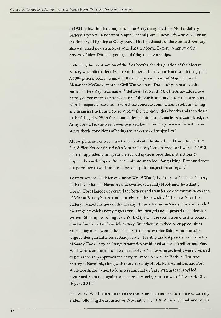
Cultural Landscape Report for the Sandy Hook Coastal Defense Batteries
In 1903, a decade after completion, the Army designated the Mortar Battery
Battery Reynolds in honor of Major-General John F. Reynolds who died during
the first day of fighting at Gettysburg. The first decade of the twentieth century
also witnessed new structures added at the Mortar Battery to improve the
process of identifying, targeting, and firing on enemy ships.
Following the construction of the data booths, the designation of the Mortar
Battery was split to identify separate batteries for the north and south firing pits.
A 1906 general order designated the north pits in honor of Major-General
Alexander McCook, another Civil War veteran. The south pits retained the
earlier Battery Reynolds name.65
Between 1906 and 1907, the Army added two
battery commander's stations on top of the earth and sand cover to correspond
with the separate batteries. From these concrete commander's stations, aiming
and firing instructions were relayed to the telephone data booths and then down
to the firing pits. With the commander's stations and data booths completed, the
Army converted the steel tower to a weather station to provide information on
atmospheric conditions affecting the trajectory of projectiles.66
Although measures were enacted to deal with displaced sand from the artillery
fire, difficulties continued with Mortar Battery's engineered earthwork. A 1910
plan for upgraded drainage and electrical systems provided instructions to
inspect the earth slopes after each rain storm to look for gullying. Personnel were
not permitted to walk on the slopes except for inspection or repair.67
To improve coastal defenses during World War I, the Army established a battery
in the high bluffs of Navesink that overlooked Sandy Hook and the Atlantic
Ocean. Fort Hancock operated the battery and transferred one mortar from each
of Mortar Battery's pits to adequately arm the new site.68 The new Navesink
battery, located further south than any of the batteries on Sandy Hook, expanded
the range at which enemy targets could be engaged and improved the defensive
system. Ships approaching New York City from the south would first encounter
mortar fire from the Navesink battery. Whether unscathed or crippled, ships
proceeding north would then face fire from the Mortar Battery and the other
large caliber gun batteries at Sandy Hook. If a ship made it past the northern tip
of Sandy Hook, large caliber gun batteries positioned at Fort Hamilton and Fort
Wadsworth, on the east and west side of the Narrows respectively, were prepared
to fire as the ship approach the entry to Upper New York Harbor. The new
battery at Navesink, along with those at Sandy Hook, Fort Hamilton, and Fort
Wadsworth, combined to form a redundant defense system that provided
continued resistance against an enemy advancing north toward New York City
(Figure 2.3 1).69
The World War I efforts to mobilize troops and expand coastal defenses abruptly
ended following the armistice on November 11, 1918. At Sandy Hook and across
42
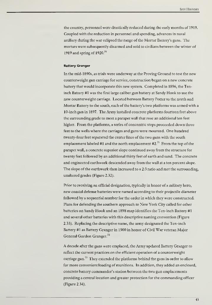
Site History
the country, personnel were drastically reduced during the early months of 1919.
Coupled with the reduction in personnel and spending, advances in naval
artillery during the war eclipsed the range of the Mortar Battery's guns. The
mortars were subsequently disarmed and sold to civilians between the winter of
1919 and spring of 1920.70
Battery Granger
In the mid- 1890s, as trials were underway at the Proving Ground to test the new
counterweight gun carriage for service, construction began on a new concrete
battery that would incorporate this new system. Completed in 1896, the Ten-
inch Battery #1 was the first large caliber gun battery at Sandy Hook to use the
new counterweight carriage. Located between Battery Potter to the north and
Mortar Battery to the south, each of the battery's two platforms was armed with a
10-inch gun in 1897. The Army installed concrete platforms fourteen feet above
the surrounding grade to meet a parapet wall that rose an additional ten feet
higher. From the platforms, a series of concentric steps proceeded down three
feet to the wells where the carriages and guns were mounted. One hundred
twenty-four feet separated the center lines of the two guns with the south
emplacement labeled #1 and the north emplacement #2.71 From the top of the
parapet wall, a concrete superior slope continued away from the structure for
twenty feet followed by an additional thirty feet of earth and sand. The concrete
and engineered earthwork descended away from the wall at a ten percent slope.
The slope of the earthwork then increased to a 2:3 ratio and met the surrounding,
unaltered grades (Figure 2.32).
Prior to receiving an official designation, typically in honor of a military hero,
new coastal defense batteries were named according to their projectile diameter
followed by a sequential number for the order in which they were constructed.
Plans for defending the southern approach to New York City called for other
batteries on Sandy Hook and an 1898 map identifies the Ten-inch Battery #1
and several other batteries with this descriptive naming convention (Figure
2.33). Replacing the descriptive name, the army designated the Ten-inch
Battery #1 as Battery Granger in 1900 in honor of Civil War veteran Major
General Gordon Granger.72
A decade after the guns were emplaced, the Army updated Battery Granger to
reflect the current practices on the efficient operation of a counterweight
carriage gun.73 They extended the platforms behind the guns in order to allow
for more convenient loading of munitions. In addition, they added an enclosed,
concrete battery commander's station between the two gun emplacements
providing a central location and greater protection for the commanding officer
(Figure 2.34).
43
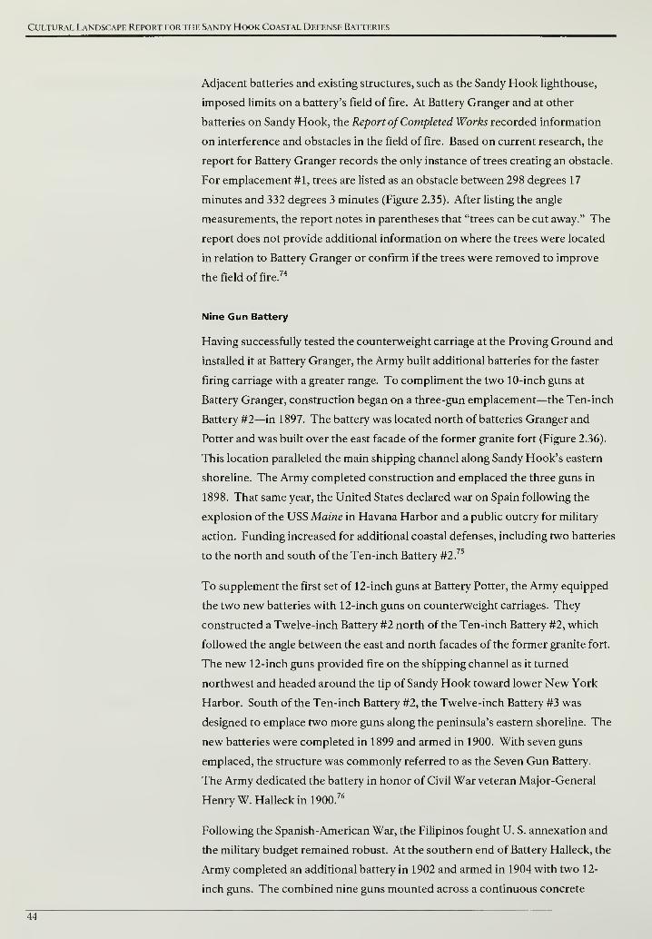
Cultural Landscape Report for the Sandy Hook Coastal Defense Batteries
Adjacent batteries and existing structures, such as the Sandy Hook lighthouse,
imposed limits on a battery's field of fire. At Battery Granger and at other
batteries on Sandy Hook, the Report of Completed Works recorded information
on interference and obstacles in the field of fire. Based on current research, the
report for Battery Granger records the only instance of trees creating an obstacle.
For emplacement #1, trees are listed as an obstacle between 298 degrees 17
minutes and 332 degrees 3 minutes (Figure 2.35). After listing the angle
measurements, the report notes in parentheses that "trees can be cut away." The
report does not provide additional information on where the trees were located
in relation to Battery Granger or confirm if the trees were removed to improve
the field of fire.74
Nine Gun Battery
Having successfully tested the counterweight carriage at the Proving Ground and
installed it at Battery Granger, the Army built additional batteries for the faster
firing carriage with a greater range. To compliment the two 10-inch guns at
Battery Granger, construction began on a three-gun emplacement—the Ten-inch
Battery #2—in 1897. The battery was located north of batteries Granger and
Potter and was built over the east facade of the former granite fort (Figure 2.36).
This location paralleled the main shipping channel along Sandy Hook's eastern
shoreline. The Army completed construction and emplaced the three guns in
1898. That same year, the United States declared war on Spain following the
explosion of the USS Maine in Havana Harbor and a public outcry for military
action. Funding increased for additional coastal defenses, including two batteries
to the north and south of the Ten-inch Battery #2.75
To supplement the first set of 12-inch guns at Battery Potter, the Army equipped
the two new batteries with 12-inch guns on counterweight carriages. They
constructed a Twelve-inch Battery #2 north of the Ten-inch Battery #2, which
followed the angle between the east and north facades of the former granite fort.
The new 12-inch guns provided fire on the shipping channel as it turned
northwest and headed around the tip of Sandy Hook toward lower New York
Harbor. South of the Ten-inch Battery #2, the Twelve-inch Battery #3 was
designed to emplace two more guns along the peninsula's eastern shoreline. The
new batteries were completed in 1899 and armed in 1900. With seven guns
emplaced, the structure was commonly referred to as the Seven Gun Battery.
The Army dedicated the battery in honor of Civil War veteran Major-General
Henry W. Halleck in 1900.76
Following the Spanish-American War, the Filipinos fought U. S. annexation and
the military budget remained robust. At the southern end of Battery Halleck, the
Army completed an additional battery in 1902 and armed in 1904 with two 12-
inch guns. The combined nine guns mounted across a continuous concrete
44
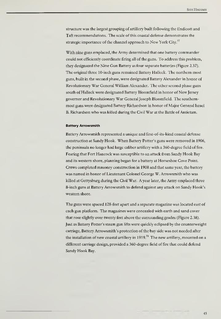
Site History
structure was the largest grouping of artillery built following the Endicott and
Taft recommendations. The scale of this coastal defense demonstrates the
strategic importance of the channel approach to New York City.77
With nine guns emplaced, the Army determined that one battery commander
could not efficiently coordinate firing all of the guns. To address this problem,
they designated the Nine Gun Battery as four separate batteries (Figure 2.37).
The original three 10-inch guns remained Battery Halleck. The northern most
guns, built in the second phase, were designated Battery Alexander in honor of
Revolutionary War General William Alexander. The other second phase guns
south of Halleck were designated Battery Bloomfield in honor of New Jersey
governor and Revolutionary War General Joseph Bloomfield. The southern-
most guns were designated Battery Richardson in honor of Major General Israel
B. Richardson who was killed during the Civil War at the Battle of Antietam.
Battery Arrowsmith
Battery Arrowsmith represented a unique and first-of-its-kind coastal defense
construction at Sandy Hook. When Battery Potter's guns were removed in 1906,
the peninsula no longer had large caliber artillery with a 360-degree field of fire.
Fearing that Fort Hancock was susceptible to an attack from Sandy Hook Bay
and its western shore, planning began for a battery at Horseshoe Cove Point.
Crews completed masonry construction in 1908 and that same year, the battery
was named in honor of Lieutenant Colonel George W. Arrowsmith who was
killed at Gettysburg during the Civil War. A year later, the Army emplaced three
8-inch guns at Battery Arrowsmith to defend against any attack on Sandy Hook's
western shore.
The guns were spaced 128-feet apart and a separate magazine was located east of
each gun platform. The magazines were concealed with earth and sand cover
that rose slightly over twenty feet above the surrounding grades (Figure 2.38).
Just as Battery Potter's steam gun lifts were quickly eclipsed by the counterweight
carriage, Battery Arrowsmith's protection of the bay side was not needed after
the installation of new coastal artillery in 1919.78 The new artillery, mounted on a
different carriage design, provided a 360-degree field of fire that could defend
Sandy Hook Bay.
45

Cultural Landscape Report for the Sandy Hook Coastal Defense Batteries
Batteries Kingman and Mills
The British introduced improved artillery on the Dreadnought and as World War
I approached, foreign navies developed similar artillery that threatened the
relatively small counterweight carriage guns at Sandy Hook. Battleships were
equipped with new turrets that positioned and fired artillery at higher angles.
With this modification that utilized the same guns and projectiles, ships could
now be positioned further offshore and out of the range of coastal defense
batteries. In addition, the counterweight carriages that lowered a battery's guns
behind protective concrete and earth for loading were now susceptible to
incoming fire from a ship's higher trajectory projectiles.
In response to this new threat, construction began on two large caliber gun
batteries utilizing a high-angle gun carriage with a greater range. In comparison
to the seven to eight mile range of counterweight carriage guns, the new artillery
had a range of over twenty miles.79 The Army mounted the high-angle carriages
on rotating platforms that resulted in a 360-degree field of fire. Instead of relying
on concrete and mounds of earth and sand to protect the artillery, the new
batteries were located on the bay side of the peninsula to be as far away as
possible from potential enemy fire and sight lines.
The Army completed masonry construction of both batteries in late 191 7.80
Each
battery included two open, circular platforms that were 100 feet in diameter.
Mounted in the center of the circle, the emplaced guns were 420 feet apart with
the south gun identified as #1 and the north as #2. In the area between the
platforms, earth covered concrete structures that housed artillery shells,
gunpowder, plotting rooms, a storeroom, a latrine, and quarters for the soldiers
stationed at either battery. Located approximately two miles from the quarters at
Fort Hancock, the engineered earthwork also served to protect the neighboring
platform from a misfire and rose approximately twenty-eight feet above the
surrounding grades (Figures 2.39 and 2.40).
The storeroom, latrine, and quarters were located in the western quarter of the
underground structures and were separated from the shell, powder, and plotting
rooms to the east by a covered passageway. The passageway was eighteen feet
wide, paved with concrete, and featured standard-gauge railroad tracks
embedded into the paving to accommodate rail deliveries of shells and
gunpowder to the batteries (Figure 2.41). When needed, soldiers retrieved shells
and gunpowder from the casemated storage areas and transported them on hand
carts to either circular platform (Figure 2.42). To improve the conditions for
soldiers at both batteries, steam heat was added to the plotting rooms, quarters,
and latrines in September 1919.
46
Site History
That same year, the Army emplaced both batteries with twelve-inch guns that had
no concealment or protection from above (Figure 2.43). The northern battery
was designated in honor of Brigadier General Dan C. Kingman who served as
Chief of Engineers for the Army Corps between 1913 and 1916. The southern
battery, 750-feet from Kingman's #1 emplacement, was designated in honor of
Brigadier General Albert L. Mills, a Medal of Honor recipient from the Spanish-
American War. 81
RAPID FIRE CUM BATTERIES
As a complement to the large caliber gun batteries that guarded the approach to
New York Harbor, rapid-fire gun batteries protected areas outside the main
shipping channel that were susceptible to attack by swift, shallow-draft boats like
landing craft and torpedo boats. In addition, the rapid-fire gun batteries
protected the minefields laid outside the channel from enemy minesweepers. At
Sandy Hook, the Army located the majority of rapid fire gun batteries at the
northern tip of the peninsula. This position allowed the batteries to protect
control mines laid adjacent to the shipping channel north of the peninsula
(Figure 2.44).
Battery Engle
Construction started on Sandy Hook's first rapid fire gun battery in 1897. The
battery was located near the northern end of the peninsula and designed to
mount a single 5-inch gun. As tension grew between the United States and Spain
over control of the Caribbean and the approach to the Panama Canal,
construction on the battery was completed and it was armed on April 21, 1898.
Four days later, Congress declared war on Spain and public pressure and funding
increased for coastal defenses.82
The Army constructed the battery was constructed with a twenty-one foot
diameter concrete platform set approximately eight feet above surrounding
grades (Figure 2.45). The platform contained a deep, cylindrical opening to hold
a balanced pillar mounted gun (Figure 2.46). To the east of the platform, a
magazine included six feet of concrete cover.
In 1903, the 5-inch rapid fire battery was designated in honor of Captain
Archibald H. Engle who was killed in the Civil War Battle of Resaca. Battery
Engle and the single 5 -inch gun did not have a long service life. At the close of the
nineteenth century, rapid-fire guns were manufactured with 3-, 4-, 4.7-, 5-, and 6-
inch caliber sizes. During World War I, caliber sizes were simplified to either 3-
inch or 6-inch. As a result, Battery Engle's 5-inch gun was declared obsolete and
disarmed in 1918.83
47
Cultural Landscape Report for the Sandy Hook Coastal Defense Batteries
Battery Urmston
Beginning in 1899, the Army constructed a six gun, rapid-fire battery west of
Battery Engle along Sandy Hook's northern shoreline. Construction occurred in
three phases and spanned five years beginning with building gun emplacements
#1 and #2 at the eastern end of the battery. Following this first phase, construction
started on the western end for gun emplacements #5 and #6. These emplacements
were completed in November 1900 and all four were armed with balanced pillar
mounted guns (Figure 2.47). When not in use, the pillar mounted guns could be
mechanically lowered below the concrete parapet. As they were lowered, the gun
barrels rotated ninety degrees and were placed in a notch in the parapet.
Battery Urmston's initial four emplacements shared a similar design with steps
leading to a rear platform approximately five feet above surrounding grade.
From the rear platform, another set of steps led to the gun platforms
approximately four feet higher in elevation. A separate magazine stood to the
east of each platform, and like Battery Engle, included six feet of concrete cover.
The top of the magazine protruded approximately three and a half feet above the
gun platform.
In June 1904, the final phase of construction at Battery Urmston included gun
emplacements #3 and #4 between the two previous sections. Unlike the earlier
rapid-fire guns, the artillery at emplacements #3 and #4 were set on fixed
pedestal mounts that could not be lowered. With all six emplacements
completed, the battery was named in honor of Lieutenant Thomas D. Urmston
who was killed during the Civil War (Figure 2.48).
In order to identify targets and direct the firing of the guns, the commanding
officer at Battery Urmston stood on top of the concrete magazine located
between two emplacements (Figure 2.49). As a component of the Taft Board's
recommendations to improve the targeting of enemy ships, a dedicated
observation station with an optical instrument known as a coincidence range
finder (CRF) was completed at Battery Urmston in February 1919. The
observation station was an open concrete structure that measured ten feet wide
by thirteen feet long. Located between emplacements #4 and #5, the station was
also fitted with a pipe frame and covered with canvas to provide some protection
against the weather (Figure 2.50).
Battery Morris
To provide a complete field of fire along Sandy Hook's northern tip, the Army
constructed a third rapid fire gun battery between Battery Engle and Battery
Urmston. Masonry construction was completed in 1903 on the four platform
battery and it was designated in 1904 in honor of Colonel Lewis Morris who was
killed during the Civil War Battle of Cold Harbor. The guns at Battery Morris
48
Site History
were intended to be mounted on pedestal carriages. Due to development and
production delays of the carriages, the guns were not emplaced until 1909.4
The four platforms were constructed approximately nine feet above surrounding
grades and were accessed by steps that led to two intermediate levels. Between
the four emplacements were three magazines that featured a combination of
concrete and earth cover. The top of the earth cover on the magazines rose seven
feet above the gun platforms (Figure 2.51).
Battery Peck
A final rapid fire battery joined Urmston, Morris, and Engle on the northern
end of Sandy Hook. Located immediately east of Battery Engle, construction
began in 1901 on a battery that supported two 6-inch rapid fire guns. This new
battery had a greater range and worked in conjunction with the remotely-
detonated minefields to stop a shallow-draft boat that ventured out of the main
shipping channel.
The Army emplaced the 6-inch guns in 1903 on barbette mounts that did not
lower the guns behind a protective parapet. A semi-circular, armor plate that
wrapped around either side of the gun barrel provided minimal protection. That
same year, the Army designated the battery in honor of Lieutenant Freemont P.
Peck who was accidentally killed at the Sandy Hook Proving Ground in 1895.
Battery Peck's two emplacements were spaced 112 feet apart with gun #1 and #2
located on the east and west halves respectively. Soldiers accessed the gun
platforms by steps on the west and east sides and in the middle of the structure.
The steps led to a rear platform approximately nine feet above surrounding
grades. From the rear platform, steps proceeded up five and a half feet to the gun
platforms. The magazines were located below this built-up structure and
accessed from the ground level through one of three doors (Figure 2.52).
Battery Gunnison
In 1898, the Army planned to build a rapid fire battery southeast of Nine Gun
Battery's southern end.85
However, this proposed location conflicted with the
ongoing operation of the Sandy Hook Proving Ground and construction was
delayed. In 1903, the Army selected an alternative location further south on the
peninsula than any battery previously built. Initial work included an extension of
the rail lines and clearing for the new battery.86
Construction was completed a
year later and the battery was designated in honor of Captain John W. Gunnison
who was killed in the Utah Territory in 1853. In 1905, two six-inch guns were
mounted on disappearing counterweight carriages. These six-inch rapid-fire
guns worked in the same manner as their larger caliber siblings. A counterweight
49
Cultural Landscape Report for the Sandy Hook Coastal Defense Batteries
raised the gun barrel into position and the recoil from firing the gun lowered the
barrel below a concrete parapet wall.
Two gun emplacements, aligned on a north-south line, faced the Atlantic Ocean
to the east and were spaced 125 feet apart on center. The platforms were
constructed approximately five and a half feet above surrounding grades. On
each platform, steps led down two feet to gun wells where the carriages and guns
were mounted. A parapet wall rose eight feet above each platform and
transitioned to a concrete superior slope that pitched away from the structure. In
between the two platforms, numerous interior rooms for communications,
offices, and equipment storage were shielded with concrete and earth cover that
rose three and a half feet higher than the top of the parapet wall (Figure 2.53).
The earth and sand slope on the east side of the battery helped to blend the
structure into the surrounding landscape and camouflage it from ships at sea.
Grasses and low-growing shrubs on the engineered earthwork contributed to the
concealment. The west facade was not camouflaged and the concrete and metal
framework of the structure was clearly visible when approaching from the west
(Figure 2.54).
The importance of the engineered earthwork in protecting the concrete structure
from artillery fire and providing camouflage can be seen in a plan prepared in
October 1905 (Figure 2.55). The plan includes notes for the artillery garrison
stationed at Battery Gunnison and instructs that:
Immediately after each rain the earth slopes shall be carefully inspected; any
slight tendency to gully or slough shall be at once remedied. Any serious
gullying shall be at once reported in writing to the Engineer Officer in charge
of the district. No person shall be allowed to walk up or down the earth
slopes at any time, except when necessary to inspect or repair them.
The earth and sand cover was susceptible to erosion from heavy storms and
unnecessary foot traffic. Regular inspection and maintenance were required to
ensure the earthwork remained an intact component of the battery's defenses.
The October 1905 plan for drainage and electrical systems highlights the issues of
water infiltration and moisture buildup that resulted from covering a concrete
structure with earth. The plan shows the layout of pipes to remove water from
the recessed gun wells and also floor drains and associated drain lines on the
interior of the battery. In addition to the drainage structures that remove
accumulated water on the interior, notes at the bottom of the plan instruct that,
"All doors should be opened from daylight until 2 P.M. on clear days, when there
is a good breeze and temperature is above 60°." At Battery Gunnison, moisture
inside the structure was limited by drainage infrastructure and by routinely
opening doors for improved air movement.
50
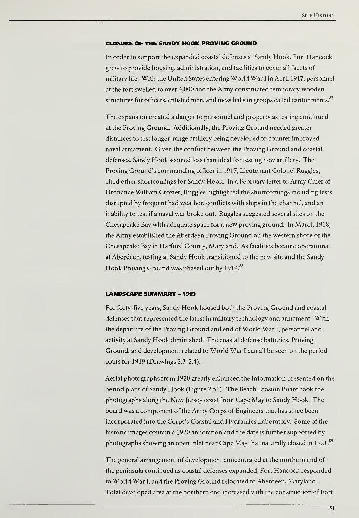
Site History
CLOSURE OF THE SANDY HOOK PROVING GROUND
In order to support the expanded coastal defenses at Sandy Hook, Fort Hancock
grew to provide housing, administration, and facilities to cover all facets of
military life. With the United States entering World War I in April 1917, personnel
at the fort swelled to over 4,000 and the Army constructed temporary wooden
structures for officers, enlisted men, and mess halls in groups called cantonments.87
The expansion created a danger to personnel and property as testing continued
at the Proving Ground. Additionally, the Proving Ground needed greater
distances to test longer-range artillery being developed to counter improved
naval armament. Given the conflict between the Proving Ground and coastal
defenses, Sandy Hook seemed less than ideal for testing new artillery. The
Proving Ground's commanding officer in 1917, Lieutenant Colonel Ruggles,
cited other shortcomings for Sandy Hook. In a February letter to Army Chief of
Ordnance William Crozier, Ruggles highlighted the shortcomings including tests
disrupted by frequent bad weather, conflicts with ships in the channel, and an
inability to test if a naval war broke out. Ruggles suggested several sites on the
Chesapeake Bay with adequate space for a new proving ground. In March 1918,
the Army established the Aberdeen Proving Ground on the western shore of the
Chesapeake Bay in Harford County, Maryland. As facilities became operational
at Aberdeen, testing at Sandy Hook transitioned to the new site and the Sandy
Hook Proving Ground was phased out by 1919.88
LANDSCAPE SUMMARY - 1919
For forty-five years, Sandy Hook housed both the Proving Ground and coastal
defenses that represented the latest in military technology and armament. With
the departure of the Proving Ground and end of World War I, personnel and
activity at Sandy Hook diminished. The coastal defense batteries, Proving
Ground, and development related to World War I can all be seen on the period
plans for 1919 (Drawings 2.3-2.4).
Aerial photographs from 1920 greatly enhanced the information presented on the
period plans of Sandy Hook (Figure 2.56). The Beach Erosion Board took the
photographs along the New Jersey coast from Cape May to Sandy Hook. The
board was a component of the Army Corps of Engineers that has since been
incorporated into the Corps's Coastal and Hydraulics Laboratory. Some of the
historic images contain a 1920 annotation and the date is further supported by
photographs showing an open inlet near Cape May that naturally closed in 1921.89
The general arrangement of development concentrated at the northern end of
the peninsula continued as coastal defenses expanded, Fort Hancock responded
to World War I, and the Proving Ground relocated to Aberdeen, Maryland.
Total developed area at the northern end increased with the construction of Fort
51
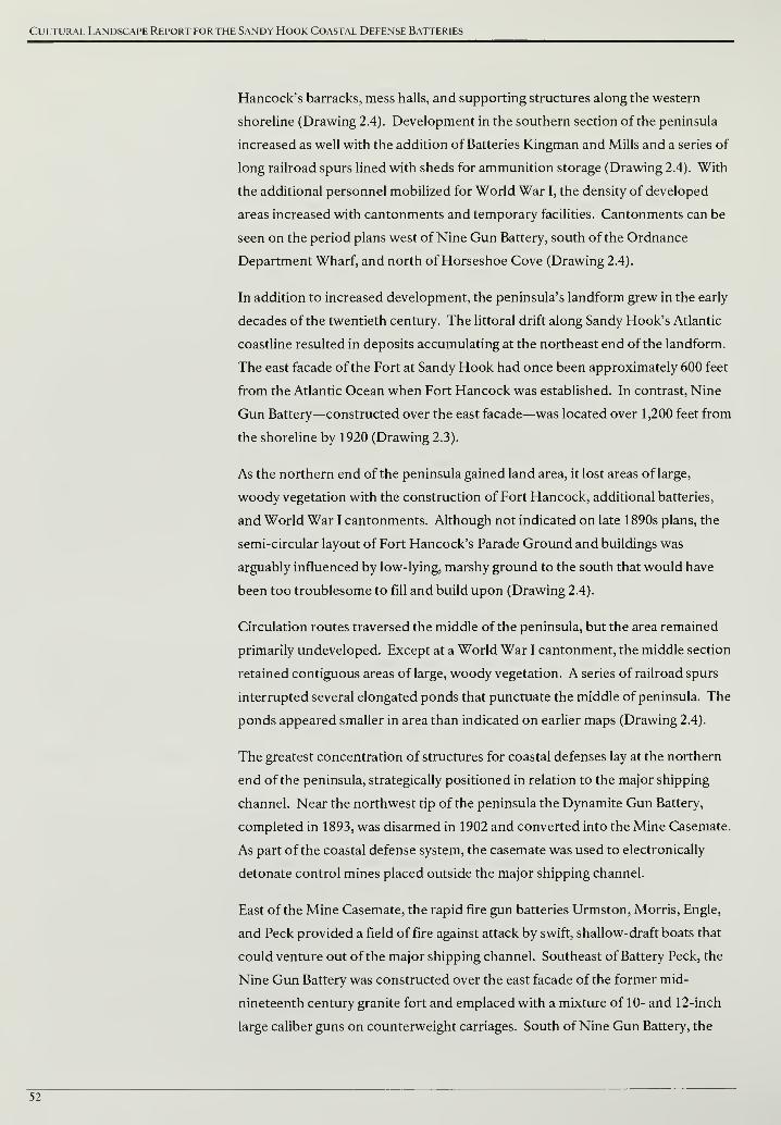
Cultural Landscape Report for the Sandy Hook Coastal Defense Batteries
Hancock's barracks, mess halls, and supporting structures along the western
shoreline (Drawing 2.4). Development in the southern section of the peninsula
increased as well with the addition of Batteries Kingman and Mills and a series of
long railroad spurs lined with sheds for ammunition storage (Drawing 2.4). With
the additional personnel mobilized for World War I, the density of developed
areas increased with cantonments and temporary facilities. Cantonments can be
seen on the period plans west of Nine Gun Battery, south of the Ordnance
Department Wharf, and north of Horseshoe Cove (Drawing 2.4).
In addition to increased development, the peninsula's landform grew in the early
decades of the twentieth century. The littoral drift along Sandy Hook's Atlantic
coastline resulted in deposits accumulating at the northeast end of the landform.
The east facade of the Fort at Sandy Hook had once been approximately 600 feet
from the Atlantic Ocean when Fort Hancock was established. In contrast, Nine
Gun Battery—constructed over the east facade—was located over 1,200 feet from
the shoreline by 1920 (Drawing 2.3).
As the northern end of the peninsula gained land area, it lost areas of large,
woody vegetation with the construction of Fort Hancock, additional batteries,
and World War I cantonments. Although not indicated on late 1890s plans, the
semi-circular layout of Fort Hancock's Parade Ground and buildings was
arguably influenced by low-lying, marshy ground to the south that would have
been too troublesome to fill and build upon (Drawing 2.4).
Circulation routes traversed the middle of the peninsula, but the area remained
primarily undeveloped. Except at a World War I cantonment, the middle section
retained contiguous areas of large, woody vegetation. A series of railroad spurs
interrupted several elongated ponds that punctuate the middle of peninsula. The
ponds appeared smaller in area than indicated on earlier maps (Drawing 2.4).
The greatest concentration of structures for coastal defenses lay at the northern
end of the peninsula, strategically positioned in relation to the major shipping
channel. Near the northwest tip of the peninsula the Dynamite Gun Battery,
completed in 1893, was disarmed in 1902 and converted into the Mine Casemate.
As part of the coastal defense system, the casemate was used to electronically
detonate control mines placed outside the major shipping channel.
East of the Mine Casemate, the rapid fire gun batteries Urmston, Morris, Engle,
and Peck provided a field of fire against attack by swift, shallow-draft boats that
could venture out of the major shipping channel. Southeast of Battery Peck, the
Nine Gun Battery was constructed over the east facade of the former mid-
nineteenth century granite fort and emplaced with a mixture of 10- and 12-inch
large caliber guns on counterweight carriages. South of Nine Gun Battery, the
52
Site History
Proving Ground expanded its Proof Battery and the number of supporting
buildings for testing ordnance (Drawing 2.4).
East of the Proof Battery, Battery Potter was disarmed in 1906 but continued to
perform a role in the coastal defense mission. Fire control stations were added to
Battery Potter's terreplein and immediately west of the structure, a powerhouse,
coal shed, and switchboard rooms were constructed. South of Battery Potter,
Battery Granger was completed in 1896 and was the first battery at Sandy Hook
to use the Buffington-Croizer counterweight carriage. South of Battery Granger,
Battery Gunnison was constructed as the only rapid fire battery on the
peninsula's eastern shore. West of Battery Gunnison, the Mortar Battery
included a battery commander's tower inside the structure's perimeter wall and
telephone data booths above each firing pit to improve aiming and firing.
West of the Mortar Battery, the Army completed housing and support facilities
for Fort Hancock and positioned around a triangular Athletic Field and semi-
circular Parade Ground. Officers' Row, the most pronounced feature of Fort
Hancock's design, was achieved by constructing a line of eighteen homes west of
the Athletic Field and Parade Ground with front facades oriented to Sandy Hook
Bay (Drawing 2.4).
South of the Parade Ground, the Army constructed Battery Arrowsmith on a
point of land projecting into Horseshoe Cove. The battery protected against
enemy ships entering Sandy Hook Bay after the 360-degree field of fire guns atop
Battery Potter were disarmed (Drawing 2.4). Further south along the western
shoreline, Batteries Kingman and Mills were constructed north of Spermaceti
Cove. The two batteries featured high trajectory, longer-range guns that could
engage enemy ships further out in the Atlantic while remaining out of the
enemy's view and artillery range (Drawing 2.4).
The increased number of coastal defense batteries and structures for Fort
Hancock necessitated an expansion of the road and railroad circulation systems
in order to move people and supplies. Railroad access had been the only
connection between Sandy Hook and the mainland to the south. Paralleling the
railroad, Hartshorne Drive was established as the major north-south vehicular
route across the peninsula. A secondary north-south route, Atlantic Drive, started
at Battery Gunnison, proceeded south, and then turned west to form a perimeter
loop with Hartshorne Drive. Between Battery Gunnison and Fort Hancock's
barracks, a major east-west connector called Gunnison Road was established.
The Ordnance Department Wharf near the northern end of peninsula expanded
and a small dock in Horseshoe Cove remained from the mid-nineteenth century
wharf constructed by the Central Railroad ofNew Jersey. Railroad lines
diverged from the Ordnance Wharf and provided access to points north, south,
53

Cultural Landscape Report for the Sandy Hook Coastal Defense Batteries
and east. North of the Mortar Battery, a railroad line terminated for Fort
Hancock's coal storage area. Additionally, the number of railroad lines increased
for the Proving Ground with five spurs constructed to align with the individual
bays of the Proof Battery (Drawing 2.4).
54
Site History
Figure 2.24. HMS Dreadnought, circa 1906-07. The British completed the first battleship featuring
12-inch caliber guns with the successful launching of the HMS Dreadnought in 1906. Dreadnought's
artillery matched the range of coastal defense artillery and lead to an international naval arms race
("British Navy Ships-HMS Dreadnought 1906-1922," U. S. Department of the Navy, Naval Historical
Center, http://www.history.navy.mil/photos/sh-fornv/uk/uksh-d/drednt9.htm).
Figure 2.25. Interior of Battery Potter plotting room, circa 1907. Part of the Taft Board's
recommendations to incorporate the latest technology resulted in improvements to fire control—the
process of acquiring and firing on enemy ships. The communications between observation, calculating,
and firing were increasingly handled by telephone, seen mounted on the wall in this image (GATE 7819).
55
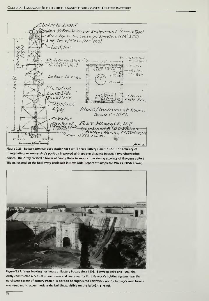
Cultural Landscape Report for the Sandy Hook Coastal Defense Batteries
{CbStacfc JLf<?hf-
"\: ll^lt
,r/eV ' /*/> off?**' i''/3.'s-4jJ
JL/fil\Tr*r Oil
—
JEfoci**,'
*~~
/Vc7/7 Of/nx/rumenh Acom. .
nFigure 2.26. Battery commander's station for Fort Tilden's Battery Harris, 1927. The accuracy of
triangulating an enemy ship's position improved with greater distance between two observation
points. The Army erected a tower at Sandy Hook to support the aiming accuracy of the guns at Fort
Tilden, located on the Rockaway peninsula in New York (Report of Completed Works, CDSG ePress).
Figure 2.27. View looking northeast at Battery Potter, circa 1906. Between 1901 and 1903, the
Army constructed a central powerhouse and coal shed for Fort Hancock's lighting system near the
northwest corner of Battery Potter. A portion of engineered earthwork on the battery's west facade
was removed to accommodate the buildings, visible on the left (GATE 7818).
56
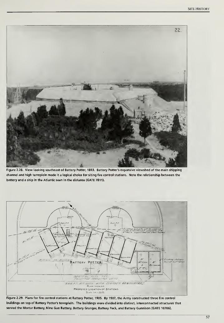
Site History
Figure 2.28. View looking southeast of Battery Potter, 1893. Battery Potter's expansive viewshed of the main shipping
channel and high terreplein made it a logical choice for siting fire control stations. Note the relationship between the
battery and a ship in the Atlantic seen in the distance (GATE 7811).
Plan smowimg
Proposed Location or StationsSol. Iin • 20 ft
Figure 2.29. Plans for fire control stations at Battery Potter, 1905. By 1907, the Army constructed three fire control
buildings on top of Battery Potter's terreplein. The buildings were divided into distinct, interconnected structures that
served the Mortar Battery, Nine Gun Battery, Battery Granger, Battery Peck, and Battery Gunnison (GATE 10706).
57
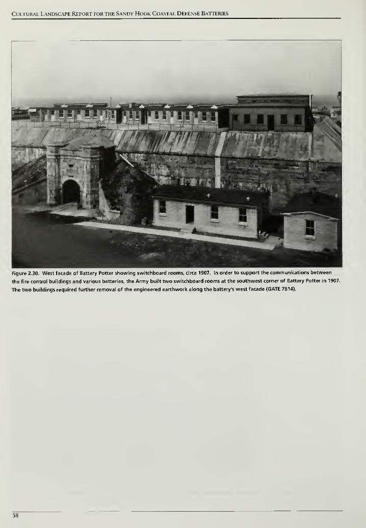
Cultural Landscape Report for the Sandy Hook Coastal Defense Batteries
Figure 2.30. West facade of Battery Potter showing switchboard rooms, circa 1907. In order to support the communications between
the fire control buildings and various batteries, the Army built two switchboard rooms at the southwest corner of Battery Potter in 1907.
The two buildings required further removal of the engineered earthwork along the battery's west facade (GATE 7814).
58
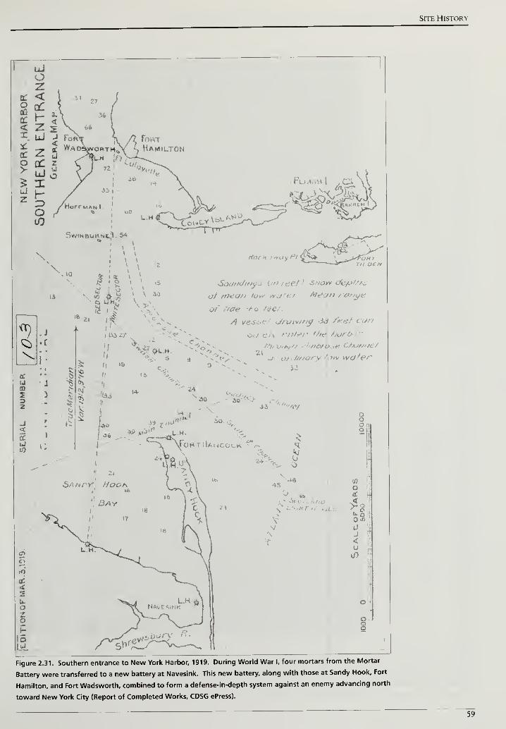
Site History
, Plui
Swinburne,:!. 54
V\ \
\\0
iL 8 i v
12
tS
30
finch may Pi
Soundman ("> fee/ •' sAo^v «./«.:/
t?/ tnea// low w&tet Mean / o//ye
at' tide -*-o /<?<?/.
A yesse/ druiv/ng AS /fe<?/ can
e/y enter t/te\ hort>
t/y, , '>£>/&_,e C/Ajf///e/
J/f/ary 'ovv wafer
Figure 2.31. Southern entrance to New York Harbor, 1919. During World War I, four mortars from the Mortar
Battery were transferred to a new battery at Navesink. This new battery, along with those at Sandy Hook, Fort
Hamilton, and Fort Wadsworth, combined to form a defense-in-depth system against an enemy advancing north
toward New York City (Report of Completed Works, CDSG ePress).
59
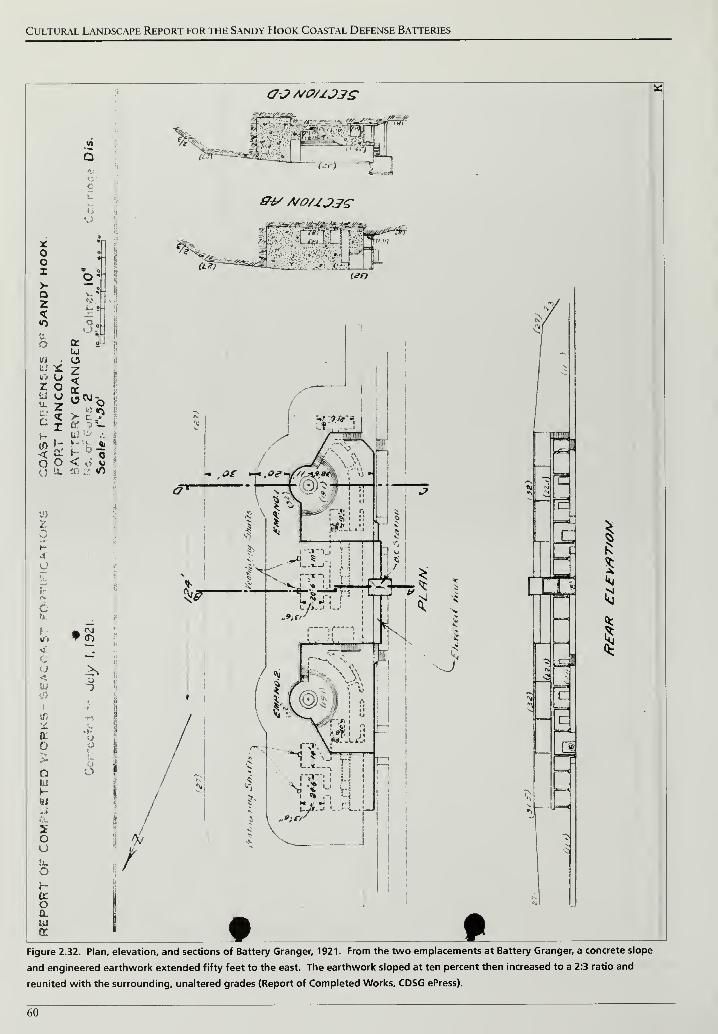
Cultural Landscape Report for the Sandy Hook Coastal Defense Batteries
<7JM(?/1J3£
^>
e 1
J
r
, L
I
1*1
Figure 2.32. Plan, elevation, and sections of Battery Granger, 1921. From the two emplacements at Battery Granger, a concrete slope
and engineered earthwork extended fifty feet to the east. The earthwork sloped at ten percent then increased to a 2:3 ratio and
reunited with the surrounding, unaltered grades (Report of Completed Works, CDSG ePress).
60
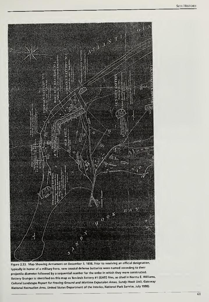
Site History
Figure 2.33. Map Showing Armament on December 3, 1898. Prior to receiving an official designation,
typically in honor of a military hero, new coastal defense batteries were named according to their
projectile diameter followed by a sequential number for the order in which they were constructed.
Battery Granger is identified on this map as Ten-inch Battery #1 (GATE files, as cited in Norma E. Williams,
Cultural Landscape Report for Proving Ground and Wartime Expansion Areas, Sandy Hook Unit, Gateway
National Recreation Area. United States Department of the Interior, National Park Service, July 1999).
61
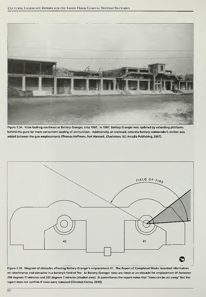
Cultural Landscape Report for the Sandy Hook Coastal Defense Batteries
Figure 2.34. View looking southeast at Battery Granger, circa 1907. In 1907, Battery Granger was updated by extending platforms
behind the guns for more convenient loading of ammunition. Additionally, an enclosed, concrete battery commander's station was
added between the gun emplacements (Thomas Hoffman, Fort Hancock, Charleston, SC: Arcadia Publishing, 2007).
Figure 2.35. Diagram of obstacles affecting Battery Granger's emplacement #1. The Report of Completed Works recorded information
on interference and obstacles in a battery's field of fire. At Battery Granger, trees are listed as an obstacle for emplacement #1 between
298 degrees 17 minutes and 332 degrees 3 minutes (shaded area). In parentheses the report notes that "trees can be cut away" but the
report does not confirm if trees were removed (Olmsted Center, 2010).
62
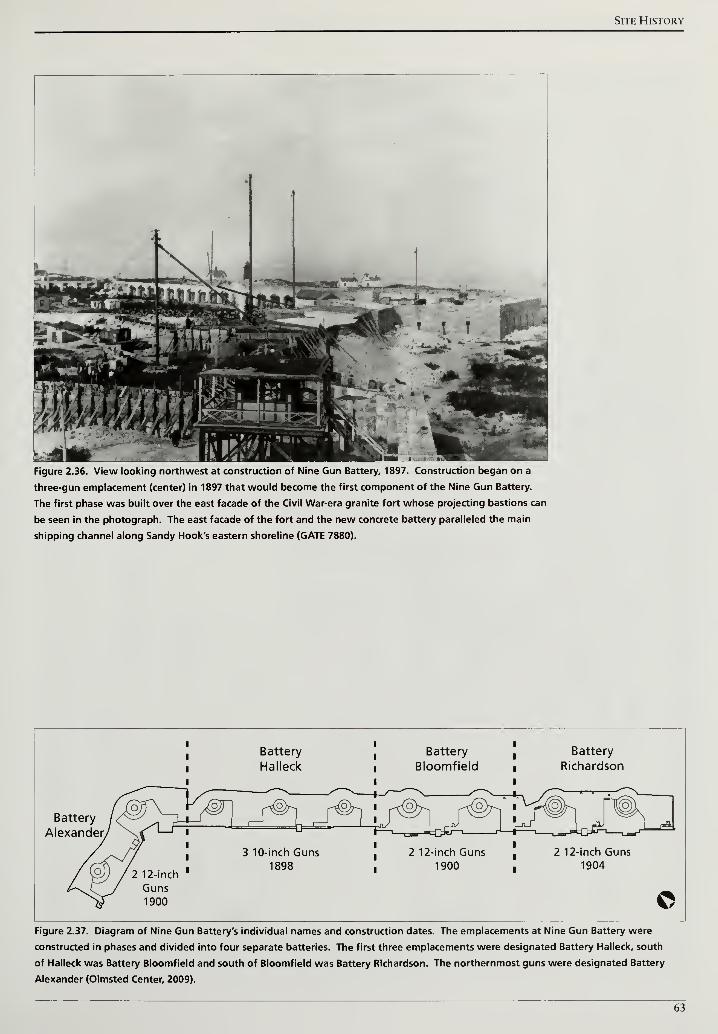
Site History
Figure 2.36. View looking northwest at construction of Nine Gun Battery, 1897. Construction began on a
three-gun emplacement (center) in 1897 that would become the first component of the Nine Gun Battery.
The first phase was built over the east facade of the Civil War-era granite fort whose projecting bastions can
be seen in the photograph. The east facade of the fort and the new concrete battery paralleled the main
shipping channel along Sandy Hook's eastern shoreline (GATE 7880).
Battery
Halleck
Battery
Richardson
Battery
Alexander
_p©-| _f@h
3 10-inch Guns1898
2 12-inch Guns1904
©Figure 2.37. Diagram of Nine Gun Battery's individual names and construction dates. The emplacements at Nine Gun Battery were
constructed in phases and divided into four separate batteries. The first three emplacements were designated Battery Halleck, south
of Halleck was Battery Bloomfield and south of Bloomfield was Battery Richardson. The northernmost guns were designated Battery
Alexander (Olmsted Center, 2009).
63
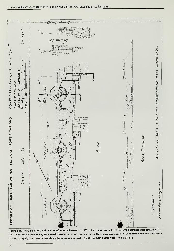
Cultural Landscape Report for the Sandy Hook Coastal Defense Batteries
Figure 2.38. Plan, elevation, and sections of Battery Arrowsmith, 1921. Battery Arrowsmith's three emplacements were spaced 128-
feet apart and a separate magazine was located east of each gun platform. The magazines were concealed with earth and sand cover
that rose slightly over twenty feet above the surrounding grades (Report of Completed Works, CDSG ePress).
64
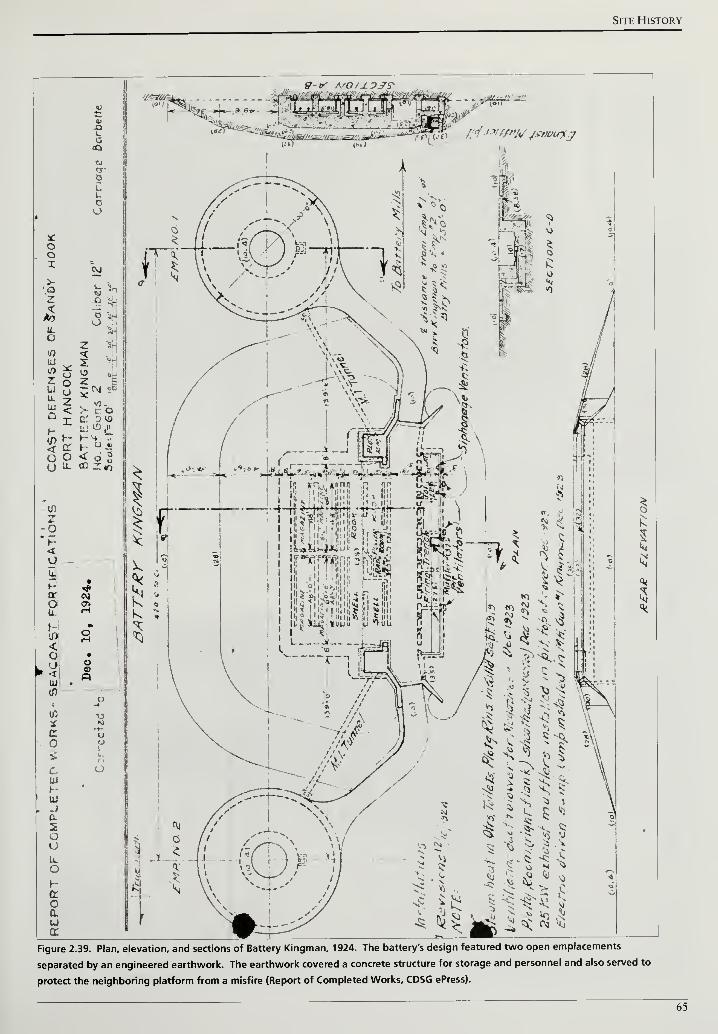
Site History
g-v A'0/j.3jr?
>--' s <-*. °-- vp . r i
'"ffimiffj? c < ' .-, a ***' '
TtT8
(Bt)
Figure 2.39. Plan, elevation, and sections of Battery Kingman, 1924. The battery's design featured two open emplacements
separated by an engineered earthwork. The earthwork covered a concrete structure for storage and personnel and also served to
protect the neighboring platform from a misfire (Report of Completed Works, CDSG ePress).
65
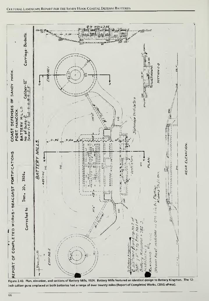
Cultural Landscape Report for the Sandy Hook Coastal Defense Batteries
XUt:49A
k k
(8
V. <n
Lf.
f au
*
r c
oa>a s-Vz<
JOS
if)
a: \
IL i
O j
10
Ui £••» 2
10 t
J
j
5) H- »~*fc i
o c i < o3y u. OJZiO
<n
2OH<
l
b. •
i
-*
Ll»
h- oVp i-i
< •o O
<HI
-
O1 •-
if) -o* Sc uo o5 h
r° O
I tu
hLU
, _J
. a2oou.oh-
aoa.UI
9-V N0.tJ.O3S
9:6*--
(»2r
'
Sl«<^<iL Jfer
—•"-- ''"" '""Wrji.
(«» <«">
<>- 1
f*e\
fc! 4Ks §CQ
*
I s i*> II *
'fc=AfcJJJiJ» »*a.|
: in|k -ii . i »• hi
Sj ii
sa -
o
Uj
-J
Figure 2.40. Plan, elevation, and sections of Battery Mills, 1924. Battery Mills featured an identical design to Battery Kingman. The 12-
inch caliber guns emplaced at both batteries had a range of over twenty miles (Report of Completed Works, CDSG ePress).
66
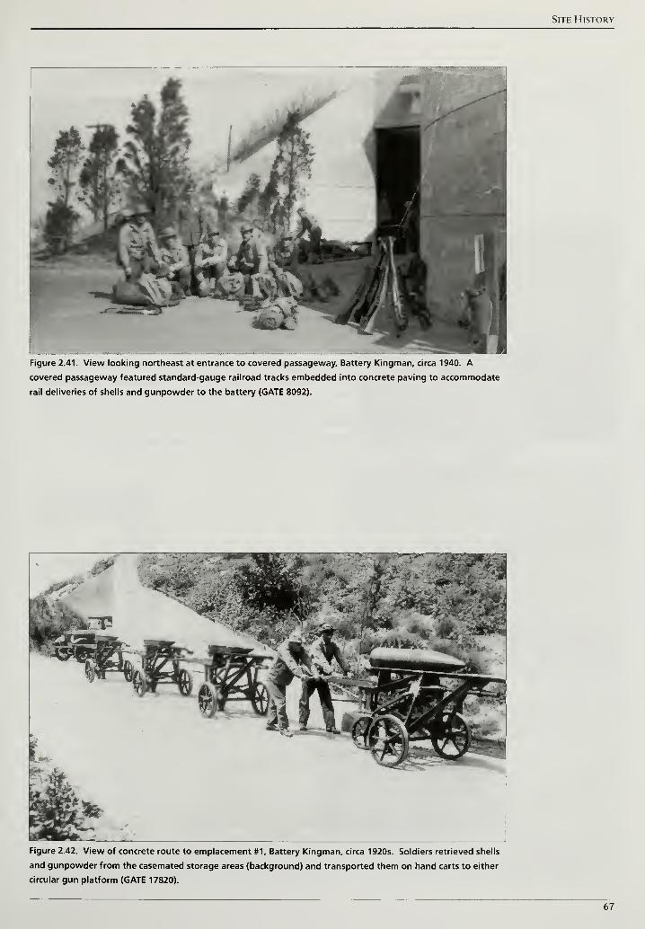
Site History
Figure 2.41. View looking northeast at entrance to covered passageway. Battery Kingman, circa 1940. A
covered passageway featured standard-gauge railroad tracks embedded into concrete paving to accommodate
rail deliveries of shells and gunpowder to the battery (GATE 8092).
Figure 2.42. View of concrete route to emplacement #1, Battery Kingman, circa 1920s. Soldiers retrieved shells
and gunpowder from the casemated storage areas (background) and transported them on hand carts to either
circular gun platform (GATE 17820).
67
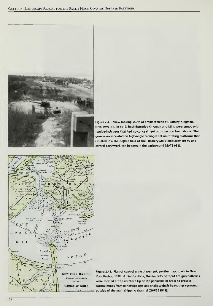
Cultural Landscape Report for the Sandy Hook Coastal Defense Batteries
Figure 2.43. View looking south at emplacement #1, Battery Kingman,
circa 1940-41. In 1919, both Batteries Kingman and Mills were armed with
twelve-inch guns that had no concealment or protection from above. The
guns were mounted on high-angle carriages set on rotating platforms that
resulted in a 360-degree field of fire. Battery Mills' emplacement #2 and
central earthwork can be seen in the background (GATE 938).
Figure 2.44. Plan of control mine placement, southern approach to New
York Harbor, 1898. At Sandy Hook, the majority of rapid fire gun batteries
were located at the northern tip of the peninsula in order to protect
control mines from minesweepers and shallow-draft boats that ventured
outside of the main shipping channel (GATE 21843).
68
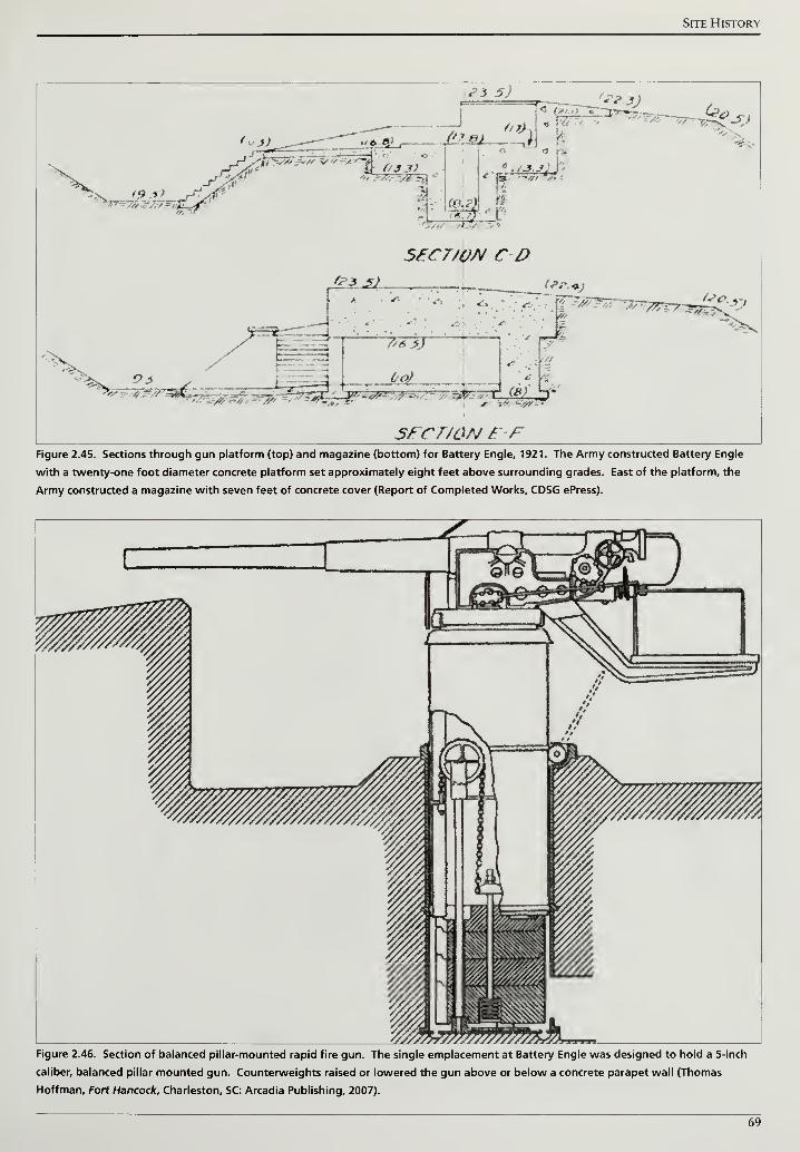
Site History
P3 5) i
fan 31
'e-s-j
I
SECTION CO
ysr,-#-,>/>Zt£^h;
a 3 ^ fe?.^J
"•
f-~-_4 ^_J^
^#< -v**
SFCr/ON F FFigure 2.45. Sections through gun platform (top) and magazine (bottom) for Battery Engle, 1921. The Army constructed Battery Engle
with a twenty-one foot diameter concrete platform set approximately eight feet above surrounding grades. East of the platform, the
Army constructed a magazine with seven feet of concrete cover (Report of Completed Works, CDSG ePress).
Figure 2.46. Section of balanced pillar-mounted rapid fire gun. The single emplacement at Battery Engle was designed to hold a 5-inch
caliber, balanced pillar mounted gun. Counterweights raised or lowered the gun above or below a concrete parapet wall (Thomas
Hoffman, Fort Hancock, Charleston, SC: Arcadia Publishing, 2007).
69
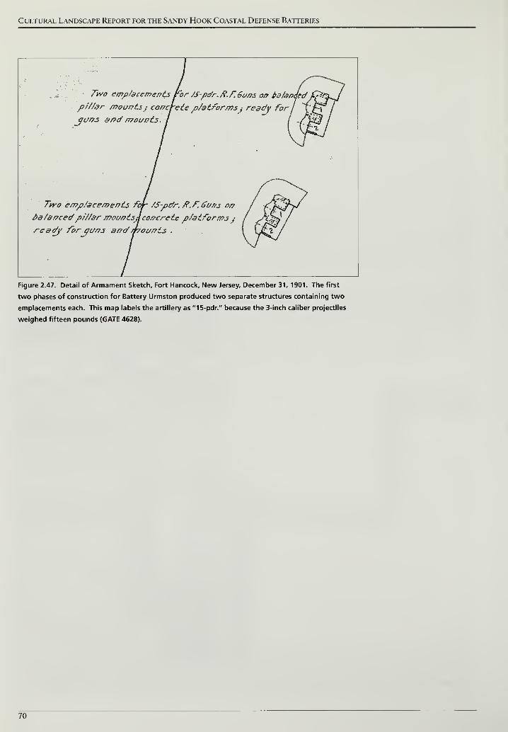
Cultural Landscape Report for the Sandy Hook Coastal Defense Batteries
Two emp/acements tor /S-pdr. /?. F.Guns or? 4aSanded
pf//dr mounts; concrete p/atformsj ready for \ffiyuns and mounts.
Two emp/acements fofr /S-pdr. fi.f.Guns on
na/ancedp///ar mountsJconcrete p/atforms yready foryuns and/hounis .
Figure 2.47. Detail of Armament Sketch, Fort Hancock, New Jersey, December 31, 1901. The first
two phases of construction for Battery Urmston produced two separate structures containing two
emplacements each. This map labels the artillery as "15-pdr." because the 3-inch caliber projectiles
weighed fifteen pounds (GATE 4628).
70
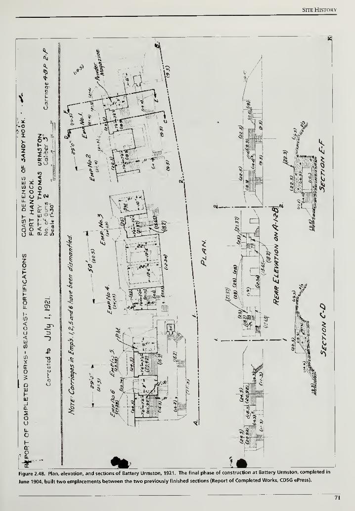
Site History
Figure 2.48. Plan, elevation, and sections of Battery Urmston, 1921. The final phase of construction at Battery Urmston, completed in
June 1904, built two emplacements between the two previously finished sections (Report of Completed Works, CDSG ePress).
71
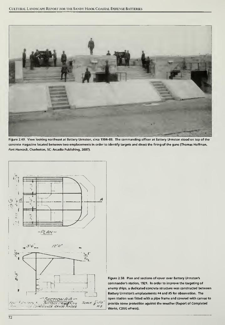
Cultural Landscape Report for the Sandy Hook Coastal Defense Batteries
Figure 2.49. View looking northeast at Battery Urmston, circa 1904-08. The commanding officer at Battery Urmston stood on top of the
concrete magazine located between two emplacements in order to identify targets and direct the firing of the guns (Thomas Hoffman,
Fort Hancock, Charleston, SC: Arcadia Publishing, 2007).
.'••
h=+V
I
ff
_/-PLAN-
-»J '^— /?-'**
-?*
v: m*fS.
Figure 2.50. Plan and sections of cover over Battery Urmston's
commander's station, 1921. In order to improve the targeting of
enemy ships, a dedicated concrete structure was constructed between
Battery Urmston's emplacements #4 and #5 for observation. The
open station was fitted with a pipe frame and covered with canvas to
provide some protection against the weather (Report of Completed
Works, CDSG ePress).
72
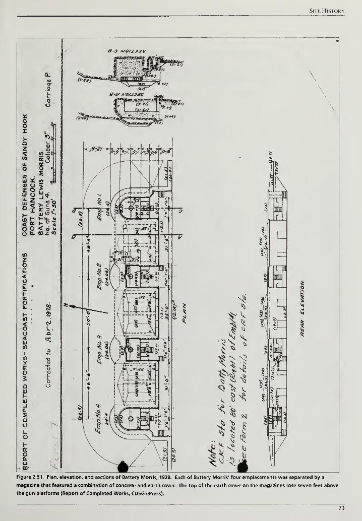
Site History
oor>-
Qz
<0
UJ(0
Zua.UJD
i
a
LCo
&o2 i
or a .
< o v»
«DZ <0
Zo
<y
i-cr
t<Hi
0)
i
tt
o
oUJ
hui-jc.
5OUu.oho0.klOf
-Gl
O--u
poO
<7-^ */0U3?e
38 im? m ?! - El
rat
;
S^^6
^ s;Hi^V)'$|
\
(Z
;CZ
in
3fltd
t
I
Figure 2.51. Plan, elevation, and sections of Battery Morris, 1928. Each of Battery Morris' four emplacements was separated by a
magazine that featured a combination of concrete and earth cover. The top of the earth cover on the magazines rose seven feet above
the gun platforms (Report of Completed Works, CDSG ePress).
73
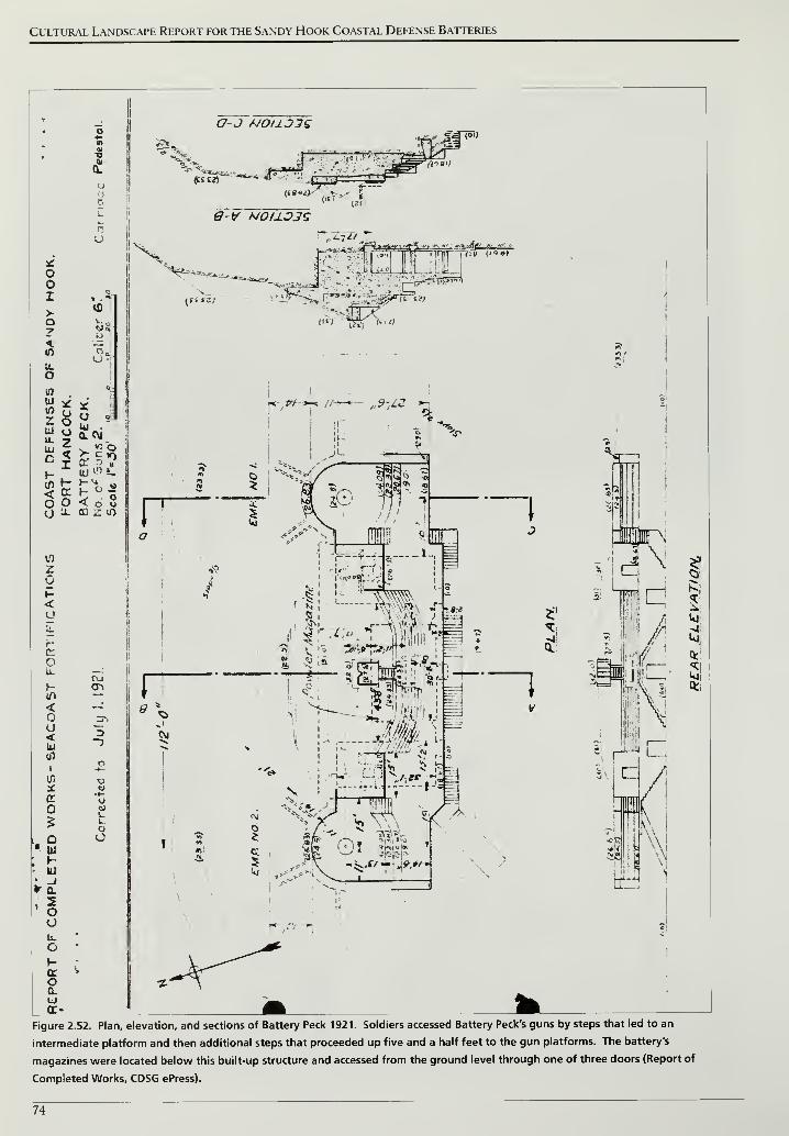
Cultural Landscape Report for the Sandy Hook Coastal Defense Batteries
oor>o
u.
owumZuu.
ku
o
3
r.
L
no
i
< £° ?
zop<
c:
Ou.
r-
<ou<IU
(fl
I
1/5
o
i t
•1Ou.
O
a.
oa.LJ
xuUJ .
a. r\j
<o 8cd z. <o
c7-J A/OUJ7Q
Ktm ' ..t . « (f,-*
—
*"i
*i
~*
"'
ii ri '
1'J '
^
1 V>
G-V N0I1O3S
*
r
_"~.':;jj&rir
~t?>
=i
*-'
ii#
3-?
oCJV.LoO
<,c> l*ef !*'»
I
Pi'
3\ rz
i
Figure 2.52. Plan, elevation, and sections of Battery Peck 1921. Soldiers accessed Battery Peck's guns by steps that led to an
intermediate platform and then additional steps that proceeded up five and a half feet to the gun platforms. The battery's
magazines were located below this built-up structure and accessed from the ground level through one of three doors (Report of
Completed Works, CDSG ePress).
74
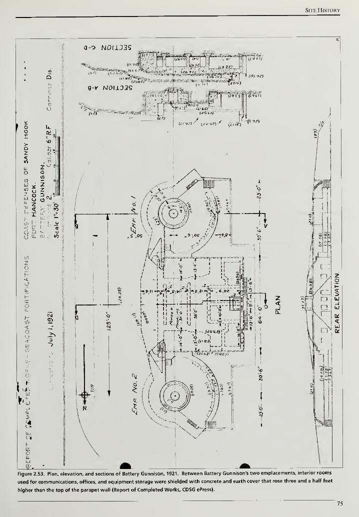
Site History
Figure 2.53. Plan, elevation, and sections of Battery Gunnison, 1921. Between Battery Gunnison's two emplacements, interior rooms
used for communications, offices, and equipment storage were shielded with concrete and earth cover that rose three and a half feet
higher than the top of the parapet wall (Report of Completed Works, CDSG ePress).
75
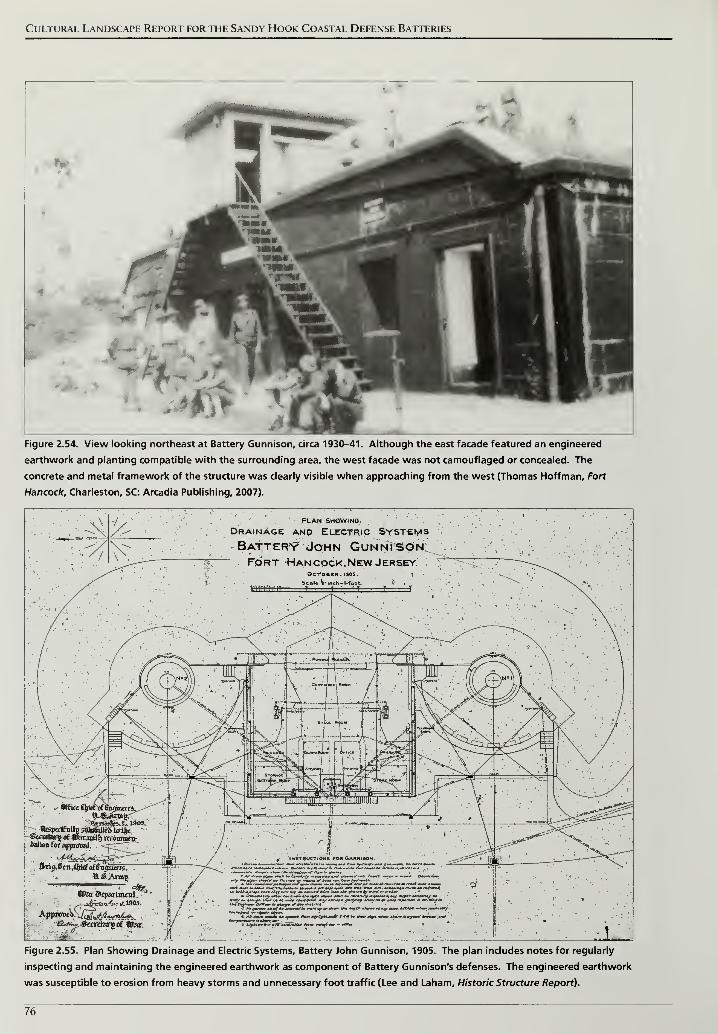
Cultural Landscape Report for the Sandy Hook Coastal Defense Batteries
Figure 2.54. View looking northeast at Battery Gunnison, circa 1930-41. Although the east facade featured an engineered
earthwork and planting compatible with the surrounding area, the west facade was not camouflaged or concealed. The
concrete and metal framework of the structure was clearly visible when approaching from the west (Thomas Hoffman, Fort
Hancock, Charleston, SC: Arcadia Publishing, 2007).
A -/, PLAN SHOWING, •
Drainage anp Electric SystemsBatter*? John GunnisonFort Han cock.New Jersey. ;
(»ri$.fcn,4tefof6iiji
<Par9q>aitm*nl, '
w«*~s JkcrAtoyi of Vktc.
L ' -lift'- . - • " ^
f »i* «/>'-,=. fct/inj r*n net iawrf one* US tnr t*»M« Q<* /ntmntPntny n*ttr c**» —i~ iA# nyte ««• *W* cnmni/t, .-.pa*
ju'y » nlouytr ir*lt un et onon -nn^&tmf <*«>• nnrinrn J**?'"? nnnf OM
S Nn nn .in i>ifl.jnM,l(n»i,riM tha —rW * "» *t
t ,t«« l»A on ymnn- /*— **,//£** *MnV /*« fc» t/—rdtjrm.n
l ,-'
^lFigure 2.55. Plan Showing Drainage and Electric Systems, Battery John Gunnison, 1905. The plan includes notes for regularly
inspecting and maintaining the engineered earthwork as component of Battery Gunnison's defenses. The engineered earthwork
was susceptible to erosion from heavy storms and unnecessary foot traffic (Lee and Laham, Historic Structure Report).
76
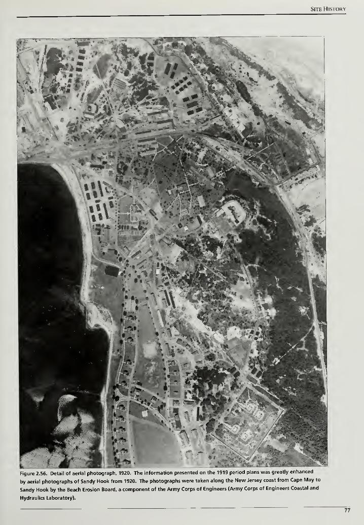
Site History
Figure 2.56. Detail of aerial photograph, 1920. The information presented on the 1919 period plans was greatly enhanced
by aerial photographs of Sandy Hook from 1920. The photographs were taken along the New Jersey coast from Cape May to
Sandy Hook by the Beach Erosion Board, a component of the Army Corps of Engineers (Army Corps of Engineers Coastal and
Hydraulics Laboratory).
77

Cultural Landscape Report for the Sandy Hook Coastal Defense Batteries
78
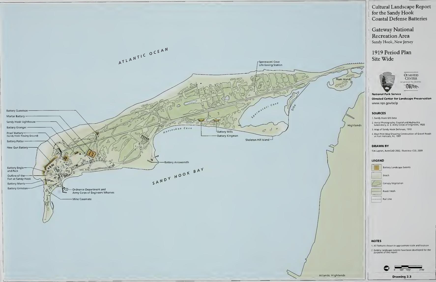
Cultural Landscape Report
for the Sandy HookCoastal Defense Batteries
Gateway National
Recreation AreaSandy Hook, New Jersey
1919 Period Plan
Site Wide
OlmstedCenter
National Park Service
Olmsted Center for Landscape Preservation
www.nps.gov/oclp
SOURCES
1 . Sandy Hook GI5 Data
!. Aerial Photographs, CcLaboratory, U. S. Army
3. Map of Sandy Hook Defenses, 1910
DRAWN BY
Tim Layton, AutoCAD 2002, Illustrator CS3, 2009
LEGEND
Battery Landscape Extents
'
Road /Walk
I Rail Line
NOTES
t All features shown in approximate scale and locatic
0' 525' 105<T
Drawing 2.3
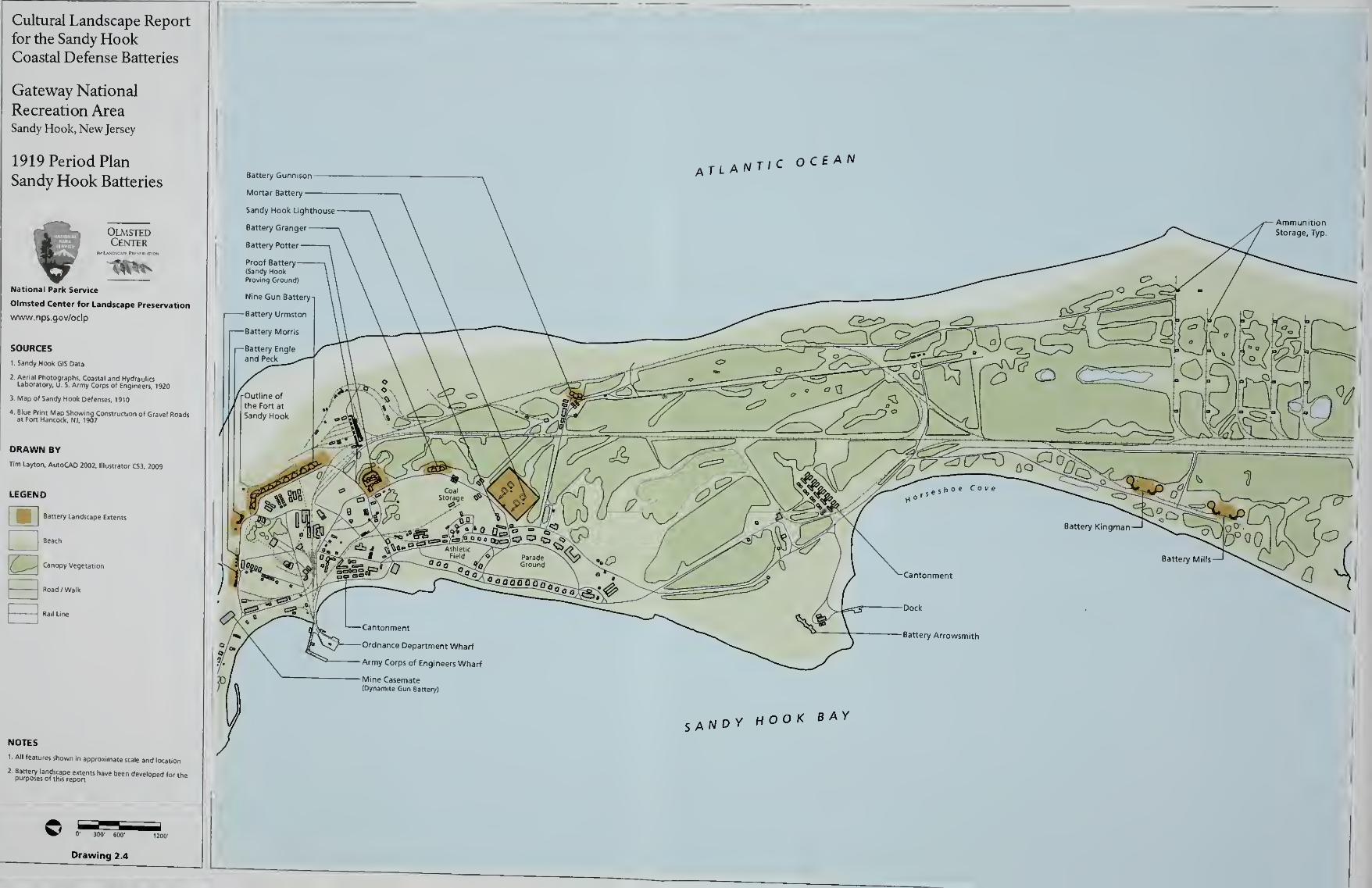
Cultural Landscape Report
for the Sandy HookCoastal Defense Batteries
Gateway National
Recreation AreaSandy Hook, New Jersey
1919 Period Plan
Sandy Hook Batteries
Site History
CARETAKER STATUS AMD WORLD WAR II 1919-1945
The World War I efforts to mobilize troops and expand coastal defenses abruptly
ended following the armistice on November ll, 1918. At Sandy Hook and across
the country, personnel were drastically reduced and the coastal defense batteries
were assigned to a minimal level of upkeep referred to as caretaker status.
Between December 1918 and June 1919, Sandy Hook's batteries saw their
personnel reduced from twenty-four officers and 1,535 enlisted men to fifteen
officers and 386 enlisted men.90
From the armistice to the conclusion of World War II, personnel levels fluctuated
at Sandy Hook due to caretaker status, the activation of National Guard units,
and training and coastal defense functions during the war. The Army reduced
the number of operational batteries at Sandy Hook and other sites defending
New York Harbor because the range of large caliber 12- and 16-inch guns
provided a greater field of fire. At Sandy Hook, Batteries Kingman and Mills
were positioned on the western side of the entry to Lower New York Harbor.
On Long Island, New York, the Rockaway peninsula marked the eastern side and
in this location, 16-inch guns were emplaced at Fort Tilden's Battery Harris.
These three batteries covered any possible approach of a major battleship and
during World War II, were joined by Battery Lewis in the Navesink Highlands.
Similar to Battery Harris, Battery Lewis had 16-inch guns that extended the field
of fire further south and east into the Atlantic Ocean (Figure 2.57).
Advances in aviation technology during the inter-war period redefined coastal
defense strategies. The potential to use airplanes in reconnaissance and bombing
campaigns required the redesign of large caliber batteries, including Kingman
and Mills. The expanded role of aviation also resulted in new detection
technologies, which were tested and installed at Sandy Hook. In the mid- 1930s,
the Army Signal Corps Laboratories at nearby Fort Monmouth developed
detection systems that transmitted radio waves and determined aircraft location,
range, and azimuth based on the reflected waves. The system became known as
radar—an acronym for Radio Detecting and Ranging.91 Due to its secure location
and the opportunity to test radio waves on passing ships and planes, the Army
Signal Corps established radar facilities at Sandy Hook (Figure 2.58).92 Working
with Western Electric, the Signal Corps built a group of eight wooden
warehouses approximately a half mile east of Batteries Kingman and Mills near
the Atlantic coastline. Each warehouse contained a SCR-268 radar unit, the
Army's first operational radar, and allowed tests on the systems in relative secrecy
without exposure to weather.
By August 1943, the Army installed eleven radar sites in New Jersey, Staten
Island, and the Rockaway peninsula to help guard the southern approach to New
York Harbor (Figure 2.59). Two of the radar sites stood on the Sandy Hook
81
Cultural Landscape Report for the Sandy Hook Coastal Defense Batteries
peninsula to detect ships and low-flying planes and transmit range and azimuth
data to specific batteries. The first site at Sandy Hook for a SCR-682 radar unit
was the top of an existing fire control tower (Figure 2.60). The tower was
constructed in the late 1920s for Battery Harris and was located approximately
700 feet west of Battery Gunnison. For the second site, the Army constructed a
new tower approximately a quarter mile south of the Signal Corps' wooden radar
shelters (Figure 2.61). This tower housed a SCR-296 radar unit that sent target
information to the rapid fire guns at Battery Gunnison.
CARETAKER RESPONSIBILITIES
The primary goal for caretaker status personnel was to prevent the serious
deterioration of the batteries' armament, fire control, and communication
systems. The Army maintained these components so they could be immediately
placed into active service when required.
In order to maintain the batteries, caretaker's duties involved monthly
inspections and emphasized the cleaning and maintenance of the guns and
carriages. In addition, caretakers were to inspect the emplacement, slopes, and
interior rooms during their monthly inspections. If deemed by the inspection,
gutters and drainage sumps had to be cleaned out and problems with vegetation
addressed, including watering during hot summer months. Following
instructions on battery construction drawings, such as the 1905 drainage plan for
Battery Gunnison, damp interiors were improved by opening doors on warm,
sunny days and promoting better ventilation. Performing all of these tasks and
successfully maintaining a battery depended on the number of caretaker
personnel assigned and whether they had to divide their time and energies among
numerous duties.93
Personnel reductions immediately after World War I were followed by new
national policy and an international treaty that kept the caretaker system active
until the mid- 1930s. With the defeat of Germany and the exhaustion of other
European powers, future conflicts seemed unlikely at this time and public
support for military spending waned. In this political environment, Congress
passed the National Defense Act of 1920 that provided a new organizational
model and regulations for the Army. The Act significantly cut active Army
personnel and restructured the service to be comprised of the Regular Army, the
National Guard, and the Organized Reserves. The National Guard and Reserves
would provide the necessary manpower if conflict erupted and the focus of the
Regular Army became training these non-permanent forces. Reduced active
personnel were coupled with decreased funding and Sandy Hook's coastal
defenses remained in caretaker status.94
82
Site History
In addition to a new national military policy, emphasis on coastal defenses was
further diminished by the Washington Naval Treaty, ratified in 1922. Under the
terms of the treaty, the United States, Great Britain, Italy, France, and Japan all
agreed to limit new naval construction and armament. With the strength of
international navies a known and fixed quantity, there was little support beyond
rudimentary maintenance for coastal defenses.
By 1930, thirty-five coastal defense groups that were developed and active
between 1890 and 1917 were reduced to only ten in active status. Sandy Hook,
part of the Southern New York Harbor Defenses, and the Eastern New York
Harbor Defenses at the confluence of the East River and Long Island Sound,
joined an additional thirteen defense groups in caretaker status. Ten defense
groups were abandoned and of the ten active groups, half were located in the
foreign territories of Hawaii, Panama, and the Philippines. In the northeast
United States, only the Long Island Sound Harbor Defenses that guarded the
eastern entry to the Sound remained on active status.95
MOBILE ARTILLERY
Changes in the overall military strategy following World War I and the reduction
in personnel and funding created an emphasis on mobile artillery. In the 1919
annual report to the Secretary of War, the Chief of Coast Artillery stated:
In the past our seacoast guns were mounted on fixed carriages because we
had no others on which guns of requisite power could he mounted. But now
we have mobile mounts for long range, powerful guns, and economy of force
would seem to demand that we take advantage of this strategical and tactical
mobility to effect artillery concentration at threatened points and thus use to
the fullest possible extent our available artillery resources.
The flexibility afforded by tractor-drawn artillery had been proven during World
War I. Additionally, a stock of large caliber guns manufactured for use in Europe
had never been shipped and being available, could be readily converted into new
mobile artillery.97
Mobile artillery was comprised of large caliber guns and mortars mounted on
either tractor-drawn flatbeds or railway cars. At Sandy Hook, a railroad line
branched off the main line and proceeded in a north-south direction closer to the
Atlantic coast line. From this branch, the Army constructed three spurs were
constructed to the west that extended into a dune area near the middle of the
peninsula (Figures 2.62). On these spurs, the Army positioned two 8-inch railway
guns and two 12-inch railway mortars between the dunes facing the shipping
channel (Figure 2.63).98
By July 1944, a map prepared by the Army Corps of
Engineers indicates the original spurs were removed and reconstructed with an
orientation to the east. The total number of spurs was also increased from three
83
Cultural Landscape Report for the Sandy Hook Coastal Defense Batteries
to five (Figure 2.64). To support the mobile artillery, the Army also mounted
collapsible searchlights on railway cars to illuminate and identify enemy ships
and appeared in service at Sandy Hook by March 1918 (Figure 2.65)."
THREATS FROM THE AIR AMD CHANGES IN CONCEALMENT STRATEGIES
The focus of coastal defense batteries countering naval strength shifted following
World War I. During the war, aircraft—including lighter than air blimps and
balloons—were used primarily for reconnaissance but also engaged in strategic
bombing and aerial combat. Less than a year after the armistice, defenses to
counter an aerial attack were approved for Sandy Hook and 3-inch anti-aircraft
guns were planned for installation at the former Dynamite Gun Battery, the
Mortar Battery, Battery Arrowsmith, and Sandy Hook's Coast Guard station.100
Billy Mitchell, a brigadier general in the Army's Air Service during World War I,
recognized the offensive capabilities of aircraft and their potential to
revolutionize warfare. In 1921, the Navy conducted bombing test on seized
German ships with Mitchell coordinating the Army's bombers. The ships were
stationary targets lacking crews and sank after successive attacks with larger
bombs. Navy officials argued that a maneuvering ship and responsive crew could
have escaped the attack, however for Mitchell and the press covering the event,
the test demonstrated the effectiveness of airpower over surface targets.101
In addition to bombing tests, the 1920s witnessed advances in aviation design.
Pilots competed to finish longer-distance flights and in 1927, Charles Lindbergh
completed the first transatlantic flight to continental Europe. Taking less than a
day and a half, Lindbergh's journey demonstrated that the vast oceans that had
kept America separated from European and Asian conflicts were increasingly
easy to cross. As plane engines became more powerful, more sophisticated
weaponry could be added and aerial bombing campaigns would become a
standard component of warfare. Aerial bombing represented a major threat to
coastal defenses. The existing concealment strategy relied on earth and sand
cover to blend the battery into the surrounding dune landscape. This engineered
earthwork was then planted with a combination of trees and shrubs at various
heights to conceal the battery when viewed from a ship at sea. A 1910
memorandum from the Army's Office of the Chief of Coast Artillery outlined
concealment procedures and clearly instructed that, "Before the actual planting
begins the post and company commanders should observe the defenses carefully
from the water to see where the screening effect is most needed and to decide as
to how it can best be effected."102
However, the efforts made to conceal a battery
and its seaward-facing slope could not protect the concrete structure from
overhead identification.
84
Site History
In order to protect coastal defense batteries when viewed from the air, the
concealment strategy expanded to include increased plant cover, netting, and
camouflage painting. In May 1943, the Chief of Coast Artillery at Fort Hancock
provided a status on the batteries, reporting:
Obscurement grading and netting installed at Kingman and Mills. Planting
90% complete at Kingman and 30% complete at Battery Mills. Obscurement
planting and painting at Battery Gunnison completed. Obscurement planting
and painting completed at Urmston, Morris, Peck, Alexander, Halleck,
Bloomfield, and Richardson. Camouflage painting of Potter and Granger
completed.
With the exception of Battery Arrowsmith, disarmed after Kingman and Mills
became operational in 1919, all of Sandy Hook's batteries are listed as having new
concealment or "obscurement" strategies implemented. This is noteworthy
because by July 1944, an Army Corps of Engineers map listed Battery Granger
and the Nine Gun Battery comprised of Alexander, Halleck, Bloomfield, and
Richardson as disarmed. Even as the structures were nearing the end of their
service, the Army deemed it necessary to upgrade their protection from overhead
identification. A more detailed discussion of the changes made to Battery
Kingman and Mills, including planting efforts, is covered under a separate
heading in this section.
PREPARATION FOR WORLD WAR II
Growing conflict in Europe and Asia during the 1930s forced an isolationist
United States to prepare for war and to reevaluate the nation's coastal defense
system. In 1936, Japan withdrew from the Washington Naval Treaty and two
years later, Germany annexed Austria and continued with invasions into
Czechoslovakia and Poland, beginning a second worldwide war.
In 1940 the U. S. War Department convened a board, similar to the Endicott and
Taft boards, to prepare a new coastal defense plan. The board standardized new
battery designs and artillery. Large-caliber artillery constructed during World
War II was comprised of either 16- or 12-inch guns. Utilizing only two gun sizes
and consistent battery design resulted in simplified tactics, training, maintenance,
and ammunition manufacturing.104
Recognizing that more personnel would be needed to prepare for an imminent
conflict, Congress amended the Selective Service Act in September 1940 and
decreased the minimum age requirement to register from 21 to 18 years old. That
same month, President Franklin Roosevelt federalized the 245th New York
National Guard Regiment making them the 245thCoastal Artillery Regiment
stationed at Fort Hancock. To accommodate the personnel increase, the Army
85
Cultural Landscape Report for the Sandy Hook Coastal Defense Batteries
established tent cities and built a new contingent of wooden barracks and mess
halls known as Camp Low north of Horseshoe Cove (Figure 2.66).105
No longer constrained by a minimal workforce that defined caretaker status,
Sandy Hook and the nation's other coastal defense sites returned to active status.
The number of military and civilian personnel on Sandy Hook grew
tremendously to between 7,000 and 12,000 from 1942 to 1943. The large number
of personnel was partially due to training exercises conducted at Fort Hancock
for troops before deployment overseas.106
Congress authorized new coastal
defense projects and renovation of two batteries at Sandy Hook with the latest
defensive strategies.
To maintain consistency with the presentation in earlier sections, the coastal
defense batteries will be divided into either large caliber gun batteries or rapid
fire gun batteries. Within each category, the individual batteries will be presented
chronologically according the dates that artillery was emplaced.
LARGE CALIBER CUM BATTERIES
Battery Potter
During World War II, the fire control stations on top of Battery Potter were no
longer required due to longer-range guns, new range finding towers, and the
disarming of older counterweight carriage artillery. The buildings and the
sweeping views from the top of Potter were assigned new roles to support
defensive efforts during the war. The Army converted the northernmost building
on top of Potter's terreplein into a meteorological station to observe and track
wind direction and weather phenomenon affecting artillery firing. To support
the meteorological station, the Army installed a metal tether to the north of the
building to attach weather balloons for recording wind speeds and direction.
During World War II, the central building, composed of five interconnected
structures, served as a Command and Observation Post for the New York Harbor
Defense Command Post (HDCP) stationed at Mortar Battery. Throughout the
war, the HDCP coordinated coastal defense activities from the eastern end of
Long Island to Atlantic City, New Jersey. With the war efforts becoming
increasingly focused on combat in Europe, the Command and Observation Post
was deactivated on March 1, 1944.m
On May 1, 1943, the Army established the Harbor Entrance Control Post (HECP)
in the southernmost building on top of Potter's terreplein. From this vantage,
personnel monitored the main shipping channel and controlled all ship traffic
coming into and out of New York Harbor (Figure 2.67). Approximately six
86
Site History
weeks after Germany's surrender to the Allies, the HECP was deactivated on June
18, 1945.108
Mortar Battery
Advances in naval artillery demonstrated during World War I that the 12-inch
mortars at Mortar Battery would be ineffective in future conflicts. The Mortar
Battery was disarmed in 1920, however, the engineered earthwork and protected
interior spaces were utilized in the decades that followed until the deactivation of
the New York Harbor Defense Program in 1950.
In addition to exhibiting the power of naval artillery, World War I introduced
new threats posed by aircraft flying reconnaissance missions and bombing
campaigns. Responding to this new offensive capability, the Army mounted two
3-inch anti-aircraft guns on top of Mortar Battery's engineered earthwork between
1922 and 1923. The top of the earthwork, about thirty-five feet higher than the
surrounding grade, offered a strategic elevation for the guns and the battery's
interior rooms were utilized for ammunition storage and defensive shelter.
In 1937, an additional anti-aircraft gun was added to the top of the engineered
earthwork and the three guns were designated A. A. Gun Battery No. 2. The
three gun positions were identified on a 1944 Army Corps of Engineers map of
Sandy Hook (Figure 2.68). With the start of World War II, the 3-inch anti-
aircraft guns were supplemented by a machine gun platform consisting of four
.50-caliber machine guns. Although not designated on the 1944 map, the smaller
machine guns can be seen in a World War II-era photograph (Figure 2.69).109
The magazines and connecting tunnels at the Mortar Battery, protected under
the engineered earthwork, also played important roles after World War I and
through World War II. In 1922, a switchboard room was installed in the
longitudinal gallery that connected the northern mortar pits with the magazines
in the center of the battery. The switchboards facilitated communications for all
of Fort Hancock's fire control systems (Figure 2.70).110 Communications
personnel and equipment were afforded protection by the engineered
earthwork but had to contend with potential water infiltration and an
accumulation of moisture inside the concrete structure. The Report ofCompleted
Works, updated a year prior to the installation of the switchboard, recorded that
the interior spaces of the Mortar Battery were damp. The Army added more
communication infrastructure to the interior of the Mortar Battery and installed
dehumidifying systems.
Between 1940 and 1941, the Army converted the Mortar Battery's remaining
interior spaces into the New York Harbor Defense Command Post (HDCP)
(Figure 2.71).
87
Cultural Landscape Report for the Sandy Hook Coastal Defense Batteries
Communications personnel staffed the post twenty-four hours a day and
coordinated coastal defenses from the eastern end of Long Island to Atlantic
City, New Jersey. The Mortar Battery's protected magazines and galleries
became known as the "catacombs of Fort Hancock" and later, "The Bombproof."
To further protect the personnel and vital role of electronic communications, air
lock rooms, gas-proof doors, and ventilation systems were added to the interior
spaces in case of a poison gas attack.111
In addition to gas proofing, repairs and
modifications for establishing the HDCP included soundproofing and
dehumidifying. The most expensive task, over a third of the total amount, was
spent on dehumidifying.112
The exterior of Mortar Battery was also modified to support the communication
operations inside and provide additional defense against aerial detection. No
longer needed as a defensive structure and anticipating an increase in personnel
and facilities, the Army demolished the north, the east, and a portion of the south
perimeter wall in 1938. At the same time, they cut an entry into the west
perimeter wall just north of the gallery that led to the southwest mortar pit. The
entry became the primary access point for communications personnel entering
the structure.113 The exterior also received an upgraded concealment treatment
to better disguise the open, concrete mortar pits when viewed from above. A
1943 photograph from the Sandy Hook lighthouse shows netting with
camouflage patterning over the gallery and southwest mortar pit (Figure 2.72).
Batteries Kingman and Mills
The 12-inch guns emplaced at Batteries Kingman and Mills in 1919 had
significantly greater range than the counterweight guns at Nine Gun Battery and
Battery Granger. Capable of firing at targets over twenty miles away, the guns at
Kingman and Mills needed new range finding stations to identify targets at
greater distances. In response, the Army built steel towers with range finding
stations located in booths at the top.114
In March 1922, two towers—one
dedicated for the fire control of Kingman and the other for Mills—were
completed about a half mile south of Battery Gunnison along Atlantic Drive.
Both towers were approximately forty feet tall and each contained a depression-
type range finder (Figure 2.73). Five years later, a one hundred-foot tall tower
was installed approximately 700 feet west of Battery Gunnison to provide fire
control for Battery Harris at Fort Tilden (Figures 2.74 and 2.75).
Although batteries Kingman and Mills were innovative coastal defenses when
installed, their design provided no protection against aerial detection and
bombing, a flaw which had to be addressed as the United States entered World
War II. The War Department's 1940 coastal defense plan utilized only 16- or 12-
inch large-caliber guns, such as those at Batteries Kingman and Mills. When
viewed from above, the existing batteries' open concrete platforms read as bull's-
88
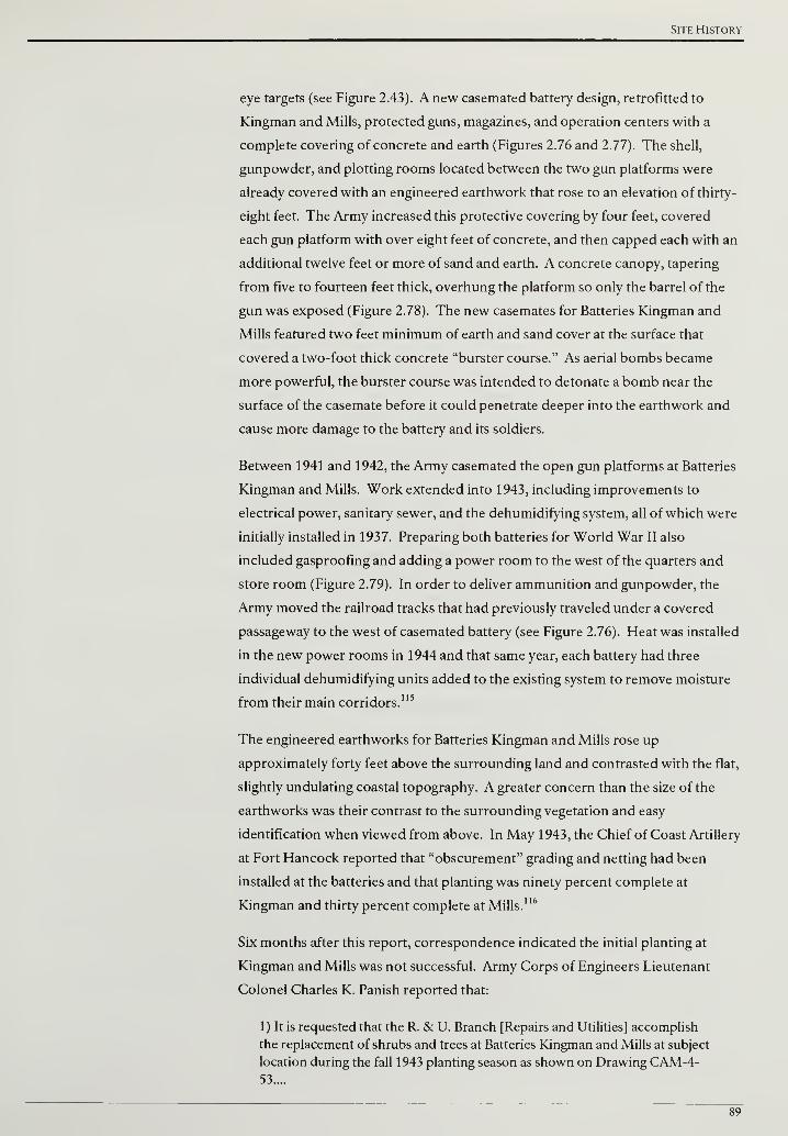
Site History
eye targets (see Figure 2.43). A new casemated battery design, retrofitted to
Kingman and Mills, protected guns, magazines, and operation centers with a
complete covering of concrete and earth (Figures 2.76 and 2.77). The shell,
gunpowder, and plotting rooms located between the two gun platforms were
already covered with an engineered earthwork that rose to an elevation of thirty-
eight feet. The Army increased this protective covering by four feet, covered
each gun platform with over eight feet of concrete, and then capped each with an
additional twelve feet or more of sand and earth. A concrete canopy, tapering
from five to fourteen feet thick, overhung the platform so only the barrel of the
gun was exposed (Figure 2.78). The new casemates for Batteries Kingman and
Mills featured two feet minimum of earth and sand cover at the surface that
covered a two-foot thick concrete "burster course." As aerial bombs became
more powerful, the burster course was intended to detonate a bomb near the
surface of the casemate before it could penetrate deeper into the earthwork and
cause more damage to the battery and its soldiers.
Between 1941 and 1942, the Army casemated the open gun platforms at Batteries
Kingman and Mills. Work extended into 1943, including improvements to
electrical power, sanitary sewer, and the dehumidifying system, all of which were
initially installed in 1937. Preparing both batteries for World War II also
included gasproofing and adding a power room to the west of the quarters and
store room (Figure 2.79). In order to deliver ammunition and gunpowder, the
Army moved the railroad tracks that had previously traveled under a covered
passageway to the west of casemated battery (see Figure 2.76). Heat was installed
in the new power rooms in 1944 and that same year, each battery had three
individual dehumidifying units added to the existing system to remove moisture
from their main corridors.115
The engineered earthworks for Batteries Kingman and Mills rose up
approximately forty feet above the surrounding land and contrasted with the flat,
slightly undulating coastal topography. A greater concern than the size of the
earthworks was their contrast to the surrounding vegetation and easy
identification when viewed from above. In May 1943, the Chief of Coast Artillery
at Fort Hancock reported that "obscurement" grading and netting had been
installed at the batteries and that planting was ninety percent complete at
Kingman and thirty percent complete at Mills.116
Six months after this report, correspondence indicated the initial planting at
Kingman and Mills was not successful. Army Corps of Engineers Lieutenant
Colonel Charles K. Panish reported that:
1) It is requested that the R. & U. Branch [Repairs and Utilities] accomplish
the replacement of shrubs and trees at Batteries Kingman and Mills at subject
location during the fall 1943 planting season as shown on Drawing CAM-4-53....
89
Cultural Landscape Report for the Sandy Hook Coastal Defense Batteries
2) The basic planting at these installations comprised a large proportion of
Groundsel Bush which failed to survive transplanting. It is recommended at
this time to replace the missing shrubs with Rugosa Roses in small sizes using
the soil in place for the planting operation. Some losses occurred in the tree
planting also and it is recommended at this time that only a few of these are
required for replacement in the obscurement program.... The plant quantities
indicated are estimated to produce a continuous shrub cover when planted to
supplement the existing plants.
3) The work is estimated to costs as follows:
11,900 shrubs® 175 $8,925.00
125 trees @ $4.00 $500.00
Total $9,425.00'17
Correspondence between the Army Corps of Engineers and the Office of the
Chief of Coast Artillery continued after this request until May 1944 when
Kingman and Mills were no longer actively manned. The debate on planting at
Kingman and Mills focused on appropriate plant species, quantities, and whether
additional vegetative cover was needed for erosion control or concealment. Based
on the correspondence, Kingman and Mills were originally planted with trees
and shrubs with the shrubs inconsistently spaced at three to ten feet on center.118
By 1944, planted or naturalized grass species and "weedy growth" were part of
the cover on the engineered earthworks and confirmed by a report indicating
"that no dust or soil erosion exists at Batteries Kingman and Mills, the existing
grass and weedy growth giving adequate permanent erosion protection to the
seacoast fortifications."11
In May 1944, as the focus of World War II concentrated on a major European
campaign and with the naval forces of Nazi Germany incapacitated, the debate
on planting at Kingman and Mills was concluded when the Eastern Defense
Command determined that:
. . .in the event of the category of defense increasing it would be required to
fully man these batteries and therefore the concealment afforded by Passive
Protection measures would be absolutely necessary. Planting required under
Passive Protection measures cannot be done effectively at the time of change
of category of defense but should be cared for in a continuous maintenance
proposition.120
Although the proposal for replacement planting was approved, it is unknown if
the plan was funded or implemented in the final year of World War II. The
protective casemates and concealment plantings at Batteries Kingman and Mills
were obsolete by the time the war concluded. The introduction of long range,
high-altitude bombers, the VI and V2 rockets, and the atomic bomb
demonstrated offensive capability that eclipsed Batteries Kingman and Mills, and
both were disarmed in 1948.
90
Site History
RAPID FIRE CUM BATTERIES
Batteries Engle and Peck
Disarmed in 1918 as a result of simplifying rapid fire artillery, Battery Engle was
not abandoned, but modified before major military reductions were
implemented following World War I. Alterations to Battery Engle occurred in
1920 to improve the fire control of nearby Battery Peck. The Army converted
Battery Engle's magazine, shielded by seven feet of concrete cover, into a plotting
room and constructed a coincidence range finding station over the concrete gun
well (Figure 2.80). The station was nineteen feet square and its floor was set
approximately four and a half feet higher than the gun well. A fifteen foot-long
coincidence range finder was installed inside the station at a height twenty-seven
feet above mean low water.
In concert with the alterations made at Battery Engle, the Army also improved
Battery Peck in 1920. Prior to the modifications, an officer for Battery Peck
stood on an open, concrete platform centered between the two emplacements
(Figure 2.81). The new construction created a fully-enclosed, concrete, battery
commander's station (Figure 2.82). To improve the range of Battery Peck's
6-inch guns, concrete was cut out of the emplacements in August 1928.
Removing some of the concrete permitted the guns to rise to a twenty degree
elevation. Increasing the angle of the gun from a horizontal position—zero
degrees—to twenty degrees allowed Battery Peck's guns to strike targets further
from the coastline.121
The improvements to Battery Peck, including the fire control modifications made
to Battery Engle, remained in service until 1943. At that time, the Army relocated
Battery Peck's guns to Battery Gunnison. Peck's 6-inch guns could fire quicker
than the 6-inch guns they replaced at Gunnison and as a result, Battery Gunnison
was designated New Battery Peck. The Army did not mothball the former
Battery Peck, but instead installed two 90mm anti-aircraft guns and designated
the structure Battery Number 8 (Figure 2.83).122
Batteries Urmston and Morris
Although a new coincidence ranger finder station was completed at Battery
Urmston in early 1919, a majority of the battery's artillery was removed a year
later and during World War II, the remaining guns were transferred to a new
location along the peninsula's eastern coastline. In March 1920, the Army
approved removal of the guns at emplacements #1, #2, #5 and #6. These four
guns used balanced pillar mounts, which proved to be inferior to the pedestal
mounted system used for other rapid fire guns.123
Battery Urmston's pedestal
mounted guns at emplacements #3 and #4 remained active until the start of
World War II. In 1942, the Army removed the two pedestal mounted guns and
91
Cultural Landscape Report for the Sandy Hook Coastal Defense Batteries
relocated them to the dunes north of Battery Gunnison (Figure 2.84). The dune
emplacement was operational in July 1943 and designated Battery Number 6.
The battery was also referred to as "New Battery Urmston" and worked with the
Harbor Entrance Control Post at Battery Potter to observe and potentially engage
ships approaching New York Harbor via the channel.124 To protect New Battery
Urmston from aerial detection the Report ofCompleted Works, updated in
September 1943, records that the guns were "concealed with camouflage fabric
on a sliding frame."125
Unlike Battery Urmston, the four pedestal mounted guns at Battery Morris
remained in service throughout World War II. As part of the Army's efforts to
improve fire control, a coincidence range finder station was added east of Battery
Morris in 1920.126 The concrete structure, thirteen feet by thirteen feet, was
constructed approximately ten feet above the ground. A nine foot-long
coincidence range finder was installed inside the station at a height
approximately twenty-seven feet above mean low water (Figure 2.85). The
instrument's height and the area north of the station free of large, woody
vegetation combined to provide unimpeded views of the water and improved fire
control for Battery Morris (Figure 2.86).
Battery Gunnison
Battery Gunnison, the last rapid fire gun battery completed, was also the only
rapid fire emplacement along the eastern shore of Sandy Hook. In addition to
protecting Gunnison's concrete structure, a sand embankment planted with
native grasses and shrubs was constructed on the battery's east side to blend the
gun battery in with the surrounding landscape.
Similar to engineered earthworks at other batteries, erosion was an ongoing issue
to contend with at Gunnison. A January 1929 letter to the Army Corps Chief of
Engineers indicated Gunnison's east embankment had eroded and additional
sand would be required to repair the earthwork.127
In 1940, the War Department convened a board to prepare a new coastal defense
plan. The conclusion of the board was that the rapid fire guns on counterweight
carriages were deficient compared to the pedestal mounted versions. The
counterweight carriage models were slower to load, had a shorter firing range,
and had a limited field of fire. As a result of the board's findings, Battery
Gunnison's guns and counterweight carriages were disarmed in 1942.128
Not wanting to leave the southern approach to New York Harbor without rapid
fire guns, plans were approved in February 1943 to relocate the pedestal mounted
guns from Battery Peck to Battery Gunnison. In order to mount Battery Peck's
guns, a redesign of Gunnison's platform areas was needed to emplace the
92
Site History
pedestal mounts. The current platforms, at the base of a parapet wall, had
concrete added in order to create a level surface for mounting the guns (Figure
2.87). Once the new guns were installed, Battery Gunnison was designated New
Battery Peck.
From 1943 to the end of World War II, Gunnison operated as directed by the
Harbor Entrance Control Post stationed atop Battery Potter. Gunnison served as
an examination battery that was intended to track targets and fire upon them
when ordered. Orders for firing included "bring-to" shots designed to warn a
commercial ship to stop until it received proper clearance and destructive fire on
enemy vessels.129
DISARMED CUM BATTERIES
By 1919, three large caliber gun batteries were disarmed as new artillery,
carriages, and improvements in battleship armaments made them obsolete. Guns
were first removed at Battery Potter and then at Mortar Battery. Both of these
structures were utilized during World War II as command posts for coastal
defense coordination. The third large caliber gun battery, Battery Arrowsmith,
was disarmed after Batteries Kigman and Mills became operational in 1919 with
360-degree fields of fire to protect the peninsula's west shoreline.
During World War II, two additional large caliber gun batteries were disarmed.
The 10- and 12-inch artillery atop Nine Gun Battery and Battery Granger was
removed because these guns did not have the range to strike better armed enemy
battleships. Additionally, the batteries were suspectible to aerial bombing and
not protected like the recently casemated Kingman and Mills. The "Report of
Completed Works," a detailed account of equipment at each battery maintained
by the Army Corps of Engineers, notes in a handwritten comment that the
"salvage of armament" at Battery Granger was approved on January 22, 1943.
Similar handwritten comments note that the artillery at Battery Halleck, the first
three emplacemnts of Nine Gun Battery, were "listed for disposal" on November
4, 1942. A year later, the Army Service Forces directed the "salvage of armament
and accessory equipment" at Batteries Richardson and Bloomfield.130
Supporting
the information in the Report of Completed Works, Nine Gun Battery, Battery
Granger, and Battery Arrowsmith are all labeled "dismantled" on a July 1944 map
of Sandy Hook prepared by the Army Corps of Engineers (Figure 2.88).
The geographic separation that afforded the United States a measure of
protection against previous global conflicts proved inadequate against
technological improvements during World War II. Entry into the war began with
the long-range Japanese aerial attack on Pearl Harbor, and by the war's
conclusion the introduction of long-range bombers, rockets, and atomic
weapons far surpassed any defensive capability offered by large caliber,
93
Cultural Landscape Report for the Sandy Hook Coastal Defense Batteries
casemated guns like Batteries Kingman and Mills. In addition, long-range
bombers could fly at a high altitude that positioned them substantially outside the
range of rapid fire gun batteries. With both categories of batteries eclipsed by
offensive weaponry, the remainder of Sandy Hook's coastal defense batteries
were deactivated and disarmed by 1948. Although deactivated, the 6-inch rapid
fire guns at Battery Gunnison remained emplaced and survived a thorough effort
at Sandy Hook and across the country to collect coastal artillery for scrap metal.131
LANDSCAPE SUMMARY - 1945
In July 1 944, perhaps sensing that the apex of World War II development had
passed, the Army Corps of Engineers prepared maps recording structures,
facilities, circulation, and the shoreline at Sandy Hook. The Army Corps of
Engineers' plans are the primary source of information for the 1945 period plans
(Drawings 2.5-2.6).
The quantity and density of development continued to be the greatest at the
northern end of the peninsula with temporary structures, tent cities, and parking
areas added in previously undeveloped areas. The middle and southern sections
of Sandy Hook also witnessed increased development, however, the
development was confined to relatively small pockets and did not occupy large
sections of land. For example, in the middle portion of the peninsula temporary
barracks, known as Camp Low, stood north of Horseshoe Cove. In the southern
section, anti-aircraft emplacements and temporary radar shelters were
established near the Atlantic coastline directly east of Batteries Kingman and
Mills (Drawing 2.6).
Sandy Hook's coastline continued to change due to currents and the depositing
of sand at the peninsula's northern end. When the Proving Ground closed in
1919, the narrowest part of the recurved spit was only 450 feet wide. As World
War II was concluding, over 1,600 feet of new land was added through
deposition north of this narrow portion (Drawing 2.5).
Unlike earlier historic maps, there is no indication of vegetation cover on the
1944 Army Corps of Engineers maps to inform the 1945 period plans.
Comparing aerial photographs from 1933 and 1962 revealed that vegetation
cover did not dramatically change except where cleared for World War II-era
construction. New vegetation also appeared at recently formed inland areas as
the coastline advanced north and provided an initial buffer for pioneer species.
Although development increased in the middle portion of the peninsula, the new
facilities for radar, anti-aircraft emplacements, and storage were located in nodes
and not widely distributed across the landscape. This development pattern
resulted in larger areas of undisturbed woody vegetation (Drawing 2.6). New
94
Site History
development also avoided a roughly circular-shaped pond shown east of Battery
Mills and approximately in the center of the landform (Drawing 2.6).
The most dramatic change to Sandy Hook's coastal defense batteries during the
World War II-era was the casemating of Batteries Kingman and Mills. The
previously open gun platforms were covered with reinforced concrete and
earthen mounds that rose approximately forty feet above the surrounding
topography (Drawing 2.6). Less striking, but more widespread along the length
of the peninsula, were the increased number of anti-aircraft artillery and
searchlights to support the war effort. Searchlights punctuated the landscape
from the northwest tip of the peninsula to its approximate center east of
Horseshoe Cove. Similarly, anti-aircraft installations were located at the
northern end in the former Battery Peck and as far south as the Spermaceti Cove
Lifesaving Station. World War II personnel increases necessitated temporary
structures and tent cities to accommodate Sandy Hook's swelling military
population. Cantonments were constructed west of Nine Gun Battery, west of
Battery Granger, and north of Horseshoe Cove. Two large tent city areas were
established south of the Mortar Battery (Drawing 2.6).
Access to and from the peninsula was provided by ship, train, and automobile
and once on Sandy Hook, railroad and vehicular infrastructure connected supply
areas, barracks, and coastal defense batteries. At the northern end of the
peninsula, the wharf expanded to a collection of four docks, each one providing
separate service for the Army Corps of Engineers, Fort Hancock's
Quartermaster, the Coast Guard, and mine delivery (Drawing 2.6).
Railroad and vehicular networks departed from the wharf to the north, east, and
south. A narrow gauge rail line to the east provided transportation for control
mines to storage facilities near the Mine Casemate (Drawing 2.6). The eastern
rail line between the wharf and former Proving Ground remained operational
and turning south past Nine Gun Battery, became the major north-south railroad
route on the peninsula. A parallel line off this main north-south route headed
further east toward the Atlantic coastline and with spurs projecting into the
sandy dunes, provided a location for large caliber and mortar artillery mounted
on rail cars. South of the rail car artillery spurs, another line branched off of the
main north-south track and headed west to provide ammunition delivery for the
12-inch guns at Batteries Kingman and Mills (Drawing 2.6).
The major vehicular route, Hartshorne Drive, paralleled the north-south rail line
in the southern half of the peninsula. At Horseshoe Cove, Hartshorne Drive
curved to the west and followed the bay shoreline in front of Fort Hancock's
Officer's Row. Vehicular access near the east coast of the peninsula was provided
by Atlantic Drive and connected sites containing searchlights, observation
towers, and power generation equipment. South of the Mortar Battery,
95

Cultural Landscape Report for the Sandy Hook Coastal Defense Batteries
Gunnison Road served as an east-west connector between Hartshorne and
Atlantic Drives (Drawings 2.5-2.6).
96
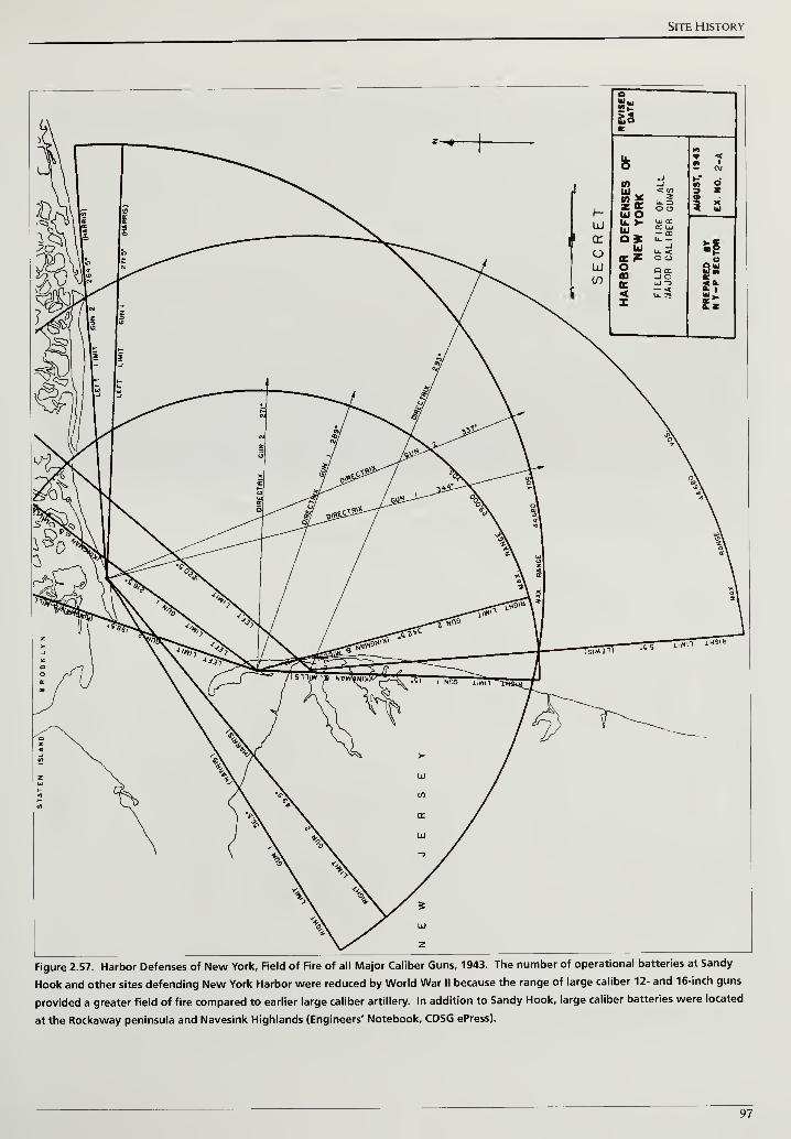
Site History
o
if)
a2"
^""™
£2B
IO
ft
* <2 A
_i K* -J
ffi< CO S .
"2Z 9E
zU. 3O C3 i 5
UJ Ou. >•111
tr uj
0*bJ
u-J
u. <t
O Q tr-JO
ssoe<
UJ "D— <* itU. S "*>-
z
^
ov?S"f-crt*-
«R|SSe«*-
oyS-
9S?
,n lHOia
iTiwr1 Nno nwn
%>
Figure 2.57. Harbor Defenses of New York, Field of Fire of all Major Caliber Guns, 1943. The number of operational batteries at Sandy
Hook and other sites defending New York Harbor were reduced by World War II because the range of large caliber 12- and 16-inch guns
provided a greater field of fire compared to earlier large caliber artillery. In addition to Sandy Hook, large caliber batteries were located
at the Rockaway peninsula and Navesink Highlands (Engineers' Notebook, CDSG ePress).
97
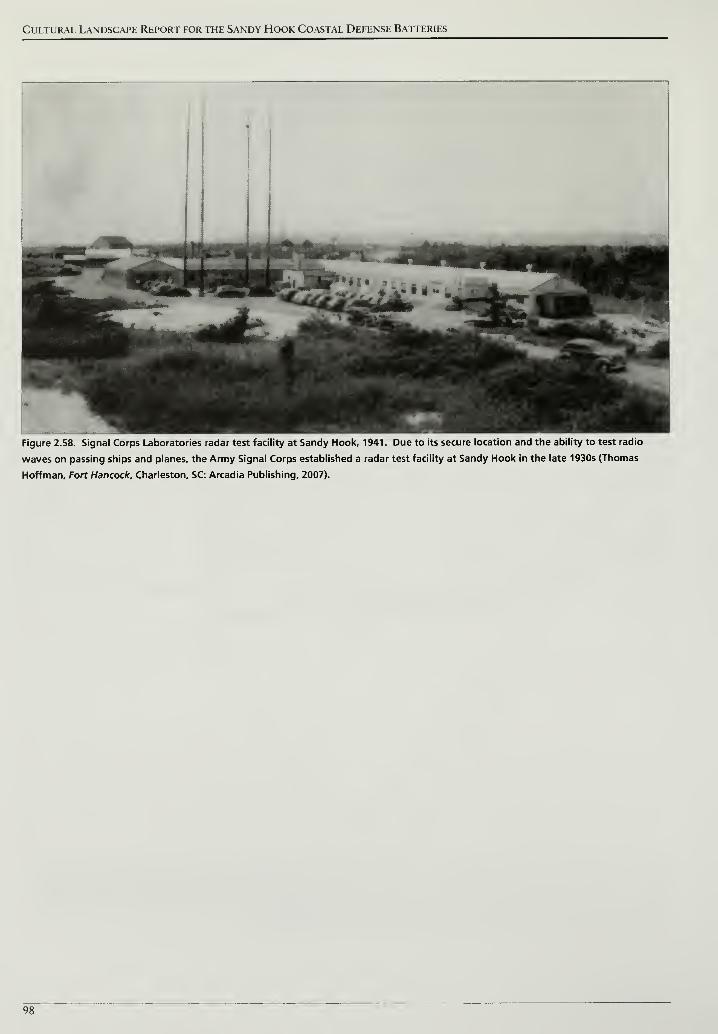
Cultural Landscape Report for the Sandy Hook Coastal Defense Batteries
^HHH^^^M ^^MFigure 2.58. Signal Corps Laboratories radar test facility at Sandy Hook, 1941. Due to its secure location and the ability to test radio
waves on passing ships and planes, the Army Signal Corps established a radar test facility at Sandy Hook in the late 1930s (Thomas
Hoffman, Fort Hancock, Charleston, SC: Arcadia Publishing, 2007).
98
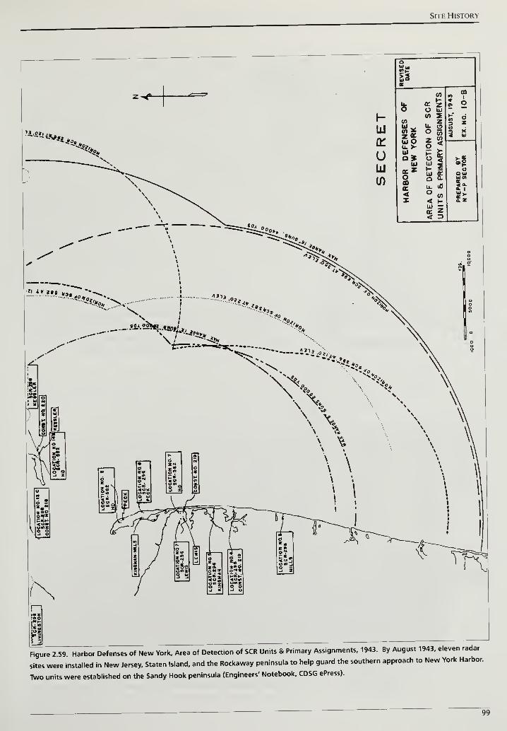
Site History
oSff
S3oc
...
(0 » ?
* OZUl
s 2V) Z
fc" 6n z
«9W V u. (9
Ul oOz
<f
3 X4 IK
U.> o15Ui
<Z
J3
S|a*oa>
1-Ulau.
UOl>(UI0)
it< o
</> 2*z < H 0.Z
uiIK Z< _?l
Figure 2 59 Harbor Defenses of New York. Area of Detection of SCR Units & Primary Assignments. 1943. By August 1943. eleven radar
sites were installed in New Jersey. Staten Island, and the Rockaway peninsula to help guard the southern approach to New York Harbor.
Two units were established on the Sandy Hook peninsula (Engineers' Notebook, CDSG ePress).
99
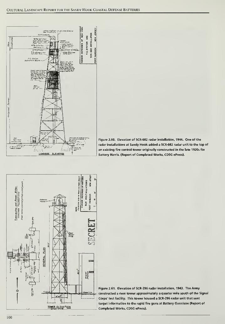
Cultural Landscape Report for the Sandy Hook Coastal Defense Batteries
LANDSIDE ELEVATION
Figure 2.60. Elevation of SCR-682 radar installation, 1944. One of the
radar installations at Sandy Hook added a SCR-682 radar unit to the top of
an existing fire control tower originally constructed in the late 1920s for
Battery Harris. (Report of Completed Works, CDSG ePress).
Figure 2.61. Elevation of SCR-296 radar installation, 1943. The Army
constructed a new tower approximately a quarter mile south of the Signal
Corps' test facility. This tower housed a SCR-296 radar unit that sent
target information to the rapid fire guns at Battery Gunnison (Report of
Completed Works, CDSG ePress).
100
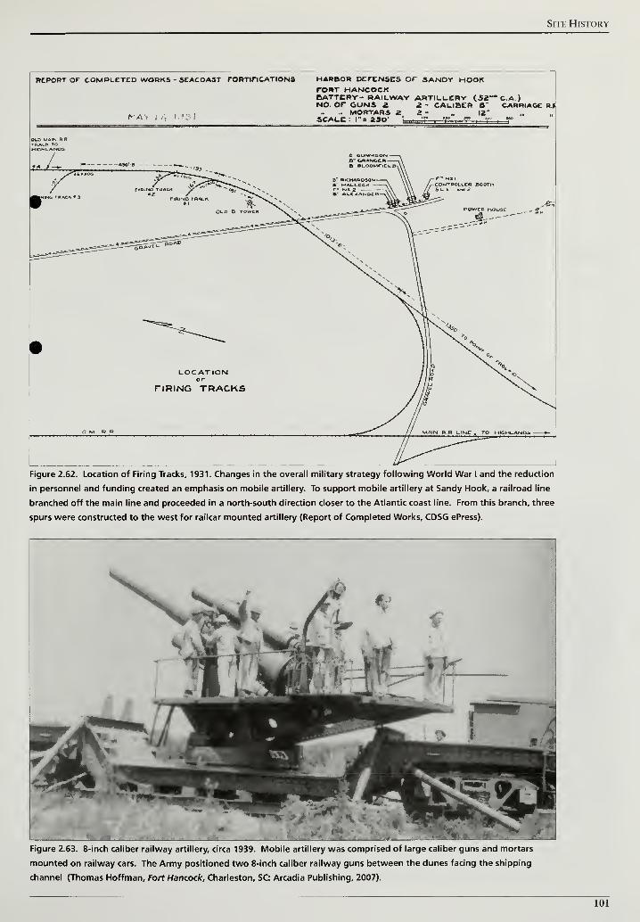
Site History
REPORT OF COMPLETED WORKS - SEACOAST FORTIFICATIONS
NA> , ,t
HARBOR DEFENSES Or SANDY HOOKTORT HANCOCKBATTERY- RAILWAY ARTILLERY (52~* C.A.)NO. OF GUNS 2 2 - CALIBER B CARRIAGE Rl
.. MORTARS 2 Z - „ 12"scale : ri zap- •„ g i r , r r , y
OLD MAIN R RTRACK TCHIGHLANDS
jL B" bNANOCR -
ft ALOownCLo. 1
POWCB MOUSE
LOCATIONor
TIRING TRACKS
Figure 2.62. Location of Firing Tracks, 1931. Changes in the overall military strategy following World War I and the reduction
in personnel and funding created an emphasis on mobile artillery. To support mobile artillery at Sandy Hook, a railroad line
branched off the main line and proceeded in a north-south direction closer to the Atlantic coast line. From this branch, three
spurs were constructed to the west for railcar mounted artillery (Report of Completed Works, CDSG ePress).
Figure 2.63. 8-inch caliber railway artillery, circa 1939. Mobile artillery was comprised of large caliber guns and mortars
mounted on railway cars. The Army positioned two 8-inch caliber railway guns between the dunes facing the shipping
channel (Thomas Hoffman, Fort Hancock, Charleston, SC: Arcadia Publishing, 2007).
101
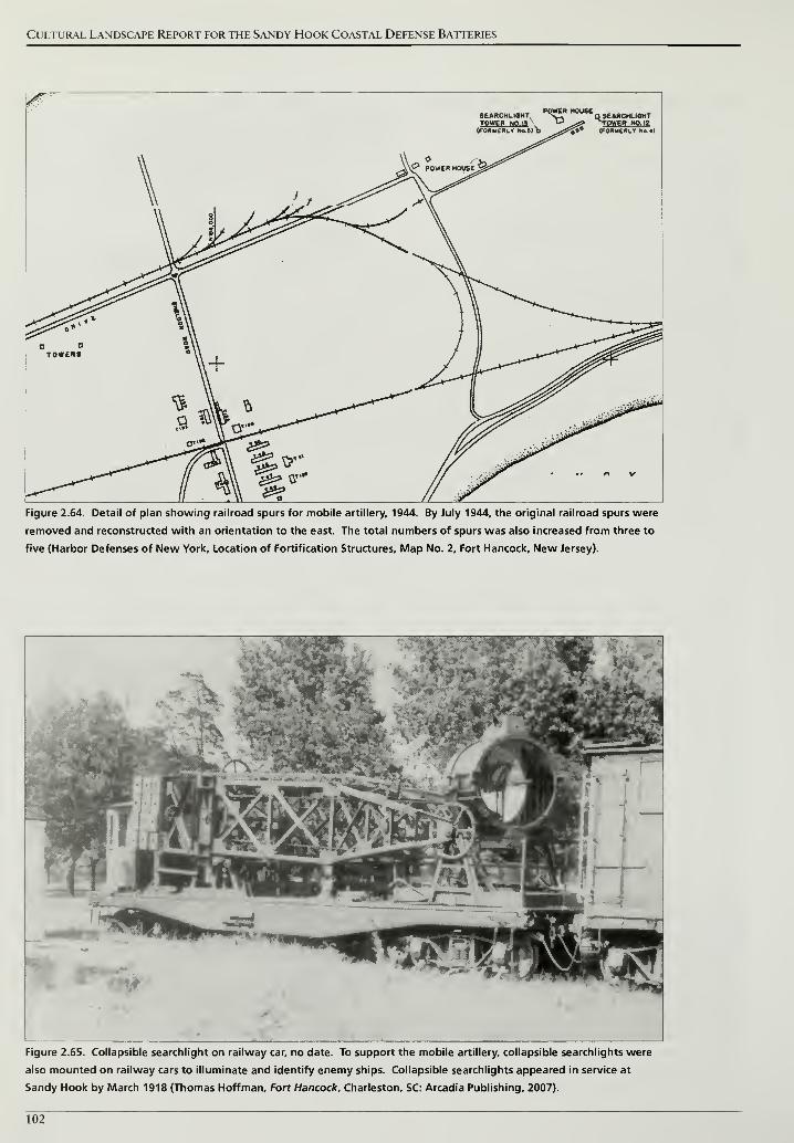
Cultural Landscape Report for the Sandy Hook Coastal Defense Batteries
tower N0.I3 ^^s? Tpweq NO, 18
Figure 2.64. Detail of plan showing railroad spurs for mobile artillery, 1944. By July 1944, the original railroad spurs were
removed and reconstructed with an orientation to the east. The total numbers of spurs was also increased from three to
five (Harbor Defenses of New York, Location of Fortification Structures, Map No. 2, Fort Hancock, New Jersey).
Figure 2.65. Collapsible searchlight on railway car, no date. To support the mobile artillery, collapsible searchlights were
also mounted on railway cars to illuminate and identify enemy ships. Collapsible searchlights appeared in service at
Sandy Hook by March 1918 (Thomas Hoffman, Fort Hancock, Charleston, SC: Arcadia Publishing, 2007).
102
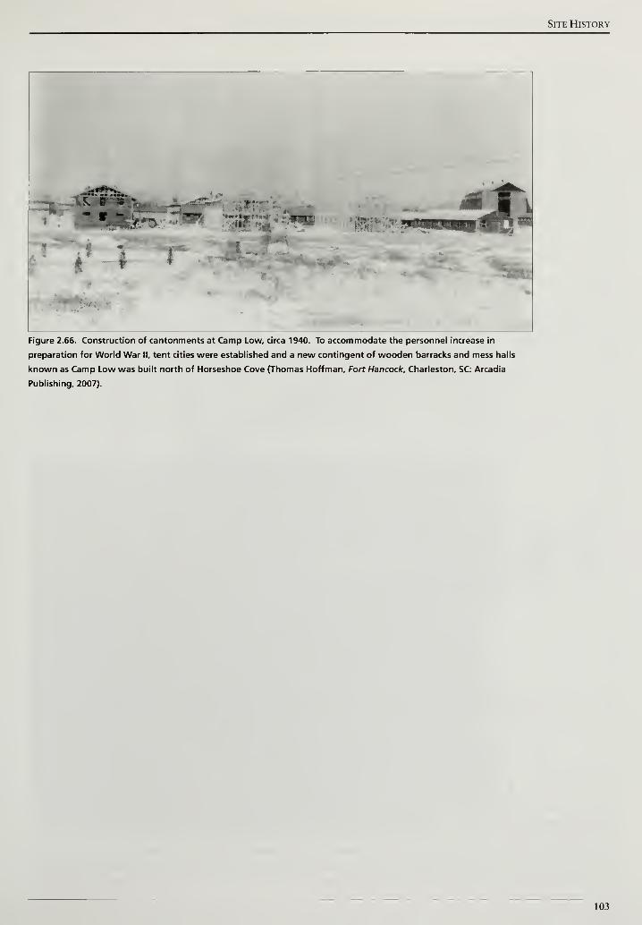
Site History
3*i
Figure 2.66. Construction of cantonments at Camp Low, circa 1940. To accommodate the personnel increase in
preparation for World War II, tent cities were established and a new contingent of wooden barracks and mess halls
known as Camp Low was built north of Horseshoe Cove (Thomas Hoffman, Fort Hancock, Charleston, SC: Arcadia
Publishing, 2007).
103
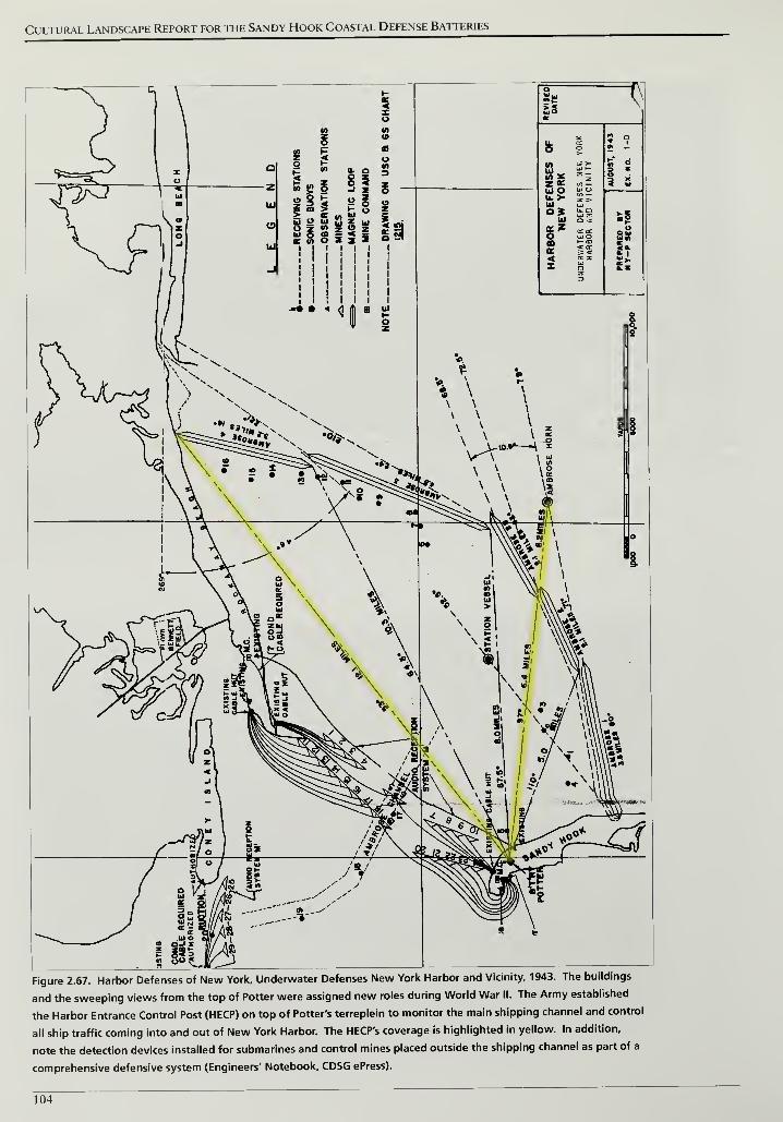
Cultural Landscape Report for the Sandy Hook Coastal Defense Batteries
Figure 2.67. Harbor Defenses of New York, Underwater Defenses New York Harbor and Vicinity, 1943. The buildings
and the sweeping views from the top of Potter were assigned new roles during World War II. The Army established
the Harbor Entrance Control Post (HECP) on top of Potter's terreplein to monitor the main shipping channel and control
all ship traffic coming into and out of New York Harbor. The HECP's coverage is highlighted in yellow. In addition,
note the detection devices installed for submarines and control mines placed outside the shipping channel as part of a
comprehensive defensive system (Engineers' Notebook, CDSG ePress).
104
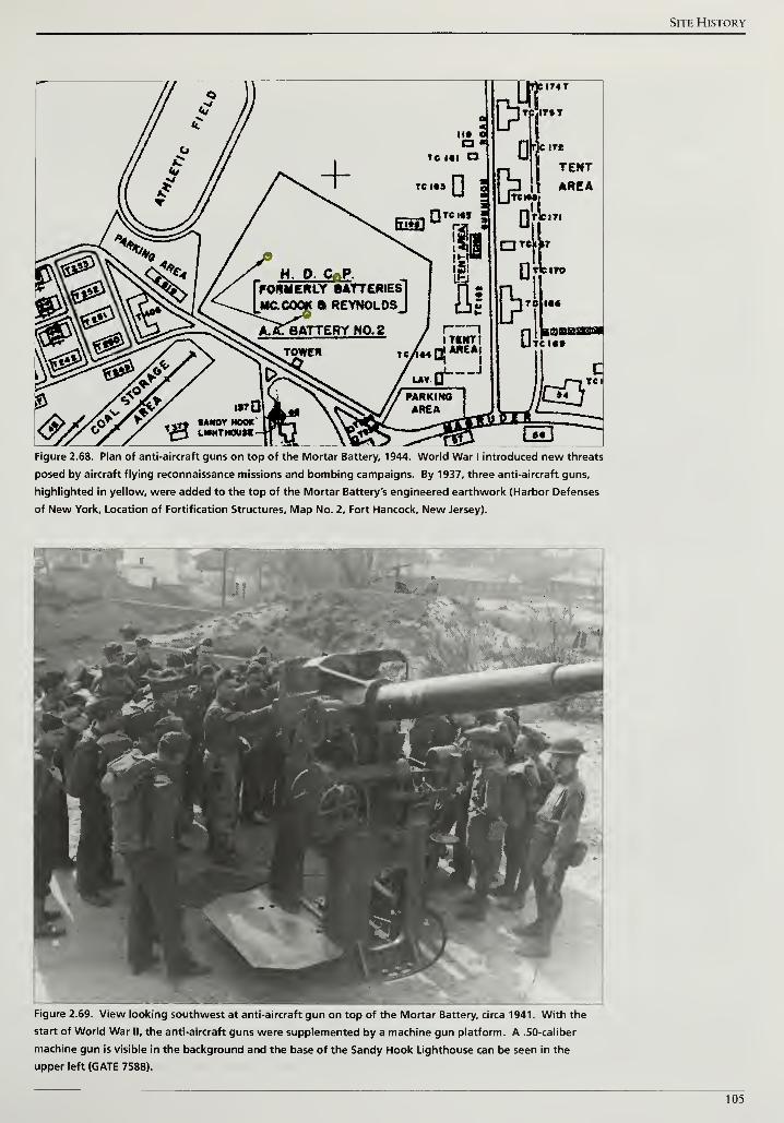
Site History
Figure 2.68. Plan of anti-aircraft guns on top of the Mortar Battery, 1944. World War I introduced new threats
posed by aircraft flying reconnaissance missions and bombing campaigns. By 1937, three anti-aircraft guns,
highlighted in yellow, were added to the top of the Mortar Battery's engineered earthwork (Harbor Defenses
of New York, Location of Fortification Structures, Map No. 2, Fort Hancock, New Jersey).
Figure 2.69. View looking southwest at anti-aircraft gun on top of the Mortar Battery, circa 1941. With the
start of World War II, the anti-aircraft guns were supplemented by a machine gun platform. A .50-caliber
machine gun is visible in the background and the base of the Sandy Hook Lighthouse can be seen in the
upper left (GATE 7588).
105
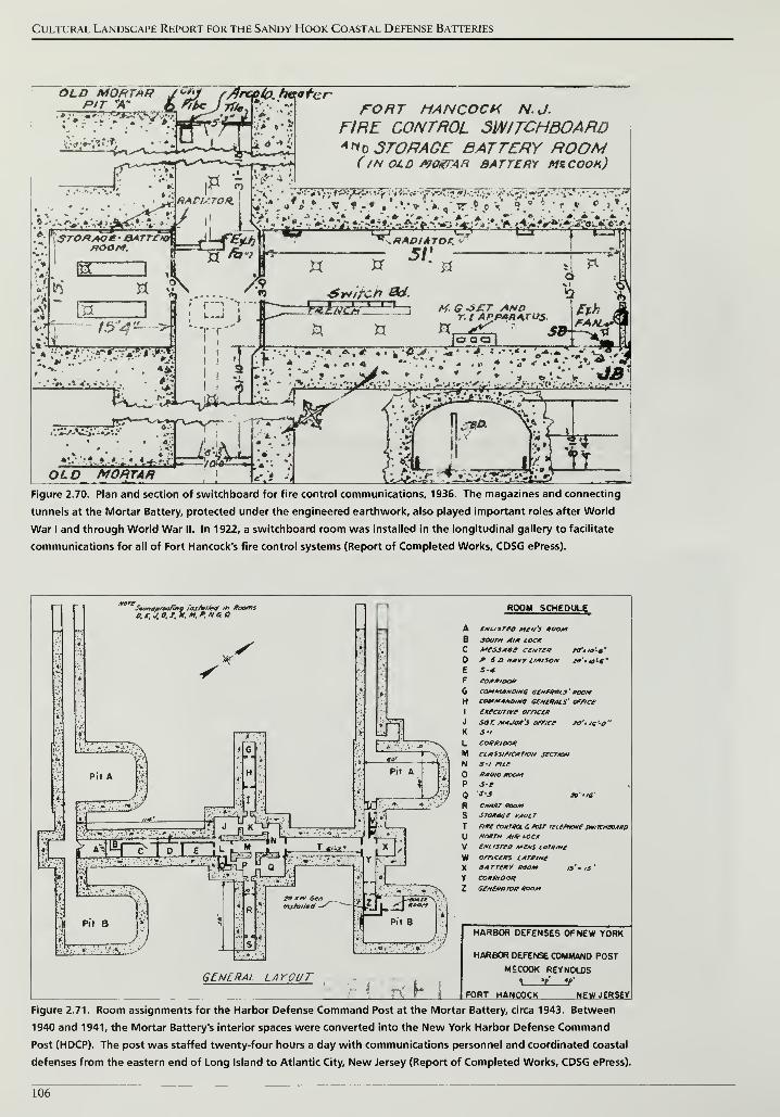
Cultural Landscape Report for the Sandy Hook Coastal Defense Batteries
OLD MORTMR j<-*y f/}rccio. heater
T- 'ffiJSl'Wyigl j^jS'^i' 'A FORT HANCOCK NJ.FIRE CONTROL SWITCHBOARD
KifS
3 r
RACUTOH
A*t> STORAGE BATTERY ROOM( /H OLD /VOtfTAR BATTERY MZCOOK)
G/54~ >
**"r*r*
\V*r. Jt'm ' i Vrini i |"ii'|ifir , 'J|^ "i » ^- ^- V7 "
".
,
'<j-"->rY lit
XT5/ '
M. G S£T AndT.I APPAH4TUS
<*•*•* • •*; *-*•*-**
rt • * JSr .
'-Jl.
'
i, -
,
:iySc('i:>:_j.-
:j;
-;
"
> -r-rV^'•'•"far;•-•«"^V ;!'V,
'
t>;. .v :
':" •« >'
OL0 MORTARBfcK3
- * -
Figure 2.70. Plan and section of switchboard for fire control communications, 1936. The magazines and connecting
tunnels at the Mortar Battery, protected under the engineered earthwork, also played important roles after World
War I and through World War II. In 1922, a switchboard room was installed in the longitudinal gallery to facilitate
communications for all of Fort Hancock's fire control systems (Report of Completed Works, CDSG ePress).
Sau.iaproofinq r'astvllea' th taoms
S to^
a**
>;
Pit B
installed S
ROOM SCHEDULE
fMusreo *te»'j roomsouth Aim LOCKAfesjAse ccntcr to'in'-*"
P & o haw liaison zo'.*o'-c~
S-4.
emrmtoa*commanding eenmu.3' roomcanM4»oiMo aemePMs' office
ixecurive ornctR
sot. Minor's office to''te<-o"
J'i
CORRIDOR
ci/tssifiCATion sccrion
s-i meRADIO ROOMs-e
CHART ROOMSTORRCC VAULT
rite comtrcl & Mar retefnone smrcnaoA*DNORTH 4lR LOCK
CNLisreo MfNS laritwc
Off/CeRS LATRlNCeATTeay Mom 13' 'is'
CORRIDOR
SentRftTOR ROOM
GENERAL LAYOUTI ; H h
HARBOR DEFENSES OF NEW YORK
HARBOR DEFENSE COMMAND POST
MSC0OK REYNOLDS> a! **
'
FORT HANCOCK NEW JERSEY
Figure 2.71. Room assignments for the Harbor Defense Command Post at the Mortar Battery, circa 1943. Between
1940 and 1941, the Mortar Battery's interior spaces were converted into the New York Harbor Defense Command
Post (HDCP). The post was staffed twenty-four hours a day with communications personnel and coordinated coastal
defenses from the eastern end of Long Island to Atlantic City, New Jersey (Report of Completed Works, CDSG ePress).
106
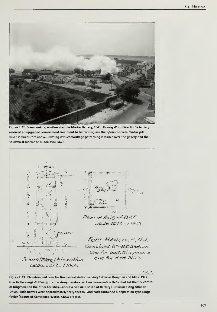
Site History
Figure 2.72. View looking southeast at the Mortar Battery, 1943. During World War II, the battery
received an upgraded concealment treatment to better disguise the open, concrete mortar pits
when viewed from above. Netting with camouflage patterning is visible over the gallery and the
southwest mortar pit (GATE 1943-662).
« S</»
Of Su Frontt l
/-'
P/os> atAxis afO.P.K
Combined B"-B.C.Sic^,^rr
One Fur &att% ftinymati *
South (S/c/eJ E/evation. 0n* *="' d<Tff -M '
"
sSca/c 12QFt.= //ncft
£.':<*.
Figure 2.73. Elevation and plan for fire control station serving Batteries Kingman and Mills, 1922.
Due to the range of their guns, the Army constructed two towers—one dedicated for the fire control
of Kingman and the other for Mills—about a half mile south of Battery Gunnison along Atlantic
Drive. Both towers were approximately forty feet tall and each contained a depression-type range
finder (Report of Completed Works, CDSG ePress).
107
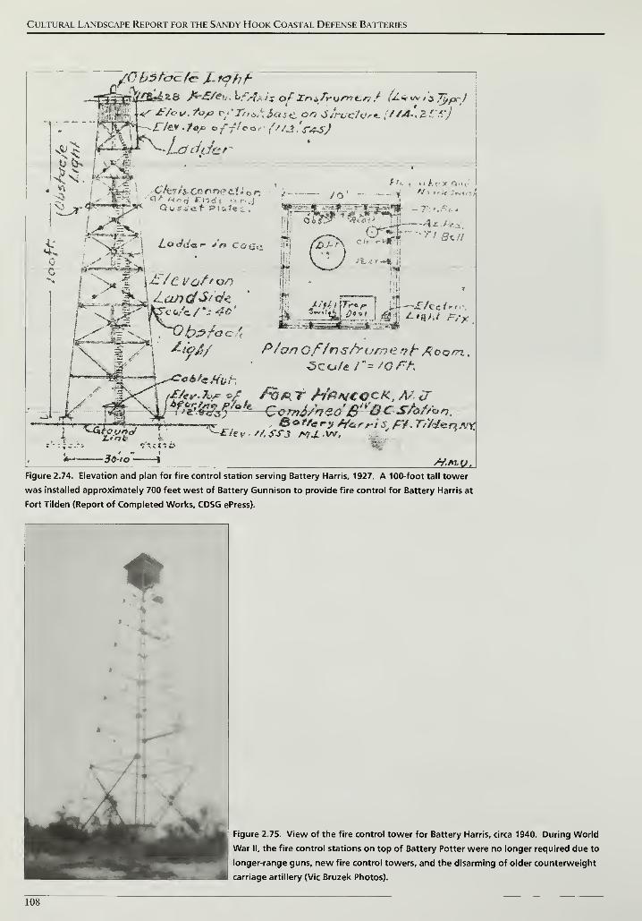
Cultural Landscape Report for the Sandy Hook Coastal Defense Batteries
\ L.O<id«t.t- j'n Co fin
- 7 . '-
Az- ' s -
4 7" 'fit//
1
I/Vc/7 Of/r)s/rumei7t Aoosn ,
fbfKT M&NCQCK,M cT
~^/e„ ,,;s?3^^rriS ' r,%H^^tints
i - c t ? o_ ' " i
-3C-io 1 H.r*uv,
Figure 2.74. Elevation and plan for fire control station serving Battery Harris, 1927. A 100-foot tall tower
was installed approximately 700 feet west of Battery Gunnison to provide fire control for Battery Harris at
Fort Tilden (Report of Completed Works, CDSG ePress).
Figure 2.75. View of the fire control tower for Battery Harris, circa 1940. During World
War II, the fire control stations on top of Battery Potter were no longer required due to
longer-range guns, new fire control towers, and the disarming of older counterweight
carriage artillery (Vic Bruzek Photos).
108
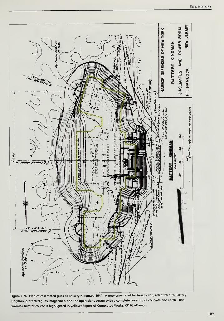
Site History
Figure 2.76. Plan of casemated guns at Battery Kingman, 1944. A new casemated battery design, retrofitted to Battery
Kingman, protected guns, magazines, and the operations center with a complete covering of concrete and earth. The
concrete burster course is highlighted in yellow (Report of Completed Works, CDSG ePress).
109
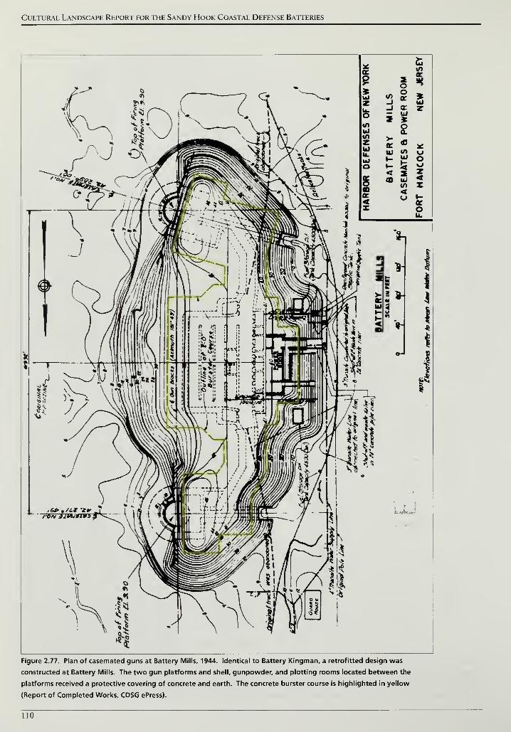
Cultural Landscape Report for the Sandy Hook Coastal Defense Batteries
Figure 2.77. Plan of casemated guns at Battery Mills, 1944. Identical to Battery Kingman, a retrofitted design was
constructed at Battery Mills. The two gun platforms and shell, gunpowder, and plotting rooms located between the
platforms received a protective covering of concrete and earth. The concrete burster course is highlighted in yellow
(Report of Completed Works, CDSG ePress).
110
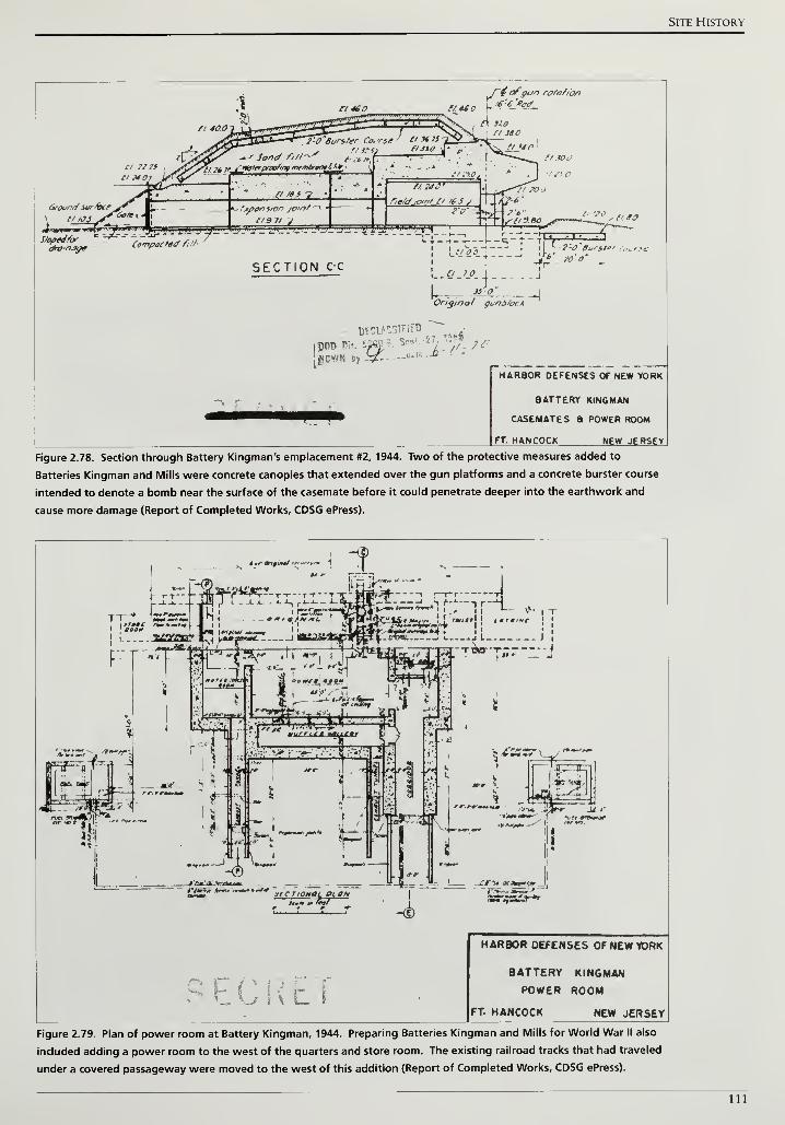
Site History
f~4 ofgun rote//on
5 /l^'iSX. , A 320
' a his £StJ*v
—
/'-f^
S/opedforCompacted fitf-
SECTION C-C
'*»»Wn—i
I
"J—"^ /""-
—
-T-H--
—
i--^-r~T ,
v ".'
'—
'
•fpL.«-'A1 J
Origmol guni/oc*
DWIASSiFtEO •
J^PCWN by -^-
H ARBOR DEFENSES OF NEW YORK
BATTERY KINGMAN
CASEMATES a POWER ROOM
FT. HANCOCK NEW JERSEY
Figure 2.78. Section through Battery Kingman's emplacement #2, 1944. Two of the protective measures added to
Batteries Kingman and Mills were concrete canopies that extended over the gun platforms and a concrete burster course
intended to denote a bomb near the surface of the casemate before it could penetrate deeper into the earthwork and
cause more damage (Report of Completed Works, CDSG ePress).
TT
„ -*,t •/" On'§itfl • t-****** ^
Hiturn
i iaaw
ft-^~Ji::iiif
-t r-i
pfss*2FL._,jL j i
SECRET
HARBOR OEFENSES OF NEW YORK
BATTERY KINGMAN
POWER ROOM
FT HANCOCK NEW JERSEY
Figure 2.79. Plan of power room at Battery Kingman, 1944. Preparing Batteries Kingman and Mills for World War II also
included adding a power room to the west of the quarters and store room. The existing railroad tracks that had traveled
under a covered passageway were moved to the west of this addition (Report of Completed Works, CDSG ePress).
Ill
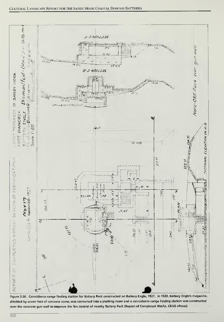
Cultural Landscape Report for the Sandy Hook Coastal Defense Batteries
Figure 2.80. Coincidence range finding station for Battery Peck constructed on Battery Engle, 1927. In 1920, Battery Engle's magazine,
shielded by seven feet of concrete cover, was converted into a plotting room and a coincidence range finding station was constructed
over the concrete gun well to improve the fire control of nearby Battery Peck (Report of Completed Works, CDSG ePress).
112
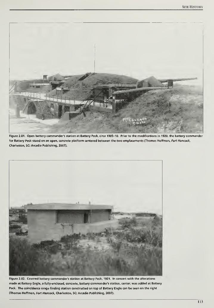
Site History
Figure 2.81. Open battery commander's station at Battery Peck, circa 1905-10. Prior to the modifications in 1920, the battery commander
for Battery Peck stood on an open, concrete platform centered between the two emplacements (Thomas Hoffman, Fort Hancock,
Charleston, SC: Arcadia Publishing, 2007).
Figure 2.82. Covered battery commander's station at Battery Peck, 1921. In concert with the alterations
made at Battery Engle, a fully-enclosed, concrete, battery commander's station, center, was added at Battery
Peck. The coincidence range finding station constructed on top of Battery Engle can be seen on the right
(Thomas Hoffman, Fort Hancock. Charleston, SC: Arcadia Publishing, 2007).
113
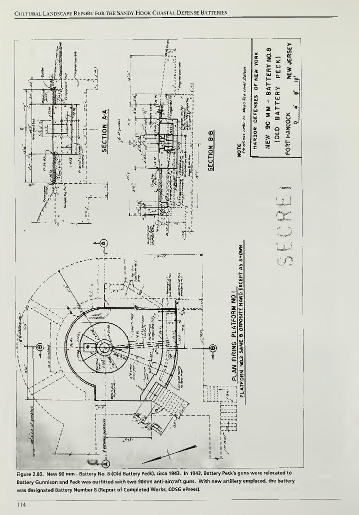
Cultural Landscape Report for the Sandy Hook Coastal Defense Batteries
>-
i
<r
O
CO
$>-oroiii
«/>
or
*4
UJ
zUJ1-
Q.UJ
1 u. t-
^ o < >CD cc CD-
4 UJc tf> -1
zu 2 1- *It. 5 4 3C
•J kl m U
i
Qor 3 o
go)o _j 4
*o * o X<z
UJz o
UL
Figure 2.83. New 90 mm - Battery No. 8 (Old Battery Peck), circa 1943. In 1943, Battery Peck's guns were relocated to
Battery Gunnison and Peck was outfitted with two 90mm anti-aircraft guns. With new artillery emplaced, the battery
was designated Battery Number 8 (Report of Completed Works, CDSG ePress).
114
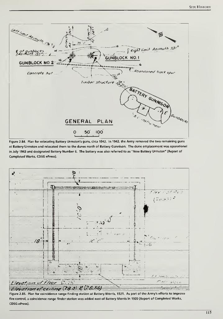
Site History
t of gunfroc**J/lll/fiath /SSV
\>UNBlOCK NO. I
IRiaKt !,*»* Azimuth 3Jf'
GUNBLOCK NO. 2
Concrete hut Abandoned tract Spur
Timber structure >J*'
GENERAL PLAN
50' 100
-<•*-
Figure 2.84. Plan for relocating Battery Urmston's guns, circa 1942. In 1942, the Army removed the two remaining guns
at Battery Urmston and relocated them to the dunes north of Battery Gunnison. The dune emplacement was operational
in July 1943 and designated Battery Number 6. The battery was also referred to as "New Battery Urmston" (Report of
Completed Works, CDSG ePress).
» •
H*»lr0f'Cjr* of f/ocr C, /3'
-£j&w&w^r^~*/3&9&£2$&1-3£a&&M&)._n^
' i " ... z^mL
. j !-... s 7T.
Figure 2.85. Plan for coincidence range finding station at Battery Morris, 1921. As part of the Army's efforts to improve
fire control, a coincidence range finder station was added east of Battery Morris in 1920 (Report of Completed Works,
CDSG ePress).
115
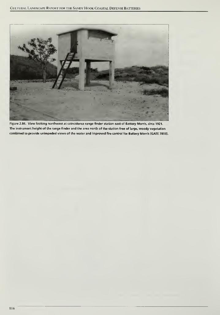
Cultural Landscape Report for the Sandy Hook Coastal Defense Batteries
Figure 2.86. View looking northwest at coincidence range finder station east of Battery Morris, circa 1921.
The instrument height of the range finder and the area north of the station free of large, woody vegetation
combined to provide unimpeded views of the water and improved fire control for Battery Morris (GATE 7893).
116
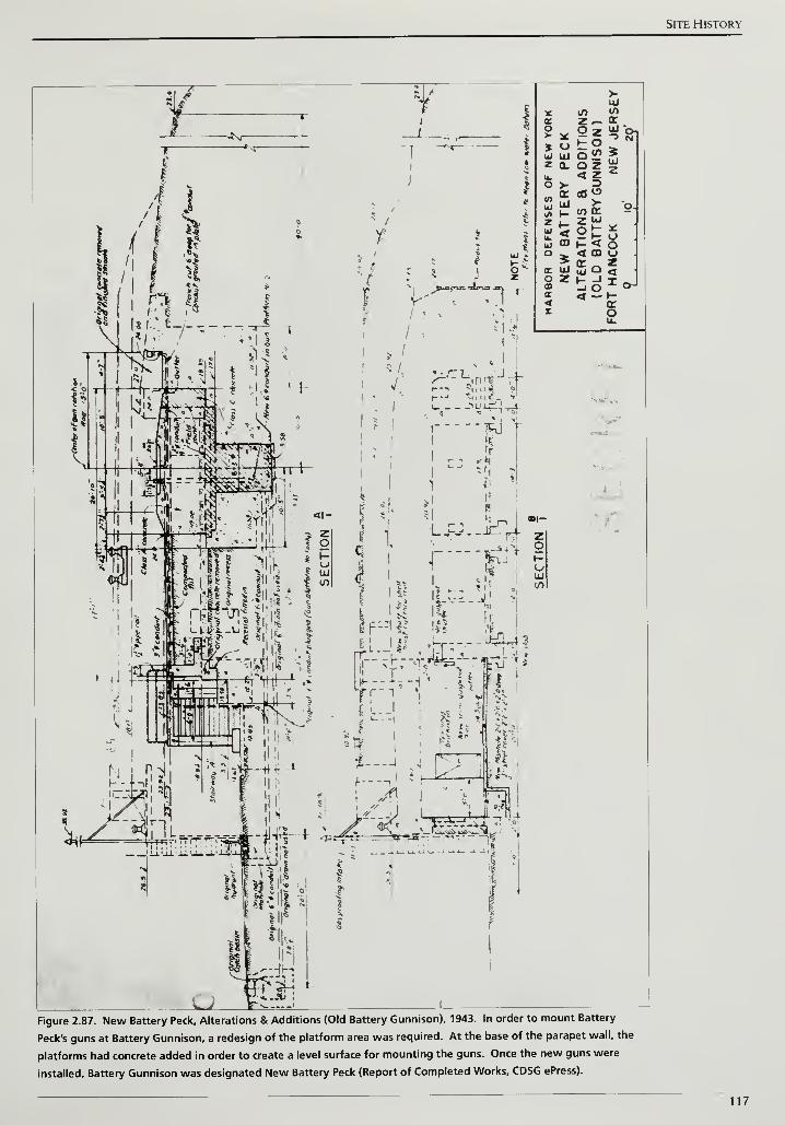
Site History
Figure 2.87. New Battery Peck, Alterations & Additions (Old Battery Gunnison), 1943. In order to mount Battery
Peck's guns at Battery Gunnison, a redesign of the platform area was required. At the base of the parapet wall, the
platforms had concrete added in order to create a level surface for mounting the guns. Once the new guns were
installed. Battery Gunnison was designated New Battery Peck (Report of Completed Works, CDSG ePress).
117
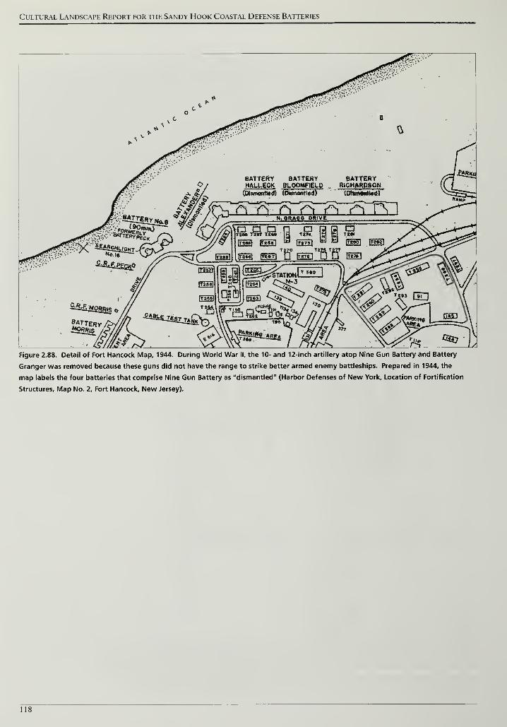
Cultural Landscape Report for the Sandy Hook Coastal Defense Batteries
Figure 2.88. Detail of Fort Hancock Map, 1944. During World War II, the 10- and 12-inch artillery atop Nine Gun Battery and Battery
Granger was removed because these guns did not have the range to strike better armed enemy battleships. Prepared in 1944, the
map labels the four batteries that comprise Nine Gun Battery as "dismantled" (Harbor Defenses of New York, Location of Fortification
Structures, Map No. 2, Fort Hancock, New Jersey).
118

Cultural Landscape Report
for the Sandy HookCoastal Defense Batteries
Gateway National
Recreation AreaSandy Hook, New Jersey
1945 Period Plan
Site Wide
OlmstedCenter
National Park Service
Olmsted Center for Landscape Preservation
www.nps.gov/oclp
SOURCES
1. Sandy Hook GIS Data
DRAWN BY
Tim Layton, AutoCAD 2002, Illustrator CS3, 2009
LEGEND
Battery Landscape Extents
\f ^J Canopy Vegetal
NOTES
1. All features shown in approxi e scale and locatic
Drawing 2.5
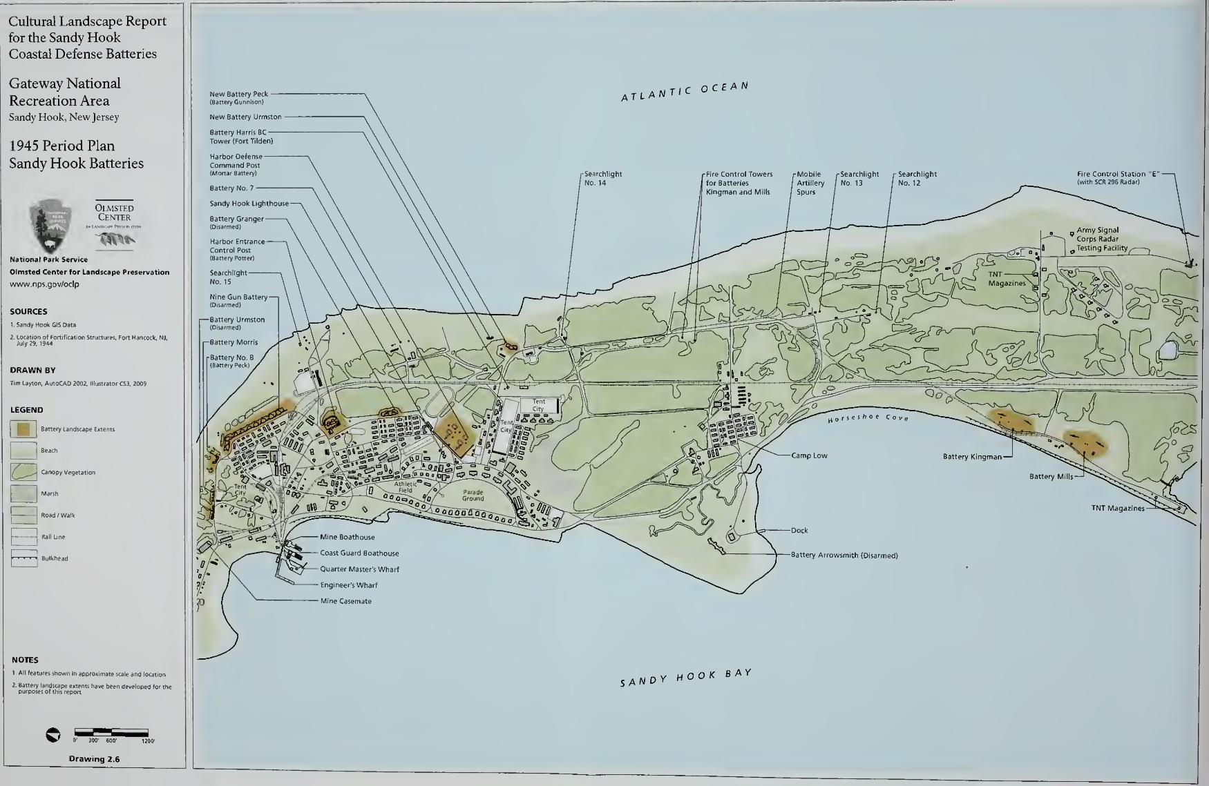
Cultural Landscape Report
for the Sandy HookCoastal Defense Batteries
Gateway National
Recreation AreaSandy Hook, New Jersey
1945 Period Plan
Sandy Hook Batteries
OlmstedCenter
National Park Service
Olmsted Center for Landscape Preservation
www.nps.gov/oclp
SOURCES
I.Sandy Hook GiS Data
DRAWN BY
Tim Layton, AutoCAD 2002, lllu:
Battery Landscape Extents
Beach
Canopy Vegetation
Marsh
Road /Walk
B 1
NOTES
1 All features shown in approximate scale and location
Site History
MIKE MISSILE SYSTEMS AMD THE COLD WAR 1945-1974
During World War II, advances in aviation made it possible to fly beyond the
range of 3-inch anti-aircraft guns, similar to those emplaced at the top of Mortar
Battery. Providing a greater range, the 90mm anti-aircraft gun became the new
Army standard during the war and could strike a target flying at 30,000 feet.132
This improved anti-aircraft artillery was installed at Sandy Hook on Battery Peck
in 1943.
In the closing years of the war the Army realized that the 90mm guns, even with
the assistance of radar technology, lacked the range, accuracy, and destructive
power to defend against an aerial attack. On August 17, 1944, Army Ordnance
officer Jacob W. Schaefer submitted a memorandum proposing the design of an
anti-aircraft rocket which could be radar-guided from the ground.133
Six months later, the Army's Chief of Ordnance issued a contract to Western
Electric and Bell Telephone Laboratories to determine the feasibility of a
defensive missile system. The project was given the code name NIKE after the
Greek goddess of victory and on November 27, 1951, a NIKE missile
successfully destroyed a drone plane during tests at the White Sands Proving
Ground in New Mexico.134
MILITARY REORGANIZATION AMD THE ORIGINS OF THE COLD WAR
Similar to responses following World War I, the years immediately after World
War II witnessed reductions in military personnel and spending. A logistical
support unit, the 1225th Army Service Unit, remained stationed at Fort Hancock
until the end of 1949. The reduction of combat and support personnel along with
new offensive weaponry that surpassed Sandy Hook's existing coastal defense
batteries resulted in Fort Hancock's deactivation on June 25, 1950.135 The Army's
departure from Sandy Hook did not last long as armed conflict erupted on the
Korean peninsula. On April 10, 1951, Fort Hancock was reactivated for defense
of the metropolitan New York area. Anti-aircraft gun batteries deployed during
World War II were reestablished and the fort served as a staging center for
training and equipping other anti-aircraft units.136
Instead of a civil war struggle between opposed domestic forces, the Korean War
became an indirect contest between the United States and the Soviet Union.
Fighting a common foe during World War II, the two nations emerged from the
war as the unrivaled economic and military powers in the world. America's
security was briefly bolstered as the only nation with atomic weaponry and
atomic bombs were considered the ultimate deterrent to future conflict. Vast
ideological differences between the two nations generated mutual distrust and
competition to shape the post-war governments in Europe and Asia. Between
121

Cultural Landscape Report for the Sandy Hook Coastal Defense Batteries
1945 and 1947, elections brought Communists to power in Yugoslavia, Albania,
Romania, Bulgaria, Poland, and Hungary and the Soviet's sphere of influence
extended over the majority of Eastern Europe.137
The United States began to address post-war strategies and defensive
preparations with passage of the National Defense Act of 1947. The legislation
created the consolidated Department of Defense and established an independent
Air Force which had previously been organized as a component of the Army. In
an address to Congress the following year, President Truman summarized the
nation's new preparatory strategy stating:
I believe that we have learned the importance of maintaining military strength
as a means of preventing war. We have found that a sound military system is
r -r • 138necessary in time or peace it we are to remain at peace.
Four months later, on July 24, 1948, the Soviets blockaded access to the
American, British, and French sections of Berlin. The Berlin Crisis persisted until
September 1949 and ended any opportunity for cordial relations between the
United States and Soviets. In testimony before the U. S. Senate, financier Bernard
Baruch described the tensions between the two nations as a "cold war" and the
term continued as an apt description of uneasy international relations for the
next four decades.139
SOVIET ADVANCES IN WEAPONRY
The impetus to fully develop and implement the NIKE system came from
increased international tensions coupled with improvements in Soviet weaponry.
In October 1947, the Soviets introduced the Tu-4 "Bull" longer range bomber
that had been developed by copying the American B-29 bomber.140 The B-29
carried the atomic payloads for the attacks on Hiroshima and Nagasaki. Two
years later, the Soviets successfully tested an atomic bomb and changed prior
American military assumptions. First, the United States could no longer deter
future conflict as the sole wielder of atomic power. Second, the test shattered
perceptions that the Soviets were technologically inferior and greatly lagged
behind American innovations. In 1953, the Soviets successfully tested a hydrogen
bomb ten months after an American test and confirmed their capability and
commitment to an arms race.141
With bombers and nuclear bombs, the Soviets
could launch a squadron from Siberia, fly over the North Pole, and attack targets
in the United States. Land-based defenses were necessary to engage this type of
attack, especially if the newly formed Air Force could not eliminate it in the air.
122
Site History
MIKE AJAX
Although conceived during World War II, development of the NIKE system was
delayed due to reduced funding immediately after the war. Renewed attention to
the NIKE program corresponded with increased tensions between the United
States and Soviets, advances in Soviet weaponry, and finally, the start of the
Korean Conflict in June 1950. Hostilities between North and South Korea
threatened to draw the United States and the allied Chinese and Soviets into
another world war. Even though a global conflict did not spread from the
Korean peninsula, United States military policy began to focus on defensive
142preparations.
In 1950, the Army reorganized defensive artillery units into the Army Anti-
Aircraft Command (ARAACOM). That same year, improvements were made in
the booster rocket and guidance systems leading to the successful test firing in
November 1951. The first generation of NIKE missiles, known as Ajax, were
twelve inches in diameter, twenty-one feet long, weighed over 2,455 pounds, and
operated remarkably similar to the system outlined by Jacob Schaefer's 1944
memorandum. 143
Ajax missiles were guided by a series of three radars. Incoming enemy aircraft
were identified by long-range radar known as LOPAR for Low-Power
Acquisition Radar. The LOPAR identification was transferred to a Target
Tracking Radar (TTR) to determine the aircraft's azimuth, elevation, and range.
Tracking information was then electronically sent to a computer which relayed
guidance information to Missile Tracking Radar (MTR) to control the missile's
flight. When launched, Ajax could travel at 2.3 times the speed of sound and
obtain altitudes up to 70,000 feet. Upon arriving at the predicted intercept point,
computers transmitted a burst signal that detonated three TNT warheads located
in the nose, middle, and tail of the missile (Figures 2.89 and 2.90). Between 1954
and 1958, the Army deployed nearly 200 NIKE Ajax batteries around the
nation's key urban, military, and industrial locations.144
In the metropolitan New
York area, nineteen batteries were established including a dual firing battery at
Sandy Hook.
MIKE HERCULES
Four months after the successful test ofNIKE Ajax at White Sands Proving
Ground, the Bureau of Ordnance recommended studying the feasibility of
equipping the missile with a nuclear warhead. In their study ofArmy and Air
Force missile defense programs, John C. Lonnquest and David F. Winkler cite
that a major limitation of the Ajax system was, ".. .the inability to discern
individual bombers within a densely-packed flying formation."145
For example, if
two planes were flying close together, the radar would detect them as one object
123
Cultural Landscape Report for the Sandy Hook Coastal Defense Batteries
and guide the missile to hit the center of that object. At best, the missile would
not score a direct hit and at worst, miss both targets completely. One way to
correct this potential shortcoming would be to arm the missile with a nuclear
warhead. Upon detonation, the nuclear warhead would create a larger and more
powerful explosion that could destroy planes without a direct hit.
Ajax designers recommended two options for adding a nuclear warhead to the
missile. First, a smaller warhead could be reconfigured and adapted for use on
the Ajax. The second option involved using a larger warhead with more
destructive power and incorporating it into a newly designed, larger missile. The
Army selected the second option on condition that the new missile system would
use the same facilities already being designed and constructed for the Ajax. In
July 1953, the Army authorized the development of the second generation NIKE
missile called Hercules. In addition to the larger warhead capacity, Hercules
would feature a longer range and more stable fuel mixture than its predecessor.146
Three years after authorization, a Hercules missile successfully destroyed a drone
aircraft at White Sands Proving Ground. Tests continued into 1957 using a solid
fuel mixture that would replace the volatile liquid mixture of jet fuel and nitric
acid used in Ajax.147
Forty-one feet long and thirty one and half inches in
diameter, Hercules' increased size accommodated not only a larger warhead, but
four booster rockets compared to a single rocket on Ajax. The added thrust
increased the range of Hercules up to three times greater than Ajax and obtained
altitudes up to 150,000 feet.148
The new flight parameters of Hercules made it theoretically possible to engage
bombers at higher altitudes and at greater distance but only if improvements
were made to the NIKE radar system. In order to identify targets at a greater
distance, Hercules sites added High-Powered Acquisition Radar or HIPAR. In
June 1958, Hercules missiles began to be deployed at converted NIKE Ajax sites
near New York City, Philadelphia, and Chicago. Over the next six years, 110
Ajax sites were converted and 35 sites were newly constructed for Hercules.
The longer range of Hercules resulted in fewer sites than had been implemented
for Ajax.149
THE MIKE SITES AT SANDY HOOK
The NIKE installation at Sandy Hook was one of nineteen missile sites that
comprised the New York Defense Area. The defense area included the five
boroughs of New York City and two counties to the north, the western half of
Long Island, and the northeastern section ofNew Jersey. Regardless of a New
York or New Jersey location, all of the NIKE sites were designated "NY"
followed by a number to indicate their association with the defense area.1 °
124
Site History
The Department of Defense announced plans to construct the NIKE site at
Sandy Hook, designated NY-56, in December 1953. With coastal defenses
redirected away from naval threats to instead intercepting aircraft, proximity and
range-finding views to important waterways were no longer important factors in
selecting locations for NIKE sites. The selecting factor changed to adequate
distance and a lack of obstructions between proposed NIKE radar and missile
locations so radar and launch equipment could properly operate in tandem.
At Sandy Hook and across the country, NIKE installations were comprised of an
Integrated Fire Control (IFC) or radar site and a launch site. The IFC contained
the acquisition and tracking radar and was separated from the launch site by a
minimum of 3,000 feet. More commonly, sites were separated by over a mile as
was the case at Sandy Hook. Regardless of the exact distance, the two locations
had to be within visual sight of each other so radar could lock onto a firing
missile.151
Buildings, tall vegetation, and utility poles are examples of objects that
could interfere with radar transmissions (Figures 2.91 and 2.92).
The IFC and launch sites at Sandy Hook were located south of Fort Hancock and
the temporary, World War II-expansion needed to accommodate increased
personnel. The IFC was located roughly in the middle of the peninsula, in the
largely undeveloped area southeast of the Camp Low barracks built during
World War II. The launch site was located east of Batteries Kingman and Mills,
across Hartshorne Drive, and immediately north of a small, existing pond. A
1944 Army Corps of Engineers map of Sandy Hook recorded a group of eight
warehouses, labeled T-10 through T-17, that were in the general vicinity of the
proposed launch site. The warehouses were constructed by Western Electric to
shelter radar antenna during tests by the Army Signal Corps (Figure 2.93).
Sandy Hook's NIKE launch site represents one of the few dual battery
installations constructed during the Cold War era. The Sandy Hook launch site
contained four underground magazines that delivered missiles by an elevator to a
row of launchers on the surface. The two magazines on the east side of the
launch area formed one firing battery and the two on the west side formed the
other. The IFC site to the north contained two control areas with separate radar
systems for each firing battery. The eastern control area, designated #1, provided
radar for the eastern firing battery while the western control area, designated #2,
was assigned to the western firing battery.152
Integrated Fire Control (IFC) or Radar Site
During the previous generations of coastal defenses at Sandy Hook, the NIKE
IFC site remained largely undeveloped. The Army's central railroad line bisected
the future IFC location and during World War II, several temporary structures
associated with Camp Low bordered either side of the tracks. A site plan for the
125
Cultural Landscape Report for the Sandy Hook Coastal Defense Batteries
IFC, issued March 22, 1954, recorded six concrete foundations in the northern
portion of the proposed site. None of the foundations were labeled with building
designations and the majority appear small enough to be outbuildings or auxiliary
structures. In addition, the site plan showed vegetation cover occupying more
than half of the proposed area and contained the labels "brush and trees up to 35'
high" (Figure 2.94).
The proposed IFC site was roughly triangular in shape with its longest perimeter
running from west to east. The western point, accessible from Hartshorne Drive,
contained Control Area #2. The eastern point contained Control Area #1 and
was accessible from Atlantic Drive. The boundaries of the site converged at a
northern point that contained the Ready Barracks and were accessible from
Sheldon Road.153
For both control areas, the three types of radar shared the same relative position
with the Acquisition Radar in the center flanked by the MTR to the west and
TTR to the east. Each area also featured a long, rectangular, concrete pad located
north of the Acquisition Radar. The pad was constructed for three trailers,
stacked front to back, that held equipment and personnel for battery control,
radar control, and spare computer and electronics parts. The wheels and
undercarriage of each trailer were removed and the trailers set on wooden blocks
on top of the concrete pad.154
The battery control trailer was immediately north of the Acquisition Radar and
contained controls for the radar as well as a missile guidance computer. Furthest
north on the pad was the radar control trailer that held computers and
equipment for the TTR and MTR. In between the two was a maintenance and
spare parts trailer (Figure 2.95).155
The TTR and MTR had to work in concert to predict an intercept point and
direct the missile to that point. To calibrate both radars, a sixty-foot tall bore
sighting mast, or collimation test mast, was erected at the northern end of the site
near the Ready Barracks. A separate mast was installed for each control area and
the site plan called out a ten degree unobstructed cone from the center of the TTR
and MTR to the bore mast. The plan further explained that the site's contractor
would be responsible for clearing the unobstructed visual cone, much of which
passed through existing vegetation up to thirty-five feet high (Figure 2.96).
A four foot-wide concrete walk was proposed from each control area to its
respective mast, however, on the site plan, the walk was labeled N.I.C.—an
abbreviation for "not-in-contract." Another drawing showing the IFC site plan
displayed a final revision date ofJanuary 22, 1960, and was annotated as "record
work as built." Although the drawing recorded other changes to the site, for
126

Site History
example, dry wells near both sets of trailers, the concrete walks to the masts were
labeled "proposed walk" indicating they had yet to be installed (Figure 2.97).
Additional changes to the site between the beginning of construction in 1954 and
the "record work as built" designation in 1960 include perimeter fencing, walks,
and construction of a basketball court. Eight months after the site plan was
issued, a revision was made that "clarified the fence and firebreak." The revised
annotations listed the fence as type FE-6—a designation for chain link fence with
a single extension arm supporting continuous strands of barbed wire. Top of
fence elevations were added near the radar installations and accompanied by a
section illustrating that the existing ground should be excavated prior to setting
the fence posts. The excavation was necessary to maintain a consistent fence
elevation and to not interfere with the transmission of the radar (Figure 2.98).
The final notes added for the fence installation specify a thirty-foot wide
firebreak inside the perimeter fence. The combination of the firebreak and
clearing for the boring masts resulted in a triangular area in the center of the site
where existing, native vegetation remained undisturbed (Figure 2.99).
Although the walks to the boring masts were not installed, a concrete walk was
constructed from each control area to the Ready Barracks between October 1955
and January 1960. Electrical conduit was buried alongside the walks and
extended around the walkways at the barracks. A total of twelve light fixtures
were added with five being located around the barracks, four located along the
walk from Control Area #1, and three located along the walk from Control Area
#2 (Figure 2.100).
During this same time period, a basketball court was added south of the Ready
Barracks. Since the IFC was physically distant from the major facilities and
recreation opportunities at Fort Hancock, the court served as a small recreation
amenity when personnel staffed the site and was a common feature at NIKE
installations across the country (Figures 2.101 and 2.102).156
Sandy Hook's NIKE site received the upgrade from the Ajax to the larger
Hercules missile and necessary modifications were made at both the IFC and
launch areas. Additionally, the IFC was part of a program called "Improved
Hercules" that added more sophisticated radar designed to counter electronic
interference from enemy aircraft.157
Site plans dated September 4, 1962, show the installation of a High-Powered
Acquisition Radar or HIPAR system designed to detect incoming aircraft at a
greater distance. A HIPAR Tower to mount the radar and a HIPAR Building for
equipment and controls are shown north of Control Area #2 (Figure 2.103).
West of the HIPAR Building, new Target Tracking and Target Ranging radars—
both components of the "Improved Hercules" system—are shown. A new Target
127
Cultural Landscape Report for the Sandy Hook Coastal Defense Batteries
Tracking Radar is also shown at Control Area #1. Battery control and radar
control trailers are still shown on the 1962 plan, however, at both control areas
the maintenance and spare parts trailer has been removed and replaced with a
building that served the same function labeled "Interconnecting Corridor"
(Figure 2.104).
Launch Site
The Army originally intended for NIKE missiles to be stored above ground and
estimated 119 acres were needed for a combined IFC and launch site. Since
NIKE sites were going to defend populated urban, military, and industrial areas,
available space was a constraining factor. To reduce the footprint of the launch
site, designs for underground magazines were prepared that resulted in an
approximate forty acre-requirement for the IFC and launch sites. On October
28, 1953, ARAACOM directed that the underground magazine design would be
used in most instances.158
The launch site at Sandy Hook was roughly T-shaped in plan. The long leg of the
"T" began at Hartshorne Drive and proceeded east toward the Atlantic Ocean
where it divided into shorter northern and southern sections. The western
portion of the "T" contained the Ready Barracks and the southern section
contained the Missile Maintenance Area. The northern section contained the
underground missile magazines and launching racks and all three areas were
surrounding by a perimeter fence (Figure 2.105).
Due to groundwater very close to the surface throughout the peninsula, the
magazines and launching racks were located in an area with existing grades
between elevations of sixteen and twenty feet. Generally higher than other areas
on the peninsula, this location, with the addition of fill material, would permit the
underground magazine design. The proposed elevation for the launchers was
twenty-feet and they were contained within a 460 by 490-foot engineered plateau
at a similar elevation (Figure 2.106).
As mentioned previously, a group of eight existing structures used for radar
testing during the late 1930s were located near the proposed launch site. On a
site plan issued March 22,1954, buildings T- 1 4 through T- 1 7 were shown and
labeled as "two story frame warehouse" with additional annotations indicating
they are unoccupied. T-16 and T-17 were located within the proposed
construction area and are labeled to be removed and salvaged. The same site
plan includes future provisions for two more magazines beyond the four planned
for construction. Although never constructed, planning for the future magazines
positioned the northern location of the perimeter fence away from any conflict
and created secured, undeveloped space at the northern end of the launch site.
Included with the layout of the perimeter fence were annotations labeling
128
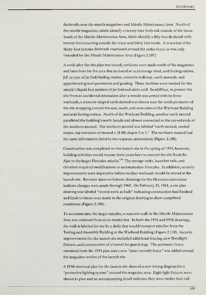
Site History
firebreaks near the missile magazines and Missile Maintenance Area. North of
the missile magazines, labels identify a twenty foot firebreak outside of the fence.
South of the Missile Maintenance Area, labels identify a fifty foot firebreak with
twenty feet occurring outside the fence and thirty feet inside. It is unclear if the
thirty-foot interior firebreak continued around the entire fence or was only
intended for the Missile Maintenance Area (Figure 2.107).
A week after the site plan was issued, revisions were made south of the magazines
and launchers for the area that included an acid storage shed, acid fueling station,
J. P. (a type of jet fuel) fueling station, concrete walkway, earth mounds, and
appurtenant gravel pavements and grading. These facilities were needed for the
missile's liquid fuel mixture of jet fuel and nitric acid. In addition, to protect the
site from an accidental detonation after a missile was armed with its three
warheads, a crescent-shaped earth mound was shown near the south perimeter of
the site wrapping around the east, south, and west sides of the Warhead Building
and acid fueling station. North of the Warhead Building, another earth mound
paralleled the building's north facade and almost connected to the curved ends of
the southern mound. The southern mound was labeled "earth mound, seeded
slopes, top elevation of mound = 21.00, slopes 3 in 1." The northern mound had
the same information listed in two separate annotations (Figure 2.108).
Construction was completed on the launch site in the spring of 1955, however,
building activities would resume three years later to convert the site from the
Ajax to the larger Hercules missile.159 The storage racks, launcher rails, and
elevators required modifications to accommodate Hercules. In addition, security
improvements were imperative before nuclear warheads would be stored at the
launch site. Revision dates on historic drawings for the Hercules conversion
indicate changes were made through 1960. On February 23, 1961, a site plan
drawing was labeled "record work as built" indicating construction had finished
and final revisions were made to the original drawing to show completed
conditions (Figure 2.109).
To accommodate the larger missiles, a concrete walk in the Missile Maintenance
Area was widened from six to twelve feet. In both the 1954 and 1958 drawings,
the walk is labeled for use by a dolly that would transport missiles from the
Testing and Assembly Building to the Warhead Building (Figure 2.110). Security
improvements for the launch site included additional fencing, new floodlight
fixtures, and construction of a kennel for guard dogs. The perimeter fence
remained from the 1954 plan and a new "inner security fence" was added around
the magazine section of the launch site.
A 1958 electrical plan for the launch site showed a new wiring diagram for a
"protective lighting system" around the magazine area. Eight light fixtures were
shown in plan and an accompanying detail indicates they were twelve foot-tall
129

Cultural Landscape Report for the Sandy Hook Coastal Defense Batteries
wood poles mounted with 1,500 watt wide-beam floodlights (Figure 2.1 1 1). The
floodlights would create a beam of light in the direction that the fixture was
mounted. In order to communicate the desired mounting direction, the plan
shows a cone, representing the beam, emanating from a circle that represents the
pole. Each of the eight fixtures are shown with their beams paralleling the path of
the inner security fence and not faced towards the launchers. Based on this plan,
the lights were not intended to facilitate night operation but to illuminate the
inner security fence and facilitate better security surveillance (Figure 2.1 12).
In addition to the inner fence and floodlights, a kennel was added to the Sandy
Hook site to house guard dogs patrolling the area between the inner and outer
fences (Figure 2.113). The kennels, along with the dual fences, were identifiable
features of converted and newly installed NIKE Hercules sites throughout the
country (Figure 2.1 14).160
At Sandy Hook, the kennel was originally designed to
be constructed south of the Missile Maintenance Area. In a revision dated
August 1958, the kennel was relocated to the northwest corner of magazine area,
arguably for closer proximity to the inner fence and to utilize space intended for
future magazine expansion that was never developed (Figure 2.115).
ICBMS, MIKE ZEUS, AMD A MEW DEFENSE PHILOSOPHY
During the 1950s, the United States and Soviet Union escalated their arms race
and began developing missiles that would travel beyond the Earth's atmosphere
and be able to strike targets half-way around the world. Known as
intercontinental ballistic missiles or ICBMs, this new offensive technology shifted
the threat away from the long range bombers that the NIKE system was intended
to stop. The Soviet Union announced they had an operational ICBM in 1957 and
following the launch of Sputnik that same year, the United States accelerated
their program and had the Atlas ICBM operational in 1959.161
In response to this new offensive weaponry, the Secretary of Defense assigned
the Army with development of an anti-missile, missile system called Zeus that
utilized existing NIKE infrastructure in 1958.162
For the next three years funds
were allocated for research and development, but not for implementation at
existing NIKE sites. Opposition mounted against the Zeus system as the scientific
community argued existing radar systems lacked the sophistication to discern
between an ICBM and debris jettisoned from its booster rockets. Furthermore,
arguments against the concept of an anti-missile, missile system contended it
could be defeated by overwhelming the system with a massive convoy of decoy
missiles with only one missile being armed with a nuclear warhead. Funding for
Zeus was cancelled in 1963, however, debate, research, and development on an
anti-ballistic missile system continued throughout the 1960s.163
130
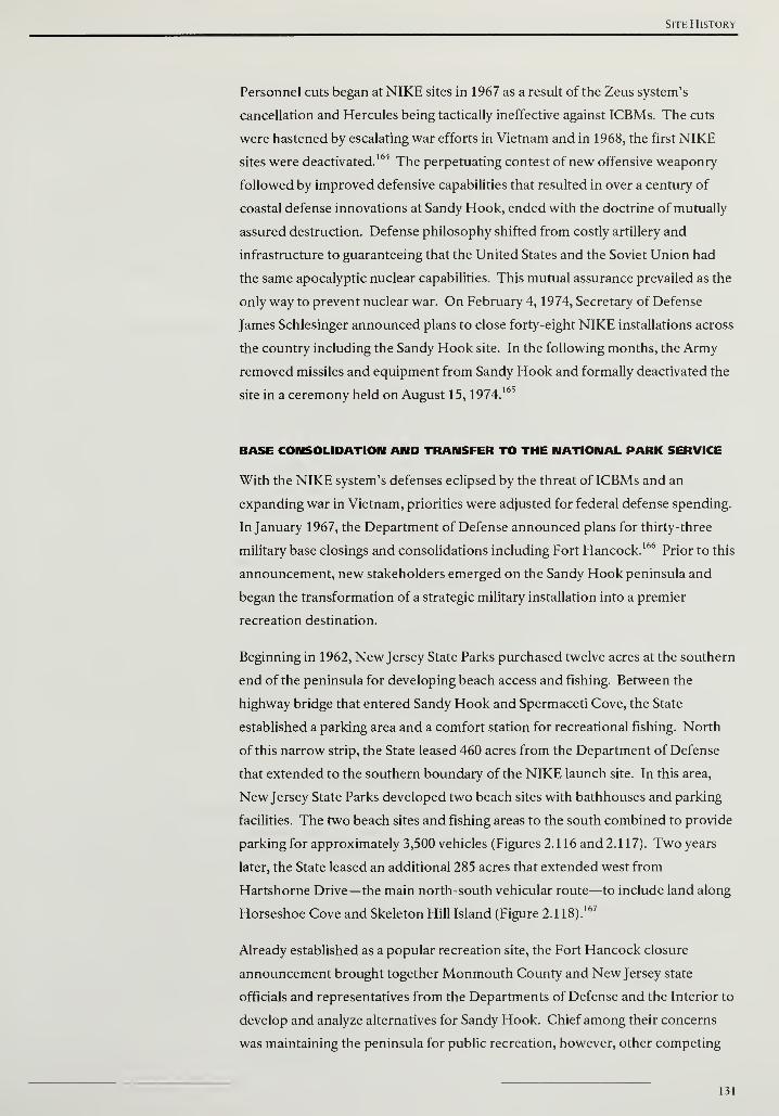
Site History
Personnel cuts began at NIKE sites in 1967 as a result of the Zeus system's
cancellation and Hercules being tactically ineffective against ICBMs. The cuts
were hastened by escalating war efforts in Vietnam and in 1968, the first NIKE
sites were deactivated.164 The perpetuating contest of new offensive weaponry
followed by improved defensive capabilities that resulted in over a century of
coastal defense innovations at Sandy Hook, ended with the doctrine of mutually
assured destruction. Defense philosophy shifted from costly artillery and
infrastructure to guaranteeing that the United States and the Soviet Union had
the same apocalyptic nuclear capabilities. This mutual assurance prevailed as the
only way to prevent nuclear war. On February 4, 1974, Secretary of Defense
James Schlesinger announced plans to close forty-eight NIKE installations across
the country including the Sandy Hook site. In the following months, the Army
removed missiles and equipment from Sandy Hook and formally deactivated the
site in a ceremony held on August 15, 1974.165
BASE CONSOLIDATION AND TRANSFER TO THE NATIONAL PARK SERVICE
With the NIKE system's defenses eclipsed by the threat of ICBMs and an
expanding war in Vietnam, priorities were adjusted for federal defense spending.
In January 1967, the Department of Defense announced plans for thirty-three
military base closings and consolidations including Fort Hancock.166
Prior to this
announcement, new stakeholders emerged on the Sandy Hook peninsula and
began the transformation of a strategic military installation into a premier
recreation destination.
Beginning in 1962, New Jersey State Parks purchased twelve acres at the southern
end of the peninsula for developing beach access and fishing. Between the
highway bridge that entered Sandy Hook and Spermaceti Cove, the State
established a parking area and a comfort station for recreational fishing. North
of this narrow strip, the State leased 460 acres from the Department of Defense
that extended to the southern boundary of the NIKE launch site. In this area,
New Jersey State Parks developed two beach sites with bathhouses and parking
facilities. The two beach sites and fishing areas to the south combined to provide
parking for approximately 3,500 vehicles (Figures 2.116 and 2.117). Two years
later, the State leased an additional 285 acres that extended west from
Hartshorne Drive—the main north-south vehicular route—to include land along
Horseshoe Cove and Skeleton Hill Island (Figure 2.1 18).167
Already established as a popular recreation site, the Fort Hancock closure
announcement brought together Monmouth County and New Jersey state
officials and representatives from the Departments of Defense and the Interior to
develop and analyze alternatives for Sandy Hook. Chief among their concerns
was maintaining the peninsula for public recreation, however, other competing
131
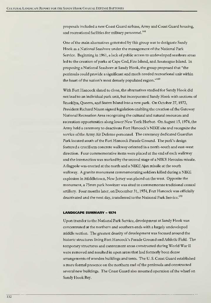
Cultural Landscape Report for the Sandy Hook Coastal Defense Batteries
proposals included a new Coast Guard airbase, Army and Coast Guard housing,
168and recreational facilities for military personnel.
One of the main alternatives generated by this group was to designate Sandy
Hook as a National Seashore under the management of the National Park
Service. Beginning in 1961, a lack of public access to undeveloped seashore areas
led to the creation of parks at Cape Cod, Fire Island, and Assateague Island. In
proposing a National Seashore at Sandy Hook, the group proposed that "the
peninsula could provide a significant and much needed recreational unit within
the heart of the nation's most densely populated region."169
With Fort Hancock slated to close, the alternatives studied for Sandy Hook did
not lead to an individual park unit, but incorporated Sandy Hook with sections of
Brooklyn, Queens, and Staten Island into a new park. On October 27, 1972,
President Richard Nixon signed legislation enabling the creation of the Gateway
National Recreation Area recognizing the cultural and natural resources and
recreation opportunities along lower New York Harbor. On August 15, 1974, the
Army held a ceremony to deactivate Fort Hancock's NIKE site and recognize the
service of the Army Air Defense personnel. The ceremony dedicated Guardian
Park located south of the Fort Hancock Parade Ground. The park's design
featured a cruciform concrete walkway oriented in a north-south and east-west
direction. Four commemorative items were placed at the end of each walkway
and the intersection was marked by the second stage of a NIKE Hercules missile.
A flagpole was erected at the north and a NIKE Ajax missile at the south
walkway. A granite monument commemorating soldiers killed during a NIKE
explosion in Middletown, New Jersey was placed on the west. Opposite the
monument, a 75mm park howitzer was sited to commemorate traditional coastal
artillery. Four months later, on December 31, 1974, Fort Hancock was officially
deactivated and the next day, transferred to the National Park Service.170
LANDSCAPE SUMMARY - 1974
Upon transfer to the National Park Service, development at Sandy Hook was
concentrated at the northern and southern ends with a largely undeveloped
middle section. The greatest density of development was focused around the
historic structures lining Fort Hancock's Parade Ground and Athletic Field. The
temporary structures and cantonment areas constructed during World War II
were removed and resulted in open areas that had formerly been dense
arrangements ofwooden buildings and tents. The U. S. Coast Guard established
a more formal presence on the northern end of the peninsula and constructed
several new buildings. The Coast Guard also assumed operation of the wharf on
Sandy Hook Bay.
132
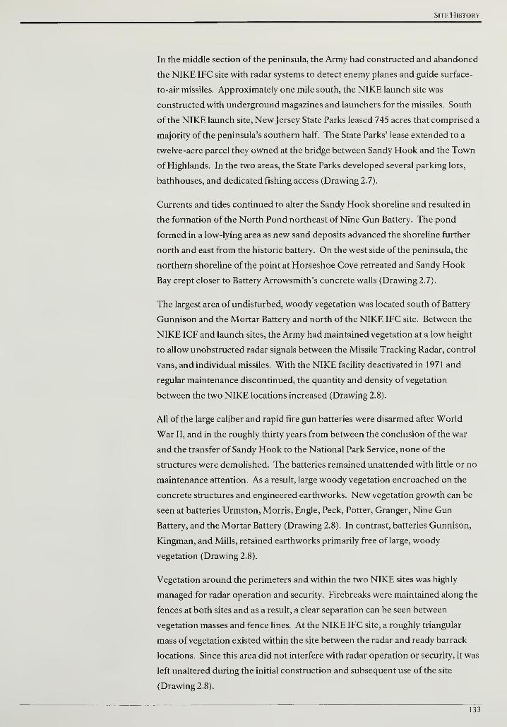
Site History
In the middle section of the peninsula, the Army had constructed and abandoned
the NIKE IFC site with radar systems to detect enemy planes and guide surface-
to-air missiles. Approximately one mile south, the NIKE launch site was
constructed with underground magazines and launchers for the missiles. South
of the NIKE launch site, New Jersey State Parks leased 745 acres that comprised a
majority of the peninsula's southern half. The State Parks' lease extended to a
twelve-acre parcel they owned at the bridge between Sandy Hook and the Town
of Highlands. In the two areas, the State Parks developed several parking lots,
bathhouses, and dedicated fishing access (Drawing 2.7).
Currents and tides continued to alter the Sandy Hook shoreline and resulted in
the formation of the North Pond northeast of Nine Gun Battery. The pond
formed in a low-lying area as new sand deposits advanced the shoreline further
north and east from the historic battery. On the west side of the peninsula, the
northern shoreline of the point at Horseshoe Cove retreated and Sandy Hook
Bay crept closer to Battery Arrowsmith's concrete walls (Drawing 2.7).
The largest area of undisturbed, woody vegetation was located south of Battery
Gunnison and the Mortar Battery and north of the NIKE IFC site. Between the
NIKE ICF and launch sites, the Army had maintained vegetation at a low height
to allow unobstructed radar signals between the Missile Tracking Radar, control
vans, and individual missiles. With the NIKE facility deactivated in 1971 and
regular maintenance discontinued, the quantity and density of vegetation
between the two NIKE locations increased (Drawing 2.8).
All of the large caliber and rapid fire gun batteries were disarmed after World
War II, and in the roughly thirty years from between the conclusion of the war
and the transfer of Sandy Hook to the National Park Service, none of the
structures were demolished. The batteries remained unattended with little or no
maintenance attention. As a result, large woody vegetation encroached on the
concrete structures and engineered earthworks. New vegetation growth can be
seen at batteries Urmston, Morris, Engle, Peck, Potter, Granger, Nine Gun
Battery, and the Mortar Battery (Drawing 2.8). In contrast, batteries Gunnison,
Kingman, and Mills, retained earthworks primarily free of large, woody
vegetation (Drawing 2.8).
Vegetation around the perimeters and within the two NIKE sites was highly
managed for radar operation and security. Firebreaks were maintained along the
fences at both sites and as a result, a clear separation can be seen between
vegetation masses and fence lines. At the NIKE IFC site, a roughly triangular
mass of vegetation existed within the site between the radar and ready barrack
locations. Since this area did not interfere with radar operation or security, it was
left unaltered during the initial construction and subsequent use of the site
(Drawing 2.8).
133
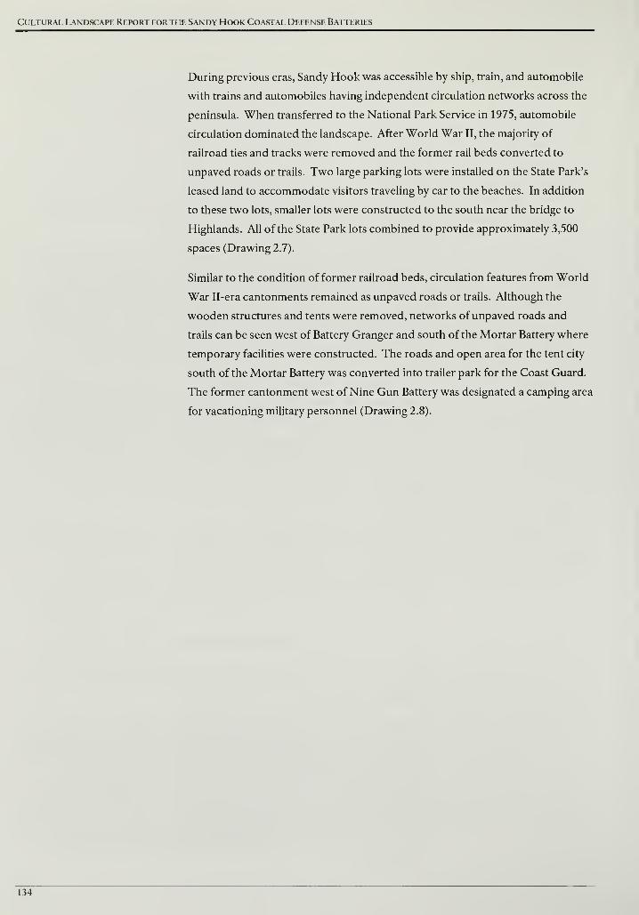
Cultural Landscape Report for the Sandy Hook Coastal Defense Batteries
During previous eras, Sandy Hook was accessible by ship, train, and automobile
with trains and automobiles having independent circulation networks across the
peninsula. When transferred to the National Park Service in 1975, automobile
circulation dominated the landscape. After World War II, the majority of
railroad ties and tracks were removed and the former rail beds converted to
unpaved roads or trails. Two large parking lots were installed on the State Park's
leased land to accommodate visitors traveling by car to the beaches. In addition
to these two lots, smaller lots were constructed to the south near the bridge to
Highlands. All of the State Park lots combined to provide approximately 3,500
spaces (Drawing 2.7).
Similar to the condition of former railroad beds, circulation features from World
War II-era cantonments remained as unpaved roads or trails. Although the
wooden structures and tents were removed, networks of unpaved roads and
trails can be seen west of Battery Granger and south of the Mortar Battery where
temporary facilities were constructed. The roads and open area for the tent city
south of the Mortar Battery was converted into trailer park for the Coast Guard.
The former cantonment west of Nine Gun Battery was designated a camping area
for vacationing military personnel (Drawing 2.8).
134
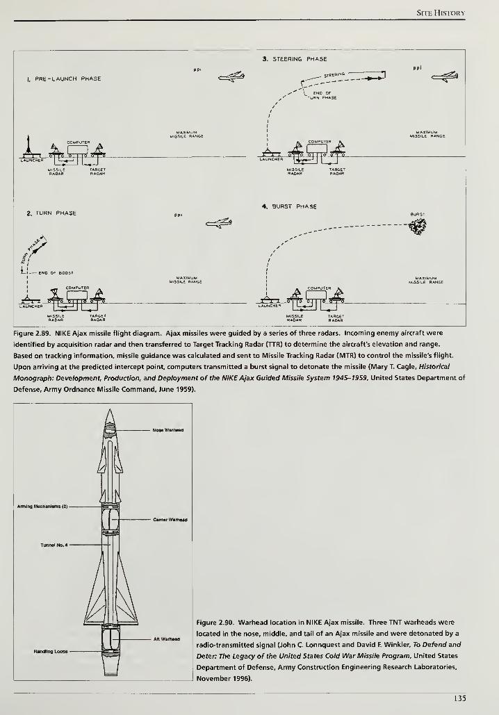
Site History
I. PRE -LAUNCH PHASE
3. STEERING PHASEppi
ENO OF"turn phase
MISSILE RANGE ^4. BURST PHASE
2. TURN PHASE
<A
if
L - END OP BOOST
COMPUTER
Ax
Figure 2.89. NIKE Ajax missile flight diagram. Ajax missiles were guided by a series of three radars. Incoming enemy aircraft were
identified by acquisition radar and then transferred to Target Tracking Radar (TTR) to determine the aircraft's elevation and range.
Based on tracking information, missile guidance was calculated and sent to Missile Tracking Radar (MTR) to control the missile's flight.
Upon arriving at the predicted intercept point, computers transmitted a burst signal to detonate the missile (Mary T. Cagle, Historical
Monograph: Development, Production, and Deployment of the NIKE Ajax Guided Missile System 1945-1959, United States Department of
Defense, Army Ordnance Missile Command, June 1959).
Aminfl Mechanisms (2) -
Nose Warheaa
n~^
^=^
Handling Loops -
Center Warnead
L
U
Figure 2.90. Warhead location in NIKE Ajax missile. Three TNT warheads were
located in the nose, middle, and tail of an Ajax missile and were detonated by a
radio-transmitted signal (John C. Lonnquest and David F. Winkler, To Defend and
Deter: The Legacy of the United States Cold War Missile Program, United States
Department of Defense, Army Construction Engineering Research Laboratories,
November 1996).
135
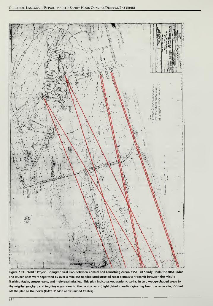
Cultural Landscape Report for the Sandy Hook Coastal Defense Batteries
Figure 2.91. "NIKE" Project, Topographical Plan Between Control and Launching Areas, 1954. At Sandy Hook, the NIKE radar
and launch sites were separated by over a mile but needed unobstructed radar signals to transmit between the Missile
Tracking Radar, control vans, and individual missiles. This plan indicates vegetation clearing in two wedge-shaped areas to
the missile launchers and two linear corridors to the control vans (highlighted in red) originating from the radar site, located
off the plan to the north (GATE 11040d and Olmsted Center).
136
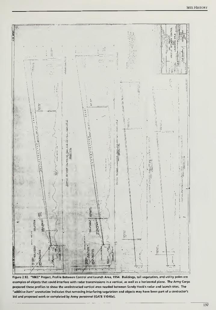
Site History
Figure 2.92. "NIKE" Project, Profile Between Control and Launch Area, 1954. Buildings, tall vegetation, and utility poles are
examples of objects that could interfere with radar transmissions in a vertical, as well as a horizontal plane. The Army Corps
prepared these profiles to show the unobstructed vertical area needed between Sandy Hook's radar and launch sites. The
"additive item" annotation indicates that removing interfering vegetation and objects may have been part of a contractor's
bid and proposed work or completed by Army personnel (GATE 11040e).
137
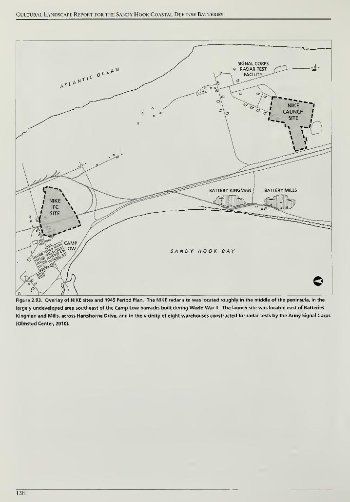
Cultural Landscape Report for the Sandy Hook Coastal Defense Batteries
E a
,tl,Tl
SIGNAL CORPSQ RADAR TEST /
A FACILITY^--^J'
—\ \ o^—-^^'
V a 0»/\ ^
1
cr.
NIKE
LAUNCHSITE
\o A--
^
NIKE
IFC
SITE
J &/&\^<2\ CAMPJc^gUOW/
x#^
BATTERY KINGMAN BATTERY MILLS
SANDY HOOK BAY
-#
v>
Figure 2.93. Overlay of NIKE sites and 1945 Period Plan. The NIKE radar site was located roughly in the middle of the peninsula, in the
largely undeveloped area southeast of the Camp Low barracks built during World War II. The launch site was located east of Batteries
Kingman and Mills, across Hartshorne Drive, and in the vicinity of eight warehouses constructed for radar tests by the Army Signal Corps
(Olmsted Center, 2010).
138
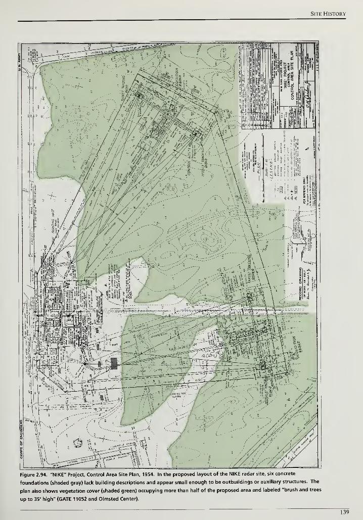
Site History
Figure 2.94. "NIKE" Project. Control Area Site Plan, 1954. In the proposed layout of the NIKE radar site, six concrete
foundations (shaded gray) lack building descriptions and appear small enough to be outbuildings or auxiliary structures. The
plan also shows vegetation cover (shaded green) occupying more than half of the proposed area and labeled "brush and trees
up to 35' high" (GATE 11052 and Olmsted Center).
139
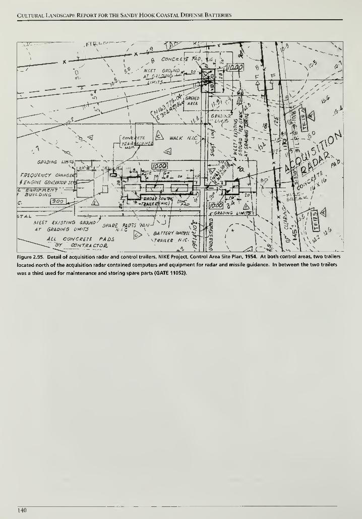
Cultural Landscape Report for the Sandy Hook Coastal Defense Batteries
&paoiNG Linnsr—K
rPtQUENCY CHAMGet
4 En 3iHI GtNEXKlOg #1
BUlLOiNC
T*fM&r~l x *"
c)j
^! - - -
STAtA/f£r EXISTING SHOUND-
AT SHADING OWrj
All conatari padsBY CCHTfiA CTOJt
\ -ji '^TruAieepKfl eft,,
5PABL PASTS i)W/v'-/N -J
/,'
NIC r^ V jCn, i, BArree* mamBA rregY cowtoi ^>
\T/?Aiiee hic-OS
fCBAQina yyjH,
>| >*~>3k ^
!.^1 c~-3
Figure 2.95. Detail of acquisition radar and control trailers, NIKE Project, Control Area Site Plan, 1954. At both control areas, two trailers
located north of the acquisition radar contained computers and equipment for radar and missile guidance. In between the two trailers
was a third used for maintenance and storing spare parts (GATE 11052).
140
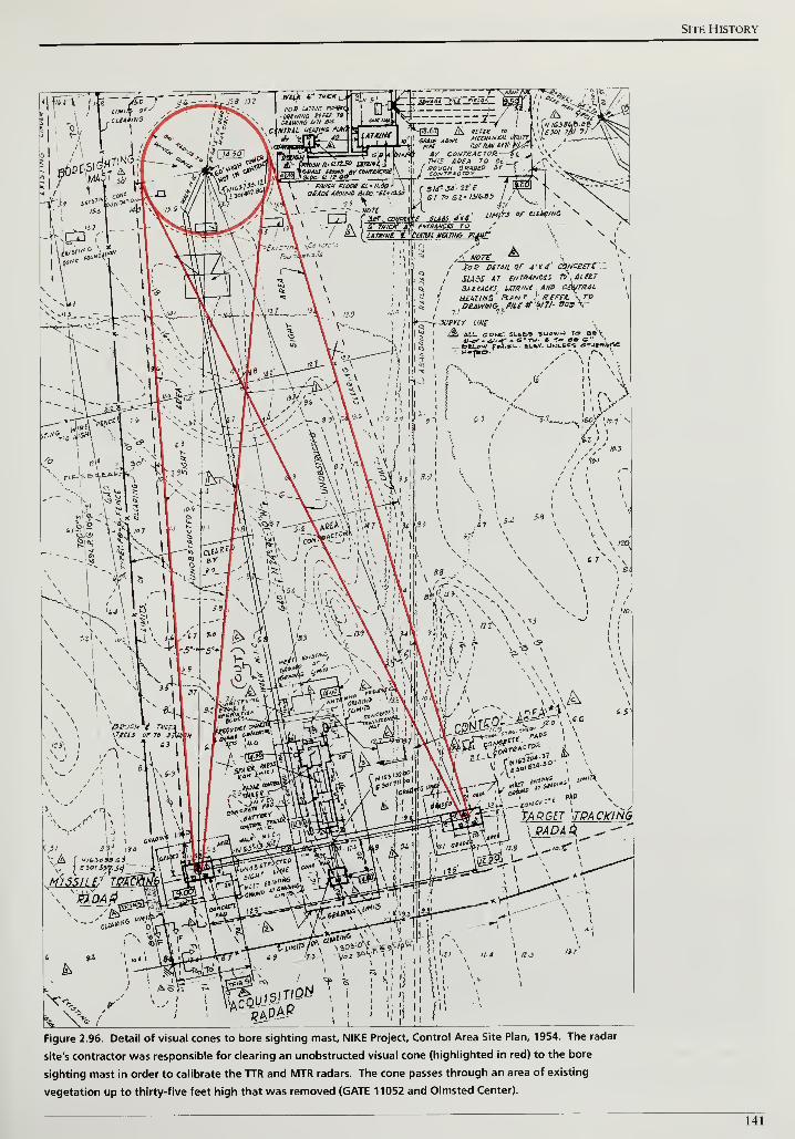
Site History
Figure 2.96. Detail of visual cones to bore sighting mast, NIKE Project, Control Area Site Plan, 1954. The radar
site's contractor was responsible for clearing an unobstructed visual cone (highlighted in red) to the bore
sighting mast in order to calibrate the TTR and MTR radars. The cone passes through an area of existing
vegetation up to thirty-five feet high that was removed (GATE 11052 and Olmsted Center).
141
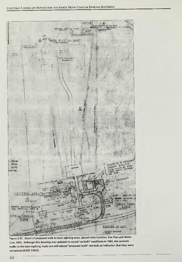
Cultural Landscape Report for the Sandy Hook Coastal Defense Batteries
Figure 2.97. Detail of proposed walk to bore sighting mast. Special AAA Facilities. Site Plan and Water
Line, 1955. Although this drawing was updated to record "as built" conditions in 1960, the concrete
walks to the bore sighting masts are still labeled "proposed walk" and lack an indication that they were
completed (GATE 11053).
142
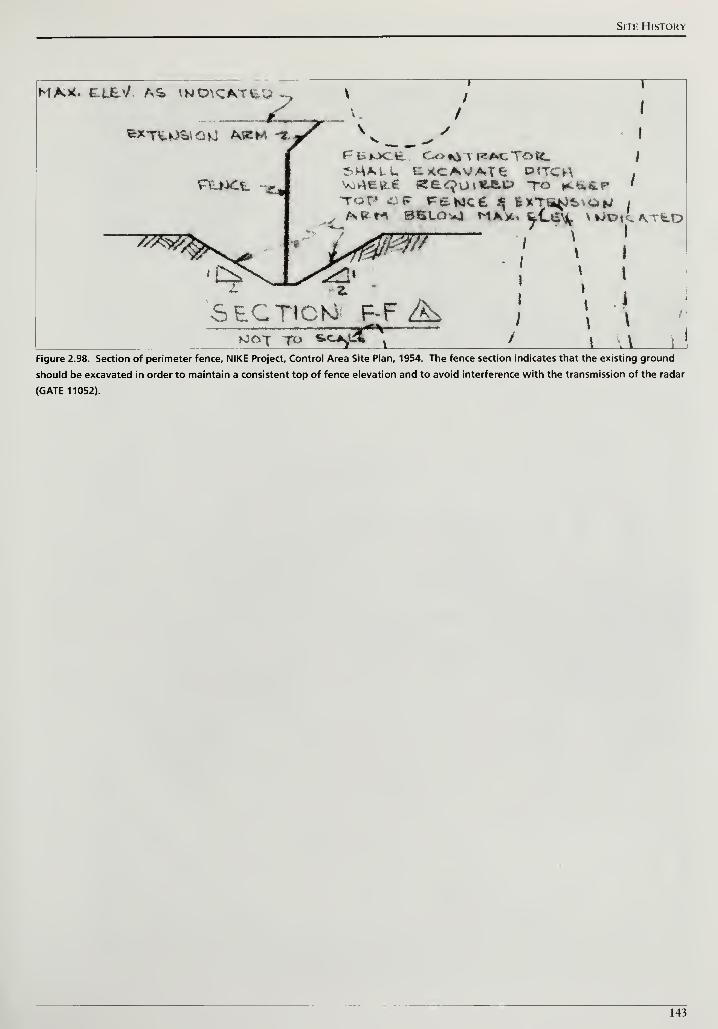
Site History
MA*. dt-E'/ AS <NO\CAT£.Uz^XT^^^QU AKM -*7
PLjJCt f« 'v.^t^f ff
£
<] O v 14-ft.t? TO K-iiPtot < f re^cC $ imfetetau /
^»M BSLO»J MA*. feCta^ * ^Dt'l MtD
/
z
SECTION F-F ^_-*^
I
I
»CJ^tV
\
I
I
i
\
Figure 2.98. Section of perimeter fence, NIKE Project, Control Area Site Plan, 1954. The fence section indicates that the existing ground
should be excavated in order to maintain a consistent top of fence elevation and to avoid interference with the transmission of the radar
(GATE 11052).
143
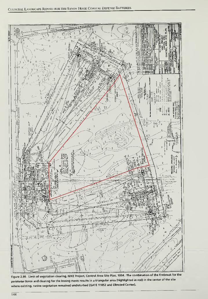
Cultural Landscape Report for the Sandy Hook Coastal Defense Batteries
Figure 2.99. Limit of vegetation clearing, NIKE Project. Control Area Site Plan, 1954. The combination of the firebreak for the
perimeter fence and clearing for the boring masts results in a triangular area (highlighted in red) in the center of the site
where existing, native vegetation remained undisturbed (GATE 11052 and Olmsted Center).
144
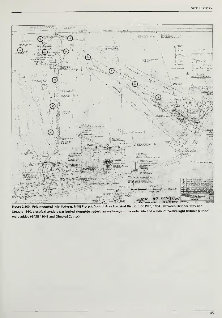
Site History
! t. \ Hi;
as s?;.'^';<v>'i-x
jm unto,* it*;
^z5;
\\* • Y i /
i I* !
"
I*. i
pTTj " ^y
>[
l"T> i'
i ±-"~Jr -1! TV i • X
ACQV S. T'OA
agi W\;.t_Jl a/ . t», TwIfMuJ . . - -J 3r \ v
'I'M ^-^ l t &»^B
.-I _^
^J"«^iFigure 2.100. Pole-mounted light fixtures. NIKE Project, Control Area Electrical Distribution Plan, 1954. Between October 1955 and
January 1960, electrical conduit was buried alongside pedestrian walkways in the radar site and a total of twelve light fixtures (circled)
were added (GATE 11046 and Olmsted Center).
145
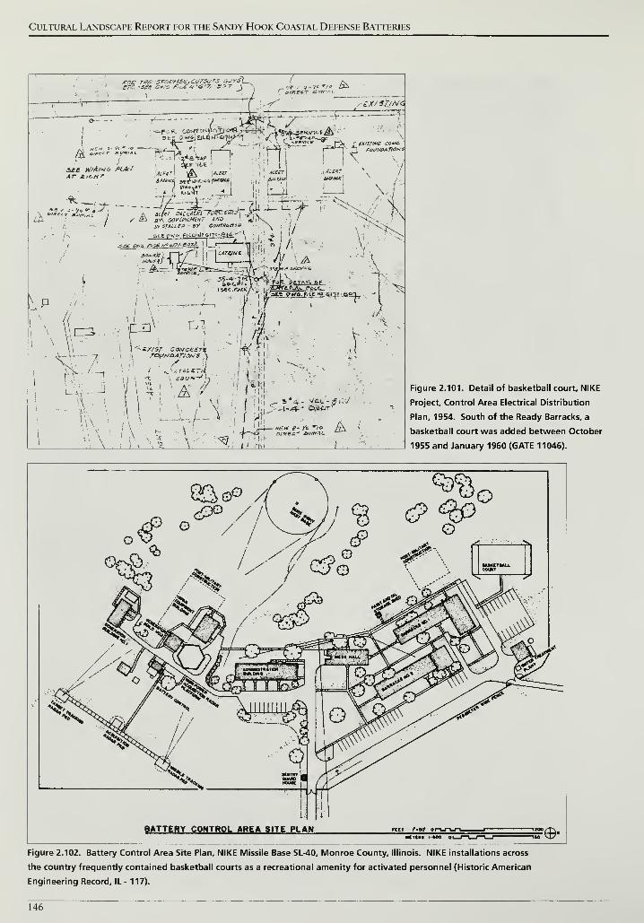
Cultural Landscape Report for the Sandy Hook Coastal Defense Batteries
roe riSfi.-;Sfoe/itBE,cv7Sf r'S Si/rs\ere -see otva r/L£*. f7. an \
,-i.X/SZ/NC
A --i-ri^S^'""
i
see h//A'>jo PLAtJAr A/c-»r
r "| p FOUNDATIONS
- ^-ztj -S^f*y SS a* goi/ephmcnt tns
\-P
/
S-flTW ja.uv sr»ues - »y coNTmaoe
sety».<,.FH.E.[tJ.'& i1i-a<4;-" ( f/
iset.fsAtKAj I
^/utrtK^f. rat
\ "7
PCW. OF
/«
1
'
i
-f;
\\ ;
\\ \ '
ill i
! Si \- A /,
.1
i I
\!
\ }- / -
^1_
11.
I* lit}
x-"-=/ •
i i:
I. it II
1 ili «Eitr £- ft "/£» /\ (I J— n^i
—
"E-
'.<?ff£- &/f»AL.
Figure 2.101. Detail of basketball court, NIKE
Project, Control Area Electrical Distribution
Plan, 1954. South of the Ready Barracks, a
basketball court was added between October
1955 and January 1960 (GATE 11046).
BATTERY CONTROL AREA SITE PLAN «ct r-»tf or-i_n_r-i_
UCTCftS I-4O0 OL5=©-
Figure 2.102. Battery Control Area Site Plan, NIKE Missile Base SL-40, Monroe County, Illinois. NIKE installations across
the country frequently contained basketball courts as a recreational amenity for activated personnel (Historic American
Engineering Record, IL- 117).
146
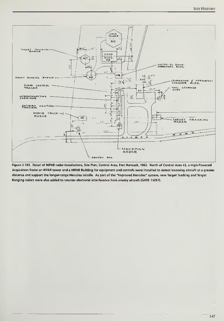
Site History
TARGET RANGING RADD.R
RADAR CONTROLTRAILER
AN/TPS-34 EQuiS.OPERATORS BLD6.
MISSILE TRACK •*£RADAR
SEMSRATOR / FREWENCYCHANGER BLOC.
ACaUtSITIO Si
RADARSENTRY Boa
Figure 2.103. Detail of HIPAR radar installations. Site Plan, Control Area, Fort Hancock, 1962. North of Control Area #2, a High-Powered
Acquisition Radar or HIPAR tower and a HIPAR Building for equipment and controls were installed to detect incoming aircraft at a greater
distance and support the longer-range Hercules missile. As part of the "Improved Hercules" system, new Target Tracking and Target
Ranging radars were also added to counter electronic interference from enemy aircraft (GATE 11057).
147
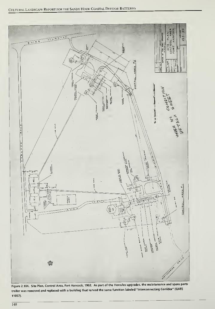
Cultural Landscape Report for the Sandy Hook Coastal Defense Batteries
Figure 2.104. Site Plan, Control Area. Fort Hancock, 1962. As part of the Hercules upgrades, the maintenance and spare parts
trailer was removed and replaced with a building that served the same function labeled "Interconnecting Corridor" (GATE
11057).
148
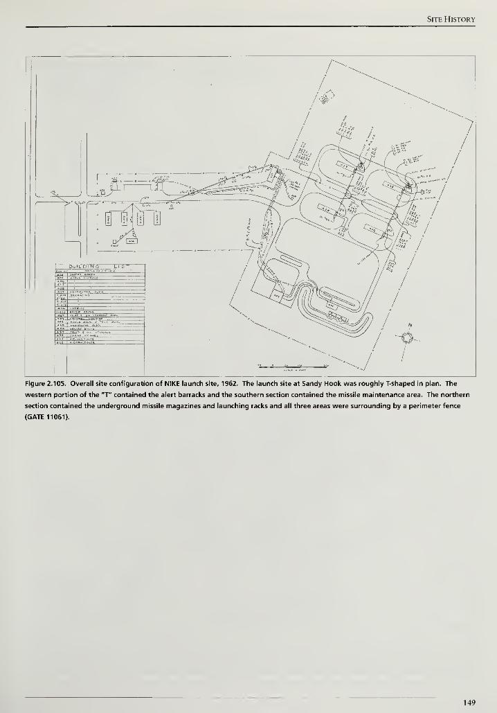
Site History
<•&,>/#
/
:*.
/
13-.— «— <-^s'-
J
^af==F*=JiS=s=5K^
I
1I
Figure 2.105. Overall site configuration of NIKE launch site, 1962. The launch site at Sandy Hook was roughly T-shaped in plan. The
western portion of the "T" contained the alert barracks and the southern section contained the missile maintenance area. The northern
section contained the underground missile magazines and launching racks and all three areas were surrounding by a perimeter fence
(GATE 11061).
149
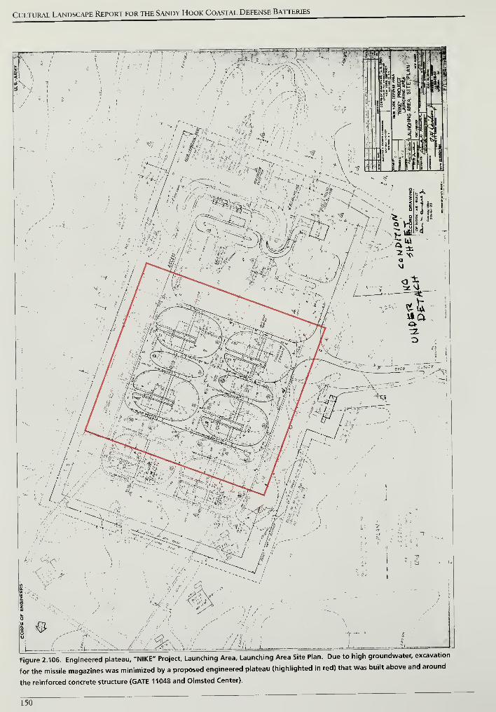
Cultural Landscape Report for the Sandy Hook Coastal Defense Batteries
.*fr\ ilL / ,/ -/I /
'i
si i V-
; - -, I
-------/
' '•>
\ .
\
•
.
t ... . 8 !
.. ;..i.:_ "1|
Figure 2.106. Engineered plateau, "NIKE" Project. Launching Area. Launching Area Site Plan. Due to high groundwater, excavation
for the missile magazines was minimized by a proposed engineered plateau (highlighted in red) that was built above and around
the reinforced concrete structure (GATE 11048 and Olmsted Center).
150
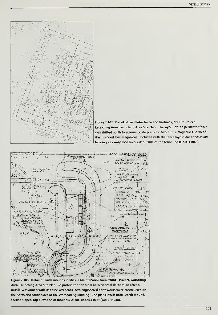
Site History
fMfwk
, . • ... :>^ t ./
Figure 2.107. Detail of perimeter fence and firebreak, "NIKE" Project,
Launching Area, Launching Area Site Plan. The layout of the perimeter fence
was shifted north to accommodate plans for two future magazines north of
the intended four magazines. Included with the fence layout are annotations
labeling a twenty foot firebreak outside of the fence line (GATE 11048).
"O! j-U/JSJ 7"
II(/."v...
/
.
E55- \\j
Wo*
?// 6-7*SS A
W<T/£ SfpBAGS SH£D
.-IN/S»\ FLOOS. Hi 11.00
SBAOi tgpUNO 1>M£5'JC.£C
V LIMIT?
'Mill £t.-jTiN<3
HtM/ND ATVMAOina Lityrs
\ei.ops •
j 5 »
I
uaaeQj&gstsl
f.iZDlT.y: ! TIM IfJSJOBAdS 51.'S3,
) ST.47/OK. J. ,c «,- •*;/
\\VALKWAy. SAgTH'TSMAPPUSTLMANT <5£AV£L\4NO v.?..V.'.y£ _ _|...
«2 "«£ &CCsiCtlSTi f*lK&AV -.
757fi$- j
Figure 2.108. Detail of earth mounds in Missile Maintenance Area, "NIKE" Project, Launching
Area, Launching Area Site Plan. To protect the site from an accidental detonation after a
missile was armed with its three warheads, two engineered earthworks were constructed on
the north and south sides of the Warheading Building. The plans labels both "earth mound,
seeded slopes, top elevation of mound = 21.00, slopes 3 in 1" (GATE 11048).
151
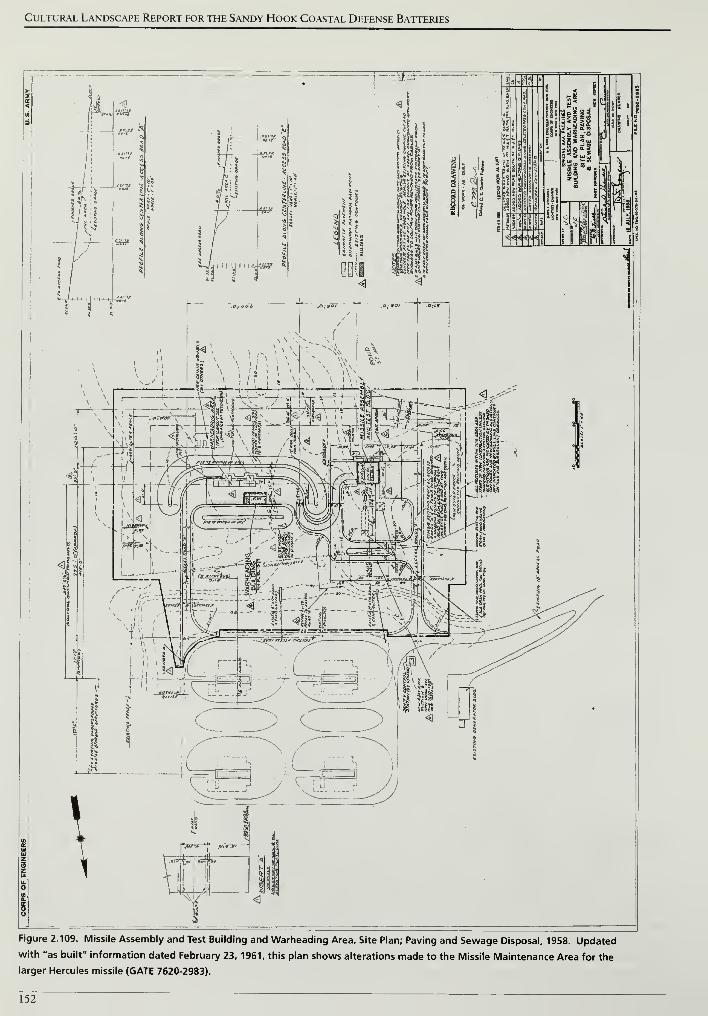
Cultural Landscape Report for the Sandy Hook Coastal Defense Batteries
Figure 2.109. Missile Assembly and Test Building and Warheading Area, Site Plan; Paving and Sewage Disposal, 1958. Updated
with "as built" information dated February 23, 1961, this plan shows alterations made to the Missile Maintenance Area for the
larger Hercules missile (GATE 7620-2983).
152
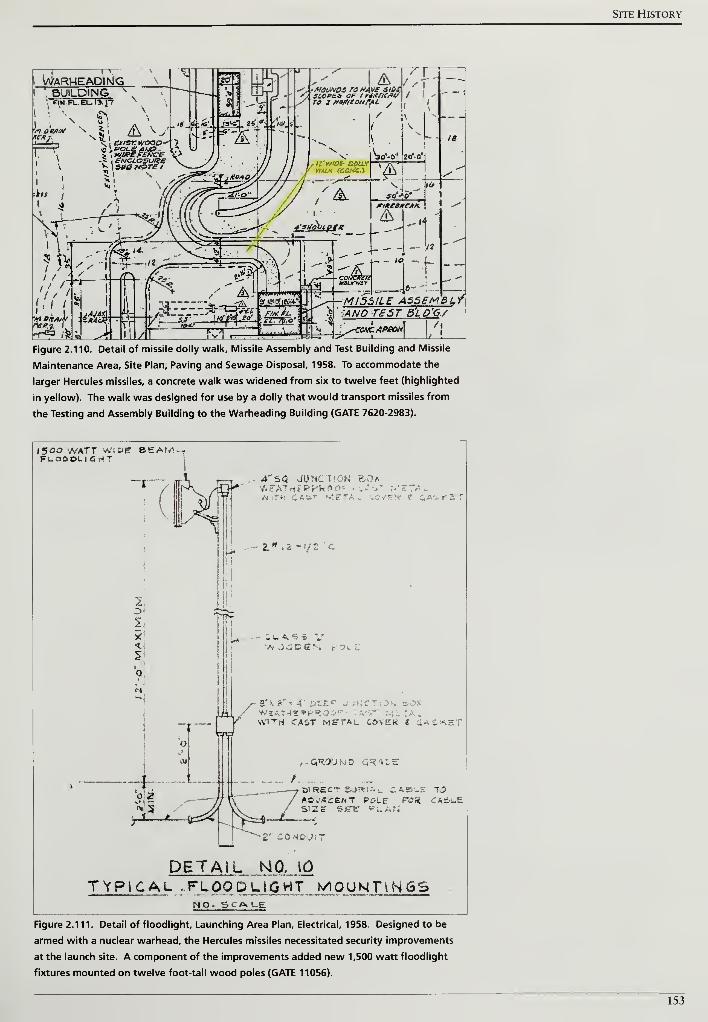
Site History
i WarmeapingBUILDING
MI55ILE ASSEMBL f. ,ANO TB5T B'LD'GY^ , ....1 1 7,COHCAPBON
Figure 2.110. Detail of missile dolly walk. Missile Assembly and Test Building and Missile
Maintenance Area, Site Plan; Paving and Sewage Disposal, 1958. To accommodate the
larger Hercules missiles, a concrete walk was widened from six to twelve feet (highlighted
in yellow). The walk was designed for use by a dolly that would transport missiles from
the Testing and Assembly Building to the Warheading Building (GATE 7620-2983).
1500 vVATT WflDJT BE AWFloooli 6 riT
A'SQ JUNCT.ON &OXW£ATHf PPkOrK,-. n •
-" :o/ew 4 ca'- t r.
S* ./ C S N
3' - 8" k 4' DEEP J.;KCrwtATneirpRo •
WITH CAST METAL COVEK e ti^CKE"
,- GROUND GRADE
BlRECT Sj^lii. CASUS 70aosacbht polp rot* CA=)L.eSIZE SE1E- PLAN
DETAIL NO. [0
TYPICAL .FLOODLIGHT MOUNTINGSNO- SCALE
Figure 2.111. Detail of floodlight. Launching Area Plan, Electrical, 1958. Designed to be
armed with a nuclear warhead, the Hercules missiles necessitated security improvements
at the launch site. A component of the improvements added new 1,500 watt floodlight
fixtures mounted on twelve foot-tall wood poles (GATE 11056).
153
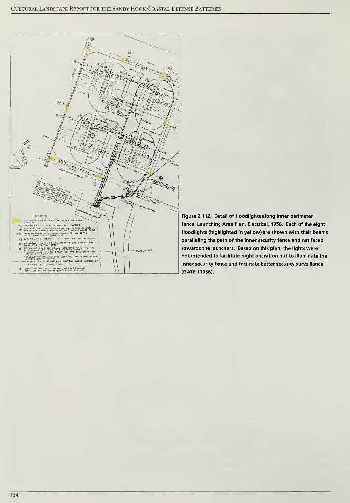
Cultural Landscape Report for the Sandy Hook Coastal Defense Batteries
< i
v -a>
S"Ji%> «, w/J^^s?
wM AMP CONTRA CABLE StMBc*"S«''
>E*GROutJ[,
1) JUNCTiahl BOX CAST METAL \*C ATWBRPHOOFSIMILAR 7t> rtCUSC-HluDt <J. CaT^roC!
I - e«'STirlC, OOTEi
Figure 2.112. Detail of floodlights along inner perimeter
fence. Launching Area Plan, Electrical, 1958. Each of the eight
floodlights (highlighted in yellow) are shown with their beams
paralleling the path of the inner security fence and not faced
towards the launchers. Based on this plan, the lights were
not intended to facilitate night operation but to illuminate the
inner security fence and facilitate better security surveillance
(GATE 11056).
154
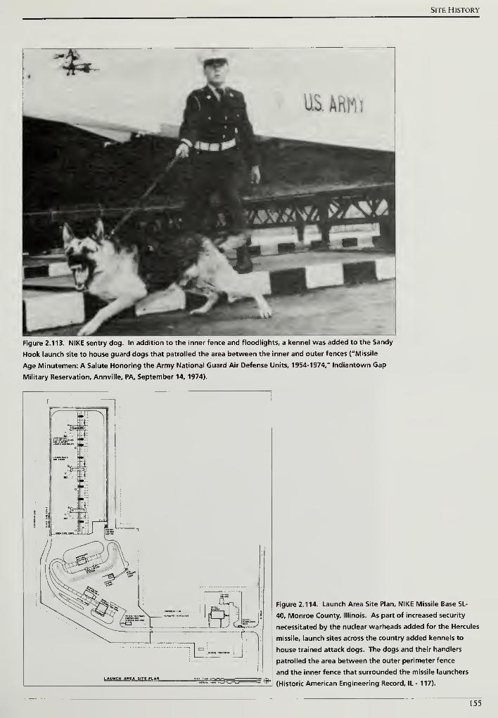
Site History
Figure 2.113. NIKE sentry dog. In addition to the inner fence and floodlights, a kennel was added to the Sandy
Hook launch site to house guard dogs that patrolled the area between the inner and outer fences ("Missile
Age Minutemen: A Salute Honoring the Army National Guard Air Defense Units, 1954-1974," Indiantown Gap
Military Reservation, Annville, PA, September 14, 1974).
LAUNCH AHEA SITE PLAN-f'
Figure 2.114. Launch Area Site Plan, NIKE Missile Base SL-
40, Monroe County, Illinois. As part of increased security
necessitated by the nuclear warheads added for the Hercules
missile, launch sites across the country added kennels to
house trained attack dogs. The dogs and their handlers
patrolled the area between the outer perimeter fence
and the inner fence that surrounded the missile launchers
(Historic American Engineering Record, IL- 117).
155
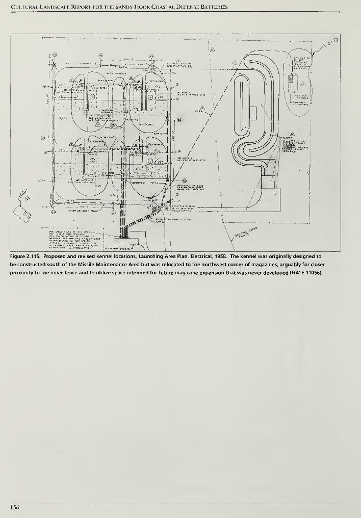
Cultural Landscape Report for the Sandy Hook Coastal Defense Batteries
>
&^-
**>
Figure 2.115. Proposed and revised kennel locations. Launching Area Plan, Electrical, 1958. The kennel was originally designed to
be constructed south of the Missile Maintenance Area but was relocated to the northwest corner of magazines, arguably for closer
proximity to the inner fence and to utilize space intended for future magazine expansion that was never developed (GATE 11056).
156
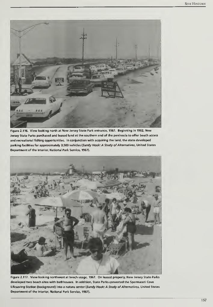
Site History
Figure 2.116. View looking north at New Jersey State Park entrance, 1967. Beginning in 1962, New
Jersey State Parks purchased and leased land at the southern end of the peninsula to offer beach access
and recreational fishing opportunities. In conjunction with acquiring the land, the state developed
parking facilities for approximately 3,500 vehicles (Sandy Hook: A Study of Alternatives, United States
Department of the Interior, National Park Service, 1967).
at
Figure 2.117. View looking northwest at beach usage, 1967. On leased property. New Jersey State Parks
developed two beach sites with bathhouses. In addition. State Parks converted the Spermaceti Cove
Lifesaving Station (background) into a nature center {Sandy Hook: A Study of Alternatives, United States
Department of the Interior, National Park Service, 1967).
157
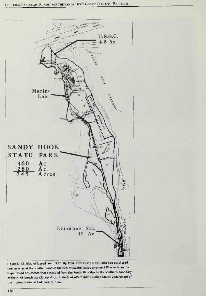
Cultural Landscape Report for the Sandy Hook Coastal Defense Batteries
/",n>/*>•--''>*-
U.S.G.C.4.5 Ac.
MarineLab
SANDY HOOKSTATE PARK
460 Ac.1ML745
Ac.Acres
Entranoe Sta.
12 Ac.
Figure 2.118. Map of leased land, 1967. By 1964, New Jersey State Parks had purchased
twelve acres at the southern end of the peninsula and leased another 745 acres from the
Department of Defense that extended from the Route 36 bridge to the southern boundary
of the NIKE launch site {Sandy Hook: A Study of Alternatives. United States Department of
the Interior, National Park Service, 1967).
158
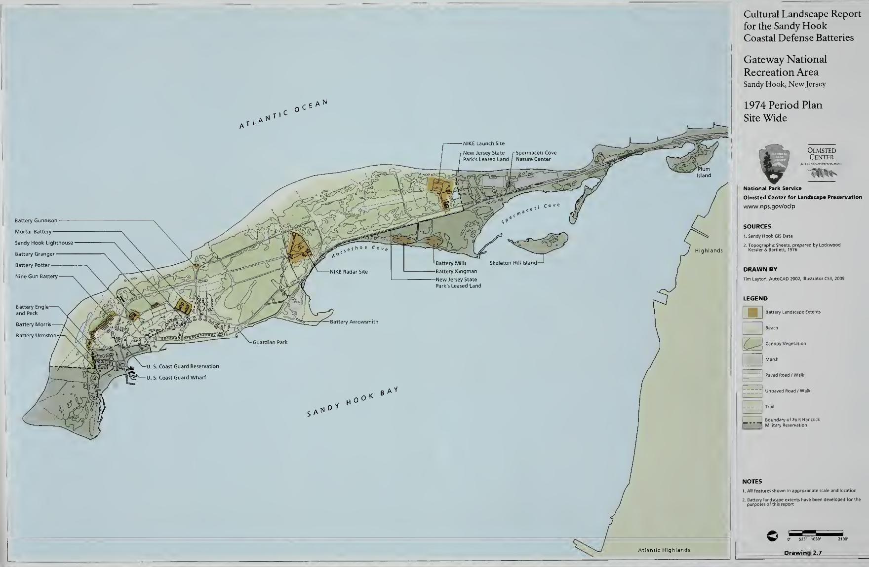
Cultural Landscape Report
for the Sandy HookCoastal Defense Batteries
Gateway National
Recreation AreaSandy Hook, New Jersey
1974 Period Plan
Site Wide
OlmstedCenter
National Park Service
Olmsted Center for Landscape Preservation
www.nps.gov/oclp
SOURCES
1 Sandy Hook GIS Data
DRAWN BY
Tim Layton, AutoCAD 2002, lllu:
LEGEND
Battery Landscape Extentsmi'
\f ^J Canopy Vegetatioi
Marsh
Paved Road /Walk
Lllld Unpaved Road /Walk
B Boundary of Fort Hancock
Military Reservation
NOTES
t All features shown in approximate scale and locatic
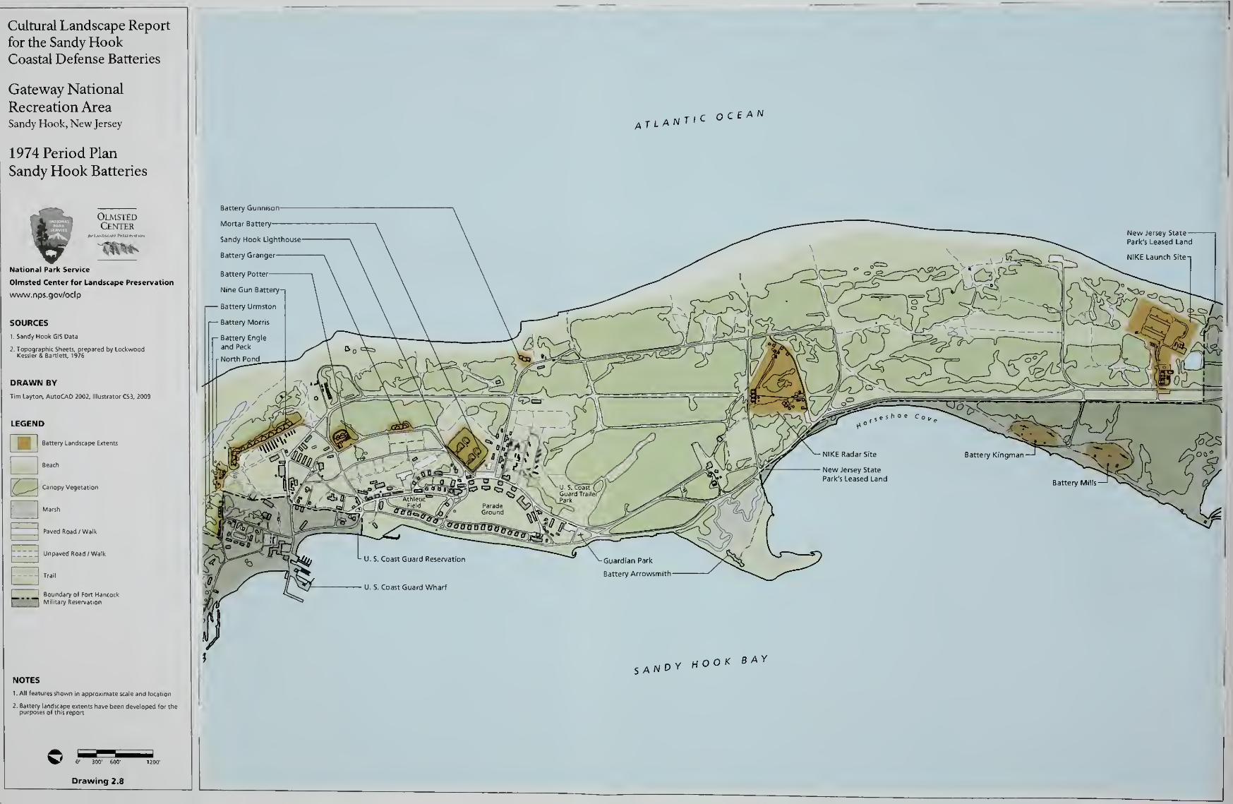
Cultural Landscape Report
for the Sandy HookCoastal Defense Batteries
Gateway National
Recreation AreaSandy Hook, New Jersey
1974 Period Plan
Sandy Hook Batteries
OlmstedCenter
National Park Service
Olmsted Center for Landscape Preservation
www.nps.gov/oclp
SOURCES
1 Sandy Hook GIS Data
DRAWN BY
Tim Layton, AutoCAD 2002, Illustrator CS3. 2009
LEGEND
Battery Landscape Extents
Beach
Canopy Vegetation
Marsh
'
'
'
Paved Road /Walk
_ 1 Unpaved Road /Walk
Trail
S Boundary of Fort Hancock
Military Reservation
NOTES
l All features shown in approximate scale and location
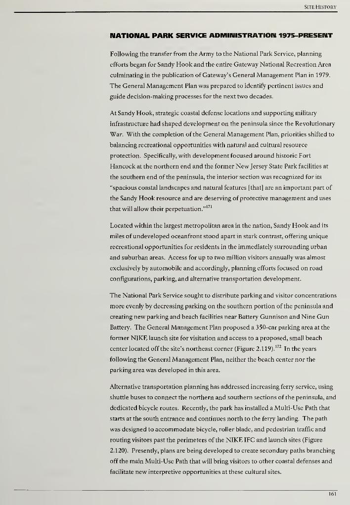
Site History
NATIONAL PARK SERVICE ADMINISTRATION 1975-PRESENT
Following the transfer from the Army to the National Park Service, planning
efforts began for Sandy Hook and the entire Gateway National Recreation Area
culminating in the publication of Gateway's General Management Plan in 1979.
The General Management Plan was prepared to identify pertinent issues and
guide decision-making processes for the next two decades.
At Sandy Hook, strategic coastal defense locations and supporting military
infrastructure had shaped development on the peninsula since the Revolutionary
War. With the completion of the General Management Plan, priorities shifted to
balancing recreational opportunities with natural and cultural resource
protection. Specifically, with development focused around historic Fort
Hancock at the northern end and the former New Jersey State Park facilities at
the southern end of the peninsula, the interior section was recognized for its
"spacious coastal landscapes and natural features [that] are an important part of
the Sandy Hook resource and are deserving of protective management and uses
that will allow their perpetuation."171
Located within the largest metropolitan area in the nation, Sandy Hook and its
miles of undeveloped oceanfront stood apart in stark contrast, offering unique
recreational opportunities for residents in the immediately surrounding urban
and suburban areas. Access for up to two million visitors annually was almost
exclusively by automobile and accordingly, planning efforts focused on road
configurations, parking, and alternative transportation development.
The National Park Service sought to distribute parking and visitor concentrations
more evenly by decreasing parking on the southern portion of the peninsula and
creating new parking and beach facilities near Battery Gunnison and Nine Gun
Battery. The General Management Plan proposed a 350-car parking area at the
former NIKE launch site for visitation and access to a proposed, small beach
center located off the site's northeast corner (Figure 2.1 19).172
In the years
following the General Management Plan, neither the beach center nor the
parking area was developed in this area.
Alternative transportation planning has addressed increasing ferry service, using
shuttle buses to connect the northern and southern sections of the peninsula, and
dedicated bicycle routes. Recently, the park has installed a Multi-Use Path that
starts at the south entrance and continues north to the ferry landing. The path
was designed to accommodate bicycle, roller blade, and pedestrian traffic and
routing visitors past the perimeters of the NIKE IFC and launch sites (Figure
2.120). Presently, plans are being developed to create secondary paths branching
off the main Multi-Use Path that will bring visitors to other coastal defenses and
facilitate new interpretive opportunities at these cultural sites.
161
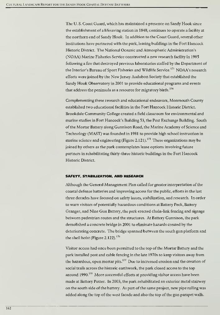
Cultural Landscape Report for the Sandy Hook Coastal Defense Batteries
The U. S. Coast Guard, which has maintained a presence on Sandy Hook since
the establishment of a lifesaving station in 1848, continues to operate a facility at
the northern end of Sandy Hook. In addition to the Coast Guard, several other
institutions have partnered with the park, leasing buildings in the Fort Hancock
Historic District. The National Oceanic and Atmospheric Administration's
(NOAA) Marine Fisheries Service constructed a new research facility in 1985
following a fire that destroyed previous laboratories staffed by the Department of
the Interior's Bureau of Sport Fisheries and Wildlife Service.173 NOAA's research
efforts were joined by the New Jersey Audubon Society that established the
Sandy Hook Observatory in 2001 to provide educational programs and events
that address the peninsula as a resource for migratory birds.174
Complementing these research and educational endeavors, Monmouth County
established two educational facilities in the Fort Hancock Historic District.
Brookdale Community College created a field classroom for environmental and
marine studies in Fort Hancock's Building 53, the Post Exchange Building. South
of the Mortar Battery along Gunnison Road, the Marine Academy of Science and
Technology (MAST) was founded in 1981 to provide high school instruction in
marine science and engineering (Figure 2.121).175
These organizations may be
joined by others as the park contemplates lease options involving future
partners in rehabilitating thirty-three historic buildings in the Fort Hancock
Historic District.
SAFETY, STABILIZATION, AND RESEARCH
Although the General Management Plan called for greater interpretation of the
coastal defense batteries and improving access for the public, efforts in the last
three decades have focused on safety issues, stabilization, and research. In order
to warn visitors of potentially hazardous conditions at Battery Peck, Battery
Granger, and Nine Gun Battery, the park erected chain-link fencing and signage
between pedestrian routes and the structures. At Battery Gunnison, the park
demolished a concrete bridge in 2001 to eliminate hazards created by the
deteriorating concrete. The bridge spanned between the south gun platform and
the shell hoist (Figure 2.122).176
Visitor access had once been permitted to the top of the Mortar Battery and the
park installed post and cable fencing in the late 1970s to keep visitors away from
the hazardous, open mortar pits.177 Due to increased erosion and the creation of
social trails across the historic earthwork, the park closed access to the top
around 1990.178 More successful efforts at providing visitor access have been
made at Battery Potter. In 2003, the park rehabilitated an exterior metal stairway
on the south side of the battery. As part of the same project, new pipe railing was
added along the top of the west facade and also the top of the gun parapet walls.
162
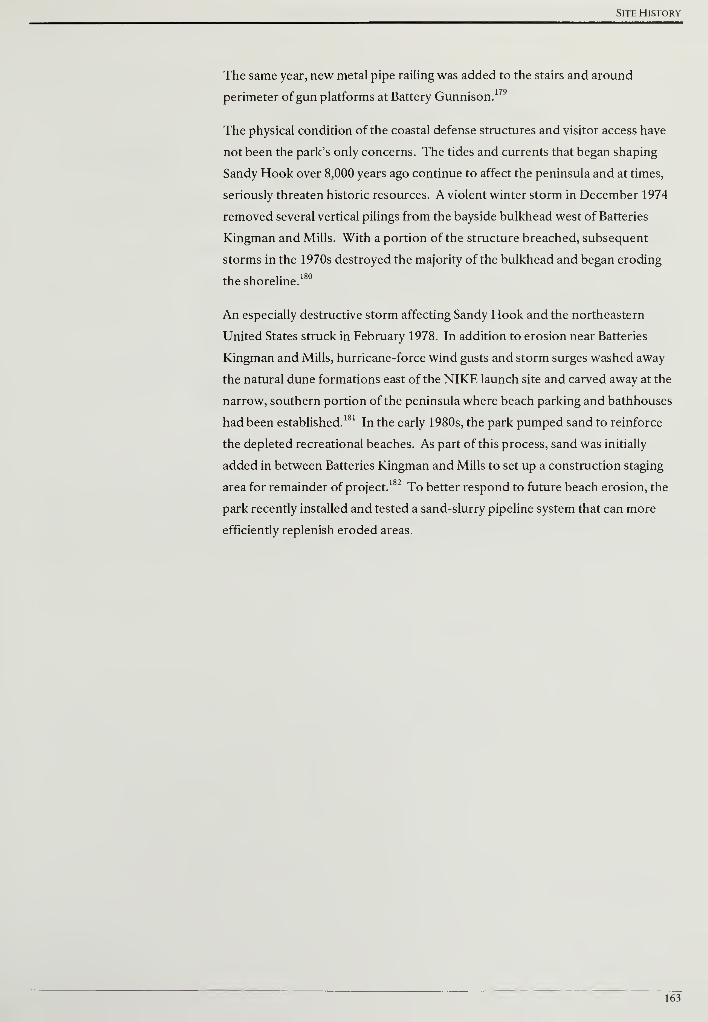
Site History
The same year, new metal pipe railing was added to the stairs and around
perimeter of gun platforms at Battery Gunnison.179
The physical condition of the coastal defense structures and visitor access have
not been the park's only concerns. The tides and currents that began shaping
Sandy Hook over 8,000 years ago continue to affect the peninsula and at times,
seriously threaten historic resources. A violent winter storm in December 1974
removed several vertical pilings from the bayside bulkhead west of Batteries
Kingman and Mills. With a portion of the structure breached, subsequent
storms in the 1970s destroyed the majority of the bulkhead and began eroding
the shoreline.180
An especially destructive storm affecting Sandy Hook and the northeastern
United States struck in February 1978. In addition to erosion near Batteries
Kingman and Mills, hurricane-force wind gusts and storm surges washed away
the natural dune formations east of the NIKE launch site and carved away at the
narrow, southern portion of the peninsula where beach parking and bathhouses
had been established.181
In the early 1980s, the park pumped sand to reinforce
the depleted recreational beaches. As part of this process, sand was initially
added in between Batteries Kingman and Mills to set up a construction staging
area for remainder of project.182 To better respond to future beach erosion, the
park recently installed and tested a sand-slurry pipeline system that can more
efficiently replenish eroded areas.
163

Cultural Landscape Report for the Sandy Hook Coastal Defense Batteries
164
Site History
otsrvcr i£a> m/eoSO INFPVS?
o luf^wepcWtt^E -V50 OiWEE>
-so «m~
, LEGEND ,
F=RjrB=n.NC> CVNac.
K>pm(S\22> sz> fcct
NEWBEA^ CENTEPG ATNIKE. <sm= /WD
• ftxx> catcEJs&cH
• pesrPooMs• RPST-AJC? -STATION
#-THE \£XJ*X» CF NEW B^aUTlESWCCBW EVSJHtNOAPEAS IWC!
epcaoN reatroci fpcmWINTER «CTM^CPTr7-PTJW
DEVELOPMENT CONCEPT
SANDY HOOK /
SOUTH BEACHGATEWAY NATIONAL RECREATION AREAUNITEO STATES DEPARTMENT OF THE INTERIOR /
NATIONAL PARK SERVICE
Figure 2.119. Development Concept Sandy Hook / South Beach. Completed in 1979, the Gateway National Recreational Area General
Management Plan proposed a 350-car parking area at the former NIKE launch site for visitation and access to a proposed, small beach
center located off the site's northeast corner. In the years following the General Management Plan, neither the beach center nor the
parking area was developed in this area (General Management Plan: Gateway National Recreation Area-New York/New Jersey, United
States Department of the Interior, National Park Service, 1979).
165
Cultural Landscape Report for the Sandy Hook Coastal Defense Batteries
North PondNine Gun Battery Field
Historic
Fort Hancock
Twin Lights
State Historic Site
Ocean Beaches shared by
beachgoers and shorebirds
ROUTE 38
Figure 2.120. Multi-use path map. Recently, the park installed a Multi-Use Path that starts at the south entrance and continues north
to the ferry landing. The path was designed to accommodate bicycle, roller blade, and pedestrian traffic and routes visitors past the
perimeters of the NIKE radar and launch sites (http://www.nps.gov/gate/planyourvisit/upload/mup%20map.pdf).
166
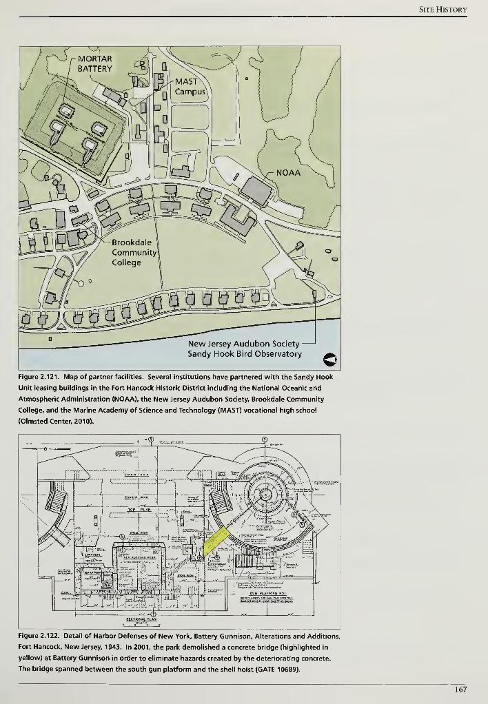
Site History
Jersey Audubon Society
Sandy Hook Bird Observatory
Figure 2.121. Map of partner facilities. Several institutions have partnered with the Sandy Hook
Unit leasing buildings in the Fort Hancock Historic District including the National Oceanic and
Atmospheric Administration (NOAA), the New Jersey Audubon Society, Brookdale Community
College, and the Marine Academy of Science and Technology (MAST) vocational high school
(Olmsted Center, 2010).
sa&ja^A
KL
. ):': \ I'l l|i i Vxh? '
-^T^ few*?- \
I, E2gS&
Hjfl mm ' I
sectional PIAH
6UN PLATfORM HOIMO0.fH*TiffH ro« oun w ttt'ovw w> 7
m»mrto!iTni»»i«tt.iiwm
Figure 2.122. Detail of Harbor Defenses of New York, Battery Gunnison, Alterations and Additions,
Fort Hancock, New Jersey, 1943. In 2001, the park demolished a concrete bridge (highlighted in
yellow) at Battery Gunnison in order to eliminate hazards created by the deteriorating concrete.
The bridge spanned between the south gun platform and the shell hoist (GATE 10689).
167

Cultural Landscape Report for the Sandy Hook Coastal Defense Batteries
168
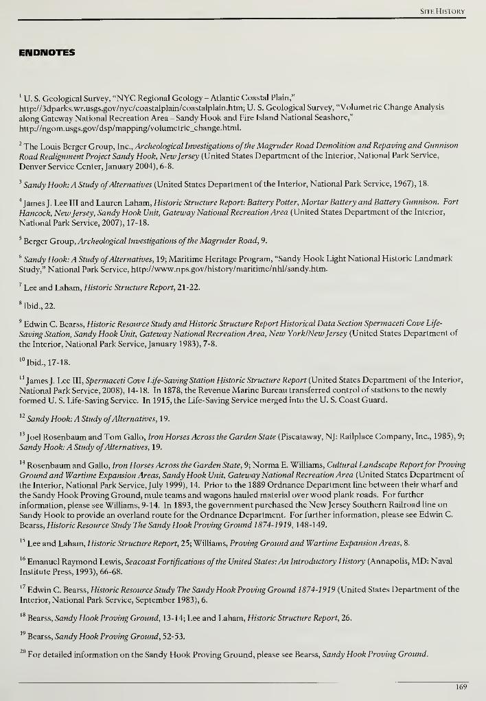
Site History
ENDNOTES
1
U. S. Geological Survey, "NYC Regional Geology - Atlantic Coastal Plain,"
http://3dparks.wr.usgs.gov/nyc/coastalplain/coastalplain.htm; U. S. Geological Survey, "Volumetric Change Analysis
along Gateway National Recreation Area - Sandy Hook and Fire Island National Seashore,"
http://ngom.usgs.gov/dsp/mapping/volumetric_change.html.
2 The Louis Berger Group, Inc., Archeological Investigations ofthe Magruder Road Demolition and Repaying and Gunnison
Road Realignment Project Sandy Hook, NewJersey (United States Department of the Interior, National Park Service,
Denver Service Center, January 2004), 6-8.
3Sandy Hook: A Study ofAlternatives (United States Department of the Interior, National Park Service, 1967), 18.
4James J. Lee III and Lauren Laham, Historic Structure Report: Battery Potter, Mortar Battery and Battery Gunnison. Fort
Hancock, NewJersey, Sandy Hook Unit, Gateway National Recreation Area (United States Department of the Interior,
National Park Service, 2007), 17-18.
5Berger Group, Archeological Investigations ofthe Magruder Road, 9.
6Sandy Hook: A Study ofAlternatives, 19; Maritime Heritage Program, "Sandy Hook Light National Historic Landmark
Study," National Park Service, http://www.nps.gov/history/maritime/nhl/sandy.htm.
7Lee and Laham, Historic Structure Report, 21-22.
8Ibid., 22.
9 Edwin C. Bearss, Historic Resource Study and Historic Structure Report Historical Data Section Spermaceti Cove Life-
Saving Station, Sandy Hook Unit, Gateway National Recreation Area, New York/NewJersey (United States Department of
the Interior, National Park Service, January 1983), 7-8.
10Ibid., 17-18.
1' James J. Lee III, Spermaceti Cove Life-Saving Station Historic Structure Report (United States Department of the Interior,
National Park Service, 2008), 14-18. In 1878, the Revenue Marine Bureau transferred control of stations to the newly
formed U. S. Life-Saving Service. In 1915, the Life-Saving Service merged into the U. S. Coast Guard.
12Sandy Hook: A Study ofAlternatives, 19.
13Joel Rosenbaum and Tom Gallo, Iron Horses Across the Garden State (Piscataway, NJ: Railplace Company, Inc., 1985), 9;
Sandy Hook: A Study ofAlternatives, 19.
14 Rosenbaum and Gallo, Iron Horses Across the Garden State, 9; Norma E. Williams, Cultural Landscape Reportfor Proving
Ground and Wartime Expansion Areas, Sandy Hook Unit, Gateway National Recreation Area (United States Department of
the Interior, National Park Service, July 1999), 14. Prior to the 1889 Ordnance Department line between their wharf and
the Sandy Hook Proving Ground, mule teams and wagons hauled material over wood plank roads. For further
information, please see Williams, 9-14. In 1893, the government purchased the New Jersey Southern Railroad line on
Sandy Hook to provide an overland route for the Ordnance Department. For further information, please see Edwin C.
Bearss, Historic Resource Study The Sandy Hook Proving Ground 1874-1919, 148-149.
15Lee and Laham, Historic Structure Report, 25; Williams, Proving Ground and Wartime Expansion Areas, 8.
16Emanuel Raymond Lewis, Seacoast Fortifications ofthe United States: An Introductory History (Annapolis, MD: Naval
Institute Press, 1993), 66-68.
17Edwin C. Bearss, Historic Resource Study The Sandy Hook Proving Ground 1874-1 919 (United States Department of the
Interior, National Park Service, September 1983), 6.
18Bearss, Sandy Hook Proving Ground, 13-14; Lee and Laham, Historic Structure Report, 26.
19Bearss, Sandy Hook Proving Ground, 52-53.
20For detailed information on the Sandy Hook Proving Ground, please see Bearss, Sandy Hook Proving Ground.
169

Cultural Landscape Report for the Sandy Hook Coastal Defense Batteries
21Lewis, Seacoast Fortifications, 77.
22Ibid.
23Lee and Laham, Historic Structure Report, 58.
24Ibid., 63.
25Ibid., 64-66 and 76.
26Ibid., 68-69. Five thousand cubic yards is roughly equivalent to the amount held by 2,500 standard pickup truck beds.
Lined up end to end, 2,500 pickup trucks would cover eight miles—greater than the distance from Battery Potter to the
Route 36 bridge to Highlands.
27Ibid., 70.
28Ibid., 78.
29Ibid., 79.
30Lewis, Seacoast Fortifications, 79; Terrance McGovern and Boiling Smith, American Coastal Defenses 1885-1950 (New
York: Osprey Publishing Limited, 2006), 24.
1
Lee and Laham, Historic Structure Report, 201-2.
Ibid., 202. A six story building the size of a football field is roughly equivalent to the volume of earth and sand placed at
the Mortar Battery.
33Ibid, 202.
4 Thomas Hoffman, "Fort Hancock Gun Batteries: Revised Draft Text" (working paper, Sandy Hook Unit, 1999).
35Lee and Laham, Historic Structure Report, 32.
36Ibid, 33.
37Ibid, 19.
38 McGovern and Smith, American Coastal Defenses 1885-1950, 12.
39JR Potts, "HMS Dreadnought," Military Factory, http://www.militaryfactory.com/ships/detail.asp?ship_id=HMS-
Dreadnought; "British Navy Ships—HMS Dreadnought 1906-1922," U. S. Department of the Navy, Naval Historical
Center, http://www.history.navy.mil/photos/sh-fornv/uk/uksh-d/drednt9.htm.
40Potts, "HMS Dreadnought"; "British Navy Ships—HMS Dreadnought 1906-1922".
Lewis, Seacoast Fortifications, 89.
42Ibid, 89-90.
Engineer's Ledger-Harbor Defenses ofNew York, CDSG ePress, Harbor Defenses ofNew York #1.
44Ibid.
Lewis, Seacoast Fortifications, 130.
Lewis, Seacoast Fortifications, 93; McGovern and Smith, American Coastal Defenses 1885-1950, 51-52.
Reports of Completed Works, CDSG ePress, Harbor Defenses ofNew York #4.
48 NARA, RG 177 Records of the Chiefs of Arms, Office of the Chief of Coast Artillery, 1901-1917, folder, box 69.
49 NARA, RG 177 Records of the Chiefs of Arms, Office of the Chief of Coast Artillery, box 49, folder 5352.
170

Site History
50Ibid.
51Ibid.
52Lee and Laham, Historic Structure Report, 79.
53 Thomas Hoffman, Fort Hancock (Charleston, SC: Arcadia Publishing, 2007), 59; Lee and Laham, Historic Structure
Report, 79.
54Lee and Laham, Historic Structure Report, 146.
55Ibid., 144.
56Ibid., 120-121.
57Ibid., 134.
58Ibid., 138.
59Ibid., 145.
60Ibid., 124.
61Major B. Burbank, Office of the Post Commander, Fort Hancock, N.J., to Adjunct General, Department of the East,
N.Y.C., March 28, 1900, as cited in Lee and Laham, Historic Structure Report, 233.
62^
63
Lee and Laham, Historic Structure Report, 234.
Ibid., 237.
64Ibid., 235.
65Lee and Laham, Historic Structure Report, 234; Hoffman, "Fort Hancock Gun Batteries: Revised Draft Text".
66Lee and Laham, Historic Structure Report, 237.
67Plan Showing Drainage and Electrical Systems, Battery Reynolds, Fort Hancock, N.J., September 1910. Approved by
Roessler, Sept. 9, 1910; Chief of Engineers Wm. H. Bixby, Sept 14, 1910; and Acting Secretary ofWar Robert Shaw Oliver,
Sept 17, 1910; Sheet 88-20, Drawer 45, RG77, NACP., as cited in Lee and Laham, Historic Structure Report, 240.
68Lee and Laham, Historic Structure Report, 242.
69 A similar system existed to defend against enemy ships entering Long Island Sound, the East River, and attacking NewYork City from the east. A series of batteries were located at the eastern entry to Long Island Sound and further west
where the Sound and East River meet near the present-day Throngs Neck Bridge.
70Lee and Laham, Historic Structure Report, 242.
71Plan drawings of batteries position the structure with the top of the page facing the target. With this orientation
established, the numbering convention always starts from right to left.
72Hoffman, "Fort Hancock Gun Batteries: Revised Draft Text"; James Tobias, "Frequently Asked Questions - Naming
Army Installations," U. S. Army Center of Military History, http://www.history.army.mil/html/faq/base_name.html. Less
commonly, designations could be for geographic location, Native American tribes, or non-military individuals.
Hoffman, Fort Hancock, 56.
74Reports of Completed Works, CDSG ePress, Harbor Defenses ofNew York #4.
Hoffman, telephone conversation with the author, February 23, 2009.
Hoffman, "Fort Hancock Gun Batteries: Revised Draft Text".
171
Cultural Landscape Report for the Sandy Hook Coastal Defense Batteries
Another large grouping is at Fort Mott in southern New Jersey that features a six gun battery to guard the approach onthe Delaware River to Philadelphia.
78Hoffman, "Fort Hancock Gun Batteries: Revised Draft Text".
79Hoffman, Fort Hancock, 100.
8Hoffman, "Fort Hancock Gun Batteries: Revised Draft Text".
81Ibid.
Hoffman, Fort Hancock, 65. The Spanish-American War was not a prolonged military struggle that sustained increased
spending on coastal defenses. The war formally ended less than a year after it started with the Treaty of Paris onDecember 10, 1898. The treaty required Spain to completely withdraw from Cuba and cede Puerto Rico, the Philippines,
and Guam to the United States.
Lewis, Seacoast Fortifications, 87; Thomas Hoffman, telephone conversation with the author, February 23, 2009.
84Hoffman, "Fort Hancock Gun Batteries: Revised Draft Text".
85Hoffman, Fort Hancock, 71.
Lee and Laham, Historic Structure Report, 301.
Williams, Proving Ground and Wartime Expansion Areas, 29; Lee and Laham, Historic Structure Report, 35.
Bearss, Sandy Hook Proving Ground, 256-59; Lee and Laham, Historic Structure Report, 29.
Andrew Morang, "Historical Aerial Photographs Made Available by the ERDC Coastal and Hydraulics Laboratory,"
U. S. Army Corps of Engineers Coastal and Hydraulics Laboratory, http://chl.wes.army.mil/shore/newjersey/shorel920/.
90Lee and Laham, Historic Structure Report, 242.
David F. Winkler, Searching the Skies: The Legacy ofthe United States Cold War Defense Radar Program (United States
Department of Defense, Air Force Air Combat Command, June 1997), 9.
2Hoffman, Fort Hancock, 111.
Mark A. Berhow, "Caretaker Status in the Coast Artillery, 1912-1948," The Coast Defense Study GroupJournal 14, no. 4
(2000): 49-51.
94Berhow, "Caretaker Status," 48-50; "Chapter 2: American Military History, Volume II," U. S. Army Center of Military
History, http://www.history.army.mil/books/AMH-V2/AMH%20V2/chapter2.htm.
Berhow, "Caretaker Status," 50.
96Annual Report of the Chief of Coast Artillery, 1919, CDSG ePress, 4044.
Lewis, Seacoast Fortifications, 102.
Reports of Completed Works, CDSG ePress, Harbor Defenses ofNew York #4; Hoffman, Fort Hancock, 108-109.
Letter from the District Engineer, 2nd District, New York, March 14, 1918, CDSG ePress, Harbor Defenses ofNewYork #1. The letter records six 60-inch lights at Sandy Hook including one mounted on a standard gauge rail car.
Journal of the District Engineer, September 27, 1920, CDSG ePress, Harbor Defenses ofNew York #1.
"Billy Mitchell," Air and Space Power Journal, http://www.airpower.maxwell.af.mil/airchronicles/cc/mitch.html.
102 NARA RG 177 Records of the Office of the Chief of Coast Artillery, Box 49, Folder 5352.
103Ibid.
172

Site History
104Lewis, Seacoast Fortifications, 116.
105Hoffman, Fort Hancock, 121.
106Lee and Laham, Historic Structure Report, 36.
107Ibid., 143.
108Ibid.
109Ibid., 247.
110Ibid., 242-243.
111Ibid., 243-245.
112Report of Completed Works, CDSG ePress, Harbor Defenses ofNew York #4.
113Lee and Laham, Historic Structure Report, 244.
114Hoffman, Fort Hancock, 102.
115Report of Completed Works, CDSG ePress, Harbor Defenses ofNew York #4.
116 NARA RG 177 Records of the Office of the Chief of Coast Artillery, Box 49, Folder 5352.
117Lt. Col. Charles K. Panish to the Commanding General, 2nd Service Command, Army Service Forces, Nov 5 1943,
NARA RG 177 Records of the Office of the Chief of Coast Artillery, Box 49, Folder 5352.
118Jan 20, 1944, NARA RG 177 Records of the Office of the Chief of Coast Artillery, Box 49, Folder 5352.
119 NARA RG 177 Records of the Office of the Chief of Coast Artillery, Box 49, Folder 5352.
120Headquarters Eastern Defense Command, Governors Island to Chief of Engineers, Army Service Forces, May 12 1944,
NARA RG 177 Records of the Office of the Chief of Coast Artillery, Box 49, Folder 5352.
121Report of Completed Works, CDSG ePress, Harbor Defenses ofNew York #4.
122Hoffman, "Fort Hancock Gun Batteries: Revised Draft Text".
123Hoffman, Fort Hancock, 70.
124Hoffman, "Fort Hancock Gun Batteries: Revised Draft Text"; Hoffman, e-mail message to the author, February 23,
2009; Lee and Laham, Historic Structure Report, 325.
125Report of Completed Works, CDSG ePress, Harbor Defenses ofNew York #4.
126Hoffman, Fort Hancock, 69.
127Capt. R. Wilkenson to Chief of Engineers, Jan 1, 1929, Preservation and Repair, Miscellaneous, folder 16 Box 35,
correspondence Relating to Fortification Projects 1907-1930, Entry 802, NARA RG 77, Northeast Region, as cited in Lee
and Laham, Historic Structure Report, 323.
128Lewis, Seacoast Fortifications, 116; Lee and Laham, Historic Structure Report, 324.
129Lee and Laham, Historic Structure Report, 325.
130Report of Completed Works, CDSG ePress, Harbor Defenses ofNew York #4. Salvage and disposal comments are not
listed for Battery Alexander at the Nine Gun Battery. Handwritten notes indicate the artillery and carriages were removed
from Battery Alexander and stored or turned over to the Chief of Ordnance.
131Lewis, Seacoast Fortifications, 132. The 6-inch guns at Battery Gunnison were replaced with similar guns from Fort
Hamilton's Battery Livingston in 1948. These guns were removed in the mid-1960s and then brought back to Battery
173

Cultural Landscape Report for the Sandy Hook Coastal Defense Batteries
Gunnison for interpretive purposes in 1975. For additional information, please see Lee and Laham, Historic Structure
Report, 328-329.
32 Roy S. Barnard, The History ofARADCOM Volume 1: The Gun Era 1950-1955 (United States Department of Defense,
Headquarters ARADCOM, [1973?]) 12-13.
33Ibid., 14-15.
34John C. Lonnquest and David F. Winkler, To Defend and Deter: The Legacy ofthe United States Cold War Missile
Program (United States Department of Defense, Army Construction Engineering Research Laboratories, November
1996), 170-171.
35Judith Q. Sullivan, Building 32 Quartermaster's Storehouse, Fort Hancock, Historic Structure Report, Sandy Hook Unit,
Gateway National Recreation Area (United States Department of the Interior, National Park Service, 2004), 28.
36Ibid.
37Barnard, The History ofARADCOM, 28.
38Ibid.
39 Thomas Hoffman, "Cold War Defender: Draft Text" (working paper, Sandy Hook Unit, 2005), 1.
40 Mark Berhow, U. S. Strategic and Defensive Missile Systems 1950-2004 (Osprey Publishing, 2005), 7.
41John A. Martini and Stephen A. Haller, What We Have We Shall Defend: An Interim History and Preservation Planfor
Nike Site SF-88L, Fort Barry, California (United States Department of the Interior, National Park Service, Golden Gate
National Recreation Area, 1998), 3.
42Hoffman, "Cold War Defender: Draft Text", 2.
43Lonnquest and Winkler, To Defend and Deter, 165.
44Ibid., 165-168.
45Ibid, 57 and 179.
46Ibid., 180.
47 On September 30, 1955, the liquid fuel mixture exploded during tests at White Sands Proving Ground killing one and
njuring five others. The accident convinced the design team that a solid fuel was necessary. For additional information
on Hercules development, please see Lonnquest and Winkler, To Defend and Deter, 179-180.
48Lonnquest and Winkler, To Defend and Deter, 177-180.
49Ibid, 177 and 182.
50Hoffman, "Cold War Defender: Draft Text", 4.
51Lonnquest and Winkler, To Defend and Deter, 172.
52Hoffman, "Cold War Defender: Draft Text", 4-5. Control Area designations are not consistent based on historic plans
for the IFC site. Plans from the 1950s follow the convention detailed above and for consistency with previous park
publications, this designation will be used. All plans obtained in this research that date to 1962 reverse the designation and
label the western area Control Area #1 and the eastern area #2. One site plan from 1954 labels both areas #1.
In addition to access from already established vehicular routes, a wetland in between IFC and Launch may have
impacted site selection, i.e., only relatively low-growing plant material present in the wetland versus the holly forest.
1 NIKE was originally discussed as a semi-mobile defense system that would be dispatched from a central location to one
of many preconfigured launch sites. Greatly influenced by the tragic losses at Pearl Harbor, this concept was dismissed
because it could not immediately respond to a surprise attack. For further information please see Lonnquest and Winkler,
To Defend and Deter, 171.
174

Site History
55Lonnquest and Winkler, To Defend and Deter, 173.
56Martini and Haller, What We Have We Shall Defend, 45.
57Lonnquest and Winkler, To Defend and Deter, 180.
58Ibid., 171-172. The combined NIKE IFC and launch sites at Sandy Hook are approximately thirty-three acres.
59Hoffman, "Cold War Defender: Draft Text", 4.
60Lonnquest and Winkler, To Defend and Deter, 182.
61Berhow, U. S. Strategic and Defensive Missile Systems, 12.
62Throughout the 1950s, the Army and Air Force extensively argued over which service branch had responsibility to
defend against aircraft and missile attacks. For additional information, please see Barnard, The History ofARADCOM, 27-
28 and 31-39 and Lonnquest and Winkler, To Defend and Deter, 60-63.
63Lonnquest and Winkler, To Defend and Deter, 1 10.
64Hoffman, "Cold War Defender: Draft Text", 10.
65 Edwin C. Bearss, Historic Resource Study Fort Hancock: 1 948-1 974, Sandy Hook Unit, Gateway National Recreation Area,
Monmouth County, NewJersey (United States Department of the Interior, National Park Service, November 1982), 162-164.
66Sandy Hook: A Study ofAlternatives, 5.
67Ibid., 27. At the time the report was published, the 285 acres leased in 1964 were not developed or available to the
public due to security concerns and a lack of fencing. Batteries Kingman and Mills, disarmed in 1948, were located within
this newly leased area.
68Ibid., 5.
69Ibid., 33.
70Lee and Laham, Historic Structure Report, 37.
71General Management Plan, Gateway National Recreation Area, New York/NewJersey (United States Department of the
Interior, National Park Service, August 1979), 12.
72Ibid, 88.
73Northeast Fisheries Science Center, "James J. Howard Marine Sciences Laboratory," National Oceanic and
Atmospheric Administration, http://sh.nefsc.noaa.gov/.
74"Sandy Hook Bird Observatory," New Jersey Audubon Society, http://www.njaudubon.org/Centers/SHBO/.
5"Marine Academy of Science and Technology," Monmouth County Vocational School District,
http://www.mast.mcvsd.org/.
Lee and Laham, Historic Structure Report, 329.
77Ibid, 248.
78Ibid.
79Ibid, 127 and 329.
Hoffman, telephone conversation with the author, February 23, 2009.
General Management Plan, 14.
Hoffman, telephone conversation with the author, February 23, 2009.
175

Cultural Landscape Report for the Sandy Hook Coastal Defense Batteries
176
Existing Conditions
EXISTING CONDITIONS
The following chapter describes the physical setting for the Sandy Hook Unit of
the Gateway National Recreation Area and current landscape characteristics for
the coastal defense batteries. The setting of the Sandy Hook peninsula serves as
the context for the coastal defense battery sites and is followed by a narrative
description of the landscape associated with eleven extant batteries and two
separate sites that comprise the NIKE missile battery. Landscape characteristics
documented for the batteries include spatial organization, topography, circulation,
buildings and structures, vegetation, tactical views, and small-scale features.
The existing conditions for the eleven extant batteries is presented in
geographical order from north to south starting with Battery Urmston and
ending with Batteries Kingman and Mills. The section concludes with the NIKE
radar site and the NIKE launch site. Although an important component in the
history of Sandy Hook's coastal defenses, the Mine Casemate is presently on U. S.
Coast Guard property and is outside the study area for this cultural landscape
report. In addition Battery Arrowsmith, located on a sandbar protruding into
Sandy Hook Bay, is not documented. The waters of the bay have compromised
the structural integrity of Battery Arrowsmith and the next major storm may
break apart the concrete structure and underlying sandbar.
Narrative descriptions of the batteries' landscape characteristics are
supplemented with photographs and existing conditions maps. The project team
inspected the battery sites in April 2008 and January 2009. Map sources included
GIS information from the park, an AutoCAD digital survey drawing from the
National Park Service Denver Service Center, and a 1990 hand-drafted survey by
Carrera and Associates.1 A 2006 color aerial orthophoto provided information
on canopy outlines for masses of vegetation, the configuration of the existing
shoreline, and confirmed the location of existing buildings, roads, and other
landscape features. The extents of each battery landscape have been identified
and drawn on existing conditions mapping to serve the purposes of this report.
While these arbitrary battery landscape boundaries did not historically exist, this
report has developed these minimal boundaries to differentiate historic
structures, engineered landforms, and battery service-related areas that are part
of Gateway National Recreation Area's cultural resources from the adjacent
naturalized landscape.
Within the set of existing conditions maps prepared for this report, the first map
shows the overall landform, major circulation features, and concentrations of
buildings at a scale of 1"=2100'. This map does not show the peninsula south of
Plum Island where the land continues to taper and a bridge spans the Navesink
River to connect Sandy Hook and the town of Highlands. The second map
177
Cultural Landscape Report for the Sandy Hook Coastal Defense Batteries
shows more detail among the batteries, buildings, circulation features, and
masses of vegetation at a scale of 1"=1200' beginning with batteries Urmston and
Morris to the north and ending with the NIKE launch site to the south. The final
series of twelve maps show the individual batteries and their specific landscape
features at a larger scale varying from 1"=30' to 1"=150' depending on the overall
area of the site.
Plan drawings of batteries position the structure with the top of the page facing
the target. With this orientation established, the numbering convention for gun
emplacements always starts from right to left. The exception to this convention
is the Mortar Battery, oriented parallel to the west perimeter wall, and the NIKE
battery sites. Since the engineered earthworks and topography are such an
important component of the landscape, a reference elevation will be given for
each battery. The reference elevation is derived from the existing conditions
mapping and represents an average of the surrounding grades that were not
modified in the construction of the coastal defense batteries. The height of
structures and engineered earthworks will be described based on the established
reference elevation.
PHYSICAL SETTING
Located in the northeast corner of Monmouth County, New Jersey, Sandy Hook
extends six and a half miles from the town of Highlands into lower New York
Harbor. The landform parallels the primary deep water channel into New York
Harbor and is nineteen miles south of the southern tip of Manhattan. The Sandy
Hook peninsula is bounded by the mouth of the Navesink River that opens into
Sandy Hook Bay on the west and the Atlantic Ocean on the north and east. The
landform is a recurved sand spit that formed over thousands of years by a south
to north littoral drift in the Atlantic Ocean. The currents continue to shape the
elongated landform by removing material from the southern, narrower end and
depositing new material at the wider, northern end of the peninsula.
Coastal forces such as tides, storm surges, salt spray, and strong winds influence
and affect the landscape characteristics on the peninsula. The topography of
Sandy Hook is relatively flat with undulating dunes shaped by waves and wind.
Typical elevations range from zero to twenty feet and the highest points on the
peninsula are engineered earthworks that were constructed as part of the coastal
defense batteries. Protected from wind and salt spray, the central portion of the
peninsula features over 200 acres of a maritime holly forest with American holly
(Ilex opaca) as the dominant plant species. In contrast to this undisturbed central
area, developed areas are primarily concentrated at either the north or south end
of the peninsula. The southern end features recreational facilities for visitors to
enjoy the undeveloped beaches and natural areas associated with the ocean and
178
Existing Conditions
bay. The northern end contains the Fort Hancock Historic District and an active
U. S. Coast Guard base. The majority of buildings in the Fort Hancock Historic
District were constructed between the late 1800s and early 1900s with the
establishment of the Proving Ground and coastal defense batteries to guard the
southern approach to New York City.
BATTERY URMSTOIU
Located at the northern end of the Sandy Hook peninsula, Battery Urmston faces
north toward the ocean and the shallow waters outside the main shipping
channel. The battery consists of six emplacements, three to the west and three to
the east, separated by an earth-covered, central storeroom. Battery Urmston is
bounded by a perimeter fence marking U. S. Coast Guard property to the west
and south and by an engineered earthen mound separating it from Battery Morris
to the east (Drawing 3.3).
The reference elevation for Battery Urmston is ten feet and south of the battery,
the topography is relatively flat. North of the emplacements, the top of the
engineered earthwork rises to more than twenty feet and slopes away from the
battery for approximately seventy feet. Two high points punctuate the
topography around Battery Urmston. The first, over twenty-five feet in elevation,
is formed from earth covering the central storeroom. The second rises to slightly
higher than twenty-three feet and separates Battery Urmston from Battery Morris.
Pedestrian access to Battery Urmston is not clearly defined and there is currently
no vehicular access to the structure. East of Battery Urmston, a remnant of
North Bragg Drive that passes to the south of Battery Morris and terminates at a
chain-link fence marking Coast Guard property. From the end of this
deteriorating road, the fence serves as a guide for pedestrian access to Battery
Urmston. There is no path or trail between the fence and the battery and the
density of vegetation impedes easy access. Due to the difficulty in accessing
Battery Urmston, no social trails were observed around the battery or on the
engineered earthwork during the project team's inspection.
The gun platforms for emplacements #1, #2, #5, and #6 are T-shaped with full-
width steps that lead up the long leg of the "T" to where rapid fire guns would
have been mounted. At the north end of the platforms, narrow notches form the
short legs of the "T" and served as a recessed space to rest pillar mounted guns
when not in use (Figure 3.1). The centers of platforms #1 and #2 and platforms
#5 and #6 are separated by approximately thirty feet. Gun platforms #3 and #4
are rectangular with a narrow set of steps heading up the center. At the north end
of each platform, a semi-circular notch is located that held a pedestal mounted
gun. Approximately forty-five feet separate platform #2 and #3 and platform #4
179
Cultural Landscape Report for the Sandy Hook Coastal Defense Batteries
and #5. The earth-covered storeroom separates platform #3 and #4. Concrete
magazines are located between the other platforms and an open battery
commander's station is immediately west of platform #4.
Efflorescence can be seen on many of the vertical concrete surfaces indicating
water has penetrated the concrete and is drawing out salts and other impurities
to the surface (see Figure 3.1). Spalling surfaces are present in the gun platforms
and the tops of the magazines have substantial cracks. Guardrails are located at
stairwells leading to the magazines and a handrail is installed along an external
set of stairs leading to the battery commander's station. Both types of railings
show a heavy degree of corrosion and are staining the concrete below them.
Access to existing doors is blocked by vegetation that has grown up in the
stairwells (Figure 3.2).
In a triangular area between the Coast Guard perimeter fence and battery,
ailanthus {Ailanthus altissima), Virginia creeper {Parthenocissus quinquefolia),
poison ivy {Toxicodendron radicans), and honey locust saplings (Gleditsia
triacanthos) overrun the space and result in limited pedestrian access. On the
north-facing engineered slope of Battery Urmston, large woody vegetation
primarily consists of eastern red cedar (Juniperus virginiana), beach plum (Prunus
maritima), hackberry {Celtis occidentalis), and ailanthus {Ailanthus altissima).
These species have also found suitable locations to grow in the low-lying areas,
flat surfaces, and cracks of the battery (Figure 3.3).
The views from the gun platforms and battery commander's station to the water
are primarily impeded by woody vegetation growing at the interface of the
engineered slope and concrete battery structure (Figure 3.4). It is difficult to
evaluate the impact on views beyond these immediate vegetative obstructions. In
general, there appears to be minimal tall vegetation beyond the engineered slope
and no additional buildings or structures. At the eastern end of the Battery
Urmston, there is an engineered earthwork that rises up between the battery and
Battery Morris. The earthwork ends abruptly at a concrete retaining wall that
extends from Urmston. Immediately east of the retaining wall, a four-foot high,
wood-slat fence meanders up the earthwork and wraps around toward the gun
platform. The fence is painted maroon red and is in fair condition.
BATTERY MORRIS
Battery Morris shares the northern ended of the peninsula with Battery Urmston
and is located approximately sixty-five feet east of Urmston's emplacement #1.
Morris is oriented to the north and consists of four emplacements separated by
three earth-covered magazines. The battery is bounded on the south by a U. S.
Coast Guard perimeter fence and a complex of Coast Guard housing
180
Existing Conditions
immediately beyond the fence. Battery Morris includes a separate coincidence
range finder (CRF) station located approximately seventy-five feet from the
battery's gun platform #1 (Drawing 3.4).
The reference elevation for Battery Morris is ten feet and south of the battery, the
topography is relatively flat. North of the emplacements, the top of the
engineered earthwork rises to more than twenty feet and slopes away from the
battery for approximately thirty feet. The toe or northern end of the engineered
earthwork forms one side of a swale at an elevation of fifteen feet. The swale
then rises up to the north to an elevation of twenty feet. Surface water gathered
by the swale would flow from west to east. The three magazines that separate the
gun platforms are covered with earth that rises to an elevation of approximately
twenty-four feet.
There is currently no vehicular access to Battery Morris and visitors wishing to
see the structure have to walk west from Nine Gun Battery and Battery Peck to
access a trail that leads to the structure. The trail has a variable width and is a
remnant of North Bragg Drive. The trail surface is comprised of broken asphalt
and accumulated leaf litter and debris. Emerging woody vegetation obscures a
clear definition of the trail and makes pedestrian access difficult (Figure 3.5).
The four gun platforms at Battery Morris are centered approximately 50 feet
apart. Each platform is divided into three levels with the highest level on the
north side. Narrow concrete steps lead from the ground level on the south to the
first level at platforms #1, #2, and #3. From the first level, central concrete stairs
lead to the gun platforms. Woody vegetation is growing in and around the stairs
to the point where they are difficult to ascend (Figure 3.6). Gun platforms #1 and
#4 are semi-circular while platforms #2 and #3 are rectangular with a semi-
circular notch at their north end. The CRT station is a thirteen foot by thirteen
foot square concrete structure supported by concrete legs at each corner. A
metal step ladder attaches to the structure on the south side and provides access
to a floor with an elevation of approximately nineteen feet. The step ladder is
severely corroded and in poor condition. Efflorescence can be seen on many of
the vertical surfaces, however, no major spalling concrete surfaces are present at
the battery. The concrete at the CRF has deteriorated to the extent that metal
reinforcing members are exposed and corroding. Doors on the south side of
Battery Morris appeared to be in good to fair condition, however, thickets of
woody vegetation block access to them.
Ailanthus (Ailanthus altissima), Virginia creeper {Parthenocissus quinquefolia),
poison ivy (Toxicodendron radicans), and honey locust saplings (Gleditsia
triacanthos) dominate the trail to Battery Morris and the narrow corridor along
the Coast Guard perimeter fence. Vegetation on the engineered earthwork and
growing on the battery structure includes eastern red cedar (Juniperus
181
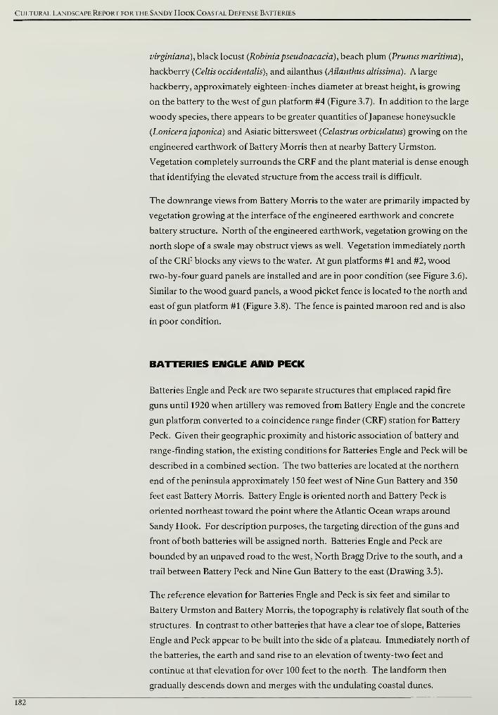
Cultural Landscape Report for the Sandy Hook Coastal Defense Batteries
virginiana), black locust (Robinia pseudoacacia), beach plum {Prunus maritima),
hackberry (Celtis occidentalis), and ailanthus (Ailanthus altissima). A large
hackberry, approximately eighteen-inches diameter at breast height, is growing
on the battery to the west of gun platform #4 (Figure 3.7). In addition to the large
woody species, there appears to be greater quantities ofJapanese honeysuckle
(Lonicerajaponica) and Asiatic bittersweet (Celastrus orbiculatus) growing on the
engineered earthwork of Battery Morris then at nearby Battery Urmston.
Vegetation completely surrounds the CRF and the plant material is dense enough
that identifying the elevated structure from the access trail is difficult.
The downrange views from Battery Morris to the water are primarily impacted by
vegetation growing at the interface of the engineered earthwork and concrete
battery structure. North of the engineered earthwork, vegetation growing on the
north slope of a swale may obstruct views as well. Vegetation immediately north
of the CRF blocks any views to the water. At gun platforms #1 and #2, wood
two-by-four guard panels are installed and are in poor condition (see Figure 3.6).
Similar to the wood guard panels, a wood picket fence is located to the north and
east of gun platform #1 (Figure 3.8). The fence is painted maroon red and is also
in poor condition.
BATTERIES ENGLE AMD PECK
Batteries Engle and Peck are two separate structures that emplaced rapid fire
guns until 1920 when artillery was removed from Battery Engle and the concrete
gun platform converted to a coincidence range finder (CRF) station for Battery
Peck. Given their geographic proximity and historic association of battery and
range-finding station, the existing conditions for Batteries Engle and Peck will be
described in a combined section. The two batteries are located at the northern
end of the peninsula approximately 150 feet west of Nine Gun Battery and 350
feet east Battery Morris. Battery Engle is oriented north and Battery Peck is
oriented northeast toward the point where the Atlantic Ocean wraps around
Sandy Hook. For description purposes, the targeting direction of the guns and
front of both batteries will be assigned north. Batteries Engle and Peck are
bounded by an unpaved road to the west, North Bragg Drive to the south, and a
trail between Battery Peck and Nine Gun Battery to the east (Drawing 3.5).
The reference elevation for Batteries Engle and Peck is six feet and similar to
Battery Urmston and Battery Morris, the topography is relatively flat south of the
structures. In contrast to other batteries that have a clear toe of slope, Batteries
Engle and Peck appear to be built into the side of a plateau. Immediately north of
the batteries, the earth and sand rise to an elevation of twenty-two feet and
continue at that elevation for over 100 feet to the north. The landform then
gradually descends down and merges with the undulating coastal dunes.
182
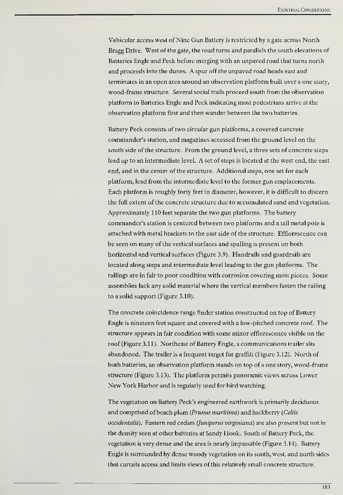
Existing Conditions
Vehicular access west of Nine Gun Battery is restricted by a gate across North
Bragg Drive. West of the gate, the road turns and parallels the south elevations of
Batteries Engle and Peck before merging with an unpaved road that turns north
and proceeds into the dunes. A spur off the unpaved road heads east and
terminates in an open area around an observation platform built over a one story,
wood-frame structure. Several social trails proceed south from the observation
platform to Batteries Engle and Peck indicating most pedestrians arrive at the
observation platform first and then wander between the two batteries.
Battery Peck consists of two circular gun platforms, a covered concrete
commander's station, and magazines accessed from the ground level on the
south side of the structure. From the ground level, a three sets of concrete steps
lead up to an intermediate level. A set of steps is located at the west end, the east
end, and in the center of the structure. Additional steps, one set for each
platform, lead from the intermediate level to the former gun emplacements.
Each platform is roughly forty feet in diameter, however, it is difficult to discern
the full extent of the concrete structure due to accumulated sand and vegetation.
Approximately 110 feet separate the two gun platforms. The battery
commander's station is centered between two platforms and a tall metal pole is
attached with metal brackets to the east side of the structure. Efflorescence can
be seen on many of the vertical surfaces and spalling is present on both
horizontal and vertical surfaces (Figure 3.9). Handrails and guardrails are
located along steps and intermediate level leading to the gun platforms. The
railings are in fair to poor condition with corrosion covering most pieces. Some
assemblies lack any solid material where the vertical members fasten the railing
to a solid support (Figure 3.10).
The concrete coincidence range finder station constructed on top of Battery
Engle is nineteen feet square and covered with a low-pitched concrete roof. The
structure appears in fair condition with some minor efflorescence visible on the
roof (Figure 3.11). Northeast of Battery Engle, a communications trailer sits
abandoned. The trailer is a frequent target for graffiti (Figure 3.12). North of
both batteries, an observation platform stands on top of a one story, wood-frame
structure (Figure 3.13). The platform permits panoramic views across Lower
New York Harbor and is regularly used for bird watching.
The vegetation on Battery Peck's engineered earthwork is primarily deciduous
and comprised of beach plum (Prunus maritima) and hackberry (Celtis
occidentalis). Eastern red cedars (Juniperus virginiana) are also present but not in
the density seen at other batteries at Sandy Hook. South of Battery Peck, the
vegetation is very dense and the area is nearly impassable (Figure 3.14). Battery
Engle is surrounded by dense woody vegetation on its south, west, and north sides
that curtails access and limits views of this relatively small concrete structure.
183
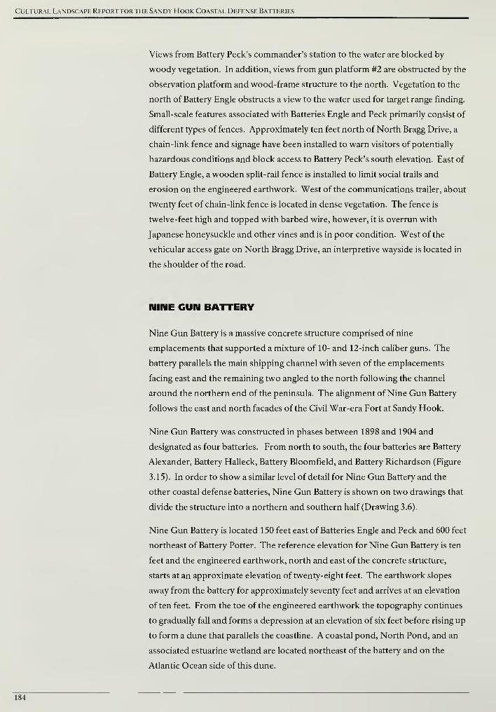
Cultural Landscape Report for the Sandy Hook Coastal Defense Batteries
Views from Battery Peck's commander's station to the water are blocked by
woody vegetation. In addition, views from gun platform #2 are obstructed by the
observation platform and wood-frame structure to the north. Vegetation to the
north of Battery Engle obstructs a view to the water used for target range finding.
Small-scale features associated with Batteries Engle and Peck primarily consist of
different types offences. Approximately ten feet north of North Bragg Drive, a
chain-link fence and signage have been installed to warn visitors of potentially
hazardous conditions and block access to Battery Peck's south elevation. East of
Battery Engle, a wooden split-rail fence is installed to limit social trails and
erosion on the engineered earthwork. West of the communications trailer, about
twenty feet of chain-link fence is located in dense vegetation. The fence is
twelve-feet high and topped with barbed wire, however, it is overrun with
Japanese honeysuckle and other vines and is in poor condition. West of the
vehicular access gate on North Bragg Drive, an interpretive wayside is located in
the shoulder of the road.
NINE GUN BATTERY
Nine Gun Battery is a massive concrete structure comprised of nine
emplacements that supported a mixture of 10- and 12-inch caliber guns. The
battery parallels the main shipping channel with seven of the emplacements
facing east and the remaining two angled to the north following the channel
around the northern end of the peninsula. The alignment of Nine Gun Battery
follows the east and north facades of the Civil War-era Fort at Sandy Hook.
Nine Gun Battery was constructed in phases between 1898 and 1904 and
designated as four batteries. From north to south, the four batteries are Battery
Alexander, Battery Halleck, Battery Bloomfield, and Battery Richardson (Figure
3.15). In order to show a similar level of detail for Nine Gun Battery and the
other coastal defense batteries, Nine Gun Battery is shown on two drawings that
divide the structure into a northern and southern half (Drawing 3.6).
Nine Gun Battery is located 150 feet east of Batteries Engle and Peck and 600 feet
northeast of Battery Potter. The reference elevation for Nine Gun Battery is ten
feet and the engineered earthwork, north and east of the concrete structure,
starts at an approximate elevation of twenty-eight feet. The earthwork slopes
away from the battery for approximately seventy feet and arrives at an elevation
often feet. From the toe of the engineered earthwork the topography continues
to gradually fall and forms a depression at an elevation of six feet before rising up
to form a dune that parallels the coastline. A coastal pond, North Pond, and an
associated estuarine wetland are located northeast of the battery and on the
Atlantic Ocean side of this dune.
184
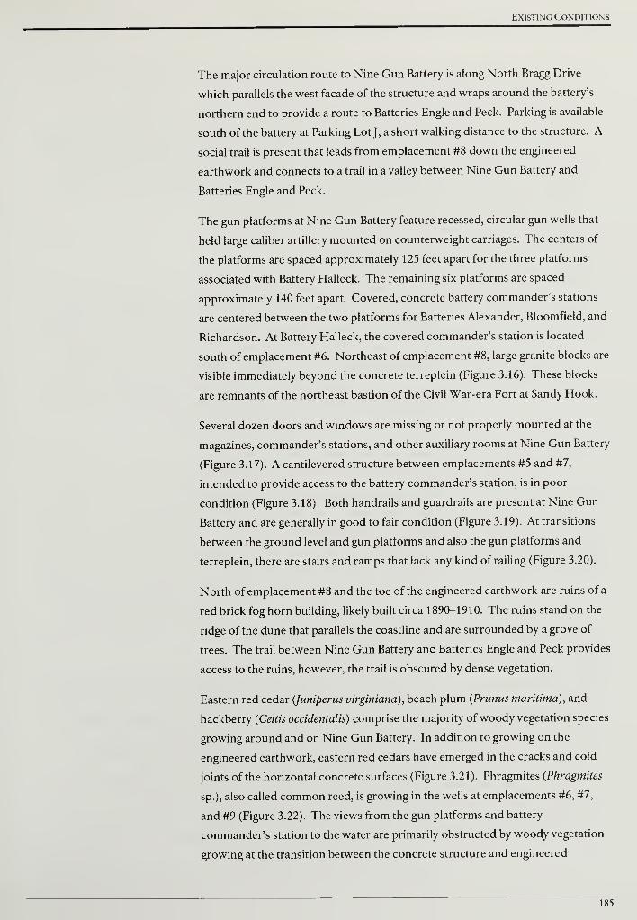
Existing Conditions
The major circulation route to Nine Gun Battery is along North Bragg Drive
which parallels the west facade of the structure and wraps around the battery's
northern end to provide a route to Batteries Engle and Peck. Parking is available
south of the battery at Parking Lot J, a short walking distance to the structure. A
social trail is present that leads from emplacement #8 down the engineered
earthwork and connects to a trail in a valley between Nine Gun Battery and
Batteries Engle and Peck.
The gun platforms at Nine Gun Battery feature recessed, circular gun wells that
held large caliber artillery mounted on counterweight carriages. The centers of
the platforms are spaced approximately 125 feet apart for the three platforms
associated with Battery Halleck. The remaining six platforms are spaced
approximately 140 feet apart. Covered, concrete battery commander's stations
are centered between the two platforms for Batteries Alexander, Bloomfield, and
Richardson. At Battery Halleck, the covered commander's station is located
south of emplacement #6. Northeast of emplacement #8, large granite blocks are
visible immediately beyond the concrete terreplein (Figure 3.16). These blocks
are remnants of the northeast bastion of the Civil War-era Fort at Sandy Hook.
Several dozen doors and windows are missing or not properly mounted at the
magazines, commander's stations, and other auxiliary rooms at Nine Gun Battery
(Figure 3.17). A cantilevered structure between emplacements #5 and #7,
intended to provide access to the battery commander's station, is in poor
condition (Figure 3.18). Both handrails and guardrails are present at Nine Gun
Battery and are generally in good to fair condition (Figure 3.19). At transitions
between the ground level and gun platforms and also the gun platforms and
terreplein, there are stairs and ramps that lack any kind of railing (Figure 3.20).
North of emplacement #8 and the toe of the engineered earthwork are ruins of a
red brick fog horn building, likely built circa 1890-1910. The ruins stand on the
ridge of the dune that parallels the coastline and are surrounded by a grove of
trees. The trail between Nine Gun Battery and Batteries Engle and Peck provides
access to the ruins, however, the trail is obscured by dense vegetation.
Eastern red cedar (Juniperus virginiana), beach plum (Prunus maritima), and
hackberry (Celtis occidentalis) comprise the majority of woody vegetation species
growing around and on Nine Gun Battery. In addition to growing on the
engineered earthwork, eastern red cedars have emerged in the cracks and cold
joints of the horizontal concrete surfaces (Figure 3.21). Phragmites (Phragmites
sp.), also called common reed, is growing in the wells at emplacements #6, #7,
and #9 (Figure 3.22). The views from the gun platforms and battery
commander's station to the water are primarily obstructed by woody vegetation
growing at the transition between the concrete structure and engineered
185
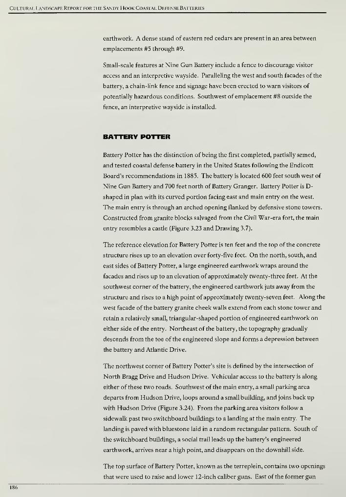
Cultural Landscape Report for the Sandy Hook Coastal Defense Batteries
earthwork. A dense stand of eastern red cedars are present in an area between
emplacements #5 through #9.
Small-scale features at Nine Gun Battery include a fence to discourage visitor
access and an interpretive wayside. Paralleling the west and south facades of the
battery, a chain-link fence and signage have been erected to warn visitors of
potentially hazardous conditions. Southwest of emplacement #8 outside the
fence, an interpretive wayside is installed.
BATTERY POTTER
Battery Potter has the distinction of being the first completed, partially armed,
and tested coastal defense battery in the United States following the Endicott
Board's recommendations in 1885. The battery is located 600 feet south west of
Nine Gun Battery and 700 feet north of Battery Granger. Battery Potter is D-
shaped in plan with its curved portion facing east and main entry on the west.
The main entry is through an arched opening flanked by defensive stone towers.
Constructed from granite blocks salvaged from the Civil War-era fort, the main
entry resembles a castle (Figure 3.23 and Drawing 3.7).
The reference elevation for Battery Potter is ten feet and the top of the concrete
structure rises up to an elevation over forty-five feet. On the north, south, and
east sides of Battery Potter, a large engineered earthwork wraps around the
facades and rises up to an elevation of approximately twenty-three feet. At the
southwest corner of the battery, the engineered earthwork juts away from the
structure and rises to a high point of approximately twenty-seven feet. Along the
west facade of the battery granite cheek walls extend from each stone tower and
retain a relatively small, triangular-shaped portion of engineered earthwork on
either side of the entry. Northeast of the battery, the topography gradually
descends from the toe of the engineered slope and forms a depression between
the battery and Atlantic Drive.
The northwest corner of Battery Potter's site is defined by the intersection of
North Bragg Drive and Hudson Drive. Vehicular access to the battery is along
either of these two roads. Southwest of the main entry, a small parking area
departs from Hudson Drive, loops around a small building, and joins back up
with Hudson Drive (Figure 3.24). From the parking area visitors follow a
sidewalk past two switchboard buildings to a landing at the main entry. The
landing is paved with bluestone laid in a random rectangular pattern. South of
the switchboard buildings, a social trail leads up the battery's engineered
earthwork, arrives near a high point, and disappears on the downhill side.
The top surface of Battery Potter, known as the terreplein, contains two openings
that were used to raise and lower 12-inch caliber guns. East of the former gun
186

Existing Conditions
emplacements, a concrete superior slope gently descends to a sentry route
known as a chemin de ronde that is fronted by a parapet wall (Figures 3.25 and
3.26). A concrete slope angles away from the parapet and meets the engineered
earthwork. On the terreplein, two groups of deteriorating concrete structures are
located west of the former gun emplacements (Figure 3.27). The structures
served as fire control stations after Battery Potter's artillery was removed and
feature large openings in their east elevations to provide views to the Atlantic
Ocean. South of the concrete structures, two concrete pillars remain from
another structure that served as fire control station (Figure 3.28). To increase
visitor safety, the National Park Service has recently added guardrails between
the superior slope and the terreplein where the guns were emplaced. Guardrails
are also installed on the western portion of the roof to prevent access to the
sloped portion of the concrete structure. Both groups of railings are in good
condition (Figures 3.29 and 3.30). A T-shaped metal pole is located north of the
fire control stations and was used in observing and recording weather
phenomenon as a means of adjusting and improving artillery firing (Figure 3.31).
In addition to the railings and pole, an exterior, metal stairway leads from the
southwest corner of the terreplein to the ground level.
On the ground level, several auxiliary structures and the foundation of a battery
commander's tower are located west of Battery Potter. A one story coal shed and
powerhouse are located near the northwest corner of the battery. Two
switchboard rooms, also one story high, are located near the southwest corner of
Battery Potter. A concrete cable hut separates two points of vehicular access
between Hudson Drive and the unpaved parking area. Across from the parking
area and west of Hudson Drive, a concrete foundation occupies a small opening
in a dense stand of woody vegetation (Figure 3.32). The foundation supported a
metal tower used to identify targets and improve fire control.
Large woody vegetation on Battery Potter's engineered earthwork is
predominantly eastern red cedar {Juniperus virginiana) and hackberry (Celtis
occidentalis). Some of the individual trees are greater than twenty-feet in height.
Woody vegetation is not only limited to the engineered earthwork. The sloped
portion of the concrete battery, rising approximately ten-feet above the
engineered earthwork, has eastern red cedars growing in cracks and in large
spalling areas (Figure 3.33). The chemin de ronde has become a collection area for
leaf litter and debris and hosts woody vegetation (Figure 3.34). On the battery's
west facade, Virginia creeper {Parthenocissus quinquefolia) is growing on the
vertical walls and sloped portion of the concrete structure. Northwest of the
battery, two deciduous trees are located in a lawn area near the intersection of
North Bragg Drive and Hudson Drive.
187
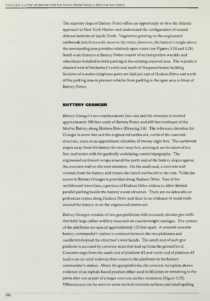
Cultural Landscape Report for the Sandy Hook Coastal Defense Batteries
The superior slope of Battery Potter offers an opportunity to view the Atlantic
approach to New York Harbor and understand the configuration of coastal
defense batteries at Sandy Hook. Vegetation growing on the engineered
earthwork interferes with views to the water, however, the battery's height above
the surrounding area provides relatively open views (see Figures 3.24 and 3.28).
Small-scale features at Battery Potter consist of an interpretive wayside and
wheelstops installed to limit parking to the existing unpaved area. The wayside is
situated west of the battery's entry and south of the powerhouse building.
Sections ofwooden telephone poles are laid just east of Hudson Drive and north
of the parking area to prevent vehicles from parking in the open area in front of
Battery Potter.
BATTERY GRANGER
Battery Granger's two emplacements face east and the structure is located
approximately 700 feet south of Battery Potter and 650 feet northeast of the
Mortar Battery along Hudson Drive (Drawing 3.8). The reference elevation for
Granger is seven feet and the engineered earthwork, north of the concrete
structure, starts at an approximate elevation of twenty-eight feet. The earthwork
slopes away from the battery for over sixty feet, arriving at an elevation of ten
feet, and unites with the gradually undulating coastal topography. The
engineered earthwork wraps around the north end of the battery slopes against
the concrete wall on the west elevation. On the south end, a concrete wall
extends from the battery and retains the raised earthwork to the east. Vehicular
access to Battery Granger is provided along Hudson Drive. East of the
northbound travel lane, a portion of Hudson Drive widens to allow limited
parallel parking beside the battery's west elevation. There are no sidewalks or
pedestrian routes along Hudson Drive and there is no evidence of social trails
around the battery or on the engineered earthwork.
Battery Granger consists of two gun platforms with recessed, circular gun wells
that held large caliber artillery mounted on counterweight carriages. The centers
of the platforms are spaced approximately 125 feet apart. A covered concrete
battery commander's station is centered between the two platforms and
cantilevers beyond the structure's west facade. The south end of each gun
platform is accessed by concrete steps that lead up from the ground level.
Concrete steps from the south end of platform #2 and north end of platform #1
lead to an elevated walkway that connects the platforms to the battery
commander's station. Above the gun platforms, the concrete terreplein shows
evidence of an asphalt-based product either used to fill joints or remaining in the
joints after use as part of a larger concrete surface treatment (Figure 3.35).
Efflorescence can be seen on some vertical concrete surfaces and small spalling
188
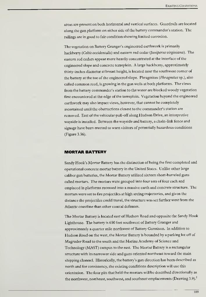
Existing Conditions
areas are present on both horizontal and vertical surfaces. Guardrails are located
along the gun platform on either side of the battery commander's station. The
railings are in good to fair condition showing limited corrosion.
The vegetation on Battery Granger's engineered earthwork is primarily
hackberry (Celtis occidentalis) and eastern red cedar (Juniperus virginiana). The
eastern red cedars appear more heavily concentrated at the interface of the
engineered slope and concrete terreplein. A large hackberry, approximately
thirty-inches diameter at breast height, is located near the southwest corner of
the battery at the toe of the engineered slope. Phragmites {Phragmites sp.), also
called common reed, is growing in the gun wells at both platforms. The views
from the battery commander's station to the water are blocked woody vegetation
first encountered at the edge of the terreplein. Vegetation beyond the engineered
earthwork may also impact views, however, that cannot be completely
ascertained until the obstructions closest to the commander's station are
removed. East of the vehicular pull-off along Hudson Drive, an interpretive
wayside is installed. Between the wayside and battery, a chain-link fence and
signage have been erected to warn visitors of potentially hazardous conditions
(Figure 3.36).
MORTAR BATTERY
Sandy Hook's Mortar Battery has the distinction of being the first completed and
operational concrete mortar battery in the United States. Unlike other large
caliber gun batteries, the Mortar Battery utilized sixteen short-barreled guns
called mortars. The mortars were grouped into four sets of four each and
emplaced in platforms recessed into a massive earth and concrete structure. The
mortars were set to fire projectiles at high arcing trajectories, and given the
distance the projectiles could travel, the structure was set further west from the
Atlantic coastline than other coastal defenses.
The Mortar Battery is located east of Hudson Road and opposite the Sandy Hook
Lighthouse. The battery is 650 feet southwest of Battery Granger and
approximately a quarter mile northwest of Battery Gunnison. In addition to
Hudson Road on the west, the Mortar Battery is bounded by a parking lot off of
Magruder Road to the south and the Marine Academy of Science and
Technology (MAST) campus to the east. The Mortar Battery is a rectangular
structure with its narrower side and guns oriented northeast toward the main
shipping channel. Historically, the battery's gun direction has been described as
north and for consistency, the existing conditions description will use this
orientation. The four pits that held the mortars will be described directionally as
the northwest, northeast, southwest, and southeast emplacements (Drawing 3.9).
189
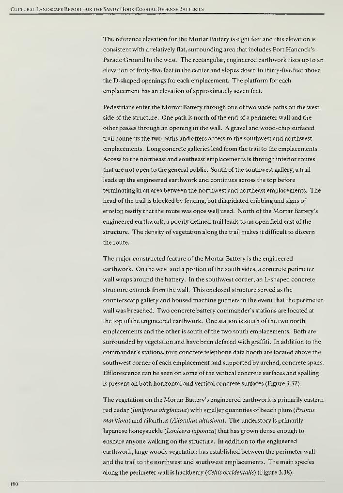
Cultural Landscape Report for the Sandy Hook Coastal Defense Batteries
The reference elevation for the Mortar Battery is eight feet and this elevation is
consistent with a relatively flat, surrounding area that includes Fort Hancock's
Parade Ground to the west. The rectangular, engineered earthwork rises up to an
elevation of forty-five feet in the center and slopes down to thirty-five feet above
the D-shaped openings for each emplacement. The platform for each
emplacement has an elevation of approximately seven feet.
Pedestrians enter the Mortar Battery through one of two wide paths on the west
side of the structure. One path is north of the end of a perimeter wall and the
other passes through an opening in the wall. A gravel and wood-chip surfaced
trail connects the two paths and offers access to the southwest and northwest
emplacements. Long concrete galleries lead from the trail to the emplacements.
Access to the northeast and southeast emplacements is through interior routes
that are not open to the general public. South of the southwest gallery, a trail
leads up the engineered earthwork and continues across the top before
terminating in an area between the northwest and northeast emplacements. The
head of the trail is blocked by fencing, but dilapidated cribbing and signs of
erosion testify that the route was once well used. North of the Mortar Battery's
engineered earthwork, a poorly defined trail leads to an open field east of the
structure. The density of vegetation along the trail makes it difficult to discern
the route.
The major constructed feature of the Mortar Battery is the engineered
earthwork. On the west and a portion of the south sides, a concrete perimeter
wall wraps around the battery. In the southwest corner, an L-shaped concrete
structure extends from the wall. This enclosed structure served as the
counterscarp gallery and housed machine gunners in the event that the perimeter
wall was breached. Two concrete battery commander's stations are located at
the top of the engineered earthwork. One station is south of the two north
emplacements and the other is south of the two south emplacements. Both are
surrounded by vegetation and have been defaced with graffiti. In addition to the
commander's stations, four concrete telephone data booth are located above the
southwest corner of each emplacement and supported by arched, concrete spans.
Efflorescence can be seen on some of the vertical concrete surfaces and spalling
is present on both horizontal and vertical concrete surfaces (Figure 3.37).
The vegetation on the Mortar Battery's engineered earthwork is primarily eastern
red cedar (Juniperus virginiana) with smaller quantities of beach plum (Prunus
maritima) and ailanthus (Ailanthus altissima). The understory is primarily
Japanese honeysuckle (Lonicerajaponica) that has grown dense enough to
ensnare anyone walking on the structure. In addition to the engineered
earthwork, large woody vegetation has established between the perimeter wall
and the trail to the northwest and southwest emplacements. The main species
along the perimeter wall is hackberry (Celtis occidentalis) (Figure 3.38).
190
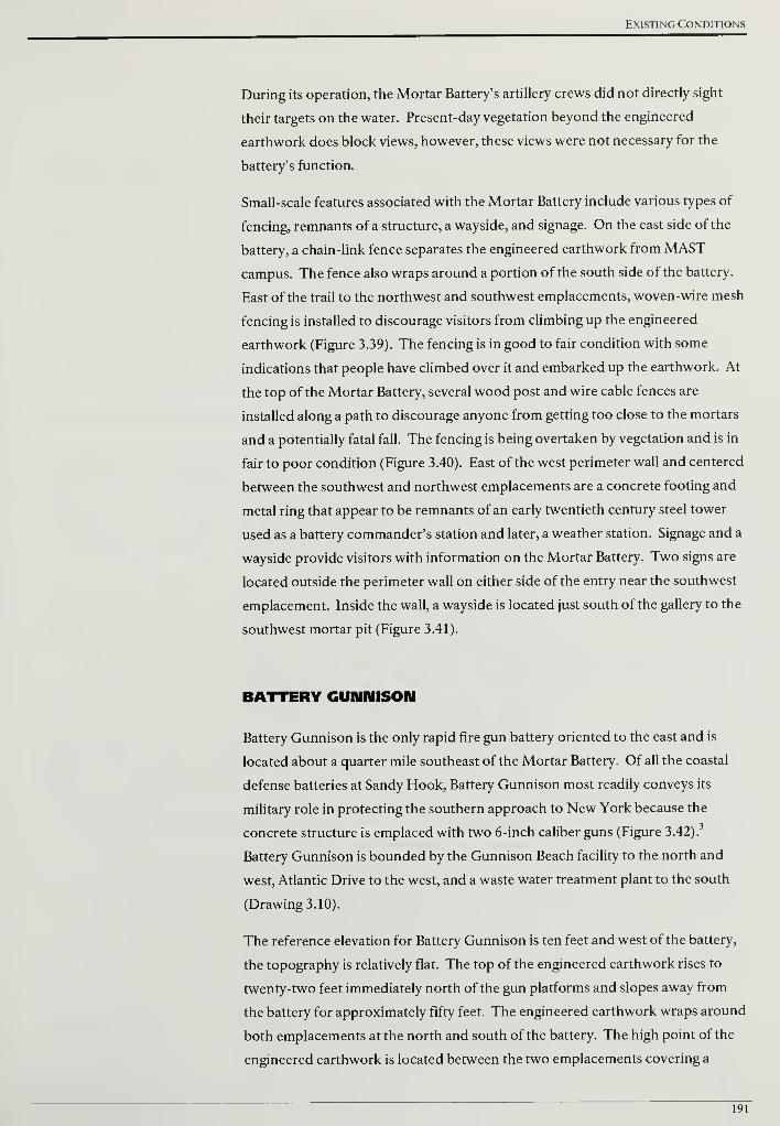
Existing Conditions
During its operation, the Mortar Battery's artillery crews did not directly sight
their targets on the water. Present-day vegetation beyond the engineered
earthwork does block views, however, these views were not necessary for the
battery's function.
Small-scale features associated with the Mortar Battery include various types of
fencing, remnants of a structure, a wayside, and signage. On the east side of the
battery, a chain-link fence separates the engineered earthwork from MAST
campus. The fence also wraps around a portion of the south side of the battery.
East of the trail to the northwest and southwest emplacements, woven-wire mesh
fencing is installed to discourage visitors from climbing up the engineered
earthwork (Figure 3.39). The fencing is in good to fair condition with some
indications that people have climbed over it and embarked up the earthwork. At
the top of the Mortar Battery, several wood post and wire cable fences are
installed along a path to discourage anyone from getting too close to the mortars
and a potentially fatal fall. The fencing is being overtaken by vegetation and is in
fair to poor condition (Figure 3.40). East of the west perimeter wall and centered
between the southwest and northwest emplacements are a concrete footing and
metal ring that appear to be remnants of an early twentieth century steel tower
used as a battery commander's station and later, a weather station. Signage and a
wayside provide visitors with information on the Mortar Battery. Two signs are
located outside the perimeter wall on either side of the entry near the southwest
emplacement. Inside the wall, a wayside is located just south of the gallery to the
southwest mortar pit (Figure 3.41).
BATTERY GUNNISON
Battery Gunnison is the only rapid fire gun battery oriented to the east and is
located about a quarter mile southeast of the Mortar Battery. Of all the coastal
defense batteries at Sandy Hook, Battery Gunnison most readily conveys its
military role in protecting the southern approach to New York because the
concrete structure is emplaced with two 6-inch caliber guns (Figure 3.42).
Battery Gunnison is bounded by the Gunnison Beach facility to the north and
west, Atlantic Drive to the west, and a waste water treatment plant to the south
(Drawing 3.10).
The reference elevation for Battery Gunnison is ten feet and west of the battery,
the topography is relatively flat. The top of the engineered earthwork rises to
twenty-two feet immediately north of the gun platforms and slopes away from
the battery for approximately fifty feet. The engineered earthwork wraps around
both emplacements at the north and south of the battery. The high point of the
engineered earthwork is located between the two emplacements covering a
191
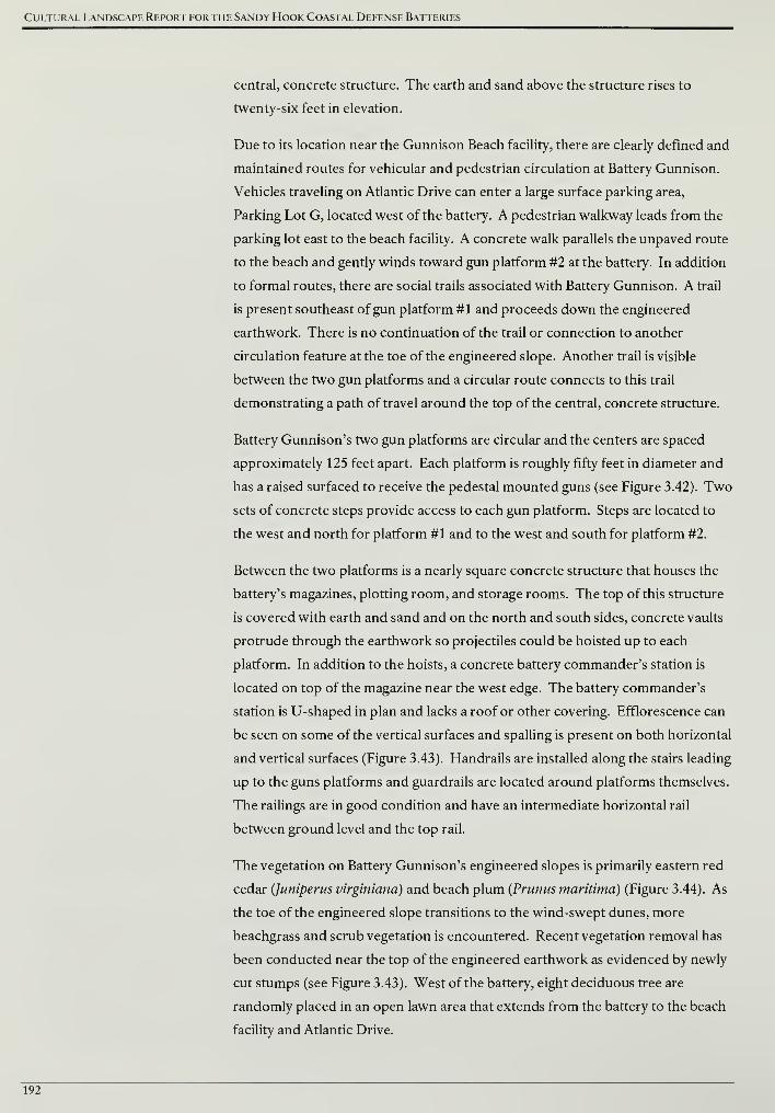
Cultural Landscape Report for the Sandy Hook Coastal Defense Batteries
central, concrete structure. The earth and sand above the structure rises to
twenty-six feet in elevation.
Due to its location near the Gunnison Beach facility, there are clearly defined and
maintained routes for vehicular and pedestrian circulation at Battery Gunnison.
Vehicles traveling on Atlantic Drive can enter a large surface parking area,
Parking Lot G, located west of the battery. A pedestrian walkway leads from the
parking lot east to the beach facility. A concrete walk parallels the unpaved route
to the beach and gently winds toward gun platform #2 at the battery. In addition
to formal routes, there are social trails associated with Battery Gunnison. A trail
is present southeast ofgun platform #1 and proceeds down the engineered
earthwork. There is no continuation of the trail or connection to another
circulation feature at the toe of the engineered slope. Another trail is visible
between the two gun platforms and a circular route connects to this trail
demonstrating a path of travel around the top of the central, concrete structure.
Battery Gunnison's two gun platforms are circular and the centers are spaced
approximately 125 feet apart. Each platform is roughly fifty feet in diameter and
has a raised surfaced to receive the pedestal mounted guns (see Figure 3.42). Two
sets of concrete steps provide access to each gun platform. Steps are located to
the west and north for platform #1 and to the west and south for platform #2.
Between the two platforms is a nearly square concrete structure that houses the
battery's magazines, plotting room, and storage rooms. The top of this structure
is covered with earth and sand and on the north and south sides, concrete vaults
protrude through the earthwork so projectiles could be hoisted up to each
platform. In addition to the hoists, a concrete battery commander's station is
located on top of the magazine near the west edge. The battery commander's
station is U-shaped in plan and lacks a roof or other covering. Efflorescence can
be seen on some of the vertical surfaces and spalling is present on both horizontal
and vertical surfaces (Figure 3.43). Handrails are installed along the stairs leading
up to the guns platforms and guardrails are located around platforms themselves.
The railings are in good condition and have an intermediate horizontal rail
between ground level and the top rail.
The vegetation on Battery Gunnison's engineered slopes is primarily eastern red
cedar (Juniperus virginiana) and beach plum (Prunus maritima) (Figure 3.44). As
the toe of the engineered slope transitions to the wind-swept dunes, more
beachgrass and scrub vegetation is encountered. Recent vegetation removal has
been conducted near the top of the engineered earthwork as evidenced by newly
cut stumps (see Figure 3.43). West of the battery, eight deciduous tree are
randomly placed in an open lawn area that extends from the battery to the beach
facility and Atlantic Drive.
192
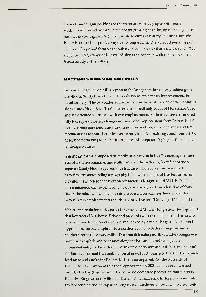
Existing Conditions
Views from the gun positions to the water are relatively open with some
obstructions caused by eastern red cedars growing near the top of the engineered
earthwork (see Figure 3.42). Small-scale features at Battery Gunnison include
bollards and an interpretive wayside. Along Atlantic Drive, wood posts support
sections of rope and form a decorative vehicular barrier that parallels road. West
of platform #2, a wayside is installed along the concrete walk that connects the
beach facility to the battery.
BATTERIES KINGMAN AND MILLS
Batteries Kingman and Mills represent the last generation of large caliber guns
installed at Sandy Hook to counter early twentieth century improvements in
naval artillery. The two batteries are located on the western side of the peninsula
along Sandy Hook Bay. The batteries are immediately south of Horseshoe Cove
and are oriented to the east with two emplacements per battery. Seven hundred
fifty feet separate Battery Kingman's southern emplacement from Battery Mills'
northern emplacement. Since the initial construction, emplaced guns, and later
modifications for both batteries were nearly identical, existing conditions will be
described pertaining to the both structures with separate highlights for specific
landscape features.
A maritime forest, composed primarily of American holly (Ilex opaca), is located
east of Batteries Kingman and Mills. West of the batteries, forty feet or more
separate Sandy Hook Bay from the structures. Except for the casemated
batteries, the surrounding topography is flat with changes of five feet or less in
elevation. The reference elevation for Batteries Kingman and Mills is five feet.
The engineered earthworks, roughly oval in shape, rise to an elevation of forty
feet in the middle. Two high points are present on each earthwork over the
battery's gun emplacements that rise to forty-five feet (Drawings 3.11 and 3.12).
Vehicular circulation to Batteries Kingman and Mills is along a non-descript road
that intersects Hartshorne Drive and proceeds west to the batteries. This access
road is closed to the general public and locked by a vehicular gate. As the road
approaches the bay, it splits into a northern route to Battery Kingman and a
southern route to Battery Mills. The branch heading north to Battery Kingman is
paved with asphalt and continues along the bay until terminating at the
casemated entry to the battery. North of the entry and around the remainder of
the battery, the road is a combination of gravel and compacted earth. The branch
leading to and encircling Battery Mills is also unpaved. On the west side of
Battery Mills a portion of this road, approximately 200-feet, has been washed
away by the bay (Figure 3.45). There are no dedicated pedestrian routes around
Batteries Kingman and Mills. For Battery Kingman, some historic maps indicate
trails ascending and on top of the engineered earthwork, however, no clear trails
193
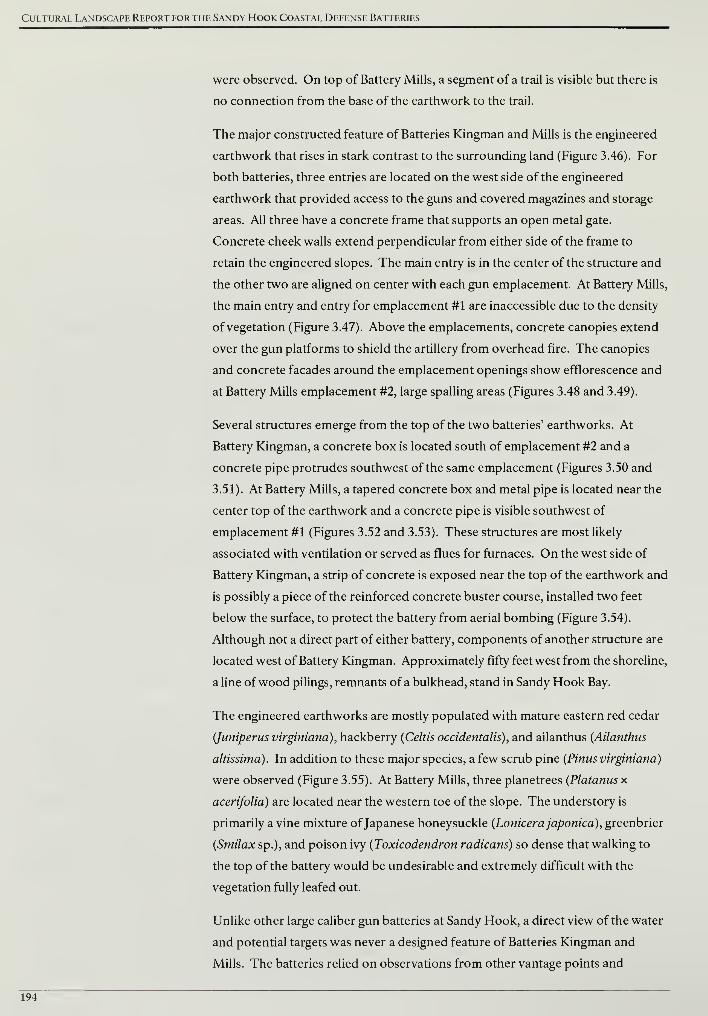
Cultural Landscape Report for the Sandy Hook Coastal Defense Batteries
were observed. On top of Battery Mills, a segment of a trail is visible but there is
no connection from the base of the earthwork to the trail.
The major constructed feature of Batteries Kingman and Mills is the engineered
earthwork that rises in stark contrast to the surrounding land (Figure 3.46). For
both batteries, three entries are located on the west side of the engineered
earthwork that provided access to the guns and covered magazines and storage
areas. All three have a concrete frame that supports an open metal gate.
Concrete cheek walls extend perpendicular from either side of the frame to
retain the engineered slopes. The main entry is in the center of the structure and
the other two are aligned on center with each gun emplacement. At Battery Mills,
the main entry and entry for emplacement #1 are inaccessible due to the density
of vegetation (Figure 3.47). Above the emplacements, concrete canopies extend
over the gun platforms to shield the artillery from overhead fire. The canopies
and concrete facades around the emplacement openings show efflorescence and
at Battery Mills emplacement #2, large spalling areas (Figures 3.48 and 3.49).
Several structures emerge from the top of the two batteries' earthworks. At
Battery Kingman, a concrete box is located south of emplacement #2 and a
concrete pipe protrudes southwest of the same emplacement (Figures 3.50 and
3.51). At Battery Mills, a tapered concrete box and metal pipe is located near the
center top of the earthwork and a concrete pipe is visible southwest of
emplacement #1 (Figures 3.52 and 3.53). These structures are most likely
associated with ventilation or served as flues for furnaces. On the west side of
Battery Kingman, a strip of concrete is exposed near the top of the earthwork and
is possibly a piece of the reinforced concrete buster course, installed two feet
below the surface, to protect the battery from aerial bombing (Figure 3.54).
Although not a direct part of either battery, components of another structure are
located west of Battery Kingman. Approximately fifty feet west from the shoreline,
a line ofwood pilings, remnants of a bulkhead, stand in Sandy Hook Bay.
The engineered earthworks are mostly populated with mature eastern red cedar
(Juniperus virginiana), hackberry (Celtis occidentalis), and ailanthus {Ailanthus
altissima). In addition to these major species, a few scrub pine (Pinus virginiana)
were observed (Figure 3.55). At Battery Mills, three planetrees (Platanus x
acerifolia) are located near the western toe of the slope. The understory is
primarily a vine mixture ofJapanese honeysuckle (Lonicerajaponica), greenbrier
(Smilax sp.), and poison ivy (Toxicodendron radicans) so dense that walking to
the top of the battery would be undesirable and extremely difficult with the
vegetation fully leafed out.
Unlike other large caliber gun batteries at Sandy Hook, a direct view of the water
and potential targets was never a designed feature of Batteries Kingman and
Mills. The batteries relied on observations from other vantage points and
194
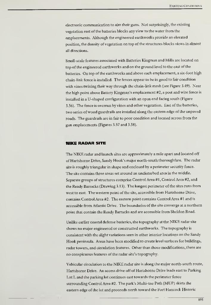
Existing Conditions
electronic communication to aim their guns. Not surprisingly, the existing
vegetation east of the batteries blocks any view to the water from the
emplacements. Although the engineered earthworks provide an elevated
position, the density of vegetation on top of the structures blocks views in almost
all directions.
Small-scale features associated with Batteries Kingman and Mills are located on
top of the engineered earthworks and on the ground level to the east of the
batteries. On top of the earthworks and above each emplacement, a six-foot high
chain-link fence is installed. The fences appear to be in good to fair condition
with vines twining their way through the chain-link mesh (see Figure 3.49). Near
the high point above Battery Kingman's emplacement #2, a post and wire fence is
installed in a U-shaped configuration with an open end facing south (Figure
3.56). The fence is overrun by vines and other vegetation. East of the batteries,
two series of wood guardrails are installed along the eastern edge of the unpaved
roads. The guardrails are in fair to poor condition and located across from the
gun emplacements (Figures 3.57 and 3.58).
NIKE RADAR SITE
The NIKE radar and launch sites are approximately a mile apart and located off
of Hartshorne Drive, Sandy Hook's major north-south thoroughfare. The radar
site is roughly triangular in shape and enclosed by a perimeter security fence.
The site contains three areas set around an undisturbed area in the middle.
Separate groups of structures comprise Control Area #1, Control Area #2, and
the Ready Barracks (Drawing 3.13). The longest perimeter of the sites runs from
west to east. The western point of the site, accessible from Hartshorne Drive,
contains Control Area #2. The eastern point contains Control Area #1 and is
accessible from Atlantic Drive. The boundaries of the site converge at a northern
point that contain the Ready Barracks and are accessible from Sheldon Road.
Unlike earlier coastal defense batteries, the topography at the NIKE radar site
shows no major engineered or constructed earthworks. The topography is
consistent with the slight variations seen in other interior locations on the Sandy
Hook peninsula. Areas have been modified to create level surfaces for buildings,
radar towers, and circulation features. Other than those modifications, there are
no conspicuous features of the radar site's topography.
Vehicular circulation to the NIKE radar site is along the major north-south route,
Hartshorne Drive. An access drive off of Hartshorne Drive leads east to Parking
Lot L and the parking lot continues east towards the perimeter fence
surrounding Control Area #2. The park's Multi-use Path (MUP) skirts the
eastern edge of the lot and proceeds north toward the Fort Hancock Historic
195
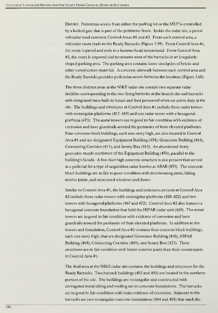
Cultural Landscape Report for the Sandy Hook Coastal Defense Batteries
District. Pedestrian access from either the parking lot or the MUP is controlled
by a locked gate that is part of the perimeter fence. Inside the radar site, a paved
vehicular road connects Control Areas #1 and #2. From each control area, a
vehicular route leads to the Ready Barracks (Figure 3.59). From Control Area #1,
the route is paved and ends in a hammerhead turnaround. From Control Area
#2, the route is unpaved and terminates west of the barracks in an irregularly-
shaped parking area. The parking area contains loose stockpiles of bricks and
other construction materials. A concrete sidewalk between each control area and
the Ready Barracks provides pedestrian access between the locations (Figure 3.60).
The three distinct areas at the NIKE radar site contain two separate radar
facilities corresponding to the two firing batteries at the launch site and barracks
with integrated mess halls to house and feed personnel when on active duty at the
site. The buildings and structures at Control Area #1 include three radar towers
with rectangular platforms (417^119) and one radar tower with a hexagonal
platform (473). The metal towers are in good to fair condition with evidence of
corrosion and have guardrails around the perimeter of their elevated platforms.
Four concrete block buildings, each one-story high, are also located in Control
Area #1 and are designated Equipment Building (454), Generator Building (414),
Connecting Corridor (411), and Sentry Box (413). An abandoned Army
generator stands northwest of the Equipment Building (454), parallel to the
building's facade. A five-foot high concrete structure is also present that served
as a pedestal for a type of acquisition radar known as ABAR (453). The concrete
block buildings are in fair to poor condition with deteriorating paint, failing
mortar joints, and unsecured windows and doors.
Similar to Control Area #1, the buildings and structures present at Control Area
#2 include three radar towers with rectangular platforms (420-422) and two
towers with hexagonal platforms (467 and 472). Control Area #2 also features a
hexagonal concrete foundation that held the HIPAR radar unit (469). The metal
towers are in good to fair condition with evidence of corrosion and have
guardrails around the perimeter of their elevated platforms. In addition to the
towers and foundation, Control Area #2 contains four concrete block buildings,
each one story high, that are designated Generator Building (410), HIPAR
Building (468), Connecting Corridor (409), and Sentry Box (423). These
structures are in fair condition with better exterior paint than their counterparts
in Control Area #1.
The final area at the NIKE radar site contains the buildings and structures for the
Ready Barracks. Two barrack buildings (402 and 403) are located in the northern
portion of the site. The buildings are rectangular and constructed with
corrugated metal siding and roofing set on concrete foundations. The barracks
are in good to fair condition with some evidence of corrosion. Adjacent to the
barracks are two rectangular concrete foundations (404 and 405) that mark the
196
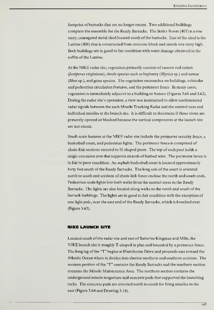
Existing Conditions
footprint of barracks that are no longer extant. Two additional buildings
complete the ensemble for the Ready Barracks. The Boiler Room (407) is a one
story, corrugated metal shed located south of the barracks. East of the shed is the
Latrine (406) that is constructed from concrete block and stands one story high.
Both buildings are in good to fair condition with some damage observed in the
soffits of the Latrine.
At the NIKE radar site, vegetation primarily consists of eastern red cedars
(Juniperus virginiana), shrub species such as bayberry (Myrica sp.) and sumac
(Rhus sp.), and grass species. The vegetation encroaches on buildings, vehicular
and pedestrian circulation features, and the perimeter fence. In many cases,
vegetation is immediately adjacent to a building or feature (Figures 3.61 and 3.62).
During the radar site's operation, a view was maintained to allow unobstructed
radar signals between the each Missile Tracking Radar and the control vans and
individual missiles at the launch site. It is difficult to determine if those views are
presently opened or blocked because the vertical components at the launch site
are not extant.
Small-scale features at the NIKE radar site include the perimeter security fence, a
basketball court, and pedestrian lights. The perimeter fence is comprised of
chain-link sections secured to H-shaped posts. The top of each post holds a
single extension arm that supports strands of barbed wire. The perimeter fence is
in fair to poor condition. An asphalt basketball court is located approximately
forty feet south of the Ready Barracks. The long axis of the court is oriented
north to south and sections of chain-link fence enclose the north and south ends.
Pedestrian -scale lights line both walks from the control areas to the Ready
Barracks. The lights are also located along walks to the north and south of the
barrack buildings. The lights are in good to fair condition with the exception of
one light pole, near the east end of the Ready Barracks, which is knocked over
(Figure 3.63).
MIKE LAUNCH SITE
Located south of the radar site and east of Batteries Kingman and Mills, the
NIKE launch site is roughly T-shaped in plan and bounded by a perimeter fence.
The long leg of the "T" begins at Hartshorne Drive and proceeds east toward the
Atlantic Ocean where it divides into shorter northern and southern sections. The
western portion of the "T" contains the Ready Barracks and the southern section
contains the Missile Maintenance Area. The northern section contains the
underground missile magazines and concrete pads that supported the launching
racks. The concrete pads are oriented north to south for firing missiles to the
east (Figure 3.64 and Drawing 3.14).
197
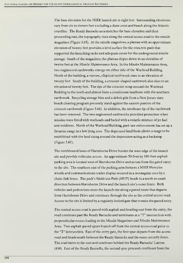
Cultural Landscape Report for the Sandy Hook Coastal Defense Batteries
The base elevation for the NIKE launch site is eight feet. Surrounding elevations
vary from six to sixteen feet excluding a dune crest and beach along the Atlantic
coastline. The Ready Barracks area matches the base elevation and then
proceeding east, the topography rises along the central access road to the missile
magazines (Figure 3.65). At the missile magazines, a plateau with an approximate
elevation of twenty feet provides a level surface for the concrete pads that
supported the launching racks and adequate cover for the underground missile
storage. South of the magazines, the plateau slopes down to an elevation of
twelve feet at the Missile Maintenance Area. In the Missile Maintenance Area,
two engineered earthworks emerge on either side of the Warhead Building.
North of the building, a narrow, elliptical earthwork rises to an elevation of
twenty feet. South of the building, a crescent-shaped earthwork also rises to an
elevation of twenty feet. The tips of the crescent wrap around the Warhead
Building to the north and almost form a continuous landform with the northern
earthwork. Recycling storage bins and a debris pile from a New Jersey state
beach cleaning program presently stand against the eastern portion of the
crescent earthwork (Figure 3.66). In addition, the northeast tip of the earthwork
has been removed. The two engineered earthworks provided protection when
missiles were fitted with warheads and fueled with a volatile mixture of jet fuel
and oxidizers. North of the Warhead Building, park law enforcement has set up a
firearms range in a low lying area. The depressed land form allows a range to be
established with the land rising around the depression acting as a backstop
(Figure 3.67).
The northbound lanes of Hartshorne Drive border the west edge of the launch
site and provide vehicular access. An approximate 50-foot by 180-foot asphalt
parking area is located west of Hartshorne Drive and across from the gated entry
to the site. The southern end of the parking area features a NIKE Hercules
missile and communications trailer display secured in a rectangular area by a
chain-link fence. The park's Multi-use Path (MUP) heads in a north to south
direction between Hartshorne Drive and the launch site's outer fence. Both
vehicles and pedestrians enter the launch site along a paved route that departs
from Hartshorne Drive and continues through the site as the central access road.
Access to the site is limited by a regularly locked gate that crosses the paved entry.
The central access road is paved with asphalt and heading east from the entry, the
road continues past the Ready Barracks and terminates at a "T" intersection with
perpendicular routes leading to the Missile Magazines and Missile Maintenance
Area. Two asphalt-paved spurs branch off from the central access road prior to
the "T" intersection. East of the entry gate, the first spur departs from the access
road and heads south between the Ready Barracks and the outer security fence.
The road turns to the east and continues behind the Ready Barracks' Latrine
(434). East of the Ready Barracks, the second spur proceeds northeast from the
198
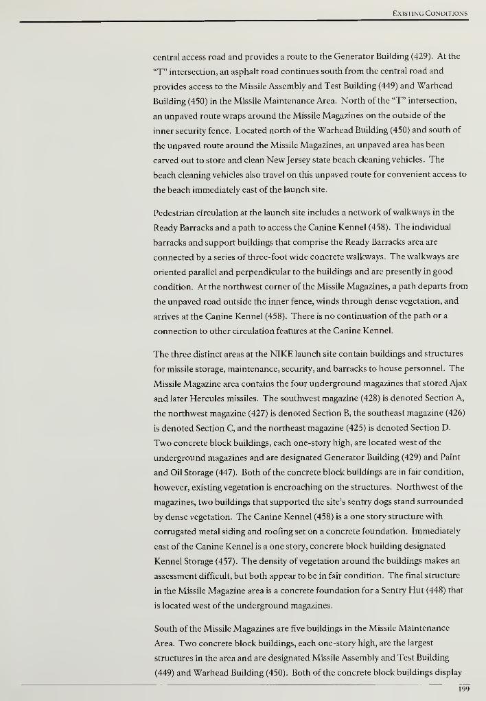
Existing Conditions
central access road and provides a route to the Generator Building (429). At the
"T" intersection, an asphalt road continues south from the central road and
provides access to the Missile Assembly and Test Building (449) and Warhead
Building (450) in the Missile Maintenance Area. North of the "T" intersection,
an unpaved route wraps around the Missile Magazines on the outside of the
inner security fence. Located north of the Warhead Building (450) and south of
the unpaved route around the Missile Magazines, an unpaved area has been
carved out to store and clean New Jersey state beach cleaning vehicles. The
beach cleaning vehicles also travel on this unpaved route for convenient access to
the beach immediately east of the launch site.
Pedestrian circulation at the launch site includes a network of walkways in the
Ready Barracks and a path to access the Canine Kennel (458). The individual
barracks and support buildings that comprise the Ready Barracks area are
connected by a series of three-foot wide concrete walkways. The walkways are
oriented parallel and perpendicular to the buildings and are presently in good
condition. At the northwest corner of the Missile Magazines, a path departs from
the unpaved road outside the inner fence, winds through dense vegetation, and
arrives at the Canine Kennel (458). There is no continuation of the path or a
connection to other circulation features at the Canine Kennel.
The three distinct areas at the NIKE launch site contain buildings and structures
for missile storage, maintenance, security, and barracks to house personnel. The
Missile Magazine area contains the four underground magazines that stored Ajax
and later Hercules missiles. The southwest magazine (428) is denoted Section A,
the northwest magazine (427) is denoted Section B, the southeast magazine (426)
is denoted Section C, and the northeast magazine (425) is denoted Section D.
Two concrete block buildings, each one-story high, are located west of the
underground magazines and are designated Generator Building (429) and Paint
and Oil Storage (447). Both of the concrete block buildings are in fair condition,
however, existing vegetation is encroaching on the structures. Northwest of the
magazines, two buildings that supported the site's sentry dogs stand surrounded
by dense vegetation. The Canine Kennel (458) is a one story structure with
corrugated metal siding and roofing set on a concrete foundation. Immediately
east of the Canine Kennel is a one story, concrete block building designated
Kennel Storage (457). The density of vegetation around the buildings makes an
assessment difficult, but both appear to be in fair condition. The final structure
in the Missile Magazine area is a concrete foundation for a Sentry Hut (448) that
is located west of the underground magazines.
South of the Missile Magazines are five buildings in the Missile Maintenance
Area. Two concrete block buildings, each one-story high, are the largest
structures in the area and are designated Missile Assembly and Test Building
(449) and Warhead Building (450). Both of the concrete block buildings display
199
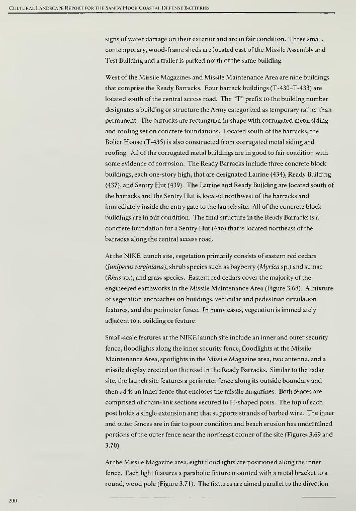
Cultural Landscape Report for the Sandy Hook Coastal Defense Batteries
signs of water damage on their exterior and are in fair condition. Three small,
contemporary, wood-frame sheds are located east of the Missile Assembly and
Test Building and a trailer is parked north of the same building.
West of the Missile Magazines and Missile Maintenance Area are nine buildings
that comprise the Ready Barracks. Four barrack buildings (T-430-T-433) are
located south of the central access road. The "T" prefix to the building number
designates a building or structure the Army categorized as temporary rather than
permanent. The barracks are rectangular in shape with corrugated metal siding
and roofing set on concrete foundations. Located south of the barracks, the
Bolier House (T-435) is also constructed from corrugated metal siding and
roofing. All of the corrugated metal buildings are in good to fair condition with
some evidence of corrosion. The Ready Barracks include three concrete block
buildings, each one-story high, that are designated Latrine (434), Ready Building
(437), and Sentry Hut (439). The Latrine and Ready Building are located south of
the barracks and the Sentry Hut is located northwest of the barracks and
immediately inside the entry gate to the launch site. All of the concrete block
buildings are in fair condition. The final structure in the Ready Barracks is a
concrete foundation for a Sentry Hut (456) that is located northeast of the
barracks along the central access road.
At the NIKE launch site, vegetation primarily consists of eastern red cedars
(Juniperus virginiana), shrub species such as bayberry (Myrica sp.) and sumac
(Rhus sp.), and grass species. Eastern red cedars cover the majority of the
engineered earthworks in the Missile Maintenance Area (Figure 3.68). A mixture
of vegetation encroaches on buildings, vehicular and pedestrian circulation
features, and the perimeter fence. In many cases, vegetation is immediately
adjacent to a building or feature.
Small-scale features at the NIKE launch site include an inner and outer security
fence, floodlights along the inner security fence, floodlights at the Missile
Maintenance Area, spotlights in the Missile Magazine area, two antenna, and a
missile display erected on the road in the Ready Barracks. Similar to the radar
site, the launch site features a perimeter fence along its outside boundary and
then adds an inner fence that encloses the missile magazines. Both fences are
comprised of chain-link sections secured to H-shaped posts. The top of each
post holds a single extension arm that supports strands of barbed wire. The inner
and outer fences are in fair to poor condition and beach erosion has undermined
portions of the outer fence near the northeast corner of the site (Figures 3.69 and
3.70).
At the Missile Magazine area, eight floodlights are positioned along the inner
fence. Each light features a parabolic fixture mounted with a metal bracket to a
round, wood pole (Figure 3.71). The fixtures are aimed parallel to the direction
200

Existing Conditions
of the inner fence. Six similar lights are located at the Missile Maintenance Area
with half located on the northern engineered earthwork and the other half on the
southern engineered earthwork. The six lights are mounted at the top of round,
metal poles. Vegetation encroaches on many of the floodlights, however, they
are in good to fair condition. In the Missile Magazine area a single, round, wood
pole stands near the Section B magazine (427). From ground level, the first eight
to ten feet of the pole are painted yellow and a red "B" is featured on the yellow
field. Two spotlights with parabolic metal hoods are mounted at the top of the
pole (Figure 3.72).
East of the Missile Maintenance Area and approaching the outer fence, an
antenna and monitoring equipment have been set up for collecting weather and
tide information (Figure 3.73). A second antenna assists with collecting weather
and tide information and is located south of the Missile Maintenance Area near
the outer fence (Figure 3.74). In the southwest corner of the Ready Barracks, a
missile display has been installed on the road connecting the central access road
to the barracks' Latrine (434). The display informs visitors about the weaponry
used at Sandy Hook's last generation of coastal defenses.
201

Cultural Landscape Report for the Sandy Hook Coastal Defense Batteries
ENDNOTES
1 The 1990 survey covers the entire peninsula and is recorded on twenty-seven sheets. Hard copies were found in the
park's Engineering Office and as a component of this Cultural Landscape Report, the surveys were scanned. A copy of the
scanned files has been sent to the park's GIS specialist.
2This naming convention is consistent with the Historic Structure Report: Battery Potter, Mortar Battery and Battery
Gunnison completed in 2007. For additional information on different names historically assigned to the mortars, please
see James J. Lee III and Lauren Laham, Historic Structure Report: Battery Potter, Mortar Battery and Battery Gunnison.
Fort Hancock, NewJersey, Sandy Hook Unit, Gateway National Recreation Area (United States Department of the Interior,
National Park Service, 2007), 191-192.
3 The guns are not original to Battery Gunnison but acquired from a similar battery and installed for interpretive purposes.
202
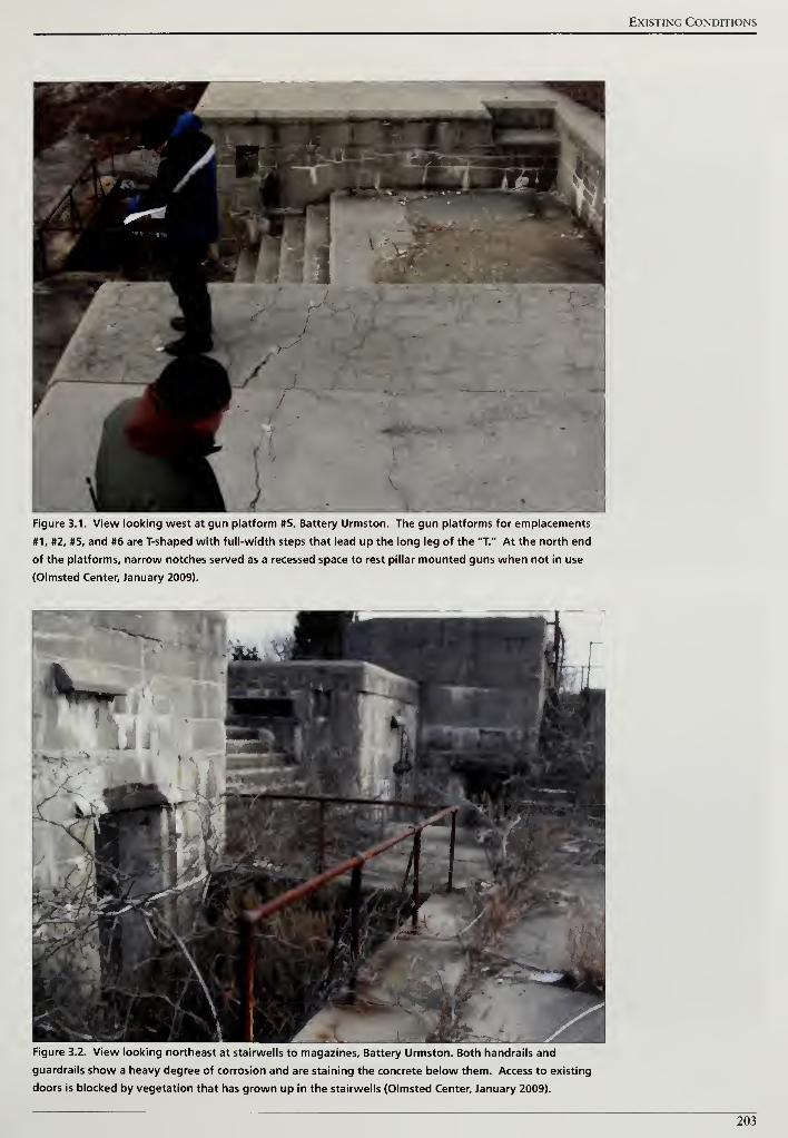
Existing Conditions
Figure 3.1. View looking west at gun platform #5, Battery Urmston. The gun platforms for emplacements
#1, #2, #5, and #6 are T-shaped with full-width steps that lead up the long leg of the "T." At the north end
of the platforms, narrow notches served as a recessed space to rest pillar mounted guns when not in use
(Olmsted Center, January 2009).
Figure 3.2. View looking northeast at stairwells to magazines. Battery Urmston. Both handrails and
guardrails show a heavy degree of corrosion and are staining the concrete below them. Access to existing
doors is blocked by vegetation that has grown up in the stairwells (Olmsted Center, January 2009).
203
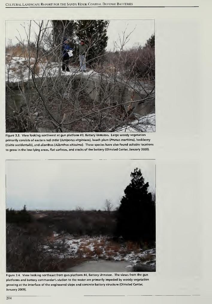
Cultural Landscape Report for the Sandy Hook Coastal Defense Batteries
Figure 3.3. View looking northwest at gun platform #3, Battery Urmston. Large woody vegetation
primarily consists of eastern red cedar (Juniperus virginiana), beach plum (Prunus maritima), hackberry
(Ce/r/s occidentalis). and ailanthus (Ailanthus altissima). These species have also found suitable locations
to grow in the low-lying areas, flat surfaces, and cracks of the battery (Olmsted Center, January 2009).
Figure 3.4. View looking northeast from gun platform #4, Battery Urmston. The views from the gun
platforms and battery commander's station to the water are primarily impeded by woody vegetation
growing at the interface of the engineered slope and concrete battery structure (Olmsted Center,
January 2009).
204
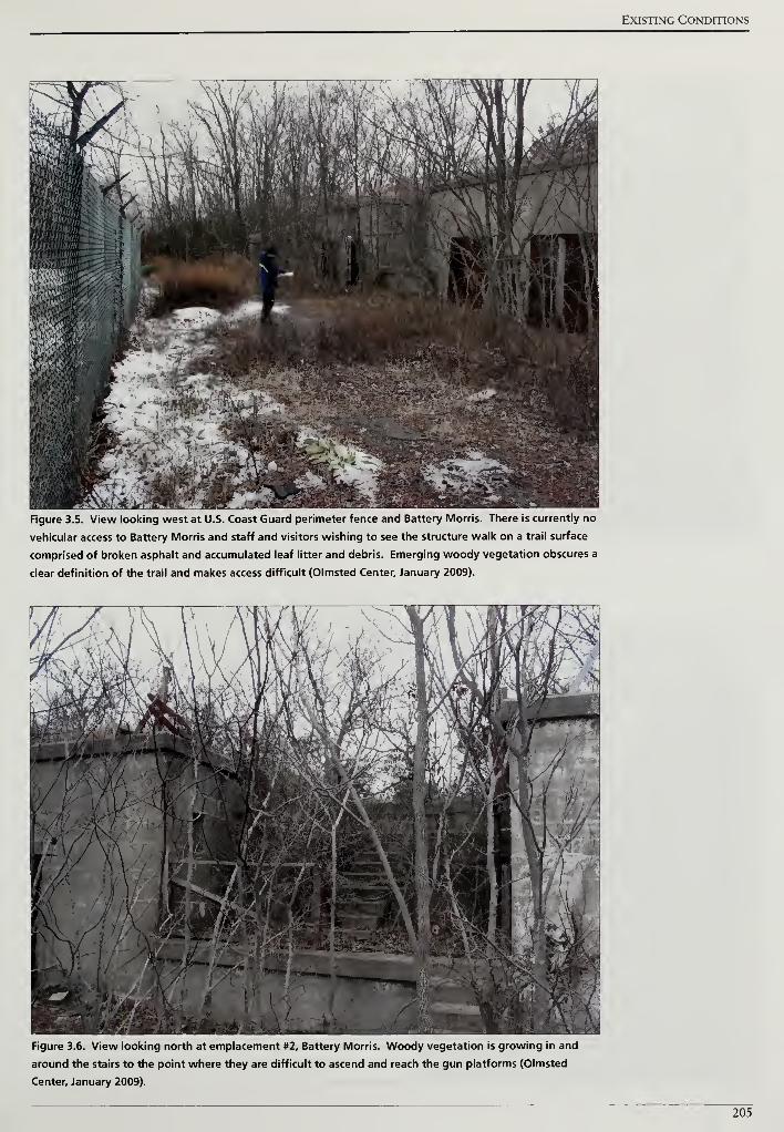
Existing Conditions
Figure 3.5. View looking west at U.S. Coast Guard perimeter fence and Battery Morris. There is currently no
vehicular access to Battery Morris and staff and visitors wishing to see the structure walk on a trail surface
comprised of broken asphalt and accumulated leaf litter and debris. Emerging woody vegetation obscures a
clear definition of the trail and makes access difficult (Olmsted Center, January 2009).
Figure 3.6. View looking north at emplacement #2, Battery Morris. Woody vegetation is growing in and
around the stairs to the point where they are difficult to ascend and reach the gun platforms (Olmsted
Center, January 2009).
205
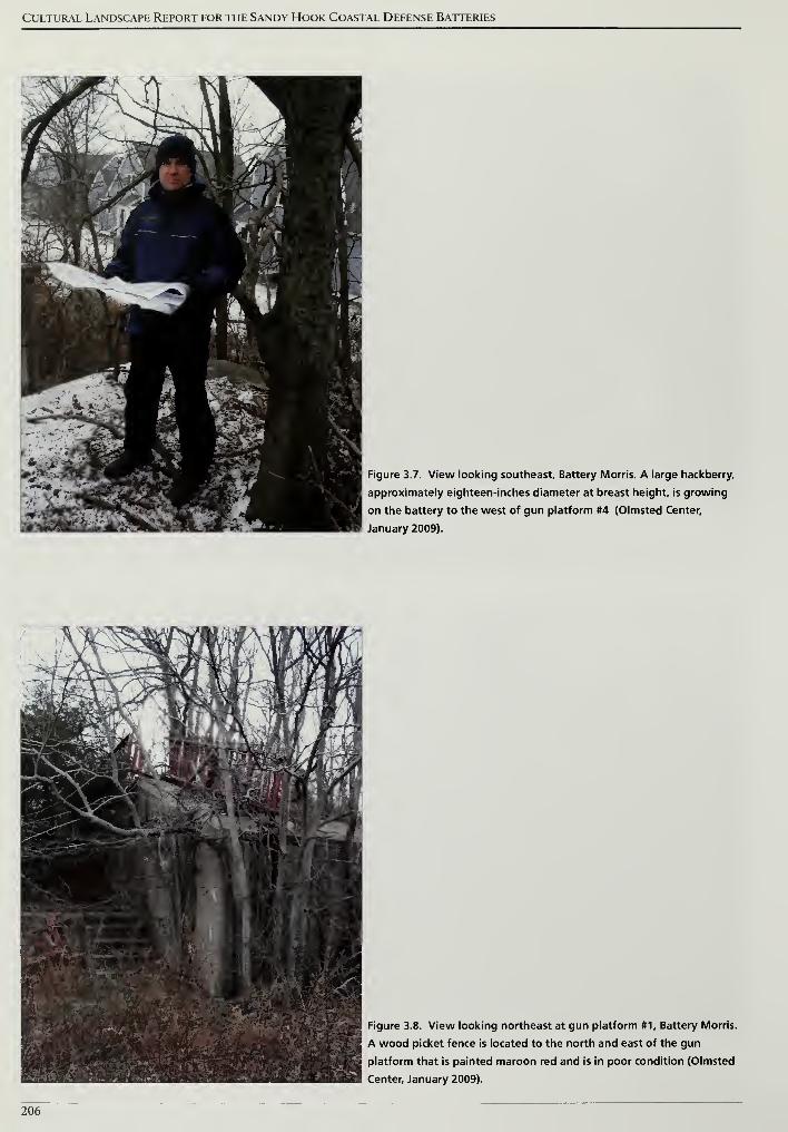
Cultural Landscape Report for the Sandy Hook Coastal Defense Batteries
Figure 3.7. View looking southeast. Battery Morris. A large hackberry,
approximately eighteen-inches diameter at breast height, is growing
on the battery to the west of gun platform #4 (Olmsted Center,
January 2009).
Figure 3.8. View looking northeast at gun platform #1, Battery Morris.
A wood picket fence is located to the north and east of the gun
platform that is painted maroon red and is in poor condition (Olmsted
Center, January 2009).
206
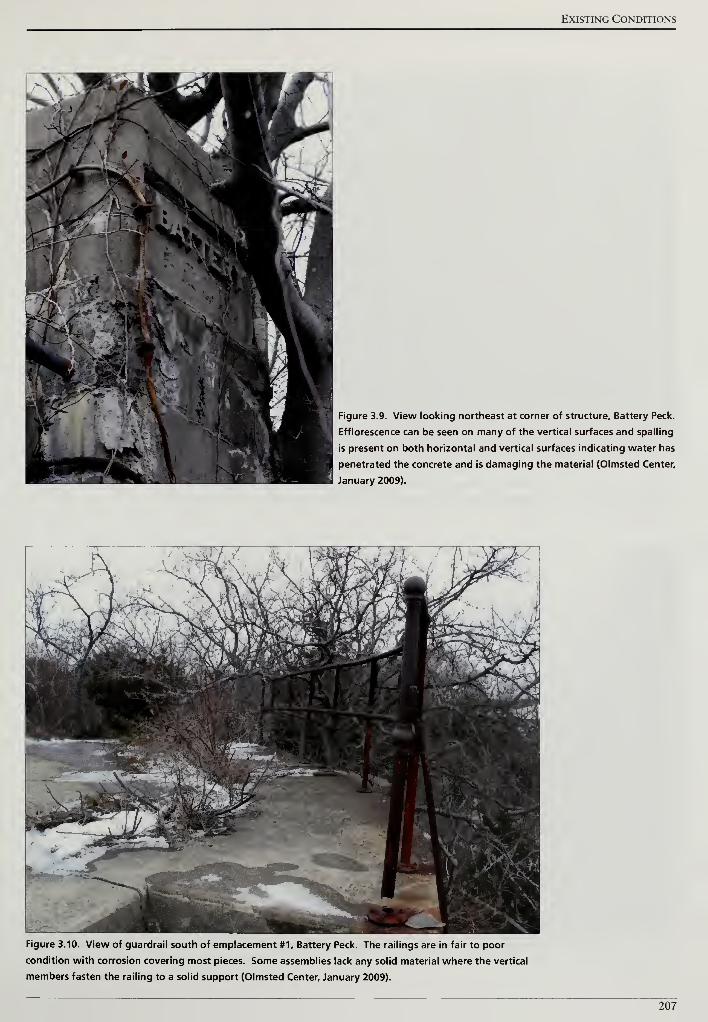
Existing Conditions
Figure 3.9. View looking northeast at corner of structure. Battery Peck.
Efflorescence can be seen on many of the vertical surfaces and spading
is present on both horizontal and vertical surfaces indicating water has
penetrated the concrete and is damaging the material (Olmsted Center,
January 2009).
Figure 3.10. View of guardrail south of emplacement #1, Battery Peck. The railings are in fair to poor
condition with corrosion covering most pieces. Some assemblies lack any solid material where the vertical
members fasten the railing to a solid support (Olmsted Center, January 2009).
207
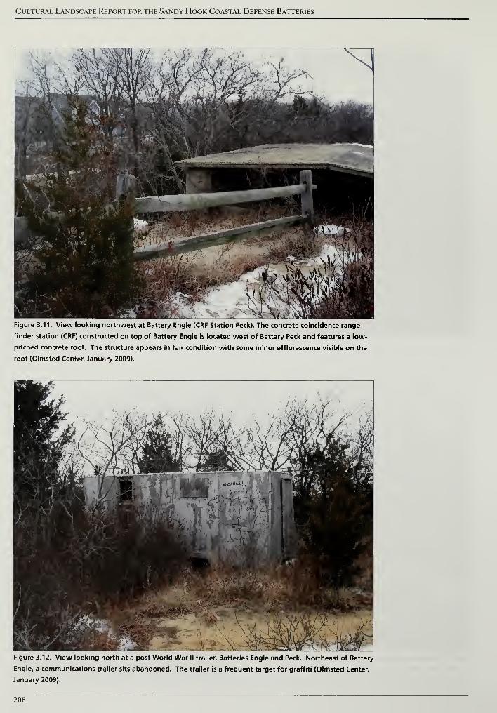
Cultural Landscape Report for the Sandy Hook Coastal Defense Batteries
Figure 3.11. View looking northwest at Battery Engle (CRF Station Peck). The concrete coincidence range
finder station (CRF) constructed on top of Battery Engle is located west of Battery Peck and features a low-
pitched concrete roof. The structure appears in fair condition with some minor efflorescence visible on the
roof (Olmsted Center, January 2009).
Figure 3.12. View looking north at a post World War II trailer. Batteries Engle and Peck. Northeast of Battery
Engle, a communications trailer sits abandoned. The trailer is a frequent target for graffiti (Olmsted Center,
January 2009).
208
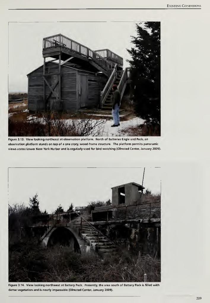
Existing Conditions
Figure 3.13. View looking northeast at observation platform. North of Batteries Engle and Peck, an
observation platform stands on top of a one story, wood-frame structure. The platform permits panoramic
views across Lower New York Harbor and is regularly used for bird watching (Olmsted Center, January 2009).
Figure 3.14. View looking northwest at Battery Peck. Presently, the area south of Battery Peck is filled with
dense vegetation and is nearly impassable (Olmsted Center, January 2009).
209
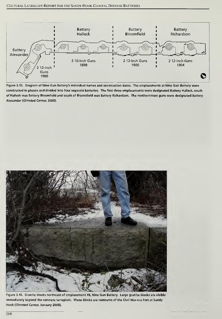
Cultural Landscape Report for the Sandy Hook Coastal Defense Batteries
Battery /
Alexander/
/ (on
JojJ~\_
I
l
I
Battery
Halleck
Battery
i Bloomfield
Battery
Richardson
]_J^i J^r,
-pO/
r-^(oVr
^° f^f@h r*
/ 2 12-inch
Guns1900
l
l
l
I
u
3 10-inch Guns1898
T-T_a„-J.;Qkj—. r^-
2 12-inch Guns
, 1900
2 12-inch Guns1904
©Figure 3.15. Diagram of Nine Gun Battery's individual names and construction dates. The emplacements at Nine Gun Battery were
constructed in phases and divided into four separate batteries. The first three emplacements were designated Battery Halleck, south
of Halleck was Battery Bloomfield and south of Bloomfield was Battery Richardson. The northernmost guns were designated Battery
Alexander (Olmsted Center, 2009).
Figure 3.16. Granite blocks northeast of emplacement #8, Nine Gun Battery. Large granite blocks are visible
immediately beyond the concrete terreplein. These blocks are remnants of the Civil War-era Fort at Sandy
Hook (Olmsted Center, January 2009).
210
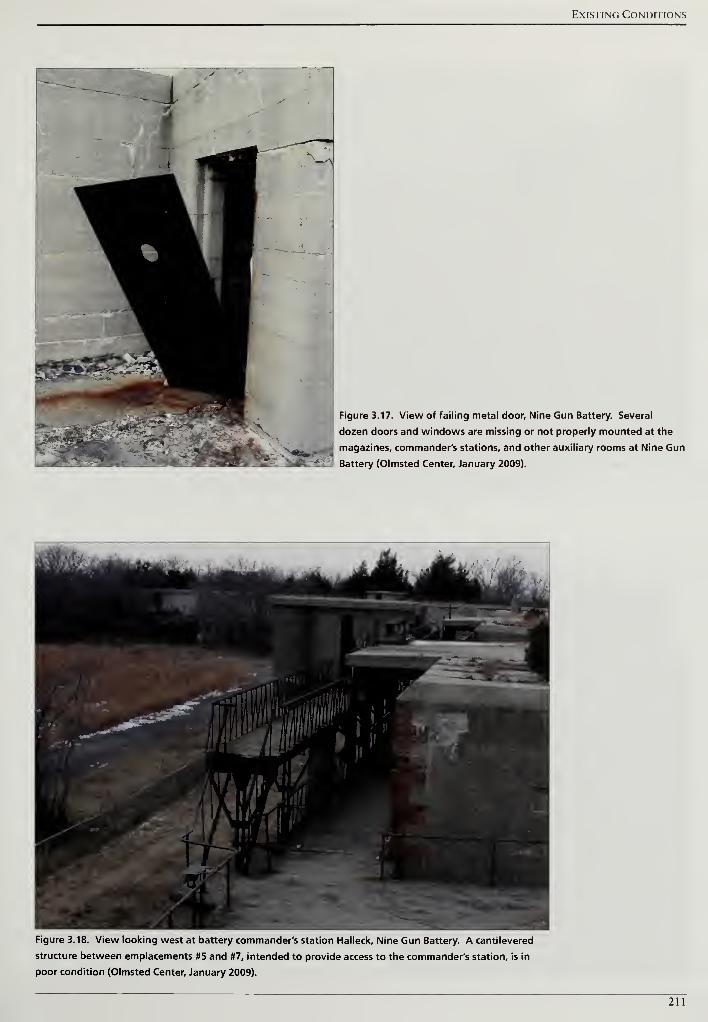
Existing Conditions
Figure 3.17. View of failing metal door. Nine Gun Battery. Several
dozen doors and windows are missing or not properly mounted at the
magazines, commander's stations, and other auxiliary rooms at Nine Gun
Battery (Olmsted Center, January 2009).
Figure 3.18. View looking west at battery commander's station Halleck, Nine Gun Battery. A cantilevered
structure between emplacements #5 and #7, intended to provide access to the commander's station, is in
poor condition (Olmsted Center, January 2009).
211
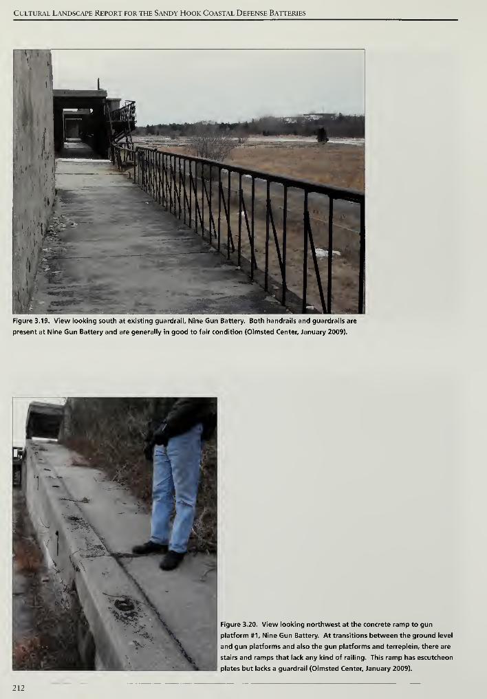
Cultural Landscape Report for the Sandy Hook Coastal Defense Batteries
Figure 3.19. View looking south at existing guardrail. Nine Gun Battery. Both handrails and guardrails are
present at Nine Gun Battery and are generally in good to fair condition (Olmsted Center, January 2009).
Figure 3.20. View looking northwest at the concrete ramp to gun
platform #1, Nine Gun Battery. At transitions between the ground level
and gun platforms and also the gun platforms and terreplein, there are
stairs and ramps that lack any kind of railing. This ramp has escutcheon
plates but lacks a guardrail (Olmsted Center, January 2009).
212
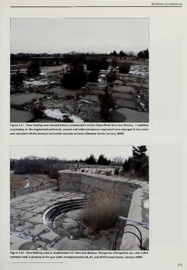
Existing Conditions
Figure 3.21. View looking west toward battery commander's station Bloomfield, Nine Gun Battery. In addition
to growing on the engineered earthwork, eastern red cedars {Juniperus virginiana) have emerged in the cracks
and cold joints of the battery's horizontal concrete surfaces (Olmsted Center, January 2009).
Figure 3.22. View looking west at emplacement #7, Nine Gun Battery. Phragmites {Phragmites sp.), also called
common reed, is growing in the gun wells at emplacements #6, #7, and #9 (Olmsted Center, January 2009).
213
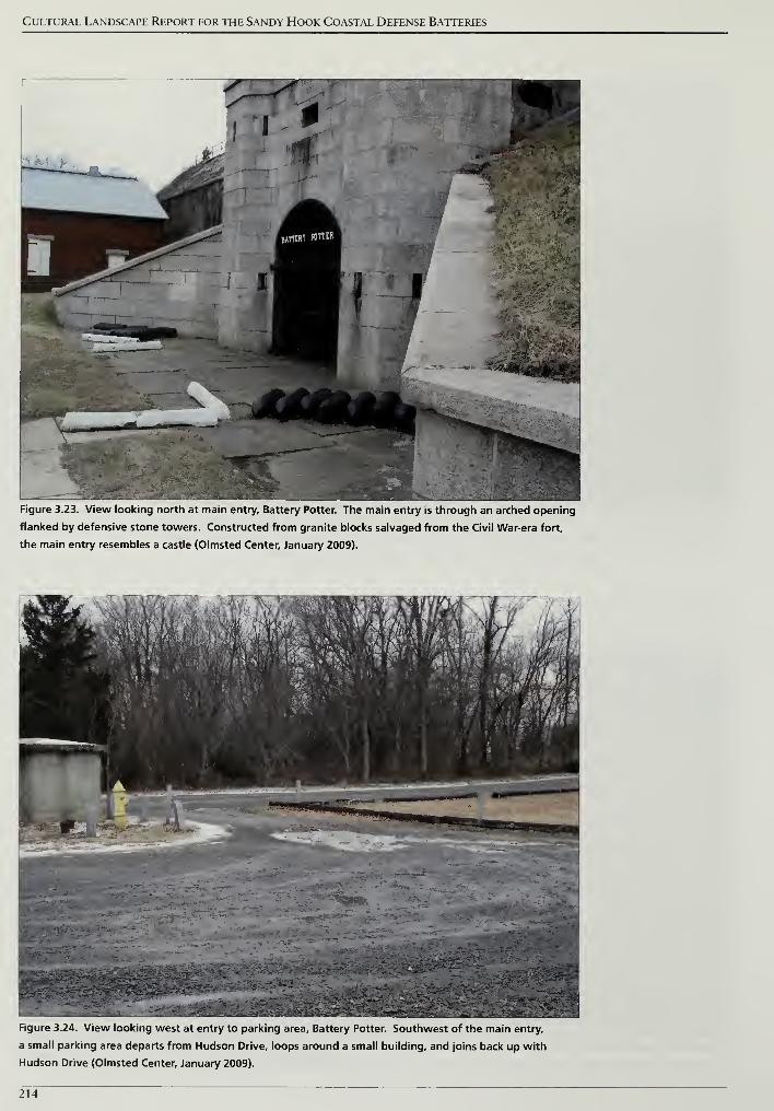
Cultural Landscape Report for the Sandy Hook Coastal Defense Batteries
Figure 3.23. View looking north at main entry. Battery Potter. The main entry is through an arched opening
flanked by defensive stone towers. Constructed from granite blocks salvaged from the Civil War-era fort,
the main entry resembles a castle (Olmsted Center, January 2009).
Figure 3.24. View looking west at entry to parking area. Battery Potter. Southwest of the main entry,
a small parking area departs from Hudson Drive, loops around a small building, and joins back up with
Hudson Drive (Olmsted Center, January 2009).
214
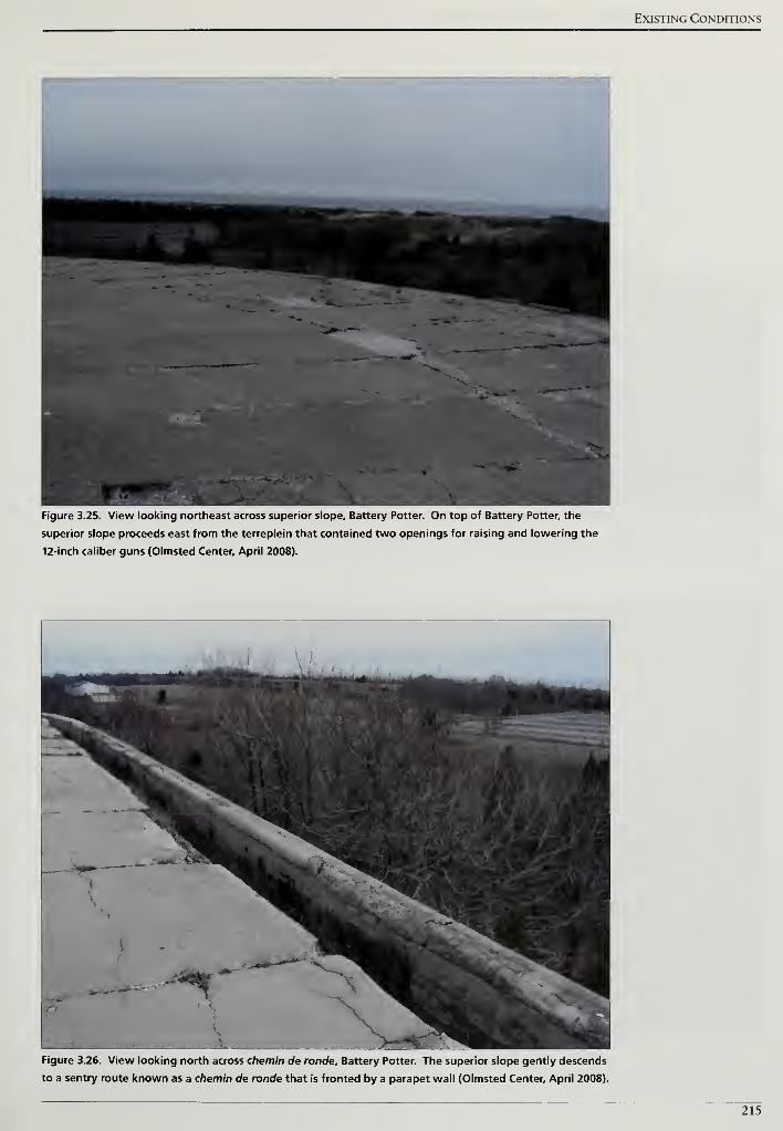
Existing Conditions
Figure 3.25. View looking northeast across superior slope. Battery Potter. On top of Battery Potter, the
superior slope proceeds east from the terreplein that contained two openings for raising and lowering the
12-inch caliber guns (Olmsted Center, April 2008).
Figure 3.26. View looking north across chemin de ronde. Battery Potter. The superior slope gently descends
to a sentry route known as a chemin de ronde that is fronted by a parapet wall (Olmsted Center, April 2008).
215
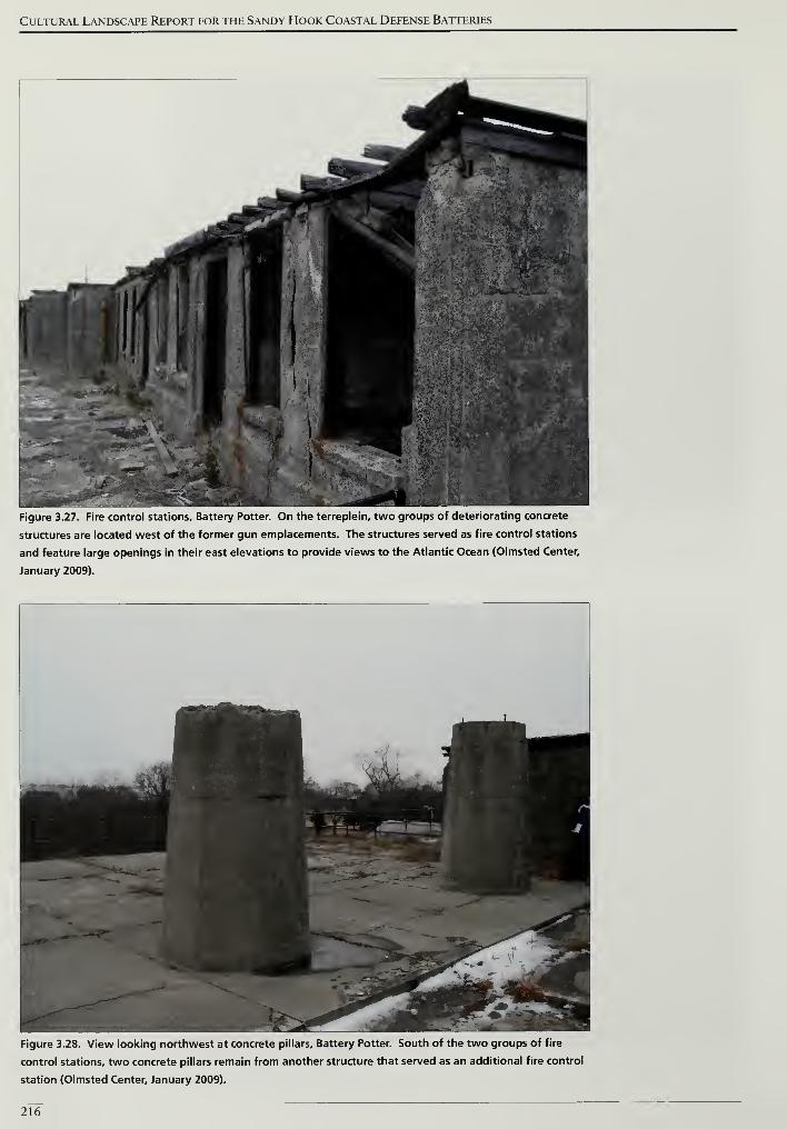
Cultural Landscape Report for the Sandy Hook Coastal Defense Batteries
Figure 3.27. Fire control stations. Battery Potter. On the terreplein, two groups of deteriorating concrete
structures are located west of the former gun emplacements. The structures served as fire control stations
and feature large openings in their east elevations to provide views to the Atlantic Ocean (Olmsted Center,
January 2009).
Figure 3.28. View looking northwest at concrete pillars. Battery Potter. South of the two groups of fire
control stations, two concrete pillars remain from another structure that served as an additional fire control
station (Olmsted Center, January 2009).
216
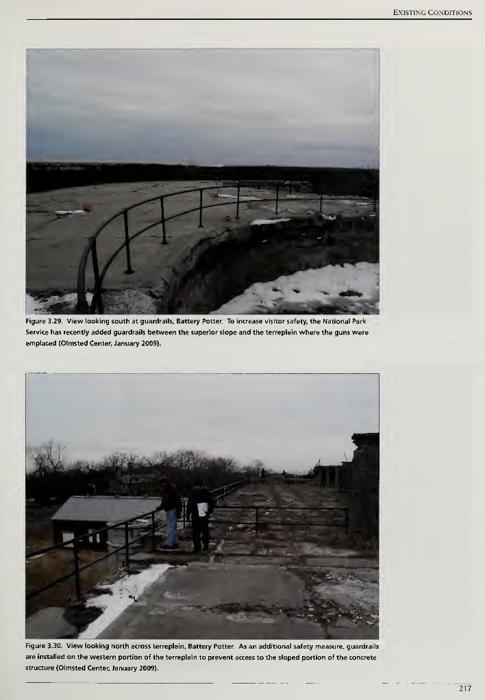
Existing Conditions
Figure 3.29. View looking south at guardrails. Battery Potter. To increase visitor safety, the National Park
Service has recently added guardrails between the superior slope and the terreplein where the guns were
emplaced (Olmsted Center, January 2009).
Figure 3.30. View looking north across terreplein. Battery Potter. As an additional safety measure, guardrails
are installed on the western portion of the terreplein to prevent access to the sloped portion of the concrete
structure (Olmsted Center, January 2009).
217
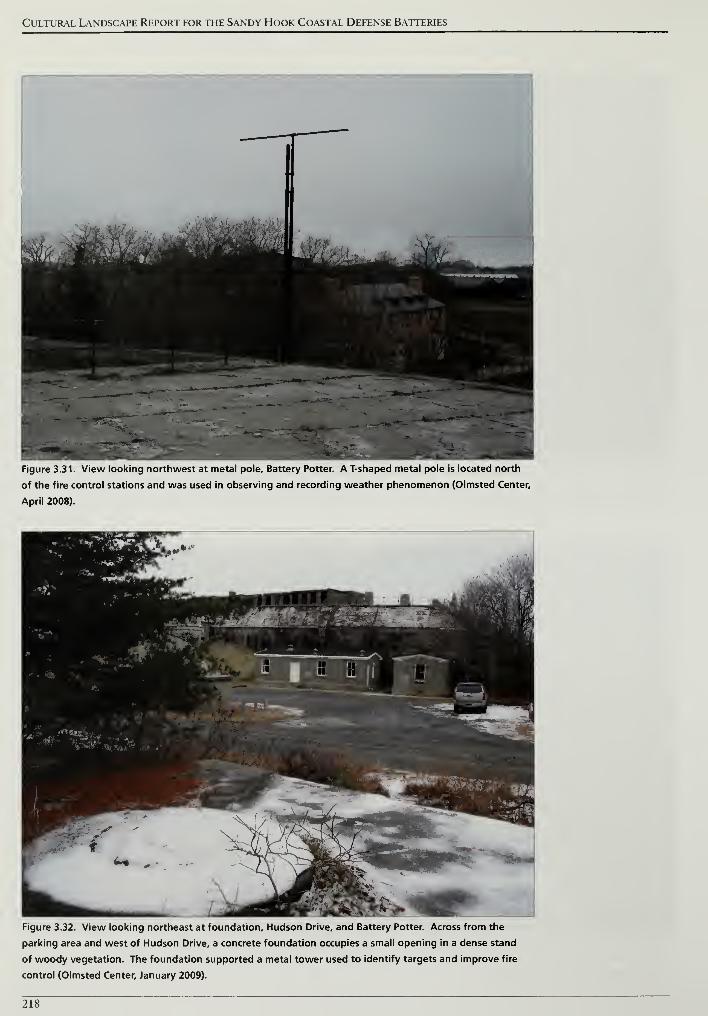
Cultural Landscape Report for the Sandy Hook Coastal Defense Batteries
Figure 3.31. View looking northwest at metal pole. Battery Potter. A T-shaped metal pole is located north
of the fire control stations and was used in observing and recording weather phenomenon (Olmsted Center,
April 2008).
Figure 3.32. View looking northeast at foundation, Hudson Drive, and Battery Potter. Across from the
parking area and west of Hudson Drive, a concrete foundation occupies a small opening in a dense stand
of woody vegetation. The foundation supported a metal tower used to identify targets and improve fire
control (Olmsted Center, January 2009).
218
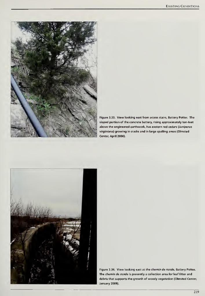
Existing Conditions
Figure 3.33. View looking east from access stairs. Battery Potter. The
sloped portion of the concrete battery, rising approximately ten-feet
above the engineered earthwork, has eastern red cedars (Juniperus
virginiana) growing in cracks and in large spalling areas (Olmsted
Center, April 2008).
- ...
;.-
* v*I 'Figure 3.34. View looking east at the chemin de ronde, Battery Potter.
The chemin de ronde is presently a collection area for leaf litter and
debris that supports the growth of woody vegetation (Olmsted Center,
January 2009).
219
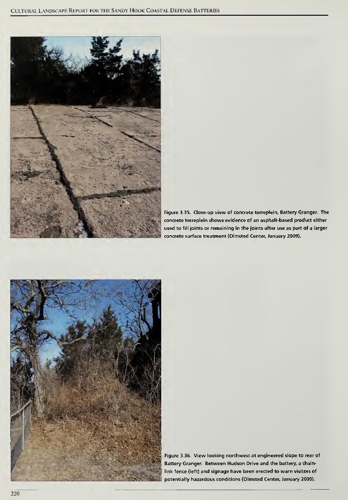
Cultural Landscape Report for the Sandy Hook Coastal Defense Batteries
Figure 3.35. Close-up view of concrete terreplein. Battery Granger. The
concrete terreplein shows evidence of an asphalt-based product either
used to fill joints or remaining in the joints after use as part of a larger
concrete surface treatment (Olmsted Center, January 2009).
r
Figure 3.36. View looking northwest at engineered slope to rear of
Battery Granger. Between Hudson Drive and the battery, a chain-
link fence (left) and signage have been erected to warn visitors of
potentially hazardous conditions (Olmsted Center, January 2009).
220
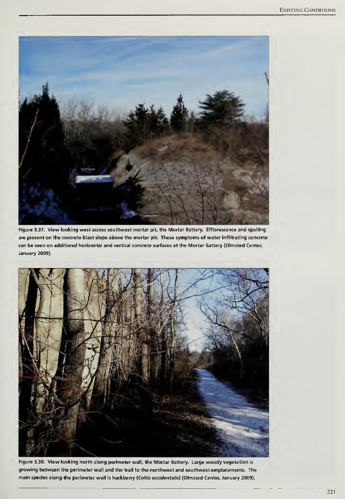
Existing Conditions
Figure 3.37. View looking west across southwest mortar pit, the Mortar Battery. Efflorescence and spalling
are present on the concrete blast slope above the mortar pit. These symptoms of water infiltrating concrete
can be seen on additional horizontal and vertical concrete surfaces at the Mortar Battery (Olmsted Center,
January 2009).
Figure 3.38. View looking north along perimeter wall, the Mortar Battery. Large woody vegetation is
growing between the perimeter wall and the trail to the northwest and southwest emplacements. The
main species along the perimeter wall is hackberry (Celtis occidentalis) (Olmsted Center, January 2009).
221
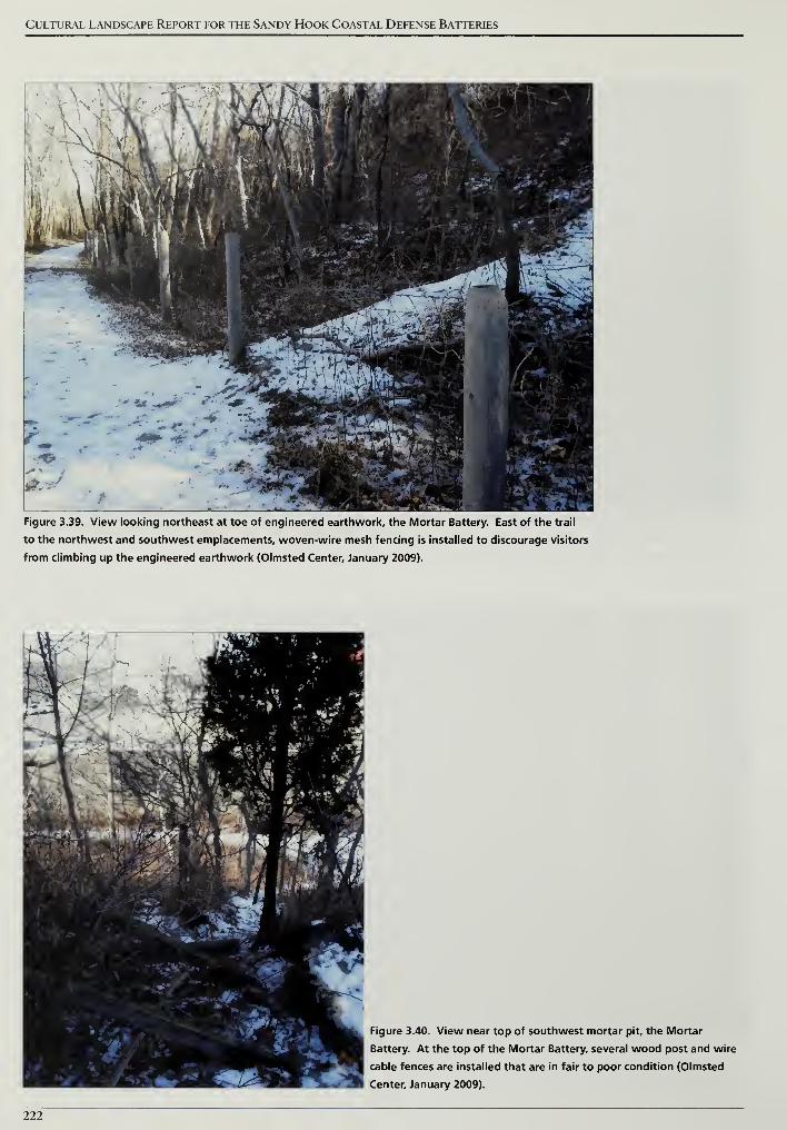
Cultural Landscape Report for the Sandy Hook Coastal Defense Batteries
Figure 3.39. View looking northeast at toe of engineered earthwork, the Mortar Battery. East of the trail
to the northwest and southwest emplacements, woven-wire mesh fencing is installed to discourage visitors
from climbing up the engineered earthwork (Olmsted Center, January 2009).
Figure 3.40. View near top of southwest mortar pit, the Mortar
Battery. At the top of the Mortar Battery, several wood post and wire
cable fences are installed that are in fair to poor condition (Olmsted
Center, January 2009).
222
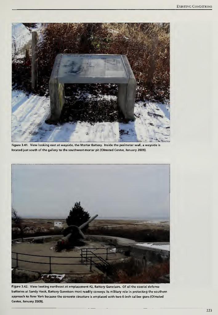
Existing Conditions
Figure 3.41. View looking east at wayside, the Mortar Battery. Inside the perimeter wall, a wayside is
located just south of the gallery to the southwest mortar pit (Olmsted Center, January 2009).
Figure 3.42. View looking northeast at emplacement #2, Battery Gunnison. Of all the coastal defense
batteries at Sandy Hook, Battery Gunnison most readily conveys its military role in protecting the southern
approach to New York because the concrete structure is emplaced with two 6-inch caliber guns (Olmsted
Center, January 2009).
223
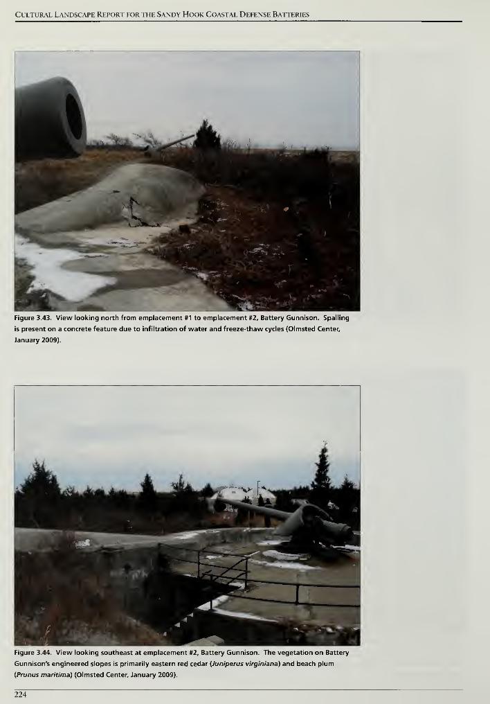
Cultural Landscape Report for the Sandy Hook Coastal Defense Batteries
Figure 3.43. View looking north from emplacement #1 to emplacement #2, Battery Gunnison. Spalling
is present on a concrete feature due to infiltration of water and freeze-thaw cycles (Olmsted Center,
January 2009).
Figure 3.44. View looking southeast at emplacement #2, Battery Gunnison. The vegetation on Battery
Gunnison's engineered slopes is primarily eastern red cedar (Juniperus virginiana) and beach plum
(Prunus maritima) (Olmsted Center, January 2009).
224
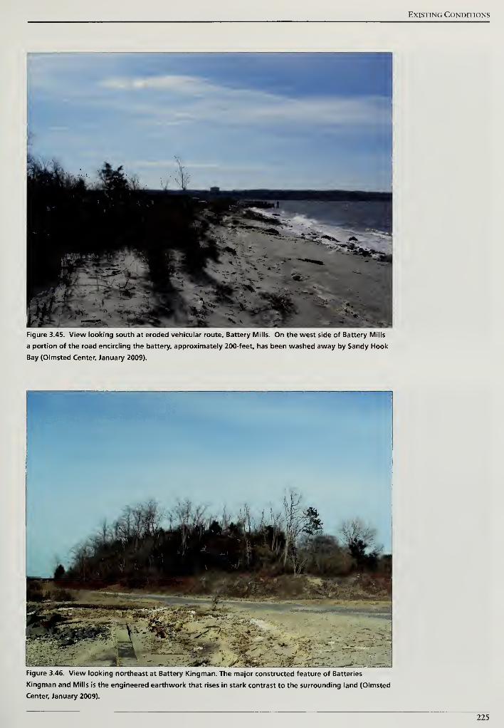
Existing Conditions
Figure 3.45. View looking south at eroded vehicular route, Battery Mills. On the west side of Battery Mills
a portion of the road encircling the battery, approximately 200-feet, has been washed away by Sandy Hook
Bay (Olmsted Center, January 2009).
Figure 3.46. View looking northeast at Battery Kingman. The major constructed feature of Batteries
Kingman and Mills is the engineered earthwork that rises in stark contrast to the surrounding land (Olmsted
Center, January 2009).
225
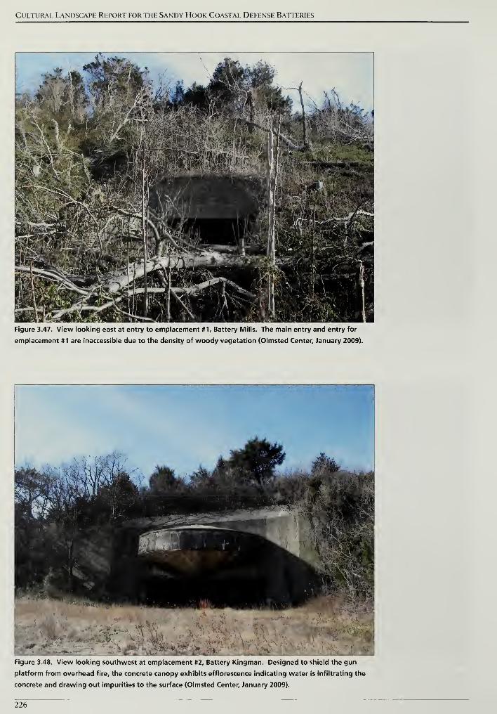
Cultural Landscape Report for the Sandy Hook Coastal Defense Batteries
Figure 3.47. View looking east at entry to emplacement #1, Battery Mills. The main entry and entry for
emplacement #1 are inaccessible due to the density of woody vegetation (Olmsted Center, January 2009).
Figure 3.48. View looking southwest at emplacement #2, Battery Kingman. Designed to shield the gun
platform from overhead fire, the concrete canopy exhibits efflorescence indicating water is infiltrating the
concrete and drawing out impurities to the surface (Olmsted Center, January 2009).
226
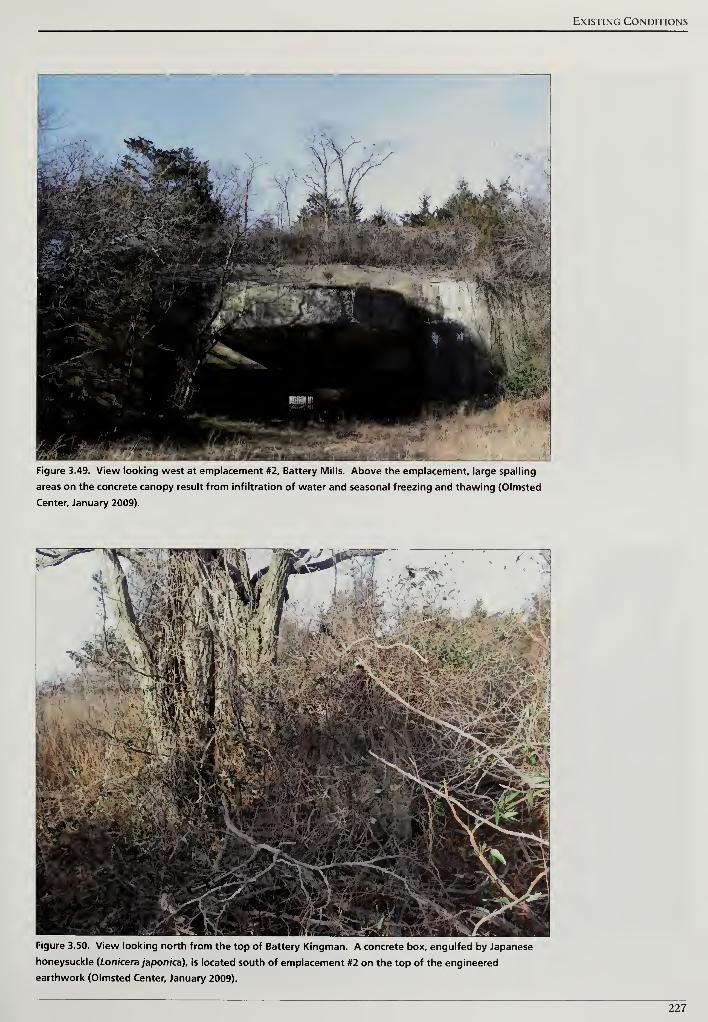
Existing Conditions
Figure 3.49. View looking west at emplacement #2, Battery Mills. Above the emplacement, large spalling
areas on the concrete canopy result from infiltration of water and seasonal freezing and thawing (Olmsted
Center, January 2009).
Figure 3.50. View looking north from the top of Battery Kingman. A concrete box, engulfed by Japanese
honeysuckle (Lonicera japonica), is located south of emplacement #2 on the top of the engineered
earthwork (Olmsted Center, January 2009).
227
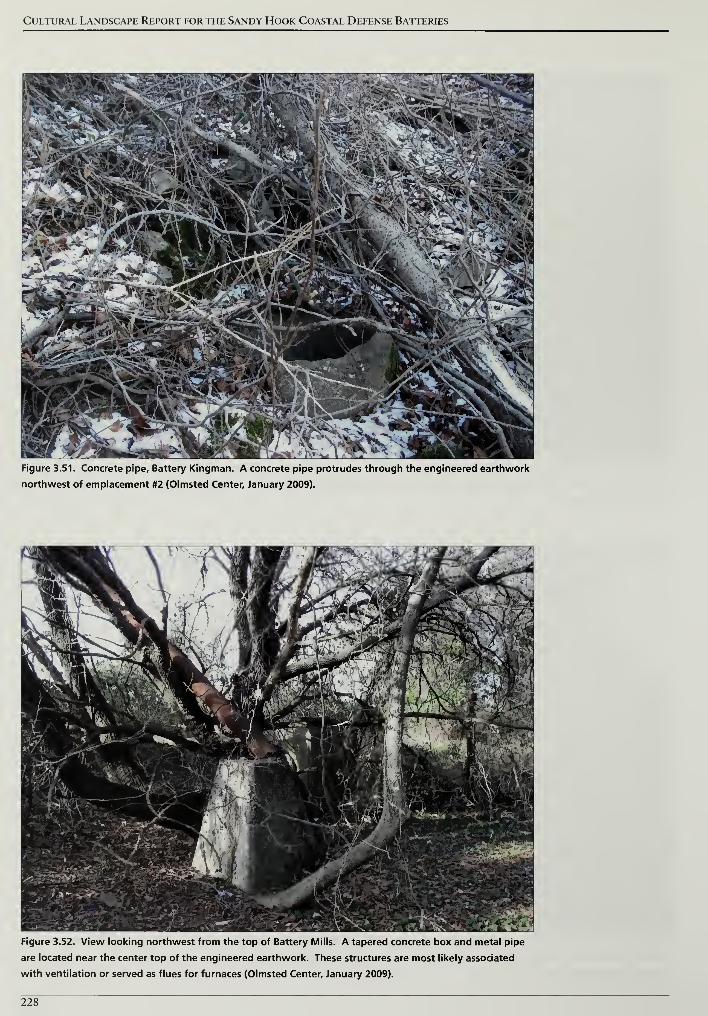
Cultural Landscape Report for the Sandy Hook Coastal Defense Batteries
Figure 3.51. Concrete pipe. Battery Kingman. A concrete pipe protrudes through the engineered earthwork
northwest of emplacement #2 (Olmsted Center, January 2009).
Figure 3.52. View looking northwest from the top of Battery Mills. A tapered concrete box and metal pipe
are located near the center top of the engineered earthwork. These structures are most likely associated
with ventilation or served as flues for furnaces (Olmsted Center, January 2009).
228
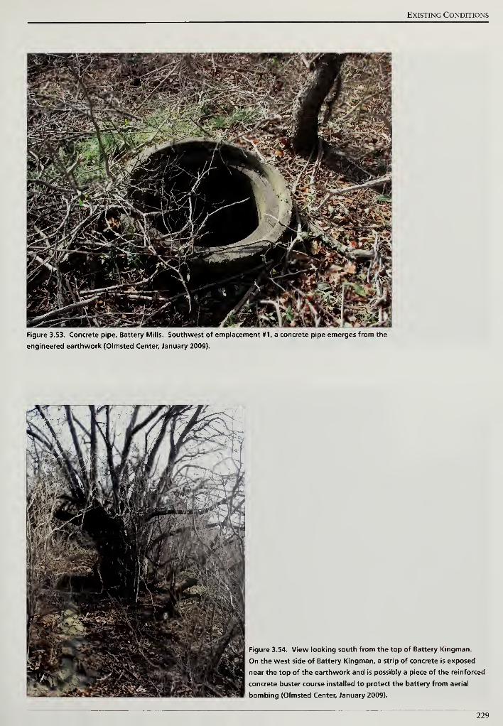
Existing Conditions
Figure 3.53. Concrete pipe. Battery Mills. Southwest of emplacement #1, a concrete pipe emerges from the
engineered earthwork (Olmsted Center, January 2009).
Figure 3.54. View looking south from the top of Battery Kingman.
On the west side of Battery Kingman, a strip of concrete is exposed
near the top of the earthwork and is possibly a piece of the reinforced
concrete buster course installed to protect the battery from aerial
bombing (Olmsted Center, January 2009).
229
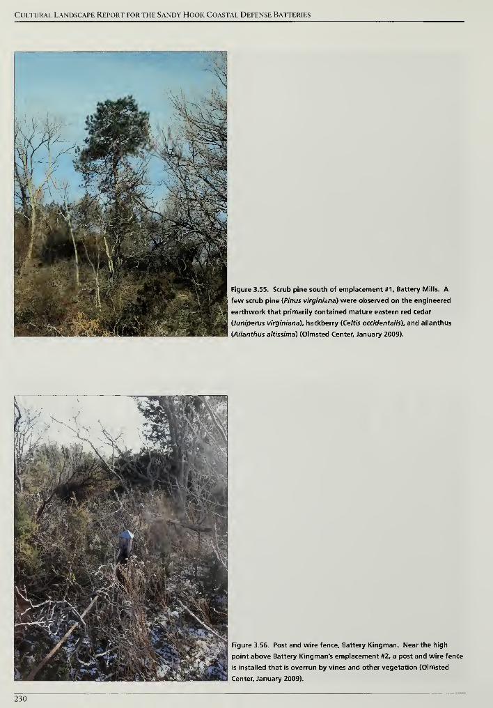
Cultural Landscape Report for the Sandy Hook Coastal Defense Batteries
Figure 3.55. Scrub pine south of emplacement #1, Battery Mills. A
few scrub pine {Pinus virginiana) were observed on the engineered
earthwork that primarily contained mature eastern red cedar
(Juniperus virginiana), hackberry {Celtis occidentalis), and ailanthus
(Ailanthus altissima) (Olmsted Center, January 2009).
Figure 3.56. Post and wire fence. Battery Kingman. Near the high
point above Battery Kingman's emplacement #2, a post and wire fence
is installed that is overrun by vines and other vegetation (Olmsted
Center, January 2009).
230
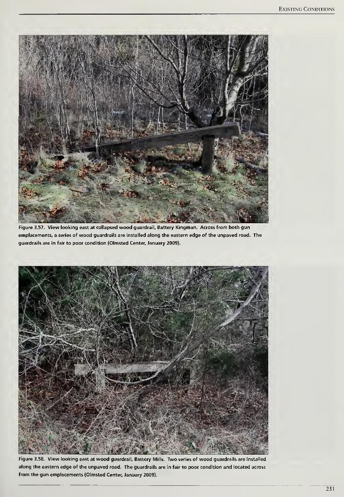
Existing Conditions
Figure 3.57. View looking east at collapsed wood guardrail. Battery Kingman. Across from both gun
emplacements, a series of wood guardrails are installed along the eastern edge of the unpaved road. The
guardrails are in fair to poor condition (Olmsted Center, January 2009).
*&&£.®ffiacM wm-0Figure 3.58. View looking east at wood guardrail. Battery Mills. Two series of wood guardrails are installed
along the eastern edge of the unpaved road. The guardrails are in fair to poor condition and located across
from the gun emplacements (Olmsted Center, January 2009).
231
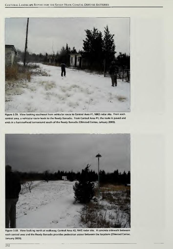
Cultural Landscape Report for the Sandy Hook Coastal Defense Batteries
Figure 3.59. View looking southeast from vehicular route to Control Area #1, NIKE radar site. From each
control area, a vehicular route leads to the Ready Barracks. From Control Area #1, the route is paved and
ends in a hammerhead turnaround south of the Ready Barracks (Olmsted Center, January 2009).
Figure 3.60. View looking north at walkway. Control Area #2, NIKE radar site. A concrete sidewalk between
each control area and the Ready Barracks provides pedestrian access between the locations (Olmsted Center,
January 2009).
232
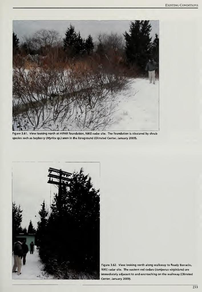
Existing Conditions
*w*.r f ?
wt J mfw V ^1
• »J
'
At'"''
''
,
,:gV\
..
.
wife,- '''2v;
-\^'Sfefc .vSH&j^^w
1 m" If 1 '
*
k&L
$0$*^£&**$fe IM yj Xg*-\
driJr I* < J Xi'lzJhPvly»wJ/<*&fj f -
47r
7
; -VH-f- ly$S W-'
A
f/ <iy
t/ .a" jyiv ^lJ> 1^ a rw m «fePFigure 3.61. View looking north at HIPAR foundation, NIKE radar site. The foundation is obscured by shrub
species such as bayberry (Myrica sp.) seen in the foreground (Olmsted Center, January 2009).
Figure 3.62. View looking north along walkway to Ready Barracks,
NIKE radar site. The eastern red cedars (Juniperus virginiana) are
immediately adjacent to and encroaching on the walkway (Olmsted
Center, January 2009).
233
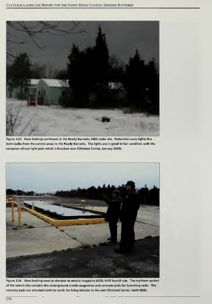
Cultural Landscape Report for the Sandy Hook Coastal Defense Batteries
Figure 3.63. View looking northwest at the Ready Barracks, NIKE radar site. Pedestrian-scale lights line
both walks from the control areas to the Ready Barracks. The lights are in good to fair condition with the
exception of one light pole which is knocked over (Olmsted Center, January 2009).
Figure 3.64. View looking west at elevator to missile magazine (425), NIKE launch site. The northern section
of the launch site contains the underground missile magazines and concrete pads for launching racks. The
concrete pads are oriented north to south for firing missiles to the east (Olmsted Center, April 2008).
234
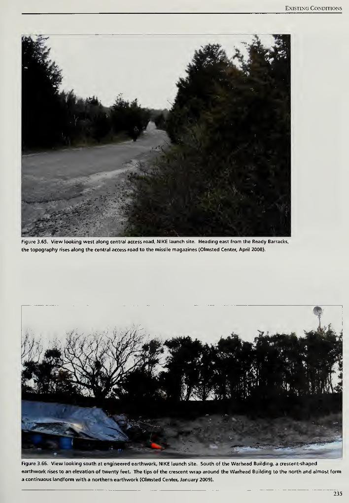
Existing Conditions
Figure 3.65. View looking west along central access road, NIKE launch site. Heading east from the Ready Barracks,
the topography rises along the central access road to the missile magazines (Olmsted Center, April 2008).
Figure 3.66. View looking south at engineered earthwork, NIKE launch site. South of the Warhead Building, a crescent-shaped
earthwork rises to an elevation of twenty feet. The tips of the crescent wrap around the Warhead Building to the north and almost form
a continuous landform with a northern earthwork (Olmsted Center, January 2009).
235
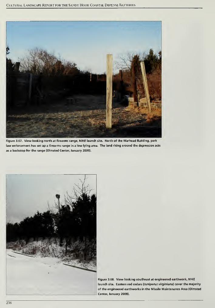
Cultural Landscape Report for the Sandy Hook Coastal Defense Batteries
Figure 3.67. View looking north at firearms range, NIKE launch site. North of the Warhead Building, park
law enforcement has set up a firearms range in a low lying area. The land rising around the depression acts
as a backstop for the range (Olmsted Center, January 2009).
Figure 3.68. View looking southeast at engineered earthwork, NIKE
launch site. Eastern red cedars (Juniperus virginiana) cover the majority
of the engineered earthworks in the Missile Maintenance Area (Olmsted
Center, January 2009).
236
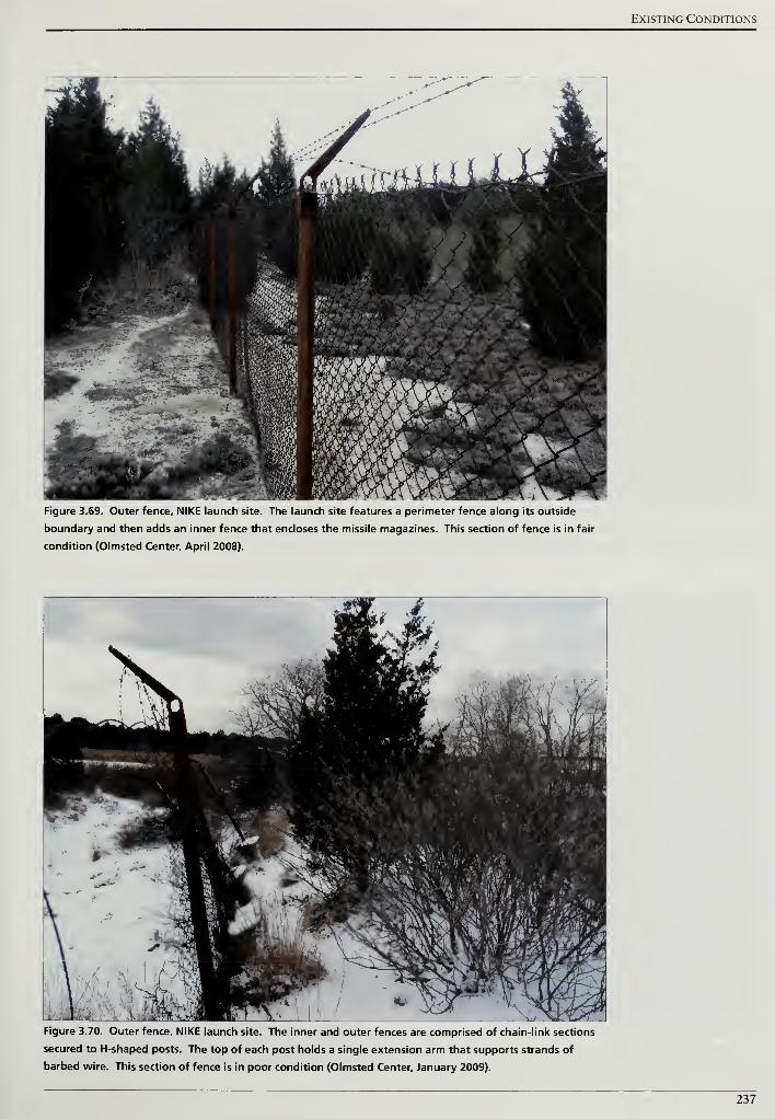
Existing Conditions
-' Bl ^ 4hk' 1
-••' ^^^"^ JL
i
1•
n IB" 7 TJH
MPiftt ir ,aB•w ,,
1**
Mm- an
••tf*4«-»a»'SKK'Mlf5aKi^ '• -u
Figure 3.69. Outer fence, NIKE launch site. The launch site features a perimeter fence along its outside
boundary and then adds an inner fence that encloses the missile magazines. This section of fence is in fair
condition (Olmsted Center, April 2008).
Figure 3.70. Outer fence, NIKE launch site. The inner and outer fences are comprised of chain-link sections
secured to H-shaped posts. The top of each post holds a single extension arm that supports strands of
barbed wire. This section of fence is in poor condition (Olmsted Center, January 2009).
237
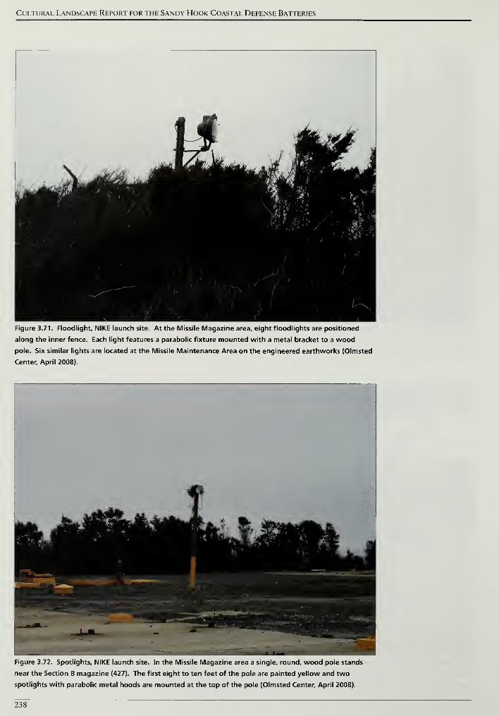
Cultural Landscape Report for the Sandy Hook Coastal Defense Batteries
„u|yjr m
dBj&gf 4^rte"
'ib/'La < '<tfi
•» '- 1W '' F^W I' '
-^T *
I'J&i MrFffWmim % ''
1, 1;•/»;"* <>•'' '
^1 • 5*'» *%:'
.•' f .. f»< <
M$ '- » '•A 3
' at
v
.
'
/
/
,
1
)
fck
Figure 3.71. Floodlight, NIKE launch site. At the Missile Magazine area, eight floodlights are positioned
along the inner fence. Each light features a parabolic fixture mounted with a metal bracket to a wood
pole. Six similar lights are located at the Missile Maintenance Area on the engineered earthworks (Olmsted
Center, April 2008).
Figure 3.72. Spotlights, NIKE launch site. In the Missile Magazine area a single, round, wood pole stands
near the Section B magazine (427). The first eight to ten feet of the pole are painted yellow and two
spotlights with parabolic metal hoods are mounted at the top of the pole (Olmsted Center, April 2008).
238
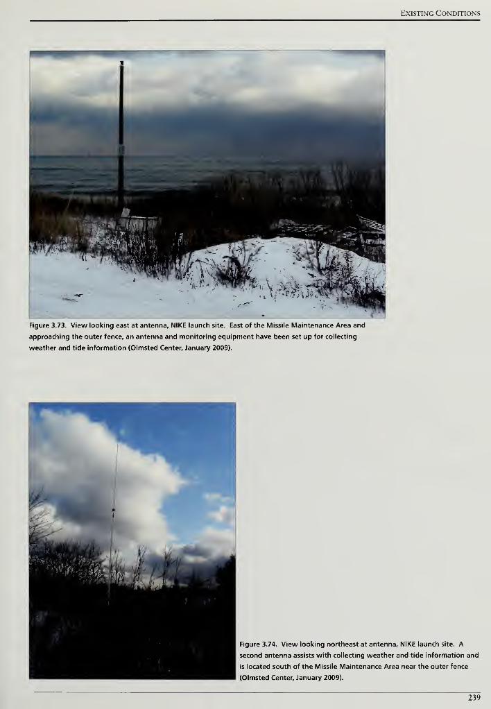
Existing Conditions
—
.
__
Figure 3.73. View looking east at antenna, NIKE launch site. East of the Missile Maintenance Area and
approaching the outer fence, an antenna and monitoring equipment have been set up for collecting
weather and tide information (Olmsted Center, January 2009).
Figure 3.74. View looking northeast at antenna, NIKE launch site. A
second antenna assists with collecting weather and tide information and
is located south of the Missile Maintenance Area near the outer fence
(Olmsted Center, January 2009).
239

Cultural Landscape Report for the Sandy Hook Coastal Defense Batteries
240
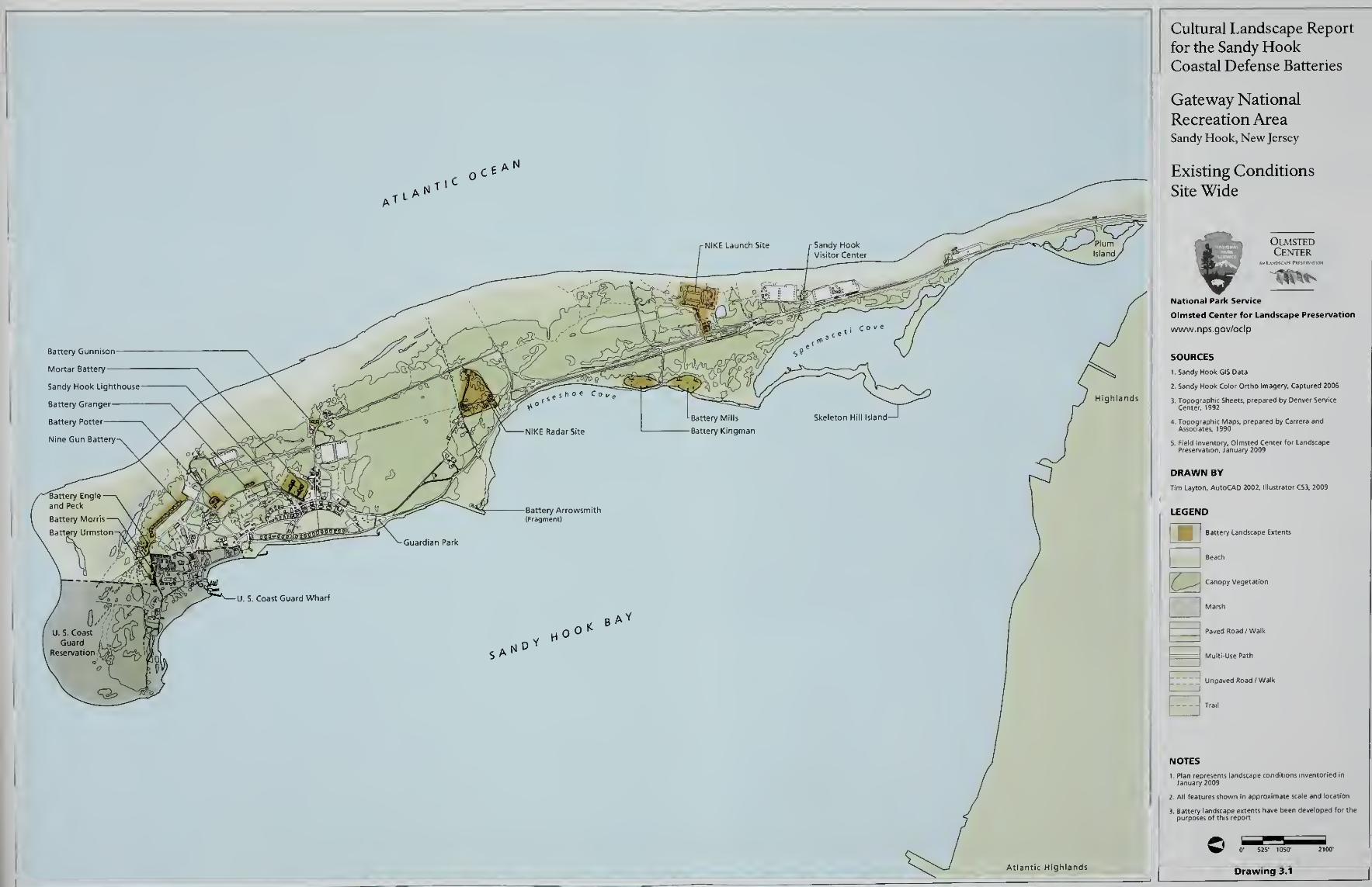
Cultural Landscape Report
for the Sandy HookCoastal Defense Batteries
Gateway National
Recreation AreaSandy Hook, New Jersey
Existing Conditions
Site Wide
OlmstedCenter
National Park Service
Olmsted Center for Landscape Preservation
www.nps.gov/oclp
SOURCES
I.Sandy Hook GIS Data
2. Sandy Hook Color Ortho Imagery, Captured 2006
DRAWN BY
Tim Layton, AutoCAD 2002, Illustrator CS3, 2009
LEGEND
I Battery Landscape Extents
'
Paved Road /Walk
Multi-Use Path
Unpaved Road /Walk
H-
II features shown in approximate scale and location
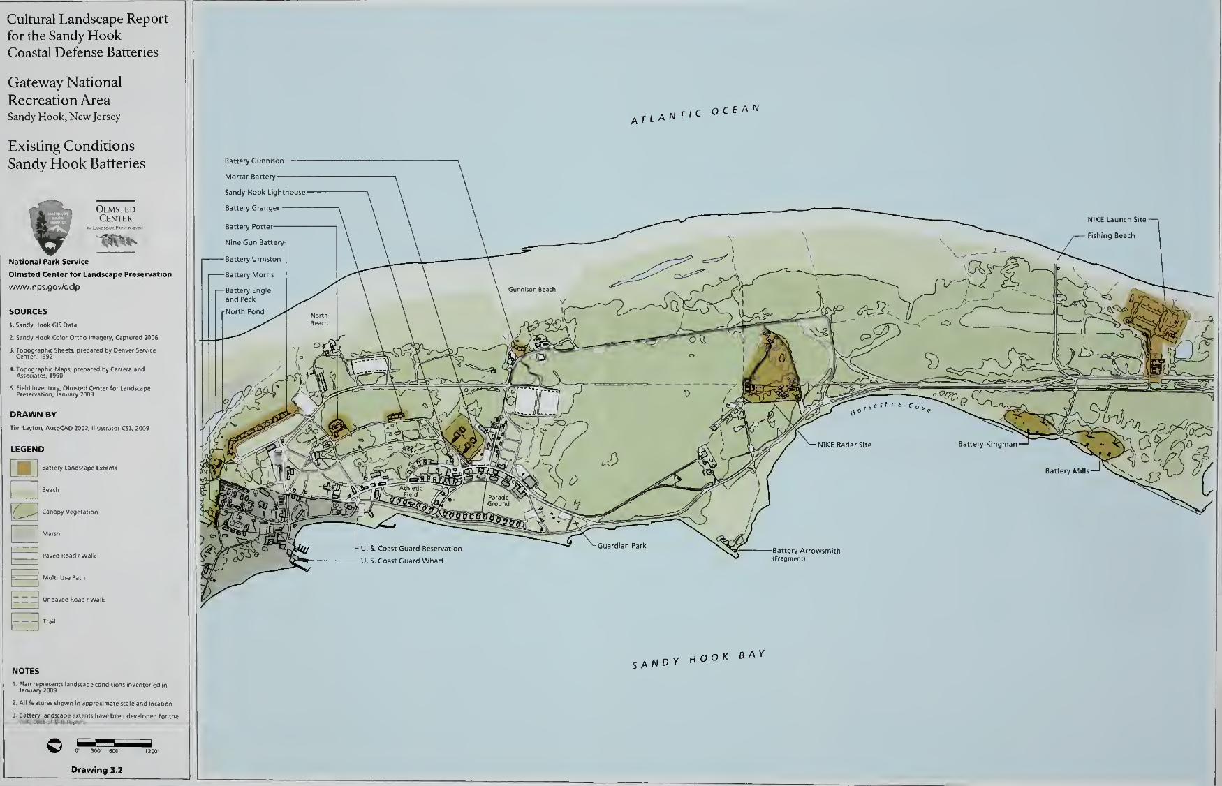
Cultural Landscape Report
for the Sandy HookCoastal Defense Batteries
Gateway National
Recreation AreaSandy Hook, New Jersey
Existing Conditions
Sandy Hook Batteries
OlmstedCenter
^^National Park Service
Olmsted Center for Landscape Preservation
www.nps.gov/oclp
SOURCES
1. Sandy Hook GIS Data
2. Sandy Hook Color Ortho imagery. Captured 2006
DRAWN BY
Tim Uyton, AutoCAD 2002, Illustrator CS3, 2009
Battery Landscape Extents
Beach
Canopy Vegetation
j
Paved Road /Walk
jMulti-Use Path
Unpaved Road /Walk
TrailB
2. All features shown in approximate scale and location
0' 300' 600'
Drawing 3.2
aMT ,c ocean
Battery Gunnison
Mortar Battery
—
Sandy Hook Lighthouse
Battery Granger
Battery Pottei
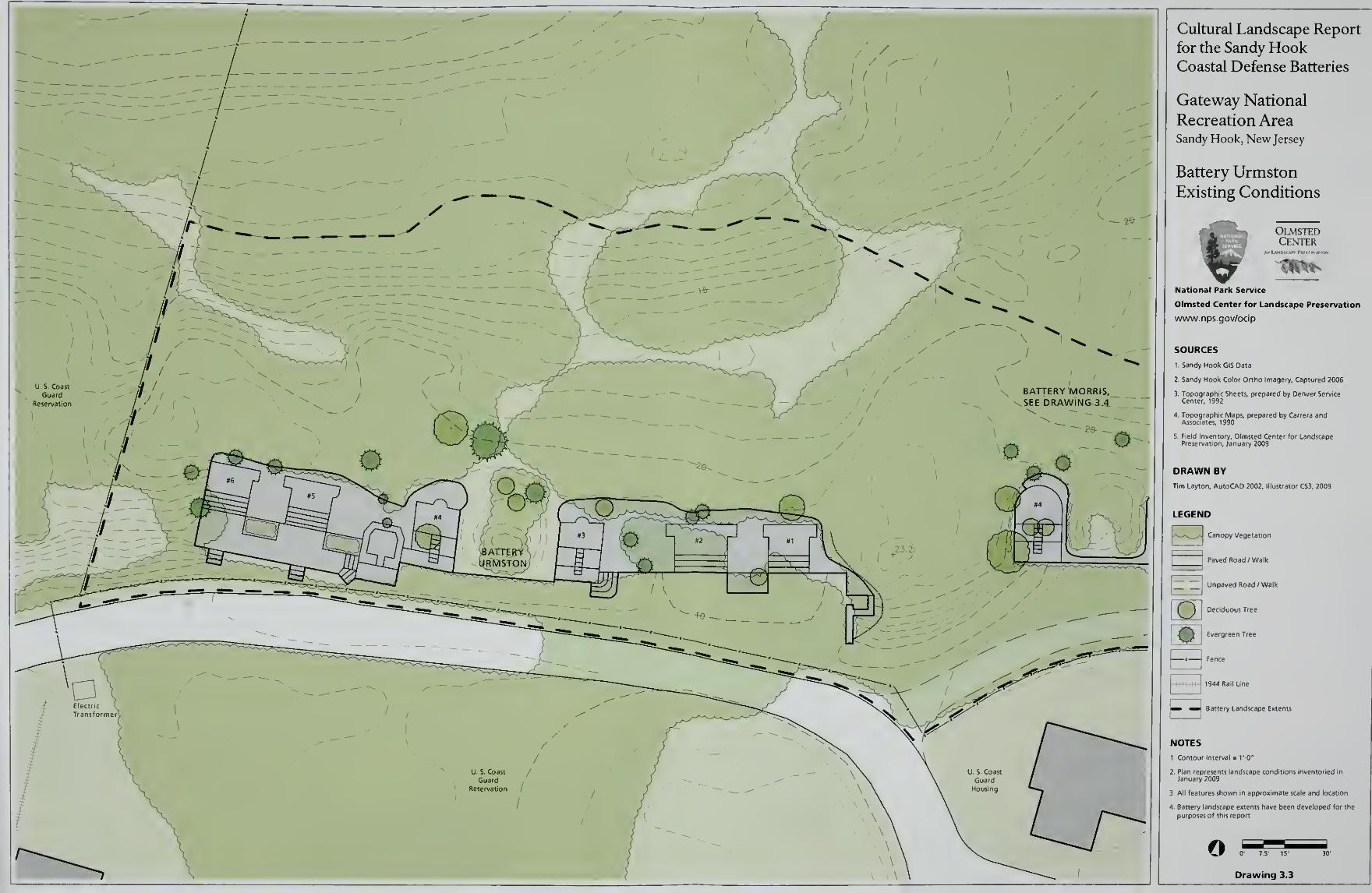
Cultural Landscape Report
for the Sandy HookCoastal Defense Batteries
Gateway National
Recreation AreaSandy Hook, New Jersey
Battery Urmston
Existing Conditions
OlmstedCenter
National Park Service
Olmsted Center for Landscape Preservation
www.nps.gov/oclp
SOURCES
1. Sandy Hook GIS Data
2. Sandy Hook Color Ortho Imagery, Captured 2006
DRAWN BY
Tim Layton, AutoCAD 2002, Illustrator CS3, 2009
B 1
LEGEND
Canopy Vegetation
Paved Road /Walk
Unpaved Road /Walk
Deciduous Tree
Evergreen Tree
FenceHHM -II' 1944 Rail Line
Battery Landscape Extents
NOTES
1 Contour Interval = TO"
3. All features shown in approximate scale and location
o 0' 7-5' 15'
Drawing 3.3
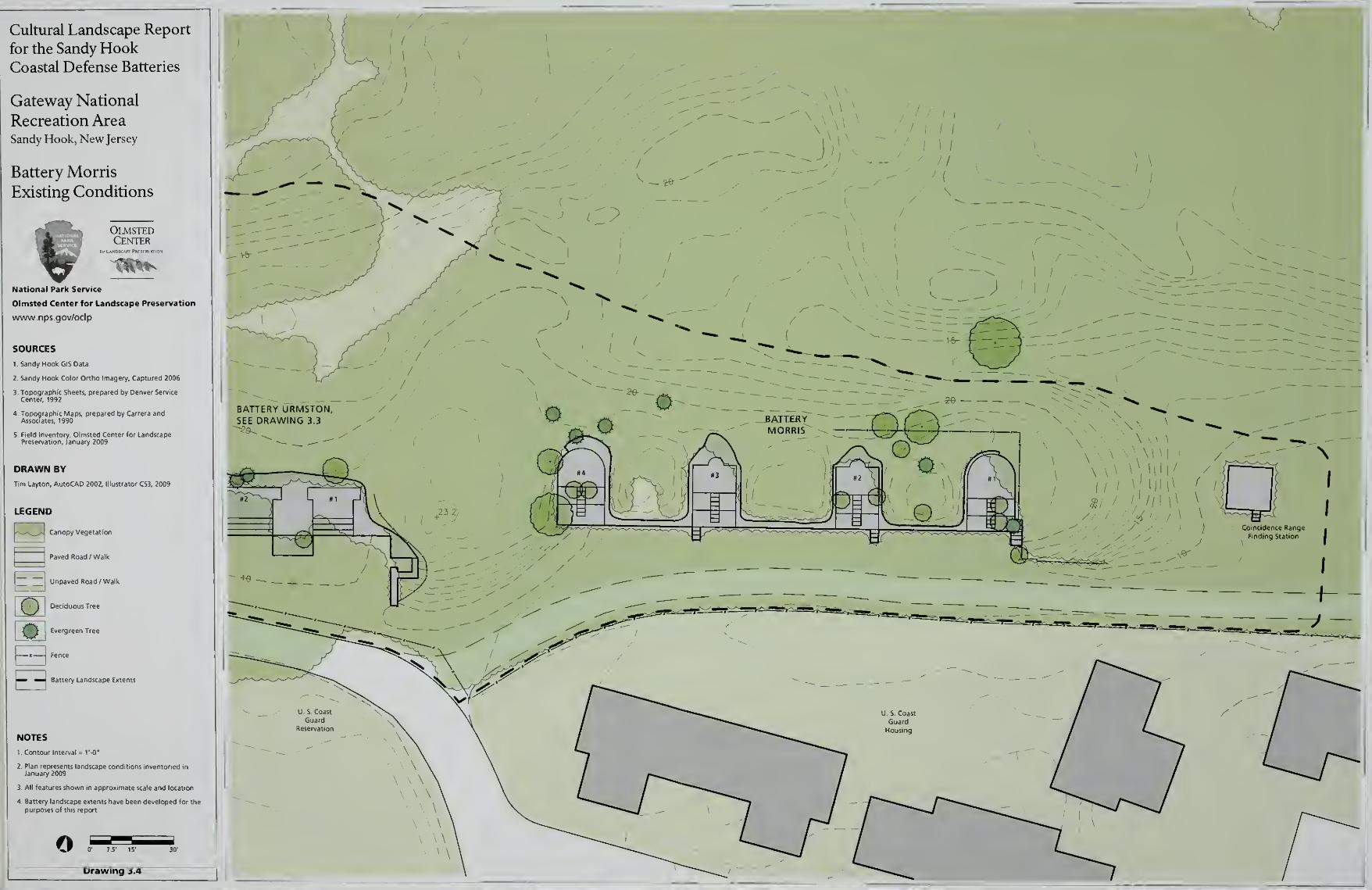
Cultural Landscape Report
for the Sandy HookCoastal Defense Batteries
Gateway National
Recreation AreaSandy Hook, New Jersey
Battery Morris
Existing Conditions
OlmstedCenter
National Park Service
Olmsted Center for Landscape Preservation
www.nps.gov/oclp
SOURCES
1 Sandy Hook GIS Oata
2. Sandy Hook Color Ortho imagery, Captured 2006
DRAWN BY
Tim Layton, AutoCAD 2002. Illustrator CS3, 2009
I
LEGEND
Canopy Vegetation
Paved Road / Walk
Unpaved Road/ Walk
Deciduous Tree
Evergreen Tree
Fence
Battery Landscape ExtentsE3-
NOTES
1. Contour Interval = TO'
3 All features shown m approximate scale and location
o 0' 7.5' 15'
Drawing 3.4
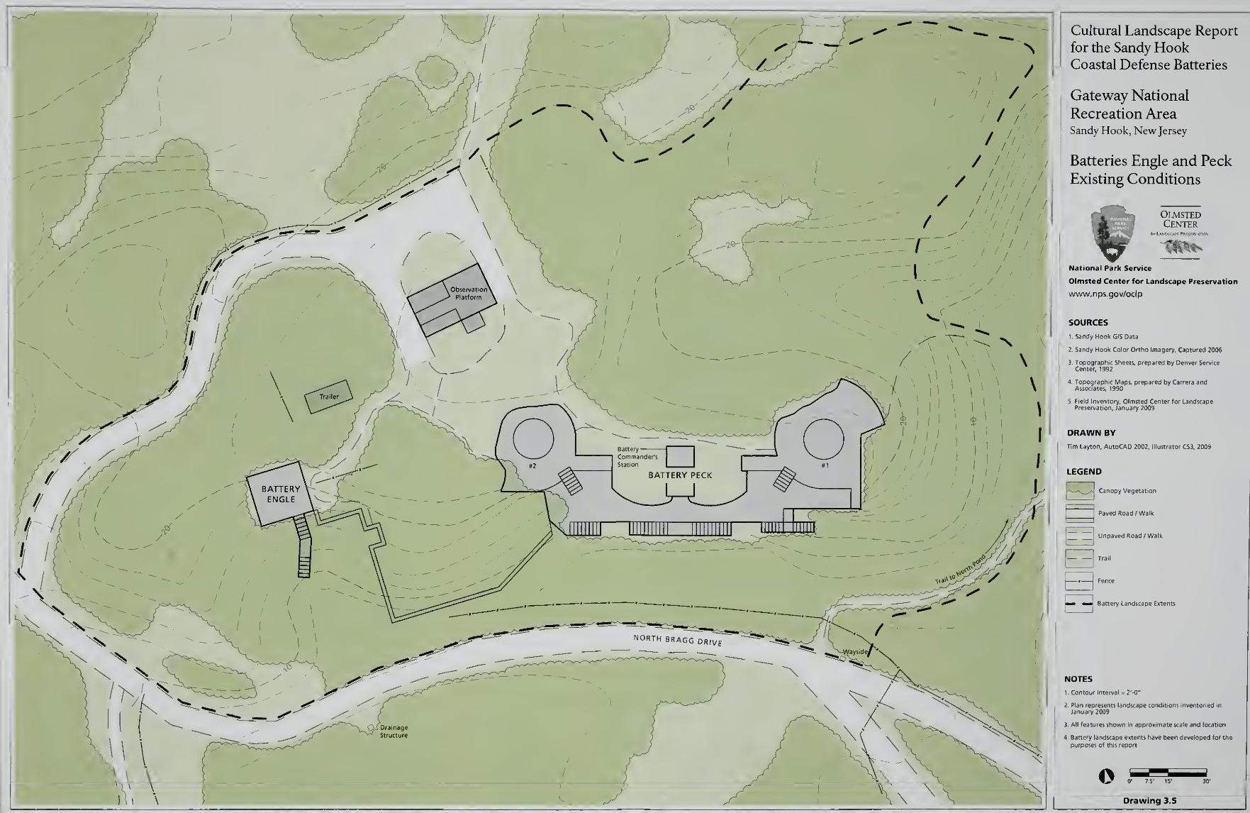
Cultural Landscape Report
for the Sandy HookCoastal Defense Batteries
Gateway National
Recreation AreaSandy Hook, New Jersey
Batteries Engle and Peck
Existing Conditions
OlmstedCenter
National Park Service
Olmsted Center for Landscape Preservation
www.nps.gov/oclp
SOURCES
1. Sandy Hook GIS Data
2. Sandy Hook Color Ortho Imagery, Captured 2006
DRAWN BY
Tim Layton, AutoCAD 2002, lllu
E3'
LEGEND
Canopy Vegetation
Paved Road /Walk
Unpaved Road /Walk
Tra.l
mB Fence
Battery Landscape Extents
NOTES
1 . Contour Interval = 2'-0"
3. All features shown in approximate scale and location
© 0' 7.5' 15'
Drawing 3.5
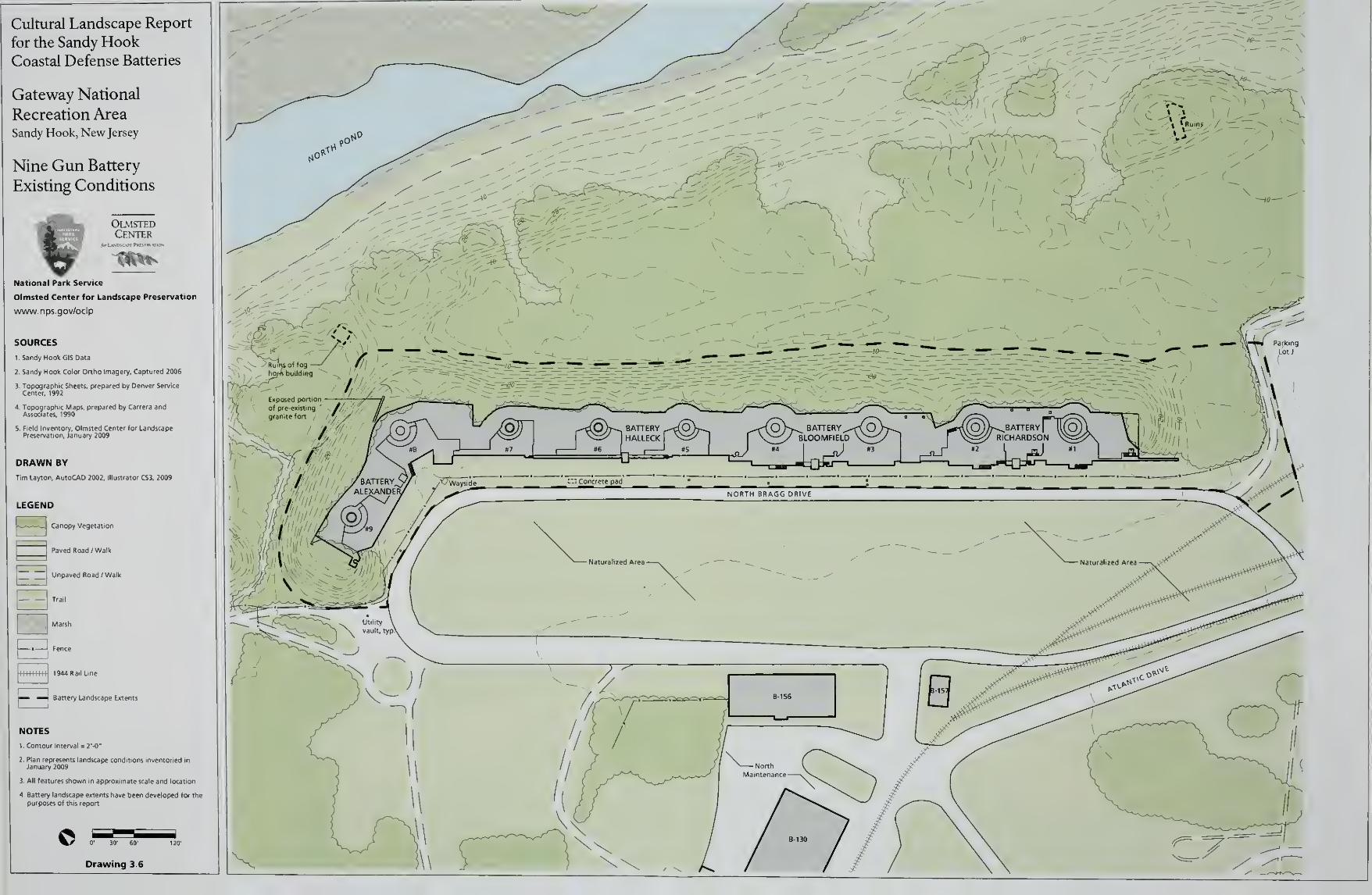
Cultural Landscape Report
for the Sandy HookCoastal Defense Batteries
Gateway National
Recreation AreaSandy Hook, New Jersey
Nine Gun Battery
Existing Conditions
OlmstedCenter
!'National Park Service
Olmsted Center for Landscape Preservation
www.nps.gov/oclp
SOURCES
1 Sandy Hook GIS Data
2. Sandy Hook Color Ortho Imagery. Captured 2006
DRAWN BY
Tim Layton. AutoCAD 2002, lllui
L^-~J i
LEGEND
Canopy Vegetation
Paved Road / Walk
Unpaved Road /Walk
TrailE3Marsh
1944 Rail line
N» ^J flattery Landscape Extents
NOTES
1 Contour Interval = 2'-0"
3 All features shown in approximate scale and locatlo
0)>^ BATTERY^rXOBLOOMFIELD
Bipiirfi \
fc/ ;/
Drawing 3.6
V
\\
i"7"
/" r
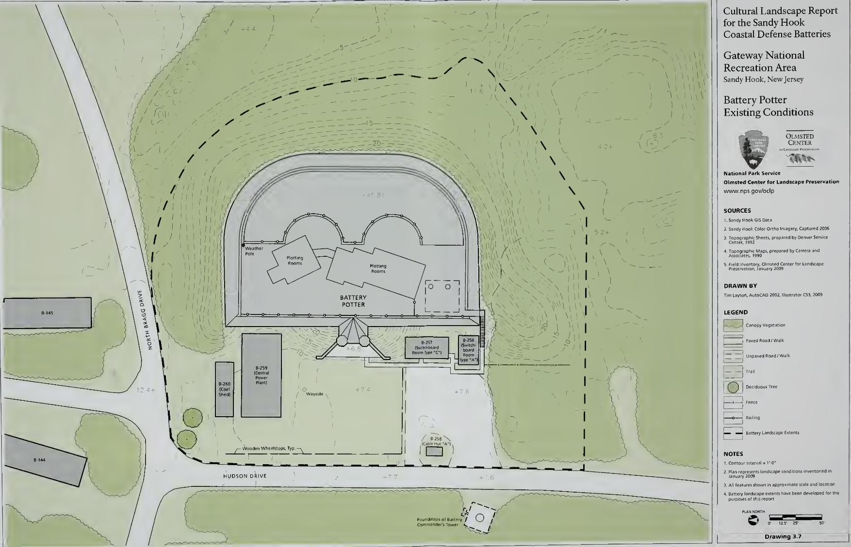
i 1 6
\ \
\
\ \|
I
) ^\W\\V I \l \\
II
I
\
BATTERYPOTTER
B-259(Central
B-260 Plant)
(Coal
Shed)
~TH
- Wooden Wheelstops, Typ.3_
/ l\\
\
1 in
/
1
\
(Switch-
board
\K\W\
1 \\]
+ 7.6
C^
HUDSON oilVE
Foundation of Battery / \_J £SiCommander's Tower
Cultural Landscape Report
for the Sandy HookCoastal Defense Batteries
Gateway National
Recreation AreaSandy Hook, New Jersey
Battery Potter
Existing Conditions
OlmstedCenter
National Park Service
Olmsted Center for Landscape Preservation
www.nps.gov/oclp
SOURCES
1. Sandy Hook GIS Data
2. Sandy Hook Color Onho Imagery, Captured 2006
DRAWN BY
Tim Layton, AutoCAD 2002, Illustrator CS3, 2009
LEGEND
Uw\^/J Canopy Vegetation
Paved Road/Walk
Unpaved ftoad / Walk
I
1
Trail
E2 Deciduous Tree
i—o Railing
E3 Battery Landscape Extents
NOTES
1. Contour Interval = 1'-0"
3. All features shown in approximate scale and location
4. Battery landscape extents have been developed for the
purposes of this report
PLAN NORTH
Drawing 3.7
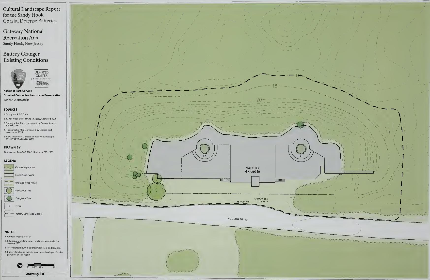
Cultural Landscape Report
for the Sandy HookCoastal Defense Batteries
Gateway National
Recreation AreaSandy Hook, New Jersey
Battery Granger
Existing Conditions
OlmstedCenter
National Park Service
Olmsted Center for Landscape Preservation
www.nps.gov/oclp
SOURCES
1. Sandy Hook GIS Data
2. Sandy Hook Color Ortho Imagery, Captured 2006
Preservation, January 2009
DRAWN BY
Tim Layton. AutoCAD 2002, Illustrator CS3, 2009
J '
JI
LEGEND
Canopy Vegetation
Paved Road / Walk
Unpaved Road/ Walk
Deciduous Tree
Evergreen Tree
Fence
Battery Landscape ExtentsE3'
NOTES
1 Contour Interval = 1'-0"
3. All features shown in approximate scale and location
0' 8 75' 17 5'
/ /
/ / r-
/ ^1
'
/1 / y " --
"' /
/1 <
/ \ 1
1\
1/
//
\ \
{ X.
/ / /
/ / '
I
^ \ I
1
) /
I
/
\
\ I
\ I
I
II
I /
I /
-J-
x "
X v-
\
/.'
1U1\\
v vII
\ \
\ \
I \
I! Hi' ! A
Drawing 3.8
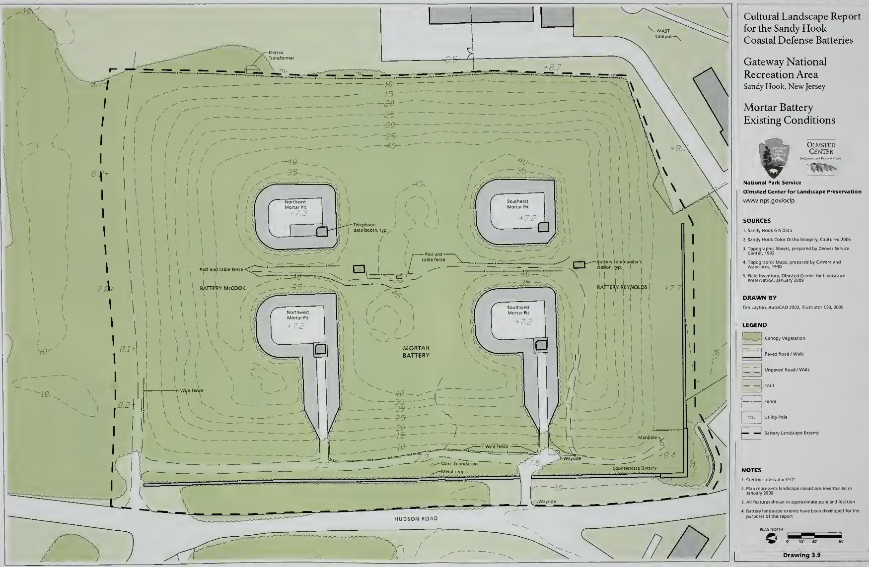
Cultural Landscape Report
for the Sandy HookCoastal Defense Batteries
Gateway National
Recreation AreaSandy Hook, New Jersey
Mortar Battery
Existing Conditions
OlmstedCenter
National Park Service
Olmsted Center for Landscape Preservation
www. nps.gov/oclp
SOURCES
1. Sandy Hook GIS Data
2. Sandy Hook Color Ortho Imagery, Captured 2006
DRAWN BY
Tim Layton, AutoCAD 2002. Illustrator CS3, 2009
LEGEND
Canopy Vegetation
Paved Road /Walk
Unpaved Road /Walk
Trail
Fence
Utility Pole
Battery Landscape Extents
k^^J '
E3'
NOTES
1. Contour li
3. All features shown in approximate scale and location
4 Battery landscape extents have been developed (or the
purposes of this report
Drawing 3.9
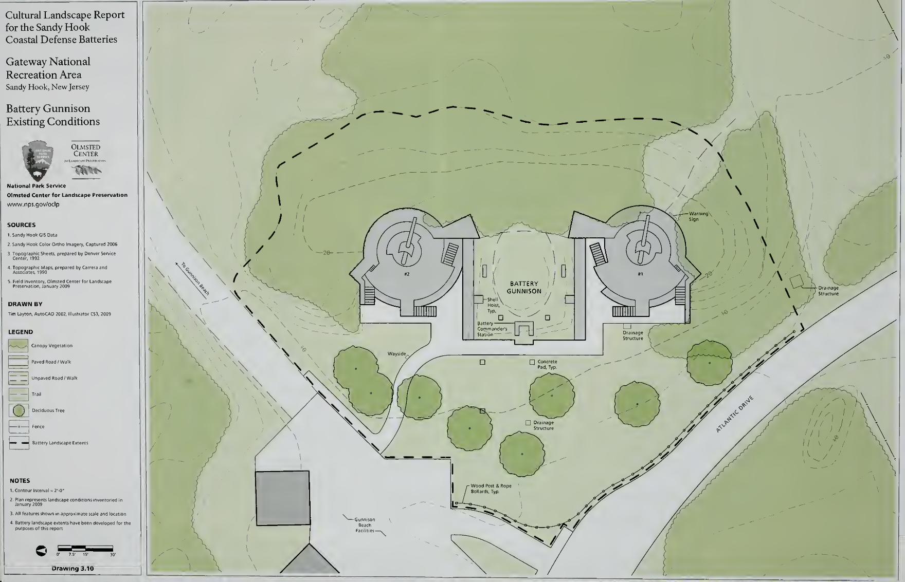
Cultural Landscape Report
for the Sandy HookCoastal Defense Batteries
Gateway National
Recreation AreaSandy Hook, New Jersey
Battery Gunnison
Existing Conditions
OlmstedCenter
f£tft.
National Park Service
Olmsted Center for Landscape Preservation
www.nps.gov/oclp
SOURCES
1. Sandy Hook GIS Data
2. Sandy Hook Color Ortho Imagery, Captured 2006
DRAWN BY
Tim Layton, AutoCAD 2002, Dili!
B 1
LEGEND
Canopy Vegetation
Paved Road /Walk
Unpaved Road/ Walk
Trail
Deciduous Tree
E3
H Fence
^— ^m Battery Landscape Exteni
NOTES
1 Contour Interval = 2'-0"
3, All features shown in approximate scale and location
i have been developed for the
Drawing 3.10
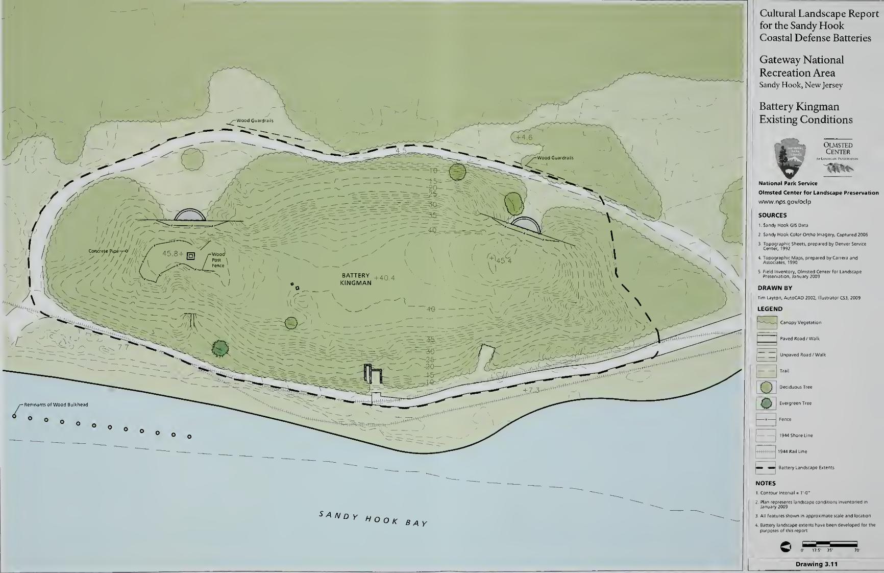
SANDY Hook BAY
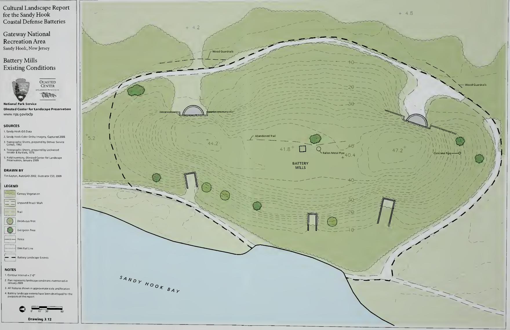
Cultural Landscape Report
for the Sandy HookCoastal Defense Batteries
Gateway National
Recreation AreaSandy Hook, New Jersey
Battery Mills
Existing Conditions
OlmstedCenter
Rft-
National Park Service
Olmsted Center for Landscape Preservation
www . n ps.gov/ocip
SOURCES
1 Sandy Hook GIS Data
2 Sandy Hook Color Ortho Imagery, Captured 2006
DRAWN BY
Tim Laylon, AutoCAD 2002, Illustrator CS3. 2009
LEGEND
r-* -J Canopy Vegetation
~~Unpaved Road /Walk
|M( ) Deciduous Tree
mK Evergreen Tree
1 Fence
1944 Rail Line
— — Battery Landscape Extents
NOTES
1.Contour Interval = 2'-0"
3. All features shown in approximate scale and location
4. Battery landscape extents have been developed for thepurposes of this report
Drawing 3.12
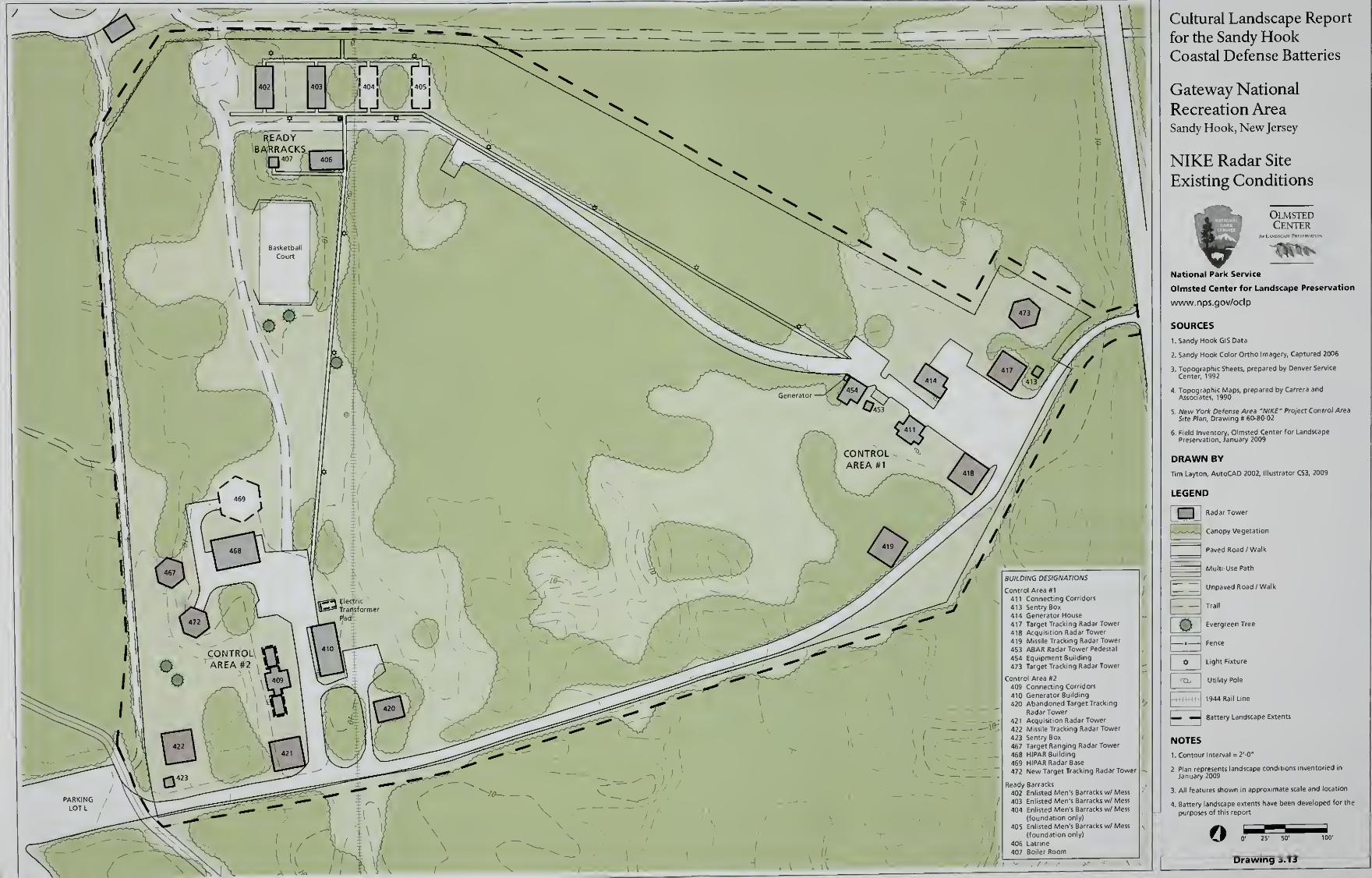
417 Target Tracking Radar Tower
418 Acquisition Radar Tower
419 Missile Tracking Radar Tower
453 ABAR Radar Tower Pedestal
454 Equipment Building
473 Target Tracking Radar Tower
Control Area #2
409 Connecting Corridors
410 Generator Building
420 Abandoned Target Tracking
Radar Tower
421 Acquisition Radar Tower
422 Missile Tracking Radar Tower
423 Sentry Box
467 Target Ranging Radar Tower
468 HIPAR Building
469 HIPAR Radar Base
472 New Target Tracking Radar Tower
Ready Barracks
402 Enlisted Men's Barracks w/ Mess
403 Enlisted Men's Barracks w/ Mess
404 Enlisted Men's Barracks w/ Mess
(foundation only)
405 Enlisted Men's Barracks w/ Mess
(foundation only)
Room
Cultural Landscape Report
for the Sandy HookCoastal Defense Batteries
Gateway National
Recreation AreaSandy Hook, New Jersey
NIKE Radar Site
Existing Conditions
OlmstedCenter
9ft -
National Park Service
Olmsted Center for Landscape Preservation
www.nps.gov/oclp
SOURCES
1. Sandy Hook GIS Data
2. Sandy Hook Color Ortho Imagery, Captured 2006
DRAWN BY
Tim Layton, AutoCAD 2002, Illustrator CS3. 2009
LEGEND
Radar Tower
jCanopy Vegetation
Paved Road /Walk
Multi-Use Path
Unpaved Road /Walk
Qt Evergreen Tree
^—»—J Fence
$ Light Fixture
^Uj Utility Pole
-H-++-H-- 1944 Rail Line
— _J Battery Landscape Extents
NOTES
1 Contour Interval = 2'-0"
3 All features shown in approxin e scale and locatic
4 Battery landscape extents have been developed for the
purposes of this report
oDrawing 3.13
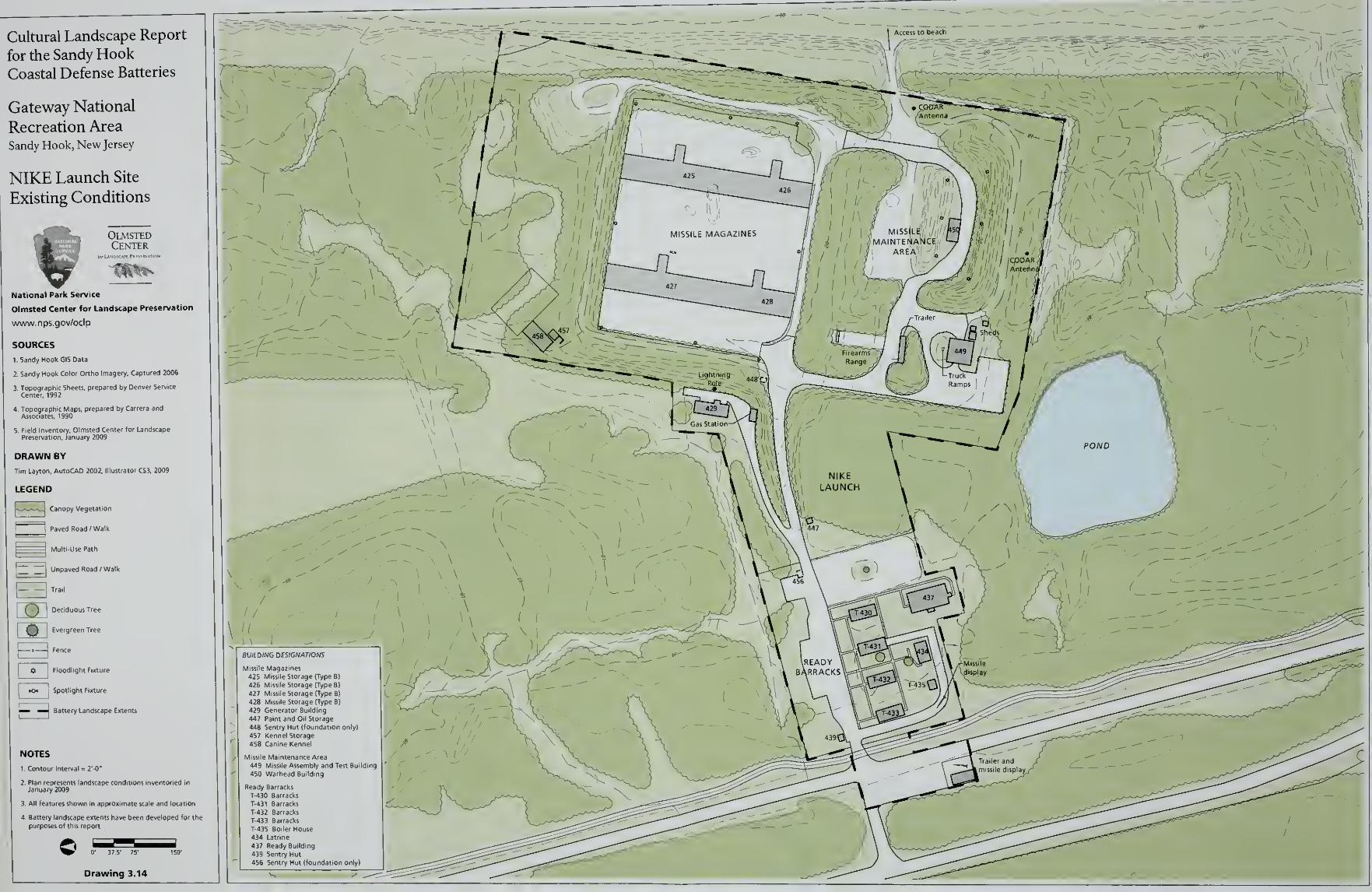
Cultural Landscape Report
for the Sandy HookCoastal Defense Batteries
Gateway National
Recreation AreaSandy Hook, New Jersey
NIKE Launch Site
Existing Conditions
OlmstedCenter
National Park Service
Olmsted Center for Landscape Preservation
www.nps.gov/oclp
SOURCES
1- Sandy Hook GIS Data
2. Sandy Hook Color Ortho imagery. Captured 2006
DRAWN BY
Tim Layton, AutoCAD 2002, Illustrator CS3, 2009
LEGEND
k- -J Canopy Vegetation
^ Paved Road /Walk
i1 Multi-Use Path
I
Unpaved Road /Walk
Trail
Deciduous Tree
i Jy Evergreen Tree
Fence
$ Floodlight Fixture
«o« Spotlight Fixture
E3"
Battery Landscape Extents
NOTES
1
.
Contour Interval = 2'-0"
2. Plan represents landscape conditions inventoried in
January 2009
3. All features shown in approximate scale and location
4. Battery landscape extents have been developed for the
purposes of this report
Drawing 3.14
BUILDING DESIGNATIONS*
Missile Magazines-) 1
425 Missile Storage (Type B)1 _JJ426 Missile Storage (Type B)
427 Missile Storage (Type B) L - ?428 Missile Storage (Type 8}
429 Generator Building
447 Paint and Oil Storage
448 Sentry Hut (foundation anly)
457 Kennel Storage
458 Canine Kennel fMissile Maintenance Area / ^449 Missile Assembly and Test Building
450 Warhead Building) /
Ready Barracks
T-430 Barracks
T-431 Barracks Z*~~^sT-432 Barracks
T-433 Barracks
T-435 Boiler House434 Latrine
437 Ready Building
439 Sentry Hut
456 Sentry Hut (foundation only) —
=

Analysis and Evaluation
ANALYSIS AND EVALUATION
This section provides a summary of the historical significance of Sandy Hook's
coastal defense batteries and an evaluation of their historic integrity. The section
is divided into two main parts. The first summarizes the National Register status
and the significance of Sandy Hook according to National Register of Historic
Places criteria. The second is an evaluation of the landscape's historic character
at each coastal defense battery according to the cultural landscape methodology
outlined in A Guide to Cultural Landscape Reports: Contents, Process and
Techniques (National Park Service, 1998). This methodology examines general
landscape characteristics, such as topography, circulation, and vegetation,
comparing existing landscape conditions documented in January 2009 with what
is documented or otherwise understood of the historic condition of these
landscape characteristics during the period of significance. A summary table of
landscape features is provided at the end of the section listing all documented
landscape features.
The analysis and evaluation covers eleven extant batteries and the two separate
sites that comprise the extant NIKE missile battery. Information is presented in
geographical order from north to south starting with Battery Urmston and
ending with Batteries Kingman and Mills. The section concludes with the NIKE
radar site and the NIKE launch site.
NATIONAL REGISTER STATUS
This analysis and evaluation is based on criteria and aspects of integrity
developed by the National Register of Historic Places Program, which lists
properties that are significant to our nation's history and prehistory. According
to the National Register, historic significance may be present in districts, sites,
buildings, structures and objects that possess integrity of location, design,
materials, workmanship, feeling, and association which meet at least one of the
following criteria:
A. Associated with events that have made a significant contribution to the
broad patterns of history.
B. Associated with the lives of persons significant in our past.
C. Embodies the distinctive characteristics of a type, period or method of
construction, or that represent the work of a master, or that possess high
artistic values, or that represent a significant and distinguishable entity
whose components may lack individual distinction.
255
Cultural Landscape Report for the Sandy Hook Coastal Defense Batteries
D. Have yielded, or may be likely to yield, information important in
prehistory or history.
The Fort Hancock and Sandy Hook Proving Ground Historic District was listed
on the National Register of Historic Places in 1980. This district was comprised
of 380 acres in the northern half of the Sandy Hook peninsula bounded by Sandy
Hook Bay on the west, portions of Magruder Road, Gunnison Road, and Atlantic
Drive on the south, the Atlantic Ocean on the east, and the U. S. Coast Guard
property on the north. In addition, the district contained eight noncontiguous
sites to the south including Battery Arrowsmith, Battery Kingman, Battery Mills,
the Signal Corps radar site, and the NIKE missile sites (Figure 4.1).1 On
November 9, 1982, revised documentation was submitted and the Fort Hancock
and Sandy Hook Proving Ground Historic District was listed as a National
Historic Landmark (NHL). The boundaries for the 4,584-acre landmark district
were expanded to include the majority of the peninsula north of the Route 36
bridge to the northern end of the landform. Only Plum Island, Skeleton Hill
Island, and South Island—all extending from the western side of the peninsula-
were excluded from the district.2
The National Historic Landmark documentation identifies Sandy Hook as
significant for its dual roles in United States military history. As a federal military
reservation, the peninsula served as the home for the Sandy Hook Proving
Ground and Fort Hancock. Additionally, the documentation recognizes Sandy
Hook as significant for the Spermaceti Cove Life-Saving Station and the Sandy
Hook Lighthouse. The period of significance for the Proving Ground, 1874 to
1919, corresponds to the time period the site served as the nation's testing center
for major artillery. For Fort Hancock and the balance of the peninsula, the
period of significance spans from 1859 through the 1950s and 1960s Cold War
era. Areas of historical significance expressed by the documentation include
engineering, military, and social/humanitarian themes.3
STATEMENT OF SIGNIFICANCE
Sandy Hook is significant in American history as the site of the federal military
reservation that played dual roles in United States military history. The peninsula
was home to both the Sandy Hook Proving Ground and Fort Hancock. Between
1874 and 1919, the Proving Ground served as the nation's testing center for major
artillery. During this critical time period, the Army developed, tested, and
transitioned to rifled artillery that was utilized to protect harbors around the
country and in foreign territories. From the 1890s to the Army's divestment of
the property in 1974, Fort Hancock and Sandy Hook's coastal defenses were a
critical element in a system of fortifications guarding the southern approach to
New York City—America's most important harbor and largest metropolis. It was
256
Analysis and Evaluation
during these years that the United States defeated Spain and emerged as a world
power, tipped the scales against the Central Powers in World War I, retreated
into the isolation of the 1920s and 30s, and emerged from World War II as a
super power.4
The Fort Hancock and Sandy Hook Proving Ground Historic District is
significant under Criterion A for association with the development of military
defenses and the design and testing of artillery that have made a significant
contribution to the broad patterns of our history. The site is also significant
under Criterion C for military architecture and engineering that embodies the
distinctive characteristics of Endicott-Taft period coastal defenses. Sandy
Hook's collection of Endicott-Taft batteries includes the first completed,
partially armed, and tested coastal defense battery in the United States following
the Endicott Board's recommendations and the first concrete mortar battery in
the United States. The district may have significance under Criterion D for
archeological resources associated with Fort Hancock and the Proving Ground
that are likely to yield information important to military history.
The period of significance for Fort Hancock and Sandy Hook's coastal defenses
spans from 1859 to 1974. The period begins in 1859 corresponding to the start of
construction on the granite Fort at Sandy Hook. In the National Historic
Landmark documentation, the narrative statement of significance does not
explicitly state the end-date of the period of significance, identifying 1958 as the
last specific date corresponding to the introduction of the improved NIKE
Hercules missile system.5 Correspondence between the National Park Service
and the New Jersey State Historic Preservation Officer in 1996 relating to the
park's List of Classified Structures (LCS) explains that, ".. . because the NIKE
missile era identified in the NHL documentation continued almost to the date of
transfer between the military and the NPS, December 31, 1974, the deactivation
date for Fort Hancock, is used as the end date of the period of significance."6
Review and concurrence by the New Jersey State Historic Preservation Officer
on January 2, 1997 established 1974 as the end date of the period of significance.
EVALUATION OF INTEGRITY
Integrity is the ability of a property to convey its historic identity and significance.
While evaluation of integrity is often a subjective judgment, it must be grounded
in an understanding of a property's physical features and how these relate to its
significance. The National Register identifies seven aspects of integrity
comprising location, design, setting, materials, workmanship, feeling and
association. Retention of these qualities is essential for a property to convey its
significance, though all seven qualities need not be present to convey a sense of
past time and place.
257
Cultural Landscape Report for the Sandy Hook Coastal Defense Batteries
Location is the place where the cultural landscape was constructed. The coastal
defense batteries continue to occupy the locations where they guarded the
southern approach to New York Harbor and the skies over the New York-New
Jersey metropolitan area. The coastal defense batteries retain integrity of
location.
Design is the combination ofelements that create theform, plan, space, structure and
style of the cultural landscape. Extant design elements include structural features
such as battery commander's stations, auxiliary support buildings, and barracks
and vehicular and pedestrian circulation. The primary change to the original
design of the coastal defense batteries is the growth of large woody vegetation on
the structures, their engineered earthworks, and in immediately adjacent areas
that would interfere with historic operations. With the exception of Battery
Gunnison, the gun batteries are missing the artillery and carriages that were part
of an earth-covered, concrete defensive structure. Similarly, the NIKE radar site
lacks the radar units that were mounted on top of the towers for target
acquisition and tracking and missile guidance. North of Battery Peck, an
observation platform and communications trailer have been added. At most
locations, the railroad tracks that supported the construction and provided the
projectiles and gunpowder for the batteries are removed. Near Nine Gun
Battery, Battery Gunnison, and the NIKE radar site, surface parking areas have
been added. The presence of large woody vegetation, addition of some non-
historic structures, and changes to circulation features diminishes the integrity of
design.
Setting is the physical environment of the cultural landscape. The setting of the
coastal defense batteries is defined by topography and vegetation communities
that inhabit large, contiguous areas and transitional zones. Contrary to the height
of the battery structures and their engineered earthworks, adjacent topography is
relatively flat or slightly undulates to form coastal dunes. These topography
features are largely intact. Masses of undisturbed vegetation, such as the holly
forest east of Batteries Kingman and Mills and the low-growing shrubs and beach
grasses on coastal dunes, have also been retained. Although Sandy Hook's
function has changed from a strategic military installation to a recreation
destination serving a densely-populated region, the coastal defense batteries
retain integrity of setting.
Materials are the physical elements that were combined or deposited during the
period ofsignificance in a particular pattern or configuration toform the cultural
landscape. The coastal defense batteries retain historic built materials of granite,
concrete, steel, and sand and earth. The condition of these materials is negatively
affected by water infiltration, rust, erosion, and large woody vegetation, however,
the materials have not been replaced with non-historic substitutes. Changes have
occurred with plant materials on the engineered earthworks and adjacent to the
258

Analysis and Evaluation
batteries due to succession and the growth of non-native invasive species such as
ailanthus. The presence of non-historic plant material can be reversed.
Workmanship is the physical evidence of the crafts ofa particular culture orpeople
during the period ofsignificance. The coastal defense batteries demonstrate
workmanship of the Army's changing technology in coastal defenses from the
late nineteenth to the mid-twentieth century. Masons set granite blocks to form a
defensible entrance for Battery Potter. When a land-based attack was no longer a
threat and the counterweight gun carriage successfully tested, large caliber gun
batteries featured open rear elevations and recessed concrete wells to emplace
the guns. Finally, when aerial bombing replaced naval gun fire, Batteries
Kingman and Mills were completely casemated in earth-covered concrete to
protect artillery and crew. The coastal defense batteries retain integrity of
workmanship.
Feeling is the cultural landscape's expression of the aesthetic or historic sense of the
historic period. Due to their scale, materials, and integration in the landscape with
engineered earthworks, the coastal defense batteries are distinct from other
buildings and structures at Sandy Hook and retain their historic feeling. At the
NIKE missile sites, the perimeter fences convey the security established when the
radar and launch sites were operational. Large woody vegetation growing on the
batteries, their engineered earthworks, and in surrounding areas diminishes the
feeling of a maintained military landscape. Similarly, vegetation along the NIKE
fence lines and the poor condition of some sections offences lessens the integrity
of feeling.
Association is the direct link between the important historic event or person and the
cultural landscape. The coastal defense batteries have a diminished integrity of
association. It is challenging to link the structures with their role in coastal
defense due to several factors. Changes in circulation systems and unchecked
growth of vegetation make access and therefore recognition of batteries such as
Urmston and Morris difficult. Large woody vegetation is the primarily culprit
obstructing downrange views from the batteries and impeding an understanding
between the battery's location and the water. Finally, vegetation growing on the
batteries conveys that the structures are relics and lessens the association of the
batteries as vital resources for coastal defense.
The coastal defense batteries at Sandy Hook retain integrity of location, setting,
materials, and workmanship. Primarily due to the growth of large woody
vegetation, the addition of non-historic structures, and changes to circulation
features, the coastal defense batteries have a diminished integrity of design,
feeling, and association. The coastal defense batteries retain their overall physical
form and addressing the condition of historic details will strengthen the
259

Cultural Landscape Report for the Sandy Hook Coastal Defense Batteries
association of the batteries as critical installations for defending the southern
approach to New York City and the metropolitan area's airspace.
EVALUATION OF LANDSCAPE CHARACTERISTICS ANDFEATURES
Landscape characteristics are the broad patterns, systems, and feature categories
that compose the landscape and determine how people interact with it. The
analysis of landscape characteristics and features serves to identify the
components of the landscape that define the historic character of the landscape
and contribute to the landscape's ability to convey its significance. The
evaluation entails comparing existing conditions to what was present during the
historic period and making an evaluation of whether the landscape characteristic
or feature contributes to the landscape's historic character.
The landscape characteristics evaluated for the coastal defense batteries include
spatial organization, topography, circulation, buildings and structures,
vegetation, tactical views, and small-scale features. The evaluation is organized
and presented in two parts. First, characteristics that are common to all battery
sites are reviewed in a narrative format with the following components:
Historic Condition: A brief outline of the history of a particular landscape
characteristic and associated features.
Existing Condition: A brief description of the current physical condition.
Evaluation: A determination of each landscape characteristic or feature's
contribution to the significance of the landscape.
Contributing - Characteristics and features that contribute to the
significance of the coastal defense batteries and that were present during
the period of significance, possess historic integrity, and are related to
the areas of historic significance.
Non-contributing - Characteristics and features that do not contribute
to the significance of the coastal defense batteries and that were not
present during the period of significance, do not retain historic integrity,
or are unrelated to the area of historic significance.
Undetermined - Characteristics and features that require additional
information to determine if they contribute to the significance of the
coastal defense batteries.
The second part of the evaluation reviews landscape characteristics and features
that are specific to the individual battery sites. The information is presented in
geographical order from north to south in separate tables corresponding to the
260
Analysis and Evaluation
eleven battery sites and two NIKE missile sites. Columns in the table identify the
landscape feature, if the feature was extant in 1945, 1974, and during the existing
conditions review in January 2009, and concludes with notes and figure
references pertaining to the feature. Listing whether a feature was extant in 1974
corresponds to the end of the period of significance for Fort Hancock and the
Sandy Hook Proving Ground Historic District. A review of the features in 1945 is
provided for the eleven gun batteries because shortly after World War II,
American coastal defenses shifted to missile installations to defend against
bomber attacks and all of Sandy Hook's gun batteries were disarmed and
deactivated. A comparison of the 1945 and 1974 columns serves to identify
features—such as large woody vegetation on the engineered earthworks—that
emerged during the twenty-nine year interval due to limited maintenance.
SPATIAL ORGANIZATION
Historic Condition: The spatial organization of the coastal defense batteries is
defined their role in a larger system of coastal defenses. The gun batteries at
Sandy Hook were not isolated, defensive fixtures but components in a system
that utilized multiple locations, varying land-based artillery, and underwater
controlled mines to defend the south approach to New York. In addition to
batteries at Sandy Hook, the Army constructed coastal defenses to the south at
Navesink, to the north at Fort Hamilton, Fort Wadsworth, and Fort Lafayette
along the Narrows, and to the east at Fort Tilden on the Rockaway peninsula (see
Figure 2.31). All of the battery sites were intended to provide defense-in-depth—
a redundant system that provided continued resistance against a potential enemy
advancing north toward New York City. The NIKE missile battery at Sandy
Hook was also part of a redundant system of defenses that incorporated
geographically separate radar sites and command centers for coordinating
nineteen missile batteries in the New York Defense Area. In addition to Sandy
Hook, nearby missile sites included Leonardo and South Plainfield, New Jersey,
and Fort Tilden on the Rockaway peninsula.
The individual gun batteries at Sandy Hook were oriented to engage a potential
enemy on the water. Consequently, a majority of the batteries faced artillery
north or east toward the major shipping channel that followed the Atlantic
shoreline of the peninsula. The firing side of the battery was protected by an
engineered earthwork that transitioned to a reinforced concrete structure. The
structure emplaced the guns, stored ammunition, and housed dedicated spaces
for calculating a target's range. The rear elevation of the concrete structure
provided personnel access and delivery of ammunition and supplies. If an enemy
fired on the battery, the safest place for personnel was under the protective cover
of reinforced concrete and engineered earthworks. Recognizing this advantage,
261
Cultural Landscape Report for the Sandy Hook Coastal Defense Batteries
the Army converted the covered galleries of the Mortar Battery to house central
communications and to serve as a command post during World War II.
Existing Condition: The coastal defense batteries at Sandy Hook have not moved
since the end of the period of significance and continue to occupy the locations
where they guarded the southern approach to New York Harbor and the skies
over the New York-New Jersey metropolitan area. The arrangement of a
battery's firing side and engineered earthwork, concrete structure, and rear
elevation for access remains unaltered.
Evaluation: Contributing
TOPOGRAPHY
Historic Condition: Mid-nineteenth century improvements to artillery and
projectiles coupled with combat experience during the Civil War convinced
military engineers that a new generation of coastal defense batteries should rely
on constructed earthworks for protection. Batteries shielded with engineered
earthworks were constructed at Sandy Hook in the 1890s and designed earthen
covered continued to be a feature of batteries until the conclusion of World War
II. Compared to masonry and concrete construction, the engineered earthworks
were easy and inexpensive to replace if damaged. In addition to protecting a
battery, the earthworks offered an added benefit of concealing the concrete
structure by blending it into the surrounding coastal topography. Hundreds of
thousands of cubic yards of earth and sand were excavated and meticulously
placed to complete the coastal defense batteries at Sandy Hook. Engineered
earthworks were also constructed at the NIKE launch site to cover the Missile
Magazines and to protect adjacent areas from an accidental explosion at the
Missile Maintenance Area.
Existing Condition: The engineered earthworks are primarily intact with some
erosion occurring since the end of the historic period. At the NIKE launch site,
recycling bins cut into a portion of the south earthwork at the Missile
Maintenance Area (Figure 4.2). For all sites, social trails across the earthworks
advance erosion and threaten these features (see Figure 3.11). Large woody
vegetation growing on the earthworks creates the potential for the placed earth
and sand to be removed by a toppled tree.
Evaluation: Contributing
CIRCULATION
Historic Condition: Multiple circulation systems and infrastructure developed on
Sandy Hook to support various modes of transportation during the historic
period. The bay side of the peninsula provided more sheltered waters for
262
Analysis and Evaluation
anchoring and docking ships and wharves were constructed on the bay side to
transport military supplies and to receive recreation seekers. In the mid-
nineteenth century, a railroad line met recreational travelers at a Horseshoe
Cover ferry landing and continued south through the peninsula to Long Branch,
Sea Bright, and other towns along the Atlantic coast. Recognizing the potential
for railroads to transport artillery and ammunition, the Army purchased the
existing railroad line and extended it north to the Sandy Hook Proving Ground
in 1889. Railroads were utilized throughout the Proving Ground's operation and
also installed to move materials for the construction of the coastal defense
batteries. After construction was completed, railroad lines served to transport
artillery and ammunition to the batteries. Railroads also contributed to the
coastal defense system by providing the means for positioning artillery and
searchlights mounted on flat rail cars. Following World War II, the gun batteries
were deactivated and the railroad lines that supported the batteries' construction
and operation were allowed to deteriorate.
In addition to the railroads, vehicular routes were established across compacted
soil and wood plank roads. As Fort Hancock was developed to support the
coastal defense batteries, compacted gravel roads were designed and installed to
connect the north and south ends of the peninsula and to provide access around
the Fort's semi-circular configuration of officers' quarters, enlisted men's
quarters, and auxiliary buildings. In many instances, roads paralleled railroad
lines along the rear of the batteries and provided access for personnel. The
network of the roads expanded with the increase in personnel during the World
Wars and designated parking areas appear on historic maps from 1944.
Circulation features also include paved and unpaved pedestrian routes associated
with the Proving Ground, Fort Hancock, and the individual batteries. The most
formal pedestrian circulation systems were designed and installed at the NIKE
missile sites to facilitate access among the barracks, radar towers, magazines,
warehouses, and support structures.
Existing Condition: The multiple modes of transportation and their
corresponding circulation systems are presently extant at Sandy Hook. A
seasonal ferry service operates from Manhattan and brings visitors to the
northern end of the peninsula. Vehicular circulation routes provide access
throughout Sandy Hook with Hartshorne Drive serving as the major north-south
route, Atlantic Drive serving as a secondary north-south route, and Gunnison
Road serving as a connecting east-west route between the two. Sidewalks and
pedestrian circulation systems connect Fort Hancock's quarters and buildings
and provide access among the individual structures that comprise the NIKE
missile sites.
Several sections of rail lines and occasional collections of wooden ties are the
only remnants of Sandy Hook's railroad system that are present (Figures 4.3 and
263
Cultural Landscape Report for the Sandy Hook Coastal Defense Batteries
4.4). Unmaintained vegetation blocks and obscures some vehicular circulation
routes and at other locations, coastal erosion is removing circulation features.
New parking lots are present to receive an increasing number of visitors and a
multi-use path stretches from the park entrance to the ferry landing to provide
dedicated access for jogging, walking, bicycle riding, and roller blading.
Evaluation: Circulation features present from the historic period are
contributing. Circulation features added during the National Park Service
administration of Sandy Hook, such as the parking lots and the multi-use path,
are non-contributing.
BUILDINGS AMD STRUCTURES
Historic Condition: The coastal defense batteries represent successive
generations of costly buildings and structures constructed in response to the
latest offensive weaponry and armament. At Sandy Hook, the Army designed
and constructed rapid fire and large caliber batteries to defend the southern
entrance to New York Harbor. In addition the Army completed experimental
battery designs, such as the Dynamite Gun Battery and Battery Potter, which used
different means to fire projectiles and raise large caliber guns. Both rapid fire and
large caliber gun batteries were a building system comprised of reinforced
concrete structures and protective, engineered earthworks.
The first gun batteries at Sandy Hook incorporated defenses against a land-based
attack. At Battery Potter, the main entry resembled a castle and featured gun
loops in a pair of flanking towers so soldiers could fire on an advancing enemy.
At the Mortar Battery, the structure was surrounded by a perimeter wall and had
machine guns set in galleries at opposite corners to fire on intruders inside the
wall. With a system ofgun batteries and controlled mines defending against a
land-based attack, later gun batteries had open, rear elevations that provided
personnel access and delivery of ammunition and supplies. Responding to the
threat of aerial reconnaissance and bombing, the large caliber gun batteries
updated during World War II featured massive concrete canopies over each gun
emplacement to protect the artillery and crews.
During the historic period, the gun batteries experienced periods of intensive
maintenance and use and also years of minimal care intended to keep the
defenses operational ready. Water-repelling coatings and camouflage paints
were added to the concrete surfaces to protect the batteries from natural forces
and human detection. Architectural features, many of them metal, were
important components in security, safety, and communications.
The Army disarmed and deactivated the gun batteries when artillery was no
longer effective and when new coastal defenses were operational. The
264
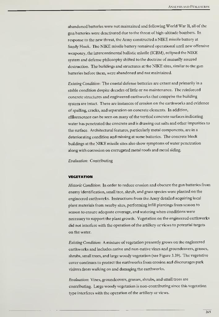
Analysis and Evaluation
abandoned batteries were not maintained and following World War II, all of the
gun batteries were deactivated due to the threat of high-altitude bombers. In
response to the new threat, the Army constructed a NIKE missile battery at
Sandy Hook. The NIKE missile battery remained operational until new offensive
weaponry, the intercontinental ballistic missile (ICBM), eclipsed the NIKE
system and defense philosophy shifted to the doctrine of mutually assured
destruction. The buildings and structures at the NIKE sites, similar to the gun
batteries before them, were abandoned and not maintained.
Existing Condition: The coastal defense batteries are extant and primarily in a
stable condition despite decades of little or no maintenance. The reinforced
concrete structures and engineered earthworks that comprise the building
system are intact. There are instances of erosion on the earthworks and evidence
of spalling, cracks, and separation on concrete elements. In addition,
efflorescence can be seen on many of the vertical concrete surfaces indicating
water has penetrated the concrete and is drawing out salts and other impurities to
the surface. Architectural features, particularly metal components, are in a
deteriorating condition and missing at some batteries. The concrete block
buildings at the NIKE missile sites also show symptoms of water penetration
along with corrosion on corrugated metal roofs and metal siding.
Evaluation: Contributing
VEGETATION
Historic Condition: In order to reduce erosion and obscure the gun batteries from
enemy identification, small tree, shrub, and grass species were planted on the
engineered earthworks. Instructions from the Army detailed acquiring local
plant materials from nearby sites, performing infill plantings from season to
season to ensure adequate coverage, and watering when conditions were
necessary to support the plant growth. Vegetation on the engineered earthworks
did not interfere with the operation of the artillery or views to potential targets
on the water.
Existing Condition: A mixture of vegetation presently grows on the engineered
earthworks and includes native and non-native vines and groundcovers, grasses,
shrubs, small trees, and large woody vegetation (see Figure 3.39). The vegetative
cover continues to protect the earthworks from erosion and discourages park
visitors from walking on and damaging the earthworks.
Evaluation: Vines, groundcovers, grasses, shrubs, and small trees are
contributing. Large woody vegetation is non-contributing since this vegetation
type interferes with the operation of the artillery or views.
265

Cultural Landscape Report for the Sandy Hook Coastal Defense Batteries
TACTICAL VIEWS
Historic Condition: The concrete gun batteries relied on unobstructed views to
the water to sight potential targets and allow unimpeded firing of projectiles. The
importance of a clear field of fire is demonstrated by the Army Corps of
Engineers' Report ofCompleted Works that recorded information on interference
and obstacles for each battery such as adjacent batteries, buildings, and
vegetation. In addition to a clear field of fire from an emplacement, unobstructed
views were necessary from battery commander's stations and fire control
stations. Constructed on top of existing batteries or as independent buildings,
battery commander's and fire control stations became dedicated structures for
locating and acquiring the range of potential targets (see Figures 2.82 and 2.86).
Tactical views of high-altitude, enemy aircraft were not possible and to counter
this strategic advantage, the NIKE missile battery utilized radar to acquire targets
and guide missiles to a computed intercept point. Radar and missiles had to be
separated by a minimum distance of 3,000 feet for guidance communication to
work. Therefore, a tactical view existed between the radar site and launch site so
the radar signals could be transmitted without obstruction. The area between the
two sites was not stripped of all features but vertical objects that could interfere
with the radar signals had to be removed, relocated or managed.
Existing Condition: Tactical views from the emplacements, battery commander's
stations, and fire control stations to the water are primarily impeded by woody
vegetation growing at the interface of the engineered earthwork and concrete
battery structure (Figure 4.5 and see Figures 3.4 and 3.42). Beyond the toe or
bottom of the engineered earthwork there may be vegetation that impacts views,
however, the impact is difficult to evaluate with obstructing vegetation in close
proximity to the start of the view. With the exception of the communications
trailer and observation platform at Batteries Engle and Peck, there appears to be
no additional buildings or structures that impact views from the emplacements,
battery commander's stations, and fire control stations.
From the NIKE radar site, signals traveled over a mile to control vans and
individual missiles at the launch site. With these vertical elements absent from
the launch site, it is difficult to determine if the tactical view is intact or
obstructed.
Evaluation: Contributing at the gun batteries, Undetermined at the NIKE missile
battery
SMALL-SCALE FEATURES
Historic Condition: The coastal defense batteries contained numerous small-scale
architectural features associated with buildings and structures. Railings and
266
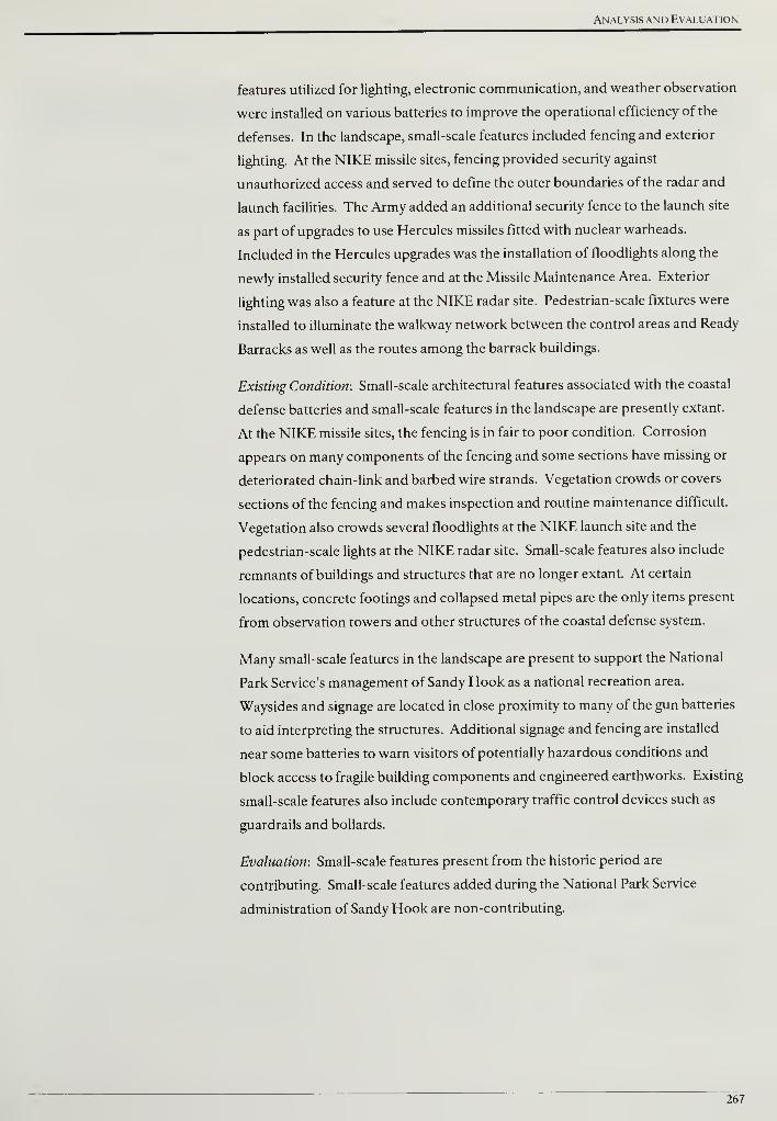
Analysis and Evaluation
features utilized for lighting, electronic communication, and weather observation
were installed on various batteries to improve the operational efficiency of the
defenses. In the landscape, small-scale features included fencing and exterior
lighting. At the NIKE missile sites, fencing provided security against
unauthorized access and served to define the outer boundaries of the radar and
launch facilities. The Army added an additional security fence to the launch site
as part of upgrades to use Hercules missiles fitted with nuclear warheads.
Included in the Hercules upgrades was the installation of floodlights along the
newly installed security fence and at the Missile Maintenance Area. Exterior
lighting was also a feature at the NIKE radar site. Pedestrian-scale fixtures were
installed to illuminate the walkway network between the control areas and Ready
Barracks as well as the routes among the barrack buildings.
Existing Condition: Small-scale architectural features associated with the coastal
defense batteries and small-scale features in the landscape are presently extant.
At the NIKE missile sites, the fencing is in fair to poor condition. Corrosion
appears on many components of the fencing and some sections have missing or
deteriorated chain-link and barbed wire strands. Vegetation crowds or covers
sections of the fencing and makes inspection and routine maintenance difficult.
Vegetation also crowds several floodlights at the NIKE launch site and the
pedestrian-scale lights at the NIKE radar site. Small-scale features also include
remnants of buildings and structures that are no longer extant. At certain
locations, concrete footings and collapsed metal pipes are the only items present
from observation towers and other structures of the coastal defense system.
Many small-scale features in the landscape are present to support the National
Park Service's management of Sandy Hook as a national recreation area.
Waysides and signage are located in close proximity to many of the gun batteries
to aid interpreting the structures. Additional signage and fencing are installed
near some batteries to warn visitors of potentially hazardous conditions and
block access to fragile building components and engineered earthworks. Existing
small-scale features also include contemporary traffic control devices such as
guardrails and bollards.
Evaluation: Small-scale features present from the historic period are
contributing. Small-scale features added during the National Park Service
administration of Sandy Hook are non-contributing.
267
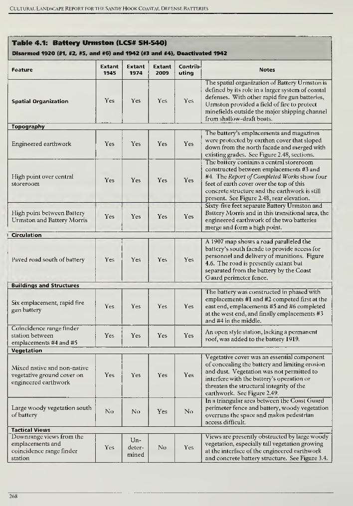
Cultural Landscape Report for the Sandy Hook Coastal Defense Batteries
Table 4.1: Battery Urmston (LCS# SH-540)
Disarmed 1920 (#1, #2. #5, and #6) and 1942 (#3 and #4), Deactivated 1942
FeatureExtant1945
Extant
1974Extant
2009Contrib-
utingNotes
Spatial Organization Yes Yes Yes Yes
The spatial organization of Battery Urmston is
defined by its role in a larger system of coastal
defenses. With other rapid fire gun batteries,
Urmston provided a field of fire to protect
minefields outside the major shipping channel
from shallow-draft boats.
Topography
Engineered earthwork Yes Yes Yes Yes
The battery's emplacements and magazines
were protected by earthen cover that sloped
down from the north facade and merged with
existing grades. See Figure 2.48, sections.
High point over central
storeroomYes Yes Yes Yes
The battery contains a central storeroom
constructed between emplacements #3 and
#4. The Report ofCompleted Works show four
feet of earth cover over the top of this
concrete structure and the earthwork is still
present. See Figure 2.48, rear elevation.
High point between Battery
Urmston and Battery MorrisYes Yes Yes Yes
Sixty-five feet separate Battery Urmston and
Battery Morris and in this transitional area, the
engineered earthwork of the two batteries
merge and form a high point.
Circulation
Paved road south of battery Yes Yes Yes Yes
A 1907 map shows a road paralleled the
battery's south facade to provide access for
personnel and delivery of munitions. Figure
4.6. The road is presently extant but
separated from the battery by the Coast
Guard perimeter fence.
Buildings and Structures
Six emplacement, rapid fire
gun batteryYes Yes Yes Yes
The battery was constructed in phased with
emplacements #1 and #2 competed first at the
east end, emplacements #5 and #6 completed
at the west end, and finally emplacements #3
and #4 in the middle.
Coincidence range finder
station between
emplacements #4 and #5
Yes Yes Yes YesAn open style station, lacking a permanent
roof, was added to the battery 1919.
Vegetation
Mixed native and non-native
vegetative ground cover onengineered earthwork
Yes Yes Yes Yes
Vegetative cover was an essential component
of concealing the battery and limiting erosion
and dust. Vegetation was not permitted to
interfere with the battery's operation or
threaten the structural integrity of the
earthwork. See Figure 2.49.
Large woody vegetation south
of batteryNo No Yes No
In a triangular area between the Coast Guard
perimeter fence and battery, woody vegetation
overruns the space and makes pedestrian
access difficult.
Tactical ViewsDownrange views from the
emplacements and
coincidence range finder
station
Yes
Un-deter-
mined
No Yes
Views are presently obstructed by large woodyvegetation, especially tall vegetation growing
at the interface of the engineered earthwork
and concrete battery structure. See Figure 3.4.
268

Analysis and Evaluation
FeatureExtant1945
Extant
1974Extant
2009Contrib-
utingNotes
Small-Scale Features
U. S. Coast Guard perimeter
fenceNo Yes Yes No
The fence appears on a 1976 survey south of
paved road paralleling the battery's south
facade. Presently, the fence is on the north side
of the road and creates a narrow space south of
the battery that makes pedestrian access
difficult. The fence consists of six-foot tall
chain-link sections topped with barbed wire.
Wood-slat fence east of
batteryNo Yes Yes No
Erected by the Army in the early 1970s and
presently in fair condition.
269
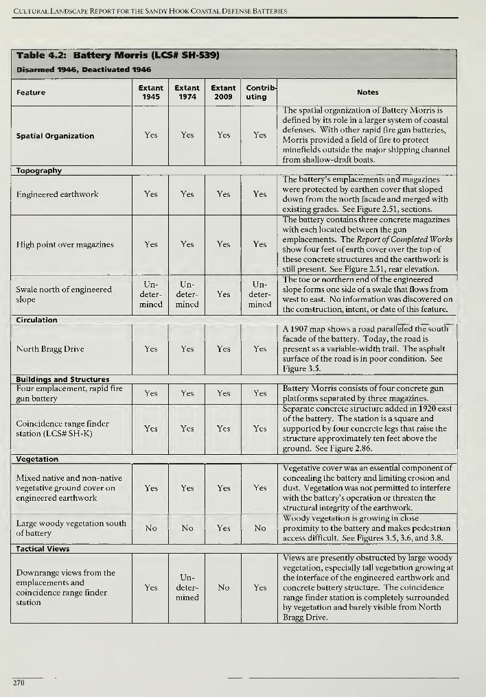
Cultural Landscape Report for the Sandy Hook Coastal Defense Batteries
Table 4.2: Battery Morris (LCS# SH-539)
Disarmed 1946, Deactivated 1946
FeatureExtant1945
Extant1974
Extant
2009Contrib-
utingNotes
Spatial Organization Yes Yes Yes Yes
The spatial organization of Battery Morris is
defined by its role in a larger system of coastal
defenses. With other rapid fire gun batteries,
Morris provided a field of fire to protect
minefields outside the major shipping channel
from shallow-draft boats.
Topography
Engineered earthwork Yes Yes Yes Yes
The battery's emplacements and magazines
were protected by earthen cover that sloped
down from the north facade and merged with
existing grades. See Figure 2.51, sections.
High point over magazines Yes Yes Yes Yes
The battery contains three concrete magazines
with each located between the gun
emplacements. The Report of Completed Works
show four feet of earth cover over the top of
these concrete structures and the earthwork is
still present. See Figure 2.51, rear elevation.
Swale north of engineered
slope
Un-deter-
mined
Un-deter-
mined
Yes
Un-deter-
mined
The toe or northern end of the engineered
slope forms one side of a swale that flows from
west to east. No information was discovered on
the construction, intent, or date of this feature.
Circulation
North Bragg Drive Yes Yes Yes Yes
A 1907 map shows a road paralleled the south
facade of the battery. Today, the road is
present as a variable-width trail. The asphalt
surface of the road is in poor condition. See
Figure 3.5.
Buildings and Structures
Four emplacement, rapid fire
gun batteryYes Yes Yes Yes
Battery Morris consists of four concrete gun
platforms separated by three magazines.
Coincidence range finder
station (LCS# SH-K)Yes Yes Yes Yes
Separate concrete structure added in 1920 east
of the battery. The station is a square and
supported by four concrete legs that raise the
structure approximately ten feet above the
ground. See Figure 2.86.
Vegetation
Mixed native and non-native
vegetative ground cover on
engineered earthwork
Yes Yes Yes Yes
Vegetative cover was an essential component of
concealing the battery and limiting erosion and
dust. Vegetation was not permitted to interfere
with the battery's operation or threaten the
structural integrity of the earthwork.
Large woody vegetation south
of batteryNo No Yes No
Woody vegetation is growing in close
proximity to the battery and makes pedestrian
access difficult. See Figures 3.5, 3.6, and 3.8.
Tactical Views
Downrange views from the
emplacements and
coincidence range finder
station
Yes
Un-deter-
mined
No Yes
Views are presently obstructed by large woodyvegetation, especially tall vegetation growing at
the interface of the engineered earthwork and
concrete battery structure. The coincidence
range finder station is completely surrounded
by vegetation and barely visible from North
Bragg Drive.
270

Analysis and Evaluation
FeatureExtant
1945Extant
1974Extant
2009Contrib-
utingNotes
Small-Scale Features
U. S. Coast Guard perimeter
fenceNo Yes Yes No
Immediately south of North Bragg Drive, the
Coast Guard has erected a six-foot tall chain-
link fence topped with barbed wire. See
Figure 3.5.
Wood-slat fence north and
east of batteryNo Yes Yes No
Erected by the Army in the early 1970s and
presently in poor condition. See Figure 3.8.
Wood two-by-four guard
panelsNo Yes Yes No
Erected by the Army in the early 1970s and
presently in poor condition. See Figure 3.6.
271
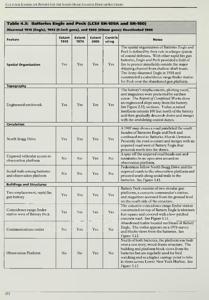
Cultural Landscape Report for the Sandy Hook Coastal Defense Batteries
Table 4.3: Batteries Engle and Peck (LCS# SH-189A and SH-180)
Disarmed 1918 (Engle), 1943 (6-inch guns), and 1946 (90mm guns); Deactivated 1946
FeatureExtant1945
Extant1974
Extant2009
Contrib-
utingNotes
Spatial Organization Yes Yes Yes Yes
The spatial organization of Batteries Engle and
Peck is defined by their role in a larger system
of coastal defenses. With other rapid fire gunbatteries, Engle and Peck provided a field of
fire to protect minefields outside the major
shipping channel from shallow-draft boats.
The Army disarmed Engle in 1918 and
constructed a coincidence range finder station
for Peck over the abandoned gun platform.
Topography
Engineered earthwork Yes Yes Yes Yes
The battery's emplacements, plotting room,
and magazines were protected by earthen
cover. The Report of Completed Works showan engineered slope away from the battery.
See Figure 2.52, sections. Today, a raised
landform extends 100 feet north of the battery
and then gradually descends down and merges
with the undulating coastal dunes.
Circulation
North Bragg Drive Yes Yes Yes Yes
A 1907 map shows a road paralleled the south
facades of Batteries Engle and Peck and
continued west to Batteries Morris Urmston.
Presently the road is extant and merges with an
unpaved road west of Battery Engle that
proceeds north into the dunes.
Unpaved vehicular access to
observation platformNo No Yes No
A spur off the unpaved road heads east and
terminates in an open area around an
observation platform.
Social trails among batteries
and observation platformNo No Yes No
Pedestrians follow North Bragg Drive and the
unpaved roads to the observation platform and
proceed south along social trails to the
batteries. See Figure 3.11.
Buildings and Structures
Two emplacement, rapid fire
gun batteryYes Yes Yes Yes
Battery Peck consists of two circular gun
platforms, a concrete commander's station,
and magazines accessed from the ground level
on the south side of the structure.
Coincidence range finder
station west of Battery PeckYes Yes Yes Yes
The concrete coincidence range finder station
constructed on top of Battery Engle is nineteen
feet square and covered with a low-pitched
concrete roof. See Figure 3.11.
Communications trailer No Yes Yes No
Abandoned trailer located northeast of Battery
Engle. The trailer appears on a 1976 survey
and blocks views from the batteries. See
Figure 3.12.
Observation Platform No No Yes No
North of both batteries, the platform was built
over a one story, wood-frame structure. Thebuilding and platform block views from the
batteries but are regularly used for bird
watching and as a higher vantage point to take
in views across Lower New York Harbor. See
Figure 3.13.
272
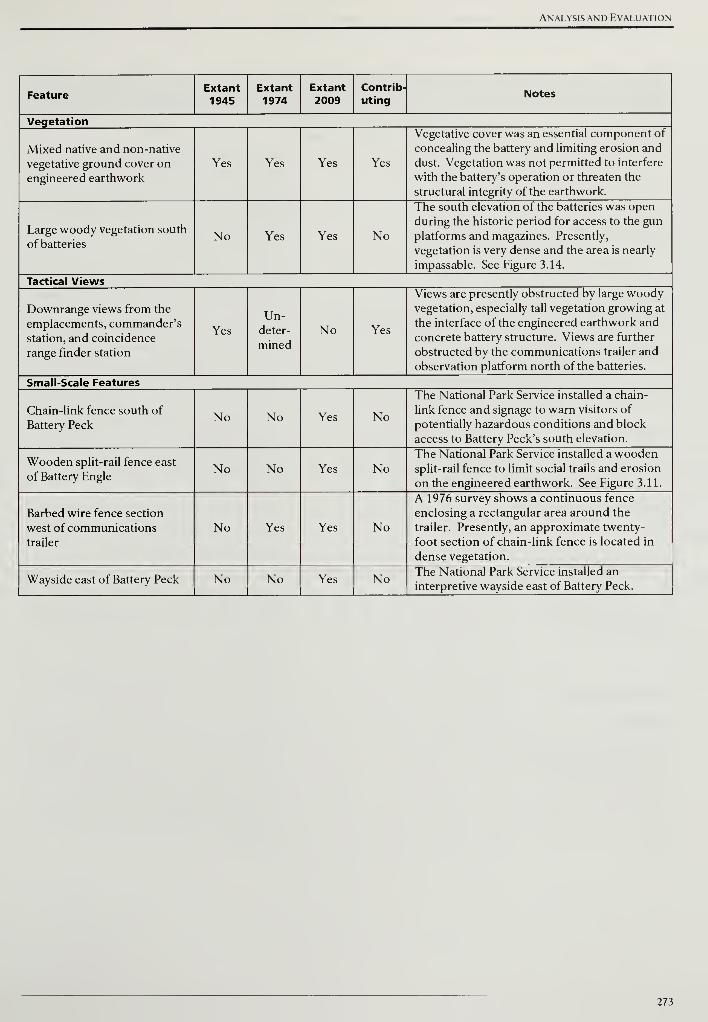
Analysis and Evaluation
FeatureExtant1945
Extant1974
Extant
2009Contrib-
utingNotes
Vegetation
Mixed native and non-native
vegetative ground cover on
engineered earthwork
Yes Yes Yes Yes
Vegetative cover was an essential component of
concealing the battery and limiting erosion and
dust. Vegetation was not permitted to interfere
with the battery's operation or threaten the
structural integrity of the earthwork.
Large woody vegetation south
of batteriesNo Yes Yes No
The south elevation of the batteries was open
during the historic period for access to the gun
platforms and magazines. Presently,
vegetation is very dense and the area is nearly
impassable. See Figure 3.14.
Tactical Views
Downrange views from the
emplacements, commander's
station, and coincidence
range finder station
Yes
Un-deter-
mined
No Yes
Views are presently obstructed by large woodyvegetation, especially tall vegetation growing at
the interface of the engineered earthwork and
concrete battery structure. Views are further
obstructed by the communications trailer and
observation platform north of the batteries.
Small-Scale Features
Chain-link fence south of
Battery PeckNo No Yes No
The National Park Service installed a chain-
link fence and signage to warn visitors of
potentially hazardous conditions and block
access to Battery Peck's south elevation.
Wooden split-rail fence east
of Battery EngleNo No Yes No
The National Park Service installed a woodensplit-rail fence to limit social trails and erosion
on the engineered earthwork. See Figure 3.11.
Barbed wire fence section
west of communications
trailer
No Yes Yes No
A 1976 survey shows a continuous fence
enclosing a rectangular area around the
trailer. Presently, an approximate twenty-
foot section of chain-link fence is located in
dense vegetation.
Wayside east of Battery Peck No No Yes No The National Park Service installed an
interpretive wayside east of Battery Peck.
273
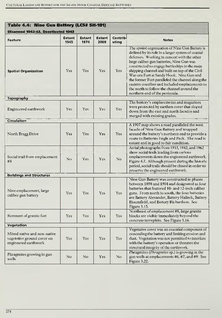
Cultural Landscape Report for the Sandy Hook Coastal Defense Batteries
Table 4.4: Mine Gun Battery (LCS# SH 181)
Disarmed 1942-43, Deactivated 1943
FeatureExtant1945
Extant
1974Extant
2009Contrib-
utingNotes
Spatial Organization Yes Yes Yes Yes
The spatial organization of Nine Gun Battery is
defined by its role in a larger system of coastal
defenses. Working in concert with the other
large caliber gun batteries, Nine Gun was
constructed to engage battleships in the main
shipping channel and built on top of the Civil
War-era Fort at Sandy Hook. Nine Gun and
the former Fort paralleled the channel along the
eastern coastline and included emplacements to
the north to follow the channel around the
northern end of the peninsula.
Topography
Engineered earthwork Yes Yes Yes Yes
The battery's emplacements and magazines
were protected by earthen cover that sloped
down from the east and north facades and
merged with existing grades.
Circulation
North Bragg Drive Yes Yes Yes Yes
A 1907 map shows a road paralleled the west
facade of Nine Gun Battery and wrapped
around the battery's northern end to provide a
route to Batteries Engle and Peck. The road is
extant and in good to fair condition.
Social trail from emplacement
#8No Yes Yes No
Aerial photographs from 1933, 1942, and 1962
show social trails leading from various
emplacements down the engineered earthwork.
Figure 4.7. Although present during the historic
period, social trails should be closed in order to
preserve the engineered earthwork.
Buildings and Structures
Nine emplacement, large
caliber gun batteryYes Yes Yes Yes
Nine Gun Battery was constructed in phases
between 1898 and 1904 and designated as four
batteries that featured 10- and 12-inch caliber
guns. From north to south, the four batteries
are Battery Alexander, Battery Halleck, Battery
Bloomfield, and Battery Richardson. See
Figure 3.15.
Remnant of granite fort Yes Yes Yes Yes
Northeast of emplacement #8, large granite
blocks are visible immediately beyond the
concrete terreplein. See Figure 3.16.
Vegetation
Mixed native and non-native
vegetative ground cover onengineered earthwork
Yes Yes Yes Yes
Vegetative cover was an essential component of
concealing the battery and limiting erosion and
dust. Vegetation was not permitted to interfere
with the battery's operation or threaten the
structural integrity of the earthwork.
Phragmites growing in gunwells
No No Yes NoPhragmites (Phragmites sp.) is growing in the
gun wells at emplacements #6, #7, and #9. See
Figure 3.22.
274
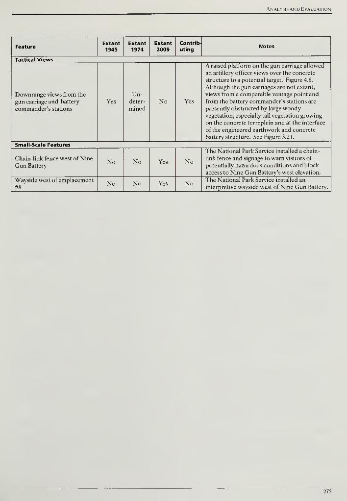
Analysis and Evaluation
FeatureExtant
1945Extant1974
Extant
2009Contrib-
utingNotes
Tactical Views
Downrange views from the
gun carriage and battery
commander's stations
Yes
Un-deter-
mined
No Yes
A raised platform on the gun carriage allowed
an artillery officer views over the concrete
structure to a potential target. Figure 4.8.
Although the gun carriages are not extant,
views from a comparable vantage point and
from the battery commander's stations are
presently obstructed by large woodyvegetation, especially tall vegetation growing
on the concrete terreplein and at the interface
of the engineered earthwork and concrete
battery structure. See Figure 3.21.
Small-Scale Features
Chain-link fence west of Nine
Gun BatteryNo No Yes No
The National Park Service installed a chain-
link fence and signage to warn visitors of
potentially hazardous conditions and block
access to Nine Gun Battery's west elevation.
Wayside west of emplacement
#8No No Yes No The National Park Service installed an
interpretive wayside west of Nine Gun Battery.
275
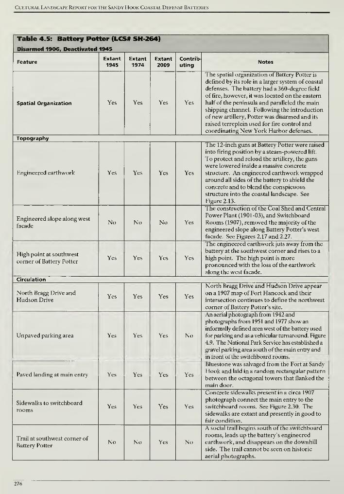
Cultural Landscape Report for the Sandy Hook Coastal Defense Batteries
Table 4.5: Battery Potter (LCS# SH 264)
Disarmed 1906, Deactivated 1945
FeatureExtant1945
Extant1974
Extant2009
Contrib-
utingNotes
Spatial Organization Yes Yes Yes Yes
The spatial organization of Battery Potter is
defined by its role in a larger system of coastal
defenses. The battery had a 360-degree field
of fire, however, it was located on the eastern
half of the peninsula and paralleled the main
shipping channel. Following the introduction
of new artillery, Potter was disarmed and its
raised terreplein used for fire control and
coordinating New York Harbor defenses.
Topography
Engineered earthwork Yes Yes Yes Yes
The 12-inch guns at Battery Potter were raised
into firing position by a steam-powered lift.
To protect and reload the artillery, the guns
were lowered inside a massive concrete
structure. An engineered earthwork wrapped
around all sides of the battery to shield the
concrete and to blend the conspicuous
structure into the coastal landscape. See
Figure 2.13.
Engineered slope along west
facadeNo No No Yes
The construction of the Coal Shed and Central
Power Plant (1901-03), and Switchboard
Rooms (1907), removed the majority of the
engineered slope along Battery Potter's west
facade. See Figures 2.17 and 2.27.
High point at southwest
corner of Battery PotterYes Yes Yes Yes
The engineered earthwork juts away from the
battery at the southwest corner and rises to a
high point. The high point is morepronounced with the loss of the earthwork
along the west facade.
Circulation
North Bragg Drive and
Hudson DriveYes Yes Yes Yes
North Bragg Drive and Hudson Drive appear
on a 1907 map of Fort Hancock and their
intersection continues to define the northwest
corner of Battery Potter's site.
Unpaved parking area Yes Yes Yes No
An aerial photograph from 1942 and
photographs from 1951 and 1977 show an
informally defined area west of the battery used
for parking and as a vehicular turnaround. Figure
4.9. The National Park Service has established a
gravel parking area south of the main entry and
in front of the switchboard rooms.
Paved landing at main entry Yes Yes Yes Yes
Bluestone was salvaged from the Fort at Sandy
Hook and laid in a random rectangular pattern
between the octagonal towers that flanked the
main door.
Sidewalks to switchboard
roomsYes Yes Yes Yes
Concrete sidewalks present in a circa 1907
photograph connect the main entry to the
switchboard rooms. See Figure 2.30. Thesidewalks are extant and presently in good to
fair condition.
Trail at southwest corner of
Battery PotterNo No Yes No
A social trail begins south of the switchboard
rooms, leads up the battery's engineered
earthwork, and disappears on the downhill
side. The trail cannot be seen on historic
aerial photographs.
276
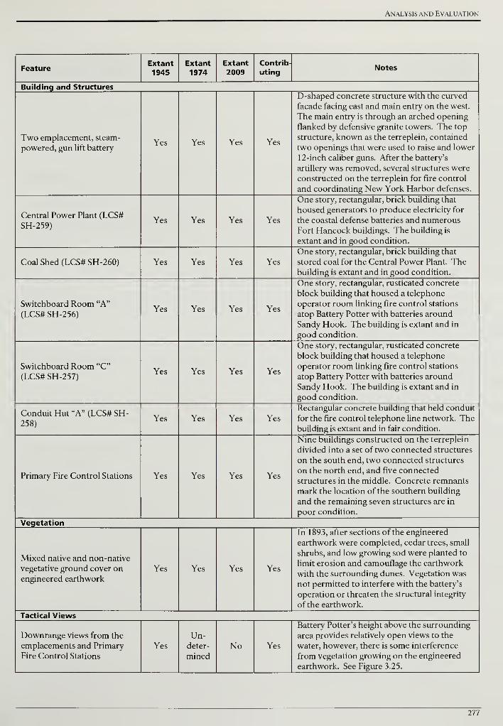
Analysis and Evaluation
FeatureExtant
1945Extant
1974Extant2009
Contrib-
utingNotes
Building and Structures
Two emplacement, steam-
powered, gun lift batteryYes Yes Yes Yes
D-shaped concrete structure with the curved
facade facing east and main entry on the west.
The main entry is through an arched opening
flanked by defensive granite towers. The top
structure, known as the terreplein, contained
two openings that were used to raise and lower
12-inch caliber guns. After the battery's
artillery was removed, several structures were
constructed on the terreplein for fire control
and coordinating New York Harbor defenses.
Central Power Plant (LCS#
SH-259)Yes Yes Yes Yes
One story, rectangular, brick building that
housed generators to produce electricity for
the coastal defense batteries and numerous
Fort Hancock buildings. The building is
extant and in good condition.
Coal Shed (LCS# SH-260) Yes Yes Yes Yes
One story, rectangular, brick building that
stored coal for the Central Power Plant. Thebuilding is extant and in good condition.
Switchboard Room "A"
(LCS# SH-256)Yes Yes Yes Yes
One story, rectangular, rusticated concrete
block building that housed a telephone
operator room linking fire control stations
atop Battery Potter with batteries around
Sandy Hook. The building is extant and in
good condition.
Switchboard Room "C"
(LCS# SH-257)Yes Yes Yes Yes
One story, rectangular, rusticated concrete
block building that housed a telephone
operator room linking fire control stations
atop Battery Potter with batteries around
Sandy Hook. The building is extant and in
good condition.
Conduit Hut "A" (LCS# SH-
258)Yes Yes Yes Yes
Rectangular concrete building that held conduit
for the fire control telephone line network. Thebuilding is extant and in fair condition.
Primary Fire Control Stations Yes Yes Yes Yes
Nine buildings constructed on the terreplein
divided into a set of two connected structures
on the south end, two connected structures
on the north end, and five connected
structures in the middle. Concrete remnants
mark the location of the southern building
and the remaining seven structures are in
poor condition.
Vegetation
Mixed native and non-native
vegetative ground cover onengineered earthwork
Yes Yes Yes Yes
In 1893, after sections of the engineered
earthwork were completed, cedar trees, small
shrubs, and low growing sod were planted to
limit erosion and camouflage the earthwork
with the surrounding dunes. Vegetation was
not permitted to interfere with the battery's
operation or threaten the structural integrity
of the earthwork.
Tactical Views
Downrange views from the
emplacements and Primary
Fire Control Stations
Yes
Un-deter-
minedNo Yes
Battery Potter's height above the surrounding
area provides relatively open views to the
water, however, there is some interference
from vegetation growing on the engineered
earthwork. See Figure 3.25.
277
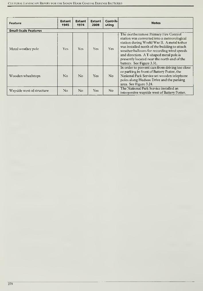
Cultural Landscape Report for the Sandy Hook Coastal Defense Batteries
FeatureExtant
1945Extant1974
Extant2009
Contrib-
utingNotes
Small-Scale Features
Metal weather pole Yes Yes Yes Yes
The northernmost Primary Fire Control
station was converted into a meteorological
station during World War II. A metal tether
was installed north of the building to attach
weather balloons for recording wind speeds
and direction. A T-shaped metal pole is
presently located near the north end of the
battery. See Figure 3.31.
Wooden wheelstops No No Yes No
In order to prevent cars from driving too close
or parking in front of Battery Potter, the
National Park Service set wooden telephone
poles along Hudson Drive and the parking
area. See Figure 3.24.
Wayside west of structure No No Yes No The National Park Service installed an
interpretive wayside west of Battery Potter.
278
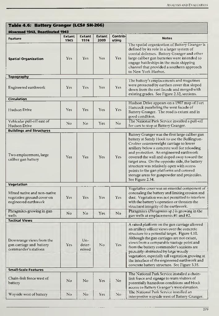
Analysis and Evaluation
Table 4.6: Battery Granger (LCS# SH 266)
Disarmed 1943, Deactivated 1943
FeatureExtant
1945Extant
1974Extant2009
Contrib-
utingNotes
Spatial Organization Yes Yes Yes Yes
The spatial organization of Battery Granger is
defined by its role in a larger system of
coastal defenses. Battery Granger and other
large caliber gun batteries were intended to
engage battleships in the main shipping
channel that provided a southern approach
to New York Harbor.
Topography
Engineered earthwork Yes Yes Yes Yes
The battery's emplacements and magazines
were protected by earthen cover that sloped
down from the east facade and merged with
existing grades. See Figure 2.32, sections.
Circulation
Hudson Drive Yes Yes Yes Yes
Hudson Drive appears on a 1907 map of Fort
Hancock paralleling the west facade of
Battery Granger. The road is extant and in
good condition.
Vehicular pull-off east of
Hudson DriveNo No Yes No The National Park Service installed a pull-off
for cars to stop at Battery Granger.
Buildings and Structures
Two emplacement, large
caliber gun batteryYes Yes Yes Yes
Battery Granger was the first large caliber gun
battery at Sandy Hook to use the Buffington-
Croizer counterweight carriage to lower
artillery below a concrete wall for reloading
and protection. An engineered earthwork
covered the wall and sloped away toward the
target area. On the opposite side, the battery
structure was relatively open with access
points to the gun platforms and covered
storage areas for gunpowder and projectiles.
See Figure 2.34.
Vegetation
Mixed native and non-native
vegetative ground cover on
engineered earthwork
Yes Yes Yes Yes
Vegetative cover was an essential component of
concealing the battery and limiting erosion and
dust. Vegetation was not permitted to interfere
with the battery's operation or threaten the
structural integrity of the earthwork.
Phragmites growing in gunwells
No No Yes NoPhragmites (Phragmites sp.) is growing in the
gun wells at emplacements #1 and #2.
Tactical Views
Downrange views from the
gun carriage and battery
commander's stations
Yes
Un-deter-
mined
No Yes
A raised platform on the gun carriage allowed
an artillery officer views over the concrete
structure to a potential target. Figure 4.10.
Although the gun carriages are not extant,
views from a comparable vantage point and
from the battery commander's stations are
presently obstructed by large woodyvegetation, especially tall vegetation growing at
the interface of the engineered earthwork and
concrete battery structure. See Figure 3.35.
Small-Scale Features
Chain-link fence west of
batteryNo No Yes No
The National Park Service installed a chain-
link fence and signage to warn visitors of
potentially hazardous conditions and block
access to Battery Granger's west elevation.
Wayside west of battery No No Yes NoThe National Park Service installed an
interpretive wayside west of Battery Granger.
279
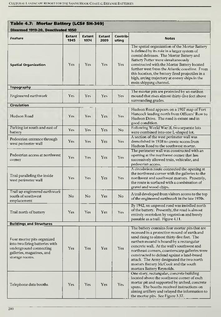
Cultural Landscape Report for the Sandy Hook Coastal Defense Batteries
Table 4.7: Mortar Battery (LCS# SH 349)
Disarmed 1919-20, Deactivated 1950
FeatureExtant
1945Extant1974
Extant
2009Contrib-
utingNotes
Spatial Organization Yes Yes Yes Yes
The spatial organization of the Mortar Battery
is defined by its role in a larger system of
coastal defenses. The Mortar Battery and
Battery Potter were simultaneously
constructed with the Mortar Battery located
further west from the Atlantic coastline. Fromthis location, the battery fired projectiles in a
high, arcing trajectory at enemy ships in the
main shipping channel.
Topography
Engineered earthwork Yes Yes Yes Yes
The mortar pits are protected by an earthen
mound that rises almost thirty-five feet above
surrounding grades.
Circulation
Hudson Road Yes Yes Yes Yes
Hudson Road appears on a 1907 map of Fort
Hancock leading north from Officers' Row to
Hudson Drive. The road is extant and in
good condition.
Parking lot south and east of
batteryYes Yes Yes No Following World War II, two separate lots
were combined into one L-shaped lot.
Pedestrian entrance through
west perimeter wallYes Yes Yes Yes
A section of the west perimeter wall was
demolished in 1938 to create access from
Hudson Road to the southwest mortar.
Pedestrian access at northwest
cornerYes Yes Yes Yes
The perimeter wall was constructed with an
opening at the northwest corner that has
successively allowed train, vehicular, and
pedestrian access.
Trail paralleling the inside
west perimeter wallYes Yes Yes Yes
A circulation route connected the opening at
the northwest corner with the galleries to the
northwest and southwest mortars. Presently,
the route is surfaced with a combination of
gravel and wood chips.
Trail up engineered earthwork
south of southwest
emplacement
No No Yes No A trail developed from visitors access to the top
of the engineered earthwork in the late 1970s.
Trail north of battery Yes Yes Yes Yes
By 1942, an unpaved road was installed north
of the battery. Presently, the road is almost
entirely overtaken by vegetation and barely
passable as a trail. Figure 4.11.
Buildings and Structures
Four mortar pits organized
into two firing batteries with
underground connecting
galleries, magazines, andstorage rooms.
Yes Yes Yes Yes
The battery contains four mortar pits that are
recessed in a protective mound of earth and
sand rising to almost thirty-five feet. Theearthen mound is bound by a rectangular
concrete wall. At the wall's southwest and
northeast corners, counterscarp galleries were
constructed to defend against a land-based
attack. The Army designated the two north
mortars Battery McCook and the south
mortars Battery Reynolds.
Telephone data booths Yes Yes Yes Yes
One story, rectangular, concrete building
located above the southwest corner of each
mortar pit and supported by arched, concrete
spans. The booths received instructions on
aiming artillery and relayed the information to
the mortar pits. See Figure 3.37.
280
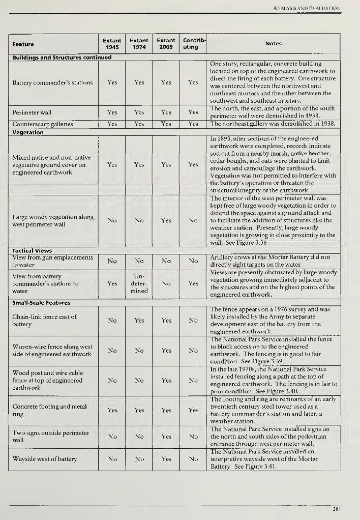
Analysis and Evaluation
FeatureExtant
1945Extant1974
Extant
2009Contrib-
utingNotes
Buildings and Structures continued
Battery commander's stations Yes Yes Yes Yes
One story, rectangular, concrete building
located on top of the engineered earthwork to
direct the firing of each battery. One structure
was centered between the northwest and
northeast mortars and the other between the
southwest and southeast mortars.
Perimeter wall Yes Yes Yes YesThe north, the east, and a portion of the south
perimeter wall were demolished in 1938.
Counterscarp galleries Yes Yes Yes Yes The northeast gallery was demolished in 1938.
Vegetation
Mixed native and non-native
vegetative ground cover on
engineered earthwork
Yes Yes Yes Yes
In 1893, after sections of the engineered
earthwork were completed, records indicate
sod cut from a nearby marsh, native heather,
cedar boughs, and oats were planted to limit
erosion and camouflage the earthwork.
Vegetation was not permitted to interfere with
the battery's operation or threaten the
structural integrity of the earthwork.
Large woody vegetation along
west perimeter wallNo No Yes No
The interior of the west perimeter wall was
kept free of large woody vegetation in order to
defend the space against a ground attack and
to facilitate the addition of structures like the
weather station. Presently, large woodyvegetation is growing in close proximity to the
wall. See Figure 3.38.
Tactical ViewsView from gun emplacements
to waterNo No No No Artillery crews at the Mortar Battery did not
directly sight targets on the water
View from battery
commander's stations to
water
Yes
Un-deter-
minedNo Yes
Views are presently obstructed by large woodyvegetation growing immediately adjacent to
the structures and on the highest points of the
engineered earthwork.
Small-Scale Features
Chain-link fence east of
batteryNo Yes Yes No
The fence appears on a 1976 survey and was
likely installed by the Army to separate
development east of the battery from the
engineered earthwork.
Woven-wire fence along west
side of engineered earthworkNo No Yes No
The National Park Service installed the fence
to block access on to the engineered
earthwork. The fencing is in good to fair
condition. See Figure 3.39.
Wood post and wire cable
fence at top of engineered
earthwork
No No Yes No
In the late 1970s, the National Park Service
installed fencing along a path at the top of
engineered earthwork. The fencing is in fair to
poor condition. See Figure 3.40.
Concrete footing and metal
ringYes Yes Yes Yes
The footing and ring are remnants of an early
twentieth century steel tower used as a
battery commander's station and later, a
weather station.
Two signs outside perimeter
wallNo No Yes No
The National Park Service installed signs on
the north and south sides of the pedestrian
entrance through west perimeter wall.
Wayside west of battery No No Yes NoThe National Park Service installed an
interpretive wayside west of the Mortar
Battery. See Figure 3.41.
281
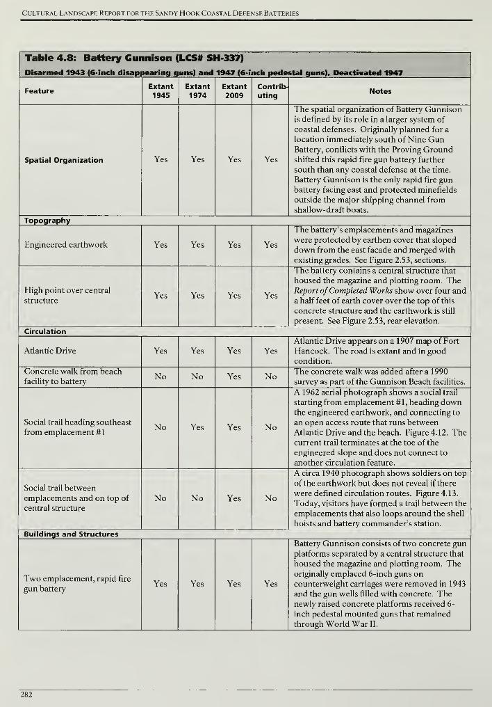
Cultural Landscape Report for the Sandy Hook Coastal Defense Batteries
Table 4.8: Battery Gunnison (LCS# SH 337)
Disarmed 1943 (6-inch disappearing guns) and 1947 (6-inch pedestal guns). Deactivated 1947
FeatureExtant1945
Extant1974
Extant
2009Contrib-
utingNotes
Spatial Organization Yes Yes Yes Yes
The spatial organization of Battery Gunnisonis defined by its role in a larger system of
coastal defenses. Originally planned for a
location immediately south of Nine GunBattery, conflicts with the Proving Groundshifted this rapid fire gun battery further
south than any coastal defense at the time.
Battery Gunnison is the only rapid fire gunbattery facing east and protected minefields
outside the major shipping channel from
shallow-draft boats.
Topography
Engineered earthwork Yes Yes Yes Yes
The battery's emplacements and magazines
were protected by earthen cover that sloped
down from the east facade and merged with
existing grades. See Figure 2.53, sections.
High point over central
structureYes Yes Yes Yes
The battery contains a central structure that
housed the magazine and plotting room. TheReport ofCompleted Works show over four and
a half feet of earth cover over the top of this
concrete structure and the earthwork is still
present. See Figure 2.53, rear elevation.
Circulation
Atlantic Drive Yes Yes Yes Yes
Atlantic Drive appears on a 1907 map of Fort
Hancock. The road is extant and in goodcondition.
Concrete walk from beach
facility to batteryNo No Yes No The concrete walk was added after a 1990
survey as part of the Gunnison Beach facilities.
Social trail heading southeast
from emplacement #1No Yes Yes No
A 1962 aerial photograph shows a social trail
starting from emplacement #1, heading downthe engineered earthwork, and connecting to
an open access route that runs between
Atlantic Drive and the beach. Figure 4.12. Thecurrent trail terminates at the toe of the
engineered slope and does not connect to
another circulation feature.
Social trail between
emplacements and on top of
central structure
No No Yes No
A circa 1940 photograph shows soldiers on top
of the earthwork but does not reveal if there
were defined circulation routes. Figure 4.13.
Today, visitors have formed a trail between the
emplacements that also loops around the shell
hoists and battery commander's station.
Buildings and Structures
Two emplacement, rapid fire
gun batteryYes Yes Yes Yes
Battery Gunnison consists of two concrete gun
platforms separated by a central structure that
housed the magazine and plotting room. Theoriginally emplaced 6-inch guns oncounterweight carriages were removed in 1943
and the gun wells filled with concrete. Thenewly raised concrete platforms received 6-
inch pedestal mounted guns that remained
through World War II.
282
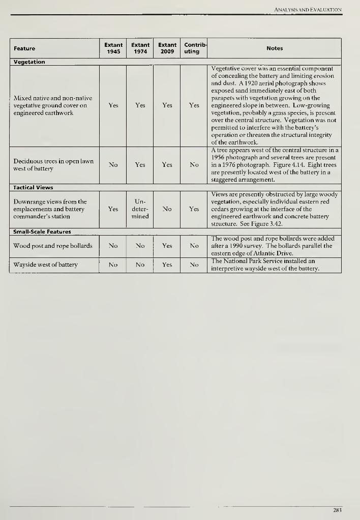
Analysis and Evaluation
FeatureExtant
1945Extant1974
Extant
2009Contrib-
utingNotes
Vegetation
Mixed native and non-native
vegetative ground cover on
engineered earthwork
Yes Yes Yes Yes
Vegetative cover was an essential componentof concealing the battery and limiting erosion
and dust. A 1920 aerial photograph shows
exposed sand immediately east of both
parapets with vegetation growing on the
engineered slope in between. Low-growing
vegetation, probably a grass species, is present
over the central structure. Vegetation was not
permitted to interfere with the battery's
operation or threaten the structural integrity
of the earthwork.
Deciduous trees in open lawn
west of batteryNo Yes Yes No
A tree appears west of the central structure in a
1956 photograph and several trees are present
in a 1976 photograph. Figure 4.14. Eight trees
are presently located west of the battery in a
staggered arrangement.
Tactical Views
Downrange views from the
emplacements and battery
commander's station
Yes
Un-deter-
minedNo Yes
Views are presently obstructed by large woodyvegetation, especially individual eastern red
cedars growing at the interface of the
engineered earthwork and concrete battery
structure. See Figure 3.42.
Small-Scale Features
Wood post and rope bollards No No Yes NoThe wood post and rope bollards were added
after a 1990 survey. The bollards parallel the
eastern edge of Atlantic Drive.
Wayside west of battery No No Yes NoThe National Park Service installed an
interpretive wayside west of the battery.
283
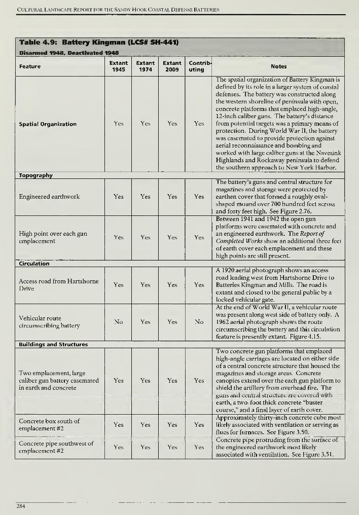
Cultural Landscape Report for the Sandy Hook Coastal Defense Batteries
Table 4.9: Battery Kingman (LCS# SH 441)
Disarmed 1948, Deactivated 1948
FeatureExtant1945
Extant1974
Extant
2009Contrib-
utingNotes
Spatial Organization Yes Yes Yes Yes
The spatial organization of Battery Kingman is
defined by its role in a larger system of coastal
defenses. The battery was constructed along
the western shoreline of peninsula with open,
concrete platforms that emplaced high-angle,
12-inch caliber guns. The battery's distance
from potential targets was a primary means of
protection. During World War II, the battery
was casemated to provide protection against
aerial reconnaissance and bombing and
worked with large caliber guns at the Navesink
Highlands and Rockaway peninsula to defend
the southern approach to New York Harbor.
Topography
Engineered earthwork Yes Yes Yes Yes
The battery's guns and central structure for
magazines and storage were protected by
earthen cover that formed a roughly oval-
shaped mound over 700 hundred feet across
and forty feet high. See Figure 2.76.
High point over each gun
emplacementYes Yes Yes Yes
Between 1941 and 1942 the open gun
platforms were casemated with concrete and
an engineered earthwork. The Report of
Completed Works show an additional three feet
of earth cover each emplacement and these
high points are still present.
Circulation
Access road from Hartshorne
DriveYes Yes Yes Yes
A 1920 aerial photograph shows an access
road leading west from Hartshorne Drive to
Batteries Kingman and Mills. The road is
extant and closed to the general public by a
locked vehicular gate.
Vehicular route
circumscribing batteryNo Yes Yes No
At the end of World War II, a vehicular route
was present along west side of battery only. A1962 aerial photograph shows the route
circumscribing the battery and this circulation
feature is presently extant. Figure 4.15.
Buildings and Structures
Two emplacement, large
caliber gun battery casemated
in earth and concrete
Yes Yes Yes Yes
Two concrete gun platforms that emplaced
high-angle carriages are located on either side
of a central concrete structure that housed the
magazines and storage areas. Concrete
canopies extend over the each gun platform to
shield the artillery from overhead fire. Theguns and central structure are covered with
earth, a two-foot thick concrete "buster
course," and a final layer of earth cover.
Concrete box south of
emplacement #2Yes Yes Yes Yes
Approximately thirty-inch concrete cube most
likely associated with ventilation or serving as
flues for furnaces. See Figure 3.50.
Concrete pipe southwest of
emplacement #2Yes Yes Yes Yes
Concrete pipe protruding from the surface of
the engineered earthwork most likely
associated with ventilation. See Figure 3.51.
284
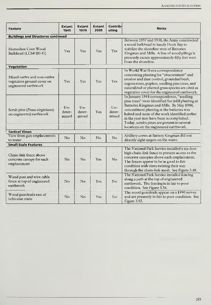
Analysis and Evaluation
FeatureExtant1945
Extant
1974Extant2009
Contrib-
utingNotes
Buildings and Structures continued
Horseshoe Cove WoodBulkhead (LCS# SH-G)
Yes Yes Yes Yes
Between 1937 and 1938, the Army constructed
a wood bulkhead in Sandy Hook Bay to
stabilize the shoreline west of Batteries
Kingman and Mills. A line ofwood pilings is
presently extant approximately fifty feet west
from the shoreline.
Vegetation
Mixed native and non-native
vegetative ground cover on
engineered earthwork
Yes Yes Yes Yes
In World War II-era correspondence
concerning planting for "obscurement" and
erosion and dust control, groundsel bush,
rugosa roses, poplars, seedling pine trees, and
naturalized or planted grass species are cited as
vegetative cover for the engineered earthwork.
Scrub pine (Pinus virginiana)
on engineered earthwork
Un-deter-
mined
Un-deter-
minedYes
Un-deter-
mined
In January 1944 correspondence, "seedling
pine trees" were identified for infill planting at
Batteries Kingman and Mills. By May 1944,
concealment planting at the batteries was
halted and none of the work identified earlier
in the year may have been accomplished.
Today, scrubs pines are present in several
locations on the engineered earthwork.
Tactical ViewsView from gun emplacements
to waterNo No No No Artillery crews at Battery Kingman did not
directly sight targets on the water.
Small-Scale Features
Chain-link fence above
concrete canopy for each
emplacement
No No Yes No
The National Park Service installed a six-foot
high chain-link fence to prevent access to the
concrete canopies above each emplacement.
The fences appear to be in good to fair
condition with vines twining their waythrough the chain-link mesh. See Figure 3.48.
Wood post and wire cable
fence at top of engineered
earthwork
No No Yes No
The National Park Service installed fencing
along a path at the top of engineered
earthwork. The fencing is in fair to poor
condition. See Figure 3.56.
Wood guardrails east of
vehicular routeNo No Yes No
The wood guardrails appear on a 1990 survey
and are presently in fair to poor condition. See
Figure 3.57.
285
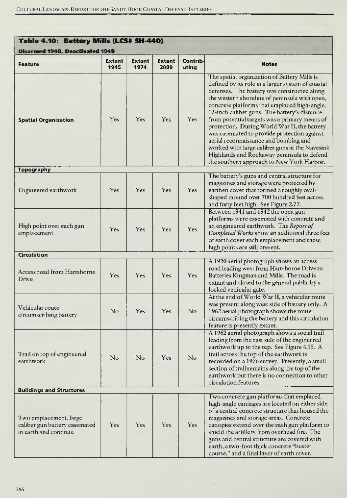
Cultural Landscape Report for the Sandy Hook Coastal Defense Batteries
Table 4.10: Battery Mills (LCS# SH-440)
Disarmed 1948, Deactivated 1948
FeatureExtant
1945Extant1974
Extant
2009Contrib-
utingNotes
Spatial Organization Yes Yes Yes Yes
The spatial organization of Battery Mills is
defined by its role in a larger system of coastal
defenses. The battery was constructed along
the western shoreline of peninsula with open,
concrete platforms that emplaced high-angle,
12-inch caliber guns. The battery's distance
from potential targets was a primary means of
protection. During World War II, the battery
was casemated to provide protection against
aerial reconnaissance and bombing and
worked with large caliber guns at the Navesink
Highlands and Rockaway peninsula to defend
the southern approach to New York Harbor.
Topography
Engineered earthwork Yes Yes Yes Yes
The battery's guns and central structure for
magazines and storage were protected by
earthen cover that formed a roughly oval-
shaped mound over 700 hundred feet across
and forty feet high. See Figure 2.77.
High point over each gun
emplacementYes Yes Yes Yes
Between 1941 and 1942 the open gun
platforms were casemated with concrete and
an engineered earthwork. The Report of
Completed Works show an additional three feet
of earth cover each emplacement and these
high points are still present.
Circulation
Access road from Hartshorne
DriveYes Yes Yes Yes
A 1920 aerial photograph shows an access
road leading west from Hartshorne Drive to
Batteries Kingman and Mills. The road is
extant and closed to the general public by a
locked vehicular gate.
Vehicular route
circumscribing batteryNo Yes Yes No
At the end of World War II, a vehicular route
was present along west side of battery only. A1962 aerial photograph shows the route
circumscribing the battery and this circulation
feature is presently extant.
Trail on top of engineered
earthworkNo No Yes No
A 1962 aerial photograph shows a social trail
leading from the east side of the engineered
earthwork up to the top. See Figure 4.15. Atrail across the top of the earthwork is
recorded on a 1976 survey. Presently, a small
section of trail remains along the top of the
earthwork but there is no connection to other
circulation features.
Buildings and Structures
Two emplacement, large
caliber gun battery casemated
in earth and concrete
Yes Yes Yes Yes
Two concrete gun platforms that emplaced
high-angle carriages are located on either side
of a central concrete structure that housed the
magazines and storage areas. Concrete
canopies extend over the each gun platform to
shield the artillery from overhead fire. Theguns and central structure are covered with
earth, a two-foot thick concrete "buster
course," and a final layer of earth cover.
286
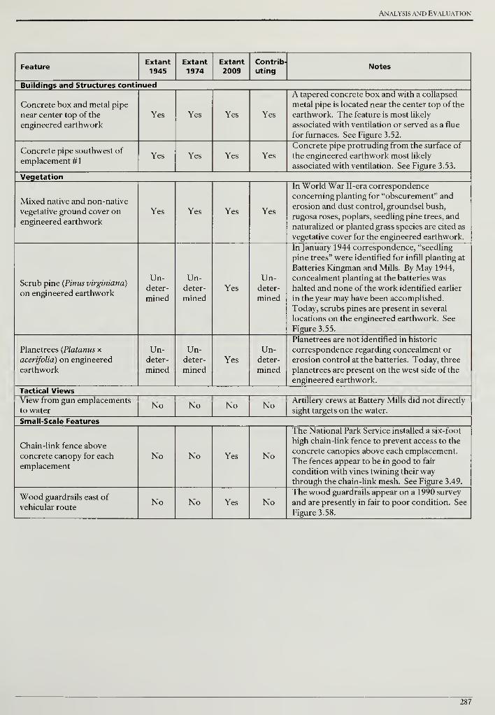
Analysis and Evaluation
FeatureExtant
1945Extant1974
Extant
2009Contrib-
utingNotes
Buildings and Structures continued
Concrete box and metal pipe
near center top of the
engineered earthwork
Yes Yes Yes Yes
A tapered concrete box and with a collapsed
metal pipe is located near the center top of the
earthwork. The feature is most likely
associated with ventilation or served as a flue
for furnaces. See Figure 3.52.
Concrete pipe southwest of
emplacement #1Yes Yes Yes Yes
Concrete pipe protruding from the surface of
the engineered earthwork most likely
associated with ventilation. See Figure 3.53.
Vegetation
Mixed native and non-native
vegetative ground cover on
engineered earthwork
Yes Yes Yes Yes
In World War II-era correspondence
concerning planting for "obscurement" and
erosion and dust control, groundsel bush,
rugosa roses, poplars, seedling pine trees, and
naturalized or planted grass species are cited as
vegetative cover for the engineered earthwork.
Scrub pine (Pinus virginiana)
on engineered earthwork
Un-deter-
mined
Un-deter-
minedYes
Un-deter-
mined
In January 1944 correspondence, "seedling
pine trees" were identified for infill planting at
Batteries Kingman and Mills. By May 1944,
concealment planting at the batteries was
halted and none of the work identified earlier
in the year may have been accomplished.
Today, scrubs pines are present in several
locations on the engineered earthwork. See
Figure 3.55.
Planetrees (Platanus x
acerifolia) on engineered
earthwork
Un-deter-
mined
Un-deter-
minedYes
Un-deter-
mined
Planetrees are not identified in historic
correspondence regarding concealment or
erosion control at the batteries. Today, three
planetrees are present on the west side of the
engineered earthwork.
Tactical ViewsView from gun emplacements
to waterNo No No No
Artillery crews at Battery Mills did not directly
sight targets on the water.
Small-Scale Features
Chain-link fence above
concrete canopy for each
emplacement
No No Yes No
The National Park Service installed a six-foot
high chain-link fence to prevent access to the
concrete canopies above each emplacement.
The fences appear to be in good to fair
condition with vines twining their waythrough the chain-link mesh. See Figure 3.49.
Wood guardrails east of
vehicular routeNo No Yes No
The wood guardrails appear on a 1990 survey
and are presently in fair to poor condition. See
Figure 3.58.
287
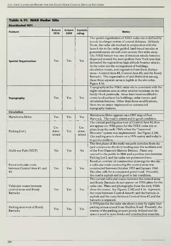
Cultural Landscape Report for the Sandy Hook Coastal Defense Batteries
Table 4.11: NIKE Radar Site
Deactivated 1971
FeatureExtant
1974Extant
2009Contrib-
utingNotes
Spatial Organization Yes Yes Yes
The spatial organization of NIKE radar site is defined by
its role in a larger system of coastal defenses. At Sandy
Hook, the radar site worked in conjunction with the
launch site to fire radar guided, land-based missiles at
potential enemy aircraft over seventy-five miles away.
The NIKE battery was one of nineteen missile batteries
dispersed around the metropolitan New York area that
defended the region from high altitude bomber attacks.
At the radar site the arrangement of buildings,
circulation routes, and vegetation form three distinct
areas—Control Area #1, Control Area #2, and the Ready
Barracks. The organization of and distinction amongthese three separate areas is legible at the site today.
Figure 4.16.
Topography Yes Yes Yes
Topography at the NIKE radar site is consistent with the
slight variations seen in other interior locations on the
Sandy Hook peninsula. Areas have been modified to
create level surfaces for buildings, radar towers, and
circulation features. Other than those modifications,
there are no major engineered or constructed
topography features.
Circulation
Hartshorne Drive Yes Yes YesHartshorne Drive appears on a 1907 map of Fort
Hancock. The road is extant and in good condition.
Parking Lot LUn-
deter-
mined
Yes
Un-deter-
mined
The current parking area west of Control Area #2 does
not appear on 1950s plans for the NIKE radar site or
plans from the early 1960s when the "Improved
Hercules" system was implemented. See Figure 2.101.
The parking area is shown on a 1976 survey and today is
in good condition.
Multi-use Path (MUP) No Yes No
The first phase of the multi-use path stretches from the
park entrance to the ferry landing near the northern end
of the Fort Hancock Historic District. Phase one
opened to the public in 2006 and a portion runs between
Parking Lot L and the radar site perimeter fence.
Paved vehicular route
between Control Area #1 and
#2
Yes Yes Yes
Based on a review of construction drawings for the site,
a vehicular route connecting the control areas was
constructed between October 1955 and January 1960.
The plan calls for a compacted gravel road. Presently,
the road is asphalt and in good to fair condition.
Vehicular routes between
control areas and Ready
Barracks
Yes Yes Yes
The current vehicular routes between the control areas
and Ready Barracks do not appear on 1950s plans for the
radar site. Plans and photographs from the early 1960s
show the routes. See Figures 2.102 and 4.16. A present,
the route between Control Area #1 and the barracks is
asphalt and the route between Control Area #2 and the
barracks is unpaved.
Parking area west of ReadyBarracks
Yes Yes Yes
A 1954 plan for the radar site shows a sixty by eighty foot
parking area accessed from Sheldon Road. Presently, the
extents of the parking area are poorly defined and the
space is used to store bricks and construction materials.
288
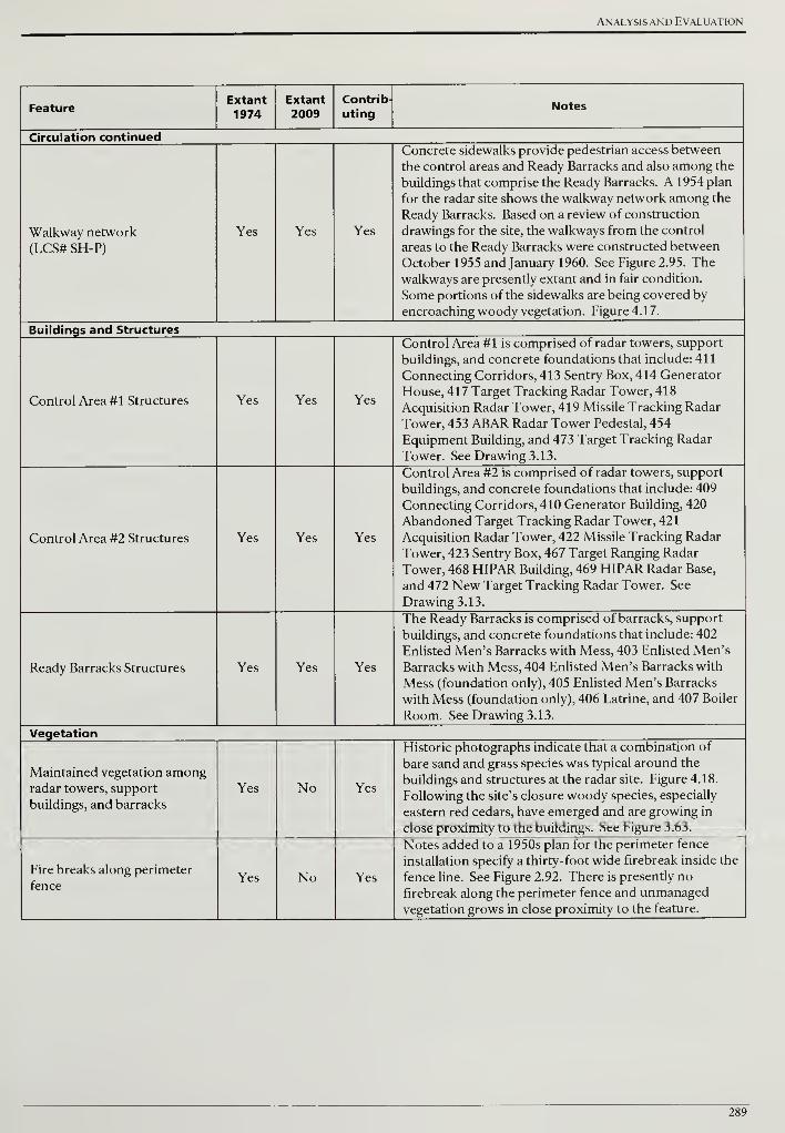
Analysis and Evaluation
FeatureExtant1974
Extant
2009Contrib-
utingNotes
Circulation continued
Walkway network
(LCS# SH-P)
Yes Yes Yes
Concrete sidewalks provide pedestrian access between
the control areas and Ready Barracks and also among the
buildings that comprise the Ready Barracks. A 1954 plan
for the radar site shows the walkway network among the
Ready Barracks. Based on a review of construction
drawings for the site, the walkways from the control
areas to the Ready Barracks were constructed between
October 1955 and January 1960. See Figure 2.95. The
walkways are presently extant and in fair condition.
Some portions of the sidewalks are being covered by
encroaching woody vegetation. Figure 4.17.
Buildings and Structures
Control Area #1 Structures Yes Yes Yes
Control Area #1 is comprised of radar towers, support
buildings, and concrete foundations that include: 411
Connecting Corridors, 413 Sentry Box, 414 Generator
House, 417 Target Tracking Radar Tower, 418
Acquisition Radar Tower, 419 Missile Tracking Radar
Tower, 453 ABAR Radar Tower Pedestal, 454
Equipment Building, and 473 Target Tracking Radar
Tower. See Drawing 3.13.
Control Area #2 Structures Yes Yes Yes
Control Area #2 is comprised of radar towers, support
buildings, and concrete foundations that include: 409
Connecting Corridors, 410 Generator Building, 420
Abandoned Target Tracking Radar Tower, 421
Acquisition Radar Tower, 422 Missile Tracking Radar
Tower, 423 Sentry Box, 467 Target Ranging Radar
Tower, 468 HIPAR Building, 469 HIPAR Radar Base,
and 472 New Target Tracking Radar Tower. See
Drawing 3.13.
Ready Barracks Structures Yes Yes Yes
The Ready Barracks is comprised of barracks, support
buildings, and concrete foundations that include: 402
Enlisted Men's Barracks with Mess, 403 Enlisted Men's
Barracks with Mess, 404 Enlisted Men's Barracks with
Mess (foundation only), 405 Enlisted Men's Barracks
with Mess (foundation only), 406 Latrine, and 407 Boiler
Room. See Drawing 3.13.
Vegetation
Maintained vegetation amongradar towers, support
buildings, and barracks
Yes No Yes
Historic photographs indicate that a combination of
bare sand and grass species was typical around the
buildings and structures at the radar site. Figure 4.18.
Following the site's closure woody species, especially
eastern red cedars, have emerged and are growing in
close proximity to the buildings. See Figure 3.63.
Fire breaks along perimeter
fenceYes No Yes
Notes added to a 1950s plan for the perimeter fence
installation specify a thirty-foot wide firebreak inside the
fence line. See Figure 2.92. There is presently no
firebreak along the perimeter fence and unmanaged
vegetation grows in close proximity to the feature.
289
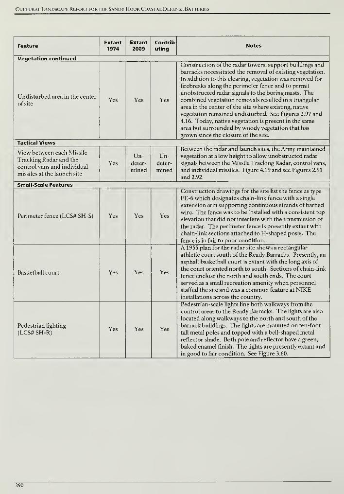
Cultural Landscape Report for the Sandy Hook Coastal Defense Batteries
FeatureExtant1974
Extant
2009Contrib-
utingNotes
Vegetation continued
Undisturbed area in the center
of siteYes Yes Yes
Construction of the radar towers, support buildings and
barracks necessitated the removal of existing vegetation.
In addition to this clearing, vegetation was removed for
firebreaks along the perimeter fence and to permit
unobstructed radar signals to the boring masts. Thecombined vegetation removals resulted in a triangular
area in the center of the site where existing, native
vegetation remained undisturbed. See Figures 2.97 and
4.16. Today, native vegetation is present in the same
area but surrounded by woody vegetation that has
grown since the closure of the site.
Tactical Views
View between each Missile
Tracking Radar and the
control vans and individual
missiles at the launch site
Yes
Un-deter-
mined
Un-deter-
mined
Between the radar and launch sites, the Army maintained
vegetation at a low height to allow unobstructed radar
signals between the Missile Tracking Radar, control vans,
and individual missiles. Figure 4.19 and see Figures 2.91
and 2.92.
Small-Scale Features
Perimeter fence (LCS# SH-S) Yes Yes Yes
Construction drawings for the site list the fence as type
FE-6 which designates chain-link fence with a single
extension arm supporting continuous strands of barbed
wire. The fence was to be installed with a consistent top
elevation that did not interfere with the transmission of
the radar. The perimeter fence is presently extant with
chain-link sections attached to H-shaped posts. Thefence is in fair to poor condition.
Basketball court Yes Yes Yes
A 1955 plan for the radar site shows a rectangular
athletic court south of the Ready Barracks. Presently, an
asphalt basketball court is extant with the long axis of
the court oriented north to south. Sections of chain-link
fence enclose the north and south ends. The court
served as a small recreation amenity when personnel
staffed the site and was a common feature at NIKEinstallations across the country.
Pedestrian lighting
(LCS# SH-R)Yes Yes Yes
Pedestrian-scale lights line both walkways from the
control areas to the Ready Barracks. The lights are also
located along walkways to the north and south of the
barrack buildings. The lights are mounted on ten-foot
tall metal poles and topped with a bell-shaped metal
reflector shade. Both pole and reflector have a green,
baked enamel finish. The lights are presently extant and
in good to fair condition. See Figure 3.60.
290
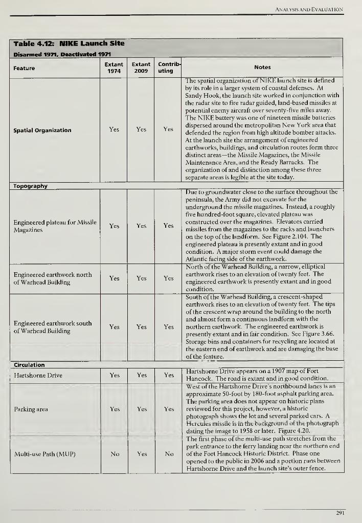
Analysis and Evaluation
Table 4.12: MIKE Launch Site
Disarmed 1971, Deactivated 1971
FeatureExtant
1974Extant
2009Contrib-
utingNotes
Spatial Organization Yes Yes Yes
The spatial organization of NIKE launch site is defined
by its role in a larger system of coastal defenses. At
Sandy Hook, the launch site worked in conjunction with
the radar site to fire radar guided, land-based missiles at
potential enemy aircraft over seventy-five miles away.
The NIKE battery was one of nineteen missile batteries
dispersed around the metropolitan New York area that
defended the region from high altitude bomber attacks.
At the launch site the arrangement of engineered
earthworks, buildings, and circulation routes form three
distinct areas—the Missile Magazines, the Missile
Maintenance Area, and the Ready Barracks. Theorganization of and distinction among these three
separate areas is legible at the site today.
Topography
Engineered plateau for Missile
MagazinesYes Yes Yes
Due to groundwater close to the surface throughout the
peninsula, the Army did not excavate for the
underground the missile magazines. Instead, a roughly
five hundred-foot square, elevated plateau was
constructed over the magazines. Elevators carried
missiles from the magazines to the racks and launchers
on the top of thelandform. See Figure 2.104. Theengineered plateau is presently extant and in good
condition. A major storm event could damage the
Atlantic facing side of the earthwork.
Engineered earthwork north
of Warhead BuildingYes Yes Yes
North of the Warhead Building, a narrow, elliptical
earthwork rises to an elevation of twenty feet. Theengineered earthwork is presently extant and in good
condition.
Engineered earthwork south
of Warhead BuildingYes Yes Yes
South of the Warhead Building, a crescent-shaped
earthwork rises to an elevation of twenty feet. The tips
of the crescent wrap around the building to the north
and almost form a continuous landform with the
northern earthwork. The engineered earthwork is
presently extant and in fair condition. See Figure 3.66.
Storage bins and containers for recycling are located at
the eastern end of earthwork and are damaging the base
of the feature.
Circulation
Hartshorne Drive Yes Yes YesHartshorne Drive appears on a 1907 map of Fort
Hancock. The road is extant and in good condition.
Parking area Yes Yes Yes
West of the Hartshorne Drive's northbound lanes is an
approximate 50-foot by 180-foot asphalt parking area.
The parking area does not appear on historic plans
reviewed for this project, however, a historic
photograph shows the lot and several parked cars. AHercules missile is in the background of the photograph
dating the image to 1958 or later. Figure 4.20.
Multi-use Path (MUP) No Yes No
The first phase of the multi-use path stretches from the
park entrance to the ferry landing near the northern end
of the Fort Hancock Historic District. Phase one
opened to the public in 2006 and a portion runs between
Hartshorne Drive and the launch site's outer fence.
291
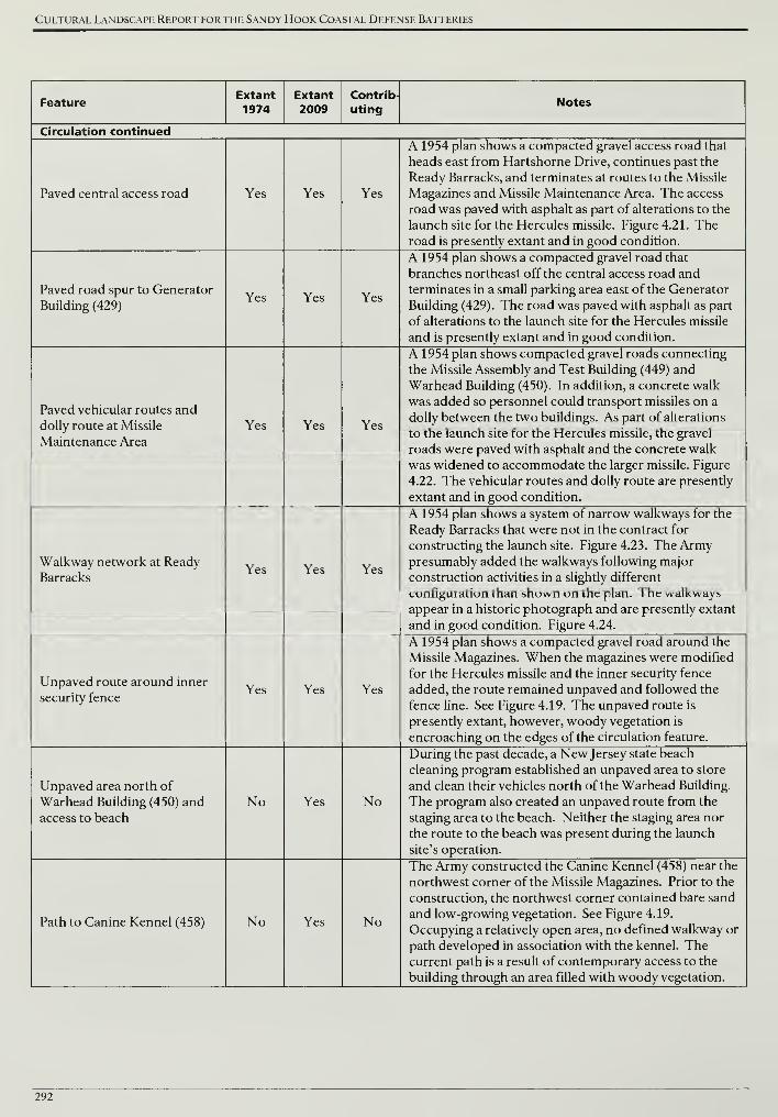
Cultural Landscape Report for the Sandy Hook Coastal Defense Batteries
FeatureExtant1974
Extant2009
Contrib-
utingNotes
Circulation continued
Paved central access road Yes Yes Yes
A 1954 plan shows a compacted gravel access road that
heads east from Hartshorne Drive, continues past the
Ready Barracks, and terminates at routes to the Missile
Magazines and Missile Maintenance Area. The access
road was paved with asphalt as part of alterations to the
launch site for the Hercules missile. Figure 4.21. Theroad is presently extant and in good condition.
Paved road spur to Generator
Building (429)Yes Yes Yes
A 1954 plan shows a compacted gravel road that
branches northeast off the central access road and
terminates in a small parking area east of the Generator
Building (429). The road was paved with asphalt as part
of alterations to the launch site for the Hercules missile
and is presently extant and in good condition.
Paved vehicular routes and
dolly route at Missile
Maintenance Area
Yes Yes Yes
A 1954 plan shows compacted gravel roads connecting
the Missile Assembly and Test Building (449) and
Warhead Building (450). In addition, a concrete walk
was added so personnel could transport missiles on a
dolly between the two buildings. As part of alterations
to the launch site for the Hercules missile, the gravel
roads were paved with asphalt and the concrete walk
was widened to accommodate the larger missile. Figure
4.22. The vehicular routes and dolly route are presently
extant and in good condition.
Walkway network at Ready
BarracksYes Yes Yes
A 1954 plan shows a system of narrow walkways for the
Ready Barracks that were not in the contract for
constructing the launch site. Figure 4.23. The Armypresumably added the walkways following major
construction activities in a slightly different
configuration than shown on the plan. The walkways
appear in a historic photograph and are presently extant
and in good condition. Figure 4.24.
Unpaved route around inner
security fenceYes Yes Yes
A 1954 plan shows a compacted gravel road around the
Missile Magazines. When the magazines were modified
for the Hercules missile and the inner security fence
added, the route remained unpaved and followed the
fence line. See Figure 4.19. The unpaved route is
presently extant, however, woody vegetation is
encroaching on the edges of the circulation feature.
Unpaved area north of
Warhead Building (450) and
access to beach
No Yes No
During the past decade, a New Jersey state beach
cleaning program established an unpaved area to store
and clean their vehicles north of the Warhead Building.
The program also created an unpaved route from the
staging area to the beach. Neither the staging area nor
the route to the beach was present during the launch
site's operation.
Path to Canine Kennel (458) No Yes No
The Army constructed the Canine Kennel (458) near the
northwest corner of the Missile Magazines. Prior to the
construction, the northwest corner contained bare sand
and low-growing vegetation. See Figure 4.19.
Occupying a relatively open area, no defined walkway or
path developed in association with the kennel. Thecurrent path is a result of contemporary access to the
building through an area filled with woody vegetation.
292
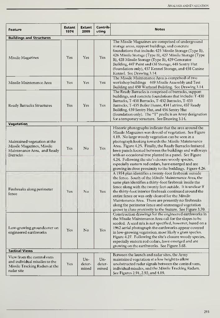
Analysis and Evaluation
FeatureExtant
1974Extant
2009Contrib-
utingNotes
Buildings and Structures
Missile Magazines Yes Yes Yes
The Missile Magazines are comprised of underground
storage areas, support buildings, and concrete
foundations that include: 425 Missile Storage (Type B),
426 Missile Storage (Type B), 427 Missile Storage (Type
B), 428 Missile Storage (Type B), 429 Generator
Building, 447 Paint and Oil Storage, 448 Sentry Hut(foundation only), 457 Kennel Storage, and 458 Canine
Kennel. See Drawing 3.14.
Missile Maintenance Area Yes Yes Yes
The Missile Maintenance Area is comprised of two
workshop buildings—449 Missile Assembly and Test
Building and 450 Warhead Building. See Drawing 3.14.
Ready Barracks Structures Yes Yes Yes
The Ready Barracks is comprised of barracks, support
buildings, and concrete foundations that include: T-430
Barracks, T-431 Barracks, T-432 Barracks, T-433
Barracks, T-435 Boiler House, 434 Latrine, 437 Ready
Building, 439 Sentry Hut, and 456 Sentry Hut(foundation only). The "T" prefix is an Army designation
for a temporary structure. See Drawing 3.14.
Vegetation
Maintained vegetation at the
Missile Magazines, Missile
Maintenance Area, and Ready
Barracks
Yes No Yes
Historic photographs indicate that the area around the
Missile Magazines was devoid of vegetation. See Figure
4.19. No large woody vegetation can be seen in a
photograph looking towards the Missile Maintenance
Area. Figure 4.25. Finally, the Ready Barracks featured
lawn panels located between the buildings and walkways
with an occasional tree planted in a panel. See Figure
4.24. Following the site's closure woody species,
especially eastern red cedars, have emerged and are
growing in close proximity to the buildings. Figure 4.26.
Firebreaks along perimeter
fenceYes No Yes
A 1954 plan identifies a twenty-foot firebreak outside
the fence. South of the Missile Maintenance Area, the
same plan identifies a thirty-foot firebreak inside the
fence along with the twenty feet outside. It is unclear if
the thirty-foot interior firebreak continued around the
entire fence or was only cleared for the Missile
Maintenance Area. There are presently no firebreaks
along the perimeter fence and unmanaged vegetation
grows in close proximity to the feature. See Figure 3.70.
Low-growing groundcover onengineered earthworks
Yes No Yes
Construction drawings for the engineered earthworks in
the Missile Maintenance Area call for the slopes to be
seeded. A seed mix is not specified, however, based on a
1962 aerial photograph the earthworks appear covered
in low-growing vegetation, most likely a grass species.
Figure 4.27. Following the site's closure woody species,
especially eastern red cedars, have emerged and are
growing on the earthworks. See Figure 3.68.
Tactical Views
View from the control vans
and individual missiles to the
Missile Tracking Radars at the
radar site
Yes
Un-deter-
mined
Un-deter-
mined
Between the launch and radar sites, the Armymaintained vegetation at a low height to allow
unobstructed radar signals between the control vans,
individual missiles, and the Missile Tracking Radars.
See Figures 2.91, 2.92, and 4.19.
293
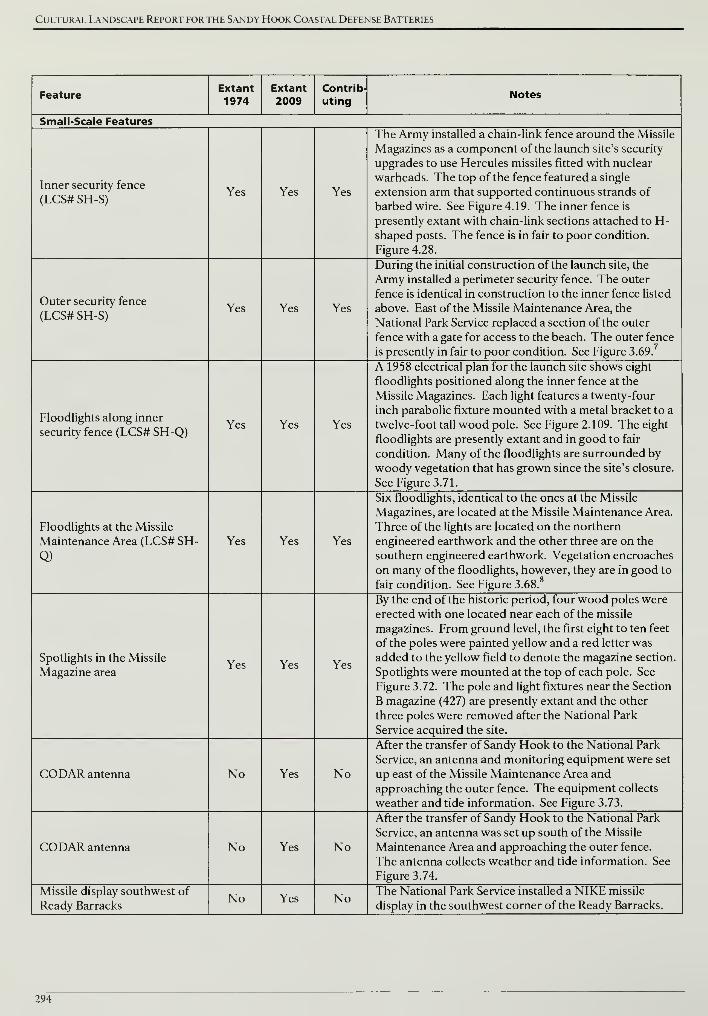
Cultural Landscape Report for the Sandy Hook Coastal Defense Batteries
FeatureExtant
1974Extant2009
Contrib-
utingNotes
Small-Scale Features
Inner security fence
(LCS# SH-S)Yes Yes Yes
The Army installed a chain-link fence around the Missile
Magazines as a component of the launch site's security
upgrades to use Hercules missiles fitted with nuclear
warheads. The top of the fence featured a single
extension arm that supported continuous strands of
barbed wire. See Figure 4.19. The inner fence is
presently extant with chain-link sections attached to H-shaped posts. The fence is in fair to poor condition.
Figure 4.28.
Outer security fence
(LCS# SH-S)Yes Yes Yes
During the initial construction of the launch site, the
Army installed a perimeter security fence. The outer
fence is identical in construction to the inner fence listed
above. East of the Missile Maintenance Area, the
National Park Service replaced a section of the outer
fence with a gate for access to the beach. The outer fence
is presently in fair to poor condition. See Figure 3.69.
Floodlights along inner
security fence (LCS# SH-Q)Yes Yes Yes
A 1958 electrical plan for the launch site shows eight
floodlights positioned along the inner fence at the
Missile Magazines. Each light features a twenty-four
inch parabolic fixture mounted with a metal bracket to a
twelve-foot tall wood pole. See Figure 2.109. The eight
floodlights are presently extant and in good to fair
condition. Many of the floodlights are surrounded by
woody vegetation that has grown since the site's closure.
See Figure 3.71.
Floodlights at the Missile
Maintenance Area (LCS# SH-
Q)
Yes Yes Yes
Six floodlights, identical to the ones at the Missile
Magazines, are located at the Missile Maintenance Area.
Three of the lights are located on the northern
engineered earthwork and the other three are on the
southern engineered earthwork. Vegetation encroaches
on many of the floodlights, however, they are in good to
fair condition. See Figure 3.68.8
Spotlights in the Missile
Magazine areaYes Yes Yes
By the end of the historic period, four wood poles were
erected with one located near each of the missile
magazines. From ground level, the first eight to ten feet
of the poles were painted yellow and a red letter was
added to the yellow field to denote the magazine section.
Spotlights were mounted at the top of each pole. See
Figure 3.72. The pole and light fixtures near the Section
B magazine (427) are presently extant and the other
three poles were removed after the National Park
Service acquired the site.
CODAR antenna No Yes No
After the transfer of Sandy Hook to the National Park
Service, an antenna and monitoring equipment were set
up east of the Missile Maintenance Area and
approaching the outer fence. The equipment collects
weather and tide information. See Figure 3.73.
CODAR antenna No Yes No
After the transfer of Sandy Hook to the National Park
Service, an antenna was set up south of the Missile
Maintenance Area and approaching the outer fence.
The antenna collects weather and tide information. See
Figure 3.74.
Missile display southwest of
Ready BarracksNo Yes No
The National Park Service installed a NIKE missile
display in the southwest corner of the Ready Barracks.
294

Analysis and Evaluation
ENDNOTES
1
Richard E. Greenwood, "National Register of Historic Places Inventory - Nomination Form, Fort Hancock and the
Sandy Hook Proving Ground Historic District," June 28, 1976, sect. 7, 1.
2Harry Butowsky, "National Register of Historic Places Inventory - Nomination Form, Fort Hancock and the Sandy
Hook Proving Ground Historic District," revised November 9, 1982, sect. 10, 1-2.
3Ibid., sect. 8,1.
4Ibid.
5Ibid., sect. 8, 5.
6Savage to Pfoutz, November 5, 1996. From correspondence in reference to "List of Classified Structures," countersigned
by Dorothy Guzzo, NJ SHPO, January 2, 1997. NPS, National Register Files, Northeast Region, Boston Office.
7The LCS only lists NIKE site fencing and does not distinguish between an inner and outer security fence at the launch
site. Identifying an inner and outer fence is important to the history of the site. The outer fence was initially installed and
approximately four years later, with the introduction of Hercules missiles fitted with nuclear warheads, the inner fence
was added.
The LCS does not distinguish between floodlights at the Missile Magazines and the Missile Maintenance Area.
295

Cultural Landscape Report for the Sandy Hook Coastal Defense Batteries
296
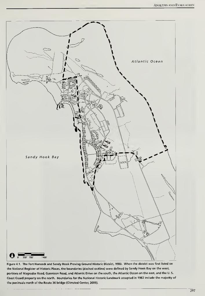
Analysis and Evaluation
Figure 4.1. The Fort Hancock and Sandy Hook Proving Ground Historic District, 1980. When the district was first listed on
the National Register of Historic Places, the boundaries (dashed outline) were defined by Sandy Hook Bay on the west,
portions of Magruder Road, Gunnison Road, and Atlantic Drive on the south, the Atlantic Ocean on the east, and the U. S.
Coast Guard property on the north. Boundaries for the National Historic Landmark accepted in 1982 include the majority of
the peninsula north of the Route 36 bridge (Olmsted Center, 2009).
297
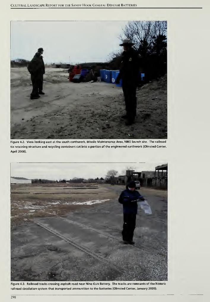
Cultural Landscape Report for the Sandy Hook Coastal Defense Batteries
Figure 4.2. View looking east at the south earthwork. Missile Maintenance Area, NIKE launch site. The railroad
tie retaining structure and recycling containers cut into a portion of the engineered earthwork (Olmsted Center,
April 2008).
Figure 4.3. Railroad tracks crossing asphalt road near Nine Gun Battery. The tracks are remnants of the historic
railroad circulation system that transported ammunition to the batteries (Olmsted Center, January 2009).
298
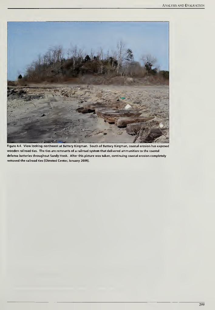
Analysis and Evaluation
Figure 4.4. View looking northwest at Battery Kingman. South of Battery Kingman, coastal erosion has exposed
wooden railroad ties. The ties are remnants of a railroad system that delivered ammunition to the coastal
defense batteries throughout Sandy Hook. After this picture was taken, continuing coastal erosion completely
removed the railroad ties (Olmsted Center, January 2009).
299
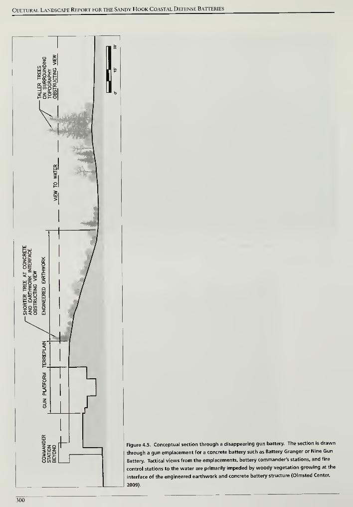
Cultural Landscape Report for the Sandy Hook Coastal Defense Batteries
i s
Bi
OQ V) Oizm z(/)< O LlI
o torn
Figure 4.5. Conceptual section through a disappearing gun battery. The section is drawn
through a gun emplacement for a concrete battery such as Battery Granger or Nine Gun
Battery. Tactical views from the emplacements, battery commander's stations, and fire
control stations to the water are primarily impeded by woody vegetation growing at the
interface of the engineered earthwork and concrete battery structure (Olmsted Center,
2009).
300
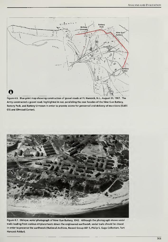
Analysis and Evaluation
Jn V. x *
\ ^.-''c. Battery
Battery f'• Peck
.\\tl r V S^fTP*
!&! "O^, jV;. ^
o .t ;A^V?>
\Figure 4.6. Blue print map showing construction of gravel roads at Ft. Hancock, N.J., August 31, 1907. The
Army constructed a gravel road, highlighted in red, paralleling the rear facades of the Nine Gun Battery,
Battery Peck, and Battery Urmston in order to provide access for personnel and delivery of munitions (GATE
GIS and Olmsted Center).
Figure 4.7. Oblique aerial photograph of Nine Gun Battery, 1942. Although the photograph shows social
trails leading from various emplacements down the engineered earthwork, social trails should be closed
in order to preserve the earthwork (National Archives, Record Group 661 S, Philip S. Gage Collection, Fort
Hancock Folder).
301
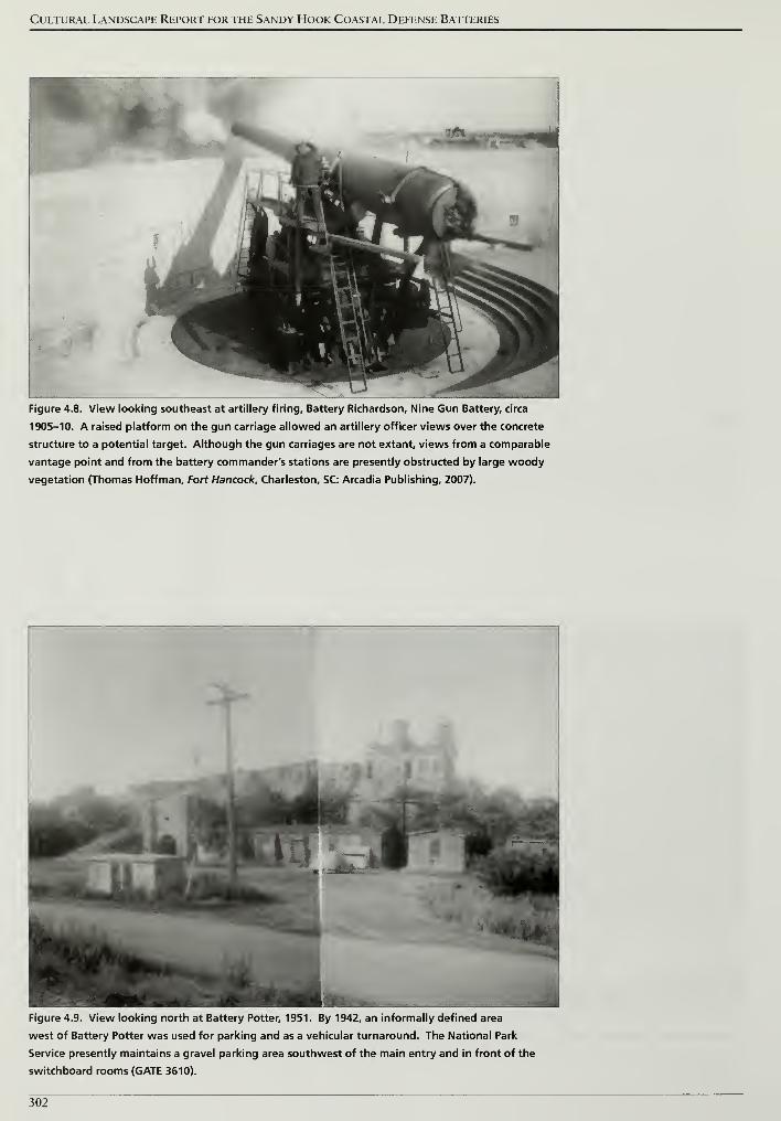
Cultural Landscape Report for the Sandy Hook Coastal Defense Batteries
L
"
11
V iv ^L
^"**"**"»
" ^Sfct
P1 1
1 '
u' 1
>
i
mmLSJl
^HHPP^
Figure 4.8. View looking southeast at artillery firing. Battery Richardson, Nine Gun Battery, circa
1905-10. A raised platform on the gun carriage allowed an artillery officer views over the concrete
structure to a potential target. Although the gun carriages are not extant, views from a comparable
vantage point and from the battery commander's stations are presently obstructed by large woody
vegetation (Thomas Hoffman, Fort Hancock, Charleston, SC: Arcadia Publishing, 2007).
Figure 4.9. View looking north at Battery Potter, 1951. By 1942, an informally defined area
west of Battery Potter was used for parking and as a vehicular turnaround. The National Park
Service presently maintains a gravel parking area southwest of the main entry and in front of the
switchboard rooms (GATE 3610).
302
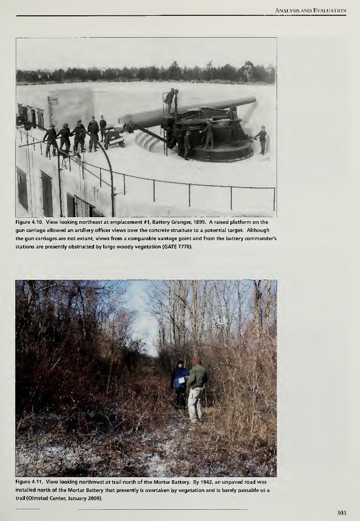
Analysis and Evaluation
Figure 4.10. View looking northeast at emplacement #1, Battery Granger, 1899. A raised platform on the
gun carriage allowed an artillery officer views over the concrete structure to a potential target. Although
the gun carriages are not extant, views from a comparable vantage point and from the battery commander's
stations are presently obstructed by large woody vegetation (GATE 7778).
Figure 4.11. View looking northwest at trail north of the Mortar Battery. By 1942, an unpaved road was
installed north of the Mortar Battery that presently is overtaken by vegetation and is barely passable as a
trail (Olmsted Center, January 2009).
303
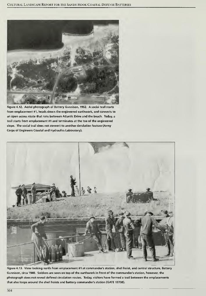
Cultural Landscape Report for the Sandy Hook Coastal Defense Batteries
Figure 4.12. Aerial photograph of Battery Gunnison, 1962. A social trail starts
from emplacement #1, heads down the engineered earthwork, and connects to
an open access route that runs between Atlantic Drive and the beach. Today, a
trail starts from emplacement #1 and terminates at the toe of the engineered
slope. The social trail does not connect to another circulation feature (Army
Corps of Engineers Coastal and Hydraulics Laboratory).
* *
&*il?*. ^^iW.^wt-til^v^*
\i* _'
Figure 4.13. View looking north from emplacement #1 at commander's station, shell hoist, and central structure. Battery
Gunnison, circa 1940. Soldiers are seen on top of the earthwork in front of the commander's station, however, the
photograph does not reveal defined circulation routes. Today, visitors have formed a trail between the emplacements
that also loops around the shell hoists and battery commander's station (GATE 13708).
304
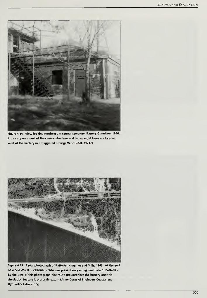
Analysis and Evaluation
Figure 4.14. View looking northeast at central structure. Battery Gunnison, 1956.
A tree appears west of the central structure and today, eight trees are located
west of the battery in a staggered arrangement (GATE 11217).
Figure 4.15. Aerial photograph of Batteries Kingman and Mills, 1962. At the end
of World War II, a vehicular route was present only along west side of batteries.
By the time of this photograph, the route circumscribes the battery and this
circulation feature is presently extant (Army Corps of Engineers Coastal and
Hydraulics Laboratory).
305
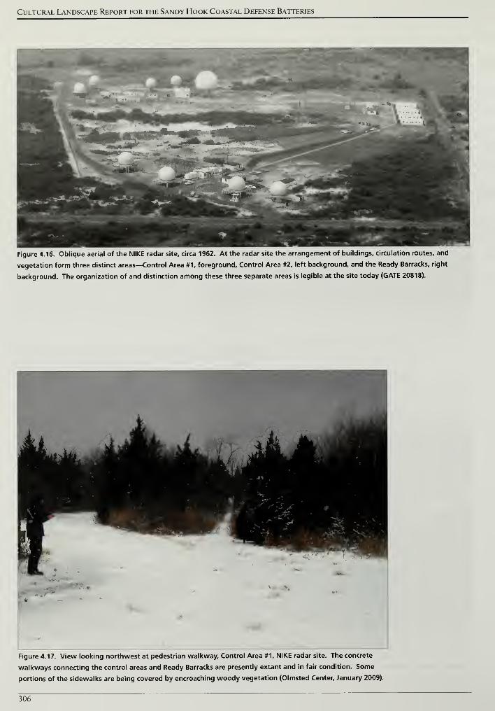
Cultural Landscape Report for the Sandy Hook Coastal Defense Batteries
Figure 4.16. Oblique aerial of the NIKE radar site, circa 1962. At the radar site the arrangement of buildings, circulation routes, and
vegetation form three distinct areas—Control Area #1, foreground. Control Area #2, left background, and the Ready Barracks, right
background. The organization of and distinction among these three separate areas is legible at the site today (GATE 20818).
Figure 4.17. View looking northwest at pedestrian walkway. Control Area #1, NIKE radar site. The concrete
walkways connecting the control areas and Ready Barracks are presently extant and in fair condition. Some
portions of the sidewalks are being covered by encroaching woody vegetation (Olmsted Center, January 2009).
306
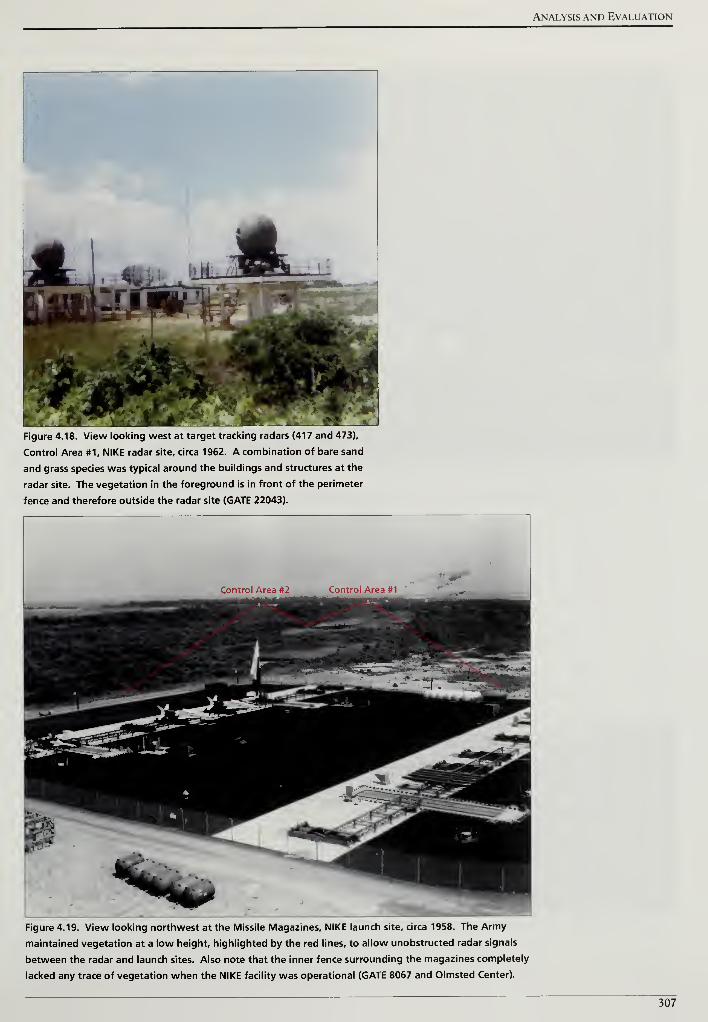
Analysis and Evaluation
Figure 4.18. View looking west at target tracking radars (417 and 473),
Control Area #1, NIKE radar site, circa 1962. A combination of bare sand
and grass species was typical around the buildings and structures at the
radar site. The vegetation in the foreground is in front of the perimeter
fence and therefore outside the radar site (GATE 22043).
Figure 4.19. View looking northwest at the Missile Magazines, NIKE launch site, circa 1958. The Army
maintained vegetation at a low height, highlighted by the red lines, to allow unobstructed radar signals
between the radar and launch sites. Also note that the inner fence surrounding the magazines completely
lacked any trace of vegetation when the NIKE facility was operational (GATE 8067 and Olmsted Center).
307
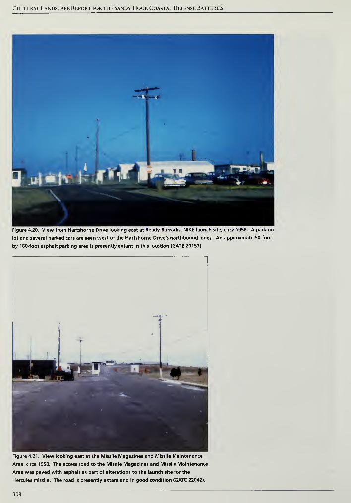
Cultural Landscape Report for the Sandy Hook Coastal Defense Batteries
Figure 4.20. View from Hartshorne Drive looking east at Ready Barracks, NIKE launch site, circa 1958. A parking
lot and several parked cars are seen west of the Hartshorne Drive's northbound lanes. An approximate 50-foot
by 180-foot asphalt parking area is presently extant in this location (GATE 20157).
Figure 4.21. View looking east at the Missile Magazines and Missile Maintenance
Area, circa 1958. The access road to the Missile Magazines and Missile Maintenance
Area was paved with asphalt as part of alterations to the launch site for the
Hercules missile. The road is presently extant and in good condition (GATE 22042).
308
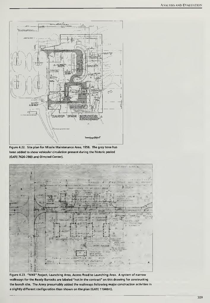
Analysis and Evaluation
bftSM
BRB Om^«i- ro**»J«»cj~-A
^m,--^- 11 * : or~~o*J =n=r-t
Figure 4.22. Site plan for Missile Maintenance Area, 1958. The gray tone has
been added to show vehicular circulation present during the historic period
(GATE 7620-2983 and Olmsted Center).
\ I -w* '^r v.:
-*•>/-- • >\ {Jit* *.'• -. \ .
..- . - < -.
—a:?..-
3£-»iiJ.-'-•
t -
rj; / r"*~
[ i--* 4 j- - 4 . * - v
;
j i i a* «« i , i
53^
-
-
I'•?'
r
L, J-'•
. - --
Figure 4.23. "NIKE" Project, Launching Area, Access Road to Launching Area. A system of narrow
walkways for the Ready Barracks are labeled "not in the contract" on this drawing for constructing
the launch site. The Army presumably added the walkways following major construction activities in
a slightly different configuration than shown on the plan (GATE 1 1040m).
309
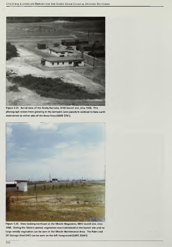
Cultural Landscape Report for the Sandy Hook Coastal Defense Batteries
Figure 4.24. Aerial view of the Ready Barracks, NIKE launch site, circa 1958. This
photograph shows trees growing in the barrack's lawn panels in contrast to bare earth
maintained on either side of the fence lines (GATE 5781).
Figure 4.25. View looking northeast at the Missile Magazines, NIKE launch site, circa
1968. During the historic period, vegetation was maintained at the launch site and no
large woody vegetation can be seen in the Missile Maintenance Area. The Paint and
Oil Storage shed (447) can be seen on the left foreground (GATE 22041).
310
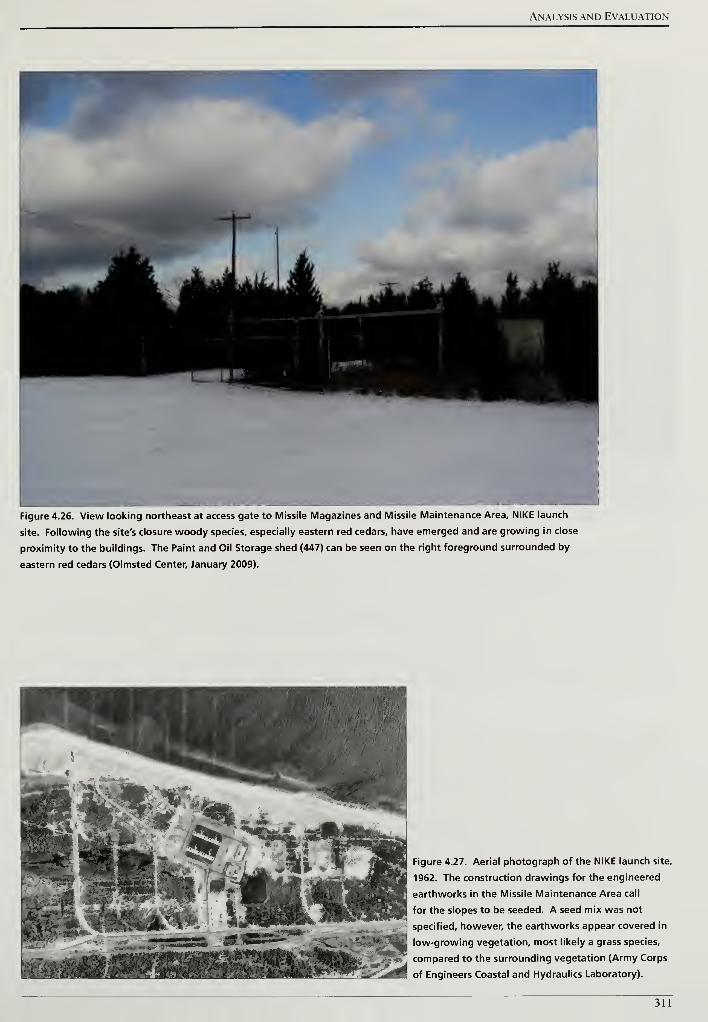
Analysis and Evaluation
Figure 4.26. View looking northeast at access gate to Missile Magazines and Missile Maintenance Area, NIKE launch
site. Following the site's closure woody species, especially eastern red cedars, have emerged and are growing in close
proximity to the buildings. The Paint and Oil Storage shed (447) can be seen on the right foreground surrounded by
eastern red cedars (Olmsted Center, January 2009).
Figure 4.27. Aerial photograph of the NIKE launch site,
1962. The construction drawings for the engineered
earthworks in the Missile Maintenance Area call
for the slopes to be seeded. A seed mix was not
specified, however, the earthworks appear covered in
low-growing vegetation, most likely a grass species,
compared to the surrounding vegetation (Army Corps
of Engineers Coastal and Hydraulics Laboratory).
311
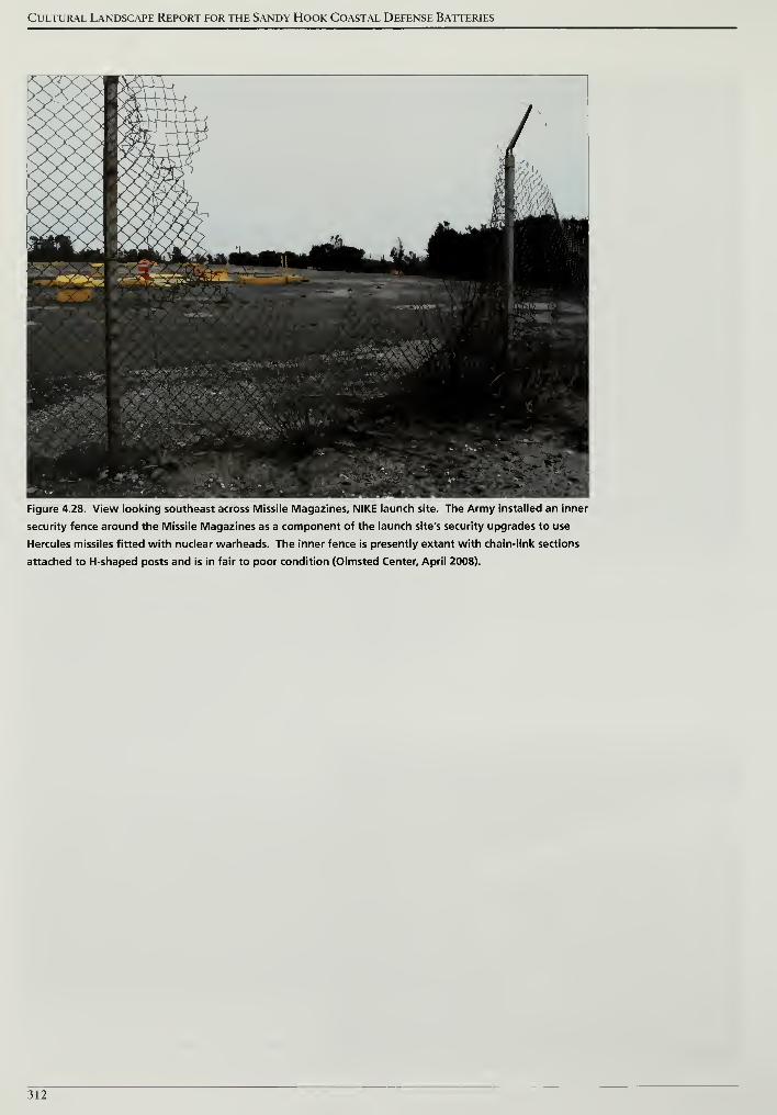
Cultural Landscape Report for the Sandy Hook Coastal Defense Batteries
Figure 4.28. View looking southeast across Missile Magazines, NIKE launch site. The Army installed an inner
security fence around the Missile Magazines as a component of the launch site's security upgrades to use
Hercules missiles fitted with nuclear warheads. The inner fence is presently extant with chain-link sections
attached to H-shaped posts and is in fair to poor condition (Olmsted Center, April 2008).
312
Treatment
TREATMENT
The National Park Service defines landscape treatment as historic preservation
efforts focused on the goal of enhancing the historic character of a cultural
landscape within the context of its contemporary function.1 Treatment
essentially describes how the landscape should look in the future. While
fundamentally focused on historic preservation, landscape treatment also
addresses other park management goals, such as public access, natural resource
conservation, and interpretation. Landscape treatment does not address routine
and cyclical measures, such as tree pruning and lawn mowing, necessary to
maintain the existing character of a landscape.2
The surviving defense infrastructure at Sandy Hook and Fort Hancock are of
national significance, being part of the extensive Fort Hancock and Sandy Hook
Proving Ground National Historic Landmark. Two of Fort Hancock's batteries,
Battery Potter and the Mortar Battery were the first of their type in the United
States. The district was listed on the National Register of Historic Places on April
24, 1980, identifying a period of significance spanning from 1859, through the
1950s and 1960s Cold War Era, and ending in 1974. The National Register
nomination recognizes the importance of the defense installations at Sandy Hook
in guarding New York City (Figure 5.1).3
This chapter begins by presenting a framework for treatment based on the park's
enabling legislation, National Park Service standards and guidelines, and current
park planning documents. The framework is followed by a treatment philosophy
that emphasizes stabilizing and rehabilitating the coastal defense batteries to
enhance historic character. A summary of preservation issues is provided and
followed by the treatment goals and approach for common-to-all and specific
treatment tasks. The narrative presentation of tasks is accompanied by graphics
and a treatment plan for each battery site.
Recognizing that the rich history of coastal defense work at Sandy Hook includes
the survival of subtle remnants of searchlight emplacements, radar installations,
mobile gun batteries, isolated concrete magazines, and pill-boxes, the following
recommendations are of a more limited scope (Figures 5.2 and 5.3). The
following recommendations are constrained largely to the more obvious large
gun and missile battery features remaining on site as the many isolated and
incidental remnants of Sandy Hook's military past may be better addressed
through individual historic structure and archeological documentation.
313
Cultural Landscape Report for the Sandy Hook Coastal Defense Batteries
FRAMEWORK FOR TREATMENT
Signed into law on October 27, 1972, the enabling legislation for the Gateway
National Recreation Area guides the framework for treatment for the coastal
defense batteries at Sandy Hook. For the Sandy Hook Unit, the act specifically
directs that the Secretary of the Interior ".. .shall inventory and evaluate all sites
and structures having present and potential historical, cultural, or architectural
significance and shall provide for appropriate programs for the preservation,
restoration, interpretation, and utilization of them."4As stated in planning
documents for Gateway National Recreation Area, the goal for historic structures
and cultural landscapes within the Fort Hancock and the Sandy Hook Proving
Ground Historic District is rehabilitation and interpretation. It is recommended
that the surviving coastal defense batteries be rehabilitated in accordance with
the Gateway National Recreation Area General Management Plan, completed in
1979, and with the fundamental historic preservation values expressed in The
Secretary of the Interior's Standardsfor the Treatment ofHistoric Properties:
Rehabilitation. Furthermore, as stated in the park's 1990 General Management
Plan Amendment, it is recommended that the batteries be interpreted to the
public with a focus on their historic functions, and the technological changes in
coastal defenses during Fort Hancock's history.5Presently, the Gateway
National Recreation Area is in the process of preparing a new General
Management Plan to guide planning and management at the park for the next
twenty years. This on-going effort has identified the coastal defense batteries as
fundamental resources of the park based on the enabling legislation.6
The National Park Service bears stewardship responsibilities for cultural as well as
natural resources, maintaining the National Register of Historic Places as the
official list of the Nation's historic places worthy of preservation. Fort Hancock
and the Sandy Hook Proving Ground were first nominated to the National
Register of Historic Places as a district in 1980, (NJ 36, Fort Hancock and vicinity,
NHL, NPS-80002505). This nomination was later amended in 1982 to enlarge the
district and include the entire Sandy Hook Peninsula and to designate it as a
National Historic Landmark (NHL) District. This documentation focused on the
property's significance under National Register "Criteria A" for its association
with the military defense of the United States for over a period of two hundred
years. In the documentation, multiple periods of significance are defined for this
district. The period from 1874-1919 is given as the period of significance for the
facilities of the Sandy Hook Proving Ground. The period from 1895-1949 is given
for the Spermaceti Cove #2 Life Saving Station (southern portion of peninsula).
Fort Hancock's period of significance is defined in the 1982 amended
documentation as the period from 1859-1950s. This period begins in 1859 due to
the existence of remnants of a granite fort dating to this period. The narrative
314
Treatment
statement of significance does not explicitly state the end-date of the period of
significance, identifying 1958 as the last specific date attendant to the introduction
of the improved NIKE Hercules missile system. However because the NIKE
missile era identified in the NHL documentation continued almost to the date of
transfer between the Department of Defense and the Department of the Interior,
the deactivation date for Fort Hancock is used as the end date of the period of
significance. The New Jersey State Historic Preservation Officer has concurred
with this finding through correspondence related to the NPS List of Classified
Structures (LCS).7
Rehabilitation of the Sandy Hook gun and missile batteries would entail the
removal of non-historic invasive vegetation as well as an extensive condition and
structural analysis of each structure. At a minimum, preserving and rehabilitating
these batteries will involve the stabilization and repair of the concrete structures,
treatment of deteriorating metal elements at the batteries, the addition of lighting,
and the repair and construction of safe railing systems, walkways, and accessible
routes. Accomplishing these tasks would greatly increase the park's ability to
provide safe public access and effective interpretation of the Endicott System of
defense installations at Sandy Hook, and to make available the dynamic history of
Sandy Hook's coastal defenses.8
TREATMENT PHILOSOPHY
Wordlessly referencing the importance of the urban skyline to the northwest, the
surviving coastal defenses at Sandy Hook, New Jersey are remnants of a vast
nationwide program that deployed generations of the most costly arms
technology imaginable upon the slender landform. Consistent with both park
enabling legislation and current park planning documents, Sandy Hook's
surviving coastal defense batteries will be stabilized and otherwise treated so as to
slow the deterioration of the historic defenses. Where it is judged safe and
appropriate to do so, coastal defense sites will be rehabilitated to enhance
historic character and in order to make the sites accessible for the education and
enjoyment of the public. Structural battery features will be considered as part of
the larger coastal battery sites that are components of Sandy Hook's cultural
landscape. Vegetation will be managed within the boundaries of Sandy Hook's
battery sites to make it possible to preserve and observe the historic structures
and to understand both the operation of the individual historic batteries and
system of batteries.
Preservation measures recommended in this cultural landscape report are
consistent with fundamental historic preservation values expressed in The
Secretary ofthe Interior's Standardsfor the Treatment of Historic Properties.
315
Cultural Landscape Report for the Sandy Hook Coastal Defense Batteries
Recommendations speaking to purely structural concerns are intended to be
consistent with recommendations of architectural conservators and historians
presented in the Historic Structure Reportfor Battery Potter, Mortar Battery and
Battery Gunnison (2007), and with the Historic Fortification Preservation
Handbook, prepared by the National Park Service, the University of Oregon and
the Washington State Parks and Recreation Commission as part of the Pacific
Northwest Preservation Partnership (2003).
PRESERVATION ISSUES
Several preservation issues for the costal defense batteries were identified by
previous cultural resource studies and through consultant with park staff.
Properly addressing these issues will result in preserving the historic character of
the batteries and improving their interpretation as critical elements in a defensive
system protecting New York City.
Coastal Erosion
As the meandering shoreline of Sandy Hook Bay has made the preservation of
Battery Arrowsmith impossible, in time coastal erosion has the potential to make
the continued preservation and public access of other coastal defense sites
impractical and the continued investment in maintenance difficult. In addition to
Battery Arrowsmith, beach erosion and rising ocean levels already threaten
Battery Kingman, Battery Mills, and the NIKE launch site. At Battery Kingman,
storm events and bayside erosion have advanced toward the western edge of the
battery landscape extents and have removed portions of a historic railroad bed.
At Battery Mills, erosion has removed a portion of the vehicular route that
circumscribes the battery. At the NIKE launch site, the Atlantic shoreline has
advanced toward the eastern perimeter of the missile facility and a future storm
event could remove portions of the perimeter fence and circulation features.
Water Infiltration
Coastal defenses were located and designed to fulfill a defensive purpose, rather
than to stand as monuments for all time. They were often constructed in less-
than-ideal locations, and sometimes constructed with less-than-perfect materials
and workmanship. Occupying coastal areas, these structures were often built on
low boggy ground, or on eroding bluffs where wind-blown mist carries a freight
of corrosive salt. Water—in the ground, in the air, or precipitated as rain—serves
as the common element at work undermining these structures over time.9Water
infiltration, combined with seasonal freeze-thaw cycles, results in concrete
spalling and cracks. Accumulation of water in battery interiors and deterioration
of metal elements further degrade the historic battery structures.
316
Treatment
Unmanaged Woody Vegetation
After the Army deactivated coastal defense batteries, routine vegetation
maintenance to support tactical operations, to provide camouflage, and to
promote security ceased. In the subsequent decades, the unmanaged growth of
large woody vegetation has become a common feature at the battery sites. The
vegetation threatens the batteries' historic earthworks due to the potential for
uprooting in a storm event. In addition, vegetation growing near and on concrete
structures accelerates deterioration of the concrete. Large woody vegetation on
the structures, the earthworks, and within tactical views to the water obscures the
visual connection between the defense and potential targets. Finally, unmanaged
woody vegetation blocks access to coastal defense batteries such as batteries
Urmston and Morris.
TREATMENT GOALS AND APPROACH
Laying to one side the threat posed by rising sea levels, coastal defense sites are
inherently transient. Effective preservation must aim to slow deterioration rather
than arrest it. Further providing some benefit for public investment in these
preservation measures, modifications to the historic defense sites are justified
where it is reasonable to provide safe visitor access. That the public may learn
something meaningful during the course of a visit, it is also reasonable to
implement modest changes to help visitors better understand the park's cultural
resources. These goals, clearly supported by park planning documents and the
enabling legislation creating Gateway National Recreation Area, suggest
Rehabilitation as the most appropriate choice among the four sanctioned
approaches to treatments identified in the Secretary ofthe Interior's Standardsfor
the Treatment ofHistoric Properties. However, it must be clearly understood, that
it is a relatively short list of fundamental preservation measures that comprise the
core of the Rehabilitation program prescribed for the Sandy Hook coastal
defenses. Of primary concern to the defense sites as cultural landscapes,
beginning and implementing effective management of vegetation serves as the
central task proposed by this report. Recommendations propose treatment
measures aimed at preserving historic structures and their features, yet these are
not intended to supersede, but rather to support recommendations found in
historic structure reports.
The following landscape treatment recommendations are presented below
relative to Sandy Hook's eleven extant batteries; including batteries Urmston,
Morris, Engle, Peck, Nine Gun, Potter, Granger, Mortar, Gunnison, Kingman
and Mills. The extant Fort Hancock NIKE missile battery, consisting of two
separate sites, a radar site for acquiring targets and tracking outgoing missiles and
317
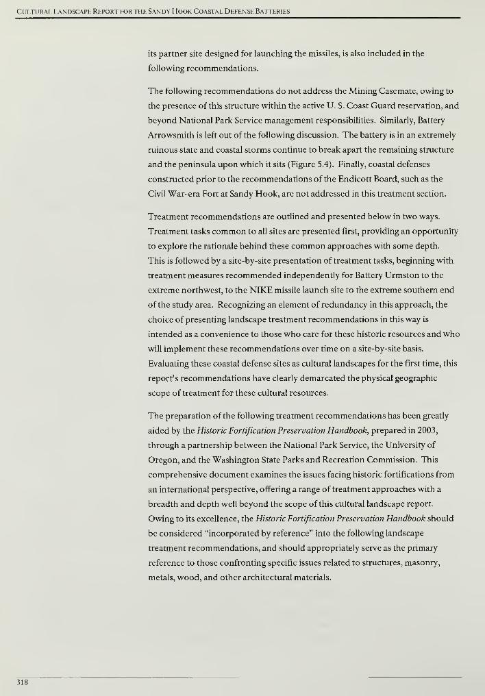
Cultural Landscape Report for the Sandy Hook Coastal Defense Batteries
its partner site designed for launching the missiles, is also included in the
following recommendations.
The following recommendations do not address the Mining Casemate, owing to
the presence of this structure within the active U. S. Coast Guard reservation, and
beyond National Park Service management responsibilities. Similarly, Battery
Arrowsmith is left out of the following discussion. The battery is in an extremely
ruinous state and coastal storms continue to break apart the remaining structure
and the peninsula upon which it sits (Figure 5.4). Finally, coastal defenses
constructed prior to the recommendations of the Endicott Board, such as the
Civil War-era Fort at Sandy Hook, are not addressed in this treatment section.
Treatment recommendations are outlined and presented below in two ways.
Treatment tasks common to all sites are presented first, providing an opportunity
to explore the rationale behind these common approaches with some depth.
This is followed by a site-by-site presentation of treatment tasks, beginning with
treatment measures recommended independently for Battery Urmston to the
extreme northwest, to the NIKE missile launch site to the extreme southern end
of the study area. Recognizing an element of redundancy in this approach, the
choice of presenting landscape treatment recommendations in this way is
intended as a convenience to those who care for these historic resources and who
will implement these recommendations over time on a site-by-site basis.
Evaluating these coastal defense sites as cultural landscapes for the first time, this
report's recommendations have clearly demarcated the physical geographic
scope of treatment for these cultural resources.
The preparation of the following treatment recommendations has been greatly
aided by the Historic Fortification Preservation Handbook, prepared in 2003,
through a partnership between the National Park Service, the University of
Oregon, and the Washington State Parks and Recreation Commission. This
comprehensive document examines the issues facing historic fortifications from
an international perspective, offering a range of treatment approaches with a
breadth and depth well beyond the scope of this cultural landscape report.
Owing to its excellence, the Historic Fortification Preservation Handbook should
be considered "incorporated by reference" into the following landscape
treatment recommendations, and should appropriately serve as the primary
reference to those confronting specific issues related to structures, masonry,
metals, wood, and other architectural materials.
318
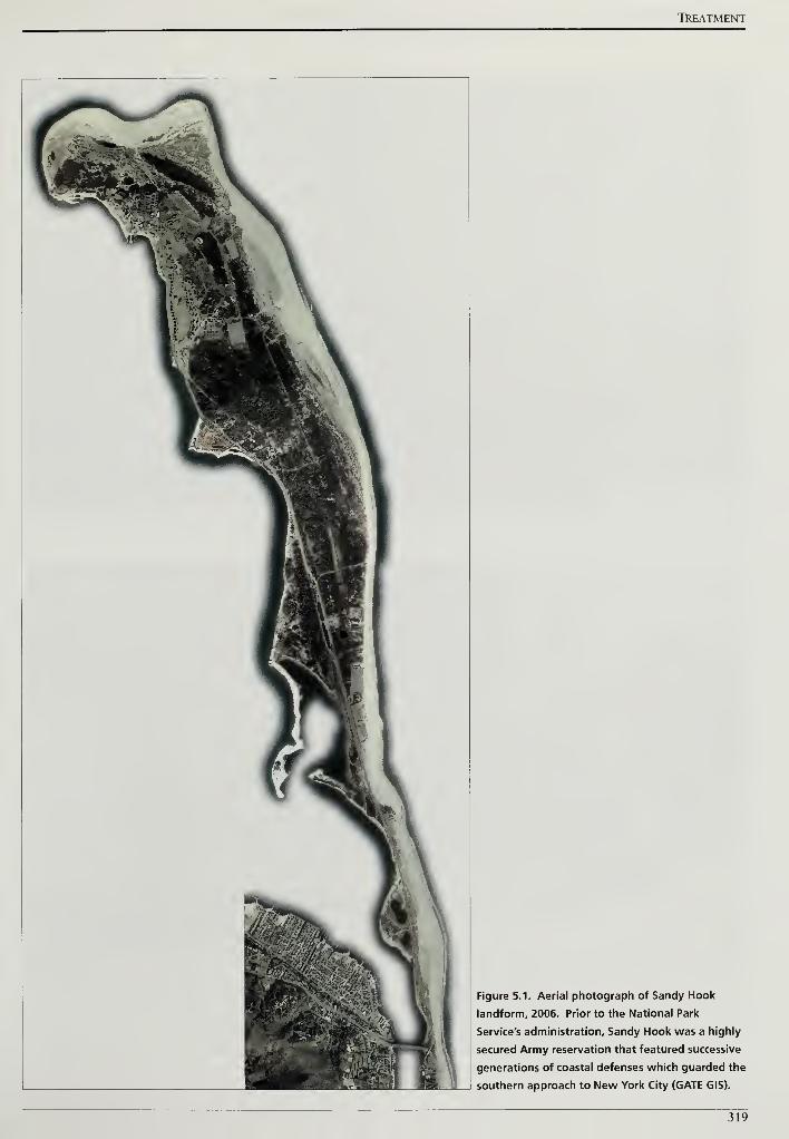
TREATMENT
Figure 5.1. Aerial photograph of Sandy Hook
landform, 2006. Prior to the National Park
Service's administration, Sandy Hook was a highly
secured Army reservation that featured successive
generations of coastal defenses which guarded the
southern approach to New York City (GATE GIS).
319
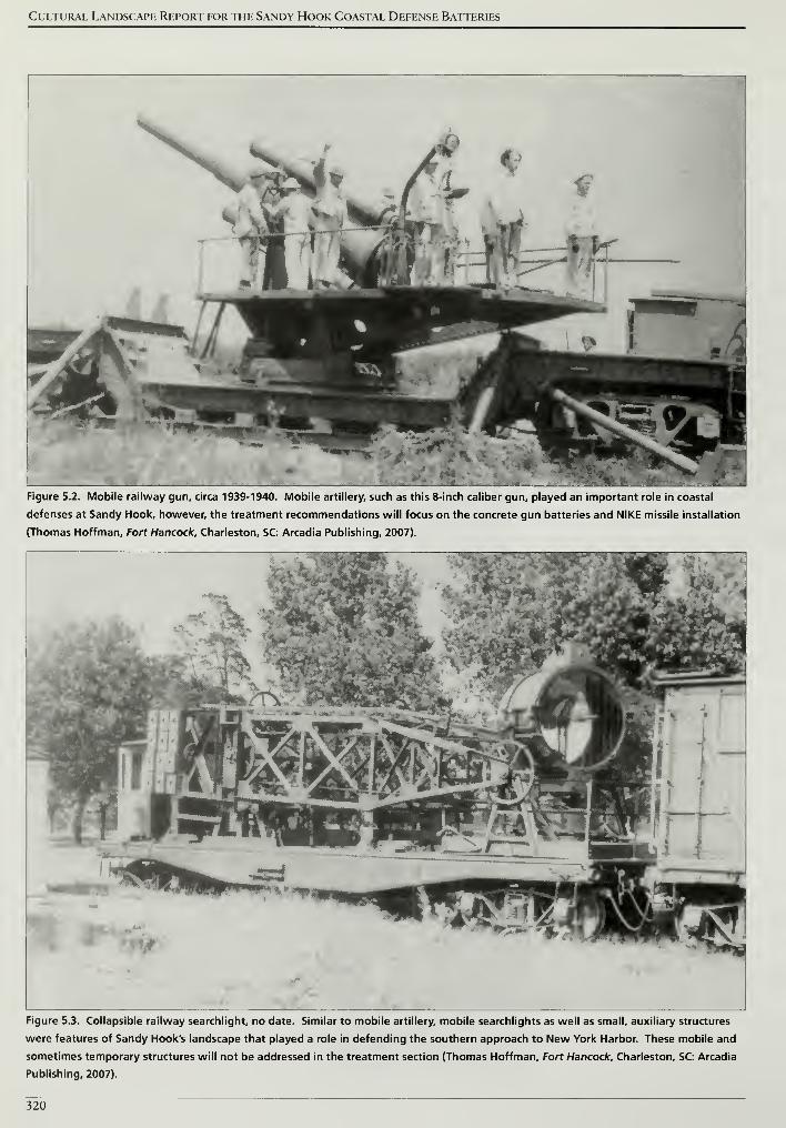
Cultural Landscape Report for the Sandy Hook Coastal Defense Batteries
Figure 5.2. Mobile railway gun, circa 1939-1940. Mobile artillery, such as this 8-inch caliber gun, played an important role in coastal
defenses at Sandy Hook, however, the treatment recommendations will focus on the concrete gun batteries and NIKE missile installation
(Thomas Hoffman, Fort Hancock, Charleston, SC: Arcadia Publishing, 2007).
Figure 5.3. Collapsible railway searchlight, no date. Similar to mobile artillery, mobile searchlights as well as small, auxiliary structures
were features of Sandy Hook's landscape that played a role in defending the southern approach to New York Harbor. These mobile and
sometimes temporary structures will not be addressed in the treatment section (Thomas Hoffman, Fort Hancock, Charleston, SC: Arcadia
Publishing, 2007).
320
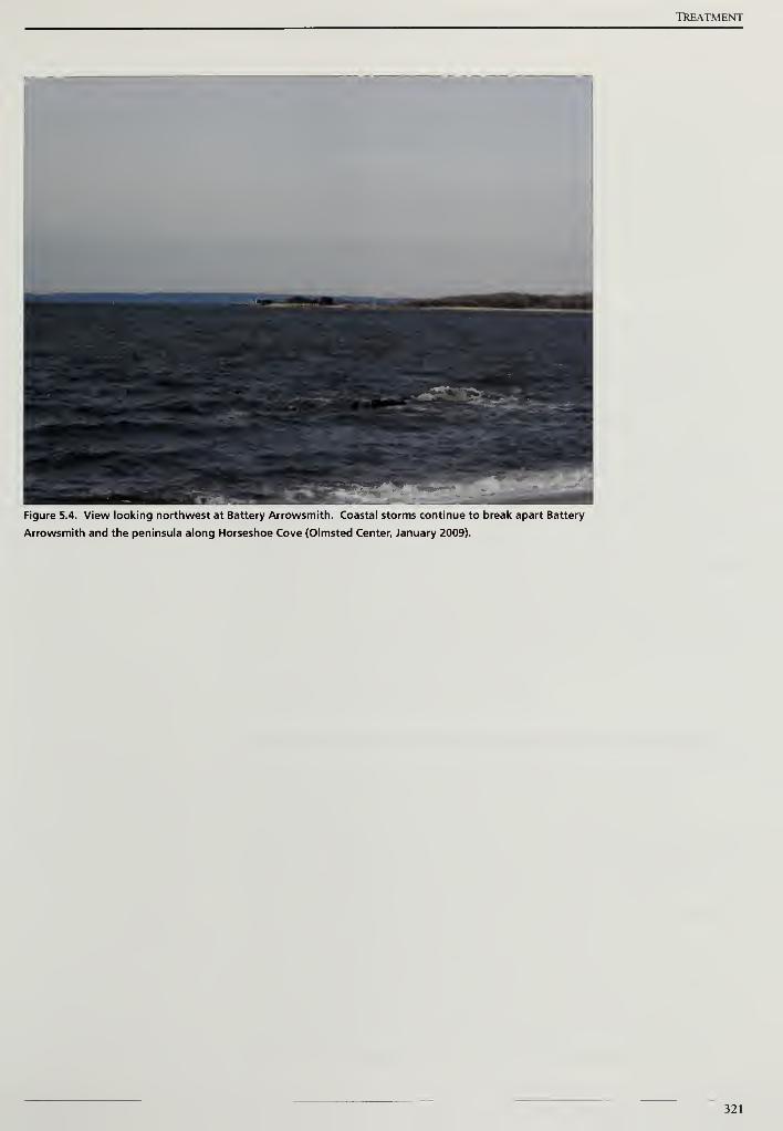
TREATMENT
Figure 5.4. View looking northwest at Battery Arrowsmith. Coastal storms continue to break apart Battery
Arrowsmith and the peninsula along Horseshoe Cove (Olmsted Center, January 2009).
321

Cultural Landscape Report for the Sandy Hook Coastal Defense Batteries
322
Treatment
TREATMENT TASKS COMMON TO ALL SITES
The fundamental purposes behind all treatment tasks prescribed for Sandy
Hook's surviving coastal defense sites include preserving historic structures,
landscapes, and providing safe and informative visitor access. Park planning
documents do not recommend that these sites be returned to the condition in
which they were in during military operation, nor to a state of nature. Therefore,
a program of straightforward preservation measures, readily achieved, becomes
more desirable than spelling out an "ideal" treatment program that would be
impossible to realize.
Management of vegetation serves as the foremost preservation task that will
prolong the life of the historic concrete and earthen structures. Additionally,
vegetation management will reestablish historic downrange views to the water
that are critical to understanding the historic purpose and function of these sites.
Following vegetation management tasks, repairs and maintenance of concrete
surfaces, including repairing voids and cracks, and sealing the porous concrete
surfaces against water infiltration will extend the number of years that the ruined
structures can be made safely accessible to the public. In conjunction with
limiting water infiltration on the concrete structures, exposed, corroding metal
components at the batteries should be stabilized to preserve the metal and
minimize deterioration to the concrete caused by metal corrosion. Providing safe
and informative visitor access involves repairing, retrofitting and replacing
deteriorated stairways, walkways, and accompanying safety railings. Providing
safe access also involves repairing doors and erecting fences and other barriers to
prevent visitors from accessing unsafe locations within these sites.
The following common tasks are presented below.
MANAGE VEGETATION TO PRESERVE AND INTERPRET PARK RESOURCES
The following vegetation management recommendations are intended to
preserve historic battery sites. These recommendations address three
components of the battery sites and are not influenced by the aesthetic or
environmental criteria of plant material. First, recommendations respond to the
threats posed by large trees that could uproot in a storm event and displace
historic engineered landforms. Second, tasks address woody vegetation
established in cracks and voids in the historic concrete structures, or otherwise
taking root in accumulated organic matter on concrete surfaces. Finally,
measures provide for managing vegetation in perpetuation of historic views,
critical to the historic operation of the ordnance. The essence of the following
recommendations might be conveniently remembered asu4-by-4-by-Fore." The
first of the two "4's" standing for eliminating trees greater than four-inches,
measured at breast height, from engineered landforms; the second of the two
323
Cultural Landscape Report for the Sandy Hook Coastal Defense Batteries
"4's" representing eliminating woody vegetation from within four-feet of
buildings and structures. The third "Fore" refers to managing vegetation forward
of battery sites that blocks historic downrange views and hinders public
interpretation and understanding of these sites.
As is the case throughout the Sandy Hook peninsula, non-native invasive species
are an endemic product of three hundred and fifty years of European settlement.
This report recommends the careful, selective removal of out-of-scale vegetation
to preserve cultural features, and discourages the creation of large areas of newly
cleared soil, that would become prone to additional erosion or otherwise the
colonization by non-native invasive species. Where non-native species are
present and are effective in stabilizing engineered landforms from erosion, it is
recommended that the protection afforded by these non-natives be provisionally
retained until such time when they can be removed in concert with a robust
revegetation program utilizing plants with a proven ability to prevent soil erosion
and protect the integrity of the cultural resource.
Manage Woody Vegetation on Engineered Slopes
With the exception of the NIKE radar site, all of the batteries reviewed for the
cultural landscape report contain engineered slopes. At the gun batteries,
engineers covered concrete structures with earth to absorb the impact and
explosion of enemy fire (Figure 5.5). In the case of the NIKE launch site, earthen
berms and traverses were constructed to shield the area where missiles were
armed with explosives.
Engineered slopes historically supported vegetation as part of a concealment
strategy. However, large trees were not permitted to grow to an extent where
they compromised the integrity of the engineered landform, or obstructed the
effective field-of-fire. Since their period of active service, unmanaged woody
vegetation has obstructed views and threatens the long-term preservation of the
earthworks and structures below them. The root systems of these woody species
have penetrated the earthwork and have the potential to exploit and damage
pores in the concrete structures. As the canopies of these woody species
continue to grow, there is a risk that snow, ice, and wind could topple a tree and a
major portion of the engineered earthwork would be removed with the tree's
roots (Figure 5.6).
In order to prevent further damage to the earthworks and structures below them,
all woody vegetation greater than four-inches diameter at breast height should be
selectively removed from the engineered slope. After the woody vegetation has
been cut, the stumps of deciduous species need to be treated to prevent sprouting
and regrowth. Since grubbing out or grinding the woody stumps would cause
damage to the historic earthwork and possibly the concrete structure below or
324

Treatment
nearby, the stumps should be treated with a triclopyr herbicide (Garlon"" brand
or approved equal) to kill the root system and prevent resprouting. The
herbicide treatment is especially important for non-native invasive species such
as ailanthus (Ailanthus altissima) that will sprout vigorously once the main stem is
cut (Figures 5.7 and 5.8). The selectively removed vegetation should be chipped
and the chips and any remaining debris should be removed from the park and
legally disposed. Removing wood chips and debris from the park is the preferred
approach to limit the spread of non-native invasive species and undesirable
plants such as poison ivy.
Manage Woody Vegetation Growing Near Buildings and Structures
All of the battery sites need to have woody vegetation removed that is growing on
and near structural and landscape features. At the NIKE sites, woody vegetation
is growing near radar platforms, barracks, and other auxiliary buildings. The root
systems threaten footings and foundations. The plants block light and air
movement accelerating the deterioration of painted surfaces, siding, and roofing.
During the historic period, the Army concealed the concrete battery structures
with camouflage surface treatments, paints, and overhead netting, however,
vegetation was never permitted to grow on the concrete structures. Since the
batteries were deactivated following World War II, low points such as stairwells
and flat areas such as roofs of battery commander's stations have accumulated
soil, leaf litter, and moisture. These conditions have resulted in the growth of
woody vegetation. Left untreated, this vegetation can grow to a considerable size
(Figure 5.9). The vegetation threatens to further deteriorate the historic battery's
concrete features and surfaces and should be removed.
Separation between individually cast concrete elements provides another
opportunity for woody vegetation to become established. A void is created
between concrete elements due to differential settling creating an opportunity for
plant material (Figure 5.10). Even ifwoody vegetation is not growing on a
structure or in a crack or void, the expanding root system of nearby vegetation
can find and exploit weaknesses in concrete structures. In addition, as nearby
vegetation grows ever larger, there will be an increase in the amount of leaf litter
and debris on the concrete structure that will support secondary plants and cause
greater moisture retention within the structure surfaces.
As a conservative measure aimed at mitigating structural problems caused or
exacerbated by woody vegetation and the concrete structures, all woody
vegetation growing on or within four-feet of concrete features should be
removed. Both deciduous and evergreen stumps should be treated with a
triclopyr herbicide (Garlon™ brand or approved equal) on the historic concrete
structures since removing the live roots and stumps would cause further
325
Cultural Landscape Report for the Sandy Hook Coastal Defense Batteries
structural damage. After the root systems are dead and decayed, the stumps
should be carefully removed to the greatest extent practicable, and following this,
appropriate concrete repairs should be completed.11
Manage Downrange Water Views
Where battery commander's stations or range finding positions were located in
close proximity to a battery, soldiers stationed at Sandy Hook's batteries could
effectively identify, track, and engage an enemy target. This would not have been
possible if the view from the battery to the water was obstructed by tall
vegetation. The downrange views to targets on the water from the gun platforms
and battery commander's stations are significant in understanding the historic
operation of the battery and should be reestablished wherever possible.
Reestablishing historic visual connections to the water is crucial for interpretive
and visitor access programs and to explain the tactical relationship of the battery
to the coastline.1
However, not all batteries relied upon a direct view to the target for their effective
operation. Most notably, the fire of the Mortar Battery and batteries Kingman
and Mills were directed from elevated positions and control towers located some
distance from the gun positions. Rather than a visual link to the water, the NIKE
missile battery relied on an in-line visual connection between the radar site and
the launch site. This was critical in order that the tracking radar equipment could
"lock" onto the nose of the missile prior to launch so that the outbound
trajectory could be monitored.
Managing downrange view comprises a third and final step in managing the
woody vegetation growing on or near historic coastal defenses. After removing
woody vegetation growing on the engineered slopes and from voids in the battery
structure itself, the resulting views to the water must be evaluated. Additional
cutting may not be needed once woody vegetation has been managed on the
structures and slopes. However, in some instances tall, individual woody
vegetation that blocks the view shed can be identified and removed (Figure 5.11).
Following removal, as is recommended in the prior two vegetation management
recommendations, deciduous stumps should be treated with a triclopyr herbicide
to discourage root sprouts and suckering. Cut material must be removed for
proper disposal.
326
Treatment
PROVIDE SAFE VISITOR ACCESS
Repair, Retrofit, and Replace Safety Railings
Handrails located along steps and ramps and guardrails are positioned near the
open sides of elevated areas at many of the batteries at Sandy Hook. The majority
of these rails are made from pipe railings with cast ball joint connectors. Repair
and replacement priority should be given to the batteries that are part of the
park's interpretive program or are planned to be made open and accessible to the
public in the foreseeable future (Figure 5.12). These include the Nine Gun
Battery, Battery Potter, and the NIKE radar site.
Where railings survive, all of the current railings have large openings below the
top or intermediate horizontal rails that would not adequately protect all visitors.
In order to provide a consistent level of protection and satisfy applicable building
codes, the existing railings should be repaired, retrofitted, and replaced where
necessary. Retrofitting existing railings or installing new railings to comply with
life safety codes is necessary when a battery is opened for public access. The
panels should be installed where there is a vertical change equal to or greater than
thirty inches.
At Golden Gate National Recreation Area in California's Bay Area, historic
architects have successfully retrofitted railing systems on historic buildings with
mesh infill panels. This approach inserts panels of steel mesh or woven-wire
fabric into the large voids of railing out of compliance with life safety codes
(Figure 5.13).
A less costly alternative to the infill approach to retrofitting safety railing may be
accomplished with simple tools and readily available building materials. This
alternative utilizes applied materials such as black vinyl-coated woven-wire
fabric, or chain-link, fastened with corrosion resistant fittings common to the
fencing industry. These materials, tensioned and clamped to the inboard side of
historic and repaired handrailings adjacent to pedestrian traffic, will satisfy safety
requirements, result in a similar modest visual appearance, and may be installed,
repaired, or replaced conveniently.
Prior to choosing either an infill or an applied approach for repairing and
retrofitting safety railings, a detailed inspection and evaluation of existing railings
must be undertaken. Those sections of surviving historic railings found in good
to fair condition may only need minor repairs and the addition of an infill or
applied treatment. Other sections of safety railing may need to have missing
sections of railing replaced, and loose paint removed and recoated with primer
and paint to match the historic black finish. Railings in good condition without
rust may be treated with corrosion inhibitors, however, these products are
327
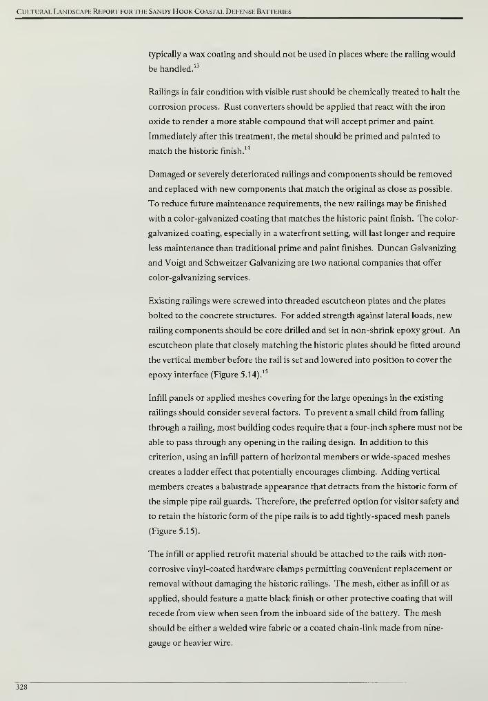
Cultural Landscape Report for the Sandy Hook Coastal Defense Batteries
typically a wax coating and should not be used in places where the railing would
be handled.13
Railings in fair condition with visible rust should be chemically treated to halt the
corrosion process. Rust converters should be applied that react with the iron
oxide to render a more stable compound that will accept primer and paint.
Immediately after this treatment, the metal should be primed and painted to
match the historic finish.14
Damaged or severely deteriorated railings and components should be removed
and replaced with new components that match the original as close as possible.
To reduce future maintenance requirements, the new railings may be finished
with a color-galvanized coating that matches the historic paint finish. The color-
galvanized coating, especially in a waterfront setting, will last longer and require
less maintenance than traditional prime and paint finishes. Duncan Galvanizing
and Voigt and Schweitzer Galvanizing are two national companies that offer
color-galvanizing services.
Existing railings were screwed into threaded escutcheon plates and the plates
bolted to the concrete structures. For added strength against lateral loads, new
railing components should be core drilled and set in non-shrink epoxy grout. An
escutcheon plate that closely matching the historic plates should be fitted around
the vertical member before the rail is set and lowered into position to cover the
epoxy interface (Figure 5.14).15
Infill panels or applied meshes covering for the large openings in the existing
railings should consider several factors. To prevent a small child from falling
through a railing, most building codes require that a four-inch sphere must not be
able to pass through any opening in the railing design. In addition to this
criterion, using an infill pattern of horizontal members or wide-spaced meshes
creates a ladder effect that potentially encourages climbing. Adding vertical
members creates a balustrade appearance that detracts from the historic form of
the simple pipe rail guards. Therefore, the preferred option for visitor safety and
to retain the historic form of the pipe rails is to add tightly-spaced mesh panels
(Figure 5.15).
The infill or applied retrofit material should be attached to the rails with non-
corrosive vinyl-coated hardware clamps permitting convenient replacement or
removal without damaging the historic railings. The mesh, either as infill or as
applied, should feature a matte black finish or other protective coating that will
recede from view when seen from the inboard side of the battery. The mesh
should be either a welded wire fabric or a coated chain-link made from nine-
gauge or heavier wire.
328

Treatment
Repair and Secure Interior Access Points
Metal and wood doors and metal gates, windows, and grating are located on gun
and missile batteries throughout Sandy Hook. All of these building features
require a detailed evaluation that is beyond the scope of this cultural landscape
report. However in general terms, sound material with minor corrosion or decay
should be treated in place. Loose paint and rust should be removed immediately
followed by priming and painting to match the historic finish. A moderate level
of repair may also be conducted in place. For example, an operational gate with a
missing a hinge spindle should be repaired in place with a new hinge spindle that
matches the historic dimensions and finish. If a component is damaged or
severely deteriorated, it should be removed and repaired at an off-site shop or
newly fabricated to match the existing (Figure 5.16).16
As was highlighted in the discussion of newly fabricated railings, new metal
doors, gates, windows, and gratings may be finished with a color-galvanized
coating that resembles the historic paint finish. The color-galvanized coating will
last longer and require less maintenance than traditional prime and paint finishes.
A final recommendation for doors and gates addresses their hinge hardware.
Bronze or brass hinge hardware may be cast into the concrete structure to receive
a door or gate. Either bronze or brass, in contact with the iron in the steel door,
reacts quickly with air and moisture to produce corrosion. To prevent this
accelerated reaction, a hard plastic washer should be installed to separate the
two metals.17
Close Hazardous Social Trails and Repair Eroded Paths
During a review of existing conditions of Sandy Hook's historic gun and missile
the batteries in January 2009, steep and unsafe social trails were observed at
Battery Engle, Battery Gunnison, Battery Potter and the Mortar Battery. Many of
these trails lead up or across a historic engineered earthwork. Due to the steep
elevation changes on the earthworks, the effect of these trails is to channelize
stormwater and promote additional soil erosion.
Despite the presence offences and signs forbidding access and warning of
dangers, visual evidence of unauthorized trail use encourages others to follow.
Low-growing native shrubs should be planted at the top and bottom of a social
trail to block access. Appropriate native species would include fragrant sumac
(Rhus aromatica) and bayberry (Myrica pensylvanica). Access to a social trail can
be further obscured by placing cut branches—three to four feet in length—at the
trail's top and bottom.
To manage erosion, straw or coir fiber wattles should be installed at
approximately ten-foot intervals along the trail to be closed. The wattles are
329
Cultural Landscape Report for the Sandy Hook Coastal Defense Batteries
commercially available in a 1-foot diameter size and are packaged in long lengths.
The wattles will need to be cut and should extend beyond the width of the trail.
They should be secured with two-inch square wood stakes. A porous,
biodegradable erosion control fabric—woven from jute, straw or wood fibers
—
should be added between the wattles on slopes greater than 4:1. Low-growing
native shrubs should be planted to secure the soil and discourage future access
(Figure 5.17). Before installation of the wattles, nearby leaf duff and organic
matter should be collected. After installation, the duff should be spread over the
former trail to help disguise and revegetate the trail bed.
As part of closing hazardous social trails and repairing eroded paths, the park
should continue to use fences to restrict access to closed battery sites and manage
pedestrian circulation. In order to reduce a variety non-historic fence types and
to make future replacements and repairs more efficient, the park should use three
fence types at the batteries. First, the tall chain-link fencing should remain and
continued to be used at sites that are not open to public access. Second, a wood
post and poultry wire fence, such as the one at the Mortar Battery, should be
installed to prevent access on historic earthworks. This second fence type should
not be installed at every battery, but only added where patterns of unauthorized
visitor access need to be changed. Third, wooden split-rail fence should be
installed to reinforce designated pedestrian routes and direct circulation. The
park currently uses split-rail fence along trails leading to the North Pond near
batteries Engle and Peck and the Nine Gun Battery. All three fence types are
readily available from commercial companies, relatively inexpensive to purchase,
install, and maintain, and identifiable as a contemporary introduction to the
historic battery sites.
PRESERVE BATTERY STRUCTURES
Repair Voids and Cracks in Concrete Surfaces
Concrete is subject to expansion and contraction caused by temperature
fluctuations. In addition, concrete will absorb small amounts of water
especially on horizontal surfaces where water may not drain quickly. The
infiltration of water, combined with seasonal freezing and thawing, results in
spalling and cracking of concrete surfaces. Even small cracks in concrete create
locations where organic matter can accumulate, and where seeds can lodge and
vegetation can take root to further damaging the structure. In order to protect
the concrete battery structures, spalling concrete surfaces should be stabilized
and cracks repaired.
Spalling surfaces should be removed until sound concrete is encountered. If
reinforcing steel is exposed, additional concrete should be removed so the steel
is 'A-inch clear minimum on all sides. The steel should be cleaned and have an
330
Treatment
anticorrosion coating applied. In consultation with a structural engineer, new
reinforcing may be required and this material should be epoxy coated to
inhibit corrosion.
The removed area should be mechanically cleaned and patching material applied
according to the manufacturer's directions. Deep patches will require dowels,
welded wire fabric, and other reinforcing. These should be installed using
specific items certified for horizontal, vertical, and overhead applications.
Finally, the texture and contour of the finished patch should be compatible with
the character of the historic concrete (Figure 5.18).
Similar to spalling concrete surfaces, cracks will allow water into the concrete
substrate where further damage will occur. Cracks should be repaired and for
small cracks, the preferred treatment is grouting and sealing. This method
involves removing an area slightly larger than the crack with a hand or power
chisel. The void should be mechanically cleaned and dry prior to installing the
sealant. The sealant should be a non-epoxy compound and have the same
properties as the material around it in terms of bonding strength and water
exchange. If the sealant is stronger and has a different porosity, it will lead to
cracks and deterioration at new locations away from the repair.
Large, structural cracks will require extensive repair and a preferred method for
their repair should be determined with a structural engineer. Small and large
crack repairs should be compatible with the character of the historic concrete
(Figure 5.19).
Seal Horizontal Concrete Battery Surfaces
After spalling and cracked concrete surfaces are repaired, maintenance coatings
are required on the exposed concrete of the gun and missile batteries to slow
ongoing decay. Challenging environmental factors that lead to concrete
deterioration will always be at work against the best-intentioned preservation
measures. In order to reduce water infiltration and to protect the concrete
battery structures, a surface coating must be applied periodically to the
horizontal surfaces.
It is important to emphasize that concrete surface defects that pool and collect
rainwater must be repaired before the application of a maintenance coating.
The two broad categories of coatings available are penetrating sealers and
surface sealers.
331
Cultural Landscape Report for the Sandy Hook Coastal Defense Batteries
Concrete Surface Sealers and Membranes
Surface sealers form a protective water repellent layer above the concrete surface.
The most readily-available sealer is latex paint. Although the Army used latex
paint at certain coastal defense batteries across the country, historic photographs
of Sandy Hook batteries indicate they were finished with an asphalt emulsion
paint—a product comparable to present-day driveway sealers (Figure 5.20).
Latex paint may also be tinted for aesthetics, including tints that mimic the look
of weathered concrete.
Other surface sealers that provide thicker and more durable protective coatings
compared to paint include Portland cement coatings modified with latex, acrylic
latex, or polyvinyl acetate, stucco, and cement-based paints.20 A preferable
surface sealer that would be in keeping with the asphalt emulsion paint is a
bitumen coating. Worthy of consideration for the expansive horizontal concrete
surface of the NIKE launch site, the materials and installation can be readily
provided by a roofing contractor and additional protection could be achieved by
laying gravel into the bitumen coating. After installation, the horizontal concrete
surfaces will be protected with a sacrificial layer and regularly scheduled
maintenance requirements will be reduced.
An advantage of a bitumen coating over paints or penetrating sealers is that it can
be built up to correct minor imperfections of the surface concrete. The coating
should be finished to preventing ponding of accumulated water and to pitch
water away from the structure. With the application of a bitumen coatings, water
vapor will only be apply to escape through exposed vertical surfaces. Before a
bitumen coating is applied, vapor transfer and its potential impact on the
concrete structure should be reviewed by qualified professionals.
Another alternative providing an effective and durable barrier to water
infiltration are the various engineered membranes commonly used in the roofing
industry. "Modified Bitumen" roofing membranes are rubberized bituminous
(tar) sheets that have been reinforced with fiberglass.22 Some of these roofing
systems and products are rated for use over weathered concrete, following the
application of a sealant product.
Penetrating Sealers
The two generic types of penetrating sealers employ silane and siloxane, which
are silicone-based compounds that penetrate into the concrete surface. These
compounds react with concrete to form microscopic pores that are too small for
water to pass through, yet the pores are large enough that water vapor may
transpire. These products do not generally produce a surface sheen and,
migrating into the concrete surface, penetrating sealers are able to resist abrasion
when walked upon. In fact, these products are used commercially to seal
332
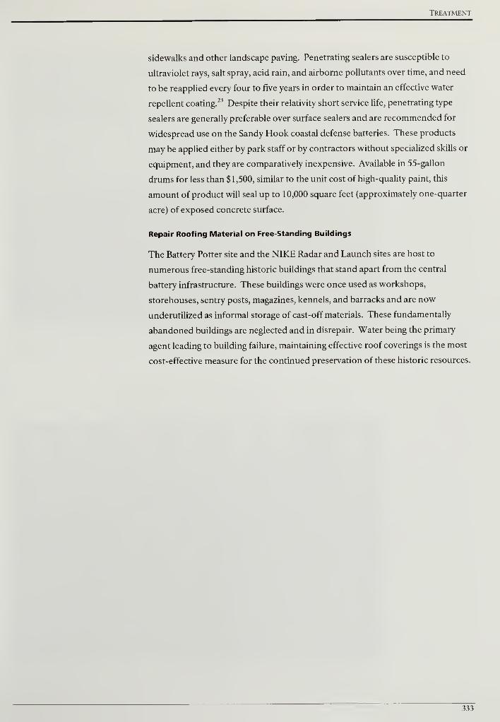
Treatment
sidewalks and other landscape paving. Penetrating sealers are susceptible to
ultraviolet rays, salt spray, acid rain, and airborne pollutants over time, and need
to be reapplied every four to five years in order to maintain an effective water
repellent coating.23
Despite their relativity short service life, penetrating type
sealers are generally preferable over surface sealers and are recommended for
widespread use on the Sandy Hook coastal defense batteries. These products
may be applied either by park staff or by contractors without specialized skills or
equipment, and they are comparatively inexpensive. Available in 55-gallon
drums for less than $1,500, similar to the unit cost of high-quality paint, this
amount of product will seal up to 10,000 square feet (approximately one-quarter
acre) of exposed concrete surface.
Repair Roofing Material on Free-Standing Buildings
The Battery Potter site and the NIKE Radar and Launch sites are host to
numerous free-standing historic buildings that stand apart from the central
battery infrastructure. These buildings were once used as workshops,
storehouses, sentry posts, magazines, kennels, and barracks and are now
underutilized as informal storage of cast-off materials. These fundamentally
abandoned buildings are neglected and in disrepair. Water being the primary
agent leading to building failure, maintaining effective roof coverings is the most
cost-effective measure for the continued preservation of these historic resources.
333

Cultural Landscape Report for the Sandy Hook Coastal Defense Batteries
334
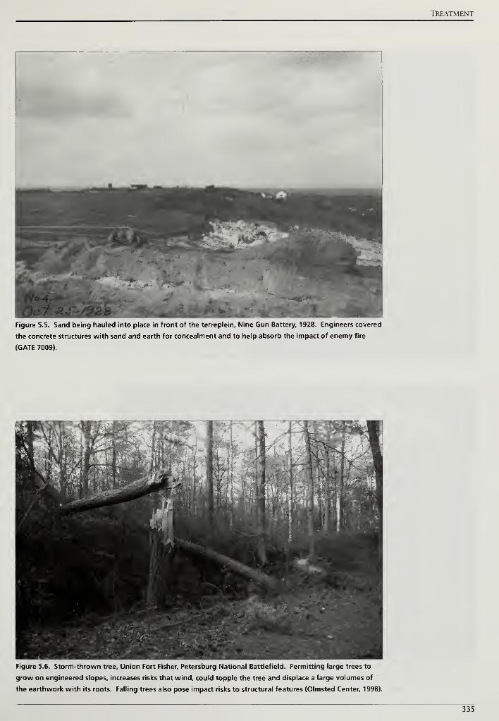
TREATMENT
Figure 5.5. Sand being hauled into place in front of the terreplein. Nine Gun Battery, 1928. Engineers covered
the concrete structures with sand and earth for concealment and to help absorb the impact of enemy fire
(GATE 7009).
Figure 5.6. Storm-thrown tree. Union Fort Fisher, Petersburg National Battlefield. Permitting large trees to
grow on engineered slopes, increases risks that wind, could topple the tree and displace a large volumes of
the earthwork with its roots. Falling trees also pose impact risks to structural features (Olmsted Center, 1998).
335
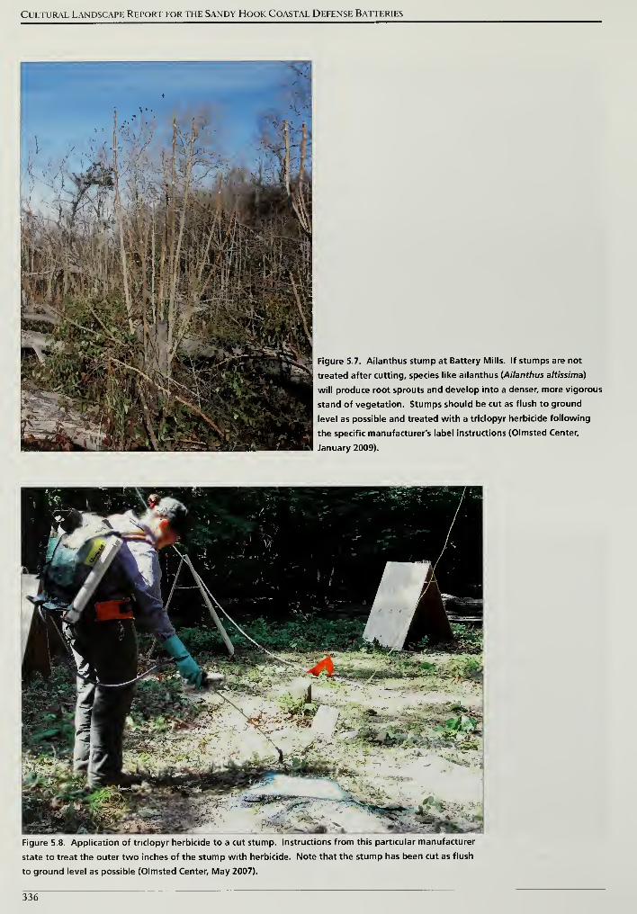
Cultural Landscape Report for the Sandy Hook Coastal Defense Batteries
Figure 5.7. Ailanthus stump at Battery Mills. If stumps are not
treated after cutting, species like ailanthus (Ailanthus altissima)
will produce root sprouts and develop into a denser, more vigorous
stand of vegetation. Stumps should be cut as flush to ground
level as possible and treated with a triclopyr herbicide following
the specific manufacturer's label instructions (Olmsted Center,
January 2009).
Figure 5.8. Application of triclopyr herbicide to a cut stump. Instructions from this particular manufacturer
state to treat the outer two inches of the stump with herbicide. Note that the stump has been cut as flush
to ground level as possible (Olmsted Center, May 2007).
336
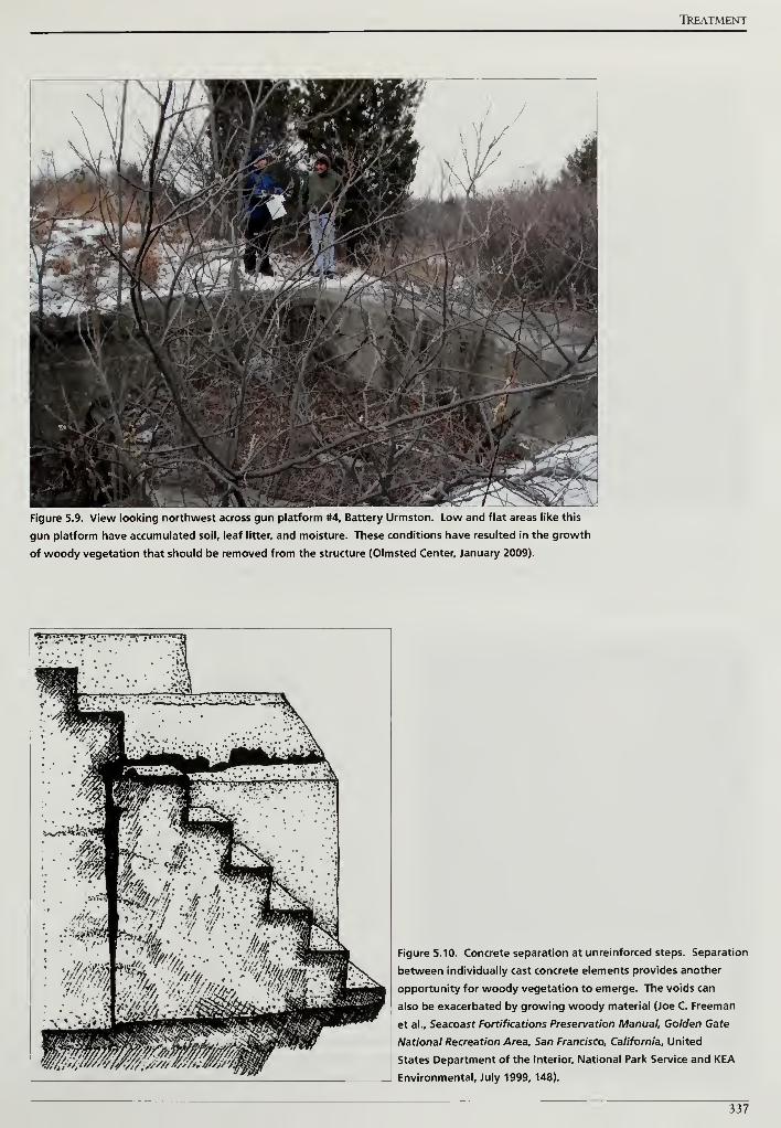
TREATMENT
Figure 5.9. View looking northwest across gun platform #4, Battery Urmston. Low and flat areas like this
gun platform have accumulated soil, leaf litter, and moisture. These conditions have resulted in the growth
of woody vegetation that should be removed from the structure (Olmsted Center, January 2009).
Figure 5.10. Concrete separation at unreinforced steps. Separation
between individually cast concrete elements provides another
opportunity for woody vegetation to emerge. The voids can
also be exacerbated by growing woody material (Joe C. Freeman
et al., Seacoast Fortifications Preservation Manual, Golden Gate
National Recreation Area, San Francisco, California, United
States Department of the Interior, National Park Service and KEA
Environmental, July 1999, 148).
337
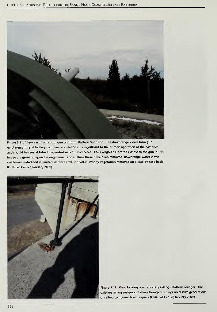
Cultural Landscape Report for the Sandy Hook Coastal Defense Batteries
Figure 5.11. View east from south gun platform. Battery Gunnison. The downrange views from gun
emplacements and battery commander's stations are significant to the historic operation of the batteries
and should be reestablished to greatest extent practicable. The evergreens located closest to the gun in this
image are growing upon the engineered slope. Once these have been removed, downrange water views
can be evaluated and in limited instances tall, individual woody vegetation removed on a case-by-case basis
(Olmsted Center, January 2009).
Figure 5.12. View looking west at safety railings. Battery Granger. The
existing railing system at Battery Granger displays successive generations
of railing components and repairs (Olmsted Center, January 2009).
338
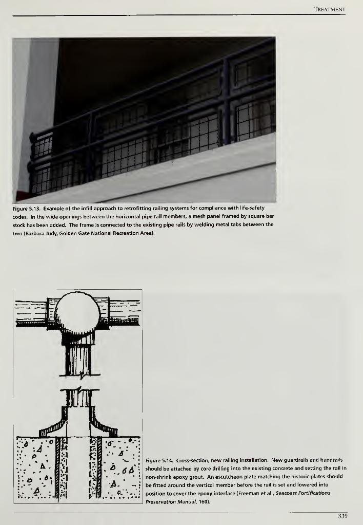
TREATMENT
Figure 5.13. Example of the infill approach to retrofitting railing systems for compliance with life-safety
codes. In the wide openings between the horizontal pipe rail members, a mesh panel framed by square bar
stock has been added. The frame is connected to the existing pipe rails by welding metal tabs between the
two (Barbara Judy, Golden Gate National Recreation Area).
Figure 5.14. Cross-section, new railing installation. New guardrails and handrails
should be attached by core drilling into the existing concrete and setting the rail in
non-shrink epoxy grout. An escutcheon plate matching the historic plates should
be fitted around the vertical member before the rail is set and lowered into
position to cover the epoxy interface (Freeman et al., Seacoast Fortifications
Preservation Manual. 160).
339
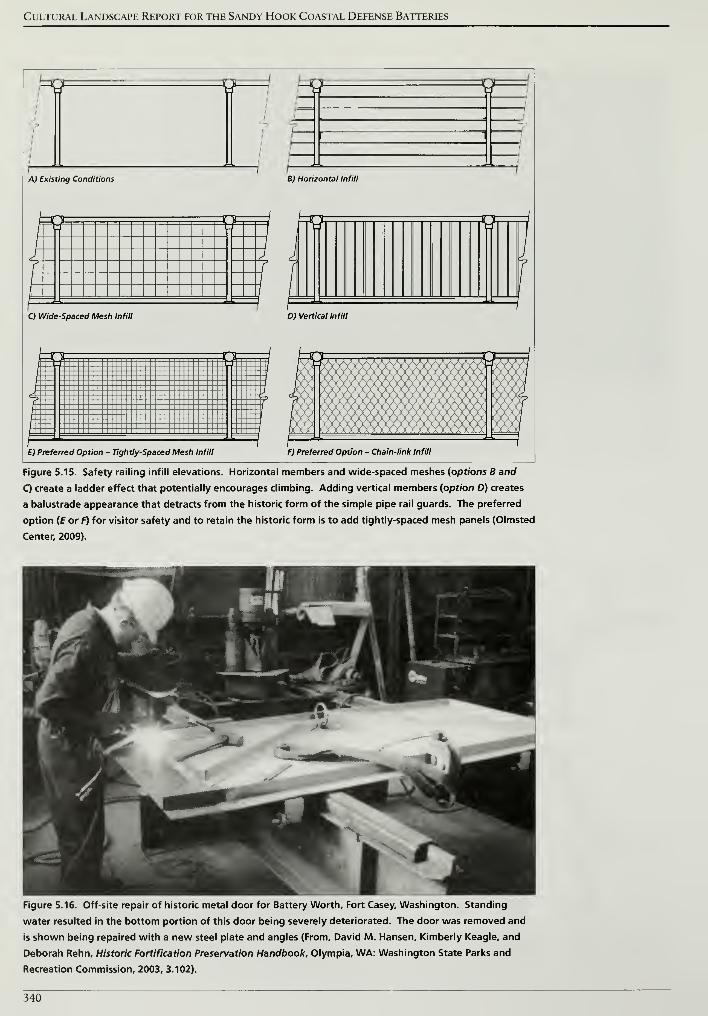
Cultural Landscape Report for the Sandy Hook Coastal Defense Batteries
y 9
A) Existing Conditions B) Horizontal Infill
S 9
C) Wide-Spaced Mesh Infill D) Vertical Infill
9
E) Preferred Option - Tightly-Spaced Mesh Infill F) Preferred Option - Chain-link Infill
Figure 5.15. Safety railing infill elevations. Horizontal members and wide-spaced meshes {options B and
Q create a ladder effect that potentially encourages climbing. Adding vertical members (option D) creates
a balustrade appearance that detracts from the historic form of the simple pipe rail guards. The preferred
option (EorF) for visitor safety and to retain the historic form is to add tightly-spaced mesh panels (Olmsted
Center, 2009).
Figure 5.16. Off-site repair of historic metal door for Battery Worth, Fort Casey, Washington. Standing
water resulted in the bottom portion of this door being severely deteriorated. The door was removed and
is shown being repaired with a new steel plate and angles (From, David M. Hansen, Kimberly Keagle, and
Deborah Rehn, Historic Fortification Preservation Handbook, Olympia, WA: Washington State Parks and
Recreation Commission, 2003, 3.102).
340
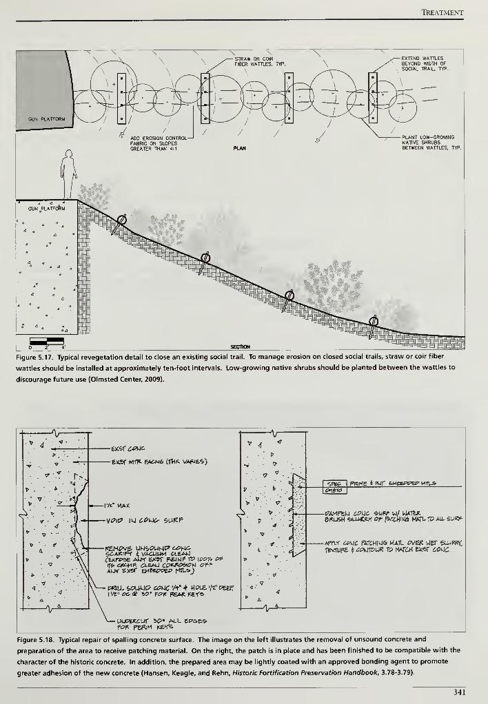
TREATMENT
GUN PLATFORM
ADO EROSION CONTROLFABRIC ON SLOPESGREATER THAN 4:1
/
PLAN
PLANT LOW-GROWINGNATIVE SHRUBSBETWEEN WATTLES, TYP.
Figure 5.17. Typical revegetation detail to close an existing social trail. To manage erosion on closed social trails, straw or coir fiber
wattles should be installed at approximately ten-foot intervals. Low-growing native shrubs should be planted between the wattles to
discourage future use (Olmsted Center, 2009).
&.V& MTP. FACiU& (fHK. VApiE.6)
l'/t" MAX
V* 4
<
„ 1
>:
5^A<IF5f l VACUUM CLEAJJ(ixrezz AWf exsr P^IKJF VP \oov. of-
IT* C&Wf: ZlBMi £9**&tt*i <???
PS3LL, feOUUC? CCMC 'A" 4 HOLE. '/«? FE#TI
1* 1 <?c® 50 * Fc>rr PEAR Kef*
uupfc-Kcur so" all ep>&es.po* nsRiM Kef's
7
-V-
6>Ffe£
C^^IOPWHE <rfVir fcMeePt^? MTUS
&KUSH <5>LU<|5.f 0r pWOflkte MAfl, tT> ALL SUKP
-AfTLf £<?L|C F5STC.HIU& HAIL 0V6* UiET SLUWi;fE*TUF£ * ^PkltPUK TO WCH EXSf £0(J£.
Figure 5.18. Typical repair of spalling concrete surface. The image on the left illustrates the removal of unsound concrete and
preparation of the area to receive patching material. On the right, the patch is in place and has been finished to be compatible with the
character of the historic concrete. In addition, the prepared area may be lightly coated with an approved bonding agent to promote
greater adhesion of the new concrete (Hansen, Keagle, and Rehn, Historic Fortification Preservation Handbook. 3.78-3.79).
341
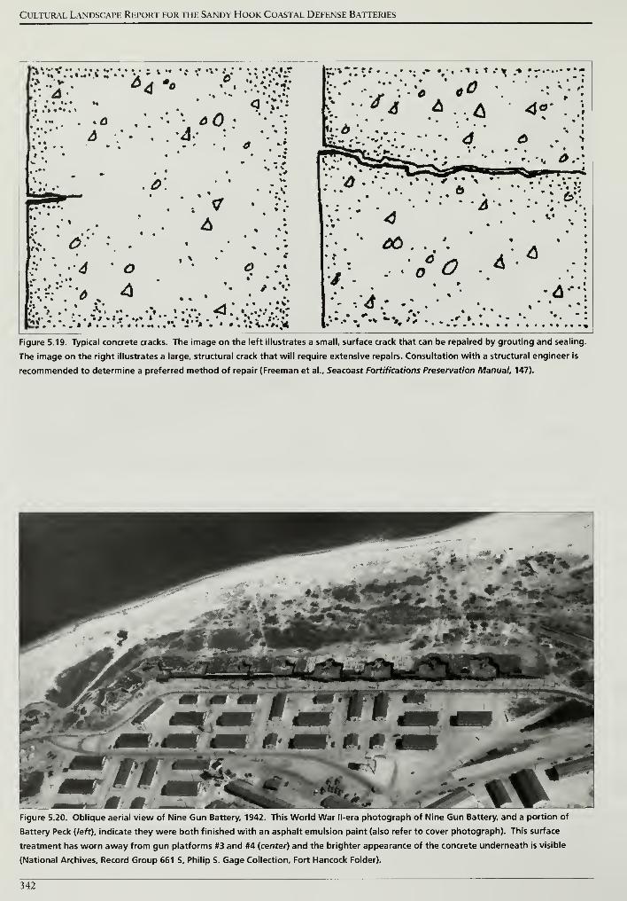
Cultural Landscape Report for the Sandy Hook Coastal Defense Batteries
*•* ••«••€> IT • • •* *
:•:-2-- 6* '"
•; • .
.• •-.. . *o
* /. ••
»'. •w •
.0'* ft » • *» -
•'.• •
t • • • "^ %1
•* • . * A ' •I." . .* . «> | •» • | 1
|2J . . * . » *..... '*.
'*
* •
A-• «
•
• •
vvt *
•
t
. • ••••-
» »
•
**
• ?;.
•
* •*
,* • •.
/ .v•
• *• •*••* • _rt •• • * 1
:;-. -.; ;'•* ** •. •: v*\ :* & & & 4f . .5
«».-* ...... . ' * ' ^ *« :
v.*- '•'•«••.• % a « *
r^>^^r '
:
; _ 1 •
''•< ^-':
• • .*
. •• • * A - • :• •;•?••.
» * .
: -.^.- %\. t.,. ,• • .^:
• I • * L« >* r * • • . •• •« "*
Figure 5.19. Typical concrete cracks. The image on the left illustrates a small, surface crack that can be repaired by grouting and sealing.
The image on the right illustrates a large, structural crack that will require extensive repairs. Consultation with a structural engineer is
recommended to determine a preferred method of repair (Freeman et al., Seacoast Fortifications Preservation Manual, 147).
Figure 5.20. Oblique aerial view of Nine Gun Battery, 1942. This World War ll-era photograph of Nine Gun Battery, and a portion of
Battery Peck (left), indicate they were both finished with an asphalt emulsion paint (also refer to cover photograph). This surface
treatment has worn away from gun platforms #3 and #4 (center) and the brighter appearance of the concrete underneath is visible
(National Archives, Record Group 661 S, Philip S. Gage Collection, Fort Hancock Folder).
342
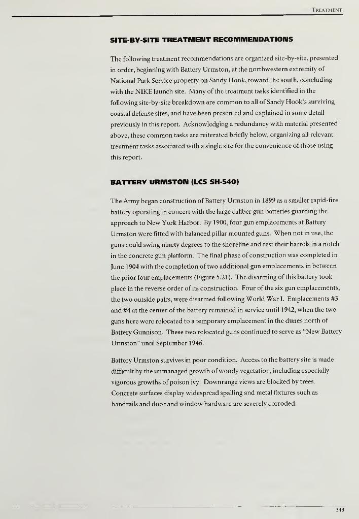
Treatment
SITE-BY-SITE TREATMENT RECOMMENDATIONS
The following treatment recommendations are organized site-by-site, presented
in order, beginning with Battery Urmston, at the northwestern extremity of
National Park Service property on Sandy Hook, toward the south, concluding
with the NIKE launch site. Many of the treatment tasks identified in the
following site-by-site breakdown are common to all of Sandy Hook's surviving
coastal defense sites, and have been presented and explained in some detail
previously in this report. Acknowledging a redundancy with material presented
above, these common tasks are reiterated briefly below, organizing all relevant
treatment tasks associated with a single site for the convenience of those using
this report.
BATTERY URMSTON (LCS SH-540)
The Army began construction of Battery Urmston in 1899 as a smaller rapid-fire
battery operating in concert with the large caliber gun batteries guarding the
approach to New York Harbor. By 1900, four gun emplacements at Battery
Urmston were fitted with balanced pillar mounted guns. When not in use, the
guns could swing ninety degrees to the shoreline and rest their barrels in a notch
in the concrete gun platform. The final phase of construction was completed in
June 1904 with the completion of two additional gun emplacements in between
the prior four emplacements (Figure 5.21). The disarming of this battery took
place in the reverse order of its construction. Four of the six gun emplacements,
the two outside pairs, were disarmed following World War I. Emplacements #3
and #4 at the center of the battery remained in service until 1942, when the two
guns here were relocated to a temporary emplacement in the dunes north of
Battery Gunnison. These two relocated guns continued to serve as "New Battery
Urmston" until September 1946.
Battery Urmston survives in poor condition. Access to the battery site is made
difficult by the unmanaged growth ofwoody vegetation, including especially
vigorous growths of poison ivy. Downrange views are blocked by trees.
Concrete surfaces display widespread spalling and metal fixtures such as
handrails and door and window hardware are severely corroded.
343
Cultural Landscape Report for the Sandy Hook Coastal Defense Batteries
TREATMENT TASKS
Vegetation Management Treatment Tasks
UR-1: Remove woody vegetation greater than four-inches diameter growing on
engineered slopes
Large woody vegetation growing on the north-facing engineered slopes of
Battery Urmston consists primarily of eastern red cedar (Juniperus virginiana),
beach plum (Prunus maritima), hackberry (Celtis occidentalis), and ailanthus
(Ailanthus altissima) (Figure 5.22). To protect the earthwork and the concrete
structures below, woody vegetation greater than four-inches diameter at breast
height should be removed following the guidelines in the general treatment
recommendations. Due to their close proximity, it is difficult to prescribe a line
that divides the engineered earthworks of Battery Urmston and Battery Morris.
Looking at both batteries as a single unit, the area to be selectively cleared would
be approximately 1.2 acres (Drawing 5.1, scope of treatment).
UR-2: Remove all woody vegetation growing on or within four-feet of concrete
features
Untreated vegetation on Battery Urmston has grown to a considerable size and
threatens to further deteriorate the historic battery's concrete features.
Consistent with treatment recommendations offered for all of Sandy Hook's
coastal defense sites, vegetation growing on or within four-feet of concrete
features should be removed. As highlighted in the general treatment
recommendations, both deciduous and evergreen stumps should be treated with
a triclopyr herbicide to inhibit resprouting and to promote root decay. After the
root systems deteriorate, the stumps should be carefully removed to the greatest
extent practicable, and appropriate concrete repairs should be undertaken.
UR-3: Remove vegetation blocking historic downrange views
Historic photographs indicate a clear line of sight and field of fire at Battery
Urmston to defend against fast moving, shallow-draft boats (Figure 5.23).
Vegetation removals on the engineered slope and structure itself will greatly
improve an unobstructed view to the water. After these removals, it will be
necessary to evaluate the views and determine if select, tall woody vegetation
beyond the engineered slope should be removed (Figure 5.24). In addition to
vegetation, the introduction of new buildings and structures can impact the visual
connection to the water. No buildings or accessory structures should be
constructed within the downrange view from Battery Urmston to the water.
344
Treatment
UR-4: Remove all woody vegetation six-feet north of the U. S. Coast Guard
perimeter fence
Immediately south of Battery Urmston is U. S. Coast Guard property separated
by a six-foot high chain-link fence topped with barbed wire. The north side of
the fence, closest to Battery Urmston, is becoming overrun with ailanthus
(Ailanthus altissima), Virginia creeper (Parthenocissus quinquefolia), poison ivy
(Toxicodendron radicans), and honey locust saplings (Gleditsia triacanthos). If
not treated and maintained, this area will soon be impassable. Once the large
woody vegetation has been removed, the six-foot width can be easily maintained
with a small tractor and brush hog mowing deck (Figure 5.25).
Visitor Access Treatment Tasks
UR-5: Construct New Visitor Access Trail
During the historic period, a road paralleled Battery Urmston's south facade and
provided access for personnel and delivery of ammunition (see Figure 5.21). The
road is presently extant but separated from the battery by the U. S. Coast Guard
perimeter fence. Visitors and park staff currently walk to the battery in the area
between the fence and concrete structure. At present, that area is becoming
overrun with vegetation that makes access difficult. After the vegetation is
removed north of the perimeter fence, the park should construct trail to Battery
Urmston. Since regular mowing will be required to maintain vegetation along the
fence, a practical method for defining and maintaining the trail is to mow a four-
foot wide route at a lower height.
UR-6: Repair, retrofit, and replace safety railings
Historic safety railings are typically located at stairwells on the south side of the
battery and a handrail is installed along an external set of stairs to the
commander's station. Both are typically constructed from pipe railings with the
individual sections connected by ball joint fixtures (Figure 5.26). Safety railings
and handrailings should be treated to stop the corrosion process followed by
priming and painting to match the historic finish. Infill panels should be installed
where there is a vertical change equal to or greater than thirty inches in order to
provide greater safety at the large openings below the top rails.
UR-7: Repair and secure doors and grating to prevent unauthorized access
Although operational during Battery Urmston's years of service, the doors
leading to the magazine and bomb proofs should be properly mounted and
locked to prevent unauthorized access to interior spaces. Specific treatments
should follow the procedures detailed in the general treatment recommendations,
beginning with a case-by-case evaluation of the condition of each door or grille.
At openings where an outer solid door and inner metal gate are installed, the gate
345
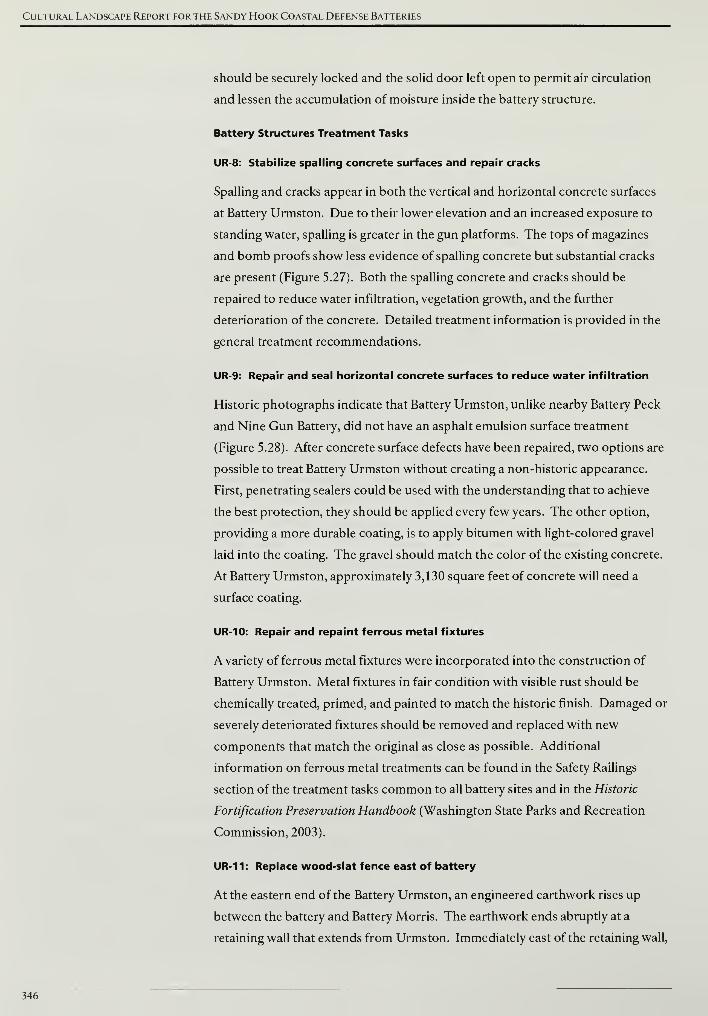
Cultural Landscape Report for the Sandy Hook Coastal Defense Batteries
should be securely locked and the solid door left open to permit air circulation
and lessen the accumulation of moisture inside the battery structure.
Battery Structures Treatment Tasks
UR-8: Stabilize spading concrete surfaces and repair cracks
Spalling and cracks appear in both the vertical and horizontal concrete surfaces
at Battery Urmston. Due to their lower elevation and an increased exposure to
standing water, spalling is greater in the gun platforms. The tops of magazines
and bomb proofs show less evidence of spalling concrete but substantial cracks
are present (Figure 5.27). Both the spalling concrete and cracks should be
repaired to reduce water infiltration, vegetation growth, and the further
deterioration of the concrete. Detailed treatment information is provided in the
general treatment recommendations.
UR-9: Repair and seal horizontal concrete surfaces to reduce water infiltration
Historic photographs indicate that Battery Urmston, unlike nearby Battery Peck
and Nine Gun Battery, did not have an asphalt emulsion surface treatment
(Figure 5.28). After concrete surface defects have been repaired, two options are
possible to treat Battery Urmston without creating a non-historic appearance.
First, penetrating sealers could be used with the understanding that to achieve
the best protection, they should be applied every few years. The other option,
providing a more durable coating, is to apply bitumen with light-colored gravel
laid into the coating. The gravel should match the color of the existing concrete.
At Battery Urmston, approximately 3,130 square feet of concrete will need a
surface coating.
UR-10: Repair and repaint ferrous metal fixtures
A variety of ferrous metal fixtures were incorporated into the construction of
Battery Urmston. Metal fixtures in fair condition with visible rust should be
chemically treated, primed, and painted to match the historic finish. Damaged or
severely deteriorated fixtures should be removed and replaced with new
components that match the original as close as possible. Additional
information on ferrous metal treatments can be found in the Safety Railings
section of the treatment tasks common to all battery sites and in the Historic
Fortification Preservation Handbook (Washington State Parks and Recreation
Commission, 2003).
UR-11: Replace wood-slat fence east of battery
At the eastern end of the Battery Urmston, an engineered earthwork rises up
between the battery and Battery Morris. The earthwork ends abruptly at a
retaining wall that extends from Urmston. Immediately east of the retaining wall,
346

Treatment
a four-foot high, wood-slat fence meanders up the earthwork and wraps around
toward the gun platform. The fence is in fair condition but is not a historic
feature of the battery. Removing the fence will help facilitate the vegetation
removals on the engineered earthwork (Drawing 5.1).
If upon the judgment of park staff, this location warrants the installation of a
non-historic safety railing, then a metal safety railing should be installed. The
metal safety railing should be visually compatible with repaired and retrofitted
historic safety railings recommended for widespread use throughout Sandy
Hook's coastal defense batteries.
347
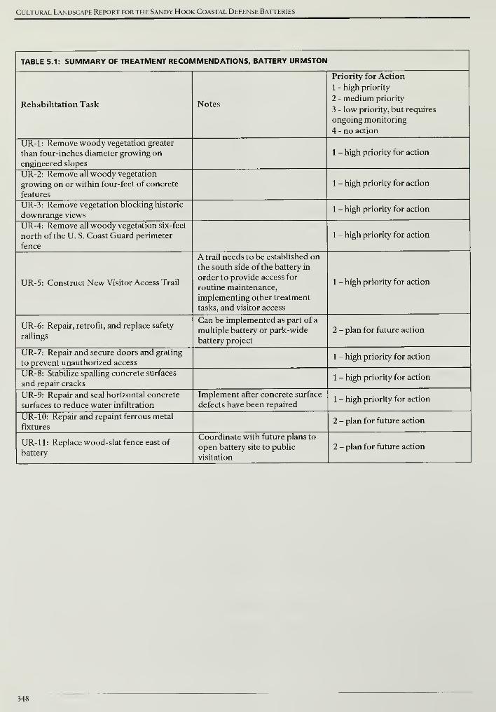
Cultural Landscape Report for the Sandy Hook Coastal Defense Batteries
TABLE 5.1: SUMMARY OF TREATMENT RECOMMENDATIONS, BATTERY URMSTON
Rehabilitation Task Notes
Priority for Action
1 - high priority
2 - medium priority
3 - low priority, but requires
ongoing monitoring
4 - no action
UR-1: Remove woody vegetation greater
than four-inches diameter growing on
engineered slopes
1 - high priority for action
UR-2: Remove all woody vegetation
growing on or within four-feet of concrete
features
1 - high priority for action
UR-3: Remove vegetation blocking historic
downrange views1 - high priority for action
UR-4: Remove all woody vegetation six-feet
north of the U. S. Coast Guard perimeter
fence
1 - high priority for action
UR-5: Construct New Visitor Access Trail
A trail needs to be established on
the south side of the battery in
order to provide access for
routine maintenance,
implementing other treatment
tasks, and visitor access
1 - high priority for action
UR-6: Repair, retrofit, and replace safety
railings
Can be implemented as part of a
multiple battery or park-wide
battery project
2 - plan for future action
UR-7: Repair and secure doors and grating
to prevent unauthorized access1 - high priority for action
UR-8: Stabilize spalling concrete surfaces
and repair cracks1 - high priority for action
UR-9: Repair and seal horizontal concrete
surfaces to reduce water infiltration
Implement after concrete surface
defects have been repaired1 - high priority for action
UR-10: Repair and repaint ferrous metal
fixtures2 - plan for future action
UR-11: Replace wood-slat fence east of
battery
Coordinate with future plans to
open battery site to public
visitation
2 - plan for future action
348
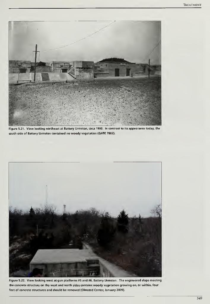
TREATMENT
Figure 5.21. View looking northeast at Battery Urmston, circa 1900. In contrast to its appearance today, the
south side of Battery Urmston contained no woody vegetation (GATE 7882).
Figure 5.22. View looking west at gun platforms #5 and #6, Battery Urmston. The engineered slope meeting
the concrete structure on the west and north sides contains woody vegetation growing on, or within, four
feet of concrete structures and should be removed (Olmsted Center, January 2009).
349
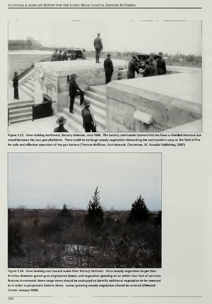
Cultural Landscape Report for the Sandy Hook Coastal Defense Batteries
Figure 5.23. View looking northwest. Battery Urmston, circa 1906. The battery commander (center) did not have a shielded structure but
stood between the two gun platforms. There could be no large woody vegetation obstructing the commander's view or the field of fire
for safe and effective operation of the gun battery (Thomas Hoffman, Fort Hancock. Charleston, SC: Arcadia Publishing, 2007).
Figure 5.24. View looking east toward water from Battery Urmston. Once woody vegetation larger than
4-inches diameter growing on engineered slopes, and vegetation growing on or within four-feet of concrete
features is removed, downrange views should be evaluated to identify additional vegetation to be removed
to in order to perpetuate historic views. Lower growing woody vegetation should be retained (Olmsted
Center, January 2009).
350

TREATMENT
Figure 5.25. U. S. Coast Guard perimeter fence south of Battery Urmston and Morris. After the large woody
vegetation has been removed along the perimeter fence, a six-foot wide swath from the fence can be easily
maintained with a small tractor and brush hog mowing deck. The mowed swath will provide a convenient
route for visitor access to these batteries (Olmsted Center, January 2009).
Figure 5.26. Existing historic safety railing at Battery Urmston is fabricated of pipe rail sections and ball joint
connectors. After treating corrosion and restoring the historic finish, infill panels should be installed where
there is a vertical change equal to or greater than thirty inches in order to provide greater safety at the large
openings below the top rails (Olmsted Center, January 2009).
351
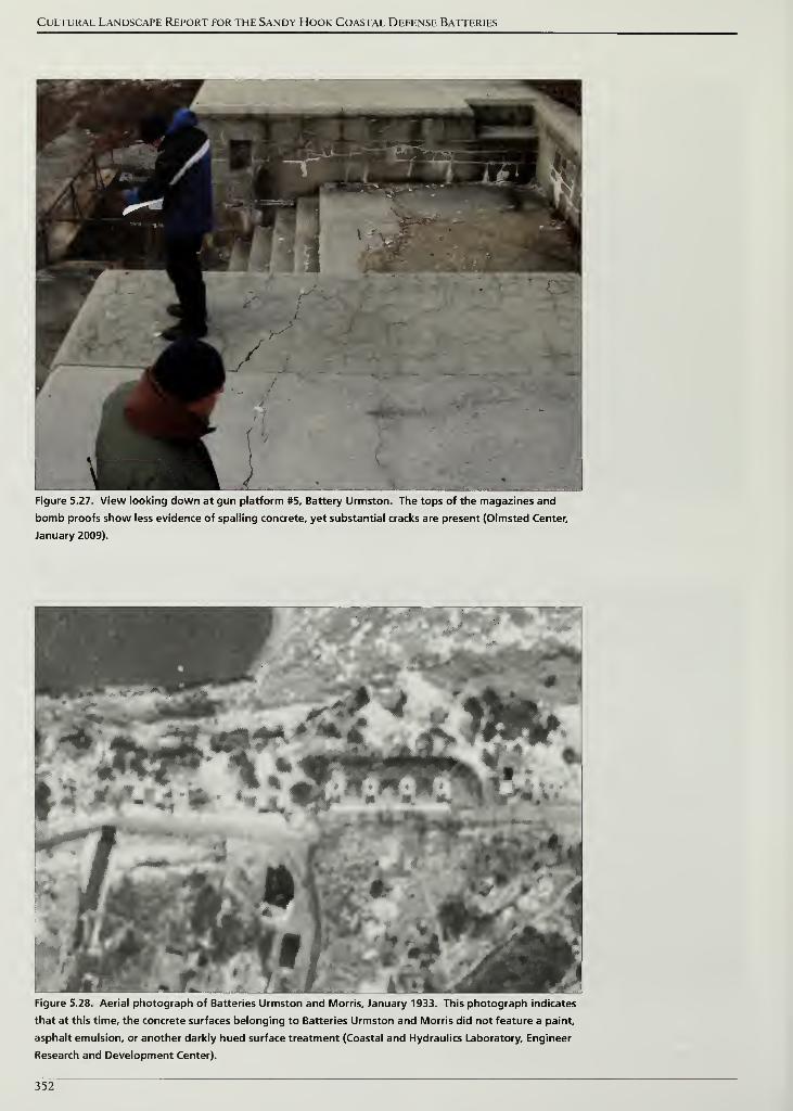
Cultural Landscape Report for the Sandy Hook Coastal Defense Batteries
Figure 5.27. View looking down at gun platform #5, Battery Urmston. The tops of the magazines and
bomb proofs show less evidence of spelling concrete, yet substantial cracks are present (Olmsted Center,
January 2009).
Figure 5.28. Aerial photograph of Batteries Urmston and Morris, January 1933. This photograph indicates
that at this time, the concrete surfaces belonging to Batteries Urmston and Morris did not feature a paint,
asphalt emulsion, or another darkly hued surface treatment (Coastal and Hydraulics Laboratory, Engineer
Research and Development Center).
352
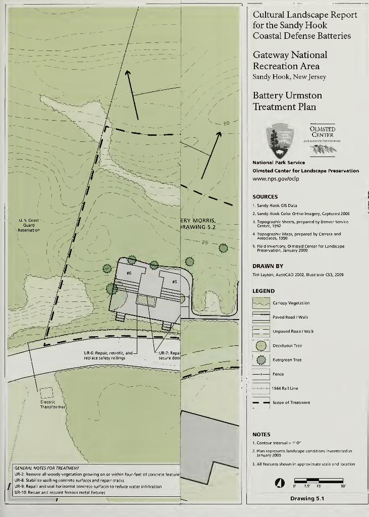
GENERAL NOTES FOR TREATMENT
UR-2: Remove all woody vegetation growing on or within four-feet of concrete feature;
UR-8: Stabilize spalling concrete surfaces and repair cracks
UR-9: Repair and seal horizontal concrete surfaces to reduce water infiltration
UR-10: Repair and repaint ferrous metal fixtures
Cultural Landscape Report
for the Sandy HookCoastal Defense Batteries
Gateway National
Recreation AreaSandy Hook, New Jersey
Battery UrmstonTreatment Plan
OlmstedCenter
for L^NDSCMT PRFSFRVATIC
National Park Service
Olmsted Center for Landscape Preservation
www.nps.gov/oclp
SOURCES
1. Sandy Hook GIS Data
2. Sandy Hook Color Ortho Imagery, Captured 2006
3. Topographic Sheets, prepared by Denver Service
Center, 1992
4. Topographic Maps, prepared by Carrera andAssociates, 1990
5. Field Inventory, Olmsted Center for LandscapePreservation, January 2009
DRAWN BY
Tim Layton, AutoCAD 2002, Illustrator CS3, 2009
LEGEND
Canopy Vegetation
o
Paved Road /Walk
Unpaved Road /Walk
Deciduous Tree
o Evergreen Tree
1944 Rail Line
Scope of Treatment
NOTES
1. Contour Interval = t'-O"
2. Plan represents landscape conditions inventoried in
January 2009
3. All features shown in approximate scale and location
o 0' 7.5' 15'
Drawing 5.1
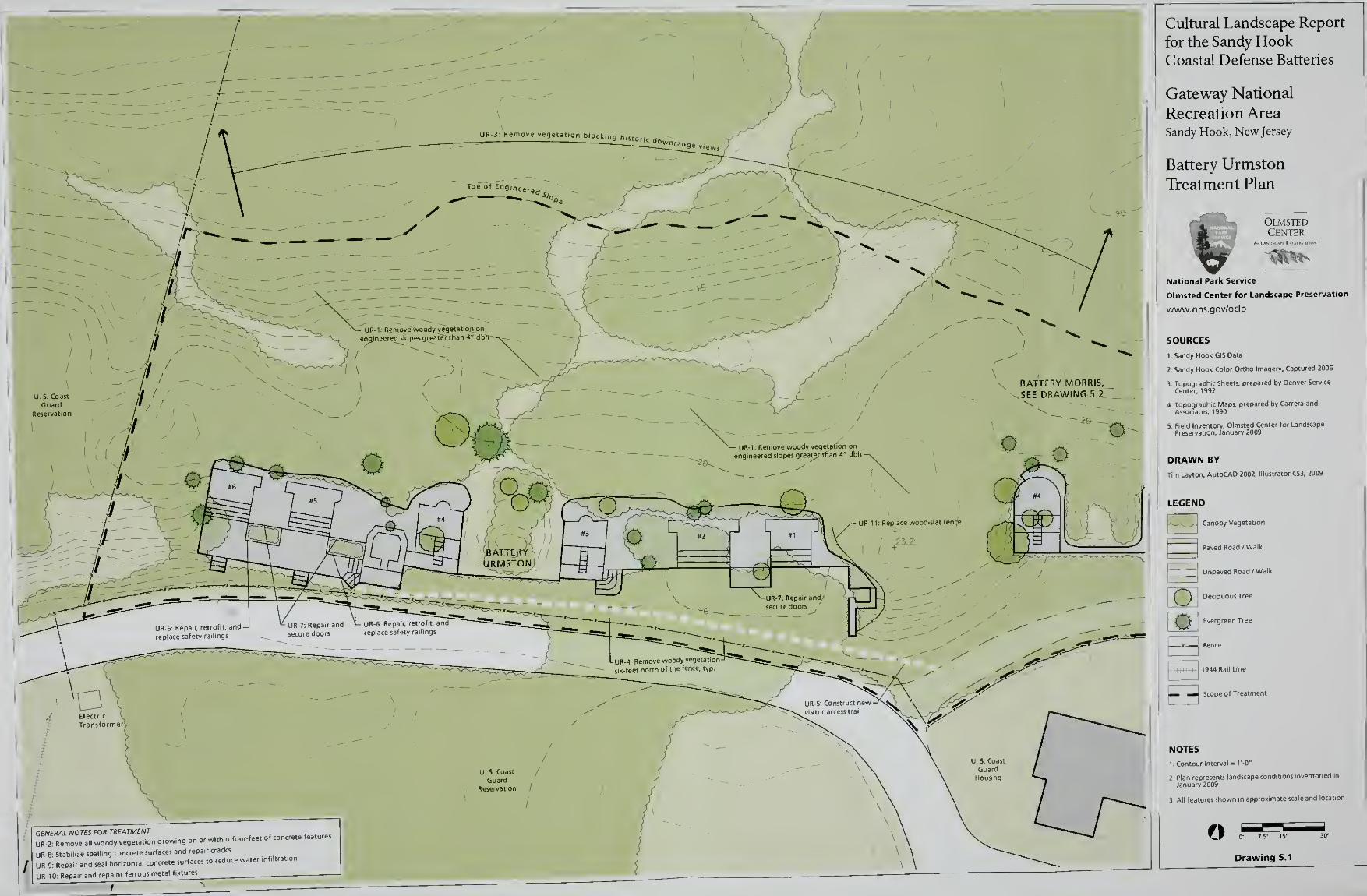
Cultural Landscape Report
for the Sandy HookCoastal Defense Batteries
Gateway National
Recreation AreaSandy Hook, New Jersey
Battery Urmston
Treatment Plan
GENERAL NOTES FOR TREATMENT..(„,,,„,
UR-2: Remove all wood, vegetation growing on o, within four-feet of concrete feature,
UR-8: Stabilize spalling concrete surfaces and repair cracks
UR-9: Repair and seal horizontal concrete surfaces to reduce I
UR-10: Repair and repaint ferrous metal fixtures
OlmstedCenter
9191•
National Park Service
Olmsted Center for Landscape Preservation
www.nps.gov/oclp
SOURCES
1, Sandy Hook GlSOata
2 Sandy Hook Color Ortho Imagery, Captured 2006
3. Topographic Sheets, prepared by Denver Service
Center, 1992
4. Topographic Maps, prepared by Carrera andAssociates. 1990
5. Field Inventory, Olmsted Center for Landscape
Preservation, January 2009
DRAWN BY
Tim Layton, AutoCAD 2002, Illustrator CS3, 2009
LEGEND
ls_^J Canopy Vegetation
I
Paved Road /Walk
~ Unpaved Road /Walk
Deciduous Tree
en Tree
Fence
1944 Rail Line
Scope of Treatment
I I Eve<g
E3
NOTES
1 Contour Interval = I'-O"
3 All features shown in approximate scale and location
oDrawing 5.1
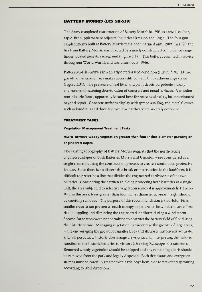
Treatment
BATTERY MORRIS (LCS SH 539)
The Army completed construction of Battery Morris in 1903 as a small-caliber,
rapid-fire supplement to adjacent batteries Urmston and Engle. The four gun
emplacements built at Battery Morris remained unarmed until 1909. In 1920, the
fire from Battery Morris was directed by a newly constructed coincidence range
finder located near its eastern end (Figure 5.29). This battery remained in service
throughout World War II, and was disarmed in 1946.
Battery Morris survives in a greatly deteriorated condition (Figure 5.30). Dense
growth of vines and trees makes access difficult and blocks downrange views
(Figure 5.31). The presence of leaf litter and plant debris perpetuate a damp
environment hastening deterioration of concrete and metal surfaces. A wooden
non-historic fence, apparently located here for reasons of safety, has deteriorated
beyond repair. Concrete surfaces display widespread spalling, and metal fixtures
such as handrails and door and window hardware are severely corroded.
TREATMENT TASKS
Vegetation Management Treatment Tasks
MO-1: Remove woody vegetation greater than four-inches diameter growing on
engineered slopes
The existing topography of Battery Morris suggests that the north-facing
engineered slopes of both Batteries Morris and Urmston were considered as a
single element during the construction process to create a continuous protective
feature. Since there is no discernable break or interruption in the landform, it is
difficult to prescribe a line that divides the engineered earthworks of the two
batteries. Considering the earthen shielding protecting both batteries as a single
unit, the area subjected to selective vegetation removal is approximately 1.2 acres.
Within this area, trees greater than four inches diameter at breast height should
be carefully removed. The purpose of this recommendation is two-fold. First,
smaller trees to not present as much canopy exposure to the wind, and are of less
risk in toppling and displacing the engineered landform during a wind storm.
Second, large trees were not permitted to obstruct the battery field of fire during
the historic period. Managing vegetation to discourage the growth of large trees,
while encouraging the growth of smaller trees and shrubs is historically accurate,
and will perpetuate historic downrange views critical to interpreting the historic
function of the historic batteries to visitors (Drawing 5.2, scope of treatment).
Removed woody vegetation should be chipped and any remaining debris should
be removed from the park and legally disposed. Both deciduous and evergreen
stumps must be carefully treated with a triclopyr herbicide to prevent resprouting
according to label directions.
355
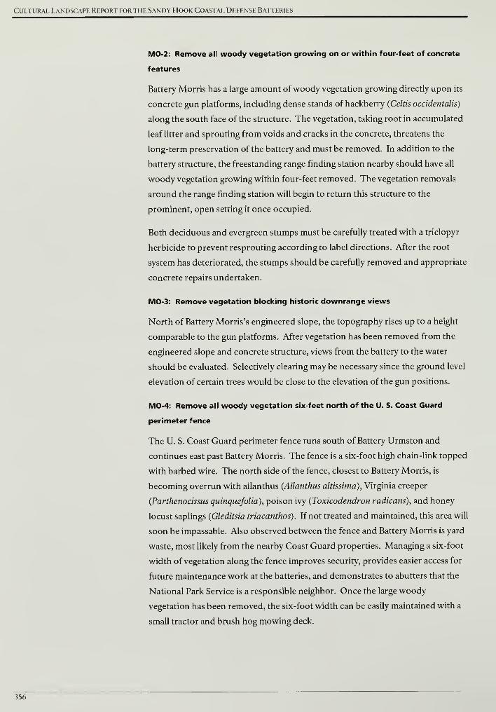
Cultural Landscape Report for the Sandy Hook Coastal Defense Batteries
MO-2: Remove all woody vegetation growing on or within four-feet of concrete
features
Battery Morris has a large amount of woody vegetation growing directly upon its
concrete gun platforms, including dense stands of hackberry (Celtis occidentalis)
along the south face of the structure. The vegetation, taking root in accumulated
leaf litter and sprouting from voids and cracks in the concrete, threatens the
long-term preservation of the battery and must be removed. In addition to the
battery structure, the freestanding range finding station nearby should have all
woody vegetation growing within four-feet removed. The vegetation removals
around the range finding station will begin to return this structure to the
prominent, open setting it once occupied.
Both deciduous and evergreen stumps must be carefully treated with a triclopyr
herbicide to prevent resprouting according to label directions. After the root
system has deteriorated, the stumps should be carefully removed and appropriate
concrete repairs undertaken.
MO-3: Remove vegetation blocking historic downrange views
North of Battery Morris's engineered slope, the topography rises up to a height
comparable to the gun platforms. After vegetation has been removed from the
engineered slope and concrete structure, views from the battery to the water
should be evaluated. Selectively clearing may be necessary since the ground level
elevation of certain trees would be close to the elevation of the gun positions.
MO-4: Remove all woody vegetation six-feet north of the U. S. Coast Guard
perimeter fence
The U. S. Coast Guard perimeter fence runs south of Battery Urmston and
continues east past Battery Morris. The fence is a six-foot high chain-link topped
with barbed wire. The north side of the fence, closest to Battery Morris, is
becoming overrun with ailanthus {Ailanthus altissima), Virginia creeper
{Parthenocissus quinquefolia), poison ivy {Toxicodendron radicans), and honey
locust saplings {Gleditsia triacanthos). If not treated and maintained, this area will
soon be impassable. Also observed between the fence and Battery Morris is yard
waste, most likely from the nearby Coast Guard properties. Managing a six-foot
width of vegetation along the fence improves security, provides easier access for
future maintenance work at the batteries, and demonstrates to abutters that the
National Park Service is a responsible neighbor. Once the large woody
vegetation has been removed, the six-foot width can be easily maintained with a
small tractor and brush hog mowing deck.
356
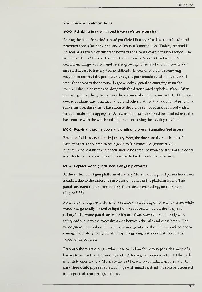
Treatment
Visitor Access Treatment Tasks
MO-5: Rehabilitate existing road trace as visitor access trail
During the historic period, a road paralleled Battery Morris's south facade and
provided access for personnel and delivery of ammunition. Today, the road is
present as a variable-width trace north of the Coast Guard perimeter fence. The
asphalt surface of the road contains numerous large cracks and is in poor
condition. Large woody vegetation is growing in the cracks and makes visitor
and staff access to Battery Morris difficult. In conjunction with removing
vegetation north of the perimeter fence, the park should rehabilitate the road
trace for access to the battery. Large woody vegetation emerging from the
roadbed should be removed along with the deteriorated asphalt surface. After
removing the asphalt, the exposed base course should be compacted. If the base
course contains clay, organic matter, and other material that would not provide a
stable surface, the existing base course should be removed and replaced with a
hard, durable stone aggregate. A new asphalt surface should be installed over the
base course with the width and alignment matching the existing roadbed.
MO-6: Repair and secure doors and grating to prevent unauthorized access
Based on field observations in January 2009, the doors on the south side of
Battery Morris appeared to be in good to fair condition (Figure 5.32).
Accumulated leaf litter and debris should be removed from the front of the doors
in order to remove a source of moisture that will accelerate corrosion.
MO-7: Replace wood guard panels on gun platforms
At the eastern most gun platform of Battery Morris, wood guard panels have been
installed due to the difference in elevation between the platform levels. The
panels are constructed from two-by-fours, and have peeling, maroon paint
(Figure 5.33).
Metal pipe railing was historically used for safety railing on coastal batteries while
wood was generally limited to light framing, doors, windows, decking, and
siding.24 The wood panels are not a historic feature and do not comply with
safety codes due to the excessive space between the rails and cross brace. The
wood guard panels should be removed and great care should be exercised not to
damage the historic concrete structures removing fasteners that secured the
wood to the concrete.
Presently the vegetation growing close to and on the battery provides more of a
barrier to access than the wood panels. After vegetation removal and if the park
intends to open Battery Morris to the public, wherever judged appropriate, the
park should add pipe rail safety railings with metal mesh infill panels as discussed
in the general treatment guidelines.
357
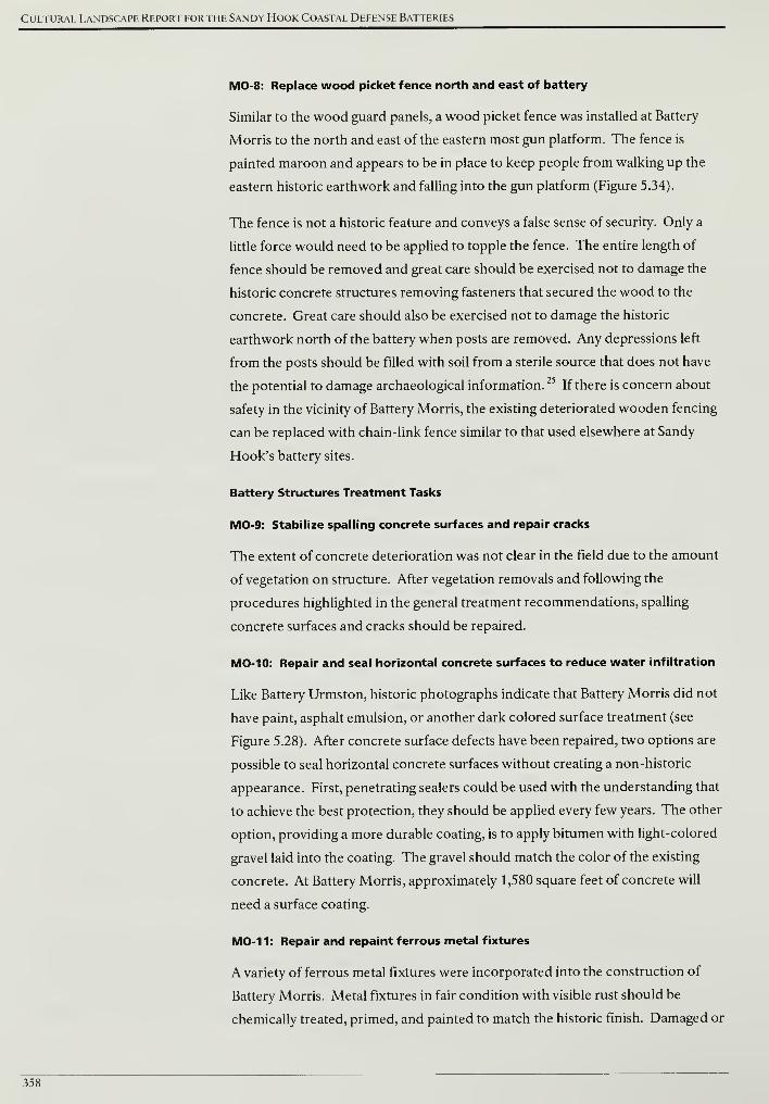
Cultural Landscape Report for the Sandy Hook Coastal Defense Batteries
MO-8: Replace wood picket fence north and east of battery
Similar to the wood guard panels, a wood picket fence was installed at Battery
Morris to the north and east of the eastern most gun platform. The fence is
painted maroon and appears to be in place to keep people from walking up the
eastern historic earthwork and falling into the gun platform (Figure 5.34).
The fence is not a historic feature and conveys a false sense of security. Only a
little force would need to be applied to topple the fence. The entire length of
fence should be removed and great care should be exercised not to damage the
historic concrete structures removing fasteners that secured the wood to the
concrete. Great care should also be exercised not to damage the historic
earthwork north of the battery when posts are removed. Any depressions left
from the posts should be filled with soil from a sterile source that does not have
the potential to damage archaeological information.25
If there is concern about
safety in the vicinity of Battery Morris, the existing deteriorated wooden fencing
can be replaced with chain-link fence similar to that used elsewhere at Sandy
Hook's battery sites.
Battery Structures Treatment Tasks
MO-9: Stabilize spalling concrete surfaces and repair cracks
The extent of concrete deterioration was not clear in the field due to the amount
of vegetation on structure. After vegetation removals and following the
procedures highlighted in the general treatment recommendations, spalling
concrete surfaces and cracks should be repaired.
MO-10: Repair and seal horizontal concrete surfaces to reduce water infiltration
Like Battery Urmston, historic photographs indicate that Battery Morris did not
have paint, asphalt emulsion, or another dark colored surface treatment (see
Figure 5.28). After concrete surface defects have been repaired, two options are
possible to seal horizontal concrete surfaces without creating a non-historic
appearance. First, penetrating sealers could be used with the understanding that
to achieve the best protection, they should be applied every few years. The other
option, providing a more durable coating, is to apply bitumen with light-colored
gravel laid into the coating. The gravel should match the color of the existing
concrete. At Battery Morris, approximately 1,580 square feet of concrete will
need a surface coating.
MO-11: Repair and repaint ferrous metal fixtures
A variety of ferrous metal fixtures were incorporated into the construction of
Battery Morris. Metal fixtures in fair condition with visible rust should be
chemically treated, primed, and painted to match the historic finish. Damaged or
358

Treatment
severely deteriorated fixtures should be removed and replaced with new
components that match the original as close as possible. Additional
information on ferrous metal treatments can be found in the Safety Railings
section of the treatment tasks common to all battery sites and in the Historic
Fortification Preservation Handbook (Washington State Parks and Recreation
Commission, 2003).
359
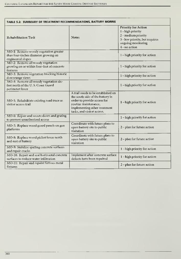
Cultural Landscape Report for the Sandy Hook Coastal Defense Batteries
TABLE 5.2: SUMMARY OF TREATMENT RECOMMENDATIONS, BATTERY MORRIS
Rehabilitation Task Notes
Priority for Action
1 - high priority
2 - medium priority
3 - low priority, but requires
ongoing monitoring
4 - no action
MO-1: Remove woody vegetation greater
than four-inches diameter growing on
engineered slopes
1 - high priority for action
MO-2: Remove all woody vegetation
growing on or within four-feet of concrete
features
1 - high priority for action
MO-3: Remove vegetation blocking historic
downrange views1 - high priority for action
MO-4: Remove all woody vegetation six-
feet north of the U. S. Coast Guard
perimeter fence
1 - high priority for action
MO-5: Rehabilitate existing road trace as
visitor access trail
A trail needs to be established on
the south side of the battery in
order to provide access for
routine maintenance,
implementing other treatment
tasks, and visitor access.
1 - high priority for action
MO-6: Repair and secure doors and grating
to prevent unauthorized access1 - high priority for action
MO-7: Replace wood guard panels on gun
platforms
Coordinate with future plans to
open battery site to public
visitation
2 - plan for future action
MO-8: Replace wood picket fence north
and east of battery
Coordinate with future plans to
open battery site to public
visitation
2 - plan for future action
MO-9: Stabilize spalling concrete surfaces
and repair cracks1 - high priority for action
MO- 10: Repair and seal horizontal concrete
surfaces to reduce water infiltration
Implement after concrete surface
defects have been repaired1 - high priority for action
MO- 11: Repair and repaint ferrous metal
fixtures2 - plan for future action
360
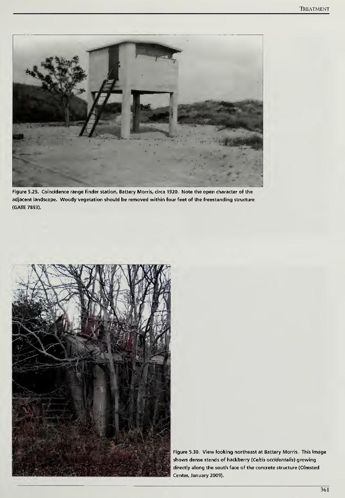
TREATMENT
Figure 5.29. Coincidence range finder station. Battery Morris, circa 1920. Note the open character of the
adjacent landscape. Woody vegetation should be removed within four feet of the freestanding structure
(GATE 7893).
Figure 5.30. View looking northeast at Battery Morris. This image
shows dense stands of hackberry (Celtis occidentalis) growing
directly along the south face of the concrete structure (Olmsted
Center, January 2009).
361
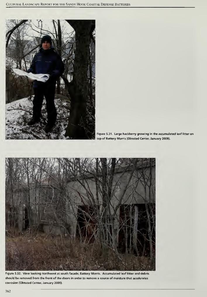
Cultural Landscape Report for the Sandy Hook Coastal Defense Batteries
Figure 5.31. Large hackberry growing in the accumulated leaf litter on
top of Battery Morris (Olmsted Center, January 2009).
Figure 5.32. View looking northwest at south facade. Battery Morris. Accumulated leaf litter and debris
should be removed from the front of the doors in order to remove a source of moisture that accelerates
corrosion (Olmsted Center, January 2009).
362
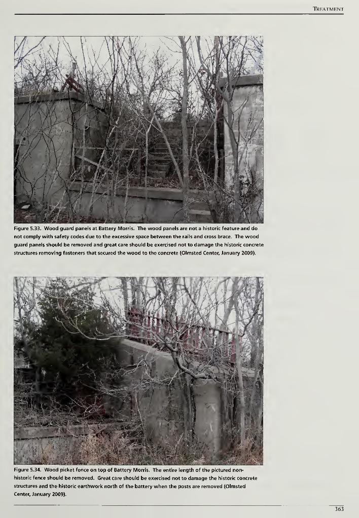
TREATMENT
Figure 5.33. Wood guard panels at Battery Morris. The wood panels are not a historic feature and do
not comply with safety codes due to the excessive space between the rails and cross brace. The wood
guard panels should be removed and great care should be exercised not to damage the historic concrete
structures removing fasteners that secured the wood to the concrete (Olmsted Center, January 2009).
Figure 5.34. Wood picket fence on top of Battery Morris. The entire length of the pictured non-
historic fence should be removed. Great care should be exercised not to damage the historic concrete
structures and the historic earthwork north of the battery when the posts are removed (Olmsted
Center, January 2009).
363

Cultural Landscape Report for the Sandy Hook Coastal Defense Batteries
364
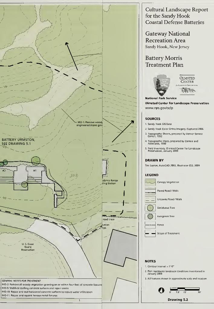
GENERAL NOTES FOR TREATMENT
MO-2: Remove all woody vegetation growing on or within four-feet of concrete feature!
MO-9: Stabilize spalling concrete surfaces and repair cracks
MO-10: Repair and seal horizontal concrete surfaces to reduce water infiltration
MO-11: Repair and repaint ferrous metal fixtures
\
Cultural Landscape Report
for the Sandy HookCoastal Defense Batteries
Gateway National
Recreation AreaSandy Hook, New Jersey
Battery Morris
Treatment Plan
OlmstedCenter
fur L\NDSCAPF PRFSFRVWION
National Park Service
Olmsted Center for Landscape Preservation
www.nps.gov/oclp
SOURCES
I.Sandy Hook GIS Data
2. Sandy Hook Color Ortho Imagery, Captured 2006
3. Topographic Sheets, prepared by Denver Service
Center, 1992
4. Topographic Maps, prepared by Carrera andAssociates, 1990
5. Field Inventory, Olmsted Center for LandscapePreservation, January 2009
DRAWN BY
Tim Layton, AutoCAD 2002, Illustrator CS3, 2009
LEGEND
Canopy Vegetation
G
E3
Paved Road /Walk
Unpaved Road /Walk
Deciduous Tree
Evergreen Tree
Scope of Treatment
NOTES
1. Contour Interval = V-0"
2. Plan represents landscape conditions inventoried in
January 2009
3. All features shown in approximate scale and location
o 0' 7.5' 15"
Drawing 5.2
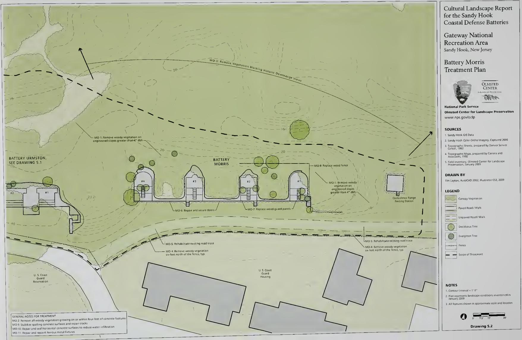
GENERAL NOTES FOR TREATMENT
MO-2: Remove all woody vegetat.on growing on or within four-feet of concrete fea
MO-9' Stabilize spalling concrete surfaces and repair cracks
MO-10: Repair and seal horizontal concrete surfaces to reduce water infiltrat.o
MO-l l Repair and repaint ferrous metal fixtures
Cultural Landscape Report
for the Sandy HookCoastal Defense Batteries
Gateway National
Recreation AreaSandy Hook, New Jersey
Battery Morris
Treatment Plan
OlmstedCenter
National Park Service
Olmsted Center for Landscape Preservation
www.nps.gov/oclp
SOURCES
l.Sandy Hook GIS Data
2 Sandy Hook Color Ortho Imagery, Captured 2006
3. Topographic Sheets, prepared by Denver Service
Center, 1992
4 Topographic Maps, prepared by Carrera and
Associates, 1990
5, Field Inventory, Olmsted Center for Landscape
Preservation, January 2009
DRAWN BY
Tim Layton, AutoCAD 2002, Illustrator CS3, 2009
k-vJ i
LEGEND
Canopy Vegetation
I ]
Paved Road /Walk
™" Unpaved Road /Walk
Deciduous Tree
Evergreen Tree
Fence
Treatment
oH— _J Scope of
NOTES
1 Contour Interval = 1'-0"
2 Plan represents landscape condit
January 2009
3 All features shown in approximate scale and location
oDrawing 5.2
Treatment
BATTERIES ENGLE AND PECK (SH-189A AND SH-180)
Although batteries Engle and Peck each have their own individual histories,
because they lay immediately adjacent, they are considered together for the
purpose of this cultural landscape report. The Army constructed and armed
Battery Engle in 1898 with a single five-inch gun. The non-standard five-inch gun
was deemed obsolete and the emplacement was disarmed in 1918. A
rangefinding station was soon constructed over the former gun emplacement in
1920, directing the fire of nearby Battery Peck (Figure 5.35).
Battery Peck was completed and armed in 1903, joining Batteries Urmston,
Morris and Engle in defending the shipping channel directly offshore Sandy
Hook's northern extremity. Battery Peck's original armament consisted of two 6-
inch barbette mount guns shielded with semi-circular armor plating. Owing to its
ability to fire rapidly, Battery Peck's guns were removed used to replace the
slower operating armament at Battery Gunnison in 1943 during World War II.
Battery Peck was in turn refitted four with "Dual-Purpose" guns capable of
engaging either aircraft or surface ships at a high rate of fire, and was
redesignated as "Battery Number 8." The former Battery Peck site served
throughout World War II, and was disarmed in 1946.26
Batteries Engle and Peck survive in deteriorated condition. Downrange views
from gun emplacements and range finder stations have been blocked by the
growth of woody vegetation (Figures 5.36 and 5.37). Accumulation of
windblown sand, organic matter and the growth of vines and other plants hinder
access throughout the battery site. Concrete surfaces display widespread
spalling, and metal fixtures such as handrails and door and window hardware are
severely corroded.
TREATMENT TASKS
Vegetation Management Treatment Tasks
EN/PE-1: Remove woody vegetation greater than four-inches diameter growing
on engineered slopes
The existing topography of the Battery Engle and Peck site suggests that the
engineered slopes and terrain of both batteries Engle and Peck were considered
as a single element during the construction process to create a continuous
protective feature. Since there is no discernable break or interruption in the
landform, it is difficult to prescribe a line that divides the engineered earthworks
of the two batteries. Within this area, trees greater than four inches diameter at
breast height should be carefully removed. The purpose of this recommendation
is two-fold. First, smaller trees do not present as much canopy to the wind, and
are of less risk in toppling and displacing the historic landform during a storm.
367
Cultural Landscape Report for the Sandy Hook Coastal Defense Batteries
Second, large trees were not permitted to obstruct the battery field of fire during
the historic period. Managing vegetation to discourage the growth of large trees,
while encouraging the growth of smaller trees and shrubs is historically accurate,
and will perpetuate historic downrange views critical to interpreting the historic
function of the batteries to visitors (Drawing 5.3, scope of treatment). Removed
woody vegetation should be chipped and any remaining debris should be
removed from the park and legally disposed. Both deciduous and evergreen
stumps must be carefully treated with a triclopyr herbicide to prevent resprouting
according to label directions.
EN/PE-2: Remove all woody vegetation growing on or within four-feet of
concrete features
Unmanaged vegetation on batteries Engle and Peck has grown to a considerable
size and threatens to further deteriorate the historic battery's concrete features.
Vegetation growing on or within four-feet of concrete features should be
removed. As highlighted previously in the treatment tasks common to all battery
sites, both deciduous and evergreen stumps should be treated with a triclopyr
herbicide to prevent resprouting and accelerate root decay. After the root
systems deteriorate, the stumps should be carefully removed to the greatest
extent practicable and appropriate concrete repairs should be made.
EN/PE-3: Remove vegetation blocking historic downrange views
North of Battery Engle and Peck's engineered slope, the topography of the
adjacent dunes rises up to a height comparable to the gun platforms. After
vegetation has been removed from the immediacy of the engineered slopes and
concrete structures, downrange views from the batteries Engle and Peck to the
water should be evaluated. Selectively clearing may be necessary since the ground
level elevation of certain trees would be close to the elevation of the gun positions.
EN/PE-4: Remove vegetation blocking access to rear of Battery Peck
During the historic period, North Bragg Drive turned west past Nine Gun Battery
and paralleled the south facade Battery Peck. The south facade provided access
for personnel and ammunition and located opposite the firing direction of the
artillery, served as the rear of the battery. The rear of Battery Peck was kept free
of vegetation to expedite deliveries and changes in personnel (Figure 5.38).
Today the area between the rear of Battery Peck and North Bragg Drive is filled
with dense vegetation and is nearly impassable (Figure 5.39). In order to provide
staff and visitor access, the vegetation growing between North Bragg Drive and
the rear of Battery Peck should be removed. Removing the vegetation also
rehabilitates the rear of Battery Peck to resemble the open character present
during the battery's years of operation.
368
Treatment
Visitor Access Treatment Tasks
EN/PE-5: Close social trail and improve eroded pathway east of battery
East of Battery Engle, a social trail winds up an engineered slope and connects to
a series of trails around Battery Peck that lead to the observation platform.
Although a spilt-rail fence has been installed, users have worn a path that
squeezes between the fence and the historic structure (see Figure 5.36). In order
to protect the historic engineered earthwork and limit potential erosion, the
social trail should be closed. Low-growing native shrubs should be planted at the
top and bottom of the trail to block access. Additional information on
appropriate species and installing erosion control materials is presented in the
treatment tasks common to all battery sites section.
EN/PE-6: Install new split-rail fence around observation platform and direct
pedestrian circulation via a new trail to the North Pond.
Due to Battery Peck's current hazardous conditions, a chain-link fence restricts
visitor access to the structure from North Bragg Drive. Visitors arrive at batteries
Engle and Peck by following an unpaved road to the observation platform and
then heading south along a series of social trails to the batteries (Drawing 5.3).
The social trails trod across the batteries' engineered earthworks and lead visitors
to structures that have not been rehabilitated for public access.
In order to curtail unauthorized access to the batteries, preserve the engineered
earthworks, and provide visitors with a continuous route to other attractions at
the park, a new split-rail fence should be installed around the observation
platform and a new trail established that unites with the existing trail to the North
Pond. Split-rail fence is currently in place north of the observation platform to
direct pedestrians and protect natural resource areas. Additional fencing should
clearly define a space around the observation platform and contain an opening at
the head of the new trail. The trail should proceed north of the engineered
earthworks and gradually descend a steep slope before uniting with the existing
trail to the North Pond (Drawing 5.3). After vegetation and battery structure
tasks are completed, visitors should access batteries Engle and Peck from North
Bragg Drive. This route allows visitors to approach the batteries in the same
manner as soldiers did during the historic period.
EN/PE-7: Repair, retrofit, and replace safety railings
At batteries Engle and Peck, metal handrails line the steps that provided access
from the ground level to the batteries. Metal guardrails are also installed near the
open sides of elevated areas such as gun platforms (Figure 5.40). Metal railings in
fair condition with visible rust should be chemically treated, primed, and painted
to match the historic finish. Damaged or severely deteriorated railings should be
369
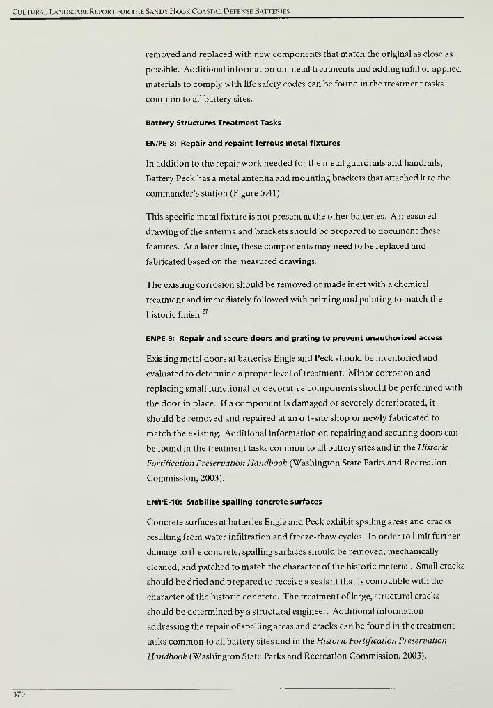
Cultural Landscape Report for the Sandy Hook Coastal Defense Batteries
removed and replaced with new components that match the original as close as
possible. Additional information on metal treatments and adding infill or applied
materials to comply with life safety codes can be found in the treatment tasks
common to all battery sites.
Battery Structures Treatment Tasks
EN/PE-8: Repair and repaint ferrous metal fixtures
In addition to the repair work needed for the metal guardrails and handrails,
Battery Peck has a metal antenna and mounting brackets that attached it to the
commander's station (Figure 5.41).
This specific metal fixture is not present at the other batteries. A measured
drawing of the antenna and brackets should be prepared to document these
features. At a later date, these components may need to be replaced and
fabricated based on the measured drawings.
The existing corrosion should be removed or made inert with a chemical
treatment and immediately followed with priming and painting to match the
historic finish.27
ENPE-9: Repair and secure doors and grating to prevent unauthorized access
Existing metal doors at batteries Engle and Peck should be inventoried and
evaluated to determine a proper level of treatment. Minor corrosion and
replacing small functional or decorative components should be performed with
the door in place. If a component is damaged or severely deteriorated, it
should be removed and repaired at an off-site shop or newly fabricated to
match the existing. Additional information on repairing and securing doors can
be found in the treatment tasks common to all battery sites and in the Historic
Fortification Preservation Handbook (Washington State Parks and Recreation
Commission, 2003).
EN/PE-10: Stabilize spalling concrete surfaces
Concrete surfaces at batteries Engle and Peck exhibit spalling areas and cracks
resulting from water infiltration and freeze-thaw cycles. In order to limit further
damage to the concrete, spalling surfaces should be removed, mechanically
cleaned, and patched to match the character of the historic material. Small cracks
should be dried and prepared to receive a sealant that is compatible with the
character of the historic concrete. The treatment of large, structural cracks
should be determined by a structural engineer. Additional information
addressing the repair of spalling areas and cracks can be found in the treatment
tasks common to all battery sites and in the Historic Fortification Preservation
Handbook (Washington State Parks and Recreation Commission, 2003).
370
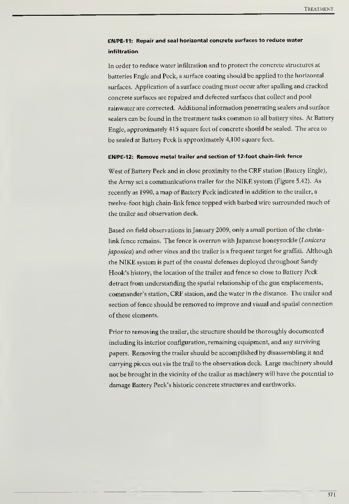
Treatment
EN/PE-11: Repair and seal horizontal concrete surfaces to reduce water
infiltration
In order to reduce water infiltration and to protect the concrete structures at
batteries Engle and Peck, a surface coating should be applied to the horizontal
surfaces. Application of a surface coating must occur after spalling and cracked
concrete surfaces are repaired and defected surfaces that collect and pool
rainwater are corrected. Additional information penetrating sealers and surface
sealers can be found in the treatment tasks common to all battery sites. At Battery
Engle, approximately 415 square feet of concrete should be sealed. The area to
be sealed at Battery Peck is approximately 4,100 square feet.
EN/PE-12: Remove metal trailer and section of 12-foot chain-link fence
West of Battery Peck and in close proximity to the CRF station (Battery Engle),
the Army set a communications trailer for the NIKE system (Figure 5.42). As
recently as 1990, a map of Battery Peck indicated in addition to the trailer, a
twelve-foot high chain-link fence topped with barbed wire surrounded much of
the trailer and observation deck.
Based on field observations in January 2009, only a small portion of the chain-
link fence remains. The fence is overrun with Japanese honeysuckle (Lonicera
japonica) and other vines and the trailer is a frequent target for graffiti. Although
the NIKE system is part of the coastal defenses deployed throughout Sandy
Hook's history, the location of the trailer and fence so close to Battery Peck
detract from understanding the spatial relationship of the gun emplacements,
commander's station, CRF station, and the water in the distance. The trailer and
section offence should be removed to improve and visual and spatial connection
of these elements.
Prior to removing the trailer, the structure should be thoroughly documented
including its interior configuration, remaining equipment, and any surviving
papers. Removing the trailer should be accomplished by disassembling it and
carrying pieces out via the trail to the observation deck. Large machinery should
not be brought in the vicinity of the trailer as machinery will have the potential to
damage Battery Peck's historic concrete structures and earthworks.
371
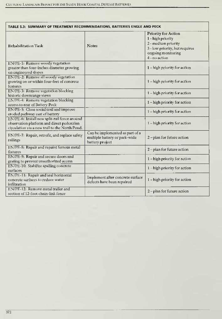
Cultural Landscape Report for the Sandy Hook Coastal Defense Batteries
TABLE 5.3: SUMMARY OF TREATMENT RECOMMENDATIONS, BATTERIES ENGLE AND PECK
Rehabilitation Task Notes
Priority for Action
1 - high priority
2 - medium priority
3 - low priority, but requires
ongoing monitoring
4 - no action
EN/PE- 1 : Remove woody vegetation
greater than four-inches diameter growing
on engineered slopes
1 - high priority for action
EN/PE-2: Remove all woody vegetation
growing on or within four-feet of concrete
features
1 - high priority for action
EN/PE-3: Remove vegetation blocking
historic downrange views1 - high priority for action
EN/PE-4: Remove vegetation blocking
access to rear of Battery Peck1 - high priority for action
EN/PE-5: Close social trail and improve
eroded pathway east of battery1 - high priority for action
EN/PE-6: Install new split-rail fence around
observation platform and direct pedestrian
circulation via a new trail to the North Pond.
1 - high priority for action
EN/PE-7: Repair, retrofit, and replace safety
railings
Can be implemented as part of a
multiple battery or park-wide
battery project
2 - plan for future action
EN/PE-8: Repair and repaint ferrous metal
fixtures2 - plan for future action
EN/PE-9: Repair and secure doors and
grating to prevent unauthorized access1 - high priority for action
EN/PE- 10: Stabilize spalling concrete
surfaces1 - high priority for action
EN/PE- 11: Repair and seal horizontal
concrete surfaces to reduce water
infiltration
Implement after concrete surface
defects have been repaired1 - high priority for action
EN/PE-12: Remove metal trailer and
section of 12-foot chain-link fence2 - plan for future action
372
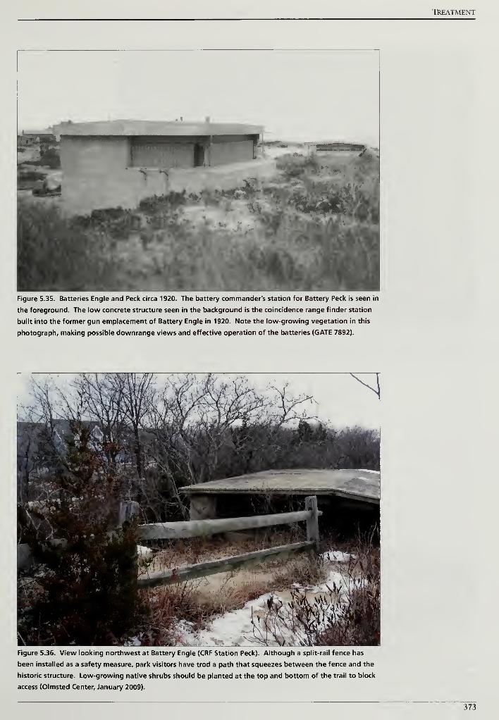
TREATMENT
Figure 5.35. Batteries Engle and Peck circa 1920. The battery commander's station for Battery Peck is seen in
the foreground. The low concrete structure seen in the background is the coincidence range finder station
built into the former gun emplacement of Battery Engle in 1920. Note the low-growing vegetation in this
photograph, making possible downrange views and effective operation of the batteries (GATE 7892).
Figure 5.36. View looking northwest at Battery Engle (CRF Station Peck). Although a split-rail fence has
been installed as a safety measure, park visitors have trod a path that squeezes between the fence and the
historic structure. Low-growing native shrubs should be planted at the top and bottom of the trail to block
access (Olmsted Center, January 2009).
373
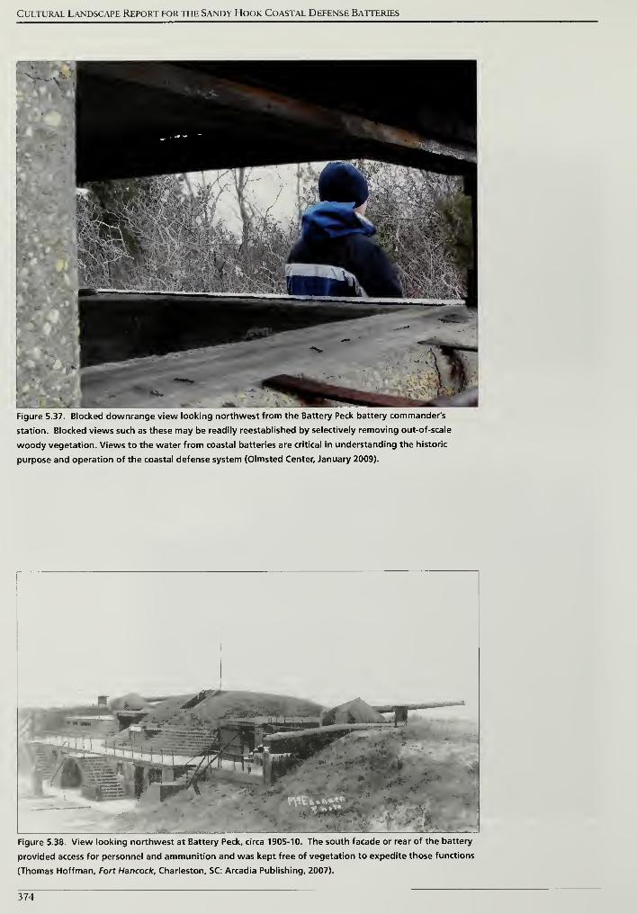
Cultural Landscape Report for the Sandy Hook Coastal Defense Batteries
Figure 5.37. Blocked downrange view looking northwest from the Battery Peck battery commander's
station. Blocked views such as these may be readily reestablished by selectively removing out-of-scale
woody vegetation. Views to the water from coastal batteries are critical in understanding the historic
purpose and operation of the coastal defense system (Olmsted Center, January 2009).
Figure 5.38. View looking northwest at Battery Peck, circa 1905-10. The south facade or rear of the battery
provided access for personnel and ammunition and was kept free of vegetation to expedite those functions
(Thomas Hoffman, Fort Hancock, Charleston, SC: Arcadia Publishing, 2007).
374
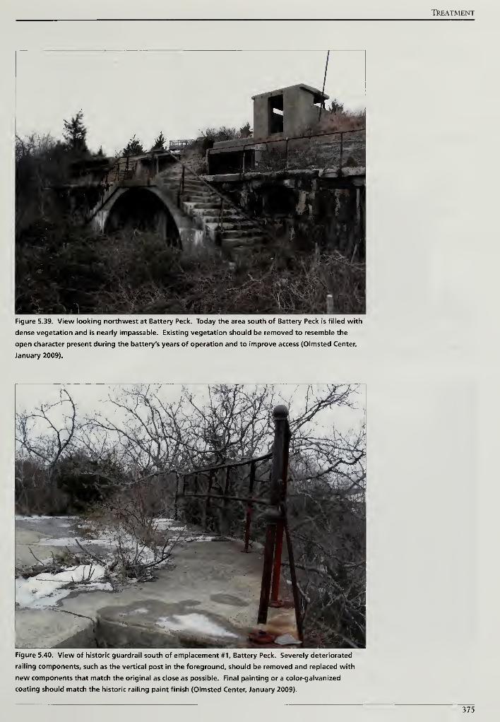
TkEATMENT
Figure 5.39. View looking northwest at Battery Peck. Today the area south of Battery Peck is filled with
dense vegetation and is nearly impassable. Existing vegetation should be removed to resemble the
open character present during the battery's years of operation and to improve access (Olmsted Center,
January 2009).
Figure 5.40. View of historic guardrail south of emplacement #1, Battery Peck. Severely deteriorated
railing components, such as the vertical post in the foreground, should be removed and replaced with
new components that match the original as close as possible. Final painting or a color-galvanized
coating should match the historic railing paint finish (Olmsted Center, January 2009).
375
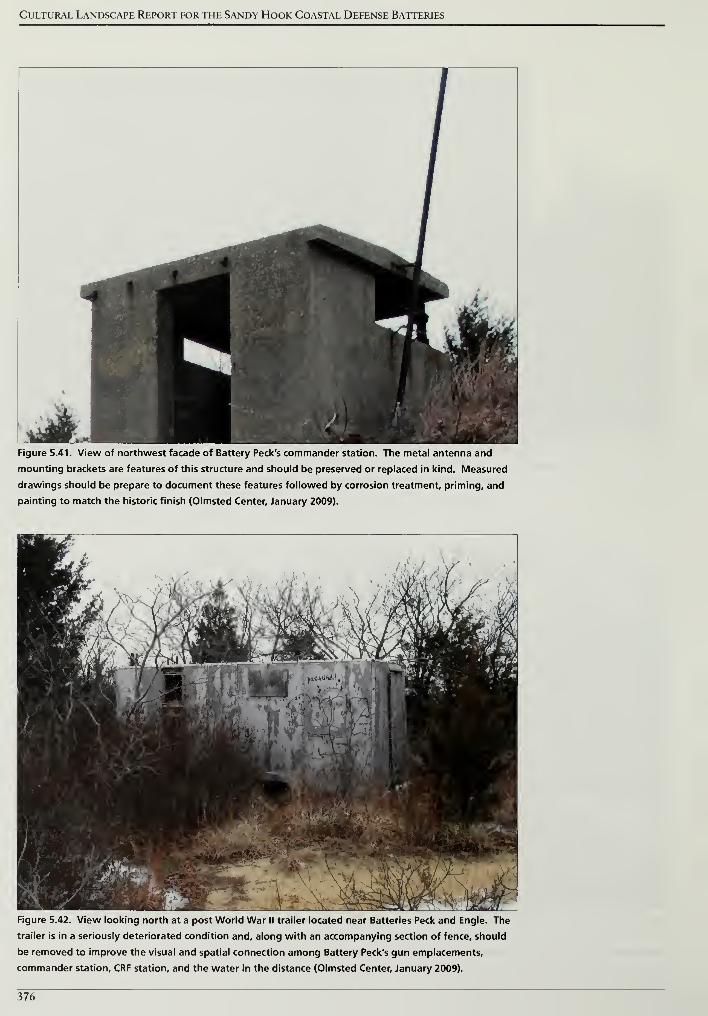
Cultural Landscape Report for the Sandy Hook Coastal Defense Batteries
Figure 5.41. View of northwest facade of Battery Peck's commander station. The metal antenna and
mounting brackets are features of this structure and should be preserved or replaced in kind. Measured
drawings should be prepare to document these features followed by corrosion treatment, priming, and
painting to match the historic finish (Olmsted Center, January 2009).
Figure 5.42. View looking north at a post World War II trailer located near Batteries Peck and Engle. The
trailer is in a seriously deteriorated condition and, along with an accompanying section of fence, should
be removed to improve the visual and spatial connection among Battery Peck's gun emplacements,
commander station, CRF station, and the water in the distance (Olmsted Center, January 2009).
376
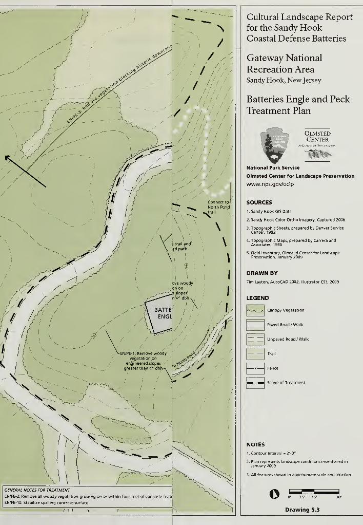
GENERAL NOTES FOR TREATMENT
EN/PE-2: Remove all woody vegetation growing on or within four-feet of concrete feati
EN/PE-10: Stabilize spalling concrete surface
Cultural Landscape Report
for the Sandy HookCoastal Defense Batteries
Gateway National
Recreation AreaSandy Hook, New Jersey
Batteries Engle and Peck
Treatment Plan
OlmstedCenter
for L*NDSCATF PRFSFR'
National Park Service
Olmsted Center for Landscape Preservation
www.nps.gov/oclp
SOURCES
1. Sandy Hook GIS Data
2. Sandy Hook Color Ortho Imagery, Captured 2006
3. Topographic Sheets, prepared by Denver Service
Center, 1992
4. Topographic Maps, prepared by Carrera andAssociates, 1990
5. Field Inventory, Olmsted Center for LandscapePreservation, January 2009
DRAWN BY
Tim Layton, AutoCAD 2002, Illustrator CS3, 2009
LEGEND
Canopy Vegetation
Paved Road /Walk
Unpaved Road /Walk
Trail
Fence
Scope of Treatment
NOTES
1. Contour Interval = 2'-0"
2. Plan represents landscape conditions inventoried in
January 2009
3. All features shown in approximate scale and location
© 0' 7.5' 15'
Drawing 5.3
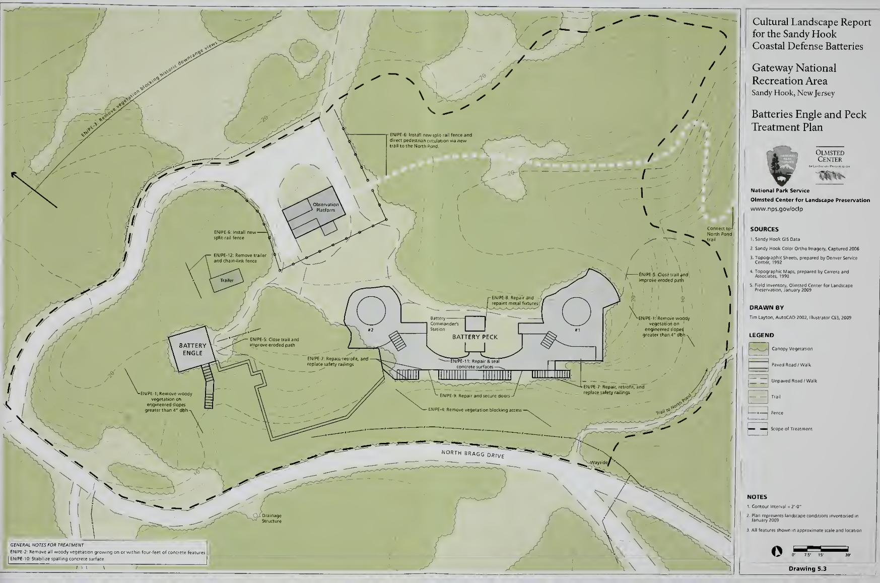
Cultural Landscape Report
for the Sandy HookCoastal Defense Batteries
Gateway National
Recreation AreaSandy Hook, New Jersey
Batteries Engle and Peck
Treatment Plan
I^^Bk OlmstedCenter
GENERAL NOTES FOR TREATMENT
EN/PE-2: Remove all woody vegetation growing
EN/pe-10 Stabilize spalling concrete surface
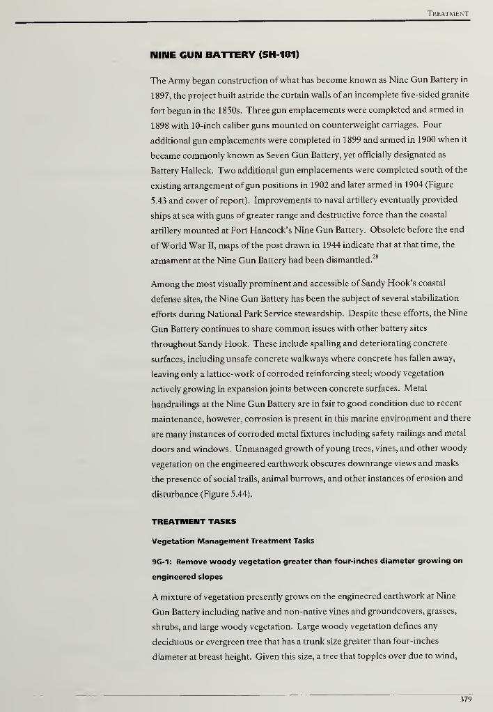
Treatment
NINE GUN BATTERY (SH 181)
The Army began construction of what has become known as Nine Gun Battery in
1897, the project built astride the curtain walls of an incomplete five-sided granite
fort begun in the 1850s. Three gun emplacements were completed and armed in
1898 with 10-inch caliber guns mounted on counterweight carriages. Four
additional gun emplacements were completed in 1899 and armed in 1900 when it
became commonly known as Seven Gun Battery, yet officially designated as
Battery Halleck. Two additional gun emplacements were completed south of the
existing arrangement of gun positions in 1902 and later armed in 1904 (Figure
5.43 and cover of report). Improvements to naval artillery eventually provided
ships at sea with guns of greater range and destructive force than the coastal
artillery mounted at Fort Hancock's Nine Gun Battery. Obsolete before the end
of World War II, maps of the post drawn in 1944 indicate that at that time, the
armament at the Nine Gun Battery had been dismantled.28
Among the most visually prominent and accessible of Sandy Hook's coastal
defense sites, the Nine Gun Battery has been the subject of several stabilization
efforts during National Park Service stewardship. Despite these efforts, the Nine
Gun Battery continues to share common issues with other battery sites
throughout Sandy Hook. These include spalling and deteriorating concrete
surfaces, including unsafe concrete walkways where concrete has fallen away,
leaving only a lattice-work of corroded reinforcing steel; woody vegetation
actively growing in expansion joints between concrete surfaces. Metal
handrailings at the Nine Gun Battery are in fair to good condition due to recent
maintenance, however, corrosion is present in this marine environment and there
are many instances of corroded metal fixtures including safety railings and metal
doors and windows. Unmanaged growth of young trees, vines, and other woody
vegetation on the engineered earthwork obscures downrange views and masks
the presence of social trails, animal burrows, and other instances of erosion and
disturbance (Figure 5.44).
TREATMENT TASKS
Vegetation Management Treatment Tasks
9G-1: Remove woody vegetation greater than four-inches diameter growing on
engineered slopes
A mixture of vegetation presently grows on the engineered earthwork at Nine
Gun Battery including native and non-native vines and groundcovers, grasses,
shrubs, and large woody vegetation. Large woody vegetation defines any
deciduous or evergreen tree that has a trunk size greater than four-inches
diameter at breast height. Given this size, a tree that topples over due to wind,
379

Cultural Landscape Report for the Sandy Hook Coastal Defense Batteries
rain, snow, or ice is likely to damage a portion of the engineered earthwork.
Additionally, the tree roots can damage the concrete structures below the
protective earthwork. In order to protect the historic earthwork, woody
vegetation greater than four-inches diameter at breast height should be
selectively removed and the stumps treated with a triclopyr herbicide. Further
information on vegetation removals and treatment can be found in the treatment
tasks common to all battery sites.
9G-2: Remove all woody vegetation growing on or within four-feet of concrete
features
At Nine Gun Battery, woody vegetation is growing in close proximity to concrete
structures and is also emerging from spalling areas, cracks, and where leaf litter
and debris have accumulated (see Figure 5.44). The existing woody vegetation is
either causing or has the potential to cause structural concrete problems. Given
the harmful effect ofwoody vegetation in this situation, all woody vegetation
growing on or within four-feet of concrete features should be removed. After
removing the woody material, both deciduous and evergreen stumps should be
treated with a triclopyr herbicide. Additional information on removing woody
vegetation growing near and on structures can be found in the treatment tasks
common to all battery sites.
9G-3: Remove vegetation blocking historic downrange views
Unobstructed views were necessary from the artillery and battery commander's
stations at Nine Gun Battery in order to have a clear field of fire and to locate and
acquire the range of potential targets (Figure 5.45). After removing woody
vegetation growing on the engineered earthwork and from the battery structure
itself, the resulting downrange views to the water must be evaluated. In some
instances tall, individual woody vegetation that blocks the view shed should be
identified and removed. Further information on managing vegetation for
downrange views can be found in the treatment tasks common to all battery sites.
9G-4: Remove phragmites (Phragmites sp.) from gun platform wells
The gun platforms at Nine Gun Battery feature concentric steps that lead to a
lower level and a circular well in which the artillery was emplaced. Over time,
water and organic debris have accumulated in several wells and colonies of
phragmites (Phragmites sp.) have emerged.
Similar to the woody vegetation growing on the concrete structures, the
phragmites threatens to further degrade the historic battery's concrete and
should be removed. In addition, the phragmites distracts from the interpretive
goal of opening sections of Nine Gun Battery to visitors and conveying the
purpose and intent of this coastal defense system (Figure 5.46).
380
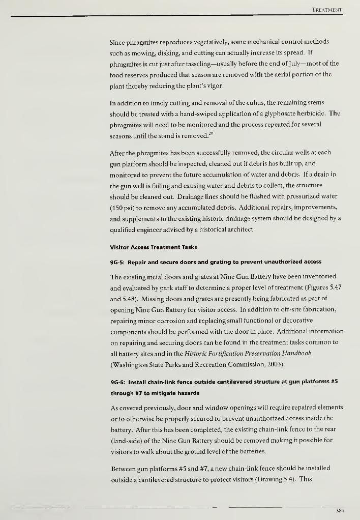
Treatment
Since phragmites reproduces vegetatively, some mechanical control methods
such as mowing, disking, and cutting can actually increase its spread. If
phragmites is cut just after tasseling—usually before the end ofJuly—most of the
food reserves produced that season are removed with the aerial portion of the
plant thereby reducing the plant's vigor.
In addition to timely cutting and removal of the culms, the remaining stems
should be treated with a hand-swiped application of a glyphosate herbicide. The
phragmites will need to be monitored and the process repeated for several
seasons until the stand is removed.
After the phragmites has been successfully removed, the circular wells at each
gun platform should be inspected, cleaned out if debris has built up, and
monitored to prevent the future accumulation of water and debris. If a drain in
the gun well is failing and causing water and debris to collect, the structure
should be cleaned out. Drainage lines should be flushed with pressurized water
(150 psi) to remove any accumulated debris. Additional repairs, improvements,
and supplements to the existing historic drainage system should be designed by a
qualified engineer advised by a historical architect.
Visitor Access Treatment Tasks
9G-5: Repair and secure doors and grating to prevent unauthorized access
The existing metal doors and grates at Nine Gun Battery have been inventoried
and evaluated by park staff to determine a proper level of treatment (Figures 5.47
and 5.48). Missing doors and grates are presently being fabricated as part of
opening Nine Gun Battery for visitor access. In addition to off-site fabrication,
repairing minor corrosion and replacing small functional or decorative
components should be performed with the door in place. Additional information
on repairing and securing doors can be found in the treatment tasks common to
all battery sites and in the Historic Fortification Preservation Handbook
(Washington State Parks and Recreation Commission, 2003).
9G-6: Install chain-link fence outside cantilevered structure at gun platforms #5
through #7 to mitigate hazards
As covered previously, door and window openings will require repaired elements
or to otherwise be properly secured to prevent unauthorized access inside the
battery. After this has been completed, the existing chain-link fence to the rear
(land-side) of the Nine Gun Battery should be removed making it possible for
visitors to walk about the ground level of the batteries.
Between gun platforms #5 and #7, a new chain-link fence should be installed
outside a cantilevered structure to protect visitors (Drawing 5.4). This
381
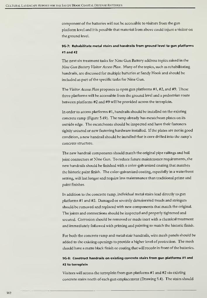
Cultural Landscape Report for the Sandy Hook Coastal Defense Batteries
component of the batteries will not be accessible to visitors from the gun
platform level and it is possible that material from above could injure a visitor on
the ground level.
9G-7: Rehabilitate metal stairs and handrails from ground level to gun platforms
#1 and #2
The next six treatment tasks for Nine Gun Battery address topics raised in the
Nine Gun Battery Visitor Access Plan. Many of the topics, such as rehabilitating
handrails, are discussed for multiple batteries at Sandy Hook and should be
included as part of the specific tasks for Nine Gun.
The Visitor Access Plan proposes to open gun platforms #1, #2, and #9. These
three platforms will be accessible from the ground level and a pedestrian route
between platforms #2 and #9 will be provided across the terreplein.
In order to access platforms #1, handrails should be installed on the existing
concrete ramp (Figure 5.49). The ramp already has escutcheon plates on its
outside edge. The escutcheons should be inspected and have their fasteners
tightly secured or new fastening hardware installed. If the plates are not in good
condition, a new handrail should be installed that is core drilled into the ramp's
concrete structure.
The new handrail components should match the original pipe railings and ball
joint connectors at Nine Gun. To reduce future maintenance requirements, the
new handrails should be finished with a color-galvanized coating that matches
the historic paint finish. The color-galvanized coating, especially in a waterfront
setting, will last longer and require less maintenance than traditional prime and
paint finishes.
In addition to the concrete ramp, individual metal stairs lead directly to gun
platforms #1 and #2. Damaged or severely deteriorated treads and stringers
should be removed and replaced with new components that match the original.
The joints and connections should be inspected and properly tightened and
secured. Corrosion should be removed or made inert with a chemical treatment
and immediately followed with priming and painting to match the historic finish.
For both the concrete ramp and metal stair handrails, wire mesh panels should be
added to the existing openings to provide a higher level of protection. The mesh
should have a matte black finish or coating that will recede in front of the batteries.
9G-8: Construct handrails on existing concrete stairs from gun platforms #1 and
#2 to terreplein
Visitors will access the terreplein from gun platforms #1 and #2 via existing
concrete stairs north of each gun emplacement (Drawing 5.4). The stairs should
382
Treatment
have new handrails added with a mesh infill on their outside edge. There is
approximately ten-feet of elevation difference between the gun platform level
and terreplein. Due to this change in elevation, the handrails need to have mesh
infill in order to act like a guardrail and provide a greater level of visitor
protection.
The new handrails should be installed by core drilling into the steps' concrete
structure and should match the original pipe railings and ball joint connectors at
Nine Gun. Each vertical member should be fitted with an escutcheon plate to
match the existing. To reduce future maintenance requirements, the new
handrails should be finished with a color-galvanized coating that matches the
historic paint finish.
9G-9: Install boardwalk at perimeter of terreplein forward slope for access
between gun platform #2 to gun platform #9
As presented in the Nine Gun Battery Visitor Access Plan, the visitor route
between gun platforms #2 and #9 will be on top of the terreplein. The terreplein
will be marked with yellow paint to demarcate a six-foot wide route visitors
should adhere to.
The currently proposed visitor route between gun platforms #2 and #9 presents
two problems. There is an approximate ten feet of elevation change between the
terreplein and the gun platform level and no proposed protective measure to
prevent an accident. In addition, there is no measure to prevent or discourage
visitors from exiting the route and proceeding down the historic earthwork.
Without some measure in place, visitors will develop trails down and across the
historic earthwork and the foot traffic will damage this resource.
In order to provide greater visitor safety and protect the historic earthwork, a
boardwalk should be installed with simple pipe rail guards. The guards will
indicate to visitors not to deviate from the boardwalk route and will be
compatible with historic pipe railings currently in place (Figures 5.50 and 5.51).
9G-10: Install wood stairway from terreplein level to gun platform #9
Unlike gun platforms #1 and #2, there are no concrete stairs from the terreplein
level to gun platform #9. In order to provide visitor access, a wood stairway
should be constructed and installed. Wood construction was seldom used at the
gun batteries and due to this fact, visitors will be better able to distinguish new,
non-historic construction from the historic fabric (Drawing 5.4).
The stairway should have uniform riser and tread dimensions with a maximum
riser height of seven-inches and a minimum tread depth of eleven-inches.
Guardrails and handrails need to be provided due to the ten-feet or more of
383
Cultural Landscape Report for the Sandy Hook Coastal Defense Batteries
elevation change. Finally the stairway should terminate on gun platform #9 in a
direction that positions visitors' path of travel away from the gun pit.
9G-11: Rehabilitate concrete stairs and install handrails from gun platform #9 to
ground level
The final component to creating a pedestrian circulation loop across Nine Gun is
to rehabilitate the concrete stairs in the west corner gun platform and install new
handrails to the ground level (Drawing 5.4). After the vegetation removals have
been completed, access to the stairs will be greatly improved. At this time, the
existing concrete should be inspected and repairs made on any spalling or cracks.
The stairs should have new handrails added with a mesh infill on their outside
edge. The new handrails should be installed by core drilling into the steps'
concrete structure and should match the original pipe railings and ball joint
connectors at Nine Gun. Each vertical member should be fitted with an
escutcheon plate to match the existing. To reduce future maintenance
requirements, the new handrails should be finished with a color-galvanized
coating that matches the historic paint finish.
9G-12: Provide picnic area at southern flank of Nine Gun Battery
South of Nine Gun Battery, Parking Lot J provides a central location where
visitors can leave their vehicles and walk to the North Beach area, Battery Potter,
and Nine Gun. Around 2000, the park removed picnic grounds from the North
Beach and is currently interested in establishing a new picnic area to address
visitor demand. Between Nine Gun Battery and Lot J, a picnic area should be
created at a node where recreation opportunities and historic resources meet
(Drawing 5.4).
The picnic area should be located south of Nine Gun's engineered slope and
large vegetation should remain between the picnic area and earthwork to
discourage visitor access on the historic resource. Selective clearing will be
needed to provide a sufficient open area for tables.
9G-13: Eliminate existing social trail and construct new visitor trail from gun
emplacement #8 toward North Pond
Historic aerial photographs indicate that informal trails lead from Nine Gun
Battery's emplacements down the engineered earthwork to the surrounding land
north and east of the battery. An existing social trail is present starting at
emplacement #8 that traverses the earthwork below emplacements #8 and #9.
The existing trail is steep, hastens erosion of the earthwork, and is dangerous for
visitors to properly use. The existing social trail should be closed and revegetated
and a better option provided for visitors wanting to connect to existing trails in
384
Treatment
the vicinity of the North Pond. Additional information on appropriate native
species to block trail access and erosion control materials is presented in the
treatment tasks common to all battery sites section.
After the existing social trail has been closed and revegetated, a new trial should
be constructed that follows shallower grades down the engineered earthwork.
Cribbing, check dams, and other trail stabilizing features should be installed as
needed to facilitate access and limit erosion. At the toe or bottom of the
engineered slope, the trail should lead across relatively level ground and avoid
existing depressions and dunes. The new trail should unite with the existing trail
west of the North Pond (Drawing 5.4).
Battery Structures Treatment Tasks
9G-14: Stabilize spalling concrete surfaces and repair cracks
The extent of concrete deterioration was not clear in the field due to the amount
of vegetation on structure. After vegetation removals and following the
procedures highlighted in the general treatment recommendations, spalling
concrete surfaces and cracks should be repaired.
9G-15: Repair and seal horizontal concrete surfaces to reduce water infiltration
Like Battery Urmston, historic photographs indicate that Battery Morris did not
have paint, asphalt emulsion, or another dark colored surface treatment. After
concrete surface defects have been repaired, two options are possible to seal
horizontal concrete surfaces without creating a non-historic appearance. First,
penetrating sealers could be used with the understanding that to achieve the best
protection, they should be applied every few years. The other option, providing a
more durable coating, is to apply bitumen with light-colored gravel laid into the
coating. The gravel should match the color of the existing concrete. At Battery
Morris, approximately 1,580 square feet of concrete will need a surface coating.
9G-16: Repair and repaint ferrous metal fixtures
A variety of ferrous metal fixtures were incorporated into the construction of
Nine Gun Battery (see Figure 5.48). Metal fixtures in fair condition with visible
rust should be chemically treated, primed, and painted to match the historic
finish. Damaged or severely deteriorated fixtures should be removed and
replaced with new components that match the original as close as possible.
Additional information on ferrous metal treatments can be found in the Safety
Railings section of the treatment tasks common to all battery sites and in the
Historic Fortification Preservation Handbook (Washington State Parks and
Recreation Commission, 2003).
385
Cultural Landscape Report for the Sandy Hook Coastal Defense Batteries
Interpretive Treatments
9G-17: Restore section of railroad track and locate flatcar to interpret the
handling of heavy ordnance and munitions
When Sandy Hook's gun batteries were operational, a railroad transported the
large guns and their ordnance from docks located near the northern tip of the
peninsula to the various batteries. Although present-day roads and trails have
been constructed over some former rail lines, the location and importance of the
railroad to coastal defenses has become difficult to perceive. In conjunction with
plans to open the Nine Gun Battery to greater visitor access, an opportunity
exists to restore a short section of railroad track and locate a flatcar upon it to
interpret the transportation of shells and other heavy materials.
South of gun platform #1, a rail line connected the docks to the west with the
proving ground to the east. This section of track ran through an area west of the
battery that had been used for overflow parking. The track continued east
crossing the present-day Parking Lot J before terminating at the proving ground
(Figure 5.52).
Although the railroad bed and ties are not visible, the tracks do appear in a
section of asphalt pavement west of Nine Gun (Figure 5.53). From this location,
the tracks should be extended roughly eighty-feet east to meet Lot J and west into
the field for a sufficient length to locate a flatcar. The park no longer plans to use
the field for overflow parking and as a result, there will be no conflict between
parking requirements and adding this interpretive element. Extending the tracks
to Lot J will help to physically draw visitors to the interpretive display and reveal
a small part of a historic transportation system that is largely obscured.
9G-18: Excavate and interpret exposed portions of the northeast bastion and
curtain wall of the pre-existing granite fort
Prior to Nine Gun Battery's construction, a granite block-constructed fort
occupied the northern end of Sandy Hook. Roughly trapezoidal in shape with
projecting bastions at the northeast, southeast, southwest and northwest corners,
the structure was known as the Fort at Sandy Hook. The Fort was constructed
between 1859 and 1867, yet never completed as powerful rifled artillery made the
brittle qualities of stone and brick masonry obsolete for future use in coastal
defense sites.30
Construction began on Nine Gun in 1897 and the concrete battery structure was
built over the pre-existing granite structure's eastern wall (Figure 5.54). The
layout and angled position of Nine Gun Battery's northernmost two gun
positions was not capricious, but matched the salient angle of the earlier granite
fort (Figure 5.55).
386

Treatment
North of gun platform #8, evidence can be seen of granite blocks that comprised
the northeast bastion of the Fort (Figure 5.56). In consultation with a regional
archaeologist, an extant section of the bastion should be excavated and exposed.
With a piece of the granite fort revealed, the proposed Nine Gun Battery Visitor
Access Plan should incorporate interpretation of this prior structure as part of the
continuum of Sandy Hook's coastal defenses.
387
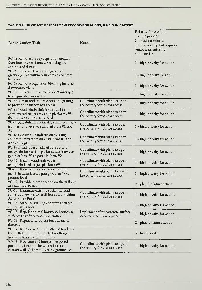
Cultural Landscape Report for the Sandy Hook Coastal Defense Batteries
TABLE 5.4: SUMMARY OF TREATMENT RECOMMENDATIONS, NINE GUN BATTERY
Rehabilitation Task Notes
Priority for Action
1 - high priority
2 - medium priority
3 - low priority, but requires
ongoing monitoring
4 - no action
9G-1: Remove woody vegetation greater
than four-inches diameter growing on
engineered slopes
1 - high priority for action
9G-2: Remove all woody vegetation
growing on or within four-feet of concrete
features
1 - high priority for action
9G-3: Remove vegetation blocking historic
downrange views1 - high priority for action
9G-4: Remove phragmites {Phragmites sp.)
from gun platform wells1 - high priority for action
9G-5: Repair and secure doors and grating
to prevent unauthorized access
Coordinate with plans to open
the battery for visitor access1 - high priority for action
9G-6: Install chain-link fence outside
cantilevered structure at gun platforms #5
through #7 to mitigate hazards
Coordinate with plans to open
the battery for visitor access1 - high priority for action
9G-7: Rehabilitate metal stairs and handrails
from ground level to gun platforms #1 and
#2
Coordinate with plans to open
the battery for visitor access1 - high priority for action
9G-8: Construct handrails on existing
concrete stairs from gun platforms #1 and
#2 to terreplein
Coordinate with plans to open
the battery for visitor access1 - high priority for action
9G-9: Install boardwalk at perimeter of
terreplein forward slope for access between
gun platform #2 to gun platform #9
Coordinate with plans to open
the battery for visitor access1 - high priority for action
9G-10: Install wood stairway from
terreplein level to gun platform #9
Coordinate with plans to open
the battery for visitor access1 - high priority for action
9G-11: Rehabilitate concrete stairs and
install handrails from gun platform #9 to
ground level
Coordinate with plans to open
the battery for visitor access1 - high priority for action
9G- 12: Provide picnic area at southern flank
of Nine Gun Battery2 - plan for future action
9G-13: Eliminate existing social trail and
construct new visitor trail from gun position
#8 to North Pond
Coordinate with plans to open
the battery for visitor access1 - high priority for action
9G-14: Stabilize spalling concrete surfaces
and repair cracks1 - high priority for action
9G-15: Repair and seal horizontal concrete
surfaces to reduce water infiltration
Implement after concrete surface
defects have been repaired1 - high priority for action
9G-16: Repair and repaint ferrous metal
fixtures2 - plan for future action
9G-17: Restore section of railroad track and
locate flatcar to interpret the handling of
heavy ordnance and munitions
3 - low priority
9G-18: Excavate and interpret exposed
portions of the northeast bastion and
curtain wall of the pre-existing granite fort
Coordinate with plans to open
the battery for visitor access1 - high priority for action
388
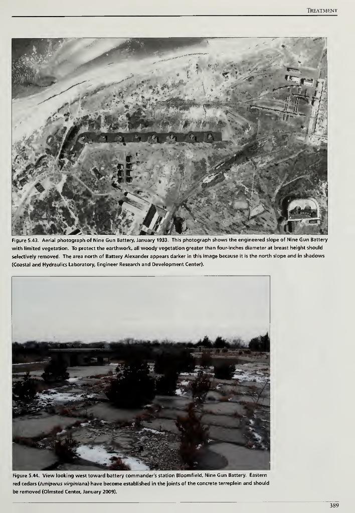
TftEATMENT
Figure 5.43. Aerial photograph of Nine Gun Battery, January 1933. This photograph shows the engineered slope of Nine Gun Battery
with limited vegetation. To protect the earthwork, all woody vegetation greater than four-inches diameter at breast height should
selectively removed. The area north of Battery Alexander appears darker in this image because it is the north slope and in shadows
(Coastal and Hydraulics Laboratory, Engineer Research and Development Center).
Figure 5.44. View looking west toward battery commander's station Bloomfield, Nine Gun Battery. Eastern
red cedars {Juniperus virginiana) have become established in the joints of the concrete terreplein and should
be removed (Olmsted Center, January 2009).
389
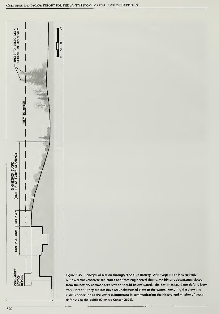
Cultural Landscape Report for the Sandy Hook Coastal Defense Batteries
Figure 5.45. Conceptual section through Nine Gun Battery. After vegetation is selectively
removed from concrete structures and from engineered slopes, the historic downrange views
from the battery commander's station should be evaluated. The batteries could not defend New
York Harbor if they did not have an unobstructed view to the water. Restoring the view and
visual connection to the water is important in communicating the history and mission of these
defenses to the public (Olmsted Center, 2009).
390
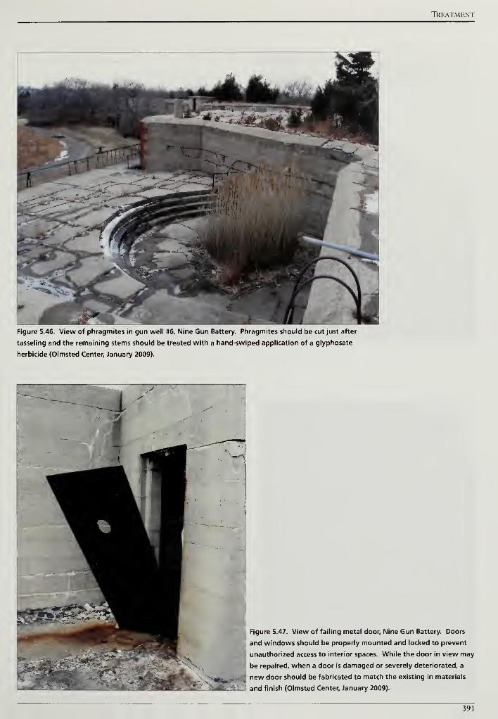
TREATMENT
Figure 5.46. View of phragmites in gun well #6, Nine Gun Battery. Phragmites should be cut just after
tasseling and the remaining stems should be treated with a hand-swiped application of a glyphosate
herbicide (Olmsted Center, January 2009).
Figure 5.47. View of failing metal door. Nine Gun Battery. Doors
and windows should be properly mounted and locked to prevent
unauthorized access to interior spaces. While the door in view may
be repaired, when a door is damaged or severely deteriorated, a
new door should be fabricated to match the existing in materials
I and finish (Olmsted Center, January 2009).
391
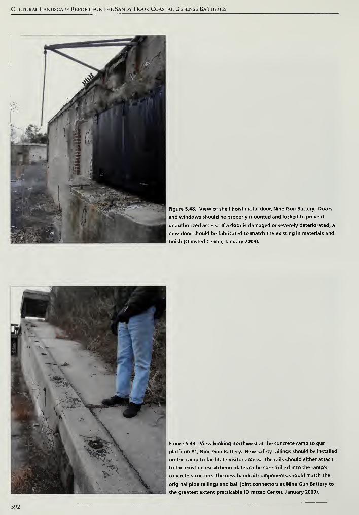
Cultural Landscape Report for the Sandy Hook Coastal Defense Batteries
1i""^^^^ ^ .
1
1
-
^T*'
Figure 5.48. View of shell hoist metal door, Nine Gun Battery. Doors
and windows should be properly mounted and locked to prevent
unauthorized access. If a door is damaged or severely deteriorated, a
new door should be fabricated to match the existing in materials and
finish (Olmsted Center, January 2009).
Figure 5.49. View looking northwest at the concrete ramp to gun
platform #1, Nine Gun Battery. New safety railings should be installed
on the ramp to facilitate visitor access. The rails should either attach
to the existing escutcheon plates or be core drilled into the ramp's
concrete structure. The new handrail components should match the
original pipe railings and ball joint connectors at Nine Gun Battery to
the greatest extent practicable (Olmsted Center, January 2009).
392
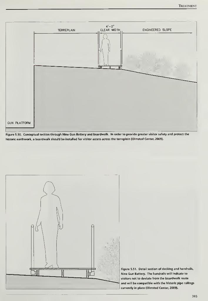
TkEATMENT
TERREPLAIN
4'-0"
CLEAR WIDTH ENGINEERED SLOPE
GUN PLATFORM
Figure 5.50. Conceptual section through Nine Gun Battery and boardwalk. In order to provide greater visitor safety and protect the
historic earthwork, a boardwalk should be installed for visitor access across the terreplein (Olmsted Center, 2009).
Figure 5.51. Detail section of decking and handrails.
Nine Gun Battery. The handrails will indicate to
visitors not to deviate from the boardwalk route
and will be compatible with the historic pipe railings
currently in place (Olmsted Center, 2009).
393
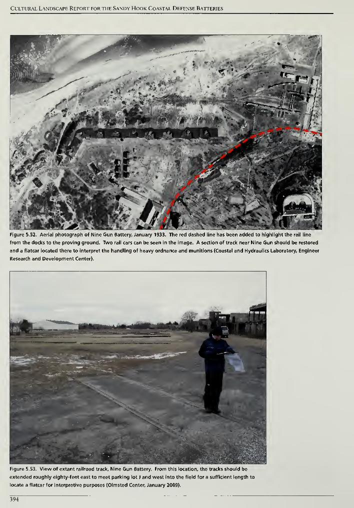
Cultural Landscape Report for the Sandy Hook Coastal Defense Batteries
Figure 5.52. Aerial photograph of Nine Gun Battery, January 1933. The red dashed line has been added to highlight the rail line
from the docks to the proving ground. Two rail cars can be seen in the image. A section of track near Nine Gun should be restored
and a flatcar located there to interpret the handling of heavy ordnance and munitions (Coastal and Hydraulics Laboratory, Engineer
Research and Development Center).
Figure 5.53. View of extant railroad track. Nine Gun Battery. From this location, the tracks should be
extended roughly eighty-feet east to meet parking lot J and west into the field for a sufficient length to
locate a flatcar for interpretive purposes (Olmsted Center, January 2009).
394
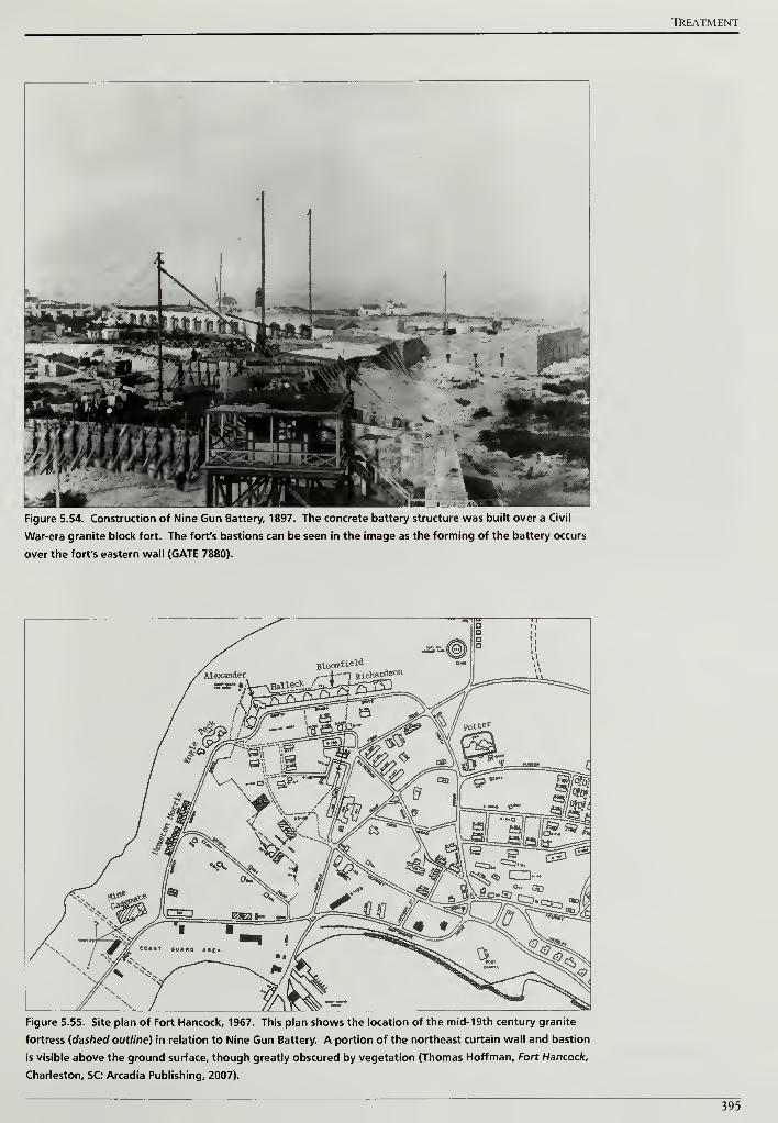
TREATMENT
Figure 5.54. Construction of Nine Gun Battery, 1897. The concrete battery structure was built over a Civil
War-era granite block fort. The fort's bastions can be seen in the image as the forming of the battery occurs
over the fort's eastern wall (GATE 7880).
Figure 5.55. Site plan of Fort Hancock, 1967. This plan shows the location of the mid-19th century granite
fortress {dashed outline) in relation to Nine Gun Battery. A portion of the northeast curtain wall and bastion
is visible above the ground surface, though greatly obscured by vegetation (Thomas Hoffman, Fort Hancock,
Charleston, SC: Arcadia Publishing, 2007).
395
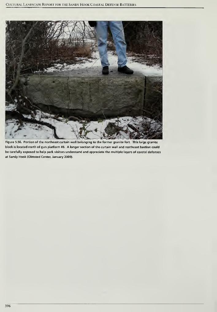
Cultural Landscape Report for the Sandy Hook Coastal Defense Batteries
Figure 5.56. Portion of the northeast curtain wall belonging to the former granite fort. This large granite
block is located north of gun platform #8. A longer section of the curtain wall and northeast bastion could
be carefully exposed to help park visitors understand and appreciate the multiple layers of coastal defenses
at Sandy Hook (Olmsted Center, January 2009).
396
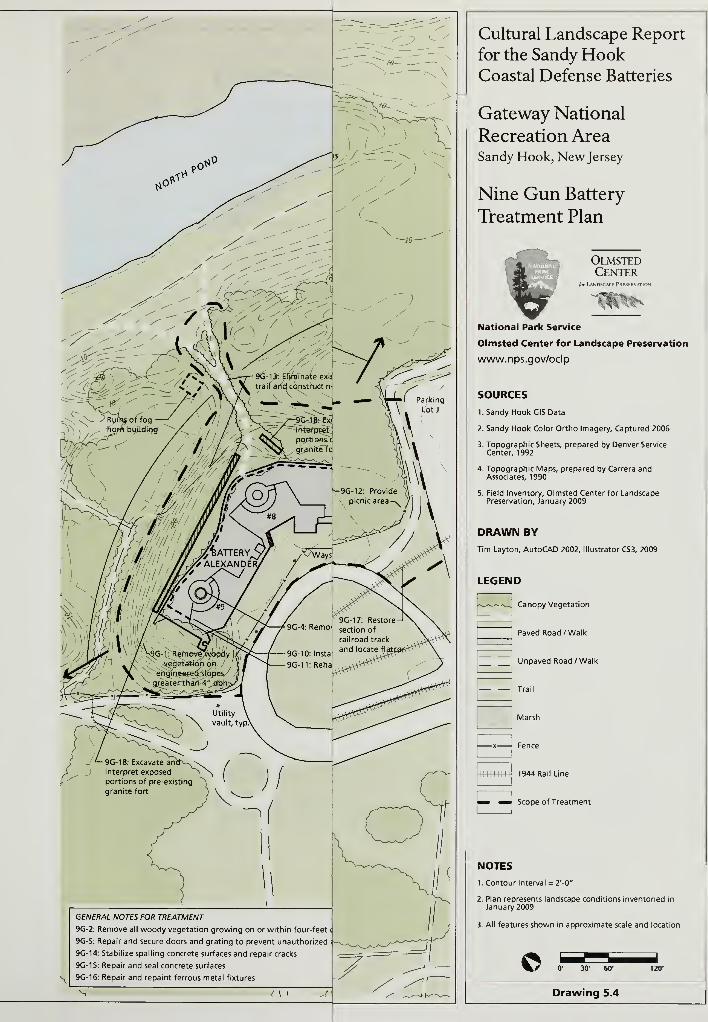
Cultural Landscape Report
for the Sandy HookCoastal Defense Batteries
Gateway National
Recreation AreaSandy Hook, New Jersey
Nine Gun Battery
Treatment Plan
OlmstedCenter
National Park Service
Olmsted Center for Landscape Preservation
www.nps.gov/oclp
SOURCES
1. Sandy Hook GIS Data
2. Sandy Hook Color Ortho Imagery, Captured 2006
3. Topographic Sheets, prepared by Denver Service
Center, 1992
4. Topographic Maps, prepared by Carrera andAssociates, 1990
5. Field Inventory, Olmsted Center for LandscapePreservation, January 2009
DRAWN BY
Tim Layton, AutoCAD 2002, Illustrator CS3, 2009
1944 Rail Line
Scope of Treatment
NOTES
1. Contour Interval = 2'-0"
2. Plan represents landscape conditions inventoried in
January 2009
3. All features shown in approximate scale and location
© 0' 30' 60*
Drawing 5.4
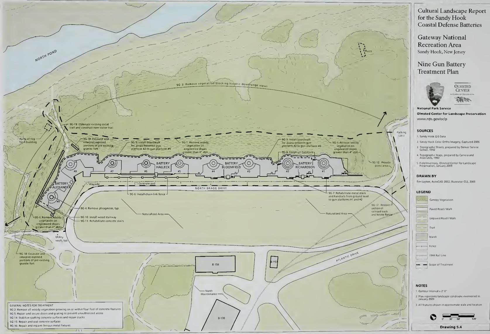
Cultural Landscape Report
for the Sandy HookCoastal Defense Batteries
Gateway National
Recreation AreaSandy Hook, New Jersey
Nine Gun Battery
Treatment Plan
OlmstedCenter
National Park Service
Olmsted Center for Landscape Preservation
www.nps.gov/oclp
SOURCES
I, Sandy Hook GiS Data
2 Sandy Hook Color Ortho Imagery, Captured 2006
r Service
and
DRAWN BY
Tim Layton, AutoCAD 2002, Illustrator CS3, 2009
LEGEND
Canopy Vegetation
Paved Road /Walk
~| Unpaved Road /Walk
Scope of Treatment
NOTES
1 Contour Interval = 2'0"
nventoned in
i All features shown m approximate scale and location
Drawing 5.4
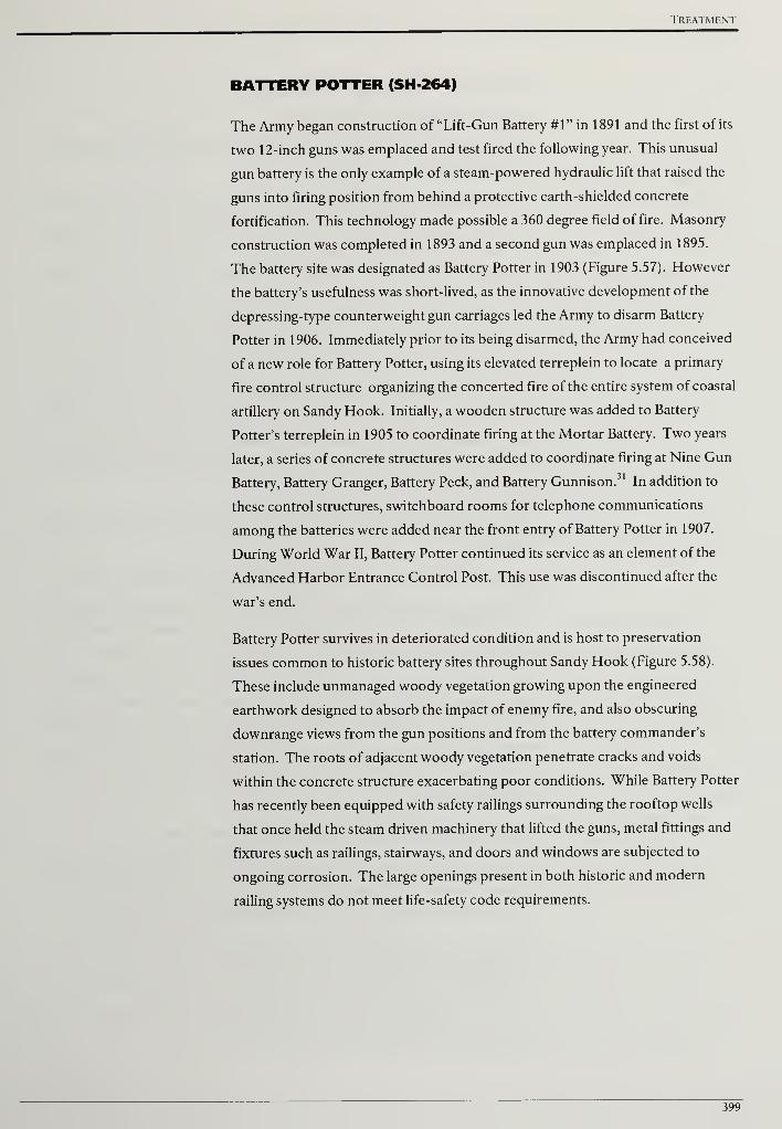
Treatment
BATTERY POTTER (SH-264)
The Army began construction of "Lift-Gun Battery #1" in 1891 and the first of its
two 12-inch guns was emplaced and test fired the following year. This unusual
gun battery is the only example of a steam-powered hydraulic lift that raised the
guns into firing position from behind a protective earth-shielded concrete
fortification. This technology made possible a 360 degree field of fire. Masonry
construction was completed in 1893 and a second gun was emplaced in 1895.
The battery site was designated as Battery Potter in 1903 (Figure 5.57). However
the battery's usefulness was short-lived, as the innovative development of the
depressing-type counterweight gun carriages led the Army to disarm Battery
Potter in 1906. Immediately prior to its being disarmed, the Army had conceived
of a new role for Battery Potter, using its elevated terreplein to locate a primary
fire control structure organizing the concerted fire of the entire system of coastal
artillery on Sandy Hook. Initially, a wooden structure was added to Battery
Potter's terreplein in 1905 to coordinate firing at the Mortar Battery. Two years
later, a series of concrete structures were added to coordinate firing at Nine Gun
Battery, Battery Granger, Battery Peck, and Battery Gunnison.31
In addition to
these control structures, switchboard rooms for telephone communications
among the batteries were added near the front entry of Battery Potter in 1907.
During World War II, Battery Potter continued its service as an element of the
Advanced Harbor Entrance Control Post. This use was discontinued after the
war's end.
Battery Potter survives in deteriorated condition and is host to preservation
issues common to historic battery sites throughout Sandy Hook (Figure 5.58).
These include unmanaged woody vegetation growing upon the engineered
earthwork designed to absorb the impact of enemy fire, and also obscuring
downrange views from the gun positions and from the battery commander's
station. The roots of adjacent woody vegetation penetrate cracks and voids
within the concrete structure exacerbating poor conditions. While Battery Potter
has recently been equipped with safety railings surrounding the rooftop wells
that once held the steam driven machinery that lifted the guns, metal fittings and
fixtures such as railings, stairways, and doors and windows are subjected to
ongoing corrosion. The large openings present in both historic and modern
railing systems do not meet life-safety code requirements.
399
Cultural Landscape Report for the Sandy Hook Coastal Defense Batteries
TREATMENT TASKS
Vegetation Management Treatment Tasks
PO-1: Remove woody vegetation greater than four-inches diameter growing on
engineered slopes
A mixture of vegetation presently grows on the engineered earthwork at Battery
Potter including native and non-native vines and groundcovers, grasses, shrubs,
and large woody vegetation. Large woody vegetation defines any deciduous or
evergreen tree that has a trunk size greater than four-inches diameter at breast
height. Given this size, a tree that topples over due to wind, rain, snow, or ice is
likely to damage a portion of the engineered earthwork. Additionally, the tree
roots can damage the concrete structures below the protective earthwork. In
order to protect the historic earthwork, woody vegetation greater than four-
inches diameter at breast height should be selectively removed and the stumps
treated with a triclopyr herbicide. For Battery Potter, the area to be selectively
cleared would be approximately 0.9 acres (Drawing 5.5, scope of treatment).
Further information on vegetation removals and treatment can be found in the
treatment tasks common to all battery sites.
PO-2: Remove all woody vegetation growing on or within four-feet of concrete
features
At Battery Potter, woody vegetation is growing in close proximity to concrete
structures and is also emerging from spalling areas, cracks, and where leaf litter
and debris have accumulated (Figure 5.59). The existing woody vegetation is
either causing or has the potential to cause structural concrete problems. Given
the harmful effect ofwoody vegetation in this situation, all woody vegetation
growing on or within four-feet of concrete features should be removed. After
removing the woody material, both deciduous and evergreen stumps should be
treated with a triclopyr herbicide. Additional information on removing woody
vegetation growing near and on structures can be found in the treatment tasks
common to all battery sites.
PO-3: Remove vegetation blocking historic downrange views
Unobstructed views were necessary from the artillery and fire control stations at
Battery Potter in order to have a clear field of fire and to locate and acquire the
range of potential targets (Figure 5.60). After removing woody vegetation
growing on the engineered earthwork and from the battery structure itself, the
resulting downrange views to the water must be evaluated. In some instances tall,
individual woody vegetation that blocks the view shed should be identified and
removed. Further information on managing vegetation for downrange views can
be found in the treatment tasks common to all battery sites.
400
Treatment
Visitor Access Treatment Tasks
PO-4: Repair, retrofit, and replace safety railings
At Battery Potter, metal guardrails are installed between the superior slope and
the terreplein where the guns were emplaced and along open sides of elevated
areas (Figure 5.61). Metal railings in fair condition with visible rust should be
chemically treated, primed, and painted to match the historic finish. Damaged or
severely deteriorated railings should be removed and replaced with new
components that match the original as close as possible. Additional information
on metal treatments and adding infill or applied materials to comply with life
safety codes can be found in the treatment tasks common to all battery sites.
PO-5: Formalize and relocate visitor parking
While there should be no increase in number of parking spaces serving Battery
Potter, the existing informal parking area is ill-defined and poorly drained.
Visually, the presence of visitor parking in its current configuration detracts from
the formality of the rear approach to the castellated granite defensible entrance.
A new parking area, surfaced in crushed stone, and of an area no greater in size
than the current parking area, should be designed and constructed to facilitate
convenient visitor access to this unique coastal battery structure and landscape.
This recommendation amounts to shifting the existing informal parking area
approximately fifty-feet southward (Drawing 5.5).
PO-6: Install Accessible Route from Parking Level to Battery Potter terreplein
An unmet need has been expressed by park staff, park partners, and the public
for an accessible elevated location where visitors might take in a panoramic view
and where the entire coastal defense system can be explained and understood.
The Sandy Hook Lighthouse provides an elevated location but it is constrained
by three factors. First, the Lighthouse is only open April through October.
Second, its narrow stairway limits the number of people who can ascend to the
top and observe the view. Finally, it would be impossible to make the Lighthouse
accessible to those with mobility issues. Seeking a more practical alternative,
interest has been expressed in making the summit of the Mortar Battery
accessible to the public in order to both explain the operation of the Mortar
Battery and the surrounding defensive system. Another option often mentioned
is the elevated terreplein of Battery Potter.
Site visits to both the Mortar Battery site and Battery Potter site, followed by
discussions with park staff, suggest that Battery Potter appears to be the most
promising and practical location on which to accommodate this unmet need.
This recommendation is based on observing the dangerously steep earthen slopes
of the Mortar Battery, where new non-historic stairways and safety railings,
401
Cultural Landscape Report for the Sandy Hook Coastal Defense Batteries
ramps, viewing platforms and corresponding safety barriers would be required
before inviting the public to the summit. These modifications to the historic
battery would also be prominently in view, greatly distracting from the historic
conditions that the park hopes to perpetuate.
Interestingly, directions communicated from the observation point atop Battery
Potter were used to direct the systematic fire of gun batteries defending the
southern approach to New York Harbor, including the Mortar Battery. While
anti-aircraft guns occupied the summit of the Mortar Battery after the large guns
were removed, soldiers originally operating the guns in the pits relied on
instructions telephoned in from off-site observation towers, such as the position
atop Battery Potter to aim the guns and track a potential enemy.
Battery Potter currently features pedestrian routes to the top of the battery
structure from both an exterior steel staircase and an interior concrete stairway.
The terreplein provides a generous viewing area that is already minimally
equipped with safety railings. These existing safety railings could be easily
supplemented and modified for improved safety with comparatively little impact
to the historic character of the structure or its corresponding landscape.
Elsewhere in the National Park system, former military sites have made historic
battery structures accessible through sensitive rehabilitation efforts. Battery
Huger, an Endicott period concrete structure, rests atop Fort Sumter in
Charleston, South Carolina (FOSU), at the center of perhaps the most historically
significant coastal battery site in the United States. Battery Huger has been made
accessible with the addition of three small wheelchair lifts. The former
bombproofJoint Operations Center located in the dry moat of fortress San
Cristobal in San Juan, Puerto Rico (SAJU) has been retrofitted with an interior
elevator, making viable use of this World War II-era concrete structure for visitor
services, museum storage, and administrative needs.
The qualities of the Battery Potter site provide the superior circumstances
required to develop a successful design for universal access to the summit of
Battery Potter. Designing and constructing a new ramp, supported in part by
concrete piers, may be designed into the wooded site immediately south-east of
Battery Potter (Drawing 5.5). Located in this position, sight of the lengthy ramp
from the vantage point of Hudson Road would be obscured by the surrounding
vegetation and the flare of the engineered earthen slope adjacent to freestanding
switchboard building (B-256).
402
Treatment
Battery Structures Treatment Tasks
PO-7: Stabilize spalling concrete surfaces and repair cracks and voids
Concrete surfaces at Battery Potter exhibit spalling areas and cracks resulting
from water infiltration and freeze-thaw cycles. In order to limit further damage
to the concrete, spalling surfaces should be removed, mechanically cleaned, and
patched to match the character of the historic material. Small cracks should be
dried and prepared to receive a sealant that is compatible with the character of
the historic concrete. The treatment of large, structural cracks should be
determined by a structural engineer. Additional information addressing the
repair of spalling areas and cracks can be found in the treatment tasks common to
all battery sites and in the Historic Fortification Preservation Handbook
(Washington State Parks and Recreation Commission, 2003).
PO-8: Repair and seal horizontal concrete surfaces to reduce water infiltration
In order to reduce water infiltration and to protect the concrete structures at
Battery Potter, a surface coating should be applied to the horizontal surfaces.
Application of a surface coating must occur after spalling and cracked concrete
surfaces are repaired and defected surfaces that collect and pool rainwater are
corrected. Additional information penetrating sealers and surface sealers can be
found in the treatment tasks common to all battery sites. At Battery Potter,
approximately 32,000 square feet of concrete should be sealed.
PO-9: Repair and repaint ferrous metal fixtures
A variety of ferrous metal fixtures were incorporated into the construction of
Battery Potter. Metal fixtures in fair condition with visible rust should be
chemically treated, primed, and painted to match the historic finish. Damaged
or severely deteriorated fixtures should be removed and replaced with new
components that match the original as close as possible. Additional
information on ferrous metal treatments can be found in the Safety Railings
section of the treatment tasks common to all battery sites and in the Historic
Fortification Preservation Handbook (Washington State Parks and Recreation
Commission, 2003).
PO-10: Restore roofs of plotting rooms
In 1907, the Army added two concrete buildings on top of Battery Potter's
terreplein to improve the targeting of enemy ships. One building was configured
as a grouping of five distinct, interconnected structures and the other building
was designed as a grouping of two. The buildings served the large caliber guns at
Nine Gun Battery and Battery Granger as well as the rapid fire guns at Battery
Peck and Battery Gunnison.
403

Cultural Landscape Report for the Sandy Hook Coastal Defense Batteries
Today, the concrete structures are in poor condition primarily due to exposure
to the elements. Deteriorating wooden rafters and trusses are present on top of
the buildings and no roofing material or other covering is present (Figure 5.62).
In order to stabilize the plotting room buildings, the roofs should be restored
based on the research presented in the Historic Structure Reportfor Battery
Potter, Mortar Battery and Battery Gunnison and following the Secretary of the
Interior's Standardsfor the Treatment ofHistoric Properties. Once the roofs are
restored, the interiors may be used to house durable exhibitry and help interpret
the coastal defense system at Sandy Hook.
404
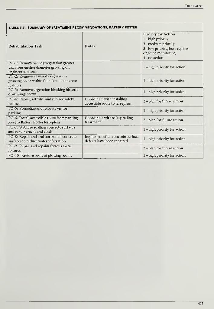
Treatment
TABLE 5.5: SUMMARY OF TREATMENT RECOMMENDATIONS, BATTERY POTTER
Rehabilitation Task Notes
Priority for Action
1 - high priority
2 - medium priority
3 - low priority, but requires
ongoing monitoring
4 - no action
PO-1: Remove woody vegetation greater
than four-inches diameter growing on
engineered slopes
1 - high priority for action
PO-2: Remove all woody vegetation
growing on or within four-feet of concrete
features
1 - high priority for action
PO-3: Remove vegetation blocking historic
downrange views1 - high priority for action
PO-4: Repair, retrofit, and replace safety
railings
Coordinate with installing
accessible route to terreplein2 - plan for future action
PO-5: Formalize and relocate visitor
parking1 - high priority for action
PO-6: Install accessible route from parking
level to Battery Potter terreplein
Coordinate with safety railing
treatment2 - plan for future action
PO-7: Stabilize spalling concrete surfaces
and repair cracks and voids1 - high priority for action
PO-8: Repair and seal horizontal concrete
surfaces to reduce water infiltration
Implement after concrete surface
defects have been repaired1 - high priority for action
PO-9: Repair and repaint ferrous metal
fixtures2 - plan for future action
PO-10: Restore roofs of plotting rooms 1 - high priority for action
405

Cultural Landscape Report for the Sandy Hook Coastal Defense Batteries
406
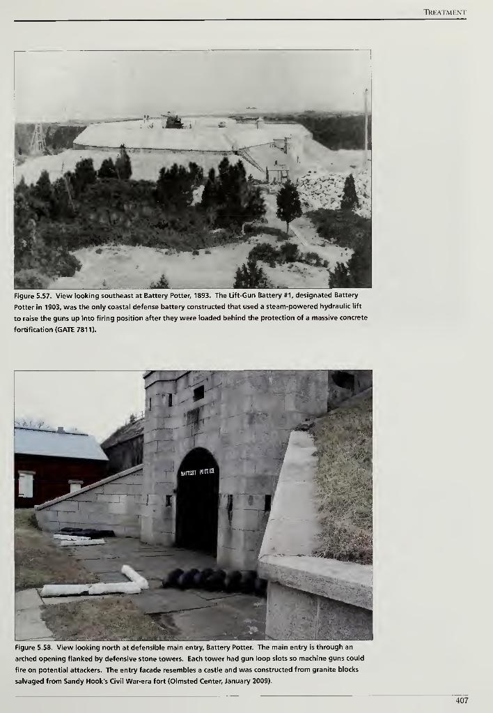
TREATMENT
Figure 5.57. View looking southeast at Battery Potter, 1893. The Lift-Gun Battery #1, designated Battery
Potter in 1903, was the only coastal defense battery constructed that used a steam-powered hydraulic lift
to raise the guns up into firing position after they were loaded behind the protection of a massive concrete
fortification (GATE 7811).
I
V
^^^^HH^^^HFigure 5.58. View looking north at defensible main entry. Battery Potter. The main entry is through an
arched opening flanked by defensive stone towers. Each tower had gun loop slots so machine guns could
fire on potential attackers. The entry facade resembles a castle and was constructed from granite blocks
salvaged from Sandy Hook's Civil War-era fort (Olmsted Center, January 2009).
407
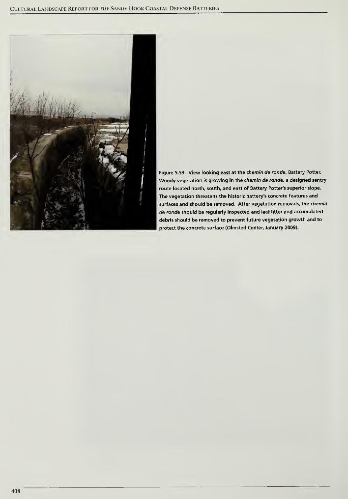
Cultural Landscape Report for the Sandy Hook Coastal Defense Batteries
Figure 5.59. View looking east at the chemin de ronde, Battery Potter.
Woody vegetation is growing in the chemin de ronde, a designed sentry
route located north, south, and east of Battery Potter's superior slope.
The vegetation threatens the historic battery's concrete features and
surfaces and should be removed. After vegetation removals, the chemin
de ronde should be regularly inspected and leaf litter and accumulated
debris should be removed to prevent future vegetation growth and to
protect the concrete surface (Olmsted Center, January 2009).
408
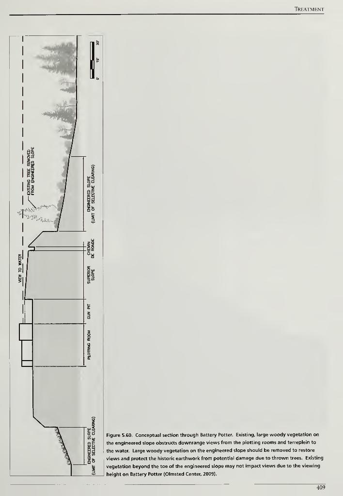
TREATMENT
Figure 5.60. Conceptual section through Battery Potter. Existing, large woody vegetation on
the engineered slope obstructs downrange views from the plotting rooms and terreplein to
the water. Large woody vegetation on the engineered slope should be removed to restore
views and protect the historic earthwork from potential damage due to thrown trees. Existing
vegetation beyond the toe of the engineered slope may not impact views due to the viewing
height on Battery Potter (Olmsted Center, 2009).
409
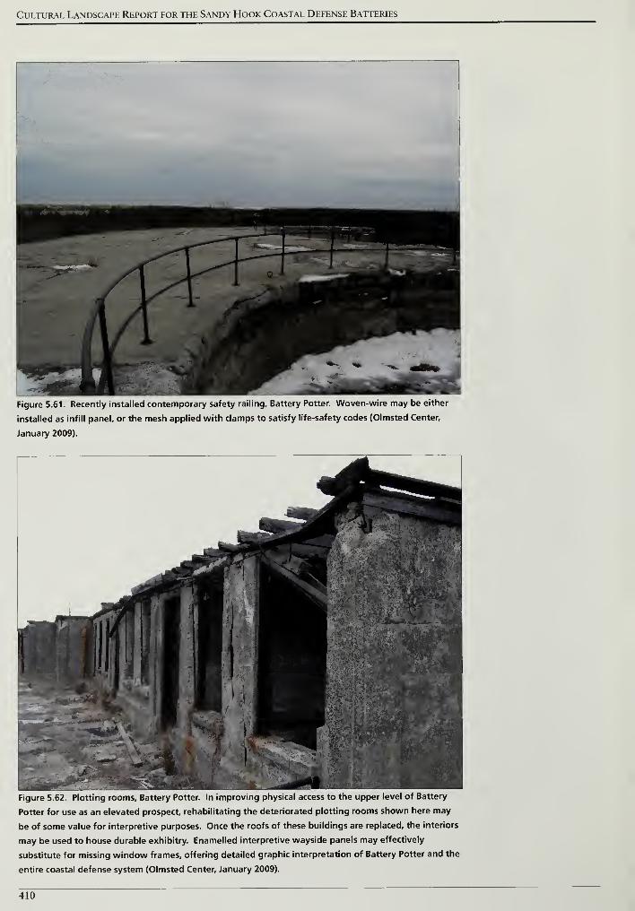
Cultural Landscape Report for the Sandy Hook Coastal Defense Batteries
Figure 5.61. Recently installed contemporary safety railing. Battery Potter. Woven-wire may be either
installed as infill panel, or the mesh applied with clamps to satisfy life-safety codes (Olmsted Center,
January 2009).
Figure 5.62. Plotting rooms. Battery Potter. In improving physical access to the upper level of Battery
Potter for use as an elevated prospect, rehabilitating the deteriorated plotting rooms shown here may
be of some value for interpretive purposes. Once the roofs of these buildings are replaced, the interiors
may be used to house durable exhibitry. Enamelled interpretive wayside panels may effectively
substitute for missing window frames, offering detailed graphic interpretation of Battery Potter and the
entire coastal defense system (Olmsted Center, January 2009).
410
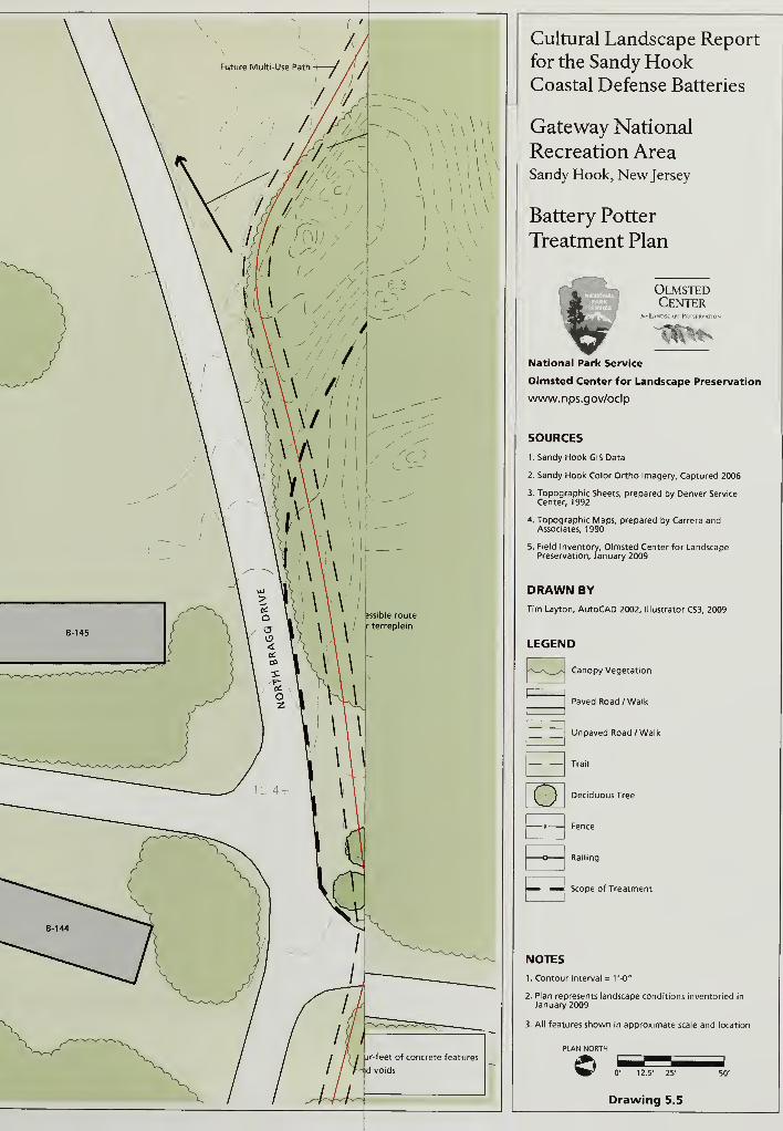
Cultural Landscape Report
for the Sandy HookCoastal Defense Batteries
Gateway National
Recreation AreaSandy Hook, New Jersey
Battery Potter
Treatment Plan
3^A tu~
OlmstedCenter
for LANDSC \PF PRI
ilk
National Park Service
Olmsted Center for Landscape Preservation
www.nps.gov/oclp
SOURCES
1. Sandy Hook GlS Data
2. Sandy Hook Color Ortho Imagery, Captured 2006
3. Topographic Sheets, prepared by Denver ServiceCenter, 1992
4. Topographic Maps, prepared by Carrera andAssociates, 1990
5. Field Inventory, Olmsted Center for LandscapePreservation, January 2009
DRAWN BY
Tim Layton, AutoCAD 2002, Illustrator CS3, 2009
LEGEND
Canopy Vegetation
Paved Road /Walk
Unpaved Road /Walk
oTrail
Deciduous Tree
Fence
Railing
Scope of Treatment
NOTES
1. Contour Interval = t'-O"
2. Plan represents landscape conditions inventoried in
January 2009
3. All features shown in approximate scale and location
PLAN NORTH
©
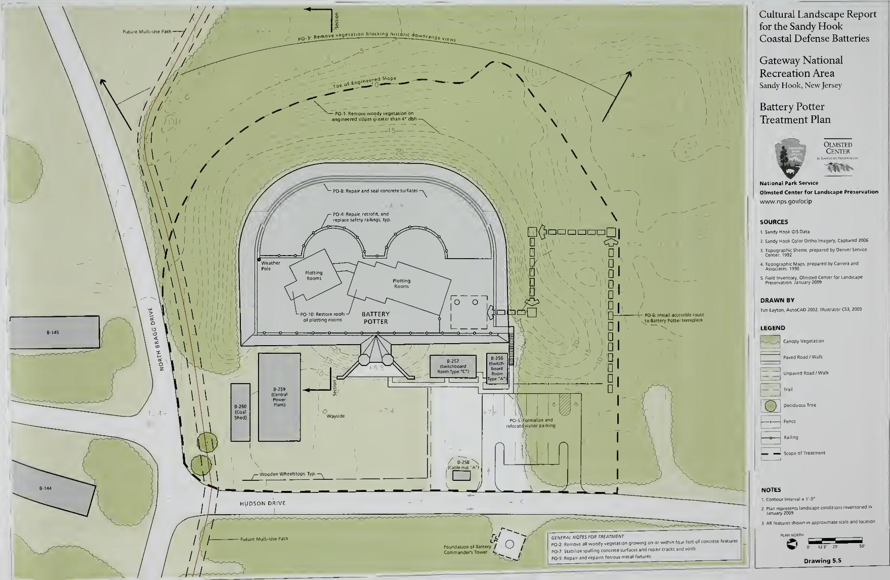
Cultural Landscape Report
for the Sandy HookCoastal Defense Batteries
Gateway National
Recreation AreaSandy Hook, New Jersey
Battery Potter
Treatment Plan
OlmstedCenter
Ml •
National Park Service
Olmsted Center for Landscape Preservation
wwwnps.gov/oclp
SOURCES
I.Sandy Hook GISOata
2. Sandy Hook Color Ortho Imagery, Captured 2006
3. Topographic Sheets, prepared by Denver Service
Center, 1992
4. Topographic Maps, prepared by Carrera andAssociates, 1990
5. Field Inventory, Olmsted Center for Landscape
Preservation, January 2009
DRAWN BY
Tim Layton, AutoCAD 2002. Illustrator CS3, 2009
LEGEND
|^->v_>4 Canopy Vegetation
Paved Road /Walk
Unpaved Road /Walk
E3-Deciduous Tree
L— _- Scope of Treatment
NOTES
l Contour interval = TO"
2. Plan represents landscape conditions inventoried in
January 2009
3 All features shown m approximate scale and locatio
N NORTH
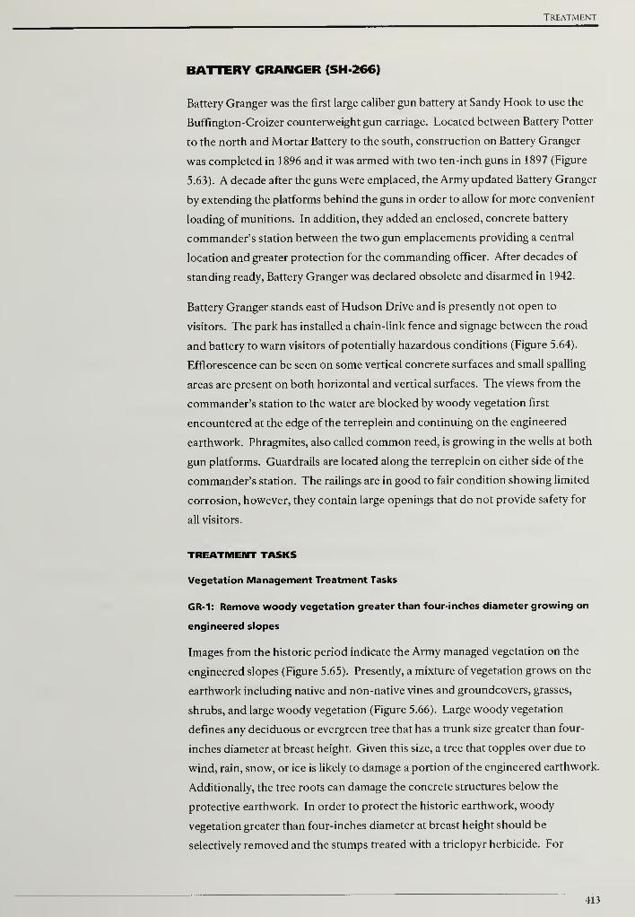
Treatment
BATTERY GRANGER (SH-266)
Battery Granger was the first large caliber gun battery at Sandy Hook to use the
Buffington-Croizer counterweight gun carriage. Located between Battery Potter
to the north and Mortar Battery to the south, construction on Battery Granger
was completed in 1896 and it was armed with two ten-inch guns in 1897 (Figure
5.63). A decade after the guns were emplaced, the Army updated Battery Granger
by extending the platforms behind the guns in order to allow for more convenient
loading of munitions. In addition, they added an enclosed, concrete battery
commander's station between the two gun emplacements providing a central
location and greater protection for the commanding officer. After decades of
standing ready, Battery Granger was declared obsolete and disarmed in 1942.
Battery Granger stands east of Hudson Drive and is presently not open to
visitors. The park has installed a chain-link fence and signage between the road
and battery to warn visitors of potentially hazardous conditions (Figure 5.64).
Efflorescence can be seen on some vertical concrete surfaces and small spalling
areas are present on both horizontal and vertical surfaces. The views from the
commander's station to the water are blocked by woody vegetation first
encountered at the edge of the terreplein and continuing on the engineered
earthwork. Phragmites, also called common reed, is growing in the wells at both
gun platforms. Guardrails are located along the terreplein on either side of the
commander's station. The railings are in good to fair condition showing limited
corrosion, however, they contain large openings that do not provide safety for
all visitors.
TREATMENT TASKS
Vegetation Management Treatment Tasks
GR-1: Remove woody vegetation greater than four-inches diameter growing on
engineered slopes
Images from the historic period indicate the Army managed vegetation on the
engineered slopes (Figure 5.65). Presently, a mixture of vegetation grows on the
earthwork including native and non-native vines and groundcovers, grasses,
shrubs, and large woody vegetation (Figure 5.66). Large woody vegetation
defines any deciduous or evergreen tree that has a trunk size greater than four-
inches diameter at breast height. Given this size, a tree that topples over due to
wind, rain, snow, or ice is likely to damage a portion of the engineered earthwork.
Additionally, the tree roots can damage the concrete structures below the
protective earthwork. In order to protect the historic earthwork, woody
vegetation greater than four-inches diameter at breast height should be
selectively removed and the stumps treated with a triclopyr herbicide. For
413
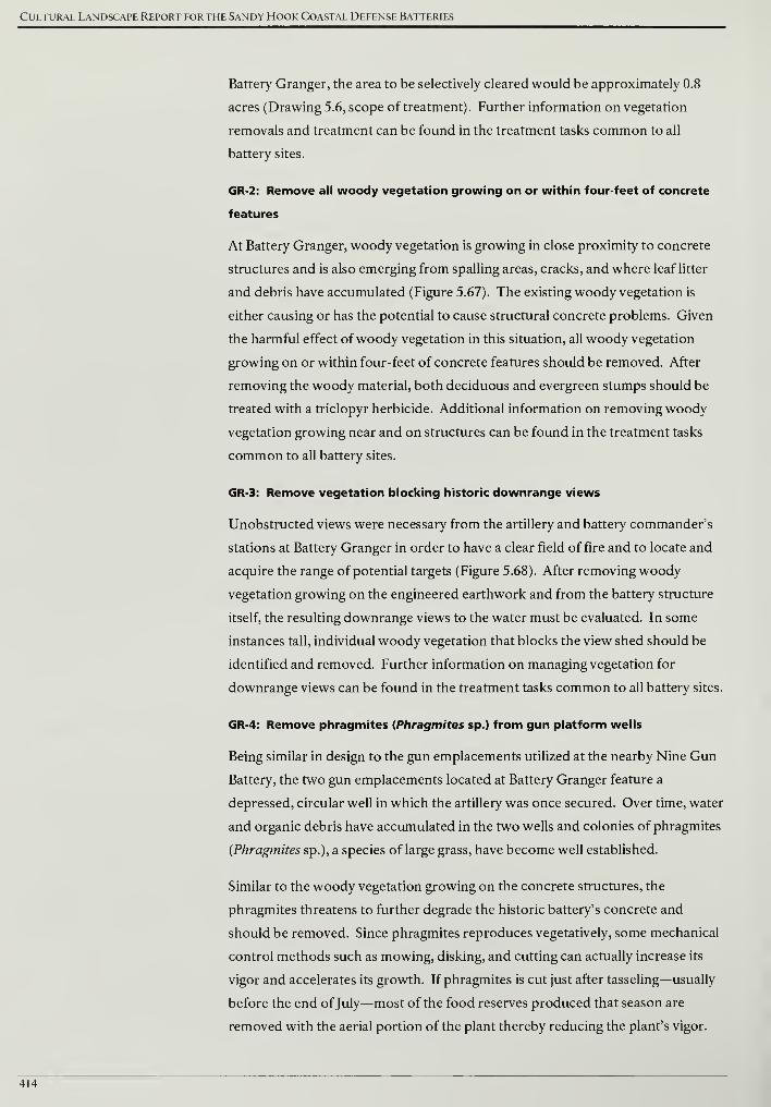
Cultural Landscape Report for the Sandy Hook Coastal Defense Batteries
Battery Granger, the area to be selectively cleared would be approximately 0.8
acres (Drawing 5.6, scope of treatment). Further information on vegetation
removals and treatment can be found in the treatment tasks common to all
battery sites.
GR-2: Remove all woody vegetation growing on or within four-feet of concrete
features
At Battery Granger, woody vegetation is growing in close proximity to concrete
structures and is also emerging from spalling areas, cracks, and where leaf litter
and debris have accumulated (Figure 5.67). The existing woody vegetation is
either causing or has the potential to cause structural concrete problems. Given
the harmful effect ofwoody vegetation in this situation, all woody vegetation
growing on or within four-feet of concrete features should be removed. After
removing the woody material, both deciduous and evergreen stumps should be
treated with a triclopyr herbicide. Additional information on removing woody
vegetation growing near and on structures can be found in the treatment tasks
common to all battery sites.
GR-3: Remove vegetation blocking historic downrange views
Unobstructed views were necessary from the artillery and battery commander's
stations at Battery Granger in order to have a clear field of fire and to locate and
acquire the range of potential targets (Figure 5.68). After removing woody
vegetation growing on the engineered earthwork and from the battery structure
itself, the resulting downrange views to the water must be evaluated. In some
instances tall, individual woody vegetation that blocks the view shed should be
identified and removed. Further information on managing vegetation for
downrange views can be found in the treatment tasks common to all battery sites.
GR-4: Remove phragmites (Phragmites sp.) from gun platform wells
Being similar in design to the gun emplacements utilized at the nearby Nine Gun
Battery, the two gun emplacements located at Battery Granger feature a
depressed, circular well in which the artillery was once secured. Over time, water
and organic debris have accumulated in the two wells and colonies of phragmites
(Phragmites sp.), a species of large grass, have become well established.
Similar to the woody vegetation growing on the concrete structures, the
phragmites threatens to further degrade the historic battery's concrete and
should be removed. Since phragmites reproduces vegetatively, some mechanical
control methods such as mowing, disking, and cutting can actually increase its
vigor and accelerates its growth. If phragmites is cut just after tasseling—usually
before the end ofJuly—most of the food reserves produced that season are
removed with the aerial portion of the plant thereby reducing the plant's vigor.
414
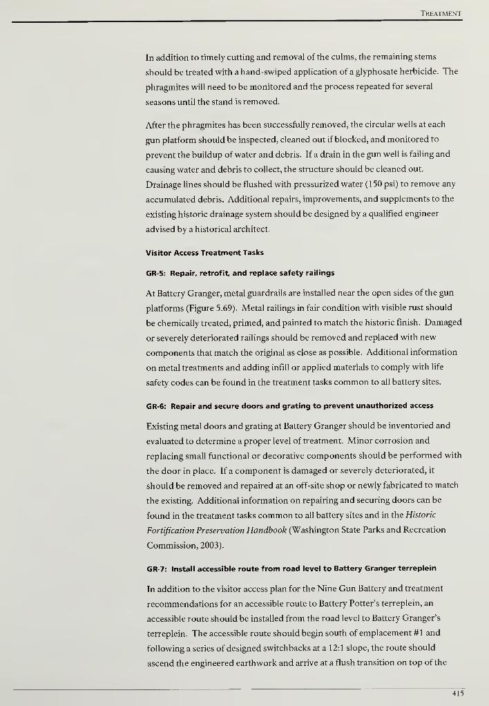
Treatment
In addition to timely cutting and removal of the culms, the remaining stems
should be treated with a hand-swiped application of a glyphosate herbicide. The
phragmites will need to be monitored and the process repeated for several
seasons until the stand is removed.
After the phragmites has been successfully removed, the circular wells at each
gun platform should be inspected, cleaned out if blocked, and monitored to
prevent the buildup of water and debris. If a drain in the gun well is failing and
causing water and debris to collect, the structure should be cleaned out.
Drainage lines should be flushed with pressurized water (150 psi) to remove any
accumulated debris. Additional repairs, improvements, and supplements to the
existing historic drainage system should be designed by a qualified engineer
advised by a historical architect.
Visitor Access Treatment Tasks
GR-5: Repair, retrofit, and replace safety railings
At Battery Granger, metal guardrails are installed near the open sides of the gun
platforms (Figure 5.69). Metal railings in fair condition with visible rust should
be chemically treated, primed, and painted to match the historic finish. Damaged
or severely deteriorated railings should be removed and replaced with new
components that match the original as close as possible. Additional information
on metal treatments and adding infill or applied materials to comply with life
safety codes can be found in the treatment tasks common to all battery sites.
GR-6: Repair and secure doors and grating to prevent unauthorized access
Existing metal doors and grating at Battery Granger should be inventoried and
evaluated to determine a proper level of treatment. Minor corrosion and
replacing small functional or decorative components should be performed with
the door in place. If a component is damaged or severely deteriorated, it
should be removed and repaired at an off-site shop or newly fabricated to match
the existing. Additional information on repairing and securing doors can be
found in the treatment tasks common to all battery sites and in the Historic
Fortification Preservation Handbook (Washington State Parks and Recreation
Commission, 2003).
GR-7: Install accessible route from road level to Battery Granger terreplein
In addition to the visitor access plan for the Nine Gun Battery and treatment
recommendations for an accessible route to Battery Potter's terreplein, an
accessible route should be installed from the road level to Battery Granger's
terreplein. The accessible route should begin south of emplacement #1 and
following a series of designed switchbacks at a 12:1 slope, the route should
ascend the engineered earthwork and arrive at a flush transition on top of the
415
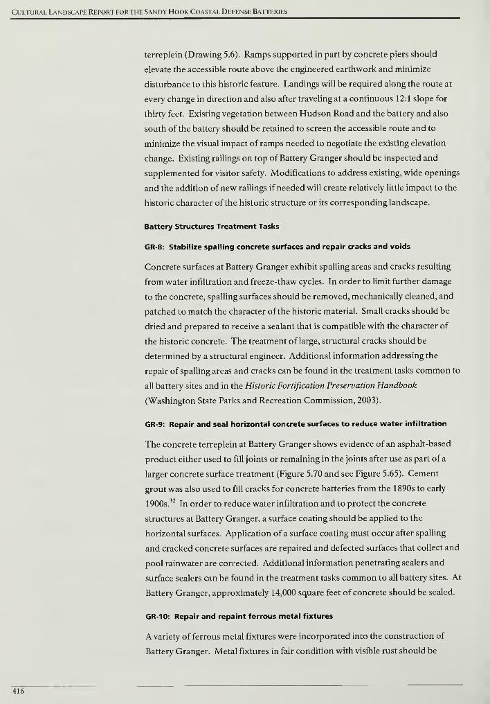
Cultural Landscape Report for the Sandy Hook Coastal Defense Batteries
terreplein (Drawing 5.6). Ramps supported in part by concrete piers should
elevate the accessible route above the engineered earthwork and minimize
disturbance to this historic feature. Landings will be required along the route at
every change in direction and also after traveling at a continuous 12:1 slope for
thirty feet. Existing vegetation between Hudson Road and the battery and also
south of the battery should be retained to screen the accessible route and to
minimize the visual impact of ramps needed to negotiate the existing elevation
change. Existing railings on top of Battery Granger should be inspected and
supplemented for visitor safety. Modifications to address existing, wide openings
and the addition of new railings if needed will create relatively little impact to the
historic character of the historic structure or its corresponding landscape.
Battery Structures Treatment Tasks
GR-8: Stabilize spalling concrete surfaces and repair cracks and voids
Concrete surfaces at Battery Granger exhibit spalling areas and cracks resulting
from water infiltration and freeze-thaw cycles. In order to limit further damage
to the concrete, spalling surfaces should be removed, mechanically cleaned, and
patched to match the character of the historic material. Small cracks should be
dried and prepared to receive a sealant that is compatible with the character of
the historic concrete. The treatment of large, structural cracks should be
determined by a structural engineer. Additional information addressing the
repair of spalling areas and cracks can be found in the treatment tasks common to
all battery sites and in the Historic Fortification Preservation Handbook
(Washington State Parks and Recreation Commission, 2003).
GR-9: Repair and seal horizontal concrete surfaces to reduce water infiltration
The concrete terreplein at Battery Granger shows evidence of an asphalt-based
product either used to fill joints or remaining in the joints after use as part of a
larger concrete surface treatment (Figure 5.70 and see Figure 5.65). Cement
grout was also used to fill cracks for concrete batteries from the 1890s to early
1900s.32
In order to reduce water infiltration and to protect the concrete
structures at Battery Granger, a surface coating should be applied to the
horizontal surfaces. Application of a surface coating must occur after spalling
and cracked concrete surfaces are repaired and defected surfaces that collect and
pool rainwater are corrected. Additional information penetrating sealers and
surface sealers can be found in the treatment tasks common to all battery sites. At
Battery Granger, approximately 14,000 square feet of concrete should be sealed.
GR-10: Repair and repaint ferrous metal fixtures
A variety of ferrous metal fixtures were incorporated into the construction of
Battery Granger. Metal fixtures in fair condition with visible rust should be
416

Treatment
chemically treated, primed, and painted to match the historic finish. Damaged or
severely deteriorated fixtures should be removed and replaced with new
components that match the original as close as possible. Additional
information on ferrous metal treatments can be found in the Safety Railings
section of the treatment tasks common to all battery sites and in the Historic
Fortification Preservation Handbook (Washington State Parks and Recreation
Commission, 2003).
417
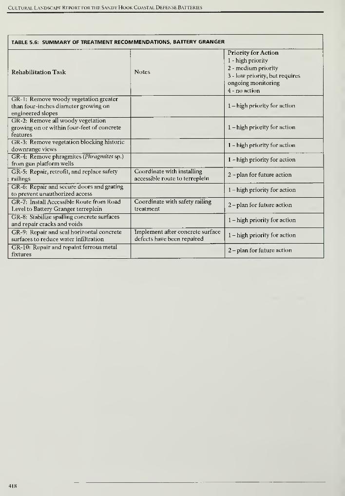
Cultural Landscape Report for the Sandy Hook Coastal Defense Batteries
TABLE 5.6: SUMMARY OF TREATMENT RECOMMENDATIONS, BATTERY GRANGER
Rehabilitation Task Notes
Priority for Action
1 - high priority
2 - medium priority
3 - low priority, but requires
ongoing monitoring
4 - no action
GR-1: Remove woody vegetation greater
than four-inches diameter growing on
engineered slopes
1 - high priority for action
GR-2: Remove all woody vegetation
growing on or within four-feet of concrete
features
1 - high priority for action
GR-3: Remove vegetation blocking historic
downrange views1 - high priority for action
GR-4: Remove phragmites (Phragmites sp.)
from gun platform wells1 - high priority for action
GR-5: Repair, retrofit, and replace safety
railings
Coordinate with installing
accessible route to terreplein2 - plan for future action
GR-6: Repair and secure doors and grating
to prevent unauthorized access1 - high priority for action
GR-7: Install Accessible Route from RoadLevel to Battery Granger terreplein
Coordinate with safety railing
treatment2 - plan for future action
GR-8: Stabilize spalling concrete surfaces
and repair cracks and voids1 - high priority for action
GR-9: Repair and seal horizontal concrete
surfaces to reduce water infiltration
Implement after concrete surface
defects have been repaired1 - high priority for action
GR-10: Repair and repaint ferrous metal
fixtures2 - plan for future action
418
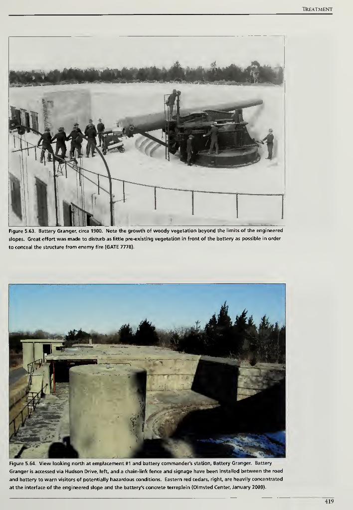
TREATMENT
Figure 5.63. Battery Granger, circa 1900. Note the growth of woody vegetation beyond the limits of the engineered
slopes. Great effort was made to disturb as little pre-existing vegetation in front of the battery as possible in order
to conceal the structure from enemy fire (GATE 7778).
Figure 5.64. View looking north at emplacement #1 and battery commander's station. Battery Granger. Battery
Granger is accessed via Hudson Drive, left, and a chain-link fence and signage have been installed between the road
and battery to warn visitors of potentially hazardous conditions. Eastern red cedars, right, are heavily concentrated
at the interface of the engineered slope and the battery's concrete terreplein (Olmsted Center, January 2009).
419
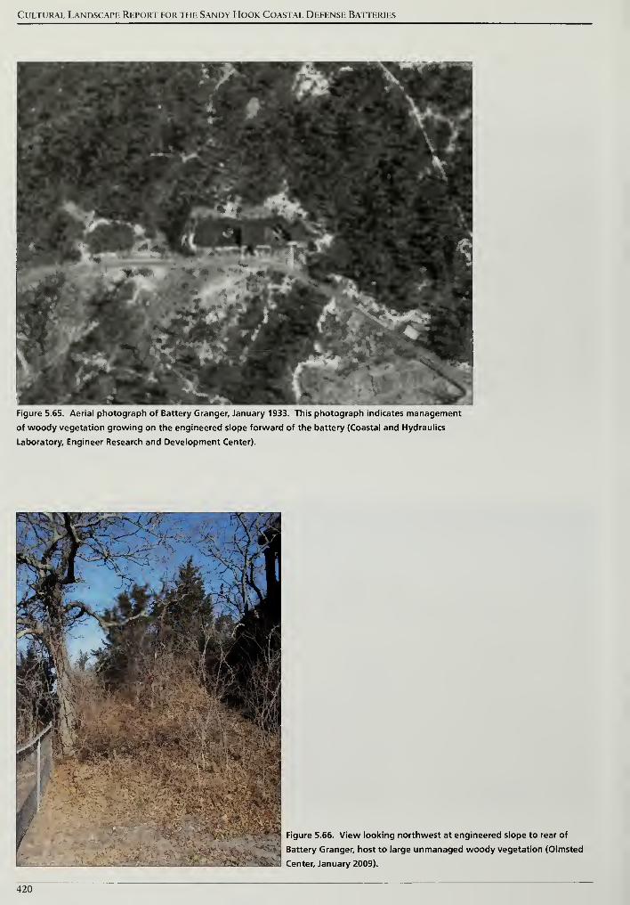
Cultural Landscape Report for the Sandy Hook Coastal Defense Batteries
Figure 5.65. Aerial photograph of Battery Granger, January 1933. This photograph indicates management
of woody vegetation growing on the engineered slope forward of the battery (Coastal and Hydraulics
Laboratory, Engineer Research and Development Center).
IFigure 5.66. View looking northwest at engineered slope to rear of
I Battery Granger, host to large unmanaged woody vegetation (Olmsted
] Center, January 2009).
420
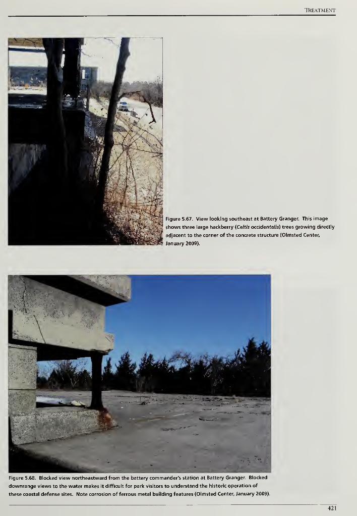
TREATMENT
Figure 5.67. View looking southeast at Battery Granger. This image
shows three large hackberry (Ce/r/'s occidentalis) trees growing directly
adjacent to the corner of the concrete structure (Olmsted Center,
January 2009).
Figure 5.68. Blocked view northeastward from the battery commander's station at Battery Granger. Blocked
downrange views to the water makes it difficult for park visitors to understand the historic operation of
these coastal defense sites. Note corrosion of ferrous metal building features (Olmsted Center, January 2009).
421
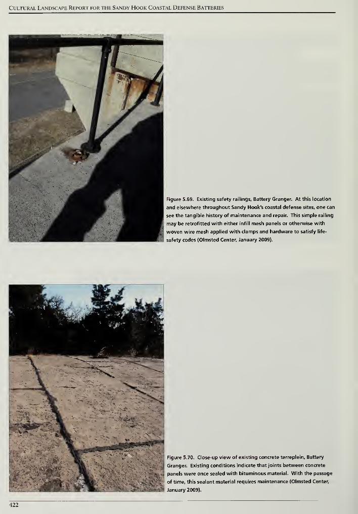
Cultural Landscape Report for the Sandy Hook Coastal Defense Batteries
Figure 5.69. Existing safety railings. Battery Granger. At this location
and elsewhere throughout Sandy Hook's coastal defense sites, one can
see the tangible history of maintenance and repair. This simple railing
may be retrofitted with either infill mesh panels or otherwise with
| woven wire mesh applied with clamps and hardware to satisfy life-
safety codes (Olmsted Center, January 2009).
Figure 5.70. Close-up view of existing concrete terreplein. Battery
Granger. Existing conditions indicate that joints between concrete
! panels were once sealed with bituminous material. With the passage
of time, this sealant material requires maintenance (Olmsted Center,
January 2009).
422
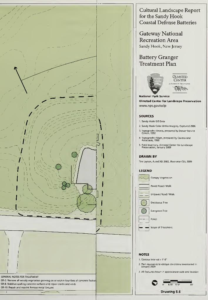
GENERAL NOTES FOR TREATMENT
GR-2: Remove all woody vegetation growing on or within four-feet of concrete featur
GR-8: Stabilize spalling concrete surfaces and repair cracks and voids
GR-10: Repair and repaint ferrous metal fixtures
Cultural Landscape Report
for the Sandy HookCoastal Defense Batteries
Gateway National
Recreation AreaSandy Hook, New Jersey
Battery Granger
Treatment Plan
Elta,
OlmstedCenter
/orL\NDSCAPF PRFSFRVATION
National Park Service
Olmsted Center for Landscape Preservation
www.nps.gov/oclp
SOURCES
1. Sandy Hook GIS Data
2. Sandy Hook Color Ortho Imagery, Captured 2006
3. Topographic Sheets, prepared by Denver Service
Center, 1992
4. Topographic Maps, prepared by Carrera andAssociates, 1990
5. Field Inventory, Olmsted Center for LandscapePreservation, January 2009
DRAWN BY
Tim Layton, AutoCAD 2002, Illustrator CS3, 2009
LEGEND
Canopy Vegetation
Paved Road /Walk
Unpaved Road /Walk
oo
Deciduous Tree
Evergreen Tree
Fence
Scope of Treatment
NOTES
1. Contour Interval = V-0"
2. Plan represents landscape conditions inventoried in
January 2009
3. All features shown in approximate scale and location
0' 8.75' 17.5'
Drawing 5.6
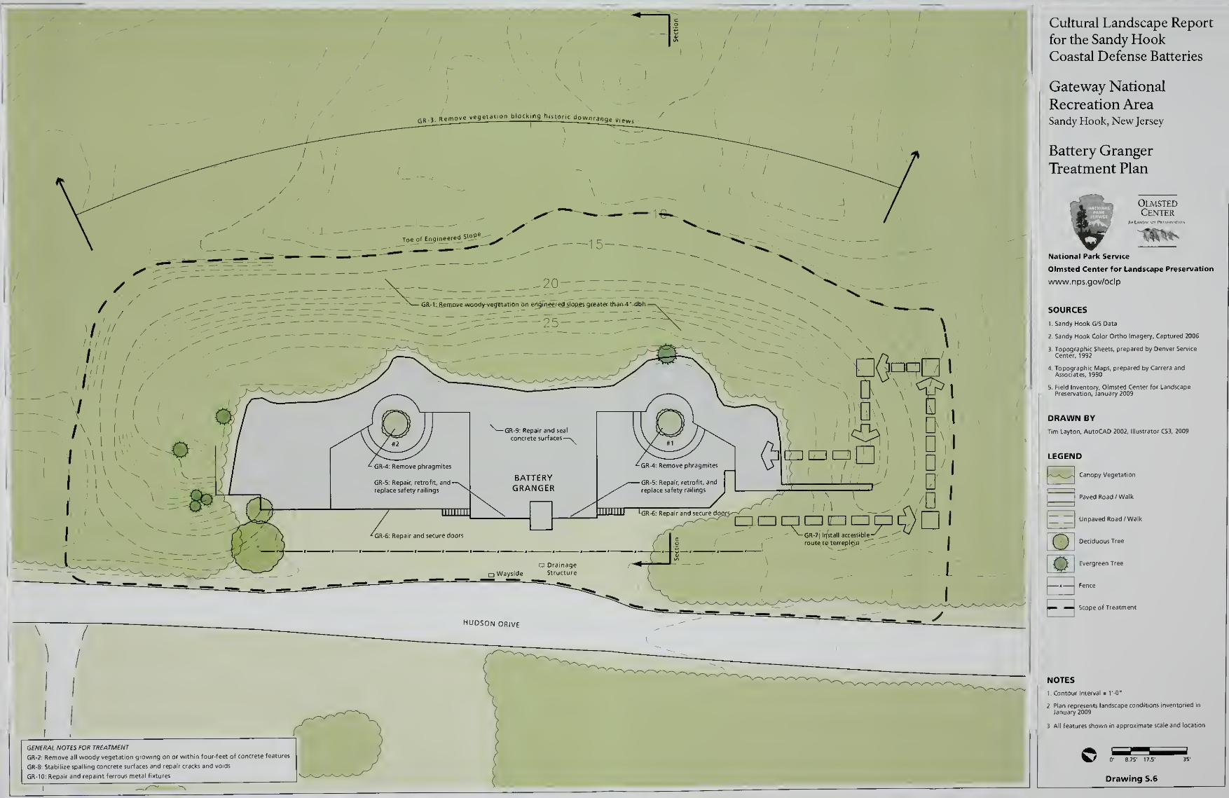
GENERAL NOTES FOR TREATMENT
GR-2-. Remove all woody vegetation growing on or within four-feet of concrete features
GR-8: Stabilize spalling concrete surfaces and repair cracks and voids
GR-10: Repair and repaint ferrous metal fixtures
Cultural Landscape Report
for the Sandy HookCoastal Defense Batteries
Gateway National
Recreation AreaSandy Hook, New Jersey
Battery Granger
Treatment Plan
OlmstedCenter
National Park Service
Olmsted Center for Landscape Preservation
www.nps.gov/oclp
SOURCES
1. Sandy Hook GIS Data
2. Sandy Hook Color Ortho Imagery, Captured 2006
DRAWN BY
Tim Layton, AutoCAD 2002. Illustrator CS3, 2009
LEGEND
U^^_^-J Canopy Vegetation
Paved Road /Walk
Unpaved Road /Walk
Deciduous TreeEIo
* Fence
Evergreen Tree
E3 Scope of Treatment
NOTES
1 Contour Interval = 1'-0"
3 All features shown m approximate scale and It
0' 8.75' 17.5' 35"
Drawing 5.6
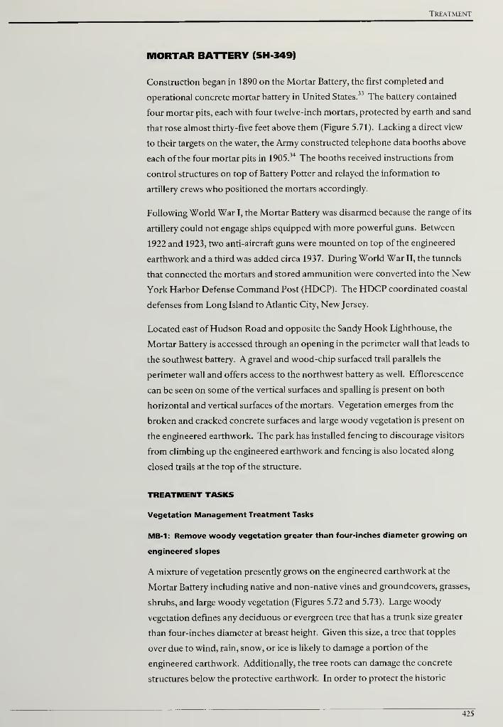
Treatment
MORTAR BATTERY (SH 349)
Construction began in 1890 on the Mortar Battery, the first completed and
operational concrete mortar battery in United States.33 The battery contained
four mortar pits, each with four twelve-inch mortars, protected by earth and sand
that rose almost thirty-five feet above them (Figure 5.71). Lacking a direct view
to their targets on the water, the Army constructed telephone data booths above
each of the four mortar pits in 1905.34 The booths received instructions from
control structures on top of Battery Potter and relayed the information to
artillery crews who positioned the mortars accordingly.
Following World War I, the Mortar Battery was disarmed because the range of its
artillery could not engage ships equipped with more powerful guns. Between
1922 and 1923, two anti-aircraft guns were mounted on top of the engineered
earthwork and a third was added circa 1937. During World War II, the tunnels
that connected the mortars and stored ammunition were converted into the New
York Harbor Defense Command Post (HDCP). The HDCP coordinated coastal
defenses from Long Island to Atlantic City, New Jersey.
Located east of Hudson Road and opposite the Sandy Hook Lighthouse, the
Mortar Battery is accessed through an opening in the perimeter wall that leads to
the southwest battery. A gravel and wood-chip surfaced trail parallels the
perimeter wall and offers access to the northwest battery as well. Efflorescence
can be seen on some of the vertical surfaces and spalling is present on both
horizontal and vertical surfaces of the mortars. Vegetation emerges from the
broken and cracked concrete surfaces and large woody vegetation is present on
the engineered earthwork. The park has installed fencing to discourage visitors
from climbing up the engineered earthwork and fencing is also located along
closed trails at the top of the structure.
TREATMENT TASKS
Vegetation Management Treatment Tasks
MB-1: Remove woody vegetation greater than four-inches diameter growing on
engineered slopes
A mixture of vegetation presently grows on the engineered earthwork at the
Mortar Battery including native and non-native vines and groundcovers, grasses,
shrubs, and large woody vegetation (Figures 5.72 and 5.73). Large woody
vegetation defines any deciduous or evergreen tree that has a trunk size greater
than four-inches diameter at breast height. Given this size, a tree that topples
over due to wind, rain, snow, or ice is likely to damage a portion of the
engineered earthwork. Additionally, the tree roots can damage the concrete
structures below the protective earthwork. In order to protect the historic
425

Cultural Landscape Report for the Sandy Hook Coastal Defense Batteries
earthwork, woody vegetation greater than four-inches diameter at breast height
should be selectively removed and the stumps treated with a triclopyr herbicide.
For the Mortar Battery, the area to be selectively cleared would be approximately
4.8 acres. Further information on vegetation removals and treatment can be
found in the treatment tasks common to all battery sites.
MB-2: Remove all woody vegetation growing on or within four-feet of concrete
structures and features
At the Mortar Battery, woody vegetation is growing in close proximity to
concrete structures and is also emerging from spalling areas, cracks, and where
leaf litter and debris have accumulated (Figures 5.74 and 5.75). The existing
woody vegetation is either causing or has the potential to cause structural
concrete problems. Given the harmful effect ofwoody vegetation in this
situation, all woody vegetation growing on or within four-feet of concrete
features should be removed. After removing the woody material, both deciduous
and evergreen stumps should be treated with a triclopyr herbicide. Additional
information on removing woody vegetation growing near and on structures can
be found in the treatment tasks common to all battery sites.
Visitor Access Treatment Tasks
MB-3: Repair, retrofit, and replace safety railings
At the Mortar Battery, metal handrails line the steps that provided access to the
telephone data booths. Metal railings in fair condition with visible rust should be
chemically treated, primed, and painted to match the historic finish. Damaged or
severely deteriorated railings should be removed and replaced with new
components that match the original as close as possible. Additional information
on metal treatments and adding infill or applied materials to comply with life
safety codes can be found in the treatment tasks common to all battery sites.
MB-4: Close social trails and stabilize the eroded path south of southwest mortar
An eroded path presently heads up the engineered earthwork south of the gallery
to the southwest mortar pit. Additional social trails lead up and across the
engineered earthwork. Both the path and trails should be closed in order to limit
erosion and preserve the historic structure. Low-growing native shrubs should
be planted at the top and bottom of a social trail to block access. Branches cut
three to four feet in length should also be placed at the top and bottom of a trail
to obscure the route. Additional information on appropriate plant species and
erosion control measures can be found in the treatment tasks common to all
battery sites.
426
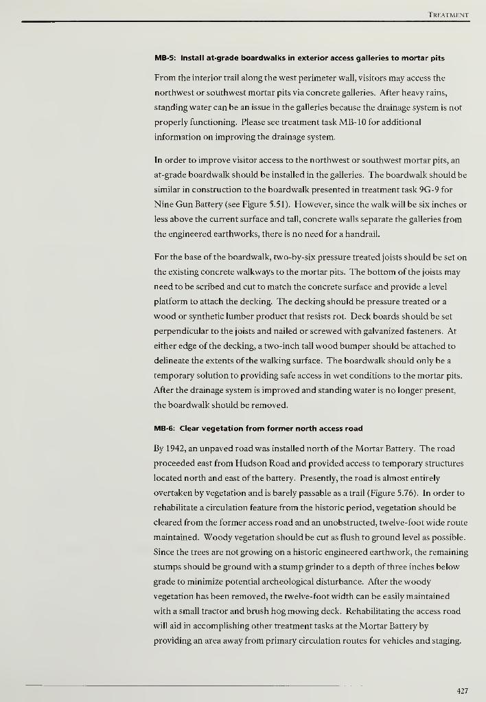
Treatment
MB-5: Install at-grade boardwalks in exterior access galleries to mortar pits
From the interior trail along the west perimeter wall, visitors may access the
northwest or southwest mortar pits via concrete galleries. After heavy rains,
standing water can be an issue in the galleries because the drainage system is not
properly functioning. Please see treatment task MB-10 for additional
information on improving the drainage system.
In order to improve visitor access to the northwest or southwest mortar pits, an
at-grade boardwalk should be installed in the galleries. The boardwalk should be
similar in construction to the boardwalk presented in treatment task 9G-9 for
Nine Gun Battery (see Figure 5.51). However, since the walk will be six inches or
less above the current surface and tall, concrete walls separate the galleries from
the engineered earthworks, there is no need for a handrail.
For the base of the boardwalk, two-by-six pressure treated joists should be set on
the existing concrete walkways to the mortar pits. The bottom of the joists may
need to be scribed and cut to match the concrete surface and provide a level
platform to attach the decking. The decking should be pressure treated or a
wood or synthetic lumber product that resists rot. Deck boards should be set
perpendicular to the joists and nailed or screwed with galvanized fasteners. At
either edge of the decking, a two-inch tall wood bumper should be attached to
delineate the extents of the walking surface. The boardwalk should only be a
temporary solution to providing safe access in wet conditions to the mortar pits.
After the drainage system is improved and standing water is no longer present,
the boardwalk should be removed.
MB-6: Clear vegetation from former north access road
By 1942, an unpaved road was installed north of the Mortar Battery. The road
proceeded east from Hudson Road and provided access to temporary structures
located north and east of the battery. Presently, the road is almost entirely
overtaken by vegetation and is barely passable as a trail (Figure 5.76). In order to
rehabilitate a circulation feature from the historic period, vegetation should be
cleared from the former access road and an unobstructed, twelve-foot wide route
maintained. Woody vegetation should be cut as flush to ground level as possible.
Since the trees are not growing on a historic engineered earthwork, the remaining
stumps should be ground with a stump grinder to a depth of three inches below
grade to minimize potential archeological disturbance. After the woody
vegetation has been removed, the twelve-foot width can be easily maintained
with a small tractor and brush hog mowing deck. Rehabilitating the access road
will aid in accomplishing other treatment tasks at the Mortar Battery by
providing an area away from primary circulation routes for vehicles and staging.
427
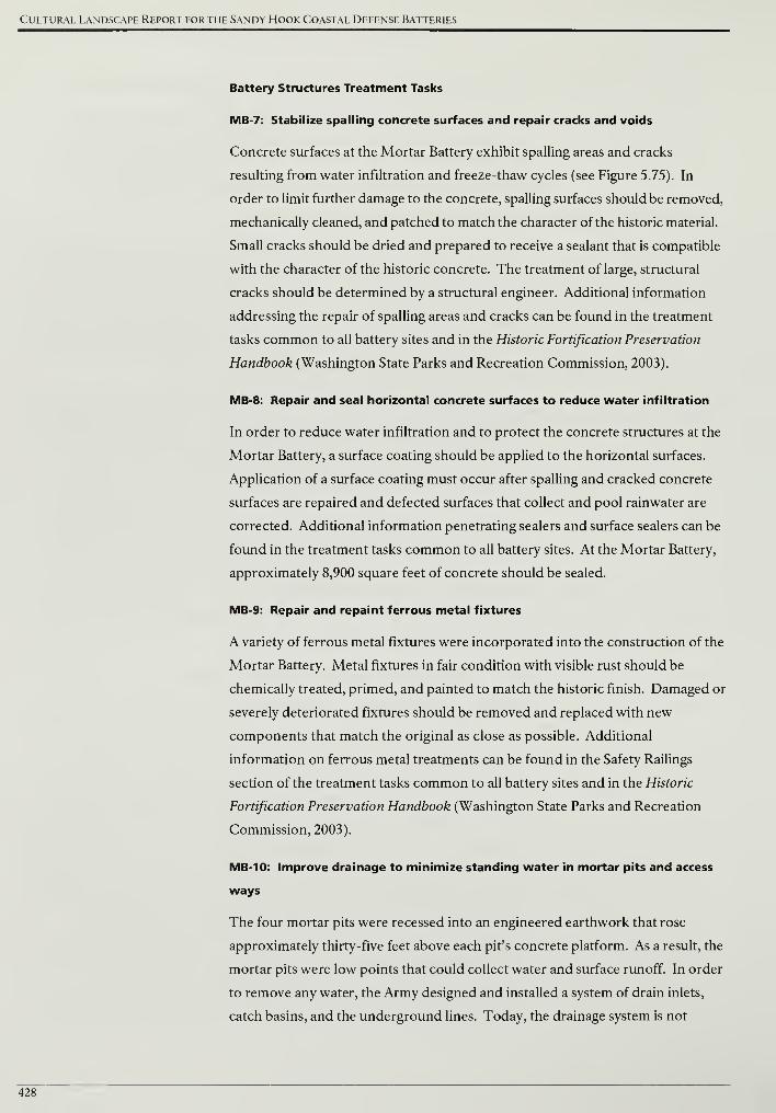
Cultural Landscape Report for the Sandy Hook Coastal Defense Batteries
Battery Structures Treatment Tasks
MB-7: Stabilize spalling concrete surfaces and repair cracks and voids
Concrete surfaces at the Mortar Battery exhibit spalling areas and cracks
resulting from water infiltration and freeze-thaw cycles (see Figure 5.75). In
order to limit further damage to the concrete, spalling surfaces should be removed,
mechanically cleaned, and patched to match the character of the historic material.
Small cracks should be dried and prepared to receive a sealant that is compatible
with the character of the historic concrete. The treatment of large, structural
cracks should be determined by a structural engineer. Additional information
addressing the repair of spalling areas and cracks can be found in the treatment
tasks common to all battery sites and in the Historic Fortification Preservation
Handbook (Washington State Parks and Recreation Commission, 2003).
MB-8: Repair and seal horizontal concrete surfaces to reduce water infiltration
In order to reduce water infiltration and to protect the concrete structures at the
Mortar Battery, a surface coating should be applied to the horizontal surfaces.
Application of a surface coating must occur after spalling and cracked concrete
surfaces are repaired and defected surfaces that collect and pool rainwater are
corrected. Additional information penetrating sealers and surface sealers can be
found in the treatment tasks common to all battery sites. At the Mortar Battery,
approximately 8,900 square feet of concrete should be sealed.
MB-9: Repair and repaint ferrous metal fixtures
A variety of ferrous metal fixtures were incorporated into the construction of the
Mortar Battery. Metal fixtures in fair condition with visible rust should be
chemically treated, primed, and painted to match the historic finish. Damaged or
severely deteriorated fixtures should be removed and replaced with new
components that match the original as close as possible. Additional
information on ferrous metal treatments can be found in the Safety Railings
section of the treatment tasks common to all battery sites and in the Historic
Fortification Preservation Handbook (Washington State Parks and Recreation
Commission, 2003).
MB-10: Improve drainage to minimize standing water in mortar pits and access
ways
The four mortar pits were recessed into an engineered earthwork that rose
approximately thirty-five feet above each pit's concrete platform. As a result, the
mortar pits were low points that could collect water and surface runoff. In order
to remove any water, the Army designed and installed a system of drain inlets,
catch basins, and the underground lines. Today, the drainage system is not
428

Treatment
properly functioning and standing water in the mortar pits and access ways
damages the historic structure and limits visitor access.
In order to improve drainage and minimize standing water, the existing drain
inlets and structures should be cleaned out. Drainage lines should be flushed
with pressurized water at 150 psi to remove any accumulated debris. If existing
cast iron or vitrified clay pipes have collapsed, the area of the identified failure
should be carefully excavated and the pipe replaced with schedule 40 PVC or
ADS N-12 pipe. Both schedule 40 PVC and ADS N-12 are designed to withstand
vehicular loads and are commonly used in drainage applications. Repairs,
improvements, and supplements to the existing historic drainage system should
be designed by a qualified engineer advised by a historical architect.
429
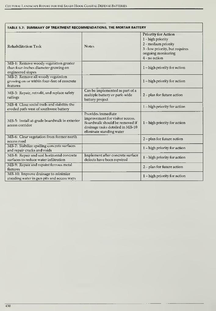
Cultural Landscape Report for the Sandy Hook Coastal Defense Batteries
TABLE 5.7: SUMMARY OF TREATMENT RECOMMENDATIONS, THE MORTAR BATTERY
Rehabilitation Task Notes
Priority for Action
1 - high priority
2 - medium priority
3 - low priority, but requires
ongoing monitoring
4 - no action
MB-1: Remove woody vegetation greater
than four-inches diameter growing on
engineered slopes
1 - high priority for action
MB-2: Remove all woody vegetation
growing on or within four-feet of concrete
features
1 - high priority for action
MB-3: Repair, retrofit, and replace safety
railings
Can be implemented as part of a
multiple battery or park-wide
battery project
2 - plan for future action
MB-4: Close social trails and stabilize the
eroded path west of southwest battery1 - high priority for action
MB-5: Install at-grade boardwalk in exterior
access corridor
Provides immediate
improvement for visitor access.
Boardwalk should be removed if
drainage tasks detailed in MB-10eliminate standing water
1 - high priority for action
MB-6: Clear vegetation from former north
access road2 - plan for future action
MB-7: Stabilize spalling concrete surfaces
and repair cracks and voids1 - high priority for action
MB-8: Repair and seal horizontal concrete
surfaces to reduce water infiltration
Implement after concrete surface
defects have been repaired1 - high priority for action
MB-9: Repair and repaint ferrous metal
fixtures2 - plan for future action
MB-10: Improve drainage to minimize
standing water in gun pits and access ways1 - high priority for action
430
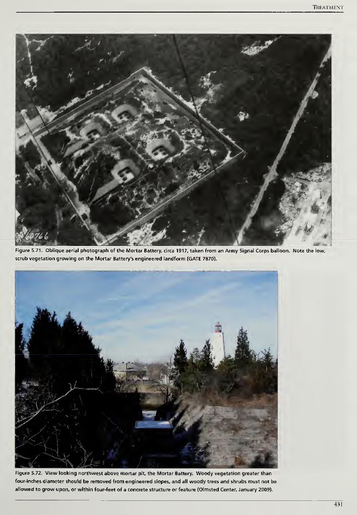
TREATMENT
Figure 5.71. Oblique aerial photograph of the Mortar Battery, circa 1917, taken from an Army Signal Corps balloon. Note the low,
scrub vegetation growing on the Mortar Battery's engineered landform (GATE 7870).
Figure 5.72. View looking northwest above mortar pit, the Mortar Battery. Woody vegetation greater than
four-inches diameter should be removed from engineered slopes, and all woody trees and shrubs must not be
allowed to grow upon, or within four-feet of a concrete structure or feature (Olmsted Center, January 2009).
431
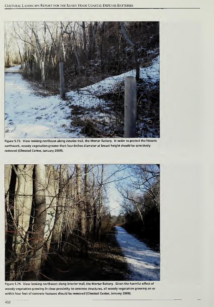
Cultural Landscape Report for the Sandy Hook Coastal Defense Batteries
Figure 5.73. View looking northeast along interior trail, the Mortar Battery. In order to protect the historic
earthwork, woody vegetation greater than four-inches diameter at breast height should be selectively
removed (Olmsted Center, January 2009).
Figure 5.74. View looking northwest along interior trail, the Mortar Battery. Given the harmful effect of
woody vegetation growing in close proximity to concrete structures, all woody vegetation growing on or
within four feet of concrete features should be removed (Olmsted Center, January 2009).
432
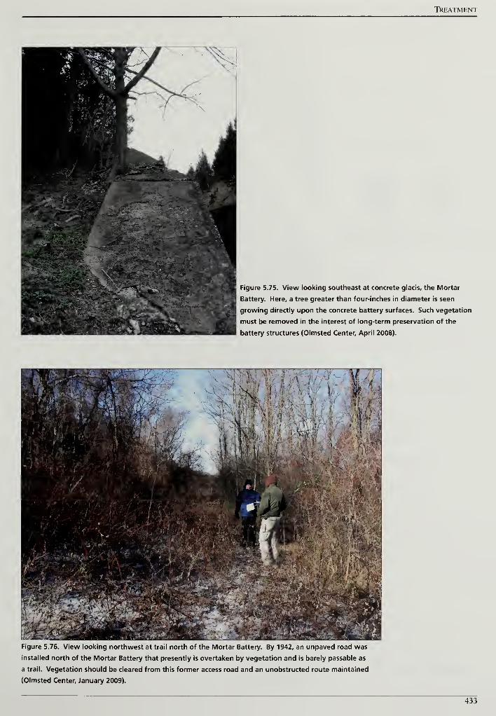
TREATMENT
Figure 5.75. View looking southeast at concrete glacis, the Mortar
Battery. Here, a tree greater than four-inches in diameter is seen
growing directly upon the concrete battery surfaces. Such vegetation
must be removed in the interest of long-term preservation of the
battery structures (Olmsted Center, April 2008).
Figure 5.76. View looking northwest at trail north of the Mortar Battery. By 1942, an unpaved road was
installed north of the Mortar Battery that presently is overtaken by vegetation and is barely passable as
a trail. Vegetation should be cleared from this former access road and an unobstructed route maintained
(Olmsted Center, January 2009).
433

Cultural Landscape Report for the Sandy Hook Coastal Defense Batteries
434
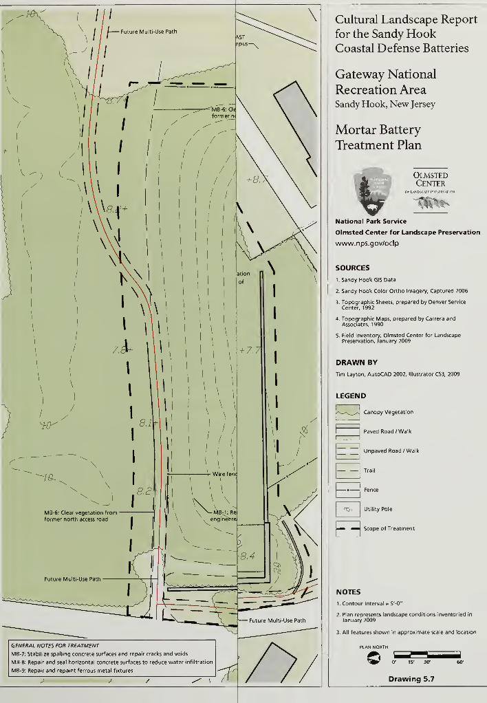
GENERAL NOTES FOR TREATMENT
MB-7: Stabilize spelling concrete surfaces and repair cracks and voids
MB-8: Repair and seal horizontal concrete surfaces to reduce water infiltration
M8-9: Repair and repaint ferrous metal fixtures
J J / -f
Cultural Landscape Report
for the Sandy HookCoastal Defense Batteries
Gateway National
Recreation AreaSandy Hook, New Jersey
Mortar Battery
Treatment Plan
OlmstedCenter
flirLANDSCAPF PRFSFRVATH
National Park Service
Olmsted Center for Landscape Preservation
www.nps.gov/oclp
SOURCES
1. Sandy Hook GIS Data
2. Sandy Hook Color Ortho Imagery, Captured 2006
3. Topographic Sheets, prepared by Denver Service
Center, 1992
4. Topographic Maps, prepared by Carrera andAssociates, 1990
5. Field Inventory, Olmsted Center for LandscapePreservation, January 2009
DRAWN BY
Tim Layton, AutoCAD 2002, Illustrator CS3, 2009
LEGEND
Canopy Vegetation
Paved Road /Walk
Unpaved Road/ Walk
Trail
TIj
Fence
Utility Pole
Scope of Treatment
NOTES
1. Contour Interval = 5'-0"
2. Plan represents landscape conditions inventoried in
January 2009
3. All features shown in approximate scale and location
PLAN NORTH
0' 15' 30'
Drawing 5.7
60'
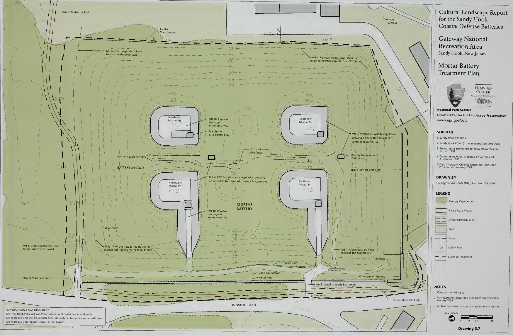
Cultural Landscape Reportfor the Sandy HookCoastal Defense Batteries
Gateway National
Recreation AreaSandy Hook, New Jersey
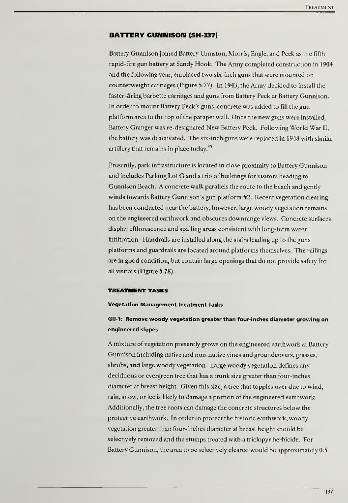
Treatment
BATTERY GUNNISON (SH 337)
Battery Gunnison joined Battery Urmston, Morris, Engle, and Peck as the fifth
rapid-fire gun battery at Sandy Hook. The Army completed construction in 1904
and the following year, emplaced two six-inch guns that were mounted on
counterweight carriages (Figure 5.77). In 1943, the Army decided to install the
faster-firing barbette carriages and guns from Battery Peck at Battery Gunnison.
In order to mount Battery Peck's guns, concrete was added to fill the gun
platform area to the top of the parapet wall. Once the new guns were installed,
Battery Granger was re-designated New Battery Peck. Following World War II,
the battery was deactivated. The six-inch guns were replaced in 1948 with similar
artillery that remains in place today.35
Presently, park infrastructure is located in close proximity to Battery Gunnison
and includes Parking Lot G and a trio of buildings for visitors heading to
Gunnison Beach. A concrete walk parallels the route to the beach and gently
winds towards Battery Gunnison's gun platform #2. Recent vegetation clearing
has been conducted near the battery, however, large woody vegetation remains
on the engineered earthwork and obscures downrange views. Concrete surfaces
display efflorescence and spalling areas consistent with long-term water
infiltration. Handrails are installed along the stairs leading up to the guns
platforms and guardrails are located around platforms themselves. The railings
are in good condition, but contain large openings that do not provide safety for
all visitors (Figure 5.78).
TREATMENT TASKS
Vegetation Management Treatment Tasks
GU-1: Remove woody vegetation greater than four-inches diameter growing on
engineered slopes
A mixture of vegetation presently grows on the engineered earthwork at Battery
Gunnison including native and non-native vines and groundcovers, grasses,
shrubs, and large woody vegetation. Large woody vegetation defines any
deciduous or evergreen tree that has a trunk size greater than four-inches
diameter at breast height. Given this size, a tree that topples over due to wind,
rain, snow, or ice is likely to damage a portion of the engineered earthwork.
Additionally, the tree roots can damage the concrete structures below the
protective earthwork. In order to protect the historic earthwork, woody
vegetation greater than four-inches diameter at breast height should be
selectively removed and the stumps treated with a triclopyr herbicide. For
Battery Gunnison, the area to be selectively cleared would be approximately 0.5
437

Cultural Landscape Report for the Sandy Hook Coastal Defense Batteries
acres. Further information on vegetation removals and treatment can be found
in the treatment tasks common to all battery sites.
GU-2: Remove all woody vegetation growing on or within four-feet of concrete
features
At Battery Gunnison, woody vegetation is growing in close proximity to concrete
structures. The existing woody vegetation is either causing or has the potential to
cause structural concrete problems. Given the harmful effect of woody
vegetation in this situation, all woody vegetation growing on or within four-feet
of concrete features should be removed. After removing the woody material,
both deciduous and evergreen stumps should be treated with a triclopyr
herbicide. Additional information on removing woody vegetation growing near
and on structures can be found in the treatment tasks common to all battery sites.
GU-3: Remove vegetation blocking historic downrange views
Unobstructed views were necessary from the artillery and battery commander's
stations at Battery Gunnison in order to have a clear field of fire and to locate and
acquire the range of potential targets. After removing woody vegetation growing
on the engineered earthwork and from the battery structure itself, the resulting
downrange views to the water must be evaluated (see Figure 5.78). In some
instances tall, individual woody vegetation that blocks the view shed should be
identified and removed. Further information on managing vegetation for
downrange views can be found in the treatment tasks common to all battery sites.
GU-4: Close social trail and stabilize erosion southeast of emplacement #1
A social trail heads southeast from emplacement #1 and terminates at the toe of the
engineered slope. The trail does not connect to another circulation feature and
should be closed in order to limit erosion and preserve the historic earthwork.
Low-growing native shrubs should be planted at the top and bottom of a social
trail to block access. Branches cut three to four feet in length should also be
placed at the top and bottom of a trail to obscure the route. Additional
information on appropriate plant species and erosion control measures can be
found in the treatment tasks common to all battery sites.
Visitor Access Treatment Tasks
GU-5: Repair, retrofit, and replace safety railings
At Battery Gunnison, metal handrails line the steps that provided access from the
ground level to the batteries. Metal guardrails are also installed near the open
sides of elevated areas such as gun platforms (see Figure 5.78). Metal railings in
fair condition with visible rust should be chemically treated, primed, and painted
to match the historic finish. Damaged or severely deteriorated railings should be
438
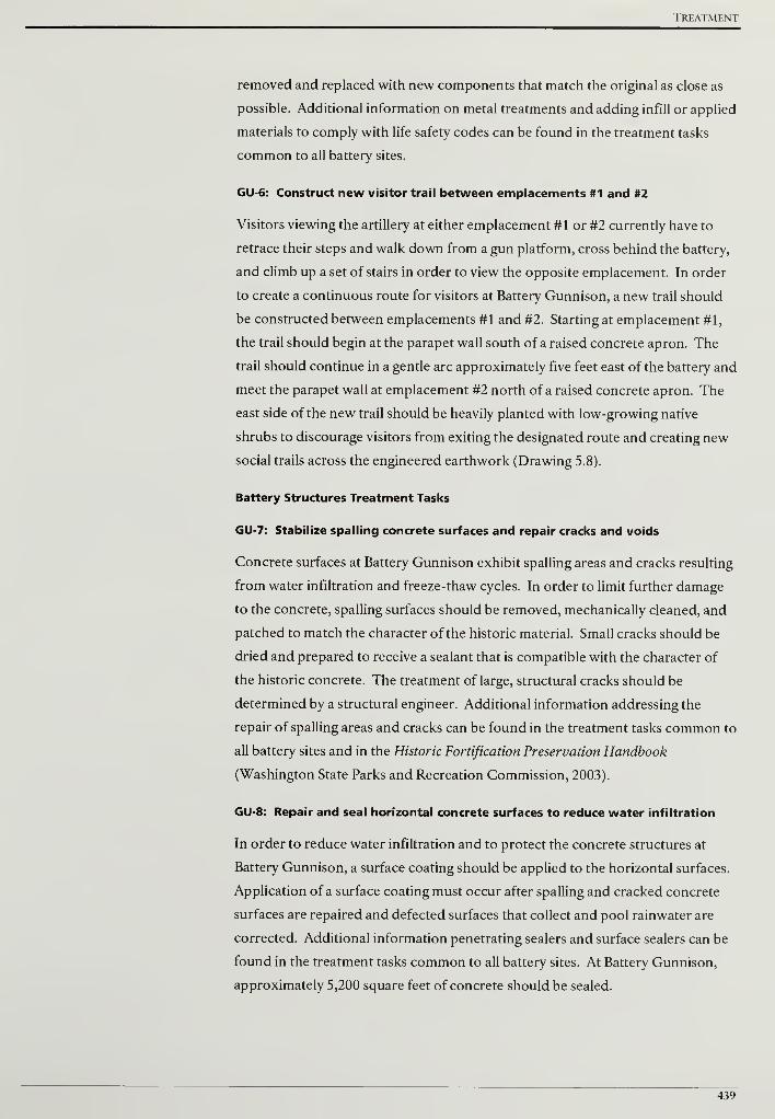
Treatment
removed and replaced with new components that match the original as close as
possible. Additional information on metal treatments and adding infill or applied
materials to comply with life safety codes can be found in the treatment tasks
common to all battery sites.
GU-6: Construct new visitor trail between emplacements #1 and #2
Visitors viewing the artillery at either emplacement #1 or #2 currently have to
retrace their steps and walk down from a gun platform, cross behind the battery,
and climb up a set of stairs in order to view the opposite emplacement. In order
to create a continuous route for visitors at Battery Gunnison, a new trail should
be constructed between emplacements #1 and #2. Starting at emplacement #1,
the trail should begin at the parapet wall south of a raised concrete apron. The
trail should continue in a gentle arc approximately five feet east of the battery and
meet the parapet wall at emplacement #2 north of a raised concrete apron. The
east side of the new trail should be heavily planted with low-growing native
shrubs to discourage visitors from exiting the designated route and creating new
social trails across the engineered earthwork (Drawing 5.8).
Battery Structures Treatment Tasks
GU-7: Stabilize spailing concrete surfaces and repair cracks and voids
Concrete surfaces at Battery Gunnison exhibit spailing areas and cracks resulting
from water infiltration and freeze-thaw cycles. In order to limit further damage
to the concrete, spailing surfaces should be removed, mechanically cleaned, and
patched to match the character of the historic material. Small cracks should be
dried and prepared to receive a sealant that is compatible with the character of
the historic concrete. The treatment of large, structural cracks should be
determined by a structural engineer. Additional information addressing the
repair of spailing areas and cracks can be found in the treatment tasks common to
all battery sites and in the Historic Fortification Preservation Handbook
(Washington State Parks and Recreation Commission, 2003).
GU-8: Repair and seal horizontal concrete surfaces to reduce water infiltration
In order to reduce water infiltration and to protect the concrete structures at
Battery Gunnison, a surface coating should be applied to the horizontal surfaces.
Application of a surface coating must occur after spailing and cracked concrete
surfaces are repaired and defected surfaces that collect and pool rainwater are
corrected. Additional information penetrating sealers and surface sealers can be
found in the treatment tasks common to all battery sites. At Battery Gunnison,
approximately 5,200 square feet of concrete should be sealed.
439

Cultural Landscape Report for the Sandy Hook Coastal Defense Batteries
GU-9: Repair and repaint ferrous metal fixtures
A variety of ferrous metal fixtures were incorporated into the construction of
Battery Gunnison. Metal fixtures in fair condition with visible rust should be
chemically treated, primed, and painted to match the historic finish. Damaged or
severely deteriorated fixtures should be removed and replaced with new
components that match the original as close as possible. Additional
information on ferrous metal treatments can be found in the Safety Railings
section of the treatment tasks common to all battery sites and in the Historic
Fortification Preservation Handbook (Washington State Parks and Recreation
Commission, 2003).
440
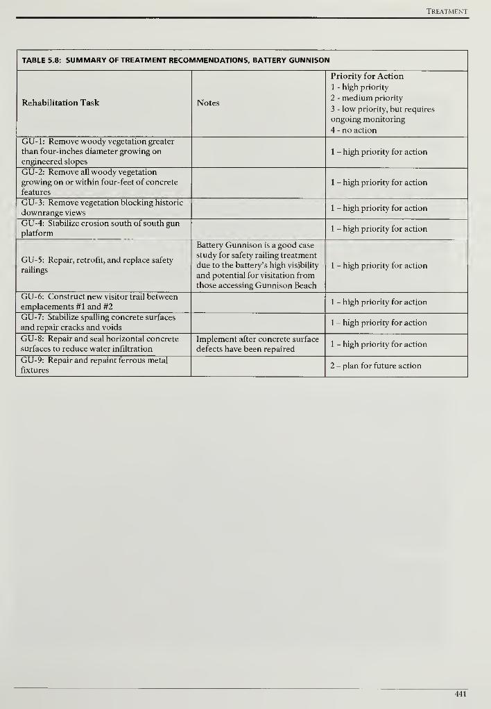
Treatment
TABLE 5.8: SUMMARY OF TREATMENT RECOMMENDATIONS, BATTERY GUNNISON
Rehabilitation Task Notes
Priority for Action
1 - high priority
2 - medium priority
3 - low priority, but requires
ongoing monitoring
4 - no action
GU-1: Remove woody vegetation greater
than four-inches diameter growing on
engineered slopes
1 - high priority for action
GU-2: Remove all woody vegetation
growing on or within four-feet of concrete
features
1 - high priority for action
GU-3: Remove vegetation blocking historic
downrange views1 - high priority for action
GU-4: Stabilize erosion south of south gun
platform1 - high priority for action
GU-5: Repair, retrofit, and replace safety
railings
Battery Gunnison is a good case
study for safety railing treatment
due to the battery's high visibility
and potential for visitation from
those accessing Gunnison Beach
1 - high priority for action
GU-6: Construct new visitor trail betweenemplacements #1 and #2
1 - high priority for action
GU-7: Stabilize spalling concrete surfaces
and repair cracks and voids1 - high priority for action
GU-8: Repair and seal horizontal concrete
surfaces to reduce water infiltration
Implement after concrete surface
defects have been repaired1 - high priority for action
GU-9: Repair and repaint ferrous metal
fixtures2 - plan for future action
441

Cultural Landscape Report for the Sandy Hook Coastal Defense Batteries
442
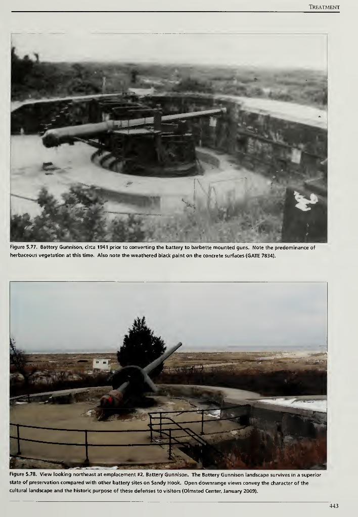
Treatment
Figure 5.77. Battery Gunnison, circa 1941 prior to converting the battery to barbette mounted guns. Note the predominance of
herbaceous vegetation at this time. Also note the weathered black paint on the concrete surfaces (GATE 7834).
Figure 5.78. View looking northeast at emplacement #2, Battery Gunnison. The Battery Gunnison landscape survives in a superior
state of preservation compared with other battery sites on Sandy Hook. Open downrange views convey the character of the
cultural landscape and the historic purpose of these defenses to visitors (Olmsted Center, January 2009).
443

Cultural Landscape Report for the Sandy Hook Coastal Defense Batteries
444
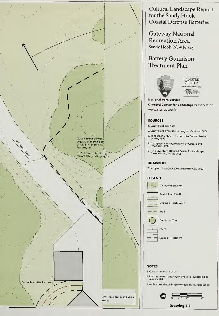
Cultural Landscape Reportfor the Sandy HookCoastal Defense Batteries
Gateway National
Recreation AreaSandy Hook, New Jersey
Battery GunnisonTreatment Plan
OlmstedCenter
for L\NDSCAPF PRFSFR\ \JK
National Park Service
Olmsted Center for Landscape Preservation
www.nps.gov/oclp
SOURCES
1. Sandy Hook GIS Data
2. Sandy Hook Color Ortho Imagery, Captured 2006
3. Topographic Sheets, prepared by Denver ServiceCenter, 1992
4. Topographic Maps, prepared by Carrera andAssociates, 1990
5. Field Inventory, Olmsted Center for LandscapePreservation, January 2009
DRAWN BY
Tim Layton, AutoCAD 2002, Illustrator CS3, 2009
LEGEND
Canopy Vegetation
Paved Road /Walk
Unpaved Road/ Walk
Trail
Deciduous Tree
Fence
Scope of Treatment
NOTES
1. Contour Interval = 2'-0"
2. Plan represents landscape conditions inventoried in
January 2009
3. All features shown in approximate scale and location
^^- 0' 7.5' 15'
Drawing 5.8
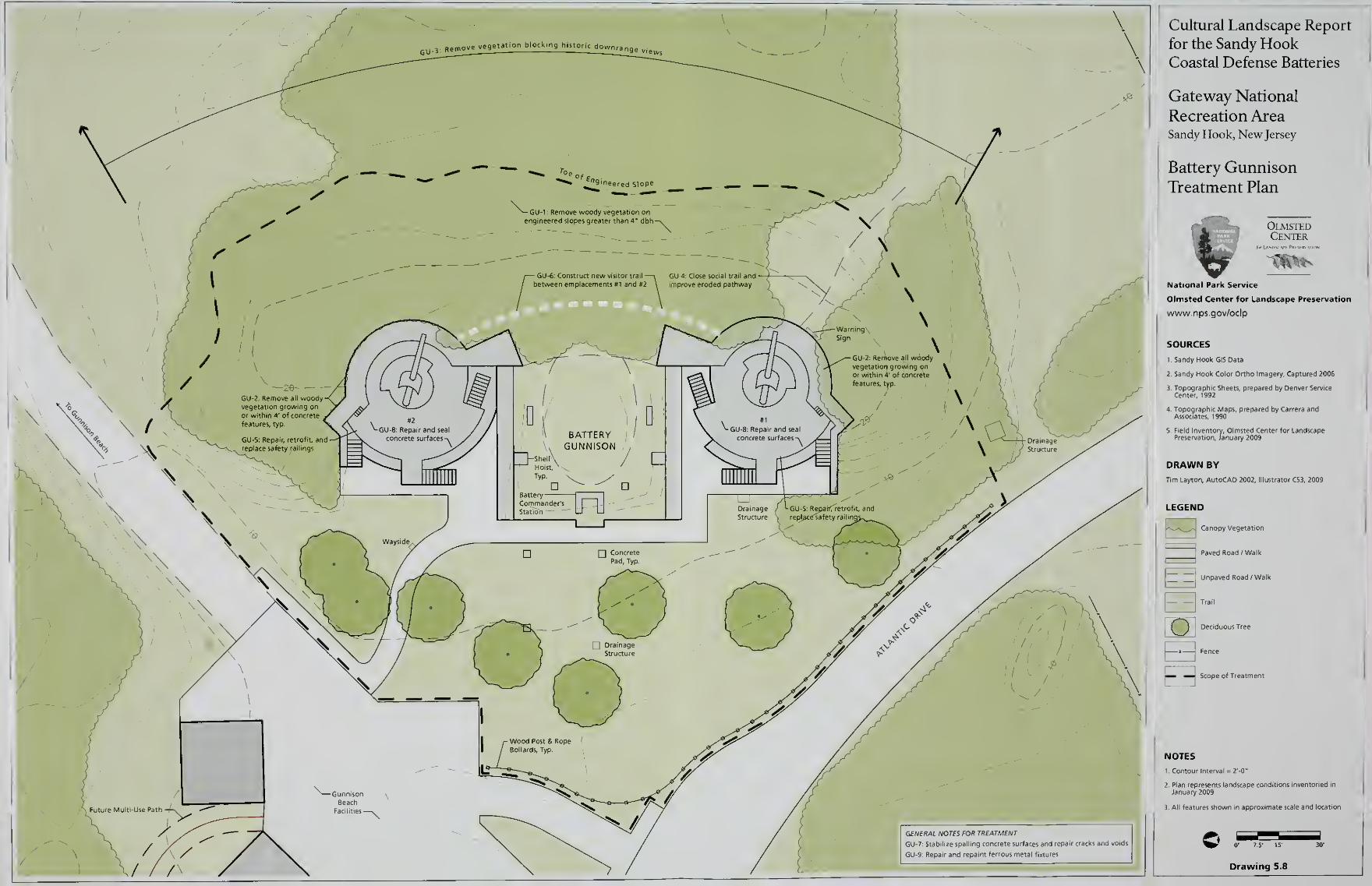
Cultural Landscape Report
for the Sandy HookCoastal Defense Batteries
Gateway National
Recreation AreaSandy Hook, New Jersey
Drawing 5.8
Treatment
BATTERIES KINGMAN AND MILLS (SH-441 AND 440)
The last large caliber gun batteries constructed at Sandy Hook were batteries
Kingman and Mills. The Army completed masonry construction of the batteries
1917 and armed them in 1919 with twelve-inch guns. The guns were emplaced
on open, circular platforms and had a 360-degree field of fire (Figure 5.79). The
artillery more than doubled the range of earlier large caliber guns and stood on
the western side of the peninsula, further away from potential enemy fire.36
Between 1941 and 1942, the open gun platforms at batteries Kingman and Mills
were casemated to protect the guns from aerial bombing (Figure 5.80). The
casemated dates appear inscribed on concrete bulkheads even though the
batteries were originally constructed twenty-five years earlier. Following World
War II, both batteries were disarmed in 1948.
Currently, the most striking feature of the two batteries is their forty-foot tall
earthen mounds that rise in stark contrast to the flat, slightly undulating coastal
topography around them (Figure 5.81). Large woody vegetation and a thick
understory of vines cover the engineered earthen casemates. Above the gun
emplacements at batteries Kingman and Mills, concrete canopies were
constructed to shield the artillery from overhead fire. The canopies and concrete
facades around the emplacement openings show efflorescence and in some cases,
large spalling areas. The park has installed a six-foot high chain-link fence above
each gun emplacement to prevent unauthorized access to the concrete canopies
and injury from a fall.
BATTERY KINGMAN TREATMENT TASKS
Vegetation Management Treatment Tasks
KM: Remove woody vegetation greater than four-inches diameter growing on
engineered slopes
The two 12-inch guns at Battery Kingman were originally emplaced on open
platforms that permitted 360-degrees of rotation and firing (see Figure 5.79).
Between 1941 and 1942, the emplacements were casemated with concrete
structures and covered with enough protective sand and earth to cover a three-
story building. World War II-era photographs show the vegetation immediately
around the gun and on the earthen casemate above was a low growing turf mixture.
Restoring the earthen casemate to a turf mixture is not a practical treatment and
would create new maintenance challenges for the park. In order to preserve the
historic earthwork and concrete structures below, all woody vegetation greater
than four-inches diameter at breast height should be removed. For Battery
Kingman, the area to be selectively cleared would be approximately 3.7 acres
(Drawing 5.9, scope of treatment).
447
Cultural Landscape Report for the Sandy Hook Coastal Defense Batteries
KI-2: Remove all woody vegetation growing on or within four-feet of concrete
features
In comparison to the disappearing gun batteries, Battery Kingman does not as
high a quantity of exposed concrete structures. Concrete facades, canopies to
shield the gun emplacements, sloped glacises that meet the earthen casement, and
bulkhead entries on the west side are all present and threatened by woody
vegetation growing on them or nearby (Figure 5.82). As discussed in the general
treatment recommendations, all woody vegetation growing on or within four-
feet of concrete features should be removed and treated with a triclopyr
herbicide to inhibit resprouting and kill the root system.
KI-3: Clear overgrowth external to gun battery in area of gun traverse/field of
fire
Two 12-inch guns were emplaced at Battery Kingman and the barrel of each gun
was nearly forty feet long. In order to rotate the gun into position and set its
firing trajectory, the vegetation immediately around the platform had to be low
growing. A 1940s photograph of the north gun platform shows the vegetation
immediately around the gun and on the earthen casemate above was a low
growing turf mixture (Figure 5.83).
Restoring a turf mix across the entire earthwork is not a practical treatment and
would create new maintenance challenges for the park. To visually convey the
space required to operate the battery's 12-inch guns, the recommendation is to
clear tree and shrub vegetation immediately around the gun platform. This
clearing effort needs to focus on the slopes against the battery's concrete facades
as the level area in front of the guns is relatively free of tree and shrub vegetation
(Figure 5.84).
To remove Japanese honeysuckle (Lonicerajaponica), greenbrier (Smilax sp.),
and poison ivy (Toxicodendron radicans), the park may consider using tended or
supervised goats enclosed within temporary fencing that the herbivores may
consume the vines and other vegetation. Gateway National Recreation Area has
successfully used goats at Battery Duane in the Staten Island Unit and the same
treatment could be considered at batteries Kingman and Mills.
With the overgrown vegetation removed, a low-maintenance, perennial, native
grass such as switch grass (Panicum virgatum) should be planted. Once
established, switch grass competes very well against invasive species and provides
excellent food and cover for wildlife. To help establish the new plantings,
erosion control fabric should be used on slopes greater than 4:1.
448
Treatment
Visitor Access Treatment Tasks
KI-4: Maintain chain-link fences above casemate canopies to prevent
unauthorized access and visitor injuries
Above both gun emplacements at Battery Kingman, concrete canopies shield the
artillery from overhead fire. The canopies emerge from a concrete facade
constructed in front of the emplacement. The engineered earthwork meets the
top of the concrete facade and continues to rise at a 2:1 slope to an elevation
approximately thirty-five feet above most of the surrounding area.
To prevent unauthorized access to the canopy and avoid injury due to the steep
slope of the earthwork, the National Park Service installed a six-foot high chain-
link fence above the concrete facade (Figure 5.85). As previously mentioned,
visitor access is not planned for Battery Kingman. Although visitors are not
supposed to have access, the chain-link fence should be maintained for added
safety. Regular inspections should make sure the line posts are solid and securely
anchored to the ground. The chain-link mesh should be inspected for any holes
or other deficiencies. Both the posts and mesh should be repaired or replaced as
conditions merit.
Battery Structures Treatment Tasks
KI-5: Stabilize spading concrete surfaces and repair cracks and voids
Concrete surfaces at Battery Kingman exhibit spalling areas and cracks resulting
from water infiltration and freeze-thaw cycles (see Figures 5.84 and 5.85). In
order to limit further damage to the concrete, spalling surfaces should be removed,
mechanically cleaned, and patched to match the character of the historic material.
Small cracks should be dried and prepared to receive a sealant that is compatible
with the character of the historic concrete. The treatment of large, structural
cracks should be determined by a structural engineer. Additional information
addressing the repair of spalling areas and cracks can be found in the treatment
tasks common to all battery sites and in the Historic Fortification Preservation
Handbook (Washington State Parks and Recreation Commission, 2003).
KI-6: Repair and seal horizontal concrete surfaces to reduce water infiltration
In order to reduce water infiltration and to protect the concrete structures at
Battery Kingman, a surface coating should be applied to the horizontal surfaces.
Application of a surface coating must occur after spalling and cracked concrete
surfaces are repaired and defected surfaces that collect and pool rainwater are
corrected. Additional information penetrating sealers and surface sealers can be
found in the treatment tasks common to all battery sites. At Battery Kingman,
approximately 975 square feet of concrete should be sealed.
449
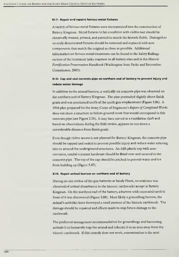
Cultural Landscape Report for the Sandy Hook Coastal Defense Batteries
KI-7: Repair and repaint ferrous metal fixtures
A variety of ferrous metal fixtures were incorporated into the construction of
Battery Kingman. Metal fixtures in fair condition with visible rust should be
chemically treated, primed, and painted to match the historic finish. Damaged or
severely deteriorated fixtures should be removed and replaced with new
components that match the original as close as possible. Additional
information on ferrous metal treatments can be found in the Safety Railings
section of the treatment tasks common to all battery sites and in the Historic
Fortification Preservation Handbook (Washington State Parks and Recreation
Commission, 2003).
KI-8: Cap and seal concrete pipe on northern end of battery to prevent injury and
reduce water damage
In addition to the animal burrow, a vertically set concrete pipe was observed on
the northern end of Battery Kingman. The pipe protruded slightly above finish
grade and was positioned north of the north gun emplacement (Figure 5.86). A
1944 plan prepared for the Army Corps of Engineers's Report ofCompleted Works
does not show a structure or below-ground room that would correspond to this
concrete pipe (see Figure 2.76). It may have served as a ventilation shaft and
based on observations during the field review, appears to run down a
considerable distance from finish grade.
Even though visitor access is not planned for Battery Kingman, the concrete pipe
should be capped and sealed to prevent possible injury and reduce water entering
into or around the underground structures. An ABS plastic cap with non-
corrosive, vandal-resistant hardware should be fitted over and secured to the
concrete pipe. The top of the cap should be pitched to prevent water and ice
from building up (Figure 5.87).
KI-9: Repair animal burrow on northern end of battery
During on-site review of the gun batteries at Sandy Hook, no evidence was
observed of animal disturbance to the historic earthworks accept at Battery
Kingman. On the northern end of the battery, a burrow with excavated earth in
front of it was discovered (Figure 5.88). Most likely a groundhog burrow, the
animal's activities have destroyed a small portion of the historic earthwork. The
damage should be repaired and efforts made to stop future damage to the
earthwork.
The preferred management recommendation for groundhogs and burrowing
animals is to humanely trap the animal and relocate it to an area away from the
historic earthwork. If this remedy does not work, extermination is the next
450
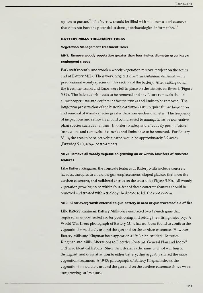
Treatment
option to pursue.37 The burrow should be filled with soil from a sterile source
that does not have the potential to damage archaeological information.38
BATTERY MILLS TREATMENT TASKS
Vegetation Management Treatment Tasks
MI-1: Remove woody vegetation greater than four-inches diameter growing on
engineered slopes
Park staff recently undertook a woody vegetation removal project on the south
end of Battery Mills. Their work targeted ailanthus (Ailanthus altissima)—the
predominant woody species on this section of the battery. After cutting down
the trees, the trunks and limbs were left in place on the historic earthwork (Figure
5.89). The fallen debris needs to be removed and any future removals should
allow proper time and equipment for the trunks and limbs to be removed. The
long-term preservation of the historic earthworks will require future inspection
and removal ofwoody species greater than four-inches diameter. The frequency
of inspections and removals should be increased to manage invasive non-native
plant species such as ailanthus. In order to safely and effectively permit future
inspections and removals, the trunks and limbs have to be removed. For Battery
Mills, the area to be selectively cleared would be approximately 3.9 acres
(Drawing 5.10, scope of treatment).
MI-2: Remove all woody vegetation growing on or within four-feet of concrete
features
Like Battery Kingman, the concrete features at Battery Mills include concrete
facades, canopies to shield the gun emplacements, sloped glacises that meet the
earthen casement, and bulkhead entries on the west side (Figure 5.90). All woody
vegetation growing on or within four-feet of these concrete features should be
removed and treated with a triclopyr herbicide to kill the root system.
MI-3: Clear overgrowth external to gun battery in area of gun traverse/field of fire
Like Battery Kingman, Battery Mills once emplaced two 12-inch guns that
required an unobstructed arc for positioning and setting their firing trajectory. A
World War II-era photograph of Battery Mills has not been found to confirm the
vegetation immediately around the gun and on the earthen casemate. However,
Battery Mills and Kingman both appear on a 1943 plan entitled "Batteries
Kingman and Mills, Alterations to Electrical Systems, General Plan and Index"
and have identical layouts. Since their design is the same and not wanting to
distinguish and draw attention to either battery, they arguably shared the same
vegetation treatment. A 1940s photograph of Battery Kingman shows the
vegetation immediately around the gun and on the earthen casemate above was a
low growing turf mixture.
451
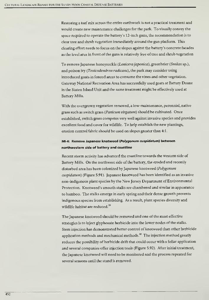
Cultural Landscape Report for the Sandy Hook Coastal Defense Batteries
Restoring a turf mix across the entire earthwork is not a practical treatment and
would create new maintenance challenges for the park. To visually convey the
space required to operate the battery's 12-inch guns, the recommendation is to
clear tree and shrub vegetation immediately around the gun platform. This
clearing effort needs to focus on the slopes against the battery's concrete facades
as the level area in front of the guns is relatively free of tree and shrub vegetation
To remove Japanese honeysuckle (Lonicera japonica), greenbrier (Smilax sp.),
and poison ivy (Toxicodendron radicans), the park may consider using
introduced goats in fenced areas to consume the vines and other vegetation.
Gateway National Recreation Area has successfully used goats at Battery Duane
in the Staten Island Unit and the same treatment might be effectively used at
Battery Mills.
With the overgrown vegetation removed, a low-maintenance, perennial, native
grass such as switch grass (Panicum virgatum) should be cultivated. Once
established, switch grass competes very well against invasive species and provides
excellent food and cover for wildlife. To help establish the new plantings,
erosion control fabric should be used on slopes greater than 4:1.
MI-4: Remove Japanese knotweed (Polygonum cuspidatum) between
northwestern side of battery and coastline
Recent storm activity has advanced the coastline towards the western side of
Battery Mills. On the northwest side of the battery, the eroded and recently
disturbed area has been colonized by Japanese knotweed (Polygonum
cuspidatum) (Figure 5.91). Japanese knotweed has been identified as an invasive
non-indigenous plant species by the New Jersey Department of Environmental
Protection. Knotweed's smooth stalks are chambered and similar in appearance
to bamboo. The stalks emerge in early spring and their dense growth prevents
indigenous species from establishing. As a result, plant species diversity and
wildlife habitat are reduced.39
The Japanese knotweed should be removed and one of the most effective
strategies is to inject glyphosate herbicide into the lower nodes of the stalks.
Stem injection has demonstrated better control of knotweed than other herbicide
application methods and mechanical methods.40 The injection method greatly
reduces the possibility of herbicide drift that could occur with a foliar application
and several companies offer injection tools (Figure 5.92). After initial treatment,
the Japanese knotweed will need to be monitored and the process repeated for
several seasons until the stand is removed.
452
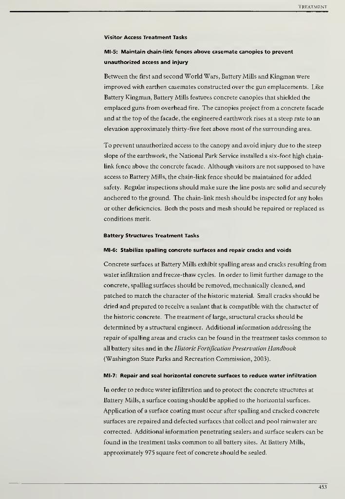
Treatment
Visitor Access Treatment Tasks
MI-5: Maintain chain-link fences above casemate canopies to prevent
unauthorized access and injury
Between the first and second World Wars, Battery Mills and Kingman were
improved with earthen casemates constructed over the gun emplacements. Like
Battery Kingman, Battery Mills features concrete canopies that shielded the
emplaced guns from overhead fire. The canopies project from a concrete facade
and at the top of the facade, the engineered earthwork rises at a steep rate to an
elevation approximately thirty-five feet above most of the surrounding area.
To prevent unauthorized access to the canopy and avoid injury due to the steep
slope of the earthwork, the National Park Service installed a six-foot high chain-
link fence above the concrete facade. Although visitors are not supposed to have
access to Battery Mills, the chain-link fence should be maintained for added
safety. Regular inspections should make sure the line posts are solid and securely
anchored to the ground. The chain-link mesh should be inspected for any holes
or other deficiencies. Both the posts and mesh should be repaired or replaced as
conditions merit.
Battery Structures Treatment Tasks
MI-6: Stabilize spading concrete surfaces and repair cracks and voids
Concrete surfaces at Battery Mills exhibit spalling areas and cracks resulting from
water infiltration and freeze-thaw cycles. In order to limit further damage to the
concrete, spalling surfaces should be removed, mechanically cleaned, and
patched to match the character of the historic material. Small cracks should be
dried and prepared to receive a sealant that is compatible with the character of
the historic concrete. The treatment of large, structural cracks should be
determined by a structural engineer. Additional information addressing the
repair of spalling areas and cracks can be found in the treatment tasks common to
all battery sites and in the Historic Fortification Preservation Handbook
(Washington State Parks and Recreation Commission, 2003).
MI-7: Repair and seal horizontal concrete surfaces to reduce water infiltration
In order to reduce water infiltration and to protect the concrete structures at
Battery Mills, a surface coating should be applied to the horizontal surfaces.
Application of a surface coating must occur after spalling and cracked concrete
surfaces are repaired and defected surfaces that collect and pool rainwater are
corrected. Additional information penetrating sealers and surface sealers can be
found in the treatment tasks common to all battery sites. At Battery Mills,
approximately 975 square feet of concrete should be sealed.
453
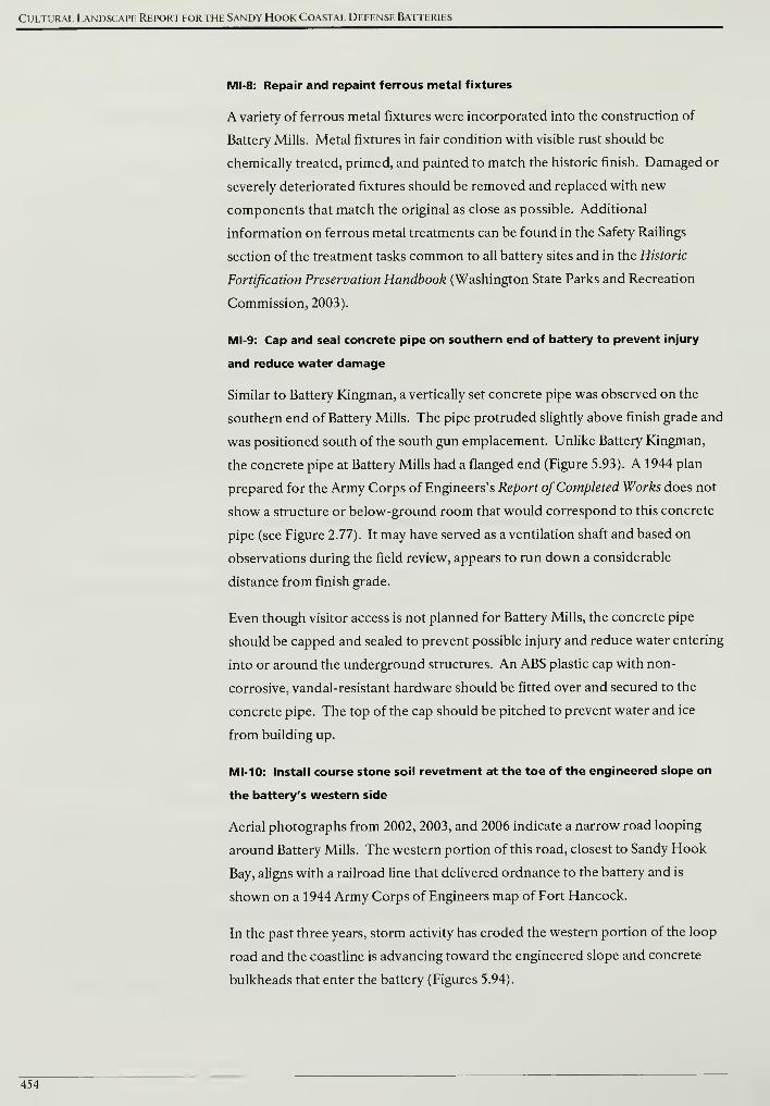
Cultural Landscape Report for the Sandy Hook Coastal Defense Batteries
MI-8: Repair and repaint ferrous metal fixtures
A variety of ferrous metal fixtures were incorporated into the construction of
Battery Mills. Metal fixtures in fair condition with visible rust should be
chemically treated, primed, and painted to match the historic finish. Damaged or
severely deteriorated fixtures should be removed and replaced with new
components that match the original as close as possible. Additional
information on ferrous metal treatments can be found in the Safety Railings
section of the treatment tasks common to all battery sites and in the Historic
Fortification Preservation Handbook (Washington State Parks and Recreation
Commission, 2003).
MI-9: Cap and seal concrete pipe on southern end of battery to prevent injury
and reduce water damage
Similar to Battery Kingman, a vertically set concrete pipe was observed on the
southern end of Battery Mills. The pipe protruded slightly above finish grade and
was positioned south of the south gun emplacement. Unlike Battery Kingman,
the concrete pipe at Battery Mills had a flanged end (Figure 5.93). A 1944 plan
prepared for the Army Corps of Engineers's Report of Completed Works does not
show a structure or below-ground room that would correspond to this concrete
pipe (see Figure 2.77). It may have served as a ventilation shaft and based on
observations during the field review, appears to run down a considerable
distance from finish grade.
Even though visitor access is not planned for Battery Mills, the concrete pipe
should be capped and sealed to prevent possible injury and reduce water entering
into or around the underground structures. An ABS plastic cap with non-
corrosive, vandal-resistant hardware should be fitted over and secured to the
concrete pipe. The top of the cap should be pitched to prevent water and ice
from building up.
MI-10: Install course stone soil revetment at the toe of the engineered slope on
the battery's western side
Aerial photographs from 2002, 2003, and 2006 indicate a narrow road looping
around Battery Mills. The western portion of this road, closest to Sandy Hook
Bay, aligns with a railroad line that delivered ordnance to the battery and is
shown on a 1944 Army Corps of Engineers map of Fort Hancock.
In the past three years, storm activity has eroded the western portion of the loop
road and the coastline is advancing toward the engineered slope and concrete
bulkheads that enter the battery (Figures 5.94).
454
Treatment
To better respond to beach erosion, the park is currently installing and testing a
sand-slurry system that can replenish eroded areas. Current plans are to deposit
sand-slurry from the testing phase of the system on the western edge of Battery
Mills. The addition of the sand-slurry will be helpful, however, to better protect
the concrete structure and historic earthworks of Battery Mills randomly and
loosely placed course stones should be installed at the toe of the battery's slope.
Placed at the toe of the slope, the course stones would be located at a minimum
approximately thirty-five feet from the shore line observed in January 2009
(Drawing 5.10). Since the course stones would be inland from the shore, they
would not interfere with normal tidal actions. The course stones would provide a
needed layer of protection to the concrete structure and historic earthwork in the
event of a major storm event or hurricane. Finally, placed course stones would
be consistent with a component of the battery's historic appearance. A 1950s
photograph indicates stacked stone walls were constructed near one of the
battery's entries (Figure 5.95).
455
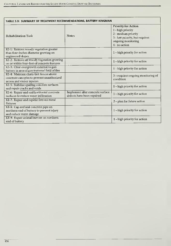
Cultural Landscape Report for the Sandy Hook Coastal Defense Batteries
TABLE 5.9: SUMMARY OF TREATMENT RECOMMENDATIONS, BATTERY KINGMAN
Rehabilitation Task Notes
Priority for Action
1 - high priority
2 - medium priority
3 - low priority, but requires
ongoing monitoring
4 - no action
KI-1: Remove woody vegetation greater
than four-inches diameter growing on
engineered slopes
1 - high priority for action
KI-2: Remove all woody vegetation growing
on or within four-feet of concrete features1 - high priority for action
KI-3: Clear overgrowth external to gun
battery in area of gun traverse/ field of fire1 - high priority for action
KI-4: Maintain chain-link fences above
casemate canopies to prevent unauthorized
access and visitor injuries
3 - requires ongoing monitoring of
condition
KI-5: Stabilize spalling concrete surfaces
and repair cracks and voids1 - high priority for action
KI-6: Repair and seal horizontal concrete
surfaces to reduce water infiltration
Implement after concrete surface
defects have been repaired1 - high priority for action
KI-7: Repair and repaint ferrous metal
fixtures2 - plan for future action
KI-8: Cap and seal concrete pipe on
northern end of battery to prevent injury
and reduce water damage
1 - high priority for action
KI-9: Repair animal burrow on northern
end of battery1 - high priority for action
456
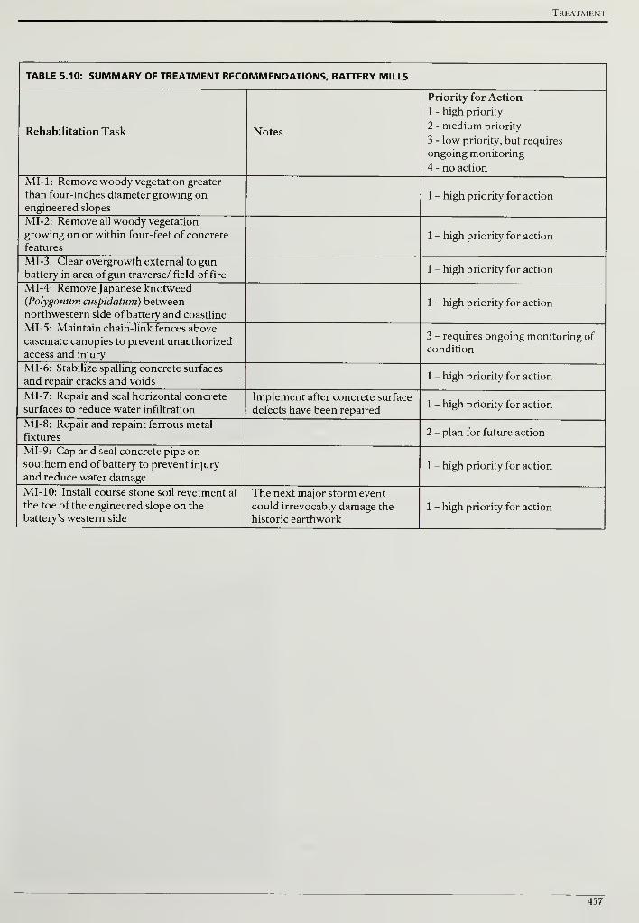
Treatment
TABLE 5.10: SUMMARY OF TREATMENT RECOMMENDATIONS, BATTERY MILLS
Rehabilitation Task Notes
Priority for Action
1 - high priority
2 - medium priority
3 - low priority, but requires
ongoing monitoring
4 - no action
MI-1: Remove woody vegetation greater
than four-inches diameter growing onengineered slopes
1 - high priority for action
MI-2: Remove all woody vegetation
growing on or within four-feet of concrete
features
1 - high priority for action
MI-3: Clear overgrowth external to gunbattery in area ofgun traverse/ field of fire
1 - high priority for action
MI-4: Remove Japanese knotweed(Polygonum cuspidatum) between
northwestern side of battery and coastline
1 - high priority for action
MI-5: Maintain chain-link fences above
casemate canopies to prevent unauthorized
access and injury
3 - requires ongoing monitoring of
condition
MI-6: Stabilize spalling concrete surfaces
and repair cracks and voids1 - high priority for action
MI-7: Repair and seal horizontal concrete
surfaces to reduce water infiltration
Implement after concrete surface
defects have been repaired1 - high priority for action
MI-8: Repair and repaint ferrous metal
fixtures2 - plan for future action
MI-9: Cap and seal concrete pipe onsouthern end of battery to prevent injury
and reduce water damage1 - high priority for action
MI- 10: Install course stone soil revetment at
the toe of the engineered slope on the
battery's western side
The next major storm event
could irrevocably damage the
historic earthwork
1 - high priority for action
457

Cultural Landscape Report for the Sandy Hook Coastal Defense Batteries
458
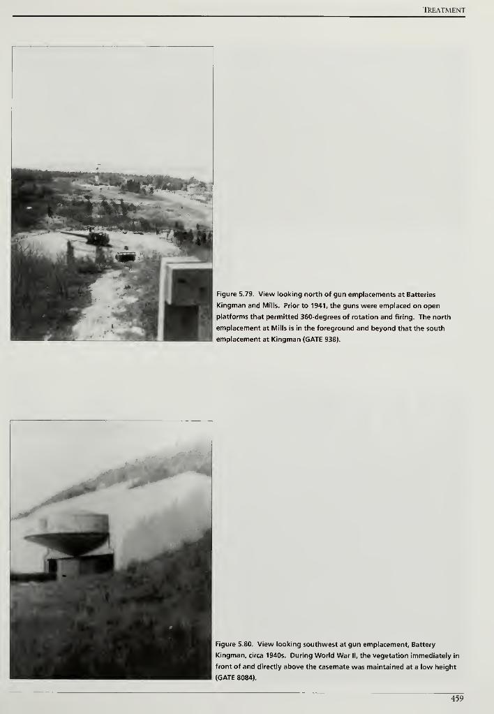
TkEATMENT
Figure 5.79. View looking north of gun emplacements at Batteries
Kingman and Mills. Prior to 1941, the guns were emplaced on open
platforms that permitted 360-degrees of rotation and firing. The north
emplacement at Mills is in the foreground and beyond that the south
emplacement at Kingman (GATE 938).
Figure 5.80. View looking southwest at gun emplacement. Battery
Kingman, circa 1940s. During World War II, the vegetation immediately in
front of and directly above the casemate was maintained at a low height
(GATE 8084).
459
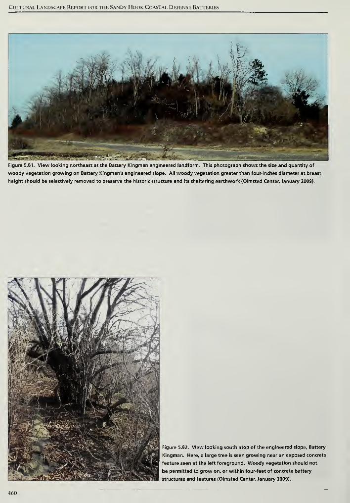
Cultural Landscape Report for the Sandy Hook Coastal Defense Batteries
Figure 5.81. View looking northeast at the Battery Kingman engineered landform. This photograph shows the size and quantity of
woody vegetation growing on Battery Kingman's engineered slope. All woody vegetation greater than four-inches diameter at breast
height should be selectively removed to preserve the historic structure and its sheltering earthwork (Olmsted Center, January 2009).
Figure 5.82. View looking south atop of the engineered slope. Battery
Kingman. Here, a large tree is seen growing near an exposed concrete
feature seen at the left foreground. Woody vegetation should not
be permitted to grow on, or within four-feet of concrete battery
structures and features (Olmsted Center, January 2009).
460
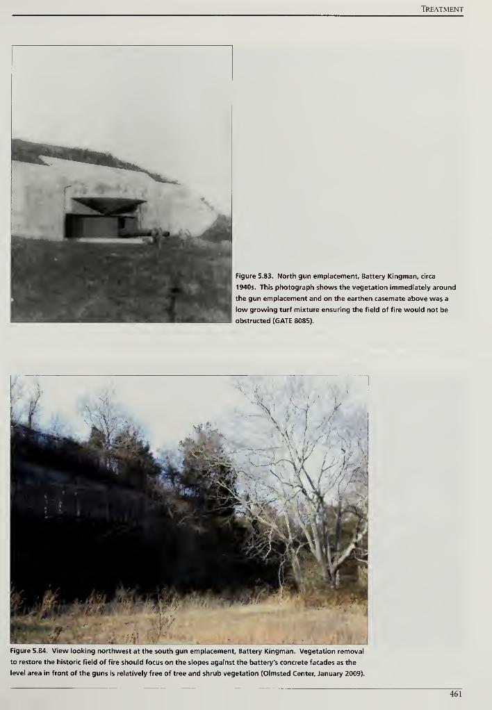
TREATMENT
Figure 5.83. North gun emplacement. Battery Kingman, circa
1940s. This photograph shows the vegetation immediately around
the gun emplacement and on the earthen casemate above was a
low growing turf mixture ensuring the field of fire would not be
obstructed (GATE 8085).
Figure 5.84. View looking northwest at the south gun emplacement. Battery Kingman. Vegetation removal
to restore the historic field of fire should focus on the slopes against the battery's concrete facades as the
level area in front of the guns is relatively free of tree and shrub vegetation (Olmsted Center, January 2009).
461
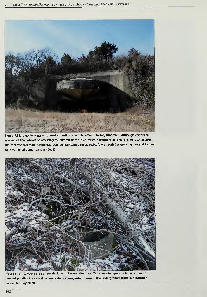
Cultural Landscape Report for the Sandy Hook Coastal Defense Batteries
Figure 5.85. View looking southwest at north gun emplacement. Battery Kingman. Although visitors are
warned of the hazards of accessing the summit of these batteries, existing chain-link fencing located above
the concrete casemate canopies should be maintained for added safety at both Battery Kingman and Battery
Mills (Olmsted Center, January 2009).
Figure 5.86. Concrete pipe on north slope of Battery Kingman. The concrete pipe should be capped to
prevent possible injury and reduce water entering into or around the underground structures (Olmsted
Center, January 2009).
462
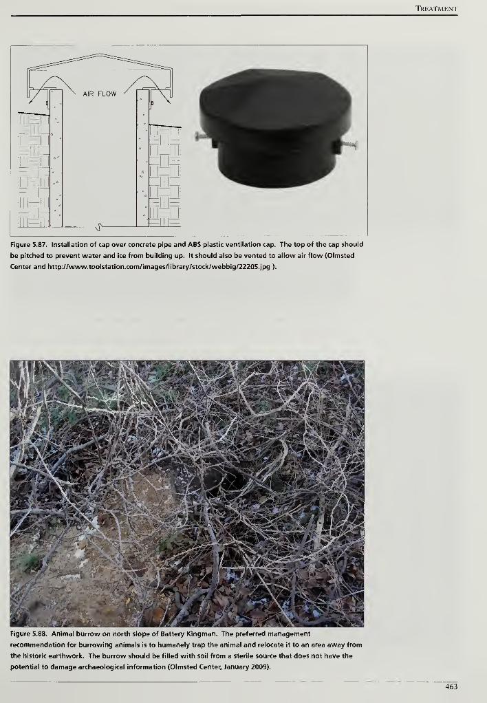
Treatment
Figure 5.87. Installation of cap over concrete pipe and ABS plastic ventilation cap. The top of the cap should
be pitched to prevent water and ice from building up. It should also be vented to allow air flow (Olmsted
Center and http://www.toolstation.com/images/library/stock/webbig/22205.jpg ).
Figure 5.88. Animal burrow on north slope of Battery Kingman. The preferred management
recommendation for burrowing animals is to humanely trap the animal and relocate it to an area away from
the historic earthwork. The burrow should be filled with soil from a sterile source that does not have the
potential to damage archaeological information (Olmsted Center, January 2009).
463
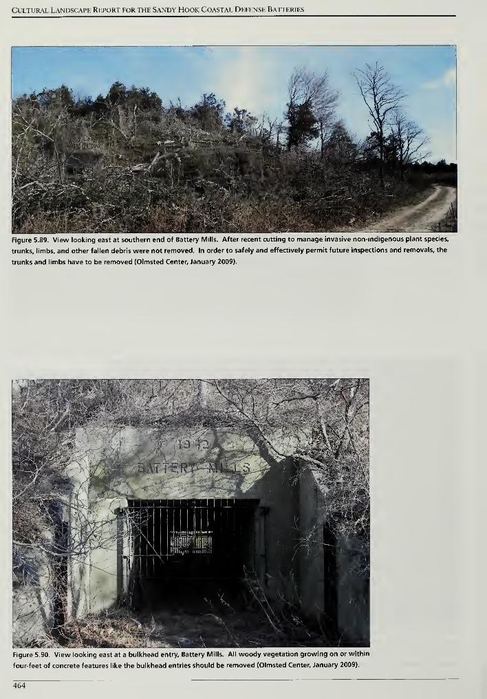
Cultural Landscape Report for the Sandy Hook Coastal Defense Batteries
Figure 5.89. View looking east at southern end of Battery Mills. After recent cutting to manage invasive non-indigenous plant species,
trunks, limbs, and other fallen debris were not removed. In order to safely and effectively permit future inspections and removals, the
trunks and limbs have to be removed (Olmsted Center, January 2009).
Figure 5.90. View looking east at a bulkhead entry. Battery Mills. All woody vegetation growing on or within
four-feet of concrete features like the bulkhead entries should be removed (Olmsted Center, January 2009).
464
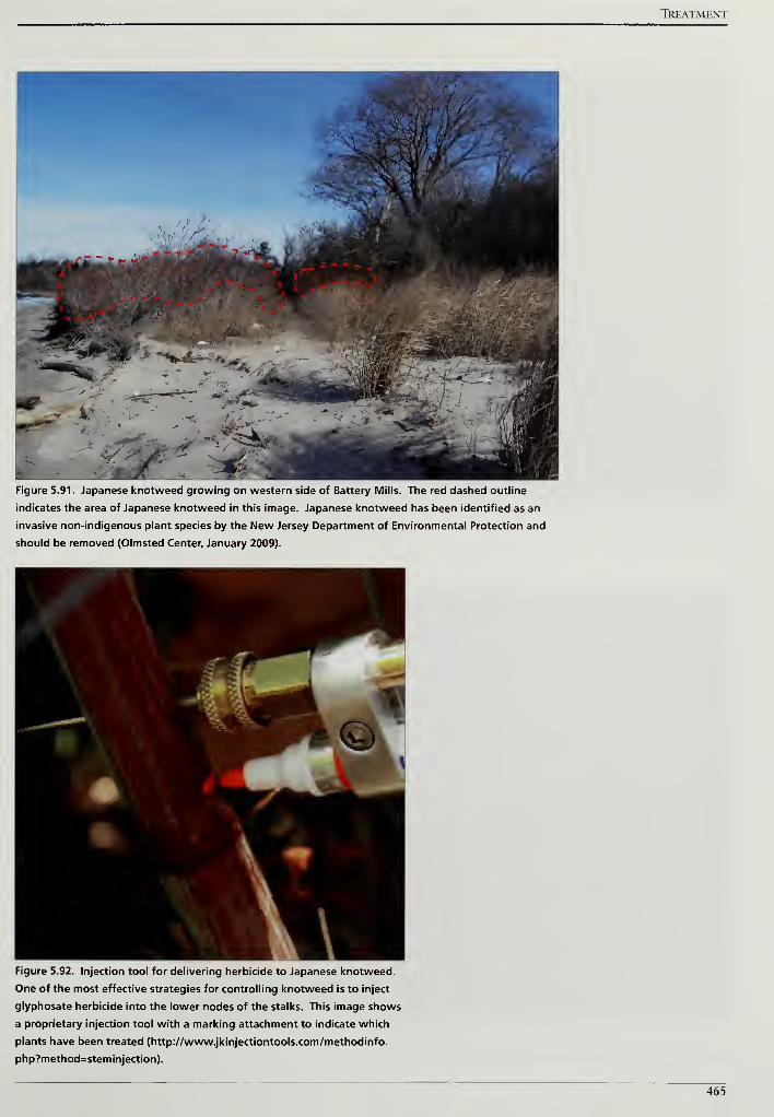
TREATMENT
Figure 5.91. Japanese knotweed growing on western side of Battery Mills. The red dashed outline
indicates the area of Japanese knotweed in this image. Japanese knotweed has been identified as an
invasive non-indigenous plant species by the New Jersey Department of Environmental Protection and
should be removed (Olmsted Center, January 2009).
Figure 5.92. Injection tool for delivering herbicide to Japanese knotweed.
One of the most effective strategies for controlling knotweed is to inject
glyphosate herbicide into the lower nodes of the stalks. This image shows
a proprietary injection tool with a marking attachment to indicate which
plants have been treated (http://www.jkinjectiontools.com/methodinfo.
php?method=stem injection).
465
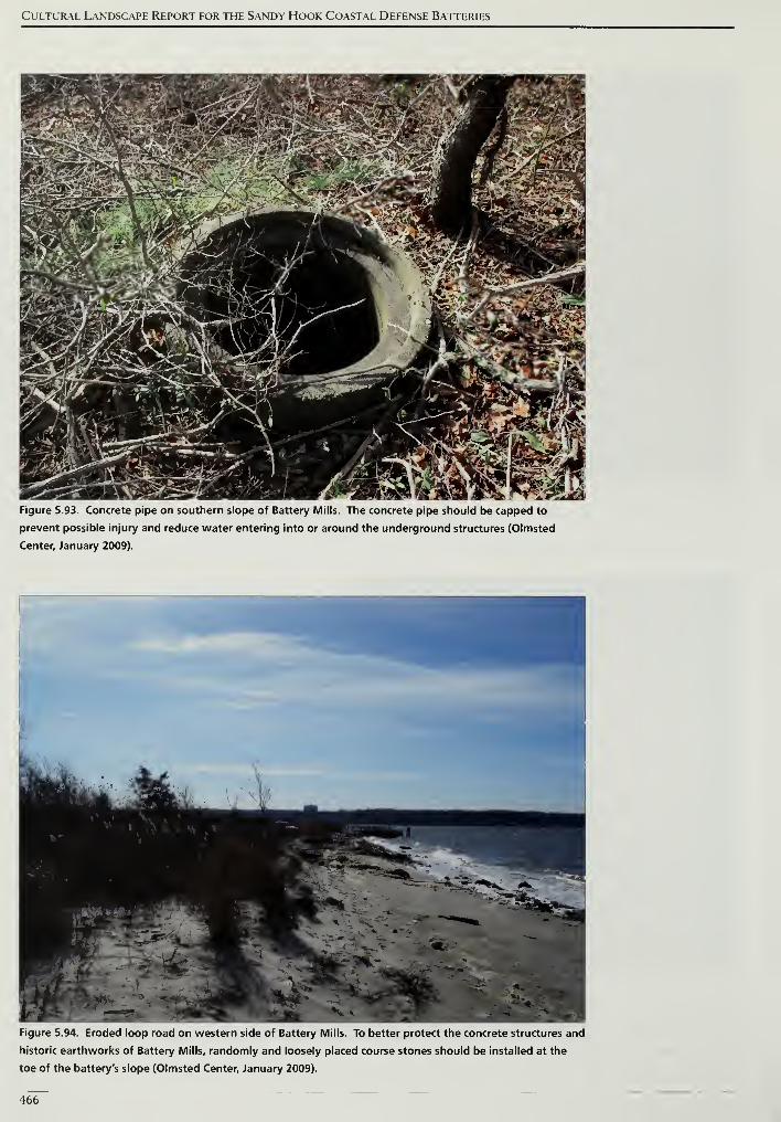
Cultural Landscape Report for the Sandy Hook Coastal Defense Batteries
Figure 5.93. Concrete pipe on southern slope of Battery Mills. The concrete pipe should be capped to
prevent possible injury and reduce water entering into or around the underground structures (Olmsted
Center, January 2009).
Figure 5.94. Eroded loop road on western side of Battery Mills. To better protect the concrete structures and
historic earthworks of Battery Mills, randomly and loosely placed course stones should be installed at the
toe of the battery's slope (Olmsted Center, January 2009).
466
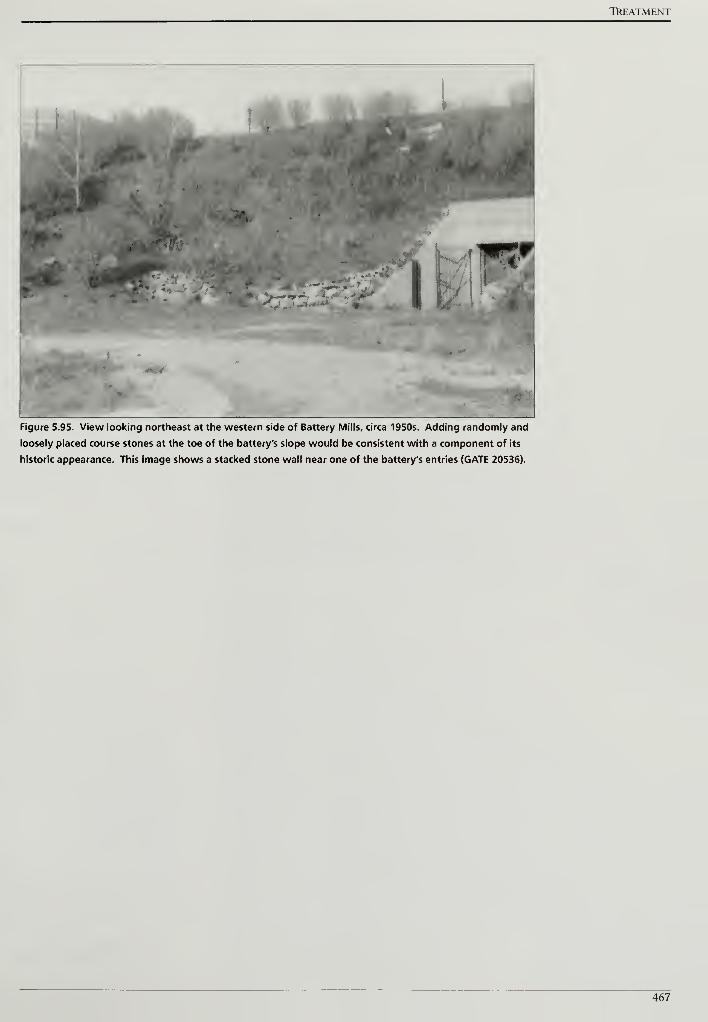
TkEATMENT
Figure 5.95. View looking northeast at the western side of Battery Mills, circa 1950s. Adding randomly and
loosely placed course stones at the toe of the battery's slope would be consistent with a component of its
historic appearance. This image shows a stacked stone wall near one of the battery's entries (GATE 20536).
467

Cultural Landscape Report for the Sandy Hook Coastal Defense Batteries
468
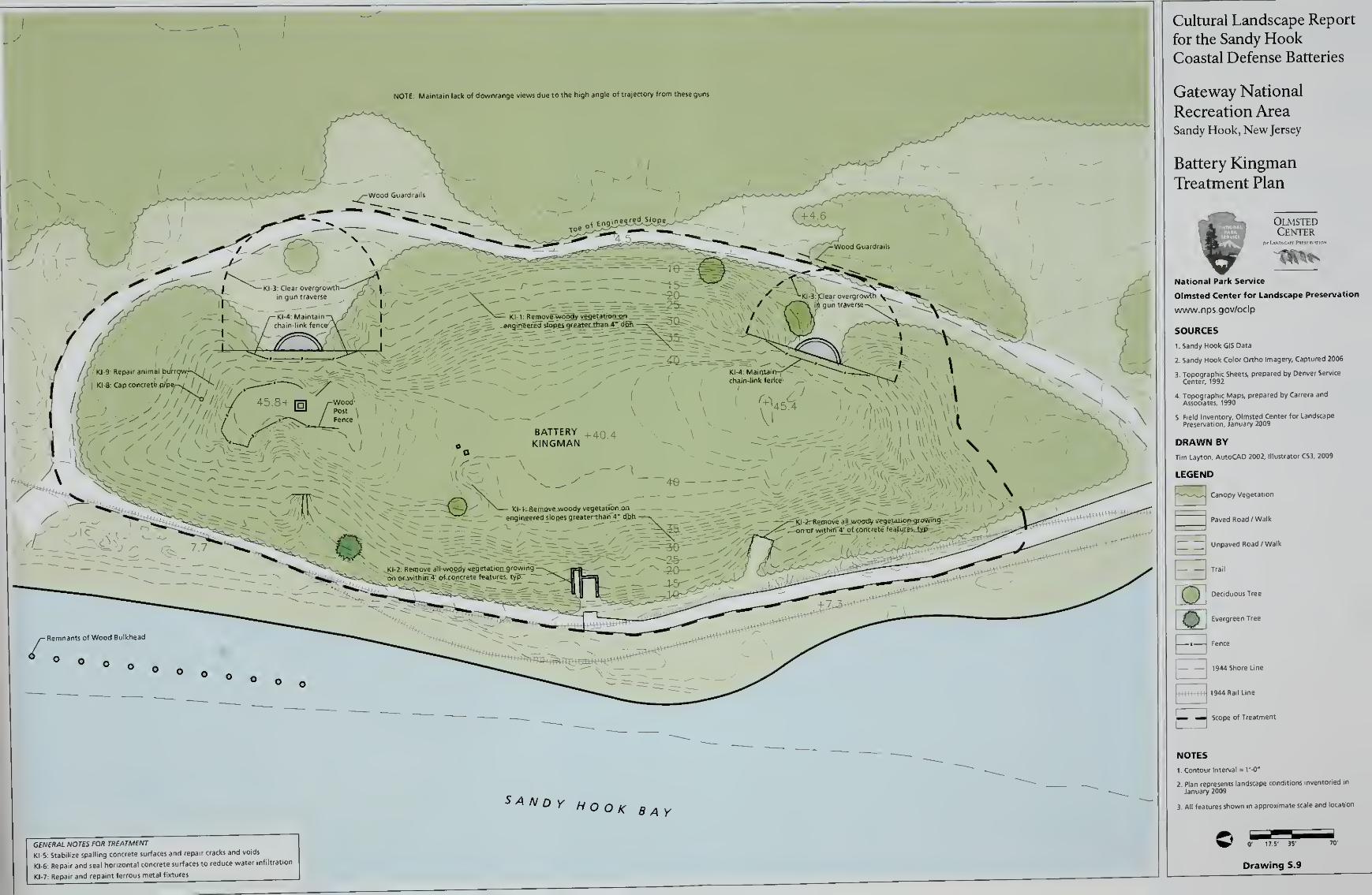
Cultural Landscape Report
for the Sandy HookCoastal Defense Batteries
Gateway National
Recreation AreaSandy Hook, New Jersey
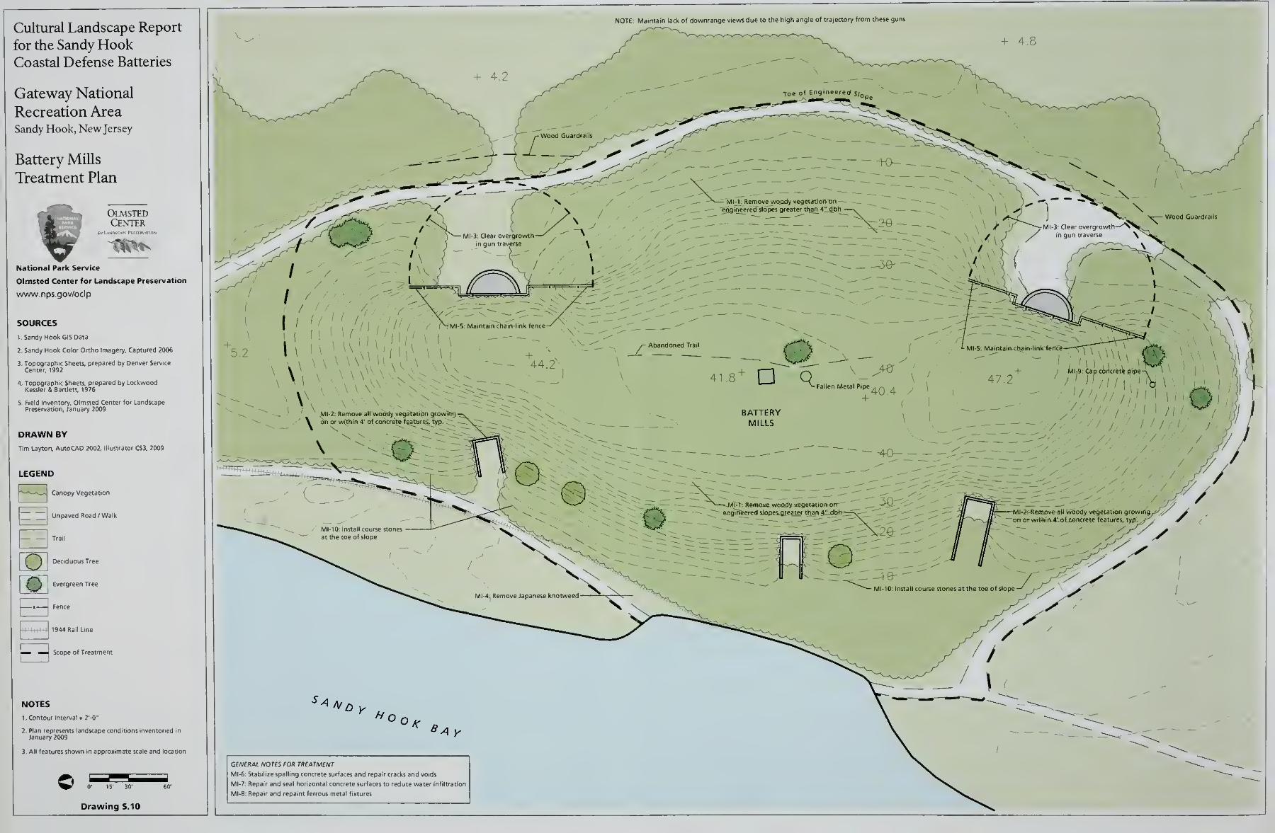
Cultural Landscape Report
for the Sandy HookCoastal Defense Batteries
Gateway National
Recreation AreaSandy Hook, New Jersey
Battery Mills
Treatment Plan
OlmstedCenter
National Park Service
Olmsted Center for Landscape Preservation
www.nps.gov/oclp
SOURCES
1. Sandy Hook GIS Data
2. Sandy Hook Color Ortho Imagery. Captured 2006
DRAWN BY
Tim Layton, AutoCAD 2002, I
LEGEND
p-*—-^_J Canopy Vegetation
~ Unpaved Road /Walk
E3E2
Trail
Deciduous Tree
Evergreen Tree
Fence
1944 Rail Line
^— «J Scope of
NOTES
1 Contour Interval = 2'-0"
3. All features shown In approximate scale and locatio
NOTE. Maintain lack of downrange views due to the high angle of trajectory from these guns
Drawing 5.10
GENERAL NOTES FOR TREATMENT
MI-6: Stabilize spalling concrete surfaces and repair cracks and voids
MI-7: Repair and seal horizontal concrete surfaces to reduce water infiltration
MI-8: Repair and repaint ferrous metal fixtures
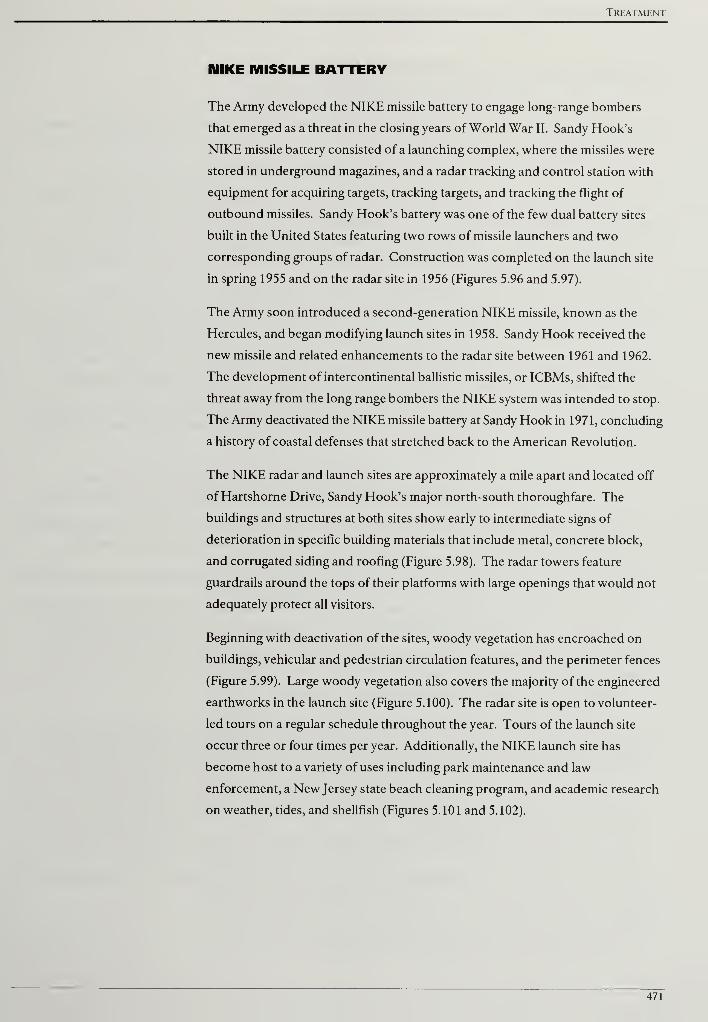
Treatment
NIKE MISSILE BATTERY
The Army developed the NIKE missile battery to engage long-range bombers
that emerged as a threat in the closing years of World War II. Sandy Hook's
NIKE missile battery consisted of a launching complex, where the missiles were
stored in underground magazines, and a radar tracking and control station with
equipment for acquiring targets, tracking targets, and tracking the flight of
outbound missiles. Sandy Hook's battery was one of the few dual battery sites
built in the United States featuring two rows of missile launchers and two
corresponding groups of radar. Construction was completed on the launch site
in spring 1955 and on the radar site in 1956 (Figures 5.96 and 5.97).
The Army soon introduced a second-generation NIKE missile, known as the
Hercules, and began modifying launch sites in 1958. Sandy Hook received the
new missile and related enhancements to the radar site between 1961 and 1962.
The development of intercontinental ballistic missiles, or ICBMs, shifted the
threat away from the long range bombers the NIKE system was intended to stop.
The Army deactivated the NIKE missile battery at Sandy Hook in 1971, concluding
a history of coastal defenses that stretched back to the American Revolution.
The NIKE radar and launch sites are approximately a mile apart and located off
of Hartshorne Drive, Sandy Hook's major north-south thoroughfare. The
buildings and structures at both sites show early to intermediate signs of
deterioration in specific building materials that include metal, concrete block,
and corrugated siding and roofing (Figure 5.98). The radar towers feature
guardrails around the tops of their platforms with large openings that would not
adequately protect all visitors.
Beginning with deactivation of the sites, woody vegetation has encroached on
buildings, vehicular and pedestrian circulation features, and the perimeter fences
(Figure 5.99). Large woody vegetation also covers the majority of the engineered
earthworks in the launch site (Figure 5.100). The radar site is open to volunteer-
led tours on a regular schedule throughout the year. Tours of the launch site
occur three or four times per year. Additionally, the NIKE launch site has
become host to a variety of uses including park maintenance and law
enforcement, a New Jersey state beach cleaning program, and academic research
on weather, tides, and shellfish (Figures 5.101 and 5.102).
471
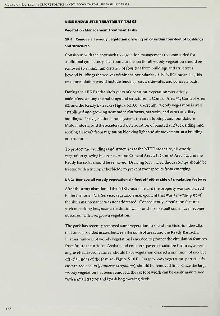
Cultural Landscape Report for the Sandy Hook Coastal Defense Batteries
MIKE RADAR SITE TREATMENT TASKS
Vegetation Management Treatment Tasks
NR-1: Remove all woody vegetation growing on or within four-feet of buildings
and structures
Consistent with the approach to vegetation management recommended for
traditional gun battery sites found to the north, all woody vegetation should be
removed to a minimum distance of four feet from buildings and structures.
Beyond buildings themselves within the boundaries of the NIKE radar site, this
recommendation would include fencing, roads, sidewalks and concrete pads.
During the NIKE radar site's years of operation, vegetation was strictly
maintained among the buildings and structures in Control Area #1, Control Area
#2, and the Ready Barracks (Figure 5.103). Currently, woody vegetation is well
established and growing near radar platforms, barracks, and other auxiliary
buildings. The vegetation's root systems threaten footings and foundations.
Mold, mildew, and the accelerated deterioration of painted surfaces, siding, and
roofing all result from vegetation blocking light and air movement at a building
or structure.
To protect the buildings and structures at the NIKE radar site, all woody
vegetation growing in a zone around Control Area #1, Control Area #2, and the
Ready Barracks should be removed (Drawing 5.11). Deciduous stumps should be
treated with a triclopyr herbicide to prevent root sprouts from emerging.
NR-2: Remove all woody vegetation six-feet off either side of circulation features
After the army abandoned the NIKE radar site and the property was transferred
to the National Park Service, vegetation management that was a routine part of
the site's maintenance was not addressed. Consequently, circulation features
such as parking lots, access roads, sidewalks and a basketball court have become
obscured with overgrown vegetation.
The park has recently removed some vegetation to reveal the historic sidewalks
that once provided access between the control areas and the Ready Barracks.
Further removal of woody vegetation is needed to protect the circulation features
from future incursions. Asphalt and concrete-paved circulation features, as well
as gravel-surfaced features, should have vegetation cleared a minimum of six-feet
off of all sides of the feature (Figure 5.104). Large woody vegetation, particularly
eastern red cedars (Juniperus virginiana), should be removed first. Once the large
woody vegetation has been removed, the six foot width can be easily maintained
with a small tractor and brush hog mowing deck.
472
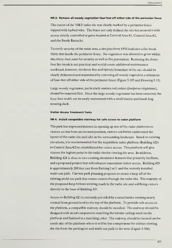
Treatment
NR-3: Remove all woody vegetation four-feet off either side of the perimeter fence
The extent of the NIKE radar site was clearly marked by a perimeter fence
topped with barbed wire. The fence not only defined the site but secured it with
access strictly controlled at gates located at Control Area #1, Control Area #2,
and the Ready Barracks.
To verify security of the radar area, a site plan from 1954 indicates a fire break
thirty-feet inside the perimeter fence. No vegetation was allowed to grow within
this thirty-foot zone for security as well as fire prevention. Restoring the thirty-
foot fire break is not practical and would create additional maintenance
workload, however, the fence line and historic boundary of the site should be
clearly delineated and maintained by removing all woody vegetation a minimum
of four-feet off either side of the perimeter fence (Figure 5.105 and Drawing 5.11).
Large woody vegetation, particularly eastern red cedars (Juniperus virginiana),
should be removed first. Once the large woody vegetation has been removed, the
four-foot width can be easily maintained with a small tractor and brush hog
mowing deck.
Visitor Access Treatment Tasks
NR-4: Install compatible stairway for safe access to radar platform
The park has expressed interest in opening up one of the radar platforms to
visitors so that from an elevated position, visitors can better understand the
layout of the radar site and take in the surrounding landscape. Based on existing
elevations, it is recommended that the acquisition radar platform (Building 421)
in Control Area #2 be rehabilitated for visitor access. This platform will give
visitors the highest point in the radar site for viewing the area. In addition,
Building 421 is close to two existing circulation features that presently facilitate,
and a proposed project that will enhance convenient visitor access. Building 421
is approximately 200 feet east from Parking Lot L and the recently installed
multi-use path. Current park planning proposes to create a loop off of the
existing multi-use path that routes visitors through the radar site. The majority of
the proposed loop follows existing roads in the radar site and will bring visitors
directly to the base of Building 42 1
.
Access to Building 421 is currently provided by a metal ladder running nearly
vertical from ground level to the top of the platform. To provide safe access to
the platform, a compatible stairway should be installed. The stairway should be
designed with metal components matching the tubular railings used on the
platform and finished in a matching color. The stairway should be located on the
north side of the platform where it will be less conspicuous for visitors viewing
the site from the parking lot and multi-use path to the west (Figure 5.106).
473
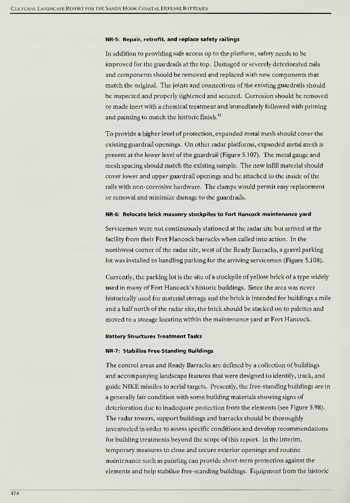
Cultural Landscape Report for the Sandy Hook Coastal Defense Batteries
NR-5: Repair, retrofit, and replace safety railings
In addition to providing safe access up to the platform, safety needs to be
improved for the guardrails at the top. Damaged or severely deteriorated rails
and components should be removed and replaced with new components that
match the original. The joints and connections of the existing guardrails should
be inspected and properly tightened and secured. Corrosion should be removed
or made inert with a chemical treatment and immediately followed with priming
and painting to match the historic finish.41
To provide a higher level of protection, expanded metal mesh should cover the
existing guardrail openings. On other radar platforms, expanded metal mesh is
present at the lower level of the guardrail (Figure 5.107). The metal gauge and
mesh spacing should match the existing sample. The new infill material should
cover lower and upper guardrail openings and be attached to the inside of the
rails with non-corrosive hardware. The clamps would permit easy replacement
or removal and minimize damage to the guardrails.
NR-6: Relocate brick masonry stockpiles to Fort Hancock maintenance yard
Servicemen were not continuously stationed at the radar site but arrived at the
facility from their Fort Hancock barracks when called into action. In the
northwest corner of the radar site, west of the Ready Barracks, a gravel parking
lot was installed to handling parking for the arriving servicemen (Figure 5.108).
Currently, the parking lot is the site of a stockpile of yellow brick of a type widely
used in many of Fort Hancock's historic buildings. Since the area was never
historically used for material storage and the brick is intended for buildings a mile
and a half north of the radar site, the brick should be stacked on to palettes and
moved to a storage location within the maintenance yard at Fort Hancock.
Battery Structures Treatment Tasks
NR-7: Stabilize Free-Standing Buildings
The control areas and Ready Barracks are defined by a collection of buildings
and accompanying landscape features that were designed to identify, track, and
guide NIKE missiles to aerial targets. Presently, the free-standing buildings are in
a generally fair condition with some building materials showing signs of
deterioration due to inadequate protection from the elements (see Figure 5.98).
The radar towers, support buildings and barracks should be thoroughly
inventoried in order to assess specific conditions and develop recommendations
for building treatments beyond the scope of this report. In the interim,
temporary measures to close and secure exterior openings and routine
maintenance such as painting can provide short-term protection against the
elements and help stabilize free-standing buildings. Equipment from the historic
474
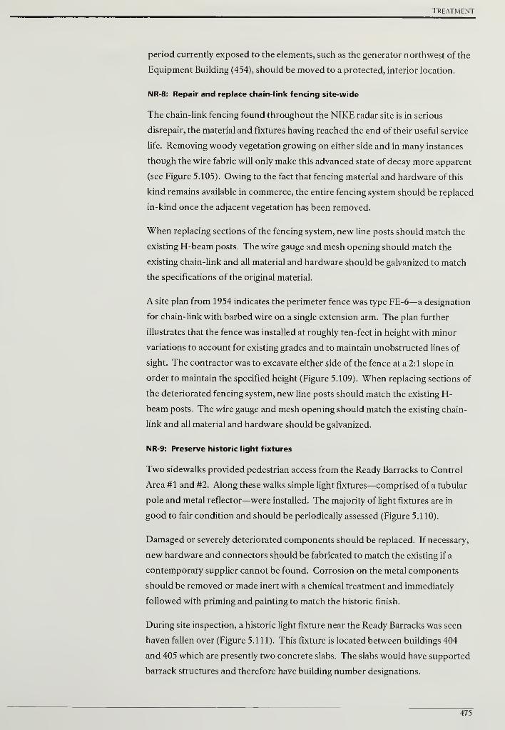
Treatment
period currently exposed to the elements, such as the generator northwest of the
Equipment Building (454), should be moved to a protected, interior location.
NR-8: Repair and replace chain-link fencing site-wide
The chain-link fencing found throughout the NIKE radar site is in serious
disrepair, the material and fixtures having reached the end of their useful service
life. Removing woody vegetation growing on either side and in many instances
though the wire fabric will only make this advanced state of decay more apparent
(see Figure 5.105). Owing to the fact that fencing material and hardware of this
kind remains available in commerce, the entire fencing system should be replaced
in-kind once the adjacent vegetation has been removed.
When replacing sections of the fencing system, new line posts should match the
existing H-beam posts. The wire gauge and mesh opening should match the
existing chain-link and all material and hardware should be galvanized to match
the specifications of the original material.
A site plan from 1954 indicates the perimeter fence was type FE-6—a designation
for chain-link with barbed wire on a single extension arm. The plan further
illustrates that the fence was installed at roughly ten-feet in height with minor
variations to account for existing grades and to maintain unobstructed lines of
sight. The contractor was to excavate either side of the fence at a 2:1 slope in
order to maintain the specified height (Figure 5.109). When replacing sections of
the deteriorated fencing system, new line posts should match the existing H-
beam posts. The wire gauge and mesh opening should match the existing chain-
link and all material and hardware should be galvanized.
NR-9: Preserve historic light fixtures
Two sidewalks provided pedestrian access from the Ready Barracks to Control
Area #1 and #2. Along these walks simple light fixtures—comprised of a tubular
pole and metal reflector—were installed. The majority of light fixtures are in
good to fair condition and should be periodically assessed (Figure 5.110).
Damaged or severely deteriorated components should be replaced. If necessary,
new hardware and connectors should be fabricated to match the existing if a
contemporary supplier cannot be found. Corrosion on the metal components
should be removed or made inert with a chemical treatment and immediately
followed with priming and painting to match the historic finish.
During site inspection, a historic light fixture near the Ready Barracks was seen
haven fallen over (Figure 5.111). This fixture is located between buildings 404
and 405 which are presently two concrete slabs. The slabs would have supported
barrack structures and therefore have building number designations.
475

Cultural Landscape Report for the Sandy Hook Coastal Defense Batteries
The light fixture should be reset and will most likely require a new concrete
footing to accomplish this task. Due to snowy conditions, it was difficult to
determine at what point the fixture failed and fell over. Resetting the fixture may
require a new tubular pole with adequate length to extend into the footing below
ground. The new pole should match the existing in material, dimensions, and
finishing. The fixture's other components should be inspected at this time and
repaired or replaced based on their condition.
476
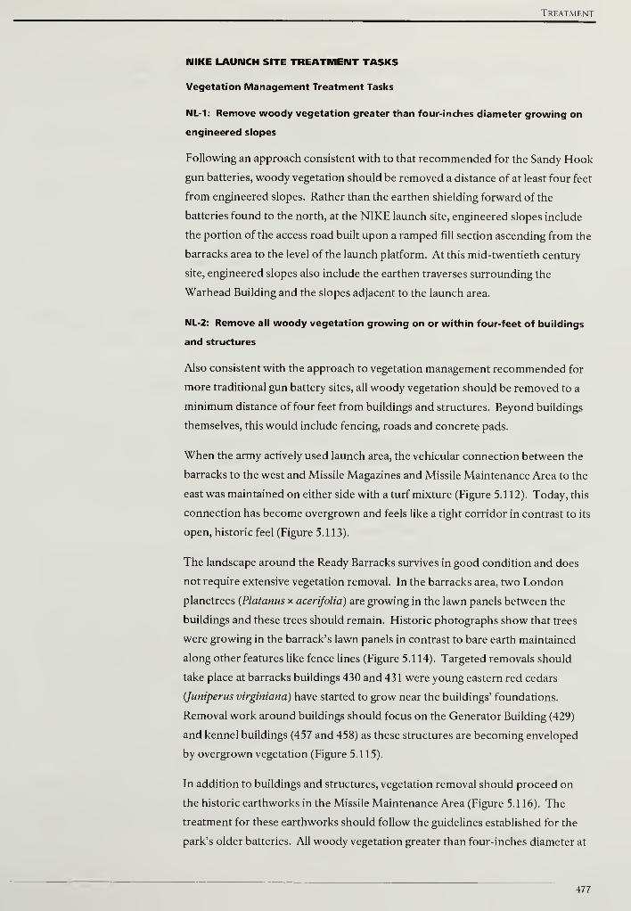
Treatment
MIKE LAUNCH SITE TREATMENT TASKS
Vegetation Management Treatment Tasks
NL-1: Remove woody vegetation greater than four-inches diameter growing on
engineered slopes
Following an approach consistent with to that recommended for the Sandy Hook
gun batteries, woody vegetation should be removed a distance of at least four feet
from engineered slopes. Rather than the earthen shielding forward of the
batteries found to the north, at the NIKE launch site, engineered slopes include
the portion of the access road built upon a ramped fill section ascending from the
barracks area to the level of the launch platform. At this mid-twentieth century
site, engineered slopes also include the earthen traverses surrounding the
Warhead Building and the slopes adjacent to the launch area.
NL-2: Remove all woody vegetation growing on or within four-feet of buildings
and structures
Also consistent with the approach to vegetation management recommended for
more traditional gun battery sites, all woody vegetation should be removed to a
minimum distance of four feet from buildings and structures. Beyond buildings
themselves, this would include fencing, roads and concrete pads.
When the army actively used launch area, the vehicular connection between the
barracks to the west and Missile Magazines and Missile Maintenance Area to the
east was maintained on either side with a turf mixture (Figure 5.112). Today, this
connection has become overgrown and feels like a tight corridor in contrast to its
open, historic feel (Figure 5.113).
The landscape around the Ready Barracks survives in good condition and does
not require extensive vegetation removal. In the barracks area, two London
planetrees (Platanus x acerifolia) are growing in the lawn panels between the
buildings and these trees should remain. Historic photographs show that trees
were growing in the barrack's lawn panels in contrast to bare earth maintained
along other features like fence lines (Figure 5.114). Targeted removals should
take place at barracks buildings 430 and 431 were young eastern red cedars
(Juniperus virginiana) have started to grow near the buildings' foundations.
Removal work around buildings should focus on the Generator Building (429)
and kennel buildings (457 and 458) as these structures are becoming enveloped
by overgrown vegetation (Figure 5.115).
In addition to buildings and structures, vegetation removal should proceed on
the historic earthworks in the Missile Maintenance Area (Figure 5.116). The
treatment for these earthworks should follow the guidelines established for the
park's older batteries. All woody vegetation greater than four-inches diameter at
477
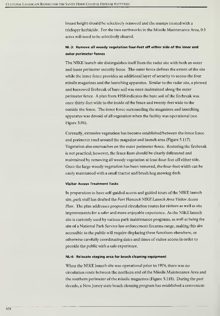
Cultural Landscape Report for the Sandy Hook Coastal Defense Batteries
breast height should be selectively removed and the stumps treated with a
triclopyr herbicide. For the two earthworks in the Missile Maintenance Area, 0.5
acres will need to be selectively cleared.
NL-3: Remove all woody vegetation four-feet off either side of the inner and
outer perimeter fences
The NIKE launch site distinguishes itself from the radar site with both an outer
and inner perimeter security fence. The outer fence defines the extent of the site
while the inner fence provides an additional layer of security to access the four
missile magazines and the launching apparatus. Similar to the radar site, a plowed
and harrowed firebreak of bare soil was once maintained along the outer
perimeter fence. A plan from 1958 indicates the bare soil of the firebreak was
once thirty-feet wide to the inside of the fence and twenty-feet wide to the
outside the fence. The inner fence surrounding the magazines and launching
apparatus was devoid of all vegetation when the facility was operational (see
Figure 5.96).
Currently, extensive vegetation has become established between the inner fence
and perimeter road around the magazine and launch area (Figure 5.117).
Vegetation also encroaches on the outer perimeter fence. Restoring the firebreak
is not practical; however, the fence lines should be clearly delineated and
maintained by removing all woody vegetation at least four-feet off either side.
Once the large woody vegetation has been removed, the four-foot width can be
easily maintained with a small tractor and brush hog mowing deck.
Visitor Access Treatment Tasks
In preparation to have self-guided access and guided tours of the NIKE launch
site, park staff has drafted the Fort Hancock NIKE Launch Area Visitor Access
Plan. The plan addresses proposed circulation routes for visitors as well as site
improvements for a safer and more enjoyable experience. As the NIKE launch
site is currently used by various park maintenance programs, as well as being the
site of a National Park Service law enforcement firearms range, making this site
accessible to the public will require displacing these functions elsewhere, or
otherwise carefully coordinating dates and times of visitor access in order to
provide the public with a safe experience.
NL-4: Relocate staging area for beach cleaning equipment
When the NIKE launch site was operational prior to 1974, there was no
circulation route between the northern end of the Missile Maintenance Area and
the southern perimeter of the missile magazines (Figure 5.118). During the past
decade, a New Jersey state beach cleaning program has established a convenient
478
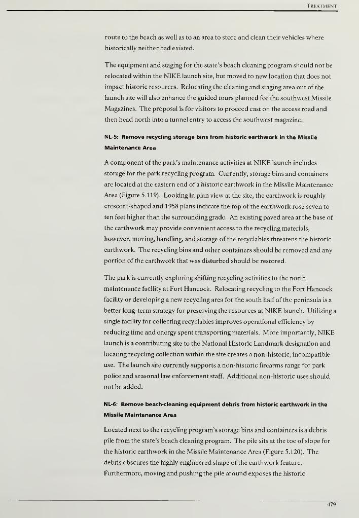
Treatment
route to the beach as well as to an area to store and clean their vehicles where
historically neither had existed.
The equipment and staging for the state's beach cleaning program should not be
relocated within the NIKE launch site, but moved to new location that does not
impact historic resources. Relocating the cleaning and staging area out of the
launch site will also enhance the guided tours planned for the southwest Missile
Magazines. The proposal is for visitors to proceed east on the access road and
then head north into a tunnel entry to access the southwest magazine.
NL-5: Remove recycling storage bins from historic earthwork in the Missile
Maintenance Area
A component of the park's maintenance activities at NIKE launch includes
storage for the park recycling program. Currently, storage bins and containers
are located at the eastern end of a historic earthwork in the Missile Maintenance
Area (Figure 5.119). Looking in plan view at the site, the earthwork is roughly
crescent-shaped and 1958 plans indicate the top of the earthwork rose seven to
ten feet higher than the surrounding grade. An existing paved area at the base of
the earthwork may provide convenient access to the recycling materials,
however, moving, handling, and storage of the recyclables threatens the historic
earthwork. The recycling bins and other containers should be removed and any
portion of the earthwork that was disturbed should be restored.
The park is currently exploring shifting recycling activities to the north
maintenance facility at Fort Hancock. Relocating recycling to the Fort Hancock
facility or developing a new recycling area for the south half of the peninsula is a
better long-term strategy for preserving the resources at NIKE launch. Utilizing a
single facility for collecting recyclables improves operational efficiency by
reducing time and energy spent transporting materials. More importantly, NIKE
launch is a contributing site to the National Historic Landmark designation and
locating recycling collection within the site creates a non-historic, incompatible
use. The launch site currently supports a non-historic firearms range for park
police and seasonal law enforcement staff. Additional non-historic uses should
not be added.
NL-6: Remove beach-cleaning equipment debris from historic earthwork in the
Missile Maintenance Area
Located next to the recycling program's storage bins and containers is a debris
pile from the state's beach cleaning program. The pile sits at the toe of slope for
the historic earthwork in the Missile Maintenance Area (Figure 5.120). The
debris obscures the highly engineered shape of the earthwork feature.
Furthermore, moving and pushing the pile around exposes the historic
479
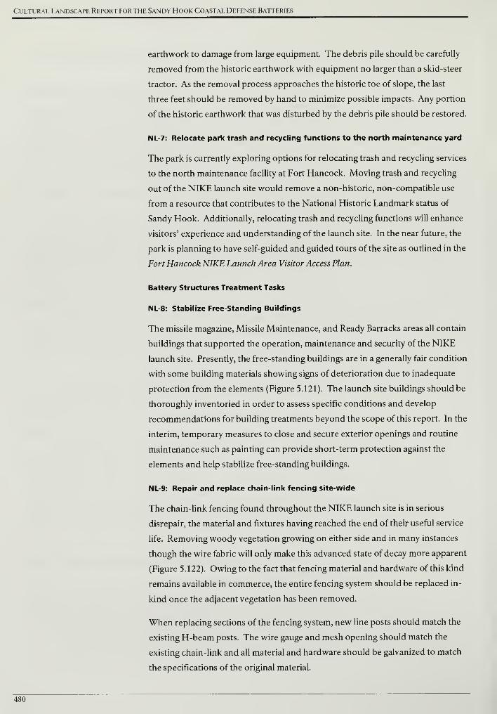
Cultural Landscape Report for the Sandy Hook Coastal Defense Batteries
earthwork to damage from large equipment. The debris pile should be carefully
removed from the historic earthwork with equipment no larger than a skid-steer
tractor. As the removal process approaches the historic toe of slope, the last
three feet should be removed by hand to minimize possible impacts. Any portion
of the historic earthwork that was disturbed by the debris pile should be restored.
NL-7: Relocate park trash and recycling functions to the north maintenance yard
The park is currently exploring options for relocating trash and recycling services
to the north maintenance facility at Fort Hancock. Moving trash and recycling
out of the NIKE launch site would remove a non-historic, non-compatible use
from a resource that contributes to the National Historic Landmark status of
Sandy Hook. Additionally, relocating trash and recycling functions will enhance
visitors' experience and understanding of the launch site. In the near future, the
park is planning to have self-guided and guided tours of the site as outlined in the
Fort Hancock NIKE Launch Area Visitor Access Plan.
Battery Structures Treatment Tasks
NL-8: Stabilize Free-Standing Buildings
The missile magazine, Missile Maintenance, and Ready Barracks areas all contain
buildings that supported the operation, maintenance and security of the NIKE
launch site. Presently, the free-standing buildings are in a generally fair condition
with some building materials showing signs of deterioration due to inadequate
protection from the elements (Figure 5.121). The launch site buildings should be
thoroughly inventoried in order to assess specific conditions and develop
recommendations for building treatments beyond the scope of this report. In the
interim, temporary measures to close and secure exterior openings and routine
maintenance such as painting can provide short-term protection against the
elements and help stabilize free-standing buildings.
NL-9: Repair and replace chain-link fencing site-wide
The chain-link fencing found throughout the NIKE launch site is in serious
disrepair, the material and fixtures having reached the end of their useful service
life. Removing woody vegetation growing on either side and in many instances
though the wire fabric will only make this advanced state of decay more apparent
(Figure 5.122). Owing to the fact that fencing material and hardware of this kind
remains available in commerce, the entire fencing system should be replaced in-
kind once the adjacent vegetation has been removed.
When replacing sections of the fencing system, new line posts should match the
existing H-beam posts. The wire gauge and mesh opening should match the
existing chain-link and all material and hardware should be galvanized to match
the specifications of the original material.
480
Treatment
NL-10: Repair, maintain, and replace missing historic light fixtures
Floodlight and spotlight fixtures at the NIKE launch site are character-defining
features of this Cold War defense installation. Each floodlight fixture is comprised
of a twenty-four inch diameter light housing attached to a metal bracket and
mounted to a pole (Figure 5.123). At the Missile Magazines, the lights are
mounted on wood poles and at the Missile Maintenance Area they are mounted
on metal poles. Within the Missile Magazine area, four spotlights were erected
by the end of the historic period. From ground level, the first eight to ten feet of
the poles were painted yellow and a red letter was added to the yellow field to
denote the magazine section. Spotlights were mounted at the top of each pole.
Three of the poles were removed following transfer to the National Park Service
and presently, only the pole and lights at the Section B magazine (427) are extant.
Each extant light fixture should be routinely inspected to make sure the pole is
vertically plumb and the material is sound. Poles should be reset to a vertical
position and if the pole is damaged, severely deteriorated, or missing, it should be
replaced to match the historic material and finish. The mounting hardware and
light fixtures should be treated for corrosion, primed, and painted to match the
historic finish. The glass lens on the fixture should be replaced to match the
existing if it is cracked or broken. The lights were historically either mounted
horizontally or angled slightly downward. If the hardware has loosened and the
fixtures aim straight down, these should be reset to a horizontal position and
securely fastened (see Drawing 5.12 for locations).
NL-11: Provide handicap accessible parking and improve visitor parking lot off of
Hartshorne Drive
One of the items in the Fort Hancock NIKE Launch Area Visitor Access Plan
indicates new handicap accessible parking inside the launch site near the Ready
Barracks. Instead of creating separate locations for handicap and standard
parking, both can be provided in the same location with a reconfiguration of the
existing visitor lot off of Hartshorne Drive (Figure 5.124).
The lot currently has two bays of parking stalls and a resulting central aisle that is
too narrow for parked cars backing up. The proposed reconfiguration would
place the stalls near the Hartshorne Drive side with a five-foot raised, curbed
buffer between the two. Without expanding the existing lot, the aisle behind the
new stalls would be wide enough for two-way traffic and cars backing up. Two
center stalls would be designated handicap accessible and share a van accessible
walkway between them.
481
Cultural Landscape Report for the Sandy Hook Coastal Defense Batteries
NL 12: Install pedestrian crosswalk and signage from visitor parking lot to site
via the multi-use path
In addition to providing handicap accessible parking at the current NIKE launch
area visitor parking lot, a modest reconfiguration of the existing parking lot
would include adding a pedestrian crosswalk from the lot to the multi-use path
on the other side of Hartshorne Drive. New Jersey Department of
Transportation required signage would also be installed with the crosswalk (see
Figure 5.124).
The crosswalk would align with the van accessible walkway in the lot and all
visitors would share the circulation system from the lot to the launch site. The
crosswalk would be located away from intersections to minimize pedestrian and
vehicular conflicts. Once across Hartshorne Drive, visitors would move along
the existing multi-use path and follow the path to the gated access at the launch
site. This would allow visitors to enter at the same point where servicemen once
arrived when the site was on alert.
NL-13: Reconstruct the sentry hut near missile magazines
A component of the Fort Hancock NIKE Launch Area Visitor Access Plan calls for
reconstructing the missing sentry hut near the missile magazine area. An
existing sentry hut survives near the access gate off of Hartshorne Drive. Its
missing companion historically guarded access at a second security point and
should be reconstructed over a surviving foundation near the missile magazine
area (Figure 5.125).
NL-14: Construct access tunnel to southwest missile magazine
One of the more ambitious goals of providing visitor access to the NIKE launch
site is a proposal to offer guided tours of the southwest underground missile
magazine and show the below ground area where NIKE missiles were stored and
raised into a firing position. In order to provide underground access, a tunnel
must be designed and constructed to connect the access road to the south with
the magazine. Visitors would proceed east on the access road and then turn
north into a tunnel entrance providing access the below-grade missile magazine.
Large corrugated metal tubing has been used at the Minute Man National
Historical Park to make possible a continuous pedestrian trail below a busy
commuter route (Figure 5.126).
In terms of visitor access, the Ready Barracks, immediately adjacent to
Hartshorne Drive, could be readily opened to self-guided tours as indicated in
the Fort Hancock NIKE Launch Area Visitor Access Plan. There is an existing
fence and gate between the Ready Barracks and access road to the missile
482

Treatment
magazines that makes the barracks self-contained and allows for self-guided
tours to just outside launch area enclosure. Limiting access to the tunnel and the
underground magazine would require that doors be installed on the entrance to
the tunnel.
NL-15: Stabilize spading concrete surfaces and repair cracks and voids
The concrete pads for the former launchers and racks exhibit spalling areas and
cracks resulting from water infiltration and freeze-thaw cycles. In order to limit
further damage to the concrete, spalling surfaces should be removed,
mechanically cleaned, and patched to match the character of the historic material.
Small cracks should be dried and prepared to receive a sealant that is compatible
with the character of the historic concrete. The treatment of large, structural
cracks should be determined by a structural engineer. Additional information
addressing the repair of spalling areas and cracks can be found in the treatment
tasks common to all battery sites and in the Historic Fortification Preservation
Handbook (Washington State Parks and Recreation Commission, 2003).
NL-16: Repair and seal horizontal concrete surfaces to reduce water infiltration
In order to reduce water infiltration and to protect the concrete pads at the
missile magazines, a surface coating should be applied to the horizontal surfaces.
Application of a surface coating must occur after spalling and cracked concrete
surfaces are repaired and defected surfaces that collect and pool rainwater are
corrected. Additional information penetrating sealers and surface sealers can be
found in the treatment tasks common to all battery sites. At the NIKE launch
site, approximately 31,000 square feet of concrete should be sealed.
NL-17: Repair and repaint ferrous metal fixtures and surfaces
A variety of ferrous metal fixtures were incorporated into the construction of the
NIKE launch site. Metal fixtures in fair condition with visible rust should be
chemically treated, primed, and painted to match the historic finish. Damaged or
severely deteriorated fixtures should be removed and replaced with new
components that match the original as close as possible. Additional
information on ferrous metal treatments can be found in the Safety Railings
section of the treatment tasks common to all battery sites and in the Historic
Fortification Preservation Handbook (Washington State Parks and Recreation
Commission, 2003).
483
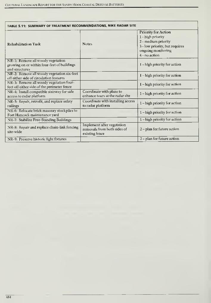
Cultural Landscape Report for the Sandy Hook Coastal Defense Batteries
TABLE 5.11: SUMMARY OF TREATMENT RECOMMENDATIONS, NIKE RADAR SITE
Rehabilitation Task Notes
Priority for Action
1 - high priority
2 - medium priority
3 - low priority, but requires
ongoing monitoring
4 - no action
NR-1: Remove all woody vegetation
growing on or within four-feet of buildings
and structures
1 - high priority for action
NR-2: Remove all woody vegetation six-feet
off either side of circulation features1 - high priority for action
NR-3: Remove all woody vegetation four-
feet off either side of the perimeter fence1 - high priority for action
NR-4: Install compatible stairway for safe
access to radar platform
Coordinate with plans to
enhance tours at the radar site1 - high priority for action
NR-5: Repair, retrofit, and replace safety
railings
Coordinate with installing access
to radar platform1 - high priority for action
NR-6: Relocate brick masonry stockpiles to
Fort Hancock maintenance yard1 - high priority for action
NR-7: Stabilize Free-Standing Buildings 1 - high priority for action
NR-8: Repair and replace chain-link fencing
site-wide
Implement after vegetation
removals from both sides of
existing fence
2 - plan for future action
NR-9: Preserve historic light fixtures 2 - plan for future action
484
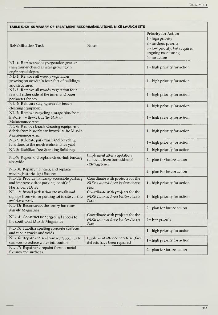
Treatment
TABLE 5.12: SUMMARY OF TREATMENT RECOMMENDATIONS, NIKE LAUNCH SITE
Rehabilitation Task Notes
Priority for Action
1 - high priority
2 - medium priority
3 - low priority, but requires
ongoing monitoring
4 - no action
NL-1: Remove woody vegetation greater
than four-inches diameter growing on
engineered slopes
1 - high priority for action
NL-2: Remove all woody vegetation
growing on or within four-feet of buildings
and structures
1 - high priority for action
NL-3: Remove all woody vegetation four-
feet off either side of the inner and outer
perimeter fences
1 - high priority for action
NL-4: Relocate staging area for beach
cleaning equipment1 - high priority for action
NL-5: Remove recycling storage bins from
historic earthwork in the Missile
Maintenance Area
1 - high priority for action
NL-6: Remove beach-cleaning equipment
debris from historic earthwork in the Missile
Maintenance Area
1 - high priority for action
NL-7: Relocate park trash and recycling
functions to the north maintenance yard1 - high priority for action
NL-8: Stabilize Free-Standing Buildings 1 - high priority for action
NL-9: Repair and replace chain-link fencing
site-wide
Implement after vegetation
removals from both sides of
existing fence
2 - plan for future action
NL-10: Repair, maintain, and replace
missing historic light fixtures2 - plan for future action
NL-11: Provide handicap accessible parking
and improve visitor parking lot off of
Hartshorne Drive
Coordinate with projects for the
NIKE Launch Area Visitor Access
Plan
1 - high priority for action
NL-12: Install pedestrian crosswalk and
signage from visitor parking lot to site via the
multi-use path
Coordinate with projects for the
NIKE Launch Area Visitor Access
Plan
1 - high priority for action
NL-1 3: Reconstruct the sentry hut near
Missile Magazines2 - plan for future action
NL-1 4: Construct underground access to
the southwest Missile Magazines
Coordinate with projects for the
NIKE Launch Area Visitor Access
Plan
3 - low priority
NL-15: Stabilize spalling concrete surfaces
and repair cracks and voids1 - high priority for action
NL-1 6: Repair and seal horizontal concrete
surfaces to reduce water infiltration
Implement after concrete surface
defects have been repaired1 - high priority for action
NL-1 7: Repair and repaint ferrous metal
fixtures and surfaces2 - plan for future action
485
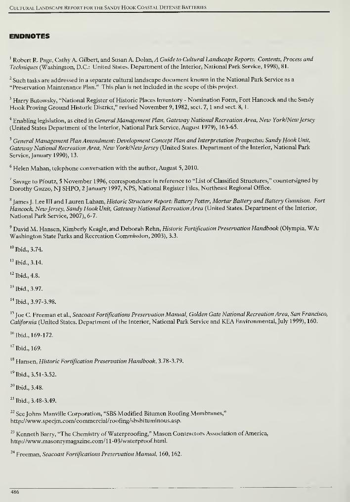
Cultural Landscape Report for the Sandy Hook Coastal Defense Batteries
ENDNOTES
1
Robert R. Page, Cathy A. Gilbert, and Susan A. Dolan, A Guide to Cultural Landscape Reports: Contents, Process and
Techniques (Washington, D.C.: United States. Department of the Interior, National Park Service, 1998), 81.
2Such tasks are addressed in a separate cultural landscape document known in the National Park Service as a
"Preservation Maintenance Plan." This plan is not included in the scope of this project.
3Harry Butowsky, "National Register of Historic Places Inventory - Nomination Form, Fort Hancock and the Sandy
Hook Proving Ground Historic District," revised November 9, 1982, sect. 7, 1 and sect. 8, 1.
4Enabling legislation, as cited in General Management Plan, Gateway National Recreation Area, New York/NewJersey
(United States Department of the Interior, National Park Service, August 1979), 163-65.
5General Management Plan Amendment: Development Concept Plan and Interpretation Prospectus: Sandy Hook Unit,
Gateway National Recreation Area, New York/NewJersey (United States. Department of the Interior, National Park
Service, January 1990), 13.
6Helen Mahan, telephone conversation with the author, August 5, 2010.
7Savage to Pfoutz, 5 November 1996, correspondence in reference to "List of Classified Structures," countersigned by
Dorothy Guzzo, NJ SHPO, 2 January 1997, NPS, National Register Files, Northeast Regional Office.
8James J. Lee III and Lauren Laham, Historic Structure Report: Battery Potter, Mortar Battery and Battery Gunnison. Fort
Hancock, NewJersey, Sandy Hook Unit, Gateway National Recreation Area (United States. Department of the Interior,
National Park Service, 2007), 6-7.
9David M. Hansen, Kimberly Keagle, and Deborah Rehn, Historic Fortification Preservation Handbook (Olympia, WA:
Washington State Parks and Recreation Commission, 2003), 3.3.
Ibid., 3.74.
'Ibid., 3.14.
2Ibid., 4.8.
3Ibid., 3.97.
4Ibid., 3.97-3.98.
5
Joe C. Freeman et al., Seacoast Fortifications Preservation Manual, Golden Gate National Recreation Area, San Francisco,
California (United States. Department of the Interior, National Park Service and KEA Environmental, July 1999), 160.
6Ibid., 169-172.
7Ibid., 169.
8Hansen, Historic Fortification Preservation Handbook, 3.78-3.79.
9Ibid., 3.51-3.52.
20Ibid., 3.48.
21Ibid., 3.48-3.49.
22See Johns Manville Corporation, "SBS Modified Bitumen Roofing Membranes,"
http://www.specjm.com/commercial/roofing/sbsbituminous.asp.
23Kenneth Barry, "The Chemistry of Waterproofing," Mason Contractors Association of America,
http://www.masonrymagazine.com/ll-03/waterproof.html.
24Freeman, Seacoast Fortifications Preservation Manual, 160, 162.
486
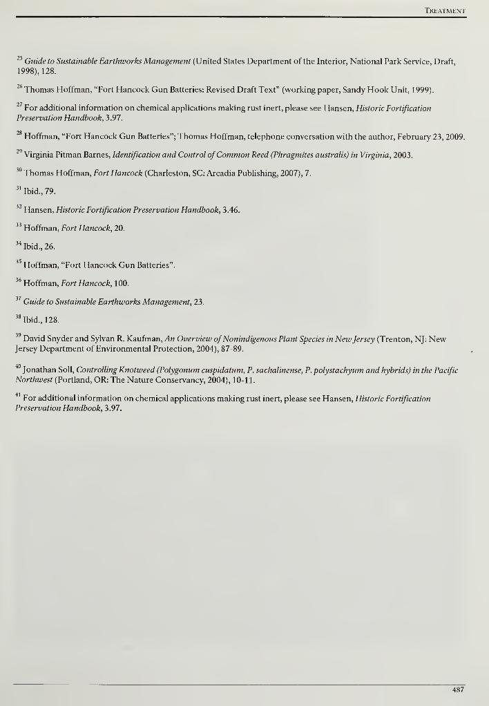
Treatment
25Guide to Sustainable Earthworks Management (United States Department of the Interior, National Park Service, Draft,
1998), 128.
6 Thomas Hoffman, "Fort Hancock Gun Batteries: Revised Draft Text" (working paper, Sandy Hook Unit, 1999).
For additional information on chemical applications making rust inert, please see Hansen, Historic Fortification
Preservation Handbook, 3.97.
28Hoffman, "Fort Hancock Gun Batteries"; Thomas Hoffman, telephone conversation with the author, February 23, 2009.
29Virginia Pitman Barnes, Identification and Control ofCommon Reed (Phragmites australis) in Virginia, 2003.
30 Thomas Hoffman, Fort Hancock (Charleston, SC: Arcadia Publishing, 2007), 7.
31Ibid., 79.
Hansen, Historic Fortification Preservation Handbook, 3.46.
Hoffman, Fort Hancock, 20.
34Ibid., 26.
Hoffman, "Fort Hancock Gun Batteries".
Hoffman, Fort Hancock, 100.
37Guide to Sustainable Earthworks Management, 23.
38Ibid., 128.
David Snyder and Sylvan R. Kaufman, An Overview ofNonindigenous Plant Species in NewJersey (Trenton, NJ: NewJersey Department of Environmental Protection, 2004), 87-89.
Jonathan Soil, Controlling Knotweed (Polygonum cuspidatum, P. sachalinense, P. polystachyum and hybrids) in the Pacific
Northwest (Portland, OR: The Nature Conservancy, 2004), 10-11.
For additional information on chemical applications making rust inert, please see Hansen, Historic Fortification
Preservation Handbook, 3.97.
487

Cultural Landscape Report for the Sandy Hook Coastal Defense Batteries
488
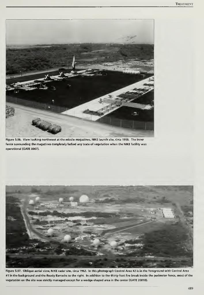
TREATMENT
Figure 5.96. View looking northwest at the missile magazines, NIKE launch site, circa 1958. The inner
fence surrounding the magazines completely lacked any trace of vegetation when the NIKE facility was
operational (GATE 8067).
Figure 5.97. Oblique aerial view, NIKE radar site, circa 1962. In this photograph Control Area #2 is in the foreground with Control Area
#1 in the background and the Ready Barracks to the right. In addition to the thirty-foot fire break inside the perimeter fence, most of the
vegetation on the site was strictly managed except for a wedge-shaped area in the center (GATE 20818).
489
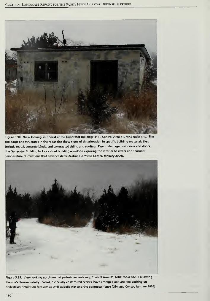
Cultural Landscape Report for the Sandy Hook Coastal Defense Batteries
Figure 5.98. View looking southeast at the Generator Building (414), Control Area #1, NIKE radar site. The
buildings and structures in the radar site show signs of deterioration in specific building materials that
include metal, concrete block, and corrugated siding and roofing. Due to damaged windows and doors,
the Generator Building lacks a closed building envelope exposing the interior to water and seasonal
temperature fluctuations that advance deterioration (Olmsted Center, January 2009).
, ^^^u Aijti ill
m .pw r* "^w Wf*i " TIT"»f
'
fck .
JF' '
wHWFkS *j
<,-
^ i
-
.:
-
.
"V m^M•!•*
-
% T..'T3***' ,r *"r
laiU.'?,. . .
T'^m--
.y
t
Figure 5.99. View looking northwest at pedestrian walkway. Control Area #1, NIKE radar site. Following
the site's closure woody species, especially eastern red cedars, have emerged and are encroaching on
pedestrian circulation features as well as buildings and the perimeter fence (Olmsted Center, January 2009).
490
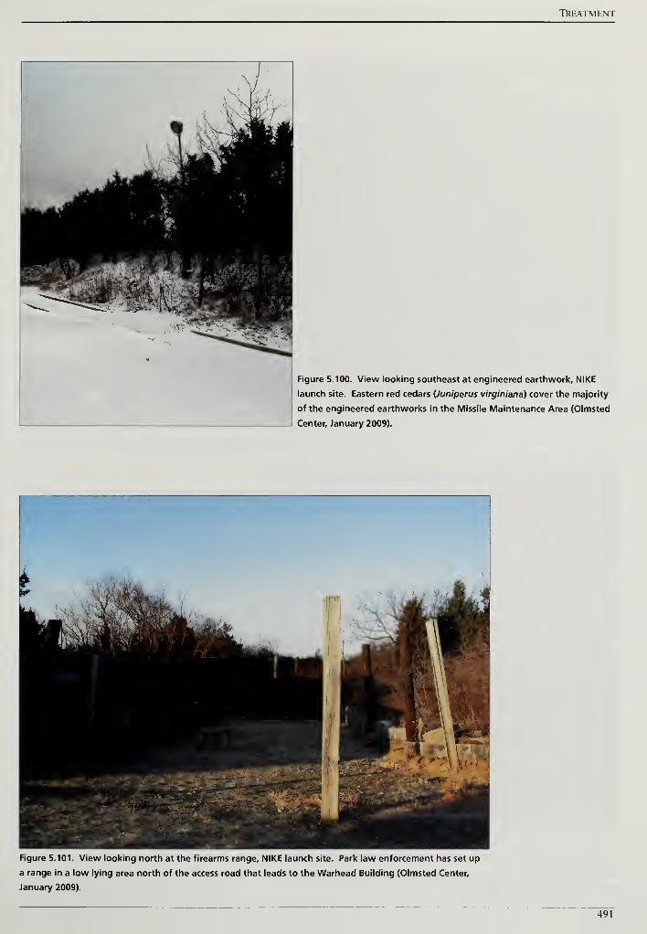
TREATMENT
Figure 5.100. View looking southeast at engineered earthwork, NIKE
launch site. Eastern red cedars (Juniperus virginiana) cover the majority
of the engineered earthworks in the Missile Maintenance Area (Olmsted
Center, January 2009).
Figure 5.101. View looking north at the firearms range, NIKE launch site. Park law enforcement has set up
a range in a low lying area north of the access road that leads to the Warhead Building (Olmsted Center,
January 2009).
491
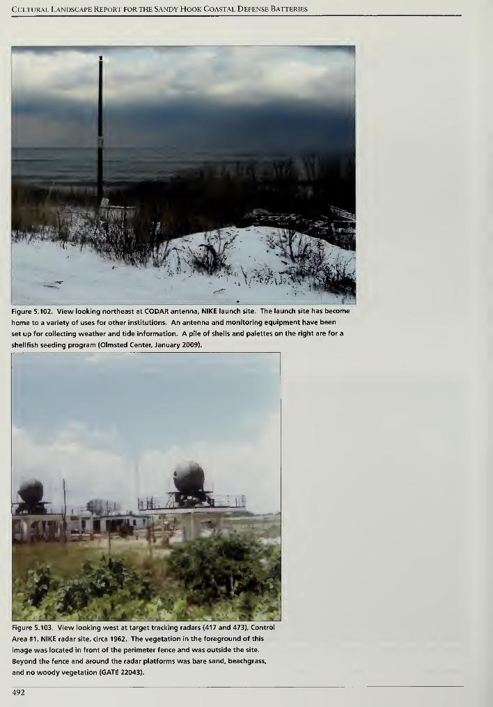
Cultural Landscape Report for the Sandy Hook Coastal Defense Batteries
Figure 5.102. View looking northeast at CODAR antenna, NIKE launch site. The launch site has become
home to a variety of uses for other institutions. An antenna and monitoring equipment have been
set up for collecting weather and tide information. A pile of shells and palettes on the right are for a
shellfish seeding program (Olmsted Center, January 2009).
Figure 5.103. View looking west at target tracking radars (417 and 473), Control
Area #1, NIKE radar site, circa 1962. The vegetation in the foreground of this
image was located in front of the perimeter fence and was outside the site.
Beyond the fence and around the radar platforms was bare sand, beachgrass,
and no woody vegetation (GATE 22043).
492
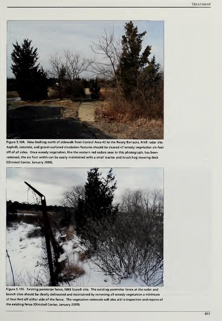
TkEATMENT
Figure 5.104. View looking north of sidewalk from Control Area #2 to the Ready Barracks, NIKE radar site.
Asphalt, concrete, and gravel-surfaced circulation features should be cleared of woody vegetation six-feet
off of all sides. Once woody vegetation, like the eastern red cedars seen in this photograph, has been
removed, the six foot width can be easily maintained with a small tractor and brush hog mowing deck
(Olmsted Center, January 2009).
W- 'v$
'***" • II nn ».
Figure 5.105. Existing perimeter fence, NIKE launch site. The existing perimeter fence at the radar and
launch sites should be clearly delineated and maintained by removing all woody vegetation a minimum
of four-feet off either side of the fence. The vegetation removals will also aid in inspection and repairs of
the existing fence (Olmsted Center, January 2009).
493
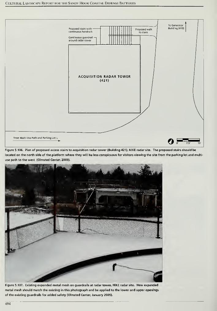
Cultural Landscape Report for the Sandy Hook Coastal Defense Batteries
JA
A Tn Gpnpratnra A * -+u
Proposed walk Building (410)
to stairs Icontinuous handrails
Continuous guardrail —around radar tower
ACQUISITION RADAR TOWER(421)
From Multi-Use Path and Parking Lot L
fL I r"^ I>~
^P 0' 7.5' 15'
Figure 5.106. Plan of proposed access stairs to acquisition radar tower (Building 421), NIKE radar site. The proposed stairs should be
located on the north side of the platform where they will be less conspicuous for visitors viewing the site from the parking lot and multi-
use path to the west (Olmsted Center, 2009).
Figure 5.107. Existing expanded metal mesh on guardrails at radar tower, NIKE radar site. New expanded
metal mesh should match the existing in this photograph and be applied to the lower and upper openings
of the existing guardrails for added safety (Olmsted Center, January 2009).
494
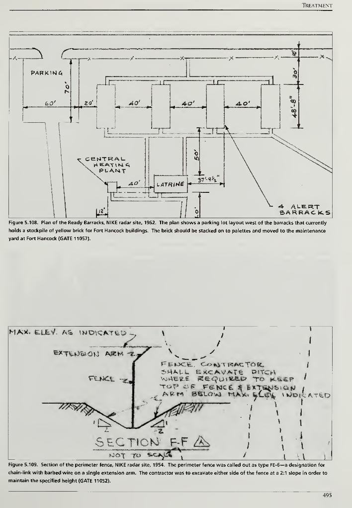
TREATMENT
zz^ cPARJOMG
(oO'
-* ^4 "X
4 >*
i n.—
I
Lt
AO'
,111
CENTRALH EATVM C,
PLANT
JS
m=;
4- ALERTBARRACKS
Figure 5.108. Plan of the Ready Barracks, NIKE radar site, 1962. The plan shows a parking lot layout west of the barracks that currently
holds a stockpile of yellow brick for Fort Hancock buildings. The brick should be stacked on to palettes and moved to the maintenance
yard at Fort Hancock (GATE 11057).
I
* /A /
*>H*UC EKCAVATfc P«TCl-\Vj»4€ttC Re^UiTtftP TO HL«a.&P
MA>X. &U&V. AS IWDKMtU y
fc*TXUW*OU AKMA ~**7
rtLWCt
/
/
SECTION F-F ^Tf-V-
fJc^X T"
\ WD(c.ATtDI
I
\
\i
\ I
J Li LFigure 5.109. Section of the perimeter fence, NIKE radar site, 1954. The perimeter fence was called out as type FE-6—a designation for
chain-link with barbed wire on a single extension arm. The contractor was to excavate either side of the fence at a 2:1 slope in order to
maintain the specified height (GATE 11052).
495
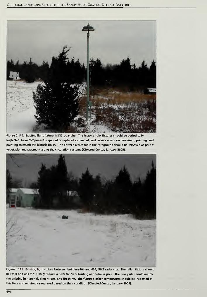
Cultural Landscape Report for the Sandy Hook Coastal Defense Batteries
Figure 5.110. Existing light fixture, NIKE radar site. The historic light fixtures should be periodically
inspected, have components repaired or replaced as needed, and receive corrosion treatment, priming, and
painting to match the historic finish. The eastern red cedar in the foreground should be removed as part of
vegetation management along the circulation systems (Olmsted Center, January 2009).
Figure 5.111. Existing light fixture between building 404 and 405, NIKE radar site. The fallen fixture should
be reset and will most likely require a new concrete footing and tubular pole. The new pole should match
the existing in material, dimensions, and finishing. The fixture's other components should be inspected at
this time and repaired or replaced based on their condition (Olmsted Center, January 2009).
496
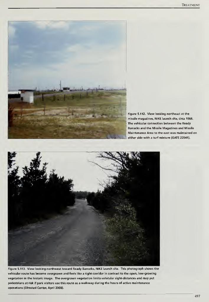
TkEATMENT
Figure 5.112. View looking northeast at the
missile magazines, NIKE launch site, circa 1968.
The vehicular connection between the Ready
Barracks and the Missile Magazines and Missile
Maintenance Area to the east was maintained on
either side with a turf mixture (GATE 22041).
Figure 5.113. View looking northwest toward Ready Barracks, NIKE launch site. This photograph shows the
vehicular route has become overgrown and feels like a tight corridor in contrast to the open, low-growing
vegetation in the historic image. The overgrown vegetation limits vehicular sight-distances and may put
pedestrians at risk if park visitors use this route as a walkway during the hours of active maintenance
operations (Olmsted Center, April 2008).
497
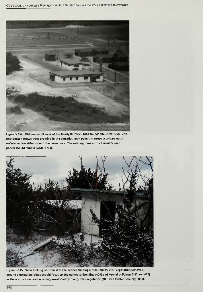
Cultural Landscape Report for the Sandy Hook Coastal Defense Batteries
Figure 5.114. Oblique aerial view of the Ready Barracks, NIKE launch site, circa 1958. This
photograph shows trees growing in the barrack's lawn panels in contrast to bare earth
maintained on either side of the fence lines. The existing trees at the barrack's lawn
panels should remain (GATE 5781).
Figure 5.115. View looking northwest at the kennel buildings, NIKE launch site. Vegetation removals
around existing buildings should focus on the generator building (429) and kennel buildings (457 and 458)
as these structures are becoming enveloped by overgrown vegetation (Olmsted Center, January 2009).
498
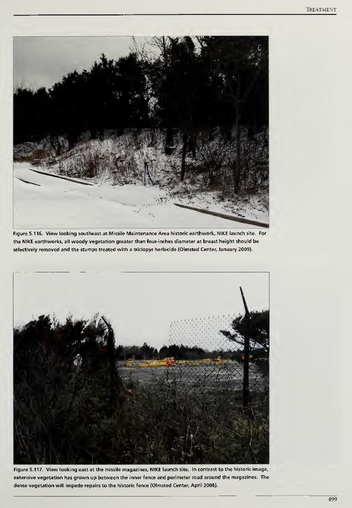
TREATMENT
Figure 5.116. View looking southeast at Missile Maintenance Area historic earthwork, NIKE launch site. For
the NIKE earthworks, all woody vegetation greater than four-inches diameter at breast height should be
selectively removed and the stumps treated with a triclopyr herbicide (Olmsted Center, January 2009).
Figure 5.1 17. View looking east at the missile magazines, NIKE launch site. In contrast to the historic image,
extensive vegetation has grown up between the inner fence and perimeter road around the magazines. The
dense vegetation will impede repairs to the historic fence (Olmsted Center, April 2008).
499
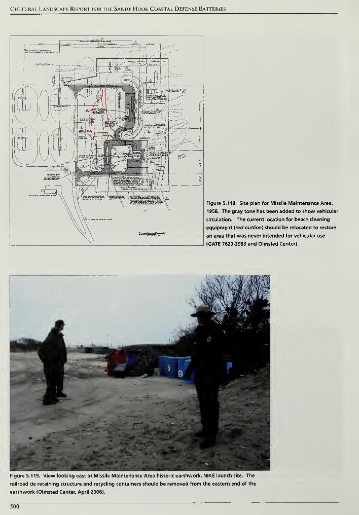
Cultural Landscape Report for the Sandy Hook Coastal Defense Batteries
-m,~WBWWB oSS&tSu nd*BE
-A7H : qY4—wg»J
»".".-''..'<'''/,
1
Figure 5.118. Site plan for Missile Maintenance Area,
1958. The gray tone has been added to show vehicular
circulation. The current location for beach cleaning
equipment (red outline) should be relocated to restore
an area that was never intended for vehicular use
(GATE 7620-2983 and Olmsted Center).
Figure 5.119. View looking east at Missile Maintenance Area historic earthwork, NIKE launch site. The
railroad tie retaining structure and recycling containers should be removed from the eastern end of the
earthwork (Olmsted Center, April 2008).
500
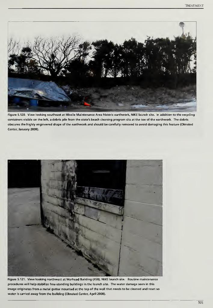
TREATMENT
Figure 5.120. View looking southeast at Missile Maintenance Area historic earthwork, NIKE launch site. In addition to the recycling
containers visible on the left, a debris pile from the state's beach cleaning program sits at the toe of the earthwork. The debris
obscures the highly engineered shape of the earthwork and should be carefully removed to avoid damaging this feature (Olmsted
Center, January 2009).
Figure 5.121. View looking northwest at Warhead Building (450), NIKE launch site. Routine maintenance
procedures will help stabilize free-standing buildings in the launch site. The water damage seen in this
image originates from a metal gutter mounted at the top of the wall that needs to be cleaned and reset so
water is carried away from the building (Olmsted Center, April 2008).
501
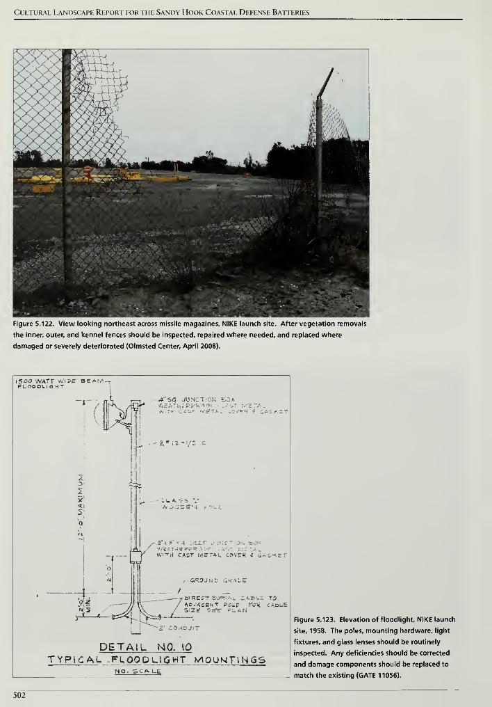
Cultural Landscape Report for the Sandy Hook Coastal Defense Batteries
Figure 5.122. View looking northeast across missile magazines, NIKE launch site. After vegetation removals
the inner, outer, and kennel fences should be inspected, repaired where needed, and replaced where
damaged or severely deteriorated (Olmsted Center, April 2008).
I500 WATT WlPS BEAW--FLOOOL16HT
A'SQ JUNCTION BOX/.-•-
, r \ w i -•
• :«.ST NtETAL tO'/Sf? 4 CASKET
i/2 C.
TIT
L-.-
X/* 5*1 8'
".« 4 PEEP .. >NCT J . :»OX:" •' '
.
W"TH CAST METAL. CftVEK e 6ASKE1
CiRSUrOD St?ACE
DIRECT BURIAL CASUS TOAD.'ACBNT POLE FC« CA6UES'Ze SETT PLAN
~Z wO^DJiT
DETAIL NO. 10
TYPIC AL . F LQODL1GHT MOUNTINGSNO- SCALE
Figure 5.123. Elevation of floodlight, NIKE launch
site, 1958. The poles, mounting hardware, light
fixtures, and glass lenses should be routinely
inspected. Any deficiencies should be corrected
and damage components should be replaced to
match the existing (GATE 11056).
502
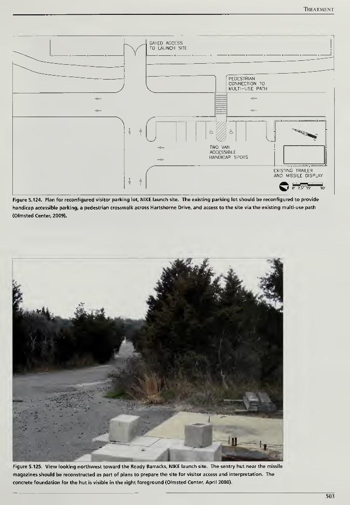
TREATMENT
GATED ACCESSTO LAUNCH SITE
PEDESTRIANCONNECTION TOMULTI-USE PATH
t
TWO VANACCESSIBLEHANDICAP SPOTS
EXISTING TRAILERAND MISSILE DISPLAY
Figure 5.124. Plan for reconfigured visitor parking lot, NIKE launch site. The existing parking lot should be reconfigured to provide
handicap accessible parking, a pedestrian crosswalk across Hartshorne Drive, and access to the site via the existing multi-use path
(Olmsted Center, 2009).
Figure 5.125. View looking northwest toward the Ready Barracks, NIKE launch site. The sentry hut near the missile
magazines should be reconstructed as part of plans to prepare the site for visitor access and interpretation. The
concrete foundation for the hut is visible in the right foreground (Olmsted Center, April 2008).
503
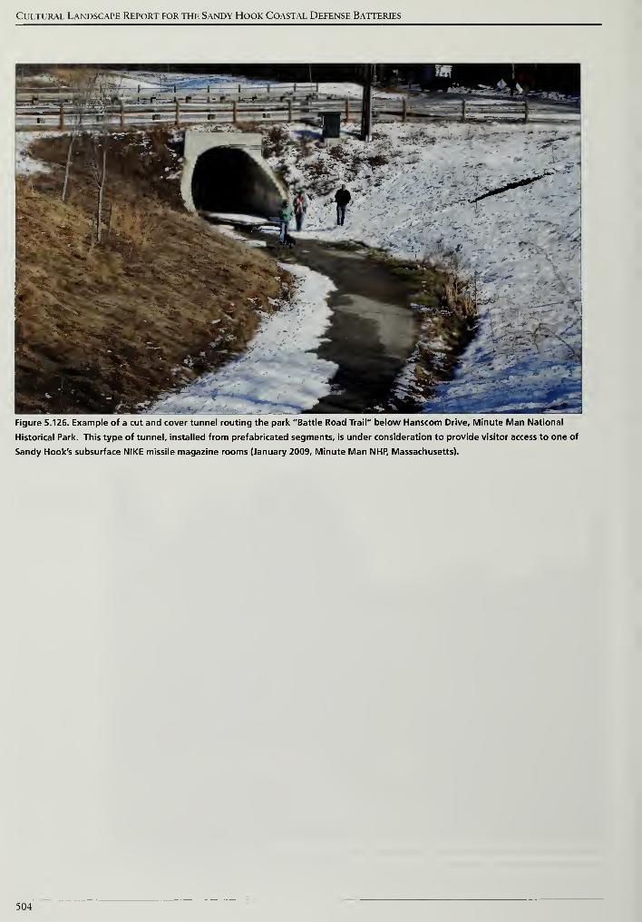
Cultural Landscape Report for the Sandy Hook Coastal Defense Batteries
Figure 5.126. Example of a cut and cover tunnel routing the park "Battle Road Trail" below Hanscom Drive, Minute Man National
Historical Park. This type of tunnel, installed from prefabricated segments, is under consideration to provide visitor access to one of
Sandy Hook's subsurface NIKE missile magazine rooms (January 2009, Minute Man NHP, Massachusetts).
504
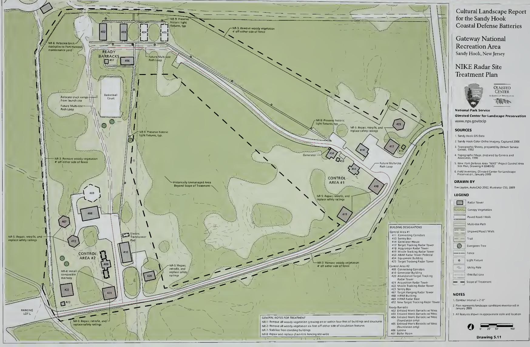
GENERAL NOTES FOR TREATMENT
NR-1: Remove all woody vegetation growing on or within four-feet of buildings a
NR-2; Remove all woody vegetation six-feet off either side of circulation features
NR-7; Stabilize free-standing buildings
NR-8: Repair and replace chain-link fencing site-wide
Control Area #1
411 Connecting Corridors
413 Sentry Box414 Generator House417 Target Tracking Radar Tower
418 Acquisition Radar Tower419 Missile Tracking Radar Tower
453 ABAR Radar Tower Pedestal
454 Equipment Building
473 Target Tracking Radar Tower
Control Area #2
409 Connecting Corridors
410 Generator Building
420 Abandoned Target Tracking
Radar Tower421 Acquisition Radar Tower
422 Missile Tracking Radar Tower
423 Sentry Box
467 Target Ranging Radar Tower
468 HIPAR Building
469 MIPAR Radar Base
472 New Target Tracking Radar Towei
Ready Barracks
402 Enlisted Men's Barracks i
403 Enlisted Men's Barracks v.
404 Enlisted Men's Barracks w
(foundation only)
405 Enlisted Men's Barracks v.
(foundation only)
406 Latrine
407 Boiler Room
Cultural Landscape Report
for the Sandy HookCoastal Defense Batteries
Gateway National
Recreation AreaSandy Hook, New Jersey
NIKE Radar Site
Treatment Plan
OlmstedCenter
National Park Service
Olmsted Center for Landscape Preservation
www.nps.gov/oclp
SOURCES
1 Sandy Hook GIS Data
2 Sandy Hook Color Ortho Imagery, Captured 2006
DRAWN BY
Tim Layton, AutoCAD 2002, lllusti
LEGEND
] Radar Tower
Canopy Vegetation
Paved Road /Walk
jMulti-Use Path
Unpaved Road /Walk
I- 1 Trail
SK Evergreen Tree
O Light Fixture
P Tb Utility Pole
1944 Rail Line
Scope of Treatment
NOTES
1 Contour Interval = 2'-0"
3. All features shown in approximate scale and locatio
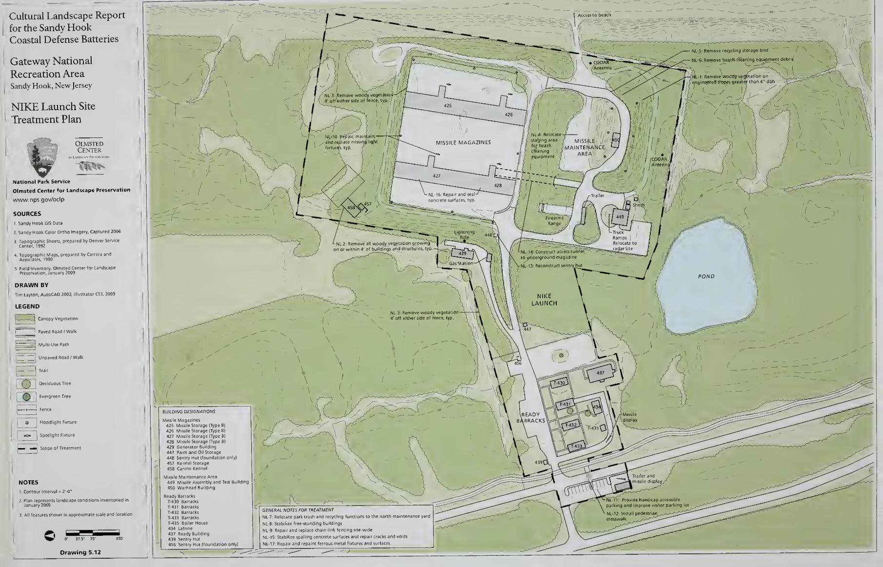
Cultural Landscape Report
for the Sandy HookCoastal Defense Batteries
Gateway National
Recreation AreaSandy Hook, New Jersey
NIKE Launch Site
Treatment Plan
OlmstedCenter
~i
'
National Park Service
Olmsted Center for Landscape Preservation
www.nps.gov/oclp
SOURCES
I.Sandy Hook GI5 Data
2 Sandy Hook Color Ortho Imagery, Captured 2006
DRAWN BY
Tim Layton, AutoCAD 2002. Illustrator CS3, 2009
LEGEND
l^- Canopy Vegetation
1 Paved Road /Walk
I
|
Multi-Use Path
~J Unpaved Road /Walk
^1 Trail
Deciduous TreeEH'I
f^\ I Evergreen Tree
Fence
Floodlight Fixture
Spotlight Fixture
Scope of Treatment
NOTES
1. Contour Interval = 2'-0"
2. Plan represents landscape conditions inventoried ii
January 2009
3 All features shown in approximate scale and locatic
; Area
449 Missile Assembly and Test Building
450 Warhead Building
Ready Barracks
T-430 Barracks
T-431 Barracks
T-432 Barracks
T-433 Barracks
T-435 Boiler House434 Latrine
437 Ready Building
439 Sentry Hut
456 Sentry Hut (foundation only)
GENERAL NOTES FOR TREATMENT
NL-7: Relocate park trash and recycling functions to the north maintena nee yard
NL-8: Stabilize free-standing buildings
NL-9: Repair and replace chain-link fencing site-wide
NL-iS: Stabilize spalling concrete surfaces and repair cracks and voids
NL-17 Repair and repaint ferrous metal fixtures and surfaces

References
REFERENCES
PUBLISHED BOOKS AND REPORTS
Barnard, Roy S. The History ofARADCOM Volume 1: The Gun Era 1 950-1 955.
United States Department of Defense, Headquarters ARADCOM, [1973?].
Bearss, Edwin C. Historic Resource Study and Historic Structure Report Historical
Data Section Spermaceti Cove Life-Saving Station, Sandy Hook Unit, Gateway
National Recreation Area, New York/NewJersey. United States Department of
the Interior, National Park Service, January 1983.
. Historic Resource Study Fort Hancock: 1 948-1974, Sandy Hook Unit,
Gateway National Recreation Area, Monmouth County, NewJersey. United
States Department of the Interior, National Park Service, November 1982.
. Historic Resource Study The Sandy Hook Proving Ground 1874-1919,
Sandy Hook Unit, Gateway National Recreation Area, NewJersey. United States
Department of the Interior, National Park Service, September 1983.
Berhow, Mark A. U. S. Strategic and Defensive Missile Systems 1 950-2004. New
York: Osprey Publishing Limited, 2005.
Freeman, Joe C, Stephen A. Haller, David M. Hansen, John A. Martini, and
Karen J. Weitze. Seacoast Fortifications Preservation Manual, Golden Gate
National Recreation Area, San Francisco, California. United States Department
of the Interior, National Park Service and KEA Environmental, July 1999.
General Management Plan, Gateway National Recreation Area, New York/New
Jersey. United States Department of the Interior, National Park Service, August
1979.
General Management Plan Amendment: Development Concept Plan and
Interpretation Prospectus: Sandy Hook Unit, Gateway National Recreation Area,
New York/NewJersey. United States Department of the Interior, National Park
Service, January 1990.
Hansen, David M., Kimberly Keagle, and Deborah Rehn. Historic Fortification
Preservation Handbook. Olympia, WA: Washington State Parks and Recreation
Commission, 2003.
Hoffman, Thomas. Fort Hancock. Charleston, SC: Arcadia Publishing, 2007.
Lee, James J. III. Spermaceti Cove Life-Saving Station Historic Structure Report,
Sandy Hook Unit, Gateway National Recreation Area, Fort Hancock, NewJersey.
United States Department of the Interior, National Park Service, 2008.
507

Cultural Landscape Report for the Sandy Hook Coastal Defense Batteries
Lee, James J. Ill and Lauren Laham. Historic Structure Report: Battery Potter,
Mortar Battery and Battery Gunnison. Fort Hancock, NewJersey, Sandy Hook
Unit, Gateway National Recreation Area. United States Department of the
Interior, National Park Service, 2007.
Lewis, Emanuel Raymond. Seacoast Fortifications ofthe United States: An
Introductory History. Annapolis, MD: Naval Institute Press, 1993. First
published 1970 by Smithsonian Institution Press.
Lonnquest, John C, and David F. Winkler. To Defend and Deter: The Legacy of
the United States Cold War Missile Program. United States Department of
Defense, Army Construction Engineering Research Laboratories, November
1996.
The Louis Berger Group, Inc. Archeological Investigations of the Magruder Road
Demolition and Repaying and Gunnison Road Realignment Project Sandy Hook,
NewJersey. United States Department of the Interior, National Park Service,
Denver Service Center, January 2004.
Martini, John A., and Stephen A. Haller. What We Have We Shall Defend: An
Interim History and Preservation Planfor Nike Site SF-88L, Fort Barry,
California. United States Department of the Interior, National Park Service,
Golden Gate National Recreation Area, 1998.
McGovern, Terrance, and Boiling Smith. American Coastal Defenses 1885-1950.
New York: Osprey Publishing Limited, 2006.
Page, Robert R., Cathy A. Gilbert, and Susan A. Dolan. A Guide to Cultural
Landscape Reports: Contents, Process and Techniques. United States
Department of the Interior, National Park Service, 1998.
Rosenbaum, Joel, and Tom Gallo. Iron Horses Across the Garden State.
Piscataway, NJ: Railpace Company, Inc., 1985.
Sandy Hook:A Study ofAlternatives. United States Department of the Interior,
National Park Service, 1967.
Snyder, David, and Sylvan R. Kaufman. An Overview ofNonindigenous Plant
Species in NewJersey. Trenton, NJ: New Jersey Department of Environmental
Protection, 2004.
Sullivan, Judith Q. Building 32 Quartermaster's Storehouse, Fort Hancock, Historic
Structure Report, Sandy Hook Unit, Gateway National Recreation Area. United
States Department of the Interior, National Park Service, 2004.
508

References
Williams, Norma E. Cultural Landscape Reportfor Proving Ground and Wartime
Expansion Areas, Sandy Hook Unit, Gateway National Recreation Area. United
States Department of the Interior, National Park Service, July 1999.
Winkler, David F. Searching the Skies: The Legacy ofthe United States Cold War
Defense Radar Program. United States Department of Defense, Air Force Air
Combat Command, June 1997.
PERIODICALS, ARTICLES, UNPUBLISHED REPORTS, AMD WEB SITES
Barnes, Virginia Pitman. Identification and Control ofCommon Reed (Phragmites
australis) in Virginia. Virginia Cooperative Extension Fact Sheet number 427-
101,2003.
Barry, Kenneth. "The Chemistry of Waterproofing." Mason Contractors
Association of America.
http://www.masonrymagazine.com/ll-03/waterproof.html.
Berhow, Mark A. "Caretaker Status in the Coast Artillery, 1912-1948." The Coast
Defense Study GroupJournal 14, no. 4 (2000): 48-57.
"Billy Mitchell." Air and Space Power Journal.
http://www.airpower.maxwell.af.mil/airchronicles/cc/mitch.html.
"British Navy Ships—HMS Dreadnought 1906-1922." United States Department
of the Navy, Naval Historical Center.
http://www.history.navy.mil/photos/sh-fornv/uk/uksh-d/drednt9.htm.
Butowsky, Harry. "National Register of Historic Places Inventory - Nomination
Form, Fort Hancock and the Sandy Hook Proving Ground Historic District,"
revised November 9, 1982.
"Chapter 2: American Military History, Volume II." United States Army Center
of Military History.
http://www.history.army.mil/books/AMH-V2/AMH%20V2/chapter2.htm.
Greenwood, Richard E. "National Register of Historic Places Inventory -
Nomination Form, Fort Hancock and the Sandy Hook Proving Ground
Historic District," June 28, 1976.
Guide to Sustainable Earthworks Management. United States Department of the
Interior, National Park Service, Draft, 1998.
Hoffman, Thomas. "Cold War Defender: Draft Text." Working paper, Sandy
Hook Unit, Gateway National Recreation Area, 2005.
. "Fort Hancock Gun Batteries: Revised Draft Text." Working paper,
Sandy Hook Unit, Gateway National Recreation Area, 1999.
509

Cultural Landscape Report for the Sandy Hook Coastal Defense Batteries
Johns Manville Corporation. "SBS Modified Bitumen Roofing Membranes."
http://www.specjm.com/commercial/roofing/sbsbituminous.asp.
"Marine Academy of Science and Technology." Monmouth County Vocational
School District, http://www.mast.mcvsd.org/.
Maritime Heritage Program. "Sandy Hook Light National Historic Landmark
Study." National Park Service.
http://www.nps.gov/history/maritime/nhl/sandy.htm.
Morang, Andrew. "Historical Aerial Photographs Made Available by the ERDC
Coastal and Hydraulics Laboratory." United States Army Corps of Engineers
Coastal and Hydraulics Laboratory.
http://chl.wes.army.mil/shore/newjersey/shorel920/.
Northeast Fisheries Science Center. "James J. Howard Marine Sciences
Laboratory." National Oceanic and Atmospheric Administration.
http://sh.nefsc.noaa.gov/.
Potts, JR. "HMS Dreadnought." Military Factory.
http://www.militaryfactory.com/ships/detail.asp?ship_id=HMS-Dreadnought.
"Sandy Hook Bird Observatory." New Jersey Audubon Society.
http://www.njaudubon.org/Centers/SHBO/.
Soil, Jonathan. Controlling Knotweed (Polygonum cuspidatum, P. sachalinense, P.
polystachyum and hybrids) in the Pacific Northwest. Portland, OR: The Nature
Conservancy, 2004.
Tobias, James. "Frequently Asked Questions - Naming Army Installations."
United States Army Center of Military History.
http://www.history.army.mil/html/faq/base_name.html.
U. S. Geological Survey. "NYC Regional Geology - Atlantic Coastal Plain."
http://3dparks.wr.usgs.gov/nyc/coastalplain/coastalplain.htm.
. "Volumetric Change Analysis along Gateway National Recreation Area -
Sandy Hook and Fire Island National Seashore."
http://ngom.usgs.gov/dsp/mapping/volumetric_change.html.
510

References
REPOSITORIES
Center for Military History, Carlisle, PA.
Coastal Defense Study Group, Bel Air, MD.
Engineering and Maintenance Division, Sandy Hook Unit, Gateway National
Recreation Area.
Gateway National Recreation Area Museum Collection.
National Archives and Records Administration, College Park, MD.
511

Cultural Landscape Report for the Sandy Hook Coastal Defense Batteries
512


National Park Service
U.S. Department of the Interior
Olmsted Center for Landscape Preservation
Boston National Historical Park
Charlestown Navy Yard, Quarters C
Boston, Massachusetts 02129
Phone: 617-241-6954
Fax: 617-241-3952
web: www.nps.gov/oclp/


