Embed Size (px)
Citation preview

Drainage, Sewage, Grinder & Propeller Pumps
50 Hz
CSP, MSP, LAP, LFP, LBP,LHP, LGP, LLP & LAS Series
Pumping Solution

Declaration of ConformityWe, Lubi hereby declare under our sole responsibility that the products CSP, MSP, LAP, LFP, LHP, LAS, LGPand LLP to which this declaration relates, are in conformity with these Council Directives on the approximation of the laws of the EC Member States:
– Machinery Directive (2006/42/EC).Standards used: EN 809: 2009 and EN 60204-1: 2006.–
– Low Voltage Directive (2006/95/EC).Applicable when the rated power is lower than 2.2 kW.– Standards used: EN 60335-1: 2002 and EN 60335-2-41: 2003.–
– Electromagnetic compatibility (2004/108/EC).Standards used: EN 61000-6-2 and EN 61000-6-3.–
Technical Director
Nosotros, Lubi declaramos bajo nuestra entera responsabilidad que los productos CSP, MSP, LAP, LFP, LHP, LAS, LGP y LLP a los cuales se refiere esta declaración, están conformes con las Directivas del Consejo en la aproximación de las leyes de las Estados Miembros del EM:
– Directiva de Maquinaria (2006/42/CE).Normas aplicadas: EN 809: 2009 y EN 60204-1: 2006.–
– Directiva de Baja Tensión (2006/95/CE). Aplicable cuando el índice de potencia es inferior a 2,2 kW.– Normas aplicadas: EN 60335-1: 2002 y EN 60335-2-41: 2003.–
– Compatibilidad electromagnética (2004/108/CE).Normas aplicadas: EN 61000-6-2 y EN 61000-6-3.–
Nous, Lubi déclarons sous notre seule responsabilité, que les produits CSP, MSP, LAP, LFP, LHP, LAS, LGPet LLP , auxquels se réfère cette déclaration, sont conformes aux Directives du Conseil concernant le rapprochement des législations des Etats membres CE relatives aux normes énoncées cidessous:
– Directive Machines (2006/42/CE).Normes utilisées: EN 809: 2009 et EN 60204-1: 2006.–
– Directive Basse Tension (2006/95/CE). Applicable lorsque la puissance nominale est inférieure à 2,2 kW.
Normes utilisées: EN 60335-1: 2002 et EN 60335-2-41: 2003.–
– Compatibilité électromagnétique (2004/108/CE).Normes utilisées: EN 61000-6-2 et EN 61000-6-3.–

CONTENTS
CSPCast Iron Submersible Drainage Pumps (0.25 & 0.50 HP) 4
MSPCorrosion Proof Submersible Drainage Pumps (0.25 & 0.50 HP) 5
LAPDrainage Pumps (0.5 HP to 3.0 HP) 6
LFPSewage Pumps (1.0 HP to 3.0 HP) 8
LHPHeavy-Duty Sewage Pumps (5.0 HP to 60.0 HP) 12
LASHeavy-Duty Construction Drainage Pumps (1.5 HP to 15.0 HP) 22
LGPGrinder Pumps (2.0 HP to 5.0 HP) 18
LLPLarge Volume Water Pumps (3.0 HP to 15.0 HP) 20
LBPStainless Steel Submersible Effluent Vortex Pumps 10

11
CSPSubmersible Drainage Pump
4
Submersible drainage pump with Wide angle float switch
Performance Table
Note : The above shown performance is nominal performance and may vary from pump to pump.
Performance Curve
Cast Iron
Model Designation
* Wide Angle Float Switch
Automatic submersible Models available
CSP521T CSP551T
0.18 kW 0.37 kWdrainage pump with
CSP521T
CSP551T
Model HP
0.25
0.50
Amp
2.0
3.0 18.0
229
254
241
254
Major Width (mm)
Height
(mm)
10
10
Max. Solid
Passage
Size (mm)
Gross
Weight (kg.)Volume
3(m )
13.5 0.023
0.028
Dimensions & Weight Data
FeaturesRugged cast iron pump housing, impeller, and motor casing.230V thermally protected energy efficient motor.Oil filled motor for better heat dissapation.Permanently lubricated ball bearings.Extra long 4.6 mtrs. (15 feet) grounded power cord.1½" BSP Discharge pipe size.Stainless steel shaftStainless steel fasteners.Provide with 1½" flexible hose connection and clamp.Available with Sic/Sic mechanical shaft seal for pumping sandy water (optional).
0 2000 4000 6000 8000 10000 12000LPH10
15
20
25
30
35
40
Q
H
(ft)
0 2000 4000 6000 8000 10000 12000LPH0
5
10
15
20
25
Q
H
(ft)
0.18 kW2900, 50 Hz
ISO 9906 Annex A
0.37 kW2900, 50 Hz
ISO 9906 Annex A
Performance Range3 Flow rate up to 11300 l/h (11.3 m /h)
Dynamic head up to 11 m.
Motor Specifications 230 V, 50 Hz, 1 Phase, 2850 RPM Oil Filled ; Thermally Protected
Direction of Rotation Clockwise as seen from the motor rear end.
Applications For clean water containing solids up to 10 mm grain size. As a sump pump for household applications. For draining flooded rooms or tanks. Extractions of water from ponds, flowing water or pits for collection of rain water.
kW
0.18
0.37
Max. Lift
(no flow)
(mtrs)
6.4
11
3m /h
l/h
1
1000
2
2000
4
4000
6
6000
8
8000
10
10000
11
11000
H (m)
6.2
10.8
6.1 5.5 4.7 3.7 2.5
10.7 10.1 9.4 8.2 6.8
1.7
-
Minimum sump pit diameter
381
406
ModelMinimum Sump
Pit Dia. (mm)
CSP521T
*
*
CSP551T
Operating ConditionsAmbient temperature : Max. +50°CLiquid temperature : 0°C to +50°CMax. Starts per hour : 30 at regular intervals.Duty Rating : S1 - When pump is completely submerged.S3 - When pump is partially submerged.
Cable data
cable x core x size (mm²) x
length (m) x Material
1 x 3 x 1.0 x 5 x PVC
1 x 3 x 1.0 x 5 x PVC

5
MSPSubmersible Drainage Pump
Submersible drainage pump with Wide angle float switch
Corrosion Proof
Performance Curve
Model Designation
* Wide Angle Float Switch
Automatic submersible Models available
MSP521T MSP551T
0.18 kW 0.37 kWdrainage pump with
Note : The above shown performance is nominal performance and may vary from pump to pump.
Performance Table
Minimum sump pit diameter
381
432
ModelMinimum Sump
Pit Dia. (mm)
MSP521T
*
*
MSP551T
MSP521T
MSP551T
Model HP
0.25
0.50
Amp
2.0
3.0 9.0
241
267
241
267
Major Width (mm)
Height
(mm)
10
10
Max. Solid
Passage
Size (mm)
Gross
Weight (kg.)Volume
3(m )
8.0 0.022
0.028
Dimensions & Weight Data
kW
0.18
0.37
Max. Lift
(no flow)
(mtrs)
6.8
13
3m /h
l/h
2
2000
H (m)
6.5
12.9
4
4000
6
6000
8
8000
10
10000
12
12000
14
14000
16
16000
18
18000
20
20000
5.9
12.5
5.2 3.9 2.2 - - - - -
12 11.2 10.2 8.9 7.7 6.1 4.5 2.5
0 2000 4000 6000 8000 10000 12000LPH0
10
20
30
Q
H(ft)
0.18 kW2900, 50 Hz
ISO 9906 Annex A
0 4400 8800 13200 17600 22000LPH0
10
20
30
40
50
Q
H(ft)
0.37 kW2900, 50 Hz
ISO 9906 Annex A
Direction of Rotation Clockwise as seen from the motor rear end.
Performance Range3 Flow rate up to 20900 l/h (20.9 m /h)
Dynamic head up to 13 m.
Applications For clean water containing solids up to 10 mm grain size. As a sump pump for household applications. For draining flooded rooms or tanks. Extractions of water from ponds, flowing water or pits for collection of rain water.
FeaturesCorrosion resistant composite construction.230V thermally protected energy efficient motor.Oil filled motor for better heat dissapation.Permanently lubricated ball bearings.Extra long 4.6 mtrs. (15 feet) grounded power cord.1½" Discharge pipe size.Stainless steel shaftStainless steel fasteners.Provide with 1½" flexible hose connection and clamp.Available with Sic/Sic mechanical shaft seal for pumping sandy water (optional).
Motor Specifications 230 V, 50 Hz, 1 Phase, 2850 RPM (syn.) Oil Filled ; Thermally Protected
Operating ConditionsAmbient temperature : Max. +45°CLiquid temperature : +5°C to +45°CMax. Starts per hour : 30 at regular intervals.Duty Rating : S1 - When pump is completely submerged.S3 - When pump is partially submerged.
1 x 3 x 1.0 x 5 x PVC
1 x 3 x 1.0 x 5 x PVC
Cable datacable x core x size (mm²) x
length (m) x Material

Performance Range
Flow rate up to 1000 l/min. (60 m³/h)Dynamic head up to 29 m.
Applications
New design for light weight, elegant shape with best quality.
Slushy water, waste water without solids, sump drainage.Drainage application, flood control.Dewatering for fish pond or basement.
LAPDrainage Pumps (0.5 HP to 3.0 HP)
Special Features on RequestOther voltages.Available in 60Hz.
Features
Unfastening the bolts between the oil casingand the upper pump casing allows the bodyto be separated for easy maintenance.
All pumps are furnished with double mechanical seal.All pumps up to 0.75 kW have carbon/ceramic sealing faces at both water end and motor end. All pumps starting with 1.5 kW and above have Sic sealing faces at the water end and carbon/ceramic sealing faces at the motor end.Available with Sic/Sic mechanical Shaft seal for pumping sandy water for 0.75 kW (optional).
Thermal overload protector
Epoxy resin seal cable base to prevent water intrusion into motor through the cable wire.
Cable base
This impeller can generate rapid rotating vortex to handle fluid mixed with long fiber, the majority of abrasive solids do not touch impeller to minimize impeller wear.
U Type Impeller
Excellent quality float switch Provided withepoxy resin sealedconnector.
Float Switch
Equipped with Automatic reset motor protector, prevents motor f rom burning due to high temperature/phase failure/voltage drop and lock impeller.
Motor2 - pole dry submersible motor
50Hz (n = 2900 RPM)
Single phase : 230V +5 - 15 %
Three phase : 400V +5 -15 %
Protection IP 68
Insulation class : F
Operating Conditions
Ambient temperature : Max. +50°C
Liquid temperature : 0°C to +50°C
Max. Starts per hour : 30 at regular intervals.
Duty Rating :
S1 - When pump is completely submerged.
S3 - When pump is partially submerged.
Type : 0.37 - 1.5 kW Single-phase pumps.
0.37 - 0.75 kW Three-phase pumps.
Applications :
The pumps are equipped with wide angle
on/off level control float switch for easy and
simple automatic operation.
Float Switch Pump
Slushy water, dewatering,
drainage application.
Handle
Automatic resetmotor protector
Shaft
Stator
Rotor
Outlet pipe
Flange
Volute
Cable
Cable base
Upper cover
Upper bearing
Stator body
Lower bearing
Lower bearing housing
Lubricant
Mechanical seal
Mechanical seal cover
Oil seal
Impeller
Strainer
6
Direction of Rotation Clockwise as seen from the motor rear end.

Gross Weight
(kg.)
Net Weight
(kg.)
Cable datacable x core x size (mm²) x
length (m) x Material
PERFORMANCE DATA AT n = 2900 RPM
DIMENSIONS
Note : Subscript "F" pumps will be provided with a float switch.7
-LAP-2035/2035F
-LAP-2135/2135F
-LAP-3235/3235F
-LAP-2335/2335F
-LAP-3335/3335F
-LAP-4335/4335F
-LAP-21A35/21A35F
LAP-2015/2015F -
LAP-2115/2115F -
LAP-3215/3215F -
LAP-2315 /2315F-
LAP-3315 /3315F-
LAP-4315 /4315F-
LAP-21A15/21A15F-
50 (2")
50 (2")
80 (3" )
50 (2")
80 (3")
100 (4")
50 (2")
Model Disc. mm (inch)
Dimensions (mm)
Length Width Height
230230277277412412280280385385390390277277
161 161178178208208216216216216208208178178
365 365440440569470572493575495584495470470
15.0 15.019.018.044.040.046.043.047.043.047.043.022.021.0
8
10
11
11
11
11
10
-LAP-2035/2035F
-LAP-2135/2135F
-LAP-3235/3235F
-LAP-2335/2335F
-LAP-3335/3335F
-LAP-4335/4335F
-LAP-21A35/21A35F
LAP-2015/2015F -
LAP-2115/2115F -
LAP-3215/3215F -
LAP-2315 /2315F-
LAP-3315 /3315F-
LAP-4315 /4315F-
LAP-21A15 /21A15F-
0.37
0.75
1.50
2.20
2.20
2.20
1.10
Model Power 45
-
-
-
-
-
9
-
kW HP
0.5
1.0
2.0
3.0
3.0
3.0
1.5
750
36
-
-
6
-
9
12
-
600
30
-
-
9.2
10.5
12.5
13.8
-
500
24
-
-
12.2
16.6
16
15.5
6.9
400
18
-
5.5
14.8
21.2
18.9
17
10.7
300
12
2.2
9.4
17
24.5
21.2
18.4
13.8
200
9
5.5
11
18
26
22.3
19
15
150
6
8.3
12.5
19.9
27
23.3
19.7
16.0
100Start
MethodCapacitor
DirectCapacitor
DirectCapacitor
DirectCapacitor
DirectCapacitor
DirectCapacitor
DirectCapacitor
Direct
3m /h
l/min.
54
-
-
-
-
-
5.5
-
900
H (m)
17.017.021.020.069.065.070.066.071.067.072.068.025.524.5
Volume3(m )
0.032 0.0320.0450.0450.1460.1460.1460.1460.1460.1460.1460.1460.0500.050
1 x 3 x 1.0 x 5 x PVC1 x 4 x 1.0 x 5 x PVC1 x 3 x 1.0 x 5 x PVC1 x 4 x 1.0 x 5 x PVC1 x 3 x 2.0 x 8 x PVC1 x 4 x 1.8 x 8 x PVC1 x 3 x 3.5 x 8 x PVC1 x 4 x 1.8 x 8 x PVC1 x 3 x 3.5 x 8 x PVC1 x 4 x 1.8 x 8 x PVC1 x 3 x 3.5 x 8 x PVC1 x 4 x 1.8 x 8 x PVC1 x 3 x 1.5 x 5 x PVC1 x 4 x 1.0 x 5 x PVC
H
L
SolidPassage
mm
0 250 500 750 1000LPM0
5
10
15
20
25
30
0
15
30
45
60
75
Q
H(m) H
(ft)
USgpm0 66 132 198 264
0 15 30 45 60m3/h
0 4 8 12 16LPS
LAP-2015/LAP2035
LAP-2115/LAP-2135
LAP-3215/LAP-3235
LAP-4315/LAP-4335
LAP-2315/LAP-2335LAP-3315/LAP-3335
LAP2900, 50 Hz
ISO 9906 Annex A
LAP-21A15/LAP-21A35
PERFORMANCE CHART AT n = 2900 RPM FOR DRAINAGE PUMPS

8
LFPSewage Pumps (1.0 HP to 3.0 HP)
Performance RangeFlow rate up to 1000 l/min. (60 m³/h)Dynamic head up to 20 m.
Applications
A precision manufactured motor is achievedutilizing a laminated sheet steel production process combined with the highest standardof quality control. The stator and wiring isimpregnated with varnish and then heat dried in an industrial oven. This ensures a 100%quality manufactured motor with stable characteristics and a high efficiency.
Drainage of sewage from the building basements,hotel industry, waste water from factories.Drainage of sewage from industrial process factories.Emptying fo septic tanks, cesspits and sewage pumpstations.Pumping surface and drainage water from garagesand sprinkler systems.
SpecificationSpecial Features on Request
Other voltages, Available in 60Hz.
Features
Thermal overload protector
Epoxy resin seal cable base to prevent water intrusion into motor through the cable wire.
Cable base
Semi-open impeller cutting foreign particles, and preventing clog by solid media.
P Type Impeller
Standard accessories include: VCT cablewith an epoxy resin sealed stainless steelcable base, AC thermal motor protector, dual mechanical seal and lip seal.
Equipped with Automatic reset motor protector, prevents motor f rom burning due to high temperature/phase failure/voltage drop and lock impeller.
Handle
Upper cover
Upper bearing
Shaft
Stator
Rotor
Mechanical seal cover
Air vent plugFlange
Delivery elbow
Volute base
Impeller
Volute
Oil seal
Mechanical seal
Lubricant
Lower bearing housing
Lower bearing
Stator body
Automatic resetmotor protector
Cable base
Cable
This impeller can generate rapid rotating vortex to handle fluid mixed with long fiber, the majority of abrasive solids do not touch impeller to minimize impeller wear.
U Type Impeller
Direction of Rotation Clockwise as seen from the motor rear end.
0°C to +50°C
50 - 80
Double Mechanical seal
F Class
Ambient temp Max. +50°C
Suitable for sewage waste water (with or without solids) from septic tanks, buildingbasements and waste water form factories.
S1 - When pump is completely submerged.S3 - When pump is partially submerged.
Volute
Volute base
Carbon v/s Ceramic (0.75 - 2.2 kW)
Carbon v/s Ceramic (0.75 kW)Silicon Carbide v/s Silicon Carbide (1.5 - 2.2 kW)
Stator body
Shaft
1 Ph. 230 V +5%/-15%, 3 Ph. 400 V +5%/-15%
50 Hz
PVC
S.S. AISI 410
S.S. AISI 304

H
L
Gross Weight
(kg.)
Net Weight
(kg.)
Cable datacable x core x size (mm²) x
length (m) x MaterialLength Width Height
Volume3(m )
9
DIMENSIONS
PERFORMANCE CHART AT n = 2900 RPM FOR SEWAGE PUMPS
PERFORMANCE DATA AT n = 2900 RPM
Note : Subscript "F" pumps will be provided with a float switch.
0 250 500 750 1000 1250LPM0
5
10
15
20
25
0
15
30
45
60
75
Q
H(m) H
(ft)
0 66 132 198 264 330
0 15 30 45 60 75m3/h
0 4 8 12 16 20LPS
LFP-2115/LFP-2135
LFP-3215/LFP-3235
LFP-3315/LFP3335
USgpm
LFP-3215U/LFP-3235U
LFP-2115U/LFP-2135U
-
LFP-2135/2135F
-
LFP-2135U/2135UF
-
LFP-3235/3235F
-
LFP-3335/3335F
-
LFP-3235U/3235UF
LFP-2115/2115F
-
LFP-2115U/2115UF
-
LFP-3215/3215F
-
LFP-3315 /3315F
-
LFP-3215U/3215UF
-
50 (2")
50 (2")
80 (3")
80 (3")
80 (3")
Model Disc. mm (Inch)
Dimensions (mm) SolidPassage
(mm)
304
304
265
265
432
432
432
432
408
408
235
235
192
192
260
260
260
260
258
258
475
475
455
455
600
505
620
530
610
530
23
35
32
35
15
Impeller Type
P
U
P
P
U
21.0
20.0
21.0
20.0
44.0
40.0
48.0
43.0
44.0
40.0
23.0
22.0
23.0
22.0
71.0
67.0
73.0
69.0
71.0
67.0
0.072
0.072
0.072
0.072
0.179
0.179
0.179
0.179
0.179
0.179
1 x 3 x 1.0 x 5 x PVC
1 x 4 x 1.0 x 5 x PVC
1 x 3 x 1.0 x 5 x PVC
1 x 4 x 1.0 x 5 x PVC
1 x 3 x 2.0 x 8 x PVC
1 x 4 x 1.8 x 8 x PVC
1 x 3 x 3.5 x 8 x PVC
1 x 4 x 1.8 x 8 x PVC
1 x 3 x 2.0 x 8 x PVC
1 x 4 x 1.8 x 8 x PVC
0.75
0.75
1.50
2.20
1.50
Power
kW HP
1.0
1.0
2.0
3.0
2.0
60
-
-
-
3.2
-
1000
48
-
-
2.9
6.7
-
800
36
-
-
6.5
10.3
3.2
600
24
3.7
4.4
10.3
13.6
7.3
400
18
6.5
6.3
12.1
15.3
8.5
300
12
9.2
8.1
14
16.9
9.5
200
6
12
10.2
15.8
18.5
10.5
100
3
13.2
11
16.6
19.3
10.9
50
StartMethod
Capacitor
Direct
Capacitor
Direct
Capacitor
Direct
Capacitor
Direct
Capacitor
Direct
3m /h
l/min.
H (m)
-
LFP-2135/2135F
-
LFP-2135U/2135UF
-
LFP-3235/3235F
-
LFP-3335/3335F
-
LFP-3235U/3235UF
LFP-2115/2115F
-
LFP-2115U/2115UF
-
LFP-3215/3215F
-
LFP-3315 /3315F
-
LFP-3215U/3215UF
-
Model
LFP2900, 50 Hz
ISO 9906 Annex A

10
LBPStainless Steel Submersible Effluent Vortex Pumps
Performance Range
Applications
Light weight, portable.
Made out of stainless steel AISI 304 sheet metal.
High quality mechanical shaft seal.
Class-F motor insulation which can handle higher
motor temperature.
Thermally protected motors which prevents motor
from burn out.
Vortex impeller designs to handle solids laden
sewage and/or fibrous substance.
A fully waterproof IP 68 structure, combined with
a high grade silicon carbide mechanical seal.
Permanently lubricated ball bearings.
Solid passage size up to 40 mm.
All applications of pumping and draining effluent,
civil and industrial sewage with suspended solids.
Pumping stations with one or more pumps for civil
and industrial plants.
Features
Specification
S1 - When pump is completely submergedS3 - When pump is partially submerged
0°C to +50°C
Type Dry motor
Ambient temp Max. +50°C
Pumps are suitable for drainage waste or sump drainage water with or without solids.
Pu
mp
Direction of Rotation Clockwise as seen from the motor rear end.
Volute
Stator body
Shaft
1 Ph. 230 V +5/-15%, 3 Ph. 400 V +5%/-15%
Vortex
S.S. AISI 304
S.S. AISI 304
S.S. AISI 304
Sic/Sic
S.S. AISI 304
S.S AISI 410
PVC
Flow rate up to 450 l/min. (27 m³/h)
Dynamic head up to 15 m.
Handle
Cable base
Upper cover
Body cover
Upper bearing housing
Upper bearing
Shaft
Lower bearing
Lower bearing housing
Mechanical shaft seal
Outlet
V-ring sand guard
Impeller
Volute
Volute base cover
Stator
Rotor
Float switch
Vortex Impeller
Vortex impellers create a hydraulic passage, allowing long fibrous materials to pass through without any contact with the impeller.

PERFORMANCE DATA AT n = 2900 RPM
PERFORMANCE CHART AT n = 2900 RPM FOR SS SUBMERSIBLE EFFLUENT VORTEX PUMPS
DIMENSIONS
LBP 2015F
-
LBP 2115F
-
LBP 21A15F
LBP 2215F
-
LBP 2035/2035F
-
LBP 2135
-
-
Model Disc. mm (Inch)
Dimensions (mm)
50 (2")
50 (2")
50 (2")
50 (2")
50 (2")
50 (2")
kW
LBP 2015F
-
LBP 2115F
-
LBP 21A15F
LBP 2215F
-
LBP 2035/2035F
-
LBP 2135
-
-
0.37
0.37
0.75
0.75
1.10
1.50
0.5
0.5
1.0
1.0
1.5
2.0
Capacitor
Direct
Capacitor
Direct
Capacitor
Capacitor
3
6.4
6.4
7.6
7.6
12
14.3
50
6
5.4
5.4
6.5
6.5
11.2
13.4
100
9
4.3
4.3
5.3
5.3
10.3
12.5
150
12
3.1
3.1
3.9
3.9
9.2
11.5
200
15
1.7
1.7
2.5
2.5
8.1
10.4
250
18 21 24 27
-
-
1
1
6.9
9.1
300 350 400 450
11.8
11.8
11.8
13.0
15.3
16.7
0.045
0.045
0.045
0.045
0.050
0.050
9.5
9.5
9.5
10.5
13.8
15.2
A B C D E F G
430
430
430
430
498
518
123
123
123
123
123
123
235
235
235
235
235
235
241
241
241
241
241
241
55
55
55
55
55
55
550
550
550
550
550
550
290
290
290
290
290
290
450
170 156
ØC
A
EB
G
F D
Cable datacable x core x size (mm²) x
length (m) x Material
1 x 3 x 1.0 x 5 x PVC
1 x 4 x 1.0 x 5 x PVC
1 x 3 x 1.0 x 5 x PVC
1 x 4 x 1.0 x 5 x PVC
1 x 3 x 1.5 x 5 x PVC
1 x 3 x 1.5 x 8 x PVC
0 2 4 6
0
4
8
12
16
0 100 200 300 400
0
10
20
30
40
50
0 5 10 15 20 25
Hft
.
Hm
ts.
0 25 50 75 100
Q
(l/sec)
Q
(l/min)
Q (m3/h)
Q (USgpm)
LBP-2015F/2035
LBP-2115F/2135
LBP-21A15F
LBP-2215F
LBP2900, 50 Hz
ISO 9906 Annex A
-
-
-
-
5.7
7.7
-
-
-
-
4.3
6.1
-
-
-
-
-
4.6
Gross Weight
(kg.)
Net Weight
(kg.)
Volume3(m )
Note : Subscript "F" pumps will be provided with a float switch.
11

12
LHPHeavy-Duty Sewage Pumps (5.0 HP to 60.0 HP)
Performance RangeFlow rate up to 28300 l/min. (1700 m³/h)Dynamic head up to 49 m.
ApplicationsDrainage of waste water from the liberation tank, purifying tank and sewage tank in water treatment plant.Drainage of waste water containing fibrous additives from leather factory, dyeing factory and food processing factory.Sewage management, accumulated water, septic tank, stock farm.Pumping sewage from single and multi family dwellings.Pumping sewage from hotels, restaurants, schools and public buildings.
Specification
U type : Semi-vortex
80 - 100 - 150Direction of Rotation Clockwise as seen from the motor rear end.
Suitable for sewage waste water (with or without solids) from septic tanks, buildingbasements and waste water form factories.
0°C to +50°C
Ambient temp Max. +50°C
Handle
Automatic resetmotor protector
Stator
Rotor
ShaftFlange
Air vent plug
Delivery elbow
Volute base
Impeller
Casing
Oil seal
Mechanical sealcover
Mechanical seal
Lower bearing housing
Lower bearing
Stator body
Upper bearing
Upper cover
Cable base
Cable
Water detector
Volute base ring
MTP-MiniatureThermal Protector
Other Voltages, Available in 60Hz.Special Features on request
3 Ph. 400 V +5/-15%
S1 - When pump is completely submerged.S3 - When pump is partially submerged.
Automatic reset motor protector (up to 7.5 kW)Miniature Thermal Protector (11 kW & above)
Volute
Volute base ring
Mechanicalseal
Motor side - Carbon v/s Ceramic
Pump side - Silicon carbide v/s Silicon carbide
Stator body
Shaft
Thermoplastic Rubber/PVC
S.S. AISI 410
Water detector Installed in the seal chamber to detect water leakage from water infiltrating (5.5 kW and above)
FeaturesInternational standard design : VCT cable, thermal overload protector, silicon carbide mechanical seal, high grade cast iron, good quality and performance.
P / E Multiple impeller designs to handle solids laden sewage and/or fibrous substance.
For Extra protection, an oil seal ring has been installed under the oil chamber. This lip seal helps prevent the ingress of silt and sand into the lower seal chamber.
Superior abrasion resistant mechanical seal manufactured with silicon carbide to ensure the best seal effect.
Full range offering low to high head and flow capabilities,with compact and easy installation. Also available withGuide Rail System, which allows automatic remote connection and disconnection without entering the pit.
A water detector is provided in the seal chamber. In case ofseal failure if water enters the seal chamber, a signal can besent to the control panel so that the pump operator is madeaware of a potential seal leakage problem.
Thermal overload protectorEquipped with Automatic reset motor protector, prevents motor from burning due to high temperature/phase failure/voltage drop and lock impeller.
Semi-open impeller enable cutting of delicate materials to prevent clogging.
P Type Impeller
U Type ImpellerVortex impellers create a hydraulic passage, allowing long fibrous materials to pass through without any contact with the impeller.Pump of U type impeller (3 Phase) operating in a higher current when reverse, please adjust into fit directions.
Epoxy resin seal cable base to prevent water intrusion into motor through the cable wire.
Cable base
Single channel non-clog impeller, allows large solids passage preventing clogging and allowing effective drainage/dewatering for higher head applications with solids laden media (for 7.5 kW to 22 kW).
E Type Impeller
Miniature Thermal ProtectorMiniature Thermal Protector (MTP) is embedded in the windings of the motor. The MTP will transmit a signal to a control panel when windings temperature reaches a set point. This feature is available in 11 kW & above models only.

ModelDisc.
mm (Inch)
Dimensions (mm)
Length Width Height
NetWeight
(kg.)
SolidPassage
(mm)
480
580
552
580
701
701
701
850
220
310
286
310
404
404
404
472
595
650
695
650
810
810
850
905
58.0
82.0
80.0
84.0
146.0
143.0
163.0
230.0
56
50
76
50
40
65
40
70
LHP-3535U2
LHP-3535
LHP-3535U
LHP-4535
LHP-4735
LHP-4735U
LHP-41035
LHP-61035
80 (3")
80 (3")
80 (3")
100 (4")
100 (4")
100 (4")
100 (4")
150 (6")
ImpellerType
U
P
U
P
E
U
E
E
Volume3
(m )
Gross Weight
(kg.)
93.0
127.0
125.0
129.0
206.0
203.0
213.0
317.0
0.186
0.288
0.275
0.285
0.475
0.475
0.495
0.663
1 x 4 x 1.8 x 8 x PVC
1 x 4 x 1.8 x 8 x PVC
1 x 4 x 1.8 x 8 x PVC
1 x 4 x 1.8 x 8 x PVC
3Ø
3Ø
3Ø
3Ø
3Ø
3Ø
3Ø
3Ø
Phase
13
DIMENSIONS
PERFORMANCE CHART AT n = 2900 RPM
PERFORMANCE DATA AT n = 2900 RPM
PERFORMANCE DATA AT n = 1450 RPMPower
kW HP
12
200
StartMethod
Direct
Direct
Direct
Direct
Direct
Direct
Direct
3m /h
l/min.
H (m)
Model
LHP-3535
LHP-3535 U
LHP-4535
LHP-4735
LHP-4735U
LHP-41035
LHP-61035
3.7
3.7
3.7
5.5
5.5
7.5
7.5
5.0
5.0
5.0
7.5
7.5
10.0
10.0
17
12.3
16.2
21.9
14
26.7
20.1
Phase
3Ø
3Ø
3Ø
3Ø
3Ø
3Ø
3Ø
0 200 400 600 800 1000
0
5
10
15
20
25
0
15
30
45
60
75
Q
USgpm0 52.8 106 158 211 264
0 12 24 36 48 60
0 3.33 6.66 9.99 13.32 16.65
LHP-3535U2
LPM
H(m) H
(ft)
m3
/h
LPS
0 900 1800 2700 3600 4500LPM0
5
10
15
20
25
30
0
15
30
45
60
75
Q
H(m)
H(ft)
USgpm0 238 475 713 950 1188
0 54 108 162 216 270m3
/h
0 15 30 45 60 75LPS
LHP-4535
LHP-4735
LHP-41035
LHP-61035
LHP-4735U
LH
P-3535
LHP-3535U
PERFORMANCE CHART AT n = 1450 RPM
H
L
42
800
36
700
30
600
24
500
18
400
12
300
6
200100
48
900
54
21.2 20.2 19 17.7 16.1 14.2 12 9.5 6.4
Power
kW HP
StartMethod
Direct
3m /h
l/min.
H (m)
Model
LHP-3535U2 3.7 5.0
Phase
3Ø
LHP2900, 50 Hz
ISO 9906 Annex A
LHP1450, 50 Hz
ISO 9906 Annex A
24
400
15.9
11
14.8
20.3
13.3
24.5
19.4
14.5
9.9
13.5
19
12.6
22.7
18.7
36 48
600 800
54 60 90 120 150 180 210 240 246
900 1000 1500 2000 2500 3000 3500 4000 4100
12.5
8.5
12
17.8
12
20.8
17.9
11.4
7.5
11.1
16.9
11.5
19.7
17.5
10
6.3
10.2
15.9
11
18.5
17
-
-
5.8
11.3
8.1
13.6
15
-
-
-
-
4.7
8
12.9
-
-
-
-
-
-
10.8
-
-
-
-
-
-
9
-
-
-
-
-
-
6.7
-
-
-
-
-
-
4.2
-
-
-
-
-
-
3.7
Cable datacable x core x size (mm²) x
length (m) x Material
1 x 4 x 6.0 x 8 x PVC + 1 x 1 x 0.75 x 8 x PVC
1 x 4 x 6.0 x 8 x PVC + 1 x 1 x 0.75 x 8 x PVC
1 x 4 x 6.0 x 8 x PVC + 1 x 1 x 0.75 x 8 x PVC
1 x 4 x 6.0 x 8 x PVC + 1 x 1 x 0.75 x 8 x PVC

14
LHPHeavy-Duty Sewage Pumps (5.0 HP to 60.0 HP)
PERFORMANCE CHART AT n = 1450 RPM
PERFORMANCE CHART AT n = 1450 RPM
0 2000 4000 6000 8000 10000LPM0
10
20
30
40
0
30
60
90
120
Q
H(m)
H(ft)
USgpm0 528
0 120 240 360 480 600m3/h
0 33.33 66.66 99.99 133.32 166.65LPS
LHP-81535
LHP-82035
LHP-83035
1056 1584 2112 2640
LHP1450, 50 Hz
ISO 9906 Annex A
Power
kW HP
StartMethod
3m /h
l/min.
H (m)
Model
LHP-81535
LHP-82035
LHP-83035
11.0
15.0
22.0
15.0
20.0
30.0
30
500
16.5
24.2
32.6
60
1000
15.4
23
31
Phase
3Ø
3Ø
3Ø
90
1500
14.6
21.9
29.4
120
2000
13.4
20.6
27.9
150
2500
12.8
19.4
26
180
3000
12
18
24
210
3500
11.3
16.8
22
240
4000
10.5
15.5
20
270
4500
9.6
14.2
17.9
300
5000
9
13
15.5
360
6000
-
7.3
10.6
420
7000
-
5.5
8
480
8000
-
3.9
5.9
60000 50004000300020001000
360
99.96
0
0
300
83.3
240
66.64
180
49.98
120
33.32
60
16.66
0
50
40
30
20
10
0
150
120
90
60
30
0 158413201056792528264
LHP - 63035LHP - 62035LHP - 61535
LHP1450, 50 Hz
ISO 9906 Annex A
H(m) H
(ft)
USgpm
Q LPM
LPS
m3
/h
Power
kW HP
60
1000
StartMethod
3m /h
l/min.
H (m)
Model
LHP-61535
LHP-62035
LHP-63035
LHP-103035
LHP-104035
LHP-105035
LHP-106035
11.0
15.0
22.0
22.0
30.0
37.0
45.0
15.0
20.0
30.0
30.0
40.0
50.0
60.0
Phase
3Ø
3Ø
3Ø
3Ø
3Ø
3Ø
3Ø
120
2000
150
2500
180
3000
240
4000
270
4500
300
5000
360
6000
420
7000
480 540 600 660
8000 90001000011000
21.8
29
35.3
29.5
29
39.2
47
-
8
15.3
20.6
22
28.3
37.3
-
-
-
15.7
19
22.8
32
-
-
-
7
15
15.2
23.7
-
-
-
-
12
11
19.2
-
-
-
-
9
6.7
14.1
-
-
-
-
-
2.8
8.7
-
-
12
19
21
26.7
35.5
-
-
-
11.8
17
19
28
8.7
11
18.3
22
23
30.2
38.8
13
17
24.1
24.7
25
33.4
41.9
15.4
20
27.2
26
26
35
43.2
17.5
23
30
27.2
27
36.5
44.6
LHP - 104035
LHP - 105035
0 1320 2640 3960
0
10
20
30
40
50
0
30
60
90
120
150
0 5000 10000 15000
0
0 300 600 900
83.33 166.66 249.99
LHP - 106035
LHP1450, 50 Hz
ISO 9906 Annex A
USgpm
H(m) H
(ft)
Q LPM
LPS
m3
/h
LHP - 103035

15
0 100 200 300 400
0
5
10
15
20
25
30
0 5000 10000 15000 20000 25000
0
15
30
45
60
75
90
0 300 600 900 1200 1500
Hft
.
Hm
ts.
0 1500 3000 4500 6000
Q
(l/sec)
Q
(l/min)
Q (m3/h)
Q (USgpm)
LHP-143035
LHP-146035
LHP-166035LHP-165035LHP-144035
LHP-145035
LHP960, 50 Hz
ISO 9906 Annex A
PERFORMANCE CHART AT n = 960 RPM
Power
kW HP
300 600 900 1200 1500
5000 10000 15000 20000 25000
StartMethod
3m /h
l/min.
H (m)
Model
LHP-143035
LHP-144035
LHP-145035
LHP-146035
LHP-165035
LHP-166035
22.0
30.0
37.0
45.0
37.0
45.0
30.0
40.0
50.0
60.0
50.0
60.0
Phase
3Ø
3Ø
3Ø
3Ø
3Ø
3Ø
11
14.7
18
22.6
15
18.1
8
11.6
14.5
17.7
12.4
15.5
4.8
8.3
9.3
12.3
9.7
12.6
-
4.8
2.5
5.6
6.4
9.5
-
-
-
-
2.8
5.4

Figure 1
D
DN
M.W.L**
N.W.L*
EF
G
AB
C
Note : (*) Minimum level for pump to operate on a continuous basis (S1 operation). (**) Minimum acceptable liquid level of the pump. Pump should switch off at this level.
LHP pumps with ring stand. (11 - 22 kW)
Model Cable datacable x core x size (mm²) x length (m) x Material
LHP - 61535
LHP - 62035
LHP - 63035
LHP - 81535
LHP - 82035
LHP - 83035
LHP - 103035
LHP - 104035
LHP - 105035
1 x 7 x 6.0 x 8 x Thermoplastic Rubber1 x 3 x 0.75 x 8 x Thermoplastic Rubber1 x 7 x 6.0 x 8 x Thermoplastic Rubber
1 x 3 x 0.75 x 8 x Thermoplastic Rubber2 x 4 x 8.0 x 8 x Thermoplastic Rubber
1 x 2 x 1.25 x 8 x Thermoplastic Rubber1 x 7 x 6.0 x 8 x Thermoplastic Rubber
1 x 3 x 0.75 x 8 x Thermoplastic Rubber1 x 7 x 6.0 x 8 x Thermoplastic Rubber
1 x 3 x 0.75 x 8 x Thermoplastic Rubber
2 x 4 x 10.0 x 8 x Thermoplastic Rubber1 x 2 x 1.25 x 8 x Thermoplastic Rubber2 x 4 x 10.0 x 8 x Thermoplastic Rubber1 x 2 x 1.25 x 8 x Thermoplastic Rubber
2 x 4 x 8.0 x 8 x Thermoplastic Rubber1 x 2 x 1.25 x 8 x Thermoplastic Rubber
2 x 4 x 10.0 x 8 x Thermoplastic Rubber1 x 2 x 1.25 x 8 x Thermoplastic Rubber
2 x 4 x 10.0 x 8 x Thermoplastic Rubber1 x 2 x 1.25 x 8 x Thermoplastic Rubber
Model Cable datacable x core x size (mm²) x length (m) x Material
LHP - 106035
LHP - 143035
LHP - 144035
LHP - 145035
LHP - 146035
LHP - 165035
LHP - 166035
2 x 4 x 10.0 x 8 x Thermoplastic Rubber1 x 2 x 1.25 x 8 x Thermoplastic Rubber 2 x 4 x 10.0 x 8 x Thermoplastic Rubber1 x 2 x 1.25 x 8 x Thermoplastic Rubber 2 x 4 x 10.0 x 8 x Thermoplastic Rubber1 x 2 x 1.25 x 8 x Thermoplastic Rubber 2 x 4 x 10.0 x 8 x Thermoplastic Rubber1 x 2 x 1.25 x 8 x Thermoplastic Rubber 2 x 4 x 10.0 x 8 x Thermoplastic Rubber1 x 2 x 1.25 x 8 x Thermoplastic Rubber 2 x 4 x 10.0 x 8 x Thermoplastic Rubber1 x 2 x 1.25 x 8 x Thermoplastic Rubber
DIMENSIONS Figure 1
Solid Passage
(mm)
Net Weight
(kg.)
70767675757660606060
1201209090
120120
GrossWeight
(kg.)
Volume3(m )
263190232277285310745765770795870880
1045108511251165
362289361389397455929949954979
127012801445148515851625
0.8390.8390.8240.9990.9991.5602.2112.2112.2112.2113.3203.3203.3203.3203.7103.710
848809850954955940
1388138813881388153315331601160117251725
6” (150)6” (150)6” (150)8” (200)8” (200)8” (200)
10” (250)10” (250)10” (250)10” (250)14” (350)14” (350)14” (350)14” (350)16” (400)16” (400)
LHP - 61535LHP - 62035LHP - 63035LHP - 81535LHP - 82035LHP - 83035
LHP - 103035LHP - 104035LHP - 105035LHP - 106035LHP - 143035LHP - 144035LHP - 145035LHP - 146035LHP - 165035LHP - 166035
7056667077857857701186118611861186125512551324132414151415
472450496502470510640640640640785785805805859859
442387400482442418740740740740824824824824875875
367330348375368325552552552552630630640640655655
958885878966966855
1340134013401340135213521371137113851385
10751001945
10841080924
1395139513951395140914091428142814431443
16

17
698765765812905905905992992
102210601064116112801591159116501650189218921961196121162116
LHP - 3535U2LHP - 3535
LHP - 3535ULHP - 4535LHP - 4735
LHP - 4735ULHP - 41035LHP - 61035LHP - 61535LHP - 62035LHP - 63035LHP - 81535LHP - 82035LHP - 83035
LHP - 103035LHP - 104035LHP - 105035LHP - 106035LHP - 143035LHP - 144035LHP - 145035LHP - 146035LHP - 165035LHP - 166035
3" (80)3" (80)3" (80)
4" (100)4" (100)4" (100)4" (100)6" (150)6" (150)6" (150)6" (150)8" (200)8" (200)8" (200)
10" (250)10" (250)10" (250)10" (250)14” (350)14” (350)14” (350)14” (350)16” (400)16” (400)
4545215215366306306307107107107506627608851118111811761176131513151374137414331433
150150150170170170170140140170170230230230270270270270305305305305373373
216285285315385385385446446450496502497510624624640640785785805805859859
290290290290290290290340340290290300340320420420420420610610610610610610
***
245245245245245245245295295245245175295280350350350350510510510510510510
200200200200200200200280280280280320320280360360360360580580580580580580
247247247247247247247327327325325350350350460460460460700700700700700700
70707070707070909070709590
100110110110110220220220220220220
505050505050505050505050504065656565114114114114114114
158158158178178178178235235260260269233200310310310310
601.5601.5602602602602
222222222222224444202041368074747474
89.589.590909090
270270270285285285285400400370370400446370560560560560950950950950950950
604658658650695695735810980927906984
10088911185118511851185142414241443144314601460
259295295260295295295370370351358393397361447447447447703703712712729729
670728728718791791831907
1070101594711021098960
1225122512251225148114811500150015171517
75313175
124124124168168221018
18836
198198195195372372372372372372
Figure 2
A
BC
D
E
F
GI
M20 X 200L-4 M NO
DN
GUIDE PIPE “K” ID
JM12 X 40L-3
H2
W2
W1
M.W.L**
N.W.L*
H1
LHP pumps on auto-coupling guide rail system (3.7 to 22.0 kW)
Note : (*) Minimum level for pump to operate on a continuous basis (S1 operation). (**) Minimum acceptable liquid level of the pump. Pump should switch off at this level.
DIMENSIONS Figure 2
*** Customer scope of supply as per actual site condition.

18
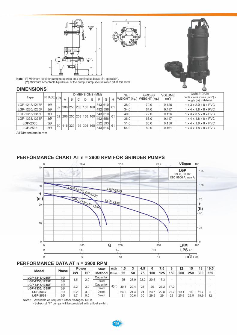
LGPGrinder Pumps (2.0 HP to 5.0 HP)
Performance Range
Flow rate up to 325 l/min. (19.5 m³/h)Dynamic head up to 32 m.
Applications
Durable heavy duty finned cast iron construction. Features
Used in pressure sewage system.
Specification
Drainage of waste water from individual residences, apartment, buildings, recreational developments, motels.
Transferring waste water of commercial buildings, industrial plants, waste water sampling, small hospitals.
Schools, federal, state and local parks’ waste water drainage.
To transfer various waste water and sewage.
Grinder is complete unit, light weight, compact, and portable, easy to be installed.Double protection at connection box: barrier grommet, barrier epoxy, prevent water ingress to the motor area, assuring a longterm reliable operation.Additionally, epoxy encapsulation and stripped leads positively eliminate wicking from the cable.Two balls bearing construction support shaft and rotor.Dry type motor with high efficiency and low current. Equipped with auto reset motor protector,prevent the motor damage from abnormal heatand current.The dual silicon carbide mechanical seal system and extra oil seal protection protects the motor from sewage contamination, to provide you exceptionally long pump service life.
An excellent vortex impeller and casing water cavity housing design. Provide high efficiency and power saving, handling ground slurry and sewage without clogging or binding.
Radial cutter and cutter ring: corrosion resistant material, hardened to 55 - 60 Rockwell C.
Specialized one single strong shaft with impeller and radial cutter, dramatically reduces the torque requirement on the motor, cuts with less horsepower, and increases the pump’s efficiency. What’s more, it prevents clogging with some troublesome objects such as sanitary napkins, plastic, rubber, disposable diapers and cloth items. The design of Lubi grinder prevents clogging, binding and roping. They chop up almost anything and everything in order for you to get a continuous, long - term pumping service.
Cutting Ability Demonstration
Handle
Upper cover
Bearing
Stator body
Bearing
Lubricant
Output
Volute
Base stand Cutter ring
Radial cutter
Vortex impeller
Oil seal
Double mechanical seal
Lower bearing housingShaft
Stator
Automatic reset motor protector
Centrifugal switch
Cable base
Cable
Cutting in progress
0°C to +50°C
Ambient temp Max. +50°C
Suitable for pumping waste water of commercial buildings, hotels & restaurants, hospitals, industrial plants & kitchen waste.
S1 - When pump is completely submerged.S3 - When pump is partially submerged.
Direction of Rotation Clockwise as seen from the motor rear end.
Volute
Stator body
Shaft
Mechanicalseal
Motor side - Carbon v/s Ceramic
Pump side - Silicon carbide v/s Silicon carbide
1 Ph. 230 V +5/-15%, 3 Ph. 400 V +5/-15%
S.S AISI 410PVC
S.S AISI 440
S.S AISI 440
19
DIMENSIONS
All Dimensions in mm
LGP-1215 /1215F
LGP-1235/1235F
LGP-1315 /1315F
LGP-1335/1335F
LGP-2335
LGP-2535
1Ø
3Ø
1Ø
3Ø
3Ø
3Ø
32
32
50
286
286
416
250
250
339
203
203
195
156
156
226
160
160
160
543
492
543
492
522
543
610
556
610
556
593
616
61
61
61
NET WEIGHT (kg.)
GROSSWEIGHT (kg.)
VOLUME3(m )
38.0
34.0
40.0
36.0
51.0
54.0
70.0
64.0
72.0
66.0
86.0
89.0
0.126
0.117
0.126
0.117
0.156
0.161
1 x 3 x 2.0 x 8 x PVC
1 x 4 x 1.8 x 8 x PVC
1 x 3 x 3.5 x 8 x PVC
1 x 4 x 1.8 x 8 x PVC
1 x 4 x 1.8 x 8 x PVC
1 x 4 x 1.8 x 8 x PVC
D
H
E
M.W.L**
F
G
N.W.L*
A
B
C
PERFORMANCE DATA AT n = 2900 RPM
PERFORMANCE CHART AT n = 2900 RPM FOR GRINDER PUMPS
Note : • Available on request : Other Voltages, 60Hz.• Subscript "F" pumps will be provided with a float switch.Note :
0 100 200 300 400LPM0
10
20
30
40
0
25
50
75
100
125
Q
H(m)
H(ft)
USgpm0 26.4 52.8 79.2 106
0 6 12 18 24m3/h
0 1.6 3.2 4.8 6.4LPS
LGP-1215/LGP-1235
LGP-2335
LGP-2535
LGP-1315/LGP-1335
Power
kW HP
15
250
12
200
9
150
7.5
125
6
100
4.5
75
3
50
1.5StartMethod
3m /h
l/min.
H(m)
LGP-1215 /1215FLGP-1235/1235FLGP-1315 /1315FLGP-1335/1335F
LGP-2335LGP-2535
Model
1Ø3Ø1Ø3Ø3Ø3Ø
2.23.7
1.5
2.2
Phase
3.05.0
2.0
3.0
CapacitorDirect
CapacitorDirectDirectDirect
18
300
19.5
325
-
24.631
24.430.6
2430
23.729.5
22.829
21.728
19.125.9
1623.5
11.719.9
512
25
- -
25
30.8
23.9
29.4
22.2
28
20.5
26
17.3
23.2
-
17.2
- - - -
-
LGP2900, 50 Hz
ISO 9906 Annex A
DIMENSIONS (MM)
Note : (*) Minimum level for pump to operate on a continuous basis (S1 operation). (**) Minimum acceptable liquid level of the pump. Pump should switch off at this level.
CABLE DATAcable x core x size (mm²) x
length (m) x Material

20
LLPLarge Volume Water Pumps (3.0 to 15.0 HP)
Flood control
Performance Range
Flow rate up to 9000 l/min. (540 m³/h)Dynamic head up to 6 m.
Applications
Large flow capacities achieved with almost no vibrationor noise by use of Propeller or Mix Flow design, giving easy operation and energy savings.
Aquaculture water pumping and drainagefor large volume water applications.Water supply for landscape and water features.Water extracting from rivers, lakes and reservoirs.Flood control.
Features
Robust construction and compact design with a dry motor, double mechanical seal and impeller flow guide vane for high efficiency.
Simple operation and maintenance.
Specification
Cable
Cable base
Bearing
Body cover
Shaft
Bearing
Volute
Lubricant
Volute cover
Volute base
Impeller
Oil seal
Mechanical seal
Mechanical seal chamber
Lower bearing housing
Rotor
Stator
Stator body
Insideupper cover
Outsideupper cover
Aquafarm dewatering
Ditch dewatering
S1 - When pump is completely or partially submerged.
0°C to +50°C
Type Dry motor
Ambient temp Max. +50°C
Suitable for aquaculture water pumping, flood control and water extraction from rivers, lakes and reservoir.
Pu
mp
Direction of Rotation Clockwise as seen from the motor rear end.
Volute
Stator body
Shaft
3 Ph. 400 V +5/-15%
S.S AISI 304
Thermoplastic Rubber/PVC
S.S AISI 304

21
PERFORMANCE DATA AT n = 1450 RPM
PERFORMANCE CHART AT n = 1450 RPM FOR HEAVY DUTY SEWAGE PUMPS
0 2000 4000 6000 8000 10000LPM0
1
2
3
4
5
6
7
8
0
6
12
18
24
Q
H(m)
H(ft)
USgpm0 528
0 120 240 360 480 600m3/h
0 33.3 66.6 99.9 133.2 166.5LPS
LLP-8735
LLP-101035
LLP-121535
LLP-6335
1056 1584 2112 2640
DIMENSIONS
LLP-6335
LLP-8735
LLP-101035
LLP-121535
Model
Three Phase
Disc. mm (Inch)
Dimensions (mm)
Length Width Height
Gross Weight(kg.)
SolidPassage (mm)
-
-
-
-
285
340
380
430
638
923
1015
1077
91.0
176.0
228.0
282.0
1 x 4 x 1.0 x 8 x PVC
1 x 4 x 6.0 x 8 x PVC
1 x 4 x 6.0 x 8 x PVC
1 x 4 x 8.0 x 8 x Thermoplastic rubber
20
22
22
23
Net Weight(kg.)
52.0
122.0
164.0
209.0
Volume 3(m )
0.159
0.272
0.344
0.432
150 (6")
200 (8")
250 (10")
300 (12")
3.2 2.6 2.3 2
5.8
2.4
5.2 3.4 2.5
4.4
kW
6 4.1 3.3
4.6
5.6
W
H
LLP1450, 50 Hz
ISO 9906 Annex A
Cable datacable x core x size (mm²) x
length (m) x Material

22
LASHeavy-Duty Construction Drainage Pumps (1.5 HP to 10.0 HP)
Performance Range
Flow rate up to 2500 l/min. (150 m³/h)Dynamic head up to 38 m.
Applications
Civil engineering dewatering of tunneling andground works, also for storm water sewers.Dewatering of fluids containing solid sediments.
Specifically designed for civil engineeringapplications, where a heavy duty, light weight,top discharge design, is required which is easy to handle. The double outer casing, water cooledmotor makes it particularly suitable for low waterlevel applications.A fully waterproof IP 68 stainless steel structure,combined with a high grade silicon carbide doublemechanical seals.The LAS range of pumps are compact, strong andeasy to operate in any situation.Special designed high efficient and wear resistantHCR (High Chrome) impeller.Multi impeller design suitable from high head withsmall capacity to low head with large capacity ofapplication requirement.Optional discharge connection (Hose, flange and thread connection)
Features
Special Features on Request
Other voltages.Available in 60Hz.
Thermal overload protectorEquipped with Automatic reset motor protector, prevents motor f rom burning due to high temperature/phase failure/voltage drop and locked impeller.
The LAS impeller is manufactured with a high chrome alloy (HCR) steel with a hardness of 55 - 60 Rc.,which makes it resistant to prolonged use in abrasive applications.
HCR Impeller
Protector Impeller
Specification
Diameter (mm)
Liquid nature
Impeller
Mech. seal
Bearing
Body cover
Upper cover
Volute
Impeller
Type
Insulation
Frequency
Thermal Protector
Stator body
Shaft
Cable
50 - 80
Liquid temp 0°C to +50°C
Open
Double Mechanical seal
Ball type bearing
Grey Iron
Grey Iron
HCR
Dry motor
F Class
50 Hz
Automatic reset motor protector
Motor Side
Pump Side
Carbon v/s Ceramic
Silicon Carbide v/s Silicon Carbide
Protection
Duty
Voltage
IP 68
S1 - When pump is completely or partially submerged.
1 Ph. 230 v +5/-15%, 3 Ph. 400 v +5/-15%
Str
uct
ure
Mate
rial
M. se
al
Pum
pM
oto
r
Mate
rial
HP 1.1 to 3.7 kW
Pum
pin
g
liquid
Suitable for dewatering at civil engineering sites and pumping of storm water.
Open Enclosed
Grey Iron
3 Ph. 400 v +5/-15%
5.5 to 7.5 kW
80 100 - 150
Wear Ring - - HCR
Flange
Handle
Cable
Upper bearing
Body cover
Stator body
Lower bearing
Lower bearing housing
Lubricant
Impeller
Strainer
Volute base ring
Volute ring
Volute
Oil seal
Mechanical seal
Rotor
Stator
Shaft
Automatic resetmotor Protector
Upper cover
Ambient temp Max. +50°C
Direction of Rotation Clockwise as seen from the motor rear end.
Thermoplastic Rubber/PVC
S.S. AISI 410
S.S. AISI 304
S.S. AISI 304

23
LASHeavy-Duty Construction Drainage Pumps (15.0 to 20.0 HP)
Specifically designed for civil engineering applications, where a heavy duty, light weight, top discharge design, is required which is easy to handle. The double outer casing, water cooled motor makes it particularly suitable for low water level applications.A water detector is provided in the seal chamber. In case ofseal failure if water enters the seal chamber, a signal can besent to the control panel so that the pump operator is madeaware of a potential seal leakage problem.A fully waterproof IP 68 stainless steel structure, combined with a high grade silicon carbide double mechanical seals.The LAS range of pumps are compact, strong and easy to operate in any situation.Special designed high efficient and wear resistant HCR (High Chrome) impeller.Multi impeller design suitable from high head with small capacity to low head with large capacity of application requirement.Optional discharge connection (Hose, flange and thread connection)
Specification
Diameter (mm)
Liquid nature
Liquid temp 0°C to +50°C
Double Mechanical seal
HP
Pum
pin
g
liquid
Suitable for dewatering at civil engineering sites and pumping of storm water.
Enclosed
11 to 15 kW
100 - 150
Ambient temp Max. +50°C
Type
Insulation
Frequency
Thermal Protector
Grey Iron
Grey Iron
HCR
Dry motor
F Class
50 Hz
Miniature Thermal Protector
Carbon v/s Ceramic
Silicon Carbide v/s Silicon Carbide
Protection
Duty
Voltage
IP 68
S1 - When pump is completely or partially submerged.
Pum
pM
oto
r
Grey Iron
3 Ph. 400 v +5/-15%
HCR
Thermoplastic Rubber/PVC
S.S. AISI 410
S.S. AISI 304
Str
uct
ure
Mate
rial
M. se
al
Impeller
Mech. seal
Water detector
Body cover
Upper cover
Volute
Impeller
Motor Side
Pump Side
Wear Ring
Bearing
Installed in the seal chamber to detect water leakage from water infiltrating
Ball type bearing
Mate
rial Stator body
Shaft
Cable
Performance Range
Flow rate up to 2600 l/min. (156 m³/h)Dynamic head up to 57 m.
Applications
Civil engineering dewatering of tunneling andground works, also for storm water sewers.Dewatering of fluids containing solid sediments.
Features
Special Features on Request
Other voltages.Available in 60Hz.
Miniature Thermal ProtectorMiniature Thermal Protector (MTP) is embedded in the windings of the motor. The MTP will transmit a signal to a control panel when windings temperature reaches a set point.
The LAS impeller is manufactured with a high chrome alloy (HCR) steel with a hardness of 55 - 60 Rc.,which makes it resistant to prolonged use in abrasive applications.
HCR Impeller
Impeller
Direction of Rotation Clockwise as seen from the motor rear end.
Lifting chain
Cable
Cable base
Upper cover
Upper bearing
Body cover
Stator body
Lower bearing
Lower bearing housing
Lubricant
Impeller
Strainer
Volute base ring
Volute
Volute ring
Oil seal
Mechanical seal
Rotor
Water detector
Shaft
MTP - MiniatureThermal Protector
Outlet

24
PERFORMANCE DATA AT n = 2900 RPM
PERFORMANCE CHART AT n = 2900 RPM FOR CONSTRUCTION DRAINAGE PUMP
LAS 21A15/21A15F
LAS 3215/3215F
LAS 3315/3315F
Model
Single Phase
Power
kW HP
StartMethod
3m /h
I/min
6
100
16.5
12
200
12.5
18
300
6
24
400
7
30
500
4
36
600
8
42
700
5.5
48
800
13.5
60
1000
8
66
1100
4.7
LAS 21A35/21A35F
LAS 3235/3235F
LAS 3335/3335F
LAS 3535
Three Phase
Capacitor
Direct
Capacitor
Direct Hm
15.3
20.3
12.8
18.4
24.5
10
16.4 14
21.6
12.5
1826 23.3 19.9 16
1.1 1.5
1.5 2.0
2.2 3.0
3.7 5.0
Capacitor
Direct
Direct
LAS 3215, 3235, 3315, 3335, 3535
LAS 21A15, 21A35 LAS 3735, 4735, 6735, 41035, 41535, 61035,
61535, 42035
H
L
W
Note : Subscript "F" pumps will be provided with a float switch.
DIMENSIONSModel
Single Phase
LAS 21A35/21A35F
LAS 3235/3235F
LAS 3335/3335F
LAS 3535
LAS 3735
LAS 4735
LAS 6735
LAS 41035
LAS 61035
LAS 41535
LAS 61535
LAS 42035
Three Phase
Disc. mm (Inch)
Dimensions (mm)
Length Width Height
Gross Weight
(kg.)
SolidPassage
mm
210
210
250
250
250
250
250
290
290
290
290
290
290
290
332
210
210
240
240
240
240
240
290
290
290
290
290
290
290
332
510
435
630
535
645
560
600
690
690
745
690
745
725
785
770
49.0
45.0
68.0
64.0
72.0
67.0
71.0
102.0
104.0
106.0
104.0
108.0
112.0
116.0
185.0
8
8
11
11
11
11
11
10
10
10
10
10
10
10
10
Net Weight
(kg.)
29.0
25.0
43.0
39.0
47.0
42.0
46.0
74.0
76.0
78.0
76.0
80.0
82.0
86.0
142.0
Volume 3(m )
0.077
0.068
0.111
0.097
0.113
0.101
0.107
0.150
0.150
0.160
0.150
0.160
0.170
0.180
0.200
50 (2")
80 (3")
80 (3")
80 (3")
80 (3")
100 (4")
150 (6")
100 (4")
150 (6")
100 (4")
150 (6")
100 (4")
LAS 21A15/21A15F
LAS 3215/3215F
LAS 3315/3315F
0 5 10 15
0
5
10
15
20
25
30
0 250 500 750 1000
0
15
30
45
60
75
90
0 15 30 45 60
Hft
.
Hm
ts.
Q (l/sec)
Q (l/min)
Q (m3/h)
LAS-3315/LAS-3335
LAS-3535
LAS-3215/LAS-3235
LA
S-21A
15/
LA
S-21A
35
0 50 100 150 200 250 Q (USgpm)
LAS2900, 50 Hz
ISO 9906 Annex A
Cable datacable x core x size (mm²) x
length (m) x Material
1 x 3 x 1.0 x 5 x PVC
1 x 4 x 1.0 x 5 x PVC
1 x 3 x 2.0 x 8 x PVC
1 x 4 x 1.8 x 8 x PVC
1 x 3 x 3.5 x 8 x PVC
1 x 4 x 1.8 x 8 x PVC
1 x 4 x 1.8 x 8 x PVC
1 x 4 x 3.5 x 8 x PVC
1 x 4 x 3.5 x 8 x PVC
1 x 4 x 3.5 x 8 x PVC
1 x 4 x 3.5 x 8 x PVC
1 x 4 x 3.5 x 8 x PVC1 x 7 x 6.0 x 8 x Thermoplastic rubber
1 x 3 x 0.75 x 8 x Thermoplastic rubber1 x 7 x 6.0 x 8 x Thermoplastic rubber
1 x 3 x 0.75 x 8 x Thermoplastic rubber1 x 7 x 6.0 x 8 x Thermoplastic rubber
1 x 3 x 0.75 x 8 x Thermoplastic rubber

25
LASHeavy-Duty Construction Drainage Pumps (7.5 HP to 20.0 HP)
PERFORMANCE DATA AT n = 2900 RPM
Model Power
kW HP
StartMethod
3m /h
I/min
LAS 3735
LAS 4735
LAS 41035
Three Phase
Direct
Direct
Direct Hm
12
200
24
400
36
600
48
800
66
1100
72
1200
96
1600
18
300
30
500
54
900
84
1400
60
1000
34.0
37.0
27.0
30.0
33.4
25.0
24.0
18.6
28.8
20.0
25.0
6.2
16.0
15.6
9.2027.9
32.0
35.9
26.0
34.6
27.5
25.0
32.0
21.5
15.0
27.0
18.8
11.0
23.0
17.5
20.8
12.7
9
108
1800
5.75.5 7.5
7.5 10.0
PERFORMANCE DATA AT n = 2900 RPM
Model Power
kW HP
StartMethod
3m /h
I/min
22.8
18
300
36
600
54
900
90
1500
LAS 6735
LAS 61035
LAS 61535
Three Phase
Direct
DirectHm
72
1200
108
1800
126
2100
20.5 18.0 15.0 12.1 9.0
27.5 24.9 22.0 19.0 16.0
144
2400
5.413.0
6.0
9.4
5.5 7.5
7.5 10.0
PERFORMANCE CHART AT n = 2900 RPM FOR CONSTRUCTION DRAINAGE PUMP
15.0
20.0
11.0
15.0
LAS 41535
LAS 42035
45.3
55.5
41.3
51.2
37.0
46.5
33.8
42.8
27.0
33.7
44.0
54.0
42.7
52.8
39.9
50.0
35.4
44.8
32.2
40.8
30.5
38.6
23.3
27.0
19.3
8.0
0 10 20 30 40
0
10
20
30
40
0 500 1000 1500 2000 2500
0
20
40
60
80
100
120
0 30 60 90 120 150
Hft
.
Hm
ts.
0 150 300 450 600
Q (l/sec)
Q (l/min)
Q (m3/h)
LAS-6735
LAS-61035
LAS2900, 50 Hz
ISO 9906 Annex A
Q (USgpm)
LAS-61535
32.1 30.2 27.8 26.0 21.5 8.617.7 14.911.0 15.0
PERFORMANCE CHART AT n = 2900 RPM FOR CONSTRUCTION DRAINAGE PUMP
Q (USgpm)
Q (l/sec)
Q (l/min)
Q (m3/h)
Hft
.
Hm
ts.
0 10 20 30
0 500 1000 1500 2000
0 25 50 75 100 125
0
20
40
60
80
100
120
140
160
180
0
10
20
30
40
50
0 100 200 300 400 500
60
LAS2900, 50 Hz
ISO 9906 Annex A
LAS-41035LAS-4735
LAS-3735
LAS-41535
LAS-42035

NOTE

NOTE
LUBI INDUSTRIES LLP
Sales Enquiries: [email protected], [email protected]
www.lubipumps.com
Near Kalyan Mills, Naroda Road, Ahmedabad-380 025, INDIA.Phone : +91 - 79 - 30610100, Fax No. :+91 - 79 - 30610300.
Product Improvement is a continuous process at ‘LUBI’. The data given in this publication is therefore subject to revision.
Toll Free Service Hotline for India : 1800 3000 305509.01.110517.0044


