Embed Size (px)
Citation preview
ME-322
(Term Project)
Academic Session- January-May, 2014
Continuously Variable Transmission
(Guided by Dr. Narayan Reddy, Assistant Professor,
Dept. of Mechanical Engineering, IITG)
BY: Deepak Paramkusam 11010342
Priyabrata Behera 11010351
Rajat Tiwari 11010351
Ramnath Vijaykumar Pillai 11010352
Prabha Shankar 11010383
Indian Institute of Technology Guwahati
Design Analysis of Continuously Variable Transmission
Abstract
This dissertation is concerned with the design, analysis and control of a continuously variable transmission and
extending its usage to a two wheeler (keeping in the mind the load and working condition of an engine of a two
wheelers like Honda active in the case). This transmission is able to provide infinite gear ratios between two
constraint limits, without the use of any clutch to disengage the engine from the drive line and hence transfers
uninterrupted power to the wheels and mostly runs engine at a constant power. The transmission is, in theory, capable
of a better user experience, without the rise and fall in speed of an engine, and the jerk felt when changing gears
poorly. Based on the parameters of a two wheeler engine, a CAD model for individual components, like belt and
pulley were designed and were further assembled. The control aspects monitoring the pulley movement was shown
through a simple hydraulic system managed by an electronic control unit (ECU).
Introduction
Most current production automobiles use either conventional manual transmission or automatic transmission
mounted with multiple gear sets that uses integral clutches and bands to achieve discrete gear ratios. The most
common current production automatic transmission have four gear ratios while newly introduced transmissions have
five gear ratios. Typically, the additional fifth gear ratio is used to improve the vehicle launch characteristics. With
Further addition of a sixth gear levels off the fuel economy improvement and any additional gear provide
dramatically reduced incremental benefits. Besides intermittent changing of gears through an integral clutch causes
a loss in rpm as one shifts from one gear to any other gear. However, use of CVT can tackle some of these problems.
A CVT’s advantage is that it allows an engine to operate over a wide range of speeds and loads while in many cases
being independent of speed and torque requirements placed on the wheels by vehicle and the driver. The CVT allows
the driver or a computer to select the relationship between the speed of the engine and the speed of the wheels within
a continuous range. A continuously variable transmission (CVT) is a transmission that can change seamlessly
through an infinite number of effective gear ratios between maximum and minimum values. In this transmission
where the ratio of the rotational speeds of two shafts, as the input shaft and output shaft of a vehicle or other machine,
can be varied continuously within a given range, providing an infinite number of possible ratios. This contrasts with
other mechanical transmissions that offer a fixed number of gear ratios. The flexibility of a CVT allows the input
shaft to maintain a constant angular velocity. An engine can produce broad range of torque at any given speed
demanded, or a broad range of engine speed for any torque demand. For any given power demand, however, there
is only a narrow operating speed and torque at which the engine is most efficient. Because a CVT allows and engine
to run at this most efficient point virtually independent of vehicle speed, a CVT equipped vehicle yields fuel
economy benefits when compared to a conventional transmission offering only a limited number of input/output
ratios.
CVTs can provide a cheap automatic gear solution by enabling the engine to run at its most efficient revolutions per
minute (RPM) for a range of vehicle speeds, CVTs can't handle high torques to have an acceptable fuel efficiency
at low cost. However, it can be used to maximize the performance of a vehicle by allowing the engine to turn at the
RPM at which it produces peak power. This is typically higher than the RPM that achieves peak efficiency. Finally,
a CVT does not strictly require the presence of a clutch. Nevertheless, in some vehicles (e.g. motorcycles) a
centrifugal clutch is added, to facilitate a "neutral" stance, which is useful when idling or manually reversing into a
parking space.
Thus, a CVT provides the precise, independent coupling of engine speed and torque output with drive wheel
requirements that allow an optimized combination of performance and fuel consumption to be realized. The sections
following consists of discussions involving the four major design aspects of CVT, that are:
General Specifications
Belt design and analysis
Pulley design and analysis
Control analysis
Pulley based Transmission—
In the case designing, the particular CVT used is a metal based V-belt type. Such a CVT consists of two pulleys
connected by a V-belt. The primary sheave is driven directly by the engine while the secondary sheave provides
input to a secondary reduction. This is a common arrangement in small vehicles that incorporate CVTs.
The main components of the primary pulley are fixed and movable sheaves, a set of two flyweights, and a hydraulic
actuator. As the engine speed increases, the flyweights tend to swing open and push the movable sheave inward
toward the fixed sheave. However, this movement is not possible until the force created by the flyweights is able to
overcome the force caused by the primary spring. Once this is occurs, the flyweights must also overcome the
resisting force caused by friction between the belt and the sheaves as well as the spring forces in both the primary
and secondary pulleys. The secondary pulley includes fixed and moveable sheaves and a spring loaded in
compression. As the primary begins to shift, its two sheaves move closer together. This, in turn, narrows the width
of the v-slot driving the belt to a larger diameter. The normal force caused by the wedging of the belt between the
sheaves forces the secondary sheaves apart, which allows the belt to move to a smaller diameter on the secondary.
This is the process that shifts the system to a higher gear ratio.
The pulleys of a push belt or chain type CVT are actuated axially to adjust transmission ratio and to apply a belt
clamping force. In conventional CVTs this is done using hydraulics. The CVT transmission ratio is dependent on
the ratio of primary and secondary clamping force, and can be controlled by the pressure in the cylinders.
CVTs are increasingly found on small cars, and especially high-gas-mileage or hybrid vehicles. On these platforms,
the torque is limited because the electric motor can provide torque without changing the speed of the engine. By
leaving the engine running at the rate that generates the best gas mileage for the given operating conditions, overall
mileage can be improved over a system with a smaller number of fixed gears, where the system may be operating at
peak efficiency only for a small range of speeds. CVTs are also found in agricultural equipment; due to the high-
torque nature of these vehicles, mechanical gears are integrated to provide tractive force at high speeds. The system
is similar to that of a hydrostatic gearbox, and at 'inching speeds' relies entirely on hydrostatic drive.
Some of the current day examples of these hybrid vehicles are Toyota Prius, Highlander and Camry, the Nissan
Altima, and newer-model Ford Escape Hybrid SUVs. CVT technology uses only one input from a prime mover, and
delivers variable output speeds and torque; whereas PST technology uses two prime mover inputs, and varies the
ratio of their contributions to output speed and power. These transmissions are fundamentally different. The
Mitsubishi Lancer, Proton Inspira, Honda Insight, Honda Fit, and Honda CR-Z hybrids, the Nissan Tiida/Versa SL
and SV models), Nissan Versa Note (S Plus and higher), Nissan Cube, Juke, Sentra, Altima, Maxima, 2013 1.2 Note,
Rogue, X-Trail, Murano, Sunny, Micra, Honda Capa, Honda Civic GX (CNG), Honda Civic HX (Hybrid), Honda
Accord, Jeep Patriot and Compass, and Subaru Forester Impreza, Legacy and Outback, Dodge Caliber, and Toyota
Corolla offer CVT.
Types of CVT
Variable-diameter pulley (VDP) or Reeves drive
In this most common CVT system,[4] there are two V-belt pulleys that are split perpendicular to their axes
of rotation, with a V-belt running between them. The gear ratio is changed by moving the two sheaves of
one pulley closer together and the two sheaves of the other pulley farther apart. Due to the V-shaped cross
section of the belt, this causes the belt to ride higher on one pulley and lower on the other. Doing this
changes the effective diameters of the pulleys, which in turn changes the overall gear ratio. The distance
between the pulleys does not change, and neither does the length of the belt, so changing the gear ratio
means both pulleys must be adjusted (one bigger, the other smaller) simultaneously in order to maintain
the proper amount of tension on the belt.
Toroidal or roller-based CVT (Extroid CVT)
Toroidal CVTs are made up of discs and rollers that transmit power between the discs. The discs can be
pictured as two almost conical parts, point to point, with the sides dished such that the two parts could fill
the central hole of a torus. One disc is the input, and the other is the output. Between the discs are rollers
which vary the ratio and which transfer power from one side to the other. When the roller's axis is
perpendicular to the axis of the near-conical parts, it contacts the near-conical parts at same-diameter
locations and thus gives a 1:1 gear ratio. The roller can be moved along the axis of the near-conical parts,
changing angle as needed to maintain contact. This will cause the roller to contact the near-conical parts at
varying and distinct diameters, giving a gear ratio of something other than 1:1. Systems may be partial or
full toroidal. Full toroidal systems are the most efficient design while partial toroidals may still require a
torque converter, and hence lose efficiency.
Magnetic CVT or mCVT
A magnetic continuous variable transmission system was developed at the University of Sheffield in 2006
and later commercialized. mCVT is a variable magnetic transmission which gives an electrically
controllable gear ratio. It can act as a power split device and can match a fixed input speed from a prime-
mover to a variable load by importing/exporting electrical power through a variator path. The mCVT is of
particular interest as a highly efficient power-split device for blended parallel hybrid vehicles, but also has
potential applications in renewable energy, marine propulsion and industrial drive sectors. The magnetic
CVT cannot generate greater torque than an electric motor of the same size, so it is not a replacement for
mechanical automobile transmission.
Hydrostatic CVTs
Hydrostatic transmissions use a variable displacement pump and a hydraulic motor. All power is
transmitted by hydraulic fluid. These types can generally transmit more torque, but can be sensitive to
contamination. Some designs are also very expensive. However, they have the advantage that the hydraulic
motor can be mounted directly to the wheel hub, allowing a more flexible suspension system and
eliminating efficiency losses from friction in the drive shaft and differential components. This type of
transmission is relatively easy to use because all forward and reverse speeds can be accessed using a single
lever.
Infinitely Variable Transmission (IVT)
A subset of CVT designs are called infinitely variable transmissions (IVT or IVTs), in which the range of
ratios of output shaft speed to input shaft speed includes a zero ratio that can be continuously approached
from a defined "higher" ratio. A zero output speed (low gear) with a finite input speed implies an infinite
input-to-output speed ratio, which can be continuously approached from a given finite input value with an
IVT. Low gears are a reference to low ratios of output speed to input speed. This low ratio is taken to the
extreme with IVTs, resulting in a "neutral", or non-driving "low" gear limit, in which the output speed is
zero. Unlike neutral in a normal automotive transmission, IVT output rotation may be prevented because
the back-driving (reverse IVT operation) ratio may be infinite, resulting in impossibly high back-driving
torque; in a ratcheting IVT, however, the output may freely rotate in the forward direction.
Design and analysis of components
Most of the CVTs that have been designed and are in use are mostly for low torque ended four wheelers or electric
hybrid cars. However, in this project we are extending our discussion and analysis to a two wheeler with low torque
requirements. For this reason we chose a Honda Activa as the vehicle to understand the engine requirements for the
same and extend it to CVT modelling.
Basic Design Parameters:
We have tried to extend the approach of usage of CVT to a two wheeler since vehicles of these kinds usually have
a low torque and power requirement. We have chosen the vehicle Honda activa with the following specifications:
Category
Specifications/Details
Engine 102 cc 4-stroke, single-cylinder, air-cooled
Top Speed 90kmph
Power 7 bhp (5.2 kW) or 8 bhp (5.71 KW)
Torque 8.74 Nm
Transmission V-matic Shaft Drive
Suspension Bottom link with spring loaded hydraulic damper (front),
unit swing with spring loaded hydraulic damper (rear)
Fuel Consumption 45-50 km/l
Basic CVT Mechanism and components involved:
The Van-Doorne metal pushing V-belt CVT comprises an endless composite metal belt with two pair of variable V-
shape pulleys (secondary and primary). The endless metal pushing V-belt is wound around both pulleys. The input
pulley is usually called the primary pulley that driving the transmission (driven pulley), which in then connected to
the vehicle wheels through the final drivetrain (driving pulley).The construction of the pulleys such way that, one-
half of each pulley are fixed to the shaft while the other half are adjustable as it can be slide along their respective
shafts. The axially adjustable V-shaped pulleys enable the MPVB to slide radially outwards or inwards. Thus, the
effective belt radius can be sleeplessly adjusted. General control has been designed in such way that the primary
pulley determine the speed ratio while at the secondary pulley, ensured that the proper belt tension always be
maintained to prevent slipping.
One sheave of each pulley is connected with a hydraulic circuit, these controlled sheaves are on the opposite side of
the belt. With the hydraulic circuit the clamping force on each pulley can be varied, by modifying the clamping force
the radius of each pulley can be changed, and so the transmission ratio. This kind of transmission can provide a
speed ratio from 0.4 up to 2 or even higher. Movement of the movable sheaves in and out cause the change of gear
ratio of a given CVT system.
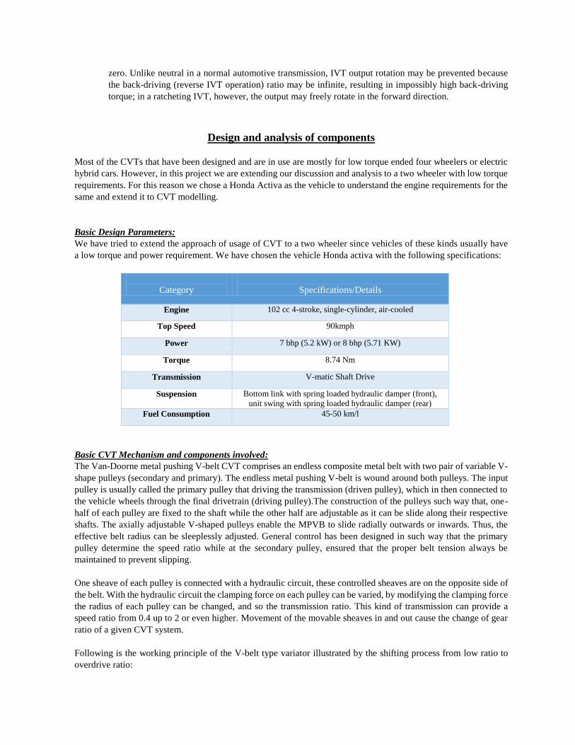
Following is the working principle of the V-belt type variator illustrated by the shifting process from low ratio to
overdrive ratio:
The Continuously Variable Transmission (CVT) system consists of two parts: the variator (drive pulley), and the
clutch (driven pulley). These are connected by the CVT belt.
The CVT system works through the changing of the distance between the plates on the two pulleys. The clutch
pulley plate width increases, and vice versa. This creates an infinite number of possible gear ratios, as the
transmission is altering itself on the fly to adapt to the current driving condition.
The variator is driven directly by the engine. Inside the variator are 6 rollers that are positioned in individual slots
with ramps that they will move along outward when centrifugal force is applied. As the rollers move outward, they
press against the ramp plate which causes the pulley plates of the variator to move toward one another, compressing
the belt. This "V" shape created by the pulley plates pushes the belt outward, which draws the belt inward on the
driven (clutch) side, increasing the gear ratio.
At idle, the rollers are at their innermost position, the variator pulley plates are at their farthest apart, and the CVT
belt is low on the variator side and high on the clutch side. With increasing RPMs, the rollers move outward along
their ramps applying pressure to the ramp plate, which compresses the variator pulley plates and squeezes the CVT
belt outwards.
The clutch in a CVT system engages when the centrifugal forces of the spinning clutch overcomes the tension of
the clutch arm springs and allow the clutch pads to engage with the clutch bell, creating movement. The main clutch
torque spring compresses the clutch pulley plates together, forcing the belt outward and acting against the variator.
As the rollers compress the variator side pulley plates when RPMs increase, the belt is forced outward on the variator.
Since the belt is a constant length, this causes the belt to be pulled inward on the clutch, overcoming the tension of
the torque spring.
The rotational torque is transmitted via belts from drive pulley to the driven pulley and thus acts as a link connecting
the two. The belt appears in several forms. The most important belt types are:
• Dry belt,
• Chain and
• Push-belt.
In our analysis we have chosen the Metal Pushing V-belt type and we would now proceed on the detailed analysis
of the BELT, PULLEY and their CONTROL SYSTEM.
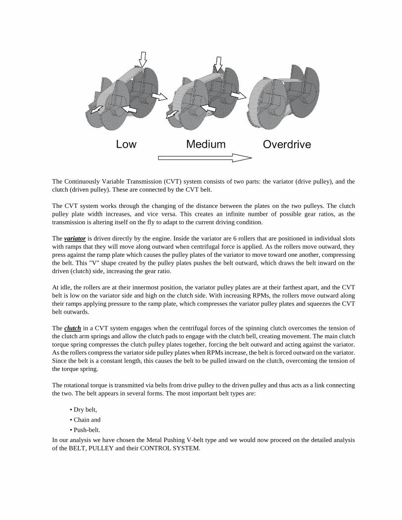
Belt Type and its Analysis
As the name goes this type of belt are V shaped. The development of the V-belt type CVT began with rubber V-
belts. However, rubber V-belt CVTs are not well suited for automotive applications, because of their limited torque
capacity. Push belts are of interest because a much higher friction coefficient is established between belt and pulleys
than in lubricated variants. It consist of segmented , thick-stamped steel blocks configured with horizontal cutouts
on both sides that contain stacked ribbons of steel termed as bands that shape the segments into an overall belt
assembly. Its function is to transfer rotational motion and torque from one pulley (driver) to other (driven) smoothly,
quietly. The belt that was designed by Van Doorne basically comprises two sets of thin metallic band strips and a
number of thin metallic plates (segment) as illustrated. The entire segment a bend together by two sets bands through
the segments location slots. This situation allowed the segment to slide freely along the sets of bands.
The flexible belt consists of many high-strength, bow-tie-shaped metal pieces that are held together by two packs of
layered steel bands. Generally each pack has 4–12 layers of bands, and each band is about 0.2 mm thick that fit
tightly together, holding the blocks together. In contrast to flat belts, V –belts are used with similar sheaves. However
they have several advantage over chain drive like flexibility, inexpensive, smooth operation, ease of installation,
usability in more than one plane etc.
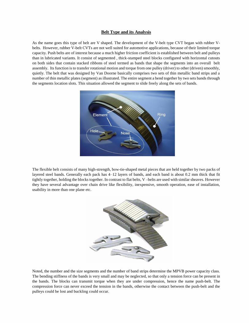
Noted, the number and the size segments and the number of band strips determine the MPVB power capacity class.
The bending stiffness of the bands is very small and may be neglected, so that only a tension force can be present in
the bands. The blocks can transmit torque when they are under compression, hence the name push-belt. The
compression force can never exceed the tension in the bands, otherwise the contact between the push-belt and the
pulleys could be lost and buckling could occur.
The function of a V belt drive is to transmit rotational motion and torque from one pulley to another, smoothly,
quietly and inexpensively. Belt provides overall combination of design flexibility, low cost and maintenance, ease
of assembly and space savings. A V belt is made of fabric and cord, usually cotton, rayon, or nylon, and impregnated
with rubber. In contrast with flat belts, v belt are used with similar sheaves and at shorter center distances. V belt
are slightly less efficient than flat belts, but a number of them can be used on a single sheave, thus making a multiple
drive. V belt are made only in certain lengths and have no joint.
The amount of power which can be transmitted is determined by tensile strength in bands as the belt squeeze.
Because the bands are in tension, they hold the blocks in line with each other. The compression force can never
exceed the tension in the bands, otherwise the contact between the push belt and the pulleys could be lost and
buckling could occur. The torque that is transmitted results from the combination of:
1) Pushing force between blocks
2) Friction force between block and bands.
Apart from the losses in the bearings of the shafts and losses due to slip, there are friction losses in the pushbelt. The
bands and the blocks do not run at the same radius, causing a speed difference between the blocks and the bands.
This results in friction losses in the pushbelt, which lowers the efficiency of the pushbelt. Because of the continuous
bending and stretching of the bands, fatigue issues are important. Fatigue resistance specifications limit the torque
capacity of the variator, because the maximum clamping forces are limited. There are much more blocks in a pushbelt
than there are pins in a chain. This results in more quiet operation and higher axial stiffness. Also better resistance
to wear is achieved due to the lower surface pressure between pushbelt and pulley.
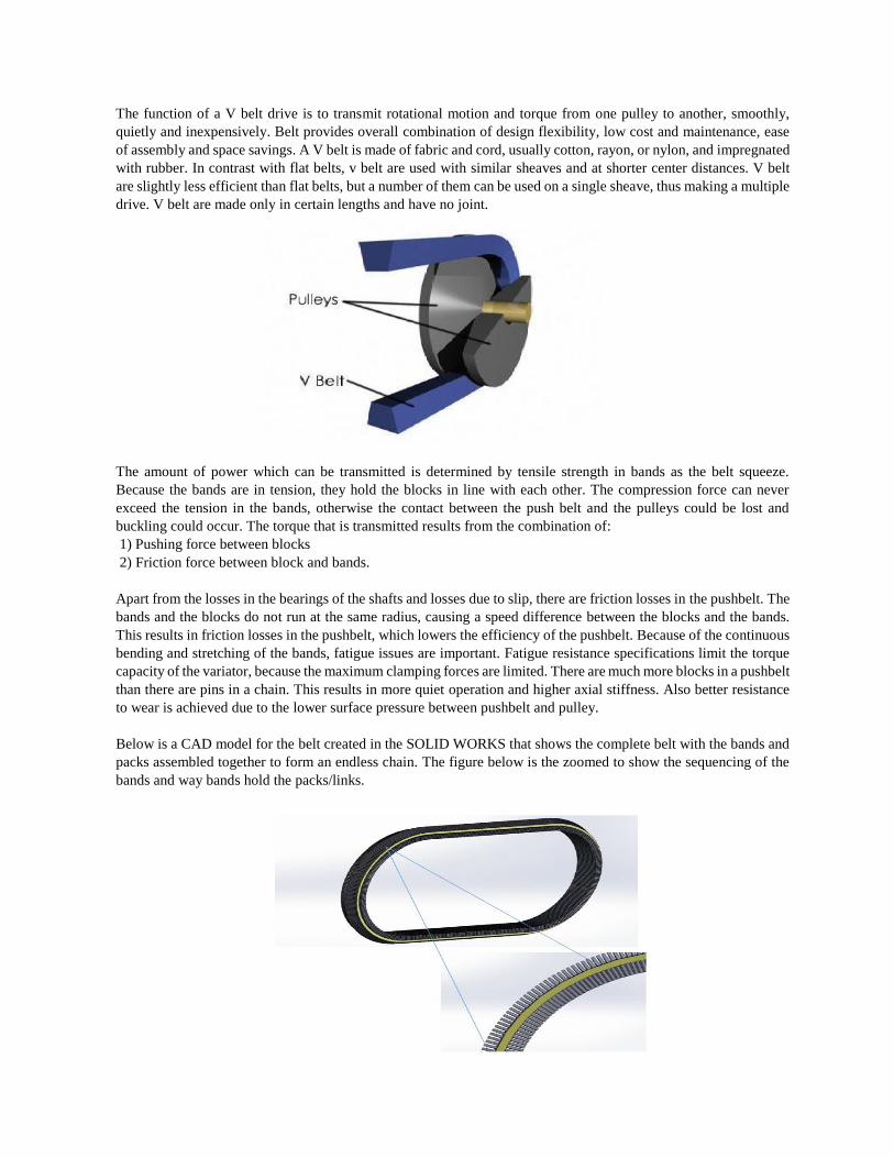
Below is a CAD model for the belt created in the SOLID WORKS that shows the complete belt with the bands and
packs assembled together to form an endless chain. The figure below is the zoomed to show the sequencing of the
bands and way bands hold the packs/links.
Length of the belt:
From the kinetic analysis of the belt under operating conditions and parameters, we derive the length of the belt. The
formula for the same has been presented here:
L = 𝝅(𝑹 + 𝒓) +(𝑹−𝒓)𝟐
𝑪 +𝑪(𝟐 − (
𝑹−𝒓
𝑪)𝟐)
where,
L: length of belt
R: radius of driver at maximum power
r: radius of driven at maximum power
C: distance between two pulley centers
Power transmitted by the belt:
To obtain the power transmitted by the belt, the dynamic analysis of the given belt assembly is done. Proceeding
ahead, the following assumptions are made in order to derive simple analytical equations for the axial forces:
(a) For the driver pulley, belt tension remains constant as T1 for the entire arc of contact by self-locking.
(b) For the driven pulley, the arc of contact is divided into two areas:
inactive area where the belt tension is constant
active area where the belt tension changes due to the belt movement in the radial and tangential direction.
(c) The coefficient of friction µ between the belt and the pulley is constant.
(d) The influence of belt bending moment is negligible that the belt is continuous and rigid:
P = 𝐓𝟏(𝟏−𝒆−𝝁𝜽/𝑺𝒊𝒏𝜶)𝐕
𝟏𝟎𝟎𝟎
where,
P: Power transmitted by belt drive
T: tension on tight side
μ: Coefficient of friction = 0.4
Θ: lapping angle
V: Velocity of belt
α: Pulley angle
From equation of power transmitted, we can get tension T1 for a known velocity at maximum power for a particular
belt configuration:
αt: allowable shear stress = St / fs
St: Ultimate tensile strength
fs: factor of safety
Here we took fs = 3 for block. Having known T1 and αt and b from inter-pulley distance for Rmin, we can get the
desired thickness t of block from following equation.
T1= 𝜶𝒕𝒕𝒃 − 𝒎𝒗𝟐
where,
t: thickness of belt
b: breadth of link
m: mass per unit length
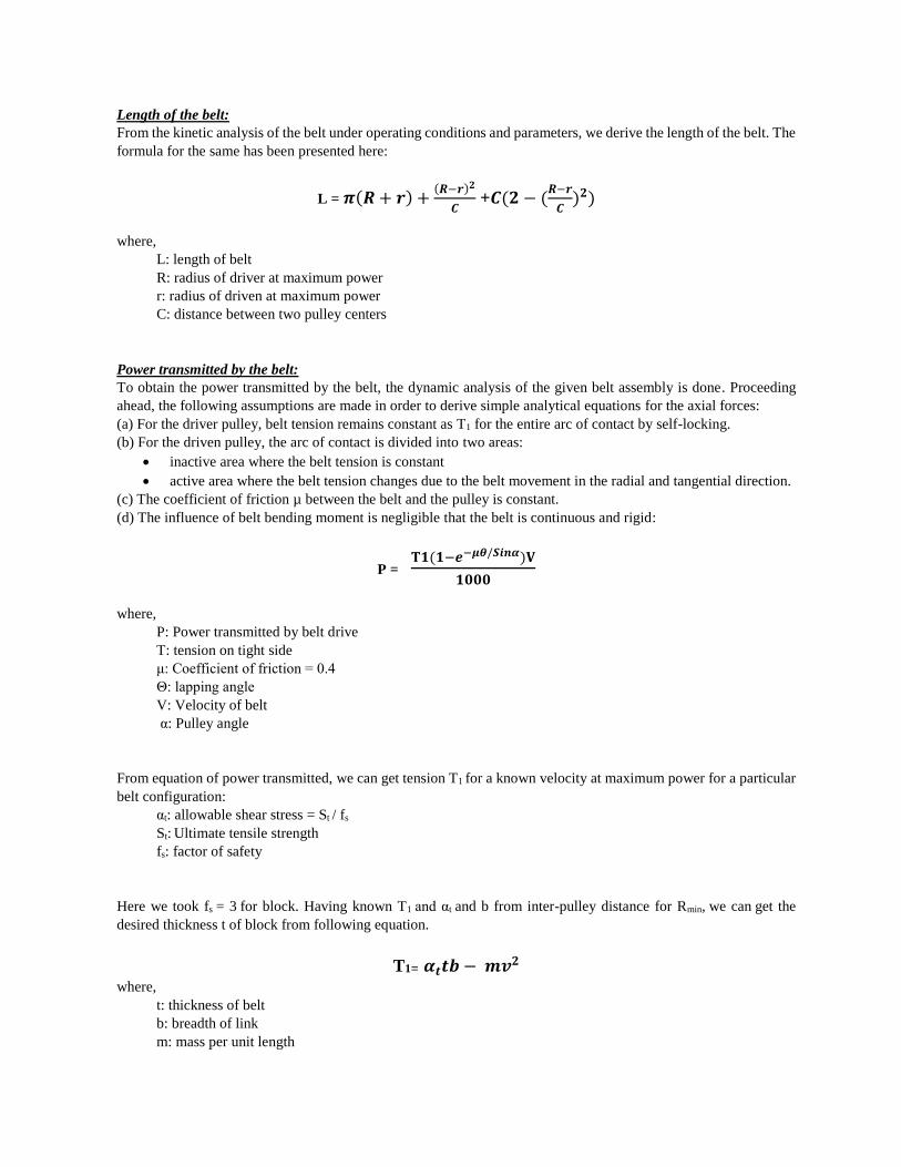
Force analysis on individual links:
Axial force (Fr) here is in z direction where α is pulley/belt angle, θ is angle of lap.
The analysis being discussed in this section follows from the FBD shown below:
Fr = θ [𝟏+𝝀
𝟒] [
𝟏−𝝁 𝐭𝐚𝐧𝜶
𝟐
𝝁+𝒕𝒂𝒏 𝜶
𝟐
]
λ = 𝐓𝟏 − 𝐓𝟐
𝐓𝟏+ 𝐓𝟐
where, T2 is tension in driven pulley belt element.
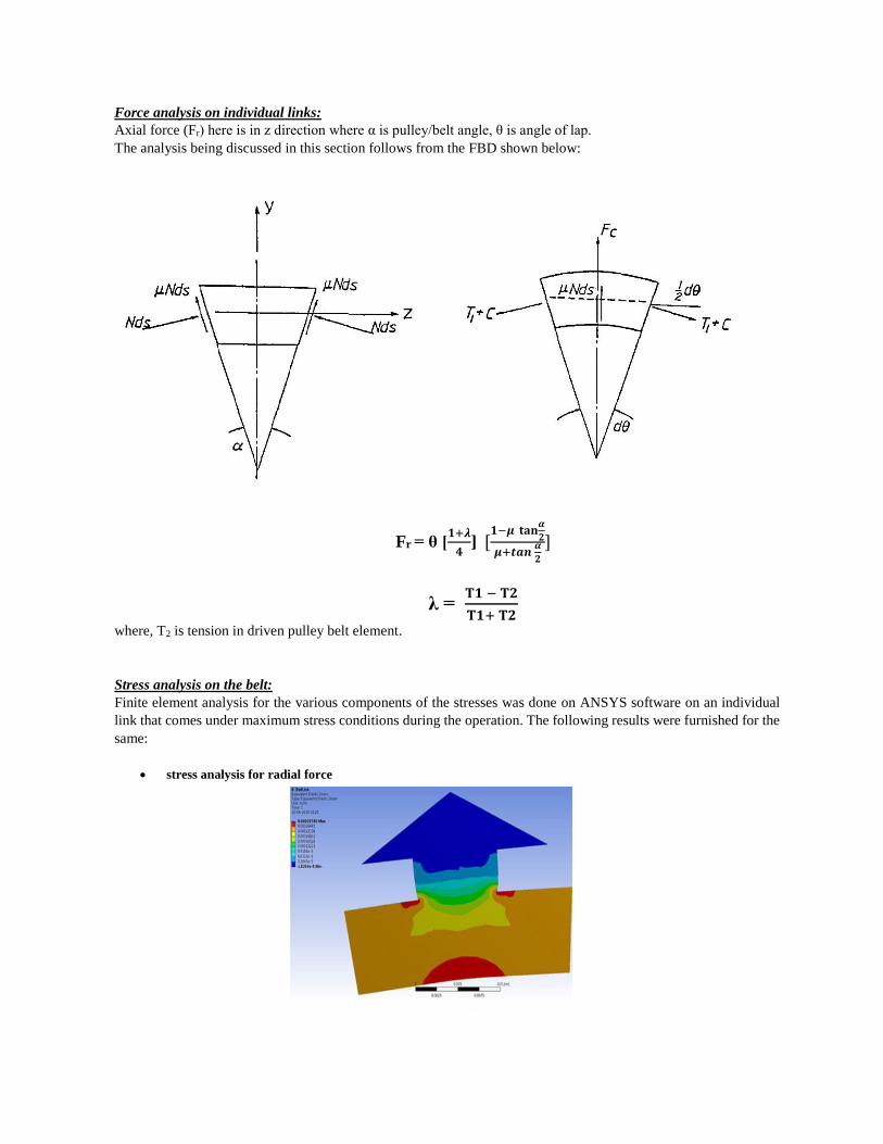
Stress analysis on the belt:
Finite element analysis for the various components of the stresses was done on ANSYS software on an individual
link that comes under maximum stress conditions during the operation. The following results were furnished for the
same:
stress analysis for radial force
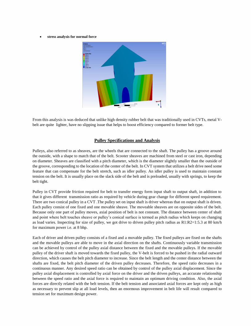
stress analysis for normal force
From this analysis is was deduced that unlike high density rubber belt that was traditionally used in CVTs, metal V-
belt are quite lighter, have no slipping issue that helps to boost efficiency compared to former belt type.
Pulley Specifications and Analysis
Pulleys, also referred to as sheaves, are the wheels that are connected to the shaft. The pulley has a groove around
the outside, with a shape to match that of the belt. Scooter sheaves are machined from steel or cast iron, depending
on diameter. Sheaves are classified with a pitch diameter, which is the diameter slightly smaller than the outside of
the groove, corresponding to the location of the center of the belt. In CVT system that utilizes a belt drive need some
feature that can compensate for the belt stretch, such as idler pulley. An idler pulley is used to maintain constant
tension on the belt. It is usually place on the slack side of the belt and is preloaded, usually with springs, to keep the
belt tight.
Pulley in CVT provide friction required for belt to transfer energy form input shaft to output shaft, in addition to
that it gives different transmission ratio as required by vehicle during gear change for different speed requirement.
There are two conical pulley in a CVT .The pulley set on input shaft is driver whereas that on output shaft is driven.
Each pulley consist of one fixed and one movable sheave. The moveable sheaves are on opposite sides of the belt.
Because only one part of pulley moves, axial position of belt is not constant. The distance between center of shaft
and point where belt touches sheave or pulley’s conical surface is termed as pitch radius which keeps on changing
as load varies. Inspecting for size of pulley, we got drive to driven pulley pitch radius as R1:R2=1:5.3 at 80 km/h
for maximum power i.e. at 8 bhp.
Each of driver and driven pulley consists of a fixed and a movable pulley. The fixed pulleys are fixed on the shafts
and the movable pulleys are able to move in the axial direction on the shafts. Continuously variable transmission
can be achieved by control of the pulley axial distance between the fixed and the movable pulleys. If the movable
pulley of the driver shaft is moved towards the fixed pulley, the V-belt is forced to be pushed in the radial outward
direction, which causes the belt pitch diameter to increase. Since the belt length and the center distance between the
shafts are fixed, the belt pitch diameter of the driven pulley decreases. Therefore, the speed ratio decreases in a
continuous manner. Any desired speed ratio can be obtained by control of the pulley axial displacement. Since the
pulley axial displacement is controlled by axial force on the driver and the driven pulleys, an accurate relationship
between the speed ratio and the axial force is required to maintain an optimum driving condition. Also, the axial
forces are directly related with the belt tension. If the belt tension and associated axial forces are kept only as high
as necessary to prevent slip at all load levels, then an enormous improvement in belt life will result compared to
tension set for maximum design power.
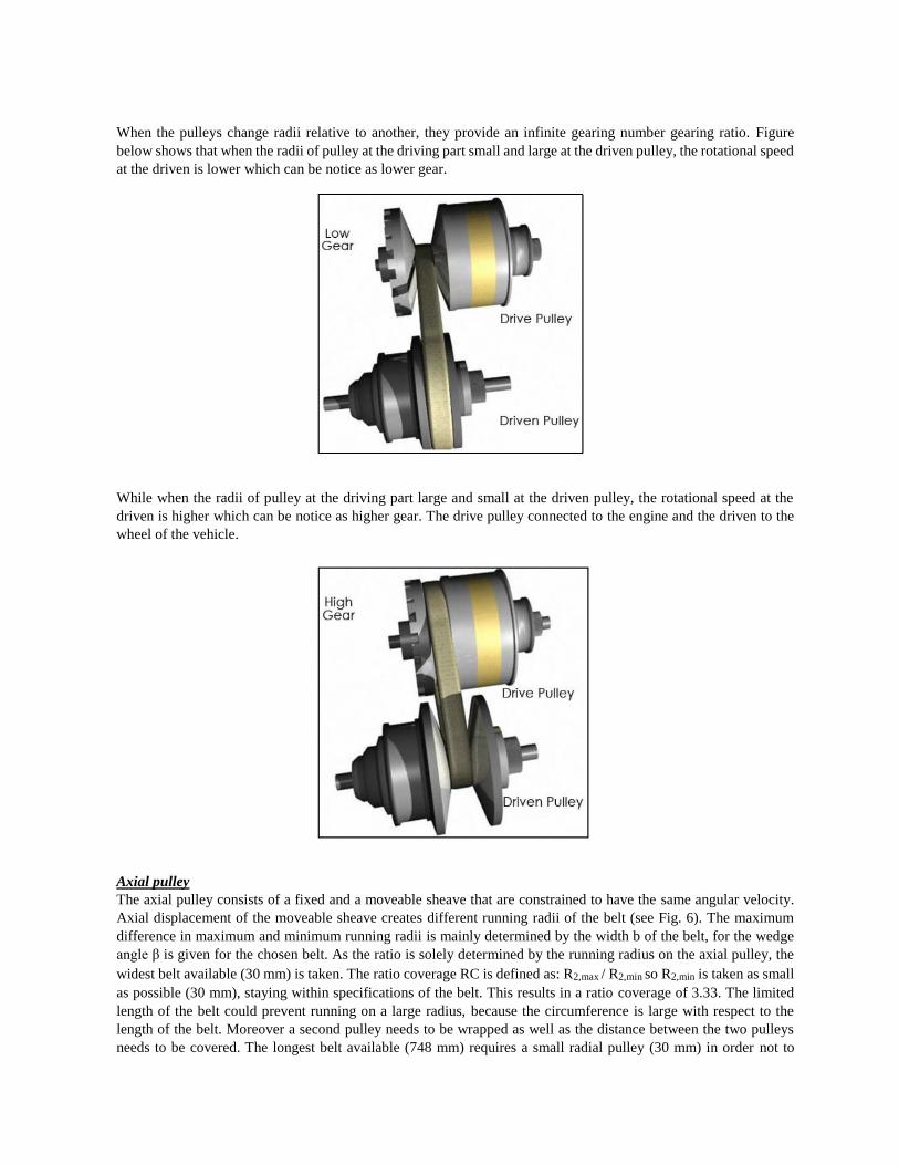
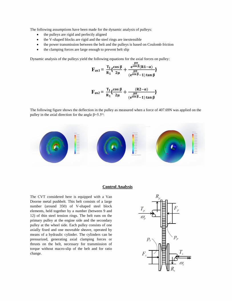
When the pulleys change radii relative to another, they provide an infinite gearing number gearing ratio. Figure
below shows that when the radii of pulley at the driving part small and large at the driven pulley, the rotational speed
at the driven is lower which can be notice as lower gear.
While when the radii of pulley at the driving part large and small at the driven pulley, the rotational speed at the
driven is higher which can be notice as higher gear. The drive pulley connected to the engine and the driven to the
wheel of the vehicle.
Axial pulley
The axial pulley consists of a fixed and a moveable sheave that are constrained to have the same angular velocity.
Axial displacement of the moveable sheave creates different running radii of the belt (see Fig. 6). The maximum
difference in maximum and minimum running radii is mainly determined by the width b of the belt, for the wedge
angle β is given for the chosen belt. As the ratio is solely determined by the running radius on the axial pulley, the
widest belt available (30 mm) is taken. The ratio coverage RC is defined as: R2,max / R2,min so R2,min is taken as small
as possible (30 mm), staying within specifications of the belt. This results in a ratio coverage of 3.33. The limited
length of the belt could prevent running on a large radius, because the circumference is large with respect to the
length of the belt. Moreover a second pulley needs to be wrapped as well as the distance between the two pulleys
needs to be covered. The longest belt available (748 mm) requires a small radial pulley (30 mm) in order not to
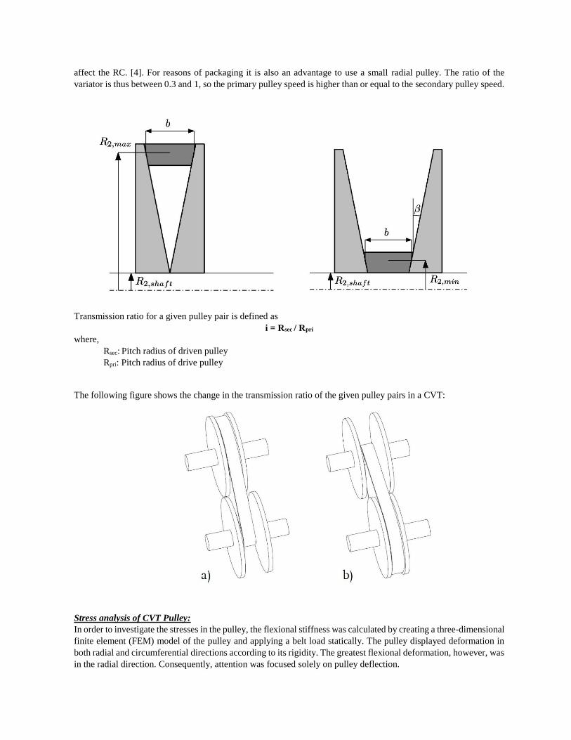
affect the RC. [4]. For reasons of packaging it is also an advantage to use a small radial pulley. The ratio of the
variator is thus between 0.3 and 1, so the primary pulley speed is higher than or equal to the secondary pulley speed.
Transmission ratio for a given pulley pair is defined as
i = Rsec / Rpri where,
Rsec: Pitch radius of driven pulley
Rpri: Pitch radius of drive pulley
The following figure shows the change in the transmission ratio of the given pulley pairs in a CVT:
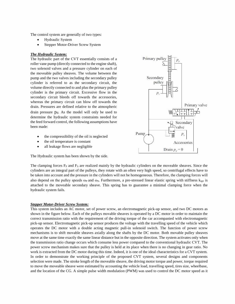
Stress analysis of CVT Pulley:
In order to investigate the stresses in the pulley, the flexional stiffness was calculated by creating a three-dimensional
finite element (FEM) model of the pulley and applying a belt load statically. The pulley displayed deformation in
both radial and circumferential directions according to its rigidity. The greatest flexional deformation, however, was
in the radial direction. Consequently, attention was focused solely on pulley deflection.
The following assumptions have been made for the dynamic analysis of pulleys:
the pulleys are rigid and perfectly aligned
the V-shaped blocks are rigid and the steel rings are inextensible
the power transmission between the belt and the pulleys is based on Coulomb friction
the clamping forces are large enough to prevent belt slip
Dynamic analysis of the pulleys yield the following equations for the axial forces on pulley:
Fax1 = 𝐓𝟏
𝐑𝟏{
𝐜𝐨𝐬 𝛃
𝟐𝛍+
𝐞𝛍𝛂
𝐬𝐢𝐧 𝛃(𝐑𝟏−𝛂)
(𝐞𝛍𝛂
𝐬𝐢𝐧 𝛃−𝟏) 𝐭𝐚𝐧 𝛃
}
Fax2 = 𝐓𝟏
𝐑𝟏{
𝐜𝐨𝐬 𝛃
𝟐𝛍+
(𝐑𝟐−𝛂)
(𝐞𝛍𝛂
𝐬𝐢𝐧 𝛃−𝟏) 𝐭𝐚𝐧 𝛃
}
The following figure shows the deflection in the pulley as measured when a force of 407.69N was applied on the
pulley in the axial direction for the angle β=5.5ᴼ:
Control Analysis
The CVT considered here is equipped with a Van
Doorne metal pushbelt. This belt consists of a large
number (around 350) of V-shaped steel block
elements, held together by a number (between 9 and
12) of thin steel tension rings. The belt runs on the
primary pulley at the engine side and the secondary
pulley at the wheel side. Each pulley consists of one
axially fixed and one moveable sheave, operated by
means of a hydraulic cylinder. The cylinders can be
pressurized, generating axial clamping forces or
thrusts on the belt, necessary for transmission of
torque without macro-slip of the belt and for ratio
change.
The control system are generally of two types:
Hydraulic System
Stepper Motor-Driver Screw System
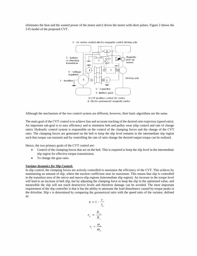
The Hydraulic System:
The hydraulic part of the CVT essentially consists of a
roller vane pump (directly connected to the engine shaft),
two solenoid valves and a pressure cylinder on each of
the moveable pulley sheaves. The volume between the
pump and the two valves including the secondary pulley
cylinder is referred to as the secondary circuit, the
volume directly connected to and plus the primary pulley
cylinder is the primary circuit. Excessive flow in the
secondary circuit bleeds off towards the accessories,
whereas the primary circuit can blow off towards the
drain. Pressures are defined relative to the atmospheric
drain pressure pd. As the model will only be used to
determine the hydraulic system constraints needed for
the feed forward control, the following assumptions have
been made:
the compressibility of the oil is neglected
the oil temperature is constant
all leakage flows are negligible
The Hydraulic system has been shown by the side.
The clamping forces FP and FS are realized mainly by the hydraulic cylinders on the moveable sheaves. Since the
cylinders are an integral part of the pulleys, they rotate with an often very high speed, so centrifugal effects have to
be taken into account and the pressure in the cylinders will not be homogeneous. Therefore, the clamping forces will
also depend on the pulley speeds ωP and ωS. Furthermore, a pre-stressed linear elastic spring with stiffness kspr is
attached to the moveable secondary sheave. This spring has to guarantee a minimal clamping force when the
hydraulic system fails.
Stepper Motor-Driver Screw System:
This system includes an AC motor, set of power screw, an electromagnetic pick-up sensor, and two DC motors as
shown in the figure below. Each of the pulleys movable sheaves is operated by a DC motor in order to maintain the
correct transmission ratio with the requirement of the driving torque of the car accompanied with electromagnetic
pick-up sensor. Electromagnetic pick-up sensor produces the voltage with the travelling speed of the vehicle which
operates the DC motor with a double acting magnetic pull-in solenoid switch. The function of power screw
mechanisms is to shift movable sheaves axially along the shafts by the DC motor. Both movable pulley sheaves
move at the same time exactly the same linear distance but in the opposite direction. The system activates only when
the transmission ratio change occurs which consume less power compared to the conventional hydraulic CVT. The
power screw mechanism makes sure that the pulley is held at its place when there is no changing in gear ratio. No
work is extracted from the DC motor during this time. Indeed, it is one of the ideal characteristics for a CVT system.
In order to demonstrate the working principle of the proposed CVT system, several designs and components
selection were made. The stroke length of the moveable sheave, the driving motor torque and power, torque required
to move the moveable sheave were estimated by accounting the vehicle load, travelling speed, tires size, wheelbase,
and the location of the CG. A simple pulse width modulation (PWM) was used to control the DC motor speed as it
eliminates the heat and the wasted power of the motor and it drives the motor with short pulses. Figure 2 shows the
3-D model of the proposed CVT.
Although the mechanism of the two control system are different, however, their basic algorithms are the same.
The main goal of the CVT control is to achieve fast and accurate tracking of the desired ratio trajectory (speed ratio).
An important sub-goal is to max efficiency and to minimize belt and pulley wear (slip control and rate of change
ratio). Hydraulic control system is responsible on the control of the clamping forces and the change of the CVT
ratio. The clamping forces are generated on the belt to keep the slip level remains in the intermediate slip region
such that torque can transmit and by controlling the rate of ratio change the desired output torque can be realized.
Hence, the two primary goals of the CVT control are:
Control of the clamping forces that act on the belt. This is required to keep the slip level in the intermediate
slip region for effective torque transmission.
To change the gear ratio.
Variator dynamics for Slip Control:
In slip control, the clamping forces are actively controlled to maximize the efficiency of the CVT. This achieve by
maintaining an amount of slip, where the traction coefficient near its maximum. This means that slip is controlled
in the transition area of the micro and macro-slip regions (intermediate slip region). An increase in the torque level
will lead to an increase in belt slip, but by adjusting the clamping force to keep the slip in the optimized value, and
meanwhile the slip will not reach destructive levels and therefore damage can be avoided. The most important
requirement of the slip controller is that it has the ability to attenuate the load disturbance caused by torque peaks in
the driveline. Slip ν is determined by comparing the geometrical ratio with the speed ratio of the variator, defined
as:
where, ωP and ωS are the angular speed for respectively the primary and the secondary pulley and rg Geometric
ratio and rs Speed ratio. The slip dynamics thus derived is:
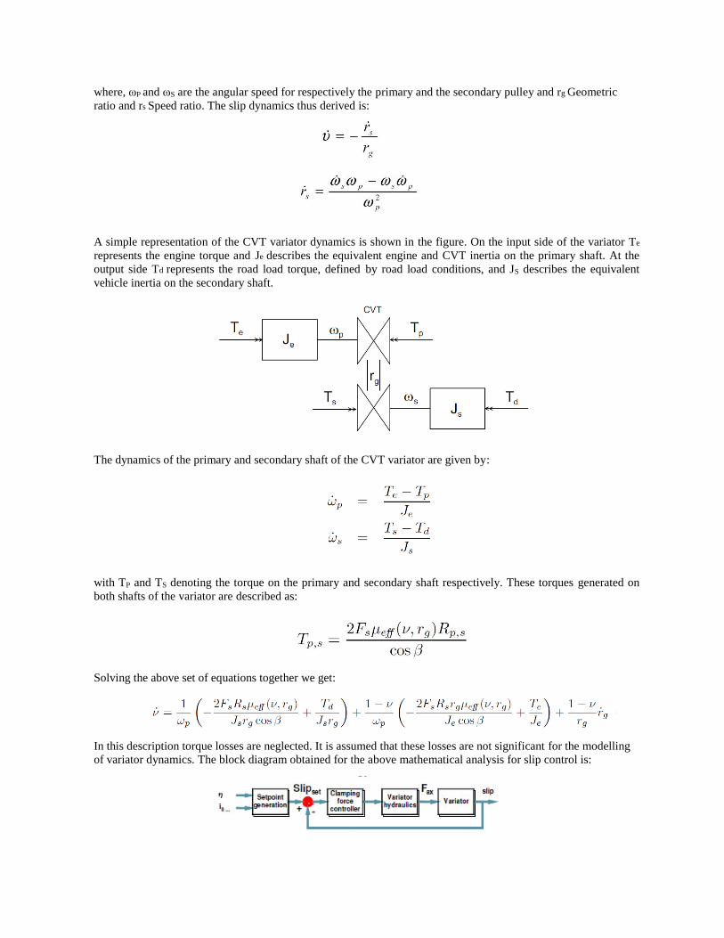
A simple representation of the CVT variator dynamics is shown in the figure. On the input side of the variator Te
represents the engine torque and Je describes the equivalent engine and CVT inertia on the primary shaft. At the
output side Td represents the road load torque, defined by road load conditions, and JS describes the equivalent
vehicle inertia on the secondary shaft.
The dynamics of the primary and secondary shaft of the CVT variator are given by:
with TP and TS denoting the torque on the primary and secondary shaft respectively. These torques generated on
both shafts of the variator are described as:
Solving the above set of equations together we get:
In this description torque losses are neglected. It is assumed that these losses are not significant for the modelling
of variator dynamics. The block diagram obtained for the above mathematical analysis for slip control is:
Variator Dynamics for Position control:
Besides the amount of slip ν, also the ratio rg is a control variable in the controller proposed. Since the primary axial
pulley position xp is measured and to avoid the nonlinear calculation from xp to xg, this linear position is used as
control variable. Considering this, the dynamic equations are rewritten to:
and
where both h(rg) and kc,x(rg) are certain ratio independent parameters. Defining the state vector x = [ ν xp ]T and
input vector u = [Fs ∆ln F Te Td]T and output vector y = x, the dynamics can be described, when linearized around
a certain working point x = [ ν0 xp0 ]T by,
Position control is usually achieved through determination of goal speed ratio which requires the involvement of
PID (Proportional, Integral and Differential) Controller.
PID controller is a control mode that has most mature technology and the most widely used in continuous system.
Because of its simple structure, easy adjustable parameters, and has accumulated rich experience during long-term
application in practice, so it has been widely used. Now, most CVT products adopt PID controller all over the world.
Ratio PID controller model is designed to realize the actual ratio's tracking of goal ratio, to make the engine working
in optimal performance set-point or optimal economic set-point ,according to the driver's intentions.
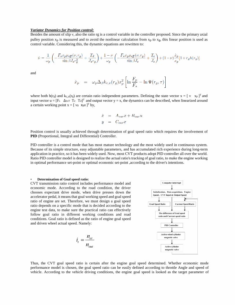
• Determination of Goal speed ratio:
CVT transmission ratio control includes performance model and
economic mode. According to the road condition, the driver
chooses expectant drive mode, when drive presses down the
accelerator pedal, it means that goal working speed and goal speed
ratio of engine are set. Therefore, we must design a goal speed
ratio depends on a specific mode that is decided according to the
engine test data, to make sure the practical ratio can effectively
follow goal ratio in different working conditions and road
conditions. Goal ratio is defined as the ratio of engine goal speed
and driven wheel actual speed. Namely:
Thus, the CVT goal speed ratio is certain after the engine goal speed determined. Whether economic mode
performance model is chosen, the goal speed ratio can be easily defined according to throttle Angle and speed of
vehicle. According to the vehicle driving conditions, the engine goal speed is looked as the target parameter of
controller, so the CVT transmission ratio and then the working point of engine can be adjusted, finally, to realize the
optimal performance and fuel economic of vehicle.
• Speed ratio PID controller model:
Speed ratio control is a process of CVT speed ratio control. If only control speed ratio of CVT system without
considering transient value caused by the ratio variation, then system transient characteristics is difficult to control.
If directly control the variation of speed ratio as control parameter, this problem can be solved. Therefore, in this
paper variation of speed ratio is controlled as PID control object to realize speed control. To determine ratio variation
reasonably is the key of CVT speed ratio matching, it will directly affect accelerating performance and smooth
acceleration of the car. Through a PID controller, the difference of goal ratio and actual ratio can obtain a transient
CVT control signal which is speed ratio variation (𝑑𝑖𝑑𝑡⁄ ). We can build a PID controller model for designing of
speed ratio PID controller. PID controller model are as follows:
Where,
kp = Proportional control parameters;
kd = Differential control parameters;
ki = Integral control parameters;
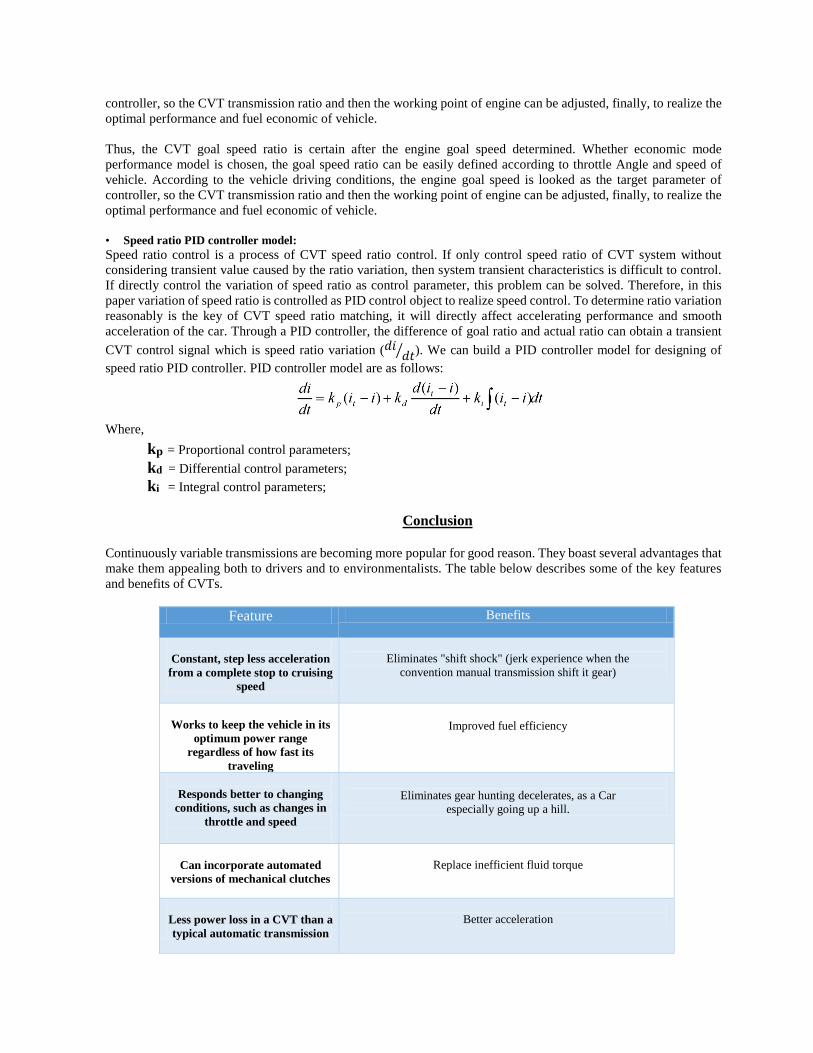
Conclusion
Continuously variable transmissions are becoming more popular for good reason. They boast several advantages that
make them appealing both to drivers and to environmentalists. The table below describes some of the key features
and benefits of CVTs.
Feature Benefits
Constant, step less acceleration
from a complete stop to cruising
speed
Eliminates "shift shock" (jerk experience when the
convention manual transmission shift it gear)
Works to keep the vehicle in its
optimum power range
regardless of how fast its
traveling
Improved fuel efficiency
Responds better to changing
conditions, such as changes in
throttle and speed
Eliminates gear hunting decelerates, as a Car
especially going up a hill.
Can incorporate automated
versions of mechanical clutches
Replace inefficient fluid torque
Less power loss in a CVT than a
typical automatic transmission
Better acceleration
However, there are certain Disadvantages associated with CVTs. The CVT's biggest problem has been user
acceptance. Because the CVT allows the engine to rev at any speed, the noises coming from under the hood sound
odd to ears accustomed to conventional manual and automatic transmissions. The gradual changes in engine note
sound like a sliding transmission or a slipping clutch – signs of trouble with a conventional transmission, but perfectly
normal for a CVT. Flooring an automatic car brings a lurch and a sudden burst of power, whereas CVTs provide a
smooth, rapid increase to maximum power. To some drivers this makes the car feel slower, when in fact a CVT will
generally out-accelerate an automatic. Automakers have gone to great lengths to make the CVT feel more like a
conventional transmission.
The continuously variable transmission is a promising transmission for all kinds of drive trains, good results can be
obtained in the field of emissions, efficiency and drivability. The pulley based CVT can be divided in two categories,
the metal push belt and the metal chain. The first step involved in the design analysis was determining the parameters
that helped us decide the engine specification. Followed by it was determination of the dimensions of the other
components to suffice the power requirements based on the parameter values and then was the stress analysis for
individual components. At the end was the portion that discussed about the control strategy of different segments of
the CVT and their synchronization.


