Embed Size (px)
Citation preview

Thank you orthoebooks for all you have done for us. This is a gift for you and others from me...:)
Dr. Tariq
Contemporary Orthodontics
5th ed.
William R. Proffit, DDS, PhD
Kenan Distinguished Professor, Department of Orthodontics and Chairman Emeritus, School of Dentistry, University of NorthCarolina, Chapel Hill, North Carolina
Henry W. Fields, DDS, MS, MSD
Professor and Head, Section of Orthodontics, College of Dentistry, The Ohio State University
Chief, Section of Orthodontics, Department of Dentistry, Columbus Children's Hospital, Columbus, Ohio
David M. Sarver, DMD, MS
Private Practice of Orthodontics, Birmingham, Alabama
Adjunct Professor, Department of Orthodontics, School of Dentistry, University of North Carolina, Chapel Hill, North Carolina
James L. Ackerman, DDS
Formerly Professor and Chairman, Department of Orthodontics, University of Pennsylvania, Philadelphia, Pennsylvania
978-0-323-08317-1
3251 Riverport Lane
St. Louis, Missouri 63043
CONTEMPORARY ORTHODONTICS
ISBN: 978-0-323-08317-1
Copyright © 2013 by Mosby, an imprint of Elsevier Inc.
Copyright © 2007, 2000, 1993, 1986 by Mosby, Inc., an affiliate of Elsevier Inc.
All rights reserved. No part of this publication may be reproduced or transmitted in any form or by any means, electronic or mechanical,including photocopying, recording, or any information storage and retrieval system, without permission in writing from the publisher.Details on how to seek permission, further information about the Publisher's permissions policies and our arrangements withorganizations such as the Copyright Clearance Center and the Copyright Licensing Agency, can be found at our website:www.elsevier.com/permissions.
This book and the individual contributions contained in it are protected under copyright by the Publisher (other than as may be notedherein).
Notices
Knowledge and best practice in this field are constantly changing. As new research and experience broaden ourunderstanding, changes in research methods, professional practices, or medical treatment may become necessary.
Practitioners and researchers must always rely on their own experience and knowledge in evaluating and using anyinformation, methods, compounds, or experiments described herein. In using such information or methods theyshould be mindful of their own safety and the safety of others, including parties for whom they have a professionalresponsibility.
With respect to any drug or pharmaceutical products identified, readers are advised to check the most currentinformation provided (i) on procedures featured or (ii) by the manufacturer of each product to be administered, toverify the recommended dose or formula, the method and duration of administration, and contraindications. It is theresponsibility of practitioners, relying on their own experience and knowledge of their patients, to make diagnoses, todetermine dosages and the best treatment for each individual patient, and to take all appropriate safety precautions.
To the fullest extent of the law, neither the Publisher nor the authors, contributors, or editors, assume any liability forany injury and/or damage to persons or property as a matter of products liability, negligence or otherwise, or from anyuse or operation of any methods, products, instructions, or ideas contained in the material herein.
Library of Congress Cataloging-in-Publication Data
Proffit, William R.
Contemporary orthodontics / William R. Proffit, Henry W. Fields Jr., David M. Sarver. – .5th ed.
p. ; cm.
Includes bibliographical references and index.
ISBN 978-0-323-08317-1 (hardcover : alk. paper)
I. Fields, Henry W. II. Sarver, David M. III. Title.
[DNLM: 1. Orthodontics–methods. WU 400]
617.6'43–dc23
2012006984
Vice President and Publisher: Linda Duncan
Executive Content Strategy: John Dolan
Senior Content Development Specialist: Brian Loehr

Publishing Services Manager: Catherine Jackson
Senior Project Manager: David Stein
Design Direction: Amy Buxton
Printed in Canada
Last digit is the print number: 9 8 7 6 5 4 3 2 1

Chapter 1 Malocclusion and Dentofacial Deformity in Contemporary Society
The Changing Goals of Orthodontic Treatment
Early Orthodontic TreatmentCrowded, irregular, and protruding teeth have been a problem for some individuals since antiquity, and attempts to correct thisdisorder go back at least to 1000 bc. Primitive (and surprisingly well-designed) orthodontic appliances have been found in bothGreek and Etruscan materials.1 As dentistry developed in the eighteenth and nineteenth centuries, a number of devices for the“regulation” of the teeth were described by various authors and apparently used sporadically by the dentists of that era.
After 1850, the first texts that systematically described orthodontics appeared, the most notable being Norman Kingsley's OralDeformities.2 Kingsley, who had a tremendous influence on American dentistry in the latter half of the nineteenth century, was amongthe first to use extraoral force to correct protruding teeth. He was also a pioneer in the treatment of cleft palate and related problems.
Despite the contributions of Kingsley and his contemporaries, their emphasis in orthodontics remained the alignment of the teeth andthe correction of facial proportions. Little attention was paid to bite relationships, and since it was common practice to remove teethfor many dental problems, extractions for crowding or malalignment were frequent. In an era when an intact dentition was a rarity, thedetails of occlusal relationships were considered unimportant.
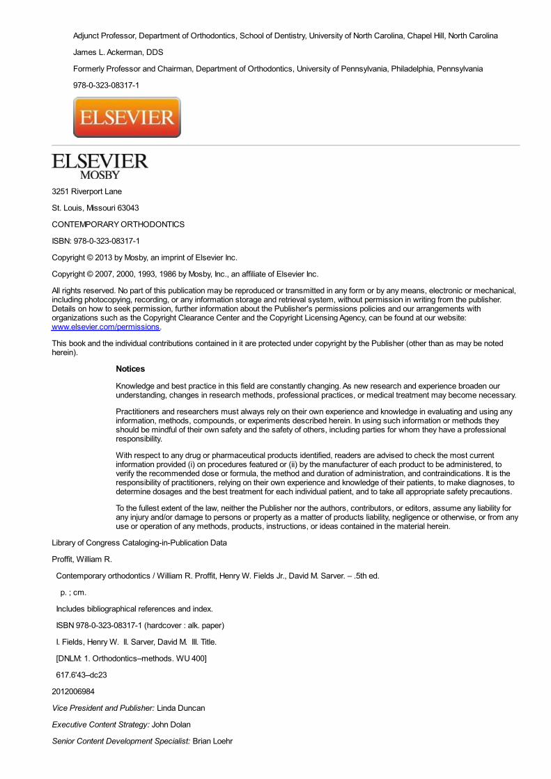
To make good prosthetic replacement teeth, it was necessary to develop a concept of occlusion, and this occurred in the late 1800s.As the concepts of prosthetic occlusion developed and were refined, it was natural to extend this to the natural dentition. Edward H.Angle (Figure 1-1), whose influence began to be felt about 1890, can be credited with much of the development of a concept ofocclusion in the natural dentition. Angle's original interest was in prosthodontics, and he taught in that department in the dentalschools at Pennsylvania and Minnesota in the 1880s. His increasing interest in dental occlusion and in the treatment necessary toobtain normal occlusion led directly to his development of orthodontics as a specialty, with himself as the “father of modernorthodontics.”
FIGURE 1-1 Edward H. Angle in his fifties, as the proprietor of the Angle Schoolof Orthodontia. After establishing himself as the first dental specialist, Angleoperated proprietary orthodontic schools from 1905 to 1928 in St. Louis; NewLondon, Connecticut; and Pasadena, California, in which many of the pioneerAmerican orthodontists were trained.
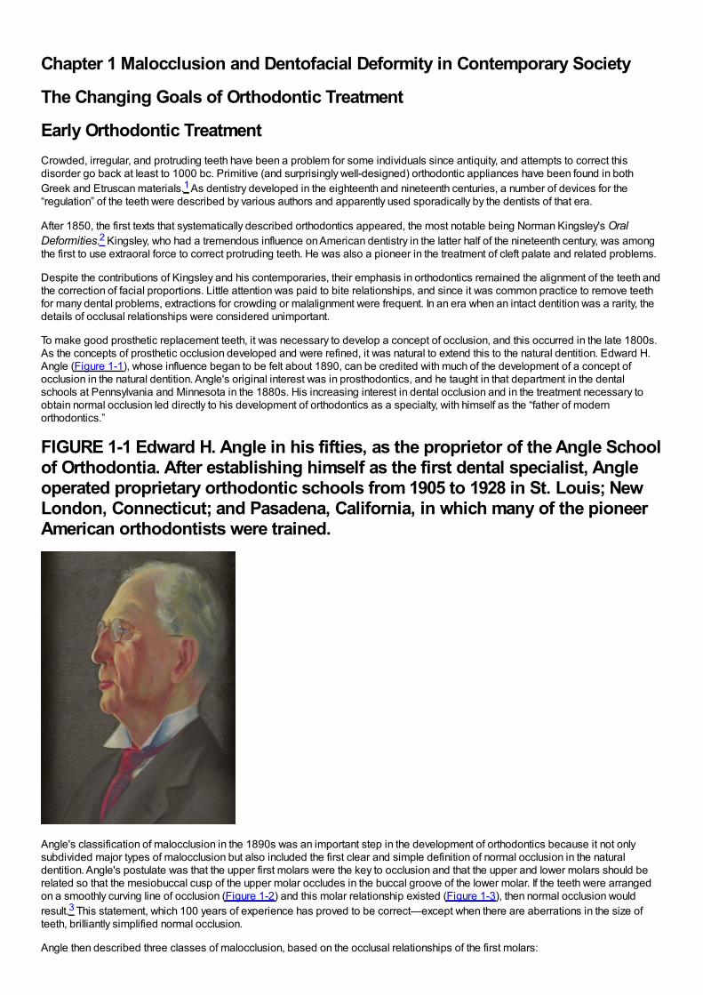
Angle's classification of malocclusion in the 1890s was an important step in the development of orthodontics because it not onlysubdivided major types of malocclusion but also included the first clear and simple definition of normal occlusion in the naturaldentition. Angle's postulate was that the upper first molars were the key to occlusion and that the upper and lower molars should berelated so that the mesiobuccal cusp of the upper molar occludes in the buccal groove of the lower molar. If the teeth were arrangedon a smoothly curving line of occlusion (Figure 1-2) and this molar relationship existed (Figure 1-3), then normal occlusion wouldresult.3 This statement, which 100 years of experience has proved to be correct—except when there are aberrations in the size ofteeth, brilliantly simplified normal occlusion.
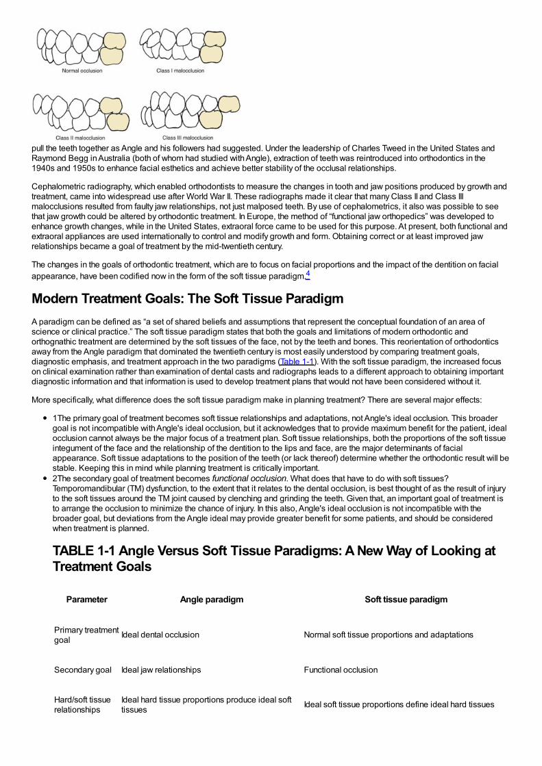
Angle then described three classes of malocclusion, based on the occlusal relationships of the first molars:
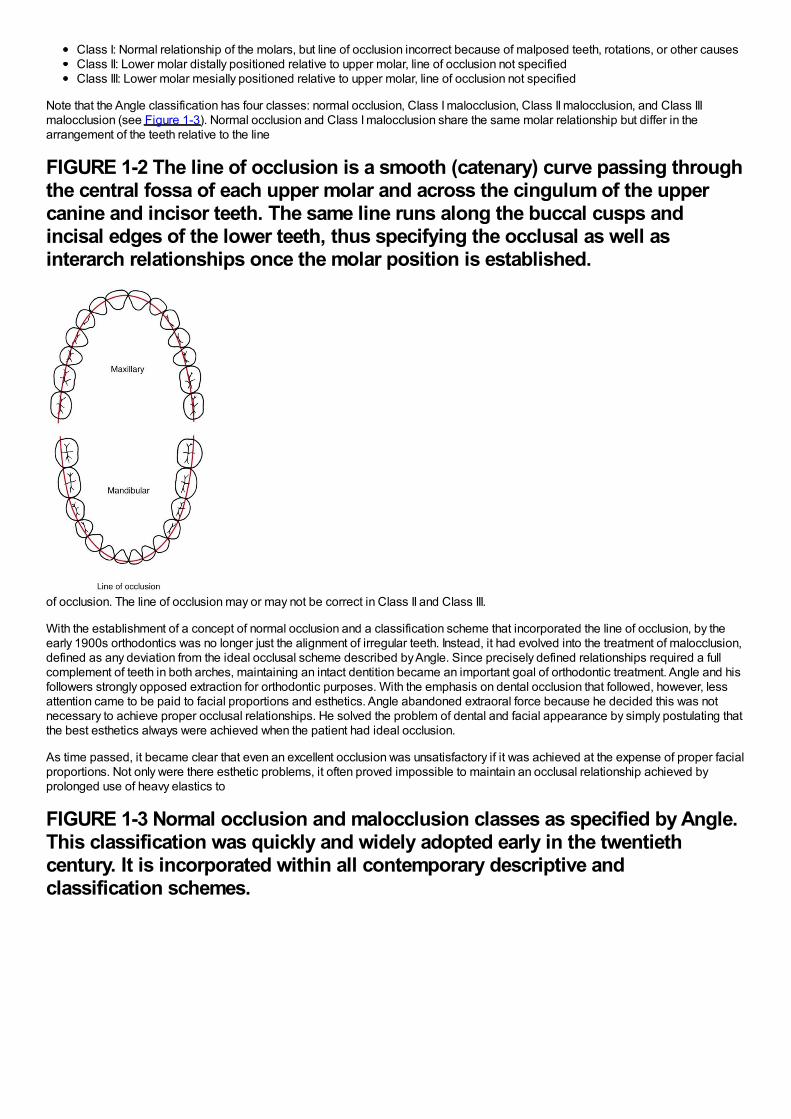
Class I: Normal relationship of the molars, but line of occlusion incorrect because of malposed teeth, rotations, or other causesClass II: Lower molar distally positioned relative to upper molar, line of occlusion not specifiedClass III: Lower molar mesially positioned relative to upper molar, line of occlusion not specified
Note that the Angle classification has four classes: normal occlusion, Class I malocclusion, Class II malocclusion, and Class IIImalocclusion (see Figure 1-3). Normal occlusion and Class I malocclusion share the same molar relationship but differ in thearrangement of the teeth relative to the line
FIGURE 1-2 The line of occlusion is a smooth (catenary) curve passing throughthe central fossa of each upper molar and across the cingulum of the uppercanine and incisor teeth. The same line runs along the buccal cusps andincisal edges of the lower teeth, thus specifying the occlusal as well asinterarch relationships once the molar position is established.
of occlusion. The line of occlusion may or may not be correct in Class II and Class III.
With the establishment of a concept of normal occlusion and a classification scheme that incorporated the line of occlusion, by theearly 1900s orthodontics was no longer just the alignment of irregular teeth. Instead, it had evolved into the treatment of malocclusion,defined as any deviation from the ideal occlusal scheme described by Angle. Since precisely defined relationships required a fullcomplement of teeth in both arches, maintaining an intact dentition became an important goal of orthodontic treatment. Angle and hisfollowers strongly opposed extraction for orthodontic purposes. With the emphasis on dental occlusion that followed, however, lessattention came to be paid to facial proportions and esthetics. Angle abandoned extraoral force because he decided this was notnecessary to achieve proper occlusal relationships. He solved the problem of dental and facial appearance by simply postulating thatthe best esthetics always were achieved when the patient had ideal occlusion.
As time passed, it became clear that even an excellent occlusion was unsatisfactory if it was achieved at the expense of proper facialproportions. Not only were there esthetic problems, it often proved impossible to maintain an occlusal relationship achieved byprolonged use of heavy elastics to
FIGURE 1-3 Normal occlusion and malocclusion classes as specified by Angle.This classification was quickly and widely adopted early in the twentiethcentury. It is incorporated within all contemporary descriptive andclassification schemes.
pull the teeth together as Angle and his followers had suggested. Under the leadership of Charles Tweed in the United States andRaymond Begg in Australia (both of whom had studied with Angle), extraction of teeth was reintroduced into orthodontics in the1940s and 1950s to enhance facial esthetics and achieve better stability of the occlusal relationships.
Cephalometric radiography, which enabled orthodontists to measure the changes in tooth and jaw positions produced by growth andtreatment, came into widespread use after World War II. These radiographs made it clear that many Class II and Class IIImalocclusions resulted from faulty jaw relationships, not just malposed teeth. By use of cephalometrics, it also was possible to seethat jaw growth could be altered by orthodontic treatment. In Europe, the method of “functional jaw orthopedics” was developed toenhance growth changes, while in the United States, extraoral force came to be used for this purpose. At present, both functional andextraoral appliances are used internationally to control and modify growth and form. Obtaining correct or at least improved jawrelationships became a goal of treatment by the mid-twentieth century.
The changes in the goals of orthodontic treatment, which are to focus on facial proportions and the impact of the dentition on facialappearance, have been codified now in the form of the soft tissue paradigm.4
Modern Treatment Goals: The Soft Tissue ParadigmA paradigm can be defined as “a set of shared beliefs and assumptions that represent the conceptual foundation of an area ofscience or clinical practice.” The soft tissue paradigm states that both the goals and limitations of modern orthodontic andorthognathic treatment are determined by the soft tissues of the face, not by the teeth and bones. This reorientation of orthodonticsaway from the Angle paradigm that dominated the twentieth century is most easily understood by comparing treatment goals,diagnostic emphasis, and treatment approach in the two paradigms (Table 1-1). With the soft tissue paradigm, the increased focuson clinical examination rather than examination of dental casts and radiographs leads to a different approach to obtaining importantdiagnostic information and that information is used to develop treatment plans that would not have been considered without it.
More specifically, what difference does the soft tissue paradigm make in planning treatment? There are several major effects:
1The primary goal of treatment becomes soft tissue relationships and adaptations, not Angle's ideal occlusion. This broadergoal is not incompatible with Angle's ideal occlusion, but it acknowledges that to provide maximum benefit for the patient, idealocclusion cannot always be the major focus of a treatment plan. Soft tissue relationships, both the proportions of the soft tissueintegument of the face and the relationship of the dentition to the lips and face, are the major determinants of facialappearance. Soft tissue adaptations to the position of the teeth (or lack thereof) determine whether the orthodontic result will bestable. Keeping this in mind while planning treatment is critically important.2The secondary goal of treatment becomes functional occlusion. What does that have to do with soft tissues?Temporomandibular (TM) dysfunction, to the extent that it relates to the dental occlusion, is best thought of as the result of injuryto the soft tissues around the TM joint caused by clenching and grinding the teeth. Given that, an important goal of treatment isto arrange the occlusion to minimize the chance of injury. In this also, Angle's ideal occlusion is not incompatible with thebroader goal, but deviations from the Angle ideal may provide greater benefit for some patients, and should be consideredwhen treatment is planned.
TABLE 1-1 Angle Versus Soft Tissue Paradigms: A New Way of Looking atTreatment Goals
Parameter Angle paradigm Soft tissue paradigm
Primary treatmentgoal Ideal dental occlusion Normal soft tissue proportions and adaptations
Secondary goal Ideal jaw relationships Functional occlusion
Hard/soft tissuerelationships
Ideal hard tissue proportions produce ideal softtissues Ideal soft tissue proportions define ideal hard tissues
Diagnosticemphasis Dental casts, cephalometric radiographs Clinical examination of intraoral and facial soft tissues
Treatmentapproach
Obtain ideal dental and skeletal relationships,assume the soft tissues will be OK
Plan ideal soft tissue relationships and then place teethand jaws as needed to achieve this
Functionemphasis TM joint in relation to dental occlusion Soft tissue movement in relation to display of teeth
Stability of result Related primarily to dental occlusion Related primarily to soft tissue pressure/equilibriumeffects
TM, Temporomandibular.
3The thought process that goes into “solving the patient's problems” is reversed. In the past, the clinician's focus was on dentaland skeletal relationships, with the tacit assumption that if these were correct, soft tissue relationships would take care ofthemselves. With the broader focus on facial and oral soft tissues, the thought process is to establish what these soft tissuerelationships should be and then determine how the teeth and jaws would have to be arranged to meet the soft tissue goals.Why is this important in establishing the goals of treatment? It relates very much to why patients/parents seek orthodontictreatment and what they expect to gain from it.
The following sections of this chapter provide some background on the prevalence of malocclusion, what we know about the need fortreatment of malocclusion and dentofacial deformity, and how soft tissue considerations, as well as teeth and bone, affect both needand demand for orthodontic treatment. It must be kept in mind that orthodontics is shaped by biological, psychosocial, and culturaldeterminants. For that reason, when defining the goals of orthodontic treatment, one has to consider not only morphologic andfunctional factors, but a wide range of psychosocial and bioethical issues as well.
The Usual Orthodontic Problems: Epidemiology of MalocclusionAngle's “normal occlusion” more properly should be considered the ideal. In fact, perfectly interdigitating teeth arranged along aperfectly regular line of occlusion are quite rare. For many years, epidemiologic studies of malocclusion suffered from considerabledisagreement among investigators about how much deviation from the ideal should be accepted within the bounds of normal. By the1970s, a series of studies by public health or university groups in most developed countries provided a reasonably clear worldwidepicture of the prevalence of various occlusal relationships or malrelationships.
In the United States, two large-scale surveys carried out by the U.S. Public Health Service (USPHS) covered children ages 6 to 11years between 1963 and 1965 and youths ages 12 to 17 years between 1969 and 1970.5,6 As part of a large-scale national surveyof health care problems and needs in the United States in 1989-1994 (National Health and Nutrition Estimates Survey III [NHANESIII]), estimates of malocclusion again were obtained. This study of some 14,000 individuals was statistically designed to provideweighted estimates for approximately 150 million persons in the sampled racial/ethnic and age groups. The data provide currentinformation for U.S. children and youths and include the first good data set for malocclusion in adults, with separate estimates for themajor racial/ethnic groups.7
The characteristics of malocclusion evaluated in NHANES III included the irregularity index, which is a measure of incisor alignment(Figure 1-4); the prevalence of midline diastema larger than 2 mm (Figure 1-5); and the prevalence of posterior crossbite (Figure 1-6). In addition, overjet (Figure 1-7) and overbite/open bite (Figure 1-8) were measured. Overjet reflects Angle's Class II and Class IIImolar relationships. Because overjet can be evaluated much more precisely than molar relationship in a clinical examination, molarrelationship was not evaluated directly.
Current data for these characteristics of malocclusion for children (age 8 to 11), youths (age 12 to 17), and adults (age 18 to 50) inthe U.S. population, taken from NHANES III, are displayed graphically in Figures 1-9 to 1-11.
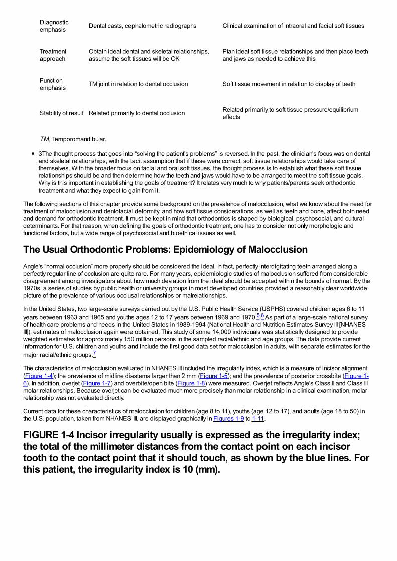
FIGURE 1-4 Incisor irregularity usually is expressed as the irregularity index;the total of the millimeter distances from the contact point on each incisortooth to the contact point that it should touch, as shown by the blue lines. Forthis patient, the irregularity index is 10 (mm).
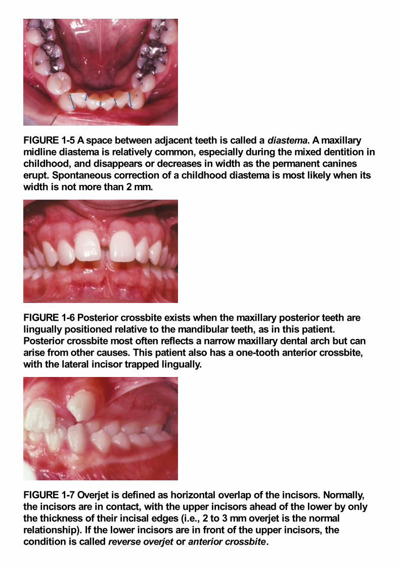
FIGURE 1-5 A space between adjacent teeth is called a diastema. A maxillarymidline diastema is relatively common, especially during the mixed dentition inchildhood, and disappears or decreases in width as the permanent canineserupt. Spontaneous correction of a childhood diastema is most likely when itswidth is not more than 2 mm.
FIGURE 1-6 Posterior crossbite exists when the maxillary posterior teeth arelingually positioned relative to the mandibular teeth, as in this patient.Posterior crossbite most often reflects a narrow maxillary dental arch but canarise from other causes. This patient also has a one-tooth anterior crossbite,with the lateral incisor trapped lingually.
FIGURE 1-7 Overjet is defined as horizontal overlap of the incisors. Normally,the incisors are in contact, with the upper incisors ahead of the lower by onlythe thickness of their incisal edges (i.e., 2 to 3 mm overjet is the normalrelationship). If the lower incisors are in front of the upper incisors, thecondition is called reverse overjet or anterior crossbite.
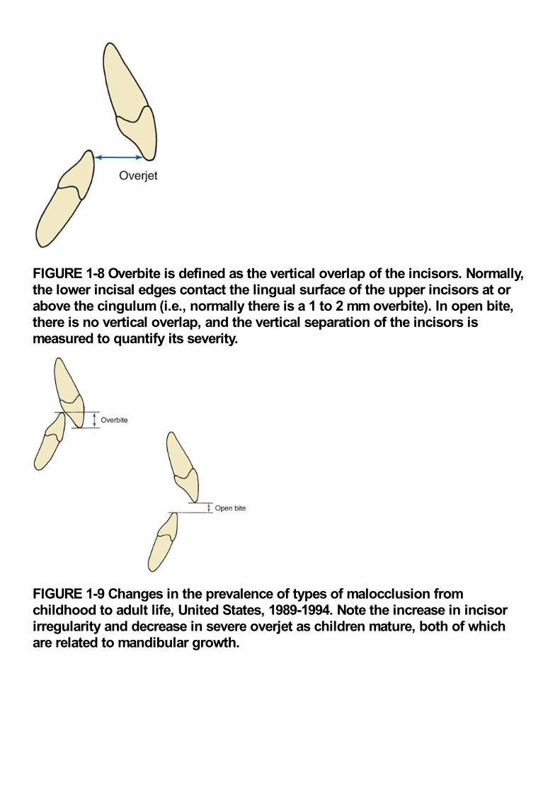
FIGURE 1-8 Overbite is defined as the vertical overlap of the incisors. Normally,the lower incisal edges contact the lingual surface of the upper incisors at orabove the cingulum (i.e., normally there is a 1 to 2 mm overbite). In open bite,there is no vertical overlap, and the vertical separation of the incisors ismeasured to quantify its severity.
FIGURE 1-9 Changes in the prevalence of types of malocclusion fromchildhood to adult life, United States, 1989-1994. Note the increase in incisorirregularity and decrease in severe overjet as children mature, both of whichare related to mandibular growth.

Note in Figure 1-9 that in the age 8 to 11 group, just over half of U.S. children have well-aligned incisors. The rest have varyingdegrees of malalignment and crowding. The percentage with excellent alignment decreases in the age 12 to 17 group as theremaining permanent teeth erupt, then remains essentially stable in the upper arch but worsens in the lower arch for adults. Only34%of adults have well-aligned lower incisors. Nearly 15%of adolescents and adults have severely or extremely irregular incisors, sothat major arch expansion or extraction of some teeth would be necessary to align them (see Figure 1-9).
FIGURE 1-10 Incisor irregularity in the U.S. population, 1989-1994. One-third ofthe population have at least moderately irregular (usually crowded) incisors,and nearly 15%have severe or extreme irregularity. Note that irregularity in thelower arch is more prevalent at any degree of severity.
FIGURE 1-11 Incisor irregularity by racial-ethnic groups. The percentage of theHispanic population with ideal alignment is lower than the other two groups,and the percentage with moderate and severe crowding is higher. This mayreflect the low number of Hispanics with orthodontic treatment at the time ofthe NHANES-III survey.
A midline diastema (see Figure 1-5) often is present in childhood (26%have >2 mm space). Although this space tends to close, over6%of youths and adults still have a noticeable diastema that compromises the appearance of the smile. Blacks are more than twice
as likely to have a midline diastema than whites or Hispanics (p < .001).
Occlusal relationships must be considered in all three planes of space. Posterior crossbite reflects deviations from ideal occlusion inthe transverse plane of space. It is relatively rare at all ages. Overjet or reverse overjet indicates anteroposterior deviations in theClass II/Class III direction, and
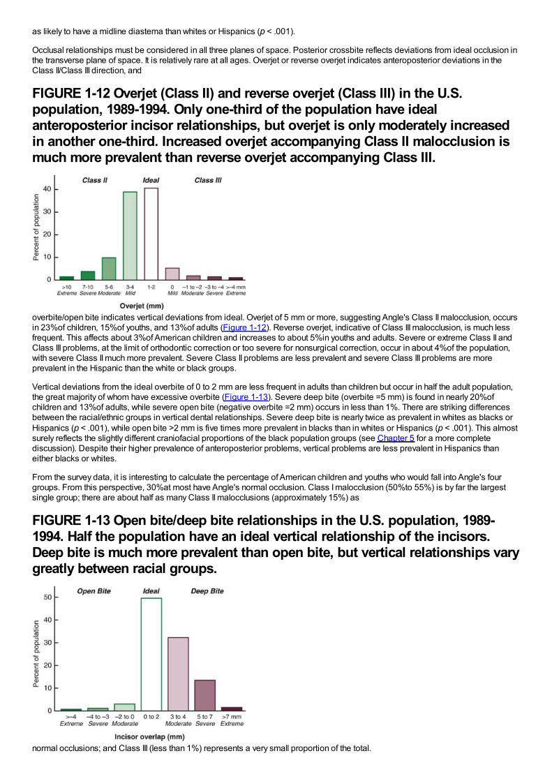
FIGURE 1-12 Overjet (Class II) and reverse overjet (Class III) in the U.S.population, 1989-1994. Only one-third of the population have idealanteroposterior incisor relationships, but overjet is only moderately increasedin another one-third. Increased overjet accompanying Class II malocclusion ismuch more prevalent than reverse overjet accompanying Class III.
overbite/open bite indicates vertical deviations from ideal. Overjet of 5 mm or more, suggesting Angle's Class II malocclusion, occursin 23%of children, 15%of youths, and 13%of adults (Figure 1-12). Reverse overjet, indicative of Class III malocclusion, is much lessfrequent. This affects about 3%of American children and increases to about 5%in youths and adults. Severe or extreme Class II andClass III problems, at the limit of orthodontic correction or too severe for nonsurgical correction, occur in about 4%of the population,with severe Class II much more prevalent. Severe Class II problems are less prevalent and severe Class III problems are moreprevalent in the Hispanic than the white or black groups.
Vertical deviations from the ideal overbite of 0 to 2 mm are less frequent in adults than children but occur in half the adult population,the great majority of whom have excessive overbite (Figure 1-13). Severe deep bite (overbite =5 mm) is found in nearly 20%ofchildren and 13%of adults, while severe open bite (negative overbite =2 mm) occurs in less than 1%. There are striking differencesbetween the racial/ethnic groups in vertical dental relationships. Severe deep bite is nearly twice as prevalent in whites as blacks orHispanics (p < .001), while open bite >2 mm is five times more prevalent in blacks than in whites or Hispanics (p < .001). This almostsurely reflects the slightly different craniofacial proportions of the black population groups (see Chapter 5 for a more completediscussion). Despite their higher prevalence of anteroposterior problems, vertical problems are less prevalent in Hispanics thaneither blacks or whites.
From the survey data, it is interesting to calculate the percentage of American children and youths who would fall into Angle's fourgroups. From this perspective, 30%at most have Angle's normal occlusion. Class I malocclusion (50%to 55%) is by far the largestsingle group; there are about half as many Class II malocclusions (approximately 15%) as
FIGURE 1-13 Open bite/deep bite relationships in the U.S. population, 1989-1994. Half the population have an ideal vertical relationship of the incisors.Deep bite is much more prevalent than open bite, but vertical relationships varygreatly between racial groups.
normal occlusions; and Class III (less than 1%) represents a very small proportion of the total.
Differences in malocclusion characteristics between the United States and other countries would be expected because ofdifferences in racial and ethnic composition. Although the available data are not as extensive as for American populations, it seemsclear that Class II problems are most prevalent in whites of northern European descent (for instance, 25%of children in Denmark arereported to be Class II), while Class III problems are most prevalent in Asian populations (3%to 5%in Japan, nearly 2%in China, withanother 2%to 3%pseudo-Class III [i.e., shifting into anterior crossbite because of incisor interferences]). African populations are by nomeans homogenous, but from the differences found in the United States between blacks and whites, it seems likely that Class III andopen bite are more frequent in African than European populations and deep bite less frequent.
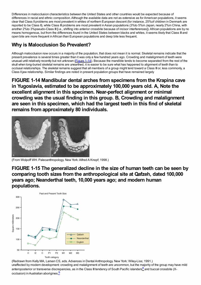
Why is Malocclusion So Prevalent?Although malocclusion now occurs in a majority of the population, that does not mean it is normal. Skeletal remains indicate that thepresent prevalence is several times greater than it was only a few hundred years ago. Crowding and malalignment of teeth wereunusual until relatively recently but not unknown (Figure 1-14). Because the mandible tends to become separated from the rest of theskull when long-buried skeletal remains are unearthed, it is easier to be sure what has happened to alignment of teeth than toocclusal relationships. The skeletal remains suggest that all members of a group might tend toward a Class III or, less commonly, aClass II jaw relationship. Similar findings are noted in present population groups that have remained largely
FIGURE 1-14 Mandibular dental arches from specimens from the Krapina cavein Yugoslavia, estimated to be approximately 100,000 years old. A, Note theexcellent alignment in this specimen. Near-perfect alignment or minimalcrowding was the usual finding in this group. B, Crowding and malalignmentare seen in this specimen, which had the largest teeth in this find of skeletalremains from approximately 80 individuals.
(From Wolpoff WH. Paleoanthropology. New York: Alfred A Knopf; 1998.)
FIGURE 1-15 The generalized decline in the size of human teeth can be seen bycomparing tooth sizes from the anthropological site at Qafzeh, dated 100,000years ago; Neanderthal teeth, 10,000 years ago; and modern humanpopulations.
(Redrawn from Kelly MA, Larsen CS, eds. Advances in Dental Anthropology. New York: Wiley-Liss; 1991.)unaffected by modern development: crowding and malalignment of teeth are uncommon, but the majority of the group may have mildanteroposterior or transverse discrepancies, as in the Class III tendency of South Pacific islanders8 and buccal crossbite (X-occlusion) in Australian aborigines.9
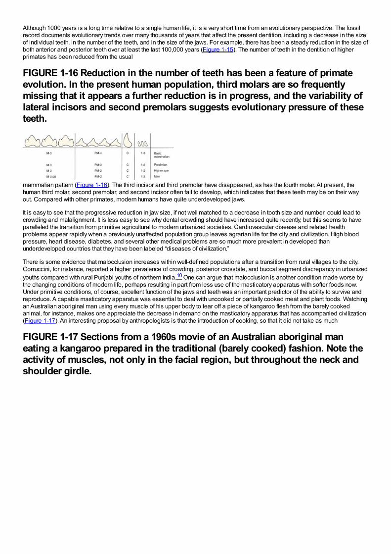
Although 1000 years is a long time relative to a single human life, it is a very short time from an evolutionary perspective. The fossilrecord documents evolutionary trends over many thousands of years that affect the present dentition, including a decrease in the sizeof individual teeth, in the number of the teeth, and in the size of the jaws. For example, there has been a steady reduction in the size ofboth anterior and posterior teeth over at least the last 100,000 years (Figure 1-15). The number of teeth in the dentition of higherprimates has been reduced from the usual
FIGURE 1-16 Reduction in the number of teeth has been a feature of primateevolution. In the present human population, third molars are so frequentlymissing that it appears a further reduction is in progress, and the variability oflateral incisors and second premolars suggests evolutionary pressure of theseteeth.
mammalian pattern (Figure 1-16). The third incisor and third premolar have disappeared, as has the fourth molar. At present, thehuman third molar, second premolar, and second incisor often fail to develop, which indicates that these teeth may be on their wayout. Compared with other primates, modern humans have quite underdeveloped jaws.
It is easy to see that the progressive reduction in jaw size, if not well matched to a decrease in tooth size and number, could lead tocrowding and malalignment. It is less easy to see why dental crowding should have increased quite recently, but this seems to haveparalleled the transition from primitive agricultural to modern urbanized societies. Cardiovascular disease and related healthproblems appear rapidly when a previously unaffected population group leaves agrarian life for the city and civilization. High bloodpressure, heart disease, diabetes, and several other medical problems are so much more prevalent in developed thanunderdeveloped countries that they have been labeled “diseases of civilization.”
There is some evidence that malocclusion increases within well-defined populations after a transition from rural villages to the city.Corruccini, for instance, reported a higher prevalence of crowding, posterior crossbite, and buccal segment discrepancy in urbanizedyouths compared with rural Punjabi youths of northern India.10 One can argue that malocclusion is another condition made worse bythe changing conditions of modern life, perhaps resulting in part from less use of the masticatory apparatus with softer foods now.Under primitive conditions, of course, excellent function of the jaws and teeth was an important predictor of the ability to survive andreproduce. A capable masticatory apparatus was essential to deal with uncooked or partially cooked meat and plant foods. Watchingan Australian aboriginal man using every muscle of his upper body to tear off a piece of kangaroo flesh from the barely cookedanimal, for instance, makes one appreciate the decrease in demand on the masticatory apparatus that has accompanied civilization(Figure 1-17). An interesting proposal by anthropologists is that the introduction of cooking, so that it did not take as much
FIGURE 1-17 Sections from a 1960s movie of an Australian aboriginal maneating a kangaroo prepared in the traditional (barely cooked) fashion. Note theactivity of muscles, not only in the facial region, but throughout the neck andshoulder girdle.
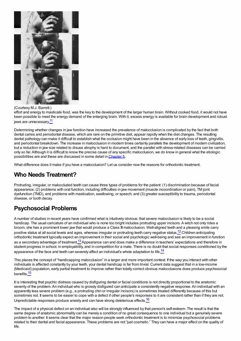
(Courtesy M.J. Barrett.)effort and energy to masticate food, was the key to the development of the larger human brain. Without cooked food, it would not havebeen possible to meet the energy demand of the enlarging brain. With it, excess energy is available for brain development and robustjaws are unnecessary.11
Determining whether changes in jaw function have increased the prevalence of malocclusion is complicated by the fact that bothdental caries and periodontal disease, which are rare on the primitive diet, appear rapidly when the diet changes. The resultingdental pathology can make it difficult to establish what the occlusion might have been in the absence of early loss of teeth, gingivitis,and periodontal breakdown. The increase in malocclusion in modern times certainly parallels the development of modern civilization,but a reduction in jaw size related to disuse atrophy is hard to document, and the parallel with stress-related diseases can be carriedonly so far. Although it is difficult to know the precise cause of any specific malocclusion, we do know in general what the etiologicpossibilities are and these are discussed in some detail in Chapter 5.
What difference does it make if you have a malocclusion? Let us consider now the reasons for orthodontic treatment.
Who Needs Treatment?Protruding, irregular, or maloccluded teeth can cause three types of problems for the patient: (1) discrimination because of facialappearance; (2) problems with oral function, including difficulties in jaw movement (muscle incoordination or pain), TM jointdysfunction (TMD), and problems with mastication, swallowing, or speech; and (3) greater susceptibility to trauma, periodontaldisease, or tooth decay.
Psychosocial ProblemsA number of studies in recent years have confirmed what is intuitively obvious: that severe malocclusion is likely to be a socialhandicap. The usual caricature of an individual who is none too bright includes protruding upper incisors. A witch not only rides abroom, she has a prominent lower jaw that would produce a Class III malocclusion. Well-aligned teeth and a pleasing smile carrypositive status at all social levels and ages, whereas irregular or protruding teeth carry negative status.12 Children anticipatingorthodontic treatment typically expect an improvement in their social and psychologic well-being and see an improvement in functionas a secondary advantage of treatment.13 Appearance can and does make a difference in teachers’ expectations and therefore instudent progress in school, in employability, and in competition for a mate. There is no doubt that social responses conditioned by theappearance of the face and teeth can severely affect an individual's whole adaptation to life.14
This places the concept of “handicapping malocclusion” in a larger and more important context. If the way you interact with otherindividuals is affected constantly by your teeth, your dental handicap is far from trivial. Current data suggest that in a low-income(Medicaid) population, early partial treatment to improve rather than totally correct obvious malocclusions does produce psychosocialbenefits.15
It is interesting that psychic distress caused by disfiguring dental or facial conditions is not directly proportional to the anatomicseverity of the problem. An individual who is grossly disfigured can anticipate a consistently negative response. An individual with anapparently less severe problem (e.g., a protruding chin or irregular incisors) is sometimes treated differently because of this butsometimes not. It seems to be easier to cope with a defect if other people's responses to it are consistent rather than if they are not.Unpredictable responses produce anxiety and can have strong deleterious effects.16
The impact of a physical defect on an individual also will be strongly influenced by that person's self-esteem. The result is that thesame degree of anatomic abnormality can be merely a condition of no great consequence to one individual but a genuinely severeproblem to another. It seems clear that the major reason people seek orthodontic treatment is to minimize psychosocial problemsrelated to their dental and facial appearance. These problems are not “just cosmetic.” They can have a major effect on the quality oflife.
Oral FunctionAlthough severe malocclusion surely affects oral function, oral function adapts to form surprisingly well. It appears that malocclusionusually affects function not by making it impossible but by making it difficult, so that extra effort is required to compensate for theanatomic deformity. For instance, everyone uses as many chewing strokes as it takes to reduce a food bolus to a consistency that issatisfactory for swallowing, so if chewing is less efficient in the presence of malocclusion, either the affected individual uses moreeffort to chew or settles for less well-masticated food before swallowing it. Tongue and lip posture adapt to the position of the teeth sothat swallowing rarely is affected (see Chapter 5). Similarly, almost everyone can move the jaw so that proper lip relationships existfor speech, so distorted speech is rarely noted even though an individual may have to make an extraordinary effort to produce normalspeech. As methods to quantify functional adaptations of this type are developed, it is likely that the effect of malocclusion on functionwill be appreciated more than it has been in the past.
The relationship of malocclusion and adaptive function to TMD, manifested as pain in and around the TM joint, is understood muchbetter now than only a few years ago. The pain may result from pathologic changes within the joint but more often is caused bymuscle fatigue and spasm. Muscle pain almost always correlates with a history of clenching or grinding the teeth as a response tostressful situations or of constantly posturing the mandible to an anterior or lateral position.
Some dentists have suggested that even minor imperfections in the occlusion serve to trigger clenching and grinding activities. If thiswere true, it would indicate a real need for perfecting the occlusion in everyone, to avoid the possibility of developing facial musclepain. Because the number of people with at least moderate degrees of malocclusion (50%to 75%of the population) far exceeds thenumber with TMD (5%to 30%, depending on which symptoms are examined), it seems unlikely that dental occlusion alone is enoughto cause hyperactivity of the oral musculature. A reaction to stress usually is involved. Some individuals react with clenching andgrinding their teeth, while others develop symptoms in other organ systems. An individual almost never has both ulcerative colitis(also a common stress-induced disease) and TMD.
Some types of malocclusion (especially posterior crossbite with a shift on closure) correlate positively with TM joint problems andother types do not, but even the strongest correlation coefficients are only 0.3 to 0.4. This means that for the great majority of patients,there is no association between malocclusion and TMD.17 Therefore orthodontics as the primary treatment for TMD almost never isindicated, but in special circumstances (see Chapter 18) it can be a useful adjunct to other treatment for the muscle pain.
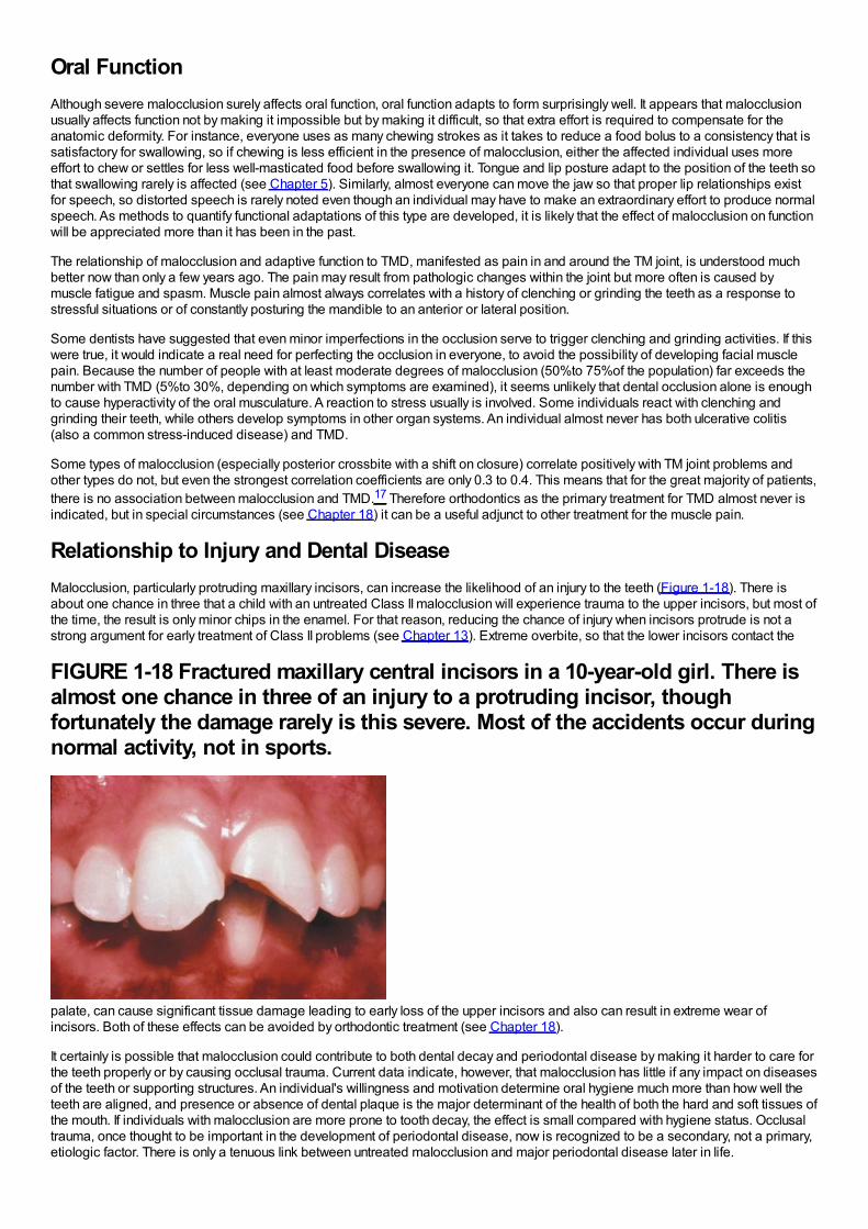
Relationship to Injury and Dental DiseaseMalocclusion, particularly protruding maxillary incisors, can increase the likelihood of an injury to the teeth (Figure 1-18). There isabout one chance in three that a child with an untreated Class II malocclusion will experience trauma to the upper incisors, but most ofthe time, the result is only minor chips in the enamel. For that reason, reducing the chance of injury when incisors protrude is not astrong argument for early treatment of Class II problems (see Chapter 13). Extreme overbite, so that the lower incisors contact the
FIGURE 1-18 Fractured maxillary central incisors in a 10-year-old girl. There isalmost one chance in three of an injury to a protruding incisor, thoughfortunately the damage rarely is this severe. Most of the accidents occur duringnormal activity, not in sports.
palate, can cause significant tissue damage leading to early loss of the upper incisors and also can result in extreme wear ofincisors. Both of these effects can be avoided by orthodontic treatment (see Chapter 18).
It certainly is possible that malocclusion could contribute to both dental decay and periodontal disease by making it harder to care forthe teeth properly or by causing occlusal trauma. Current data indicate, however, that malocclusion has little if any impact on diseasesof the teeth or supporting structures. An individual's willingness and motivation determine oral hygiene much more than how well theteeth are aligned, and presence or absence of dental plaque is the major determinant of the health of both the hard and soft tissues ofthe mouth. If individuals with malocclusion are more prone to tooth decay, the effect is small compared with hygiene status. Occlusaltrauma, once thought to be important in the development of periodontal disease, now is recognized to be a secondary, not a primary,etiologic factor. There is only a tenuous link between untreated malocclusion and major periodontal disease later in life.
Could orthodontic treatment itself be an etiologic agent for oral disease? Long-term studies show no indication that orthodontictreatment increased the chance of later periodontal problems.18 The association between early orthodontic and later periodontaltreatment appears to be only another manifestation of the phenomenon that one segment of the population seeks dental treatmentwhile another avoids it. Those who have had one type of successful dental treatment, like orthodontics in childhood, are more likely toseek another like periodontal therapy in adult life.
In summary, it appears that both psychosocial and functional handicaps can produce significant need for orthodontic treatment. Theevidence is less clear that orthodontic treatment reduces the development of later dental disease.
Type of Treatment: Evidence-Based SelectionIf treatment is needed, how do you decide what sort of treatment to use? The present trend in health care is strongly toward evidence-based treatment; that is, treatment procedures should be chosen on the basis of clear evidence that the selected method is the mostsuccessful approach to that particular patient's problem(s). The better the evidence, the easier the decision.
Randomized Clinical Trials: The Best EvidenceOrthodontics traditionally has been a specialty in which the opinions of leaders were important, to the point that professional groupscoalesced around a strong leader. Angle, Begg, and Tweed societies still exist, and new ones whose primary purpose is topromulgate its leader's opinions are still being formed in the early twenty-first century. As any professional group comes of age,however, there must be a focus on evidence-based rather than opinion-based decisions. This now is a major focus of organizeddentistry in general and orthodontics in particular.
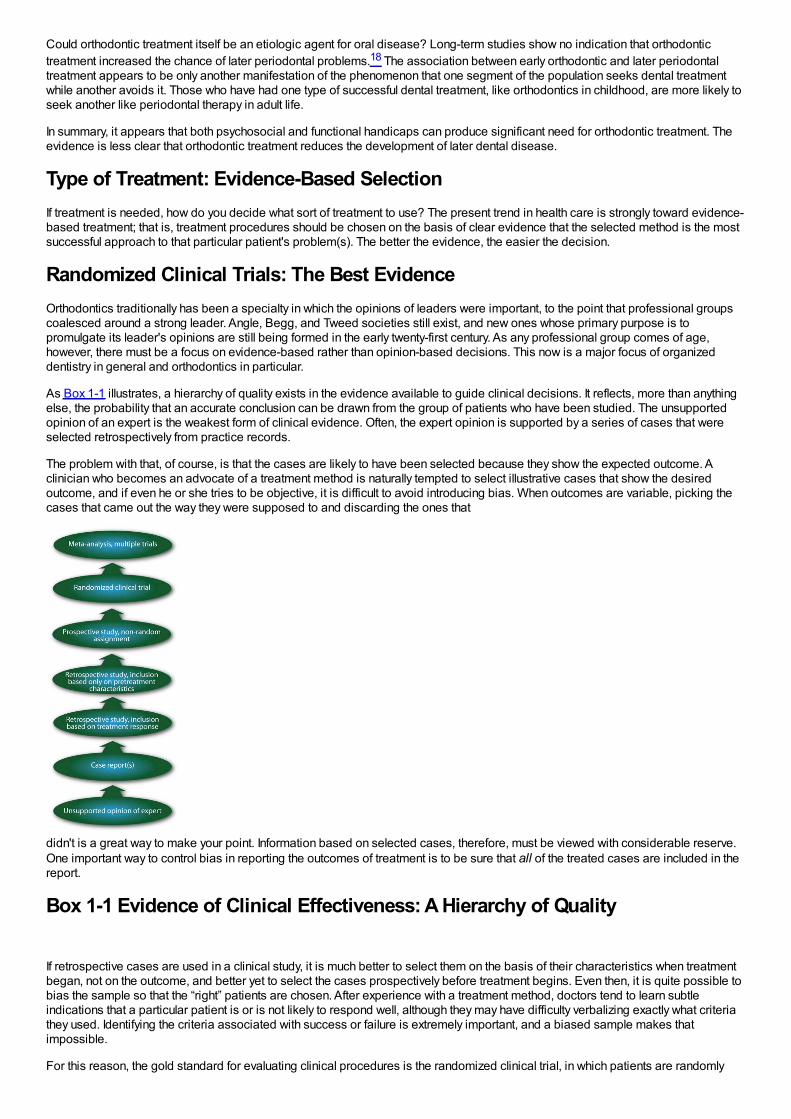
As Box 1-1 illustrates, a hierarchy of quality exists in the evidence available to guide clinical decisions. It reflects, more than anythingelse, the probability that an accurate conclusion can be drawn from the group of patients who have been studied. The unsupportedopinion of an expert is the weakest form of clinical evidence. Often, the expert opinion is supported by a series of cases that wereselected retrospectively from practice records.
The problem with that, of course, is that the cases are likely to have been selected because they show the expected outcome. Aclinician who becomes an advocate of a treatment method is naturally tempted to select illustrative cases that show the desiredoutcome, and if even he or she tries to be objective, it is difficult to avoid introducing bias. When outcomes are variable, picking thecases that came out the way they were supposed to and discarding the ones that
didn't is a great way to make your point. Information based on selected cases, therefore, must be viewed with considerable reserve.One important way to control bias in reporting the outcomes of treatment is to be sure that all of the treated cases are included in thereport.
Box 1-1 Evidence of Clinical Effectiveness: A Hierarchy of Quality
If retrospective cases are used in a clinical study, it is much better to select them on the basis of their characteristics when treatmentbegan, not on the outcome, and better yet to select the cases prospectively before treatment begins. Even then, it is quite possible tobias the sample so that the “right” patients are chosen. After experience with a treatment method, doctors tend to learn subtleindications that a particular patient is or is not likely to respond well, although they may have difficulty verbalizing exactly what criteriathey used. Identifying the criteria associated with success or failure is extremely important, and a biased sample makes thatimpossible.
For this reason, the gold standard for evaluating clinical procedures is the randomized clinical trial, in which patients are randomly
assigned in advance to alternative treatment procedures. The great advantage of this method is that random assignment, if thesample is large enough, should result in a similar distribution of all variables between (or among) the groups. Even variables thatwere not recognized in advance should be controlled by this type of patient assignment—and in clinical work, often importantvariables are identified only after the treatment has been started or even completed. The clinical trials in orthodontics that have beenreported are referred to in some detail later in this book.
Unfortunately, randomized trials cannot be used in many situations for ethical or practical reasons. For instance, a randomized trial ofextraction versus nonextraction orthodontic treatment would encounter ethical concerns, would be very difficult and expensive toorganize and manage if ethical difficulties could be overcome, and would require following patients for many years to evaluate long-term outcomes.
Retrospective Studies: Control Group RequiredA second acceptable way to replace opinion with evidence is by careful retrospective study of treatment outcomes under well-definedconditions. The best way to know—often the only way to know—whether a treatment method really works is to compare treatedpatients with an untreated control group. For such a comparison to be valid, the two groups must be equivalent before treatmentstarts. If the groups were different to start with, you cannot with any confidence say that differences afterward were due to thetreatment.
There are a number of difficulties in setting up control groups for orthodontic treatment. The principal ones are that the controls mustbe followed over a long period of time, equivalent to the treatment time, and that sequential radiographs usually are required.Radiation exposure for untreated children is problematic. At present, it is very difficult to get permission to expose children to x-raysthat will be of no benefit to them personally. This means that longitudinal growth studies of untreated children in the mid-twentiethcentury, now 50 or more years ago, still are being used to provide control data, especially in studies involving growth modification.When historic controls are the best that are available, it is better to have them than nothing, but the limitations must be kept in mind. Alot has changed in the last 50 years.
An additional way to gain better data for treatment responses is the application of metaanalysis. This draws on recently-developedstatistical techniques to group the data from several studies of the same phenomenon. Orthodontic research is an excellent exampleof an area in which numerous small studies have been carried out toward similar ends, often with protocols that were at leastsomewhat similar but different enough to make comparisons difficult. Metaanalysis is no substitute for new data collected withprecise protocols, and including poorly done studies in a metaanalysis carries the risk of confusing rather than clarifying the issue.Nevertheless, applying it to clinical questions has considerable potential to reduce uncertainty about the best treatment methods.Several recent reviews have taken advantage of this method to improve the quality of evidence about the outcomes of orthodontictreatment procedures.19-21
The era of orthodontics as an opinion-driven specialty clearly is at an end. In the future, it will be evidence-driven, which is all for thebest. In the meantime, clinical decisions still must be made using the best information currently available. When the latest new methodappears with someone's strong recommendation and a series of case reports in which it worked very well, it is wise to remember theaphorism “Enthusiastic reports tend to lack controls; well-controlled reports tend to lack enthusiasm.”
In this and the subsequent chapters, recommendations for treatment are based insofar as possible on solid clinical evidence. Wherethis is not available, the authors’ current opinions are provided and labeled as such.
Demand for Treatment
Epidemiologic Estimates of Orthodontic Treatment NeedPsychosocial and facial considerations, not just the way the teeth fit, play a role in defining orthodontic treatment need. For thisreason, it is difficult to determine who needs treatment and who does not just from an examination of dental casts or radiographs.Nevertheless, it seems reasonable that the severity of a malocclusion correlates with need for treatment. This assumption isnecessary when treatment need is estimated for population groups.
Several indices for scoring how much the teeth deviate from the normal, as indicators of orthodontic treatment need, were proposedin the 1970s but not widely accepted for screening potential patients. The Index of Treatment Need (IOTN), developed by Shaw andcoworkers in the United Kingdom,22 places patients in five grades from “no need for treatment” to “treatment need” that correlatereasonably well with clinician's judgments of need for treatment. The index has a dental health component derived from occlusion andalignment (Box 1-2) and an esthetic component derived from comparison of the dental appearance to standard photographs (Figure1-19). There is a surprisingly good correlation between treatment need assessed by the dental health and esthetic components ofIOTN (i.e., children selected as needing treatment on one of the scales are also quite likely to be selected using the other).23
With some allowances for the effect of missing teeth, it is possible to calculate the percentages of U.S. children and youths whowould fall into the various IOTN grades from the NHANES III data set.24 Figure 1-20 shows the percentage of youths age 12 to 17 inthe three major racial/ethnic groups in the U.S. population estimated by IOTN to have mild/moderate/severe treatment need and thepercentage who had treatment at that time. As the graph shows, the number of white children who received treatment wasconsiderably higher than blacks or Hispanics (p < .001). Treatment almost always produces an improvement but may not totallyeliminate all the characteristics of malocclusion, so the effect is to move some individuals from the severe to the mild treatment needcategories. The higher proportion of severe malocclusion among blacks probably reflects more treatment in the white group, whichmoved them down the severity scale, rather than the presence of more severe malocclusion in the black population.
How do the IOTN scores compare with what parents and dentists think relative to orthodontic treatment need? The existing (ratherweak) data suggest that in typical American neighborhoods, about 35%of adolescents are perceived by parents and peers asneeding orthodontic treatment. Note that this is larger than the number of children who would be placed in IOTN grades 4 and 5 assevere problems definitely needing treatment, but smaller than the total of grades 3, 4, and 5 for moderate and severe problems.
Dentists usually judge that only about one-third of their patients have normal occlusion, and they suggest treatment for about55%(thereby putting about 10%in a category of malocclusion with little need for treatment). It appears that they would include all thechildren in IOTN grade 3 and some of those in grade 2 in the group who would benefit from orthodontics. Presumably, facialappearance and psychosocial considerations are used in addition to dental characteristics when parents judge treatment need ordentists decide to recommend treatment.
Who Seeks Treatment?Demand for treatment is indicated by the number of patients who actually make appointments and seek care. Not all patients withmalocclusion, even those with extreme deviations from the normal, seek orthodontic treatment. Some do not recognize that they havea problem; others feel that they need treatment but cannot afford it or cannot obtain it.
Box 1-2 Index of Treatment Needs (IOTN) Treatment Grades
Grade 5 (Extreme/Need Treatment)
5.i Impeded eruption of teeth (except third molars) due to crowding, displacement, the presence of supernumerary teeth, retaineddeciduous teeth, and any pathologic cause.
5.h Extensive hypodontia with restorative implications (more than one tooth per quadrant) requiring preprosthetic orthodontics.
5.a Increased overjet greater than 9 mm.
5.m Reverse overjet greater than 3.5 mm with reported masticatory and speech difficulties.
5.p Defects of cleft lip and palate and other craniofacial anomalies.
5.s Submerged deciduous teeth.
Grade 4 (Severe/Need Treatment)
4.h Less extensive hypodontia requiring prerestorative orthodontics or orthodontic space closure (one tooth per quadrant).
4.a Increased overjet greater than 6 mm but less than or equal to 9 mm.
4.b Reverse overjet greater than 3.5 mm with no masticatory or speech difficulties.
4.m Reverse overjet greater than 1 mm but less than 3.5 mm with recorded masticatory or speech difficulties.
4.c Anterior or posterior crossbites with greater than 2 mm discrepancy between retruded contact position and intercuspal position.
4.l Posterior lingual crossbite with no functional occlusal contact in one or both buccal segments.
4.d Severe contact point displacements greater than 4 mm.
4.e Extreme lateral or anterior open bites greater than 4 mm.
4.f Increased and complete overbite with gingival or palatal trauma.
4.t Partially erupted teeth, tipped, and impacted against adjacent teeth.
4.x Presence of supernumerary teeth.
Grade 3 (Moderate/Borderline Need)
3.a Increased overjet greater than 3.5 mm but less than or equal to 6 mm with incompetent lips.
3.b Reverse overjet greater than 1 mm but less than or equal to 3.5 mm.
3.c Anterior or posterior crossbites with greater than 1 mm but less than or equal to 2 mm discrepancy between retruded contactposition and intercuspal position.
3.d Contact point displacements greater than 2 mm but less than or equal to 4 mm.
3.e Lateral or anterior open bite greater than 2 mm but less than or equal to 4 mm.
3.f Deep overbite complete on gingival or palatal tissues but no trauma.
Grade 2 (Mild/Little Need)
2.a Increased overjet greater than 3.5 mm but less than or equal to 6 mm with competent lips.
2.b Reverse overjet greater than 0 mm but less than or equal to 1 mm.
2.c Anterior or posterior crossbite with less than or equal to 1 mm discrepancy between retruded contact position and intercuspalposition.
2.d Contact point displacements greater than 1 mm but less than or equal to 2 mm.
2.e Anterior or posterior open bite greater than 1 mm but less than or equal to 2 mm.
2.f Increased overbite greater than or equal to 3.5 mm without gingival contact.
2.g Prenormal or postnormal occlusions with no other anomalies.
Grade 1 (No Need)
1. Extremely minor malocclusions, including contact point displacements less than 1 mm.
Both the perceived need and demand vary with social and cultural conditions. More children in urban areas are thought (by parentsand peers) to need treatment than children in rural areas. Family income is a major determinant of how many children receivetreatment (Figure 1-21). This appears to reflect two things: not only that higher income families can more easily afford orthodontictreatment, but also that good facial appearance and avoidance of disfiguring dental conditions are associated with more prestigioussocial positions and occupations. The higher the aspirations for a child, the more likely the parents are to seek orthodontic treatmentfor him or her. It is widely recognized that severe malocclusion can affect an individual's entire life adjustment, and every state nowprovides at least some orthodontic treatment for low-income families through its Medicaid program, but
FIGURE 1-19 The stimulus photographs of the IOTN esthetic index. The score
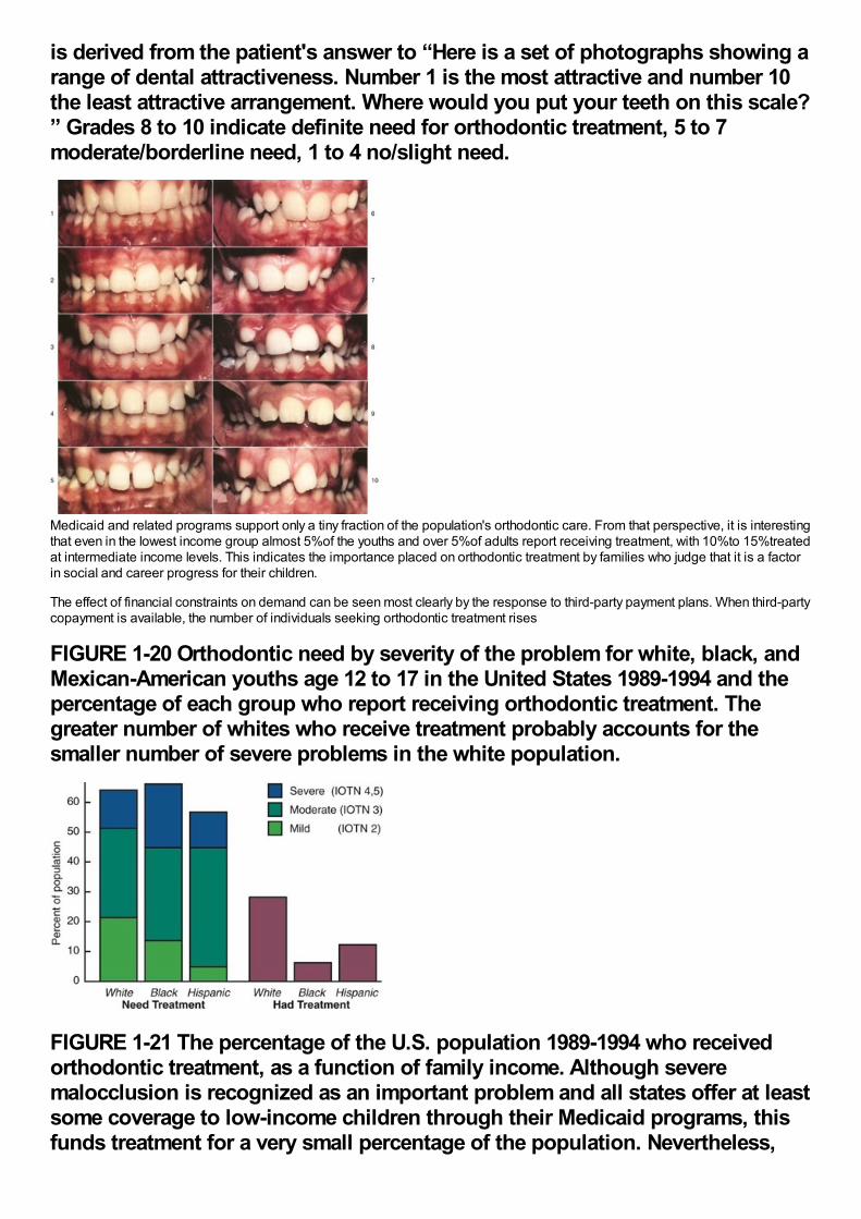
is derived from the patient's answer to “Here is a set of photographs showing arange of dental attractiveness. Number 1 is the most attractive and number 10the least attractive arrangement. Where would you put your teeth on this scale?” Grades 8 to 10 indicate definite need for orthodontic treatment, 5 to 7moderate/borderline need, 1 to 4 no/slight need.
Medicaid and related programs support only a tiny fraction of the population's orthodontic care. From that perspective, it is interestingthat even in the lowest income group almost 5%of the youths and over 5%of adults report receiving treatment, with 10%to 15%treatedat intermediate income levels. This indicates the importance placed on orthodontic treatment by families who judge that it is a factorin social and career progress for their children.
The effect of financial constraints on demand can be seen most clearly by the response to third-party payment plans. When third-partycopayment is available, the number of individuals seeking orthodontic treatment rises
FIGURE 1-20 Orthodontic need by severity of the problem for white, black, andMexican-American youths age 12 to 17 in the United States 1989-1994 and thepercentage of each group who report receiving orthodontic treatment. Thegreater number of whites who receive treatment probably accounts for thesmaller number of severe problems in the white population.
FIGURE 1-21 The percentage of the U.S. population 1989-1994 who receivedorthodontic treatment, as a function of family income. Although severemalocclusion is recognized as an important problem and all states offer at leastsome coverage to low-income children through their Medicaid programs, thisfunds treatment for a very small percentage of the population. Nevertheless,
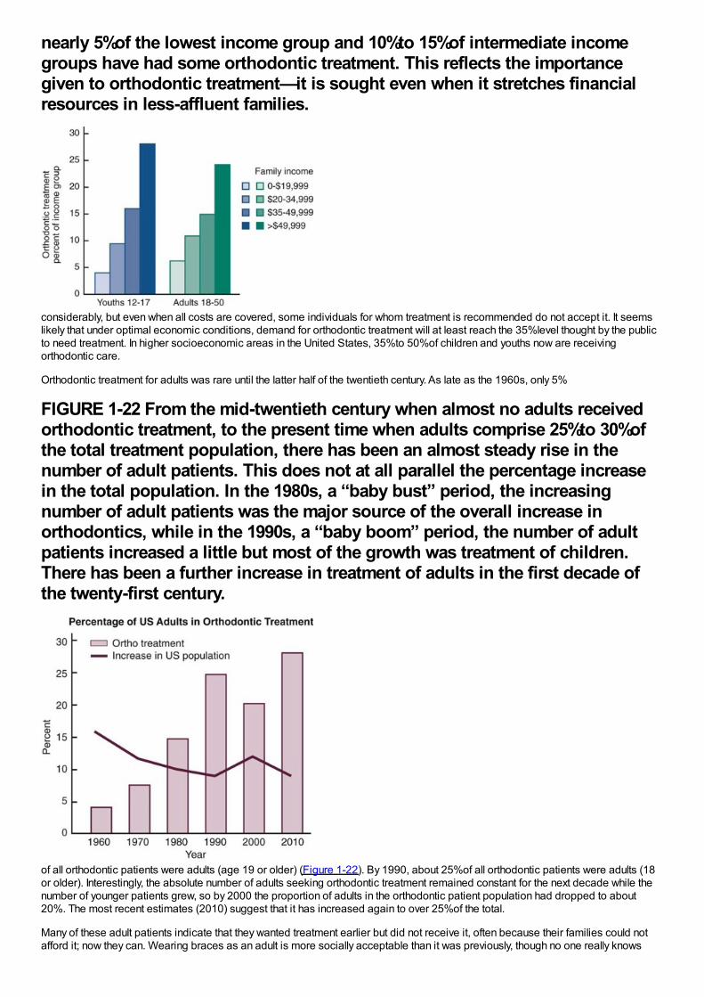
nearly 5%of the lowest income group and 10%to 15%of intermediate incomegroups have had some orthodontic treatment. This reflects the importancegiven to orthodontic treatment—it is sought even when it stretches financialresources in less-affluent families.
considerably, but even when all costs are covered, some individuals for whom treatment is recommended do not accept it. It seemslikely that under optimal economic conditions, demand for orthodontic treatment will at least reach the 35%level thought by the publicto need treatment. In higher socioeconomic areas in the United States, 35%to 50%of children and youths now are receivingorthodontic care.
Orthodontic treatment for adults was rare until the latter half of the twentieth century. As late as the 1960s, only 5%
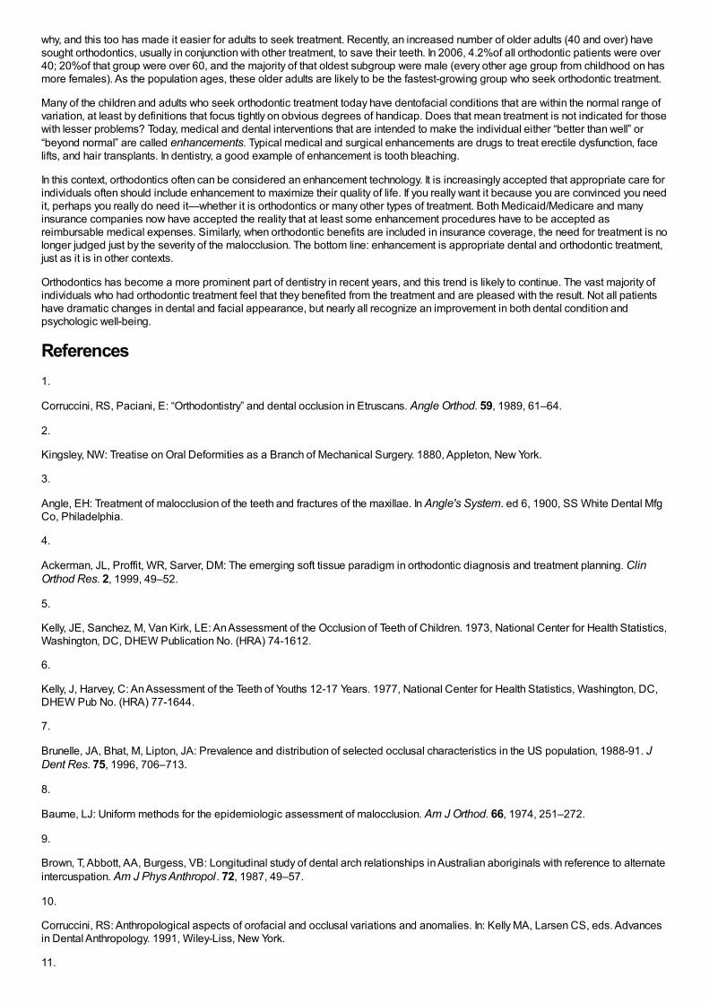
FIGURE 1-22 From the mid-twentieth century when almost no adults receivedorthodontic treatment, to the present time when adults comprise 25%to 30%ofthe total treatment population, there has been an almost steady rise in thenumber of adult patients. This does not at all parallel the percentage increasein the total population. In the 1980s, a “baby bust” period, the increasingnumber of adult patients was the major source of the overall increase inorthodontics, while in the 1990s, a “baby boom” period, the number of adultpatients increased a little but most of the growth was treatment of children.There has been a further increase in treatment of adults in the first decade ofthe twenty-first century.
of all orthodontic patients were adults (age 19 or older) (Figure 1-22). By 1990, about 25%of all orthodontic patients were adults (18or older). Interestingly, the absolute number of adults seeking orthodontic treatment remained constant for the next decade while thenumber of younger patients grew, so by 2000 the proportion of adults in the orthodontic patient population had dropped to about20%. The most recent estimates (2010) suggest that it has increased again to over 25%of the total.
Many of these adult patients indicate that they wanted treatment earlier but did not receive it, often because their families could notafford it; now they can. Wearing braces as an adult is more socially acceptable than it was previously, though no one really knows
why, and this too has made it easier for adults to seek treatment. Recently, an increased number of older adults (40 and over) havesought orthodontics, usually in conjunction with other treatment, to save their teeth. In 2006, 4.2%of all orthodontic patients were over40; 20%of that group were over 60, and the majority of that oldest subgroup were male (every other age group from childhood on hasmore females). As the population ages, these older adults are likely to be the fastest-growing group who seek orthodontic treatment.
Many of the children and adults who seek orthodontic treatment today have dentofacial conditions that are within the normal range ofvariation, at least by definitions that focus tightly on obvious degrees of handicap. Does that mean treatment is not indicated for thosewith lesser problems? Today, medical and dental interventions that are intended to make the individual either “better than well” or“beyond normal” are called enhancements. Typical medical and surgical enhancements are drugs to treat erectile dysfunction, facelifts, and hair transplants. In dentistry, a good example of enhancement is tooth bleaching.
In this context, orthodontics often can be considered an enhancement technology. It is increasingly accepted that appropriate care forindividuals often should include enhancement to maximize their quality of life. If you really want it because you are convinced you needit, perhaps you really do need it—whether it is orthodontics or many other types of treatment. Both Medicaid/Medicare and manyinsurance companies now have accepted the reality that at least some enhancement procedures have to be accepted asreimbursable medical expenses. Similarly, when orthodontic benefits are included in insurance coverage, the need for treatment is nolonger judged just by the severity of the malocclusion. The bottom line: enhancement is appropriate dental and orthodontic treatment,just as it is in other contexts.
Orthodontics has become a more prominent part of dentistry in recent years, and this trend is likely to continue. The vast majority ofindividuals who had orthodontic treatment feel that they benefited from the treatment and are pleased with the result. Not all patientshave dramatic changes in dental and facial appearance, but nearly all recognize an improvement in both dental condition andpsychologic well-being.
References1.
Corruccini, RS, Paciani, E: “Orthodontistry” and dental occlusion in Etruscans. Angle Orthod. 59, 1989, 61–64.
2.
Kingsley, NW: Treatise on Oral Deformities as a Branch of Mechanical Surgery. 1880, Appleton, New York.
3.
Angle, EH: Treatment of malocclusion of the teeth and fractures of the maxillae. In Angle's System. ed 6, 1900, SS White Dental MfgCo, Philadelphia.
4.
Ackerman, JL, Proffit, WR, Sarver, DM: The emerging soft tissue paradigm in orthodontic diagnosis and treatment planning. ClinOrthod Res. 2, 1999, 49–52.
5.
Kelly, JE, Sanchez, M, Van Kirk, LE: An Assessment of the Occlusion of Teeth of Children. 1973, National Center for Health Statistics,Washington, DC, DHEW Publication No. (HRA) 74-1612.
6.
Kelly, J, Harvey, C: An Assessment of the Teeth of Youths 12-17 Years. 1977, National Center for Health Statistics, Washington, DC,DHEW Pub No. (HRA) 77-1644.
7.
Brunelle, JA, Bhat, M, Lipton, JA: Prevalence and distribution of selected occlusal characteristics in the US population, 1988-91. JDent Res. 75, 1996, 706–713.
8.
Baume, LJ: Uniform methods for the epidemiologic assessment of malocclusion. Am J Orthod. 66, 1974, 251–272.
9.
Brown, T, Abbott, AA, Burgess, VB: Longitudinal study of dental arch relationships in Australian aboriginals with reference to alternateintercuspation. Am J Phys Anthropol. 72, 1987, 49–57.
10.
Corruccini, RS: Anthropological aspects of orofacial and occlusal variations and anomalies. In: Kelly MA, Larsen CS, eds. Advancesin Dental Anthropology. 1991, Wiley-Liss, New York.
11.

Wrangham, R: Catching Fire: How Cooking Made Us Human. 2009, Basic Books, New York.
12.
Shaw, WC, Rees, G, Dawe, M, et al.: The influence of dentofacial appearance on the social attractiveness of young adults. Am JOrthod. 87, 1985, 21–26.
13.
Bresnahan, B, Kiyak, A, Masters, SH, et al.: Quality of life and economic burdens of malocclusion in US patients enrolled in.Medicaid. J Am Dent Assn . 141, 2010, 1202–1212.
14.
Meyer-Marcotty, P, Gerdes, AB, Reuther, T, et al.: Persons with cleft lip and palate are looked at differently. J Dent Res. 89, 2010, 400–404.
15.
Jolley, C, Huang, GJ, Greenlee, G, et al.: Dental effects of interceptive orthodontic treatment in a Medicaid population: interim resultsfrom a randomized clinical trial. Am J Orthod Dentofac Orthop. 137, 2010, 324–333.
16.
Macgregor, FC: Social and psychological implications of dentofacial disfigurement. Angle Orthod. 40, 1979, 231–233.
17.
Macfarlane, TV, Kenealy, P, Kingdon, HA, et al.: Twenty-year cohort study of health gain from orthodontic treatment:temporomandibular disorders. Am J Orthod Dentofac Orthop. 192, 2009, e1–e8.
18.
Jonsson, T, Karlsson, KO, Ragnarsson, B, et al.: Long-term development of malocclusion traits in orthodontically treated anduntreated subjects. Am J Orthod Dentofac Orthop. 137, 2010, 277–284.
19.
Bollen, AM, Cunha-Cruz, J, Bakko, DW, et al.: The effects of orthodontic therapy on periodontal health: a systematic review ofcontrolled evidence. Am J Orthod Dentofac Orthop. 135, 2008, 413–422.
20.
Liu, Z, McGrath, C, Haag, U: The impact of malocclusion/orthodontic treatment need on the quality of life: a systematic review. AngleOrthod. 79, 2009, 585–591.
21.
Weltman, B, Vig, KWL, Fields, HW, et al.: Root resorption associated with orthodontic tooth movement: a systematic review. Am JOrthod Dentofac Orthop. 137, 2010, 462–476.
22.
Brook, PH, Shaw, WC: The development of an index for orthodontic treatment priority. Eur J Orthod. 11, 1989, 309–332.
23.
Richmond, S, Shaw, WC, O'Brien, KD, et al.: The relationship between the index of treatment need and consensus opinion of a panelof 74 dentists. Br Dent J. 178, 1995, 370–374.
24.
Proffit, WR, Fields, HW, Moray, LJ: Prevalence of malocclusion and orthodontic treatment need in the United States: estimates fromthe NHANES III survey. Int J Adult Orthod Orthogn Surg. 13, 1998, 97–106.

Malocclusion and dentofacial deformity arise through variations in the normal developmental process and must be evaluated against aperspective of normal development. Because orthodontic treatment often involves manipulation of skeletal growth, clinicalorthodontics requires an understanding not only of dental development but also of more general concepts of physical growth andphysiologic and psychosocial development. This section begins in Chapter 2 with a discussion of basic concepts in growth anddevelopment. A brief discussion of psychologic development is included, emphasizing emotional and cognitive development, as wellas how the dentist can utilize this information to communicate with children and adolescents. Information on physical growth and dentaldevelopment at the various stages is then presented sequentially in Chapters 3 and 4, beginning with prenatal growth and extendinginto adult life, in which developmental changes continue at a slower pace. The etiology of malocclusion and special developmentalproblems in children with malocclusion and dentofacial deformity are considered in some detail in Chapter 5.
Chapter 2 Concepts of Growth and DevelopmentA thorough background in craniofacial growth and development is necessary for every dentist. Even for those who never work withchildren, it is difficult to comprehend conditions observed in adults without understanding the developmental processes that producedthese problems. For those who do interact professionally with children—and almost every dentist does so at least occasionally—it isimportant to distinguish normal variation from the effects of abnormal or pathologic processes. Since dentists and orthodontists areheavily involved in the development of not just the dentition but the entire dentofacial complex, a conscientious practitioner may beable to manipulate facial growth for the benefit of the patient. Obviously, it is not possible to do so without a thorough understanding ofboth the pattern of normal growth and the mechanisms that underlie it.
The very terms growth and development can cause difficulties in understanding. Growth and development, though closely related, arenot synonymous. In conversational English, growth usually refers to an increase in size but tends to be linked more to change thananything else. Only if growth meant change, after all, could someone seriously speak of a period of economic recession as one of“negative economic growth.” Since some tissues grow rapidly and then shrink or disappear, a plot of physical growth versus time mayinclude a negative phase. On the other hand, if growth is defined solely as a process of change, the term becomes almostmeaningless. In this chapter, the term growth usually refers to an increase in size or number. Occasionally, however, the increase willbe in neither size nor number, but in complexity.
As a general term, development connotes an increasing degree of organization, often with unfortunate consequences for the naturalenvironment. With reference to growth, the term development is used almost always to refer to an increase in complexity, and it isused in that way in this chapter. Development carries an overtone of increasing specialization, so that one price of increaseddevelopment is a loss of potential. Growth is largely an anatomic phenomenon, whereas development is physiologic and behavioral.
It should be kept in mind that although dentists work with the physical features of the teeth and face, a major reason for orthodontictreatment is its psychosocial effects. Furthermore, patient cooperation is necessary, and eliciting it in children of different agesrequires a knowledge of social and behavioral development. Both physiologic and psychosocial development are important subjectsfor this chapter. For convenience, not because they are innately more important, physical growth concepts are presented first, andthen developmental factors are reviewed.
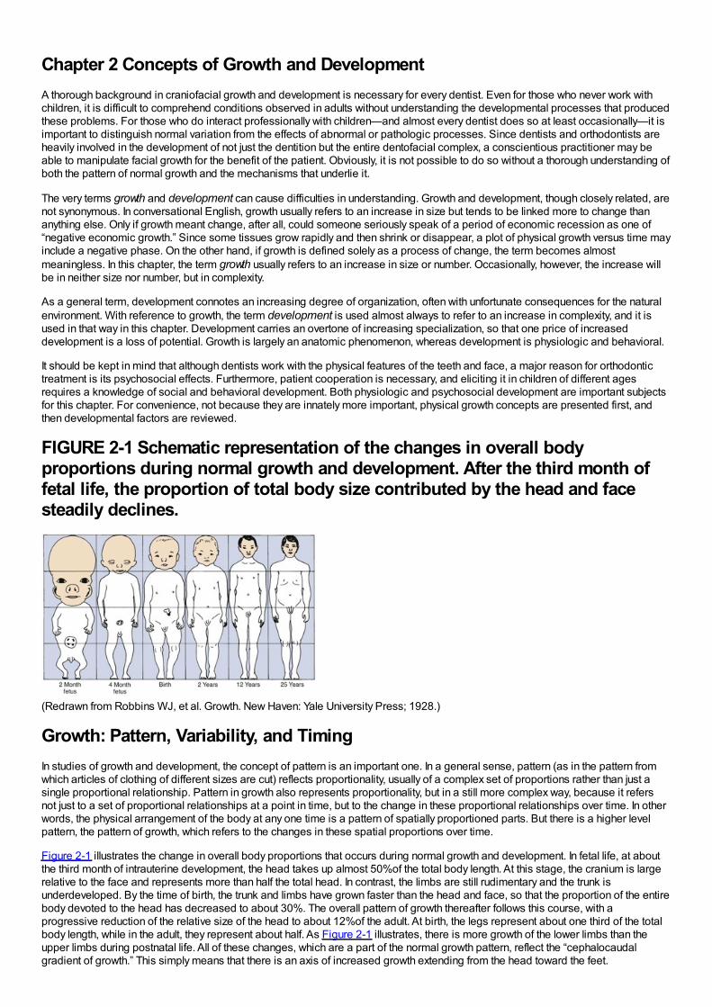
FIGURE 2-1 Schematic representation of the changes in overall bodyproportions during normal growth and development. After the third month offetal life, the proportion of total body size contributed by the head and facesteadily declines.
(Redrawn from Robbins WJ, et al. Growth. New Haven: Yale University Press; 1928.)
Growth: Pattern, Variability, and TimingIn studies of growth and development, the concept of pattern is an important one. In a general sense, pattern (as in the pattern fromwhich articles of clothing of different sizes are cut) reflects proportionality, usually of a complex set of proportions rather than just asingle proportional relationship. Pattern in growth also represents proportionality, but in a still more complex way, because it refersnot just to a set of proportional relationships at a point in time, but to the change in these proportional relationships over time. In otherwords, the physical arrangement of the body at any one time is a pattern of spatially proportioned parts. But there is a higher levelpattern, the pattern of growth, which refers to the changes in these spatial proportions over time.
Figure 2-1 illustrates the change in overall body proportions that occurs during normal growth and development. In fetal life, at aboutthe third month of intrauterine development, the head takes up almost 50%of the total body length. At this stage, the cranium is largerelative to the face and represents more than half the total head. In contrast, the limbs are still rudimentary and the trunk isunderdeveloped. By the time of birth, the trunk and limbs have grown faster than the head and face, so that the proportion of the entirebody devoted to the head has decreased to about 30%. The overall pattern of growth thereafter follows this course, with aprogressive reduction of the relative size of the head to about 12%of the adult. At birth, the legs represent about one third of the totalbody length, while in the adult, they represent about half. As Figure 2-1 illustrates, there is more growth of the lower limbs than theupper limbs during postnatal life. All of these changes, which are a part of the normal growth pattern, reflect the “cephalocaudalgradient of growth.” This simply means that there is an axis of increased growth extending from the head toward the feet.
Another aspect of the normal growth pattern is that not all the tissue systems of the body grow at the same rate (Figure 2-2).Obviously, as the relative decrease of head size after birth shows, the muscular and skeletal elements grow faster than the brain andcentral nervous system. The overall pattern of growth is a reflection of the growth of the various tissues making up the wholeorganism. To put it differently, one reason for gradients of growth is that different tissue systems that grow at different rates areconcentrated in various parts of the body.
Even within the head and face, the cephalocaudal growth gradient strongly affects proportions and leads to changes in proportionwith growth (Figure 2-3). When the skull of a newborn infant is compared proportionally with that of an adult, it is easy to see that theinfant has a relatively much larger cranium and a much smaller face. This change is an important aspect of the pattern of facialgrowth. Not only is there a cephalocaudal gradient of growth within the body, there also is one within the face. From that perspective,it is not surprising that the mandible, being farther away from the brain, tends to grow more and later than the maxilla, which is closer.
An important aspect of pattern is its predictability. Patterns repeat, whether in the organization of different-colored tiles in the designof a floor or in skeletal proportions changing over time. The proportional relationships within a pattern can be specifiedmathematically, and the only difference between a growth pattern and a geometric one is the addition of a time dimension. Thinkingabout pattern in this way allows one to be more precise in defining what constitutes a change in pattern. Change, clearly, woulddenote an alteration in the predictable pattern of
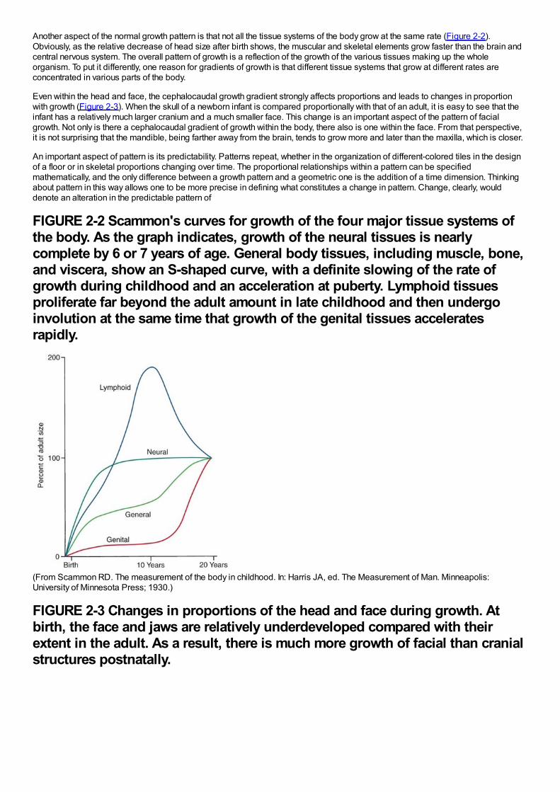
FIGURE 2-2 Scammon's curves for growth of the four major tissue systems ofthe body. As the graph indicates, growth of the neural tissues is nearlycomplete by 6 or 7 years of age. General body tissues, including muscle, bone,and viscera, show an S-shaped curve, with a definite slowing of the rate ofgrowth during childhood and an acceleration at puberty. Lymphoid tissuesproliferate far beyond the adult amount in late childhood and then undergoinvolution at the same time that growth of the genital tissues acceleratesrapidly.
(From Scammon RD. The measurement of the body in childhood. In: Harris JA, ed. The Measurement of Man. Minneapolis:University of Minnesota Press; 1930.)
FIGURE 2-3 Changes in proportions of the head and face during growth. Atbirth, the face and jaws are relatively underdeveloped compared with theirextent in the adult. As a result, there is much more growth of facial than cranialstructures postnatally.
(Redrawn from Lowery GH. Growth and Development of Children. 6th ed. Chicago: Year Book Medical Publishers; 1973.)mathematical relationships. A change in growth pattern would indicate some alteration in the expected changes in body proportions.
A second important concept in the study of growth and development is variability. Obviously, everyone is not alike in the way that theygrow, as in everything else. It can be difficult but clinically very important to decide whether an individual is merely at the extreme ofthe normal variation or falls outside the normal range.
Rather than categorizing growth as normal or abnormal, it is more useful to think in terms of deviations from the usual pattern and toexpress variability quantitatively. One way to do this is to evaluate a given child relative to peers on a standard growth chart (Figure 2-4). Although charts of this type are commonly used for height and weight, the growth of any part of the body can be plotted in this way.The “normal variability,” as derived from large-scale studies of groups of children, is shown by the solid lines on the graphs. Anindividual who stood exactly at the midpoint of the normal distribution would fall along the 50%line of the graph. One who was largerthan 90%of the population would plot above the 90%line; one who was smaller than 90%of the population would plot below the10%line.
These charts can be used in two ways to determine whether growth is normal or abnormal. First, the location of an individual relativeto the group can be established. A general guideline is that a child who falls outside the range of 97%of the population should receivespecial study before being accepted as just an extreme of the normal population. Second and perhaps more importantly, growthcharts can be used to follow a child over time to evaluate whether there is an unexpected change in growth pattern. Pattern impliespredictability. For the growth charts, this means that a child's growth should plot along the same percentile line at all ages. If thepercentile position of an individual relative to his or her peer group changes, especially if there is a marked change
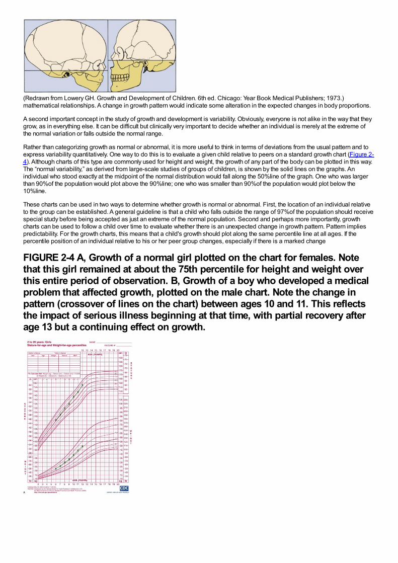
FIGURE 2-4 A, Growth of a normal girl plotted on the chart for females. Notethat this girl remained at about the 75th percentile for height and weight overthis entire period of observation. B, Growth of a boy who developed a medicalproblem that affected growth, plotted on the male chart. Note the change inpattern (crossover of lines on the chart) between ages 10 and 11. This reflectsthe impact of serious illness beginning at that time, with partial recovery afterage 13 but a continuing effect on growth.
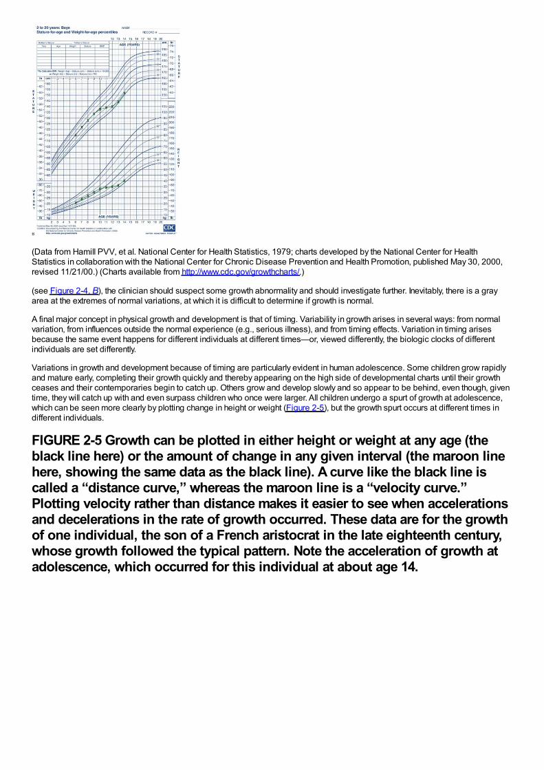
(Data from Hamill PVV, et al. National Center for Health Statistics, 1979; charts developed by the National Center for HealthStatistics in collaboration with the National Center for Chronic Disease Prevention and Health Promotion, published May 30, 2000,revised 11/21/00.) (Charts available from http://www.cdc.gov/growthcharts/.)
(see Figure 2-4, B), the clinician should suspect some growth abnormality and should investigate further. Inevitably, there is a grayarea at the extremes of normal variations, at which it is difficult to determine if growth is normal.
A final major concept in physical growth and development is that of timing. Variability in growth arises in several ways: from normalvariation, from influences outside the normal experience (e.g., serious illness), and from timing effects. Variation in timing arisesbecause the same event happens for different individuals at different times—or, viewed differently, the biologic clocks of differentindividuals are set differently.
Variations in growth and development because of timing are particularly evident in human adolescence. Some children grow rapidlyand mature early, completing their growth quickly and thereby appearing on the high side of developmental charts until their growthceases and their contemporaries begin to catch up. Others grow and develop slowly and so appear to be behind, even though, giventime, they will catch up with and even surpass children who once were larger. All children undergo a spurt of growth at adolescence,which can be seen more clearly by plotting change in height or weight (Figure 2-5), but the growth spurt occurs at different times indifferent individuals.
FIGURE 2-5 Growth can be plotted in either height or weight at any age (theblack line here) or the amount of change in any given interval (the maroon linehere, showing the same data as the black line). A curve like the black line iscalled a “distance curve,” whereas the maroon line is a “velocity curve.”Plotting velocity rather than distance makes it easier to see when accelerationsand decelerations in the rate of growth occurred. These data are for the growthof one individual, the son of a French aristocrat in the late eighteenth century,whose growth followed the typical pattern. Note the acceleration of growth atadolescence, which occurred for this individual at about age 14.
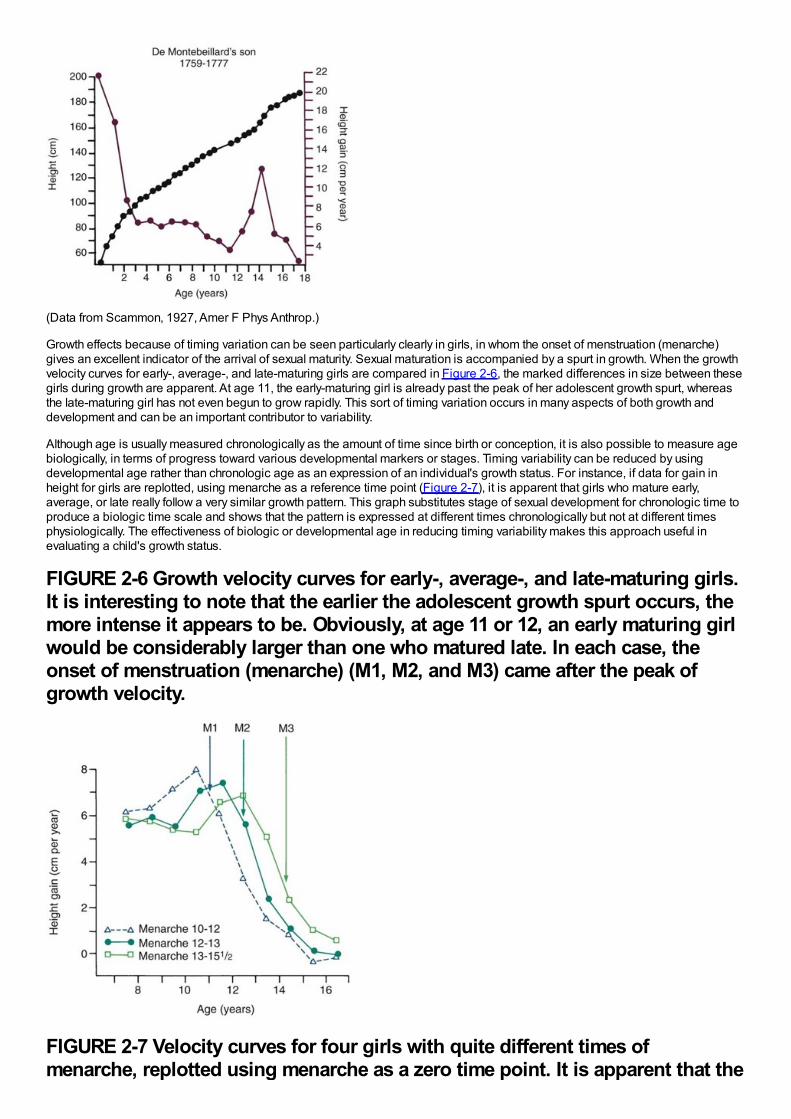
(Data from Scammon, 1927, Amer F Phys Anthrop.)
Growth effects because of timing variation can be seen particularly clearly in girls, in whom the onset of menstruation (menarche)gives an excellent indicator of the arrival of sexual maturity. Sexual maturation is accompanied by a spurt in growth. When the growthvelocity curves for early-, average-, and late-maturing girls are compared in Figure 2-6, the marked differences in size between thesegirls during growth are apparent. At age 11, the early-maturing girl is already past the peak of her adolescent growth spurt, whereasthe late-maturing girl has not even begun to grow rapidly. This sort of timing variation occurs in many aspects of both growth anddevelopment and can be an important contributor to variability.
Although age is usually measured chronologically as the amount of time since birth or conception, it is also possible to measure agebiologically, in terms of progress toward various developmental markers or stages. Timing variability can be reduced by usingdevelopmental age rather than chronologic age as an expression of an individual's growth status. For instance, if data for gain inheight for girls are replotted, using menarche as a reference time point (Figure 2-7), it is apparent that girls who mature early,average, or late really follow a very similar growth pattern. This graph substitutes stage of sexual development for chronologic time toproduce a biologic time scale and shows that the pattern is expressed at different times chronologically but not at different timesphysiologically. The effectiveness of biologic or developmental age in reducing timing variability makes this approach useful inevaluating a child's growth status.
FIGURE 2-6 Growth velocity curves for early-, average-, and late-maturing girls.It is interesting to note that the earlier the adolescent growth spurt occurs, themore intense it appears to be. Obviously, at age 11 or 12, an early maturing girlwould be considerably larger than one who matured late. In each case, theonset of menstruation (menarche) (M1, M2, and M3) came after the peak ofgrowth velocity.
FIGURE 2-7 Velocity curves for four girls with quite different times ofmenarche, replotted using menarche as a zero time point. It is apparent that the
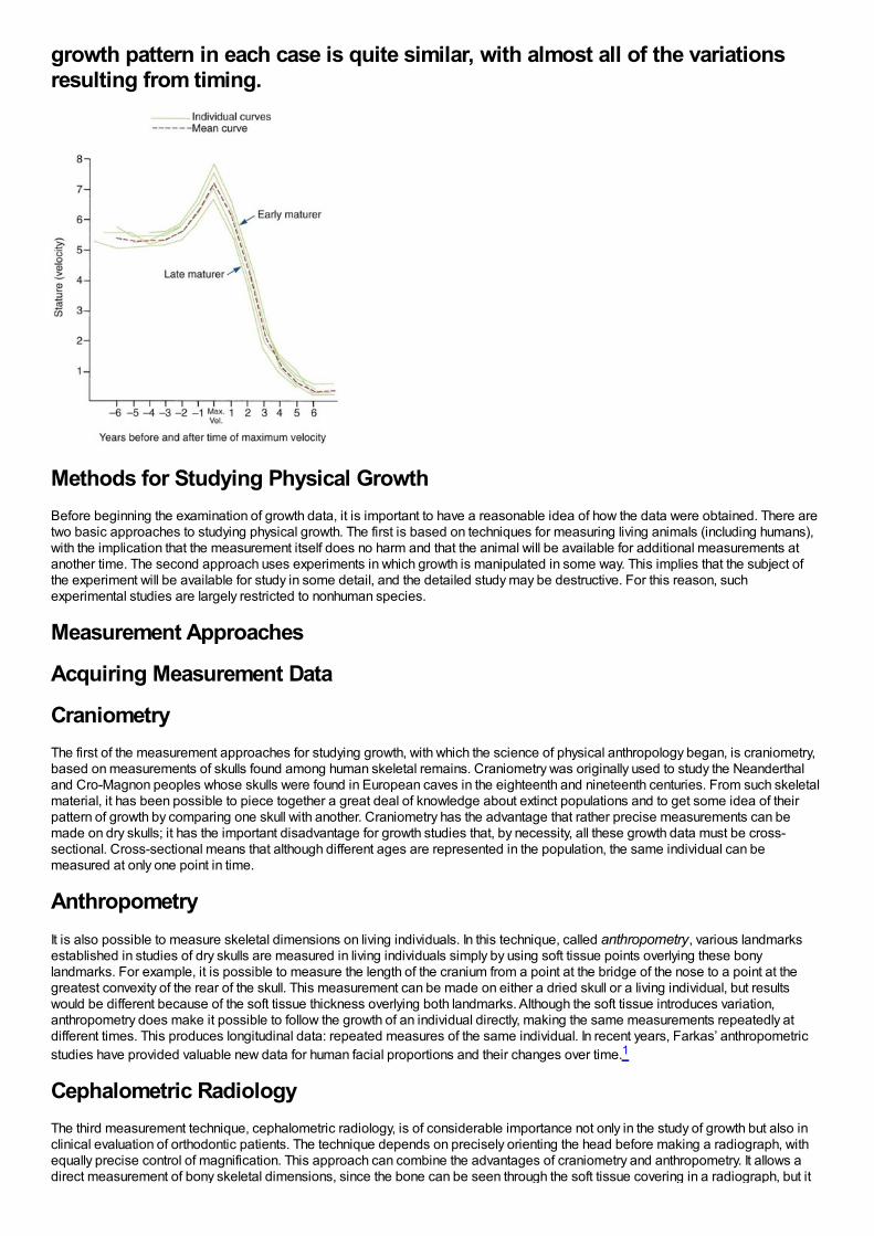
growth pattern in each case is quite similar, with almost all of the variationsresulting from timing.
Methods for Studying Physical GrowthBefore beginning the examination of growth data, it is important to have a reasonable idea of how the data were obtained. There aretwo basic approaches to studying physical growth. The first is based on techniques for measuring living animals (including humans),with the implication that the measurement itself does no harm and that the animal will be available for additional measurements atanother time. The second approach uses experiments in which growth is manipulated in some way. This implies that the subject ofthe experiment will be available for study in some detail, and the detailed study may be destructive. For this reason, suchexperimental studies are largely restricted to nonhuman species.
Measurement Approaches
Acquiring Measurement Data
CraniometryThe first of the measurement approaches for studying growth, with which the science of physical anthropology began, is craniometry,based on measurements of skulls found among human skeletal remains. Craniometry was originally used to study the Neanderthaland Cro-Magnon peoples whose skulls were found in European caves in the eighteenth and nineteenth centuries. From such skeletalmaterial, it has been possible to piece together a great deal of knowledge about extinct populations and to get some idea of theirpattern of growth by comparing one skull with another. Craniometry has the advantage that rather precise measurements can bemade on dry skulls; it has the important disadvantage for growth studies that, by necessity, all these growth data must be cross-sectional. Cross-sectional means that although different ages are represented in the population, the same individual can bemeasured at only one point in time.
AnthropometryIt is also possible to measure skeletal dimensions on living individuals. In this technique, called anthropometry, various landmarksestablished in studies of dry skulls are measured in living individuals simply by using soft tissue points overlying these bonylandmarks. For example, it is possible to measure the length of the cranium from a point at the bridge of the nose to a point at thegreatest convexity of the rear of the skull. This measurement can be made on either a dried skull or a living individual, but resultswould be different because of the soft tissue thickness overlying both landmarks. Although the soft tissue introduces variation,anthropometry does make it possible to follow the growth of an individual directly, making the same measurements repeatedly atdifferent times. This produces longitudinal data: repeated measures of the same individual. In recent years, Farkas’ anthropometricstudies have provided valuable new data for human facial proportions and their changes over time.1
Cephalometric RadiologyThe third measurement technique, cephalometric radiology, is of considerable importance not only in the study of growth but also inclinical evaluation of orthodontic patients. The technique depends on precisely orienting the head before making a radiograph, withequally precise control of magnification. This approach can combine the advantages of craniometry and anthropometry. It allows adirect measurement of bony skeletal dimensions, since the bone can be seen through the soft tissue covering in a radiograph, but it
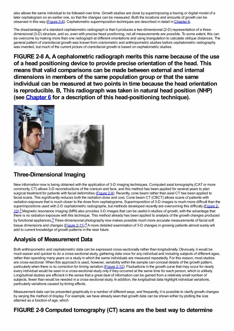
also allows the same individual to be followed over time. Growth studies are done by superimposing a tracing or digital model of alater cephalogram on an earlier one, so that the changes can be measured. Both the locations and amounts of growth can beobserved in this way (Figure 2-8). Cephalometric superimposition techniques are described in detail in Chapter 6.
The disadvantage of a standard cephalometric radiograph is that it produces a two-dimensional (2-D) representation of a three-dimensional (3-D) structure, and so, even with precise head positioning, not all measurements are possible. To some extent, this canbe overcome by making more than one radiograph at different orientations and using triangulation to calculate oblique distances. Thegeneral pattern of craniofacial growth was known from craniometric and anthropometric studies before cephalometric radiographywas invented, but much of the current picture of craniofacial growth is based on cephalometric studies.
FIGURE 2-8 A, A cephalometric radiograph merits this name because of the useof a head positioning device to provide precise orientation of the head. Thismeans that valid comparisons can be made between external and internaldimensions in members of the same population group or that the sameindividual can be measured at two points in time because the head orientationis reproducible. B, This radiograph was taken in natural head position (NHP)(see Chapter 6 for a description of this head-positioning technique).
Three-Dimensional ImagingNew information now is being obtained with the application of 3-D imaging techniques. Computed axial tomography (CAT or morecommonly, CT) allows 3-D reconstructions of the cranium and face, and this method has been applied for several years to plansurgical treatment for patients with facial deformities (Figure 2-9). Recently, cone beam rather than axial CT has been applied tofacial scans. This significantly reduces both the radiation dose and cost. Cone beam CT (CBCT) allows scans of patients withradiation exposure that is much closer to the dose from cephalograms. Superimposition of 3-D images is much more difficult than thesuperimpositions used with 2-D cephalometric radiographs, but methods developed recently are overcoming this difficulty (Figure 2-10).2 Magnetic resonance imaging (MRI) also provides 3-D images that can be useful in studies of growth, with the advantage thatthere is no radiation exposure with this technique. This method already has been applied to analysis of the growth changes producedby functional appliances.3 Three-dimensional photography now makes possible much more accurate measurements of facial softtissue dimensions and changes (Figure 2-11).4 A more detailed examination of 3-D changes in growing patients almost surely willadd to current knowledge of growth patterns in the near future.
Analysis of Measurement DataBoth anthropometric and cephalometric data can be expressed cross-sectionally rather than longitudinally. Obviously, it would bemuch easier and quicker to do a cross-sectional study, gathering data once for any individual and including subjects of different ages,rather than spending many years on a study in which the same individuals are measured repeatedly. For this reason, most studiesare cross-sectional. When this approach is used, however, variability within the sample can conceal details of the growth pattern,particularly when there is no correction for timing variation (Figure 2-12). Fluctuations in the growth curve that may occur for nearlyevery individual would be seen in a cross-sectional study only if they occurred at the same time for each person, which is unlikely.Longitudinal studies are efficient in the sense that a great deal of information can be gained from a relatively small number ofsubjects, fewer than would be needed in a cross-sectional study. In addition, the longitudinal data highlight individual variations,particularly variations caused by timing effects.
Measurement data can be presented graphically in a number of different ways, and frequently, it is possible to clarify growth changesby varying the method of display. For example, we have already seen that growth data can be shown either by plotting the sizeattained as a function of age, which
FIGURE 2-9 Computed tomography (CT) scans are the best way to determine
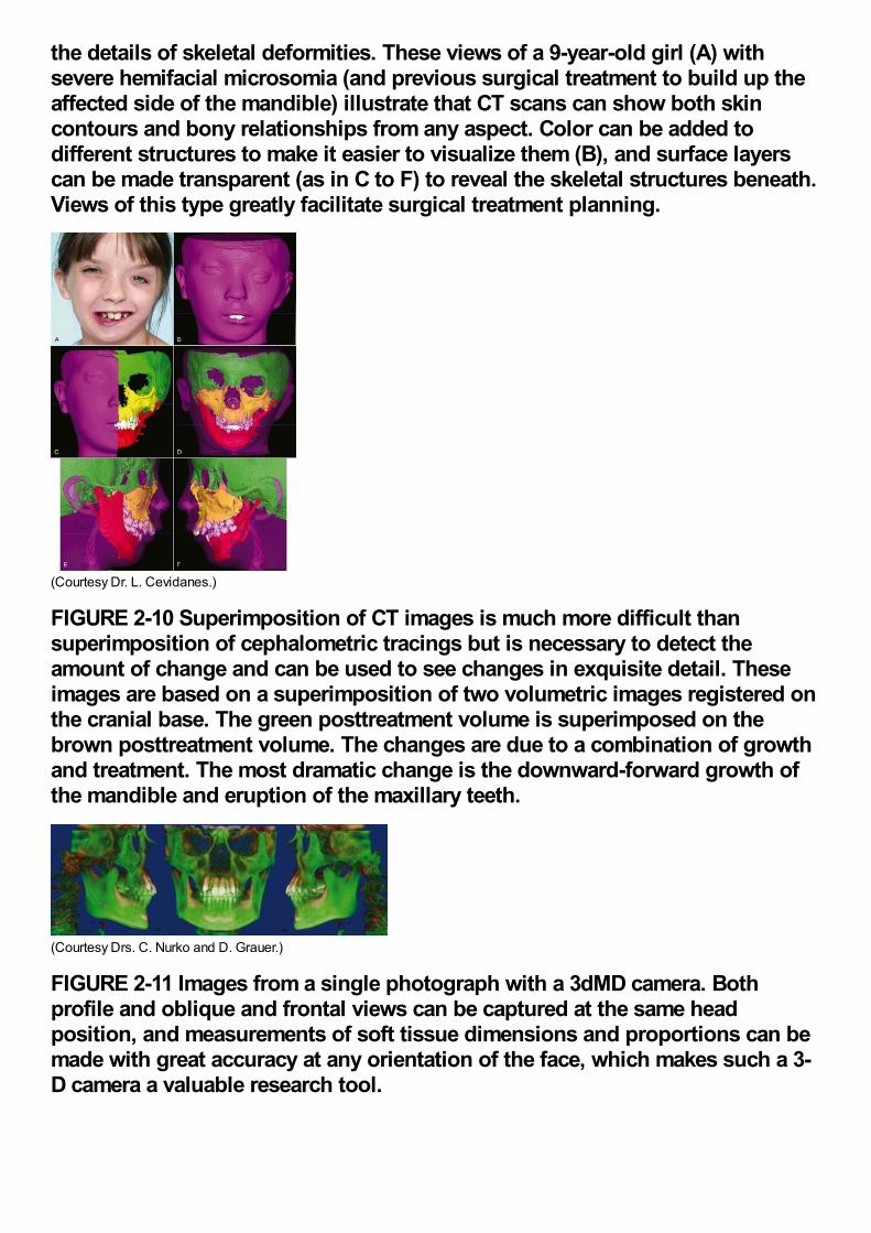
the details of skeletal deformities. These views of a 9-year-old girl (A) withsevere hemifacial microsomia (and previous surgical treatment to build up theaffected side of the mandible) illustrate that CT scans can show both skincontours and bony relationships from any aspect. Color can be added todifferent structures to make it easier to visualize them (B), and surface layerscan be made transparent (as in C to F) to reveal the skeletal structures beneath.Views of this type greatly facilitate surgical treatment planning.
(Courtesy Dr. L. Cevidanes.)
FIGURE 2-10 Superimposition of CT images is much more difficult thansuperimposition of cephalometric tracings but is necessary to detect theamount of change and can be used to see changes in exquisite detail. Theseimages are based on a superimposition of two volumetric images registered onthe cranial base. The green posttreatment volume is superimposed on thebrown posttreatment volume. The changes are due to a combination of growthand treatment. The most dramatic change is the downward-forward growth ofthe mandible and eruption of the maxillary teeth.
(Courtesy Drs. C. Nurko and D. Grauer.)
FIGURE 2-11 Images from a single photograph with a 3dMD camera. Bothprofile and oblique and frontal views can be captured at the same headposition, and measurements of soft tissue dimensions and proportions can bemade with great accuracy at any orientation of the face, which makes such a 3-D camera a valuable research tool.
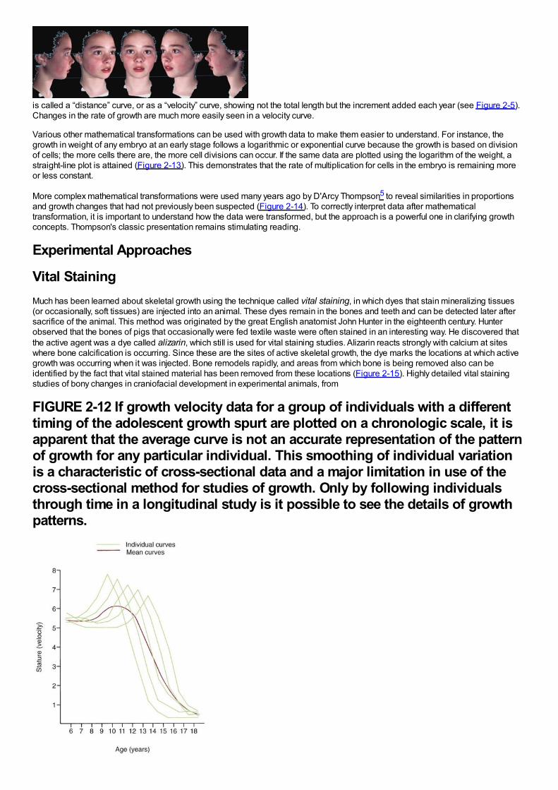
is called a “distance” curve, or as a “velocity” curve, showing not the total length but the increment added each year (see Figure 2-5).Changes in the rate of growth are much more easily seen in a velocity curve.
Various other mathematical transformations can be used with growth data to make them easier to understand. For instance, thegrowth in weight of any embryo at an early stage follows a logarithmic or exponential curve because the growth is based on divisionof cells; the more cells there are, the more cell divisions can occur. If the same data are plotted using the logarithm of the weight, astraight-line plot is attained (Figure 2-13). This demonstrates that the rate of multiplication for cells in the embryo is remaining moreor less constant.
More complex mathematical transformations were used many years ago by D'Arcy Thompson5 to reveal similarities in proportionsand growth changes that had not previously been suspected (Figure 2-14). To correctly interpret data after mathematicaltransformation, it is important to understand how the data were transformed, but the approach is a powerful one in clarifying growthconcepts. Thompson's classic presentation remains stimulating reading.
Experimental Approaches
Vital StainingMuch has been learned about skeletal growth using the technique called vital staining, in which dyes that stain mineralizing tissues(or occasionally, soft tissues) are injected into an animal. These dyes remain in the bones and teeth and can be detected later aftersacrifice of the animal. This method was originated by the great English anatomist John Hunter in the eighteenth century. Hunterobserved that the bones of pigs that occasionally were fed textile waste were often stained in an interesting way. He discovered thatthe active agent was a dye called alizarin, which still is used for vital staining studies. Alizarin reacts strongly with calcium at siteswhere bone calcification is occurring. Since these are the sites of active skeletal growth, the dye marks the locations at which activegrowth was occurring when it was injected. Bone remodels rapidly, and areas from which bone is being removed also can beidentified by the fact that vital stained material has been removed from these locations (Figure 2-15). Highly detailed vital stainingstudies of bony changes in craniofacial development in experimental animals, from
FIGURE 2-12 If growth velocity data for a group of individuals with a differenttiming of the adolescent growth spurt are plotted on a chronologic scale, it isapparent that the average curve is not an accurate representation of the patternof growth for any particular individual. This smoothing of individual variationis a characteristic of cross-sectional data and a major limitation in use of thecross-sectional method for studies of growth. Only by following individualsthrough time in a longitudinal study is it possible to see the details of growthpatterns.
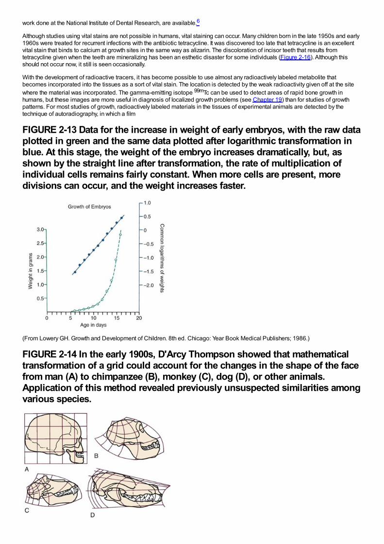
work done at the National Institute of Dental Research, are available.6
Although studies using vital stains are not possible in humans, vital staining can occur. Many children born in the late 1950s and early1960s were treated for recurrent infections with the antibiotic tetracycline. It was discovered too late that tetracycline is an excellentvital stain that binds to calcium at growth sites in the same way as alizarin. The discoloration of incisor teeth that results fromtetracycline given when the teeth are mineralizing has been an esthetic disaster for some individuals (Figure 2-16). Although thisshould not occur now, it still is seen occasionally.
With the development of radioactive tracers, it has become possible to use almost any radioactively labeled metabolite thatbecomes incorporated into the tissues as a sort of vital stain. The location is detected by the weak radioactivity given off at the sitewhere the material was incorporated. The gamma-emitting isotope 99mTc can be used to detect areas of rapid bone growth inhumans, but these images are more useful in diagnosis of localized growth problems (see Chapter 19) than for studies of growthpatterns. For most studies of growth, radioactively labeled materials in the tissues of experimental animals are detected by thetechnique of autoradiography, in which a film
FIGURE 2-13 Data for the increase in weight of early embryos, with the raw dataplotted in green and the same data plotted after logarithmic transformation inblue. At this stage, the weight of the embryo increases dramatically, but, asshown by the straight line after transformation, the rate of multiplication ofindividual cells remains fairly constant. When more cells are present, moredivisions can occur, and the weight increases faster.
(From Lowery GH. Growth and Development of Children. 8th ed. Chicago: Year Book Medical Publishers; 1986.)
FIGURE 2-14 In the early 1900s, D'Arcy Thompson showed that mathematicaltransformation of a grid could account for the changes in the shape of the facefrom man (A) to chimpanzee (B), monkey (C), dog (D), or other animals.Application of this method revealed previously unsuspected similarities amongvarious species.
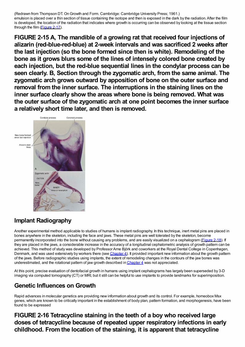
(Redrawn from Thompson DT. On Growth and Form. Cambridge: Cambridge University Press; 1961.)emulsion is placed over a thin section of tissue containing the isotope and then is exposed in the dark by the radiation. After the filmis developed, the location of the radiation that indicates where growth is occurring can be observed by looking at the tissue sectionthrough the film (Figure 2-17).
FIGURE 2-15 A, The mandible of a growing rat that received four injections ofalizarin (red-blue-red-blue) at 2-week intervals and was sacrificed 2 weeks afterthe last injection (so the bone formed since then is white). Remodeling of thebone as it grows blurs some of the lines of intensely colored bone created byeach injection, but the red-blue sequential lines in the condylar process can beseen clearly. B, Section through the zygomatic arch, from the same animal. Thezygomatic arch grows outward by apposition of bone on the outer surface andremoval from the inner surface. The interruptions in the staining lines on theinner surface clearly show the areas where bone is being removed. What wasthe outer surface of the zygomatic arch at one point becomes the inner surfacea relatively short time later, and then is removed.
Implant RadiographyAnother experimental method applicable to studies of humans is implant radiography. In this technique, inert metal pins are placed inbones anywhere in the skeleton, including the face and jaws. These metal pins are well tolerated by the skeleton, becomepermanently incorporated into the bone without causing any problems, and are easily visualized on a cephalogram (Figure 2-18). Ifthey are placed in the jaws, a considerable increase in the accuracy of a longitudinal cephalometric analysis of growth pattern can beachieved. This method of study was developed by Professor Arne Björk and coworkers at the Royal Dental College in Copenhagen,Denmark, and was used extensively by workers there (see Chapter 4). It provided important new information about the growth patternof the jaws. Before radiographic studies using implants, the extent of remodeling changes in the contours of the jaw bones wasunderestimated, and the rotational pattern of jaw growth described in Chapter 4 was not appreciated.
At this point, precise evaluation of dentofacial growth in humans using implant cephalograms has largely been superseded by 3-Dimaging via computed tomography (CT) or MRI, but it still can be helpful to use implants to provide landmarks for superimposition.
Genetic Influences on GrowthRapid advances in molecular genetics are providing new information about growth and its control. For example, homeobox Msxgenes, which are known to be critically important in the establishment of body plan, pattern formation, and morphogenesis, have beenfound to be expressed
FIGURE 2-16 Tetracycline staining in the teeth of a boy who received largedoses of tetracycline because of repeated upper respiratory infections in earlychildhood. From the location of the staining, it is apparent that tetracycline
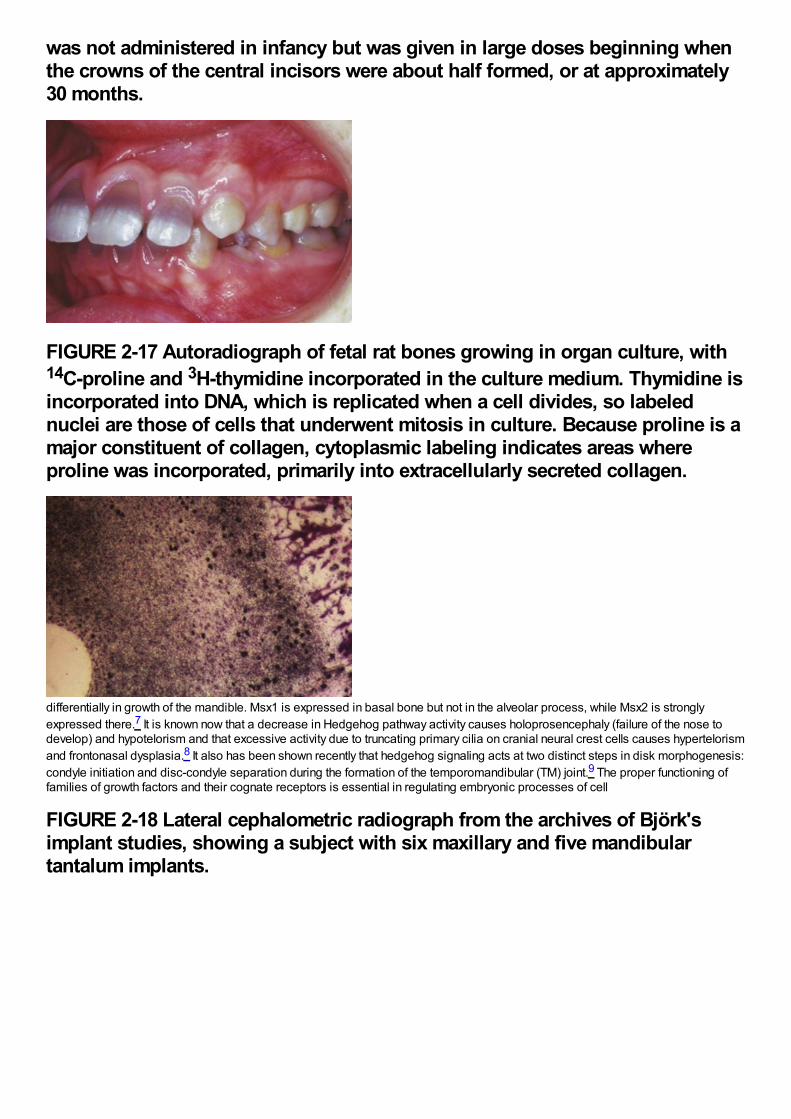
was not administered in infancy but was given in large doses beginning whenthe crowns of the central incisors were about half formed, or at approximately30 months.
FIGURE 2-17 Autoradiograph of fetal rat bones growing in organ culture, with14C-proline and 3H-thymidine incorporated in the culture medium. Thymidine isincorporated into DNA, which is replicated when a cell divides, so labelednuclei are those of cells that underwent mitosis in culture. Because proline is amajor constituent of collagen, cytoplasmic labeling indicates areas whereproline was incorporated, primarily into extracellularly secreted collagen.
differentially in growth of the mandible. Msx1 is expressed in basal bone but not in the alveolar process, while Msx2 is stronglyexpressed there.7 It is known now that a decrease in Hedgehog pathway activity causes holoprosencephaly (failure of the nose todevelop) and hypotelorism and that excessive activity due to truncating primary cilia on cranial neural crest cells causes hypertelorismand frontonasal dysplasia.8 It also has been shown recently that hedgehog signaling acts at two distinct steps in disk morphogenesis:condyle initiation and disc-condyle separation during the formation of the temporomandibular (TM) joint.9 The proper functioning offamilies of growth factors and their cognate receptors is essential in regulating embryonic processes of cell
FIGURE 2-18 Lateral cephalometric radiograph from the archives of Björk'simplant studies, showing a subject with six maxillary and five mandibulartantalum implants.
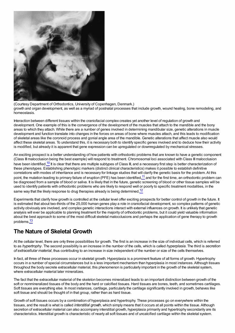
(Courtesy Department of Orthodontics, University of Copenhagen, Denmark.)growth and organ development, as well as a myriad of postnatal processes that include growth, wound healing, bone remodeling, andhomeostasis.
Interaction between different tissues within the craniofacial complex creates yet another level of regulation of growth anddevelopment. One example of this is the convergence of the development of the muscles that attach to the mandible and the bonyareas to which they attach. While there are a number of genes involved in determining mandibular size, genetic alterations in muscledevelopment and function translate into changes in the forces on areas of bone where muscles attach, and this leads to modificationof skeletal areas like the coronoid process and gonial angle area of the mandible. Genetic alterations that affect muscle also wouldaffect these skeletal areas. To understand this, it is necessary both to identify specific genes involved and to deduce how their activityis modified, but already it is apparent that gene expression can be upregulated or downregulated by mechanical stresses.
An exciting prospect is a better understanding of how patients with orthodontic problems that are known to have a genetic component(Class III malocclusion being the best example) will respond to treatment. Chromosomal loci associated with Class III malocclusionhave been identified.10 It is clear that there are multiple subtypes of Class III, and a necessary first step is better characterization ofthese phenotypes. Establishing phenotypic markers (distinct clinical characteristics) makes it possible to establish definitivecorrelations with modes of inheritance and is necessary for linkage studies that will clarify the genetic basis for the problem. At thispoint, the mutation leading to primary failure of eruption (PFE) has been identified,11 and for the first time, an orthodontic problem canbe diagnosed from a sample of blood or saliva. It is likely that in the future, genetic screening of blood or other tissue samples will beused to identify patients with orthodontic problems who are likely to respond well or poorly to specific treatment modalities, in thesame way that the likely response to drug therapies already is being determined.12
Experiments that clarify how growth is controlled at the cellular level offer exciting prospects for better control of growth in the future. Itis estimated that about two-thirds of the 25,000 human genes play a role in craniofacial development, so complex patterns of geneticactivity obviously are involved, and complex genetic interactions interact with external influences on growth. It is unlikely that geneticanalysis will ever be applicable to planning treatment for the majority of orthodontic problems, but it could yield valuable informationabout the best approach to some of the most difficult skeletal malocclusions and perhaps the application of gene therapy to growthproblems.13
The Nature of Skeletal GrowthAt the cellular level, there are only three possibilities for growth. The first is an increase in the size of individual cells, which is referredto as hypertrophy. The second possibility is an increase in the number of the cells, which is called hyperplasia. The third is secretionof extracellular material, thus contributing to an increase in size independent of the number or size of the cells themselves.
In fact, all three of these processes occur in skeletal growth. Hyperplasia is a prominent feature of all forms of growth. Hypertrophyoccurs in a number of special circumstances but is a less important mechanism than hyperplasia in most instances. Although tissuesthroughout the body secrete extracellular material, this phenomenon is particularly important in the growth of the skeletal system,where extracellular material later mineralizes.
The fact that the extracellular material of the skeleton becomes mineralized leads to an important distinction between growth of thesoft or nonmineralized tissues of the body and the hard or calcified tissues. Hard tissues are bones, teeth, and sometimes cartilages.Soft tissues are everything else. In most instances, cartilage, particularly the cartilage significantly involved in growth, behaves likesoft tissue and should be thought of in that group, rather than as hard tissue.
Growth of soft tissues occurs by a combination of hyperplasia and hypertrophy. These processes go on everywhere within thetissues, and the result is what is called interstitial growth, which simply means that it occurs at all points within the tissue. Althoughsecretion of extracellular material can also accompany interstitial growth, hyperplasia primarily and hypertrophy secondarily are itscharacteristics. Interstitial growth is characteristic of nearly all soft tissues and of uncalcified cartilage within the skeletal system.
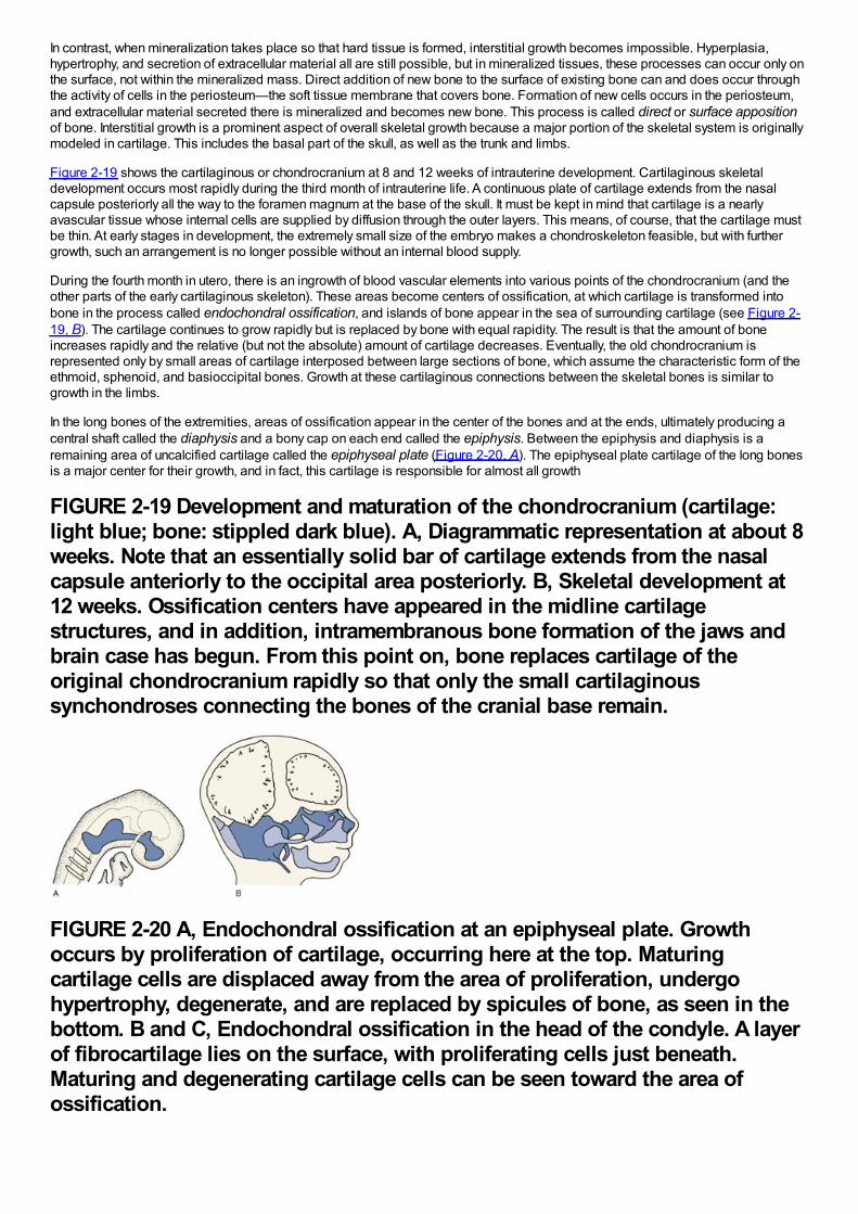
In contrast, when mineralization takes place so that hard tissue is formed, interstitial growth becomes impossible. Hyperplasia,hypertrophy, and secretion of extracellular material all are still possible, but in mineralized tissues, these processes can occur only onthe surface, not within the mineralized mass. Direct addition of new bone to the surface of existing bone can and does occur throughthe activity of cells in the periosteum—the soft tissue membrane that covers bone. Formation of new cells occurs in the periosteum,and extracellular material secreted there is mineralized and becomes new bone. This process is called direct or surface appositionof bone. Interstitial growth is a prominent aspect of overall skeletal growth because a major portion of the skeletal system is originallymodeled in cartilage. This includes the basal part of the skull, as well as the trunk and limbs.
Figure 2-19 shows the cartilaginous or chondrocranium at 8 and 12 weeks of intrauterine development. Cartilaginous skeletaldevelopment occurs most rapidly during the third month of intrauterine life. A continuous plate of cartilage extends from the nasalcapsule posteriorly all the way to the foramen magnum at the base of the skull. It must be kept in mind that cartilage is a nearlyavascular tissue whose internal cells are supplied by diffusion through the outer layers. This means, of course, that the cartilage mustbe thin. At early stages in development, the extremely small size of the embryo makes a chondroskeleton feasible, but with furthergrowth, such an arrangement is no longer possible without an internal blood supply.
During the fourth month in utero, there is an ingrowth of blood vascular elements into various points of the chondrocranium (and theother parts of the early cartilaginous skeleton). These areas become centers of ossification, at which cartilage is transformed intobone in the process called endochondral ossification, and islands of bone appear in the sea of surrounding cartilage (see Figure 2-19, B). The cartilage continues to grow rapidly but is replaced by bone with equal rapidity. The result is that the amount of boneincreases rapidly and the relative (but not the absolute) amount of cartilage decreases. Eventually, the old chondrocranium isrepresented only by small areas of cartilage interposed between large sections of bone, which assume the characteristic form of theethmoid, sphenoid, and basioccipital bones. Growth at these cartilaginous connections between the skeletal bones is similar togrowth in the limbs.
In the long bones of the extremities, areas of ossification appear in the center of the bones and at the ends, ultimately producing acentral shaft called the diaphysis and a bony cap on each end called the epiphysis. Between the epiphysis and diaphysis is aremaining area of uncalcified cartilage called the epiphyseal plate (Figure 2-20, A). The epiphyseal plate cartilage of the long bonesis a major center for their growth, and in fact, this cartilage is responsible for almost all growth
FIGURE 2-19 Development and maturation of the chondrocranium (cartilage:light blue; bone: stippled dark blue). A, Diagrammatic representation at about 8weeks. Note that an essentially solid bar of cartilage extends from the nasalcapsule anteriorly to the occipital area posteriorly. B, Skeletal development at12 weeks. Ossification centers have appeared in the midline cartilagestructures, and in addition, intramembranous bone formation of the jaws andbrain case has begun. From this point on, bone replaces cartilage of theoriginal chondrocranium rapidly so that only the small cartilaginoussynchondroses connecting the bones of the cranial base remain.
FIGURE 2-20 A, Endochondral ossification at an epiphyseal plate. Growthoccurs by proliferation of cartilage, occurring here at the top. Maturingcartilage cells are displaced away from the area of proliferation, undergohypertrophy, degenerate, and are replaced by spicules of bone, as seen in thebottom. B and C, Endochondral ossification in the head of the condyle. A layerof fibrocartilage lies on the surface, with proliferating cells just beneath.Maturing and degenerating cartilage cells can be seen toward the area ofossification.
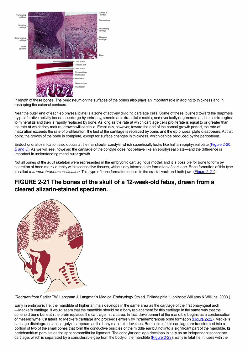
in length of these bones. The periosteum on the surfaces of the bones also plays an important role in adding to thickness and inreshaping the external contours.
Near the outer end of each epiphyseal plate is a zone of actively dividing cartilage cells. Some of these, pushed toward the diaphysisby proliferative activity beneath, undergo hypertrophy, secrete an extracellular matrix, and eventually degenerate as the matrix beginsto mineralize and then is rapidly replaced by bone. As long as the rate at which cartilage cells proliferate is equal to or greater thanthe rate at which they mature, growth will continue. Eventually, however, toward the end of the normal growth period, the rate ofmaturation exceeds the rate of proliferation, the last of the cartilage is replaced by bone, and the epiphyseal plate disappears. At thatpoint, the growth of the bone is complete, except for surface changes in thickness, which can be produced by the periosteum.
Endochondral ossification also occurs at the mandibular condyle, which superficially looks like half an epiphyseal plate (Figure 2-20,B and C). As we will see, however, the cartilage of the condyle does not behave like an epiphyseal plate—and the difference isimportant in understanding mandibular growth.
Not all bones of the adult skeleton were represented in the embryonic cartilaginous model, and it is possible for bone to form bysecretion of bone matrix directly within connective tissues, without any intermediate formation of cartilage. Bone formation of this typeis called intramembranous ossification. This type of bone formation occurs in the cranial vault and both jaws (Figure 2-21).
FIGURE 2-21 The bones of the skull of a 12-week-old fetus, drawn from acleared alizarin-stained specimen.
(Redrawn from Sadler TW, Langman J. Langman's Medical Embryology. 9th ed. Philadelphia: Lippincott Williams & Wilkins; 2003.)
Early in embryonic life, the mandible of higher animals develops in the same area as the cartilage of the first pharyngeal arch—Meckel's cartilage. It would seem that the mandible should be a bony replacement for this cartilage in the same way that thesphenoid bone beneath the brain replaces the cartilage in that area. In fact, development of the mandible begins as a condensationof mesenchyme just lateral to Meckel's cartilage and proceeds entirely by intramembranous bone formation (Figure 2-22). Meckel'scartilage disintegrates and largely disappears as the bony mandible develops. Remnants of this cartilage are transformed into aportion of two of the small bones that form the conductive ossicles of the middle ear but not into a significant part of the mandible. Itsperichondrium persists as the sphenomandibular ligament. The condylar cartilage develops initially as an independent secondarycartilage, which is separated by a considerable gap from the body of the mandible (Figure 2-23). Early in fetal life, it fuses with the
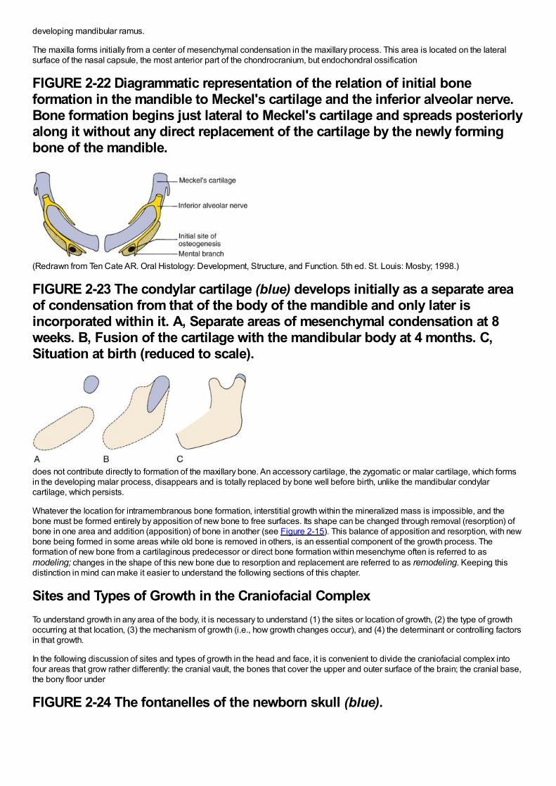
developing mandibular ramus.
The maxilla forms initially from a center of mesenchymal condensation in the maxillary process. This area is located on the lateralsurface of the nasal capsule, the most anterior part of the chondrocranium, but endochondral ossification
FIGURE 2-22 Diagrammatic representation of the relation of initial boneformation in the mandible to Meckel's cartilage and the inferior alveolar nerve.Bone formation begins just lateral to Meckel's cartilage and spreads posteriorlyalong it without any direct replacement of the cartilage by the newly formingbone of the mandible.
(Redrawn from Ten Cate AR. Oral Histology: Development, Structure, and Function. 5th ed. St. Louis: Mosby; 1998.)
FIGURE 2-23 The condylar cartilage (blue) develops initially as a separate areaof condensation from that of the body of the mandible and only later isincorporated within it. A, Separate areas of mesenchymal condensation at 8weeks. B, Fusion of the cartilage with the mandibular body at 4 months. C,Situation at birth (reduced to scale).
does not contribute directly to formation of the maxillary bone. An accessory cartilage, the zygomatic or malar cartilage, which formsin the developing malar process, disappears and is totally replaced by bone well before birth, unlike the mandibular condylarcartilage, which persists.
Whatever the location for intramembranous bone formation, interstitial growth within the mineralized mass is impossible, and thebone must be formed entirely by apposition of new bone to free surfaces. Its shape can be changed through removal (resorption) ofbone in one area and addition (apposition) of bone in another (see Figure 2-15). This balance of apposition and resorption, with newbone being formed in some areas while old bone is removed in others, is an essential component of the growth process. Theformation of new bone from a cartilaginous predecessor or direct bone formation within mesenchyme often is referred to asmodeling; changes in the shape of this new bone due to resorption and replacement are referred to as remodeling. Keeping thisdistinction in mind can make it easier to understand the following sections of this chapter.
Sites and Types of Growth in the Craniofacial ComplexTo understand growth in any area of the body, it is necessary to understand (1) the sites or location of growth, (2) the type of growthoccurring at that location, (3) the mechanism of growth (i.e., how growth changes occur), and (4) the determinant or controlling factorsin that growth.
In the following discussion of sites and types of growth in the head and face, it is convenient to divide the craniofacial complex intofour areas that grow rather differently: the cranial vault, the bones that cover the upper and outer surface of the brain; the cranial base,the bony floor under
FIGURE 2-24 The fontanelles of the newborn skull (blue).
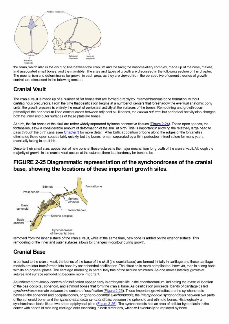
the brain, which also is the dividing line between the cranium and the face; the nasomaxillary complex, made up of the nose, maxilla,and associated small bones; and the mandible. The sites and types of growth are discussed in the following section of this chapter.The mechanism and determinants for growth in each area, as they are viewed from the perspective of current theories of growthcontrol, are discussed in the following section.
Cranial VaultThe cranial vault is made up of a number of flat bones that are formed directly by intramembranous bone formation, withoutcartilaginous precursors. From the time that ossification begins at a number of centers that foreshadow the eventual anatomic bonyunits, the growth process is entirely the result of periosteal activity at the surfaces of the bones. Remodeling and growth occurprimarily at the periosteum-lined contact areas between adjacent skull bones, the cranial sutures, but periosteal activity also changesboth the inner and outer surfaces of these platelike bones.
At birth, the flat bones of the skull are rather widely separated by loose connective tissues (Figure 2-24). These open spaces, thefontanelles, allow a considerable amount of deformation of the skull at birth. This is important in allowing the relatively large head topass through the birth canal (see Chapter 3 for more detail). After birth, apposition of bone along the edges of the fontanelleseliminates these open spaces fairly quickly, but the bones remain separated by a thin, periosteum-lined suture for many years,eventually fusing in adult life.
Despite their small size, apposition of new bone at these sutures is the major mechanism for growth of the cranial vault. Although themajority of growth in the cranial vault occurs at the sutures, there is a tendency for bone to be
FIGURE 2-25 Diagrammatic representation of the synchondroses of the cranialbase, showing the locations of these important growth sites.
removed from the inner surface of the cranial vault, while at the same time, new bone is added on the exterior surface. Thisremodeling of the inner and outer surfaces allows for changes in contour during growth.
Cranial BaseIn contrast to the cranial vault, the bones of the base of the skull (the cranial base) are formed initially in cartilage and these cartilagemodels are later transformed into bone by endochondral ossification. The situation is more complicated, however, than in a long bonewith its epiphyseal plates. The cartilage modeling is particularly true of the midline structures. As one moves laterally, growth atsutures and surface remodeling become more important.
As indicated previously, centers of ossification appear early in embryonic life in the chondrocranium, indicating the eventual locationof the basioccipital, sphenoid, and ethmoid bones that form the cranial base. As ossification proceeds, bands of cartilage calledsynchondroses remain between the centers of ossification (Figure 2-25). These important growth sites are the synchondrosisbetween the sphenoid and occipital bones, or spheno-occipital synchondrosis; the intersphenoid synchondrosis between two partsof the sphenoid bone; and the spheno-ethmoidal synchondrosis between the sphenoid and ethmoid bones. Histologically, asynchondrosis looks like a two-sided epiphyseal plate (Figure 2-26). The synchondrosis has an area of cellular hyperplasia in thecenter with bands of maturing cartilage cells extending in both directions, which will eventually be replaced by bone.
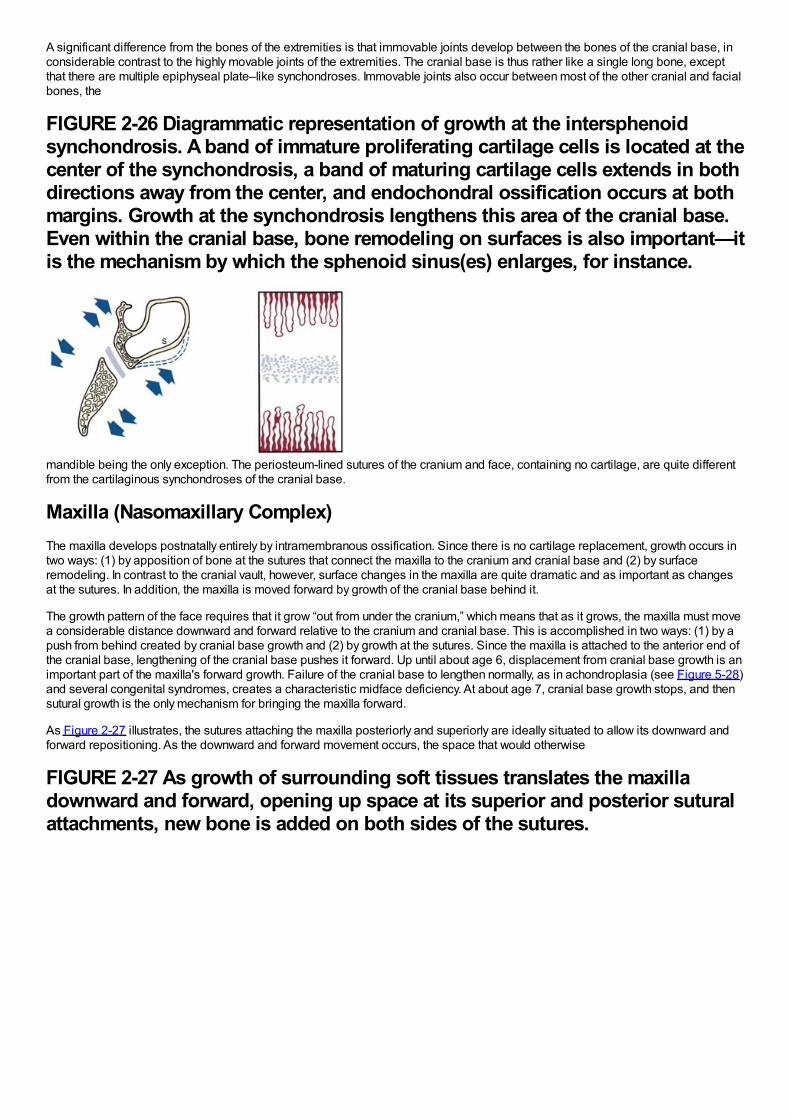
A significant difference from the bones of the extremities is that immovable joints develop between the bones of the cranial base, inconsiderable contrast to the highly movable joints of the extremities. The cranial base is thus rather like a single long bone, exceptthat there are multiple epiphyseal plate–like synchondroses. Immovable joints also occur between most of the other cranial and facialbones, the
FIGURE 2-26 Diagrammatic representation of growth at the intersphenoidsynchondrosis. A band of immature proliferating cartilage cells is located at thecenter of the synchondrosis, a band of maturing cartilage cells extends in bothdirections away from the center, and endochondral ossification occurs at bothmargins. Growth at the synchondrosis lengthens this area of the cranial base.Even within the cranial base, bone remodeling on surfaces is also important—itis the mechanism by which the sphenoid sinus(es) enlarges, for instance.
mandible being the only exception. The periosteum-lined sutures of the cranium and face, containing no cartilage, are quite differentfrom the cartilaginous synchondroses of the cranial base.
Maxilla (Nasomaxillary Complex)The maxilla develops postnatally entirely by intramembranous ossification. Since there is no cartilage replacement, growth occurs intwo ways: (1) by apposition of bone at the sutures that connect the maxilla to the cranium and cranial base and (2) by surfaceremodeling. In contrast to the cranial vault, however, surface changes in the maxilla are quite dramatic and as important as changesat the sutures. In addition, the maxilla is moved forward by growth of the cranial base behind it.
The growth pattern of the face requires that it grow “out from under the cranium,” which means that as it grows, the maxilla must movea considerable distance downward and forward relative to the cranium and cranial base. This is accomplished in two ways: (1) by apush from behind created by cranial base growth and (2) by growth at the sutures. Since the maxilla is attached to the anterior end ofthe cranial base, lengthening of the cranial base pushes it forward. Up until about age 6, displacement from cranial base growth is animportant part of the maxilla's forward growth. Failure of the cranial base to lengthen normally, as in achondroplasia (see Figure 5-28)and several congenital syndromes, creates a characteristic midface deficiency. At about age 7, cranial base growth stops, and thensutural growth is the only mechanism for bringing the maxilla forward.
As Figure 2-27 illustrates, the sutures attaching the maxilla posteriorly and superiorly are ideally situated to allow its downward andforward repositioning. As the downward and forward movement occurs, the space that would otherwise
FIGURE 2-27 As growth of surrounding soft tissues translates the maxilladownward and forward, opening up space at its superior and posterior suturalattachments, new bone is added on both sides of the sutures.
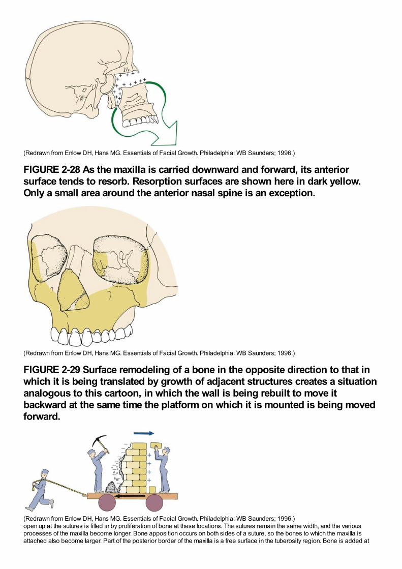
(Redrawn from Enlow DH, Hans MG. Essentials of Facial Growth. Philadelphia: WB Saunders; 1996.)
FIGURE 2-28 As the maxilla is carried downward and forward, its anteriorsurface tends to resorb. Resorption surfaces are shown here in dark yellow.Only a small area around the anterior nasal spine is an exception.
(Redrawn from Enlow DH, Hans MG. Essentials of Facial Growth. Philadelphia: WB Saunders; 1996.)
FIGURE 2-29 Surface remodeling of a bone in the opposite direction to that inwhich it is being translated by growth of adjacent structures creates a situationanalogous to this cartoon, in which the wall is being rebuilt to move itbackward at the same time the platform on which it is mounted is being movedforward.
(Redrawn from Enlow DH, Hans MG. Essentials of Facial Growth. Philadelphia: WB Saunders; 1996.)open up at the sutures is filled in by proliferation of bone at these locations. The sutures remain the same width, and the variousprocesses of the maxilla become longer. Bone apposition occurs on both sides of a suture, so the bones to which the maxilla isattached also become larger. Part of the posterior border of the maxilla is a free surface in the tuberosity region. Bone is added at
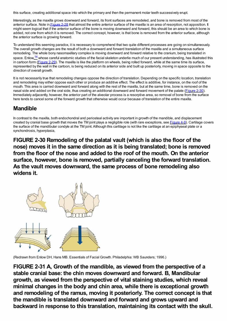
this surface, creating additional space into which the primary and then the permanent molar teeth successively erupt.
Interestingly, as the maxilla grows downward and forward, its front surfaces are remodeled, and bone is removed from most of theanterior surface. Note in Figure 2-28 that almost the entire anterior surface of the maxilla is an area of resorption, not apposition. Itmight seem logical that if the anterior surface of the bone is moving downward and forward, this should be an area to which bone isadded, not one from which it is removed. The correct concept, however, is that bone is removed from the anterior surface, althoughthe anterior surface is growing forward.
To understand this seeming paradox, it is necessary to comprehend that two quite different processes are going on simultaneously.The overall growth changes are the result of both a downward and forward translation of the maxilla and a simultaneous surfaceremodeling. The whole bony nasomaxillary complex is moving downward and forward relative to the cranium, being translated inspace. Enlow,14 whose careful anatomic studies of the facial skeleton underlie much of our present understanding, has illustrated thisin cartoon form (Figure 2-29). The maxilla is like the platform on wheels, being rolled forward, while at the same time its surface,represented by the wall in the cartoon, is being reduced on its anterior side and built up posteriorly, moving in space opposite to thedirection of overall growth.
It is not necessarily true that remodeling changes oppose the direction of translation. Depending on the specific location, translationand remodeling may either oppose each other or produce an additive effect. The effect is additive, for instance, on the roof of themouth. This area is carried downward and forward along with the rest of the maxilla, but at the same time, bone is removed on thenasal side and added on the oral side, thus creating an additional downward and forward movement of the palate (Figure 2-30).Immediately adjacently, however, the anterior part of the alveolar process is a resorptive area, so removal of bone from the surfacehere tends to cancel some of the forward growth that otherwise would occur because of translation of the entire maxilla.
MandibleIn contrast to the maxilla, both endochondral and periosteal activity are important in growth of the mandible, and displacementcreated by cranial base growth that moves the TM joint plays a negligible role (with rare exceptions, see Figure 4-9). Cartilage coversthe surface of the mandibular condyle at the TM joint. Although this cartilage is not like the cartilage at an epiphyseal plate or asynchondrosis, hyperplasia,
FIGURE 2-30 Remodeling of the palatal vault (which is also the floor of thenose) moves it in the same direction as it is being translated; bone is removedfrom the floor of the nose and added to the roof of the mouth. On the anteriorsurface, however, bone is removed, partially canceling the forward translation.As the vault moves downward, the same process of bone remodeling alsowidens it.
(Redrawn from Enlow DH, Hans MB. Essentials of Facial Growth. Philadelphia: WB Saunders; 1996.)
FIGURE 2-31 A, Growth of the mandible, as viewed from the perspective of astable cranial base: the chin moves downward and forward. B, Mandibulargrowth, as viewed from the perspective of vital staining studies, which revealminimal changes in the body and chin area, while there is exceptional growthand remodeling of the ramus, moving it posteriorly. The correct concept is thatthe mandible is translated downward and forward and grows upward andbackward in response to this translation, maintaining its contact with the skull.
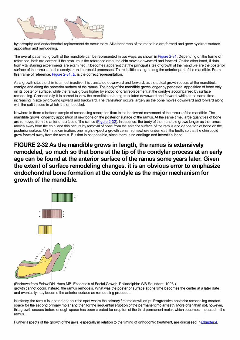
hypertrophy, and endochondral replacement do occur there. All other areas of the mandible are formed and grow by direct surfaceapposition and remodeling.
The overall pattern of growth of the mandible can be represented in two ways, as shown in Figure 2-31. Depending on the frame ofreference, both are correct. If the cranium is the reference area, the chin moves downward and forward. On the other hand, if datafrom vital staining experiments are examined, it becomes apparent that the principal sites of growth of the mandible are the posteriorsurface of the ramus and the condylar and coronoid processes. There is little change along the anterior part of the mandible. Fromthis frame of reference, Figure 2-31, B, is the correct representation.
As a growth site, the chin is almost inactive. It is translated downward and forward, as the actual growth occurs at the mandibularcondyle and along the posterior surface of the ramus. The body of the mandible grows longer by periosteal apposition of bone onlyon its posterior surface, while the ramus grows higher by endochondral replacement at the condyle accompanied by surfaceremodeling. Conceptually, it is correct to view the mandible as being translated downward and forward, while at the same timeincreasing in size by growing upward and backward. The translation occurs largely as the bone moves downward and forward alongwith the soft tissues in which it is embedded.
Nowhere is there a better example of remodeling resorption than in the backward movement of the ramus of the mandible. Themandible grows longer by apposition of new bone on the posterior surface of the ramus. At the same time, large quantities of boneare removed from the anterior surface of the ramus (Figure 2-32). In essence, the body of the mandible grows longer as the ramusmoves away from the chin, and this occurs by removal of bone from the anterior surface of the ramus and deposition of bone on theposterior surface. On first examination, one might expect a growth center somewhere underneath the teeth, so that the chin couldgrow forward away from the ramus. But that is not possible, since there is no cartilage and interstitial bone
FIGURE 2-32 As the mandible grows in length, the ramus is extensivelyremodeled, so much so that bone at the tip of the condylar process at an earlyage can be found at the anterior surface of the ramus some years later. Giventhe extent of surface remodeling changes, it is an obvious error to emphasizeendochondral bone formation at the condyle as the major mechanism forgrowth of the mandible.
(Redrawn from Enlow DH, Hans MB. Essentials of Facial Growth. Philadelphia: WB Saunders; 1996.)growth cannot occur. Instead, the ramus remodels. What was the posterior surface at one time becomes the center at a later dateand eventually may become the anterior surface as remodeling proceeds.
In infancy, the ramus is located at about the spot where the primary first molar will erupt. Progressive posterior remodeling createsspace for the second primary molar and then for the sequential eruption of the permanent molar teeth. More often than not, however,this growth ceases before enough space has been created for eruption of the third permanent molar, which becomes impacted in theramus.
Further aspects of the growth of the jaws, especially in relation to the timing of orthodontic treatment, are discussed in Chapter 4.
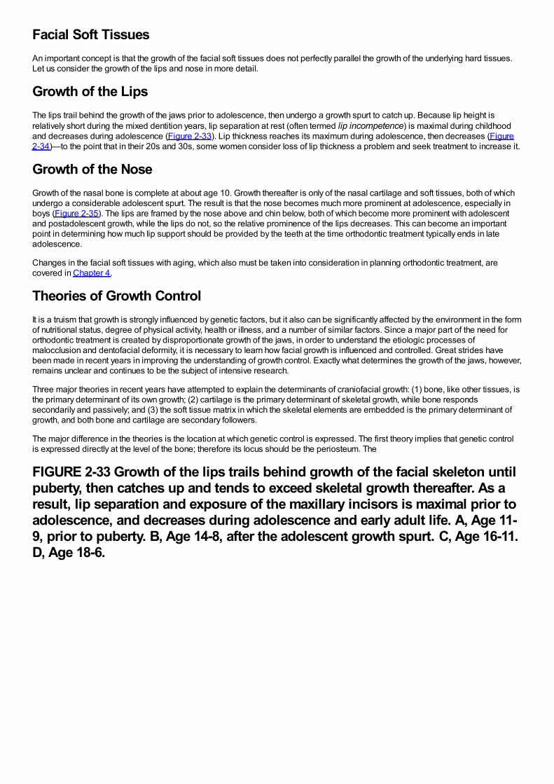
Facial Soft TissuesAn important concept is that the growth of the facial soft tissues does not perfectly parallel the growth of the underlying hard tissues.Let us consider the growth of the lips and nose in more detail.
Growth of the LipsThe lips trail behind the growth of the jaws prior to adolescence, then undergo a growth spurt to catch up. Because lip height isrelatively short during the mixed dentition years, lip separation at rest (often termed lip incompetence) is maximal during childhoodand decreases during adolescence (Figure 2-33). Lip thickness reaches its maximum during adolescence, then decreases (Figure2-34)—to the point that in their 20s and 30s, some women consider loss of lip thickness a problem and seek treatment to increase it.
Growth of the NoseGrowth of the nasal bone is complete at about age 10. Growth thereafter is only of the nasal cartilage and soft tissues, both of whichundergo a considerable adolescent spurt. The result is that the nose becomes much more prominent at adolescence, especially inboys (Figure 2-35). The lips are framed by the nose above and chin below, both of which become more prominent with adolescentand postadolescent growth, while the lips do not, so the relative prominence of the lips decreases. This can become an importantpoint in determining how much lip support should be provided by the teeth at the time orthodontic treatment typically ends in lateadolescence.
Changes in the facial soft tissues with aging, which also must be taken into consideration in planning orthodontic treatment, arecovered in Chapter 4.
Theories of Growth ControlIt is a truism that growth is strongly influenced by genetic factors, but it also can be significantly affected by the environment in the formof nutritional status, degree of physical activity, health or illness, and a number of similar factors. Since a major part of the need fororthodontic treatment is created by disproportionate growth of the jaws, in order to understand the etiologic processes ofmalocclusion and dentofacial deformity, it is necessary to learn how facial growth is influenced and controlled. Great strides havebeen made in recent years in improving the understanding of growth control. Exactly what determines the growth of the jaws, however,remains unclear and continues to be the subject of intensive research.
Three major theories in recent years have attempted to explain the determinants of craniofacial growth: (1) bone, like other tissues, isthe primary determinant of its own growth; (2) cartilage is the primary determinant of skeletal growth, while bone respondssecondarily and passively; and (3) the soft tissue matrix in which the skeletal elements are embedded is the primary determinant ofgrowth, and both bone and cartilage are secondary followers.
The major difference in the theories is the location at which genetic control is expressed. The first theory implies that genetic controlis expressed directly at the level of the bone; therefore its locus should be the periosteum. The
FIGURE 2-33 Growth of the lips trails behind growth of the facial skeleton untilpuberty, then catches up and tends to exceed skeletal growth thereafter. As aresult, lip separation and exposure of the maxillary incisors is maximal prior toadolescence, and decreases during adolescence and early adult life. A, Age 11-9, prior to puberty. B, Age 14-8, after the adolescent growth spurt. C, Age 16-11.D, Age 18-6.
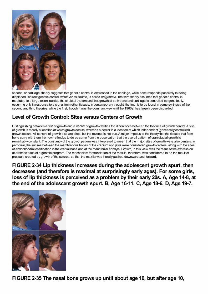
second, or cartilage, theory suggests that genetic control is expressed in the cartilage, while bone responds passively to beingdisplaced. Indirect genetic control, whatever its source, is called epigenetic. The third theory assumes that genetic control ismediated to a large extent outside the skeletal system and that growth of both bone and cartilage is controlled epigenetically,occurring only in response to a signal from other tissues. In contemporary thought, the truth is to be found in some synthesis of thesecond and third theories, while the first, though it was the dominant view until the 1960s, has largely been discarded.
Level of Growth Control: Sites versus Centers of GrowthDistinguishing between a site of growth and a center of growth clarifies the differences between the theories of growth control. A siteof growth is merely a location at which growth occurs, whereas a center is a location at which independent (genetically controlled)growth occurs. All centers of growth also are sites, but the reverse is not true. A major impetus to the theory that the tissues that formbone carry with them their own stimulus to do so came from the observation that the overall pattern of craniofacial growth isremarkably constant. The constancy of the growth pattern was interpreted to mean that the major sites of growth were also centers. Inparticular, the sutures between the membranous bones of the cranium and jaws were considered growth centers, along with the sitesof endochondral ossification in the cranial base and at the mandibular condyle. Growth, in this view, was the result of the expressionat all these sites of a genetic program. The mechanism for translation of the maxilla, therefore, was considered to be the result ofpressure created by growth of the sutures, so that the maxilla was literally pushed downward and forward.
FIGURE 2-34 Lip thickness increases during the adolescent growth spurt, thendecreases (and therefore is maximal at surprisingly early ages). For some girls,loss of lip thickness is perceived as a problem by their early 20s. A, Age 14-8, atthe end of the adolescent growth spurt. B, Age 16-11. C, Age 18-6. D, Age 19-7.
FIGURE 2-35 The nasal bone grows up until about age 10, but after age 10,
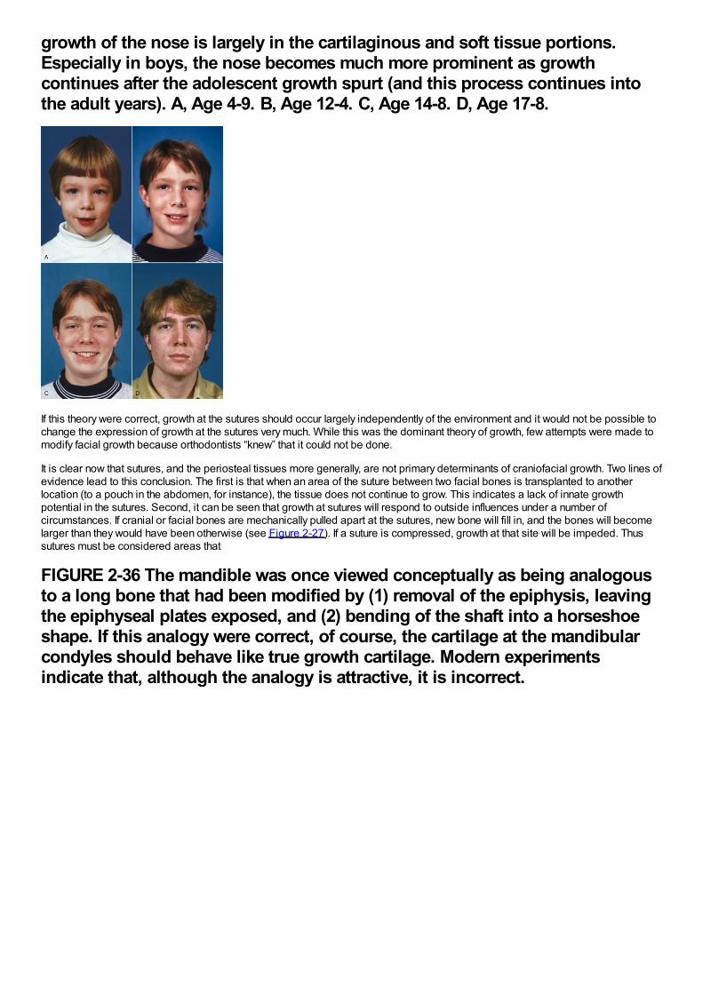
growth of the nose is largely in the cartilaginous and soft tissue portions.Especially in boys, the nose becomes much more prominent as growthcontinues after the adolescent growth spurt (and this process continues intothe adult years). A, Age 4-9. B, Age 12-4. C, Age 14-8. D, Age 17-8.
If this theory were correct, growth at the sutures should occur largely independently of the environment and it would not be possible tochange the expression of growth at the sutures very much. While this was the dominant theory of growth, few attempts were made tomodify facial growth because orthodontists “knew” that it could not be done.
It is clear now that sutures, and the periosteal tissues more generally, are not primary determinants of craniofacial growth. Two lines ofevidence lead to this conclusion. The first is that when an area of the suture between two facial bones is transplanted to anotherlocation (to a pouch in the abdomen, for instance), the tissue does not continue to grow. This indicates a lack of innate growthpotential in the sutures. Second, it can be seen that growth at sutures will respond to outside influences under a number ofcircumstances. If cranial or facial bones are mechanically pulled apart at the sutures, new bone will fill in, and the bones will becomelarger than they would have been otherwise (see Figure 2-27). If a suture is compressed, growth at that site will be impeded. Thussutures must be considered areas that
FIGURE 2-36 The mandible was once viewed conceptually as being analogousto a long bone that had been modified by (1) removal of the epiphysis, leavingthe epiphyseal plates exposed, and (2) bending of the shaft into a horseshoeshape. If this analogy were correct, of course, the cartilage at the mandibularcondyles should behave like true growth cartilage. Modern experimentsindicate that, although the analogy is attractive, it is incorrect.
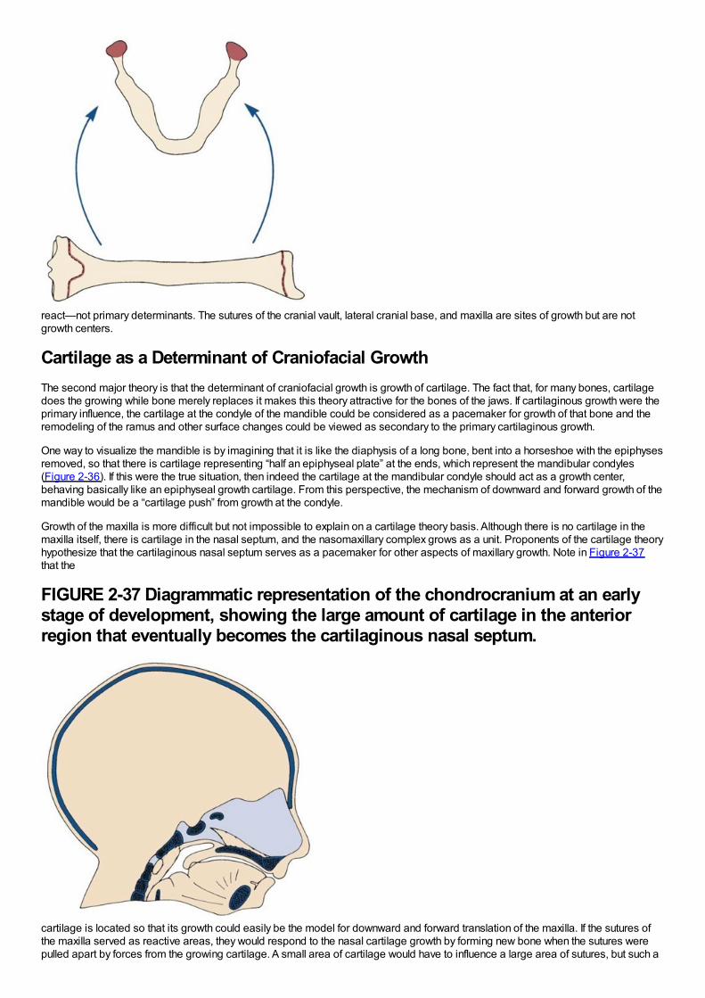
react—not primary determinants. The sutures of the cranial vault, lateral cranial base, and maxilla are sites of growth but are notgrowth centers.
Cartilage as a Determinant of Craniofacial GrowthThe second major theory is that the determinant of craniofacial growth is growth of cartilage. The fact that, for many bones, cartilagedoes the growing while bone merely replaces it makes this theory attractive for the bones of the jaws. If cartilaginous growth were theprimary influence, the cartilage at the condyle of the mandible could be considered as a pacemaker for growth of that bone and theremodeling of the ramus and other surface changes could be viewed as secondary to the primary cartilaginous growth.
One way to visualize the mandible is by imagining that it is like the diaphysis of a long bone, bent into a horseshoe with the epiphysesremoved, so that there is cartilage representing “half an epiphyseal plate” at the ends, which represent the mandibular condyles(Figure 2-36). If this were the true situation, then indeed the cartilage at the mandibular condyle should act as a growth center,behaving basically like an epiphyseal growth cartilage. From this perspective, the mechanism of downward and forward growth of themandible would be a “cartilage push” from growth at the condyle.
Growth of the maxilla is more difficult but not impossible to explain on a cartilage theory basis. Although there is no cartilage in themaxilla itself, there is cartilage in the nasal septum, and the nasomaxillary complex grows as a unit. Proponents of the cartilage theoryhypothesize that the cartilaginous nasal septum serves as a pacemaker for other aspects of maxillary growth. Note in Figure 2-37that the
FIGURE 2-37 Diagrammatic representation of the chondrocranium at an earlystage of development, showing the large amount of cartilage in the anteriorregion that eventually becomes the cartilaginous nasal septum.
cartilage is located so that its growth could easily be the model for downward and forward translation of the maxilla. If the sutures ofthe maxilla served as reactive areas, they would respond to the nasal cartilage growth by forming new bone when the sutures werepulled apart by forces from the growing cartilage. A small area of cartilage would have to influence a large area of sutures, but such a
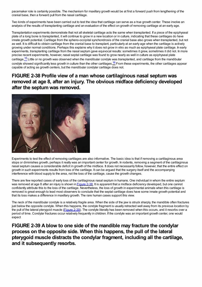
pacemaker role is certainly possible. The mechanism for maxillary growth would be at first a forward push from lengthening of thecranial base, then a forward pull from the nasal cartilage.
Two kinds of experiments have been carried out to test the idea that cartilage can serve as a true growth center. These involve ananalysis of the results of transplanting cartilage and an evaluation of the effect on growth of removing cartilage at an early age.
Transplantation experiments demonstrate that not all skeletal cartilage acts the same when transplanted. If a piece of the epiphysealplate of a long bone is transplanted, it will continue to grow in a new location or in culture, indicating that these cartilages do haveinnate growth potential. Cartilage from the spheno-occipital synchondrosis of the cranial base also grows when transplanted, but notas well. It is difficult to obtain cartilage from the cranial base to transplant, particularly at an early age when the cartilage is activelygrowing under normal conditions. Perhaps this explains why it does not grow in vitro as much as epiphyseal plate cartilage. In earlyexperiments, transplanting cartilage from the nasal septum gave equivocal results: sometimes it grew, sometimes it did not. In moreprecise recent experiments, however, nasal septal cartilage was found to grow nearly as well in culture as epiphyseal platecartilage.15 Little or no growth was observed when the mandibular condyle was transplanted, and cartilage from the mandibularcondyle showed significantly less growth in culture than the other cartilages.16 From these experiments, the other cartilages appearcapable of acting as growth centers, but the mandibular condylar cartilage does not.
FIGURE 2-38 Profile view of a man whose cartilaginous nasal septum wasremoved at age 8, after an injury. The obvious midface deficiency developedafter the septum was removed.
Experiments to test the effect of removing cartilages are also informative. The basic idea is that if removing a cartilaginous areastops or diminishes growth, perhaps it really was an important center for growth. In rodents, removing a segment of the cartilaginousnasal septum causes a considerable deficit in growth of the midface. It does not necessarily follow, however, that the entire effect ongrowth in such experiments results from loss of the cartilage. It can be argued that the surgery itself and the accompanyinginterference with blood supply to the area, not the loss of the cartilage, cause the growth changes.
There are few reported cases of early loss of the cartilaginous nasal septum in humans. One individual in whom the entire septumwas removed at age 8 after an injury is shown in Figure 2-38. It is apparent that a midface deficiency developed, but one cannotconfidently attribute this to the loss of the cartilage. Nevertheless, the loss of growth in experimental animals when this cartilage isremoved is great enough to lead most observers to conclude that the septal cartilage does have some innate growth potential andthat its loss makes a difference in maxillary growth. The rare human cases support this view.
The neck of the mandibular condyle is a relatively fragile area. When the side of the jaw is struck sharply, the mandible often fracturesjust below the opposite condyle. When this happens, the condyle fragment is usually retracted well away from its previous location bythe pull of the lateral pterygoid muscle (Figure 2-39). The condyle literally has been removed when this occurs, and it resorbs over aperiod of time. Condylar fractures occur relatively frequently in children. If the condyle was an important growth center, one wouldexpect
FIGURE 2-39 A blow to one side of the mandible may fracture the condylarprocess on the opposite side. When this happens, the pull of the lateralpterygoid muscle distracts the condylar fragment, including all the cartilage,and it subsequently resorbs.
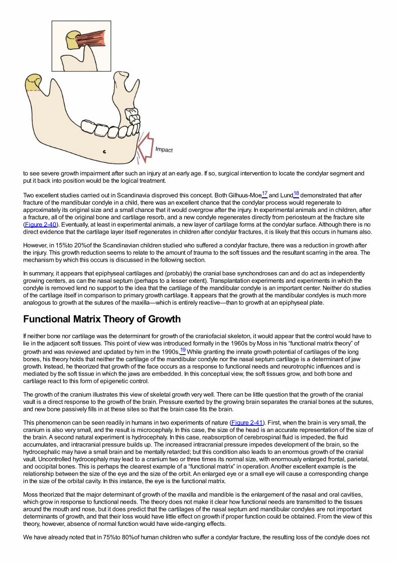
to see severe growth impairment after such an injury at an early age. If so, surgical intervention to locate the condylar segment andput it back into position would be the logical treatment.
Two excellent studies carried out in Scandinavia disproved this concept. Both Gilhuus-Moe17 and Lund18 demonstrated that afterfracture of the mandibular condyle in a child, there was an excellent chance that the condylar process would regenerate toapproximately its original size and a small chance that it would overgrow after the injury. In experimental animals and in children, aftera fracture, all of the original bone and cartilage resorb, and a new condyle regenerates directly from periosteum at the fracture site(Figure 2-40). Eventually, at least in experimental animals, a new layer of cartilage forms at the condylar surface. Although there is nodirect evidence that the cartilage layer itself regenerates in children after condylar fractures, it is likely that this occurs in humans also.
However, in 15%to 20%of the Scandinavian children studied who suffered a condylar fracture, there was a reduction in growth afterthe injury. This growth reduction seems to relate to the amount of trauma to the soft tissues and the resultant scarring in the area. Themechanism by which this occurs is discussed in the following section.
In summary, it appears that epiphyseal cartilages and (probably) the cranial base synchondroses can and do act as independentlygrowing centers, as can the nasal septum (perhaps to a lesser extent). Transplantation experiments and experiments in which thecondyle is removed lend no support to the idea that the cartilage of the mandibular condyle is an important center. Neither do studiesof the cartilage itself in comparison to primary growth cartilage. It appears that the growth at the mandibular condyles is much moreanalogous to growth at the sutures of the maxilla—which is entirely reactive—than to growth at an epiphyseal plate.
Functional Matrix Theory of GrowthIf neither bone nor cartilage was the determinant for growth of the craniofacial skeleton, it would appear that the control would have tolie in the adjacent soft tissues. This point of view was introduced formally in the 1960s by Moss in his “functional matrix theory” ofgrowth and was reviewed and updated by him in the 1990s.19 While granting the innate growth potential of cartilages of the longbones, his theory holds that neither the cartilage of the mandibular condyle nor the nasal septum cartilage is a determinant of jawgrowth. Instead, he theorized that growth of the face occurs as a response to functional needs and neurotrophic influences and ismediated by the soft tissue in which the jaws are embedded. In this conceptual view, the soft tissues grow, and both bone andcartilage react to this form of epigenetic control.
The growth of the cranium illustrates this view of skeletal growth very well. There can be little question that the growth of the cranialvault is a direct response to the growth of the brain. Pressure exerted by the growing brain separates the cranial bones at the sutures,and new bone passively fills in at these sites so that the brain case fits the brain.
This phenomenon can be seen readily in humans in two experiments of nature (Figure 2-41). First, when the brain is very small, thecranium is also very small, and the result is microcephaly. In this case, the size of the head is an accurate representation of the size ofthe brain. A second natural experiment is hydrocephaly. In this case, reabsorption of cerebrospinal fluid is impeded, the fluidaccumulates, and intracranial pressure builds up. The increased intracranial pressure impedes development of the brain, so thehydrocephalic may have a small brain and be mentally retarded; but this condition also leads to an enormous growth of the cranialvault. Uncontrolled hydrocephaly may lead to a cranium two or three times its normal size, with enormously enlarged frontal, parietal,and occipital bones. This is perhaps the clearest example of a “functional matrix” in operation. Another excellent example is therelationship between the size of the eye and the size of the orbit. An enlarged eye or a small eye will cause a corresponding changein the size of the orbital cavity. In this instance, the eye is the functional matrix.
Moss theorized that the major determinant of growth of the maxilla and mandible is the enlargement of the nasal and oral cavities,which grow in response to functional needs. The theory does not make it clear how functional needs are transmitted to the tissuesaround the mouth and nose, but it does predict that the cartilages of the nasal septum and mandibular condyles are not importantdeterminants of growth, and that their loss would have little effect on growth if proper function could be obtained. From the view of thistheory, however, absence of normal function would have wide-ranging effects.
We have already noted that in 75%to 80%of human children who suffer a condylar fracture, the resulting loss of the condyle does not
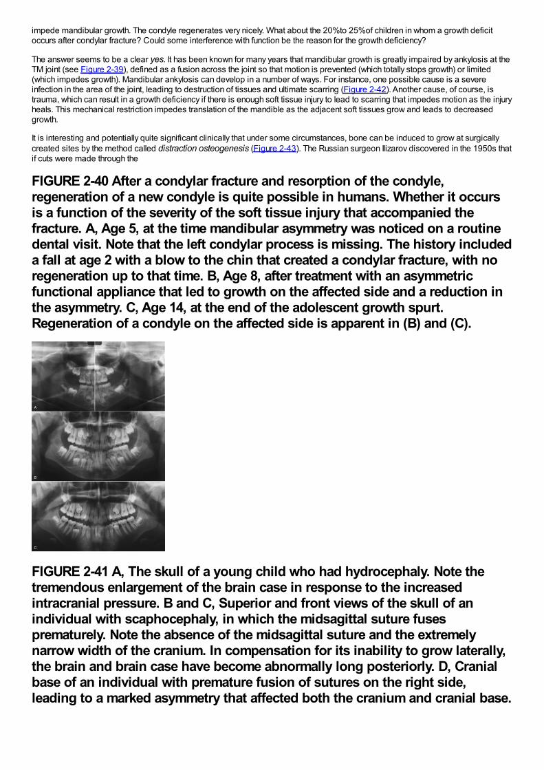
impede mandibular growth. The condyle regenerates very nicely. What about the 20%to 25%of children in whom a growth deficitoccurs after condylar fracture? Could some interference with function be the reason for the growth deficiency?
The answer seems to be a clear yes. It has been known for many years that mandibular growth is greatly impaired by ankylosis at theTM joint (see Figure 2-39), defined as a fusion across the joint so that motion is prevented (which totally stops growth) or limited(which impedes growth). Mandibular ankylosis can develop in a number of ways. For instance, one possible cause is a severeinfection in the area of the joint, leading to destruction of tissues and ultimate scarring (Figure 2-42). Another cause, of course, istrauma, which can result in a growth deficiency if there is enough soft tissue injury to lead to scarring that impedes motion as the injuryheals. This mechanical restriction impedes translation of the mandible as the adjacent soft tissues grow and leads to decreasedgrowth.
It is interesting and potentially quite significant clinically that under some circumstances, bone can be induced to grow at surgicallycreated sites by the method called distraction osteogenesis (Figure 2-43). The Russian surgeon Ilizarov discovered in the 1950s thatif cuts were made through the
FIGURE 2-40 After a condylar fracture and resorption of the condyle,regeneration of a new condyle is quite possible in humans. Whether it occursis a function of the severity of the soft tissue injury that accompanied thefracture. A, Age 5, at the time mandibular asymmetry was noticed on a routinedental visit. Note that the left condylar process is missing. The history includeda fall at age 2 with a blow to the chin that created a condylar fracture, with noregeneration up to that time. B, Age 8, after treatment with an asymmetricfunctional appliance that led to growth on the affected side and a reduction inthe asymmetry. C, Age 14, at the end of the adolescent growth spurt.Regeneration of a condyle on the affected side is apparent in (B) and (C).
FIGURE 2-41 A, The skull of a young child who had hydrocephaly. Note thetremendous enlargement of the brain case in response to the increasedintracranial pressure. B and C, Superior and front views of the skull of anindividual with scaphocephaly, in which the midsagittal suture fusesprematurely. Note the absence of the midsagittal suture and the extremelynarrow width of the cranium. In compensation for its inability to grow laterally,the brain and brain case have become abnormally long posteriorly. D, Cranialbase of an individual with premature fusion of sutures on the right side,leading to a marked asymmetry that affected both the cranium and cranial base.
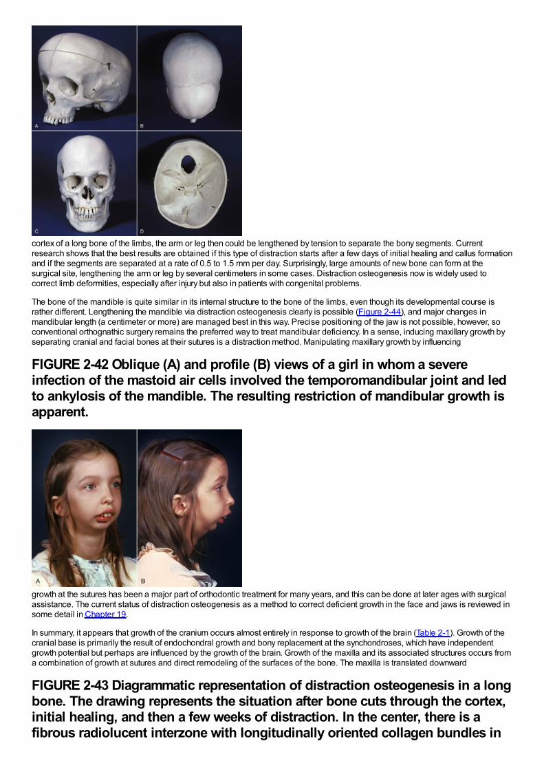
cortex of a long bone of the limbs, the arm or leg then could be lengthened by tension to separate the bony segments. Currentresearch shows that the best results are obtained if this type of distraction starts after a few days of initial healing and callus formationand if the segments are separated at a rate of 0.5 to 1.5 mm per day. Surprisingly, large amounts of new bone can form at thesurgical site, lengthening the arm or leg by several centimeters in some cases. Distraction osteogenesis now is widely used tocorrect limb deformities, especially after injury but also in patients with congenital problems.
The bone of the mandible is quite similar in its internal structure to the bone of the limbs, even though its developmental course israther different. Lengthening the mandible via distraction osteogenesis clearly is possible (Figure 2-44), and major changes inmandibular length (a centimeter or more) are managed best in this way. Precise positioning of the jaw is not possible, however, soconventional orthognathic surgery remains the preferred way to treat mandibular deficiency. In a sense, inducing maxillary growth byseparating cranial and facial bones at their sutures is a distraction method. Manipulating maxillary growth by influencing
FIGURE 2-42 Oblique (A) and profile (B) views of a girl in whom a severeinfection of the mastoid air cells involved the temporomandibular joint and ledto ankylosis of the mandible. The resulting restriction of mandibular growth isapparent.
growth at the sutures has been a major part of orthodontic treatment for many years, and this can be done at later ages with surgicalassistance. The current status of distraction osteogenesis as a method to correct deficient growth in the face and jaws is reviewed insome detail in Chapter 19.
In summary, it appears that growth of the cranium occurs almost entirely in response to growth of the brain (Table 2-1). Growth of thecranial base is primarily the result of endochondral growth and bony replacement at the synchondroses, which have independentgrowth potential but perhaps are influenced by the growth of the brain. Growth of the maxilla and its associated structures occurs froma combination of growth at sutures and direct remodeling of the surfaces of the bone. The maxilla is translated downward
FIGURE 2-43 Diagrammatic representation of distraction osteogenesis in a longbone. The drawing represents the situation after bone cuts through the cortex,initial healing, and then a few weeks of distraction. In the center, there is afibrous radiolucent interzone with longitudinally oriented collagen bundles in
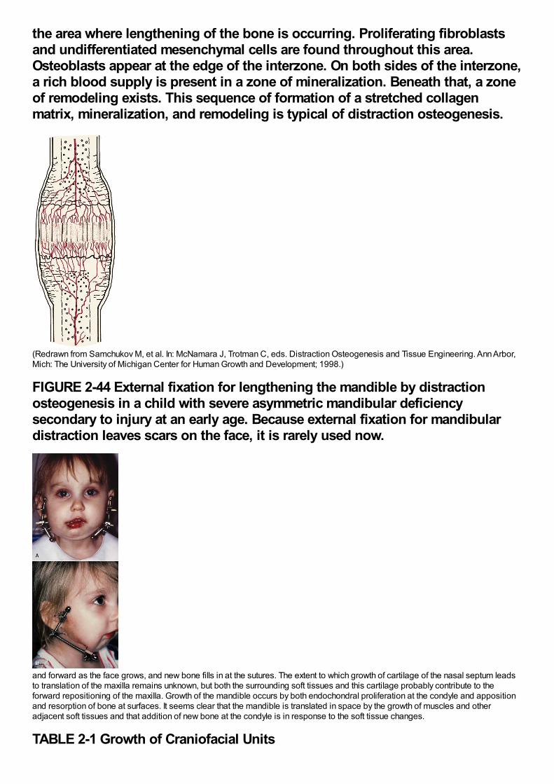
the area where lengthening of the bone is occurring. Proliferating fibroblastsand undifferentiated mesenchymal cells are found throughout this area.Osteoblasts appear at the edge of the interzone. On both sides of the interzone,a rich blood supply is present in a zone of mineralization. Beneath that, a zoneof remodeling exists. This sequence of formation of a stretched collagenmatrix, mineralization, and remodeling is typical of distraction osteogenesis.
(Redrawn from Samchukov M, et al. In: McNamara J, Trotman C, eds. Distraction Osteogenesis and Tissue Engineering. Ann Arbor,Mich: The University of Michigan Center for Human Growth and Development; 1998.)
FIGURE 2-44 External fixation for lengthening the mandible by distractionosteogenesis in a child with severe asymmetric mandibular deficiencysecondary to injury at an early age. Because external fixation for mandibulardistraction leaves scars on the face, it is rarely used now.
and forward as the face grows, and new bone fills in at the sutures. The extent to which growth of cartilage of the nasal septum leadsto translation of the maxilla remains unknown, but both the surrounding soft tissues and this cartilage probably contribute to theforward repositioning of the maxilla. Growth of the mandible occurs by both endochondral proliferation at the condyle and appositionand resorption of bone at surfaces. It seems clear that the mandible is translated in space by the growth of muscles and otheradjacent soft tissues and that addition of new bone at the condyle is in response to the soft tissue changes.
TABLE 2-1 Growth of Craniofacial Units
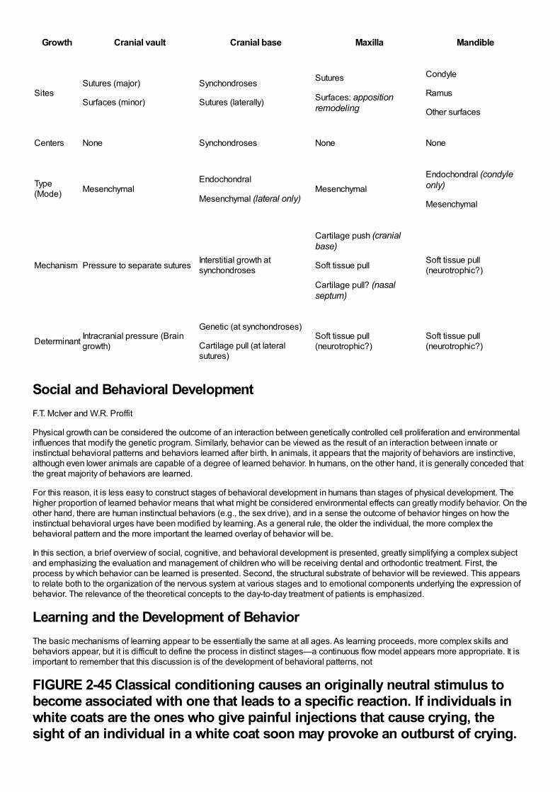
Growth Cranial vault Cranial base Maxilla Mandible
SitesSutures (major)
Surfaces (minor)
Synchondroses
Sutures (laterally)
Sutures
Surfaces: appositionremodeling
Condyle
Ramus
Other surfaces
Centers None Synchondroses None None
Type(Mode) Mesenchymal
Endochondral
Mesenchymal (lateral only)Mesenchymal
Endochondral (condyleonly)
Mesenchymal
Mechanism Pressure to separate sutures Interstitial growth atsynchondroses
Cartilage push (cranialbase)
Soft tissue pull
Cartilage pull? (nasalseptum)
Soft tissue pull(neurotrophic?)
Determinant Intracranial pressure (Braingrowth)
Genetic (at synchondroses)
Cartilage pull (at lateralsutures)
Soft tissue pull(neurotrophic?)
Soft tissue pull(neurotrophic?)
Social and Behavioral DevelopmentF.T. McIver and W.R. Proffit
Physical growth can be considered the outcome of an interaction between genetically controlled cell proliferation and environmentalinfluences that modify the genetic program. Similarly, behavior can be viewed as the result of an interaction between innate orinstinctual behavioral patterns and behaviors learned after birth. In animals, it appears that the majority of behaviors are instinctive,although even lower animals are capable of a degree of learned behavior. In humans, on the other hand, it is generally conceded thatthe great majority of behaviors are learned.
For this reason, it is less easy to construct stages of behavioral development in humans than stages of physical development. Thehigher proportion of learned behavior means that what might be considered environmental effects can greatly modify behavior. On theother hand, there are human instinctual behaviors (e.g., the sex drive), and in a sense the outcome of behavior hinges on how theinstinctual behavioral urges have been modified by learning. As a general rule, the older the individual, the more complex thebehavioral pattern and the more important the learned overlay of behavior will be.
In this section, a brief overview of social, cognitive, and behavioral development is presented, greatly simplifying a complex subjectand emphasizing the evaluation and management of children who will be receiving dental and orthodontic treatment. First, theprocess by which behavior can be learned is presented. Second, the structural substrate of behavior will be reviewed. This appearsto relate both to the organization of the nervous system at various stages and to emotional components underlying the expression ofbehavior. The relevance of the theoretical concepts to the day-to-day treatment of patients is emphasized.
Learning and the Development of BehaviorThe basic mechanisms of learning appear to be essentially the same at all ages. As learning proceeds, more complex skills andbehaviors appear, but it is difficult to define the process in distinct stages—a continuous flow model appears more appropriate. It isimportant to remember that this discussion is of the development of behavioral patterns, not
FIGURE 2-45 Classical conditioning causes an originally neutral stimulus tobecome associated with one that leads to a specific reaction. If individuals inwhite coats are the ones who give painful injections that cause crying, thesight of an individual in a white coat soon may provoke an outburst of crying.
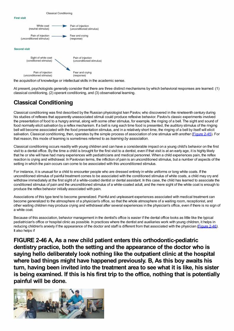
the acquisition of knowledge or intellectual skills in the academic sense.
At present, psychologists generally consider that there are three distinct mechanisms by which behavioral responses are learned: (1)classical conditioning, (2) operant conditioning, and (3) observational learning.
Classical ConditioningClassical conditioning was first described by the Russian physiologist Ivan Pavlov, who discovered in the nineteenth century duringhis studies of reflexes that apparently unassociated stimuli could produce reflexive behavior. Pavlov's classic experiments involvedthe presentation of food to a hungry animal, along with some other stimulus, for example, the ringing of a bell. The sight and sound offood normally elicit salivation by a reflex mechanism. If a bell is rung each time food is presented, the auditory stimulus of the ringingbell will become associated with the food presentation stimulus, and in a relatively short time, the ringing of a bell by itself will elicitsalivation. Classical conditioning, then, operates by the simple process of association of one stimulus with another (Figure 2-45). Forthat reason, this mode of learning is sometimes referred to as learning by association.
Classical conditioning occurs readily with young children and can have a considerable impact on a young child's behavior on the firstvisit to a dental office. By the time a child is brought for the first visit to a dentist, even if that visit is at an early age, it is highly likelythat he or she will have had many experiences with pediatricians and medical personnel. When a child experiences pain, the reflexreaction is crying and withdrawal. In Pavlovian terms, the infliction of pain is an unconditioned stimulus, but a number of aspects of thesetting in which the pain occurs can come to be associated with this unconditioned stimulus.
For instance, it is unusual for a child to encounter people who are dressed entirely in white uniforms or long white coats. If theunconditioned stimulus of painful treatment comes to be associated with the conditioned stimulus of white coats, a child may cry andwithdraw immediately at the first sight of a white-coated dentist or dental assistant. In this case, the child has learned to associate theconditioned stimulus of pain and the unconditioned stimulus of a white-coated adult, and the mere sight of the white coat is enough toproduce the reflex behavior initially associated with pain.
Associations of this type tend to become generalized. Painful and unpleasant experiences associated with medical treatment canbecome generalized to the atmosphere of a physician's office, so that the whole atmosphere of a waiting room, receptionist, andother waiting children may produce crying and withdrawal after several experiences in the physician's office, even if there is no sign ofa white coat.
Because of this association, behavior management in the dentist's office is easier if the dental office looks as little like the typicalpediatrician's office or hospital clinic as possible. In practices where the dentist and auxiliaries work with young children, it helps inreducing children's anxiety if the appearance of the doctor and staff is different from that associated with the physician (Figure 2-46).It also helps if
FIGURE 2-46 A, As a new child patient enters this orthodontic-pediatricdentistry practice, both the setting and the appearance of the doctor who issaying hello deliberately look nothing like the outpatient clinic at the hospitalwhere bad things might have happened previously. B, As this boy awaits histurn, having been invited into the treatment area to see what it is like, his sisteris being examined. If this is his first trip to the office, nothing that is potentiallypainful will be done.
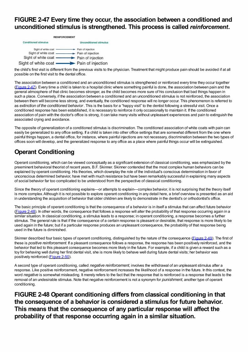
FIGURE 2-47 Every time they occur, the association between a conditioned andunconditioned stimulus is strengthened. This process is called reinforcement.
the child's first visit is different from the previous visits to the physician. Treatment that might produce pain should be avoided if at allpossible on the first visit to the dental office.
The association between a conditioned and an unconditioned stimulus is strengthened or reinforced every time they occur together(Figure 2-47). Every time a child is taken to a hospital clinic where something painful is done, the association between pain and thegeneral atmosphere of that clinic becomes stronger, as the child becomes more sure of his conclusion that bad things happen insuch a place. Conversely, if the association between a conditioned and an unconditioned stimulus is not reinforced, the associationbetween them will become less strong, and eventually, the conditioned response will no longer occur. This phenomenon is referred toas extinction of the conditioned behavior . This is the basis for a “happy visit” to the dentist following a stressful visit. Once aconditioned response has been established, it is necessary to reinforce it only occasionally to maintain it. If the conditionedassociation of pain with the doctor's office is strong, it can take many visits without unpleasant experiences and pain to extinguish theassociated crying and avoidance.
The opposite of generalization of a conditioned stimulus is discrimination. The conditioned association of white coats with pain caneasily be generalized to any office setting. If a child is taken into other office settings that are somewhat different from the one wherepainful things happen, a dental office, for instance, where painful injections are not necessary, discrimination between the two types ofoffices soon will develop, and the generalized response to any office as a place where painful things occur will be extinguished.
Operant ConditioningOperant conditioning, which can be viewed conceptually as a significant extension of classical conditioning, was emphasized by thepreeminent behavioral theorist of recent years, B.F. Skinner. Skinner contended that the most complex human behaviors can beexplained by operant conditioning. His theories, which downplay the role of the individual's conscious determination in favor ofunconscious determined behavior, have met with much resistance but have been remarkably successful in explaining many aspectsof social behavior far too complicated to be understood from the perspective of classical conditioning.
Since the theory of operant conditioning explains—or attempts to explain—complex behavior, it is not surprising that the theory itselfis more complex. Although it is not possible to explore operant conditioning in any detail here, a brief overview is presented as an aidin understanding the acquisition of behavior that older children are likely to demonstrate in the dentist's or orthodontist's office.
The basic principle of operant conditioning is that the consequence of a behavior is in itself a stimulus that can affect future behavior(Figure 2-48). In other words, the consequence that follows a response will alter the probability of that response occurring again in asimilar situation. In classical conditioning, a stimulus leads to a response; in operant conditioning, a response becomes a furtherstimulus. The general rule is that if the consequence of a certain response is pleasant or desirable, that response is more likely to beused again in the future; but if a particular response produces an unpleasant consequence, the probability of that response beingused in the future is diminished.
Skinner described four basic types of operant conditioning, distinguished by the nature of the consequence (Figure 2-49). The first ofthese is positive reinforcement. If a pleasant consequence follows a response, the response has been positively reinforced, and thebehavior that led to this pleasant consequence becomes more likely in the future. For example, if a child is given a reward such as atoy for behaving well during her first dental visit, she is more likely to behave well during future dental visits; her behavior waspositively reinforced (Figure 2-50).
A second type of operant conditioning, called negative reinforcement, involves the withdrawal of an unpleasant stimulus after aresponse. Like positive reinforcement, negative reinforcement increases the likelihood of a response in the future. In this context, theword negative is somewhat misleading. It merely refers to the fact that the response that is reinforced is a response that leads to theremoval of an undesirable stimulus. Note that negative reinforcement is not a synonym for punishment, another type of operantconditioning.
FIGURE 2-48 Operant conditioning differs from classical conditioning in thatthe consequence of a behavior is considered a stimulus for future behavior.This means that the consequence of any particular response will affect theprobability of that response occurring again in a similar situation.
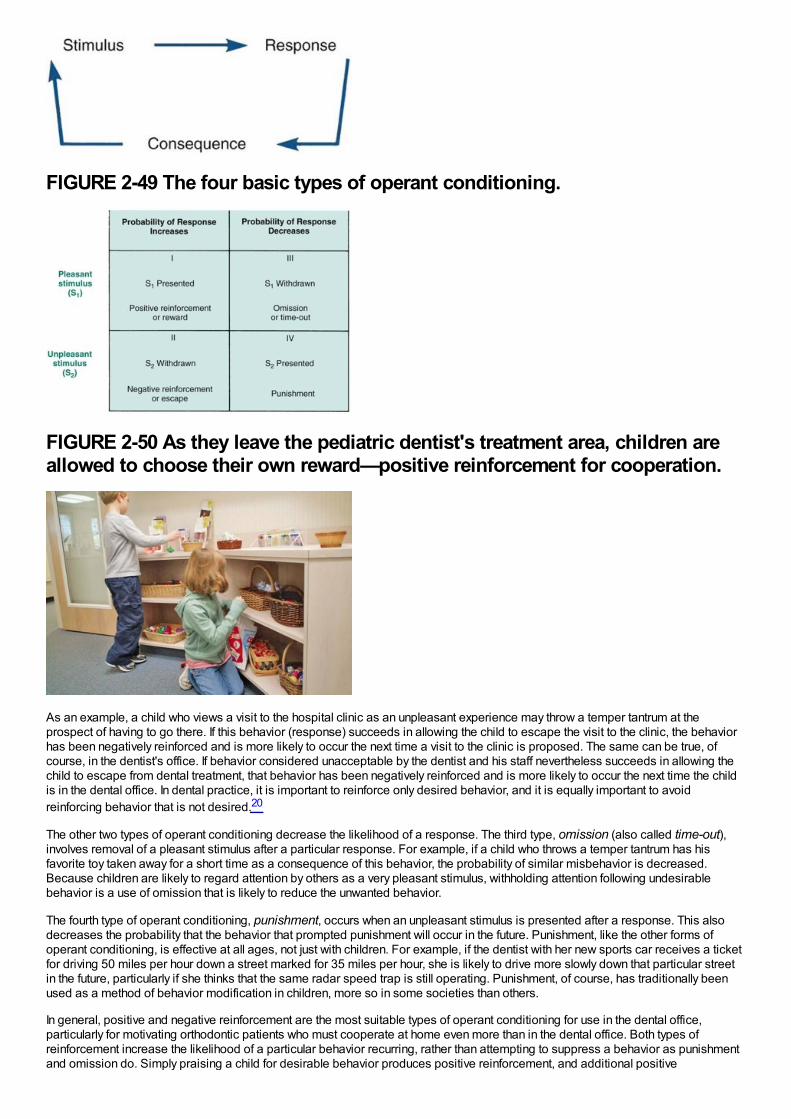
FIGURE 2-49 The four basic types of operant conditioning.
FIGURE 2-50 As they leave the pediatric dentist's treatment area, children areallowed to choose their own reward—positive reinforcement for cooperation.
As an example, a child who views a visit to the hospital clinic as an unpleasant experience may throw a temper tantrum at theprospect of having to go there. If this behavior (response) succeeds in allowing the child to escape the visit to the clinic, the behaviorhas been negatively reinforced and is more likely to occur the next time a visit to the clinic is proposed. The same can be true, ofcourse, in the dentist's office. If behavior considered unacceptable by the dentist and his staff nevertheless succeeds in allowing thechild to escape from dental treatment, that behavior has been negatively reinforced and is more likely to occur the next time the childis in the dental office. In dental practice, it is important to reinforce only desired behavior, and it is equally important to avoidreinforcing behavior that is not desired.20
The other two types of operant conditioning decrease the likelihood of a response. The third type, omission (also called time-out),involves removal of a pleasant stimulus after a particular response. For example, if a child who throws a temper tantrum has hisfavorite toy taken away for a short time as a consequence of this behavior, the probability of similar misbehavior is decreased.Because children are likely to regard attention by others as a very pleasant stimulus, withholding attention following undesirablebehavior is a use of omission that is likely to reduce the unwanted behavior.
The fourth type of operant conditioning, punishment, occurs when an unpleasant stimulus is presented after a response. This alsodecreases the probability that the behavior that prompted punishment will occur in the future. Punishment, like the other forms ofoperant conditioning, is effective at all ages, not just with children. For example, if the dentist with her new sports car receives a ticketfor driving 50 miles per hour down a street marked for 35 miles per hour, she is likely to drive more slowly down that particular streetin the future, particularly if she thinks that the same radar speed trap is still operating. Punishment, of course, has traditionally beenused as a method of behavior modification in children, more so in some societies than others.
In general, positive and negative reinforcement are the most suitable types of operant conditioning for use in the dental office,particularly for motivating orthodontic patients who must cooperate at home even more than in the dental office. Both types ofreinforcement increase the likelihood of a particular behavior recurring, rather than attempting to suppress a behavior as punishmentand omission do. Simply praising a child for desirable behavior produces positive reinforcement, and additional positive
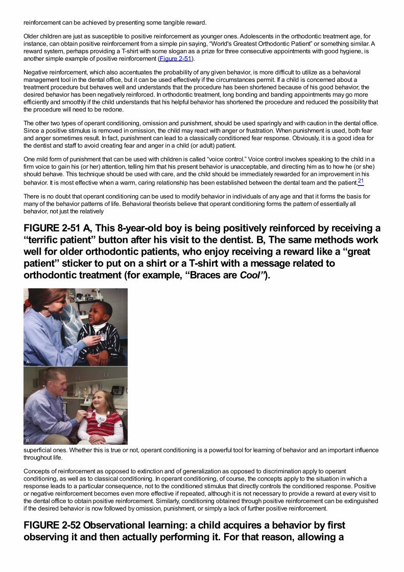
reinforcement can be achieved by presenting some tangible reward.
Older children are just as susceptible to positive reinforcement as younger ones. Adolescents in the orthodontic treatment age, forinstance, can obtain positive reinforcement from a simple pin saying, “World's Greatest Orthodontic Patient” or something similar. Areward system, perhaps providing a T-shirt with some slogan as a prize for three consecutive appointments with good hygiene, isanother simple example of positive reinforcement (Figure 2-51).
Negative reinforcement, which also accentuates the probability of any given behavior, is more difficult to utilize as a behavioralmanagement tool in the dental office, but it can be used effectively if the circumstances permit. If a child is concerned about atreatment procedure but behaves well and understands that the procedure has been shortened because of his good behavior, thedesired behavior has been negatively reinforced. In orthodontic treatment, long bonding and banding appointments may go moreefficiently and smoothly if the child understands that his helpful behavior has shortened the procedure and reduced the possibility thatthe procedure will need to be redone.
The other two types of operant conditioning, omission and punishment, should be used sparingly and with caution in the dental office.Since a positive stimulus is removed in omission, the child may react with anger or frustration. When punishment is used, both fearand anger sometimes result. In fact, punishment can lead to a classically conditioned fear response. Obviously, it is a good idea forthe dentist and staff to avoid creating fear and anger in a child (or adult) patient.
One mild form of punishment that can be used with children is called “voice control.” Voice control involves speaking to the child in afirm voice to gain his (or her) attention, telling him that his present behavior is unacceptable, and directing him as to how he (or she)should behave. This technique should be used with care, and the child should be immediately rewarded for an improvement in hisbehavior. It is most effective when a warm, caring relationship has been established between the dental team and the patient.21
There is no doubt that operant conditioning can be used to modify behavior in individuals of any age and that it forms the basis formany of the behavior patterns of life. Behavioral theorists believe that operant conditioning forms the pattern of essentially allbehavior, not just the relatively
FIGURE 2-51 A, This 8-year-old boy is being positively reinforced by receiving a“terrific patient” button after his visit to the dentist. B, The same methods workwell for older orthodontic patients, who enjoy receiving a reward like a “greatpatient” sticker to put on a shirt or a T-shirt with a message related toorthodontic treatment (for example, “Braces are Cool”).
superficial ones. Whether this is true or not, operant conditioning is a powerful tool for learning of behavior and an important influencethroughout life.
Concepts of reinforcement as opposed to extinction and of generalization as opposed to discrimination apply to operantconditioning, as well as to classical conditioning. In operant conditioning, of course, the concepts apply to the situation in which aresponse leads to a particular consequence, not to the conditioned stimulus that directly controls the conditioned response. Positiveor negative reinforcement becomes even more effective if repeated, although it is not necessary to provide a reward at every visit tothe dental office to obtain positive reinforcement. Similarly, conditioning obtained through positive reinforcement can be extinguishedif the desired behavior is now followed by omission, punishment, or simply a lack of further positive reinforcement.
FIGURE 2-52 Observational learning: a child acquires a behavior by firstobserving it and then actually performing it. For that reason, allowing a
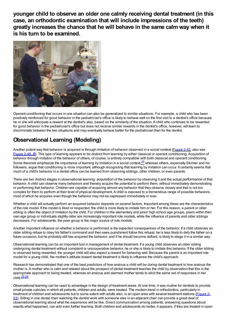
younger child to observe an older one calmly receiving dental treatment (in thiscase, an orthodontic examination that will include impressions of the teeth)greatly increases the chance that he will behave in the same calm way when itis his turn to be examined.
Operant conditioning that occurs in one situation can also be generalized to similar situations. For example, a child who has beenpositively reinforced for good behavior in the pediatrician's office is likely to behave well on the first visit to a dentist's office becausehe or she will anticipate a reward at the dentist's also, based on the similarity of the situation. A child who continues to be rewardedfor good behavior in the pediatrician's office but does not receive similar rewards in the dentist's office, however, will learn todiscriminate between the two situations and may eventually behave better for the pediatrician than for the dentist.
Observational Learning (Modeling)Another potent way that behavior is acquired is through imitation of behavior observed in a social context (Figure 2-52, also seeFigure 2-46, B). This type of learning appears to be distinct from learning by either classical or operant conditioning. Acquisition ofbehavior through imitation of the behavior of others, of course, is entirely compatible with both classical and operant conditioning.Some theorists emphasize the importance of learning by imitation in a social context,22 whereas others, especially Skinner and hisfollowers, argue that conditioning is more important, although recognizing that learning by imitation can occur. It certainly seems thatmuch of a child's behavior in a dental office can be learned from observing siblings, other children, or even parents.
There are two distinct stages in observational learning: acquisition of the behavior by observing it and the actual performance of thatbehavior. A child can observe many behaviors and thereby acquire the potential to perform them, without immediately demonstratingor performing that behavior. Children are capable of acquiring almost any behavior that they observe closely and that is not toocomplex for them to perform at their level of physical development. A child is exposed to a tremendous range of possible behaviors,most of which he acquires even though the behavior may not be expressed immediately or ever.
Whether a child will actually perform an acquired behavior depends on several factors. Important among these are the characteristicsof the role model. If the model is liked or respected, the child is more likely to imitate him or her. For this reason, a parent or oldersibling is often the object of imitation by the child. For children in the elementary and junior high school age groups, peers within theirown age group or individuals slightly older are increasingly important role models, while the influence of parents and older siblingsdecreases. For adolescents, the peer group is the major source of role models.
Another important influence on whether a behavior is performed is the expected consequences of the behavior. If a child observes anolder sibling refuse to obey his father's command and then sees punishment follow this refusal, he is less likely to defy the father on afuture occasion, but he probably still has acquired the behavior, and if he should become defiant, is likely to stage it in a similar way.
Observational learning can be an important tool in management of dental treatment. If a young child observes an older siblingundergoing dental treatment without complaint or uncooperative behavior, he or she is likely to imitate this behavior. If the older siblingis observed being rewarded, the younger child will also expect a reward for behaving well. Because the parent is an important rolemodel for a young child, the mother's attitude toward dental treatment is likely to influence the child's approach.
Research has demonstrated that one of the best predictors of how anxious a child will be during dental treatment is how anxious themother is. A mother who is calm and relaxed about the prospect of dental treatment teaches the child by observation that this is theappropriate approach to being treated, whereas an anxious and alarmed mother tends to elicit the same set of responses in herchild.23,24
Observational learning can be used to advantage in the design of treatment areas. At one time, it was routine for dentists to providesmall private cubicles in which all patients, children and adults, were treated. The modern trend in orthodontics, particularly intreatment of children and adolescents but to some extent with adults also, is an open area with several treatment stations (Figure 2-53). Sitting in one dental chair watching the dentist work with someone else in an adjacent chair can provide a great deal ofobservational learning about what the experience will be like. Direct communication among patients, answering questions aboutexactly what happened, can add even further learning. Both children and adolescents do better, it appears, if they are treated in open
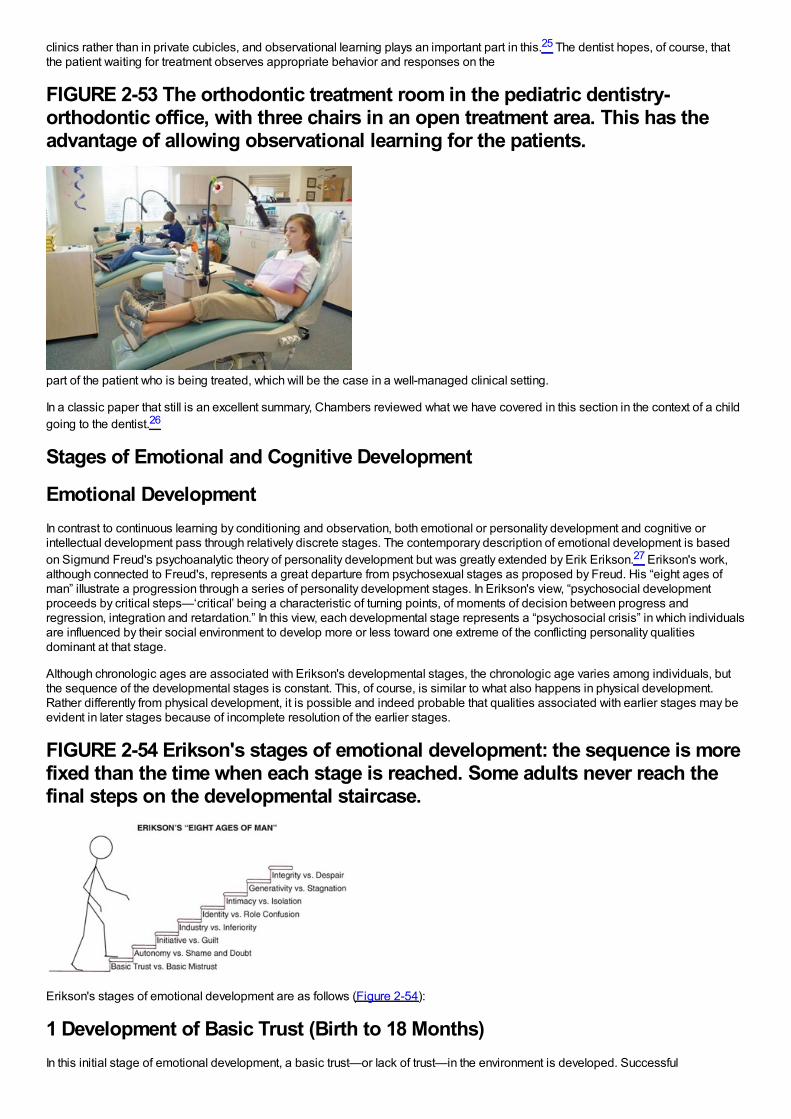
clinics rather than in private cubicles, and observational learning plays an important part in this.25 The dentist hopes, of course, thatthe patient waiting for treatment observes appropriate behavior and responses on the
FIGURE 2-53 The orthodontic treatment room in the pediatric dentistry-orthodontic office, with three chairs in an open treatment area. This has theadvantage of allowing observational learning for the patients.
part of the patient who is being treated, which will be the case in a well-managed clinical setting.
In a classic paper that still is an excellent summary, Chambers reviewed what we have covered in this section in the context of a childgoing to the dentist.26
Stages of Emotional and Cognitive Development
Emotional DevelopmentIn contrast to continuous learning by conditioning and observation, both emotional or personality development and cognitive orintellectual development pass through relatively discrete stages. The contemporary description of emotional development is basedon Sigmund Freud's psychoanalytic theory of personality development but was greatly extended by Erik Erikson.27 Erikson's work,although connected to Freud's, represents a great departure from psychosexual stages as proposed by Freud. His “eight ages ofman” illustrate a progression through a series of personality development stages. In Erikson's view, “psychosocial developmentproceeds by critical steps—‘critical’ being a characteristic of turning points, of moments of decision between progress andregression, integration and retardation.” In this view, each developmental stage represents a “psychosocial crisis” in which individualsare influenced by their social environment to develop more or less toward one extreme of the conflicting personality qualitiesdominant at that stage.
Although chronologic ages are associated with Erikson's developmental stages, the chronologic age varies among individuals, butthe sequence of the developmental stages is constant. This, of course, is similar to what also happens in physical development.Rather differently from physical development, it is possible and indeed probable that qualities associated with earlier stages may beevident in later stages because of incomplete resolution of the earlier stages.
FIGURE 2-54 Erikson's stages of emotional development: the sequence is morefixed than the time when each stage is reached. Some adults never reach thefinal steps on the developmental staircase.
Erikson's stages of emotional development are as follows (Figure 2-54):
1 Development of Basic Trust (Birth to 18 Months)In this initial stage of emotional development, a basic trust—or lack of trust—in the environment is developed. Successful
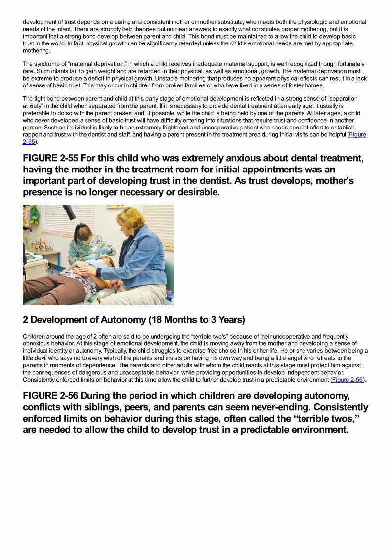
development of trust depends on a caring and consistent mother or mother substitute, who meets both the physiologic and emotionalneeds of the infant. There are strongly held theories but no clear answers to exactly what constitutes proper mothering, but it isimportant that a strong bond develop between parent and child. This bond must be maintained to allow the child to develop basictrust in the world. In fact, physical growth can be significantly retarded unless the child's emotional needs are met by appropriatemothering.
The syndrome of “maternal deprivation,” in which a child receives inadequate maternal support, is well recognized though fortunatelyrare. Such infants fail to gain weight and are retarded in their physical, as well as emotional, growth. The maternal deprivation mustbe extreme to produce a deficit in physical growth. Unstable mothering that produces no apparent physical effects can result in a lackof sense of basic trust. This may occur in children from broken families or who have lived in a series of foster homes.
The tight bond between parent and child at this early stage of emotional development is reflected in a strong sense of “separationanxiety” in the child when separated from the parent. If it is necessary to provide dental treatment at an early age, it usually ispreferable to do so with the parent present and, if possible, while the child is being held by one of the parents. At later ages, a childwho never developed a sense of basic trust will have difficulty entering into situations that require trust and confidence in anotherperson. Such an individual is likely to be an extremely frightened and uncooperative patient who needs special effort to establishrapport and trust with the dentist and staff, and having a parent present in the treatment area during initial visits can be helpful (Figure2-55).
FIGURE 2-55 For this child who was extremely anxious about dental treatment,having the mother in the treatment room for initial appointments was animportant part of developing trust in the dentist. As trust develops, mother'spresence is no longer necessary or desirable.
2 Development of Autonomy (18 Months to 3 Years)Children around the age of 2 often are said to be undergoing the “terrible two's” because of their uncooperative and frequentlyobnoxious behavior. At this stage of emotional development, the child is moving away from the mother and developing a sense ofindividual identity or autonomy. Typically, the child struggles to exercise free choice in his or her life. He or she varies between being alittle devil who says no to every wish of the parents and insists on having his own way and being a little angel who retreats to theparents in moments of dependence. The parents and other adults with whom the child reacts at this stage must protect him againstthe consequences of dangerous and unacceptable behavior, while providing opportunities to develop independent behavior.Consistently enforced limits on behavior at this time allow the child to further develop trust in a predictable environment (Figure 2-56).
FIGURE 2-56 During the period in which children are developing autonomy,conflicts with siblings, peers, and parents can seem never-ending. Consistentlyenforced limits on behavior during this stage, often called the “terrible twos,”are needed to allow the child to develop trust in a predictable environment.
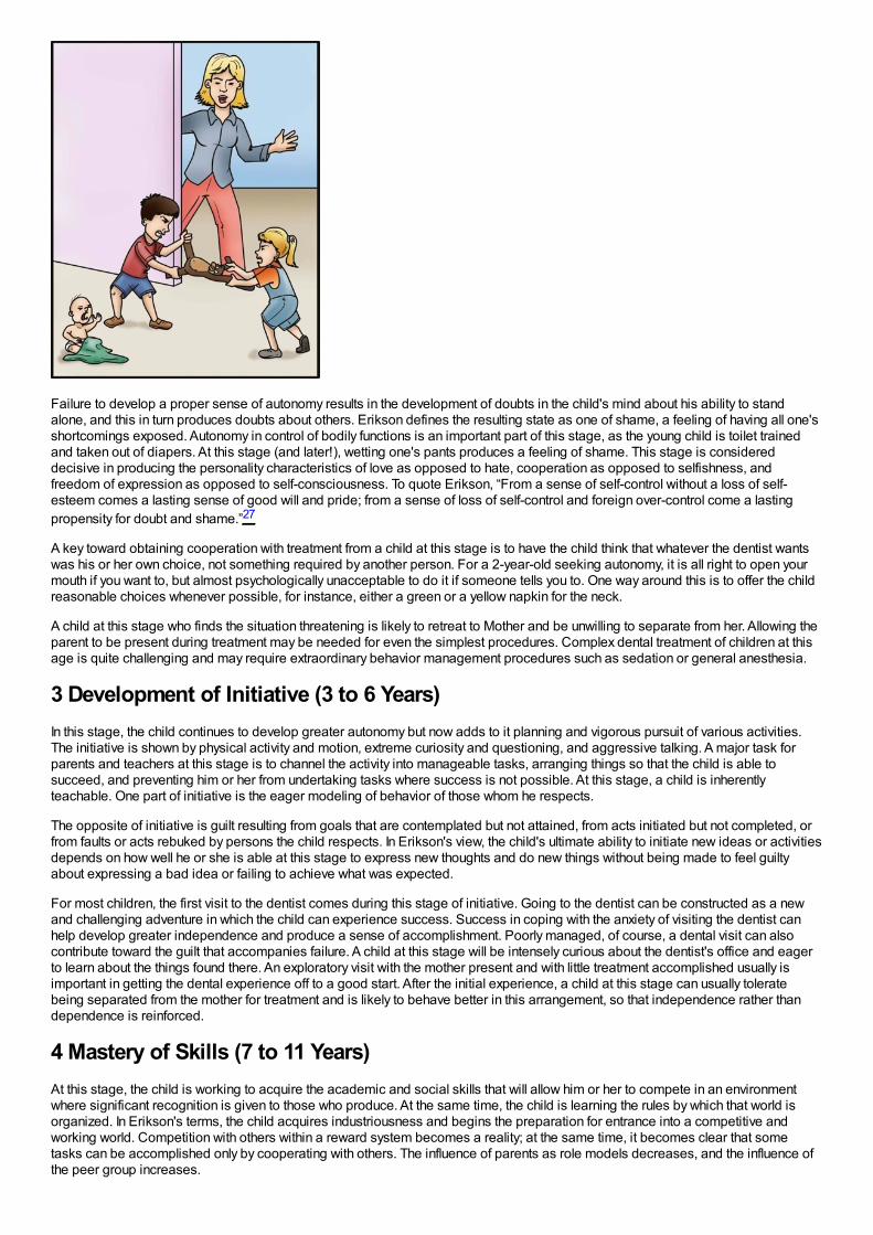
Failure to develop a proper sense of autonomy results in the development of doubts in the child's mind about his ability to standalone, and this in turn produces doubts about others. Erikson defines the resulting state as one of shame, a feeling of having all one'sshortcomings exposed. Autonomy in control of bodily functions is an important part of this stage, as the young child is toilet trainedand taken out of diapers. At this stage (and later!), wetting one's pants produces a feeling of shame. This stage is considereddecisive in producing the personality characteristics of love as opposed to hate, cooperation as opposed to selfishness, andfreedom of expression as opposed to self-consciousness. To quote Erikson, “From a sense of self-control without a loss of self-esteem comes a lasting sense of good will and pride; from a sense of loss of self-control and foreign over-control come a lastingpropensity for doubt and shame.”27
A key toward obtaining cooperation with treatment from a child at this stage is to have the child think that whatever the dentist wantswas his or her own choice, not something required by another person. For a 2-year-old seeking autonomy, it is all right to open yourmouth if you want to, but almost psychologically unacceptable to do it if someone tells you to. One way around this is to offer the childreasonable choices whenever possible, for instance, either a green or a yellow napkin for the neck.
A child at this stage who finds the situation threatening is likely to retreat to Mother and be unwilling to separate from her. Allowing theparent to be present during treatment may be needed for even the simplest procedures. Complex dental treatment of children at thisage is quite challenging and may require extraordinary behavior management procedures such as sedation or general anesthesia.
3 Development of Initiative (3 to 6 Years)In this stage, the child continues to develop greater autonomy but now adds to it planning and vigorous pursuit of various activities.The initiative is shown by physical activity and motion, extreme curiosity and questioning, and aggressive talking. A major task forparents and teachers at this stage is to channel the activity into manageable tasks, arranging things so that the child is able tosucceed, and preventing him or her from undertaking tasks where success is not possible. At this stage, a child is inherentlyteachable. One part of initiative is the eager modeling of behavior of those whom he respects.
The opposite of initiative is guilt resulting from goals that are contemplated but not attained, from acts initiated but not completed, orfrom faults or acts rebuked by persons the child respects. In Erikson's view, the child's ultimate ability to initiate new ideas or activitiesdepends on how well he or she is able at this stage to express new thoughts and do new things without being made to feel guiltyabout expressing a bad idea or failing to achieve what was expected.
For most children, the first visit to the dentist comes during this stage of initiative. Going to the dentist can be constructed as a newand challenging adventure in which the child can experience success. Success in coping with the anxiety of visiting the dentist canhelp develop greater independence and produce a sense of accomplishment. Poorly managed, of course, a dental visit can alsocontribute toward the guilt that accompanies failure. A child at this stage will be intensely curious about the dentist's office and eagerto learn about the things found there. An exploratory visit with the mother present and with little treatment accomplished usually isimportant in getting the dental experience off to a good start. After the initial experience, a child at this stage can usually toleratebeing separated from the mother for treatment and is likely to behave better in this arrangement, so that independence rather thandependence is reinforced.
4 Mastery of Skills (7 to 11 Years)At this stage, the child is working to acquire the academic and social skills that will allow him or her to compete in an environmentwhere significant recognition is given to those who produce. At the same time, the child is learning the rules by which that world isorganized. In Erikson's terms, the child acquires industriousness and begins the preparation for entrance into a competitive andworking world. Competition with others within a reward system becomes a reality; at the same time, it becomes clear that sometasks can be accomplished only by cooperating with others. The influence of parents as role models decreases, and the influence ofthe peer group increases.
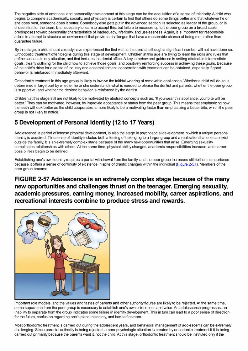
The negative side of emotional and personality development at this stage can be the acquisition of a sense of inferiority. A child whobegins to compete academically, socially, and physically is certain to find that others do some things better and that whatever he orshe does best, someone does it better. Somebody else gets put in the advanced section, is selected as leader of the group, or ischosen first for the team. It is necessary to learn to accept this, but failure to measure up to the peer group on a broad scalepredisposes toward personality characteristics of inadequacy, inferiority, and uselessness. Again, it is important for responsibleadults to attempt to structure an environment that provides challenges that have a reasonable chance of being met, rather thanguarantee failure.
By this stage, a child should already have experienced the first visit to the dentist, although a significant number will not have done so.Orthodontic treatment often begins during this stage of development. Children at this age are trying to learn the skills and rules thatdefine success in any situation, and that includes the dental office. A key to behavioral guidance is setting attainable intermediategoals, clearly outlining for the child how to achieve those goals, and positively reinforcing success in achieving these goals. Becauseof the child's drive for a sense of industry and accomplishment, cooperation with treatment can be obtained, especially if goodbehavior is reinforced immediately afterward.
Orthodontic treatment in this age group is likely to involve the faithful wearing of removable appliances. Whether a child will do so isdetermined in large part by whether he or she understands what is needed to please the dentist and parents, whether the peer groupis supportive, and whether the desired behavior is reinforced by the dentist.
Children at this stage still are not likely to be motivated by abstract concepts such as, “If you wear this appliance, your bite will bebetter.” They can be motivated, however, by improved acceptance or status from the peer group. This means that emphasizing howthe teeth will look better as the child cooperates is more likely to be a motivating factor than emphasizing a better bite, which the peergroup is not likely to notice.
5 Development of Personal Identity (12 to 17 Years)Adolescence, a period of intense physical development, is also the stage in psychosocial development in which a unique personalidentity is acquired. This sense of identity includes both a feeling of belonging to a larger group and a realization that one can existoutside the family. It is an extremely complex stage because of the many new opportunities that arise. Emerging sexualitycomplicates relationships with others. At the same time, physical ability changes, academic responsibilities increase, and careerpossibilities begin to be defined.
Establishing one's own identity requires a partial withdrawal from the family, and the peer group increases still further in importancebecause it offers a sense of continuity of existence in spite of drastic changes within the individual (Figure 2-57). Members of thepeer group become
FIGURE 2-57 Adolescence is an extremely complex stage because of the manynew opportunities and challenges thrust on the teenager. Emerging sexuality,academic pressures, earning money, increased mobility, career aspirations, andrecreational interests combine to produce stress and rewards.
important role models, and the values and tastes of parents and other authority figures are likely to be rejected. At the same time,some separation from the peer group is necessary to establish one's own uniqueness and value. As adolescence progresses, aninability to separate from the group indicates some failure in identity development. This in turn can lead to a poor sense of directionfor the future, confusion regarding one's place in society, and low self-esteem.
Most orthodontic treatment is carried out during the adolescent years, and behavioral management of adolescents can be extremelychallenging. Since parental authority is being rejected, a poor psychologic situation is created by orthodontic treatment if it is beingcarried out primarily because the parents want it, not the child. At this stage, orthodontic treatment should be instituted only if the
patient wants it, not just to please the parents.
Motivation for seeking treatment can be defined as internal or external. External motivation is from pressure from others, as inorthodontic treatment, “to get mother off my back.” Internal motivation is provided by an individual's own desire for treatment to correcta defect that he perceives in himself, not some defect pointed to by authority figures whose values are being rejected anyway.28
Approval of the peer group is extremely important. At one time, there was a certain stigma attached to being the only one in the groupso unfortunate as to have to wear braces. Now, in some areas of the United States and other developed countries, orthodontictreatment has become so common that there may be a loss of status from being one of the few in the group who is not wearingbraces. For that reason, unnecessary treatment may be requested in order to remain “one of the crowd.”
It is extremely important for an adolescent to actively desire the treatment as something being done for—not to—him or her. In thisstage, abstract concepts can be grasped readily, but appeals to do something because of its impact on personal health are not likelyto be heeded. The typical adolescent feels that health problems are concerns of somebody else, and this attitude covers everythingfrom accidental death in reckless driving to development of decalcified areas on carelessly brushed teeth.
6 Development of Intimacy (Young Adult)The adult stages of development begin with the attainment of intimate relationships with others. Successful development of intimacydepends on a willingness to compromise and even to sacrifice to maintain a relationship. Success leads to the establishment ofaffiliations and partnerships, both with a mate and with others of the same sex, in working toward the attainment of career goals.Failure leads to isolation from others and is likely to be accompanied by strong prejudices and a set of attitudes that serve to keepothers away rather than bringing them into closer contact.
A growing number of young adults are seeking orthodontic care. Often, these individuals are seeking to correct a dental appearancethey perceive as flawed. They may feel that a change in their appearance will facilitate attainment of intimate relationships. On theother hand, a “new look” resulting from orthodontic treatment may interfere with previously established relationships.
The factors that affect the development of an intimate relationship include all aspects of each person—appearance, personality,emotional qualities, intellect, and others. A significant change in any of these may be perceived by either partner as altering therelationship. Because of these potential problems, the potential psychologic impact of orthodontic treatment must be fully discussedwith a young adult patient before beginning therapy.
7 Guidance of the Next Generation (Adult)A major responsibility of a mature adult is the establishment and guidance of the next generation. Becoming a successful andsupportive parent is obviously a major part of this, but another aspect of the same responsibility is service to the group, community,and nation. The next generation is guided, in short, not only by nurturing and influencing one's own children but also by supporting thenetwork of social services needed to ensure the next generation's success. The opposite personality characteristic in mature adultsis stagnation, characterized by self-indulgence and self-centered behavior.
8 Attainment of Integrity (Late Adult)The final stage in psychosocial development is the attainment of integrity. At this stage, the individual has adapted to the combinationof gratification and disappointment that every adult experiences. The feeling of integrity is best summed up as a feeling that one hasmade the best of this life's situation and has made peace with it. The opposite characteristic is despair. This feeling is oftenexpressed as disgust and unhappiness on a broad scale, frequently accompanied by a fear that death will occur before a life changethat might lead to integrity can be accomplished.
Cognitive DevelopmentCognitive development, the development of intellectual capabilities, also occurs in a series of relatively distinct stages. Like the otherpsychologic theories, the theory of cognitive development is strongly associated with one dominant individual, in this case, the Swisspsychologist Jean Piaget. From the perspective of Piaget and his followers, the development of intelligence is another example ofthe widespread phenomenon of biologic adaptation. Every individual is born with the capacity to adjust or adapt to both the physicaland the sociocultural environments in which he or she must live.29
In Piaget's view, adaptation occurs through two complementary processes: assimilation and accommodation. From the beginning, achild incorporates or assimilates events within the environment into mental categories called cognitive structures. A cognitivestructure in this sense is a classification for sensations and perceptions.
For example, a child who has just learned the word “bird” will tend to assimilate all flying objects into his idea of bird. When he sees abee, he will probably say, “Look, bird!” However, for intelligence to develop, the child must also have the complementary process ofaccommodation. Accommodation occurs when the child changes his or her cognitive structure or mental category to better representthe environment. In the previous example, the child will be corrected by an adult or older child and will soon learn to distinguishbetween birds and bees. In other words, the child will accommodate to the event of seeing a bee by creating a separate category offlying objects for bees.
Intelligence develops as an interplay between assimilation and accommodation. Each time the child in our example sees a flyingobject, he or she will try to assimilate it into existing cognitive categories. If these categories do not work, he or she will try toaccommodate by creating new ones. However, the child's ability to adapt is limited by the current level of development. The notion
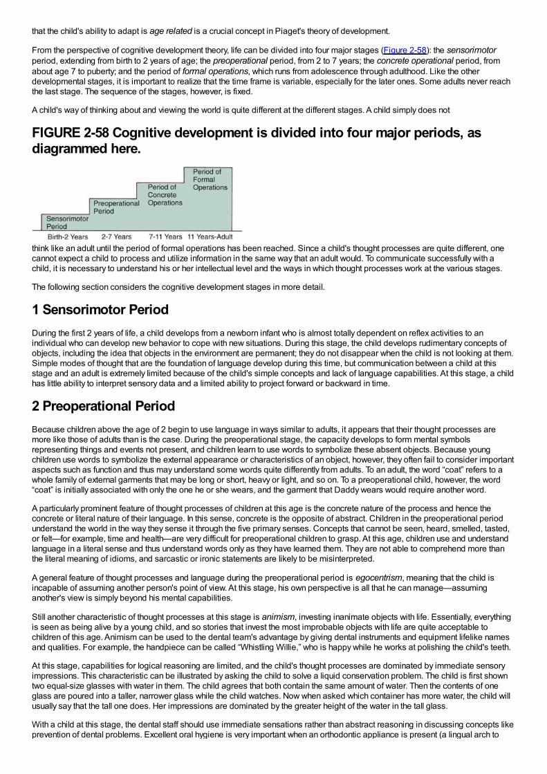
that the child's ability to adapt is age related is a crucial concept in Piaget's theory of development.
From the perspective of cognitive development theory, life can be divided into four major stages (Figure 2-58): the sensorimotorperiod, extending from birth to 2 years of age; the preoperational period, from 2 to 7 years; the concrete operational period, fromabout age 7 to puberty; and the period of formal operations, which runs from adolescence through adulthood. Like the otherdevelopmental stages, it is important to realize that the time frame is variable, especially for the later ones. Some adults never reachthe last stage. The sequence of the stages, however, is fixed.
A child's way of thinking about and viewing the world is quite different at the different stages. A child simply does not
FIGURE 2-58 Cognitive development is divided into four major periods, asdiagrammed here.
think like an adult until the period of formal operations has been reached. Since a child's thought processes are quite different, onecannot expect a child to process and utilize information in the same way that an adult would. To communicate successfully with achild, it is necessary to understand his or her intellectual level and the ways in which thought processes work at the various stages.
The following section considers the cognitive development stages in more detail.
1 Sensorimotor PeriodDuring the first 2 years of life, a child develops from a newborn infant who is almost totally dependent on reflex activities to anindividual who can develop new behavior to cope with new situations. During this stage, the child develops rudimentary concepts ofobjects, including the idea that objects in the environment are permanent; they do not disappear when the child is not looking at them.Simple modes of thought that are the foundation of language develop during this time, but communication between a child at thisstage and an adult is extremely limited because of the child's simple concepts and lack of language capabilities. At this stage, a childhas little ability to interpret sensory data and a limited ability to project forward or backward in time.
2 Preoperational PeriodBecause children above the age of 2 begin to use language in ways similar to adults, it appears that their thought processes aremore like those of adults than is the case. During the preoperational stage, the capacity develops to form mental symbolsrepresenting things and events not present, and children learn to use words to symbolize these absent objects. Because youngchildren use words to symbolize the external appearance or characteristics of an object, however, they often fail to consider importantaspects such as function and thus may understand some words quite differently from adults. To an adult, the word “coat” refers to awhole family of external garments that may be long or short, heavy or light, and so on. To a preoperational child, however, the word“coat” is initially associated with only the one he or she wears, and the garment that Daddy wears would require another word.
A particularly prominent feature of thought processes of children at this age is the concrete nature of the process and hence theconcrete or literal nature of their language. In this sense, concrete is the opposite of abstract. Children in the preoperational periodunderstand the world in the way they sense it through the five primary senses. Concepts that cannot be seen, heard, smelled, tasted,or felt—for example, time and health—are very difficult for preoperational children to grasp. At this age, children use and understandlanguage in a literal sense and thus understand words only as they have learned them. They are not able to comprehend more thanthe literal meaning of idioms, and sarcastic or ironic statements are likely to be misinterpreted.
A general feature of thought processes and language during the preoperational period is egocentrism, meaning that the child isincapable of assuming another person's point of view. At this stage, his own perspective is all that he can manage—assuminganother's view is simply beyond his mental capabilities.
Still another characteristic of thought processes at this stage is animism, investing inanimate objects with life. Essentially, everythingis seen as being alive by a young child, and so stories that invest the most improbable objects with life are quite acceptable tochildren of this age. Animism can be used to the dental team's advantage by giving dental instruments and equipment lifelike namesand qualities. For example, the handpiece can be called “Whistling Willie,” who is happy while he works at polishing the child's teeth.
At this stage, capabilities for logical reasoning are limited, and the child's thought processes are dominated by immediate sensoryimpressions. This characteristic can be illustrated by asking the child to solve a liquid conservation problem. The child is first showntwo equal-size glasses with water in them. The child agrees that both contain the same amount of water. Then the contents of oneglass are poured into a taller, narrower glass while the child watches. Now when asked which container has more water, the child willusually say that the tall one does. Her impressions are dominated by the greater height of the water in the tall glass.
With a child at this stage, the dental staff should use immediate sensations rather than abstract reasoning in discussing concepts likeprevention of dental problems. Excellent oral hygiene is very important when an orthodontic appliance is present (a lingual arch to
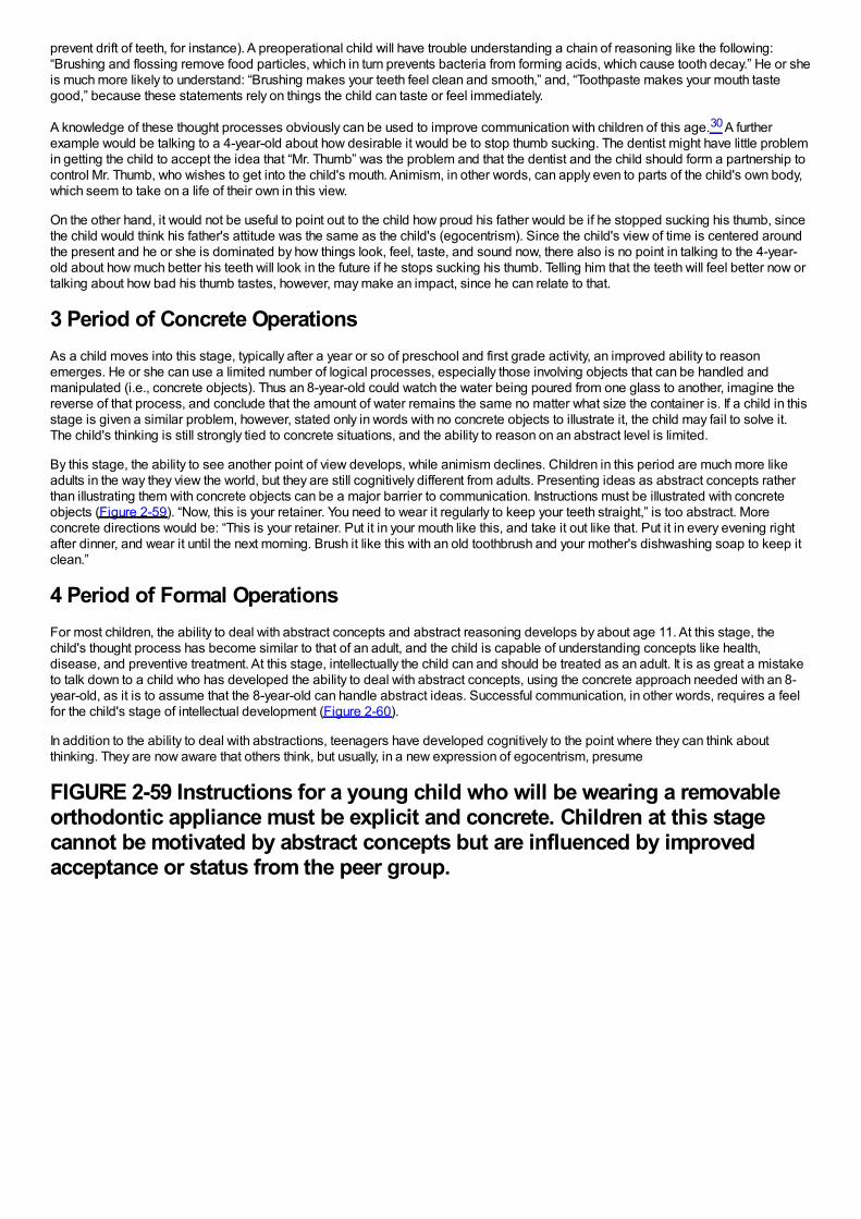
prevent drift of teeth, for instance). A preoperational child will have trouble understanding a chain of reasoning like the following:“Brushing and flossing remove food particles, which in turn prevents bacteria from forming acids, which cause tooth decay.” He or sheis much more likely to understand: “Brushing makes your teeth feel clean and smooth,” and, “Toothpaste makes your mouth tastegood,” because these statements rely on things the child can taste or feel immediately.
A knowledge of these thought processes obviously can be used to improve communication with children of this age.30 A furtherexample would be talking to a 4-year-old about how desirable it would be to stop thumb sucking. The dentist might have little problemin getting the child to accept the idea that “Mr. Thumb” was the problem and that the dentist and the child should form a partnership tocontrol Mr. Thumb, who wishes to get into the child's mouth. Animism, in other words, can apply even to parts of the child's own body,which seem to take on a life of their own in this view.
On the other hand, it would not be useful to point out to the child how proud his father would be if he stopped sucking his thumb, sincethe child would think his father's attitude was the same as the child's (egocentrism). Since the child's view of time is centered aroundthe present and he or she is dominated by how things look, feel, taste, and sound now, there also is no point in talking to the 4-year-old about how much better his teeth will look in the future if he stops sucking his thumb. Telling him that the teeth will feel better now ortalking about how bad his thumb tastes, however, may make an impact, since he can relate to that.
3 Period of Concrete OperationsAs a child moves into this stage, typically after a year or so of preschool and first grade activity, an improved ability to reasonemerges. He or she can use a limited number of logical processes, especially those involving objects that can be handled andmanipulated (i.e., concrete objects). Thus an 8-year-old could watch the water being poured from one glass to another, imagine thereverse of that process, and conclude that the amount of water remains the same no matter what size the container is. If a child in thisstage is given a similar problem, however, stated only in words with no concrete objects to illustrate it, the child may fail to solve it.The child's thinking is still strongly tied to concrete situations, and the ability to reason on an abstract level is limited.
By this stage, the ability to see another point of view develops, while animism declines. Children in this period are much more likeadults in the way they view the world, but they are still cognitively different from adults. Presenting ideas as abstract concepts ratherthan illustrating them with concrete objects can be a major barrier to communication. Instructions must be illustrated with concreteobjects (Figure 2-59). “Now, this is your retainer. You need to wear it regularly to keep your teeth straight,” is too abstract. Moreconcrete directions would be: “This is your retainer. Put it in your mouth like this, and take it out like that. Put it in every evening rightafter dinner, and wear it until the next morning. Brush it like this with an old toothbrush and your mother's dishwashing soap to keep itclean.”
4 Period of Formal OperationsFor most children, the ability to deal with abstract concepts and abstract reasoning develops by about age 11. At this stage, thechild's thought process has become similar to that of an adult, and the child is capable of understanding concepts like health,disease, and preventive treatment. At this stage, intellectually the child can and should be treated as an adult. It is as great a mistaketo talk down to a child who has developed the ability to deal with abstract concepts, using the concrete approach needed with an 8-year-old, as it is to assume that the 8-year-old can handle abstract ideas. Successful communication, in other words, requires a feelfor the child's stage of intellectual development (Figure 2-60).
In addition to the ability to deal with abstractions, teenagers have developed cognitively to the point where they can think aboutthinking. They are now aware that others think, but usually, in a new expression of egocentrism, presume
FIGURE 2-59 Instructions for a young child who will be wearing a removableorthodontic appliance must be explicit and concrete. Children at this stagecannot be motivated by abstract concepts but are influenced by improvedacceptance or status from the peer group.
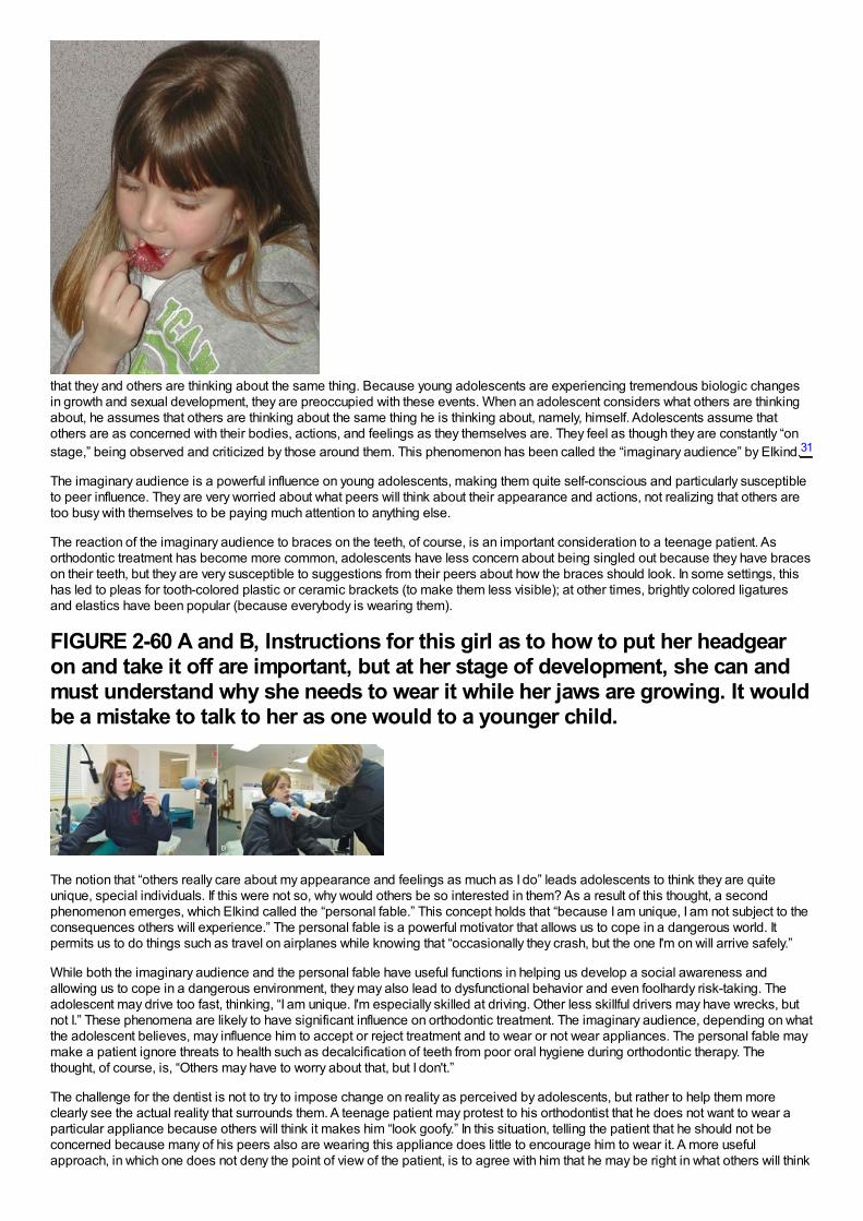
that they and others are thinking about the same thing. Because young adolescents are experiencing tremendous biologic changesin growth and sexual development, they are preoccupied with these events. When an adolescent considers what others are thinkingabout, he assumes that others are thinking about the same thing he is thinking about, namely, himself. Adolescents assume thatothers are as concerned with their bodies, actions, and feelings as they themselves are. They feel as though they are constantly “onstage,” being observed and criticized by those around them. This phenomenon has been called the “imaginary audience” by Elkind.31
The imaginary audience is a powerful influence on young adolescents, making them quite self-conscious and particularly susceptibleto peer influence. They are very worried about what peers will think about their appearance and actions, not realizing that others aretoo busy with themselves to be paying much attention to anything else.
The reaction of the imaginary audience to braces on the teeth, of course, is an important consideration to a teenage patient. Asorthodontic treatment has become more common, adolescents have less concern about being singled out because they have braceson their teeth, but they are very susceptible to suggestions from their peers about how the braces should look. In some settings, thishas led to pleas for tooth-colored plastic or ceramic brackets (to make them less visible); at other times, brightly colored ligaturesand elastics have been popular (because everybody is wearing them).
FIGURE 2-60 A and B, Instructions for this girl as to how to put her headgearon and take it off are important, but at her stage of development, she can andmust understand why she needs to wear it while her jaws are growing. It wouldbe a mistake to talk to her as one would to a younger child.
The notion that “others really care about my appearance and feelings as much as I do” leads adolescents to think they are quiteunique, special individuals. If this were not so, why would others be so interested in them? As a result of this thought, a secondphenomenon emerges, which Elkind called the “personal fable.” This concept holds that “because I am unique, I am not subject to theconsequences others will experience.” The personal fable is a powerful motivator that allows us to cope in a dangerous world. Itpermits us to do things such as travel on airplanes while knowing that “occasionally they crash, but the one I'm on will arrive safely.”
While both the imaginary audience and the personal fable have useful functions in helping us develop a social awareness andallowing us to cope in a dangerous environment, they may also lead to dysfunctional behavior and even foolhardy risk-taking. Theadolescent may drive too fast, thinking, “I am unique. I'm especially skilled at driving. Other less skillful drivers may have wrecks, butnot I.” These phenomena are likely to have significant influence on orthodontic treatment. The imaginary audience, depending on whatthe adolescent believes, may influence him to accept or reject treatment and to wear or not wear appliances. The personal fable maymake a patient ignore threats to health such as decalcification of teeth from poor oral hygiene during orthodontic therapy. Thethought, of course, is, “Others may have to worry about that, but I don't.”
The challenge for the dentist is not to try to impose change on reality as perceived by adolescents, but rather to help them moreclearly see the actual reality that surrounds them. A teenage patient may protest to his orthodontist that he does not want to wear aparticular appliance because others will think it makes him “look goofy.” In this situation, telling the patient that he should not beconcerned because many of his peers also are wearing this appliance does little to encourage him to wear it. A more usefulapproach, in which one does not deny the point of view of the patient, is to agree with him that he may be right in what others will think
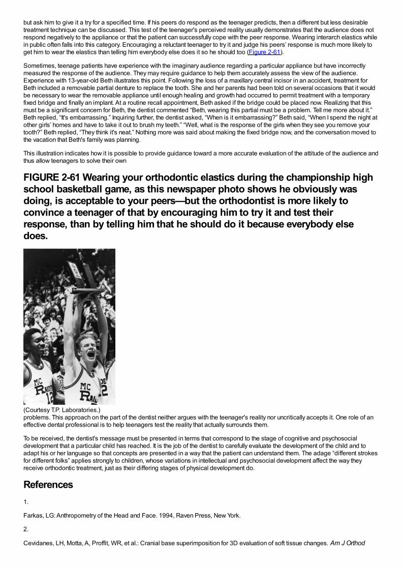
but ask him to give it a try for a specified time. If his peers do respond as the teenager predicts, then a different but less desirabletreatment technique can be discussed. This test of the teenager's perceived reality usually demonstrates that the audience does notrespond negatively to the appliance or that the patient can successfully cope with the peer response. Wearing interarch elastics whilein public often falls into this category. Encouraging a reluctant teenager to try it and judge his peers’ response is much more likely toget him to wear the elastics than telling him everybody else does it so he should too (Figure 2-61).
Sometimes, teenage patients have experience with the imaginary audience regarding a particular appliance but have incorrectlymeasured the response of the audience. They may require guidance to help them accurately assess the view of the audience.Experience with 13-year-old Beth illustrates this point. Following the loss of a maxillary central incisor in an accident, treatment forBeth included a removable partial denture to replace the tooth. She and her parents had been told on several occasions that it wouldbe necessary to wear the removable appliance until enough healing and growth had occurred to permit treatment with a temporaryfixed bridge and finally an implant. At a routine recall appointment, Beth asked if the bridge could be placed now. Realizing that thismust be a significant concern for Beth, the dentist commented “Beth, wearing this partial must be a problem. Tell me more about it.”Beth replied, “It's embarrassing.” Inquiring further, the dentist asked, “When is it embarrassing?” Beth said, “When I spend the night atother girls’ homes and have to take it out to brush my teeth.” “Well, what is the response of the girls when they see you remove yourtooth?” Beth replied, “They think it's neat.” Nothing more was said about making the fixed bridge now, and the conversation moved tothe vacation that Beth's family was planning.
This illustration indicates how it is possible to provide guidance toward a more accurate evaluation of the attitude of the audience andthus allow teenagers to solve their own
FIGURE 2-61 Wearing your orthodontic elastics during the championship highschool basketball game, as this newspaper photo shows he obviously wasdoing, is acceptable to your peers—but the orthodontist is more likely toconvince a teenager of that by encouraging him to try it and test theirresponse, than by telling him that he should do it because everybody elsedoes.
(Courtesy T.P. Laboratories.)problems. This approach on the part of the dentist neither argues with the teenager's reality nor uncritically accepts it. One role of aneffective dental professional is to help teenagers test the reality that actually surrounds them.
To be received, the dentist's message must be presented in terms that correspond to the stage of cognitive and psychosocialdevelopment that a particular child has reached. It is the job of the dentist to carefully evaluate the development of the child and toadapt his or her language so that concepts are presented in a way that the patient can understand them. The adage “different strokesfor different folks” applies strongly to children, whose variations in intellectual and psychosocial development affect the way theyreceive orthodontic treatment, just as their differing stages of physical development do.
References1.
Farkas, LG: Anthropometry of the Head and Face. 1994, Raven Press, New York.
2.
Cevidanes, LH, Motta, A, Proffit, WR, et al.: Cranial base superimposition for 3D evaluation of soft tissue changes. Am J Orthod

Dentofac Orthop. 137(suppl 4), 2010, S120–129.
3.
Cevidanes, LH, Franco, AA, Gehrig, G, et al.: Assessment of mandibular growth and response to orthopedic treatment with 3-dimensional magnetic resonance images. Am J Orthod Dentofac Orthop. 128, 2005, 16–26.
4.
Chihiro, T, Takada, K, van Aalst, J, et al.: Objective three-dimensional assessment of lip form in patients with repaired cleft palate.Cleft Palate Craniofacial J. 47, 2010, 611–622.
5.
Thompson, DT: On Growth and Form. 1971, Cambridge University Press, Cambridge.
6.
Baer, MJ, Bosma, JF, Ackerman, JL: The Postnatal Development of the Rat Skull. 1983, The University of Michigan Press, Ann Arbor,Mich.
7.
Brugmann, SA, Allen, NC, James, AW, et al.: A primary cilia-dependent etiology for midline facial disorders. Hum Mol Genet. 19,2010, 1577–1592.
8.
Berdal, A, Molla, M, Hotton, D, et al.: Differential impact of MSX1 and MSX2 homeogenes on mouse maxillofacial skeleton. CellsTissues Organs. 189, 2009, 126–132.
9.
Purcell, P, Joo, BW, Hu, JK, et al.: Temporomandibular joint formation requires two distinct hedgehog-dependent steps. Proc NatlAcad Sci USA. 106, 2009, 18297–18302.
10.
Xue, F, Wong, RW, Rabie, AB: Genes, genetics, and Class III malocclusion. Orthod Craniofac Res. 13, 2010, 69–74.
11.
Decker, E, Stellzig-Eisenhauer, A, Fiebig, BS, et al.: PTHR1 loss-of-function mutations in familial, nonsyndromic primary failure oftooth eruption. Am J Human Genetics. 83, 2008, 781–786.
12.
Frazier-Bowers, SA, Simmons, D, Wright, JT, et al.: Primary failure of eruption and PTH1R: the importance of a genetic diagnosis fororthodontic treatment planning. Am J Orthod Dentofac Orthop. 137, 2010, 160e1–160e7, discussion 160-161.
13.
Dai, J, Rabie, AB: Gene therapy to enhance condylar growth using rAAV-VEGF. Angle Orthod. 78, 2008, 89–94.
14.
Enlow, DH, Hans, MG: Essentials of Facial Growth. 1996, WB Saunders, Philadelphia.
15.
Copray, JC: Growth of the nasal septal cartilage of the rat in vitro. J Anat. 144, 1986, 99–111.
16.
Delatte, M, Von den Hoff, JW, van Rheden, RE, et al.: Primary and secondary cartilages of the neonatal rat: the femoral head and themandibular condyle. Eur J Oral Sci. 112, 2004, 156–162.
17.
Gilhuus-Moe, O: Fractures of the Mandibular Condyle in the Growth Period. 1969, Scandinavian University Books,Universitatsforlaget, Stockholm.
18.
Lund, K: Mandibular growth and remodelling process after mandibular fractures: a longitudinal roentgencephalometric study. Acta

Odontol Scand. 32(64), 1974, 3–117.
19.
Moss, ML: The functional matrix hypothesis revisited. Am J Orthod Dentofac Orthop. 112, 1997, 8–11, 221-226, 338-342, 410-417.
20.
Weinstein, P: Child-centered child management in a changing world. Eur Arch Paediatr Dent . 9(suppl 1), 2008, 6–10.
21.
Roberts, JF, Curzon, ME, Koch, G, et al.: Review: behaviour management techniques in paediatric dentistry. Eur Arch Paediatr Dent .11, 2010, 166–174.
22.
Miltenberger, RG: Behavior Modification: Principles and Procedures. 3rd ed, 2004, Brooks/Cole, Pacific Grove, Calif.
23.
Baghadi, ZD: Principles and application of learning theory in child patient management. Quintessence International. 32, 2001, 135–141.
24.
Gustafsson, A: Dental behaviour management problems among children and adolescents–a matter of understanding? Studies ondental fear, personal characteristics and psychosocial concomitants. Swed Dent J. (suppl 202), 2010, 1–46.
25.
Farhat-McHayleh, N, Harfouche, A, Souaid, P: Techniques for managing behavior in pediatric dentistry: comparative study of livemodeling and tell-show-do based on children's heart rates during treatment. J Can Dent Assoc. 75, 2009, 283.
26.
Chambers, DW: Managing anxieties of young dental patients. ASDC J Dent Child. 37, 1970, 363–373.
27.
Erikson, EH: A Way of Looking at Things—Selected Papers from 1930 to 1980 (S. Schlein, editor). 1987, WW Norton & Co, NewYork.
28.
de Paula, DF Jr., Santos, NC, da Silva, ET, et al.: Psychosocial impact of dental esthetics on quality of life in adolescents. AngleOrthod. 79, 2009, 1188–1193.
29.
Wadsworth, BJ: Piaget's Theory of Cognitive and Affective Development. 1989, Longman, New York.
30.
Newton, JT, Harrison, V: The cognitive and social development of the child. Dent Update. 32, 2005, 33–34, 37-38.
31.
Elkind, D: The teenager's reality. Pediatr Dent. 9, 1987, 337–341.

Chapter 3 Early Stages of Development
Late Fetal Development and BirthBy the third trimester of intrauterine life, the human fetus weighs approximately 1000 gm and though far from ready for life outside theprotective intrauterine environment, can often survive premature birth. During the last 3 months of intrauterine life, continued rapidgrowth results in a tripling of body mass to about 3000 gm. Dental development, which begins in the third month, proceeds rapidlythereafter (Table 3-1). Development of all primary teeth and the permanent first molars starts well before birth.
Although the proportion of the total body mass represented by the head decreases from the fourth month of intrauterine life onwardbecause of the cephalocaudal gradient of growth discussed earlier, at birth the head is still nearly half the total body mass andrepresents the largest impediment to passage of the infant through the birth canal. Making the head longer and narrower obviouslywould facilitate birth, and this is accomplished by a literal distortion of its shape (Figure 3-1). The change of shape is possiblebecause at birth, relatively large uncalcified fontanelles persist between the flat bones of the brain case. As the head is compressedwithin the birth canal, the brain case (calvarium) can increase in length and decrease in width, assuming the desired tubular form andeasing passage through the birth canal.
The relative lack of growth of the lower jaw prenatally also makes birth easier, since a prominent bony chin at the time of birth wouldbe a considerable problem in passage through the birth canal. Many a young dentist, acutely aware of the orthodontic problems thatcan arise later because of skeletal mandibular deficiency, has been shocked to discover how incredibly mandibular deficient his orher own newborn is and has required reassurance that this is a perfectly normal and indeed desirable phenomenon. Postnatally, themandible grows more than the other facial structures and gradually catches up, producing the eventual adult proportions.
Despite the physical adaptations that facilitate it, birth is a traumatic process. In the best of circumstances, being thrust into the worldrequires a dramatic set of physiologic adaptations. For a short period, growth ceases and often there is a small decrease in weightduring the first 7 to 10 days of life. Such an interruption in growth produces a physical effect in skeletal tissues that are forming at thetime because the orderly sequence of calcification is disturbed. The result is a noticeable line across both bones and teeth that areforming at the time. However, bones are not visible and are remodeled to such an extent that any lines caused by the growth arrest atbirth would soon be covered over at any rate.
Teeth, on the other hand, are quite visible, and the extent of any growth disturbance related to birth can be seen in the enamel, whichis not remodeled. Almost every child has a “neonatal line” across the surface of the primary teeth, its location varying from tooth totooth depending on the stage
FIGURE 3-1 This photograph of a newborn infant clearly shows the headdistortion that accompanies (and facilitates) passage through the birth canal.Note that the head has been squeezed into a more elliptical or tubular “cone-head” shape, a distortion made possible by the presence of the relatively largefontanelles.
of development at birth (Figure 3-2). Under normal circumstances, the line is so slight that it can be seen only if the tooth surface ismagnified, but if the neonatal period was stormy, a prominent area of stained, distorted, or poorly calcified enamel can be the result.1
TABLE 3-1 Chronology of Tooth Development, Primary Dentition
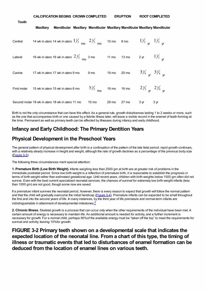
ToothCALCIFICATION BEGINS CROWN COMPLETED ERUPTION ROOT COMPLETED
Maxillary Mandibular Maxillary Mandibular Maxillary Mandibular Maxillary Mandibular
Central 14 wk in utero 14 wk in utero mo mo
10 mo 8 mo yr yr
Lateral 16 wk in utero 16 wk in utero mo
3 mo 11 mo 13 mo 2 yr yr
Canine 17 wk in utero 17 wk in utero 9 mo 9 mo 19 mo 20 mo yr yr
First molar 15 wk in utero 15 wk in utero 6 mo mo
16 mo 16 mo yr yr
Second molar 19 wk in utero 18 wk in utero 11 mo 10 mo 29 mo 27 mo 3 yr 3 yr
Birth is not the only circumstance that can have this effect. As a general rule, growth disturbances lasting 1 to 2 weeks or more, suchas the one that accompanies birth or one caused by a febrile illness later, will leave a visible record in the enamel of teeth forming atthe time. Permanent as well as primary teeth can be affected by illnesses during infancy and early childhood.
Infancy and Early Childhood: The Primary Dentition Years
Physical Development in the Preschool YearsThe general pattern of physical development after birth is a continuation of the pattern of the late fetal period: rapid growth continues,with a relatively steady increase in height and weight, although the rate of growth declines as a percentage of the previous body size(Figure 3-3).
The following three circumstances merit special attention:
1. Premature Birth (Low Birth Weight). Infants weighing less than 2500 gm at birth are at greater risk of problems in theimmediate postnatal period. Since low birth weight is a reflection of premature birth, it is reasonable to establish the prognosis interms of birth weight rather than estimated gestational age. Until recent years, children with birth weights below 1500 gm often did notsurvive. Even with the best current specialized neonatal services, the chances of survival for extremely low birth weight infants (lessthan 1000 gm) are not good, though some now are saved.
If a premature infant survives the neonatal period, however, there is every reason to expect that growth will follow the normal patternand that the child will gradually overcome the initial handicap (Figure 3-4). Premature infants can be expected to be small throughoutthe first and into the second years of life. In many instances, by the third year of life premature and normal-term infants areindistinguishable in attainment of developmental milestones.2
2. Chronic Illness. Skeletal growth is a process that can occur only when the other requirements of the individual have been met. Acertain amount of energy is necessary to maintain life. An additional amount is needed for activity, and a further increment isnecessary for growth. For a normal child, perhaps 90%of the available energy must be “taken off the top” to meet the requirements forsurvival and activity, leaving 10%for growth.
FIGURE 3-2 Primary teeth shown on a developmental scale that indicates theexpected location of the neonatal line. From a chart of this type, the timing ofillness or traumatic events that led to disturbances of enamel formation can bededuced from the location of enamel lines on various teeth.
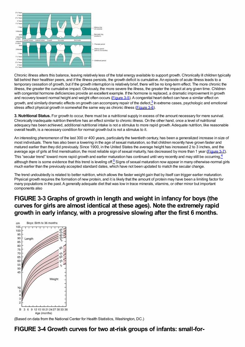
Chronic illness alters this balance, leaving relatively less of the total energy available to support growth. Chronically ill children typicallyfall behind their healthier peers, and if the illness persists, the growth deficit is cumulative. An episode of acute illness leads to atemporary cessation of growth, but if the growth interruption is relatively brief, there will be no long-term effect. The more chronic theillness, the greater the cumulative impact. Obviously, the more severe the illness, the greater the impact at any given time. Childrenwith congenital hormone deficiencies provide an excellent example. If the hormone is replaced, a dramatic improvement in growthand recovery toward normal height and weight often occurs (Figure 3-5). A congenital heart defect can have a similar effect ongrowth, and similarly dramatic effects on growth can accompany repair of the defect.3 In extreme cases, psychologic and emotionalstress affect physical growth in somewhat the same way as chronic illness (Figure 3-6).
3. Nutritional Status. For growth to occur, there must be a nutritional supply in excess of the amount necessary for mere survival.Chronically inadequate nutrition therefore has an effect similar to chronic illness. On the other hand, once a level of nutritionaladequacy has been achieved, additional nutritional intake is not a stimulus to more rapid growth. Adequate nutrition, like reasonableoverall health, is a necessary condition for normal growth but is not a stimulus to it.
An interesting phenomenon of the last 300 or 400 years, particularly the twentieth century, has been a generalized increase in size ofmost individuals. There has also been a lowering in the age of sexual maturation, so that children recently have grown faster andmatured earlier than they did previously. Since 1900, in the United States the average height has increased 2 to 3 inches, and theaverage age of girls at first menstruation, the most reliable sign of sexual maturity, has decreased by more than 1 year (Figure 3-7).This “secular trend” toward more rapid growth and earlier maturation has continued until very recently and may still be occurring,4
although there is some evidence that this trend is leveling off.5 Signs of sexual maturation now appear in many otherwise-normal girlsmuch earlier than the previously accepted standard dates, which have not been updated to match the secular change.
The trend undoubtedly is related to better nutrition, which allows the faster weight gain that by itself can trigger earlier maturation.Physical growth requires the formation of new protein, and it is likely that the amount of protein may have been a limiting factor formany populations in the past. A generally adequate diet that was low in trace minerals, vitamins, or other minor but importantcomponents also
FIGURE 3-3 Graphs of growth in length and weight in infancy for boys (thecurves for girls are almost identical at these ages). Note the extremely rapidgrowth in early infancy, with a progressive slowing after the first 6 months.
(Based on data from the National Center for Health Statistics, Washington, DC.)
FIGURE 3-4 Growth curves for two at-risk groups of infants: small-for-
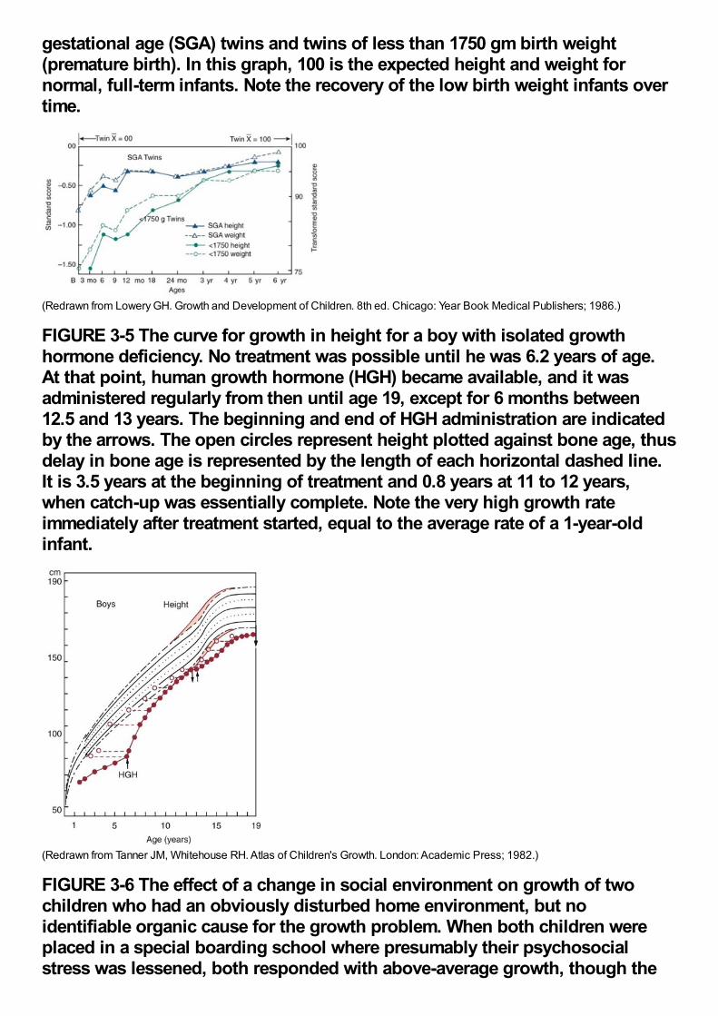
gestational age (SGA) twins and twins of less than 1750 gm birth weight(premature birth). In this graph, 100 is the expected height and weight fornormal, full-term infants. Note the recovery of the low birth weight infants overtime.
(Redrawn from Lowery GH. Growth and Development of Children. 8th ed. Chicago: Year Book Medical Publishers; 1986.)
FIGURE 3-5 The curve for growth in height for a boy with isolated growthhormone deficiency. No treatment was possible until he was 6.2 years of age.At that point, human growth hormone (HGH) became available, and it wasadministered regularly from then until age 19, except for 6 months between12.5 and 13 years. The beginning and end of HGH administration are indicatedby the arrows. The open circles represent height plotted against bone age, thusdelay in bone age is represented by the length of each horizontal dashed line.It is 3.5 years at the beginning of treatment and 0.8 years at 11 to 12 years,when catch-up was essentially complete. Note the very high growth rateimmediately after treatment started, equal to the average rate of a 1-year-oldinfant.
(Redrawn from Tanner JM, Whitehouse RH. Atlas of Children's Growth. London: Academic Press; 1982.)
FIGURE 3-6 The effect of a change in social environment on growth of twochildren who had an obviously disturbed home environment, but noidentifiable organic cause for the growth problem. When both children wereplaced in a special boarding school where presumably their psychosocialstress was lessened, both responded with above-average growth, though the
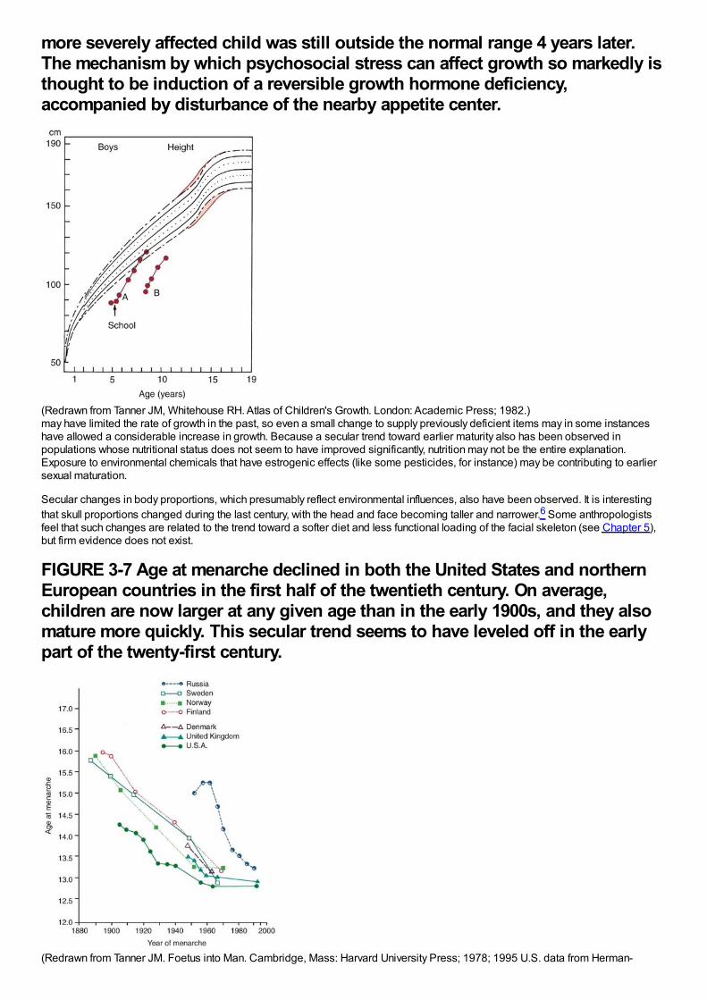
more severely affected child was still outside the normal range 4 years later.The mechanism by which psychosocial stress can affect growth so markedly isthought to be induction of a reversible growth hormone deficiency,accompanied by disturbance of the nearby appetite center.
(Redrawn from Tanner JM, Whitehouse RH. Atlas of Children's Growth. London: Academic Press; 1982.)may have limited the rate of growth in the past, so even a small change to supply previously deficient items may in some instanceshave allowed a considerable increase in growth. Because a secular trend toward earlier maturity also has been observed inpopulations whose nutritional status does not seem to have improved significantly, nutrition may not be the entire explanation.Exposure to environmental chemicals that have estrogenic effects (like some pesticides, for instance) may be contributing to earliersexual maturation.
Secular changes in body proportions, which presumably reflect environmental influences, also have been observed. It is interestingthat skull proportions changed during the last century, with the head and face becoming taller and narrower.6 Some anthropologistsfeel that such changes are related to the trend toward a softer diet and less functional loading of the facial skeleton (see Chapter 5),but firm evidence does not exist.
FIGURE 3-7 Age at menarche declined in both the United States and northernEuropean countries in the first half of the twentieth century. On average,children are now larger at any given age than in the early 1900s, and they alsomature more quickly. This secular trend seems to have leveled off in the earlypart of the twenty-first century.
(Redrawn from Tanner JM. Foetus into Man. Cambridge, Mass: Harvard University Press; 1978; 1995 U.S. data from Herman-
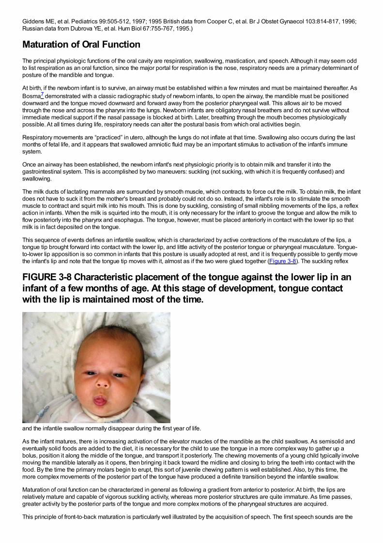
Giddens ME, et al. Pediatrics 99:505-512, 1997; 1995 British data from Cooper C, et al. Br J Obstet Gynaecol 103:814-817, 1996;Russian data from Dubrova YE, et al. Hum Biol 67:755-767, 1995.)
Maturation of Oral FunctionThe principal physiologic functions of the oral cavity are respiration, swallowing, mastication, and speech. Although it may seem oddto list respiration as an oral function, since the major portal for respiration is the nose, respiratory needs are a primary determinant ofposture of the mandible and tongue.
At birth, if the newborn infant is to survive, an airway must be established within a few minutes and must be maintained thereafter. AsBosma7 demonstrated with a classic radiographic study of newborn infants, to open the airway, the mandible must be positioneddownward and the tongue moved downward and forward away from the posterior pharyngeal wall. This allows air to be movedthrough the nose and across the pharynx into the lungs. Newborn infants are obligatory nasal breathers and do not survive withoutimmediate medical support if the nasal passage is blocked at birth. Later, breathing through the mouth becomes physiologicallypossible. At all times during life, respiratory needs can alter the postural basis from which oral activities begin.
Respiratory movements are “practiced” in utero, although the lungs do not inflate at that time. Swallowing also occurs during the lastmonths of fetal life, and it appears that swallowed amniotic fluid may be an important stimulus to activation of the infant's immunesystem.
Once an airway has been established, the newborn infant's next physiologic priority is to obtain milk and transfer it into thegastrointestinal system. This is accomplished by two maneuvers: suckling (not sucking, with which it is frequently confused) andswallowing.
The milk ducts of lactating mammals are surrounded by smooth muscle, which contracts to force out the milk. To obtain milk, the infantdoes not have to suck it from the mother's breast and probably could not do so. Instead, the infant's role is to stimulate the smoothmuscle to contract and squirt milk into his mouth. This is done by suckling, consisting of small nibbling movements of the lips, a reflexaction in infants. When the milk is squirted into the mouth, it is only necessary for the infant to groove the tongue and allow the milk toflow posteriorly into the pharynx and esophagus. The tongue, however, must be placed anteriorly in contact with the lower lip so thatmilk is in fact deposited on the tongue.
This sequence of events defines an infantile swallow, which is characterized by active contractions of the musculature of the lips, atongue tip brought forward into contact with the lower lip, and little activity of the posterior tongue or pharyngeal musculature. Tongue-to-lower lip apposition is so common in infants that this posture is usually adopted at rest, and it is frequently possible to gently movethe infant's lip and note that the tongue tip moves with it, almost as if the two were glued together (Figure 3-8). The suckling reflex
FIGURE 3-8 Characteristic placement of the tongue against the lower lip in aninfant of a few months of age. At this stage of development, tongue contactwith the lip is maintained most of the time.
and the infantile swallow normally disappear during the first year of life.
As the infant matures, there is increasing activation of the elevator muscles of the mandible as the child swallows. As semisolid andeventually solid foods are added to the diet, it is necessary for the child to use the tongue in a more complex way to gather up abolus, position it along the middle of the tongue, and transport it posteriorly. The chewing movements of a young child typically involvemoving the mandible laterally as it opens, then bringing it back toward the midline and closing to bring the teeth into contact with thefood. By the time the primary molars begin to erupt, this sort of juvenile chewing pattern is well established. Also, by this time, themore complex movements of the posterior part of the tongue have produced a definite transition beyond the infantile swallow.
Maturation of oral function can be characterized in general as following a gradient from anterior to posterior. At birth, the lips arerelatively mature and capable of vigorous suckling activity, whereas more posterior structures are quite immature. As time passes,greater activity by the posterior parts of the tongue and more complex motions of the pharyngeal structures are acquired.
This principle of front-to-back maturation is particularly well illustrated by the acquisition of speech. The first speech sounds are the
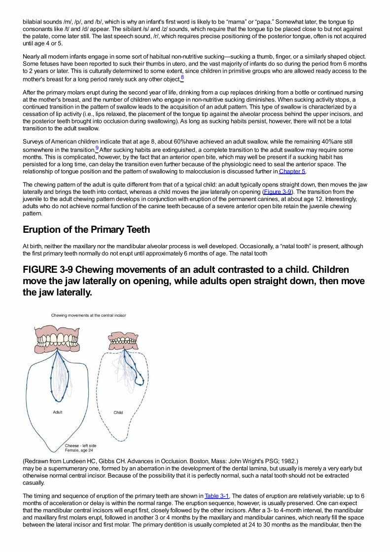
bilabial sounds /m/, /p/, and /b/, which is why an infant's first word is likely to be “mama” or “papa.” Somewhat later, the tongue tipconsonants like /t/ and /d/ appear. The sibilant /s/ and /z/ sounds, which require that the tongue tip be placed close to but not againstthe palate, come later still. The last speech sound, /r/, which requires precise positioning of the posterior tongue, often is not acquireduntil age 4 or 5.
Nearly all modern infants engage in some sort of habitual non-nutritive sucking—sucking a thumb, finger, or a similarly shaped object.Some fetuses have been reported to suck their thumbs in utero, and the vast majority of infants do so during the period from 6 monthsto 2 years or later. This is culturally determined to some extent, since children in primitive groups who are allowed ready access to themother's breast for a long period rarely suck any other object.8
After the primary molars erupt during the second year of life, drinking from a cup replaces drinking from a bottle or continued nursingat the mother's breast, and the number of children who engage in non-nutritive sucking diminishes. When sucking activity stops, acontinued transition in the pattern of swallow leads to the acquisition of an adult pattern. This type of swallow is characterized by acessation of lip activity (i.e., lips relaxed, the placement of the tongue tip against the alveolar process behind the upper incisors, andthe posterior teeth brought into occlusion during swallowing). As long as sucking habits persist, however, there will not be a totaltransition to the adult swallow.
Surveys of American children indicate that at age 8, about 60%have achieved an adult swallow, while the remaining 40%are stillsomewhere in the transition.9 After sucking habits are extinguished, a complete transition to the adult swallow may require somemonths. This is complicated, however, by the fact that an anterior open bite, which may well be present if a sucking habit haspersisted for a long time, can delay the transition even further because of the physiologic need to seal the anterior space. Therelationship of tongue position and the pattern of swallowing to malocclusion is discussed further in Chapter 5.
The chewing pattern of the adult is quite different from that of a typical child: an adult typically opens straight down, then moves the jawlaterally and brings the teeth into contact, whereas a child moves the jaw laterally on opening (Figure 3-9). The transition from thejuvenile to the adult chewing pattern develops in conjunction with eruption of the permanent canines, at about age 12. Interestingly,adults who do not achieve normal function of the canine teeth because of a severe anterior open bite retain the juvenile chewingpattern.
Eruption of the Primary TeethAt birth, neither the maxillary nor the mandibular alveolar process is well developed. Occasionally, a “natal tooth” is present, althoughthe first primary teeth normally do not erupt until approximately 6 months of age. The natal tooth
FIGURE 3-9 Chewing movements of an adult contrasted to a child. Childrenmove the jaw laterally on opening, while adults open straight down, then movethe jaw laterally.
(Redrawn from Lundeen HC, Gibbs CH. Advances in Occlusion. Boston, Mass: John Wright's PSG; 1982.)may be a supernumerary one, formed by an aberration in the development of the dental lamina, but usually is merely a very early butotherwise normal central incisor. Because of the possibility that it is perfectly normal, such a natal tooth should not be extractedcasually.
The timing and sequence of eruption of the primary teeth are shown in Table 3-1. The dates of eruption are relatively variable; up to 6months of acceleration or delay is within the normal range. The eruption sequence, however, is usually preserved. One can expectthat the mandibular central incisors will erupt first, closely followed by the other incisors. After a 3- to 4-month interval, the mandibularand maxillary first molars erupt, followed in another 3 or 4 months by the maxillary and mandibular canines, which nearly fill the spacebetween the lateral incisor and first molar. The primary dentition is usually completed at 24 to 30 months as the mandibular, then the
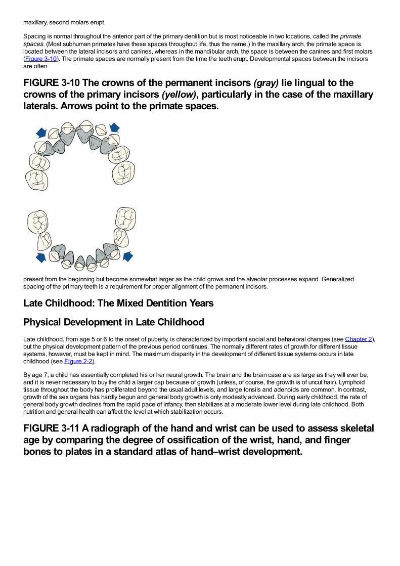
maxillary, second molars erupt.
Spacing is normal throughout the anterior part of the primary dentition but is most noticeable in two locations, called the primatespaces. (Most subhuman primates have these spaces throughout life, thus the name.) In the maxillary arch, the primate space islocated between the lateral incisors and canines, whereas in the mandibular arch, the space is between the canines and first molars(Figure 3-10). The primate spaces are normally present from the time the teeth erupt. Developmental spaces between the incisorsare often
FIGURE 3-10 The crowns of the permanent incisors (gray) lie lingual to thecrowns of the primary incisors (yellow), particularly in the case of the maxillarylaterals. Arrows point to the primate spaces.
present from the beginning but become somewhat larger as the child grows and the alveolar processes expand. Generalizedspacing of the primary teeth is a requirement for proper alignment of the permanent incisors.
Late Childhood: The Mixed Dentition Years
Physical Development in Late ChildhoodLate childhood, from age 5 or 6 to the onset of puberty, is characterized by important social and behavioral changes (see Chapter 2),but the physical development pattern of the previous period continues. The normally different rates of growth for different tissuesystems, however, must be kept in mind. The maximum disparity in the development of different tissue systems occurs in latechildhood (see Figure 2-2).
By age 7, a child has essentially completed his or her neural growth. The brain and the brain case are as large as they will ever be,and it is never necessary to buy the child a larger cap because of growth (unless, of course, the growth is of uncut hair). Lymphoidtissue throughout the body has proliferated beyond the usual adult levels, and large tonsils and adenoids are common. In contrast,growth of the sex organs has hardly begun and general body growth is only modestly advanced. During early childhood, the rate ofgeneral body growth declines from the rapid pace of infancy, then stabilizes at a moderate lower level during late childhood. Bothnutrition and general health can affect the level at which stabilization occurs.
FIGURE 3-11 A radiograph of the hand and wrist can be used to assess skeletalage by comparing the degree of ossification of the wrist, hand, and fingerbones to plates in a standard atlas of hand–wrist development.
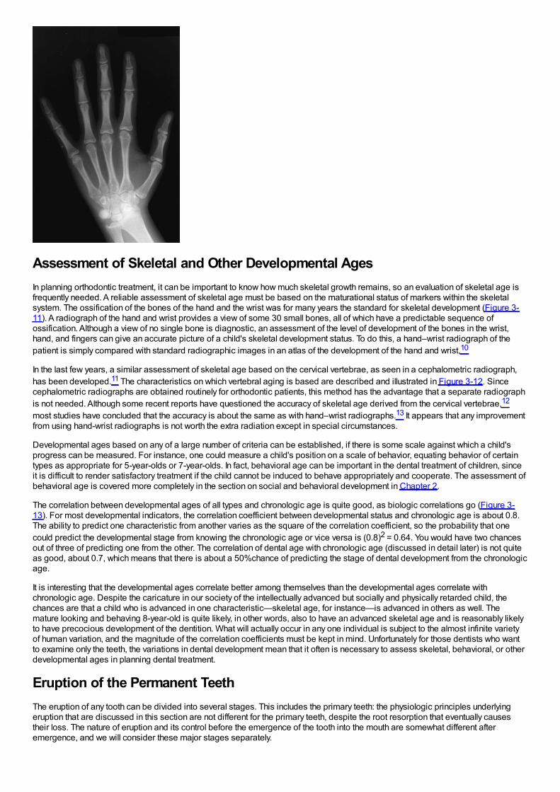
Assessment of Skeletal and Other Developmental AgesIn planning orthodontic treatment, it can be important to know how much skeletal growth remains, so an evaluation of skeletal age isfrequently needed. A reliable assessment of skeletal age must be based on the maturational status of markers within the skeletalsystem. The ossification of the bones of the hand and the wrist was for many years the standard for skeletal development (Figure 3-11). A radiograph of the hand and wrist provides a view of some 30 small bones, all of which have a predictable sequence ofossification. Although a view of no single bone is diagnostic, an assessment of the level of development of the bones in the wrist,hand, and fingers can give an accurate picture of a child's skeletal development status. To do this, a hand–wrist radiograph of thepatient is simply compared with standard radiographic images in an atlas of the development of the hand and wrist.10
In the last few years, a similar assessment of skeletal age based on the cervical vertebrae, as seen in a cephalometric radiograph,has been developed.11 The characteristics on which vertebral aging is based are described and illustrated in Figure 3-12. Sincecephalometric radiographs are obtained routinely for orthodontic patients, this method has the advantage that a separate radiographis not needed. Although some recent reports have questioned the accuracy of skeletal age derived from the cervical vertebrae,12
most studies have concluded that the accuracy is about the same as with hand–wrist radiographs.13 It appears that any improvementfrom using hand-wrist radiographs is not worth the extra radiation except in special circumstances.
Developmental ages based on any of a large number of criteria can be established, if there is some scale against which a child'sprogress can be measured. For instance, one could measure a child's position on a scale of behavior, equating behavior of certaintypes as appropriate for 5-year-olds or 7-year-olds. In fact, behavioral age can be important in the dental treatment of children, sinceit is difficult to render satisfactory treatment if the child cannot be induced to behave appropriately and cooperate. The assessment ofbehavioral age is covered more completely in the section on social and behavioral development in Chapter 2.
The correlation between developmental ages of all types and chronologic age is quite good, as biologic correlations go (Figure 3-13). For most developmental indicators, the correlation coefficient between developmental status and chronologic age is about 0.8.The ability to predict one characteristic from another varies as the square of the correlation coefficient, so the probability that onecould predict the developmental stage from knowing the chronologic age or vice versa is (0.8)2 = 0.64. You would have two chancesout of three of predicting one from the other. The correlation of dental age with chronologic age (discussed in detail later) is not quiteas good, about 0.7, which means that there is about a 50%chance of predicting the stage of dental development from the chronologicage.
It is interesting that the developmental ages correlate better among themselves than the developmental ages correlate withchronologic age. Despite the caricature in our society of the intellectually advanced but socially and physically retarded child, thechances are that a child who is advanced in one characteristic—skeletal age, for instance—is advanced in others as well. Themature looking and behaving 8-year-old is quite likely, in other words, also to have an advanced skeletal age and is reasonably likelyto have precocious development of the dentition. What will actually occur in any one individual is subject to the almost infinite varietyof human variation, and the magnitude of the correlation coefficients must be kept in mind. Unfortunately for those dentists who wantto examine only the teeth, the variations in dental development mean that it often is necessary to assess skeletal, behavioral, or otherdevelopmental ages in planning dental treatment.
Eruption of the Permanent TeethThe eruption of any tooth can be divided into several stages. This includes the primary teeth: the physiologic principles underlyingeruption that are discussed in this section are not different for the primary teeth, despite the root resorption that eventually causestheir loss. The nature of eruption and its control before the emergence of the tooth into the mouth are somewhat different afteremergence, and we will consider these major stages separately.
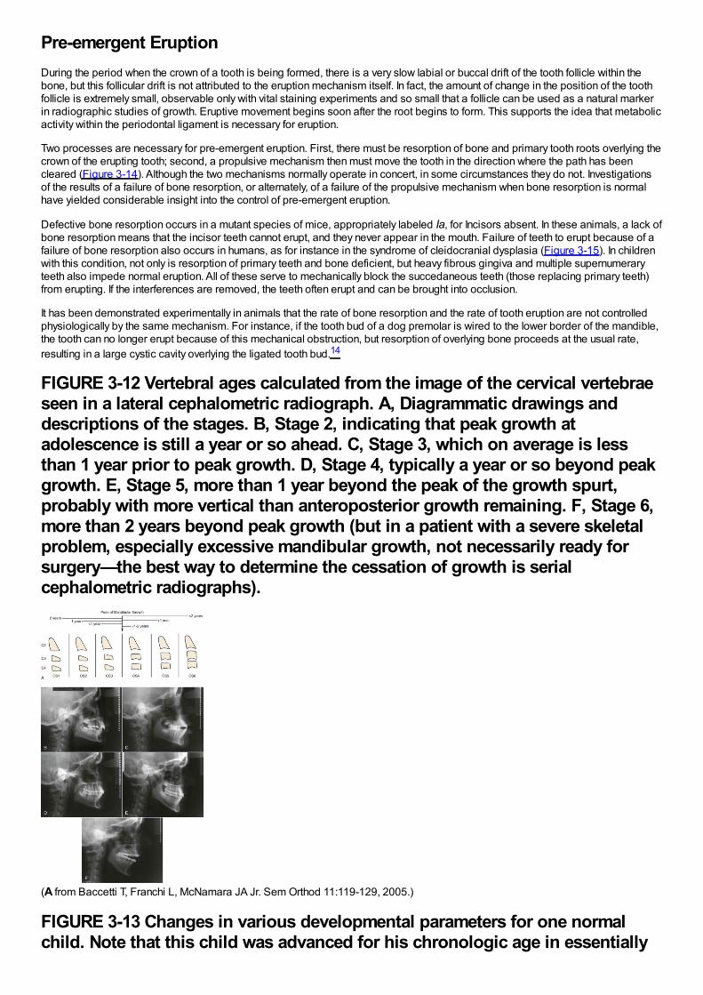
Pre-emergent EruptionDuring the period when the crown of a tooth is being formed, there is a very slow labial or buccal drift of the tooth follicle within thebone, but this follicular drift is not attributed to the eruption mechanism itself. In fact, the amount of change in the position of the toothfollicle is extremely small, observable only with vital staining experiments and so small that a follicle can be used as a natural markerin radiographic studies of growth. Eruptive movement begins soon after the root begins to form. This supports the idea that metabolicactivity within the periodontal ligament is necessary for eruption.
Two processes are necessary for pre-emergent eruption. First, there must be resorption of bone and primary tooth roots overlying thecrown of the erupting tooth; second, a propulsive mechanism then must move the tooth in the direction where the path has beencleared (Figure 3-14). Although the two mechanisms normally operate in concert, in some circumstances they do not. Investigationsof the results of a failure of bone resorption, or alternately, of a failure of the propulsive mechanism when bone resorption is normalhave yielded considerable insight into the control of pre-emergent eruption.
Defective bone resorption occurs in a mutant species of mice, appropriately labeled Ia, for Incisors absent. In these animals, a lack ofbone resorption means that the incisor teeth cannot erupt, and they never appear in the mouth. Failure of teeth to erupt because of afailure of bone resorption also occurs in humans, as for instance in the syndrome of cleidocranial dysplasia (Figure 3-15). In childrenwith this condition, not only is resorption of primary teeth and bone deficient, but heavy fibrous gingiva and multiple supernumeraryteeth also impede normal eruption. All of these serve to mechanically block the succedaneous teeth (those replacing primary teeth)from erupting. If the interferences are removed, the teeth often erupt and can be brought into occlusion.
It has been demonstrated experimentally in animals that the rate of bone resorption and the rate of tooth eruption are not controlledphysiologically by the same mechanism. For instance, if the tooth bud of a dog premolar is wired to the lower border of the mandible,the tooth can no longer erupt because of this mechanical obstruction, but resorption of overlying bone proceeds at the usual rate,resulting in a large cystic cavity overlying the ligated tooth bud.14
FIGURE 3-12 Vertebral ages calculated from the image of the cervical vertebraeseen in a lateral cephalometric radiograph. A, Diagrammatic drawings anddescriptions of the stages. B, Stage 2, indicating that peak growth atadolescence is still a year or so ahead. C, Stage 3, which on average is lessthan 1 year prior to peak growth. D, Stage 4, typically a year or so beyond peakgrowth. E, Stage 5, more than 1 year beyond the peak of the growth spurt,probably with more vertical than anteroposterior growth remaining. F, Stage 6,more than 2 years beyond peak growth (but in a patient with a severe skeletalproblem, especially excessive mandibular growth, not necessarily ready forsurgery—the best way to determine the cessation of growth is serialcephalometric radiographs).
(A from Baccetti T, Franchi L, McNamara JA Jr. Sem Orthod 11:119-129, 2005.)
FIGURE 3-13 Changes in various developmental parameters for one normalchild. Note that this child was advanced for his chronologic age in essentially
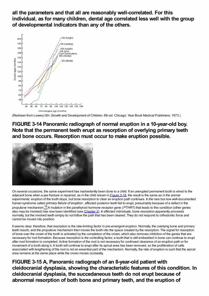
all the parameters and that all are reasonably well-correlated. For thisindividual, as for many children, dental age correlated less well with the groupof developmental indicators than any of the others.
(Redrawn from Lowery GH. Growth and Development of Children. 6th ed. Chicago: Year Book Medical Publishers; 1973.)
FIGURE 3-14 Panoramic radiograph of normal eruption in a 10-year-old boy.Note that the permanent teeth erupt as resorption of overlying primary teethand bone occurs. Resorption must occur to make eruption possible.
On several occasions, the same experiment has inadvertently been done to a child. If an unerupted permanent tooth is wired to theadjacent bone when a jaw fracture is repaired, as in the child shown in Figure 3-16, the result is the same as in the animalexperiments: eruption of the tooth stops, but bone resorption to clear an eruption path continues. In the rare but now well-documentedhuman syndrome called primary failure of eruption , affected posterior teeth fail to erupt, presumably because of a defect in thepropulsive mechanism.15 A mutation in the parathyroid hormone receptor gene (PTHR1) that leads to this condition (other genesalso may be involved) has now been identified (see Chapter 2). In affected individuals, bone resorption apparently proceedsnormally, but the involved teeth simply do not follow the path that has been cleared. They do not respond to orthodontic force andcannot be moved into position.
It seems clear, therefore, that resorption is the rate-limiting factor in pre-emergent eruption. Normally, the overlying bone and primaryteeth resorb, and the propulsive mechanism then moves the tooth into the space created by the resorption. The signal for resorptionof bone over the crown of the tooth is activated by the completion of the crown, which also removes inhibition of the genes that arenecessary for root formation. Because resorption is the controlling factor, a tooth that is still embedded in bone can continue to eruptafter root formation is completed. Active formation of the root is not necessary for continued clearance of an eruption path or formovement of a tooth along it. A tooth will continue to erupt after its apical area has been removed, so the proliferation of cellsassociated with lengthening of the root is not an essential part of the mechanism. Normally, the rate of eruption is such that the apicalarea remains at the same place while the crown moves occlusally,
FIGURE 3-15 A, Panoramic radiograph of an 8-year-old patient withcleidocranial dysplasia, showing the characteristic features of this condition. Incleidocranial dysplasia, the succedaneous teeth do not erupt because ofabnormal resorption of both bone and primary teeth, and the eruption of
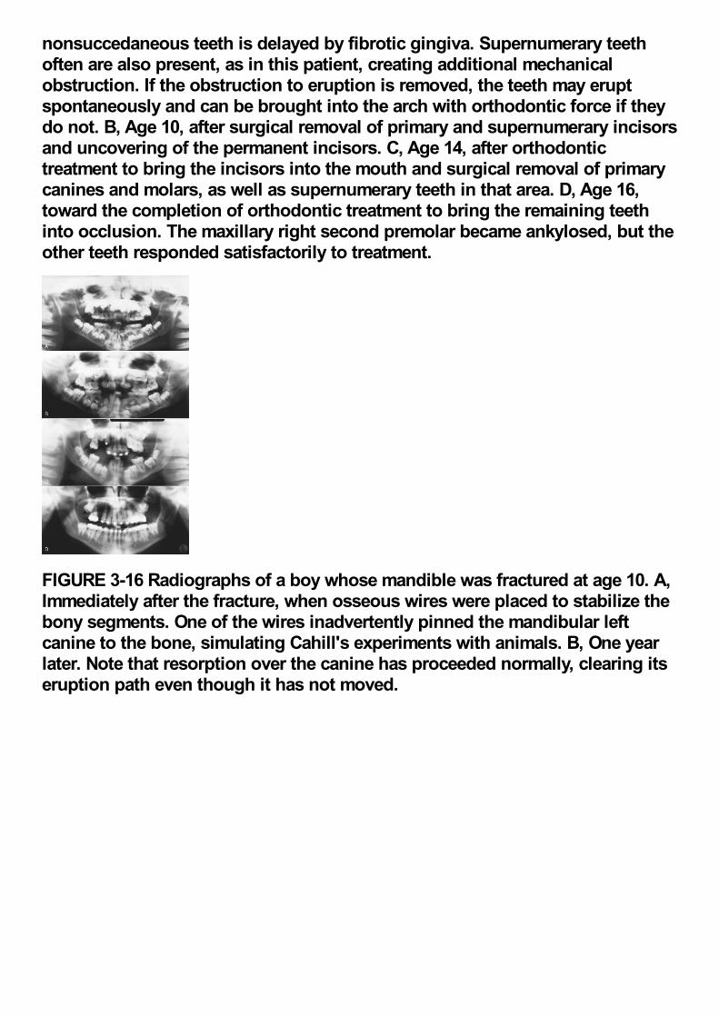
nonsuccedaneous teeth is delayed by fibrotic gingiva. Supernumerary teethoften are also present, as in this patient, creating additional mechanicalobstruction. If the obstruction to eruption is removed, the teeth may eruptspontaneously and can be brought into the arch with orthodontic force if theydo not. B, Age 10, after surgical removal of primary and supernumerary incisorsand uncovering of the permanent incisors. C, Age 14, after orthodontictreatment to bring the incisors into the mouth and surgical removal of primarycanines and molars, as well as supernumerary teeth in that area. D, Age 16,toward the completion of orthodontic treatment to bring the remaining teethinto occlusion. The maxillary right second premolar became ankylosed, but theother teeth responded satisfactorily to treatment.
FIGURE 3-16 Radiographs of a boy whose mandible was fractured at age 10. A,Immediately after the fracture, when osseous wires were placed to stabilize thebony segments. One of the wires inadvertently pinned the mandibular leftcanine to the bone, simulating Cahill's experiments with animals. B, One yearlater. Note that resorption over the canine has proceeded normally, clearing itseruption path even though it has not moved.
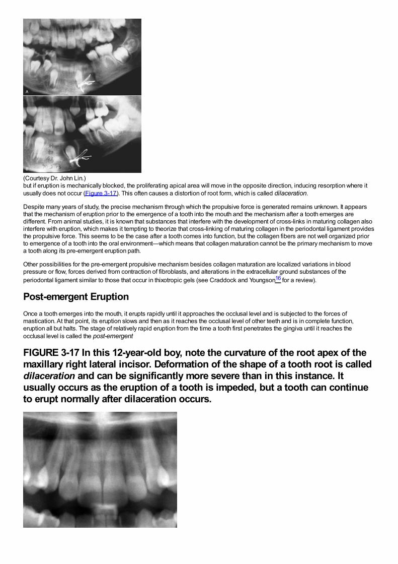
(Courtesy Dr. John Lin.)but if eruption is mechanically blocked, the proliferating apical area will move in the opposite direction, inducing resorption where itusually does not occur (Figure 3-17). This often causes a distortion of root form, which is called dilaceration.
Despite many years of study, the precise mechanism through which the propulsive force is generated remains unknown. It appearsthat the mechanism of eruption prior to the emergence of a tooth into the mouth and the mechanism after a tooth emerges aredifferent. From animal studies, it is known that substances that interfere with the development of cross-links in maturing collagen alsointerfere with eruption, which makes it tempting to theorize that cross-linking of maturing collagen in the periodontal ligament providesthe propulsive force. This seems to be the case after a tooth comes into function, but the collagen fibers are not well organized priorto emergence of a tooth into the oral environment—which means that collagen maturation cannot be the primary mechanism to movea tooth along its pre-emergent eruption path.
Other possibilities for the pre-emergent propulsive mechanism besides collagen maturation are localized variations in bloodpressure or flow, forces derived from contraction of fibroblasts, and alterations in the extracellular ground substances of theperiodontal ligament similar to those that occur in thixotropic gels (see Craddock and Youngson16 for a review).
Post-emergent EruptionOnce a tooth emerges into the mouth, it erupts rapidly until it approaches the occlusal level and is subjected to the forces ofmastication. At that point, its eruption slows and then as it reaches the occlusal level of other teeth and is in complete function,eruption all but halts. The stage of relatively rapid eruption from the time a tooth first penetrates the gingiva until it reaches theocclusal level is called the post-emergent
FIGURE 3-17 In this 12-year-old boy, note the curvature of the root apex of themaxillary right lateral incisor. Deformation of the shape of a tooth root is calleddilaceration and can be significantly more severe than in this instance. Itusually occurs as the eruption of a tooth is impeded, but a tooth can continueto erupt normally after dilaceration occurs.

FIGURE 3-18 A, Eruption plots for human second premolars observed via afiber optic cable to a video microscope, which provides 1 to 2 micronresolution, from 8 PM (20:00) to 6 AM (06:00). Note the consistent pattern oferuption in the early evening, trailing off to no eruption or intrusion towardmidnight, with no further eruption after that. It now is clear that eruptionoccurs only during a few critical hours in the early evening. B, Eruption plotsfor a human second premolar observed via Moire magnification, whichprovides 0.2 micron resolution, over a 30-minute period in the early eveningwhen force opposing eruption was applied while active eruption wasoccurring. Note that the tooth erupted nearly 10 microns during this short time.The vertical spikes are movement artefacts produced by the applied force; ashort-duration cycle superimposed on the eruption curve (significanceunknown) also can be observed. Force applications either have no effect oneruption, as in this subject, or produce a transient depression of eruption thatlasts less than 2 minutes.
(A redrawn from Risinger RK, Proffit WR. Arch Oral Biol 41:779-786, 1996. B redrawn from Gierie WV, Paterson RL, Proffit WR.Arch Oral Biol 44:423-428, 1999.)spurt, in contrast to the following phase of very slow eruption, termed the juvenile occlusal equilibrium.
In the 1990s, new instrumentation made it possible to track the short-term movements of a tooth during the post-emergent spurt, andthis showed that eruption occurs only during a critical period between 8 pm and midnight or 1 am (Figure 3-18).17 During the earlymorning hours and the day, the tooth stops erupting and often intrudes slightly. The day-night differences in eruption seem to reflect anunderlying circadian rhythm, probably related to the very similar cycle of growth hormone release. Experiments with the application ofpressure against an erupting premolar suggest that eruption is stopped by force for only one to three minutes, so food contacts withthe erupting tooth even though it is out of contact with its antagonist, almost surely do not explain the daily rhythm.18 In humans, theeruption of premolars that are moving from gingival emergence toward occlusion has been shown to be affected by changing bloodflow in the apical area. This suggests that blood flow is at least a contributing factor in the eruption mechanism up to that point.19
The eruption mechanism may be different after emergence—collagen cross-linking in the periodontal ligament is more prominentafter a tooth comes into occlusal function, so shortening of collagen fibers as the mechanism seems more likely—and the controlmechanism certainly is different. It seems obvious that as a tooth is subjected to biting forces that oppose eruption, the overall rate oferuption would be slowed, and in fact exactly this occurs. In humans, after the teeth reach the occlusal level, eruption becomes almostimperceptibly slow, although it definitely continues. During the juvenile equilibrium, teeth that are in function erupt at a rate thatparallels the rate of vertical growth of the mandibular ramus (Figure 3-19). As the mandible continues to grow, it moves away from themaxilla,
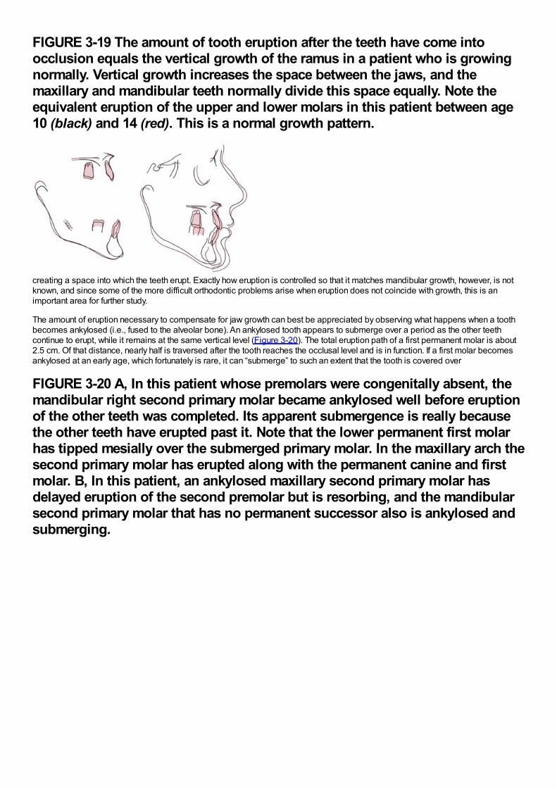
FIGURE 3-19 The amount of tooth eruption after the teeth have come intoocclusion equals the vertical growth of the ramus in a patient who is growingnormally. Vertical growth increases the space between the jaws, and themaxillary and mandibular teeth normally divide this space equally. Note theequivalent eruption of the upper and lower molars in this patient between age10 (black) and 14 (red). This is a normal growth pattern.
creating a space into which the teeth erupt. Exactly how eruption is controlled so that it matches mandibular growth, however, is notknown, and since some of the more difficult orthodontic problems arise when eruption does not coincide with growth, this is animportant area for further study.
The amount of eruption necessary to compensate for jaw growth can best be appreciated by observing what happens when a toothbecomes ankylosed (i.e., fused to the alveolar bone). An ankylosed tooth appears to submerge over a period as the other teethcontinue to erupt, while it remains at the same vertical level (Figure 3-20). The total eruption path of a first permanent molar is about2.5 cm. Of that distance, nearly half is traversed after the tooth reaches the occlusal level and is in function. If a first molar becomesankylosed at an early age, which fortunately is rare, it can “submerge” to such an extent that the tooth is covered over
FIGURE 3-20 A, In this patient whose premolars were congenitally absent, themandibular right second primary molar became ankylosed well before eruptionof the other teeth was completed. Its apparent submergence is really becausethe other teeth have erupted past it. Note that the lower permanent first molarhas tipped mesially over the submerged primary molar. In the maxillary arch thesecond primary molar has erupted along with the permanent canine and firstmolar. B, In this patient, an ankylosed maxillary second primary molar hasdelayed eruption of the second premolar but is resorbing, and the mandibularsecond primary molar that has no permanent successor also is ankylosed andsubmerging.
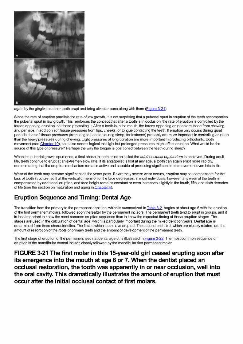
again by the gingiva as other teeth erupt and bring alveolar bone along with them (Figure 3-21).
Since the rate of eruption parallels the rate of jaw growth, it is not surprising that a pubertal spurt in eruption of the teeth accompaniesthe pubertal spurt in jaw growth. This reinforces the concept that after a tooth is in occlusion, the rate of eruption is controlled by theforces opposing eruption, not those promoting it. After a tooth is in the mouth, the forces opposing eruption are those from chewing,and perhaps in addition soft tissue pressures from lips, cheeks, or tongue contacting the teeth. If eruption only occurs during quietperiods, the soft tissue pressures (from tongue position during sleep, for instance) probably are more important in controlling eruptionthan the heavy pressures during chewing. Light pressures of long duration are more important in producing orthodontic toothmovement (see Chapter 10), so it also seems logical that light but prolonged pressures might affect eruption. What would be thesource of this type of pressure? Perhaps the way the tongue is positioned between the teeth during sleep?
When the pubertal growth spurt ends, a final phase in tooth eruption called the adult occlusal equilibrium is achieved. During adultlife, teeth continue to erupt at an extremely slow rate. If its antagonist is lost at any age, a tooth can again erupt more rapidly,demonstrating that the eruption mechanism remains active and capable of producing significant tooth movement even late in life.
Wear of the teeth may become significant as the years pass. If extremely severe wear occurs, eruption may not compensate for theloss of tooth structure, so that the vertical dimension of the face decreases. In most individuals, however, any wear of the teeth iscompensated by additional eruption, and face height remains constant or even increases slightly in the fourth, fifth, and sixth decadesof life (see the section on maturation and aging in Chapter 4).
Eruption Sequence and Timing: Dental AgeThe transition from the primary to the permanent dentition, which is summarized in Table 3-2, begins at about age 6 with the eruptionof the first permanent molars, followed soon thereafter by the permanent incisors. The permanent teeth tend to erupt in groups, and itis less important to know the most common eruption sequence than to know the expected timing of these eruption stages. Thestages are used in the calculation of dental age, which is particularly important during the mixed dentition years. Dental age isdetermined from three characteristics. The first is which teeth have erupted. The second and third, which are closely related, are theamount of resorption of the roots of primary teeth and the amount of development of the permanent teeth.
The first stage of eruption of the permanent teeth, at dental age 6, is illustrated in Figure 3-22. The most common sequence oferuption is the mandibular central incisor, closely followed by the mandibular first permanent molar
FIGURE 3-21 The first molar in this 15-year-old girl ceased erupting soon afterits emergence into the mouth at age 6 or 7. When the dentist placed anocclusal restoration, the tooth was apparently in or near occlusion, well intothe oral cavity. This dramatically illustrates the amount of eruption that mustoccur after the initial occlusal contact of first molars.
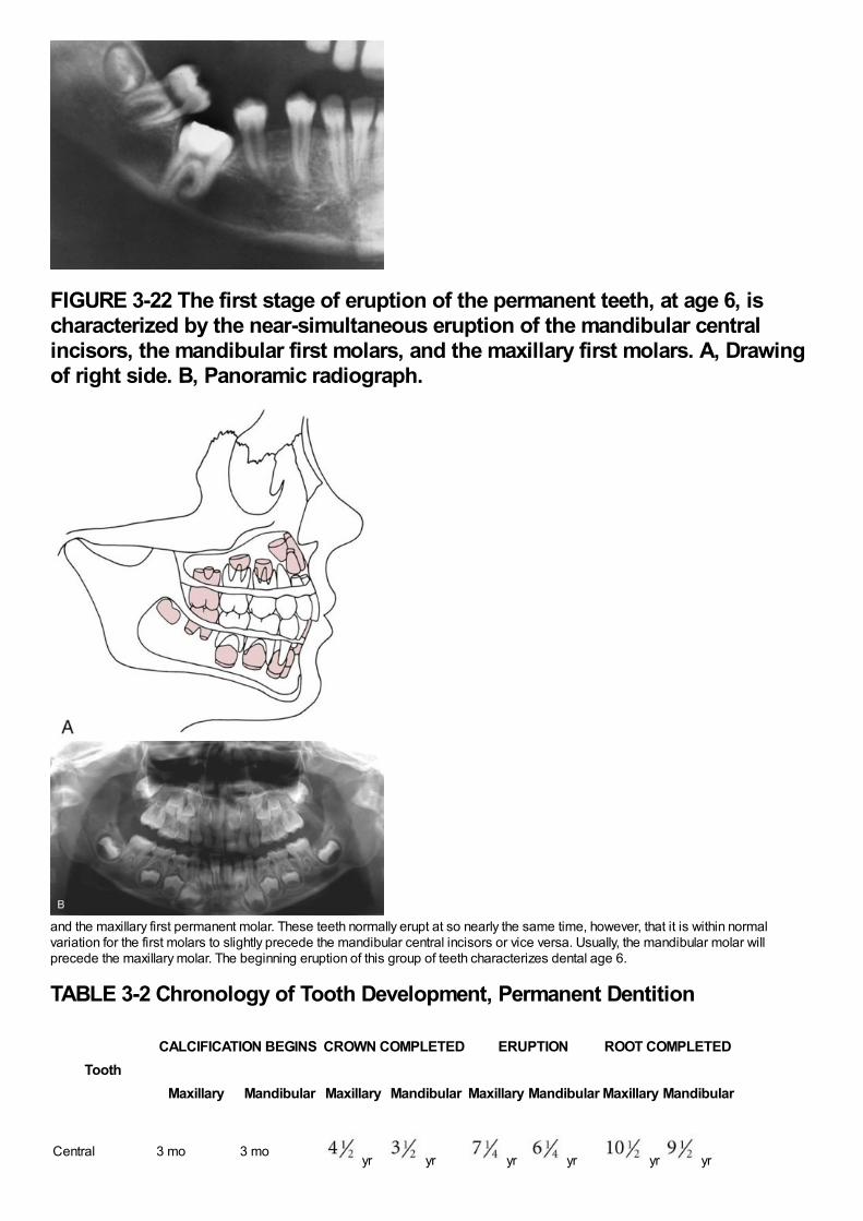
FIGURE 3-22 The first stage of eruption of the permanent teeth, at age 6, ischaracterized by the near-simultaneous eruption of the mandibular centralincisors, the mandibular first molars, and the maxillary first molars. A, Drawingof right side. B, Panoramic radiograph.
and the maxillary first permanent molar. These teeth normally erupt at so nearly the same time, however, that it is within normalvariation for the first molars to slightly precede the mandibular central incisors or vice versa. Usually, the mandibular molar willprecede the maxillary molar. The beginning eruption of this group of teeth characterizes dental age 6.
TABLE 3-2 Chronology of Tooth Development, Permanent Dentition
ToothCALCIFICATION BEGINS CROWN COMPLETED ERUPTION ROOT COMPLETED
Maxillary Mandibular Maxillary Mandibular Maxillary Mandibular Maxillary Mandibular
Central 3 mo 3 mo yr yr yr yr yr yr
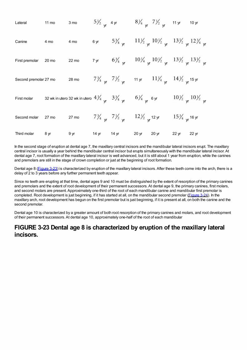
Lateral 11 mo 3 mo yr
4 yr yr yr
11 yr 10 yr
Canine 4 mo 4 mo 6 yr yr yr yr yr yr
First premolar 20 mo 22 mo 7 yr yr yr yr yr yr
Second premolar 27 mo 28 mo yr yr11 yr
yr yr15 yr
First molar 32 wk in utero 32 wk in utero yr yr yr
6 yr yr yr
Second molar 27 mo 27 mo yr yr yr12 yr yr 16 yr
Third molar 8 yr 9 yr 14 yr 14 yr 20 yr 20 yr 22 yr 22 yr
In the second stage of eruption at dental age 7, the maxillary central incisors and the mandibular lateral incisors erupt. The maxillarycentral incisor is usually a year behind the mandibular central incisor but erupts simultaneously with the mandibular lateral incisor. Atdental age 7, root formation of the maxillary lateral incisor is well advanced, but it is still about 1 year from eruption, while the caninesand premolars are still in the stage of crown completion or just at the beginning of root formation.
Dental age 8 (Figure 3-23) is characterized by eruption of the maxillary lateral incisors. After these teeth come into the arch, there is adelay of 2 to 3 years before any further permanent teeth appear.
Since no teeth are erupting at that time, dental ages 9 and 10 must be distinguished by the extent of resorption of the primary caninesand premolars and the extent of root development of their permanent successors. At dental age 9, the primary canines, first molars,and second molars are present. Approximately one-third of the root of each mandibular canine and mandibular first premolar iscompleted. Root development is just beginning, if it has started at all, on the mandibular second premolar (Figure 3-24). In themaxillary arch, root development has begun on the first premolar but is just beginning, if it is present at all, on both the canine and thesecond premolar.
Dental age 10 is characterized by a greater amount of both root resorption of the primary canines and molars, and root developmentof their permanent successors. At dental age 10, approximately one-half of the root of each mandibular
FIGURE 3-23 Dental age 8 is characterized by eruption of the maxillary lateralincisors.
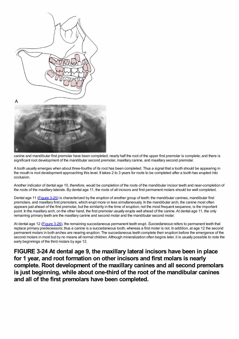
canine and mandibular first premolar have been completed; nearly half the root of the upper first premolar is complete; and there issignificant root development of the mandibular second premolar, maxillary canine, and maxillary second premolar.
A tooth usually emerges when about three-fourths of its root has been completed. Thus a signal that a tooth should be appearing inthe mouth is root development approaching this level. It takes 2 to 3 years for roots to be completed after a tooth has erupted intoocclusion.
Another indicator of dental age 10, therefore, would be completion of the roots of the mandibular incisor teeth and near-completion ofthe roots of the maxillary laterals. By dental age 11, the roots of all incisors and first permanent molars should be well completed.
Dental age 11 (Figure 3-25) is characterized by the eruption of another group of teeth: the mandibular canines, mandibular firstpremolars, and maxillary first premolars, which erupt more or less simultaneously. In the mandibular arch, the canine most oftenappears just ahead of the first premolar, but the similarity in the time of eruption, not the most frequent sequence, is the importantpoint. In the maxillary arch, on the other hand, the first premolar usually erupts well ahead of the canine. At dental age 11, the onlyremaining primary teeth are the maxillary canine and second molar and the mandibular second molar.
At dental age 12 (Figure 3-26), the remaining succedaneous permanent teeth erupt. Succedaneous refers to permanent teeth thatreplace primary predecessors; thus a canine is a succedaneous tooth, whereas a first molar is not. In addition, at age 12 the secondpermanent molars in both arches are nearing eruption. The succedaneous teeth complete their eruption before the emergence of thesecond molars in most but by no means all normal children. Although mineralization often begins later, it is usually possible to note theearly beginnings of the third molars by age 12.
FIGURE 3-24 At dental age 9, the maxillary lateral incisors have been in placefor 1 year, and root formation on other incisors and first molars is nearlycomplete. Root development of the maxillary canines and all second premolarsis just beginning, while about one-third of the root of the mandibular caninesand all of the first premolars have been completed.
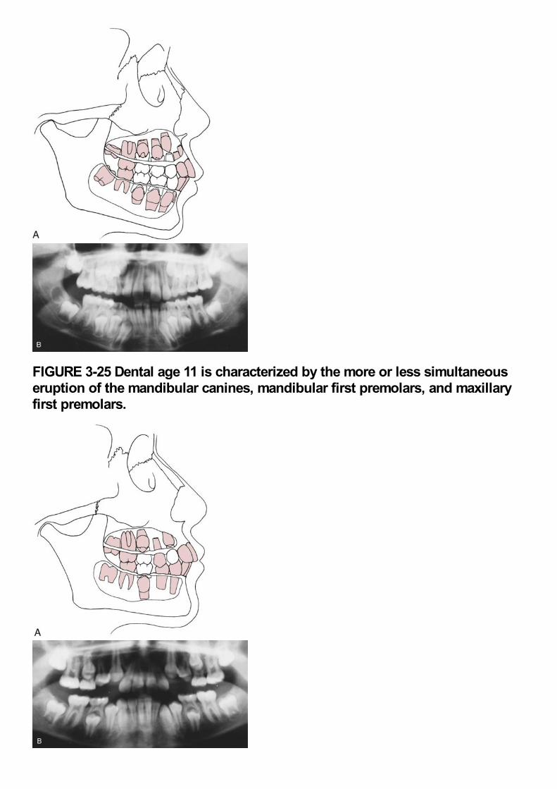
FIGURE 3-25 Dental age 11 is characterized by the more or less simultaneouseruption of the mandibular canines, mandibular first premolars, and maxillaryfirst premolars.
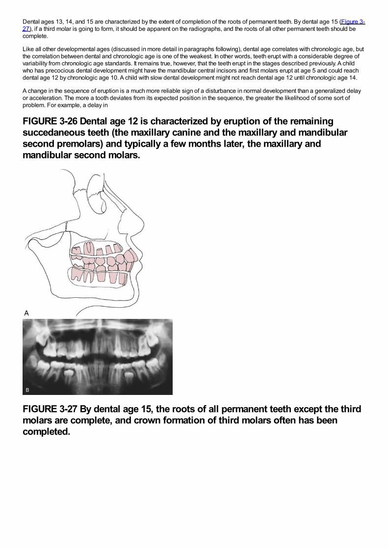
Dental ages 13, 14, and 15 are characterized by the extent of completion of the roots of permanent teeth. By dental age 15 (Figure 3-27), if a third molar is going to form, it should be apparent on the radiographs, and the roots of all other permanent teeth should becomplete.
Like all other developmental ages (discussed in more detail in paragraphs following), dental age correlates with chronologic age, butthe correlation between dental and chronologic age is one of the weakest. In other words, teeth erupt with a considerable degree ofvariability from chronologic age standards. It remains true, however, that the teeth erupt in the stages described previously. A childwho has precocious dental development might have the mandibular central incisors and first molars erupt at age 5 and could reachdental age 12 by chronologic age 10. A child with slow dental development might not reach dental age 12 until chronologic age 14.
A change in the sequence of eruption is a much more reliable sign of a disturbance in normal development than a generalized delayor acceleration. The more a tooth deviates from its expected position in the sequence, the greater the likelihood of some sort ofproblem. For example, a delay in
FIGURE 3-26 Dental age 12 is characterized by eruption of the remainingsuccedaneous teeth (the maxillary canine and the maxillary and mandibularsecond premolars) and typically a few months later, the maxillary andmandibular second molars.
FIGURE 3-27 By dental age 15, the roots of all permanent teeth except the thirdmolars are complete, and crown formation of third molars often has beencompleted.
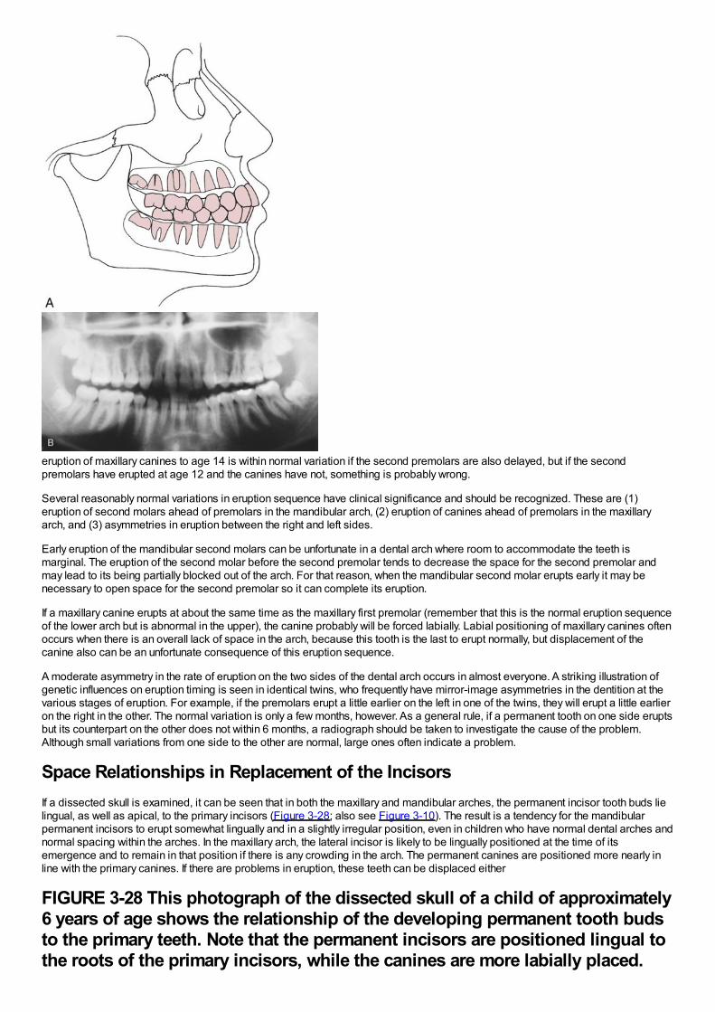
eruption of maxillary canines to age 14 is within normal variation if the second premolars are also delayed, but if the secondpremolars have erupted at age 12 and the canines have not, something is probably wrong.
Several reasonably normal variations in eruption sequence have clinical significance and should be recognized. These are (1)eruption of second molars ahead of premolars in the mandibular arch, (2) eruption of canines ahead of premolars in the maxillaryarch, and (3) asymmetries in eruption between the right and left sides.
Early eruption of the mandibular second molars can be unfortunate in a dental arch where room to accommodate the teeth ismarginal. The eruption of the second molar before the second premolar tends to decrease the space for the second premolar andmay lead to its being partially blocked out of the arch. For that reason, when the mandibular second molar erupts early it may benecessary to open space for the second premolar so it can complete its eruption.
If a maxillary canine erupts at about the same time as the maxillary first premolar (remember that this is the normal eruption sequenceof the lower arch but is abnormal in the upper), the canine probably will be forced labially. Labial positioning of maxillary canines oftenoccurs when there is an overall lack of space in the arch, because this tooth is the last to erupt normally, but displacement of thecanine also can be an unfortunate consequence of this eruption sequence.
A moderate asymmetry in the rate of eruption on the two sides of the dental arch occurs in almost everyone. A striking illustration ofgenetic influences on eruption timing is seen in identical twins, who frequently have mirror-image asymmetries in the dentition at thevarious stages of eruption. For example, if the premolars erupt a little earlier on the left in one of the twins, they will erupt a little earlieron the right in the other. The normal variation is only a few months, however. As a general rule, if a permanent tooth on one side eruptsbut its counterpart on the other does not within 6 months, a radiograph should be taken to investigate the cause of the problem.Although small variations from one side to the other are normal, large ones often indicate a problem.
Space Relationships in Replacement of the IncisorsIf a dissected skull is examined, it can be seen that in both the maxillary and mandibular arches, the permanent incisor tooth buds lielingual, as well as apical, to the primary incisors (Figure 3-28; also see Figure 3-10). The result is a tendency for the mandibularpermanent incisors to erupt somewhat lingually and in a slightly irregular position, even in children who have normal dental arches andnormal spacing within the arches. In the maxillary arch, the lateral incisor is likely to be lingually positioned at the time of itsemergence and to remain in that position if there is any crowding in the arch. The permanent canines are positioned more nearly inline with the primary canines. If there are problems in eruption, these teeth can be displaced either
FIGURE 3-28 This photograph of the dissected skull of a child of approximately6 years of age shows the relationship of the developing permanent tooth budsto the primary teeth. Note that the permanent incisors are positioned lingual tothe roots of the primary incisors, while the canines are more labially placed.
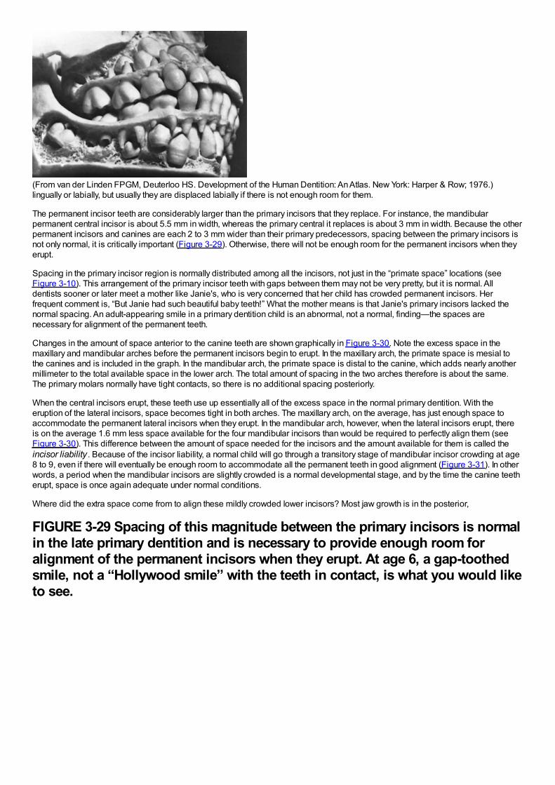
(From van der Linden FPGM, Deuterloo HS. Development of the Human Dentition: An Atlas. New York: Harper & Row; 1976.)lingually or labially, but usually they are displaced labially if there is not enough room for them.
The permanent incisor teeth are considerably larger than the primary incisors that they replace. For instance, the mandibularpermanent central incisor is about 5.5 mm in width, whereas the primary central it replaces is about 3 mm in width. Because the otherpermanent incisors and canines are each 2 to 3 mm wider than their primary predecessors, spacing between the primary incisors isnot only normal, it is critically important (Figure 3-29). Otherwise, there will not be enough room for the permanent incisors when theyerupt.
Spacing in the primary incisor region is normally distributed among all the incisors, not just in the “primate space” locations (seeFigure 3-10). This arrangement of the primary incisor teeth with gaps between them may not be very pretty, but it is normal. Alldentists sooner or later meet a mother like Janie's, who is very concerned that her child has crowded permanent incisors. Herfrequent comment is, “But Janie had such beautiful baby teeth!” What the mother means is that Janie's primary incisors lacked thenormal spacing. An adult-appearing smile in a primary dentition child is an abnormal, not a normal, finding—the spaces arenecessary for alignment of the permanent teeth.
Changes in the amount of space anterior to the canine teeth are shown graphically in Figure 3-30. Note the excess space in themaxillary and mandibular arches before the permanent incisors begin to erupt. In the maxillary arch, the primate space is mesial tothe canines and is included in the graph. In the mandibular arch, the primate space is distal to the canine, which adds nearly anothermillimeter to the total available space in the lower arch. The total amount of spacing in the two arches therefore is about the same.The primary molars normally have tight contacts, so there is no additional spacing posteriorly.
When the central incisors erupt, these teeth use up essentially all of the excess space in the normal primary dentition. With theeruption of the lateral incisors, space becomes tight in both arches. The maxillary arch, on the average, has just enough space toaccommodate the permanent lateral incisors when they erupt. In the mandibular arch, however, when the lateral incisors erupt, thereis on the average 1.6 mm less space available for the four mandibular incisors than would be required to perfectly align them (seeFigure 3-30). This difference between the amount of space needed for the incisors and the amount available for them is called theincisor liability . Because of the incisor liability, a normal child will go through a transitory stage of mandibular incisor crowding at age8 to 9, even if there will eventually be enough room to accommodate all the permanent teeth in good alignment (Figure 3-31). In otherwords, a period when the mandibular incisors are slightly crowded is a normal developmental stage, and by the time the canine teetherupt, space is once again adequate under normal conditions.
Where did the extra space come from to align these mildly crowded lower incisors? Most jaw growth is in the posterior,
FIGURE 3-29 Spacing of this magnitude between the primary incisors is normalin the late primary dentition and is necessary to provide enough room foralignment of the permanent incisors when they erupt. At age 6, a gap-toothedsmile, not a “Hollywood smile” with the teeth in contact, is what you would liketo see.
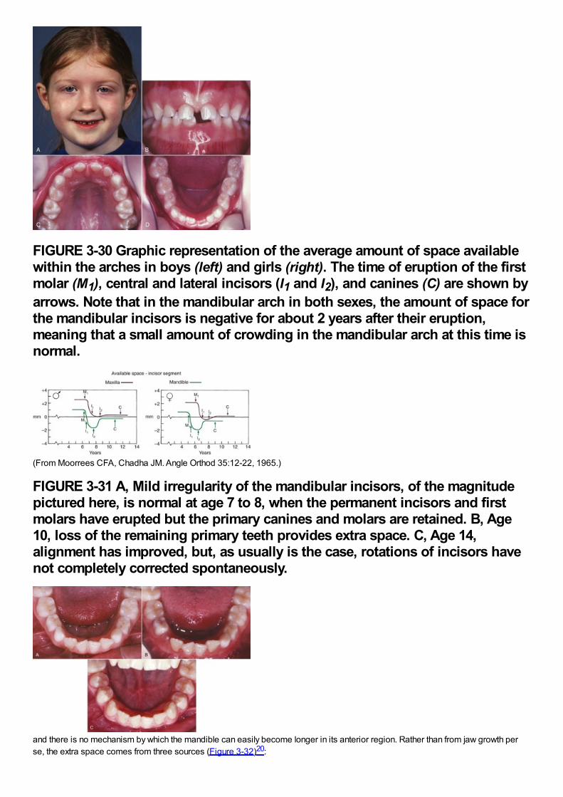
FIGURE 3-30 Graphic representation of the average amount of space availablewithin the arches in boys (left) and girls (right). The time of eruption of the firstmolar (M1), central and lateral incisors (I1 and I2), and canines (C) are shown byarrows. Note that in the mandibular arch in both sexes, the amount of space forthe mandibular incisors is negative for about 2 years after their eruption,meaning that a small amount of crowding in the mandibular arch at this time isnormal.
(From Moorrees CFA, Chadha JM. Angle Orthod 35:12-22, 1965.)
FIGURE 3-31 A, Mild irregularity of the mandibular incisors, of the magnitudepictured here, is normal at age 7 to 8, when the permanent incisors and firstmolars have erupted but the primary canines and molars are retained. B, Age10, loss of the remaining primary teeth provides extra space. C, Age 14,alignment has improved, but, as usually is the case, rotations of incisors havenot completely corrected spontaneously.
and there is no mechanism by which the mandible can easily become longer in its anterior region. Rather than from jaw growth perse, the extra space comes from three sources (Figure 3-32)20:
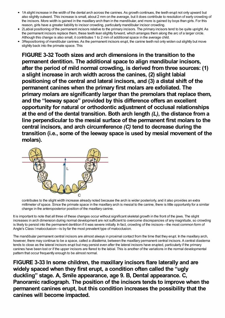
1A slight increase in the width of the dental arch across the canines. As growth continues, the teeth erupt not only upward butalso slightly outward. This increase is small, about 2 mm on the average, but it does contribute to resolution of early crowding ofthe incisors. More width is gained in the maxillary arch than in the mandibular, and more is gained by boys than girls. For thisreason, girls have a greater liability to incisor crowding, particularly mandibular incisor crowding.2Labial positioning of the permanent incisors relative to the primary incisors. The primary incisors tend to be quite upright. Asthe permanent incisors replace them, these teeth lean slightly forward, which arranges them along the arc of a larger circle.Although this change is also small, it contributes 1 to 2 mm of additional space in the average child.3Repositioning of mandibular canines. As the permanent incisors erupt, the canine teeth not only widen out slightly but moveslightly back into the primate space. This
FIGURE 3-32 Tooth sizes and arch dimensions in the transition to thepermanent dentition. The additional space to align mandibular incisors,after the period of mild normal crowding, is derived from three sources: (1)a slight increase in arch width across the canines, (2) slight labialpositioning of the central and lateral incisors, and (3) a distal shift of thepermanent canines when the primary first molars are exfoliated. Theprimary molars are significantly larger than the premolars that replace them,and the “leeway space” provided by this difference offers an excellentopportunity for natural or orthodontic adjustment of occlusal relationshipsat the end of the dental transition. Both arch length (L), the distance from aline perpendicular to the mesial surface of the permanent first molars to thecentral incisors, and arch circumference (C) tend to decrease during thetransition (i.e., some of the leeway space is used by mesial movement of themolars).
contributes to the slight width increase already noted because the arch is wider posteriorly, and it also provides an extramillimeter of space. Since the primate space in the maxillary arch is mesial to the canine, there is little opportunity for a similarchange in the anteroposterior position of the maxillary canine.
It is important to note that all three of these changes occur without significant skeletal growth in the front of the jaws. The slightincreases in arch dimension during normal development are not sufficient to overcome discrepancies of any magnitude, so crowdingis likely to persist into the permanent dentition if it was severe initially. In fact, crowding of the incisors—the most common form ofAngle's Class I malocclusion—is by far the most prevalent type of malocclusion.
The mandibular permanent central incisors are almost always in proximal contact from the time that they erupt. In the maxillary arch,however, there may continue to be a space, called a diastema, between the maxillary permanent central incisors. A central diastematends to close as the lateral incisors erupt but may persist even after the lateral incisors have erupted, particularly if the primarycanines have been lost or if the upper incisors are flared to the labial. This is another of the variations in the normal developmentalpattern that occur frequently enough to be almost normal.
FIGURE 3-33 In some children, the maxillary incisors flare laterally and arewidely spaced when they first erupt, a condition often called the “uglyduckling” stage. A, Smile appearance, age 9. B, Dental appearance. C,Panoramic radiograph. The position of the incisors tends to improve when thepermanent canines erupt, but this condition increases the possibility that thecanines will become impacted.
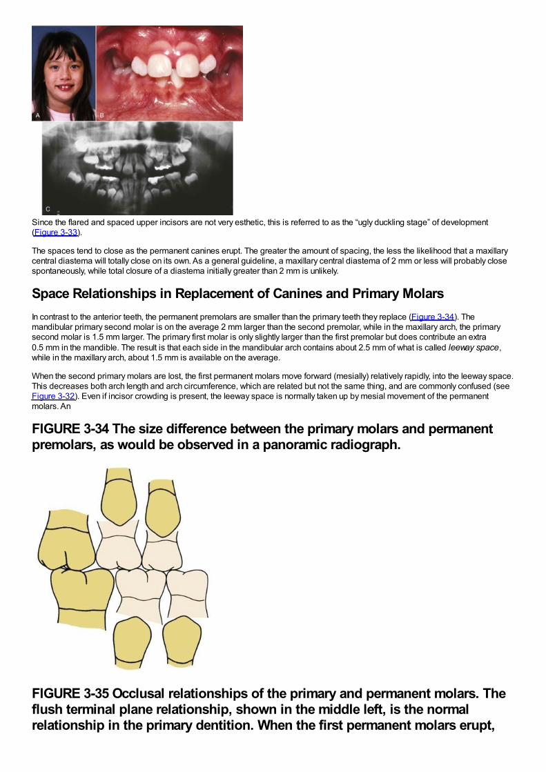
Since the flared and spaced upper incisors are not very esthetic, this is referred to as the “ugly duckling stage” of development(Figure 3-33).
The spaces tend to close as the permanent canines erupt. The greater the amount of spacing, the less the likelihood that a maxillarycentral diastema will totally close on its own. As a general guideline, a maxillary central diastema of 2 mm or less will probably closespontaneously, while total closure of a diastema initially greater than 2 mm is unlikely.
Space Relationships in Replacement of Canines and Primary MolarsIn contrast to the anterior teeth, the permanent premolars are smaller than the primary teeth they replace (Figure 3-34). Themandibular primary second molar is on the average 2 mm larger than the second premolar, while in the maxillary arch, the primarysecond molar is 1.5 mm larger. The primary first molar is only slightly larger than the first premolar but does contribute an extra0.5 mm in the mandible. The result is that each side in the mandibular arch contains about 2.5 mm of what is called leeway space,while in the maxillary arch, about 1.5 mm is available on the average.
When the second primary molars are lost, the first permanent molars move forward (mesially) relatively rapidly, into the leeway space.This decreases both arch length and arch circumference, which are related but not the same thing, and are commonly confused (seeFigure 3-32). Even if incisor crowding is present, the leeway space is normally taken up by mesial movement of the permanentmolars. An
FIGURE 3-34 The size difference between the primary molars and permanentpremolars, as would be observed in a panoramic radiograph.
FIGURE 3-35 Occlusal relationships of the primary and permanent molars. Theflush terminal plane relationship, shown in the middle left, is the normalrelationship in the primary dentition. When the first permanent molars erupt,
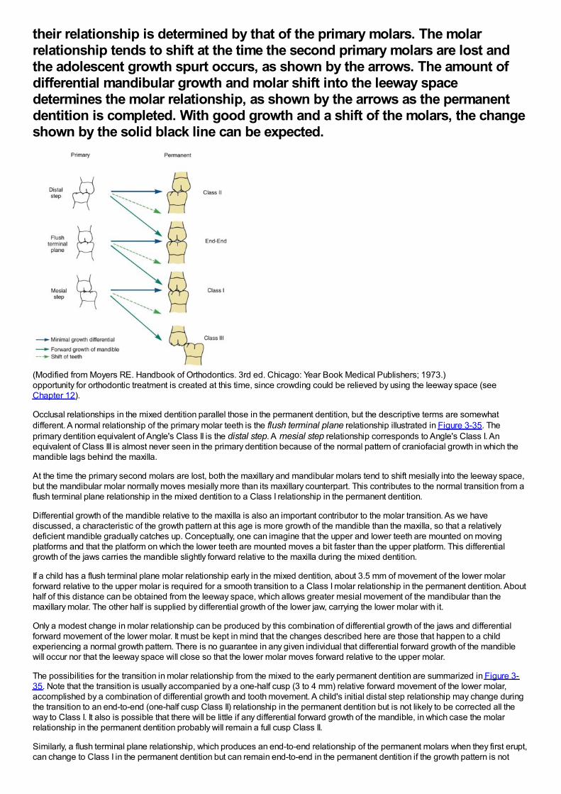
their relationship is determined by that of the primary molars. The molarrelationship tends to shift at the time the second primary molars are lost andthe adolescent growth spurt occurs, as shown by the arrows. The amount ofdifferential mandibular growth and molar shift into the leeway spacedetermines the molar relationship, as shown by the arrows as the permanentdentition is completed. With good growth and a shift of the molars, the changeshown by the solid black line can be expected.
(Modified from Moyers RE. Handbook of Orthodontics. 3rd ed. Chicago: Year Book Medical Publishers; 1973.)opportunity for orthodontic treatment is created at this time, since crowding could be relieved by using the leeway space (seeChapter 12).
Occlusal relationships in the mixed dentition parallel those in the permanent dentition, but the descriptive terms are somewhatdifferent. A normal relationship of the primary molar teeth is the flush terminal plane relationship illustrated in Figure 3-35. Theprimary dentition equivalent of Angle's Class II is the distal step. A mesial step relationship corresponds to Angle's Class I. Anequivalent of Class III is almost never seen in the primary dentition because of the normal pattern of craniofacial growth in which themandible lags behind the maxilla.
At the time the primary second molars are lost, both the maxillary and mandibular molars tend to shift mesially into the leeway space,but the mandibular molar normally moves mesially more than its maxillary counterpart. This contributes to the normal transition from aflush terminal plane relationship in the mixed dentition to a Class I relationship in the permanent dentition.
Differential growth of the mandible relative to the maxilla is also an important contributor to the molar transition. As we havediscussed, a characteristic of the growth pattern at this age is more growth of the mandible than the maxilla, so that a relativelydeficient mandible gradually catches up. Conceptually, one can imagine that the upper and lower teeth are mounted on movingplatforms and that the platform on which the lower teeth are mounted moves a bit faster than the upper platform. This differentialgrowth of the jaws carries the mandible slightly forward relative to the maxilla during the mixed dentition.
If a child has a flush terminal plane molar relationship early in the mixed dentition, about 3.5 mm of movement of the lower molarforward relative to the upper molar is required for a smooth transition to a Class I molar relationship in the permanent dentition. Abouthalf of this distance can be obtained from the leeway space, which allows greater mesial movement of the mandibular than themaxillary molar. The other half is supplied by differential growth of the lower jaw, carrying the lower molar with it.
Only a modest change in molar relationship can be produced by this combination of differential growth of the jaws and differentialforward movement of the lower molar. It must be kept in mind that the changes described here are those that happen to a childexperiencing a normal growth pattern. There is no guarantee in any given individual that differential forward growth of the mandiblewill occur nor that the leeway space will close so that the lower molar moves forward relative to the upper molar.
The possibilities for the transition in molar relationship from the mixed to the early permanent dentition are summarized in Figure 3-35. Note that the transition is usually accompanied by a one-half cusp (3 to 4 mm) relative forward movement of the lower molar,accomplished by a combination of differential growth and tooth movement. A child's initial distal step relationship may change duringthe transition to an end-to-end (one-half cusp Class II) relationship in the permanent dentition but is not likely to be corrected all theway to Class I. It also is possible that there will be little if any differential forward growth of the mandible, in which case the molarrelationship in the permanent dentition probably will remain a full cusp Class II.
Similarly, a flush terminal plane relationship, which produces an end-to-end relationship of the permanent molars when they first erupt,can change to Class I in the permanent dentition but can remain end-to-end in the permanent dentition if the growth pattern is not

favorable.
Finally, a child who has experienced early mandibular growth may have a mesial step relationship in the primary molars, producing aClass I molar relationship at an early age. It is quite possible for this mesial step relationship to progress to a half-cusp Class IIIduring the molar transition and proceed further to a full Class III relationship with continued mandibular growth. On the other hand, ifdifferential mandibular growth no longer occurs, the mesial step relationship at an early age may simply become a Class Irelationship later.
The bottom line: not every child has a smooth transition from his or her primary molar relationships to a Class I permanent molarrelationship. The amount and direction of mandibular growth, not the movement of the permanent molars when the primary secondmolars are lost, is the key variable in determining the permanent dentition molar relationship.
References1.
Eli, J, Sarnat, H, Talmi, E: Effect of the birth process on the neonatal line in primary tooth enamel. Pediatr Dent. 11, 1989, 220–223.
2.
Brandt, I: Growth dynamics of low-birth-weight infants. 2nd ed, In Falkner, F, Tanner, JM (Eds.): Human Growth. vol 1, 1986, PlenumPublishing, New York.
3.
Peterson, RE, Wetzel, GT: Growth failure in congenital heart disease: where are we now?. Curr Opin Cardiol. 19, 2004, 81–83.
4.
McDowell, MA, Brody, DJ, Hughes, JP: Has age at menarche changed? Results from the National Health and Nutrition ExaminationSurvey (NHANES) 1999-2004. J Adolesc Health. 40, 2007, 227–231.
5.
Rigon, F, Bianchin, L, Bernasconi, S, et al.: Update on age at menarche in Italy: toward the leveling off of the secular trend. J AdolescHealth. 46, 2010, 238–244.
6.
Jantz, RL: Cranial change in Americans: 1850-1975. J Forensic Sci. 46, 2001, 784–787.
7.
Bosma, JF: Maturation of function of the oral and pharyngeal region. Am J Orthod. 49, 1963, 94–104.
8.
Larsson, EF, Dahlin, KG: The prevalence of finger- and dummy-sucking habits in European and primitive population groups. Am JOrthod. 87, 1985, 432–435.
9.
Gross, AM, Kellum, GD, Hale, ST, et al.: Myofunctional and dentofacial relationships in second grade children. Angle Orthod. 60,1990, 247–253.
10.
Tanner, JM: Assessment of Skeletal Maturity and Prediction of Adult Height. 2001, WB Saunders, New York.
11.
Baccetti, T, Franchi, L, McNamara, JA Jr.: The cervical vertebral maturation (CVM) method for the assessment of optimal treatmenttiming in dentofacial orthopedics. Sem Orthod. 11, 2005, 119–129.
12.
Gabriel, DB, Southard, KA, Qian, F, et al.: Cervical vertebrae maturation method: poor reproducibility. Am J Orthod Dentofac Orthop.136, 2009, 478.e1–478.e7.
13.
Wong, RWK, Alkhal, HA, Rabie, ABM: Use of cervical vertebral maturation to determine skeletal age. Am J Orthod Dentofac Orthop.136, 2009, 484.e1–484.e6.

14.
Marks, SC Jr., Schroeder, HE: Tooth eruption: theories and facts. Anat Rec. 245, 1996, 374–393.
15.
Frazier-Bowers, S, Koehler, K, Ackerman, JL, Proffit, WR: Primary failure of eruption: further characterization of a rare eruptiondisorder. Am J Orthod Dentofac Orthop. 131, 2007, 578e1–578e9.
16.
Craddock, HL, Youngson, CC: Eruptive tooth movement—the current state of knowledge. Br Dent J. 197, 2004, 385–391.
17.
Risinger, RK, Proffit, WR: Continuous overnight observation of human premolar eruption. Arch Oral Biol. 41, 1996, 779–789.
18.
Trentini, CJ, Proffit, WR: High resolution observations of human premolar eruption. Arch Oral Biol. 41, 1996, 63–68.
19.
Cheek, CC, Paterson, RL, Proffit, WR: Response of erupting human second premolars to blood flow changes. Arch Oral Biol. 47,2002, 851–858.
20.
Moorrees, CFA, Chadha, JM: Available space for the incisors during dental development—a growth study based on physiologic age.Angle Orthod. 35, 1965, 12–22.
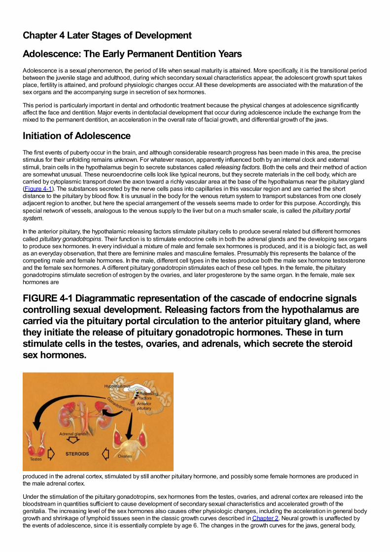
Chapter 4 Later Stages of Development
Adolescence: The Early Permanent Dentition YearsAdolescence is a sexual phenomenon, the period of life when sexual maturity is attained. More specifically, it is the transitional periodbetween the juvenile stage and adulthood, during which secondary sexual characteristics appear, the adolescent growth spurt takesplace, fertility is attained, and profound physiologic changes occur. All these developments are associated with the maturation of thesex organs and the accompanying surge in secretion of sex hormones.
This period is particularly important in dental and orthodontic treatment because the physical changes at adolescence significantlyaffect the face and dentition. Major events in dentofacial development that occur during adolescence include the exchange from themixed to the permanent dentition, an acceleration in the overall rate of facial growth, and differential growth of the jaws.
Initiation of AdolescenceThe first events of puberty occur in the brain, and although considerable research progress has been made in this area, the precisestimulus for their unfolding remains unknown. For whatever reason, apparently influenced both by an internal clock and externalstimuli, brain cells in the hypothalamus begin to secrete substances called releasing factors. Both the cells and their method of actionare somewhat unusual. These neuroendocrine cells look like typical neurons, but they secrete materials in the cell body, which arecarried by cytoplasmic transport down the axon toward a richly vascular area at the base of the hypothalamus near the pituitary gland(Figure 4-1). The substances secreted by the nerve cells pass into capillaries in this vascular region and are carried the shortdistance to the pituitary by blood flow. It is unusual in the body for the venous return system to transport substances from one closelyadjacent region to another, but here the special arrangement of the vessels seems made to order for this purpose. Accordingly, thisspecial network of vessels, analogous to the venous supply to the liver but on a much smaller scale, is called the pituitary portalsystem.
In the anterior pituitary, the hypothalamic releasing factors stimulate pituitary cells to produce several related but different hormonescalled pituitary gonadotropins. Their function is to stimulate endocrine cells in both the adrenal glands and the developing sex organsto produce sex hormones. In every individual a mixture of male and female sex hormones is produced, and it is a biologic fact, as wellas an everyday observation, that there are feminine males and masculine females. Presumably this represents the balance of thecompeting male and female hormones. In the male, different cell types in the testes produce both the male sex hormone testosteroneand the female sex hormones. A different pituitary gonadotropin stimulates each of these cell types. In the female, the pituitarygonadotropins stimulate secretion of estrogen by the ovaries, and later progesterone by the same organ. In the female, male sexhormones are
FIGURE 4-1 Diagrammatic representation of the cascade of endocrine signalscontrolling sexual development. Releasing factors from the hypothalamus arecarried via the pituitary portal circulation to the anterior pituitary gland, wherethey initiate the release of pituitary gonadotropic hormones. These in turnstimulate cells in the testes, ovaries, and adrenals, which secrete the steroidsex hormones.
produced in the adrenal cortex, stimulated by still another pituitary hormone, and possibly some female hormones are produced inthe male adrenal cortex.
Under the stimulation of the pituitary gonadotropins, sex hormones from the testes, ovaries, and adrenal cortex are released into thebloodstream in quantities sufficient to cause development of secondary sexual characteristics and accelerated growth of thegenitalia. The increasing level of the sex hormones also causes other physiologic changes, including the acceleration in general bodygrowth and shrinkage of lymphoid tissues seen in the classic growth curves described in Chapter 2. Neural growth is unaffected bythe events of adolescence, since it is essentially complete by age 6. The changes in the growth curves for the jaws, general body,
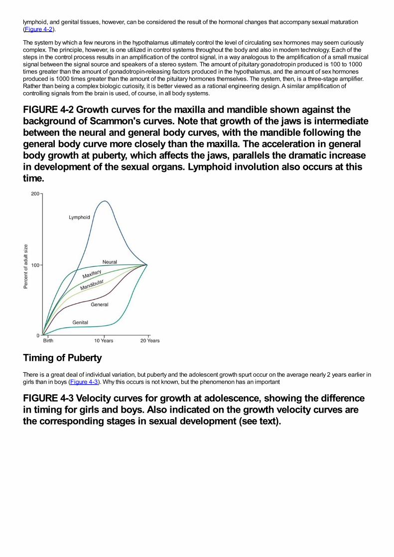
lymphoid, and genital tissues, however, can be considered the result of the hormonal changes that accompany sexual maturation(Figure 4-2).
The system by which a few neurons in the hypothalamus ultimately control the level of circulating sex hormones may seem curiouslycomplex. The principle, however, is one utilized in control systems throughout the body and also in modern technology. Each of thesteps in the control process results in an amplification of the control signal, in a way analogous to the amplification of a small musicalsignal between the signal source and speakers of a stereo system. The amount of pituitary gonadotropin produced is 100 to 1000times greater than the amount of gonadotropin-releasing factors produced in the hypothalamus, and the amount of sex hormonesproduced is 1000 times greater than the amount of the pituitary hormones themselves. The system, then, is a three-stage amplifier.Rather than being a complex biologic curiosity, it is better viewed as a rational engineering design. A similar amplification ofcontrolling signals from the brain is used, of course, in all body systems.
FIGURE 4-2 Growth curves for the maxilla and mandible shown against thebackground of Scammon's curves. Note that growth of the jaws is intermediatebetween the neural and general body curves, with the mandible following thegeneral body curve more closely than the maxilla. The acceleration in generalbody growth at puberty, which affects the jaws, parallels the dramatic increasein development of the sexual organs. Lymphoid involution also occurs at thistime.
Timing of PubertyThere is a great deal of individual variation, but puberty and the adolescent growth spurt occur on the average nearly 2 years earlier ingirls than in boys (Figure 4-3). Why this occurs is not known, but the phenomenon has an important
FIGURE 4-3 Velocity curves for growth at adolescence, showing the differencein timing for girls and boys. Also indicated on the growth velocity curves arethe corresponding stages in sexual development (see text).
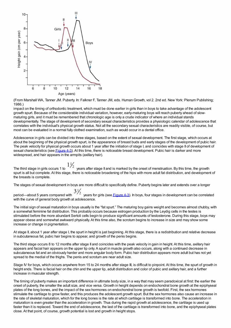
(From Marshall WA, Tanner JM. Puberty. In: Falkner F, Tanner JM, eds. Human Growth, vol 2. 2nd ed. New York: Plenum Publishing;1986.)impact on the timing of orthodontic treatment, which must be done earlier in girls than in boys to take advantage of the adolescentgrowth spurt. Because of the considerable individual variation, however, early-maturing boys will reach puberty ahead of slow-maturing girls, and it must be remembered that chronologic age is only a crude indicator of where an individual standsdevelopmentally. The stage of development of secondary sexual characteristics provides a physiologic calendar of adolescence thatcorrelates with the individual's physical growth status. Not all the secondary sexual characteristics are readily visible, of course, butmost can be evaluated in a normal fully clothed examination, such as would occur in a dental office.
Adolescence in girls can be divided into three stages, based on the extent of sexual development. The first stage, which occurs atabout the beginning of the physical growth spurt, is the appearance of breast buds and early stages of the development of pubic hair.The peak velocity for physical growth occurs about 1 year after the initiation of stage I, and coincides with stage II of development ofsexual characteristics (see Figure 4-3). At this time, there is noticeable breast development. Pubic hair is darker and morewidespread, and hair appears in the armpits (axillary hair).
The third stage in girls occurs 1 to years after stage II and is marked by the onset of menstruation. By this time, the growthspurt is all but complete. At this stage, there is noticeable broadening of the hips with more adult fat distribution, and development ofthe breasts is complete.
The stages of sexual development in boys are more difficult to specifically define. Puberty begins later and extends over a longer
period—about 5 years compared with years for girls (see Figure 4-3). In boys, four stages in development can be correlatedwith the curve of general body growth at adolescence.
The initial sign of sexual maturation in boys usually is the “fat spurt.” The maturing boy gains weight and becomes almost chubby, witha somewhat feminine fat distribution. This probably occurs because estrogen production by the Leydig cells in the testes isstimulated before the more abundant Sertoli cells begin to produce significant amounts of testosterone. During this stage, boys mayappear obese and somewhat awkward physically. At this time also, the scrotum begins to increase in size and may show someincrease or change in pigmentation.
At stage II, about 1 year after stage I, the spurt in height is just beginning. At this stage, there is a redistribution and relative decreasein subcutaneous fat, pubic hair begins to appear, and growth of the penis begins.
The third stage occurs 8 to 12 months after stage II and coincides with the peak velocity in gain in height. At this time, axillary hairappears and facial hair appears on the upper lip only. A spurt in muscle growth also occurs, along with a continued decrease insubcutaneous fat and an obviously harder and more angular body form. Pubic hair distribution appears more adult but has not yetspread to the medial of the thighs. The penis and scrotum are near adult size.
Stage IV for boys, which occurs anywhere from 15 to 24 months after stage III, is difficult to pinpoint. At this time, the spurt of growth inheight ends. There is facial hair on the chin and the upper lip, adult distribution and color of pubic and axillary hair, and a furtherincrease in muscular strength.
The timing of puberty makes an important difference in ultimate body size, in a way that may seem paradoxical at first: the earlier theonset of puberty, the smaller the adult size, and vice versa. Growth in height depends on endochondral bone growth at the epiphysealplates of the long bones, and the impact of the sex hormones on endochondral bone growth is twofold. First, the sex hormonesstimulate the cartilage to grow faster, and this produces the adolescent growth spurt. But the sex hormones also cause an increase inthe rate of skeletal maturation, which for the long bones is the rate at which cartilage is transformed into bone. The acceleration inmaturation is even greater than the acceleration in growth. Thus during the rapid growth at adolescence, the cartilage is used upfaster than it is replaced. Toward the end of adolescence, the last of the cartilage is transformed into bone, and the epiphyseal platesclose. At that point, of course, growth potential is lost and growth in height stops.
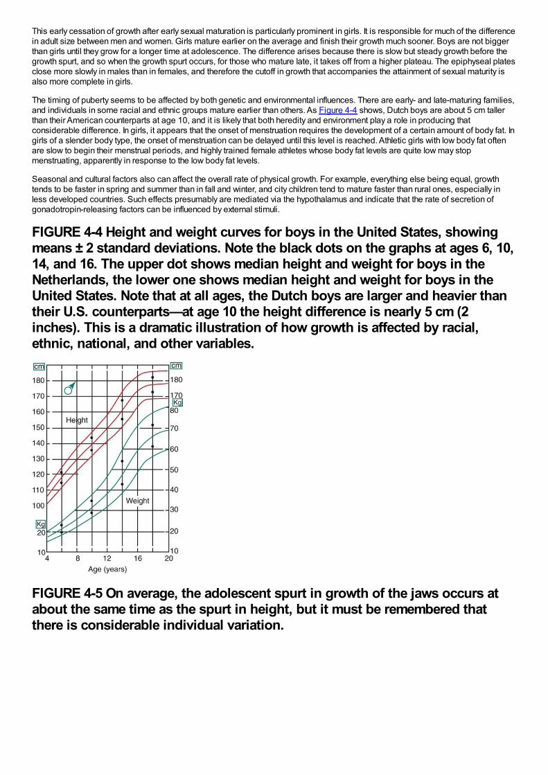
This early cessation of growth after early sexual maturation is particularly prominent in girls. It is responsible for much of the differencein adult size between men and women. Girls mature earlier on the average and finish their growth much sooner. Boys are not biggerthan girls until they grow for a longer time at adolescence. The difference arises because there is slow but steady growth before thegrowth spurt, and so when the growth spurt occurs, for those who mature late, it takes off from a higher plateau. The epiphyseal platesclose more slowly in males than in females, and therefore the cutoff in growth that accompanies the attainment of sexual maturity isalso more complete in girls.
The timing of puberty seems to be affected by both genetic and environmental influences. There are early- and late-maturing families,and individuals in some racial and ethnic groups mature earlier than others. As Figure 4-4 shows, Dutch boys are about 5 cm tallerthan their American counterparts at age 10, and it is likely that both heredity and environment play a role in producing thatconsiderable difference. In girls, it appears that the onset of menstruation requires the development of a certain amount of body fat. Ingirls of a slender body type, the onset of menstruation can be delayed until this level is reached. Athletic girls with low body fat oftenare slow to begin their menstrual periods, and highly trained female athletes whose body fat levels are quite low may stopmenstruating, apparently in response to the low body fat levels.
Seasonal and cultural factors also can affect the overall rate of physical growth. For example, everything else being equal, growthtends to be faster in spring and summer than in fall and winter, and city children tend to mature faster than rural ones, especially inless developed countries. Such effects presumably are mediated via the hypothalamus and indicate that the rate of secretion ofgonadotropin-releasing factors can be influenced by external stimuli.
FIGURE 4-4 Height and weight curves for boys in the United States, showingmeans ± 2 standard deviations. Note the black dots on the graphs at ages 6, 10,14, and 16. The upper dot shows median height and weight for boys in theNetherlands, the lower one shows median height and weight for boys in theUnited States. Note that at all ages, the Dutch boys are larger and heavier thantheir U.S. counterparts—at age 10 the height difference is nearly 5 cm (2inches). This is a dramatic illustration of how growth is affected by racial,ethnic, national, and other variables.
FIGURE 4-5 On average, the adolescent spurt in growth of the jaws occurs atabout the same time as the spurt in height, but it must be remembered thatthere is considerable individual variation.
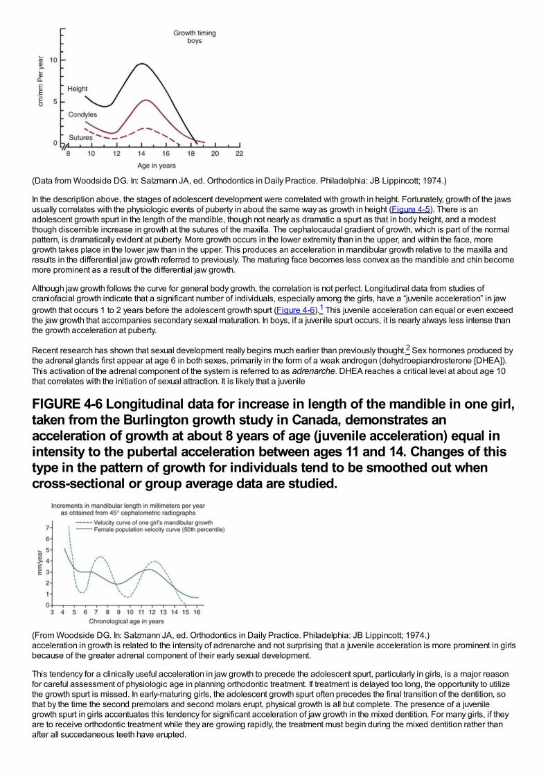
(Data from Woodside DG. In: Salzmann JA, ed. Orthodontics in Daily Practice. Philadelphia: JB Lippincott; 1974.)
In the description above, the stages of adolescent development were correlated with growth in height. Fortunately, growth of the jawsusually correlates with the physiologic events of puberty in about the same way as growth in height (Figure 4-5). There is anadolescent growth spurt in the length of the mandible, though not nearly as dramatic a spurt as that in body height, and a modestthough discernible increase in growth at the sutures of the maxilla. The cephalocaudal gradient of growth, which is part of the normalpattern, is dramatically evident at puberty. More growth occurs in the lower extremity than in the upper, and within the face, moregrowth takes place in the lower jaw than in the upper. This produces an acceleration in mandibular growth relative to the maxilla andresults in the differential jaw growth referred to previously. The maturing face becomes less convex as the mandible and chin becomemore prominent as a result of the differential jaw growth.
Although jaw growth follows the curve for general body growth, the correlation is not perfect. Longitudinal data from studies ofcraniofacial growth indicate that a significant number of individuals, especially among the girls, have a “juvenile acceleration” in jawgrowth that occurs 1 to 2 years before the adolescent growth spurt (Figure 4-6).1 This juvenile acceleration can equal or even exceedthe jaw growth that accompanies secondary sexual maturation. In boys, if a juvenile spurt occurs, it is nearly always less intense thanthe growth acceleration at puberty.
Recent research has shown that sexual development really begins much earlier than previously thought.2 Sex hormones produced bythe adrenal glands first appear at age 6 in both sexes, primarily in the form of a weak androgen (dehydroepiandrosterone [DHEA]).This activation of the adrenal component of the system is referred to as adrenarche. DHEA reaches a critical level at about age 10that correlates with the initiation of sexual attraction. It is likely that a juvenile
FIGURE 4-6 Longitudinal data for increase in length of the mandible in one girl,taken from the Burlington growth study in Canada, demonstrates anacceleration of growth at about 8 years of age (juvenile acceleration) equal inintensity to the pubertal acceleration between ages 11 and 14. Changes of thistype in the pattern of growth for individuals tend to be smoothed out whencross-sectional or group average data are studied.
(From Woodside DG. In: Salzmann JA, ed. Orthodontics in Daily Practice. Philadelphia: JB Lippincott; 1974.)acceleration in growth is related to the intensity of adrenarche and not surprising that a juvenile acceleration is more prominent in girlsbecause of the greater adrenal component of their early sexual development.
This tendency for a clinically useful acceleration in jaw growth to precede the adolescent spurt, particularly in girls, is a major reasonfor careful assessment of physiologic age in planning orthodontic treatment. If treatment is delayed too long, the opportunity to utilizethe growth spurt is missed. In early-maturing girls, the adolescent growth spurt often precedes the final transition of the dentition, sothat by the time the second premolars and second molars erupt, physical growth is all but complete. The presence of a juvenilegrowth spurt in girls accentuates this tendency for significant acceleration of jaw growth in the mixed dentition. For many girls, if theyare to receive orthodontic treatment while they are growing rapidly, the treatment must begin during the mixed dentition rather thanafter all succedaneous teeth have erupted.
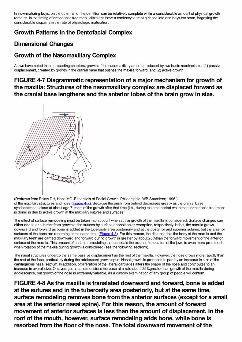
In slow-maturing boys, on the other hand, the dentition can be relatively complete while a considerable amount of physical growthremains. In the timing of orthodontic treatment, clinicians have a tendency to treat girls too late and boys too soon, forgetting theconsiderable disparity in the rate of physiologic maturation.
Growth Patterns in the Dentofacial Complex
Dimensional Changes
Growth of the Nasomaxillary ComplexAs we have noted in the preceding chapters, growth of the nasomaxillary area is produced by two basic mechanisms: (1) passivedisplacement, created by growth in the cranial base that pushes the maxilla forward, and (2) active growth
FIGURE 4-7 Diagrammatic representation of a major mechanism for growth ofthe maxilla: Structures of the nasomaxillary complex are displaced forward asthe cranial base lengthens and the anterior lobes of the brain grow in size.
(Redrawn from Enlow DH, Hans MG. Essentials of Facial Growth. Philadelphia: WB Saunders; 1996.)of the maxillary structures and nose (Figure 4-7). Because the push from behind decreases greatly as the cranial basesynchondroses close at about age 7, most of the growth after that time (i.e., during the time period when most orthodontic treatmentis done) is due to active growth at the maxillary sutures and surfaces.
The effect of surface remodeling must be taken into account when active growth of the maxilla is considered. Surface changes caneither add to or subtract from growth at the sutures by surface apposition or resorption, respectively. In fact, the maxilla growsdownward and forward as bone is added in the tuberosity area posteriorly and at the posterior and superior sutures, but the anteriorsurfaces of the bone are resorbing at the same time (Figure 4-8). For this reason, the distance that the body of the maxilla and themaxillary teeth are carried downward and forward during growth is greater by about 25%than the forward movement of the anteriorsurface of the maxilla. This amount of surface remodeling that conceals the extent of relocation of the jaws is even more prominentwhen rotation of the maxilla during growth is considered (see the following sections).
The nasal structures undergo the same passive displacement as the rest of the maxilla. However, the nose grows more rapidly thanthe rest of the face, particularly during the adolescent growth spurt. Nasal growth is produced in part by an increase in size of thecartilaginous nasal septum. In addition, proliferation of the lateral cartilages alters the shape of the nose and contributes to anincrease in overall size. On average, nasal dimensions increase at a rate about 25%greater than growth of the maxilla duringadolescence, but growth of the nose is extremely variable, as a cursory examination of any group of people will confirm.
FIGURE 4-8 As the maxilla is translated downward and forward, bone is addedat the sutures and in the tuberosity area posteriorly, but at the same time,surface remodeling removes bone from the anterior surfaces (except for a smallarea at the anterior nasal spine). For this reason, the amount of forwardmovement of anterior surfaces is less than the amount of displacement. In theroof of the mouth, however, surface remodeling adds bone, while bone isresorbed from the floor of the nose. The total downward movement of the
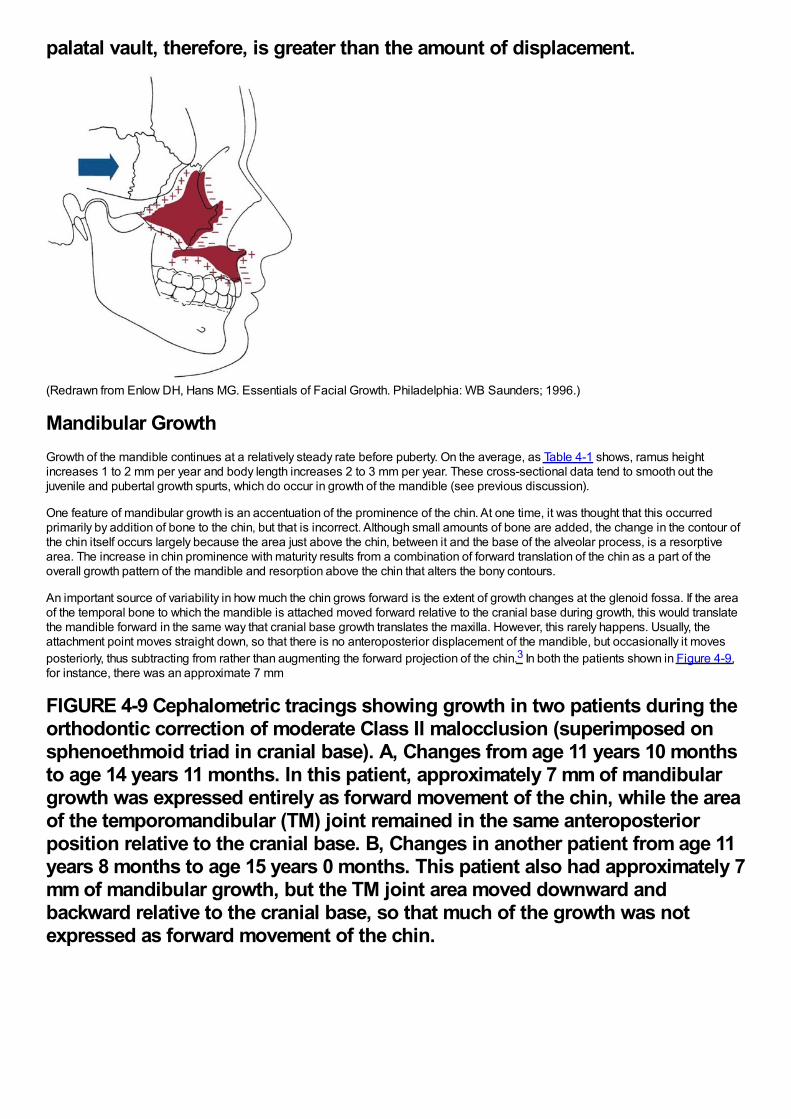
palatal vault, therefore, is greater than the amount of displacement.
(Redrawn from Enlow DH, Hans MG. Essentials of Facial Growth. Philadelphia: WB Saunders; 1996.)
Mandibular GrowthGrowth of the mandible continues at a relatively steady rate before puberty. On the average, as Table 4-1 shows, ramus heightincreases 1 to 2 mm per year and body length increases 2 to 3 mm per year. These cross-sectional data tend to smooth out thejuvenile and pubertal growth spurts, which do occur in growth of the mandible (see previous discussion).
One feature of mandibular growth is an accentuation of the prominence of the chin. At one time, it was thought that this occurredprimarily by addition of bone to the chin, but that is incorrect. Although small amounts of bone are added, the change in the contour ofthe chin itself occurs largely because the area just above the chin, between it and the base of the alveolar process, is a resorptivearea. The increase in chin prominence with maturity results from a combination of forward translation of the chin as a part of theoverall growth pattern of the mandible and resorption above the chin that alters the bony contours.
An important source of variability in how much the chin grows forward is the extent of growth changes at the glenoid fossa. If the areaof the temporal bone to which the mandible is attached moved forward relative to the cranial base during growth, this would translatethe mandible forward in the same way that cranial base growth translates the maxilla. However, this rarely happens. Usually, theattachment point moves straight down, so that there is no anteroposterior displacement of the mandible, but occasionally it movesposteriorly, thus subtracting from rather than augmenting the forward projection of the chin.3 In both the patients shown in Figure 4-9,for instance, there was an approximate 7 mm
FIGURE 4-9 Cephalometric tracings showing growth in two patients during theorthodontic correction of moderate Class II malocclusion (superimposed onsphenoethmoid triad in cranial base). A, Changes from age 11 years 10 monthsto age 14 years 11 months. In this patient, approximately 7 mm of mandibulargrowth was expressed entirely as forward movement of the chin, while the areaof the temporomandibular (TM) joint remained in the same anteroposteriorposition relative to the cranial base. B, Changes in another patient from age 11years 8 months to age 15 years 0 months. This patient also had approximately 7mm of mandibular growth, but the TM joint area moved downward andbackward relative to the cranial base, so that much of the growth was notexpressed as forward movement of the chin.
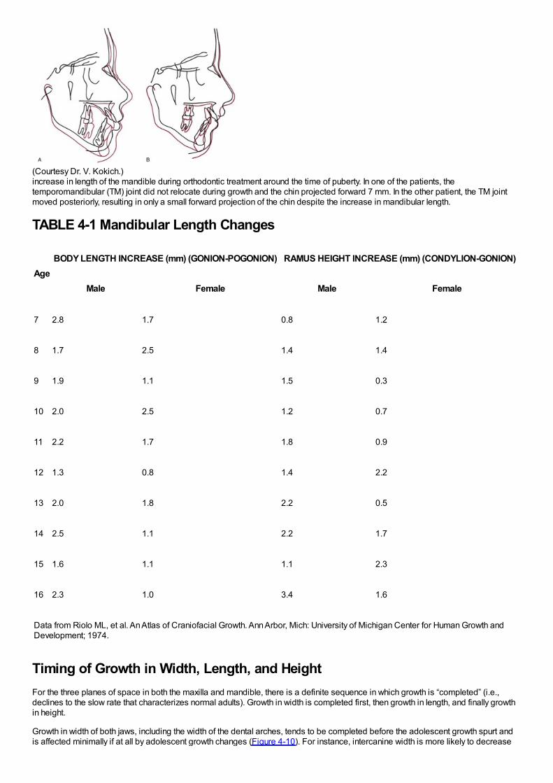
(Courtesy Dr. V. Kokich.)increase in length of the mandible during orthodontic treatment around the time of puberty. In one of the patients, thetemporomandibular (TM) joint did not relocate during growth and the chin projected forward 7 mm. In the other patient, the TM jointmoved posteriorly, resulting in only a small forward projection of the chin despite the increase in mandibular length.
TABLE 4-1 Mandibular Length Changes
AgeBODY LENGTH INCREASE (mm) (GONION-POGONION) RAMUS HEIGHT INCREASE (mm) (CONDYLION-GONION)
Male Female Male Female
7 2.8 1.7 0.8 1.2
8 1.7 2.5 1.4 1.4
9 1.9 1.1 1.5 0.3
10 2.0 2.5 1.2 0.7
11 2.2 1.7 1.8 0.9
12 1.3 0.8 1.4 2.2
13 2.0 1.8 2.2 0.5
14 2.5 1.1 2.2 1.7
15 1.6 1.1 1.1 2.3
16 2.3 1.0 3.4 1.6
Data from Riolo ML, et al. An Atlas of Craniofacial Growth. Ann Arbor, Mich: University of Michigan Center for Human Growth andDevelopment; 1974.
Timing of Growth in Width, Length, and HeightFor the three planes of space in both the maxilla and mandible, there is a definite sequence in which growth is “completed” (i.e.,declines to the slow rate that characterizes normal adults). Growth in width is completed first, then growth in length, and finally growthin height.
Growth in width of both jaws, including the width of the dental arches, tends to be completed before the adolescent growth spurt andis affected minimally if at all by adolescent growth changes (Figure 4-10). For instance, intercanine width is more likely to decrease
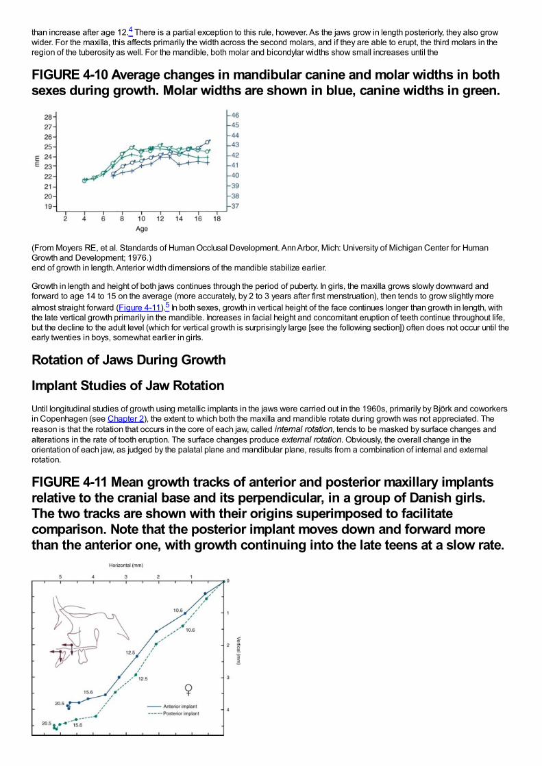
than increase after age 12.4 There is a partial exception to this rule, however. As the jaws grow in length posteriorly, they also growwider. For the maxilla, this affects primarily the width across the second molars, and if they are able to erupt, the third molars in theregion of the tuberosity as well. For the mandible, both molar and bicondylar widths show small increases until the
FIGURE 4-10 Average changes in mandibular canine and molar widths in bothsexes during growth. Molar widths are shown in blue, canine widths in green.
(From Moyers RE, et al. Standards of Human Occlusal Development. Ann Arbor, Mich: University of Michigan Center for HumanGrowth and Development; 1976.)end of growth in length. Anterior width dimensions of the mandible stabilize earlier.
Growth in length and height of both jaws continues through the period of puberty. In girls, the maxilla grows slowly downward andforward to age 14 to 15 on the average (more accurately, by 2 to 3 years after first menstruation), then tends to grow slightly morealmost straight forward (Figure 4-11).5 In both sexes, growth in vertical height of the face continues longer than growth in length, withthe late vertical growth primarily in the mandible. Increases in facial height and concomitant eruption of teeth continue throughout life,but the decline to the adult level (which for vertical growth is surprisingly large [see the following section]) often does not occur until theearly twenties in boys, somewhat earlier in girls.
Rotation of Jaws During Growth
Implant Studies of Jaw RotationUntil longitudinal studies of growth using metallic implants in the jaws were carried out in the 1960s, primarily by Björk and coworkersin Copenhagen (see Chapter 2), the extent to which both the maxilla and mandible rotate during growth was not appreciated. Thereason is that the rotation that occurs in the core of each jaw, called internal rotation, tends to be masked by surface changes andalterations in the rate of tooth eruption. The surface changes produce external rotation. Obviously, the overall change in theorientation of each jaw, as judged by the palatal plane and mandibular plane, results from a combination of internal and externalrotation.
FIGURE 4-11 Mean growth tracks of anterior and posterior maxillary implantsrelative to the cranial base and its perpendicular, in a group of Danish girls.The two tracks are shown with their origins superimposed to facilitatecomparison. Note that the posterior implant moves down and forward morethan the anterior one, with growth continuing into the late teens at a slow rate.
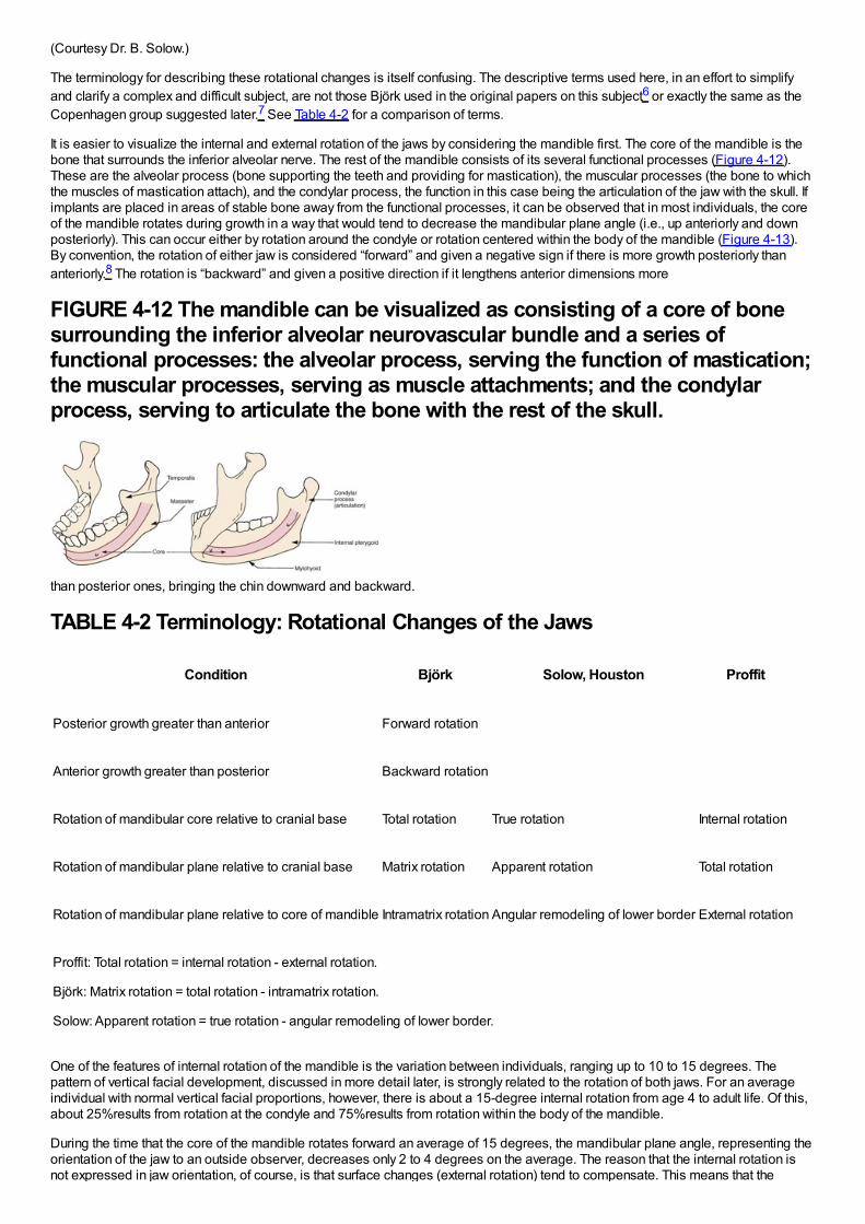
(Courtesy Dr. B. Solow.)
The terminology for describing these rotational changes is itself confusing. The descriptive terms used here, in an effort to simplifyand clarify a complex and difficult subject, are not those Björk used in the original papers on this subject6 or exactly the same as theCopenhagen group suggested later.7 See Table 4-2 for a comparison of terms.
It is easier to visualize the internal and external rotation of the jaws by considering the mandible first. The core of the mandible is thebone that surrounds the inferior alveolar nerve. The rest of the mandible consists of its several functional processes (Figure 4-12).These are the alveolar process (bone supporting the teeth and providing for mastication), the muscular processes (the bone to whichthe muscles of mastication attach), and the condylar process, the function in this case being the articulation of the jaw with the skull. Ifimplants are placed in areas of stable bone away from the functional processes, it can be observed that in most individuals, the coreof the mandible rotates during growth in a way that would tend to decrease the mandibular plane angle (i.e., up anteriorly and downposteriorly). This can occur either by rotation around the condyle or rotation centered within the body of the mandible (Figure 4-13).By convention, the rotation of either jaw is considered “forward” and given a negative sign if there is more growth posteriorly thananteriorly.8 The rotation is “backward” and given a positive direction if it lengthens anterior dimensions more
FIGURE 4-12 The mandible can be visualized as consisting of a core of bonesurrounding the inferior alveolar neurovascular bundle and a series offunctional processes: the alveolar process, serving the function of mastication;the muscular processes, serving as muscle attachments; and the condylarprocess, serving to articulate the bone with the rest of the skull.
than posterior ones, bringing the chin downward and backward.
TABLE 4-2 Terminology: Rotational Changes of the Jaws
Condition Björk Solow, Houston Proffit
Posterior growth greater than anterior Forward rotation
Anterior growth greater than posterior Backward rotation
Rotation of mandibular core relative to cranial base Total rotation True rotation Internal rotation
Rotation of mandibular plane relative to cranial base Matrix rotation Apparent rotation Total rotation
Rotation of mandibular plane relative to core of mandible Intramatrix rotation Angular remodeling of lower border External rotation
Proffit: Total rotation = internal rotation - external rotation.
Björk: Matrix rotation = total rotation - intramatrix rotation.
Solow: Apparent rotation = true rotation - angular remodeling of lower border.
One of the features of internal rotation of the mandible is the variation between individuals, ranging up to 10 to 15 degrees. Thepattern of vertical facial development, discussed in more detail later, is strongly related to the rotation of both jaws. For an averageindividual with normal vertical facial proportions, however, there is about a 15-degree internal rotation from age 4 to adult life. Of this,about 25%results from rotation at the condyle and 75%results from rotation within the body of the mandible.
During the time that the core of the mandible rotates forward an average of 15 degrees, the mandibular plane angle, representing theorientation of the jaw to an outside observer, decreases only 2 to 4 degrees on the average. The reason that the internal rotation isnot expressed in jaw orientation, of course, is that surface changes (external rotation) tend to compensate. This means that the
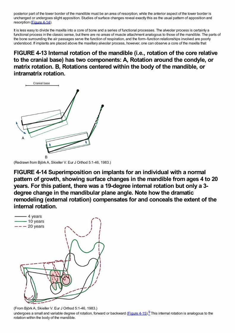
posterior part of the lower border of the mandible must be an area of resorption, while the anterior aspect of the lower border isunchanged or undergoes slight apposition. Studies of surface changes reveal exactly this as the usual pattern of apposition andresorption (Figure 4-14).
It is less easy to divide the maxilla into a core of bone and a series of functional processes. The alveolar process is certainly afunctional process in the classic sense, but there are no areas of muscle attachment analogous to those of the mandible. The parts ofthe bone surrounding the air passages serve the function of respiration, and the form–function relationships involved are poorlyunderstood. If implants are placed above the maxillary alveolar process, however, one can observe a core of the maxilla that
FIGURE 4-13 Internal rotation of the mandible (i.e., rotation of the core relativeto the cranial base) has two components: A, Rotation around the condyle, ormatrix rotation. B, Rotations centered within the body of the mandible, orintramatrix rotation.
(Redrawn from Björk A, Skieller V. Eur J Orthod 5:1-46, 1983.)
FIGURE 4-14 Superimposition on implants for an individual with a normalpattern of growth, showing surface changes in the mandible from ages 4 to 20years. For this patient, there was a 19-degree internal rotation but only a 3-degree change in the mandibular plane angle. Note how the dramaticremodeling (external rotation) compensates for and conceals the extent of theinternal rotation.
(From Björk A, Skieller V. Eur J Orthod 5:1-46, 1983.)undergoes a small and variable degree of rotation, forward or backward (Figure 4-15).9 This internal rotation is analogous to therotation within the body of the mandible.
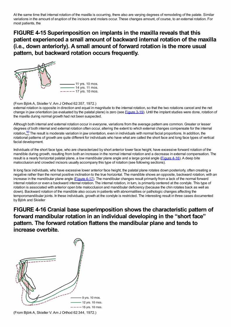
At the same time that internal rotation of the maxilla is occurring, there also are varying degrees of remodeling of the palate. Similarvariations in the amount of eruption of the incisors and molars occur. These changes amount, of course, to an external rotation. Formost patients, the
FIGURE 4-15 Superimposition on implants in the maxilla reveals that thispatient experienced a small amount of backward internal rotation of the maxilla(i.e., down anteriorly). A small amount of forward rotation is the more usualpattern, but backward rotation occurs frequently.
(From Björk A, Skieller V. Am J Orthod 62:357, 1972.)external rotation is opposite in direction and equal in magnitude to the internal rotation, so that the two rotations cancel and the netchange in jaw orientation (as evaluated by the palatal plane) is zero (see Figure 3-19). Until the implant studies were done, rotation ofthe maxilla during normal growth had not been suspected.
Although both internal and external rotation occur in everyone, variations from the average pattern are common. Greater or lesserdegrees of both internal and external rotation often occur, altering the extent to which external changes compensate for the internalrotation.10 The result is moderate variation in jaw orientation, even in individuals with normal facial proportions. In addition, therotational patterns of growth are quite different for individuals who have what are called the short face and long face types of verticalfacial development.
Individuals of the short face type, who are characterized by short anterior lower face height, have excessive forward rotation of themandible during growth, resulting from both an increase in the normal internal rotation and a decrease in external compensation. Theresult is a nearly horizontal palatal plane, a low mandibular plane angle and a large gonial angle (Figure 4-16). A deep bitemalocclusion and crowded incisors usually accompany this type of rotation (see following sections).
In long face individuals, who have excessive lower anterior face height, the palatal plane rotates down posteriorly, often creating anegative rather than the normal positive inclination to the true horizontal. The mandible shows an opposite, backward rotation, with anincrease in the mandibular plane angle (Figure 4-17). The mandibular changes result primarily from a lack of the normal forwardinternal rotation or even a backward internal rotation. The internal rotation, in turn, is primarily centered at the condyle. This type ofrotation is associated with anterior open bite malocclusion and mandibular deficiency (because the chin rotates back as well asdown). Backward rotation of the mandible also occurs in patients with abnormalities or pathologic changes affecting thetemporomandibular joints. In these individuals, growth at the condyle is restricted. The interesting result in three cases documentedby Björk and Skieller
FIGURE 4-16 Cranial base superimposition shows the characteristic pattern offorward mandibular rotation in an individual developing in the “short face”pattern. The forward rotation flattens the mandibular plane and tends toincrease overbite.
(From Björk A, Skieller V. Am J Orthod 62:344, 1972.)
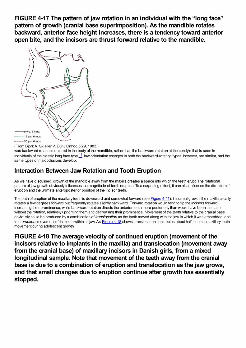
FIGURE 4-17 The pattern of jaw rotation in an individual with the “long face”pattern of growth (cranial base superimposition). As the mandible rotatesbackward, anterior face height increases, there is a tendency toward anterioropen bite, and the incisors are thrust forward relative to the mandible.
(From Björk A, Skieller V. Eur J Orthod 5:29, 1983.)was backward rotation centered in the body of the mandible, rather than the backward rotation at the condyle that is seen inindividuals of the classic long face type.11 Jaw orientation changes in both the backward-rotating types, however, are similar, and thesame types of malocclusions develop.
Interaction Between Jaw Rotation and Tooth EruptionAs we have discussed, growth of the mandible away from the maxilla creates a space into which the teeth erupt. The rotationalpattern of jaw growth obviously influences the magnitude of tooth eruption. To a surprising extent, it can also influence the direction oferuption and the ultimate anteroposterior position of the incisor teeth.
The path of eruption of the maxillary teeth is downward and somewhat forward (see Figure 4-11). In normal growth, the maxilla usuallyrotates a few degrees forward but frequently rotates slightly backward. Forward rotation would tend to tip the incisors forward,increasing their prominence, while backward rotation directs the anterior teeth more posteriorly than would have been the casewithout the rotation, relatively uprighting them and decreasing their prominence. Movement of the teeth relative to the cranial baseobviously could be produced by a combination of translocation as the tooth moved along with the jaw in which it was embedded, andtrue eruption, movement of the tooth within its jaw. As Figure 4-18 shows, translocation contributes about half the total maxillary toothmovement during adolescent growth.
FIGURE 4-18 The average velocity of continued eruption (movement of theincisors relative to implants in the maxilla) and translocation (movement awayfrom the cranial base) of maxillary incisors in Danish girls, from a mixedlongitudinal sample. Note that movement of the teeth away from the cranialbase is due to a combination of eruption and translocation as the jaw grows,and that small changes due to eruption continue after growth has essentiallystopped.
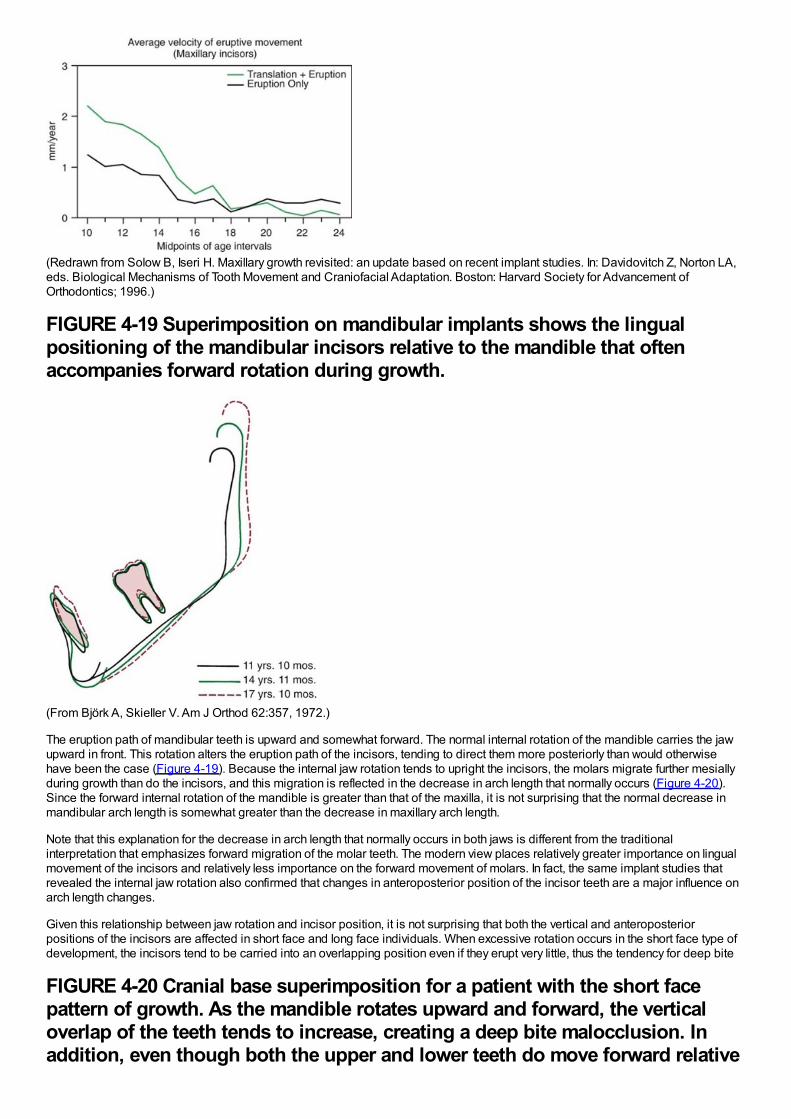
(Redrawn from Solow B, Iseri H. Maxillary growth revisited: an update based on recent implant studies. In: Davidovitch Z, Norton LA,eds. Biological Mechanisms of Tooth Movement and Craniofacial Adaptation. Boston: Harvard Society for Advancement ofOrthodontics; 1996.)
FIGURE 4-19 Superimposition on mandibular implants shows the lingualpositioning of the mandibular incisors relative to the mandible that oftenaccompanies forward rotation during growth.
(From Björk A, Skieller V. Am J Orthod 62:357, 1972.)
The eruption path of mandibular teeth is upward and somewhat forward. The normal internal rotation of the mandible carries the jawupward in front. This rotation alters the eruption path of the incisors, tending to direct them more posteriorly than would otherwisehave been the case (Figure 4-19). Because the internal jaw rotation tends to upright the incisors, the molars migrate further mesiallyduring growth than do the incisors, and this migration is reflected in the decrease in arch length that normally occurs (Figure 4-20).Since the forward internal rotation of the mandible is greater than that of the maxilla, it is not surprising that the normal decrease inmandibular arch length is somewhat greater than the decrease in maxillary arch length.
Note that this explanation for the decrease in arch length that normally occurs in both jaws is different from the traditionalinterpretation that emphasizes forward migration of the molar teeth. The modern view places relatively greater importance on lingualmovement of the incisors and relatively less importance on the forward movement of molars. In fact, the same implant studies thatrevealed the internal jaw rotation also confirmed that changes in anteroposterior position of the incisor teeth are a major influence onarch length changes.
Given this relationship between jaw rotation and incisor position, it is not surprising that both the vertical and anteroposteriorpositions of the incisors are affected in short face and long face individuals. When excessive rotation occurs in the short face type ofdevelopment, the incisors tend to be carried into an overlapping position even if they erupt very little, thus the tendency for deep bite
FIGURE 4-20 Cranial base superimposition for a patient with the short facepattern of growth. As the mandible rotates upward and forward, the verticaloverlap of the teeth tends to increase, creating a deep bite malocclusion. Inaddition, even though both the upper and lower teeth do move forward relative
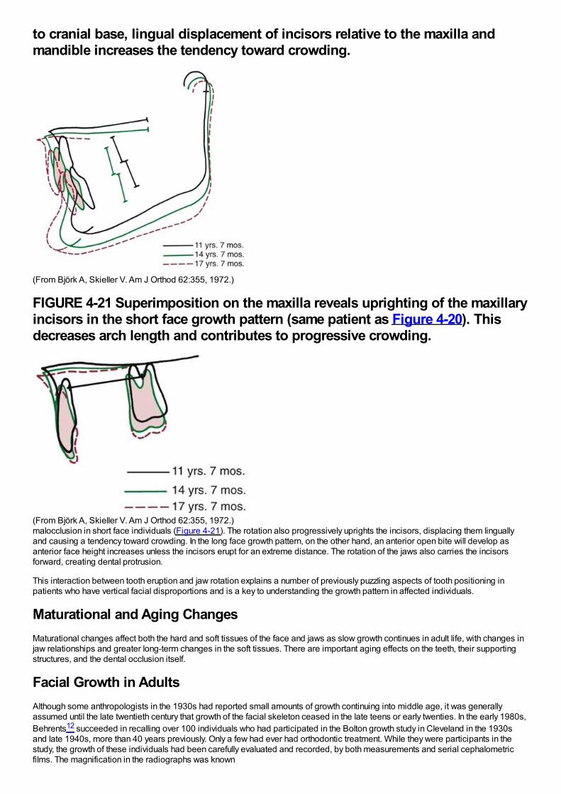
to cranial base, lingual displacement of incisors relative to the maxilla andmandible increases the tendency toward crowding.
(From Björk A, Skieller V. Am J Orthod 62:355, 1972.)
FIGURE 4-21 Superimposition on the maxilla reveals uprighting of the maxillaryincisors in the short face growth pattern (same patient as Figure 4-20). Thisdecreases arch length and contributes to progressive crowding.
(From Björk A, Skieller V. Am J Orthod 62:355, 1972.)malocclusion in short face individuals (Figure 4-21). The rotation also progressively uprights the incisors, displacing them linguallyand causing a tendency toward crowding. In the long face growth pattern, on the other hand, an anterior open bite will develop asanterior face height increases unless the incisors erupt for an extreme distance. The rotation of the jaws also carries the incisorsforward, creating dental protrusion.
This interaction between tooth eruption and jaw rotation explains a number of previously puzzling aspects of tooth positioning inpatients who have vertical facial disproportions and is a key to understanding the growth pattern in affected individuals.
Maturational and Aging ChangesMaturational changes affect both the hard and soft tissues of the face and jaws as slow growth continues in adult life, with changes injaw relationships and greater long-term changes in the soft tissues. There are important aging effects on the teeth, their supportingstructures, and the dental occlusion itself.
Facial Growth in AdultsAlthough some anthropologists in the 1930s had reported small amounts of growth continuing into middle age, it was generallyassumed until the late twentieth century that growth of the facial skeleton ceased in the late teens or early twenties. In the early 1980s,Behrents12 succeeded in recalling over 100 individuals who had participated in the Bolton growth study in Cleveland in the 1930sand late 1940s, more than 40 years previously. Only a few had ever had orthodontic treatment. While they were participants in thestudy, the growth of these individuals had been carefully evaluated and recorded, by both measurements and serial cephalometricfilms. The magnification in the radiographs was known
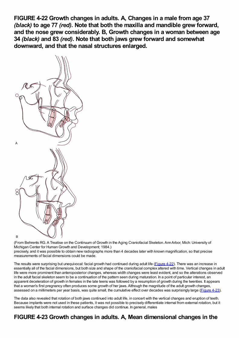
FIGURE 4-22 Growth changes in adults. A, Changes in a male from age 37(black) to age 77 (red). Note that both the maxilla and mandible grew forward,and the nose grew considerably. B, Growth changes in a woman between age34 (black) and 83 (red). Note that both jaws grew forward and somewhatdownward, and that the nasal structures enlarged.
(From Behrents RG. A Treatise on the Continuum of Growth in the Aging Craniofacial Skeleton. Ann Arbor, Mich: University ofMichigan Center for Human Growth and Development; 1984.)precisely, and it was possible to obtain new radiographs more than 4 decades later with known magnification, so that precisemeasurements of facial dimensions could be made.
The results were surprising but unequivocal: facial growth had continued during adult life (Figure 4-22). There was an increase inessentially all of the facial dimensions, but both size and shape of the craniofacial complex altered with time. Vertical changes in adultlife were more prominent than anteroposterior changes, whereas width changes were least evident, and so the alterations observedin the adult facial skeleton seem to be a continuation of the pattern seen during maturation. In a point of particular interest, anapparent deceleration of growth in females in the late teens was followed by a resumption of growth during the twenties. It appearsthat a woman's first pregnancy often produces some growth of her jaws. Although the magnitude of the adult growth changes,assessed on a millimeters per year basis, was quite small, the cumulative effect over decades was surprisingly large (Figure 4-23).
The data also revealed that rotation of both jaws continued into adult life, in concert with the vertical changes and eruption of teeth.Because implants were not used in these patients, it was not possible to precisely differentiate internal from external rotation, but itseems likely that both internal rotation and surface changes did continue. In general, males
FIGURE 4-23 Growth changes in adults. A, Mean dimensional changes in the
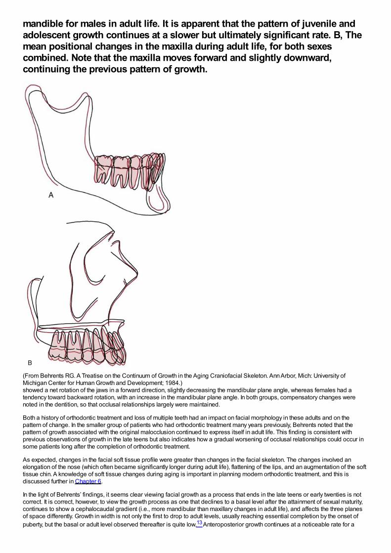
mandible for males in adult life. It is apparent that the pattern of juvenile andadolescent growth continues at a slower but ultimately significant rate. B, Themean positional changes in the maxilla during adult life, for both sexescombined. Note that the maxilla moves forward and slightly downward,continuing the previous pattern of growth.
(From Behrents RG. A Treatise on the Continuum of Growth in the Aging Craniofacial Skeleton. Ann Arbor, Mich: University ofMichigan Center for Human Growth and Development; 1984.)showed a net rotation of the jaws in a forward direction, slightly decreasing the mandibular plane angle, whereas females had atendency toward backward rotation, with an increase in the mandibular plane angle. In both groups, compensatory changes werenoted in the dentition, so that occlusal relationships largely were maintained.
Both a history of orthodontic treatment and loss of multiple teeth had an impact on facial morphology in these adults and on thepattern of change. In the smaller group of patients who had orthodontic treatment many years previously, Behrents noted that thepattern of growth associated with the original malocclusion continued to express itself in adult life. This finding is consistent withprevious observations of growth in the late teens but also indicates how a gradual worsening of occlusal relationships could occur insome patients long after the completion of orthodontic treatment.
As expected, changes in the facial soft tissue profile were greater than changes in the facial skeleton. The changes involved anelongation of the nose (which often became significantly longer during adult life), flattening of the lips, and an augmentation of the softtissue chin. A knowledge of soft tissue changes during aging is important in planning modern orthodontic treatment, and this isdiscussed further in Chapter 6.
In the light of Behrents’ findings, it seems clear viewing facial growth as a process that ends in the late teens or early twenties is notcorrect. It is correct, however, to view the growth process as one that declines to a basal level after the attainment of sexual maturity,continues to show a cephalocaudal gradient (i.e., more mandibular than maxillary changes in adult life), and affects the three planesof space differently. Growth in width is not only the first to drop to adult levels, usually reaching essential completion by the onset ofpuberty, but the basal or adult level observed thereafter is quite low.13 Anteroposterior growth continues at a noticeable rate for a
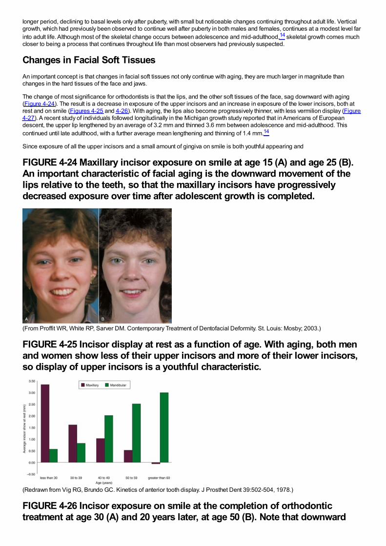
longer period, declining to basal levels only after puberty, with small but noticeable changes continuing throughout adult life. Verticalgrowth, which had previously been observed to continue well after puberty in both males and females, continues at a modest level farinto adult life. Although most of the skeletal change occurs between adolescence and mid-adulthood,14 skeletal growth comes muchcloser to being a process that continues throughout life than most observers had previously suspected.
Changes in Facial Soft TissuesAn important concept is that changes in facial soft tissues not only continue with aging, they are much larger in magnitude thanchanges in the hard tissues of the face and jaws.
The change of most significance for orthodontists is that the lips, and the other soft tissues of the face, sag downward with aging(Figure 4-24). The result is a decrease in exposure of the upper incisors and an increase in exposure of the lower incisors, both atrest and on smile (Figures 4-25 and 4-26). With aging, the lips also become progressively thinner, with less vermilion display (Figure4-27). A recent study of individuals followed longitudinally in the Michigan growth study reported that in Americans of Europeandescent, the upper lip lengthened by an average of 3.2 mm and thinned 3.6 mm between adolescence and mid-adulthood. Thiscontinued until late adulthood, with a further average mean lengthening and thinning of 1.4 mm.14
Since exposure of all the upper incisors and a small amount of gingiva on smile is both youthful appearing and
FIGURE 4-24 Maxillary incisor exposure on smile at age 15 (A) and age 25 (B).An important characteristic of facial aging is the downward movement of thelips relative to the teeth, so that the maxillary incisors have progressivelydecreased exposure over time after adolescent growth is completed.
(From Proffit WR, White RP, Sarver DM. Contemporary Treatment of Dentofacial Deformity. St. Louis: Mosby; 2003.)
FIGURE 4-25 Incisor display at rest as a function of age. With aging, both menand women show less of their upper incisors and more of their lower incisors,so display of upper incisors is a youthful characteristic.
(Redrawn from Vig RG, Brundo GC. Kinetics of anterior tooth display. J Prosthet Dent 39:502-504, 1978.)
FIGURE 4-26 Incisor exposure on smile at the completion of orthodontictreatment at age 30 (A) and 20 years later, at age 50 (B). Note that downward
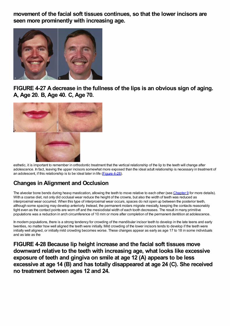
movement of the facial soft tissues continues, so that the lower incisors areseen more prominently with increasing age.
FIGURE 4-27 A decrease in the fullness of the lips is an obvious sign of aging.A, Age 20. B, Age 40. C, Age 70.
esthetic, it is important to remember in orthodontic treatment that the vertical relationship of the lip to the teeth will change afteradolescence. In fact, leaving the upper incisors somewhat more exposed than the ideal adult relationship is necessary in treatment ofan adolescent, if this relationship is to be ideal later in life (Figure 4-28).
Changes in Alignment and OcclusionThe alveolar bone bends during heavy mastication, allowing the teeth to move relative to each other (see Chapter 9 for more details).With a coarse diet, not only did occlusal wear reduce the height of the crowns, but also the width of teeth was reduced asinterproximal wear occurred. When this type of interproximal wear occurs, spaces do not open up between the posterior teeth,although some spacing may develop anteriorly. Instead, the permanent molars migrate mesially, keeping the contacts reasonablytight even as the contact points are worn off and the mesiodistal width of each tooth decreases. The result in many primitivepopulations was a reduction in arch circumference of 10 mm or more after completion of the permanent dentition at adolescence.
In modern populations, there is a strong tendency for crowding of the mandibular incisor teeth to develop in the late teens and earlytwenties, no matter how well aligned the teeth were initially. Mild crowding of the lower incisors tends to develop if the teeth wereinitially well aligned, or initially mild crowding becomes worse. These changes appear as early as age 17 to 18 in some individualsand as late as the
FIGURE 4-28 Because lip height increase and the facial soft tissues movedownward relative to the teeth with increasing age, what looks like excessiveexposure of teeth and gingiva on smile at age 12 (A) appears to be lessexcessive at age 14 (B) and has totally disappeared at age 24 (C). She receivedno treatment between ages 12 and 24.
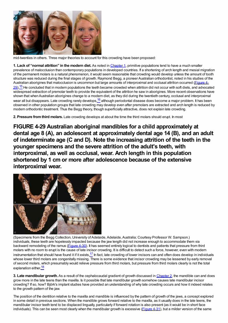
mid-twenties in others. Three major theories to account for this crowding have been proposed:
1. Lack of “normal attrition” in the modern diet. As noted in Chapter 1, primitive populations tend to have a much smallerprevalence of malocclusion than contemporary populations in developed countries. If a shortening of arch length and mesial migrationof the permanent molars is a natural phenomenon, it would seem reasonable that crowding would develop unless the amount of toothstructure was reduced during the final stages of growth. Raymond Begg, a pioneer Australian orthodontist, noted in his studies of theAustralian aborigines that malocclusion is uncommon but large amounts of interproximal and occlusal attrition occurred (Figure 4-29).15 He concluded that in modern populations the teeth became crowded when attrition did not occur with soft diets, and advocatedwidespread extraction of premolar teeth to provide the equivalent of the attrition he saw in aborigines. More recent observations haveshown that when Australian aborigines change to a modern diet, as they did during the twentieth century, occlusal and interproximalwear all but disappears. Late crowding rarely develops,16 although periodontal disease does become a major problem. It has beenobserved in other population groups that late crowding may develop even after premolars are extracted and arch length is reduced bymodern orthodontic treatment. Thus the Begg theory, though superficially attractive, does not explain late crowding.
2. Pressure from third molars. Late crowding develops at about the time the third molars should erupt. In most
FIGURE 4-29 Australian aboriginal mandibles for a child approximately atdental age 8 (A), an adolescent at approximately dental age 14 (B), and an adultof indeterminate age (C and D). Note the increasing attrition of the teeth in theyounger specimens and the severe attrition of the adult's teeth, withinterproximal, as well as occlusal, wear. Arch length in this populationshortened by 1 cm or more after adolescence because of the extensiveinterproximal wear.
(Specimens from the Begg Collection, University of Adelaide, Adelaide, Australia; Courtesy Professor W. Sampson.)individuals, these teeth are hopelessly impacted because the jaw length did not increase enough to accommodate them viabackward remodeling of the ramus (Figure 4-30). It has seemed entirely logical to dentists and patients that pressure from thirdmolars with no room to erupt is the cause of late incisor crowding. It is difficult to detect such a force, however, even with moderninstrumentation that should have found it if it exists.17 In fact, late crowding of lower incisors can and often does develop in individualswhose lower third molars are congenitally missing. There is some evidence that incisor crowding may be lessened by early removalof second molars, which presumably would relieve pressure from third molars, but pressure from third molars clearly is not the totalexplanation either.18
3. Late mandibular growth. As a result of the cephalocaudal gradient of growth discussed in Chapter 2, the mandible can and doesgrow more in the late teens than the maxilla. Is it possible that late mandibular growth somehow causes late mandibular incisorcrowding? If so, how? Björk's implant studies have provided an understanding of why late crowding occurs and how it indeed relatesto the growth pattern of the jaw.
The position of the dentition relative to the maxilla and mandible is influenced by the pattern of growth of the jaws, a concept exploredin some detail in previous sections. When the mandible grows forward relative to the maxilla, as it usually does in the late teens, themandibular incisor teeth tend to be displaced lingually, particularly if forward rotation is also present (as it would be in short faceindividuals). This can be seen most clearly when the mandibular growth is excessive (Figure 4-31), but a milder version of the same
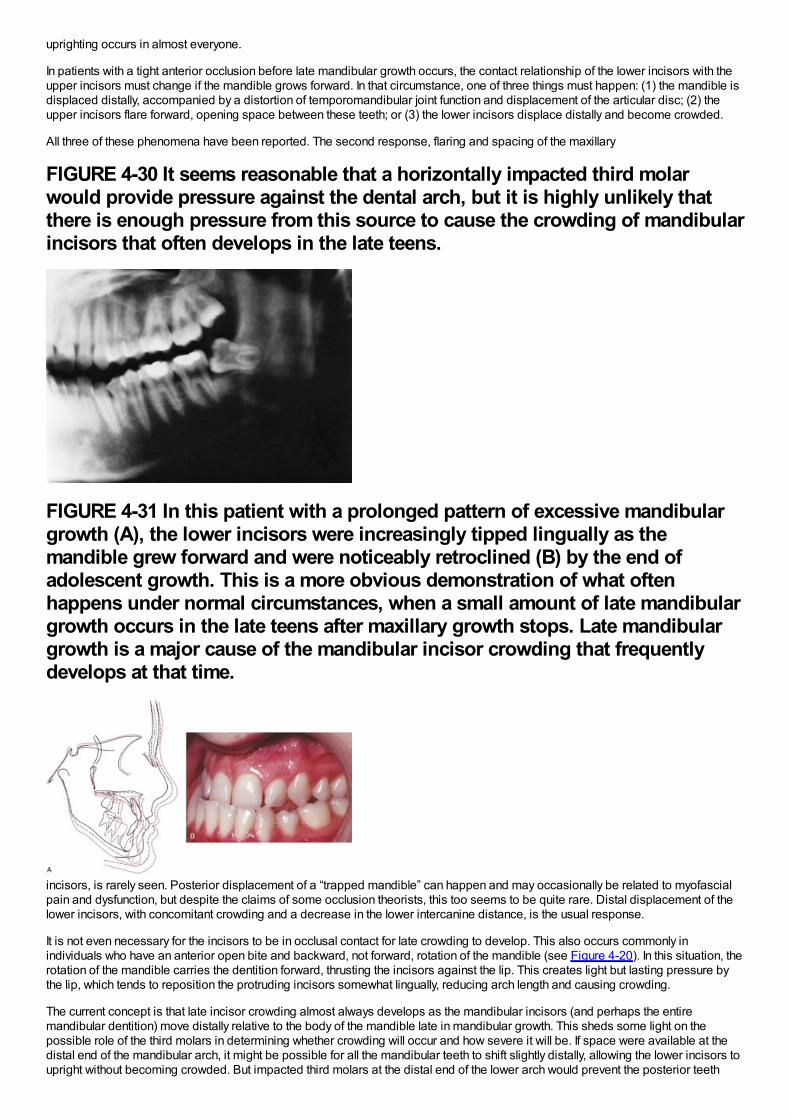
uprighting occurs in almost everyone.
In patients with a tight anterior occlusion before late mandibular growth occurs, the contact relationship of the lower incisors with theupper incisors must change if the mandible grows forward. In that circumstance, one of three things must happen: (1) the mandible isdisplaced distally, accompanied by a distortion of temporomandibular joint function and displacement of the articular disc; (2) theupper incisors flare forward, opening space between these teeth; or (3) the lower incisors displace distally and become crowded.
All three of these phenomena have been reported. The second response, flaring and spacing of the maxillary
FIGURE 4-30 It seems reasonable that a horizontally impacted third molarwould provide pressure against the dental arch, but it is highly unlikely thatthere is enough pressure from this source to cause the crowding of mandibularincisors that often develops in the late teens.
FIGURE 4-31 In this patient with a prolonged pattern of excessive mandibulargrowth (A), the lower incisors were increasingly tipped lingually as themandible grew forward and were noticeably retroclined (B) by the end ofadolescent growth. This is a more obvious demonstration of what oftenhappens under normal circumstances, when a small amount of late mandibulargrowth occurs in the late teens after maxillary growth stops. Late mandibulargrowth is a major cause of the mandibular incisor crowding that frequentlydevelops at that time.
incisors, is rarely seen. Posterior displacement of a “trapped mandible” can happen and may occasionally be related to myofascialpain and dysfunction, but despite the claims of some occlusion theorists, this too seems to be quite rare. Distal displacement of thelower incisors, with concomitant crowding and a decrease in the lower intercanine distance, is the usual response.
It is not even necessary for the incisors to be in occlusal contact for late crowding to develop. This also occurs commonly inindividuals who have an anterior open bite and backward, not forward, rotation of the mandible (see Figure 4-20). In this situation, therotation of the mandible carries the dentition forward, thrusting the incisors against the lip. This creates light but lasting pressure bythe lip, which tends to reposition the protruding incisors somewhat lingually, reducing arch length and causing crowding.
The current concept is that late incisor crowding almost always develops as the mandibular incisors (and perhaps the entiremandibular dentition) move distally relative to the body of the mandible late in mandibular growth. This sheds some light on thepossible role of the third molars in determining whether crowding will occur and how severe it will be. If space were available at thedistal end of the mandibular arch, it might be possible for all the mandibular teeth to shift slightly distally, allowing the lower incisors toupright without becoming crowded. But impacted third molars at the distal end of the lower arch would prevent the posterior teeth
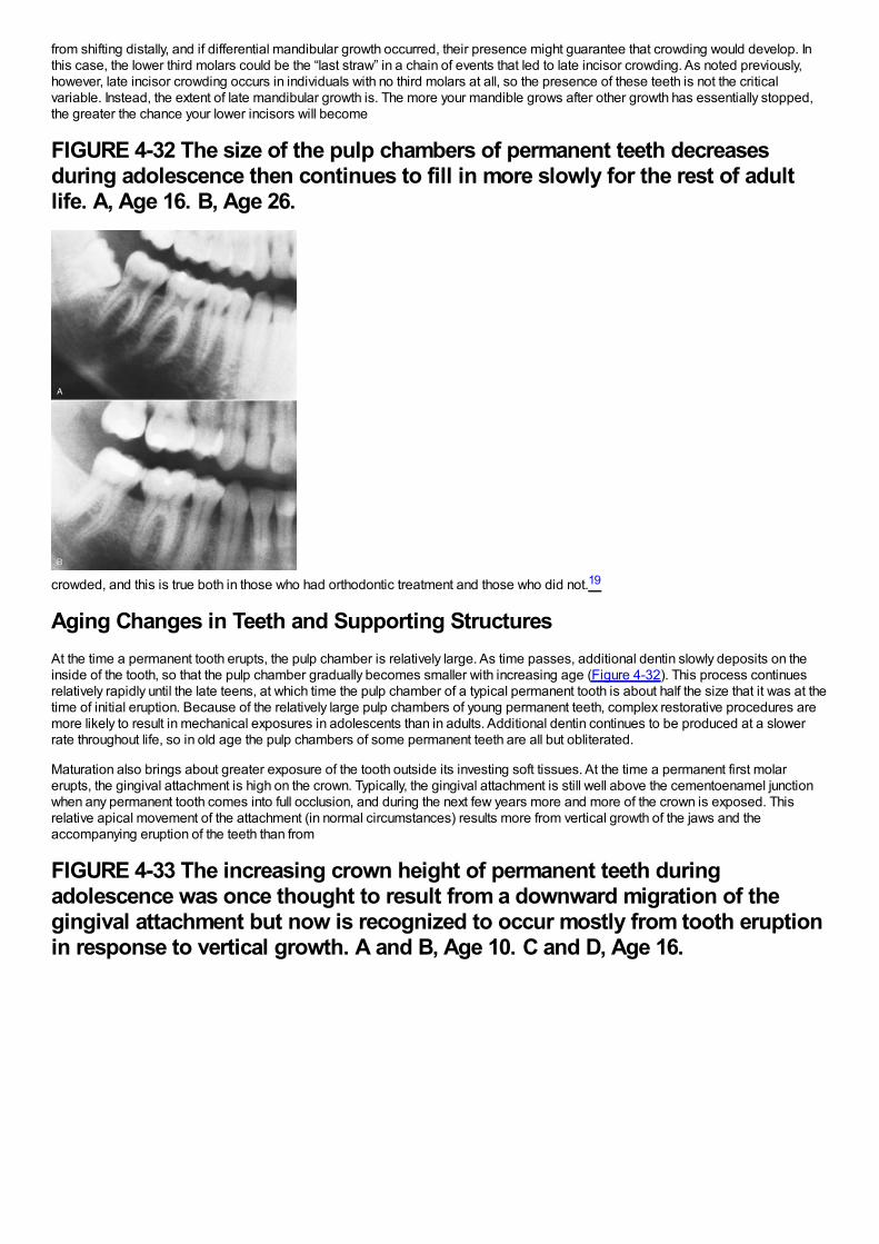
from shifting distally, and if differential mandibular growth occurred, their presence might guarantee that crowding would develop. Inthis case, the lower third molars could be the “last straw” in a chain of events that led to late incisor crowding. As noted previously,however, late incisor crowding occurs in individuals with no third molars at all, so the presence of these teeth is not the criticalvariable. Instead, the extent of late mandibular growth is. The more your mandible grows after other growth has essentially stopped,the greater the chance your lower incisors will become
FIGURE 4-32 The size of the pulp chambers of permanent teeth decreasesduring adolescence then continues to fill in more slowly for the rest of adultlife. A, Age 16. B, Age 26.
crowded, and this is true both in those who had orthodontic treatment and those who did not.19
Aging Changes in Teeth and Supporting StructuresAt the time a permanent tooth erupts, the pulp chamber is relatively large. As time passes, additional dentin slowly deposits on theinside of the tooth, so that the pulp chamber gradually becomes smaller with increasing age (Figure 4-32). This process continuesrelatively rapidly until the late teens, at which time the pulp chamber of a typical permanent tooth is about half the size that it was at thetime of initial eruption. Because of the relatively large pulp chambers of young permanent teeth, complex restorative procedures aremore likely to result in mechanical exposures in adolescents than in adults. Additional dentin continues to be produced at a slowerrate throughout life, so in old age the pulp chambers of some permanent teeth are all but obliterated.
Maturation also brings about greater exposure of the tooth outside its investing soft tissues. At the time a permanent first molarerupts, the gingival attachment is high on the crown. Typically, the gingival attachment is still well above the cementoenamel junctionwhen any permanent tooth comes into full occlusion, and during the next few years more and more of the crown is exposed. Thisrelative apical movement of the attachment (in normal circumstances) results more from vertical growth of the jaws and theaccompanying eruption of the teeth than from
FIGURE 4-33 The increasing crown height of permanent teeth duringadolescence was once thought to result from a downward migration of thegingival attachment but now is recognized to occur mostly from tooth eruptionin response to vertical growth. A and B, Age 10. C and D, Age 16.
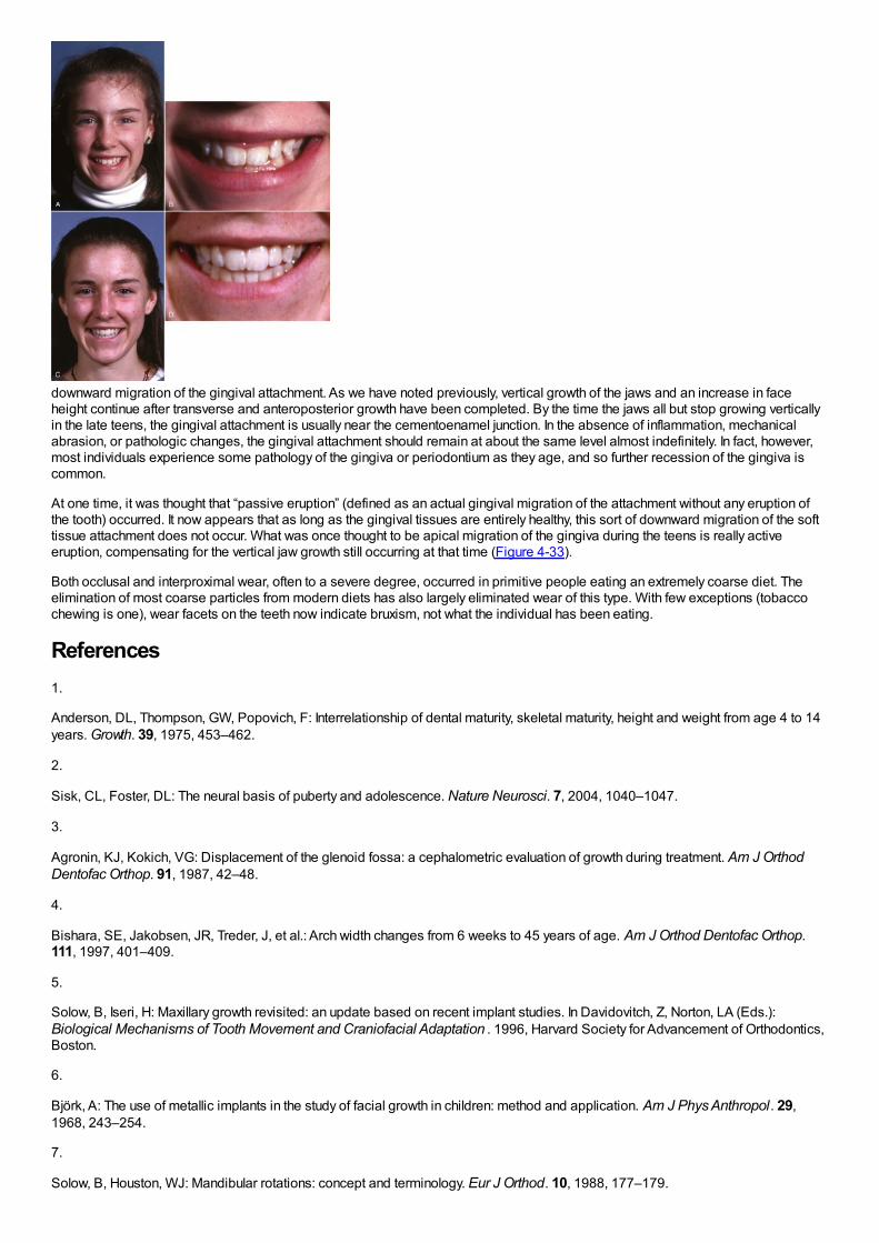
downward migration of the gingival attachment. As we have noted previously, vertical growth of the jaws and an increase in faceheight continue after transverse and anteroposterior growth have been completed. By the time the jaws all but stop growing verticallyin the late teens, the gingival attachment is usually near the cementoenamel junction. In the absence of inflammation, mechanicalabrasion, or pathologic changes, the gingival attachment should remain at about the same level almost indefinitely. In fact, however,most individuals experience some pathology of the gingiva or periodontium as they age, and so further recession of the gingiva iscommon.
At one time, it was thought that “passive eruption” (defined as an actual gingival migration of the attachment without any eruption ofthe tooth) occurred. It now appears that as long as the gingival tissues are entirely healthy, this sort of downward migration of the softtissue attachment does not occur. What was once thought to be apical migration of the gingiva during the teens is really activeeruption, compensating for the vertical jaw growth still occurring at that time (Figure 4-33).
Both occlusal and interproximal wear, often to a severe degree, occurred in primitive people eating an extremely coarse diet. Theelimination of most coarse particles from modern diets has also largely eliminated wear of this type. With few exceptions (tobaccochewing is one), wear facets on the teeth now indicate bruxism, not what the individual has been eating.
References1.
Anderson, DL, Thompson, GW, Popovich, F: Interrelationship of dental maturity, skeletal maturity, height and weight from age 4 to 14years. Growth. 39, 1975, 453–462.
2.
Sisk, CL, Foster, DL: The neural basis of puberty and adolescence. Nature Neurosci. 7, 2004, 1040–1047.
3.
Agronin, KJ, Kokich, VG: Displacement of the glenoid fossa: a cephalometric evaluation of growth during treatment. Am J OrthodDentofac Orthop. 91, 1987, 42–48.
4.
Bishara, SE, Jakobsen, JR, Treder, J, et al.: Arch width changes from 6 weeks to 45 years of age. Am J Orthod Dentofac Orthop.111, 1997, 401–409.
5.
Solow, B, Iseri, H: Maxillary growth revisited: an update based on recent implant studies. In Davidovitch, Z, Norton, LA (Eds.):Biological Mechanisms of Tooth Movement and Craniofacial Adaptation . 1996, Harvard Society for Advancement of Orthodontics,Boston.
6.
Björk, A: The use of metallic implants in the study of facial growth in children: method and application. Am J Phys Anthropol. 29,1968, 243–254.
7.
Solow, B, Houston, WJ: Mandibular rotations: concept and terminology. Eur J Orthod. 10, 1988, 177–179.

8.
Björk, A, Skieller, V: Normal and abnormal growth of the mandible: a synthesis of longitudinal cephalometric implant studies over aperiod of 25 years. Eur J Orthod. 5, 1983, 1–46.
9.
Björk, A, Skieller, V: Postnatal growth and development of the maxillary complex. In McNamara, JA (Ed.): Factors Affecting Growth ofthe Midface. 1976, University of Michigan Center for Human Growth and Development, Ann Arbor, Mich.
10.
Houston, WJ: Mandibular growth rotations—their mechanisms and importance. Eur J Orthod. 10, 1988, 369–373.
11.
Björk, A, Skieller, V: Contrasting mandibular growth and facial development in long face syndrome, juvenile rheumatoid arthritis andmandibulofacial dysostosis. J Craniofac Genet Dev Biol. 1(suppl), 1985, 127–138.
12.
Behrents, RG: A Treatise on the Continuum of Growth in the Aging Craniofacial Skeleton. 1984, University of Michigan Center forHuman Growth and Development, Ann Arbor, Mich.
13.
Harris, EF: A longitudinal study of arch size and form in untreated adults. Am J Orthod Dentofac Orthop. 111, 1997, 419–427.
14.
Pecora, NG, Beccetti, T, McNamara, JA Jr.: The aging craniofacial complex: a longitudinal cephalometric study from lateadolescence to late adulthood. Am J Orthod Dentofac Orthop. 134, 2008, 496–506.
15.
Begg, PR: Stone age man's dentition. Am J Orthod. 40, 1954, 298–312, 373-383, 462-475, 517-531.
16.
Corruccini, RS: Australian aboriginal tooth succession, interproximal attrition and Begg's theory. Am J Orthod Dentofac Orthop. 97,1990, 349–357.
17.
Southard, TE, Southard, KA, Weeda, LW: Mesial force from unerupted third molars. Am J Orthod Dentofac Orthop. 99, 1991, 220–225.
18.
Richardson, ME: Late lower arch crowding: the aetiology reviewed. Dent Update. 29, 2002, 234–238.
19.
Jonsson, T, Magnusson, TE: Crowding and spacing in the dental arches: long-term development in treated and untreated subjects.Am J Orthod Dentofac Orthop. 138, 2010, 384.e1–384.e7 discussion 384-386.
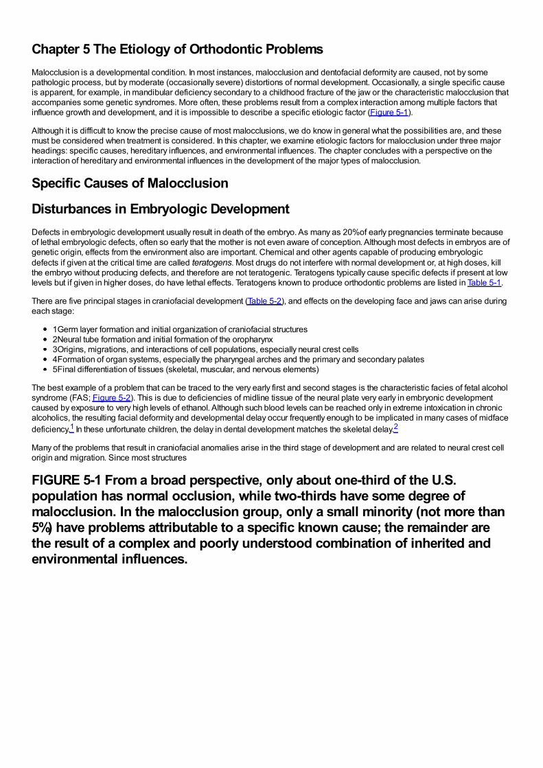
Chapter 5 The Etiology of Orthodontic ProblemsMalocclusion is a developmental condition. In most instances, malocclusion and dentofacial deformity are caused, not by somepathologic process, but by moderate (occasionally severe) distortions of normal development. Occasionally, a single specific causeis apparent, for example, in mandibular deficiency secondary to a childhood fracture of the jaw or the characteristic malocclusion thataccompanies some genetic syndromes. More often, these problems result from a complex interaction among multiple factors thatinfluence growth and development, and it is impossible to describe a specific etiologic factor (Figure 5-1).
Although it is difficult to know the precise cause of most malocclusions, we do know in general what the possibilities are, and thesemust be considered when treatment is considered. In this chapter, we examine etiologic factors for malocclusion under three majorheadings: specific causes, hereditary influences, and environmental influences. The chapter concludes with a perspective on theinteraction of hereditary and environmental influences in the development of the major types of malocclusion.
Specific Causes of Malocclusion
Disturbances in Embryologic DevelopmentDefects in embryologic development usually result in death of the embryo. As many as 20%of early pregnancies terminate becauseof lethal embryologic defects, often so early that the mother is not even aware of conception. Although most defects in embryos are ofgenetic origin, effects from the environment also are important. Chemical and other agents capable of producing embryologicdefects if given at the critical time are called teratogens. Most drugs do not interfere with normal development or, at high doses, killthe embryo without producing defects, and therefore are not teratogenic. Teratogens typically cause specific defects if present at lowlevels but if given in higher doses, do have lethal effects. Teratogens known to produce orthodontic problems are listed in Table 5-1.
There are five principal stages in craniofacial development (Table 5-2), and effects on the developing face and jaws can arise duringeach stage:
1Germ layer formation and initial organization of craniofacial structures2Neural tube formation and initial formation of the oropharynx3Origins, migrations, and interactions of cell populations, especially neural crest cells4Formation of organ systems, especially the pharyngeal arches and the primary and secondary palates5Final differentiation of tissues (skeletal, muscular, and nervous elements)
The best example of a problem that can be traced to the very early first and second stages is the characteristic facies of fetal alcoholsyndrome (FAS; Figure 5-2). This is due to deficiencies of midline tissue of the neural plate very early in embryonic developmentcaused by exposure to very high levels of ethanol. Although such blood levels can be reached only in extreme intoxication in chronicalcoholics, the resulting facial deformity and developmental delay occur frequently enough to be implicated in many cases of midfacedeficiency.1 In these unfortunate children, the delay in dental development matches the skeletal delay.2
Many of the problems that result in craniofacial anomalies arise in the third stage of development and are related to neural crest cellorigin and migration. Since most structures
FIGURE 5-1 From a broad perspective, only about one-third of the U.S.population has normal occlusion, while two-thirds have some degree ofmalocclusion. In the malocclusion group, only a small minority (not more than5%) have problems attributable to a specific known cause; the remainder arethe result of a complex and poorly understood combination of inherited andenvironmental influences.

of the face are ultimately derived from migrating neural crest cells (Figure 5-3), it is not surprising that interferences with this migrationproduce facial deformities. At the completion of the migration of the neural crest cells in the fourth week of human embryonic life, theyform practically all of the
FIGURE 5-2 The characteristic facial appearance of fetal alcohol syndrome(FAS), caused by exposure to very high blood alcohol levels during the firsttrimester of pregnancy.
FIGURE 5-3 Diagrammatic lateral sections of embryos at 20 and 24 days,showing formation of the neural folds, neural groove, and neural crest. A, At 20days, neural crest cells (pink) can be identified at the lips of the deepeningneural groove, forerunner of the central nervous system. B, At 24 days, theneural crest cells have separated from the neural tube and are beginning theirextensive migration beneath the surface ectoderm. The migration is soextensive and the role of these neural crest cells is so important in formation ofstructures of the head and face that they can almost be considered a fourthprimary germ layer.
loose mesenchymal tissue in the facial region that lies between the surface ectoderm and the underlying forebrain and eye and mostof the mesenchyme in the mandibular arch. Most of the neural crest cells in the facial area later differentiate into skeletal andconnective tissues, including the bones of the jaw and the teeth.
TABLE 5-1 Teratogens Affecting Dentofacial Development
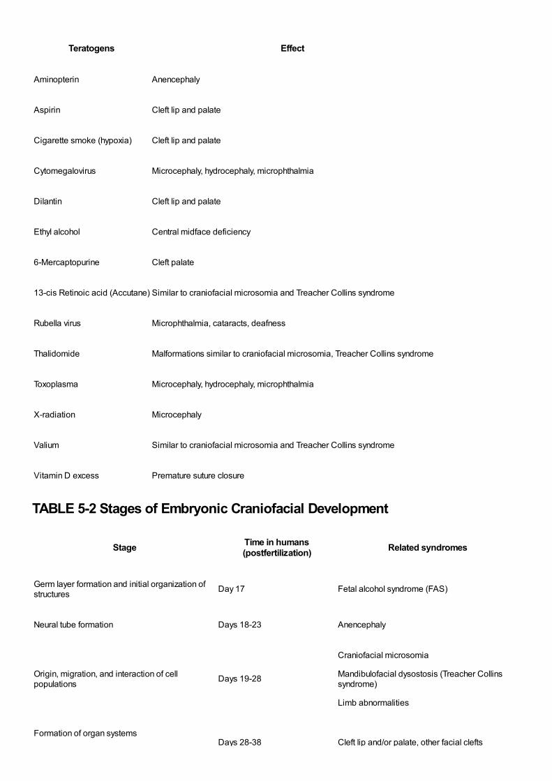
Teratogens Effect
Aminopterin Anencephaly
Aspirin Cleft lip and palate
Cigarette smoke (hypoxia) Cleft lip and palate
Cytomegalovirus Microcephaly, hydrocephaly, microphthalmia
Dilantin Cleft lip and palate
Ethyl alcohol Central midface deficiency
6-Mercaptopurine Cleft palate
13-cis Retinoic acid (Accutane) Similar to craniofacial microsomia and Treacher Collins syndrome
Rubella virus Microphthalmia, cataracts, deafness
Thalidomide Malformations similar to craniofacial microsomia, Treacher Collins syndrome
Toxoplasma Microcephaly, hydrocephaly, microphthalmia
X-radiation Microcephaly
Valium Similar to craniofacial microsomia and Treacher Collins syndrome
Vitamin D excess Premature suture closure
TABLE 5-2 Stages of Embryonic Craniofacial Development
Stage Time in humans(postfertilization) Related syndromes
Germ layer formation and initial organization ofstructures Day 17 Fetal alcohol syndrome (FAS)
Neural tube formation Days 18-23 Anencephaly
Origin, migration, and interaction of cellpopulations Days 19-28
Craniofacial microsomia
Mandibulofacial dysostosis (Treacher Collinssyndrome)
Limb abnormalities
Formation of organ systemsDays 28-38 Cleft lip and/or palate, other facial clefts
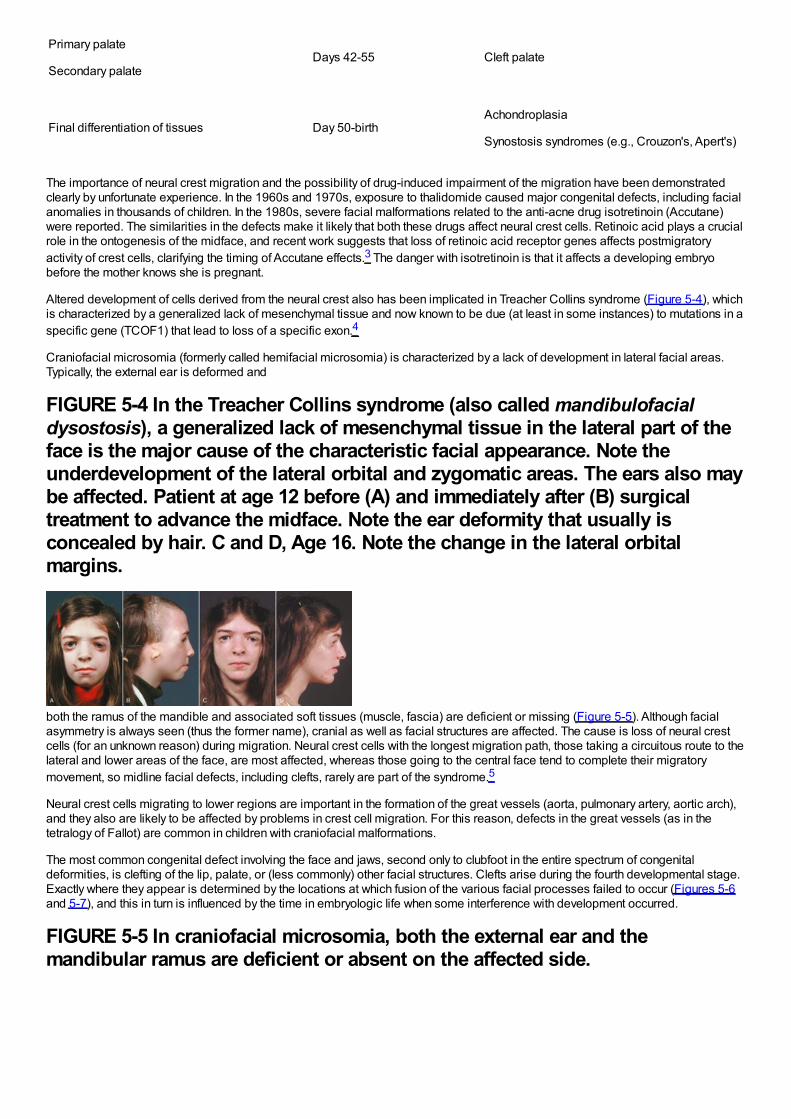
Primary palate
Secondary palateDays 42-55 Cleft palate
Final differentiation of tissues Day 50-birthAchondroplasia
Synostosis syndromes (e.g., Crouzon's, Apert's)
The importance of neural crest migration and the possibility of drug-induced impairment of the migration have been demonstratedclearly by unfortunate experience. In the 1960s and 1970s, exposure to thalidomide caused major congenital defects, including facialanomalies in thousands of children. In the 1980s, severe facial malformations related to the anti-acne drug isotretinoin (Accutane)were reported. The similarities in the defects make it likely that both these drugs affect neural crest cells. Retinoic acid plays a crucialrole in the ontogenesis of the midface, and recent work suggests that loss of retinoic acid receptor genes affects postmigratoryactivity of crest cells, clarifying the timing of Accutane effects.3 The danger with isotretinoin is that it affects a developing embryobefore the mother knows she is pregnant.
Altered development of cells derived from the neural crest also has been implicated in Treacher Collins syndrome (Figure 5-4), whichis characterized by a generalized lack of mesenchymal tissue and now known to be due (at least in some instances) to mutations in aspecific gene (TCOF1) that lead to loss of a specific exon.4
Craniofacial microsomia (formerly called hemifacial microsomia) is characterized by a lack of development in lateral facial areas.Typically, the external ear is deformed and
FIGURE 5-4 In the Treacher Collins syndrome (also called mandibulofacialdysostosis), a generalized lack of mesenchymal tissue in the lateral part of theface is the major cause of the characteristic facial appearance. Note theunderdevelopment of the lateral orbital and zygomatic areas. The ears also maybe affected. Patient at age 12 before (A) and immediately after (B) surgicaltreatment to advance the midface. Note the ear deformity that usually isconcealed by hair. C and D, Age 16. Note the change in the lateral orbitalmargins.
both the ramus of the mandible and associated soft tissues (muscle, fascia) are deficient or missing (Figure 5-5). Although facialasymmetry is always seen (thus the former name), cranial as well as facial structures are affected. The cause is loss of neural crestcells (for an unknown reason) during migration. Neural crest cells with the longest migration path, those taking a circuitous route to thelateral and lower areas of the face, are most affected, whereas those going to the central face tend to complete their migratorymovement, so midline facial defects, including clefts, rarely are part of the syndrome.5
Neural crest cells migrating to lower regions are important in the formation of the great vessels (aorta, pulmonary artery, aortic arch),and they also are likely to be affected by problems in crest cell migration. For this reason, defects in the great vessels (as in thetetralogy of Fallot) are common in children with craniofacial malformations.
The most common congenital defect involving the face and jaws, second only to clubfoot in the entire spectrum of congenitaldeformities, is clefting of the lip, palate, or (less commonly) other facial structures. Clefts arise during the fourth developmental stage.Exactly where they appear is determined by the locations at which fusion of the various facial processes failed to occur (Figures 5-6and 5-7), and this in turn is influenced by the time in embryologic life when some interference with development occurred.
FIGURE 5-5 In craniofacial microsomia, both the external ear and themandibular ramus are deficient or absent on the affected side.
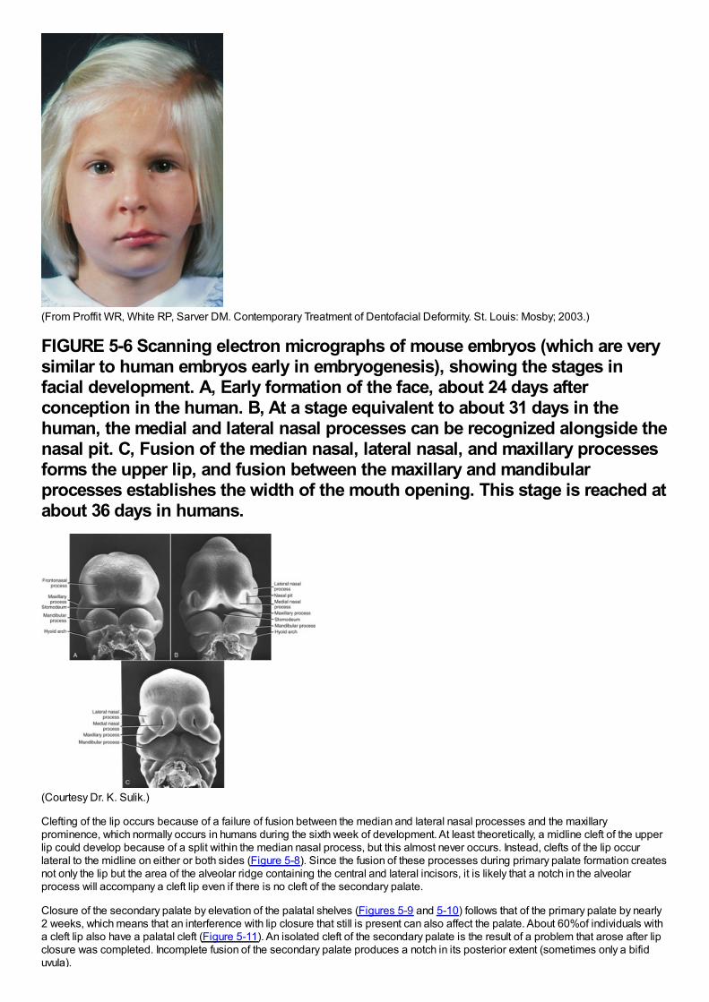
(From Proffit WR, White RP, Sarver DM. Contemporary Treatment of Dentofacial Deformity. St. Louis: Mosby; 2003.)
FIGURE 5-6 Scanning electron micrographs of mouse embryos (which are verysimilar to human embryos early in embryogenesis), showing the stages infacial development. A, Early formation of the face, about 24 days afterconception in the human. B, At a stage equivalent to about 31 days in thehuman, the medial and lateral nasal processes can be recognized alongside thenasal pit. C, Fusion of the median nasal, lateral nasal, and maxillary processesforms the upper lip, and fusion between the maxillary and mandibularprocesses establishes the width of the mouth opening. This stage is reached atabout 36 days in humans.
(Courtesy Dr. K. Sulik.)
Clefting of the lip occurs because of a failure of fusion between the median and lateral nasal processes and the maxillaryprominence, which normally occurs in humans during the sixth week of development. At least theoretically, a midline cleft of the upperlip could develop because of a split within the median nasal process, but this almost never occurs. Instead, clefts of the lip occurlateral to the midline on either or both sides (Figure 5-8). Since the fusion of these processes during primary palate formation createsnot only the lip but the area of the alveolar ridge containing the central and lateral incisors, it is likely that a notch in the alveolarprocess will accompany a cleft lip even if there is no cleft of the secondary palate.
Closure of the secondary palate by elevation of the palatal shelves (Figures 5-9 and 5-10) follows that of the primary palate by nearly2 weeks, which means that an interference with lip closure that still is present can also affect the palate. About 60%of individuals witha cleft lip also have a palatal cleft (Figure 5-11). An isolated cleft of the secondary palate is the result of a problem that arose after lipclosure was completed. Incomplete fusion of the secondary palate produces a notch in its posterior extent (sometimes only a bifiduvula).
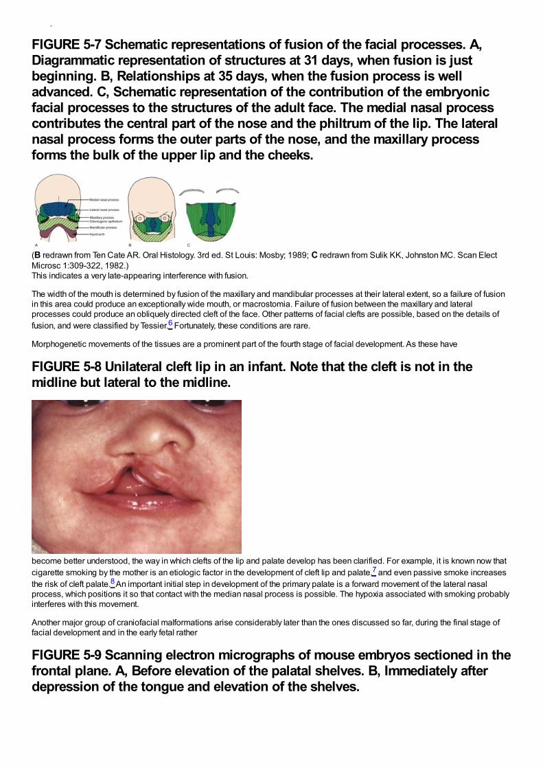
uvula).
FIGURE 5-7 Schematic representations of fusion of the facial processes. A,Diagrammatic representation of structures at 31 days, when fusion is justbeginning. B, Relationships at 35 days, when the fusion process is welladvanced. C, Schematic representation of the contribution of the embryonicfacial processes to the structures of the adult face. The medial nasal processcontributes the central part of the nose and the philtrum of the lip. The lateralnasal process forms the outer parts of the nose, and the maxillary processforms the bulk of the upper lip and the cheeks.
(B redrawn from Ten Cate AR. Oral Histology. 3rd ed. St Louis: Mosby; 1989; C redrawn from Sulik KK, Johnston MC. Scan ElectMicrosc 1:309-322, 1982.)This indicates a very late-appearing interference with fusion.
The width of the mouth is determined by fusion of the maxillary and mandibular processes at their lateral extent, so a failure of fusionin this area could produce an exceptionally wide mouth, or macrostomia. Failure of fusion between the maxillary and lateralprocesses could produce an obliquely directed cleft of the face. Other patterns of facial clefts are possible, based on the details offusion, and were classified by Tessier.6 Fortunately, these conditions are rare.
Morphogenetic movements of the tissues are a prominent part of the fourth stage of facial development. As these have
FIGURE 5-8 Unilateral cleft lip in an infant. Note that the cleft is not in themidline but lateral to the midline.
become better understood, the way in which clefts of the lip and palate develop has been clarified. For example, it is known now thatcigarette smoking by the mother is an etiologic factor in the development of cleft lip and palate,7 and even passive smoke increasesthe risk of cleft palate.8 An important initial step in development of the primary palate is a forward movement of the lateral nasalprocess, which positions it so that contact with the median nasal process is possible. The hypoxia associated with smoking probablyinterferes with this movement.
Another major group of craniofacial malformations arise considerably later than the ones discussed so far, during the final stage offacial development and in the early fetal rather
FIGURE 5-9 Scanning electron micrographs of mouse embryos sectioned in thefrontal plane. A, Before elevation of the palatal shelves. B, Immediately afterdepression of the tongue and elevation of the shelves.
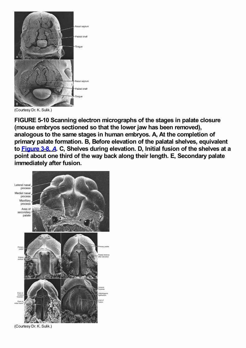
(Courtesy Dr. K. Sulik.)
FIGURE 5-10 Scanning electron micrographs of the stages in palate closure(mouse embryos sectioned so that the lower jaw has been removed),analogous to the same stages in human embryos. A, At the completion ofprimary palate formation. B, Before elevation of the palatal shelves, equivalentto Figure 3-8, A. C, Shelves during elevation. D, Initial fusion of the shelves at apoint about one third of the way back along their length. E, Secondary palateimmediately after fusion.
(Courtesy Dr. K. Sulik.)
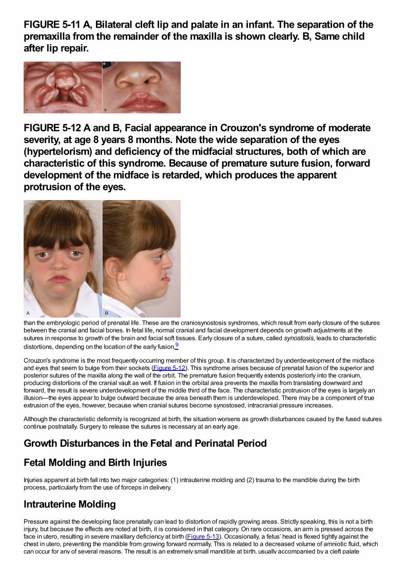
FIGURE 5-11 A, Bilateral cleft lip and palate in an infant. The separation of thepremaxilla from the remainder of the maxilla is shown clearly. B, Same childafter lip repair.
FIGURE 5-12 A and B, Facial appearance in Crouzon's syndrome of moderateseverity, at age 8 years 8 months. Note the wide separation of the eyes(hypertelorism) and deficiency of the midfacial structures, both of which arecharacteristic of this syndrome. Because of premature suture fusion, forwarddevelopment of the midface is retarded, which produces the apparentprotrusion of the eyes.
than the embryologic period of prenatal life. These are the craniosynostosis syndromes, which result from early closure of the suturesbetween the cranial and facial bones. In fetal life, normal cranial and facial development depends on growth adjustments at thesutures in response to growth of the brain and facial soft tissues. Early closure of a suture, called synostosis, leads to characteristicdistortions, depending on the location of the early fusion.9
Crouzon's syndrome is the most frequently occurring member of this group. It is characterized by underdevelopment of the midfaceand eyes that seem to bulge from their sockets (Figure 5-12). This syndrome arises because of prenatal fusion of the superior andposterior sutures of the maxilla along the wall of the orbit. The premature fusion frequently extends posteriorly into the cranium,producing distortions of the cranial vault as well. If fusion in the orbital area prevents the maxilla from translating downward andforward, the result is severe underdevelopment of the middle third of the face. The characteristic protrusion of the eyes is largely anillusion—the eyes appear to bulge outward because the area beneath them is underdeveloped. There may be a component of trueextrusion of the eyes, however, because when cranial sutures become synostosed, intracranial pressure increases.
Although the characteristic deformity is recognized at birth, the situation worsens as growth disturbances caused by the fused suturescontinue postnatally. Surgery to release the sutures is necessary at an early age.
Growth Disturbances in the Fetal and Perinatal Period
Fetal Molding and Birth InjuriesInjuries apparent at birth fall into two major categories: (1) intrauterine molding and (2) trauma to the mandible during the birthprocess, particularly from the use of forceps in delivery.
Intrauterine MoldingPressure against the developing face prenatally can lead to distortion of rapidly growing areas. Strictly speaking, this is not a birthinjury, but because the effects are noted at birth, it is considered in that category. On rare occasions, an arm is pressed across theface in utero, resulting in severe maxillary deficiency at birth (Figure 5-13). Occasionally, a fetus’ head is flexed tightly against thechest in utero, preventing the mandible from growing forward normally. This is related to a decreased volume of amniotic fluid, whichcan occur for any of several reasons. The result is an extremely small mandible at birth, usually accompanied by a cleft palate
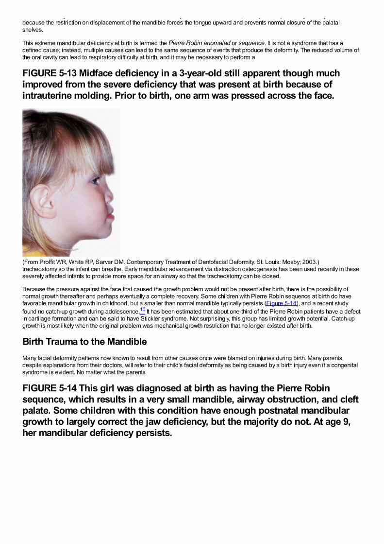
can occur for any of several reasons. The result is an extremely small mandible at birth, usually accompanied by a cleft palatebecause the restriction on displacement of the mandible forces the tongue upward and prevents normal closure of the palatalshelves.
This extreme mandibular deficiency at birth is termed the Pierre Robin anomalad or sequence. It is not a syndrome that has adefined cause; instead, multiple causes can lead to the same sequence of events that produce the deformity. The reduced volume ofthe oral cavity can lead to respiratory difficulty at birth, and it may be necessary to perform a
FIGURE 5-13 Midface deficiency in a 3-year-old still apparent though muchimproved from the severe deficiency that was present at birth because ofintrauterine molding. Prior to birth, one arm was pressed across the face.
(From Proffit WR, White RP, Sarver DM. Contemporary Treatment of Dentofacial Deformity. St. Louis: Mosby; 2003.)tracheostomy so the infant can breathe. Early mandibular advancement via distraction osteogenesis has been used recently in theseseverely affected infants to provide more space for an airway so that the tracheostomy can be closed.
Because the pressure against the face that caused the growth problem would not be present after birth, there is the possibility ofnormal growth thereafter and perhaps eventually a complete recovery. Some children with Pierre Robin sequence at birth do havefavorable mandibular growth in childhood, but a smaller than normal mandible typically persists (Figure 5-14), and a recent studyfound no catch-up growth during adolescence.10 It has been estimated that about one-third of the Pierre Robin patients have a defectin cartilage formation and can be said to have Stickler syndrome. Not surprisingly, this group has limited growth potential. Catch-upgrowth is most likely when the original problem was mechanical growth restriction that no longer existed after birth.
Birth Trauma to the MandibleMany facial deformity patterns now known to result from other causes once were blamed on injuries during birth. Many parents,despite explanations from their doctors, will refer to their child's facial deformity as being caused by a birth injury even if a congenitalsyndrome is evident. No matter what the parents
FIGURE 5-14 This girl was diagnosed at birth as having the Pierre Robinsequence, which results in a very small mandible, airway obstruction, and cleftpalate. Some children with this condition have enough postnatal mandibulargrowth to largely correct the jaw deficiency, but the majority do not. At age 9,her mandibular deficiency persists.
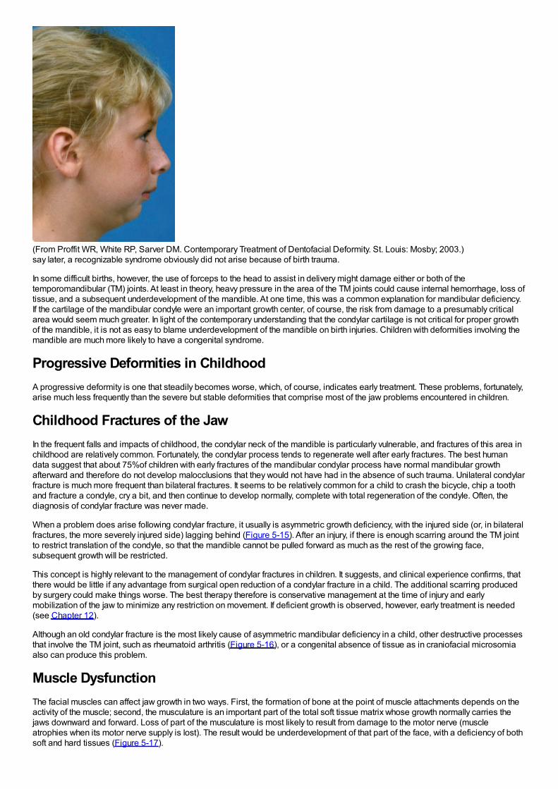
(From Proffit WR, White RP, Sarver DM. Contemporary Treatment of Dentofacial Deformity. St. Louis: Mosby; 2003.)say later, a recognizable syndrome obviously did not arise because of birth trauma.
In some difficult births, however, the use of forceps to the head to assist in delivery might damage either or both of thetemporomandibular (TM) joints. At least in theory, heavy pressure in the area of the TM joints could cause internal hemorrhage, loss oftissue, and a subsequent underdevelopment of the mandible. At one time, this was a common explanation for mandibular deficiency.If the cartilage of the mandibular condyle were an important growth center, of course, the risk from damage to a presumably criticalarea would seem much greater. In light of the contemporary understanding that the condylar cartilage is not critical for proper growthof the mandible, it is not as easy to blame underdevelopment of the mandible on birth injuries. Children with deformities involving themandible are much more likely to have a congenital syndrome.
Progressive Deformities in ChildhoodA progressive deformity is one that steadily becomes worse, which, of course, indicates early treatment. These problems, fortunately,arise much less frequently than the severe but stable deformities that comprise most of the jaw problems encountered in children.
Childhood Fractures of the JawIn the frequent falls and impacts of childhood, the condylar neck of the mandible is particularly vulnerable, and fractures of this area inchildhood are relatively common. Fortunately, the condylar process tends to regenerate well after early fractures. The best humandata suggest that about 75%of children with early fractures of the mandibular condylar process have normal mandibular growthafterward and therefore do not develop malocclusions that they would not have had in the absence of such trauma. Unilateral condylarfracture is much more frequent than bilateral fractures. It seems to be relatively common for a child to crash the bicycle, chip a toothand fracture a condyle, cry a bit, and then continue to develop normally, complete with total regeneration of the condyle. Often, thediagnosis of condylar fracture was never made.
When a problem does arise following condylar fracture, it usually is asymmetric growth deficiency, with the injured side (or, in bilateralfractures, the more severely injured side) lagging behind (Figure 5-15). After an injury, if there is enough scarring around the TM jointto restrict translation of the condyle, so that the mandible cannot be pulled forward as much as the rest of the growing face,subsequent growth will be restricted.
This concept is highly relevant to the management of condylar fractures in children. It suggests, and clinical experience confirms, thatthere would be little if any advantage from surgical open reduction of a condylar fracture in a child. The additional scarring producedby surgery could make things worse. The best therapy therefore is conservative management at the time of injury and earlymobilization of the jaw to minimize any restriction on movement. If deficient growth is observed, however, early treatment is needed(see Chapter 12).
Although an old condylar fracture is the most likely cause of asymmetric mandibular deficiency in a child, other destructive processesthat involve the TM joint, such as rheumatoid arthritis (Figure 5-16), or a congenital absence of tissue as in craniofacial microsomiaalso can produce this problem.
Muscle DysfunctionThe facial muscles can affect jaw growth in two ways. First, the formation of bone at the point of muscle attachments depends on theactivity of the muscle; second, the musculature is an important part of the total soft tissue matrix whose growth normally carries thejaws downward and forward. Loss of part of the musculature is most likely to result from damage to the motor nerve (muscleatrophies when its motor nerve supply is lost). The result would be underdevelopment of that part of the face, with a deficiency of bothsoft and hard tissues (Figure 5-17).
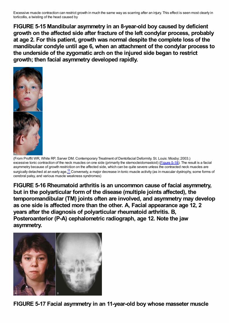
Excessive muscle contraction can restrict growth in much the same way as scarring after an injury. This effect is seen most clearly intorticollis, a twisting of the head caused by
FIGURE 5-15 Mandibular asymmetry in an 8-year-old boy caused by deficientgrowth on the affected side after fracture of the left condylar process, probablyat age 2. For this patient, growth was normal despite the complete loss of themandibular condyle until age 6, when an attachment of the condylar process tothe underside of the zygomatic arch on the injured side began to restrictgrowth; then facial asymmetry developed rapidly.
(From Proffit WR, White RP, Sarver DM. Contemporary Treatment of Dentofacial Deformity. St. Louis: Mosby; 2003.)excessive tonic contraction of the neck muscles on one side (primarily the sternocleidomastoid) (Figure 5-18). The result is a facialasymmetry because of growth restriction on the affected side, which can be quite severe unless the contracted neck muscles aresurgically detached at an early age.11 Conversely, a major decrease in tonic muscle activity (as in muscular dystrophy, some forms ofcerebral palsy, and various muscle weakness syndromes)
FIGURE 5-16 Rheumatoid arthritis is an uncommon cause of facial asymmetry,but in the polyarticular form of the disease (multiple joints affected), thetemporomandibular (TM) joints often are involved, and asymmetry may developas one side is affected more than the other. A, Facial appearance age 12, 2years after the diagnosis of polyarticular rheumatoid arthritis. B,Posteroanterior (P-A) cephalometric radiograph, age 12. Note the jawasymmetry.
FIGURE 5-17 Facial asymmetry in an 11-year-old boy whose masseter muscle
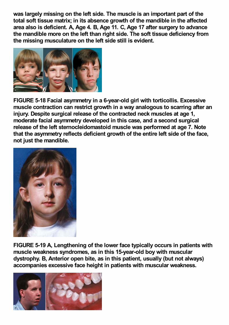
was largely missing on the left side. The muscle is an important part of thetotal soft tissue matrix; in its absence growth of the mandible in the affectedarea also is deficient. A, Age 4. B, Age 11. C, Age 17 after surgery to advancethe mandible more on the left than right side. The soft tissue deficiency fromthe missing musculature on the left side still is evident.
FIGURE 5-18 Facial asymmetry in a 6-year-old girl with torticollis. Excessivemuscle contraction can restrict growth in a way analogous to scarring after aninjury. Despite surgical release of the contracted neck muscles at age 1,moderate facial asymmetry developed in this case, and a second surgicalrelease of the left sternocleidomastoid muscle was performed at age 7. Notethat the asymmetry reflects deficient growth of the entire left side of the face,not just the mandible.
FIGURE 5-19 A, Lengthening of the lower face typically occurs in patients withmuscle weakness syndromes, as in this 15-year-old boy with musculardystrophy. B, Anterior open bite, as in this patient, usually (but not always)accompanies excessive face height in patients with muscular weakness.
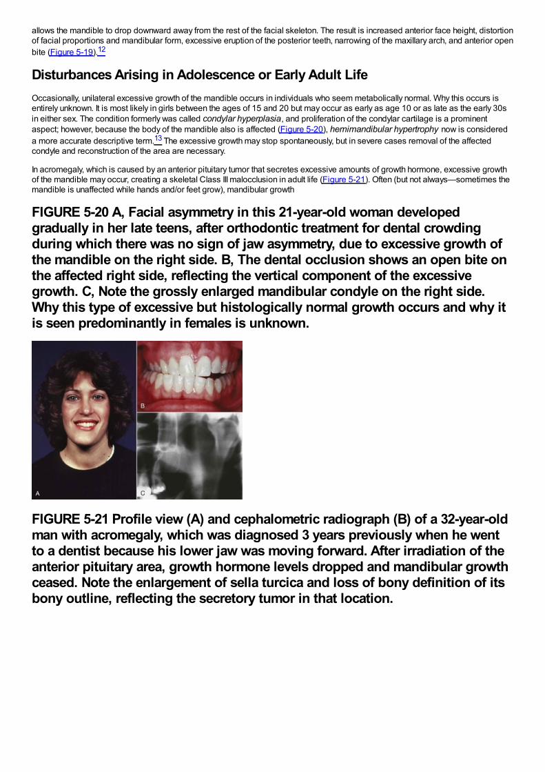
allows the mandible to drop downward away from the rest of the facial skeleton. The result is increased anterior face height, distortionof facial proportions and mandibular form, excessive eruption of the posterior teeth, narrowing of the maxillary arch, and anterior openbite (Figure 5-19).12
Disturbances Arising in Adolescence or Early Adult LifeOccasionally, unilateral excessive growth of the mandible occurs in individuals who seem metabolically normal. Why this occurs isentirely unknown. It is most likely in girls between the ages of 15 and 20 but may occur as early as age 10 or as late as the early 30sin either sex. The condition formerly was called condylar hyperplasia, and proliferation of the condylar cartilage is a prominentaspect; however, because the body of the mandible also is affected (Figure 5-20), hemimandibular hypertrophy now is considereda more accurate descriptive term.13 The excessive growth may stop spontaneously, but in severe cases removal of the affectedcondyle and reconstruction of the area are necessary.
In acromegaly, which is caused by an anterior pituitary tumor that secretes excessive amounts of growth hormone, excessive growthof the mandible may occur, creating a skeletal Class III malocclusion in adult life (Figure 5-21). Often (but not always—sometimes themandible is unaffected while hands and/or feet grow), mandibular growth
FIGURE 5-20 A, Facial asymmetry in this 21-year-old woman developedgradually in her late teens, after orthodontic treatment for dental crowdingduring which there was no sign of jaw asymmetry, due to excessive growth ofthe mandible on the right side. B, The dental occlusion shows an open bite onthe affected right side, reflecting the vertical component of the excessivegrowth. C, Note the grossly enlarged mandibular condyle on the right side.Why this type of excessive but histologically normal growth occurs and why itis seen predominantly in females is unknown.
FIGURE 5-21 Profile view (A) and cephalometric radiograph (B) of a 32-year-oldman with acromegaly, which was diagnosed 3 years previously when he wentto a dentist because his lower jaw was moving forward. After irradiation of theanterior pituitary area, growth hormone levels dropped and mandibular growthceased. Note the enlargement of sella turcica and loss of bony definition of itsbony outline, reflecting the secretory tumor in that location.
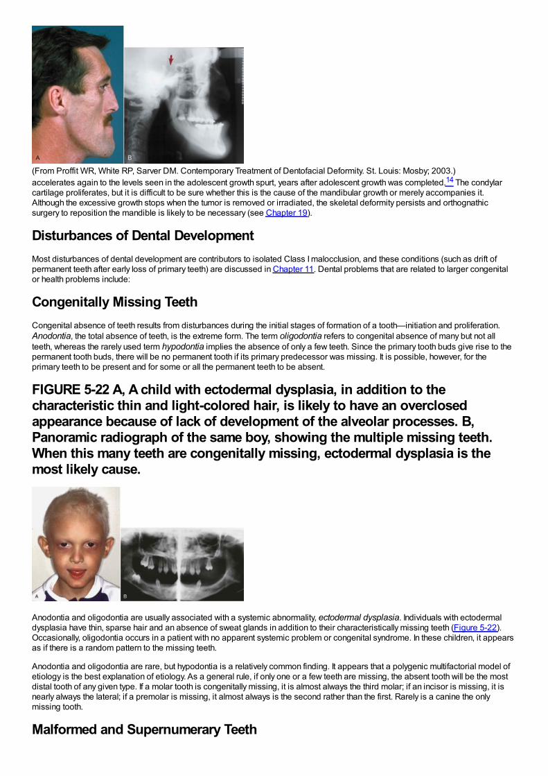
(From Proffit WR, White RP, Sarver DM. Contemporary Treatment of Dentofacial Deformity. St. Louis: Mosby; 2003.)accelerates again to the levels seen in the adolescent growth spurt, years after adolescent growth was completed.14 The condylarcartilage proliferates, but it is difficult to be sure whether this is the cause of the mandibular growth or merely accompanies it.Although the excessive growth stops when the tumor is removed or irradiated, the skeletal deformity persists and orthognathicsurgery to reposition the mandible is likely to be necessary (see Chapter 19).
Disturbances of Dental DevelopmentMost disturbances of dental development are contributors to isolated Class I malocclusion, and these conditions (such as drift ofpermanent teeth after early loss of primary teeth) are discussed in Chapter 11. Dental problems that are related to larger congenitalor health problems include:
Congenitally Missing TeethCongenital absence of teeth results from disturbances during the initial stages of formation of a tooth—initiation and proliferation.Anodontia, the total absence of teeth, is the extreme form. The term oligodontia refers to congenital absence of many but not allteeth, whereas the rarely used term hypodontia implies the absence of only a few teeth. Since the primary tooth buds give rise to thepermanent tooth buds, there will be no permanent tooth if its primary predecessor was missing. It is possible, however, for theprimary teeth to be present and for some or all the permanent teeth to be absent.
FIGURE 5-22 A, A child with ectodermal dysplasia, in addition to thecharacteristic thin and light-colored hair, is likely to have an overclosedappearance because of lack of development of the alveolar processes. B,Panoramic radiograph of the same boy, showing the multiple missing teeth.When this many teeth are congenitally missing, ectodermal dysplasia is themost likely cause.
Anodontia and oligodontia are usually associated with a systemic abnormality, ectodermal dysplasia. Individuals with ectodermaldysplasia have thin, sparse hair and an absence of sweat glands in addition to their characteristically missing teeth (Figure 5-22).Occasionally, oligodontia occurs in a patient with no apparent systemic problem or congenital syndrome. In these children, it appearsas if there is a random pattern to the missing teeth.
Anodontia and oligodontia are rare, but hypodontia is a relatively common finding. It appears that a polygenic multifactorial model ofetiology is the best explanation of etiology. As a general rule, if only one or a few teeth are missing, the absent tooth will be the mostdistal tooth of any given type. If a molar tooth is congenitally missing, it is almost always the third molar; if an incisor is missing, it isnearly always the lateral; if a premolar is missing, it almost always is the second rather than the first. Rarely is a canine the onlymissing tooth.
Malformed and Supernumerary Teeth
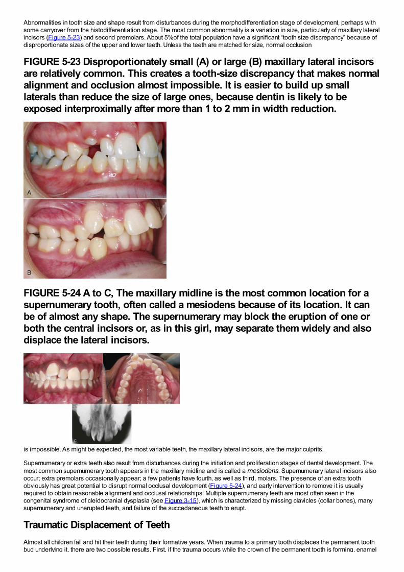
Abnormalities in tooth size and shape result from disturbances during the morphodifferentiation stage of development, perhaps withsome carryover from the histodifferentiation stage. The most common abnormality is a variation in size, particularly of maxillary lateralincisors (Figure 5-23) and second premolars. About 5%of the total population have a significant “tooth size discrepancy” because ofdisproportionate sizes of the upper and lower teeth. Unless the teeth are matched for size, normal occlusion
FIGURE 5-23 Disproportionately small (A) or large (B) maxillary lateral incisorsare relatively common. This creates a tooth-size discrepancy that makes normalalignment and occlusion almost impossible. It is easier to build up smalllaterals than reduce the size of large ones, because dentin is likely to beexposed interproximally after more than 1 to 2 mm in width reduction.
FIGURE 5-24 A to C, The maxillary midline is the most common location for asupernumerary tooth, often called a mesiodens because of its location. It canbe of almost any shape. The supernumerary may block the eruption of one orboth the central incisors or, as in this girl, may separate them widely and alsodisplace the lateral incisors.
is impossible. As might be expected, the most variable teeth, the maxillary lateral incisors, are the major culprits.
Supernumerary or extra teeth also result from disturbances during the initiation and proliferation stages of dental development. Themost common supernumerary tooth appears in the maxillary midline and is called a mesiodens. Supernumerary lateral incisors alsooccur; extra premolars occasionally appear; a few patients have fourth, as well as third, molars. The presence of an extra toothobviously has great potential to disrupt normal occlusal development (Figure 5-24), and early intervention to remove it is usuallyrequired to obtain reasonable alignment and occlusal relationships. Multiple supernumerary teeth are most often seen in thecongenital syndrome of cleidocranial dysplasia (see Figure 3-15), which is characterized by missing clavicles (collar bones), manysupernumerary and unerupted teeth, and failure of the succedaneous teeth to erupt.
Traumatic Displacement of TeethAlmost all children fall and hit their teeth during their formative years. When trauma to a primary tooth displaces the permanent toothbud underlying it, there are two possible results. First, if the trauma occurs while the crown of the permanent tooth is forming, enamel
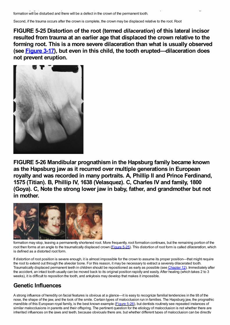
bud underlying it, there are two possible results. First, if the trauma occurs while the crown of the permanent tooth is forming, enamelformation will be disturbed and there will be a defect in the crown of the permanent tooth.
Second, if the trauma occurs after the crown is complete, the crown may be displaced relative to the root. Root
FIGURE 5-25 Distortion of the root (termed dilaceration) of this lateral incisorresulted from trauma at an earlier age that displaced the crown relative to theforming root. This is a more severe dilaceration than what is usually observed(see Figure 3-17), but even in this child, the tooth erupted—dilaceration doesnot prevent eruption.
FIGURE 5-26 Mandibular prognathism in the Hapsburg family became knownas the Hapsburg jaw as it recurred over multiple generations in Europeanroyalty and was recorded in many portraits. A, Phillip II and Prince Ferdinand,1575 (Titian). B, Phillip IV, 1638 (Velasquez). C, Charles IV and family, 1800(Goya). C, Note the strong lower jaw in baby, father, and grandmother but notin mother.
formation may stop, leaving a permanently shortened root. More frequently, root formation continues, but the remaining portion of theroot then forms at an angle to the traumatically displaced crown (Figure 5-25). This distortion of root form is called dilaceration, whichis defined as a distorted root form.
If distortion of root position is severe enough, it is almost impossible for the crown to assume its proper position—that might requirethe root to extend out through the alveolar bone. For this reason, it may be necessary to extract a severely dilacerated tooth.Traumatically displaced permanent teeth in children should be repositioned as early as possible (see Chapter 12). Immediately afterthe accident, an intact tooth usually can be moved back to its original position rapidly and easily. After healing (which takes 2 to 3weeks), it is difficult to reposition the tooth, and ankylosis may develop that makes it impossible.
Genetic InfluencesA strong influence of heredity on facial features is obvious at a glance—it is easy to recognize familial tendencies in the tilt of thenose, the shape of the jaw, and the look of the smile. Certain types of malocclusion run in families. The Hapsburg jaw, the prognathicmandible of this European royal family, is the best known example (Figure 5-26), but dentists routinely see repeated instances ofsimilar malocclusions in parents and their offspring. The pertinent question for the etiology of malocclusion is not whether there areinherited influences on the jaws and teeth, because obviously there are, but whether different types of malocclusion can be directly
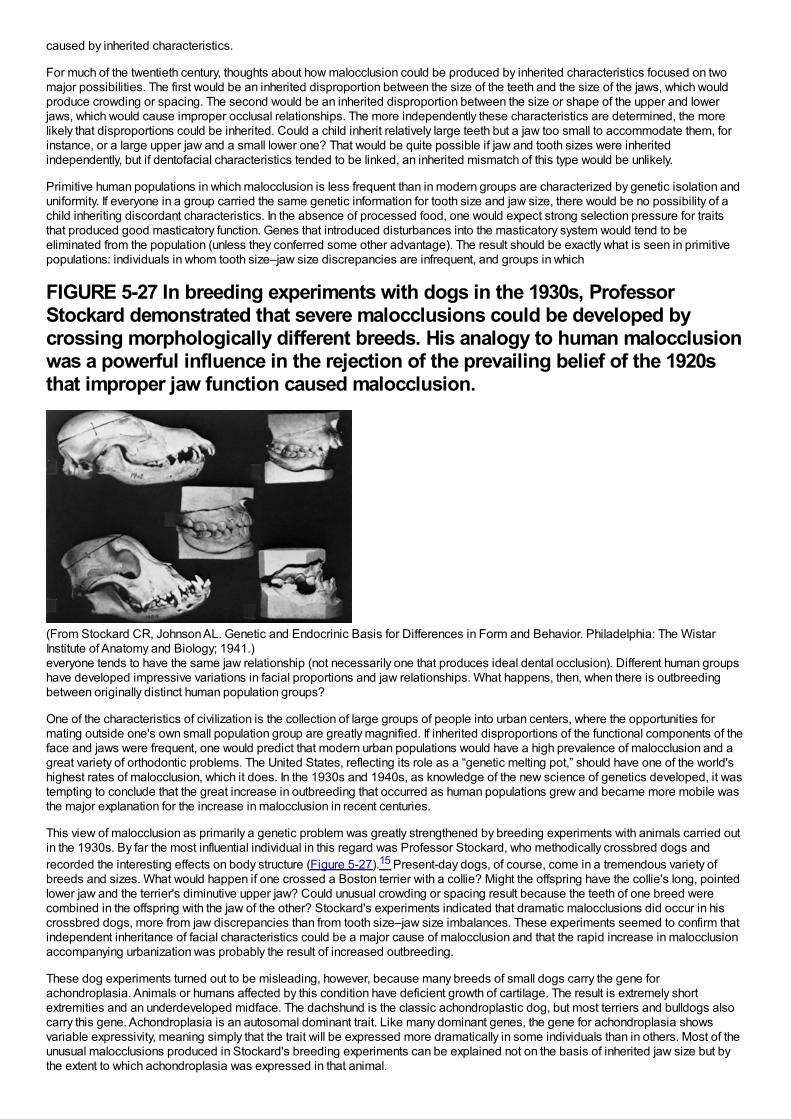
caused by inherited characteristics.
For much of the twentieth century, thoughts about how malocclusion could be produced by inherited characteristics focused on twomajor possibilities. The first would be an inherited disproportion between the size of the teeth and the size of the jaws, which wouldproduce crowding or spacing. The second would be an inherited disproportion between the size or shape of the upper and lowerjaws, which would cause improper occlusal relationships. The more independently these characteristics are determined, the morelikely that disproportions could be inherited. Could a child inherit relatively large teeth but a jaw too small to accommodate them, forinstance, or a large upper jaw and a small lower one? That would be quite possible if jaw and tooth sizes were inheritedindependently, but if dentofacial characteristics tended to be linked, an inherited mismatch of this type would be unlikely.
Primitive human populations in which malocclusion is less frequent than in modern groups are characterized by genetic isolation anduniformity. If everyone in a group carried the same genetic information for tooth size and jaw size, there would be no possibility of achild inheriting discordant characteristics. In the absence of processed food, one would expect strong selection pressure for traitsthat produced good masticatory function. Genes that introduced disturbances into the masticatory system would tend to beeliminated from the population (unless they conferred some other advantage). The result should be exactly what is seen in primitivepopulations: individuals in whom tooth size–jaw size discrepancies are infrequent, and groups in which
FIGURE 5-27 In breeding experiments with dogs in the 1930s, ProfessorStockard demonstrated that severe malocclusions could be developed bycrossing morphologically different breeds. His analogy to human malocclusionwas a powerful influence in the rejection of the prevailing belief of the 1920sthat improper jaw function caused malocclusion.
(From Stockard CR, Johnson AL. Genetic and Endocrinic Basis for Differences in Form and Behavior. Philadelphia: The WistarInstitute of Anatomy and Biology; 1941.)everyone tends to have the same jaw relationship (not necessarily one that produces ideal dental occlusion). Different human groupshave developed impressive variations in facial proportions and jaw relationships. What happens, then, when there is outbreedingbetween originally distinct human population groups?
One of the characteristics of civilization is the collection of large groups of people into urban centers, where the opportunities formating outside one's own small population group are greatly magnified. If inherited disproportions of the functional components of theface and jaws were frequent, one would predict that modern urban populations would have a high prevalence of malocclusion and agreat variety of orthodontic problems. The United States, reflecting its role as a “genetic melting pot,” should have one of the world'shighest rates of malocclusion, which it does. In the 1930s and 1940s, as knowledge of the new science of genetics developed, it wastempting to conclude that the great increase in outbreeding that occurred as human populations grew and became more mobile wasthe major explanation for the increase in malocclusion in recent centuries.
This view of malocclusion as primarily a genetic problem was greatly strengthened by breeding experiments with animals carried outin the 1930s. By far the most influential individual in this regard was Professor Stockard, who methodically crossbred dogs andrecorded the interesting effects on body structure (Figure 5-27).15 Present-day dogs, of course, come in a tremendous variety ofbreeds and sizes. What would happen if one crossed a Boston terrier with a collie? Might the offspring have the collie's long, pointedlower jaw and the terrier's diminutive upper jaw? Could unusual crowding or spacing result because the teeth of one breed werecombined in the offspring with the jaw of the other? Stockard's experiments indicated that dramatic malocclusions did occur in hiscrossbred dogs, more from jaw discrepancies than from tooth size–jaw size imbalances. These experiments seemed to confirm thatindependent inheritance of facial characteristics could be a major cause of malocclusion and that the rapid increase in malocclusionaccompanying urbanization was probably the result of increased outbreeding.
These dog experiments turned out to be misleading, however, because many breeds of small dogs carry the gene forachondroplasia. Animals or humans affected by this condition have deficient growth of cartilage. The result is extremely shortextremities and an underdeveloped midface. The dachshund is the classic achondroplastic dog, but most terriers and bulldogs alsocarry this gene. Achondroplasia is an autosomal dominant trait. Like many dominant genes, the gene for achondroplasia showsvariable expressivity, meaning simply that the trait will be expressed more dramatically in some individuals than in others. Most of theunusual malocclusions produced in Stockard's breeding experiments can be explained not on the basis of inherited jaw size but bythe extent to which achondroplasia was expressed in that animal.
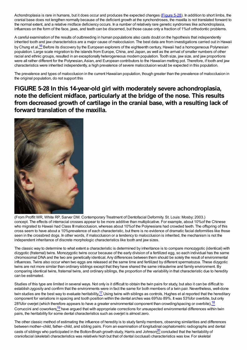
Achondroplasia is rare in humans, but it does occur and produces the expected changes (Figure 5-28). In addition to short limbs, thecranial base does not lengthen normally because of the deficient growth at the synchondroses, the maxilla is not translated forward tothe normal extent, and a relative midface deficiency occurs. In a number of relatively rare genetic syndromes like achondroplasia,influences on the form of the face, jaws, and teeth can be discerned, but those cause only a fraction of 1%of orthodontic problems.
A careful examination of the results of outbreeding in human populations also casts doubt on the hypothesis that independentlyinherited tooth and jaw characteristics are a major cause of malocclusion. The best data are from investigations carried out in Hawaiiby Chung et al.16 Before its discovery by the European explorers of the eighteenth century, Hawaii had a homogeneous Polynesianpopulation. Large scale migration to the islands from Europe, China, and Japan, as well as the arrival of smaller numbers of otherracial and ethnic groups, resulted in an exceptionally heterogeneous modern population. Tooth size, jaw size, and jaw proportionswere all rather different for the Polynesian, Asian, and European contributors to the Hawaiian melting pot. Therefore, if tooth and jawcharacteristics were inherited independently, a high prevalence of severe malocclusion would be expected in this population.
The prevalence and types of malocclusion in the current Hawaiian population, though greater than the prevalence of malocclusion inthe original population, do not support this
FIGURE 5-28 In this 14-year-old girl with moderately severe achondroplasia,note the deficient midface, particularly at the bridge of the nose. This resultsfrom decreased growth of cartilage in the cranial base, with a resulting lack offorward translation of the maxilla.
(From Proffit WR, White RP, Sarver DM. Contemporary Treatment of Dentofacial Deformity. St. Louis: Mosby; 2003.)concept. The effects of interracial crosses appear to be more additive than multiplicative. For example, about 10%of the Chinesewho migrated to Hawaii had Class III malocclusion, whereas about 10%of the Polynesians had crowded teeth. The offspring of thiscross seem to have about a 10%prevalence of each characteristic, but there is no evidence of dramatic facial deformities like thoseseen in the crossbred dogs. In other words, if malocclusion or a tendency to malocclusion is inherited, the mechanism is not theindependent inheritance of discrete morphologic characteristics like tooth and jaw sizes.
The classic way to determine to what extent a characteristic is determined by inheritance is to compare monozygotic (identical) withdizygotic (fraternal) twins. Monozygotic twins occur because of the early division of a fertilized egg, so each individual has the samechromosomal DNA and the two are genetically identical. Any differences between them should be solely the result of environmentalinfluences. Twins also occur when two eggs are released at the same time and fertilized by different spermatozoa. These dizygotictwins are not more similar than ordinary siblings except that they have shared the same intrauterine and family environment. Bycomparing identical twins, fraternal twins, and ordinary siblings, the proportion of the variability in that characteristic due to hereditycan be estimated.
Studies of this type are limited in several ways. Not only is it difficult to obtain the twin pairs for study, but also it can be difficult toestablish zygosity and confirm that the environments were in fact the same for both members of a twin pair. Nevertheless, well-donetwin studies are the best way to evaluate heritability.17 Using twins with siblings as controls, Hughes et al reported that the hereditarycomponent for variations in spacing and tooth position within the dental arches was 69%to 89%. It was 53%for overbite, but only28%for overjet (which therefore appears to have a greater environmental component than crowding/spacing or overbite).18
Corruccini and coworkers19 have argued that with appropriate corrections for unsuspected environmental differences within twinpairs, the heritability for some dental characteristics such as overjet is almost zero.
The other classic method of estimating the influence of heredity is to study family members, observing similarities and differencesbetween mother–child, father–child, and sibling pairs. From an examination of longitudinal cephalometric radiographs and dentalcasts of siblings who participated in the Bolton-Brush growth study, Harris and Johnson20 concluded that the heritability ofcraniofacial (skeletal) characteristics was relatively high but that of dental (occlusal) characteristics was low. For skeletal
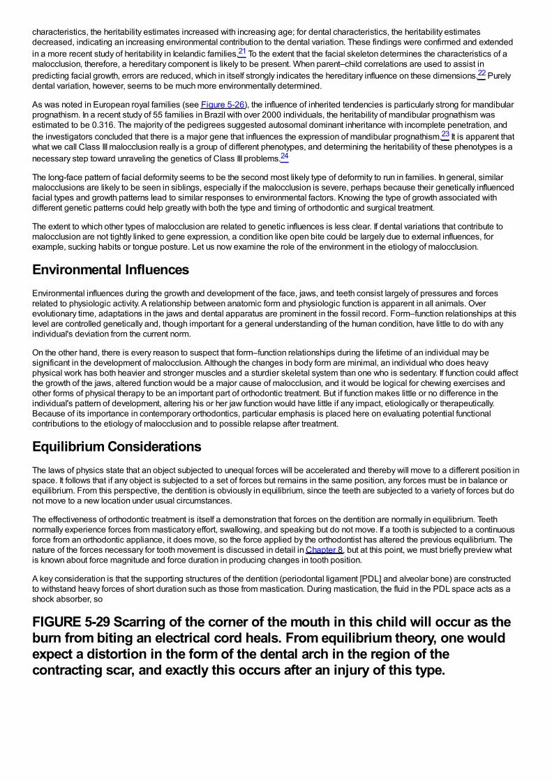
characteristics, the heritability estimates increased with increasing age; for dental characteristics, the heritability estimatesdecreased, indicating an increasing environmental contribution to the dental variation. These findings were confirmed and extendedin a more recent study of heritability in Icelandic families.21 To the extent that the facial skeleton determines the characteristics of amalocclusion, therefore, a hereditary component is likely to be present. When parent–child correlations are used to assist inpredicting facial growth, errors are reduced, which in itself strongly indicates the hereditary influence on these dimensions.22 Purelydental variation, however, seems to be much more environmentally determined.
As was noted in European royal families (see Figure 5-26), the influence of inherited tendencies is particularly strong for mandibularprognathism. In a recent study of 55 families in Brazil with over 2000 individuals, the heritability of mandibular prognathism wasestimated to be 0.316. The majority of the pedigrees suggested autosomal dominant inheritance with incomplete penetration, andthe investigators concluded that there is a major gene that influences the expression of mandibular prognathism.23 It is apparent thatwhat we call Class III malocclusion really is a group of different phenotypes, and determining the heritability of these phenotypes is anecessary step toward unraveling the genetics of Class III problems.24
The long-face pattern of facial deformity seems to be the second most likely type of deformity to run in families. In general, similarmalocclusions are likely to be seen in siblings, especially if the malocclusion is severe, perhaps because their genetically influencedfacial types and growth patterns lead to similar responses to environmental factors. Knowing the type of growth associated withdifferent genetic patterns could help greatly with both the type and timing of orthodontic and surgical treatment.
The extent to which other types of malocclusion are related to genetic influences is less clear. If dental variations that contribute tomalocclusion are not tightly linked to gene expression, a condition like open bite could be largely due to external influences, forexample, sucking habits or tongue posture. Let us now examine the role of the environment in the etiology of malocclusion.
Environmental InfluencesEnvironmental influences during the growth and development of the face, jaws, and teeth consist largely of pressures and forcesrelated to physiologic activity. A relationship between anatomic form and physiologic function is apparent in all animals. Overevolutionary time, adaptations in the jaws and dental apparatus are prominent in the fossil record. Form–function relationships at thislevel are controlled genetically and, though important for a general understanding of the human condition, have little to do with anyindividual's deviation from the current norm.
On the other hand, there is every reason to suspect that form–function relationships during the lifetime of an individual may besignificant in the development of malocclusion. Although the changes in body form are minimal, an individual who does heavyphysical work has both heavier and stronger muscles and a sturdier skeletal system than one who is sedentary. If function could affectthe growth of the jaws, altered function would be a major cause of malocclusion, and it would be logical for chewing exercises andother forms of physical therapy to be an important part of orthodontic treatment. But if function makes little or no difference in theindividual's pattern of development, altering his or her jaw function would have little if any impact, etiologically or therapeutically.Because of its importance in contemporary orthodontics, particular emphasis is placed here on evaluating potential functionalcontributions to the etiology of malocclusion and to possible relapse after treatment.
Equilibrium ConsiderationsThe laws of physics state that an object subjected to unequal forces will be accelerated and thereby will move to a different position inspace. It follows that if any object is subjected to a set of forces but remains in the same position, any forces must be in balance orequilibrium. From this perspective, the dentition is obviously in equilibrium, since the teeth are subjected to a variety of forces but donot move to a new location under usual circumstances.
The effectiveness of orthodontic treatment is itself a demonstration that forces on the dentition are normally in equilibrium. Teethnormally experience forces from masticatory effort, swallowing, and speaking but do not move. If a tooth is subjected to a continuousforce from an orthodontic appliance, it does move, so the force applied by the orthodontist has altered the previous equilibrium. Thenature of the forces necessary for tooth movement is discussed in detail in Chapter 8, but at this point, we must briefly preview whatis known about force magnitude and force duration in producing changes in tooth position.
A key consideration is that the supporting structures of the dentition (periodontal ligament [PDL] and alveolar bone) are constructedto withstand heavy forces of short duration such as those from mastication. During mastication, the fluid in the PDL space acts as ashock absorber, so
FIGURE 5-29 Scarring of the corner of the mouth in this child will occur as theburn from biting an electrical cord heals. From equilibrium theory, one wouldexpect a distortion in the form of the dental arch in the region of thecontracting scar, and exactly this occurs after an injury of this type.
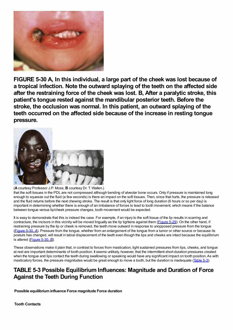
FIGURE 5-30 A, In this individual, a large part of the cheek was lost because ofa tropical infection. Note the outward splaying of the teeth on the affected sideafter the restraining force of the cheek was lost. B, After a paralytic stroke, thispatient's tongue rested against the mandibular posterior teeth. Before thestroke, the occlusion was normal. In this patient, an outward splaying of theteeth occurred on the affected side because of the increase in resting tonguepressure.
(A courtesy Professor J.P. Moss; B courtesy Dr. T. Wallen.)that the soft tissues in the PDL are not compressed although bending of alveolar bone occurs. Only if pressure is maintained longenough to squeeze out the fluid (a few seconds) is there an impact on the soft tissues. Then, since that hurts, the pressure is releasedand the fluid returns before the next chewing stroke. The result is that only light force of long duration (6 hours or so per day) isimportant in determining whether there is enough of an imbalance of forces to lead to tooth movement, which means if the balancebetween tongue versus lip/cheek pressure changes, tooth movement would be expected.
It is easy to demonstrate that this is indeed the case. For example, if an injury to the soft tissue of the lip results in scarring andcontracture, the incisors in this vicinity will be moved lingually as the lip tightens against them (Figure 5-29). On the other hand, ifrestraining pressure by the lip or cheek is removed, the teeth move outward in response to unopposed pressure from the tongue(Figure 5-30, A). Pressure from the tongue, whether from an enlargement of the tongue from a tumor or other source or because itsposture has changed, will result in labial displacement of the teeth even though the lips and cheeks are intact because the equilibriumis altered (Figure 5-30, B).
These observations make it plain that, in contrast to forces from mastication, light sustained pressures from lips, cheeks, and tongueat rest are important determinants of tooth position. It seems unlikely, however, that the intermittent short-duration pressures createdwhen the tongue and lips contact the teeth during swallowing or speaking would have any significant impact on tooth position. As withmasticatory forces, the pressure magnitudes would be great enough to move a tooth, but the duration is inadequate (Table 5-3).
TABLE 5-3 Possible Equilibrium Influences: Magnitude and Duration of ForceAgainst the Teeth During Function
Possible equilibrium influence Force magnitude Force duration
Tooth Contacts
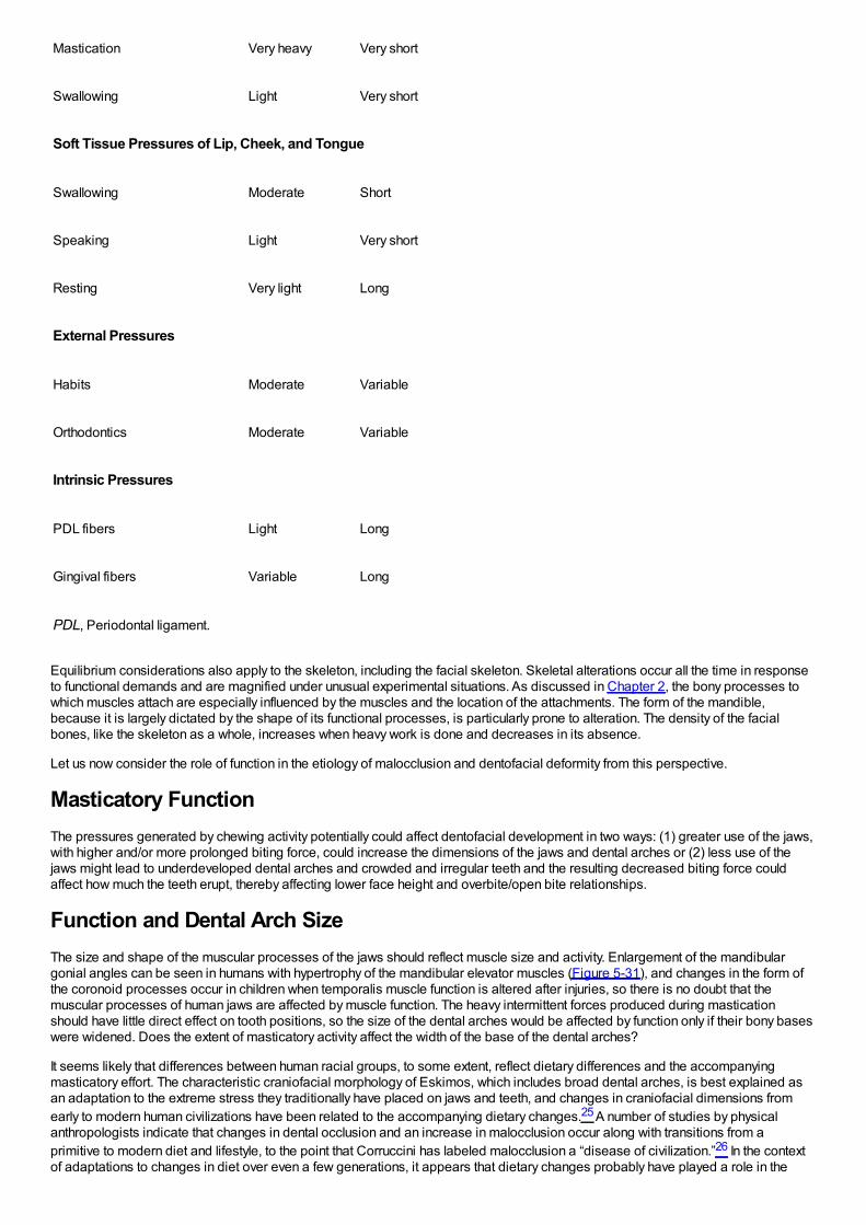
Mastication Very heavy Very short
Swallowing Light Very short
Soft Tissue Pressures of Lip, Cheek, and Tongue
Swallowing Moderate Short
Speaking Light Very short
Resting Very light Long
External Pressures
Habits Moderate Variable
Orthodontics Moderate Variable
Intrinsic Pressures
PDL fibers Light Long
Gingival fibers Variable Long
PDL, Periodontal ligament.
Equilibrium considerations also apply to the skeleton, including the facial skeleton. Skeletal alterations occur all the time in responseto functional demands and are magnified under unusual experimental situations. As discussed in Chapter 2, the bony processes towhich muscles attach are especially influenced by the muscles and the location of the attachments. The form of the mandible,because it is largely dictated by the shape of its functional processes, is particularly prone to alteration. The density of the facialbones, like the skeleton as a whole, increases when heavy work is done and decreases in its absence.
Let us now consider the role of function in the etiology of malocclusion and dentofacial deformity from this perspective.
Masticatory FunctionThe pressures generated by chewing activity potentially could affect dentofacial development in two ways: (1) greater use of the jaws,with higher and/or more prolonged biting force, could increase the dimensions of the jaws and dental arches or (2) less use of thejaws might lead to underdeveloped dental arches and crowded and irregular teeth and the resulting decreased biting force couldaffect how much the teeth erupt, thereby affecting lower face height and overbite/open bite relationships.
Function and Dental Arch SizeThe size and shape of the muscular processes of the jaws should reflect muscle size and activity. Enlargement of the mandibulargonial angles can be seen in humans with hypertrophy of the mandibular elevator muscles (Figure 5-31), and changes in the form ofthe coronoid processes occur in children when temporalis muscle function is altered after injuries, so there is no doubt that themuscular processes of human jaws are affected by muscle function. The heavy intermittent forces produced during masticationshould have little direct effect on tooth positions, so the size of the dental arches would be affected by function only if their bony baseswere widened. Does the extent of masticatory activity affect the width of the base of the dental arches?
It seems likely that differences between human racial groups, to some extent, reflect dietary differences and the accompanyingmasticatory effort. The characteristic craniofacial morphology of Eskimos, which includes broad dental arches, is best explained asan adaptation to the extreme stress they traditionally have placed on jaws and teeth, and changes in craniofacial dimensions fromearly to modern human civilizations have been related to the accompanying dietary changes.25 A number of studies by physicalanthropologists indicate that changes in dental occlusion and an increase in malocclusion occur along with transitions from aprimitive to modern diet and lifestyle, to the point that Corruccini has labeled malocclusion a “disease of civilization.”26 In the contextof adaptations to changes in diet over even a few generations, it appears that dietary changes probably have played a role in the
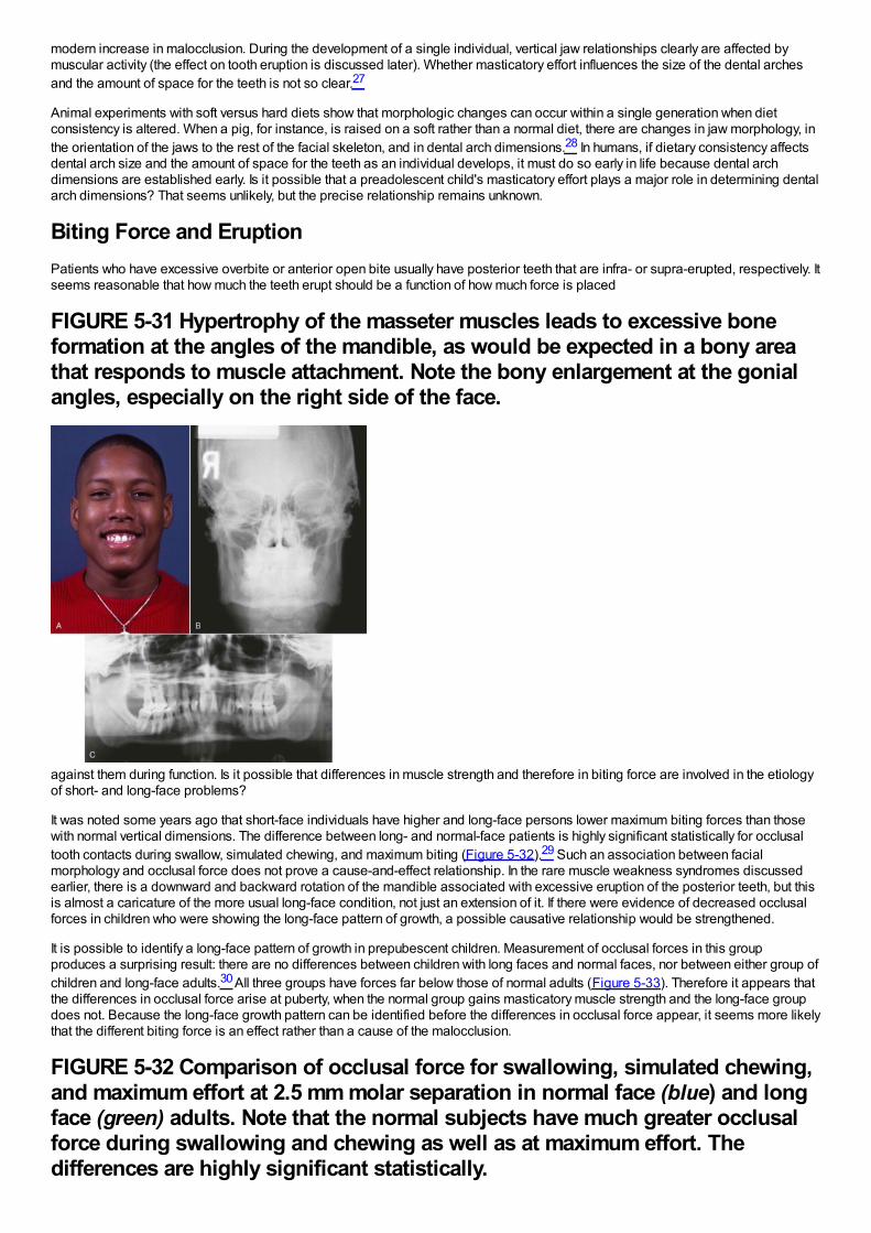
modern increase in malocclusion. During the development of a single individual, vertical jaw relationships clearly are affected bymuscular activity (the effect on tooth eruption is discussed later). Whether masticatory effort influences the size of the dental archesand the amount of space for the teeth is not so clear.27
Animal experiments with soft versus hard diets show that morphologic changes can occur within a single generation when dietconsistency is altered. When a pig, for instance, is raised on a soft rather than a normal diet, there are changes in jaw morphology, inthe orientation of the jaws to the rest of the facial skeleton, and in dental arch dimensions.28 In humans, if dietary consistency affectsdental arch size and the amount of space for the teeth as an individual develops, it must do so early in life because dental archdimensions are established early. Is it possible that a preadolescent child's masticatory effort plays a major role in determining dentalarch dimensions? That seems unlikely, but the precise relationship remains unknown.
Biting Force and EruptionPatients who have excessive overbite or anterior open bite usually have posterior teeth that are infra- or supra-erupted, respectively. Itseems reasonable that how much the teeth erupt should be a function of how much force is placed
FIGURE 5-31 Hypertrophy of the masseter muscles leads to excessive boneformation at the angles of the mandible, as would be expected in a bony areathat responds to muscle attachment. Note the bony enlargement at the gonialangles, especially on the right side of the face.
against them during function. Is it possible that differences in muscle strength and therefore in biting force are involved in the etiologyof short- and long-face problems?
It was noted some years ago that short-face individuals have higher and long-face persons lower maximum biting forces than thosewith normal vertical dimensions. The difference between long- and normal-face patients is highly significant statistically for occlusaltooth contacts during swallow, simulated chewing, and maximum biting (Figure 5-32).29 Such an association between facialmorphology and occlusal force does not prove a cause-and-effect relationship. In the rare muscle weakness syndromes discussedearlier, there is a downward and backward rotation of the mandible associated with excessive eruption of the posterior teeth, but thisis almost a caricature of the more usual long-face condition, not just an extension of it. If there were evidence of decreased occlusalforces in children who were showing the long-face pattern of growth, a possible causative relationship would be strengthened.
It is possible to identify a long-face pattern of growth in prepubescent children. Measurement of occlusal forces in this groupproduces a surprising result: there are no differences between children with long faces and normal faces, nor between either group ofchildren and long-face adults.30 All three groups have forces far below those of normal adults (Figure 5-33). Therefore it appears thatthe differences in occlusal force arise at puberty, when the normal group gains masticatory muscle strength and the long-face groupdoes not. Because the long-face growth pattern can be identified before the differences in occlusal force appear, it seems more likelythat the different biting force is an effect rather than a cause of the malocclusion.
FIGURE 5-32 Comparison of occlusal force for swallowing, simulated chewing,and maximum effort at 2.5 mm molar separation in normal face (blue) and longface (green) adults. Note that the normal subjects have much greater occlusalforce during swallowing and chewing as well as at maximum effort. Thedifferences are highly significant statistically.
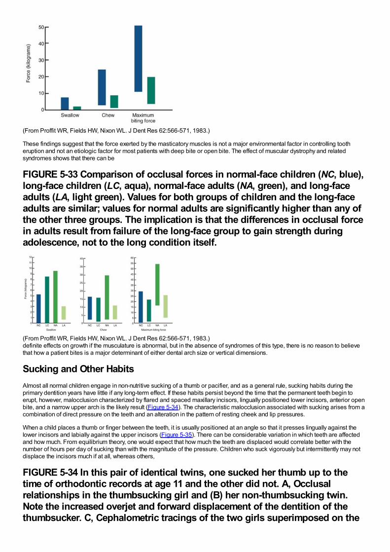
(From Proffit WR, Fields HW, Nixon WL. J Dent Res 62:566-571, 1983.)
These findings suggest that the force exerted by the masticatory muscles is not a major environmental factor in controlling tootheruption and not an etiologic factor for most patients with deep bite or open bite. The effect of muscular dystrophy and relatedsyndromes shows that there can be
FIGURE 5-33 Comparison of occlusal forces in normal-face children (NC, blue),long-face children (LC, aqua), normal-face adults (NA, green), and long-faceadults (LA, light green). Values for both groups of children and the long-faceadults are similar; values for normal adults are significantly higher than any ofthe other three groups. The implication is that the differences in occlusal forcein adults result from failure of the long-face group to gain strength duringadolescence, not to the long condition itself.
(From Proffit WR, Fields HW, Nixon WL. J Dent Res 62:566-571, 1983.)definite effects on growth if the musculature is abnormal, but in the absence of syndromes of this type, there is no reason to believethat how a patient bites is a major determinant of either dental arch size or vertical dimensions.
Sucking and Other HabitsAlmost all normal children engage in non-nutritive sucking of a thumb or pacifier, and as a general rule, sucking habits during theprimary dentition years have little if any long-term effect. If these habits persist beyond the time that the permanent teeth begin toerupt, however, malocclusion characterized by flared and spaced maxillary incisors, lingually positioned lower incisors, anterior openbite, and a narrow upper arch is the likely result (Figure 5-34). The characteristic malocclusion associated with sucking arises from acombination of direct pressure on the teeth and an alteration in the pattern of resting cheek and lip pressures.
When a child places a thumb or finger between the teeth, it is usually positioned at an angle so that it presses lingually against thelower incisors and labially against the upper incisors (Figure 5-35). There can be considerable variation in which teeth are affectedand how much. From equilibrium theory, one would expect that how much the teeth are displaced would correlate better with thenumber of hours per day of sucking than with the magnitude of the pressure. Children who suck vigorously but intermittently may notdisplace the incisors much if at all, whereas others,
FIGURE 5-34 In this pair of identical twins, one sucked her thumb up to thetime of orthodontic records at age 11 and the other did not. A, Occlusalrelationships in the thumbsucking girl and (B) her non-thumbsucking twin.Note the increased overjet and forward displacement of the dentition of thethumbsucker. C, Cephalometric tracings of the two girls superimposed on the
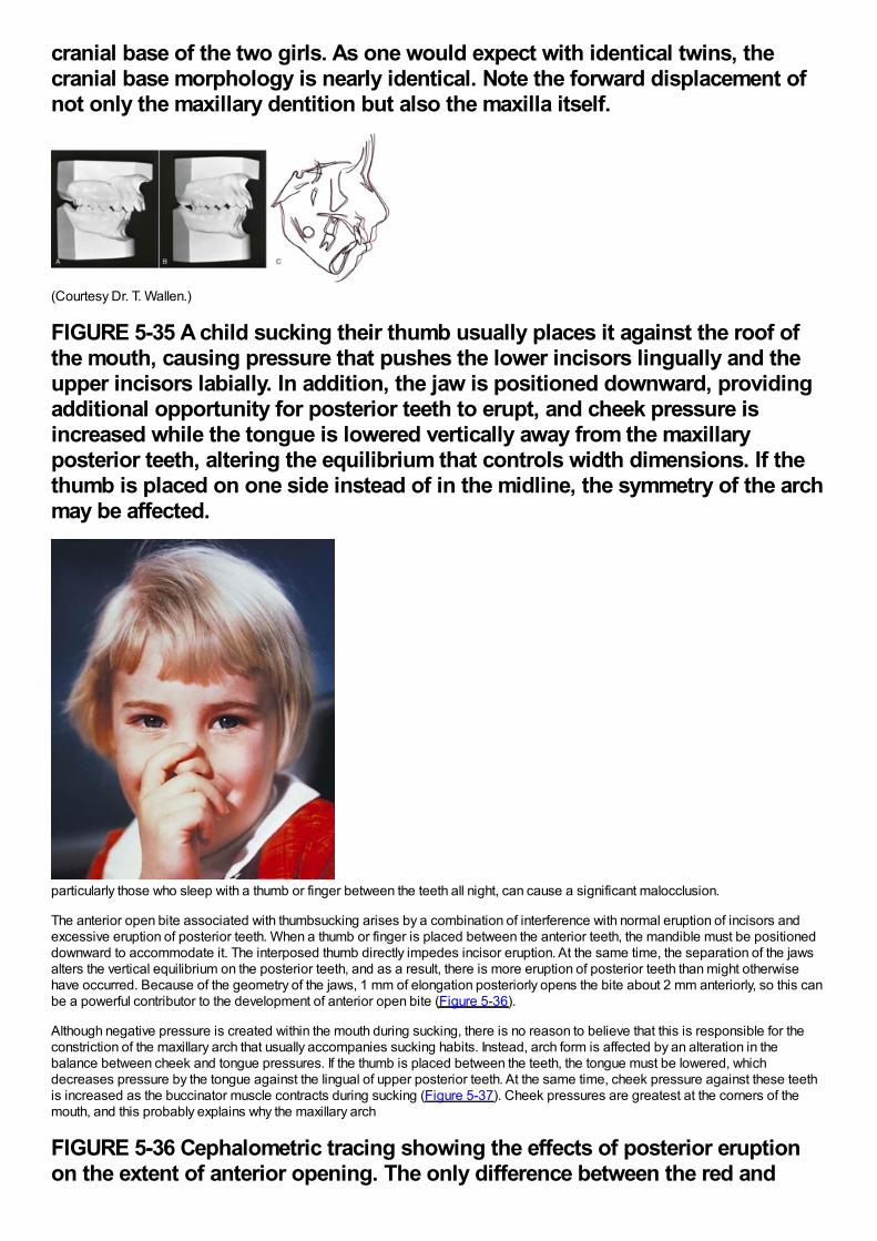
cranial base of the two girls. As one would expect with identical twins, thecranial base morphology is nearly identical. Note the forward displacement ofnot only the maxillary dentition but also the maxilla itself.
(Courtesy Dr. T. Wallen.)
FIGURE 5-35 A child sucking their thumb usually places it against the roof ofthe mouth, causing pressure that pushes the lower incisors lingually and theupper incisors labially. In addition, the jaw is positioned downward, providingadditional opportunity for posterior teeth to erupt, and cheek pressure isincreased while the tongue is lowered vertically away from the maxillaryposterior teeth, altering the equilibrium that controls width dimensions. If thethumb is placed on one side instead of in the midline, the symmetry of the archmay be affected.
particularly those who sleep with a thumb or finger between the teeth all night, can cause a significant malocclusion.
The anterior open bite associated with thumbsucking arises by a combination of interference with normal eruption of incisors andexcessive eruption of posterior teeth. When a thumb or finger is placed between the anterior teeth, the mandible must be positioneddownward to accommodate it. The interposed thumb directly impedes incisor eruption. At the same time, the separation of the jawsalters the vertical equilibrium on the posterior teeth, and as a result, there is more eruption of posterior teeth than might otherwisehave occurred. Because of the geometry of the jaws, 1 mm of elongation posteriorly opens the bite about 2 mm anteriorly, so this canbe a powerful contributor to the development of anterior open bite (Figure 5-36).
Although negative pressure is created within the mouth during sucking, there is no reason to believe that this is responsible for theconstriction of the maxillary arch that usually accompanies sucking habits. Instead, arch form is affected by an alteration in thebalance between cheek and tongue pressures. If the thumb is placed between the teeth, the tongue must be lowered, whichdecreases pressure by the tongue against the lingual of upper posterior teeth. At the same time, cheek pressure against these teethis increased as the buccinator muscle contracts during sucking (Figure 5-37). Cheek pressures are greatest at the corners of themouth, and this probably explains why the maxillary arch
FIGURE 5-36 Cephalometric tracing showing the effects of posterior eruptionon the extent of anterior opening. The only difference between the red and
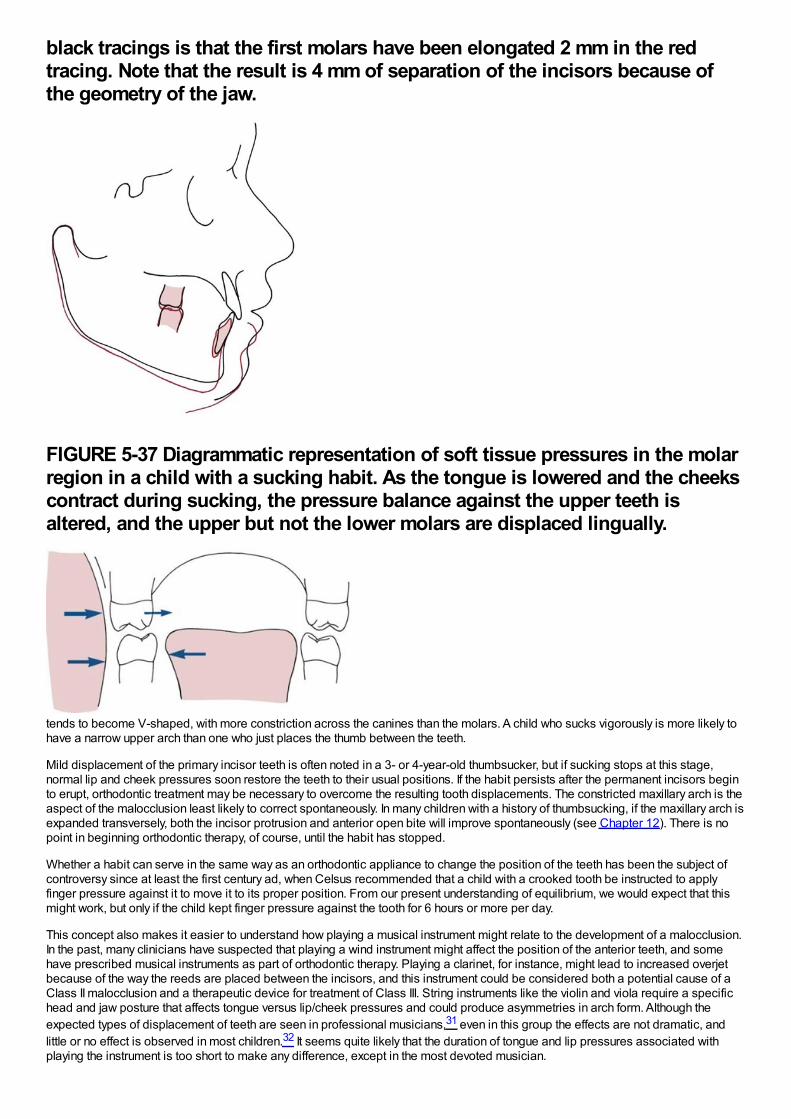
black tracings is that the first molars have been elongated 2 mm in the redtracing. Note that the result is 4 mm of separation of the incisors because ofthe geometry of the jaw.
FIGURE 5-37 Diagrammatic representation of soft tissue pressures in the molarregion in a child with a sucking habit. As the tongue is lowered and the cheekscontract during sucking, the pressure balance against the upper teeth isaltered, and the upper but not the lower molars are displaced lingually.
tends to become V-shaped, with more constriction across the canines than the molars. A child who sucks vigorously is more likely tohave a narrow upper arch than one who just places the thumb between the teeth.
Mild displacement of the primary incisor teeth is often noted in a 3- or 4-year-old thumbsucker, but if sucking stops at this stage,normal lip and cheek pressures soon restore the teeth to their usual positions. If the habit persists after the permanent incisors beginto erupt, orthodontic treatment may be necessary to overcome the resulting tooth displacements. The constricted maxillary arch is theaspect of the malocclusion least likely to correct spontaneously. In many children with a history of thumbsucking, if the maxillary arch isexpanded transversely, both the incisor protrusion and anterior open bite will improve spontaneously (see Chapter 12). There is nopoint in beginning orthodontic therapy, of course, until the habit has stopped.
Whether a habit can serve in the same way as an orthodontic appliance to change the position of the teeth has been the subject ofcontroversy since at least the first century ad, when Celsus recommended that a child with a crooked tooth be instructed to applyfinger pressure against it to move it to its proper position. From our present understanding of equilibrium, we would expect that thismight work, but only if the child kept finger pressure against the tooth for 6 hours or more per day.
This concept also makes it easier to understand how playing a musical instrument might relate to the development of a malocclusion.In the past, many clinicians have suspected that playing a wind instrument might affect the position of the anterior teeth, and somehave prescribed musical instruments as part of orthodontic therapy. Playing a clarinet, for instance, might lead to increased overjetbecause of the way the reeds are placed between the incisors, and this instrument could be considered both a potential cause of aClass II malocclusion and a therapeutic device for treatment of Class III. String instruments like the violin and viola require a specifichead and jaw posture that affects tongue versus lip/cheek pressures and could produce asymmetries in arch form. Although theexpected types of displacement of teeth are seen in professional musicians,31 even in this group the effects are not dramatic, andlittle or no effect is observed in most children.32 It seems quite likely that the duration of tongue and lip pressures associated withplaying the instrument is too short to make any difference, except in the most devoted musician.
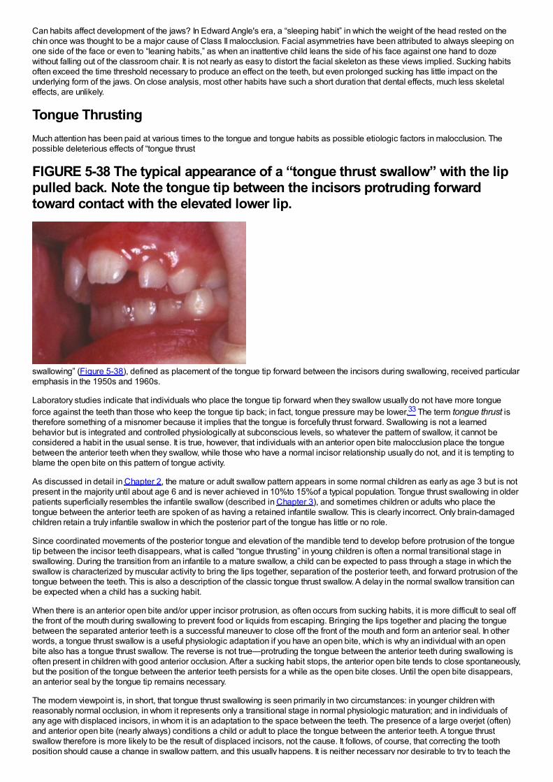
Can habits affect development of the jaws? In Edward Angle's era, a “sleeping habit” in which the weight of the head rested on thechin once was thought to be a major cause of Class II malocclusion. Facial asymmetries have been attributed to always sleeping onone side of the face or even to “leaning habits,” as when an inattentive child leans the side of his face against one hand to dozewithout falling out of the classroom chair. It is not nearly as easy to distort the facial skeleton as these views implied. Sucking habitsoften exceed the time threshold necessary to produce an effect on the teeth, but even prolonged sucking has little impact on theunderlying form of the jaws. On close analysis, most other habits have such a short duration that dental effects, much less skeletaleffects, are unlikely.
Tongue ThrustingMuch attention has been paid at various times to the tongue and tongue habits as possible etiologic factors in malocclusion. Thepossible deleterious effects of “tongue thrust
FIGURE 5-38 The typical appearance of a “tongue thrust swallow” with the lippulled back. Note the tongue tip between the incisors protruding forwardtoward contact with the elevated lower lip.
swallowing” (Figure 5-38), defined as placement of the tongue tip forward between the incisors during swallowing, received particularemphasis in the 1950s and 1960s.
Laboratory studies indicate that individuals who place the tongue tip forward when they swallow usually do not have more tongueforce against the teeth than those who keep the tongue tip back; in fact, tongue pressure may be lower.33 The term tongue thrust istherefore something of a misnomer because it implies that the tongue is forcefully thrust forward. Swallowing is not a learnedbehavior but is integrated and controlled physiologically at subconscious levels, so whatever the pattern of swallow, it cannot beconsidered a habit in the usual sense. It is true, however, that individuals with an anterior open bite malocclusion place the tonguebetween the anterior teeth when they swallow, while those who have a normal incisor relationship usually do not, and it is tempting toblame the open bite on this pattern of tongue activity.
As discussed in detail in Chapter 2, the mature or adult swallow pattern appears in some normal children as early as age 3 but is notpresent in the majority until about age 6 and is never achieved in 10%to 15%of a typical population. Tongue thrust swallowing in olderpatients superficially resembles the infantile swallow (described in Chapter 3), and sometimes children or adults who place thetongue between the anterior teeth are spoken of as having a retained infantile swallow. This is clearly incorrect. Only brain-damagedchildren retain a truly infantile swallow in which the posterior part of the tongue has little or no role.
Since coordinated movements of the posterior tongue and elevation of the mandible tend to develop before protrusion of the tonguetip between the incisor teeth disappears, what is called “tongue thrusting” in young children is often a normal transitional stage inswallowing. During the transition from an infantile to a mature swallow, a child can be expected to pass through a stage in which theswallow is characterized by muscular activity to bring the lips together, separation of the posterior teeth, and forward protrusion of thetongue between the teeth. This is also a description of the classic tongue thrust swallow. A delay in the normal swallow transition canbe expected when a child has a sucking habit.
When there is an anterior open bite and/or upper incisor protrusion, as often occurs from sucking habits, it is more difficult to seal offthe front of the mouth during swallowing to prevent food or liquids from escaping. Bringing the lips together and placing the tonguebetween the separated anterior teeth is a successful maneuver to close off the front of the mouth and form an anterior seal. In otherwords, a tongue thrust swallow is a useful physiologic adaptation if you have an open bite, which is why an individual with an openbite also has a tongue thrust swallow. The reverse is not true—protruding the tongue between the anterior teeth during swallowing isoften present in children with good anterior occlusion. After a sucking habit stops, the anterior open bite tends to close spontaneously,but the position of the tongue between the anterior teeth persists for a while as the open bite closes. Until the open bite disappears,an anterior seal by the tongue tip remains necessary.
The modern viewpoint is, in short, that tongue thrust swallowing is seen primarily in two circumstances: in younger children withreasonably normal occlusion, in whom it represents only a transitional stage in normal physiologic maturation; and in individuals ofany age with displaced incisors, in whom it is an adaptation to the space between the teeth. The presence of a large overjet (often)and anterior open bite (nearly always) conditions a child or adult to place the tongue between the anterior teeth. A tongue thrustswallow therefore is more likely to be the result of displaced incisors, not the cause. It follows, of course, that correcting the toothposition should cause a change in swallow pattern, and this usually happens. It is neither necessary nor desirable to try to teach the
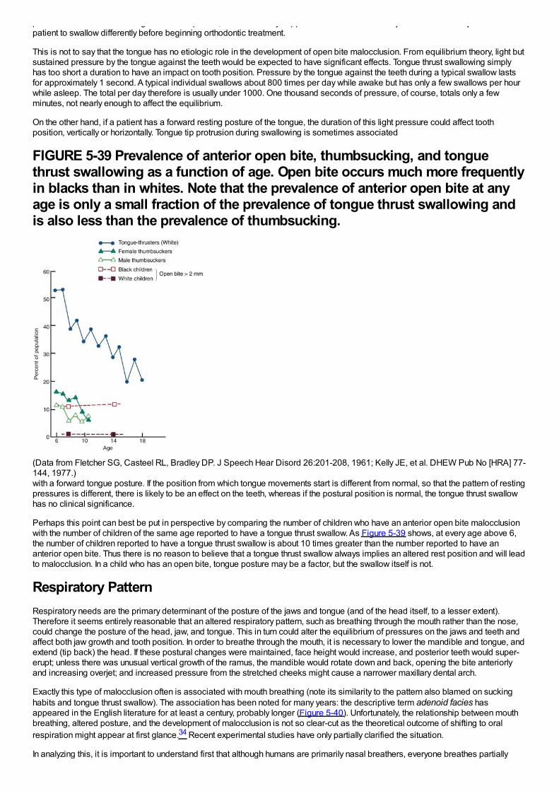
position should cause a change in swallow pattern, and this usually happens. It is neither necessary nor desirable to try to teach thepatient to swallow differently before beginning orthodontic treatment.
This is not to say that the tongue has no etiologic role in the development of open bite malocclusion. From equilibrium theory, light butsustained pressure by the tongue against the teeth would be expected to have significant effects. Tongue thrust swallowing simplyhas too short a duration to have an impact on tooth position. Pressure by the tongue against the teeth during a typical swallow lastsfor approximately 1 second. A typical individual swallows about 800 times per day while awake but has only a few swallows per hourwhile asleep. The total per day therefore is usually under 1000. One thousand seconds of pressure, of course, totals only a fewminutes, not nearly enough to affect the equilibrium.
On the other hand, if a patient has a forward resting posture of the tongue, the duration of this light pressure could affect toothposition, vertically or horizontally. Tongue tip protrusion during swallowing is sometimes associated
FIGURE 5-39 Prevalence of anterior open bite, thumbsucking, and tonguethrust swallowing as a function of age. Open bite occurs much more frequentlyin blacks than in whites. Note that the prevalence of anterior open bite at anyage is only a small fraction of the prevalence of tongue thrust swallowing andis also less than the prevalence of thumbsucking.
(Data from Fletcher SG, Casteel RL, Bradley DP. J Speech Hear Disord 26:201-208, 1961; Kelly JE, et al. DHEW Pub No [HRA] 77-144, 1977.)with a forward tongue posture. If the position from which tongue movements start is different from normal, so that the pattern of restingpressures is different, there is likely to be an effect on the teeth, whereas if the postural position is normal, the tongue thrust swallowhas no clinical significance.
Perhaps this point can best be put in perspective by comparing the number of children who have an anterior open bite malocclusionwith the number of children of the same age reported to have a tongue thrust swallow. As Figure 5-39 shows, at every age above 6,the number of children reported to have a tongue thrust swallow is about 10 times greater than the number reported to have ananterior open bite. Thus there is no reason to believe that a tongue thrust swallow always implies an altered rest position and will leadto malocclusion. In a child who has an open bite, tongue posture may be a factor, but the swallow itself is not.
Respiratory PatternRespiratory needs are the primary determinant of the posture of the jaws and tongue (and of the head itself, to a lesser extent).Therefore it seems entirely reasonable that an altered respiratory pattern, such as breathing through the mouth rather than the nose,could change the posture of the head, jaw, and tongue. This in turn could alter the equilibrium of pressures on the jaws and teeth andaffect both jaw growth and tooth position. In order to breathe through the mouth, it is necessary to lower the mandible and tongue, andextend (tip back) the head. If these postural changes were maintained, face height would increase, and posterior teeth would super-erupt; unless there was unusual vertical growth of the ramus, the mandible would rotate down and back, opening the bite anteriorlyand increasing overjet; and increased pressure from the stretched cheeks might cause a narrower maxillary dental arch.
Exactly this type of malocclusion often is associated with mouth breathing (note its similarity to the pattern also blamed on suckinghabits and tongue thrust swallow). The association has been noted for many years: the descriptive term adenoid facies hasappeared in the English literature for at least a century, probably longer (Figure 5-40). Unfortunately, the relationship between mouthbreathing, altered posture, and the development of malocclusion is not so clear-cut as the theoretical outcome of shifting to oralrespiration might appear at first glance.34 Recent experimental studies have only partially clarified the situation.
In analyzing this, it is important to understand first that although humans are primarily nasal breathers, everyone breathes partially
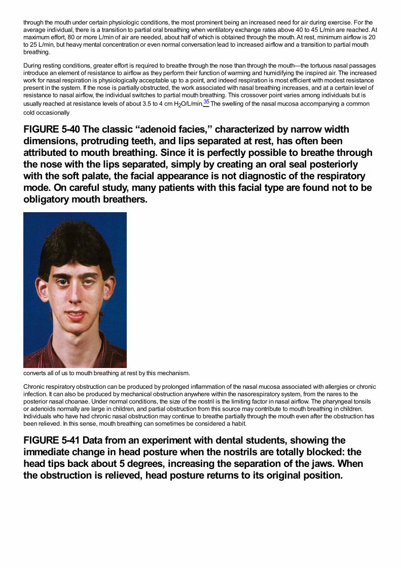
through the mouth under certain physiologic conditions, the most prominent being an increased need for air during exercise. For theaverage individual, there is a transition to partial oral breathing when ventilatory exchange rates above 40 to 45 L/min are reached. Atmaximum effort, 80 or more L/min of air are needed, about half of which is obtained through the mouth. At rest, minimum airflow is 20to 25 L/min, but heavy mental concentration or even normal conversation lead to increased airflow and a transition to partial mouthbreathing.
During resting conditions, greater effort is required to breathe through the nose than through the mouth—the tortuous nasal passagesintroduce an element of resistance to airflow as they perform their function of warming and humidifying the inspired air. The increasedwork for nasal respiration is physiologically acceptable up to a point, and indeed respiration is most efficient with modest resistancepresent in the system. If the nose is partially obstructed, the work associated with nasal breathing increases, and at a certain level ofresistance to nasal airflow, the individual switches to partial mouth breathing. This crossover point varies among individuals but isusually reached at resistance levels of about 3.5 to 4 cm H2O/L/min.35 The swelling of the nasal mucosa accompanying a commoncold occasionally
FIGURE 5-40 The classic “adenoid facies,” characterized by narrow widthdimensions, protruding teeth, and lips separated at rest, has often beenattributed to mouth breathing. Since it is perfectly possible to breathe throughthe nose with the lips separated, simply by creating an oral seal posteriorlywith the soft palate, the facial appearance is not diagnostic of the respiratorymode. On careful study, many patients with this facial type are found not to beobligatory mouth breathers.
converts all of us to mouth breathing at rest by this mechanism.
Chronic respiratory obstruction can be produced by prolonged inflammation of the nasal mucosa associated with allergies or chronicinfection. It can also be produced by mechanical obstruction anywhere within the nasorespiratory system, from the nares to theposterior nasal choanae. Under normal conditions, the size of the nostril is the limiting factor in nasal airflow. The pharyngeal tonsilsor adenoids normally are large in children, and partial obstruction from this source may contribute to mouth breathing in children.Individuals who have had chronic nasal obstruction may continue to breathe partially through the mouth even after the obstruction hasbeen relieved. In this sense, mouth breathing can sometimes be considered a habit.
FIGURE 5-41 Data from an experiment with dental students, showing theimmediate change in head posture when the nostrils are totally blocked: thehead tips back about 5 degrees, increasing the separation of the jaws. Whenthe obstruction is relieved, head posture returns to its original position.
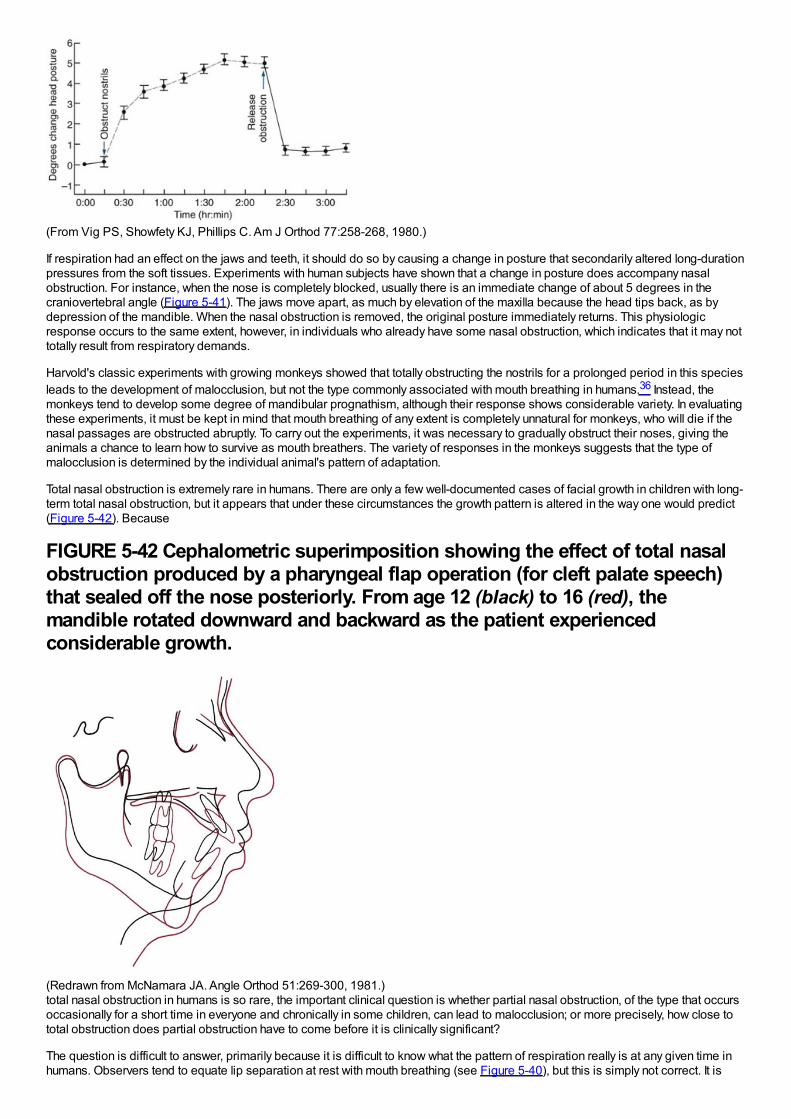
(From Vig PS, Showfety KJ, Phillips C. Am J Orthod 77:258-268, 1980.)
If respiration had an effect on the jaws and teeth, it should do so by causing a change in posture that secondarily altered long-durationpressures from the soft tissues. Experiments with human subjects have shown that a change in posture does accompany nasalobstruction. For instance, when the nose is completely blocked, usually there is an immediate change of about 5 degrees in thecraniovertebral angle (Figure 5-41). The jaws move apart, as much by elevation of the maxilla because the head tips back, as bydepression of the mandible. When the nasal obstruction is removed, the original posture immediately returns. This physiologicresponse occurs to the same extent, however, in individuals who already have some nasal obstruction, which indicates that it may nottotally result from respiratory demands.
Harvold's classic experiments with growing monkeys showed that totally obstructing the nostrils for a prolonged period in this speciesleads to the development of malocclusion, but not the type commonly associated with mouth breathing in humans.36 Instead, themonkeys tend to develop some degree of mandibular prognathism, although their response shows considerable variety. In evaluatingthese experiments, it must be kept in mind that mouth breathing of any extent is completely unnatural for monkeys, who will die if thenasal passages are obstructed abruptly. To carry out the experiments, it was necessary to gradually obstruct their noses, giving theanimals a chance to learn how to survive as mouth breathers. The variety of responses in the monkeys suggests that the type ofmalocclusion is determined by the individual animal's pattern of adaptation.
Total nasal obstruction is extremely rare in humans. There are only a few well-documented cases of facial growth in children with long-term total nasal obstruction, but it appears that under these circumstances the growth pattern is altered in the way one would predict(Figure 5-42). Because
FIGURE 5-42 Cephalometric superimposition showing the effect of total nasalobstruction produced by a pharyngeal flap operation (for cleft palate speech)that sealed off the nose posteriorly. From age 12 (black) to 16 (red), themandible rotated downward and backward as the patient experiencedconsiderable growth.
(Redrawn from McNamara JA. Angle Orthod 51:269-300, 1981.)total nasal obstruction in humans is so rare, the important clinical question is whether partial nasal obstruction, of the type that occursoccasionally for a short time in everyone and chronically in some children, can lead to malocclusion; or more precisely, how close tototal obstruction does partial obstruction have to come before it is clinically significant?
The question is difficult to answer, primarily because it is difficult to know what the pattern of respiration really is at any given time inhumans. Observers tend to equate lip separation at rest with mouth breathing (see Figure 5-40), but this is simply not correct. It is
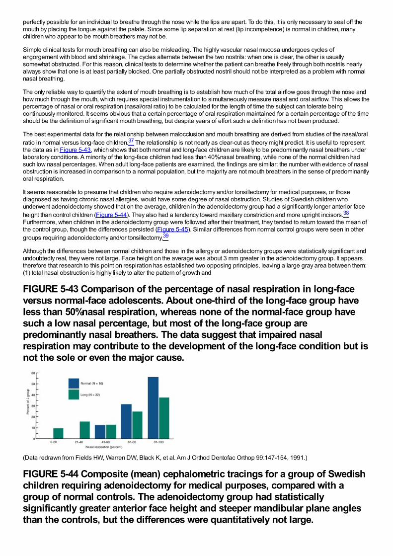
perfectly possible for an individual to breathe through the nose while the lips are apart. To do this, it is only necessary to seal off themouth by placing the tongue against the palate. Since some lip separation at rest (lip incompetence) is normal in children, manychildren who appear to be mouth breathers may not be.
Simple clinical tests for mouth breathing can also be misleading. The highly vascular nasal mucosa undergoes cycles ofengorgement with blood and shrinkage. The cycles alternate between the two nostrils: when one is clear, the other is usuallysomewhat obstructed. For this reason, clinical tests to determine whether the patient can breathe freely through both nostrils nearlyalways show that one is at least partially blocked. One partially obstructed nostril should not be interpreted as a problem with normalnasal breathing.
The only reliable way to quantify the extent of mouth breathing is to establish how much of the total airflow goes through the nose andhow much through the mouth, which requires special instrumentation to simultaneously measure nasal and oral airflow. This allows thepercentage of nasal or oral respiration (nasal/oral ratio) to be calculated for the length of time the subject can tolerate beingcontinuously monitored. It seems obvious that a certain percentage of oral respiration maintained for a certain percentage of the timeshould be the definition of significant mouth breathing, but despite years of effort such a definition has not been produced.
The best experimental data for the relationship between malocclusion and mouth breathing are derived from studies of the nasal/oralratio in normal versus long-face children.37 The relationship is not nearly as clear-cut as theory might predict. It is useful to representthe data as in Figure 5-43, which shows that both normal and long-face children are likely to be predominantly nasal breathers underlaboratory conditions. A minority of the long-face children had less than 40%nasal breathing, while none of the normal children hadsuch low nasal percentages. When adult long-face patients are examined, the findings are similar: the number with evidence of nasalobstruction is increased in comparison to a normal population, but the majority are not mouth breathers in the sense of predominantlyoral respiration.
It seems reasonable to presume that children who require adenoidectomy and/or tonsillectomy for medical purposes, or thosediagnosed as having chronic nasal allergies, would have some degree of nasal obstruction. Studies of Swedish children whounderwent adenoidectomy showed that on the average, children in the adenoidectomy group had a significantly longer anterior faceheight than control children (Figure 5-44). They also had a tendency toward maxillary constriction and more upright incisors.38
Furthermore, when children in the adenoidectomy group were followed after their treatment, they tended to return toward the mean ofthe control group, though the differences persisted (Figure 5-45). Similar differences from normal control groups were seen in othergroups requiring adenoidectomy and/or tonsillectomy.39
Although the differences between normal children and those in the allergy or adenoidectomy groups were statistically significant andundoubtedly real, they were not large. Face height on the average was about 3 mm greater in the adenoidectomy group. It appearstherefore that research to this point on respiration has established two opposing principles, leaving a large gray area between them:(1) total nasal obstruction is highly likely to alter the pattern of growth and
FIGURE 5-43 Comparison of the percentage of nasal respiration in long-faceversus normal-face adolescents. About one-third of the long-face group haveless than 50%nasal respiration, whereas none of the normal-face group havesuch a low nasal percentage, but most of the long-face group arepredominantly nasal breathers. The data suggest that impaired nasalrespiration may contribute to the development of the long-face condition but isnot the sole or even the major cause.
(Data redrawn from Fields HW, Warren DW, Black K, et al. Am J Orthod Dentofac Orthop 99:147-154, 1991.)
FIGURE 5-44 Composite (mean) cephalometric tracings for a group of Swedishchildren requiring adenoidectomy for medical purposes, compared with agroup of normal controls. The adenoidectomy group had statisticallysignificantly greater anterior face height and steeper mandibular plane anglesthan the controls, but the differences were quantitatively not large.
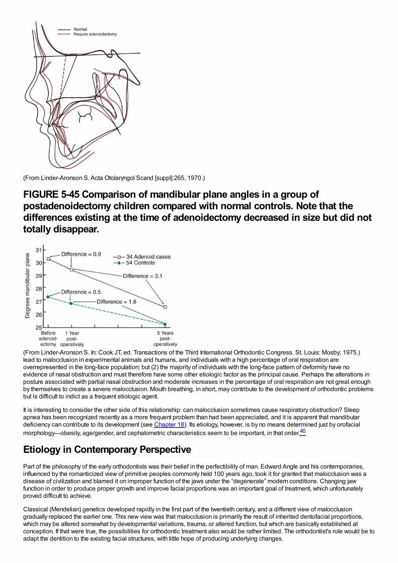
(From Linder-Aronson S. Acta Otolaryngol Scand [suppl]:265, 1970.)
FIGURE 5-45 Comparison of mandibular plane angles in a group ofpostadenoidectomy children compared with normal controls. Note that thedifferences existing at the time of adenoidectomy decreased in size but did nottotally disappear.
(From Linder-Aronson S. In: Cook JT, ed. Transactions of the Third International Orthodontic Congress. St. Louis: Mosby; 1975.)lead to malocclusion in experimental animals and humans, and individuals with a high percentage of oral respiration areoverrepresented in the long-face population; but (2) the majority of individuals with the long-face pattern of deformity have noevidence of nasal obstruction and must therefore have some other etiologic factor as the principal cause. Perhaps the alterations inposture associated with partial nasal obstruction and moderate increases in the percentage of oral respiration are not great enoughby themselves to create a severe malocclusion. Mouth breathing, in short, may contribute to the development of orthodontic problemsbut is difficult to indict as a frequent etiologic agent.
It is interesting to consider the other side of this relationship: can malocclusion sometimes cause respiratory obstruction? Sleepapnea has been recognized recently as a more frequent problem than had been appreciated, and it is apparent that mandibulardeficiency can contribute to its development (see Chapter 18). Its etiology, however, is by no means determined just by orofacialmorphology—obesity, age/gender, and cephalometric characteristics seem to be important, in that order.40
Etiology in Contemporary PerspectivePart of the philosophy of the early orthodontists was their belief in the perfectibility of man. Edward Angle and his contemporaries,influenced by the romanticized view of primitive peoples commonly held 100 years ago, took it for granted that malocclusion was adisease of civilization and blamed it on improper function of the jaws under the “degenerate” modern conditions. Changing jawfunction in order to produce proper growth and improve facial proportions was an important goal of treatment, which unfortunatelyproved difficult to achieve.
Classical (Mendelian) genetics developed rapidly in the first part of the twentieth century, and a different view of malocclusiongradually replaced the earlier one. This new view was that malocclusion is primarily the result of inherited dentofacial proportions,which may be altered somewhat by developmental variations, trauma, or altered function, but which are basically established atconception. If that were true, the possibilities for orthodontic treatment also would be rather limited. The orthodontist's role would be toadapt the dentition to the existing facial structures, with little hope of producing underlying changes.

In the 1980s, there was a strong swing back toward the earlier view, as the failure of heredity to explain most variation in occlusionand jaw proportions was appreciated and as the new theories of growth control indicated how environmental influences couldoperate by altering posture. The earlier concept that jaw function is related to the development of malocclusion was revived andstrengthened, both by the evidence against simple inheritance and by a more optimistic view of the extent to which the humanskeleton can be altered. Clinical applications, some already recognized as unfortunate, reflected extreme optimism about archexpansion and growth modification.
As the twenty-first century moves ahead, a more balanced view seems to be emerging. Contemporary research has refuted thesimplistic picture of malocclusion as resulting from independent inheritance of dental and facial characteristics, but the researchfindings consistently have shown also that there are no simple explanations for malocclusion in terms of oral function. Mouthbreathing, tongue thrusting, soft diet, sleeping posture—none of these can be regarded as the sole or even the major reason for mostmalocclusions. Along the same lines, it is fair to say that the research has not yet clarified the precise role of heredity as an etiologicagent for malocclusion. The relatively high heritability of craniofacial dimensions and the relatively low heritability of dental archvariations now have been established, but exactly how this relates to the etiologic process of malocclusions that have both skeletaland dental components remains unknown. Conclusions about the etiology of most orthodontic problems are difficult because severalinteracting factors probably played a role. At least, at this point we are more aware of how much we really do not yet know about theetiology of orthodontic problems.
References1.
Moore, ES, Ward, RE, Jamison, PL, et al.: New perspectives on the face in fetal alcohol syndrome: what anthropometry tells us. Am JMed Genet. 109, 2002, 249–260.
2.
Naidoo, S, Norval, G, Swanevelder, S, et al.: Foetal alcohol syndrome: a dental and skeletal age analysis of patients and controls.Eur J Orthod. 28, 2006, 247–253.
3.
Dupé, V, Pellerin, I: Retinoic acid receptors exhibit cell-autonomous functions in cranial neural crest cells. Dev Dyn. 238, 2009, 2701–2711.
4.
Macaya, D, Katsanis, SH, Hefferon, TW, et al.: A synonymous mutation in TCOF1 causes Treacher Collins syndrome due to mis-splicing of a constitutive exon. Am J Med Genet A. 149, 2009, 1624–1627.
5.
Johnston, MC, Bronsky, PT: Abnormal craniofacial development: an overview. Crit Rev Oral Biol Med. 6, 1995, 368–422.
6.
Tessier, P: Anatomical classification of facial, craniofacial and latero-facial clefts. J Maxillofac Surg. 4, 1976, 69–92.
7.
Shaw, GM, Carmichael, SL, Vollset, SE: Mid-pregnancy cotinine and risks of orofacial clefts and neural tube defects. J Pediatr. 154,2009, 17–19.
8.
Li, Z, Liu, J, Ye, R, et al.: Maternal passive smoking and risk of cleft lip with or without cleft palate. Epidemiology. 21, 2010, 240–242.
9.
Turvey, TA, Vig, KWL, Fonseca, RJ: Facial Clefts and Craniosynostosis: Principles and Management. 1996, WB Saunders,Philadelphia.
10.
Suri, S, Ross, RB, Tompson, BD: Craniofacial morphology and adolescent facial growth in Pierre Robin sequence. Am J OrthodDentofac Orthop. 137, 2010, 763–774.
11.
Yu, CC, Wong, FH, Lo, LJ, et al.: Craniofacial deformity in patients with uncorrected congenital muscular torticollis: an assessmentfrom three-dimensional computed tomography imaging. Plast Reconstr Surg. 113, 2004, 24–33.
12.

Kiliaridis, S, Katsaros, C: The effects of myotonic dystrophy and Duchenne muscular dystrophy on the orofacial muscles anddentofacial morphology. Acta Odontol Scand. 56, 1998, 369–374.
13.
Obwegeser, HL: Mandibular Growth Anomalies. 2000, Springer-Verlag, Berlin.
14.
Fleseriu, M, Delashaw, JB Jr., Cook, DM: Acromegaly: a review of current medical therapy and new drugs on the horizon. NeurosurgFocus. 29, 2010, E15.
15.
Stockard, CR, Johnson, AL: Genetic and Endocrinic Basis for Differences in Form and Behavior. 1941, The Wistar Institute ofAnatomy and Biology, Philadelphia.
16.
Chung, CS, Niswander, JD, Runck, DW, et al.: Genetic and epidemiologic studies of oral characteristics in Hawaii's schoolchildren. II.Malocclusion. Am J Human Genet. 23, 1971, 471–495.
17.
Townsend, G, Hughes, T, Bockmann, M, et al.: How studies of twins can inform our understanding of dental morphology. Front OralBiol. 13, 2009, 136–141.
18.
Hughes, T, Thomas, C, Richards, L, et al.: A study of occlusal variation in the primary dentition of Australian twins and singletons. ArchOral Biol. 46, 2001, 857–864.
19.
Corruccini, RS, Sharma, K, Potter, RHY: Comparative genetic variance and heritability of dental occlusal variables in U.S. andnorthwest Indian twins. Am J Phys Anthropol. 70, 1986, 293–299.
20.
Harris, EF, Johnson, MG: Heritability of craniometric and occlusal variables: a longitudinal sib analysis. Am J Orthod DentofacOrthop. 99, 1991, 258–268.
21.
Johannsdottir, B, Thorarinsson, F, Thordarson, A, et al.: Heritability of craniofacial characteristics between parents and offspringestimated from lateral cephalograms. Am J Orthod Dentofac Orthop. 127, 2005, 200–207.
22.
Suzuki, A, Takahama, Y: Parental data used to predict growth of craniofacial form. Am J Orthod Dentofac Orthop. 99, 1991, 107–121.
23.
Cruz, RM, Krieger, H, Ferreira, R, et al.: Major gene and multifactorial inheritance of mandibular prognathism. Am J Med Genet A.146A, 2008, 71–77.
24.
Bui, C, King, T, Proffit, W, et al.: Phenotypic characterization of Class III patients. Angle Orthod. 76, 2006, 564–569.
25.
Larsen, CS: Bioarchaeology: Interpreting Behavior from the Human Skeleton. 1997, Cambridge University Press, Cambridge.
26.
Corruccini, RS: Anthropological aspects of orofacial and occlusal variations and anomalies. In Kelly, MA, Larsen, CS (Eds.):Advances in Dental Anthropology . 1991, Wiley-Liss, New York.
27.
Kiliaridis, S: Masticatory muscle influence on craniofacial growth. Acta Odontol Scand. 53, 1995, 196–202.

28.
Ciochon, RL, Nisbett, RA, Corruccini, RS: Dietary consistency and craniofacial development related to masticatory function inminipigs. J Craniofac Genet Dev Biol. 17, 1997, 96–102.
29.
Proffit, WR, Fields, HW, Nixon, WL: Occlusal forces in normal and long face adults. J Dent Res. 62, 1983, 566–571.
30.
Proffit, WR, Fields, HW: Occlusal forces in normal and long face children. J Dent Res. 62, 1983, 571–574.
31.
Kovero, O, Kononen, M, Pirinen, S: The effect of professional violin and viola playing on the bony facial structures. Eur J Orthod. 19,1997, 39–45.
32.
Kindisbacher, I, Hirschi, U, Ingervall, B, et al.: Little influence on tooth position from playing a wind instrument. Angle Orthod. 60,1990, 223–228.
33.
Proffit, WR: Lingual pressure patterns in the transition from tongue thrust to adult swallowing. Arch Oral Biol. 17, 1972, 555–563.
34.
Vig, KWL: Nasal obstruction and facial growth: the strength of evidence for clinical assumptions. Am J Orthod Dentofac Orthop. 113,1998, 603–611.
35.
Warren, DW, Mayo, R, Zajac, DJ, et al.: Dyspnea following experimentally induced increased nasal airway resistance. Cleft Palate-Craniofac J. 33, 1996, 231–235.
36.
Harvold, EP, Tomer, BS, Vargervik, K, et al.: Primate experiments on oral respiration. Am J Orthod. 79, 1981, 359–372.
37.
Fields, HW, Warren, DW, Black, K, Phillips, C: Relationship between vertical dentofacial morphology and respiration in adolescents.Am J Orthod Dentofac Orthop. 99, 1991, 147–154.
38.
Linder-Aronson, S: Adenoids: their effect on mode of breathing and nasal airflow and their relationship to characteristics of the facialskeleton and dentition. Acta Otolaryngol Scand. 265, 1970, 1–132.
39.
Woodside, DG, Linder-Aronson, S, Lundstrom, A, et al.: Mandibular and maxillary growth after changed mode of breathing. Am JOrthod Dentofac Orthop. 100, 1991, 1–18.
40.
In Friedman, F (Ed.): Sleep Apnea and Snoring: Surgical and Non-surgical Therapy . 2009, Saunders-Elsevier, Edinburgh.
Diagnosis and Treatment PlanningThe process of orthodontic diagnosis and treatment planning lends itself well to the problem-oriented approach. Diagnosis inorthodontics, as in other disciplines of dentistry and medicine, requires the collection of an adequate database of information aboutthe patient and the distillation from that database of a comprehensive but clearly stated list of the patient's problems. It is important torecognize that both the patient's perceptions and the doctor's observations are needed in formulating the problem list. Then the taskof treatment planning is to synthesize the possible solutions to these specific problems (often there are many possibilities) into aspecific treatment strategy that would provide maximum benefit for this particular patient.
Keep in mind that diagnosis and treatment planning, though part of the same process, are different procedures with fundamentallydifferent goals. In the development of a database and formulation of a problem list, the goal is truth—the goal of scientific inquiry. Atthis stage there is no room for opinion or judgment. Instead, a totally factual appraisal of the situation is required. On the other hand,the goal of treatment planning is not scientific truth, but wisdom—the plan that a wise and prudent clinician would follow to maximizebenefit for the patient. For this reason, treatment planning inevitably is something of an art form. Diagnosis must be donescientifically; for all practical purposes, treatment planning cannot be science alone. Judgment by the clinician is required asproblems are prioritized and as alternative treatment possibilities are evaluated. Wise treatment choices, of course, are facilitated ifno significant points have been overlooked previously and if it is realized that treatment planning is an interactive process requiringthat the patient be given a role in the decision-making process.
We recommend carrying out diagnosis and treatment planning in a series of logical steps. The following first two steps constitutediagnosis:
1Development of an adequate diagnostic database.2Formulation of a problem list (the diagnosis) from the database. Both pathologic and developmental problems may bepresent. If so, pathologic problems should be separated from the developmental ones so that they can receive priority fortreatment—not because they are more important but because pathologic processes must be under control before treatment ofdevelopmental problems begins. The diagnostic process is outlined in detail in Chapter 6.
Once a patient's orthodontic problems have been identified and prioritized, four issues must be faced in determining the optimaltreatment plan: (1) the timing of treatment, (2) the complexity of the treatment that would be required, (3) the predictability of successwith a given treatment approach, and (4) the patient's (and parents’) goals and desires. These issues are considered briefly in thenext paragraphs.
Orthodontic treatment can be carried out at any time during a patient's life and can be aimed at a specific problem or becomprehensive. Usually, treatment is comprehensive (i.e., with a goal of the best possible occlusion, facial esthetics, and stability)and is done in adolescence, as the last permanent teeth are erupting. There are good reasons for this choice. At this point, for mostpatients there is sufficient growth remaining to potentially improve jaw relationships, and all permanent teeth, including the secondmolars, can be controlled and placed in a more or less final position. From a psychosocial point of view, patients in this age groupoften are reaching the point of self-motivation for treatment, which is evident in their improved ability to cooperate duringappointments and in appliance and oral hygiene care. A reasonably short course of treatment in early adolescence, as opposed totwo stages of early and later treatment, fits well within the cooperative potential of patients and families.
Even though not all patients respond well to treatment during adolescence, treatment at this time remains the “gold standard” againstwhich other approaches must be measured. For a child with obvious malocclusion, does it really make sense to start treatment earlyin the preadolescent years? Obviously, timing will depend on the specific problems. Issues in the timing of treatment are reviewed indetail in Chapters 7 and 13.
The complexity of the treatment that would be required affects treatment planning, especially in the context of who should do thetreatment. In orthodontics, as in all areas of dentistry, it makes sense that the less complex cases would be selected for treatment ingeneral or family practice, while the more complex cases would be referred to a specialist. The only difference in orthodontics is thattraditionally the family practitioner has referred a larger number of orthodontic cases. In family practice, an important issue is how yourationally select patients for treatment or referral. Chapter 11 includes a formal scheme for separating patients most appropriate fortreatment in family practice from those more likely to require complex treatment.
The third special issue is the predictability of treatment with any particular method. If alternative methods of treatment are available,as usually is the case, which one should be chosen? Data gradually are accumulating to allow choices to be based on evidence ofoutcomes rather than anecdotal reports and the claims of advocates of particular approaches. Existing data for treatment outcomes,as a basis for deciding what the best treatment approach might be, are emphasized in Chapter 7.
Finally, but most important, treatment planning must be an interactive process. No longer can the doctor decide, in a paternalisticway, what is best for a patient. Both ethically and practically, patients must be involved in the decision-making process. Ethically,patients have the right to control what happens to them in treatment—treatment is something done for them not to them. Practically,the patient's compliance is likely to be a critical issue in success or failure, and there is little reason to select a mode of treatment thatthe patient would not support. Informed consent, in its modern form, requires involving the patient in the treatment planning process.This is emphasized in the procedure for presenting treatment recommendations to patients in Chapter 7.
The logical sequence for treatment planning, with these issues in mind, is as follows:
1Prioritization of the items on the orthodontic problem list so that the most important problem receives highest priority fortreatment2Consideration of possible solutions to each problem, with each problem evaluated for the moment as if it were the only
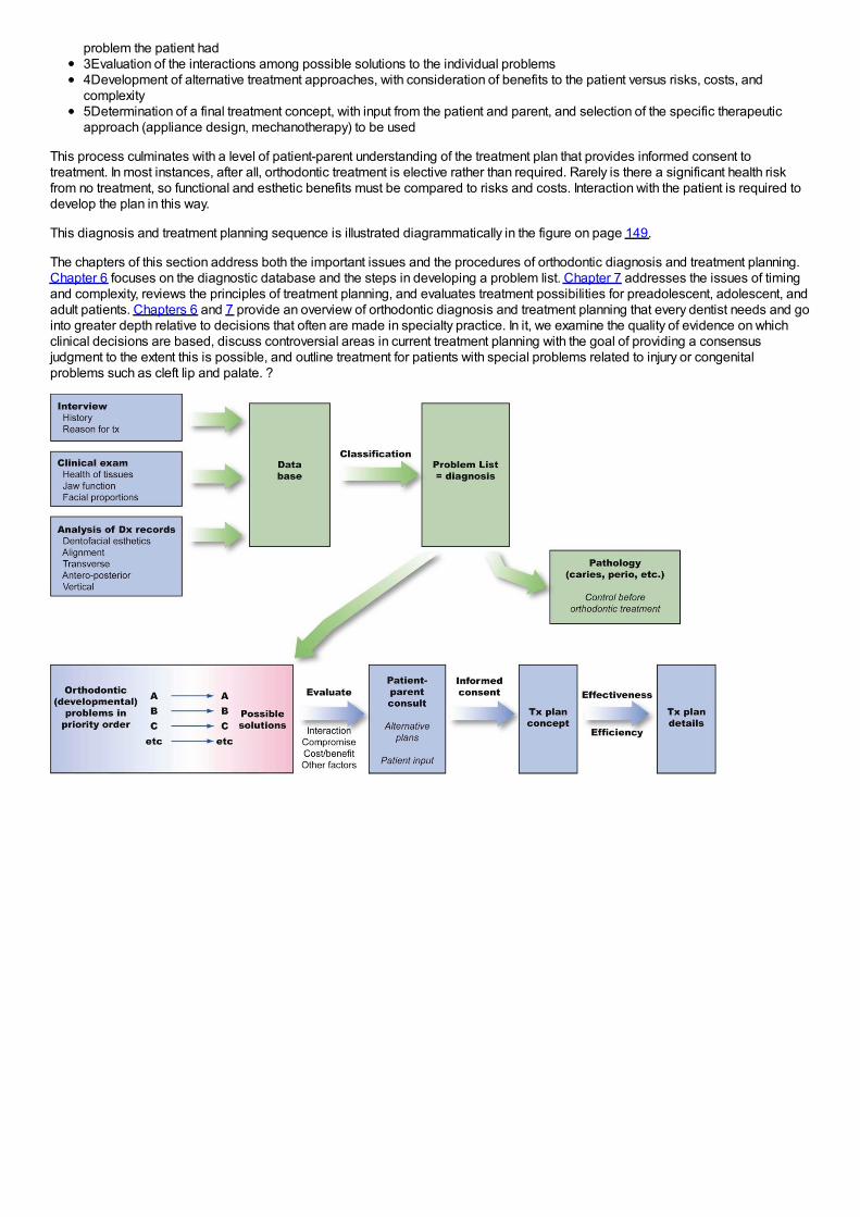
problem the patient had3Evaluation of the interactions among possible solutions to the individual problems4Development of alternative treatment approaches, with consideration of benefits to the patient versus risks, costs, andcomplexity5Determination of a final treatment concept, with input from the patient and parent, and selection of the specific therapeuticapproach (appliance design, mechanotherapy) to be used
This process culminates with a level of patient-parent understanding of the treatment plan that provides informed consent totreatment. In most instances, after all, orthodontic treatment is elective rather than required. Rarely is there a significant health riskfrom no treatment, so functional and esthetic benefits must be compared to risks and costs. Interaction with the patient is required todevelop the plan in this way.
This diagnosis and treatment planning sequence is illustrated diagrammatically in the figure on page 149.
The chapters of this section address both the important issues and the procedures of orthodontic diagnosis and treatment planning.Chapter 6 focuses on the diagnostic database and the steps in developing a problem list. Chapter 7 addresses the issues of timingand complexity, reviews the principles of treatment planning, and evaluates treatment possibilities for preadolescent, adolescent, andadult patients. Chapters 6 and 7 provide an overview of orthodontic diagnosis and treatment planning that every dentist needs and gointo greater depth relative to decisions that often are made in specialty practice. In it, we examine the quality of evidence on whichclinical decisions are based, discuss controversial areas in current treatment planning with the goal of providing a consensusjudgment to the extent this is possible, and outline treatment for patients with special problems related to injury or congenitalproblems such as cleft lip and palate. ?
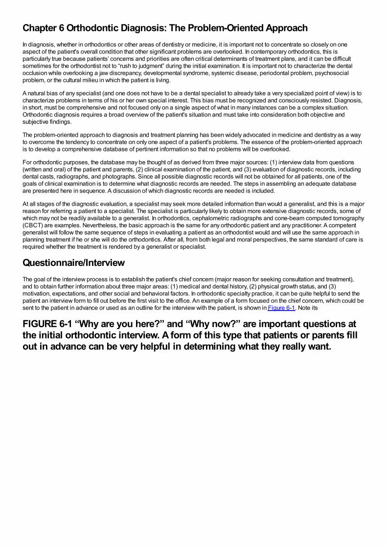
Chapter 6 Orthodontic Diagnosis: The Problem-Oriented ApproachIn diagnosis, whether in orthodontics or other areas of dentistry or medicine, it is important not to concentrate so closely on oneaspect of the patient's overall condition that other significant problems are overlooked. In contemporary orthodontics, this isparticularly true because patients’ concerns and priorities are often critical determinants of treatment plans, and it can be difficultsometimes for the orthodontist not to “rush to judgment” during the initial examination. It is important not to characterize the dentalocclusion while overlooking a jaw discrepancy, developmental syndrome, systemic disease, periodontal problem, psychosocialproblem, or the cultural milieu in which the patient is living.
A natural bias of any specialist (and one does not have to be a dental specialist to already take a very specialized point of view) is tocharacterize problems in terms of his or her own special interest. This bias must be recognized and consciously resisted. Diagnosis,in short, must be comprehensive and not focused only on a single aspect of what in many instances can be a complex situation.Orthodontic diagnosis requires a broad overview of the patient's situation and must take into consideration both objective andsubjective findings.
The problem-oriented approach to diagnosis and treatment planning has been widely advocated in medicine and dentistry as a wayto overcome the tendency to concentrate on only one aspect of a patient's problems. The essence of the problem-oriented approachis to develop a comprehensive database of pertinent information so that no problems will be overlooked.
For orthodontic purposes, the database may be thought of as derived from three major sources: (1) interview data from questions(written and oral) of the patient and parents, (2) clinical examination of the patient, and (3) evaluation of diagnostic records, includingdental casts, radiographs, and photographs. Since all possible diagnostic records will not be obtained for all patients, one of thegoals of clinical examination is to determine what diagnostic records are needed. The steps in assembling an adequate databaseare presented here in sequence. A discussion of which diagnostic records are needed is included.
At all stages of the diagnostic evaluation, a specialist may seek more detailed information than would a generalist, and this is a majorreason for referring a patient to a specialist. The specialist is particularly likely to obtain more extensive diagnostic records, some ofwhich may not be readily available to a generalist. In orthodontics, cephalometric radiographs and cone-beam computed tomography(CBCT) are examples. Nevertheless, the basic approach is the same for any orthodontic patient and any practitioner. A competentgeneralist will follow the same sequence of steps in evaluating a patient as an orthodontist would and will use the same approach inplanning treatment if he or she will do the orthodontics. After all, from both legal and moral perspectives, the same standard of care isrequired whether the treatment is rendered by a generalist or specialist.
Questionnaire/InterviewThe goal of the interview process is to establish the patient's chief concern (major reason for seeking consultation and treatment),and to obtain further information about three major areas: (1) medical and dental history, (2) physical growth status, and (3)motivation, expectations, and other social and behavioral factors. In orthodontic specialty practice, it can be quite helpful to send thepatient an interview form to fill out before the first visit to the office. An example of a form focused on the chief concern, which could besent to the patient in advance or used as an outline for the interview with the patient, is shown in Figure 6-1. Note its
FIGURE 6-1 “Why are you here?” and “Why now?” are important questions atthe initial orthodontic interview. A form of this type that patients or parents fillout in advance can be very helpful in determining what they really want.
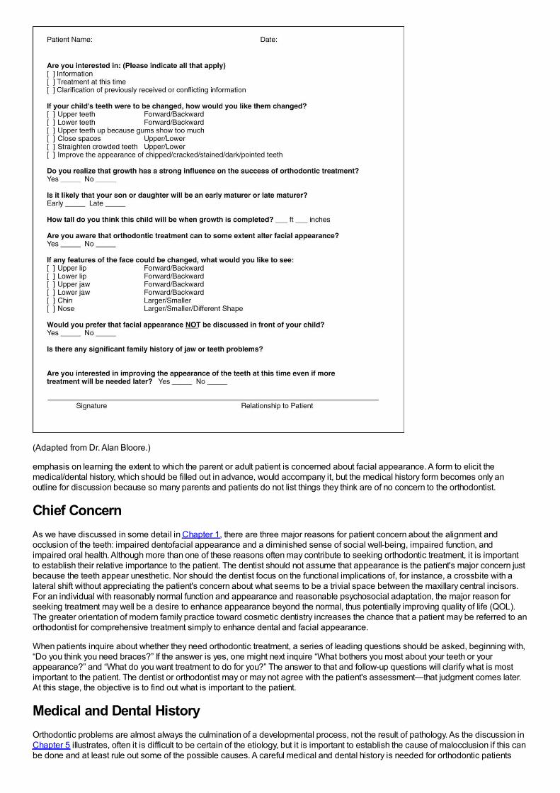
(Adapted from Dr. Alan Bloore.)
emphasis on learning the extent to which the parent or adult patient is concerned about facial appearance. A form to elicit themedical/dental history, which should be filled out in advance, would accompany it, but the medical history form becomes only anoutline for discussion because so many parents and patients do not list things they think are of no concern to the orthodontist.
Chief ConcernAs we have discussed in some detail in Chapter 1, there are three major reasons for patient concern about the alignment andocclusion of the teeth: impaired dentofacial appearance and a diminished sense of social well-being, impaired function, andimpaired oral health. Although more than one of these reasons often may contribute to seeking orthodontic treatment, it is importantto establish their relative importance to the patient. The dentist should not assume that appearance is the patient's major concern justbecause the teeth appear unesthetic. Nor should the dentist focus on the functional implications of, for instance, a crossbite with alateral shift without appreciating the patient's concern about what seems to be a trivial space between the maxillary central incisors.For an individual with reasonably normal function and appearance and reasonable psychosocial adaptation, the major reason forseeking treatment may well be a desire to enhance appearance beyond the normal, thus potentially improving quality of life (QOL).The greater orientation of modern family practice toward cosmetic dentistry increases the chance that a patient may be referred to anorthodontist for comprehensive treatment simply to enhance dental and facial appearance.
When patients inquire about whether they need orthodontic treatment, a series of leading questions should be asked, beginning with,“Do you think you need braces?” If the answer is yes, one might next inquire “What bothers you most about your teeth or yourappearance?” and “What do you want treatment to do for you?” The answer to that and follow-up questions will clarify what is mostimportant to the patient. The dentist or orthodontist may or may not agree with the patient's assessment—that judgment comes later.At this stage, the objective is to find out what is important to the patient.
Medical and Dental HistoryOrthodontic problems are almost always the culmination of a developmental process, not the result of pathology. As the discussion inChapter 5 illustrates, often it is difficult to be certain of the etiology, but it is important to establish the cause of malocclusion if this canbe done and at least rule out some of the possible causes. A careful medical and dental history is needed for orthodontic patients
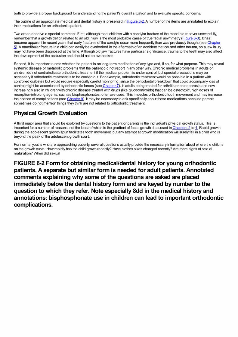
both to provide a proper background for understanding the patient's overall situation and to evaluate specific concerns.
The outline of an appropriate medical and dental history is presented in Figure 6-2. A number of the items are annotated to explaintheir implications for an orthodontic patient.
Two areas deserve a special comment. First, although most children with a condylar fracture of the mandible recover uneventfully,remember that a growth deficit related to an old injury is the most probable cause of true facial asymmetry (Figure 6-3). It hasbecome apparent in recent years that early fractures of the condyle occur more frequently than was previously thought (see Chapter5). A mandibular fracture in a child can easily be overlooked in the aftermath of an accident that caused other trauma, so a jaw injurymay not have been diagnosed at the time. Although old jaw fractures have particular significance, trauma to the teeth may also affectthe development of the occlusion and should not be overlooked.
Second, it is important to note whether the patient is on long-term medication of any type and, if so, for what purpose. This may revealsystemic disease or metabolic problems that the patient did not report in any other way. Chronic medical problems in adults orchildren do not contraindicate orthodontic treatment if the medical problem is under control, but special precautions may benecessary if orthodontic treatment is to be carried out. For example, orthodontic treatment would be possible in a patient withcontrolled diabetes but would require especially careful monitoring, since the periodontal breakdown that could accompany loss ofcontrol might be accentuated by orthodontic forces (see Chapter 7). In adults being treated for arthritis or osteoporosis and nowincreasingly also in children with chronic disease treated with drugs (like glucocorticoids) that can be osteotoxic, high doses ofresorption-inhibiting agents, such as bisphosphonates, often are used. This impedes orthodontic tooth movement and may increasethe chance of complications (see Chapter 9). It may be necessary to ask specifically about these medications because parentssometimes do not mention things they think are not related to orthodontic treatment.
Physical Growth EvaluationA third major area that should be explored by questions to the patient or parents is the individual's physical growth status. This isimportant for a number of reasons, not the least of which is the gradient of facial growth discussed in Chapters 2 to 4. Rapid growthduring the adolescent growth spurt facilitates tooth movement, but any attempt at growth modification will surely fail in a child who isbeyond the peak of the adolescent growth spurt.
For normal youths who are approaching puberty, several questions usually provide the necessary information about where the child ison the growth curve: How rapidly has the child grown recently? Have clothes sizes changed recently? Are there signs of sexualmaturation? When did sexual
FIGURE 6-2 Form for obtaining medical/dental history for young orthodonticpatients. A separate but similar form is needed for adult patients. Annotatedcomments explaining why some of the questions are asked are placedimmediately below the dental history form and are keyed by number to thequestion to which they refer. Note especially 8dd in the medical history andannotations: bisphosphonate use in children can lead to important orthodonticcomplications.

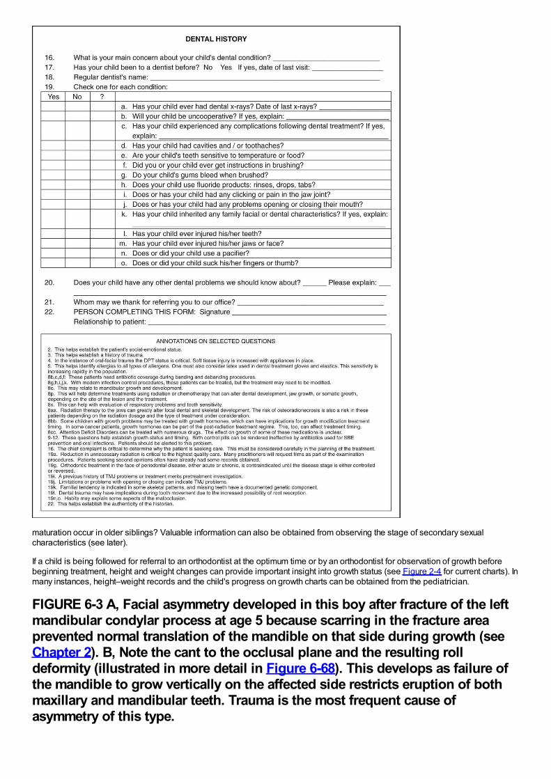
maturation occur in older siblings? Valuable information can also be obtained from observing the stage of secondary sexualcharacteristics (see later).
If a child is being followed for referral to an orthodontist at the optimum time or by an orthodontist for observation of growth beforebeginning treatment, height and weight changes can provide important insight into growth status (see Figure 2-4 for current charts). Inmany instances, height–weight records and the child's progress on growth charts can be obtained from the pediatrician.
FIGURE 6-3 A, Facial asymmetry developed in this boy after fracture of the leftmandibular condylar process at age 5 because scarring in the fracture areaprevented normal translation of the mandible on that side during growth (seeChapter 2). B, Note the cant to the occlusal plane and the resulting rolldeformity (illustrated in more detail in Figure 6-68). This develops as failure ofthe mandible to grow vertically on the affected side restricts eruption of bothmaxillary and mandibular teeth. Trauma is the most frequent cause ofasymmetry of this type.
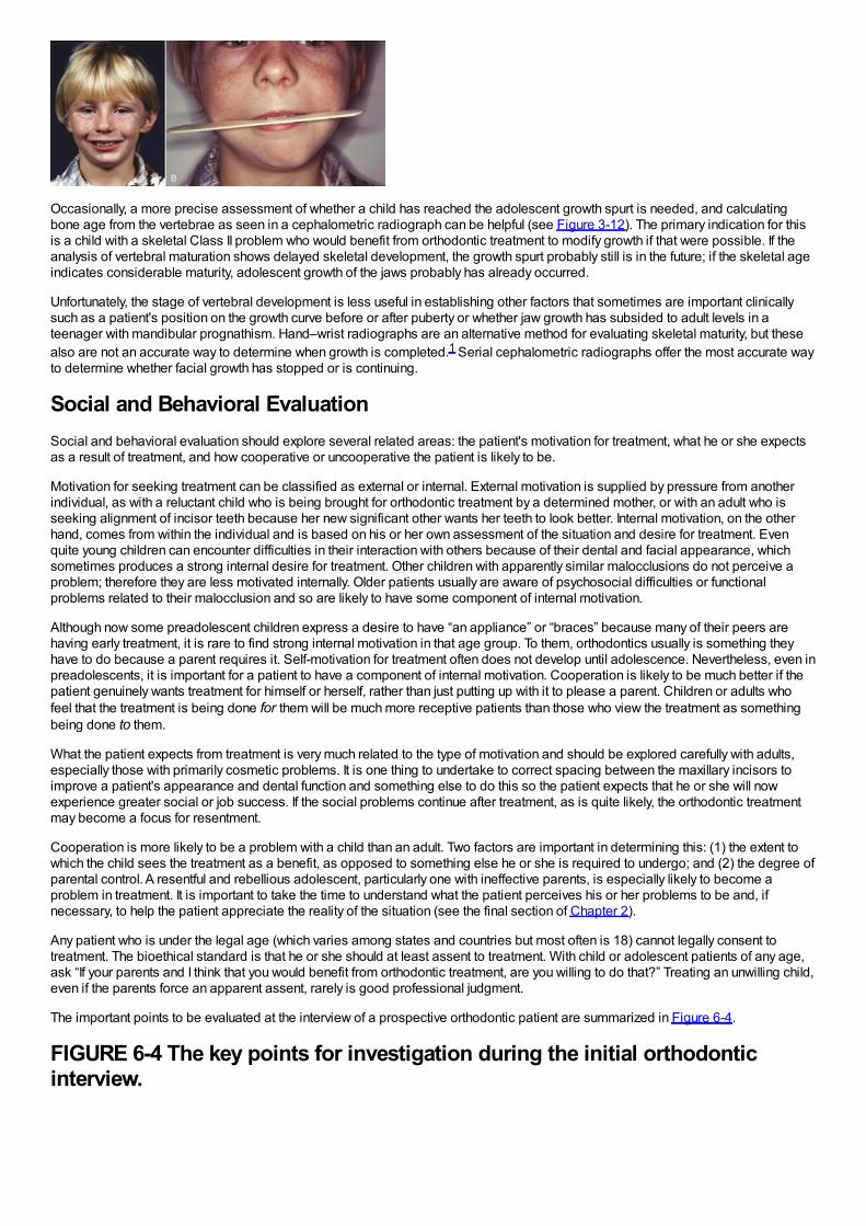
Occasionally, a more precise assessment of whether a child has reached the adolescent growth spurt is needed, and calculatingbone age from the vertebrae as seen in a cephalometric radiograph can be helpful (see Figure 3-12). The primary indication for thisis a child with a skeletal Class II problem who would benefit from orthodontic treatment to modify growth if that were possible. If theanalysis of vertebral maturation shows delayed skeletal development, the growth spurt probably still is in the future; if the skeletal ageindicates considerable maturity, adolescent growth of the jaws probably has already occurred.
Unfortunately, the stage of vertebral development is less useful in establishing other factors that sometimes are important clinicallysuch as a patient's position on the growth curve before or after puberty or whether jaw growth has subsided to adult levels in ateenager with mandibular prognathism. Hand–wrist radiographs are an alternative method for evaluating skeletal maturity, but thesealso are not an accurate way to determine when growth is completed.1 Serial cephalometric radiographs offer the most accurate wayto determine whether facial growth has stopped or is continuing.
Social and Behavioral EvaluationSocial and behavioral evaluation should explore several related areas: the patient's motivation for treatment, what he or she expectsas a result of treatment, and how cooperative or uncooperative the patient is likely to be.
Motivation for seeking treatment can be classified as external or internal. External motivation is supplied by pressure from anotherindividual, as with a reluctant child who is being brought for orthodontic treatment by a determined mother, or with an adult who isseeking alignment of incisor teeth because her new significant other wants her teeth to look better. Internal motivation, on the otherhand, comes from within the individual and is based on his or her own assessment of the situation and desire for treatment. Evenquite young children can encounter difficulties in their interaction with others because of their dental and facial appearance, whichsometimes produces a strong internal desire for treatment. Other children with apparently similar malocclusions do not perceive aproblem; therefore they are less motivated internally. Older patients usually are aware of psychosocial difficulties or functionalproblems related to their malocclusion and so are likely to have some component of internal motivation.
Although now some preadolescent children express a desire to have “an appliance” or “braces” because many of their peers arehaving early treatment, it is rare to find strong internal motivation in that age group. To them, orthodontics usually is something theyhave to do because a parent requires it. Self-motivation for treatment often does not develop until adolescence. Nevertheless, even inpreadolescents, it is important for a patient to have a component of internal motivation. Cooperation is likely to be much better if thepatient genuinely wants treatment for himself or herself, rather than just putting up with it to please a parent. Children or adults whofeel that the treatment is being done for them will be much more receptive patients than those who view the treatment as somethingbeing done to them.
What the patient expects from treatment is very much related to the type of motivation and should be explored carefully with adults,especially those with primarily cosmetic problems. It is one thing to undertake to correct spacing between the maxillary incisors toimprove a patient's appearance and dental function and something else to do this so the patient expects that he or she will nowexperience greater social or job success. If the social problems continue after treatment, as is quite likely, the orthodontic treatmentmay become a focus for resentment.
Cooperation is more likely to be a problem with a child than an adult. Two factors are important in determining this: (1) the extent towhich the child sees the treatment as a benefit, as opposed to something else he or she is required to undergo; and (2) the degree ofparental control. A resentful and rebellious adolescent, particularly one with ineffective parents, is especially likely to become aproblem in treatment. It is important to take the time to understand what the patient perceives his or her problems to be and, ifnecessary, to help the patient appreciate the reality of the situation (see the final section of Chapter 2).
Any patient who is under the legal age (which varies among states and countries but most often is 18) cannot legally consent totreatment. The bioethical standard is that he or she should at least assent to treatment. With child or adolescent patients of any age,ask “If your parents and I think that you would benefit from orthodontic treatment, are you willing to do that?” Treating an unwilling child,even if the parents force an apparent assent, rarely is good professional judgment.
The important points to be evaluated at the interview of a prospective orthodontic patient are summarized in Figure 6-4.
FIGURE 6-4 The key points for investigation during the initial orthodonticinterview.
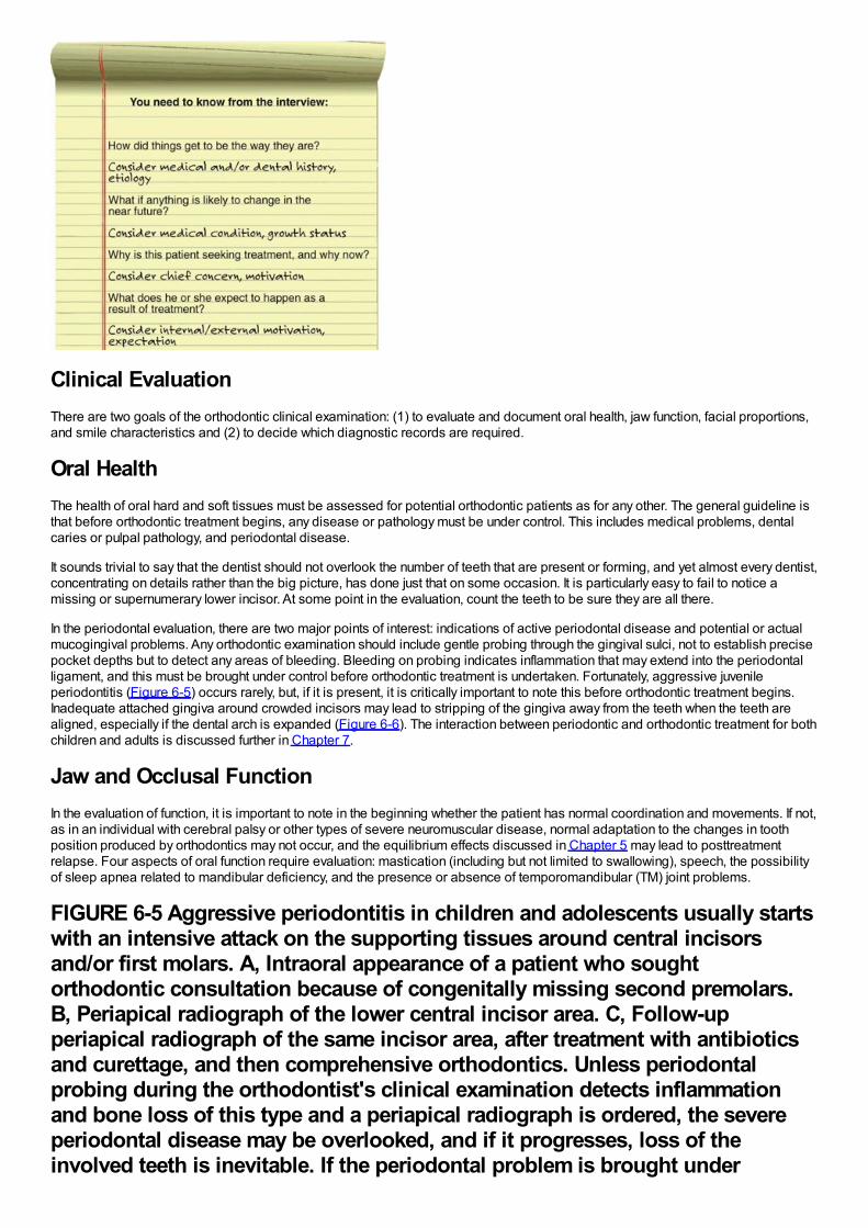
Clinical EvaluationThere are two goals of the orthodontic clinical examination: (1) to evaluate and document oral health, jaw function, facial proportions,and smile characteristics and (2) to decide which diagnostic records are required.
Oral HealthThe health of oral hard and soft tissues must be assessed for potential orthodontic patients as for any other. The general guideline isthat before orthodontic treatment begins, any disease or pathology must be under control. This includes medical problems, dentalcaries or pulpal pathology, and periodontal disease.
It sounds trivial to say that the dentist should not overlook the number of teeth that are present or forming, and yet almost every dentist,concentrating on details rather than the big picture, has done just that on some occasion. It is particularly easy to fail to notice amissing or supernumerary lower incisor. At some point in the evaluation, count the teeth to be sure they are all there.
In the periodontal evaluation, there are two major points of interest: indications of active periodontal disease and potential or actualmucogingival problems. Any orthodontic examination should include gentle probing through the gingival sulci, not to establish precisepocket depths but to detect any areas of bleeding. Bleeding on probing indicates inflammation that may extend into the periodontalligament, and this must be brought under control before orthodontic treatment is undertaken. Fortunately, aggressive juvenileperiodontitis (Figure 6-5) occurs rarely, but, if it is present, it is critically important to note this before orthodontic treatment begins.Inadequate attached gingiva around crowded incisors may lead to stripping of the gingiva away from the teeth when the teeth arealigned, especially if the dental arch is expanded (Figure 6-6). The interaction between periodontic and orthodontic treatment for bothchildren and adults is discussed further in Chapter 7.
Jaw and Occlusal FunctionIn the evaluation of function, it is important to note in the beginning whether the patient has normal coordination and movements. If not,as in an individual with cerebral palsy or other types of severe neuromuscular disease, normal adaptation to the changes in toothposition produced by orthodontics may not occur, and the equilibrium effects discussed in Chapter 5 may lead to posttreatmentrelapse. Four aspects of oral function require evaluation: mastication (including but not limited to swallowing), speech, the possibilityof sleep apnea related to mandibular deficiency, and the presence or absence of temporomandibular (TM) joint problems.
FIGURE 6-5 Aggressive periodontitis in children and adolescents usually startswith an intensive attack on the supporting tissues around central incisorsand/or first molars. A, Intraoral appearance of a patient who soughtorthodontic consultation because of congenitally missing second premolars.B, Periapical radiograph of the lower central incisor area. C, Follow-upperiapical radiograph of the same incisor area, after treatment with antibioticsand curettage, and then comprehensive orthodontics. Unless periodontalprobing during the orthodontist's clinical examination detects inflammationand bone loss of this type and a periapical radiograph is ordered, the severeperiodontal disease may be overlooked, and if it progresses, loss of theinvolved teeth is inevitable. If the periodontal problem is brought under
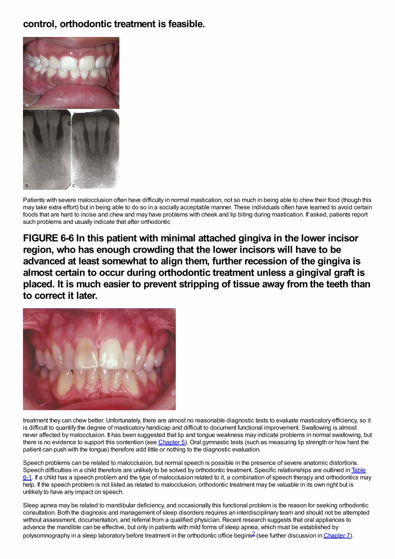
control, orthodontic treatment is feasible.
Patients with severe malocclusion often have difficulty in normal mastication, not so much in being able to chew their food (though thismay take extra effort) but in being able to do so in a socially acceptable manner. These individuals often have learned to avoid certainfoods that are hard to incise and chew and may have problems with cheek and lip biting during mastication. If asked, patients reportsuch problems and usually indicate that after orthodontic
FIGURE 6-6 In this patient with minimal attached gingiva in the lower incisorregion, who has enough crowding that the lower incisors will have to beadvanced at least somewhat to align them, further recession of the gingiva isalmost certain to occur during orthodontic treatment unless a gingival graft isplaced. It is much easier to prevent stripping of tissue away from the teeth thanto correct it later.
treatment they can chew better. Unfortunately, there are almost no reasonable diagnostic tests to evaluate masticatory efficiency, so itis difficult to quantify the degree of masticatory handicap and difficult to document functional improvement. Swallowing is almostnever affected by malocclusion. It has been suggested that lip and tongue weakness may indicate problems in normal swallowing, butthere is no evidence to support this contention (see Chapter 5). Oral gymnastic tests (such as measuring lip strength or how hard thepatient can push with the tongue) therefore add little or nothing to the diagnostic evaluation.
Speech problems can be related to malocclusion, but normal speech is possible in the presence of severe anatomic distortions.Speech difficulties in a child therefore are unlikely to be solved by orthodontic treatment. Specific relationships are outlined in Table6-1. If a child has a speech problem and the type of malocclusion related to it, a combination of speech therapy and orthodontics mayhelp. If the speech problem is not listed as related to malocclusion, orthodontic treatment may be valuable in its own right but isunlikely to have any impact on speech.
Sleep apnea may be related to mandibular deficiency, and occasionally this functional problem is the reason for seeking orthodonticconsultation. Both the diagnosis and management of sleep disorders requires an interdisciplinary team and should not be attemptedwithout assessment, documentation, and referral from a qualified physician. Recent research suggests that oral appliances toadvance the mandible can be effective, but only in patients with mild forms of sleep apnea, which must be established bypolysomnography in a sleep laboratory before treatment in the orthodontic office begins2 (see further discussion in Chapter 7).
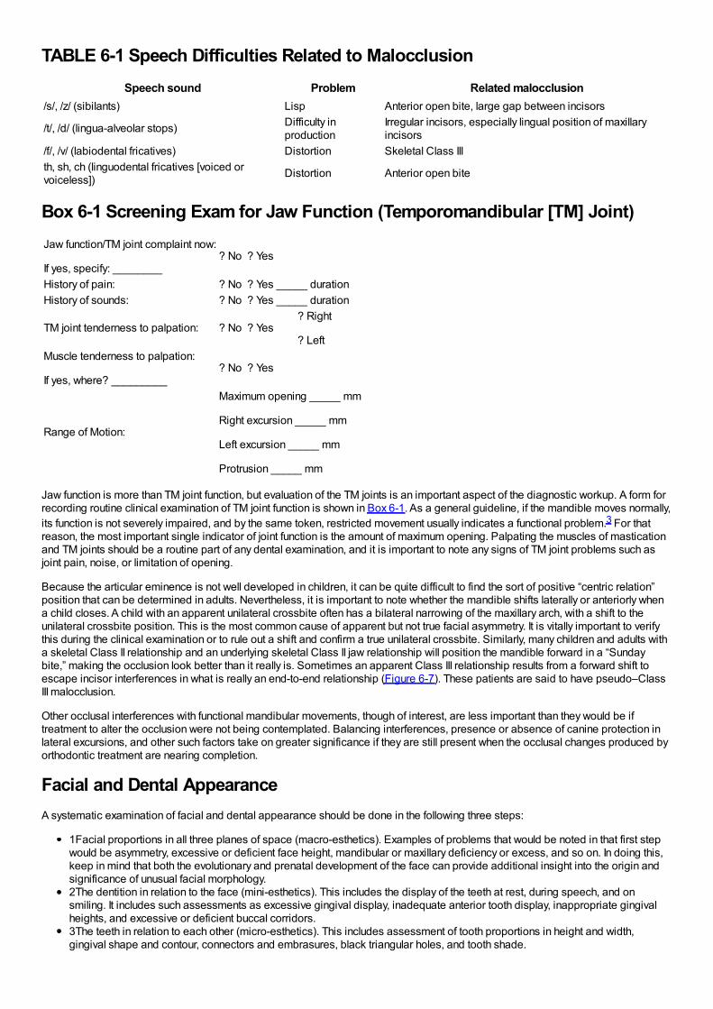
TABLE 6-1 Speech Difficulties Related to MalocclusionSpeech sound Problem Related malocclusion
/s/, /z/ (sibilants) Lisp Anterior open bite, large gap between incisors
/t/, /d/ (lingua-alveolar stops) Difficulty inproduction
Irregular incisors, especially lingual position of maxillaryincisors
/f/, /v/ (labiodental fricatives) Distortion Skeletal Class IIIth, sh, ch (linguodental fricatives [voiced orvoiceless]) Distortion Anterior open bite
Box 6-1 Screening Exam for Jaw Function (Temporomandibular [TM] Joint)Jaw function/TM joint complaint now:
If yes, specify: ________? No ? Yes
History of pain: ? No ? Yes _____ durationHistory of sounds: ? No ? Yes _____ duration
TM joint tenderness to palpation: ? No ? Yes? Right
? LeftMuscle tenderness to palpation:
If yes, where? _________? No ? Yes
Range of Motion:
Maximum opening _____ mm
Right excursion _____ mm
Left excursion _____ mm
Protrusion _____ mm
Jaw function is more than TM joint function, but evaluation of the TM joints is an important aspect of the diagnostic workup. A form forrecording routine clinical examination of TM joint function is shown in Box 6-1. As a general guideline, if the mandible moves normally,its function is not severely impaired, and by the same token, restricted movement usually indicates a functional problem.3 For thatreason, the most important single indicator of joint function is the amount of maximum opening. Palpating the muscles of masticationand TM joints should be a routine part of any dental examination, and it is important to note any signs of TM joint problems such asjoint pain, noise, or limitation of opening.
Because the articular eminence is not well developed in children, it can be quite difficult to find the sort of positive “centric relation”position that can be determined in adults. Nevertheless, it is important to note whether the mandible shifts laterally or anteriorly whena child closes. A child with an apparent unilateral crossbite often has a bilateral narrowing of the maxillary arch, with a shift to theunilateral crossbite position. This is the most common cause of apparent but not true facial asymmetry. It is vitally important to verifythis during the clinical examination or to rule out a shift and confirm a true unilateral crossbite. Similarly, many children and adults witha skeletal Class II relationship and an underlying skeletal Class II jaw relationship will position the mandible forward in a “Sundaybite,” making the occlusion look better than it really is. Sometimes an apparent Class III relationship results from a forward shift toescape incisor interferences in what is really an end-to-end relationship (Figure 6-7). These patients are said to have pseudo–ClassIII malocclusion.
Other occlusal interferences with functional mandibular movements, though of interest, are less important than they would be iftreatment to alter the occlusion were not being contemplated. Balancing interferences, presence or absence of canine protection inlateral excursions, and other such factors take on greater significance if they are still present when the occlusal changes produced byorthodontic treatment are nearing completion.
Facial and Dental AppearanceA systematic examination of facial and dental appearance should be done in the following three steps:
1Facial proportions in all three planes of space (macro-esthetics). Examples of problems that would be noted in that first stepwould be asymmetry, excessive or deficient face height, mandibular or maxillary deficiency or excess, and so on. In doing this,keep in mind that both the evolutionary and prenatal development of the face can provide additional insight into the origin andsignificance of unusual facial morphology.2The dentition in relation to the face (mini-esthetics). This includes the display of the teeth at rest, during speech, and onsmiling. It includes such assessments as excessive gingival display, inadequate anterior tooth display, inappropriate gingivalheights, and excessive or deficient buccal corridors.3The teeth in relation to each other (micro-esthetics). This includes assessment of tooth proportions in height and width,gingival shape and contour, connectors and embrasures, black triangular holes, and tooth shade.
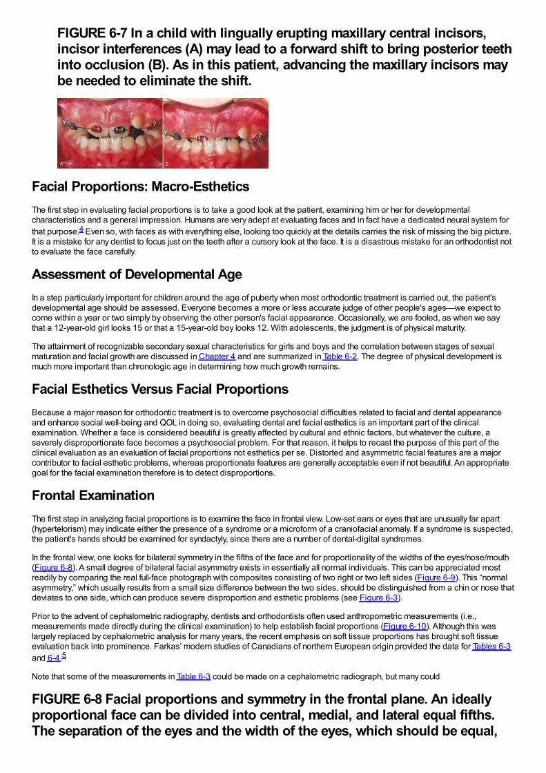
FIGURE 6-7 In a child with lingually erupting maxillary central incisors,incisor interferences (A) may lead to a forward shift to bring posterior teethinto occlusion (B). As in this patient, advancing the maxillary incisors maybe needed to eliminate the shift.
Facial Proportions: Macro-EstheticsThe first step in evaluating facial proportions is to take a good look at the patient, examining him or her for developmentalcharacteristics and a general impression. Humans are very adept at evaluating faces and in fact have a dedicated neural system forthat purpose.4 Even so, with faces as with everything else, looking too quickly at the details carries the risk of missing the big picture.It is a mistake for any dentist to focus just on the teeth after a cursory look at the face. It is a disastrous mistake for an orthodontist notto evaluate the face carefully.
Assessment of Developmental AgeIn a step particularly important for children around the age of puberty when most orthodontic treatment is carried out, the patient'sdevelopmental age should be assessed. Everyone becomes a more or less accurate judge of other people's ages—we expect tocome within a year or two simply by observing the other person's facial appearance. Occasionally, we are fooled, as when we saythat a 12-year-old girl looks 15 or that a 15-year-old boy looks 12. With adolescents, the judgment is of physical maturity.
The attainment of recognizable secondary sexual characteristics for girls and boys and the correlation between stages of sexualmaturation and facial growth are discussed in Chapter 4 and are summarized in Table 6-2. The degree of physical development ismuch more important than chronologic age in determining how much growth remains.
Facial Esthetics Versus Facial ProportionsBecause a major reason for orthodontic treatment is to overcome psychosocial difficulties related to facial and dental appearanceand enhance social well-being and QOL in doing so, evaluating dental and facial esthetics is an important part of the clinicalexamination. Whether a face is considered beautiful is greatly affected by cultural and ethnic factors, but whatever the culture, aseverely disproportionate face becomes a psychosocial problem. For that reason, it helps to recast the purpose of this part of theclinical evaluation as an evaluation of facial proportions not esthetics per se. Distorted and asymmetric facial features are a majorcontributor to facial esthetic problems, whereas proportionate features are generally acceptable even if not beautiful. An appropriategoal for the facial examination therefore is to detect disproportions.
Frontal ExaminationThe first step in analyzing facial proportions is to examine the face in frontal view. Low-set ears or eyes that are unusually far apart(hypertelorism) may indicate either the presence of a syndrome or a microform of a craniofacial anomaly. If a syndrome is suspected,the patient's hands should be examined for syndactyly, since there are a number of dental-digital syndromes.
In the frontal view, one looks for bilateral symmetry in the fifths of the face and for proportionality of the widths of the eyes/nose/mouth(Figure 6-8). A small degree of bilateral facial asymmetry exists in essentially all normal individuals. This can be appreciated mostreadily by comparing the real full-face photograph with composites consisting of two right or two left sides (Figure 6-9). This “normalasymmetry,” which usually results from a small size difference between the two sides, should be distinguished from a chin or nose thatdeviates to one side, which can produce severe disproportion and esthetic problems (see Figure 6-3).
Prior to the advent of cephalometric radiography, dentists and orthodontists often used anthropometric measurements (i.e.,measurements made directly during the clinical examination) to help establish facial proportions (Figure 6-10). Although this waslargely replaced by cephalometric analysis for many years, the recent emphasis on soft tissue proportions has brought soft tissueevaluation back into prominence. Farkas’ modern studies of Canadians of northern European origin provided the data for Tables 6-3and 6-4.5
Note that some of the measurements in Table 6-3 could be made on a cephalometric radiograph, but many could
FIGURE 6-8 Facial proportions and symmetry in the frontal plane. An ideallyproportional face can be divided into central, medial, and lateral equal fifths.The separation of the eyes and the width of the eyes, which should be equal,
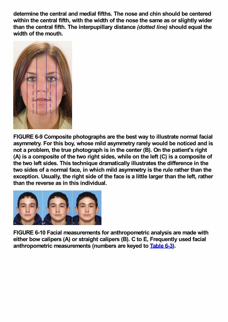
determine the central and medial fifths. The nose and chin should be centeredwithin the central fifth, with the width of the nose the same as or slightly widerthan the central fifth. The interpupillary distance (dotted line) should equal thewidth of the mouth.
FIGURE 6-9 Composite photographs are the best way to illustrate normal facialasymmetry. For this boy, whose mild asymmetry rarely would be noticed and isnot a problem, the true photograph is in the center (B). On the patient's right(A) is a composite of the two right sides, while on the left (C) is a composite ofthe two left sides. This technique dramatically illustrates the difference in thetwo sides of a normal face, in which mild asymmetry is the rule rather than theexception. Usually, the right side of the face is a little larger than the left, ratherthan the reverse as in this individual.
FIGURE 6-10 Facial measurements for anthropometric analysis are made witheither bow calipers (A) or straight calipers (B). C to E, Frequently used facialanthropometric measurements (numbers are keyed to Table 6-3).
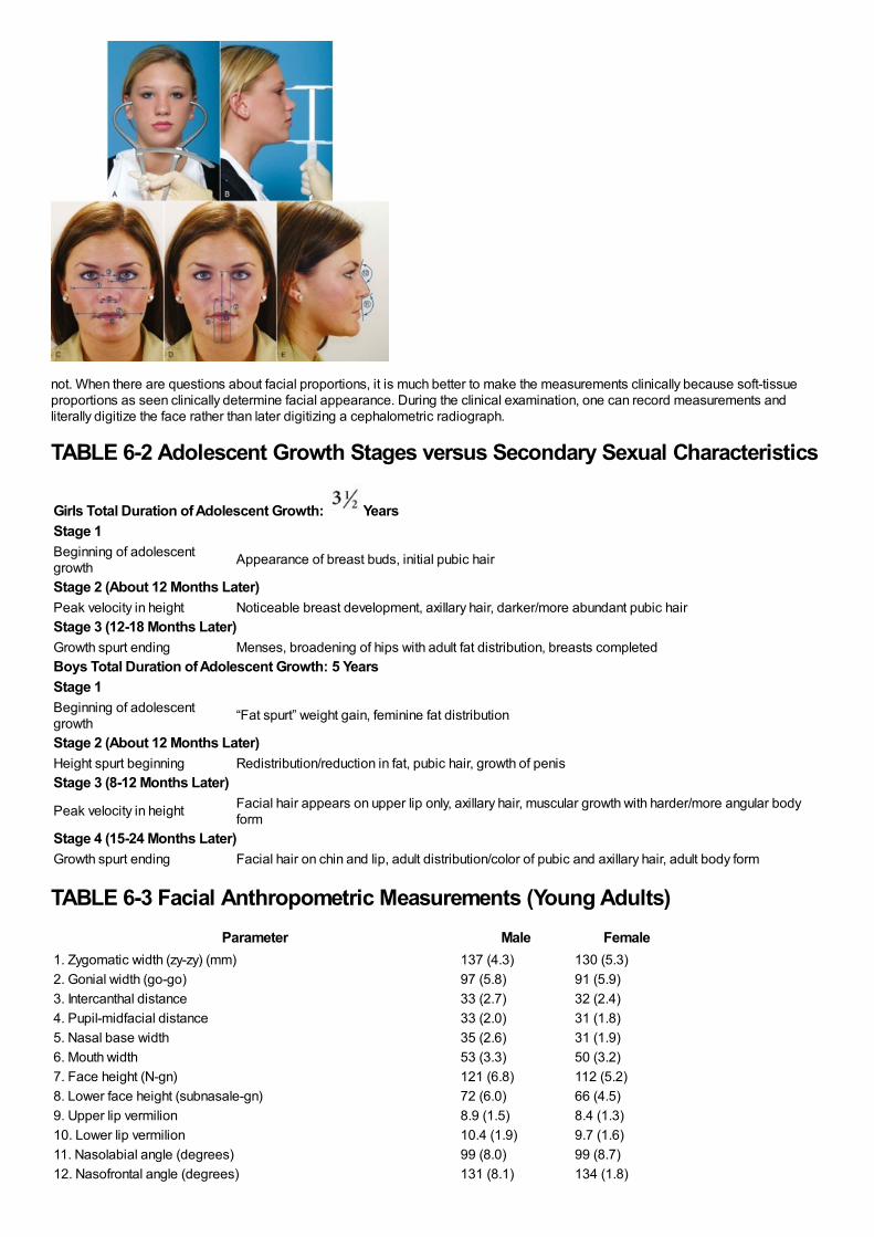
not. When there are questions about facial proportions, it is much better to make the measurements clinically because soft-tissueproportions as seen clinically determine facial appearance. During the clinical examination, one can record measurements andliterally digitize the face rather than later digitizing a cephalometric radiograph.
TABLE 6-2 Adolescent Growth Stages versus Secondary Sexual Characteristics
Girls Total Duration of Adolescent Growth: YearsStage 1Beginning of adolescentgrowth Appearance of breast buds, initial pubic hair
Stage 2 (About 12 Months Later)Peak velocity in height Noticeable breast development, axillary hair, darker/more abundant pubic hairStage 3 (12-18 Months Later)Growth spurt ending Menses, broadening of hips with adult fat distribution, breasts completedBoys Total Duration of Adolescent Growth: 5 YearsStage 1Beginning of adolescentgrowth “Fat spurt” weight gain, feminine fat distribution
Stage 2 (About 12 Months Later)Height spurt beginning Redistribution/reduction in fat, pubic hair, growth of penisStage 3 (8-12 Months Later)
Peak velocity in height Facial hair appears on upper lip only, axillary hair, muscular growth with harder/more angular bodyform
Stage 4 (15-24 Months Later)Growth spurt ending Facial hair on chin and lip, adult distribution/color of pubic and axillary hair, adult body form
TABLE 6-3 Facial Anthropometric Measurements (Young Adults)Parameter Male Female
1. Zygomatic width (zy-zy) (mm) 137 (4.3) 130 (5.3)2. Gonial width (go-go) 97 (5.8) 91 (5.9)3. Intercanthal distance 33 (2.7) 32 (2.4)4. Pupil-midfacial distance 33 (2.0) 31 (1.8)5. Nasal base width 35 (2.6) 31 (1.9)6. Mouth width 53 (3.3) 50 (3.2)7. Face height (N-gn) 121 (6.8) 112 (5.2)8. Lower face height (subnasale-gn) 72 (6.0) 66 (4.5)9. Upper lip vermilion 8.9 (1.5) 8.4 (1.3)10. Lower lip vermilion 10.4 (1.9) 9.7 (1.6)11. Nasolabial angle (degrees) 99 (8.0) 99 (8.7)12. Nasofrontal angle (degrees) 131 (8.1) 134 (1.8)
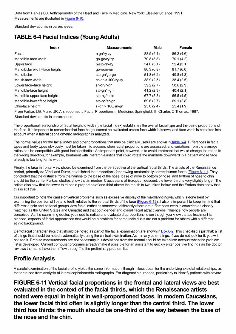
Data from Farkas LG. Anthropometry of the Head and Face in Medicine. New York: Elsevier Science; 1991.Measurements are illustrated in Figure 6-10.
Standard deviation is in parentheses.
TABLE 6-4 Facial Indices (Young Adults)Index Measurements Male Female
Facial n-gn/zy-zy 88.5 (5.1) 86.2 (4.6)Mandible-face width go-go/zy-zy 70.8 (3.8) 70.1 (4.2)Upper face n-sto-/zy-zy 54.0 (3.1) 52.4 (3.1)Mandibular width–face height go-go/n-gn 80.3 (6.8) 81.7 (6.0)Mandibular sto-gn/go-go 51.8 (6.2) 49.8 (4.8)Mouth-face width ch-ch × 100/zy-zy 38.9 (2.5) 38.4 (2.5)Lower face–face height sn-gn/n-gn 59.2 (2.7) 58.6 (2.9)Mandible-face height sto-gn/n-gn 41.2 (2.3) 40.4 (2.1)Mandible-upper face height sto-ng/n-sto 67.7 (5.3) 66.5 (4.5)Mandible-lower face height sto-ng/sn-gn 69.6 (2.7) 69.1 (2.8)Chin-face height sl-gn × 100/sn-gn 25.0 (2.4) 25.4 (1.9)From Farkas LG, Munro JR. Anthropometric Facial Proportions in Medicine. Springfield, Ill.: Charles C Thomas; 1987.Standard deviation is in parentheses.
The proportional relationship of facial height to width (the facial index) establishes the overall facial type and the basic proportions ofthe face. It is important to remember that face height cannot be evaluated unless face width is known, and face width is not taken intoaccount when a lateral cephalometric radiograph is analyzed.
The normal values for the facial index and other proportions that may be clinically useful are shown in Table 6-4. Differences in facialtypes and body types obviously must be taken into account when facial proportions are assessed, and variations from the averageratios can be compatible with good facial esthetics. An important point, however, is to avoid treatment that would change the ratios inthe wrong direction, for example, treatment with interarch elastics that could rotate the mandible downward in a patient whose facealready is too long for its width.
Finally, the face in frontal view should be examined from the perspective of the vertical facial thirds. The artists of the Renaissanceperiod, primarily da Vinci and Durer, established the proportions for drawing anatomically correct human faces (Figure 6-11). Theyconcluded that the distance from the hairline to the base of the nose, base of nose to bottom of nose, and bottom of nose to chinshould be the same. Farkas’ studies show that in modern Caucasians of European descent, the lower third is very slightly longer. Theartists also saw that the lower third has a proportion of one-third above the mouth to two-thirds below, and the Farkas data show thatthis is still true.
It is important to note the cause of vertical problems such as excessive display of the maxillary gingiva, which is done best byexamining the position of lips and teeth relative to the vertical thirds of the face (Figure 6-12). It also is important to keep in mind thatdifferent ethnic and national groups view facial esthetics somewhat differently (there are differences even in countries as closelymatched as the United States and Canada) and that both gender and overall facial attractiveness influence how people areperceived. As the examining doctor, you need to notice and evaluate disproportions, even though you know that as treatment isplanned, aspects of facial appearance that would be a problem for some individuals are not a problem for others with a differentethnic background.
Dentofacial characteristics that should be noted as part of the facial examination are shown in Box 6-2. This checklist is just that: a listof things that should be noted systematically during the clinical examination. As in many other things, if you do not look for it, you willnot see it. Precise measurements are not necessary, but deviations from the normal should be taken into account when the problemlist is developed. Current computer programs already make it possible for an assistant to quickly enter positive findings as the doctorreviews them and have them “flow through” to the preliminary problem list.
Profile AnalysisA careful examination of the facial profile yields the same information, though in less detail for the underlying skeletal relationships, asthat obtained from analysis of lateral cephalometric radiographs. For diagnostic purposes, particularly to identify patients with severe
FIGURE 6-11 Vertical facial proportions in the frontal and lateral views are bestevaluated in the context of the facial thirds, which the Renaissance artistsnoted were equal in height in well-proportioned faces. In modern Caucasians,the lower facial third often is slightly longer than the central third. The lowerthird has thirds: the mouth should be one-third of the way between the base ofthe nose and the chin.
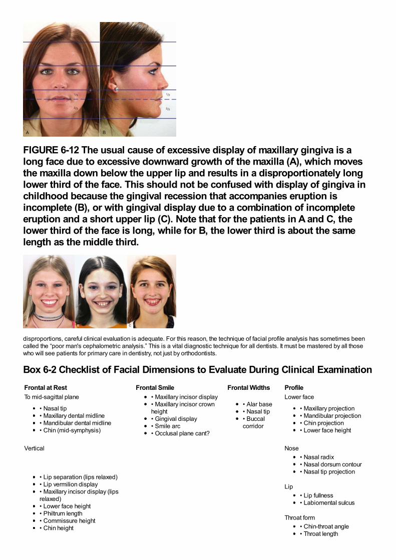
FIGURE 6-12 The usual cause of excessive display of maxillary gingiva is along face due to excessive downward growth of the maxilla (A), which movesthe maxilla down below the upper lip and results in a disproportionately longlower third of the face. This should not be confused with display of gingiva inchildhood because the gingival recession that accompanies eruption isincomplete (B), or with gingival display due to a combination of incompleteeruption and a short upper lip (C). Note that for the patients in A and C, thelower third of the face is long, while for B, the lower third is about the samelength as the middle third.
disproportions, careful clinical evaluation is adequate. For this reason, the technique of facial profile analysis has sometimes beencalled the “poor man's cephalometric analysis.” This is a vital diagnostic technique for all dentists. It must be mastered by all thosewho will see patients for primary care in dentistry, not just by orthodontists.
Box 6-2 Checklist of Facial Dimensions to Evaluate During Clinical ExaminationFrontal at Rest Frontal Smile Frontal Widths ProfileTo mid-sagittal plane • Maxillary incisor display
• Maxillary incisor crownheight• Gingival display• Smile arc• Occlusal plane cant?
• Alar base• Nasal tip• Buccalcorridor
Lower face
• Nasal tip• Maxillary dental midline• Mandibular dental midline• Chin (mid-symphysis)
• Maxillary projection• Mandibular projection• Chin projection• Lower face height
Vertical Nose
• Lip separation (lips relaxed)• Lip vermilion display• Maxillary incisor display (lipsrelaxed)• Lower face height• Philtrum length• Commissure height• Chin height
• Nasal radix• Nasal dorsum contour• Nasal tip projection
Lip• Lip fullness• Labiomental sulcus
Throat form• Chin-throat angle• Throat length
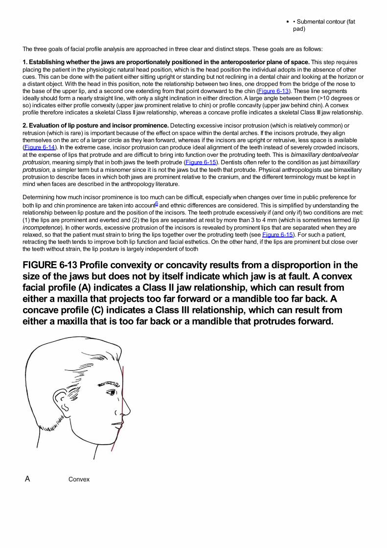
• Submental contour (fatpad)
The three goals of facial profile analysis are approached in three clear and distinct steps. These goals are as follows:
1. Establishing whether the jaws are proportionately positioned in the anteroposterior plane of space. This step requiresplacing the patient in the physiologic natural head position, which is the head position the individual adopts in the absence of othercues. This can be done with the patient either sitting upright or standing but not reclining in a dental chair and looking at the horizon ora distant object. With the head in this position, note the relationship between two lines, one dropped from the bridge of the nose tothe base of the upper lip, and a second one extending from that point downward to the chin (Figure 6-13). These line segmentsideally should form a nearly straight line, with only a slight inclination in either direction. A large angle between them (>10 degrees orso) indicates either profile convexity (upper jaw prominent relative to chin) or profile concavity (upper jaw behind chin). A convexprofile therefore indicates a skeletal Class II jaw relationship, whereas a concave profile indicates a skeletal Class III jaw relationship.
2. Evaluation of lip posture and incisor prominence. Detecting excessive incisor protrusion (which is relatively common) orretrusion (which is rare) is important because of the effect on space within the dental arches. If the incisors protrude, they alignthemselves on the arc of a larger circle as they lean forward, whereas if the incisors are upright or retrusive, less space is available(Figure 6-14). In the extreme case, incisor protrusion can produce ideal alignment of the teeth instead of severely crowded incisors,at the expense of lips that protrude and are difficult to bring into function over the protruding teeth. This is bimaxillary dentoalveolarprotrusion, meaning simply that in both jaws the teeth protrude (Figure 6-15). Dentists often refer to the condition as just bimaxillaryprotrusion, a simpler term but a misnomer since it is not the jaws but the teeth that protrude. Physical anthropologists use bimaxillaryprotrusion to describe faces in which both jaws are prominent relative to the cranium, and the different terminology must be kept inmind when faces are described in the anthropology literature.
Determining how much incisor prominence is too much can be difficult, especially when changes over time in public preference forboth lip and chin prominence are taken into account6 and ethnic differences are considered. This is simplified by understanding therelationship between lip posture and the position of the incisors. The teeth protrude excessively if (and only if) two conditions are met:(1) the lips are prominent and everted and (2) the lips are separated at rest by more than 3 to 4 mm (which is sometimes termed lipincompetence). In other words, excessive protrusion of the incisors is revealed by prominent lips that are separated when they arerelaxed, so that the patient must strain to bring the lips together over the protruding teeth (see Figure 6-15). For such a patient,retracting the teeth tends to improve both lip function and facial esthetics. On the other hand, if the lips are prominent but close overthe teeth without strain, the lip posture is largely independent of tooth
FIGURE 6-13 Profile convexity or concavity results from a disproportion in thesize of the jaws but does not by itself indicate which jaw is at fault. A convexfacial profile (A) indicates a Class II jaw relationship, which can result fromeither a maxilla that projects too far forward or a mandible too far back. Aconcave profile (C) indicates a Class III relationship, which can result fromeither a maxilla that is too far back or a mandible that protrudes forward.
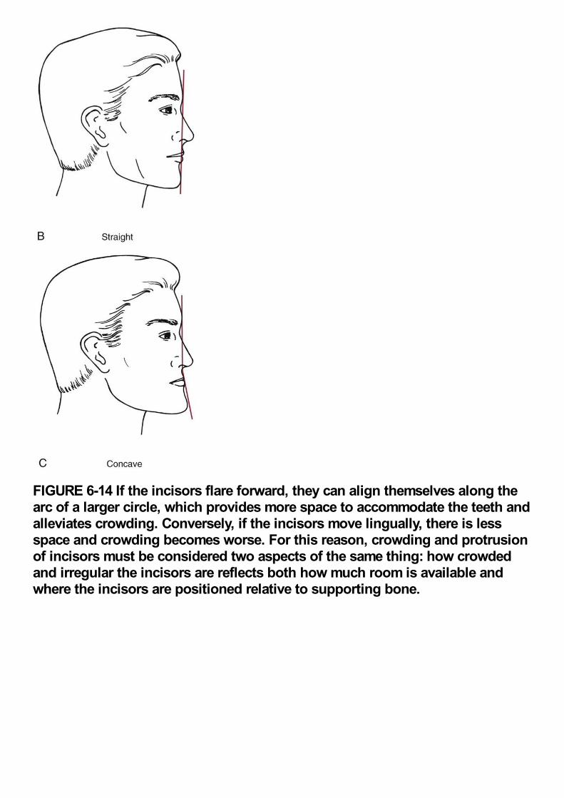
FIGURE 6-14 If the incisors flare forward, they can align themselves along thearc of a larger circle, which provides more space to accommodate the teeth andalleviates crowding. Conversely, if the incisors move lingually, there is lessspace and crowding becomes worse. For this reason, crowding and protrusionof incisors must be considered two aspects of the same thing: how crowdedand irregular the incisors are reflects both how much room is available andwhere the incisors are positioned relative to supporting bone.
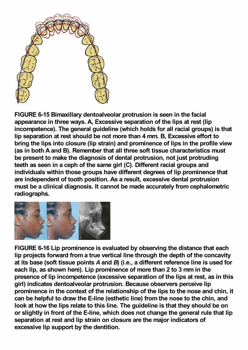
FIGURE 6-15 Bimaxillary dentoalveolar protrusion is seen in the facialappearance in three ways. A, Excessive separation of the lips at rest (lipincompetence). The general guideline (which holds for all racial groups) is thatlip separation at rest should be not more than 4 mm. B, Excessive effort tobring the lips into closure (lip strain) and prominence of lips in the profile view(as in both A and B). Remember that all three soft tissue characteristics mustbe present to make the diagnosis of dental protrusion, not just protrudingteeth as seen in a ceph of the same girl (C). Different racial groups andindividuals within those groups have different degrees of lip prominence thatare independent of tooth position. As a result, excessive dental protrusionmust be a clinical diagnosis. It cannot be made accurately from cephalometricradiographs.
FIGURE 6-16 Lip prominence is evaluated by observing the distance that eachlip projects forward from a true vertical line through the depth of the concavityat its base (soft tissue points A and B) (i.e., a different reference line is used foreach lip, as shown here). Lip prominence of more than 2 to 3 mm in thepresence of lip incompetence (excessive separation of the lips at rest, as in thisgirl) indicates dentoalveolar protrusion. Because observers perceive lipprominence in the context of the relationship of the lips to the nose and chin, itcan be helpful to draw the E-line (esthetic line) from the nose to the chin, andlook at how the lips relate to this line. The guideline is that they should be onor slightly in front of the E-line, which does not change the general rule that lipseparation at rest and lip strain on closure are the major indicators ofexcessive lip support by the dentition.
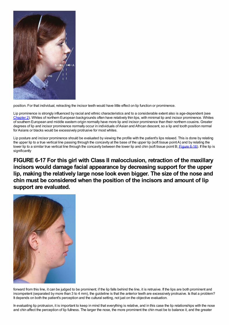
position. For that individual, retracting the incisor teeth would have little effect on lip function or prominence.
Lip prominence is strongly influenced by racial and ethnic characteristics and to a considerable extent also is age-dependent (seeChapter 2). Whites of northern European backgrounds often have relatively thin lips, with minimal lip and incisor prominence. Whitesof southern European and middle eastern origin normally have more lip and incisor prominence than their northern cousins. Greaterdegrees of lip and incisor prominence normally occur in individuals of Asian and African descent, so a lip and tooth position normalfor Asians or blacks would be excessively protrusive for most whites.
Lip posture and incisor prominence should be evaluated by viewing the profile with the patient's lips relaxed. This is done by relatingthe upper lip to a true vertical line passing through the concavity at the base of the upper lip (soft tissue point A) and by relating thelower lip to a similar true vertical line through the concavity between the lower lip and chin (soft tissue point B; Figure 6-16). If the lip issignificantly
FIGURE 6-17 For this girl with Class II malocclusion, retraction of the maxillaryincisors would damage facial appearance by decreasing support for the upperlip, making the relatively large nose look even bigger. The size of the nose andchin must be considered when the position of the incisors and amount of lipsupport are evaluated.
forward from this line, it can be judged to be prominent; if the lip falls behind the line, it is retrusive. If the lips are both prominent andincompetent (separated by more than 3 to 4 mm), the guideline is that the anterior teeth are excessively protrusive. Is that a problem?It depends on both the patient's perception and the cultural setting, not just on the objective evaluation.
In evaluating lip protrusion, it is important to keep in mind that everything is relative, and in this case the lip relationships with the noseand chin affect the perception of lip fullness. The larger the nose, the more prominent the chin must be to balance it, and the greater
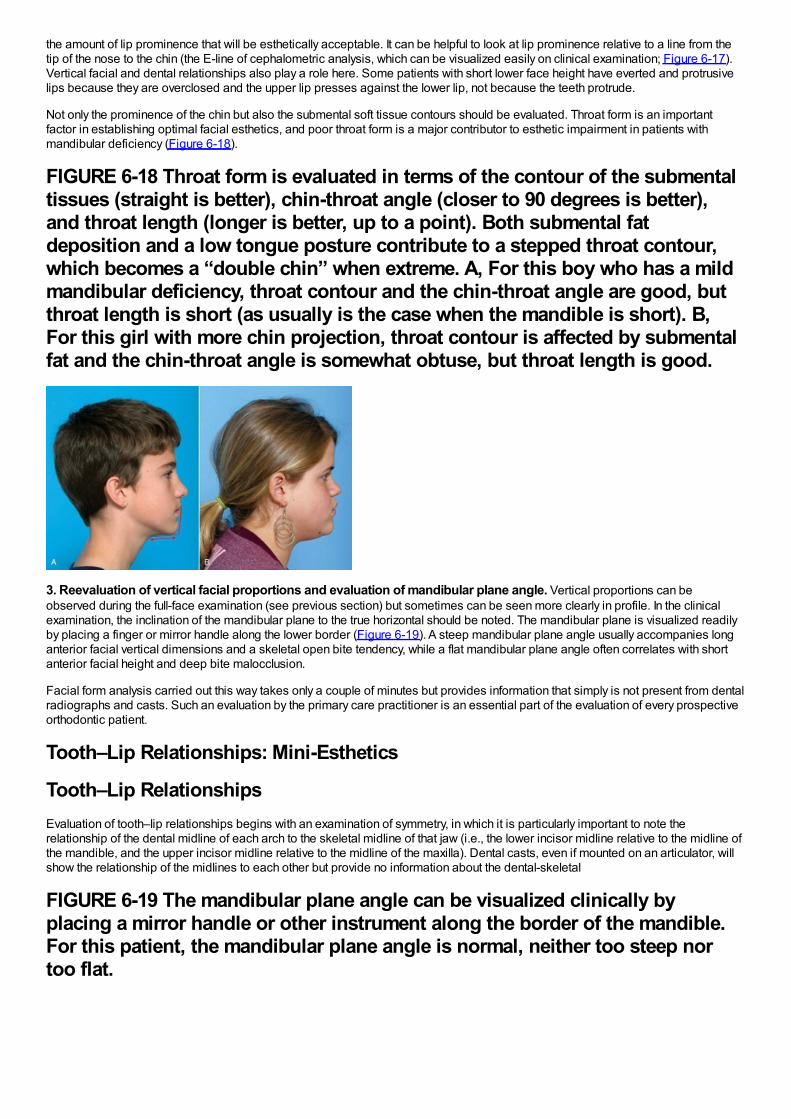
the amount of lip prominence that will be esthetically acceptable. It can be helpful to look at lip prominence relative to a line from thetip of the nose to the chin (the E-line of cephalometric analysis, which can be visualized easily on clinical examination; Figure 6-17).Vertical facial and dental relationships also play a role here. Some patients with short lower face height have everted and protrusivelips because they are overclosed and the upper lip presses against the lower lip, not because the teeth protrude.
Not only the prominence of the chin but also the submental soft tissue contours should be evaluated. Throat form is an importantfactor in establishing optimal facial esthetics, and poor throat form is a major contributor to esthetic impairment in patients withmandibular deficiency (Figure 6-18).
FIGURE 6-18 Throat form is evaluated in terms of the contour of the submentaltissues (straight is better), chin-throat angle (closer to 90 degrees is better),and throat length (longer is better, up to a point). Both submental fatdeposition and a low tongue posture contribute to a stepped throat contour,which becomes a “double chin” when extreme. A, For this boy who has a mildmandibular deficiency, throat contour and the chin-throat angle are good, butthroat length is short (as usually is the case when the mandible is short). B,For this girl with more chin projection, throat contour is affected by submentalfat and the chin-throat angle is somewhat obtuse, but throat length is good.
3. Reevaluation of vertical facial proportions and evaluation of mandibular plane angle. Vertical proportions can beobserved during the full-face examination (see previous section) but sometimes can be seen more clearly in profile. In the clinicalexamination, the inclination of the mandibular plane to the true horizontal should be noted. The mandibular plane is visualized readilyby placing a finger or mirror handle along the lower border (Figure 6-19). A steep mandibular plane angle usually accompanies longanterior facial vertical dimensions and a skeletal open bite tendency, while a flat mandibular plane angle often correlates with shortanterior facial height and deep bite malocclusion.
Facial form analysis carried out this way takes only a couple of minutes but provides information that simply is not present from dentalradiographs and casts. Such an evaluation by the primary care practitioner is an essential part of the evaluation of every prospectiveorthodontic patient.
Tooth–Lip Relationships: Mini-Esthetics
Tooth–Lip RelationshipsEvaluation of tooth–lip relationships begins with an examination of symmetry, in which it is particularly important to note therelationship of the dental midline of each arch to the skeletal midline of that jaw (i.e., the lower incisor midline relative to the midline ofthe mandible, and the upper incisor midline relative to the midline of the maxilla). Dental casts, even if mounted on an articulator, willshow the relationship of the midlines to each other but provide no information about the dental-skeletal
FIGURE 6-19 The mandibular plane angle can be visualized clinically byplacing a mirror handle or other instrument along the border of the mandible.For this patient, the mandibular plane angle is normal, neither too steep nortoo flat.
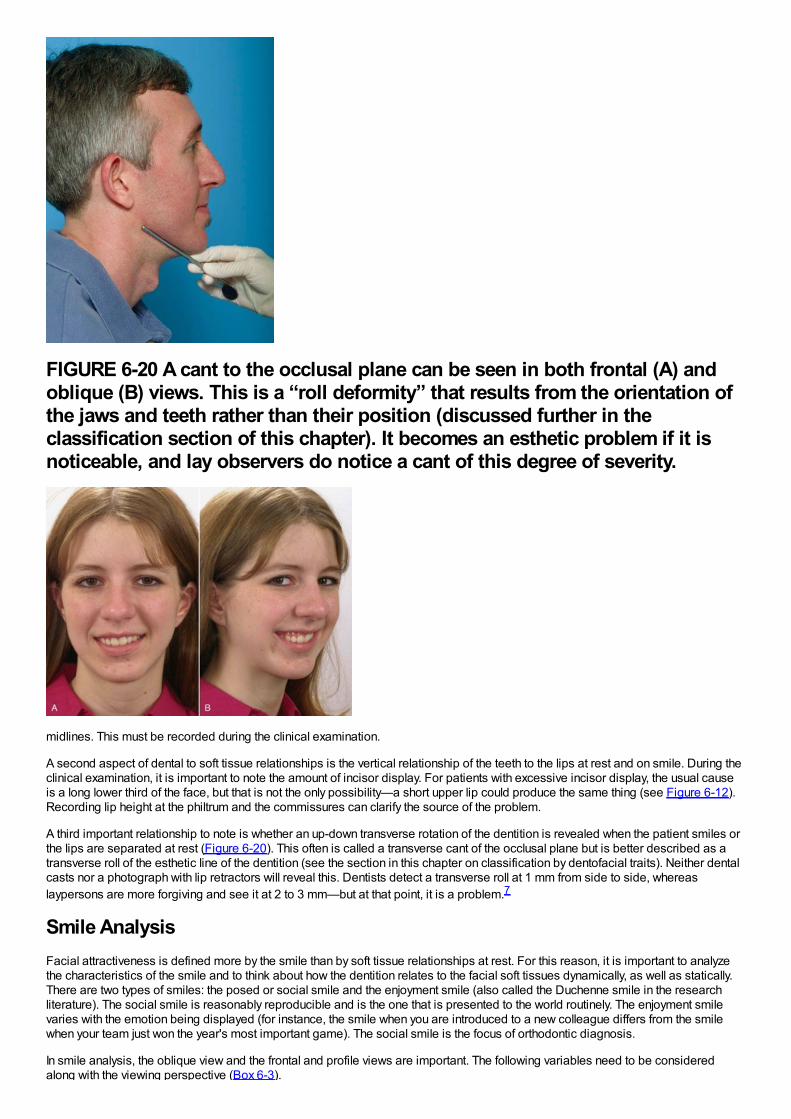
FIGURE 6-20 A cant to the occlusal plane can be seen in both frontal (A) andoblique (B) views. This is a “roll deformity” that results from the orientation ofthe jaws and teeth rather than their position (discussed further in theclassification section of this chapter). It becomes an esthetic problem if it isnoticeable, and lay observers do notice a cant of this degree of severity.
midlines. This must be recorded during the clinical examination.
A second aspect of dental to soft tissue relationships is the vertical relationship of the teeth to the lips at rest and on smile. During theclinical examination, it is important to note the amount of incisor display. For patients with excessive incisor display, the usual causeis a long lower third of the face, but that is not the only possibility—a short upper lip could produce the same thing (see Figure 6-12).Recording lip height at the philtrum and the commissures can clarify the source of the problem.
A third important relationship to note is whether an up-down transverse rotation of the dentition is revealed when the patient smiles orthe lips are separated at rest (Figure 6-20). This often is called a transverse cant of the occlusal plane but is better described as atransverse roll of the esthetic line of the dentition (see the section in this chapter on classification by dentofacial traits). Neither dentalcasts nor a photograph with lip retractors will reveal this. Dentists detect a transverse roll at 1 mm from side to side, whereaslaypersons are more forgiving and see it at 2 to 3 mm—but at that point, it is a problem.7
Smile AnalysisFacial attractiveness is defined more by the smile than by soft tissue relationships at rest. For this reason, it is important to analyzethe characteristics of the smile and to think about how the dentition relates to the facial soft tissues dynamically, as well as statically.There are two types of smiles: the posed or social smile and the enjoyment smile (also called the Duchenne smile in the researchliterature). The social smile is reasonably reproducible and is the one that is presented to the world routinely. The enjoyment smilevaries with the emotion being displayed (for instance, the smile when you are introduced to a new colleague differs from the smilewhen your team just won the year's most important game). The social smile is the focus of orthodontic diagnosis.
In smile analysis, the oblique view and the frontal and profile views are important. The following variables need to be consideredalong with the viewing perspective (Box 6-3).
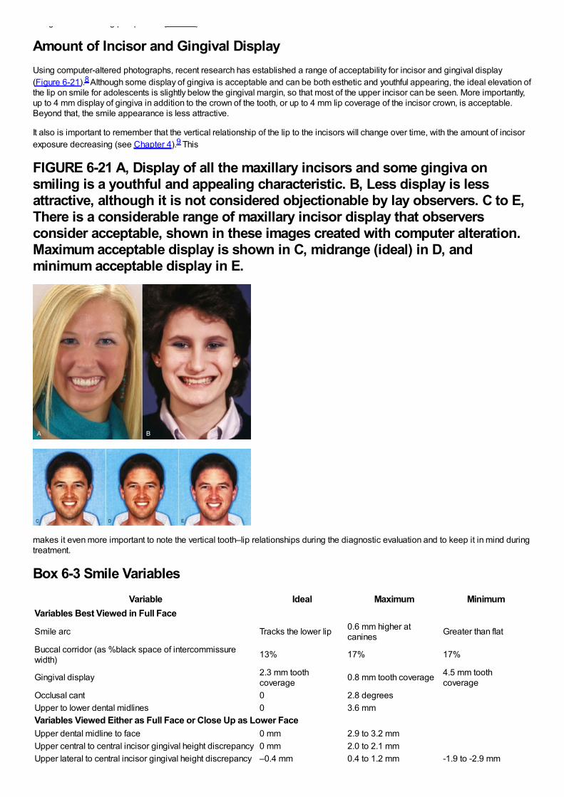
along with the viewing perspective (Box 6-3).
Amount of Incisor and Gingival DisplayUsing computer-altered photographs, recent research has established a range of acceptability for incisor and gingival display(Figure 6-21).8 Although some display of gingiva is acceptable and can be both esthetic and youthful appearing, the ideal elevation ofthe lip on smile for adolescents is slightly below the gingival margin, so that most of the upper incisor can be seen. More importantly,up to 4 mm display of gingiva in addition to the crown of the tooth, or up to 4 mm lip coverage of the incisor crown, is acceptable.Beyond that, the smile appearance is less attractive.
It also is important to remember that the vertical relationship of the lip to the incisors will change over time, with the amount of incisorexposure decreasing (see Chapter 4).9 This
FIGURE 6-21 A, Display of all the maxillary incisors and some gingiva onsmiling is a youthful and appealing characteristic. B, Less display is lessattractive, although it is not considered objectionable by lay observers. C to E,There is a considerable range of maxillary incisor display that observersconsider acceptable, shown in these images created with computer alteration.Maximum acceptable display is shown in C, midrange (ideal) in D, andminimum acceptable display in E.
makes it even more important to note the vertical tooth–lip relationships during the diagnostic evaluation and to keep it in mind duringtreatment.
Box 6-3 Smile VariablesVariable Ideal Maximum Minimum
Variables Best Viewed in Full Face
Smile arc Tracks the lower lip 0.6 mm higher atcanines Greater than flat
Buccal corridor (as %black space of intercommissurewidth) 13% 17% 17%
Gingival display 2.3 mm toothcoverage 0.8 mm tooth coverage 4.5 mm tooth
coverageOcclusal cant 0 2.8 degreesUpper to lower dental midlines 0 3.6 mmVariables Viewed Either as Full Face or Close Up as Lower FaceUpper dental midline to face 0 mm 2.9 to 3.2 mmUpper central to central incisor gingival height discrepancy 0 mm 2.0 to 2.1 mmUpper lateral to central incisor gingival height discrepancy –0.4 mm 0.4 to 1.2 mm -1.9 to -2.9 mm
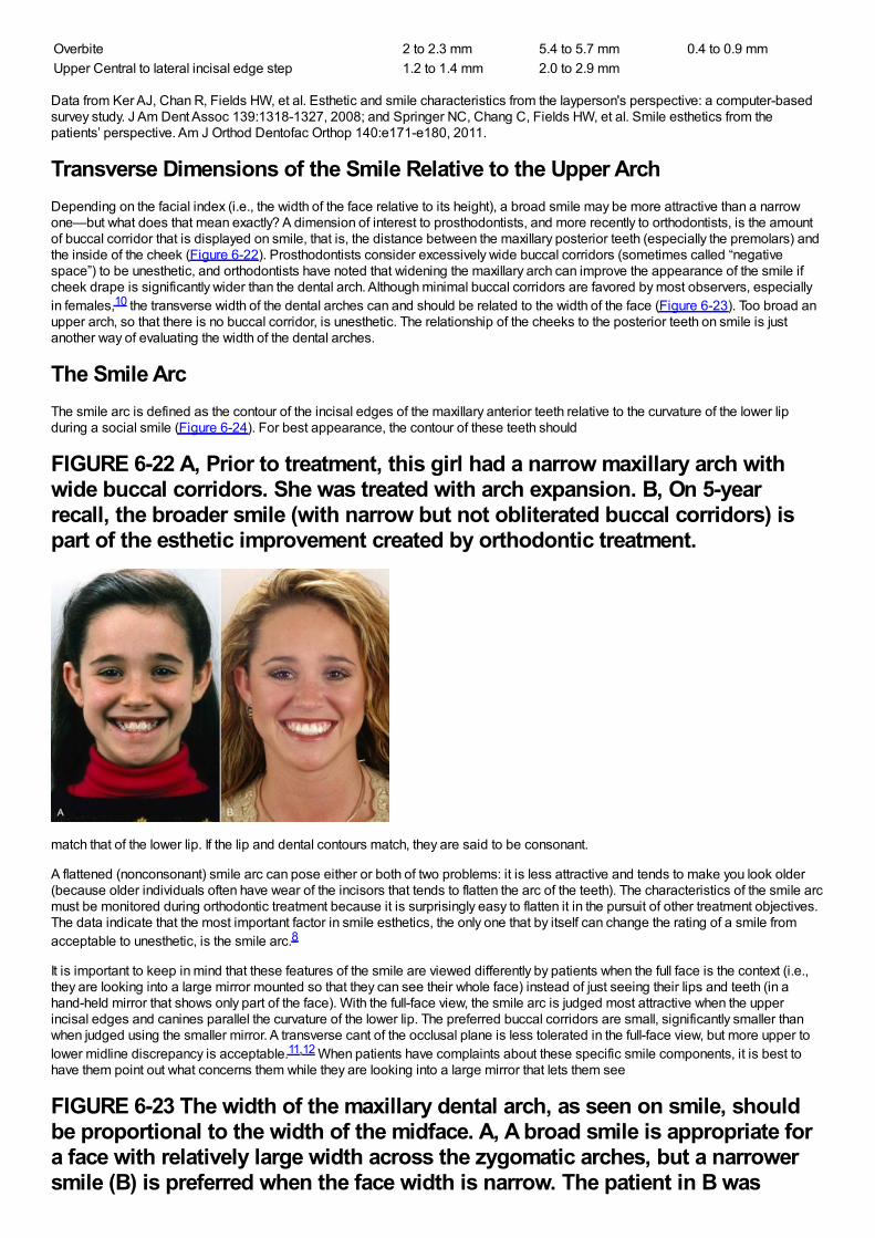
Overbite 2 to 2.3 mm 5.4 to 5.7 mm 0.4 to 0.9 mmUpper Central to lateral incisal edge step 1.2 to 1.4 mm 2.0 to 2.9 mm
Data from Ker AJ, Chan R, Fields HW, et al. Esthetic and smile characteristics from the layperson's perspective: a computer-basedsurvey study. J Am Dent Assoc 139:1318-1327, 2008; and Springer NC, Chang C, Fields HW, et al. Smile esthetics from thepatients’ perspective. Am J Orthod Dentofac Orthop 140:e171-e180, 2011.
Transverse Dimensions of the Smile Relative to the Upper ArchDepending on the facial index (i.e., the width of the face relative to its height), a broad smile may be more attractive than a narrowone—but what does that mean exactly? A dimension of interest to prosthodontists, and more recently to orthodontists, is the amountof buccal corridor that is displayed on smile, that is, the distance between the maxillary posterior teeth (especially the premolars) andthe inside of the cheek (Figure 6-22). Prosthodontists consider excessively wide buccal corridors (sometimes called “negativespace”) to be unesthetic, and orthodontists have noted that widening the maxillary arch can improve the appearance of the smile ifcheek drape is significantly wider than the dental arch. Although minimal buccal corridors are favored by most observers, especiallyin females,10 the transverse width of the dental arches can and should be related to the width of the face (Figure 6-23). Too broad anupper arch, so that there is no buccal corridor, is unesthetic. The relationship of the cheeks to the posterior teeth on smile is justanother way of evaluating the width of the dental arches.
The Smile ArcThe smile arc is defined as the contour of the incisal edges of the maxillary anterior teeth relative to the curvature of the lower lipduring a social smile (Figure 6-24). For best appearance, the contour of these teeth should
FIGURE 6-22 A, Prior to treatment, this girl had a narrow maxillary arch withwide buccal corridors. She was treated with arch expansion. B, On 5-yearrecall, the broader smile (with narrow but not obliterated buccal corridors) ispart of the esthetic improvement created by orthodontic treatment.
match that of the lower lip. If the lip and dental contours match, they are said to be consonant.
A flattened (nonconsonant) smile arc can pose either or both of two problems: it is less attractive and tends to make you look older(because older individuals often have wear of the incisors that tends to flatten the arc of the teeth). The characteristics of the smile arcmust be monitored during orthodontic treatment because it is surprisingly easy to flatten it in the pursuit of other treatment objectives.The data indicate that the most important factor in smile esthetics, the only one that by itself can change the rating of a smile fromacceptable to unesthetic, is the smile arc.8
It is important to keep in mind that these features of the smile are viewed differently by patients when the full face is the context (i.e.,they are looking into a large mirror mounted so that they can see their whole face) instead of just seeing their lips and teeth (in ahand-held mirror that shows only part of the face). With the full-face view, the smile arc is judged most attractive when the upperincisal edges and canines parallel the curvature of the lower lip. The preferred buccal corridors are small, significantly smaller thanwhen judged using the smaller mirror. A transverse cant of the occlusal plane is less tolerated in the full-face view, but more upper tolower midline discrepancy is acceptable.11,12 When patients have complaints about these specific smile components, it is best tohave them point out what concerns them while they are looking into a large mirror that lets them see
FIGURE 6-23 The width of the maxillary dental arch, as seen on smile, shouldbe proportional to the width of the midface. A, A broad smile is appropriate fora face with relatively large width across the zygomatic arches, but a narrowersmile (B) is preferred when the face width is narrow. The patient in B was
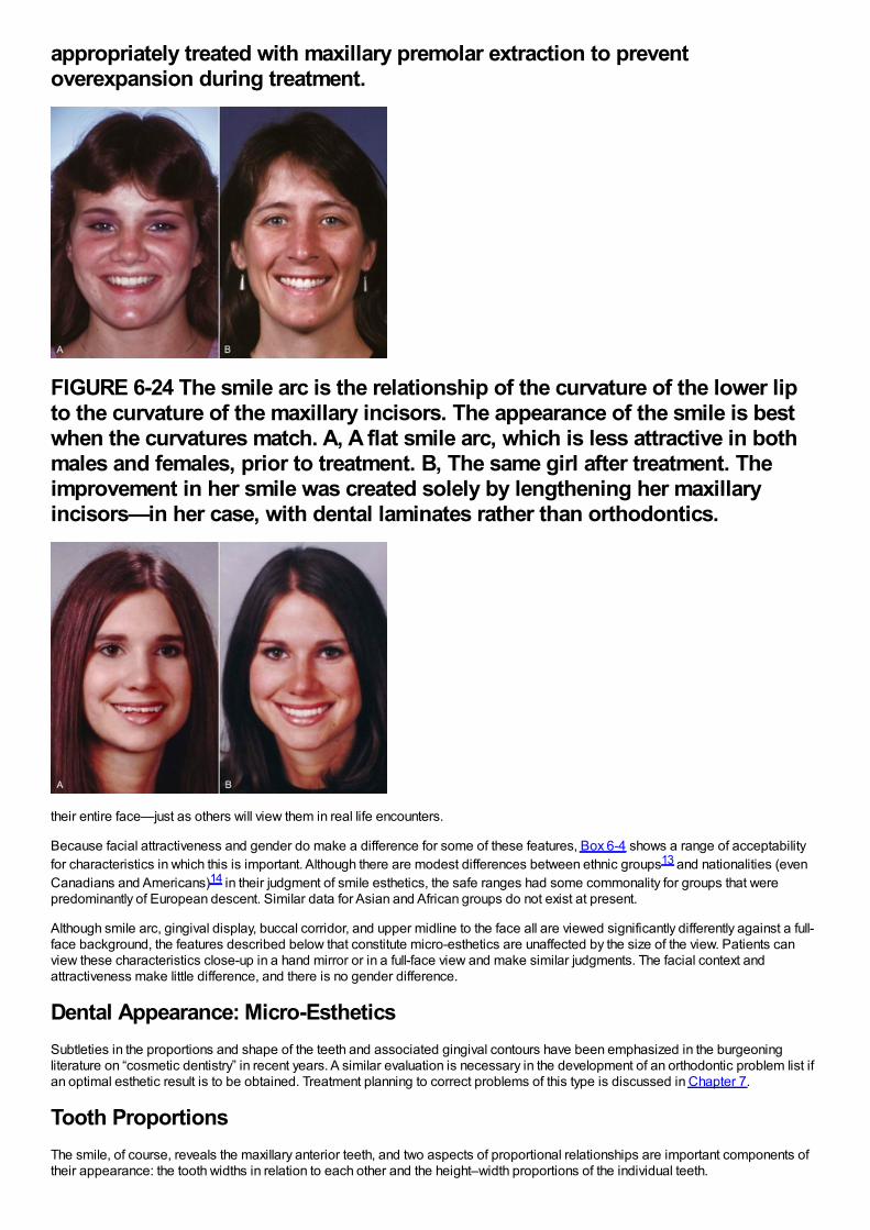
appropriately treated with maxillary premolar extraction to preventoverexpansion during treatment.
FIGURE 6-24 The smile arc is the relationship of the curvature of the lower lipto the curvature of the maxillary incisors. The appearance of the smile is bestwhen the curvatures match. A, A flat smile arc, which is less attractive in bothmales and females, prior to treatment. B, The same girl after treatment. Theimprovement in her smile was created solely by lengthening her maxillaryincisors—in her case, with dental laminates rather than orthodontics.
their entire face—just as others will view them in real life encounters.
Because facial attractiveness and gender do make a difference for some of these features, Box 6-4 shows a range of acceptabilityfor characteristics in which this is important. Although there are modest differences between ethnic groups13 and nationalities (evenCanadians and Americans)14 in their judgment of smile esthetics, the safe ranges had some commonality for groups that werepredominantly of European descent. Similar data for Asian and African groups do not exist at present.
Although smile arc, gingival display, buccal corridor, and upper midline to the face all are viewed significantly differently against a full-face background, the features described below that constitute micro-esthetics are unaffected by the size of the view. Patients canview these characteristics close-up in a hand mirror or in a full-face view and make similar judgments. The facial context andattractiveness make little difference, and there is no gender difference.
Dental Appearance: Micro-EstheticsSubtleties in the proportions and shape of the teeth and associated gingival contours have been emphasized in the burgeoningliterature on “cosmetic dentistry” in recent years. A similar evaluation is necessary in the development of an orthodontic problem list ifan optimal esthetic result is to be obtained. Treatment planning to correct problems of this type is discussed in Chapter 7.
Tooth ProportionsThe smile, of course, reveals the maxillary anterior teeth, and two aspects of proportional relationships are important components oftheir appearance: the tooth widths in relation to each other and the height–width proportions of the individual teeth.
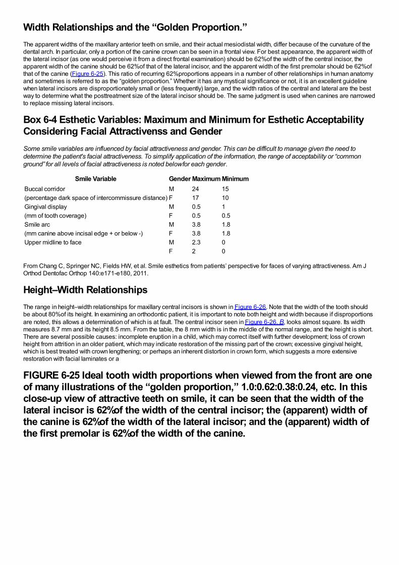
Width Relationships and the “Golden Proportion.”The apparent widths of the maxillary anterior teeth on smile, and their actual mesiodistal width, differ because of the curvature of thedental arch. In particular, only a portion of the canine crown can be seen in a frontal view. For best appearance, the apparent width ofthe lateral incisor (as one would perceive it from a direct frontal examination) should be 62%of the width of the central incisor, theapparent width of the canine should be 62%of that of the lateral incisor, and the apparent width of the first premolar should be 62%ofthat of the canine (Figure 6-25). This ratio of recurring 62%proportions appears in a number of other relationships in human anatomyand sometimes is referred to as the “golden proportion.” Whether it has any mystical significance or not, it is an excellent guidelinewhen lateral incisors are disproportionately small or (less frequently) large, and the width ratios of the central and lateral are the bestway to determine what the posttreatment size of the lateral incisor should be. The same judgment is used when canines are narrowedto replace missing lateral incisors.
Box 6-4 Esthetic Variables: Maximum and Minimum for Esthetic AcceptabilityConsidering Facial Attractivenss and GenderSome smile variables are influenced by facial attractiveness and gender. This can be difficult to manage given the need todetermine the patient's facial attractiveness. To simplify application of the information, the range of acceptability or “commonground” for all levels of facial attractiveness is noted below for each gender.
Smile Variable Gender Maximum MinimumBuccal corridor M 24 15(percentage dark space of intercommissure distance) F 17 10Gingival display M 0.5 1(mm of tooth coverage) F 0.5 0.5Smile arc M 3.8 1.8(mm canine above incisal edge + or below -) F 3.8 1.8Upper midline to face M 2.3 0
F 2 0
From Chang C, Springer NC, Fields HW, et al. Smile esthetics from patients’ perspective for faces of varying attractiveness. Am JOrthod Dentofac Orthop 140:e171-e180, 2011.
Height–Width RelationshipsThe range in height–width relationships for maxillary central incisors is shown in Figure 6-26. Note that the width of the tooth shouldbe about 80%of its height. In examining an orthodontic patient, it is important to note both height and width because if disproportionsare noted, this allows a determination of which is at fault. The central incisor seen in Figure 6-26, B, looks almost square. Its widthmeasures 8.7 mm and its height 8.5 mm. From the table, the 8 mm width is in the middle of the normal range, and the height is short.There are several possible causes: incomplete eruption in a child, which may correct itself with further development; loss of crownheight from attrition in an older patient, which may indicate restoration of the missing part of the crown; excessive gingival height,which is best treated with crown lengthening; or perhaps an inherent distortion in crown form, which suggests a more extensiverestoration with facial laminates or a
FIGURE 6-25 Ideal tooth width proportions when viewed from the front are oneof many illustrations of the “golden proportion,” 1.0:0.62:0.38:0.24, etc. In thisclose-up view of attractive teeth on smile, it can be seen that the width of thelateral incisor is 62%of the width of the central incisor; the (apparent) width ofthe canine is 62%of the width of the lateral incisor; and the (apparent) width ofthe first premolar is 62%of the width of the canine.
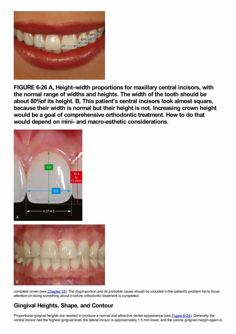
FIGURE 6-26 A, Height–width proportions for maxillary central incisors, withthe normal range of widths and heights. The width of the tooth should beabout 80%of its height. B, This patient's central incisors look almost square,because their width is normal but their height is not. Increasing crown heightwould be a goal of comprehensive orthodontic treatment. How to do thatwould depend on mini- and macro-esthetic considerations.
complete crown (see Chapter 18). The disproportion and its probable cause should be included in the patient's problem list to focusattention on doing something about it before orthodontic treatment is completed.
Gingival Heights, Shape, and ContourProportional gingival heights are needed to produce a normal and attractive dental appearance (see Figure 6-24). Generally, thecentral incisor has the highest gingival level, the lateral incisor is approximately 1.5 mm lower, and the canine gingival margin again is
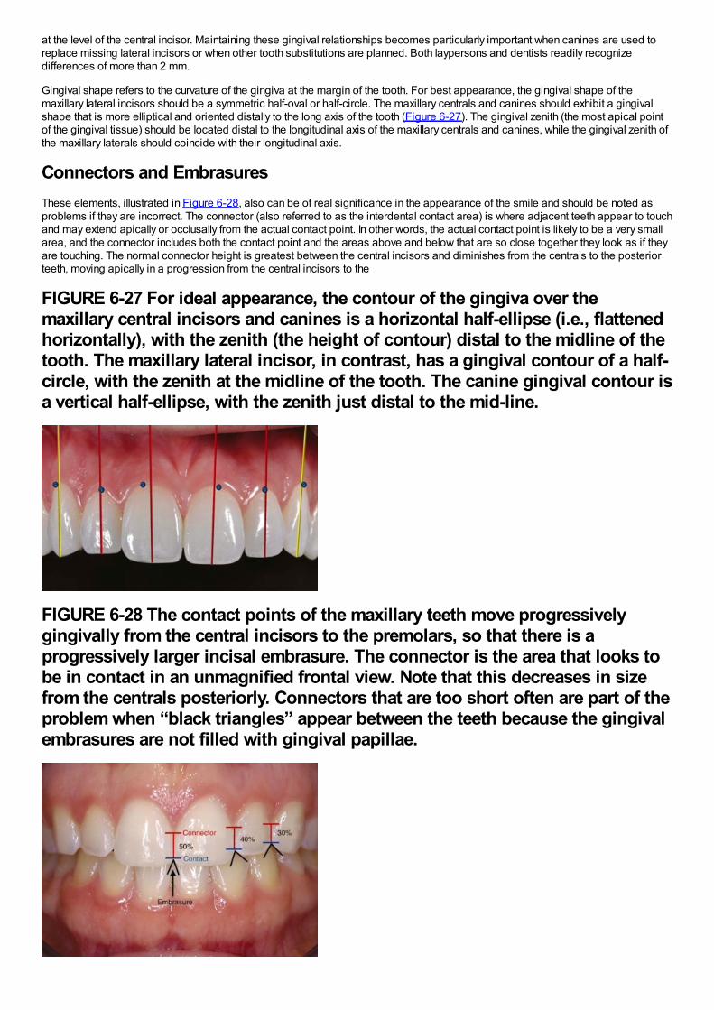
at the level of the central incisor. Maintaining these gingival relationships becomes particularly important when canines are used toreplace missing lateral incisors or when other tooth substitutions are planned. Both laypersons and dentists readily recognizedifferences of more than 2 mm.
Gingival shape refers to the curvature of the gingiva at the margin of the tooth. For best appearance, the gingival shape of themaxillary lateral incisors should be a symmetric half-oval or half-circle. The maxillary centrals and canines should exhibit a gingivalshape that is more elliptical and oriented distally to the long axis of the tooth (Figure 6-27). The gingival zenith (the most apical pointof the gingival tissue) should be located distal to the longitudinal axis of the maxillary centrals and canines, while the gingival zenith ofthe maxillary laterals should coincide with their longitudinal axis.
Connectors and EmbrasuresThese elements, illustrated in Figure 6-28, also can be of real significance in the appearance of the smile and should be noted asproblems if they are incorrect. The connector (also referred to as the interdental contact area) is where adjacent teeth appear to touchand may extend apically or occlusally from the actual contact point. In other words, the actual contact point is likely to be a very smallarea, and the connector includes both the contact point and the areas above and below that are so close together they look as if theyare touching. The normal connector height is greatest between the central incisors and diminishes from the centrals to the posteriorteeth, moving apically in a progression from the central incisors to the
FIGURE 6-27 For ideal appearance, the contour of the gingiva over themaxillary central incisors and canines is a horizontal half-ellipse (i.e., flattenedhorizontally), with the zenith (the height of contour) distal to the midline of thetooth. The maxillary lateral incisor, in contrast, has a gingival contour of a half-circle, with the zenith at the midline of the tooth. The canine gingival contour isa vertical half-ellipse, with the zenith just distal to the mid-line.
FIGURE 6-28 The contact points of the maxillary teeth move progressivelygingivally from the central incisors to the premolars, so that there is aprogressively larger incisal embrasure. The connector is the area that looks tobe in contact in an unmagnified frontal view. Note that this decreases in sizefrom the centrals posteriorly. Connectors that are too short often are part of theproblem when “black triangles” appear between the teeth because the gingivalembrasures are not filled with gingival papillae.
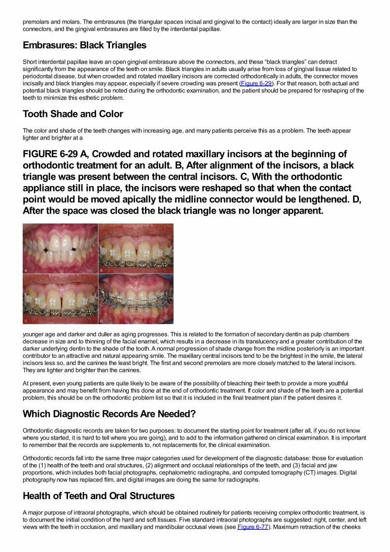
premolars and molars. The embrasures (the triangular spaces incisal and gingival to the contact) ideally are larger in size than theconnectors, and the gingival embrasures are filled by the interdental papillae.
Embrasures: Black TrianglesShort interdental papillae leave an open gingival embrasure above the connectors, and these “black triangles” can detractsignificantly from the appearance of the teeth on smile. Black triangles in adults usually arise from loss of gingival tissue related toperiodontal disease, but when crowded and rotated maxillary incisors are corrected orthodontically in adults, the connector movesincisally and black triangles may appear, especially if severe crowding was present (Figure 6-29). For that reason, both actual andpotential black triangles should be noted during the orthodontic examination, and the patient should be prepared for reshaping of theteeth to minimize this esthetic problem.
Tooth Shade and ColorThe color and shade of the teeth changes with increasing age, and many patients perceive this as a problem. The teeth appearlighter and brighter at a
FIGURE 6-29 A, Crowded and rotated maxillary incisors at the beginning oforthodontic treatment for an adult. B, After alignment of the incisors, a blacktriangle was present between the central incisors. C, With the orthodonticappliance still in place, the incisors were reshaped so that when the contactpoint would be moved apically the midline connector would be lengthened. D,After the space was closed the black triangle was no longer apparent.
younger age and darker and duller as aging progresses. This is related to the formation of secondary dentin as pulp chambersdecrease in size and to thinning of the facial enamel, which results in a decrease in its translucency and a greater contribution of thedarker underlying dentin to the shade of the tooth. A normal progression of shade change from the midline posteriorly is an importantcontributor to an attractive and natural appearing smile. The maxillary central incisors tend to be the brightest in the smile, the lateralincisors less so, and the canines the least bright. The first and second premolars are more closely matched to the lateral incisors.They are lighter and brighter than the canines.
At present, even young patients are quite likely to be aware of the possibility of bleaching their teeth to provide a more youthfulappearance and may benefit from having this done at the end of orthodontic treatment. If color and shade of the teeth are a potentialproblem, this should be on the orthodontic problem list so that it is included in the final treatment plan if the patient desires it.
Which Diagnostic Records Are Needed?Orthodontic diagnostic records are taken for two purposes: to document the starting point for treatment (after all, if you do not knowwhere you started, it is hard to tell where you are going), and to add to the information gathered on clinical examination. It is importantto remember that the records are supplements to, not replacements for, the clinical examination.
Orthodontic records fall into the same three major categories used for development of the diagnostic database: those for evaluationof the (1) health of the teeth and oral structures, (2) alignment and occlusal relationships of the teeth, and (3) facial and jawproportions, which includes both facial photographs, cephalometric radiographs, and computed tomography (CT) images. Digitalphotography now has replaced film, and digital images are doing the same for radiographs.
Health of Teeth and Oral StructuresA major purpose of intraoral photographs, which should be obtained routinely for patients receiving complex orthodontic treatment, isto document the initial condition of the hard and soft tissues. Five standard intraoral photographs are suggested: right, center, and leftviews with the teeth in occlusion, and maxillary and mandibular occlusal views (see Figure 6-77). Maximum retraction of the cheeks
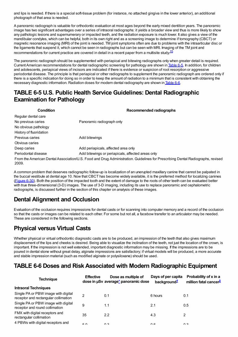
and lips is needed. If there is a special soft-tissue problem (for instance, no attached gingiva in the lower anterior), an additionalphotograph of that area is needed.
A panoramic radiograph is valuable for orthodontic evaluation at most ages beyond the early mixed dentition years. The panoramicimage has two significant advantages over a series of intraoral radiographs: it yields a broader view and thus is more likely to showany pathologic lesions and supernumerary or impacted teeth, and the radiation exposure is much lower. It also gives a view of themandibular condyles, which can be helpful, both in its own right and as a screening image to determine if tomography (CBCT) ormagnetic resonance imaging (MRI) of the joint is needed. TM joint symptoms often are due to problems with the intraarticular disc orthe ligaments that suspend it, which cannot be seen in radiographs but can be seen with MRI. Imaging of the TM joint andrecommendations for current practice are covered in detail in a recent paper from a multisite study.15
The panoramic radiograph should be supplemented with periapical and bitewing radiographs only when greater detail is required.Current American recommendations for dental radiographic screening for pathology are shown in Table 6-5. In addition, for childrenand adolescents, periapical views of incisors are indicated if there is evidence or suspicion of root resorption or aggressiveperiodontal disease. The principle is that periapical or other radiographs to supplement the panoramic radiograph are ordered only ifthere is a specific indication for doing so in order to keep the amount of radiation to a minimum that is consistent with obtaining thenecessary diagnostic information. Radiation doses for modern dental radiography are shown in Table 6-6.
TABLE 6-5 U.S. Public Health Service Guidelines: Dental RadiographicExamination for Pathology
Condition Recommended radiographsRegular dental careNo previous caries Panoramic radiograph onlyNo obvious pathologyHistory of fluoridationPrevious caries Add bitewingsObvious cariesDeep caries Add periapicals, affected area onlyPeriodontal disease Add bitewings or periapicals, affected areas onlyFrom the American Dental Association/U.S. Food and Drug Administration. Guidelines for Prescribing Dental Radiographs, revised2009.
A common problem that deserves radiographic follow-up is localization of an unerupted maxillary canine that cannot be palpated inthe buccal vestibule at dental age 10. Now that CBCT has become widely available, it is the preferred method for localizing canines(Figure 6-30). Both the position of the impacted tooth and the extent of damage to the roots of other teeth can be evaluated betterwith true three-dimensional (3-D) images. The use of 3-D imaging, including its use to replace panoramic and cephalometricradiographs, is discussed further in the section of this chapter on analysis of these images.
Dental Alignment and OcclusionEvaluation of the occlusion requires impressions for dental casts or for scanning into computer memory and a record of the occlusionso that the casts or images can be related to each other. For some but not all, a facebow transfer to an articulator may be needed.These are considered in the following sections.
Physical versus Virtual CastsWhether physical or virtual orthodontic diagnostic casts are to be produced, an impression of the teeth that also gives maximumdisplacement of the lips and cheeks is desired. Being able to visualize the inclination of the teeth, not just the location of the crown, isimportant. If the impression is not well extended, important diagnostic information may be missing. If the impressions are to bepoured in dental stone without great delay, alginate impressions are satisfactory; if virtual models will be produced, a more accurateand stable impression material (such as modified alginate or polysiloxane) should be used.
TABLE 6-6 Doses and Risk Associated with Modern Radiographic Equipment
Technique Effectivedose in µSv
Dose as multiple ofaverage* panoramic dose
Days of per capitabackground†
Probability of x in amillion fatal cancer‡
Intraoral TechniquesSingle PA or PBW image with digitalreceptor and rectangular collimation 2 0.1 6 hours 0.1
Single PA or PBW image with digitalreceptor and round collimation 9 1.1 2.1 0.5
FMX with digital receptors andrectangular collimation 35 2.2 4.3 2
4 PBWs with digital receptors and 5.0 0.3 0.6 0.3
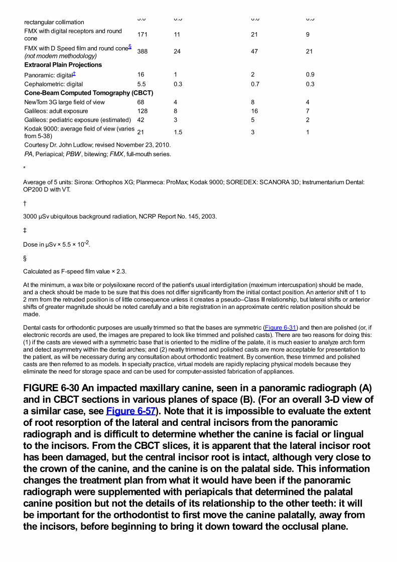
rectangular collimation 5.0 0.3 0.6 0.3
FMX with digital receptors and roundcone 171 11 21 9
FMX with D Speed film and round cone§
(not modern methodology)388 24 47 21
Extraoral Plain ProjectionsPanoramic: digital† 16 1 2 0.9Cephalometric: digital 5.5 0.3 0.7 0.3Cone-Beam Computed Tomography (CBCT)NewTom 3G large field of view 68 4 8 4Galileos: adult exposure 128 8 16 7Galileos: pediatric exposure (estimated) 42 3 5 2Kodak 9000: average field of view (variesfrom 5-38) 21 1.5 3 1
Courtesy Dr. John Ludlow; revised November 23, 2010.PA, Periapical; PBW , bitewing; FMX, full-mouth series.
*
Average of 5 units: Sirona: Orthophos XG; Planmeca: ProMax; Kodak 9000; SOREDEX: SCANORA 3D; Instrumentarium Dental:OP200 D with VT.
†
3000 µSv ubiquitous background radiation, NCRP Report No. 145, 2003.
‡
Dose in µSv × 5.5 × 10⁻².
§
Calculated as F-speed film value × 2.3.
At the minimum, a wax bite or polysiloxane record of the patient's usual interdigitation (maximum intercuspation) should be made,and a check should be made to be sure that this does not differ significantly from the initial contact position. An anterior shift of 1 to2 mm from the retruded position is of little consequence unless it creates a pseudo–Class III relationship, but lateral shifts or anteriorshifts of greater magnitude should be noted carefully and a bite registration in an approximate centric relation position should bemade.
Dental casts for orthodontic purposes are usually trimmed so that the bases are symmetric (Figure 6-31) and then are polished (or, ifelectronic records are used, the images are prepared to look like trimmed and polished casts). There are two reasons for doing this:(1) if the casts are viewed with a symmetric base that is oriented to the midline of the palate, it is much easier to analyze arch formand detect asymmetry within the dental arches; and (2) neatly trimmed and polished casts are more acceptable for presentation tothe patient, as will be necessary during any consultation about orthodontic treatment. By convention, these trimmed and polishedcasts are then referred to as models. In specialty practice, virtual models are rapidly replacing physical models because theyeliminate the need for storage space and can be used for computer-assisted fabrication of appliances.
FIGURE 6-30 An impacted maxillary canine, seen in a panoramic radiograph (A)and in CBCT sections in various planes of space (B). (For an overall 3-D view ofa similar case, see Figure 6-57). Note that it is impossible to evaluate the extentof root resorption of the lateral and central incisors from the panoramicradiograph and is difficult to determine whether the canine is facial or lingualto the incisors. From the CBCT slices, it is apparent that the lateral incisor roothas been damaged, but the central incisor root is intact, although very close tothe crown of the canine, and the canine is on the palatal side. This informationchanges the treatment plan from what it would have been if the panoramicradiograph were supplemented with periapicals that determined the palatalcanine position but not the details of its relationship to the other teeth: it willbe important for the orthodontist to first move the canine palatally, away fromthe incisors, before beginning to bring it down toward the occlusal plane.
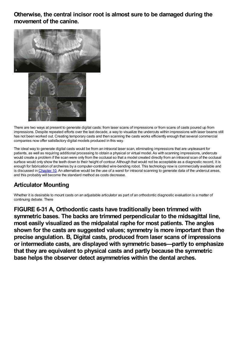
Otherwise, the central incisor root is almost sure to be damaged during themovement of the canine.
There are two ways at present to generate digital casts: from laser scans of impressions or from scans of casts poured up fromimpressions. Despite repeated efforts over the last decade, a way to visualize the undercuts within impressions with laser beams stillhas not been worked out. Creating temporary casts and then scanning the casts works efficiently enough that several commercialcompanies now offer satisfactory digital models produced in this way.
The ideal way to generate digital casts would be from an intraoral laser scan, eliminating impressions that are unpleasant forpatients, as well as requiring additional processing to obtain a physical or virtual model. As with scanning impressions, undercutswould create a problem if the scan were only from the occlusal so that a model created directly from an intraoral scan of the occlusalsurface would only show the teeth down to their height of contour. Although that would not be acceptable as a diagnostic record, it isenough for fabrication of archwires by a computer-controlled wire-bending robot. This technology now is commercially available andis discussed in Chapter 10. An alternative would be the use of a wand for intraoral scanning to generate data of the undercut areas,and this probably will become the standard method as costs decrease.
Articulator MountingWhether it is desirable to mount casts on an adjustable articulator as part of an orthodontic diagnostic evaluation is a matter ofcontinuing debate. There
FIGURE 6-31 A, Orthodontic casts have traditionally been trimmed withsymmetric bases. The backs are trimmed perpendicular to the midsagittal line,most easily visualized as the midpalatal raphe for most patients. The anglesshown for the casts are suggested values; symmetry is more important than theprecise angulation. B, Digital casts, produced from laser scans of impressionsor intermediate casts, are displayed with symmetric bases—partly to emphasizethat they are equivalent to physical casts and partly because the symmetricbase helps the observer detect asymmetries within the dental arches.
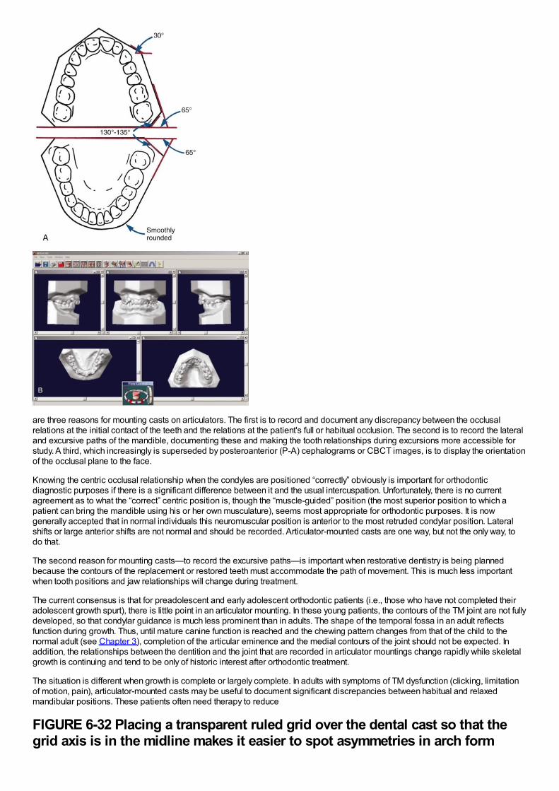
are three reasons for mounting casts on articulators. The first is to record and document any discrepancy between the occlusalrelations at the initial contact of the teeth and the relations at the patient's full or habitual occlusion. The second is to record the lateraland excursive paths of the mandible, documenting these and making the tooth relationships during excursions more accessible forstudy. A third, which increasingly is superseded by posteroanterior (P-A) cephalograms or CBCT images, is to display the orientationof the occlusal plane to the face.
Knowing the centric occlusal relationship when the condyles are positioned “correctly” obviously is important for orthodonticdiagnostic purposes if there is a significant difference between it and the usual intercuspation. Unfortunately, there is no currentagreement as to what the “correct” centric position is, though the “muscle-guided” position (the most superior position to which apatient can bring the mandible using his or her own musculature), seems most appropriate for orthodontic purposes. It is nowgenerally accepted that in normal individuals this neuromuscular position is anterior to the most retruded condylar position. Lateralshifts or large anterior shifts are not normal and should be recorded. Articulator-mounted casts are one way, but not the only way, todo that.
The second reason for mounting casts—to record the excursive paths—is important when restorative dentistry is being plannedbecause the contours of the replacement or restored teeth must accommodate the path of movement. This is much less importantwhen tooth positions and jaw relationships will change during treatment.
The current consensus is that for preadolescent and early adolescent orthodontic patients (i.e., those who have not completed theiradolescent growth spurt), there is little point in an articulator mounting. In these young patients, the contours of the TM joint are not fullydeveloped, so that condylar guidance is much less prominent than in adults. The shape of the temporal fossa in an adult reflectsfunction during growth. Thus, until mature canine function is reached and the chewing pattern changes from that of the child to thenormal adult (see Chapter 3), completion of the articular eminence and the medial contours of the joint should not be expected. Inaddition, the relationships between the dentition and the joint that are recorded in articulator mountings change rapidly while skeletalgrowth is continuing and tend to be only of historic interest after orthodontic treatment.
The situation is different when growth is complete or largely complete. In adults with symptoms of TM dysfunction (clicking, limitationof motion, pain), articulator-mounted casts may be useful to document significant discrepancies between habitual and relaxedmandibular positions. These patients often need therapy to reduce
FIGURE 6-32 Placing a transparent ruled grid over the dental cast so that thegrid axis is in the midline makes it easier to spot asymmetries in arch form
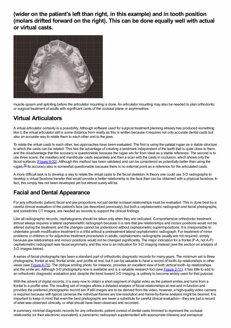
(wider on the patient's left than right, in this example) and in tooth position(molars drifted forward on the right). This can be done equally well with actualor virtual casts.
muscle spasm and splinting before the articulator mounting is done. An articulator mounting may also be needed to plan orthodonticor surgical treatment of adults with significant cants of the occlusal plane or asymmetries.
Virtual ArticulatorsA virtual articulator certainly is a possibility. Although software used for surgical treatment planning already has produced somethinglike it, the virtual articulator still is some distance from reality as this is written because it requires not only accurate dental casts butalso an accurate way to relate them to each other and to the jaws.
To relate the virtual casts to each other, two approaches have been evaluated. The first is using the palatal rugae as a stable structureto which the casts can be related. This has the advantage of creating a landmark independent of the teeth that is quite close to them,and the disadvantage that the accuracy is questionable because the rugae are far from ideal as a stable reference. The second is touse three scans: the maxillary and mandibular casts separately and then a scan with the casts in occlusion, which shows only thefacial surfaces (Figure 6-32). Although this method has been validated and can be considered as potentially better than using therugae,16 its accuracy also is somewhat questionable because there is no external point as a reference for the articulated casts.
A more difficult task is to develop a way to relate the virtual casts to the facial skeleton. In theory one could use 3-D radiographs todevelop a virtual facebow transfer that would provide a better relationship to the face than can be obtained with a physical facebow. Infact, this simply has not been developed yet but almost surely will be.
Facial and Dental AppearanceFor any orthodontic patient, facial and jaw proportions not just dental occlusal relationships must be evaluated. This is done best by acareful clinical evaluation of the patient's face (as described previously), but both a cephalometric radiograph and facial photographs,and sometimes CT images, are needed as records to support the clinical findings.
Like all radiographic records, cephalograms should be taken only when they are indicated. Comprehensive orthodontic treatmentalmost always requires a lateral cephalometric radiograph because it is rare that jaw relationships and incisor positions would not bealtered during the treatment, and the changes cannot be understood without cephalometric superimpositions. It is irresponsible toundertake growth modification treatment in a child without a pretreatment lateral cephalometric radiograph. For treatment of minorproblems in children or for adjunctive treatment procedures in adults, cephalometric radiographs usually are not required, simplybecause jaw relationships and incisor positions would not be changed significantly. The major indication for a frontal (P-A, not A-P)cephalometric radiograph was facial asymmetry, and this now is an indication for 3-D imaging instead (see the section on analysis of3-D images below).
A series of facial photographs has been a standard part of orthodontic diagnostic records for many years. The minimum set is threephotographs, frontal at rest, frontal smile, and profile at rest, but it can be valuable to have a record of tooth–lip relationships in otherviews (see Figure 6-75). The oblique smiling photo, for instance, provides an excellent view of both vertical tooth–lip relationshipsand the smile arc. Although 3-D photography now is available and is a valuable research tool (see Figure 2-11), it has little to add toan orthodontic diagnostic evaluation and, despite the trend toward 3-D imaging, is unlikely to become widely used for that purpose.
With the advent of digital records, it is easy now to obtain a short segment of digital video as the patient smiles and turns from afrontal to a profile view. The resulting set of images allows a detailed analysis of facial relationships at rest and in function andprovides the preferred photographic record set. If still images are to be derived from the video, however, a high-quality video camerais required because with typical cameras the individual frames are low-resolution and frame-by-frame analysis might be desired. It isimportant to keep in mind that even the best photographs are never a substitute for careful clinical evaluation—they are just a recordof what was observed clinically, or what should have been observed and recorded.
In summary, minimal diagnostic records for any orthodontic patient consist of dental casts trimmed to represent the occlusalrelationship (or their electronic equivalent), a panoramic radiograph supplemented with appropriate bitewing and periapical
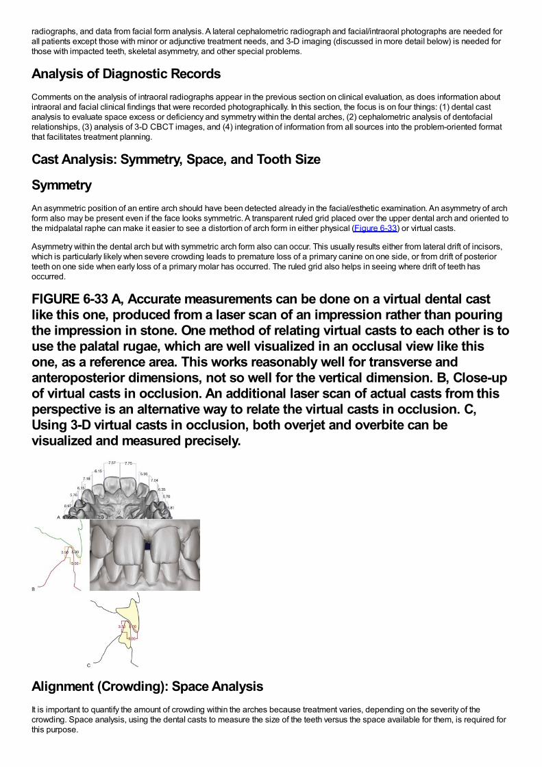
radiographs, and data from facial form analysis. A lateral cephalometric radiograph and facial/intraoral photographs are needed forall patients except those with minor or adjunctive treatment needs, and 3-D imaging (discussed in more detail below) is needed forthose with impacted teeth, skeletal asymmetry, and other special problems.
Analysis of Diagnostic RecordsComments on the analysis of intraoral radiographs appear in the previous section on clinical evaluation, as does information aboutintraoral and facial clinical findings that were recorded photographically. In this section, the focus is on four things: (1) dental castanalysis to evaluate space excess or deficiency and symmetry within the dental arches, (2) cephalometric analysis of dentofacialrelationships, (3) analysis of 3-D CBCT images, and (4) integration of information from all sources into the problem-oriented formatthat facilitates treatment planning.
Cast Analysis: Symmetry, Space, and Tooth Size
SymmetryAn asymmetric position of an entire arch should have been detected already in the facial/esthetic examination. An asymmetry of archform also may be present even if the face looks symmetric. A transparent ruled grid placed over the upper dental arch and oriented tothe midpalatal raphe can make it easier to see a distortion of arch form in either physical (Figure 6-33) or virtual casts.
Asymmetry within the dental arch but with symmetric arch form also can occur. This usually results either from lateral drift of incisors,which is particularly likely when severe crowding leads to premature loss of a primary canine on one side, or from drift of posteriorteeth on one side when early loss of a primary molar has occurred. The ruled grid also helps in seeing where drift of teeth hasoccurred.
FIGURE 6-33 A, Accurate measurements can be done on a virtual dental castlike this one, produced from a laser scan of an impression rather than pouringthe impression in stone. One method of relating virtual casts to each other is touse the palatal rugae, which are well visualized in an occlusal view like thisone, as a reference area. This works reasonably well for transverse andanteroposterior dimensions, not so well for the vertical dimension. B, Close-upof virtual casts in occlusion. An additional laser scan of actual casts from thisperspective is an alternative way to relate the virtual casts in occlusion. C,Using 3-D virtual casts in occlusion, both overjet and overbite can bevisualized and measured precisely.
Alignment (Crowding): Space AnalysisIt is important to quantify the amount of crowding within the arches because treatment varies, depending on the severity of thecrowding. Space analysis, using the dental casts to measure the size of the teeth versus the space available for them, is required forthis purpose.
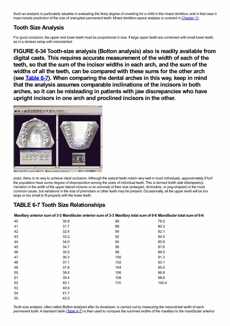
Such an analysis is particularly valuable in evaluating the likely degree of crowding for a child in the mixed dentition, and in that case itmust include prediction of the size of unerupted permanent teeth. Mixed dentition space analysis is covered in Chapter 11.
Tooth Size AnalysisFor good occlusion, the upper and lower teeth must be proportional in size. If large upper teeth are combined with small lower teeth,as in a denture setup with mismatched
FIGURE 6-34 Tooth-size analysis (Bolton analysis) also is readily available fromdigital casts. This requires accurate measurement of the width of each of theteeth, so that the sum of the incisor widths in each arch, and the sum of thewidths of all the teeth, can be compared with these sums for the other arch(see Table 6-7). When comparing the dental arches in this way, keep in mindthat the analysis assumes comparable inclinations of the incisors in botharches, so it can be misleading in patients with jaw discrepancies who haveupright incisors in one arch and proclined incisors in the other.
sizes, there is no way to achieve ideal occlusion. Although the natural teeth match very well in most individuals, approximately 5%ofthe population have some degree of disproportion among the sizes of individual teeth. This is termed tooth size discrepancy.Variation in the width of the upper lateral incisors or an anomaly of their size (enlarged, diminutive, or peg-shaped) is the mostcommon cause, but variations in the size of premolars or other teeth may be present. Occasionally, all the upper teeth will be toolarge or too small to fit properly with the lower teeth.
TABLE 6-7 Tooth Size RelationshipsMaxillary anterior sum of 3-3 Mandibular anterior sum of 3-3 Maxillary total sum of 6-6 Mandibular total sum of 6-640 30.9 86 78.541 31.7 88 80.342 32.4 90 82.143 33.2 92 84.044 34.0 94 85.845 34.7 96 87.646 35.5 98 89.547 36.3 100 91.348 37.1 102 93.149 37.8 104 95.050 38.6 106 96.851 39.4 108 98.652 40.1 110 100.453 40.954 41.755 42.5
Tooth size analysis, often called Bolton analysis after its developer, is carried out by measuring the mesiodistal width of eachpermanent tooth. A standard table (Table 6-7) is then used to compare the summed widths of the maxillary to the mandibular anterior
teeth and the total width of all upper to lower teeth (excluding second and third molars). One advantage of measuring individual toothwidths into a computer template during space analysis is that the computer then can quickly provide a tooth size analysis (Figure 6-34).
A quick check for anterior tooth size discrepancy can be done by comparing the size of upper and lower lateral incisors. Unless theupper laterals are wider, a discrepancy almost surely exists. A quick check for posterior tooth size discrepancy is to compare the sizeof upper and lower second premolars, which should be about equal size. A tooth size discrepancy of less than 1.5 mm is rarelysignificant, but larger discrepancies create treatment problems in achieving ideal occlusal relationships and must be included in theorthodontic problem list.
Cephalometric AnalysisThe introduction of radiographic cephalometrics in 1934 by Hofrath in Germany and Broadbent in the United States provided both aresearch and a clinical tool for the study of malocclusion and underlying skeletal disproportions (Figure 6-35). The original purpose ofcephalometrics was research on growth patterns in the craniofacial complex. The concepts of normal development presented inChapters 2 and 3 were largely derived from such cephalometric studies.
It soon became clear, however, that cephalometric radiographs could be used to evaluate dentofacial proportions and clarify theanatomic basis for a malocclusion. The orthodontist needs to know how the major functional components of the face (cranial base,jaws, teeth) are related to each other (Figure 6-36). Any malocclusion is the result of an interaction between jaw position and theposition the teeth assume as they erupt, which is affected by the jaw relationships (see Chapter 4 for a discussion of dentalcompensation or adaptation). For this reason, apparently similar malocclusions as evaluated from the dental occlusions may turn outto be quite different when evaluated more completely (Figure 6-37). Although careful observation of the face can provide thisinformation, cephalometric analysis allows greater precision.
FIGURE 6-35 Diagrammatic representation of the American standardcephalometric arrangement. By convention, the distance from the x-ray sourceto the subject's midsagittal plane is 5 feet. The distance from the midsagittalplane to the cassette can vary but must be the same for any one patient everytime.
FIGURE 6-36 The structural components of the face, shown superimposed onthe anatomic drawing. The cranium and cranial base (1), the skeletal maxillaand nasomaxillary complex (2), and the skeletal mandible (3) are parts of theface that exist whether there is or is not a dentition. The maxillary teeth andalveolar process (4) and the mandibular teeth and alveolar process (5) areindependent functional units, which can be displaced relative to thesupporting bone of the maxilla and mandible, respectively. The major goal ofcephalometric analysis is to establish the relationship of these components inboth the anteroposterior and vertical planes of space.
FIGURE 6-37 The ideal relationships of the facial and dental components canbe represented as shown in A. Cephalometric analysis can distinguish andclarify the differing dental and skeletal contributions to malocclusions thatpresent identical dental relationships. A Class II division 1 malocclusion, forexample, could be produced by (B) protrusion of the maxillary teeth althoughthe jaw relationship was normal, (C) mandibular deficiency with the teeth ofboth arches normally related to the jaw, (D) downward-backward rotation of themandible produced by excessive vertical growth of the maxilla, or a number ofother possibilities. The objective of cephalometric analysis is to visualize thecontribution of skeletal and dental relationships to the malocclusion in thisway, not to generate a table of numbers that are estimators of relationships.Measurements and other analytic procedures are a means to the end ofunderstanding dental and skeletal relationships for an individual patient, notends in themselves.
Cephalometric radiographs are not taken as a screen for pathology, but the possibility of observing pathologic changes on theseradiographs should not be overlooked. Occasionally, previously unsuspected anomalies in the cervical spine (Figure 6-38) ordegenerative changes in the vertebrae are revealed in a cephalometric radiograph, and sometimes other pathologic changes in theskull, jaws, or cranial base can be observed.17 This becomes particularly important when 3-D images of the head are obtained (seebelow), and examination of such images by a radiologist is needed to be sure nothing is overlooked in the orthodontist's efforts to
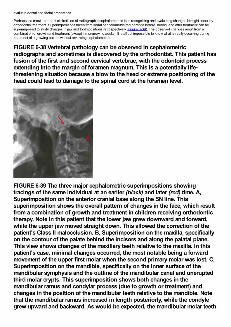
evaluate dental and facial proportions.
Perhaps the most important clinical use of radiographic cephalometrics is in recognizing and evaluating changes brought about byorthodontic treatment. Superimpositions taken from serial cephalometric radiographs before, during, and after treatment can besuperimposed to study changes in jaw and tooth positions retrospectively (Figure 6-39). The observed changes result from acombination of growth and treatment (except in nongrowing adults). It is all but impossible to know what is really occurring duringtreatment of a growing patient without reviewing cephalometric
FIGURE 6-38 Vertebral pathology can be observed in cephalometricradiographs and sometimes is discovered by the orthodontist. This patient hasfusion of the first and second cervical vertebrae, with the odontoid processextending into the margin of foramen magnum. This is a potentially life-threatening situation because a blow to the head or extreme positioning of thehead could lead to damage to the spinal cord at the foramen level.
FIGURE 6-39 The three major cephalometric superimpositions showingtracings of the same individual at an earlier (black) and later (red) time. A,Superimposition on the anterior cranial base along the SN line. Thissuperimposition shows the overall pattern of changes in the face, which resultfrom a combination of growth and treatment in children receiving orthodontictherapy. Note in this patient that the lower jaw grew downward and forward,while the upper jaw moved straight down. This allowed the correction of thepatient's Class II malocclusion. B, Superimposition on the maxilla, specificallyon the contour of the palate behind the incisors and along the palatal plane.This view shows changes of the maxillary teeth relative to the maxilla. In thispatient's case, minimal changes occurred, the most notable being a forwardmovement of the upper first molar when the second primary molar was lost. C,Superimposition on the mandible, specifically on the inner surface of themandibular symphysis and the outline of the mandibular canal and uneruptedthird molar crypts. This superimposition shows both changes in themandibular ramus and condylar process (due to growth or treatment) andchanges in the position of the mandibular teeth relative to the mandible. Notethat the mandibular ramus increased in length posteriorly, while the condylegrew upward and backward. As would be expected, the mandibular molar teeth
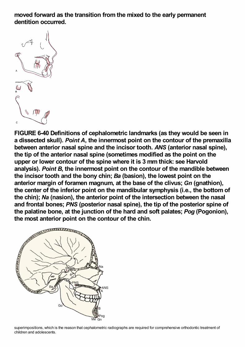
moved forward as the transition from the mixed to the early permanentdentition occurred.
FIGURE 6-40 Definitions of cephalometric landmarks (as they would be seen ina dissected skull). Point A, the innermost point on the contour of the premaxillabetween anterior nasal spine and the incisor tooth. ANS (anterior nasal spine),the tip of the anterior nasal spine (sometimes modified as the point on theupper or lower contour of the spine where it is 3 mm thick: see Harvoldanalysis). Point B, the innermost point on the contour of the mandible betweenthe incisor tooth and the bony chin; Ba (basion), the lowest point on theanterior margin of foramen magnum, at the base of the clivus; Gn (gnathion),the center of the inferior point on the mandibular symphysis (i.e., the bottom ofthe chin); Na (nasion), the anterior point of the intersection between the nasaland frontal bones; PNS (posterior nasal spine), the tip of the posterior spine ofthe palatine bone, at the junction of the hard and soft palates; Pog (Pogonion),the most anterior point on the contour of the chin.
superimpositions, which is the reason that cephalometric radiographs are required for comprehensive orthodontic treatment ofchildren and adolescents.
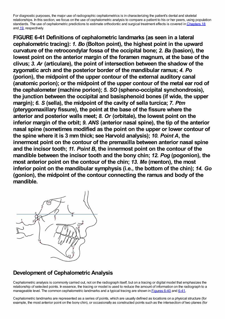
For diagnostic purposes, the major use of radiographic cephalometrics is in characterizing the patient's dental and skeletalrelationships. In this section, we focus on the use of cephalometric analysis to compare a patient to his or her peers, using populationstandards. The use of cephalometric predictions to estimate orthodontic and surgical treatment effects is covered in Chapters 18and 19, respectively.
FIGURE 6-41 Definitions of cephalometric landmarks (as seen in a lateralcephalometric tracing): 1. Bo (Bolton point), the highest point in the upwardcurvature of the retrocondylar fossa of the occipital bone; 2. Ba (basion), thelowest point on the anterior margin of the foramen magnum, at the base of theclivus; 3. Ar (articulare), the point of intersection between the shadow of thezygomatic arch and the posterior border of the mandibular ramus; 4. Po(porion), the midpoint of the upper contour of the external auditory canal(anatomic porion); or the midpoint of the upper contour of the metal ear rod ofthe cephalometer (machine porion); 5. SO (spheno-occipital synchondrosis),the junction between the occipital and basisphenoid bones (if wide, the uppermargin); 6. S (sella), the midpoint of the cavity of sella turcica; 7. Ptm(pterygomaxillary fissure), the point at the base of the fissure where theanterior and posterior walls meet; 8. Or (orbitale), the lowest point on theinferior margin of the orbit; 9. ANS (anterior nasal spine), the tip of the anteriornasal spine (sometimes modified as the point on the upper or lower contour ofthe spine where it is 3 mm thick; see Harvold analysis); 10. Point A, theinnermost point on the contour of the premaxilla between anterior nasal spineand the incisor tooth; 11. Point B, the innermost point on the contour of themandible between the incisor tooth and the bony chin; 12. Pog (pogonion), themost anterior point on the contour of the chin; 13. Me (menton), the mostinferior point on the mandibular symphysis (i.e., the bottom of the chin); 14. Go(gonion), the midpoint of the contour connecting the ramus and body of themandible.
Development of Cephalometric AnalysisCephalometric analysis is commonly carried out, not on the radiograph itself, but on a tracing or digital model that emphasizes therelationship of selected points. In essence, the tracing or model is used to reduce the amount of information on the radiograph to amanageable level. The common cephalometric landmarks and a typical tracing are shown in Figures 6-40 and 6-41.
Cephalometric landmarks are represented as a series of points, which are usually defined as locations on a physical structure (forexample, the most anterior point on the bony chin), or occasionally as constructed points such as the intersection of two planes (for
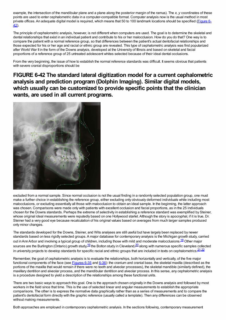
example, the intersection of the mandibular plane and a plane along the posterior margin of the ramus). The x, y coordinates of thesepoints are used to enter cephalometric data in a computer-compatible format. Computer analysis now is the usual method in mostprivate offices. An adequate digital model is required, which means that 50 to 100 landmark locations should be specified (Figure 6-42).
The principle of cephalometric analysis, however, is not different when computers are used. The goal is to determine the skeletal anddental relationships that exist in an individual patient and contribute to his or her malocclusion. How do you do that? One way is tocompare the patient with a normal reference group, so that differences between the patient's actual dentofacial relationships andthose expected for his or her age and racial or ethnic group are revealed. This type of cephalometric analysis was first popularizedafter World War II in the form of the Downs analysis, developed at the University of Illinois and based on skeletal and facialproportions of a reference group of 25 untreated adolescent whites selected because of their ideal dental occlusions.
From the very beginning, the issue of how to establish the normal reference standards was difficult. It seems obvious that patientswith severe cranial disproportions should be
FIGURE 6-42 The standard lateral digitization model for a current cephalometricanalysis and prediction program (Dolphin Imaging). Similar digital models,which usually can be customized to provide specific points that the clinicianwants, are used in all current programs.
excluded from a normal sample. Since normal occlusion is not the usual finding in a randomly selected population group, one mustmake a further choice in establishing the reference group, either excluding only obviously deformed individuals while including mostmalocclusions, or excluding essentially all those with malocclusion to obtain an ideal sample. In the beginning, the latter approachwas chosen. Comparisons were made only with patients with excellent occlusion and facial proportions, as in the 25 individualschosen for the Downs standards. Perhaps the extreme of selectivity in establishing a reference standard was exemplified by Steiner,whose original ideal measurements were reputedly based on one Hollywood starlet. Although the story is apocryphal, if it is true, Dr.Steiner had a very good eye because recalculation of his original values based on averages from much larger samples producedonly minor changes.
The standards developed for the Downs, Steiner, and Wits analyses are still useful but have largely been replaced by newerstandards based on less rigidly selected groups. A major database for contemporary analysis is the Michigan growth study, carriedout in Ann Arbor and involving a typical group of children, including those with mild and moderate malocclusions.18 Other majorsources are the Burlington (Ontario) growth study,19 the Bolton study in Cleveland,20 along with numerous specific samples collectedin university projects to develop standards for specific racial and ethnic groups that are included in texts on cephalometrics.21,22
Remember, the goal of cephalometric analysis is to evaluate the relationships, both horizontally and vertically, of the five majorfunctional components of the face (see Figures 6-35 and 6-36): the cranium and cranial base, the skeletal maxilla (described as theportions of the maxilla that would remain if there were no teeth and alveolar processes), the skeletal mandible (similarly defined), themaxillary dentition and alveolar process, and the mandibular dentition and alveolar process. In this sense, any cephalometric analysisis a procedure designed to yield a description of the relationships among these functional units.
There are two basic ways to approach this goal. One is the approach chosen originally in the Downs analysis and followed by mostworkers in the field since that time. This is the use of selected linear and angular measurements to establish the appropriatecomparisons. The other is to express the normative data graphically rather than as a series of measurements and to compare thepatient's dentofacial form directly with the graphic reference (usually called a template). Then any differences can be observedwithout making measurements.
Both approaches are employed in contemporary cephalometric analysis. In the sections following, contemporary measurement
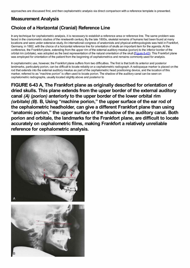
approaches are discussed first, and then cephalometric analysis via direct comparison with a reference template is presented.
Measurement Analysis
Choice of a Horizontal (Cranial) Reference LineIn any technique for cephalometric analysis, it is necessary to establish a reference area or reference line. The same problem wasfaced in the craniometric studies of the nineteenth century. By the late 1800s, skeletal remains of humans had been found at manylocations and were under extensive study. An international congress of anatomists and physical anthropologists was held in Frankfort,Germany, in 1882, with the choice of a horizontal reference line for orientation of skulls an important item for the agenda. At theconference, the Frankfort plane, extending from the upper rim of the external auditory meatus (porion) to the inferior border of theorbital rim (orbitale), was adopted as the best representation of the natural orientation of the skull (Figure 6-43). This Frankfort planewas employed for orientation of the patient from the beginning of cephalometrics and remains commonly used for analysis.
In cephalometric use, however, the Frankfort plane suffers from two difficulties. The first is that both its anterior and posteriorlandmarks, particularly porion, can be difficult to locate reliably on a cephalometric radiograph. A radiopaque marker is placed on therod that extends into the external auditory meatus as part of the cephalometric head positioning device, and the location of thismarker, referred to as “machine porion” is often used to locate porion. The shadow of the auditory canal can be seen oncephalometric radiographs, usually located slightly above and posterior to
FIGURE 6-43 A, The Frankfort plane as originally described for orientation ofdried skulls. This plane extends from the upper border of the external auditorycanal (A) (porion) anteriorly to the upper border of the lower orbital rim(orbitale) (B). B, Using “machine porion,” the upper surface of the ear rod ofthe cephalometric headholder, can give a different Frankfort plane than using“anatomic porion,” the upper surface of the shadow of the auditory canal. Bothporion and orbitale, the landmarks for the Frankfort plane, are difficult to locateaccurately on cephalometric films, making Frankfort a relatively unreliablereference for cephalometric analysis.
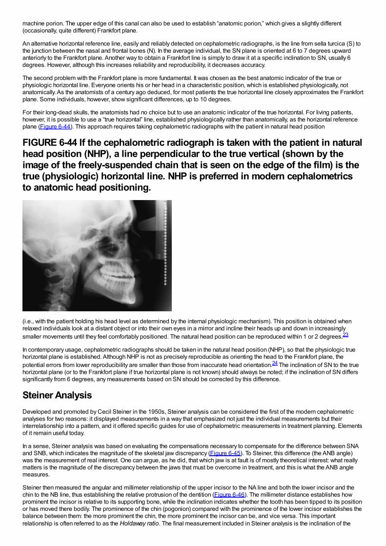
machine porion. The upper edge of this canal can also be used to establish “anatomic porion,” which gives a slightly different(occasionally, quite different) Frankfort plane.
An alternative horizontal reference line, easily and reliably detected on cephalometric radiographs, is the line from sella turcica (S) tothe junction between the nasal and frontal bones (N). In the average individual, the SN plane is oriented at 6 to 7 degrees upwardanteriorly to the Frankfort plane. Another way to obtain a Frankfort line is simply to draw it at a specific inclination to SN, usually 6degrees. However, although this increases reliability and reproducibility, it decreases accuracy.
The second problem with the Frankfort plane is more fundamental. It was chosen as the best anatomic indicator of the true orphysiologic horizontal line. Everyone orients his or her head in a characteristic position, which is established physiologically, notanatomically. As the anatomists of a century ago deduced, for most patients the true horizontal line closely approximates the Frankfortplane. Some individuals, however, show significant differences, up to 10 degrees.
For their long-dead skulls, the anatomists had no choice but to use an anatomic indicator of the true horizontal. For living patients,however, it is possible to use a “true horizontal” line, established physiologically rather than anatomically, as the horizontal referenceplane (Figure 6-44). This approach requires taking cephalometric radiographs with the patient in natural head position
FIGURE 6-44 If the cephalometric radiograph is taken with the patient in naturalhead position (NHP), a line perpendicular to the true vertical (shown by theimage of the freely-suspended chain that is seen on the edge of the film) is thetrue (physiologic) horizontal line. NHP is preferred in modern cephalometricsto anatomic head positioning.
(i.e., with the patient holding his head level as determined by the internal physiologic mechanism). This position is obtained whenrelaxed individuals look at a distant object or into their own eyes in a mirror and incline their heads up and down in increasinglysmaller movements until they feel comfortably positioned. The natural head position can be reproduced within 1 or 2 degrees.23
In contemporary usage, cephalometric radiographs should be taken in the natural head position (NHP), so that the physiologic truehorizontal plane is established. Although NHP is not as precisely reproducible as orienting the head to the Frankfort plane, thepotential errors from lower reproducibility are smaller than those from inaccurate head orientation.24 The inclination of SN to the truehorizontal plane (or to the Frankfort plane if true horizontal plane is not known) should always be noted; if the inclination of SN differssignificantly from 6 degrees, any measurements based on SN should be corrected by this difference.
Steiner AnalysisDeveloped and promoted by Cecil Steiner in the 1950s, Steiner analysis can be considered the first of the modern cephalometricanalyses for two reasons: it displayed measurements in a way that emphasized not just the individual measurements but theirinterrelationship into a pattern, and it offered specific guides for use of cephalometric measurements in treatment planning. Elementsof it remain useful today.
In a sense, Steiner analysis was based on evaluating the compensations necessary to compensate for the difference between SNAand SNB, which indicates the magnitude of the skeletal jaw discrepancy (Figure 6-45). To Steiner, this difference (the ANB angle)was the measurement of real interest. One can argue, as he did, that which jaw is at fault is of mostly theoretical interest: what reallymatters is the magnitude of the discrepancy between the jaws that must be overcome in treatment, and this is what the ANB anglemeasures.
Steiner then measured the angular and millimeter relationship of the upper incisor to the NA line and both the lower incisor and thechin to the NB line, thus establishing the relative protrusion of the dentition (Figure 6-46). The millimeter distance establishes howprominent the incisor is relative to its supporting bone, while the inclination indicates whether the tooth has been tipped to its positionor has moved there bodily. The prominence of the chin (pogonion) compared with the prominence of the lower incisor establishes thebalance between them: the more prominent the chin, the more prominent the incisor can be, and vice versa. This importantrelationship is often referred to as the Holdaway ratio. The final measurement included in Steiner analysis is the inclination of the
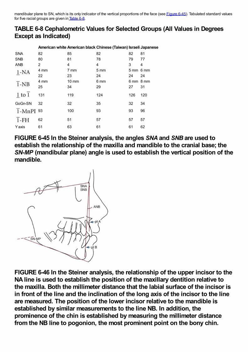
mandibular plane to SN, which is its only indicator of the vertical proportions of the face (see Figure 6-45). Tabulated standard valuesfor five racial groups are given in Table 6-8.
TABLE 6-8 Cephalometric Values for Selected Groups (All Values in DegreesExcept as Indicated)
American white American black Chinese (Taiwan) Israeli JapaneseSNA 82 85 82 82 81SNB 80 81 78 79 77ANB 2 4 4 3 4
4 mm 7 mm 5 mm 5 mm 6 mm22 23 24 24 244 mm 10 mm 6 mm 6 mm 8 mm25 34 29 27 31
131 119 124 126 120
GoGn-SN 32 32 35 32 34
93 100 93 93 96
62 51 57 57 57
Y axis 61 63 61 61 62
FIGURE 6-45 In the Steiner analysis, the angles SNA and SNB are used toestablish the relationship of the maxilla and mandible to the cranial base; theSN-MP (mandibular plane) angle is used to establish the vertical position of themandible.
FIGURE 6-46 In the Steiner analysis, the relationship of the upper incisor to theNA line is used to establish the position of the maxillary dentition relative tothe maxilla. Both the millimeter distance that the labial surface of the incisor isin front of the line and the inclination of the long axis of the incisor to the lineare measured. The position of the lower incisor relative to the mandible isestablished by similar measurements to the line NB. In addition, theprominence of the chin is established by measuring the millimeter distancefrom the NB line to pogonion, the most prominent point on the bony chin.
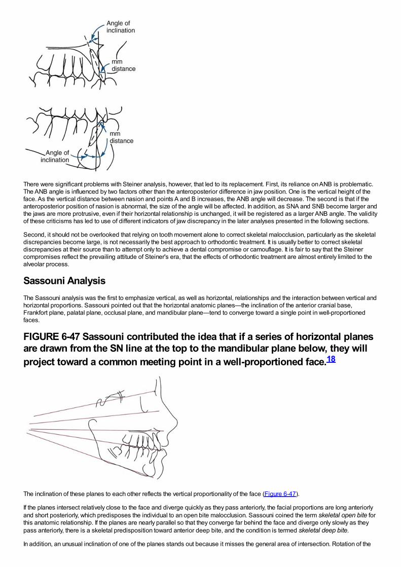
There were significant problems with Steiner analysis, however, that led to its replacement. First, its reliance on ANB is problematic.The ANB angle is influenced by two factors other than the anteroposterior difference in jaw position. One is the vertical height of theface. As the vertical distance between nasion and points A and B increases, the ANB angle will decrease. The second is that if theanteroposterior position of nasion is abnormal, the size of the angle will be affected. In addition, as SNA and SNB become larger andthe jaws are more protrusive, even if their horizontal relationship is unchanged, it will be registered as a larger ANB angle. The validityof these criticisms has led to use of different indicators of jaw discrepancy in the later analyses presented in the following sections.
Second, it should not be overlooked that relying on tooth movement alone to correct skeletal malocclusion, particularly as the skeletaldiscrepancies become large, is not necessarily the best approach to orthodontic treatment. It is usually better to correct skeletaldiscrepancies at their source than to attempt only to achieve a dental compromise or camouflage. It is fair to say that the Steinercompromises reflect the prevailing attitude of Steiner's era, that the effects of orthodontic treatment are almost entirely limited to thealveolar process.
Sassouni AnalysisThe Sassouni analysis was the first to emphasize vertical, as well as horizontal, relationships and the interaction between vertical andhorizontal proportions. Sassouni pointed out that the horizontal anatomic planes—the inclination of the anterior cranial base,Frankfort plane, palatal plane, occlusal plane, and mandibular plane—tend to converge toward a single point in well-proportionedfaces.
FIGURE 6-47 Sassouni contributed the idea that if a series of horizontal planesare drawn from the SN line at the top to the mandibular plane below, they willproject toward a common meeting point in a well-proportioned face.18
The inclination of these planes to each other reflects the vertical proportionality of the face (Figure 6-47).
If the planes intersect relatively close to the face and diverge quickly as they pass anteriorly, the facial proportions are long anteriorlyand short posteriorly, which predisposes the individual to an open bite malocclusion. Sassouni coined the term skeletal open bite forthis anatomic relationship. If the planes are nearly parallel so that they converge far behind the face and diverge only slowly as theypass anteriorly, there is a skeletal predisposition toward anterior deep bite, and the condition is termed skeletal deep bite.
In addition, an unusual inclination of one of the planes stands out because it misses the general area of intersection. Rotation of the
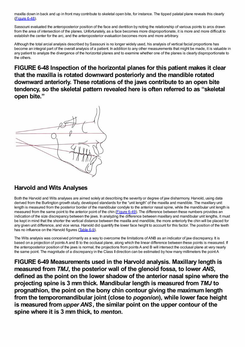
maxilla down in back and up in front may contribute to skeletal open bite, for instance. The tipped palatal plane reveals this clearly(Figure 6-48).
Sassouni evaluated the anteroposterior position of the face and dentition by noting the relationship of various points to arcs drawnfrom the area of intersection of the planes. Unfortunately, as a face becomes more disproportionate, it is more and more difficult toestablish the center for the arc, and the anteroposterior evaluation becomes more and more arbitrary.
Although the total arcial analysis described by Sassouni is no longer widely used, his analysis of vertical facial proportions hasbecome an integral part of the overall analysis of a patient. In addition to any other measurements that might be made, it is valuable inany patient to analyze the divergence of the horizontal planes and to examine whether one of the planes is clearly disproportionate tothe others.
FIGURE 6-48 Inspection of the horizontal planes for this patient makes it clearthat the maxilla is rotated downward posteriorly and the mandible rotateddownward anteriorly. These rotations of the jaws contribute to an open bitetendency, so the skeletal pattern revealed here is often referred to as “skeletalopen bite.”
Harvold and Wits AnalysesBoth the Harvold and Wits analyses are aimed solely at describing the severity or degree of jaw disharmony. Harvold, using dataderived from the Burlington growth study, developed standards for the “unit length” of the maxilla and mandible. The maxillary unitlength is measured from the posterior border of the mandibular condyle to the anterior nasal spine, while the mandibular unit length ismeasured from the same point to the anterior point of the chin (Figure 6-49). The difference between these numbers provides anindication of the size discrepancy between the jaws. In analyzing the difference between maxillary and mandibular unit lengths, it mustbe kept in mind that the shorter the vertical distance between the maxilla and mandible, the more anteriorly the chin will be placed forany given unit difference, and vice versa. Harvold did quantify the lower face height to account for this factor. The position of the teethhas no influence on the Harvold figures (Table 6-9).
The Wits analysis was conceived primarily as a way to overcome the limitations of ANB as an indicator of jaw discrepancy. It isbased on a projection of points A and B to the occlusal plane, along which the linear difference between these points is measured. Ifthe anteroposterior position of the jaws is normal, the projections from points A and B will intersect the occlusal plane at very nearlythe same point. The magnitude of a discrepancy in the Class II direction can be estimated by how many millimeters the point A
FIGURE 6-49 Measurements used in the Harvold analysis. Maxillary length ismeasured from TMJ, the posterior wall of the glenoid fossa, to lower ANS,defined as the point on the lower shadow of the anterior nasal spine where theprojecting spine is 3 mm thick. Mandibular length is measured from TMJ toprognathion, the point on the bony chin contour giving the maximum lengthfrom the temporomandibular joint (close to pogonion), while lower face heightis measured from upper ANS , the similar point on the upper contour of thespine where it is 3 mm thick, to menton.
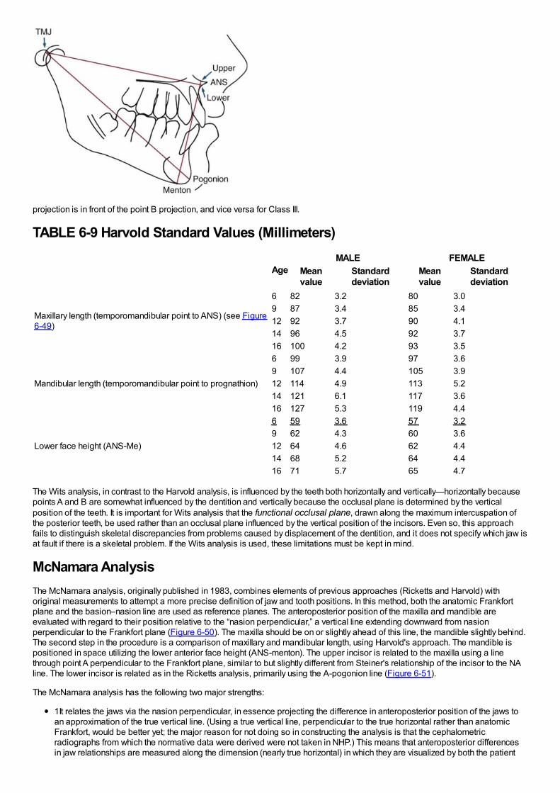
projection is in front of the point B projection, and vice versa for Class III.
TABLE 6-9 Harvold Standard Values (Millimeters)
AgeMALE FEMALE
Meanvalue
Standarddeviation
Meanvalue
Standarddeviation
Maxillary length (temporomandibular point to ANS) (see Figure6-49)
6 82 3.2 80 3.09 87 3.4 85 3.412 92 3.7 90 4.114 96 4.5 92 3.716 100 4.2 93 3.5
Mandibular length (temporomandibular point to prognathion)
6 99 3.9 97 3.69 107 4.4 105 3.912 114 4.9 113 5.214 121 6.1 117 3.616 127 5.3 119 4.4
Lower face height (ANS-Me)
6 59 3.6 57 3.29 62 4.3 60 3.612 64 4.6 62 4.414 68 5.2 64 4.416 71 5.7 65 4.7
The Wits analysis, in contrast to the Harvold analysis, is influenced by the teeth both horizontally and vertically—horizontally becausepoints A and B are somewhat influenced by the dentition and vertically because the occlusal plane is determined by the verticalposition of the teeth. It is important for Wits analysis that the functional occlusal plane, drawn along the maximum intercuspation ofthe posterior teeth, be used rather than an occlusal plane influenced by the vertical position of the incisors. Even so, this approachfails to distinguish skeletal discrepancies from problems caused by displacement of the dentition, and it does not specify which jaw isat fault if there is a skeletal problem. If the Wits analysis is used, these limitations must be kept in mind.
McNamara AnalysisThe McNamara analysis, originally published in 1983, combines elements of previous approaches (Ricketts and Harvold) withoriginal measurements to attempt a more precise definition of jaw and tooth positions. In this method, both the anatomic Frankfortplane and the basion–nasion line are used as reference planes. The anteroposterior position of the maxilla and mandible areevaluated with regard to their position relative to the “nasion perpendicular,” a vertical line extending downward from nasionperpendicular to the Frankfort plane (Figure 6-50). The maxilla should be on or slightly ahead of this line, the mandible slightly behind.The second step in the procedure is a comparison of maxillary and mandibular length, using Harvold's approach. The mandible ispositioned in space utilizing the lower anterior face height (ANS-menton). The upper incisor is related to the maxilla using a linethrough point A perpendicular to the Frankfort plane, similar to but slightly different from Steiner's relationship of the incisor to the NAline. The lower incisor is related as in the Ricketts analysis, primarily using the A-pogonion line (Figure 6-51).
The McNamara analysis has the following two major strengths:
1It relates the jaws via the nasion perpendicular, in essence projecting the difference in anteroposterior position of the jaws toan approximation of the true vertical line. (Using a true vertical line, perpendicular to the true horizontal rather than anatomicFrankfort, would be better yet; the major reason for not doing so in constructing the analysis is that the cephalometricradiographs from which the normative data were derived were not taken in NHP.) This means that anteroposterior differencesin jaw relationships are measured along the dimension (nearly true horizontal) in which they are visualized by both the patient
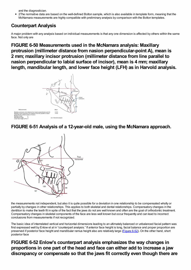
and the diagnostician.2The normative data are based on the well-defined Bolton sample, which is also available in template form, meaning that theMcNamara measurements are highly compatible with preliminary analysis by comparison with the Bolton templates.
Counterpart AnalysisA major problem with any analysis based on individual measurements is that any one dimension is affected by others within the sameface. Not only are
FIGURE 6-50 Measurements used in the McNamara analysis: Maxillaryprotrusion (millimeter distance from nasion perpendicular-point A), mean is2 mm; maxillary incisor protrusion (millimeter distance from line parallel tonasion perpendicular to labial surface of incisor), mean is 4 mm; maxillarylength, mandibular length, and lower face height (LFH) as in Harvold analysis.
FIGURE 6-51 Analysis of a 12-year-old male, using the McNamara approach.
the measurements not independent, but also it is quite possible for a deviation in one relationship to be compensated wholly orpartially by changes in other relationships. This applies to both skeletal and dental relationships. Compensatory changes in thedentition to make the teeth fit in spite of the fact that the jaws do not are well known and often are the goal of orthodontic treatment.Compensatory changes in skeletal components of the face are less well known but occur frequently and can lead to incorrectconclusions from measurements if not recognized.
The basic idea of interrelated vertical and horizontal dimensions leading to an ultimately balanced or unbalanced facial pattern wasfirst expressed well by Enlow et al in “counterpart analysis.” If anterior face height is long, facial balance and proper proportion arepreserved if posterior face height and mandibular ramus height also are relatively large (Figure 6-52). On the other hand, shortposterior face
FIGURE 6-52 Enlow's counterpart analysis emphasizes the way changes inproportions in one part of the head and face can either add to increase a jawdiscrepancy or compensate so that the jaws fit correctly even though there are
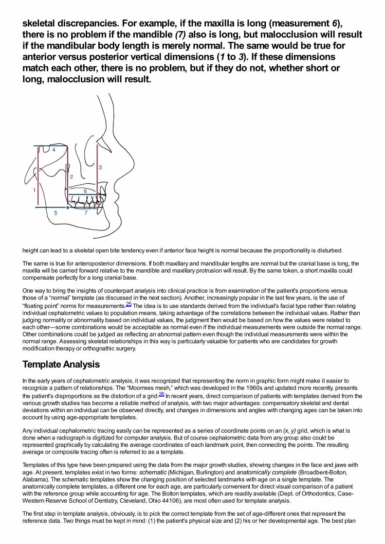
skeletal discrepancies. For example, if the maxilla is long (measurement 6),there is no problem if the mandible (7) also is long, but malocclusion will resultif the mandibular body length is merely normal. The same would be true foranterior versus posterior vertical dimensions (1 to 3). If these dimensionsmatch each other, there is no problem, but if they do not, whether short orlong, malocclusion will result.
height can lead to a skeletal open bite tendency even if anterior face height is normal because the proportionality is disturbed.
The same is true for anteroposterior dimensions. If both maxillary and mandibular lengths are normal but the cranial base is long, themaxilla will be carried forward relative to the mandible and maxillary protrusion will result. By the same token, a short maxilla couldcompensate perfectly for a long cranial base.
One way to bring the insights of counterpart analysis into clinical practice is from examination of the patient's proportions versusthose of a “normal” template (as discussed in the next section). Another, increasingly popular in the last few years, is the use of“floating point” norms for measurements.25 The idea is to use standards derived from the individual's facial type rather than relatingindividual cephalometric values to population means, taking advantage of the correlations between the individual values. Rather thanjudging normality or abnormality based on individual values, the judgment then would be based on how the values were related toeach other—some combinations would be acceptable as normal even if the individual measurements were outside the normal range.Other combinations could be judged as reflecting an abnormal pattern even though the individual measurements were within thenormal range. Assessing skeletal relationships in this way is particularly valuable for patients who are candidates for growthmodification therapy or orthognathic surgery.
Template AnalysisIn the early years of cephalometric analysis, it was recognized that representing the norm in graphic form might make it easier torecognize a pattern of relationships. The “Moorrees mesh,” which was developed in the 1960s and updated more recently, presentsthe patient's disproportions as the distortion of a grid.26 In recent years, direct comparison of patients with templates derived from thevarious growth studies has become a reliable method of analysis, with two major advantages: compensatory skeletal and dentaldeviations within an individual can be observed directly, and changes in dimensions and angles with changing ages can be taken intoaccount by using age-appropriate templates.
Any individual cephalometric tracing easily can be represented as a series of coordinate points on an (x, y) grid, which is what isdone when a radiograph is digitized for computer analysis. But of course cephalometric data from any group also could berepresented graphically by calculating the average coordinates of each landmark point, then connecting the points. The resultingaverage or composite tracing often is referred to as a template.
Templates of this type have been prepared using the data from the major growth studies, showing changes in the face and jaws withage. At present, templates exist in two forms: schematic (Michigan, Burlington) and anatomically complete (Broadbent-Bolton,Alabama). The schematic templates show the changing position of selected landmarks with age on a single template. Theanatomically complete templates, a different one for each age, are particularly convenient for direct visual comparison of a patientwith the reference group while accounting for age. The Bolton templates, which are readily available (Dept. of Orthodontics, Case-Western Reserve School of Dentistry, Cleveland, Ohio 44106), are most often used for template analysis.
The first step in template analysis, obviously, is to pick the correct template from the set of age-different ones that represent thereference data. Two things must be kept in mind: (1) the patient's physical size and (2) his or her developmental age. The best plan
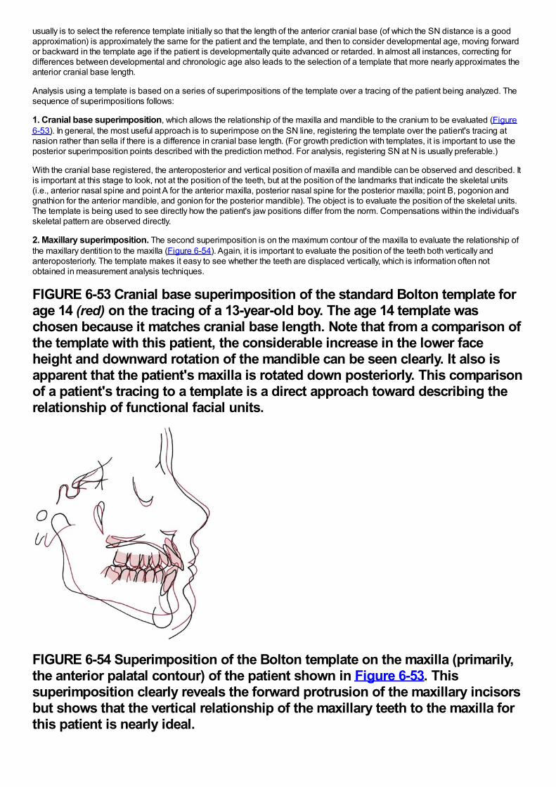
usually is to select the reference template initially so that the length of the anterior cranial base (of which the SN distance is a goodapproximation) is approximately the same for the patient and the template, and then to consider developmental age, moving forwardor backward in the template age if the patient is developmentally quite advanced or retarded. In almost all instances, correcting fordifferences between developmental and chronologic age also leads to the selection of a template that more nearly approximates theanterior cranial base length.
Analysis using a template is based on a series of superimpositions of the template over a tracing of the patient being analyzed. Thesequence of superimpositions follows:
1. Cranial base superimposition, which allows the relationship of the maxilla and mandible to the cranium to be evaluated (Figure6-53). In general, the most useful approach is to superimpose on the SN line, registering the template over the patient's tracing atnasion rather than sella if there is a difference in cranial base length. (For growth prediction with templates, it is important to use theposterior superimposition points described with the prediction method. For analysis, registering SN at N is usually preferable.)
With the cranial base registered, the anteroposterior and vertical position of maxilla and mandible can be observed and described. Itis important at this stage to look, not at the position of the teeth, but at the position of the landmarks that indicate the skeletal units(i.e., anterior nasal spine and point A for the anterior maxilla, posterior nasal spine for the posterior maxilla; point B, pogonion andgnathion for the anterior mandible, and gonion for the posterior mandible). The object is to evaluate the position of the skeletal units.The template is being used to see directly how the patient's jaw positions differ from the norm. Compensations within the individual'sskeletal pattern are observed directly.
2. Maxillary superimposition. The second superimposition is on the maximum contour of the maxilla to evaluate the relationship ofthe maxillary dentition to the maxilla (Figure 6-54). Again, it is important to evaluate the position of the teeth both vertically andanteroposteriorly. The template makes it easy to see whether the teeth are displaced vertically, which is information often notobtained in measurement analysis techniques.
FIGURE 6-53 Cranial base superimposition of the standard Bolton template forage 14 (red) on the tracing of a 13-year-old boy. The age 14 template waschosen because it matches cranial base length. Note that from a comparison ofthe template with this patient, the considerable increase in the lower faceheight and downward rotation of the mandible can be seen clearly. It also isapparent that the patient's maxilla is rotated down posteriorly. This comparisonof a patient's tracing to a template is a direct approach toward describing therelationship of functional facial units.
FIGURE 6-54 Superimposition of the Bolton template on the maxilla (primarily,the anterior palatal contour) of the patient shown in Figure 6-53. Thissuperimposition clearly reveals the forward protrusion of the maxillary incisorsbut shows that the vertical relationship of the maxillary teeth to the maxilla forthis patient is nearly ideal.
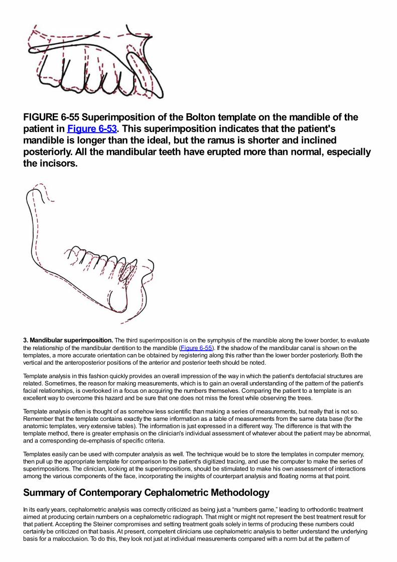
FIGURE 6-55 Superimposition of the Bolton template on the mandible of thepatient in Figure 6-53. This superimposition indicates that the patient'smandible is longer than the ideal, but the ramus is shorter and inclinedposteriorly. All the mandibular teeth have erupted more than normal, especiallythe incisors.
3. Mandibular superimposition. The third superimposition is on the symphysis of the mandible along the lower border, to evaluatethe relationship of the mandibular dentition to the mandible (Figure 6-55). If the shadow of the mandibular canal is shown on thetemplates, a more accurate orientation can be obtained by registering along this rather than the lower border posteriorly. Both thevertical and the anteroposterior positions of the anterior and posterior teeth should be noted.
Template analysis in this fashion quickly provides an overall impression of the way in which the patient's dentofacial structures arerelated. Sometimes, the reason for making measurements, which is to gain an overall understanding of the pattern of the patient'sfacial relationships, is overlooked in a focus on acquiring the numbers themselves. Comparing the patient to a template is anexcellent way to overcome this hazard and be sure that one does not miss the forest while observing the trees.
Template analysis often is thought of as somehow less scientific than making a series of measurements, but really that is not so.Remember that the template contains exactly the same information as a table of measurements from the same data base (for theanatomic templates, very extensive tables). The information is just expressed in a different way. The difference is that with thetemplate method, there is greater emphasis on the clinician's individual assessment of whatever about the patient may be abnormal,and a corresponding de-emphasis of specific criteria.
Templates easily can be used with computer analysis as well. The technique would be to store the templates in computer memory,then pull up the appropriate template for comparison to the patient's digitized tracing, and use the computer to make the series ofsuperimpositions. The clinician, looking at the superimpositions, should be stimulated to make his own assessment of interactionsamong the various components of the face, incorporating the insights of counterpart analysis and floating norms at that point.
Summary of Contemporary Cephalometric MethodologyIn its early years, cephalometric analysis was correctly criticized as being just a “numbers game,” leading to orthodontic treatmentaimed at producing certain numbers on a cephalometric radiograph. That might or might not represent the best treatment result forthat patient. Accepting the Steiner compromises and setting treatment goals solely in terms of producing these numbers couldcertainly be criticized on that basis. At present, competent clinicians use cephalometric analysis to better understand the underlyingbasis for a malocclusion. To do this, they look not just at individual measurements compared with a norm but at the pattern of
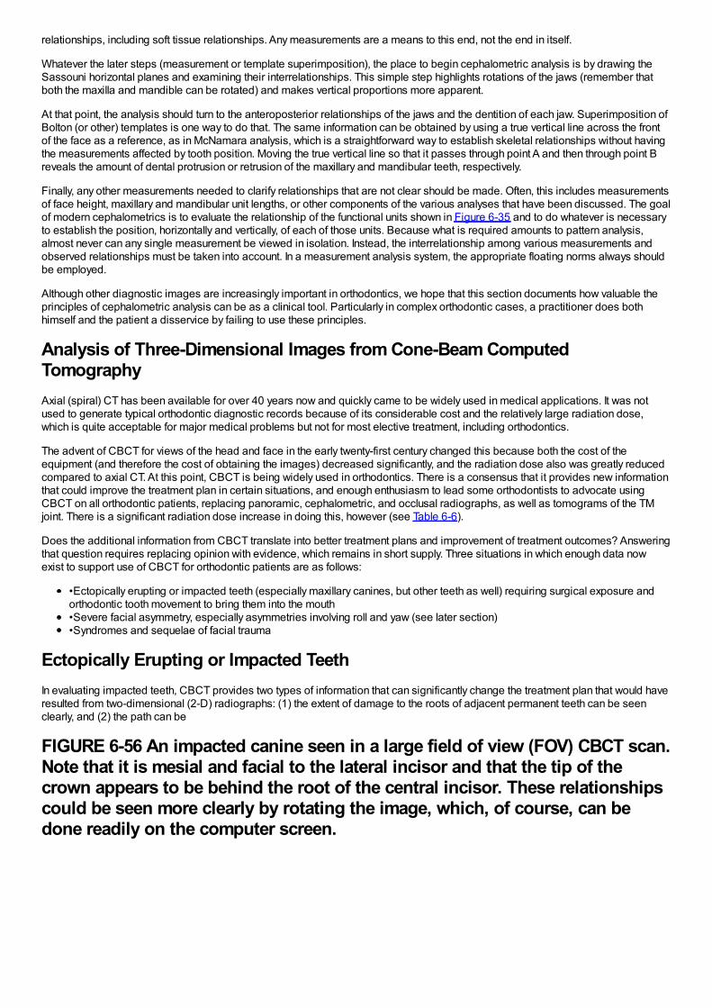
relationships, including soft tissue relationships. Any measurements are a means to this end, not the end in itself.
Whatever the later steps (measurement or template superimposition), the place to begin cephalometric analysis is by drawing theSassouni horizontal planes and examining their interrelationships. This simple step highlights rotations of the jaws (remember thatboth the maxilla and mandible can be rotated) and makes vertical proportions more apparent.
At that point, the analysis should turn to the anteroposterior relationships of the jaws and the dentition of each jaw. Superimposition ofBolton (or other) templates is one way to do that. The same information can be obtained by using a true vertical line across the frontof the face as a reference, as in McNamara analysis, which is a straightforward way to establish skeletal relationships without havingthe measurements affected by tooth position. Moving the true vertical line so that it passes through point A and then through point Breveals the amount of dental protrusion or retrusion of the maxillary and mandibular teeth, respectively.
Finally, any other measurements needed to clarify relationships that are not clear should be made. Often, this includes measurementsof face height, maxillary and mandibular unit lengths, or other components of the various analyses that have been discussed. The goalof modern cephalometrics is to evaluate the relationship of the functional units shown in Figure 6-35 and to do whatever is necessaryto establish the position, horizontally and vertically, of each of those units. Because what is required amounts to pattern analysis,almost never can any single measurement be viewed in isolation. Instead, the interrelationship among various measurements andobserved relationships must be taken into account. In a measurement analysis system, the appropriate floating norms always shouldbe employed.
Although other diagnostic images are increasingly important in orthodontics, we hope that this section documents how valuable theprinciples of cephalometric analysis can be as a clinical tool. Particularly in complex orthodontic cases, a practitioner does bothhimself and the patient a disservice by failing to use these principles.
Analysis of Three-Dimensional Images from Cone-Beam ComputedTomographyAxial (spiral) CT has been available for over 40 years now and quickly came to be widely used in medical applications. It was notused to generate typical orthodontic diagnostic records because of its considerable cost and the relatively large radiation dose,which is quite acceptable for major medical problems but not for most elective treatment, including orthodontics.
The advent of CBCT for views of the head and face in the early twenty-first century changed this because both the cost of theequipment (and therefore the cost of obtaining the images) decreased significantly, and the radiation dose also was greatly reducedcompared to axial CT. At this point, CBCT is being widely used in orthodontics. There is a consensus that it provides new informationthat could improve the treatment plan in certain situations, and enough enthusiasm to lead some orthodontists to advocate usingCBCT on all orthodontic patients, replacing panoramic, cephalometric, and occlusal radiographs, as well as tomograms of the TMjoint. There is a significant radiation dose increase in doing this, however (see Table 6-6).
Does the additional information from CBCT translate into better treatment plans and improvement of treatment outcomes? Answeringthat question requires replacing opinion with evidence, which remains in short supply. Three situations in which enough data nowexist to support use of CBCT for orthodontic patients are as follows:
•Ectopically erupting or impacted teeth (especially maxillary canines, but other teeth as well) requiring surgical exposure andorthodontic tooth movement to bring them into the mouth•Severe facial asymmetry, especially asymmetries involving roll and yaw (see later section)•Syndromes and sequelae of facial trauma
Ectopically Erupting or Impacted TeethIn evaluating impacted teeth, CBCT provides two types of information that can significantly change the treatment plan that would haveresulted from two-dimensional (2-D) radiographs: (1) the extent of damage to the roots of adjacent permanent teeth can be seenclearly, and (2) the path can be
FIGURE 6-56 An impacted canine seen in a large field of view (FOV) CBCT scan.Note that it is mesial and facial to the lateral incisor and that the tip of thecrown appears to be behind the root of the central incisor. These relationshipscould be seen more clearly by rotating the image, which, of course, can bedone readily on the computer screen.

defined along which it should be moved to bring it into the mouth most efficiently and with the least further damage to adjacentteeth.27 This allows adjustments such as bringing an impacted canine facially before beginning to bring it toward the occlusal plane,in order to avoid the remaining root of a damaged lateral incisor (Figure 6-56), and makes it possible for the surgeon to place anattachment on the tooth at the most favorable location for biomechanical advantage in moving it.
With CBCT, the radiation dose can be reduced in either or both of two ways: decreasing the size of the field of view (FOV), anddecreasing the scan time to produce the image (and therefore its resolution). If the main reason for a CBCT image is an impactedtooth, a small FOV and relatively low scan time are adequate to allow detailed evaluation of the tooth and the best path for bringing itinto the arch. The radiation dose then is relatively close to the dose from two periapical radiographs, which would have been theminimum 2-D radiographs required to localize the tooth, and the machine also is much less expensive than one with a FOV largeenough for images of the entire face. For dental family practice, a CBCT machine with a small FOV would be adequate for almost allapplications. For orthodontists, a larger FOV would be preferred so that both facial proportions and impacted teeth could beevaluated (Figure 6-57), but it would be desirable for the FOV to be adjustable, so that field size and scan time could be reducedwhen only an impacted tooth was the target. CBCT machines of this type now are available. For an orthodontic office, the alternativeto an
FIGURE 6-57 A series of images of an impacted canine, moving along the upperdental arch (top two rows) and from the occlusal plane upward (lower tworows). The relationship of the impacted tooth to both the bone around it andthe other teeth can be seen in detail at each level.
adjustable FOV is a “hybrid” machine that also incorporates a conventional cephalometric and panoramic unit. It would be used toreduce the radiation dose when only one of these views is needed.28
Facial AsymmetryUntil CBCT became readily available, the major indication for a frontal cephalometric radiograph was facial asymmetry. Even with theaddition of this image to the standard panoramic and lateral cephalometric views, evaluating asymmetry required extrapolationbetween the three images and was qualitative, not quantitative. With these three radiographs of a patient with an asymmetricmandible, one could see in the lateral cephalometric view that the ramus and mandibular body are longer on one side, in the
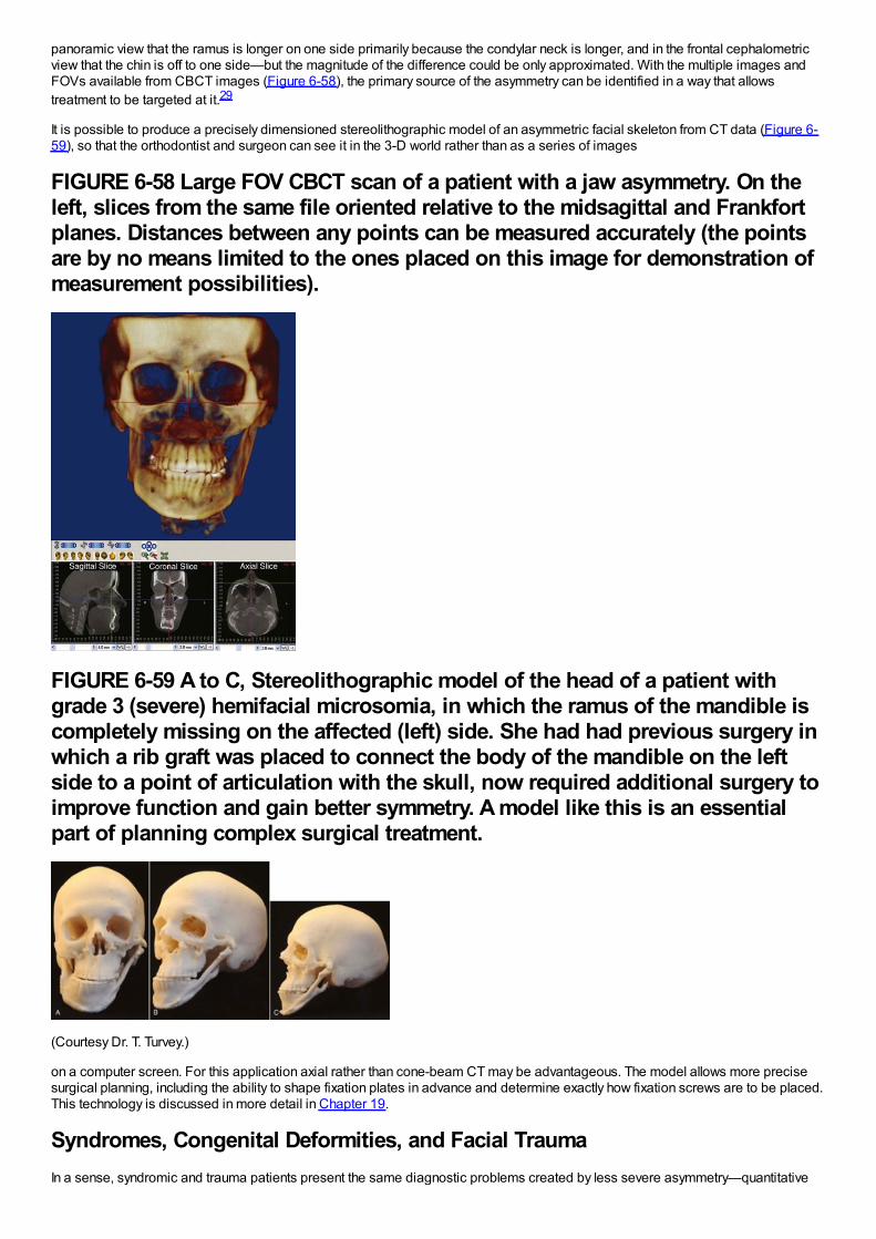
panoramic view that the ramus is longer on one side primarily because the condylar neck is longer, and in the frontal cephalometricview that the chin is off to one side—but the magnitude of the difference could be only approximated. With the multiple images andFOVs available from CBCT images (Figure 6-58), the primary source of the asymmetry can be identified in a way that allowstreatment to be targeted at it.29
It is possible to produce a precisely dimensioned stereolithographic model of an asymmetric facial skeleton from CT data (Figure 6-59), so that the orthodontist and surgeon can see it in the 3-D world rather than as a series of images
FIGURE 6-58 Large FOV CBCT scan of a patient with a jaw asymmetry. On theleft, slices from the same file oriented relative to the midsagittal and Frankfortplanes. Distances between any points can be measured accurately (the pointsare by no means limited to the ones placed on this image for demonstration ofmeasurement possibilities).
FIGURE 6-59 A to C, Stereolithographic model of the head of a patient withgrade 3 (severe) hemifacial microsomia, in which the ramus of the mandible iscompletely missing on the affected (left) side. She had had previous surgery inwhich a rib graft was placed to connect the body of the mandible on the leftside to a point of articulation with the skull, now required additional surgery toimprove function and gain better symmetry. A model like this is an essentialpart of planning complex surgical treatment.
(Courtesy Dr. T. Turvey.)
on a computer screen. For this application axial rather than cone-beam CT may be advantageous. The model allows more precisesurgical planning, including the ability to shape fixation plates in advance and determine exactly how fixation screws are to be placed.This technology is discussed in more detail in Chapter 19.
Syndromes, Congenital Deformities, and Facial TraumaIn a sense, syndromic and trauma patients present the same diagnostic problems created by less severe asymmetry—quantitative
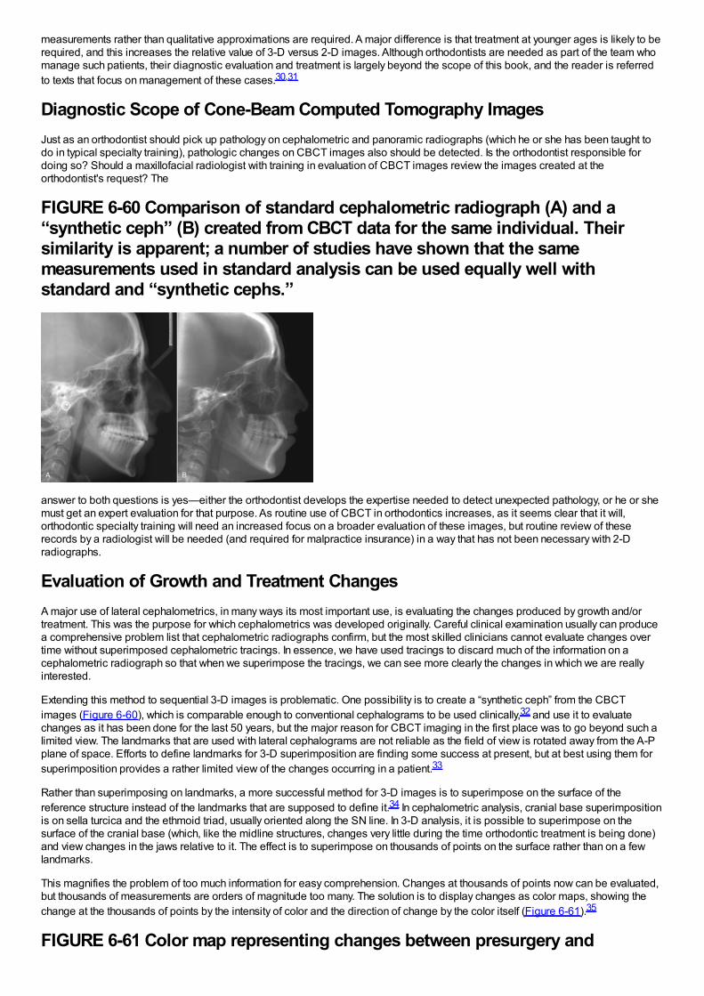
measurements rather than qualitative approximations are required. A major difference is that treatment at younger ages is likely to berequired, and this increases the relative value of 3-D versus 2-D images. Although orthodontists are needed as part of the team whomanage such patients, their diagnostic evaluation and treatment is largely beyond the scope of this book, and the reader is referredto texts that focus on management of these cases.30,31
Diagnostic Scope of Cone-Beam Computed Tomography ImagesJust as an orthodontist should pick up pathology on cephalometric and panoramic radiographs (which he or she has been taught todo in typical specialty training), pathologic changes on CBCT images also should be detected. Is the orthodontist responsible fordoing so? Should a maxillofacial radiologist with training in evaluation of CBCT images review the images created at theorthodontist's request? The
FIGURE 6-60 Comparison of standard cephalometric radiograph (A) and a“synthetic ceph” (B) created from CBCT data for the same individual. Theirsimilarity is apparent; a number of studies have shown that the samemeasurements used in standard analysis can be used equally well withstandard and “synthetic cephs.”
answer to both questions is yes—either the orthodontist develops the expertise needed to detect unexpected pathology, or he or shemust get an expert evaluation for that purpose. As routine use of CBCT in orthodontics increases, as it seems clear that it will,orthodontic specialty training will need an increased focus on a broader evaluation of these images, but routine review of theserecords by a radiologist will be needed (and required for malpractice insurance) in a way that has not been necessary with 2-Dradiographs.
Evaluation of Growth and Treatment ChangesA major use of lateral cephalometrics, in many ways its most important use, is evaluating the changes produced by growth and/ortreatment. This was the purpose for which cephalometrics was developed originally. Careful clinical examination usually can producea comprehensive problem list that cephalometric radiographs confirm, but the most skilled clinicians cannot evaluate changes overtime without superimposed cephalometric tracings. In essence, we have used tracings to discard much of the information on acephalometric radiograph so that when we superimpose the tracings, we can see more clearly the changes in which we are reallyinterested.
Extending this method to sequential 3-D images is problematic. One possibility is to create a “synthetic ceph” from the CBCTimages (Figure 6-60), which is comparable enough to conventional cephalograms to be used clinically,32 and use it to evaluatechanges as it has been done for the last 50 years, but the major reason for CBCT imaging in the first place was to go beyond such alimited view. The landmarks that are used with lateral cephalograms are not reliable as the field of view is rotated away from the A-Pplane of space. Efforts to define landmarks for 3-D superimposition are finding some success at present, but at best using them forsuperimposition provides a rather limited view of the changes occurring in a patient.33
Rather than superimposing on landmarks, a more successful method for 3-D images is to superimpose on the surface of thereference structure instead of the landmarks that are supposed to define it.34 In cephalometric analysis, cranial base superimpositionis on sella turcica and the ethmoid triad, usually oriented along the SN line. In 3-D analysis, it is possible to superimpose on thesurface of the cranial base (which, like the midline structures, changes very little during the time orthodontic treatment is being done)and view changes in the jaws relative to it. The effect is to superimpose on thousands of points on the surface rather than on a fewlandmarks.
This magnifies the problem of too much information for easy comprehension. Changes at thousands of points now can be evaluated,but thousands of measurements are orders of magnitude too many. The solution is to display changes as color maps, showing thechange at the thousands of points by the intensity of color and the direction of change by the color itself (Figure 6-61).35
FIGURE 6-61 Color map representing changes between presurgery and
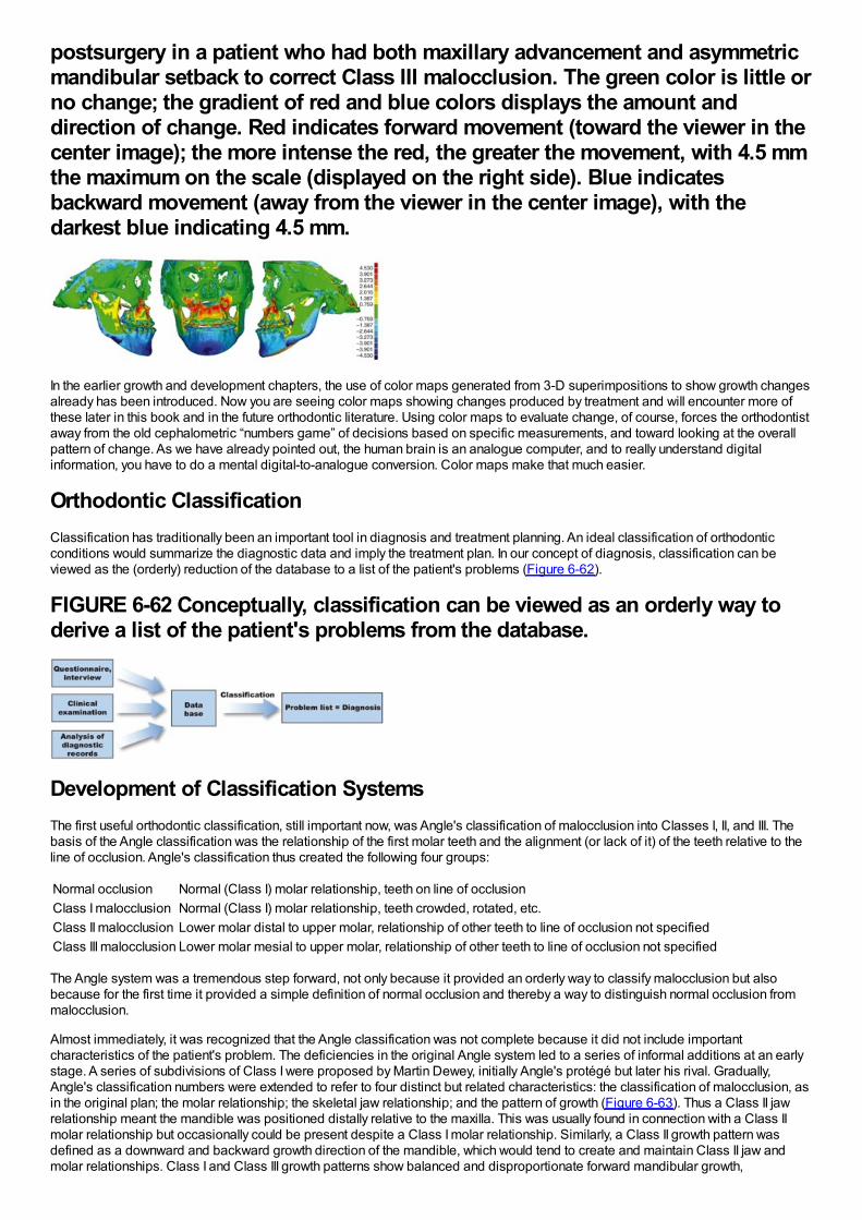
postsurgery in a patient who had both maxillary advancement and asymmetricmandibular setback to correct Class III malocclusion. The green color is little orno change; the gradient of red and blue colors displays the amount anddirection of change. Red indicates forward movement (toward the viewer in thecenter image); the more intense the red, the greater the movement, with 4.5 mmthe maximum on the scale (displayed on the right side). Blue indicatesbackward movement (away from the viewer in the center image), with thedarkest blue indicating 4.5 mm.
In the earlier growth and development chapters, the use of color maps generated from 3-D superimpositions to show growth changesalready has been introduced. Now you are seeing color maps showing changes produced by treatment and will encounter more ofthese later in this book and in the future orthodontic literature. Using color maps to evaluate change, of course, forces the orthodontistaway from the old cephalometric “numbers game” of decisions based on specific measurements, and toward looking at the overallpattern of change. As we have already pointed out, the human brain is an analogue computer, and to really understand digitalinformation, you have to do a mental digital-to-analogue conversion. Color maps make that much easier.
Orthodontic ClassificationClassification has traditionally been an important tool in diagnosis and treatment planning. An ideal classification of orthodonticconditions would summarize the diagnostic data and imply the treatment plan. In our concept of diagnosis, classification can beviewed as the (orderly) reduction of the database to a list of the patient's problems (Figure 6-62).
FIGURE 6-62 Conceptually, classification can be viewed as an orderly way toderive a list of the patient's problems from the database.
Development of Classification SystemsThe first useful orthodontic classification, still important now, was Angle's classification of malocclusion into Classes I, II, and III. Thebasis of the Angle classification was the relationship of the first molar teeth and the alignment (or lack of it) of the teeth relative to theline of occlusion. Angle's classification thus created the following four groups:
Normal occlusion Normal (Class I) molar relationship, teeth on line of occlusionClass I malocclusion Normal (Class I) molar relationship, teeth crowded, rotated, etc.Class II malocclusion Lower molar distal to upper molar, relationship of other teeth to line of occlusion not specifiedClass III malocclusion Lower molar mesial to upper molar, relationship of other teeth to line of occlusion not specified
The Angle system was a tremendous step forward, not only because it provided an orderly way to classify malocclusion but alsobecause for the first time it provided a simple definition of normal occlusion and thereby a way to distinguish normal occlusion frommalocclusion.
Almost immediately, it was recognized that the Angle classification was not complete because it did not include importantcharacteristics of the patient's problem. The deficiencies in the original Angle system led to a series of informal additions at an earlystage. A series of subdivisions of Class I were proposed by Martin Dewey, initially Angle's protégé but later his rival. Gradually,Angle's classification numbers were extended to refer to four distinct but related characteristics: the classification of malocclusion, asin the original plan; the molar relationship; the skeletal jaw relationship; and the pattern of growth (Figure 6-63). Thus a Class II jawrelationship meant the mandible was positioned distally relative to the maxilla. This was usually found in connection with a Class IImolar relationship but occasionally could be present despite a Class I molar relationship. Similarly, a Class II growth pattern wasdefined as a downward and backward growth direction of the mandible, which would tend to create and maintain Class II jaw andmolar relationships. Class I and Class III growth patterns show balanced and disproportionate forward mandibular growth,
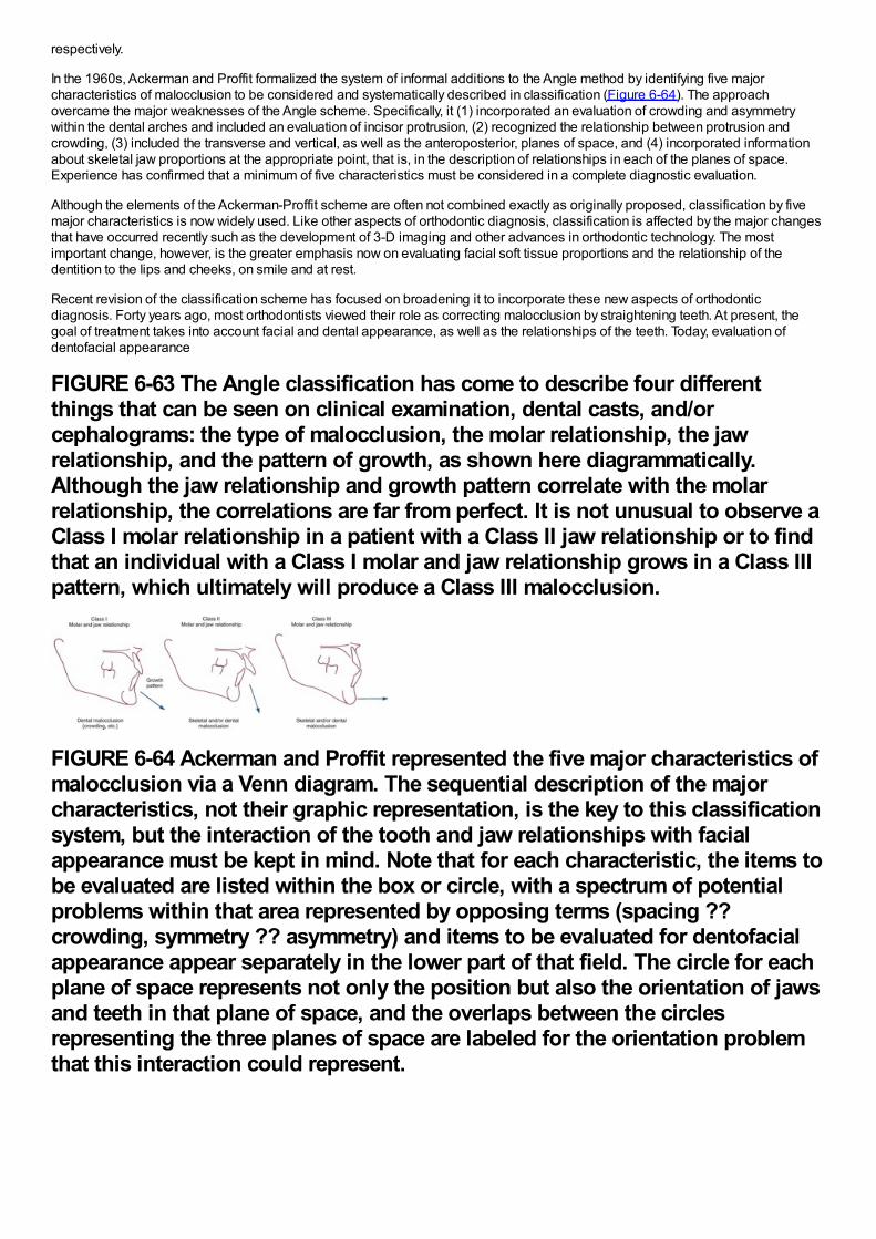
respectively.
In the 1960s, Ackerman and Proffit formalized the system of informal additions to the Angle method by identifying five majorcharacteristics of malocclusion to be considered and systematically described in classification (Figure 6-64). The approachovercame the major weaknesses of the Angle scheme. Specifically, it (1) incorporated an evaluation of crowding and asymmetrywithin the dental arches and included an evaluation of incisor protrusion, (2) recognized the relationship between protrusion andcrowding, (3) included the transverse and vertical, as well as the anteroposterior, planes of space, and (4) incorporated informationabout skeletal jaw proportions at the appropriate point, that is, in the description of relationships in each of the planes of space.Experience has confirmed that a minimum of five characteristics must be considered in a complete diagnostic evaluation.
Although the elements of the Ackerman-Proffit scheme are often not combined exactly as originally proposed, classification by fivemajor characteristics is now widely used. Like other aspects of orthodontic diagnosis, classification is affected by the major changesthat have occurred recently such as the development of 3-D imaging and other advances in orthodontic technology. The mostimportant change, however, is the greater emphasis now on evaluating facial soft tissue proportions and the relationship of thedentition to the lips and cheeks, on smile and at rest.
Recent revision of the classification scheme has focused on broadening it to incorporate these new aspects of orthodonticdiagnosis. Forty years ago, most orthodontists viewed their role as correcting malocclusion by straightening teeth. At present, thegoal of treatment takes into account facial and dental appearance, as well as the relationships of the teeth. Today, evaluation ofdentofacial appearance
FIGURE 6-63 The Angle classification has come to describe four differentthings that can be seen on clinical examination, dental casts, and/orcephalograms: the type of malocclusion, the molar relationship, the jawrelationship, and the pattern of growth, as shown here diagrammatically.Although the jaw relationship and growth pattern correlate with the molarrelationship, the correlations are far from perfect. It is not unusual to observe aClass I molar relationship in a patient with a Class II jaw relationship or to findthat an individual with a Class I molar and jaw relationship grows in a Class IIIpattern, which ultimately will produce a Class III malocclusion.
FIGURE 6-64 Ackerman and Proffit represented the five major characteristics ofmalocclusion via a Venn diagram. The sequential description of the majorcharacteristics, not their graphic representation, is the key to this classificationsystem, but the interaction of the tooth and jaw relationships with facialappearance must be kept in mind. Note that for each characteristic, the items tobe evaluated are listed within the box or circle, with a spectrum of potentialproblems within that area represented by opposing terms (spacing ??crowding, symmetry ?? asymmetry) and items to be evaluated for dentofacialappearance appear separately in the lower part of that field. The circle for eachplane of space represents not only the position but also the orientation of jawsand teeth in that plane of space, and the overlaps between the circlesrepresenting the three planes of space are labeled for the orientation problemthat this interaction could represent.
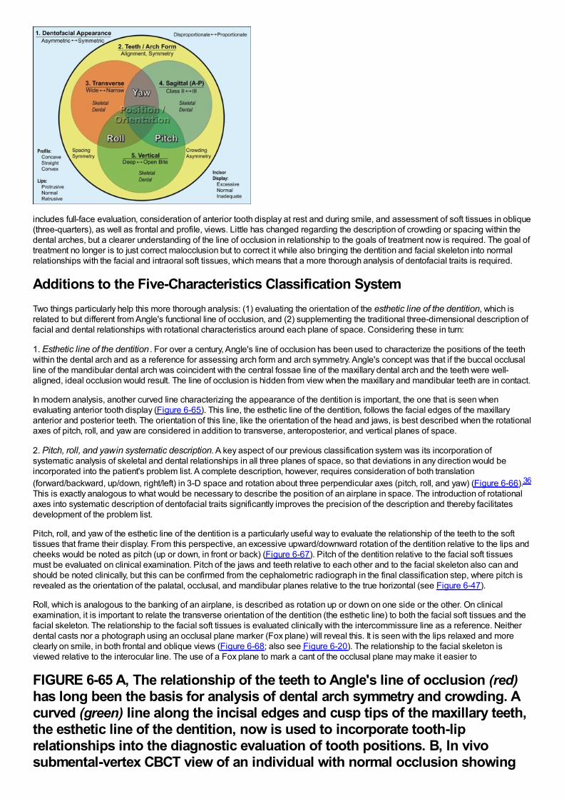
includes full-face evaluation, consideration of anterior tooth display at rest and during smile, and assessment of soft tissues in oblique(three-quarters), as well as frontal and profile, views. Little has changed regarding the description of crowding or spacing within thedental arches, but a clearer understanding of the line of occlusion in relationship to the goals of treatment now is required. The goal oftreatment no longer is to just correct malocclusion but to correct it while also bringing the dentition and facial skeleton into normalrelationships with the facial and intraoral soft tissues, which means that a more thorough analysis of dentofacial traits is required.
Additions to the Five-Characteristics Classification SystemTwo things particularly help this more thorough analysis: (1) evaluating the orientation of the esthetic line of the dentition, which isrelated to but different from Angle's functional line of occlusion, and (2) supplementing the traditional three-dimensional description offacial and dental relationships with rotational characteristics around each plane of space. Considering these in turn:
1. Esthetic line of the dentition . For over a century, Angle's line of occlusion has been used to characterize the positions of the teethwithin the dental arch and as a reference for assessing arch form and arch symmetry. Angle's concept was that if the buccal occlusalline of the mandibular dental arch was coincident with the central fossae line of the maxillary dental arch and the teeth were well-aligned, ideal occlusion would result. The line of occlusion is hidden from view when the maxillary and mandibular teeth are in contact.
In modern analysis, another curved line characterizing the appearance of the dentition is important, the one that is seen whenevaluating anterior tooth display (Figure 6-65). This line, the esthetic line of the dentition, follows the facial edges of the maxillaryanterior and posterior teeth. The orientation of this line, like the orientation of the head and jaws, is best described when the rotationalaxes of pitch, roll, and yaw are considered in addition to transverse, anteroposterior, and vertical planes of space.
2. Pitch, roll, and yaw in systematic description. A key aspect of our previous classification system was its incorporation ofsystematic analysis of skeletal and dental relationships in all three planes of space, so that deviations in any direction would beincorporated into the patient's problem list. A complete description, however, requires consideration of both translation(forward/backward, up/down, right/left) in 3-D space and rotation about three perpendicular axes (pitch, roll, and yaw) (Figure 6-66).36
This is exactly analogous to what would be necessary to describe the position of an airplane in space. The introduction of rotationalaxes into systematic description of dentofacial traits significantly improves the precision of the description and thereby facilitatesdevelopment of the problem list.
Pitch, roll, and yaw of the esthetic line of the dentition is a particularly useful way to evaluate the relationship of the teeth to the softtissues that frame their display. From this perspective, an excessive upward/downward rotation of the dentition relative to the lips andcheeks would be noted as pitch (up or down, in front or back) (Figure 6-67). Pitch of the dentition relative to the facial soft tissuesmust be evaluated on clinical examination. Pitch of the jaws and teeth relative to each other and to the facial skeleton also can andshould be noted clinically, but this can be confirmed from the cephalometric radiograph in the final classification step, where pitch isrevealed as the orientation of the palatal, occlusal, and mandibular planes relative to the true horizontal (see Figure 6-47).
Roll, which is analogous to the banking of an airplane, is described as rotation up or down on one side or the other. On clinicalexamination, it is important to relate the transverse orientation of the dentition (the esthetic line) to both the facial soft tissues and thefacial skeleton. The relationship to the facial soft tissues is evaluated clinically with the intercommissure line as a reference. Neitherdental casts nor a photograph using an occlusal plane marker (Fox plane) will reveal this. It is seen with the lips relaxed and moreclearly on smile, in both frontal and oblique views (Figure 6-68; also see Figure 6-20). The relationship to the facial skeleton isviewed relative to the interocular line. The use of a Fox plane to mark a cant of the occlusal plane may make it easier to
FIGURE 6-65 A, The relationship of the teeth to Angle's line of occlusion (red)has long been the basis for analysis of dental arch symmetry and crowding. Acurved (green) line along the incisal edges and cusp tips of the maxillary teeth,the esthetic line of the dentition, now is used to incorporate tooth-liprelationships into the diagnostic evaluation of tooth positions. B, In vivosubmental-vertex CBCT view of an individual with normal occlusion showing
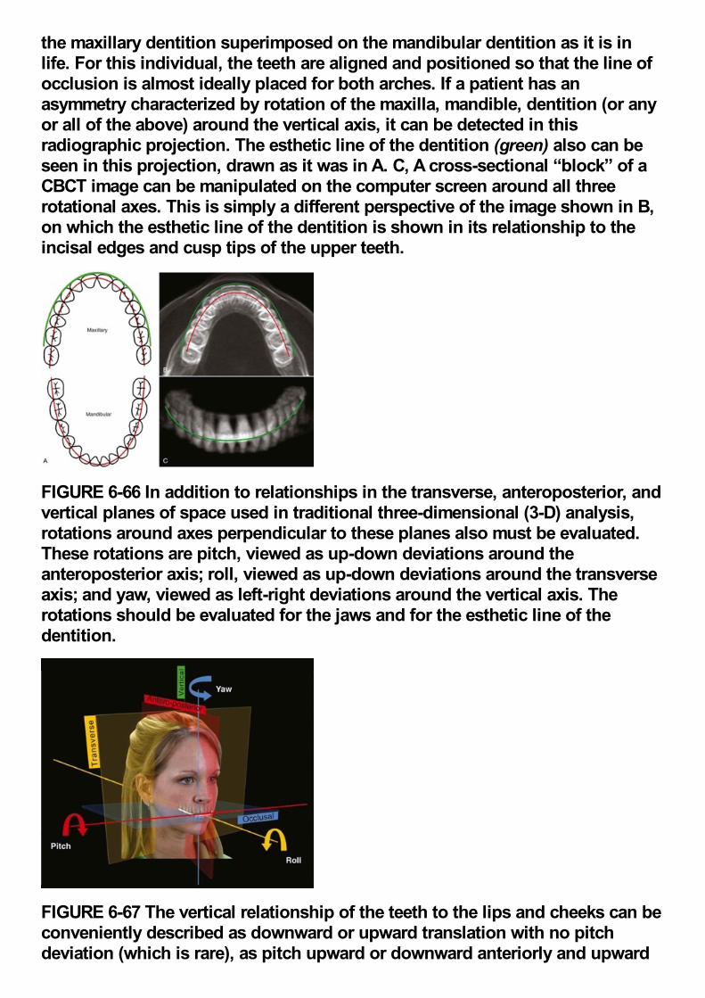
the maxillary dentition superimposed on the mandibular dentition as it is inlife. For this individual, the teeth are aligned and positioned so that the line ofocclusion is almost ideally placed for both arches. If a patient has anasymmetry characterized by rotation of the maxilla, mandible, dentition (or anyor all of the above) around the vertical axis, it can be detected in thisradiographic projection. The esthetic line of the dentition (green) also can beseen in this projection, drawn as it was in A. C, A cross-sectional “block” of aCBCT image can be manipulated on the computer screen around all threerotational axes. This is simply a different perspective of the image shown in B,on which the esthetic line of the dentition is shown in its relationship to theincisal edges and cusp tips of the upper teeth.
FIGURE 6-66 In addition to relationships in the transverse, anteroposterior, andvertical planes of space used in traditional three-dimensional (3-D) analysis,rotations around axes perpendicular to these planes also must be evaluated.These rotations are pitch, viewed as up-down deviations around theanteroposterior axis; roll, viewed as up-down deviations around the transverseaxis; and yaw, viewed as left-right deviations around the vertical axis. Therotations should be evaluated for the jaws and for the esthetic line of thedentition.
FIGURE 6-67 The vertical relationship of the teeth to the lips and cheeks can beconveniently described as downward or upward translation with no pitchdeviation (which is rare), as pitch upward or downward anteriorly and upward
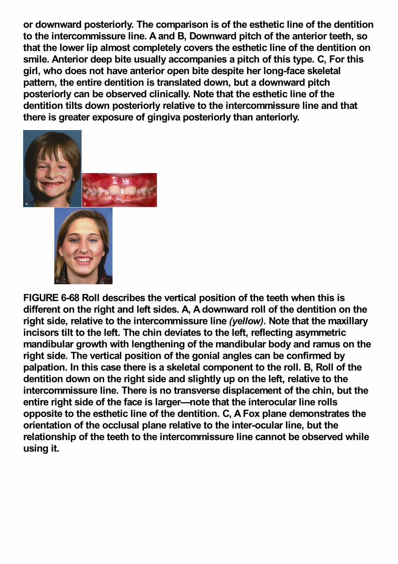
or downward posteriorly. The comparison is of the esthetic line of the dentitionto the intercommissure line. A and B, Downward pitch of the anterior teeth, sothat the lower lip almost completely covers the esthetic line of the dentition onsmile. Anterior deep bite usually accompanies a pitch of this type. C, For thisgirl, who does not have anterior open bite despite her long-face skeletalpattern, the entire dentition is translated down, but a downward pitchposteriorly can be observed clinically. Note that the esthetic line of thedentition tilts down posteriorly relative to the intercommissure line and thatthere is greater exposure of gingiva posteriorly than anteriorly.
FIGURE 6-68 Roll describes the vertical position of the teeth when this isdifferent on the right and left sides. A, A downward roll of the dentition on theright side, relative to the intercommissure line (yellow). Note that the maxillaryincisors tilt to the left. The chin deviates to the left, reflecting asymmetricmandibular growth with lengthening of the mandibular body and ramus on theright side. The vertical position of the gonial angles can be confirmed bypalpation. In this case there is a skeletal component to the roll. B, Roll of thedentition down on the right side and slightly up on the left, relative to theintercommissure line. There is no transverse displacement of the chin, but theentire right side of the face is larger—note that the interocular line rollsopposite to the esthetic line of the dentition. C, A Fox plane demonstrates theorientation of the occlusal plane relative to the inter-ocular line, but therelationship of the teeth to the intercommissure line cannot be observed whileusing it.
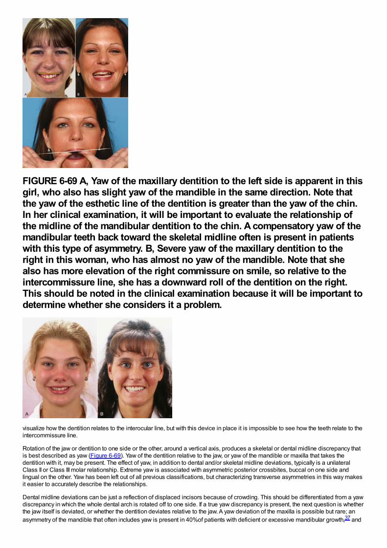
FIGURE 6-69 A, Yaw of the maxillary dentition to the left side is apparent in thisgirl, who also has slight yaw of the mandible in the same direction. Note thatthe yaw of the esthetic line of the dentition is greater than the yaw of the chin.In her clinical examination, it will be important to evaluate the relationship ofthe midline of the mandibular dentition to the chin. A compensatory yaw of themandibular teeth back toward the skeletal midline often is present in patientswith this type of asymmetry. B, Severe yaw of the maxillary dentition to theright in this woman, who has almost no yaw of the mandible. Note that shealso has more elevation of the right commissure on smile, so relative to theintercommissure line, she has a downward roll of the dentition on the right.This should be noted in the clinical examination because it will be important todetermine whether she considers it a problem.
visualize how the dentition relates to the interocular line, but with this device in place it is impossible to see how the teeth relate to theintercommissure line.
Rotation of the jaw or dentition to one side or the other, around a vertical axis, produces a skeletal or dental midline discrepancy thatis best described as yaw (Figure 6-69). Yaw of the dentition relative to the jaw, or yaw of the mandible or maxilla that takes thedentition with it, may be present. The effect of yaw, in addition to dental and/or skeletal midline deviations, typically is a unilateralClass II or Class III molar relationship. Extreme yaw is associated with asymmetric posterior crossbites, buccal on one side andlingual on the other. Yaw has been left out of all previous classifications, but characterizing transverse asymmetries in this way makesit easier to accurately describe the relationships.
Dental midline deviations can be just a reflection of displaced incisors because of crowding. This should be differentiated from a yawdiscrepancy in which the whole dental arch is rotated off to one side. If a true yaw discrepancy is present, the next question is whetherthe jaw itself is deviated, or whether the dentition deviates relative to the jaw. A yaw deviation of the maxilla is possible but rare; anasymmetry of the mandible that often includes yaw is present in 40%of patients with deficient or excessive mandibular growth,37 and
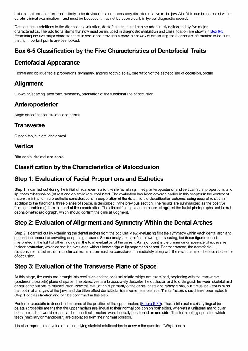
in these patients the dentition is likely to be deviated in a compensatory direction relative to the jaw. All of this can be detected with acareful clinical examination—and must be because it may not be seen clearly in typical diagnostic records.
Despite these additions to the diagnostic evaluation, dentofacial traits still can be adequately delineated by five majorcharacteristics. The additional items that now must be included in diagnostic evaluation and classification are shown in Box 6-5.Examining the five major characteristics in sequence provides a convenient way of organizing the diagnostic information to be surethat no important points are overlooked.
Box 6-5 Classification by the Five Characteristics of Dentofacial Traits
Dentofacial AppearanceFrontal and oblique facial proportions, symmetry, anterior tooth display, orientation of the esthetic line of occlusion, profile
AlignmentCrowding/spacing, arch form, symmetry, orientation of the functional line of occlusion
AnteroposteriorAngle classification, skeletal and dental
TransverseCrossbites, skeletal and dental
VerticalBite depth, skeletal and dental
Classification by the Characteristics of Malocclusion
Step 1: Evaluation of Facial Proportions and EstheticsStep 1 is carried out during the initial clinical examination, while facial asymmetry, anteroposterior and vertical facial proportions, andlip–tooth relationships (at rest and on smile) are evaluated. The evaluation has been covered earlier in this chapter in the context ofmacro-, mini- and micro-esthetic considerations. Incorporation of the data into the classification scheme, using axes of rotation inaddition to the traditional three planes of space, is described in the previous section. The results are summarized as the positivefindings (problems) from this part of the examination. The clinical findings can be checked against the facial photographs and lateralcephalometric radiograph, which should confirm the clinical judgment.
Step 2: Evaluation of Alignment and Symmetry Within the Dental ArchesStep 2 is carried out by examining the dental arches from the occlusal view, evaluating first the symmetry within each dental arch andsecond the amount of crowding or spacing present. Space analysis quantifies crowding or spacing, but these figures must beinterpreted in the light of other findings in the total evaluation of the patient. A major point is the presence or absence of excessiveincisor protrusion, which cannot be evaluated without knowledge of lip separation at rest. For that reason, the dentofacialrelationships noted in the initial clinical examination must be considered immediately along with the relationship of the teeth to the lineof occlusion.
Step 3: Evaluation of the Transverse Plane of SpaceAt this stage, the casts are brought into occlusion and the occlusal relationships are examined, beginning with the transverse(posterior crossbite) plane of space. The objectives are to accurately describe the occlusion and to distinguish between skeletal anddental contributions to malocclusion. Now the evaluation is primarily of the dental casts and radiographs, but it must be kept in mindthat both roll and yaw of the jaws and dentition affect dentofacial transverse relationships. These factors should have been noted inStep 1 of classification and can be confirmed in this step.
Posterior crossbite is described in terms of the position of the upper molars (Figure 6-70). Thus a bilateral maxillary lingual (orpalatal) crossbite means that the upper molars are lingual to their normal position on both sides, whereas a unilateral mandibularbuccal crossbite would mean that the mandibular molars were buccally positioned on one side. This terminology specifies whichteeth (maxillary or mandibular) are displaced from their normal position.
It is also important to evaluate the underlying skeletal relationships to answer the question, “Why does this
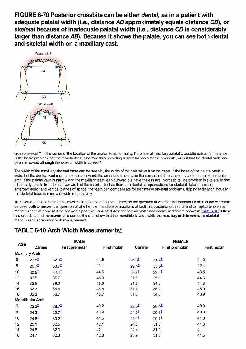
FIGURE 6-70 Posterior crossbite can be either dental, as in a patient withadequate palatal width (i.e., distance AB approximately equals distance CD), orskeletal because of inadequate palatal width (i.e., distance CD is considerablylarger than distance AB). Because it shows the palate, you can see both dentaland skeletal width on a maxillary cast.
crossbite exist?” in the sense of the location of the anatomic abnormality. If a bilateral maxillary palatal crossbite exists, for instance,is the basic problem that the maxilla itself is narrow, thus providing a skeletal basis for the crossbite, or is it that the dental arch hasbeen narrowed although the skeletal width is correct?
The width of the maxillary skeletal base can be seen by the width of the palatal vault on the casts. If the base of the palatal vault iswide, but the dentoalveolar processes lean inward, the crossbite is dental in the sense that it is caused by a distortion of the dentalarch. If the palatal vault is narrow and the maxillary teeth lean outward but nevertheless are in crossbite, the problem is skeletal in thatit basically results from the narrow width of the maxilla. Just as there are dental compensations for skeletal deformity in theanteroposterior and vertical planes of space, the teeth can compensate for transverse skeletal problems, tipping facially or lingually ifthe skeletal base is narrow or wide respectively.
Transverse displacement of the lower molars on the mandible is rare, so the question of whether the mandibular arch is too wide canbe used both to answer the question of whether the mandible or maxilla is at fault in a posterior crossbite and to implicate skeletalmandibular development if the answer is positive. Tabulated data for normal molar and canine widths are shown in Table 6-10. If thereis a crossbite and measurements across the arch show that the mandible is wide while the maxillary arch is normal, a skeletalmandibular discrepancy probably is present.
TABLE 6-10 Arch Width Measurements*
AGEMALE FEMALE
Canine First premolar First molar Canine First premolar First molarMaxillary Arch 6 27.5† 32.3† 41.9 26.9† 31.7† 41.3 8 29.7† 33.7† 43.1 29.1† 33.0† 42.410 30.5† 34.4† 44.5 29.8† 33.6† 43.512 32.5 35.7 45.3 31.5 35.1 44.614 32.5 36.0 45.9 31.3 34.9 44.316 32.3 36.6 46.6 31.4 35.2 45.018 32.3 36.7 46.7 31.2 34.6 43.9Mandibular Arch 6 23.3† 28.7† 40.2 22.2† 28.4† 40.0 8 24.3† 29.7† 40.9 24.0† 29.5† 40.310 24.6† 30.2† 41.5 24.1† 29.7† 41.012 25.1 32.5 42.1 24.8 31.6 41.814 24.8 32.3 42.1 24.4 31.0 41.116 24.7 32.3 42.8 23.9 31.0 41.5
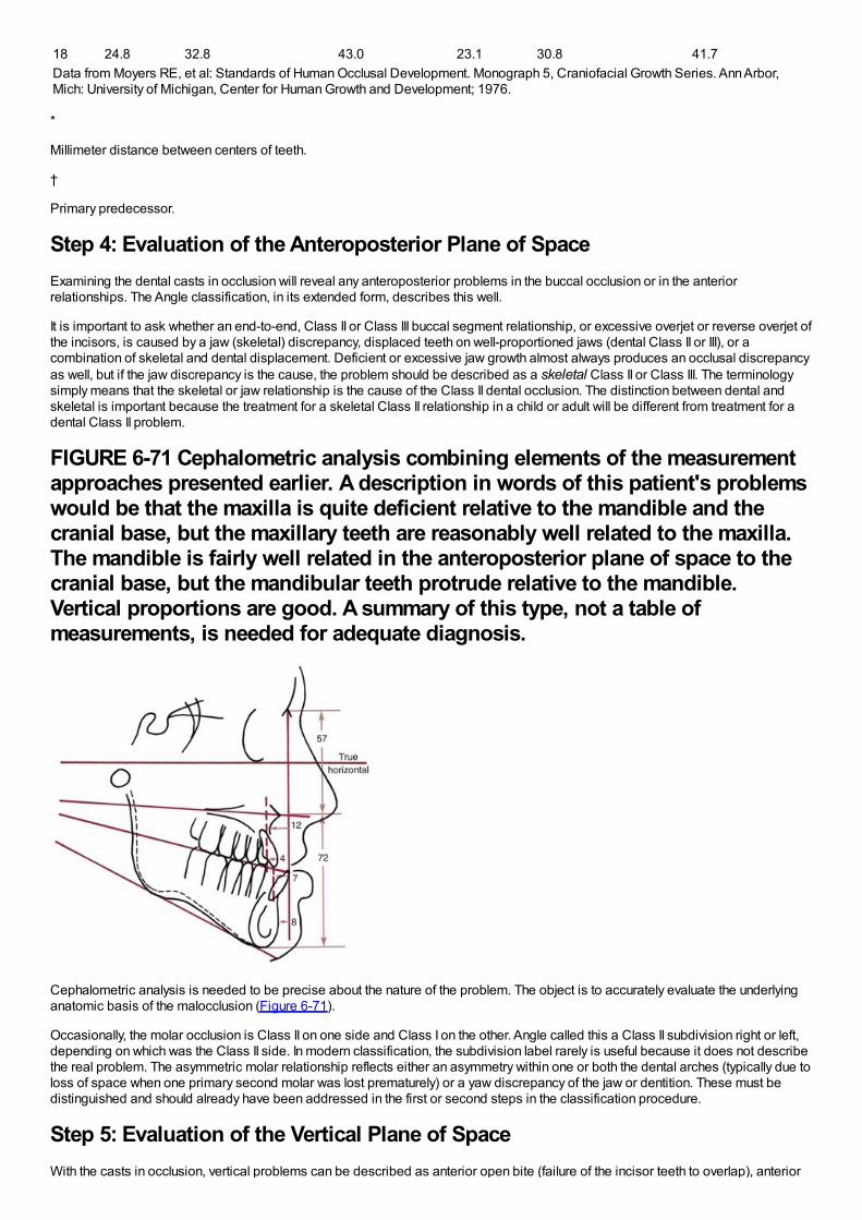
16 24.7 32.3 42.8 23.9 31.0 41.518 24.8 32.8 43.0 23.1 30.8 41.7Data from Moyers RE, et al: Standards of Human Occlusal Development. Monograph 5, Craniofacial Growth Series. Ann Arbor,Mich: University of Michigan, Center for Human Growth and Development; 1976.
*
Millimeter distance between centers of teeth.
†
Primary predecessor.
Step 4: Evaluation of the Anteroposterior Plane of SpaceExamining the dental casts in occlusion will reveal any anteroposterior problems in the buccal occlusion or in the anteriorrelationships. The Angle classification, in its extended form, describes this well.
It is important to ask whether an end-to-end, Class II or Class III buccal segment relationship, or excessive overjet or reverse overjet ofthe incisors, is caused by a jaw (skeletal) discrepancy, displaced teeth on well-proportioned jaws (dental Class II or III), or acombination of skeletal and dental displacement. Deficient or excessive jaw growth almost always produces an occlusal discrepancyas well, but if the jaw discrepancy is the cause, the problem should be described as a skeletal Class II or Class III. The terminologysimply means that the skeletal or jaw relationship is the cause of the Class II dental occlusion. The distinction between dental andskeletal is important because the treatment for a skeletal Class II relationship in a child or adult will be different from treatment for adental Class II problem.
FIGURE 6-71 Cephalometric analysis combining elements of the measurementapproaches presented earlier. A description in words of this patient's problemswould be that the maxilla is quite deficient relative to the mandible and thecranial base, but the maxillary teeth are reasonably well related to the maxilla.The mandible is fairly well related in the anteroposterior plane of space to thecranial base, but the mandibular teeth protrude relative to the mandible.Vertical proportions are good. A summary of this type, not a table ofmeasurements, is needed for adequate diagnosis.
Cephalometric analysis is needed to be precise about the nature of the problem. The object is to accurately evaluate the underlyinganatomic basis of the malocclusion (Figure 6-71).
Occasionally, the molar occlusion is Class II on one side and Class I on the other. Angle called this a Class II subdivision right or left,depending on which was the Class II side. In modern classification, the subdivision label rarely is useful because it does not describethe real problem. The asymmetric molar relationship reflects either an asymmetry within one or both the dental arches (typically due toloss of space when one primary second molar was lost prematurely) or a yaw discrepancy of the jaw or dentition. These must bedistinguished and should already have been addressed in the first or second steps in the classification procedure.
Step 5: Evaluation of the Vertical Plane of SpaceWith the casts in occlusion, vertical problems can be described as anterior open bite (failure of the incisor teeth to overlap), anterior
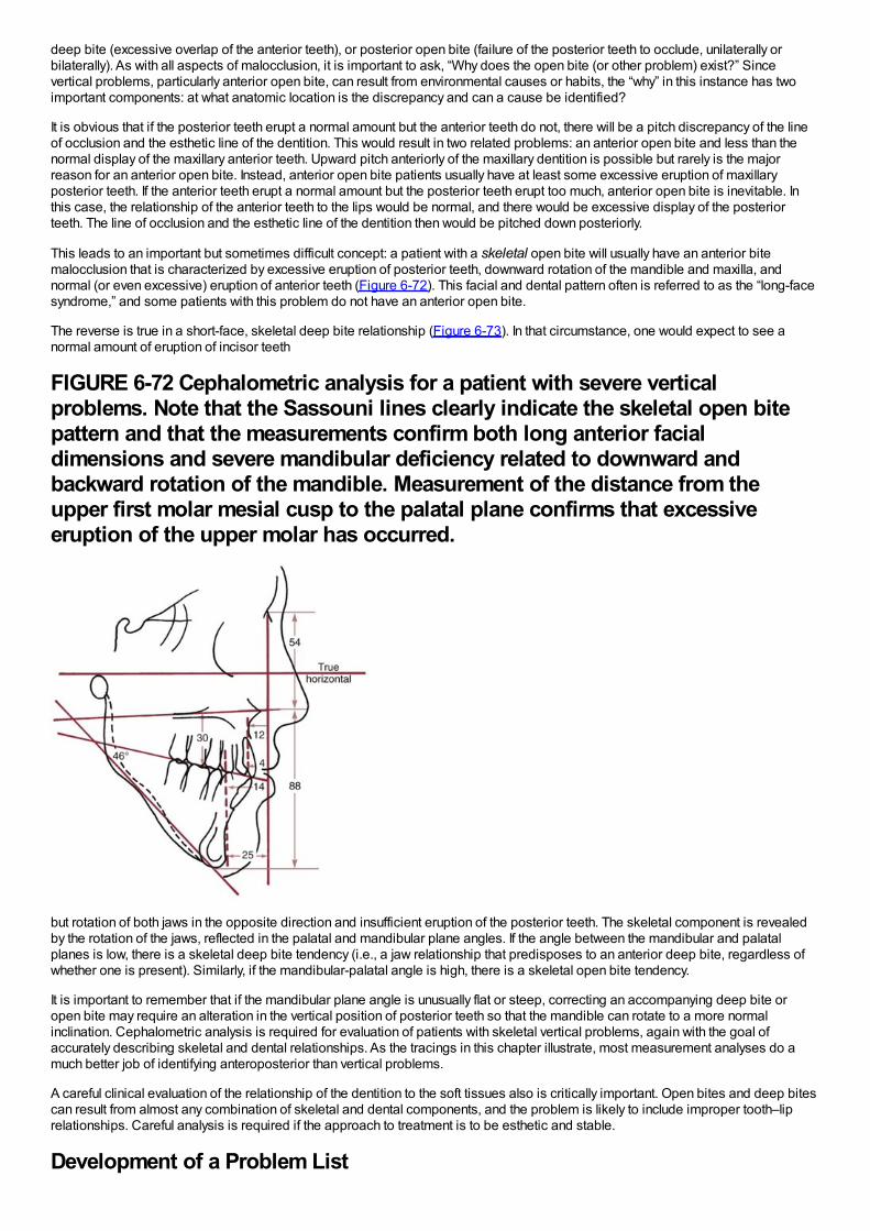
deep bite (excessive overlap of the anterior teeth), or posterior open bite (failure of the posterior teeth to occlude, unilaterally orbilaterally). As with all aspects of malocclusion, it is important to ask, “Why does the open bite (or other problem) exist?” Sincevertical problems, particularly anterior open bite, can result from environmental causes or habits, the “why” in this instance has twoimportant components: at what anatomic location is the discrepancy and can a cause be identified?
It is obvious that if the posterior teeth erupt a normal amount but the anterior teeth do not, there will be a pitch discrepancy of the lineof occlusion and the esthetic line of the dentition. This would result in two related problems: an anterior open bite and less than thenormal display of the maxillary anterior teeth. Upward pitch anteriorly of the maxillary dentition is possible but rarely is the majorreason for an anterior open bite. Instead, anterior open bite patients usually have at least some excessive eruption of maxillaryposterior teeth. If the anterior teeth erupt a normal amount but the posterior teeth erupt too much, anterior open bite is inevitable. Inthis case, the relationship of the anterior teeth to the lips would be normal, and there would be excessive display of the posteriorteeth. The line of occlusion and the esthetic line of the dentition then would be pitched down posteriorly.
This leads to an important but sometimes difficult concept: a patient with a skeletal open bite will usually have an anterior bitemalocclusion that is characterized by excessive eruption of posterior teeth, downward rotation of the mandible and maxilla, andnormal (or even excessive) eruption of anterior teeth (Figure 6-72). This facial and dental pattern often is referred to as the “long-facesyndrome,” and some patients with this problem do not have an anterior open bite.
The reverse is true in a short-face, skeletal deep bite relationship (Figure 6-73). In that circumstance, one would expect to see anormal amount of eruption of incisor teeth
FIGURE 6-72 Cephalometric analysis for a patient with severe verticalproblems. Note that the Sassouni lines clearly indicate the skeletal open bitepattern and that the measurements confirm both long anterior facialdimensions and severe mandibular deficiency related to downward andbackward rotation of the mandible. Measurement of the distance from theupper first molar mesial cusp to the palatal plane confirms that excessiveeruption of the upper molar has occurred.
but rotation of both jaws in the opposite direction and insufficient eruption of the posterior teeth. The skeletal component is revealedby the rotation of the jaws, reflected in the palatal and mandibular plane angles. If the angle between the mandibular and palatalplanes is low, there is a skeletal deep bite tendency (i.e., a jaw relationship that predisposes to an anterior deep bite, regardless ofwhether one is present). Similarly, if the mandibular-palatal angle is high, there is a skeletal open bite tendency.
It is important to remember that if the mandibular plane angle is unusually flat or steep, correcting an accompanying deep bite oropen bite may require an alteration in the vertical position of posterior teeth so that the mandible can rotate to a more normalinclination. Cephalometric analysis is required for evaluation of patients with skeletal vertical problems, again with the goal ofaccurately describing skeletal and dental relationships. As the tracings in this chapter illustrate, most measurement analyses do amuch better job of identifying anteroposterior than vertical problems.
A careful clinical evaluation of the relationship of the dentition to the soft tissues also is critically important. Open bites and deep bitescan result from almost any combination of skeletal and dental components, and the problem is likely to include improper tooth–liprelationships. Careful analysis is required if the approach to treatment is to be esthetic and stable.
Development of a Problem List
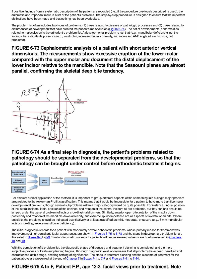
If positive findings from a systematic description of the patient are recorded (i.e., if the procedure previously described is used), theautomatic and important result is a list of the patient's problems. The step-by-step procedure is designed to ensure that the importantdistinctions have been made and that nothing has been overlooked.
The problem list often includes two types of problems: (1) those relating to disease or pathologic processes and (2) those relating todisturbances of development that have created the patient's malocclusion (Figure 6-74). The set of developmental abnormalitiesrelated to malocclusion is the orthodontic problem list. A developmental problem is just that (e.g., mandibular deficiency), not thefindings that indicate its presence (e.g., weak chin, increased facial convexity, and increased ANB angle all are findings, notproblems).
FIGURE 6-73 Cephalometric analysis of a patient with short anterior verticaldimensions. The measurements show excessive eruption of the lower molarcompared with the upper molar and document the distal displacement of thelower incisor relative to the mandible. Note that the Sassouni planes are almostparallel, confirming the skeletal deep bite tendency.
FIGURE 6-74 As a final step in diagnosis, the patient's problems related topathology should be separated from the developmental problems, so that thepathology can be brought under control before orthodontic treatment begins.
For efficient clinical application of the method, it is important to group different aspects of the same thing into a single major problemarea related to the Ackerman-Proffit classification. This means that it would be impossible for a patient to have more than five majordevelopmental problems, though several subproblems within a major category would be quite possible. For instance, lingual positionof the lateral incisors, labial position of the canines, and rotation of the central incisors all are problems, but they can and should belumped under the general problem of incisor crowding/malalignment. Similarly, anterior open bite, rotation of the maxilla downposteriorly and rotation of the mandible down anteriorly, and extreme lip incompetence are all aspects of skeletal open bite. Wherepossible, the problems should be indicated quantitatively or at least classified as mild, moderate, or severe (e.g., 5 mm mandibularincisor crowding, severe mandibular deficiency).
The initial diagnostic records for a patient with moderately severe orthodontic problems, whose primary reason for treatment wasimprovement of her dental and facial appearance, are shown in Figures 6-75 to 6-78 and the steps in developing a problem list areillustrated in Boxes 6-6 to 6-9. Similar diagnostic workups for patients with more severe problems are briefly reviewed in Chapters18 and 19.
With the completion of a problem list, the diagnostic phase of diagnosis and treatment planning is completed, and the moresubjective process of treatment planning begins. Thorough diagnostic evaluation means that all problems have been identified andcharacterized at this stage, omitting nothing of significance. The steps in treatment planning and the outcome of treatment for thepatient above are presented at the end of Chapter 7 in Boxes 7-1 to 7-7 and Figures 7-41 to 7-44.
FIGURE 6-75 A to F, Patient F.P., age 12-3, facial views prior to treatment. Note
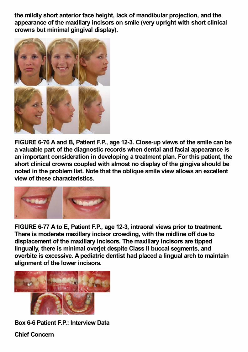
the mildly short anterior face height, lack of mandibular projection, and theappearance of the maxillary incisors on smile (very upright with short clinicalcrowns but minimal gingival display).
FIGURE 6-76 A and B, Patient F.P., age 12-3. Close-up views of the smile can bea valuable part of the diagnostic records when dental and facial appearance isan important consideration in developing a treatment plan. For this patient, theshort clinical crowns coupled with almost no display of the gingiva should benoted in the problem list. Note that the oblique smile view allows an excellentview of these characteristics.
FIGURE 6-77 A to E, Patient F.P., age 12-3, intraoral views prior to treatment.There is moderate maxillary incisor crowding, with the midline off due todisplacement of the maxillary incisors. The maxillary incisors are tippedlingually, there is minimal overjet despite Class II buccal segments, andoverbite is excessive. A pediatric dentist had placed a lingual arch to maintainalignment of the lower incisors.
Box 6-6 Patient F.P.: Interview Data
Chief Concern
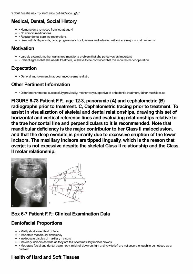
“I don't like the way my teeth stick out and look ugly.”
Medical, Dental, Social History• Hemangioma removed from leg at age 4• No chronic medications• Regular dental care, no restorations• Lives with both parents, good progress in school, seems well adjusted without any major social problems
Motivation• Largely external, mother wants treatment for a problem that she perceives as important• Patient agrees that she needs treatment, will have to be convinced that this requires her cooperation
Expectation• General improvement in appearance, seems realistic
Other Pertinent Information• Older brother treated successfully previously; mother very supportive of orthodontic treatment, father much less so
FIGURE 6-78 Patient F.P., age 12-3, panoramic (A) and cephalometric (B)radiographs prior to treatment. C, Cephalometric tracing prior to treatment. Toassist in visualization of skeletal and dental relationships, drawing this set ofhorizontal and vertical reference lines and evaluating relationships relative tothe true horizontal line and perpendiculars to it is recommended. Note thatmandibular deficiency is the major contributor to her Class II malocclusion,and that the deep overbite is primarily due to excessive eruption of the lowerincisors. The maxillary incisors are tipped lingually, which is the reason thatoverjet is not excessive despite the skeletal Class II relationship and the ClassII molar relationship.
Box 6-7 Patient F.P.: Clinical Examination Data
Dentofacial Proportions• Mildly short lower third of face• Moderate mandibular deficiency• Inadequate display of maxillary incisors• Maxillary incisors as wide as they are tall: short maxillary incisor crowns• Moderate facial and dental asymmetry: mild roll down on right and yaw to left are not severe enough to be noticed as aproblem
Health of Hard and Soft Tissues
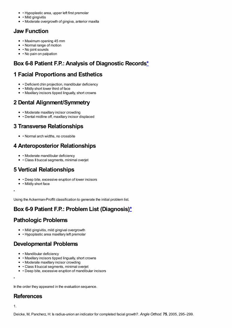
• Hypoplastic area, upper left first premolar• Mild gingivitis• Moderate overgrowth of gingiva, anterior maxilla
Jaw Function• Maximum opening 45 mm• Normal range of motion• No joint sounds• No pain on palpation
Box 6-8 Patient F.P.: Analysis of Diagnostic Records*
1 Facial Proportions and Esthetics• Deficient chin projection, mandibular deficiency• Mildly short lower third of face• Maxillary incisors tipped lingually, short crowns
2 Dental Alignment/Symmetry• Moderate maxillary incisor crowding• Dental midline off, maxillary incisor displaced
3 Transverse Relationships• Normal arch widths, no crossbite
4 Anteroposterior Relationships• Moderate mandibular deficiency• Class II buccal segments, minimal overjet
5 Vertical Relationships• Deep bite, excessive eruption of lower incisors• Mildly short face
*
Using the Ackerman-Proffit classification to generate the initial problem list.
Box 6-9 Patient F.P.: Problem List (Diagnosis)*
Pathologic Problems• Mild gingivitis, mild gingival overgrowth• Hypoplastic area maxillary left premolar
Developmental Problems• Mandibular deficiency• Maxillary incisors tipped lingually, short crowns• Moderate maxillary incisor crowding• Class II buccal segments, minimal overjet• Deep bite, excessive eruption of mandibular incisors
*
In the order they appeared in the evaluation sequence.
References1.
Deicke, M, Pancherz, H: Is radius-union an indicator for completed facial growth?. Angle Orthod. 75, 2005, 295–299.
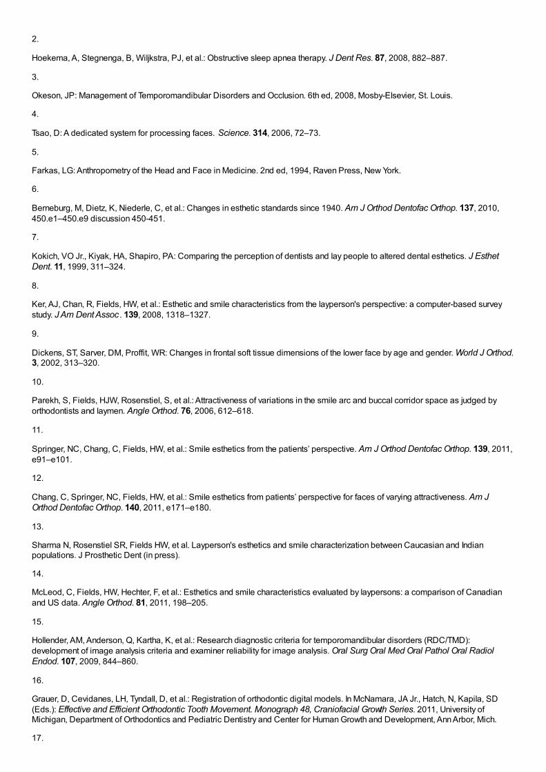
2.
Hoekema, A, Stegnenga, B, Wiljkstra, PJ, et al.: Obstructive sleep apnea therapy. J Dent Res. 87, 2008, 882–887.
3.
Okeson, JP: Management of Temporomandibular Disorders and Occlusion. 6th ed, 2008, Mosby-Elsevier, St. Louis.
4.
Tsao, D: A dedicated system for processing faces. Science. 314, 2006, 72–73.
5.
Farkas, LG: Anthropometry of the Head and Face in Medicine. 2nd ed, 1994, Raven Press, New York.
6.
Berneburg, M, Dietz, K, Niederle, C, et al.: Changes in esthetic standards since 1940. Am J Orthod Dentofac Orthop. 137, 2010,450.e1–450.e9 discussion 450-451.
7.
Kokich, VO Jr., Kiyak, HA, Shapiro, PA: Comparing the perception of dentists and lay people to altered dental esthetics. J EsthetDent. 11, 1999, 311–324.
8.
Ker, AJ, Chan, R, Fields, HW, et al.: Esthetic and smile characteristics from the layperson's perspective: a computer-based surveystudy. J Am Dent Assoc . 139, 2008, 1318–1327.
9.
Dickens, ST, Sarver, DM, Proffit, WR: Changes in frontal soft tissue dimensions of the lower face by age and gender. World J Orthod.3, 2002, 313–320.
10.
Parekh, S, Fields, HJW, Rosenstiel, S, et al.: Attractiveness of variations in the smile arc and buccal corridor space as judged byorthodontists and laymen. Angle Orthod. 76, 2006, 612–618.
11.
Springer, NC, Chang, C, Fields, HW, et al.: Smile esthetics from the patients’ perspective. Am J Orthod Dentofac Orthop. 139, 2011,e91–e101.
12.
Chang, C, Springer, NC, Fields, HW, et al.: Smile esthetics from patients’ perspective for faces of varying attractiveness. Am JOrthod Dentofac Orthop. 140, 2011, e171–e180.
13.
Sharma N, Rosenstiel SR, Fields HW, et al. Layperson's esthetics and smile characterization between Caucasian and Indianpopulations. J Prosthetic Dent (in press).
14.
McLeod, C, Fields, HW, Hechter, F, et al.: Esthetics and smile characteristics evaluated by laypersons: a comparison of Canadianand US data. Angle Orthod. 81, 2011, 198–205.
15.
Hollender, AM, Anderson, Q, Kartha, K, et al.: Research diagnostic criteria for temporomandibular disorders (RDC/TMD):development of image analysis criteria and examiner reliability for image analysis. Oral Surg Oral Med Oral Pathol Oral RadiolEndod. 107, 2009, 844–860.
16.
Grauer, D, Cevidanes, LH, Tyndall, D, et al.: Registration of orthodontic digital models. In McNamara, JA Jr., Hatch, N, Kapila, SD(Eds.): Effective and Efficient Orthodontic Tooth Movement. Monograph 48, Craniofacial Growth Series. 2011, University ofMichigan, Department of Orthodontics and Pediatric Dentistry and Center for Human Growth and Development, Ann Arbor, Mich.
17.

Kantor, ML, Norton, LA: Normal radiographic anatomy and common anomalies seen in cephalometric films. Am J Orthod DentofacOrthop. 91, 1987, 414–426.
18.
Riolo, ML, et al.: An Atlas of Craniofacial Growth, Monograph 2, Craniofacial Growth Series. 1974, University of Michigan, Center forHuman Growth and Development, Ann Arbor, Mich.
19.
Popovich, F, Thompson, GW: Craniofacial templates for orthodontic case analysis. Am J Orthod. 71, 1977, 406–420.
20.
Broadbent, BH Sr, Broadbent, BH Jr., Golden, WH: Bolton Standards of Dentofacial Developmental Growth. 1975, Mosby, St. Louis.
21.
Jacobson, A: Radiographic Cephalometry: From Basics to Videoimaging. 1995, Quintessence, Chicago.
22.
Athanasiou, AE: Orthodontic Cephalometry. 1995, Mosby, Chicago.
23.
Cooke, MS: Five-year reproducibility of natural head posture: a longitudinal study. Am J Orthod Dentofac Orthop. 97, 1990, 487–494.
24.
Lundstrom, A, Lundstrom, F, Lebret, LM, et al.: Natural head position and natural head orientation: basic considerations incephalometric analysis. Eur J Orthod. 17, 1995, 111–120.
25.
Anderson, G, Fields, HW, Beck, FM, et al.: Development of cephalometric norms using a unified facial and dental approach. AngleOrthod. 76, 2006, 612–618.
26.
Faustini, MM, Hale, C, Cisneros, GJ: Mesh diagram analysis: developing a norm for African Americans. Angle Orthod. 67, 1997, 121–128.
27.
Haney, E, Gansky, SA, Lee, JS, et al.: Comparative analysis of traditional radiographs and cone-beam computed tomographyvolumetric images in the diagnosis and treatment planning of maxillary impacted canines. Am J Orthod Dentofac Orthop. 137, 2010,590–597.
28.
Molen, AD: Comparing cone-beam computed tomography systems from an orthodontic perspective. Sem Orthod. 17, 2011, 34–38.
29.
Cevidanes, LH, Alhadidi, A, Paniagua, B, et al.: 3D quantification of mandibular asymmetry. Oral Surg Oral Med Oral Pathol OralRadiol Endod. 111, 2011, 757–770.
30.
Proffit, WR, White, RP Jr., Sarver, DM: Contemporary Treatment of Dentofacial Deformity. 2003, Mosby, St Louis.
31.
Hennekam, RCM, Krantz, ID, Allanson, JE: Gorlin's Syndromes of the Head and Neck. 5th ed, 2010, Oxford University Press, NewYork.
32.
Grauer, D, Cevidanes, LS, Styner, MA, et al.: Accuracy and landmark error calculation using CBCT-generated cephalograms. AngleOrthod. 80, 2010, 286–294.
33.

Grauer, D, Cevidanes, LH, Proffit, WR: Working with DICOM craniofacial images. Am J Orthod Dentofac Orthop. 136, 2009, 460–470.
34.
Cevidanes, LH, Styner, MA, Proffit, WR: Image analysis and superimposition of 3-D cone-beam CT models. Am J Orthod DentofacOrthop. 129, 2006, 611–618.
35.
Cevidanes, LH, Bailey, LJ, Tucker, SF, et al.: Three-dimensional cone-beam computed tomography for assessment of mandibularchanges after orthognathic surgery. Am J Orthod Dentofac Orthop. 131, 2007, 44–50.
36.
Ackerman, J, Proffit, WR, Sarver, DM, et al.: Pitch, roll and yaw: describing the spatial orientation of dentofacial traits. Am J OrthodDentofac Orthop. 131, 2007, 305–310.
37.
Severt, TR, Proffit, WR: The prevalence of facial asymmetry in the dentofacial deformities population at the University of NorthCarolina. Int J Adult Orthod Orthogn Surg. 12, 1997, 171–176.
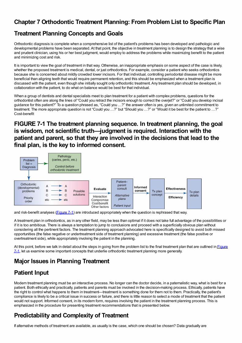
Chapter 7 Orthodontic Treatment Planning: From Problem List to Specific Plan
Treatment Planning Concepts and GoalsOrthodontic diagnosis is complete when a comprehensive list of the patient's problems has been developed and pathologic anddevelopmental problems have been separated. At that point, the objective in treatment planning is to design the strategy that a wiseand prudent clinician, using his or her best judgment, would employ to address the problems while maximizing benefit to the patientand minimizing cost and risk.
It is important to view the goal of treatment in that way. Otherwise, an inappropriate emphasis on some aspect of the case is likely,whether the proposed treatment is medical, dental, or just orthodontics. For example, consider a patient who seeks orthodonticsbecause she is concerned about mildly crowded lower incisors. For that individual, controlling periodontal disease might be morebeneficial than aligning teeth that would require permanent retention, and this should be emphasized when a treatment plan isdiscussed with the patient, even though she initially sought only orthodontic treatment. Any treatment plan should be developed, incollaboration with the patient, to do what on balance would be best for that individual.
When a group of dentists and dental specialists meet to plan treatment for a patient with complex problems, questions for theorthodontist often are along the lines of “Could you retract the incisors enough to correct the overjet?” or “Could you develop incisalguidance for this patient?” To a question phrased as, “Could you …?” the answer often is yes, given an unlimited commitment totreatment. The more appropriate question is not “Could you …?” but “Should you …?” or “Would it be best for the patient to …?”Cost-benefit
FIGURE 7-1 The treatment planning sequence. In treatment planning, the goalis wisdom, not scientific truth—judgment is required. Interaction with thepatient and parent, so that they are involved in the decisions that lead to thefinal plan, is the key to informed consent.
and risk-benefit analyses (Figure 7-1) are introduced appropriately when the question is rephrased that way.
A treatment plan in orthodontics, as in any other field, may be less than optimal if it does not take full advantage of the possibilities orif it is too ambitious. There is always a temptation to jump to conclusions and proceed with a superficially obvious plan withoutconsidering all the pertinent factors. The treatment planning approach advocated here is specifically designed to avoid both missedopportunities (the false negative or undertreatment side of treatment planning) and excessive treatment (the false positive orovertreatment side), while appropriately involving the patient in the planning.
At this point, before we talk in detail about the steps in going from the problem list to the final treatment plan that are outlined in Figure7-1, let us examine some important concepts that underlie orthodontic treatment planning more generally.
Major Issues in Planning Treatment
Patient InputModern treatment planning must be an interactive process. No longer can the doctor decide, in a paternalistic way, what is best for apatient. Both ethically and practically, patients and parents must be involved in the decision-making process. Ethically, patients havethe right to control what happens to them in treatment—treatment is something done for them not to them. Practically, the patient'scompliance is likely to be a critical issue in success or failure, and there is little reason to select a mode of treatment that the patientwould not support. Informed consent, in its modern form, requires involving the patient in the treatment planning process. This isemphasized in the procedure for presenting treatment recommendations that is presented below.
Predictability and Complexity of TreatmentIf alternative methods of treatment are available, as usually is the case, which one should be chosen? Data gradually are
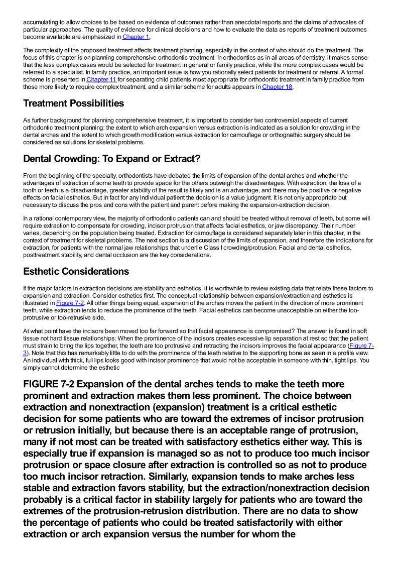
accumulating to allow choices to be based on evidence of outcomes rather than anecdotal reports and the claims of advocates ofparticular approaches. The quality of evidence for clinical decisions and how to evaluate the data as reports of treatment outcomesbecome available are emphasized in Chapter 1.
The complexity of the proposed treatment affects treatment planning, especially in the context of who should do the treatment. Thefocus of this chapter is on planning comprehensive orthodontic treatment. In orthodontics as in all areas of dentistry, it makes sensethat the less complex cases would be selected for treatment in general or family practice, while the more complex cases would bereferred to a specialist. In family practice, an important issue is how you rationally select patients for treatment or referral. A formalscheme is presented in Chapter 11 for separating child patients most appropriate for orthodontic treatment in family practice fromthose more likely to require complex treatment, and a similar scheme for adults appears in Chapter 18.
Treatment PossibilitiesAs further background for planning comprehensive treatment, it is important to consider two controversial aspects of currentorthodontic treatment planning: the extent to which arch expansion versus extraction is indicated as a solution for crowding in thedental arches and the extent to which growth modification versus extraction for camouflage or orthognathic surgery should beconsidered as solutions for skeletal problems.
Dental Crowding: To Expand or Extract?From the beginning of the specialty, orthodontists have debated the limits of expansion of the dental arches and whether theadvantages of extraction of some teeth to provide space for the others outweigh the disadvantages. With extraction, the loss of atooth or teeth is a disadvantage, greater stability of the result is likely and is an advantage, and there may be positive or negativeeffects on facial esthetics. But in fact for any individual patient the decision is a value judgment. It is not only appropriate butnecessary to discuss the pros and cons with the patient and parent before making the expansion-extraction decision.
In a rational contemporary view, the majority of orthodontic patients can and should be treated without removal of teeth, but some willrequire extraction to compensate for crowding, incisor protrusion that affects facial esthetics, or jaw discrepancy. Their numbervaries, depending on the population being treated. Extraction for camouflage is considered separately later in this chapter, in thecontext of treatment for skeletal problems. The next section is a discussion of the limits of expansion, and therefore the indications forextraction, for patients with the normal jaw relationships that underlie Class I crowding/protrusion. Facial and dental esthetics,posttreatment stability, and dental occlusion are the key considerations.
Esthetic ConsiderationsIf the major factors in extraction decisions are stability and esthetics, it is worthwhile to review existing data that relate these factors toexpansion and extraction. Consider esthetics first. The conceptual relationship between expansion/extraction and esthetics isillustrated in Figure 7-2. All other things being equal, expansion of the arches moves the patient in the direction of more prominentteeth, while extraction tends to reduce the prominence of the teeth. Facial esthetics can become unacceptable on either the too-protrusive or too-retrusive side.
At what point have the incisors been moved too far forward so that facial appearance is compromised? The answer is found in softtissue not hard tissue relationships: When the prominence of the incisors creates excessive lip separation at rest so that the patientmust strain to bring the lips together, the teeth are too protrusive and retracting the incisors improves the facial appearance (Figure 7-3). Note that this has remarkably little to do with the prominence of the teeth relative to the supporting bone as seen in a profile view.An individual with thick, full lips looks good with incisor prominence that would not be acceptable in someone with thin, tight lips. Yousimply cannot determine the esthetic
FIGURE 7-2 Expansion of the dental arches tends to make the teeth moreprominent and extraction makes them less prominent. The choice betweenextraction and nonextraction (expansion) treatment is a critical estheticdecision for some patients who are toward the extremes of incisor protrusionor retrusion initially, but because there is an acceptable range of protrusion,many if not most can be treated with satisfactory esthetics either way. This isespecially true if expansion is managed so as not to produce too much incisorprotrusion or space closure after extraction is controlled so as not to producetoo much incisor retraction. Similarly, expansion tends to make arches lessstable and extraction favors stability, but the extraction/nonextraction decisionprobably is a critical factor in stability largely for patients who are toward theextremes of the protrusion-retrusion distribution. There are no data to showthe percentage of patients who could be treated satisfactorily with eitherextraction or arch expansion versus the number for whom the
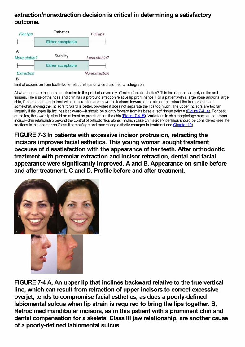
extraction/nonextraction decision is critical in determining a satisfactoryoutcome.
limit of expansion from tooth–bone relationships on a cephalometric radiograph.
At what point are the incisors retracted to the point of adversely affecting facial esthetics? This too depends largely on the softtissues. The size of the nose and chin has a profound effect on relative lip prominence. For a patient with a large nose and/or a largechin, if the choices are to treat without extraction and move the incisors forward or to extract and retract the incisors at leastsomewhat, moving the incisors forward is better, provided it does not separate the lips too much. The upper incisors are too farlingually if the upper lip inclines backward—it should be slightly forward from its base at soft tissue point A (Figure 7-4, A). For bestesthetics, the lower lip should be at least as prominent as the chin (Figure 7-4, B). Variations in chin morphology may put the properincisor–chin relationship beyond the control of orthodontics alone, in which case chin surgery perhaps should be considered (see thesections in this chapter on Class II camouflage and maximizing esthetic changes in treatment and Chapter 19).
FIGURE 7-3 In patients with excessive incisor protrusion, retracting theincisors improves facial esthetics. This young woman sought treatmentbecause of dissatisfaction with the appearance of her teeth. After orthodontictreatment with premolar extraction and incisor retraction, dental and facialappearance were significantly improved. A and B, Appearance on smile beforeand after treatment. C and D, Profile before and after treatment.
FIGURE 7-4 A, An upper lip that inclines backward relative to the true verticalline, which can result from retraction of upper incisors to correct excessiveoverjet, tends to compromise facial esthetics, as does a poorly-definedlabiomental sulcus when lip strain is required to bring the lips together. B,Retroclined mandibular incisors, as in this patient with a prominent chin anddental compensation for a skeletal Class III jaw relationship, are another causeof a poorly-defined labiomental sulcus.
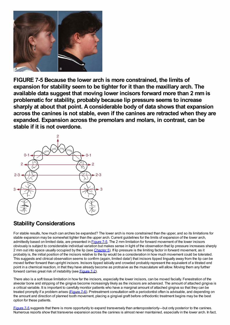
FIGURE 7-5 Because the lower arch is more constrained, the limits ofexpansion for stability seem to be tighter for it than the maxillary arch. Theavailable data suggest that moving lower incisors forward more than 2 mm isproblematic for stability, probably because lip pressure seems to increasesharply at about that point. A considerable body of data shows that expansionacross the canines is not stable, even if the canines are retracted when they areexpanded. Expansion across the premolars and molars, in contrast, can bestable if it is not overdone.
Stability ConsiderationsFor stable results, how much can arches be expanded? The lower arch is more constrained than the upper, and so its limitations forstable expansion may be somewhat tighter than the upper arch. Current guidelines for the limits of expansion of the lower arch,admittedly based on limited data, are presented in Figure 7-5. The 2 mm limitation for forward movement of the lower incisorsobviously is subject to considerable individual variation but makes sense in light of the observation that lip pressure increases sharply2 mm out into space usually occupied by the lip (see Chapter 5). If lip pressure is the limiting factor in forward movement, as itprobably is, the initial position of the incisors relative to the lip would be a consideration in how much movement could be tolerated.This suggests and clinical observation seems to confirm (again, limited data!) that incisors tipped lingually away from the lip can bemoved farther forward than upright incisors. Incisors tipped labially and crowded probably represent the equivalent of a titrated endpoint in a chemical reaction, in that they have already become as protrusive as the musculature will allow. Moving them any furtherforward carries great risk of instability (see Figure 7-2).
There also is a soft tissue limitation in how far the incisors, especially the lower incisors, can be moved facially. Fenestration of thealveolar bone and stripping of the gingiva become increasingly likely as the incisors are advanced. The amount of attached gingiva isa critical variable. It is important to carefully monitor patients who have a marginal amount of attached gingiva so that they can betreated promptly if a problem arises (Figure 7-6). Pretreatment consultation with a periodontist often is advisable, and depending onthe amount and direction of planned tooth movement, placing a gingival graft before orthodontic treatment begins may be the bestoption for these patients.
Figure 7-5 suggests that there is more opportunity to expand transversely than anteroposteriorly—but only posterior to the canines.Numerous reports show that transverse expansion across the canines is almost never maintained, especially in the lower arch. In fact,
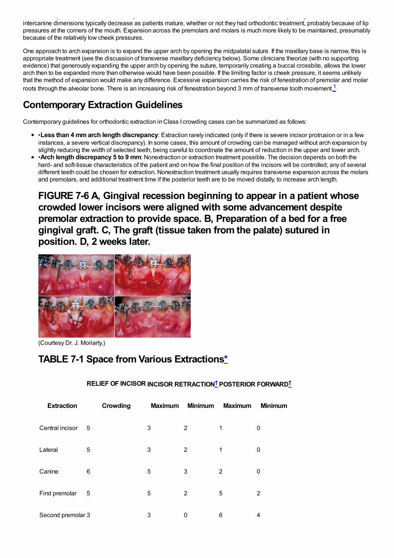
Numerous reports show that transverse expansion across the canines is almost never maintained, especially in the lower arch. In fact,intercanine dimensions typically decrease as patients mature, whether or not they had orthodontic treatment, probably because of lippressures at the corners of the mouth. Expansion across the premolars and molars is much more likely to be maintained, presumablybecause of the relatively low cheek pressures.
One approach to arch expansion is to expand the upper arch by opening the midpalatal suture. If the maxillary base is narrow, this isappropriate treatment (see the discussion of transverse maxillary deficiency below). Some clinicians theorize (with no supportingevidence) that generously expanding the upper arch by opening the suture, temporarily creating a buccal crossbite, allows the lowerarch then to be expanded more than otherwise would have been possible. If the limiting factor is cheek pressure, it seems unlikelythat the method of expansion would make any difference. Excessive expansion carries the risk of fenestration of premolar and molarroots through the alveolar bone. There is an increasing risk of fenestration beyond 3 mm of transverse tooth movement.1
Contemporary Extraction GuidelinesContemporary guidelines for orthodontic extraction in Class I crowding cases can be summarized as follows:
•Less than 4 mm arch length discrepancy: Extraction rarely indicated (only if there is severe incisor protrusion or in a fewinstances, a severe vertical discrepancy). In some cases, this amount of crowding can be managed without arch expansion byslightly reducing the width of selected teeth, being careful to coordinate the amount of reduction in the upper and lower arch.•Arch length discrepancy 5 to 9 mm: Nonextraction or extraction treatment possible. The decision depends on both thehard- and soft-tissue characteristics of the patient and on how the final position of the incisors will be controlled; any of severaldifferent teeth could be chosen for extraction. Nonextraction treatment usually requires transverse expansion across the molarsand premolars, and additional treatment time if the posterior teeth are to be moved distally, to increase arch length.
FIGURE 7-6 A, Gingival recession beginning to appear in a patient whosecrowded lower incisors were aligned with some advancement despitepremolar extraction to provide space. B, Preparation of a bed for a freegingival graft. C, The graft (tissue taken from the palate) sutured inposition. D, 2 weeks later.
(Courtesy Dr. J. Moriarty.)
TABLE 7-1 Space from Various Extractions*
RELIEF OF INCISOR INCISOR RETRACTION† POSTERIOR FORWARD†
Extraction Crowding Maximum Minimum Maximum Minimum
Central incisor 5 3 2 1 0
Lateral 5 3 2 1 0
Canine 6 5 3 2 0
First premolar 5 5 2 5 2
Second premolar 3 3 0 6 4
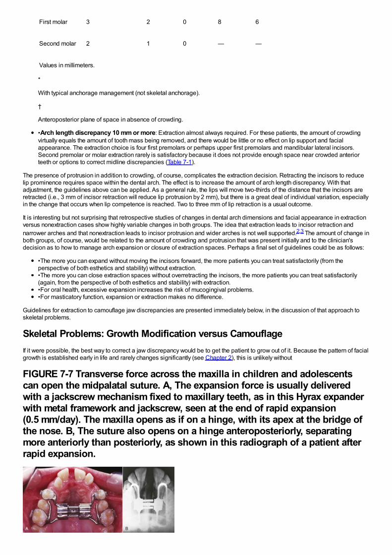
First molar 3 2 0 8 6
Second molar 2 1 0 — —
Values in millimeters.
*
With typical anchorage management (not skeletal anchorage).
†
Anteroposterior plane of space in absence of crowding.
•Arch length discrepancy 10 mm or more: Extraction almost always required. For these patients, the amount of crowdingvirtually equals the amount of tooth mass being removed, and there would be little or no effect on lip support and facialappearance. The extraction choice is four first premolars or perhaps upper first premolars and mandibular lateral incisors.Second premolar or molar extraction rarely is satisfactory because it does not provide enough space near crowded anteriorteeth or options to correct midline discrepancies (Table 7-1).
The presence of protrusion in addition to crowding, of course, complicates the extraction decision. Retracting the incisors to reducelip prominence requires space within the dental arch. The effect is to increase the amount of arch length discrepancy. With thatadjustment, the guidelines above can be applied. As a general rule, the lips will move two-thirds of the distance that the incisors areretracted (i.e., 3 mm of incisor retraction will reduce lip protrusion by 2 mm), but there is a great deal of individual variation, especiallyin the change that occurs when lip competence is reached. Two to three mm of lip retraction is a usual outcome.
It is interesting but not surprising that retrospective studies of changes in dental arch dimensions and facial appearance in extractionversus nonextraction cases show highly variable changes in both groups. The idea that extraction leads to incisor retraction andnarrower arches and that nonextraction leads to incisor protrusion and wider arches is not well supported.2,3 The amount of change inboth groups, of course, would be related to the amount of crowding and protrusion that was present initially and to the clinician'sdecision as to how to manage arch expansion or closure of extraction spaces. Perhaps a final set of guidelines could be as follows:
•The more you can expand without moving the incisors forward, the more patients you can treat satisfactorily (from theperspective of both esthetics and stability) without extraction.•The more you can close extraction spaces without overretracting the incisors, the more patients you can treat satisfactorily(again, from the perspective of both esthetics and stability) with extraction.•For oral health, excessive expansion increases the risk of mucogingival problems.•For masticatory function, expansion or extraction makes no difference.
Guidelines for extraction to camouflage jaw discrepancies are presented immediately below, in the discussion of that approach toskeletal problems.
Skeletal Problems: Growth Modification versus CamouflageIf it were possible, the best way to correct a jaw discrepancy would be to get the patient to grow out of it. Because the pattern of facialgrowth is established early in life and rarely changes significantly (see Chapter 2), this is unlikely without
FIGURE 7-7 Transverse force across the maxilla in children and adolescentscan open the midpalatal suture. A, The expansion force is usually deliveredwith a jackscrew mechanism fixed to maxillary teeth, as in this Hyrax expanderwith metal framework and jackscrew, seen at the end of rapid expansion(0.5 mm/day). The maxilla opens as if on a hinge, with its apex at the bridge ofthe nose. B, The suture also opens on a hinge anteroposteriorly, separatingmore anteriorly than posteriorly, as shown in this radiograph of a patient afterrapid expansion.
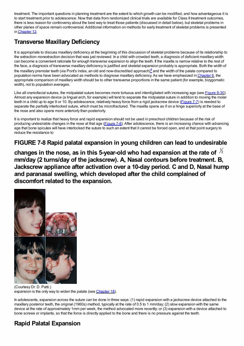
treatment. The important questions in planning treatment are the extent to which growth can be modified, and how advantageous it isto start treatment prior to adolescence. Now that data from randomized clinical trials are available for Class II treatment outcomes,there is less reason for controversy about the best way to treat those patients (discussed in detail below), but skeletal problems inother planes of space remain controversial. Additional information on methods for early treatment of skeletal problems is presentedin Chapter 12.
Transverse Maxillary DeficiencyIt is appropriate to discuss maxillary deficiency at the beginning of this discussion of skeletal problems because of its relationship tothe extraction–nonextraction decision that was just reviewed. In a child with crowded teeth, a diagnosis of deficient maxillary widthcan become a convenient rationale for enough transverse expansion to align the teeth. If the maxilla is narrow relative to the rest ofthe face, a diagnosis of transverse maxillary deficiency is justified and skeletal expansion probably is appropriate. Both the width ofthe maxillary premolar teeth (via Pont's index, an old and now-discredited approach)4 and the width of the palate compared topopulation norms have been advocated as methods to diagnose maxillary deficiency. As we have emphasized in Chapter 6, theappropriate comparison of maxillary width should be to other transverse proportions in the same patient (for example, bizygomaticwidth), not to population averages.
Like all craniofacial sutures, the midpalatal suture becomes more tortuous and interdigitated with increasing age (see Figure 8-30).Almost any expansion device (a lingual arch, for example) will tend to separate the midpalatal suture in addition to moving the molarteeth in a child up to age 9 or 10. By adolescence, relatively heavy force from a rigid jackscrew device (Figure 7-7) is needed toseparate the partially interlocked suture, which must be microfractured. The maxilla opens as if on a hinge superiorly at the base ofthe nose and also opens more anteriorly than posteriorly.
It is important to realize that heavy force and rapid expansion should not be used in preschool children because of the risk ofproducing undesirable changes in the nose at that age (Figure 7-8). After adolescence, there is an increasing chance with advancingage that bone spicules will have interlocked the suture to such an extent that it cannot be forced open, and at that point surgery toreduce the resistance to
FIGURE 7-8 Rapid palatal expansion in young children can lead to undesirablechanges in the nose, as in this 5-year-old who had expansion at the rate of mm/day (2 turns/day of the jackscrew). A, Nasal contours before treatment. B,Jackscrew appliance after activation over a 10-day period. C and D, Nasal humpand paranasal swelling, which developed after the child complained ofdiscomfort related to the expansion.
(Courtesy Dr. D. Patti.)expansion is the only way to widen the palate (see Chapter 18).
In adolescents, expansion across the suture can be done in three ways: (1) rapid expansion with a jackscrew device attached to themaxillary posterior teeth, the original (1960s) method, typically at the rate of 0.5 to 1 mm/day; (2) slow expansion with the samedevice at the rate of approximately 1mm per week, the method advocated more recently; or (3) expansion with a device attached tobone screws or implants, so that the force is directly applied to the bone and there is no pressure against the teeth.
Rapid Palatal Expansion
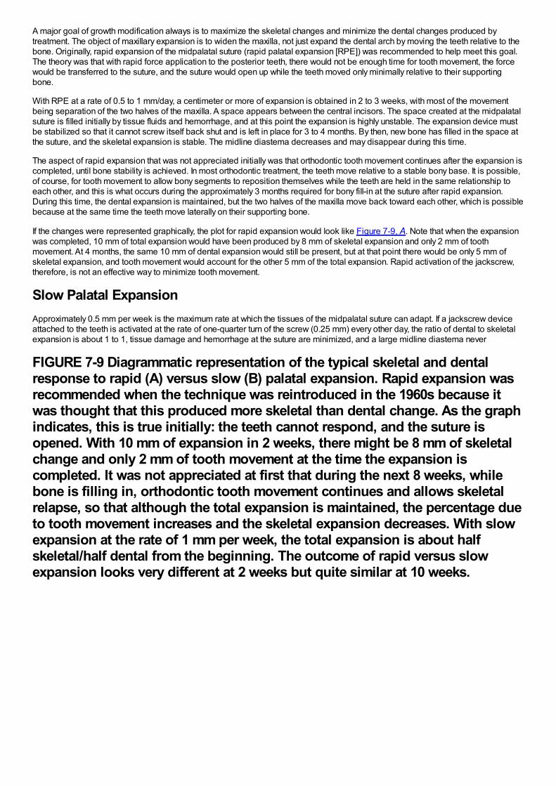
A major goal of growth modification always is to maximize the skeletal changes and minimize the dental changes produced bytreatment. The object of maxillary expansion is to widen the maxilla, not just expand the dental arch by moving the teeth relative to thebone. Originally, rapid expansion of the midpalatal suture (rapid palatal expansion [RPE]) was recommended to help meet this goal.The theory was that with rapid force application to the posterior teeth, there would not be enough time for tooth movement, the forcewould be transferred to the suture, and the suture would open up while the teeth moved only minimally relative to their supportingbone.
With RPE at a rate of 0.5 to 1 mm/day, a centimeter or more of expansion is obtained in 2 to 3 weeks, with most of the movementbeing separation of the two halves of the maxilla. A space appears between the central incisors. The space created at the midpalatalsuture is filled initially by tissue fluids and hemorrhage, and at this point the expansion is highly unstable. The expansion device mustbe stabilized so that it cannot screw itself back shut and is left in place for 3 to 4 months. By then, new bone has filled in the space atthe suture, and the skeletal expansion is stable. The midline diastema decreases and may disappear during this time.
The aspect of rapid expansion that was not appreciated initially was that orthodontic tooth movement continues after the expansion iscompleted, until bone stability is achieved. In most orthodontic treatment, the teeth move relative to a stable bony base. It is possible,of course, for tooth movement to allow bony segments to reposition themselves while the teeth are held in the same relationship toeach other, and this is what occurs during the approximately 3 months required for bony fill-in at the suture after rapid expansion.During this time, the dental expansion is maintained, but the two halves of the maxilla move back toward each other, which is possiblebecause at the same time the teeth move laterally on their supporting bone.
If the changes were represented graphically, the plot for rapid expansion would look like Figure 7-9, A. Note that when the expansionwas completed, 10 mm of total expansion would have been produced by 8 mm of skeletal expansion and only 2 mm of toothmovement. At 4 months, the same 10 mm of dental expansion would still be present, but at that point there would be only 5 mm ofskeletal expansion, and tooth movement would account for the other 5 mm of the total expansion. Rapid activation of the jackscrew,therefore, is not an effective way to minimize tooth movement.
Slow Palatal ExpansionApproximately 0.5 mm per week is the maximum rate at which the tissues of the midpalatal suture can adapt. If a jackscrew deviceattached to the teeth is activated at the rate of one-quarter turn of the screw (0.25 mm) every other day, the ratio of dental to skeletalexpansion is about 1 to 1, tissue damage and hemorrhage at the suture are minimized, and a large midline diastema never
FIGURE 7-9 Diagrammatic representation of the typical skeletal and dentalresponse to rapid (A) versus slow (B) palatal expansion. Rapid expansion wasrecommended when the technique was reintroduced in the 1960s because itwas thought that this produced more skeletal than dental change. As the graphindicates, this is true initially: the teeth cannot respond, and the suture isopened. With 10 mm of expansion in 2 weeks, there might be 8 mm of skeletalchange and only 2 mm of tooth movement at the time the expansion iscompleted. It was not appreciated at first that during the next 8 weeks, whilebone is filling in, orthodontic tooth movement continues and allows skeletalrelapse, so that although the total expansion is maintained, the percentage dueto tooth movement increases and the skeletal expansion decreases. With slowexpansion at the rate of 1 mm per week, the total expansion is about halfskeletal/half dental from the beginning. The outcome of rapid versus slowexpansion looks very different at 2 weeks but quite similar at 10 weeks.
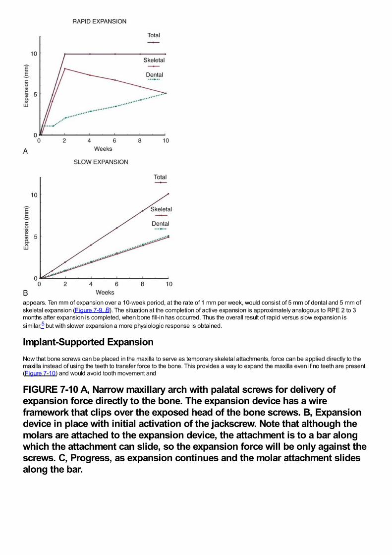
appears. Ten mm of expansion over a 10-week period, at the rate of 1 mm per week, would consist of 5 mm of dental and 5 mm ofskeletal expansion (Figure 7-9, B). The situation at the completion of active expansion is approximately analogous to RPE 2 to 3months after expansion is completed, when bone fill-in has occurred. Thus the overall result of rapid versus slow expansion issimilar,5 but with slower expansion a more physiologic response is obtained.
Implant-Supported ExpansionNow that bone screws can be placed in the maxilla to serve as temporary skeletal attachments, force can be applied directly to themaxilla instead of using the teeth to transfer force to the bone. This provides a way to expand the maxilla even if no teeth are present(Figure 7-10) and would avoid tooth movement and
FIGURE 7-10 A, Narrow maxillary arch with palatal screws for delivery ofexpansion force directly to the bone. The expansion device has a wireframework that clips over the exposed head of the bone screws. B, Expansiondevice in place with initial activation of the jackscrew. Note that although themolars are attached to the expansion device, the attachment is to a bar alongwhich the attachment can slide, so the expansion force will be only against thescrews. C, Progress, as expansion continues and the molar attachment slidesalong the bar.
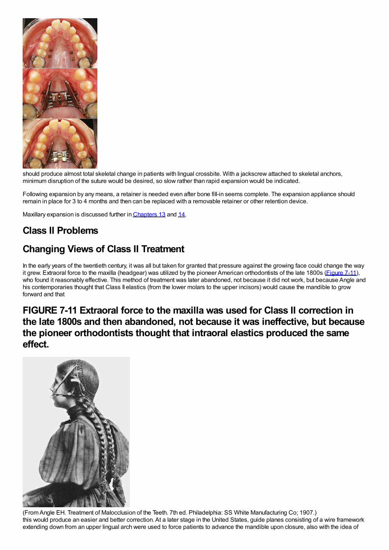
should produce almost total skeletal change in patients with lingual crossbite. With a jackscrew attached to skeletal anchors,minimum disruption of the suture would be desired, so slow rather than rapid expansion would be indicated.
Following expansion by any means, a retainer is needed even after bone fill-in seems complete. The expansion appliance shouldremain in place for 3 to 4 months and then can be replaced with a removable retainer or other retention device.
Maxillary expansion is discussed further in Chapters 13 and 14.
Class II Problems
Changing Views of Class II TreatmentIn the early years of the twentieth century, it was all but taken for granted that pressure against the growing face could change the wayit grew. Extraoral force to the maxilla (headgear) was utilized by the pioneer American orthodontists of the late 1800s (Figure 7-11),who found it reasonably effective. This method of treatment was later abandoned, not because it did not work, but because Angle andhis contemporaries thought that Class II elastics (from the lower molars to the upper incisors) would cause the mandible to growforward and that
FIGURE 7-11 Extraoral force to the maxilla was used for Class II correction inthe late 1800s and then abandoned, not because it was ineffective, but becausethe pioneer orthodontists thought that intraoral elastics produced the sameeffect.
(From Angle EH. Treatment of Malocclusion of the Teeth. 7th ed. Philadelphia: SS White Manufacturing Co; 1907.)this would produce an easier and better correction. At a later stage in the United States, guide planes consisting of a wire frameworkextending down from an upper lingual arch were used to force patients to advance the mandible upon closure, also with the idea of
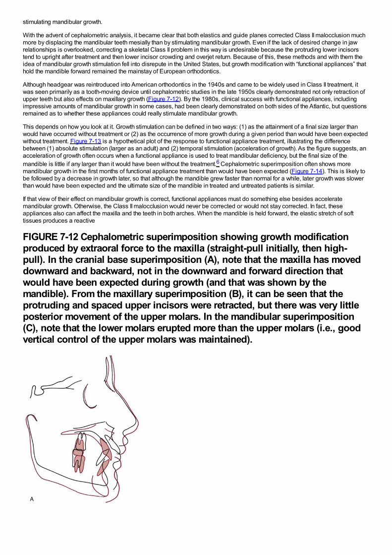
stimulating mandibular growth.
With the advent of cephalometric analysis, it became clear that both elastics and guide planes corrected Class II malocclusion muchmore by displacing the mandibular teeth mesially than by stimulating mandibular growth. Even if the lack of desired change in jawrelationships is overlooked, correcting a skeletal Class II problem in this way is undesirable because the protruding lower incisorstend to upright after treatment and then lower incisor crowding and overjet return. Because of this, these methods and with them theidea of mandibular growth stimulation fell into disrepute in the United States, but growth modification with “functional appliances” thathold the mandible forward remained the mainstay of European orthodontics.
Although headgear was reintroduced into American orthodontics in the 1940s and came to be widely used in Class II treatment, itwas seen primarily as a tooth-moving device until cephalometric studies in the late 1950s clearly demonstrated not only retraction ofupper teeth but also effects on maxillary growth (Figure 7-12). By the 1980s, clinical success with functional appliances, includingimpressive amounts of mandibular growth in some cases, had been clearly demonstrated on both sides of the Atlantic, but questionsremained as to whether these appliances could really stimulate mandibular growth.
This depends on how you look at it. Growth stimulation can be defined in two ways: (1) as the attainment of a final size larger thanwould have occurred without treatment or (2) as the occurrence of more growth during a given period than would have been expectedwithout treatment. Figure 7-13 is a hypothetical plot of the response to functional appliance treatment, illustrating the differencebetween (1) absolute stimulation (larger as an adult) and (2) temporal stimulation (acceleration of growth). As the figure suggests, anacceleration of growth often occurs when a functional appliance is used to treat mandibular deficiency, but the final size of themandible is little if any larger than it would have been without the treatment.6 Cephalometric superimposition often shows moremandibular growth in the first months of functional appliance treatment than would have been expected (Figure 7-14). This is likely tobe followed by a decrease in growth later, so that although the mandible grew faster than normal for a while, later growth was slowerthan would have been expected and the ultimate size of the mandible in treated and untreated patients is similar.
If that view of their effect on mandibular growth is correct, functional appliances must do something else besides acceleratemandibular growth. Otherwise, the Class II malocclusion would never be corrected or would not stay corrected. In fact, theseappliances also can affect the maxilla and the teeth in both arches. When the mandible is held forward, the elastic stretch of softtissues produces a reactive
FIGURE 7-12 Cephalometric superimposition showing growth modificationproduced by extraoral force to the maxilla (straight-pull initially, then high-pull). In the cranial base superimposition (A), note that the maxilla has moveddownward and backward, not in the downward and forward direction thatwould have been expected during growth (and that was shown by themandible). From the maxillary superimposition (B), it can be seen that theprotruding and spaced upper incisors were retracted, but there was very littleposterior movement of the upper molars. In the mandibular superimposition(C), note that the lower molars erupted more than the upper molars (i.e., goodvertical control of the upper molars was maintained).
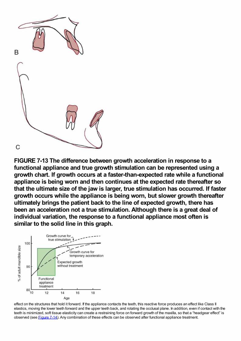
FIGURE 7-13 The difference between growth acceleration in response to afunctional appliance and true growth stimulation can be represented using agrowth chart. If growth occurs at a faster-than-expected rate while a functionalappliance is being worn and then continues at the expected rate thereafter sothat the ultimate size of the jaw is larger, true stimulation has occurred. If fastergrowth occurs while the appliance is being worn, but slower growth thereafterultimately brings the patient back to the line of expected growth, there hasbeen an acceleration not a true stimulation. Although there is a great deal ofindividual variation, the response to a functional appliance most often issimilar to the solid line in this graph.
effect on the structures that hold it forward. If the appliance contacts the teeth, this reactive force produces an effect like Class IIelastics, moving the lower teeth forward and the upper teeth back, and rotating the occlusal plane. In addition, even if contact with theteeth is minimized, soft tissue elasticity can create a restraining force on forward growth of the maxilla, so that a “headgear effect” isobserved (see Figure 7-14). Any combination of these effects can be observed after functional appliance treatment.
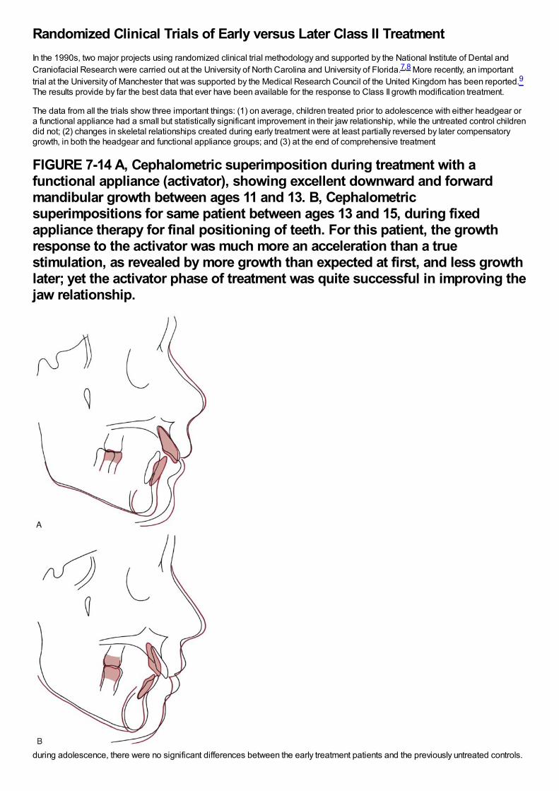
Randomized Clinical Trials of Early versus Later Class II TreatmentIn the 1990s, two major projects using randomized clinical trial methodology and supported by the National Institute of Dental andCraniofacial Research were carried out at the University of North Carolina and University of Florida.7,8 More recently, an importanttrial at the University of Manchester that was supported by the Medical Research Council of the United Kingdom has been reported.9The results provide by far the best data that ever have been available for the response to Class II growth modification treatment.
The data from all the trials show three important things: (1) on average, children treated prior to adolescence with either headgear ora functional appliance had a small but statistically significant improvement in their jaw relationship, while the untreated control childrendid not; (2) changes in skeletal relationships created during early treatment were at least partially reversed by later compensatorygrowth, in both the headgear and functional appliance groups; and (3) at the end of comprehensive treatment
FIGURE 7-14 A, Cephalometric superimposition during treatment with afunctional appliance (activator), showing excellent downward and forwardmandibular growth between ages 11 and 13. B, Cephalometricsuperimpositions for same patient between ages 13 and 15, during fixedappliance therapy for final positioning of teeth. For this patient, the growthresponse to the activator was much more an acceleration than a truestimulation, as revealed by more growth than expected at first, and less growthlater; yet the activator phase of treatment was quite successful in improving thejaw relationship.
during adolescence, there were no significant differences between the early treatment patients and the previously untreated controls.
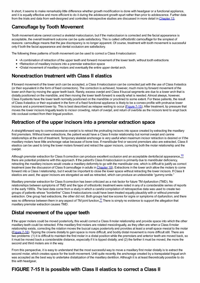
In short, it seems to make remarkably little difference whether growth modification is done with headgear or a functional appliance,and it is equally effective and more efficient to do it during the adolescent growth spurt rather than prior to adolescence. Further datafrom the trials and data from well-designed and controlled retrospective studies are discussed in more detail in Chapter 13.
Camouflage by Tooth MovementTooth movement alone cannot correct a skeletal malocclusion, but if the malocclusion is corrected and the facial appearance isacceptable, the overall treatment outcome can be quite satisfactory. This is called orthodontic camouflage for the simplest ofreasons: camouflage means that the jaw discrepancy is no longer apparent. Of course, treatment with tooth movement is successfulonly if both the facial appearance and dental occlusion are satisfactory.
The following three patterns of tooth movement can be used to correct a Class II malocclusion:
•A combination of retraction of the upper teeth and forward movement of the lower teeth, without tooth extractions•Retraction of maxillary incisors into a premolar extraction space•Distal movement of maxillary molars and eventually the entire upper dental arch.
Nonextraction treatment with Class II elasticsIf forward movement of the lower arch can be accepted, a Class II malocclusion can be corrected just with the use of Class II elastics(or their equivalent in the form of fixed connectors). The correction is achieved, however, much more by forward movement of thelower arch than by moving the upper teeth back. Rarely, excess overjet and Class II buccal segments are due to a lower arch that isdistally positioned on the mandible, and then moving the lower teeth forward is exactly what is needed. Almost always, however,Class II patients have the lower teeth normally positioned on the mandible or proclined to some extent. For these patients, the resultof Class II elastics or their equivalent in the form of a fixed functional appliance is likely to be a convex profile with protrusive lowerincisors and a prominent lower lip. This is best described as relapse waiting to occur (Figure 7-15). After treatment, lip pressure thatmoves the lower incisors lingually leads to incisor crowding, return of overjet, and return of overbite as the incisors tend to erupt backinto occlusal contact from their lingual position.
Retraction of the upper incisors into a premolar extraction spaceA straightforward way to correct excessive overjet is to retract the protruding incisors into space created by extracting the maxillaryfirst premolars. Without lower extractions, the patient would have a Class II molar relationship but normal overjet and caninerelationships at the end of treatment. Temporary skeletal anchorage is very useful when maximum incisor retraction is desired or if themaxillary molars have little anchorage value because of bone loss. If mandibular first or second premolars also are extracted, Class IIelastics can be used to bring the lower molars forward and retract the upper incisors, correcting both the molar relationship and theoverjet.
Although premolar extraction for Class II correction can produce excellent occlusion and an acceptable dentofacial appearance,10
there are potential problems with this approach. If the patient's Class II malocclusion is primarily due to mandibular deficiency,retracting the maxillary incisors would create a maxillary deformity to go with the mandibular one, which is difficult to justify as correcttreatment (see the discussion of Class II camouflage in adults in Chapter 18). Extractions in the lower arch allow the molars to comeforward into a Class I relationship, but it would be important to close the lower space without retracting the lower incisors. If Class IIelastics are used, the upper incisors are elongated as well as retracted, which can produce an undesirable “gummy smile.”
Maxillary premolar extraction for Class II correction has been criticized as a risk factor for future TM dysfunction (TMD). Norelationships between symptoms of TMD and the type of orthodontic treatment were noted in any of a considerable series of reportsin the early 1990s. The best data come from a study in which a careful compilation of retrospective data was used to create twogroups of patients whose “borderline” Class II malocclusions could have been treated equally plausibly with or without premolarextraction. One group had extractions, the other did not. Both groups had low scores for signs or symptoms of dysfunction, and therewas no difference between them in any aspect of TM joint function.11 There is simply no evidence to support the allegation thatmaxillary premolar extraction causes TMD.
Distal movement of the upper teethIf the upper molars could be moved posteriorly, this would correct a Class II molar relationship and provide space into which the othermaxillary teeth could be retracted. If the maxillary first molars are rotated mesiolingually, as they often are when a Class II molarrelationship exists, correcting the rotation moves the buccal cusps posteriorly and provides at least a small space mesial to the molar(Figure 7-16). Tipping the crowns distally to gain space is more difficult, and bodily distal movement is more difficult still. There aretwo problems: (1) it is difficult to maintain the first molar in a distal position while the premolars and anterior teeth are moved back, soit must be moved back a considerable distance, especially if it is tipped distally; and (2) the farther it must be moved, the more thesecond and third molars are in the way.
From this perspective, it is easy to understand that the most successful way to move a maxillary first molar distally is to extract thesecond molar, which creates space for the tooth movement. Until quite recently, the anchorage created by a transpalatal lingual archwas accepted as the best way to undertake distalization of the maxillary dentition. Although it is at least theoretically possible to dothis with headgear,
FIGURE 7-15 It is possible with Class II elastics to correct a Class II
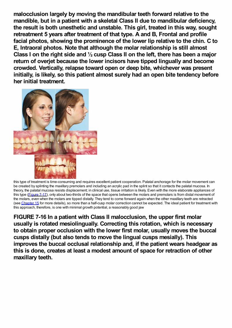
malocclusion largely by moving the mandibular teeth forward relative to themandible, but in a patient with a skeletal Class II due to mandibular deficiency,the result is both unesthetic and unstable. This girl, treated in this way, soughtretreatment 5 years after treatment of that type. A and B, Frontal and profilefacial photos, showing the prominence of the lower lip relative to the chin. C toE, Intraoral photos. Note that although the molar relationship is still almostClass I on the right side and ½ cusp Class II on the left, there has been a majorreturn of overjet because the lower incisors have tipped lingually and becomecrowded. Vertically, relapse toward open or deep bite, whichever was presentinitially, is likely, so this patient almost surely had an open bite tendency beforeher initial treatment.
this type of treatment is time-consuming and requires excellent patient cooperation. Palatal anchorage for the molar movement canbe created by splinting the maxillary premolars and including an acrylic pad in the splint so that it contacts the palatal mucosa. Intheory, the palatal mucosa resists displacement; in clinical use, tissue irritation is likely. Even with the more elaborate appliances ofthis type (Figure 7-17), only about two-thirds of the space that opens between the molars and premolars is from distal movement ofthe molars, even when the molars are tipped distally. They tend to come forward again when the other maxillary teeth are retracted(see Chapter 15 for more details), so more than a half-cusp molar correction cannot be expected. The ideal patient for treatment withthis approach, therefore, is one with minimal growth potential, a reasonably good jaw
FIGURE 7-16 In a patient with Class II malocclusion, the upper first molarusually is rotated mesiolingually. Correcting this rotation, which is necessaryto obtain proper occlusion with the lower first molar, usually moves the buccalcusps distally (but also tends to move the lingual cusps mesially). Thisimproves the buccal occlusal relationship and, if the patient wears headgear asthis is done, creates at least a modest amount of space for retraction of othermaxillary teeth.
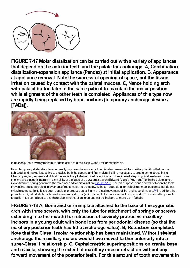
FIGURE 7-17 Molar distalization can be carried out with a variety of appliancesthat depend on the anterior teeth and the palate for anchorage. A, Combinationdistalization-expansion appliance (Pendex) at initial application. B, Appearanceat appliance removal. Note the successful opening of space, but the tissueirritation caused by contact with the palatal mucosa. C, Nance holding archwith palatal button later in the same patient to maintain the molar positionwhile alignment of the other teeth is completed. Appliances of this type noware rapidly being replaced by bone anchors (temporary anchorage devices[TADs]).
relationship (not severely mandibular deficient) and a half-cusp Class II molar relationship.
Using temporary skeletal anchorage greatly improves the amount of true distal movement of the maxillary dentition that can beachieved, and makes it possible to distalize both the second and first molars. It still is necessary to create some space in thetuberosity region, so removal of third molars is likely to be required later if it is not done immediately. In typical treatment, boneanchors are placed bilaterally in the vicinity of the base of the zygomatic arch (Edward Angle's “key ridge”) or in the palate, and anickel-titanium spring generates the force needed for distalization (Figure 7-18). For this purpose, bone screws between the teethprevent the necessary distal movement of roots mesial to the screw. Although good data for typical treatment outcomes still do notexist, in some patients it has been possible to produce up to 6 mm of distal movement of first and second molars.12 In addition, thepremolars migrate distally as the molars are moved back (which is due to the supercrestal fiber network). This makes the premolarretraction less complicated, and there also is no reaction force against the incisors to move them facially.
FIGURE 7-18 A, Bone anchor (miniplate attached to the base of the zygomaticarch with three screws, with only the tube for attachment of springs or screwsextending into the mouth) for retraction of severely protrusive maxillaryincisors in a young adult with bone loss from periodontal disease (so that themaxillary posterior teeth had little anchorage value). B, Retraction completed.Note that the Class II molar relationship has been maintained. Without skeletalanchorage the maxillary molars would have moved farther anteriorly into asuper-Class II relationship. C, Cephalometric superimpositions on cranial baseand maxilla, showing the extent of maxillary incisor retraction without anyforward movement of the posterior teeth. For this amount of tooth movement in
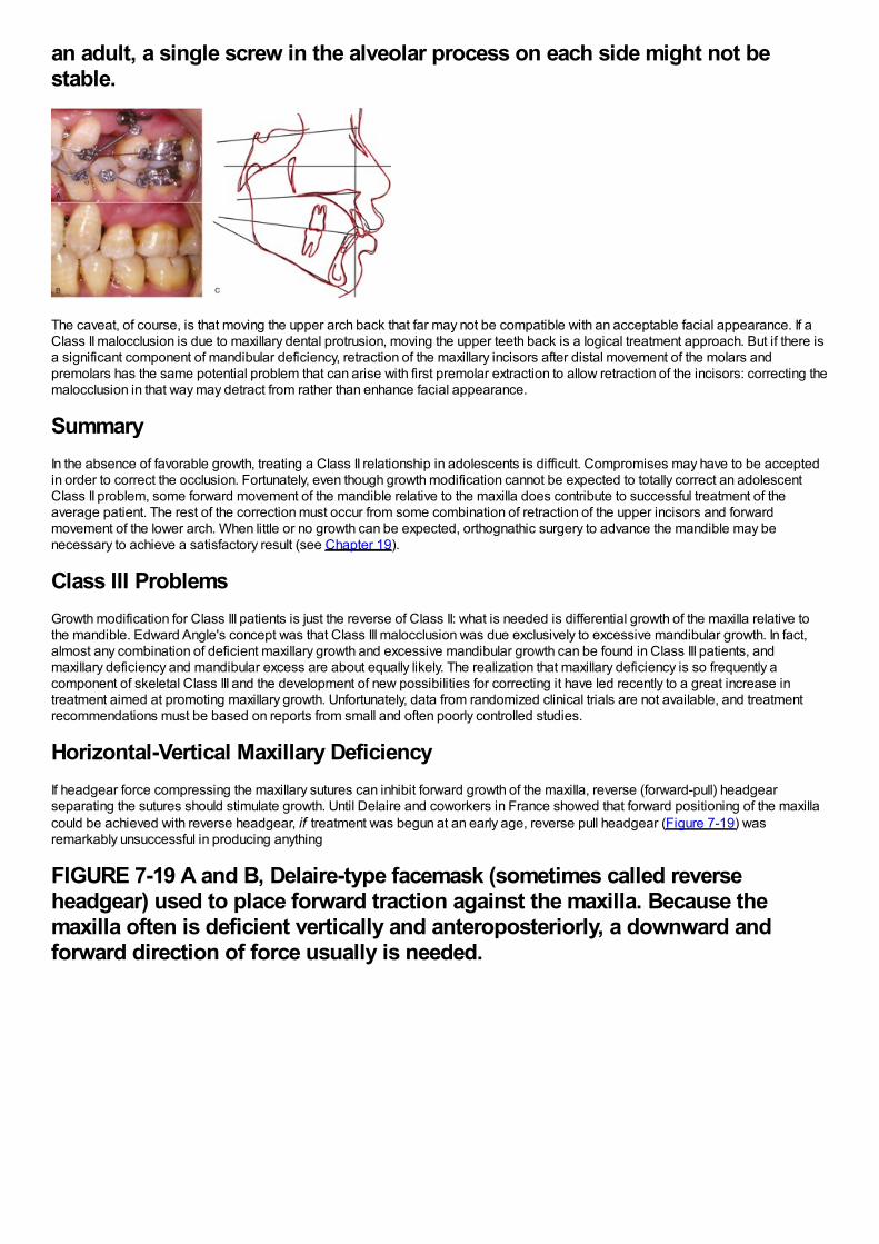
an adult, a single screw in the alveolar process on each side might not bestable.
The caveat, of course, is that moving the upper arch back that far may not be compatible with an acceptable facial appearance. If aClass II malocclusion is due to maxillary dental protrusion, moving the upper teeth back is a logical treatment approach. But if there isa significant component of mandibular deficiency, retraction of the maxillary incisors after distal movement of the molars andpremolars has the same potential problem that can arise with first premolar extraction to allow retraction of the incisors: correcting themalocclusion in that way may detract from rather than enhance facial appearance.
SummaryIn the absence of favorable growth, treating a Class II relationship in adolescents is difficult. Compromises may have to be acceptedin order to correct the occlusion. Fortunately, even though growth modification cannot be expected to totally correct an adolescentClass II problem, some forward movement of the mandible relative to the maxilla does contribute to successful treatment of theaverage patient. The rest of the correction must occur from some combination of retraction of the upper incisors and forwardmovement of the lower arch. When little or no growth can be expected, orthognathic surgery to advance the mandible may benecessary to achieve a satisfactory result (see Chapter 19).
Class III ProblemsGrowth modification for Class III patients is just the reverse of Class II: what is needed is differential growth of the maxilla relative tothe mandible. Edward Angle's concept was that Class III malocclusion was due exclusively to excessive mandibular growth. In fact,almost any combination of deficient maxillary growth and excessive mandibular growth can be found in Class III patients, andmaxillary deficiency and mandibular excess are about equally likely. The realization that maxillary deficiency is so frequently acomponent of skeletal Class III and the development of new possibilities for correcting it have led recently to a great increase intreatment aimed at promoting maxillary growth. Unfortunately, data from randomized clinical trials are not available, and treatmentrecommendations must be based on reports from small and often poorly controlled studies.
Horizontal-Vertical Maxillary DeficiencyIf headgear force compressing the maxillary sutures can inhibit forward growth of the maxilla, reverse (forward-pull) headgearseparating the sutures should stimulate growth. Until Delaire and coworkers in France showed that forward positioning of the maxillacould be achieved with reverse headgear, if treatment was begun at an early age, reverse pull headgear (Figure 7-19) wasremarkably unsuccessful in producing anything
FIGURE 7-19 A and B, Delaire-type facemask (sometimes called reverseheadgear) used to place forward traction against the maxilla. Because themaxilla often is deficient vertically and anteroposteriorly, a downward andforward direction of force usually is needed.
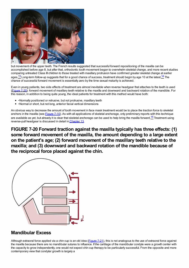
but movement of the upper teeth. The French results suggested that successful forward repositioning of the maxilla can beaccomplished before age 8, but after that, orthodontic tooth movement began to overwhelm skeletal change, and more recent studiescomparing untreated Class III children to those treated with maxillary protrusion have confirmed greater skeletal change at earlierages.13 Long-term follow-up suggests that for a good chance of success, treatment should begin by age 10 at the latest.14 Thechance of successful forward movement is essentially zero by the time sexual maturity is achieved.
Even in young patients, two side effects of treatment are almost inevitable when reverse headgear that attaches to the teeth is used(Figure 7-20): forward movement of maxillary teeth relative to the maxilla and downward and backward rotation of the mandible. Forthis reason, in addition to being quite young, the ideal patients for treatment with this method would have both:
•Normally positioned or retrusive, but not protrusive, maxillary teeth•Normal or short, but not long, anterior facial vertical dimensions
An obvious way to decrease the amount of tooth movement in face mask treatment would be to place the traction force to skeletalanchors in the maxilla (see Figure 7-10). As with all applications of skeletal anchorage, only preliminary reports with this techniqueare available as yet, but already it is clear that skeletal anchorage can be used to help bring the maxilla forward.15 Treatment usingreverse-pull headgear is discussed in detail in Chapter 13.
FIGURE 7-20 Forward traction against the maxilla typically has three effects: (1)some forward movement of the maxilla, the amount depending to a large extenton the patient's age; (2) forward movement of the maxillary teeth relative to themaxilla; and (3) downward and backward rotation of the mandible because ofthe reciprocal force placed against the chin.
Mandibular ExcessAlthough extraoral force applied via a chin cup is an old idea (Figure 7-21), this is not analogous to the use of extraoral force againstthe maxilla because there are no mandibular sutures to influence. If the cartilage of the mandibular condyle were a growth center withthe capacity to grow independently, one would not expect chin cup therapy to be particularly successful. From the opposite and morecontemporary view that condylar growth is largely a
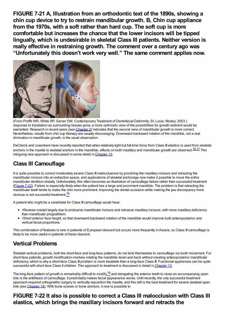
FIGURE 7-21 A, Illustration from an orthodontic text of the 1890s, showing achin cup device to try to restrain mandibular growth. B, Chin cup appliancefrom the 1970s, with a soft rather than hard cup. The soft cup is morecomfortable but increases the chance that the lower incisors will be tippedlingually, which is undesirable in skeletal Class III patients. Neither version isreally effective in restraining growth. The comment over a century ago was“Unfortunately this doesn't work very well.” The same comment applies now.
(From Proffit WR, White RP, Sarver DM. Contemporary Treatment of Dentofacial Deformity. St. Louis: Mosby; 2003.)response to translation as surrounding tissues grow, a more optimistic view of the possibilities for growth restraint would bewarranted. Research in recent years (see Chapter 2) indicates that the second view of mandibular growth is more correct.Nevertheless, results from chin cup therapy are usually discouraging. Downward-backward rotation of the mandible, not a realdiminution in mandibular growth, is the usual observation.
DeClerck and coworkers have recently reported that when relatively light but full-time force from Class III elastics is used from skeletalanchors in the maxilla to skeletal anchors in the mandible, effects on both maxillary and mandibular growth are observed.16,17 Thisintriguing new approach is discussed in some detail in Chapter 13.
Class III CamouflageIt is quite possible to correct moderately severe Class III malocclusions by proclining the maxillary incisors and retracting themandibular incisors into an extraction space, and applications of skeletal anchorage now make it possible to move the entiremandibular dentition distally. Unfortunately, this often becomes an illustration of camouflage failure rather than successful treatment(Figure 7-22). Failure is especially likely when the patient has a large and prominent mandible. The problem is that retracting themandibular teeth tends to make the chin more prominent. Improving the dental occlusion while making the jaw discrepancy moreobvious is not successful treatment.18
A patient who might be a candidate for Class III camouflage would have:
•Reverse overjet largely due to protrusive mandibular incisors and retrusive maxillary incisors, with more maxillary deficiencythan mandibular prognathism.•Short anterior face height, so that downward-backward rotation of the mandible would improve both anteroposterior andvertical facial proportions.
This combination of features is rare in patients of European descent but occurs more frequently in Asians, so Class III camouflage islikely to be more useful in patients of Asian descent.
Vertical ProblemsSkeletal vertical problems, both the short-face and long-face patterns, do not lend themselves to camouflage via tooth movement. Forshort-face patients, growth modification involves rotating the mandible down and back without creating anteroposterior mandibulardeficiency, which is why a short-face Class III problem is more treatable than a long-face Class III. Functional appliances can be quitesuccessful with short-face Class II children. This approach to treatment is discussed in detail in Chapter 13.
The long-face pattern of growth is remarkably difficult to modify,19 and elongating the anterior teeth to close an accompanying openbite is the antithesis of camouflage. It predictably makes facial appearance worse. Until recently, the only successful treatmentapproach required orthognathic surgery to vertically reposition the maxilla, and this still is the best treatment for severe skeletal openbite (see Chapter 19). With bone screws or bone anchors, it now is possible to
FIGURE 7-22 It also is possible to correct a Class III malocclusion with Class IIIelastics, which brings the maxillary incisors forward and retracts the
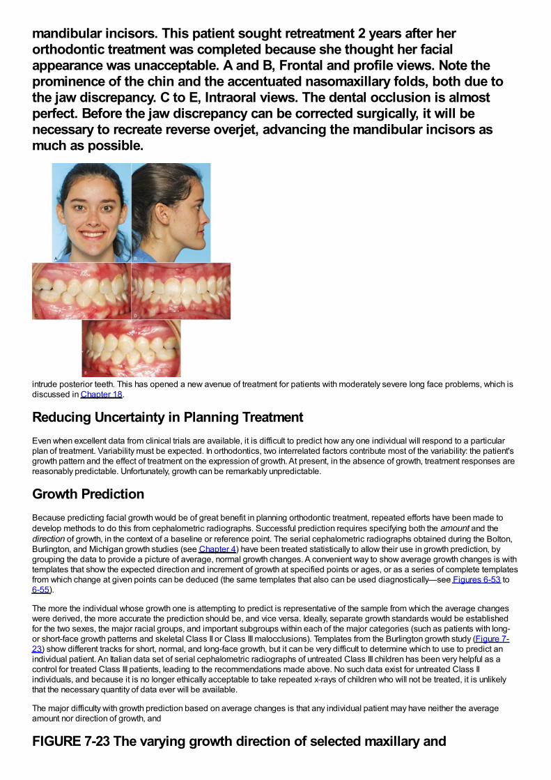
mandibular incisors. This patient sought retreatment 2 years after herorthodontic treatment was completed because she thought her facialappearance was unacceptable. A and B, Frontal and profile views. Note theprominence of the chin and the accentuated nasomaxillary folds, both due tothe jaw discrepancy. C to E, Intraoral views. The dental occlusion is almostperfect. Before the jaw discrepancy can be corrected surgically, it will benecessary to recreate reverse overjet, advancing the mandibular incisors asmuch as possible.
intrude posterior teeth. This has opened a new avenue of treatment for patients with moderately severe long face problems, which isdiscussed in Chapter 18.
Reducing Uncertainty in Planning TreatmentEven when excellent data from clinical trials are available, it is difficult to predict how any one individual will respond to a particularplan of treatment. Variability must be expected. In orthodontics, two interrelated factors contribute most of the variability: the patient'sgrowth pattern and the effect of treatment on the expression of growth. At present, in the absence of growth, treatment responses arereasonably predictable. Unfortunately, growth can be remarkably unpredictable.
Growth PredictionBecause predicting facial growth would be of great benefit in planning orthodontic treatment, repeated efforts have been made todevelop methods to do this from cephalometric radiographs. Successful prediction requires specifying both the amount and thedirection of growth, in the context of a baseline or reference point. The serial cephalometric radiographs obtained during the Bolton,Burlington, and Michigan growth studies (see Chapter 4) have been treated statistically to allow their use in growth prediction, bygrouping the data to provide a picture of average, normal growth changes. A convenient way to show average growth changes is withtemplates that show the expected direction and increment of growth at specified points or ages, or as a series of complete templatesfrom which change at given points can be deduced (the same templates that also can be used diagnostically—see Figures 6-53 to6-55).
The more the individual whose growth one is attempting to predict is representative of the sample from which the average changeswere derived, the more accurate the prediction should be, and vice versa. Ideally, separate growth standards would be establishedfor the two sexes, the major racial groups, and important subgroups within each of the major categories (such as patients with long-or short-face growth patterns and skeletal Class II or Class III malocclusions). Templates from the Burlington growth study (Figure 7-23) show different tracks for short, normal, and long-face growth, but it can be very difficult to determine which to use to predict anindividual patient. An Italian data set of serial cephalometric radiographs of untreated Class III children has been very helpful as acontrol for treated Class III patients, leading to the recommendations made above. No such data exist for untreated Class IIindividuals, and because it is no longer ethically acceptable to take repeated x-rays of children who will not be treated, it is unlikelythat the necessary quantity of data ever will be available.
The major difficulty with growth prediction based on average changes is that any individual patient may have neither the averageamount nor direction of growth, and
FIGURE 7-23 The varying growth direction of selected maxillary and
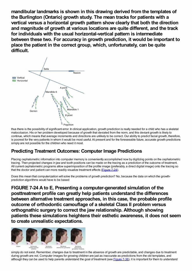
mandibular landmarks is shown in this drawing derived from the templates ofthe Burlington (Ontario) growth study. The mean tracks for patients with avertical versus a horizontal growth pattern show clearly that both the directionand magnitude of growth at various locations are quite different, and the trackfor individuals with the usual horizontal-vertical pattern is intermediatebetween these two. For accuracy in growth prediction, it would be important toplace the patient in the correct group, which, unfortunately, can be quitedifficult.
thus there is the possibility of significant error. In clinical application, growth prediction is really needed for a child who has a skeletalmalocclusion. His or her problem developed because of growth that deviated from the norm, and this deviant growth is likely tocontinue, which means that average increments and directions are unlikely to be correct. Our ability to predict facial growth, therefore,is poorest for the very patients in whom it would be most useful. At present and for the foreseeable future, accurate growth predictionssimply are not possible for the children who need it most.
Predicting Treatment Outcomes: Computer Image PredictionsPlacing cephalometric information into computer memory is conveniently accomplished now by digitizing points on the cephalometrictracing. Then projected changes in jaw and tooth positions can be made on the tracing as a prediction of the outcome of treatment.All current cephalometric programs allow superimposition of the profile image (preferably, a direct digital image) onto the tracing sothat the doctor and patient can more readily visualize treatment effects (Figure 7-24).
Does this mean that computerization will solve the problems of growth prediction? No, because the data on which the growth-prediction algorithms would have to be based
FIGURE 7-24 A to E, Presenting a computer-generated simulation of theposttreatment profile can greatly help patients understand the differencesbetween alternative treatment approaches, in this case, the probable profileoutcome of orthodontic camouflage of a skeletal Class II problem versusorthognathic surgery to correct the jaw relationship. Although showingpatients these simulations heightens their esthetic awareness, it does not seemto create unrealistic expectations.
simply do not exist. Remember, changes due to treatment in the absence of growth are predictable, and changes due to treatmentduring growth are not. Computer images for growing children are just as inaccurate as predictions from the old templates, andalthough they can be used to help parents understand the goal of treatment (see Figure 7-36), it is important for them to understand
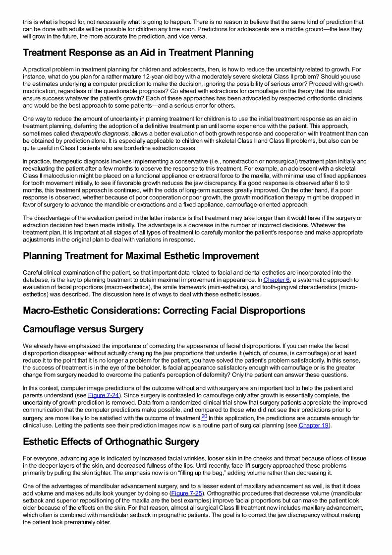
this is what is hoped for, not necessarily what is going to happen. There is no reason to believe that the same kind of prediction thatcan be done with adults will be possible for children any time soon. Predictions for adolescents are a middle ground—the less theywill grow in the future, the more accurate the prediction, and vice versa.
Treatment Response as an Aid in Treatment PlanningA practical problem in treatment planning for children and adolescents, then, is how to reduce the uncertainty related to growth. Forinstance, what do you plan for a rather mature 12-year-old boy with a moderately severe skeletal Class II problem? Should you usethe estimates underlying a computer prediction to make the decision, ignoring the possibility of serious error? Proceed with growthmodification, regardless of the questionable prognosis? Go ahead with extractions for camouflage on the theory that this wouldensure success whatever the patient's growth? Each of these approaches has been advocated by respected orthodontic cliniciansand would be the best approach to some patients—and a serious error for others.
One way to reduce the amount of uncertainty in planning treatment for children is to use the initial treatment response as an aid intreatment planning, deferring the adoption of a definitive treatment plan until some experience with the patient. This approach,sometimes called therapeutic diagnosis, allows a better evaluation of both growth response and cooperation with treatment than canbe obtained by prediction alone. It is especially applicable to children with skeletal Class II and Class III problems, but also can bequite useful in Class I patients who are borderline extraction cases.
In practice, therapeutic diagnosis involves implementing a conservative (i.e., nonextraction or nonsurgical) treatment plan initially andreevaluating the patient after a few months to observe the response to this treatment. For example, an adolescent with a skeletalClass II malocclusion might be placed on a functional appliance or extraoral force to the maxilla, with minimal use of fixed appliancesfor tooth movement initially, to see if favorable growth reduces the jaw discrepancy. If a good response is observed after 6 to 9months, this treatment approach is continued, with the odds of long-term success greatly improved. On the other hand, if a poorresponse is observed, whether because of poor cooperation or poor growth, the growth modification therapy might be dropped infavor of surgery to advance the mandible or extractions and a fixed appliance, camouflage-oriented approach.
The disadvantage of the evaluation period in the latter instance is that treatment may take longer than it would have if the surgery orextraction decision had been made initially. The advantage is a decrease in the number of incorrect decisions. Whatever thetreatment plan, it is important at all stages of all types of treatment to carefully monitor the patient's response and make appropriateadjustments in the original plan to deal with variations in response.
Planning Treatment for Maximal Esthetic ImprovementCareful clinical examination of the patient, so that important data related to facial and dental esthetics are incorporated into thedatabase, is the key to planning treatment to obtain maximal improvement in appearance. In Chapter 6, a systematic approach toevaluation of facial proportions (macro-esthetics), the smile framework (mini-esthetics), and tooth-gingival characteristics (micro-esthetics) was described. The discussion here is of ways to deal with these esthetic issues.
Macro-Esthetic Considerations: Correcting Facial Disproportions
Camouflage versus SurgeryWe already have emphasized the importance of correcting the appearance of facial disproportions. If you can make the facialdisproportion disappear without actually changing the jaw proportions that underlie it (which, of course, is camouflage) or at leastreduce it to the point that it is no longer a problem for the patient, you have solved the patient's problem satisfactorily. In this sense,the success of treatment is in the eye of the beholder. Is facial appearance satisfactory enough with camouflage or is the greaterchange from surgery needed to overcome the patient's perception of deformity? Only the patient can answer these questions.
In this context, computer image predictions of the outcome without and with surgery are an important tool to help the patient andparents understand (see Figure 7-24). Since surgery is contrasted to camouflage only after growth is essentially complete, theuncertainty of growth prediction is removed. Data from a randomized clinical trial show that surgery patients appreciate the improvedcommunication that the computer predictions make possible, and compared to those who did not see their predictions prior tosurgery, are more likely to be satisfied with the outcome of treatment.20 In this application, the predictions are accurate enough forclinical use. Letting the patients see their prediction images now is a routine part of surgical planning (see Chapter 19).
Esthetic Effects of Orthognathic SurgeryFor everyone, advancing age is indicated by increased facial wrinkles, looser skin in the cheeks and throat because of loss of tissuein the deeper layers of the skin, and decreased fullness of the lips. Until recently, face lift surgery approached these problemsprimarily by pulling the skin tighter. The emphasis now is on “filling up the bag,” adding volume rather than decreasing it.
One of the advantages of mandibular advancement surgery, and to a lesser extent of maxillary advancement as well, is that it doesadd volume and makes adults look younger by doing so (Figure 7-25). Orthognathic procedures that decrease volume (mandibularsetback and superior repositioning of the maxilla are the best examples) improve facial proportions but can make the patient lookolder because of the effects on the skin. For that reason, almost all surgical Class III treatment now includes maxillary advancement,which often is combined with mandibular setback in prognathic patients. The goal is to correct the jaw discrepancy without makingthe patient look prematurely older.
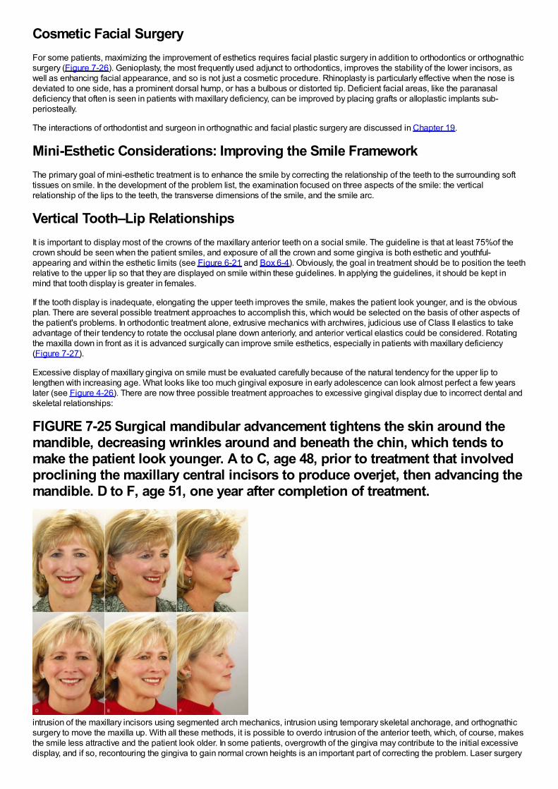
Cosmetic Facial SurgeryFor some patients, maximizing the improvement of esthetics requires facial plastic surgery in addition to orthodontics or orthognathicsurgery (Figure 7-26). Genioplasty, the most frequently used adjunct to orthodontics, improves the stability of the lower incisors, aswell as enhancing facial appearance, and so is not just a cosmetic procedure. Rhinoplasty is particularly effective when the nose isdeviated to one side, has a prominent dorsal hump, or has a bulbous or distorted tip. Deficient facial areas, like the paranasaldeficiency that often is seen in patients with maxillary deficiency, can be improved by placing grafts or alloplastic implants sub-periosteally.
The interactions of orthodontist and surgeon in orthognathic and facial plastic surgery are discussed in Chapter 19.
Mini-Esthetic Considerations: Improving the Smile FrameworkThe primary goal of mini-esthetic treatment is to enhance the smile by correcting the relationship of the teeth to the surrounding softtissues on smile. In the development of the problem list, the examination focused on three aspects of the smile: the verticalrelationship of the lips to the teeth, the transverse dimensions of the smile, and the smile arc.
Vertical Tooth–Lip RelationshipsIt is important to display most of the crowns of the maxillary anterior teeth on a social smile. The guideline is that at least 75%of thecrown should be seen when the patient smiles, and exposure of all the crown and some gingiva is both esthetic and youthful-appearing and within the esthetic limits (see Figure 6-21 and Box 6-4). Obviously, the goal in treatment should be to position the teethrelative to the upper lip so that they are displayed on smile within these guidelines. In applying the guidelines, it should be kept inmind that tooth display is greater in females.
If the tooth display is inadequate, elongating the upper teeth improves the smile, makes the patient look younger, and is the obviousplan. There are several possible treatment approaches to accomplish this, which would be selected on the basis of other aspects ofthe patient's problems. In orthodontic treatment alone, extrusive mechanics with archwires, judicious use of Class II elastics to takeadvantage of their tendency to rotate the occlusal plane down anteriorly, and anterior vertical elastics could be considered. Rotatingthe maxilla down in front as it is advanced surgically can improve smile esthetics, especially in patients with maxillary deficiency(Figure 7-27).
Excessive display of maxillary gingiva on smile must be evaluated carefully because of the natural tendency for the upper lip tolengthen with increasing age. What looks like too much gingival exposure in early adolescence can look almost perfect a few yearslater (see Figure 4-26). There are now three possible treatment approaches to excessive gingival display due to incorrect dental andskeletal relationships:
FIGURE 7-25 Surgical mandibular advancement tightens the skin around themandible, decreasing wrinkles around and beneath the chin, which tends tomake the patient look younger. A to C, age 48, prior to treatment that involvedproclining the maxillary central incisors to produce overjet, then advancing themandible. D to F, age 51, one year after completion of treatment.
intrusion of the maxillary incisors using segmented arch mechanics, intrusion using temporary skeletal anchorage, and orthognathicsurgery to move the maxilla up. With all these methods, it is possible to overdo intrusion of the anterior teeth, which, of course, makesthe smile less attractive and the patient look older. In some patients, overgrowth of the gingiva may contribute to the initial excessivedisplay, and if so, recontouring the gingiva to gain normal crown heights is an important part of correcting the problem. Laser surgery
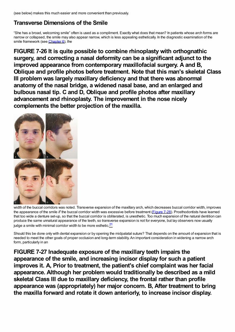
(see below) makes this much easier and more convenient than previously.
Transverse Dimensions of the Smile“She has a broad, welcoming smile” often is used as a compliment. Exactly what does that mean? In patients whose arch forms arenarrow or collapsed, the smile may also appear narrow, which is less appealing esthetically. In the diagnostic examination of thesmile framework (see Chapter 6), the
FIGURE 7-26 It is quite possible to combine rhinoplasty with orthognathicsurgery, and correcting a nasal deformity can be a significant adjunct to theimproved appearance from contemporary maxillofacial surgery. A and B,Oblique and profile photos before treatment. Note that this man's skeletal ClassIII problem was largely maxillary deficiency and that there was abnormalanatomy of the nasal bridge, a widened nasal base, and an enlarged andbulbous nasal tip. C and D, Oblique and profile photos after maxillaryadvancement and rhinoplasty. The improvement in the nose nicelycomplements the better projection of the maxilla.
width of the buccal corridors was noted. Transverse expansion of the maxillary arch, which decreases buccal corridor width, improvesthe appearance of the smile if the buccal corridor width was excessive before treatment (Figure 7-28). Prosthodontists have learnedthat too wide a denture set-up, so that the buccal corridor is obliterated, is unesthetic. Too much expansion of the natural dentition canproduce the same unnatural appearance of the teeth, so transverse expansion is not for everyone, but lay observers now usuallyjudge a smile with minimal corridor width to be more esthetic.21
Should this be done only with dental expansion or by opening the midpalatal suture? That depends on the amount of expansion that isneeded to meet the other goals of proper occlusion and long-term stability. An important consideration in widening a narrow archform, particularly in an
FIGURE 7-27 Inadequate exposure of the maxillary teeth impairs theappearance of the smile, and increasing incisor display for such a patientimproves it. A, Prior to treatment, the patient's chief complaint was her facialappearance. Although her problem would traditionally be described as a mildskeletal Class III due to maxillary deficiency, the frontal rather than profileappearance was (appropriately) her major concern. B, After treatment to bringthe maxilla forward and rotate it down anteriorly, to increase incisor display.
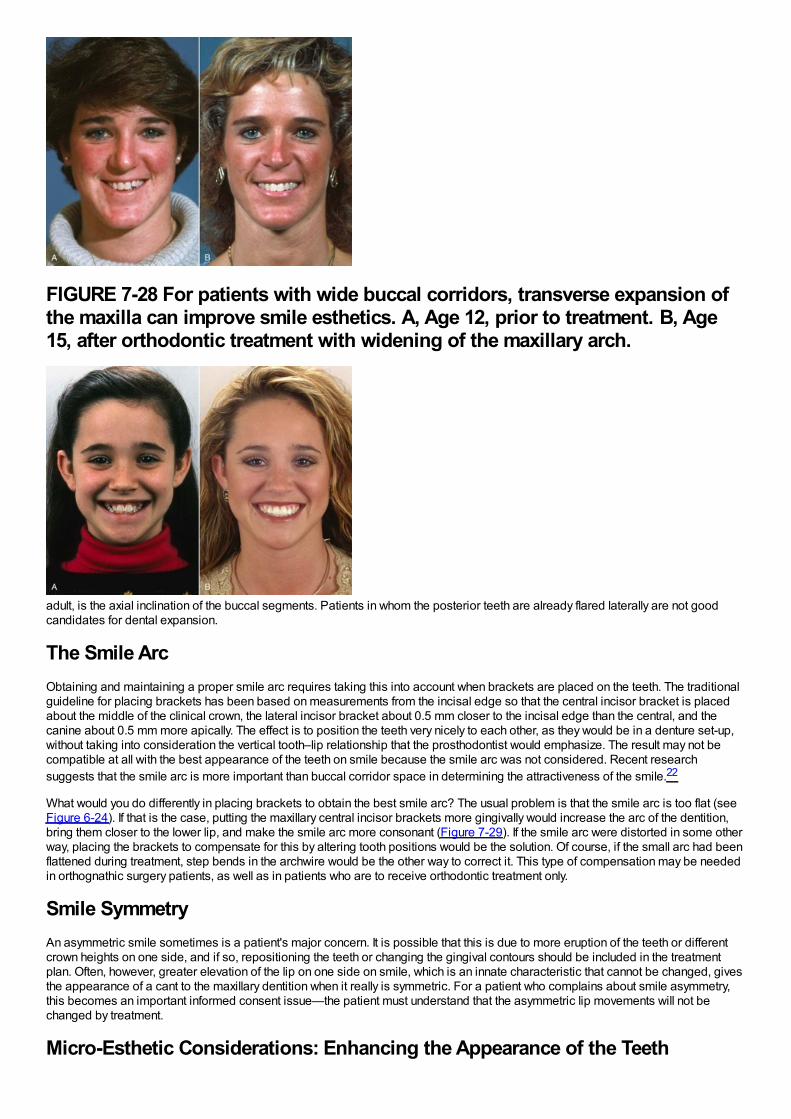
FIGURE 7-28 For patients with wide buccal corridors, transverse expansion ofthe maxilla can improve smile esthetics. A, Age 12, prior to treatment. B, Age15, after orthodontic treatment with widening of the maxillary arch.
adult, is the axial inclination of the buccal segments. Patients in whom the posterior teeth are already flared laterally are not goodcandidates for dental expansion.
The Smile ArcObtaining and maintaining a proper smile arc requires taking this into account when brackets are placed on the teeth. The traditionalguideline for placing brackets has been based on measurements from the incisal edge so that the central incisor bracket is placedabout the middle of the clinical crown, the lateral incisor bracket about 0.5 mm closer to the incisal edge than the central, and thecanine about 0.5 mm more apically. The effect is to position the teeth very nicely to each other, as they would be in a denture set-up,without taking into consideration the vertical tooth–lip relationship that the prosthodontist would emphasize. The result may not becompatible at all with the best appearance of the teeth on smile because the smile arc was not considered. Recent researchsuggests that the smile arc is more important than buccal corridor space in determining the attractiveness of the smile.22
What would you do differently in placing brackets to obtain the best smile arc? The usual problem is that the smile arc is too flat (seeFigure 6-24). If that is the case, putting the maxillary central incisor brackets more gingivally would increase the arc of the dentition,bring them closer to the lower lip, and make the smile arc more consonant (Figure 7-29). If the smile arc were distorted in some otherway, placing the brackets to compensate for this by altering tooth positions would be the solution. Of course, if the small arc had beenflattened during treatment, step bends in the archwire would be the other way to correct it. This type of compensation may be neededin orthognathic surgery patients, as well as in patients who are to receive orthodontic treatment only.
Smile SymmetryAn asymmetric smile sometimes is a patient's major concern. It is possible that this is due to more eruption of the teeth or differentcrown heights on one side, and if so, repositioning the teeth or changing the gingival contours should be included in the treatmentplan. Often, however, greater elevation of the lip on one side on smile, which is an innate characteristic that cannot be changed, givesthe appearance of a cant to the maxillary dentition when it really is symmetric. For a patient who complains about smile asymmetry,this becomes an important informed consent issue—the patient must understand that the asymmetric lip movements will not bechanged by treatment.
Micro-Esthetic Considerations: Enhancing the Appearance of the Teeth
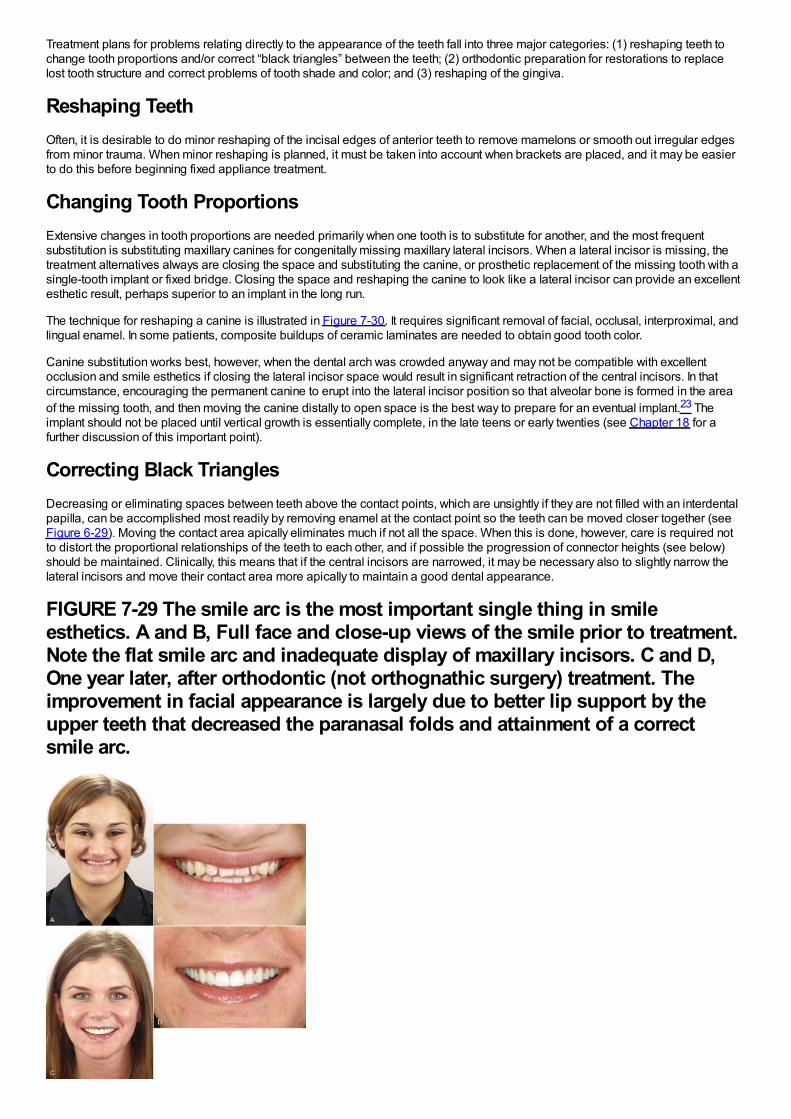
Treatment plans for problems relating directly to the appearance of the teeth fall into three major categories: (1) reshaping teeth tochange tooth proportions and/or correct “black triangles” between the teeth; (2) orthodontic preparation for restorations to replacelost tooth structure and correct problems of tooth shade and color; and (3) reshaping of the gingiva.
Reshaping TeethOften, it is desirable to do minor reshaping of the incisal edges of anterior teeth to remove mamelons or smooth out irregular edgesfrom minor trauma. When minor reshaping is planned, it must be taken into account when brackets are placed, and it may be easierto do this before beginning fixed appliance treatment.
Changing Tooth ProportionsExtensive changes in tooth proportions are needed primarily when one tooth is to substitute for another, and the most frequentsubstitution is substituting maxillary canines for congenitally missing maxillary lateral incisors. When a lateral incisor is missing, thetreatment alternatives always are closing the space and substituting the canine, or prosthetic replacement of the missing tooth with asingle-tooth implant or fixed bridge. Closing the space and reshaping the canine to look like a lateral incisor can provide an excellentesthetic result, perhaps superior to an implant in the long run.
The technique for reshaping a canine is illustrated in Figure 7-30. It requires significant removal of facial, occlusal, interproximal, andlingual enamel. In some patients, composite buildups of ceramic laminates are needed to obtain good tooth color.
Canine substitution works best, however, when the dental arch was crowded anyway and may not be compatible with excellentocclusion and smile esthetics if closing the lateral incisor space would result in significant retraction of the central incisors. In thatcircumstance, encouraging the permanent canine to erupt into the lateral incisor position so that alveolar bone is formed in the areaof the missing tooth, and then moving the canine distally to open space is the best way to prepare for an eventual implant.23 Theimplant should not be placed until vertical growth is essentially complete, in the late teens or early twenties (see Chapter 18 for afurther discussion of this important point).
Correcting Black TrianglesDecreasing or eliminating spaces between teeth above the contact points, which are unsightly if they are not filled with an interdentalpapilla, can be accomplished most readily by removing enamel at the contact point so the teeth can be moved closer together (seeFigure 6-29). Moving the contact area apically eliminates much if not all the space. When this is done, however, care is required notto distort the proportional relationships of the teeth to each other, and if possible the progression of connector heights (see below)should be maintained. Clinically, this means that if the central incisors are narrowed, it may be necessary also to slightly narrow thelateral incisors and move their contact area more apically to maintain a good dental appearance.
FIGURE 7-29 The smile arc is the most important single thing in smileesthetics. A and B, Full face and close-up views of the smile prior to treatment.Note the flat smile arc and inadequate display of maxillary incisors. C and D,One year later, after orthodontic (not orthognathic surgery) treatment. Theimprovement in facial appearance is largely due to better lip support by theupper teeth that decreased the paranasal folds and attainment of a correctsmile arc.
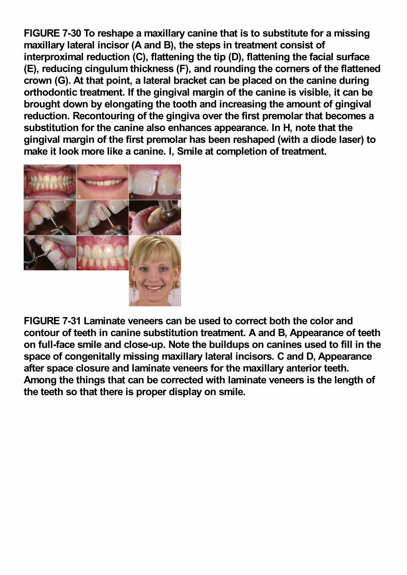
FIGURE 7-30 To reshape a maxillary canine that is to substitute for a missingmaxillary lateral incisor (A and B), the steps in treatment consist ofinterproximal reduction (C), flattening the tip (D), flattening the facial surface(E), reducing cingulum thickness (F), and rounding the corners of the flattenedcrown (G). At that point, a lateral bracket can be placed on the canine duringorthodontic treatment. If the gingival margin of the canine is visible, it can bebrought down by elongating the tooth and increasing the amount of gingivalreduction. Recontouring of the gingiva over the first premolar that becomes asubstitution for the canine also enhances appearance. In H, note that thegingival margin of the first premolar has been reshaped (with a diode laser) tomake it look more like a canine. I, Smile at completion of treatment.
FIGURE 7-31 Laminate veneers can be used to correct both the color andcontour of teeth in canine substitution treatment. A and B, Appearance of teethon full-face smile and close-up. Note the buildups on canines used to fill in thespace of congenitally missing maxillary lateral incisors. C and D, Appearanceafter space closure and laminate veneers for the maxillary anterior teeth.Among the things that can be corrected with laminate veneers is the length ofthe teeth so that there is proper display on smile.
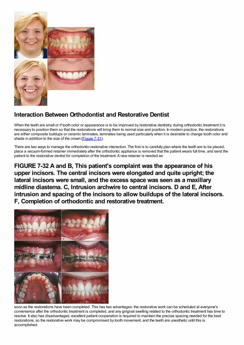
Interaction Between Orthodontist and Restorative DentistWhen the teeth are small or if tooth color or appearance is to be improved by restorative dentistry, during orthodontic treatment it isnecessary to position them so that the restorations will bring them to normal size and position. In modern practice, the restorationsare either composite buildups or ceramic laminates, laminates being used particularly when it is desirable to change tooth color andshade in addition to the size of the crown (Figure 7-31).
There are two ways to manage the orthodontic-restorative interaction. The first is to carefully plan where the teeth are to be placed,place a vacuum-formed retainer immediately after the orthodontic appliance is removed that the patient wears full time, and send thepatient to the restorative dentist for completion of the treatment. A new retainer is needed as
FIGURE 7-32 A and B, This patient's complaint was the appearance of hisupper incisors. The central incisors were elongated and quite upright; thelateral incisors were small, and the excess space was seen as a maxillarymidline diastema. C, Intrusion archwire to central incisors. D and E, Afterintrusion and spacing of the incisors to allow buildups of the lateral incisors.F, Completion of orthodontic and restorative treatment.
soon as the restorations have been completed. This has two advantages: the restorative work can be scheduled at everyone'sconvenience after the orthodontic treatment is completed, and any gingival swelling related to the orthodontic treatment has time toresolve. It also has disadvantages: excellent patient cooperation is required to maintain the precise spacing needed for the bestrestorations, so the restorative work may be compromised by tooth movement, and the teeth are unesthetic until this isaccomplished.
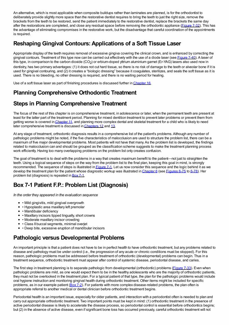
An alternative, which is most applicable when composite buildups rather than laminates are planned, is for the orthodontist todeliberately provide slightly more space than the restorative dentist requires to bring the teeth to just the right size, remove thebrackets from the teeth to be restored, send the patient immediately to the restorative dentist, replace the brackets the same dayafter the restorations are completed, and close any residual space before removing the orthodontic appliance (Figure 7-32). This hasthe advantage of eliminating compromises in the restorative work, but the disadvantage that careful coordination of the appointmentsis required.
Reshaping Gingival Contours: Applications of a Soft Tissue LaserAppropriate display of the teeth requires removal of excessive gingiva covering the clinical crown, and is enhanced by correcting thegingival contours. Treatment of this type now can be carried out effectively with the use of a diode laser (see Figure 7-40). A laser ofthis type, in comparison to the carbon dioxide (CO2) or erbium-doped yttrium aluminium garnet (Er-YAG) lasers also used now indentistry, has two primary advantages: (1) it does not cut hard tissue, so there is no risk of damage to the teeth or alveolar bone if it isused for gingival contouring, and (2) it creates a “biologic dressing” because it coagulates, sterilizes, and seals the soft tissue as it isused. There is no bleeding, no other dressing is required, and there is no waiting period for healing.
Use of a soft tissue laser as part of finishing procedures is discussed further in Chapter 16.
Planning Comprehensive Orthodontic Treatment
Steps in Planning Comprehensive TreatmentThe focus of the rest of this chapter is on comprehensive treatment, in adolescence or later, when the permanent teeth are present atleast for the latter part of the treatment period. Planning for mixed dentition treatment to prevent later problems or prevent them fromgetting worse is covered in Chapter 11, and planning more complex dental and skeletal treatment for a child who is likely to needlater comprehensive treatment is discussed in Chapters 12 and 13.
At any stage of treatment, orthodontic diagnosis results in a comprehensive list of the patient's problems. Although any number ofpathologic problems might be noted, if the five characteristics of malocclusion are used to structure the problem list, there can be amaximum of five major developmental problems. Most patients will not have that many. As the problem list is developed, the findingsrelated to malocclusion can and should be grouped as the classification scheme suggests to make the treatment planning processwork efficiently. Having too many overlapping problems on the problem list only creates confusion.
The goal of treatment is to deal with the problems in a way that creates maximum benefit to the patient—not just to straighten theteeth. Using a logical sequence of steps on the way from the problem list to the final plan, keeping this goal in mind, is stronglyrecommended. The sequence of steps is illustrated in Figure 7-1. Let us now consider this sequence and the logic behind it as wedevelop the treatment plan for the patient whose diagnostic workup was illustrated in Chapter 6 (see Figures 6-75 to 6-78). Herproblem list (diagnosis) is repeated in Box 7-1.
Box 7-1 Patient F.P.: Problem List (Diagnosis)In the order they appeared in the evaluation sequence
• Mild gingivitis, mild gingival overgrowth• Hypoplastic area maxillary left premolar• Mandibular deficiency• Maxillary incisors tipped lingually, short crowns• Moderate maxillary incisor crowding• Class II buccal segments, minimal overjet• Deep bite, excessive eruption of mandibular incisors
Pathologic versus Developmental ProblemsAn important principle is that a patient does not have to be in perfect health to have orthodontic treatment, but any problems related todisease and pathology must be under control (i.e., the progression of any acute or chronic conditions must be stopped). For thisreason, pathologic problems must be addressed before treatment of orthodontic (developmental) problems can begin. Thus in atreatment sequence, orthodontic treatment must appear after control of systemic disease, periodontal disease, and caries.
The first step in treatment planning is to separate pathologic from developmental (orthodontic) problems (Figure 7-33). Even whenpathologic problems are mild, as one would expect them to be in the healthy adolescents who are the majority of orthodontic patients,they must not be overlooked in the treatment plan. For a typical patient of that type, the plan for the pathologic problems would includeoral hygiene instruction and monitoring gingival health during orthodontic treatment. Other items might be included for specificproblems, as in our example patient (Box 7-2). For patients with more complex disease-related problems, the plan often isappropriate referral to another medical or dental clinician before orthodontic treatment begins.
Periodontal health is an important issue, especially for older patients, and interaction with a periodontist often is needed to plan andcarry out appropriate orthodontic treatment. Two important points must be kept in mind: (1) orthodontic treatment in the presence ofactive periodontal disease is likely to accelerate the disease process, so periodontal control is essential before orthodontics begins;but (2) in the absence of active disease, even if significant bone loss has occurred previously, careful orthodontic treatment will not
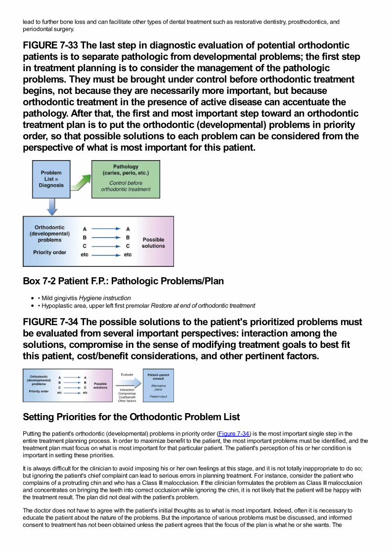
lead to further bone loss and can facilitate other types of dental treatment such as restorative dentistry, prosthodontics, andperiodontal surgery.
FIGURE 7-33 The last step in diagnostic evaluation of potential orthodonticpatients is to separate pathologic from developmental problems; the first stepin treatment planning is to consider the management of the pathologicproblems. They must be brought under control before orthodontic treatmentbegins, not because they are necessarily more important, but becauseorthodontic treatment in the presence of active disease can accentuate thepathology. After that, the first and most important step toward an orthodontictreatment plan is to put the orthodontic (developmental) problems in priorityorder, so that possible solutions to each problem can be considered from theperspective of what is most important for this patient.
Box 7-2 Patient F.P.: Pathologic Problems/Plan• Mild gingivitis Hygiene instruction• Hypoplastic area, upper left first premolar Restore at end of orthodontic treatment
FIGURE 7-34 The possible solutions to the patient's prioritized problems mustbe evaluated from several important perspectives: interaction among thesolutions, compromise in the sense of modifying treatment goals to best fitthis patient, cost/benefit considerations, and other pertinent factors.
Setting Priorities for the Orthodontic Problem ListPutting the patient's orthodontic (developmental) problems in priority order (Figure 7-34) is the most important single step in theentire treatment planning process. In order to maximize benefit to the patient, the most important problems must be identified, and thetreatment plan must focus on what is most important for that particular patient. The patient's perception of his or her condition isimportant in setting these priorities.
It is always difficult for the clinician to avoid imposing his or her own feelings at this stage, and it is not totally inappropriate to do so;but ignoring the patient's chief complaint can lead to serious errors in planning treatment. For instance, consider the patient whocomplains of a protruding chin and who has a Class III malocclusion. If the clinician formulates the problem as Class III malocclusionand concentrates on bringing the teeth into correct occlusion while ignoring the chin, it is not likely that the patient will be happy withthe treatment result. The plan did not deal with the patient's problem.
The doctor does not have to agree with the patient's initial thoughts as to what is most important. Indeed, often it is necessary toeducate the patient about the nature of the problems. But the importance of various problems must be discussed, and informedconsent to treatment has not been obtained unless the patient agrees that the focus of the plan is what he or she wants. The
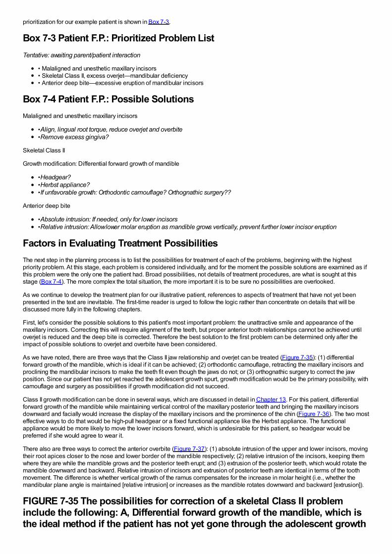
prioritization for our example patient is shown in Box 7-3.
Box 7-3 Patient F.P.: Prioritized Problem ListTentative: awaiting parent/patient interaction
• Malaligned and unesthetic maxillary incisors• Skeletal Class II, excess overjet—mandibular deficiency• Anterior deep bite—excessive eruption of mandibular incisors
Box 7-4 Patient F.P.: Possible SolutionsMalaligned and unesthetic maxillary incisors
•Align, lingual root torque, reduce overjet and overbite•Remove excess gingiva?
Skeletal Class II
Growth modification: Differential forward growth of mandible
•Headgear?•Herbst appliance?•If unfavorable growth: Orthodontic camouflage? Orthognathic surgery??
Anterior deep bite
•Absolute intrusion: If needed, only for lower incisors•Relative intrusion: Allow lower molar eruption as mandible grows vertically, prevent further lower incisor eruption
Factors in Evaluating Treatment PossibilitiesThe next step in the planning process is to list the possibilities for treatment of each of the problems, beginning with the highestpriority problem. At this stage, each problem is considered individually, and for the moment the possible solutions are examined as ifthis problem were the only one the patient had. Broad possibilities, not details of treatment procedures, are what is sought at thisstage (Box 7-4). The more complex the total situation, the more important it is to be sure no possibilities are overlooked.
As we continue to develop the treatment plan for our illustrative patient, references to aspects of treatment that have not yet beenpresented in the text are inevitable. The first-time reader is urged to follow the logic rather than concentrate on details that will bediscussed more fully in the following chapters.
First, let's consider the possible solutions to this patient's most important problem: the unattractive smile and appearance of themaxillary incisors. Correcting this will require alignment of the teeth, but proper anterior tooth relationships cannot be achieved untiloverjet is reduced and the deep bite is corrected. Therefore the best solution to the first problem can be determined only after theimpact of possible solutions to overjet and overbite have been considered.
As we have noted, there are three ways that the Class II jaw relationship and overjet can be treated (Figure 7-35): (1) differentialforward growth of the mandible, which is ideal if it can be achieved; (2) orthodontic camouflage, retracting the maxillary incisors andproclining the mandibular incisors to make the teeth fit even though the jaws do not; or (3) orthognathic surgery to correct the jawposition. Since our patient has not yet reached the adolescent growth spurt, growth modification would be the primary possibility, withcamouflage and surgery as possibilities if growth modification did not succeed.
Class II growth modification can be done in several ways, which are discussed in detail in Chapter 13. For this patient, differentialforward growth of the mandible while maintaining vertical control of the maxillary posterior teeth and bringing the maxillary incisorsdownward and facially would increase the display of the maxillary incisors and the prominence of the chin (Figure 7-36). The two mosteffective ways to do that would be high-pull headgear or a fixed functional appliance like the Herbst appliance. The functionalappliance would be more likely to move the lower incisors forward, which is undesirable for this patient, so headgear would bepreferred if she would agree to wear it.
There also are three ways to correct the anterior overbite (Figure 7-37): (1) absolute intrusion of the upper and lower incisors, movingtheir root apices closer to the nose and lower border of the mandible respectively; (2) relative intrusion of the incisors, keeping themwhere they are while the mandible grows and the posterior teeth erupt; and (3) extrusion of the posterior teeth, which would rotate themandible downward and backward. Relative intrusion of incisors and extrusion of posterior teeth are identical in terms of the toothmovement. The difference is whether vertical growth of the ramus compensates for the increase in molar height (i.e., whether themandibular plane angle is maintained [relative intrusion] or increases as the mandible rotates downward and backward [extrusion]).
FIGURE 7-35 The possibilities for correction of a skeletal Class II probleminclude the following: A, Differential forward growth of the mandible, which isthe ideal method if the patient has not yet gone through the adolescent growth
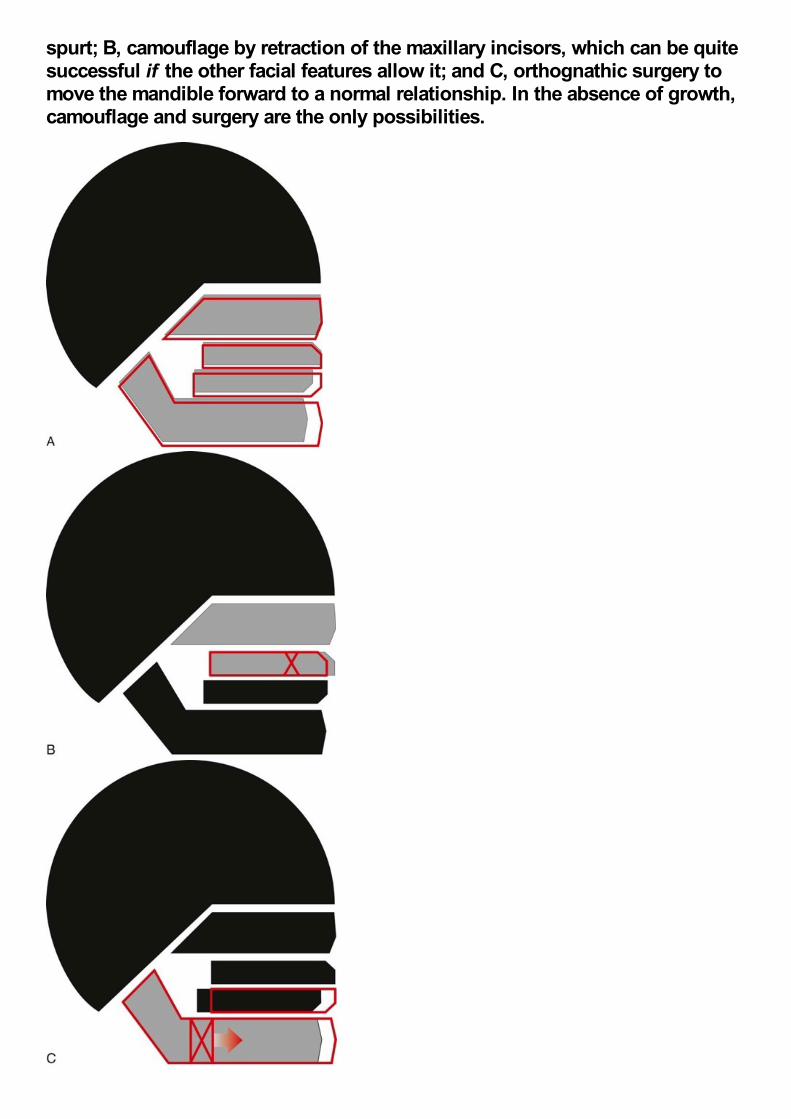
spurt; B, camouflage by retraction of the maxillary incisors, which can be quitesuccessful if the other facial features allow it; and C, orthognathic surgery tomove the mandible forward to a normal relationship. In the absence of growth,camouflage and surgery are the only possibilities.
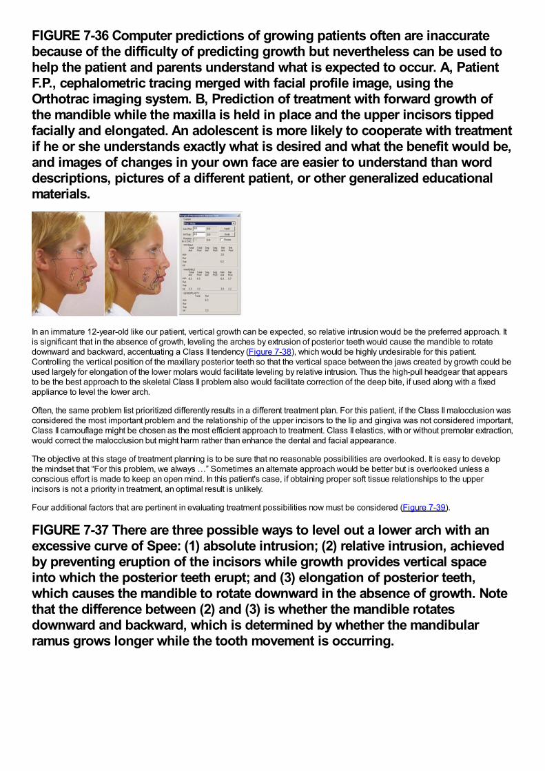
FIGURE 7-36 Computer predictions of growing patients often are inaccuratebecause of the difficulty of predicting growth but nevertheless can be used tohelp the patient and parents understand what is expected to occur. A, PatientF.P., cephalometric tracing merged with facial profile image, using theOrthotrac imaging system. B, Prediction of treatment with forward growth ofthe mandible while the maxilla is held in place and the upper incisors tippedfacially and elongated. An adolescent is more likely to cooperate with treatmentif he or she understands exactly what is desired and what the benefit would be,and images of changes in your own face are easier to understand than worddescriptions, pictures of a different patient, or other generalized educationalmaterials.
In an immature 12-year-old like our patient, vertical growth can be expected, so relative intrusion would be the preferred approach. Itis significant that in the absence of growth, leveling the arches by extrusion of posterior teeth would cause the mandible to rotatedownward and backward, accentuating a Class II tendency (Figure 7-38), which would be highly undesirable for this patient.Controlling the vertical position of the maxillary posterior teeth so that the vertical space between the jaws created by growth could beused largely for elongation of the lower molars would facilitate leveling by relative intrusion. Thus the high-pull headgear that appearsto be the best approach to the skeletal Class II problem also would facilitate correction of the deep bite, if used along with a fixedappliance to level the lower arch.
Often, the same problem list prioritized differently results in a different treatment plan. For this patient, if the Class II malocclusion wasconsidered the most important problem and the relationship of the upper incisors to the lip and gingiva was not considered important,Class II camouflage might be chosen as the most efficient approach to treatment. Class II elastics, with or without premolar extraction,would correct the malocclusion but might harm rather than enhance the dental and facial appearance.
The objective at this stage of treatment planning is to be sure that no reasonable possibilities are overlooked. It is easy to developthe mindset that “For this problem, we always …” Sometimes an alternate approach would be better but is overlooked unless aconscious effort is made to keep an open mind. In this patient's case, if obtaining proper soft tissue relationships to the upperincisors is not a priority in treatment, an optimal result is unlikely.
Four additional factors that are pertinent in evaluating treatment possibilities now must be considered (Figure 7-39).
FIGURE 7-37 There are three possible ways to level out a lower arch with anexcessive curve of Spee: (1) absolute intrusion; (2) relative intrusion, achievedby preventing eruption of the incisors while growth provides vertical spaceinto which the posterior teeth erupt; and (3) elongation of posterior teeth,which causes the mandible to rotate downward in the absence of growth. Notethat the difference between (2) and (3) is whether the mandible rotatesdownward and backward, which is determined by whether the mandibularramus grows longer while the tooth movement is occurring.
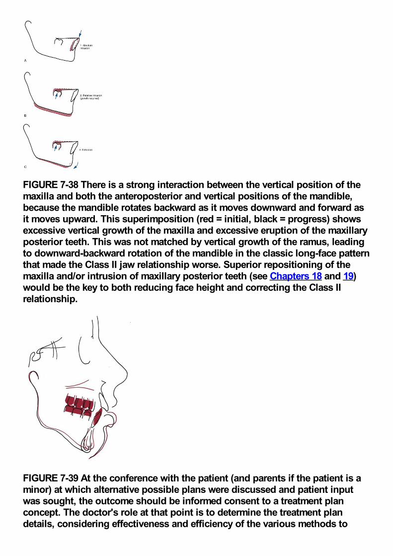
FIGURE 7-38 There is a strong interaction between the vertical position of themaxilla and both the anteroposterior and vertical positions of the mandible,because the mandible rotates backward as it moves downward and forward asit moves upward. This superimposition (red = initial, black = progress) showsexcessive vertical growth of the maxilla and excessive eruption of the maxillaryposterior teeth. This was not matched by vertical growth of the ramus, leadingto downward-backward rotation of the mandible in the classic long-face patternthat made the Class II jaw relationship worse. Superior repositioning of themaxilla and/or intrusion of maxillary posterior teeth (see Chapters 18 and 19)would be the key to both reducing face height and correcting the Class IIrelationship.
FIGURE 7-39 At the conference with the patient (and parents if the patient is aminor) at which alternative possible plans were discussed and patient inputwas sought, the outcome should be informed consent to a treatment planconcept. The doctor's role at that point is to determine the treatment plandetails, considering effectiveness and efficiency of the various methods to
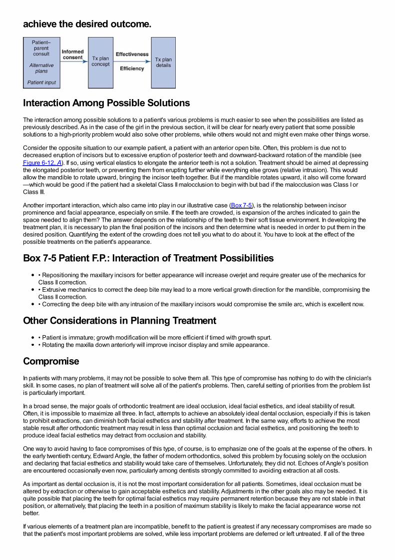
achieve the desired outcome.
Interaction Among Possible SolutionsThe interaction among possible solutions to a patient's various problems is much easier to see when the possibilities are listed aspreviously described. As in the case of the girl in the previous section, it will be clear for nearly every patient that some possiblesolutions to a high-priority problem would also solve other problems, while others would not and might even make other things worse.
Consider the opposite situation to our example patient, a patient with an anterior open bite. Often, this problem is due not todecreased eruption of incisors but to excessive eruption of posterior teeth and downward-backward rotation of the mandible (seeFigure 6-12, A). If so, using vertical elastics to elongate the anterior teeth is not a solution. Treatment should be aimed at depressingthe elongated posterior teeth, or preventing them from erupting further while everything else grows (relative intrusion). This wouldallow the mandible to rotate upward, bringing the incisor teeth together. But if the mandible rotates upward, it also will come forward—which would be good if the patient had a skeletal Class II malocclusion to begin with but bad if the malocclusion was Class I orClass III.
Another important interaction, which also came into play in our illustrative case (Box 7-5), is the relationship between incisorprominence and facial appearance, especially on smile. If the teeth are crowded, is expansion of the arches indicated to gain thespace needed to align them? The answer depends on the relationship of the teeth to their soft tissue environment. In developing thetreatment plan, it is necessary to plan the final position of the incisors and then determine what is needed in order to put them in thedesired position. Quantifying the extent of the crowding does not tell you what to do about it. You have to look at the effect of thepossible treatments on the patient's appearance.
Box 7-5 Patient F.P.: Interaction of Treatment Possibilities• Repositioning the maxillary incisors for better appearance will increase overjet and require greater use of the mechanics forClass II correction.• Extrusive mechanics to correct the deep bite may lead to a more vertical growth direction for the mandible, compromising theClass II correction.• Correcting the deep bite with any intrusion of the maxillary incisors would compromise the smile arc, which is excellent now.
Other Considerations in Planning Treatment• Patient is immature; growth modification will be more efficient if timed with growth spurt.• Rotating the maxilla down anteriorly will improve incisor display and smile appearance.
CompromiseIn patients with many problems, it may not be possible to solve them all. This type of compromise has nothing to do with the clinician'sskill. In some cases, no plan of treatment will solve all of the patient's problems. Then, careful setting of priorities from the problem listis particularly important.
In a broad sense, the major goals of orthodontic treatment are ideal occlusion, ideal facial esthetics, and ideal stability of result.Often, it is impossible to maximize all three. In fact, attempts to achieve an absolutely ideal dental occlusion, especially if this is takento prohibit extractions, can diminish both facial esthetics and stability after treatment. In the same way, efforts to achieve the moststable result after orthodontic treatment may result in less than optimal occlusion and facial esthetics, and positioning the teeth toproduce ideal facial esthetics may detract from occlusion and stability.
One way to avoid having to face compromises of this type, of course, is to emphasize one of the goals at the expense of the others. Inthe early twentieth century, Edward Angle, the father of modern orthodontics, solved this problem by focusing solely on the occlusionand declaring that facial esthetics and stability would take care of themselves. Unfortunately, they did not. Echoes of Angle's positionare encountered occasionally even now, particularly among dentists strongly committed to avoiding extraction at all costs.
As important as dental occlusion is, it is not the most important consideration for all patients. Sometimes, ideal occlusion must bealtered by extraction or otherwise to gain acceptable esthetics and stability. Adjustments in the other goals also may be needed. It isquite possible that placing the teeth for optimal facial esthetics may require permanent retention because they are not stable in thatposition, or alternatively, that placing the teeth in a position of maximum stability is likely to make the facial appearance worse notbetter.
If various elements of a treatment plan are incompatible, benefit to the patient is greatest if any necessary compromises are made sothat the patient's most important problems are solved, while less important problems are deferred or left untreated. If all of the three
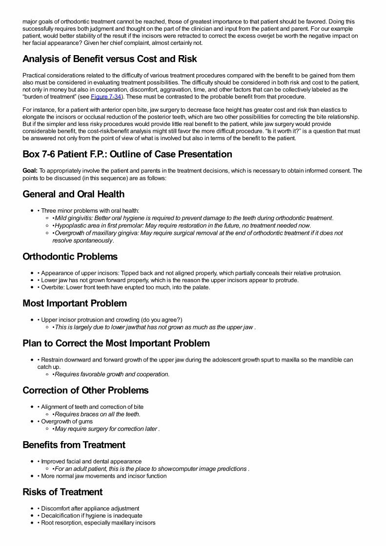
major goals of orthodontic treatment cannot be reached, those of greatest importance to that patient should be favored. Doing thissuccessfully requires both judgment and thought on the part of the clinician and input from the patient and parent. For our examplepatient, would better stability of the result if the incisors were retracted to correct the excess overjet be worth the negative impact onher facial appearance? Given her chief complaint, almost certainly not.
Analysis of Benefit versus Cost and RiskPractical considerations related to the difficulty of various treatment procedures compared with the benefit to be gained from themalso must be considered in evaluating treatment possibilities. The difficulty should be considered in both risk and cost to the patient,not only in money but also in cooperation, discomfort, aggravation, time, and other factors that can be collectively labeled as the“burden of treatment” (see Figure 7-34). These must be contrasted to the probable benefit from that procedure.
For instance, for a patient with anterior open bite, jaw surgery to decrease face height has greater cost and risk than elastics toelongate the incisors or occlusal reduction of the posterior teeth, which are two other possibilities for correcting the bite relationship.But if the simpler and less risky procedures would provide little real benefit to the patient, while jaw surgery would provideconsiderable benefit, the cost-risk/benefit analysis might still favor the more difficult procedure. “Is it worth it?” is a question that mustbe answered not only from the point of view of what is involved but also in terms of the benefit to the patient.
Box 7-6 Patient F.P.: Outline of Case PresentationGoal: To appropriately involve the patient and parents in the treatment decisions, which is necessary to obtain informed consent. Thepoints to be discussed (in this sequence) are as follows:
General and Oral Health• Three minor problems with oral health:
•Mild gingivitis: Better oral hygiene is required to prevent damage to the teeth during orthodontic treatment.•Hypoplastic area in first premolar: May require restoration in the future, no treatment needed now.•Overgrowth of maxillary gingiva: May require surgical removal at the end of orthodontic treatment if it does notresolve spontaneously.
Orthodontic Problems• Appearance of upper incisors: Tipped back and not aligned properly, which partially conceals their relative protrusion.• Lower jaw has not grown forward properly, which is the reason the upper incisors appear to protrude.• Overbite: Lower front teeth have erupted too much, into the palate.
Most Important Problem• Upper incisor protrusion and crowding (do you agree?)
•This is largely due to lower jaw that has not grown as much as the upper jaw .
Plan to Correct the Most Important Problem• Restrain downward and forward growth of the upper jaw during the adolescent growth spurt to maxilla so the mandible cancatch up.
•Requires favorable growth and cooperation.
Correction of Other Problems• Alignment of teeth and correction of bite
•Requires braces on all the teeth.• Overgrowth of gums
•May require surgery for correction later .
Benefits from Treatment• Improved facial and dental appearance
•For an adult patient, this is the place to show computer image predictions .• More normal jaw movements and incisor function
Risks of Treatment• Discomfort after appliance adjustment• Decalcification if hygiene is inadequate• Root resorption, especially maxillary incisors
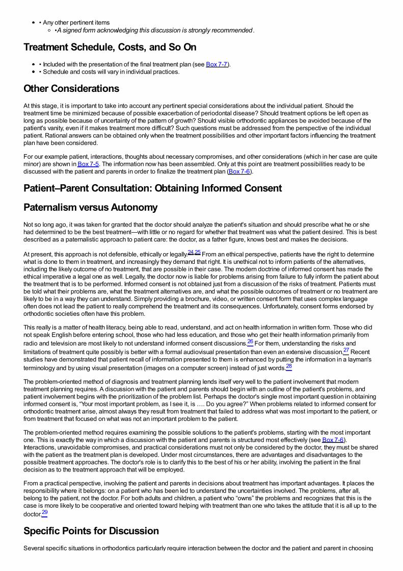
• Any other pertinent items•A signed form acknowledging this discussion is strongly recommended .
Treatment Schedule, Costs, and So On• Included with the presentation of the final treatment plan (see Box 7-7).• Schedule and costs will vary in individual practices.
Other ConsiderationsAt this stage, it is important to take into account any pertinent special considerations about the individual patient. Should thetreatment time be minimized because of possible exacerbation of periodontal disease? Should treatment options be left open aslong as possible because of uncertainty of the pattern of growth? Should visible orthodontic appliances be avoided because of thepatient's vanity, even if it makes treatment more difficult? Such questions must be addressed from the perspective of the individualpatient. Rational answers can be obtained only when the treatment possibilities and other important factors influencing the treatmentplan have been considered.
For our example patient, interactions, thoughts about necessary compromises, and other considerations (which in her case are quiteminor) are shown in Box 7-5. The information now has been assembled. Only at this point are treatment possibilities ready to bediscussed with the patient and parents in order to finalize the treatment plan (Box 7-6).
Patient–Parent Consultation: Obtaining Informed Consent
Paternalism versus AutonomyNot so long ago, it was taken for granted that the doctor should analyze the patient's situation and should prescribe what he or shehad determined to be the best treatment—with little or no regard for whether that treatment was what the patient desired. This is bestdescribed as a paternalistic approach to patient care: the doctor, as a father figure, knows best and makes the decisions.
At present, this approach is not defensible, ethically or legally.24,25 From an ethical perspective, patients have the right to determinewhat is done to them in treatment, and increasingly they demand that right. It is unethical not to inform patients of the alternatives,including the likely outcome of no treatment, that are possible in their case. The modern doctrine of informed consent has made theethical imperative a legal one as well. Legally, the doctor now is liable for problems arising from failure to fully inform the patient aboutthe treatment that is to be performed. Informed consent is not obtained just from a discussion of the risks of treatment. Patients mustbe told what their problems are, what the treatment alternatives are, and what the possible outcomes of treatment or no treatment arelikely to be in a way they can understand. Simply providing a brochure, video, or written consent form that uses complex languageoften does not lead the patient to really comprehend the treatment and its consequences. Unfortunately, consent forms endorsed byorthodontic societies often have this problem.
This really is a matter of health literacy, being able to read, understand, and act on health information in written form. Those who didnot speak English before entering school, those who had less education, and those who get their health information primarily fromradio and television are most likely to not understand informed consent discussions.26 For them, understanding the risks andlimitations of treatment quite possibly is better with a formal audiovisual presentation than even an extensive discussion.27 Recentstudies have demonstrated that patient recall of information presented to them is enhanced by putting the information in a layman'sterminology and by using visual presentation (images on a computer screen) instead of just words.28
The problem-oriented method of diagnosis and treatment planning lends itself very well to the patient involvement that moderntreatment planning requires. A discussion with the patient and parents should begin with an outline of the patient's problems, andpatient involvement begins with the prioritization of the problem list. Perhaps the doctor's single most important question in obtaininginformed consent is, “Your most important problem, as I see it, is …. Do you agree?” When problems related to informed consent fororthodontic treatment arise, almost always they result from treatment that failed to address what was most important to the patient, orfrom treatment that focused on what was not an important problem to the patient.
The problem-oriented method requires examining the possible solutions to the patient's problems, starting with the most importantone. This is exactly the way in which a discussion with the patient and parents is structured most effectively (see Box 7-6).Interactions, unavoidable compromises, and practical considerations must not only be considered by the doctor, they must be sharedwith the patient as the treatment plan is developed. Under most circumstances, there are advantages and disadvantages to thepossible treatment approaches. The doctor's role is to clarify this to the best of his or her ability, involving the patient in the finaldecision as to the treatment approach that will be employed.
From a practical perspective, involving the patient and parents in decisions about treatment has important advantages. It places theresponsibility where it belongs: on a patient who has been led to understand the uncertainties involved. The problems, after all,belong to the patient, not the doctor. For both adults and children, a patient who “owns” the problems and recognizes that this is thecase is more likely to be cooperative and oriented toward helping with treatment than one who takes the attitude that it is all up to thedoctor.29
Specific Points for DiscussionSeveral specific situations in orthodontics particularly require interaction between the doctor and the patient and parent in choosing
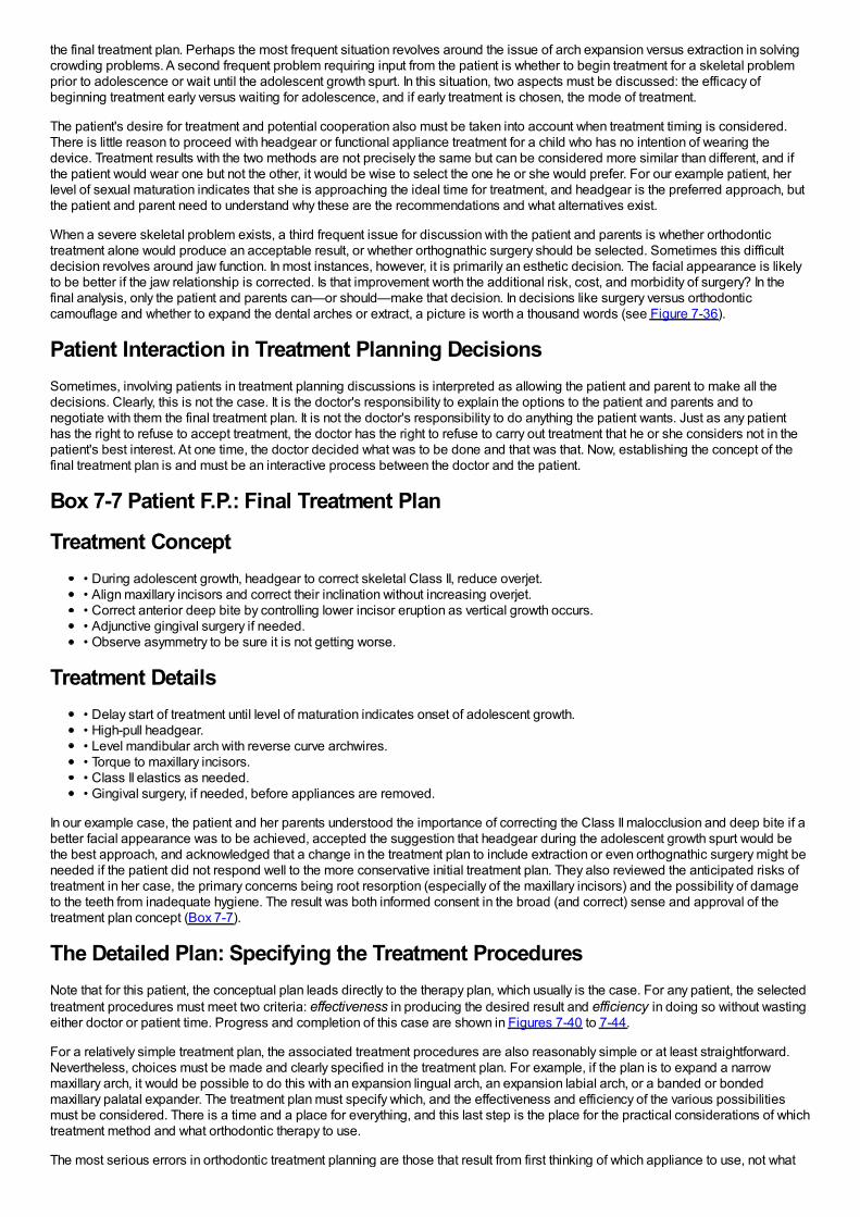
the final treatment plan. Perhaps the most frequent situation revolves around the issue of arch expansion versus extraction in solvingcrowding problems. A second frequent problem requiring input from the patient is whether to begin treatment for a skeletal problemprior to adolescence or wait until the adolescent growth spurt. In this situation, two aspects must be discussed: the efficacy ofbeginning treatment early versus waiting for adolescence, and if early treatment is chosen, the mode of treatment.
The patient's desire for treatment and potential cooperation also must be taken into account when treatment timing is considered.There is little reason to proceed with headgear or functional appliance treatment for a child who has no intention of wearing thedevice. Treatment results with the two methods are not precisely the same but can be considered more similar than different, and ifthe patient would wear one but not the other, it would be wise to select the one he or she would prefer. For our example patient, herlevel of sexual maturation indicates that she is approaching the ideal time for treatment, and headgear is the preferred approach, butthe patient and parent need to understand why these are the recommendations and what alternatives exist.
When a severe skeletal problem exists, a third frequent issue for discussion with the patient and parents is whether orthodontictreatment alone would produce an acceptable result, or whether orthognathic surgery should be selected. Sometimes this difficultdecision revolves around jaw function. In most instances, however, it is primarily an esthetic decision. The facial appearance is likelyto be better if the jaw relationship is corrected. Is that improvement worth the additional risk, cost, and morbidity of surgery? In thefinal analysis, only the patient and parents can—or should—make that decision. In decisions like surgery versus orthodonticcamouflage and whether to expand the dental arches or extract, a picture is worth a thousand words (see Figure 7-36).
Patient Interaction in Treatment Planning DecisionsSometimes, involving patients in treatment planning discussions is interpreted as allowing the patient and parent to make all thedecisions. Clearly, this is not the case. It is the doctor's responsibility to explain the options to the patient and parents and tonegotiate with them the final treatment plan. It is not the doctor's responsibility to do anything the patient wants. Just as any patienthas the right to refuse to accept treatment, the doctor has the right to refuse to carry out treatment that he or she considers not in thepatient's best interest. At one time, the doctor decided what was to be done and that was that. Now, establishing the concept of thefinal treatment plan is and must be an interactive process between the doctor and the patient.
Box 7-7 Patient F.P.: Final Treatment Plan
Treatment Concept• During adolescent growth, headgear to correct skeletal Class II, reduce overjet.• Align maxillary incisors and correct their inclination without increasing overjet.• Correct anterior deep bite by controlling lower incisor eruption as vertical growth occurs.• Adjunctive gingival surgery if needed.• Observe asymmetry to be sure it is not getting worse.
Treatment Details• Delay start of treatment until level of maturation indicates onset of adolescent growth.• High-pull headgear.• Level mandibular arch with reverse curve archwires.• Torque to maxillary incisors.• Class II elastics as needed.• Gingival surgery, if needed, before appliances are removed.
In our example case, the patient and her parents understood the importance of correcting the Class II malocclusion and deep bite if abetter facial appearance was to be achieved, accepted the suggestion that headgear during the adolescent growth spurt would bethe best approach, and acknowledged that a change in the treatment plan to include extraction or even orthognathic surgery might beneeded if the patient did not respond well to the more conservative initial treatment plan. They also reviewed the anticipated risks oftreatment in her case, the primary concerns being root resorption (especially of the maxillary incisors) and the possibility of damageto the teeth from inadequate hygiene. The result was both informed consent in the broad (and correct) sense and approval of thetreatment plan concept (Box 7-7).
The Detailed Plan: Specifying the Treatment ProceduresNote that for this patient, the conceptual plan leads directly to the therapy plan, which usually is the case. For any patient, the selectedtreatment procedures must meet two criteria: effectiveness in producing the desired result and efficiency in doing so without wastingeither doctor or patient time. Progress and completion of this case are shown in Figures 7-40 to 7-44.
For a relatively simple treatment plan, the associated treatment procedures are also reasonably simple or at least straightforward.Nevertheless, choices must be made and clearly specified in the treatment plan. For example, if the plan is to expand a narrowmaxillary arch, it would be possible to do this with an expansion lingual arch, an expansion labial arch, or a banded or bondedmaxillary palatal expander. The treatment plan must specify which, and the effectiveness and efficiency of the various possibilitiesmust be considered. There is a time and a place for everything, and this last step is the place for the practical considerations of whichtreatment method and what orthodontic therapy to use.
The most serious errors in orthodontic treatment planning are those that result from first thinking of which appliance to use, not what
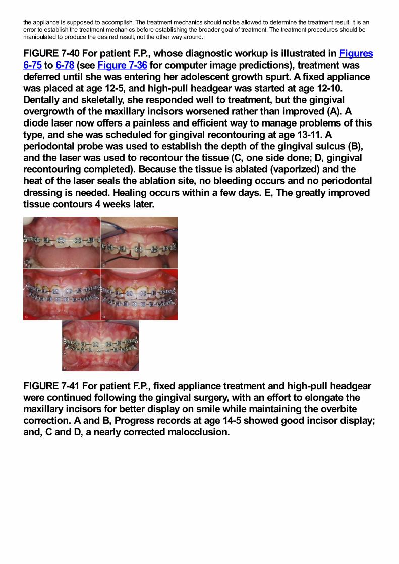
the appliance is supposed to accomplish. The treatment mechanics should not be allowed to determine the treatment result. It is anerror to establish the treatment mechanics before establishing the broader goal of treatment. The treatment procedures should bemanipulated to produce the desired result, not the other way around.
FIGURE 7-40 For patient F.P., whose diagnostic workup is illustrated in Figures6-75 to 6-78 (see Figure 7-36 for computer image predictions), treatment wasdeferred until she was entering her adolescent growth spurt. A fixed appliancewas placed at age 12-5, and high-pull headgear was started at age 12-10.Dentally and skeletally, she responded well to treatment, but the gingivalovergrowth of the maxillary incisors worsened rather than improved (A). Adiode laser now offers a painless and efficient way to manage problems of thistype, and she was scheduled for gingival recontouring at age 13-11. Aperiodontal probe was used to establish the depth of the gingival sulcus (B),and the laser was used to recontour the tissue (C, one side done; D, gingivalrecontouring completed). Because the tissue is ablated (vaporized) and theheat of the laser seals the ablation site, no bleeding occurs and no periodontaldressing is needed. Healing occurs within a few days. E, The greatly improvedtissue contours 4 weeks later.
FIGURE 7-41 For patient F.P., fixed appliance treatment and high-pull headgearwere continued following the gingival surgery, with an effort to elongate themaxillary incisors for better display on smile while maintaining the overbitecorrection. A and B, Progress records at age 14-5 showed good incisor display;and, C and D, a nearly corrected malocclusion.
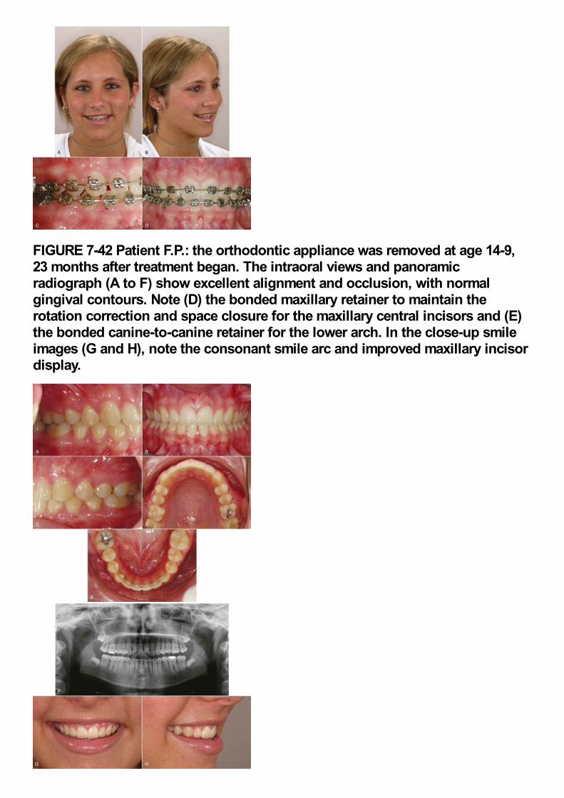
FIGURE 7-42 Patient F.P.: the orthodontic appliance was removed at age 14-9,23 months after treatment began. The intraoral views and panoramicradiograph (A to F) show excellent alignment and occlusion, with normalgingival contours. Note (D) the bonded maxillary retainer to maintain therotation correction and space closure for the maxillary central incisors and (E)the bonded canine-to-canine retainer for the lower arch. In the close-up smileimages (G and H), note the consonant smile arc and improved maxillary incisordisplay.
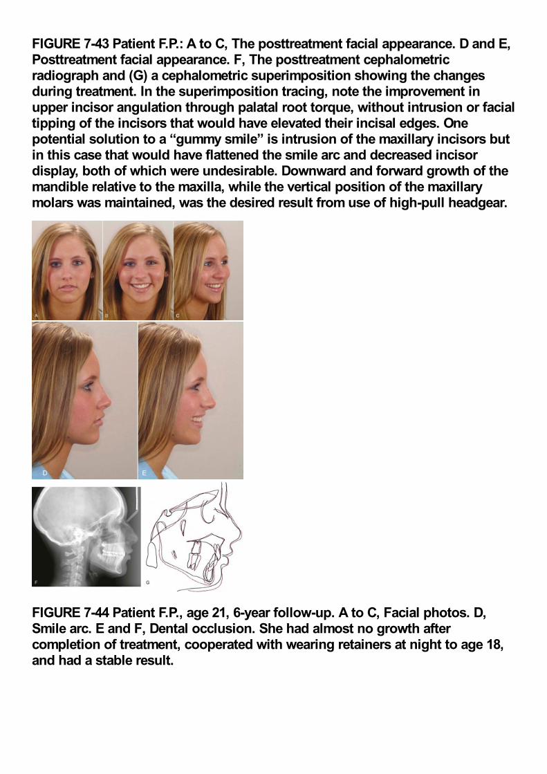
FIGURE 7-43 Patient F.P.: A to C, The posttreatment facial appearance. D and E,Posttreatment facial appearance. F, The posttreatment cephalometricradiograph and (G) a cephalometric superimposition showing the changesduring treatment. In the superimposition tracing, note the improvement inupper incisor angulation through palatal root torque, without intrusion or facialtipping of the incisors that would have elevated their incisal edges. Onepotential solution to a “gummy smile” is intrusion of the maxillary incisors butin this case that would have flattened the smile arc and decreased incisordisplay, both of which were undesirable. Downward and forward growth of themandible relative to the maxilla, while the vertical position of the maxillarymolars was maintained, was the desired result from use of high-pull headgear.
FIGURE 7-44 Patient F.P., age 21, 6-year follow-up. A to C, Facial photos. D,Smile arc. E and F, Dental occlusion. She had almost no growth aftercompletion of treatment, cooperated with wearing retainers at night to age 18,and had a stable result.
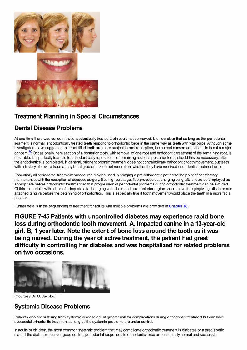
Treatment Planning in Special Circumstances
Dental Disease ProblemsAt one time there was concern that endodontically treated teeth could not be moved. It is now clear that as long as the periodontalligament is normal, endodontically treated teeth respond to orthodontic force in the same way as teeth with vital pulps. Although someinvestigators have suggested that root-filled teeth are more subject to root resorption, the current consensus is that this is not a majorconcern.30 Occasionally, hemisection of a posterior tooth, with removal of one root and endodontic treatment of the remaining root, isdesirable. It is perfectly feasible to orthodontically reposition the remaining root of a posterior tooth, should this be necessary, afterthe endodontics is completed. In general, prior endodontic treatment does not contraindicate orthodontic tooth movement, but teethwith a history of severe trauma may be at greater risk of root resorption, whether they have received endodontic treatment or not.
Essentially all periodontal treatment procedures may be used in bringing a pre-orthodontic patient to the point of satisfactorymaintenance, with the exception of osseous surgery. Scaling, curettage, flap procedures, and gingival grafts should be employed asappropriate before orthodontic treatment so that progression of periodontal problems during orthodontic treatment can be avoided.Children or adults with a lack of adequate attached gingiva in the mandibular anterior region should have free gingival grafts to createattached gingiva before the beginning of orthodontics. This is especially true if tooth movement would place the teeth in a more facialposition.
Further details in the sequencing of treatment for adults with multiple problems are provided in Chapter 18.
FIGURE 7-45 Patients with uncontrolled diabetes may experience rapid boneloss during orthodontic tooth movement. A, Impacted canine in a 13-year-oldgirl. B, 1 year later. Note the extent of bone loss around the tooth as it wasbeing moved. During the year of active treatment, the patient had greatdifficulty in controlling her diabetes and was hospitalized for related problemson two occasions.
(Courtesy Dr. G. Jacobs.)
Systemic Disease ProblemsPatients who are suffering from systemic disease are at greater risk for complications during orthodontic treatment but can havesuccessful orthodontic treatment as long as the systemic problems are under control.
In adults or children, the most common systemic problem that may complicate orthodontic treatment is diabetes or a prediabeticstate. If the diabetes is under good control, periodontal responses to orthodontic force are essentially normal and successful
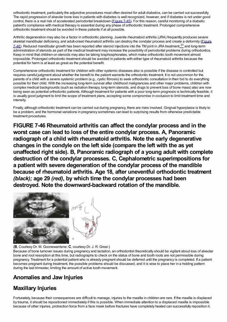
orthodontic treatment, particularly the adjunctive procedures most often desired for adult diabetics, can be carried out successfully.The rapid progression of alveolar bone loss in patients with diabetes is well recognized, however, and if diabetes is not under goodcontrol, there is a real risk of accelerated periodontal breakdown (Figure 7-45). For this reason, careful monitoring of a diabeticpatient's compliance with medical therapy is essential during any phase of orthodontic treatment. Prolonged comprehensiveorthodontic treatment should be avoided in these patients if at all possible.
Arthritic degeneration may also be a factor in orthodontic planning. Juvenile rheumatoid arthritis (JRA) frequently produces severeskeletal mandibular deficiency, and adult-onset rheumatoid arthritis can destroy the condylar process and create a deformity (Figure7-46). Reduced mandibular growth has been reported after steroid injections into the TM joint in JRA treatment,31 and long-termadministration of steroids as part of the medical treatment may increase the possibility of periodontal problems during orthodontics.Keep in mind that children on steroids may also be taking bisphosphonates, which make orthodontic tooth movement almostimpossible. Prolonged orthodontic treatment should be avoided in patients with either type of rheumatoid arthritis because thepotential for harm is at least as great as the potential benefit.
Comprehensive orthodontic treatment for children with other systemic diseases also is possible if the disease is controlled butrequires careful judgment about whether the benefit to the patient warrants the orthodontic treatment. It is not uncommon for theparents of a child with a severe systemic problem (e.g., cystic fibrosis) to seek orthodontic consultation in their bid to do everythingpossible for their child. With the increasing long-term survival after childhood malignancies and other major problems, children withcomplex medical backgrounds (such as radiation therapy, long-term steroids, and drugs to prevent loss of bone mass) also are nowbeing seen as potential orthodontic patients. Although treatment for patients with a poor long-term prognosis is technically feasible, itis usually good judgment to limit the scope of treatment plans, accepting some compromise in occlusion to limit treatment time andintensity.
Finally, although orthodontic treatment can be carried out during pregnancy, there are risks involved. Gingival hyperplasia is likely tobe a problem, and the hormonal variations in pregnancy sometimes can lead to surprising results from otherwise predictabletreatment procedures.
FIGURE 7-46 Rheumatoid arthritis can affect the condylar process and in theworst case can lead to loss of the entire condylar process. A, Panoramicradiograph of a child with rheumatoid arthritis. Note the early degenerativechanges in the condyle on the left side (compare the left with the as yetunaffected right side). B, Panoramic radiograph of a young adult with completedestruction of the condylar processes. C, Cephalometric superimpositions fora patient with severe degeneration of the condylar process of the mandiblebecause of rheumatoid arthritis. Age 18, after uneventful orthodontic treatment(black); age 29 (red), by which time the condylar processes had beendestroyed. Note the downward-backward rotation of the mandible.
(B, Courtesy Dr. M. Goonewardene; C, courtesy Dr. J. R. Greer.)Because of bone turnover issues during pregnancy and lactation, an orthodontist theoretically should be vigilant about loss of alveolarbone and root resorption at this time, but radiographs to check on the status of bone and tooth roots are not permissible duringpregnancy. Treatment for a potential patient who is already pregnant should be deferred until the pregnancy is completed. If a patientbecomes pregnant during treatment, the possible problems should be discussed, and it is wise to place her in a holding patternduring the last trimester, limiting the amount of active tooth movement.
Anomalies and Jaw Injuries
Maxillary InjuriesFortunately, because their consequences are difficult to manage, injuries to the maxilla in children are rare. If the maxilla is displacedby trauma, it should be repositioned immediately if this is possible. When immediate attention to a displaced maxilla is impossiblebecause of other injuries, protraction force from a face mask before fractures have completely healed can successfully reposition it.
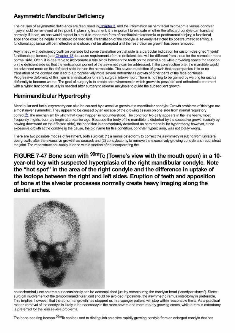
Asymmetric Mandibular DeficiencyThe causes of asymmetric deficiency are discussed in Chapter 3, and the information on hemifacial microsomia versus condylarinjury should be reviewed at this point. In planning treatment, it is important to evaluate whether the affected condyle can translatenormally. If it can, as one would expect in a mild-to-moderate form of hemifacial microsomia or posttraumatic injury, a functionalappliance could be helpful and should be tried first. If translation of the condyle is severely restricted by posttraumatic scarring, afunctional appliance will be ineffective and should not be attempted until the restriction on growth has been removed.
Asymmetry with deficient growth on one side but some translation on that side is a particular indication for custom-designed “hybrid”functional appliances (see Chapter 13) because requirements for the deficient side will be different from those for the normal or morenormal side. Often, it is desirable to incorporate a bite block between the teeth on the normal side while providing space for eruptionon the deficient side so that the vertical component of the asymmetry can be addressed. In the construction bite, the mandible wouldbe advanced more on the deficient side than on the normal side. The severe restriction of growth that accompanies little or notranslation of the condyle can lead to a progressively more severe deformity as growth of other parts of the face continues.Progressive deformity of this type is an indication for early surgical intervention. There is nothing to be gained by waiting for such adeformity to become worse. The goal of surgery is to create an environment in which growth is possible, and orthodontic treatmentwith a hybrid functional usually is needed after surgery to release ankylosis to guide the subsequent growth.
Hemimandibular HypertrophyMandibular and facial asymmetry can also be caused by excessive growth at a mandibular condyle. Growth problems of this type arealmost never symmetric. They appear to be caused by an escape of the growing tissues on one side from normal regulatorycontrol.32 The mechanism by which that could happen is not understood. The condition typically appears in the late teens, mostfrequently in girls, but may begin at an earlier age. Because the body of the mandible is distorted by the excessive growth (usually bybowing downward on the affected side), the condition is appropriately described as hemimandibular hypertrophy; however, sinceexcessive growth at the condyle is the cause, the old name for this condition, condylar hyperplasia, was not totally wrong.
There are two possible modes of treatment, both surgical: (1) a ramus osteotomy to correct the asymmetry resulting from unilateralovergrowth, after the excessive growth has ceased; and (2) condylectomy to remove the excessively growing condyle and reconstructthe joint. The reconstruction usually is done with a section of rib incorporating the
FIGURE 7-47 Bone scan with 99mTc (Towne's view with the mouth open) in a 10-year-old boy with suspected hyperplasia of the right mandibular condyle. Notethe “hot spot” in the area of the right condyle and the difference in uptake ofthe isotope between the right and left sides. Eruption of teeth and appositionof bone at the alveolar processes normally create heavy imaging along thedental arches.
costochondral junction area but occasionally can be accomplished just by recontouring the condylar head (“condylar shave”). Sincesurgical involvement of the temporomandibular joint should be avoided if possible, the asymmetric ramus osteotomy is preferable.This implies, however, that the abnormal growth has stopped or, in a younger patient, will stop within reasonable limits. As a practicalmatter, removal of the condyle is likely to be necessary in the more severe and more rapidly growing cases, while a ramus osteotomyis preferred for the less severe problems.
The bone-seeking isotope 99mTc can be used to distinguish an active rapidly growing condyle from an enlarged condyle that has
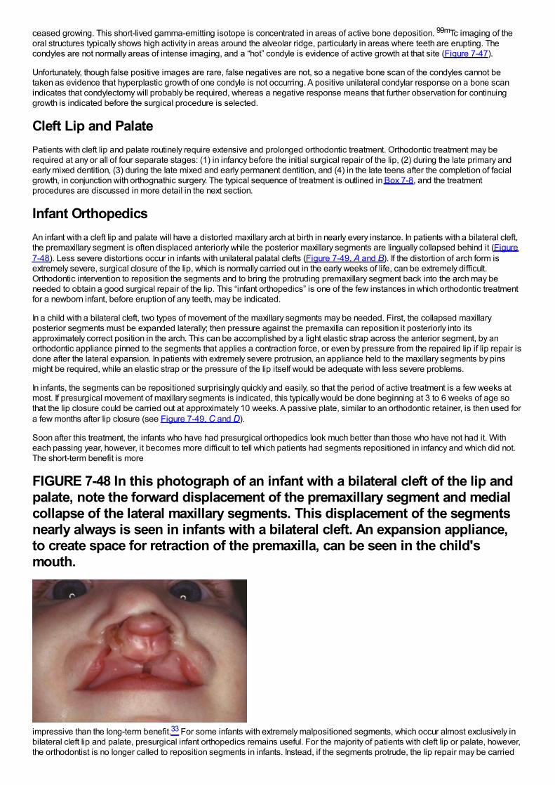
ceased growing. This short-lived gamma-emitting isotope is concentrated in areas of active bone deposition. 99mTc imaging of theoral structures typically shows high activity in areas around the alveolar ridge, particularly in areas where teeth are erupting. Thecondyles are not normally areas of intense imaging, and a “hot” condyle is evidence of active growth at that site (Figure 7-47).
Unfortunately, though false positive images are rare, false negatives are not, so a negative bone scan of the condyles cannot betaken as evidence that hyperplastic growth of one condyle is not occurring. A positive unilateral condylar response on a bone scanindicates that condylectomy will probably be required, whereas a negative response means that further observation for continuinggrowth is indicated before the surgical procedure is selected.
Cleft Lip and PalatePatients with cleft lip and palate routinely require extensive and prolonged orthodontic treatment. Orthodontic treatment may berequired at any or all of four separate stages: (1) in infancy before the initial surgical repair of the lip, (2) during the late primary andearly mixed dentition, (3) during the late mixed and early permanent dentition, and (4) in the late teens after the completion of facialgrowth, in conjunction with orthognathic surgery. The typical sequence of treatment is outlined in Box 7-8, and the treatmentprocedures are discussed in more detail in the next section.
Infant OrthopedicsAn infant with a cleft lip and palate will have a distorted maxillary arch at birth in nearly every instance. In patients with a bilateral cleft,the premaxillary segment is often displaced anteriorly while the posterior maxillary segments are lingually collapsed behind it (Figure7-48). Less severe distortions occur in infants with unilateral palatal clefts (Figure 7-49, A and B). If the distortion of arch form isextremely severe, surgical closure of the lip, which is normally carried out in the early weeks of life, can be extremely difficult.Orthodontic intervention to reposition the segments and to bring the protruding premaxillary segment back into the arch may beneeded to obtain a good surgical repair of the lip. This “infant orthopedics” is one of the few instances in which orthodontic treatmentfor a newborn infant, before eruption of any teeth, may be indicated.
In a child with a bilateral cleft, two types of movement of the maxillary segments may be needed. First, the collapsed maxillaryposterior segments must be expanded laterally; then pressure against the premaxilla can reposition it posteriorly into itsapproximately correct position in the arch. This can be accomplished by a light elastic strap across the anterior segment, by anorthodontic appliance pinned to the segments that applies a contraction force, or even by pressure from the repaired lip if lip repair isdone after the lateral expansion. In patients with extremely severe protrusion, an appliance held to the maxillary segments by pinsmight be required, while an elastic strap or the pressure of the lip itself would be adequate with less severe problems.
In infants, the segments can be repositioned surprisingly quickly and easily, so that the period of active treatment is a few weeks atmost. If presurgical movement of maxillary segments is indicated, this typically would be done beginning at 3 to 6 weeks of age sothat the lip closure could be carried out at approximately 10 weeks. A passive plate, similar to an orthodontic retainer, is then used fora few months after lip closure (see Figure 7-49, C and D).
Soon after this treatment, the infants who have had presurgical orthopedics look much better than those who have not had it. Witheach passing year, however, it becomes more difficult to tell which patients had segments repositioned in infancy and which did not.The short-term benefit is more
FIGURE 7-48 In this photograph of an infant with a bilateral cleft of the lip andpalate, note the forward displacement of the premaxillary segment and medialcollapse of the lateral maxillary segments. This displacement of the segmentsnearly always is seen in infants with a bilateral cleft. An expansion appliance,to create space for retraction of the premaxilla, can be seen in the child'smouth.
impressive than the long-term benefit.33 For some infants with extremely malpositioned segments, which occur almost exclusively inbilateral cleft lip and palate, presurgical infant orthopedics remains useful. For the majority of patients with cleft lip or palate, however,the orthodontist is no longer called to reposition segments in infants. Instead, if the segments protrude, the lip repair may be carried
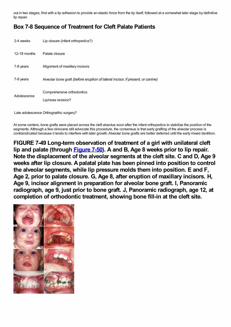
out in two stages, first with a lip adhesion to provide an elastic force from the lip itself, followed at a somewhat later stage by definitivelip repair.
Box 7-8 Sequence of Treatment for Cleft Palate Patients
2-4 weeks Lip closure (infant orthopedics?)
12-18 months Palate closure
7-8 years Alignment of maxillary incisors
7-9 years Alveolar bone graft (before eruption of lateral incisor, if present, or canine)
AdolescenceComprehensive orthodontics
Lip/nose revision?
Late adolescence Orthognathic surgery?
At some centers, bone grafts were placed across the cleft alveolus soon after the infant orthopedics to stabilize the position of thesegments. Although a few clinicians still advocate this procedure, the consensus is that early grafting of the alveolar process iscontraindicated because it tends to interfere with later growth. Alveolar bone grafts are better deferred until the early mixed dentition.
FIGURE 7-49 Long-term observation of treatment of a girl with unilateral cleftlip and palate (through Figure 7-50). A and B, Age 8 weeks prior to lip repair.Note the displacement of the alveolar segments at the cleft site. C and D, Age 9weeks after lip closure. A palatal plate has been pinned into position to controlthe alveolar segments, while lip pressure molds them into position. E and F,Age 2, prior to palate closure. G, Age 8, after eruption of maxillary incisors. H,Age 9, incisor alignment in preparation for alveolar bone graft. I, Panoramicradiograph, age 9, just prior to bone graft. J, Panoramic radiograph, age 12, atcompletion of orthodontic treatment, showing bone fill-in at the cleft site.
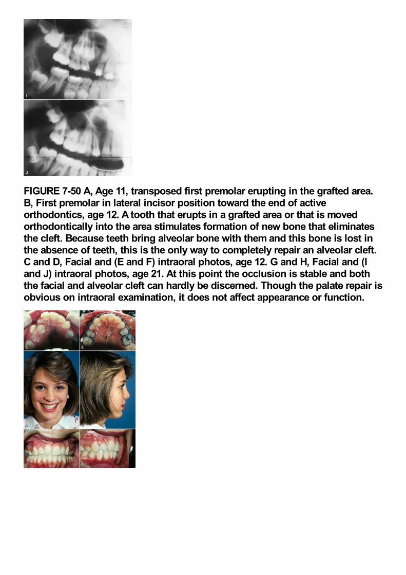
FIGURE 7-50 A, Age 11, transposed first premolar erupting in the grafted area.B, First premolar in lateral incisor position toward the end of activeorthodontics, age 12. A tooth that erupts in a grafted area or that is movedorthodontically into the area stimulates formation of new bone that eliminatesthe cleft. Because teeth bring alveolar bone with them and this bone is lost inthe absence of teeth, this is the only way to completely repair an alveolar cleft.C and D, Facial and (E and F) intraoral photos, age 12. G and H, Facial and (Iand J) intraoral photos, age 21. At this point the occlusion is stable and boththe facial and alveolar cleft can hardly be discerned. Though the palate repair isobvious on intraoral examination, it does not affect appearance or function.
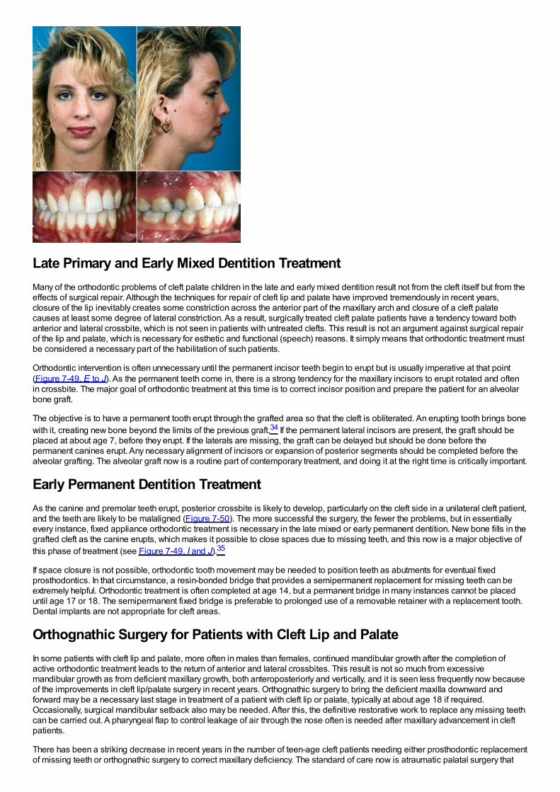
Late Primary and Early Mixed Dentition TreatmentMany of the orthodontic problems of cleft palate children in the late and early mixed dentition result not from the cleft itself but from theeffects of surgical repair. Although the techniques for repair of cleft lip and palate have improved tremendously in recent years,closure of the lip inevitably creates some constriction across the anterior part of the maxillary arch and closure of a cleft palatecauses at least some degree of lateral constriction. As a result, surgically treated cleft palate patients have a tendency toward bothanterior and lateral crossbite, which is not seen in patients with untreated clefts. This result is not an argument against surgical repairof the lip and palate, which is necessary for esthetic and functional (speech) reasons. It simply means that orthodontic treatment mustbe considered a necessary part of the habilitation of such patients.
Orthodontic intervention is often unnecessary until the permanent incisor teeth begin to erupt but is usually imperative at that point(Figure 7-49, E to J). As the permanent teeth come in, there is a strong tendency for the maxillary incisors to erupt rotated and oftenin crossbite. The major goal of orthodontic treatment at this time is to correct incisor position and prepare the patient for an alveolarbone graft.
The objective is to have a permanent tooth erupt through the grafted area so that the cleft is obliterated. An erupting tooth brings bonewith it, creating new bone beyond the limits of the previous graft.34 If the permanent lateral incisors are present, the graft should beplaced at about age 7, before they erupt. If the laterals are missing, the graft can be delayed but should be done before thepermanent canines erupt. Any necessary alignment of incisors or expansion of posterior segments should be completed before thealveolar grafting. The alveolar graft now is a routine part of contemporary treatment, and doing it at the right time is critically important.
Early Permanent Dentition TreatmentAs the canine and premolar teeth erupt, posterior crossbite is likely to develop, particularly on the cleft side in a unilateral cleft patient,and the teeth are likely to be malaligned (Figure 7-50). The more successful the surgery, the fewer the problems, but in essentiallyevery instance, fixed appliance orthodontic treatment is necessary in the late mixed or early permanent dentition. New bone fills in thegrafted cleft as the canine erupts, which makes it possible to close spaces due to missing teeth, and this now is a major objective ofthis phase of treatment (see Figure 7-49, I and J).35
If space closure is not possible, orthodontic tooth movement may be needed to position teeth as abutments for eventual fixedprosthodontics. In that circumstance, a resin-bonded bridge that provides a semipermanent replacement for missing teeth can beextremely helpful. Orthodontic treatment is often completed at age 14, but a permanent bridge in many instances cannot be placeduntil age 17 or 18. The semipermanent fixed bridge is preferable to prolonged use of a removable retainer with a replacement tooth.Dental implants are not appropriate for cleft areas.
Orthognathic Surgery for Patients with Cleft Lip and PalateIn some patients with cleft lip and palate, more often in males than females, continued mandibular growth after the completion ofactive orthodontic treatment leads to the return of anterior and lateral crossbites. This result is not so much from excessivemandibular growth as from deficient maxillary growth, both anteroposteriorly and vertically, and it is seen less frequently now becauseof the improvements in cleft lip/palate surgery in recent years. Orthognathic surgery to bring the deficient maxilla downward andforward may be a necessary last stage in treatment of a patient with cleft lip or palate, typically at about age 18 if required.Occasionally, surgical mandibular setback also may be needed. After this, the definitive restorative work to replace any missing teethcan be carried out. A pharyngeal flap to control leakage of air through the nose often is needed after maxillary advancement in cleftpatients.
There has been a striking decrease in recent years in the number of teen-age cleft patients needing either prosthodontic replacementof missing teeth or orthognathic surgery to correct maxillary deficiency. The standard of care now is atraumatic palatal surgery that

minimizes interferences with growth, and closure of the space where teeth are missing, made possible by alveolar grafts in the earlymixed dentition.
References1.
Betts, NJ, Vanarsdall, RJ, Barber, HD, et al.: Diagnosis and treatment of transverse maxillary deficiency. Int J Adult Orthod OrthognSurg. 10, 1995, 75–96.
2.
Bowman, SJ, Johnston, LE: The esthetic impact of extraction and non-extraction treatments on Caucasian patients. Angle Orthod.70, 2000, 3–10.
3.
Kim, E, Gianelly, AA: Extraction vs non-extraction: arch widths and smile esthetics. Angle Orthod. 73, 2003, 354–358.
4.
Nimkarn, Y, Miles, PG, O'Reilly, MT, et al.: The validity of maxillary expansion indices. Angle Orthod. 65, 1995, 321–326.
5.
Huynh, T, Kennedy, DB, Joondeph, DR, et al.: Treatment response and stability of slow maxillary expansion using Haas, hyrax andquad-helix appliances. Am J Orthod Dentofac Orthop. 136, 2009, 331–339.
6.
Pancherz, H, Fackel, U: The skeletofacial growth pattern pre- and post-dentofacial orthopedics. Eur J Orthod. 12, 1990, 209–218.
7.
Tulloch, JFC, Proffit, WR, Phillips, C: Permanent dentition outcomes in a two-phase randomized clinical trial of early Class IItreatment. Am J Orthod Dentofac Orthop. 125, 2004, 657–667.
8.
King, GJ, McGorray, SP, Wheeler, TT, et al.: Comparison of peer assessment ratings (PAR) from 1-phase and 2-phase treatmentprotocols for Class II malocclusions. Am J Orthod Dentofac Orthop. 123, 2003, 489–496.
9.
O'Brien, K, Wright, J, Conboy, F, et al.: Early treatment for Class II division 1 malocclusion with the twin-block appliance. Am J OrthodDentofac Orthop. 135, 2009, 573–579.
10.
Luppapornlap, S, Johnston, LE: The effects of premolar extraction: a long-term comparison of outcomes in “clear-cut” extraction andnonextraction Class II patients. Angle Orthod. 63, 1993, 257–272.
11.
Beattie, JR, Paquette, DE, Johnston, LE: The functional impact of extraction and non-extraction treatments: A long-term comparisonin patients with “borderline,” equally susceptible Class II malocclusions. Am J Orthod Dentofac Orthop. 105, 1994, 444–449.
12.
Polat-Ozsoy, O, Kircelli, BH, Arman-Ozcirpici, A, et al.: Pendulum appliances with 2 anchorage designs: conventional anchorage vs.bone anchorage. Am J Orthod Dentofac Orthop. 133, 2008, 339, e9-e17.
13.
Baccetti, T, Franchi, L, McNamara, JA: Cephalometric variables predicting long-term success or failure of combined RPE and facemask therapy. Am J Orthod Dentofac Orthop. 126, 2004, 16–22.
14.
Wells, AW, Sarver, DM, Proffit, WR: Long-term efficacy of reverse-pull headgear therapy. Angle Orthod. 76, 2006, 915–922.
15.
Kircelli, BH, Pektas, ZO: Midfacial protraction with skeletally anchored face mask therapy: a novel approach and preliminary results.

Am J Orthod Dentofac Orthop. 122, 2008, 349–352.
16.
DeClerck, H, Cevidanes, L, Baccetti, T: Dentofacial effects of bone-anchored maxillary protraction: a controlled study of consecutivelytreated Class III patients. Am J Orthod Dentofac Orthop. 138, 2010, 577–581.
17.
Heymann, GC, Cevidanes, L, Cornelis, M, et al.: Three-dimensional analysis of maxillary protraction with intermaxillary elastics tominiplates. Am J Orthod Dentofac Orthop. 137, 2010, 274–284.
18.
Burns, NR, Musich, DR, Martin, C, et al.: Class III camouflage treatment: what are the limits?. Am J Orthod Dentofac Orthop. 137,2010, 9e1–e13, eds summary 137:9-11.
19.
Freeman, CS, McNamara, JA, Baccetti, T, et al.: Treatment effects of the bionator and high-pull facebow combination followed byfixed appliances in patients with increased vertical dimensions. Am J Orthod Dentofac Orthop. 131, 2007, 184–195.
20.
Phillips, C, Hill, BJ, Cannac, C: The influence of video imaging on patients’ perceptions and expectations. Angle Orthod. 65, 1995,263–270.
21.
Parekh, J, Fields, H, Beck, M, et al.: The perception of selected aspects of smile esthetics—smile arcs and buccal corridors. Am JOrthod Dentofac Orthop. 129, 2006, 711–717.
22.
Ker, AJ, Chan, R, Fields, HW, et al.: Esthetic and smile characteristics from the layperson's perspective: a computer-based surveystudy. J Am Dent Assoc . 139, 2008, 1318–1327.
23.
Kokich, VO, Kinzer, GA: Managing congenitally missing lateral incisors. Part I. Canine substitution. J Esthet Restor Dent. 17, 2005, 5–10, Part II. Tooth-supported restorations, 17:76-84, 2005; Part III. Implants, 17:202-210, 2005.
24.
Sfikas, PM: A duty to disclose: issues to consider in securing informed consent. J Am Dent Assoc . 134, 2003, 1329–1333.
25.
Mortensen, MG, Kiyak, HA, Omnell, L: Patient and parent understanding of informed consent in orthodontics. Am J Orthod DentofacOrthop. 124, 2003, 541–550.
26.
Kutner M, Greenberg E, Jin Y, et al. The health literacy of America's adults: results from the 2003 National Assessment of AdultLiteracy. US Department of Education, National Center for Education Statistics. NCES 2006-483.
27.
Carr KM, Fields HW, Beck FM, et al. Improving orthodontic informed consent: a new approach. Am J Orthod Dentofac Orthop, inpress.
28.
Kang, EY, Fields, HW, Kiyak, A, et al.: Informed consent recall and comprehension in orthodontics: traditional versus improvedreadability and processability methods. Am J Orthod Dentofac Orthop. 136, 2009, 488, e1-e13.
29.
Bandura, A, Barbaranelli, C, Capara, GV, et al.: Self-efficacy beliefs as shapers of children's aspirations and career trajectories.Child Development. 72, 2001, 187–206.
30.
Llamas-Carreras, JM, Amarilla, A, Solano, E, et al.: Study of external root resorption during orthodontic treatment in root filled teethcompared with their contralateral teeth with vital pulps. Int Endod J. 43, 2010, 654–662.

compared with their contralateral teeth with vital pulps. . 43, 2010, 654–662.
31.
Stostrup, P, Kristensen, KD, Kuseler, A, et al.: Reduced mandibular growth in experimental arthritis in the TM joint treated with intra-articular corticosteroids. Eur J Orthod. 30, 2008, 111–119.
32.
Eslami, B, Behnia, H, Javadi, H, et al.: Histopathologic comparison of normal and hyperplastic condyles. Oral Surg Oral Med OralPathol Oral Radiol Endod. 96, 2003, 711–717.
33.
Bongaarts, CAM, Prahl-Andersen, B, Bronkhorst, EW, et al.: Infant orthopedics and facial growth in complete unilateral cleft lip andpalate until six years of age (Dutchcleft). Cleft Palate Craniofac J. 46, 2009, 654–663.
34.
Goudy, S, Lott, D, Burton, R, et al.: Secondary alveolar bone grafting: outcomes, revisions and new applications. Cleft PalateCraniofac J. 46, 2009, 610–612.
35.
Oosterkamp, BCM, Dijkstra, PU, Remmelink, HJ, et al.: Orthodontic space closure versus prosthetic replacement of missing upperlateral incisors in patients with bilateral cleft lip and palate. Cleft Palate Craniofac J. 47, 2010, 591–596.

Biomechanics, Mechanics, and Contemporary Orthodontic AppliancesOrthodontic therapy depends on the reaction of the teeth, and more generally the facial structures, to gentle but persistent force. In anorthodontic context, biomechanics is commonly used in discussions of the reaction of the dental and facial structures to orthodonticforce, whereas mechanics is reserved for the properties of the strictly mechanical components of the appliance system. In this section,the biologic responses to orthodontic force that underlie biomechanics are discussed in Chapter 8, and new possibilities foraccelerating the rate of tooth movement are reviewed and evaluated. Chapter 9, which is concerned with the design and application oforthodontic appliances, is largely devoted to mechanics but includes some biomechanical considerations as well and introduces theapplication of temporary skeletal anchorage, which is discussed in more detail in Chapter 10.Contemporary orthodontic treatment involves the use of both fixed and removable appliances. The first part of Chapter 10 describesall types of removables that are useful at present, with emphasis on the components approach to designing functional appliances forindividual patients, and on the considerations that are important in clear aligner therapy.In the first years of the twenty-first century, there have been major changes in fixed appliances, and these are reviewed in the secondpart of Chapter 10. The principle of the edgewise appliance, control of tooth movement via rectangular archwires in a rectangular slot,remains the basis of contemporary fixed appliance therapy, but changes in brackets and archwire fabrication are occurring ascomputer-aided design/computer-aided manufacturing (CAD/CAM) design and production become more and more important. Themajor problems that limited the use of fixed lingual appliances have largely been overcome. Skeletal anchorage, based on bothmultiscrew miniplates and alveolar bone screws, has quickly become an important part of contemporary treatment. A major goal ofChapter 10 and the following chapters on comprehensive treatment is to evaluate these changes in appliances in the context of datafor clinical outcomes with their use.
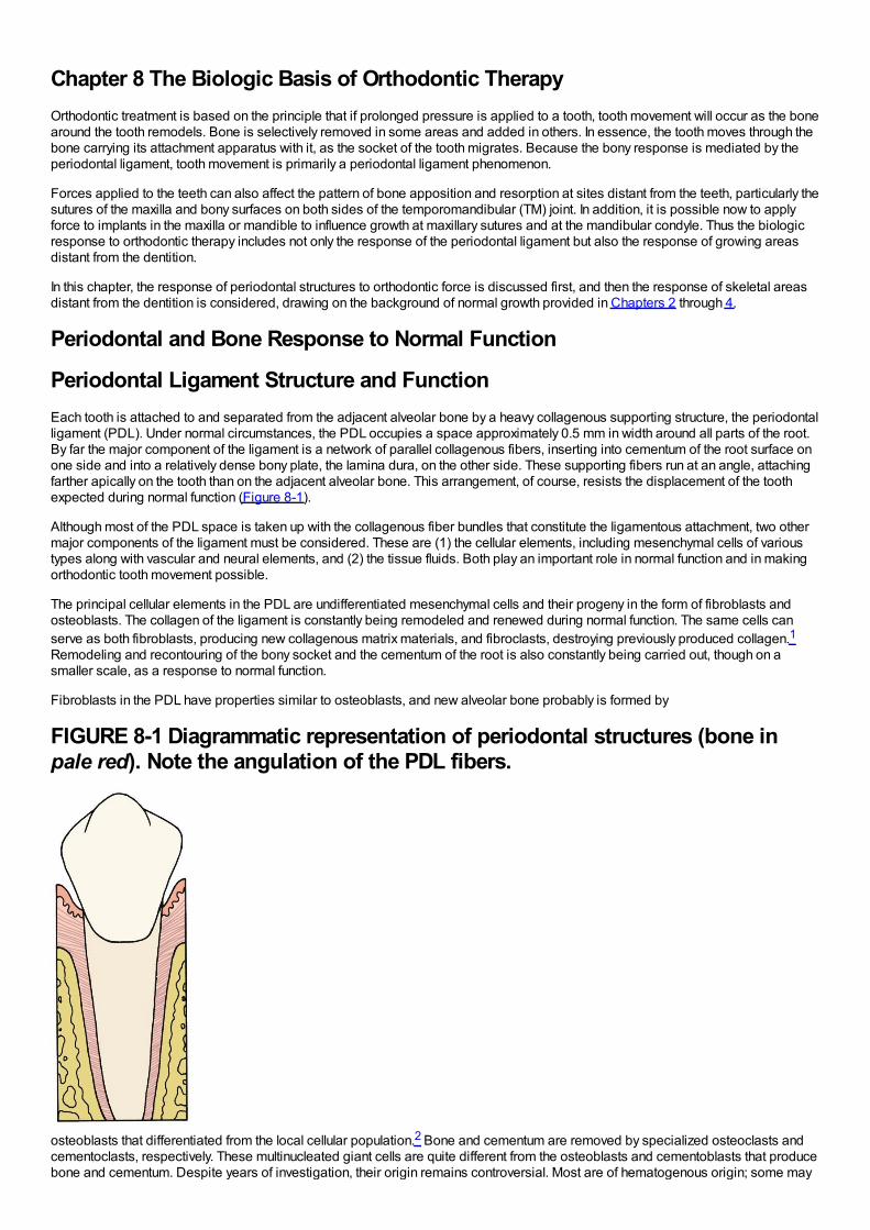
Chapter 8 The Biologic Basis of Orthodontic TherapyOrthodontic treatment is based on the principle that if prolonged pressure is applied to a tooth, tooth movement will occur as the bonearound the tooth remodels. Bone is selectively removed in some areas and added in others. In essence, the tooth moves through thebone carrying its attachment apparatus with it, as the socket of the tooth migrates. Because the bony response is mediated by theperiodontal ligament, tooth movement is primarily a periodontal ligament phenomenon.
Forces applied to the teeth can also affect the pattern of bone apposition and resorption at sites distant from the teeth, particularly thesutures of the maxilla and bony surfaces on both sides of the temporomandibular (TM) joint. In addition, it is possible now to applyforce to implants in the maxilla or mandible to influence growth at maxillary sutures and at the mandibular condyle. Thus the biologicresponse to orthodontic therapy includes not only the response of the periodontal ligament but also the response of growing areasdistant from the dentition.
In this chapter, the response of periodontal structures to orthodontic force is discussed first, and then the response of skeletal areasdistant from the dentition is considered, drawing on the background of normal growth provided in Chapters 2 through 4.
Periodontal and Bone Response to Normal Function
Periodontal Ligament Structure and FunctionEach tooth is attached to and separated from the adjacent alveolar bone by a heavy collagenous supporting structure, the periodontalligament (PDL). Under normal circumstances, the PDL occupies a space approximately 0.5 mm in width around all parts of the root.By far the major component of the ligament is a network of parallel collagenous fibers, inserting into cementum of the root surface onone side and into a relatively dense bony plate, the lamina dura, on the other side. These supporting fibers run at an angle, attachingfarther apically on the tooth than on the adjacent alveolar bone. This arrangement, of course, resists the displacement of the toothexpected during normal function (Figure 8-1).
Although most of the PDL space is taken up with the collagenous fiber bundles that constitute the ligamentous attachment, two othermajor components of the ligament must be considered. These are (1) the cellular elements, including mesenchymal cells of varioustypes along with vascular and neural elements, and (2) the tissue fluids. Both play an important role in normal function and in makingorthodontic tooth movement possible.
The principal cellular elements in the PDL are undifferentiated mesenchymal cells and their progeny in the form of fibroblasts andosteoblasts. The collagen of the ligament is constantly being remodeled and renewed during normal function. The same cells canserve as both fibroblasts, producing new collagenous matrix materials, and fibroclasts, destroying previously produced collagen.1Remodeling and recontouring of the bony socket and the cementum of the root is also constantly being carried out, though on asmaller scale, as a response to normal function.
Fibroblasts in the PDL have properties similar to osteoblasts, and new alveolar bone probably is formed by
FIGURE 8-1 Diagrammatic representation of periodontal structures (bone inpale red). Note the angulation of the PDL fibers.
osteoblasts that differentiated from the local cellular population.2 Bone and cementum are removed by specialized osteoclasts andcementoclasts, respectively. These multinucleated giant cells are quite different from the osteoblasts and cementoblasts that producebone and cementum. Despite years of investigation, their origin remains controversial. Most are of hematogenous origin; some may
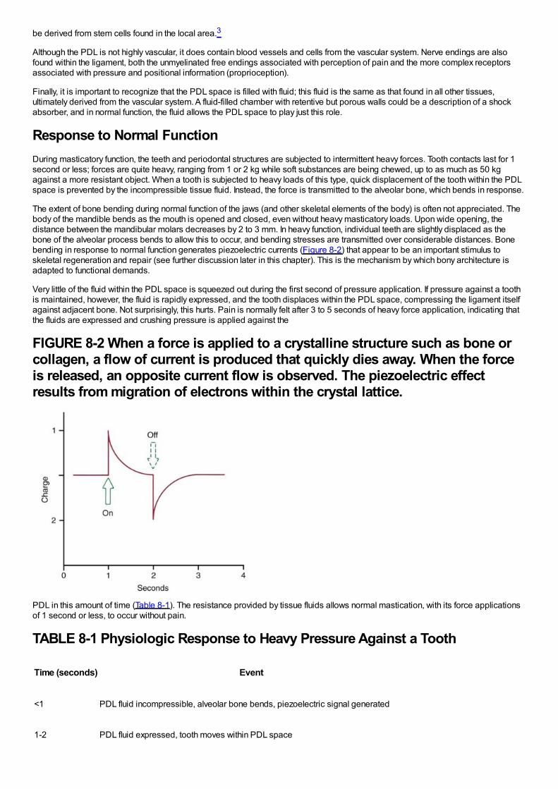
be derived from stem cells found in the local area.3
Although the PDL is not highly vascular, it does contain blood vessels and cells from the vascular system. Nerve endings are alsofound within the ligament, both the unmyelinated free endings associated with perception of pain and the more complex receptorsassociated with pressure and positional information (proprioception).
Finally, it is important to recognize that the PDL space is filled with fluid; this fluid is the same as that found in all other tissues,ultimately derived from the vascular system. A fluid-filled chamber with retentive but porous walls could be a description of a shockabsorber, and in normal function, the fluid allows the PDL space to play just this role.
Response to Normal FunctionDuring masticatory function, the teeth and periodontal structures are subjected to intermittent heavy forces. Tooth contacts last for 1second or less; forces are quite heavy, ranging from 1 or 2 kg while soft substances are being chewed, up to as much as 50 kgagainst a more resistant object. When a tooth is subjected to heavy loads of this type, quick displacement of the tooth within the PDLspace is prevented by the incompressible tissue fluid. Instead, the force is transmitted to the alveolar bone, which bends in response.
The extent of bone bending during normal function of the jaws (and other skeletal elements of the body) is often not appreciated. Thebody of the mandible bends as the mouth is opened and closed, even without heavy masticatory loads. Upon wide opening, thedistance between the mandibular molars decreases by 2 to 3 mm. In heavy function, individual teeth are slightly displaced as thebone of the alveolar process bends to allow this to occur, and bending stresses are transmitted over considerable distances. Bonebending in response to normal function generates piezoelectric currents (Figure 8-2) that appear to be an important stimulus toskeletal regeneration and repair (see further discussion later in this chapter). This is the mechanism by which bony architecture isadapted to functional demands.
Very little of the fluid within the PDL space is squeezed out during the first second of pressure application. If pressure against a toothis maintained, however, the fluid is rapidly expressed, and the tooth displaces within the PDL space, compressing the ligament itselfagainst adjacent bone. Not surprisingly, this hurts. Pain is normally felt after 3 to 5 seconds of heavy force application, indicating thatthe fluids are expressed and crushing pressure is applied against the
FIGURE 8-2 When a force is applied to a crystalline structure such as bone orcollagen, a flow of current is produced that quickly dies away. When the forceis released, an opposite current flow is observed. The piezoelectric effectresults from migration of electrons within the crystal lattice.
PDL in this amount of time (Table 8-1). The resistance provided by tissue fluids allows normal mastication, with its force applicationsof 1 second or less, to occur without pain.
TABLE 8-1 Physiologic Response to Heavy Pressure Against a Tooth
Time (seconds) Event
<1 PDL fluid incompressible, alveolar bone bends, piezoelectric signal generated
1-2 PDL fluid expressed, tooth moves within PDL space
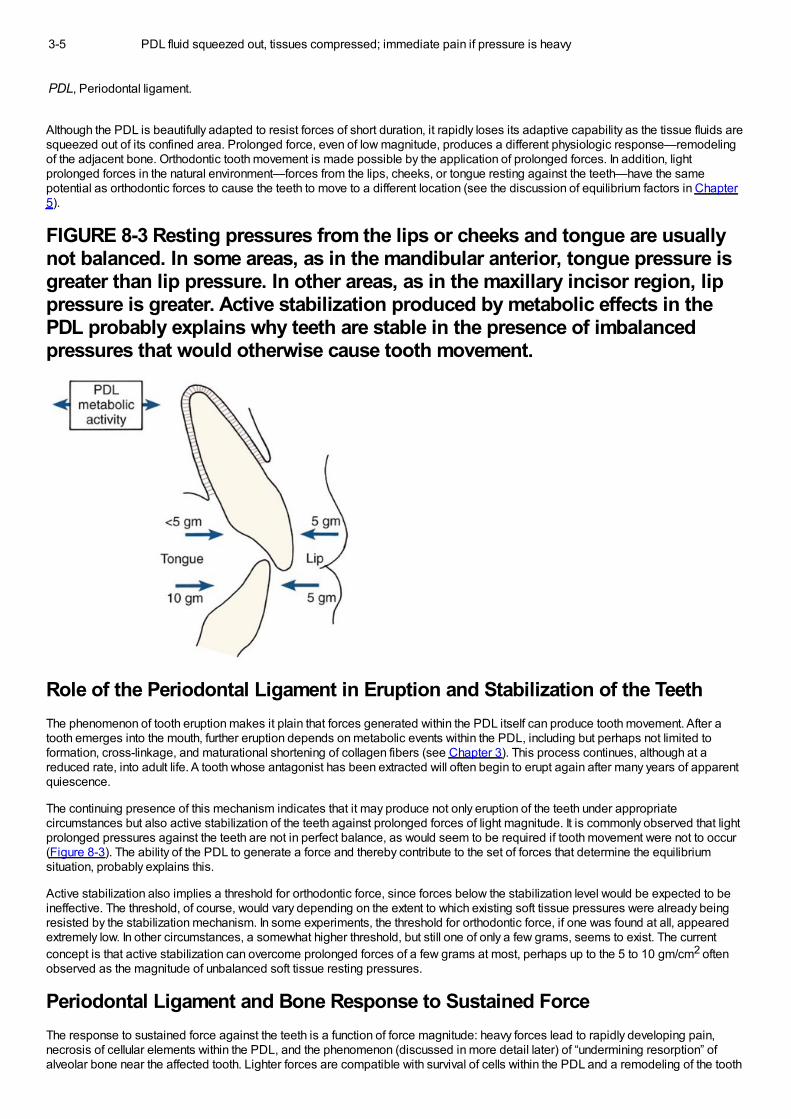
3-5 PDL fluid squeezed out, tissues compressed; immediate pain if pressure is heavy
PDL, Periodontal ligament.
Although the PDL is beautifully adapted to resist forces of short duration, it rapidly loses its adaptive capability as the tissue fluids aresqueezed out of its confined area. Prolonged force, even of low magnitude, produces a different physiologic response—remodelingof the adjacent bone. Orthodontic tooth movement is made possible by the application of prolonged forces. In addition, lightprolonged forces in the natural environment—forces from the lips, cheeks, or tongue resting against the teeth—have the samepotential as orthodontic forces to cause the teeth to move to a different location (see the discussion of equilibrium factors in Chapter5).
FIGURE 8-3 Resting pressures from the lips or cheeks and tongue are usuallynot balanced. In some areas, as in the mandibular anterior, tongue pressure isgreater than lip pressure. In other areas, as in the maxillary incisor region, lippressure is greater. Active stabilization produced by metabolic effects in thePDL probably explains why teeth are stable in the presence of imbalancedpressures that would otherwise cause tooth movement.
Role of the Periodontal Ligament in Eruption and Stabilization of the TeethThe phenomenon of tooth eruption makes it plain that forces generated within the PDL itself can produce tooth movement. After atooth emerges into the mouth, further eruption depends on metabolic events within the PDL, including but perhaps not limited toformation, cross-linkage, and maturational shortening of collagen fibers (see Chapter 3). This process continues, although at areduced rate, into adult life. A tooth whose antagonist has been extracted will often begin to erupt again after many years of apparentquiescence.
The continuing presence of this mechanism indicates that it may produce not only eruption of the teeth under appropriatecircumstances but also active stabilization of the teeth against prolonged forces of light magnitude. It is commonly observed that lightprolonged pressures against the teeth are not in perfect balance, as would seem to be required if tooth movement were not to occur(Figure 8-3). The ability of the PDL to generate a force and thereby contribute to the set of forces that determine the equilibriumsituation, probably explains this.
Active stabilization also implies a threshold for orthodontic force, since forces below the stabilization level would be expected to beineffective. The threshold, of course, would vary depending on the extent to which existing soft tissue pressures were already beingresisted by the stabilization mechanism. In some experiments, the threshold for orthodontic force, if one was found at all, appearedextremely low. In other circumstances, a somewhat higher threshold, but still one of only a few grams, seems to exist. The currentconcept is that active stabilization can overcome prolonged forces of a few grams at most, perhaps up to the 5 to 10 gm/cm2 oftenobserved as the magnitude of unbalanced soft tissue resting pressures.
Periodontal Ligament and Bone Response to Sustained ForceThe response to sustained force against the teeth is a function of force magnitude: heavy forces lead to rapidly developing pain,necrosis of cellular elements within the PDL, and the phenomenon (discussed in more detail later) of “undermining resorption” ofalveolar bone near the affected tooth. Lighter forces are compatible with survival of cells within the PDL and a remodeling of the tooth
socket by a relatively painless “frontal resorption” of the tooth socket. In orthodontic practice, the objective is to produce toothmovement as much as possible by frontal resorption, recognizing that some areas of PDL necrosis and undermining resorption willprobably occur despite efforts to prevent this.
Biologic Control of Tooth MovementBefore discussing in detail the response to orthodontic force, it is necessary to consider the biologic control mechanisms that leadfrom the stimulus of sustained force application to the response of orthodontic tooth movement. Two possible control elements,biologic electricity and pressure-tension in the PDL that affects blood flow, are contrasted in the two major theories of orthodontictooth movement. The bioelectric theory relates tooth movement at least in part to changes in bone metabolism controlled by biologicelectricity that are produced by light pressure against the teeth. The pressure–tension theory relates tooth movement to cellularchanges produced by chemical messengers, traditionally thought to be generated by alterations in blood flow through the PDL.Pressure and tension within the PDL, by reducing (pressure) or increasing (tension) the diameter of blood vessels in the ligamentspace, could certainly alter blood flow. The two theories are neither incompatible nor mutually exclusive, and it appears that bothmechanisms may play a part in the biologic control of tooth movement.4
Biologic ElectricityElectric signals that might initiate tooth movement initially were thought to be piezoelectric. Piezoelectricity is a phenomenonobserved in many crystalline materials in which a deformation of the crystal structure produces a flow of electric current as electronsare displaced from one part of the crystal lattice to another. The piezoelectricity of many inorganic crystals like those in bone hasbeen recognized for many years and has been used in everyday technology (e.g., the crystal pickup in inexpensive phonographs).Organic crystals also can be piezoelectric, and collagen in the PDL is an excellent example.
Piezoelectric signals have two unusual characteristics: (1) a quick decay rate (i.e., when a force is applied, a piezoelectric signal iscreated in response that quickly dies away to zero even though the force is maintained) and (2) the production of an equivalent signal,opposite in direction, when the force is released (see Figure 8-2).
Both of these characteristics are explained by the migration of electrons within the crystal lattice as it is distorted by pressure. Whenthe crystal structure is deformed, electrons migrate from one location to another and an electric current flow is observed. As long asthe force is maintained, the crystal structure is stable and no further electric events are observed. When the force is released,however, the crystal returns to its original shape, and a reverse flow of electrons is seen. With this arrangement, rhythmic activitywould produce a constant interplay of current flows in one direction and then the other that would be measured as amperes, whereasoccasional application and release of force would produce only occasional signal of this type.
Ions in the fluids that bathe living bone interact with the complex electric field generated when the bone bends, causing electricsignals in the form of volts as well as temperature changes. As a result, both convection and conduction currents can be detected inthe extracellular fluids, and the currents are affected by the nature of the fluids. The small voltages that are observed are called the“streaming potential.” These voltages, though different from piezoelectric current flows, have in common their rapid onset andalteration as changing stresses are placed on the bone.
There is also a reverse piezoelectric effect. Not only will the application of force cause distortion of crystalline structure and with it anelectric signal, but also application of an electric field can cause a crystal to deform and produce force in doing so. Reversepiezoelectricity has no place in natural control systems, at least as far as is presently known, but there are intriguing possibilities forusing external electric fields to promote bone healing and regeneration after injury.5
There is no longer any doubt that stress-generated signals are important in the general maintenance of the skeleton. Without suchsignals, bone mineral is lost and general skeletal atrophy ensues—a situation that has proved troublesome for astronauts whosebones no longer flex in a weightless environment as they would under normal gravity. Signals generated by the bending of alveolarbone during normal chewing almost surely are important for maintenance of the bone around the teeth.
On the other hand, sustained force of the type used to induce orthodontic tooth movement does not produce prominent stress-generated signals. As long as the force is sustained, nothing happens. If stress-generated signals were important in producing thebone remodeling associated with orthodontic tooth movement, a vibrating application of pressure would be advantageous. Althoughearlier experiments indicated little or no advantage in vibrating over sustained force for the movement of teeth,6 this idea has beenrevived recently and is discussed below in the section of this chapter on possibilities for accelerating tooth movement. It still is thecase, however, that the stress-generated signals that are so important for normal skeletal function have little if anything to do with theresponse to orthodontic tooth movement.
Electromagnetic fields also can affect cell membrane potentials and permeability and thereby trigger changes in cellular activity. Inanimal experiments, a pulsed electromagnetic field increased the rate of tooth movement, apparently by shortening the initial “lagphase” before tooth movement begins.7 This does not mean that the fields generated by small magnets attached to the teeth togenerate tooth-moving forces (see Chapter 9) could change the basic biology of the response to force. Claims that moving teeth withmagnetic force reduces pain and mobility are not supported by evidence.
Pressure–Tension in Periodontal LigamentThe pressure–tension theory, the classic theory of tooth movement, relies on chemical rather than electric signals as the stimulus forcellular differentiation and ultimately tooth movement. Chemical messengers are important in the cascade of events that lead toremodeling of alveolar bone
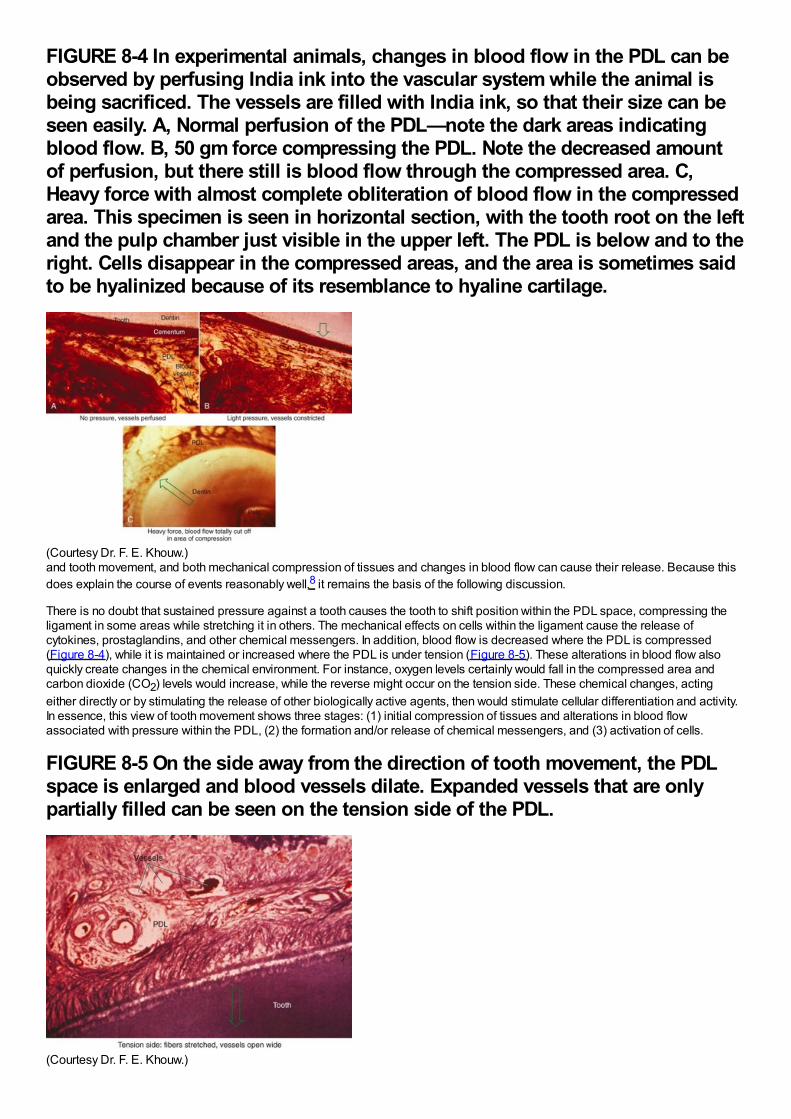
FIGURE 8-4 In experimental animals, changes in blood flow in the PDL can beobserved by perfusing India ink into the vascular system while the animal isbeing sacrificed. The vessels are filled with India ink, so that their size can beseen easily. A, Normal perfusion of the PDL—note the dark areas indicatingblood flow. B, 50 gm force compressing the PDL. Note the decreased amountof perfusion, but there still is blood flow through the compressed area. C,Heavy force with almost complete obliteration of blood flow in the compressedarea. This specimen is seen in horizontal section, with the tooth root on the leftand the pulp chamber just visible in the upper left. The PDL is below and to theright. Cells disappear in the compressed areas, and the area is sometimes saidto be hyalinized because of its resemblance to hyaline cartilage.
(Courtesy Dr. F. E. Khouw.)and tooth movement, and both mechanical compression of tissues and changes in blood flow can cause their release. Because thisdoes explain the course of events reasonably well,8 it remains the basis of the following discussion.
There is no doubt that sustained pressure against a tooth causes the tooth to shift position within the PDL space, compressing theligament in some areas while stretching it in others. The mechanical effects on cells within the ligament cause the release ofcytokines, prostaglandins, and other chemical messengers. In addition, blood flow is decreased where the PDL is compressed(Figure 8-4), while it is maintained or increased where the PDL is under tension (Figure 8-5). These alterations in blood flow alsoquickly create changes in the chemical environment. For instance, oxygen levels certainly would fall in the compressed area andcarbon dioxide (CO2) levels would increase, while the reverse might occur on the tension side. These chemical changes, actingeither directly or by stimulating the release of other biologically active agents, then would stimulate cellular differentiation and activity.In essence, this view of tooth movement shows three stages: (1) initial compression of tissues and alterations in blood flowassociated with pressure within the PDL, (2) the formation and/or release of chemical messengers, and (3) activation of cells.
FIGURE 8-5 On the side away from the direction of tooth movement, the PDLspace is enlarged and blood vessels dilate. Expanded vessels that are onlypartially filled can be seen on the tension side of the PDL.
(Courtesy Dr. F. E. Khouw.)
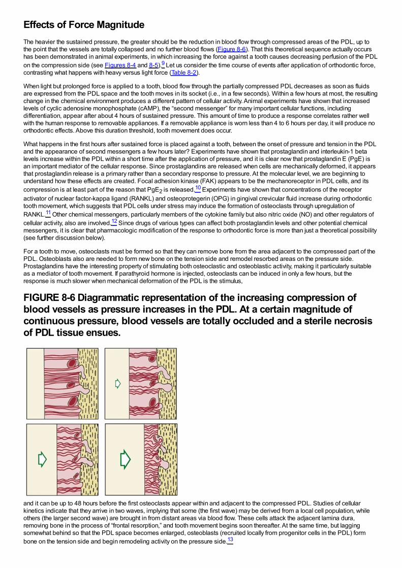
Effects of Force MagnitudeThe heavier the sustained pressure, the greater should be the reduction in blood flow through compressed areas of the PDL, up tothe point that the vessels are totally collapsed and no further blood flows (Figure 8-6). That this theoretical sequence actually occurshas been demonstrated in animal experiments, in which increasing the force against a tooth causes decreasing perfusion of the PDLon the compression side (see Figures 8-4 and 8-5).9 Let us consider the time course of events after application of orthodontic force,contrasting what happens with heavy versus light force (Table 8-2).
When light but prolonged force is applied to a tooth, blood flow through the partially compressed PDL decreases as soon as fluidsare expressed from the PDL space and the tooth moves in its socket (i.e., in a few seconds). Within a few hours at most, the resultingchange in the chemical environment produces a different pattern of cellular activity. Animal experiments have shown that increasedlevels of cyclic adenosine monophosphate (cAMP), the “second messenger” for many important cellular functions, includingdifferentiation, appear after about 4 hours of sustained pressure. This amount of time to produce a response correlates rather wellwith the human response to removable appliances. If a removable appliance is worn less than 4 to 6 hours per day, it will produce noorthodontic effects. Above this duration threshold, tooth movement does occur.
What happens in the first hours after sustained force is placed against a tooth, between the onset of pressure and tension in the PDLand the appearance of second messengers a few hours later? Experiments have shown that prostaglandin and interleukin-1 betalevels increase within the PDL within a short time after the application of pressure, and it is clear now that prostaglandin E (PgE) isan important mediator of the cellular response. Since prostaglandins are released when cells are mechanically deformed, it appearsthat prostaglandin release is a primary rather than a secondary response to pressure. At the molecular level, we are beginning tounderstand how these effects are created. Focal adhesion kinase (FAK) appears to be the mechanoreceptor in PDL cells, and itscompression is at least part of the reason that PgE2 is released.10 Experiments have shown that concentrations of the receptoractivator of nuclear factor-kappa ligand (RANKL) and osteoprotegerin (OPG) in gingival crevicular fluid increase during orthodontictooth movement, which suggests that PDL cells under stress may induce the formation of osteoclasts through upregulation ofRANKL.11 Other chemical messengers, particularly members of the cytokine family but also nitric oxide (NO) and other regulators ofcellular activity, also are involved.12 Since drugs of various types can affect both prostaglandin levels and other potential chemicalmessengers, it is clear that pharmacologic modification of the response to orthodontic force is more than just a theoretical possibility(see further discussion below).
For a tooth to move, osteoclasts must be formed so that they can remove bone from the area adjacent to the compressed part of thePDL. Osteoblasts also are needed to form new bone on the tension side and remodel resorbed areas on the pressure side.Prostaglandins have the interesting property of stimulating both osteoclastic and osteoblastic activity, making it particularly suitableas a mediator of tooth movement. If parathyroid hormone is injected, osteoclasts can be induced in only a few hours, but theresponse is much slower when mechanical deformation of the PDL is the stimulus,
FIGURE 8-6 Diagrammatic representation of the increasing compression ofblood vessels as pressure increases in the PDL. At a certain magnitude ofcontinuous pressure, blood vessels are totally occluded and a sterile necrosisof PDL tissue ensues.
and it can be up to 48 hours before the first osteoclasts appear within and adjacent to the compressed PDL. Studies of cellularkinetics indicate that they arrive in two waves, implying that some (the first wave) may be derived from a local cell population, whileothers (the larger second wave) are brought in from distant areas via blood flow. These cells attack the adjacent lamina dura,removing bone in the process of “frontal resorption,” and tooth movement begins soon thereafter. At the same time, but laggingsomewhat behind so that the PDL space becomes enlarged, osteoblasts (recruited locally from progenitor cells in the PDL) formbone on the tension side and begin remodeling activity on the pressure side.13
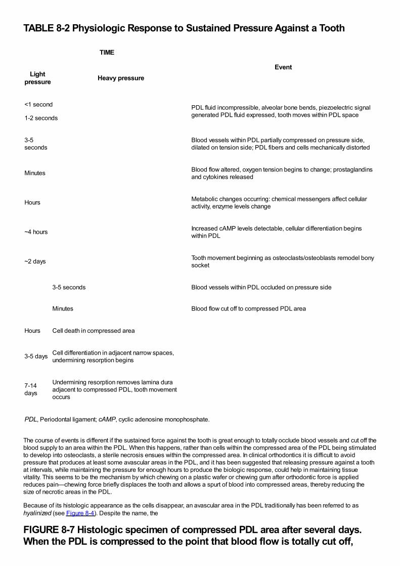
TABLE 8-2 Physiologic Response to Sustained Pressure Against a Tooth
TIME
EventLight
pressure Heavy pressure
<1 second
1-2 seconds
PDL fluid incompressible, alveolar bone bends, piezoelectric signalgenerated PDL fluid expressed, tooth moves within PDL space
3-5seconds
Blood vessels within PDL partially compressed on pressure side,dilated on tension side; PDL fibers and cells mechanically distorted
Minutes Blood flow altered, oxygen tension begins to change; prostaglandinsand cytokines released
Hours Metabolic changes occurring: chemical messengers affect cellularactivity, enzyme levels change
~4 hours Increased cAMP levels detectable, cellular differentiation beginswithin PDL
~2 days Tooth movement beginning as osteoclasts/osteoblasts remodel bonysocket
3-5 seconds Blood vessels within PDL occluded on pressure side
Minutes Blood flow cut off to compressed PDL area
Hours Cell death in compressed area
3-5 days Cell differentiation in adjacent narrow spaces,undermining resorption begins
7-14days
Undermining resorption removes lamina duraadjacent to compressed PDL, tooth movementoccurs
PDL, Periodontal ligament; cAMP, cyclic adenosine monophosphate.
The course of events is different if the sustained force against the tooth is great enough to totally occlude blood vessels and cut off theblood supply to an area within the PDL. When this happens, rather than cells within the compressed area of the PDL being stimulatedto develop into osteoclasts, a sterile necrosis ensues within the compressed area. In clinical orthodontics it is difficult to avoidpressure that produces at least some avascular areas in the PDL, and it has been suggested that releasing pressure against a toothat intervals, while maintaining the pressure for enough hours to produce the biologic response, could help in maintaining tissuevitality. This seems to be the mechanism by which chewing on a plastic wafer or chewing gum after orthodontic force is appliedreduces pain—chewing force briefly displaces the tooth and allows a spurt of blood into compressed areas, thereby reducing thesize of necrotic areas in the PDL.
Because of its histologic appearance as the cells disappear, an avascular area in the PDL traditionally has been referred to ashyalinized (see Figure 8-4). Despite the name, the
FIGURE 8-7 Histologic specimen of compressed PDL area after several days.When the PDL is compressed to the point that blood flow is totally cut off,
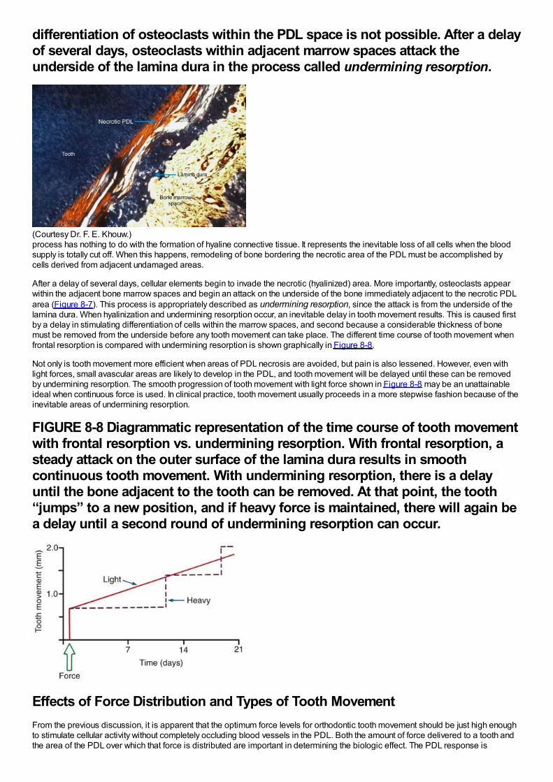
differentiation of osteoclasts within the PDL space is not possible. After a delayof several days, osteoclasts within adjacent marrow spaces attack theunderside of the lamina dura in the process called undermining resorption.
(Courtesy Dr. F. E. Khouw.)process has nothing to do with the formation of hyaline connective tissue. It represents the inevitable loss of all cells when the bloodsupply is totally cut off. When this happens, remodeling of bone bordering the necrotic area of the PDL must be accomplished bycells derived from adjacent undamaged areas.
After a delay of several days, cellular elements begin to invade the necrotic (hyalinized) area. More importantly, osteoclasts appearwithin the adjacent bone marrow spaces and begin an attack on the underside of the bone immediately adjacent to the necrotic PDLarea (Figure 8-7). This process is appropriately described as undermining resorption, since the attack is from the underside of thelamina dura. When hyalinization and undermining resorption occur, an inevitable delay in tooth movement results. This is caused firstby a delay in stimulating differentiation of cells within the marrow spaces, and second because a considerable thickness of bonemust be removed from the underside before any tooth movement can take place. The different time course of tooth movement whenfrontal resorption is compared with undermining resorption is shown graphically in Figure 8-8.
Not only is tooth movement more efficient when areas of PDL necrosis are avoided, but pain is also lessened. However, even withlight forces, small avascular areas are likely to develop in the PDL, and tooth movement will be delayed until these can be removedby undermining resorption. The smooth progression of tooth movement with light force shown in Figure 8-8 may be an unattainableideal when continuous force is used. In clinical practice, tooth movement usually proceeds in a more stepwise fashion because of theinevitable areas of undermining resorption.
FIGURE 8-8 Diagrammatic representation of the time course of tooth movementwith frontal resorption vs. undermining resorption. With frontal resorption, asteady attack on the outer surface of the lamina dura results in smoothcontinuous tooth movement. With undermining resorption, there is a delayuntil the bone adjacent to the tooth can be removed. At that point, the tooth“jumps” to a new position, and if heavy force is maintained, there will again bea delay until a second round of undermining resorption can occur.
Effects of Force Distribution and Types of Tooth MovementFrom the previous discussion, it is apparent that the optimum force levels for orthodontic tooth movement should be just high enoughto stimulate cellular activity without completely occluding blood vessels in the PDL. Both the amount of force delivered to a tooth andthe area of the PDL over which that force is distributed are important in determining the biologic effect. The PDL response is
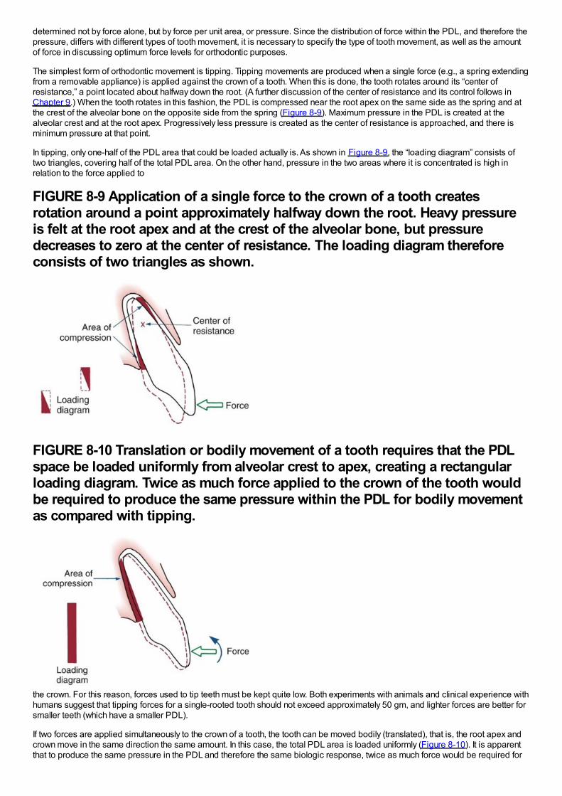
determined not by force alone, but by force per unit area, or pressure. Since the distribution of force within the PDL, and therefore thepressure, differs with different types of tooth movement, it is necessary to specify the type of tooth movement, as well as the amountof force in discussing optimum force levels for orthodontic purposes.
The simplest form of orthodontic movement is tipping. Tipping movements are produced when a single force (e.g., a spring extendingfrom a removable appliance) is applied against the crown of a tooth. When this is done, the tooth rotates around its “center ofresistance,” a point located about halfway down the root. (A further discussion of the center of resistance and its control follows inChapter 9.) When the tooth rotates in this fashion, the PDL is compressed near the root apex on the same side as the spring and atthe crest of the alveolar bone on the opposite side from the spring (Figure 8-9). Maximum pressure in the PDL is created at thealveolar crest and at the root apex. Progressively less pressure is created as the center of resistance is approached, and there isminimum pressure at that point.
In tipping, only one-half of the PDL area that could be loaded actually is. As shown in Figure 8-9, the “loading diagram” consists oftwo triangles, covering half of the total PDL area. On the other hand, pressure in the two areas where it is concentrated is high inrelation to the force applied to
FIGURE 8-9 Application of a single force to the crown of a tooth createsrotation around a point approximately halfway down the root. Heavy pressureis felt at the root apex and at the crest of the alveolar bone, but pressuredecreases to zero at the center of resistance. The loading diagram thereforeconsists of two triangles as shown.
FIGURE 8-10 Translation or bodily movement of a tooth requires that the PDLspace be loaded uniformly from alveolar crest to apex, creating a rectangularloading diagram. Twice as much force applied to the crown of the tooth wouldbe required to produce the same pressure within the PDL for bodily movementas compared with tipping.
the crown. For this reason, forces used to tip teeth must be kept quite low. Both experiments with animals and clinical experience withhumans suggest that tipping forces for a single-rooted tooth should not exceed approximately 50 gm, and lighter forces are better forsmaller teeth (which have a smaller PDL).
If two forces are applied simultaneously to the crown of a tooth, the tooth can be moved bodily (translated), that is, the root apex andcrown move in the same direction the same amount. In this case, the total PDL area is loaded uniformly (Figure 8-10). It is apparentthat to produce the same pressure in the PDL and therefore the same biologic response, twice as much force would be required for
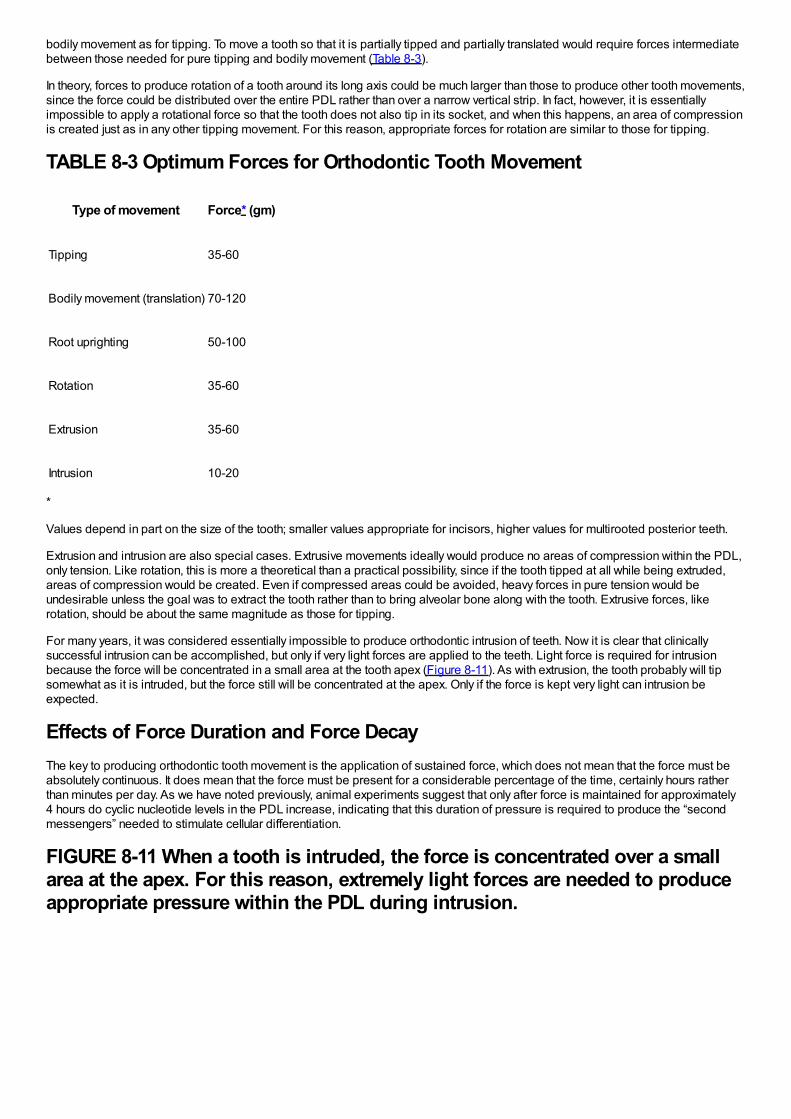
bodily movement as for tipping. To move a tooth so that it is partially tipped and partially translated would require forces intermediatebetween those needed for pure tipping and bodily movement (Table 8-3).
In theory, forces to produce rotation of a tooth around its long axis could be much larger than those to produce other tooth movements,since the force could be distributed over the entire PDL rather than over a narrow vertical strip. In fact, however, it is essentiallyimpossible to apply a rotational force so that the tooth does not also tip in its socket, and when this happens, an area of compressionis created just as in any other tipping movement. For this reason, appropriate forces for rotation are similar to those for tipping.
TABLE 8-3 Optimum Forces for Orthodontic Tooth Movement
Type of movement Force* (gm)
Tipping 35-60
Bodily movement (translation) 70-120
Root uprighting 50-100
Rotation 35-60
Extrusion 35-60
Intrusion 10-20
*
Values depend in part on the size of the tooth; smaller values appropriate for incisors, higher values for multirooted posterior teeth.
Extrusion and intrusion are also special cases. Extrusive movements ideally would produce no areas of compression within the PDL,only tension. Like rotation, this is more a theoretical than a practical possibility, since if the tooth tipped at all while being extruded,areas of compression would be created. Even if compressed areas could be avoided, heavy forces in pure tension would beundesirable unless the goal was to extract the tooth rather than to bring alveolar bone along with the tooth. Extrusive forces, likerotation, should be about the same magnitude as those for tipping.
For many years, it was considered essentially impossible to produce orthodontic intrusion of teeth. Now it is clear that clinicallysuccessful intrusion can be accomplished, but only if very light forces are applied to the teeth. Light force is required for intrusionbecause the force will be concentrated in a small area at the tooth apex (Figure 8-11). As with extrusion, the tooth probably will tipsomewhat as it is intruded, but the force still will be concentrated at the apex. Only if the force is kept very light can intrusion beexpected.
Effects of Force Duration and Force DecayThe key to producing orthodontic tooth movement is the application of sustained force, which does not mean that the force must beabsolutely continuous. It does mean that the force must be present for a considerable percentage of the time, certainly hours ratherthan minutes per day. As we have noted previously, animal experiments suggest that only after force is maintained for approximately4 hours do cyclic nucleotide levels in the PDL increase, indicating that this duration of pressure is required to produce the “secondmessengers” needed to stimulate cellular differentiation.
FIGURE 8-11 When a tooth is intruded, the force is concentrated over a smallarea at the apex. For this reason, extremely light forces are needed to produceappropriate pressure within the PDL during intrusion.
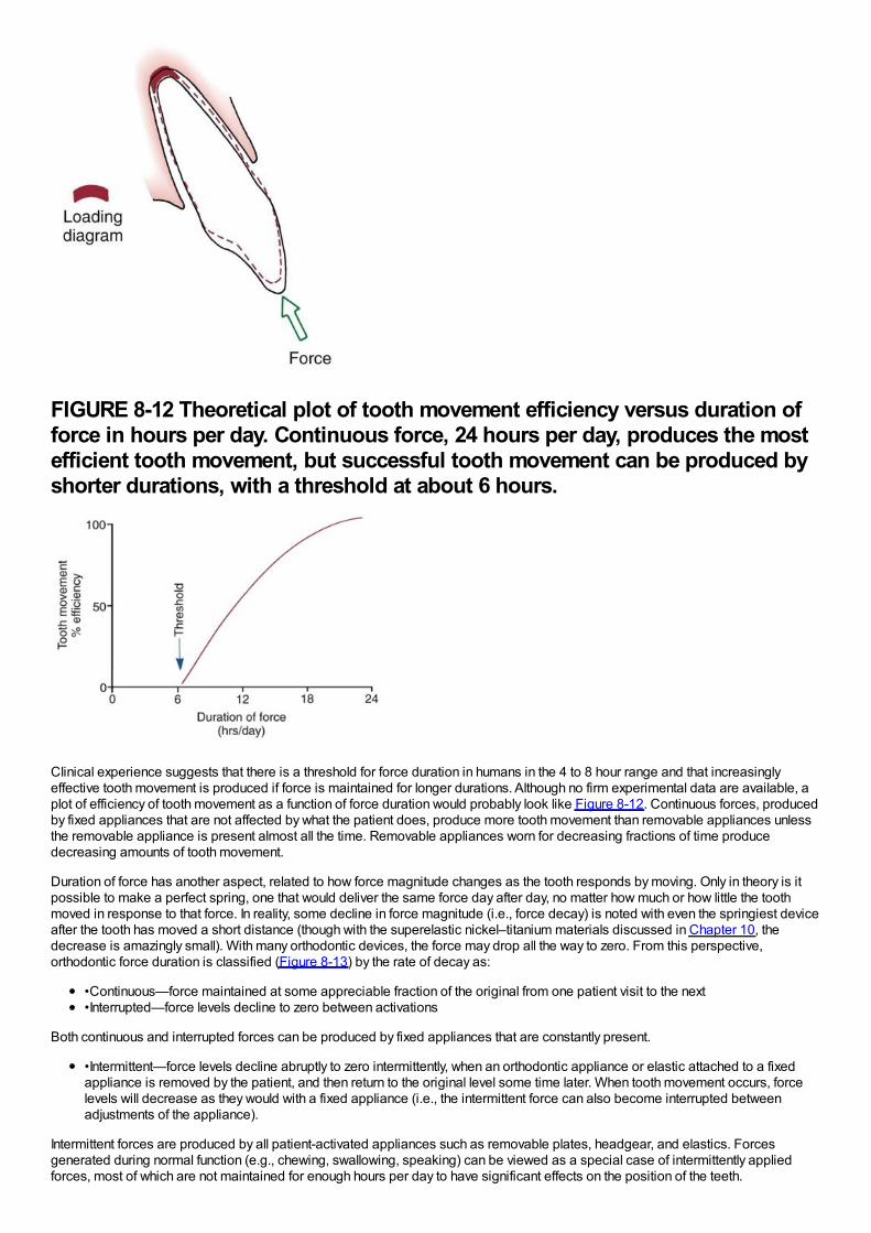
FIGURE 8-12 Theoretical plot of tooth movement efficiency versus duration offorce in hours per day. Continuous force, 24 hours per day, produces the mostefficient tooth movement, but successful tooth movement can be produced byshorter durations, with a threshold at about 6 hours.
Clinical experience suggests that there is a threshold for force duration in humans in the 4 to 8 hour range and that increasinglyeffective tooth movement is produced if force is maintained for longer durations. Although no firm experimental data are available, aplot of efficiency of tooth movement as a function of force duration would probably look like Figure 8-12. Continuous forces, producedby fixed appliances that are not affected by what the patient does, produce more tooth movement than removable appliances unlessthe removable appliance is present almost all the time. Removable appliances worn for decreasing fractions of time producedecreasing amounts of tooth movement.
Duration of force has another aspect, related to how force magnitude changes as the tooth responds by moving. Only in theory is itpossible to make a perfect spring, one that would deliver the same force day after day, no matter how much or how little the toothmoved in response to that force. In reality, some decline in force magnitude (i.e., force decay) is noted with even the springiest deviceafter the tooth has moved a short distance (though with the superelastic nickel–titanium materials discussed in Chapter 10, thedecrease is amazingly small). With many orthodontic devices, the force may drop all the way to zero. From this perspective,orthodontic force duration is classified (Figure 8-13) by the rate of decay as:
•Continuous—force maintained at some appreciable fraction of the original from one patient visit to the next•Interrupted—force levels decline to zero between activations
Both continuous and interrupted forces can be produced by fixed appliances that are constantly present.
•Intermittent—force levels decline abruptly to zero intermittently, when an orthodontic appliance or elastic attached to a fixedappliance is removed by the patient, and then return to the original level some time later. When tooth movement occurs, forcelevels will decrease as they would with a fixed appliance (i.e., the intermittent force can also become interrupted betweenadjustments of the appliance).
Intermittent forces are produced by all patient-activated appliances such as removable plates, headgear, and elastics. Forcesgenerated during normal function (e.g., chewing, swallowing, speaking) can be viewed as a special case of intermittently appliedforces, most of which are not maintained for enough hours per day to have significant effects on the position of the teeth.
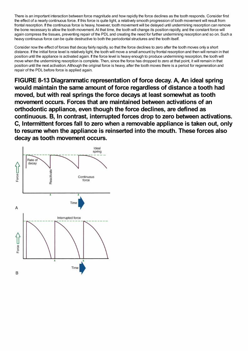
There is an important interaction between force magnitude and how rapidly the force declines as the tooth responds. Consider firstthe effect of a nearly continuous force. If this force is quite light, a relatively smooth progression of tooth movement will result fromfrontal resorption. If the continuous force is heavy, however, tooth movement will be delayed until undermining resorption can removethe bone necessary to allow the tooth movement. At that time, the tooth will change its position rapidly, and the constant force willagain compress the tissues, preventing repair of the PDL and creating the need for further undermining resorption and so on. Such aheavy continuous force can be quite destructive to both the periodontal structures and the tooth itself.
Consider now the effect of forces that decay fairly rapidly, so that the force declines to zero after the tooth moves only a shortdistance. If the initial force level is relatively light, the tooth will move a small amount by frontal resorption and then will remain in thatposition until the appliance is activated again. If the force level is heavy enough to produce undermining resorption, the tooth willmove when the undermining resorption is complete. Then, since the force has dropped to zero at that point, it will remain in thatposition until the next activation. Although the original force is heavy, after the tooth moves there is a period for regeneration andrepair of the PDL before force is applied again.
FIGURE 8-13 Diagrammatic representation of force decay. A, An ideal springwould maintain the same amount of force regardless of distance a tooth hadmoved, but with real springs the force decays at least somewhat as toothmovement occurs. Forces that are maintained between activations of anorthodontic appliance, even though the force declines, are defined ascontinuous. B, In contrast, interrupted forces drop to zero between activations.C, Intermittent forces fall to zero when a removable appliance is taken out, onlyto resume when the appliance is reinserted into the mouth. These forces alsodecay as tooth movement occurs.
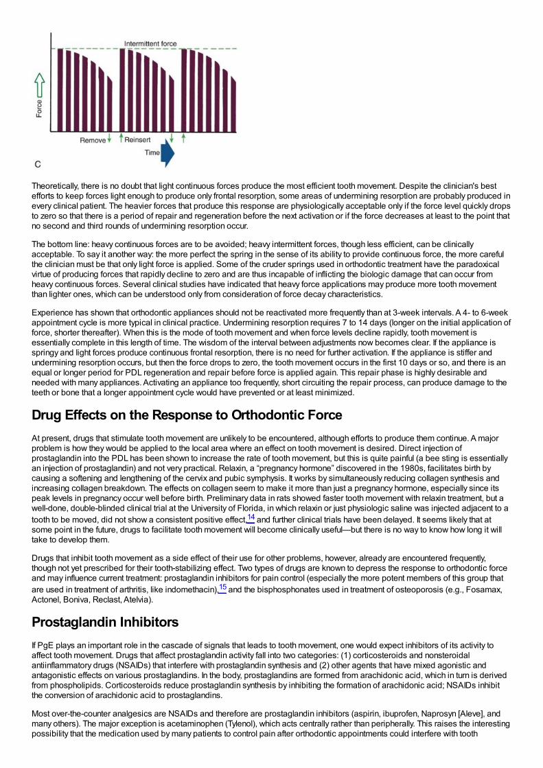
Theoretically, there is no doubt that light continuous forces produce the most efficient tooth movement. Despite the clinician's bestefforts to keep forces light enough to produce only frontal resorption, some areas of undermining resorption are probably produced inevery clinical patient. The heavier forces that produce this response are physiologically acceptable only if the force level quickly dropsto zero so that there is a period of repair and regeneration before the next activation or if the force decreases at least to the point thatno second and third rounds of undermining resorption occur.
The bottom line: heavy continuous forces are to be avoided; heavy intermittent forces, though less efficient, can be clinicallyacceptable. To say it another way: the more perfect the spring in the sense of its ability to provide continuous force, the more carefulthe clinician must be that only light force is applied. Some of the cruder springs used in orthodontic treatment have the paradoxicalvirtue of producing forces that rapidly decline to zero and are thus incapable of inflicting the biologic damage that can occur fromheavy continuous forces. Several clinical studies have indicated that heavy force applications may produce more tooth movementthan lighter ones, which can be understood only from consideration of force decay characteristics.
Experience has shown that orthodontic appliances should not be reactivated more frequently than at 3-week intervals. A 4- to 6-weekappointment cycle is more typical in clinical practice. Undermining resorption requires 7 to 14 days (longer on the initial application offorce, shorter thereafter). When this is the mode of tooth movement and when force levels decline rapidly, tooth movement isessentially complete in this length of time. The wisdom of the interval between adjustments now becomes clear. If the appliance isspringy and light forces produce continuous frontal resorption, there is no need for further activation. If the appliance is stiffer andundermining resorption occurs, but then the force drops to zero, the tooth movement occurs in the first 10 days or so, and there is anequal or longer period for PDL regeneration and repair before force is applied again. This repair phase is highly desirable andneeded with many appliances. Activating an appliance too frequently, short circuiting the repair process, can produce damage to theteeth or bone that a longer appointment cycle would have prevented or at least minimized.
Drug Effects on the Response to Orthodontic ForceAt present, drugs that stimulate tooth movement are unlikely to be encountered, although efforts to produce them continue. A majorproblem is how they would be applied to the local area where an effect on tooth movement is desired. Direct injection ofprostaglandin into the PDL has been shown to increase the rate of tooth movement, but this is quite painful (a bee sting is essentiallyan injection of prostaglandin) and not very practical. Relaxin, a “pregnancy hormone” discovered in the 1980s, facilitates birth bycausing a softening and lengthening of the cervix and pubic symphysis. It works by simultaneously reducing collagen synthesis andincreasing collagen breakdown. The effects on collagen seem to make it more than just a pregnancy hormone, especially since itspeak levels in pregnancy occur well before birth. Preliminary data in rats showed faster tooth movement with relaxin treatment, but awell-done, double-blinded clinical trial at the University of Florida, in which relaxin or just physiologic saline was injected adjacent to atooth to be moved, did not show a consistent positive effect,14 and further clinical trials have been delayed. It seems likely that atsome point in the future, drugs to facilitate tooth movement will become clinically useful—but there is no way to know how long it willtake to develop them.
Drugs that inhibit tooth movement as a side effect of their use for other problems, however, already are encountered frequently,though not yet prescribed for their tooth-stabilizing effect. Two types of drugs are known to depress the response to orthodontic forceand may influence current treatment: prostaglandin inhibitors for pain control (especially the more potent members of this group thatare used in treatment of arthritis, like indomethacin),15 and the bisphosphonates used in treatment of osteoporosis (e.g., Fosamax,Actonel, Boniva, Reclast, Atelvia).
Prostaglandin InhibitorsIf PgE plays an important role in the cascade of signals that leads to tooth movement, one would expect inhibitors of its activity toaffect tooth movement. Drugs that affect prostaglandin activity fall into two categories: (1) corticosteroids and nonsteroidalantiinflammatory drugs (NSAIDs) that interfere with prostaglandin synthesis and (2) other agents that have mixed agonistic andantagonistic effects on various prostaglandins. In the body, prostaglandins are formed from arachidonic acid, which in turn is derivedfrom phospholipids. Corticosteroids reduce prostaglandin synthesis by inhibiting the formation of arachidonic acid; NSAIDs inhibitthe conversion of arachidonic acid to prostaglandins.
Most over-the-counter analgesics are NSAIDs and therefore are prostaglandin inhibitors (aspirin, ibuprofen, Naprosyn [Aleve], andmany others). The major exception is acetaminophen (Tylenol), which acts centrally rather than peripherally. This raises the interestingpossibility that the medication used by many patients to control pain after orthodontic appointments could interfere with tooth
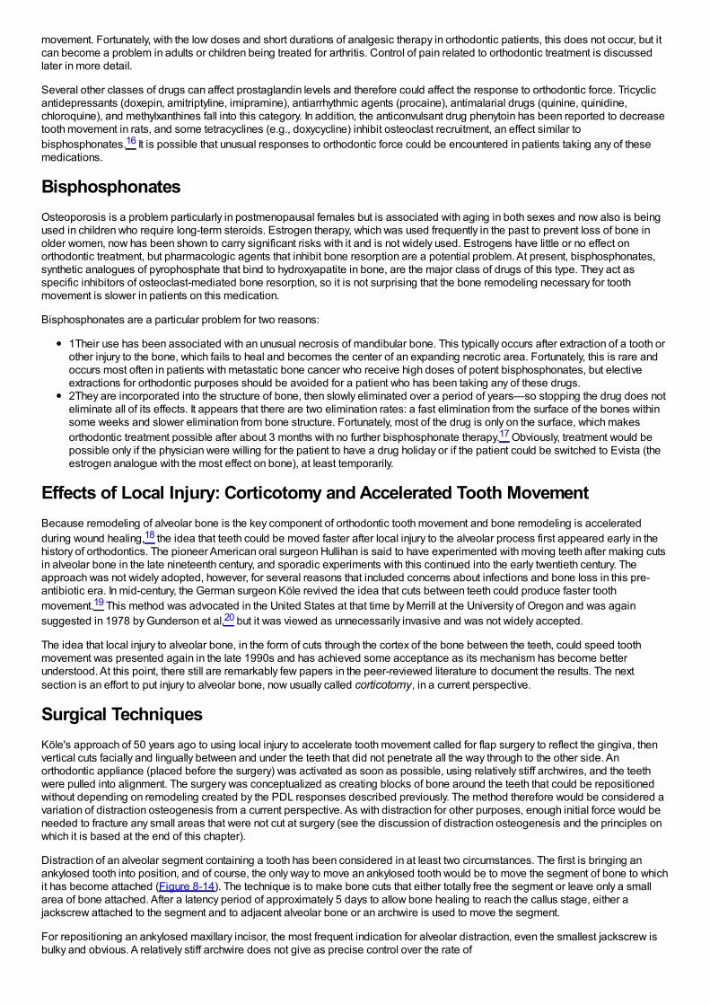
movement. Fortunately, with the low doses and short durations of analgesic therapy in orthodontic patients, this does not occur, but itcan become a problem in adults or children being treated for arthritis. Control of pain related to orthodontic treatment is discussedlater in more detail.
Several other classes of drugs can affect prostaglandin levels and therefore could affect the response to orthodontic force. Tricyclicantidepressants (doxepin, amitriptyline, imipramine), antiarrhythmic agents (procaine), antimalarial drugs (quinine, quinidine,chloroquine), and methylxanthines fall into this category. In addition, the anticonvulsant drug phenytoin has been reported to decreasetooth movement in rats, and some tetracyclines (e.g., doxycycline) inhibit osteoclast recruitment, an effect similar tobisphosphonates.16 It is possible that unusual responses to orthodontic force could be encountered in patients taking any of thesemedications.
BisphosphonatesOsteoporosis is a problem particularly in postmenopausal females but is associated with aging in both sexes and now also is beingused in children who require long-term steroids. Estrogen therapy, which was used frequently in the past to prevent loss of bone inolder women, now has been shown to carry significant risks with it and is not widely used. Estrogens have little or no effect onorthodontic treatment, but pharmacologic agents that inhibit bone resorption are a potential problem. At present, bisphosphonates,synthetic analogues of pyrophosphate that bind to hydroxyapatite in bone, are the major class of drugs of this type. They act asspecific inhibitors of osteoclast-mediated bone resorption, so it is not surprising that the bone remodeling necessary for toothmovement is slower in patients on this medication.
Bisphosphonates are a particular problem for two reasons:
1Their use has been associated with an unusual necrosis of mandibular bone. This typically occurs after extraction of a tooth orother injury to the bone, which fails to heal and becomes the center of an expanding necrotic area. Fortunately, this is rare andoccurs most often in patients with metastatic bone cancer who receive high doses of potent bisphosphonates, but electiveextractions for orthodontic purposes should be avoided for a patient who has been taking any of these drugs.2They are incorporated into the structure of bone, then slowly eliminated over a period of years—so stopping the drug does noteliminate all of its effects. It appears that there are two elimination rates: a fast elimination from the surface of the bones withinsome weeks and slower elimination from bone structure. Fortunately, most of the drug is only on the surface, which makesorthodontic treatment possible after about 3 months with no further bisphosphonate therapy.17 Obviously, treatment would bepossible only if the physician were willing for the patient to have a drug holiday or if the patient could be switched to Evista (theestrogen analogue with the most effect on bone), at least temporarily.
Effects of Local Injury: Corticotomy and Accelerated Tooth MovementBecause remodeling of alveolar bone is the key component of orthodontic tooth movement and bone remodeling is acceleratedduring wound healing,18 the idea that teeth could be moved faster after local injury to the alveolar process first appeared early in thehistory of orthodontics. The pioneer American oral surgeon Hullihan is said to have experimented with moving teeth after making cutsin alveolar bone in the late nineteenth century, and sporadic experiments with this continued into the early twentieth century. Theapproach was not widely adopted, however, for several reasons that included concerns about infections and bone loss in this pre-antibiotic era. In mid-century, the German surgeon Köle revived the idea that cuts between teeth could produce faster toothmovement.19 This method was advocated in the United States at that time by Merrill at the University of Oregon and was againsuggested in 1978 by Gunderson et al,20 but it was viewed as unnecessarily invasive and was not widely accepted.
The idea that local injury to alveolar bone, in the form of cuts through the cortex of the bone between the teeth, could speed toothmovement was presented again in the late 1990s and has achieved some acceptance as its mechanism has become betterunderstood. At this point, there still are remarkably few papers in the peer-reviewed literature to document the results. The nextsection is an effort to put injury to alveolar bone, now usually called corticotomy, in a current perspective.
Surgical TechniquesKöle's approach of 50 years ago to using local injury to accelerate tooth movement called for flap surgery to reflect the gingiva, thenvertical cuts facially and lingually between and under the teeth that did not penetrate all the way through to the other side. Anorthodontic appliance (placed before the surgery) was activated as soon as possible, using relatively stiff archwires, and the teethwere pulled into alignment. The surgery was conceptualized as creating blocks of bone around the teeth that could be repositionedwithout depending on remodeling created by the PDL responses described previously. The method therefore would be considered avariation of distraction osteogenesis from a current perspective. As with distraction for other purposes, enough initial force would beneeded to fracture any small areas that were not cut at surgery (see the discussion of distraction osteogenesis and the principles onwhich it is based at the end of this chapter).
Distraction of an alveolar segment containing a tooth has been considered in at least two circumstances. The first is bringing anankylosed tooth into position, and of course, the only way to move an ankylosed tooth would be to move the segment of bone to whichit has become attached (Figure 8-14). The technique is to make bone cuts that either totally free the segment or leave only a smallarea of bone attached. After a latency period of approximately 5 days to allow bone healing to reach the callus stage, either ajackscrew attached to the segment and to adjacent alveolar bone or an archwire is used to move the segment.
For repositioning an ankylosed maxillary incisor, the most frequent indication for alveolar distraction, even the smallest jackscrew isbulky and obvious. A relatively stiff archwire does not give as precise control over the rate of
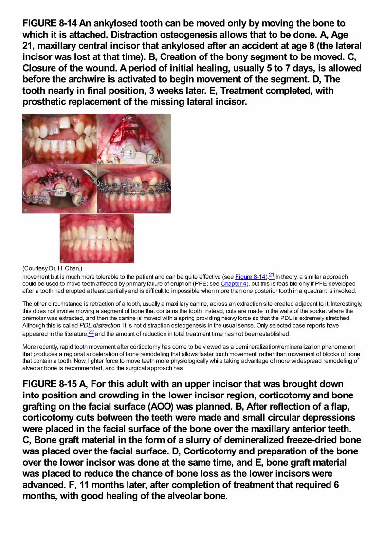
FIGURE 8-14 An ankylosed tooth can be moved only by moving the bone towhich it is attached. Distraction osteogenesis allows that to be done. A, Age21, maxillary central incisor that ankylosed after an accident at age 8 (the lateralincisor was lost at that time). B, Creation of the bony segment to be moved. C,Closure of the wound. A period of initial healing, usually 5 to 7 days, is allowedbefore the archwire is activated to begin movement of the segment. D, Thetooth nearly in final position, 3 weeks later. E, Treatment completed, withprosthetic replacement of the missing lateral incisor.
(Courtesy Dr. H. Chen.)movement but is much more tolerable to the patient and can be quite effective (see Figure 8-14).21 In theory, a similar approachcould be used to move teeth affected by primary failure of eruption (PFE; see Chapter 4), but this is feasible only if PFE developedafter a tooth had erupted at least partially and is difficult to impossible when more than one posterior tooth in a quadrant is involved.
The other circumstance is retraction of a tooth, usually a maxillary canine, across an extraction site created adjacent to it. Interestingly,this does not involve moving a segment of bone that contains the tooth. Instead, cuts are made in the walls of the socket where thepremolar was extracted, and then the canine is moved with a spring providing heavy force so that the PDL is extremely stretched.Although this is called PDL distraction, it is not distraction osteogenesis in the usual sense. Only selected case reports haveappeared in the literature,22 and the amount of reduction in total treatment time has not been established.
More recently, rapid tooth movement after corticotomy has come to be viewed as a demineralization/remineralization phenomenonthat produces a regional acceleration of bone remodeling that allows faster tooth movement, rather than movement of blocks of bonethat contain a tooth. Now, lighter force to move teeth more physiologically while taking advantage of more widespread remodeling ofalveolar bone is recommended, and the surgical approach has
FIGURE 8-15 A, For this adult with an upper incisor that was brought downinto position and crowding in the lower incisor region, corticotomy and bonegrafting on the facial surface (AOO) was planned. B, After reflection of a flap,corticotomy cuts between the teeth were made and small circular depressionswere placed in the facial surface of the bone over the maxillary anterior teeth.C, Bone graft material in the form of a slurry of demineralized freeze-dried bonewas placed over the facial surface. D, Corticotomy and preparation of the boneover the lower incisor was done at the same time, and E, bone graft materialwas placed to reduce the chance of bone loss as the lower incisors wereadvanced. F, 11 months later, after completion of treatment that required 6months, with good healing of the alveolar bone.
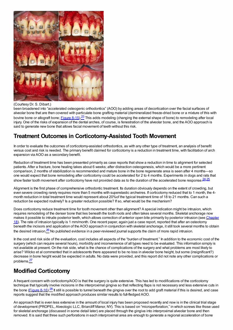
(Courtesy Dr. S. Dibart.)been broadened into “accelerated osteogenic orthodontics” (AOO) by adding areas of decortication over the facial surfaces ofalveolar bone that are then covered with particulate bone grafting material (demineralized freeze-dried bone or a mixture of this withbovine bone or allograft bone; Figure 8-15).23 This adds modeling (changing the external shape of bone) to remodeling after localinjury. One of the risks of expansion of the dental arches, of course, is fenestration of the alveolar bone, and the AOO approach issaid to generate new bone that allows facial movement of teeth without this risk.
Treatment Outcomes in Corticotomy-Assisted Tooth MovementIn order to evaluate the outcomes of corticotomy-assisted orthodontics, as with any other type of treatment, an analysis of benefitversus cost and risk is needed. The primary benefit claimed for corticotomy is a reduction in treatment time, with facilitation of archexpansion via AOO as a secondary benefit.
Reduction of treatment time has been presented primarily as case reports that show a reduction in time to alignment for selectedpatients. After a fracture, bone healing takes about 6 weeks; after distraction osteogenesis, which would be a more pertinentcomparison, 2 months of stabilization is recommended and mature bone in the bone regenerate area is seen after 4 months—soone would expect that bone remodeling after corticotomy could be accelerated for 2 to 4 months. Experiments in dogs and rats thatshow faster tooth movement after corticotomy have not provided data as to the duration of the accelerated bone response.24,25
Alignment is the first phase of comprehensive orthodontic treatment. Its duration obviously depends on the extent of crowding, buteven severe crowding rarely requires more than 5 months with superelastic archwires. If corticotomy reduced that to 1 month, the 4-month reduction in total treatment time would represent about 20%of the typical treatment time of 18 to 21 months. Can such areduction be expected routinely? Is a greater reduction possible? If so, what would be the mechanism?
Does corticotomy reduce treatment time for tooth movement other than alignment? A special indication might be intrusion, whichrequires remodeling of the denser bone that lies beneath the tooth roots and often takes several months. Skeletal anchorage nowmakes it possible to intrude posterior teeth, which allows correction of anterior open bite primarily by posterior intrusion (see Chapter18). The rate of intrusion typically is 1 mm/month. One recent paper, again just a case report, reported that after an osteotomybeneath the incisors and application of the AOO approach in conjunction with skeletal anchorage, it still took several months to obtainthe desired intrusion.26 No published evidence in a peer-reviewed journal supports the claim of more rapid intrusion.
In the cost and risk side of the evaluation, cost includes all aspects of the “burden of treatment.” In addition to the economic cost of thesurgery (which can require several hours), morbidity and inconvenience of all types need to be evaluated. This information simply isnot available at present. On the risk side, what is the chance of complications of the surgery and what problems are most likely toarise? Wilcko et al commented that in adolescents there appeared to be no loss in alveolar bone height, but some (insignificant?)decrease in bone height would be expected in adults. No data were provided, and this report did not note any other complications orproblems.27
Modified CorticotomyA frequent concern with corticotomy/AOO is that the surgery is quite extensive. This has led to modifications of the corticotomytechnique that typically involve incisions in the interproximal gingiva so that reflecting flaps is not necessary and less extensive cuts inthe bone (Figure 8-16).28 It still is possible to tunnel beneath the gingiva over the root to add graft material if this is desired, and casereports suggest that the modified approach produces similar results to full-fledged AOO.
An approach that is even less extensive in the amount of local injury has been proposed recently and now is in the clinical trial stageof development (PROPEL, Alveologic LLC, Briarcliff Manor, NY). This is based on “microperforation,” in which screws like those usedfor skeletal anchorage (discussed in some detail later) are placed through the gingiva into interproximal alveolar bone and thenremoved. It is said that three such perforations in each interproximal area are enough to generate a regional acceleration of bone
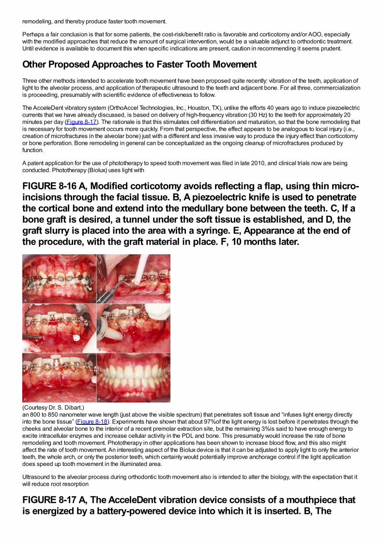
remodeling, and thereby produce faster tooth movement.
Perhaps a fair conclusion is that for some patients, the cost-risk/benefit ratio is favorable and corticotomy and/or AOO, especiallywith the modified approaches that reduce the amount of surgical intervention, would be a valuable adjunct to orthodontic treatment.Until evidence is available to document this when specific indications are present, caution in recommending it seems prudent.
Other Proposed Approaches to Faster Tooth MovementThree other methods intended to accelerate tooth movement have been proposed quite recently: vibration of the teeth, application oflight to the alveolar process, and application of therapeutic ultrasound to the teeth and adjacent bone. For all three, commercializationis proceeding, presumably with scientific evidence of effectiveness to follow.
The AcceleDent vibratory system (OrthoAccel Technologies, Inc., Houston, TX), unlike the efforts 40 years ago to induce piezoelectriccurrents that we have already discussed, is based on delivery of high-frequency vibration (30 Hz) to the teeth for approximately 20minutes per day (Figure 8-17). The rationale is that this stimulates cell differentiation and maturation, so that the bone remodeling thatis necessary for tooth movement occurs more quickly. From that perspective, the effect appears to be analogous to local injury (i.e.,creation of microfractures in the alveolar bone) just with a different and less invasive way to produce the injury effect than corticotomyor bone perforation. Bone remodeling in general can be conceptualized as the ongoing cleanup of microfractures produced byfunction.
A patent application for the use of phototherapy to speed tooth movement was filed in late 2010, and clinical trials now are beingconducted. Phototherapy (Biolux) uses light with
FIGURE 8-16 A, Modified corticotomy avoids reflecting a flap, using thin micro-incisions through the facial tissue. B, A piezoelectric knife is used to penetratethe cortical bone and extend into the medullary bone between the teeth. C, If abone graft is desired, a tunnel under the soft tissue is established, and D, thegraft slurry is placed into the area with a syringe. E, Appearance at the end ofthe procedure, with the graft material in place. F, 10 months later.
(Courtesy Dr. S. Dibart.)an 800 to 850 nanometer wave length (just above the visible spectrum) that penetrates soft tissue and “infuses light energy directlyinto the bone tissue” (Figure 8-18). Experiments have shown that about 97%of the light energy is lost before it penetrates through thecheeks and alveolar bone to the interior of a recent premolar extraction site, but the remaining 3%is said to have enough energy toexcite intracellular enzymes and increase cellular activity in the PDL and bone. This presumably would increase the rate of boneremodeling and tooth movement. Phototherapy in other applications has been shown to increase blood flow, and this also mightaffect the rate of tooth movement. An interesting aspect of the Biolux device is that it can be adjusted to apply light to only the anteriorteeth, the whole arch, or only the posterior teeth, which certainly would potentially improve anchorage control if the light applicationdoes speed up tooth movement in the illuminated area.
Ultrasound to the alveolar process during orthodontic tooth movement also is intended to alter the biology, with the expectation that itwill reduce root resorption
FIGURE 8-17 A, The AcceleDent vibration device consists of a mouthpiece thatis energized by a battery-powered device into which it is inserted. B, The
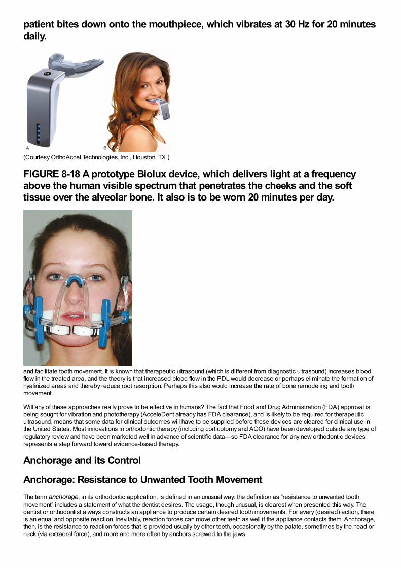
patient bites down onto the mouthpiece, which vibrates at 30 Hz for 20 minutesdaily.
(Courtesy OrthoAccel Technologies, Inc., Houston, TX.)
FIGURE 8-18 A prototype Biolux device, which delivers light at a frequencyabove the human visible spectrum that penetrates the cheeks and the softtissue over the alveolar bone. It also is to be worn 20 minutes per day.
and facilitate tooth movement. It is known that therapeutic ultrasound (which is different from diagnostic ultrasound) increases bloodflow in the treated area, and the theory is that increased blood flow in the PDL would decrease or perhaps eliminate the formation ofhyalinized areas and thereby reduce root resorption. Perhaps this also would increase the rate of bone remodeling and toothmovement.
Will any of these approaches really prove to be effective in humans? The fact that Food and Drug Administration (FDA) approval isbeing sought for vibration and phototherapy (AcceleDent already has FDA clearance), and is likely to be required for therapeuticultrasound, means that some data for clinical outcomes will have to be supplied before these devices are cleared for clinical use inthe United States. Most innovations in orthodontic therapy (including corticotomy and AOO) have been developed outside any type ofregulatory review and have been marketed well in advance of scientific data—so FDA clearance for any new orthodontic devicesrepresents a step forward toward evidence-based therapy.
Anchorage and its Control
Anchorage: Resistance to Unwanted Tooth MovementThe term anchorage, in its orthodontic application, is defined in an unusual way: the definition as “resistance to unwanted toothmovement” includes a statement of what the dentist desires. The usage, though unusual, is clearest when presented this way. Thedentist or orthodontist always constructs an appliance to produce certain desired tooth movements. For every (desired) action, thereis an equal and opposite reaction. Inevitably, reaction forces can move other teeth as well if the appliance contacts them. Anchorage,then, is the resistance to reaction forces that is provided usually by other teeth, occasionally by the palate, sometimes by the head orneck (via extraoral force), and more and more often by anchors screwed to the jaws.
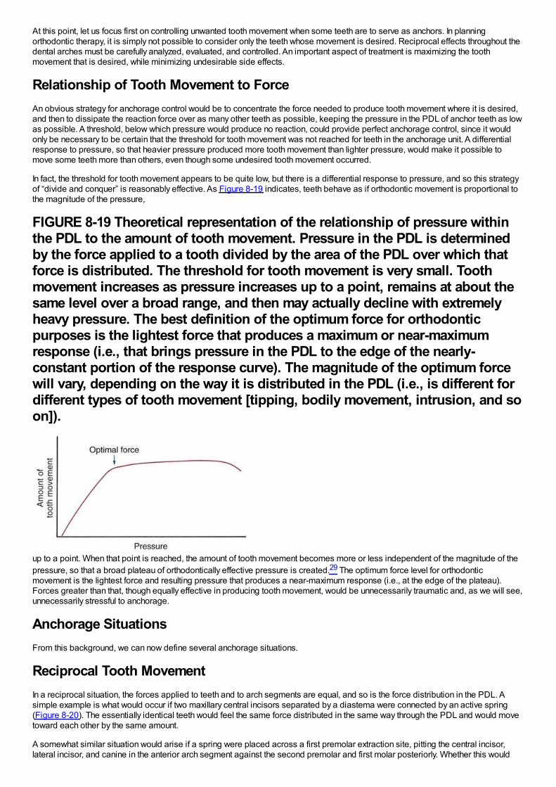
At this point, let us focus first on controlling unwanted tooth movement when some teeth are to serve as anchors. In planningorthodontic therapy, it is simply not possible to consider only the teeth whose movement is desired. Reciprocal effects throughout thedental arches must be carefully analyzed, evaluated, and controlled. An important aspect of treatment is maximizing the toothmovement that is desired, while minimizing undesirable side effects.
Relationship of Tooth Movement to ForceAn obvious strategy for anchorage control would be to concentrate the force needed to produce tooth movement where it is desired,and then to dissipate the reaction force over as many other teeth as possible, keeping the pressure in the PDL of anchor teeth as lowas possible. A threshold, below which pressure would produce no reaction, could provide perfect anchorage control, since it wouldonly be necessary to be certain that the threshold for tooth movement was not reached for teeth in the anchorage unit. A differentialresponse to pressure, so that heavier pressure produced more tooth movement than lighter pressure, would make it possible tomove some teeth more than others, even though some undesired tooth movement occurred.
In fact, the threshold for tooth movement appears to be quite low, but there is a differential response to pressure, and so this strategyof “divide and conquer” is reasonably effective. As Figure 8-19 indicates, teeth behave as if orthodontic movement is proportional tothe magnitude of the pressure,
FIGURE 8-19 Theoretical representation of the relationship of pressure withinthe PDL to the amount of tooth movement. Pressure in the PDL is determinedby the force applied to a tooth divided by the area of the PDL over which thatforce is distributed. The threshold for tooth movement is very small. Toothmovement increases as pressure increases up to a point, remains at about thesame level over a broad range, and then may actually decline with extremelyheavy pressure. The best definition of the optimum force for orthodonticpurposes is the lightest force that produces a maximum or near-maximumresponse (i.e., that brings pressure in the PDL to the edge of the nearly-constant portion of the response curve). The magnitude of the optimum forcewill vary, depending on the way it is distributed in the PDL (i.e., is different fordifferent types of tooth movement [tipping, bodily movement, intrusion, and soon]).
up to a point. When that point is reached, the amount of tooth movement becomes more or less independent of the magnitude of thepressure, so that a broad plateau of orthodontically effective pressure is created.29 The optimum force level for orthodonticmovement is the lightest force and resulting pressure that produces a near-maximum response (i.e., at the edge of the plateau).Forces greater than that, though equally effective in producing tooth movement, would be unnecessarily traumatic and, as we will see,unnecessarily stressful to anchorage.
Anchorage SituationsFrom this background, we can now define several anchorage situations.
Reciprocal Tooth MovementIn a reciprocal situation, the forces applied to teeth and to arch segments are equal, and so is the force distribution in the PDL. Asimple example is what would occur if two maxillary central incisors separated by a diastema were connected by an active spring(Figure 8-20). The essentially identical teeth would feel the same force distributed in the same way through the PDL and would movetoward each other by the same amount.
A somewhat similar situation would arise if a spring were placed across a first premolar extraction site, pitting the central incisor,lateral incisor, and canine in the anterior arch segment against the second premolar and first molar posteriorly. Whether this would
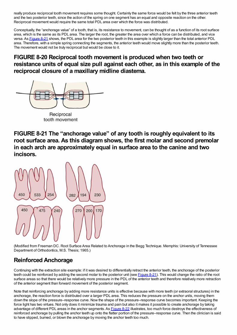
really produce reciprocal tooth movement requires some thought. Certainly the same force would be felt by the three anterior teethand the two posterior teeth, since the action of the spring on one segment has an equal and opposite reaction on the other.Reciprocal movement would require the same total PDL area over which the force was distributed.
Conceptually, the “anchorage value” of a tooth, that is, its resistance to movement, can be thought of as a function of its root surfacearea, which is the same as its PDL area. The larger the root, the greater the area over which a force can be distributed, and viceversa. As Figure 8-21 shows, the PDL area for the two posterior teeth in this example is slightly larger than the total anterior PDLarea. Therefore, with a simple spring connecting the segments, the anterior teeth would move slightly more than the posterior teeth.The movement would not be truly reciprocal but would be close to it.
FIGURE 8-20 Reciprocal tooth movement is produced when two teeth orresistance units of equal size pull against each other, as in this example of thereciprocal closure of a maxillary midline diastema.
FIGURE 8-21 The “anchorage value” of any tooth is roughly equivalent to itsroot surface area. As this diagram shows, the first molar and second premolarin each arch are approximately equal in surface area to the canine and twoincisors.
(Modified from Freeman DC. Root Surface Area Related to Anchorage in the Begg Technique. Memphis: University of TennesseeDepartment of Orthodontics, M.S. Thesis; 1965.)
Reinforced AnchorageContinuing with the extraction site example: if it was desired to differentially retract the anterior teeth, the anchorage of the posteriorteeth could be reinforced by adding the second molar to the posterior unit (see Figure 8-21). This would change the ratio of the rootsurface areas so that there would be relatively more pressure in the PDL of the anterior teeth and therefore relatively more retractionof the anterior segment than forward movement of the posterior segment.
Note that reinforcing anchorage by adding more resistance units is effective because with more teeth (or extraoral structures) in theanchorage, the reaction force is distributed over a larger PDL area. This reduces the pressure on the anchor units, moving themdown the slope of the pressure–response curve. Now the shape of the pressure–response curve becomes important. Keeping theforce light has two virtues. Not only does it minimize trauma and pain but also it makes it possible to create anchorage by takingadvantage of different PDL areas in the anchor segments. As Figure 8-22 illustrates, too much force destroys the effectiveness ofreinforced anchorage by pulling the anchor teeth up onto the flatter portion of the pressure–response curve. Then the clinician is saidto have slipped, burned, or blown the anchorage by moving the anchor teeth too much.
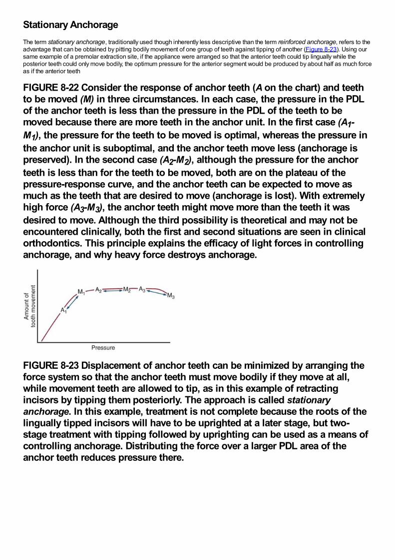
Stationary AnchorageThe term stationary anchorage, traditionally used though inherently less descriptive than the term reinforced anchorage, refers to theadvantage that can be obtained by pitting bodily movement of one group of teeth against tipping of another (Figure 8-23). Using oursame example of a premolar extraction site, if the appliance were arranged so that the anterior teeth could tip lingually while theposterior teeth could only move bodily, the optimum pressure for the anterior segment would be produced by about half as much forceas if the anterior teeth
FIGURE 8-22 Consider the response of anchor teeth (A on the chart) and teethto be moved (M) in three circumstances. In each case, the pressure in the PDLof the anchor teeth is less than the pressure in the PDL of the teeth to bemoved because there are more teeth in the anchor unit. In the first case (A1-M1), the pressure for the teeth to be moved is optimal, whereas the pressure inthe anchor unit is suboptimal, and the anchor teeth move less (anchorage ispreserved). In the second case (A2-M2), although the pressure for the anchorteeth is less than for the teeth to be moved, both are on the plateau of thepressure-response curve, and the anchor teeth can be expected to move asmuch as the teeth that are desired to move (anchorage is lost). With extremelyhigh force (A3-M3), the anchor teeth might move more than the teeth it wasdesired to move. Although the third possibility is theoretical and may not beencountered clinically, both the first and second situations are seen in clinicalorthodontics. This principle explains the efficacy of light forces in controllinganchorage, and why heavy force destroys anchorage.
FIGURE 8-23 Displacement of anchor teeth can be minimized by arranging theforce system so that the anchor teeth must move bodily if they move at all,while movement teeth are allowed to tip, as in this example of retractingincisors by tipping them posteriorly. The approach is called stationaryanchorage. In this example, treatment is not complete because the roots of thelingually tipped incisors will have to be uprighted at a later stage, but two-stage treatment with tipping followed by uprighting can be used as a means ofcontrolling anchorage. Distributing the force over a larger PDL area of theanchor teeth reduces pressure there.
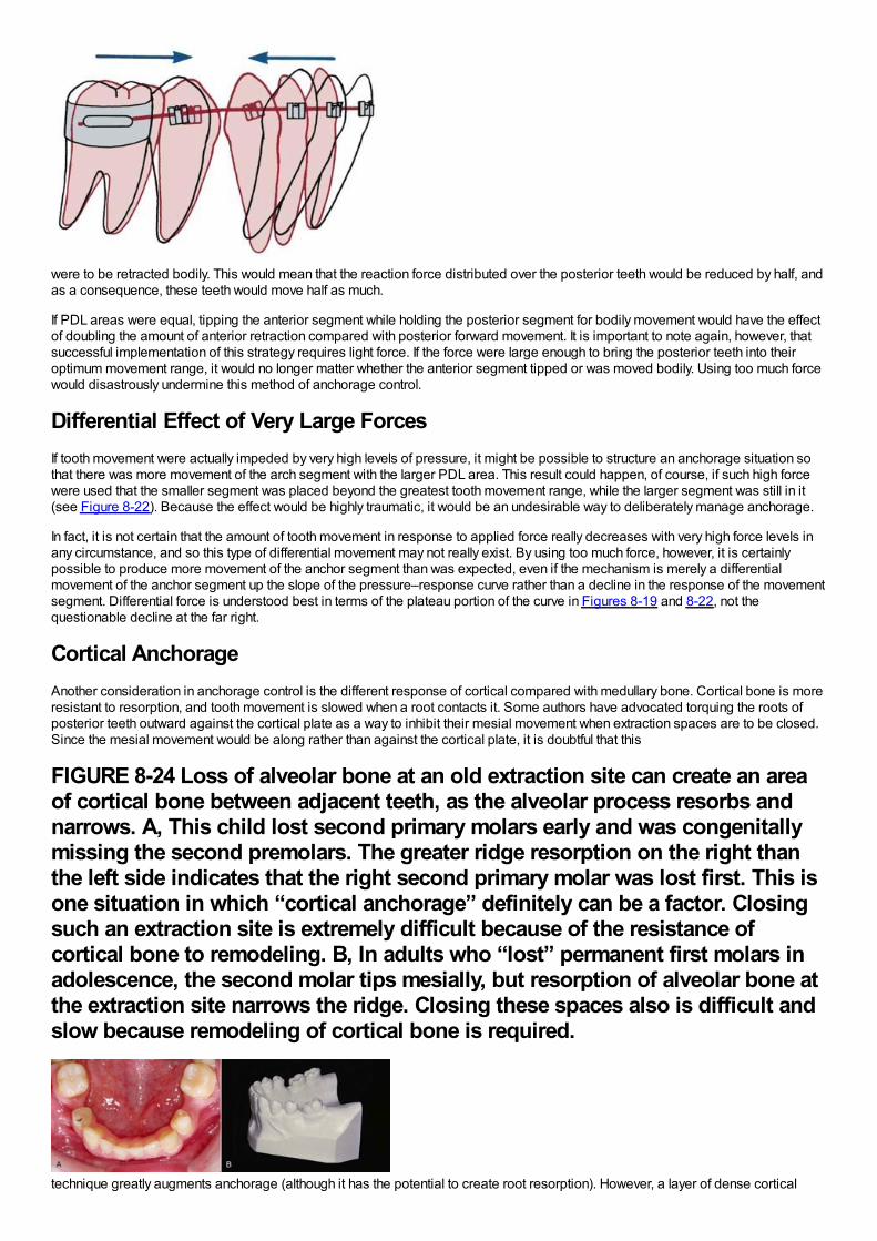
were to be retracted bodily. This would mean that the reaction force distributed over the posterior teeth would be reduced by half, andas a consequence, these teeth would move half as much.
If PDL areas were equal, tipping the anterior segment while holding the posterior segment for bodily movement would have the effectof doubling the amount of anterior retraction compared with posterior forward movement. It is important to note again, however, thatsuccessful implementation of this strategy requires light force. If the force were large enough to bring the posterior teeth into theiroptimum movement range, it would no longer matter whether the anterior segment tipped or was moved bodily. Using too much forcewould disastrously undermine this method of anchorage control.
Differential Effect of Very Large ForcesIf tooth movement were actually impeded by very high levels of pressure, it might be possible to structure an anchorage situation sothat there was more movement of the arch segment with the larger PDL area. This result could happen, of course, if such high forcewere used that the smaller segment was placed beyond the greatest tooth movement range, while the larger segment was still in it(see Figure 8-22). Because the effect would be highly traumatic, it would be an undesirable way to deliberately manage anchorage.
In fact, it is not certain that the amount of tooth movement in response to applied force really decreases with very high force levels inany circumstance, and so this type of differential movement may not really exist. By using too much force, however, it is certainlypossible to produce more movement of the anchor segment than was expected, even if the mechanism is merely a differentialmovement of the anchor segment up the slope of the pressure–response curve rather than a decline in the response of the movementsegment. Differential force is understood best in terms of the plateau portion of the curve in Figures 8-19 and 8-22, not thequestionable decline at the far right.
Cortical AnchorageAnother consideration in anchorage control is the different response of cortical compared with medullary bone. Cortical bone is moreresistant to resorption, and tooth movement is slowed when a root contacts it. Some authors have advocated torquing the roots ofposterior teeth outward against the cortical plate as a way to inhibit their mesial movement when extraction spaces are to be closed.Since the mesial movement would be along rather than against the cortical plate, it is doubtful that this
FIGURE 8-24 Loss of alveolar bone at an old extraction site can create an areaof cortical bone between adjacent teeth, as the alveolar process resorbs andnarrows. A, This child lost second primary molars early and was congenitallymissing the second premolars. The greater ridge resorption on the right thanthe left side indicates that the right second primary molar was lost first. This isone situation in which “cortical anchorage” definitely can be a factor. Closingsuch an extraction site is extremely difficult because of the resistance ofcortical bone to remodeling. B, In adults who “lost” permanent first molars inadolescence, the second molar tips mesially, but resorption of alveolar bone atthe extraction site narrows the ridge. Closing these spaces also is difficult andslow because remodeling of cortical bone is required.
technique greatly augments anchorage (although it has the potential to create root resorption). However, a layer of dense cortical
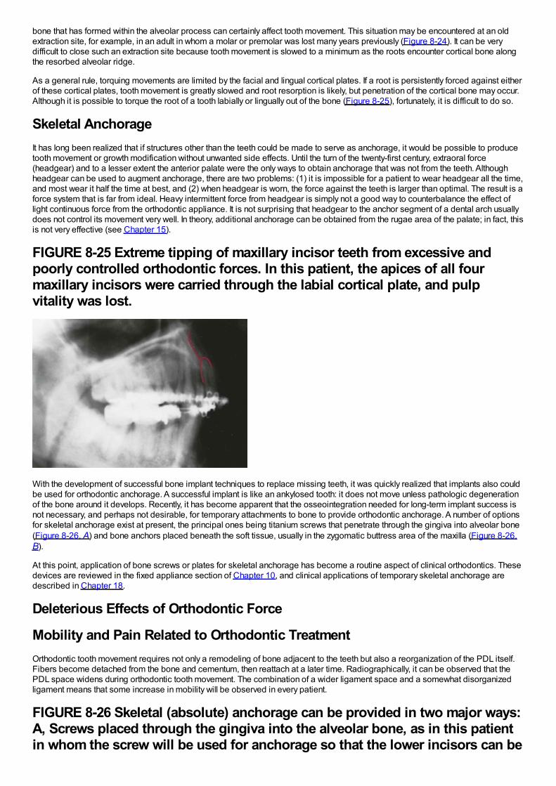
bone that has formed within the alveolar process can certainly affect tooth movement. This situation may be encountered at an oldextraction site, for example, in an adult in whom a molar or premolar was lost many years previously (Figure 8-24). It can be verydifficult to close such an extraction site because tooth movement is slowed to a minimum as the roots encounter cortical bone alongthe resorbed alveolar ridge.
As a general rule, torquing movements are limited by the facial and lingual cortical plates. If a root is persistently forced against eitherof these cortical plates, tooth movement is greatly slowed and root resorption is likely, but penetration of the cortical bone may occur.Although it is possible to torque the root of a tooth labially or lingually out of the bone (Figure 8-25), fortunately, it is difficult to do so.
Skeletal AnchorageIt has long been realized that if structures other than the teeth could be made to serve as anchorage, it would be possible to producetooth movement or growth modification without unwanted side effects. Until the turn of the twenty-first century, extraoral force(headgear) and to a lesser extent the anterior palate were the only ways to obtain anchorage that was not from the teeth. Althoughheadgear can be used to augment anchorage, there are two problems: (1) it is impossible for a patient to wear headgear all the time,and most wear it half the time at best, and (2) when headgear is worn, the force against the teeth is larger than optimal. The result is aforce system that is far from ideal. Heavy intermittent force from headgear is simply not a good way to counterbalance the effect oflight continuous force from the orthodontic appliance. It is not surprising that headgear to the anchor segment of a dental arch usuallydoes not control its movement very well. In theory, additional anchorage can be obtained from the rugae area of the palate; in fact, thisis not very effective (see Chapter 15).
FIGURE 8-25 Extreme tipping of maxillary incisor teeth from excessive andpoorly controlled orthodontic forces. In this patient, the apices of all fourmaxillary incisors were carried through the labial cortical plate, and pulpvitality was lost.
With the development of successful bone implant techniques to replace missing teeth, it was quickly realized that implants also couldbe used for orthodontic anchorage. A successful implant is like an ankylosed tooth: it does not move unless pathologic degenerationof the bone around it develops. Recently, it has become apparent that the osseointegration needed for long-term implant success isnot necessary, and perhaps not desirable, for temporary attachments to bone to provide orthodontic anchorage. A number of optionsfor skeletal anchorage exist at present, the principal ones being titanium screws that penetrate through the gingiva into alveolar bone(Figure 8-26, A) and bone anchors placed beneath the soft tissue, usually in the zygomatic buttress area of the maxilla (Figure 8-26,B).
At this point, application of bone screws or plates for skeletal anchorage has become a routine aspect of clinical orthodontics. Thesedevices are reviewed in the fixed appliance section of Chapter 10, and clinical applications of temporary skeletal anchorage aredescribed in Chapter 18.
Deleterious Effects of Orthodontic Force
Mobility and Pain Related to Orthodontic TreatmentOrthodontic tooth movement requires not only a remodeling of bone adjacent to the teeth but also a reorganization of the PDL itself.Fibers become detached from the bone and cementum, then reattach at a later time. Radiographically, it can be observed that thePDL space widens during orthodontic tooth movement. The combination of a wider ligament space and a somewhat disorganizedligament means that some increase in mobility will be observed in every patient.
FIGURE 8-26 Skeletal (absolute) anchorage can be provided in two major ways:A, Screws placed through the gingiva into the alveolar bone, as in this patientin whom the screw will be used for anchorage so that the lower incisors can be
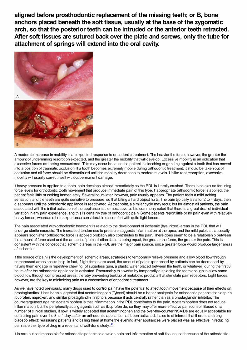
aligned before prosthodontic replacement of the missing teeth; or B, boneanchors placed beneath the soft tissue, usually at the base of the zygomaticarch, so that the posterior teeth can be intruded or the anterior teeth retracted.After soft tissues are sutured back over the plate and screws, only the tube forattachment of springs will extend into the oral cavity.
A moderate increase in mobility is an expected response to orthodontic treatment. The heavier the force, however, the greater theamount of undermining resorption expected, and the greater the mobility that will develop. Excessive mobility is an indication thatexcessive forces are being encountered. This may occur because the patient is clenching or grinding against a tooth that has movedinto a position of traumatic occlusion. If a tooth becomes extremely mobile during orthodontic treatment, it should be taken out ofocclusion and all force should be discontinued until the mobility decreases to moderate levels. Unlike root resorption, excessivemobility will usually correct itself without permanent damage.
If heavy pressure is applied to a tooth, pain develops almost immediately as the PDL is literally crushed. There is no excuse for usingforce levels for orthodontic tooth movement that produce immediate pain of this type. If appropriate orthodontic force is applied, thepatient feels little or nothing immediately. Several hours later, however, pain usually appears. The patient feels a mild achingsensation, and the teeth are quite sensitive to pressure, so that biting a hard object hurts. The pain typically lasts for 2 to 4 days, thendisappears until the orthodontic appliance is reactivated. At that point, a similar cycle may recur, but for almost all patients, the painassociated with the initial activation of the appliance is the most severe. It is commonly noted that there is a great deal of individualvariation in any pain experience, and this is certainly true of orthodontic pain. Some patients report little or no pain even with relativelyheavy forces, whereas others experience considerable discomfort with quite light forces.
The pain associated with orthodontic treatment is related to the development of ischemic (hyalinized) areas in the PDL that willundergo sterile necrosis. The increased tenderness to pressure suggests inflammation at the apex, and the mild pulpitis that usuallyappears soon after orthodontic force is applied probably also contributes to the pain. There does seem to be a relationship betweenthe amount of force used and the amount of pain: all other factors being equal, the greater the force, the greater the pain. This isconsistent with the concept that ischemic areas in the PDL are the major pain source, since greater force would produce larger areasof ischemia.
If the source of pain is the development of ischemic areas, strategies to temporarily relieve pressure and allow blood flow throughcompressed areas should help. In fact, if light forces are used, the amount of pain experienced by patients can be decreased byhaving them engage in repetitive chewing (of sugarless gum, a plastic wafer placed between the teeth, or whatever) during the first 8hours after the orthodontic appliance is activated. Presumably this works by temporarily displacing the teeth enough to allow someblood flow through compressed areas, thereby preventing buildup of metabolic products that stimulate pain receptors. Light forces,however, are the key to minimizing pain as a concomitant of orthodontic treatment.
As we have noted previously, many drugs used to control pain have the potential to affect tooth movement because of their effects onprostaglandins. It has been suggested that acetaminophen (Tylenol) should be a better analgesic for orthodontic patients than aspirin,ibuprofen, naproxen, and similar prostaglandin inhibitors because it acts centrally rather than as a prostaglandin inhibitor. Thecounterargument against acetaminophen is that inflammation in the PDL contributes to the pain. Acetaminophen does not reduceinflammation, but the peripherally acting agents such as ibuprofen do, so they may offer more effective pain control. Based on anumber of clinical studies, it now is widely accepted that acetaminophen and the over-the-counter NSAIDs are equally acceptable forcontrolling pain over the 3 to 4 days after an orthodontic appliance has been activated. It also is of interest that there is a strongplacebo effect: reassuring patients and calling them at home the evening after appliances were placed was as effective in reducingpain as either type of drug in a recent and well-done study.30
It is rare but not impossible for orthodontic patients to develop pain and inflammation of soft tissues, not because of the orthodontic
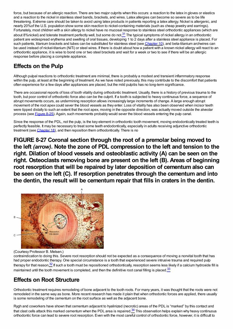
force, but because of an allergic reaction. There are two major culprits when this occurs: a reaction to the latex in gloves or elasticsand a reaction to the nickel in stainless steel bands, brackets, and wires. Latex allergies can become so severe as to be lifethreatening. Extreme care should be taken to avoid using latex products in patients reporting a latex allergy. Nickel is allergenic, andnearly 20%of the U.S. population show some skin reaction to nickel-containing materials (such as cheap jewelry and earrings).Fortunately, most children with a skin allergy to nickel have no mucosal response to stainless steel orthodontic appliances (which areabout 8%nickel) and tolerate treatment perfectly well, but some do not.31 The typical symptoms of nickel allergy in an orthodonticpatient are widespread erythema and swelling of oral tissues, developing 1 to 2 days after a stainless steel appliance is placed. Forsuch patients, titanium brackets and tubes can be substituted for stainless steel (see Chapter 10), and beta-titanium archwires canbe used instead of nickel-titanium (NiTi) or steel wires. If there is doubt about how a patient with a known nickel allergy will react to anorthodontic appliance, it is wise to bond one or two steel brackets and wait for a week or two to see if there will be an allergicresponse before placing a complete appliance.
Effects on the PulpAlthough pulpal reactions to orthodontic treatment are minimal, there is probably a modest and transient inflammatory responsewithin the pulp, at least at the beginning of treatment. As we have noted previously, this may contribute to the discomfort that patientsoften experience for a few days after appliances are placed, but the mild pulpitis has no long-term significance.
There are occasional reports of loss of tooth vitality during orthodontic treatment. Usually, there is a history of previous trauma to thetooth, but poor control of orthodontic force also can be the culprit. If a tooth is subjected to heavy continuous force, a sequence ofabrupt movements occurs, as undermining resorption allows increasingly large increments of change. A large enough abruptmovement of the root apex could sever the blood vessels as they enter. Loss of vitality has also been observed when incisor teethwere tipped distally to such an extent that the root apex, moving in the opposite direction, was actually moved outside the alveolarprocess (see Figure 8-25). Again, such movements probably would sever the blood vessels entering the pulp canal.
Since the response of the PDL, not the pulp, is the key element in orthodontic tooth movement, moving endodontically treated teeth isperfectly feasible. It may be necessary to treat some teeth endodontically, especially in adults receiving adjunctive orthodontictreatment (see Chapter 18), and then reposition them orthodontically. There is no
FIGURE 8-27 Coronal section through the root of a premolar being moved tothe left (arrow). Note the zone of PDL compression to the left and tension to theright. Dilation of blood vessels and osteoblastic activity (A) can be seen on theright. Osteoclasts removing bone are present on the left (B). Areas of beginningroot resorption that will be repaired by later deposition of cementum also canbe seen on the left (C). If resorption penetrates through the cementum and intothe dentin, the result will be cementum repair that fills in craters in the dentin.
(Courtesy Professor B. Melsen.)contraindication to doing this. Severe root resorption should not be expected as a consequence of moving a nonvital tooth that hashad proper endodontic therapy. One special circumstance is a tooth that experienced severe intrusive trauma and required pulptherapy for that reason.32 If such a tooth must be repositioned orthodontically, resorption seems less likely if a calcium hydroxide fill ismaintained until the tooth movement is completed, and then the definitive root canal filling is placed.33
Effects on Root StructureOrthodontic treatment requires remodeling of bone adjacent to the tooth roots. For many years, it was thought that the roots were notremodeled in the same way as bone. More recent research has made it plain that when orthodontic forces are applied, there usuallyis some remodeling of the cementum on the root surface as well as the adjacent bone.
Rygh and coworkers have shown that cementum adjacent to hyalinized (necrotic) areas of the PDL is “marked” by this contact andthat clast cells attack this marked cementum when the PDL area is repaired.34 This observation helps explain why heavy continuousorthodontic force can lead to severe root resorption. Even with the most careful control of orthodontic force, however, it is difficult to
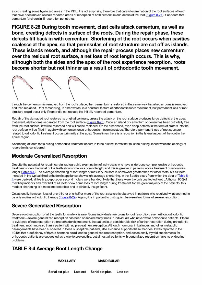
avoid creating some hyalinized areas in the PDL. It is not surprising therefore that careful examination of the root surfaces of teeththat have been moved reveals repaired areas of resorption of both cementum and dentin of the root (Figure 8-27). It appears thatcementum (and dentin, if resorption penetrates
FIGURE 8-28 During tooth movement, clast cells attack cementum, as well asbone, creating defects in surface of the roots. During the repair phase, thesedefects fill back in with cementum. Shortening of the root occurs when cavitiescoalesce at the apex, so that peninsulas of root structure are cut off as islands.These islands resorb, and although the repair process places new cementumover the residual root surface, a net loss of root length occurs. This is why,although both the sides and the apex of the root experience resorption, rootsbecome shorter but not thinner as a result of orthodontic tooth movement.
through the cementum) is removed from the root surface, then cementum is restored in the same way that alveolar bone is removedand then replaced. Root remodeling, in other words, is a constant feature of orthodontic tooth movement, but permanent loss of rootstructure would occur only if repair did not replace the initially resorbed cementum.
Repair of the damaged root restores its original contours, unless the attack on the root surface produces large defects at the apexthat eventually become separated from the root surface (Figure 8-28). Once an island of cementum or dentin has been cut totally freefrom the root surface, it will be resorbed and will not be replaced. On the other hand, even deep defects in the form of craters into theroot surface will be filled in again with cementum once orthodontic movement stops. Therefore permanent loss of root structurerelated to orthodontic treatment occurs primarily at the apex. Sometimes there is a reduction in the lateral aspect of the root in theapical region.
Shortening of tooth roots during orthodontic treatment occurs in three distinct forms that must be distinguished when the etiology ofresorption is considered.
Moderate Generalized ResorptionDespite the potential for repair, careful radiographic examination of individuals who have undergone comprehensive orthodontictreatment shows that most of the teeth show some loss of root length, and this is greater in patients whose treatment duration waslonger (Table 8-4). The average shortening of root length of maxillary incisors is somewhat greater than for other teeth, but all teethincluded in the typical fixed orthodontic appliance show slight average shortening. In the Seattle study from which the data of Table 8-4 were derived, all teeth except upper second molars were banded. Note that these were the only unaffected teeth. Although 90%ofmaxillary incisors and over half of all teeth show some loss of root length during treatment, for the great majority of the patients, thismodest shortening is almost imperceptible and is clinically insignificant.
Occasionally, however, loss of one-third or one-half or more of the root structure is observed in patients who received what seemed tobe only routine orthodontic therapy (Figure 8-29). Again, it is important to distinguish between two forms of severe resorption.
Severe Generalized ResorptionSevere root resorption of all the teeth, fortunately, is rare. Some individuals are prone to root resorption, even without orthodontictreatment—severe generalized resorption has been observed many times in individuals who never were orthodontic patients. If thereis evidence of root resorption before orthodontic treatment, the patient is at considerable risk of further resorption during orthodontictreatment, much more so than a patient with no pretreatment resorption. Although hormonal imbalances and other metabolicderangements have been suspected in these susceptible patients, little evidence supports these theories. It was reported in the1940s that a deficiency of thyroid hormone could lead to generalized root resorption, and occasionally thyroid supplements fororthodontic patients are suggested as a way to prevent this, but almost all patients with generalized resorption have no endocrineproblems.
TABLE 8-4 Average Root Length Change
MAXILLARY MANDIBULAR
Serial ext plus Late ext Serial ext plus Late ext
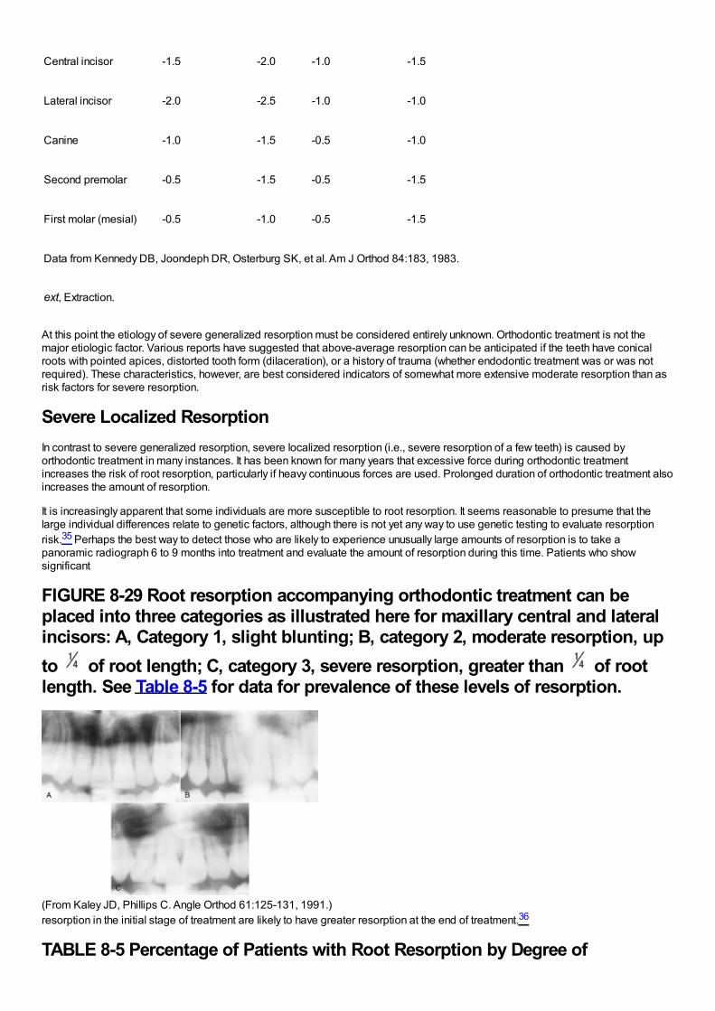
Central incisor -1.5 -2.0 -1.0 -1.5
Lateral incisor -2.0 -2.5 -1.0 -1.0
Canine -1.0 -1.5 -0.5 -1.0
Second premolar -0.5 -1.5 -0.5 -1.5
First molar (mesial) -0.5 -1.0 -0.5 -1.5
Data from Kennedy DB, Joondeph DR, Osterburg SK, et al. Am J Orthod 84:183, 1983.
ext, Extraction.
At this point the etiology of severe generalized resorption must be considered entirely unknown. Orthodontic treatment is not themajor etiologic factor. Various reports have suggested that above-average resorption can be anticipated if the teeth have conicalroots with pointed apices, distorted tooth form (dilaceration), or a history of trauma (whether endodontic treatment was or was notrequired). These characteristics, however, are best considered indicators of somewhat more extensive moderate resorption than asrisk factors for severe resorption.
Severe Localized ResorptionIn contrast to severe generalized resorption, severe localized resorption (i.e., severe resorption of a few teeth) is caused byorthodontic treatment in many instances. It has been known for many years that excessive force during orthodontic treatmentincreases the risk of root resorption, particularly if heavy continuous forces are used. Prolonged duration of orthodontic treatment alsoincreases the amount of resorption.
It is increasingly apparent that some individuals are more susceptible to root resorption. It seems reasonable to presume that thelarge individual differences relate to genetic factors, although there is not yet any way to use genetic testing to evaluate resorptionrisk.35 Perhaps the best way to detect those who are likely to experience unusually large amounts of resorption is to take apanoramic radiograph 6 to 9 months into treatment and evaluate the amount of resorption during this time. Patients who showsignificant
FIGURE 8-29 Root resorption accompanying orthodontic treatment can beplaced into three categories as illustrated here for maxillary central and lateralincisors: A, Category 1, slight blunting; B, category 2, moderate resorption, upto of root length; C, category 3, severe resorption, greater than of rootlength. See Table 8-5 for data for prevalence of these levels of resorption.
(From Kaley JD, Phillips C. Angle Orthod 61:125-131, 1991.)resorption in the initial stage of treatment are likely to have greater resorption at the end of treatment.36
TABLE 8-5 Percentage of Patients with Root Resorption by Degree of
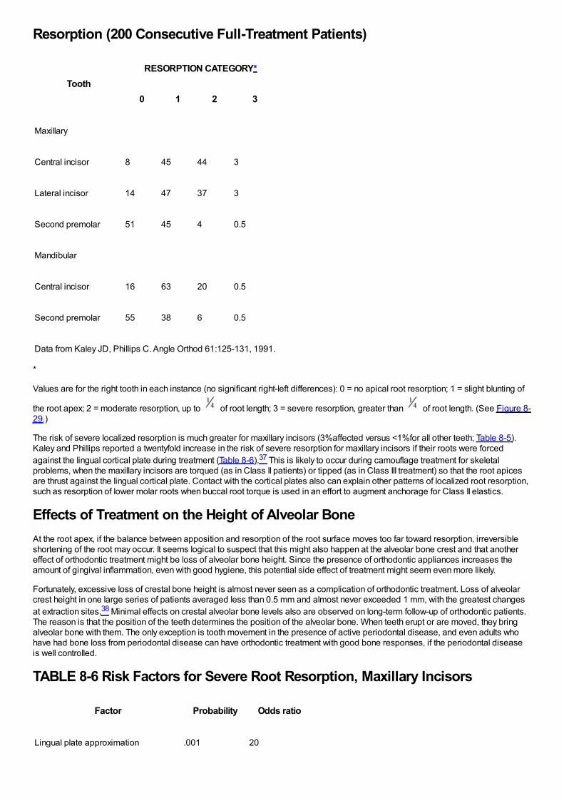
Resorption (200 Consecutive Full-Treatment Patients)
ToothRESORPTION CATEGORY*
0 1 2 3
Maxillary
Central incisor 8 45 44 3
Lateral incisor 14 47 37 3
Second premolar 51 45 4 0.5
Mandibular
Central incisor 16 63 20 0.5
Second premolar 55 38 6 0.5
Data from Kaley JD, Phillips C. Angle Orthod 61:125-131, 1991.
*
Values are for the right tooth in each instance (no significant right-left differences): 0 = no apical root resorption; 1 = slight blunting of
the root apex; 2 = moderate resorption, up to of root length; 3 = severe resorption, greater than of root length. (See Figure 8-29.)
The risk of severe localized resorption is much greater for maxillary incisors (3%affected versus <1%for all other teeth; Table 8-5).Kaley and Phillips reported a twentyfold increase in the risk of severe resorption for maxillary incisors if their roots were forcedagainst the lingual cortical plate during treatment (Table 8-6).37 This is likely to occur during camouflage treatment for skeletalproblems, when the maxillary incisors are torqued (as in Class II patients) or tipped (as in Class III treatment) so that the root apicesare thrust against the lingual cortical plate. Contact with the cortical plates also can explain other patterns of localized root resorption,such as resorption of lower molar roots when buccal root torque is used in an effort to augment anchorage for Class II elastics.
Effects of Treatment on the Height of Alveolar BoneAt the root apex, if the balance between apposition and resorption of the root surface moves too far toward resorption, irreversibleshortening of the root may occur. It seems logical to suspect that this might also happen at the alveolar bone crest and that anothereffect of orthodontic treatment might be loss of alveolar bone height. Since the presence of orthodontic appliances increases theamount of gingival inflammation, even with good hygiene, this potential side effect of treatment might seem even more likely.
Fortunately, excessive loss of crestal bone height is almost never seen as a complication of orthodontic treatment. Loss of alveolarcrest height in one large series of patients averaged less than 0.5 mm and almost never exceeded 1 mm, with the greatest changesat extraction sites.38 Minimal effects on crestal alveolar bone levels also are observed on long-term follow-up of orthodontic patients.The reason is that the position of the teeth determines the position of the alveolar bone. When teeth erupt or are moved, they bringalveolar bone with them. The only exception is tooth movement in the presence of active periodontal disease, and even adults whohave had bone loss from periodontal disease can have orthodontic treatment with good bone responses, if the periodontal diseaseis well controlled.
TABLE 8-6 Risk Factors for Severe Root Resorption, Maxillary Incisors
Factor Probability Odds ratio
Lingual plate approximation .001 20
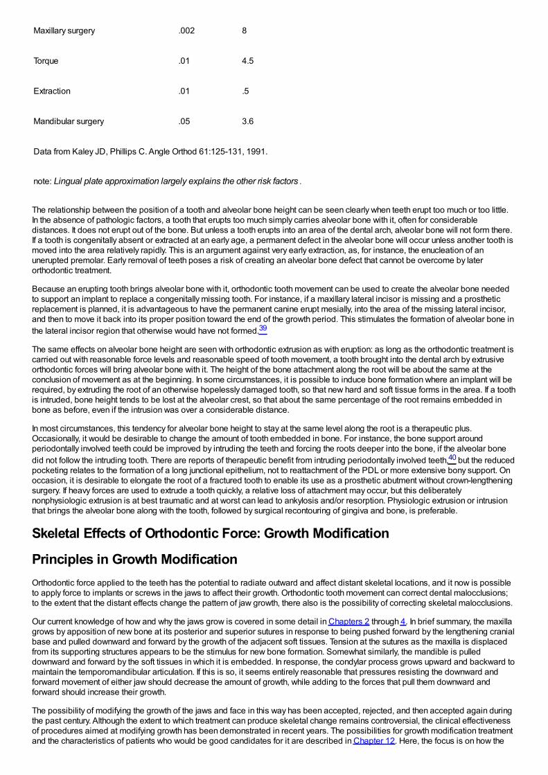
Maxillary surgery .002 8
Torque .01 4.5
Extraction .01 .5
Mandibular surgery .05 3.6
Data from Kaley JD, Phillips C. Angle Orthod 61:125-131, 1991.
note: Lingual plate approximation largely explains the other risk factors .
The relationship between the position of a tooth and alveolar bone height can be seen clearly when teeth erupt too much or too little.In the absence of pathologic factors, a tooth that erupts too much simply carries alveolar bone with it, often for considerabledistances. It does not erupt out of the bone. But unless a tooth erupts into an area of the dental arch, alveolar bone will not form there.If a tooth is congenitally absent or extracted at an early age, a permanent defect in the alveolar bone will occur unless another tooth ismoved into the area relatively rapidly. This is an argument against very early extraction, as, for instance, the enucleation of anunerupted premolar. Early removal of teeth poses a risk of creating an alveolar bone defect that cannot be overcome by laterorthodontic treatment.
Because an erupting tooth brings alveolar bone with it, orthodontic tooth movement can be used to create the alveolar bone neededto support an implant to replace a congenitally missing tooth. For instance, if a maxillary lateral incisor is missing and a prostheticreplacement is planned, it is advantageous to have the permanent canine erupt mesially, into the area of the missing lateral incisor,and then to move it back into its proper position toward the end of the growth period. This stimulates the formation of alveolar bone inthe lateral incisor region that otherwise would have not formed.39
The same effects on alveolar bone height are seen with orthodontic extrusion as with eruption: as long as the orthodontic treatment iscarried out with reasonable force levels and reasonable speed of tooth movement, a tooth brought into the dental arch by extrusiveorthodontic forces will bring alveolar bone with it. The height of the bone attachment along the root will be about the same at theconclusion of movement as at the beginning. In some circumstances, it is possible to induce bone formation where an implant will berequired, by extruding the root of an otherwise hopelessly damaged tooth, so that new hard and soft tissue forms in the area. If a toothis intruded, bone height tends to be lost at the alveolar crest, so that about the same percentage of the root remains embedded inbone as before, even if the intrusion was over a considerable distance.
In most circumstances, this tendency for alveolar bone height to stay at the same level along the root is a therapeutic plus.Occasionally, it would be desirable to change the amount of tooth embedded in bone. For instance, the bone support aroundperiodontally involved teeth could be improved by intruding the teeth and forcing the roots deeper into the bone, if the alveolar bonedid not follow the intruding tooth. There are reports of therapeutic benefit from intruding periodontally involved teeth,40 but the reducedpocketing relates to the formation of a long junctional epithelium, not to reattachment of the PDL or more extensive bony support. Onoccasion, it is desirable to elongate the root of a fractured tooth to enable its use as a prosthetic abutment without crown-lengtheningsurgery. If heavy forces are used to extrude a tooth quickly, a relative loss of attachment may occur, but this deliberatelynonphysiologic extrusion is at best traumatic and at worst can lead to ankylosis and/or resorption. Physiologic extrusion or intrusionthat brings the alveolar bone along with the tooth, followed by surgical recontouring of gingiva and bone, is preferable.
Skeletal Effects of Orthodontic Force: Growth Modification
Principles in Growth ModificationOrthodontic force applied to the teeth has the potential to radiate outward and affect distant skeletal locations, and it now is possibleto apply force to implants or screws in the jaws to affect their growth. Orthodontic tooth movement can correct dental malocclusions;to the extent that the distant effects change the pattern of jaw growth, there also is the possibility of correcting skeletal malocclusions.
Our current knowledge of how and why the jaws grow is covered in some detail in Chapters 2 through 4. In brief summary, the maxillagrows by apposition of new bone at its posterior and superior sutures in response to being pushed forward by the lengthening cranialbase and pulled downward and forward by the growth of the adjacent soft tissues. Tension at the sutures as the maxilla is displacedfrom its supporting structures appears to be the stimulus for new bone formation. Somewhat similarly, the mandible is pulleddownward and forward by the soft tissues in which it is embedded. In response, the condylar process grows upward and backward tomaintain the temporomandibular articulation. If this is so, it seems entirely reasonable that pressures resisting the downward andforward movement of either jaw should decrease the amount of growth, while adding to the forces that pull them downward andforward should increase their growth.
The possibility of modifying the growth of the jaws and face in this way has been accepted, rejected, and then accepted again duringthe past century. Although the extent to which treatment can produce skeletal change remains controversial, the clinical effectivenessof procedures aimed at modifying growth has been demonstrated in recent years. The possibilities for growth modification treatmentand the characteristics of patients who would be good candidates for it are described in Chapter 12. Here, the focus is on how the
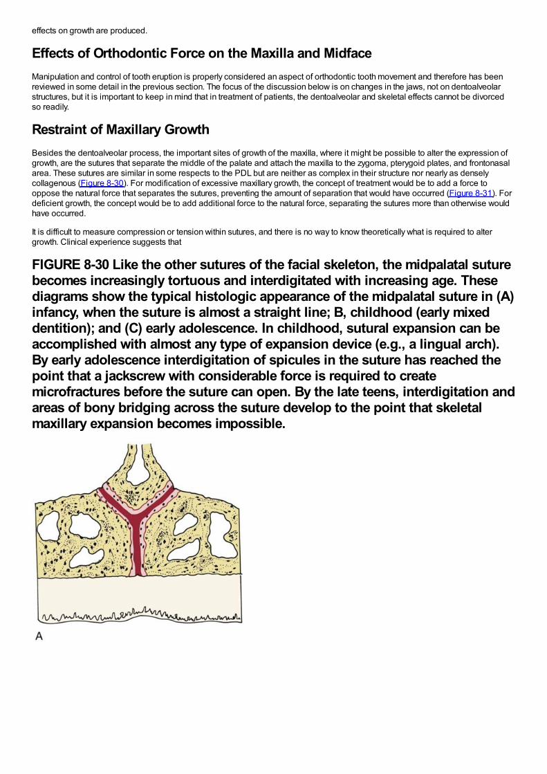
effects on growth are produced.
Effects of Orthodontic Force on the Maxilla and MidfaceManipulation and control of tooth eruption is properly considered an aspect of orthodontic tooth movement and therefore has beenreviewed in some detail in the previous section. The focus of the discussion below is on changes in the jaws, not on dentoalveolarstructures, but it is important to keep in mind that in treatment of patients, the dentoalveolar and skeletal effects cannot be divorcedso readily.
Restraint of Maxillary GrowthBesides the dentoalveolar process, the important sites of growth of the maxilla, where it might be possible to alter the expression ofgrowth, are the sutures that separate the middle of the palate and attach the maxilla to the zygoma, pterygoid plates, and frontonasalarea. These sutures are similar in some respects to the PDL but are neither as complex in their structure nor nearly as denselycollagenous (Figure 8-30). For modification of excessive maxillary growth, the concept of treatment would be to add a force tooppose the natural force that separates the sutures, preventing the amount of separation that would have occurred (Figure 8-31). Fordeficient growth, the concept would be to add additional force to the natural force, separating the sutures more than otherwise wouldhave occurred.
It is difficult to measure compression or tension within sutures, and there is no way to know theoretically what is required to altergrowth. Clinical experience suggests that
FIGURE 8-30 Like the other sutures of the facial skeleton, the midpalatal suturebecomes increasingly tortuous and interdigitated with increasing age. Thesediagrams show the typical histologic appearance of the midpalatal suture in (A)infancy, when the suture is almost a straight line; B, childhood (early mixeddentition); and (C) early adolescence. In childhood, sutural expansion can beaccomplished with almost any type of expansion device (e.g., a lingual arch).By early adolescence interdigitation of spicules in the suture has reached thepoint that a jackscrew with considerable force is required to createmicrofractures before the suture can open. By the late teens, interdigitation andareas of bony bridging across the suture develop to the point that skeletalmaxillary expansion becomes impossible.
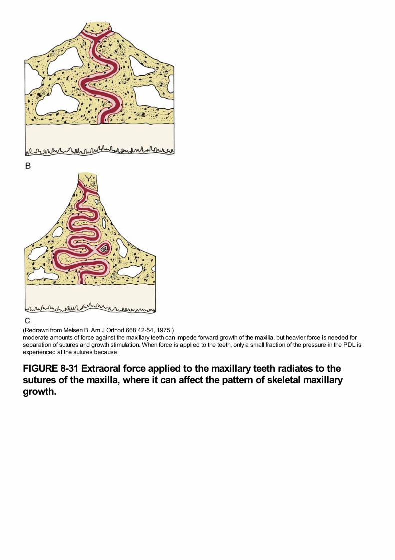
(Redrawn from Melsen B. Am J Orthod 668:42-54, 1975.)moderate amounts of force against the maxillary teeth can impede forward growth of the maxilla, but heavier force is needed forseparation of sutures and growth stimulation. When force is applied to the teeth, only a small fraction of the pressure in the PDL isexperienced at the sutures because
FIGURE 8-31 Extraoral force applied to the maxillary teeth radiates to thesutures of the maxilla, where it can affect the pattern of skeletal maxillarygrowth.
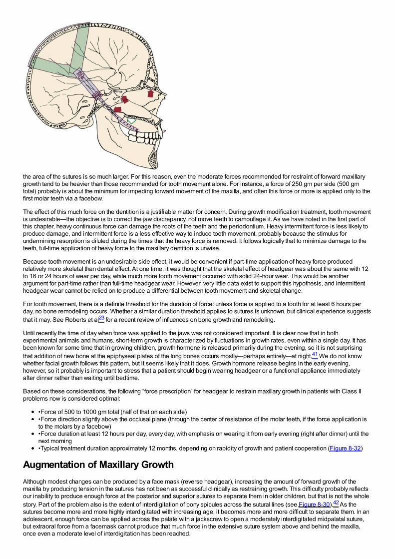
the area of the sutures is so much larger. For this reason, even the moderate forces recommended for restraint of forward maxillarygrowth tend to be heavier than those recommended for tooth movement alone. For instance, a force of 250 gm per side (500 gmtotal) probably is about the minimum for impeding forward movement of the maxilla, and often this force or more is applied only to thefirst molar teeth via a facebow.
The effect of this much force on the dentition is a justifiable matter for concern. During growth modification treatment, tooth movementis undesirable—the objective is to correct the jaw discrepancy, not move teeth to camouflage it. As we have noted in the first part ofthis chapter, heavy continuous force can damage the roots of the teeth and the periodontium. Heavy intermittent force is less likely toproduce damage, and intermittent force is a less effective way to induce tooth movement, probably because the stimulus forundermining resorption is diluted during the times that the heavy force is removed. It follows logically that to minimize damage to theteeth, full-time application of heavy force to the maxillary dentition is unwise.
Because tooth movement is an undesirable side effect, it would be convenient if part-time application of heavy force producedrelatively more skeletal than dental effect. At one time, it was thought that the skeletal effect of headgear was about the same with 12to 16 or 24 hours of wear per day, while much more tooth movement occurred with solid 24-hour wear. This would be anotherargument for part-time rather than full-time headgear wear. However, very little data exist to support this hypothesis, and intermittentheadgear wear cannot be relied on to produce a differential between tooth movement and skeletal change.
For tooth movement, there is a definite threshold for the duration of force: unless force is applied to a tooth for at least 6 hours perday, no bone remodeling occurs. Whether a similar duration threshold applies to sutures is unknown, but clinical experience suggeststhat it may. See Roberts et al23 for a recent review of influences on bone growth and remodeling.
Until recently the time of day when force was applied to the jaws was not considered important. It is clear now that in bothexperimental animals and humans, short-term growth is characterized by fluctuations in growth rates, even within a single day. It hasbeen known for some time that in growing children, growth hormone is released primarily during the evening, so it is not surprisingthat addition of new bone at the epiphyseal plates of the long bones occurs mostly—perhaps entirely—at night.41 We do not knowwhether facial growth follows this pattern, but it seems likely that it does. Growth hormone release begins in the early evening,however, so it probably is important to stress that a patient should begin wearing headgear or a functional appliance immediatelyafter dinner rather than waiting until bedtime.
Based on these considerations, the following “force prescription” for headgear to restrain maxillary growth in patients with Class IIproblems now is considered optimal:
•Force of 500 to 1000 gm total (half of that on each side)•Force direction slightly above the occlusal plane (through the center of resistance of the molar teeth, if the force application isto the molars by a facebow)•Force duration at least 12 hours per day, every day, with emphasis on wearing it from early evening (right after dinner) until thenext morning•Typical treatment duration approximately 12 months, depending on rapidity of growth and patient cooperation (Figure 8-32)
Augmentation of Maxillary GrowthAlthough modest changes can be produced by a face mask (reverse headgear), increasing the amount of forward growth of themaxilla by producing tension in the sutures has not been as successful clinically as restraining growth. This difficulty probably reflectsour inability to produce enough force at the posterior and superior sutures to separate them in older children, but that is not the wholestory. Part of the problem also is the extent of interdigitation of bony spicules across the sutural lines (see Figure 8-30).42 As thesutures become more and more highly interdigitated with increasing age, it becomes more and more difficult to separate them. In anadolescent, enough force can be applied across the palate with a jackscrew to open a moderately interdigitated midpalatal suture,but extraoral force from a facemask cannot produce that much force in the extensive suture system above and behind the maxilla,once even a moderate level of interdigitation has been reached.
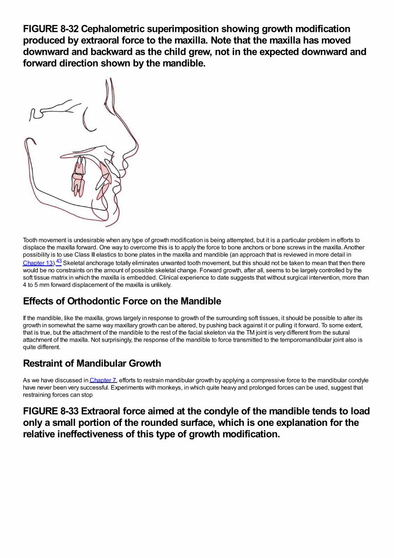
FIGURE 8-32 Cephalometric superimposition showing growth modificationproduced by extraoral force to the maxilla. Note that the maxilla has moveddownward and backward as the child grew, not in the expected downward andforward direction shown by the mandible.
Tooth movement is undesirable when any type of growth modification is being attempted, but it is a particular problem in efforts todisplace the maxilla forward. One way to overcome this is to apply the force to bone anchors or bone screws in the maxilla. Anotherpossibility is to use Class III elastics to bone plates in the maxilla and mandible (an approach that is reviewed in more detail inChapter 13).43 Skeletal anchorage totally eliminates unwanted tooth movement, but this should not be taken to mean that then therewould be no constraints on the amount of possible skeletal change. Forward growth, after all, seems to be largely controlled by thesoft tissue matrix in which the maxilla is embedded. Clinical experience to date suggests that without surgical intervention, more than4 to 5 mm forward displacement of the maxilla is unlikely.
Effects of Orthodontic Force on the MandibleIf the mandible, like the maxilla, grows largely in response to growth of the surrounding soft tissues, it should be possible to alter itsgrowth in somewhat the same way maxillary growth can be altered, by pushing back against it or pulling it forward. To some extent,that is true, but the attachment of the mandible to the rest of the facial skeleton via the TM joint is very different from the suturalattachment of the maxilla. Not surprisingly, the response of the mandible to force transmitted to the temporomandibular joint also isquite different.
Restraint of Mandibular GrowthAs we have discussed in Chapter 7, efforts to restrain mandibular growth by applying a compressive force to the mandibular condylehave never been very successful. Experiments with monkeys, in which quite heavy and prolonged forces can be used, suggest thatrestraining forces can stop
FIGURE 8-33 Extraoral force aimed at the condyle of the mandible tends to loadonly a small portion of the rounded surface, which is one explanation for therelative ineffectiveness of this type of growth modification.
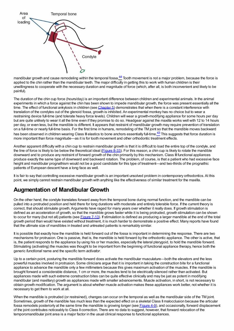
mandibular growth and cause remodeling within the temporal fossa.44 Tooth movement is not a major problem, because the force isapplied to the chin rather than the mandibular teeth. The major difficulty in getting this to work with human children is theirunwillingness to cooperate with the necessary duration and magnitude of force (which, after all, is both inconvenient and likely to bepainful).
The duration of the chin cup force (hours/day) is an important difference between children and experimental animals. In the animalexperiments in which a force against the chin has been shown to impede mandibular growth, the force was present essentially all thetime. The effect of functional ankylosis in children (see Chapter 5) demonstrates that when there is a constant interference withtranslation of the condyles out of the glenoid fossa, growth is inhibited. An experimental monkey has no choice but to wear arestraining device full-time (and tolerate heavy force levels). Children will wear a growth-modifying appliance for some hours per daybut are quite unlikely to wear it all the time even if they promise to do so. Headgear against the maxilla works well with 12 to 14 hoursper day, or even less, but the mandible is different. It appears that restraint of mandibular growth may require prevention of translationon a full-time or nearly full-time basis. For the first time in humans, remodeling of the TM joint so that the mandible moves backwardhas been observed in children wearing Class III elastics to bone anchors essentially full-time.43 This suggests that force duration ismore important than force magnitude—as it is for tooth movement and other orthodontic treatment effects.
Another apparent difficulty with a chin cup to restrain mandibular growth is that it is difficult to load the entire top of the condyle, andthe line of force is likely to be below the theoretical ideal (Figure 8-33). For this reason, a chin cup is likely to rotate the mandibledownward and to produce any restraint of forward growth of the chin primarily by this mechanism. Class III functional appliancesproduce exactly the same type of downward and backward rotation. The problem, of course, is that a patient who had excessive faceheight and mandibular prognathism would not be a good candidate for this type of treatment—and two-thirds of the prognathicpatients of European descent have a long face as well.
It is fair to say that controlling excessive mandibular growth is an important unsolved problem in contemporary orthodontics. At thispoint, we simply cannot restrain mandibular growth with anything like the effectiveness of similar treatment for the maxilla.
Augmentation of Mandibular GrowthOn the other hand, the condyle translates forward away from the temporal bone during normal function, and the mandible can bepulled into a protruded position and held there for long durations with moderate and entirely tolerable force. If the current theory iscorrect, that should stimulate growth. Arguments have raged for many years over whether it really does. If growth stimulation isdefined as an acceleration of growth, so that the mandible grows faster while it is being protruded, growth stimulation can be shownto occur for many (but not all) patients (see Figure 7-13). If stimulation is defined as producing a larger mandible at the end of the totalgrowth period than would have existed without treatment, it is much harder to demonstrate a positive effect. Many reports have foundthat the ultimate size of mandibles in treated and untreated patients is remarkably similar.
It is possible that exactly how the mandible is held forward out of the fossa is important in determining the response. There are twomechanisms for protrusion. One is passive, that is, the mandible is held forward by the orthodontic appliance. The other is active, thatis, the patient responds to the appliance by using his or her muscles, especially the lateral pterygoid, to hold the mandible forward.Stimulating (activating) the muscles was thought to be important from the beginning of functional appliance therapy, hence both thegeneric functional name and the specific term activator.
Up to a certain point, posturing the mandible forward does activate the mandibular musculature—both the elevators and the lesspowerful muscles involved in protrusion. Some clinicians argue that it is important in taking the construction bite for a functionalappliance to advance the mandible only a few millimeters because this gives maximum activation of the muscles. If the mandible isbrought forward a considerable distance, 1 cm or more, the muscles tend to be electrically silenced rather than activated. Butappliances made with such extreme construction bites can be quite effective clinically and may be just as potent in modifyingmandibular (and maxillary) growth as appliances made with smaller advancements. Muscle activation, in short, is not necessary toobtain growth modification. The argument is about whether muscle activation makes these appliances work better, not whether it isnecessary to get them to work at all.
When the mandible is protruded (or restrained), changes can occur on the temporal as well as the mandibular side of the TM joint.Sometimes, growth of the mandible has much less than the expected effect on a skeletal Class II malocclusion because the articularfossa remodels posteriorly at the same time the mandible is growing longer (see Figure 4-9), and occasionally, forward displacementof the joint contributes noticeably to Class II correction. There are no data to suggest, however, that forward relocation of thetemporomandibular joint area is a major factor in the usual clinical response to functional appliances.
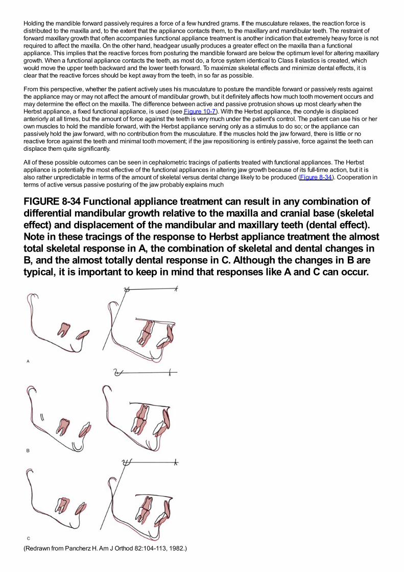
Holding the mandible forward passively requires a force of a few hundred grams. If the musculature relaxes, the reaction force isdistributed to the maxilla and, to the extent that the appliance contacts them, to the maxillary and mandibular teeth. The restraint offorward maxillary growth that often accompanies functional appliance treatment is another indication that extremely heavy force is notrequired to affect the maxilla. On the other hand, headgear usually produces a greater effect on the maxilla than a functionalappliance. This implies that the reactive forces from posturing the mandible forward are below the optimum level for altering maxillarygrowth. When a functional appliance contacts the teeth, as most do, a force system identical to Class II elastics is created, whichwould move the upper teeth backward and the lower teeth forward. To maximize skeletal effects and minimize dental effects, it isclear that the reactive forces should be kept away from the teeth, in so far as possible.
From this perspective, whether the patient actively uses his musculature to posture the mandible forward or passively rests againstthe appliance may or may not affect the amount of mandibular growth, but it definitely affects how much tooth movement occurs andmay determine the effect on the maxilla. The difference between active and passive protrusion shows up most clearly when theHerbst appliance, a fixed functional appliance, is used (see Figure 10-7). With the Herbst appliance, the condyle is displacedanteriorly at all times, but the amount of force against the teeth is very much under the patient's control. The patient can use his or herown muscles to hold the mandible forward, with the Herbst appliance serving only as a stimulus to do so; or the appliance canpassively hold the jaw forward, with no contribution from the musculature. If the muscles hold the jaw forward, there is little or noreactive force against the teeth and minimal tooth movement; if the jaw repositioning is entirely passive, force against the teeth candisplace them quite significantly.
All of these possible outcomes can be seen in cephalometric tracings of patients treated with functional appliances. The Herbstappliance is potentially the most effective of the functional appliances in altering jaw growth because of its full-time action, but it isalso rather unpredictable in terms of the amount of skeletal versus dental change likely to be produced (Figure 8-34). Cooperation interms of active versus passive posturing of the jaw probably explains much
FIGURE 8-34 Functional appliance treatment can result in any combination ofdifferential mandibular growth relative to the maxilla and cranial base (skeletaleffect) and displacement of the mandibular and maxillary teeth (dental effect).Note in these tracings of the response to Herbst appliance treatment the almosttotal skeletal response in A, the combination of skeletal and dental changes inB, and the almost totally dental response in C. Although the changes in B aretypical, it is important to keep in mind that responses like A and C can occur.
(Redrawn from Pancherz H. Am J Orthod 82:104-113, 1982.)

of the variability in the results. The Frankel appliance (see Figure 10-8), which is supported mostly by the soft tissues rather than theteeth, should be and probably is the functional appliance least likely to displace the teeth, but a Class II elastics effect can be seeneven with it.
The various types of functional appliances and their use in clinical treatment are reviewed in detail, along with other growth-modifyingappliances, in Chapter 13.
References1.
Bumann, A, Carvalho, RS, Schwarzer, CL, et al.: Collagen synthesis from human PDL cells following orthodontic tooth movement. EurJ Orthod. 19, 1997, 29–37.
2.
Basdra, EK, Komposch, G: Osteoblast-like properties of human periodontal ligament cells: An in vitro analysis. Eur J Orthod. 19,1997, 615–621.
3.
Yokoya, K, Sasaki, T, Shibasaki, Y: Distributional changes of osteoclasts and pre-osteoclastic cells in periodontal tissues duringexperimental tooth movement. J Dent Res. 76, 1997, 580–587.
4.
Thilander, B: Tissue reactions in orthodontics. In Graber, LW, Vanarsdall, R, Vig, KWL (Eds.): Orthodontics: Current Principles andTechniques. 5th ed, 2011, Elsevier, St. Louis.
5.
Pilla, AA: Low-intensity electromagnetic and mechanical modulation of bone growth and repair: are they equivalent?. J Orthop Sci. 7,2002, 420–428.
6.
Shapiro, E: Orthodontic movement using pulsating force-induced piezoelectricity. Am J Orthod. 73, 1979, 59–66.
7.
Darendeliler, MA, Zea, A, Shen, G, et al.: Effects of pulsed electromagnetic field vibration on tooth movement induced by magneticand mechanical forces: a preliminary study. Australian Dent J. 52, 2007, 282–287.
8.
Krishnan, V, Davidovitch, Z: On a path to unfolding the biologic mechanisms of orthodontic tooth movement. J Dent Res. 88, 2009,597–608.
9.
Khouw, FE, Goldhaber, P: Changes in vasculature of the periodontium associated with tooth movement in the rhesus monkey anddog. Arch Oral Biol. 15, 1970, 1125–1132.
10.
Kang, YG, Nam, JH, Kim, KH, et al.: FAK pathway regulates PGE2 production in compressed periodontal ligament cells. J Dent Res.89, 2010, 1444–1449.
11.
Yamaguchi, M: RANK/RANKL/OPG during orthodontic tooth movement. Orthod Craniofac Res. 12, 2009, 113–119.
12.
Nifforoushan, D, Manolson, MF: Expression of nitric oxide synthases in orthodontic tooth movement. Angle Orthod. 79, 2009, 502–508.
13.
Roberts, WE: Bone physiology, metabolism, and biomechanics in orthodontic practice. In Graber, LW, Vanarsdall, RL, Vig, KWL(Eds.): Orthodontics: Current Principles and Techniques. 5th ed, 2011, Elsevier, St Louis.
14.

McGorray SP, Dolce C, Kramer S, et al. A randomized, placebo-controlled clinical trial on the effects of recombinant human relaxin ontooth movement and retention. Am J Orthod Dentofac Orthop, in press.
15.
Zhou, D, Hughes, B, King, GJ: Histomorphometric and biochemical study of osteoclasts at orthodontic compression sites in the ratduring indomethacin inhibition. Arch Oral Biol. 42, 1997, 717–726.
16.
Bartzela, T, Turp, JC, Motschall, E, et al.: Medication effects on the rate of orthodontic tooth movement: a systematic literature review.Am J Orthod Dentofac Orthop. 135, 2009, 16–26.
17.
Zahrowski, JJ: Optimizing orthodontic treatment in patients taking bisphosphonates for osteoporosis. Am J Orthod Dentofac Orthop.135, 2009, 361–374.
18.
Frost, HM: Wolff's Law and bone's structural adaptations to mechanical usage: an overview for clinicians. Angle Orthod. 64, 1994,175–188.
19.
Köle, H: Surgical operations of the alveolar ridge to correct occlusal abnormalities. Oral Surg Oral Med Oral Pathol. 12, 1959, 515–529.
20.
Gunderson, RM, Porter, JM, Zell, A, et al.: Combined surgical and orthodontic management of anterior open bite using corticotomy. JOral Surg. 34, 1978, 216–219.
21.
Chang, HY, Chang, YL, Chen, HL: Treatment of a severely ankylosed central incisor and a missing lateral incisor by distractionosteogenesis and orthodontic treatment. Am J Orthod Dentofac Orthop. 138, 2010, 829–838.
22.
Lv, T, Kang, N, Wang, C, et al.: Biologic response of rapid tooth movement with periodontal ligament distraction. Am J OrthodDentofac Orthop. 136, 2009, 401–411.
23.
Roberts, WE, Epker, BN, Burr, DB, et al.: Remodeling of mineralized tissues, part II: control and physiology. Sem Orthod. 12, 2006,238–253.
24.
Mostafa, YA, Fayed, MMS, Mehanni, S, et al.: Comparison of corticotomy-facilitated vs standard tooth-movement techniques in dogswith miniscrews as anchor units. Am J Orthod Dentofac Orthop. 136, 2009, 570–577.
25.
Liu, SS, Lee, W, Lei, D, et al.: Tissue responses in corticotomy- and osteotomy-assisted tooth movements in rats: histology andimmunostaining. Am J Orthod Dentofac Orthop. 136, 2009, 770e1–770e11, eds summary and author interview, 136:770-771.
26.
Kim, S, Yoon, A, Jeong, D, et al.: Clinical application of accelerated osteogenic orthodontics and partially osseointegrated mini-implants for minor tooth movement. Am J Orthod Dentofac Orthop. 136, 2009, 431–439.
27.
Wilcko, MT, Wilcko, WM, Pulver, JJ, et al.: Accelerated osteogenic orthodontics technique: a 1-stage surgically facilitated rapidorthodontic technique with alveolar augmentation. J Oral Maxillofacial Surg. 67, 2009, 2149–2159.
28.
Dibart, S, Sebaoun, JD, Surmenian, J: Piezocision: a minimally invasive, periodontally accelerated orthodontic tooth movementprocedure. Compend Contin Educ Dent. 30, 2009, 342–344, 346, 348-350.
29.

Quinn, RS, Yoshikawa, DK: A reassessment of force magnitude in orthodontics. Am J Orthod. 88, 1985, 252–260.
30.
Murdock, S, Phillips, C, Khondker, Z, et al.: Treatment of pain after initial arch wire placement: a noninferiority randomized clinical trialcomparing over-the-counter analgesics and bite-wafer use. Am J Orthod Dentofac Orthop. 137, 2010, 316–323.
31.
Kusy, RP: Clinical response to allergies in patients. Am J Orthod Dentofac Orthop. 125, 2004, 544–547.
32.
Llamas-Carreras, JM, Amarilla, A, Solano, E, et al.: Study of external root resorption during orthodontic treatment in root filled teethcompared with their contralateral teeth with vital pulps. Int Endod J. 43, 2010, 654–662.
33.
Chaushu, S, Shapira, J, Heling, I, et al.: Emergency orthodontic treatment after the traumatic intrusive luxation of maxillary incisors.Am J Orthod Dentofac Orthop. 126, 2004, 162–172.
34.
Brudvik, P, Rygh, P: Transition and determinants of orthodontic root resorption-repair sequence. Eur J Orthod. 17, 1995, 177–188.
35.
Hartsfield, JK Jr.: Pathways in external apical root resorption associated with orthodontia. Orthod Craniofac Res. 12, 2009, 236–242.
36.
Artun, J, Van t'Hullenaar, R, Doppel, D, et al.: Identification of orthodontic patients at risk of severe apical root resorption. Am JOrthod Dentofac Orthop. 135, 2009, 448–455.
37.
Kaley, JD, Phillips, C: Factors related to root resorption in edgewise practice. Angle Orthod. 61, 1991, 125–131.
38.
Kennedy, DB, Joondeph, DR, Osterburg, SK, et al.: The effect of extraction and orthodontic treatment on dentoalveolar support. Am JOrthod. 84, 1983, 183–190.
39.
Kokich, VO, Kinzer, GA: Managing congenitally missing lateral incisors, Part III: implant replacement. J Esthetic Restorative Dent.17, 2005, 202–210.
40.
Melsen, B, Agerbaek, N, Markenstam, G: Intrusion of incisors in adult patients with marginal bone loss. Am J Orthod DentofacOrthop. 96, 1989, 232–241.
41.
Beier, F: Cell-cycle control and the cartilage growth plate. J Cell Physiol. 202, 2005, 1–8.
42.
Melsen, B: Palatal growth studied on human autopsy material. Am J Orthod. 68, 1975, 42–54.
43.
DeClerck, H, Cevidanes, L, Baccetti, T: Dentofacial effects of bone-anchored maxillary protraction: a controlled study ofconsecutively-treated Class III patients. Am J Orthod Dentofac Orthop. 138, 2010, 577–581.
44.
Janzen, EK, Bluher, JA: The cephalometric, anatomic and histologic changes in Macaca mulatta after application of a continuous-acting retraction force on the mandible. Am J Orthod. 51, 1965, 832–855.
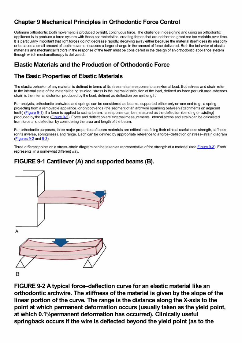
Chapter 9 Mechanical Principles in Orthodontic Force ControlOptimum orthodontic tooth movement is produced by light, continuous force. The challenge in designing and using an orthodonticappliance is to produce a force system with these characteristics, creating forces that are neither too great nor too variable over time.It is particularly important that light forces do not decrease rapidly, decaying away either because the material itself loses its elasticityor because a small amount of tooth movement causes a larger change in the amount of force delivered. Both the behavior of elasticmaterials and mechanical factors in the response of the teeth must be considered in the design of an orthodontic appliance systemthrough which mechanotherapy is delivered.
Elastic Materials and the Production of Orthodontic Force
The Basic Properties of Elastic MaterialsThe elastic behavior of any material is defined in terms of its stress–strain response to an external load. Both stress and strain referto the internal state of the material being studied: stress is the internal distribution of the load, defined as force per unit area, whereasstrain is the internal distortion produced by the load, defined as deflection per unit length.
For analysis, orthodontic archwires and springs can be considered as beams, supported either only on one end (e.g., a springprojecting from a removable appliance) or on both ends (the segment of an archwire spanning between attachments on adjacentteeth) (Figure 9-1). If a force is applied to such a beam, its response can be measured as the deflection (bending or twisting)produced by the force (Figure 9-2). Force and deflection are external measurements. Internal stress and strain can be calculatedfrom force and deflection by considering the area and length of the beam.
For orthodontic purposes, three major properties of beam materials are critical in defining their clinical usefulness: strength, stiffness(or its inverse, springiness), and range. Each can be defined by appropriate reference to a force–deflection or stress–strain diagram(Figures 9-2 and 9-3).
Three different points on a stress–strain diagram can be taken as representative of the strength of a material (see Figure 9-3). Eachrepresents, in a somewhat different way,
FIGURE 9-1 Cantilever (A) and supported beams (B).
FIGURE 9-2 A typical force–deflection curve for an elastic material like anorthodontic archwire. The stiffness of the material is given by the slope of thelinear portion of the curve. The range is the distance along the X-axis to thepoint at which permanent deformation occurs (usually taken as the yield point,at which 0.1%permanent deformation has occurred). Clinically usefulspringback occurs if the wire is deflected beyond the yield point (as to the
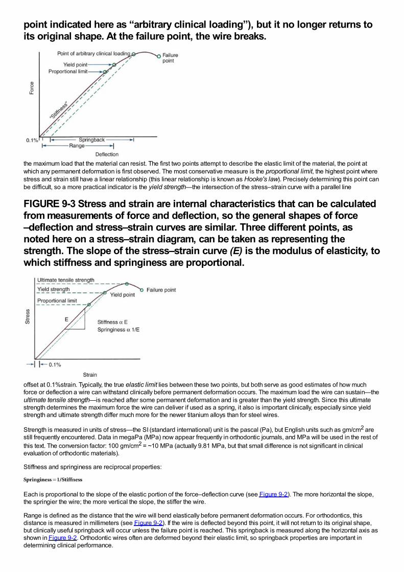
point indicated here as “arbitrary clinical loading”), but it no longer returns toits original shape. At the failure point, the wire breaks.
the maximum load that the material can resist. The first two points attempt to describe the elastic limit of the material, the point atwhich any permanent deformation is first observed. The most conservative measure is the proportional limit, the highest point wherestress and strain still have a linear relationship (this linear relationship is known as Hooke's law). Precisely determining this point canbe difficult, so a more practical indicator is the yield strength—the intersection of the stress–strain curve with a parallel line
FIGURE 9-3 Stress and strain are internal characteristics that can be calculatedfrom measurements of force and deflection, so the general shapes of force–deflection and stress–strain curves are similar. Three different points, asnoted here on a stress–strain diagram, can be taken as representing thestrength. The slope of the stress–strain curve (E) is the modulus of elasticity, towhich stiffness and springiness are proportional.
offset at 0.1%strain. Typically, the true elastic limit lies between these two points, but both serve as good estimates of how muchforce or deflection a wire can withstand clinically before permanent deformation occurs. The maximum load the wire can sustain—theultimate tensile strength—is reached after some permanent deformation and is greater than the yield strength. Since this ultimatestrength determines the maximum force the wire can deliver if used as a spring, it also is important clinically, especially since yieldstrength and ultimate strength differ much more for the newer titanium alloys than for steel wires.
Strength is measured in units of stress—the SI (standard international) unit is the pascal (Pa), but English units such as gm/cm2 arestill frequently encountered. Data in megaPa (MPa) now appear frequently in orthodontic journals, and MPa will be used in the rest ofthis text. The conversion factor: 100 gm/cm2 = ~10 MPa (actually 9.81 MPa, but that small difference is not significant in clinicalevaluation of orthodontic materials).
Stiffness and springiness are reciprocal properties:
Each is proportional to the slope of the elastic portion of the force–deflection curve (see Figure 9-2). The more horizontal the slope,the springier the wire; the more vertical the slope, the stiffer the wire.
Range is defined as the distance that the wire will bend elastically before permanent deformation occurs. For orthodontics, thisdistance is measured in millimeters (see Figure 9-2). If the wire is deflected beyond this point, it will not return to its original shape,but clinically useful springback will occur unless the failure point is reached. This springback is measured along the horizontal axis asshown in Figure 9-2. Orthodontic wires often are deformed beyond their elastic limit, so springback properties are important indetermining clinical performance.
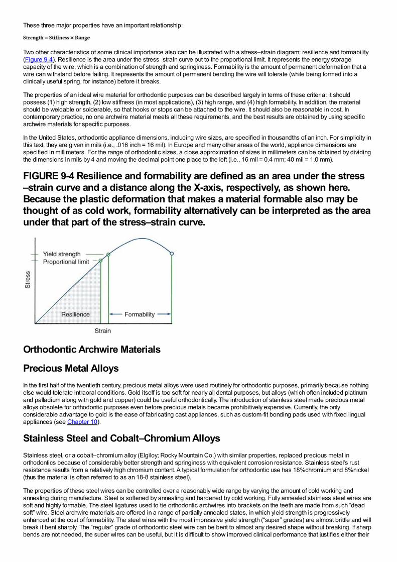
These three major properties have an important relationship:
Two other characteristics of some clinical importance also can be illustrated with a stress–strain diagram: resilience and formability(Figure 9-4). Resilience is the area under the stress–strain curve out to the proportional limit. It represents the energy storagecapacity of the wire, which is a combination of strength and springiness. Formability is the amount of permanent deformation that awire can withstand before failing. It represents the amount of permanent bending the wire will tolerate (while being formed into aclinically useful spring, for instance) before it breaks.
The properties of an ideal wire material for orthodontic purposes can be described largely in terms of these criteria: it shouldpossess (1) high strength, (2) low stiffness (in most applications), (3) high range, and (4) high formability. In addition, the materialshould be weldable or solderable, so that hooks or stops can be attached to the wire. It should also be reasonable in cost. Incontemporary practice, no one archwire material meets all these requirements, and the best results are obtained by using specificarchwire materials for specific purposes.
In the United States, orthodontic appliance dimensions, including wire sizes, are specified in thousandths of an inch. For simplicity inthis text, they are given in mils (i.e., .016 inch = 16 mil). In Europe and many other areas of the world, appliance dimensions arespecified in millimeters. For the range of orthodontic sizes, a close approximation of sizes in millimeters can be obtained by dividingthe dimensions in mils by 4 and moving the decimal point one place to the left (i.e., 16 mil = 0.4 mm; 40 mil = 1.0 mm).
FIGURE 9-4 Resilience and formability are defined as an area under the stress–strain curve and a distance along the X-axis, respectively, as shown here.Because the plastic deformation that makes a material formable also may bethought of as cold work, formability alternatively can be interpreted as the areaunder that part of the stress–strain curve.
Orthodontic Archwire Materials
Precious Metal AlloysIn the first half of the twentieth century, precious metal alloys were used routinely for orthodontic purposes, primarily because nothingelse would tolerate intraoral conditions. Gold itself is too soft for nearly all dental purposes, but alloys (which often included platinumand palladium along with gold and copper) could be useful orthodontically. The introduction of stainless steel made precious metalalloys obsolete for orthodontic purposes even before precious metals became prohibitively expensive. Currently, the onlyconsiderable advantage to gold is the ease of fabricating cast appliances, such as custom-fit bonding pads used with fixed lingualappliances (see Chapter 10).
Stainless Steel and Cobalt–Chromium AlloysStainless steel, or a cobalt–chromium alloy (Elgiloy; Rocky Mountain Co.) with similar properties, replaced precious metal inorthodontics because of considerably better strength and springiness with equivalent corrosion resistance. Stainless steel's rustresistance results from a relatively high chromium content. A typical formulation for orthodontic use has 18%chromium and 8%nickel(thus the material is often referred to as an 18-8 stainless steel).
The properties of these steel wires can be controlled over a reasonably wide range by varying the amount of cold working andannealing during manufacture. Steel is softened by annealing and hardened by cold working. Fully annealed stainless steel wires aresoft and highly formable. The steel ligatures used to tie orthodontic archwires into brackets on the teeth are made from such “deadsoft” wire. Steel archwire materials are offered in a range of partially annealed states, in which yield strength is progressivelyenhanced at the cost of formability. The steel wires with the most impressive yield strength (“super” grades) are almost brittle and willbreak if bent sharply. The “regular” grade of orthodontic steel wire can be bent to almost any desired shape without breaking. If sharpbends are not needed, the super wires can be useful, but it is difficult to show improved clinical performance that justifies either their
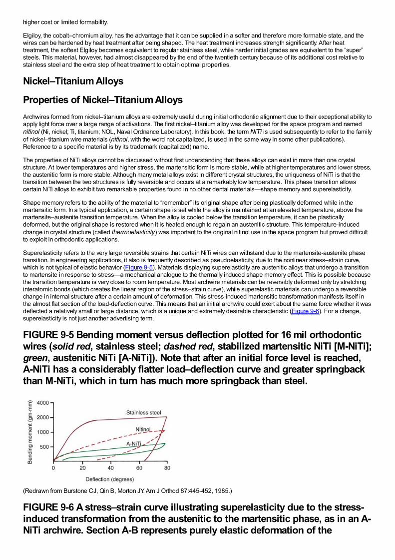
higher cost or limited formability.
Elgiloy, the cobalt–chromium alloy, has the advantage that it can be supplied in a softer and therefore more formable state, and thewires can be hardened by heat treatment after being shaped. The heat treatment increases strength significantly. After heattreatment, the softest Elgiloy becomes equivalent to regular stainless steel, while harder initial grades are equivalent to the “super”steels. This material, however, had almost disappeared by the end of the twentieth century because of its additional cost relative tostainless steel and the extra step of heat treatment to obtain optimal properties.
Nickel–Titanium Alloys
Properties of Nickel–Titanium AlloysArchwires formed from nickel–titanium alloys are extremely useful during initial orthodontic alignment due to their exceptional ability toapply light force over a large range of activations. The first nickel–titanium alloy was developed for the space program and namednitinol (Ni, nickel; Ti, titanium; NOL, Naval Ordnance Laboratory). In this book, the term NiTi is used subsequently to refer to the familyof nickel–titanium wire materials (nitinol, with the word not capitalized, is used in the same way in some other publications).Reference to a specific material is by its trademark (capitalized) name.
The properties of NiTi alloys cannot be discussed without first understanding that these alloys can exist in more than one crystalstructure. At lower temperatures and higher stress, the martensitic form is more stable, while at higher temperatures and lower stress,the austenitic form is more stable. Although many metal alloys exist in different crystal structures, the uniqueness of NiTi is that thetransition between the two structures is fully reversible and occurs at a remarkably low temperature. This phase transition allowscertain NiTi alloys to exhibit two remarkable properties found in no other dental materials—shape memory and superelasticity.
Shape memory refers to the ability of the material to “remember” its original shape after being plastically deformed while in themartensitic form. In a typical application, a certain shape is set while the alloy is maintained at an elevated temperature, above themartensite–austenite transition temperature. When the alloy is cooled below the transition temperature, it can be plasticallydeformed, but the original shape is restored when it is heated enough to regain an austenitic structure. This temperature-inducedchange in crystal structure (called thermoelasticity) was important to the original nitinol use in the space program but proved difficultto exploit in orthodontic applications.
Superelasticity refers to the very large reversible strains that certain NiTi wires can withstand due to the martensite-austenite phasetransition. In engineering applications, it also is frequently described as pseudoelasticity, due to the nonlinear stress–strain curve,which is not typical of elastic behavior (Figure 9-5). Materials displaying superelasticity are austenitic alloys that undergo a transitionto martensite in response to stress—a mechanical analogue to the thermally induced shape memory effect. This is possible becausethe transition temperature is very close to room temperature. Most archwire materials can be reversibly deformed only by stretchinginteratomic bonds (which creates the linear region of the stress–strain curve), while superelastic materials can undergo a reversiblechange in internal structure after a certain amount of deformation. This stress-induced martensitic transformation manifests itself inthe almost flat section of the load-deflection curve. This means that an initial archwire could exert about the same force whether it wasdeflected a relatively small or large distance, which is a unique and extremely desirable characteristic (Figure 9-6). For a change,superelasticity is not just another advertising term.
FIGURE 9-5 Bending moment versus deflection plotted for 16 mil orthodonticwires (solid red, stainless steel; dashed red, stabilized martensitic NiTi [M-NiTi];green, austenitic NiTi [A-NiTi]). Note that after an initial force level is reached,A-NiTi has a considerably flatter load–deflection curve and greater springbackthan M-NiTi, which in turn has much more springback than steel.
(Redrawn from Burstone CJ, Qin B, Morton JY. Am J Orthod 87:445-452, 1985.)
FIGURE 9-6 A stress–strain curve illustrating superelasticity due to the stress-induced transformation from the austenitic to the martensitic phase, as in an A-NiTi archwire. Section A-B represents purely elastic deformation of the
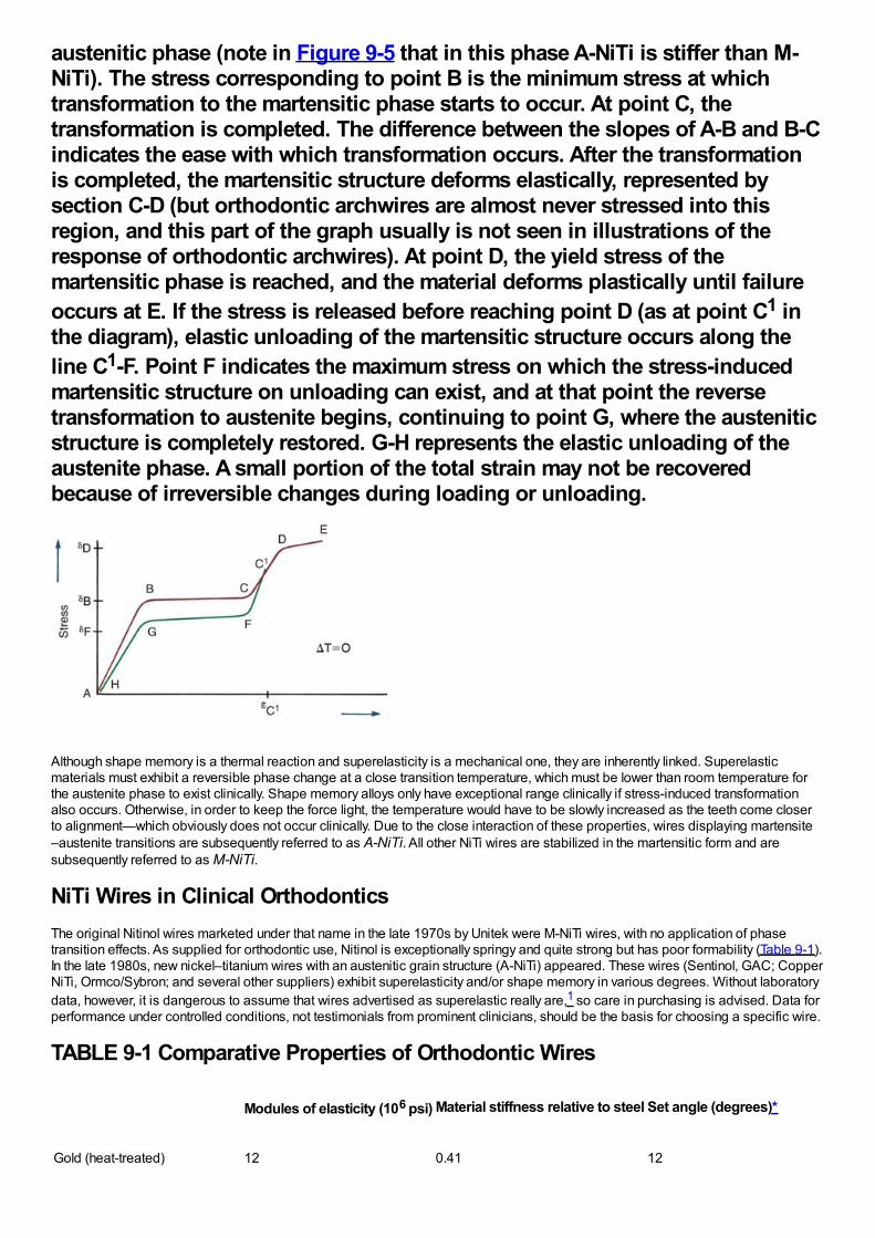
austenitic phase (note in Figure 9-5 that in this phase A-NiTi is stiffer than M-NiTi). The stress corresponding to point B is the minimum stress at whichtransformation to the martensitic phase starts to occur. At point C, thetransformation is completed. The difference between the slopes of A-B and B-Cindicates the ease with which transformation occurs. After the transformationis completed, the martensitic structure deforms elastically, represented bysection C-D (but orthodontic archwires are almost never stressed into thisregion, and this part of the graph usually is not seen in illustrations of theresponse of orthodontic archwires). At point D, the yield stress of themartensitic phase is reached, and the material deforms plastically until failureoccurs at E. If the stress is released before reaching point D (as at point C1 inthe diagram), elastic unloading of the martensitic structure occurs along theline C1-F. Point F indicates the maximum stress on which the stress-inducedmartensitic structure on unloading can exist, and at that point the reversetransformation to austenite begins, continuing to point G, where the austeniticstructure is completely restored. G-H represents the elastic unloading of theaustenite phase. A small portion of the total strain may not be recoveredbecause of irreversible changes during loading or unloading.
Although shape memory is a thermal reaction and superelasticity is a mechanical one, they are inherently linked. Superelasticmaterials must exhibit a reversible phase change at a close transition temperature, which must be lower than room temperature forthe austenite phase to exist clinically. Shape memory alloys only have exceptional range clinically if stress-induced transformationalso occurs. Otherwise, in order to keep the force light, the temperature would have to be slowly increased as the teeth come closerto alignment—which obviously does not occur clinically. Due to the close interaction of these properties, wires displaying martensite–austenite transitions are subsequently referred to as A-NiTi. All other NiTi wires are stabilized in the martensitic form and aresubsequently referred to as M-NiTi.
NiTi Wires in Clinical OrthodonticsThe original Nitinol wires marketed under that name in the late 1970s by Unitek were M-NiTi wires, with no application of phasetransition effects. As supplied for orthodontic use, Nitinol is exceptionally springy and quite strong but has poor formability (Table 9-1).In the late 1980s, new nickel–titanium wires with an austenitic grain structure (A-NiTi) appeared. These wires (Sentinol, GAC; CopperNiTi, Ormco/Sybron; and several other suppliers) exhibit superelasticity and/or shape memory in various degrees. Without laboratorydata, however, it is dangerous to assume that wires advertised as superelastic really are,1 so care in purchasing is advised. Data forperformance under controlled conditions, not testimonials from prominent clinicians, should be the basis for choosing a specific wire.
TABLE 9-1 Comparative Properties of Orthodontic Wires
Modules of elasticity (106 psi) Material stiffness relative to steel Set angle (degrees)*
Gold (heat-treated) 12 0.41 12
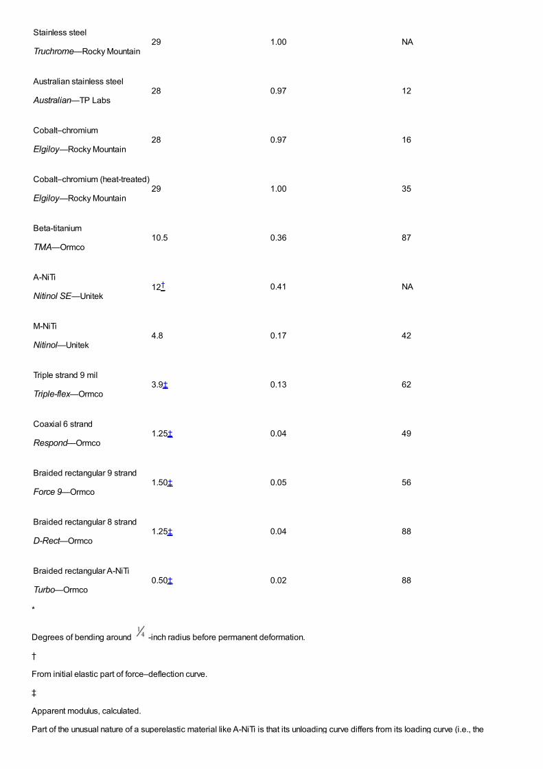
Stainless steel
Truchrome—Rocky Mountain29 1.00 NA
Australian stainless steel
Australian—TP Labs28 0.97 12
Cobalt–chromium
Elgiloy—Rocky Mountain28 0.97 16
Cobalt–chromium (heat-treated)
Elgiloy—Rocky Mountain29 1.00 35
Beta-titanium
TMA—Ormco10.5 0.36 87
A-NiTi
Nitinol SE—Unitek12† 0.41 NA
M-NiTi
Nitinol—Unitek4.8 0.17 42
Triple strand 9 mil
Triple-flex—Ormco3.9‡ 0.13 62
Coaxial 6 strand
Respond—Ormco1.25‡ 0.04 49
Braided rectangular 9 strand
Force 9—Ormco1.50‡ 0.05 56
Braided rectangular 8 strand
D-Rect—Ormco1.25‡ 0.04 88
Braided rectangular A-NiTi
Turbo—Ormco0.50‡ 0.02 88
*
Degrees of bending around -inch radius before permanent deformation.
†
From initial elastic part of force–deflection curve.
‡
Apparent modulus, calculated.
Part of the unusual nature of a superelastic material like A-NiTi is that its unloading curve differs from its loading curve (i.e., the
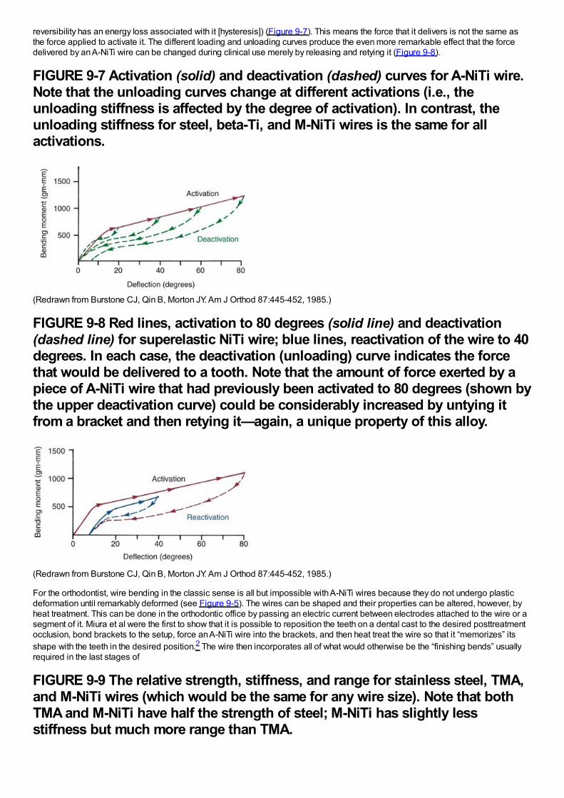
reversibility has an energy loss associated with it [hysteresis]) (Figure 9-7). This means the force that it delivers is not the same asthe force applied to activate it. The different loading and unloading curves produce the even more remarkable effect that the forcedelivered by an A-NiTi wire can be changed during clinical use merely by releasing and retying it (Figure 9-8).
FIGURE 9-7 Activation (solid) and deactivation (dashed) curves for A-NiTi wire.Note that the unloading curves change at different activations (i.e., theunloading stiffness is affected by the degree of activation). In contrast, theunloading stiffness for steel, beta-Ti, and M-NiTi wires is the same for allactivations.
(Redrawn from Burstone CJ, Qin B, Morton JY. Am J Orthod 87:445-452, 1985.)
FIGURE 9-8 Red lines, activation to 80 degrees (solid line) and deactivation(dashed line) for superelastic NiTi wire; blue lines, reactivation of the wire to 40degrees. In each case, the deactivation (unloading) curve indicates the forcethat would be delivered to a tooth. Note that the amount of force exerted by apiece of A-NiTi wire that had previously been activated to 80 degrees (shown bythe upper deactivation curve) could be considerably increased by untying itfrom a bracket and then retying it—again, a unique property of this alloy.
(Redrawn from Burstone CJ, Qin B, Morton JY. Am J Orthod 87:445-452, 1985.)
For the orthodontist, wire bending in the classic sense is all but impossible with A-NiTi wires because they do not undergo plasticdeformation until remarkably deformed (see Figure 9-5). The wires can be shaped and their properties can be altered, however, byheat treatment. This can be done in the orthodontic office by passing an electric current between electrodes attached to the wire or asegment of it. Miura et al were the first to show that it is possible to reposition the teeth on a dental cast to the desired posttreatmentocclusion, bond brackets to the setup, force an A-NiTi wire into the brackets, and then heat treat the wire so that it “memorizes” itsshape with the teeth in the desired position.2 The wire then incorporates all of what would otherwise be the “finishing bends” usuallyrequired in the last stages of
FIGURE 9-9 The relative strength, stiffness, and range for stainless steel, TMA,and M-NiTi wires (which would be the same for any wire size). Note that bothTMA and M-NiTi have half the strength of steel; M-NiTi has slightly lessstiffness but much more range than TMA.
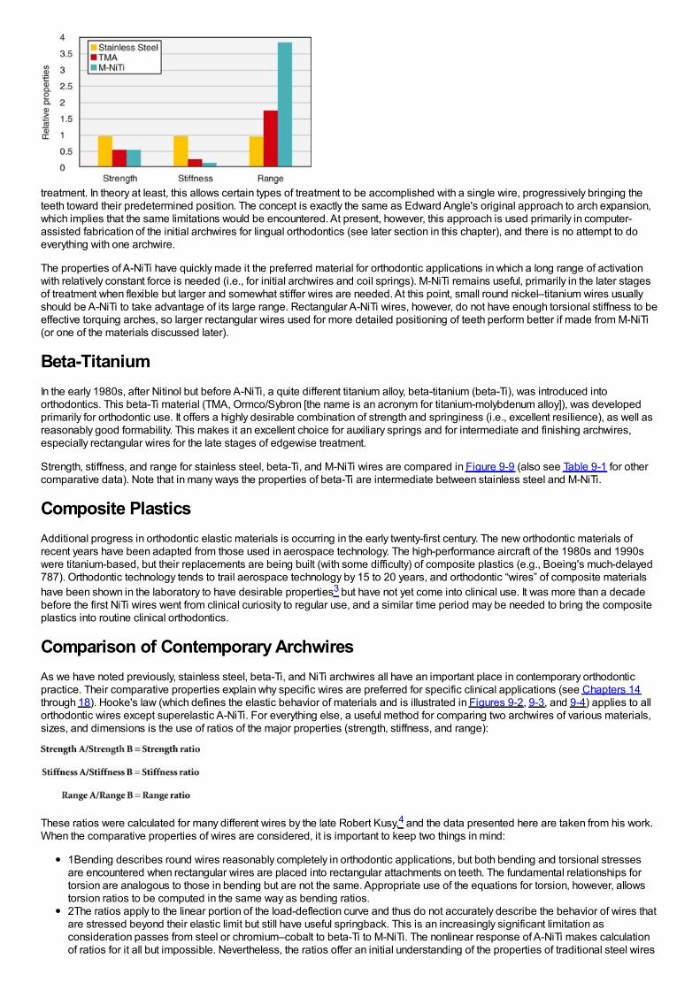
treatment. In theory at least, this allows certain types of treatment to be accomplished with a single wire, progressively bringing theteeth toward their predetermined position. The concept is exactly the same as Edward Angle's original approach to arch expansion,which implies that the same limitations would be encountered. At present, however, this approach is used primarily in computer-assisted fabrication of the initial archwires for lingual orthodontics (see later section in this chapter), and there is no attempt to doeverything with one archwire.
The properties of A-NiTi have quickly made it the preferred material for orthodontic applications in which a long range of activationwith relatively constant force is needed (i.e., for initial archwires and coil springs). M-NiTi remains useful, primarily in the later stagesof treatment when flexible but larger and somewhat stiffer wires are needed. At this point, small round nickel–titanium wires usuallyshould be A-NiTi to take advantage of its large range. Rectangular A-NiTi wires, however, do not have enough torsional stiffness to beeffective torquing arches, so larger rectangular wires used for more detailed positioning of teeth perform better if made from M-NiTi(or one of the materials discussed later).
Beta-TitaniumIn the early 1980s, after Nitinol but before A-NiTi, a quite different titanium alloy, beta-titanium (beta-Ti), was introduced intoorthodontics. This beta-Ti material (TMA, Ormco/Sybron [the name is an acronym for titanium-molybdenum alloy]), was developedprimarily for orthodontic use. It offers a highly desirable combination of strength and springiness (i.e., excellent resilience), as well asreasonably good formability. This makes it an excellent choice for auxiliary springs and for intermediate and finishing archwires,especially rectangular wires for the late stages of edgewise treatment.
Strength, stiffness, and range for stainless steel, beta-Ti, and M-NiTi wires are compared in Figure 9-9 (also see Table 9-1 for othercomparative data). Note that in many ways the properties of beta-Ti are intermediate between stainless steel and M-NiTi.
Composite PlasticsAdditional progress in orthodontic elastic materials is occurring in the early twenty-first century. The new orthodontic materials ofrecent years have been adapted from those used in aerospace technology. The high-performance aircraft of the 1980s and 1990swere titanium-based, but their replacements are being built (with some difficulty) of composite plastics (e.g., Boeing's much-delayed787). Orthodontic technology tends to trail aerospace technology by 15 to 20 years, and orthodontic “wires” of composite materialshave been shown in the laboratory to have desirable properties3 but have not yet come into clinical use. It was more than a decadebefore the first NiTi wires went from clinical curiosity to regular use, and a similar time period may be needed to bring the compositeplastics into routine clinical orthodontics.
Comparison of Contemporary ArchwiresAs we have noted previously, stainless steel, beta-Ti, and NiTi archwires all have an important place in contemporary orthodonticpractice. Their comparative properties explain why specific wires are preferred for specific clinical applications (see Chapters 14through 18). Hooke's law (which defines the elastic behavior of materials and is illustrated in Figures 9-2, 9-3, and 9-4) applies to allorthodontic wires except superelastic A-NiTi. For everything else, a useful method for comparing two archwires of various materials,sizes, and dimensions is the use of ratios of the major properties (strength, stiffness, and range):
These ratios were calculated for many different wires by the late Robert Kusy,4 and the data presented here are taken from his work.When the comparative properties of wires are considered, it is important to keep two things in mind:
1Bending describes round wires reasonably completely in orthodontic applications, but both bending and torsional stressesare encountered when rectangular wires are placed into rectangular attachments on teeth. The fundamental relationships fortorsion are analogous to those in bending but are not the same. Appropriate use of the equations for torsion, however, allowstorsion ratios to be computed in the same way as bending ratios.2The ratios apply to the linear portion of the load-deflection curve and thus do not accurately describe the behavior of wires thatare stressed beyond their elastic limit but still have useful springback. This is an increasingly significant limitation asconsideration passes from steel or chromium–cobalt to beta-Ti to M-NiTi. The nonlinear response of A-NiTi makes calculationof ratios for it all but impossible. Nevertheless, the ratios offer an initial understanding of the properties of traditional steel wires
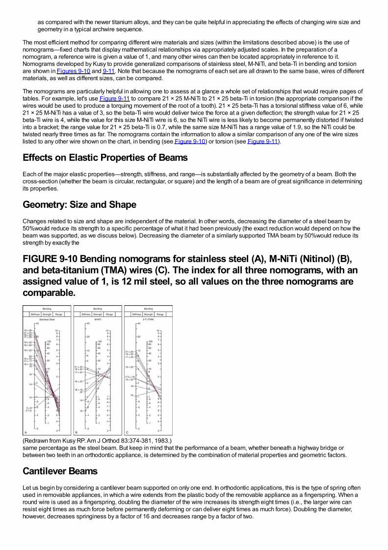
as compared with the newer titanium alloys, and they can be quite helpful in appreciating the effects of changing wire size andgeometry in a typical archwire sequence.
The most efficient method for comparing different wire materials and sizes (within the limitations described above) is the use ofnomograms—fixed charts that display mathematical relationships via appropriately adjusted scales. In the preparation of anomogram, a reference wire is given a value of 1, and many other wires can then be located appropriately in reference to it.Nomograms developed by Kusy to provide generalized comparisons of stainless steel, M-NiTi, and beta-Ti in bending and torsionare shown in Figures 9-10 and 9-11. Note that because the nomograms of each set are all drawn to the same base, wires of differentmaterials, as well as different sizes, can be compared.
The nomograms are particularly helpful in allowing one to assess at a glance a whole set of relationships that would require pages oftables. For example, let's use Figure 9-11 to compare 21 × 25 M-NiTi to 21 × 25 beta-Ti in torsion (the appropriate comparison if thewires would be used to produce a torquing movement of the root of a tooth). 21 × 25 beta-Ti has a torsional stiffness value of 6, while21 × 25 M-NiTi has a value of 3, so the beta-Ti wire would deliver twice the force at a given deflection; the strength value for 21 × 25beta-Ti wire is 4, while the value for this size M-NiTi wire is 6, so the NiTi wire is less likely to become permanently distorted if twistedinto a bracket; the range value for 21 × 25 beta-Ti is 0.7, while the same size M-NiTi has a range value of 1.9, so the NiTi could betwisted nearly three times as far. The nomograms contain the information to allow a similar comparison of any one of the wire sizeslisted to any other wire shown on the chart, in bending (see Figure 9-10) or torsion (see Figure 9-11).
Effects on Elastic Properties of BeamsEach of the major elastic properties—strength, stiffness, and range—is substantially affected by the geometry of a beam. Both thecross-section (whether the beam is circular, rectangular, or square) and the length of a beam are of great significance in determiningits properties.
Geometry: Size and ShapeChanges related to size and shape are independent of the material. In other words, decreasing the diameter of a steel beam by50%would reduce its strength to a specific percentage of what it had been previously (the exact reduction would depend on how thebeam was supported, as we discuss below). Decreasing the diameter of a similarly supported TMA beam by 50%would reduce itsstrength by exactly the
FIGURE 9-10 Bending nomograms for stainless steel (A), M-NiTi (Nitinol) (B),and beta-titanium (TMA) wires (C). The index for all three nomograms, with anassigned value of 1, is 12 mil steel, so all values on the three nomograms arecomparable.
(Redrawn from Kusy RP. Am J Orthod 83:374-381, 1983.)same percentage as the steel beam. But keep in mind that the performance of a beam, whether beneath a highway bridge orbetween two teeth in an orthodontic appliance, is determined by the combination of material properties and geometric factors.
Cantilever BeamsLet us begin by considering a cantilever beam supported on only one end. In orthodontic applications, this is the type of spring oftenused in removable appliances, in which a wire extends from the plastic body of the removable appliance as a fingerspring. When around wire is used as a fingerspring, doubling the diameter of the wire increases its strength eight times (i.e., the larger wire canresist eight times as much force before permanently deforming or can deliver eight times as much force). Doubling the diameter,however, decreases springiness by a factor of 16 and decreases range by a factor of two.
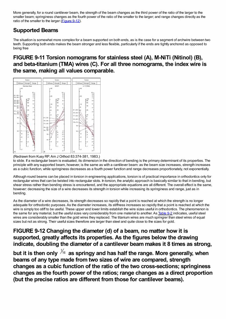
More generally, for a round cantilever beam, the strength of the beam changes as the third power of the ratio of the larger to thesmaller beam; springiness changes as the fourth power of the ratio of the smaller to the larger; and range changes directly as theratio of the smaller to the larger (Figure 9-12).
Supported BeamsThe situation is somewhat more complex for a beam supported on both ends, as is the case for a segment of archwire between twoteeth. Supporting both ends makes the beam stronger and less flexible, particularly if the ends are tightly anchored as opposed tobeing free
FIGURE 9-11 Torsion nomograms for stainless steel (A), M-NiTi (Nitinol) (B),and beta-titanium (TMA) wires (C). For all three nomograms, the index wire isthe same, making all values comparable.
(Redrawn from Kusy RP. Am J Orthod 83:374-381, 1983.)to slide. If a rectangular beam is evaluated, its dimension in the direction of bending is the primary determinant of its properties. Theprinciple with any supported beam, however, is the same as with a cantilever beam: as the beam size increases, strength increasesas a cubic function, while springiness decreases as a fourth power function and range decreases proportionately, not exponentially.
Although round beams can be placed in torsion in engineering applications, torsion is of practical importance in orthodontics only forrectangular wires that can be twisted into rectangular slots. In torsion, the analytic approach is basically similar to that in bending, butshear stress rather than bending stress is encountered, and the appropriate equations are all different. The overall effect is the same,however: decreasing the size of a wire decreases its strength in torsion while increasing its springiness and range, just as inbending.
As the diameter of a wire decreases, its strength decreases so rapidly that a point is reached at which the strength is no longeradequate for orthodontic purposes. As the diameter increases, its stiffness increases so rapidly that a point is reached at which thewire is simply too stiff to be useful. These upper and lower limits establish the wire sizes useful in orthodontics. The phenomenon isthe same for any material, but the useful sizes vary considerably from one material to another. As Table 9-2 indicates, useful steelwires are considerably smaller than the gold wires they replaced. The titanium wires are much springier than steel wires of equalsizes but not as strong. Their useful sizes therefore are larger than steel and quite close to the sizes for gold.
FIGURE 9-12 Changing the diameter (d) of a beam, no matter how it issupported, greatly affects its properties. As the figures below the drawingindicate, doubling the diameter of a cantilever beam makes it 8 times as strong,but it is then only as springy and has half the range. More generally, whenbeams of any type made from two sizes of wire are compared, strengthchanges as a cubic function of the ratio of the two cross-sections; springinesschanges as the fourth power of the ratios; range changes as a direct proportion(but the precise ratios are different from those for cantilever beams).
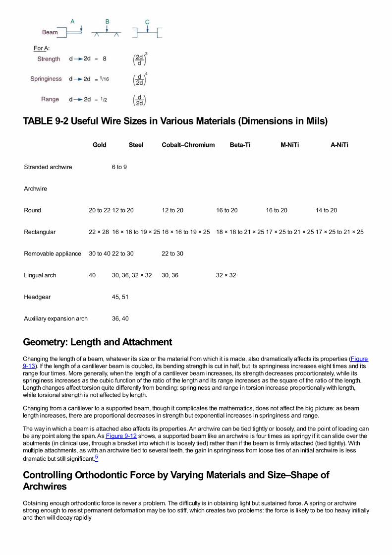
TABLE 9-2 Useful Wire Sizes in Various Materials (Dimensions in Mils)
Gold Steel Cobalt–Chromium Beta-Ti M-NiTi A-NiTi
Stranded archwire 6 to 9
Archwire
Round 20 to 22 12 to 20 12 to 20 16 to 20 16 to 20 14 to 20
Rectangular 22 × 28 16 × 16 to 19 × 25 16 × 16 to 19 × 25 18 × 18 to 21 × 25 17 × 25 to 21 × 25 17 × 25 to 21 × 25
Removable appliance 30 to 40 22 to 30 22 to 30
Lingual arch 40 30, 36, 32 × 32 30, 36 32 × 32
Headgear 45, 51
Auxiliary expansion arch 36, 40
Geometry: Length and AttachmentChanging the length of a beam, whatever its size or the material from which it is made, also dramatically affects its properties (Figure9-13). If the length of a cantilever beam is doubled, its bending strength is cut in half, but its springiness increases eight times and itsrange four times. More generally, when the length of a cantilever beam increases, its strength decreases proportionately, while itsspringiness increases as the cubic function of the ratio of the length and its range increases as the square of the ratio of the length.Length changes affect torsion quite differently from bending: springiness and range in torsion increase proportionally with length,while torsional strength is not affected by length.
Changing from a cantilever to a supported beam, though it complicates the mathematics, does not affect the big picture: as beamlength increases, there are proportional decreases in strength but exponential increases in springiness and range.
The way in which a beam is attached also affects its properties. An archwire can be tied tightly or loosely, and the point of loading canbe any point along the span. As Figure 9-12 shows, a supported beam like an archwire is four times as springy if it can slide over theabutments (in clinical use, through a bracket into which it is loosely tied) rather than if the beam is firmly attached (tied tightly). Withmultiple attachments, as with an archwire tied to several teeth, the gain in springiness from loose ties of an initial archwire is lessdramatic but still significant.5
Controlling Orthodontic Force by Varying Materials and Size–Shape ofArchwiresObtaining enough orthodontic force is never a problem. The difficulty is in obtaining light but sustained force. A spring or archwirestrong enough to resist permanent deformation may be too stiff, which creates two problems: the force is likely to be too heavy initiallyand then will decay rapidly
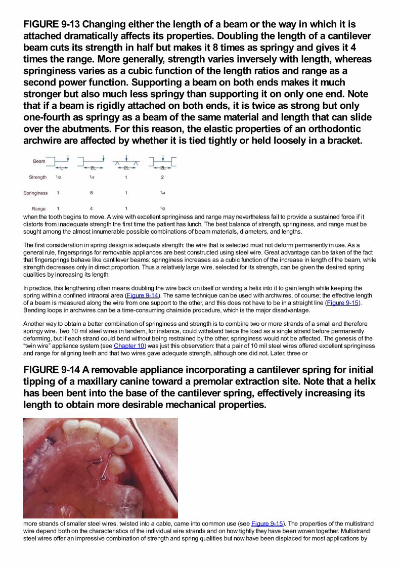
FIGURE 9-13 Changing either the length of a beam or the way in which it isattached dramatically affects its properties. Doubling the length of a cantileverbeam cuts its strength in half but makes it 8 times as springy and gives it 4times the range. More generally, strength varies inversely with length, whereasspringiness varies as a cubic function of the length ratios and range as asecond power function. Supporting a beam on both ends makes it muchstronger but also much less springy than supporting it on only one end. Notethat if a beam is rigidly attached on both ends, it is twice as strong but onlyone-fourth as springy as a beam of the same material and length that can slideover the abutments. For this reason, the elastic properties of an orthodonticarchwire are affected by whether it is tied tightly or held loosely in a bracket.
when the tooth begins to move. A wire with excellent springiness and range may nevertheless fail to provide a sustained force if itdistorts from inadequate strength the first time the patient has lunch. The best balance of strength, springiness, and range must besought among the almost innumerable possible combinations of beam materials, diameters, and lengths.
The first consideration in spring design is adequate strength: the wire that is selected must not deform permanently in use. As ageneral rule, fingersprings for removable appliances are best constructed using steel wire. Great advantage can be taken of the factthat fingersprings behave like cantilever beams: springiness increases as a cubic function of the increase in length of the beam, whilestrength decreases only in direct proportion. Thus a relatively large wire, selected for its strength, can be given the desired springqualities by increasing its length.
In practice, this lengthening often means doubling the wire back on itself or winding a helix into it to gain length while keeping thespring within a confined intraoral area (Figure 9-14). The same technique can be used with archwires, of course; the effective lengthof a beam is measured along the wire from one support to the other, and this does not have to be in a straight line (Figure 9-15).Bending loops in archwires can be a time-consuming chairside procedure, which is the major disadvantage.
Another way to obtain a better combination of springiness and strength is to combine two or more strands of a small and thereforespringy wire. Two 10 mil steel wires in tandem, for instance, could withstand twice the load as a single strand before permanentlydeforming, but if each strand could bend without being restrained by the other, springiness would not be affected. The genesis of the“twin wire” appliance system (see Chapter 10) was just this observation: that a pair of 10 mil steel wires offered excellent springinessand range for aligning teeth and that two wires gave adequate strength, although one did not. Later, three or
FIGURE 9-14 A removable appliance incorporating a cantilever spring for initialtipping of a maxillary canine toward a premolar extraction site. Note that a helixhas been bent into the base of the cantilever spring, effectively increasing itslength to obtain more desirable mechanical properties.
more strands of smaller steel wires, twisted into a cable, came into common use (see Figure 9-15). The properties of the multistrandwire depend both on the characteristics of the individual wire strands and on how tightly they have been woven together. Multistrandsteel wires offer an impressive combination of strength and spring qualities but now have been displaced for most applications by
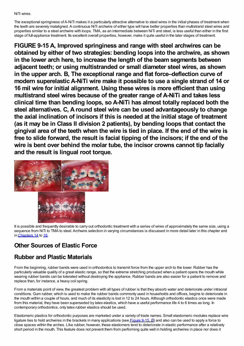
NiTi wires.
The exceptional springiness of A-NiTi makes it a particularly attractive alternative to steel wires in the initial phases of treatment whenthe teeth are severely malaligned. A continuous NiTi archwire of either type will have better properties than multistrand steel wires andproperties similar to a steel archwire with loops. TMA, as an intermediate between NiTi and steel, is less useful than either in the firststage of full-appliance treatment. Its excellent overall properties, however, make it quite useful in the later stages of treatment.
FIGURE 9-15 A, Improved springiness and range with steel archwires can beobtained by either of two strategies: bending loops into the archwire, as shownin the lower arch here, to increase the length of the beam segments betweenadjacent teeth; or using multistranded or small diameter steel wires, as shownin the upper arch. B, The exceptional range and flat force–deflection curve ofmodern superelastic A-NiTi wire make it possible to use a single strand of 14 or16 mil wire for initial alignment. Using these wires is more efficient than usingmultistrand steel wires because of the greater range of A-NiTi and takes lessclinical time than bending loops, so A-NiTi has almost totally replaced both thesteel alternatives. C, A round steel wire can be used advantageously to changethe axial inclination of incisors if this is needed at the initial stage of treatment(as it may be in Class II division 2 patients), by bending loops that contact thegingival area of the teeth when the wire is tied in place. If the end of the wire isfree to slide forward, the result is facial tipping of the incisors; if the end of thewire is bent over behind the molar tube, the incisor crowns cannot tip faciallyand the result is lingual root torque.
It is possible and frequently desirable to carry out orthodontic treatment with a series of wires of approximately the same size, using asequence from NiTi to TMA to steel. Archwire selection in varying circumstances is discussed in more detail later in this chapter andin Chapters 14 to 16.
Other Sources of Elastic Force
Rubber and Plastic MaterialsFrom the beginning, rubber bands were used in orthodontics to transmit force from the upper arch to the lower. Rubber has theparticularly valuable quality of a great elastic range, so that the extreme stretching produced when a patient opens the mouth whilewearing rubber bands can be tolerated without destroying the appliance. Rubber bands are also easier for a patient to remove andreplace than, for instance, a heavy coil spring.
From a materials point of view, the greatest problem with all types of rubber is that they absorb water and deteriorate under intraoralconditions. Gum rubber, which is used to make the rubber bands commonly used in households and offices, begins to deteriorate inthe mouth within a couple of hours, and much of its elasticity is lost in 12 to 24 hours. Although orthodontic elastics once were madefrom this material, they have been superseded by latex elastics, which have a useful performance life 4 to 6 times as long. Incontemporary orthodontics, only latex rubber elastics should be used.
Elastomeric plastics for orthodontic purposes are marketed under a variety of trade names. Small elastomeric modules replace wireligature ties to hold archwires in the brackets in many applications (see Figure 9-15, B) and also can be used to apply a force toclose spaces within the arches. Like rubber, however, these elastomers tend to deteriorate in elastic performance after a relativelyshort period in the mouth. This feature does not prevent them from performing quite well in holding archwires in place nor does it
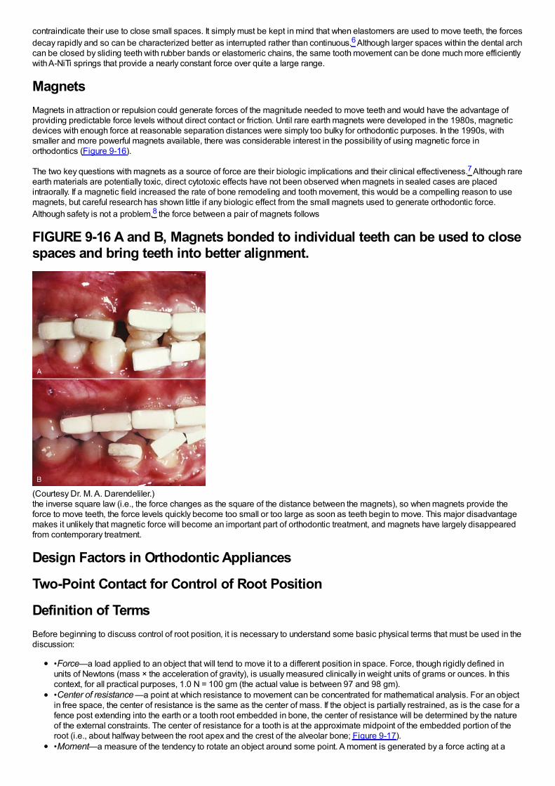
contraindicate their use to close small spaces. It simply must be kept in mind that when elastomers are used to move teeth, the forcesdecay rapidly and so can be characterized better as interrupted rather than continuous.6 Although larger spaces within the dental archcan be closed by sliding teeth with rubber bands or elastomeric chains, the same tooth movement can be done much more efficientlywith A-NiTi springs that provide a nearly constant force over quite a large range.
MagnetsMagnets in attraction or repulsion could generate forces of the magnitude needed to move teeth and would have the advantage ofproviding predictable force levels without direct contact or friction. Until rare earth magnets were developed in the 1980s, magneticdevices with enough force at reasonable separation distances were simply too bulky for orthodontic purposes. In the 1990s, withsmaller and more powerful magnets available, there was considerable interest in the possibility of using magnetic force inorthodontics (Figure 9-16).
The two key questions with magnets as a source of force are their biologic implications and their clinical effectiveness.7 Although rareearth materials are potentially toxic, direct cytotoxic effects have not been observed when magnets in sealed cases are placedintraorally. If a magnetic field increased the rate of bone remodeling and tooth movement, this would be a compelling reason to usemagnets, but careful research has shown little if any biologic effect from the small magnets used to generate orthodontic force.Although safety is not a problem,8 the force between a pair of magnets follows
FIGURE 9-16 A and B, Magnets bonded to individual teeth can be used to closespaces and bring teeth into better alignment.
(Courtesy Dr. M. A. Darendeliler.)the inverse square law (i.e., the force changes as the square of the distance between the magnets), so when magnets provide theforce to move teeth, the force levels quickly become too small or too large as soon as teeth begin to move. This major disadvantagemakes it unlikely that magnetic force will become an important part of orthodontic treatment, and magnets have largely disappearedfrom contemporary treatment.
Design Factors in Orthodontic Appliances
Two-Point Contact for Control of Root Position
Definition of TermsBefore beginning to discuss control of root position, it is necessary to understand some basic physical terms that must be used in thediscussion:
•Force—a load applied to an object that will tend to move it to a different position in space. Force, though rigidly defined inunits of Newtons (mass × the acceleration of gravity), is usually measured clinically in weight units of grams or ounces. In thiscontext, for all practical purposes, 1.0 N = 100 gm (the actual value is between 97 and 98 gm).•Center of resistance —a point at which resistance to movement can be concentrated for mathematical analysis. For an objectin free space, the center of resistance is the same as the center of mass. If the object is partially restrained, as is the case for afence post extending into the earth or a tooth root embedded in bone, the center of resistance will be determined by the natureof the external constraints. The center of resistance for a tooth is at the approximate midpoint of the embedded portion of theroot (i.e., about halfway between the root apex and the crest of the alveolar bone; Figure 9-17).•Moment—a measure of the tendency to rotate an object around some point. A moment is generated by a force acting at a
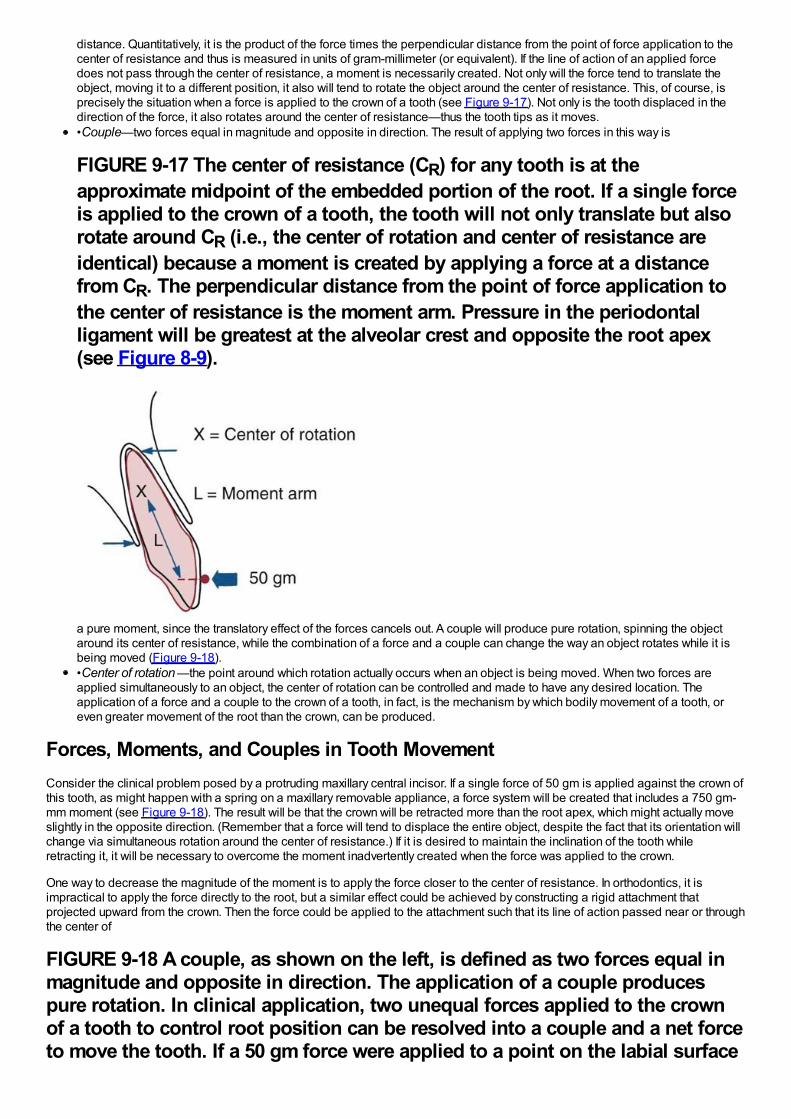
distance. Quantitatively, it is the product of the force times the perpendicular distance from the point of force application to thecenter of resistance and thus is measured in units of gram-millimeter (or equivalent). If the line of action of an applied forcedoes not pass through the center of resistance, a moment is necessarily created. Not only will the force tend to translate theobject, moving it to a different position, it also will tend to rotate the object around the center of resistance. This, of course, isprecisely the situation when a force is applied to the crown of a tooth (see Figure 9-17). Not only is the tooth displaced in thedirection of the force, it also rotates around the center of resistance—thus the tooth tips as it moves.•Couple—two forces equal in magnitude and opposite in direction. The result of applying two forces in this way is
FIGURE 9-17 The center of resistance (CR) for any tooth is at theapproximate midpoint of the embedded portion of the root. If a single forceis applied to the crown of a tooth, the tooth will not only translate but alsorotate around CR (i.e., the center of rotation and center of resistance areidentical) because a moment is created by applying a force at a distancefrom CR. The perpendicular distance from the point of force application tothe center of resistance is the moment arm. Pressure in the periodontalligament will be greatest at the alveolar crest and opposite the root apex(see Figure 8-9).
a pure moment, since the translatory effect of the forces cancels out. A couple will produce pure rotation, spinning the objectaround its center of resistance, while the combination of a force and a couple can change the way an object rotates while it isbeing moved (Figure 9-18).•Center of rotation —the point around which rotation actually occurs when an object is being moved. When two forces areapplied simultaneously to an object, the center of rotation can be controlled and made to have any desired location. Theapplication of a force and a couple to the crown of a tooth, in fact, is the mechanism by which bodily movement of a tooth, oreven greater movement of the root than the crown, can be produced.
Forces, Moments, and Couples in Tooth MovementConsider the clinical problem posed by a protruding maxillary central incisor. If a single force of 50 gm is applied against the crown ofthis tooth, as might happen with a spring on a maxillary removable appliance, a force system will be created that includes a 750 gm-mm moment (see Figure 9-18). The result will be that the crown will be retracted more than the root apex, which might actually moveslightly in the opposite direction. (Remember that a force will tend to displace the entire object, despite the fact that its orientation willchange via simultaneous rotation around the center of resistance.) If it is desired to maintain the inclination of the tooth whileretracting it, it will be necessary to overcome the moment inadvertently created when the force was applied to the crown.
One way to decrease the magnitude of the moment is to apply the force closer to the center of resistance. In orthodontics, it isimpractical to apply the force directly to the root, but a similar effect could be achieved by constructing a rigid attachment thatprojected upward from the crown. Then the force could be applied to the attachment such that its line of action passed near or throughthe center of
FIGURE 9-18 A couple, as shown on the left, is defined as two forces equal inmagnitude and opposite in direction. The application of a couple producespure rotation. In clinical application, two unequal forces applied to the crownof a tooth to control root position can be resolved into a couple and a net forceto move the tooth. If a 50 gm force were applied to a point on the labial surface
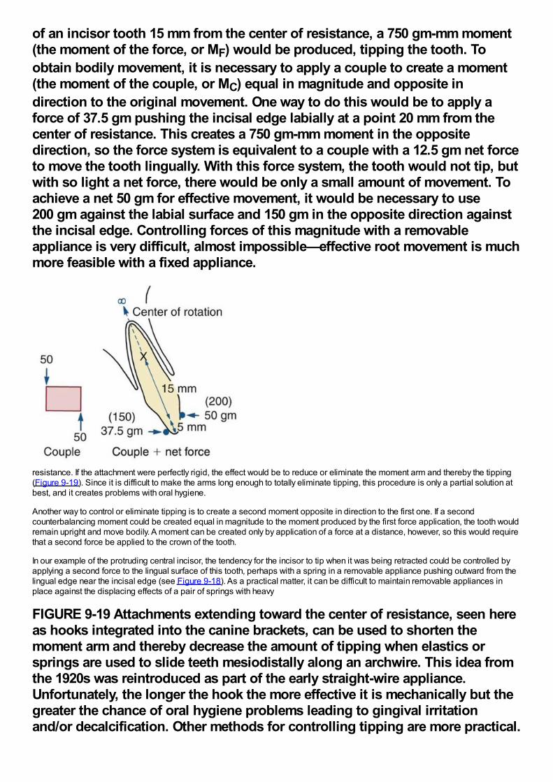
of an incisor tooth 15 mm from the center of resistance, a 750 gm-mm moment(the moment of the force, or MF) would be produced, tipping the tooth. Toobtain bodily movement, it is necessary to apply a couple to create a moment(the moment of the couple, or MC) equal in magnitude and opposite indirection to the original movement. One way to do this would be to apply aforce of 37.5 gm pushing the incisal edge labially at a point 20 mm from thecenter of resistance. This creates a 750 gm-mm moment in the oppositedirection, so the force system is equivalent to a couple with a 12.5 gm net forceto move the tooth lingually. With this force system, the tooth would not tip, butwith so light a net force, there would be only a small amount of movement. Toachieve a net 50 gm for effective movement, it would be necessary to use200 gm against the labial surface and 150 gm in the opposite direction againstthe incisal edge. Controlling forces of this magnitude with a removableappliance is very difficult, almost impossible—effective root movement is muchmore feasible with a fixed appliance.
resistance. If the attachment were perfectly rigid, the effect would be to reduce or eliminate the moment arm and thereby the tipping(Figure 9-19). Since it is difficult to make the arms long enough to totally eliminate tipping, this procedure is only a partial solution atbest, and it creates problems with oral hygiene.
Another way to control or eliminate tipping is to create a second moment opposite in direction to the first one. If a secondcounterbalancing moment could be created equal in magnitude to the moment produced by the first force application, the tooth wouldremain upright and move bodily. A moment can be created only by application of a force at a distance, however, so this would requirethat a second force be applied to the crown of the tooth.
In our example of the protruding central incisor, the tendency for the incisor to tip when it was being retracted could be controlled byapplying a second force to the lingual surface of this tooth, perhaps with a spring in a removable appliance pushing outward from thelingual edge near the incisal edge (see Figure 9-18). As a practical matter, it can be difficult to maintain removable appliances inplace against the displacing effects of a pair of springs with heavy
FIGURE 9-19 Attachments extending toward the center of resistance, seen hereas hooks integrated into the canine brackets, can be used to shorten themoment arm and thereby decrease the amount of tipping when elastics orsprings are used to slide teeth mesiodistally along an archwire. This idea fromthe 1920s was reintroduced as part of the early straight-wire appliance.Unfortunately, the longer the hook the more effective it is mechanically but thegreater the chance of oral hygiene problems leading to gingival irritationand/or decalcification. Other methods for controlling tipping are more practical.
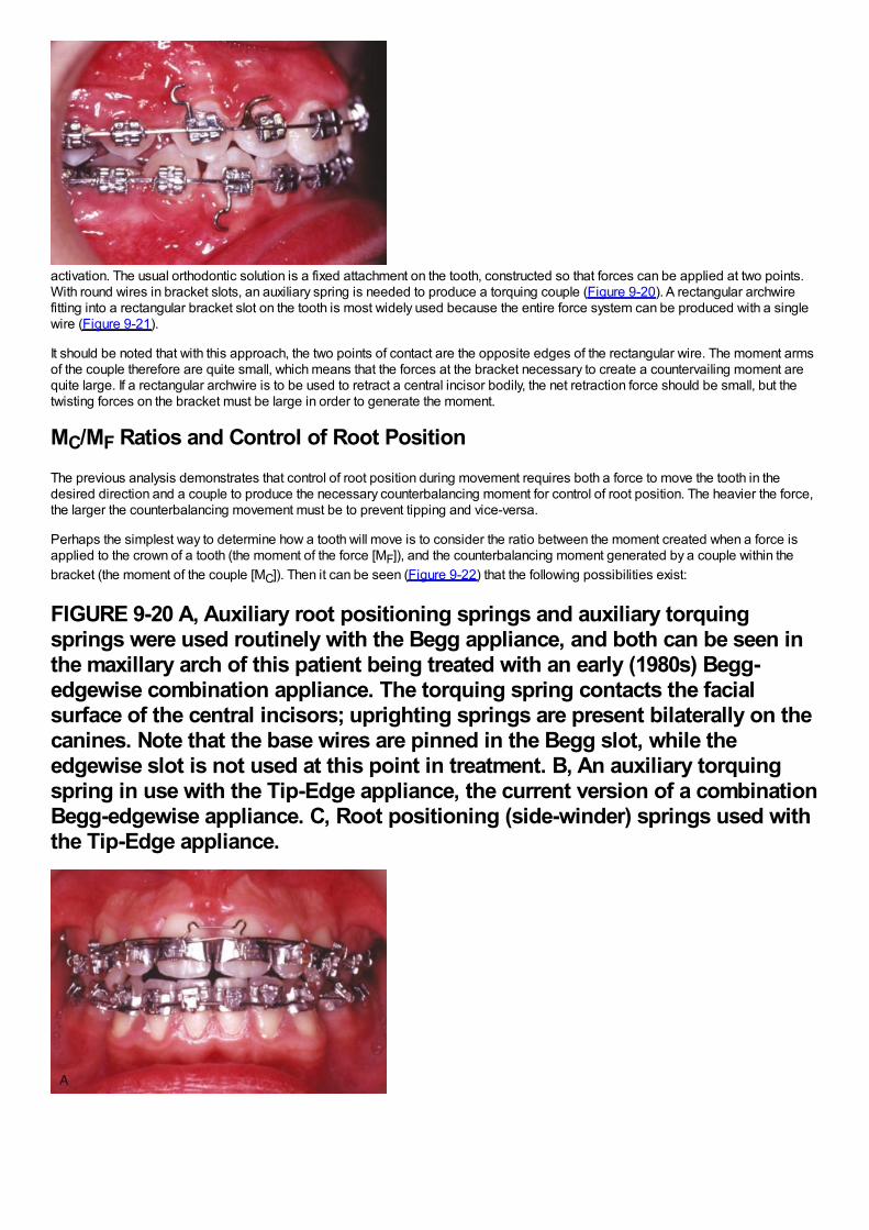
activation. The usual orthodontic solution is a fixed attachment on the tooth, constructed so that forces can be applied at two points.With round wires in bracket slots, an auxiliary spring is needed to produce a torquing couple (Figure 9-20). A rectangular archwirefitting into a rectangular bracket slot on the tooth is most widely used because the entire force system can be produced with a singlewire (Figure 9-21).
It should be noted that with this approach, the two points of contact are the opposite edges of the rectangular wire. The moment armsof the couple therefore are quite small, which means that the forces at the bracket necessary to create a countervailing moment arequite large. If a rectangular archwire is to be used to retract a central incisor bodily, the net retraction force should be small, but thetwisting forces on the bracket must be large in order to generate the moment.
MC/MF Ratios and Control of Root PositionThe previous analysis demonstrates that control of root position during movement requires both a force to move the tooth in thedesired direction and a couple to produce the necessary counterbalancing moment for control of root position. The heavier the force,the larger the counterbalancing movement must be to prevent tipping and vice-versa.
Perhaps the simplest way to determine how a tooth will move is to consider the ratio between the moment created when a force isapplied to the crown of a tooth (the moment of the force [MF]), and the counterbalancing moment generated by a couple within thebracket (the moment of the couple [MC]). Then it can be seen (Figure 9-22) that the following possibilities exist:
FIGURE 9-20 A, Auxiliary root positioning springs and auxiliary torquingsprings were used routinely with the Begg appliance, and both can be seen inthe maxillary arch of this patient being treated with an early (1980s) Begg-edgewise combination appliance. The torquing spring contacts the facialsurface of the central incisors; uprighting springs are present bilaterally on thecanines. Note that the base wires are pinned in the Begg slot, while theedgewise slot is not used at this point in treatment. B, An auxiliary torquingspring in use with the Tip-Edge appliance, the current version of a combinationBegg-edgewise appliance. C, Root positioning (side-winder) springs used withthe Tip-Edge appliance.
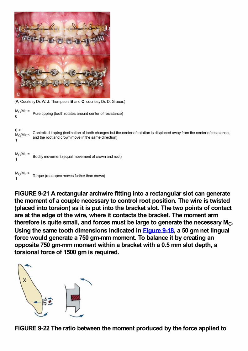
(A, Courtesy Dr. W. J. Thompson; B and C, courtesy Dr. D. Grauer.)
MC/MF =0
Pure tipping (tooth rotates around center of resistance)
0 <MC/MF <1
Controlled tipping (inclination of tooth changes but the center of rotation is displaced away from the center of resistance,and the root and crown move in the same direction)
MC/MF =1
Bodily movement (equal movement of crown and root)
MC/MF >1
Torque (root apex moves further than crown)
FIGURE 9-21 A rectangular archwire fitting into a rectangular slot can generatethe moment of a couple necessary to control root position. The wire is twisted(placed into torsion) as it is put into the bracket slot. The two points of contactare at the edge of the wire, where it contacts the bracket. The moment armtherefore is quite small, and forces must be large to generate the necessary MC.Using the same tooth dimensions indicated in Figure 9-18, a 50 gm net lingualforce would generate a 750 gm-mm moment. To balance it by creating anopposite 750 gm-mm moment within a bracket with a 0.5 mm slot depth, atorsional force of 1500 gm is required.
FIGURE 9-22 The ratio between the moment produced by the force applied to
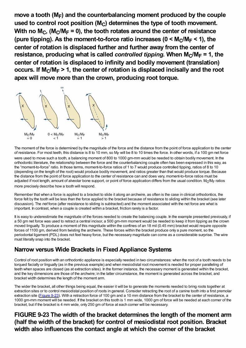
move a tooth (MF) and the counterbalancing moment produced by the coupleused to control root position (MC) determines the type of tooth movement.With no MC, (MC/MF = 0), the tooth rotates around the center of resistance(pure tipping). As the moment-to-force ratio increases (0 < MC/MF < 1), thecenter of rotation is displaced further and further away from the center ofresistance, producing what is called controlled tipping. When MC/MF = 1, thecenter of rotation is displaced to infinity and bodily movement (translation)occurs. If MC/MF > 1, the center of rotation is displaced incisally and the rootapex will move more than the crown, producing root torque.
The moment of the force is determined by the magnitude of the force and the distance from the point of force application to the centerof resistance. For most teeth, this distance is 8 to 10 mm, so MF will be 8 to 10 times the force. In other words, if a 100 gm net forcewere used to move such a tooth, a balancing moment of 800 to 1000 gm-mm would be needed to obtain bodily movement. In theorthodontic literature, the relationship between the force and the counterbalancing couple often has been expressed in this way, asthe “moment-to-force” ratio. In those terms, moment-to-force ratios of 1 to 7 would produce controlled tipping, ratios of 8 to 10(depending on the length of the root) would produce bodily movement, and ratios greater than that would produce torque. Becausethe distance from the point of force application to the center of resistance can and does vary, moment-to-force ratios must beadjusted if root length, amount of alveolar bone support, or point of force application differs from the usual condition. MC/MF ratiosmore precisely describe how a tooth will respond.
Remember that when a force is applied to a bracket to slide it along an archwire, as often is the case in clinical orthodontics, theforce felt by the tooth will be less than the force applied to the bracket because of resistance to sliding within the bracket (see laterdiscussion). The net force (after resistance to sliding is subtracted) and the moment associated with the net force are what isimportant. In contrast, when a couple is created within a bracket, friction rarely is a factor.
It is easy to underestimate the magnitude of the forces needed to create the balancing couple. In the example presented previously, ifa 50 gm net force was used to retract a central incisor, a 500 gm-mm moment would be needed to keep it from tipping as the crownmoved lingually. To produce a moment of this magnitude within the confines of an 18 mil (0.45 mm) bracket would require oppositeforces of 1100 gm, derived from twisting the archwire. These forces within the bracket produce only a pure moment, so theperiodontal ligament (PDL) does not feel heavy force, but the necessary magnitude can come as a considerable surprise. The wiremust literally snap into the bracket.
Narrow versus Wide Brackets in Fixed Appliance SystemsControl of root position with an orthodontic appliance is especially needed in two circumstances: when the root of a tooth needs to betorqued facially or lingually (as in the previous example) and when mesiodistal root movement is needed for proper paralleling ofteeth when spaces are closed (as at extraction sites). In the former instance, the necessary moment is generated within the bracket,and the key dimensions are those of the archwire; in the latter circumstance, the moment is generated across the bracket, andbracket width determines the length of the moment arm.
The wider the bracket, all other things being equal, the easier it will be to generate the moments needed to bring roots together atextraction sites or to control mesiodistal position of roots in general. Consider retracting the root of a canine tooth into a first premolarextraction site (Figure 9-23). With a retraction force of 100 gm and a 10 mm distance from the bracket to the center of resistance, a1000 gm-mm moment will be needed. If the bracket on this tooth is 1 mm wide, 1000 gm of force will be needed at each corner of thebracket, but if the bracket is 4 mm wide, only 250 gm of force at each corner will be necessary.
FIGURE 9-23 The width of the bracket determines the length of the moment arm(half the width of the bracket) for control of mesiodistal root position. Bracketwidth also influences the contact angle at which the corner of the bracket
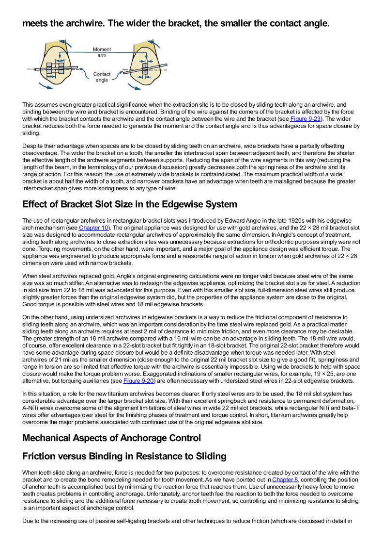
meets the archwire. The wider the bracket, the smaller the contact angle.
This assumes even greater practical significance when the extraction site is to be closed by sliding teeth along an archwire, andbinding between the wire and bracket is encountered. Binding of the wire against the corners of the bracket is affected by the forcewith which the bracket contacts the archwire and the contact angle between the wire and the bracket (see Figure 9-23). The widerbracket reduces both the force needed to generate the moment and the contact angle and is thus advantageous for space closure bysliding.
Despite their advantage when spaces are to be closed by sliding teeth on an archwire, wide brackets have a partially offsettingdisadvantage. The wider the bracket on a tooth, the smaller the interbracket span between adjacent teeth, and therefore the shorterthe effective length of the archwire segments between supports. Reducing the span of the wire segments in this way (reducing thelength of the beam, in the terminology of our previous discussion) greatly decreases both the springiness of the archwire and itsrange of action. For this reason, the use of extremely wide brackets is contraindicated. The maximum practical width of a widebracket is about half the width of a tooth, and narrower brackets have an advantage when teeth are malaligned because the greaterinterbracket span gives more springiness to any type of wire.
Effect of Bracket Slot Size in the Edgewise SystemThe use of rectangular archwires in rectangular bracket slots was introduced by Edward Angle in the late 1920s with his edgewisearch mechanism (see Chapter 10). The original appliance was designed for use with gold archwires, and the 22 × 28 mil bracket slotsize was designed to accommodate rectangular archwires of approximately the same dimension. In Angle's concept of treatment,sliding teeth along archwires to close extraction sites was unnecessary because extractions for orthodontic purposes simply were notdone. Torquing movements, on the other hand, were important, and a major goal of the appliance design was efficient torque. Theappliance was engineered to produce appropriate force and a reasonable range of action in torsion when gold archwires of 22 × 28dimension were used with narrow brackets.
When steel archwires replaced gold, Angle's original engineering calculations were no longer valid because steel wire of the samesize was so much stiffer. An alternative was to redesign the edgewise appliance, optimizing the bracket slot size for steel. A reductionin slot size from 22 to 18 mil was advocated for this purpose. Even with this smaller slot size, full-dimension steel wires still produceslightly greater forces than the original edgewise system did, but the properties of the appliance system are close to the original.Good torque is possible with steel wires and 18 mil edgewise brackets.
On the other hand, using undersized archwires in edgewise brackets is a way to reduce the frictional component of resistance tosliding teeth along an archwire, which was an important consideration by the time steel wire replaced gold. As a practical matter,sliding teeth along an archwire requires at least 2 mil of clearance to minimize friction, and even more clearance may be desirable.The greater strength of an 18 mil archwire compared with a 16 mil wire can be an advantage in sliding teeth. The 18 mil wire would,of course, offer excellent clearance in a 22-slot bracket but fit tightly in an 18-slot bracket. The original 22-slot bracket therefore wouldhave some advantage during space closure but would be a definite disadvantage when torque was needed later. With steelarchwires of 21 mil as the smaller dimension (close enough to the original 22 mil bracket slot size to give a good fit), springiness andrange in torsion are so limited that effective torque with the archwire is essentially impossible. Using wide brackets to help with spaceclosure would make the torque problem worse. Exaggerated inclinations of smaller rectangular wires, for example, 19 × 25, are onealternative, but torquing auxiliaries (see Figure 9-20) are often necessary with undersized steel wires in 22-slot edgewise brackets.
In this situation, a role for the new titanium archwires becomes clearer. If only steel wires are to be used, the 18 mil slot system hasconsiderable advantage over the larger bracket slot size. With their excellent springback and resistance to permanent deformation,A-NiTi wires overcome some of the alignment limitations of steel wires in wide 22 mil slot brackets, while rectangular NiTi and beta-Tiwires offer advantages over steel for the finishing phases of treatment and torque control. In short, titanium archwires greatly helpovercome the major problems associated with continued use of the original edgewise slot size.
Mechanical Aspects of Anchorage Control
Friction versus Binding in Resistance to SlidingWhen teeth slide along an archwire, force is needed for two purposes: to overcome resistance created by contact of the wire with thebracket and to create the bone remodeling needed for tooth movement. As we have pointed out in Chapter 8, controlling the positionof anchor teeth is accomplished best by minimizing the reaction force that reaches them. Use of unnecessarily heavy force to moveteeth creates problems in controlling anchorage. Unfortunately, anchor teeth feel the reaction to both the force needed to overcomeresistance to sliding and the additional force necessary to create tooth movement, so controlling and minimizing resistance to slidingis an important aspect of anchorage control.
Due to the increasing use of passive self-ligating brackets and other techniques to reduce friction (which are discussed in detail in
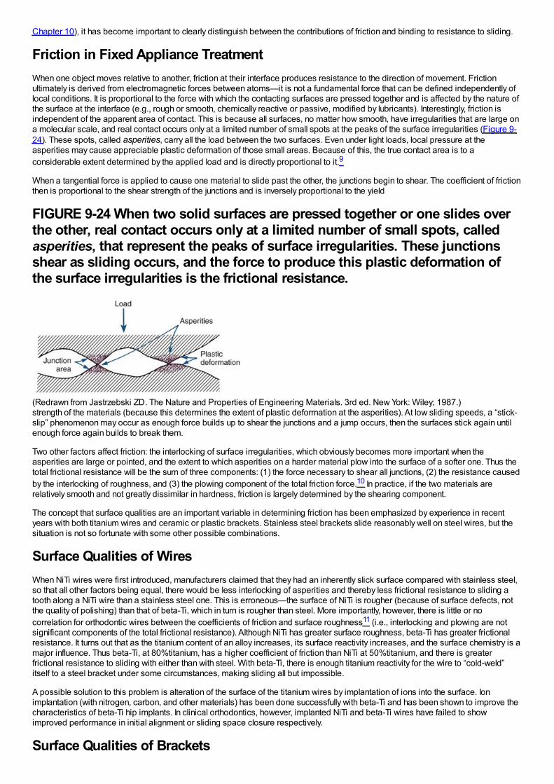
Chapter 10), it has become important to clearly distinguish between the contributions of friction and binding to resistance to sliding.
Friction in Fixed Appliance TreatmentWhen one object moves relative to another, friction at their interface produces resistance to the direction of movement. Frictionultimately is derived from electromagnetic forces between atoms—it is not a fundamental force that can be defined independently oflocal conditions. It is proportional to the force with which the contacting surfaces are pressed together and is affected by the nature ofthe surface at the interface (e.g., rough or smooth, chemically reactive or passive, modified by lubricants). Interestingly, friction isindependent of the apparent area of contact. This is because all surfaces, no matter how smooth, have irregularities that are large ona molecular scale, and real contact occurs only at a limited number of small spots at the peaks of the surface irregularities (Figure 9-24). These spots, called asperities, carry all the load between the two surfaces. Even under light loads, local pressure at theasperities may cause appreciable plastic deformation of those small areas. Because of this, the true contact area is to aconsiderable extent determined by the applied load and is directly proportional to it.9
When a tangential force is applied to cause one material to slide past the other, the junctions begin to shear. The coefficient of frictionthen is proportional to the shear strength of the junctions and is inversely proportional to the yield
FIGURE 9-24 When two solid surfaces are pressed together or one slides overthe other, real contact occurs only at a limited number of small spots, calledasperities, that represent the peaks of surface irregularities. These junctionsshear as sliding occurs, and the force to produce this plastic deformation ofthe surface irregularities is the frictional resistance.
(Redrawn from Jastrzebski ZD. The Nature and Properties of Engineering Materials. 3rd ed. New York: Wiley; 1987.)strength of the materials (because this determines the extent of plastic deformation at the asperities). At low sliding speeds, a “stick-slip” phenomenon may occur as enough force builds up to shear the junctions and a jump occurs, then the surfaces stick again untilenough force again builds to break them.
Two other factors affect friction: the interlocking of surface irregularities, which obviously becomes more important when theasperities are large or pointed, and the extent to which asperities on a harder material plow into the surface of a softer one. Thus thetotal frictional resistance will be the sum of three components: (1) the force necessary to shear all junctions, (2) the resistance causedby the interlocking of roughness, and (3) the plowing component of the total friction force.10 In practice, if the two materials arerelatively smooth and not greatly dissimilar in hardness, friction is largely determined by the shearing component.
The concept that surface qualities are an important variable in determining friction has been emphasized by experience in recentyears with both titanium wires and ceramic or plastic brackets. Stainless steel brackets slide reasonably well on steel wires, but thesituation is not so fortunate with some other possible combinations.
Surface Qualities of WiresWhen NiTi wires were first introduced, manufacturers claimed that they had an inherently slick surface compared with stainless steel,so that all other factors being equal, there would be less interlocking of asperities and thereby less frictional resistance to sliding atooth along a NiTi wire than a stainless steel one. This is erroneous—the surface of NiTi is rougher (because of surface defects, notthe quality of polishing) than that of beta-Ti, which in turn is rougher than steel. More importantly, however, there is little or nocorrelation for orthodontic wires between the coefficients of friction and surface roughness11 (i.e., interlocking and plowing are notsignificant components of the total frictional resistance). Although NiTi has greater surface roughness, beta-Ti has greater frictionalresistance. It turns out that as the titanium content of an alloy increases, its surface reactivity increases, and the surface chemistry is amajor influence. Thus beta-Ti, at 80%titanium, has a higher coefficient of friction than NiTi at 50%titanium, and there is greaterfrictional resistance to sliding with either than with steel. With beta-Ti, there is enough titanium reactivity for the wire to “cold-weld”itself to a steel bracket under some circumstances, making sliding all but impossible.
A possible solution to this problem is alteration of the surface of the titanium wires by implantation of ions into the surface. Ionimplantation (with nitrogen, carbon, and other materials) has been done successfully with beta-Ti and has been shown to improve thecharacteristics of beta-Ti hip implants. In clinical orthodontics, however, implanted NiTi and beta-Ti wires have failed to showimproved performance in initial alignment or sliding space closure respectively.
Surface Qualities of Brackets
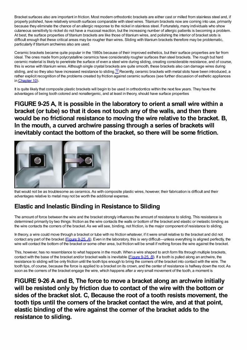
Bracket surfaces also are important in friction. Most modern orthodontic brackets are either cast or milled from stainless steel and, ifproperly polished, have relatively smooth surfaces comparable with steel wires. Titanium brackets now are coming into use, primarilybecause they eliminate the chance of an allergic response to the nickel in stainless steel. Fortunately, many individuals who showcutaneous sensitivity to nickel do not have a mucosal reaction, but the increasing number of allergic patients is becoming a problem.At best, the surface properties of titanium brackets are like those of titanium wires, and polishing the interior of bracket slots isdifficult enough that these critical areas may be rougher than wires. Sliding with titanium brackets therefore may be problematic,particularly if titanium archwires also are used.
Ceramic brackets became quite popular in the 1980s because of their improved esthetics, but their surface properties are far fromideal. The ones made from polycrystalline ceramics have considerably rougher surfaces than steel brackets. The rough but hardceramic material is likely to penetrate the surface of even a steel wire during sliding, creating considerable resistance, and of course,this is worse with titanium wires. Although single crystal brackets are quite smooth, these brackets also can damage wires duringsliding, and so they also have increased resistance to sliding.12 Recently, ceramic brackets with metal slots have been introduced, arather explicit recognition of the problems created by friction against ceramic surfaces (see further discussion of esthetic appliancesin Chapter 10).
It is quite likely that composite plastic brackets will begin to be used in orthodontics within the next few years. They have theadvantages of being tooth colored and nonallergenic, and at least in theory, should have surface properties
FIGURE 9-25 A, It is possible in the laboratory to orient a small wire within abracket (or tube) so that it does not touch any of the walls, and then therewould be no frictional resistance to moving the wire relative to the bracket. B,In the mouth, a curved archwire passing through a series of brackets willinevitably contact the bottom of the bracket, so there will be some friction.
that would not be as troublesome as ceramics. As with composite plastic wires, however, their fabrication is difficult and theiradvantages relative to metal may not be worth the additional expense.
Elastic and Inelastic Binding in Resistance to SlidingThe amount of force between the wire and the bracket strongly influences the amount of resistance to sliding. This resistance isdetermined primarily by two things: friction as the wire contacts the walls or bottom of the bracket and elastic or inelastic binding asthe wire contacts the corners of the bracket. As we will see, binding, not friction, is the major component of resistance to sliding.
In theory, a wire could move through a bracket or tube with no friction whatever, if it were small relative to the bracket and did notcontact any part of the bracket (Figure 9-25, A). Even in the laboratory, this is very difficult—unless everything is aligned perfectly, thewire will contact the bottom of the bracket or some other area, but friction will be small if nothing forces the wire against the bracket.
This, however, has no resemblance to what happens in the mouth. When a wire shaped to arch form fits through multiple brackets,contact with the base of the bracket and/or bracket walls is inevitable (Figure 9-25, B). If a tooth is pulled along an archwire, theresistance to sliding will be only friction until the tooth tips enough to bring the corners of the bracket into contact with the wire. Thetooth tips, of course, because the force is applied to a bracket on its crown, and the center of resistance is halfway down the root. Assoon as the corners of the bracket engage the wire, which happens after a very small movement of the tooth, a moment is
FIGURE 9-26 A and B, The force to move a bracket along an archwire initiallywill be resisted only by friction due to contact of the wire with the bottom orsides of the bracket slot. C, Because the root of a tooth resists movement, thetooth tips until the corners of the bracket contact the wire, and at that point,elastic binding of the wire against the corner of the bracket adds to theresistance to sliding.
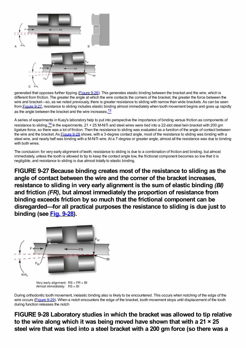
generated that opposes further tipping (Figure 9-26). This generates elastic binding between the bracket and the wire, which isdifferent from friction. The greater the angle at which the wire contacts the corners of the bracket, the greater the force between thewire and bracket—so, as we noted previously, there is greater resistance to sliding with narrow than wide brackets. As can be seenfrom Figure 9-27, resistance to sliding includes elastic binding almost immediately when tooth movement begins and goes up rapidlyas the angle between the bracket and the wire increases.13
A series of experiments in Kusy's laboratory help to put into perspective the importance of binding versus friction as components ofresistance to sliding.14 In the experiments, 21 × 25 M-NiTi and steel wires were tied into a 22-slot steel twin bracket with 200 gmligature force, so there was a lot of friction. Then the resistance to sliding was evaluated as a function of the angle of contact betweenthe wire and the bracket. As Figure 9-28 shows, with a 3-degree contact angle, most of the resistance to sliding was binding with asteel wire, and nearly half was binding with a M-NiTi wire. At a 7-degree or greater angle, almost all the resistance was due to bindingwith both wires.
The conclusion: for very early alignment of teeth, resistance to sliding is due to a combination of friction and binding, but almostimmediately, unless the tooth is allowed to tip to keep the contact angle low, the frictional component becomes so low that it isnegligible, and resistance to sliding is due almost totally to elastic binding.
FIGURE 9-27 Because binding creates most of the resistance to sliding as theangle of contact between the wire and the corner of the bracket increases,resistance to sliding in very early alignment is the sum of elastic binding (BI)and friction (FR), but almost immediately the proportion of resistance frombinding exceeds friction by so much that the frictional component can bedisregarded—for all practical purposes the resistance to sliding is due just tobinding (see Fig. 9-28).
During orthodontic tooth movement, inelastic binding also is likely to be encountered. This occurs when notching of the edge of thewire occurs (Figure 9-29). When a notch encounters the edge of the bracket, tooth movement stops until displacement of the toothduring function releases the notch
FIGURE 9-28 Laboratory studies in which the bracket was allowed to tip relativeto the wire along which it was being moved have shown that with a 21 × 25steel wire that was tied into a steel bracket with a 200 gm force (so there was a
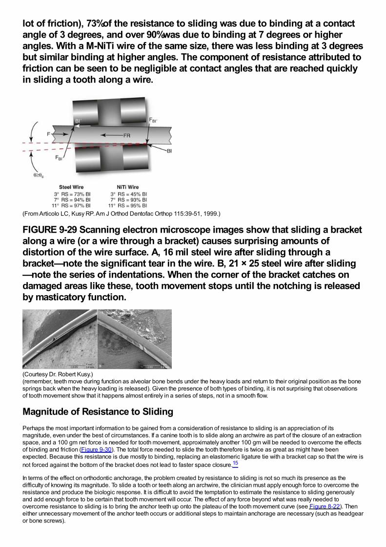
lot of friction), 73%of the resistance to sliding was due to binding at a contactangle of 3 degrees, and over 90%was due to binding at 7 degrees or higherangles. With a M-NiTi wire of the same size, there was less binding at 3 degreesbut similar binding at higher angles. The component of resistance attributed tofriction can be seen to be negligible at contact angles that are reached quicklyin sliding a tooth along a wire.
(From Articolo LC, Kusy RP. Am J Orthod Dentofac Orthop 115:39-51, 1999.)
FIGURE 9-29 Scanning electron microscope images show that sliding a bracketalong a wire (or a wire through a bracket) causes surprising amounts ofdistortion of the wire surface. A, 16 mil steel wire after sliding through abracket—note the significant tear in the wire. B, 21 × 25 steel wire after sliding—note the series of indentations. When the corner of the bracket catches ondamaged areas like these, tooth movement stops until the notching is releasedby masticatory function.
(Courtesy Dr. Robert Kusy.)(remember, teeth move during function as alveolar bone bends under the heavy loads and return to their original position as the bonesprings back when the heavy loading is released). Given the presence of both types of binding, it is not surprising that observationsof tooth movement show that it happens almost entirely in a series of steps, not in a smooth flow.
Magnitude of Resistance to SlidingPerhaps the most important information to be gained from a consideration of resistance to sliding is an appreciation of itsmagnitude, even under the best of circumstances. If a canine tooth is to slide along an archwire as part of the closure of an extractionspace, and a 100 gm net force is needed for tooth movement, approximately another 100 gm will be needed to overcome the effectsof binding and friction (Figure 9-30). The total force needed to slide the tooth therefore is twice as great as might have beenexpected. Because this resistance is due mostly to binding, replacing an elastomeric ligature tie with a bracket cap so that the wire isnot forced against the bottom of the bracket does not lead to faster space closure.15
In terms of the effect on orthodontic anchorage, the problem created by resistance to sliding is not so much its presence as thedifficulty of knowing its magnitude. To slide a tooth or teeth along an archwire, the clinician must apply enough force to overcome theresistance and produce the biologic response. It is difficult to avoid the temptation to estimate the resistance to sliding generouslyand add enough force to be certain that tooth movement will occur. The effect of any force beyond what was really needed toovercome resistance to sliding is to bring the anchor teeth up onto the plateau of the tooth movement curve (see Figure 8-22). Theneither unnecessary movement of the anchor teeth occurs or additional steps to maintain anchorage are necessary (such as headgearor bone screws).
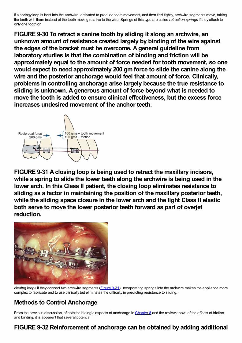
If a springy loop is bent into the archwire, activated to produce tooth movement, and then tied tightly, archwire segments move, takingthe teeth with them instead of the teeth moving relative to the wire. Springs of this type are called retraction springs if they attach toonly one tooth or
FIGURE 9-30 To retract a canine tooth by sliding it along an archwire, anunknown amount of resistance created largely by binding of the wire againstthe edges of the bracket must be overcome. A general guideline fromlaboratory studies is that the combination of binding and friction will beapproximately equal to the amount of force needed for tooth movement, so onewould expect to need approximately 200 gm force to slide the canine along thewire and the posterior anchorage would feel that amount of force. Clinically,problems in controlling anchorage arise largely because the true resistance tosliding is unknown. A generous amount of force beyond what is needed tomove the tooth is added to ensure clinical effectiveness, but the excess forceincreases undesired movement of the anchor teeth.
FIGURE 9-31 A closing loop is being used to retract the maxillary incisors,while a spring to slide the lower teeth along the archwire is being used in thelower arch. In this Class II patient, the closing loop eliminates resistance tosliding as a factor in maintaining the position of the maxillary posterior teeth,while the sliding space closure in the lower arch and the light Class II elasticboth serve to move the lower posterior teeth forward as part of overjetreduction.
closing loops if they connect two archwire segments (Figure 9-31). Incorporating springs into the archwire makes the appliance morecomplex to fabricate and to use clinically but eliminates the difficulty in predicting resistance to sliding.
Methods to Control AnchorageFrom the previous discussion, of both the biologic aspects of anchorage in Chapter 8 and the review above of the effects of frictionand binding, it is apparent that several potential
FIGURE 9-32 Reinforcement of anchorage can be obtained by adding additional
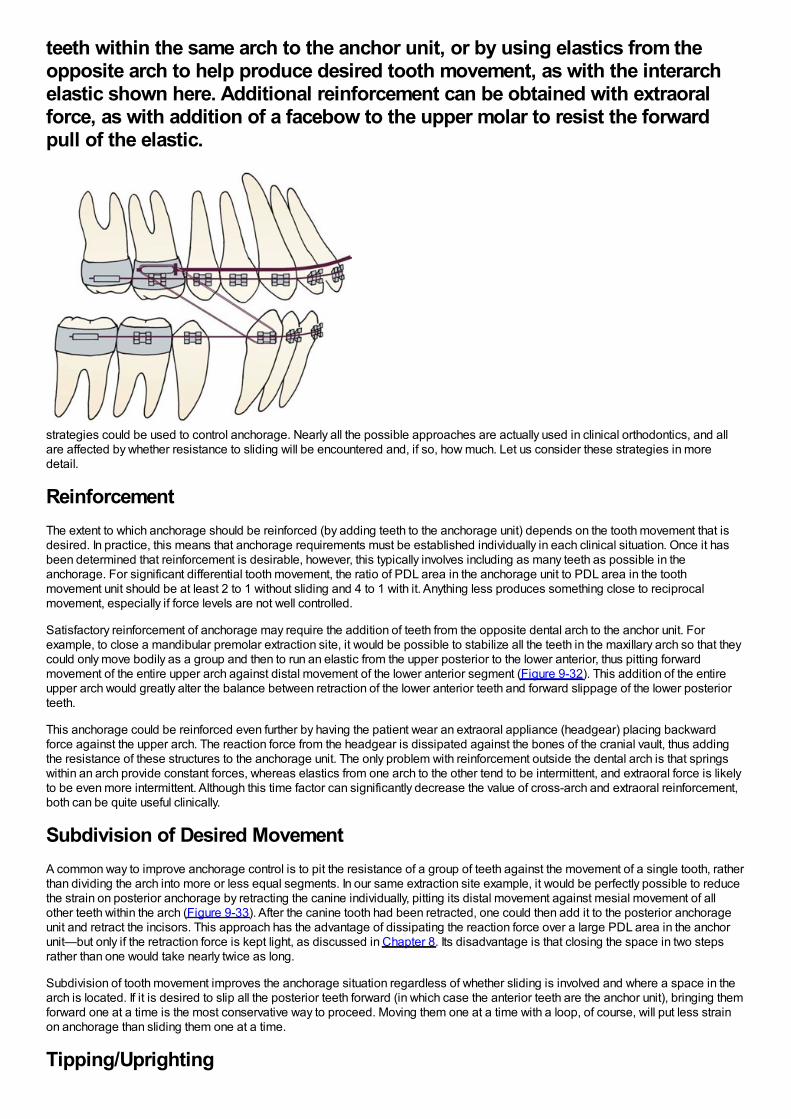
teeth within the same arch to the anchor unit, or by using elastics from theopposite arch to help produce desired tooth movement, as with the interarchelastic shown here. Additional reinforcement can be obtained with extraoralforce, as with addition of a facebow to the upper molar to resist the forwardpull of the elastic.
strategies could be used to control anchorage. Nearly all the possible approaches are actually used in clinical orthodontics, and allare affected by whether resistance to sliding will be encountered and, if so, how much. Let us consider these strategies in moredetail.
ReinforcementThe extent to which anchorage should be reinforced (by adding teeth to the anchorage unit) depends on the tooth movement that isdesired. In practice, this means that anchorage requirements must be established individually in each clinical situation. Once it hasbeen determined that reinforcement is desirable, however, this typically involves including as many teeth as possible in theanchorage. For significant differential tooth movement, the ratio of PDL area in the anchorage unit to PDL area in the toothmovement unit should be at least 2 to 1 without sliding and 4 to 1 with it. Anything less produces something close to reciprocalmovement, especially if force levels are not well controlled.
Satisfactory reinforcement of anchorage may require the addition of teeth from the opposite dental arch to the anchor unit. Forexample, to close a mandibular premolar extraction site, it would be possible to stabilize all the teeth in the maxillary arch so that theycould only move bodily as a group and then to run an elastic from the upper posterior to the lower anterior, thus pitting forwardmovement of the entire upper arch against distal movement of the lower anterior segment (Figure 9-32). This addition of the entireupper arch would greatly alter the balance between retraction of the lower anterior teeth and forward slippage of the lower posteriorteeth.
This anchorage could be reinforced even further by having the patient wear an extraoral appliance (headgear) placing backwardforce against the upper arch. The reaction force from the headgear is dissipated against the bones of the cranial vault, thus addingthe resistance of these structures to the anchorage unit. The only problem with reinforcement outside the dental arch is that springswithin an arch provide constant forces, whereas elastics from one arch to the other tend to be intermittent, and extraoral force is likelyto be even more intermittent. Although this time factor can significantly decrease the value of cross-arch and extraoral reinforcement,both can be quite useful clinically.
Subdivision of Desired MovementA common way to improve anchorage control is to pit the resistance of a group of teeth against the movement of a single tooth, ratherthan dividing the arch into more or less equal segments. In our same extraction site example, it would be perfectly possible to reducethe strain on posterior anchorage by retracting the canine individually, pitting its distal movement against mesial movement of allother teeth within the arch (Figure 9-33). After the canine tooth had been retracted, one could then add it to the posterior anchorageunit and retract the incisors. This approach has the advantage of dissipating the reaction force over a large PDL area in the anchorunit—but only if the retraction force is kept light, as discussed in Chapter 8. Its disadvantage is that closing the space in two stepsrather than one would take nearly twice as long.
Subdivision of tooth movement improves the anchorage situation regardless of whether sliding is involved and where a space in thearch is located. If it is desired to slip all the posterior teeth forward (in which case the anterior teeth are the anchor unit), bringing themforward one at a time is the most conservative way to proceed. Moving them one at a time with a loop, of course, will put less strainon anchorage than sliding them one at a time.
Tipping/Uprighting
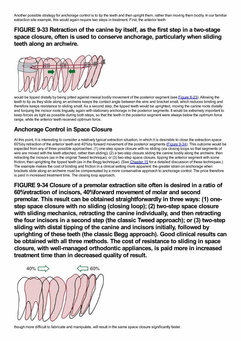
Another possible strategy for anchorage control is to tip the teeth and then upright them, rather than moving them bodily. In our familiarextraction site example, this would again require two steps in treatment. First, the anterior teeth
FIGURE 9-33 Retraction of the canine by itself, as the first step in a two-stagespace closure, often is used to conserve anchorage, particularly when slidingteeth along an archwire.
would be tipped distally by being pitted against mesial bodily movement of the posterior segment (see Figure 8-23). Allowing theteeth to tip as they slide along an archwire keeps the contact angle between the wire and bracket small, which reduces binding andtherefore keeps resistance to sliding small. As a second step, the tipped teeth would be uprighted, moving the canine roots distallyand torquing the incisor roots lingually, again with stationary anchorage in the posterior segments. It would be extremely important tokeep forces as light as possible during both steps, so that the teeth in the posterior segment were always below the optimum forcerange, while the anterior teeth received optimum force.
Anchorage Control in Space ClosureAt this point, it is interesting to consider a relatively typical extraction situation, in which it is desirable to close the extraction space60%by retraction of the anterior teeth and 40%by forward movement of the posterior segments (Figure 9-34). This outcome would beexpected from any of three possible approaches: (1) one-step space closure with no sliding (via closing loops so that segments ofwire are moved with the teeth attached, rather than sliding); (2) a two-step closure sliding the canine bodily along the archwire, thenretracting the incisors (as in the original Tweed technique); or (3) two-step space closure, tipping the anterior segment with somefriction, then uprighting the tipped teeth (as in the Begg technique). (See Chapter 15 for a detailed discussion of these techniques.)The example makes the cost of binding and friction in a clinical setting more apparent: the greater strain on anchorage whenbrackets slide along an archwire must be compensated by a more conservative approach to anchorage control. The price thereforeis paid in increased treatment time. The closing loop approach,
FIGURE 9-34 Closure of a premolar extraction site often is desired in a ratio of60%retraction of incisors, 40%forward movement of molar and secondpremolar. This result can be obtained straightforwardly in three ways: (1) one-step space closure with no sliding (closing loop); (2) two-step space closurewith sliding mechanics, retracting the canine individually, and then retractingthe four incisors in a second step (the classic Tweed approach); or (3) two-stepsliding with distal tipping of the canine and incisors initially, followed byuprighting of these teeth (the classic Begg approach). Good clinical results canbe obtained with all three methods. The cost of resistance to sliding in spaceclosure, with well-managed orthodontic appliances, is paid more in increasedtreatment time than in decreased quality of result.
though more difficult to fabricate and manipulate, will result in the same space closure significantly faster.
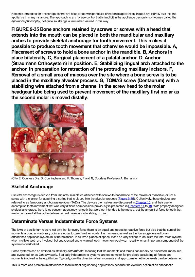
Note that strategies for anchorage control are associated with particular orthodontic appliances, indeed are literally built into theappliance in many instances. The approach to anchorage control that is implicit in the appliance design is sometimes called theappliance philosophy, not quite so strange a term when viewed in this way.
FIGURE 9-35 Bone anchors retained by screws or screws with a head thatextends into the mouth can be placed in both the mandibular and maxillaryarches to provide skeletal anchorage for tooth movement. This makes itpossible to produce tooth movement that otherwise would be impossible. A,Placement of screws to hold a bone anchor in the mandible. B, Anchors inplace bilaterally. C, Surgical placement of a palatal anchor. D, Anchor(Straumann Orthosystem) in position. E, Stabilizing lingual arch attached to theanchor, in preparation for retraction of the protruding maxillary incisors. F,Removal of a small area of mucosa over the site where a bone screw is to beplaced in the maxillary alveolar process. G, TOMAS screw (Dentaurum) with astabilizing wire attached from a channel in the screw head to the molarheadgear tube being used to prevent movement of the maxillary first molar asthe second molar is moved distally.
(C to E, Courtesy Drs. S. Cunningham and P. Thomas; F and G, Courtesy Professor A. Bumann.)
Skeletal AnchorageSkeletal anchorage is derived from implants, miniplates attached with screws to basal bone of the maxilla or mandible, or just ascrew with a channel for attaching a spring that is placed into the alveolar process (Figure 9-35). Collectively, these devices arereferred to as temporary anchorage devices (TADs). The devices themselves are discussed in Chapter 10, and their use toaccomplish tooth movement that was very difficult or impossible previously is presented in Chapters 14 to 18. With properly designedskeletal anchorage, there is no concern about moving teeth that were not intended to be moved, but the amount of force to teeth thatare to be moved still must be determined with resistance to sliding in mind.
Determinate Versus Indeterminate Force SystemsThe laws of equilibrium require not only that for every force there is an equal and opposite reactive force but also that the sum of themoments around any arbitrary point are equal to zero. In other words, the moments, as well as the forces, generated by anorthodontic appliance system must be balanced, in all three planes of space. It can be very difficult to visualize the total force systemwhen multiple teeth are involved, but unexpected and unwanted tooth movement easily can result when an important component of thesystem is overlooked.
Force systems can be defined as statically determinate, meaning that the moments and forces can readily be discerned, measured,and evaluated, or as indeterminate. Statically indeterminate systems are too complex for precisely calculating all forces andmoments involved in the equilibrium. Typically, only the direction of net moments and approximate net force levels can be determined.
This is more of a problem in orthodontics than in most engineering applications because the eventual action of an orthodontic
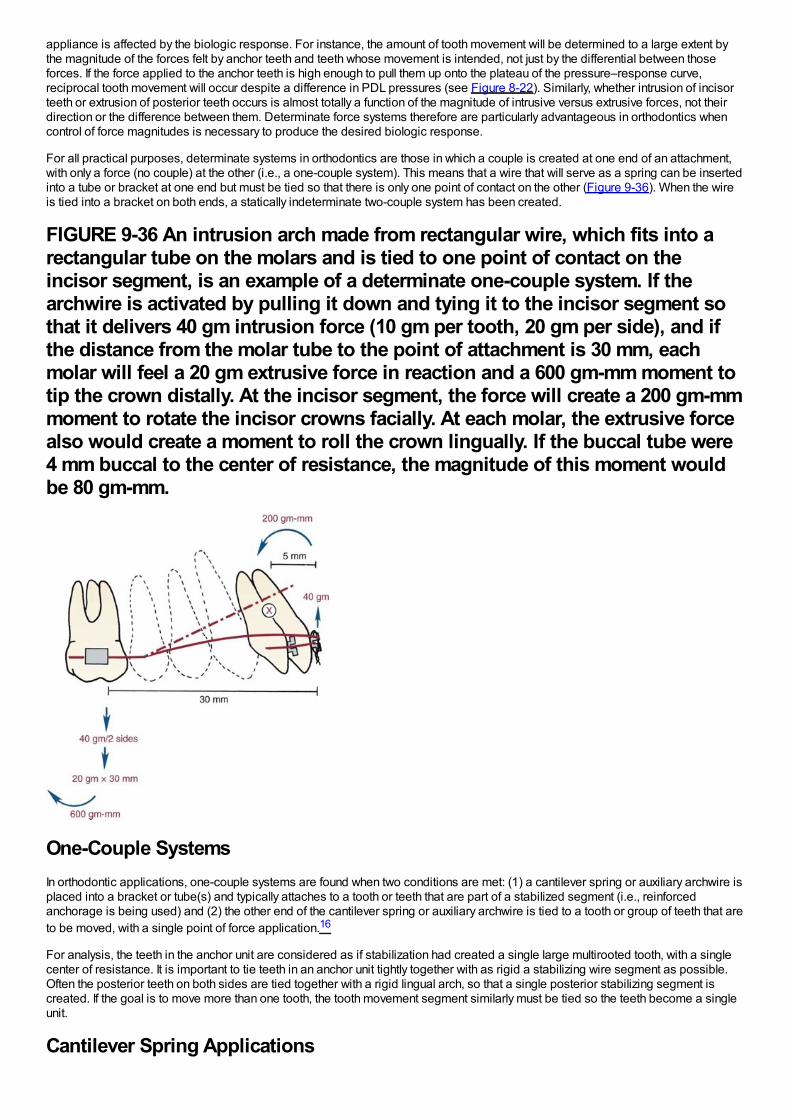
appliance is affected by the biologic response. For instance, the amount of tooth movement will be determined to a large extent bythe magnitude of the forces felt by anchor teeth and teeth whose movement is intended, not just by the differential between thoseforces. If the force applied to the anchor teeth is high enough to pull them up onto the plateau of the pressure–response curve,reciprocal tooth movement will occur despite a difference in PDL pressures (see Figure 8-22). Similarly, whether intrusion of incisorteeth or extrusion of posterior teeth occurs is almost totally a function of the magnitude of intrusive versus extrusive forces, not theirdirection or the difference between them. Determinate force systems therefore are particularly advantageous in orthodontics whencontrol of force magnitudes is necessary to produce the desired biologic response.
For all practical purposes, determinate systems in orthodontics are those in which a couple is created at one end of an attachment,with only a force (no couple) at the other (i.e., a one-couple system). This means that a wire that will serve as a spring can be insertedinto a tube or bracket at one end but must be tied so that there is only one point of contact on the other (Figure 9-36). When the wireis tied into a bracket on both ends, a statically indeterminate two-couple system has been created.
FIGURE 9-36 An intrusion arch made from rectangular wire, which fits into arectangular tube on the molars and is tied to one point of contact on theincisor segment, is an example of a determinate one-couple system. If thearchwire is activated by pulling it down and tying it to the incisor segment sothat it delivers 40 gm intrusion force (10 gm per tooth, 20 gm per side), and ifthe distance from the molar tube to the point of attachment is 30 mm, eachmolar will feel a 20 gm extrusive force in reaction and a 600 gm-mm moment totip the crown distally. At the incisor segment, the force will create a 200 gm-mmmoment to rotate the incisor crowns facially. At each molar, the extrusive forcealso would create a moment to roll the crown lingually. If the buccal tube were4 mm buccal to the center of resistance, the magnitude of this moment wouldbe 80 gm-mm.
One-Couple SystemsIn orthodontic applications, one-couple systems are found when two conditions are met: (1) a cantilever spring or auxiliary archwire isplaced into a bracket or tube(s) and typically attaches to a tooth or teeth that are part of a stabilized segment (i.e., reinforcedanchorage is being used) and (2) the other end of the cantilever spring or auxiliary archwire is tied to a tooth or group of teeth that areto be moved, with a single point of force application.16
For analysis, the teeth in the anchor unit are considered as if stabilization had created a single large multirooted tooth, with a singlecenter of resistance. It is important to tie teeth in an anchor unit tightly together with as rigid a stabilizing wire segment as possible.Often the posterior teeth on both sides are tied together with a rigid lingual arch, so that a single posterior stabilizing segment iscreated. If the goal is to move more than one tooth, the tooth movement segment similarly must be tied so the teeth become a singleunit.
Cantilever Spring Applications
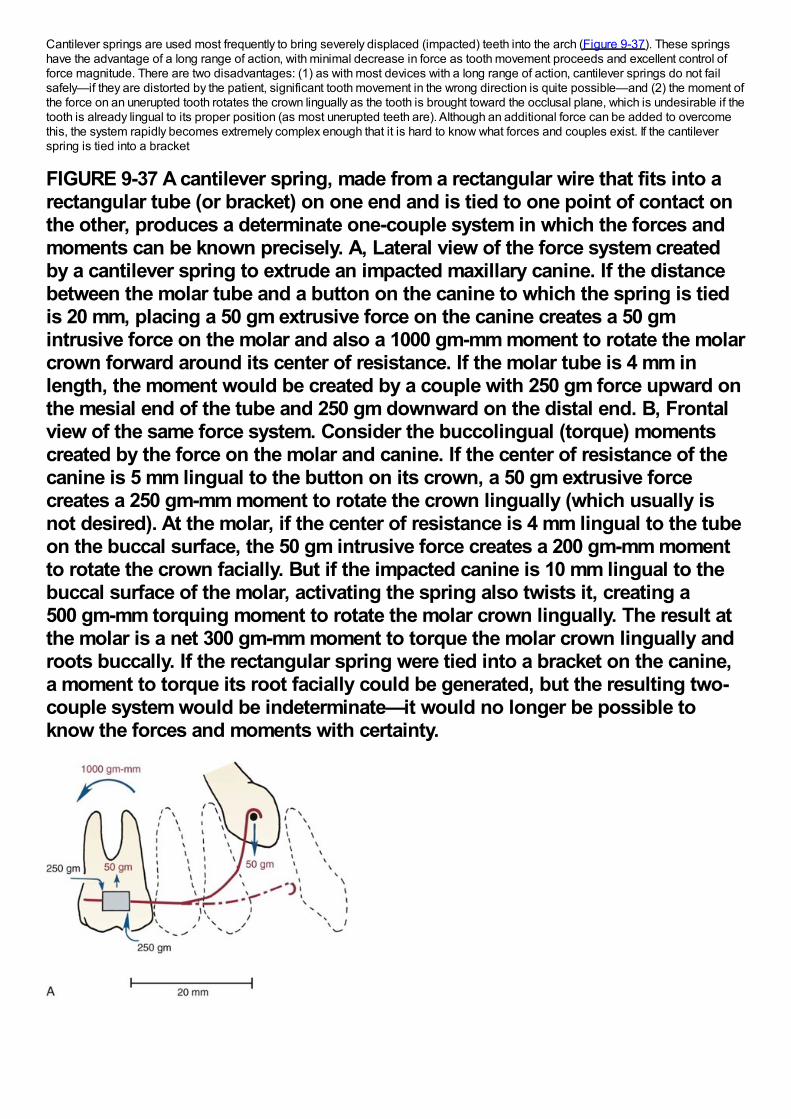
Cantilever springs are used most frequently to bring severely displaced (impacted) teeth into the arch (Figure 9-37). These springshave the advantage of a long range of action, with minimal decrease in force as tooth movement proceeds and excellent control offorce magnitude. There are two disadvantages: (1) as with most devices with a long range of action, cantilever springs do not failsafely—if they are distorted by the patient, significant tooth movement in the wrong direction is quite possible—and (2) the moment ofthe force on an unerupted tooth rotates the crown lingually as the tooth is brought toward the occlusal plane, which is undesirable if thetooth is already lingual to its proper position (as most unerupted teeth are). Although an additional force can be added to overcomethis, the system rapidly becomes extremely complex enough that it is hard to know what forces and couples exist. If the cantileverspring is tied into a bracket
FIGURE 9-37 A cantilever spring, made from a rectangular wire that fits into arectangular tube (or bracket) on one end and is tied to one point of contact onthe other, produces a determinate one-couple system in which the forces andmoments can be known precisely. A, Lateral view of the force system createdby a cantilever spring to extrude an impacted maxillary canine. If the distancebetween the molar tube and a button on the canine to which the spring is tiedis 20 mm, placing a 50 gm extrusive force on the canine creates a 50 gmintrusive force on the molar and also a 1000 gm-mm moment to rotate the molarcrown forward around its center of resistance. If the molar tube is 4 mm inlength, the moment would be created by a couple with 250 gm force upward onthe mesial end of the tube and 250 gm downward on the distal end. B, Frontalview of the same force system. Consider the buccolingual (torque) momentscreated by the force on the molar and canine. If the center of resistance of thecanine is 5 mm lingual to the button on its crown, a 50 gm extrusive forcecreates a 250 gm-mm moment to rotate the crown lingually (which usually isnot desired). At the molar, if the center of resistance is 4 mm lingual to the tubeon the buccal surface, the 50 gm intrusive force creates a 200 gm-mm momentto rotate the crown facially. But if the impacted canine is 10 mm lingual to thebuccal surface of the molar, activating the spring also twists it, creating a500 gm-mm torquing moment to rotate the molar crown lingually. The result atthe molar is a net 300 gm-mm moment to torque the molar crown lingually androots buccally. If the rectangular spring were tied into a bracket on the canine,a moment to torque its root facially could be generated, but the resulting two-couple system would be indeterminate—it would no longer be possible toknow the forces and moments with certainty.
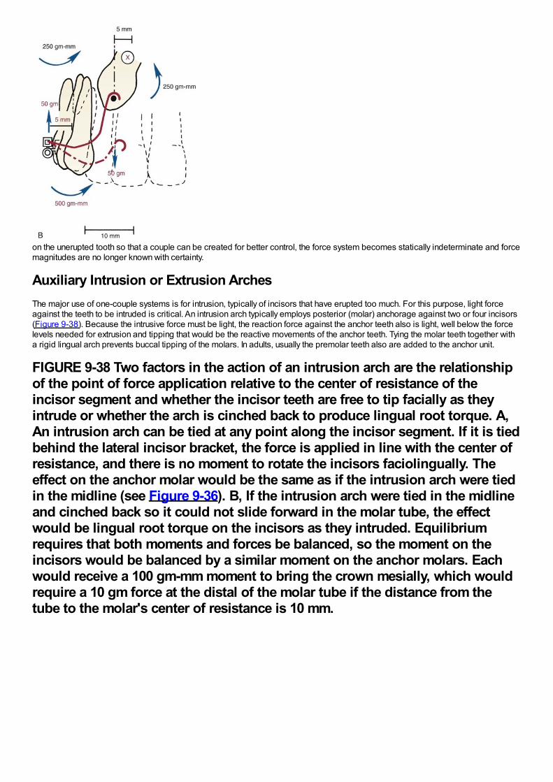
on the unerupted tooth so that a couple can be created for better control, the force system becomes statically indeterminate and forcemagnitudes are no longer known with certainty.
Auxiliary Intrusion or Extrusion ArchesThe major use of one-couple systems is for intrusion, typically of incisors that have erupted too much. For this purpose, light forceagainst the teeth to be intruded is critical. An intrusion arch typically employs posterior (molar) anchorage against two or four incisors(Figure 9-38). Because the intrusive force must be light, the reaction force against the anchor teeth also is light, well below the forcelevels needed for extrusion and tipping that would be the reactive movements of the anchor teeth. Tying the molar teeth together witha rigid lingual arch prevents buccal tipping of the molars. In adults, usually the premolar teeth also are added to the anchor unit.
FIGURE 9-38 Two factors in the action of an intrusion arch are the relationshipof the point of force application relative to the center of resistance of theincisor segment and whether the incisor teeth are free to tip facially as theyintrude or whether the arch is cinched back to produce lingual root torque. A,An intrusion arch can be tied at any point along the incisor segment. If it is tiedbehind the lateral incisor bracket, the force is applied in line with the center ofresistance, and there is no moment to rotate the incisors faciolingually. Theeffect on the anchor molar would be the same as if the intrusion arch were tiedin the midline (see Figure 9-36). B, If the intrusion arch were tied in the midlineand cinched back so it could not slide forward in the molar tube, the effectwould be lingual root torque on the incisors as they intruded. Equilibriumrequires that both moments and forces be balanced, so the moment on theincisors would be balanced by a similar moment on the anchor molars. Eachwould receive a 100 gm-mm moment to bring the crown mesially, which wouldrequire a 10 gm force at the distal of the molar tube if the distance from thetube to the molar's center of resistance is 10 mm.
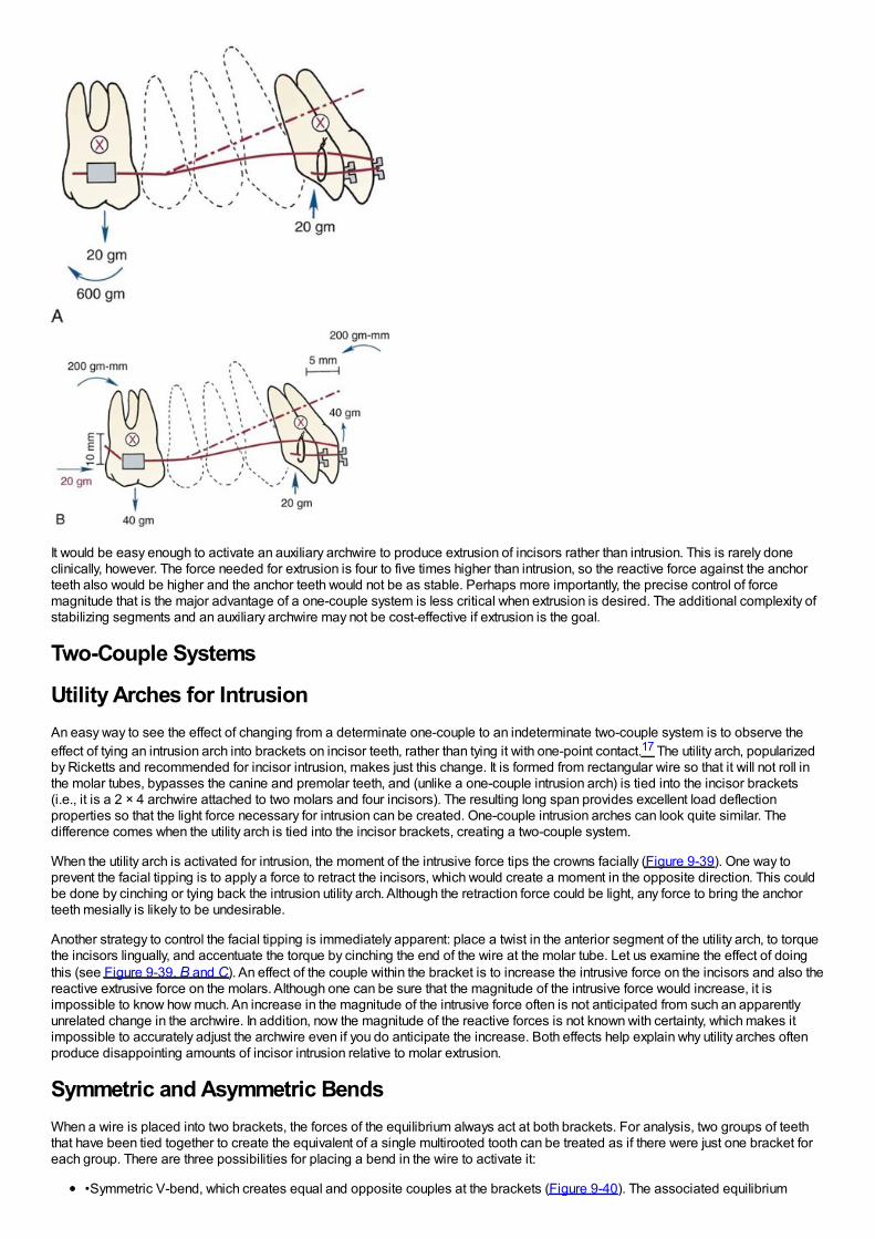
It would be easy enough to activate an auxiliary archwire to produce extrusion of incisors rather than intrusion. This is rarely doneclinically, however. The force needed for extrusion is four to five times higher than intrusion, so the reactive force against the anchorteeth also would be higher and the anchor teeth would not be as stable. Perhaps more importantly, the precise control of forcemagnitude that is the major advantage of a one-couple system is less critical when extrusion is desired. The additional complexity ofstabilizing segments and an auxiliary archwire may not be cost-effective if extrusion is the goal.
Two-Couple Systems
Utility Arches for IntrusionAn easy way to see the effect of changing from a determinate one-couple to an indeterminate two-couple system is to observe theeffect of tying an intrusion arch into brackets on incisor teeth, rather than tying it with one-point contact.17 The utility arch, popularizedby Ricketts and recommended for incisor intrusion, makes just this change. It is formed from rectangular wire so that it will not roll inthe molar tubes, bypasses the canine and premolar teeth, and (unlike a one-couple intrusion arch) is tied into the incisor brackets(i.e., it is a 2 × 4 archwire attached to two molars and four incisors). The resulting long span provides excellent load deflectionproperties so that the light force necessary for intrusion can be created. One-couple intrusion arches can look quite similar. Thedifference comes when the utility arch is tied into the incisor brackets, creating a two-couple system.
When the utility arch is activated for intrusion, the moment of the intrusive force tips the crowns facially (Figure 9-39). One way toprevent the facial tipping is to apply a force to retract the incisors, which would create a moment in the opposite direction. This couldbe done by cinching or tying back the intrusion utility arch. Although the retraction force could be light, any force to bring the anchorteeth mesially is likely to be undesirable.
Another strategy to control the facial tipping is immediately apparent: place a twist in the anterior segment of the utility arch, to torquethe incisors lingually, and accentuate the torque by cinching the end of the wire at the molar tube. Let us examine the effect of doingthis (see Figure 9-39, B and C). An effect of the couple within the bracket is to increase the intrusive force on the incisors and also thereactive extrusive force on the molars. Although one can be sure that the magnitude of the intrusive force would increase, it isimpossible to know how much. An increase in the magnitude of the intrusive force often is not anticipated from such an apparentlyunrelated change in the archwire. In addition, now the magnitude of the reactive forces is not known with certainty, which makes itimpossible to accurately adjust the archwire even if you do anticipate the increase. Both effects help explain why utility arches oftenproduce disappointing amounts of incisor intrusion relative to molar extrusion.
Symmetric and Asymmetric BendsWhen a wire is placed into two brackets, the forces of the equilibrium always act at both brackets. For analysis, two groups of teeththat have been tied together to create the equivalent of a single multirooted tooth can be treated as if there were just one bracket foreach group. There are three possibilities for placing a bend in the wire to activate it:
•Symmetric V-bend, which creates equal and opposite couples at the brackets (Figure 9-40). The associated equilibrium
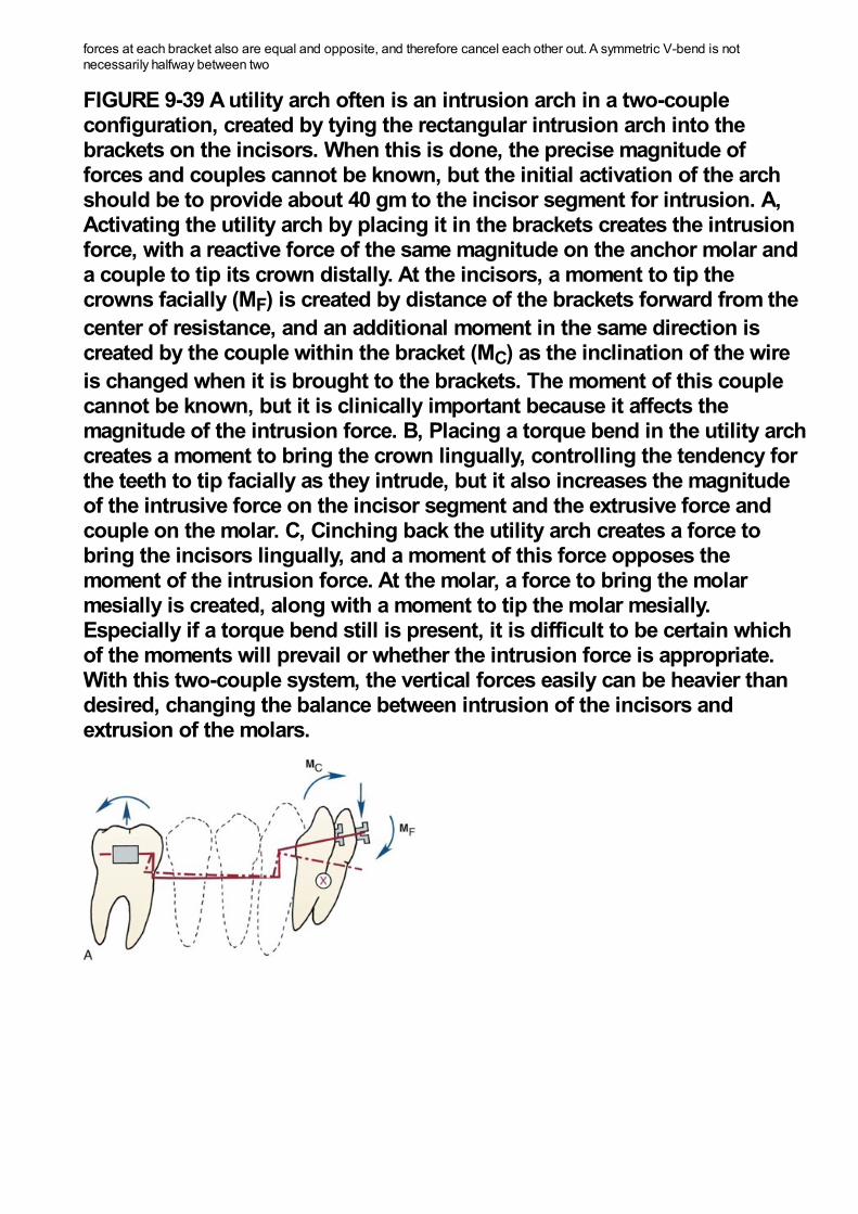
forces at each bracket also are equal and opposite, and therefore cancel each other out. A symmetric V-bend is notnecessarily halfway between two
FIGURE 9-39 A utility arch often is an intrusion arch in a two-coupleconfiguration, created by tying the rectangular intrusion arch into thebrackets on the incisors. When this is done, the precise magnitude offorces and couples cannot be known, but the initial activation of the archshould be to provide about 40 gm to the incisor segment for intrusion. A,Activating the utility arch by placing it in the brackets creates the intrusionforce, with a reactive force of the same magnitude on the anchor molar anda couple to tip its crown distally. At the incisors, a moment to tip thecrowns facially (MF) is created by distance of the brackets forward from thecenter of resistance, and an additional moment in the same direction iscreated by the couple within the bracket (MC) as the inclination of the wireis changed when it is brought to the brackets. The moment of this couplecannot be known, but it is clinically important because it affects themagnitude of the intrusion force. B, Placing a torque bend in the utility archcreates a moment to bring the crown lingually, controlling the tendency forthe teeth to tip facially as they intrude, but it also increases the magnitudeof the intrusive force on the incisor segment and the extrusive force andcouple on the molar. C, Cinching back the utility arch creates a force tobring the incisors lingually, and a moment of this force opposes themoment of the intrusion force. At the molar, a force to bring the molarmesially is created, along with a moment to tip the molar mesially.Especially if a torque bend still is present, it is difficult to be certain whichof the moments will prevail or whether the intrusion force is appropriate.With this two-couple system, the vertical forces easily can be heavier thandesired, changing the balance between intrusion of the incisors andextrusion of the molars.
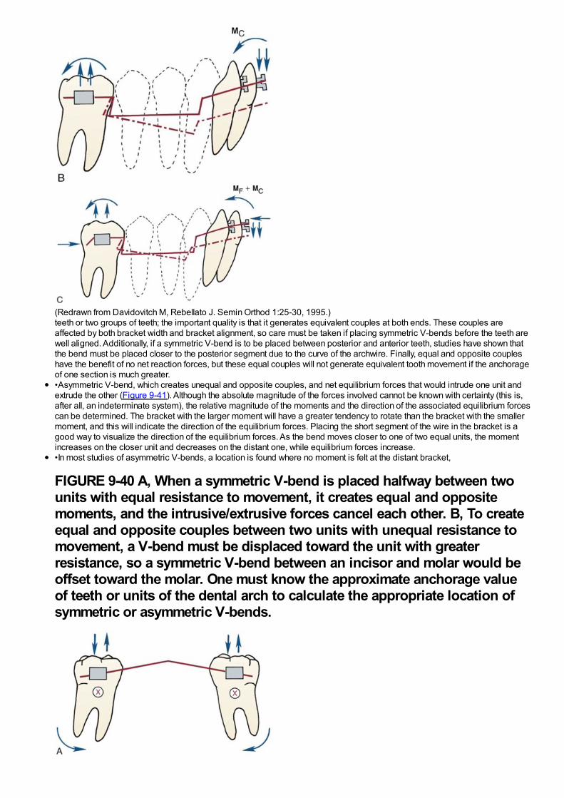
(Redrawn from Davidovitch M, Rebellato J. Semin Orthod 1:25-30, 1995.)teeth or two groups of teeth; the important quality is that it generates equivalent couples at both ends. These couples areaffected by both bracket width and bracket alignment, so care must be taken if placing symmetric V-bends before the teeth arewell aligned. Additionally, if a symmetric V-bend is to be placed between posterior and anterior teeth, studies have shown thatthe bend must be placed closer to the posterior segment due to the curve of the archwire. Finally, equal and opposite coupleshave the benefit of no net reaction forces, but these equal couples will not generate equivalent tooth movement if the anchorageof one section is much greater.•Asymmetric V-bend, which creates unequal and opposite couples, and net equilibrium forces that would intrude one unit andextrude the other (Figure 9-41). Although the absolute magnitude of the forces involved cannot be known with certainty (this is,after all, an indeterminate system), the relative magnitude of the moments and the direction of the associated equilibrium forcescan be determined. The bracket with the larger moment will have a greater tendency to rotate than the bracket with the smallermoment, and this will indicate the direction of the equilibrium forces. Placing the short segment of the wire in the bracket is agood way to visualize the direction of the equilibrium forces. As the bend moves closer to one of two equal units, the momentincreases on the closer unit and decreases on the distant one, while equilibrium forces increase.•In most studies of asymmetric V-bends, a location is found where no moment is felt at the distant bracket,
FIGURE 9-40 A, When a symmetric V-bend is placed halfway between twounits with equal resistance to movement, it creates equal and oppositemoments, and the intrusive/extrusive forces cancel each other. B, To createequal and opposite couples between two units with unequal resistance tomovement, a V-bend must be displaced toward the unit with greaterresistance, so a symmetric V-bend between an incisor and molar would beoffset toward the molar. One must know the approximate anchorage valueof teeth or units of the dental arch to calculate the appropriate location ofsymmetric or asymmetric V-bends.
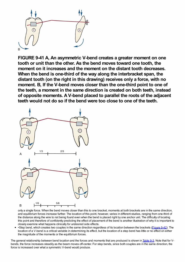
FIGURE 9-41 A, An asymmetric V-bend creates a greater moment on onetooth or unit than the other. As the bend moves toward one tooth, themoment on it increases and the moment on the distant tooth decreases.When the bend is one-third of the way along the interbracket span, thedistant tooth (on the right in this drawing) receives only a force, with nomoment. B, If the V-bend moves closer than the one-third point to one ofthe teeth, a moment in the same direction is created on both teeth, insteadof opposite moments. A V-bend placed to parallel the roots of the adjacentteeth would not do so if the bend were too close to one of the teeth.
only a single force. When the bend moves closer than this to one bracket, moments at both brackets are in the same direction,and equilibrium forces increase further. The location of this point, however, varies in different studies, ranging from one-third ofthe distance along the wire to not being found even when the bend is placed right by one anchor unit. The difficulty of locatingthis point and therefore of confidently predicting the effect of placement of the bend is another illustration of why it is important toclosely examine what happens clinically for undesired side effects.•Step bend, which creates two couples in the same direction regardless of its location between the brackets (Figure 9-42). Thelocation of a V-bend is a critical variable in determining its effect, but the location of a step bend has little or no effect on eitherthe magnitude of the moments or the equilibrium forces.
The general relationship between bend location and the forces and moments that are produced is shown in Table 9-3. Note that for V-bends, the force increases steadily as the beam moves off-center. For step bends, since both couples are in the same direction, theforce is increased over what a symmetric V-bend would produce.
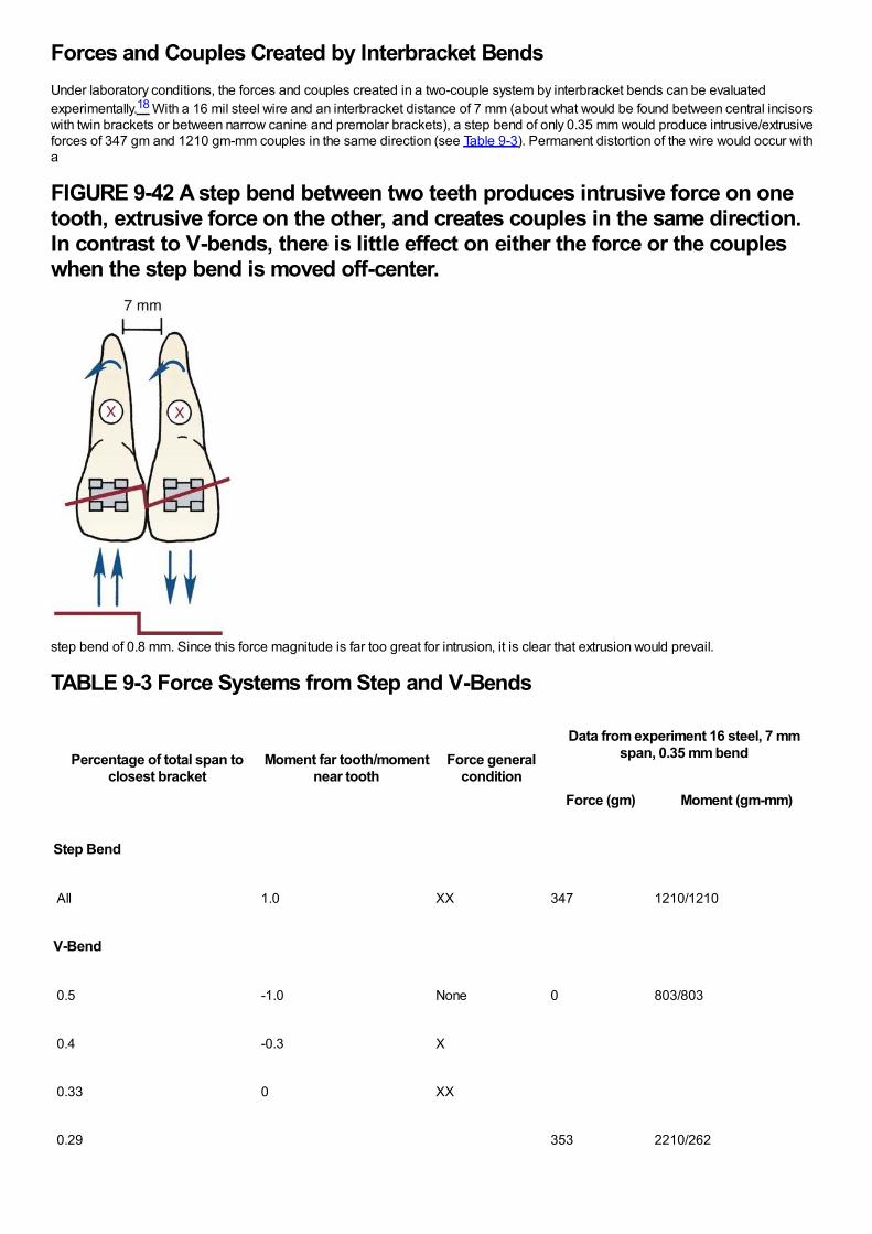
Forces and Couples Created by Interbracket BendsUnder laboratory conditions, the forces and couples created in a two-couple system by interbracket bends can be evaluatedexperimentally.18 With a 16 mil steel wire and an interbracket distance of 7 mm (about what would be found between central incisorswith twin brackets or between narrow canine and premolar brackets), a step bend of only 0.35 mm would produce intrusive/extrusiveforces of 347 gm and 1210 gm-mm couples in the same direction (see Table 9-3). Permanent distortion of the wire would occur witha
FIGURE 9-42 A step bend between two teeth produces intrusive force on onetooth, extrusive force on the other, and creates couples in the same direction.In contrast to V-bends, there is little effect on either the force or the coupleswhen the step bend is moved off-center.
step bend of 0.8 mm. Since this force magnitude is far too great for intrusion, it is clear that extrusion would prevail.
TABLE 9-3 Force Systems from Step and V-Bends
Percentage of total span toclosest bracket
Moment far tooth/momentnear tooth
Force generalcondition
Data from experiment 16 steel, 7 mmspan, 0.35 mm bend
Force (gm) Moment (gm-mm)
Step Bend
All 1.0 XX 347 1210/1210
V-Bend
0.5 -1.0 None 0 803/803
0.4 -0.3 X
0.33 0 XX
0.29 353 2210/262
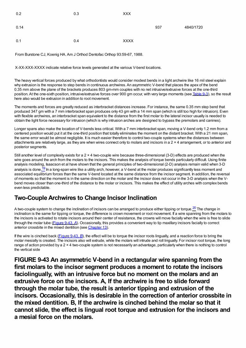
0.2 0.3 XXX
0.14 937 4840/1720
0.1 0.4 XXXX
From Burstone CJ, Koenig HA. Am J Orthod Dentofac Orthop 93:59-67, 1988.
X-XX-XXX-XXXX indicate relative force levels generated at the various V-bend locations.
The heavy vertical forces produced by what orthodontists would consider modest bends in a light archwire like 16 mil steel explainwhy extrusion is the response to step bends in continuous archwires. An asymmetric V-bend that places the apex of the bend0.35 mm above the plane of the brackets produces 803 gm-mm couples with no net intrusive/extrusive forces at the one-thirdposition. At the one-sixth position, intrusive/extrusive forces over 900 gm occur, with very large moments (see Table 9-3), so the resulthere also would be extrusion in addition to root movement.
The moments and forces are greatly reduced as interbracket distances increase. For instance, the same 0.35 mm step bend thatproduced 347 gm with a 7 mm interbracket span produces only 43 gm with a 14 mm span (which is still too high for intrusion). Evenwith flexible archwires, an interbracket span equivalent to the distance from the first molar to the lateral incisor usually is needed toobtain the light force necessary for intrusion (which is why intrusion arches are designed to bypass the premolars and canines).
Longer spans also make the location of V-bends less critical. With a 7 mm interbracket span, moving a V-bend only 1.2 mm from acentered position would put it at the one-third position that totally eliminates the moment on the distant bracket. With a 21 mm span,the same error would be almost negligible. It is much easier therefore to control two-couple systems when the distances betweenattachments are relatively large, as they are when wires connect only to molars and incisors in a 2 × 4 arrangement, or to anterior andposterior segments.
Still another level of complexity exists for a 2 × 4 two-couple wire because three-dimensional (3-D) effects are produced when thewire goes around the arch from the molars to the incisors. This makes the analysis of torque bends particularly difficult. Using finiteanalysis modeling, Isaacson et al have shown that the general principles of two-dimensional (2-D) analysis remain valid when 3-Danalysis is done.19 In a long-span wire like a utility arch, however, a V-bend at the molar produces significantly less moment andassociated equilibrium forces than the same V-bend located at the same distance from the incisor segment. In addition, the reversalof moments so that the moment is in the same direction on the molar and the incisor does not occur in the 3-D analysis when the V-bend moves closer than one-third of the distance to the molar or incisors. This makes the effect of utility arches with complex bendseven less predictable.
Two-Couple Archwires to Change Incisor InclinationA two-couple system to change the inclination of incisors can be arranged to produce either tipping or torque.20 The change ininclination is the same for tipping or torque, the difference is crown movement or root movement. If a wire spanning from the molars tothe incisors is activated to rotate incisors around their center of resistance, the crowns will move facially when the wire is free to slidethrough the molar tube (Figure 9-43, A). Occasionally, this provides a convenient way to tip maxillary incisors facially to correctanterior crossbite in the mixed dentition (see Chapter 13).
If the wire is cinched back (Figure 9-43, B), the effect will be to torque the incisor roots lingually, and a reaction force to bring themolar mesially is created. The incisors also will extrude, while the molars will intrude and roll lingually. For incisor root torque, the longrange of action provided by a 2 × 4 two-couple system is not necessarily an advantage, particularly when there is nothing to controlthe vertical side
FIGURE 9-43 An asymmetric V-bend in a rectangular wire spanning from thefirst molars to the incisor segment produces a moment to rotate the incisorsfaciolingually, with an intrusive force but no moment on the molars and anextrusive force on the incisors. A, If the archwire is free to slide forwardthrough the molar tube, the result is anterior tipping and extrusion of theincisors. Occasionally, this is desirable in the correction of anterior crossbite inthe mixed dentition. B, If the archwire is cinched behind the molar so that itcannot slide, the effect is lingual root torque and extrusion for the incisors anda mesial force on the molars.
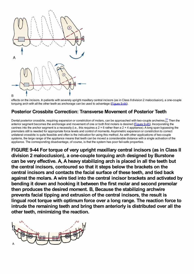
effects on the incisors. In patients with severely upright maxillary central incisors (as in Class II division 2 malocclusion), a one-coupletorquing arch with all the other teeth as anchorage can be used to advantage (Figure 9-44).
Posterior Crossbite Correction: Transverse Movement of Posterior TeethDental posterior crossbite, requiring expansion or constriction of molars, can be approached with two-couple archwires.21 Then theanterior segment becomes the anchorage and movement of one or both first molars is desired (Figure 9-45). Incorporating thecanines into the anchor segment is a necessity (i.e., this requires a 2 × 6 rather than a 2 × 4 appliance). A long span bypassing thepremolars still is needed for appropriate force levels and control of moments. Asymmetric expansion or constriction to correctunilateral crossbite is quite feasible and often is the indication for using this method. As with other applications of two-couplesystems, the large range of the appliance means that teeth can be moved a considerable distance with a single activation of theappliance. The corresponding disadvantage, of course, is that the system has poor fail-safe properties.
FIGURE 9-44 For torque of very upright maxillary central incisors (as in Class IIdivision 2 malocclusion), a one-couple torquing arch designed by Burstonecan be very effective. A, A heavy stabilizing arch is placed in all the teeth butthe central incisors, contoured so that it steps below the brackets on thecentral incisors and contacts the facial surface of these teeth, and tied backagainst the molars. A wire tied into the central incisor brackets and activated bybending it down and hooking it between the first molar and second premolarthen produces the desired moment. B, Because the stabilizing archwireprevents facial tipping and extrusion of the central incisors, the result islingual root torque with optimum force over a long range. The reaction force tointrude the remaining teeth and bring them anteriorly is distributed over all theother teeth, minimizing the reaction.
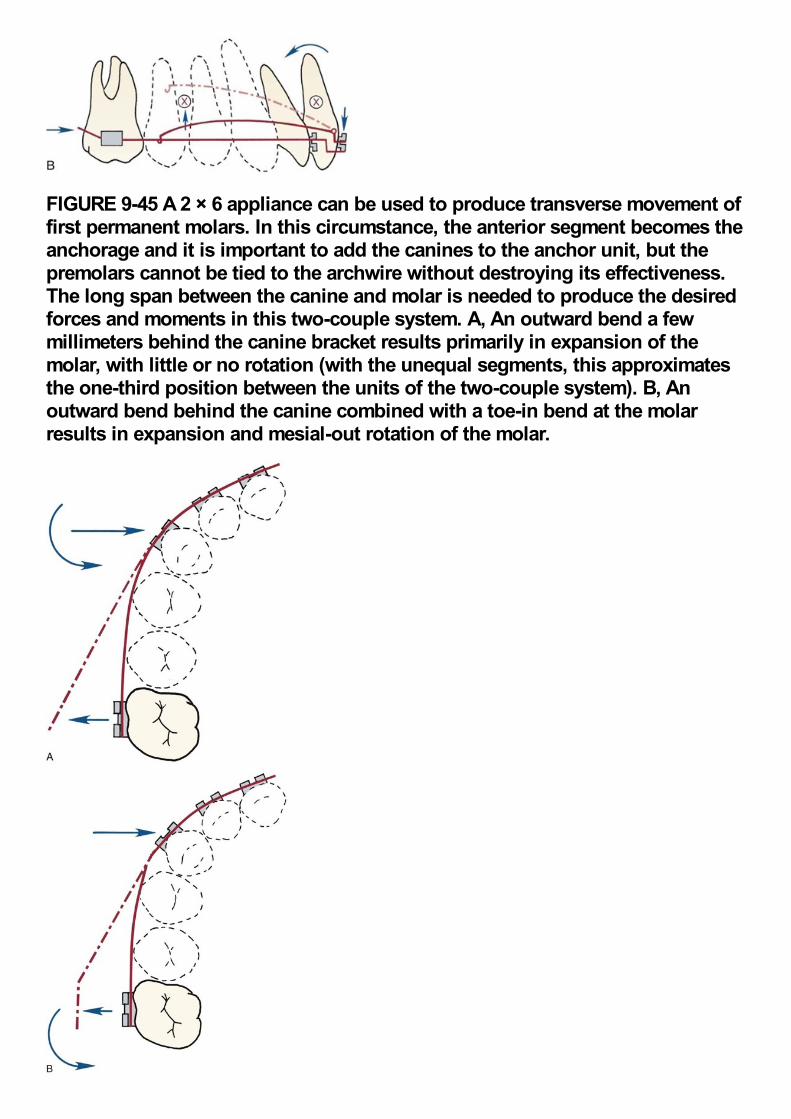
FIGURE 9-45 A 2 × 6 appliance can be used to produce transverse movement offirst permanent molars. In this circumstance, the anterior segment becomes theanchorage and it is important to add the canines to the anchor unit, but thepremolars cannot be tied to the archwire without destroying its effectiveness.The long span between the canine and molar is needed to produce the desiredforces and moments in this two-couple system. A, An outward bend a fewmillimeters behind the canine bracket results primarily in expansion of themolar, with little or no rotation (with the unequal segments, this approximatesthe one-third position between the units of the two-couple system). B, Anoutward bend behind the canine combined with a toe-in bend at the molarresults in expansion and mesial-out rotation of the molar.
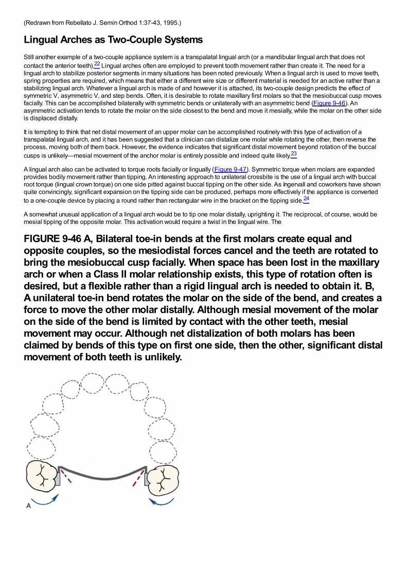
(Redrawn from Rebellato J. Semin Orthod 1:37-43, 1995.)
Lingual Arches as Two-Couple SystemsStill another example of a two-couple appliance system is a transpalatal lingual arch (or a mandibular lingual arch that does notcontact the anterior teeth).22 Lingual arches often are employed to prevent tooth movement rather than create it. The need for alingual arch to stabilize posterior segments in many situations has been noted previously. When a lingual arch is used to move teeth,spring properties are required, which means that either a different wire size or different material is needed for an active rather than astabilizing lingual arch. Whatever a lingual arch is made of and however it is attached, its two-couple design predicts the effect ofsymmetric V, asymmetric V, and step bends. Often, it is desirable to rotate maxillary first molars so that the mesiobuccal cusp movesfacially. This can be accomplished bilaterally with symmetric bends or unilaterally with an asymmetric bend (Figure 9-46). Anasymmetric activation tends to rotate the molar on the side closest to the bend and move it mesially, while the molar on the other sideis displaced distally.
It is tempting to think that net distal movement of an upper molar can be accomplished routinely with this type of activation of atranspalatal lingual arch, and it has been suggested that a clinician can distalize one molar while rotating the other, then reverse theprocess, moving both of them back. However, the evidence indicates that significant distal movement beyond rotation of the buccalcusps is unlikely—mesial movement of the anchor molar is entirely possible and indeed quite likely.23
A lingual arch also can be activated to torque roots facially or lingually (Figure 9-47). Symmetric torque when molars are expandedprovides bodily movement rather than tipping. An interesting approach to unilateral crossbite is the use of a lingual arch with buccalroot torque (lingual crown torque) on one side pitted against buccal tipping on the other side. As Ingervall and coworkers have shownquite convincingly, significant expansion on the tipping side can be produced, perhaps more effectively if the appliance is convertedto a one-couple device by placing a round rather than rectangular wire in the bracket on the tipping side.24
A somewhat unusual application of a lingual arch would be to tip one molar distally, uprighting it. The reciprocal, of course, would bemesial tipping of the opposite molar. This activation would require a twist in the lingual wire. The
FIGURE 9-46 A, Bilateral toe-in bends at the first molars create equal andopposite couples, so the mesiodistal forces cancel and the teeth are rotated tobring the mesiobuccal cusp facially. When space has been lost in the maxillaryarch or when a Class II molar relationship exists, this type of rotation often isdesired, but a flexible rather than a rigid lingual arch is needed to obtain it. B,A unilateral toe-in bend rotates the molar on the side of the bend, and creates aforce to move the other molar distally. Although mesial movement of the molaron the side of the bend is limited by contact with the other teeth, mesialmovement may occur. Although net distalization of both molars has beenclaimed by bends of this type on first one side, then the other, significant distalmovement of both teeth is unlikely.
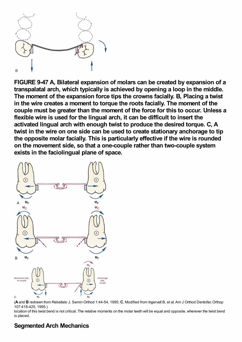
FIGURE 9-47 A, Bilateral expansion of molars can be created by expansion of atranspalatal arch, which typically is achieved by opening a loop in the middle.The moment of the expansion force tips the crowns facially. B, Placing a twistin the wire creates a moment to torque the roots facially. The moment of thecouple must be greater than the moment of the force for this to occur. Unless aflexible wire is used for the lingual arch, it can be difficult to insert theactivated lingual arch with enough twist to produce the desired torque. C, Atwist in the wire on one side can be used to create stationary anchorage to tipthe opposite molar facially. This is particularly effective if the wire is roundedon the movement side, so that a one-couple rather than two-couple systemexists in the faciolingual plane of space.
(A and B redrawn from Rebellato J. Semin Orthod 1:44-54, 1995; C, Modified from Ingervall B, et al. Am J Orthod Dentofac Orthop107:418-425, 1995.)location of this twist bend is not critical. The relative moments on the molar teeth will be equal and opposite, wherever the twist bendis placed.
Segmented Arch Mechanics
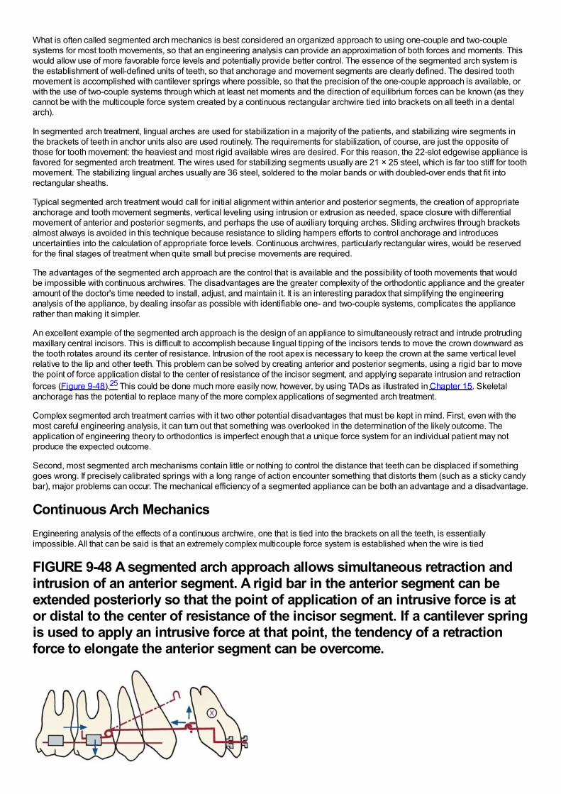
What is often called segmented arch mechanics is best considered an organized approach to using one-couple and two-couplesystems for most tooth movements, so that an engineering analysis can provide an approximation of both forces and moments. Thiswould allow use of more favorable force levels and potentially provide better control. The essence of the segmented arch system isthe establishment of well-defined units of teeth, so that anchorage and movement segments are clearly defined. The desired toothmovement is accomplished with cantilever springs where possible, so that the precision of the one-couple approach is available, orwith the use of two-couple systems through which at least net moments and the direction of equilibrium forces can be known (as theycannot be with the multicouple force system created by a continuous rectangular archwire tied into brackets on all teeth in a dentalarch).
In segmented arch treatment, lingual arches are used for stabilization in a majority of the patients, and stabilizing wire segments inthe brackets of teeth in anchor units also are used routinely. The requirements for stabilization, of course, are just the opposite ofthose for tooth movement: the heaviest and most rigid available wires are desired. For this reason, the 22-slot edgewise appliance isfavored for segmented arch treatment. The wires used for stabilizing segments usually are 21 × 25 steel, which is far too stiff for toothmovement. The stabilizing lingual arches usually are 36 steel, soldered to the molar bands or with doubled-over ends that fit intorectangular sheaths.
Typical segmented arch treatment would call for initial alignment within anterior and posterior segments, the creation of appropriateanchorage and tooth movement segments, vertical leveling using intrusion or extrusion as needed, space closure with differentialmovement of anterior and posterior segments, and perhaps the use of auxiliary torquing arches. Sliding archwires through bracketsalmost always is avoided in this technique because resistance to sliding hampers efforts to control anchorage and introducesuncertainties into the calculation of appropriate force levels. Continuous archwires, particularly rectangular wires, would be reservedfor the final stages of treatment when quite small but precise movements are required.
The advantages of the segmented arch approach are the control that is available and the possibility of tooth movements that wouldbe impossible with continuous archwires. The disadvantages are the greater complexity of the orthodontic appliance and the greateramount of the doctor's time needed to install, adjust, and maintain it. It is an interesting paradox that simplifying the engineeringanalysis of the appliance, by dealing insofar as possible with identifiable one- and two-couple systems, complicates the appliancerather than making it simpler.
An excellent example of the segmented arch approach is the design of an appliance to simultaneously retract and intrude protrudingmaxillary central incisors. This is difficult to accomplish because lingual tipping of the incisors tends to move the crown downward asthe tooth rotates around its center of resistance. Intrusion of the root apex is necessary to keep the crown at the same vertical levelrelative to the lip and other teeth. This problem can be solved by creating anterior and posterior segments, using a rigid bar to movethe point of force application distal to the center of resistance of the incisor segment, and applying separate intrusion and retractionforces (Figure 9-48).25 This could be done much more easily now, however, by using TADs as illustrated in Chapter 15. Skeletalanchorage has the potential to replace many of the more complex applications of segmented arch treatment.
Complex segmented arch treatment carries with it two other potential disadvantages that must be kept in mind. First, even with themost careful engineering analysis, it can turn out that something was overlooked in the determination of the likely outcome. Theapplication of engineering theory to orthodontics is imperfect enough that a unique force system for an individual patient may notproduce the expected outcome.
Second, most segmented arch mechanisms contain little or nothing to control the distance that teeth can be displaced if somethinggoes wrong. If precisely calibrated springs with a long range of action encounter something that distorts them (such as a sticky candybar), major problems can occur. The mechanical efficiency of a segmented appliance can be both an advantage and a disadvantage.
Continuous Arch MechanicsEngineering analysis of the effects of a continuous archwire, one that is tied into the brackets on all the teeth, is essentiallyimpossible. All that can be said is that an extremely complex multicouple force system is established when the wire is tied
FIGURE 9-48 A segmented arch approach allows simultaneous retraction andintrusion of an anterior segment. A rigid bar in the anterior segment can beextended posteriorly so that the point of application of an intrusive force is ator distal to the center of resistance of the incisor segment. If a cantilever springis used to apply an intrusive force at that point, the tendency of a retractionforce to elongate the anterior segment can be overcome.

(Redrawn from Shroff B, et al. Angle Orthod 67:455-462, 1997.)into place. The initial result is a small movement of one tooth. As soon as that occurs, the force system is changed, and the newsystem causes a small movement of another tooth (or a different movement of the first tooth). Either way, the result is still anothercomplex force system, which causes another movement, leading to another change in the system, and so on. Sometimes,orthodontic tooth movement is conceived as a slow, smooth transition of the teeth from one arrangement to another, but the forcesystems involved, particularly those with continuous arch mechanics, make it plain that this is far from the case. If it were possible totake time-lapse photographs of teeth being moved into position, we undoubtedly would see “the dance of the teeth,” as the complexforce systems formed and changed, producing varied effects in sequence, and Hayashi recently has shown just this sort ofmovement.26 It is a saving grace that a continuous archwire usually does not allow the teeth to move very far from the desiredendpoint.
The advantages and disadvantages of the continuous arch approach are just the reverse of those with the segmented arch approach.Continuous arch treatment is not as well-defined in terms of the forces and moments that will be generated at any one time andcertainly is less elegant from an engineering perspective. But continuous archwires often take less chair time because they aresimpler to make and install, and they have excellent fail-safe properties in most applications. In modern orthodontics, often theclinician must evaluate the trade-off between segmented and continuous arch approaches to specific problems. For those who useprimarily the segmented approach, some use of continuous archwires simplifies life. For those who use primarily continuousarchwires, some use of the segmented approach is necessary to meet specific objectives. Quite literally, you consider the benefitsversus the cost (time) and risks, and take your choice.
The development of contemporary fixed appliances and their characteristics are discussed in Chapter 10. Clinical applications of themechanical principles reviewed in this chapter and further information about the use of specific treatment methods are provided insome detail in Chapters 14 to 18.
References1.
Gurgel, J, Kerr, S, Powers, JM, et al.: Force-deflection properties of superelastic nickel-titanium archwires. Am J Orthod DentofacOrthop. 120, 2001, 378–382.
2.
Miura, F, Mogi, M, Okamoto, Y: New application of superelastic NiTi rectangular wire. J Clin Orthod. 24, 1990, 544–548.
3.
Cacciafesta, V, Sfondrini, MF, Scribante, LA, et al.: Force levels of fiber-reinforced composites and orthodontic stainless steel wires:a 3-point bending test. Am J Orthod Dentofac Orthop. 133, 2008, 410–413.
4.
Kusy, RP: On the use of nomograms to determine the elastic property ratios of orthodontic archwires. Am J Orthod. 83, 1983, 374–381.
5.
Adams, DM, Powers, JM, Asgar, K: Effects of brackets and ties on stiffness of an arch wire. Am J Orthod Dentofac Orthop. 91,1987, 131–136.
6.
Josell, SD, Leiss, JB, Rekow, ED: Force degradation in elastomeric chains. Semin Orthod. 3, 1997, 189–197.
7.
Darendeliler, MA, Darendeliler, A, Mandurino, M: Clinical application of magnets in orthodontics and biological implications: a review.Eur J Orthod. 19, 1997, 431–442.
8.
Linder-Aronson, A, Lindskog, S, Rygh, P: Orthodontic magnets: effects on gingival epithelium and alveolar bone in monkeys. Eur JOrthod. 14, 1992, 255–263.
9.
Jastrzebski, ZD: The Nature and Properties of Engineering Materials. 3rd ed, 1987, Wiley, New York.
10.
Kusy, RP, Whitley, JQ: Effects of surface roughness on the coefficients of friction in model orthodontic systems. J Biomech. 23, 1990,913–925.

11.
Kusy, RP, Whitley, JQ, Gurgel, J: Comparisons of surface roughnesses and sliding resistances of 6 titanium-based or TMA-typearchwires. Am J Orthod Dentofac Orthop. 126, 2004, 589–603.
12.
Saunders, CR, Kusy, RP: Surface topography and frictional characteristics of ceramic brackets. Am J Orthod Dentofac Orthop. 106,1994, 76–87.
13.
Kusy, RP, Whitley, JQ: Assessment of second-order clearances between orthodontic archwires and bracket slots via the criticalcontact angle for binding. Angle Orthod. 69, 1999, 71–80.
14.
Articolo, LC, Kusy, RP: Influence of angulation on the resistance to sliding in fixed appliances. Am J Orthod Dentofac Orthop. 115,1999, 39–51.
15.
Burrow, SJ: Canine retraction rate with self-ligating brackets vs conventional edgewise brackets. Angle Orthod. 80, 2010, 438–445.
16.
Lindauer, SJ, Isaacson, RJ: One-couple systems. Semin Orthod. 1, 1995, 12–24.
17.
Davidovitch, M, Rebellato, J: Utility arches: a two-couple intrusion system. Semin Orthod. 1, 1995, 25–30.
18.
Burstone, CJ, Koenig, HA: Creative wire bending—the force system from step and V bends. Am J Orthod Dentofac Orthop. 93,1988, 59–67.
19.
Isaacson, RJ, Lindauer, SJ, Conley, P: Responses of 3-dimensional archwires to vertical V-bends: comparisons with existing 2-dimensional data in the lateral view. Semin Orthod. 1, 1995, 57–63.
20.
Isaacson, RJ, Rebellato, J: Two-couple orthodontic appliance systems: torquing arches. Semin Orthod. 1, 1995, 31–36.
21.
Rebellato, J: Two-couple orthodontic appliance systems: activations in the transverse dimension. Semin Orthod. 1, 1995, 37–43.
22.
Rebellato, J: Two-couple orthodontic appliance systems: transpalatal arches. Semin Orthod. 1, 1995, 44–54.
23.
Dahlquist, A, Gebauer, U, Ingervall, B: The effect of a transpalatal arch for correction of first molar rotation. Eur J Orthod. 18, 1996,257–267.
24.
Ingervall, B, Gollner, P, Gebauer, U, et al.: A clinical investigation of the correction of unilateral molar crossbite with a transpalatal arch.Am J Orthod Dentofac Orthop. 107, 1995, 418–425.
25.
Shroff, B, Yoon, WM, Lindauer, SJ, et al.: Simultaneous intrusion and retraction using a three-piece base arch. Angle Orthod. 67,1997, 455–462.
26.
Hayashi, K, DeLong, R, Mizoguchi, I: Comparison of the finite helical axis and the rectangular coordinate system in representingorthodontic tooth movement. J Biomechanics. 39, 2006, 2925–2933.
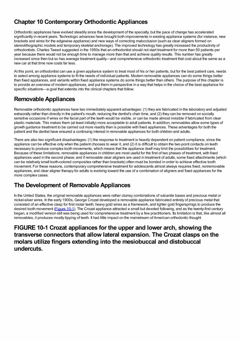
Chapter 10 Contemporary Orthodontic AppliancesOrthodontic appliances have evolved steadily since the development of the specialty, but the pace of change has acceleratedsignificantly in recent years. Technologic advances have brought both improvements in existing appliance systems (for instance, newbrackets and wires for the edgewise appliance) and new ways of correcting malocclusion (such as clear aligners formed onstereolithographic models and temporary skeletal anchorage). The improved technology has greatly increased the productivity oforthodontists. Charles Tweed suggested in the 1950s that an orthodontist should not start treatment for more than 50 patients peryear because there would not be enough time to manage more than that and achieve quality results. This number has greatlyincreased since then but so has average treatment quality—and comprehensive orthodontic treatment that cost about the same as anew car at that time now costs far less.
At this point, an orthodontist can use a given appliance system to treat most of his or her patients, but for the best patient care, needsto select among appliance systems to fit the needs of individual patients. Modern removable appliances can do some things betterthan fixed appliances, and variants within fixed appliance systems do some things better than others. The purpose of this chapter isto provide an overview of modern appliances, and put them in perspective in a way that helps in the choice of the best appliance forspecific situations—a goal that extends into the clinical chapters that follow.
Removable AppliancesRemovable orthodontic appliances have two immediately apparent advantages: (1) they are fabricated in the laboratory and adjustedextraorally rather than directly in the patient's mouth, reducing the dentist's chair time, and (2) they can be removed on sociallysensitive occasions if wires on the facial part of the teeth would be visible, or can be made almost invisible if fabricated from clearplastic materials. This makes them (at least initially) more acceptable to adult patients. In addition, removables allow some types ofgrowth guidance treatment to be carried out more readily than is possible with fixed appliances. These advantages for both thepatient and the dentist have ensured a continuing interest in removable appliances for both children and adults.
There are also two significant disadvantages: (1) the response to treatment is heavily dependent on patient compliance, since theappliance can be effective only when the patient chooses to wear it, and (2) it is difficult to obtain the two-point contacts on teethnecessary to produce complex tooth movements, which means that the appliance itself may limit the possibilities for treatment.Because of these limitations, removable appliances in children are most useful for the first of two phases of treatment, with fixedappliances used in the second phase; and if removable clear aligners are used in treatment of adults, some fixed attachments (whichcan be relatively small tooth-colored composites rather than brackets) often must be bonded in order to achieve effective toothmovement. For these reasons, contemporary comprehensive treatment for adolescents almost always requires fixed, nonremovableappliances, and clear aligner therapy for adults is evolving toward the use of a combination of aligners and fixed appliances for themore complex cases.
The Development of Removable AppliancesIn the United States, the original removable appliances were rather clumsy combinations of vulcanite bases and precious metal ornickel-silver wires. In the early 1900s, George Crozat developed a removable appliance fabricated entirely of precious metal thatconsisted of an effective clasp for first molar teeth, heavy gold wires as a framework, and lighter gold fingersprings to produce thedesired tooth movement (Figure 10-1). The Crozat appliance attracted a small but devoted following, and as the twenty-first centurybegan, a modified version still was being used for comprehensive treatment by a few practitioners. Its limitation is that, like almost allremovables, it produces mostly tipping of teeth. It had little impact on the mainstream of American orthodontic thought
FIGURE 10-1 Crozat appliances for the upper and lower arch, showing thetransverse connectors that allow lateral expansion. The Crozat clasps on themolars utilize fingers extending into the mesiobuccal and distobuccalundercuts.
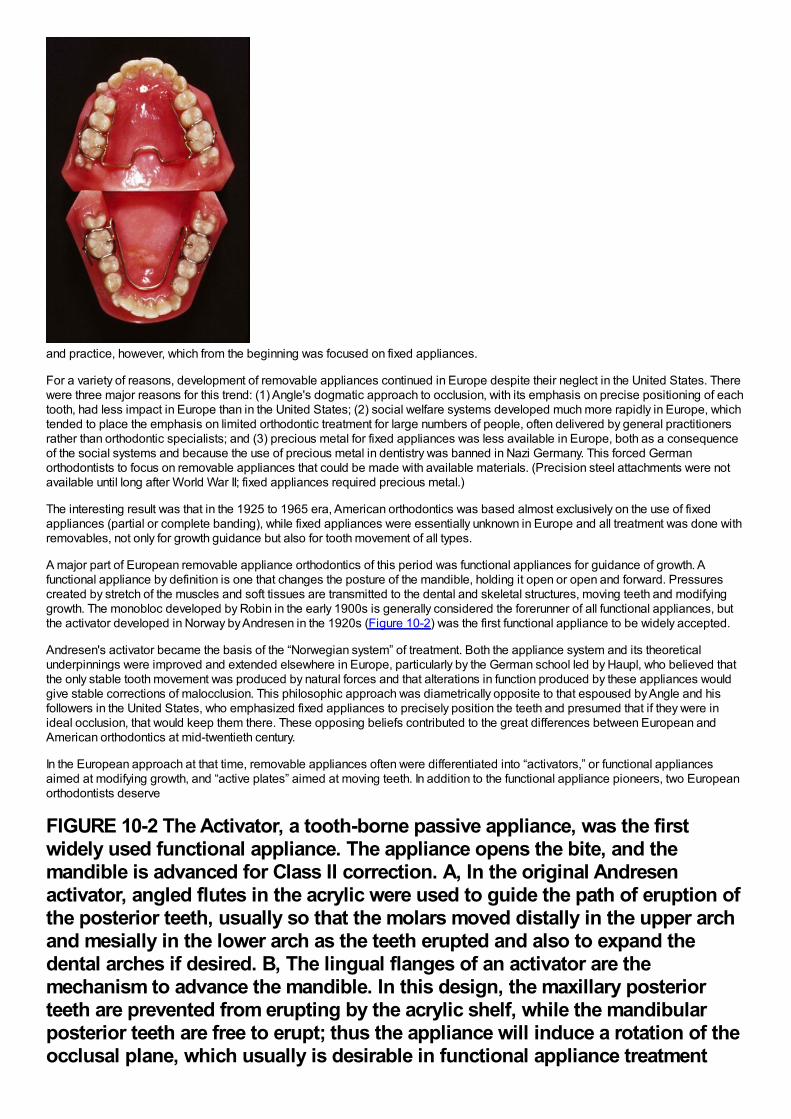
and practice, however, which from the beginning was focused on fixed appliances.
For a variety of reasons, development of removable appliances continued in Europe despite their neglect in the United States. Therewere three major reasons for this trend: (1) Angle's dogmatic approach to occlusion, with its emphasis on precise positioning of eachtooth, had less impact in Europe than in the United States; (2) social welfare systems developed much more rapidly in Europe, whichtended to place the emphasis on limited orthodontic treatment for large numbers of people, often delivered by general practitionersrather than orthodontic specialists; and (3) precious metal for fixed appliances was less available in Europe, both as a consequenceof the social systems and because the use of precious metal in dentistry was banned in Nazi Germany. This forced Germanorthodontists to focus on removable appliances that could be made with available materials. (Precision steel attachments were notavailable until long after World War II; fixed appliances required precious metal.)
The interesting result was that in the 1925 to 1965 era, American orthodontics was based almost exclusively on the use of fixedappliances (partial or complete banding), while fixed appliances were essentially unknown in Europe and all treatment was done withremovables, not only for growth guidance but also for tooth movement of all types.
A major part of European removable appliance orthodontics of this period was functional appliances for guidance of growth. Afunctional appliance by definition is one that changes the posture of the mandible, holding it open or open and forward. Pressurescreated by stretch of the muscles and soft tissues are transmitted to the dental and skeletal structures, moving teeth and modifyinggrowth. The monobloc developed by Robin in the early 1900s is generally considered the forerunner of all functional appliances, butthe activator developed in Norway by Andresen in the 1920s (Figure 10-2) was the first functional appliance to be widely accepted.
Andresen's activator became the basis of the “Norwegian system” of treatment. Both the appliance system and its theoreticalunderpinnings were improved and extended elsewhere in Europe, particularly by the German school led by Haupl, who believed thatthe only stable tooth movement was produced by natural forces and that alterations in function produced by these appliances wouldgive stable corrections of malocclusion. This philosophic approach was diametrically opposite to that espoused by Angle and hisfollowers in the United States, who emphasized fixed appliances to precisely position the teeth and presumed that if they were inideal occlusion, that would keep them there. These opposing beliefs contributed to the great differences between European andAmerican orthodontics at mid-twentieth century.
In the European approach at that time, removable appliances often were differentiated into “activators,” or functional appliancesaimed at modifying growth, and “active plates” aimed at moving teeth. In addition to the functional appliance pioneers, two Europeanorthodontists deserve
FIGURE 10-2 The Activator, a tooth-borne passive appliance, was the firstwidely used functional appliance. The appliance opens the bite, and themandible is advanced for Class II correction. A, In the original Andresenactivator, angled flutes in the acrylic were used to guide the path of eruption ofthe posterior teeth, usually so that the molars moved distally in the upper archand mesially in the lower arch as the teeth erupted and also to expand thedental arches if desired. B, The lingual flanges of an activator are themechanism to advance the mandible. In this design, the maxillary posteriorteeth are prevented from erupting by the acrylic shelf, while the mandibularposterior teeth are free to erupt; thus the appliance will induce a rotation of theocclusal plane, which usually is desirable in functional appliance treatment
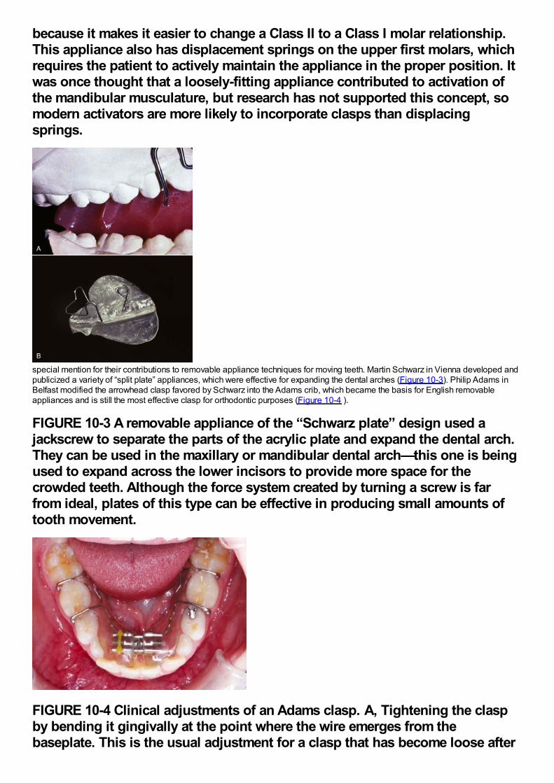
because it makes it easier to change a Class II to a Class I molar relationship.This appliance also has displacement springs on the upper first molars, whichrequires the patient to actively maintain the appliance in the proper position. Itwas once thought that a loosely-fitting appliance contributed to activation ofthe mandibular musculature, but research has not supported this concept, somodern activators are more likely to incorporate clasps than displacingsprings.
special mention for their contributions to removable appliance techniques for moving teeth. Martin Schwarz in Vienna developed andpublicized a variety of “split plate” appliances, which were effective for expanding the dental arches (Figure 10-3). Philip Adams inBelfast modified the arrowhead clasp favored by Schwarz into the Adams crib, which became the basis for English removableappliances and is still the most effective clasp for orthodontic purposes (Figure 10-4 ).
FIGURE 10-3 A removable appliance of the “Schwarz plate” design used ajackscrew to separate the parts of the acrylic plate and expand the dental arch.They can be used in the maxillary or mandibular dental arch—this one is beingused to expand across the lower incisors to provide more space for thecrowded teeth. Although the force system created by turning a screw is farfrom ideal, plates of this type can be effective in producing small amounts oftooth movement.
FIGURE 10-4 Clinical adjustments of an Adams clasp. A, Tightening the claspby bending it gingivally at the point where the wire emerges from thebaseplate. This is the usual adjustment for a clasp that has become loose after
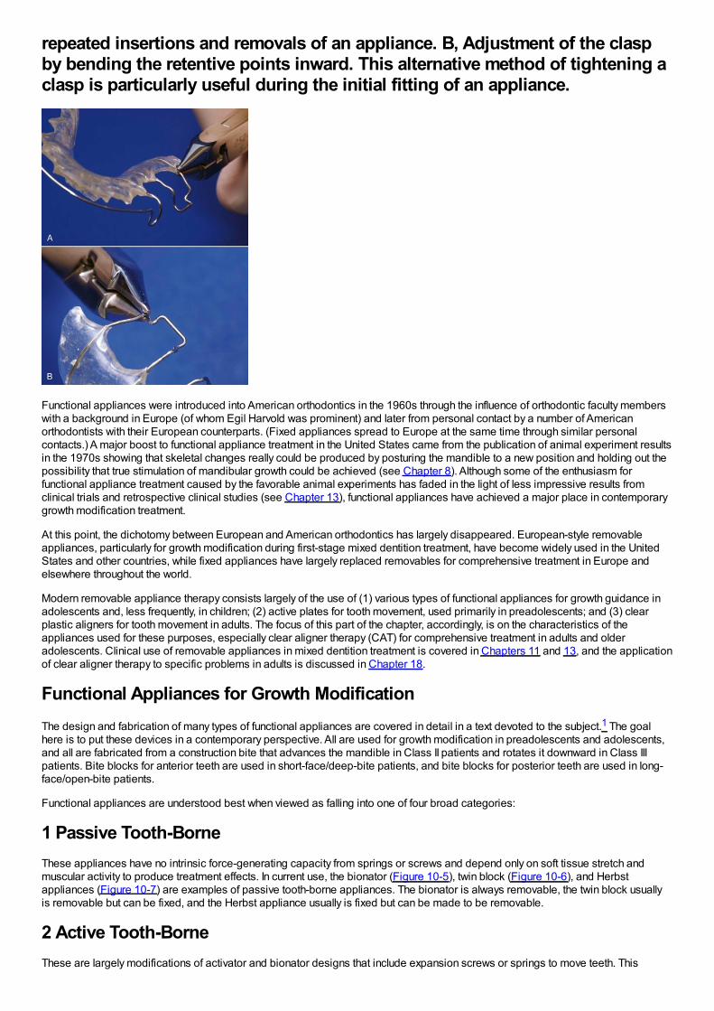
repeated insertions and removals of an appliance. B, Adjustment of the claspby bending the retentive points inward. This alternative method of tightening aclasp is particularly useful during the initial fitting of an appliance.
Functional appliances were introduced into American orthodontics in the 1960s through the influence of orthodontic faculty memberswith a background in Europe (of whom Egil Harvold was prominent) and later from personal contact by a number of Americanorthodontists with their European counterparts. (Fixed appliances spread to Europe at the same time through similar personalcontacts.) A major boost to functional appliance treatment in the United States came from the publication of animal experiment resultsin the 1970s showing that skeletal changes really could be produced by posturing the mandible to a new position and holding out thepossibility that true stimulation of mandibular growth could be achieved (see Chapter 8). Although some of the enthusiasm forfunctional appliance treatment caused by the favorable animal experiments has faded in the light of less impressive results fromclinical trials and retrospective clinical studies (see Chapter 13), functional appliances have achieved a major place in contemporarygrowth modification treatment.
At this point, the dichotomy between European and American orthodontics has largely disappeared. European-style removableappliances, particularly for growth modification during first-stage mixed dentition treatment, have become widely used in the UnitedStates and other countries, while fixed appliances have largely replaced removables for comprehensive treatment in Europe andelsewhere throughout the world.
Modern removable appliance therapy consists largely of the use of (1) various types of functional appliances for growth guidance inadolescents and, less frequently, in children; (2) active plates for tooth movement, used primarily in preadolescents; and (3) clearplastic aligners for tooth movement in adults. The focus of this part of the chapter, accordingly, is on the characteristics of theappliances used for these purposes, especially clear aligner therapy (CAT) for comprehensive treatment in adults and olderadolescents. Clinical use of removable appliances in mixed dentition treatment is covered in Chapters 11 and 13, and the applicationof clear aligner therapy to specific problems in adults is discussed in Chapter 18.
Functional Appliances for Growth ModificationThe design and fabrication of many types of functional appliances are covered in detail in a text devoted to the subject.1 The goalhere is to put these devices in a contemporary perspective. All are used for growth modification in preadolescents and adolescents,and all are fabricated from a construction bite that advances the mandible in Class II patients and rotates it downward in Class IIIpatients. Bite blocks for anterior teeth are used in short-face/deep-bite patients, and bite blocks for posterior teeth are used in long-face/open-bite patients.
Functional appliances are understood best when viewed as falling into one of four broad categories:
1 Passive Tooth-BorneThese appliances have no intrinsic force-generating capacity from springs or screws and depend only on soft tissue stretch andmuscular activity to produce treatment effects. In current use, the bionator (Figure 10-5), twin block (Figure 10-6), and Herbstappliances (Figure 10-7) are examples of passive tooth-borne appliances. The bionator is always removable, the twin block usuallyis removable but can be fixed, and the Herbst appliance usually is fixed but can be made to be removable.
2 Active Tooth-BorneThese are largely modifications of activator and bionator designs that include expansion screws or springs to move teeth. This
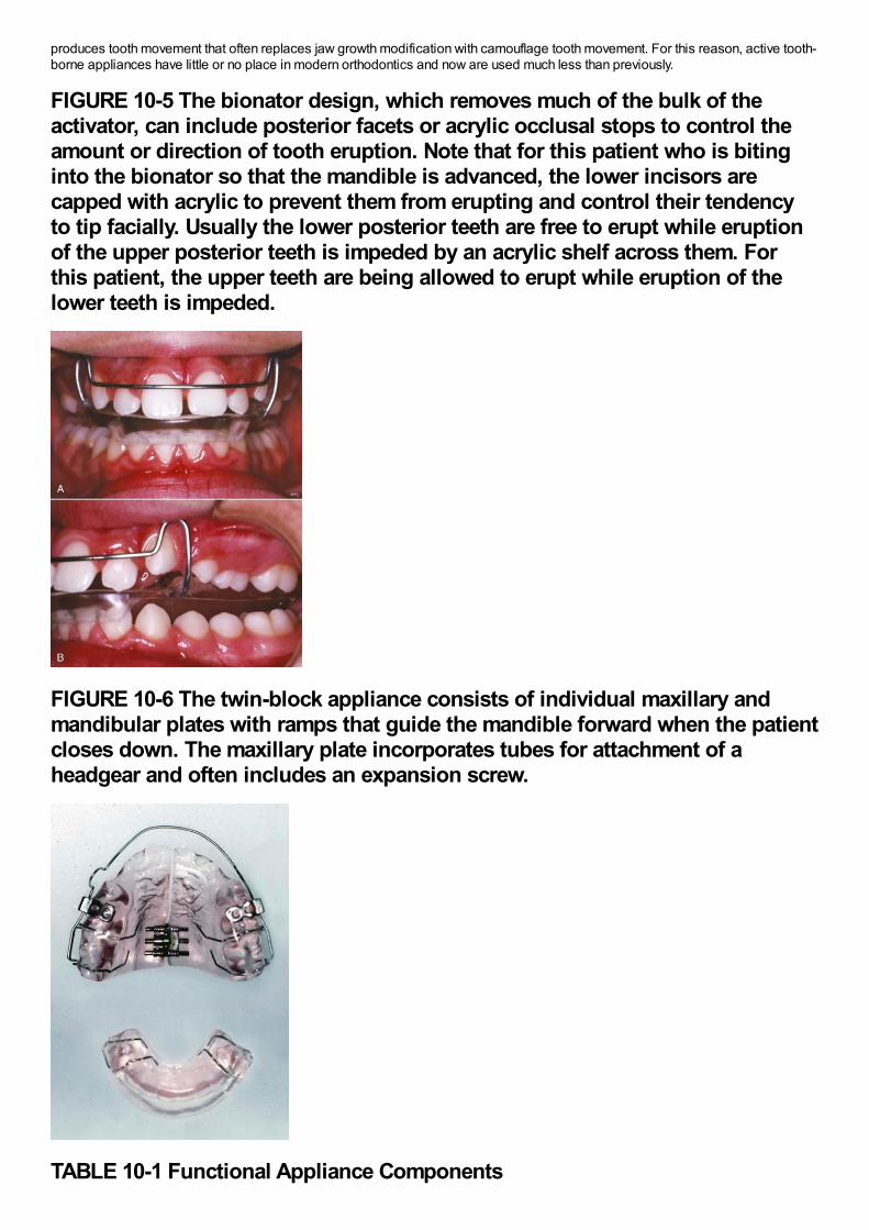
produces tooth movement that often replaces jaw growth modification with camouflage tooth movement. For this reason, active tooth-borne appliances have little or no place in modern orthodontics and now are used much less than previously.
FIGURE 10-5 The bionator design, which removes much of the bulk of theactivator, can include posterior facets or acrylic occlusal stops to control theamount or direction of tooth eruption. Note that for this patient who is bitinginto the bionator so that the mandible is advanced, the lower incisors arecapped with acrylic to prevent them from erupting and control their tendencyto tip facially. Usually the lower posterior teeth are free to erupt while eruptionof the upper posterior teeth is impeded by an acrylic shelf across them. Forthis patient, the upper teeth are being allowed to erupt while eruption of thelower teeth is impeded.
FIGURE 10-6 The twin-block appliance consists of individual maxillary andmandibular plates with ramps that guide the mandible forward when the patientcloses down. The maxillary plate incorporates tubes for attachment of aheadgear and often includes an expansion screw.
TABLE 10-1 Functional Appliance Components
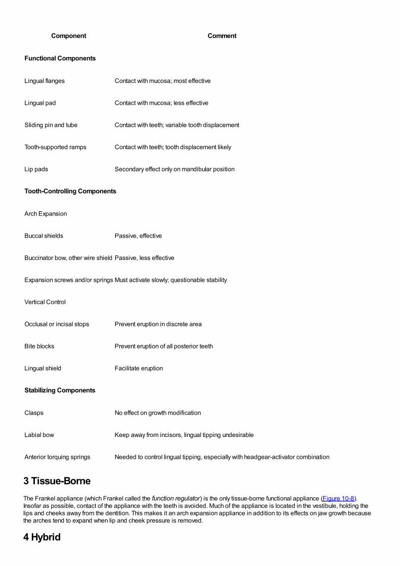
Component Comment
Functional Components
Lingual flanges Contact with mucosa; most effective
Lingual pad Contact with mucosa; less effective
Sliding pin and tube Contact with teeth; variable tooth displacement
Tooth-supported ramps Contact with teeth; tooth displacement likely
Lip pads Secondary effect only on mandibular position
Tooth-Controlling Components
Arch Expansion
Buccal shields Passive, effective
Buccinator bow, other wire shield Passive, less effective
Expansion screws and/or springs Must activate slowly; questionable stability
Vertical Control
Occlusal or incisal stops Prevent eruption in discrete area
Bite blocks Prevent eruption of all posterior teeth
Lingual shield Facilitate eruption
Stabilizing Components
Clasps No effect on growth modification
Labial bow Keep away from incisors, lingual tipping undesirable
Anterior torquing springs Needed to control lingual tipping, especially with headgear-activator combination
3 Tissue-BorneThe Frankel appliance (which Frankel called the function regulator) is the only tissue-borne functional appliance (Figure 10-8).Insofar as possible, contact of the appliance with the teeth is avoided. Much of the appliance is located in the vestibule, holding thelips and cheeks away from the dentition. This makes it an arch expansion appliance in addition to its effects on jaw growth becausethe arches tend to expand when lip and cheek pressure is removed.
4 Hybrid
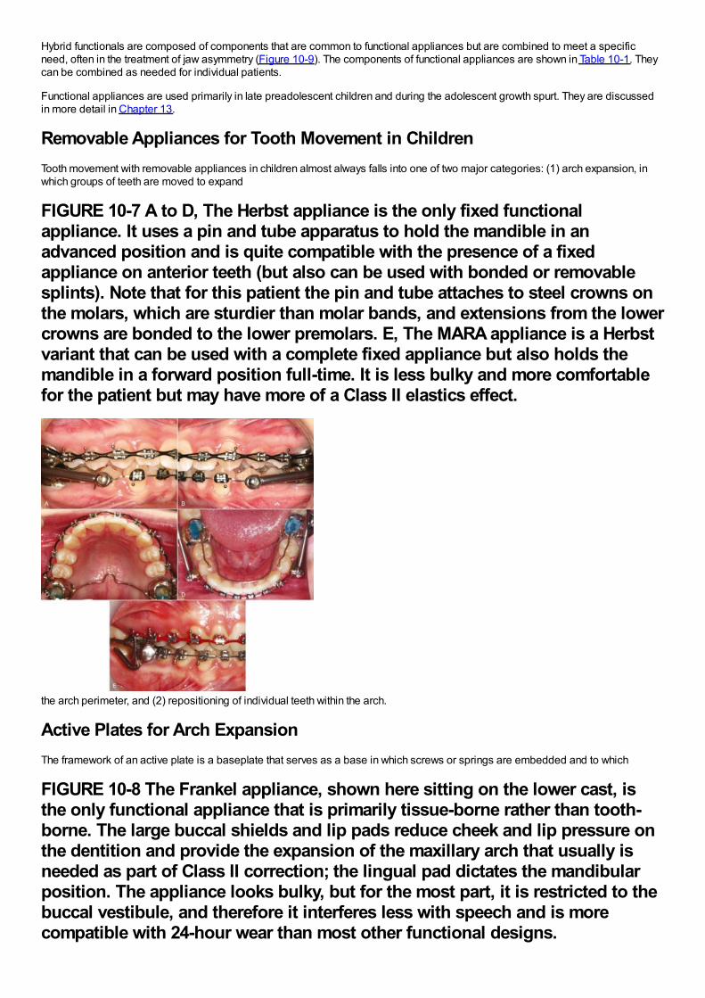
Hybrid functionals are composed of components that are common to functional appliances but are combined to meet a specificneed, often in the treatment of jaw asymmetry (Figure 10-9). The components of functional appliances are shown in Table 10-1. Theycan be combined as needed for individual patients.
Functional appliances are used primarily in late preadolescent children and during the adolescent growth spurt. They are discussedin more detail in Chapter 13.
Removable Appliances for Tooth Movement in ChildrenTooth movement with removable appliances in children almost always falls into one of two major categories: (1) arch expansion, inwhich groups of teeth are moved to expand
FIGURE 10-7 A to D, The Herbst appliance is the only fixed functionalappliance. It uses a pin and tube apparatus to hold the mandible in anadvanced position and is quite compatible with the presence of a fixedappliance on anterior teeth (but also can be used with bonded or removablesplints). Note that for this patient the pin and tube attaches to steel crowns onthe molars, which are sturdier than molar bands, and extensions from the lowercrowns are bonded to the lower premolars. E, The MARA appliance is a Herbstvariant that can be used with a complete fixed appliance but also holds themandible in a forward position full-time. It is less bulky and more comfortablefor the patient but may have more of a Class II elastics effect.
the arch perimeter, and (2) repositioning of individual teeth within the arch.
Active Plates for Arch ExpansionThe framework of an active plate is a baseplate that serves as a base in which screws or springs are embedded and to which
FIGURE 10-8 The Frankel appliance, shown here sitting on the lower cast, isthe only functional appliance that is primarily tissue-borne rather than tooth-borne. The large buccal shields and lip pads reduce cheek and lip pressure onthe dentition and provide the expansion of the maxillary arch that usually isneeded as part of Class II correction; the lingual pad dictates the mandibularposition. The appliance looks bulky, but for the most part, it is restricted to thebuccal vestibule, and therefore it interferes less with speech and is morecompatible with 24-hour wear than most other functional designs.
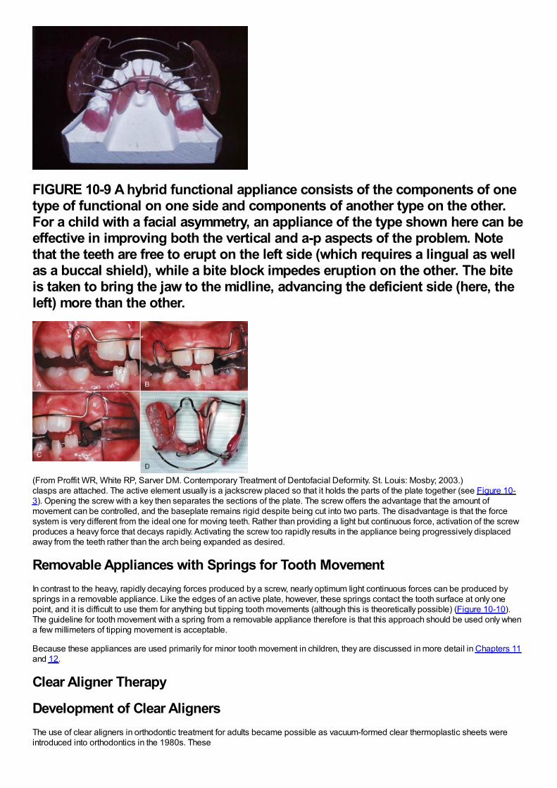
FIGURE 10-9 A hybrid functional appliance consists of the components of onetype of functional on one side and components of another type on the other.For a child with a facial asymmetry, an appliance of the type shown here can beeffective in improving both the vertical and a-p aspects of the problem. Notethat the teeth are free to erupt on the left side (which requires a lingual as wellas a buccal shield), while a bite block impedes eruption on the other. The biteis taken to bring the jaw to the midline, advancing the deficient side (here, theleft) more than the other.
(From Proffit WR, White RP, Sarver DM. Contemporary Treatment of Dentofacial Deformity. St. Louis: Mosby; 2003.)clasps are attached. The active element usually is a jackscrew placed so that it holds the parts of the plate together (see Figure 10-3). Opening the screw with a key then separates the sections of the plate. The screw offers the advantage that the amount ofmovement can be controlled, and the baseplate remains rigid despite being cut into two parts. The disadvantage is that the forcesystem is very different from the ideal one for moving teeth. Rather than providing a light but continuous force, activation of the screwproduces a heavy force that decays rapidly. Activating the screw too rapidly results in the appliance being progressively displacedaway from the teeth rather than the arch being expanded as desired.
Removable Appliances with Springs for Tooth MovementIn contrast to the heavy, rapidly decaying forces produced by a screw, nearly optimum light continuous forces can be produced bysprings in a removable appliance. Like the edges of an active plate, however, these springs contact the tooth surface at only onepoint, and it is difficult to use them for anything but tipping tooth movements (although this is theoretically possible) (Figure 10-10).The guideline for tooth movement with a spring from a removable appliance therefore is that this approach should be used only whena few millimeters of tipping movement is acceptable.
Because these appliances are used primarily for minor tooth movement in children, they are discussed in more detail in Chapters 11and 12.
Clear Aligner Therapy
Development of Clear AlignersThe use of clear aligners in orthodontic treatment for adults became possible as vacuum-formed clear thermoplastic sheets wereintroduced into orthodontics in the 1980s. These
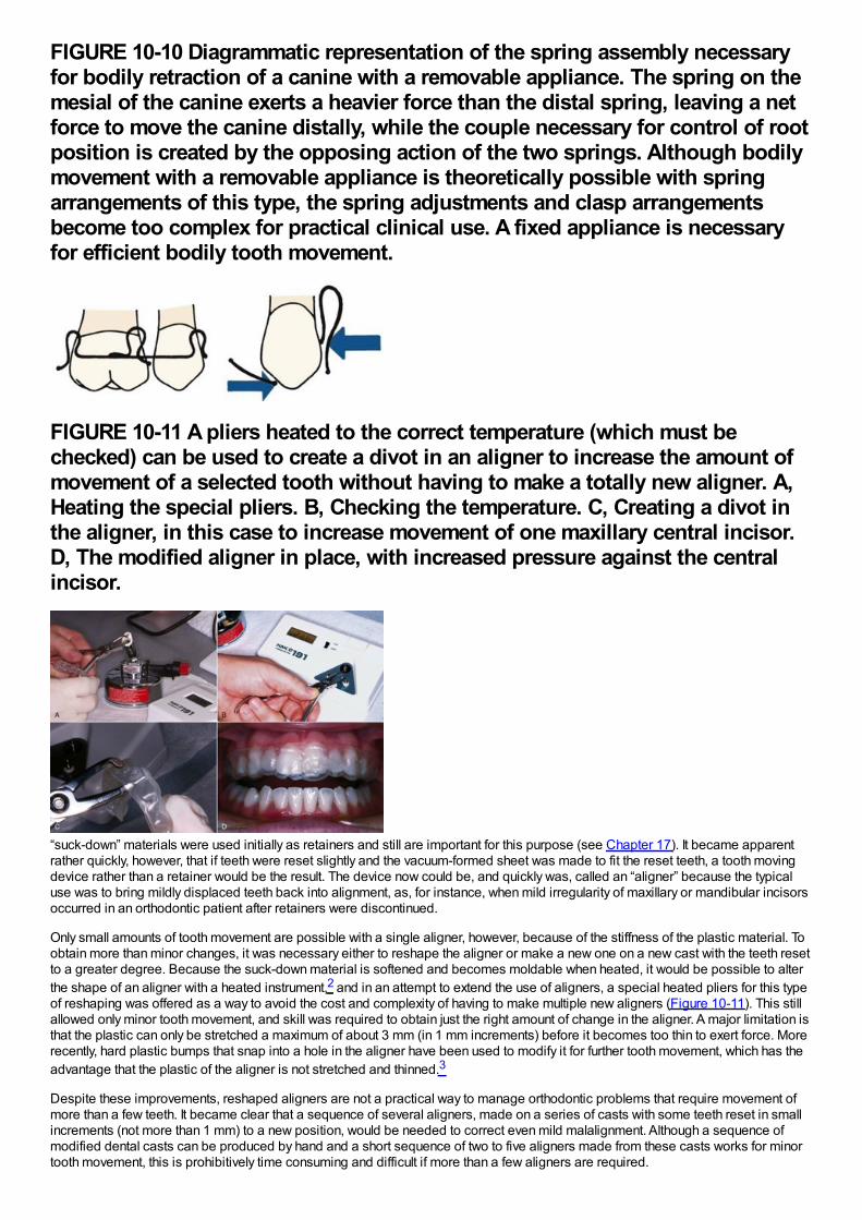
FIGURE 10-10 Diagrammatic representation of the spring assembly necessaryfor bodily retraction of a canine with a removable appliance. The spring on themesial of the canine exerts a heavier force than the distal spring, leaving a netforce to move the canine distally, while the couple necessary for control of rootposition is created by the opposing action of the two springs. Although bodilymovement with a removable appliance is theoretically possible with springarrangements of this type, the spring adjustments and clasp arrangementsbecome too complex for practical clinical use. A fixed appliance is necessaryfor efficient bodily tooth movement.
FIGURE 10-11 A pliers heated to the correct temperature (which must bechecked) can be used to create a divot in an aligner to increase the amount ofmovement of a selected tooth without having to make a totally new aligner. A,Heating the special pliers. B, Checking the temperature. C, Creating a divot inthe aligner, in this case to increase movement of one maxillary central incisor.D, The modified aligner in place, with increased pressure against the centralincisor.
“suck-down” materials were used initially as retainers and still are important for this purpose (see Chapter 17). It became apparentrather quickly, however, that if teeth were reset slightly and the vacuum-formed sheet was made to fit the reset teeth, a tooth movingdevice rather than a retainer would be the result. The device now could be, and quickly was, called an “aligner” because the typicaluse was to bring mildly displaced teeth back into alignment, as, for instance, when mild irregularity of maxillary or mandibular incisorsoccurred in an orthodontic patient after retainers were discontinued.
Only small amounts of tooth movement are possible with a single aligner, however, because of the stiffness of the plastic material. Toobtain more than minor changes, it was necessary either to reshape the aligner or make a new one on a new cast with the teeth resetto a greater degree. Because the suck-down material is softened and becomes moldable when heated, it would be possible to alterthe shape of an aligner with a heated instrument,2 and in an attempt to extend the use of aligners, a special heated pliers for this typeof reshaping was offered as a way to avoid the cost and complexity of having to make multiple new aligners (Figure 10-11). This stillallowed only minor tooth movement, and skill was required to obtain just the right amount of change in the aligner. A major limitation isthat the plastic can only be stretched a maximum of about 3 mm (in 1 mm increments) before it becomes too thin to exert force. Morerecently, hard plastic bumps that snap into a hole in the aligner have been used to modify it for further tooth movement, which has theadvantage that the plastic of the aligner is not stretched and thinned.3
Despite these improvements, reshaped aligners are not a practical way to manage orthodontic problems that require movement ofmore than a few teeth. It became clear that a sequence of several aligners, made on a series of casts with some teeth reset in smallincrements (not more than 1 mm) to a new position, would be needed to correct even mild malalignment. Although a sequence ofmodified dental casts can be produced by hand and a short sequence of two to five aligners made from these casts works for minortooth movement, this is prohibitively time consuming and difficult if more than a few aligners are required.
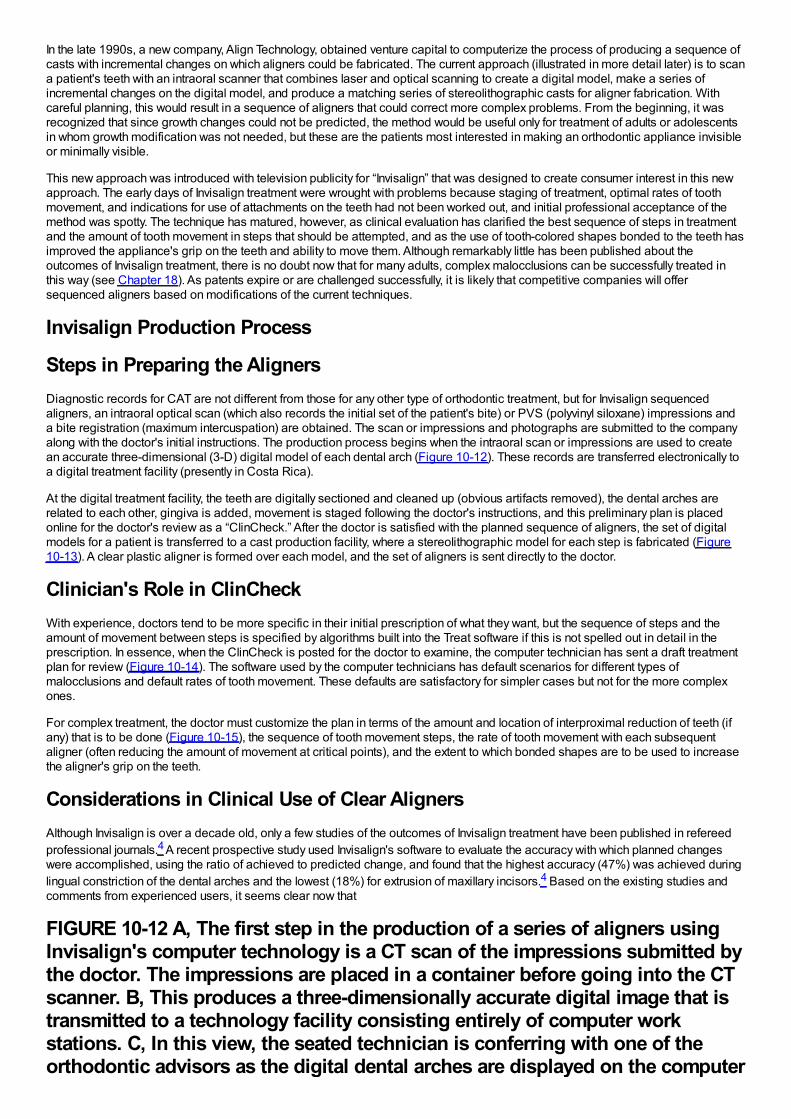
In the late 1990s, a new company, Align Technology, obtained venture capital to computerize the process of producing a sequence ofcasts with incremental changes on which aligners could be fabricated. The current approach (illustrated in more detail later) is to scana patient's teeth with an intraoral scanner that combines laser and optical scanning to create a digital model, make a series ofincremental changes on the digital model, and produce a matching series of stereolithographic casts for aligner fabrication. Withcareful planning, this would result in a sequence of aligners that could correct more complex problems. From the beginning, it wasrecognized that since growth changes could not be predicted, the method would be useful only for treatment of adults or adolescentsin whom growth modification was not needed, but these are the patients most interested in making an orthodontic appliance invisibleor minimally visible.
This new approach was introduced with television publicity for “Invisalign” that was designed to create consumer interest in this newapproach. The early days of Invisalign treatment were wrought with problems because staging of treatment, optimal rates of toothmovement, and indications for use of attachments on the teeth had not been worked out, and initial professional acceptance of themethod was spotty. The technique has matured, however, as clinical evaluation has clarified the best sequence of steps in treatmentand the amount of tooth movement in steps that should be attempted, and as the use of tooth-colored shapes bonded to the teeth hasimproved the appliance's grip on the teeth and ability to move them. Although remarkably little has been published about theoutcomes of Invisalign treatment, there is no doubt now that for many adults, complex malocclusions can be successfully treated inthis way (see Chapter 18). As patents expire or are challenged successfully, it is likely that competitive companies will offersequenced aligners based on modifications of the current techniques.
Invisalign Production Process
Steps in Preparing the AlignersDiagnostic records for CAT are not different from those for any other type of orthodontic treatment, but for Invisalign sequencedaligners, an intraoral optical scan (which also records the initial set of the patient's bite) or PVS (polyvinyl siloxane) impressions anda bite registration (maximum intercuspation) are obtained. The scan or impressions and photographs are submitted to the companyalong with the doctor's initial instructions. The production process begins when the intraoral scan or impressions are used to createan accurate three-dimensional (3-D) digital model of each dental arch (Figure 10-12). These records are transferred electronically toa digital treatment facility (presently in Costa Rica).
At the digital treatment facility, the teeth are digitally sectioned and cleaned up (obvious artifacts removed), the dental arches arerelated to each other, gingiva is added, movement is staged following the doctor's instructions, and this preliminary plan is placedonline for the doctor's review as a “ClinCheck.” After the doctor is satisfied with the planned sequence of aligners, the set of digitalmodels for a patient is transferred to a cast production facility, where a stereolithographic model for each step is fabricated (Figure10-13). A clear plastic aligner is formed over each model, and the set of aligners is sent directly to the doctor.
Clinician's Role in ClinCheckWith experience, doctors tend to be more specific in their initial prescription of what they want, but the sequence of steps and theamount of movement between steps is specified by algorithms built into the Treat software if this is not spelled out in detail in theprescription. In essence, when the ClinCheck is posted for the doctor to examine, the computer technician has sent a draft treatmentplan for review (Figure 10-14). The software used by the computer technicians has default scenarios for different types ofmalocclusions and default rates of tooth movement. These defaults are satisfactory for simpler cases but not for the more complexones.
For complex treatment, the doctor must customize the plan in terms of the amount and location of interproximal reduction of teeth (ifany) that is to be done (Figure 10-15), the sequence of tooth movement steps, the rate of tooth movement with each subsequentaligner (often reducing the amount of movement at critical points), and the extent to which bonded shapes are to be used to increasethe aligner's grip on the teeth.
Considerations in Clinical Use of Clear AlignersAlthough Invisalign is over a decade old, only a few studies of the outcomes of Invisalign treatment have been published in refereedprofessional journals.4 A recent prospective study used Invisalign's software to evaluate the accuracy with which planned changeswere accomplished, using the ratio of achieved to predicted change, and found that the highest accuracy (47%) was achieved duringlingual constriction of the dental arches and the lowest (18%) for extrusion of maxillary incisors.4 Based on the existing studies andcomments from experienced users, it seems clear now that
FIGURE 10-12 A, The first step in the production of a series of aligners usingInvisalign's computer technology is a CT scan of the impressions submitted bythe doctor. The impressions are placed in a container before going into the CTscanner. B, This produces a three-dimensionally accurate digital image that istransmitted to a technology facility consisting entirely of computer workstations. C, In this view, the seated technician is conferring with one of theorthodontic advisors as the digital dental arches are displayed on the computer
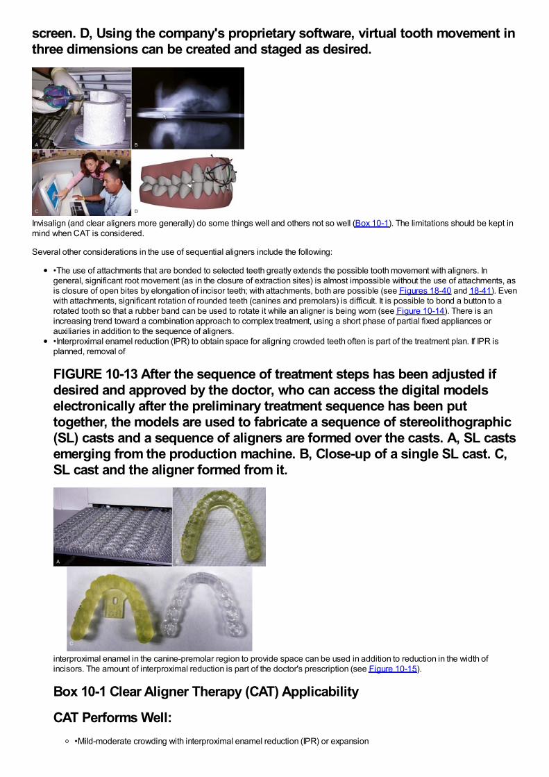
screen. D, Using the company's proprietary software, virtual tooth movement inthree dimensions can be created and staged as desired.
Invisalign (and clear aligners more generally) do some things well and others not so well (Box 10-1). The limitations should be kept inmind when CAT is considered.
Several other considerations in the use of sequential aligners include the following:
•The use of attachments that are bonded to selected teeth greatly extends the possible tooth movement with aligners. Ingeneral, significant root movement (as in the closure of extraction sites) is almost impossible without the use of attachments, asis closure of open bites by elongation of incisor teeth; with attachments, both are possible (see Figures 18-40 and 18-41). Evenwith attachments, significant rotation of rounded teeth (canines and premolars) is difficult. It is possible to bond a button to arotated tooth so that a rubber band can be used to rotate it while an aligner is being worn (see Figure 10-14). There is anincreasing trend toward a combination approach to complex treatment, using a short phase of partial fixed appliances orauxiliaries in addition to the sequence of aligners.•Interproximal enamel reduction (IPR) to obtain space for aligning crowded teeth often is part of the treatment plan. If IPR isplanned, removal of
FIGURE 10-13 After the sequence of treatment steps has been adjusted ifdesired and approved by the doctor, who can access the digital modelselectronically after the preliminary treatment sequence has been puttogether, the models are used to fabricate a sequence of stereolithographic(SL) casts and a sequence of aligners are formed over the casts. A, SL castsemerging from the production machine. B, Close-up of a single SL cast. C,SL cast and the aligner formed from it.
interproximal enamel in the canine-premolar region to provide space can be used in addition to reduction in the width ofincisors. The amount of interproximal reduction is part of the doctor's prescription (see Figure 10-15).
Box 10-1 Clear Aligner Therapy (CAT) Applicability
CAT Performs Well:•Mild-moderate crowding with interproximal enamel reduction (IPR) or expansion
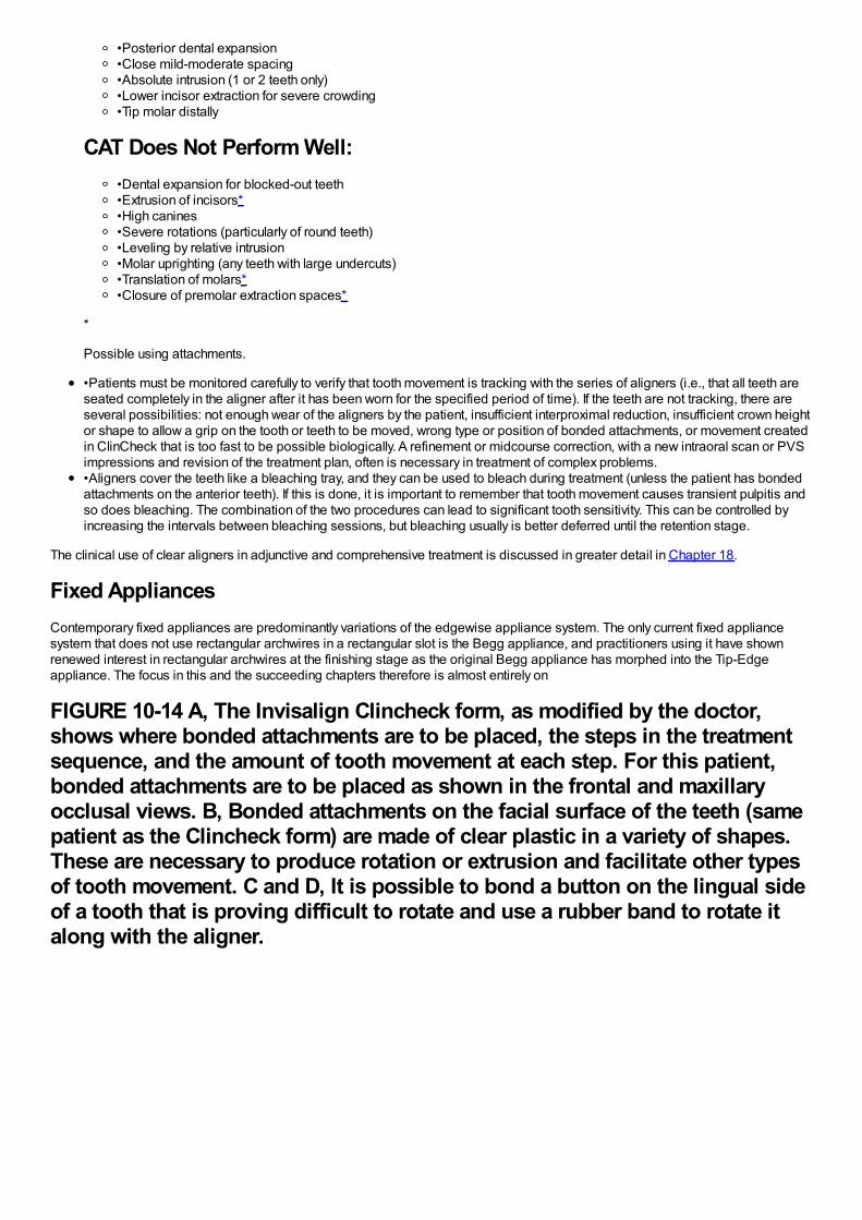
•Posterior dental expansion•Close mild-moderate spacing•Absolute intrusion (1 or 2 teeth only)•Lower incisor extraction for severe crowding•Tip molar distally
CAT Does Not Perform Well:•Dental expansion for blocked-out teeth•Extrusion of incisors*•High canines•Severe rotations (particularly of round teeth)•Leveling by relative intrusion•Molar uprighting (any teeth with large undercuts)•Translation of molars*•Closure of premolar extraction spaces*
*
Possible using attachments.
•Patients must be monitored carefully to verify that tooth movement is tracking with the series of aligners (i.e., that all teeth areseated completely in the aligner after it has been worn for the specified period of time). If the teeth are not tracking, there areseveral possibilities: not enough wear of the aligners by the patient, insufficient interproximal reduction, insufficient crown heightor shape to allow a grip on the tooth or teeth to be moved, wrong type or position of bonded attachments, or movement createdin ClinCheck that is too fast to be possible biologically. A refinement or midcourse correction, with a new intraoral scan or PVSimpressions and revision of the treatment plan, often is necessary in treatment of complex problems.•Aligners cover the teeth like a bleaching tray, and they can be used to bleach during treatment (unless the patient has bondedattachments on the anterior teeth). If this is done, it is important to remember that tooth movement causes transient pulpitis andso does bleaching. The combination of the two procedures can lead to significant tooth sensitivity. This can be controlled byincreasing the intervals between bleaching sessions, but bleaching usually is better deferred until the retention stage.
The clinical use of clear aligners in adjunctive and comprehensive treatment is discussed in greater detail in Chapter 18.
Fixed AppliancesContemporary fixed appliances are predominantly variations of the edgewise appliance system. The only current fixed appliancesystem that does not use rectangular archwires in a rectangular slot is the Begg appliance, and practitioners using it have shownrenewed interest in rectangular archwires at the finishing stage as the original Begg appliance has morphed into the Tip-Edgeappliance. The focus in this and the succeeding chapters therefore is almost entirely on
FIGURE 10-14 A, The Invisalign Clincheck form, as modified by the doctor,shows where bonded attachments are to be placed, the steps in the treatmentsequence, and the amount of tooth movement at each step. For this patient,bonded attachments are to be placed as shown in the frontal and maxillaryocclusal views. B, Bonded attachments on the facial surface of the teeth (samepatient as the Clincheck form) are made of clear plastic in a variety of shapes.These are necessary to produce rotation or extrusion and facilitate other typesof tooth movement. C and D, It is possible to bond a button on the lingual sideof a tooth that is proving difficult to rotate and use a rubber band to rotate italong with the aligner.
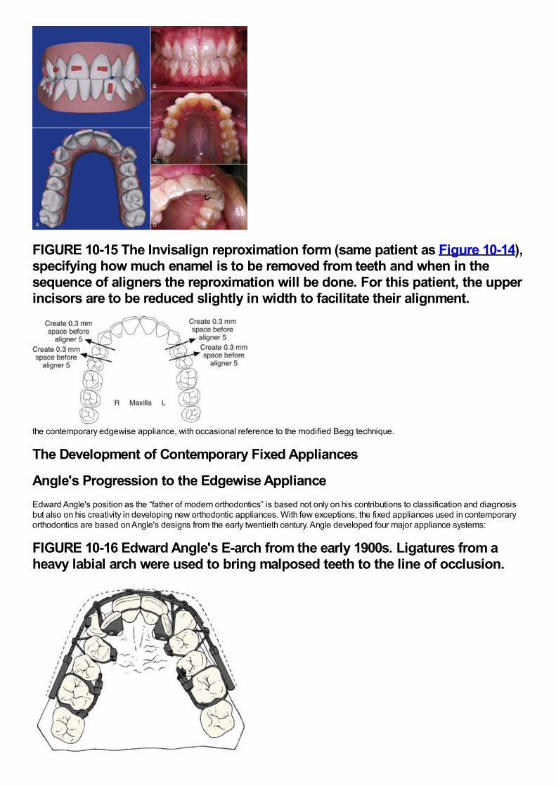
FIGURE 10-15 The Invisalign reproximation form (same patient as Figure 10-14),specifying how much enamel is to be removed from teeth and when in thesequence of aligners the reproximation will be done. For this patient, the upperincisors are to be reduced slightly in width to facilitate their alignment.
the contemporary edgewise appliance, with occasional reference to the modified Begg technique.
The Development of Contemporary Fixed Appliances
Angle's Progression to the Edgewise ApplianceEdward Angle's position as the “father of modern orthodontics” is based not only on his contributions to classification and diagnosisbut also on his creativity in developing new orthodontic appliances. With few exceptions, the fixed appliances used in contemporaryorthodontics are based on Angle's designs from the early twentieth century. Angle developed four major appliance systems:
FIGURE 10-16 Edward Angle's E-arch from the early 1900s. Ligatures from aheavy labial arch were used to bring malposed teeth to the line of occlusion.
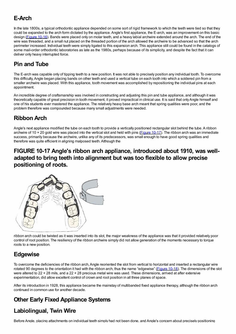
E-ArchIn the late 1800s, a typical orthodontic appliance depended on some sort of rigid framework to which the teeth were tied so that theycould be expanded to the arch form dictated by the appliance. Angle's first appliance, the E-arch, was an improvement on this basicdesign (Figure 10-16). Bands were placed only on molar teeth, and a heavy labial archwire extended around the arch. The end of thewire was threaded, and a small nut placed on the threaded portion of the arch allowed the archwire to be advanced so that the archperimeter increased. Individual teeth were simply ligated to this expansion arch. This appliance still could be found in the catalogs ofsome mail-order orthodontic laboratories as late as the 1980s, perhaps because of its simplicity, and despite the fact that it candeliver only heavy interrupted force.
Pin and TubeThe E-arch was capable only of tipping teeth to a new position. It was not able to precisely position any individual tooth. To overcomethis difficulty, Angle began placing bands on other teeth and used a vertical tube on each tooth into which a soldered pin from asmaller archwire was placed. With this appliance, tooth movement was accomplished by repositioning the individual pins at eachappointment.
An incredible degree of craftsmanship was involved in constructing and adjusting this pin and tube appliance, and although it wastheoretically capable of great precision in tooth movement, it proved impractical in clinical use. It is said that only Angle himself andone of his students ever mastered the appliance. The relatively heavy base arch meant that spring qualities were poor, and theproblem therefore was compounded because many small adjustments were needed.
Ribbon ArchAngle's next appliance modified the tube on each tooth to provide a vertically positioned rectangular slot behind the tube. A ribbonarchwire of 10 × 20 gold wire was placed into the vertical slot and held with pins (Figure 10-17). The ribbon arch was an immediatesuccess, primarily because the archwire, unlike any of its predecessors, was small enough to have good spring qualities andtherefore was quite efficient in aligning malposed teeth. Although the
FIGURE 10-17 Angle's ribbon arch appliance, introduced about 1910, was well-adapted to bring teeth into alignment but was too flexible to allow precisepositioning of roots.
ribbon arch could be twisted as it was inserted into its slot, the major weakness of the appliance was that it provided relatively poorcontrol of root position. The resiliency of the ribbon archwire simply did not allow generation of the moments necessary to torqueroots to a new position.
EdgewiseTo overcome the deficiencies of the ribbon arch, Angle reoriented the slot from vertical to horizontal and inserted a rectangular wirerotated 90 degrees to the orientation it had with the ribbon arch, thus the name “edgewise” (Figure 10-18). The dimensions of the slotwere altered to 22 × 28 mils, and a 22 × 28 precious metal wire was used. These dimensions, arrived at after extensiveexperimentation, did allow excellent control of crown and root position in all three planes of space.
After its introduction in 1928, this appliance became the mainstay of multibanded fixed appliance therapy, although the ribbon archcontinued in common use for another decade.
Other Early Fixed Appliance Systems
Labiolingual, Twin WireBefore Angle, placing attachments on individual teeth simply had not been done, and Angle's concern about precisely positioning
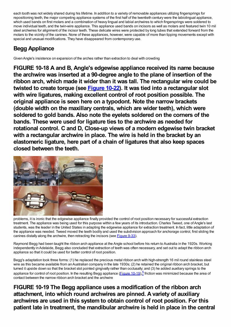
each tooth was not widely shared during his lifetime. In addition to a variety of removable appliances utilizing fingersprings forrepositioning teeth, the major competing appliance systems of the first half of the twentieth century were the labiolingual appliance,which used bands on first molars and a combination of heavy lingual and labial archwires to which fingersprings were soldered tomove individual teeth, and the twin-wire appliance. This appliance used bands on incisors as well as molars and featured twin 10 milsteel archwires for alignment of the incisor teeth. These delicate wires were protected by long tubes that extended forward from themolars to the vicinity of the canines. None of these appliances, however, were capable of more than tipping movements except withspecial and unusual modifications. They have disappeared from contemporary use.
Begg ApplianceGiven Angle's insistence on expansion of the arches rather than extraction to deal with crowding
FIGURE 10-18 A and B, Angle's edgewise appliance received its name becausethe archwire was inserted at a 90-degree angle to the plane of insertion of theribbon arch, which made it wider than it was tall. The rectangular wire could betwisted to create torque (see Figure 10-22). It was tied into a rectangular slotwith wire ligatures, making excellent control of root position possible. Theoriginal appliance is seen here on a typodont. Note the narrow brackets(double width on the maxillary centrals, which are wider teeth), which weresoldered to gold bands. Also note the eyelets soldered on the corners of thebands. These were used for ligature ties to the archwire as needed forrotational control. C and D, Close-up views of a modern edgewise twin bracketwith a rectangular archwire in place. The wire is held in the bracket by anelastomeric ligature, here part of a chain of ligatures that also keep spacesclosed between the teeth.
problems, it is ironic that the edgewise appliance finally provided the control of root position necessary for successful extractiontreatment. The appliance was being used for this purpose within a few years of its introduction. Charles Tweed, one of Angle's laststudents, was the leader in the United States in adapting the edgewise appliance for extraction treatment. In fact, little adaptation ofthe appliance was needed. Tweed moved the teeth bodily and used the subdivision approach for anchorage control, first sliding thecanines distally along the archwire, then retracting the incisors (see Figure 9-33).
Raymond Begg had been taught the ribbon arch appliance at the Angle school before his return to Australia in the 1920s. Workingindependently in Adelaide, Begg also concluded that extraction of teeth was often necessary, and set out to adapt the ribbon archappliance so that it could be used for better control of root position.
Begg's adaptation took three forms: (1) he replaced the precious metal ribbon arch with high-strength 16 mil round stainless steelwire as this became available from an Australian company in the late 1930s; (2) he retained the original ribbon arch bracket, butturned it upside down so that the bracket slot pointed gingivally rather than occlusally; and (3) he added auxiliary springs to theappliance for control of root position. In the resulting Begg appliance (Figure 10-19),5 friction was minimized because the area ofcontact between the narrow ribbon arch bracket and the archwire
FIGURE 10-19 The Begg appliance uses a modification of the ribbon archattachment, into which round archwires are pinned. A variety of auxiliaryarchwires are used in this system to obtain control of root position. For thispatient late in treatment, the mandibular archwire is held in place in the central
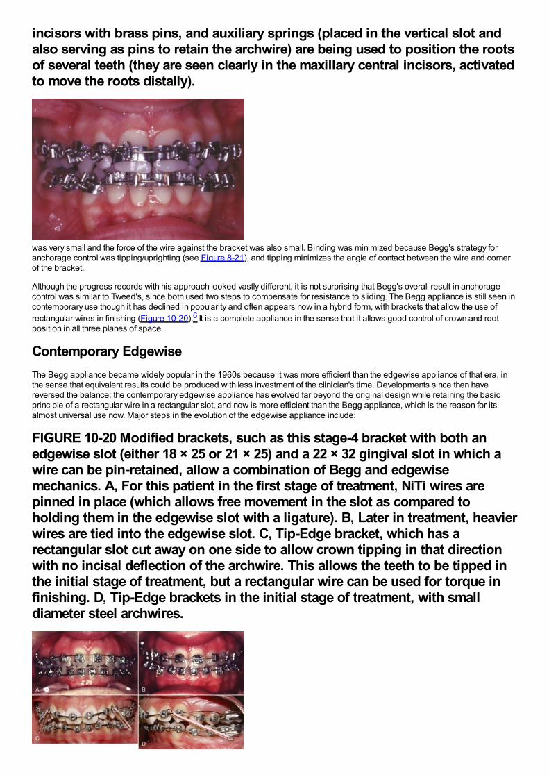
incisors with brass pins, and auxiliary springs (placed in the vertical slot andalso serving as pins to retain the archwire) are being used to position the rootsof several teeth (they are seen clearly in the maxillary central incisors, activatedto move the roots distally).
was very small and the force of the wire against the bracket was also small. Binding was minimized because Begg's strategy foranchorage control was tipping/uprighting (see Figure 8-21), and tipping minimizes the angle of contact between the wire and cornerof the bracket.
Although the progress records with his approach looked vastly different, it is not surprising that Begg's overall result in anchoragecontrol was similar to Tweed's, since both used two steps to compensate for resistance to sliding. The Begg appliance is still seen incontemporary use though it has declined in popularity and often appears now in a hybrid form, with brackets that allow the use ofrectangular wires in finishing (Figure 10-20).6 It is a complete appliance in the sense that it allows good control of crown and rootposition in all three planes of space.
Contemporary EdgewiseThe Begg appliance became widely popular in the 1960s because it was more efficient than the edgewise appliance of that era, inthe sense that equivalent results could be produced with less investment of the clinician's time. Developments since then havereversed the balance: the contemporary edgewise appliance has evolved far beyond the original design while retaining the basicprinciple of a rectangular wire in a rectangular slot, and now is more efficient than the Begg appliance, which is the reason for itsalmost universal use now. Major steps in the evolution of the edgewise appliance include:
FIGURE 10-20 Modified brackets, such as this stage-4 bracket with both anedgewise slot (either 18 × 25 or 21 × 25) and a 22 × 32 gingival slot in which awire can be pin-retained, allow a combination of Begg and edgewisemechanics. A, For this patient in the first stage of treatment, NiTi wires arepinned in place (which allows free movement in the slot as compared toholding them in the edgewise slot with a ligature). B, Later in treatment, heavierwires are tied into the edgewise slot. C, Tip-Edge bracket, which has arectangular slot cut away on one side to allow crown tipping in that directionwith no incisal deflection of the archwire. This allows the teeth to be tipped inthe initial stage of treatment, but a rectangular wire can be used for torque infinishing. D, Tip-Edge brackets in the initial stage of treatment, with smalldiameter steel archwires.
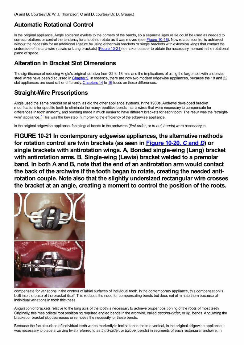
(A and B, Courtesy Dr. W. J. Thompson; C and D, courtesy Dr. D. Grauer.)
Automatic Rotational ControlIn the original appliance, Angle soldered eyelets to the corners of the bands, so a separate ligature tie could be used as needed tocorrect rotations or control the tendency for a tooth to rotate as it was moved (see Figure 10-18). Now rotation control is achievedwithout the necessity for an additional ligature by using either twin brackets or single brackets with extension wings that contact theunderside of the archwire (Lewis or Lang brackets) (Figure 10-21) to make it easier to obtain the necessary moment in the rotationalplane of space.
Alteration in Bracket Slot DimensionsThe significance of reducing Angle's original slot size from 22 to 18 mils and the implications of using the larger slot with undersizesteel wires have been discussed in Chapter 9. In essence, there are now two modern edgewise appliances, because the 18 and 22slot appliances are used rather differently. Chapters 14 to 16 focus on these differences.
Straight-Wire PrescriptionsAngle used the same bracket on all teeth, as did the other appliance systems. In the 1980s, Andrews developed bracketmodifications for specific teeth to eliminate the many repetitive bends in archwires that were necessary to compensate fordifferences in tooth anatomy, and bonding made it much easier to have different brackets for each tooth. The result was the “straight-wire” appliance.7 This was the key step in improving the efficiency of the edgewise appliance.
In the original edgewise appliance, faciolingual bends in the archwires (first-order, or in-out, bends) were necessary to
FIGURE 10-21 In contemporary edgewise appliances, the alternative methodsfor rotation control are twin brackets (as seen in Figure 10-20, C and D) orsingle brackets with antirotation wings. A, Bonded single-wing (Lang) bracketwith antirotation arms. B, Single-wing (Lewis) bracket welded to a premolarband. In both A and B, note that the end of an antirotation arm would contactthe back of the archwire if the tooth began to rotate, creating the needed anti-rotation couple. Note also that the slightly undersized rectangular wire crossesthe bracket at an angle, creating a moment to control the position of the roots.
compensate for variations in the contour of labial surfaces of individual teeth. In the contemporary appliance, this compensation isbuilt into the base of the bracket itself. This reduces the need for compensating bends but does not eliminate them because ofindividual variations in tooth thickness.
Angulation of brackets relative to the long axis of the tooth is necessary to achieve proper positioning of the roots of most teeth.Originally, this mesiodistal root positioning required angled bends in the archwire, called second-order, or tip, bends. Angulating thebracket or bracket slot decreases or removes the necessity for these bends.
Because the facial surface of individual teeth varies markedly in inclination to the true vertical, in the original edgewise appliance itwas necessary to place a varying twist (referred to as third-order, or torque, bends) in segments of each rectangular archwire, in
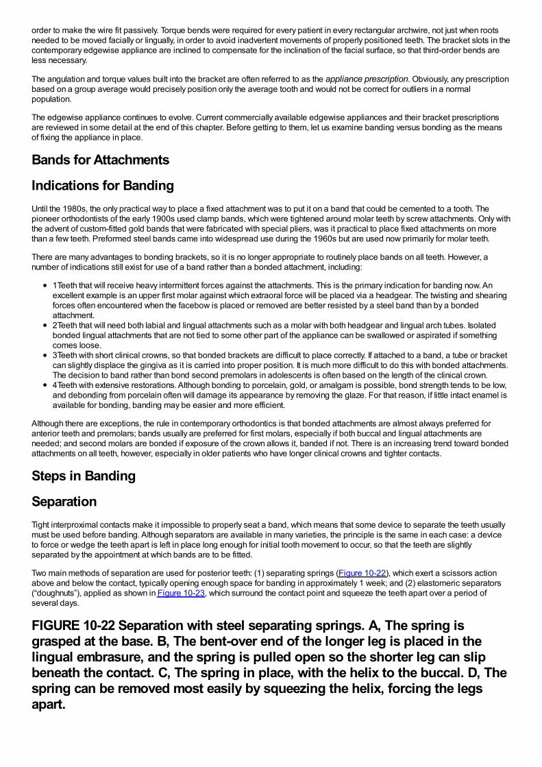
order to make the wire fit passively. Torque bends were required for every patient in every rectangular archwire, not just when rootsneeded to be moved facially or lingually, in order to avoid inadvertent movements of properly positioned teeth. The bracket slots in thecontemporary edgewise appliance are inclined to compensate for the inclination of the facial surface, so that third-order bends areless necessary.
The angulation and torque values built into the bracket are often referred to as the appliance prescription. Obviously, any prescriptionbased on a group average would precisely position only the average tooth and would not be correct for outliers in a normalpopulation.
The edgewise appliance continues to evolve. Current commercially available edgewise appliances and their bracket prescriptionsare reviewed in some detail at the end of this chapter. Before getting to them, let us examine banding versus bonding as the meansof fixing the appliance in place.
Bands for Attachments
Indications for BandingUntil the 1980s, the only practical way to place a fixed attachment was to put it on a band that could be cemented to a tooth. Thepioneer orthodontists of the early 1900s used clamp bands, which were tightened around molar teeth by screw attachments. Only withthe advent of custom-fitted gold bands that were fabricated with special pliers, was it practical to place fixed attachments on morethan a few teeth. Preformed steel bands came into widespread use during the 1960s but are used now primarily for molar teeth.
There are many advantages to bonding brackets, so it is no longer appropriate to routinely place bands on all teeth. However, anumber of indications still exist for use of a band rather than a bonded attachment, including:
1Teeth that will receive heavy intermittent forces against the attachments. This is the primary indication for banding now. Anexcellent example is an upper first molar against which extraoral force will be placed via a headgear. The twisting and shearingforces often encountered when the facebow is placed or removed are better resisted by a steel band than by a bondedattachment.2Teeth that will need both labial and lingual attachments such as a molar with both headgear and lingual arch tubes. Isolatedbonded lingual attachments that are not tied to some other part of the appliance can be swallowed or aspirated if somethingcomes loose.3Teeth with short clinical crowns, so that bonded brackets are difficult to place correctly. If attached to a band, a tube or bracketcan slightly displace the gingiva as it is carried into proper position. It is much more difficult to do this with bonded attachments.The decision to band rather than bond second premolars in adolescents is often based on the length of the clinical crown.4Teeth with extensive restorations. Although bonding to porcelain, gold, or amalgam is possible, bond strength tends to be low,and debonding from porcelain often will damage its appearance by removing the glaze. For that reason, if little intact enamel isavailable for bonding, banding may be easier and more efficient.
Although there are exceptions, the rule in contemporary orthodontics is that bonded attachments are almost always preferred foranterior teeth and premolars; bands usually are preferred for first molars, especially if both buccal and lingual attachments areneeded; and second molars are bonded if exposure of the crown allows it, banded if not. There is an increasing trend toward bondedattachments on all teeth, however, especially in older patients who have longer clinical crowns and tighter contacts.
Steps in Banding
SeparationTight interproximal contacts make it impossible to properly seat a band, which means that some device to separate the teeth usuallymust be used before banding. Although separators are available in many varieties, the principle is the same in each case: a deviceto force or wedge the teeth apart is left in place long enough for initial tooth movement to occur, so that the teeth are slightlyseparated by the appointment at which bands are to be fitted.
Two main methods of separation are used for posterior teeth: (1) separating springs (Figure 10-22), which exert a scissors actionabove and below the contact, typically opening enough space for banding in approximately 1 week; and (2) elastomeric separators(“doughnuts”), applied as shown in Figure 10-23, which surround the contact point and squeeze the teeth apart over a period ofseveral days.
FIGURE 10-22 Separation with steel separating springs. A, The spring isgrasped at the base. B, The bent-over end of the longer leg is placed in thelingual embrasure, and the spring is pulled open so the shorter leg can slipbeneath the contact. C, The spring in place, with the helix to the buccal. D, Thespring can be removed most easily by squeezing the helix, forcing the legsapart.
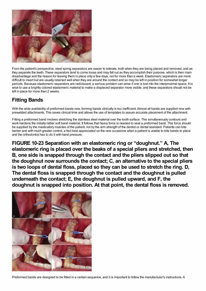
From the patient's perspective, steel spring separators are easier to tolerate, both when they are being placed and removed, and asthey separate the teeth. These separators tend to come loose and may fall out as they accomplish their purpose, which is their maindisadvantage and the reason for leaving them in place only a few days, not for more than a week. Elastomeric separators are moredifficult to insert but are usually retained well when they are around the contact and so may be left in position for somewhat longerperiods. Because elastomeric separators are radiolucent, a serious problem can arise if one is lost into the interproximal space. It iswise to use a brightly colored elastomeric material to make a displaced separator more visible, and these separators should not beleft in place for more than 2 weeks.
Fitting BandsWith the wide availability of preformed bands now, forming bands clinically is too inefficient. Almost all bands are supplied now withprewelded attachments. This saves clinical time and allows the use of templates to assure accurate placement of the attachment.
Fitting a preformed band involves stretching the stainless steel material over the tooth surface. This simultaneously contours andwork-hardens the initially rather soft band material. It follows that heavy force is needed to seat a preformed band. This force shouldbe supplied by the masticatory muscles of the patient, not by the arm strength of the dentist or dental assistant. Patients can biteharder and with much greater control, a fact best appreciated on the rare occasions when a patient is unable to bite bands to placeand the orthodontist has to do it with hand pressure.
FIGURE 10-23 Separation with an elastomeric ring or “doughnut.” A, Theelastomeric ring is placed over the beaks of a special pliers and stretched, thenB, one side is snapped through the contact and the pliers slipped out so thatthe doughnut now surrounds the contact; C, an alternative to the special pliersis two loops of dental floss, placed so they can be used to stretch the ring. D,The dental floss is snapped through the contact and the doughnut is pulledunderneath the contact; E, the doughnut is pulled upward, and F, thedoughnut is snapped into position. At that point, the dental floss is removed.
Preformed bands are designed to be fitted in a certain sequence, and it is important to follow the manufacturer's instructions. A
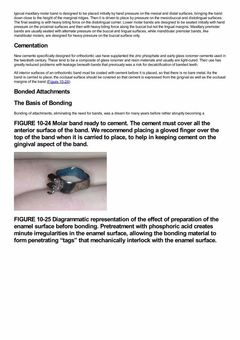
typical maxillary molar band is designed to be placed initially by hand pressure on the mesial and distal surfaces, bringing the banddown close to the height of the marginal ridges. Then it is driven to place by pressure on the mesiobuccal and distolingual surfaces.The final seating is with heavy biting force on the distolingual corner. Lower molar bands are designed to be seated initially with handpressure on the proximal surfaces and then with heavy biting force along the buccal but not the lingual margins. Maxillary premolarbands are usually seated with alternate pressure on the buccal and lingual surfaces, while mandibular premolar bands, likemandibular molars, are designed for heavy pressure on the buccal surface only.
CementationNew cements specifically designed for orthodontic use have supplanted the zinc phosphate and early glass ionomer cements used inthe twentieth century. These tend to be a composite of glass ionomer and resin materials and usually are light-cured. Their use hasgreatly reduced problems with leakage beneath bands that previously was a risk for decalcification of banded teeth.
All interior surfaces of an orthodontic band must be coated with cement before it is placed, so that there is no bare metal. As theband is carried to place, the occlusal surface should be covered so that cement is expressed from the gingival as well as the occlusalmargins of the band (Figure 10-24).
Bonded Attachments
The Basis of BondingBonding of attachments, eliminating the need for bands, was a dream for many years before rather abruptly becoming a
FIGURE 10-24 Molar band ready to cement. The cement must cover all theanterior surface of the band. We recommend placing a gloved finger over thetop of the band when it is carried to place, to help in keeping cement on thegingival aspect of the band.
FIGURE 10-25 Diagrammatic representation of the effect of preparation of theenamel surface before bonding. Pretreatment with phosphoric acid createsminute irregularities in the enamel surface, allowing the bonding material toform penetrating “tags” that mechanically interlock with the enamel surface.
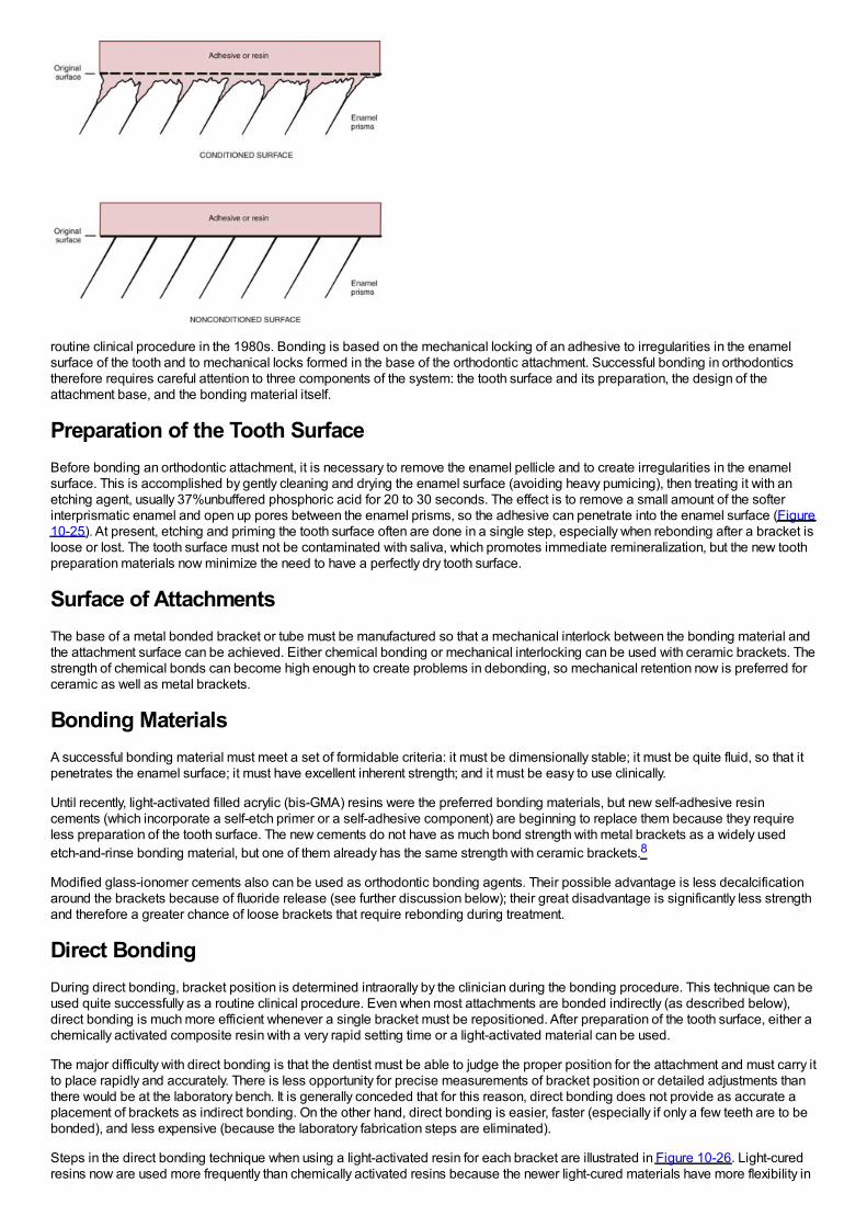
routine clinical procedure in the 1980s. Bonding is based on the mechanical locking of an adhesive to irregularities in the enamelsurface of the tooth and to mechanical locks formed in the base of the orthodontic attachment. Successful bonding in orthodonticstherefore requires careful attention to three components of the system: the tooth surface and its preparation, the design of theattachment base, and the bonding material itself.
Preparation of the Tooth SurfaceBefore bonding an orthodontic attachment, it is necessary to remove the enamel pellicle and to create irregularities in the enamelsurface. This is accomplished by gently cleaning and drying the enamel surface (avoiding heavy pumicing), then treating it with anetching agent, usually 37%unbuffered phosphoric acid for 20 to 30 seconds. The effect is to remove a small amount of the softerinterprismatic enamel and open up pores between the enamel prisms, so the adhesive can penetrate into the enamel surface (Figure10-25). At present, etching and priming the tooth surface often are done in a single step, especially when rebonding after a bracket isloose or lost. The tooth surface must not be contaminated with saliva, which promotes immediate remineralization, but the new toothpreparation materials now minimize the need to have a perfectly dry tooth surface.
Surface of AttachmentsThe base of a metal bonded bracket or tube must be manufactured so that a mechanical interlock between the bonding material andthe attachment surface can be achieved. Either chemical bonding or mechanical interlocking can be used with ceramic brackets. Thestrength of chemical bonds can become high enough to create problems in debonding, so mechanical retention now is preferred forceramic as well as metal brackets.
Bonding MaterialsA successful bonding material must meet a set of formidable criteria: it must be dimensionally stable; it must be quite fluid, so that itpenetrates the enamel surface; it must have excellent inherent strength; and it must be easy to use clinically.
Until recently, light-activated filled acrylic (bis-GMA) resins were the preferred bonding materials, but new self-adhesive resincements (which incorporate a self-etch primer or a self-adhesive component) are beginning to replace them because they requireless preparation of the tooth surface. The new cements do not have as much bond strength with metal brackets as a widely usedetch-and-rinse bonding material, but one of them already has the same strength with ceramic brackets.8
Modified glass-ionomer cements also can be used as orthodontic bonding agents. Their possible advantage is less decalcificationaround the brackets because of fluoride release (see further discussion below); their great disadvantage is significantly less strengthand therefore a greater chance of loose brackets that require rebonding during treatment.
Direct BondingDuring direct bonding, bracket position is determined intraorally by the clinician during the bonding procedure. This technique can beused quite successfully as a routine clinical procedure. Even when most attachments are bonded indirectly (as described below),direct bonding is much more efficient whenever a single bracket must be repositioned. After preparation of the tooth surface, either achemically activated composite resin with a very rapid setting time or a light-activated material can be used.
The major difficulty with direct bonding is that the dentist must be able to judge the proper position for the attachment and must carry itto place rapidly and accurately. There is less opportunity for precise measurements of bracket position or detailed adjustments thanthere would be at the laboratory bench. It is generally conceded that for this reason, direct bonding does not provide as accurate aplacement of brackets as indirect bonding. On the other hand, direct bonding is easier, faster (especially if only a few teeth are to bebonded), and less expensive (because the laboratory fabrication steps are eliminated).
Steps in the direct bonding technique when using a light-activated resin for each bracket are illustrated in Figure 10-26. Light-curedresins now are used more frequently than chemically activated resins because the newer light-cured materials have more flexibility in
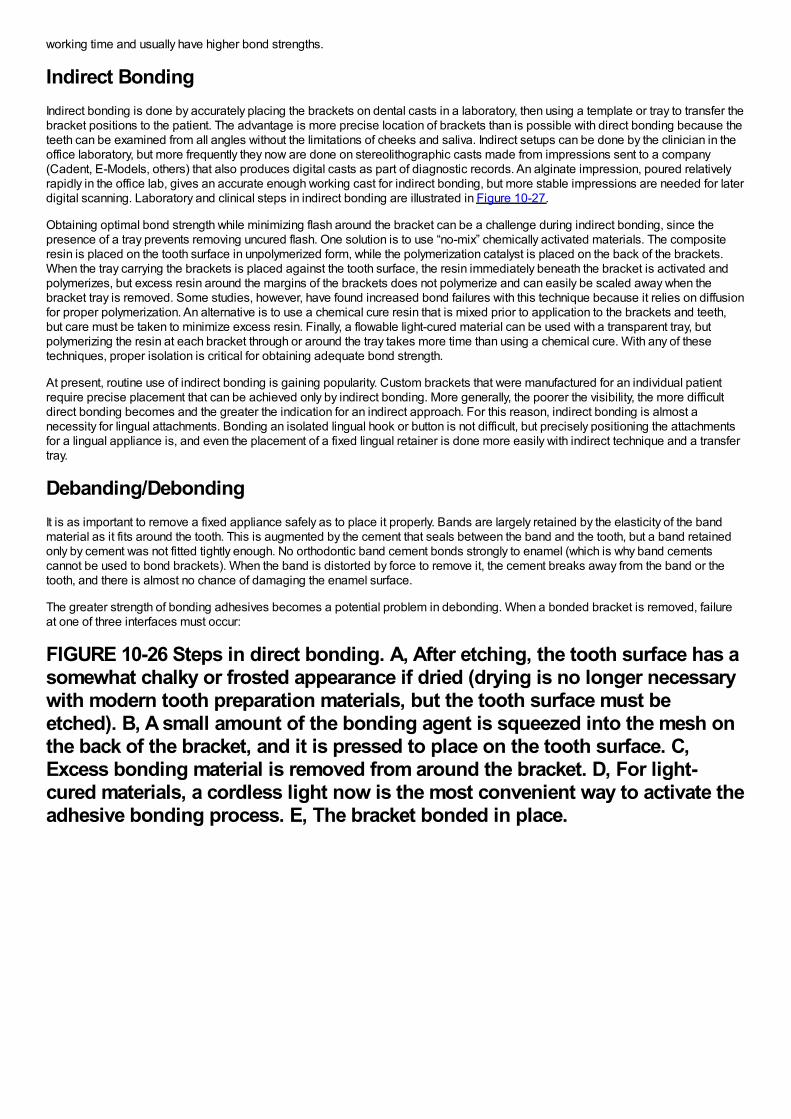
working time and usually have higher bond strengths.
Indirect BondingIndirect bonding is done by accurately placing the brackets on dental casts in a laboratory, then using a template or tray to transfer thebracket positions to the patient. The advantage is more precise location of brackets than is possible with direct bonding because theteeth can be examined from all angles without the limitations of cheeks and saliva. Indirect setups can be done by the clinician in theoffice laboratory, but more frequently they now are done on stereolithographic casts made from impressions sent to a company(Cadent, E-Models, others) that also produces digital casts as part of diagnostic records. An alginate impression, poured relativelyrapidly in the office lab, gives an accurate enough working cast for indirect bonding, but more stable impressions are needed for laterdigital scanning. Laboratory and clinical steps in indirect bonding are illustrated in Figure 10-27.
Obtaining optimal bond strength while minimizing flash around the bracket can be a challenge during indirect bonding, since thepresence of a tray prevents removing uncured flash. One solution is to use “no-mix” chemically activated materials. The compositeresin is placed on the tooth surface in unpolymerized form, while the polymerization catalyst is placed on the back of the brackets.When the tray carrying the brackets is placed against the tooth surface, the resin immediately beneath the bracket is activated andpolymerizes, but excess resin around the margins of the brackets does not polymerize and can easily be scaled away when thebracket tray is removed. Some studies, however, have found increased bond failures with this technique because it relies on diffusionfor proper polymerization. An alternative is to use a chemical cure resin that is mixed prior to application to the brackets and teeth,but care must be taken to minimize excess resin. Finally, a flowable light-cured material can be used with a transparent tray, butpolymerizing the resin at each bracket through or around the tray takes more time than using a chemical cure. With any of thesetechniques, proper isolation is critical for obtaining adequate bond strength.
At present, routine use of indirect bonding is gaining popularity. Custom brackets that were manufactured for an individual patientrequire precise placement that can be achieved only by indirect bonding. More generally, the poorer the visibility, the more difficultdirect bonding becomes and the greater the indication for an indirect approach. For this reason, indirect bonding is almost anecessity for lingual attachments. Bonding an isolated lingual hook or button is not difficult, but precisely positioning the attachmentsfor a lingual appliance is, and even the placement of a fixed lingual retainer is done more easily with indirect technique and a transfertray.
Debanding/DebondingIt is as important to remove a fixed appliance safely as to place it properly. Bands are largely retained by the elasticity of the bandmaterial as it fits around the tooth. This is augmented by the cement that seals between the band and the tooth, but a band retainedonly by cement was not fitted tightly enough. No orthodontic band cement bonds strongly to enamel (which is why band cementscannot be used to bond brackets). When the band is distorted by force to remove it, the cement breaks away from the band or thetooth, and there is almost no chance of damaging the enamel surface.
The greater strength of bonding adhesives becomes a potential problem in debonding. When a bonded bracket is removed, failureat one of three interfaces must occur:
FIGURE 10-26 Steps in direct bonding. A, After etching, the tooth surface has asomewhat chalky or frosted appearance if dried (drying is no longer necessarywith modern tooth preparation materials, but the tooth surface must beetched). B, A small amount of the bonding agent is squeezed into the mesh onthe back of the bracket, and it is pressed to place on the tooth surface. C,Excess bonding material is removed from around the bracket. D, For light-cured materials, a cordless light now is the most convenient way to activate theadhesive bonding process. E, The bracket bonded in place.
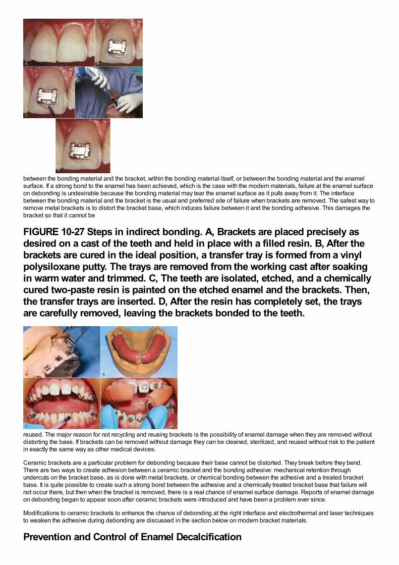
between the bonding material and the bracket, within the bonding material itself, or between the bonding material and the enamelsurface. If a strong bond to the enamel has been achieved, which is the case with the modern materials, failure at the enamel surfaceon debonding is undesirable because the bonding material may tear the enamel surface as it pulls away from it. The interfacebetween the bonding material and the bracket is the usual and preferred site of failure when brackets are removed. The safest way toremove metal brackets is to distort the bracket base, which induces failure between it and the bonding adhesive. This damages thebracket so that it cannot be
FIGURE 10-27 Steps in indirect bonding. A, Brackets are placed precisely asdesired on a cast of the teeth and held in place with a filled resin. B, After thebrackets are cured in the ideal position, a transfer tray is formed from a vinylpolysiloxane putty. The trays are removed from the working cast after soakingin warm water and trimmed. C, The teeth are isolated, etched, and a chemicallycured two-paste resin is painted on the etched enamel and the brackets. Then,the transfer trays are inserted. D, After the resin has completely set, the traysare carefully removed, leaving the brackets bonded to the teeth.
reused. The major reason for not recycling and reusing brackets is the possibility of enamel damage when they are removed withoutdistorting the base. If brackets can be removed without damage they can be cleaned, sterilized, and reused without risk to the patientin exactly the same way as other medical devices.
Ceramic brackets are a particular problem for debonding because their base cannot be distorted. They break before they bend.There are two ways to create adhesion between a ceramic bracket and the bonding adhesive: mechanical retention throughundercuts on the bracket base, as is done with metal brackets, or chemical bonding between the adhesive and a treated bracketbase. It is quite possible to create such a strong bond between the adhesive and a chemically treated bracket base that failure willnot occur there, but then when the bracket is removed, there is a real chance of enamel surface damage. Reports of enamel damageon debonding began to appear soon after ceramic brackets were introduced and have been a problem ever since.
Modifications to ceramic brackets to enhance the chance of debonding at the right interface and electrothermal and laser techniquesto weaken the adhesive during debonding are discussed in the section below on modern bracket materials.
Prevention and Control of Enamel Decalcification
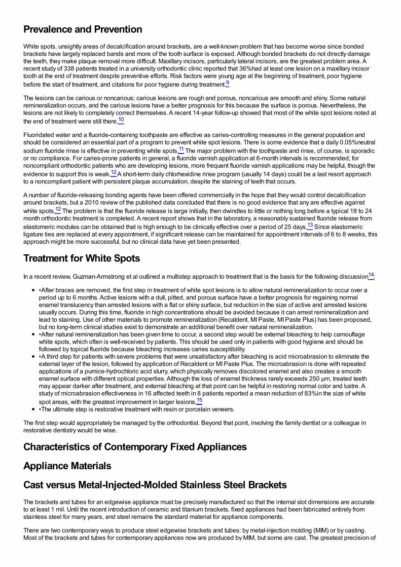
Prevalence and PreventionWhite spots, unsightly areas of decalcification around brackets, are a well-known problem that has become worse since bondedbrackets have largely replaced bands and more of the tooth surface is exposed. Although bonded brackets do not directly damagethe teeth, they make plaque removal more difficult. Maxillary incisors, particularly lateral incisors, are the greatest problem area. Arecent study of 338 patients treated in a university orthodontic clinic reported that 36%had at least one lesion on a maxillary incisortooth at the end of treatment despite preventive efforts. Risk factors were young age at the beginning of treatment, poor hygienebefore the start of treatment, and citations for poor hygiene during treatment.9
The lesions can be carious or noncarious; carious lesions are rough and porous, noncarious are smooth and shiny. Some naturalremineralization occurs, and the carious lesions have a better prognosis for this because the surface is porous. Nevertheless, thelesions are not likely to completely correct themselves. A recent 14-year follow-up showed that most of the white spot lesions noted atthe end of treatment were still there.10
Fluoridated water and a fluoride-containing toothpaste are effective as caries-controlling measures in the general population andshould be considered an essential part of a program to prevent white spot lesions. There is some evidence that a daily 0.05%neutralsodium fluoride rinse is effective in preventing white spots.11 The major problem with the toothpaste and rinse, of course, is sporadicor no compliance. For caries-prone patients in general, a fluoride varnish application at 6-month intervals is recommended; fornoncompliant orthodontic patients who are developing lesions, more frequent fluoride varnish applications may be helpful, though theevidence to support this is weak.12 A short-term daily chlorhexidine rinse program (usually 14 days) could be a last resort approachto a noncompliant patient with persistent plaque accumulation, despite the staining of teeth that occurs.
A number of fluoride-releasing bonding agents have been offered commercially in the hope that they would control decalcificationaround brackets, but a 2010 review of the published data concluded that there is no good evidence that any are effective againstwhite spots.12 The problem is that the fluoride release is large initially, then dwindles to little or nothing long before a typical 18 to 24month orthodontic treatment is completed. A recent report shows that in the laboratory, a reasonably sustained fluoride release fromelastomeric modules can be obtained that is high enough to be clinically effective over a period of 25 days.13 Since elastomericligature ties are replaced at every appointment, if significant release can be maintained for appointment intervals of 6 to 8 weeks, thisapproach might be more successful, but no clinical data have yet been presented.
Treatment for White SpotsIn a recent review, Guzman-Armstrong et al outlined a multistep approach to treatment that is the basis for the following discussion14:
•After braces are removed, the first step in treatment of white spot lesions is to allow natural remineralization to occur over aperiod up to 6 months. Active lesions with a dull, pitted, and porous surface have a better prognosis for regaining normalenamel translucency than arrested lesions with a flat or shiny surface, but reduction in the size of active and arrested lesionsusually occurs. During this time, fluoride in high concentrations should be avoided because it can arrest remineralization andlead to staining. Use of other materials to promote remineralization (Recaldent, MI Paste, MI Paste Plus) has been proposed,but no long-term clinical studies exist to demonstrate an additional benefit over natural remineralization.•After natural remineralization has been given time to occur, a second step would be external bleaching to help camouflagewhite spots, which often is well-received by patients. This should be used only in patients with good hygiene and should befollowed by topical fluoride because bleaching increases caries susceptibility.•A third step for patients with severe problems that were unsatisfactory after bleaching is acid microabrasion to eliminate theexternal layer of the lesion, followed by application of Recaldent or MI Paste Plus. The microabrasion is done with repeatedapplications of a pumice-hydrochloric acid slurry, which physically removes discolored enamel and also creates a smoothenamel surface with different optical properties. Although the loss of enamel thickness rarely exceeds 250 µm, treated teethmay appear darker after treatment, and external bleaching at that point can be helpful in restoring normal color and lustre. Astudy of microabrasion effectiveness in 16 affected teeth in 8 patients reported a mean reduction of 83%in the size of whitespot areas, with the greatest improvement in larger lesions.15
•The ultimate step is restorative treatment with resin or porcelain veneers.
The first step would appropriately be managed by the orthodontist. Beyond that point, involving the family dentist or a colleague inrestorative dentistry would be wise.
Characteristics of Contemporary Fixed Appliances
Appliance Materials
Cast versus Metal-Injected-Molded Stainless Steel BracketsThe brackets and tubes for an edgewise appliance must be precisely manufactured so that the internal slot dimensions are accurateto at least 1 mil. Until the recent introduction of ceramic and titanium brackets, fixed appliances had been fabricated entirely fromstainless steel for many years, and steel remains the standard material for appliance components.
There are two contemporary ways to produce steel edgewise brackets and tubes: by metal-injection molding (MIM) or by casting.Most of the brackets and tubes for contemporary appliances now are produced by MIM, but some are cast. The greatest precision of
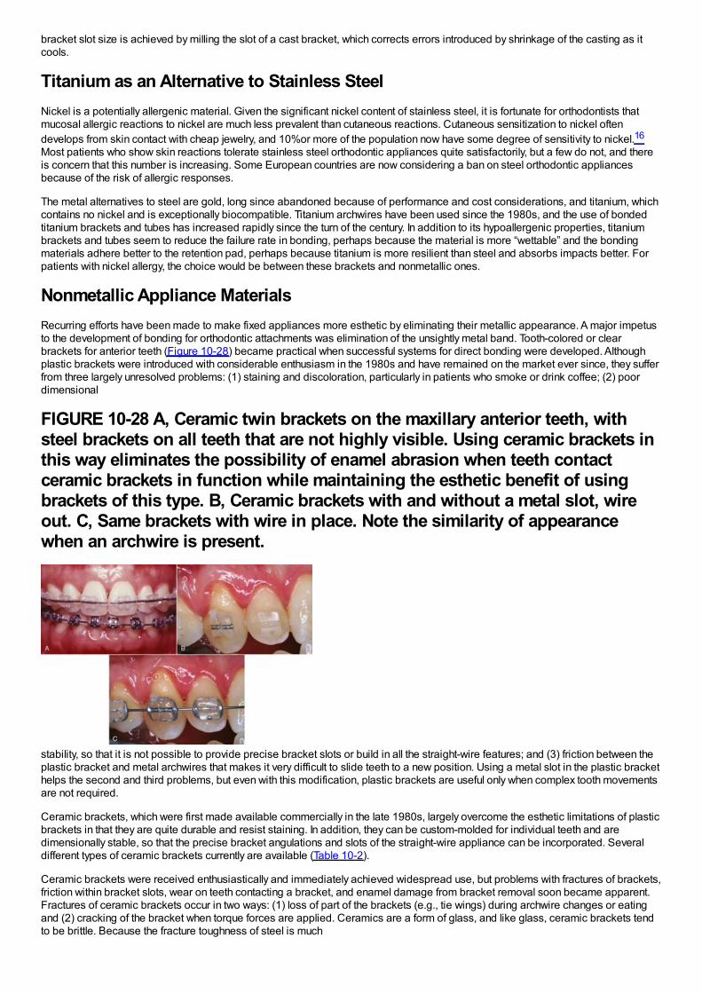
bracket slot size is achieved by milling the slot of a cast bracket, which corrects errors introduced by shrinkage of the casting as itcools.
Titanium as an Alternative to Stainless SteelNickel is a potentially allergenic material. Given the significant nickel content of stainless steel, it is fortunate for orthodontists thatmucosal allergic reactions to nickel are much less prevalent than cutaneous reactions. Cutaneous sensitization to nickel oftendevelops from skin contact with cheap jewelry, and 10%or more of the population now have some degree of sensitivity to nickel.16
Most patients who show skin reactions tolerate stainless steel orthodontic appliances quite satisfactorily, but a few do not, and thereis concern that this number is increasing. Some European countries are now considering a ban on steel orthodontic appliancesbecause of the risk of allergic responses.
The metal alternatives to steel are gold, long since abandoned because of performance and cost considerations, and titanium, whichcontains no nickel and is exceptionally biocompatible. Titanium archwires have been used since the 1980s, and the use of bondedtitanium brackets and tubes has increased rapidly since the turn of the century. In addition to its hypoallergenic properties, titaniumbrackets and tubes seem to reduce the failure rate in bonding, perhaps because the material is more “wettable” and the bondingmaterials adhere better to the retention pad, perhaps because titanium is more resilient than steel and absorbs impacts better. Forpatients with nickel allergy, the choice would be between these brackets and nonmetallic ones.
Nonmetallic Appliance MaterialsRecurring efforts have been made to make fixed appliances more esthetic by eliminating their metallic appearance. A major impetusto the development of bonding for orthodontic attachments was elimination of the unsightly metal band. Tooth-colored or clearbrackets for anterior teeth (Figure 10-28) became practical when successful systems for direct bonding were developed. Althoughplastic brackets were introduced with considerable enthusiasm in the 1980s and have remained on the market ever since, they sufferfrom three largely unresolved problems: (1) staining and discoloration, particularly in patients who smoke or drink coffee; (2) poordimensional
FIGURE 10-28 A, Ceramic twin brackets on the maxillary anterior teeth, withsteel brackets on all teeth that are not highly visible. Using ceramic brackets inthis way eliminates the possibility of enamel abrasion when teeth contactceramic brackets in function while maintaining the esthetic benefit of usingbrackets of this type. B, Ceramic brackets with and without a metal slot, wireout. C, Same brackets with wire in place. Note the similarity of appearancewhen an archwire is present.
stability, so that it is not possible to provide precise bracket slots or build in all the straight-wire features; and (3) friction between theplastic bracket and metal archwires that makes it very difficult to slide teeth to a new position. Using a metal slot in the plastic brackethelps the second and third problems, but even with this modification, plastic brackets are useful only when complex tooth movementsare not required.
Ceramic brackets, which were first made available commercially in the late 1980s, largely overcome the esthetic limitations of plasticbrackets in that they are quite durable and resist staining. In addition, they can be custom-molded for individual teeth and aredimensionally stable, so that the precise bracket angulations and slots of the straight-wire appliance can be incorporated. Severaldifferent types of ceramic brackets currently are available (Table 10-2).
Ceramic brackets were received enthusiastically and immediately achieved widespread use, but problems with fractures of brackets,friction within bracket slots, wear on teeth contacting a bracket, and enamel damage from bracket removal soon became apparent.Fractures of ceramic brackets occur in two ways: (1) loss of part of the brackets (e.g., tie wings) during archwire changes or eatingand (2) cracking of the bracket when torque forces are applied. Ceramics are a form of glass, and like glass, ceramic brackets tendto be brittle. Because the fracture toughness of steel is much
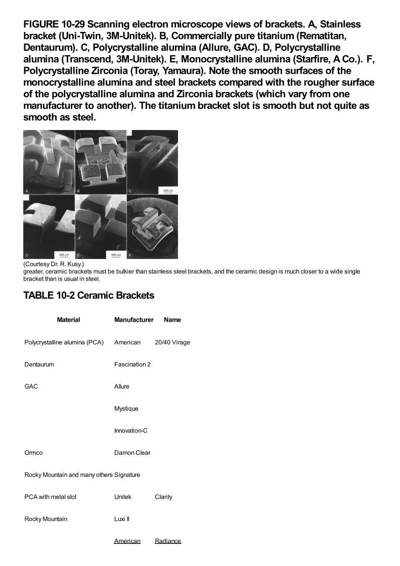
FIGURE 10-29 Scanning electron microscope views of brackets. A, Stainlessbracket (Uni-Twin, 3M-Unitek). B, Commercially pure titanium (Rematitan,Dentaurum). C, Polycrystalline alumina (Allure, GAC). D, Polycrystallinealumina (Transcend, 3M-Unitek). E, Monocrystalline alumina (Starfire, A Co.). F,Polycrystalline Zirconia (Toray, Yamaura). Note the smooth surfaces of themonocrystalline alumina and steel brackets compared with the rougher surfaceof the polycrystalline alumina and Zirconia brackets (which vary from onemanufacturer to another). The titanium bracket slot is smooth but not quite assmooth as steel.
(Courtesy Dr. R. Kusy.)greater, ceramic brackets must be bulkier than stainless steel brackets, and the ceramic design is much closer to a wide singlebracket than is usual in steel.
TABLE 10-2 Ceramic Brackets
Material Manufacturer Name
Polycrystalline alumina (PCA) American 20/40 Virage
Dentaurum Fascination 2
GAC Allure
Mystique
Innovation-C
Ormco Damon Clear
Rocky Mountain and many others Signature
PCA with metal slot Unitek Clarity
Rocky Mountain Luxi II
American Radiance
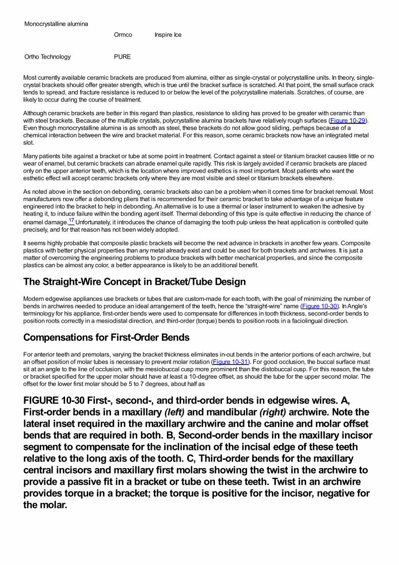
Monocrystalline alumina
Ormco Inspire Ice
Ortho Technology PURE
Most currently available ceramic brackets are produced from alumina, either as single-crystal or polycrystalline units. In theory, single-crystal brackets should offer greater strength, which is true until the bracket surface is scratched. At that point, the small surface cracktends to spread, and fracture resistance is reduced to or below the level of the polycrystalline materials. Scratches, of course, arelikely to occur during the course of treatment.
Although ceramic brackets are better in this regard than plastics, resistance to sliding has proved to be greater with ceramic thanwith steel brackets. Because of the multiple crystals, polycrystalline alumina brackets have relatively rough surfaces (Figure 10-29).Even though monocrystalline alumina is as smooth as steel, these brackets do not allow good sliding, perhaps because of achemical interaction between the wire and bracket material. For this reason, some ceramic brackets now have an integrated metalslot.
Many patients bite against a bracket or tube at some point in treatment. Contact against a steel or titanium bracket causes little or nowear of enamel, but ceramic brackets can abrade enamel quite rapidly. This risk is largely avoided if ceramic brackets are placedonly on the upper anterior teeth, which is the location where improved esthetics is most important. Most patients who want theesthetic effect will accept ceramic brackets only where they are most visible and steel or titanium brackets elsewhere.
As noted above in the section on debonding, ceramic brackets also can be a problem when it comes time for bracket removal. Mostmanufacturers now offer a debonding pliers that is recommended for their ceramic bracket to take advantage of a unique featureengineered into the bracket to help in debonding. An alternative is to use a thermal or laser instrument to weaken the adhesive byheating it, to induce failure within the bonding agent itself. Thermal debonding of this type is quite effective in reducing the chance ofenamel damage.17 Unfortunately, it introduces the chance of damaging the tooth pulp unless the heat application is controlled quiteprecisely, and for that reason has not been widely adopted.
It seems highly probable that composite plastic brackets will become the next advance in brackets in another few years. Compositeplastics with better physical properties than any metal already exist and could be used for both brackets and archwires. It is just amatter of overcoming the engineering problems to produce brackets with better mechanical properties, and since the compositeplastics can be almost any color, a better appearance is likely to be an additional benefit.
The Straight-Wire Concept in Bracket/Tube DesignModern edgewise appliances use brackets or tubes that are custom-made for each tooth, with the goal of minimizing the number ofbends in archwires needed to produce an ideal arrangement of the teeth, hence the “straight-wire” name (Figure 10-30). In Angle'sterminology for his appliance, first-order bends were used to compensate for differences in tooth thickness, second-order bends toposition roots correctly in a mesiodistal direction, and third-order (torque) bends to position roots in a faciolingual direction.
Compensations for First-Order BendsFor anterior teeth and premolars, varying the bracket thickness eliminates in-out bends in the anterior portions of each archwire, butan offset position of molar tubes is necessary to prevent molar rotation (Figure 10-31). For good occlusion, the buccal surface mustsit at an angle to the line of occlusion, with the mesiobuccal cusp more prominent than the distobuccal cusp. For this reason, the tubeor bracket specified for the upper molar should have at least a 10-degree offset, as should the tube for the upper second molar. Theoffset for the lower first molar should be 5 to 7 degrees, about half as
FIGURE 10-30 First-, second-, and third-order bends in edgewise wires. A,First-order bends in a maxillary (left) and mandibular (right) archwire. Note thelateral inset required in the maxillary archwire and the canine and molar offsetbends that are required in both. B, Second-order bends in the maxillary incisorsegment to compensate for the inclination of the incisal edge of these teethrelative to the long axis of the tooth. C, Third-order bends for the maxillarycentral incisors and maxillary first molars showing the twist in the archwire toprovide a passive fit in a bracket or tube on these teeth. Twist in an archwireprovides torque in a bracket; the torque is positive for the incisor, negative forthe molar.
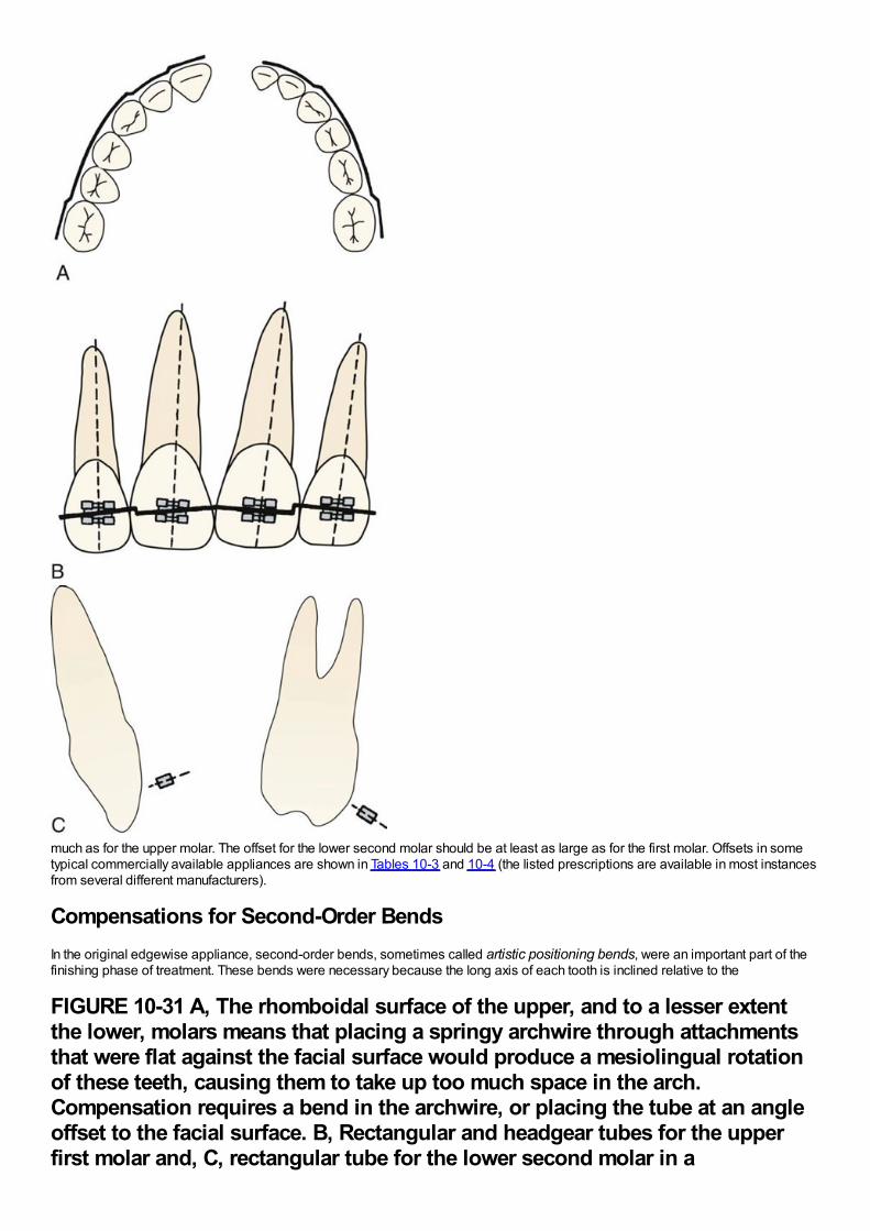
much as for the upper molar. The offset for the lower second molar should be at least as large as for the first molar. Offsets in sometypical commercially available appliances are shown in Tables 10-3 and 10-4 (the listed prescriptions are available in most instancesfrom several different manufacturers).
Compensations for Second-Order BendsIn the original edgewise appliance, second-order bends, sometimes called artistic positioning bends, were an important part of thefinishing phase of treatment. These bends were necessary because the long axis of each tooth is inclined relative to the
FIGURE 10-31 A, The rhomboidal surface of the upper, and to a lesser extentthe lower, molars means that placing a springy archwire through attachmentsthat were flat against the facial surface would produce a mesiolingual rotationof these teeth, causing them to take up too much space in the arch.Compensation requires a bend in the archwire, or placing the tube at an angleoffset to the facial surface. B, Rectangular and headgear tubes for the upperfirst molar and, C, rectangular tube for the lower second molar in a
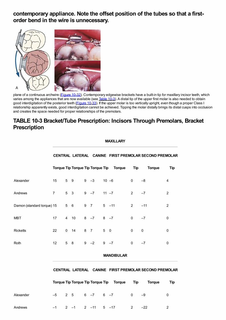
contemporary appliance. Note the offset position of the tubes so that a first-order bend in the wire is unnecessary.
plane of a continuous archwire (Figure 10-32). Contemporary edgewise brackets have a built-in tip for maxillary incisor teeth, whichvaries among the appliances that are now available (see Table 10-3). A distal tip of the upper first molar is also needed to obtaingood interdigitation of the posterior teeth (Figure 10-33). If the upper molar is too vertically upright, even though a proper Class Irelationship apparently exists, good interdigitation cannot be achieved. Tipping the molar distally brings its distal cusps into occlusionand creates the space needed for proper relationships of the premolars.
TABLE 10-3 Bracket/Tube Prescription: Incisors Through Premolars, BracketPrescription
MAXILLARY
CENTRAL LATERAL CANINE FIRST PREMOLAR SECOND PREMOLAR
Torque Tip Torque Tip Torque Tip Torque Tip Torque Tip
Alexander 15 5 9 9 –3 10 –6 0 –8 4
Andrews 7 5 3 9 –7 11 –7 2 –7 2
Damon (standard torque) 15 5 6 9 7 5 –11 2 –11 2
MBT 17 4 10 8 –7 8 –7 0 –7 0
Ricketts 22 0 14 8 7 5 0 0 0 0
Roth 12 5 8 9 –2 9 –7 0 –7 0
MANDIBULAR
CENTRAL LATERAL CANINE FIRST PREMOLAR SECOND PREMOLAR
Torque Tip Torque Tip Torque Tip Torque Tip Torque Tip
Alexander –5 2 5 6 –7 6 –7 0 –9 0
Andrews –1 2 –1 2 –11 5 –17 2 –22 2
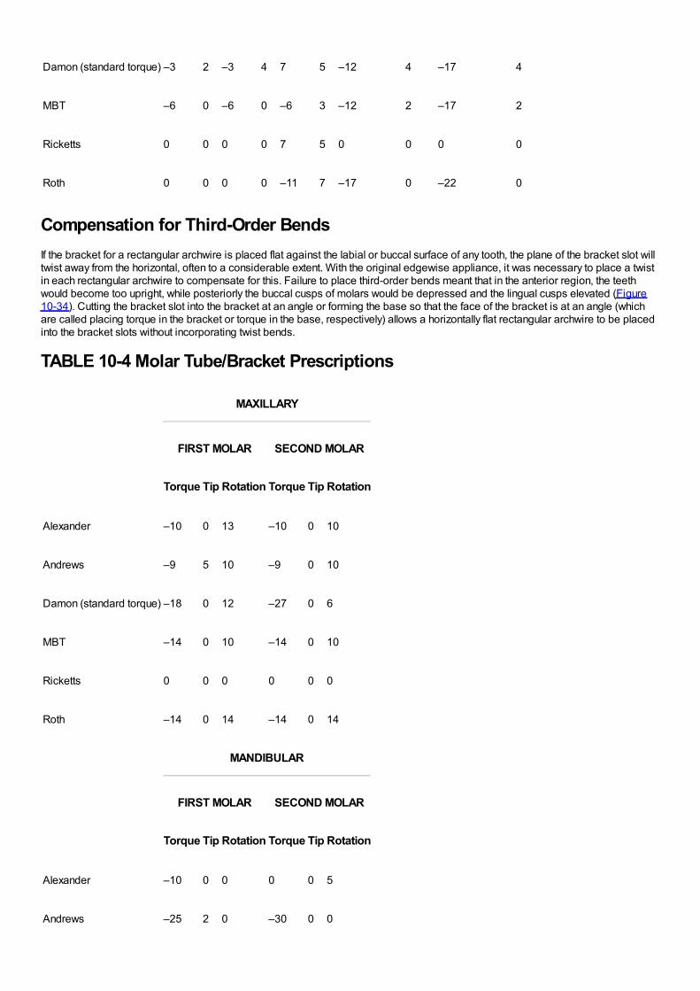
Andrews –1 2 –1 2 –11 5 –17 2 –22 2
Damon (standard torque) –3 2 –3 4 7 5 –12 4 –17 4
MBT –6 0 –6 0 –6 3 –12 2 –17 2
Ricketts 0 0 0 0 7 5 0 0 0 0
Roth 0 0 0 0 –11 7 –17 0 –22 0
Compensation for Third-Order BendsIf the bracket for a rectangular archwire is placed flat against the labial or buccal surface of any tooth, the plane of the bracket slot willtwist away from the horizontal, often to a considerable extent. With the original edgewise appliance, it was necessary to place a twistin each rectangular archwire to compensate for this. Failure to place third-order bends meant that in the anterior region, the teethwould become too upright, while posteriorly the buccal cusps of molars would be depressed and the lingual cusps elevated (Figure10-34). Cutting the bracket slot into the bracket at an angle or forming the base so that the face of the bracket is at an angle (whichare called placing torque in the bracket or torque in the base, respectively) allows a horizontally flat rectangular archwire to be placedinto the bracket slots without incorporating twist bends.
TABLE 10-4 Molar Tube/Bracket Prescriptions
MAXILLARY
FIRST MOLAR SECOND MOLAR
Torque Tip Rotation Torque Tip Rotation
Alexander –10 0 13 –10 0 10
Andrews –9 5 10 –9 0 10
Damon (standard torque) –18 0 12 –27 0 6
MBT –14 0 10 –14 0 10
Ricketts 0 0 0 0 0 0
Roth –14 0 14 –14 0 14
MANDIBULAR
FIRST MOLAR SECOND MOLAR
Torque Tip Rotation Torque Tip Rotation
Alexander –10 0 0 0 0 5
Andrews –25 2 0 –30 0 0
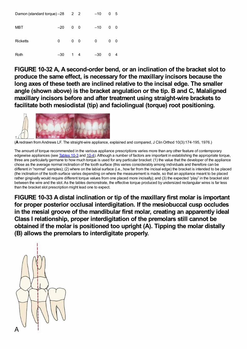
Damon (standard torque) –28 2 2 –10 0 5
MBT –20 0 0 –10 0 0
Ricketts 0 0 0 0 0 0
Roth –30 1 4 –30 0 4
FIGURE 10-32 A, A second-order bend, or an inclination of the bracket slot toproduce the same effect, is necessary for the maxillary incisors because thelong axes of these teeth are inclined relative to the incisal edge. The smallerangle (shown above) is the bracket angulation or the tip. B and C, Malalignedmaxillary incisors before and after treatment using straight-wire brackets tofacilitate both mesiodistal (tip) and faciolingual (torque) root positioning.
(A redrawn from Andrews LF. The straight-wire appliance, explained and compared, J Clin Orthod 10(3):174-195, 1976.)
The amount of torque recommended in the various appliance prescriptions varies more than any other feature of contemporaryedgewise appliances (see Tables 10-3 and 10-4). Although a number of factors are important in establishing the appropriate torque,three are particularly germane to how much torque is used for any particular bracket: (1) the value that the developer of the appliancechose as the average normal inclination of the tooth surface (this varies considerably among individuals and therefore can bedifferent in “normal” samples); (2) where on the labial surface (i.e., how far from the incisal edge) the bracket is intended to be placed(the inclination of the tooth surface varies depending on where the measurement is made, so that an appliance meant to be placedrather gingivally would require different torque values from one placed more incisally); and (3) the expected “play” in the bracket slotbetween the wire and the slot. As the tables demonstrate, the effective torque produced by undersized rectangular wires is far lessthan the bracket slot prescription might lead one to expect.
FIGURE 10-33 A distal inclination or tip of the maxillary first molar is importantfor proper posterior occlusal interdigitation. If the mesiobuccal cusp occludesin the mesial groove of the mandibular first molar, creating an apparently idealClass I relationship, proper interdigitation of the premolars still cannot beobtained if the molar is positioned too upright (A). Tipping the molar distally(B) allows the premolars to interdigitate properly.
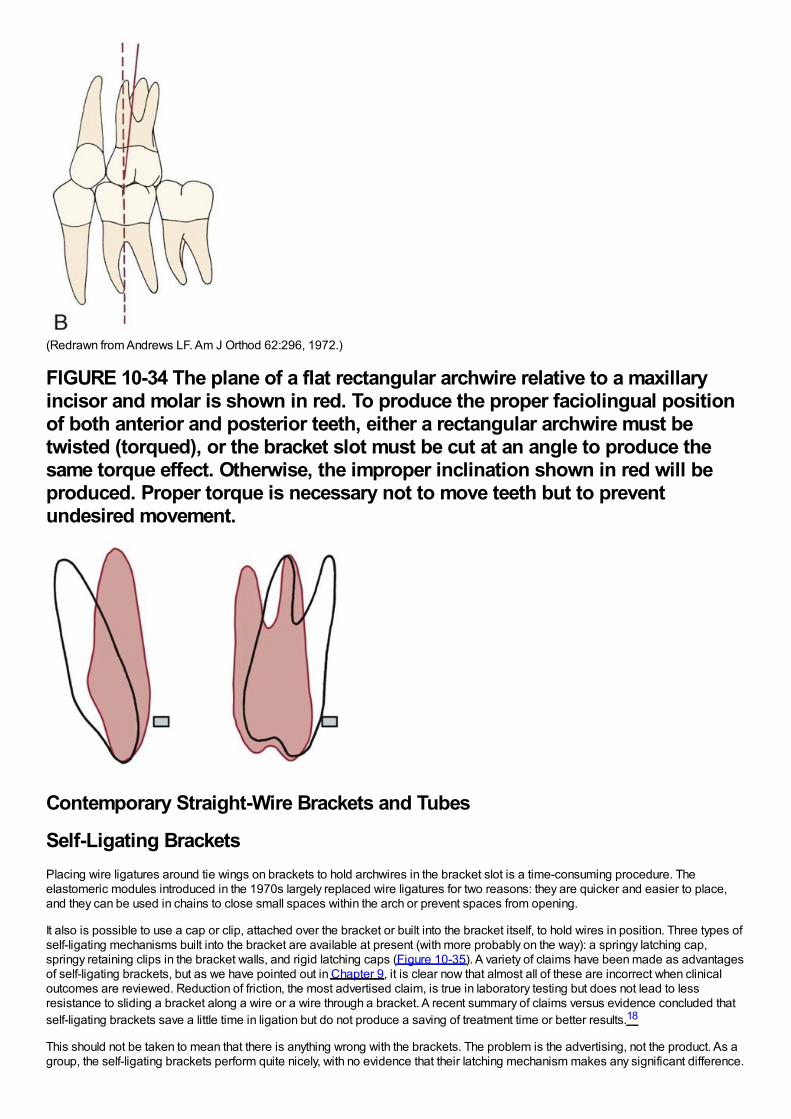
(Redrawn from Andrews LF. Am J Orthod 62:296, 1972.)
FIGURE 10-34 The plane of a flat rectangular archwire relative to a maxillaryincisor and molar is shown in red. To produce the proper faciolingual positionof both anterior and posterior teeth, either a rectangular archwire must betwisted (torqued), or the bracket slot must be cut at an angle to produce thesame torque effect. Otherwise, the improper inclination shown in red will beproduced. Proper torque is necessary not to move teeth but to preventundesired movement.
Contemporary Straight-Wire Brackets and Tubes
Self-Ligating BracketsPlacing wire ligatures around tie wings on brackets to hold archwires in the bracket slot is a time-consuming procedure. Theelastomeric modules introduced in the 1970s largely replaced wire ligatures for two reasons: they are quicker and easier to place,and they can be used in chains to close small spaces within the arch or prevent spaces from opening.
It also is possible to use a cap or clip, attached over the bracket or built into the bracket itself, to hold wires in position. Three types ofself-ligating mechanisms built into the bracket are available at present (with more probably on the way): a springy latching cap,springy retaining clips in the bracket walls, and rigid latching caps (Figure 10-35). A variety of claims have been made as advantagesof self-ligating brackets, but as we have pointed out in Chapter 9, it is clear now that almost all of these are incorrect when clinicaloutcomes are reviewed. Reduction of friction, the most advertised claim, is true in laboratory testing but does not lead to lessresistance to sliding a bracket along a wire or a wire through a bracket. A recent summary of claims versus evidence concluded thatself-ligating brackets save a little time in ligation but do not produce a saving of treatment time or better results.18
This should not be taken to mean that there is anything wrong with the brackets. The problem is the advertising, not the product. As agroup, the self-ligating brackets perform quite nicely, with no evidence that their latching mechanism makes any significant difference.
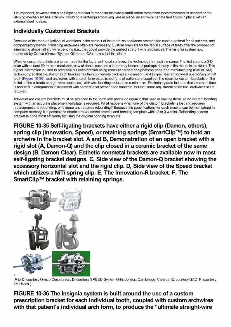
It is important, however, that a self-ligating bracket is made so that when stabilization rather than tooth movement is needed or thelatching mechanism has difficulty in holding a rectangular torquing wire in place, an archwire can be tied tightly in place with anexternal steel ligature.
Individually Customized BracketsBecause of the marked individual variations in the contour of the teeth, no appliance prescription can be optimal for all patients, andcompensatory bends in finishing archwires often are necessary. Custom brackets for the facial surface of teeth offer the prospect ofeliminating almost all archwire bending (i.e., they could provide the perfect straight wire appliance). The Insignia system nowmarketed by Ormco (Ormco/Sybron, Glendora, CA) makes just this claim.
Whether custom brackets are to be made for the facial or lingual surfaces, the technology is much the same. The first step is a 3-Dscan with at least 50 micron resolution, now of dental casts on a laboratory bench but perhaps directly in the mouth in the future. Thisdigital information is used to precisely cut each bracket using computer-aided design/computer-aided manufacturing (CAD/CAM)technology, so that the slot for each bracket has the appropriate thickness, inclination, and torque needed for ideal positioning of thattooth (Figure 10-36), and archwires with an arch form established for that patient are supplied. The result for custom brackets on thefacial is “the ultimate straight-wire appliance,” with wire bending reduced to a minimum. Preliminary data indicate that treatment timeis reduced in comparison to treatment with conventional prescription brackets, but that some adjustment of the final archwires still isrequired.
Individualized custom brackets must be attached to the teeth with precision equal to that used in making them, so an indirect bondingsystem with an accurate placement template is required. What happens when one of the custom brackets is lost and requiresreplacement and rebonding, or is loose and requires rebonding? Because the specifications for each bracket can be maintained incomputer memory, it is possible to obtain a replacement bracket and bonding template within 2 to 3 weeks. Rebonding a loosebracket is done most efficiently by using the original bonding template,
FIGURE 10-35 Self-ligating brackets have either a rigid clip (Damon, others),spring clip (Innovation, Speed), or retaining springs (SmartClip™) to hold anarchwire in the bracket slot. A and B, Demonstration of an open bracket with arigid slot (A, Damon-Q) and the clip closed in a ceramic bracket of the samedesign (B, Damon Clear). Esthetic nonmetal brackets are available now in mostself-ligating bracket designs. C, Side view of the Damon-Q bracket showing theaccessory horizontal slot and the rigid clip. D, Side view of the Speed bracketwhich utilizes a NiTi spring clip. E, The Innovation-R bracket. F, TheSmartClip™ bracket with retaining springs.
(A to C, courtesy Ormco Corporation; D, courtesy SPEED System Orthodontics, Cambridge, Canada; E, courtesy GAC; F, courtesy3M Unitek.)
FIGURE 10-36 The Insignia system is built around the use of a customprescription bracket for each individual tooth, coupled with custom archwireswith that patient's individual arch form, to produce the “ultimate straight-wire
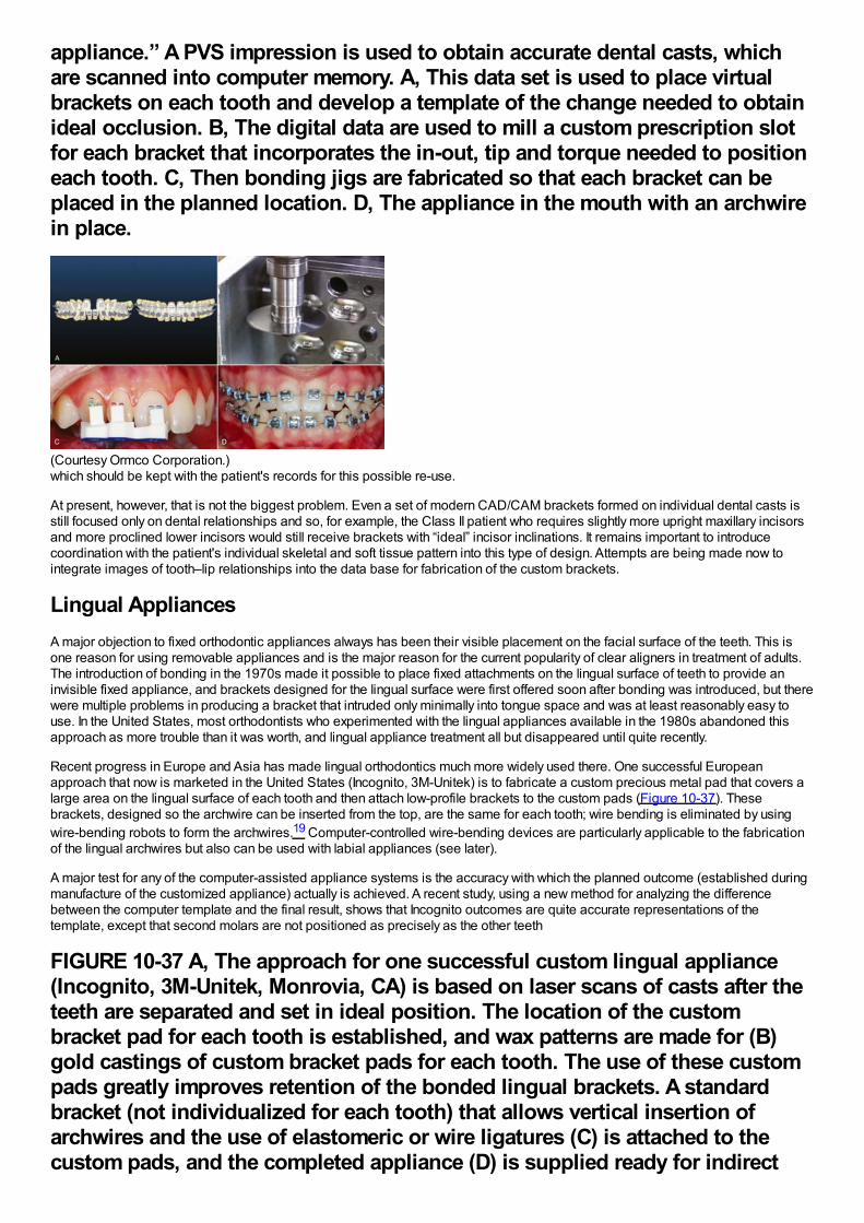
appliance.” A PVS impression is used to obtain accurate dental casts, whichare scanned into computer memory. A, This data set is used to place virtualbrackets on each tooth and develop a template of the change needed to obtainideal occlusion. B, The digital data are used to mill a custom prescription slotfor each bracket that incorporates the in-out, tip and torque needed to positioneach tooth. C, Then bonding jigs are fabricated so that each bracket can beplaced in the planned location. D, The appliance in the mouth with an archwirein place.
(Courtesy Ormco Corporation.)which should be kept with the patient's records for this possible re-use.
At present, however, that is not the biggest problem. Even a set of modern CAD/CAM brackets formed on individual dental casts isstill focused only on dental relationships and so, for example, the Class II patient who requires slightly more upright maxillary incisorsand more proclined lower incisors would still receive brackets with “ideal” incisor inclinations. It remains important to introducecoordination with the patient's individual skeletal and soft tissue pattern into this type of design. Attempts are being made now tointegrate images of tooth–lip relationships into the data base for fabrication of the custom brackets.
Lingual AppliancesA major objection to fixed orthodontic appliances always has been their visible placement on the facial surface of the teeth. This isone reason for using removable appliances and is the major reason for the current popularity of clear aligners in treatment of adults.The introduction of bonding in the 1970s made it possible to place fixed attachments on the lingual surface of teeth to provide aninvisible fixed appliance, and brackets designed for the lingual surface were first offered soon after bonding was introduced, but therewere multiple problems in producing a bracket that intruded only minimally into tongue space and was at least reasonably easy touse. In the United States, most orthodontists who experimented with the lingual appliances available in the 1980s abandoned thisapproach as more trouble than it was worth, and lingual appliance treatment all but disappeared until quite recently.
Recent progress in Europe and Asia has made lingual orthodontics much more widely used there. One successful Europeanapproach that now is marketed in the United States (Incognito, 3M-Unitek) is to fabricate a custom precious metal pad that covers alarge area on the lingual surface of each tooth and then attach low-profile brackets to the custom pads (Figure 10-37). Thesebrackets, designed so the archwire can be inserted from the top, are the same for each tooth; wire bending is eliminated by usingwire-bending robots to form the archwires.19 Computer-controlled wire-bending devices are particularly applicable to the fabricationof the lingual archwires but also can be used with labial appliances (see later).
A major test for any of the computer-assisted appliance systems is the accuracy with which the planned outcome (established duringmanufacture of the customized appliance) actually is achieved. A recent study, using a new method for analyzing the differencebetween the computer template and the final result, shows that Incognito outcomes are quite accurate representations of thetemplate, except that second molars are not positioned as precisely as the other teeth
FIGURE 10-37 A, The approach for one successful custom lingual appliance(Incognito, 3M-Unitek, Monrovia, CA) is based on laser scans of casts after theteeth are separated and set in ideal position. The location of the custombracket pad for each tooth is established, and wax patterns are made for (B)gold castings of custom bracket pads for each tooth. The use of these custompads greatly improves retention of the bonded lingual brackets. A standardbracket (not individualized for each tooth) that allows vertical insertion ofarchwires and the use of elastomeric or wire ligatures (C) is attached to thecustom pads, and the completed appliance (D) is supplied ready for indirect
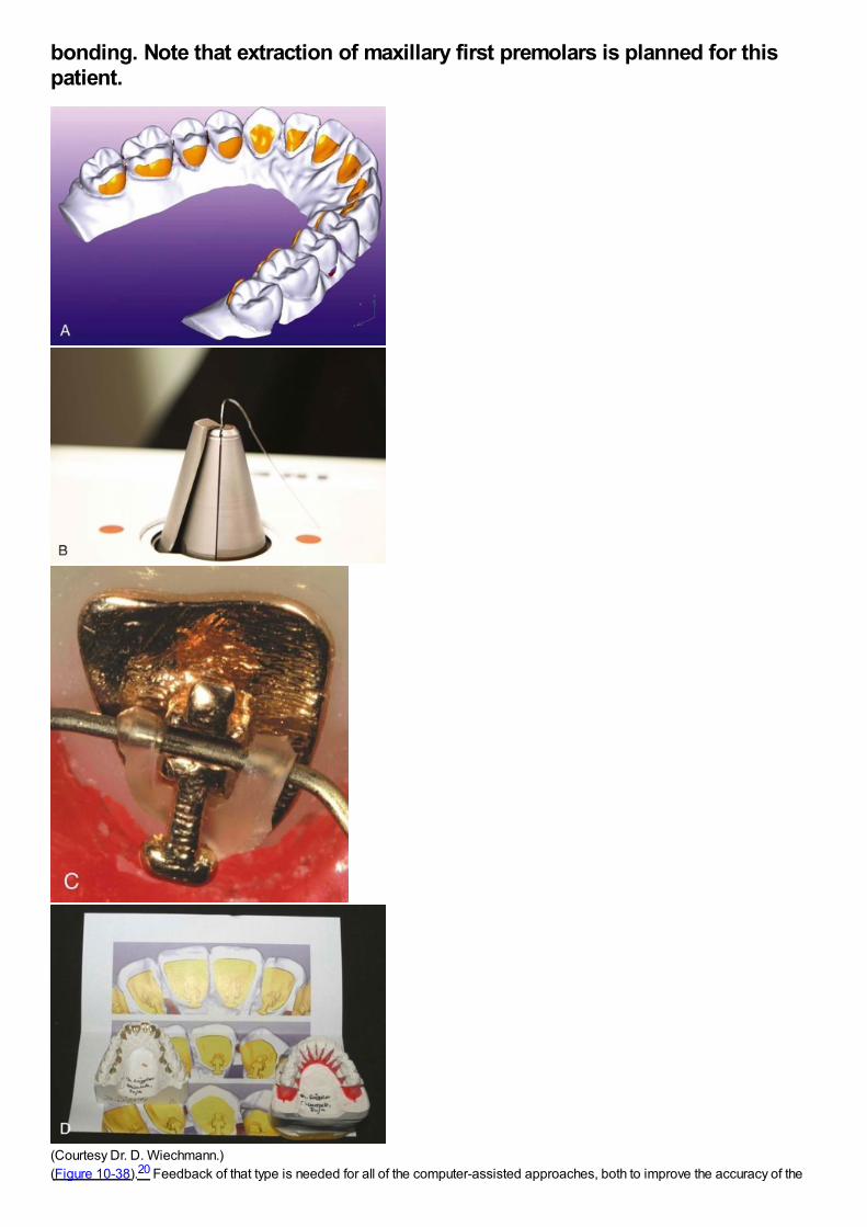
bonding. Note that extraction of maxillary first premolars is planned for thispatient.
(Courtesy Dr. D. Wiechmann.)(Figure 10-38).20 Feedback of that type is needed for all of the computer-assisted approaches, both to improve the accuracy of the
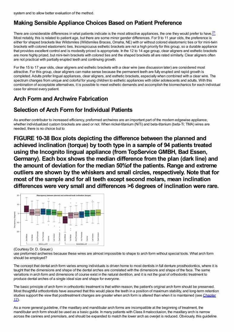
system and to allow better evaluation of the method.
Making Sensible Appliance Choices Based on Patient PreferenceThere are considerable differences in what patients indicate is the most attractive appliances, the one they would prefer to have.21
Most notably, this is related to patient age, but there are some minor gender differences. For 9 to 11 year olds, the preference iseither for shaped brackets like Wildsmiles (Wildsmiles Braces, Omaha, NE) with or without colored elastomeric ties or for mini-twinbrackets with colored elastomeric ties. Inconspicuous esthetic brackets are not a high priority for this group, so a durable appliancethat provides excellent control and is modestly priced is appropriate. In the 12 to 14 age group, clear aligners and esthetic bracketsare more highly prized, but mini-twin brackets with colored ties and the shaped brackets all are rated similarly. Clear aligners oftenare not practical with partially erupted teeth and continuing growth.
For the 15 to 17 year olds, clear aligners and esthetic brackets with a clear wire (see discussion later) are considered mostattractive. For this group, clear aligners can make sense because the permanent teeth are fully erupted and rapid growth iscompleted. Adults prefer lingual appliances, clear aligners, and esthetic brackets, especially when combined with a clear wire. Thespectrum changes from unique and colorful for young children to esthetic appliances with older adolescents and adults. With thiscombination of acceptable alternatives, it is possible to meet esthetic demands and accomplish the biomechanics for each individualcase for almost every patient.
Arch Form and Archwire Fabrication
Selection of Arch Form for Individual PatientsAs another contributor to increased efficiency, preformed archwires are an important part of the modern edgewise appliance,whether individualized custom brackets are used or not. When nickel-titanium (NiTi) and beta-titanium (beta-Ti; TMA) wires areneeded, there is no choice but to
FIGURE 10-38 Box plots depicting the difference between the planned andachieved inclination (torque) by tooth type in a sample of 94 patients treatedusing the Incognito lingual appliance (from TopService GMBH, Bad Essen,Germany). Each box shows the median difference from the plan (dark line) andthe amount of deviation for the median 50%of the patients. Range and extremeoutliers are shown by the whiskers and small circles, respectively. Note that formost of the sample and for all teeth except second molars, mean inclinationdifferences were very small and differences >6 degrees of inclination were rare.
(Courtesy Dr. D. Grauer.)use preformed archwires because these wires are almost impossible to shape to arch form without special tools. What arch formshould be employed?
The concept that dental arch form varies among individuals is driven home to most dentists in full denture prosthodontics, where it istaught that the dimensions and shape of the dental arches are correlated with the dimensions and shape of the face. The samevariations in arch form and dimensions of course exist in the natural dentition, and it is not the goal of orthodontic treatment toproduce dental arches of a single ideal size and shape for everyone.
The basic principle of arch form in orthodontic treatment is that within reason, the patient's original arch form should be preserved.Most thoughtful orthodontists have assumed that this would place the teeth in a position of maximum stability, and long-term retentionstudies support the view that posttreatment changes are greater when arch form is altered than when it is maintained (see Chapter17).
As a more general guideline, if the maxillary and mandibular arch forms are incompatible at the beginning of treatment, themandibular arch form should be used as a basic guide. In many patients with Class II malocclusion, the maxillary arch is narrowacross the canines and premolars, and should be expanded to match the lower arch as overjet is reduced. Obviously, this guideline
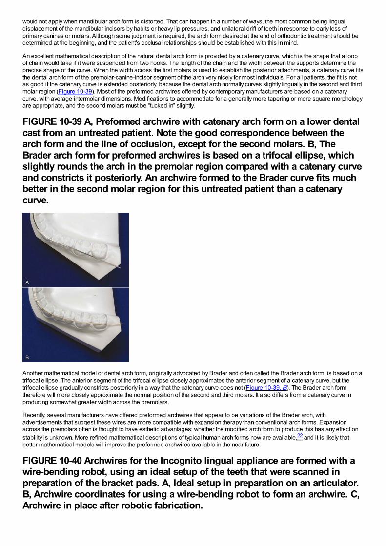
would not apply when mandibular arch form is distorted. That can happen in a number of ways, the most common being lingualdisplacement of the mandibular incisors by habits or heavy lip pressures, and unilateral drift of teeth in response to early loss ofprimary canines or molars. Although some judgment is required, the arch form desired at the end of orthodontic treatment should bedetermined at the beginning, and the patient's occlusal relationships should be established with this in mind.
An excellent mathematical description of the natural dental arch form is provided by a catenary curve, which is the shape that a loopof chain would take if it were suspended from two hooks. The length of the chain and the width between the supports determine theprecise shape of the curve. When the width across the first molars is used to establish the posterior attachments, a catenary curve fitsthe dental arch form of the premolar-canine-incisor segment of the arch very nicely for most individuals. For all patients, the fit is notas good if the catenary curve is extended posteriorly, because the dental arch normally curves slightly lingually in the second and thirdmolar region (Figure 10-39). Most of the preformed archwires offered by contemporary manufacturers are based on a catenarycurve, with average intermolar dimensions. Modifications to accommodate for a generally more tapering or more square morphologyare appropriate, and the second molars must be “tucked in” slightly.
FIGURE 10-39 A, Preformed archwire with catenary arch form on a lower dentalcast from an untreated patient. Note the good correspondence between thearch form and the line of occlusion, except for the second molars. B, TheBrader arch form for preformed archwires is based on a trifocal ellipse, whichslightly rounds the arch in the premolar region compared with a catenary curveand constricts it posteriorly. An archwire formed to the Brader curve fits muchbetter in the second molar region for this untreated patient than a catenarycurve.
Another mathematical model of dental arch form, originally advocated by Brader and often called the Brader arch form, is based on atrifocal ellipse. The anterior segment of the trifocal ellipse closely approximates the anterior segment of a catenary curve, but thetrifocal ellipse gradually constricts posteriorly in a way that the catenary curve does not (Figure 10-39, B). The Brader arch formtherefore will more closely approximate the normal position of the second and third molars. It also differs from a catenary curve inproducing somewhat greater width across the premolars.
Recently, several manufacturers have offered preformed archwires that appear to be variations of the Brader arch, withadvertisements that suggest these wires are more compatible with expansion therapy than conventional arch forms. Expansionacross the premolars often is thought to have esthetic advantages; whether the modified arch form to produce this has any effect onstability is unknown. More refined mathematical descriptions of typical human arch forms now are available,22 and it is likely thatbetter mathematical models will improve the preformed archwires available in the near future.
FIGURE 10-40 Archwires for the Incognito lingual appliance are formed with awire-bending robot, using an ideal setup of the teeth that were scanned inpreparation of the bracket pads. A, Ideal setup in preparation on an articulator.B, Archwire coordinates for using a wire-bending robot to form an archwire. C,Archwire in place after robotic fabrication.
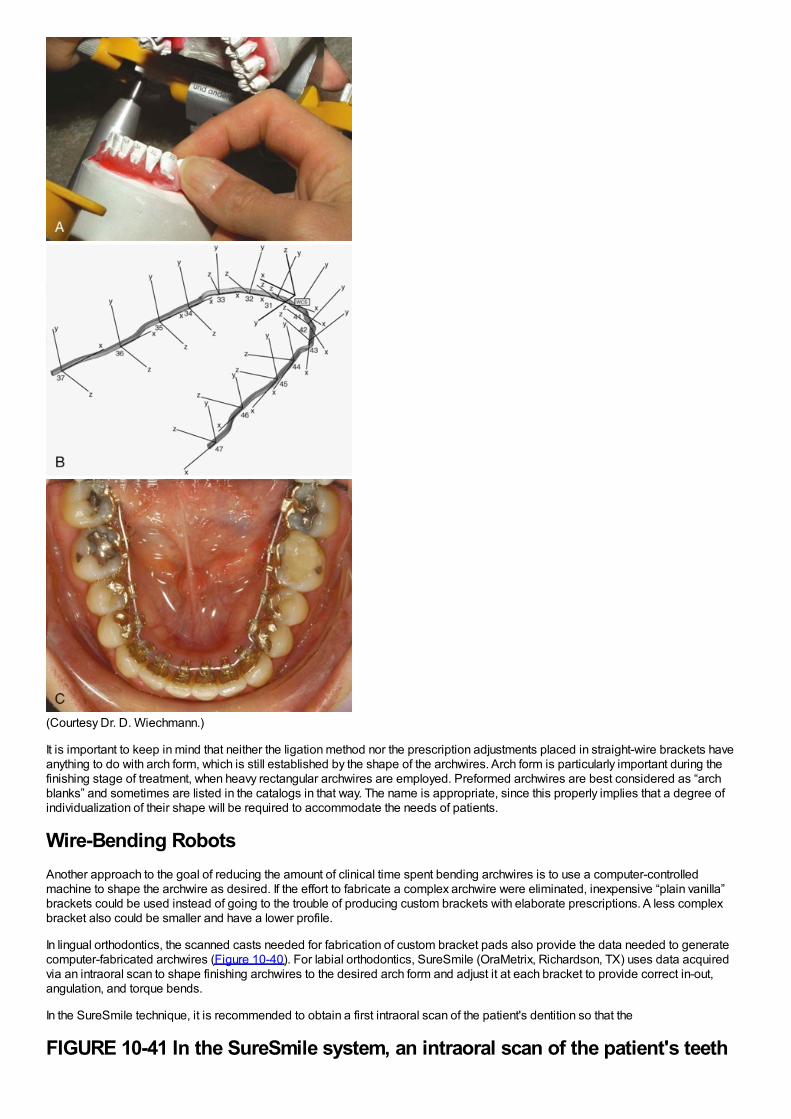
(Courtesy Dr. D. Wiechmann.)
It is important to keep in mind that neither the ligation method nor the prescription adjustments placed in straight-wire brackets haveanything to do with arch form, which is still established by the shape of the archwires. Arch form is particularly important during thefinishing stage of treatment, when heavy rectangular archwires are employed. Preformed archwires are best considered as “archblanks” and sometimes are listed in the catalogs in that way. The name is appropriate, since this properly implies that a degree ofindividualization of their shape will be required to accommodate the needs of patients.
Wire-Bending RobotsAnother approach to the goal of reducing the amount of clinical time spent bending archwires is to use a computer-controlledmachine to shape the archwire as desired. If the effort to fabricate a complex archwire were eliminated, inexpensive “plain vanilla”brackets could be used instead of going to the trouble of producing custom brackets with elaborate prescriptions. A less complexbracket also could be smaller and have a lower profile.
In lingual orthodontics, the scanned casts needed for fabrication of custom bracket pads also provide the data needed to generatecomputer-fabricated archwires (Figure 10-40). For labial orthodontics, SureSmile (OraMetrix, Richardson, TX) uses data acquiredvia an intraoral scan to shape finishing archwires to the desired arch form and adjust it at each bracket to provide correct in-out,angulation, and torque bends.
In the SureSmile technique, it is recommended to obtain a first intraoral scan of the patient's dentition so that the
FIGURE 10-41 In the SureSmile system, an intraoral scan of the patient's teeth
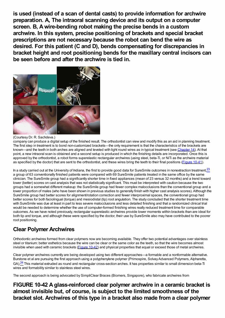
is used (instead of a scan of dental casts) to provide information for archwirepreparation. A, The intraoral scanning device and its output on a computerscreen. B, A wire-bending robot making the precise bends in a customarchwire. In this system, precise positioning of brackets and special bracketprescriptions are not necessary because the robot can bend the wire asdesired. For this patient (C and D), bends compensating for discrepancies inbracket height and root positioning bends for the maxillary central incisors canbe seen before and after the archwire is tied in.
(Courtesy Dr. R. Sachdeva.)company can produce a digital setup of the finished result. The orthodontist can view and modify this as an aid in planning treatment.The first step in treatment is to bond non-customized brackets—the only requirement is that the characteristics of the brackets areknown—and the teeth in both arches are aligned and leveled with light round wires as in typical treatment (see Chapter 14). At thatpoint, a new intraoral scan is obtained and a second setup is produced in which the finishing details are incorporated. Once this isapproved by the orthodontist, a robot forms superelastic rectangular archwires (using steel, beta-Ti, or NiTi as the archwire materialas specified by the doctor) that are sent to the orthodontist, and these wires bring the teeth to their final positions (Figure 10-41).
In a study carried out at the University of Indiana, the first to provide good data for SureSmile outcomes in nonextraction treatment,23
a group of 63 conventionally finished patients were compared with 69 SureSmile patients treated in the same office by the sameclinician. The SureSmile group had a significantly shorter time in fixed appliances (mean of 23 versus 32 months) and a trend towardlower (better) scores on cast analysis that was not statistically significant. This must be interpreted with caution because the twogroups had a somewhat different makeup: the SureSmile group had fewer complex malocclusions than the conventional group and alower proportion of males (who have been shown in previous studies to generally finish with higher cast analysis scores). Although theSureSmile group had better scores for alignment/rotation correction and fewer interproximal spaces, the conventional group hadbetter scores for both faciolingual (torque) and mesiodistal (tip) root angulation. The study concluded that the shorter treatment timewith SureSmile was due at least in part to less severe malocclusions and less detailed finishing and that a randomized clinical trialwould be needed to determine whether the use of computer-formed finishing wires really reduced treatment time for comparableoutcomes. As we have noted previously, rectangular superelastic archwires provide lower moments within brackets than are ideal forboth tip and torque, and although these were specified by the doctor, their use by SureSmile also may have contributed to the poorerroot positioning.
Clear Polymer ArchwiresOrthodontic archwires formed from clear polymers now are becoming available. They offer two potential advantages over stainlesssteel or titanium: better esthetics because the wire can be clear or the same color as the teeth, so that the wire becomes almostinvisible when used with ceramic brackets (Figure 10-42) and physical properties that equal or exceed those of metal archwires.
Clear polymer archwires currently are being developed using two different approaches—a formable and a nonformable alternative.Burstone et al are pursuing the first approach using a polyphenylene polymer (Primospire, Solvay Advanced Polymers, Alpharetta,GA).24 This material extruded as round and rectangular cross-section arches. It has properties similar to small dimension beta-Tiwires and formability similar to stainless steel wires.
The second approach is being advocated by SimpliClear Braces (Biomers, Singapore), who fabricate archwires from
FIGURE 10-42 A glass-reinforced clear polymer archwire in a ceramic bracket isalmost invisible but, of course, is subject to the limited smoothness of thebracket slot. Archwires of this type in a bracket also made from a clear polymer
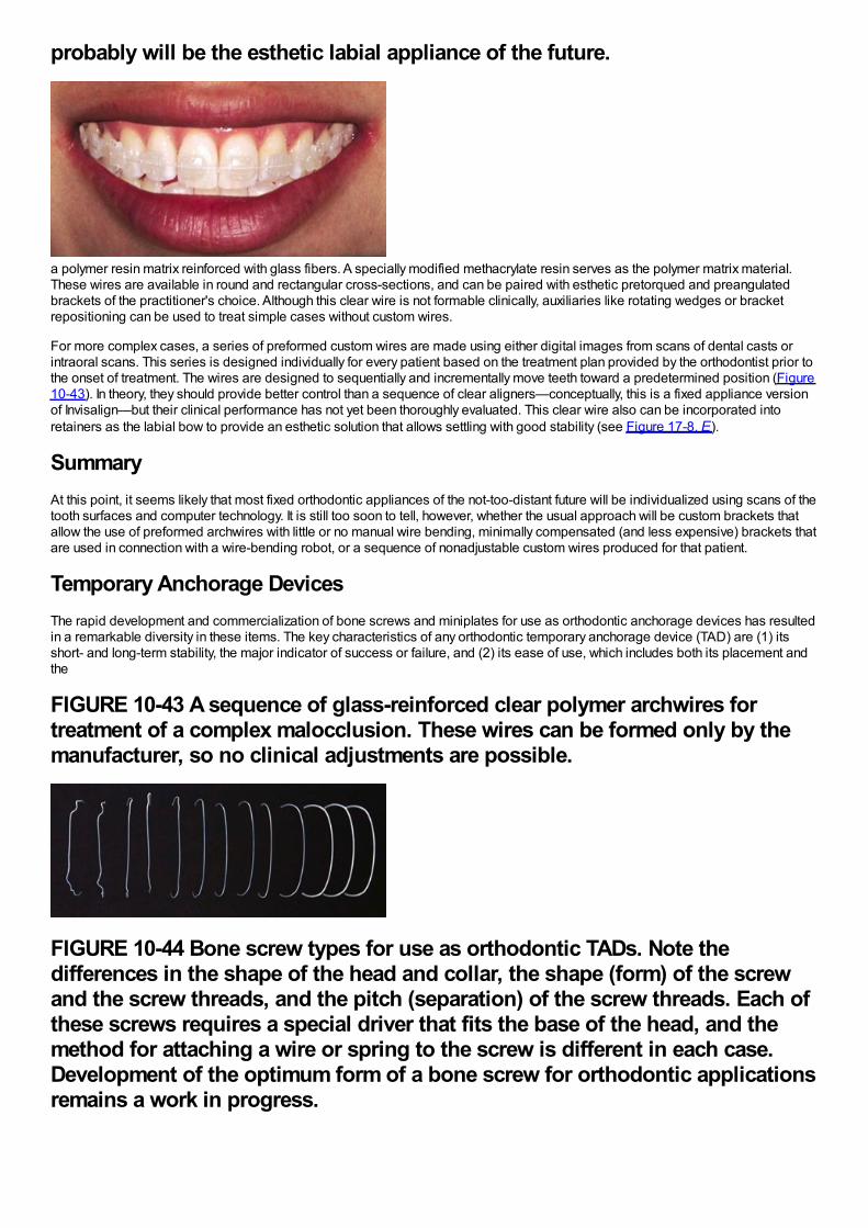
probably will be the esthetic labial appliance of the future.
a polymer resin matrix reinforced with glass fibers. A specially modified methacrylate resin serves as the polymer matrix material.These wires are available in round and rectangular cross-sections, and can be paired with esthetic pretorqued and preangulatedbrackets of the practitioner's choice. Although this clear wire is not formable clinically, auxiliaries like rotating wedges or bracketrepositioning can be used to treat simple cases without custom wires.
For more complex cases, a series of preformed custom wires are made using either digital images from scans of dental casts orintraoral scans. This series is designed individually for every patient based on the treatment plan provided by the orthodontist prior tothe onset of treatment. The wires are designed to sequentially and incrementally move teeth toward a predetermined position (Figure10-43). In theory, they should provide better control than a sequence of clear aligners—conceptually, this is a fixed appliance versionof Invisalign—but their clinical performance has not yet been thoroughly evaluated. This clear wire also can be incorporated intoretainers as the labial bow to provide an esthetic solution that allows settling with good stability (see Figure 17-8, E).
SummaryAt this point, it seems likely that most fixed orthodontic appliances of the not-too-distant future will be individualized using scans of thetooth surfaces and computer technology. It is still too soon to tell, however, whether the usual approach will be custom brackets thatallow the use of preformed archwires with little or no manual wire bending, minimally compensated (and less expensive) brackets thatare used in connection with a wire-bending robot, or a sequence of nonadjustable custom wires produced for that patient.
Temporary Anchorage DevicesThe rapid development and commercialization of bone screws and miniplates for use as orthodontic anchorage devices has resultedin a remarkable diversity in these items. The key characteristics of any orthodontic temporary anchorage device (TAD) are (1) itsshort- and long-term stability, the major indicator of success or failure, and (2) its ease of use, which includes both its placement andthe
FIGURE 10-43 A sequence of glass-reinforced clear polymer archwires fortreatment of a complex malocclusion. These wires can be formed only by themanufacturer, so no clinical adjustments are possible.
FIGURE 10-44 Bone screw types for use as orthodontic TADs. Note thedifferences in the shape of the head and collar, the shape (form) of the screwand the screw threads, and the pitch (separation) of the screw threads. Each ofthese screws requires a special driver that fits the base of the head, and themethod for attaching a wire or spring to the screw is different in each case.Development of the optimum form of a bone screw for orthodontic applicationsremains a work in progress.
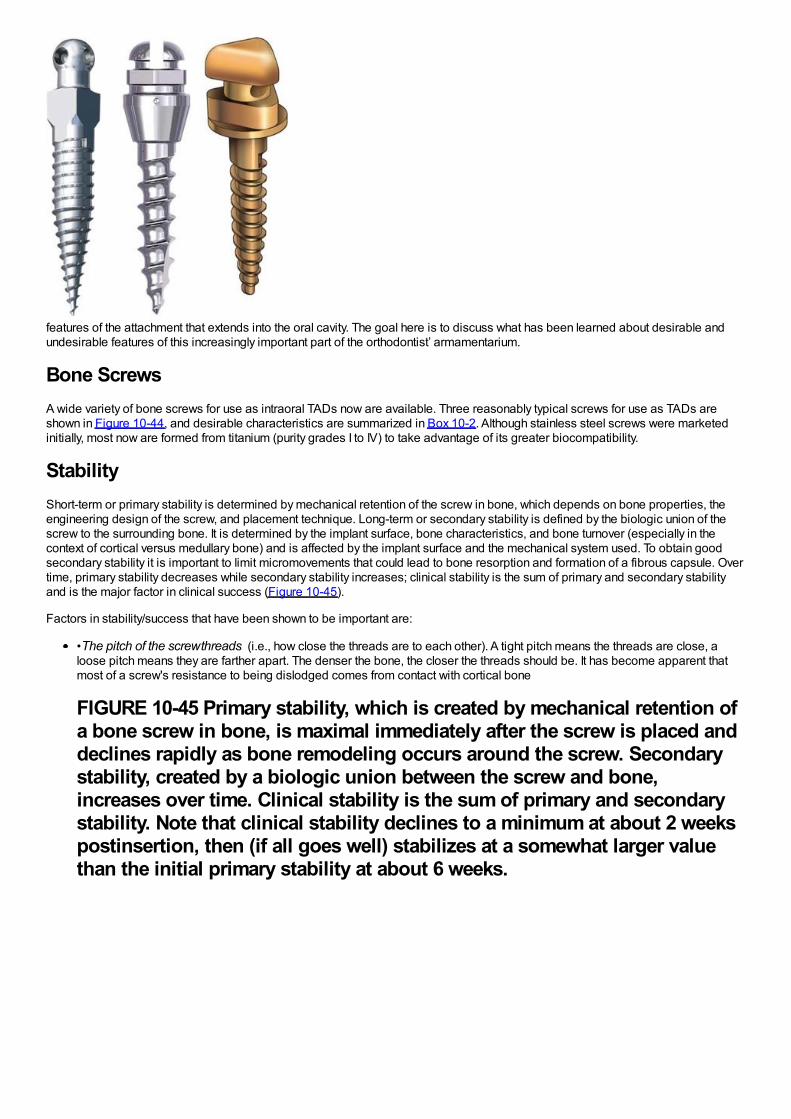
features of the attachment that extends into the oral cavity. The goal here is to discuss what has been learned about desirable andundesirable features of this increasingly important part of the orthodontist’ armamentarium.
Bone ScrewsA wide variety of bone screws for use as intraoral TADs now are available. Three reasonably typical screws for use as TADs areshown in Figure 10-44, and desirable characteristics are summarized in Box 10-2. Although stainless steel screws were marketedinitially, most now are formed from titanium (purity grades I to IV) to take advantage of its greater biocompatibility.
StabilityShort-term or primary stability is determined by mechanical retention of the screw in bone, which depends on bone properties, theengineering design of the screw, and placement technique. Long-term or secondary stability is defined by the biologic union of thescrew to the surrounding bone. It is determined by the implant surface, bone characteristics, and bone turnover (especially in thecontext of cortical versus medullary bone) and is affected by the implant surface and the mechanical system used. To obtain goodsecondary stability it is important to limit micromovements that could lead to bone resorption and formation of a fibrous capsule. Overtime, primary stability decreases while secondary stability increases; clinical stability is the sum of primary and secondary stabilityand is the major factor in clinical success (Figure 10-45).
Factors in stability/success that have been shown to be important are:
•The pitch of the screw threads (i.e., how close the threads are to each other). A tight pitch means the threads are close, aloose pitch means they are farther apart. The denser the bone, the closer the threads should be. It has become apparent thatmost of a screw's resistance to being dislodged comes from contact with cortical bone
FIGURE 10-45 Primary stability, which is created by mechanical retention ofa bone screw in bone, is maximal immediately after the screw is placed anddeclines rapidly as bone remodeling occurs around the screw. Secondarystability, created by a biologic union between the screw and bone,increases over time. Clinical stability is the sum of primary and secondarystability. Note that clinical stability declines to a minimum at about 2 weekspostinsertion, then (if all goes well) stabilizes at a somewhat larger valuethan the initial primary stability at about 6 weeks.
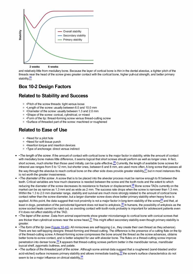
and relatively little from medullary bone. Because the layer of cortical bone is thin in the dental alveolus, a tighter pitch of thethreads near the head of the screw gives greater contact with the cortical bone, higher pull-out strength, and better primarystability.25
Box 10-2 Design Factors
Related to Stability and Success•Pitch of the screw threads: tight versus loose•Length of the screw: usually between 6.0 and 10.0 mm•Diameter of the screw: usually between 1.3 and 2.0 mm•Shape of the screw: conical, cylindrical, or mixed•Form of the tip: thread-forming screw versus thread-cutting screw•Surface of threaded part of the screw: machined or roughened
Related to Ease of Use•Need for a pilot hole•Need for soft tissue punch•Insertion torque and insertion devices•Type of anchorage: direct versus indirect
•The length of the screw. If the amount of contact with cortical bone is the major factor in stability, while the amount of contactwith medullary bone makes little difference, it seems logical that short screws should perform as well as longer ones. In fact,short screws, much shorter than those used initially, can be quite effective.26 Currently, the length of available bone screws forintraoral use ranges from 5 to 12 mm, but shorter ones, between 6 and 8 mm, are used more often. A long screw that passes allthe way through the alveolus to reach cortical bone on the other side does provide greater stability,27 but in most instances thisis not worth the greater invasiveness.•The diameter of the screw . A screw that is to be placed into the alveolar process must be narrow enough to fit between theteeth. Critical variables are how much clearance is needed between the screw and the tooth roots and the extent to whichreducing the diameter of the screw decreases its resistance to fracture or displacement.28 Bone screw TADs currently on themarket can be as narrow as 1.3 mm and as wide as 2 mm. The success rate drops when the screw is narrower than 1.3 mm.Within the 1.3 to 2.0 mm diameter range, stability and survival are much more strongly related to the amount of cortical bonecontact rather than the screw diameter, but a larger diameter screw does show better primary stability when heavy force isapplied. At this point, the data suggest that root proximity is not a major factor in long-term stability of the screw29 and that, atleast in dogs, penetration of the periodontal ligament does not lead to ankylosis.30 In humans, the possibility of ankylosis as thescrew socket heals cannot be ruled out, so avoiding contact with tooth roots probably is important for adolescent patients evenif it does not affect stability of the TAD.•The taper of the screw . Data from animal experiments show greater microdamage to cortical bone with conical screws thatare thicker than cylindrical screws near the screw head.31 This might affect secondary stability even though primary stability isgreater.•The form of the tip (see Figure 10-45). All miniscrews are self-tapping (i.e., they create their own thread as they advance).There are two self-tapping designs: thread-forming and thread-cutting. The difference is the presence of a cutting flute on the tipof the thread-cutting screw. A thread-forming screw compresses the bone around the thread as the screw advances, obtainsbetter bone-to-screw contact, and is better adapted for use with alveolar bone. The flutes on a thread-cutting screw improvepenetration into denser bone.32 It appears that thread-cutting screws perform better in the mandibular ramus, mandibularbuccal shelf, zygomatic buttress, and palate.•The surface of the threaded part of the screw . Although some animal data suggest that a roughened (sand-blasted and/oracid-etched) surface increases primary stability and allows immediate loading,33 the screw's surface characteristics do notseem to be a major influence on clinical stability.34
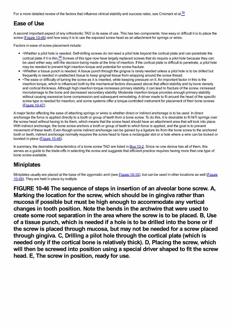
For a more detailed review of the factors that influence clinical stability and success rates, see Crismani et al.35
Ease of UseA second important aspect of any orthodontic TAD is its ease of use. This has two components: how easy or difficult it is to place thescrew (Figure 10-46) and how easy it is to use the exposed screw head as an attachment for springs or wires.
Factors in ease of screw placement include:
•Whether a pilot hole is needed. Self-drilling screws do not need a pilot hole beyond the cortical plate and can penetrate thecortical plate if it is thin.36 Screws of this type now have largely replaced screws that do require a pilot hole because they canbe used either way, with the decision being made at the time of insertion. If the cortical plate is difficult to penetrate, a pilot holemay be needed to prevent high insertion torque and potential for screw fracture.•Whether a tissue punch is needed. A tissue punch through the gingiva is rarely needed unless a pilot hole is to be drilled butfrequently is needed in unattached tissue to keep gingival tissue from wrapping around the screw thread.•The ease or difficulty of turning the screw as it is inserted, while keeping pressure on it. An important factor in this is theinsertion torque, which is influenced both by the mechanical factors discussed above that affect stability and by bone densityand cortical thickness. Although high insertion torque increases primary stability, it can lead to fracture of the screw, increasedmicrodamage to the bone and decreased secondary stability. Moderate insertion torque provides enough primary stabilitywithout causing excessive bone compression and subsequent remodeling. A driver made to fit around the head of the specificscrew type is needed for insertion, and some systems offer a torque-controlled instrument for placement of their bone screws(Figure 10-47).
A major factor affecting the ease of attaching springs or wires is whether direct or indirect anchorage is to be used. In directanchorage the force is applied directly to a tooth or group of teeth from a bone screw. To do this, it is desirable to fit NiTi springs overthe screw head without having to tie them, which means that the screw head should have an attachment area that will lock into place.With indirect anchorage, the bone screw anchors a tooth or group of teeth to which force is applied, and the goal is to preventmovement of these teeth. Even though some indirect anchorage can be gained by a ligature tie from the bone screw to the anchoredtooth or teeth, indirect anchorage normally requires the screw head to have a rectangular slot or a hole where a wire can be locked orbonded in place (Figure 10-48).
In summary, the desirable characteristics of a bone screw TAD are listed in Box 10-2. Since no one device has all of them, thisserves as a guide to the trade-offs in selecting the screw and suggests that efficient practice requires having more than one type ofbone screw available.
MiniplatesMiniplates usually are placed at the base of the zygomatic arch (see Figure 15-10), but can be used in other locations as well (Figure10-49). They are held in place by multiple
FIGURE 10-46 The sequence of steps in insertion of an alveolar bone screw. A,Marking the location for the screw, which should be in gingiva rather thanmucosa if possible but must be high enough to accommodate any verticalchanges in tooth position. Note the bends in the archwire that were used tocreate some root separation in the area where the screw is to be placed. B, Useof a tissue punch, which is needed if a hole is to be drilled into the bone or ifthe screw is placed through mucosa, but may not be needed for a screw placedthrough gingiva. C, Drilling a pilot hole through the cortical plate (which isneeded only if the cortical bone is relatively thick). D, Placing the screw, whichwill then be screwed into position using a special driver shaped to fit the screwhead. E, The screw in position, ready for use.
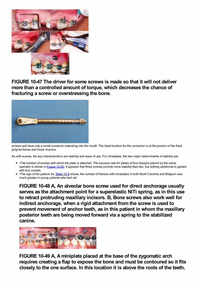
FIGURE 10-47 The driver for some screws is made so that it will not delivermore than a controlled amount of torque, which decreases the chance offracturing a screw or overstressing the bone.
screws and have only a small connector extending into the mouth. The ideal location for the connector is at the junction of the fixedgingival tissue and loose mucosa.
As with screws, the key characteristics are stability and ease of use. For miniplates, the two major determinants of stability are:
•The number of screws with which the plate is attached. The success rate for plates of four designs placed by the sameoperator is shown in Figure 10-50. It appears that three screws provide more stability than two, but nothing additional is gainedwith four screws.•The age of the patient. As Table 10-5 shows, the number of failures with miniplates in both North Carolina and Belgium wasmuch greater in young patients who had not
FIGURE 10-48 A, An alveolar bone screw used for direct anchorage usuallyserves as the attachment point for a superelastic NiTi spring, as in this useto retract protruding maxillary incisors. B, Bone screws also work well forindirect anchorage, when a rigid attachment from the screw is used toprevent movement of anchor teeth, as in this patient in whom the maxillaryposterior teeth are being moved forward via a spring to the stabilizedcanine.
FIGURE 10-49 A, A miniplate placed at the base of the zygomatic archrequires creating a flap to expose the bone and must be contoured so it fitsclosely to the one surface. In this location it is above the roots of the teeth,
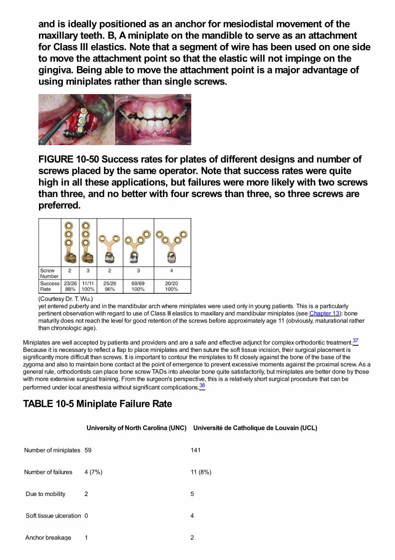
and is ideally positioned as an anchor for mesiodistal movement of themaxillary teeth. B, A miniplate on the mandible to serve as an attachmentfor Class III elastics. Note that a segment of wire has been used on one sideto move the attachment point so that the elastic will not impinge on thegingiva. Being able to move the attachment point is a major advantage ofusing miniplates rather than single screws.
FIGURE 10-50 Success rates for plates of different designs and number ofscrews placed by the same operator. Note that success rates were quitehigh in all these applications, but failures were more likely with two screwsthan three, and no better with four screws than three, so three screws arepreferred.
(Courtesy Dr. T. Wu.)yet entered puberty and in the mandibular arch where miniplates were used only in young patients. This is a particularlypertinent observation with regard to use of Class III elastics to maxillary and mandibular miniplates (see Chapter 13): bonematurity does not reach the level for good retention of the screws before approximately age 11 (obviously, maturational ratherthan chronologic age).
Miniplates are well accepted by patients and providers and are a safe and effective adjunct for complex orthodontic treatment.37
Because it is necessary to reflect a flap to place miniplates and then suture the soft tissue incision, their surgical placement issignificantly more difficult than screws. It is important to contour the miniplates to fit closely against the bone of the base of thezygoma and also to maintain bone contact at the point of emergence to prevent excessive moments against the proximal screw. As ageneral rule, orthodontists can place bone screw TADs into alveolar bone quite satisfactorily, but miniplates are better done by thosewith more extensive surgical training. From the surgeon's perspective, this is a relatively short surgical procedure that can beperformed under local anesthesia without significant complications.38
TABLE 10-5 Miniplate Failure Rate
University of North Carolina (UNC) Université de Catholique de Louvain (UCL)
Number of miniplates 59 141
Number of failures 4 (7%) 11 (8%)
Due to mobility 2 5
Soft tissue ulceration 0 4
Anchor breakage 1 2
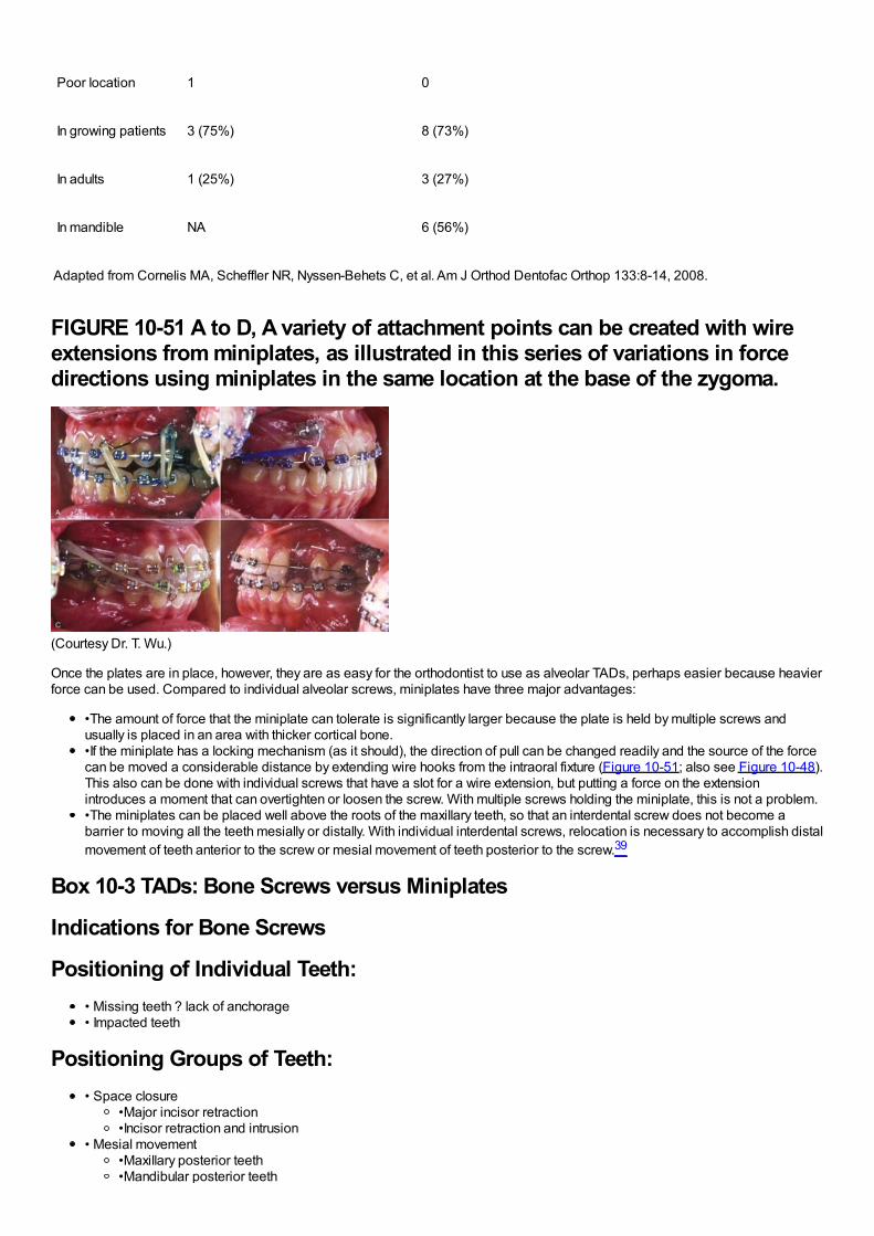
Poor location 1 0
In growing patients 3 (75%) 8 (73%)
In adults 1 (25%) 3 (27%)
In mandible NA 6 (56%)
Adapted from Cornelis MA, Scheffler NR, Nyssen-Behets C, et al. Am J Orthod Dentofac Orthop 133:8-14, 2008.
FIGURE 10-51 A to D, A variety of attachment points can be created with wireextensions from miniplates, as illustrated in this series of variations in forcedirections using miniplates in the same location at the base of the zygoma.
(Courtesy Dr. T. Wu.)
Once the plates are in place, however, they are as easy for the orthodontist to use as alveolar TADs, perhaps easier because heavierforce can be used. Compared to individual alveolar screws, miniplates have three major advantages:
•The amount of force that the miniplate can tolerate is significantly larger because the plate is held by multiple screws andusually is placed in an area with thicker cortical bone.•If the miniplate has a locking mechanism (as it should), the direction of pull can be changed readily and the source of the forcecan be moved a considerable distance by extending wire hooks from the intraoral fixture (Figure 10-51; also see Figure 10-48).This also can be done with individual screws that have a slot for a wire extension, but putting a force on the extensionintroduces a moment that can overtighten or loosen the screw. With multiple screws holding the miniplate, this is not a problem.•The miniplates can be placed well above the roots of the maxillary teeth, so that an interdental screw does not become abarrier to moving all the teeth mesially or distally. With individual interdental screws, relocation is necessary to accomplish distalmovement of teeth anterior to the screw or mesial movement of teeth posterior to the screw.39
Box 10-3 TADs: Bone Screws versus Miniplates
Indications for Bone Screws
Positioning of Individual Teeth:• Missing teeth ? lack of anchorage• Impacted teeth
Positioning Groups of Teeth:• Space closure
•Major incisor retraction•Incisor retraction and intrusion
• Mesial movement•Maxillary posterior teeth•Mandibular posterior teeth
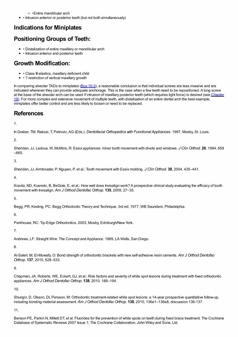
•Entire mandibular arch• Intrusion anterior or posterior teeth (but not both simultaneously)
Indications for Miniplates
Positioning Groups of Teeth:• Distalization of entire maxillary or mandibular arch• Intrusion anterior and posterior teeth
Growth Modification:• Class III elastics, maxillary deficient child• ? restriction of vertical maxillary growth
In comparing alveolar TADs to miniplates (Box 10-3), a reasonable conclusion is that individual screws are less invasive and areindicated whenever they can provide adequate anchorage. This is the case when a few teeth need to be repositioned. A long screwat the base of the alveolar arch can be used if intrusion of maxillary posterior teeth (which requires light force) is desired (see Chapter18). For more complex and extensive movement of multiple teeth, with distalization of an entire dental arch the best example,miniplates offer better control and are less likely to loosen or need to be replaced.
References1.
In Graber, TM, Rakosi, T, Petrovic, AG (Eds.): Dentofacial Orthopedics with Functional Appliances. 1997, Mosby, St. Louis.
2.
Sheridan, JJ, Ledoux, W, McMinn, R: Essix appliances: minor tooth movement with divots and windows. J Clin Orthod. 28, 1994, 659–665.
3.
Sheridan, JJ, Armbruster, P, Nguyen, P, et al.: Tooth movement with Essix molding. J Clin Orthod. 38, 2004, 435–441.
4.
Kravitz, ND, Kusnoto, B, BeGole, E, et al.: How well does Invisalign work? A prospective clinical study evaluating the efficacy of toothmovement with Invisalign. Am J Orthod Dentofac Orthop. 135, 2009, 27–35.
5.
Begg, PR, Kesling, PC: Begg Orthodontic Theory and Technique. 3rd ed, 1977, WB Saunders, Philadelphia.
6.
Parkhouse, RC: Tip-Edge Orthodontics. 2003, Mosby, Edinburgh/New York.
7.
Andrews, LF: Straight Wire: The Concept and Appliance. 1989, LA Wells, San Diego.
8.
Al-Saleh, M, El-Mowafy, O: Bond strength of orthodontic brackets with new self-adhesive resin cements. Am J Orthod DentofacOrthop. 137, 2010, 528–533.
9.
Chapman, JA, Roberts, WE, Eckert, GJ, et al.: Risk factors and severity of white spot lesions during treatment with fixed orthodonticappliances. Am J Orthod Dentofac Orthop. 138, 2010, 188–194.
10.
Shungin, D, Olsson, DI, Persson, M: Orthodontic treatment-related white spot lesions: a 14-year prospective quantitative follow-up,including bonding material assessment. Am J Orthod Dentofac Orthop. 138, 2010, 136e1–136e8, discussion 136-137.
11.
Benson PE, Parkin N, Millett DT, et al. Fluorides for the prevention of white spots on teeth during fixed brace treatment. The CochraneDatabase of Systematic Reviews 2007 Issue 1; The Cochrane Collaboration. John Wiley and Sons, Ltd.

12.
Rogers, S, Chadwick, B, Treasure, E: Fluoride-containing orthodontic adhesives and decalcification in patients with fixed appliances:a systematic review. Am J Orthod Dentofac Orthop. 138, 2010, 390.e1–390.e8 discussion 390-391.
13.
Baturina, O, Tulecki, E, Guney-Altay, O, et al.: Development of a sustained fluoride delivery system. Angle Orthod. 80, 2010, 1129–1135.
14.
Guzman-Armstrong, S, Chalmers, J, Warren, JJ: White spot lesions: prevention and treatment. Am J Orthod Dentofac Orthop. 138,2010, 690–696.
15.
Murphy, TC, Willmot, DR, Rodd, HD: Management of postorthodontic white lesion with microabrasion: a quantitative assessment.Am J Orthod Dentofac Orthop. 131, 2007, 27–33.
16.
Kolokitha, OE, Kaklamanos, EG, Papadopoulos, MA: Prevalence of nickel hypersensitivity in orthodontic patients: a meta-analysis.Am J Orthod Dentofac Orthop. 134, 2008, 722.e1–722.e12 discussion 722-723.
17.
Feldon, PJ, Murray, PE, Burch, JG, et al.: Diode laser debonding of ceramic brackets. Am J Orthod Dentofac Orthop. 138, 2010,458–462.
18.
Marshall, SD, Currier, GF, Hatch, NE, et al.: Self-ligating bracket claims. Am J Orthod Dentofac Orthop. 138, 2010, 128–131.
19.
Wiechmann, D: A new bracket system for lingual orthodontic treatment. Part 1. J Orofac Orthop. 63, 2002, 234–245, Part 2. J OrofacOrthop 64:372-388, 2003.
20.
Grauer, D, Proffit, WR: Accuracy in tooth positioning with fully customized lingual orthodontic appliances. Am J Orthod DentofacOrthop. 140, 2011, 433–443.
21.
Walton, D, Fields, HW, Johnston, WM, et al.: Orthodontic appliance preferences of children and adolescents. Am J Orthod DentofacOrthop. 138, 2010, 698.e1–698.e12.
22.
Braun, S, Hnat, WH, Fender, WE, et al.: The form of the human dental arch. Angle Orthod. 68, 1998, 29–36.
23.
Alford, TJ, Roberts, WE, Hartsfield, JK, et al.: Clinical outcomes for patients finished with the SureSmile method compared toconventional fixed orthodontic therapy. Angle Orthod. 81, 2011, 383–388.
24.
Burstone, CJ, Liebler, SA, Goldberg, AJ: Polyphenylene polymers as esthetic orthodontic archwires. Am J Orthod Dentofac Orthop.139(4 Suppl), 2011, e391–e398.
25.
Brinley, CL, Behrents, R, Kim, KB, et al.: Pitch and longitudinal fluting effects on the primary stability of miniscrew implants. AngleOrthod. 79, 2009, 1156–1161.
26.
Park, HS, Jeong, SH, Kwon, OW: Factors affecting the clinical success of screw implants used as orthodontic anchorage. Am JOrthod Dentofac Orthop. 130, 2006, 18–25.
27.

Brettin, BT, Grosland, NM, Qian, F, et al.: Bicortical vs. monocortical orthodontic skeletal anchorage. Am J Orthod Dentofac Orthop.134, 2008, 625–635.
28.
Chatzigianni, A, Keilig, L, Reimann, S, et al.: Effect of mini-implant length and diameter on primary stability under loading with twoforce levels. Eur J Orthod. 2010, E-pub Nov.
29.
Kim, SH, Kang, SM, Choi, YS, et al.: Cone-beam computed tomography evaluation of mini-implants after placement: is root proximitya major risk factor for failure?. Am J Orthod Dentofac Orthop. 138, 2010, 264–276.
30.
Brisceno, CE, Rossouw, PE, Carrillo, R, et al.: Healing of the roots and surrounding structures after intentional damage withminiscrew implants. Am J Orthod Dentofac Orthop. 135, 2009, 292–301.
31.
Lee, NK, Baek, SH: Effects of the diameter and shape of orthodontic mini-implants on microdamage to the cortical bone. Am JOrthod Dentofac Orthop. 138, 2010, 8.e1–8.e8 discussion 8-9.
32.
Yerby, S, Scott, CC, Evans, NJ, et al.: Effect of cutting flute design on cortical bone screw insertion torque and pullout strength. JOrthop Trauma. 15, 2001, 216–221.
33.
Kim, SH, Cho, JH, Chung, KR, et al.: Removal torque values of surface-treated mini-implants after loading. Am J Orthod DentofacOrthop. 134, 2008, 36–43.
34.
Chaddad, K, Ferreira, AF, Geurs, N, et al.: Influence of surface characteristics on survival rates of mini-implants. Angle Orthod. 78,2008, 107–113.
35.
Crismani, AG, Bertl, MH, Celar, AG, et al.: Miniscrews in orthodontic treatment: review and analysis of published clinical trials. Am JOrthod Dentofac Orthop. 137, 2010, 108–113.
36.
Baumgaertel, S: Predrilling of the implant site: is it necessary for orthodontic mini-implants?. Am J Orthod Dentofac Orthop. 137,2010, 825–829.
37.
Cornelis, MA, Scheffler, NR, Nyssen-Behets, C, et al.: Patients’ and orthodontists’ perceptions of miniplates used for temporaryskeletal anchorage: a prospective study. Am J Orthod Dentofac Orthop. 133, 2008, 18–24.
38.
Cornelis, MA, Scheffler, NR, Mahy, P, et al.: Modified miniplates for temporary skeletal anchorage in orthodontics: placement andremoval surgeries. J Oral Maxillofac Surg. 66, 2008, 1439–1445.
39.
Chung, KR, Choo, H, Kim, SH, et al.: Timely relocation of mini-implants for uninterrupted full-arch distalization. Am J Orthod DentofacOrthop. 138, 2010, 839–849.
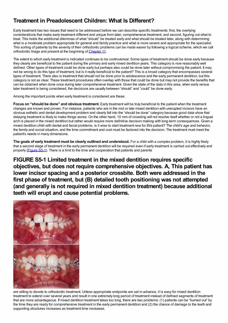
Treatment in Preadolescent Children: What Is Different?Early treatment has two issues that need to be addressed before we can describe specific treatments: first, the overlyingconsiderations that make early treatment different and unique from later, comprehensive treatment, and second, figuring out what totreat. This holds the additional dilemmas of what “should” be treated early and what should be treated later, along with determiningwhat is a moderate problem appropriate for general and family practice and what is more severe and appropriate for the specialist.This sorting of patients by the severity of their orthodontic problems can be made easier by following a logical scheme, which we callorthodontic triage and present at the beginning of Chapter 11.
The extent to which early treatment is indicated continues to be controversial. Some types of treatment should be done early becausethey clearly are beneficial to the patient during the primary and early mixed dentition years. This category is now reasonably welldefined. Other types of treatment could be done early but perhaps also could be done later without compromising the patient. It maynot be wrong to do this type of treatment, but is it really beneficial to the patient? This is a broad category that encompasses severaltypes of treatment. There also is treatment that should not be done prior to adolescence and the early permanent dentition, but thiscategory is not as clear. These treatment procedures often overlap with those that could be done but may not provide the benefits thatcan be obtained when done once during later comprehensive treatment. Given the state of the data in this area, when early versuslater treatment is being considered, the decisions are usually between “should” and “could” be done early.
Among the important points when early treatment is considered are these:
Focus on “should be done” and obvious treatment. Early treatment will be truly beneficial to the patient when the treatmentchanges are known and proven. For instance, patients who are in the mid or late mixed dentition with unerupted incisors have anobvious esthetic and dental development problem and clearly fall into the “should be done” category because good data show thatdelaying treatment is likely to make things worse. On the other hand, 10 mm of crowding will not resolve itself whether or not a lingualarch is placed in the mixed dentition but rather would require more definitive decision making with long-term consequences. Given amixed dentition child with dental and facial problems, is it wise to start treatment now for this patient? The child's age and behavior,the family and social situation, and the time commitment and cost must be factored into the decision. The treatment must meet thepatient's needs in many dimensions.
The goals of early treatment must be clearly outlined and understood. For a child with a complex problem, it is highly likelythat a second stage of treatment in the early permanent dentition will be required even if early treatment is carried out effectively andproperly (Figure S5-1). There is a limit to the time and cooperation that patients and parents
FIGURE S5-1 Limited treatment in the mixed dentition requires specificobjectives, but does not require comprehensive objectives. A, This patient haslower incisor spacing and a posterior crossbite. Both were addressed in thefirst phase of treatment, but (B) detailed tooth positioning was not attempted(and generally is not required in mixed dentition treatment) because additionalteeth will erupt and cause potential problems.
are willing to devote to orthodontic treatment. Unless appropriate endpoints are set in advance, it is easy for mixed dentitiontreatment to extend over several years and result in one extremely long period of treatment instead of defined segments of treatmentthat are more advantageous. If mixed dentition treatment takes too long, there are two problems: (1) patients can be “burned out” bythe time they are ready for comprehensive treatment in the early permanent dentition and (2) the chance of damage to the teeth andsupporting structures increases as treatment time increases.
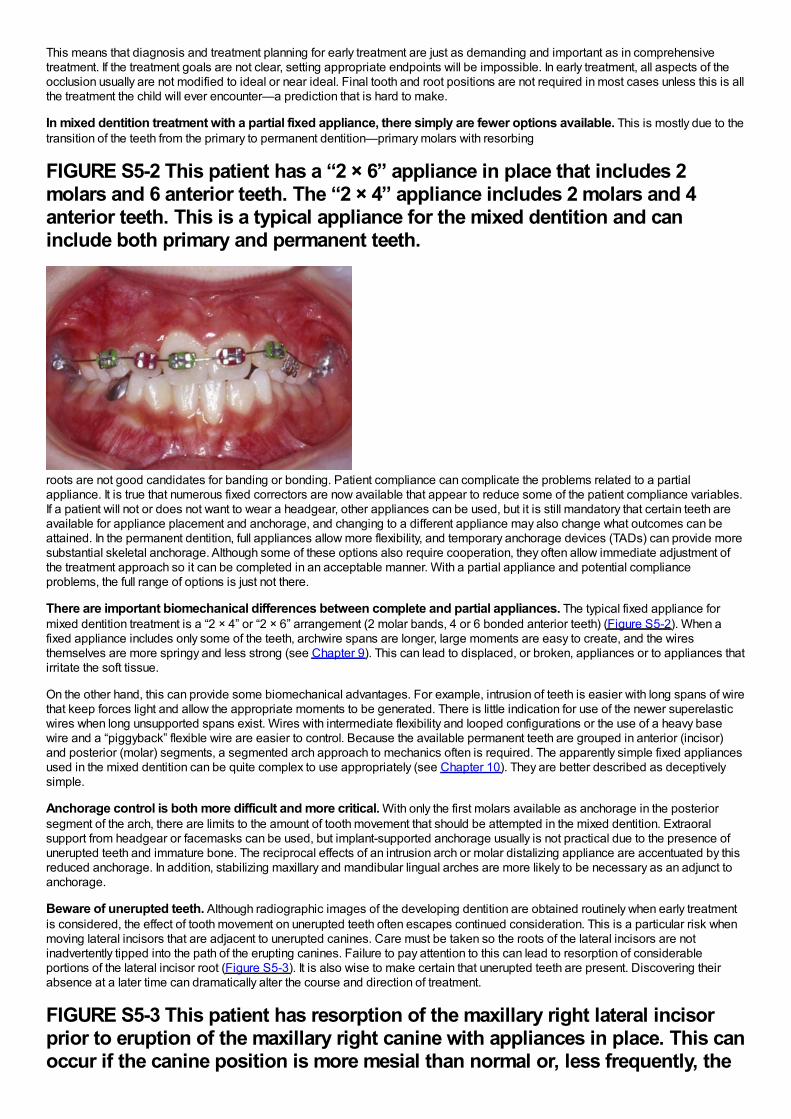
This means that diagnosis and treatment planning for early treatment are just as demanding and important as in comprehensivetreatment. If the treatment goals are not clear, setting appropriate endpoints will be impossible. In early treatment, all aspects of theocclusion usually are not modified to ideal or near ideal. Final tooth and root positions are not required in most cases unless this is allthe treatment the child will ever encounter—a prediction that is hard to make.
In mixed dentition treatment with a partial fixed appliance, there simply are fewer options available. This is mostly due to thetransition of the teeth from the primary to permanent dentition—primary molars with resorbing
FIGURE S5-2 This patient has a “2 × 6” appliance in place that includes 2molars and 6 anterior teeth. The “2 × 4” appliance includes 2 molars and 4anterior teeth. This is a typical appliance for the mixed dentition and caninclude both primary and permanent teeth.
roots are not good candidates for banding or bonding. Patient compliance can complicate the problems related to a partialappliance. It is true that numerous fixed correctors are now available that appear to reduce some of the patient compliance variables.If a patient will not or does not want to wear a headgear, other appliances can be used, but it is still mandatory that certain teeth areavailable for appliance placement and anchorage, and changing to a different appliance may also change what outcomes can beattained. In the permanent dentition, full appliances allow more flexibility, and temporary anchorage devices (TADs) can provide moresubstantial skeletal anchorage. Although some of these options also require cooperation, they often allow immediate adjustment ofthe treatment approach so it can be completed in an acceptable manner. With a partial appliance and potential complianceproblems, the full range of options is just not there.
There are important biomechanical differences between complete and partial appliances. The typical fixed appliance formixed dentition treatment is a “2 × 4” or “2 × 6” arrangement (2 molar bands, 4 or 6 bonded anterior teeth) (Figure S5-2). When afixed appliance includes only some of the teeth, archwire spans are longer, large moments are easy to create, and the wiresthemselves are more springy and less strong (see Chapter 9). This can lead to displaced, or broken, appliances or to appliances thatirritate the soft tissue.
On the other hand, this can provide some biomechanical advantages. For example, intrusion of teeth is easier with long spans of wirethat keep forces light and allow the appropriate moments to be generated. There is little indication for use of the newer superelasticwires when long unsupported spans exist. Wires with intermediate flexibility and looped configurations or the use of a heavy basewire and a “piggyback” flexible wire are easier to control. Because the available permanent teeth are grouped in anterior (incisor)and posterior (molar) segments, a segmented arch approach to mechanics often is required. The apparently simple fixed appliancesused in the mixed dentition can be quite complex to use appropriately (see Chapter 10). They are better described as deceptivelysimple.
Anchorage control is both more difficult and more critical. With only the first molars available as anchorage in the posteriorsegment of the arch, there are limits to the amount of tooth movement that should be attempted in the mixed dentition. Extraoralsupport from headgear or facemasks can be used, but implant-supported anchorage usually is not practical due to the presence ofunerupted teeth and immature bone. The reciprocal effects of an intrusion arch or molar distalizing appliance are accentuated by thisreduced anchorage. In addition, stabilizing maxillary and mandibular lingual arches are more likely to be necessary as an adjunct toanchorage.
Beware of unerupted teeth. Although radiographic images of the developing dentition are obtained routinely when early treatmentis considered, the effect of tooth movement on unerupted teeth often escapes continued consideration. This is a particular risk whenmoving lateral incisors that are adjacent to unerupted canines. Care must be taken so the roots of the lateral incisors are notinadvertently tipped into the path of the erupting canines. Failure to pay attention to this can lead to resorption of considerableportions of the lateral incisor root (Figure S5-3). It is also wise to make certain that unerupted teeth are present. Discovering theirabsence at a later time can dramatically alter the course and direction of treatment.
FIGURE S5-3 This patient has resorption of the maxillary right lateral incisorprior to eruption of the maxillary right canine with appliances in place. This canoccur if the canine position is more mesial than normal or, less frequently, the
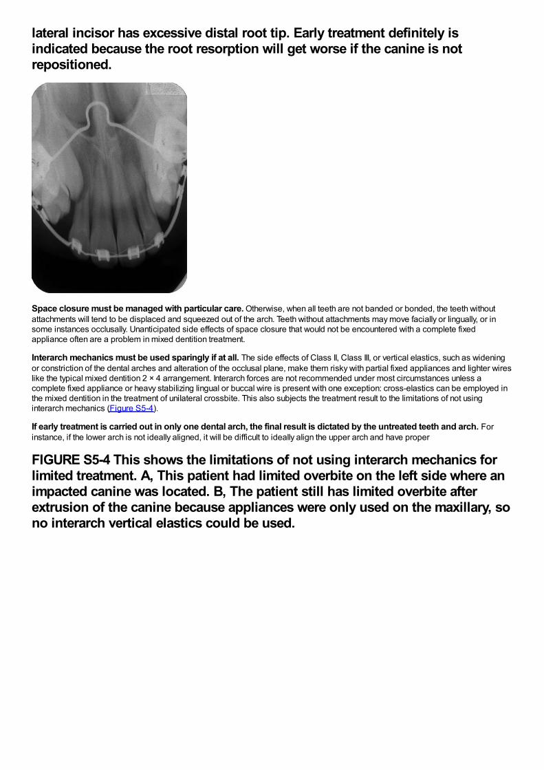
lateral incisor has excessive distal root tip. Early treatment definitely isindicated because the root resorption will get worse if the canine is notrepositioned.
Space closure must be managed with particular care. Otherwise, when all teeth are not banded or bonded, the teeth withoutattachments will tend to be displaced and squeezed out of the arch. Teeth without attachments may move facially or lingually, or insome instances occlusally. Unanticipated side effects of space closure that would not be encountered with a complete fixedappliance often are a problem in mixed dentition treatment.
Interarch mechanics must be used sparingly if at all. The side effects of Class II, Class III, or vertical elastics, such as wideningor constriction of the dental arches and alteration of the occlusal plane, make them risky with partial fixed appliances and lighter wireslike the typical mixed dentition 2 × 4 arrangement. Interarch forces are not recommended under most circumstances unless acomplete fixed appliance or heavy stabilizing lingual or buccal wire is present with one exception: cross-elastics can be employed inthe mixed dentition in the treatment of unilateral crossbite. This also subjects the treatment result to the limitations of not usinginterarch mechanics (Figure S5-4).
If early treatment is carried out in only one dental arch, the final result is dictated by the untreated teeth and arch. Forinstance, if the lower arch is not ideally aligned, it will be difficult to ideally align the upper arch and have proper
FIGURE S5-4 This shows the limitations of not using interarch mechanics forlimited treatment. A, This patient had limited overbite on the left side where animpacted canine was located. B, The patient still has limited overbite afterextrusion of the canine because appliances were only used on the maxillary, sono interarch vertical elastics could be used.
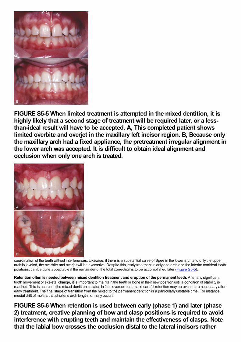
FIGURE S5-5 When limited treatment is attempted in the mixed dentition, it ishighly likely that a second stage of treatment will be required later, or a less-than-ideal result will have to be accepted. A, This completed patient showslimited overbite and overjet in the maxillary left incisor region. B, Because onlythe maxillary arch had a fixed appliance, the pretreatment irregular alignment inthe lower arch was accepted. It is difficult to obtain ideal alignment andocclusion when only one arch is treated.
coordination of the teeth without interferences. Likewise, if there is a substantial curve of Spee in the lower arch and only the upperarch is leveled, the overbite and overjet will be excessive. Despite this, early treatment in only one arch and the interim nonideal toothpositions, can be quite acceptable if the remainder of the total correction is to be accomplished later (Figure S5-5).
Retention often is needed between mixed dentition treatment and eruption of the permanent teeth. After any significanttooth movement or skeletal change, it is important to maintain the teeth or bone in their new position until a condition of stability isreached. This is as true in the mixed dentition as later. In fact, overcorrection and careful retention may be even more necessary afterearly treatment. The final stage of transition from the mixed to the permanent dentition is a particularly unstable time. For instance,mesial drift of molars that shortens arch length normally occurs
FIGURE S5-6 When retention is used between early (phase 1) and later (phase2) treatment, creative planning of bow and clasp positions is required to avoidinterference with erupting teeth and maintain the effectiveness of clasps. Notethat the labial bow crosses the occlusion distal to the lateral incisors rather
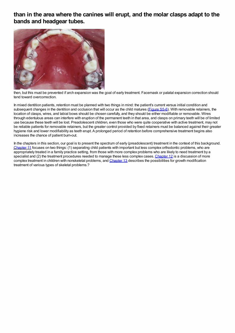
than in the area where the canines will erupt, and the molar clasps adapt to thebands and headgear tubes.
then, but this must be prevented if arch expansion was the goal of early treatment. Facemask or palatal expansion correction shouldtend toward overcorrection.
In mixed dentition patients, retention must be planned with two things in mind: the patient's current versus initial condition andsubsequent changes in the dentition and occlusion that will occur as the child matures (Figure S5-6). With removable retainers, thelocation of clasps, wires, and labial bows should be chosen carefully, and they should be either modifiable or removable. Wiresthrough edentulous areas can interfere with eruption of the permanent teeth in that area, and clasps on primary teeth will be of limiteduse because these teeth will be lost. Preadolescent children, even those who were quite cooperative with active treatment, may notbe reliable patients for removable retainers, but the greater control provided by fixed retainers must be balanced against their greaterhygiene risk and lower modifiability as teeth erupt. A prolonged period of retention before comprehensive treatment begins alsoincreases the chance of patient burn-out.
In the chapters in this section, our goal is to present the spectrum of early (preadolescent) treatment in the context of this background.Chapter 11 focuses on two things: (1) separating child patients with important but less complex orthodontic problems, who areappropriately treated in a family practice setting, from those with more complex problems who are likely to need treatment by aspecialist and (2) the treatment procedures needed to manage these less complex cases. Chapter 12 is a discussion of morecomplex treatment in children with nonskeletal problems, and Chapter 13 describes the possibilities for growth modificationtreatment of various types of skeletal problems.?
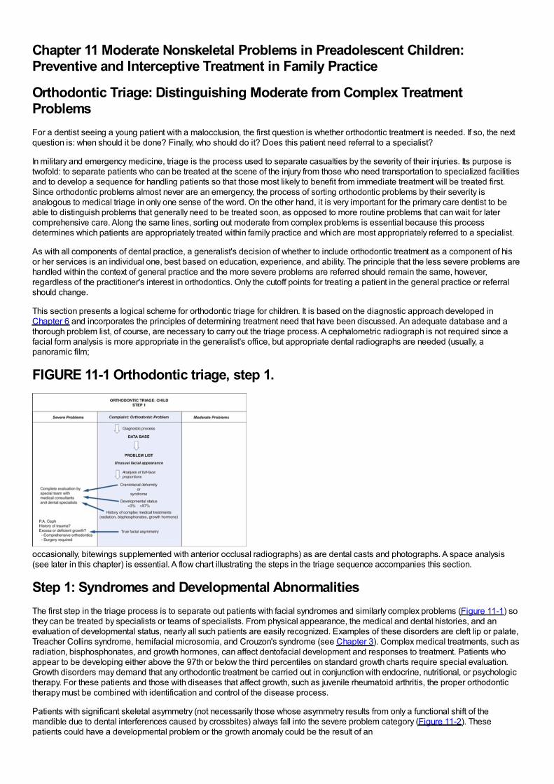
Chapter 11 Moderate Nonskeletal Problems in Preadolescent Children:Preventive and Interceptive Treatment in Family Practice
Orthodontic Triage: Distinguishing Moderate from Complex TreatmentProblemsFor a dentist seeing a young patient with a malocclusion, the first question is whether orthodontic treatment is needed. If so, the nextquestion is: when should it be done? Finally, who should do it? Does this patient need referral to a specialist?
In military and emergency medicine, triage is the process used to separate casualties by the severity of their injuries. Its purpose istwofold: to separate patients who can be treated at the scene of the injury from those who need transportation to specialized facilitiesand to develop a sequence for handling patients so that those most likely to benefit from immediate treatment will be treated first.Since orthodontic problems almost never are an emergency, the process of sorting orthodontic problems by their severity isanalogous to medical triage in only one sense of the word. On the other hand, it is very important for the primary care dentist to beable to distinguish problems that generally need to be treated soon, as opposed to more routine problems that can wait for latercomprehensive care. Along the same lines, sorting out moderate from complex problems is essential because this processdetermines which patients are appropriately treated within family practice and which are most appropriately referred to a specialist.
As with all components of dental practice, a generalist's decision of whether to include orthodontic treatment as a component of hisor her services is an individual one, best based on education, experience, and ability. The principle that the less severe problems arehandled within the context of general practice and the more severe problems are referred should remain the same, however,regardless of the practitioner's interest in orthodontics. Only the cutoff points for treating a patient in the general practice or referralshould change.
This section presents a logical scheme for orthodontic triage for children. It is based on the diagnostic approach developed inChapter 6 and incorporates the principles of determining treatment need that have been discussed. An adequate database and athorough problem list, of course, are necessary to carry out the triage process. A cephalometric radiograph is not required since afacial form analysis is more appropriate in the generalist's office, but appropriate dental radiographs are needed (usually, apanoramic film;
FIGURE 11-1 Orthodontic triage, step 1.
occasionally, bitewings supplemented with anterior occlusal radiographs) as are dental casts and photographs. A space analysis(see later in this chapter) is essential. A flow chart illustrating the steps in the triage sequence accompanies this section.
Step 1: Syndromes and Developmental AbnormalitiesThe first step in the triage process is to separate out patients with facial syndromes and similarly complex problems (Figure 11-1) sothey can be treated by specialists or teams of specialists. From physical appearance, the medical and dental histories, and anevaluation of developmental status, nearly all such patients are easily recognized. Examples of these disorders are cleft lip or palate,Treacher Collins syndrome, hemifacial microsomia, and Crouzon's syndrome (see Chapter 3). Complex medical treatments, such asradiation, bisphosphonates, and growth hormones, can affect dentofacial development and responses to treatment. Patients whoappear to be developing either above the 97th or below the third percentiles on standard growth charts require special evaluation.Growth disorders may demand that any orthodontic treatment be carried out in conjunction with endocrine, nutritional, or psychologictherapy. For these patients and those with diseases that affect growth, such as juvenile rheumatoid arthritis, the proper orthodontictherapy must be combined with identification and control of the disease process.
Patients with significant skeletal asymmetry (not necessarily those whose asymmetry results from only a functional shift of themandible due to dental interferences caused by crossbites) always fall into the severe problem category (Figure 11-2). Thesepatients could have a developmental problem or the growth anomaly could be the result of an
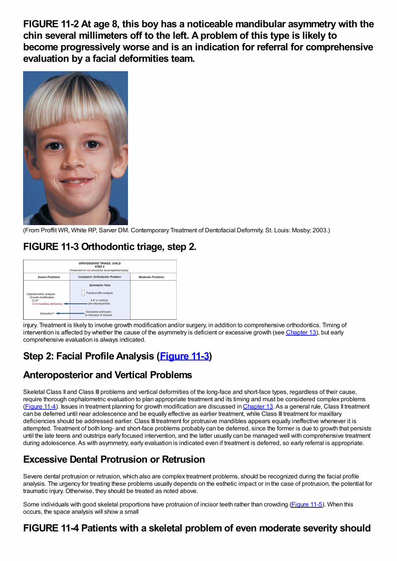
FIGURE 11-2 At age 8, this boy has a noticeable mandibular asymmetry with thechin several millimeters off to the left. A problem of this type is likely tobecome progressively worse and is an indication for referral for comprehensiveevaluation by a facial deformities team.
(From Proffit WR, White RP, Sarver DM. Contemporary Treatment of Dentofacial Deformity. St. Louis: Mosby; 2003.)
FIGURE 11-3 Orthodontic triage, step 2.
injury. Treatment is likely to involve growth modification and/or surgery, in addition to comprehensive orthodontics. Timing ofintervention is affected by whether the cause of the asymmetry is deficient or excessive growth (see Chapter 13), but earlycomprehensive evaluation is always indicated.
Step 2: Facial Profile Analysis (Figure 11-3)
Anteroposterior and Vertical ProblemsSkeletal Class II and Class III problems and vertical deformities of the long-face and short-face types, regardless of their cause,require thorough cephalometric evaluation to plan appropriate treatment and its timing and must be considered complex problems(Figure 11-4). Issues in treatment planning for growth modification are discussed in Chapter 13. As a general rule, Class II treatmentcan be deferred until near adolescence and be equally effective as earlier treatment, while Class III treatment for maxillarydeficiencies should be addressed earlier. Class III treatment for protrusive mandibles appears equally ineffective whenever it isattempted. Treatment of both long- and short-face problems probably can be deferred, since the former is due to growth that persistsuntil the late teens and outstrips early focused intervention, and the latter usually can be managed well with comprehensive treatmentduring adolescence. As with asymmetry, early evaluation is indicated even if treatment is deferred, so early referral is appropriate.
Excessive Dental Protrusion or RetrusionSevere dental protrusion or retrusion, which also are complex treatment problems, should be recognized during the facial profileanalysis. The urgency for treating these problems usually depends on the esthetic impact or in the case of protrusion, the potential fortraumatic injury. Otherwise, they should be treated as noted above.
Some individuals with good skeletal proportions have protrusion of incisor teeth rather than crowding (Figure 11-5). When thisoccurs, the space analysis will show a small
FIGURE 11-4 Patients with a skeletal problem of even moderate severity should
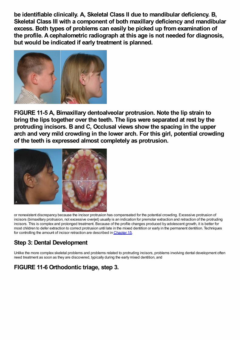
be identifiable clinically. A, Skeletal Class II due to mandibular deficiency. B,Skeletal Class III with a component of both maxillary deficiency and mandibularexcess. Both types of problems can easily be picked up from examination ofthe profile. A cephalometric radiograph at this age is not needed for diagnosis,but would be indicated if early treatment is planned.
FIGURE 11-5 A, Bimaxillary dentoalveolar protrusion. Note the lip strain tobring the lips together over the teeth. The lips were separated at rest by theprotruding incisors. B and C, Occlusal views show the spacing in the upperarch and very mild crowding in the lower arch. For this girl, potential crowdingof the teeth is expressed almost completely as protrusion.
or nonexistent discrepancy because the incisor protrusion has compensated for the potential crowding. Excessive protrusion ofincisors (bimaxillary protrusion, not excessive overjet) usually is an indication for premolar extraction and retraction of the protrudingincisors. This is complex and prolonged treatment. Because of the profile changes produced by adolescent growth, it is better formost children to defer extraction to correct protrusion until late in the mixed dentition or early in the permanent dentition. Techniquesfor controlling the amount of incisor retraction are described in Chapter 15.
Step 3: Dental DevelopmentUnlike the more complex skeletal problems and problems related to protruding incisors, problems involving dental development oftenneed treatment as soon as they are discovered, typically during the early mixed dentition, and
FIGURE 11-6 Orthodontic triage, step 3.
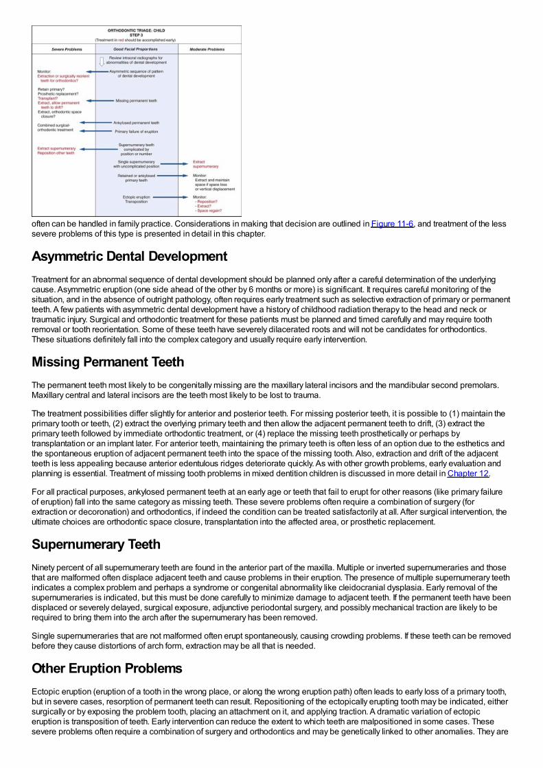
often can be handled in family practice. Considerations in making that decision are outlined in Figure 11-6, and treatment of the lesssevere problems of this type is presented in detail in this chapter.
Asymmetric Dental DevelopmentTreatment for an abnormal sequence of dental development should be planned only after a careful determination of the underlyingcause. Asymmetric eruption (one side ahead of the other by 6 months or more) is significant. It requires careful monitoring of thesituation, and in the absence of outright pathology, often requires early treatment such as selective extraction of primary or permanentteeth. A few patients with asymmetric dental development have a history of childhood radiation therapy to the head and neck ortraumatic injury. Surgical and orthodontic treatment for these patients must be planned and timed carefully and may require toothremoval or tooth reorientation. Some of these teeth have severely dilacerated roots and will not be candidates for orthodontics.These situations definitely fall into the complex category and usually require early intervention.
Missing Permanent TeethThe permanent teeth most likely to be congenitally missing are the maxillary lateral incisors and the mandibular second premolars.Maxillary central and lateral incisors are the teeth most likely to be lost to trauma.
The treatment possibilities differ slightly for anterior and posterior teeth. For missing posterior teeth, it is possible to (1) maintain theprimary tooth or teeth, (2) extract the overlying primary teeth and then allow the adjacent permanent teeth to drift, (3) extract theprimary teeth followed by immediate orthodontic treatment, or (4) replace the missing teeth prosthetically or perhaps bytransplantation or an implant later. For anterior teeth, maintaining the primary teeth is often less of an option due to the esthetics andthe spontaneous eruption of adjacent permanent teeth into the space of the missing tooth. Also, extraction and drift of the adjacentteeth is less appealing because anterior edentulous ridges deteriorate quickly. As with other growth problems, early evaluation andplanning is essential. Treatment of missing tooth problems in mixed dentition children is discussed in more detail in Chapter 12.
For all practical purposes, ankylosed permanent teeth at an early age or teeth that fail to erupt for other reasons (like primary failureof eruption) fall into the same category as missing teeth. These severe problems often require a combination of surgery (forextraction or decoronation) and orthodontics, if indeed the condition can be treated satisfactorily at all. After surgical intervention, theultimate choices are orthodontic space closure, transplantation into the affected area, or prosthetic replacement.
Supernumerary TeethNinety percent of all supernumerary teeth are found in the anterior part of the maxilla. Multiple or inverted supernumeraries and thosethat are malformed often displace adjacent teeth and cause problems in their eruption. The presence of multiple supernumerary teethindicates a complex problem and perhaps a syndrome or congenital abnormality like cleidocranial dysplasia. Early removal of thesupernumeraries is indicated, but this must be done carefully to minimize damage to adjacent teeth. If the permanent teeth have beendisplaced or severely delayed, surgical exposure, adjunctive periodontal surgery, and possibly mechanical traction are likely to berequired to bring them into the arch after the supernumerary has been removed.
Single supernumeraries that are not malformed often erupt spontaneously, causing crowding problems. If these teeth can be removedbefore they cause distortions of arch form, extraction may be all that is needed.
Other Eruption ProblemsEctopic eruption (eruption of a tooth in the wrong place, or along the wrong eruption path) often leads to early loss of a primary tooth,but in severe cases, resorption of permanent teeth can result. Repositioning of the ectopically erupting tooth may be indicated, eithersurgically or by exposing the problem tooth, placing an attachment on it, and applying traction. A dramatic variation of ectopiceruption is transposition of teeth. Early intervention can reduce the extent to which teeth are malpositioned in some cases. Thesesevere problems often require a combination of surgery and orthodontics and may be genetically linked to other anomalies. They are
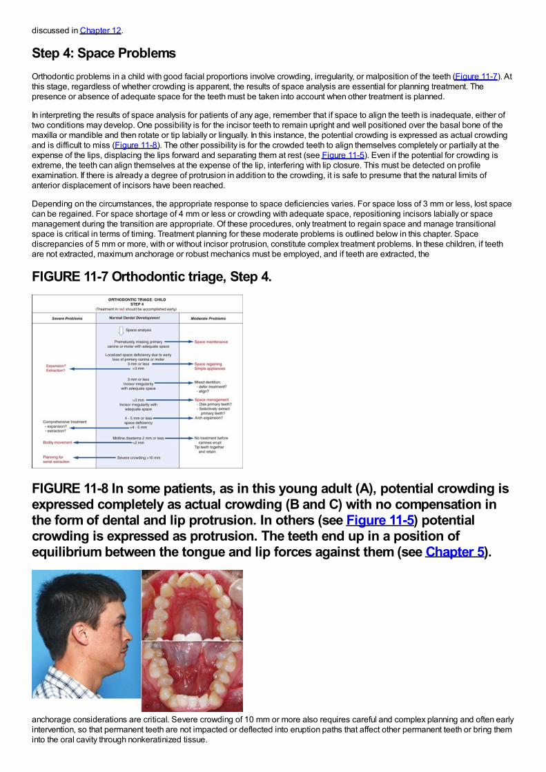
discussed in Chapter 12.
Step 4: Space ProblemsOrthodontic problems in a child with good facial proportions involve crowding, irregularity, or malposition of the teeth (Figure 11-7). Atthis stage, regardless of whether crowding is apparent, the results of space analysis are essential for planning treatment. Thepresence or absence of adequate space for the teeth must be taken into account when other treatment is planned.
In interpreting the results of space analysis for patients of any age, remember that if space to align the teeth is inadequate, either oftwo conditions may develop. One possibility is for the incisor teeth to remain upright and well positioned over the basal bone of themaxilla or mandible and then rotate or tip labially or lingually. In this instance, the potential crowding is expressed as actual crowdingand is difficult to miss (Figure 11-8). The other possibility is for the crowded teeth to align themselves completely or partially at theexpense of the lips, displacing the lips forward and separating them at rest (see Figure 11-5). Even if the potential for crowding isextreme, the teeth can align themselves at the expense of the lip, interfering with lip closure. This must be detected on profileexamination. If there is already a degree of protrusion in addition to the crowding, it is safe to presume that the natural limits ofanterior displacement of incisors have been reached.
Depending on the circumstances, the appropriate response to space deficiencies varies. For space loss of 3 mm or less, lost spacecan be regained. For space shortage of 4 mm or less or crowding with adequate space, repositioning incisors labially or spacemanagement during the transition are appropriate. Of these procedures, only treatment to regain space and manage transitionalspace is critical in terms of timing. Treatment planning for these moderate problems is outlined below in this chapter. Spacediscrepancies of 5 mm or more, with or without incisor protrusion, constitute complex treatment problems. In these children, if teethare not extracted, maximum anchorage or robust mechanics must be employed, and if teeth are extracted, the
FIGURE 11-7 Orthodontic triage, Step 4.
FIGURE 11-8 In some patients, as in this young adult (A), potential crowding isexpressed completely as actual crowding (B and C) with no compensation inthe form of dental and lip protrusion. In others (see Figure 11-5) potentialcrowding is expressed as protrusion. The teeth end up in a position ofequilibrium between the tongue and lip forces against them (see Chapter 5).
anchorage considerations are critical. Severe crowding of 10 mm or more also requires careful and complex planning and often earlyintervention, so that permanent teeth are not impacted or deflected into eruption paths that affect other permanent teeth or bring theminto the oral cavity through nonkeratinized tissue.
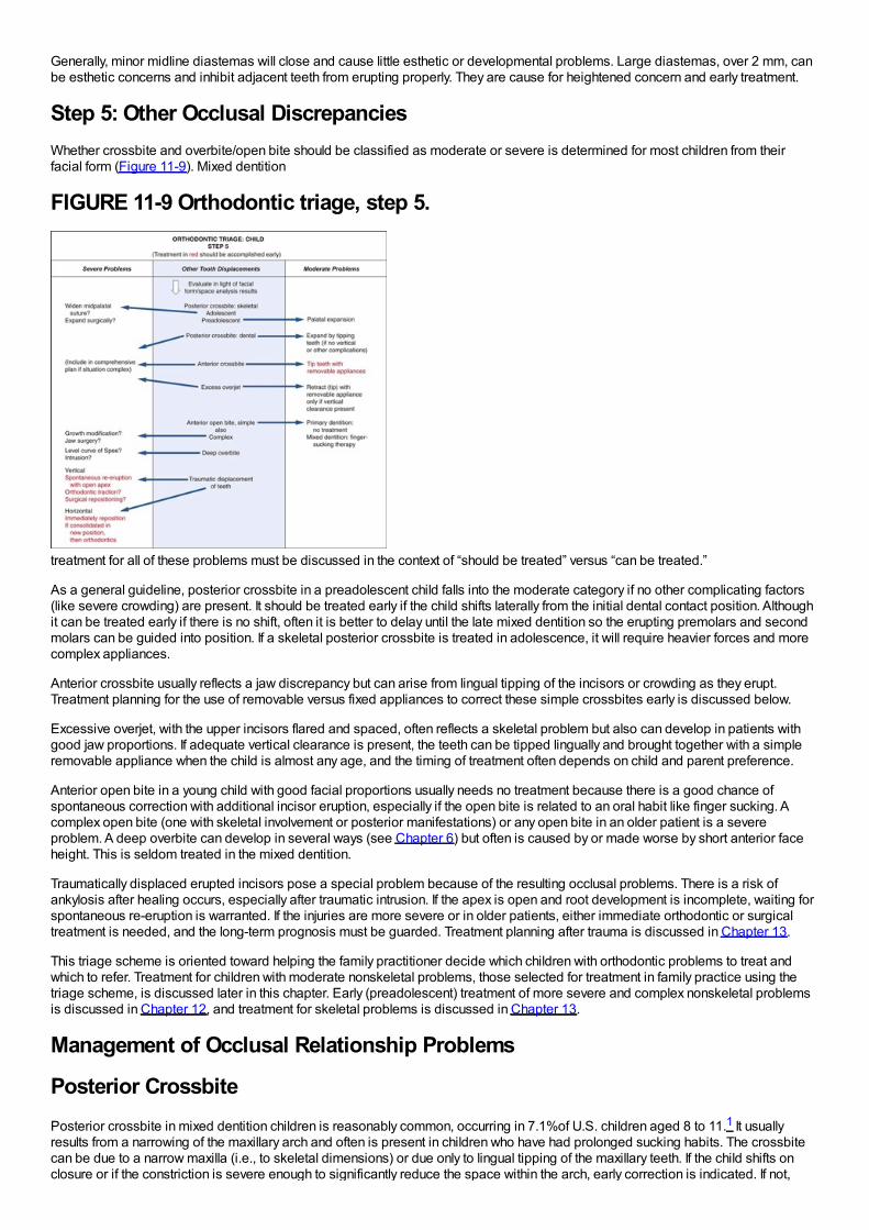
Generally, minor midline diastemas will close and cause little esthetic or developmental problems. Large diastemas, over 2 mm, canbe esthetic concerns and inhibit adjacent teeth from erupting properly. They are cause for heightened concern and early treatment.
Step 5: Other Occlusal DiscrepanciesWhether crossbite and overbite/open bite should be classified as moderate or severe is determined for most children from theirfacial form (Figure 11-9). Mixed dentition
FIGURE 11-9 Orthodontic triage, step 5.
treatment for all of these problems must be discussed in the context of “should be treated” versus “can be treated.”
As a general guideline, posterior crossbite in a preadolescent child falls into the moderate category if no other complicating factors(like severe crowding) are present. It should be treated early if the child shifts laterally from the initial dental contact position. Althoughit can be treated early if there is no shift, often it is better to delay until the late mixed dentition so the erupting premolars and secondmolars can be guided into position. If a skeletal posterior crossbite is treated in adolescence, it will require heavier forces and morecomplex appliances.
Anterior crossbite usually reflects a jaw discrepancy but can arise from lingual tipping of the incisors or crowding as they erupt.Treatment planning for the use of removable versus fixed appliances to correct these simple crossbites early is discussed below.
Excessive overjet, with the upper incisors flared and spaced, often reflects a skeletal problem but also can develop in patients withgood jaw proportions. If adequate vertical clearance is present, the teeth can be tipped lingually and brought together with a simpleremovable appliance when the child is almost any age, and the timing of treatment often depends on child and parent preference.
Anterior open bite in a young child with good facial proportions usually needs no treatment because there is a good chance ofspontaneous correction with additional incisor eruption, especially if the open bite is related to an oral habit like finger sucking. Acomplex open bite (one with skeletal involvement or posterior manifestations) or any open bite in an older patient is a severeproblem. A deep overbite can develop in several ways (see Chapter 6) but often is caused by or made worse by short anterior faceheight. This is seldom treated in the mixed dentition.
Traumatically displaced erupted incisors pose a special problem because of the resulting occlusal problems. There is a risk ofankylosis after healing occurs, especially after traumatic intrusion. If the apex is open and root development is incomplete, waiting forspontaneous re-eruption is warranted. If the injuries are more severe or in older patients, either immediate orthodontic or surgicaltreatment is needed, and the long-term prognosis must be guarded. Treatment planning after trauma is discussed in Chapter 13.
This triage scheme is oriented toward helping the family practitioner decide which children with orthodontic problems to treat andwhich to refer. Treatment for children with moderate nonskeletal problems, those selected for treatment in family practice using thetriage scheme, is discussed later in this chapter. Early (preadolescent) treatment of more severe and complex nonskeletal problemsis discussed in Chapter 12, and treatment for skeletal problems is discussed in Chapter 13.
Management of Occlusal Relationship Problems
Posterior CrossbitePosterior crossbite in mixed dentition children is reasonably common, occurring in 7.1%of U.S. children aged 8 to 11.1 It usuallyresults from a narrowing of the maxillary arch and often is present in children who have had prolonged sucking habits. The crossbitecan be due to a narrow maxilla (i.e., to skeletal dimensions) or due only to lingual tipping of the maxillary teeth. If the child shifts onclosure or if the constriction is severe enough to significantly reduce the space within the arch, early correction is indicated. If not,
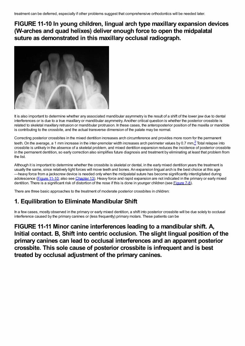
treatment can be deferred, especially if other problems suggest that comprehensive orthodontics will be needed later.
FIGURE 11-10 In young children, lingual arch type maxillary expansion devices(W-arches and quad helixes) deliver enough force to open the midpalatalsuture as demonstrated in this maxillary occlusal radiograph.
It is also important to determine whether any associated mandibular asymmetry is the result of a shift of the lower jaw due to dentalinterferences or is due to a true maxillary or mandibular asymmetry. Another critical question is whether the posterior crossbite isrelated to skeletal maxillary retrusion or mandibular protrusion. In these cases, the anteroposterior position of the maxilla or mandibleis contributing to the crossbite, and the actual transverse dimension of the palate may be normal.
Correcting posterior crossbites in the mixed dentition increases arch circumference and provides more room for the permanentteeth. On the average, a 1 mm increase in the inter-premolar width increases arch perimeter values by 0.7 mm.2 Total relapse intocrossbite is unlikely in the absence of a skeletal problem, and mixed dentition expansion reduces the incidence of posterior crossbitein the permanent dentition, so early correction also simplifies future diagnosis and treatment by eliminating at least that problem fromthe list.
Although it is important to determine whether the crossbite is skeletal or dental, in the early mixed dentition years the treatment isusually the same, since relatively light forces will move teeth and bones. An expansion lingual arch is the best choice at this age—heavy force from a jackscrew device is needed only when the midpalatal suture has become significantly interdigitated duringadolescence (Figure 11-10; also see Chapter 13). Heavy force and rapid expansion are not indicated in the primary or early mixeddentition. There is a significant risk of distortion of the nose if this is done in younger children (see Figure 7-8).
There are three basic approaches to the treatment of moderate posterior crossbites in children:
1. Equilibration to Eliminate Mandibular ShiftIn a few cases, mostly observed in the primary or early mixed dentition, a shift into posterior crossbite will be due solely to occlusalinterference caused by the primary canines or (less frequently) primary molars. These patients can be
FIGURE 11-11 Minor canine interferences leading to a mandibular shift. A,Initial contact. B, Shift into centric occlusion. The slight lingual position of theprimary canines can lead to occlusal interferences and an apparent posteriorcrossbite. This sole cause of posterior crossbite is infrequent and is besttreated by occlusal adjustment of the primary canines.
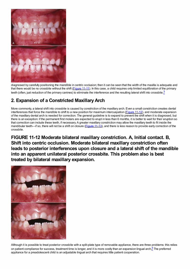
diagnosed by carefully positioning the mandible in centric occlusion; then it can be seen that the width of the maxilla is adequate andthat there would be no crossbite without the shift (Figure 11-11). In this case, a child requires only limited equilibration of the primaryteeth (often, just reduction of the primary canines) to eliminate the interference and the resulting lateral shift into crossbite.3
2. Expansion of a Constricted Maxillary ArchMore commonly, a lateral shift into crossbite is caused by constriction of the maxillary arch. Even a small constriction creates dentalinterferences that force the mandible to shift to a new position for maximum intercuspation (Figure 11-12), and moderate expansionof the maxillary dental arch is needed for correction. The general guideline is to expand to prevent the shift when it is diagnosed, butthere is an exception: if the permanent first molars are expected to erupt in less than 6 months, it is better to wait for their eruption sothat correction can include these teeth, if necessary. A greater maxillary constriction may allow the maxillary teeth to fit inside themandibular teeth—if so, there will not be a shift on closure (Figure 11-13), and there is less reason to provide early correction of thecrossbite.
FIGURE 11-12 Moderate bilateral maxillary constriction. A, Initial contact. B,Shift into centric occlusion. Moderate bilateral maxillary constriction oftenleads to posterior interferences upon closure and a lateral shift of the mandibleinto an apparent unilateral posterior crossbite. This problem also is besttreated by bilateral maxillary expansion.
Although it is possible to treat posterior crossbite with a split-plate type of removable appliance, there are three problems: this relieson patient compliance for success, treatment time is longer, and it is more costly than an expansion lingual arch.4 The preferredappliance for a preadolescent child is an adjustable lingual arch that requires little patient cooperation.
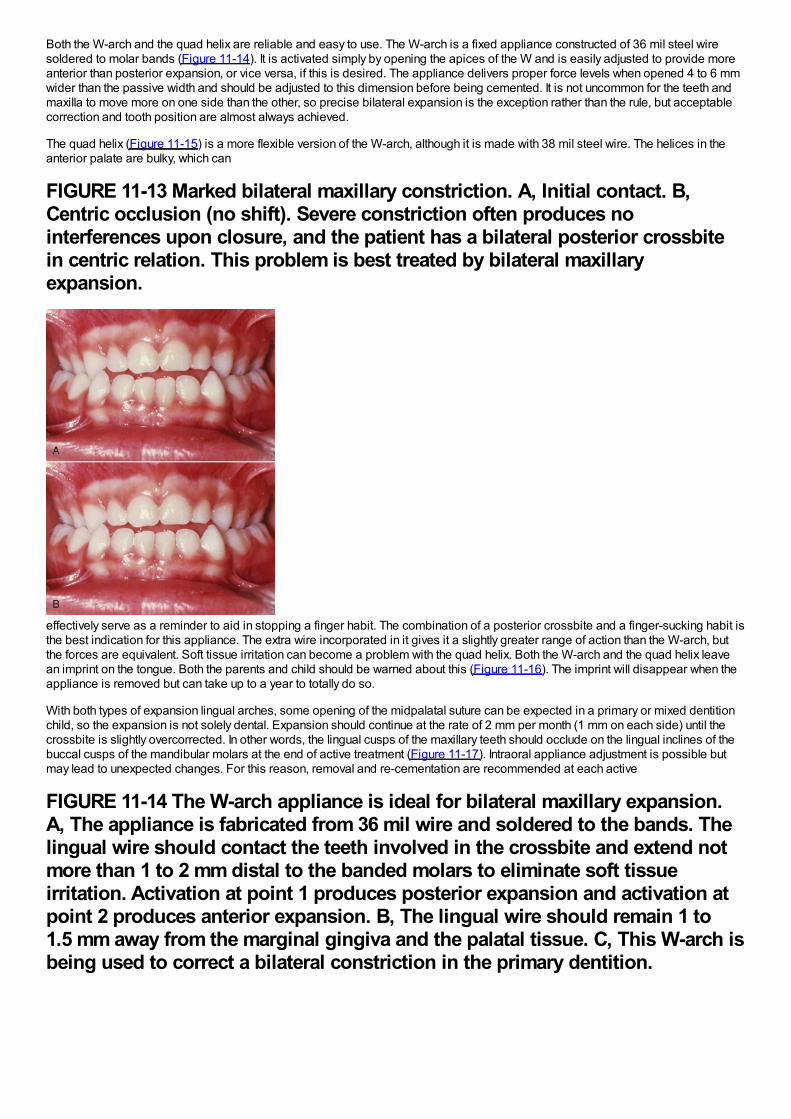
Both the W-arch and the quad helix are reliable and easy to use. The W-arch is a fixed appliance constructed of 36 mil steel wiresoldered to molar bands (Figure 11-14). It is activated simply by opening the apices of the W and is easily adjusted to provide moreanterior than posterior expansion, or vice versa, if this is desired. The appliance delivers proper force levels when opened 4 to 6 mmwider than the passive width and should be adjusted to this dimension before being cemented. It is not uncommon for the teeth andmaxilla to move more on one side than the other, so precise bilateral expansion is the exception rather than the rule, but acceptablecorrection and tooth position are almost always achieved.
The quad helix (Figure 11-15) is a more flexible version of the W-arch, although it is made with 38 mil steel wire. The helices in theanterior palate are bulky, which can
FIGURE 11-13 Marked bilateral maxillary constriction. A, Initial contact. B,Centric occlusion (no shift). Severe constriction often produces nointerferences upon closure, and the patient has a bilateral posterior crossbitein centric relation. This problem is best treated by bilateral maxillaryexpansion.
effectively serve as a reminder to aid in stopping a finger habit. The combination of a posterior crossbite and a finger-sucking habit isthe best indication for this appliance. The extra wire incorporated in it gives it a slightly greater range of action than the W-arch, butthe forces are equivalent. Soft tissue irritation can become a problem with the quad helix. Both the W-arch and the quad helix leavean imprint on the tongue. Both the parents and child should be warned about this (Figure 11-16). The imprint will disappear when theappliance is removed but can take up to a year to totally do so.
With both types of expansion lingual arches, some opening of the midpalatal suture can be expected in a primary or mixed dentitionchild, so the expansion is not solely dental. Expansion should continue at the rate of 2 mm per month (1 mm on each side) until thecrossbite is slightly overcorrected. In other words, the lingual cusps of the maxillary teeth should occlude on the lingual inclines of thebuccal cusps of the mandibular molars at the end of active treatment (Figure 11-17). Intraoral appliance adjustment is possible butmay lead to unexpected changes. For this reason, removal and re-cementation are recommended at each active
FIGURE 11-14 The W-arch appliance is ideal for bilateral maxillary expansion.A, The appliance is fabricated from 36 mil wire and soldered to the bands. Thelingual wire should contact the teeth involved in the crossbite and extend notmore than 1 to 2 mm distal to the banded molars to eliminate soft tissueirritation. Activation at point 1 produces posterior expansion and activation atpoint 2 produces anterior expansion. B, The lingual wire should remain 1 to1.5 mm away from the marginal gingiva and the palatal tissue. C, This W-arch isbeing used to correct a bilateral constriction in the primary dentition.
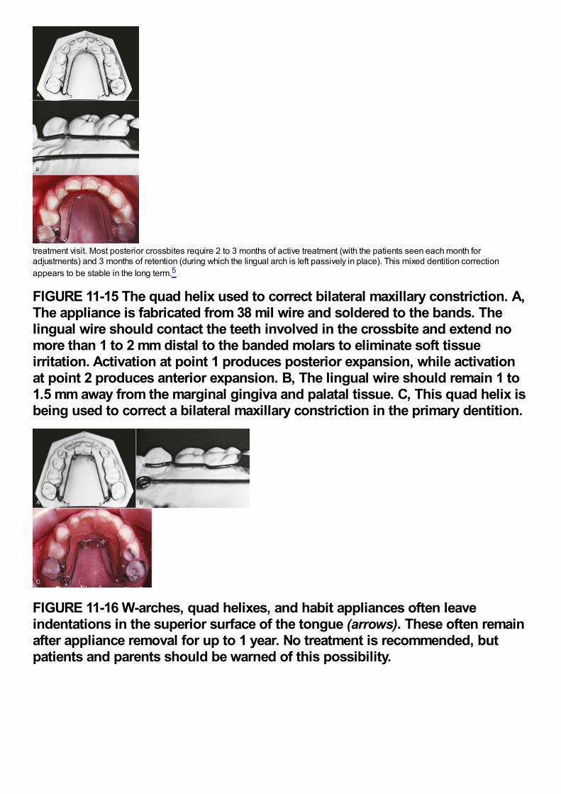
treatment visit. Most posterior crossbites require 2 to 3 months of active treatment (with the patients seen each month foradjustments) and 3 months of retention (during which the lingual arch is left passively in place). This mixed dentition correctionappears to be stable in the long term.5
FIGURE 11-15 The quad helix used to correct bilateral maxillary constriction. A,The appliance is fabricated from 38 mil wire and soldered to the bands. Thelingual wire should contact the teeth involved in the crossbite and extend nomore than 1 to 2 mm distal to the banded molars to eliminate soft tissueirritation. Activation at point 1 produces posterior expansion, while activationat point 2 produces anterior expansion. B, The lingual wire should remain 1 to1.5 mm away from the marginal gingiva and palatal tissue. C, This quad helix isbeing used to correct a bilateral maxillary constriction in the primary dentition.
FIGURE 11-16 W-arches, quad helixes, and habit appliances often leaveindentations in the superior surface of the tongue (arrows). These often remainafter appliance removal for up to 1 year. No treatment is recommended, butpatients and parents should be warned of this possibility.
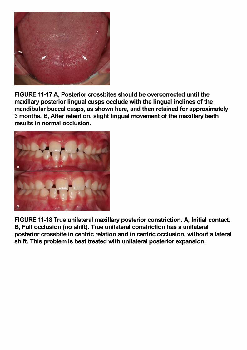
FIGURE 11-17 A, Posterior crossbites should be overcorrected until themaxillary posterior lingual cusps occlude with the lingual inclines of themandibular buccal cusps, as shown here, and then retained for approximately3 months. B, After retention, slight lingual movement of the maxillary teethresults in normal occlusion.
FIGURE 11-18 True unilateral maxillary posterior constriction. A, Initial contact.B, Full occlusion (no shift). True unilateral constriction has a unilateralposterior crossbite in centric relation and in centric occlusion, without a lateralshift. This problem is best treated with unilateral posterior expansion.
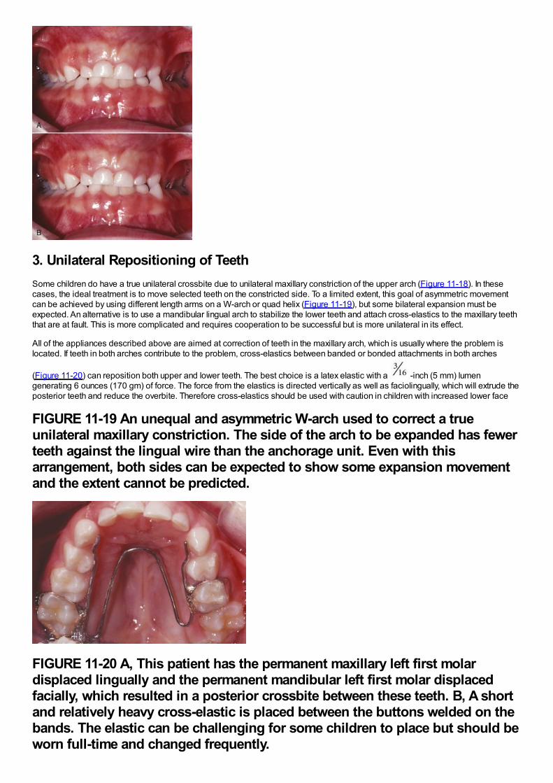
3. Unilateral Repositioning of TeethSome children do have a true unilateral crossbite due to unilateral maxillary constriction of the upper arch (Figure 11-18). In thesecases, the ideal treatment is to move selected teeth on the constricted side. To a limited extent, this goal of asymmetric movementcan be achieved by using different length arms on a W-arch or quad helix (Figure 11-19), but some bilateral expansion must beexpected. An alternative is to use a mandibular lingual arch to stabilize the lower teeth and attach cross-elastics to the maxillary teeththat are at fault. This is more complicated and requires cooperation to be successful but is more unilateral in its effect.
All of the appliances described above are aimed at correction of teeth in the maxillary arch, which is usually where the problem islocated. If teeth in both arches contribute to the problem, cross-elastics between banded or bonded attachments in both arches
(Figure 11-20) can reposition both upper and lower teeth. The best choice is a latex elastic with a -inch (5 mm) lumengenerating 6 ounces (170 gm) of force. The force from the elastics is directed vertically as well as faciolingually, which will extrude theposterior teeth and reduce the overbite. Therefore cross-elastics should be used with caution in children with increased lower face
FIGURE 11-19 An unequal and asymmetric W-arch used to correct a trueunilateral maxillary constriction. The side of the arch to be expanded has fewerteeth against the lingual wire than the anchorage unit. Even with thisarrangement, both sides can be expected to show some expansion movementand the extent cannot be predicted.
FIGURE 11-20 A, This patient has the permanent maxillary left first molardisplaced lingually and the permanent mandibular left first molar displacedfacially, which resulted in a posterior crossbite between these teeth. B, A shortand relatively heavy cross-elastic is placed between the buttons welded on thebands. The elastic can be challenging for some children to place but should beworn full-time and changed frequently.
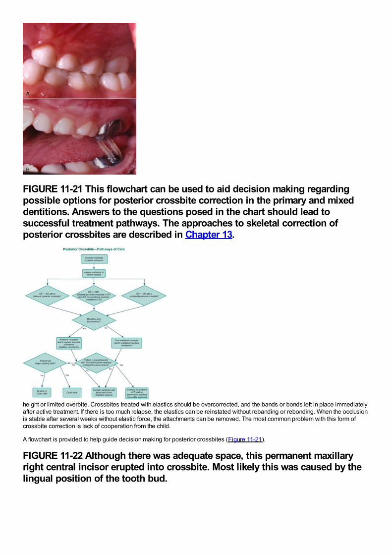
FIGURE 11-21 This flowchart can be used to aid decision making regardingpossible options for posterior crossbite correction in the primary and mixeddentitions. Answers to the questions posed in the chart should lead tosuccessful treatment pathways. The approaches to skeletal correction ofposterior crossbites are described in Chapter 13.
height or limited overbite. Crossbites treated with elastics should be overcorrected, and the bands or bonds left in place immediatelyafter active treatment. If there is too much relapse, the elastics can be reinstated without rebanding or rebonding. When the occlusionis stable after several weeks without elastic force, the attachments can be removed. The most common problem with this form ofcrossbite correction is lack of cooperation from the child.
A flowchart is provided to help guide decision making for posterior crossbites (Figure 11-21).
FIGURE 11-22 Although there was adequate space, this permanent maxillaryright central incisor erupted into crossbite. Most likely this was caused by thelingual position of the tooth bud.
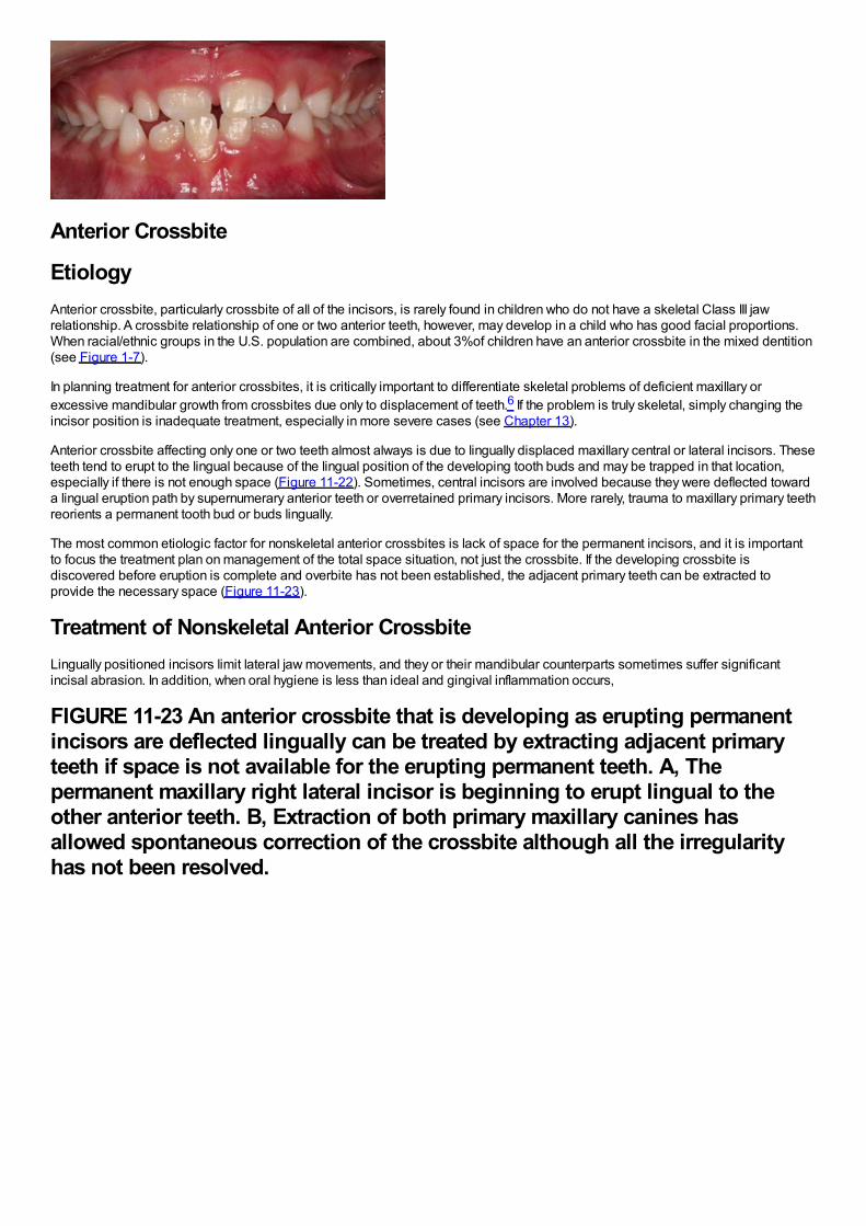
Anterior Crossbite
EtiologyAnterior crossbite, particularly crossbite of all of the incisors, is rarely found in children who do not have a skeletal Class III jawrelationship. A crossbite relationship of one or two anterior teeth, however, may develop in a child who has good facial proportions.When racial/ethnic groups in the U.S. population are combined, about 3%of children have an anterior crossbite in the mixed dentition(see Figure 1-7).
In planning treatment for anterior crossbites, it is critically important to differentiate skeletal problems of deficient maxillary orexcessive mandibular growth from crossbites due only to displacement of teeth.6 If the problem is truly skeletal, simply changing theincisor position is inadequate treatment, especially in more severe cases (see Chapter 13).
Anterior crossbite affecting only one or two teeth almost always is due to lingually displaced maxillary central or lateral incisors. Theseteeth tend to erupt to the lingual because of the lingual position of the developing tooth buds and may be trapped in that location,especially if there is not enough space (Figure 11-22). Sometimes, central incisors are involved because they were deflected towarda lingual eruption path by supernumerary anterior teeth or overretained primary incisors. More rarely, trauma to maxillary primary teethreorients a permanent tooth bud or buds lingually.
The most common etiologic factor for nonskeletal anterior crossbites is lack of space for the permanent incisors, and it is importantto focus the treatment plan on management of the total space situation, not just the crossbite. If the developing crossbite isdiscovered before eruption is complete and overbite has not been established, the adjacent primary teeth can be extracted toprovide the necessary space (Figure 11-23).
Treatment of Nonskeletal Anterior CrossbiteLingually positioned incisors limit lateral jaw movements, and they or their mandibular counterparts sometimes suffer significantincisal abrasion. In addition, when oral hygiene is less than ideal and gingival inflammation occurs,
FIGURE 11-23 An anterior crossbite that is developing as erupting permanentincisors are deflected lingually can be treated by extracting adjacent primaryteeth if space is not available for the erupting permanent teeth. A, Thepermanent maxillary right lateral incisor is beginning to erupt lingual to theother anterior teeth. B, Extraction of both primary maxillary canines hasallowed spontaneous correction of the crossbite although all the irregularityhas not been resolved.
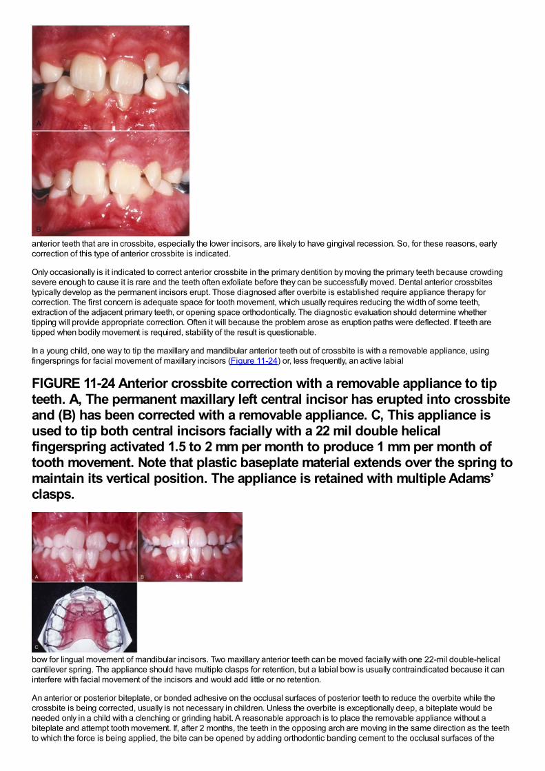
anterior teeth that are in crossbite, especially the lower incisors, are likely to have gingival recession. So, for these reasons, earlycorrection of this type of anterior crossbite is indicated.
Only occasionally is it indicated to correct anterior crossbite in the primary dentition by moving the primary teeth because crowdingsevere enough to cause it is rare and the teeth often exfoliate before they can be successfully moved. Dental anterior crossbitestypically develop as the permanent incisors erupt. Those diagnosed after overbite is established require appliance therapy forcorrection. The first concern is adequate space for tooth movement, which usually requires reducing the width of some teeth,extraction of the adjacent primary teeth, or opening space orthodontically. The diagnostic evaluation should determine whethertipping will provide appropriate correction. Often it will because the problem arose as eruption paths were deflected. If teeth aretipped when bodily movement is required, stability of the result is questionable.
In a young child, one way to tip the maxillary and mandibular anterior teeth out of crossbite is with a removable appliance, usingfingersprings for facial movement of maxillary incisors (Figure 11-24) or, less frequently, an active labial
FIGURE 11-24 Anterior crossbite correction with a removable appliance to tipteeth. A, The permanent maxillary left central incisor has erupted into crossbiteand (B) has been corrected with a removable appliance. C, This appliance isused to tip both central incisors facially with a 22 mil double helicalfingerspring activated 1.5 to 2 mm per month to produce 1 mm per month oftooth movement. Note that plastic baseplate material extends over the spring tomaintain its vertical position. The appliance is retained with multiple Adams’clasps.
bow for lingual movement of mandibular incisors. Two maxillary anterior teeth can be moved facially with one 22-mil double-helicalcantilever spring. The appliance should have multiple clasps for retention, but a labial bow is usually contraindicated because it caninterfere with facial movement of the incisors and would add little or no retention.
An anterior or posterior biteplate, or bonded adhesive on the occlusal surfaces of posterior teeth to reduce the overbite while thecrossbite is being corrected, usually is not necessary in children. Unless the overbite is exceptionally deep, a biteplate would beneeded only in a child with a clenching or grinding habit. A reasonable approach is to place the removable appliance without abiteplate and attempt tooth movement. If, after 2 months, the teeth in the opposing arch are moving in the same direction as the teethto which the force is being applied, the bite can be opened by adding orthodontic banding cement to the occlusal surfaces of the
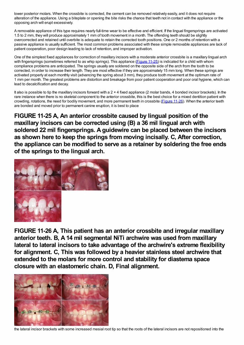
lower posterior molars. When the crossbite is corrected, the cement can be removed relatively easily, and it does not requirealteration of the appliance. Using a biteplate or opening the bite risks the chance that teeth not in contact with the appliance or theopposing arch will erupt excessively.
A removable appliance of this type requires nearly full-time wear to be effective and efficient. If the lingual fingersprings are activated1.5 to 2 mm, they will produce approximately 1 mm of tooth movement in a month. The offending teeth should be slightlyovercorrected and retained until overbite is adequate to retain the corrected tooth positions. One or 2 months of retention with apassive appliance is usually sufficient. The most common problems associated with these simple removable appliances are lack ofpatient cooperation, poor design leading to lack of retention, and improper activation.
One of the simplest fixed appliances for correction of maxillary incisors with a moderate anterior crossbite is a maxillary lingual archwith fingersprings (sometimes referred to as whip springs). This appliance (Figure 11-25) is indicated for a child with whomcompliance problems are anticipated. The springs usually are soldered on the opposite side of the arch from the tooth to becorrected, in order to increase their length. They are most effective if they are approximately 15 mm long. When these springs areactivated properly at each monthly visit (advancing the spring about 3 mm), they produce tooth movement at the optimum rate of1 mm per month. The greatest problems are distortion and breakage from poor patient cooperation and poor oral hygiene, which canlead to decalcification and decay.
It also is possible to tip the maxillary incisors forward with a 2 × 4 fixed appliance (2 molar bands, 4 bonded incisor brackets). In therare instance when there is no skeletal component to the anterior crossbite, this is the best choice for a mixed dentition patient withcrowding, rotations, the need for bodily movement, and more permanent teeth in crossbite (Figure 11-26). When the anterior teethare bonded and moved prior to permanent canine eruption, it is best to place
FIGURE 11-25 A, An anterior crossbite caused by lingual position of themaxillary incisors can be corrected using (B) a 36 mil lingual arch withsoldered 22 mil fingersprings. A guidewire can be placed between the incisorsas shown here to keep the springs from moving incisally. C, After correction,the appliance can be modified to serve as a retainer by soldering the free endsof the springs to the lingual arch.
FIGURE 11-26 A, This patient has an anterior crossbite and irregular maxillaryanterior teeth. B, A 14 mil segmental NiTi archwire was used from maxillarylateral to lateral incisors to take advantage of the archwire's extreme flexibilityfor alignment. C, This was followed by a heavier stainless steel archwire thatextended to the molars for more control and stability for diastema spaceclosure with an elastomeric chain. D, Final alignment.
the lateral incisor brackets with some increased mesial root tip so that the roots of the lateral incisors are not repositioned into the
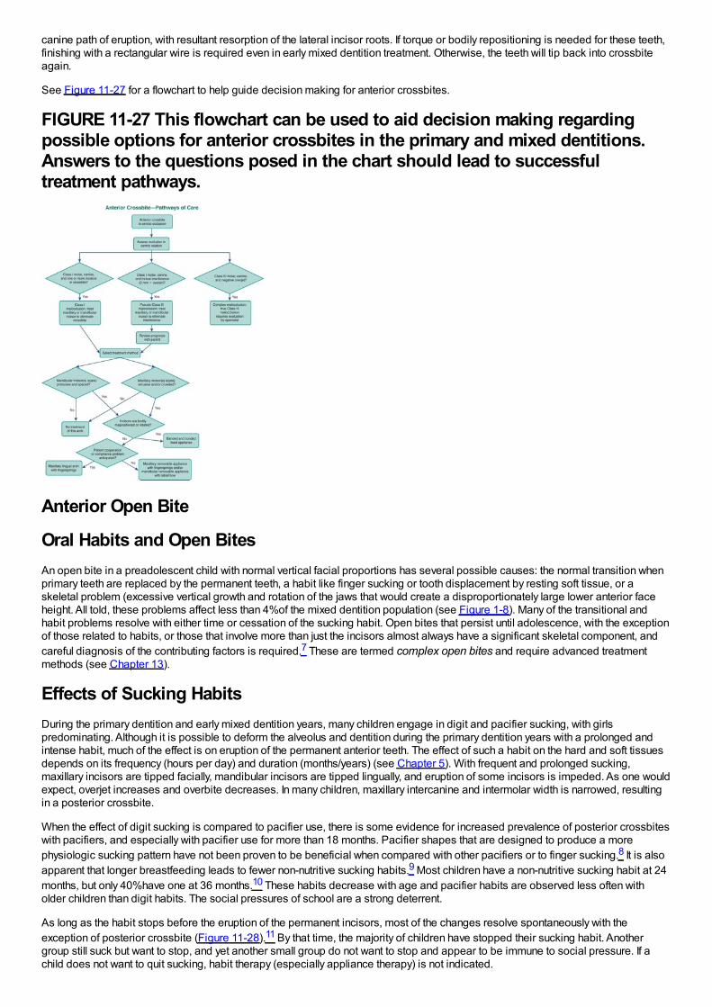
canine path of eruption, with resultant resorption of the lateral incisor roots. If torque or bodily repositioning is needed for these teeth,finishing with a rectangular wire is required even in early mixed dentition treatment. Otherwise, the teeth will tip back into crossbiteagain.
See Figure 11-27 for a flowchart to help guide decision making for anterior crossbites.
FIGURE 11-27 This flowchart can be used to aid decision making regardingpossible options for anterior crossbites in the primary and mixed dentitions.Answers to the questions posed in the chart should lead to successfultreatment pathways.
Anterior Open Bite
Oral Habits and Open BitesAn open bite in a preadolescent child with normal vertical facial proportions has several possible causes: the normal transition whenprimary teeth are replaced by the permanent teeth, a habit like finger sucking or tooth displacement by resting soft tissue, or askeletal problem (excessive vertical growth and rotation of the jaws that would create a disproportionately large lower anterior faceheight. All told, these problems affect less than 4%of the mixed dentition population (see Figure 1-8). Many of the transitional andhabit problems resolve with either time or cessation of the sucking habit. Open bites that persist until adolescence, with the exceptionof those related to habits, or those that involve more than just the incisors almost always have a significant skeletal component, andcareful diagnosis of the contributing factors is required.7 These are termed complex open bites and require advanced treatmentmethods (see Chapter 13).
Effects of Sucking HabitsDuring the primary dentition and early mixed dentition years, many children engage in digit and pacifier sucking, with girlspredominating. Although it is possible to deform the alveolus and dentition during the primary dentition years with a prolonged andintense habit, much of the effect is on eruption of the permanent anterior teeth. The effect of such a habit on the hard and soft tissuesdepends on its frequency (hours per day) and duration (months/years) (see Chapter 5). With frequent and prolonged sucking,maxillary incisors are tipped facially, mandibular incisors are tipped lingually, and eruption of some incisors is impeded. As one wouldexpect, overjet increases and overbite decreases. In many children, maxillary intercanine and intermolar width is narrowed, resultingin a posterior crossbite.
When the effect of digit sucking is compared to pacifier use, there is some evidence for increased prevalence of posterior crossbiteswith pacifiers, and especially with pacifier use for more than 18 months. Pacifier shapes that are designed to produce a morephysiologic sucking pattern have not been proven to be beneficial when compared with other pacifiers or to finger sucking.8 It is alsoapparent that longer breastfeeding leads to fewer non-nutritive sucking habits.9 Most children have a non-nutritive sucking habit at 24months, but only 40%have one at 36 months.10 These habits decrease with age and pacifier habits are observed less often witholder children than digit habits. The social pressures of school are a strong deterrent.
As long as the habit stops before the eruption of the permanent incisors, most of the changes resolve spontaneously with theexception of posterior crossbite (Figure 11-28).11 By that time, the majority of children have stopped their sucking habit. Anothergroup still suck but want to stop, and yet another small group do not want to stop and appear to be immune to social pressure. If achild does not want to quit sucking, habit therapy (especially appliance therapy) is not indicated.

Nondental InterventionAs the time of eruption of the permanent incisors approaches, the simplest approach to habit therapy is a straightforward discussionbetween the child and the dentist that expresses concern and includes an explanation by the dentist of the problems caused by aprolonged finger habit. This “adult” approach (and restraint from intervention by the parents) may be enough to terminate the habitduring this first part of the transition to the permanent dentition but is most effective with older children.
Another level of intervention is reminder therapy. This is for the child who wants to quit but needs help. Any one of several remindersthat are introduced with an explanation to the child can be useful. One of the simplest approaches is to secure an adhesive bandagewith waterproof tape on the finger that is sucked (Figure 11-29). The anterior portion of the quad helix appliance also can be quiteuseful as a reminder when it is placed in the appropriate position in the palate (see Figure 11-15).
If the reminder approach fails, a reward system can be implemented that provides a small tangible daily reward for not engaging inthe habit. In some cases, a large reward must be negotiated for complete cessation of the habit.
If all of these fail and the child really wants to quit, an elastic bandage loosely wrapped around the elbow prevents the arm from flexingand the fingers from being sucked. If this is used, wearing it only at night and 6 to 8 weeks of intervention should be sufficient. Thechild should understand that this is not punishment.
Appliance TherapyIf the previous methods have not succeeded in eliminating the habit, a removable reminder appliance is contraindicated becauselack of compliance is part of the problem. The child who wants to stop can be fitted with a cemented reminder appliance thatimpedes sucking (Figure 11-30). These appliances can be deformed and removed by children who are not compliant and do not trulywish to stop the habit, so cooperation still is important. If this is understood by the child as a “helping hand” rather than punishment,the treatment will be successful and psychologic problems will not result.12 The preferred method is a maxillary lingual arch with ananterior crib device, making it extremely difficult for the child to place the thumb or other object in the mouth.
In about half of the children for whom such a crib is made, thumb-sucking stops immediately and the anterior open bite usually beginsto close relatively rapidly thereafter. In the remaining children, thumb-sucking persists for a few weeks, but the crib device is eventuallyeffective in extinguishing thumb-sucking in 85%to 90%of patients.13 It is a good idea to leave the crib in place for 6 months after thehabit has apparently been eliminated. Commonly, these cemented reminders, like lingual arch expanders, leave an imprint on thetongue (see Figure 11-16) that will resolve
FIGURE 11-28 A to D, Photos at 1-year intervals of a child who stopped suckinghis thumb at the time of the first photo. Gradual closure of the open bite,without a need for further intervention, usually occurs in patients with normalfacial proportions after habits stop. E, If a sucking habit persists, a crib of thistype can be used to help extinguish the habit. A crib is most effective in a childwho wants to stop the thumb- or finger-sucking and accepts the crib as areminder not to do so.
FIGURE 11-29 An adhesive bandage can be applied over the end of the finger
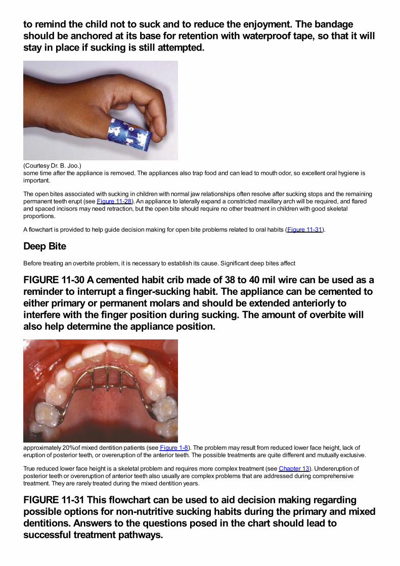
to remind the child not to suck and to reduce the enjoyment. The bandageshould be anchored at its base for retention with waterproof tape, so that it willstay in place if sucking is still attempted.
(Courtesy Dr. B. Joo.)some time after the appliance is removed. The appliances also trap food and can lead to mouth odor, so excellent oral hygiene isimportant.
The open bites associated with sucking in children with normal jaw relationships often resolve after sucking stops and the remainingpermanent teeth erupt (see Figure 11-28). An appliance to laterally expand a constricted maxillary arch will be required, and flaredand spaced incisors may need retraction, but the open bite should require no other treatment in children with good skeletalproportions.
A flowchart is provided to help guide decision making for open bite problems related to oral habits (Figure 11-31).
Deep BiteBefore treating an overbite problem, it is necessary to establish its cause. Significant deep bites affect
FIGURE 11-30 A cemented habit crib made of 38 to 40 mil wire can be used as areminder to interrupt a finger-sucking habit. The appliance can be cemented toeither primary or permanent molars and should be extended anteriorly tointerfere with the finger position during sucking. The amount of overbite willalso help determine the appliance position.
approximately 20%of mixed dentition patients (see Figure 1-8). The problem may result from reduced lower face height, lack oferuption of posterior teeth, or overeruption of the anterior teeth. The possible treatments are quite different and mutually exclusive.
True reduced lower face height is a skeletal problem and requires more complex treatment (see Chapter 13). Undereruption ofposterior teeth or overeruption of anterior teeth also usually are complex problems that are addressed during comprehensivetreatment. They are rarely treated during the mixed dentition years.
FIGURE 11-31 This flowchart can be used to aid decision making regardingpossible options for non-nutritive sucking habits during the primary and mixeddentitions. Answers to the questions posed in the chart should lead tosuccessful treatment pathways.
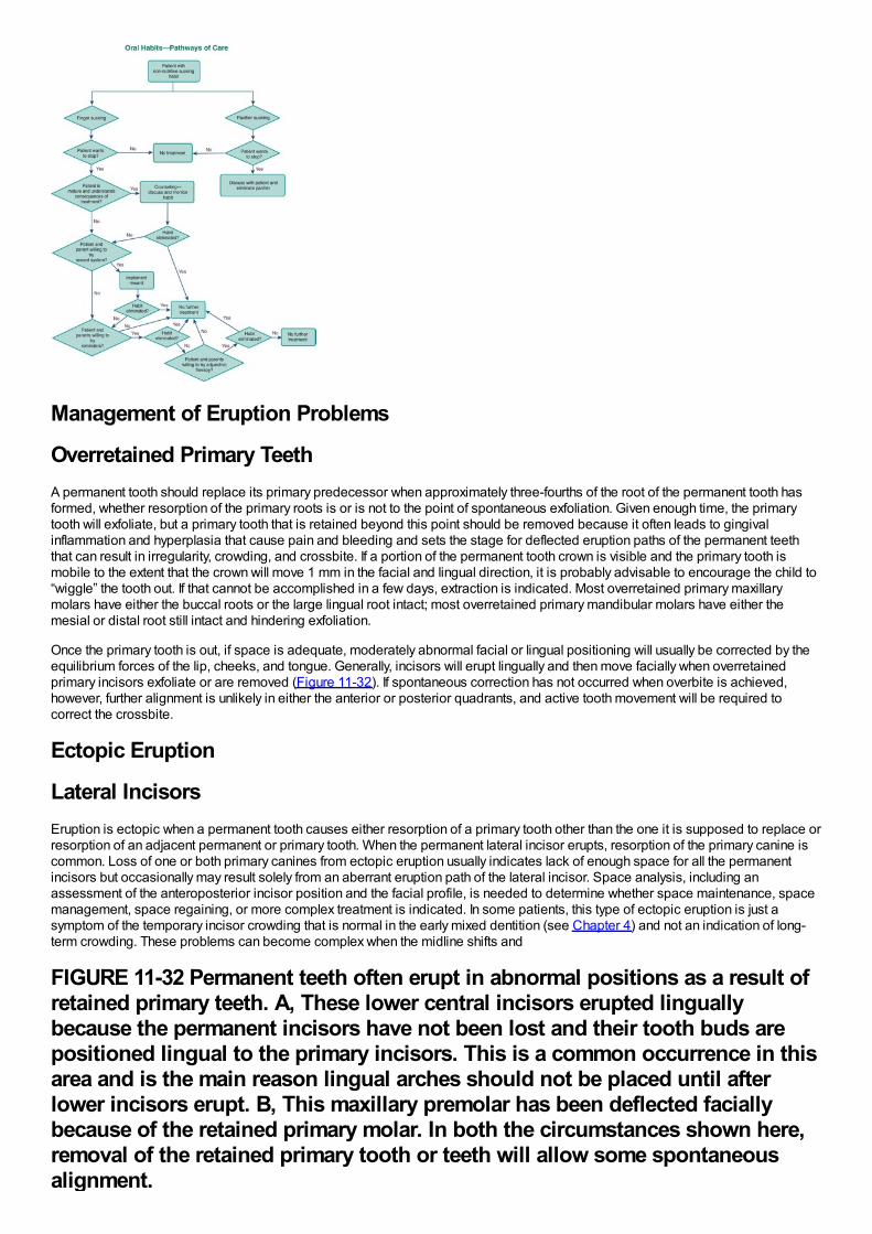
Management of Eruption Problems
Overretained Primary TeethA permanent tooth should replace its primary predecessor when approximately three-fourths of the root of the permanent tooth hasformed, whether resorption of the primary roots is or is not to the point of spontaneous exfoliation. Given enough time, the primarytooth will exfoliate, but a primary tooth that is retained beyond this point should be removed because it often leads to gingivalinflammation and hyperplasia that cause pain and bleeding and sets the stage for deflected eruption paths of the permanent teeththat can result in irregularity, crowding, and crossbite. If a portion of the permanent tooth crown is visible and the primary tooth ismobile to the extent that the crown will move 1 mm in the facial and lingual direction, it is probably advisable to encourage the child to“wiggle” the tooth out. If that cannot be accomplished in a few days, extraction is indicated. Most overretained primary maxillarymolars have either the buccal roots or the large lingual root intact; most overretained primary mandibular molars have either themesial or distal root still intact and hindering exfoliation.
Once the primary tooth is out, if space is adequate, moderately abnormal facial or lingual positioning will usually be corrected by theequilibrium forces of the lip, cheeks, and tongue. Generally, incisors will erupt lingually and then move facially when overretainedprimary incisors exfoliate or are removed (Figure 11-32). If spontaneous correction has not occurred when overbite is achieved,however, further alignment is unlikely in either the anterior or posterior quadrants, and active tooth movement will be required tocorrect the crossbite.
Ectopic Eruption
Lateral IncisorsEruption is ectopic when a permanent tooth causes either resorption of a primary tooth other than the one it is supposed to replace orresorption of an adjacent permanent or primary tooth. When the permanent lateral incisor erupts, resorption of the primary canine iscommon. Loss of one or both primary canines from ectopic eruption usually indicates lack of enough space for all the permanentincisors but occasionally may result solely from an aberrant eruption path of the lateral incisor. Space analysis, including anassessment of the anteroposterior incisor position and the facial profile, is needed to determine whether space maintenance, spacemanagement, space regaining, or more complex treatment is indicated. In some patients, this type of ectopic eruption is just asymptom of the temporary incisor crowding that is normal in the early mixed dentition (see Chapter 4) and not an indication of long-term crowding. These problems can become complex when the midline shifts and
FIGURE 11-32 Permanent teeth often erupt in abnormal positions as a result ofretained primary teeth. A, These lower central incisors erupted linguallybecause the permanent incisors have not been lost and their tooth buds arepositioned lingual to the primary incisors. This is a common occurrence in thisarea and is the main reason lingual arches should not be placed until afterlower incisors erupt. B, This maxillary premolar has been deflected faciallybecause of the retained primary molar. In both the circumstances shown here,removal of the retained primary tooth or teeth will allow some spontaneousalignment.
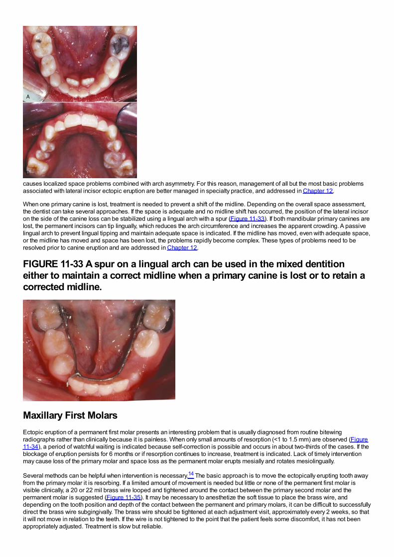
causes localized space problems combined with arch asymmetry. For this reason, management of all but the most basic problemsassociated with lateral incisor ectopic eruption are better managed in specialty practice, and addressed in Chapter 12.
When one primary canine is lost, treatment is needed to prevent a shift of the midline. Depending on the overall space assessment,the dentist can take several approaches. If the space is adequate and no midline shift has occurred, the position of the lateral incisoron the side of the canine loss can be stabilized using a lingual arch with a spur (Figure 11-33). If both mandibular primary canines arelost, the permanent incisors can tip lingually, which reduces the arch circumference and increases the apparent crowding. A passivelingual arch to prevent lingual tipping and maintain adequate space is indicated. If the midline has moved, even with adequate space,or the midline has moved and space has been lost, the problems rapidly become complex. These types of problems need to beresolved prior to canine eruption and are addressed in Chapter 12.
FIGURE 11-33 A spur on a lingual arch can be used in the mixed dentitioneither to maintain a correct midline when a primary canine is lost or to retain acorrected midline.
Maxillary First MolarsEctopic eruption of a permanent first molar presents an interesting problem that is usually diagnosed from routine bitewingradiographs rather than clinically because it is painless. When only small amounts of resorption (<1 to 1.5 mm) are observed (Figure11-34), a period of watchful waiting is indicated because self-correction is possible and occurs in about two-thirds of the cases. If theblockage of eruption persists for 6 months or if resorption continues to increase, treatment is indicated. Lack of timely interventionmay cause loss of the primary molar and space loss as the permanent molar erupts mesially and rotates mesiolingually.
Several methods can be helpful when intervention is necessary.14 The basic approach is to move the ectopically erupting tooth awayfrom the primary molar it is resorbing. If a limited amount of movement is needed but little or none of the permanent first molar isvisible clinically, a 20 or 22 mil brass wire looped and tightened around the contact between the primary second molar and thepermanent molar is suggested (Figure 11-35). It may be necessary to anesthetize the soft tissue to place the brass wire, anddepending on the tooth position and depth of the contact between the permanent and primary molars, it can be difficult to successfullydirect the brass wire subgingivally. The brass wire should be tightened at each adjustment visit, approximately every 2 weeks, so thatit will not move in relation to the teeth. If the wire is not tightened to the point that the patient feels some discomfort, it has not beenappropriately adjusted. Treatment is slow but reliable.
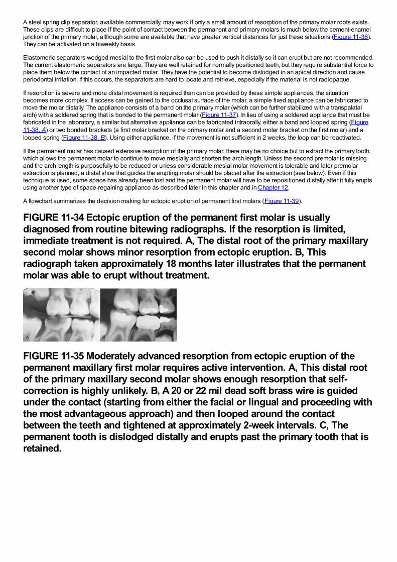
A steel spring clip separator, available commercially, may work if only a small amount of resorption of the primary molar roots exists.These clips are difficult to place if the point of contact between the permanent and primary molars is much below the cement-enameljunction of the primary molar, although some are available that have greater vertical distances for just these situations (Figure 11-36).They can be activated on a biweekly basis.
Elastomeric separators wedged mesial to the first molar also can be used to push it distally so it can erupt but are not recommended.The current elastomeric separators are large. They are well retained for normally positioned teeth, but they require substantial force toplace them below the contact of an impacted molar. They have the potential to become dislodged in an apical direction and causeperiodontal irritation. If this occurs, the separators are hard to locate and retrieve, especially if the material is not radiopaque.
If resorption is severe and more distal movement is required than can be provided by these simple appliances, the situationbecomes more complex. If access can be gained to the occlusal surface of the molar, a simple fixed appliance can be fabricated tomove the molar distally. The appliance consists of a band on the primary molar (which can be further stabilized with a transpalatalarch) with a soldered spring that is bonded to the permanent molar (Figure 11-37). In lieu of using a soldered appliance that must befabricated in the laboratory, a similar but alternative appliance can be fabricated intraorally, either a band and looped spring (Figure11-38, A) or two bonded brackets (a first molar bracket on the primary molar and a second molar bracket on the first molar) and alooped spring (Figure 11-38, B). Using either appliance, if the movement is not sufficient in 2 weeks, the loop can be reactivated.
If the permanent molar has caused extensive resorption of the primary molar, there may be no choice but to extract the primary tooth,which allows the permanent molar to continue to move mesially and shorten the arch length. Unless the second premolar is missingand the arch length is purposefully to be reduced or unless considerable mesial molar movement is tolerable and later premolarextraction is planned, a distal shoe that guides the erupting molar should be placed after the extraction (see below). Even if thistechnique is used, some space has already been lost and the permanent molar will have to be repositioned distally after it fully eruptsusing another type of space-regaining appliance as described later in this chapter and in Chapter 12.
A flowchart summarizes the decision making for ectopic eruption of permanent first molars (Figure 11-39).
FIGURE 11-34 Ectopic eruption of the permanent first molar is usuallydiagnosed from routine bitewing radiographs. If the resorption is limited,immediate treatment is not required. A, The distal root of the primary maxillarysecond molar shows minor resorption from ectopic eruption. B, Thisradiograph taken approximately 18 months later illustrates that the permanentmolar was able to erupt without treatment.
FIGURE 11-35 Moderately advanced resorption from ectopic eruption of thepermanent maxillary first molar requires active intervention. A, This distal rootof the primary maxillary second molar shows enough resorption that self-correction is highly unlikely. B, A 20 or 22 mil dead soft brass wire is guidedunder the contact (starting from either the facial or lingual and proceeding withthe most advantageous approach) and then looped around the contactbetween the teeth and tightened at approximately 2-week intervals. C, Thepermanent tooth is dislodged distally and erupts past the primary tooth that isretained.
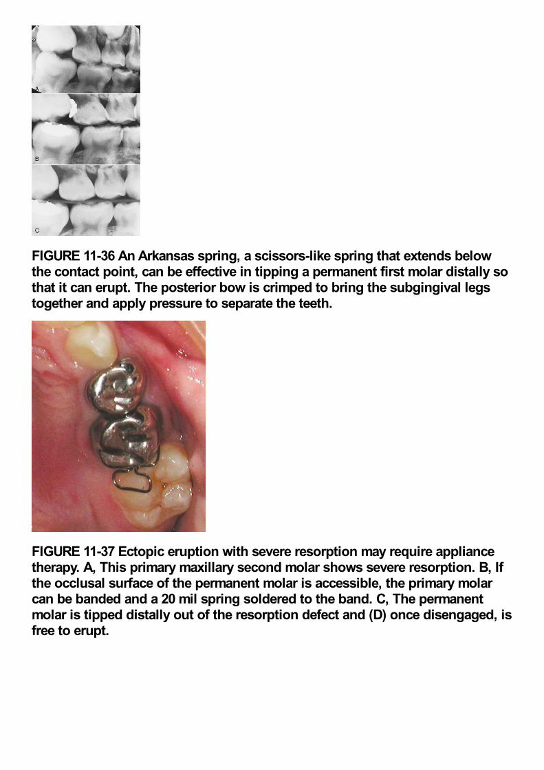
FIGURE 11-36 An Arkansas spring, a scissors-like spring that extends belowthe contact point, can be effective in tipping a permanent first molar distally sothat it can erupt. The posterior bow is crimped to bring the subgingival legstogether and apply pressure to separate the teeth.
FIGURE 11-37 Ectopic eruption with severe resorption may require appliancetherapy. A, This primary maxillary second molar shows severe resorption. B, Ifthe occlusal surface of the permanent molar is accessible, the primary molarcan be banded and a 20 mil spring soldered to the band. C, The permanentmolar is tipped distally out of the resorption defect and (D) once disengaged, isfree to erupt.
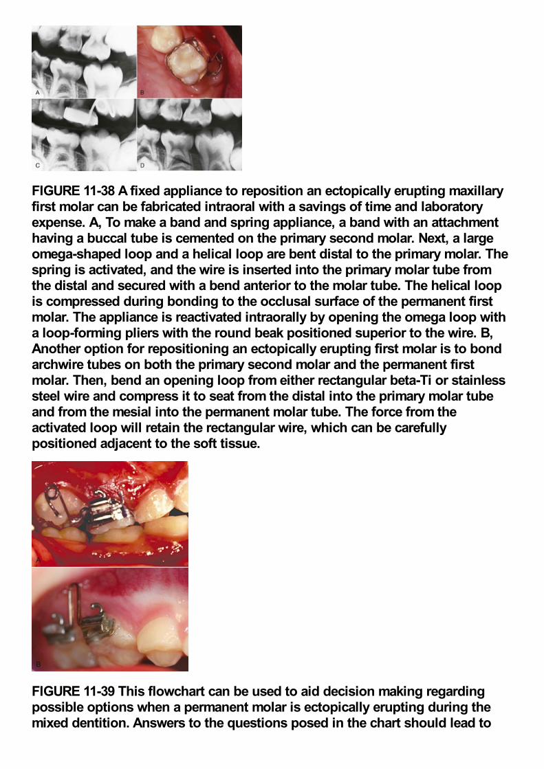
FIGURE 11-38 A fixed appliance to reposition an ectopically erupting maxillaryfirst molar can be fabricated intraoral with a savings of time and laboratoryexpense. A, To make a band and spring appliance, a band with an attachmenthaving a buccal tube is cemented on the primary second molar. Next, a largeomega-shaped loop and a helical loop are bent distal to the primary molar. Thespring is activated, and the wire is inserted into the primary molar tube fromthe distal and secured with a bend anterior to the molar tube. The helical loopis compressed during bonding to the occlusal surface of the permanent firstmolar. The appliance is reactivated intraorally by opening the omega loop witha loop-forming pliers with the round beak positioned superior to the wire. B,Another option for repositioning an ectopically erupting first molar is to bondarchwire tubes on both the primary second molar and the permanent firstmolar. Then, bend an opening loop from either rectangular beta-Ti or stainlesssteel wire and compress it to seat from the distal into the primary molar tubeand from the mesial into the permanent molar tube. The force from theactivated loop will retain the rectangular wire, which can be carefullypositioned adjacent to the soft tissue.
FIGURE 11-39 This flowchart can be used to aid decision making regardingpossible options when a permanent molar is ectopically erupting during themixed dentition. Answers to the questions posed in the chart should lead to
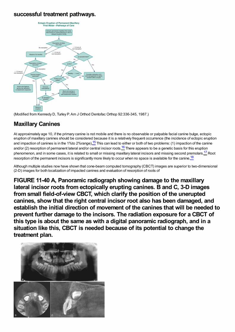
successful treatment pathways.
(Modified from Kennedy D, Turley P. Am J Orthod Dentofac Orthop 92:336-345, 1987.)
Maxillary CaninesAt approximately age 10, if the primary canine is not mobile and there is no observable or palpable facial canine bulge, ectopiceruption of maxillary canines should be considered because it is a relatively frequent occurrence (the incidence of ectopic eruptionand impaction of canines is in the 1%to 2%range).15 This can lead to either or both of two problems: (1) impaction of the canineand/or (2) resorption of permanent lateral and/or central incisor roots.16 There appears to be a genetic basis for this eruptionphenomenon, and in some cases, it is related to small or missing maxillary lateral incisors and missing second premolars.17 Rootresorption of the permanent incisors is significantly more likely to occur when no space is available for the canine.18
Although multiple studies now have shown that cone-beam computed tomography (CBCT) images are superior to two-dimensional(2-D) images for both localization of impacted canines and evaluation of resorption of roots of
FIGURE 11-40 A, Panoramic radiograph showing damage to the maxillarylateral incisor roots from ectopically erupting canines. B and C, 3-D imagesfrom small field-of-view CBCT, which clarify the position of the uneruptedcanines, show that the right central incisor root also has been damaged, andestablish the initial direction of movement of the canines that will be needed toprevent further damage to the incisors. The radiation exposure for a CBCT ofthis type is about the same as with a digital panoramic radiograph, and in asituation like this, CBCT is needed because of its potential to change thetreatment plan.
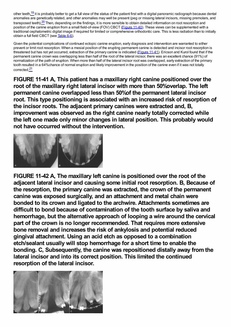
other teeth,19 it is probably better to get a full view of the status of the patient first with a digital panoramic radiograph because dentalanomalies are genetically related, and other anomalies may well be present (peg or missing lateral incisors, missing premolars, andtransposed teeth).20 Then, depending on the findings, it is more sensible to obtain detailed information on root resorption andposition of the canine eruption from a small field-of-view (FOV) CBCT (Figure 11-40). These views can be supplemented with atraditional cephalometric digital image if required for limited or comprehensive orthodontic care. This is less radiation than to initiallyobtain a full field CBCT (see Table 6-6).
Given the potential complications of continued ectopic canine eruption, early diagnosis and intervention are warranted to eitherprevent or limit root resorption. When a mesial position of the erupting permanent canine is detected and incisor root resorption isthreatened but has not yet occurred, extraction of the primary canine is indicated (Figure 11-41). Ericson and Kurol found that if thepermanent canine crown was overlapping less than half of the root of the lateral incisor, there was an excellent chance (91%) ofnormalization of the path of eruption. When more than half of the lateral incisor root was overlapped, early extraction of the primarytooth resulted in a 64%chance of normal eruption and likely improvement in the position of the canine even if it was not totallycorrected.21
FIGURE 11-41 A, This patient has a maxillary right canine positioned over theroot of the maxillary right lateral incisor with more than 50%overlap. The leftpermanent canine overlapped less than 50%of the permanent lateral incisorroot. This type positioning is associated with an increased risk of resorption ofthe incisor roots. The adjacent primary canines were extracted and, B,improvement was observed as the right canine nearly totally corrected whilethe left one made only minor changes in lateral position. This probably wouldnot have occurred without the intervention.
FIGURE 11-42 A, The maxillary left canine is positioned over the root of theadjacent lateral incisor and causing some initial root resorption. B, Because ofthe resorption, the primary canine was extracted, the crown of the permanentcanine was exposed surgically, and an attachment and metal chain werebonded to its crown and ligated to the archwire. Attachments sometimes aredifficult to bond because of contamination of the tooth surface by saliva andhemorrhage, but the alternative approach of looping a wire around the cervicalpart of the crown is no longer recommended. That requires more extensivebone removal and increases the risk of ankylosis and potential reducedgingival attachment. Using an acid etch as opposed to a combinationetch/sealant usually will stop hemorrhage for a short time to enable thebonding. C, Subsequently, the canine was repositioned distally away from thelateral incisor and into its correct position. This limited the continuedresorption of the lateral incisor.
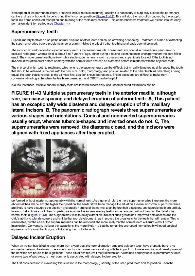
If resorption of the permanent lateral or central incisor roots is occurring, usually it is necessary to surgically expose the permanentcanine and use orthodontic force to bring it to its correct position (Figure 11-42). This will stop the resorption caused by the ectopictooth, but some continued resorption and blunting of the roots may continue. This comprehensive treatment will extend into the earlypermanent dentition period (see Chapter 14).
Supernumerary TeethSupernumerary teeth can disrupt the normal eruption of other teeth and cause crowding or spacing. Treatment is aimed at extractingthe supernumeraries before problems arise or at minimizing the effect if other teeth have already been displaced.
The most common location for supernumerary teeth is the anterior maxilla. These teeth are often discovered on a panoramic orocclusal radiograph when a child is about 6 to 7 years of age, either during a routine examination or when permanent incisors fail toerupt. The simple cases are those in which a single supernumerary tooth is present and superficially located. If the tooth is notinverted, it will often erupt before or along with the normal tooth and can be extracted before it interferes with the adjacent teeth.
The choice of which tooth to retain and which one is the supernumerary can be difficult, but in reality it makes no difference. The tooththat should be retained is the one with the best size, color, morphology, and position related to the other teeth. All other things beingequal, the tooth that is nearest to the ultimate final position should be retained. These decisions are difficult to make fromconventional radiographs when the teeth are unerupted, and CBCT can be helpful.
In a few instances, multiple supernumerary teeth are located superficially, and uncomplicated extractions can be
FIGURE 11-43 Multiple supernumerary teeth in the anterior maxilla, althoughrare, can cause spacing and delayed eruption of anterior teeth. A, This patienthas an exceptionally wide diastema and delayed eruption of the maxillarylateral incisors. B, The panoramic radiograph reveals three supernumeraries ofvarious shapes and orientations. Conical and noninverted supernumerariesusually erupt, whereas tubercle-shaped and inverted ones do not. C, Thesupernumeraries were removed, the diastema closed, and the incisors werealigned with fixed appliances after they erupted.
performed without interfering appreciably with the normal teeth. As a general rule, the more supernumeraries there are, the moreabnormal their shape and the higher their position, the harder it will be to manage the situation. Several abnormal supernumerariesare likely to have disturbed the position and eruption timing of the normal teeth before their discovery, and tubercle teeth are unlikelyto erupt. Extractions should be completed as soon as the supernumerary teeth can be removed without harming the developingnormal teeth (Figure 11-43). The surgeon may wish to delay extraction until continued growth has improved both access and thechild's ability to tolerate surgery and until further root development has improved the prognosis for the teeth that will remain. This isreasonable, but the earlier the supernumeraries can be removed, the more likely that the normal teeth will erupt without furtherintervention. Conversely, the later the extractions, the more likely it is that the remaining unerupted normal teeth will need surgicalexposure, orthodontic traction, or both to bring them into the arch.
Delayed Incisor EruptionWhen an incisor has failed to erupt more than a year past the normal eruption time and adjacent teeth have erupted, there is noexcuse for delaying treatment. The esthetic and social consequences along with the impact on ultimate eruption and development ofthe dentition are bound to be significant. These situations require timely intervention. A retained primary tooth, supernumerary tooth,or some type of pathology is most commonly associated with delayed incisor eruption.
The first consideration in evaluating this situation is the morphology (usability) of the unerupted tooth and its position. Then the
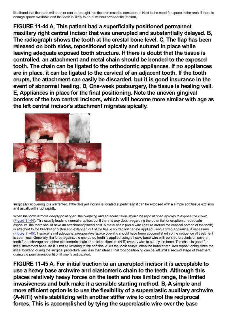
likelihood that the tooth will erupt or can be brought into the arch must be considered. Next is the need for space in the arch. If there isenough space available and the tooth is likely to erupt without orthodontic traction,
FIGURE 11-44 A, This patient had a superficially positioned permanentmaxillary right central incisor that was unerupted and substantially delayed. B,The radiograph shows the tooth at the crestal bone level. C, The flap has beenreleased on both sides, repositioned apically and sutured in place whileleaving adequate exposed tooth structure. If there is doubt that the tissue iscontrolled, an attachment and metal chain should be bonded to the exposedtooth. The chain can be ligated to the orthodontic appliances. If no appliancesare in place, it can be ligated to the cervical of an adjacent tooth. If the tootherupts, the attachment can easily be discarded, but it is good insurance in theevent of abnormal healing. D, One-week postsurgery, the tissue is healing well.E, Appliances in place for the final positioning. Note the uneven gingivalborders of the two central incisors, which will become more similar with age asthe left central incisor's attachment migrates apically.
surgically uncovering it is warranted. If the delayed incisor is located superficially, it can be exposed with a simple soft tissue excisionand usually will erupt rapidly.
When the tooth is more deeply positioned, the overlying and adjacent tissue should be repositioned apically to expose the crown(Figure 11-44). This usually leads to normal eruption, but if there is any doubt regarding the potential for eruption or adequateexposure, the tooth should have an attachment placed on it. A metal chain (not a wire ligature around the cervical portion of the tooth)is attached to the bracket or button and extended out of the tissue so traction can be applied using a fixed appliance, if necessary(Figure 11-45). If space is not adequate, preoperative space opening should have been accomplished so the sequence of treatmentis seamless. Generally, the force against the unerupted tooth is applied using a heavy base wire with bonded brackets on severalteeth for anchorage and either elastomeric chain or a nickel–titanium (NiTi) overlay wire to supply the force. The chain is good forinitial movement because it is not as irritating to the soft tissue. As the tooth erupts, often the bracket requires repositioning since theinitial bonding during the surgical procedure was less than ideal. Final root positioning can be left until a second stage of treatmentduring the permanent dentition if one is anticipated.
FIGURE 11-45 A, For initial traction to an unerupted incisor it is acceptable touse a heavy base archwire and elastomeric chain to the teeth. Although thisplaces relatively heavy forces on the teeth and has limited range, the limitedinvasiveness and bulk make it a sensible starting method. B, A simple andmore efficient option is to use the flexibility of a superelastic auxiliary archwire(A-NiTi) while stabilizing with another stiffer wire to control the reciprocalforces. This is accomplished by tying the superelastic wire over the base
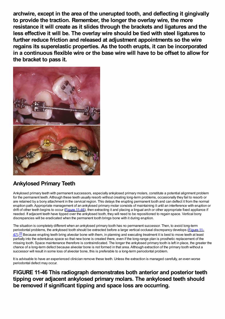
archwire, except in the area of the unerupted tooth, and deflecting it gingivallyto provide the traction. Remember, the longer the overlay wire, the moreresistance it will create as it slides through the brackets and ligatures and theless effective it will be. The overlay wire should be tied with steel ligatures tofurther reduce friction and released at adjustment appointments so the wireregains its superelastic properties. As the tooth erupts, it can be incorporatedin a continuous flexible wire or the base wire will have to be offset to allow forthe bracket to pass it.
Ankylosed Primary TeethAnkylosed primary teeth with permanent successors, especially ankylosed primary molars, constitute a potential alignment problemfor the permanent teeth. Although these teeth usually resorb without creating long-term problems, occasionally they fail to resorb orare retained by a bony attachment in the cervical region. This delays the erupting permanent tooth and can deflect it from the normaleruption path. Appropriate management of an ankylosed primary molar consists of maintaining it until an interference with eruption ordrift of other teeth begins to occur (Figure 11-46), then extracting it and placing a lingual arch or other appropriate fixed appliance ifneeded. If adjacent teeth have tipped over the ankylosed tooth, they will need to be repositioned to regain space. Vertical bonydiscrepancies will be eradicated when the permanent tooth brings bone with it during eruption.
The situation is completely different when an ankylosed primary tooth has no permanent successor. Then, to avoid long-termperiodontal problems, the ankylosed tooth should be extracted before a large vertical occlusal discrepancy develops (Figure 11-47).22 Because erupting teeth bring alveolar bone with them, in planning and executing treatment it is best to move teeth at leastpartially into the edentulous space so that new bone is created there, even if the long-range plan is prosthetic replacement of themissing tooth. Space maintenance therefore is contraindicated. The longer the ankylosed primary tooth is left in place, the greater thechance of a long-term defect because alveolar bone is not formed in that area. Although extraction of the primary tooth without asuccessor will result in some loss of alveolar bone, this is preferable to a long-term periodontal problem.
It is advisable to have an experienced clinician remove these teeth. Unless the extraction is managed carefully, an even worseperiodontal defect may occur.
FIGURE 11-46 This radiograph demonstrates both anterior and posterior teethtipping over adjacent ankylosed primary molars. The ankylosed teeth shouldbe removed if significant tipping and space loss are occurring.
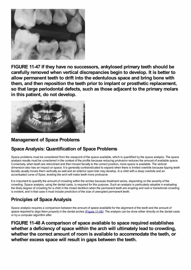
FIGURE 11-47 If they have no successors, ankylosed primary teeth should becarefully removed when vertical discrepancies begin to develop. It is better toallow permanent teeth to drift into the edentulous space and bring bone withthem, and then reposition the teeth prior to implant or prosthetic replacement,so that large periodontal defects, such as those adjacent to the primary molarsin this patient, do not develop.
Management of Space Problems
Space Analysis: Quantification of Space ProblemsSpace problems must be considered from the viewpoint of the space available, which is quantified by the space analysis. The spaceanalysis results must be considered in the context of the profile because reducing protrusion reduces the amount of available space.Conversely, when teeth are retroclined and then moved facially to the correct position, more space is available. The verticaldimension also has an impact on space. It is generally contraindicated to expand when there is limited overbite because tipping teethfacially usually moves them vertically as well and an anterior open bite may develop. In a child with a deep overbite and anaccentuated curve of Spee, leveling the arch will make teeth more protrusive.
It is important to quantify the amount of crowding within the arches because treatment varies, depending on the severity of thecrowding. Space analysis, using the dental casts, is required for this purpose. Such an analysis is particularly valuable in evaluatingthe likely degree of crowding for a child in the mixed dentition when the permanent teeth are erupting and real or transitional crowdingis evident, and in that case it must include prediction of the size of unerupted permanent teeth.
Principles of Space AnalysisSpace analysis requires a comparison between the amount of space available for the alignment of the teeth and the amount ofspace required to align them properly in the dental arches (Figure 11-48). The analysis can be done either directly on the dental castsor by a computer algorithm after
FIGURE 11-48 A comparison of space available to space required establisheswhether a deficiency of space within the arch will ultimately lead to crowding,whether the correct amount of room is available to accommodate the teeth, orwhether excess space will result in gaps between the teeth.
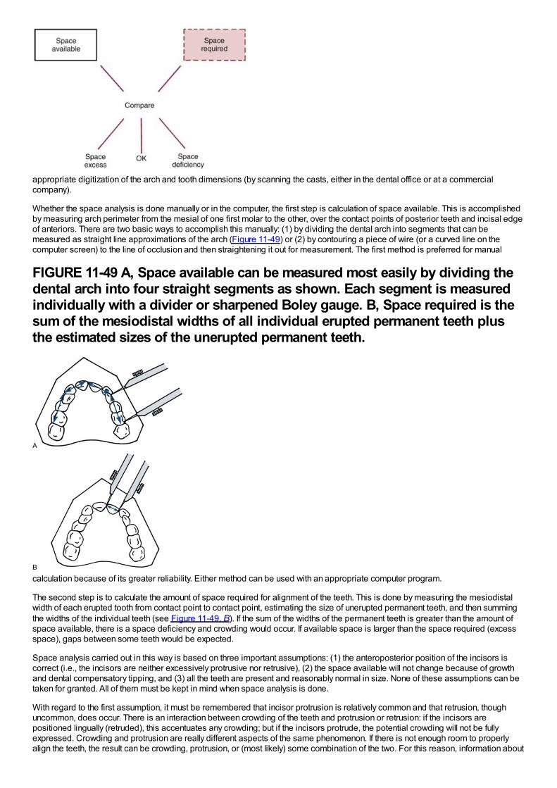
appropriate digitization of the arch and tooth dimensions (by scanning the casts, either in the dental office or at a commercialcompany).
Whether the space analysis is done manually or in the computer, the first step is calculation of space available. This is accomplishedby measuring arch perimeter from the mesial of one first molar to the other, over the contact points of posterior teeth and incisal edgeof anteriors. There are two basic ways to accomplish this manually: (1) by dividing the dental arch into segments that can bemeasured as straight line approximations of the arch (Figure 11-49) or (2) by contouring a piece of wire (or a curved line on thecomputer screen) to the line of occlusion and then straightening it out for measurement. The first method is preferred for manual
FIGURE 11-49 A, Space available can be measured most easily by dividing thedental arch into four straight segments as shown. Each segment is measuredindividually with a divider or sharpened Boley gauge. B, Space required is thesum of the mesiodistal widths of all individual erupted permanent teeth plusthe estimated sizes of the unerupted permanent teeth.
calculation because of its greater reliability. Either method can be used with an appropriate computer program.
The second step is to calculate the amount of space required for alignment of the teeth. This is done by measuring the mesiodistalwidth of each erupted tooth from contact point to contact point, estimating the size of unerupted permanent teeth, and then summingthe widths of the individual teeth (see Figure 11-49, B). If the sum of the widths of the permanent teeth is greater than the amount ofspace available, there is a space deficiency and crowding would occur. If available space is larger than the space required (excessspace), gaps between some teeth would be expected.
Space analysis carried out in this way is based on three important assumptions: (1) the anteroposterior position of the incisors iscorrect (i.e., the incisors are neither excessively protrusive nor retrusive), (2) the space available will not change because of growthand dental compensatory tipping, and (3) all the teeth are present and reasonably normal in size. None of these assumptions can betaken for granted. All of them must be kept in mind when space analysis is done.
With regard to the first assumption, it must be remembered that incisor protrusion is relatively common and that retrusion, thoughuncommon, does occur. There is an interaction between crowding of the teeth and protrusion or retrusion: if the incisors arepositioned lingually (retruded), this accentuates any crowding; but if the incisors protrude, the potential crowding will not be fullyexpressed. Crowding and protrusion are really different aspects of the same phenomenon. If there is not enough room to properlyalign the teeth, the result can be crowding, protrusion, or (most likely) some combination of the two. For this reason, information about
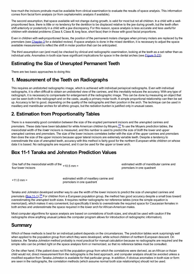
how much the incisors protrude must be available from clinical examination to evaluate the results of space analysis. This informationcomes from facial form analysis (or from cephalometric analysis if available).
The second assumption, that space available will not change during growth, is valid for most but not all children. In a child with a well-proportioned face, there is little or no tendency for the dentition to be displaced relative to the jaw during growth, but the teeth oftenshift anteriorly or posteriorly in a child with a jaw discrepancy. For this reason, space analysis is less accurate and less useful forchildren with skeletal problems (Class II, Class III, long face, short face) than in those with good facial proportions.
Even in children with well-proportioned faces, the position of the permanent molars changes when primary molars are replaced by thepremolars (see Chapter 3 for a detailed review). If space analysis is done in the mixed dentition, it is necessary to adjust the spaceavailable measurement to reflect the shift in molar position that can be anticipated.
The third assumption can (and must) be checked by clinical and radiographic examination, looking at the teeth as a set rather than asindividual units. Anomalies in tooth size have significant implications for space in the dental arches (see Figure 5-23).
Estimating the Size of Unerupted Permanent TeethThere are two basic approaches to doing this:
1. Measurement of the Teeth on RadiographsThis requires an undistorted radiographic image, which is achieved with individual periapical radiographs. Even with individualradiographs, it is often difficult to obtain an undistorted view of the canines, and this inevitably reduces the accuracy. With any type ofradiograph, it is necessary to compensate for enlargement of the radiographic image. This can be done by measuring an object thatcan be seen both in the radiograph and on the casts, usually a primary molar tooth. A simple proportional relationship can then be setup. Accuracy is fair to good, depending on the quality of the radiographs and their position in the arch. The technique can be used inmaxillary and mandibular arches for all ethnic groups, but the radiation burden is justified only in unusual cases.
2. Estimation from Proportionality TablesThere is a reasonably good correlation between the size of the erupted permanent incisors and the unerupted canines andpremolars. These data have been tabulated for white American children by Moyers.23 To use the Moyers prediction tables, themesiodistal width of the lower incisors is measured, and this number is used to predict the size of both the lower and upperunerupted canines and premolars. The size of the lower incisors correlates better with the size of the upper canines and premolarsthan does the size of the upper incisors because upper lateral incisors are extremely variable teeth. Despite a tendency tooverestimate the size of unerupted teeth, accuracy with this method is fairly good for the northern European white children on whosedata it is based. No radiographs are required, and it can be used for the upper or lower arch.
Box 11-1 Tanaka and Johnston Prediction Values
One half of the mesiodistal width of thefour lower incisors +10.5 mm = estimated width of mandibular canine and
premolars in one quadrant
+11.0 mm = estimated width of maxillary canine andpremolars in one quadrant
Tanaka and Johnston developed another way to use the width of the lower incisors to predict the size of unerupted canines andpremolars (Box 11-1).24 For children from a European population group, the method has good accuracy despite a small bias towardoverestimating the unerupted tooth sizes. It requires neither radiographs nor reference tables (once the simple equation ismemorized), which makes it very convenient, but specifically it tends to overestimate the required space for Caucasian females inboth arches and underestimate the space required in the lower arch for African-American males.
Most computer algorithms for space analysis are based on correlations of tooth sizes, and should be used with caution if theradiographs show anything unusual (unless the computer program allows for introduction of radiographic information).
SummaryWhich of these methods is best for an individual patient depends on the circumstances. The prediction tables work surprisingly wellwhen applied to the population group from which they were developed, white school children of northern European descent. Onbalance, the Tanaka-Johnston method probably is most practical for manual calculation because no radiographs are required and thesimple ratio can be printed right on the space analysis form or memorized, so that no reference tables must be consulted.
On the other hand, if the patient does not fit the population group from which the correlations were derived, as an African or Asianchild would not, direct measurement from the radiographs is the best approach, and computer analysis should be avoided unless amodified equation from Tanaka-Johnston is available for that particular group. In addition, if obvious anomalies in tooth size or formare seen in the radiographs, the correlation methods (which assume normal tooth size relationships) should not be used.
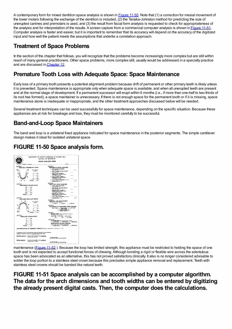
A contemporary form for mixed dentition space analysis is shown in Figure 11-50. Note that (1) a correction for mesial movement ofthe lower molars following the exchange of the dentition is included, (2) the Tanaka-Johnston method for predicting the size ofunerupted canines and premolars is used, and (3) the result from facial form analysis is requested to check for appropriateness ofthe analysis and for interpretation of the results. A screen capture from a commercial computer analysis is shown in Figure 11-51.Computer analysis is faster and easier, but it is important to remember that its accuracy will depend on the accuracy of the digitizedinput and how well the patient meets the assumptions that underlie a correlation approach.
Treatment of Space ProblemsIn the section of the chapter that follows, you will recognize that the problems become increasingly more complex but are still withinreach of many general practitioners. Other space problems, more complex still, usually would be addressed in a specialty practiceand are discussed in Chapter 12.
Premature Tooth Loss with Adequate Space: Space MaintenanceEarly loss of a primary tooth presents a potential alignment problem because drift of permanent or other primary teeth is likely unlessit is prevented. Space maintenance is appropriate only when adequate space is available, and when all unerupted teeth are presentand at the normal stage of development. If a permanent successor will erupt within 6 months (i.e., if more than one-half to two-thirds ofits root has formed), a space maintainer is unnecessary. If there is not enough space for the permanent tooth or if it is missing, spacemaintenance alone is inadequate or inappropriate, and the other treatment approaches discussed below will be needed.
Several treatment techniques can be used successfully for space maintenance, depending on the specific situation. Because theseappliances are at risk for breakage and loss, they must be monitored carefully to be successful.
Band-and-Loop Space MaintainersThe band and loop is a unilateral fixed appliance indicated for space maintenance in the posterior segments. The simple cantileverdesign makes it ideal for isolated unilateral space
FIGURE 11-50 Space analysis form.
maintenance (Figure 11-52 ). Because the loop has limited strength, this appliance must be restricted to holding the space of onetooth and is not expected to accept functional forces of chewing. Although bonding a rigid or flexible wire across the edentulousspace has been advocated as an alternative, this has not proved satisfactory clinically. It also is no longer considered advisable tosolder the loop portion to a stainless steel crown because this precludes simple appliance removal and replacement. Teeth withstainless steel crowns should be banded like natural teeth.
FIGURE 11-51 Space analysis can be accomplished by a computer algorithm.The data for the arch dimensions and tooth widths can be entered by digitizingthe already present digital casts. Then, the computer does the calculations.
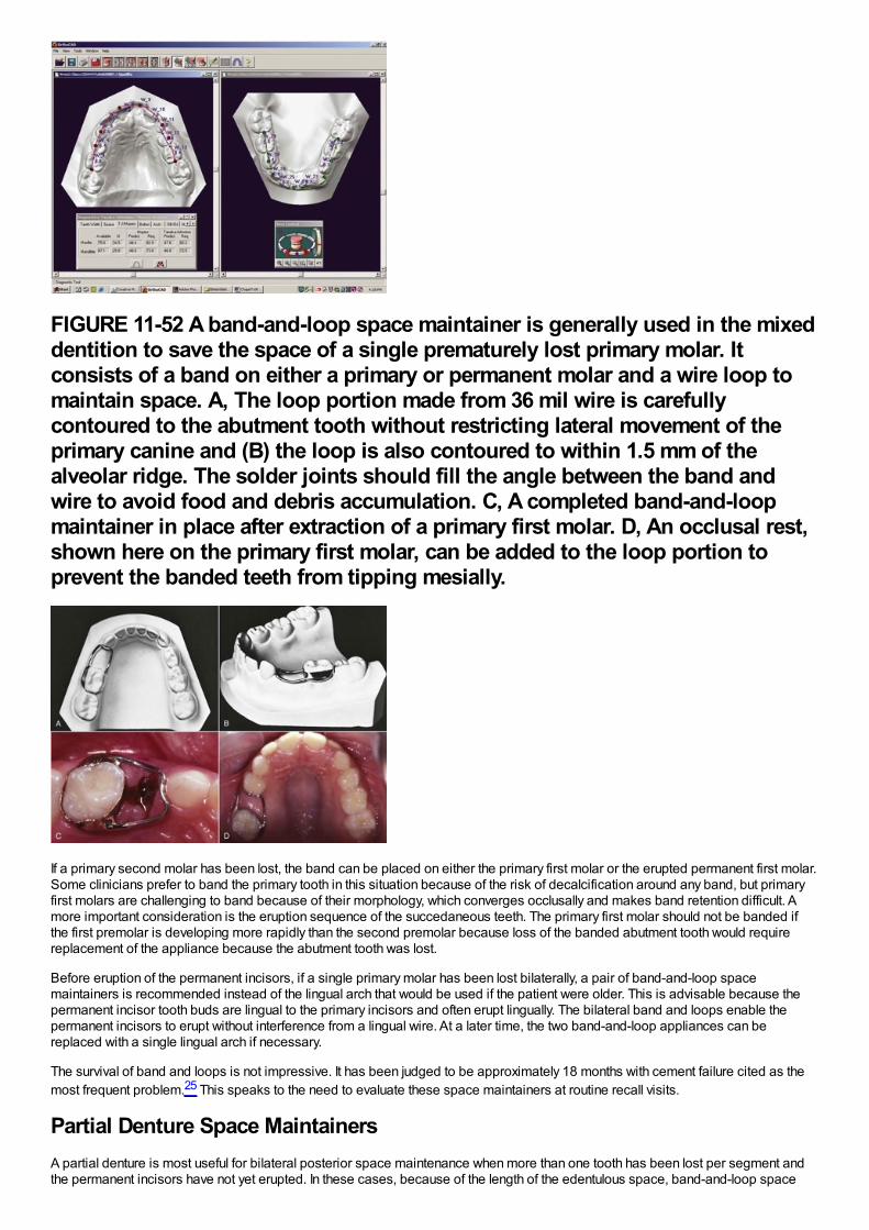
FIGURE 11-52 A band-and-loop space maintainer is generally used in the mixeddentition to save the space of a single prematurely lost primary molar. Itconsists of a band on either a primary or permanent molar and a wire loop tomaintain space. A, The loop portion made from 36 mil wire is carefullycontoured to the abutment tooth without restricting lateral movement of theprimary canine and (B) the loop is also contoured to within 1.5 mm of thealveolar ridge. The solder joints should fill the angle between the band andwire to avoid food and debris accumulation. C, A completed band-and-loopmaintainer in place after extraction of a primary first molar. D, An occlusal rest,shown here on the primary first molar, can be added to the loop portion toprevent the banded teeth from tipping mesially.
If a primary second molar has been lost, the band can be placed on either the primary first molar or the erupted permanent first molar.Some clinicians prefer to band the primary tooth in this situation because of the risk of decalcification around any band, but primaryfirst molars are challenging to band because of their morphology, which converges occlusally and makes band retention difficult. Amore important consideration is the eruption sequence of the succedaneous teeth. The primary first molar should not be banded ifthe first premolar is developing more rapidly than the second premolar because loss of the banded abutment tooth would requirereplacement of the appliance because the abutment tooth was lost.
Before eruption of the permanent incisors, if a single primary molar has been lost bilaterally, a pair of band-and-loop spacemaintainers is recommended instead of the lingual arch that would be used if the patient were older. This is advisable because thepermanent incisor tooth buds are lingual to the primary incisors and often erupt lingually. The bilateral band and loops enable thepermanent incisors to erupt without interference from a lingual wire. At a later time, the two band-and-loop appliances can bereplaced with a single lingual arch if necessary.
The survival of band and loops is not impressive. It has been judged to be approximately 18 months with cement failure cited as themost frequent problem.25 This speaks to the need to evaluate these space maintainers at routine recall visits.
Partial Denture Space MaintainersA partial denture is most useful for bilateral posterior space maintenance when more than one tooth has been lost per segment andthe permanent incisors have not yet erupted. In these cases, because of the length of the edentulous space, band-and-loop space
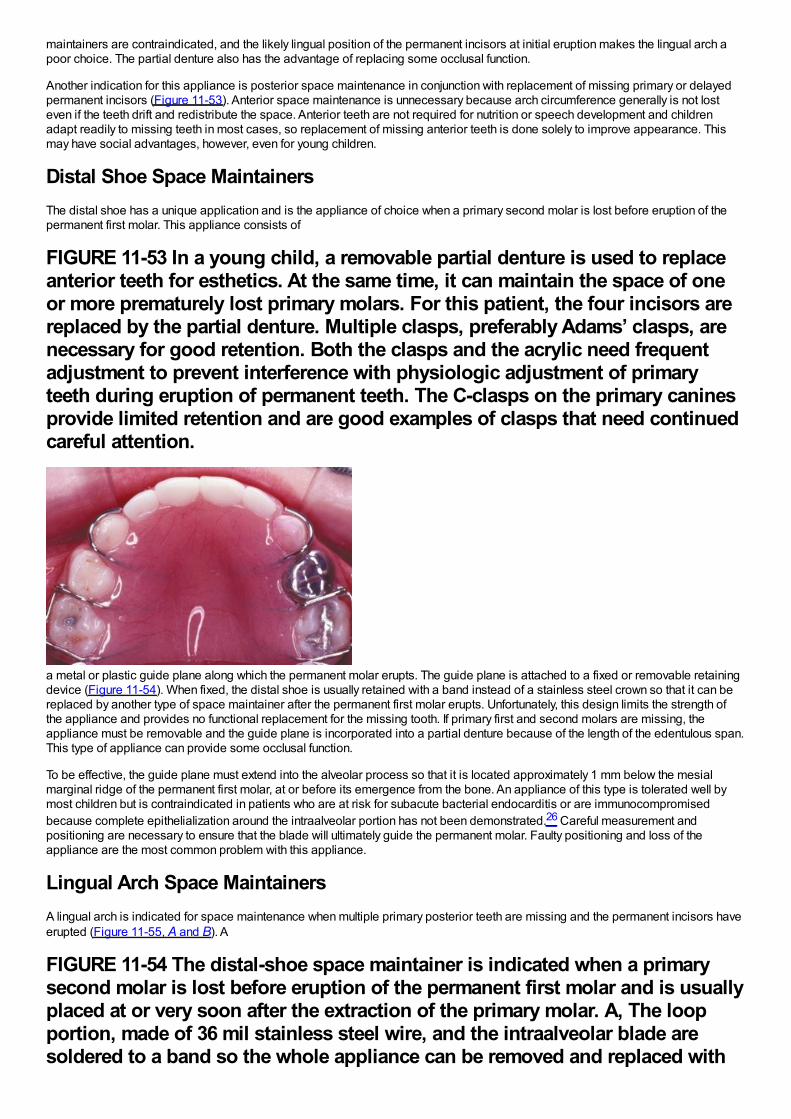
maintainers are contraindicated, and the likely lingual position of the permanent incisors at initial eruption makes the lingual arch apoor choice. The partial denture also has the advantage of replacing some occlusal function.
Another indication for this appliance is posterior space maintenance in conjunction with replacement of missing primary or delayedpermanent incisors (Figure 11-53). Anterior space maintenance is unnecessary because arch circumference generally is not losteven if the teeth drift and redistribute the space. Anterior teeth are not required for nutrition or speech development and childrenadapt readily to missing teeth in most cases, so replacement of missing anterior teeth is done solely to improve appearance. Thismay have social advantages, however, even for young children.
Distal Shoe Space MaintainersThe distal shoe has a unique application and is the appliance of choice when a primary second molar is lost before eruption of thepermanent first molar. This appliance consists of
FIGURE 11-53 In a young child, a removable partial denture is used to replaceanterior teeth for esthetics. At the same time, it can maintain the space of oneor more prematurely lost primary molars. For this patient, the four incisors arereplaced by the partial denture. Multiple clasps, preferably Adams’ clasps, arenecessary for good retention. Both the clasps and the acrylic need frequentadjustment to prevent interference with physiologic adjustment of primaryteeth during eruption of permanent teeth. The C-clasps on the primary caninesprovide limited retention and are good examples of clasps that need continuedcareful attention.
a metal or plastic guide plane along which the permanent molar erupts. The guide plane is attached to a fixed or removable retainingdevice (Figure 11-54). When fixed, the distal shoe is usually retained with a band instead of a stainless steel crown so that it can bereplaced by another type of space maintainer after the permanent first molar erupts. Unfortunately, this design limits the strength ofthe appliance and provides no functional replacement for the missing tooth. If primary first and second molars are missing, theappliance must be removable and the guide plane is incorporated into a partial denture because of the length of the edentulous span.This type of appliance can provide some occlusal function.
To be effective, the guide plane must extend into the alveolar process so that it is located approximately 1 mm below the mesialmarginal ridge of the permanent first molar, at or before its emergence from the bone. An appliance of this type is tolerated well bymost children but is contraindicated in patients who are at risk for subacute bacterial endocarditis or are immunocompromisedbecause complete epithelialization around the intraalveolar portion has not been demonstrated.26 Careful measurement andpositioning are necessary to ensure that the blade will ultimately guide the permanent molar. Faulty positioning and loss of theappliance are the most common problem with this appliance.
Lingual Arch Space MaintainersA lingual arch is indicated for space maintenance when multiple primary posterior teeth are missing and the permanent incisors haveerupted (Figure 11-55, A and B). A
FIGURE 11-54 The distal-shoe space maintainer is indicated when a primarysecond molar is lost before eruption of the permanent first molar and is usuallyplaced at or very soon after the extraction of the primary molar. A, The loopportion, made of 36 mil stainless steel wire, and the intraalveolar blade aresoldered to a band so the whole appliance can be removed and replaced with
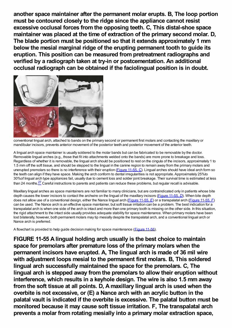
another space maintainer after the permanent molar erupts. B, The loop portionmust be contoured closely to the ridge since the appliance cannot resistexcessive occlusal forces from the opposing teeth. C, This distal-shoe spacemaintainer was placed at the time of extraction of the primary second molar. D,The blade portion must be positioned so that it extends approximately 1 mmbelow the mesial marginal ridge of the erupting permanent tooth to guide itseruption. This position can be measured from pretreatment radiographs andverified by a radiograph taken at try-in or postcementation. An additionalocclusal radiograph can be obtained if the faciolingual position is in doubt.
conventional lingual arch, attached to bands on the primary second or permanent first molars and contacting the maxillary ormandibular incisors, prevents anterior movement of the posterior teeth and posterior movement of the anterior teeth.
A lingual arch space maintainer is usually soldered to the molar bands but can be fabricated to be removable by the doctor.Removable lingual arches (e.g., those that fit into attachments welded onto the bands) are more prone to breakage and loss.Regardless of whether it is removable, the lingual arch should be positioned to rest on the cingula of the incisors, approximately 1 to1.5 mm off the soft tissue, and should be stepped to the lingual in the canine region to remain away from the primary molars andunerupted premolars so there is no interference with their eruption (Figure 11-55, C). Lingual arches should have ideal arch form sothe teeth can align if they have space. Making the arch conform to dental irregularities is not appropriate. Approximately 25%to30%of lingual arch type appliances fail, usually due to cement loss and solder joint breakage. Their survival time is estimated at lessthan 24 months.27 Careful instructions to parents and patients can reduce these problems, but regular recall is advisable.
Maxillary lingual arches as space maintainers are not familiar to many clinicians, but are contraindicated only in patients whose bitedepth causes the lower incisors to contact the archwire on the lingual of the maxillary incisors (Figure 11-55, D). When bite depthdoes not allow use of a conventional design, either the Nance lingual arch (Figure 11-55, E) or a transpalatal arch (Figure 11-55, F)can be used. The Nance arch is an effective space maintainer, but soft tissue irritation can be a problem. The best indication for atranspalatal arch is when one side of the arch is intact and more than one primary tooth is missing on the other side. In this situation,the rigid attachment to the intact side usually provides adequate stability for space maintenance. When primary molars have beenlost bilaterally, however, both permanent molars may tip mesially despite the transpalatal arch, and a conventional lingual arch orNance arch is preferred.
A flowchart is provided to help guide decision making for space maintenance (Figure 11-56).
FIGURE 11-55 A lingual holding arch usually is the best choice to maintainspace for premolars after premature loss of the primary molars when thepermanent incisors have erupted. A, The lingual arch is made of 36 mil wirewith adjustment loops mesial to the permanent first molars. B, This solderedlingual arch successfully maintained the space for the premolars. C, Thelingual arch is stepped away from the premolars to allow their eruption withoutinterference, which results in a keyhole design. The wire is also 1.5 mm awayfrom the soft tissue at all points. D, A maxillary lingual arch is used when theoverbite is not excessive, or (E) a Nance arch with an acrylic button in thepalatal vault is indicated if the overbite is excessive. The palatal button must bemonitored because it may cause soft tissue irritation. F, The transpalatal archprevents a molar from rotating mesially into a primary molar extraction space,
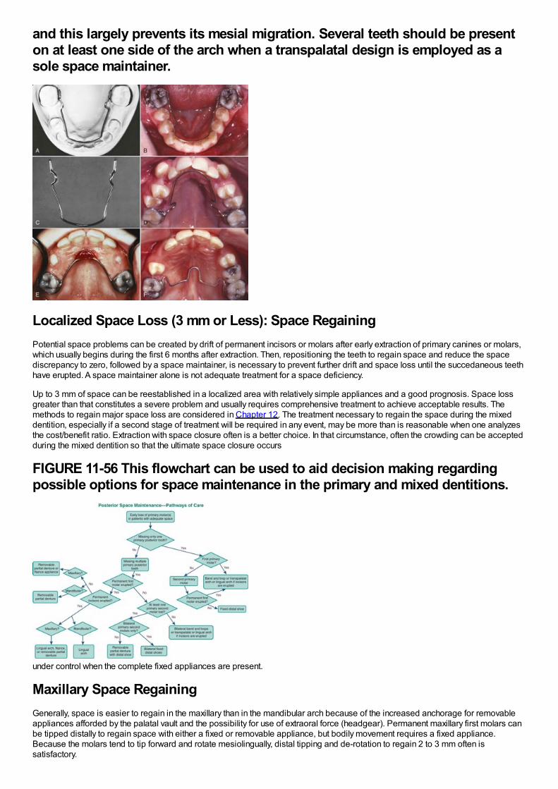
and this largely prevents its mesial migration. Several teeth should be presenton at least one side of the arch when a transpalatal design is employed as asole space maintainer.
Localized Space Loss (3 mm or Less): Space RegainingPotential space problems can be created by drift of permanent incisors or molars after early extraction of primary canines or molars,which usually begins during the first 6 months after extraction. Then, repositioning the teeth to regain space and reduce the spacediscrepancy to zero, followed by a space maintainer, is necessary to prevent further drift and space loss until the succedaneous teethhave erupted. A space maintainer alone is not adequate treatment for a space deficiency.
Up to 3 mm of space can be reestablished in a localized area with relatively simple appliances and a good prognosis. Space lossgreater than that constitutes a severe problem and usually requires comprehensive treatment to achieve acceptable results. Themethods to regain major space loss are considered in Chapter 12. The treatment necessary to regain the space during the mixeddentition, especially if a second stage of treatment will be required in any event, may be more than is reasonable when one analyzesthe cost/benefit ratio. Extraction with space closure often is a better choice. In that circumstance, often the crowding can be acceptedduring the mixed dentition so that the ultimate space closure occurs
FIGURE 11-56 This flowchart can be used to aid decision making regardingpossible options for space maintenance in the primary and mixed dentitions.
under control when the complete fixed appliances are present.
Maxillary Space RegainingGenerally, space is easier to regain in the maxillary than in the mandibular arch because of the increased anchorage for removableappliances afforded by the palatal vault and the possibility for use of extraoral force (headgear). Permanent maxillary first molars canbe tipped distally to regain space with either a fixed or removable appliance, but bodily movement requires a fixed appliance.Because the molars tend to tip forward and rotate mesiolingually, distal tipping and de-rotation to regain 2 to 3 mm often issatisfactory.
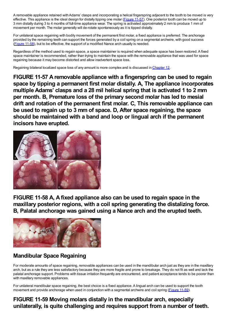
A removable appliance retained with Adams’ clasps and incorporating a helical fingerspring adjacent to the tooth to be moved is veryeffective. This appliance is the ideal design for distally tipping one molar (Figure 11-57). One posterior tooth can be moved up to3 mm distally during 3 to 4 months of full-time appliance wear. The spring is activated approximately 2 mm to produce 1 mm ofmovement per month. The molar generally will de-rotate spontaneously as it is tipped distally.
For unilateral space regaining with bodily movement of the permanent first molar, a fixed appliance is preferred. The anchorageprovided by the remaining teeth can support the forces generated by a coil spring on a segmental archwire, with good success(Figure 11-58), but to be effective, the support of a modified Nance arch usually is needed.
Regardless of the method used to regain space, a space maintainer is required when adequate space has been restored. A fixedspace maintainer is recommended, rather than trying to maintain the space with the removable appliance that was used for spaceregaining because it may become distorted and allow inadvertent space loss.
Regaining bilateral localized space loss of any amount is more complex and is discussed in Chapter 12.
FIGURE 11-57 A removable appliance with a fingerspring can be used to regainspace by tipping a permanent first molar distally. A, The appliance incorporatesmultiple Adams’ clasps and a 28 mil helical spring that is activated 1 to 2 mmper month. B, Premature loss of the primary second molar has led to mesialdrift and rotation of the permanent first molar. C, This removable appliance canbe used to regain up to 3 mm of space. D, After space regaining, the spaceshould be maintained with a band and loop or lingual arch if the permanentincisors have erupted.
FIGURE 11-58 A, A fixed appliance also can be used to regain space in themaxillary posterior regions, with a coil spring generating the distalizing force.B, Palatal anchorage was gained using a Nance arch and the erupted teeth.
Mandibular Space RegainingFor moderate amounts of space regaining, removable appliances can be used in the mandibular arch just as they are in the maxillaryarch, but as a rule they are less satisfactory because they are more fragile and prone to breakage. They do not fit as well and lack thepalatal anchorage support. Problems with tissue irritation frequently are encountered, and patient acceptance tends to be poorer thanwith maxillary removable appliances.
For unilateral mandibular space regaining, the best choice is a fixed appliance. A lingual arch can be used to support the toothmovement and provide anchorage when used in conjunction with a segmental archwire and coil spring (Figure 11-59).
FIGURE 11-59 Moving molars distally in the mandibular arch, especiallyunilaterally, is quite challenging and requires support from a number of teeth.
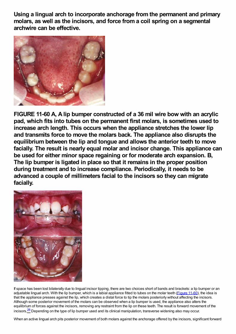
Using a lingual arch to incorporate anchorage from the permanent and primarymolars, as well as the incisors, and force from a coil spring on a segmentalarchwire can be effective.
FIGURE 11-60 A, A lip bumper constructed of a 36 mil wire bow with an acrylicpad, which fits into tubes on the permanent first molars, is sometimes used toincrease arch length. This occurs when the appliance stretches the lower lipand transmits force to move the molars back. The appliance also disrupts theequilibrium between the lip and tongue and allows the anterior teeth to movefacially. The result is nearly equal molar and incisor change. This appliance canbe used for either minor space regaining or for moderate arch expansion. B,The lip bumper is ligated in place so that it remains in the proper positionduring treatment and to increase compliance. Periodically, it needs to beadvanced a couple of millimeters facial to the incisors so they can migratefacially.
If space has been lost bilaterally due to lingual incisor tipping, there are two choices short of bands and brackets: a lip bumper or anadjustable lingual arch. With the lip bumper, which is a labial appliance fitted to tubes on the molar teeth (Figure 11-60), the idea isthat the appliance presses against the lip, which creates a distal force to tip the molars posteriorly without affecting the incisors.Although some posterior movement of the molars can be observed when a lip bumper is used, the appliance also alters theequilibrium of forces against the incisors, removing any restraint from the lip on these teeth. The result is forward movement of theincisors.28 Depending on the type of lip bumper used and its clinical manipulation, transverse widening also may occur.
When an active lingual arch pits posterior movement of both molars against the anchorage offered by the incisors, significant forward
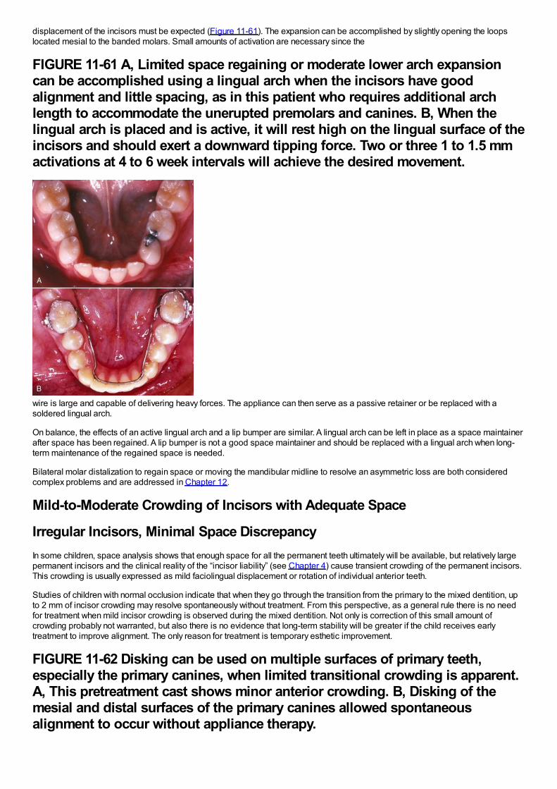
displacement of the incisors must be expected (Figure 11-61). The expansion can be accomplished by slightly opening the loopslocated mesial to the banded molars. Small amounts of activation are necessary since the
FIGURE 11-61 A, Limited space regaining or moderate lower arch expansioncan be accomplished using a lingual arch when the incisors have goodalignment and little spacing, as in this patient who requires additional archlength to accommodate the unerupted premolars and canines. B, When thelingual arch is placed and is active, it will rest high on the lingual surface of theincisors and should exert a downward tipping force. Two or three 1 to 1.5 mmactivations at 4 to 6 week intervals will achieve the desired movement.
wire is large and capable of delivering heavy forces. The appliance can then serve as a passive retainer or be replaced with asoldered lingual arch.
On balance, the effects of an active lingual arch and a lip bumper are similar. A lingual arch can be left in place as a space maintainerafter space has been regained. A lip bumper is not a good space maintainer and should be replaced with a lingual arch when long-term maintenance of the regained space is needed.
Bilateral molar distalization to regain space or moving the mandibular midline to resolve an asymmetric loss are both consideredcomplex problems and are addressed in Chapter 12.
Mild-to-Moderate Crowding of Incisors with Adequate Space
Irregular Incisors, Minimal Space DiscrepancyIn some children, space analysis shows that enough space for all the permanent teeth ultimately will be available, but relatively largepermanent incisors and the clinical reality of the “incisor liability” (see Chapter 4) cause transient crowding of the permanent incisors.This crowding is usually expressed as mild faciolingual displacement or rotation of individual anterior teeth.
Studies of children with normal occlusion indicate that when they go through the transition from the primary to the mixed dentition, upto 2 mm of incisor crowding may resolve spontaneously without treatment. From this perspective, as a general rule there is no needfor treatment when mild incisor crowding is observed during the mixed dentition. Not only is correction of this small amount ofcrowding probably not warranted, but also there is no evidence that long-term stability will be greater if the child receives earlytreatment to improve alignment. The only reason for treatment is temporary esthetic improvement.
FIGURE 11-62 Disking can be used on multiple surfaces of primary teeth,especially the primary canines, when limited transitional crowding is apparent.A, This pretreatment cast shows minor anterior crowding. B, Disking of themesial and distal surfaces of the primary canines allowed spontaneousalignment to occur without appliance therapy.
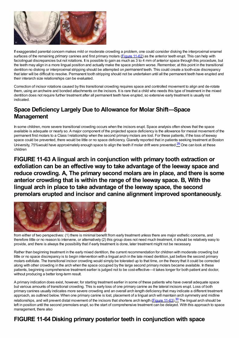
If exaggerated parental concern makes mild or moderate crowding a problem, one could consider disking the interproximal enamelsurfaces of the remaining primary canines and first primary molars (Figure 11-62) as the anterior teeth erupt. This can help withfaciolingual discrepancies but not rotations. It is possible to gain as much as 3 to 4 mm of anterior space through this procedure, butthe teeth may align in a more lingual position and actually make the space problem worse. Remember, at this point in the transitionaldentition no disking or interproximal stripping should be attempted on permanent teeth. This could create a tooth-size discrepancythat later will be difficult to resolve. Permanent tooth stripping should not be undertaken until all the permanent teeth have erupted andtheir interarch size relationships can be evaluated.
Correction of incisor rotations caused by this transitional crowding requires space and controlled movement to align and de-rotatethem, using an archwire and bonded attachments on the incisors. It is rare that a child who needs this type of treatment in the mixeddentition does not require further treatment after all permanent teeth have erupted, so extensive early treatment is usually notindicated.
Space Deficiency Largely Due to Allowance for Molar Shift—SpaceManagementIn some children, more severe transitional crowding occurs when the incisors erupt. Space analysis often shows that the spaceavailable is adequate or nearly so. A major component of the projected space deficiency is the allowance for mesial movement of thepermanent first molars to a Class I relationship when the second primary molars are lost. For these patients, if the loss of leewayspace could be prevented, there would be little or no space deficiency. Gianelly reported that in patients seeking treatment at BostonUniversity, 75%would have approximately enough space to align the teeth if molar drift were prevented.29 One can look at thesechildren
FIGURE 11-63 A lingual arch in conjunction with primary tooth extraction orexfoliation can be an effective way to take advantage of the leeway space andreduce crowding. A, The primary second molars are in place, and there is someanterior crowding that is within the range of the leeway space. B, With thelingual arch in place to take advantage of the leeway space, the secondpremolars erupted and incisor and canine alignment improved spontaneously.
from either of two perspectives: (1) there is minimal benefit from early treatment unless there are major esthetic concerns, andtherefore little or no reason to intervene, or alternatively (2) this group does not need much treatment, it should be relatively easy toprovide, and there is always the possibility that if early treatment is done, later treatment might not be necessary.
Rather than beginning treatment in the early mixed dentition, the current recommendation for children with moderate crowding butlittle or no space discrepancy is to begin intervention with a lingual arch in the late mixed dentition, just before the second primarymolars exfoliate. The transitional incisor crowding would simply be tolerated up to that time, on the theory that it could be correctedalong with other crowding in the arch when the space occupied by the large second primary molars became available. In thesepatients, beginning comprehensive treatment earlier is judged not to be cost-effective—it takes longer for both patient and doctor,without producing a better long-term result.
A primary indication does exist, however, for starting treatment earlier in some of these patients who have overall adequate spacebut various amounts of transitional crowding. This is early loss of one primary canine as the lateral incisors erupt. Loss of bothprimary canines usually indicates more severe crowding and an overall arch length deficiency that may indicate a different treatmentapproach, as outlined below. When one primary canine is lost, placement of a lingual arch will maintain arch symmetry and midlinerelationships, and will prevent distal movement of the incisors that shortens arch length (Figure 11-63).30 The lingual arch should beleft in position until the second premolars erupt, so the start of comprehensive treatment can be delayed. With this approach to spacemanagement, there also
FIGURE 11-64 Disking primary posterior teeth in conjunction with space
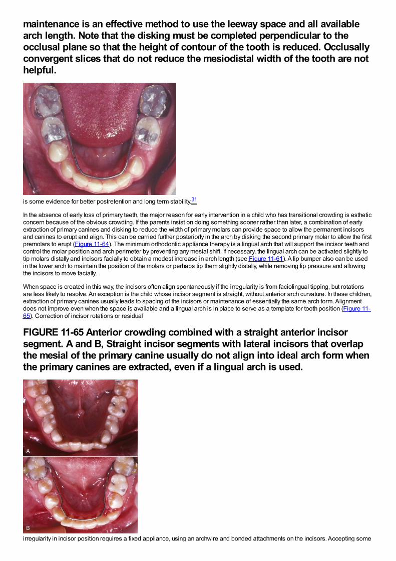
maintenance is an effective method to use the leeway space and all availablearch length. Note that the disking must be completed perpendicular to theocclusal plane so that the height of contour of the tooth is reduced. Occlusallyconvergent slices that do not reduce the mesiodistal width of the tooth are nothelpful.
is some evidence for better postretention and long term stability.31
In the absence of early loss of primary teeth, the major reason for early intervention in a child who has transitional crowding is estheticconcern because of the obvious crowding. If the parents insist on doing something sooner rather than later, a combination of earlyextraction of primary canines and disking to reduce the width of primary molars can provide space to allow the permanent incisorsand canines to erupt and align. This can be carried further posteriorly in the arch by disking the second primary molar to allow the firstpremolars to erupt (Figure 11-64). The minimum orthodontic appliance therapy is a lingual arch that will support the incisor teeth andcontrol the molar position and arch perimeter by preventing any mesial shift. If necessary, the lingual arch can be activated slightly totip molars distally and incisors facially to obtain a modest increase in arch length (see Figure 11-61). A lip bumper also can be usedin the lower arch to maintain the position of the molars or perhaps tip them slightly distally, while removing lip pressure and allowingthe incisors to move facially.
When space is created in this way, the incisors often align spontaneously if the irregularity is from faciolingual tipping, but rotationsare less likely to resolve. An exception is the child whose incisor segment is straight, without anterior arch curvature. In these children,extraction of primary canines usually leads to spacing of the incisors or maintenance of essentially the same arch form. Alignmentdoes not improve even when the space is available and a lingual arch is in place to serve as a template for tooth position (Figure 11-65). Correction of incisor rotations or residual
FIGURE 11-65 Anterior crowding combined with a straight anterior incisorsegment. A and B, Straight incisor segments with lateral incisors that overlapthe mesial of the primary canine usually do not align into ideal arch form whenthe primary canines are extracted, even if a lingual arch is used.
irregularity in incisor position requires a fixed appliance, using an archwire and bonded attachments on the incisors. Accepting some

incisor crowding and deferring treatment until as late as possible—when the premolars are erupting—usually is the best judgment.
Because the molars have not been allowed to shift forward into the leeway space when space management is employed, they oftenare maintained in the end-to-end relationship that is normal before the premolars erupt, instead of moving into a Class I relationship.For that reason, correction of the molar relationship also must become a goal of treatment. Doing this during the second phase oftreatment, when a complete fixed appliance is available, is the most efficient approach. The techniques used for molar correction arediscussed in detail in Chapter 15.
Generalized Moderate CrowdingA child with a generalized arch length discrepancy of 2 to 4 mm and no prematurely missing primary teeth can be expected to havemoderately crowded incisors. This occurs in about 25%of each ethnic group in the United States (see Figure 1-13). Unless theincisors are severely protrusive, the long-term plan would be generalized expansion of the arch to align the teeth. The majoradvantage of doing this in the mixed dentition is esthetic, and the benefit is largely for the parents, not the child.
If the parents strongly desire early treatment for moderate crowding, in the mandibular arch an adjustable lingual arch is the applianceof choice for simple expansion by tipping tooth movement. In the maxilla, either a removable or fixed appliance can be employed(Figure 11-66). Keep in mind that rotated incisors usually will not correct spontaneously even if space is provided, so early correctionwould require bonded attachments for these teeth.
Other Tooth Displacements
Spaced and Flared Maxillary IncisorsIn children with spaced and flared maxillary incisors who have Class I molar relationships and good facial proportions, space analysisshould show that the space available is excessive rather than deficient. This condition often is found in the mixed dentition afterprolonged thumb-sucking and frequently occurs in connection with some narrowing of the maxillary arch. A thumb or finger habitshould be eliminated before attempting to retract the incisors. Physiologic adaptation to the space between the anterior teethrequires placing the tongue in this area to seal off the gap for successful swallowing and speech. This “tongue thrust” is not the causeof the protrusion or open bite and should not be the focus of
FIGURE 11-66 Limited maxillary appliances can be used in the mixed dentitionto align teeth and distribute space. A, This patient had unerupted maxillarylateral incisors as a result of the large midline diastema. B and C, The teethwere aligned and the diastema closed. Note the tubing that protects thepatient's lip from the expanse of continuous wire on the patient's left side.
therapy. If the teeth are retracted, the tongue thrust will disappear as the tongue adapts to the new morphology.
If the upper incisors are flared forward and there is no contact with the lower incisors, the protruding upper incisors can be retractedquite satisfactorily with a removable appliance. A Hawley-type appliance utilizing multiple clasps
FIGURE 11-67 A removable appliance can be used in the mixed dentition toretract spaced and protruding anterior teeth. A, The labial bow is activated 1.5
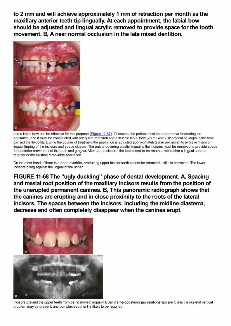
to 2 mm and will achieve approximately 1 mm of retraction per month as themaxillary anterior teeth tip lingually. At each appointment, the labial bowshould be adjusted and lingual acrylic removed to provide space for the toothmovement. B, A near normal occlusion in the late mixed dentition.
and a labial bow can be effective for this purpose (Figure 11-67). Of course, the patient must be cooperative in wearing theappliance, and it must be constructed with adequate retention and a flexible labial bow (28 mil wire). Incorporating loops in the bowcan aid the flexibility. During the course of treatment the appliance is adjusted approximately 2 mm per month to achieve 1 mm oflingual tipping of the incisors and space closure. The palate-covering plastic lingual to the incisors must be removed to provide spacefor posterior movement of the teeth and gingiva. After space closure, the teeth need to be retained with either a lingual bondedretainer or the existing removable appliance.
On the other hand, if there is a deep overbite, protruding upper incisor teeth cannot be retracted until it is corrected. The lowerincisors biting against the lingual of the upper
FIGURE 11-68 The “ugly duckling” phase of dental development. A, Spacingand mesial root position of the maxillary incisors results from the position ofthe unerupted permanent canines. B, This panoramic radiograph shows thatthe canines are erupting and in close proximity to the roots of the lateralincisors. The spaces between the incisors, including the midline diastema,decrease and often completely disappear when the canines erupt.
incisors prevent the upper teeth from being moved lingually. Even if anteroposterior jaw relationships are Class I, a skeletal verticalproblem may be present, and complex treatment is likely to be required.
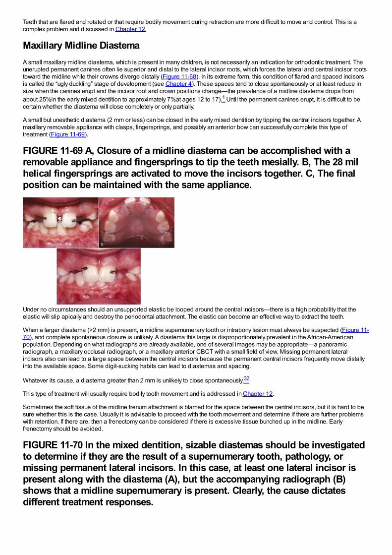
Teeth that are flared and rotated or that require bodily movement during retraction are more difficult to move and control. This is acomplex problem and discussed in Chapter 12.
Maxillary Midline DiastemaA small maxillary midline diastema, which is present in many children, is not necessarily an indication for orthodontic treatment. Theunerupted permanent canines often lie superior and distal to the lateral incisor roots, which forces the lateral and central incisor rootstoward the midline while their crowns diverge distally (Figure 11-68). In its extreme form, this condition of flared and spaced incisorsis called the “ugly duckling” stage of development (see Chapter 4). These spaces tend to close spontaneously or at least reduce insize when the canines erupt and the incisor root and crown positions change—the prevalence of a midline diastema drops fromabout 25%in the early mixed dentition to approximately 7%at ages 12 to 17).1 Until the permanent canines erupt, it is difficult to becertain whether the diastema will close completely or only partially.
A small but unesthetic diastema (2 mm or less) can be closed in the early mixed dentition by tipping the central incisors together. Amaxillary removable appliance with clasps, fingersprings, and possibly an anterior bow can successfully complete this type oftreatment (Figure 11-69).
FIGURE 11-69 A, Closure of a midline diastema can be accomplished with aremovable appliance and fingersprings to tip the teeth mesially. B, The 28 milhelical fingersprings are activated to move the incisors together. C, The finalposition can be maintained with the same appliance.
Under no circumstances should an unsupported elastic be looped around the central incisors—there is a high probability that theelastic will slip apically and destroy the periodontal attachment. The elastic can become an effective way to extract the teeth.
When a larger diastema (>2 mm) is present, a midline supernumerary tooth or intrabony lesion must always be suspected (Figure 11-70), and complete spontaneous closure is unlikely. A diastema this large is disproportionately prevalent in the African-Americanpopulation. Depending on what radiographs are already available, one of several images may be appropriate—a panoramicradiograph, a maxillary occlusal radiograph, or a maxillary anterior CBCT with a small field of view. Missing permanent lateralincisors also can lead to a large space between the central incisors because the permanent central incisors frequently move distallyinto the available space. Some digit-sucking habits can lead to diastemas and spacing.
Whatever its cause, a diastema greater than 2 mm is unlikely to close spontaneously.32
This type of treatment will usually require bodily tooth movement and is addressed in Chapter 12.
Sometimes the soft tissue of the midline frenum attachment is blamed for the space between the central incisors, but it is hard to besure whether this is the case. Usually it is advisable to proceed with the tooth movement and determine if there are further problemswith retention. If there are, then a frenectomy can be considered if there is excessive tissue bunched up in the midline. Earlyfrenectomy should be avoided.
FIGURE 11-70 In the mixed dentition, sizable diastemas should be investigatedto determine if they are the result of a supernumerary tooth, pathology, ormissing permanent lateral incisors. In this case, at least one lateral incisor ispresent along with the diastema (A), but the accompanying radiograph (B)shows that a midline supernumerary is present. Clearly, the cause dictatesdifferent treatment responses.
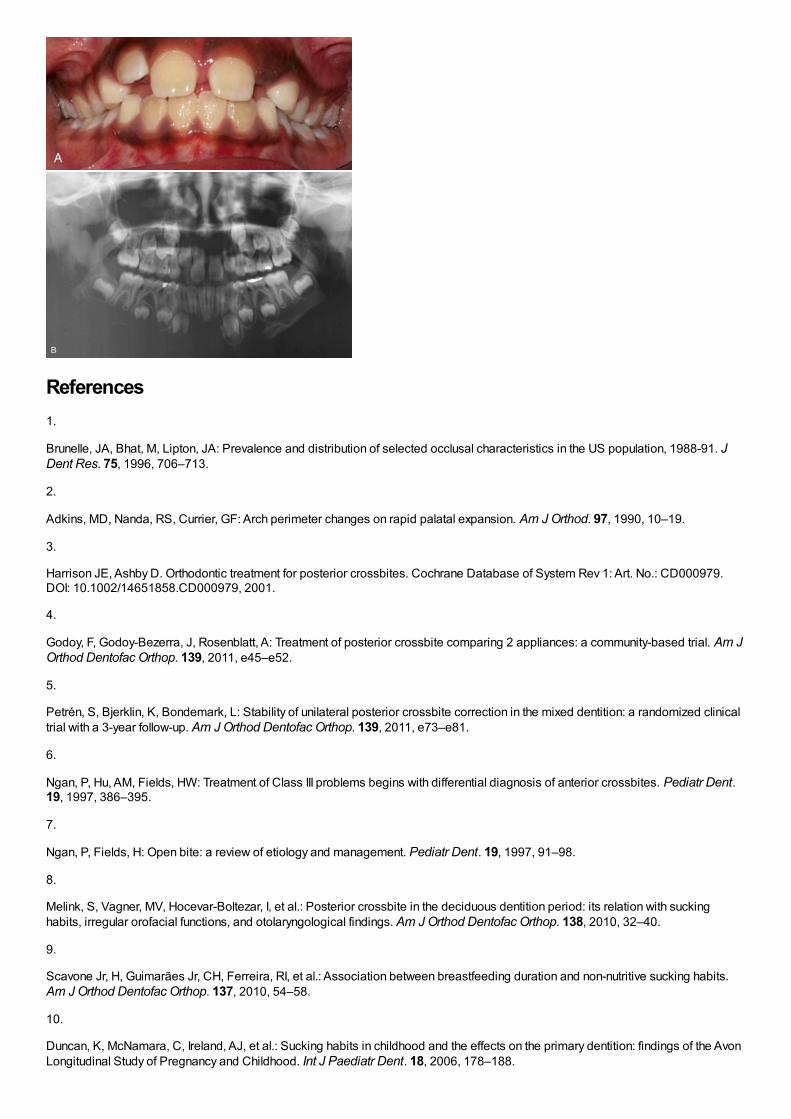
References1.
Brunelle, JA, Bhat, M, Lipton, JA: Prevalence and distribution of selected occlusal characteristics in the US population, 1988-91. JDent Res. 75, 1996, 706–713.
2.
Adkins, MD, Nanda, RS, Currier, GF: Arch perimeter changes on rapid palatal expansion. Am J Orthod. 97, 1990, 10–19.
3.
Harrison JE, Ashby D. Orthodontic treatment for posterior crossbites. Cochrane Database of System Rev 1: Art. No.: CD000979.DOI: 10.1002/14651858.CD000979, 2001.
4.
Godoy, F, Godoy-Bezerra, J, Rosenblatt, A: Treatment of posterior crossbite comparing 2 appliances: a community-based trial. Am JOrthod Dentofac Orthop. 139, 2011, e45–e52.
5.
Petrén, S, Bjerklin, K, Bondemark, L: Stability of unilateral posterior crossbite correction in the mixed dentition: a randomized clinicaltrial with a 3-year follow-up. Am J Orthod Dentofac Orthop. 139, 2011, e73–e81.
6.
Ngan, P, Hu, AM, Fields, HW: Treatment of Class III problems begins with differential diagnosis of anterior crossbites. Pediatr Dent.19, 1997, 386–395.
7.
Ngan, P, Fields, H: Open bite: a review of etiology and management. Pediatr Dent. 19, 1997, 91–98.
8.
Melink, S, Vagner, MV, Hocevar-Boltezar, I, et al.: Posterior crossbite in the deciduous dentition period: its relation with suckinghabits, irregular orofacial functions, and otolaryngological findings. Am J Orthod Dentofac Orthop. 138, 2010, 32–40.
9.
Scavone Jr, H, Guimarães Jr, CH, Ferreira, RI, et al.: Association between breastfeeding duration and non-nutritive sucking habits.Am J Orthod Dentofac Orthop. 137, 2010, 54–58.
10.
Duncan, K, McNamara, C, Ireland, AJ, et al.: Sucking habits in childhood and the effects on the primary dentition: findings of the AvonLongitudinal Study of Pregnancy and Childhood. Int J Paediatr Dent. 18, 2006, 178–188.

11.
Warren, JJ, Slayton, RL, Bishara, SE, et al.: Effects of nonnutritive sucking habits on occlusal characteristics in the mixed dentition.Pediatr Dent. 27, 2005, 445–450.
12.
Haryett, R, Hansen, R, Davidson, P, et al.: Chronic thumbsucking: the psychological effects and the relative effectiveness of thevarious methods of treatment. Am J Orthod. 53, 1967, 559–585.
13.
Villa, NL, Cisneros, GJ: Changes in the dentition secondary to palatal crib therapy in digit-suckers. Pediatric Dent. 19, 1997, 323–326.
14.
Kennedy, DB, Turley, PK: The clinical management of ectopically erupting first permanent molars. Am J Orthod Dentofac Orthop. 92,1987, 336–345.
15.
Aydin, U, Yilmaz, HH, Yildirim, D: Incidence of canine impaction and transmigration in a patient population. DentomaxillofacialRadiol. 33, 2004, 164–169.
16.
Naoumova, J, Kurol, J, Kjellbert, H: A systematic review of the interceptive treatment of palatally displaced maxillary canines. Eur JOrthod. 33, 2011, 143–149.
17.
Garib, DG, Alencar, BM, Lauris, JR, et al.: Agenesis of maxillary lateral incisors and associated dental anomalies. Am J OrthodDentofac Orthop. 137, 2010, e1–e6, 732.
18.
Cernochova, P, Krupa, P, Izakovicova-Holla, LA: Root resorption associated with ectopically erupting maxillary permanent canines: acomputed tomography study. Eur J Orthod. 33, 2011, 483–491.
19.
Botticelli, S, Verna, C, Cattaneo, PM, et al.: Two- versus three-dimensional imaging in subjects with unerupted maxillary canines. EurJ Orthod. 33, 2011, 344–349.
20.
Alqerban, A, Jacobs, R, Fieuws, S, et al.: Comparison of two cone-beam computed tomographic systems versus panoramic imagingfor localization of impacted maxillary canines and detection of root resorption. Eur J Orthod. 33, 2011, 93–102.
21.
Ericson, S, Kurol, J: Early treatment of palatally erupting maxillary canines by extraction of the primary canines. Eur J Orthod. 10,1988, 283–295.
22.
Kurol, J, Thilander, B: Infraocclusion of primary molars with aplasia of the permanent successor: A longitudinal study. Angle Orthod.54, 1984, 283–294.
23.
Moyers, RE: Handbook of Orthodontics. 3rd ed, 1973, Mosby, Chicago.
24.
Tanaka, MM, Johnston, LE: The prediction of the size of unerupted canines and premolars in a contemporary orthodontic population.J Am Dent Assn . 88, 1974, 798–801.
25.
Sasa, IS, Hasan, AA, Qudeimat, MA: Longevity of band and loop space maintainers using glass ionomer cement: a prospectivestudy. Eur Arch Paediatr Dent . 10, 2009, 6–10.

26.
Mayhew, M, Dilley, G, Dilley, D, et al.: Tissue response to intragingival appliances in monkeys. Pediatr Dent. 6, 1984, 148–152.
27.
Moore, TR, Kennedy, DB: Bilateral space maintainers: a 7-year retrospective study from private practice. Pediatr Dent. 28, 2006,499–505.
28.
Hashish, DI, Mostafa, YA: Effect of lip bumpers on mandibular arch dimensions. Am J Orthod Dentofac Orthop. 135, 2009, 106–109.
29.
Gianelly, AA: Crowding: timing of treatment. Angle Orthod. 64, 1994, 415–418.
30.
Brennan, M, Gianelly, AA: The use of the lingual arch in the mixed dentition to resolve crowding. Am J Orthod Dentofac Orthop. 117,2000, 81–85.
31.
Little, RM: Stability and relapse: early treatment of arch length deficiency. Am J Orthod Dentofac Orthop. 121(6), 2002, 578–581.
32.
Huang, WJ, Creath, CJ: The midline diastema: a review of its etiology and treatment. Pediatr Dent. 17, 1995, 171–179.
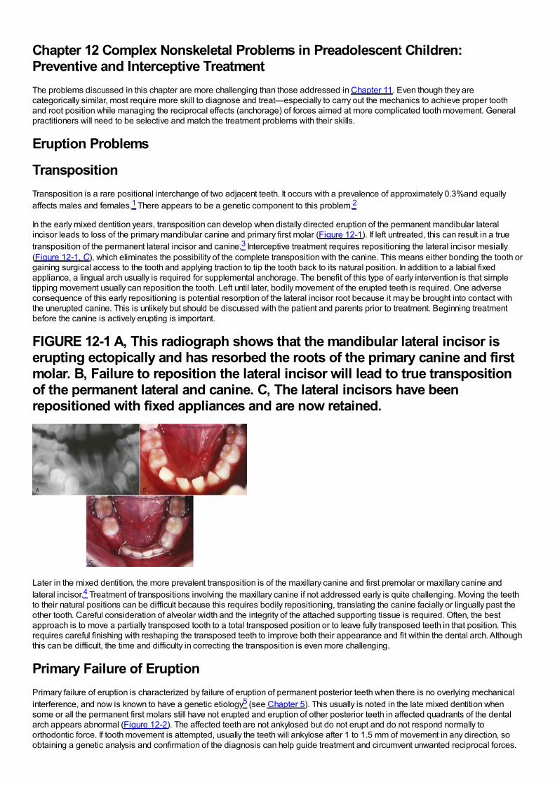
Chapter 12 Complex Nonskeletal Problems in Preadolescent Children:Preventive and Interceptive TreatmentThe problems discussed in this chapter are more challenging than those addressed in Chapter 11. Even though they arecategorically similar, most require more skill to diagnose and treat—especially to carry out the mechanics to achieve proper toothand root position while managing the reciprocal effects (anchorage) of forces aimed at more complicated tooth movement. Generalpractitioners will need to be selective and match the treatment problems with their skills.
Eruption Problems
TranspositionTransposition is a rare positional interchange of two adjacent teeth. It occurs with a prevalence of approximately 0.3%and equallyaffects males and females.1 There appears to be a genetic component to this problem.2
In the early mixed dentition years, transposition can develop when distally directed eruption of the permanent mandibular lateralincisor leads to loss of the primary mandibular canine and primary first molar (Figure 12-1). If left untreated, this can result in a truetransposition of the permanent lateral incisor and canine.3 Interceptive treatment requires repositioning the lateral incisor mesially(Figure 12-1, C), which eliminates the possibility of the complete transposition with the canine. This means either bonding the tooth orgaining surgical access to the tooth and applying traction to tip the tooth back to its natural position. In addition to a labial fixedappliance, a lingual arch usually is required for supplemental anchorage. The benefit of this type of early intervention is that simpletipping movement usually can reposition the tooth. Left until later, bodily movement of the erupted teeth is required. One adverseconsequence of this early repositioning is potential resorption of the lateral incisor root because it may be brought into contact withthe unerupted canine. This is unlikely but should be discussed with the patient and parents prior to treatment. Beginning treatmentbefore the canine is actively erupting is important.
FIGURE 12-1 A, This radiograph shows that the mandibular lateral incisor iserupting ectopically and has resorbed the roots of the primary canine and firstmolar. B, Failure to reposition the lateral incisor will lead to true transpositionof the permanent lateral and canine. C, The lateral incisors have beenrepositioned with fixed appliances and are now retained.
Later in the mixed dentition, the more prevalent transposition is of the maxillary canine and first premolar or maxillary canine andlateral incisor.4 Treatment of transpositions involving the maxillary canine if not addressed early is quite challenging. Moving the teethto their natural positions can be difficult because this requires bodily repositioning, translating the canine facially or lingually past theother tooth. Careful consideration of alveolar width and the integrity of the attached supporting tissue is required. Often, the bestapproach is to move a partially transposed tooth to a total transposed position or to leave fully transposed teeth in that position. Thisrequires careful finishing with reshaping the transposed teeth to improve both their appearance and fit within the dental arch. Althoughthis can be difficult, the time and difficulty in correcting the transposition is even more challenging.
Primary Failure of EruptionPrimary failure of eruption is characterized by failure of eruption of permanent posterior teeth when there is no overlying mechanicalinterference, and now is known to have a genetic etiology5 (see Chapter 5). This usually is noted in the late mixed dentition whensome or all the permanent first molars still have not erupted and eruption of other posterior teeth in affected quadrants of the dentalarch appears abnormal (Figure 12-2). The affected teeth are not ankylosed but do not erupt and do not respond normally toorthodontic force. If tooth movement is attempted, usually the teeth will ankylose after 1 to 1.5 mm of movement in any direction, soobtaining a genetic analysis and confirmation of the diagnosis can help guide treatment and circumvent unwanted reciprocal forces.
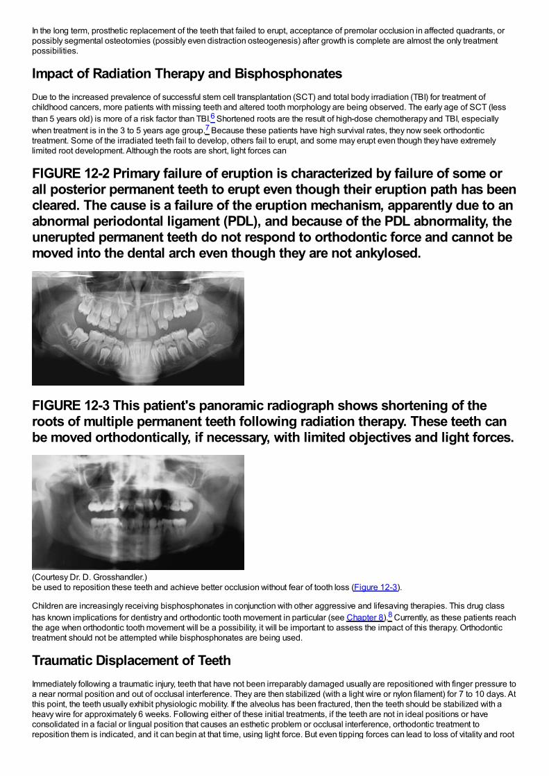
In the long term, prosthetic replacement of the teeth that failed to erupt, acceptance of premolar occlusion in affected quadrants, orpossibly segmental osteotomies (possibly even distraction osteogenesis) after growth is complete are almost the only treatmentpossibilities.
Impact of Radiation Therapy and BisphosphonatesDue to the increased prevalence of successful stem cell transplantation (SCT) and total body irradiation (TBI) for treatment ofchildhood cancers, more patients with missing teeth and altered tooth morphology are being observed. The early age of SCT (lessthan 5 years old) is more of a risk factor than TBI.6 Shortened roots are the result of high-dose chemotherapy and TBI, especiallywhen treatment is in the 3 to 5 years age group.7 Because these patients have high survival rates, they now seek orthodontictreatment. Some of the irradiated teeth fail to develop, others fail to erupt, and some may erupt even though they have extremelylimited root development. Although the roots are short, light forces can
FIGURE 12-2 Primary failure of eruption is characterized by failure of some orall posterior permanent teeth to erupt even though their eruption path has beencleared. The cause is a failure of the eruption mechanism, apparently due to anabnormal periodontal ligament (PDL), and because of the PDL abnormality, theunerupted permanent teeth do not respond to orthodontic force and cannot bemoved into the dental arch even though they are not ankylosed.
FIGURE 12-3 This patient's panoramic radiograph shows shortening of theroots of multiple permanent teeth following radiation therapy. These teeth canbe moved orthodontically, if necessary, with limited objectives and light forces.
(Courtesy Dr. D. Grosshandler.)be used to reposition these teeth and achieve better occlusion without fear of tooth loss (Figure 12-3).
Children are increasingly receiving bisphosphonates in conjunction with other aggressive and lifesaving therapies. This drug classhas known implications for dentistry and orthodontic tooth movement in particular (see Chapter 8).8 Currently, as these patients reachthe age when orthodontic tooth movement will be a possibility, it will be important to assess the impact of this therapy. Orthodontictreatment should not be attempted while bisphosphonates are being used.
Traumatic Displacement of TeethImmediately following a traumatic injury, teeth that have not been irreparably damaged usually are repositioned with finger pressure toa near normal position and out of occlusal interference. They are then stabilized (with a light wire or nylon filament) for 7 to 10 days. Atthis point, the teeth usually exhibit physiologic mobility. If the alveolus has been fractured, then the teeth should be stabilized with aheavy wire for approximately 6 weeks. Following either of these initial treatments, if the teeth are not in ideal positions or haveconsolidated in a facial or lingual position that causes an esthetic problem or occlusal interference, orthodontic treatment toreposition them is indicated, and it can begin at that time, using light force. But even tipping forces can lead to loss of vitality and root
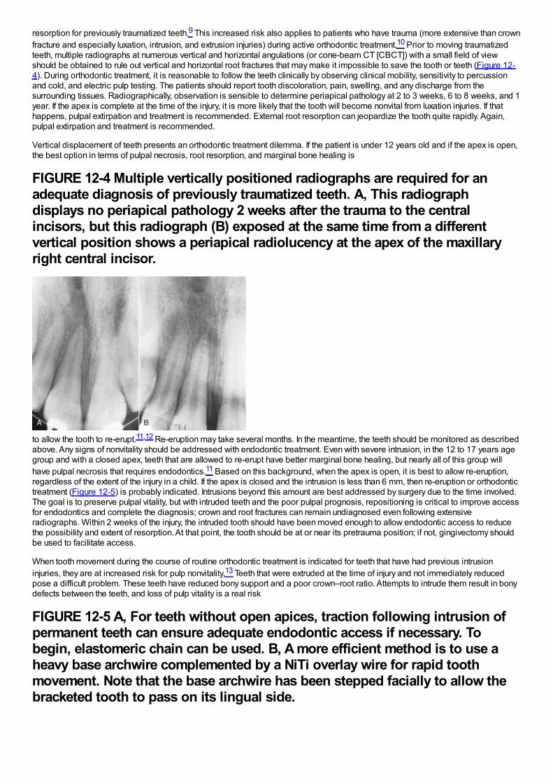
resorption for previously traumatized teeth.9 This increased risk also applies to patients who have trauma (more extensive than crownfracture and especially luxation, intrusion, and extrusion injuries) during active orthodontic treatment.10 Prior to moving traumatizedteeth, multiple radiographs at numerous vertical and horizontal angulations (or cone-beam CT [CBCT]) with a small field of viewshould be obtained to rule out vertical and horizontal root fractures that may make it impossible to save the tooth or teeth (Figure 12-4). During orthodontic treatment, it is reasonable to follow the teeth clinically by observing clinical mobility, sensitivity to percussionand cold, and electric pulp testing. The patients should report tooth discoloration, pain, swelling, and any discharge from thesurrounding tissues. Radiographically, observation is sensible to determine periapical pathology at 2 to 3 weeks, 6 to 8 weeks, and 1year. If the apex is complete at the time of the injury, it is more likely that the tooth will become nonvital from luxation injuries. If thathappens, pulpal extirpation and treatment is recommended. External root resorption can jeopardize the tooth quite rapidly. Again,pulpal extirpation and treatment is recommended.
Vertical displacement of teeth presents an orthodontic treatment dilemma. If the patient is under 12 years old and if the apex is open,the best option in terms of pulpal necrosis, root resorption, and marginal bone healing is
FIGURE 12-4 Multiple vertically positioned radiographs are required for anadequate diagnosis of previously traumatized teeth. A, This radiographdisplays no periapical pathology 2 weeks after the trauma to the centralincisors, but this radiograph (B) exposed at the same time from a differentvertical position shows a periapical radiolucency at the apex of the maxillaryright central incisor.
to allow the tooth to re-erupt.11,12 Re-eruption may take several months. In the meantime, the teeth should be monitored as describedabove. Any signs of nonvitality should be addressed with endodontic treatment. Even with severe intrusion, in the 12 to 17 years agegroup and with a closed apex, teeth that are allowed to re-erupt have better marginal bone healing, but nearly all of this group willhave pulpal necrosis that requires endodontics.11 Based on this background, when the apex is open, it is best to allow re-eruption,regardless of the extent of the injury in a child. If the apex is closed and the intrusion is less than 6 mm, then re-eruption or orthodontictreatment (Figure 12-5) is probably indicated. Intrusions beyond this amount are best addressed by surgery due to the time involved.The goal is to preserve pulpal vitality, but with intruded teeth and the poor pulpal prognosis, repositioning is critical to improve accessfor endodontics and complete the diagnosis; crown and root fractures can remain undiagnosed even following extensiveradiographs. Within 2 weeks of the injury, the intruded tooth should have been moved enough to allow endodontic access to reducethe possibility and extent of resorption. At that point, the tooth should be at or near its pretrauma position; if not, gingivectomy shouldbe used to facilitate access.
When tooth movement during the course of routine orthodontic treatment is indicated for teeth that have had previous intrusioninjuries, they are at increased risk for pulp nonvitality.13 Teeth that were extruded at the time of injury and not immediately reducedpose a difficult problem. These teeth have reduced bony support and a poor crown–root ratio. Attempts to intrude them result in bonydefects between the teeth, and loss of pulp vitality is a real risk
FIGURE 12-5 A, For teeth without open apices, traction following intrusion ofpermanent teeth can ensure adequate endodontic access if necessary. Tobegin, elastomeric chain can be used. B, A more efficient method is to use aheavy base archwire complemented by a NiTi overlay wire for rapid toothmovement. Note that the base archwire has been stepped facially to allow thebracketed tooth to pass on its lingual side.
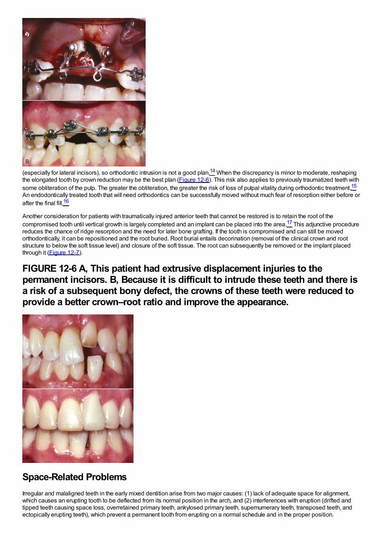
(especially for lateral incisors), so orthodontic intrusion is not a good plan.14 When the discrepancy is minor to moderate, reshapingthe elongated tooth by crown reduction may be the best plan (Figure 12-6). This risk also applies to previously traumatized teeth withsome obliteration of the pulp. The greater the obliteration, the greater the risk of loss of pulpal vitality during orthodontic treatment.15
An endodontically treated tooth that will need orthodontics can be successfully moved without much fear of resorption either before orafter the final fill.16
Another consideration for patients with traumatically injured anterior teeth that cannot be restored is to retain the root of thecompromised tooth until vertical growth is largely completed and an implant can be placed into the area.17 This adjunctive procedurereduces the chance of ridge resorption and the need for later bone grafting. If the tooth is compromised and can still be movedorthodontically, it can be repositioned and the root buried. Root burial entails decorination (removal of the clinical crown and rootstructure to below the soft tissue level) and closure of the soft tissue. The root can subsequently be removed or the implant placedthrough it (Figure 12-7).
FIGURE 12-6 A, This patient had extrusive displacement injuries to thepermanent incisors. B, Because it is difficult to intrude these teeth and there isa risk of a subsequent bony defect, the crowns of these teeth were reduced toprovide a better crown–root ratio and improve the appearance.
Space-Related ProblemsIrregular and malaligned teeth in the early mixed dentition arise from two major causes: (1) lack of adequate space for alignment,which causes an erupting tooth to be deflected from its normal position in the arch, and (2) interferences with eruption (drifted andtipped teeth causing space loss, overretained primary teeth, ankylosed primary teeth, supernumerary teeth, transposed teeth, andectopically erupting teeth), which prevent a permanent tooth from erupting on a normal schedule and in the proper position.
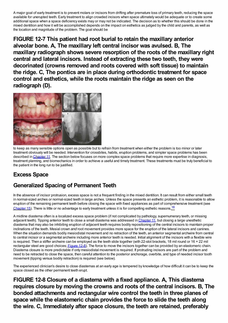
A major goal of early treatment is to prevent molars or incisors from drifting after premature loss of primary teeth, reducing the spaceavailable for unerupted teeth. Early treatment to align crowded incisors when space ultimately would be adequate or to create someadditional space when a space deficiency exists may or may not be indicated. The decision as to whether this should be done in themixed dentition and how it will be accomplished depends on the impact on esthetics as judged by the child and parents, as well asthe location and magnitude of the problem. The goal should be
FIGURE 12-7 This patient had root burial to retain the maxillary anterioralveolar bone. A, The maxillary left central incisor was avulsed. B, Themaxillary radiograph shows severe resorption of the roots of the maxillary rightcentral and lateral incisors. Instead of extracting these two teeth, they weredecorinated (crowns removed and roots covered with soft tissue) to maintainthe ridge. C, The pontics are in place during orthodontic treatment for spacecontrol and esthetics, while the roots maintain the ridge as seen on theradiograph (D).
to keep as many sensible options open as possible but to refrain from treatment when either the problem is too minor or latertreatment obviously will be needed. Intervention for crossbites, habits, eruption problems, and simpler space problems has beendescribed in Chapter 11. The section below focuses on more complex space problems that require more expertise in diagnosis,treatment planning, and biomechanics in order to achieve a useful and timely treatment. These treatments must be truly beneficial tothe patient in the long run to be justified.
Excess Space
Generalized Spacing of Permanent TeethIn the absence of incisor protrusion, excess space is not a frequent finding in the mixed dentition. It can result from either small teethin normal-sized arches or normal-sized teeth in large arches. Unless the space presents an esthetic problem, it is reasonable to alloweruption of the remaining permanent teeth before closing the space with fixed appliances as part of comprehensive treatment (seeChapter 15). There is little or no advantage to early treatment unless it is for compelling esthetic reasons.18
A midline diastema often is a localized excess space problem (if not complicated by pathology, supernumerary teeth, or missingadjacent teeth). Tipping anterior teeth to close a small diastema was addressed in Chapter 11, but closing a large unestheticdiastema that may also be inhibiting eruption of adjacent teeth requires bodily repositioning of the central incisors to maintain properinclinations of the teeth. Mesial crown and root movement provides more space for the eruption of the lateral incisors and canines.When the situation demands bodily mesiodistal movement and no retraction of the teeth, an anterior segmental archwire from centralto central incisor or a segmental archwire including more anterior teeth is needed. Initial alignment of the incisors with a flexible wireis required. Then a stiffer archwire can be employed as the teeth slide together (with 22-slot brackets, 18 mil round or 16 × 22 milrectangular steel are good choices; Figure 12-8). The force to move the incisors together can be provided by an elastomeric chain.Diastema closure is more predictable if only mesiodistal movement is required. If protruding incisors are part of the problem andneed to be retracted to close the space, then careful attention to the posterior anchorage, overbite, and type of needed incisor toothmovement (tipping versus bodily retraction) is required (see below).
The experienced clinician's desire to close diastemas at an early age is tempered by knowledge of how difficult it can be to keep thespace closed as the other permanent teeth erupt.
FIGURE 12-8 Closure of a diastema with a fixed appliance. A, This diastemarequires closure by moving the crowns and roots of the central incisors. B, Thebonded attachments and rectangular wire control the teeth in three planes ofspace while the elastomeric chain provides the force to slide the teeth alongthe wire. C, Immediately after space closure, the teeth are retained, preferably
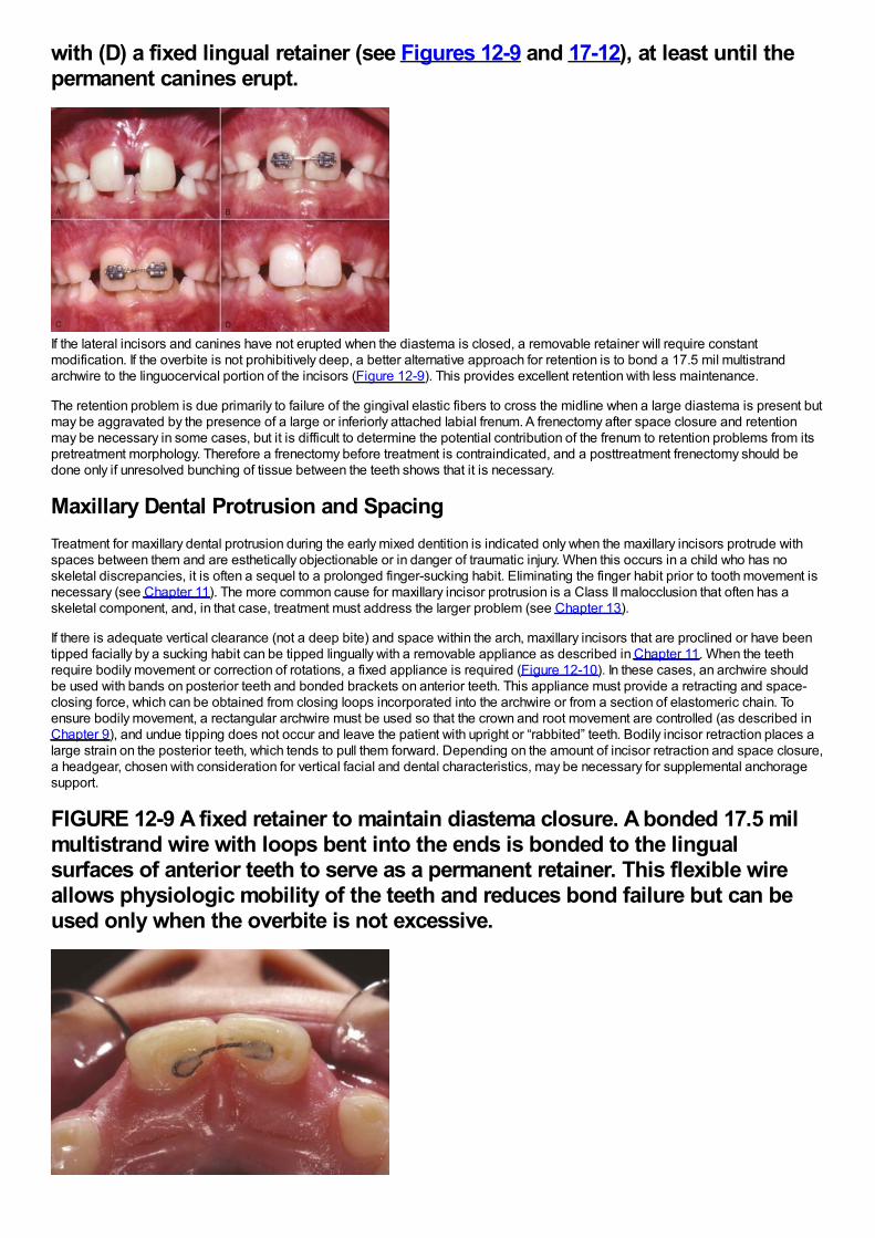
with (D) a fixed lingual retainer (see Figures 12-9 and 17-12), at least until thepermanent canines erupt.
If the lateral incisors and canines have not erupted when the diastema is closed, a removable retainer will require constantmodification. If the overbite is not prohibitively deep, a better alternative approach for retention is to bond a 17.5 mil multistrandarchwire to the linguocervical portion of the incisors (Figure 12-9). This provides excellent retention with less maintenance.
The retention problem is due primarily to failure of the gingival elastic fibers to cross the midline when a large diastema is present butmay be aggravated by the presence of a large or inferiorly attached labial frenum. A frenectomy after space closure and retentionmay be necessary in some cases, but it is difficult to determine the potential contribution of the frenum to retention problems from itspretreatment morphology. Therefore a frenectomy before treatment is contraindicated, and a posttreatment frenectomy should bedone only if unresolved bunching of tissue between the teeth shows that it is necessary.
Maxillary Dental Protrusion and SpacingTreatment for maxillary dental protrusion during the early mixed dentition is indicated only when the maxillary incisors protrude withspaces between them and are esthetically objectionable or in danger of traumatic injury. When this occurs in a child who has noskeletal discrepancies, it is often a sequel to a prolonged finger-sucking habit. Eliminating the finger habit prior to tooth movement isnecessary (see Chapter 11). The more common cause for maxillary incisor protrusion is a Class II malocclusion that often has askeletal component, and, in that case, treatment must address the larger problem (see Chapter 13).
If there is adequate vertical clearance (not a deep bite) and space within the arch, maxillary incisors that are proclined or have beentipped facially by a sucking habit can be tipped lingually with a removable appliance as described in Chapter 11. When the teethrequire bodily movement or correction of rotations, a fixed appliance is required (Figure 12-10). In these cases, an archwire shouldbe used with bands on posterior teeth and bonded brackets on anterior teeth. This appliance must provide a retracting and space-closing force, which can be obtained from closing loops incorporated into the archwire or from a section of elastomeric chain. Toensure bodily movement, a rectangular archwire must be used so that the crown and root movement are controlled (as described inChapter 9), and undue tipping does not occur and leave the patient with upright or “rabbited” teeth. Bodily incisor retraction places alarge strain on the posterior teeth, which tends to pull them forward. Depending on the amount of incisor retraction and space closure,a headgear, chosen with consideration for vertical facial and dental characteristics, may be necessary for supplemental anchoragesupport.
FIGURE 12-9 A fixed retainer to maintain diastema closure. A bonded 17.5 milmultistrand wire with loops bent into the ends is bonded to the lingualsurfaces of anterior teeth to serve as a permanent retainer. This flexible wireallows physiologic mobility of the teeth and reduces bond failure but can beused only when the overbite is not excessive.
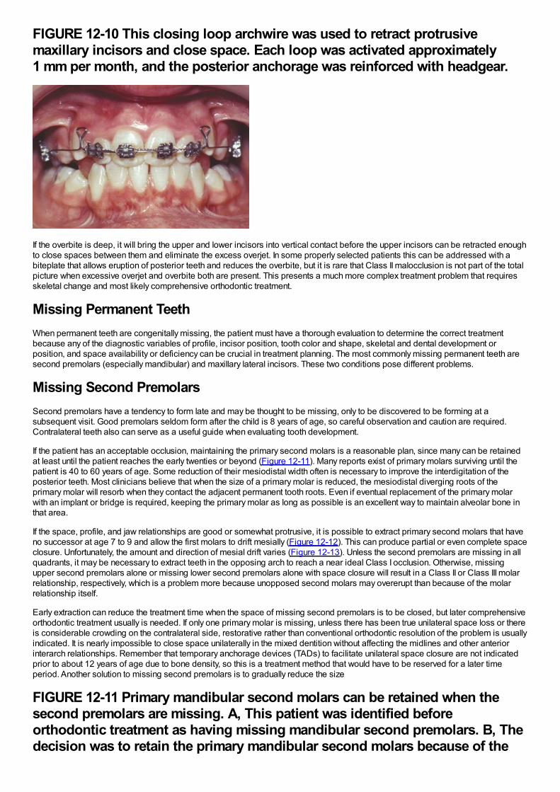
FIGURE 12-10 This closing loop archwire was used to retract protrusivemaxillary incisors and close space. Each loop was activated approximately1 mm per month, and the posterior anchorage was reinforced with headgear.
If the overbite is deep, it will bring the upper and lower incisors into vertical contact before the upper incisors can be retracted enoughto close spaces between them and eliminate the excess overjet. In some properly selected patients this can be addressed with abiteplate that allows eruption of posterior teeth and reduces the overbite, but it is rare that Class II malocclusion is not part of the totalpicture when excessive overjet and overbite both are present. This presents a much more complex treatment problem that requiresskeletal change and most likely comprehensive orthodontic treatment.
Missing Permanent TeethWhen permanent teeth are congenitally missing, the patient must have a thorough evaluation to determine the correct treatmentbecause any of the diagnostic variables of profile, incisor position, tooth color and shape, skeletal and dental development orposition, and space availability or deficiency can be crucial in treatment planning. The most commonly missing permanent teeth aresecond premolars (especially mandibular) and maxillary lateral incisors. These two conditions pose different problems.
Missing Second PremolarsSecond premolars have a tendency to form late and may be thought to be missing, only to be discovered to be forming at asubsequent visit. Good premolars seldom form after the child is 8 years of age, so careful observation and caution are required.Contralateral teeth also can serve as a useful guide when evaluating tooth development.
If the patient has an acceptable occlusion, maintaining the primary second molars is a reasonable plan, since many can be retainedat least until the patient reaches the early twenties or beyond (Figure 12-11). Many reports exist of primary molars surviving until thepatient is 40 to 60 years of age. Some reduction of their mesiodistal width often is necessary to improve the interdigitation of theposterior teeth. Most clinicians believe that when the size of a primary molar is reduced, the mesiodistal diverging roots of theprimary molar will resorb when they contact the adjacent permanent tooth roots. Even if eventual replacement of the primary molarwith an implant or bridge is required, keeping the primary molar as long as possible is an excellent way to maintain alveolar bone inthat area.
If the space, profile, and jaw relationships are good or somewhat protrusive, it is possible to extract primary second molars that haveno successor at age 7 to 9 and allow the first molars to drift mesially (Figure 12-12). This can produce partial or even complete spaceclosure. Unfortunately, the amount and direction of mesial drift varies (Figure 12-13). Unless the second premolars are missing in allquadrants, it may be necessary to extract teeth in the opposing arch to reach a near ideal Class I occlusion. Otherwise, missingupper second premolars alone or missing lower second premolars alone with space closure will result in a Class II or Class III molarrelationship, respectively, which is a problem more because unopposed second molars may overerupt than because of the molarrelationship itself.
Early extraction can reduce the treatment time when the space of missing second premolars is to be closed, but later comprehensiveorthodontic treatment usually is needed. If only one primary molar is missing, unless there has been true unilateral space loss or thereis considerable crowding on the contralateral side, restorative rather than conventional orthodontic resolution of the problem is usuallyindicated. It is nearly impossible to close space unilaterally in the mixed dentition without affecting the midlines and other anteriorinterarch relationships. Remember that temporary anchorage devices (TADs) to facilitate unilateral space closure are not indicatedprior to about 12 years of age due to bone density, so this is a treatment method that would have to be reserved for a later timeperiod. Another solution to missing second premolars is to gradually reduce the size
FIGURE 12-11 Primary mandibular second molars can be retained when thesecond premolars are missing. A, This patient was identified beforeorthodontic treatment as having missing mandibular second premolars. B, Thedecision was to retain the primary mandibular second molars because of the
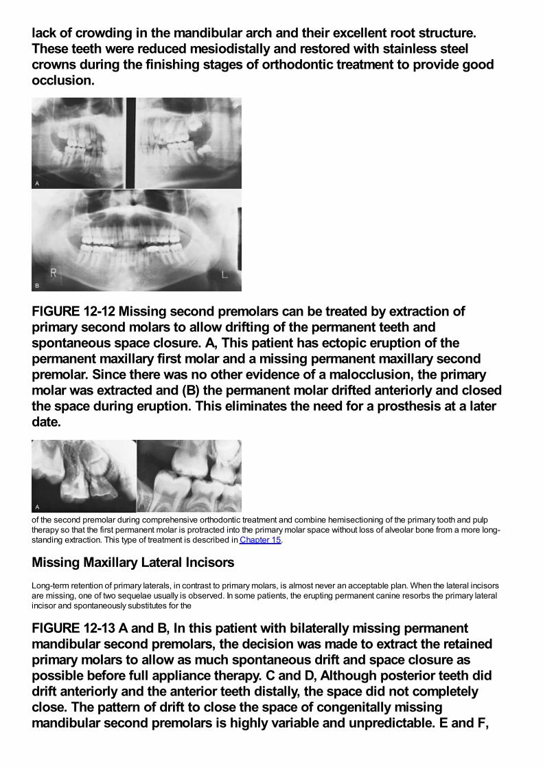
lack of crowding in the mandibular arch and their excellent root structure.These teeth were reduced mesiodistally and restored with stainless steelcrowns during the finishing stages of orthodontic treatment to provide goodocclusion.
FIGURE 12-12 Missing second premolars can be treated by extraction ofprimary second molars to allow drifting of the permanent teeth andspontaneous space closure. A, This patient has ectopic eruption of thepermanent maxillary first molar and a missing permanent maxillary secondpremolar. Since there was no other evidence of a malocclusion, the primarymolar was extracted and (B) the permanent molar drifted anteriorly and closedthe space during eruption. This eliminates the need for a prosthesis at a laterdate.
of the second premolar during comprehensive orthodontic treatment and combine hemisectioning of the primary tooth and pulptherapy so that the first permanent molar is protracted into the primary molar space without loss of alveolar bone from a more long-standing extraction. This type of treatment is described in Chapter 15.
Missing Maxillary Lateral IncisorsLong-term retention of primary laterals, in contrast to primary molars, is almost never an acceptable plan. When the lateral incisorsare missing, one of two sequelae usually is observed. In some patients, the erupting permanent canine resorbs the primary lateralincisor and spontaneously substitutes for the
FIGURE 12-13 A and B, In this patient with bilaterally missing permanentmandibular second premolars, the decision was made to extract the retainedprimary molars to allow as much spontaneous drift and space closure aspossible before full appliance therapy. C and D, Although posterior teeth diddrift anteriorly and the anterior teeth distally, the space did not completelyclose. The pattern of drift to close the space of congenitally missingmandibular second premolars is highly variable and unpredictable. E and F,
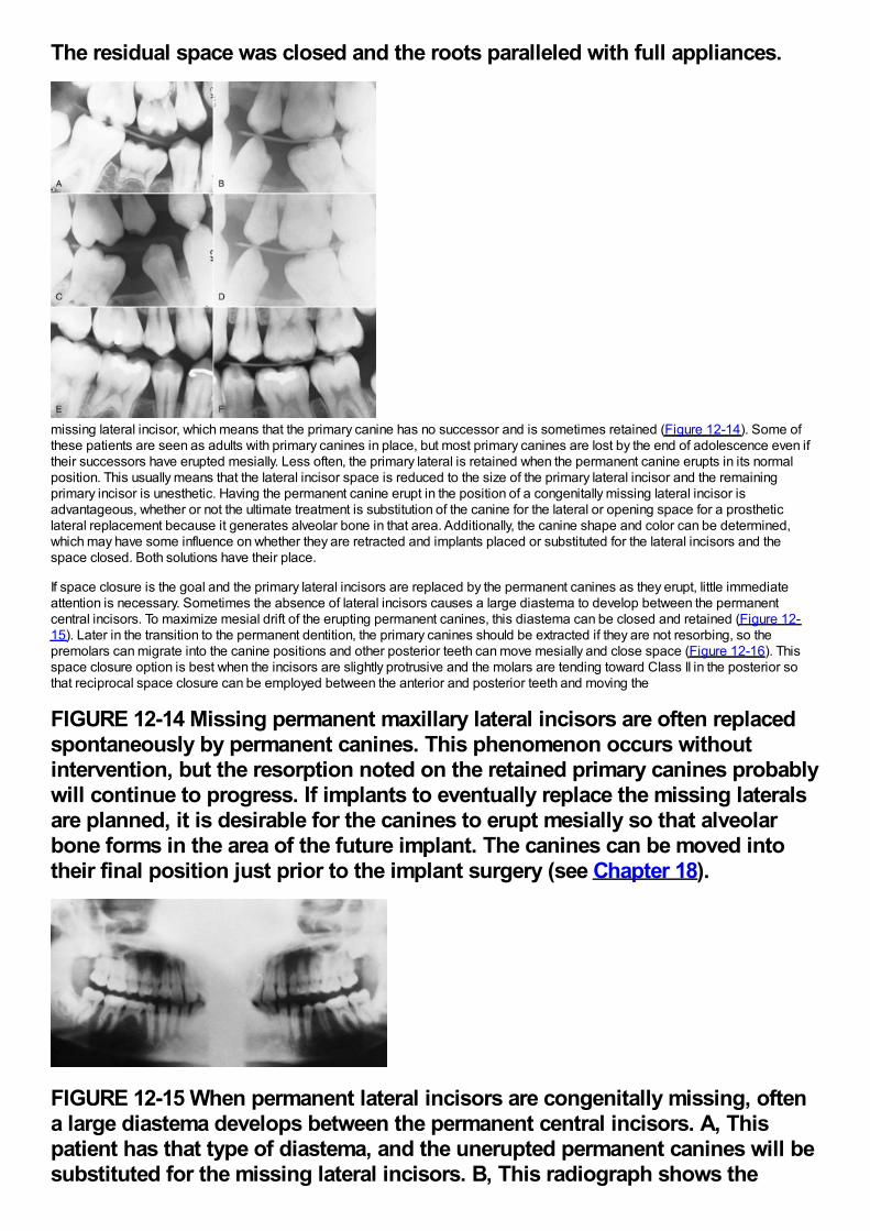
The residual space was closed and the roots paralleled with full appliances.
missing lateral incisor, which means that the primary canine has no successor and is sometimes retained (Figure 12-14). Some ofthese patients are seen as adults with primary canines in place, but most primary canines are lost by the end of adolescence even iftheir successors have erupted mesially. Less often, the primary lateral is retained when the permanent canine erupts in its normalposition. This usually means that the lateral incisor space is reduced to the size of the primary lateral incisor and the remainingprimary incisor is unesthetic. Having the permanent canine erupt in the position of a congenitally missing lateral incisor isadvantageous, whether or not the ultimate treatment is substitution of the canine for the lateral or opening space for a prostheticlateral replacement because it generates alveolar bone in that area. Additionally, the canine shape and color can be determined,which may have some influence on whether they are retracted and implants placed or substituted for the lateral incisors and thespace closed. Both solutions have their place.
If space closure is the goal and the primary lateral incisors are replaced by the permanent canines as they erupt, little immediateattention is necessary. Sometimes the absence of lateral incisors causes a large diastema to develop between the permanentcentral incisors. To maximize mesial drift of the erupting permanent canines, this diastema can be closed and retained (Figure 12-15). Later in the transition to the permanent dentition, the primary canines should be extracted if they are not resorbing, so thepremolars can migrate into the canine positions and other posterior teeth can move mesially and close space (Figure 12-16). Thisspace closure option is best when the incisors are slightly protrusive and the molars are tending toward Class II in the posterior sothat reciprocal space closure can be employed between the anterior and posterior teeth and moving the
FIGURE 12-14 Missing permanent maxillary lateral incisors are often replacedspontaneously by permanent canines. This phenomenon occurs withoutintervention, but the resorption noted on the retained primary canines probablywill continue to progress. If implants to eventually replace the missing lateralsare planned, it is desirable for the canines to erupt mesially so that alveolarbone forms in the area of the future implant. The canines can be moved intotheir final position just prior to the implant surgery (see Chapter 18).
FIGURE 12-15 When permanent lateral incisors are congenitally missing, oftena large diastema develops between the permanent central incisors. A, Thispatient has that type of diastema, and the unerupted permanent canines will besubstituted for the missing lateral incisors. B, This radiograph shows the
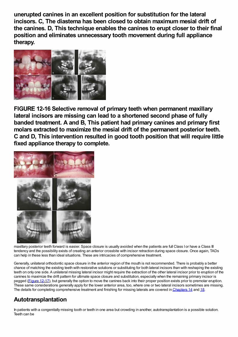
unerupted canines in an excellent position for substitution for the lateralincisors. C, The diastema has been closed to obtain maximum mesial drift ofthe canines. D, This technique enables the canines to erupt closer to their finalposition and eliminates unnecessary tooth movement during full appliancetherapy.
FIGURE 12-16 Selective removal of primary teeth when permanent maxillarylateral incisors are missing can lead to a shortened second phase of fullybanded treatment. A and B, This patient had primary canines and primary firstmolars extracted to maximize the mesial drift of the permanent posterior teeth.C and D, This intervention resulted in good tooth position that will require littlefixed appliance therapy to complete.
maxillary posterior teeth forward is easier. Space closure is usually avoided when the patients are full Class I or have a Class IIItendency and the possibility exists of creating an anterior crossbite with incisor retraction during space closure. Once again, TADscan help in these less than ideal situations. These are intricacies of comprehensive treatment.
Generally, unilateral orthodontic space closure in the anterior region of the mouth is not recommended. There is probably a betterchance of matching the existing teeth with restorative solutions or substituting for both lateral incisors than with reshaping the existingteeth on only one side. A unilateral missing lateral incisor might require the extraction of the other lateral incisor prior to eruption of thecanines to maximize the drift pattern for ultimate space closure and substitution, especially when the remaining primary incisor ispegged (Figure 12-17), but generally the option to move the canines back into their proper position exists prior to premolar eruption.These same considerations generally apply for the lower anterior area, too, where one or two lateral incisors sometimes are missing.The details for completing comprehensive treatment and finishing for missing laterals are covered in Chapters 14 and 18.
AutotransplantationIn patients with a congenitally missing tooth or teeth in one area but crowding in another, autotransplantation is a possible solution.Teeth can be
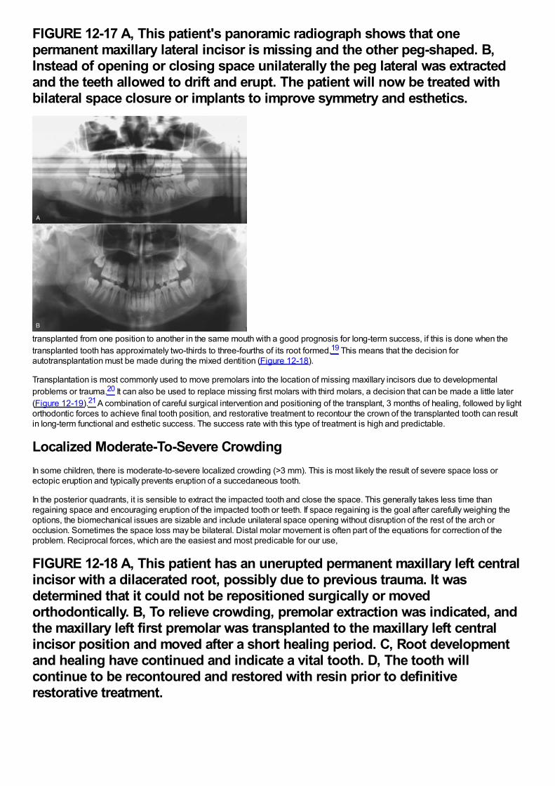
FIGURE 12-17 A, This patient's panoramic radiograph shows that onepermanent maxillary lateral incisor is missing and the other peg-shaped. B,Instead of opening or closing space unilaterally the peg lateral was extractedand the teeth allowed to drift and erupt. The patient will now be treated withbilateral space closure or implants to improve symmetry and esthetics.
transplanted from one position to another in the same mouth with a good prognosis for long-term success, if this is done when thetransplanted tooth has approximately two-thirds to three-fourths of its root formed.19 This means that the decision forautotransplantation must be made during the mixed dentition (Figure 12-18).
Transplantation is most commonly used to move premolars into the location of missing maxillary incisors due to developmentalproblems or trauma.20 It can also be used to replace missing first molars with third molars, a decision that can be made a little later(Figure 12-19).21 A combination of careful surgical intervention and positioning of the transplant, 3 months of healing, followed by lightorthodontic forces to achieve final tooth position, and restorative treatment to recontour the crown of the transplanted tooth can resultin long-term functional and esthetic success. The success rate with this type of treatment is high and predictable.
Localized Moderate-To-Severe CrowdingIn some children, there is moderate-to-severe localized crowding (>3 mm). This is most likely the result of severe space loss orectopic eruption and typically prevents eruption of a succedaneous tooth.
In the posterior quadrants, it is sensible to extract the impacted tooth and close the space. This generally takes less time thanregaining space and encouraging eruption of the impacted tooth or teeth. If space regaining is the goal after carefully weighing theoptions, the biomechanical issues are sizable and include unilateral space opening without disruption of the rest of the arch orocclusion. Sometimes the space loss may be bilateral. Distal molar movement is often part of the equations for correction of theproblem. Reciprocal forces, which are the easiest and most predicable for our use,
FIGURE 12-18 A, This patient has an unerupted permanent maxillary left centralincisor with a dilacerated root, possibly due to previous trauma. It wasdetermined that it could not be repositioned surgically or movedorthodontically. B, To relieve crowding, premolar extraction was indicated, andthe maxillary left first premolar was transplanted to the maxillary left centralincisor position and moved after a short healing period. C, Root developmentand healing have continued and indicate a vital tooth. D, The tooth willcontinue to be recontoured and restored with resin prior to definitiverestorative treatment.
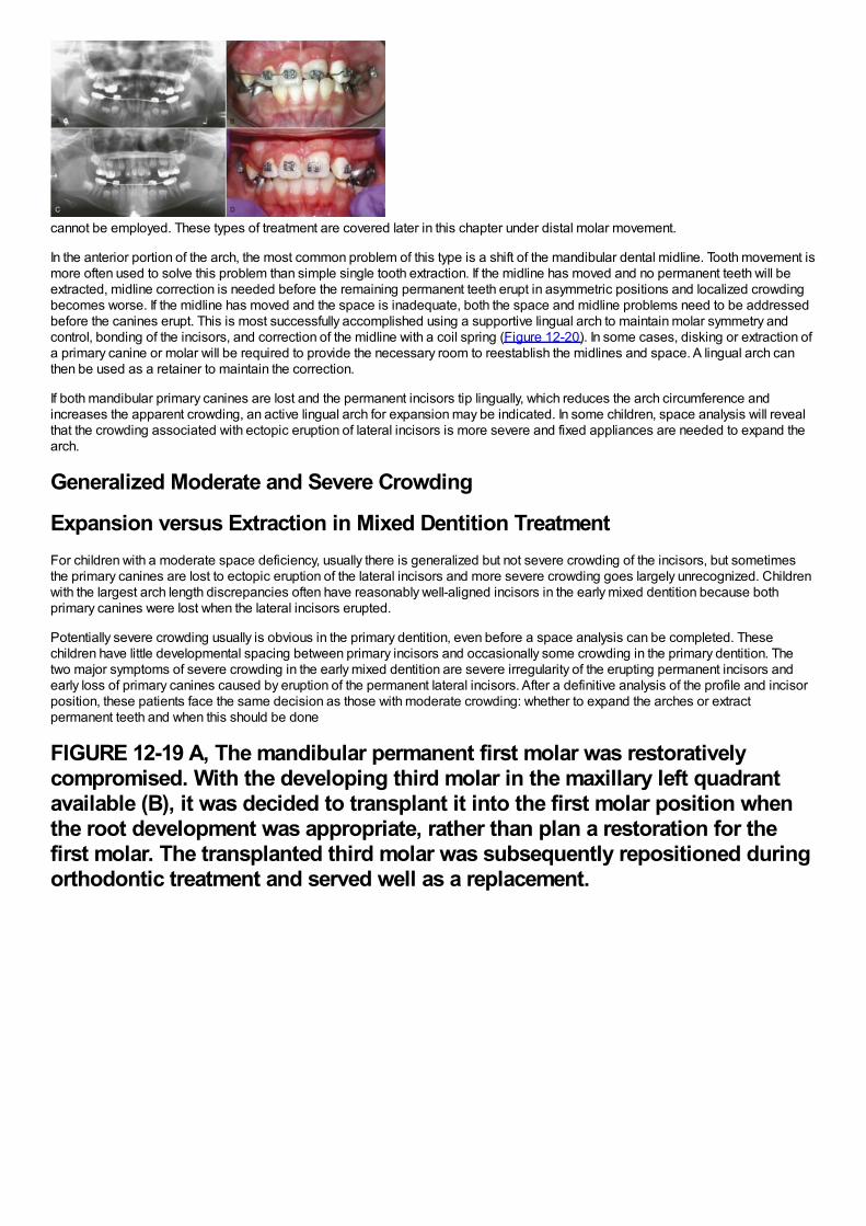
cannot be employed. These types of treatment are covered later in this chapter under distal molar movement.
In the anterior portion of the arch, the most common problem of this type is a shift of the mandibular dental midline. Tooth movement ismore often used to solve this problem than simple single tooth extraction. If the midline has moved and no permanent teeth will beextracted, midline correction is needed before the remaining permanent teeth erupt in asymmetric positions and localized crowdingbecomes worse. If the midline has moved and the space is inadequate, both the space and midline problems need to be addressedbefore the canines erupt. This is most successfully accomplished using a supportive lingual arch to maintain molar symmetry andcontrol, bonding of the incisors, and correction of the midline with a coil spring (Figure 12-20). In some cases, disking or extraction ofa primary canine or molar will be required to provide the necessary room to reestablish the midlines and space. A lingual arch canthen be used as a retainer to maintain the correction.
If both mandibular primary canines are lost and the permanent incisors tip lingually, which reduces the arch circumference andincreases the apparent crowding, an active lingual arch for expansion may be indicated. In some children, space analysis will revealthat the crowding associated with ectopic eruption of lateral incisors is more severe and fixed appliances are needed to expand thearch.
Generalized Moderate and Severe Crowding
Expansion versus Extraction in Mixed Dentition TreatmentFor children with a moderate space deficiency, usually there is generalized but not severe crowding of the incisors, but sometimesthe primary canines are lost to ectopic eruption of the lateral incisors and more severe crowding goes largely unrecognized. Childrenwith the largest arch length discrepancies often have reasonably well-aligned incisors in the early mixed dentition because bothprimary canines were lost when the lateral incisors erupted.
Potentially severe crowding usually is obvious in the primary dentition, even before a space analysis can be completed. Thesechildren have little developmental spacing between primary incisors and occasionally some crowding in the primary dentition. Thetwo major symptoms of severe crowding in the early mixed dentition are severe irregularity of the erupting permanent incisors andearly loss of primary canines caused by eruption of the permanent lateral incisors. After a definitive analysis of the profile and incisorposition, these patients face the same decision as those with moderate crowding: whether to expand the arches or extractpermanent teeth and when this should be done
FIGURE 12-19 A, The mandibular permanent first molar was restorativelycompromised. With the developing third molar in the maxillary left quadrantavailable (B), it was decided to transplant it into the first molar position whenthe root development was appropriate, rather than plan a restoration for thefirst molar. The transplanted third molar was subsequently repositioned duringorthodontic treatment and served well as a replacement.
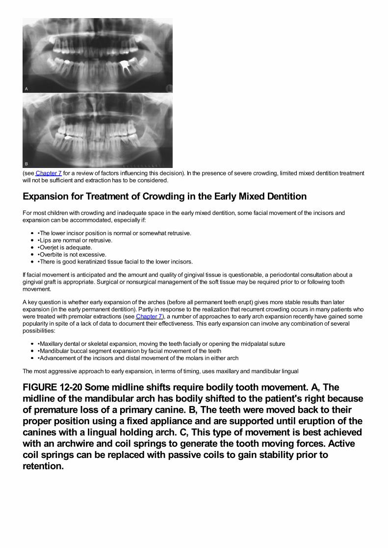
(see Chapter 7 for a review of factors influencing this decision). In the presence of severe crowding, limited mixed dentition treatmentwill not be sufficient and extraction has to be considered.
Expansion for Treatment of Crowding in the Early Mixed DentitionFor most children with crowding and inadequate space in the early mixed dentition, some facial movement of the incisors andexpansion can be accommodated, especially if:
•The lower incisor position is normal or somewhat retrusive.•Lips are normal or retrusive.•Overjet is adequate.•Overbite is not excessive.•There is good keratinized tissue facial to the lower incisors.
If facial movement is anticipated and the amount and quality of gingival tissue is questionable, a periodontal consultation about agingival graft is appropriate. Surgical or nonsurgical management of the soft tissue may be required prior to or following toothmovement.
A key question is whether early expansion of the arches (before all permanent teeth erupt) gives more stable results than laterexpansion (in the early permanent dentition). Partly in response to the realization that recurrent crowding occurs in many patients whowere treated with premolar extractions (see Chapter 7), a number of approaches to early arch expansion recently have gained somepopularity in spite of a lack of data to document their effectiveness. This early expansion can involve any combination of severalpossibilities:
•Maxillary dental or skeletal expansion, moving the teeth facially or opening the midpalatal suture•Mandibular buccal segment expansion by facial movement of the teeth•Advancement of the incisors and distal movement of the molars in either arch
The most aggressive approach to early expansion, in terms of timing, uses maxillary and mandibular lingual
FIGURE 12-20 Some midline shifts require bodily tooth movement. A, Themidline of the mandibular arch has bodily shifted to the patient's right becauseof premature loss of a primary canine. B, The teeth were moved back to theirproper position using a fixed appliance and are supported until eruption of thecanines with a lingual holding arch. C, This type of movement is best achievedwith an archwire and coil springs to generate the tooth moving forces. Activecoil springs can be replaced with passive coils to gain stability prior toretention.
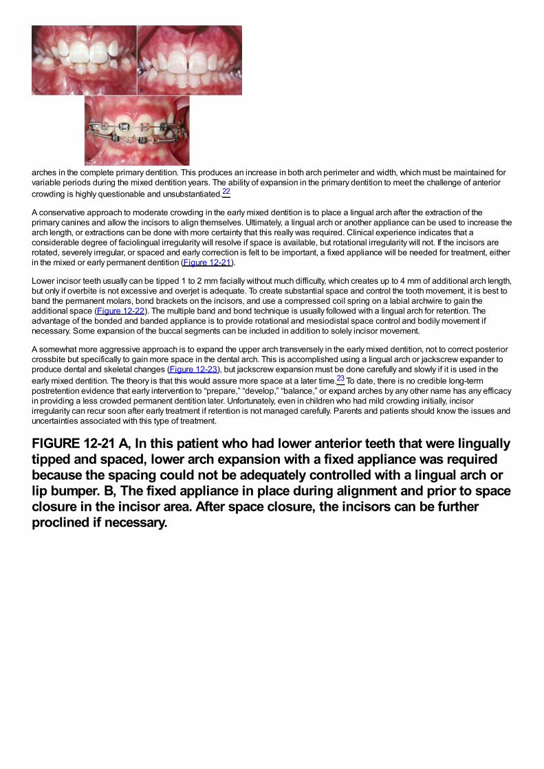
arches in the complete primary dentition. This produces an increase in both arch perimeter and width, which must be maintained forvariable periods during the mixed dentition years. The ability of expansion in the primary dentition to meet the challenge of anteriorcrowding is highly questionable and unsubstantiated.22
A conservative approach to moderate crowding in the early mixed dentition is to place a lingual arch after the extraction of theprimary canines and allow the incisors to align themselves. Ultimately, a lingual arch or another appliance can be used to increase thearch length, or extractions can be done with more certainty that this really was required. Clinical experience indicates that aconsiderable degree of faciolingual irregularity will resolve if space is available, but rotational irregularity will not. If the incisors arerotated, severely irregular, or spaced and early correction is felt to be important, a fixed appliance will be needed for treatment, eitherin the mixed or early permanent dentition (Figure 12-21).
Lower incisor teeth usually can be tipped 1 to 2 mm facially without much difficulty, which creates up to 4 mm of additional arch length,but only if overbite is not excessive and overjet is adequate. To create substantial space and control the tooth movement, it is best toband the permanent molars, bond brackets on the incisors, and use a compressed coil spring on a labial archwire to gain theadditional space (Figure 12-22). The multiple band and bond technique is usually followed with a lingual arch for retention. Theadvantage of the bonded and banded appliance is to provide rotational and mesiodistal space control and bodily movement ifnecessary. Some expansion of the buccal segments can be included in addition to solely incisor movement.
A somewhat more aggressive approach is to expand the upper arch transversely in the early mixed dentition, not to correct posteriorcrossbite but specifically to gain more space in the dental arch. This is accomplished using a lingual arch or jackscrew expander toproduce dental and skeletal changes (Figure 12-23), but jackscrew expansion must be done carefully and slowly if it is used in theearly mixed dentition. The theory is that this would assure more space at a later time.23 To date, there is no credible long-termpostretention evidence that early intervention to “prepare,” “develop,” “balance,” or expand arches by any other name has any efficacyin providing a less crowded permanent dentition later. Unfortunately, even in children who had mild crowding initially, incisorirregularity can recur soon after early treatment if retention is not managed carefully. Parents and patients should know the issues anduncertainties associated with this type of treatment.
FIGURE 12-21 A, In this patient who had lower anterior teeth that were linguallytipped and spaced, lower arch expansion with a fixed appliance was requiredbecause the spacing could not be adequately controlled with a lingual arch orlip bumper. B, The fixed appliance in place during alignment and prior to spaceclosure in the incisor area. After space closure, the incisors can be furtherproclined if necessary.
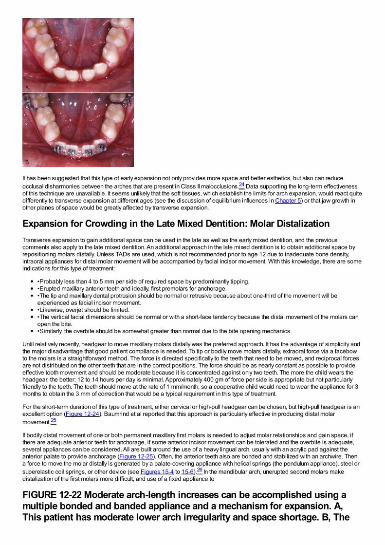
It has been suggested that this type of early expansion not only provides more space and better esthetics, but also can reduceocclusal disharmonies between the arches that are present in Class II malocclusions.24 Data supporting the long-term effectivenessof this technique are unavailable. It seems unlikely that the soft tissues, which establish the limits for arch expansion, would react quitedifferently to transverse expansion at different ages (see the discussion of equilibrium influences in Chapter 5) or that jaw growth inother planes of space would be greatly affected by transverse expansion.
Expansion for Crowding in the Late Mixed Dentition: Molar DistalizationTransverse expansion to gain additional space can be used in the late as well as the early mixed dentition, and the previouscomments also apply to the late mixed dentition. An additional approach in the late mixed dentition is to obtain additional space byrepositioning molars distally. Unless TADs are used, which is not recommended prior to age 12 due to inadequate bone density,intraoral appliances for distal molar movement will be accompanied by facial incisor movement. With this knowledge, there are someindications for this type of treatment:
•Probably less than 4 to 5 mm per side of required space by predominantly tipping.•Erupted maxillary anterior teeth and ideally, first premolars for anchorage.•The lip and maxillary dental protrusion should be normal or retrusive because about one-third of the movement will beexperienced as facial incisor movement.•Likewise, overjet should be limited.•The vertical facial dimensions should be normal or with a short-face tendency because the distal movement of the molars canopen the bite.•Similarly, the overbite should be somewhat greater than normal due to the bite opening mechanics.
Until relatively recently, headgear to move maxillary molars distally was the preferred approach. It has the advantage of simplicity andthe major disadvantage that good patient compliance is needed. To tip or bodily move molars distally, extraoral force via a facebowto the molars is a straightforward method. The force is directed specifically to the teeth that need to be moved, and reciprocal forcesare not distributed on the other teeth that are in the correct positions. The force should be as nearly constant as possible to provideeffective tooth movement and should be moderate because it is concentrated against only two teeth. The more the child wears theheadgear, the better; 12 to 14 hours per day is minimal. Approximately 400 gm of force per side is appropriate but not particularlyfriendly to the teeth. The teeth should move at the rate of 1 mm/month, so a cooperative child would need to wear the appliance for 3months to obtain the 3 mm of correction that would be a typical requirement in this type of treatment.
For the short-term duration of this type of treatment, either cervical or high-pull headgear can be chosen, but high-pull headgear is anexcellent option (Figure 12-24). Baumrind et al reported that this approach is particularly effective in producing distal molarmovement.25
If bodily distal movement of one or both permanent maxillary first molars is needed to adjust molar relationships and gain space, ifthere are adequate anterior teeth for anchorage, if some anterior incisor movement can be tolerated and the overbite is adequate,several appliances can be considered. All are built around the use of a heavy lingual arch, usually with an acrylic pad against theanterior palate to provide anchorage (Figure 12-25). Often, the anterior teeth also are bonded and stabilized with an archwire. Then,a force to move the molar distally is generated by a palate-covering appliance with helical springs (the pendulum appliance), steel orsuperelastic coil springs, or other device (see Figures 15-4 to 15-6).26 In the mandibular arch, unerupted second molars makedistalization of the first molars more difficult, and use of a fixed appliance to
FIGURE 12-22 Moderate arch-length increases can be accomplished using amultiple bonded and banded appliance and a mechanism for expansion. A,This patient has moderate lower arch irregularity and space shortage. B, The
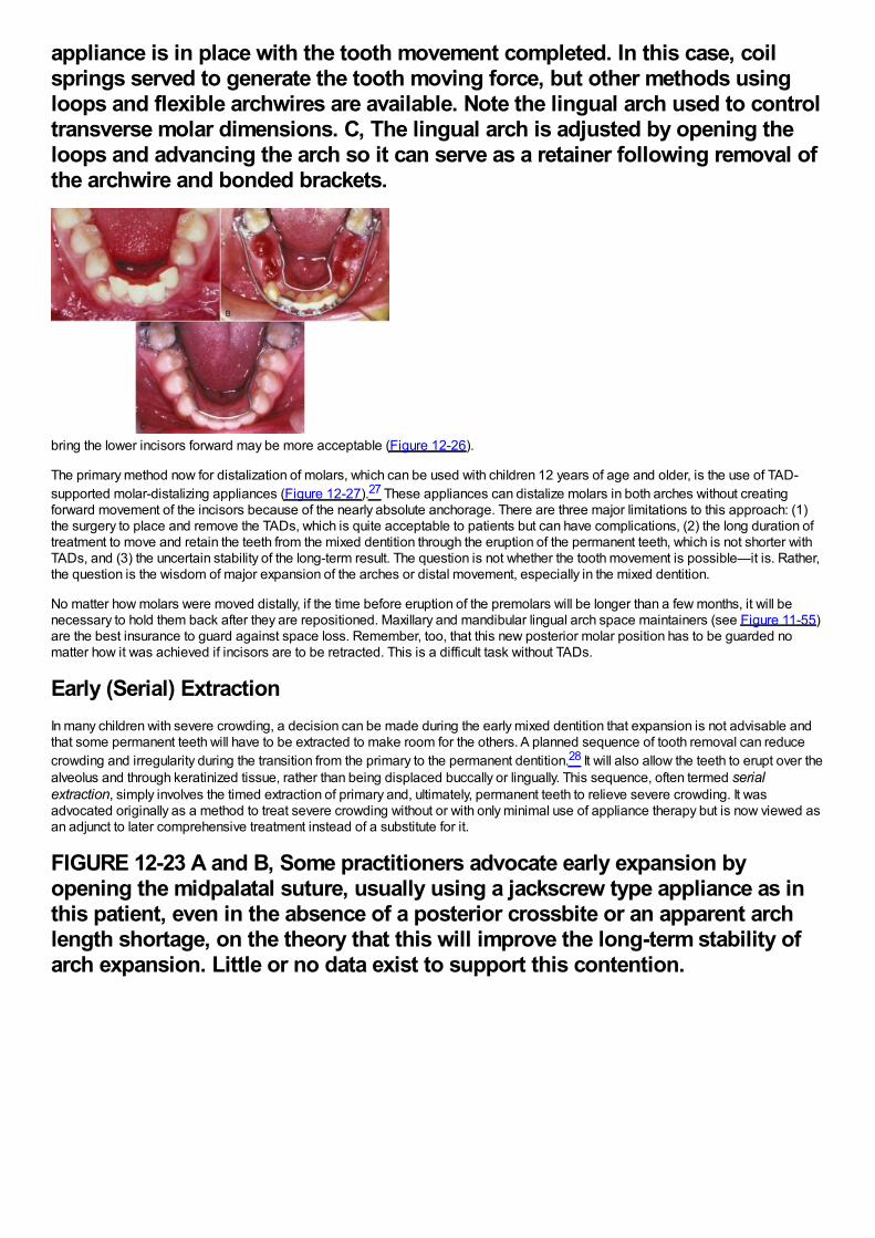
appliance is in place with the tooth movement completed. In this case, coilsprings served to generate the tooth moving force, but other methods usingloops and flexible archwires are available. Note the lingual arch used to controltransverse molar dimensions. C, The lingual arch is adjusted by opening theloops and advancing the arch so it can serve as a retainer following removal ofthe archwire and bonded brackets.
bring the lower incisors forward may be more acceptable (Figure 12-26).
The primary method now for distalization of molars, which can be used with children 12 years of age and older, is the use of TAD-supported molar-distalizing appliances (Figure 12-27).27 These appliances can distalize molars in both arches without creatingforward movement of the incisors because of the nearly absolute anchorage. There are three major limitations to this approach: (1)the surgery to place and remove the TADs, which is quite acceptable to patients but can have complications, (2) the long duration oftreatment to move and retain the teeth from the mixed dentition through the eruption of the permanent teeth, which is not shorter withTADs, and (3) the uncertain stability of the long-term result. The question is not whether the tooth movement is possible—it is. Rather,the question is the wisdom of major expansion of the arches or distal movement, especially in the mixed dentition.
No matter how molars were moved distally, if the time before eruption of the premolars will be longer than a few months, it will benecessary to hold them back after they are repositioned. Maxillary and mandibular lingual arch space maintainers (see Figure 11-55)are the best insurance to guard against space loss. Remember, too, that this new posterior molar position has to be guarded nomatter how it was achieved if incisors are to be retracted. This is a difficult task without TADs.
Early (Serial) ExtractionIn many children with severe crowding, a decision can be made during the early mixed dentition that expansion is not advisable andthat some permanent teeth will have to be extracted to make room for the others. A planned sequence of tooth removal can reducecrowding and irregularity during the transition from the primary to the permanent dentition.28 It will also allow the teeth to erupt over thealveolus and through keratinized tissue, rather than being displaced buccally or lingually. This sequence, often termed serialextraction, simply involves the timed extraction of primary and, ultimately, permanent teeth to relieve severe crowding. It wasadvocated originally as a method to treat severe crowding without or with only minimal use of appliance therapy but is now viewed asan adjunct to later comprehensive treatment instead of a substitute for it.
FIGURE 12-23 A and B, Some practitioners advocate early expansion byopening the midpalatal suture, usually using a jackscrew type appliance as inthis patient, even in the absence of a posterior crossbite or an apparent archlength shortage, on the theory that this will improve the long-term stability ofarch expansion. Little or no data exist to support this contention.
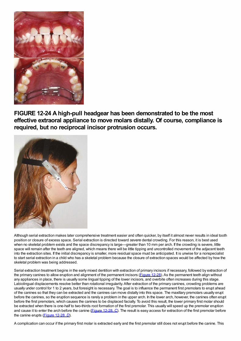
FIGURE 12-24 A high-pull headgear has been demonstrated to be the mosteffective extraoral appliance to move molars distally. Of course, compliance isrequired, but no reciprocal incisor protrusion occurs.
Although serial extraction makes later comprehensive treatment easier and often quicker, by itself it almost never results in ideal toothposition or closure of excess space. Serial extraction is directed toward severe dental crowding. For this reason, it is best usedwhen no skeletal problem exists and the space discrepancy is large—greater than 10 mm per arch. If the crowding is severe, littlespace will remain after the teeth are aligned, which means there will be little tipping and uncontrolled movement of the adjacent teethinto the extraction sites. If the initial discrepancy is smaller, more residual space must be anticipated. It is unwise for a nonspecialistto start serial extraction in a child who has a skeletal problem because the closure of extraction spaces would be affected by how theskeletal problem was being addressed.
Serial extraction treatment begins in the early mixed dentition with extraction of primary incisors if necessary, followed by extraction ofthe primary canines to allow eruption and alignment of the permanent incisors (Figure 12-28). As the permanent teeth align withoutany appliances in place, there is usually some lingual tipping of the lower incisors, and overbite often increases during this stage.Labiolingual displacements resolve better than rotational irregularity. After extraction of the primary canines, crowding problems areusually under control for 1 to 2 years, but foresight is necessary. The goal is to influence the permanent first premolars to erupt aheadof the canines so that they can be extracted and the canines can move distally into this space. The maxillary premolars usually eruptbefore the canines, so the eruption sequence is rarely a problem in the upper arch. In the lower arch, however, the canines often eruptbefore the first premolars, which causes the canines to be displaced facially. To avoid this result, the lower primary first molar shouldbe extracted when there is one-half to two-thirds root formation of the first premolar. This usually will speed up the premolar eruptionand cause it to enter the arch before the canine (Figure 12-28, C). The result is easy access for extraction of the first premolar beforethe canine erupts (Figure 12-28, D).
A complication can occur if the primary first molar is extracted early and the first premolar still does not erupt before the canine. This
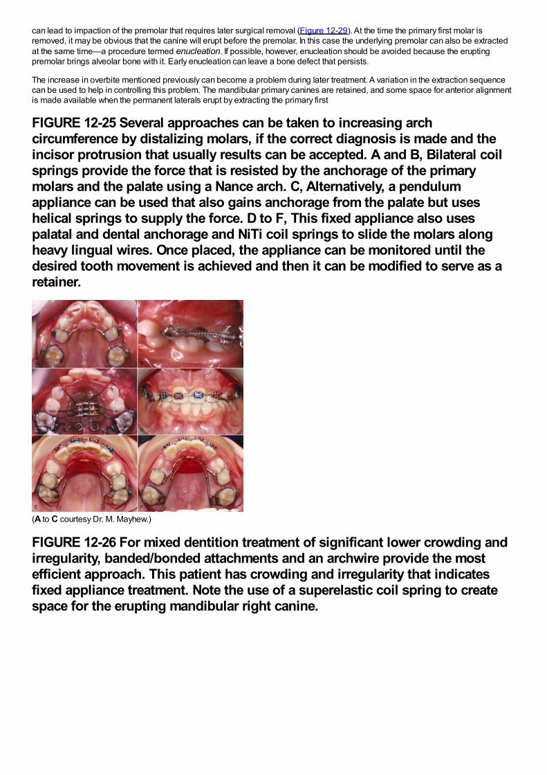
can lead to impaction of the premolar that requires later surgical removal (Figure 12-29). At the time the primary first molar isremoved, it may be obvious that the canine will erupt before the premolar. In this case the underlying premolar can also be extractedat the same time—a procedure termed enucleation. If possible, however, enucleation should be avoided because the eruptingpremolar brings alveolar bone with it. Early enucleation can leave a bone defect that persists.
The increase in overbite mentioned previously can become a problem during later treatment. A variation in the extraction sequencecan be used to help in controlling this problem. The mandibular primary canines are retained, and some space for anterior alignmentis made available when the permanent laterals erupt by extracting the primary first
FIGURE 12-25 Several approaches can be taken to increasing archcircumference by distalizing molars, if the correct diagnosis is made and theincisor protrusion that usually results can be accepted. A and B, Bilateral coilsprings provide the force that is resisted by the anchorage of the primarymolars and the palate using a Nance arch. C, Alternatively, a pendulumappliance can be used that also gains anchorage from the palate but useshelical springs to supply the force. D to F, This fixed appliance also usespalatal and dental anchorage and NiTi coil springs to slide the molars alongheavy lingual wires. Once placed, the appliance can be monitored until thedesired tooth movement is achieved and then it can be modified to serve as aretainer.
(A to C courtesy Dr. M. Mayhew.)
FIGURE 12-26 For mixed dentition treatment of significant lower crowding andirregularity, banded/bonded attachments and an archwire provide the mostefficient approach. This patient has crowding and irregularity that indicatesfixed appliance treatment. Note the use of a superelastic coil spring to createspace for the erupting mandibular right canine.
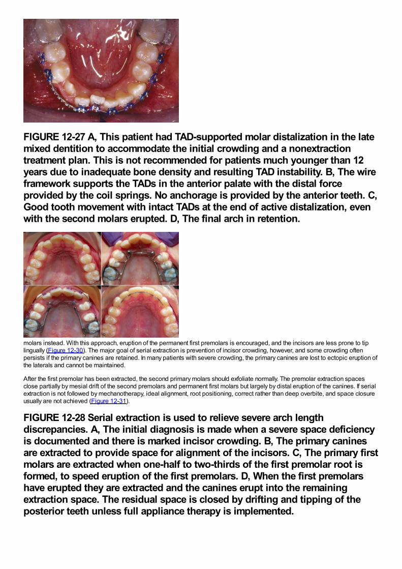
FIGURE 12-27 A, This patient had TAD-supported molar distalization in the latemixed dentition to accommodate the initial crowding and a nonextractiontreatment plan. This is not recommended for patients much younger than 12years due to inadequate bone density and resulting TAD instability. B, The wireframework supports the TADs in the anterior palate with the distal forceprovided by the coil springs. No anchorage is provided by the anterior teeth. C,Good tooth movement with intact TADs at the end of active distalization, evenwith the second molars erupted. D, The final arch in retention.
molars instead. With this approach, eruption of the permanent first premolars is encouraged, and the incisors are less prone to tiplingually (Figure 12-30). The major goal of serial extraction is prevention of incisor crowding, however, and some crowding oftenpersists if the primary canines are retained. In many patients with severe crowding, the primary canines are lost to ectopic eruption ofthe laterals and cannot be maintained.
After the first premolar has been extracted, the second primary molars should exfoliate normally. The premolar extraction spacesclose partially by mesial drift of the second premolars and permanent first molars but largely by distal eruption of the canines. If serialextraction is not followed by mechanotherapy, ideal alignment, root positioning, correct rather than deep overbite, and space closureusually are not achieved (Figure 12-31).
FIGURE 12-28 Serial extraction is used to relieve severe arch lengthdiscrepancies. A, The initial diagnosis is made when a severe space deficiencyis documented and there is marked incisor crowding. B, The primary caninesare extracted to provide space for alignment of the incisors. C, The primary firstmolars are extracted when one-half to two-thirds of the first premolar root isformed, to speed eruption of the first premolars. D, When the first premolarshave erupted they are extracted and the canines erupt into the remainingextraction space. The residual space is closed by drifting and tipping of theposterior teeth unless full appliance therapy is implemented.
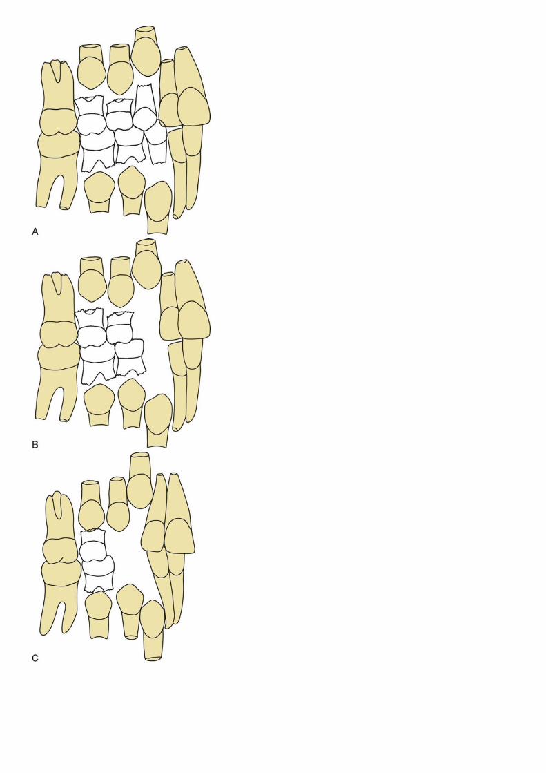
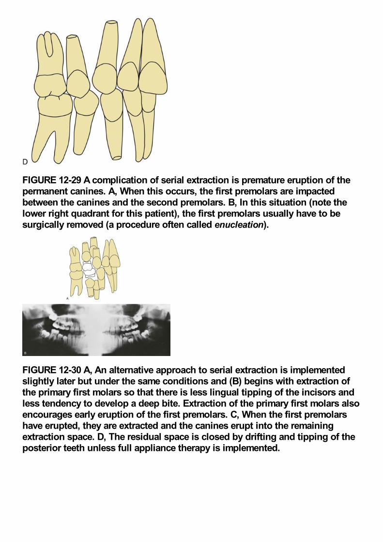
FIGURE 12-29 A complication of serial extraction is premature eruption of thepermanent canines. A, When this occurs, the first premolars are impactedbetween the canines and the second premolars. B, In this situation (note thelower right quadrant for this patient), the first premolars usually have to besurgically removed (a procedure often called enucleation).
FIGURE 12-30 A, An alternative approach to serial extraction is implementedslightly later but under the same conditions and (B) begins with extraction ofthe primary first molars so that there is less lingual tipping of the incisors andless tendency to develop a deep bite. Extraction of the primary first molars alsoencourages early eruption of the first premolars. C, When the first premolarshave erupted, they are extracted and the canines erupt into the remainingextraction space. D, The residual space is closed by drifting and tipping of theposterior teeth unless full appliance therapy is implemented.
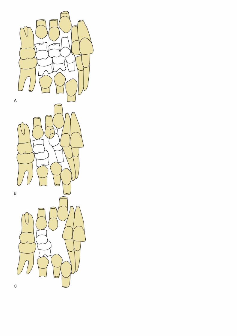
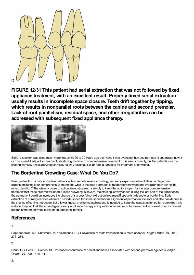
FIGURE 12-31 This patient had serial extraction that was not followed by fixedappliance treatment, with an excellent result. Properly timed serial extractionusually results in incomplete space closure. Teeth drift together by tipping,which results in nonparallel roots between the canine and second premolar.Lack of root parallelism, residual space, and other irregularities can beaddressed with subsequent fixed appliance therapy.
Serial extraction was used much more frequently 20 to 30 years ago than now. It was overused then and perhaps is underused now. Itcan be a useful adjunct to treatment, shortening the time of comprehensive treatment if it is used correctly, but the patients must bechosen carefully and supervised carefully as they develop. It is far from a panacea for treatment of crowding.
The Borderline Crowding Case: What Do You Do?If early extraction is only for the few patients with extremely severe crowding, and early expansion offers little advantage overexpansion during later comprehensive treatment, what is the best approach to moderately crowded and irregular teeth during themixed dentition? The wisest course of action, in most cases, is simply to keep the options open for the later comprehensivetreatment that these children will need. Unless crowding is severe, maintaining leeway space during the last part of the transition tothe permanent dentition increases the chance of successful nonextraction treatment if space is adequate or borderline. Earlyextraction of primary canines often can provide space for some spontaneous alignment of permanent incisors and also can decreasethe chance of canine impaction, but a lower lingual arch to maintain space is needed to keep the nonextraction option open when thisis done. Beyond that, the advantages of early appliance therapy are questionable and must be viewed in the context of an increasedburden of treatment versus little or no additional benefit.
References1.
Papadopoulos, MA, Chatzoudi, M, Kaklamanos, EG: Prevalence of tooth transposition. A meta-analysis. Angle Orthod. 80, 2010,275–285.
2.
Garib, DG, Peck, S, Gomes, SC: Increased occurrence of dental anomalies associated with second-premolar agenesis. AngleOrthod. 79, 2009, 436–441.
3.
Shapira, Y, Kuftinec, MM: Intrabony migration of impacted teeth. Angle Orthod. 73, 2003, 738–743.
4.
Peck, S, Peck, L: Classification of maxillary tooth transpositions. Am J Orthod Dent Orthop. 107, 1995, 505–517.
5.
Frazier-Bowers, SA, Simmons, D, Wright, JT, et al.: Primary failure of eruption and PTH1R: the importance of a genetic diagnosis fororthodontic treatment planning. Am J Orthod Dentofac Orthop. 137, 2010, 160.e1–160.e7 discussion 160-161.
6.
Hölttä, P, Alaluusua, S, Saarinen-Pihkala, UM, et al.: Agenesis and microdontia of permanent teeth as late adverse effects after stemcell transplantation in young children. Cancer. 103, 2005, 181–190.
7.
Hölttä, P, Hovi, L, Saarinen-Pihkala, UM, et al.: Disturbed root development of permanent teeth after pediatric stem celltransplantation. Dental root development after SCT. Cancer. 103, 2005, 1484–1493.
8.
Iglesias-Linares, A, Yáñez-Vico, RM, Solano-Reina, E, et al.: Influence of bisphosphonates in orthodontic therapy: systematic review.J Dent Res. 38, 2010, 603–611.
9.
Brin, I, Ben-Bassat, Y, Heling, I, et al.: The influence of orthodontic treatment on previously traumatized permanent incisors. Eur JOrthod. 13, 1991, 372–377.
10.
Bauss, O, Röhling, J, Meyer, K, et al.: Pulp vitality in teeth suffering trauma during orthodontic therapy. Angle Orthod. 79, 2009, 166–171.
11.
Andreasen, JO, Bakland, LK, Andreasen, FM: Traumatic intrusion of permanent teeth. Part 3. A clinical study of the effect of treatmentvariables such as treatment delay, method of repositioning, type of splint, length of splinting and antibiotics on 140 teeth. DentTraumatol. 22, 2006, 99–111.
12.
Wigen, TI, Agnalt, R, Jacobsen, I: Intrusive luxation of permanent incisors in Norwegians aged 6-17 years: a retrospective study oftreatment and outcome. Dent Traumatol. 24, 2008, 612–618.
13.
Bauss, O, Schäfer, W, Sadat-Khonsari, R, et al.: Influence of orthodontic extrusion on pulpal vitality of traumatized maxillary incisors. JEndodont. 36, 2010, 203–207.
14.
Bauss, O, Röhling, J, Sadat-Khonsari, R, et al.: Influence of orthodontic intrusion on pulpal vitality of previously traumatized maxillarypermanent incisors. Am J Orthod Dentofac Orthop. 134, 2008, 12–17.
15.
Bauss, O, Röhling, J, Rahman, A, et al.: The effect of pulp obliteration on pulpal vitality of orthodontically intruded traumatized teeth. JEndodont. 34, 2008, 417–420.
16.
Esteves, T, Ramos, AL, Pereira, CM, et al.: Orthodontic root resorption of endodontically treated teeth. J Endodont. 33, 2007, 119–122.
17.
Rodd, HD, Davidson, LE, Livesey, S, et al.: Survival of intentionally retained permanent incisor roots following crown root fractures inchildren. Dent Traumatol. 18, 2002, 92–97.
18.

Little, R, Riedel, R: Postretention evaluation of stability and relapse—mandibular arches with generalized spacing. Am J Orthod. 95,1989, 37–41.
19.
Paulsen, HU, Andreasen, JO, Schwartz, O: Tooth loss treatment in the anterior region: autotransplantation of premolars andcryopreservation. World J Orthod. 7, 2006, 27–34.
20.
Zachrisson, BU, Stenvik, A, Haanaes, HR: Management of missing maxillary anterior teeth with emphasis on autotransplantation. AmJ Orthod Dentofac Orthop. 126, 2004, 284–288.
21.
Bauss, O, Sadat-Khonsari, R, Engelke, W, et al.: Results of transplanting developing third molars as part of orthodontics spacemanagement. Part 2. Results following the orthodontic treatment of transplanted developing third molars in cases of aplasia andpremature loss of teeth with atrophy of the alveolar process. J Orofac Orthop. 64, 2003, 40–47.
22.
Lutz, HD, Poulton, D: Stability of dental arch expansion in the deciduous dentition. Angle Orthod. 55, 1985, 299–315.
23.
O'Grady, PW, McNamara, JA Jr., Baccetti, T, et al.: A long-term evaluation of the mandibular Schwarz appliance and the acrylic splintexpander in early mixed dentition patients. Am J Orthod Dentofac Orthop. 130, 2006, 202–213.
24.
McNamara, JA Jr., Sigler, LM, Franchi, L, et al.: Changes in occlusal relationships in mixed dentition patients treated with rapidmaxillary expansion. A prospective clinical study. Angle Orthod. 80, 2010, 230–238.
25.
Baumrind, S, Korn, EL, Isaacson, RJ, et al.: Quantitative analysis of orthodontic and orthopedic effects of maxillary traction. Am JOrthod. 84, 1983, 384–398.
26.
Antonarakis, GS, Kiliaridis, S: Maxillary molar distalization with noncompliance intramaxillary appliances in Class II malocclusion. Asystematic review. Angle Orthod. 78, 2008, 1133–1140.
27.
Polat-Ozsoy, O, Kircelli, BH, Arman-Ozçirpici, A, et al.: Pendulum appliances with 2 anchorage designs: conventional anchorage vs.bone anchorage. Am J Orthod Dentofac Orthop. 133, 2008, 339.e9–339.e17.
28.
Hotz, RP: Guidance of eruption versus serial extraction. Am J Orthod. 58, 1970, 1–20.
Chapter 13 Treatment of Skeletal Problems in Children and PreadolescentsWhenever a jaw discrepancy exists, the ideal solution is to correct it by modifying the child's facial growth, so that the skeletalproblem is corrected by more or less growth of one jaw than the other (Figure 13-1). Unfortunately, such an ideal solution is notalways possible, but growth modification for skeletal problems can be successful. Treatment planning for skeletal problems and whathas been learned about the optimum timing of treatment have been discussed extensively in Chapter 7. This chapter briefly reviewsthe issues in treatment timing that were presented previously but focuses on clinical treatment aimed at growth modification. Usuallythis is accomplished by applying forces directly to the teeth and secondarily and indirectly to the skeletal structures, instead ofapplying direct pressure to the bones. Tooth movement, in addition to any changes in skeletal relationships, is unavoidable. It ispossible now to apply force directly against the bone by using temporary implants, miniplates, or bone screws (see Chapter 10). Thisapproach is likely to be used more and more in the future because the dental changes that accompany growth modification often (butnot always) are undesirable. Excessive tooth movement, whether it results from a weakness in the treatment plan, poorbiomechanical control, or poor compliance, can cause growth modification to be incomplete and unsuccessful.
The material in this chapter is organized in the context of the child's major skeletal problem. In some cases that provides a precisedescription: the upper or lower jaw is clearly at fault because of its position and size and the malocclusion is almost totally due to thejaw discrepancy. More frequently, there also are dental components to the problem, with displacement of the teeth relative to theirsupporting bone in any or all of the planes of space and/or crowding/spacing within the dental arches. In such cases, the therapy mustbe based on the solutions to that specific patient's set of problems. In particular, dental changes that would be unwanted side effectsin some patients can be quite helpful in others. For this reason, the secondary (dental), as well as the primary (skeletal), effects of thevarious appliances are reviewed in detail in this chapter.
FIGURE 13-1 A to C, At age 11-10, this boy sought treatment because of traumato his protruding front teeth and the crowding that was developing in theupper arch, where there was no room for the permanent canines. Skeletal ClassII malocclusion, due primarily to mandibular deficiency, was apparent. Becauseof the damaged maxillary central incisors (one of which had a root fracture),the treatment plan called for cervical headgear to promote differentialmandibular growth and create space in the maxillary arch. D, Fifteen months ofheadgear during the adolescent growth spurt produced significantimprovement in the jaw relationship with differential forward growth of themandible and created nearly enough space to bring the maxillary canines intothe arch. E and F, A partial fixed appliance was placed, staying off thetraumatized maxillary incisors until the very end of treatment, and light Class IIelastics off a stabilized lower arch were used. G to I, The 15-month secondstage of treatment produced excellent dental relationships, but note in thecephalometric superimposition (J) that minimal further anteroposterior growthoccurred. This illustrates the importance of starting growth modificationtreatment in the mixed dentition for children whose skeletal maturity is aheadof their dental age.
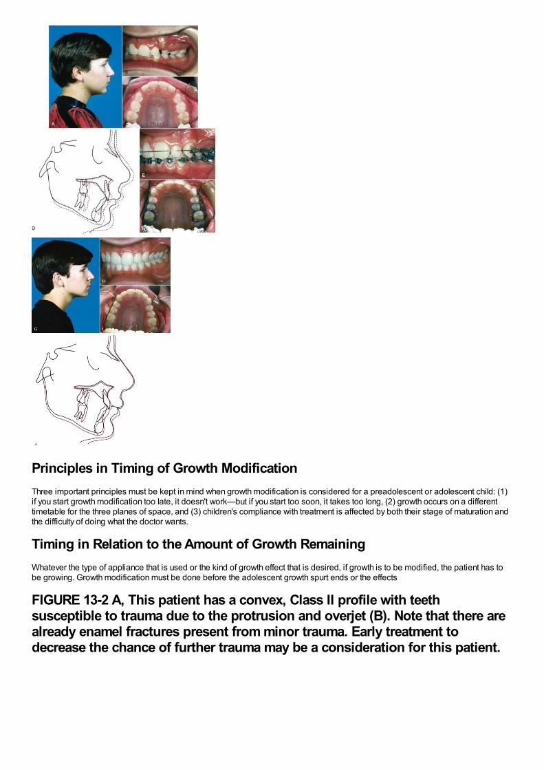
Principles in Timing of Growth ModificationThree important principles must be kept in mind when growth modification is considered for a preadolescent or adolescent child: (1)if you start growth modification too late, it doesn't work—but if you start too soon, it takes too long, (2) growth occurs on a differenttimetable for the three planes of space, and (3) children's compliance with treatment is affected by both their stage of maturation andthe difficulty of doing what the doctor wants.
Timing in Relation to the Amount of Growth RemainingWhatever the type of appliance that is used or the kind of growth effect that is desired, if growth is to be modified, the patient has tobe growing. Growth modification must be done before the adolescent growth spurt ends or the effects
FIGURE 13-2 A, This patient has a convex, Class II profile with teethsusceptible to trauma due to the protrusion and overjet (B). Note that there arealready enamel fractures present from minor trauma. Early treatment todecrease the chance of further trauma may be a consideration for this patient.
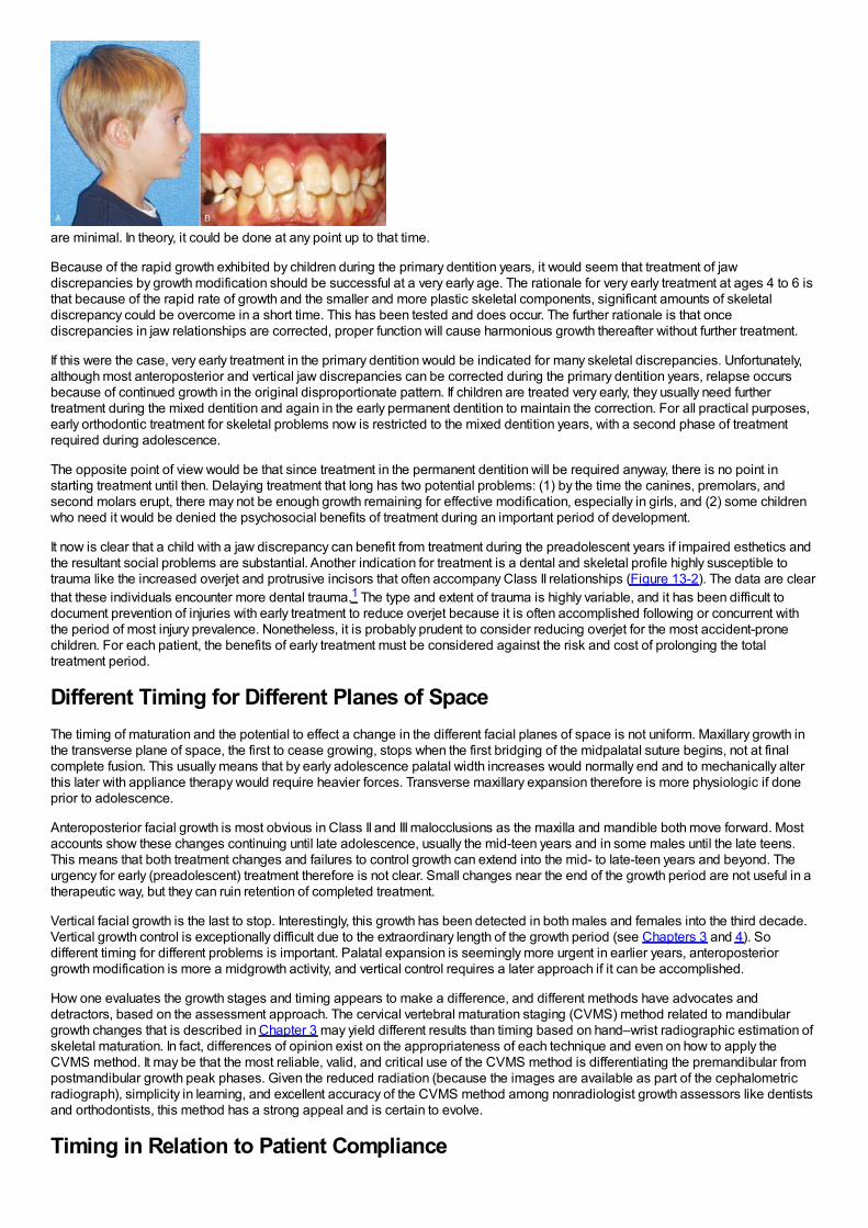
are minimal. In theory, it could be done at any point up to that time.
Because of the rapid growth exhibited by children during the primary dentition years, it would seem that treatment of jawdiscrepancies by growth modification should be successful at a very early age. The rationale for very early treatment at ages 4 to 6 isthat because of the rapid rate of growth and the smaller and more plastic skeletal components, significant amounts of skeletaldiscrepancy could be overcome in a short time. This has been tested and does occur. The further rationale is that oncediscrepancies in jaw relationships are corrected, proper function will cause harmonious growth thereafter without further treatment.
If this were the case, very early treatment in the primary dentition would be indicated for many skeletal discrepancies. Unfortunately,although most anteroposterior and vertical jaw discrepancies can be corrected during the primary dentition years, relapse occursbecause of continued growth in the original disproportionate pattern. If children are treated very early, they usually need furthertreatment during the mixed dentition and again in the early permanent dentition to maintain the correction. For all practical purposes,early orthodontic treatment for skeletal problems now is restricted to the mixed dentition years, with a second phase of treatmentrequired during adolescence.
The opposite point of view would be that since treatment in the permanent dentition will be required anyway, there is no point instarting treatment until then. Delaying treatment that long has two potential problems: (1) by the time the canines, premolars, andsecond molars erupt, there may not be enough growth remaining for effective modification, especially in girls, and (2) some childrenwho need it would be denied the psychosocial benefits of treatment during an important period of development.
It now is clear that a child with a jaw discrepancy can benefit from treatment during the preadolescent years if impaired esthetics andthe resultant social problems are substantial. Another indication for treatment is a dental and skeletal profile highly susceptible totrauma like the increased overjet and protrusive incisors that often accompany Class II relationships (Figure 13-2). The data are clearthat these individuals encounter more dental trauma.1 The type and extent of trauma is highly variable, and it has been difficult todocument prevention of injuries with early treatment to reduce overjet because it is often accomplished following or concurrent withthe period of most injury prevalence. Nonetheless, it is probably prudent to consider reducing overjet for the most accident-pronechildren. For each patient, the benefits of early treatment must be considered against the risk and cost of prolonging the totaltreatment period.
Different Timing for Different Planes of SpaceThe timing of maturation and the potential to effect a change in the different facial planes of space is not uniform. Maxillary growth inthe transverse plane of space, the first to cease growing, stops when the first bridging of the midpalatal suture begins, not at finalcomplete fusion. This usually means that by early adolescence palatal width increases would normally end and to mechanically alterthis later with appliance therapy would require heavier forces. Transverse maxillary expansion therefore is more physiologic if doneprior to adolescence.
Anteroposterior facial growth is most obvious in Class II and III malocclusions as the maxilla and mandible both move forward. Mostaccounts show these changes continuing until late adolescence, usually the mid-teen years and in some males until the late teens.This means that both treatment changes and failures to control growth can extend into the mid- to late-teen years and beyond. Theurgency for early (preadolescent) treatment therefore is not clear. Small changes near the end of the growth period are not useful in atherapeutic way, but they can ruin retention of completed treatment.
Vertical facial growth is the last to stop. Interestingly, this growth has been detected in both males and females into the third decade.Vertical growth control is exceptionally difficult due to the extraordinary length of the growth period (see Chapters 3 and 4). Sodifferent timing for different problems is important. Palatal expansion is seemingly more urgent in earlier years, anteroposteriorgrowth modification is more a midgrowth activity, and vertical control requires a later approach if it can be accomplished.
How one evaluates the growth stages and timing appears to make a difference, and different methods have advocates anddetractors, based on the assessment approach. The cervical vertebral maturation staging (CVMS) method related to mandibulargrowth changes that is described in Chapter 3 may yield different results than timing based on hand–wrist radiographic estimation ofskeletal maturation. In fact, differences of opinion exist on the appropriateness of each technique and even on how to apply theCVMS method. It may be that the most reliable, valid, and critical use of the CVMS method is differentiating the premandibular frompostmandibular growth peak phases. Given the reduced radiation (because the images are available as part of the cephalometricradiograph), simplicity in learning, and excellent accuracy of the CVMS method among nonradiologist growth assessors like dentistsand orthodontists, this method has a strong appeal and is certain to evolve.
Timing in Relation to Patient Compliance
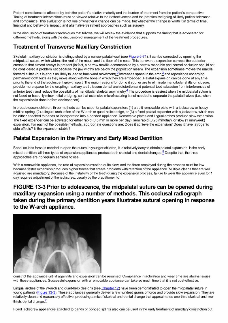
Patient compliance is affected by both the patient's relative maturity and the burden of treatment from the patient's perspective.Timing of treatment interventions must be viewed relative to their effectiveness and the practical weighing of likely patient toleranceand compliance. This evaluation is not one of whether a change can be made, but whether the change is worth it in terms of time,financial and behavioral impact, and alternative treatment approaches such as surgery.
In the discussion of treatment techniques that follows, we will review the evidence that supports the timing that is advocated fordifferent methods, along with the discussion of management of the treatment procedures.
Treatment of Transverse Maxillary ConstrictionSkeletal maxillary constriction is distinguished by a narrow palatal vault (see Figure 6-71). It can be corrected by opening themidpalatal suture, which widens the roof of the mouth and the floor of the nose. This transverse expansion corrects the posteriorcrossbite that almost always is present (in fact, a narrow maxilla accompanied by a narrow mandible and normal occlusion should notbe considered a problem just because the jaw widths are below the population mean). The expansion sometimes moves the maxillaforward a little (but is about as likely to lead to backward movement),2 increases space in the arch,3 and repositions underlyingpermanent tooth buds as they move along with the bone in which they are embedded. Palatal expansion can be done at any timeprior to the end of the adolescent growth spurt. The major reasons for doing it sooner are to eliminate mandibular shifts on closure,provide more space for the erupting maxillary teeth, lessen dental arch distortion and potential tooth abrasion from interferences ofanterior teeth, and reduce the possibility of mandibular skeletal asymmetry.4 The procedure is easiest when the midpalatal suture isnot fused or has only minor initial bridging, so that extensive microfracturing is not needed to separate the palatal halves (i.e., whenthe expansion is done before adolescence).
In preadolescent children, three methods can be used for palatal expansion: (1) a split removable plate with a jackscrew or heavymidline spring, (2) a lingual arch, often of the W-arch or quad-helix design, or (3) a fixed palatal expander with a jackscrew, which canbe either attached to bands or incorporated into a bonded appliance. Removable plates and lingual arches produce slow expansion.The fixed expander can be activated for either rapid (0.5 mm or more per day), semirapid (0.25 mm/day), or slow (1 mm/week)expansion. For each of the possible methods, appropriate questions are: Does it achieve the expansion? Does it have iatrogenicside effects? Is the expansion stable?
Palatal Expansion in the Primary and Early Mixed DentitionBecause less force is needed to open the suture in younger children, it is relatively easy to obtain palatal expansion. In the earlymixed dentition, all three types of expansion appliances produce both skeletal and dental changes.5 Despite that, the threeapproaches are not equally sensible to use.
With a removable appliance, the rate of expansion must be quite slow, and the force employed during the process must be lowbecause faster expansion produces higher forces that create problems with retention of the appliance. Multiple clasps that are welladjusted are mandatory. Because of the instability of the teeth during the expansion process, failure to wear the appliance even for 1day requires adjustment of the jackscrew, usually by the practitioner, to
FIGURE 13-3 Prior to adolescence, the midpalatal suture can be opened duringmaxillary expansion using a number of methods. This occlusal radiographtaken during the primary dentition years illustrates sutural opening in responseto the W-arch appliance.
constrict the appliance until it again fits and expansion can be resumed. Compliance in activation and wear time are always issueswith these appliances. Successful expansion with a removable appliance can take so much time that it is not cost-effective.
Lingual arches of the W-arch and quad-helix designs (see Chapter 12) have been demonstrated to open the midpalatal suture inyoung patients (Figure 13-3). These appliances generally deliver a few hundred grams of force and provide slow expansion. They arerelatively clean and reasonably effective, producing a mix of skeletal and dental change that approximates one-third skeletal and two-thirds dental change.2
Fixed jackscrew appliances attached to bands or bonded splints also can be used in the early treatment of maxillary constriction but
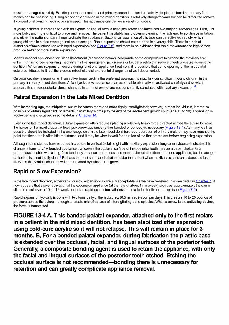
must be managed carefully. Banding permanent molars and primary second molars is relatively simple, but banding primary firstmolars can be challenging. Using a bonded appliance in the mixed dentition is relatively straightforward but can be difficult to removeif conventional bonding techniques are used. This appliance can deliver a variety of forces.
In young children, in comparison with an expansion lingual arch, a fixed jackscrew appliance has two major disadvantages. First, it ismore bulky and more difficult to place and remove. The patient inevitably has problems cleaning it, which lead to soft tissue irritation,and either the patient or parent must activate the appliance. Second, an appliance of this type can be activated rapidly, which inyoung children is a disadvantage, not an advantage. Rapid expansion should not be done in a young child. There is a risk ofdistortion of facial structures with rapid expansion (see Figure 7-8), and there is no evidence that rapid movement and high forcesproduce better or more stable expansion.
Many functional appliances for Class II treatment (discussed below) incorporate some components to expand the maxillary arch,either intrinsic force-generating mechanisms like springs and jackscrews or buccal shields that reduce cheek pressure against thedentition. When arch expansion occurs during functional appliance treatment, it is possible that some opening of the midpalatalsuture contributes to it, but the precise mix of skeletal and dental change is not well-documented.
On balance, slow expansion with an active lingual arch is the preferred approach to maxillary constriction in young children in theprimary and early mixed dentitions. A fixed jackscrew appliance is an acceptable alternative if activated carefully and slowly. Itappears that anteroposterior dental changes in terms of overjet are not consistently correlated with maxillary expansion.6
Palatal Expansion in the Late Mixed DentitionWith increasing age, the midpalatal suture becomes more and more tightly interdigitated; however, in most individuals, it remainspossible to obtain significant increments in maxillary width up to the end of the adolescent growth spurt (age 15 to 18). Expansion inadolescents is discussed in some detail in Chapter 14.
Even in the late mixed dentition, sutural expansion often requires placing a relatively heavy force directed across the suture to movethe halves of the maxilla apart. A fixed jackscrew appliance (either banded or bonded) is necessary (Figure 13-4). As many teeth aspossible should be included in the anchorage unit. In the late mixed dentition, root resorption of primary molars may have reached thepoint that these teeth offer little resistance, and it may be wise to wait for eruption of the first premolars before beginning expansion.
Although some studies have reported increases in vertical facial height with maxillary expansion, long-term evidence indicates thischange is transitory.7 A bonded appliance that covers the occlusal surface of the posterior teeth may be a better choice for apreadolescent child with a long-face tendency because it produces less mandibular rotation than a banded appliance, but for youngerpatients this is not totally clear.8 Perhaps the best summary is that the older the patient when maxillary expansion is done, the lesslikely it is that vertical changes will be recovered by subsequent growth.
Rapid or Slow Expansion?In the late mixed dentition, either rapid or slow expansion is clinically acceptable. As we have reviewed in some detail in Chapter 7, itnow appears that slower activation of the expansion appliance (at the rate of about 1 mm/week) provides approximately the sameultimate result over a 10- to 12-week period as rapid expansion, with less trauma to the teeth and bones (see Figure 7-9).
Rapid expansion typically is done with two turns daily of the jackscrew (0.5 mm activation per day). This creates 10 to 20 pounds ofpressure across the suture—enough to create microfractures of interdigitating bone spicules. When a screw is the activating device,the force is transmitted
FIGURE 13-4 A, This banded palatal expander, attached only to the first molarsin a patient in the mid mixed dentition, has been stabilized after expansionusing cold-cure acrylic so it will not relapse. This will remain in place for 3months. B, For a bonded palatal expander, during fabrication the plastic baseis extended over the occlusal, facial, and lingual surfaces of the posterior teeth.Generally, a composite bonding agent is used to retain the appliance, with onlythe facial and lingual surfaces of the posterior teeth etched. Etching theocclusal surface is not recommended—bonding there is unnecessary forretention and can greatly complicate appliance removal.
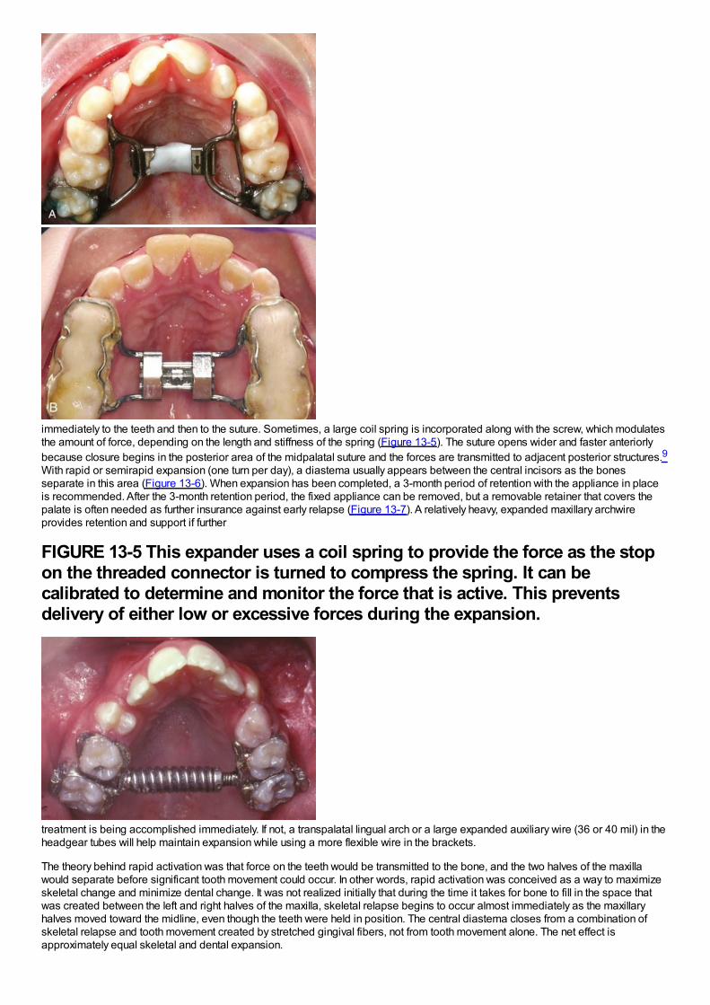
immediately to the teeth and then to the suture. Sometimes, a large coil spring is incorporated along with the screw, which modulatesthe amount of force, depending on the length and stiffness of the spring (Figure 13-5). The suture opens wider and faster anteriorlybecause closure begins in the posterior area of the midpalatal suture and the forces are transmitted to adjacent posterior structures.9With rapid or semirapid expansion (one turn per day), a diastema usually appears between the central incisors as the bonesseparate in this area (Figure 13-6). When expansion has been completed, a 3-month period of retention with the appliance in placeis recommended. After the 3-month retention period, the fixed appliance can be removed, but a removable retainer that covers thepalate is often needed as further insurance against early relapse (Figure 13-7). A relatively heavy, expanded maxillary archwireprovides retention and support if further
FIGURE 13-5 This expander uses a coil spring to provide the force as the stopon the threaded connector is turned to compress the spring. It can becalibrated to determine and monitor the force that is active. This preventsdelivery of either low or excessive forces during the expansion.
treatment is being accomplished immediately. If not, a transpalatal lingual arch or a large expanded auxiliary wire (36 or 40 mil) in theheadgear tubes will help maintain expansion while using a more flexible wire in the brackets.
The theory behind rapid activation was that force on the teeth would be transmitted to the bone, and the two halves of the maxillawould separate before significant tooth movement could occur. In other words, rapid activation was conceived as a way to maximizeskeletal change and minimize dental change. It was not realized initially that during the time it takes for bone to fill in the space thatwas created between the left and right halves of the maxilla, skeletal relapse begins to occur almost immediately as the maxillaryhalves moved toward the midline, even though the teeth were held in position. The central diastema closes from a combination ofskeletal relapse and tooth movement created by stretched gingival fibers, not from tooth movement alone. The net effect isapproximately equal skeletal and dental expansion.
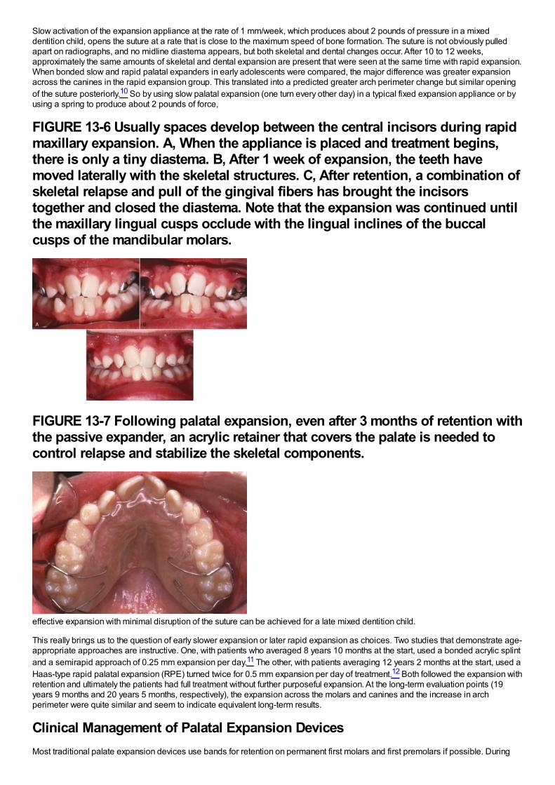
Slow activation of the expansion appliance at the rate of 1 mm/week, which produces about 2 pounds of pressure in a mixeddentition child, opens the suture at a rate that is close to the maximum speed of bone formation. The suture is not obviously pulledapart on radiographs, and no midline diastema appears, but both skeletal and dental changes occur. After 10 to 12 weeks,approximately the same amounts of skeletal and dental expansion are present that were seen at the same time with rapid expansion.When bonded slow and rapid palatal expanders in early adolescents were compared, the major difference was greater expansionacross the canines in the rapid expansion group. This translated into a predicted greater arch perimeter change but similar openingof the suture posteriorly.10 So by using slow palatal expansion (one turn every other day) in a typical fixed expansion appliance or byusing a spring to produce about 2 pounds of force,
FIGURE 13-6 Usually spaces develop between the central incisors during rapidmaxillary expansion. A, When the appliance is placed and treatment begins,there is only a tiny diastema. B, After 1 week of expansion, the teeth havemoved laterally with the skeletal structures. C, After retention, a combination ofskeletal relapse and pull of the gingival fibers has brought the incisorstogether and closed the diastema. Note that the expansion was continued untilthe maxillary lingual cusps occlude with the lingual inclines of the buccalcusps of the mandibular molars.
FIGURE 13-7 Following palatal expansion, even after 3 months of retention withthe passive expander, an acrylic retainer that covers the palate is needed tocontrol relapse and stabilize the skeletal components.
effective expansion with minimal disruption of the suture can be achieved for a late mixed dentition child.
This really brings us to the question of early slower expansion or later rapid expansion as choices. Two studies that demonstrate age-appropriate approaches are instructive. One, with patients who averaged 8 years 10 months at the start, used a bonded acrylic splintand a semirapid approach of 0.25 mm expansion per day.11 The other, with patients averaging 12 years 2 months at the start, used aHaas-type rapid palatal expansion (RPE) turned twice for 0.5 mm expansion per day of treatment.12 Both followed the expansion withretention and ultimately the patients had full treatment without further purposeful expansion. At the long-term evaluation points (19years 9 months and 20 years 5 months, respectively), the expansion across the molars and canines and the increase in archperimeter were quite similar and seem to indicate equivalent long-term results.
Clinical Management of Palatal Expansion DevicesMost traditional palate expansion devices use bands for retention on permanent first molars and first premolars if possible. During
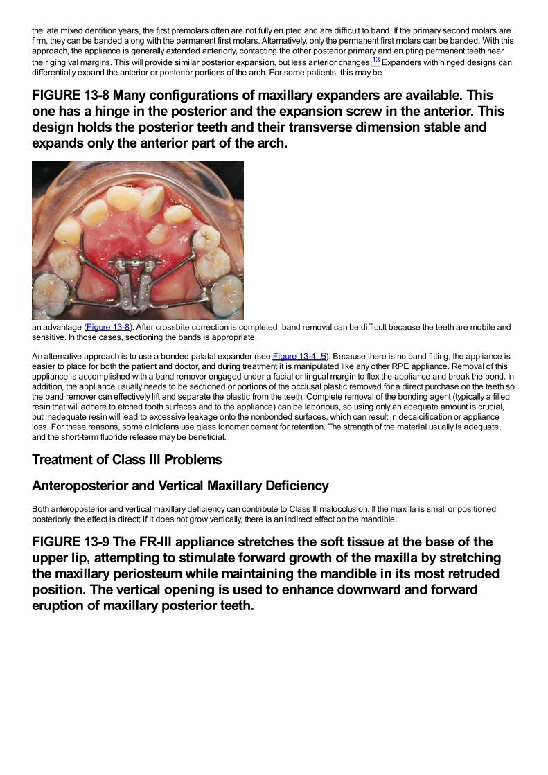
the late mixed dentition years, the first premolars often are not fully erupted and are difficult to band. If the primary second molars arefirm, they can be banded along with the permanent first molars. Alternatively, only the permanent first molars can be banded. With thisapproach, the appliance is generally extended anteriorly, contacting the other posterior primary and erupting permanent teeth neartheir gingival margins. This will provide similar posterior expansion, but less anterior changes.13 Expanders with hinged designs candifferentially expand the anterior or posterior portions of the arch. For some patients, this may be
FIGURE 13-8 Many configurations of maxillary expanders are available. Thisone has a hinge in the posterior and the expansion screw in the anterior. Thisdesign holds the posterior teeth and their transverse dimension stable andexpands only the anterior part of the arch.
an advantage (Figure 13-8). After crossbite correction is completed, band removal can be difficult because the teeth are mobile andsensitive. In those cases, sectioning the bands is appropriate.
An alternative approach is to use a bonded palatal expander (see Figure 13-4, B). Because there is no band fitting, the appliance iseasier to place for both the patient and doctor, and during treatment it is manipulated like any other RPE appliance. Removal of thisappliance is accomplished with a band remover engaged under a facial or lingual margin to flex the appliance and break the bond. Inaddition, the appliance usually needs to be sectioned or portions of the occlusal plastic removed for a direct purchase on the teeth sothe band remover can effectively lift and separate the plastic from the teeth. Complete removal of the bonding agent (typically a filledresin that will adhere to etched tooth surfaces and to the appliance) can be laborious, so using only an adequate amount is crucial,but inadequate resin will lead to excessive leakage onto the nonbonded surfaces, which can result in decalcification or applianceloss. For these reasons, some clinicians use glass ionomer cement for retention. The strength of the material usually is adequate,and the short-term fluoride release may be beneficial.
Treatment of Class III Problems
Anteroposterior and Vertical Maxillary DeficiencyBoth anteroposterior and vertical maxillary deficiency can contribute to Class III malocclusion. If the maxilla is small or positionedposteriorly, the effect is direct; if it does not grow vertically, there is an indirect effect on the mandible,
FIGURE 13-9 The FR-III appliance stretches the soft tissue at the base of theupper lip, attempting to stimulate forward growth of the maxilla by stretchingthe maxillary periosteum while maintaining the mandible in its most retrudedposition. The vertical opening is used to enhance downward and forwarderuption of maxillary posterior teeth.
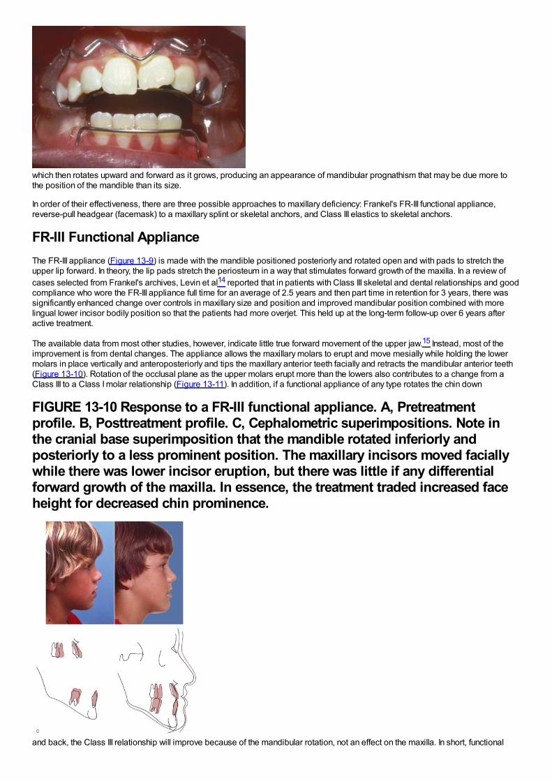
which then rotates upward and forward as it grows, producing an appearance of mandibular prognathism that may be due more tothe position of the mandible than its size.
In order of their effectiveness, there are three possible approaches to maxillary deficiency: Frankel's FR-III functional appliance,reverse-pull headgear (facemask) to a maxillary splint or skeletal anchors, and Class III elastics to skeletal anchors.
FR-III Functional ApplianceThe FR-III appliance (Figure 13-9) is made with the mandible positioned posteriorly and rotated open and with pads to stretch theupper lip forward. In theory, the lip pads stretch the periosteum in a way that stimulates forward growth of the maxilla. In a review ofcases selected from Frankel's archives, Levin et al14 reported that in patients with Class III skeletal and dental relationships and goodcompliance who wore the FR-III appliance full time for an average of 2.5 years and then part time in retention for 3 years, there wassignificantly enhanced change over controls in maxillary size and position and improved mandibular position combined with morelingual lower incisor bodily position so that the patients had more overjet. This held up at the long-term follow-up over 6 years afteractive treatment.
The available data from most other studies, however, indicate little true forward movement of the upper jaw.15 Instead, most of theimprovement is from dental changes. The appliance allows the maxillary molars to erupt and move mesially while holding the lowermolars in place vertically and anteroposteriorly and tips the maxillary anterior teeth facially and retracts the mandibular anterior teeth(Figure 13-10). Rotation of the occlusal plane as the upper molars erupt more than the lowers also contributes to a change from aClass III to a Class I molar relationship (Figure 13-11). In addition, if a functional appliance of any type rotates the chin down
FIGURE 13-10 Response to a FR-III functional appliance. A, Pretreatmentprofile. B, Posttreatment profile. C, Cephalometric superimpositions. Note inthe cranial base superimposition that the mandible rotated inferiorly andposteriorly to a less prominent position. The maxillary incisors moved faciallywhile there was lower incisor eruption, but there was little if any differentialforward growth of the maxilla. In essence, the treatment traded increased faceheight for decreased chin prominence.
and back, the Class III relationship will improve because of the mandibular rotation, not an effect on the maxilla. In short, functional
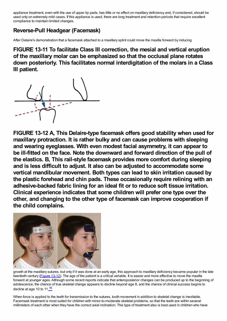
appliance treatment, even with the use of upper lip pads, has little or no effect on maxillary deficiency and, if considered, should beused only on extremely mild cases. If this appliance is used, there are long treatment and retention periods that require excellentcompliance to maintain limited changes.
Reverse-Pull Headgear (Facemask)After Delaire's demonstration that a facemask attached to a maxillary splint could move the maxilla forward by inducing
FIGURE 13-11 To facilitate Class III correction, the mesial and vertical eruptionof the maxillary molar can be emphasized so that the occlusal plane rotatesdown posteriorly. This facilitates normal interdigitation of the molars in a ClassIII patient.
FIGURE 13-12 A, This Delaire-type facemask offers good stability when used formaxillary protraction. It is rather bulky and can cause problems with sleepingand wearing eyeglasses. With even modest facial asymmetry, it can appear tobe ill-fitted on the face. Note the downward and forward direction of the pull ofthe elastics. B, This rail-style facemask provides more comfort during sleepingand is less difficult to adjust. It also can be adjusted to accommodate somevertical mandibular movement. Both types can lead to skin irritation caused bythe plastic forehead and chin pads. These occasionally require relining with anadhesive-backed fabric lining for an ideal fit or to reduce soft tissue irritation.Clinical experience indicates that some children will prefer one type over theother, and changing to the other type of facemask can improve cooperation ifthe child complains.
growth at the maxillary sutures, but only if it was done at an early age, this approach to maxillary deficiency became popular in the latetwentieth century (Figure 13-12). The age of the patient is a critical variable. It is easier and more effective to move the maxillaforward at younger ages. Although some recent reports indicate that anteroposterior changes can be produced up to the beginning ofadolescence, the chance of true skeletal change appears to decline beyond age 8, and the chance of clinical success begins todecline at age 10 to 11.16
When force is applied to the teeth for transmission to the sutures, tooth movement in addition to skeletal change is inevitable.Facemask treatment is most suited for children with minor-to-moderate skeletal problems, so that the teeth are within severalmillimeters of each other when they have the correct axial inclination. This type of treatment also is best used in children who have
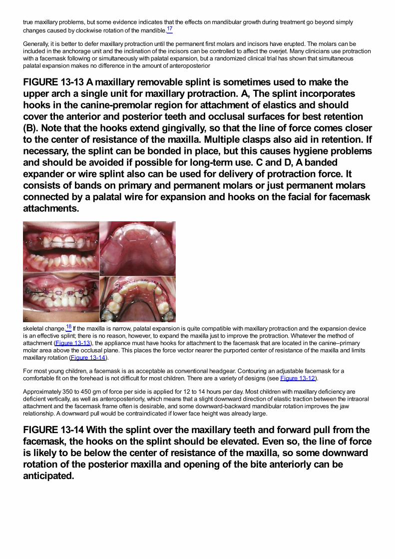
true maxillary problems, but some evidence indicates that the effects on mandibular growth during treatment go beyond simplychanges caused by clockwise rotation of the mandible.17
Generally, it is better to defer maxillary protraction until the permanent first molars and incisors have erupted. The molars can beincluded in the anchorage unit and the inclination of the incisors can be controlled to affect the overjet. Many clinicians use protractionwith a facemask following or simultaneously with palatal expansion, but a randomized clinical trial has shown that simultaneouspalatal expansion makes no difference in the amount of anteroposterior
FIGURE 13-13 A maxillary removable splint is sometimes used to make theupper arch a single unit for maxillary protraction. A, The splint incorporateshooks in the canine-premolar region for attachment of elastics and shouldcover the anterior and posterior teeth and occlusal surfaces for best retention(B). Note that the hooks extend gingivally, so that the line of force comes closerto the center of resistance of the maxilla. Multiple clasps also aid in retention. Ifnecessary, the splint can be bonded in place, but this causes hygiene problemsand should be avoided if possible for long-term use. C and D, A bandedexpander or wire splint also can be used for delivery of protraction force. Itconsists of bands on primary and permanent molars or just permanent molarsconnected by a palatal wire for expansion and hooks on the facial for facemaskattachments.
skeletal change.18 If the maxilla is narrow, palatal expansion is quite compatible with maxillary protraction and the expansion deviceis an effective splint; there is no reason, however, to expand the maxilla just to improve the protraction. Whatever the method ofattachment (Figure 13-13), the appliance must have hooks for attachment to the facemask that are located in the canine–primarymolar area above the occlusal plane. This places the force vector nearer the purported center of resistance of the maxilla and limitsmaxillary rotation (Figure 13-14).
For most young children, a facemask is as acceptable as conventional headgear. Contouring an adjustable facemask for acomfortable fit on the forehead is not difficult for most children. There are a variety of designs (see Figure 13-12).
Approximately 350 to 450 gm of force per side is applied for 12 to 14 hours per day. Most children with maxillary deficiency aredeficient vertically, as well as anteroposteriorly, which means that a slight downward direction of elastic traction between the intraoralattachment and the facemask frame often is desirable, and some downward-backward mandibular rotation improves the jawrelationship. A downward pull would be contraindicated if lower face height was already large.
FIGURE 13-14 With the splint over the maxillary teeth and forward pull from thefacemask, the hooks on the splint should be elevated. Even so, the line of forceis likely to be below the center of resistance of the maxilla, so some downwardrotation of the posterior maxilla and opening of the bite anteriorly can beanticipated.

Backward displacement of the mandibular teeth and forward displacement of the maxillary teeth also typically occur in response tothis type of treatment (Figure 13-15).19 As children come closer to adolescence, mandibular rotation and displacement of maxillaryteeth—not forward movement of the maxilla—are the major components of the treatment result.
Application of Skeletal AnchorageClearly, a major negative side effect of maxillary protraction is maxillary dental movement that detracts from the skeletal change.Before bone screws and miniplates became available, Shapiro and Kokich deliberately ankylosed primary canines so they could beused as “natural implants.”20 With traction against a maxillary arch stabilized by these teeth, they were able to demonstrateapproximately 3 mm of maxillary protraction in 1 year, with minimal dental change. If a child with maxillary retrusion has spontaneousankylosis of primary molars, a splint can be fabricated to take advantage of these teeth as implants and gain the samebiomechanical advantage.
For more routine use in clinical practice, it appears that the effects of treatment to change the deficient maxillary position can bemagnified in one of two ways. First, the facemask can be applied to miniplates at the base of the zygomatic arch21 or in the anteriormaxilla.22 With anchors above the incisors, 400 gm of force per side, and use of the facemask for a minimum of 16 hours per day,Sar et al22 reported 0.45 mm per month of anterior maxillary movement (compared to 0.24 mm with conventional facemask) withoutrotation of the maxilla. For patients approaching adolescence (i.e., about age 11 and old enough for good retention of bone screws),this appears to be promising.
Alternatively, bone-supported miniplates can be placed bilaterally in the maxilla and the mandible, so that interarch force from Class IIIelastics is delivered to the jaws rather than the teeth (Figure 13-16).23 Three-dimensional (3-D) imaging of patients treated in thisway has shown a variety of interesting responses (Figure 13-17) that include forward movement of the maxilla at a higher level thanhas been observed previously and displacement or remodeling in the temporomandibular (TM) fossae. In a sequence of 25consecutive children treated in this way with full-time elastics delivering approximately 150 gm per side (about 5 ounces), the varietyof changes seen in the 3-D images are summarized in Figure 13-18. More than 2 mm maxillary protraction was noted in 14 (56%) ofthe 25 patients.
This approach has two advantages: (1) it is clearly more effective than a facemask to a maxillary splint24 and also appears toproduce more skeletal change than has been reported with facemasks to anterior miniplates and (2) wearing an extraoral applianceis not necessary and nearly full-time application of the force can be obtained. Compared to facemasks attached to a maxillary splint,it has the disadvantage of requiring surgical application and removal of the miniplates by a surgeon trained to do this, although this isnot major surgery. Alveolar bone screws with Class III elastics would be simpler to place and remove than miniplates, but both thelower density of the bone in preadolescents and avoiding damage to unerupted permanent teeth pose substantial problems with theiruse (see Chapter 10). Miniplates attached to basal bone can be used at age 10-6 or 11. The minimum age for alveolar bone screwsfor this application appears to be approximately age 12, probably too late for an optimal skeletal effect.
SummaryThere is no doubt that maxillary protraction at an early age usually produces clinical improvement in a Class III patient. Importantconcerns are the extent to which this will be maintained long-term and the chance that orthognathic surgery eventually will benecessary despite the early treatment. The answer to these issues, of course, requires recall 8 to 10 years after the initial treatmentwas completed. Three recent studies now show essentially the same thing: that 25%to 30%of their facemask patients ended up inanterior crossbite after adolescent growth and that the majority of these would require surgery for correction.25
There is no way to know at present whether the long-term outcomes would be better if facemasks or Class III elastics were attachedto skeletal anchors, but when a Class III problem recurs, it is because of excessive mandibular growth during and following
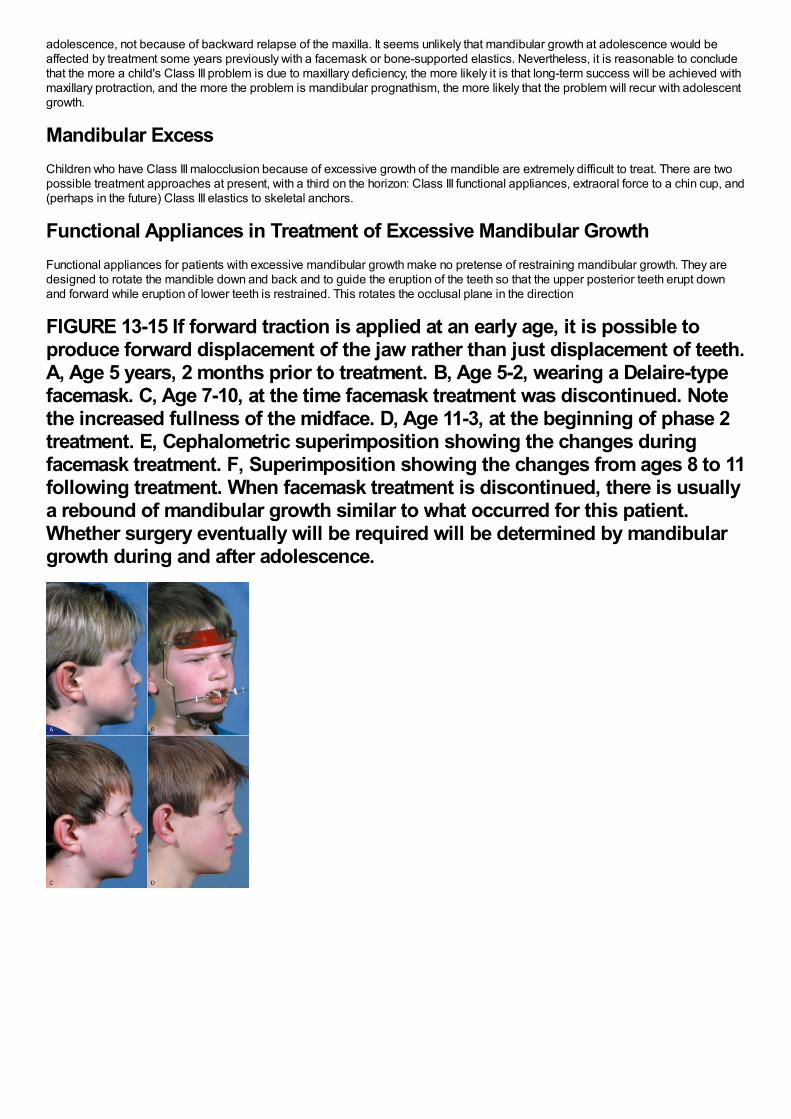
adolescence, not because of backward relapse of the maxilla. It seems unlikely that mandibular growth at adolescence would beaffected by treatment some years previously with a facemask or bone-supported elastics. Nevertheless, it is reasonable to concludethat the more a child's Class III problem is due to maxillary deficiency, the more likely it is that long-term success will be achieved withmaxillary protraction, and the more the problem is mandibular prognathism, the more likely that the problem will recur with adolescentgrowth.
Mandibular ExcessChildren who have Class III malocclusion because of excessive growth of the mandible are extremely difficult to treat. There are twopossible treatment approaches at present, with a third on the horizon: Class III functional appliances, extraoral force to a chin cup, and(perhaps in the future) Class III elastics to skeletal anchors.
Functional Appliances in Treatment of Excessive Mandibular GrowthFunctional appliances for patients with excessive mandibular growth make no pretense of restraining mandibular growth. They aredesigned to rotate the mandible down and back and to guide the eruption of the teeth so that the upper posterior teeth erupt downand forward while eruption of lower teeth is restrained. This rotates the occlusal plane in the direction
FIGURE 13-15 If forward traction is applied at an early age, it is possible toproduce forward displacement of the jaw rather than just displacement of teeth.A, Age 5 years, 2 months prior to treatment. B, Age 5-2, wearing a Delaire-typefacemask. C, Age 7-10, at the time facemask treatment was discontinued. Notethe increased fullness of the midface. D, Age 11-3, at the beginning of phase 2treatment. E, Cephalometric superimposition showing the changes duringfacemask treatment. F, Superimposition showing the changes from ages 8 to 11following treatment. When facemask treatment is discontinued, there is usuallya rebound of mandibular growth similar to what occurred for this patient.Whether surgery eventually will be required will be determined by mandibulargrowth during and after adolescence.
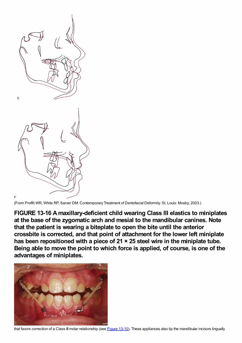
(From Proffit WR, White RP, Sarver DM. Contemporary Treatment of Dentofacial Deformity. St. Louis: Mosby; 2003.)
FIGURE 13-16 A maxillary-deficient child wearing Class III elastics to miniplatesat the base of the zygomatic arch and mesial to the mandibular canines. Notethat the patient is wearing a biteplate to open the bite until the anteriorcrossbite is corrected, and that point of attachment for the lower left miniplatehas been repositioned with a piece of 21 × 25 steel wire in the miniplate tube.Being able to move the point to which force is applied, of course, is one of theadvantages of miniplates.
that favors correction of a Class III molar relationship (see Figure 13-10). These appliances also tip the mandibular incisors lingually
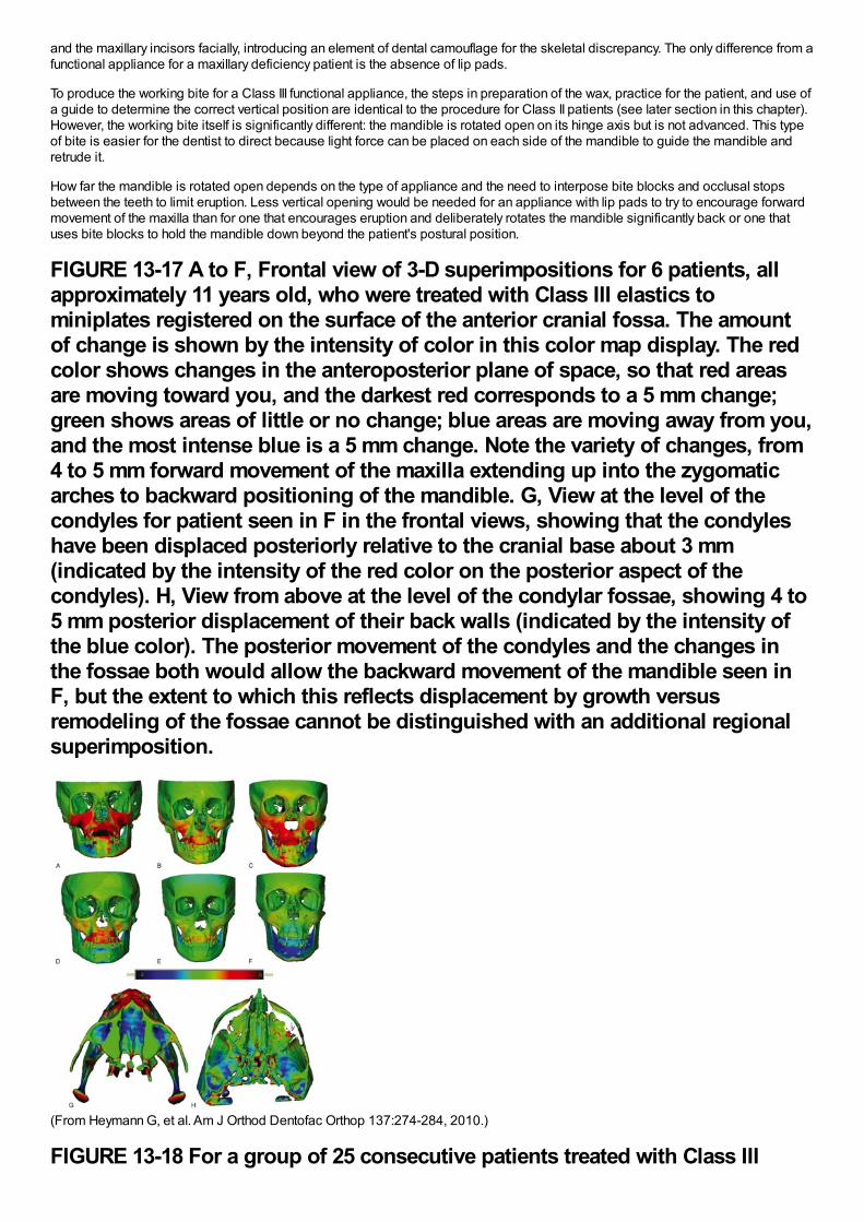
and the maxillary incisors facially, introducing an element of dental camouflage for the skeletal discrepancy. The only difference from afunctional appliance for a maxillary deficiency patient is the absence of lip pads.
To produce the working bite for a Class III functional appliance, the steps in preparation of the wax, practice for the patient, and use ofa guide to determine the correct vertical position are identical to the procedure for Class II patients (see later section in this chapter).However, the working bite itself is significantly different: the mandible is rotated open on its hinge axis but is not advanced. This typeof bite is easier for the dentist to direct because light force can be placed on each side of the mandible to guide the mandible andretrude it.
How far the mandible is rotated open depends on the type of appliance and the need to interpose bite blocks and occlusal stopsbetween the teeth to limit eruption. Less vertical opening would be needed for an appliance with lip pads to try to encourage forwardmovement of the maxilla than for one that encourages eruption and deliberately rotates the mandible significantly back or one thatuses bite blocks to hold the mandible down beyond the patient's postural position.
FIGURE 13-17 A to F, Frontal view of 3-D superimpositions for 6 patients, allapproximately 11 years old, who were treated with Class III elastics tominiplates registered on the surface of the anterior cranial fossa. The amountof change is shown by the intensity of color in this color map display. The redcolor shows changes in the anteroposterior plane of space, so that red areasare moving toward you, and the darkest red corresponds to a 5 mm change;green shows areas of little or no change; blue areas are moving away from you,and the most intense blue is a 5 mm change. Note the variety of changes, from4 to 5 mm forward movement of the maxilla extending up into the zygomaticarches to backward positioning of the mandible. G, View at the level of thecondyles for patient seen in F in the frontal views, showing that the condyleshave been displaced posteriorly relative to the cranial base about 3 mm(indicated by the intensity of the red color on the posterior aspect of thecondyles). H, View from above at the level of the condylar fossae, showing 4 to5 mm posterior displacement of their back walls (indicated by the intensity ofthe blue color). The posterior movement of the condyles and the changes inthe fossae both would allow the backward movement of the mandible seen inF, but the extent to which this reflects displacement by growth versusremodeling of the fossae cannot be distinguished with an additional regionalsuperimposition.
(From Heymann G, et al. Am J Orthod Dentofac Orthop 137:274-284, 2010.)
FIGURE 13-18 For a group of 25 consecutive patients treated with Class III
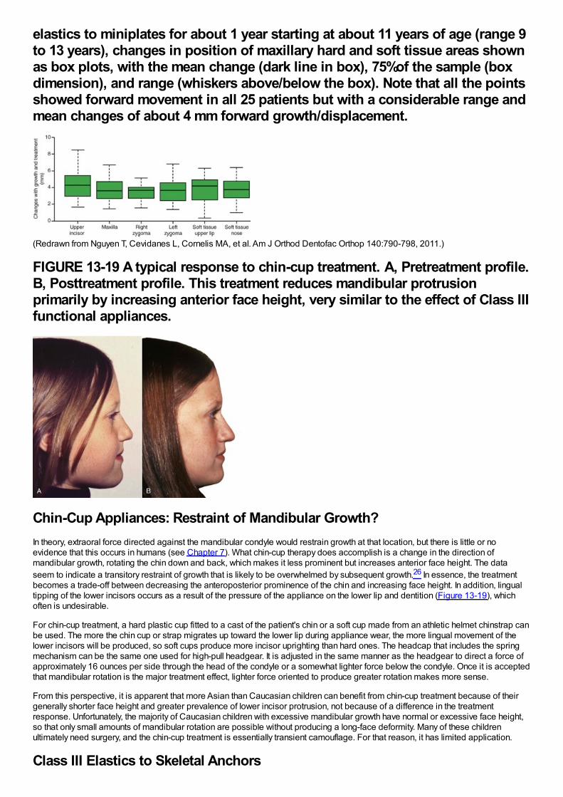
elastics to miniplates for about 1 year starting at about 11 years of age (range 9to 13 years), changes in position of maxillary hard and soft tissue areas shownas box plots, with the mean change (dark line in box), 75%of the sample (boxdimension), and range (whiskers above/below the box). Note that all the pointsshowed forward movement in all 25 patients but with a considerable range andmean changes of about 4 mm forward growth/displacement.
(Redrawn from Nguyen T, Cevidanes L, Cornelis MA, et al. Am J Orthod Dentofac Orthop 140:790-798, 2011.)
FIGURE 13-19 A typical response to chin-cup treatment. A, Pretreatment profile.B, Posttreatment profile. This treatment reduces mandibular protrusionprimarily by increasing anterior face height, very similar to the effect of Class IIIfunctional appliances.
Chin-Cup Appliances: Restraint of Mandibular Growth?In theory, extraoral force directed against the mandibular condyle would restrain growth at that location, but there is little or noevidence that this occurs in humans (see Chapter 7). What chin-cup therapy does accomplish is a change in the direction ofmandibular growth, rotating the chin down and back, which makes it less prominent but increases anterior face height. The dataseem to indicate a transitory restraint of growth that is likely to be overwhelmed by subsequent growth.26 In essence, the treatmentbecomes a trade-off between decreasing the anteroposterior prominence of the chin and increasing face height. In addition, lingualtipping of the lower incisors occurs as a result of the pressure of the appliance on the lower lip and dentition (Figure 13-19), whichoften is undesirable.
For chin-cup treatment, a hard plastic cup fitted to a cast of the patient's chin or a soft cup made from an athletic helmet chinstrap canbe used. The more the chin cup or strap migrates up toward the lower lip during appliance wear, the more lingual movement of thelower incisors will be produced, so soft cups produce more incisor uprighting than hard ones. The headcap that includes the springmechanism can be the same one used for high-pull headgear. It is adjusted in the same manner as the headgear to direct a force ofapproximately 16 ounces per side through the head of the condyle or a somewhat lighter force below the condyle. Once it is acceptedthat mandibular rotation is the major treatment effect, lighter force oriented to produce greater rotation makes more sense.
From this perspective, it is apparent that more Asian than Caucasian children can benefit from chin-cup treatment because of theirgenerally shorter face height and greater prevalence of lower incisor protrusion, not because of a difference in the treatmentresponse. Unfortunately, the majority of Caucasian children with excessive mandibular growth have normal or excessive face height,so that only small amounts of mandibular rotation are possible without producing a long-face deformity. Many of these childrenultimately need surgery, and the chin-cup treatment is essentially transient camouflage. For that reason, it has limited application.
Class III Elastics to Skeletal Anchors
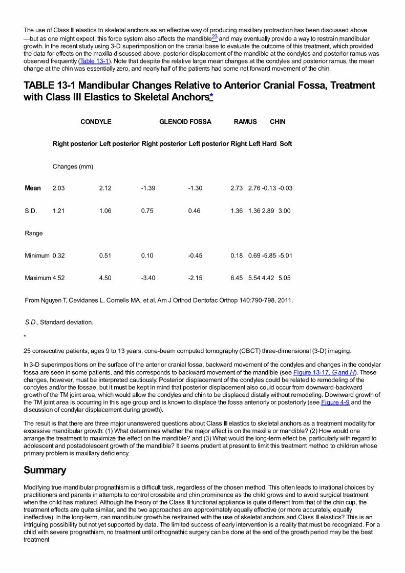
The use of Class III elastics to skeletal anchors as an effective way of producing maxillary protraction has been discussed above—but as one might expect, this force system also affects the mandible23 and may eventually provide a way to restrain mandibulargrowth. In the recent study using 3-D superimposition on the cranial base to evaluate the outcome of this treatment, which providedthe data for effects on the maxilla discussed above, posterior displacement of the mandible at the condyles and posterior ramus wasobserved frequently (Table 13-1). Note that despite the relative large mean changes at the condyles and posterior ramus, the meanchange at the chin was essentially zero, and nearly half of the patients had some net forward movement of the chin.
TABLE 13-1 Mandibular Changes Relative to Anterior Cranial Fossa, Treatmentwith Class III Elastics to Skeletal Anchors*
CONDYLE GLENOID FOSSA RAMUS CHIN
Right posterior Left posterior Right posterior Left posterior Right Left Hard Soft
Changes (mm)
Mean 2.03 2.12 -1.39 -1.30 2.73 2.76 -0.13 -0.03
S.D. 1.21 1.06 0.75 0.46 1.36 1.36 2.89 3.00
Range
Minimum 0.32 0.51 0.10 -0.45 0.18 0.69 -5.85 -5.01
Maximum 4.52 4.50 -3.40 -2.15 6.45 5.54 4.42 5.05
From Nguyen T, Cevidanes L, Cornelis MA, et al. Am J Orthod Dentofac Orthop 140:790-798, 2011.
S.D., Standard deviation.
*
25 consecutive patients, ages 9 to 13 years, cone-beam computed tomography (CBCT) three-dimensional (3-D) imaging.
In 3-D superimpositions on the surface of the anterior cranial fossa, backward movement of the condyles and changes in the condylarfossa are seen in some patients, and this corresponds to backward movement of the mandible (see Figure 13-17, G and H). Thesechanges, however, must be interpreted cautiously. Posterior displacement of the condyles could be related to remodeling of thecondyles and/or the fossae, but it must be kept in mind that posterior displacement also could occur from downward-backwardgrowth of the TM joint area, which would allow the condyles and chin to be displaced distally without remodeling. Downward growth ofthe TM joint area is occurring in this age group and is known to displace the fossa anteriorly or posteriorly (see Figure 4-9 and thediscussion of condylar displacement during growth).
The result is that there are three major unanswered questions about Class III elastics to skeletal anchors as a treatment modality forexcessive mandibular growth: (1) What determines whether the major effect is on the maxilla or mandible? (2) How would onearrange the treatment to maximize the effect on the mandible? and (3) What would the long-term effect be, particularly with regard toadolescent and postadolescent growth of the mandible? It seems prudent at present to limit this treatment method to children whoseprimary problem is maxillary deficiency.
SummaryModifying true mandibular prognathism is a difficult task, regardless of the chosen method. This often leads to irrational choices bypractitioners and parents in attempts to control crossbite and chin prominence as the child grows and to avoid surgical treatmentwhen the child has matured. Although the theory of the Class III functional appliance is quite different from that of the chin cup, thetreatment effects are quite similar, and the two approaches are approximately equally effective (or more accurately, equallyineffective). In the long-term, can mandibular growth be restrained with the use of skeletal anchors and Class III elastics? This is anintriguing possibility but not yet supported by data. The limited success of early intervention is a reality that must be recognized. For achild with severe prognathism, no treatment until orthognathic surgery can be done at the end of the growth period may be the besttreatment
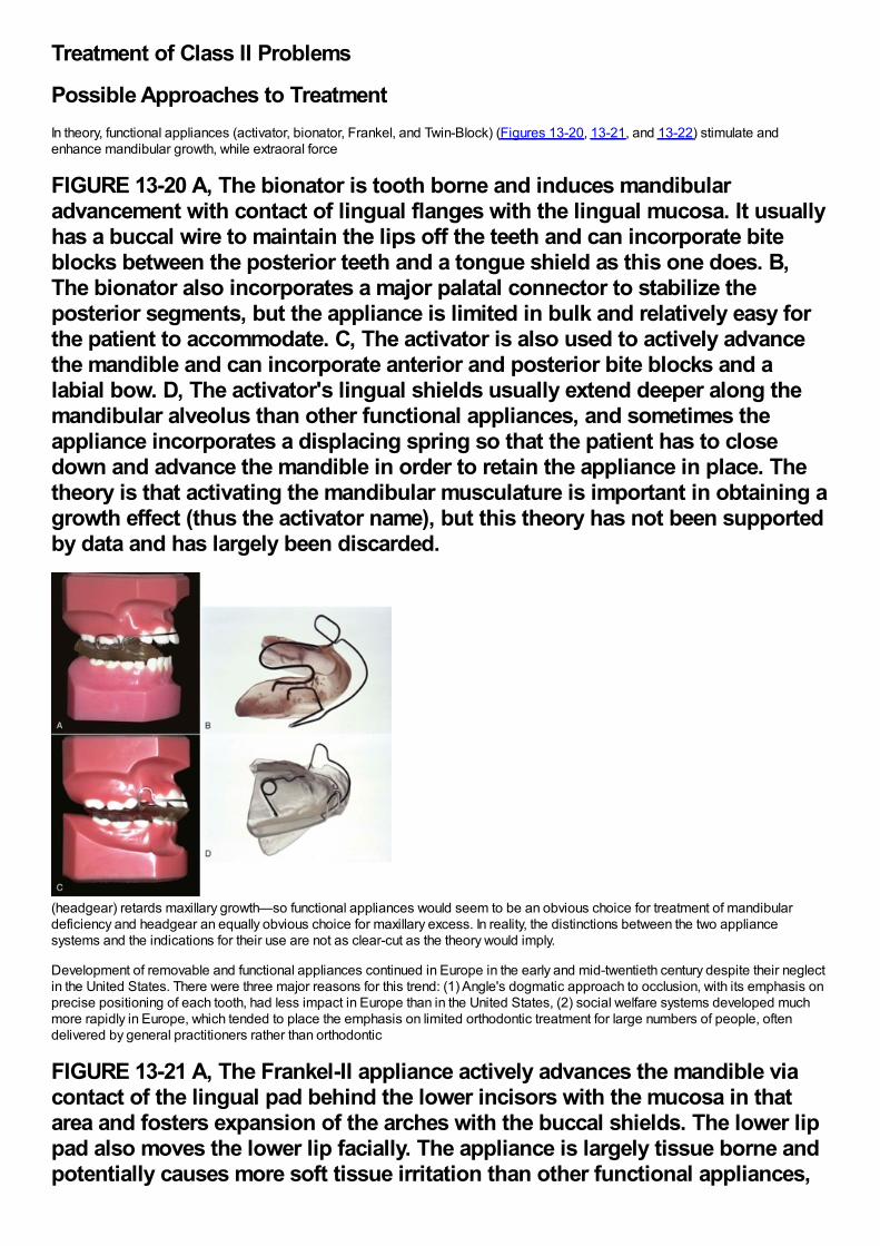
Treatment of Class II Problems
Possible Approaches to TreatmentIn theory, functional appliances (activator, bionator, Frankel, and Twin-Block) (Figures 13-20, 13-21, and 13-22) stimulate andenhance mandibular growth, while extraoral force
FIGURE 13-20 A, The bionator is tooth borne and induces mandibularadvancement with contact of lingual flanges with the lingual mucosa. It usuallyhas a buccal wire to maintain the lips off the teeth and can incorporate biteblocks between the posterior teeth and a tongue shield as this one does. B,The bionator also incorporates a major palatal connector to stabilize theposterior segments, but the appliance is limited in bulk and relatively easy forthe patient to accommodate. C, The activator is also used to actively advancethe mandible and can incorporate anterior and posterior bite blocks and alabial bow. D, The activator's lingual shields usually extend deeper along themandibular alveolus than other functional appliances, and sometimes theappliance incorporates a displacing spring so that the patient has to closedown and advance the mandible in order to retain the appliance in place. Thetheory is that activating the mandibular musculature is important in obtaining agrowth effect (thus the activator name), but this theory has not been supportedby data and has largely been discarded.
(headgear) retards maxillary growth—so functional appliances would seem to be an obvious choice for treatment of mandibulardeficiency and headgear an equally obvious choice for maxillary excess. In reality, the distinctions between the two appliancesystems and the indications for their use are not as clear-cut as the theory would imply.
Development of removable and functional appliances continued in Europe in the early and mid-twentieth century despite their neglectin the United States. There were three major reasons for this trend: (1) Angle's dogmatic approach to occlusion, with its emphasis onprecise positioning of each tooth, had less impact in Europe than in the United States, (2) social welfare systems developed muchmore rapidly in Europe, which tended to place the emphasis on limited orthodontic treatment for large numbers of people, oftendelivered by general practitioners rather than orthodontic
FIGURE 13-21 A, The Frankel-II appliance actively advances the mandible viacontact of the lingual pad behind the lower incisors with the mucosa in thatarea and fosters expansion of the arches with the buccal shields. The lower lippad also moves the lower lip facially. The appliance is largely tissue borne andpotentially causes more soft tissue irritation than other functional appliances,
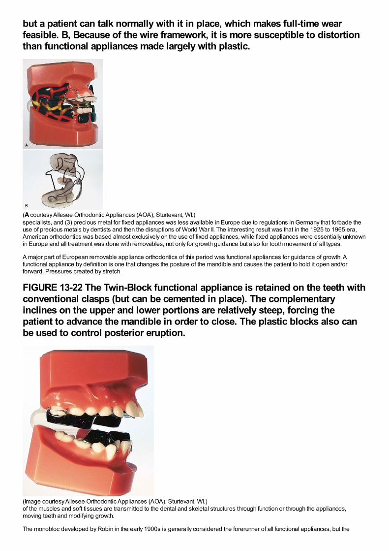
but a patient can talk normally with it in place, which makes full-time wearfeasible. B, Because of the wire framework, it is more susceptible to distortionthan functional appliances made largely with plastic.
(A courtesy Allesee Orthodontic Appliances (AOA), Sturtevant, WI.)specialists, and (3) precious metal for fixed appliances was less available in Europe due to regulations in Germany that forbade theuse of precious metals by dentists and then the disruptions of World War II. The interesting result was that in the 1925 to 1965 era,American orthodontics was based almost exclusively on the use of fixed appliances, while fixed appliances were essentially unknownin Europe and all treatment was done with removables, not only for growth guidance but also for tooth movement of all types.
A major part of European removable appliance orthodontics of this period was functional appliances for guidance of growth. Afunctional appliance by definition is one that changes the posture of the mandible and causes the patient to hold it open and/orforward. Pressures created by stretch
FIGURE 13-22 The Twin-Block functional appliance is retained on the teeth withconventional clasps (but can be cemented in place). The complementaryinclines on the upper and lower portions are relatively steep, forcing thepatient to advance the mandible in order to close. The plastic blocks also canbe used to control posterior eruption.
(Image courtesy Allesee Orthodontic Appliances (AOA), Sturtevant, WI.)of the muscles and soft tissues are transmitted to the dental and skeletal structures through function or through the appliances,moving teeth and modifying growth.
The monobloc developed by Robin in the early 1900s is generally considered the forerunner of all functional appliances, but the
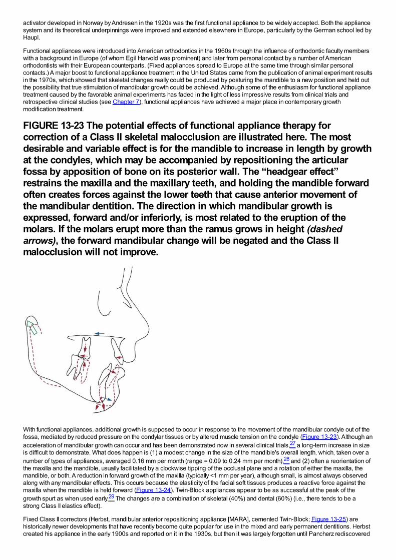
activator developed in Norway by Andresen in the 1920s was the first functional appliance to be widely accepted. Both the appliancesystem and its theoretical underpinnings were improved and extended elsewhere in Europe, particularly by the German school led byHaupl.
Functional appliances were introduced into American orthodontics in the 1960s through the influence of orthodontic faculty memberswith a background in Europe (of whom Egil Harvold was prominent) and later from personal contact by a number of Americanorthodontists with their European counterparts. (Fixed appliances spread to Europe at the same time through similar personalcontacts.) A major boost to functional appliance treatment in the United States came from the publication of animal experiment resultsin the 1970s, which showed that skeletal changes really could be produced by posturing the mandible to a new position and held outthe possibility that true stimulation of mandibular growth could be achieved. Although some of the enthusiasm for functional appliancetreatment caused by the favorable animal experiments has faded in the light of less impressive results from clinical trials andretrospective clinical studies (see Chapter 7), functional appliances have achieved a major place in contemporary growthmodification treatment.
FIGURE 13-23 The potential effects of functional appliance therapy forcorrection of a Class II skeletal malocclusion are illustrated here. The mostdesirable and variable effect is for the mandible to increase in length by growthat the condyles, which may be accompanied by repositioning the articularfossa by apposition of bone on its posterior wall. The “headgear effect”restrains the maxilla and the maxillary teeth, and holding the mandible forwardoften creates forces against the lower teeth that cause anterior movement ofthe mandibular dentition. The direction in which mandibular growth isexpressed, forward and/or inferiorly, is most related to the eruption of themolars. If the molars erupt more than the ramus grows in height (dashedarrows), the forward mandibular change will be negated and the Class IImalocclusion will not improve.
With functional appliances, additional growth is supposed to occur in response to the movement of the mandibular condyle out of thefossa, mediated by reduced pressure on the condylar tissues or by altered muscle tension on the condyle (Figure 13-23). Although anacceleration of mandibular growth can occur and has been demonstrated now in several clinical trials,27 a long-term increase in sizeis difficult to demonstrate. What does happen is (1) a modest change in the size of the mandible's overall length, which, taken over anumber of types of appliances, averaged 0.16 mm per month (range = 0.09 to 0.24 mm per month),28 and (2) often a reorientation ofthe maxilla and the mandible, usually facilitated by a clockwise tipping of the occlusal plane and a rotation of either the maxilla, themandible, or both. A reduction in forward growth of the maxilla (typically <1 mm per year), although small, is almost always observedalong with any mandibular effects. This occurs because the elasticity of the facial soft tissues produces a reactive force against themaxilla when the mandible is held forward (Figure 13-24). Twin-Block appliances appear to be as successful at the peak of thegrowth spurt as when used early.29 The changes are a combination of skeletal (40%) and dental (60%) (i.e., there tends to be astrong Class II elastics effect).
Fixed Class II correctors (Herbst, mandibular anterior repositioning appliance [MARA], cemented Twin-Block; Figure 13-25) arehistorically newer developments that have recently become quite popular for use in the mixed and early permanent dentitions. Herbstcreated his appliance in the early 1900s and reported on it in the 1930s, but then it was largely forgotten until Pancherz rediscovered
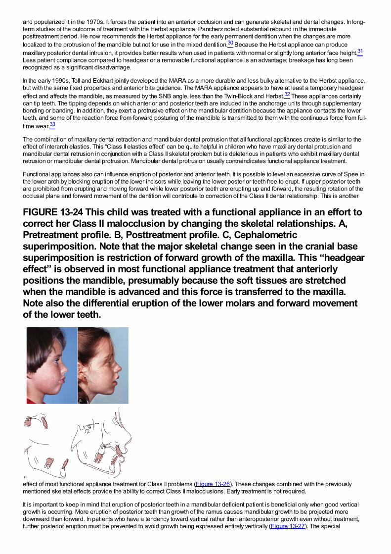
and popularized it in the 1970s. It forces the patient into an anterior occlusion and can generate skeletal and dental changes. In long-term studies of the outcome of treatment with the Herbst appliance, Pancherz noted substantial rebound in the immediateposttreatment period. He now recommends the Herbst appliance for the early permanent dentition when the changes are morelocalized to the protrusion of the mandible but not for use in the mixed dentition.30 Because the Herbst appliance can producemaxillary posterior dental intrusion, it provides better results when used in patients with normal or slightly long anterior face height.31
Less patient compliance compared to headgear or a removable functional appliance is an advantage; breakage has long beenrecognized as a significant disadvantage.
In the early 1990s, Toll and Eckhart jointly developed the MARA as a more durable and less bulky alternative to the Herbst appliance,but with the same fixed properties and anterior bite guidance. The MARA appliance appears to have at least a temporary headgeareffect and affects the mandible, as measured by the SNB angle, less than the Twin-Block and Herbst.32 These appliances certainlycan tip teeth. The tipping depends on which anterior and posterior teeth are included in the anchorage units through supplementarybonding or banding. In addition, they exert a protrusive effect on the mandibular dentition because the appliance contacts the lowerteeth, and some of the reaction force from forward posturing of the mandible is transmitted to them with the continuous force from full-time wear.33
The combination of maxillary dental retraction and mandibular dental protrusion that all functional appliances create is similar to theeffect of interarch elastics. This “Class II elastics effect” can be quite helpful in children who have maxillary dental protrusion andmandibular dental retrusion in conjunction with a Class II skeletal problem but is deleterious in patients who exhibit maxillary dentalretrusion or mandibular dental protrusion. Mandibular dental protrusion usually contraindicates functional appliance treatment.
Functional appliances also can influence eruption of posterior and anterior teeth. It is possible to level an excessive curve of Spee inthe lower arch by blocking eruption of the lower incisors while leaving the lower posterior teeth free to erupt. If upper posterior teethare prohibited from erupting and moving forward while lower posterior teeth are erupting up and forward, the resulting rotation of theocclusal plane and forward movement of the dentition will contribute to correction of the Class II dental relationship. This is another
FIGURE 13-24 This child was treated with a functional appliance in an effort tocorrect her Class II malocclusion by changing the skeletal relationships. A,Pretreatment profile. B, Posttreatment profile. C, Cephalometricsuperimposition. Note that the major skeletal change seen in the cranial basesuperimposition is restriction of forward growth of the maxilla. This “headgeareffect” is observed in most functional appliance treatment that anteriorlypositions the mandible, presumably because the soft tissues are stretchedwhen the mandible is advanced and this force is transferred to the maxilla.Note also the differential eruption of the lower molars and forward movementof the lower teeth.
effect of most functional appliance treatment for Class II problems (Figure 13-26). These changes combined with the previouslymentioned skeletal effects provide the ability to correct Class II malocclusions. Early treatment is not required.
It is important to keep in mind that eruption of posterior teeth in a mandibular deficient patient is beneficial only when good verticalgrowth is occurring. More eruption of posterior teeth than growth of the ramus causes mandibular growth to be projected moredownward than forward. In patients who have a tendency toward vertical rather than anteroposterior growth even without treatment,further posterior eruption must be prevented to avoid growth being expressed entirely vertically (Figure 13-27). The special
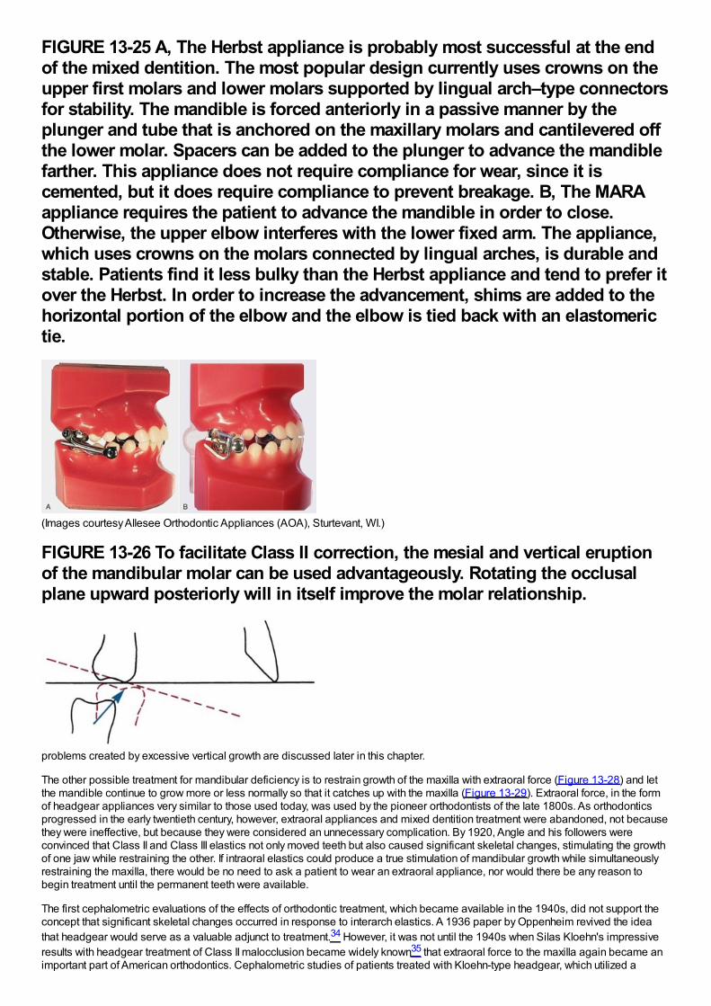
FIGURE 13-25 A, The Herbst appliance is probably most successful at the endof the mixed dentition. The most popular design currently uses crowns on theupper first molars and lower molars supported by lingual arch–type connectorsfor stability. The mandible is forced anteriorly in a passive manner by theplunger and tube that is anchored on the maxillary molars and cantilevered offthe lower molar. Spacers can be added to the plunger to advance the mandiblefarther. This appliance does not require compliance for wear, since it iscemented, but it does require compliance to prevent breakage. B, The MARAappliance requires the patient to advance the mandible in order to close.Otherwise, the upper elbow interferes with the lower fixed arm. The appliance,which uses crowns on the molars connected by lingual arches, is durable andstable. Patients find it less bulky than the Herbst appliance and tend to prefer itover the Herbst. In order to increase the advancement, shims are added to thehorizontal portion of the elbow and the elbow is tied back with an elastomerictie.
(Images courtesy Allesee Orthodontic Appliances (AOA), Sturtevant, WI.)
FIGURE 13-26 To facilitate Class II correction, the mesial and vertical eruptionof the mandibular molar can be used advantageously. Rotating the occlusalplane upward posteriorly will in itself improve the molar relationship.
problems created by excessive vertical growth are discussed later in this chapter.
The other possible treatment for mandibular deficiency is to restrain growth of the maxilla with extraoral force (Figure 13-28) and letthe mandible continue to grow more or less normally so that it catches up with the maxilla (Figure 13-29). Extraoral force, in the formof headgear appliances very similar to those used today, was used by the pioneer orthodontists of the late 1800s. As orthodonticsprogressed in the early twentieth century, however, extraoral appliances and mixed dentition treatment were abandoned, not becausethey were ineffective, but because they were considered an unnecessary complication. By 1920, Angle and his followers wereconvinced that Class II and Class III elastics not only moved teeth but also caused significant skeletal changes, stimulating the growthof one jaw while restraining the other. If intraoral elastics could produce a true stimulation of mandibular growth while simultaneouslyrestraining the maxilla, there would be no need to ask a patient to wear an extraoral appliance, nor would there be any reason tobegin treatment until the permanent teeth were available.
The first cephalometric evaluations of the effects of orthodontic treatment, which became available in the 1940s, did not support theconcept that significant skeletal changes occurred in response to interarch elastics. A 1936 paper by Oppenheim revived the ideathat headgear would serve as a valuable adjunct to treatment.34 However, it was not until the 1940s when Silas Kloehn's impressiveresults with headgear treatment of Class II malocclusion became widely known35 that extraoral force to the maxilla again became animportant part of American orthodontics. Cephalometric studies of patients treated with Kloehn-type headgear, which utilized a
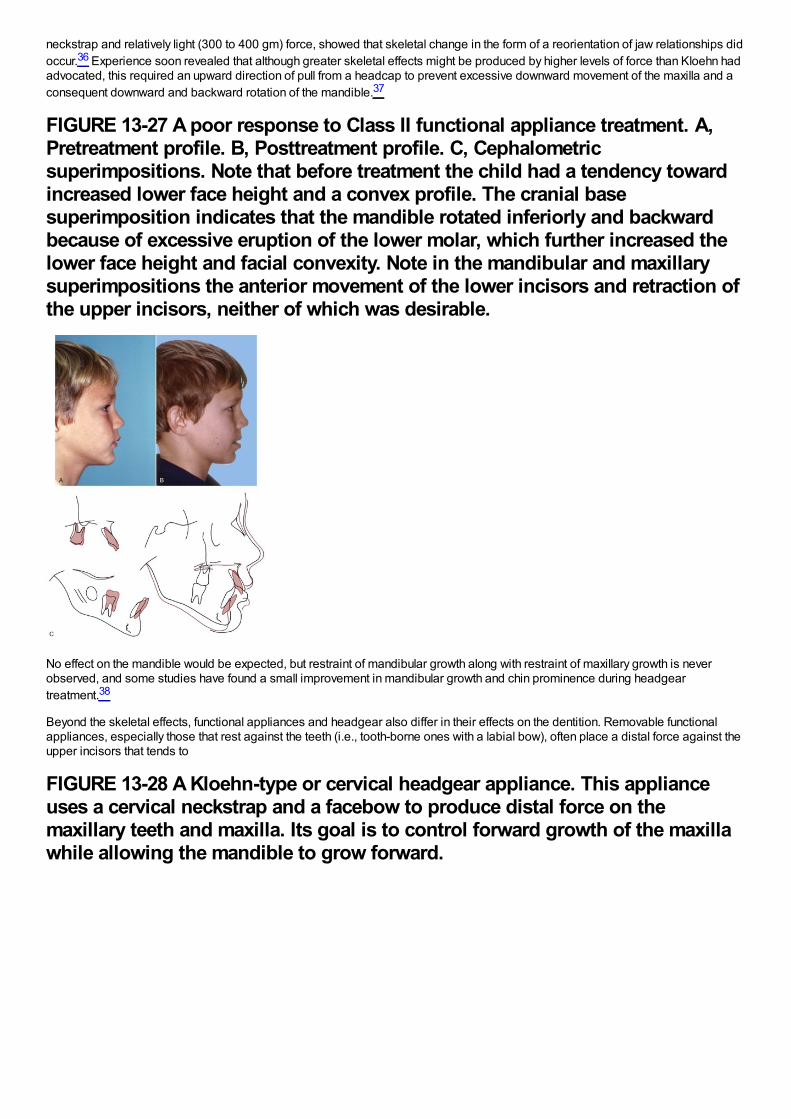
neckstrap and relatively light (300 to 400 gm) force, showed that skeletal change in the form of a reorientation of jaw relationships didoccur.36 Experience soon revealed that although greater skeletal effects might be produced by higher levels of force than Kloehn hadadvocated, this required an upward direction of pull from a headcap to prevent excessive downward movement of the maxilla and aconsequent downward and backward rotation of the mandible.37
FIGURE 13-27 A poor response to Class II functional appliance treatment. A,Pretreatment profile. B, Posttreatment profile. C, Cephalometricsuperimpositions. Note that before treatment the child had a tendency towardincreased lower face height and a convex profile. The cranial basesuperimposition indicates that the mandible rotated inferiorly and backwardbecause of excessive eruption of the lower molar, which further increased thelower face height and facial convexity. Note in the mandibular and maxillarysuperimpositions the anterior movement of the lower incisors and retraction ofthe upper incisors, neither of which was desirable.
No effect on the mandible would be expected, but restraint of mandibular growth along with restraint of maxillary growth is neverobserved, and some studies have found a small improvement in mandibular growth and chin prominence during headgeartreatment.38
Beyond the skeletal effects, functional appliances and headgear also differ in their effects on the dentition. Removable functionalappliances, especially those that rest against the teeth (i.e., tooth-borne ones with a labial bow), often place a distal force against theupper incisors that tends to
FIGURE 13-28 A Kloehn-type or cervical headgear appliance. This applianceuses a cervical neckstrap and a facebow to produce distal force on themaxillary teeth and maxilla. Its goal is to control forward growth of the maxillawhile allowing the mandible to grow forward.
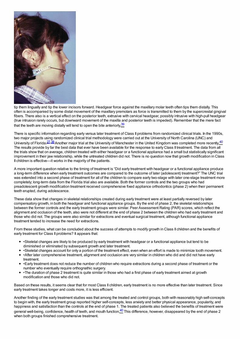
tip them lingually and tip the lower incisors forward. Headgear force against the maxillary molar teeth often tips them distally. Thisoften is accompanied by some distal movement of the maxillary premolars as force is transmitted to them by the supercrestal gingivalfibers. There also is a vertical effect on the posterior teeth, extrusive with cervical headgear, possibly intrusive with high-pull headgear(true intrusion rarely occurs, but downward movement of the maxilla and posterior teeth is impeded). Remember that the mere factthat the teeth are moving distally will tend to open the bite anteriorly.39
There is specific information regarding early versus later treatment of Class II problems from randomized clinical trials. In the 1990s,two major projects using randomized clinical trial methodology were carried out at the University of North Carolina (UNC) andUniversity of Florida.27,38 Another major trial at the University of Manchester in the United Kingdom was completed more recently.40
The results provide by far the best data that ever have been available for the response to early Class II treatment. The data from allthe trials show that on average, children treated with either headgear or a functional appliance had a small but statistically significantimprovement in their jaw relationship, while the untreated children did not. There is no question now that growth modification in ClassII children is effective—it works in the majority of the patients.
A more important question relative to the timing of treatment is “Did early treatment with headgear or a functional appliance producea long-term difference when early treatment outcomes are compared to the outcome of later (adolescent) treatment?” The UNC trialwas extended into a second phase of treatment for all of the children to compare early two-stage with later one-stage treatment morecompletely; long-term data from the Florida trial also are available. Both the former controls and the two groups who hadpreadolescent growth modification treatment received comprehensive fixed appliance orthodontics (phase 2) when their permanentteeth erupted, during adolescence.
These data show that changes in skeletal relationships created during early treatment were at least partially reversed by latercompensatory growth, in both the headgear and functional appliance groups. By the end of phase 2, the skeletal relationshipsbetween the former controls and the early treatment groups were similar. Peer Assessment Rating (PAR) scores, which reflect thealignment and occlusion of the teeth, also were not different at the end of phase 2 between the children who had early treatment andthose who did not. The groups were also similar for extractions and eventual surgical treatment, although functional appliancetreatment tended to increase the need for extractions.
From these studies, what can be concluded about the success of attempts to modify growth in Class II children and the benefits ofearly treatment for Class II problems? It appears that:
•Skeletal changes are likely to be produced by early treatment with headgear or a functional appliance but tend to bediminished or eliminated by subsequent growth and later treatment.•Skeletal changes account for only a portion of the treatment effect, even when an effort is made to minimize tooth movement.•After later comprehensive treatment, alignment and occlusion are very similar in children who did and did not have earlytreatment.•Early treatment does not reduce the number of children who require extractions during a second phase of treatment or thenumber who eventually require orthognathic surgery.•The duration of phase 2 treatment is quite similar in those who had a first phase of early treatment aimed at growthmodification and those who did not.
Based on these results, it seems clear that for most Class II children, early treatment is no more effective than later treatment. Sinceearly treatment takes longer and costs more, it is less efficient.
Another finding of the early treatment studies was that among the treated and control groups, both with reasonably high self-conceptsto begin with, the early treatment group reported higher self-concepts, less anxiety and better physical appearance, popularity, andhappiness and satisfaction than the controls at the end of phase 1. The treated patients also believed the benefits of treatment weregeneral well-being, confidence, health of teeth, and mouth function.40 This difference, however, disappeared by the end of phase 2when both groups finished comprehensive treatment.
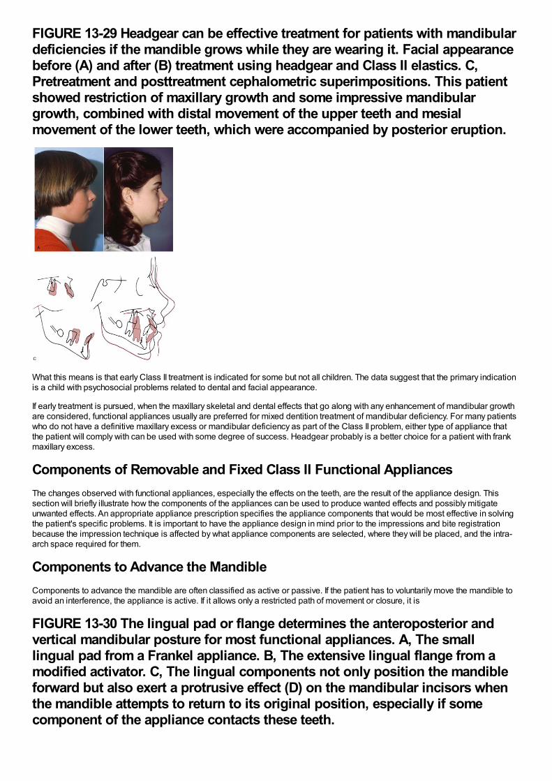
FIGURE 13-29 Headgear can be effective treatment for patients with mandibulardeficiencies if the mandible grows while they are wearing it. Facial appearancebefore (A) and after (B) treatment using headgear and Class II elastics. C,Pretreatment and posttreatment cephalometric superimpositions. This patientshowed restriction of maxillary growth and some impressive mandibulargrowth, combined with distal movement of the upper teeth and mesialmovement of the lower teeth, which were accompanied by posterior eruption.
What this means is that early Class II treatment is indicated for some but not all children. The data suggest that the primary indicationis a child with psychosocial problems related to dental and facial appearance.
If early treatment is pursued, when the maxillary skeletal and dental effects that go along with any enhancement of mandibular growthare considered, functional appliances usually are preferred for mixed dentition treatment of mandibular deficiency. For many patientswho do not have a definitive maxillary excess or mandibular deficiency as part of the Class II problem, either type of appliance thatthe patient will comply with can be used with some degree of success. Headgear probably is a better choice for a patient with frankmaxillary excess.
Components of Removable and Fixed Class II Functional AppliancesThe changes observed with functional appliances, especially the effects on the teeth, are the result of the appliance design. Thissection will briefly illustrate how the components of the appliances can be used to produce wanted effects and possibly mitigateunwanted effects. An appropriate appliance prescription specifies the appliance components that would be most effective in solvingthe patient's specific problems. It is important to have the appliance design in mind prior to the impressions and bite registrationbecause the impression technique is affected by what appliance components are selected, where they will be placed, and the intra-arch space required for them.
Components to Advance the MandibleComponents to advance the mandible are often classified as active or passive. If the patient has to voluntarily move the mandible toavoid an interference, the appliance is active. If it allows only a restricted path of movement or closure, it is
FIGURE 13-30 The lingual pad or flange determines the anteroposterior andvertical mandibular posture for most functional appliances. A, The smalllingual pad from a Frankel appliance. B, The extensive lingual flange from amodified activator. C, The lingual components not only position the mandibleforward but also exert a protrusive effect (D) on the mandibular incisors whenthe mandible attempts to return to its original position, especially if somecomponent of the appliance contacts these teeth.
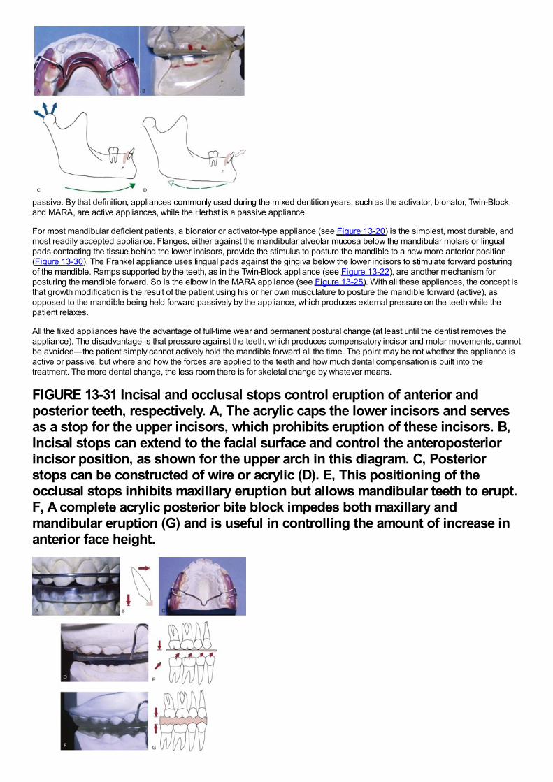
passive. By that definition, appliances commonly used during the mixed dentition years, such as the activator, bionator, Twin-Block,and MARA, are active appliances, while the Herbst is a passive appliance.
For most mandibular deficient patients, a bionator or activator-type appliance (see Figure 13-20) is the simplest, most durable, andmost readily accepted appliance. Flanges, either against the mandibular alveolar mucosa below the mandibular molars or lingualpads contacting the tissue behind the lower incisors, provide the stimulus to posture the mandible to a new more anterior position(Figure 13-30). The Frankel appliance uses lingual pads against the gingiva below the lower incisors to stimulate forward posturingof the mandible. Ramps supported by the teeth, as in the Twin-Block appliance (see Figure 13-22), are another mechanism forposturing the mandible forward. So is the elbow in the MARA appliance (see Figure 13-25). With all these appliances, the concept isthat growth modification is the result of the patient using his or her own musculature to posture the mandible forward (active), asopposed to the mandible being held forward passively by the appliance, which produces external pressure on the teeth while thepatient relaxes.
All the fixed appliances have the advantage of full-time wear and permanent postural change (at least until the dentist removes theappliance). The disadvantage is that pressure against the teeth, which produces compensatory incisor and molar movements, cannotbe avoided—the patient simply cannot actively hold the mandible forward all the time. The point may be not whether the appliance isactive or passive, but where and how the forces are applied to the teeth and how much dental compensation is built into thetreatment. The more dental change, the less room there is for skeletal change by whatever means.
FIGURE 13-31 Incisal and occlusal stops control eruption of anterior andposterior teeth, respectively. A, The acrylic caps the lower incisors and servesas a stop for the upper incisors, which prohibits eruption of these incisors. B,Incisal stops can extend to the facial surface and control the anteroposteriorincisor position, as shown for the upper arch in this diagram. C, Posteriorstops can be constructed of wire or acrylic (D). E, This positioning of theocclusal stops inhibits maxillary eruption but allows mandibular teeth to erupt.F, A complete acrylic posterior bite block impedes both maxillary andmandibular eruption (G) and is useful in controlling the amount of increase inanterior face height.
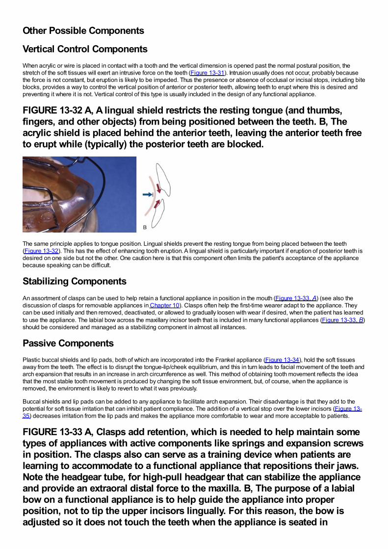
Other Possible Components
Vertical Control ComponentsWhen acrylic or wire is placed in contact with a tooth and the vertical dimension is opened past the normal postural position, thestretch of the soft tissues will exert an intrusive force on the teeth (Figure 13-31). Intrusion usually does not occur, probably becausethe force is not constant, but eruption is likely to be impeded. Thus the presence or absence of occlusal or incisal stops, including biteblocks, provides a way to control the vertical position of anterior or posterior teeth, allowing teeth to erupt where this is desired andpreventing it where it is not. Vertical control of this type is usually included in the design of any functional appliance.
FIGURE 13-32 A, A lingual shield restricts the resting tongue (and thumbs,fingers, and other objects) from being positioned between the teeth. B, Theacrylic shield is placed behind the anterior teeth, leaving the anterior teeth freeto erupt while (typically) the posterior teeth are blocked.
The same principle applies to tongue position. Lingual shields prevent the resting tongue from being placed between the teeth(Figure 13-32). This has the effect of enhancing tooth eruption. A lingual shield is particularly important if eruption of posterior teeth isdesired on one side but not the other. One caution here is that this component often limits the patient's acceptance of the appliancebecause speaking can be difficult.
Stabilizing ComponentsAn assortment of clasps can be used to help retain a functional appliance in position in the mouth (Figure 13-33, A) (see also thediscussion of clasps for removable appliances in Chapter 10). Clasps often help the first-time wearer adapt to the appliance. Theycan be used initially and then removed, deactivated, or allowed to gradually loosen with wear if desired, when the patient has learnedto use the appliance. The labial bow across the maxillary incisor teeth that is included in many functional appliances (Figure 13-33, B)should be considered and managed as a stabilizing component in almost all instances.
Passive ComponentsPlastic buccal shields and lip pads, both of which are incorporated into the Frankel appliance (Figure 13-34), hold the soft tissuesaway from the teeth. The effect is to disrupt the tongue-lip/cheek equilibrium, and this in turn leads to facial movement of the teeth andarch expansion that results in an increase in arch circumference as well. This method of obtaining tooth movement reflects the ideathat the most stable tooth movement is produced by changing the soft tissue environment, but, of course, when the appliance isremoved, the environment is likely to revert to what it was previously.
Buccal shields and lip pads can be added to any appliance to facilitate arch expansion. Their disadvantage is that they add to thepotential for soft tissue irritation that can inhibit patient compliance. The addition of a vertical stop over the lower incisors (Figure 13-35) decreases irritation from the lip pads and makes the appliance more comfortable to wear and more acceptable to patients.
FIGURE 13-33 A, Clasps add retention, which is needed to help maintain sometypes of appliances with active components like springs and expansion screwsin position. The clasps also can serve as a training device when patients arelearning to accommodate to a functional appliance that repositions their jaws.Note the headgear tube, for high-pull headgear that can stabilize the applianceand provide an extraoral distal force to the maxilla. B, The purpose of a labialbow on a functional appliance is to help guide the appliance into properposition, not to tip the upper incisors lingually. For this reason, the bow isadjusted so it does not touch the teeth when the appliance is seated in
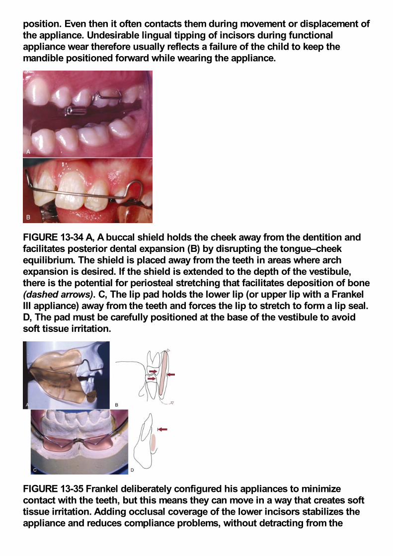
position. Even then it often contacts them during movement or displacement ofthe appliance. Undesirable lingual tipping of incisors during functionalappliance wear therefore usually reflects a failure of the child to keep themandible positioned forward while wearing the appliance.
FIGURE 13-34 A, A buccal shield holds the cheek away from the dentition andfacilitates posterior dental expansion (B) by disrupting the tongue–cheekequilibrium. The shield is placed away from the teeth in areas where archexpansion is desired. If the shield is extended to the depth of the vestibule,there is the potential for periosteal stretching that facilitates deposition of bone(dashed arrows). C, The lip pad holds the lower lip (or upper lip with a FrankelIII appliance) away from the teeth and forces the lip to stretch to form a lip seal.D, The pad must be carefully positioned at the base of the vestibule to avoidsoft tissue irritation.
FIGURE 13-35 Frankel deliberately configured his appliances to minimizecontact with the teeth, but this means they can move in a way that creates softtissue irritation. Adding occlusal coverage of the lower incisors stabilizes theappliance and reduces compliance problems, without detracting from the
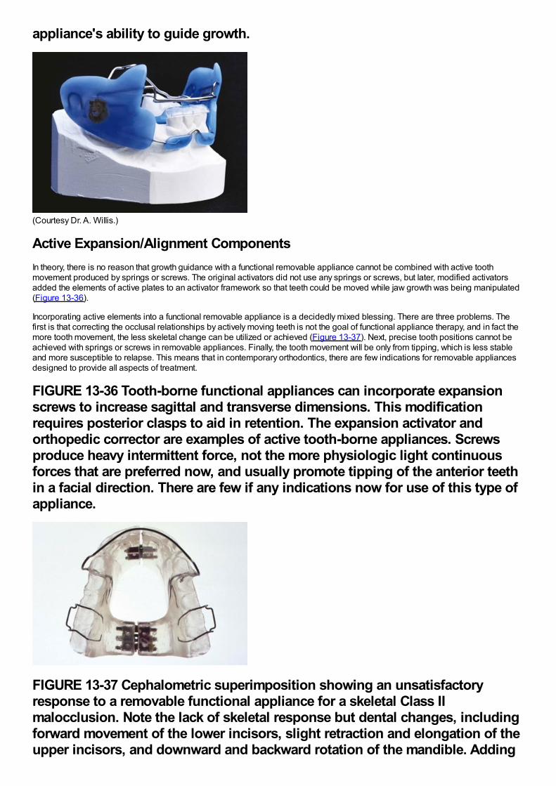
appliance's ability to guide growth.
(Courtesy Dr. A. Willis.)
Active Expansion/Alignment ComponentsIn theory, there is no reason that growth guidance with a functional removable appliance cannot be combined with active toothmovement produced by springs or screws. The original activators did not use any springs or screws, but later, modified activatorsadded the elements of active plates to an activator framework so that teeth could be moved while jaw growth was being manipulated(Figure 13-36).
Incorporating active elements into a functional removable appliance is a decidedly mixed blessing. There are three problems. Thefirst is that correcting the occlusal relationships by actively moving teeth is not the goal of functional appliance therapy, and in fact themore tooth movement, the less skeletal change can be utilized or achieved (Figure 13-37). Next, precise tooth positions cannot beachieved with springs or screws in removable appliances. Finally, the tooth movement will be only from tipping, which is less stableand more susceptible to relapse. This means that in contemporary orthodontics, there are few indications for removable appliancesdesigned to provide all aspects of treatment.
FIGURE 13-36 Tooth-borne functional appliances can incorporate expansionscrews to increase sagittal and transverse dimensions. This modificationrequires posterior clasps to aid in retention. The expansion activator andorthopedic corrector are examples of active tooth-borne appliances. Screwsproduce heavy intermittent force, not the more physiologic light continuousforces that are preferred now, and usually promote tipping of the anterior teethin a facial direction. There are few if any indications now for use of this type ofappliance.
FIGURE 13-37 Cephalometric superimposition showing an unsatisfactoryresponse to a removable functional appliance for a skeletal Class IImalocclusion. Note the lack of skeletal response but dental changes, includingforward movement of the lower incisors, slight retraction and elongation of theupper incisors, and downward and backward rotation of the mandible. Adding
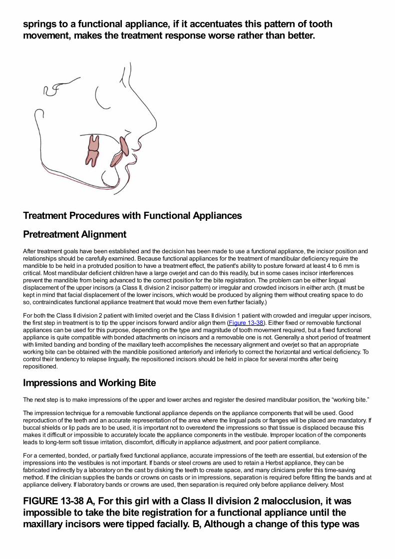
springs to a functional appliance, if it accentuates this pattern of toothmovement, makes the treatment response worse rather than better.
Treatment Procedures with Functional Appliances
Pretreatment AlignmentAfter treatment goals have been established and the decision has been made to use a functional appliance, the incisor position andrelationships should be carefully examined. Because functional appliances for the treatment of mandibular deficiency require themandible to be held in a protruded position to have a treatment effect, the patient's ability to posture forward at least 4 to 6 mm iscritical. Most mandibular deficient children have a large overjet and can do this readily, but in some cases incisor interferencesprevent the mandible from being advanced to the correct position for the bite registration. The problem can be either lingualdisplacement of the upper incisors (a Class II, division 2 incisor pattern) or irregular and crowded incisors in either arch. (It must bekept in mind that facial displacement of the lower incisors, which would be produced by aligning them without creating space to doso, contraindicates functional appliance treatment that would move them even further facially.)
For both the Class II division 2 patient with limited overjet and the Class II division 1 patient with crowded and irregular upper incisors,the first step in treatment is to tip the upper incisors forward and/or align them (Figure 13-38). Either fixed or removable functionalappliances can be used for this purpose, depending on the type and magnitude of tooth movement required, but a fixed functionalappliance is quite compatible with bonded attachments on incisors and a removable one is not. Generally a short period of treatmentwith limited banding and bonding of the maxillary teeth accomplishes the necessary alignment and overjet so that an appropriateworking bite can be obtained with the mandible positioned anteriorly and inferiorly to correct the horizontal and vertical deficiency. Tocontrol their tendency to relapse lingually, the repositioned incisors should be held in place for several months after beingrepositioned.
Impressions and Working BiteThe next step is to make impressions of the upper and lower arches and register the desired mandibular position, the “working bite.”
The impression technique for a removable functional appliance depends on the appliance components that will be used. Goodreproduction of the teeth and an accurate representation of the area where the lingual pads or flanges will be placed are mandatory. Ifbuccal shields or lip pads are to be used, it is important not to overextend the impressions so that tissue is displaced because thismakes it difficult or impossible to accurately locate the appliance components in the vestibule. Improper location of the componentsleads to long-term soft tissue irritation, discomfort, difficulty in appliance adjustment, and poor patient compliance.
For a cemented, bonded, or partially fixed functional appliance, accurate impressions of the teeth are essential, but extension of theimpressions into the vestibules is not important. If bands or steel crowns are used to retain a Herbst appliance, they can befabricated indirectly by a laboratory on the cast by disking the teeth to create space, and many clinicians prefer this time-savingmethod. If the clinician supplies the bands or crowns on casts or in impressions, separation is required before fitting the bands and atappliance delivery. If laboratory bands or crowns are used, then separation is required only before appliance delivery. Most
FIGURE 13-38 A, For this girl with a Class II division 2 malocclusion, it wasimpossible to take the bite registration for a functional appliance until themaxillary incisors were tipped facially. B, Although a change of this type was
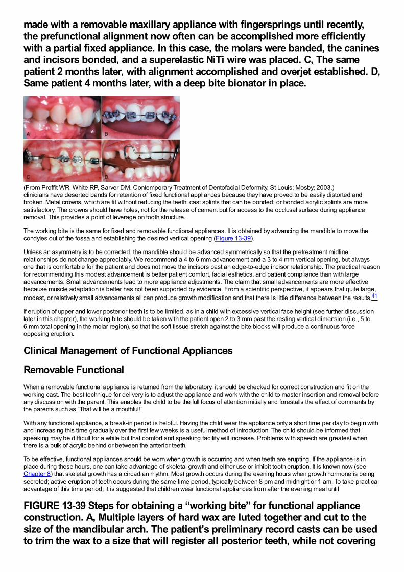
made with a removable maxillary appliance with fingersprings until recently,the prefunctional alignment now often can be accomplished more efficientlywith a partial fixed appliance. In this case, the molars were banded, the caninesand incisors bonded, and a superelastic NiTi wire was placed. C, The samepatient 2 months later, with alignment accomplished and overjet established. D,Same patient 4 months later, with a deep bite bionator in place.
(From Proffit WR, White RP, Sarver DM. Contemporary Treatment of Dentofacial Deformity. St Louis: Mosby; 2003.)clinicians have deserted bands for retention of fixed functional appliances because they have proved to be easily distorted andbroken. Metal crowns, which are fit without reducing the teeth; cast splints that can be bonded; or bonded acrylic splints are moresatisfactory. The crowns should have holes, not for the release of cement but for access to the occlusal surface during applianceremoval. This provides a point of leverage on tooth structure.
The working bite is the same for fixed and removable functional appliances. It is obtained by advancing the mandible to move thecondyles out of the fossa and establishing the desired vertical opening (Figure 13-39).
Unless an asymmetry is to be corrected, the mandible should be advanced symmetrically so that the pretreatment midlinerelationships do not change appreciably. We recommend a 4 to 6 mm advancement and a 3 to 4 mm vertical opening, but alwaysone that is comfortable for the patient and does not move the incisors past an edge-to-edge incisor relationship. The practical reasonfor recommending this modest advancement is better patient comfort, facial esthetics, and patient compliance than with largeadvancements. Small advancements lead to more appliance adjustments. The claim that small advancements are more effectivebecause muscle adaptation is better has not been supported by evidence. From a scientific perspective, it appears that quite large,modest, or relatively small advancements all can produce growth modification and that there is little difference between the results.41
If eruption of upper and lower posterior teeth is to be limited, as in a child with excessive vertical face height (see further discussionlater in this chapter), the working bite should be taken with the patient open 2 to 3 mm past the resting vertical dimension (i.e., 5 to6 mm total opening in the molar region), so that the soft tissue stretch against the bite blocks will produce a continuous forceopposing eruption.
Clinical Management of Functional Appliances
Removable FunctionalWhen a removable functional appliance is returned from the laboratory, it should be checked for correct construction and fit on theworking cast. The best technique for delivery is to adjust the appliance and work with the child to master insertion and removal beforeany discussion with the parent. This enables the child to be the full focus of attention initially and forestalls the effect of comments bythe parents such as “That will be a mouthful!”
With any functional appliance, a break-in period is helpful. Having the child wear the appliance only a short time per day to begin withand increasing this time gradually over the first few weeks is a useful method of introduction. The child should be informed thatspeaking may be difficult for a while but that comfort and speaking facility will increase. Problems with speech are greatest whenthere is a bulk of acrylic behind or between the anterior teeth.
To be effective, functional appliances should be worn when growth is occurring and when teeth are erupting. If the appliance is inplace during these hours, one can take advantage of skeletal growth and either use or inhibit tooth eruption. It is known now (seeChapter 8) that skeletal growth has a circadian rhythm. Most growth occurs during the evening hours when growth hormone is beingsecreted; active eruption of teeth occurs during the same time period, typically between 8 pm and midnight or 1 am. To take practicaladvantage of this time period, it is suggested that children wear functional appliances from after the evening meal until
FIGURE 13-39 Steps for obtaining a “working bite” for functional applianceconstruction. A, Multiple layers of hard wax are luted together and cut to thesize of the mandibular arch. The patient's preliminary record casts can be usedto trim the wax to a size that will register all posterior teeth, while not covering
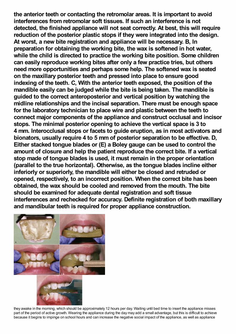
the anterior teeth or contacting the retromolar areas. It is important to avoidinterferences from retromolar soft tissues. If such an interference is notdetected, the finished appliance will not seat correctly. At best, this will requirereduction of the posterior plastic stops if they were integrated into the design.At worst, a new bite registration and appliance will be necessary. B, Inpreparation for obtaining the working bite, the wax is softened in hot water,while the child is directed to practice the working bite position. Some childrencan easily reproduce working bites after only a few practice tries, but othersneed more opportunities and perhaps some help. The softened wax is seatedon the maxillary posterior teeth and pressed into place to ensure goodindexing of the teeth. C, With the anterior teeth exposed, the position of themandible easily can be judged while the bite is being taken. The mandible isguided to the correct anteroposterior and vertical position by watching themidline relationships and the incisal separation. There must be enough spacefor the laboratory technician to place wire and plastic between the teeth toconnect major components of the appliance and construct occlusal and incisorstops. The minimal posterior opening to achieve the vertical space is 3 to4 mm. Interocclusal stops or facets to guide eruption, as in most activators andbionators, usually require 4 to 5 mm of posterior separation to be effective. D,Either stacked tongue blades or (E) a Boley gauge can be used to control theamount of closure and help the patient reproduce the correct bite. If a verticalstop made of tongue blades is used, it must remain in the proper orientation(parallel to the true horizontal). Otherwise, as the tongue blades incline eitherinferiorly or superiorly, the mandible will either be closed and retruded oropened, respectively, to an incorrect position. When the correct bite has beenobtained, the wax should be cooled and removed from the mouth. The biteshould be examined for adequate dental registration and soft tissueinterferences and rechecked for accuracy. Definite registration of both maxillaryand mandibular teeth is required for proper appliance construction.
they awake in the morning, which should be approximately 12 hours per day. Waiting until bed time to insert the appliance missespart of the period of active growth. Wearing the appliance during the day may add a small advantage, but this is difficult to achievebecause it begins to impinge on school hours and can increase the negative social impact of the appliance, as well as appliance
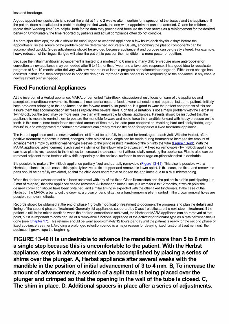
loss and breakage.
A good appointment schedule is to recall the child at 1 and 2 weeks after insertion for inspection of the tissues and the appliance. Ifthe patient does not call about a problem during the first week, the one-week appointment can be cancelled. Charts for children torecord their “wearing time” are helpful, both for the data they provide and because the chart serves as a reinforcement for the desiredbehavior. Unfortunately, the time reported by patients and actual compliance often do not coincide.
If a sore spot develops, the child should be encouraged to wear the appliance a few hours each day for 2 days before theappointment, so the source of the problem can be determined accurately. Usually, smoothing the plastic components can beaccomplished quickly. Gross adjustments should be avoided because appliance fit and purpose can be greatly altered. For example,heavy reduction of the lingual flanges will allow the patient to position the mandible in a more posterior position.
Because the initial mandibular advancement is limited to a modest 4 to 6 mm and many children require more anteroposteriorcorrection, a new appliance may be needed after 6 to 12 months of wear and a favorable response. It is a good idea to reevaluateprogress at 8 to 10 months after delivery with new records or at least a progress cephalometric radiograph. If little or no change hasoccurred in that time, then compliance is poor, the design is improper, or the patient is not responding to the appliance. In any case, anew treatment plan is needed.
Fixed Functional AppliancesAt the insertion of a Herbst appliance, MARA, or cemented Twin-Block, discussion should focus on care of the appliance andacceptable mandibular movements. Because these appliances are fixed, a wear schedule is not required, but some patients initiallyhave problems adapting to the appliance and the forward mandibular position. It is good to warn the patient and parents of this andassure them that accommodation increases rapidly after several days. Soft tissue irritation is not a major problem with the Herbst orTwin-Block, but the teeth may be more sensitive than with removable functional appliances. Patients should be instructed that theappliance is meant to remind them to posture the mandible forward and not to force the mandible forward with heavy pressure on theteeth. In this sense, sore teeth for an extended amount of time may indicate poor cooperation. Avoiding hard and sticky foods, largemouthfuls, and exaggerated mandibular movements can greatly reduce the need for repair of a fixed functional appliance.
The Herbst appliance and the newer variations of it must be carefully inspected for breakage at each visit. With the Herbst, after apositive treatment response is noted, changes in the pin and tube length can be made during treatment to increase the amount ofadvancement simply by adding washer-type sleeves to the pin to restrict insertion of the pin into the tube (Figure 13-40). With theMARA appliance, advancement is achieved via shims on the elbow wire to advance it. A fixed (or removable) Twin-Block appliancecan have plastic resin added to the inclines to increase the advancement without totally remaking the appliance. Plastic also can beremoved adjacent to the teeth to allow drift, especially on the occlusal surfaces to encourage eruption when that is desirable.
It is possible to make a Twin-Block appliance partially fixed and partially removable (Figure 13-41). This also is possible with aHerbst appliance. In both cases, this typically involves a fixed upper and removable lower splint. In this case, the fixed and removableparts should be carefully explained, so that the child does not remove or loosen the appliance due to a misunderstanding.
When the desired advancement has been achieved with any of the fixed Class II correctors and the patient is stable (anticipating 1 to2 mm of relapse), then the appliance can be removed. A Herbst appliance usually is worn for 8 to 12 months, at which point thedesired correction should have been obtained, and similar timing is expected with the other fixed functionals. In the case of theHerbst or the MARA, a bur to cut the crowns, a crown or band slitter, or a band-removing plier inserted in the crown removal holes arepossible removal methods.
Records should be obtained at the end of phase 1 growth modification treatment to document the progress and plan the details andtiming of the second phase of treatment. Generally, full appliances supported by Class II elastics are the next step in treatment. If thepatient is still in the mixed dentition when the desired correction is achieved, the Herbst or MARA appliance can be removed at thatpoint, but it is important to consider use of a removable functional appliance of the activator or bionator type as a retainer when this isdone (see Chapter 17). This retainer should be worn approximately 12 hours per day until the patient is ready for the second phase offixed appliance treatment. Avoiding a prolonged retention period is a major reason for delaying fixed functional treatment until theadolescent growth spurt is beginning.
FIGURE 13-40 It is undesirable to advance the mandible more than 5 to 6 mm ina single step because this is uncomfortable to the patient. With the Herbstappliance, steps in advancement can be accomplished by placing a series ofshims over the plunger. A, Herbst appliance after several weeks with themandible in the position of initial advancement of 3 to 4 mm. B, To increase theamount of advancement, a section of a split tube is being placed over theplunger and crimped so that the opening in the wall of the tube is closed. C,The shim in place. D, Additional spacers in place after a series of adjustments.
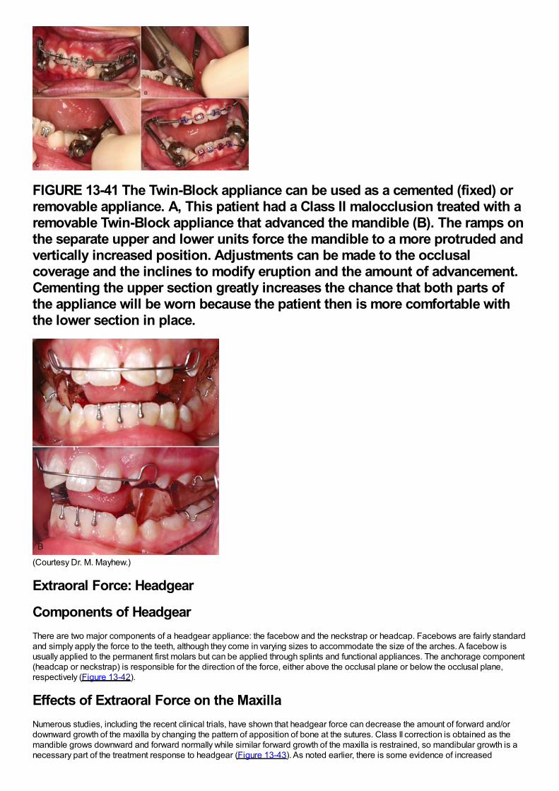
FIGURE 13-41 The Twin-Block appliance can be used as a cemented (fixed) orremovable appliance. A, This patient had a Class II malocclusion treated with aremovable Twin-Block appliance that advanced the mandible (B). The ramps onthe separate upper and lower units force the mandible to a more protruded andvertically increased position. Adjustments can be made to the occlusalcoverage and the inclines to modify eruption and the amount of advancement.Cementing the upper section greatly increases the chance that both parts ofthe appliance will be worn because the patient then is more comfortable withthe lower section in place.
(Courtesy Dr. M. Mayhew.)
Extraoral Force: Headgear
Components of HeadgearThere are two major components of a headgear appliance: the facebow and the neckstrap or headcap. Facebows are fairly standardand simply apply the force to the teeth, although they come in varying sizes to accommodate the size of the arches. A facebow isusually applied to the permanent first molars but can be applied through splints and functional appliances. The anchorage component(headcap or neckstrap) is responsible for the direction of the force, either above the occlusal plane or below the occlusal plane,respectively (Figure 13-42).
Effects of Extraoral Force on the MaxillaNumerous studies, including the recent clinical trials, have shown that headgear force can decrease the amount of forward and/ordownward growth of the maxilla by changing the pattern of apposition of bone at the sutures. Class II correction is obtained as themandible grows downward and forward normally while similar forward growth of the maxilla is restrained, so mandibular growth is anecessary part of the treatment response to headgear (Figure 13-43). As noted earlier, there is some evidence of increased
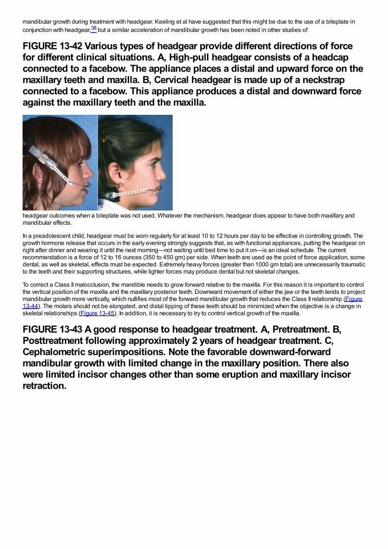
mandibular growth during treatment with headgear. Keeling et al have suggested that this might be due to the use of a biteplate inconjunction with headgear,38 but a similar acceleration of mandibular growth has been noted in other studies of
FIGURE 13-42 Various types of headgear provide different directions of forcefor different clinical situations. A, High-pull headgear consists of a headcapconnected to a facebow. The appliance places a distal and upward force on themaxillary teeth and maxilla. B, Cervical headgear is made up of a neckstrapconnected to a facebow. This appliance produces a distal and downward forceagainst the maxillary teeth and the maxilla.
headgear outcomes when a biteplate was not used. Whatever the mechanism, headgear does appear to have both maxillary andmandibular effects.
In a preadolescent child, headgear must be worn regularly for at least 10 to 12 hours per day to be effective in controlling growth. Thegrowth hormone release that occurs in the early evening strongly suggests that, as with functional appliances, putting the headgear onright after dinner and wearing it until the next morning—not waiting until bed time to put it on—is an ideal schedule. The currentrecommendation is a force of 12 to 16 ounces (350 to 450 gm) per side. When teeth are used as the point of force application, somedental, as well as skeletal, effects must be expected. Extremely heavy forces (greater than 1000 gm total) are unnecessarily traumaticto the teeth and their supporting structures, while lighter forces may produce dental but not skeletal changes.
To correct a Class II malocclusion, the mandible needs to grow forward relative to the maxilla. For this reason it is important to controlthe vertical position of the maxilla and the maxillary posterior teeth. Downward movement of either the jaw or the teeth tends to projectmandibular growth more vertically, which nullifies most of the forward mandibular growth that reduces the Class II relationship (Figure13-44). The molars should not be elongated, and distal tipping of these teeth should be minimized when the objective is a change inskeletal relationships (Figure 13-45). In addition, it is necessary to try to control vertical growth of the maxilla.
FIGURE 13-43 A good response to headgear treatment. A, Pretreatment. B,Posttreatment following approximately 2 years of headgear treatment. C,Cephalometric superimpositions. Note the favorable downward-forwardmandibular growth with limited change in the maxillary position. There alsowere limited incisor changes other than some eruption and maxillary incisorretraction.
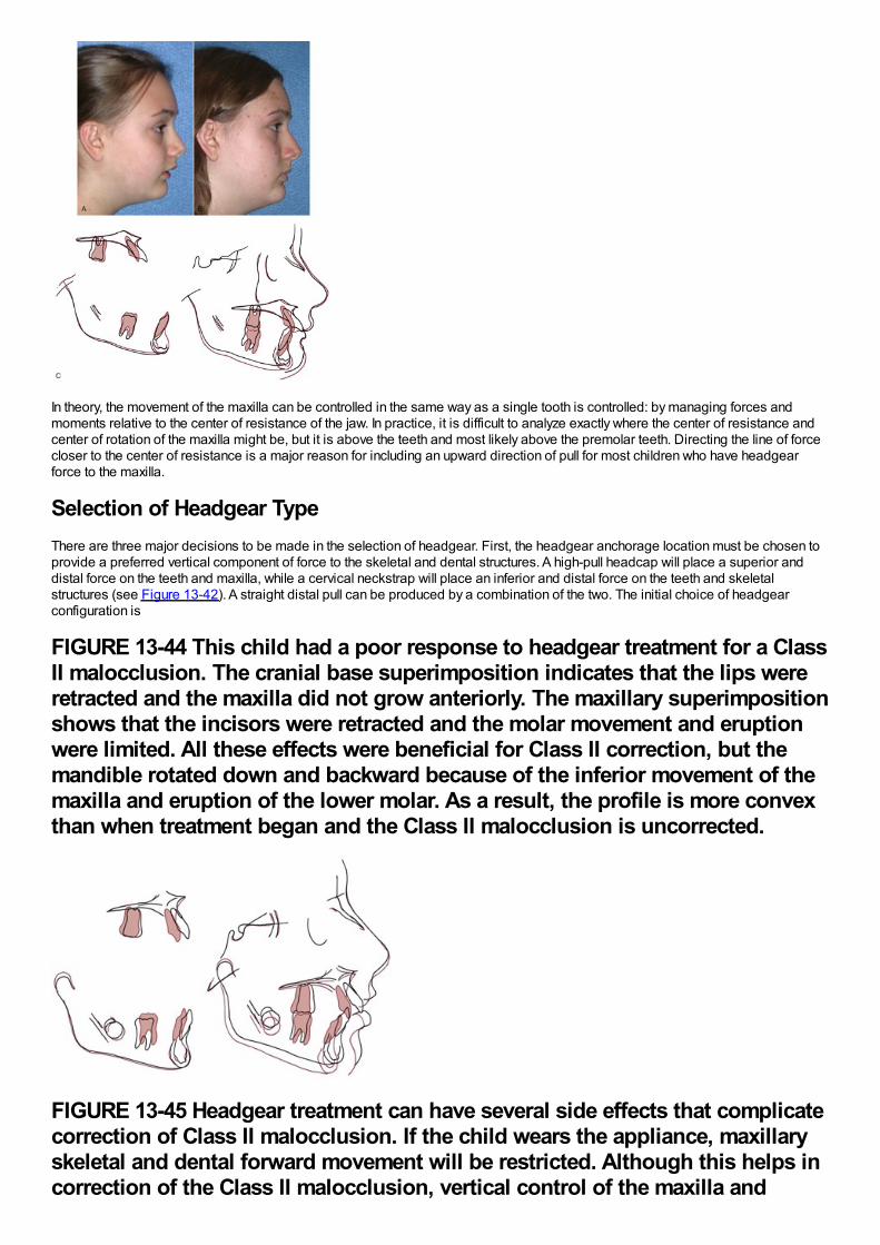
In theory, the movement of the maxilla can be controlled in the same way as a single tooth is controlled: by managing forces andmoments relative to the center of resistance of the jaw. In practice, it is difficult to analyze exactly where the center of resistance andcenter of rotation of the maxilla might be, but it is above the teeth and most likely above the premolar teeth. Directing the line of forcecloser to the center of resistance is a major reason for including an upward direction of pull for most children who have headgearforce to the maxilla.
Selection of Headgear TypeThere are three major decisions to be made in the selection of headgear. First, the headgear anchorage location must be chosen toprovide a preferred vertical component of force to the skeletal and dental structures. A high-pull headcap will place a superior anddistal force on the teeth and maxilla, while a cervical neckstrap will place an inferior and distal force on the teeth and skeletalstructures (see Figure 13-42). A straight distal pull can be produced by a combination of the two. The initial choice of headgearconfiguration is
FIGURE 13-44 This child had a poor response to headgear treatment for a ClassII malocclusion. The cranial base superimposition indicates that the lips wereretracted and the maxilla did not grow anteriorly. The maxillary superimpositionshows that the incisors were retracted and the molar movement and eruptionwere limited. All these effects were beneficial for Class II correction, but themandible rotated down and backward because of the inferior movement of themaxilla and eruption of the lower molar. As a result, the profile is more convexthan when treatment began and the Class II malocclusion is uncorrected.
FIGURE 13-45 Headgear treatment can have several side effects that complicatecorrection of Class II malocclusion. If the child wears the appliance, maxillaryskeletal and dental forward movement will be restricted. Although this helps incorrection of the Class II malocclusion, vertical control of the maxilla and
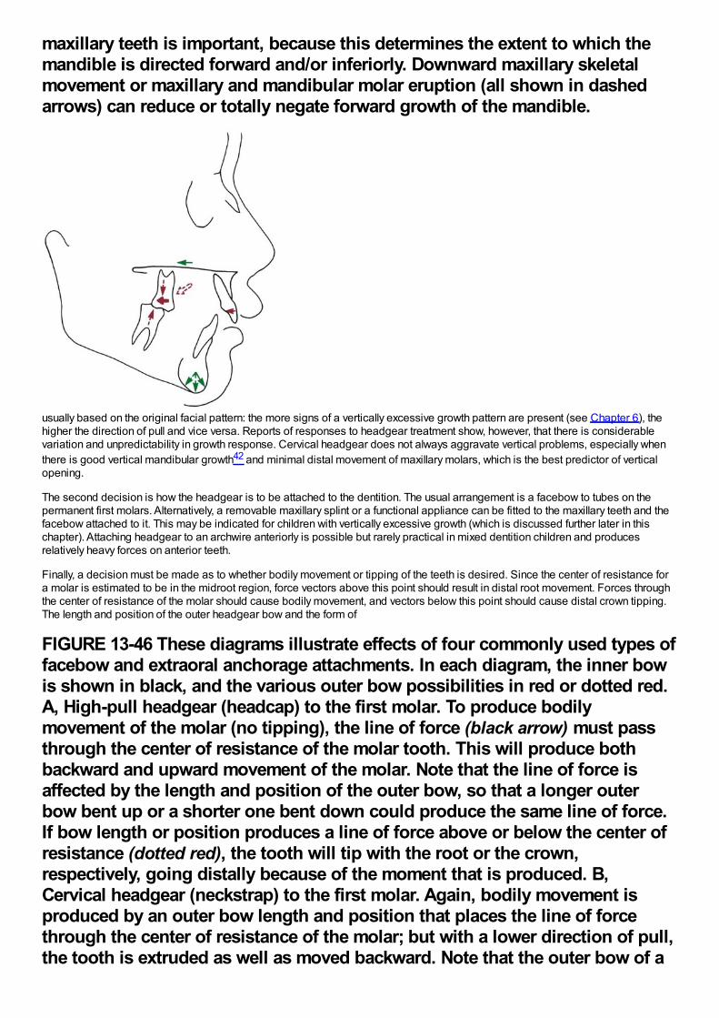
maxillary teeth is important, because this determines the extent to which themandible is directed forward and/or inferiorly. Downward maxillary skeletalmovement or maxillary and mandibular molar eruption (all shown in dashedarrows) can reduce or totally negate forward growth of the mandible.
usually based on the original facial pattern: the more signs of a vertically excessive growth pattern are present (see Chapter 6), thehigher the direction of pull and vice versa. Reports of responses to headgear treatment show, however, that there is considerablevariation and unpredictability in growth response. Cervical headgear does not always aggravate vertical problems, especially whenthere is good vertical mandibular growth42 and minimal distal movement of maxillary molars, which is the best predictor of verticalopening.
The second decision is how the headgear is to be attached to the dentition. The usual arrangement is a facebow to tubes on thepermanent first molars. Alternatively, a removable maxillary splint or a functional appliance can be fitted to the maxillary teeth and thefacebow attached to it. This may be indicated for children with vertically excessive growth (which is discussed further later in thischapter). Attaching headgear to an archwire anteriorly is possible but rarely practical in mixed dentition children and producesrelatively heavy forces on anterior teeth.
Finally, a decision must be made as to whether bodily movement or tipping of the teeth is desired. Since the center of resistance fora molar is estimated to be in the midroot region, force vectors above this point should result in distal root movement. Forces throughthe center of resistance of the molar should cause bodily movement, and vectors below this point should cause distal crown tipping.The length and position of the outer headgear bow and the form of
FIGURE 13-46 These diagrams illustrate effects of four commonly used types offacebow and extraoral anchorage attachments. In each diagram, the inner bowis shown in black, and the various outer bow possibilities in red or dotted red.A, High-pull headgear (headcap) to the first molar. To produce bodilymovement of the molar (no tipping), the line of force (black arrow) must passthrough the center of resistance of the molar tooth. This will produce bothbackward and upward movement of the molar. Note that the line of force isaffected by the length and position of the outer bow, so that a longer outerbow bent up or a shorter one bent down could produce the same line of force.If bow length or position produces a line of force above or below the center ofresistance (dotted red), the tooth will tip with the root or the crown,respectively, going distally because of the moment that is produced. B,Cervical headgear (neckstrap) to the first molar. Again, bodily movement isproduced by an outer bow length and position that places the line of forcethrough the center of resistance of the molar; but with a lower direction of pull,the tooth is extruded as well as moved backward. Note that the outer bow of a
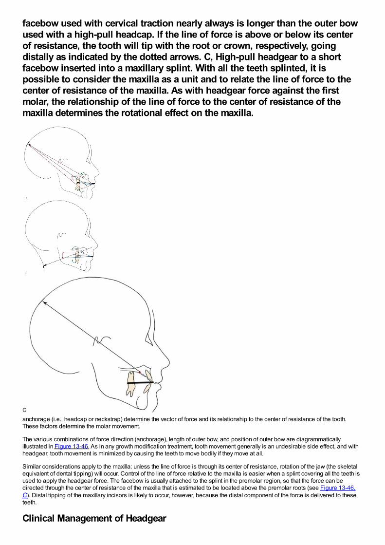
facebow used with cervical traction nearly always is longer than the outer bowused with a high-pull headcap. If the line of force is above or below its centerof resistance, the tooth will tip with the root or crown, respectively, goingdistally as indicated by the dotted arrows. C, High-pull headgear to a shortfacebow inserted into a maxillary splint. With all the teeth splinted, it ispossible to consider the maxilla as a unit and to relate the line of force to thecenter of resistance of the maxilla. As with headgear force against the firstmolar, the relationship of the line of force to the center of resistance of themaxilla determines the rotational effect on the maxilla.
anchorage (i.e., headcap or neckstrap) determine the vector of force and its relationship to the center of resistance of the tooth.These factors determine the molar movement.
The various combinations of force direction (anchorage), length of outer bow, and position of outer bow are diagrammaticallyillustrated in Figure 13-46. As in any growth modification treatment, tooth movement generally is an undesirable side effect, and withheadgear, tooth movement is minimized by causing the teeth to move bodily if they move at all.
Similar considerations apply to the maxilla: unless the line of force is through its center of resistance, rotation of the jaw (the skeletalequivalent of dental tipping) will occur. Control of the line of force relative to the maxilla is easier when a splint covering all the teeth isused to apply the headgear force. The facebow is usually attached to the splint in the premolar region, so that the force can bedirected through the center of resistance of the maxilla that is estimated to be located above the premolar roots (see Figure 13-46,C). Distal tipping of the maxillary incisors is likely to occur, however, because the distal component of the force is delivered to theseteeth.
Clinical Management of Headgear
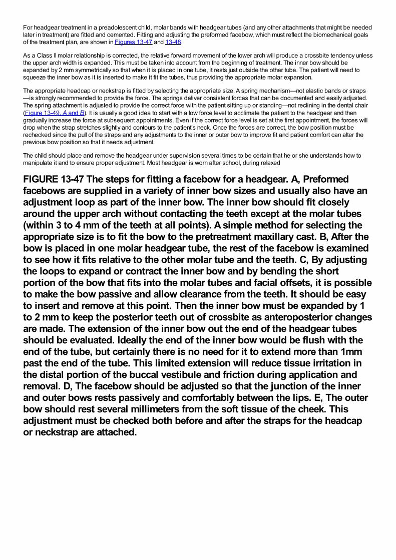
For headgear treatment in a preadolescent child, molar bands with headgear tubes (and any other attachments that might be neededlater in treatment) are fitted and cemented. Fitting and adjusting the preformed facebow, which must reflect the biomechanical goalsof the treatment plan, are shown in Figures 13-47 and 13-48.
As a Class II molar relationship is corrected, the relative forward movement of the lower arch will produce a crossbite tendency unlessthe upper arch width is expanded. This must be taken into account from the beginning of treatment. The inner bow should beexpanded by 2 mm symmetrically so that when it is placed in one tube, it rests just outside the other tube. The patient will need tosqueeze the inner bow as it is inserted to make it fit the tubes, thus providing the appropriate molar expansion.
The appropriate headcap or neckstrap is fitted by selecting the appropriate size. A spring mechanism—not elastic bands or straps—is strongly recommended to provide the force. The springs deliver consistent forces that can be documented and easily adjusted.The spring attachment is adjusted to provide the correct force with the patient sitting up or standing—not reclining in the dental chair(Figure 13-49, A and B). It is usually a good idea to start with a low force level to acclimate the patient to the headgear and thengradually increase the force at subsequent appointments. Even if the correct force level is set at the first appointment, the forces willdrop when the strap stretches slightly and contours to the patient's neck. Once the forces are correct, the bow position must berechecked since the pull of the straps and any adjustments to the inner or outer bow to improve fit and patient comfort can alter theprevious bow position so that it needs adjustment.
The child should place and remove the headgear under supervision several times to be certain that he or she understands how tomanipulate it and to ensure proper adjustment. Most headgear is worn after school, during relaxed
FIGURE 13-47 The steps for fitting a facebow for a headgear. A, Preformedfacebows are supplied in a variety of inner bow sizes and usually also have anadjustment loop as part of the inner bow. The inner bow should fit closelyaround the upper arch without contacting the teeth except at the molar tubes(within 3 to 4 mm of the teeth at all points). A simple method for selecting theappropriate size is to fit the bow to the pretreatment maxillary cast. B, After thebow is placed in one molar headgear tube, the rest of the facebow is examinedto see how it fits relative to the other molar tube and the teeth. C, By adjustingthe loops to expand or contract the inner bow and by bending the shortportion of the bow that fits into the molar tubes and facial offsets, it is possibleto make the bow passive and allow clearance from the teeth. It should be easyto insert and remove at this point. Then the inner bow must be expanded by 1to 2 mm to keep the posterior teeth out of crossbite as anteroposterior changesare made. The extension of the inner bow out the end of the headgear tubesshould be evaluated. Ideally the end of the inner bow would be flush with theend of the tube, but certainly there is no need for it to extend more than 1mmpast the end of the tube. This limited extension will reduce tissue irritation inthe distal portion of the buccal vestibule and friction during application andremoval. D, The facebow should be adjusted so that the junction of the innerand outer bows rests passively and comfortably between the lips. E, The outerbow should rest several millimeters from the soft tissue of the cheek. Thisadjustment must be checked both before and after the straps for the headcapor neckstrap are attached.
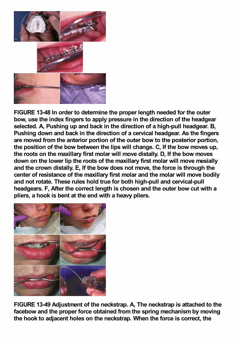
FIGURE 13-48 In order to determine the proper length needed for the outerbow, use the index fingers to apply pressure in the direction of the headgearselected. A, Pushing up and back in the direction of a high-pull headgear. B,Pushing down and back in the direction of a cervical headgear. As the fingersare moved from the anterior portion of the outer bow to the posterior portion,the position of the bow between the lips will change. C, If the bow moves up,the roots on the maxillary first molar will move distally. D, If the bow movesdown on the lower lip the roots of the maxillary first molar will move mesiallyand the crown distally. E, If the bow does not move, the force is through thecenter of resistance of the maxillary first molar and the molar will move bodilyand not rotate. These rules hold true for both high-pull and cervical-pullheadgears. F, After the correct length is chosen and the outer bow cut with apliers, a hook is bent at the end with a heavy pliers.
FIGURE 13-49 Adjustment of the neckstrap. A, The neckstrap is attached to thefacebow and the proper force obtained from the spring mechanism by movingthe hook to adjacent holes on the neckstrap. When the force is correct, the
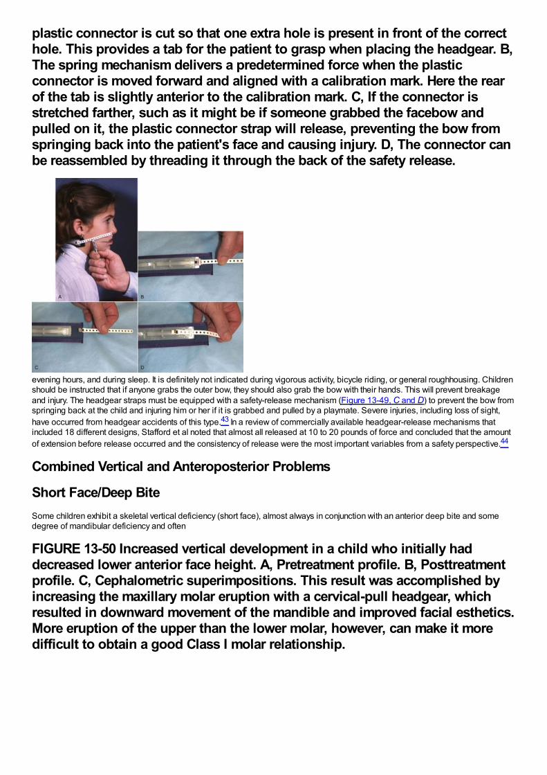
plastic connector is cut so that one extra hole is present in front of the correcthole. This provides a tab for the patient to grasp when placing the headgear. B,The spring mechanism delivers a predetermined force when the plasticconnector is moved forward and aligned with a calibration mark. Here the rearof the tab is slightly anterior to the calibration mark. C, If the connector isstretched farther, such as it might be if someone grabbed the facebow andpulled on it, the plastic connector strap will release, preventing the bow fromspringing back into the patient's face and causing injury. D, The connector canbe reassembled by threading it through the back of the safety release.
evening hours, and during sleep. It is definitely not indicated during vigorous activity, bicycle riding, or general roughhousing. Childrenshould be instructed that if anyone grabs the outer bow, they should also grab the bow with their hands. This will prevent breakageand injury. The headgear straps must be equipped with a safety-release mechanism (Figure 13-49, C and D) to prevent the bow fromspringing back at the child and injuring him or her if it is grabbed and pulled by a playmate. Severe injuries, including loss of sight,have occurred from headgear accidents of this type.43 In a review of commercially available headgear-release mechanisms thatincluded 18 different designs, Stafford et al noted that almost all released at 10 to 20 pounds of force and concluded that the amountof extension before release occurred and the consistency of release were the most important variables from a safety perspective.44
Combined Vertical and Anteroposterior Problems
Short Face/Deep BiteSome children exhibit a skeletal vertical deficiency (short face), almost always in conjunction with an anterior deep bite and somedegree of mandibular deficiency and often
FIGURE 13-50 Increased vertical development in a child who initially haddecreased lower anterior face height. A, Pretreatment profile. B, Posttreatmentprofile. C, Cephalometric superimpositions. This result was accomplished byincreasing the maxillary molar eruption with a cervical-pull headgear, whichresulted in downward movement of the mandible and improved facial esthetics.More eruption of the upper than the lower molar, however, can make it moredifficult to obtain a good Class I molar relationship.
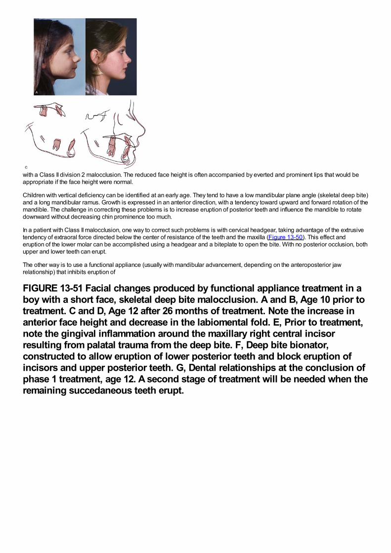
with a Class II division 2 malocclusion. The reduced face height is often accompanied by everted and prominent lips that would beappropriate if the face height were normal.
Children with vertical deficiency can be identified at an early age. They tend to have a low mandibular plane angle (skeletal deep bite)and a long mandibular ramus. Growth is expressed in an anterior direction, with a tendency toward upward and forward rotation of themandible. The challenge in correcting these problems is to increase eruption of posterior teeth and influence the mandible to rotatedownward without decreasing chin prominence too much.
In a patient with Class II malocclusion, one way to correct such problems is with cervical headgear, taking advantage of the extrusivetendency of extraoral force directed below the center of resistance of the teeth and the maxilla (Figure 13-50). This effect anderuption of the lower molar can be accomplished using a headgear and a biteplate to open the bite. With no posterior occlusion, bothupper and lower teeth can erupt.
The other way is to use a functional appliance (usually with mandibular advancement, depending on the anteroposterior jawrelationship) that inhibits eruption of
FIGURE 13-51 Facial changes produced by functional appliance treatment in aboy with a short face, skeletal deep bite malocclusion. A and B, Age 10 prior totreatment. C and D, Age 12 after 26 months of treatment. Note the increase inanterior face height and decrease in the labiomental fold. E, Prior to treatment,note the gingival inflammation around the maxillary right central incisorresulting from palatal trauma from the deep bite. F, Deep bite bionator,constructed to allow eruption of lower posterior teeth and block eruption ofincisors and upper posterior teeth. G, Dental relationships at the conclusion ofphase 1 treatment, age 12. A second stage of treatment will be needed when theremaining succedaneous teeth erupt.
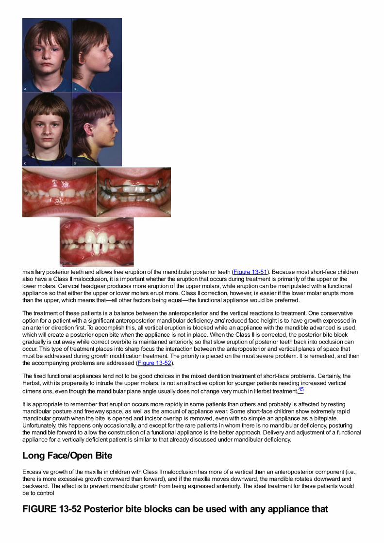
maxillary posterior teeth and allows free eruption of the mandibular posterior teeth (Figure 13-51). Because most short-face childrenalso have a Class II malocclusion, it is important whether the eruption that occurs during treatment is primarily of the upper or thelower molars. Cervical headgear produces more eruption of the upper molars, while eruption can be manipulated with a functionalappliance so that either the upper or lower molars erupt more. Class II correction, however, is easier if the lower molar erupts morethan the upper, which means that—all other factors being equal—the functional appliance would be preferred.
The treatment of these patients is a balance between the anteroposterior and the vertical reactions to treatment. One conservativeoption for a patient with a significant anteroposterior mandibular deficiency and reduced face height is to have growth expressed inan anterior direction first. To accomplish this, all vertical eruption is blocked while an appliance with the mandible advanced is used,which will create a posterior open bite when the appliance is not in place. When the Class II is corrected, the posterior bite blockgradually is cut away while correct overbite is maintained anteriorly, so that slow eruption of posterior teeth back into occlusion canoccur. This type of treatment places into sharp focus the interaction between the anteroposterior and vertical planes of space thatmust be addressed during growth modification treatment. The priority is placed on the most severe problem. It is remedied, and thenthe accompanying problems are addressed (Figure 13-52).
The fixed functional appliances tend not to be good choices in the mixed dentition treatment of short-face problems. Certainly, theHerbst, with its propensity to intrude the upper molars, is not an attractive option for younger patients needing increased verticaldimensions, even though the mandibular plane angle usually does not change very much in Herbst treatment.45
It is appropriate to remember that eruption occurs more rapidly in some patients than others and probably is affected by restingmandibular posture and freeway space, as well as the amount of appliance wear. Some short-face children show extremely rapidmandibular growth when the bite is opened and incisor overlap is removed, even with so simple an appliance as a biteplate.Unfortunately, this happens only occasionally, and except for the rare patients in whom there is no mandibular deficiency, posturingthe mandible forward to allow the construction of a functional appliance is the better approach. Delivery and adjustment of a functionalappliance for a vertically deficient patient is similar to that already discussed under mandibular deficiency.
Long Face/Open BiteExcessive growth of the maxilla in children with Class II malocclusion has more of a vertical than an anteroposterior component (i.e.,there is more excessive growth downward than forward), and if the maxilla moves downward, the mandible rotates downward andbackward. The effect is to prevent mandibular growth from being expressed anteriorly. The ideal treatment for these patients wouldbe to control
FIGURE 13-52 Posterior bite blocks can be used with any appliance that
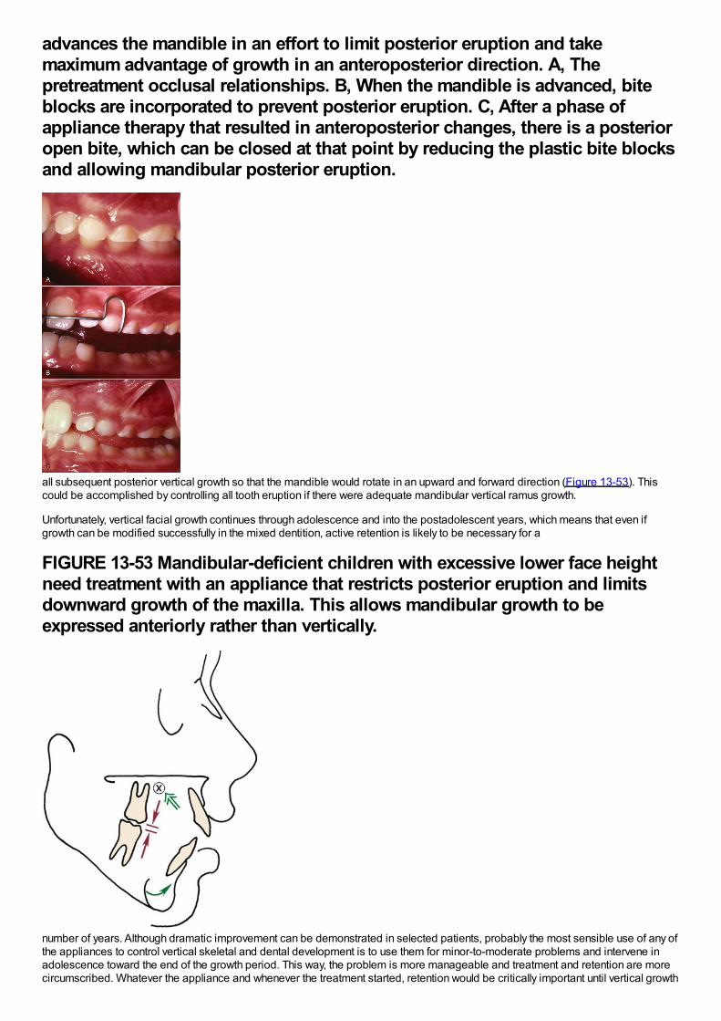
advances the mandible in an effort to limit posterior eruption and takemaximum advantage of growth in an anteroposterior direction. A, Thepretreatment occlusal relationships. B, When the mandible is advanced, biteblocks are incorporated to prevent posterior eruption. C, After a phase ofappliance therapy that resulted in anteroposterior changes, there is a posterioropen bite, which can be closed at that point by reducing the plastic bite blocksand allowing mandibular posterior eruption.
all subsequent posterior vertical growth so that the mandible would rotate in an upward and forward direction (Figure 13-53). Thiscould be accomplished by controlling all tooth eruption if there were adequate mandibular vertical ramus growth.
Unfortunately, vertical facial growth continues through adolescence and into the postadolescent years, which means that even ifgrowth can be modified successfully in the mixed dentition, active retention is likely to be necessary for a
FIGURE 13-53 Mandibular-deficient children with excessive lower face heightneed treatment with an appliance that restricts posterior eruption and limitsdownward growth of the maxilla. This allows mandibular growth to beexpressed anteriorly rather than vertically.
number of years. Although dramatic improvement can be demonstrated in selected patients, probably the most sensible use of any ofthe appliances to control vertical skeletal and dental development is to use them for minor-to-moderate problems and intervene inadolescence toward the end of the growth period. This way, the problem is more manageable and treatment and retention are morecircumscribed. Whatever the appliance and whenever the treatment started, retention would be critically important until vertical growth
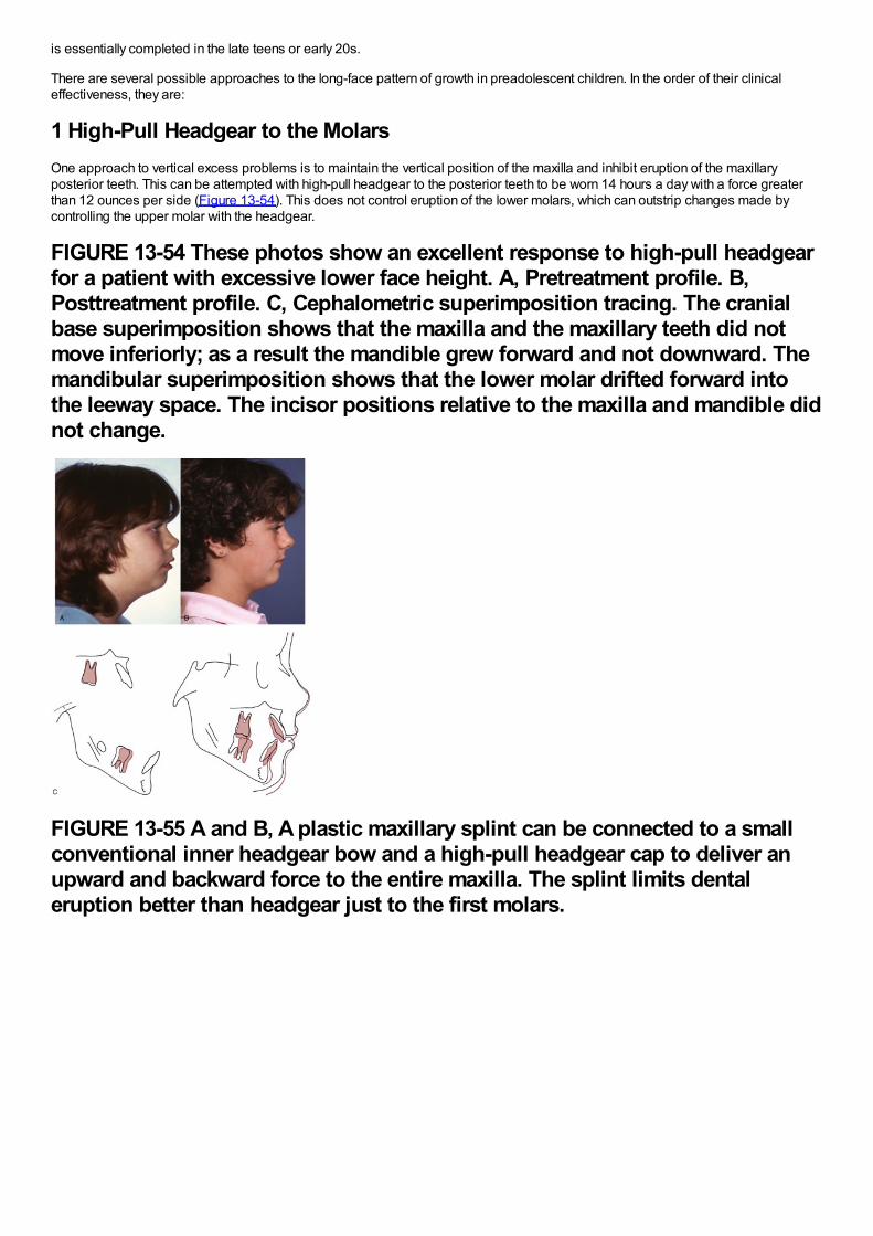
is essentially completed in the late teens or early 20s.
There are several possible approaches to the long-face pattern of growth in preadolescent children. In the order of their clinicaleffectiveness, they are:
1 High-Pull Headgear to the MolarsOne approach to vertical excess problems is to maintain the vertical position of the maxilla and inhibit eruption of the maxillaryposterior teeth. This can be attempted with high-pull headgear to the posterior teeth to be worn 14 hours a day with a force greaterthan 12 ounces per side (Figure 13-54). This does not control eruption of the lower molars, which can outstrip changes made bycontrolling the upper molar with the headgear.
FIGURE 13-54 These photos show an excellent response to high-pull headgearfor a patient with excessive lower face height. A, Pretreatment profile. B,Posttreatment profile. C, Cephalometric superimposition tracing. The cranialbase superimposition shows that the maxilla and the maxillary teeth did notmove inferiorly; as a result the mandible grew forward and not downward. Themandibular superimposition shows that the lower molar drifted forward intothe leeway space. The incisor positions relative to the maxilla and mandible didnot change.
FIGURE 13-55 A and B, A plastic maxillary splint can be connected to a smallconventional inner headgear bow and a high-pull headgear cap to deliver anupward and backward force to the entire maxilla. The splint limits dentaleruption better than headgear just to the first molars.
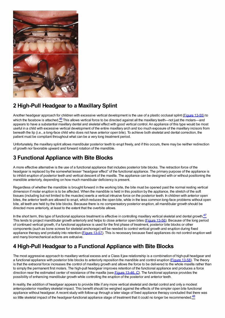
2 High-Pull Headgear to a Maxillary SplintAnother headgear approach for children with excessive vertical development is the use of a plastic occlusal splint (Figure 13-55) towhich the facebow is attached.46 This allows vertical force to be directed against all the maxillary teeth—not just the molars—andappears to have a substantial maxillary dental and skeletal effect with good vertical control. An appliance of this type would be mostuseful in a child with excessive vertical development of the entire maxillary arch and too much exposure of the maxillary incisors frombeneath the lip (i.e., a long-face child who does not have anterior open bite). To achieve both skeletal and dental correction, thepatient must be compliant throughout what can be a very long treatment period.
Unfortunately, the maxillary splint allows mandibular posterior teeth to erupt freely, and if this occurs, there may be neither redirectionof growth nor favorable upward and forward rotation of the mandible.
3 Functional Appliance with Bite BlocksA more effective alternative is the use of a functional appliance that includes posterior bite blocks. The retraction force of theheadgear is replaced by the somewhat lesser “headgear effect” of the functional appliance. The primary purpose of the appliance isto inhibit eruption of posterior teeth and vertical descent of the maxilla. The appliance can be designed with or without positioning themandible anteriorly, depending on how much mandibular deficiency is present.
Regardless of whether the mandible is brought forward in the working bite, the bite must be opened past the normal resting verticaldimension if molar eruption is to be affected. When the mandible is held in this position by the appliance, the stretch of the softtissues (including but not limited to the muscles) exerts a vertical intrusive force on the posterior teeth. In children with anterior openbites, the anterior teeth are allowed to erupt, which reduces the open bite, while in the less common long-face problems without openbite, all teeth are held by the bite blocks. Because there is no compensatory posterior eruption, all mandibular growth should bedirected more anteriorly, at least to the extent that the overbite allows.
In the short term, this type of functional appliance treatment is effective in controlling maxillary vertical skeletal and dental growth.47
This tends to project mandibular growth anteriorly and helps to close anterior open bites (Figure 13-56). Because of the long periodof continued vertical growth, if a functional appliance is used for the first phase of treatment, posterior bite blocks or othercomponents (such as bone screws for skeletal anchorage) will be needed to control vertical growth and eruption during fixedappliance therapy and probably into retention (Figure 13-57). This is necessary because fixed appliances do not control eruption welland many biomechanical actions are extrusive.
4 High-Pull Headgear to a Functional Appliance with Bite BlocksThe most aggressive approach to maxillary vertical excess and a Class II jaw relationship is a combination of high-pull headgear anda functional appliance with posterior bite blocks to anteriorly reposition the mandible and control eruption (Figure 13-58). The theoryis that the extraoral force increases the control of maxillary growth and allows the force to be delivered to the whole maxilla rather thanto simply the permanent first molars. The high-pull headgear improves retention of the functional appliance and produces a forcedirection near the estimated center of resistance of the maxilla (see Figure 13-46, C). The functional appliance provides thepossibility of enhancing mandibular growth while controlling the eruption of the posterior and anterior teeth.
In reality, the addition of headgear appears to provide little if any more vertical skeletal and dental control and only a modestanteroposterior maxillary skeletal impact. This benefit should be weighed against the effects of the simpler open bite functionalappliance without headgear. A recent study with follow-up through a later stage of fixed appliance therapy concluded that there wasso little skeletal impact of the headgear-functional appliance stage of treatment that it could no longer be recommended.48
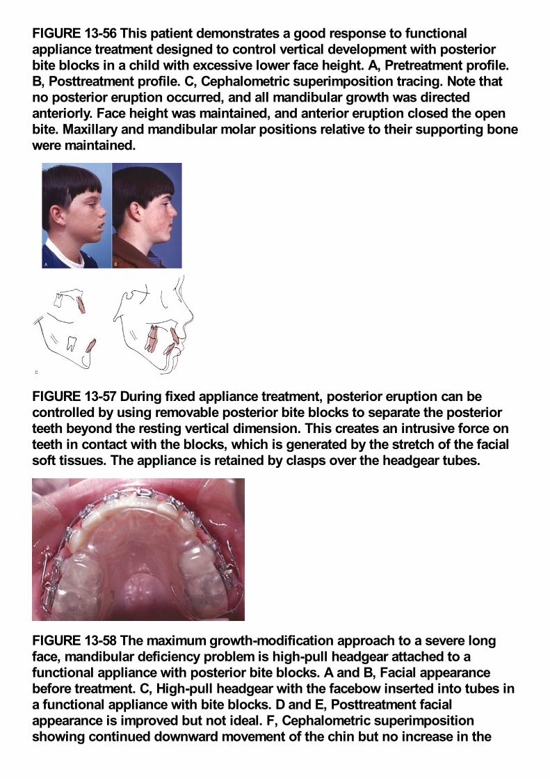
FIGURE 13-56 This patient demonstrates a good response to functionalappliance treatment designed to control vertical development with posteriorbite blocks in a child with excessive lower face height. A, Pretreatment profile.B, Posttreatment profile. C, Cephalometric superimposition tracing. Note thatno posterior eruption occurred, and all mandibular growth was directedanteriorly. Face height was maintained, and anterior eruption closed the openbite. Maxillary and mandibular molar positions relative to their supporting bonewere maintained.
FIGURE 13-57 During fixed appliance treatment, posterior eruption can becontrolled by using removable posterior bite blocks to separate the posteriorteeth beyond the resting vertical dimension. This creates an intrusive force onteeth in contact with the blocks, which is generated by the stretch of the facialsoft tissues. The appliance is retained by clasps over the headgear tubes.
FIGURE 13-58 The maximum growth-modification approach to a severe longface, mandibular deficiency problem is high-pull headgear attached to afunctional appliance with posterior bite blocks. A and B, Facial appearancebefore treatment. C, High-pull headgear with the facebow inserted into tubes ina functional appliance with bite blocks. D and E, Posttreatment facialappearance is improved but not ideal. F, Cephalometric superimpositionshowing continued downward movement of the chin but no increase in the
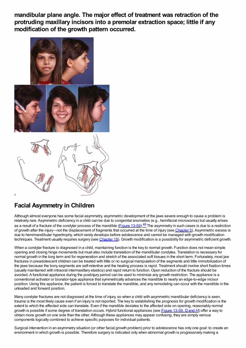
mandibular plane angle. The major effect of treatment was retraction of theprotruding maxillary incisors into a premolar extraction space; little if anymodification of the growth pattern occurred.
Facial Asymmetry in ChildrenAlthough almost everyone has some facial asymmetry, asymmetric development of the jaws severe enough to cause a problem isrelatively rare. Asymmetric deficiency in a child can be due to congenital anomalies (e.g., hemifacial microsomia) but usually arisesas a result of a fracture of the condylar process of the mandible (Figure 13-59).49 The asymmetry in such cases is due to a restrictionof growth after the injury—not the displacement of fragments that occurred at the time of injury (see Chapter 5). Asymmetric excess isdue to hemimandibular hypertrophy, which rarely develops before adolescence and cannot be managed with growth modificationtechniques. Treatment usually requires surgery (see Chapter 19). Growth modification is a possibility for asymmetric deficient growth.
When a condylar fracture is diagnosed in a child, maintaining function is the key to normal growth. Function does not mean simpleopening and closing hinge movements but must also include translation of the mandibular condyles. Translation is necessary fornormal growth in the long term and for regeneration and stretch of the associated soft tissues in the short term. Fortunately, most jawfractures in preadolescent children can be treated with little or no surgical manipulation of the segments and little immobilization ofthe jaws because the bony segments are self-retentive and the healing process is rapid. Treatment should involve short fixation times(usually maintained with intraoral intermaxillary elastics) and rapid return to function. Open reduction of the fracture should beavoided. A functional appliance during the postinjury period can be used to minimize any growth restriction. The appliance is aconventional activator or bionator-type appliance that symmetrically advances the mandible to nearly an edge-to-edge incisorposition. Using this appliance, the patient is forced to translate the mandible, and any remodeling can occur with the mandible in theunloaded and forward position.
Many condylar fractures are not diagnosed at the time of injury, so when a child with asymmetric mandibular deficiency is seen,trauma is the most likely cause even if an injury is not reported. The key to establishing the prognosis for growth modification is theextent to which the affected side can translate. Even if the mandible deviates to the affected side on opening, reasonably normalgrowth is possible if some degree of translation occurs. Hybrid functional appliances (see Figure 13-59, G and H) offer a way toobtain more growth on one side than the other. Although these appliances may appear confusing, they are simply variouscomponents logically combined to achieve specific purposes for individual patients.
Surgical intervention in an asymmetry situation (or other facial growth problem) prior to adolescence has only one goal: to create anenvironment in which growth is possible. Therefore surgery is indicated only when abnormal growth is progressively making a
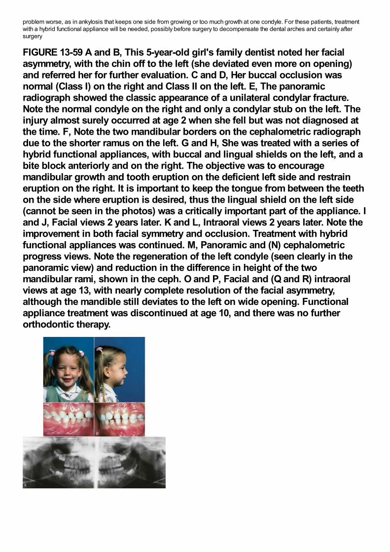
problem worse, as in ankylosis that keeps one side from growing or too much growth at one condyle. For these patients, treatmentwith a hybrid functional appliance will be needed, possibly before surgery to decompensate the dental arches and certainly aftersurgery
FIGURE 13-59 A and B, This 5-year-old girl's family dentist noted her facialasymmetry, with the chin off to the left (she deviated even more on opening)and referred her for further evaluation. C and D, Her buccal occlusion wasnormal (Class I) on the right and Class II on the left. E, The panoramicradiograph showed the classic appearance of a unilateral condylar fracture.Note the normal condyle on the right and only a condylar stub on the left. Theinjury almost surely occurred at age 2 when she fell but was not diagnosed atthe time. F, Note the two mandibular borders on the cephalometric radiographdue to the shorter ramus on the left. G and H, She was treated with a series ofhybrid functional appliances, with buccal and lingual shields on the left, and abite block anteriorly and on the right. The objective was to encouragemandibular growth and tooth eruption on the deficient left side and restraineruption on the right. It is important to keep the tongue from between the teethon the side where eruption is desired, thus the lingual shield on the left side(cannot be seen in the photos) was a critically important part of the appliance. Iand J, Facial views 2 years later. K and L, Intraoral views 2 years later. Note theimprovement in both facial symmetry and occlusion. Treatment with hybridfunctional appliances was continued. M, Panoramic and (N) cephalometricprogress views. Note the regeneration of the left condyle (seen clearly in thepanoramic view) and reduction in the difference in height of the twomandibular rami, shown in the ceph. O and P, Facial and (Q and R) intraoralviews at age 13, with nearly complete resolution of the facial asymmetry,although the mandible still deviates to the left on wide opening. Functionalappliance treatment was discontinued at age 10, and there was no furtherorthodontic therapy.
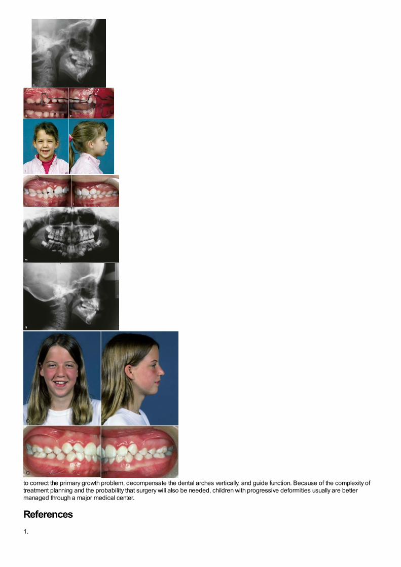
to correct the primary growth problem, decompensate the dental arches vertically, and guide function. Because of the complexity oftreatment planning and the probability that surgery will also be needed, children with progressive deformities usually are bettermanaged through a major medical center.
References1.

Borzabadi-Farahani, A, Borzabadi-Farahani, A, Eslamipour, F: An investigation into the association between facial profile andmaxillary incisor trauma, a clinical non-radiographic study. Dent Traumatol. 26, 2010, 403–408.
2.
Sandikcioglu, M, Hazar, S: Skeletal and dental changes after maxillary expansion in the mixed dentition. Am J Orthod DentofacOrthop. 111, 1997, 321–327.
3.
Adkins, MD, Nanda, RS, Currier, GF: Arch perimeter changes on rapid palatal expansion. Am J Orthod. 97, 1990, 10–19.
4.
Kilic, N, Kiki, A, Oktay, H: Condylar asymmetry in unilateral posterior crossbite patients. Am J Orthod Dentofac Orthop. 133, 2008,382–387.
5.
daSilva Filho, OG, Villas Boas, M, Capelozza Filho, L: Rapid palatal expansion in the deciduous and mixed dentitions: acephalometric evaluation. Am J Orthod Dentofac Orthop. 100, 1991, 171–181.
6.
Petrén, S, Bjerklin, K, Bondemark, L: Stability of unilateral posterior crossbite correction in the mixed dentition: a randomized clinicaltrial with a 3-year follow-up. Am J Orthod Dentofac Orthop. 139, 2011, e73–e81.
7.
Chang, JY, McNamara, JA Jr., Herberger, TA: A longitudinal study of skeletal side effects induced by rapid maxillary expansion. Am JOrthod Dentofac Orthop. 112, 1997, 330–337.
8.
Reed, N, Ghosh, J, Nanda, RS: Comparison of treatment outcomes with banded and bonded RPE appliances. Am J OrthodDentofac Orthop. 116, 1999, 31–40.
9.
Leonardi, R, Sicurezza, E, Cutrera, A, et al.: Changes of circumaxillary sutures in young patients treated with rapid maxillaryexpansion. Angle Orthod. 81, 2011, 36–41.
10.
Akkaya, S, Lorenzon, S, Ucem, TT: Comparison of dental arch and arch perimeter changes between bonded rapid and slowmaxillary expansion procedures. Eur J Orthod. 20, 1998, 255–261.
11.
Geran, RG, McNamara, JA, Baccetti, T, et al.: A prospective long-term study on the effects of rapid maxillary expansion in the earlymixed dentition. Am J Orthod Dentofac Orthop. 129, 2006, 631–640.
12.
McNamara, JA, Baccetti, T, Franchi, L, et al.: Rapid maxillary expansion followed by fixed appliances: a long-term evaluation ofchanges in arch dimensions. Angle Orthod. 73, 2003, 344–353.
13.
Schneidman, E, Wilson, S, Erkis, R: Two-point rapid palatal expansion: an alternate approach to traditional treatment. Pediatr Dent.12, 1990, 92–97.
14.
Levin, AS, McNamara, JA Jr., Franchi, L, et al.: Short-term and long-term treatment outcomes with the FR-3 appliance of Fränkel. AmJ Orthod Dentofac Orthop. 134, 2008, 513–524.
15.
Ulgen, M, Firatli, S: The effects of the Fränkel's function regulator on the Class III malocclusion. Am J Orthod Dentofac Orthop. 105,1994, 561–567.
16.

Kim, JH, Viana, MC, Graber, TM, et al.: The effectiveness of protraction face mask therapy: a meta-analysis. Am J Orthod DentofacOrthop. 115, 1999, 675–685.
17.
Westwood, PV, McNamara, JA Jr., Baccetti, T, et al.: Long-term effects of Class III treatment with rapid maxillary expansion andfacemask therapy followed by fixed appliances. Am J Orthod Dentofac Orthop. 123, 2003, 306–320.
18.
Vaughn, GA, Mason, B, Moon, HB, et al.: The effects of maxillary protraction therapy with or without rapid palatal expansion: aprospective, randomized clinical trial. Am J Orthod Dentofac Orthop. 128, 2005, 299–309.
19.
da Silva Filho, OG, Magro, AC, Capelozza Filho, L: Early treatment of the Class III malocclusion with rapid maxillary expansion andmaxillary protraction. Am J Orthod Dentofac Orthop. 113, 1998, 196–203.
20.
Shapiro, PA, Kokich, VG: Treatment alternatives for children with severe maxillary hypoplasia. Eur J Orthod. 6, 1984, 141–147.
21.
Cha, BK, Choi, DS, Ngan, P, et al.: Maxillary protraction with miniplates providing skeletal anchorage in a growing Class III patient.Am J Orthod Dentofac Orthop. 139, 2011, 99–112.
22.
Sar, C, Arman-Özçirpici, A, Uçkan, S, et al.: Comparative evaluation of maxillary protraction with or without skeletal anchorage. Am JOrthod Dentofac Orthop. 139, 2011, 636–649.
23.
Nguyen, T, Cevidanes, L, Cornelis, MA, et al.: 3D assessment of maxillary changes associated with bone anchored maxillaryprotraction. Am J Orthod Dentofac Orthop. 140, 2011, 790–798.
24.
Cevidanes, L, Baccetti, T, Franchi, L, et al.: Comparison of two protocols for maxillary protraction: bone anchors versus face maskwith rapid maxillary expansion. Angle Orthod. 80, 2010, 799–806.
25.
Wells, AP, Sarver, DM, Proffit, WR: Long-term efficacy of reverse pull headgear therapy. Angle Orthod. 76, 2006, 915–922.
26.
Sugawara, J, Mitani, H: Facial growth of skeletal Class III malocclusion and the effects, limitations, and long-term dentofacialadaptations to chin cap therapy. Semin Orthod. 3, 1997, 244–254.
27.
Tulloch, JF, Proffit, WR, Phillips, C: Outcomes in a 2-phase randomized clinical trial of early Class II treatment. Am J Orthod DentofacOrthop. 125, 2004, 657–667.
28.
Cozza, P, Baccetti, T, Franchi, L, et al.: Mandibular changes produced by functional appliances in Class II malocclusion: a systematicreview. Am J Orthod Dentofac Orthop. 129, 2006, 599.e1–599.e12.
29.
O'Brien, K, Wright, J, Conboy, F, et al.: Early treatment for Class II division 1 malocclusion with the twin-block appliance: a multi-center, randomized, controlled trial. Am J Orthod Dentofac Orthop. 135, 2009, 573–579.
30.
Pancherz, H: The effects, limitations, and long-term dentofacial adaptations to treatment with the Herbst appliance. Semin Orthod. 3,1997, 232–243.
31.
Franchi, L, Baccetti, T: Prediction of individual mandibular changes induced by functional jaw orthopedics followed by fixed

appliances in Class II patients. Angle Orthod. 76, 2006, 950–954.
32.
Siara-Olds, NJ, Pangrazio-Kulbersh, V, Berger, J, et al.: Long-term dentoskeletal changes with the bionator, Herbst, twin block andMARA functional appliances. Angle Orthod. 80, 2010, 18–29.
33.
Pancherz, H, Malmgren, O, Hagg, U, et al.: Class II correction in Herbst and Bass therapy. Eur J Orthod. 11, 1989, 17–30.
34.
Oppenheim, A: Biologic orthodontic therapy and reality. Angle Orthod. 6, 1936, 69–79.
35.
Kloehn, S: Guiding alveolar growth and eruption of the teeth to reduce treatment time and produce a more balanced denture andface. Am J Orthod. 17, 1947, 10–33.
36.
Wieslander, L: The effects of orthodontic treatment on the concurrent development of the craniofacial complex. Am J Orthod. 49,1963, 15–27.
37.
Armstrong, MM: Controlling the magnitude, direction and duration of extraoral force. Am J Orthod. 59, 1971, 217–243.
38.
Keeling, SD, Wheeler, TT, King, GJ, et al.: Anteroposterior skeletal and dental changes after early Class II treatment with bionatorsand headgear. Am J Orthod Dentofac Orthop. 113, 1998, 40–50.
39.
Baumrind, S, Molthen, R, West, EE, et al.: Mandibular plane changes during maxillary retraction, part 2. Am J Orthod. 74, 1978, 603–621.
40.
O'Brien, K, Wright, J, Conboy, F, et al.: Effectiveness of early orthodontic treatment with the Twin-block appliance: a multicenter,randomized, controlled trial. Part 2: Psychosocial effects. Am J Orthod Dentofac Orthop. 124, 2003, 488–494.
41.
Banks, P, Wright, J, O'Brien, K: Incremental versus maximum bite advancement during twin-block therapy: a randomized controlledclinical trial. Am J Orthod Dentofac Orthop. 126, 2004, 583–588.
42.
Haralabakis, NB, Sifakakis, IB: The effect of cervical headgear on patients with high or low mandibular plane angles and the “myth” ofposterior mandibular rotation. Am J Orthod Dentofac Orthop. 126, 2004, 310–317.
43.
Chaushu, G, Chausu, S, Weinberger, T: Infraorbital abscess from orthodontic headgear. Am J Orthod Dentofac Orthop. 112, 1997,364–366.
44.
Stafford, GD, Caputo, AA, Turley, PK: Characteristics of headgear release mechanisms: Safety implications. Angle Orthod. 68,1998, 319–326.
45.
Ruf, S, Pancherz, H: The effect of Herbst appliance treatment on the mandibular plane angle: A cephalometric roentgenographicstudy. Am J Orthod Dentofac Orthop. 110, 1996, 225–229.
46.
Orton, HS, Slattery, DA, Orton, S: The treatment of severe ‘gummy’ Class II division 1 malocclusion using the maxillary intrusion splint.Eur J Orthod. 14, 1992, 216–223.
47.

Weinbach, JR, Smith, RJ: Cephalometric changes during treatment with the open bite bionator. Am J Orthod Dentofac Orthop. 101,1992, 367–374.
48.
Freeman, CS, McNamara, JA Jr., Baccetti, T, et al.: Treatment effects of the bionator and high-pull facebow combination followed byfixed appliances in patients with increased vertical dimensions. Am J Orthod Dentofac Orthop. 131, 2007, 184–195.
49.
Turvey, TA, Ruiz, R, Blakey, GH, et al.: Management of facial fractures in the growing patient. In Fonseca, RJ, Walker, RV, Betts, NJ, etal. (Eds.): Oral and Maxillofacial Trauma. 2005, WB Saunders, Philadelphia.

Comprehensive Orthodontic Treatment in the Early Permanent Dentition
Comprehensive orthodontic treatment implies an effort to make the patient's occlusion as ideal as possible, repositioning all or nearly all the teeth in theprocess. From this perspective, the mixed dentition treatment described in Chapters 11 to 13 is not comprehensive, despite its importance for somepatients because the final position of all the permanent teeth is not affected. A second phase of comprehensive treatment after the permanent teeth erupt,during which the details of occlusal relationships are established, is usually needed for children with moderate or severe malocclusion even if significantimprovement occurred during a first phase of treatment in the mixed dentition.
The ideal time for comprehensive treatment is during adolescence, when the succedaneous teeth have just erupted, some vertical and anteroposteriorgrowth of the jaws remains, and the social adjustment to orthodontic treatment is no great problem. Not all adolescent patients require comprehensivetreatment, of course, and limited treatment to overcome specific problems can certainly be done at any age. Comprehensive treatment is also possible foradults, but it poses some special problems. These are discussed in Chapter 18.
Comprehensive orthodontic treatment usually requires a complete fixed appliance. In the chapters that follow, the use of a contemporary edgewiseappliance that incorporates offsets, angulation, and torque in the brackets (i.e., a “straight-wire” appliance) is assumed during much of the discussion.Three major stages of treatment are used to conveniently divide comprehensive treatment into sequential steps for discussion in Chapters 14 to 16. Ineach of these chapters, the different archwires and archwire sequences for sliding versus loop mechanics and 22-slot versus 18-slot are emphasized. Abrief description of treatment with the Begg appliance and its current modifications is included at appropriate points.
Whatever the orthodontic technique, treatment must be discontinued gradually, using some sort of retention appliance for a time, and this importantsubject is covered in the last chapter of this section.
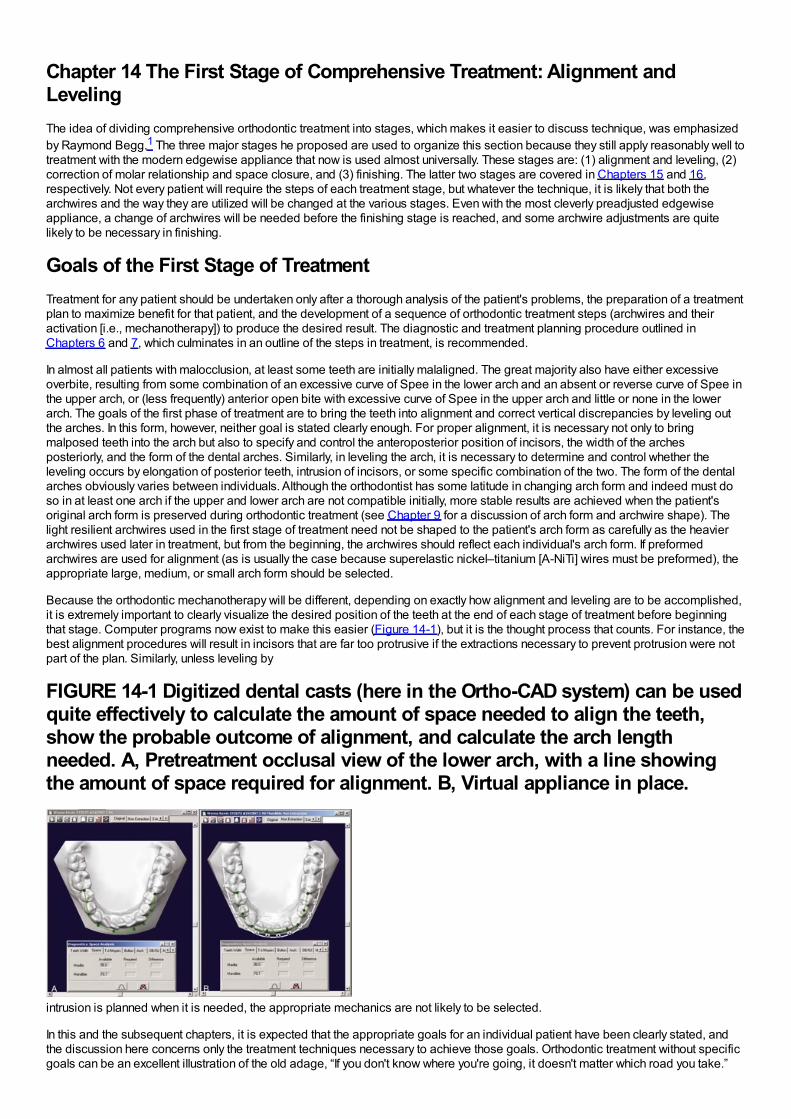
Chapter 14 The First Stage of Comprehensive Treatment: Alignment andLevelingThe idea of dividing comprehensive orthodontic treatment into stages, which makes it easier to discuss technique, was emphasizedby Raymond Begg.1 The three major stages he proposed are used to organize this section because they still apply reasonably well totreatment with the modern edgewise appliance that now is used almost universally. These stages are: (1) alignment and leveling, (2)correction of molar relationship and space closure, and (3) finishing. The latter two stages are covered in Chapters 15 and 16,respectively. Not every patient will require the steps of each treatment stage, but whatever the technique, it is likely that both thearchwires and the way they are utilized will be changed at the various stages. Even with the most cleverly preadjusted edgewiseappliance, a change of archwires will be needed before the finishing stage is reached, and some archwire adjustments are quitelikely to be necessary in finishing.
Goals of the First Stage of TreatmentTreatment for any patient should be undertaken only after a thorough analysis of the patient's problems, the preparation of a treatmentplan to maximize benefit for that patient, and the development of a sequence of orthodontic treatment steps (archwires and theiractivation [i.e., mechanotherapy]) to produce the desired result. The diagnostic and treatment planning procedure outlined inChapters 6 and 7, which culminates in an outline of the steps in treatment, is recommended.
In almost all patients with malocclusion, at least some teeth are initially malaligned. The great majority also have either excessiveoverbite, resulting from some combination of an excessive curve of Spee in the lower arch and an absent or reverse curve of Spee inthe upper arch, or (less frequently) anterior open bite with excessive curve of Spee in the upper arch and little or none in the lowerarch. The goals of the first phase of treatment are to bring the teeth into alignment and correct vertical discrepancies by leveling outthe arches. In this form, however, neither goal is stated clearly enough. For proper alignment, it is necessary not only to bringmalposed teeth into the arch but also to specify and control the anteroposterior position of incisors, the width of the archesposteriorly, and the form of the dental arches. Similarly, in leveling the arch, it is necessary to determine and control whether theleveling occurs by elongation of posterior teeth, intrusion of incisors, or some specific combination of the two. The form of the dentalarches obviously varies between individuals. Although the orthodontist has some latitude in changing arch form and indeed must doso in at least one arch if the upper and lower arch are not compatible initially, more stable results are achieved when the patient'soriginal arch form is preserved during orthodontic treatment (see Chapter 9 for a discussion of arch form and archwire shape). Thelight resilient archwires used in the first stage of treatment need not be shaped to the patient's arch form as carefully as the heavierarchwires used later in treatment, but from the beginning, the archwires should reflect each individual's arch form. If preformedarchwires are used for alignment (as is usually the case because superelastic nickel–titanium [A-NiTi] wires must be preformed), theappropriate large, medium, or small arch form should be selected.
Because the orthodontic mechanotherapy will be different, depending on exactly how alignment and leveling are to be accomplished,it is extremely important to clearly visualize the desired position of the teeth at the end of each stage of treatment before beginningthat stage. Computer programs now exist to make this easier (Figure 14-1), but it is the thought process that counts. For instance, thebest alignment procedures will result in incisors that are far too protrusive if the extractions necessary to prevent protrusion were notpart of the plan. Similarly, unless leveling by
FIGURE 14-1 Digitized dental casts (here in the Ortho-CAD system) can be usedquite effectively to calculate the amount of space needed to align the teeth,show the probable outcome of alignment, and calculate the arch lengthneeded. A, Pretreatment occlusal view of the lower arch, with a line showingthe amount of space required for alignment. B, Virtual appliance in place.
intrusion is planned when it is needed, the appropriate mechanics are not likely to be selected.
In this and the subsequent chapters, it is expected that the appropriate goals for an individual patient have been clearly stated, andthe discussion here concerns only the treatment techniques necessary to achieve those goals. Orthodontic treatment without specificgoals can be an excellent illustration of the old adage, “If you don't know where you're going, it doesn't matter which road you take.”
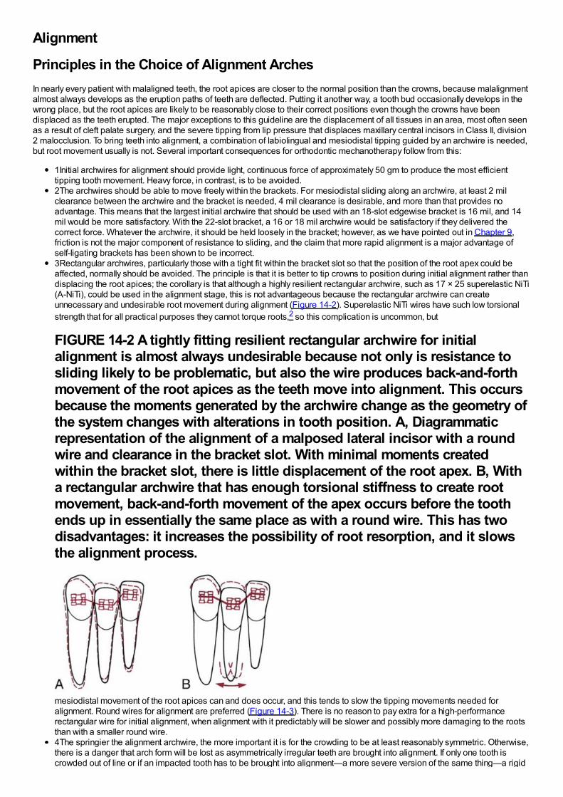
Alignment
Principles in the Choice of Alignment ArchesIn nearly every patient with malaligned teeth, the root apices are closer to the normal position than the crowns, because malalignmentalmost always develops as the eruption paths of teeth are deflected. Putting it another way, a tooth bud occasionally develops in thewrong place, but the root apices are likely to be reasonably close to their correct positions even though the crowns have beendisplaced as the teeth erupted. The major exceptions to this guideline are the displacement of all tissues in an area, most often seenas a result of cleft palate surgery, and the severe tipping from lip pressure that displaces maxillary central incisors in Class II, division2 malocclusion. To bring teeth into alignment, a combination of labiolingual and mesiodistal tipping guided by an archwire is needed,but root movement usually is not. Several important consequences for orthodontic mechanotherapy follow from this:
1Initial archwires for alignment should provide light, continuous force of approximately 50 gm to produce the most efficienttipping tooth movement. Heavy force, in contrast, is to be avoided.2The archwires should be able to move freely within the brackets. For mesiodistal sliding along an archwire, at least 2 milclearance between the archwire and the bracket is needed, 4 mil clearance is desirable, and more than that provides noadvantage. This means that the largest initial archwire that should be used with an 18-slot edgewise bracket is 16 mil, and 14mil would be more satisfactory. With the 22-slot bracket, a 16 or 18 mil archwire would be satisfactory if they delivered thecorrect force. Whatever the archwire, it should be held loosely in the bracket; however, as we have pointed out in Chapter 9,friction is not the major component of resistance to sliding, and the claim that more rapid alignment is a major advantage ofself-ligating brackets has been shown to be incorrect.3Rectangular archwires, particularly those with a tight fit within the bracket slot so that the position of the root apex could beaffected, normally should be avoided. The principle is that it is better to tip crowns to position during initial alignment rather thandisplacing the root apices; the corollary is that although a highly resilient rectangular archwire, such as 17 × 25 superelastic NiTi(A-NiTi), could be used in the alignment stage, this is not advantageous because the rectangular archwire can createunnecessary and undesirable root movement during alignment (Figure 14-2). Superelastic NiTi wires have such low torsionalstrength that for all practical purposes they cannot torque roots,2 so this complication is uncommon, but
FIGURE 14-2 A tightly fitting resilient rectangular archwire for initialalignment is almost always undesirable because not only is resistance tosliding likely to be problematic, but also the wire produces back-and-forthmovement of the root apices as the teeth move into alignment. This occursbecause the moments generated by the archwire change as the geometry ofthe system changes with alterations in tooth position. A, Diagrammaticrepresentation of the alignment of a malposed lateral incisor with a roundwire and clearance in the bracket slot. With minimal moments createdwithin the bracket slot, there is little displacement of the root apex. B, Witha rectangular archwire that has enough torsional stiffness to create rootmovement, back-and-forth movement of the apex occurs before the toothends up in essentially the same place as with a round wire. This has twodisadvantages: it increases the possibility of root resorption, and it slowsthe alignment process.
mesiodistal movement of the root apices can and does occur, and this tends to slow the tipping movements needed foralignment. Round wires for alignment are preferred (Figure 14-3). There is no reason to pay extra for a high-performancerectangular wire for initial alignment, when alignment with it predictably will be slower and possibly more damaging to the rootsthan with a smaller round wire.4The springier the alignment archwire, the more important it is for the crowding to be at least reasonably symmetric. Otherwise,there is a danger that arch form will be lost as asymmetrically irregular teeth are brought into alignment. If only one tooth iscrowded out of line or if an impacted tooth has to be brought into alignment—a more severe version of the same thing—a rigid
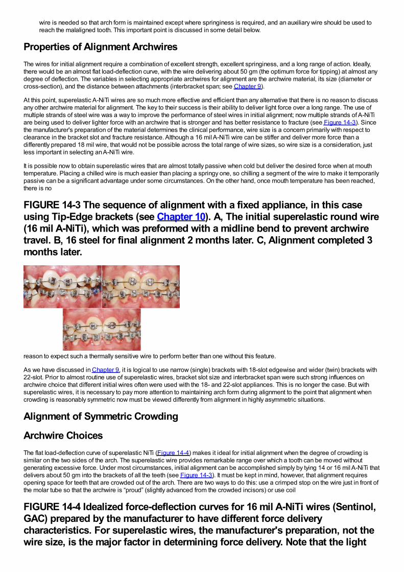
wire is needed so that arch form is maintained except where springiness is required, and an auxiliary wire should be used toreach the malaligned tooth. This important point is discussed in some detail below.
Properties of Alignment ArchwiresThe wires for initial alignment require a combination of excellent strength, excellent springiness, and a long range of action. Ideally,there would be an almost flat load-deflection curve, with the wire delivering about 50 gm (the optimum force for tipping) at almost anydegree of deflection. The variables in selecting appropriate archwires for alignment are the archwire material, its size (diameter orcross-section), and the distance between attachments (interbracket span; see Chapter 9).
At this point, superelastic A-NiTi wires are so much more effective and efficient than any alternative that there is no reason to discussany other archwire material for alignment. The key to their success is their ability to deliver light force over a long range. The use ofmultiple strands of steel wire was a way to improve the performance of steel wires in initial alignment; now multiple strands of A-NiTiare being used to deliver lighter force with an archwire that is stronger and has better resistance to fracture (see Figure 14-3). Sincethe manufacturer's preparation of the material determines the clinical performance, wire size is a concern primarily with respect toclearance in the bracket slot and fracture resistance. Although a 16 mil A-NiTi wire can be stiffer and deliver more force than adifferently prepared 18 mil wire, that would not be possible across the total range of wire sizes, so wire size is a consideration, justless important in selecting an A-NiTi wire.
It is possible now to obtain superelastic wires that are almost totally passive when cold but deliver the desired force when at mouthtemperature. Placing a chilled wire is much easier than placing a springy one, so chilling a segment of the wire to make it temporarilypassive can be a significant advantage under some circumstances. On the other hand, once mouth temperature has been reached,there is no
FIGURE 14-3 The sequence of alignment with a fixed appliance, in this caseusing Tip-Edge brackets (see Chapter 10). A, The initial superelastic round wire(16 mil A-NiTi), which was preformed with a midline bend to prevent archwiretravel. B, 16 steel for final alignment 2 months later. C, Alignment completed 3months later.
reason to expect such a thermally sensitive wire to perform better than one without this feature.
As we have discussed in Chapter 9, it is logical to use narrow (single) brackets with 18-slot edgewise and wider (twin) brackets with22-slot. Prior to almost routine use of superelastic wires, bracket slot size and interbracket span were such strong influences onarchwire choice that different initial wires often were used with the 18- and 22-slot appliances. This is no longer the case. But withsuperelastic wires, it is necessary to pay more attention to maintaining arch form during alignment to the point that alignment whencrowding is reasonably symmetric now must be viewed differently from alignment in highly asymmetric situations.
Alignment of Symmetric Crowding
Archwire ChoicesThe flat load-deflection curve of superelastic NiTi (Figure 14-4) makes it ideal for initial alignment when the degree of crowding issimilar on the two sides of the arch. The superelastic wire provides remarkable range over which a tooth can be moved withoutgenerating excessive force. Under most circumstances, initial alignment can be accomplished simply by tying 14 or 16 mil A-NiTi thatdelivers about 50 gm into the brackets of all the teeth (see Figure 14-3). It must be kept in mind, however, that alignment requiresopening space for teeth that are crowded out of the arch. There are two ways to do this: use a crimped stop on the wire just in front ofthe molar tube so that the archwire is “proud” (slightly advanced from the crowded incisors) or use coil
FIGURE 14-4 Idealized force-deflection curves for 16 mil A-NiTi wires (Sentinol,GAC) prepared by the manufacturer to have different force deliverycharacteristics. For superelastic wires, the manufacturer's preparation, not thewire size, is the major factor in determining force delivery. Note that the light
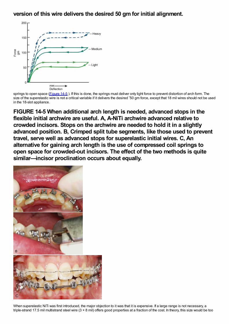
version of this wire delivers the desired 50 gm for initial alignment.
springs to open space (Figure 14-5 ). If this is done, the springs must deliver only light force to prevent distortion of arch form. Thesize of the superelastic wire is not a critical variable if it delivers the desired ˜50 gm force, except that 18 mil wires should not be usedin the 18-slot appliance.
FIGURE 14-5 When additional arch length is needed, advanced stops in theflexible initial archwire are useful. A, A-NiTi archwire advanced relative tocrowded incisors. Stops on the archwire are needed to hold it in a slightlyadvanced position. B, Crimped split tube segments, like those used to preventtravel, serve well as advanced stops for superelastic initial wires. C, Analternative for gaining arch length is the use of compressed coil springs toopen space for crowded-out incisors. The effect of the two methods is quitesimilar—incisor proclination occurs about equally.
When superelastic NiTi was first introduced, the major objection to it was that it is expensive. If a large range is not necessary, atriple-strand 17.5 mil multistrand steel wire (3 × 8 mil) offers good properties at a fraction of the cost. In theory, this size would be too
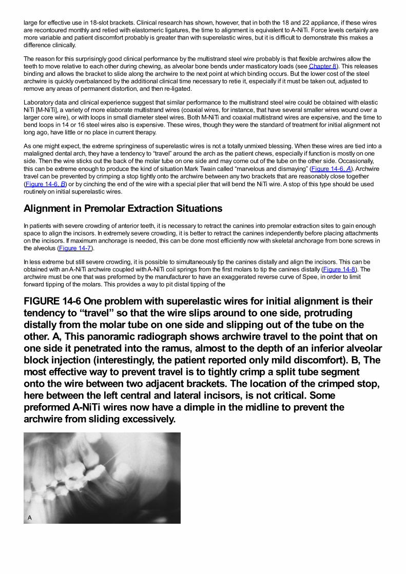
large for effective use in 18-slot brackets. Clinical research has shown, however, that in both the 18 and 22 appliance, if these wiresare recontoured monthly and retied with elastomeric ligatures, the time to alignment is equivalent to A-NiTi. Force levels certainly aremore variable and patient discomfort probably is greater than with superelastic wires, but it is difficult to demonstrate this makes adifference clinically.
The reason for this surprisingly good clinical performance by the multistrand steel wire probably is that flexible archwires allow theteeth to move relative to each other during chewing, as alveolar bone bends under masticatory loads (see Chapter 8). This releasesbinding and allows the bracket to slide along the archwire to the next point at which binding occurs. But the lower cost of the steelarchwire is quickly overbalanced by the additional clinical time necessary to retie it, especially if it must be taken out, adjusted toremove any areas of permanent distortion, and then re-ligated.
Laboratory data and clinical experience suggest that similar performance to the multistrand steel wire could be obtained with elasticNiTi [M-NiTi], a variety of more elaborate multistrand wires (coaxial wires, for instance, that have several smaller wires wound over alarger core wire), or with loops in small diameter steel wires. Both M-NiTi and coaxial multistrand wires are expensive, and the time tobend loops in 14 or 16 steel wires also is expensive. These wires, though they were the standard of treatment for initial alignment notlong ago, have little or no place in current therapy.
As one might expect, the extreme springiness of superelastic wires is not a totally unmixed blessing. When these wires are tied into amalaligned dental arch, they have a tendency to “travel” around the arch as the patient chews, especially if function is mostly on oneside. Then the wire sticks out the back of the molar tube on one side and may come out of the tube on the other side. Occasionally,this can be extreme enough to produce the kind of situation Mark Twain called “marvelous and dismaying” (Figure 14-6, A). Archwiretravel can be prevented by crimping a stop tightly onto the archwire between any two brackets that are reasonably close together(Figure 14-6, B) or by cinching the end of the wire with a special plier that will bend the NiTi wire. A stop of this type should be usedroutinely on initial superelastic wires.
Alignment in Premolar Extraction SituationsIn patients with severe crowding of anterior teeth, it is necessary to retract the canines into premolar extraction sites to gain enoughspace to align the incisors. In extremely severe crowding, it is better to retract the canines independently before placing attachmentson the incisors. If maximum anchorage is needed, this can be done most efficiently now with skeletal anchorage from bone screws inthe alveolus (Figure 14-7).
In less extreme but still severe crowding, it is possible to simultaneously tip the canines distally and align the incisors. This can beobtained with an A-NiTi archwire coupled with A-NiTi coil springs from the first molars to tip the canines distally (Figure 14-8). Thearchwire must be one that was preformed by the manufacturer to have an exaggerated reverse curve of Spee, in order to limitforward tipping of the molars. This provides a way to pit distal tipping of the
FIGURE 14-6 One problem with superelastic wires for initial alignment is theirtendency to “travel” so that the wire slips around to one side, protrudingdistally from the molar tube on one side and slipping out of the tube on theother. A, This panoramic radiograph shows archwire travel to the point that onone side it penetrated into the ramus, almost to the depth of an inferior alveolarblock injection (interestingly, the patient reported only mild discomfort). B, Themost effective way to prevent travel is to tightly crimp a split tube segmentonto the wire between two adjacent brackets. The location of the crimped stop,here between the left central and lateral incisors, is not critical. Somepreformed A-NiTi wires now have a dimple in the midline to prevent thearchwire from sliding excessively.
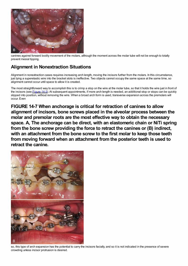
canines against forward bodily movement of the molars, although the moment across the molar tube will not be enough to totallyprevent mesial tipping.
Alignment in Nonextraction SituationsAlignment in nonextraction cases requires increasing arch length, moving the incisors further from the molars. In this circumstance,just tying a superelastic wire into the bracket slots is ineffective. Two objects cannot occupy the same space at the same time, soalignment cannot occur until space to allow it is created.
The most straightforward way to accomplish this is to crimp a stop on the wire at the molar tube, so that it holds the wire just in front ofthe incisors (see Figure 14-3). At subsequent appointments, if more arch length is needed, an additional stop or stops can be quicklyslipped into position, without removing the wire. When a broad arch form is used, transverse expansion across the premolars willoccur. Even
FIGURE 14-7 When anchorage is critical for retraction of canines to allowalignment of incisors, bone screws placed in the alveolar process between themolar and premolar roots are the most effective way to obtain the necessaryspace. A, The anchorage can be direct, with an elastomeric chain or NiTi springfrom the bone screw providing the force to retract the canines or (B) indirect,with an attachment from the bone screw to the first molar to keep those teethfrom moving forward when an attachment from the posterior teeth is used toretract the canine.
so, this type of arch expansion has the potential to carry the incisors facially, and so it is not indicated in the presence of severecrowding unless incisor protrusion is desired.
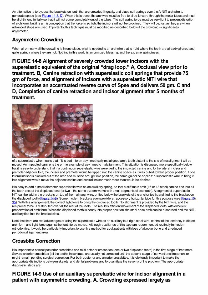
An alternative is to bypass the brackets on teeth that are crowded lingually, and place coil springs over the A-NiTi archwire togenerate space (see Figure 14-3, D). When this is done, the archwire must be free to slide forward through the molar tubes and mustbe slightly long initially so that it will not come completely out of the tubes. The coil spring force must be very light to prevent distortionof arch form, but it is a misconception that the force is so light the incisors will not be proclined. They will be, just as they are whenadvanced stops are used. Importantly, this technique must be modified as described below if the crowding is significantlyasymmetric.
Asymmetric CrowdingWhen all or nearly all the crowding is in one place, what is needed is an archwire that is rigid where the teeth are already aligned andquite springy where they are not. Nothing in this world is an unmixed blessing, and the extreme springiness
FIGURE 14-8 Alignment of severely crowded lower incisors with thesuperelastic equivalent of the original “drag loop.” A, Occlusal view prior totreatment. B, Canine retraction with superelastic coil springs that provide 75gm of force, and alignment of incisors with a superelastic NiTi wire thatincorporates an accentuated reverse curve of Spee and delivers 50 gm. C andD, Completion of canine retraction and incisor alignment after 5 months oftreatment.
of a superelastic wire means that if it is tied into an asymmetrically malaligned arch, teeth distant to the site of malalignment will bemoved. An impacted canine is the prime example of asymmetric malalignment. This situation is discussed more specifically below,but it is easy to understand that if a continuous superelastic wire were tied to the impacted canine and to the lateral incisor andpremolar adjacent to it, the incisor and premolar would be tipped into the canine space as it was pulled toward proper position. If onelateral incisor is blocked out of the arch and must be brought into position, the same guideline applies: a superelastic wire to bring itinto alignment would move the adjacent canine and central incisor much more than would be desired.
It is easy to add a small diameter superelastic wire as an auxiliary spring, so that a stiff main arch (16 or 18 steel) can be tied into allthe teeth except the displaced one (or two—the same system works with small segments of two teeth). A segment of superelasticNiTi can be laid in the brackets on top of the main archwire, or tied below the brackets of the anchor teeth, and tied to the bracket onthe displaced tooth (Figure 14-9). Some modern brackets even provide an accessory horizontal tube for this purpose (see Figure 10-35). With this arrangement, the correct light force to bring the displaced tooth into alignment is provided by the NiTi wire, and thereciprocal force is distributed over all the rest of the teeth. The result is efficient movement of the displaced tooth, with excellentpreservation of arch form. When the displaced tooth is nearly into proper position, the steel base arch can be discarded and the NiTiauxiliary tied into the bracket slots.
Note that there are two advantages of using the superelastic wire as an auxiliary to a rigid steel wire: control of the tendency to distortarch form and light force against the tooth to be moved. Although auxiliaries of this type are recommended routinely in modernorthodontics, it would be particularly important to use this method for adult patients with loss of alveolar bone and a reducedperiodontal ligament area.
Crossbite CorrectionIt is important to correct posterior crossbites and mild anterior crossbites (one or two displaced teeth) in the first stage of treatment.Severe anterior crossbites (all the teeth), in contrast, are usually not corrected until the second stage of conventional treatment ormight remain pending surgical correction. For both posterior and anterior crossbites, it is obviously important to make theappropriate distinctions between skeletal and dental problems and to quantitate the severity of the problem. The appropriatediagnostic steps are
FIGURE 14-9 Use of an auxiliary superelastic wire for incisor alignment in apatient with asymmetric crowding. A, Crowding expressed largely as
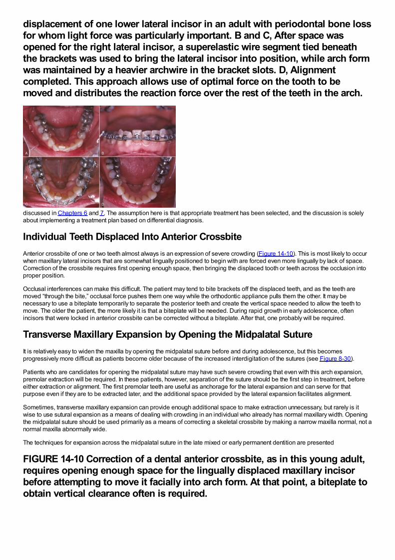
displacement of one lower lateral incisor in an adult with periodontal bone lossfor whom light force was particularly important. B and C, After space wasopened for the right lateral incisor, a superelastic wire segment tied beneaththe brackets was used to bring the lateral incisor into position, while arch formwas maintained by a heavier archwire in the bracket slots. D, Alignmentcompleted. This approach allows use of optimal force on the tooth to bemoved and distributes the reaction force over the rest of the teeth in the arch.
discussed in Chapters 6 and 7. The assumption here is that appropriate treatment has been selected, and the discussion is solelyabout implementing a treatment plan based on differential diagnosis.
Individual Teeth Displaced Into Anterior CrossbiteAnterior crossbite of one or two teeth almost always is an expression of severe crowding (Figure 14-10). This is most likely to occurwhen maxillary lateral incisors that are somewhat lingually positioned to begin with are forced even more lingually by lack of space.Correction of the crossbite requires first opening enough space, then bringing the displaced tooth or teeth across the occlusion intoproper position.
Occlusal interferences can make this difficult. The patient may tend to bite brackets off the displaced teeth, and as the teeth aremoved “through the bite,” occlusal force pushes them one way while the orthodontic appliance pulls them the other. It may benecessary to use a biteplate temporarily to separate the posterior teeth and create the vertical space needed to allow the teeth tomove. The older the patient, the more likely it is that a biteplate will be needed. During rapid growth in early adolescence, oftenincisors that were locked in anterior crossbite can be corrected without a biteplate. After that, one probably will be required.
Transverse Maxillary Expansion by Opening the Midpalatal SutureIt is relatively easy to widen the maxilla by opening the midpalatal suture before and during adolescence, but this becomesprogressively more difficult as patients become older because of the increased interdigitation of the sutures (see Figure 8-30).
Patients who are candidates for opening the midpalatal suture may have such severe crowding that even with this arch expansion,premolar extraction will be required. In these patients, however, separation of the suture should be the first step in treatment, beforeeither extraction or alignment. The first premolar teeth are useful as anchorage for the lateral expansion and can serve for thatpurpose even if they are to be extracted later, and the additional space provided by the lateral expansion facilitates alignment.
Sometimes, transverse maxillary expansion can provide enough additional space to make extraction unnecessary, but rarely is itwise to use sutural expansion as a means of dealing with crowding in an individual who already has normal maxillary width. Openingthe midpalatal suture should be used primarily as a means of correcting a skeletal crossbite by making a narrow maxilla normal, not anormal maxilla abnormally wide.
The techniques for expansion across the midpalatal suture in the late mixed or early permanent dentition are presented
FIGURE 14-10 Correction of a dental anterior crossbite, as in this young adult,requires opening enough space for the lingually displaced maxillary incisorbefore attempting to move it facially into arch form. At that point, a biteplate toobtain vertical clearance often is required.
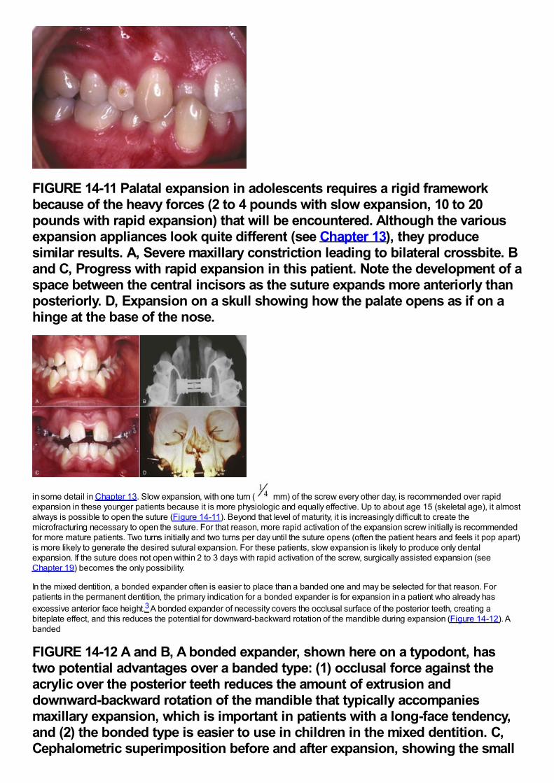
FIGURE 14-11 Palatal expansion in adolescents requires a rigid frameworkbecause of the heavy forces (2 to 4 pounds with slow expansion, 10 to 20pounds with rapid expansion) that will be encountered. Although the variousexpansion appliances look quite different (see Chapter 13), they producesimilar results. A, Severe maxillary constriction leading to bilateral crossbite. Band C, Progress with rapid expansion in this patient. Note the development of aspace between the central incisors as the suture expands more anteriorly thanposteriorly. D, Expansion on a skull showing how the palate opens as if on ahinge at the base of the nose.
in some detail in Chapter 13. Slow expansion, with one turn ( mm) of the screw every other day, is recommended over rapidexpansion in these younger patients because it is more physiologic and equally effective. Up to about age 15 (skeletal age), it almostalways is possible to open the suture (Figure 14-11). Beyond that level of maturity, it is increasingly difficult to create themicrofracturing necessary to open the suture. For that reason, more rapid activation of the expansion screw initially is recommendedfor more mature patients. Two turns initially and two turns per day until the suture opens (often the patient hears and feels it pop apart)is more likely to generate the desired sutural expansion. For these patients, slow expansion is likely to produce only dentalexpansion. If the suture does not open within 2 to 3 days with rapid activation of the screw, surgically assisted expansion (seeChapter 19) becomes the only possibility.
In the mixed dentition, a bonded expander often is easier to place than a banded one and may be selected for that reason. Forpatients in the permanent dentition, the primary indication for a bonded expander is for expansion in a patient who already hasexcessive anterior face height.3 A bonded expander of necessity covers the occlusal surface of the posterior teeth, creating abiteplate effect, and this reduces the potential for downward-backward rotation of the mandible during expansion (Figure 14-12). Abanded
FIGURE 14-12 A and B, A bonded expander, shown here on a typodont, hastwo potential advantages over a banded type: (1) occlusal force against theacrylic over the posterior teeth reduces the amount of extrusion anddownward-backward rotation of the mandible that typically accompaniesmaxillary expansion, which is important in patients with a long-face tendency,and (2) the bonded type is easier to use in children in the mixed dentition. C,Cephalometric superimposition before and after expansion, showing the small
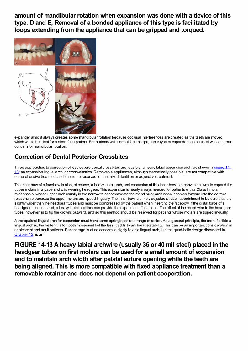
amount of mandibular rotation when expansion was done with a device of thistype. D and E, Removal of a bonded appliance of this type is facilitated byloops extending from the appliance that can be gripped and torqued.
expander almost always creates some mandibular rotation because occlusal interferences are created as the teeth are moved,which would be ideal for a short-face patient. For patients with normal face height, either type of expander can be used without greatconcern for mandibular rotation.
Correction of Dental Posterior CrossbitesThree approaches to correction of less severe dental crossbites are feasible: a heavy labial expansion arch, as shown in Figure 14-13; an expansion lingual arch; or cross-elastics. Removable appliances, although theoretically possible, are not compatible withcomprehensive treatment and should be reserved for the mixed dentition or adjunctive treatment.
The inner bow of a facebow is also, of course, a heavy labial arch, and expansion of this inner bow is a convenient way to expand theupper molars in a patient who is wearing headgear. This expansion is nearly always needed for patients with a Class II molarrelationship, whose upper arch usually is too narrow to accommodate the mandibular arch when it comes forward into the correctrelationship because the upper molars are tipped lingually. The inner bow is simply adjusted at each appointment to be sure that it isslightly wider than the headgear tubes and must be compressed by the patient when inserting the facebow. If the distal force of aheadgear is not desired, a heavy labial auxiliary can provide the expansion effect alone. The effect of the round wire in the headgeartubes, however, is to tip the crowns outward, and so this method should be reserved for patients whose molars are tipped lingually.
A transpalatal lingual arch for expansion must have some springiness and range of action. As a general principle, the more flexible alingual arch is, the better it is for tooth movement but the less it adds to anchorage stability. This can be an important consideration inadolescent and adult patients. If anchorage is of no concern, a highly flexible lingual arch, like the quad-helix design discussed inChapter 12, is an
FIGURE 14-13 A heavy labial archwire (usually 36 or 40 mil steel) placed in theheadgear tubes on first molars can be used for a small amount of expansionand to maintain arch width after palatal suture opening while the teeth arebeing aligned. This is more compatible with fixed appliance treatment than aremovable retainer and does not depend on patient cooperation.
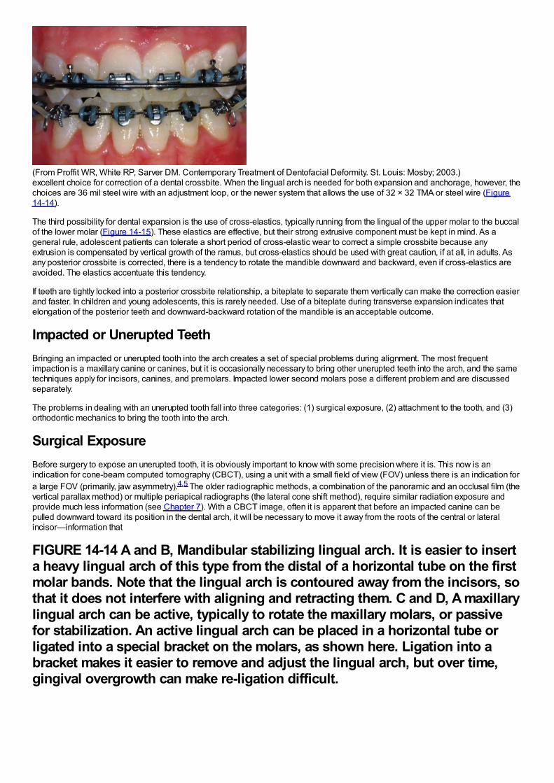
(From Proffit WR, White RP, Sarver DM. Contemporary Treatment of Dentofacial Deformity. St. Louis: Mosby; 2003.)excellent choice for correction of a dental crossbite. When the lingual arch is needed for both expansion and anchorage, however, thechoices are 36 mil steel wire with an adjustment loop, or the newer system that allows the use of 32 × 32 TMA or steel wire (Figure14-14).
The third possibility for dental expansion is the use of cross-elastics, typically running from the lingual of the upper molar to the buccalof the lower molar (Figure 14-15). These elastics are effective, but their strong extrusive component must be kept in mind. As ageneral rule, adolescent patients can tolerate a short period of cross-elastic wear to correct a simple crossbite because anyextrusion is compensated by vertical growth of the ramus, but cross-elastics should be used with great caution, if at all, in adults. Asany posterior crossbite is corrected, there is a tendency to rotate the mandible downward and backward, even if cross-elastics areavoided. The elastics accentuate this tendency.
If teeth are tightly locked into a posterior crossbite relationship, a biteplate to separate them vertically can make the correction easierand faster. In children and young adolescents, this is rarely needed. Use of a biteplate during transverse expansion indicates thatelongation of the posterior teeth and downward-backward rotation of the mandible is an acceptable outcome.
Impacted or Unerupted TeethBringing an impacted or unerupted tooth into the arch creates a set of special problems during alignment. The most frequentimpaction is a maxillary canine or canines, but it is occasionally necessary to bring other unerupted teeth into the arch, and the sametechniques apply for incisors, canines, and premolars. Impacted lower second molars pose a different problem and are discussedseparately.
The problems in dealing with an unerupted tooth fall into three categories: (1) surgical exposure, (2) attachment to the tooth, and (3)orthodontic mechanics to bring the tooth into the arch.
Surgical ExposureBefore surgery to expose an unerupted tooth, it is obviously important to know with some precision where it is. This now is anindication for cone-beam computed tomography (CBCT), using a unit with a small field of view (FOV) unless there is an indication fora large FOV (primarily, jaw asymmetry).4,5 The older radiographic methods, a combination of the panoramic and an occlusal film (thevertical parallax method) or multiple periapical radiographs (the lateral cone shift method), require similar radiation exposure andprovide much less information (see Chapter 7). With a CBCT image, often it is apparent that before an impacted canine can bepulled downward toward its position in the dental arch, it will be necessary to move it away from the roots of the central or lateralincisor—information that
FIGURE 14-14 A and B, Mandibular stabilizing lingual arch. It is easier to inserta heavy lingual arch of this type from the distal of a horizontal tube on the firstmolar bands. Note that the lingual arch is contoured away from the incisors, sothat it does not interfere with aligning and retracting them. C and D, A maxillarylingual arch can be active, typically to rotate the maxillary molars, or passivefor stabilization. An active lingual arch can be placed in a horizontal tube orligated into a special bracket on the molars, as shown here. Ligation into abracket makes it easier to remove and adjust the lingual arch, but over time,gingival overgrowth can make re-ligation difficult.
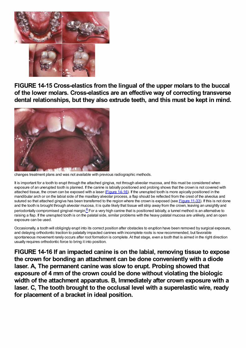
FIGURE 14-15 Cross-elastics from the lingual of the upper molars to the buccalof the lower molars. Cross-elastics are an effective way of correcting transversedental relationships, but they also extrude teeth, and this must be kept in mind.
changes treatment plans and was not available with previous radiographic methods.
It is important for a tooth to erupt through the attached gingiva, not through alveolar mucosa, and this must be considered whenexposure of an unerupted tooth is planned. If the canine is labially positioned and probing shows that the crown is not covered withattached tissue, the crown can be exposed with a laser (Figure 14-16). If the unerupted tooth is more apically positioned in themandibular arch or on the labial side of the maxillary alveolar process, a flap should be reflected from the crest of the alveolus andsutured so that attached gingiva has been transferred to the region where the crown is exposed (see Figure 11-33). If this is not doneand the tooth is brought through alveolar mucosa, it is quite likely that tissue will strip away from the crown, leaving an unsightly andperiodontally compromised gingival margin.6 For a very high canine that is positioned labially, a tunnel method is an alternative toraising a flap. If the unerupted tooth is on the palatal side, similar problems with the heavy palatal mucosa are unlikely, and an openexposure can be used.
Occasionally, a tooth will obligingly erupt into its correct position after obstacles to eruption have been removed by surgical exposure,and delaying orthodontic traction to palatally impacted canines with incomplete roots is now recommended, but favorablespontaneous movement rarely occurs after root formation is complete. At that stage, even a tooth that is aimed in the right directionusually requires orthodontic force to bring it into position.
FIGURE 14-16 If an impacted canine is on the labial, removing tissue to exposethe crown for bonding an attachment can be done conveniently with a diodelaser. A, The permanent canine was slow to erupt. Probing showed thatexposure of 4 mm of the crown could be done without violating the biologicwidth of the attachment apparatus. B, Immediately after crown exposure with alaser. C, The tooth brought to the occlusal level with a superelastic wire, readyfor placement of a bracket in ideal position.
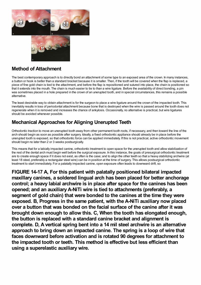
Method of AttachmentThe best contemporary approach is to directly bond an attachment of some type to an exposed area of the crown. In many instances,a button or hook is better than a standard bracket because it is smaller. Then, if the tooth will be covered when the flap is replaced, apiece of fine gold chain is tied to the attachment, and before the flap is repositioned and sutured into place, the chain is positioned sothat it extends into the mouth. The chain is much easier to tie to than a wire ligature. Before the availability of direct bonding, a pinwas sometimes placed in a hole prepared in the crown of an unerupted tooth, and in special circumstances, this remains a possiblealternative.
The least desirable way to obtain attachment is for the surgeon to place a wire ligature around the crown of the impacted tooth. Thisinevitably results in loss of periodontal attachment because bone that is destroyed when the wire is passed around the tooth does notregenerate when it is removed and increases the chance of ankylosis. Occasionally, no alternative is practical, but wire ligaturesshould be avoided whenever possible.
Mechanical Approaches for Aligning Unerupted TeethOrthodontic traction to move an unerupted tooth away from other permanent tooth roots, if necessary, and then toward the line of thearch should begin as soon as possible after surgery. Ideally, a fixed orthodontic appliance should already be in place before theunerupted tooth is exposed, so that orthodontic force can be applied immediately. If this is not practical, active orthodontic movementshould begin no later than 2 or 3 weeks postsurgically.
This means that for a labially impacted canine, orthodontic treatment to open space for the unerupted tooth and allow stabilization ofthe rest of the dental arch must begin well before the surgical exposure. In this instance, the goals of presurgical orthodontic treatmentare to create enough space if it does not exist, as often is the case; and to align the other teeth so that a heavy stabilizing archwire (atleast 18 steel, preferably a rectangular steel wire) can be in position at the time of surgery. This allows postsurgical orthodontictreatment to start immediately. For a palatally impacted canine, open exposure often leads to downward drift, so
FIGURE 14-17 A, For this patient with palatally positioned bilateral impactedmaxillary canines, a soldered lingual arch has been placed for better anchoragecontrol; a heavy labial archwire is in place after space for the canines has beenopened; and an auxiliary A-NiTi wire is tied to attachments (preferably, asegment of gold chain) that were bonded to the canines at the time they wereexposed. B, Progress in the same patient, with the A-NiTi auxiliary now placedover a button that was bonded on the facial surface of the canine after it wasbrought down enough to allow this. C, When the tooth has elongated enough,the button is replaced with a standard canine bracket and alignment iscomplete. D, A vertical spring bent into a 14 mil steel archwire is an alternativeapproach to bring down an impacted canine. The spring is a loop of wire thatfaces downward before activation and is rotated 90 degrees for attachment tothe impacted tooth or teeth. This method is effective but less efficient thanusing a superelastic auxiliary wire.
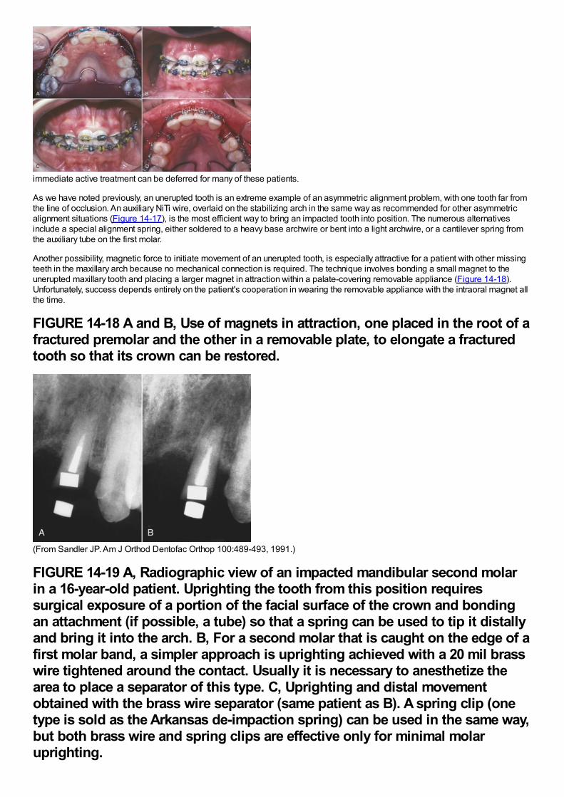
immediate active treatment can be deferred for many of these patients.
As we have noted previously, an unerupted tooth is an extreme example of an asymmetric alignment problem, with one tooth far fromthe line of occlusion. An auxiliary NiTi wire, overlaid on the stabilizing arch in the same way as recommended for other asymmetricalignment situations (Figure 14-17), is the most efficient way to bring an impacted tooth into position. The numerous alternativesinclude a special alignment spring, either soldered to a heavy base archwire or bent into a light archwire, or a cantilever spring fromthe auxiliary tube on the first molar.
Another possibility, magnetic force to initiate movement of an unerupted tooth, is especially attractive for a patient with other missingteeth in the maxillary arch because no mechanical connection is required. The technique involves bonding a small magnet to theunerupted maxillary tooth and placing a larger magnet in attraction within a palate-covering removable appliance (Figure 14-18).Unfortunately, success depends entirely on the patient's cooperation in wearing the removable appliance with the intraoral magnet allthe time.
FIGURE 14-18 A and B, Use of magnets in attraction, one placed in the root of afractured premolar and the other in a removable plate, to elongate a fracturedtooth so that its crown can be restored.
(From Sandler JP. Am J Orthod Dentofac Orthop 100:489-493, 1991.)
FIGURE 14-19 A, Radiographic view of an impacted mandibular second molarin a 16-year-old patient. Uprighting the tooth from this position requiressurgical exposure of a portion of the facial surface of the crown and bondingan attachment (if possible, a tube) so that a spring can be used to tip it distallyand bring it into the arch. B, For a second molar that is caught on the edge of afirst molar band, a simpler approach is uprighting achieved with a 20 mil brasswire tightened around the contact. Usually it is necessary to anesthetize thearea to place a separator of this type. C, Uprighting and distal movementobtained with the brass wire separator (same patient as B). A spring clip (onetype is sold as the Arkansas de-impaction spring) can be used in the same way,but both brass wire and spring clips are effective only for minimal molaruprighting.
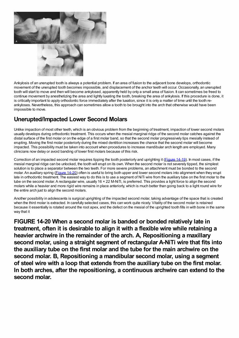
Ankylosis of an unerupted tooth is always a potential problem. If an area of fusion to the adjacent bone develops, orthodonticmovement of the unerupted tooth becomes impossible, and displacement of the anchor teeth will occur. Occasionally, an uneruptedtooth will start to move and then will become ankylosed, apparently held by only a small area of fusion. It can sometimes be freed tocontinue movement by anesthetizing the area and lightly luxating the tooth, breaking the area of ankylosis. If this procedure is done, itis critically important to apply orthodontic force immediately after the luxation, since it is only a matter of time until the tooth re-ankyloses. Nevertheless, this approach can sometimes allow a tooth to be brought into the arch that otherwise would have beenimpossible to move.
Unerupted/Impacted Lower Second MolarsUnlike impaction of most other teeth, which is an obvious problem from the beginning of treatment, impaction of lower second molarsusually develops during orthodontic treatment. This occurs when the mesial marginal ridge of the second molar catches against thedistal surface of the first molar or on the edge of a first molar band, so that the second molar progressively tips mesially instead oferupting. Moving the first molar posteriorly during the mixed dentition increases the chance that the second molar will becomeimpacted. This possibility must be taken into account when procedures to increase mandibular arch length are employed. Manyclinicians now delay or avoid banding of lower first molars because of this risk.
Correction of an impacted second molar requires tipping the tooth posteriorly and uprighting it (Figure 14-19). In most cases, if themesial marginal ridge can be unlocked, the tooth will erupt on its own. When the second molar is not severely tipped, the simplestsolution is to place a separator between the two teeth. For more severe problems, an attachment must be bonded to the secondmolar. An auxiliary spring (Figure 14-20) often is useful to bring both upper and lower second molars into alignment when they eruptlate in orthodontic treatment. The easiest way to do this is to use a segment of NiTi wire from the auxiliary tube on the first molar to thetube on the second molar. A rectangular wire, usually 16 × 22 M-NiTi, is preferred. This provides a light force to align the secondmolars while a heavier and more rigid wire remains in place anteriorly, which is much better than going back to a light round wire forthe entire arch just to align the second molars.
Another possibility in adolescents is surgical uprighting of the impacted second molar, taking advantage of the space that is createdwhen the third molar is extracted. In carefully selected cases, this can work quite nicely. Vitality of the second molar is retainedbecause it essentially is rotated around the root apex, and the defect on the mesial of the uprighted tooth fills in with bone in the sameway that it
FIGURE 14-20 When a second molar is banded or bonded relatively late intreatment, often it is desirable to align it with a flexible wire while retaining aheavier archwire in the remainder of the arch. A, Repositioning a maxillarysecond molar, using a straight segment of rectangular A-NiTi wire that fits intothe auxiliary tube on the first molar and the tube for the main archwire on thesecond molar. B, Repositioning a mandibular second molar, using a segmentof steel wire with a loop that extends from the auxiliary tube on the first molar.In both arches, after the repositioning, a continuous archwire can extend to thesecond molar.
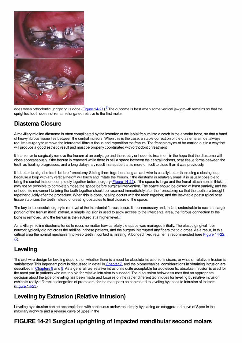
does when orthodontic uprighting is done (Figure 14-21).7 The outcome is best when some vertical jaw growth remains so that theuprighted tooth does not remain elongated relative to the first molar.
Diastema ClosureA maxillary midline diastema is often complicated by the insertion of the labial frenum into a notch in the alveolar bone, so that a bandof heavy fibrous tissue lies between the central incisors. When this is the case, a stable correction of the diastema almost alwaysrequires surgery to remove the interdental fibrous tissue and reposition the frenum. The frenectomy must be carried out in a way thatwill produce a good esthetic result and must be properly coordinated with orthodontic treatment.
It is an error to surgically remove the frenum at an early age and then delay orthodontic treatment in the hope that the diastema willclose spontaneously. If the frenum is removed while there is still a space between the central incisors, scar tissue forms between theteeth as healing progresses, and a long delay may result in a space that is more difficult to close than it was previously.
It is better to align the teeth before frenectomy. Sliding them together along an archwire is usually better than using a closing loopbecause a loop with any vertical height will touch and irritate the frenum. If the diastema is relatively small, it is usually possible tobring the central incisors completely together before surgery (Figure 14-22). If the space is large and the frenal attachment is thick, itmay not be possible to completely close the space before surgical intervention. The space should be closed at least partially, and theorthodontic movement to bring the teeth together should be resumed immediately after the frenectomy, so that the teeth are broughttogether quickly after the procedure. When this is done, healing occurs with the teeth together, and the inevitable postsurgical scartissue stabilizes the teeth instead of creating obstacles to final closure of the space.
The key to successful surgery is removal of the interdental fibrous tissue. It is unnecessary and, in fact, undesirable to excise a largeportion of the frenum itself. Instead, a simple incision is used to allow access to the interdental area, the fibrous connection to thebone is removed, and the frenum is then sutured at a higher level.8
A maxillary midline diastema tends to recur, no matter how carefully the space was managed initially. The elastic gingival fibernetwork typically did not cross the midline in these patients, and the surgery interrupted any fibers that did cross. As a result, in thiscritical area the normal mechanism to keep teeth in contact is missing. A bonded fixed retainer is recommended (see Figure 14-22,G).
LevelingThe archwire design for leveling depends on whether there is a need for absolute intrusion of incisors, or whether relative intrusion issatisfactory. This important point is discussed in detail in Chapter 7, and the biomechanical considerations in obtaining intrusion aredescribed in Chapters 8 and 9. As a general rule, relative intrusion is quite acceptable for adolescents; absolute intrusion is used forthe most part in patients who are too old for relative intrusion to succeed. The discussion below assumes that an appropriatedecision about the type of leveling has been made and focuses on the rather different techniques for leveling by relative intrusion(which is really differential elongation of premolars, for the most part) as contrasted to leveling by absolute intrusion of incisors(Figure 14-23).
Leveling by Extrusion (Relative Intrusion)Leveling by extrusion can be accomplished with continuous archwires, simply by placing an exaggerated curve of Spee in themaxillary archwire and a reverse curve of Spee in the
FIGURE 14-21 Surgical uprighting of impacted mandibular second molars
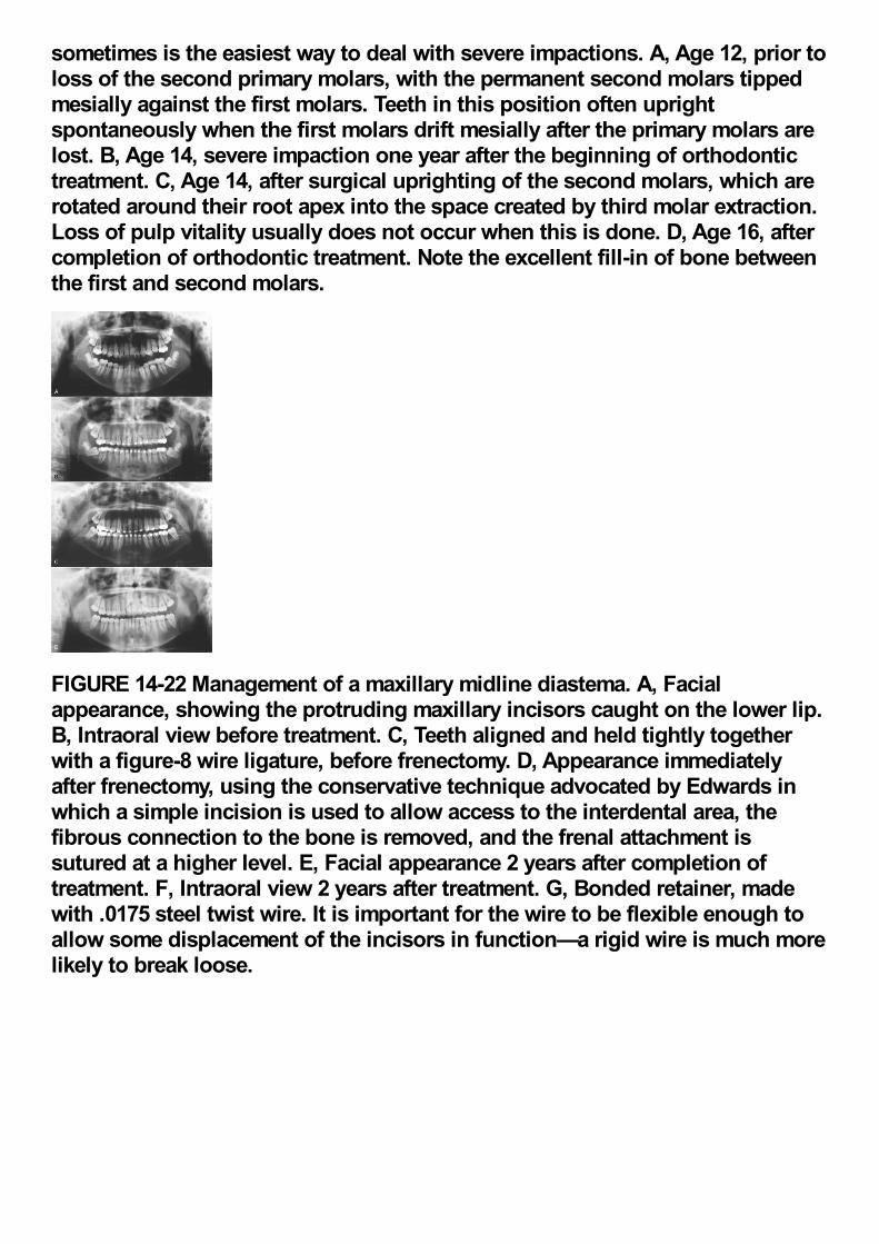
sometimes is the easiest way to deal with severe impactions. A, Age 12, prior toloss of the second primary molars, with the permanent second molars tippedmesially against the first molars. Teeth in this position often uprightspontaneously when the first molars drift mesially after the primary molars arelost. B, Age 14, severe impaction one year after the beginning of orthodontictreatment. C, Age 14, after surgical uprighting of the second molars, which arerotated around their root apex into the space created by third molar extraction.Loss of pulp vitality usually does not occur when this is done. D, Age 16, aftercompletion of orthodontic treatment. Note the excellent fill-in of bone betweenthe first and second molars.
FIGURE 14-22 Management of a maxillary midline diastema. A, Facialappearance, showing the protruding maxillary incisors caught on the lower lip.B, Intraoral view before treatment. C, Teeth aligned and held tightly togetherwith a figure-8 wire ligature, before frenectomy. D, Appearance immediatelyafter frenectomy, using the conservative technique advocated by Edwards inwhich a simple incision is used to allow access to the interdental area, thefibrous connection to the bone is removed, and the frenal attachment issutured at a higher level. E, Facial appearance 2 years after completion oftreatment. F, Intraoral view 2 years after treatment. G, Bonded retainer, madewith .0175 steel twist wire. It is important for the wire to be flexible enough toallow some displacement of the incisors in function—a rigid wire is much morelikely to break loose.
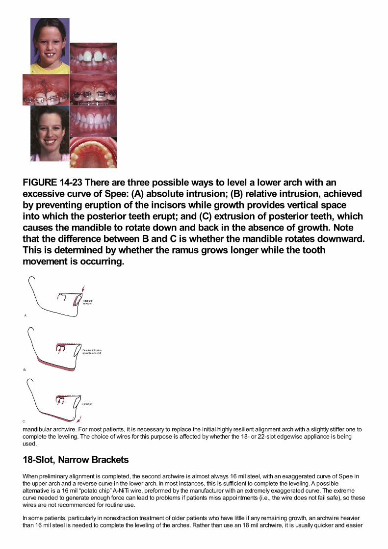
FIGURE 14-23 There are three possible ways to level a lower arch with anexcessive curve of Spee: (A) absolute intrusion; (B) relative intrusion, achievedby preventing eruption of the incisors while growth provides vertical spaceinto which the posterior teeth erupt; and (C) extrusion of posterior teeth, whichcauses the mandible to rotate down and back in the absence of growth. Notethat the difference between B and C is whether the mandible rotates downward.This is determined by whether the ramus grows longer while the toothmovement is occurring.
mandibular archwire. For most patients, it is necessary to replace the initial highly resilient alignment arch with a slightly stiffer one tocomplete the leveling. The choice of wires for this purpose is affected by whether the 18- or 22-slot edgewise appliance is beingused.
18-Slot, Narrow BracketsWhen preliminary alignment is completed, the second archwire is almost always 16 mil steel, with an exaggerated curve of Spee inthe upper arch and a reverse curve in the lower arch. In most instances, this is sufficient to complete the leveling. A possiblealternative is a 16 mil “potato chip” A-NiTi wire, preformed by the manufacturer with an extremely exaggerated curve. The extremecurve needed to generate enough force can lead to problems if patients miss appointments (i.e., the wire does not fail safe), so thesewires are not recommended for routine use.
In some patients, particularly in nonextraction treatment of older patients who have little if any remaining growth, an archwire heavierthan 16 mil steel is needed to complete the leveling of the arches. Rather than use an 18 mil archwire, it is usually quicker and easier
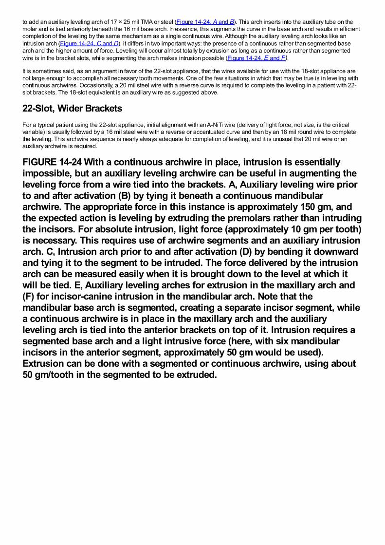
to add an auxiliary leveling arch of 17 × 25 mil TMA or steel (Figure 14-24, A and B). This arch inserts into the auxiliary tube on themolar and is tied anteriorly beneath the 16 mil base arch. In essence, this augments the curve in the base arch and results in efficientcompletion of the leveling by the same mechanism as a single continuous wire. Although the auxiliary leveling arch looks like anintrusion arch (Figure 14-24, C and D), it differs in two important ways: the presence of a continuous rather than segmented basearch and the higher amount of force. Leveling will occur almost totally by extrusion as long as a continuous rather than segmentedwire is in the bracket slots, while segmenting the arch makes intrusion possible (Figure 14-24, E and F).
It is sometimes said, as an argument in favor of the 22-slot appliance, that the wires available for use with the 18-slot appliance arenot large enough to accomplish all necessary tooth movements. One of the few situations in which that may be true is in leveling withcontinuous archwires. Occasionally, a 20 mil steel wire with a reverse curve is required to complete the leveling in a patient with 22-slot brackets. The 18-slot equivalent is an auxiliary wire as suggested above.
22-Slot, Wider BracketsFor a typical patient using the 22-slot appliance, initial alignment with an A-NiTi wire (delivery of light force, not size, is the criticalvariable) is usually followed by a 16 mil steel wire with a reverse or accentuated curve and then by an 18 mil round wire to completethe leveling. This archwire sequence is nearly always adequate for completion of leveling, and it is unusual that 20 mil wire or anauxiliary archwire is required.
FIGURE 14-24 With a continuous archwire in place, intrusion is essentiallyimpossible, but an auxiliary leveling archwire can be useful in augmenting theleveling force from a wire tied into the brackets. A, Auxiliary leveling wire priorto and after activation (B) by tying it beneath a continuous mandibulararchwire. The appropriate force in this instance is approximately 150 gm, andthe expected action is leveling by extruding the premolars rather than intrudingthe incisors. For absolute intrusion, light force (approximately 10 gm per tooth)is necessary. This requires use of archwire segments and an auxiliary intrusionarch. C, Intrusion arch prior to and after activation (D) by bending it downwardand tying it to the segment to be intruded. The force delivered by the intrusionarch can be measured easily when it is brought down to the level at which itwill be tied. E, Auxiliary leveling arches for extrusion in the maxillary arch and(F) for incisor-canine intrusion in the mandibular arch. Note that themandibular base arch is segmented, creating a separate incisor segment, whilea continuous archwire is in place in the maxillary arch and the auxiliaryleveling arch is tied into the anterior brackets on top of it. Intrusion requires asegmented base arch and a light intrusive force (here, with six mandibularincisors in the anterior segment, approximately 50 gm would be used).Extrusion can be done with a segmented or continuous archwire, using about50 gm/tooth in the segmented to be extruded.
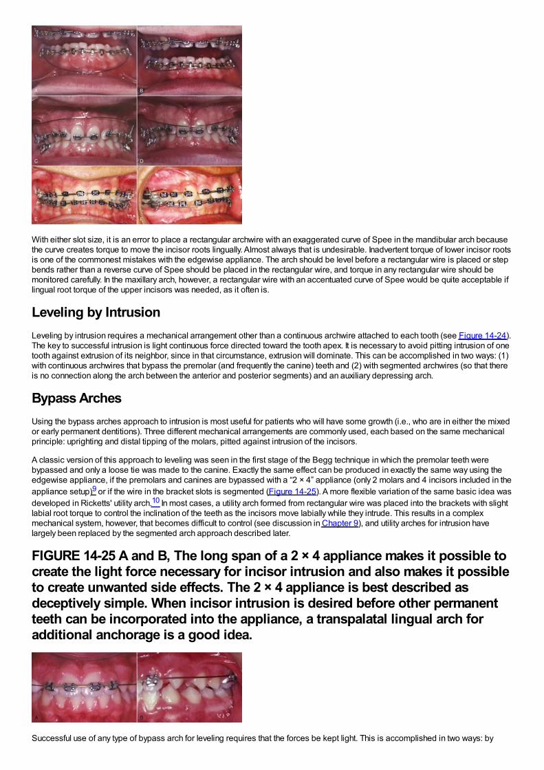
With either slot size, it is an error to place a rectangular archwire with an exaggerated curve of Spee in the mandibular arch becausethe curve creates torque to move the incisor roots lingually. Almost always that is undesirable. Inadvertent torque of lower incisor rootsis one of the commonest mistakes with the edgewise appliance. The arch should be level before a rectangular wire is placed or stepbends rather than a reverse curve of Spee should be placed in the rectangular wire, and torque in any rectangular wire should bemonitored carefully. In the maxillary arch, however, a rectangular wire with an accentuated curve of Spee would be quite acceptable iflingual root torque of the upper incisors was needed, as it often is.
Leveling by IntrusionLeveling by intrusion requires a mechanical arrangement other than a continuous archwire attached to each tooth (see Figure 14-24).The key to successful intrusion is light continuous force directed toward the tooth apex. It is necessary to avoid pitting intrusion of onetooth against extrusion of its neighbor, since in that circumstance, extrusion will dominate. This can be accomplished in two ways: (1)with continuous archwires that bypass the premolar (and frequently the canine) teeth and (2) with segmented archwires (so that thereis no connection along the arch between the anterior and posterior segments) and an auxiliary depressing arch.
Bypass ArchesUsing the bypass arches approach to intrusion is most useful for patients who will have some growth (i.e., who are in either the mixedor early permanent dentitions). Three different mechanical arrangements are commonly used, each based on the same mechanicalprinciple: uprighting and distal tipping of the molars, pitted against intrusion of the incisors.
A classic version of this approach to leveling was seen in the first stage of the Begg technique in which the premolar teeth werebypassed and only a loose tie was made to the canine. Exactly the same effect can be produced in exactly the same way using theedgewise appliance, if the premolars and canines are bypassed with a “2 × 4” appliance (only 2 molars and 4 incisors included in theappliance setup)9 or if the wire in the bracket slots is segmented (Figure 14-25). A more flexible variation of the same basic idea wasdeveloped in Ricketts' utility arch.10 In most cases, a utility arch formed from rectangular wire was placed into the brackets with slightlabial root torque to control the inclination of the teeth as the incisors move labially while they intrude. This results in a complexmechanical system, however, that becomes difficult to control (see discussion in Chapter 9), and utility arches for intrusion havelargely been replaced by the segmented arch approach described later.
FIGURE 14-25 A and B, The long span of a 2 × 4 appliance makes it possible tocreate the light force necessary for incisor intrusion and also makes it possibleto create unwanted side effects. The 2 × 4 appliance is best described asdeceptively simple. When incisor intrusion is desired before other permanentteeth can be incorporated into the appliance, a transpalatal lingual arch foradditional anchorage is a good idea.
Successful use of any type of bypass arch for leveling requires that the forces be kept light. This is accomplished in two ways: by
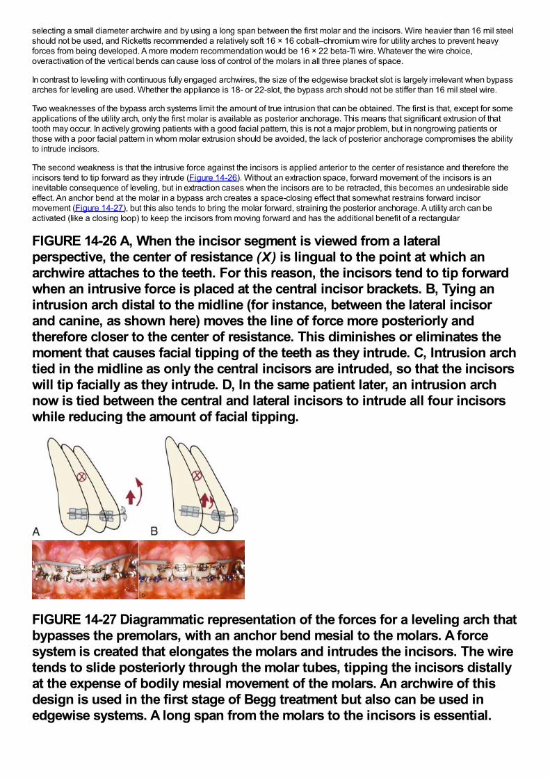
selecting a small diameter archwire and by using a long span between the first molar and the incisors. Wire heavier than 16 mil steelshould not be used, and Ricketts recommended a relatively soft 16 × 16 cobalt–chromium wire for utility arches to prevent heavyforces from being developed. A more modern recommendation would be 16 × 22 beta-Ti wire. Whatever the wire choice,overactivation of the vertical bends can cause loss of control of the molars in all three planes of space.
In contrast to leveling with continuous fully engaged archwires, the size of the edgewise bracket slot is largely irrelevant when bypassarches for leveling are used. Whether the appliance is 18- or 22-slot, the bypass arch should not be stiffer than 16 mil steel wire.
Two weaknesses of the bypass arch systems limit the amount of true intrusion that can be obtained. The first is that, except for someapplications of the utility arch, only the first molar is available as posterior anchorage. This means that significant extrusion of thattooth may occur. In actively growing patients with a good facial pattern, this is not a major problem, but in nongrowing patients orthose with a poor facial pattern in whom molar extrusion should be avoided, the lack of posterior anchorage compromises the abilityto intrude incisors.
The second weakness is that the intrusive force against the incisors is applied anterior to the center of resistance and therefore theincisors tend to tip forward as they intrude (Figure 14-26). Without an extraction space, forward movement of the incisors is aninevitable consequence of leveling, but in extraction cases when the incisors are to be retracted, this becomes an undesirable sideeffect. An anchor bend at the molar in a bypass arch creates a space-closing effect that somewhat restrains forward incisormovement (Figure 14-27), but this also tends to bring the molar forward, straining the posterior anchorage. A utility arch can beactivated (like a closing loop) to keep the incisors from moving forward and has the additional benefit of a rectangular
FIGURE 14-26 A, When the incisor segment is viewed from a lateralperspective, the center of resistance (X) is lingual to the point at which anarchwire attaches to the teeth. For this reason, the incisors tend to tip forwardwhen an intrusive force is placed at the central incisor brackets. B, Tying anintrusion arch distal to the midline (for instance, between the lateral incisorand canine, as shown here) moves the line of force more posteriorly andtherefore closer to the center of resistance. This diminishes or eliminates themoment that causes facial tipping of the teeth as they intrude. C, Intrusion archtied in the midline as only the central incisors are intruded, so that the incisorswill tip facially as they intrude. D, In the same patient later, an intrusion archnow is tied between the central and lateral incisors to intrude all four incisorswhile reducing the amount of facial tipping.
FIGURE 14-27 Diagrammatic representation of the forces for a leveling arch thatbypasses the premolars, with an anchor bend mesial to the molars. A forcesystem is created that elongates the molars and intrudes the incisors. The wiretends to slide posteriorly through the molar tubes, tipping the incisors distallyat the expense of bodily mesial movement of the molars. An archwire of thisdesign is used in the first stage of Begg treatment but also can be used inedgewise systems. A long span from the molars to the incisors is essential.
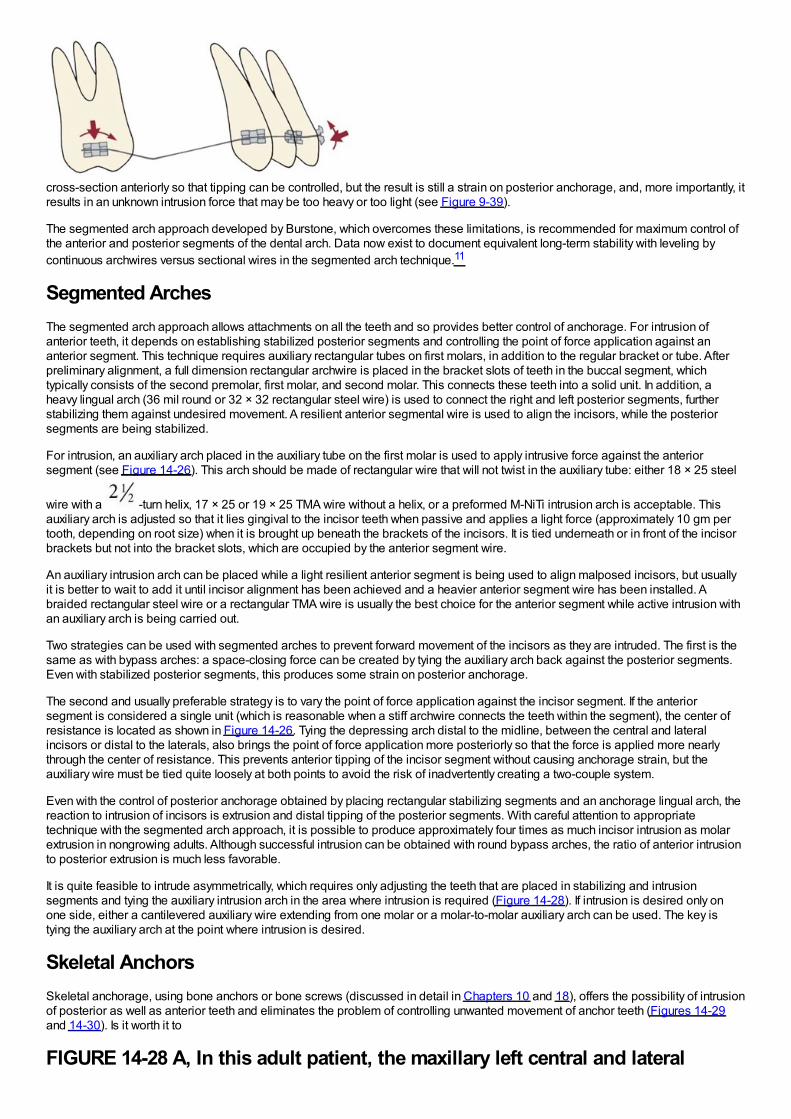
cross-section anteriorly so that tipping can be controlled, but the result is still a strain on posterior anchorage, and, more importantly, itresults in an unknown intrusion force that may be too heavy or too light (see Figure 9-39).
The segmented arch approach developed by Burstone, which overcomes these limitations, is recommended for maximum control ofthe anterior and posterior segments of the dental arch. Data now exist to document equivalent long-term stability with leveling bycontinuous archwires versus sectional wires in the segmented arch technique.11
Segmented ArchesThe segmented arch approach allows attachments on all the teeth and so provides better control of anchorage. For intrusion ofanterior teeth, it depends on establishing stabilized posterior segments and controlling the point of force application against ananterior segment. This technique requires auxiliary rectangular tubes on first molars, in addition to the regular bracket or tube. Afterpreliminary alignment, a full dimension rectangular archwire is placed in the bracket slots of teeth in the buccal segment, whichtypically consists of the second premolar, first molar, and second molar. This connects these teeth into a solid unit. In addition, aheavy lingual arch (36 mil round or 32 × 32 rectangular steel wire) is used to connect the right and left posterior segments, furtherstabilizing them against undesired movement. A resilient anterior segmental wire is used to align the incisors, while the posteriorsegments are being stabilized.
For intrusion, an auxiliary arch placed in the auxiliary tube on the first molar is used to apply intrusive force against the anteriorsegment (see Figure 14-26). This arch should be made of rectangular wire that will not twist in the auxiliary tube: either 18 × 25 steel
wire with a -turn helix, 17 × 25 or 19 × 25 TMA wire without a helix, or a preformed M-NiTi intrusion arch is acceptable. Thisauxiliary arch is adjusted so that it lies gingival to the incisor teeth when passive and applies a light force (approximately 10 gm pertooth, depending on root size) when it is brought up beneath the brackets of the incisors. It is tied underneath or in front of the incisorbrackets but not into the bracket slots, which are occupied by the anterior segment wire.
An auxiliary intrusion arch can be placed while a light resilient anterior segment is being used to align malposed incisors, but usuallyit is better to wait to add it until incisor alignment has been achieved and a heavier anterior segment wire has been installed. Abraided rectangular steel wire or a rectangular TMA wire is usually the best choice for the anterior segment while active intrusion withan auxiliary arch is being carried out.
Two strategies can be used with segmented arches to prevent forward movement of the incisors as they are intruded. The first is thesame as with bypass arches: a space-closing force can be created by tying the auxiliary arch back against the posterior segments.Even with stabilized posterior segments, this produces some strain on posterior anchorage.
The second and usually preferable strategy is to vary the point of force application against the incisor segment. If the anteriorsegment is considered a single unit (which is reasonable when a stiff archwire connects the teeth within the segment), the center ofresistance is located as shown in Figure 14-26. Tying the depressing arch distal to the midline, between the central and lateralincisors or distal to the laterals, also brings the point of force application more posteriorly so that the force is applied more nearlythrough the center of resistance. This prevents anterior tipping of the incisor segment without causing anchorage strain, but theauxiliary wire must be tied quite loosely at both points to avoid the risk of inadvertently creating a two-couple system.
Even with the control of posterior anchorage obtained by placing rectangular stabilizing segments and an anchorage lingual arch, thereaction to intrusion of incisors is extrusion and distal tipping of the posterior segments. With careful attention to appropriatetechnique with the segmented arch approach, it is possible to produce approximately four times as much incisor intrusion as molarextrusion in nongrowing adults. Although successful intrusion can be obtained with round bypass arches, the ratio of anterior intrusionto posterior extrusion is much less favorable.
It is quite feasible to intrude asymmetrically, which requires only adjusting the teeth that are placed in stabilizing and intrusionsegments and tying the auxiliary intrusion arch in the area where intrusion is required (Figure 14-28). If intrusion is desired only onone side, either a cantilevered auxiliary wire extending from one molar or a molar-to-molar auxiliary arch can be used. The key istying the auxiliary arch at the point where intrusion is desired.
Skeletal AnchorsSkeletal anchorage, using bone anchors or bone screws (discussed in detail in Chapters 10 and 18), offers the possibility of intrusionof posterior as well as anterior teeth and eliminates the problem of controlling unwanted movement of anchor teeth (Figures 14-29and 14-30). Is it worth it to
FIGURE 14-28 A, In this adult patient, the maxillary left central and lateral
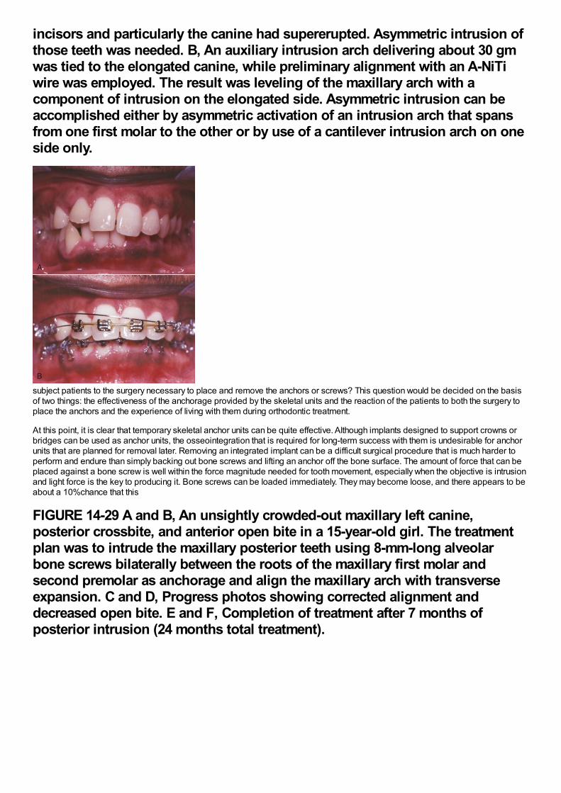
incisors and particularly the canine had supererupted. Asymmetric intrusion ofthose teeth was needed. B, An auxiliary intrusion arch delivering about 30 gmwas tied to the elongated canine, while preliminary alignment with an A-NiTiwire was employed. The result was leveling of the maxillary arch with acomponent of intrusion on the elongated side. Asymmetric intrusion can beaccomplished either by asymmetric activation of an intrusion arch that spansfrom one first molar to the other or by use of a cantilever intrusion arch on oneside only.
subject patients to the surgery necessary to place and remove the anchors or screws? This question would be decided on the basisof two things: the effectiveness of the anchorage provided by the skeletal units and the reaction of the patients to both the surgery toplace the anchors and the experience of living with them during orthodontic treatment.
At this point, it is clear that temporary skeletal anchor units can be quite effective. Although implants designed to support crowns orbridges can be used as anchor units, the osseointegration that is required for long-term success with them is undesirable for anchorunits that are planned for removal later. Removing an integrated implant can be a difficult surgical procedure that is much harder toperform and endure than simply backing out bone screws and lifting an anchor off the bone surface. The amount of force that can beplaced against a bone screw is well within the force magnitude needed for tooth movement, especially when the objective is intrusionand light force is the key to producing it. Bone screws can be loaded immediately. They may become loose, and there appears to beabout a 10%chance that this
FIGURE 14-29 A and B, An unsightly crowded-out maxillary left canine,posterior crossbite, and anterior open bite in a 15-year-old girl. The treatmentplan was to intrude the maxillary posterior teeth using 8-mm-long alveolarbone screws bilaterally between the roots of the maxillary first molar andsecond premolar as anchorage and align the maxillary arch with transverseexpansion. C and D, Progress photos showing corrected alignment anddecreased open bite. E and F, Completion of treatment after 7 months ofposterior intrusion (24 months total treatment).
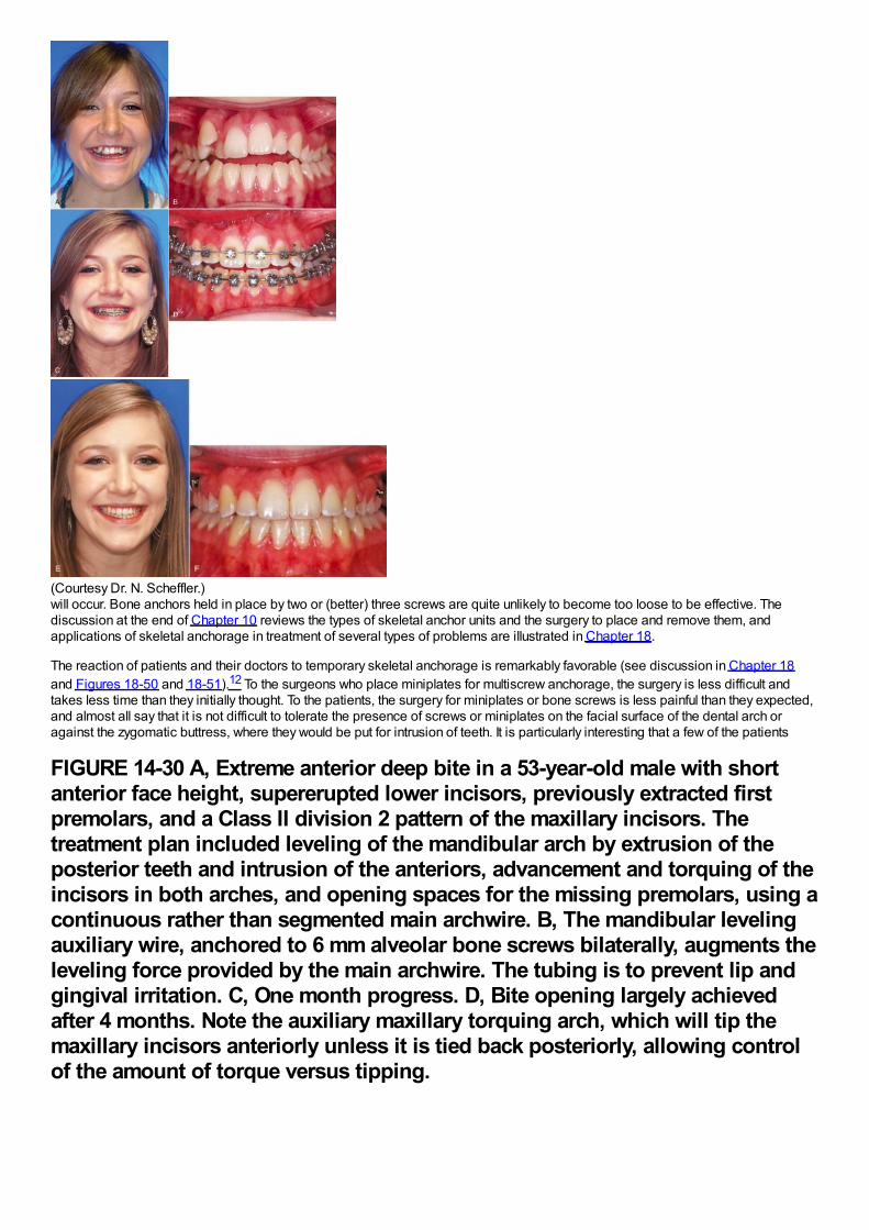
(Courtesy Dr. N. Scheffler.)will occur. Bone anchors held in place by two or (better) three screws are quite unlikely to become too loose to be effective. Thediscussion at the end of Chapter 10 reviews the types of skeletal anchor units and the surgery to place and remove them, andapplications of skeletal anchorage in treatment of several types of problems are illustrated in Chapter 18.
The reaction of patients and their doctors to temporary skeletal anchorage is remarkably favorable (see discussion in Chapter 18and Figures 18-50 and 18-51).12 To the surgeons who place miniplates for multiscrew anchorage, the surgery is less difficult andtakes less time than they initially thought. To the patients, the surgery for miniplates or bone screws is less painful than they expected,and almost all say that it is not difficult to tolerate the presence of screws or miniplates on the facial surface of the dental arch oragainst the zygomatic buttress, where they would be put for intrusion of teeth. It is particularly interesting that a few of the patients
FIGURE 14-30 A, Extreme anterior deep bite in a 53-year-old male with shortanterior face height, supererupted lower incisors, previously extracted firstpremolars, and a Class II division 2 pattern of the maxillary incisors. Thetreatment plan included leveling of the mandibular arch by extrusion of theposterior teeth and intrusion of the anteriors, advancement and torquing of theincisors in both arches, and opening spaces for the missing premolars, using acontinuous rather than segmented main archwire. B, The mandibular levelingauxiliary wire, anchored to 6 mm alveolar bone screws bilaterally, augments theleveling force provided by the main archwire. The tubing is to prevent lip andgingival irritation. C, One month progress. D, Bite opening largely achievedafter 4 months. Note the auxiliary maxillary torquing arch, which will tip themaxillary incisors anteriorly unless it is tied back posteriorly, allowing controlof the amount of torque versus tipping.
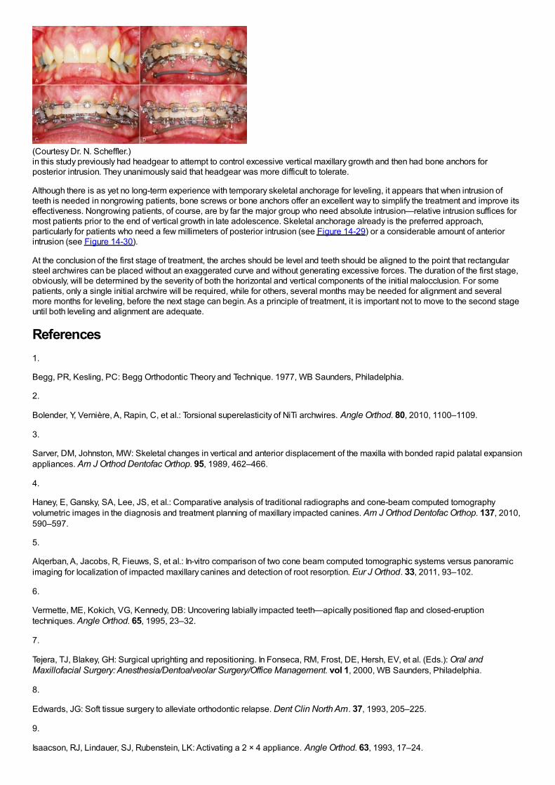
(Courtesy Dr. N. Scheffler.)in this study previously had headgear to attempt to control excessive vertical maxillary growth and then had bone anchors forposterior intrusion. They unanimously said that headgear was more difficult to tolerate.
Although there is as yet no long-term experience with temporary skeletal anchorage for leveling, it appears that when intrusion ofteeth is needed in nongrowing patients, bone screws or bone anchors offer an excellent way to simplify the treatment and improve itseffectiveness. Nongrowing patients, of course, are by far the major group who need absolute intrusion—relative intrusion suffices formost patients prior to the end of vertical growth in late adolescence. Skeletal anchorage already is the preferred approach,particularly for patients who need a few millimeters of posterior intrusion (see Figure 14-29) or a considerable amount of anteriorintrusion (see Figure 14-30).
At the conclusion of the first stage of treatment, the arches should be level and teeth should be aligned to the point that rectangularsteel archwires can be placed without an exaggerated curve and without generating excessive forces. The duration of the first stage,obviously, will be determined by the severity of both the horizontal and vertical components of the initial malocclusion. For somepatients, only a single initial archwire will be required, while for others, several months may be needed for alignment and severalmore months for leveling, before the next stage can begin. As a principle of treatment, it is important not to move to the second stageuntil both leveling and alignment are adequate.
References1.
Begg, PR, Kesling, PC: Begg Orthodontic Theory and Technique. 1977, WB Saunders, Philadelphia.
2.
Bolender, Y, Vernière, A, Rapin, C, et al.: Torsional superelasticity of NiTi archwires. Angle Orthod. 80, 2010, 1100–1109.
3.
Sarver, DM, Johnston, MW: Skeletal changes in vertical and anterior displacement of the maxilla with bonded rapid palatal expansionappliances. Am J Orthod Dentofac Orthop. 95, 1989, 462–466.
4.
Haney, E, Gansky, SA, Lee, JS, et al.: Comparative analysis of traditional radiographs and cone-beam computed tomographyvolumetric images in the diagnosis and treatment planning of maxillary impacted canines. Am J Orthod Dentofac Orthop. 137, 2010,590–597.
5.
Alqerban, A, Jacobs, R, Fieuws, S, et al.: In-vitro comparison of two cone beam computed tomographic systems versus panoramicimaging for localization of impacted maxillary canines and detection of root resorption. Eur J Orthod. 33, 2011, 93–102.
6.
Vermette, ME, Kokich, VG, Kennedy, DB: Uncovering labially impacted teeth—apically positioned flap and closed-eruptiontechniques. Angle Orthod. 65, 1995, 23–32.
7.
Tejera, TJ, Blakey, GH: Surgical uprighting and repositioning. In Fonseca, RM, Frost, DE, Hersh, EV, et al. (Eds.): Oral andMaxillofacial Surgery: Anesthesia/Dentoalveolar Surgery/Office Management. vol 1, 2000, WB Saunders, Philadelphia.
8.
Edwards, JG: Soft tissue surgery to alleviate orthodontic relapse. Dent Clin North Am. 37, 1993, 205–225.
9.
Isaacson, RJ, Lindauer, SJ, Rubenstein, LK: Activating a 2 × 4 appliance. Angle Orthod. 63, 1993, 17–24.

10.
Ricketts, RW, Bench, RW, Gugino, CF, et al.: Bioprogressive Therapy. 1979, Rocky Mountain Orthodontics, Denver.
11.
Preston, CB, Maggard, MB, Lampasso, J, et al.: Long-term effectiveness of the continuous and the sectional archwire techniques inleveling the curve of Spee. Am J Orthod Dentofac Orthop. 133, 2008, 550–555.
12.
Cornelis, MA, Scheffler, NR, DeClerck, H, et al.: Patients' and orthodontists' perceptions of miniplates used for temporary skeletalanchorage: a prospective study. Am J Orthod Dentofac Orthop. 133, 2008, 18–24.
Chapter 15 The Second Stage of Comprehensive Treatment: Correction ofMolar Relationship and Space ClosureAt the beginning of the second stage of treatment, the teeth should be well aligned, and any excessive or reverse curve of Speeshould have been eliminated. The objectives of this stage of treatment are to correct molar and buccal segment relationships toprovide normal occlusion in the anteroposterior plane of space, close extraction spaces or residual spaces in the arches, and correctexcessive or negative overjet. This is possible only if the jaw relationships are reasonably correct, which means that orthognathicsurgery must be considered for the most severe problems. Indications for surgical treatment and the orthodontist–surgeon interactionare discussed in Chapter 19.
Correction of Molar RelationshipOrthodontic correction of the molar relationship nearly always involves moving from a Class II or partially Class II relationship to ClassI, although occasionally the treatment will be aimed at a Class III problem. Excluding surgery to reposition the jaws, there are twopossibilities: (1) differential growth of the jaws, guided by extraoral force or a functional appliance or (2) differential anteroposteriormovement of the upper and lower teeth, with or without differential closure of extraction spaces. These approaches are not mutuallyexclusive, but even when growth modification is successful, it typically provides only a partial correction of a full-cusp Class II or ClassIII malocclusion. Some tooth movement almost always is needed to complete the correction of the molar relationship.
Differential Growth in Adolescent Class II TreatmentThe use of extraoral force or functional appliances to influence jaw growth is discussed in some detail in Chapter 13. The differenttiming of skeletal growth in males and females must be kept in mind when this approach is used. During adolescence, the mandibletends to grow forward more than the maxilla, providing an opportunity to improve a skeletal Class II jaw relationship. Girls matureconsiderably earlier than boys and are often beyond the peak of the adolescent growth spurt before the full permanent dentition isavailable and comprehensive orthodontic treatment can begin. Boys, who mature more slowly and have a more prolonged period ofadolescent growth, are much more likely to have a clinically useful amount of anteroposterior growth during comprehensive treatmentin the early permanent dentition.
When either extraoral force (headgear) or a functional appliance is used to modify growth in Class II patients, a favorable responseincludes both restraint of maxillary growth and differential forward mandibular growth. In skeletally immature patients with a permanentdentition, there is nothing wrong with a first phase of functional appliance treatment, even though the permanent teeth have erupted,and then a fixed appliance to obtain detailed occlusal results, but headgear is more compatible with the fixed appliances needed forcomprehensive treatment. A removable functional appliance alone is unlikely to provide a satisfactory result in the early permanentdentition, and it will have to be modified or discontinued when the fixed appliance treatment begins. Many clinicians would like tobelieve that Class II elastics (or fixed springs that have the same effect) can influence growth, as well as move teeth. Unfortunately, theevidence indicates that growth modification in adolescent patients is unlikely with elastics or flexible spring devices.1,2 In anadolescent in the early permanent dentition, a rigidly coupled fixed functional appliance like the Herbst appliance effectively correctsClass II molar relationships (with varying combinations of differential growth and forward displacement of mandibular teeth), butheadgear can be quite effective in a cooperative patient and does not introduce a Class II elastics effect.
An ideal patient for headgear in the early permanent dentition is a 12- to 14-year-old boy with a Class II problem, whose skeletalmaturity is somewhat behind his stage of dental development, and who has good growth potential (Figure 15-1). Boys at age 13, itmust be remembered, are on the average at the same stage of maturation as girls at 11, and significant skeletal growth is almostalways continuing. On the other hand, girls at age 13 are, on the average, at the same developmental stage as boys at 15, and by thistime, clinically useful changes in jaw relationship from growth guidance are unlikely.
Although correction of molar relationship is a major goal of the second rather than the first stage of treatment, there is no reason towait for alignment and leveling to be completed before beginning headgear or a fixed functional appliance, especially since everypassing day decreases the probability of a favorable growth response.
Although the main purpose of headgear is growth modification, some tooth movement in all three planes of space inevitablyaccompanies it when the extraoral force is delivered to the teeth. With headgear for Class II correction, when there is good verticalgrowth and the maxillary molars are allowed to elongate, the maxillary teeth erupt downward and backward, and spaces may open upin the maxillary arch. Even though the extraoral force is applied against the first molar, it is unusual for space to develop between thefirst molar and second premolar. Instead, the second and, to a lesser degree, the first premolars follow the molars. The result is oftena space distal to the canines, along with a partial reduction of overjet as the jaw relationship improves (Figure 15-2).
When this result occurs, the preferred approach is to consolidate space within the maxillary arch at a single location, usingelastomeric chains to bring the canines and incisors into an anterior segment and the molar and premolars into a posterior segment.When the molar relationship has been corrected, the residual overjet is then reduced by retracting the incisors in this nonextractionpatient in exactly the same way as in a patient who had a first premolar extraction space (see the following discussion). Extraoralforce should be continued until an intact maxillary arch has been achieved. Discontinuing it when only the molar relationship has beencorrected is unwise, both because the maximum skeletal effect probably has not been obtained at that point and because theretraction of the incisor teeth requires posterior anchorage, which can be reinforced by the headgear.
In the early permanent dentition, space opening within the maxillary arch rarely occurs when a Herbst appliance or some of itsmodern variants (see Figure 10-7) are used. Bonding the teeth that are available (canines and incisors in both arches, maxillary
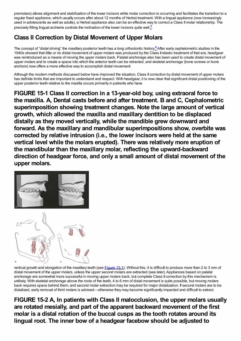
premolars) allows alignment and stabilization of the lower incisors while molar correction is occurring and facilitates the transition to aregular fixed appliance, which usually occurs after about 12 months of Herbst treatment. With a lingual appliance (now increasinglyused in adolescents as well as adults), a Herbst appliance also can be an effective way to correct a Class II molar relationship. Theprecisely fitting lingual archwire controls the inclination of the lower incisors quite well.3
Class II Correction by Distal Movement of Upper MolarsThe concept of “distal driving” the maxillary posterior teeth has a long orthodontic history.4 After early cephalometric studies in the1940s showed that little or no distal movement of upper molars was produced by the Class II elastic treatment of that era, headgearwas reintroduced as a means of moving the upper molars back. Palatal anchorage also has been used to create distal movement ofupper molars and to create a space into which the anterior teeth can be retracted, and skeletal anchorage (bone screws or boneanchors) now offers a more effective way to accomplish distal movement.
Although the modern methods discussed below have improved the situation, Class II correction by distal movement of upper molarshas definite limits that are important to understand and respect. With headgear, it is now clear that significant distal positioning of theupper posterior teeth relative to the maxilla occurs primarily in patients who have
FIGURE 15-1 Class II correction in a 13-year-old boy, using extraoral force tothe maxilla. A, Dental casts before and after treatment. B and C, Cephalometricsuperimposition showing treatment changes. Note the large amount of verticalgrowth, which allowed the maxilla and maxillary dentition to be displaceddistally as they moved vertically, while the mandible grew downward andforward. As the maxillary and mandibular superimpositions show, overbite wascorrected by relative intrusion (i.e., the lower incisors were held at the samevertical level while the molars erupted). There was relatively more eruption ofthe mandibular than the maxillary molar, reflecting the upward-backwarddirection of headgear force, and only a small amount of distal movement of theupper molars.
vertical growth and elongation of the maxillary teeth (see Figure 15-1). Without this, it is difficult to produce more than 2 to 3 mm ofdistal movement of the upper molars, unless the upper second molars are extracted (see later). Appliances based on palatalanchorage are somewhat more successful in moving upper molars back, but complete Class II correction by this mechanism isunlikely. With skeletal anchorage above the roots of the teeth, 4 to 6 mm of distal movement is quite possible, but moving molarsback requires space behind them, and second molar extraction may be required for major distalization. If second molars are to bedistalized, early removal of third molars is advised—otherwise they may become significantly impacted and difficult to extract.
FIGURE 15-2 A, In patients with Class II malocclusion, the upper molars usuallyare rotated mesially, and part of the apparent backward movement of the firstmolar is a distal rotation of the buccal cusps as the tooth rotates around itslingual root. The inner bow of a headgear facebow should be adjusted to
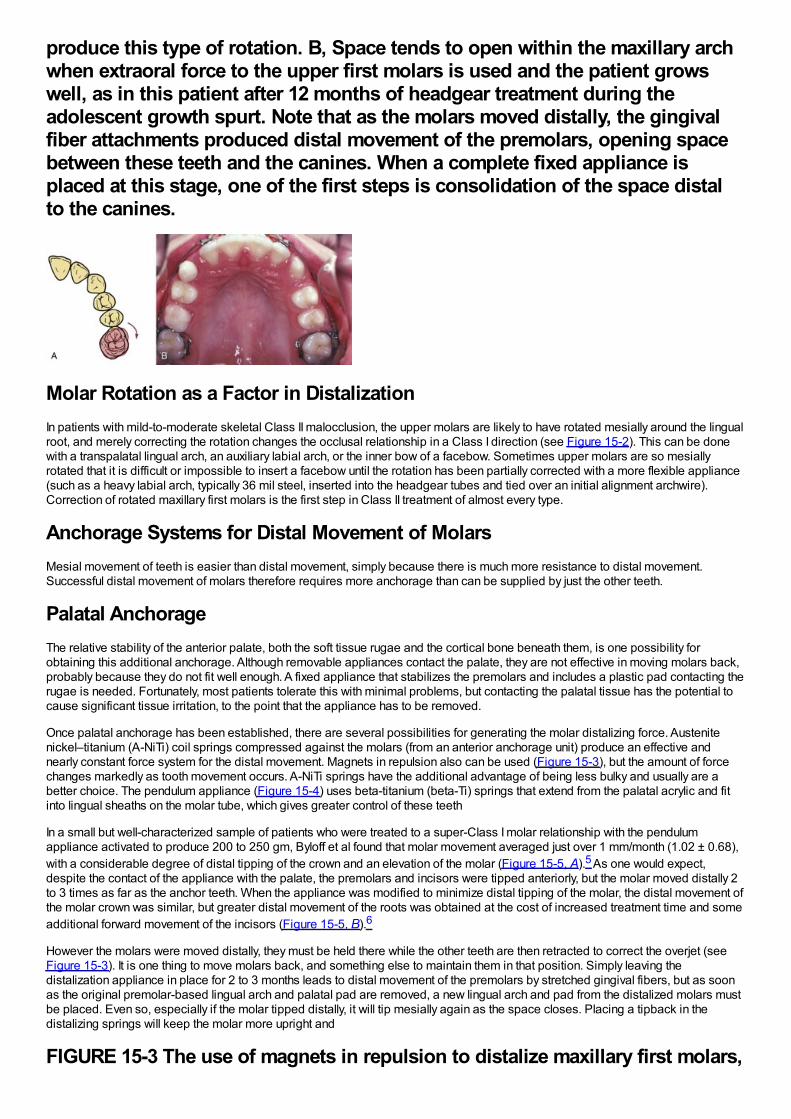
produce this type of rotation. B, Space tends to open within the maxillary archwhen extraoral force to the upper first molars is used and the patient growswell, as in this patient after 12 months of headgear treatment during theadolescent growth spurt. Note that as the molars moved distally, the gingivalfiber attachments produced distal movement of the premolars, opening spacebetween these teeth and the canines. When a complete fixed appliance isplaced at this stage, one of the first steps is consolidation of the space distalto the canines.
Molar Rotation as a Factor in DistalizationIn patients with mild-to-moderate skeletal Class II malocclusion, the upper molars are likely to have rotated mesially around the lingualroot, and merely correcting the rotation changes the occlusal relationship in a Class I direction (see Figure 15-2). This can be donewith a transpalatal lingual arch, an auxiliary labial arch, or the inner bow of a facebow. Sometimes upper molars are so mesiallyrotated that it is difficult or impossible to insert a facebow until the rotation has been partially corrected with a more flexible appliance(such as a heavy labial arch, typically 36 mil steel, inserted into the headgear tubes and tied over an initial alignment archwire).Correction of rotated maxillary first molars is the first step in Class II treatment of almost every type.
Anchorage Systems for Distal Movement of MolarsMesial movement of teeth is easier than distal movement, simply because there is much more resistance to distal movement.Successful distal movement of molars therefore requires more anchorage than can be supplied by just the other teeth.
Palatal AnchorageThe relative stability of the anterior palate, both the soft tissue rugae and the cortical bone beneath them, is one possibility forobtaining this additional anchorage. Although removable appliances contact the palate, they are not effective in moving molars back,probably because they do not fit well enough. A fixed appliance that stabilizes the premolars and includes a plastic pad contacting therugae is needed. Fortunately, most patients tolerate this with minimal problems, but contacting the palatal tissue has the potential tocause significant tissue irritation, to the point that the appliance has to be removed.
Once palatal anchorage has been established, there are several possibilities for generating the molar distalizing force. Austenitenickel–titanium (A-NiTi) coil springs compressed against the molars (from an anterior anchorage unit) produce an effective andnearly constant force system for the distal movement. Magnets in repulsion also can be used (Figure 15-3), but the amount of forcechanges markedly as tooth movement occurs. A-NiTi springs have the additional advantage of being less bulky and usually are abetter choice. The pendulum appliance (Figure 15-4) uses beta-titanium (beta-Ti) springs that extend from the palatal acrylic and fitinto lingual sheaths on the molar tube, which gives greater control of these teeth
In a small but well-characterized sample of patients who were treated to a super-Class I molar relationship with the pendulumappliance activated to produce 200 to 250 gm, Byloff et al found that molar movement averaged just over 1 mm/month (1.02 ± 0.68),with a considerable degree of distal tipping of the crown and an elevation of the molar (Figure 15-5, A).5 As one would expect,despite the contact of the appliance with the palate, the premolars and incisors were tipped anteriorly, but the molar moved distally 2to 3 times as far as the anchor teeth. When the appliance was modified to minimize distal tipping of the molar, the distal movement ofthe molar crown was similar, but greater distal movement of the roots was obtained at the cost of increased treatment time and someadditional forward movement of the incisors (Figure 15-5, B).6
However the molars were moved distally, they must be held there while the other teeth are then retracted to correct the overjet (seeFigure 15-3). It is one thing to move molars back, and something else to maintain them in that position. Simply leaving thedistalization appliance in place for 2 to 3 months leads to distal movement of the premolars by stretched gingival fibers, but as soonas the original premolar-based lingual arch and palatal pad are removed, a new lingual arch and pad from the distalized molars mustbe placed. Even so, especially if the molar tipped distally, it will tip mesially again as the space closes. Placing a tipback in thedistalizing springs will keep the molar more upright and
FIGURE 15-3 The use of magnets in repulsion to distalize maxillary first molars,
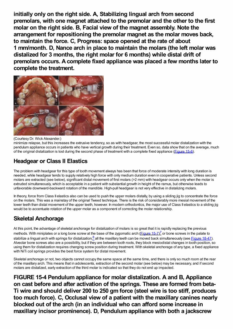
initially only on the right side. A, Stabilizing lingual arch from secondpremolars, with one magnet attached to the premolar and the other to the firstmolar on the right side. B, Facial view of the magnet assembly. Note thearrangement for repositioning the premolar magnet as the molar moves back,to maintain the force. C, Progress: space opened at the rate of about1 mm/month. D, Nance arch in place to maintain the molars (the left molar wasdistalized for 3 months, the right molar for 6 months) while distal drift ofpremolars occurs. A complete fixed appliance was placed a few months later tocomplete the treatment.
(Courtesy Dr. Wick Alexander.)minimize relapse, but this increases the extrusive tendency, so as with headgear, the most successful molar distalization with thependulum appliance occurs in patients who have vertical growth during their treatment. Even so, data show that on the average, muchof the original distalization is lost during the second phase of treatment with a complete fixed appliance (Figure 15-6).
Headgear or Class II ElasticsThe problem with headgear for this type of tooth movement always has been that force of moderate intensity with long duration isneeded, while headgear tends to supply relatively high force with only medium duration even in cooperative patients. Unless secondmolars are extracted (see below), significant distal movement of first molars (>2 mm) with headgear occurs only when the molar isextruded simultaneously, which is acceptable in a patient with substantial growth in height of the ramus, but otherwise leads tounfavorable downward-backward rotation of the mandible. High-pull headgear is not very effective in distalizing molars.
In theory, force from Class II elastics also can be used to push the upper molars distally, by using a sliding jig to concentrate the forceon the molars. This was a mainstay of the original Tweed technique. There is the risk of considerably more mesial movement of thelower teeth than distal movement of the upper teeth, however. In modern orthodontics, the major use of Class II elastics to a sliding jigwould be to accentuate rotation of the upper molar as a component of correcting the molar relationship.
Skeletal AnchorageAt this point, the advantage of skeletal anchorage for distalization of molars is so great that it is rapidly replacing the previousmethods. With miniplates or a long bone screw at the base of the zygomatic arch (Figure 15-7)7 or bone screws in the palate tostabilize a lingual arch with springs for distalization,8 all the maxillary teeth can be moved back simultaneously (see Figure 18-47).Alveolar bone screws also are a possibility, but if they are between tooth roots, they block mesiodistal changes in tooth position, sousing them for distalization requires changing screw position during treatment. With skeletal anchorage of any type, a fixed appliancewith NiTi coil springs provides the best force system for distal movement.
Skeletal anchorage or not, two objects cannot occupy the same space at the same time, and there is only so much room at the rearof the maxillary arch. This means that in adolescents, extraction of the second molar (see below) may be necessary, and if secondmolars are distalized, early extraction of the third molar is indicated so that they do not end up impacted.
FIGURE 15-4 Pendulum appliance for molar distalization. A and B, Applianceon cast before and after activation of the springs. These are formed from beta-Ti wire and should deliver 200 to 250 gm force (steel wire is too stiff, producestoo much force). C, Occlusal view of a patient with the maxillary canines nearlyblocked out of the arch (in an individual who can afford some increase inmaxillary incisor prominence). D, Pendulum appliance with both a jackscrew
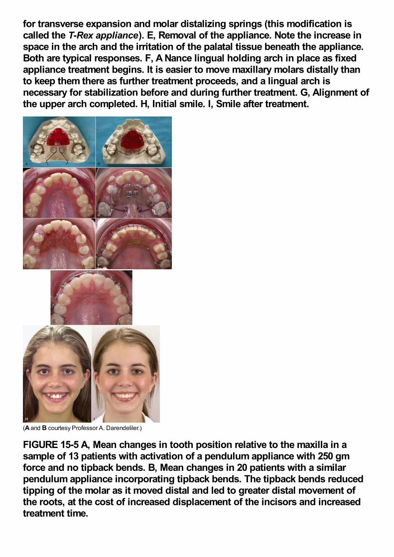
for transverse expansion and molar distalizing springs (this modification iscalled the T-Rex appliance). E, Removal of the appliance. Note the increase inspace in the arch and the irritation of the palatal tissue beneath the appliance.Both are typical responses. F, A Nance lingual holding arch in place as fixedappliance treatment begins. It is easier to move maxillary molars distally thanto keep them there as further treatment proceeds, and a lingual arch isnecessary for stabilization before and during further treatment. G, Alignment ofthe upper arch completed. H, Initial smile. I, Smile after treatment.
(A and B courtesy Professor A. Darendeliler.)
FIGURE 15-5 A, Mean changes in tooth position relative to the maxilla in asample of 13 patients with activation of a pendulum appliance with 250 gmforce and no tipback bends. B, Mean changes in 20 patients with a similarpendulum appliance incorporating tipback bends. The tipback bends reducedtipping of the molar as it moved distal and led to greater distal movement ofthe roots, at the cost of increased displacement of the incisors and increasedtreatment time.
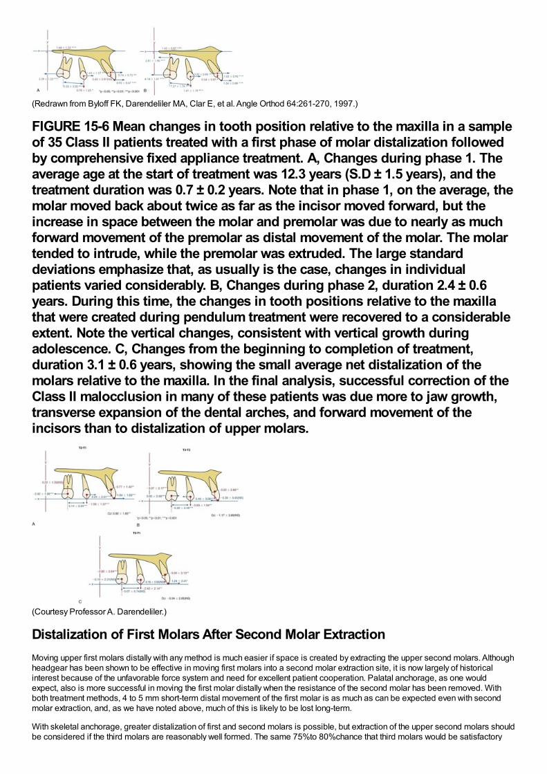
(Redrawn from Byloff FK, Darendeliler MA, Clar E, et al. Angle Orthod 64:261-270, 1997.)
FIGURE 15-6 Mean changes in tooth position relative to the maxilla in a sampleof 35 Class II patients treated with a first phase of molar distalization followedby comprehensive fixed appliance treatment. A, Changes during phase 1. Theaverage age at the start of treatment was 12.3 years (S.D ± 1.5 years), and thetreatment duration was 0.7 ± 0.2 years. Note that in phase 1, on the average, themolar moved back about twice as far as the incisor moved forward, but theincrease in space between the molar and premolar was due to nearly as muchforward movement of the premolar as distal movement of the molar. The molartended to intrude, while the premolar was extruded. The large standarddeviations emphasize that, as usually is the case, changes in individualpatients varied considerably. B, Changes during phase 2, duration 2.4 ± 0.6years. During this time, the changes in tooth positions relative to the maxillathat were created during pendulum treatment were recovered to a considerableextent. Note the vertical changes, consistent with vertical growth duringadolescence. C, Changes from the beginning to completion of treatment,duration 3.1 ± 0.6 years, showing the small average net distalization of themolars relative to the maxilla. In the final analysis, successful correction of theClass II malocclusion in many of these patients was due more to jaw growth,transverse expansion of the dental arches, and forward movement of theincisors than to distalization of upper molars.
(Courtesy Professor A. Darendeliler.)
Distalization of First Molars After Second Molar ExtractionMoving upper first molars distally with any method is much easier if space is created by extracting the upper second molars. Althoughheadgear has been shown to be effective in moving first molars into a second molar extraction site, it is now largely of historicalinterest because of the unfavorable force system and need for excellent patient cooperation. Palatal anchorage, as one wouldexpect, also is more successful in moving the first molar distally when the resistance of the second molar has been removed. Withboth treatment methods, 4 to 5 mm short-term distal movement of the first molar is as much as can be expected even with secondmolar extraction, and, as we have noted above, much of this is likely to be lost long-term.
With skeletal anchorage, greater distalization of first and second molars is possible, but extraction of the upper second molars shouldbe considered if the third molars are reasonably well formed. The same 75%to 80%chance that third molars would be satisfactory
replacements for the second molars presumably would apply with use of skeletal anchorage, as it did with headgear for distalization.9
FIGURE 15-7 Placement of a bone anchor for maximum retraction of protrudingmaxillary incisors. A, Exposure of the zygomatic buttress area, initial hole forscrew drilled. B, Anchor in place, secured by three bone screws. C, Soft tissuecovering the anchor, with only the tube for attachment of a retraction springexposed in the mouth.
Occasionally, unilateral molar distalization is indicated, typically when a unilateral Class II malocclusion is present and there is adental midline discrepancy. Extraction of one second molar facilitates this treatment, and the third molar usually replaces the missingsecond molar quite satisfactorily (Figure 15-8). Unilateral cervical headgear can be used for this treatment plan, but skeletalanchorage is definitely preferred now.
It is difficult to distalize the upper teeth too much with headgear or palatal anchorage. Skeletal anchorage is so effective thatoverretraction of the upper incisors is possible, which of course becomes unsuccessful camouflage. This makes it all the moreimportant to establish the desired final position of the incisors in planning treatment and then control tooth movement to reach thisgoal. In one sense, temporary anchorage devices (TADs) make it possible to do what only surgery could do previously: move themaxillary dentition back too much.
Differential Anteroposterior Tooth Movement Using Extraction SpacesThere are two reasons for extracting teeth in orthodontics, as discussed in detail in Chapter 7: (1) to provide space to align crowdedincisors without creating excessive protrusion and (2) to allow camouflage of moderate Class II or Class III jaw relationships whencorrection by growth modification is not possible. A patient who is both Class II (or III) and crowded is a particular problem becausethe same space cannot be used for both purposes. The more extraction space is required for alignment, the less is available fordifferential movement in camouflage, and vice versa.
An important part of treatment planning is deciding which teeth to extract and how the extraction spaces are to be closed (i.e., byretraction of incisor teeth, mesial movement of posterior teeth, or some combination). These decisions determine the orthodonticmechanics.
Class II Camouflage by Extraction of Upper First PremolarsIn the late 1980s, it was claimed by some dentists that extraction of upper first premolars would lead to later temporomandibulardysfunction (TMD) problems. The theory, to the extent that the proponents of this claim had one, was that retracting the upper incisorswould inevitably lead to incisor interferences, and this would cause TMD. The claim was never supported by any evidence, andresearch data have refuted it.10,11 It is important to limit first premolar extraction for camouflage of Class II malocclusion to theappropriate patients and not to retract the incisors too much, but if this is done, it can be an excellent treatment method.
FIGURE 15-8 A, In this patient the treatment plan was extraction of the maxillaryleft second molar, so that the first molar and premolars on that side could bemoved distally to correct a yaw of the maxillary arch. B, Posttreatment, with thethird molar already erupting into the second molar extraction site. Eventuallythe remaining three third molars would be scheduled for extraction. A well-formed maxillary third molar can be a satisfactory replacement for an extractedsecond molar, and usually erupts in a way that facilitates the replacement.
With this approach, the objective is to maintain the existing Class II molar relationship, closing the first premolar extraction spacelargely by retracting the protruding incisor teeth (Figure 15-9). Anchorage must be reinforced, but one method, Class II elastics fromthe lower arch, is specifically contraindicated unless the lower incisors need to be moved forward (which rarely is the case). Theremaining possibilities are extraoral force to the first molars, a stabilizing lingual arch, retraction of the maxillary anterior segment withextraoral force directly against these teeth, or skeletal anchorage.
Excellent reinforcement of posterior anchorage can be obtained with extraoral force only if it is applied consistently and for longdurations. The more constant the headgear wear, the less a stabilizing lingual arch will be needed. Conversely, a stabilizing lingualarch augments the posterior anchorage full time, while headgear is likely to be worn a good bit less.
It seems intuitively obvious that a lingual arch with a button against the palatal tissue should be more effective than a straighttranspalatal lingual arch, but when first molars are being stabilized in a premolar extraction case, this is not necessarily true. Theeffect of the lingual arch is primarily to prevent the molars from rotating mesiolingually around their palatal root and secondarily toprevent them from tipping mesially. A straight transpalatal lingual arch (see Figure 14-14) is as effective as one with a palatal buttonin preventing rotation, and for most patients, the marginally better stabilization with a palatal button is not worth the cost in tissueirritation. Note that this is true when a lingual arch is used to stabilize molars, but not true when the lingual arch is to stabilizepremolars, as in the molar distalization technique discussed above. When pushed mesially, premolars tip more than they rotate, anda palatal button is needed on a lingual arch to stabilize them.
In addition to headgear and/or lingual arch stabilization, all the strategies described in Chapter 10 for reducing strain on anchorage(i.e., minimizing binding and friction, retracting canines individually, skeletal anchorage) are appropriate with upper first premolarextraction and can be brought into use.
Retracting protruding maxillary anterior teeth with headgear attached to the archwire (often called J-hook headgear) totally avoidsstrain on the posterior teeth and once was attractive from that point of view. This technique has two major disadvantages: (1) as withany headgear that provides too few hours and too much force, the force system is unfavorable for tooth movement and (2) there issignificant binding and friction, not only where teeth slide along the archwire but also within the headgear mechanism itself becausethe headgear wires that attach to the teeth tend to bind against their protective sleeves. This makes it difficult to control the amount offorce, and more net force on one side than the other may lead to an asymmetric response. In fact, it is unusual if space does notclose faster on one side than the other. Only if the headgear is worn nearly full time (including school hours) will efficient toothmovement be obtained. For both reasons, headgear for direct retraction of the incisor segment rarely is used now.
Skeletal anchorage in these premolar extraction cases is a straightforward method of reinforcing anchorage, and retraction of the sixanterior teeth usually can be managed
FIGURE 15-9 Effect of maxillary premolar extraction in a patient with a poorresponse to attempted nonextraction treatment. A and B, Facial appearance atthe point that excessive maxillary incisor protrusion and persistent Class IImolar relationship led to the decision for extraction of maxillary first premolars.C and D, One year later, at the completion of treatment. E, Cephalometricsuperimposition over the period of extraction treatment.
(From Proffit WR, White RP, Sarver DM. Contemporary Treatment of Dentofacial Deformity. St. Louis: Mosby; 2003.)satisfactorily with a single bone screw between the second premolar and first molar (see Figure 10-48). In adolescents, use of TADsis necessary only if maximum retraction of the anterior segment without any elongation of the incisors is desired, a situation morelikely to be encountered in adults.
Extraction of Maxillary and Mandibular PremolarsCorrection of Class II buccal segment relationships with extraction of all four first premolars implies that the mandibular posteriorsegments will be moved anteriorly nearly the width of the extraction space. At the same time, the protruding maxillary anterior teethwill be retracted without forward movement of the maxillary buccal segments. This, in turn, implies (though it does not absolutelyrequire) that Class II elastics will be used to assist in closing the extraction sites.
The Begg technique is a classic illustration of using Class II elastics to produce differential movement of the arch segments whilecorrecting the molar relationship. In the Begg approach (with the modernized appliance as well as the original one), at the beginningof the second stage of treatment light interarch elastics are added to help close space, while Class II elastics are continued (Figure15-10). An anchor bend is placed in the upper archwire so that the maxillary anterior teeth are tipped back in part by the force systemassociated with the archwire itself. In the lower arch, the anchor bend is used to control the amount of mesial tipping of the molars.The Class II elastics reinforce and accentuate the differential tooth movements along the
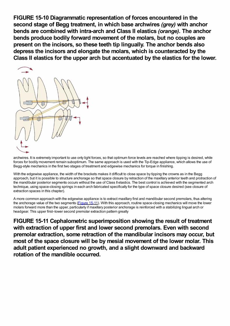
FIGURE 15-10 Diagrammatic representation of forces encountered in thesecond stage of Begg treatment, in which base archwires (grey) with anchorbends are combined with intra-arch and Class II elastics (orange). The anchorbends produce bodily forward movement of the molars, but no couples arepresent on the incisors, so these teeth tip lingually. The anchor bends alsodepress the incisors and elongate the molars, which is counteracted by theClass II elastics for the upper arch but accentuated by the elastics for the lower.
archwires. It is extremely important to use only light forces, so that optimum force levels are reached where tipping is desired, whileforces for bodily movement remain suboptimum. The same approach is used with the Tip-Edge appliance, which allows the use ofBegg-style mechanics in the first two stages of treatment and edgewise mechanics for torque in finishing.
With the edgewise appliance, the width of the brackets makes it difficult to close space by tipping the crowns as in the Beggapproach, but it is possible to structure anchorage so that space closure by retraction of the maxillary anterior teeth and protraction ofthe mandibular posterior segments occurs without the use of Class II elastics. The best control is achieved with the segmented archtechnique, using space-closing springs in each arch fabricated specifically for the type of space closure desired (see closure ofextraction spaces in this chapter).
A more common approach with the edgewise appliance is to extract maxillary first and mandibular second premolars, thus alteringthe anchorage value of the two segments (Figure 15-11). With this approach, routine space-closing mechanics will move the lowermolars forward more than the upper, particularly if maxillary posterior anchorage is reinforced with a stabilizing lingual arch orheadgear. This upper first–lower second premolar extraction pattern greatly
FIGURE 15-11 Cephalometric superimposition showing the result of treatmentwith extraction of upper first and lower second premolars. Even with secondpremolar extraction, some retraction of the mandibular incisors may occur, butmost of the space closure will be by mesial movement of the lower molar. Thisadult patient experienced no growth, and a slight downward and backwardrotation of the mandible occurred.
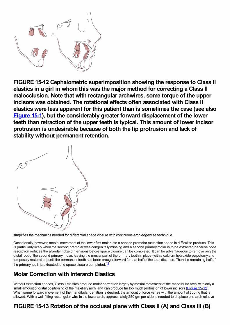
FIGURE 15-12 Cephalometric superimposition showing the response to Class IIelastics in a girl in whom this was the major method for correcting a Class IImalocclusion. Note that with rectangular archwires, some torque of the upperincisors was obtained. The rotational effects often associated with Class IIelastics were less apparent for this patient than is sometimes the case (see alsoFigure 15-1), but the considerably greater forward displacement of the lowerteeth than retraction of the upper teeth is typical. This amount of lower incisorprotrusion is undesirable because of both the lip protrusion and lack ofstability without permanent retention.
simplifies the mechanics needed for differential space closure with continuous-arch edgewise technique.
Occasionally, however, mesial movement of the lower first molar into a second premolar extraction space is difficult to produce. Thisis particularly likely when the second premolar was congenitally missing and a second primary molar is to be extracted because boneresorption reduces the alveolar ridge dimensions before space closure can be completed. It can be advantageous to remove only thedistal root of the second primary molar, leaving the mesial part of the primary tooth in place (with a calcium hydroxide pulpotomy andtemporary restoration) until the permanent tooth has been brought forward for that half of the total distance. Then the remaining half ofthe primary tooth is extracted, and space closure completed.12
Molar Correction with Interarch ElasticsWithout extraction spaces, Class II elastics produce molar correction largely by mesial movement of the mandibular arch, with only asmall amount of distal positioning of the maxillary arch, and can produce far too much protrusion of lower incisors (Figure 15-12).When some forward movement of the mandibular dentition is desired, the amount of force varies with the amount of tipping that isallowed. With a well-fitting rectangular wire in the lower arch, approximately 250 gm per side is needed to displace one arch relative
FIGURE 15-13 Rotation of the occlusal plane with Class II (A) and Class III (B)
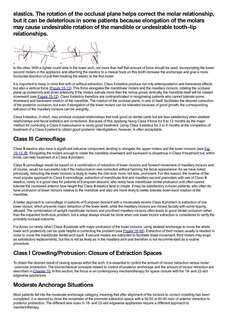
elastics. The rotation of the occlusal plane helps correct the molar relationship,but it can be deleterious in some patients because elongation of the molarsmay cause undesirable rotation of the mandible or undesirable tooth–liprelationships.
to the other. With a lighter round wire in the lower arch, not more than half that amount of force should be used. Incorporating the lowersecond molars in the appliance and attaching the elastics to a mesial hook on this tooth increase the anchorage and give a morehorizontal direction of pull than hooking the elastic to the first molar.
It is important to keep in mind that with or without extraction, Class II elastics produce not only anteroposterior and transverse effectsbut also a vertical force (Figure 15-13). This force elongates the mandibular molars and the maxillary incisors, rotating the occlusalplane up posteriorly and down anteriorly. If the molars extrude more than the ramus grows vertically, the mandible itself will be rotateddownward (see Figure 15-12). Class II elastics therefore are contraindicated in nongrowing patients who cannot tolerate somedownward and backward rotation of the mandible. The rotation of the occlusal plane, in and of itself, facilitates the desired correctionof the posterior occlusion, but even if elongation of the lower molars can be tolerated because of good growth, the correspondingextrusion of the maxillary incisors can be unsightly.
Class II elastics, in short, may produce occlusal relationships that look good on dental casts but are less satisfactory when skeletalrelationships and facial esthetics are considered. Because of this, applying heavy Class II force for 9 to 12 months as the majormethod for correcting a Class II malocclusion is rarely good treatment. Using Class II elastics for 3 or 4 months at the completion oftreatment of a Class II patient to obtain good posterior interdigitation, however, is often acceptable.
Class III CamouflageClass III elastics also have a significant extrusive component, tending to elongate the upper molars and the lower incisors (see Fig15-13, B). Elongating the molars enough to rotate the mandible downward and backward is disastrous in Class II treatment but, withinlimits, can help treatment of a Class III problem.
Class III camouflage would be based on a combination of retraction of lower incisors and forward movement of maxillary incisors and,of course, would be successful only if the malocclusion was corrected without harming the facial appearance. As we have notedpreviously, retracting the lower incisors is likely to make the chin look more, not less, prominent. For this reason, the reverse of themost popular approach to Class II camouflage, extraction of mandibular first and maxillary second premolars with use of Class IIIelastics, rarely is a good idea for patients of European descent, who rarely have mandibular dental protrusion and often cannottolerate the increased anterior face height that Class III elastics tend to create. It may be satisfactory in Asian patients, who often dohave protrusion of lower incisors relative to the mandible and also are more likely to better tolerate down-back rotation of themandible.
A better approach to camouflage in patients of European descent with a moderately severe Class III problem is extraction of onelower incisor, which prevents major retraction of the lower teeth, while the maxillary incisors are moved facially with some tippingallowed. The combination of upright mandibular incisors and proclined maxillary incisors often leads to good dental occlusion ratherthan the expected tooth-size problem, but a setup always should be done when one lower incisor extraction is considered to verify theprobably occlusal outcome.
For Asian (or rarely, other) Class III patients with major protrusion of the lower incisors, using skeletal anchorage to move the wholelower arch posteriorly can be quite helpful in correcting the problem (see Figure 18-48). Extraction of third molars usually is needed inorder to move the mandibular dental arch back. If second molars are extracted to facilitate distal movement, third molars may eruptas satisfactory replacements, but this is not as likely as in the maxillary arch and therefore is not recommended as a routineprocedure.
Class I Crowding/Protrusion: Closure of Extraction SpacesTo obtain the desired result of closing spaces within the arch, it is essential to control the amount of incisor retraction versus molar–premolar protraction. The biomechanical concepts related to control of posterior anchorage and the amount of incisor retraction aredescribed in Chapter 10. In this section, the focus is on contemporary mechanotherapy for space closure with the 18- and 22-slotedgewise appliances.
Moderate Anchorage SituationsMost patients fall into the moderate anchorage category, meaning that after alignment of the incisors to correct crowding has beencompleted, it is desired to close the remainder of the premolar extraction space with a 50:50 or 60:40 ratio of anterior retraction toposterior protraction. The different wire sizes in 18- and 22-slot edgewise appliances require a different approach tomechanotherapy.
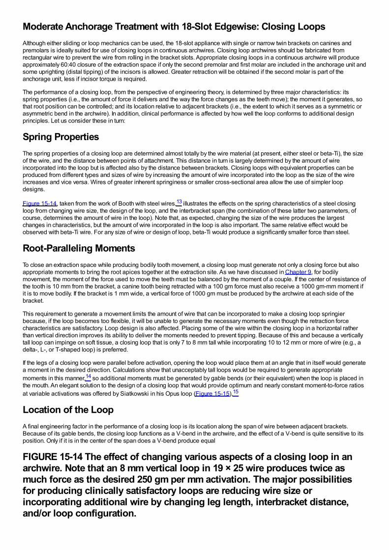
Moderate Anchorage Treatment with 18-Slot Edgewise: Closing LoopsAlthough either sliding or loop mechanics can be used, the 18-slot appliance with single or narrow twin brackets on canines andpremolars is ideally suited for use of closing loops in continuous archwires. Closing loop archwires should be fabricated fromrectangular wire to prevent the wire from rolling in the bracket slots. Appropriate closing loops in a continuous archwire will produceapproximately 60:40 closure of the extraction space if only the second premolar and first molar are included in the anchorage unit andsome uprighting (distal tipping) of the incisors is allowed. Greater retraction will be obtained if the second molar is part of theanchorage unit, less if incisor torque is required.
The performance of a closing loop, from the perspective of engineering theory, is determined by three major characteristics: itsspring properties (i.e., the amount of force it delivers and the way the force changes as the teeth move); the moment it generates, sothat root position can be controlled; and its location relative to adjacent brackets (i.e., the extent to which it serves as a symmetric orasymmetric bend in the archwire). In addition, clinical performance is affected by how well the loop conforms to additional designprinciples. Let us consider these in turn:
Spring PropertiesThe spring properties of a closing loop are determined almost totally by the wire material (at present, either steel or beta-Ti), the sizeof the wire, and the distance between points of attachment. This distance in turn is largely determined by the amount of wireincorporated into the loop but is affected also by the distance between brackets. Closing loops with equivalent properties can beproduced from different types and sizes of wire by increasing the amount of wire incorporated into the loop as the size of the wireincreases and vice versa. Wires of greater inherent springiness or smaller cross-sectional area allow the use of simpler loopdesigns.
Figure 15-14, taken from the work of Booth with steel wires,13 illustrates the effects on the spring characteristics of a steel closingloop from changing wire size, the design of the loop, and the interbracket span (the combination of these latter two parameters, ofcourse, determines the amount of wire in the loop). Note that, as expected, changing the size of the wire produces the largestchanges in characteristics, but the amount of wire incorporated in the loop is also important. The same relative effect would beobserved with beta-Ti wire. For any size of wire or design of loop, beta-Ti would produce a significantly smaller force than steel.
Root-Paralleling MomentsTo close an extraction space while producing bodily tooth movement, a closing loop must generate not only a closing force but alsoappropriate moments to bring the root apices together at the extraction site. As we have discussed in Chapter 9, for bodilymovement, the moment of the force used to move the teeth must be balanced by the moment of a couple. If the center of resistance ofthe tooth is 10 mm from the bracket, a canine tooth being retracted with a 100 gm force must also receive a 1000 gm-mm moment ifit is to move bodily. If the bracket is 1 mm wide, a vertical force of 1000 gm must be produced by the archwire at each side of thebracket.
This requirement to generate a movement limits the amount of wire that can be incorporated to make a closing loop springierbecause, if the loop becomes too flexible, it will be unable to generate the necessary moments even though the retraction forcecharacteristics are satisfactory. Loop design is also affected. Placing some of the wire within the closing loop in a horizontal ratherthan vertical direction improves its ability to deliver the moments needed to prevent tipping. Because of this and because a verticallytall loop can impinge on soft tissue, a closing loop that is only 7 to 8 mm tall while incorporating 10 to 12 mm or more of wire (e.g., adelta-, L-, or T-shaped loop) is preferred.
If the legs of a closing loop were parallel before activation, opening the loop would place them at an angle that in itself would generatea moment in the desired direction. Calculations show that unacceptably tall loops would be required to generate appropriatemoments in this manner,14 so additional moments must be generated by gable bends (or their equivalent) when the loop is placed inthe mouth. An elegant solution to the design of a closing loop that would provide optimum and nearly constant moment-to-force ratiosat variable activations was offered by Siatkowski in his Opus loop (Figure 15-15).15
Location of the LoopA final engineering factor in the performance of a closing loop is its location along the span of wire between adjacent brackets.Because of its gable bends, the closing loop functions as a V-bend in the archwire, and the effect of a V-bend is quite sensitive to itsposition. Only if it is in the center of the span does a V-bend produce equal
FIGURE 15-14 The effect of changing various aspects of a closing loop in anarchwire. Note that an 8 mm vertical loop in 19 × 25 wire produces twice asmuch force as the desired 250 gm per mm activation. The major possibilitiesfor producing clinically satisfactory loops are reducing wire size orincorporating additional wire by changing leg length, interbracket distance,and/or loop configuration.
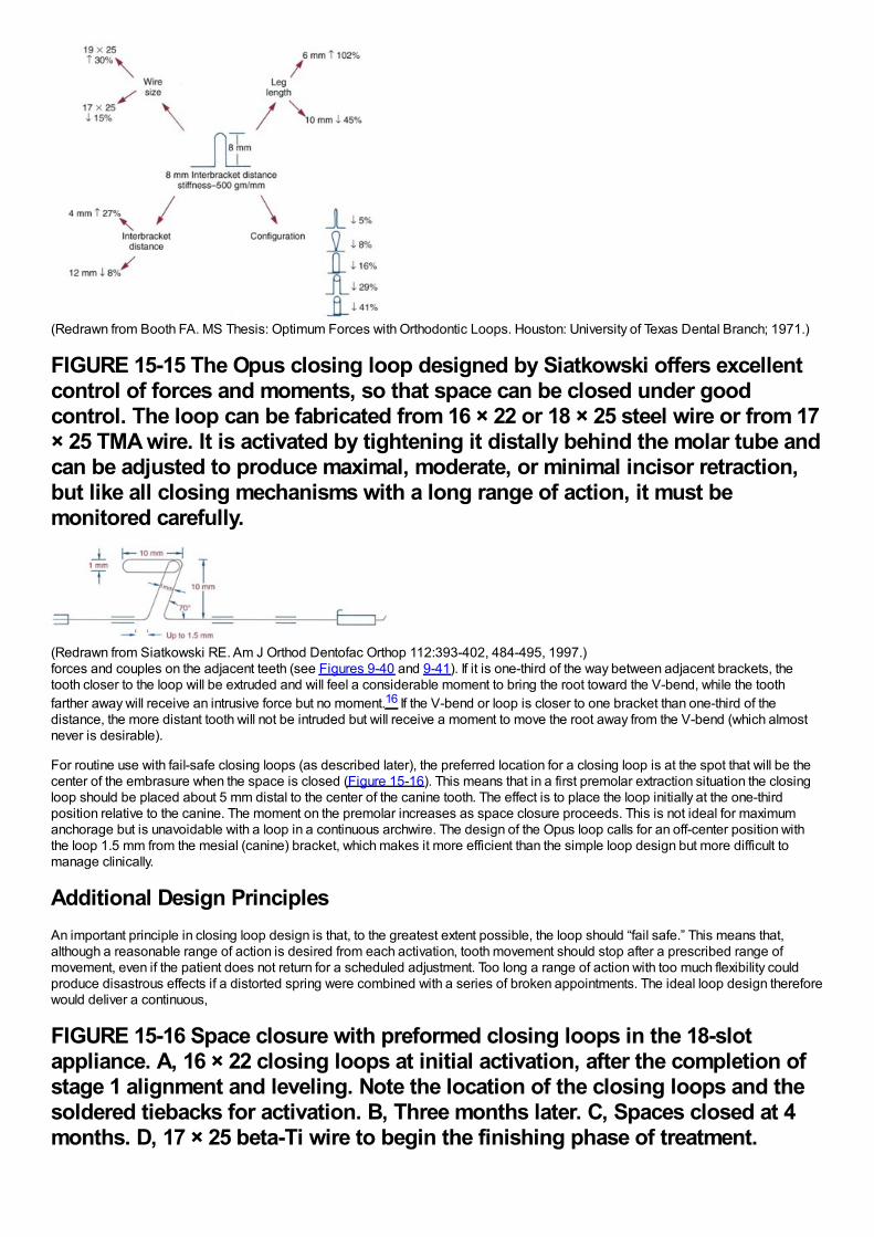
(Redrawn from Booth FA. MS Thesis: Optimum Forces with Orthodontic Loops. Houston: University of Texas Dental Branch; 1971.)
FIGURE 15-15 The Opus closing loop designed by Siatkowski offers excellentcontrol of forces and moments, so that space can be closed under goodcontrol. The loop can be fabricated from 16 × 22 or 18 × 25 steel wire or from 17× 25 TMA wire. It is activated by tightening it distally behind the molar tube andcan be adjusted to produce maximal, moderate, or minimal incisor retraction,but like all closing mechanisms with a long range of action, it must bemonitored carefully.
(Redrawn from Siatkowski RE. Am J Orthod Dentofac Orthop 112:393-402, 484-495, 1997.)forces and couples on the adjacent teeth (see Figures 9-40 and 9-41). If it is one-third of the way between adjacent brackets, thetooth closer to the loop will be extruded and will feel a considerable moment to bring the root toward the V-bend, while the toothfarther away will receive an intrusive force but no moment.16 If the V-bend or loop is closer to one bracket than one-third of thedistance, the more distant tooth will not be intruded but will receive a moment to move the root away from the V-bend (which almostnever is desirable).
For routine use with fail-safe closing loops (as described later), the preferred location for a closing loop is at the spot that will be thecenter of the embrasure when the space is closed (Figure 15-16). This means that in a first premolar extraction situation the closingloop should be placed about 5 mm distal to the center of the canine tooth. The effect is to place the loop initially at the one-thirdposition relative to the canine. The moment on the premolar increases as space closure proceeds. This is not ideal for maximumanchorage but is unavoidable with a loop in a continuous archwire. The design of the Opus loop calls for an off-center position withthe loop 1.5 mm from the mesial (canine) bracket, which makes it more efficient than the simple loop design but more difficult tomanage clinically.
Additional Design PrinciplesAn important principle in closing loop design is that, to the greatest extent possible, the loop should “fail safe.” This means that,although a reasonable range of action is desired from each activation, tooth movement should stop after a prescribed range ofmovement, even if the patient does not return for a scheduled adjustment. Too long a range of action with too much flexibility couldproduce disastrous effects if a distorted spring were combined with a series of broken appointments. The ideal loop design thereforewould deliver a continuous,
FIGURE 15-16 Space closure with preformed closing loops in the 18-slotappliance. A, 16 × 22 closing loops at initial activation, after the completion ofstage 1 alignment and leveling. Note the location of the closing loops and thesoldered tiebacks for activation. B, Three months later. C, Spaces closed at 4months. D, 17 × 25 beta-Ti wire to begin the finishing phase of treatment.
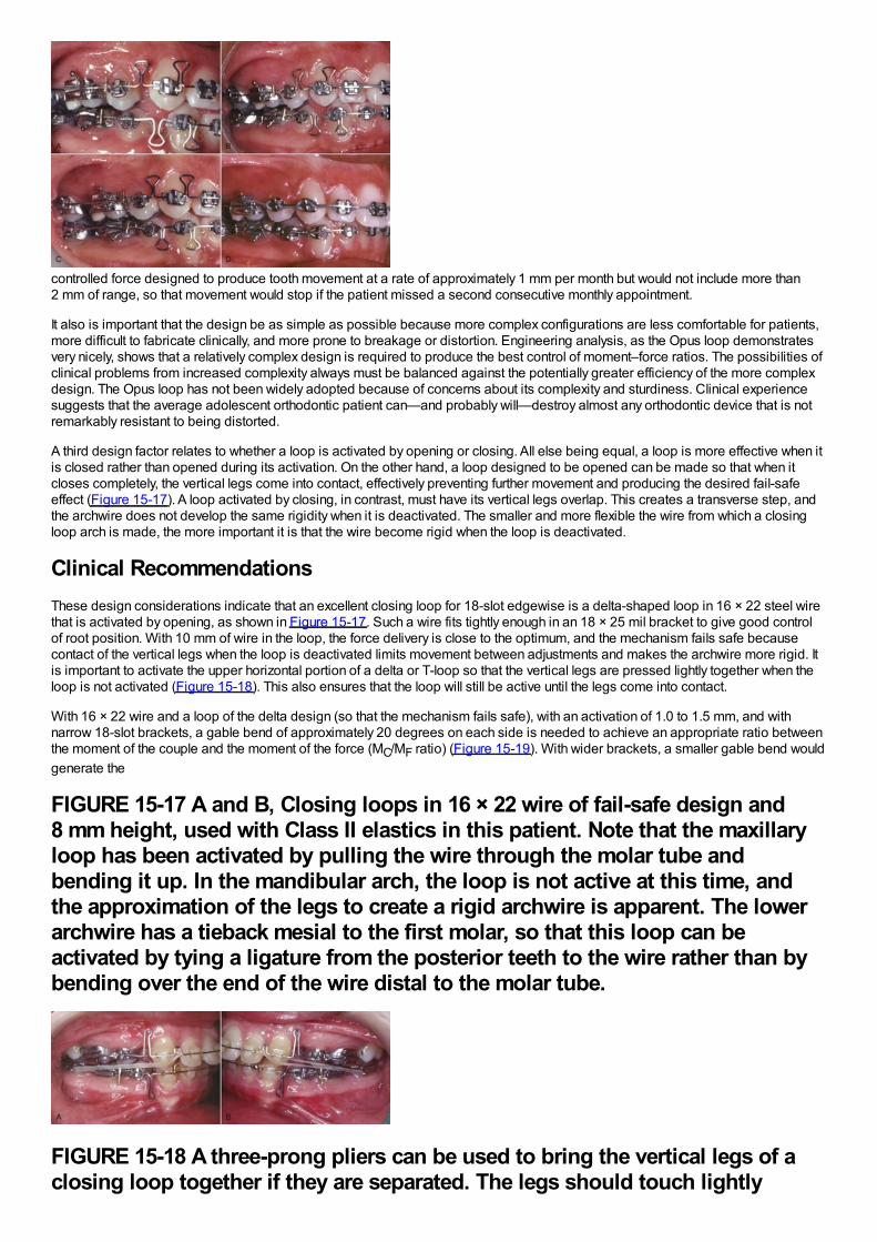
controlled force designed to produce tooth movement at a rate of approximately 1 mm per month but would not include more than2 mm of range, so that movement would stop if the patient missed a second consecutive monthly appointment.
It also is important that the design be as simple as possible because more complex configurations are less comfortable for patients,more difficult to fabricate clinically, and more prone to breakage or distortion. Engineering analysis, as the Opus loop demonstratesvery nicely, shows that a relatively complex design is required to produce the best control of moment–force ratios. The possibilities ofclinical problems from increased complexity always must be balanced against the potentially greater efficiency of the more complexdesign. The Opus loop has not been widely adopted because of concerns about its complexity and sturdiness. Clinical experiencesuggests that the average adolescent orthodontic patient can—and probably will—destroy almost any orthodontic device that is notremarkably resistant to being distorted.
A third design factor relates to whether a loop is activated by opening or closing. All else being equal, a loop is more effective when itis closed rather than opened during its activation. On the other hand, a loop designed to be opened can be made so that when itcloses completely, the vertical legs come into contact, effectively preventing further movement and producing the desired fail-safeeffect (Figure 15-17). A loop activated by closing, in contrast, must have its vertical legs overlap. This creates a transverse step, andthe archwire does not develop the same rigidity when it is deactivated. The smaller and more flexible the wire from which a closingloop arch is made, the more important it is that the wire become rigid when the loop is deactivated.
Clinical RecommendationsThese design considerations indicate that an excellent closing loop for 18-slot edgewise is a delta-shaped loop in 16 × 22 steel wirethat is activated by opening, as shown in Figure 15-17. Such a wire fits tightly enough in an 18 × 25 mil bracket to give good controlof root position. With 10 mm of wire in the loop, the force delivery is close to the optimum, and the mechanism fails safe becausecontact of the vertical legs when the loop is deactivated limits movement between adjustments and makes the archwire more rigid. Itis important to activate the upper horizontal portion of a delta or T-loop so that the vertical legs are pressed lightly together when theloop is not activated (Figure 15-18). This also ensures that the loop will still be active until the legs come into contact.
With 16 × 22 wire and a loop of the delta design (so that the mechanism fails safe), with an activation of 1.0 to 1.5 mm, and withnarrow 18-slot brackets, a gable bend of approximately 20 degrees on each side is needed to achieve an appropriate ratio betweenthe moment of the couple and the moment of the force (MC/MF ratio) (Figure 15-19). With wider brackets, a smaller gable bend wouldgenerate the
FIGURE 15-17 A and B, Closing loops in 16 × 22 wire of fail-safe design and8 mm height, used with Class II elastics in this patient. Note that the maxillaryloop has been activated by pulling the wire through the molar tube andbending it up. In the mandibular arch, the loop is not active at this time, andthe approximation of the legs to create a rigid archwire is apparent. The lowerarchwire has a tieback mesial to the first molar, so that this loop can beactivated by tying a ligature from the posterior teeth to the wire rather than bybending over the end of the wire distal to the molar tube.
FIGURE 15-18 A three-prong pliers can be used to bring the vertical legs of aclosing loop together if they are separated. The legs should touch lightly
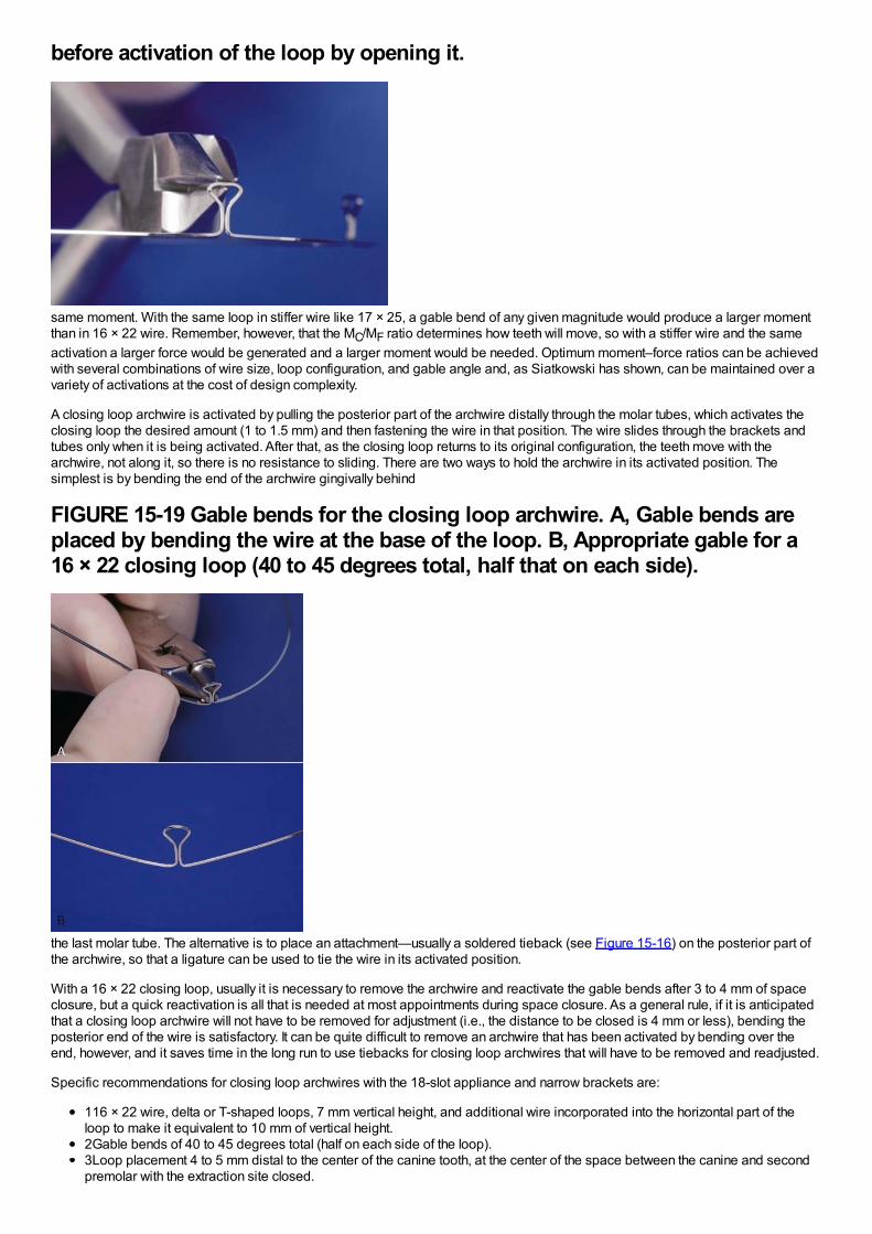
before activation of the loop by opening it.
same moment. With the same loop in stiffer wire like 17 × 25, a gable bend of any given magnitude would produce a larger momentthan in 16 × 22 wire. Remember, however, that the MC/MF ratio determines how teeth will move, so with a stiffer wire and the sameactivation a larger force would be generated and a larger moment would be needed. Optimum moment–force ratios can be achievedwith several combinations of wire size, loop configuration, and gable angle and, as Siatkowski has shown, can be maintained over avariety of activations at the cost of design complexity.
A closing loop archwire is activated by pulling the posterior part of the archwire distally through the molar tubes, which activates theclosing loop the desired amount (1 to 1.5 mm) and then fastening the wire in that position. The wire slides through the brackets andtubes only when it is being activated. After that, as the closing loop returns to its original configuration, the teeth move with thearchwire, not along it, so there is no resistance to sliding. There are two ways to hold the archwire in its activated position. Thesimplest is by bending the end of the archwire gingivally behind
FIGURE 15-19 Gable bends for the closing loop archwire. A, Gable bends areplaced by bending the wire at the base of the loop. B, Appropriate gable for a16 × 22 closing loop (40 to 45 degrees total, half that on each side).
the last molar tube. The alternative is to place an attachment—usually a soldered tieback (see Figure 15-16) on the posterior part ofthe archwire, so that a ligature can be used to tie the wire in its activated position.
With a 16 × 22 closing loop, usually it is necessary to remove the archwire and reactivate the gable bends after 3 to 4 mm of spaceclosure, but a quick reactivation is all that is needed at most appointments during space closure. As a general rule, if it is anticipatedthat a closing loop archwire will not have to be removed for adjustment (i.e., the distance to be closed is 4 mm or less), bending theposterior end of the wire is satisfactory. It can be quite difficult to remove an archwire that has been activated by bending over theend, however, and it saves time in the long run to use tiebacks for closing loop archwires that will have to be removed and readjusted.
Specific recommendations for closing loop archwires with the 18-slot appliance and narrow brackets are:
116 × 22 wire, delta or T-shaped loops, 7 mm vertical height, and additional wire incorporated into the horizontal part of theloop to make it equivalent to 10 mm of vertical height.2Gable bends of 40 to 45 degrees total (half on each side of the loop).3Loop placement 4 to 5 mm distal to the center of the canine tooth, at the center of the space between the canine and secondpremolar with the extraction site closed.
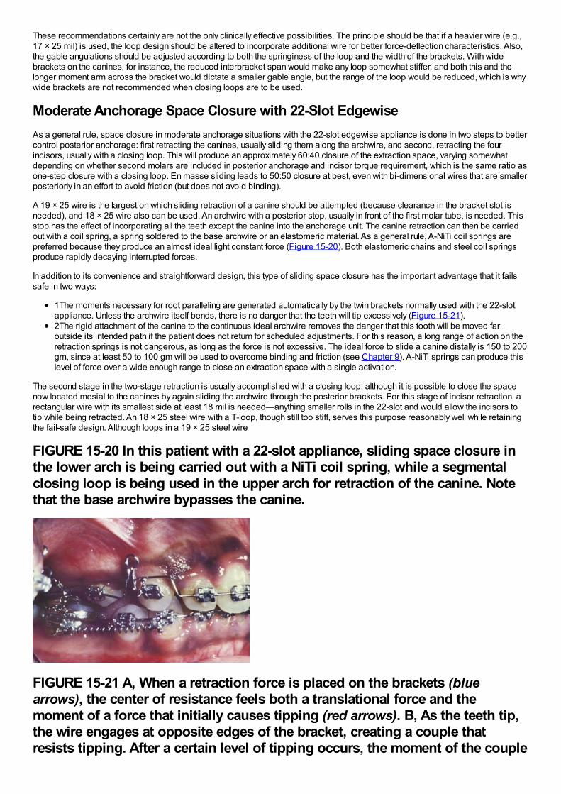
These recommendations certainly are not the only clinically effective possibilities. The principle should be that if a heavier wire (e.g.,17 × 25 mil) is used, the loop design should be altered to incorporate additional wire for better force-deflection characteristics. Also,the gable angulations should be adjusted according to both the springiness of the loop and the width of the brackets. With widebrackets on the canines, for instance, the reduced interbracket span would make any loop somewhat stiffer, and both this and thelonger moment arm across the bracket would dictate a smaller gable angle, but the range of the loop would be reduced, which is whywide brackets are not recommended when closing loops are to be used.
Moderate Anchorage Space Closure with 22-Slot EdgewiseAs a general rule, space closure in moderate anchorage situations with the 22-slot edgewise appliance is done in two steps to bettercontrol posterior anchorage: first retracting the canines, usually sliding them along the archwire, and second, retracting the fourincisors, usually with a closing loop. This will produce an approximately 60:40 closure of the extraction space, varying somewhatdepending on whether second molars are included in posterior anchorage and incisor torque requirement, which is the same ratio asone-step closure with a closing loop. En masse sliding leads to 50:50 closure at best, even with bi-dimensional wires that are smallerposteriorly in an effort to avoid friction (but does not avoid binding).
A 19 × 25 wire is the largest on which sliding retraction of a canine should be attempted (because clearance in the bracket slot isneeded), and 18 × 25 wire also can be used. An archwire with a posterior stop, usually in front of the first molar tube, is needed. Thisstop has the effect of incorporating all the teeth except the canine into the anchorage unit. The canine retraction can then be carriedout with a coil spring, a spring soldered to the base archwire or an elastomeric material. As a general rule, A-NiTi coil springs arepreferred because they produce an almost ideal light constant force (Figure 15-20). Both elastomeric chains and steel coil springsproduce rapidly decaying interrupted forces.
In addition to its convenience and straightforward design, this type of sliding space closure has the important advantage that it failssafe in two ways:
1The moments necessary for root paralleling are generated automatically by the twin brackets normally used with the 22-slotappliance. Unless the archwire itself bends, there is no danger that the teeth will tip excessively (Figure 15-21).2The rigid attachment of the canine to the continuous ideal archwire removes the danger that this tooth will be moved faroutside its intended path if the patient does not return for scheduled adjustments. For this reason, a long range of action on theretraction springs is not dangerous, as long as the force is not excessive. The ideal force to slide a canine distally is 150 to 200gm, since at least 50 to 100 gm will be used to overcome binding and friction (see Chapter 9). A-NiTi springs can produce thislevel of force over a wide enough range to close an extraction space with a single activation.
The second stage in the two-stage retraction is usually accomplished with a closing loop, although it is possible to close the spacenow located mesial to the canines by again sliding the archwire through the posterior brackets. For this stage of incisor retraction, arectangular wire with its smallest side at least 18 mil is needed—anything smaller rolls in the 22-slot and would allow the incisors totip while being retracted. An 18 × 25 steel wire with a T-loop, though still too stiff, serves this purpose reasonably well while retainingthe fail-safe design. Although loops in a 19 × 25 steel wire
FIGURE 15-20 In this patient with a 22-slot appliance, sliding space closure inthe lower arch is being carried out with a NiTi coil spring, while a segmentalclosing loop is being used in the upper arch for retraction of the canine. Notethat the base archwire bypasses the canine.
FIGURE 15-21 A, When a retraction force is placed on the brackets (bluearrows), the center of resistance feels both a translational force and themoment of a force that initially causes tipping (red arrows). B, As the teeth tip,the wire engages at opposite edges of the bracket, creating a couple thatresists tipping. After a certain level of tipping occurs, the moment of the couple
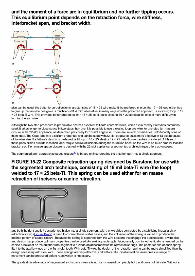
and the moment of a force are in equilibrium and no further tipping occurs.This equilibrium point depends on the retraction force, wire stiffness,interbracket span, and bracket width.
also can be used, the better force-deflection characteristics of 18 × 25 wire make it the preferred choice: the 19 × 25 loop either hasto give up the fail-safe design or is much too stiff. A third alternative, in many ways now the preferred approach, is a closing loop in 19× 25 beta-Ti wire. This provides better properties than 18 × 25 steel (quite close to 16 × 22 steel) at the cost of more difficulty informing the archwire.
Although the two-step procedure is predictable and has excellent fail-safe characteristics, which explains why it remains commonlyused, it takes longer to close space in two steps than one. It is possible to use a closing loop archwire for one-step (en masse)closure in the 22-slot appliance, as described previously for 18-slot edgewise. There are several possibilities, unfortunately none ofthem ideal. The Opus loop has excellent properties and can be used with 22-slot edgewise but is more effective in 18-slot becauseof the wire size. If a fail-safe design is preferred, a T-loop in 18 × 25 steel or 19 × 25 beta-Ti wire can be considered. All three ofthese possibilities provide less than ideal torque control of incisors during the retraction because the wire is so much smaller than thebracket slot. If en masse space closure is desired with the 22-slot appliance, a segmented arch technique offers advantages.
The segmented arch approach to space closure17 is based on incorporating the anterior teeth into a single segment,
FIGURE 15-22 Composite retraction spring designed by Burstone for use withthe segmented arch technique, consisting of 18 mil beta-Ti wire (the loop)welded to 17 × 25 beta-Ti. This spring can be used either for en masseretraction of incisors or canine retraction.
and both the right and left posterior teeth also into a single segment, with the two sides connected by a stabilizing lingual arch. Aretraction spring (Figure 15-22) is used to connect these stable bases, and the activation of the spring is varied to produce thedesired pattern of space closure. Because the spring is separate from the wire sections that engage the bracket slots, a wire sizeand design that produce optimum properties can be used. An auxiliary rectangular tube, usually positioned vertically, is needed on thecanine bracket or on the anterior wire segment to provide an attachment for the retraction springs. The posterior end of each springfits into the auxiliary tube on the first molar tooth. With beta-Ti wire, the design of the retraction spring can be more simplified than thedesign necessary with steel wire. These springs are very effective, and with careful initial activation, an impressive range ofmovement can be produced before reactivation is necessary.
The greatest disadvantage of segmented arch space closure is not its increased complexity but that it does not fail safe. Without a
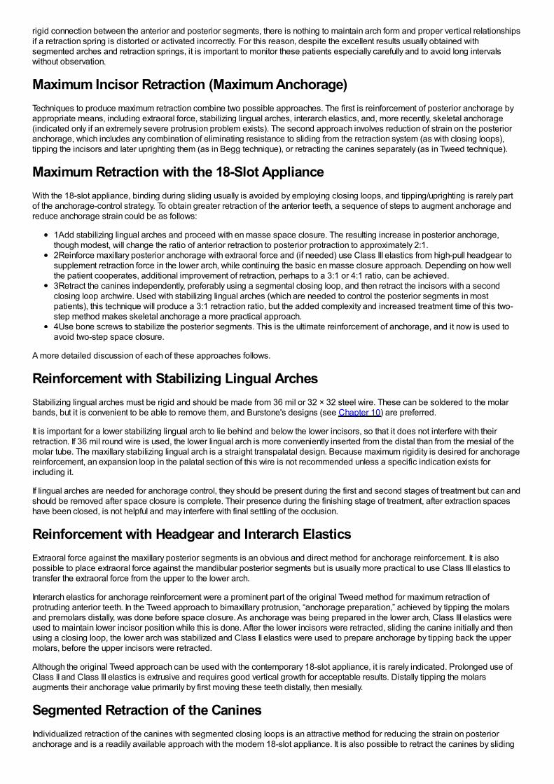
rigid connection between the anterior and posterior segments, there is nothing to maintain arch form and proper vertical relationshipsif a retraction spring is distorted or activated incorrectly. For this reason, despite the excellent results usually obtained withsegmented arches and retraction springs, it is important to monitor these patients especially carefully and to avoid long intervalswithout observation.
Maximum Incisor Retraction (Maximum Anchorage)Techniques to produce maximum retraction combine two possible approaches. The first is reinforcement of posterior anchorage byappropriate means, including extraoral force, stabilizing lingual arches, interarch elastics, and, more recently, skeletal anchorage(indicated only if an extremely severe protrusion problem exists). The second approach involves reduction of strain on the posterioranchorage, which includes any combination of eliminating resistance to sliding from the retraction system (as with closing loops),tipping the incisors and later uprighting them (as in Begg technique), or retracting the canines separately (as in Tweed technique).
Maximum Retraction with the 18-Slot ApplianceWith the 18-slot appliance, binding during sliding usually is avoided by employing closing loops, and tipping/uprighting is rarely partof the anchorage-control strategy. To obtain greater retraction of the anterior teeth, a sequence of steps to augment anchorage andreduce anchorage strain could be as follows:
1Add stabilizing lingual arches and proceed with en masse space closure. The resulting increase in posterior anchorage,though modest, will change the ratio of anterior retraction to posterior protraction to approximately 2:1.2Reinforce maxillary posterior anchorage with extraoral force and (if needed) use Class III elastics from high-pull headgear tosupplement retraction force in the lower arch, while continuing the basic en masse closure approach. Depending on how wellthe patient cooperates, additional improvement of retraction, perhaps to a 3:1 or 4:1 ratio, can be achieved.3Retract the canines independently, preferably using a segmental closing loop, and then retract the incisors with a secondclosing loop archwire. Used with stabilizing lingual arches (which are needed to control the posterior segments in mostpatients), this technique will produce a 3:1 retraction ratio, but the added complexity and increased treatment time of this two-step method makes skeletal anchorage a more practical approach.4Use bone screws to stabilize the posterior segments. This is the ultimate reinforcement of anchorage, and it now is used toavoid two-step space closure.
A more detailed discussion of each of these approaches follows.
Reinforcement with Stabilizing Lingual ArchesStabilizing lingual arches must be rigid and should be made from 36 mil or 32 × 32 steel wire. These can be soldered to the molarbands, but it is convenient to be able to remove them, and Burstone's designs (see Chapter 10) are preferred.
It is important for a lower stabilizing lingual arch to lie behind and below the lower incisors, so that it does not interfere with theirretraction. If 36 mil round wire is used, the lower lingual arch is more conveniently inserted from the distal than from the mesial of themolar tube. The maxillary stabilizing lingual arch is a straight transpalatal design. Because maximum rigidity is desired for anchoragereinforcement, an expansion loop in the palatal section of this wire is not recommended unless a specific indication exists forincluding it.
If lingual arches are needed for anchorage control, they should be present during the first and second stages of treatment but can andshould be removed after space closure is complete. Their presence during the finishing stage of treatment, after extraction spaceshave been closed, is not helpful and may interfere with final settling of the occlusion.
Reinforcement with Headgear and Interarch ElasticsExtraoral force against the maxillary posterior segments is an obvious and direct method for anchorage reinforcement. It is alsopossible to place extraoral force against the mandibular posterior segments but is usually more practical to use Class III elastics totransfer the extraoral force from the upper to the lower arch.
Interarch elastics for anchorage reinforcement were a prominent part of the original Tweed method for maximum retraction ofprotruding anterior teeth. In the Tweed approach to bimaxillary protrusion, “anchorage preparation,” achieved by tipping the molarsand premolars distally, was done before space closure. As anchorage was being prepared in the lower arch, Class III elastics wereused to maintain lower incisor position while this is done. After the lower incisors were retracted, sliding the canine initially and thenusing a closing loop, the lower arch was stabilized and Class II elastics were used to prepare anchorage by tipping back the uppermolars, before the upper incisors were retracted.
Although the original Tweed approach can be used with the contemporary 18-slot appliance, it is rarely indicated. Prolonged use ofClass II and Class III elastics is extrusive and requires good vertical growth for acceptable results. Distally tipping the molarsaugments their anchorage value primarily by first moving these teeth distally, then mesially.
Segmented Retraction of the CaninesIndividualized retraction of the canines with segmented closing loops is an attractive method for reducing the strain on posterioranchorage and is a readily available approach with the modern 18-slot appliance. It is also possible to retract the canines by sliding
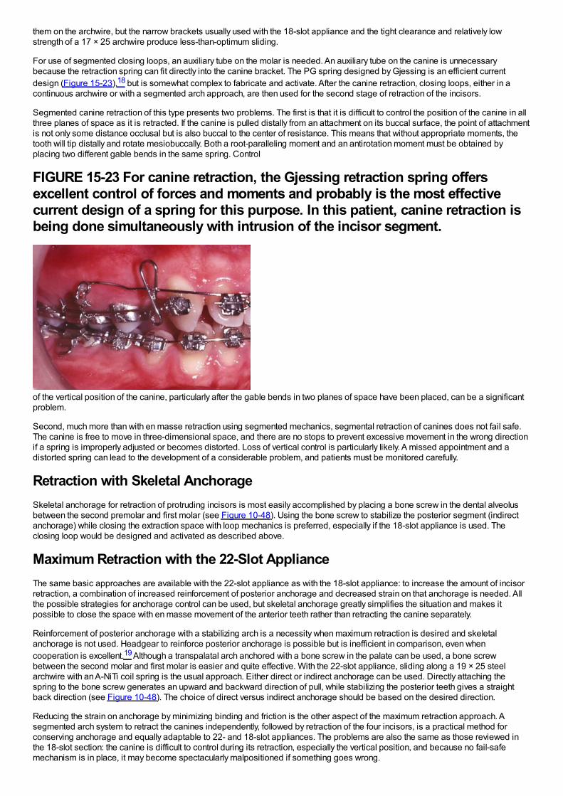
them on the archwire, but the narrow brackets usually used with the 18-slot appliance and the tight clearance and relatively lowstrength of a 17 × 25 archwire produce less-than-optimum sliding.
For use of segmented closing loops, an auxiliary tube on the molar is needed. An auxiliary tube on the canine is unnecessarybecause the retraction spring can fit directly into the canine bracket. The PG spring designed by Gjessing is an efficient currentdesign (Figure 15-23),18 but is somewhat complex to fabricate and activate. After the canine retraction, closing loops, either in acontinuous archwire or with a segmented arch approach, are then used for the second stage of retraction of the incisors.
Segmented canine retraction of this type presents two problems. The first is that it is difficult to control the position of the canine in allthree planes of space as it is retracted. If the canine is pulled distally from an attachment on its buccal surface, the point of attachmentis not only some distance occlusal but is also buccal to the center of resistance. This means that without appropriate moments, thetooth will tip distally and rotate mesiobuccally. Both a root-paralleling moment and an antirotation moment must be obtained byplacing two different gable bends in the same spring. Control
FIGURE 15-23 For canine retraction, the Gjessing retraction spring offersexcellent control of forces and moments and probably is the most effectivecurrent design of a spring for this purpose. In this patient, canine retraction isbeing done simultaneously with intrusion of the incisor segment.
of the vertical position of the canine, particularly after the gable bends in two planes of space have been placed, can be a significantproblem.
Second, much more than with en masse retraction using segmented mechanics, segmental retraction of canines does not fail safe.The canine is free to move in three-dimensional space, and there are no stops to prevent excessive movement in the wrong directionif a spring is improperly adjusted or becomes distorted. Loss of vertical control is particularly likely. A missed appointment and adistorted spring can lead to the development of a considerable problem, and patients must be monitored carefully.
Retraction with Skeletal AnchorageSkeletal anchorage for retraction of protruding incisors is most easily accomplished by placing a bone screw in the dental alveolusbetween the second premolar and first molar (see Figure 10-48). Using the bone screw to stabilize the posterior segment (indirectanchorage) while closing the extraction space with loop mechanics is preferred, especially if the 18-slot appliance is used. Theclosing loop would be designed and activated as described above.
Maximum Retraction with the 22-Slot ApplianceThe same basic approaches are available with the 22-slot appliance as with the 18-slot appliance: to increase the amount of incisorretraction, a combination of increased reinforcement of posterior anchorage and decreased strain on that anchorage is needed. Allthe possible strategies for anchorage control can be used, but skeletal anchorage greatly simplifies the situation and makes itpossible to close the space with en masse movement of the anterior teeth rather than retracting the canine separately.
Reinforcement of posterior anchorage with a stabilizing arch is a necessity when maximum retraction is desired and skeletalanchorage is not used. Headgear to reinforce posterior anchorage is possible but is inefficient in comparison, even whencooperation is excellent.19 Although a transpalatal arch anchored with a bone screw in the palate can be used, a bone screwbetween the second molar and first molar is easier and quite effective. With the 22-slot appliance, sliding along a 19 × 25 steelarchwire with an A-NiTi coil spring is the usual approach. Either direct or indirect anchorage can be used. Directly attaching thespring to the bone screw generates an upward and backward direction of pull, while stabilizing the posterior teeth gives a straightback direction (see Figure 10-48). The choice of direct versus indirect anchorage should be based on the desired direction.
Reducing the strain on anchorage by minimizing binding and friction is the other aspect of the maximum retraction approach. Asegmented arch system to retract the canines independently, followed by retraction of the four incisors, is a practical method forconserving anchorage and equally adaptable to 22- and 18-slot appliances. The problems are also the same as those reviewed inthe 18-slot section: the canine is difficult to control during its retraction, especially the vertical position, and because no fail-safemechanism is in place, it may become spectacularly malpositioned if something goes wrong.
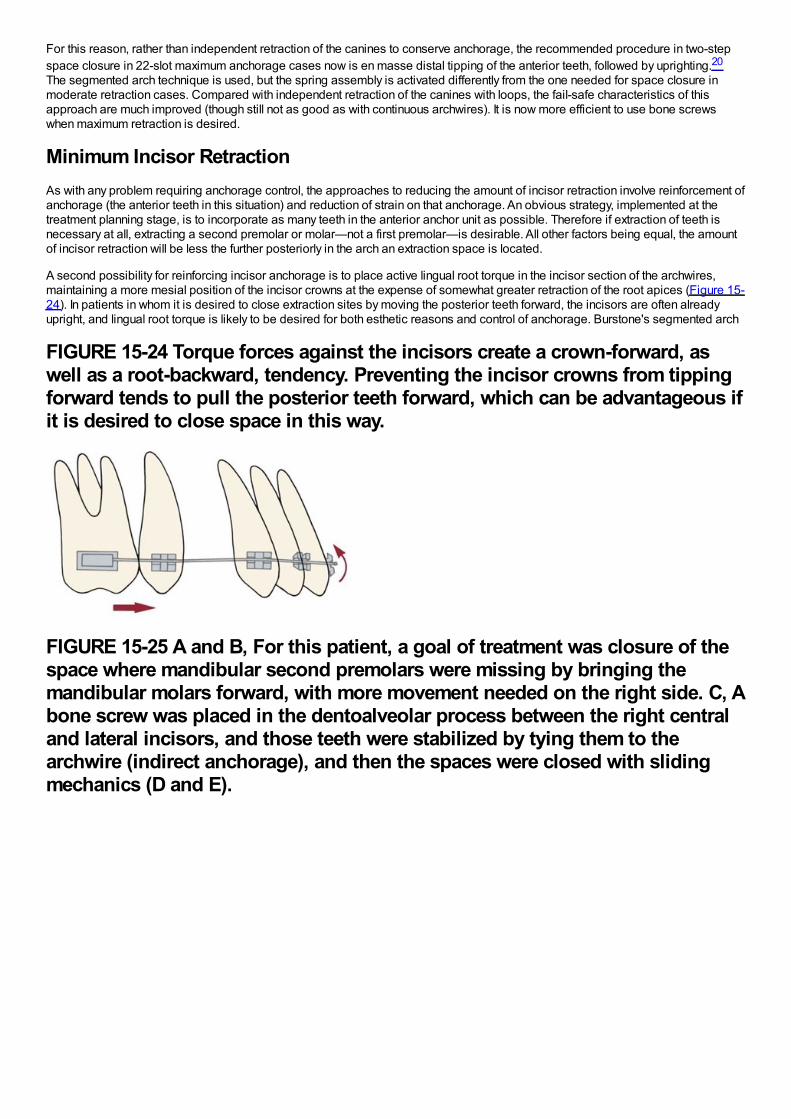
For this reason, rather than independent retraction of the canines to conserve anchorage, the recommended procedure in two-stepspace closure in 22-slot maximum anchorage cases now is en masse distal tipping of the anterior teeth, followed by uprighting.20
The segmented arch technique is used, but the spring assembly is activated differently from the one needed for space closure inmoderate retraction cases. Compared with independent retraction of the canines with loops, the fail-safe characteristics of thisapproach are much improved (though still not as good as with continuous archwires). It is now more efficient to use bone screwswhen maximum retraction is desired.
Minimum Incisor RetractionAs with any problem requiring anchorage control, the approaches to reducing the amount of incisor retraction involve reinforcement ofanchorage (the anterior teeth in this situation) and reduction of strain on that anchorage. An obvious strategy, implemented at thetreatment planning stage, is to incorporate as many teeth in the anterior anchor unit as possible. Therefore if extraction of teeth isnecessary at all, extracting a second premolar or molar—not a first premolar—is desirable. All other factors being equal, the amountof incisor retraction will be less the further posteriorly in the arch an extraction space is located.
A second possibility for reinforcing incisor anchorage is to place active lingual root torque in the incisor section of the archwires,maintaining a more mesial position of the incisor crowns at the expense of somewhat greater retraction of the root apices (Figure 15-24). In patients in whom it is desired to close extraction sites by moving the posterior teeth forward, the incisors are often alreadyupright, and lingual root torque is likely to be desired for both esthetic reasons and control of anchorage. Burstone's segmented arch
FIGURE 15-24 Torque forces against the incisors create a crown-forward, aswell as a root-backward, tendency. Preventing the incisor crowns from tippingforward tends to pull the posterior teeth forward, which can be advantageous ifit is desired to close space in this way.
FIGURE 15-25 A and B, For this patient, a goal of treatment was closure of thespace where mandibular second premolars were missing by bringing themandibular molars forward, with more movement needed on the right side. C, Abone screw was placed in the dentoalveolar process between the right centraland lateral incisors, and those teeth were stabilized by tying them to thearchwire (indirect anchorage), and then the spaces were closed with slidingmechanics (D and E).
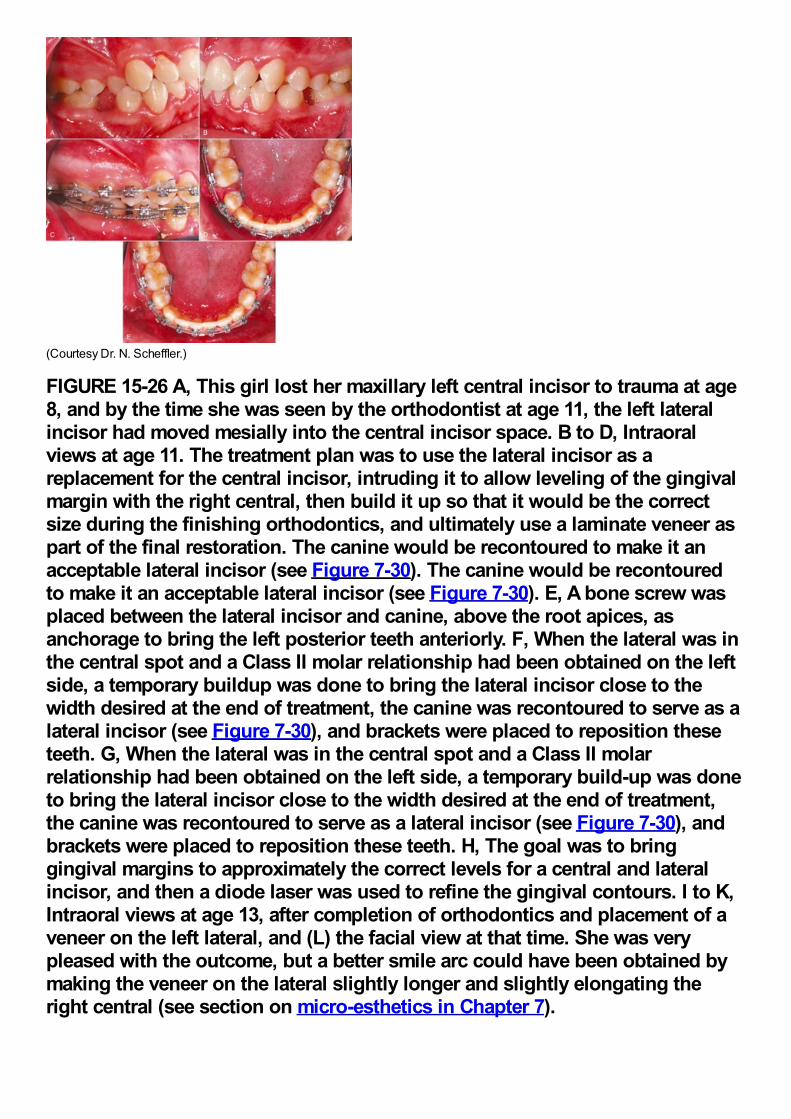
(Courtesy Dr. N. Scheffler.)
FIGURE 15-26 A, This girl lost her maxillary left central incisor to trauma at age8, and by the time she was seen by the orthodontist at age 11, the left lateralincisor had moved mesially into the central incisor space. B to D, Intraoralviews at age 11. The treatment plan was to use the lateral incisor as areplacement for the central incisor, intruding it to allow leveling of the gingivalmargin with the right central, then build it up so that it would be the correctsize during the finishing orthodontics, and ultimately use a laminate veneer aspart of the final restoration. The canine would be recontoured to make it anacceptable lateral incisor (see Figure 7-30). The canine would be recontouredto make it an acceptable lateral incisor (see Figure 7-30). E, A bone screw wasplaced between the lateral incisor and canine, above the root apices, asanchorage to bring the left posterior teeth anteriorly. F, When the lateral was inthe central spot and a Class II molar relationship had been obtained on the leftside, a temporary buildup was done to bring the lateral incisor close to thewidth desired at the end of treatment, the canine was recontoured to serve as alateral incisor (see Figure 7-30), and brackets were placed to reposition theseteeth. G, When the lateral was in the central spot and a Class II molarrelationship had been obtained on the left side, a temporary build-up was doneto bring the lateral incisor close to the width desired at the end of treatment,the canine was recontoured to serve as a lateral incisor (see Figure 7-30), andbrackets were placed to reposition these teeth. H, The goal was to bringgingival margins to approximately the correct levels for a central and lateralincisor, and then a diode laser was used to refine the gingival contours. I to K,Intraoral views at age 13, after completion of orthodontics and placement of aveneer on the left lateral, and (L) the facial view at that time. She was verypleased with the outcome, but a better smile arc could have been obtained bymaking the veneer on the lateral slightly longer and slightly elongating theright central (see section on micro-esthetics in Chapter 7).
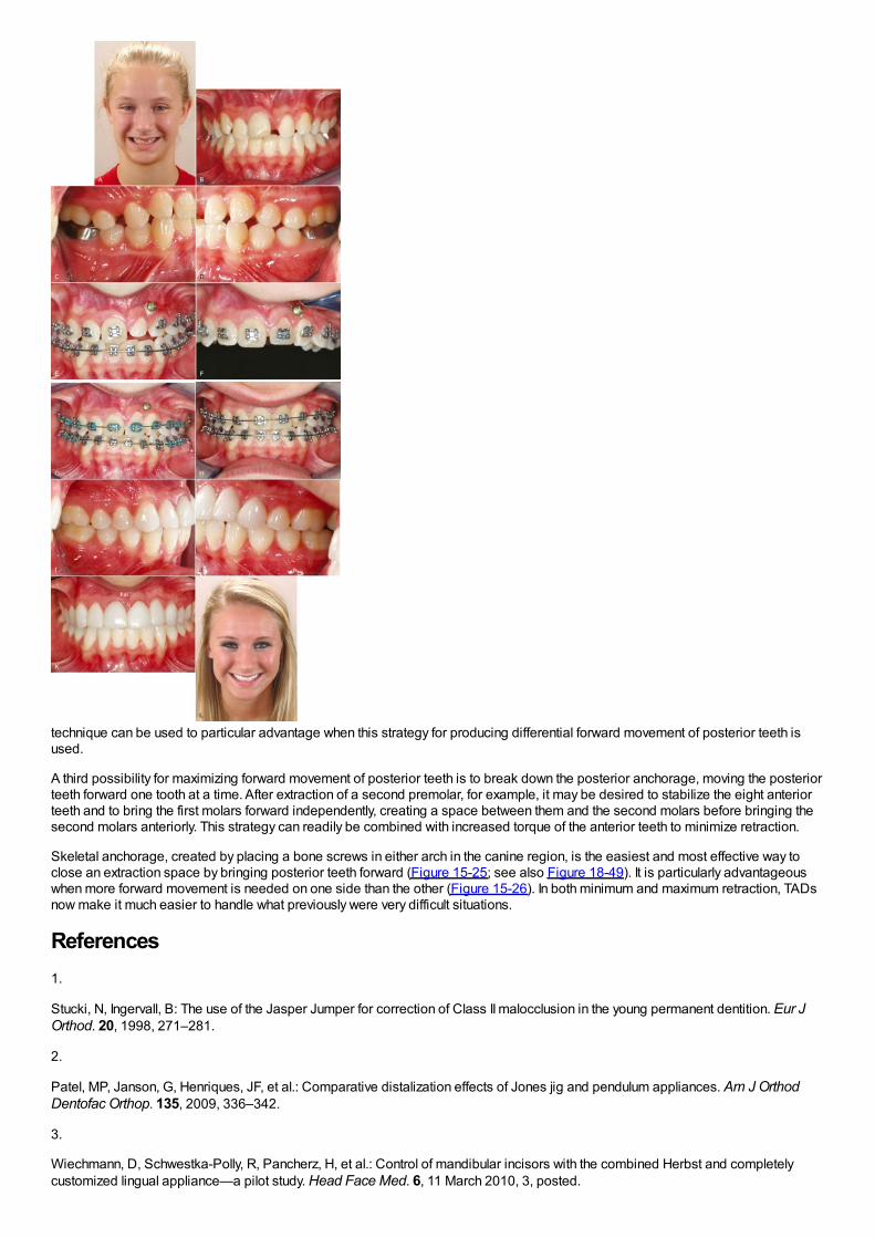
technique can be used to particular advantage when this strategy for producing differential forward movement of posterior teeth isused.
A third possibility for maximizing forward movement of posterior teeth is to break down the posterior anchorage, moving the posteriorteeth forward one tooth at a time. After extraction of a second premolar, for example, it may be desired to stabilize the eight anteriorteeth and to bring the first molars forward independently, creating a space between them and the second molars before bringing thesecond molars anteriorly. This strategy can readily be combined with increased torque of the anterior teeth to minimize retraction.
Skeletal anchorage, created by placing a bone screws in either arch in the canine region, is the easiest and most effective way toclose an extraction space by bringing posterior teeth forward (Figure 15-25; see also Figure 18-49). It is particularly advantageouswhen more forward movement is needed on one side than the other (Figure 15-26). In both minimum and maximum retraction, TADsnow make it much easier to handle what previously were very difficult situations.
References1.
Stucki, N, Ingervall, B: The use of the Jasper Jumper for correction of Class II malocclusion in the young permanent dentition. Eur JOrthod. 20, 1998, 271–281.
2.
Patel, MP, Janson, G, Henriques, JF, et al.: Comparative distalization effects of Jones jig and pendulum appliances. Am J OrthodDentofac Orthop. 135, 2009, 336–342.
3.
Wiechmann, D, Schwestka-Polly, R, Pancherz, H, et al.: Control of mandibular incisors with the combined Herbst and completelycustomized lingual appliance—a pilot study. Head Face Med. 6, 11 March 2010, 3, posted.

4.
Antonarakis, GS, Kiliaridis, S: Maxillary molar distalization with noncompliance intramaxillary appliances in Class II malocclusion. Asystematic review. Angle Orthod. 78, 2008, 1133–1140.
5.
Byloff, FK, Darendeliler, MA: Distal molar movement using the pendulum appliance. Part I. Clinical and radiological evaluation. AngleOrthod. 67, 1997, 249–260.
6.
Byloff, FK, Darendeliler, MA, Clar, E, et al.: Distal molar movement using the pendulum appliance. Part II. The effects of maxillarymolar root uprighting bends. Angle Orthod. 64, 1997, 261–270.
7.
Cornelis, MA, De Clerck, HJ: Maxillary molar distalization with miniplates assessed on digital models: a prospective clinical trial. AmJ Orthod Dentofac Orthop. 132, 2007, 373–377.
8.
Onçag, G, Seçkin, O, Dinçer, B, et al.: Osseointegrated implants with pendulum springs for maxillary molar distalization: acephalometric study. Am J Orthod Dentofac Orthop. 131, 2007, 16–26.
9.
Moffitt, AH: Eruption and function of maxillary third molars after extraction of second molars. Angle Orthod. 68, 1998, 147–152.
10.
McLaughlin, RP, Bennett, JC: The extraction-nonextraction dilemma as it relates to TMD. Angle Orthod. 65, 1995, 175–186.
11.
Rinchuse, DJ, Rinchuse, DJ, Kandasamy, S: Evidence-based versus experience-based views on occlusion and TMD. Am J OrthodDentofac Orthop. 127, 2005, 249–254.
12.
Northway, WM: The nuts and bolts of hemisection treatment: managing congenitally missing mandibular second premolars. Am JOrthod Dentofac Orthop. 127, 2005, 606–610.
13.
Booth, FA: MS Thesis: Optimum Forces with Orthodontic Loops. 1971, University of Texas Dental Branch, Houston.
14.
Braun, S, Sjursen, RC, Legan, HL: On the management of extraction sites. Am J Orthod Dentofac Orthop. 112, 1997, 645–655.
15.
Siatkowski, RE: Continuous archwire closing loop design, optimization and verification. Parts I and II. Am J Orthod Dentofac Orthop.112, 1997, 393–402, 484-495.
16.
Ronay, F, Kleinert, W, Melsen, B, et al.: Force system developed by V bends in an elastic orthodontic wire. Am J Orthod DentofacOrthop. 96, 1989, 295–301.
17.
In Nanda, R (Ed.): Biomechanics and Esthetic Strategies in Clinical Orthodontics. 2005, Elsevier/Saunders, Philadelphia.
18.
Eden, JD, Waters, N: An investigation into the characteristics of the PG canine retraction spring. Am J Orthod Dentofac Orthop. 105,1994, 49–60.
19.
Li, F, Hu, HK, Chen, JW, et al.: Comparison of anchorage capacity between implant and headgear during anterior segment retraction.Angle Orthod. 81, 2011, 915–922.

20.
Shroff, B, Yoon, WM, Lindauer, SJ, et al.: Simultaneous intrusion and retraction using a three-piece base arch. Angle Orthod. 67,1997, 455–462.
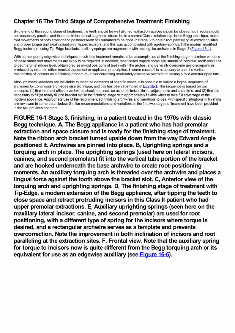
Chapter 16 The Third Stage of Comprehensive Treatment: FinishingBy the end of the second stage of treatment, the teeth should be well aligned, extraction spaces should be closed, tooth roots shouldbe reasonably parallel, and the teeth in the buccal segments should be in a normal Class I relationship. In the Begg technique, majorroot movements of both anterior and posterior teeth still remained to be done in Stage 3 to obtain root paralleling at extraction sitesand proper torque and axial inclination of tipped incisors, and this was accomplished with auxiliary springs. In the modern modifiedBegg technique, using Tip-Edge brackets, auxiliary springs are augmented with rectangular archwires in Stage 3 (Figure 16-1).
With contemporary edgewise techniques, much less treatment remains to be accomplished at the finishing stage, but minor versionsof these same root movements are likely to be required. In addition, most cases require some adjustment of individual tooth positionsto get marginal ridges level, obtain precise in–out positions of teeth within the arches, and generally overcome any discrepanciesproduced by errors in either bracket placement or appliance prescription. In some cases, it is necessary to alter the verticalrelationship of incisors as a finishing procedure, either correcting moderately excessive overbite or closing a mild anterior open bite.
Although many variations are inevitable to meet the demands of specific cases, it is possible to outline a logical sequence ofarchwires for continuous arch edgewise technique, and this has been attempted in Box 16-1. The sequence is based on twoconcepts: (1) that the most efficient archwires should be used, so as to minimize clinical adjustments and chair time, and (2) that it isnecessary to fill (or nearly fill) the bracket slot in the finishing stage with appropriately flexible wires to take full advantage of themodern appliance. Appropriate use of the recommended finishing archwires and variations to deal with specific situations in finishingare reviewed in some detail below. Similar recommendations and variations in the first two stages of treatment have been providedin the two previous chapters.
FIGURE 16-1 Stage 3, finishing, in a patient treated in the 1970s with classicBegg technique. A, The Begg appliance in a patient who has had premolarextraction and space closure and is ready for the finishing stage of treatment.Note the ribbon arch bracket turned upside down from the way Edward Anglepositioned it. Archwires are pinned into place. B, Uprighting springs and atorquing arch in place. The uprighting springs (used here on lateral incisors,canines, and second premolars) fit into the vertical tube portion of the bracketand are hooked underneath the base archwire to create root-positioningmoments. An auxiliary torquing arch is threaded over the archwire and places alingual force against the tooth above the bracket slot. C, Anterior view of thetorquing arch and uprighting springs. D, The finishing stage of treatment withTip-Edge, a modern extension of the Begg appliance, after tipping the teeth toclose space and retract protruding incisors in this Class II patient who hadupper premolar extractions. E, Auxiliary uprighting springs (seen here on themaxillary lateral incisor, canine, and second premolar) are used for rootpositioning, with a different type of spring for the incisors where torque isdesired, and a rectangular archwire serves as a template and preventsovercorrection. Note the improvement in both inclination of incisors and rootparalleling at the extraction sites. F, Frontal view. Note that the auxiliary springfor torque to incisors now is quite different from the Begg torquing arch or itsequivalent for use as an edgewise auxiliary (see Figure 16-6).
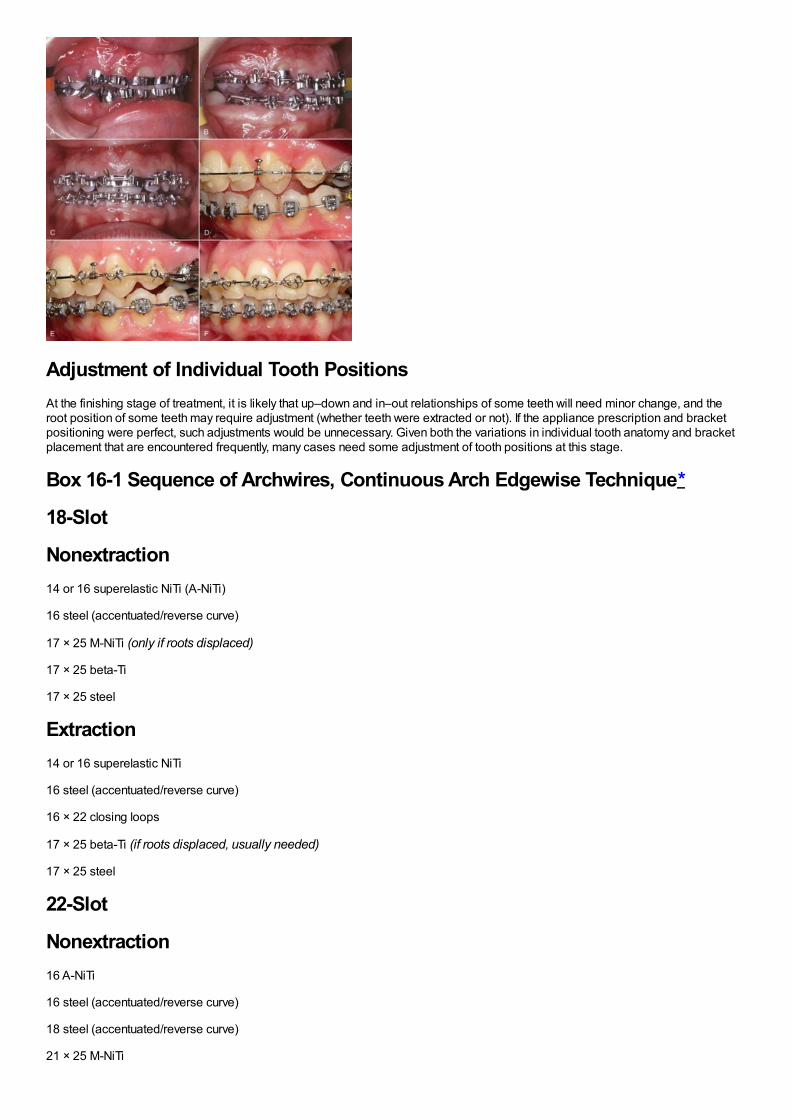
Adjustment of Individual Tooth PositionsAt the finishing stage of treatment, it is likely that up–down and in–out relationships of some teeth will need minor change, and theroot position of some teeth may require adjustment (whether teeth were extracted or not). If the appliance prescription and bracketpositioning were perfect, such adjustments would be unnecessary. Given both the variations in individual tooth anatomy and bracketplacement that are encountered frequently, many cases need some adjustment of tooth positions at this stage.
Box 16-1 Sequence of Archwires, Continuous Arch Edgewise Technique*
18-Slot
Nonextraction14 or 16 superelastic NiTi (A-NiTi)
16 steel (accentuated/reverse curve)
17 × 25 M-NiTi (only if roots displaced)
17 × 25 beta-Ti
17 × 25 steel
Extraction14 or 16 superelastic NiTi
16 steel (accentuated/reverse curve)
16 × 22 closing loops
17 × 25 beta-Ti (if roots displaced, usually needed)
17 × 25 steel
22-Slot
Nonextraction16 A-NiTi
16 steel (accentuated/reverse curve)
18 steel (accentuated/reverse curve)
21 × 25 M-NiTi
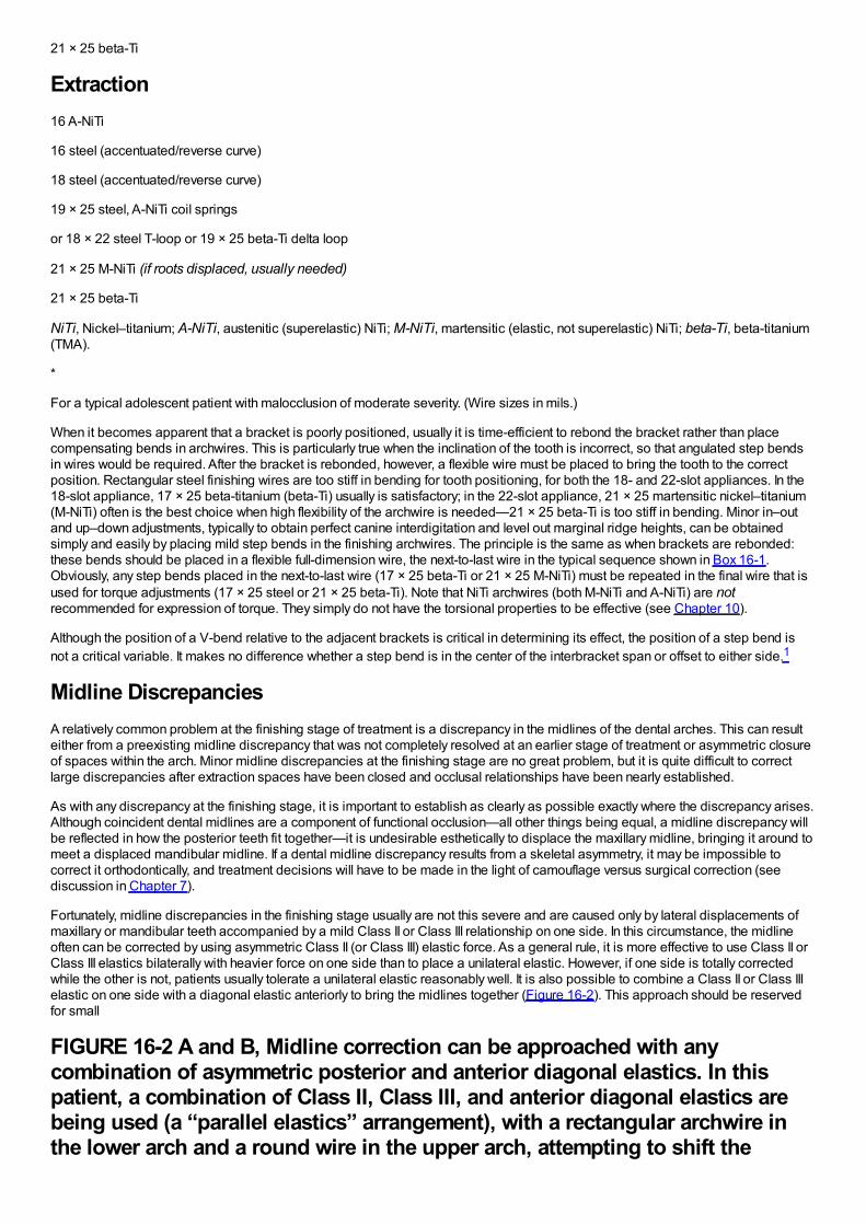
21 × 25 beta-Ti
Extraction16 A-NiTi
16 steel (accentuated/reverse curve)
18 steel (accentuated/reverse curve)
19 × 25 steel, A-NiTi coil springs
or 18 × 22 steel T-loop or 19 × 25 beta-Ti delta loop
21 × 25 M-NiTi (if roots displaced, usually needed)
21 × 25 beta-Ti
NiTi, Nickel–titanium; A-NiTi, austenitic (superelastic) NiTi; M-NiTi, martensitic (elastic, not superelastic) NiTi; beta-Ti, beta-titanium(TMA).
*
For a typical adolescent patient with malocclusion of moderate severity. (Wire sizes in mils.)
When it becomes apparent that a bracket is poorly positioned, usually it is time-efficient to rebond the bracket rather than placecompensating bends in archwires. This is particularly true when the inclination of the tooth is incorrect, so that angulated step bendsin wires would be required. After the bracket is rebonded, however, a flexible wire must be placed to bring the tooth to the correctposition. Rectangular steel finishing wires are too stiff in bending for tooth positioning, for both the 18- and 22-slot appliances. In the18-slot appliance, 17 × 25 beta-titanium (beta-Ti) usually is satisfactory; in the 22-slot appliance, 21 × 25 martensitic nickel–titanium(M-NiTi) often is the best choice when high flexibility of the archwire is needed—21 × 25 beta-Ti is too stiff in bending. Minor in–outand up–down adjustments, typically to obtain perfect canine interdigitation and level out marginal ridge heights, can be obtainedsimply and easily by placing mild step bends in the finishing archwires. The principle is the same as when brackets are rebonded:these bends should be placed in a flexible full-dimension wire, the next-to-last wire in the typical sequence shown in Box 16-1.Obviously, any step bends placed in the next-to-last wire (17 × 25 beta-Ti or 21 × 25 M-NiTi) must be repeated in the final wire that isused for torque adjustments (17 × 25 steel or 21 × 25 beta-Ti). Note that NiTi archwires (both M-NiTi and A-NiTi) are notrecommended for expression of torque. They simply do not have the torsional properties to be effective (see Chapter 10).
Although the position of a V-bend relative to the adjacent brackets is critical in determining its effect, the position of a step bend isnot a critical variable. It makes no difference whether a step bend is in the center of the interbracket span or offset to either side.1
Midline DiscrepanciesA relatively common problem at the finishing stage of treatment is a discrepancy in the midlines of the dental arches. This can resulteither from a preexisting midline discrepancy that was not completely resolved at an earlier stage of treatment or asymmetric closureof spaces within the arch. Minor midline discrepancies at the finishing stage are no great problem, but it is quite difficult to correctlarge discrepancies after extraction spaces have been closed and occlusal relationships have been nearly established.
As with any discrepancy at the finishing stage, it is important to establish as clearly as possible exactly where the discrepancy arises.Although coincident dental midlines are a component of functional occlusion—all other things being equal, a midline discrepancy willbe reflected in how the posterior teeth fit together—it is undesirable esthetically to displace the maxillary midline, bringing it around tomeet a displaced mandibular midline. If a dental midline discrepancy results from a skeletal asymmetry, it may be impossible tocorrect it orthodontically, and treatment decisions will have to be made in the light of camouflage versus surgical correction (seediscussion in Chapter 7).
Fortunately, midline discrepancies in the finishing stage usually are not this severe and are caused only by lateral displacements ofmaxillary or mandibular teeth accompanied by a mild Class II or Class III relationship on one side. In this circumstance, the midlineoften can be corrected by using asymmetric Class II (or Class III) elastic force. As a general rule, it is more effective to use Class II orClass III elastics bilaterally with heavier force on one side than to place a unilateral elastic. However, if one side is totally correctedwhile the other is not, patients usually tolerate a unilateral elastic reasonably well. It is also possible to combine a Class II or Class IIIelastic on one side with a diagonal elastic anteriorly to bring the midlines together (Figure 16-2). This approach should be reservedfor small
FIGURE 16-2 A and B, Midline correction can be approached with anycombination of asymmetric posterior and anterior diagonal elastics. In thispatient, a combination of Class II, Class III, and anterior diagonal elastics arebeing used (a “parallel elastics” arrangement), with a rectangular archwire inthe lower arch and a round wire in the upper arch, attempting to shift the
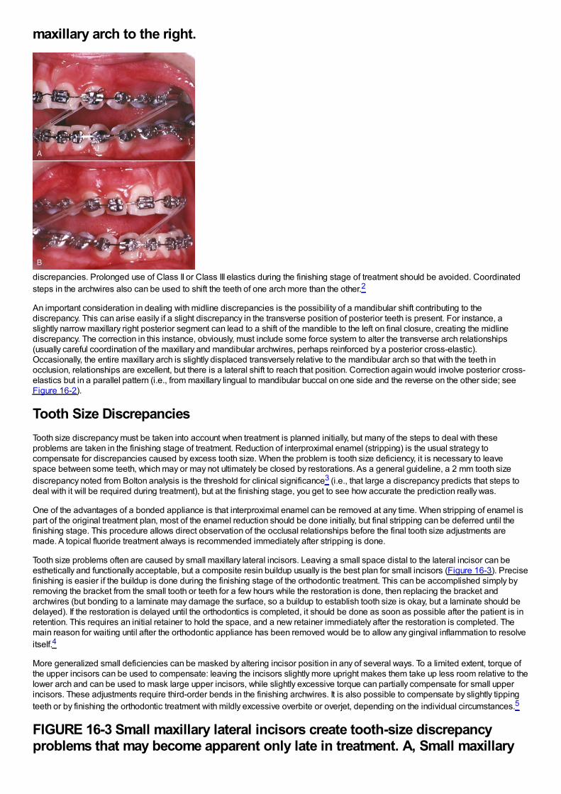
maxillary arch to the right.
discrepancies. Prolonged use of Class II or Class III elastics during the finishing stage of treatment should be avoided. Coordinatedsteps in the archwires also can be used to shift the teeth of one arch more than the other.2
An important consideration in dealing with midline discrepancies is the possibility of a mandibular shift contributing to thediscrepancy. This can arise easily if a slight discrepancy in the transverse position of posterior teeth is present. For instance, aslightly narrow maxillary right posterior segment can lead to a shift of the mandible to the left on final closure, creating the midlinediscrepancy. The correction in this instance, obviously, must include some force system to alter the transverse arch relationships(usually careful coordination of the maxillary and mandibular archwires, perhaps reinforced by a posterior cross-elastic).Occasionally, the entire maxillary arch is slightly displaced transversely relative to the mandibular arch so that with the teeth inocclusion, relationships are excellent, but there is a lateral shift to reach that position. Correction again would involve posterior cross-elastics but in a parallel pattern (i.e., from maxillary lingual to mandibular buccal on one side and the reverse on the other side; seeFigure 16-2).
Tooth Size DiscrepanciesTooth size discrepancy must be taken into account when treatment is planned initially, but many of the steps to deal with theseproblems are taken in the finishing stage of treatment. Reduction of interproximal enamel (stripping) is the usual strategy tocompensate for discrepancies caused by excess tooth size. When the problem is tooth size deficiency, it is necessary to leavespace between some teeth, which may or may not ultimately be closed by restorations. As a general guideline, a 2 mm tooth sizediscrepancy noted from Bolton analysis is the threshold for clinical significance3 (i.e., that large a discrepancy predicts that steps todeal with it will be required during treatment), but at the finishing stage, you get to see how accurate the prediction really was.
One of the advantages of a bonded appliance is that interproximal enamel can be removed at any time. When stripping of enamel ispart of the original treatment plan, most of the enamel reduction should be done initially, but final stripping can be deferred until thefinishing stage. This procedure allows direct observation of the occlusal relationships before the final tooth size adjustments aremade. A topical fluoride treatment always is recommended immediately after stripping is done.
Tooth size problems often are caused by small maxillary lateral incisors. Leaving a small space distal to the lateral incisor can beesthetically and functionally acceptable, but a composite resin buildup usually is the best plan for small incisors (Figure 16-3). Precisefinishing is easier if the buildup is done during the finishing stage of the orthodontic treatment. This can be accomplished simply byremoving the bracket from the small tooth or teeth for a few hours while the restoration is done, then replacing the bracket andarchwires (but bonding to a laminate may damage the surface, so a buildup to establish tooth size is okay, but a laminate should bedelayed). If the restoration is delayed until the orthodontics is completed, it should be done as soon as possible after the patient is inretention. This requires an initial retainer to hold the space, and a new retainer immediately after the restoration is completed. Themain reason for waiting until after the orthodontic appliance has been removed would be to allow any gingival inflammation to resolveitself.4
More generalized small deficiencies can be masked by altering incisor position in any of several ways. To a limited extent, torque ofthe upper incisors can be used to compensate: leaving the incisors slightly more upright makes them take up less room relative to thelower arch and can be used to mask large upper incisors, while slightly excessive torque can partially compensate for small upperincisors. These adjustments require third-order bends in the finishing archwires. It is also possible to compensate by slightly tippingteeth or by finishing the orthodontic treatment with mildly excessive overbite or overjet, depending on the individual circumstances.5
FIGURE 16-3 Small maxillary lateral incisors create tooth-size discrepancyproblems that may become apparent only late in treatment. A, Small maxillary
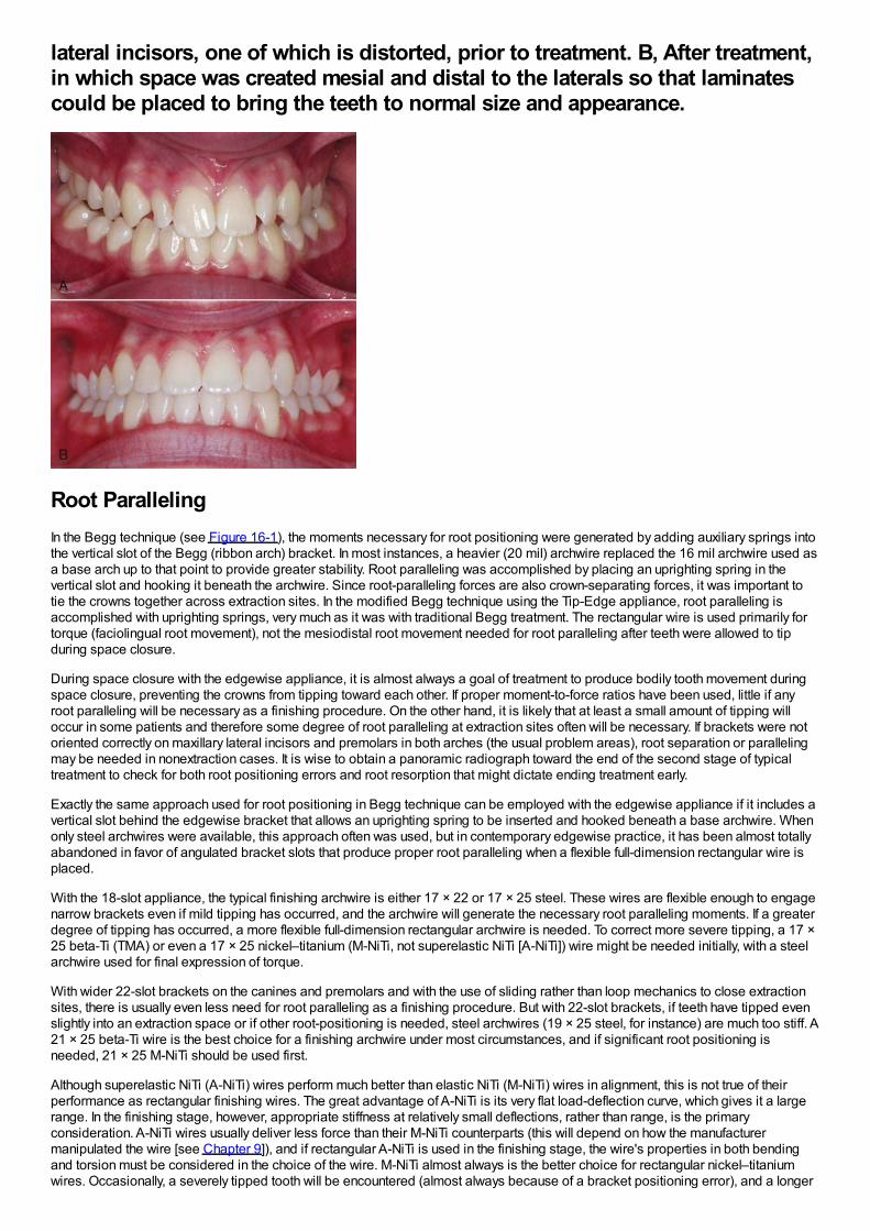
lateral incisors, one of which is distorted, prior to treatment. B, After treatment,in which space was created mesial and distal to the laterals so that laminatescould be placed to bring the teeth to normal size and appearance.
Root ParallelingIn the Begg technique (see Figure 16-1), the moments necessary for root positioning were generated by adding auxiliary springs intothe vertical slot of the Begg (ribbon arch) bracket. In most instances, a heavier (20 mil) archwire replaced the 16 mil archwire used asa base arch up to that point to provide greater stability. Root paralleling was accomplished by placing an uprighting spring in thevertical slot and hooking it beneath the archwire. Since root-paralleling forces are also crown-separating forces, it was important totie the crowns together across extraction sites. In the modified Begg technique using the Tip-Edge appliance, root paralleling isaccomplished with uprighting springs, very much as it was with traditional Begg treatment. The rectangular wire is used primarily fortorque (faciolingual root movement), not the mesiodistal root movement needed for root paralleling after teeth were allowed to tipduring space closure.
During space closure with the edgewise appliance, it is almost always a goal of treatment to produce bodily tooth movement duringspace closure, preventing the crowns from tipping toward each other. If proper moment-to-force ratios have been used, little if anyroot paralleling will be necessary as a finishing procedure. On the other hand, it is likely that at least a small amount of tipping willoccur in some patients and therefore some degree of root paralleling at extraction sites often will be necessary. If brackets were notoriented correctly on maxillary lateral incisors and premolars in both arches (the usual problem areas), root separation or parallelingmay be needed in nonextraction cases. It is wise to obtain a panoramic radiograph toward the end of the second stage of typicaltreatment to check for both root positioning errors and root resorption that might dictate ending treatment early.
Exactly the same approach used for root positioning in Begg technique can be employed with the edgewise appliance if it includes avertical slot behind the edgewise bracket that allows an uprighting spring to be inserted and hooked beneath a base archwire. Whenonly steel archwires were available, this approach often was used, but in contemporary edgewise practice, it has been almost totallyabandoned in favor of angulated bracket slots that produce proper root paralleling when a flexible full-dimension rectangular wire isplaced.
With the 18-slot appliance, the typical finishing archwire is either 17 × 22 or 17 × 25 steel. These wires are flexible enough to engagenarrow brackets even if mild tipping has occurred, and the archwire will generate the necessary root paralleling moments. If a greaterdegree of tipping has occurred, a more flexible full-dimension rectangular archwire is needed. To correct more severe tipping, a 17 ×25 beta-Ti (TMA) or even a 17 × 25 nickel–titanium (M-NiTi, not superelastic NiTi [A-NiTi]) wire might be needed initially, with a steelarchwire used for final expression of torque.
With wider 22-slot brackets on the canines and premolars and with the use of sliding rather than loop mechanics to close extractionsites, there is usually even less need for root paralleling as a finishing procedure. But with 22-slot brackets, if teeth have tipped evenslightly into an extraction space or if other root-positioning is needed, steel archwires (19 × 25 steel, for instance) are much too stiff. A21 × 25 beta-Ti wire is the best choice for a finishing archwire under most circumstances, and if significant root positioning isneeded, 21 × 25 M-NiTi should be used first.
Although superelastic NiTi (A-NiTi) wires perform much better than elastic NiTi (M-NiTi) wires in alignment, this is not true of theirperformance as rectangular finishing wires. The great advantage of A-NiTi is its very flat load-deflection curve, which gives it a largerange. In the finishing stage, however, appropriate stiffness at relatively small deflections, rather than range, is the primaryconsideration. A-NiTi wires usually deliver less force than their M-NiTi counterparts (this will depend on how the manufacturermanipulated the wire [see Chapter 9]), and if rectangular A-NiTi is used in the finishing stage, the wire's properties in both bendingand torsion must be considered in the choice of the wire. M-NiTi almost always is the better choice for rectangular nickel–titaniumwires. Occasionally, a severely tipped tooth will be encountered (almost always because of a bracket positioning error), and a longer
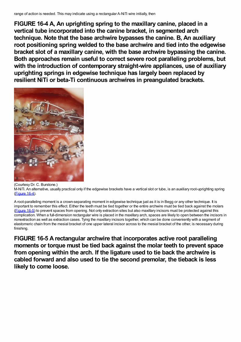
range of action is needed. This may indicate using a rectangular A-NiTi wire initially, then
FIGURE 16-4 A, An uprighting spring to the maxillary canine, placed in avertical tube incorporated into the canine bracket, in segmented archtechnique. Note that the base archwire bypasses the canine. B, An auxiliaryroot positioning spring welded to the base archwire and tied into the edgewisebracket slot of a maxillary canine, with the base archwire bypassing the canine.Both approaches remain useful to correct severe root paralleling problems, butwith the introduction of contemporary straight-wire appliances, use of auxiliaryuprighting springs in edgewise technique has largely been replaced byresilient NiTi or beta-Ti continuous archwires in preangulated brackets.
(Courtesy Dr. C. Burstone.)M-NiTi. An alternative, usually practical only if the edgewise brackets have a vertical slot or tube, is an auxiliary root-uprighting spring(Figure 16-4).
A root-paralleling moment is a crown-separating moment in edgewise technique just as it is in Begg or any other technique. It isimportant to remember this effect. Either the teeth must be tied together or the entire archwire must be tied back against the molars(Figure 16-5) to prevent spaces from opening. Not only extraction sites but also maxillary incisors must be protected against thiscomplication. When a full-dimension rectangular wire is placed in the maxillary arch, spaces are likely to open between the incisors innonextraction as well as extraction cases. Tying the maxillary incisors together, which can be done conveniently with a segment ofelastomeric chain from the mesial bracket of one upper lateral incisor across to the mesial bracket of the other, is necessary duringfinishing.
FIGURE 16-5 A rectangular archwire that incorporates active root parallelingmoments or torque must be tied back against the molar teeth to prevent spacefrom opening within the arch. If the ligature used to tie back the archwire iscabled forward and also used to tie the second premolar, the tieback is lesslikely to come loose.
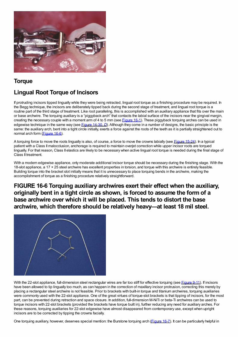
Torque
Lingual Root Torque of IncisorsIf protruding incisors tipped lingually while they were being retracted, lingual root torque as a finishing procedure may be required. Inthe Begg technique, the incisors are deliberately tipped back during the second stage of treatment, and lingual root torque is aroutine part of the third stage of treatment. Like root paralleling, this is accomplished with an auxiliary appliance that fits over the mainor base archwire. The torquing auxiliary is a “piggyback arch” that contacts the labial surface of the incisors near the gingival margin,creating the necessary couple with a moment arm of 4 to 5 mm (see Figure 16-1). These piggyback torquing arches can be used inedgewise technique in the same way (see Figure 14-30, D). Although they come in a number of designs, the basic principle is thesame: the auxiliary arch, bent into a tight circle initially, exerts a force against the roots of the teeth as it is partially straightened out tonormal arch form (Figure 16-6).
A torquing force to move the roots lingually is also, of course, a force to move the crowns labially (see Figure 15-24). In a typicalpatient with a Class II malocclusion, anchorage is required to maintain overjet correction while upper incisor roots are torquedlingually. For that reason, Class II elastics are likely to be necessary when active lingual root torque is needed during the final stage ofClass II treatment.
With a modern edgewise appliance, only moderate additional incisor torque should be necessary during the finishing stage. With the18-slot appliance, a 17 × 25 steel archwire has excellent properties in torsion, and torque with this archwire is entirely feasible.Building torque into the bracket slot initially means that it is unnecessary to place torquing bends in the archwire, making theaccomplishment of torque as a finishing procedure relatively straightforward.
FIGURE 16-6 Torquing auxiliary archwires exert their effect when the auxiliary,originally bent in a tight circle as shown, is forced to assume the form of abase archwire over which it will be placed. This tends to distort the basearchwire, which therefore should be relatively heavy—at least 18 mil steel.
With the 22-slot appliance, full-dimension steel rectangular wires are far too stiff for effective torquing (see Figure 9-11). If incisorshave been allowed to tip lingually too much, as can happen in the correction of maxillary incisor protrusion, correcting this merely byplacing a rectangular steel archwire is not feasible. Prior to brackets with built-in torque and titanium archwires, torquing auxiliarieswere commonly used with the 22-slot appliance. One of the great virtues of torque-slot brackets is that tipping of incisors, for the mostpart, can be prevented during retraction and space closure. In addition, full-dimension M-NiTi or beta-Ti archwires can be used totorque incisors with 22-slot brackets (provided the brackets have torque built in), further reducing any need for auxiliary arches. Forthese reasons, torquing auxiliaries for 22-slot edgewise have almost disappeared from contemporary use, except when uprightincisors are to be corrected by tipping the crowns facially.
One torquing auxiliary, however, deserves special mention: the Burstone torquing arch (Figure 16-7). It can be particularly helpful in
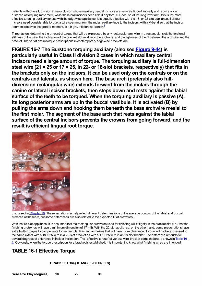
patients with Class II, division 2 malocclusion whose maxillary central incisors are severely tipped lingually and require a longdistance of torquing movement, while the lateral incisors need little if any torque. Because of the long lever arm, this is the mosteffective torquing auxiliary for use with the edgewise appliance. It is equally effective with the 18- or 22-slot appliance. If all fourincisors need considerable torque, a wire spanning from the molar auxiliary tube to the incisors, with a V-bend so that the incisorsegment receives the greater moment, is a highly efficient approach.6
Three factors determine the amount of torque that will be expressed by any rectangular archwire in a rectangular slot: the torsionalstiffness of the wire, the inclination of the bracket slot relative to the archwire, and the tightness of the fit between the archwire and thebracket. The variations in torque prescriptions in contemporary edgewise brackets are
FIGURE 16-7 The Burstone torquing auxiliary (also see Figure 9-44) isparticularly useful in Class II division 2 cases in which maxillary centralincisors need a large amount of torque. The torquing auxiliary is full-dimensionsteel wire (21 × 25 or 17 × 25, in 22- or 18-slot brackets, respectively) that fits inthe brackets only on the incisors. It can be used only on the centrals or on thecentrals and laterals, as shown here. The base arch (preferably also full-dimension rectangular wire) extends forward from the molars through thecanine or lateral incisor brackets, then steps down and rests against the labialsurface of the teeth to be torqued. When the torquing auxiliary is passive (A),its long posterior arms are up in the buccal vestibule. It is activated (B) bypulling the arms down and hooking them beneath the base archwire mesial tothe first molar. The segment of the base arch that rests against the labialsurface of the central incisors prevents the crowns from going forward, and theresult is efficient lingual root torque.
discussed in Chapter 10. These variations largely reflect different determinations of the average contour of the labial and buccalsurfaces of the teeth, but some differences are also related to the expected fit of archwires.
With the 18-slot appliance, it is assumed that the rectangular archwires used for finishing will fit tightly in the bracket slot (i.e., that thefinishing archwires will have a minimum dimension of 17 mil). With the 22-slot appliance, on the other hand, some prescriptions haveextra built-in torque to compensate for rectangular finishing archwires that will have more clearance. Torque will not be expressed tothe same extent with a 19 × 25 wire in a 22-slot bracket as with a 17 × 25 wire in an 18-slot bracket. The difference amounts toseveral degrees of difference in incisor inclination. The “effective torque” of various wire-bracket combinations is shown in Table 16-1. Obviously, when the torque prescription for a bracket is established, it is important to know what finishing wires are intended.
TABLE 16-1 Effective Torque
Wire size Play (degrees)
BRACKET TORQUE ANGLE (DEGREES)
10 22 30
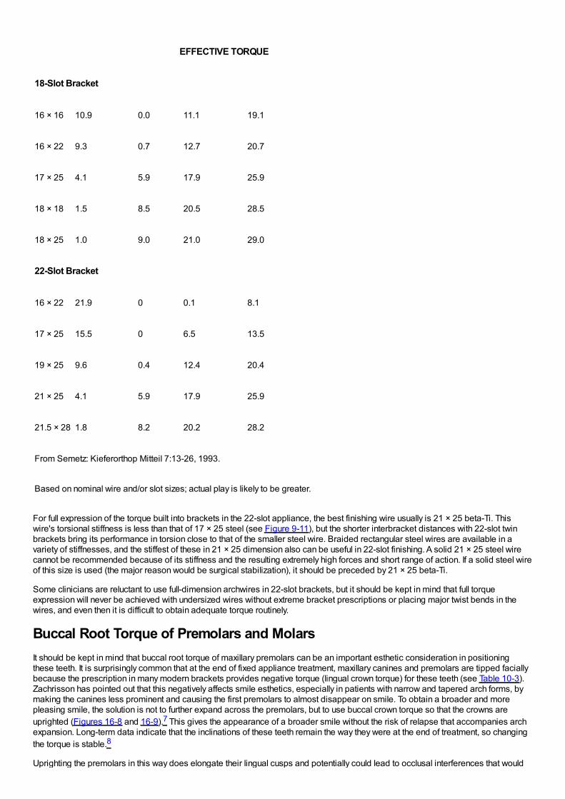
EFFECTIVE TORQUE
18-Slot Bracket
16 × 16 10.9 0.0 11.1 19.1
16 × 22 9.3 0.7 12.7 20.7
17 × 25 4.1 5.9 17.9 25.9
18 × 18 1.5 8.5 20.5 28.5
18 × 25 1.0 9.0 21.0 29.0
22-Slot Bracket
16 × 22 21.9 0 0.1 8.1
17 × 25 15.5 0 6.5 13.5
19 × 25 9.6 0.4 12.4 20.4
21 × 25 4.1 5.9 17.9 25.9
21.5 × 28 1.8 8.2 20.2 28.2
From Semetz: Kieferorthop Mitteil 7:13-26, 1993.
Based on nominal wire and/or slot sizes; actual play is likely to be greater.
For full expression of the torque built into brackets in the 22-slot appliance, the best finishing wire usually is 21 × 25 beta-Ti. Thiswire's torsional stiffness is less than that of 17 × 25 steel (see Figure 9-11), but the shorter interbracket distances with 22-slot twinbrackets bring its performance in torsion close to that of the smaller steel wire. Braided rectangular steel wires are available in avariety of stiffnesses, and the stiffest of these in 21 × 25 dimension also can be useful in 22-slot finishing. A solid 21 × 25 steel wirecannot be recommended because of its stiffness and the resulting extremely high forces and short range of action. If a solid steel wireof this size is used (the major reason would be surgical stabilization), it should be preceded by 21 × 25 beta-Ti.
Some clinicians are reluctant to use full-dimension archwires in 22-slot brackets, but it should be kept in mind that full torqueexpression will never be achieved with undersized wires without extreme bracket prescriptions or placing major twist bends in thewires, and even then it is difficult to obtain adequate torque routinely.
Buccal Root Torque of Premolars and MolarsIt should be kept in mind that buccal root torque of maxillary premolars can be an important esthetic consideration in positioningthese teeth. It is surprisingly common that at the end of fixed appliance treatment, maxillary canines and premolars are tipped faciallybecause the prescription in many modern brackets provides negative torque (lingual crown torque) for these teeth (see Table 10-3).Zachrisson has pointed out that this negatively affects smile esthetics, especially in patients with narrow and tapered arch forms, bymaking the canines less prominent and causing the first premolars to almost disappear on smile. To obtain a broader and morepleasing smile, the solution is not to further expand across the premolars, but to use buccal crown torque so that the crowns areuprighted (Figures 16-8 and 16-9).7 This gives the appearance of a broader smile without the risk of relapse that accompanies archexpansion. Long-term data indicate that the inclinations of these teeth remain the way they were at the end of treatment, so changingthe torque is stable.8
Uprighting the premolars in this way does elongate their lingual cusps and potentially could lead to occlusal interferences that would
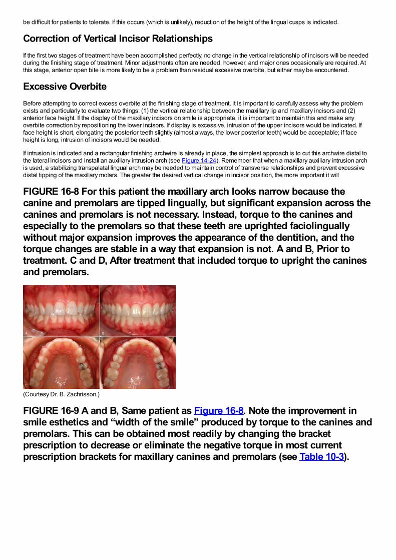
be difficult for patients to tolerate. If this occurs (which is unlikely), reduction of the height of the lingual cusps is indicated.
Correction of Vertical Incisor RelationshipsIf the first two stages of treatment have been accomplished perfectly, no change in the vertical relationship of incisors will be neededduring the finishing stage of treatment. Minor adjustments often are needed, however, and major ones occasionally are required. Atthis stage, anterior open bite is more likely to be a problem than residual excessive overbite, but either may be encountered.
Excessive OverbiteBefore attempting to correct excess overbite at the finishing stage of treatment, it is important to carefully assess why the problemexists and particularly to evaluate two things: (1) the vertical relationship between the maxillary lip and maxillary incisors and (2)anterior face height. If the display of the maxillary incisors on smile is appropriate, it is important to maintain this and make anyoverbite correction by repositioning the lower incisors. If display is excessive, intrusion of the upper incisors would be indicated. Ifface height is short, elongating the posterior teeth slightly (almost always, the lower posterior teeth) would be acceptable; if faceheight is long, intrusion of incisors would be needed.
If intrusion is indicated and a rectangular finishing archwire is already in place, the simplest approach is to cut this archwire distal tothe lateral incisors and install an auxiliary intrusion arch (see Figure 14-24). Remember that when a maxillary auxiliary intrusion archis used, a stabilizing transpalatal lingual arch may be needed to maintain control of transverse relationships and prevent excessivedistal tipping of the maxillary molars. The greater the desired vertical change in incisor position, the more important it will
FIGURE 16-8 For this patient the maxillary arch looks narrow because thecanine and premolars are tipped lingually, but significant expansion across thecanines and premolars is not necessary. Instead, torque to the canines andespecially to the premolars so that these teeth are uprighted faciolinguallywithout major expansion improves the appearance of the dentition, and thetorque changes are stable in a way that expansion is not. A and B, Prior totreatment. C and D, After treatment that included torque to upright the caninesand premolars.
(Courtesy Dr. B. Zachrisson.)
FIGURE 16-9 A and B, Same patient as Figure 16-8. Note the improvement insmile esthetics and “width of the smile” produced by torque to the canines andpremolars. This can be obtained most readily by changing the bracketprescription to decrease or eliminate the negative torque in most currentprescription brackets for maxillary canines and premolars (see Table 10-3).
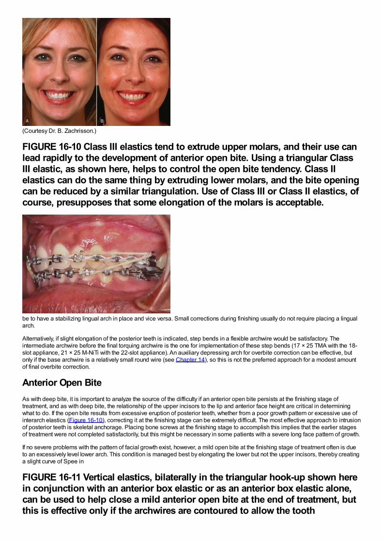
(Courtesy Dr. B. Zachrisson.)
FIGURE 16-10 Class III elastics tend to extrude upper molars, and their use canlead rapidly to the development of anterior open bite. Using a triangular ClassIII elastic, as shown here, helps to control the open bite tendency. Class IIelastics can do the same thing by extruding lower molars, and the bite openingcan be reduced by a similar triangulation. Use of Class III or Class II elastics, ofcourse, presupposes that some elongation of the molars is acceptable.
be to have a stabilizing lingual arch in place and vice versa. Small corrections during finishing usually do not require placing a lingualarch.
Alternatively, if slight elongation of the posterior teeth is indicated, step bends in a flexible archwire would be satisfactory. Theintermediate archwire before the final torquing archwire is the one for implementation of these step bends (17 × 25 TMA with the 18-slot appliance, 21 × 25 M-NiTi with the 22-slot appliance). An auxiliary depressing arch for overbite correction can be effective, butonly if the base archwire is a relatively small round wire (see Chapter 14), so this is not the preferred approach for a modest amountof final overbite correction.
Anterior Open BiteAs with deep bite, it is important to analyze the source of the difficulty if an anterior open bite persists at the finishing stage oftreatment, and as with deep bite, the relationship of the upper incisors to the lip and anterior face height are critical in determiningwhat to do. If the open bite results from excessive eruption of posterior teeth, whether from a poor growth pattern or excessive use ofinterarch elastics (Figure 16-10), correcting it at the finishing stage can be extremely difficult. The most effective approach to intrusionof posterior teeth is skeletal anchorage. Placing bone screws at the finishing stage to accomplish this implies that the earlier stagesof treatment were not completed satisfactorily, but this might be necessary in some patients with a severe long face pattern of growth.
If no severe problems with the pattern of facial growth exist, however, a mild open bite at the finishing stage of treatment often is dueto an excessively level lower arch. This condition is managed best by elongating the lower but not the upper incisors, thereby creatinga slight curve of Spee in
FIGURE 16-11 Vertical elastics, bilaterally in the triangular hook-up shown herein conjunction with an anterior box elastic or as an anterior box elastic alone,can be used to help close a mild anterior open bite at the end of treatment, butthis is effective only if the archwires are contoured to allow the tooth
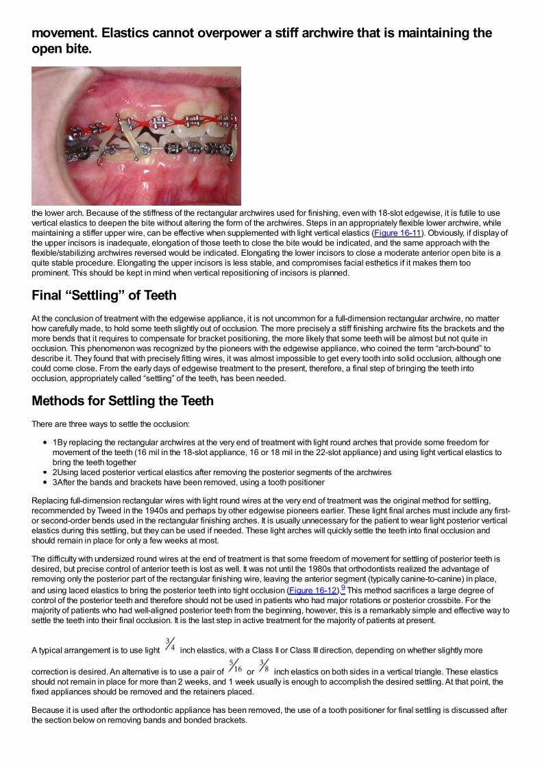
movement. Elastics cannot overpower a stiff archwire that is maintaining theopen bite.
the lower arch. Because of the stiffness of the rectangular archwires used for finishing, even with 18-slot edgewise, it is futile to usevertical elastics to deepen the bite without altering the form of the archwires. Steps in an appropriately flexible lower archwire, whilemaintaining a stiffer upper wire, can be effective when supplemented with light vertical elastics (Figure 16-11). Obviously, if display ofthe upper incisors is inadequate, elongation of those teeth to close the bite would be indicated, and the same approach with theflexible/stabilizing archwires reversed would be indicated. Elongating the lower incisors to close a moderate anterior open bite is aquite stable procedure. Elongating the upper incisors is less stable, and compromises facial esthetics if it makes them tooprominent. This should be kept in mind when vertical repositioning of incisors is planned.
Final “Settling” of TeethAt the conclusion of treatment with the edgewise appliance, it is not uncommon for a full-dimension rectangular archwire, no matterhow carefully made, to hold some teeth slightly out of occlusion. The more precisely a stiff finishing archwire fits the brackets and themore bends that it requires to compensate for bracket positioning, the more likely that some teeth will be almost but not quite inocclusion. This phenomenon was recognized by the pioneers with the edgewise appliance, who coined the term “arch-bound” todescribe it. They found that with precisely fitting wires, it was almost impossible to get every tooth into solid occlusion, although onecould come close. From the early days of edgewise treatment to the present, therefore, a final step of bringing the teeth intoocclusion, appropriately called “settling” of the teeth, has been needed.
Methods for Settling the TeethThere are three ways to settle the occlusion:
1By replacing the rectangular archwires at the very end of treatment with light round arches that provide some freedom formovement of the teeth (16 mil in the 18-slot appliance, 16 or 18 mil in the 22-slot appliance) and using light vertical elastics tobring the teeth together2Using laced posterior vertical elastics after removing the posterior segments of the archwires3After the bands and brackets have been removed, using a tooth positioner
Replacing full-dimension rectangular wires with light round wires at the very end of treatment was the original method for settling,recommended by Tweed in the 1940s and perhaps by other edgewise pioneers earlier. These light final arches must include any first-or second-order bends used in the rectangular finishing arches. It is usually unnecessary for the patient to wear light posterior verticalelastics during this settling, but they can be used if needed. These light arches will quickly settle the teeth into final occlusion andshould remain in place for only a few weeks at most.
The difficulty with undersized round wires at the end of treatment is that some freedom of movement for settling of posterior teeth isdesired, but precise control of anterior teeth is lost as well. It was not until the 1980s that orthodontists realized the advantage ofremoving only the posterior part of the rectangular finishing wire, leaving the anterior segment (typically canine-to-canine) in place,and using laced elastics to bring the posterior teeth into tight occlusion (Figure 16-12).9 This method sacrifices a large degree ofcontrol of the posterior teeth and therefore should not be used in patients who had major rotations or posterior crossbite. For themajority of patients who had well-aligned posterior teeth from the beginning, however, this is a remarkably simple and effective way tosettle the teeth into their final occlusion. It is the last step in active treatment for the majority of patients at present.
A typical arrangement is to use light inch elastics, with a Class II or Class III direction, depending on whether slightly more
correction is desired. An alternative is to use a pair of or inch elastics on both sides in a vertical triangle. These elasticsshould not remain in place for more than 2 weeks, and 1 week usually is enough to accomplish the desired settling. At that point, thefixed appliances should be removed and the retainers placed.
Because it is used after the orthodontic appliance has been removed, the use of a tooth positioner for final settling is discussed afterthe section below on removing bands and bonded brackets.
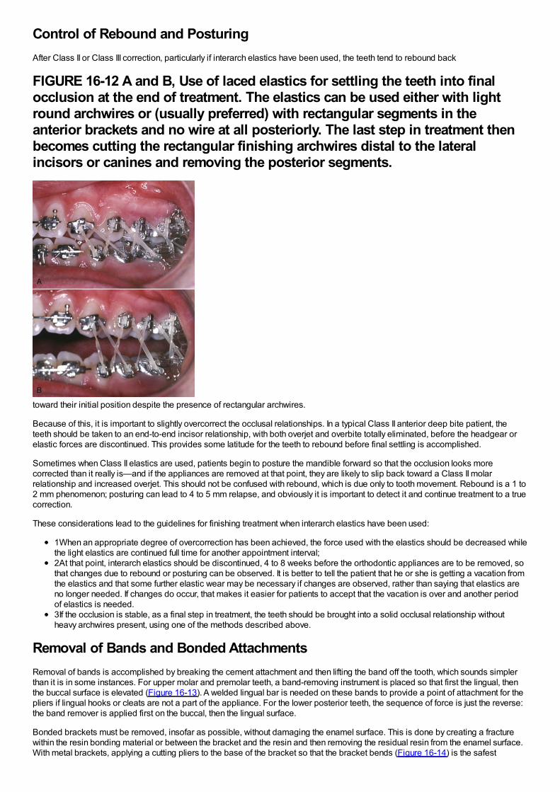
Control of Rebound and PosturingAfter Class II or Class III correction, particularly if interarch elastics have been used, the teeth tend to rebound back
FIGURE 16-12 A and B, Use of laced elastics for settling the teeth into finalocclusion at the end of treatment. The elastics can be used either with lightround archwires or (usually preferred) with rectangular segments in theanterior brackets and no wire at all posteriorly. The last step in treatment thenbecomes cutting the rectangular finishing archwires distal to the lateralincisors or canines and removing the posterior segments.
toward their initial position despite the presence of rectangular archwires.
Because of this, it is important to slightly overcorrect the occlusal relationships. In a typical Class II anterior deep bite patient, theteeth should be taken to an end-to-end incisor relationship, with both overjet and overbite totally eliminated, before the headgear orelastic forces are discontinued. This provides some latitude for the teeth to rebound before final settling is accomplished.
Sometimes when Class II elastics are used, patients begin to posture the mandible forward so that the occlusion looks morecorrected than it really is—and if the appliances are removed at that point, they are likely to slip back toward a Class II molarrelationship and increased overjet. This should not be confused with rebound, which is due only to tooth movement. Rebound is a 1 to2 mm phenomenon; posturing can lead to 4 to 5 mm relapse, and obviously it is important to detect it and continue treatment to a truecorrection.
These considerations lead to the guidelines for finishing treatment when interarch elastics have been used:
1When an appropriate degree of overcorrection has been achieved, the force used with the elastics should be decreased whilethe light elastics are continued full time for another appointment interval;2At that point, interarch elastics should be discontinued, 4 to 8 weeks before the orthodontic appliances are to be removed, sothat changes due to rebound or posturing can be observed. It is better to tell the patient that he or she is getting a vacation fromthe elastics and that some further elastic wear may be necessary if changes are observed, rather than saying that elastics areno longer needed. If changes do occur, that makes it easier for patients to accept that the vacation is over and another periodof elastics is needed.3If the occlusion is stable, as a final step in treatment, the teeth should be brought into a solid occlusal relationship withoutheavy archwires present, using one of the methods described above.
Removal of Bands and Bonded AttachmentsRemoval of bands is accomplished by breaking the cement attachment and then lifting the band off the tooth, which sounds simplerthan it is in some instances. For upper molar and premolar teeth, a band-removing instrument is placed so that first the lingual, thenthe buccal surface is elevated (Figure 16-13). A welded lingual bar is needed on these bands to provide a point of attachment for thepliers if lingual hooks or cleats are not a part of the appliance. For the lower posterior teeth, the sequence of force is just the reverse:the band remover is applied first on the buccal, then the lingual surface.
Bonded brackets must be removed, insofar as possible, without damaging the enamel surface. This is done by creating a fracturewithin the resin bonding material or between the bracket and the resin and then removing the residual resin from the enamel surface.With metal brackets, applying a cutting pliers to the base of the bracket so that the bracket bends (Figure 16-14) is the safest
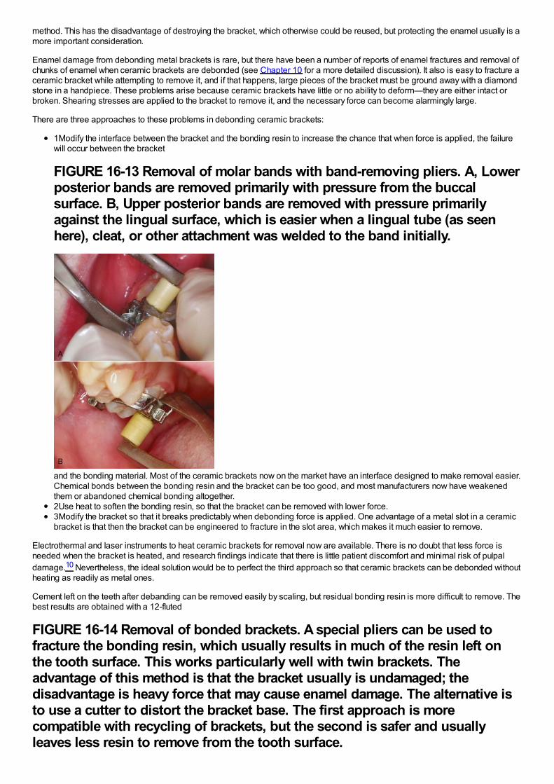
method. This has the disadvantage of destroying the bracket, which otherwise could be reused, but protecting the enamel usually is amore important consideration.
Enamel damage from debonding metal brackets is rare, but there have been a number of reports of enamel fractures and removal ofchunks of enamel when ceramic brackets are debonded (see Chapter 10 for a more detailed discussion). It also is easy to fracture aceramic bracket while attempting to remove it, and if that happens, large pieces of the bracket must be ground away with a diamondstone in a handpiece. These problems arise because ceramic brackets have little or no ability to deform—they are either intact orbroken. Shearing stresses are applied to the bracket to remove it, and the necessary force can become alarmingly large.
There are three approaches to these problems in debonding ceramic brackets:
1Modify the interface between the bracket and the bonding resin to increase the chance that when force is applied, the failurewill occur between the bracket
FIGURE 16-13 Removal of molar bands with band-removing pliers. A, Lowerposterior bands are removed primarily with pressure from the buccalsurface. B, Upper posterior bands are removed with pressure primarilyagainst the lingual surface, which is easier when a lingual tube (as seenhere), cleat, or other attachment was welded to the band initially.
and the bonding material. Most of the ceramic brackets now on the market have an interface designed to make removal easier.Chemical bonds between the bonding resin and the bracket can be too good, and most manufacturers now have weakenedthem or abandoned chemical bonding altogether.2Use heat to soften the bonding resin, so that the bracket can be removed with lower force.3Modify the bracket so that it breaks predictably when debonding force is applied. One advantage of a metal slot in a ceramicbracket is that then the bracket can be engineered to fracture in the slot area, which makes it much easier to remove.
Electrothermal and laser instruments to heat ceramic brackets for removal now are available. There is no doubt that less force isneeded when the bracket is heated, and research findings indicate that there is little patient discomfort and minimal risk of pulpaldamage.10 Nevertheless, the ideal solution would be to perfect the third approach so that ceramic brackets can be debonded withoutheating as readily as metal ones.
Cement left on the teeth after debanding can be removed easily by scaling, but residual bonding resin is more difficult to remove. Thebest results are obtained with a 12-fluted
FIGURE 16-14 Removal of bonded brackets. A special pliers can be used tofracture the bonding resin, which usually results in much of the resin left onthe tooth surface. This works particularly well with twin brackets. Theadvantage of this method is that the bracket usually is undamaged; thedisadvantage is heavy force that may cause enamel damage. The alternative isto use a cutter to distort the bracket base. The first approach is morecompatible with recycling of brackets, but the second is safer and usuallyleaves less resin to remove from the tooth surface.
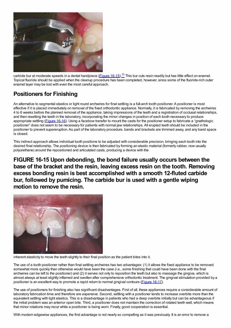
carbide bur at moderate speeds in a dental handpiece (Figure 16-15).11 This bur cuts resin readily but has little effect on enamel.Topical fluoride should be applied when the cleanup procedure has been completed, however, since some of the fluoride-rich outerenamel layer may be lost with even the most careful approach.
Positioners for FinishingAn alternative to segmental elastics or light round archwires for final settling is a full-arch tooth positioner. A positioner is mosteffective if it is placed immediately on removal of the fixed orthodontic appliance. Normally, it is fabricated by removing the archwires4 to 6 weeks before the planned removal of the appliance, taking impressions of the teeth and a registration of occlusal relationships,and then resetting the teeth in the laboratory, incorporating the minor changes in position of each tooth necessary to produceappropriate settling (Figure 16-16). Using a facebow transfer to mount the casts for the positioner setup to fabricate a “gnathologicpositioner” does not seem to be necessary for patients with normal jaw relationships. All erupted teeth should be included in thepositioner to prevent supereruption. As part of the laboratory procedure, bands and brackets are trimmed away, and any band spaceis closed.
This indirect approach allows individual tooth positions to be adjusted with considerable precision, bringing each tooth into thedesired final relationship. The positioning device is then fabricated by forming an elastic material (formerly rubber, now usuallypolyurethane) around the repositioned and articulated casts, producing a device with the
FIGURE 16-15 Upon debonding, the bond failure usually occurs between thebase of the bracket and the resin, leaving excess resin on the tooth. Removingexcess bonding resin is best accomplished with a smooth 12-fluted carbidebur, followed by pumicing. The carbide bur is used with a gentle wipingmotion to remove the resin.
inherent elasticity to move the teeth slightly to their final position as the patient bites into it.
The use of a tooth positioner rather than final settling archwires has two advantages: (1) it allows the fixed appliance to be removedsomewhat more quickly than otherwise would have been the case (i.e., some finishing that could have been done with the finalarchwires can be left to the positioner) and (2) it serves not only to reposition the teeth but also to massage the gingiva, which isalmost always at least slightly inflamed and swollen after comprehensive orthodontic treatment. The gingival stimulation provided by apositioner is an excellent way to promote a rapid return to normal gingival contours (Figure 16-17).
The use of positioners for finishing also has significant disadvantages. First of all, these appliances require a considerable amount oflaboratory fabrication time and therefore are expensive. Second, settling with a positioner tends to increase overbite more than theequivalent settling with light elastics. This is a disadvantage in patients who had a deep overbite initially but can be advantageous ifthe initial problem was an anterior open bite. Third, a positioner does not maintain the correction of rotated teeth well, which meansthat minor rotations may recur while a positioner is being worn. Finally, good cooperation is essential.
With modern edgewise appliances, the first advantage is not nearly so compelling as it was previously. It is an error to remove a
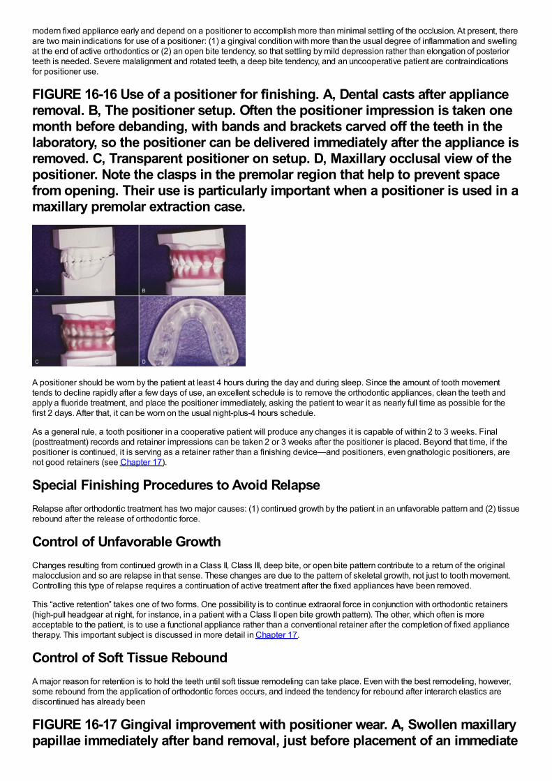
modern fixed appliance early and depend on a positioner to accomplish more than minimal settling of the occlusion. At present, thereare two main indications for use of a positioner: (1) a gingival condition with more than the usual degree of inflammation and swellingat the end of active orthodontics or (2) an open bite tendency, so that settling by mild depression rather than elongation of posteriorteeth is needed. Severe malalignment and rotated teeth, a deep bite tendency, and an uncooperative patient are contraindicationsfor positioner use.
FIGURE 16-16 Use of a positioner for finishing. A, Dental casts after applianceremoval. B, The positioner setup. Often the positioner impression is taken onemonth before debanding, with bands and brackets carved off the teeth in thelaboratory, so the positioner can be delivered immediately after the appliance isremoved. C, Transparent positioner on setup. D, Maxillary occlusal view of thepositioner. Note the clasps in the premolar region that help to prevent spacefrom opening. Their use is particularly important when a positioner is used in amaxillary premolar extraction case.
A positioner should be worn by the patient at least 4 hours during the day and during sleep. Since the amount of tooth movementtends to decline rapidly after a few days of use, an excellent schedule is to remove the orthodontic appliances, clean the teeth andapply a fluoride treatment, and place the positioner immediately, asking the patient to wear it as nearly full time as possible for thefirst 2 days. After that, it can be worn on the usual night-plus-4 hours schedule.
As a general rule, a tooth positioner in a cooperative patient will produce any changes it is capable of within 2 to 3 weeks. Final(posttreatment) records and retainer impressions can be taken 2 or 3 weeks after the positioner is placed. Beyond that time, if thepositioner is continued, it is serving as a retainer rather than a finishing device—and positioners, even gnathologic positioners, arenot good retainers (see Chapter 17).
Special Finishing Procedures to Avoid RelapseRelapse after orthodontic treatment has two major causes: (1) continued growth by the patient in an unfavorable pattern and (2) tissuerebound after the release of orthodontic force.
Control of Unfavorable GrowthChanges resulting from continued growth in a Class II, Class III, deep bite, or open bite pattern contribute to a return of the originalmalocclusion and so are relapse in that sense. These changes are due to the pattern of skeletal growth, not just to tooth movement.Controlling this type of relapse requires a continuation of active treatment after the fixed appliances have been removed.
This “active retention” takes one of two forms. One possibility is to continue extraoral force in conjunction with orthodontic retainers(high-pull headgear at night, for instance, in a patient with a Class II open bite growth pattern). The other, which often is moreacceptable to the patient, is to use a functional appliance rather than a conventional retainer after the completion of fixed appliancetherapy. This important subject is discussed in more detail in Chapter 17.
Control of Soft Tissue ReboundA major reason for retention is to hold the teeth until soft tissue remodeling can take place. Even with the best remodeling, however,some rebound from the application of orthodontic forces occurs, and indeed the tendency for rebound after interarch elastics arediscontinued has already been
FIGURE 16-17 Gingival improvement with positioner wear. A, Swollen maxillarypapillae immediately after band removal, just before placement of an immediate
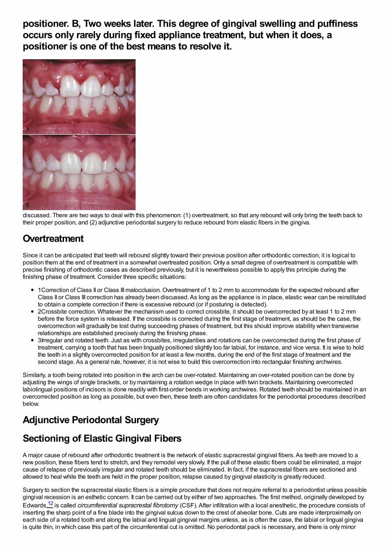
positioner. B, Two weeks later. This degree of gingival swelling and puffinessoccurs only rarely during fixed appliance treatment, but when it does, apositioner is one of the best means to resolve it.
discussed. There are two ways to deal with this phenomenon: (1) overtreatment, so that any rebound will only bring the teeth back totheir proper position, and (2) adjunctive periodontal surgery to reduce rebound from elastic fibers in the gingiva.
OvertreatmentSince it can be anticipated that teeth will rebound slightly toward their previous position after orthodontic correction, it is logical toposition them at the end of treatment in a somewhat overtreated position. Only a small degree of overtreatment is compatible withprecise finishing of orthodontic cases as described previously, but it is nevertheless possible to apply this principle during thefinishing phase of treatment. Consider three specific situations:
1Correction of Class II or Class III malocclusion. Overtreatment of 1 to 2 mm to accommodate for the expected rebound afterClass II or Class III correction has already been discussed. As long as the appliance is in place, elastic wear can be reinstitutedto obtain a complete correction if there is excessive rebound (or if posturing is detected).2Crossbite correction. Whatever the mechanism used to correct crossbite, it should be overcorrected by at least 1 to 2 mmbefore the force system is released. If the crossbite is corrected during the first stage of treatment, as should be the case, theovercorrection will gradually be lost during succeeding phases of treatment, but this should improve stability when transverserelationships are established precisely during the finishing phase.3Irregular and rotated teeth. Just as with crossbites, irregularities and rotations can be overcorrected during the first phase oftreatment, carrying a tooth that has been lingually positioned slightly too far labial, for instance, and vice versa. It is wise to holdthe teeth in a slightly overcorrected position for at least a few months, during the end of the first stage of treatment and thesecond stage. As a general rule, however, it is not wise to build this overcorrection into rectangular finishing archwires.
Similarly, a tooth being rotated into position in the arch can be over-rotated. Maintaining an over-rotated position can be done byadjusting the wings of single brackets, or by maintaining a rotation wedge in place with twin brackets. Maintaining overcorrectedlabiolingual positions of incisors is done readily with first-order bends in working archwires. Rotated teeth should be maintained in anovercorrected position as long as possible, but even then, these teeth are often candidates for the periodontal procedures describedbelow.
Adjunctive Periodontal Surgery
Sectioning of Elastic Gingival FibersA major cause of rebound after orthodontic treatment is the network of elastic supracrestal gingival fibers. As teeth are moved to anew position, these fibers tend to stretch, and they remodel very slowly. If the pull of these elastic fibers could be eliminated, a majorcause of relapse of previously irregular and rotated teeth should be eliminated. In fact, if the supracrestal fibers are sectioned andallowed to heal while the teeth are held in the proper position, relapse caused by gingival elasticity is greatly reduced.
Surgery to section the supracrestal elastic fibers is a simple procedure that does not require referral to a periodontist unless possiblegingival recession is an esthetic concern. It can be carried out by either of two approaches. The first method, originally developed byEdwards,12 is called circumferential supracrestal fibrotomy (CSF). After infiltration with a local anesthetic, the procedure consists ofinserting the sharp point of a fine blade into the gingival sulcus down to the crest of alveolar bone. Cuts are made interproximally oneach side of a rotated tooth and along the labial and lingual gingival margins unless, as is often the case, the labial or lingual gingivais quite thin, in which case this part of the circumferential cut is omitted. No periodontal pack is necessary, and there is only minor
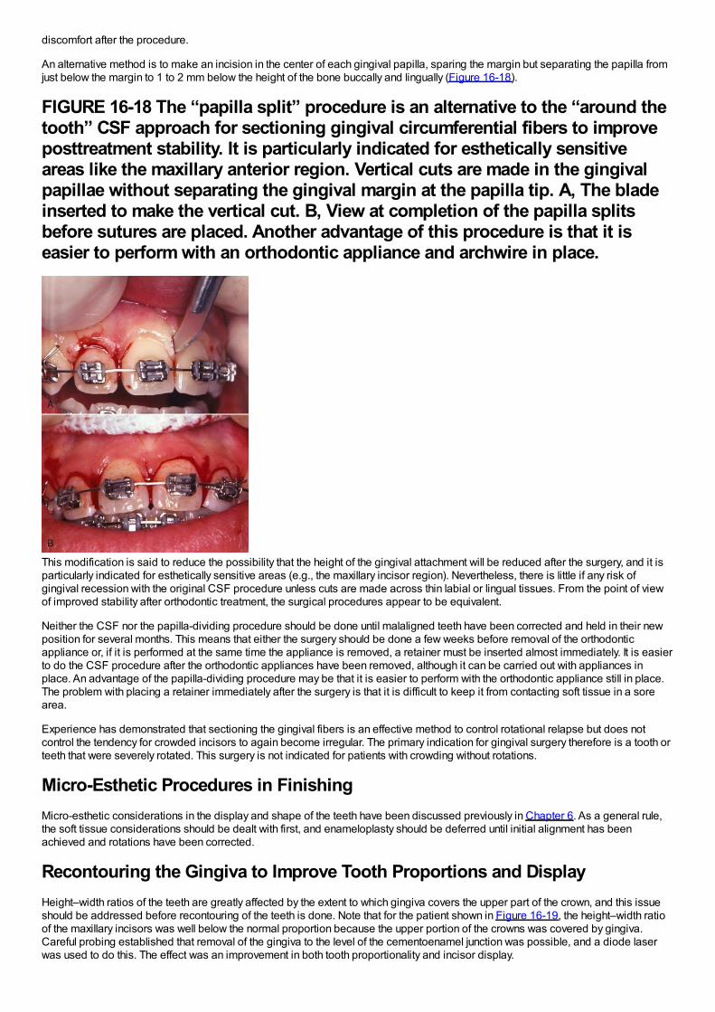
discomfort after the procedure.
An alternative method is to make an incision in the center of each gingival papilla, sparing the margin but separating the papilla fromjust below the margin to 1 to 2 mm below the height of the bone buccally and lingually (Figure 16-18).
FIGURE 16-18 The “papilla split” procedure is an alternative to the “around thetooth” CSF approach for sectioning gingival circumferential fibers to improveposttreatment stability. It is particularly indicated for esthetically sensitiveareas like the maxillary anterior region. Vertical cuts are made in the gingivalpapillae without separating the gingival margin at the papilla tip. A, The bladeinserted to make the vertical cut. B, View at completion of the papilla splitsbefore sutures are placed. Another advantage of this procedure is that it iseasier to perform with an orthodontic appliance and archwire in place.
This modification is said to reduce the possibility that the height of the gingival attachment will be reduced after the surgery, and it isparticularly indicated for esthetically sensitive areas (e.g., the maxillary incisor region). Nevertheless, there is little if any risk ofgingival recession with the original CSF procedure unless cuts are made across thin labial or lingual tissues. From the point of viewof improved stability after orthodontic treatment, the surgical procedures appear to be equivalent.
Neither the CSF nor the papilla-dividing procedure should be done until malaligned teeth have been corrected and held in their newposition for several months. This means that either the surgery should be done a few weeks before removal of the orthodonticappliance or, if it is performed at the same time the appliance is removed, a retainer must be inserted almost immediately. It is easierto do the CSF procedure after the orthodontic appliances have been removed, although it can be carried out with appliances inplace. An advantage of the papilla-dividing procedure may be that it is easier to perform with the orthodontic appliance still in place.The problem with placing a retainer immediately after the surgery is that it is difficult to keep it from contacting soft tissue in a sorearea.
Experience has demonstrated that sectioning the gingival fibers is an effective method to control rotational relapse but does notcontrol the tendency for crowded incisors to again become irregular. The primary indication for gingival surgery therefore is a tooth orteeth that were severely rotated. This surgery is not indicated for patients with crowding without rotations.
Micro-Esthetic Procedures in FinishingMicro-esthetic considerations in the display and shape of the teeth have been discussed previously in Chapter 6. As a general rule,the soft tissue considerations should be dealt with first, and enameloplasty should be deferred until initial alignment has beenachieved and rotations have been corrected.
Recontouring the Gingiva to Improve Tooth Proportions and DisplayHeight–width ratios of the teeth are greatly affected by the extent to which gingiva covers the upper part of the crown, and this issueshould be addressed before recontouring of the teeth is done. Note that for the patient shown in Figure 16-19, the height–width ratioof the maxillary incisors was well below the normal proportion because the upper portion of the crowns was covered by gingiva.Careful probing established that removal of the gingiva to the level of the cementoenamel junction was possible, and a diode laserwas used to do this. The effect was an improvement in both tooth proportionality and incisor display.
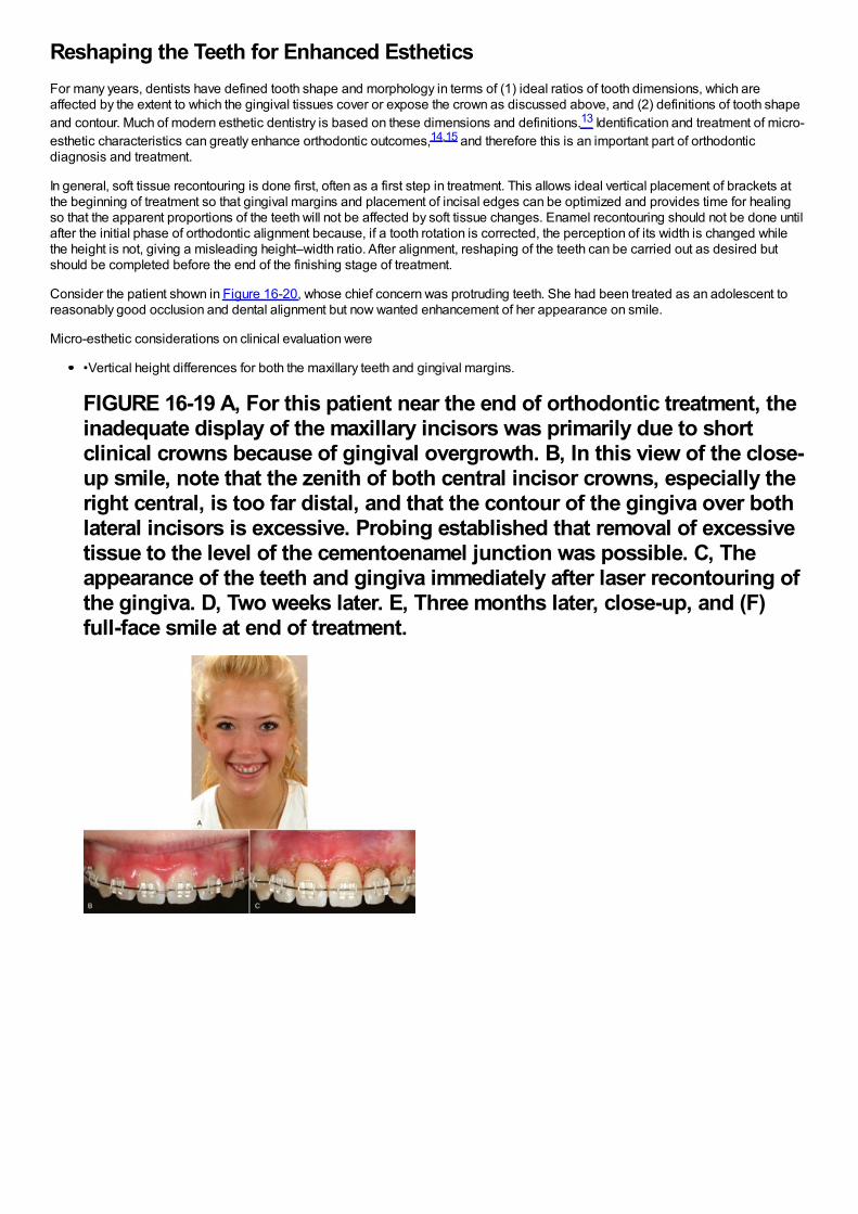
Reshaping the Teeth for Enhanced EstheticsFor many years, dentists have defined tooth shape and morphology in terms of (1) ideal ratios of tooth dimensions, which areaffected by the extent to which the gingival tissues cover or expose the crown as discussed above, and (2) definitions of tooth shapeand contour. Much of modern esthetic dentistry is based on these dimensions and definitions.13 Identification and treatment of micro-esthetic characteristics can greatly enhance orthodontic outcomes,14,15 and therefore this is an important part of orthodonticdiagnosis and treatment.
In general, soft tissue recontouring is done first, often as a first step in treatment. This allows ideal vertical placement of brackets atthe beginning of treatment so that gingival margins and placement of incisal edges can be optimized and provides time for healingso that the apparent proportions of the teeth will not be affected by soft tissue changes. Enamel recontouring should not be done untilafter the initial phase of orthodontic alignment because, if a tooth rotation is corrected, the perception of its width is changed whilethe height is not, giving a misleading height–width ratio. After alignment, reshaping of the teeth can be carried out as desired butshould be completed before the end of the finishing stage of treatment.
Consider the patient shown in Figure 16-20, whose chief concern was protruding teeth. She had been treated as an adolescent toreasonably good occlusion and dental alignment but now wanted enhancement of her appearance on smile.
Micro-esthetic considerations on clinical evaluation were
•Vertical height differences for both the maxillary teeth and gingival margins.
FIGURE 16-19 A, For this patient near the end of orthodontic treatment, theinadequate display of the maxillary incisors was primarily due to shortclinical crowns because of gingival overgrowth. B, In this view of the close-up smile, note that the zenith of both central incisor crowns, especially theright central, is too far distal, and that the contour of the gingiva over bothlateral incisors is excessive. Probing established that removal of excessivetissue to the level of the cementoenamel junction was possible. C, Theappearance of the teeth and gingiva immediately after laser recontouring ofthe gingiva. D, Two weeks later. E, Three months later, close-up, and (F)full-face smile at end of treatment.
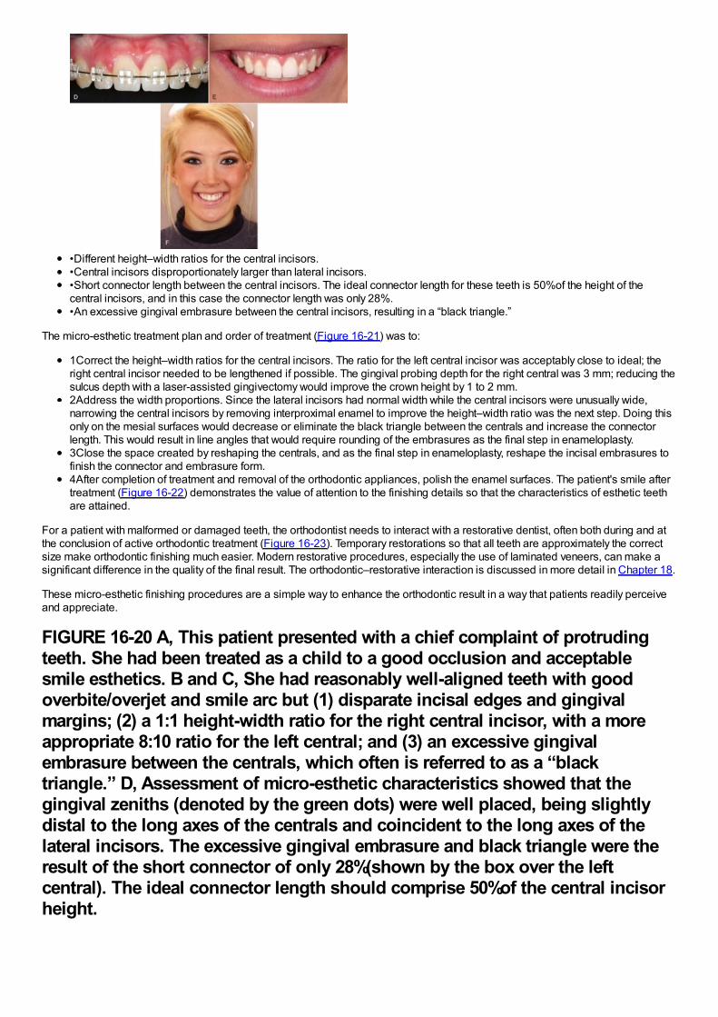
•Different height–width ratios for the central incisors.•Central incisors disproportionately larger than lateral incisors.•Short connector length between the central incisors. The ideal connector length for these teeth is 50%of the height of thecentral incisors, and in this case the connector length was only 28%.•An excessive gingival embrasure between the central incisors, resulting in a “black triangle.”
The micro-esthetic treatment plan and order of treatment (Figure 16-21) was to:
1Correct the height–width ratios for the central incisors. The ratio for the left central incisor was acceptably close to ideal; theright central incisor needed to be lengthened if possible. The gingival probing depth for the right central was 3 mm; reducing thesulcus depth with a laser-assisted gingivectomy would improve the crown height by 1 to 2 mm.2Address the width proportions. Since the lateral incisors had normal width while the central incisors were unusually wide,narrowing the central incisors by removing interproximal enamel to improve the height–width ratio was the next step. Doing thisonly on the mesial surfaces would decrease or eliminate the black triangle between the centrals and increase the connectorlength. This would result in line angles that would require rounding of the embrasures as the final step in enameloplasty.3Close the space created by reshaping the centrals, and as the final step in enameloplasty, reshape the incisal embrasures tofinish the connector and embrasure form.4After completion of treatment and removal of the orthodontic appliances, polish the enamel surfaces. The patient's smile aftertreatment (Figure 16-22) demonstrates the value of attention to the finishing details so that the characteristics of esthetic teethare attained.
For a patient with malformed or damaged teeth, the orthodontist needs to interact with a restorative dentist, often both during and atthe conclusion of active orthodontic treatment (Figure 16-23). Temporary restorations so that all teeth are approximately the correctsize make orthodontic finishing much easier. Modern restorative procedures, especially the use of laminated veneers, can make asignificant difference in the quality of the final result. The orthodontic–restorative interaction is discussed in more detail in Chapter 18.
These micro-esthetic finishing procedures are a simple way to enhance the orthodontic result in a way that patients readily perceiveand appreciate.
FIGURE 16-20 A, This patient presented with a chief complaint of protrudingteeth. She had been treated as a child to a good occlusion and acceptablesmile esthetics. B and C, She had reasonably well-aligned teeth with goodoverbite/overjet and smile arc but (1) disparate incisal edges and gingivalmargins; (2) a 1:1 height-width ratio for the right central incisor, with a moreappropriate 8:10 ratio for the left central; and (3) an excessive gingivalembrasure between the centrals, which often is referred to as a “blacktriangle.” D, Assessment of micro-esthetic characteristics showed that thegingival zeniths (denoted by the green dots) were well placed, being slightlydistal to the long axes of the centrals and coincident to the long axes of thelateral incisors. The excessive gingival embrasure and black triangle were theresult of the short connector of only 28%(shown by the box over the leftcentral). The ideal connector length should comprise 50%of the central incisorheight.
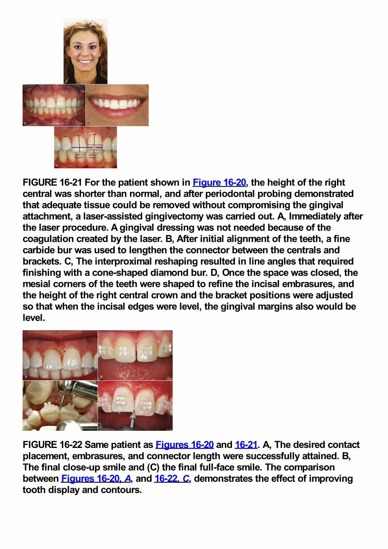
FIGURE 16-21 For the patient shown in Figure 16-20, the height of the rightcentral was shorter than normal, and after periodontal probing demonstratedthat adequate tissue could be removed without compromising the gingivalattachment, a laser-assisted gingivectomy was carried out. A, Immediately afterthe laser procedure. A gingival dressing was not needed because of thecoagulation created by the laser. B, After initial alignment of the teeth, a finecarbide bur was used to lengthen the connector between the centrals andbrackets. C, The interproximal reshaping resulted in line angles that requiredfinishing with a cone-shaped diamond bur. D, Once the space was closed, themesial corners of the teeth were shaped to refine the incisal embrasures, andthe height of the right central crown and the bracket positions were adjustedso that when the incisal edges were level, the gingival margins also would belevel.
FIGURE 16-22 Same patient as Figures 16-20 and 16-21. A, The desired contactplacement, embrasures, and connector length were successfully attained. B,The final close-up smile and (C) the final full-face smile. The comparisonbetween Figures 16-20, A, and 16-22, C, demonstrates the effect of improvingtooth display and contours.
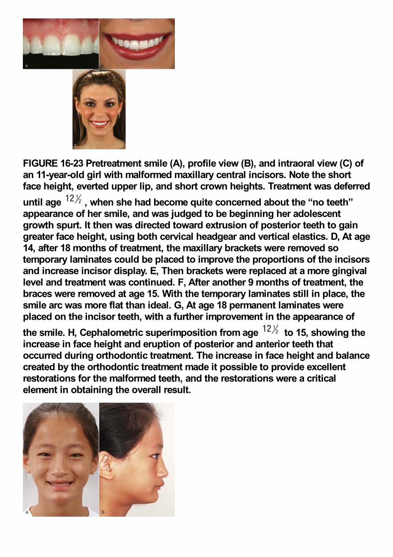
FIGURE 16-23 Pretreatment smile (A), profile view (B), and intraoral view (C) ofan 11-year-old girl with malformed maxillary central incisors. Note the shortface height, everted upper lip, and short crown heights. Treatment was deferreduntil age , when she had become quite concerned about the “no teeth”appearance of her smile, and was judged to be beginning her adolescentgrowth spurt. It then was directed toward extrusion of posterior teeth to gaingreater face height, using both cervical headgear and vertical elastics. D, At age14, after 18 months of treatment, the maxillary brackets were removed sotemporary laminates could be placed to improve the proportions of the incisorsand increase incisor display. E, Then brackets were replaced at a more gingivallevel and treatment was continued. F, After another 9 months of treatment, thebraces were removed at age 15. With the temporary laminates still in place, thesmile arc was more flat than ideal. G, At age 18 permanent laminates wereplaced on the incisor teeth, with a further improvement in the appearance ofthe smile. H, Cephalometric superimposition from age to 15, showing theincrease in face height and eruption of posterior and anterior teeth thatoccurred during orthodontic treatment. The increase in face height and balancecreated by the orthodontic treatment made it possible to provide excellentrestorations for the malformed teeth, and the restorations were a criticalelement in obtaining the overall result.
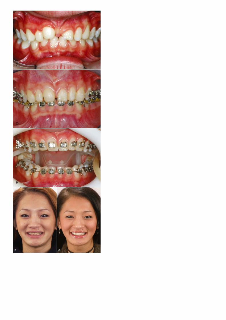
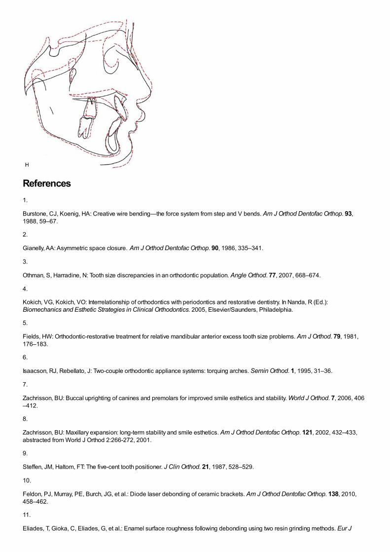
References1.
Burstone, CJ, Koenig, HA: Creative wire bending—the force system from step and V bends. Am J Orthod Dentofac Orthop. 93,1988, 59–67.
2.
Gianelly, AA: Asymmetric space closure. Am J Orthod Dentofac Orthop. 90, 1986, 335–341.
3.
Othman, S, Harradine, N: Tooth size discrepancies in an orthodontic population. Angle Orthod. 77, 2007, 668–674.
4.
Kokich, VG, Kokich, VO: Interrelationship of orthodontics with periodontics and restorative dentistry. In Nanda, R (Ed.):Biomechanics and Esthetic Strategies in Clinical Orthodontics. 2005, Elsevier/Saunders, Philadelphia.
5.
Fields, HW: Orthodontic-restorative treatment for relative mandibular anterior excess tooth size problems. Am J Orthod. 79, 1981,176–183.
6.
Isaacson, RJ, Rebellato, J: Two-couple orthodontic appliance systems: torquing arches. Semin Orthod. 1, 1995, 31–36.
7.
Zachrisson, BU: Buccal uprighting of canines and premolars for improved smile esthetics and stability. World J Orthod. 7, 2006, 406–412.
8.
Zachrisson, BU: Maxillary expansion: long-term stability and smile esthetics. Am J Orthod Dentofac Orthop. 121, 2002, 432–433,abstracted from World J Orthod 2:266-272, 2001.
9.
Steffen, JM, Haltom, FT: The five-cent tooth positioner. J Clin Orthod. 21, 1987, 528–529.
10.
Feldon, PJ, Murray, PE, Burch, JG, et al.: Diode laser debonding of ceramic brackets. Am J Orthod Dentofac Orthop. 138, 2010,458–462.
11.
Eliades, T, Gioka, C, Eliades, G, et al.: Enamel surface roughness following debonding using two resin grinding methods. Eur J

Orthod. 26, 2004, 333–338.
12.
Edwards, JG: A long-term prospective evaluation of the circumferential supracrestal fiberotomy in alleviating orthodontic relapse. AmJ Orthod Dentofac Orthop. 93, 1988, 380–387.
13.
Spear, FM, Kokich, VG, Mathews, DP: Interdisciplinary management of anterior dental esthetics. J Am Dent Assoc . 137, 2006, 160–169.
14.
Sarver, DM: Enameloplasty and esthetic finishing in orthodontics—Identification and treatment of microesthetic features inorthodontics. Part 1. J Esthet Restor Dent. 23, 2011, 296–302.
15.
Sarver, DM: Enameloplasty and esthetic finishing in orthodontics—Differential diagnosis of incisor proclination—The importance ofappropriate visualization and records. Part 2. J Esthet Restor Dent. 23, 2011, 303–313.
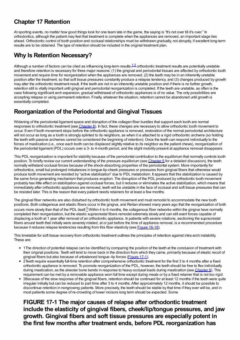
Chapter 17 RetentionAt sporting events, no matter how good things look for one team late in the game, the saying is “It's not over till it's over.” Inorthodontics, although the patient may feel that treatment is complete when the appliances are removed, an important stage liesahead. Orthodontic control of tooth position and occlusal relationships must be withdrawn gradually, not abruptly, if excellent long-termresults are to be obtained. The type of retention should be included in the original treatment plan.
Why Is Retention Necessary?Although a number of factors can be cited as influencing long-term results,1,2 orthodontic treatment results are potentially unstableand therefore retention is necessary for three major reasons: (1) the gingival and periodontal tissues are affected by orthodontic toothmovement and require time for reorganization when the appliances are removed, (2) the teeth may be in an inherently unstableposition after the treatment, so that soft tissue pressures constantly produce a relapse tendency, and (3) changes produced by growthmay alter the orthodontic treatment result. If the teeth are not in an inherently unstable position and if there is no further growth,retention still is vitally important until gingival and periodontal reorganization is completed. If the teeth are unstable, as often is thecase following significant arch expansion, gradual withdrawal of orthodontic appliances is of no value. The only possibilities areaccepting relapse or using permanent retention. Finally, whatever the situation, retention cannot be abandoned until growth isessentially completed.
Reorganization of the Periodontal and Gingival TissuesWidening of the periodontal ligament space and disruption of the collagen fiber bundles that support each tooth are normalresponses to orthodontic treatment (see Chapter 8). In fact, these changes are necessary to allow orthodontic tooth movement tooccur. Even if tooth movement stops before the orthodontic appliance is removed, restoration of the normal periodontal architecturewill not occur as long as a tooth is strongly splinted to its neighbors, as when it is attached to a rigid orthodontic archwire (so holdingthe teeth with passive archwires cannot be considered the beginning of retention). Once the teeth can respond individually to theforces of mastication (i.e., once each tooth can be displaced slightly relative to its neighbor as the patient chews), reorganization ofthe periodontal ligament (PDL) occurs over a 3- to 4-month period, and the slight mobility present at appliance removal disappears.
This PDL reorganization is important for stability because of the periodontal contribution to the equilibrium that normally controls toothposition. To briefly review our current understanding of the pressure equilibrium (see Chapter 5 for a detailed discussion), the teethnormally withstand occlusal forces because of the shock-absorbing properties of the periodontal system. More importantly fororthodontics, small but prolonged imbalances in tongue-lip-cheek pressures or pressures from gingival fibers that otherwise wouldproduce tooth movement are resisted by “active stabilization” due to PDL metabolism. It appears that this stabilization is caused bythe same force-generating mechanism that produces eruption. The disruption of the PDL produced by orthodontic tooth movementprobably has little effect on stabilization against occlusal forces, but it reduces or eliminates the active stabilization, which means thatimmediately after orthodontic appliances are removed, teeth will be unstable in the face of occlusal and soft tissue pressures that canbe resisted later. This is the reason that every patient needs retainers for at least a few months.
The gingival fiber networks are also disturbed by orthodontic tooth movement and must remodel to accommodate the new toothpositions. Both collagenous and elastic fibers occur in the gingiva, and Reitan showed many years ago that the reorganization of bothoccurs more slowly than that of the PDL itself.3 Within 4 to 6 months, the collagenous fiber networks within the gingiva have normallycompleted their reorganization, but the elastic supracrestal fibers remodel extremely slowly and can still exert forces capable ofdisplacing a tooth at 1 year after removal of an orthodontic appliance. In patients with severe rotations, sectioning the supracrestalfibers around teeth that initially were severely rotated, at or just before the time of appliance removal, is a recommended procedurebecause it reduces relapse tendencies resulting from this fiber elasticity (see Figure 16-18).
This timetable for soft tissue recovery from orthodontic treatment outlines the principles of retention against intra-arch instability.These are:
1The direction of potential relapse can be identified by comparing the position of the teeth at the conclusion of treatment withtheir original positions. Teeth will tend to move back in the direction from which they came, primarily because of elastic recoil ofgingival fibers but also because of unbalanced tongue–lip forces (Figure 17-1).2Teeth require essentially full-time retention after comprehensive orthodontic treatment for the first 3 to 4 months after a fixedorthodontic appliance is removed. To promote reorganization of the PDL, however, the teeth should be free to flex individuallyduring mastication, as the alveolar bone bends in response to heavy occlusal loads during mastication (see Chapter 8). Thisrequirement can be met by a removable appliance worn full time except during meals or by a fixed retainer that is not too rigid.3Because of the slow response of the gingival fibers, retention should be continued for at least 12 months if the teeth were quiteirregular initially but can be reduced to part time after 3 to 4 months. After approximately 12 months, it should be possible todiscontinue retention in nongrowing patients. More precisely, the teeth should be stable by that time if they ever will be, and inmost patients some degree of re-crowding of lower incisors long term should be expected. Some
FIGURE 17-1 The major causes of relapse after orthodontic treatmentinclude the elasticity of gingival fibers, cheek/lip/tongue pressures, and jawgrowth. Gingival fibers and soft tissue pressures are especially potent inthe first few months after treatment ends, before PDL reorganization has
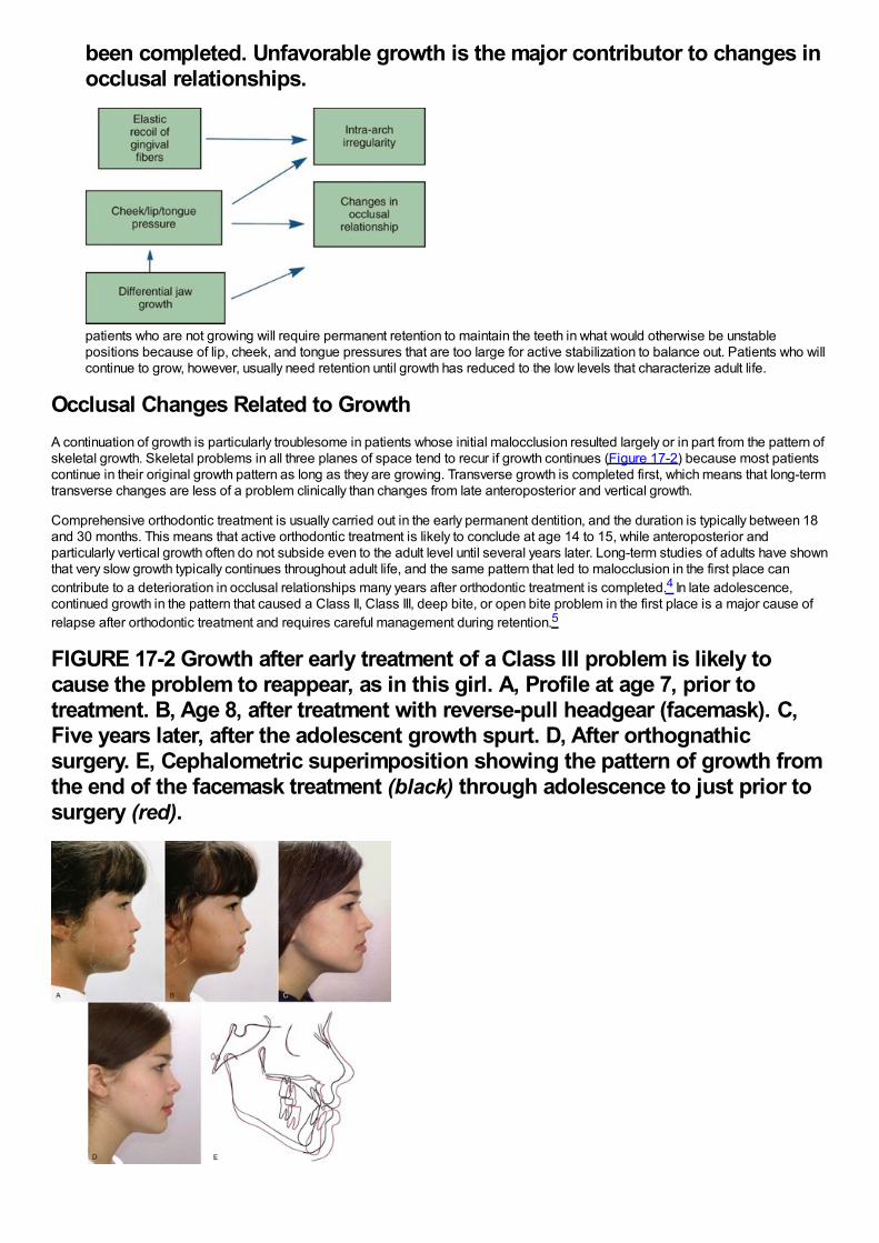
been completed. Unfavorable growth is the major contributor to changes inocclusal relationships.
patients who are not growing will require permanent retention to maintain the teeth in what would otherwise be unstablepositions because of lip, cheek, and tongue pressures that are too large for active stabilization to balance out. Patients who willcontinue to grow, however, usually need retention until growth has reduced to the low levels that characterize adult life.
Occlusal Changes Related to GrowthA continuation of growth is particularly troublesome in patients whose initial malocclusion resulted largely or in part from the pattern ofskeletal growth. Skeletal problems in all three planes of space tend to recur if growth continues (Figure 17-2) because most patientscontinue in their original growth pattern as long as they are growing. Transverse growth is completed first, which means that long-termtransverse changes are less of a problem clinically than changes from late anteroposterior and vertical growth.
Comprehensive orthodontic treatment is usually carried out in the early permanent dentition, and the duration is typically between 18and 30 months. This means that active orthodontic treatment is likely to conclude at age 14 to 15, while anteroposterior andparticularly vertical growth often do not subside even to the adult level until several years later. Long-term studies of adults have shownthat very slow growth typically continues throughout adult life, and the same pattern that led to malocclusion in the first place cancontribute to a deterioration in occlusal relationships many years after orthodontic treatment is completed.4 In late adolescence,continued growth in the pattern that caused a Class II, Class III, deep bite, or open bite problem in the first place is a major cause ofrelapse after orthodontic treatment and requires careful management during retention.5
FIGURE 17-2 Growth after early treatment of a Class III problem is likely tocause the problem to reappear, as in this girl. A, Profile at age 7, prior totreatment. B, Age 8, after treatment with reverse-pull headgear (facemask). C,Five years later, after the adolescent growth spurt. D, After orthognathicsurgery. E, Cephalometric superimposition showing the pattern of growth fromthe end of the facemask treatment (black) through adolescence to just prior tosurgery (red).
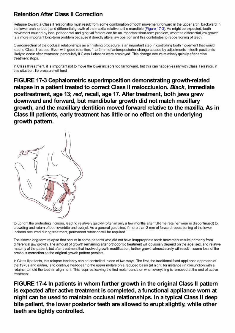
Retention After Class II CorrectionRelapse toward a Class II relationship must result from some combination of tooth movement (forward in the upper arch, backward inthe lower arch, or both) and differential growth of the maxilla relative to the mandible (Figure 17-3). As might be expected, toothmovement caused by local periodontal and gingival factors can be an important short-term problem, whereas differential jaw growthis a more important long-term problem because it directly alters jaw position and this contributes to repositioning of teeth.
Overcorrection of the occlusal relationships as a finishing procedure is an important step in controlling tooth movement that wouldlead to Class II relapse. Even with good retention, 1 to 2 mm of anteroposterior change caused by adjustments in tooth position islikely to occur after treatment, particularly if Class II elastics were employed. This change occurs relatively quickly after activetreatment stops.
In Class II treatment, it is important not to move the lower incisors too far forward, but this can happen easily with Class II elastics. Inthis situation, lip pressure will tend
FIGURE 17-3 Cephalometric superimposition demonstrating growth-relatedrelapse in a patient treated to correct Class II malocclusion. Black, Immediateposttreatment, age 13; red, recall, age 17. After treatment, both jaws grewdownward and forward, but mandibular growth did not match maxillarygrowth, and the maxillary dentition moved forward relative to the maxilla. As inClass III patients, early treatment has little or no effect on the underlyinggrowth pattern.
to upright the protruding incisors, leading relatively quickly (often in only a few months after full-time retainer wear is discontinued) tocrowding and return of both overbite and overjet. As a general guideline, if more than 2 mm of forward repositioning of the lowerincisors occurred during treatment, permanent retention will be required.
The slower long-term relapse that occurs in some patients who did not have inappropriate tooth movement results primarily fromdifferential jaw growth. The amount of growth remaining after orthodontic treatment will obviously depend on the age, sex, and relativematurity of the patient, but after treatment that involved growth modification, further growth almost surely will result in some loss of theprevious correction as the original growth pattern persists.
In Class II patients, this relapse tendency can be controlled in one of two ways. The first, the traditional fixed appliance approach ofthe 1970s and earlier, is to continue headgear to the upper molars on a reduced basis (at night, for instance) in conjunction with aretainer to hold the teeth in alignment. This requires leaving the first molar bands on when everything is removed at the end of activetreatment.
FIGURE 17-4 In patients in whom further growth in the original Class II patternis expected after active treatment is completed, a functional appliance worn atnight can be used to maintain occlusal relationships. In a typical Class II deepbite patient, the lower posterior teeth are allowed to erupt slightly, while otherteeth are tightly controlled.
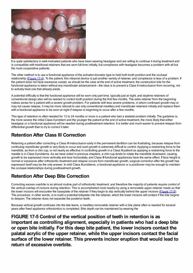
It is quite satisfactory in well-motivated patients who have been wearing headgear and are willing to continue it during treatment andis compatible with traditional retainers that are worn full time initially, but compliance with headgear becomes a problem with all butthe most cooperative patients.
The other method is to use a functional appliance of the activator-bionator type to hold both tooth position and the occlusalrelationship (Figure 17-4). To the patient, this intraoral device is just another variety of retainer, and compliance is less of a problem. Ifthe patient does not have excessive overjet, as should be the case at the end of active treatment, the construction bite for thefunctional appliance is taken without any mandibular advancement—the idea is to prevent a Class II malocclusion from recurring, notto actively treat one that already exists.
A potential difficulty is that the functional appliance will be worn only part time, typically just at night, and daytime retainers ofconventional design also will be needed to control tooth position during the first few months. The extra retainer from the beginningmakes sense for a patient with a severe growth problem. For patients with less severe problems, in whom continued growth may ormay not cause relapse, it may be more rational to use only conventional maxillary and mandibular retainers initially and replace themwith a functional appliance to be worn at night if relapse is beginning to occur after a few months.
This type of retention is often needed for 12 to 24 months or more in a patient who had a skeletal problem initially. The guideline is:the more severe the initial Class II problem and the younger the patient at the end of active treatment, the more likely that eitherheadgear or a functional appliance will be needed during posttreatment retention. It is better and much easier to prevent relapse fromdifferential growth than to try to correct it later.
Retention After Class III CorrectionRetaining a patient after correcting a Class III malocclusion early in the permanent dentition can be frustrating, because relapse fromcontinuing mandibular growth is very likely to occur and such growth is extremely difficult to control. Applying a restraining force to themandible, as from a chin cup, is not nearly as effective in controlling growth in a Class III patient as applying a restraining force to themaxilla is in Class II problems. As we have noted in previous chapters, a chin cup tends to rotate the mandible downward, causinggrowth to be expressed more vertically and less horizontally, and Class III functional appliances have the same effect. If face height isnormal or excessive after orthodontic treatment and relapse occurs from mandibular growth, surgical correction after the growth hasexpressed itself may be the only answer. In mild Class III problems, a functional appliance or a positioner may be enough to maintainthe occlusal relationships during posttreatment growth.
Retention After Deep Bite CorrectionCorrecting excess overbite is an almost routine part of orthodontic treatment, and therefore the majority of patients require control ofthe vertical overlap of incisors during retention. This is accomplished most readily by using a removable upper retainer made so thatthe lower incisors will encounter the baseplate of the retainer if they begin to slip vertically behind the upper incisors (Figure 17-5).The procedure, in other words, is to build a potential biteplate into the retainer, which the lower incisors will contact if the bite beginsto deepen. The retainer does not separate the posterior teeth.
Because vertical growth continues into the late teens, a maxillary removable retainer with a bite plane often is needed for severalyears after fixed appliance orthodontics is completed. Bite depth can be maintained by wearing the
FIGURE 17-5 Control of the vertical position of teeth in retention is asimportant as controlling alignment, especially in patients who had a deep biteor open bite initially. For this deep bite patient, the lower incisors contact thepalatal acrylic of the upper retainer, while the upper incisors contact the facialsurface of the lower retainer. This prevents incisor eruption that would lead toreturn of excessive overbite.
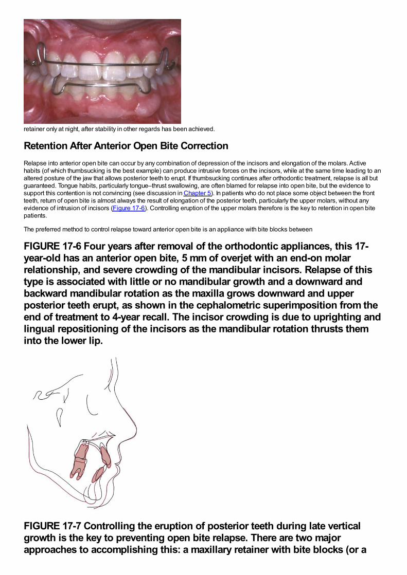
retainer only at night, after stability in other regards has been achieved.
Retention After Anterior Open Bite CorrectionRelapse into anterior open bite can occur by any combination of depression of the incisors and elongation of the molars. Activehabits (of which thumbsucking is the best example) can produce intrusive forces on the incisors, while at the same time leading to analtered posture of the jaw that allows posterior teeth to erupt. If thumbsucking continues after orthodontic treatment, relapse is all butguaranteed. Tongue habits, particularly tongue–thrust swallowing, are often blamed for relapse into open bite, but the evidence tosupport this contention is not convincing (see discussion in Chapter 5). In patients who do not place some object between the frontteeth, return of open bite is almost always the result of elongation of the posterior teeth, particularly the upper molars, without anyevidence of intrusion of incisors (Figure 17-6). Controlling eruption of the upper molars therefore is the key to retention in open bitepatients.
The preferred method to control relapse toward anterior open bite is an appliance with bite blocks between
FIGURE 17-6 Four years after removal of the orthodontic appliances, this 17-year-old has an anterior open bite, 5 mm of overjet with an end-on molarrelationship, and severe crowding of the mandibular incisors. Relapse of thistype is associated with little or no mandibular growth and a downward andbackward mandibular rotation as the maxilla grows downward and upperposterior teeth erupt, as shown in the cephalometric superimposition from theend of treatment to 4-year recall. The incisor crowding is due to uprighting andlingual repositioning of the incisors as the mandibular rotation thrusts theminto the lower lip.
FIGURE 17-7 Controlling the eruption of posterior teeth during late verticalgrowth is the key to preventing open bite relapse. There are two majorapproaches to accomplishing this: a maxillary retainer with bite blocks (or a
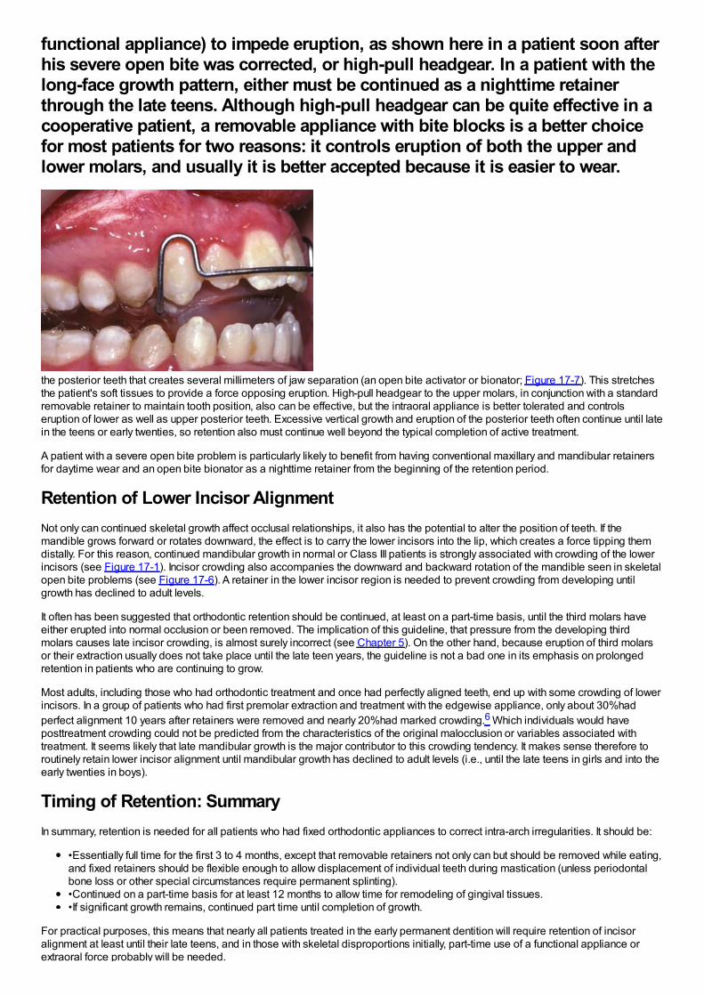
functional appliance) to impede eruption, as shown here in a patient soon afterhis severe open bite was corrected, or high-pull headgear. In a patient with thelong-face growth pattern, either must be continued as a nighttime retainerthrough the late teens. Although high-pull headgear can be quite effective in acooperative patient, a removable appliance with bite blocks is a better choicefor most patients for two reasons: it controls eruption of both the upper andlower molars, and usually it is better accepted because it is easier to wear.
the posterior teeth that creates several millimeters of jaw separation (an open bite activator or bionator; Figure 17-7). This stretchesthe patient's soft tissues to provide a force opposing eruption. High-pull headgear to the upper molars, in conjunction with a standardremovable retainer to maintain tooth position, also can be effective, but the intraoral appliance is better tolerated and controlseruption of lower as well as upper posterior teeth. Excessive vertical growth and eruption of the posterior teeth often continue until latein the teens or early twenties, so retention also must continue well beyond the typical completion of active treatment.
A patient with a severe open bite problem is particularly likely to benefit from having conventional maxillary and mandibular retainersfor daytime wear and an open bite bionator as a nighttime retainer from the beginning of the retention period.
Retention of Lower Incisor AlignmentNot only can continued skeletal growth affect occlusal relationships, it also has the potential to alter the position of teeth. If themandible grows forward or rotates downward, the effect is to carry the lower incisors into the lip, which creates a force tipping themdistally. For this reason, continued mandibular growth in normal or Class III patients is strongly associated with crowding of the lowerincisors (see Figure 17-1). Incisor crowding also accompanies the downward and backward rotation of the mandible seen in skeletalopen bite problems (see Figure 17-6). A retainer in the lower incisor region is needed to prevent crowding from developing untilgrowth has declined to adult levels.
It often has been suggested that orthodontic retention should be continued, at least on a part-time basis, until the third molars haveeither erupted into normal occlusion or been removed. The implication of this guideline, that pressure from the developing thirdmolars causes late incisor crowding, is almost surely incorrect (see Chapter 5). On the other hand, because eruption of third molarsor their extraction usually does not take place until the late teen years, the guideline is not a bad one in its emphasis on prolongedretention in patients who are continuing to grow.
Most adults, including those who had orthodontic treatment and once had perfectly aligned teeth, end up with some crowding of lowerincisors. In a group of patients who had first premolar extraction and treatment with the edgewise appliance, only about 30%hadperfect alignment 10 years after retainers were removed and nearly 20%had marked crowding.6 Which individuals would haveposttreatment crowding could not be predicted from the characteristics of the original malocclusion or variables associated withtreatment. It seems likely that late mandibular growth is the major contributor to this crowding tendency. It makes sense therefore toroutinely retain lower incisor alignment until mandibular growth has declined to adult levels (i.e., until the late teens in girls and into theearly twenties in boys).
Timing of Retention: SummaryIn summary, retention is needed for all patients who had fixed orthodontic appliances to correct intra-arch irregularities. It should be:
•Essentially full time for the first 3 to 4 months, except that removable retainers not only can but should be removed while eating,and fixed retainers should be flexible enough to allow displacement of individual teeth during mastication (unless periodontalbone loss or other special circumstances require permanent splinting).•Continued on a part-time basis for at least 12 months to allow time for remodeling of gingival tissues.•If significant growth remains, continued part time until completion of growth.
For practical purposes, this means that nearly all patients treated in the early permanent dentition will require retention of incisoralignment at least until their late teens, and in those with skeletal disproportions initially, part-time use of a functional appliance orextraoral force probably will be needed.
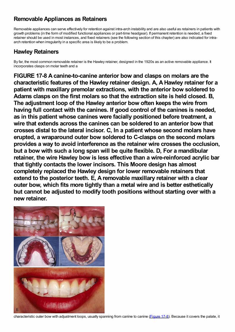
Removable Appliances as RetainersRemovable appliances can serve effectively for retention against intra-arch instability and are also useful as retainers in patients withgrowth problems (in the form of modified functional appliances or part-time headgear). If permanent retention is needed, a fixedretainer should be used in most instances, and fixed retainers (see the following section of this chapter) are also indicated for intra-arch retention when irregularity in a specific area is likely to be a problem.
Hawley RetainersBy far, the most common removable retainer is the Hawley retainer, designed in the 1920s as an active removable appliance. Itincorporates clasps on molar teeth and a
FIGURE 17-8 A canine-to-canine anterior bow and clasps on molars are thecharacteristic features of the Hawley retainer design. A, A Hawley retainer for apatient with maxillary premolar extractions, with the anterior bow soldered toAdams clasps on the first molars so that the extraction site is held closed. B,The adjustment loop of the Hawley anterior bow often keeps the wire fromhaving full contact with the canines. If good control of the canines is needed,as in this patient whose canines were facially positioned before treatment, awire that extends across the canines can be soldered to an anterior bow thatcrosses distal to the lateral incisor. C, In a patient whose second molars haveerupted, a wraparound outer bow soldered to C-clasps on the second molarsprovides a way to avoid interference as the retainer wire crosses the occlusion,but a bow with such a long span will be quite flexible. D, For a mandibularretainer, the wire Hawley bow is less effective than a wire-reinforced acrylic barthat tightly contacts the lower incisors. This Moore design has almostcompletely replaced the Hawley design for lower removable retainers thatextend to the posterior teeth. E, A removable maxillary retainer with a clearouter bow, which fits more tightly than a metal wire and is better estheticallybut cannot be adjusted to modify tooth positions without starting over with anew retainer.
characteristic outer bow with adjustment loops, usually spanning from canine to canine (Figure 17-8). Because it covers the palate, it
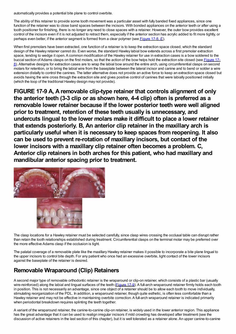
automatically provides a potential bite plane to control overbite.
The ability of this retainer to provide some tooth movement was a particular asset with fully banded fixed appliances, since onefunction of the retainer was to close band spaces between the incisors. With bonded appliances on the anterior teeth or after using atooth positioner for finishing, there is no longer any need to close spaces with a retainer. However, the outer bow provides excellentcontrol of the incisors even if it is not adjusted to retract them, especially if the anterior section has acrylic added to fit more tightly, orperhaps even better, if the anterior segment is formed from a clear polymer (see Figure 17-8, E).
When first premolars have been extracted, one function of a retainer is to keep the extraction space closed, which the standarddesign of the Hawley retainer cannot do. Even worse, the standard Hawley labial bow extends across a first premolar extractionspace, tending to wedge it open. A common modification of the Hawley retainer for use in extraction cases is a bow soldered to thebuccal section of Adams clasps on the first molars, so that the action of the bow helps hold the extraction site closed (see Figure 17-8). Alternative designs for extraction cases are to wrap the labial bow around the entire arch, using circumferential clasps on secondmolars for retention, or to bring the labial wire from the baseplate between the lateral incisor and canine and to bend or solder a wireextension distally to control the canines. The latter alternative does not provide an active force to keep an extraction space closed butavoids having the wire cross through the extraction site and gives positive control of canines that were labially positioned initially(which the loop of the traditional Hawley design may not provide).
FIGURE 17-9 A, A removable clip-type retainer that controls alignment of onlythe anterior teeth (3-3 clip or as shown here, 4-4 clip) often is preferred as aremovable lower retainer because if the lower posterior teeth were well alignedprior to treatment, retention of these teeth usually is unnecessary, andundercuts lingual to the lower molars make it difficult to place a lower retainerthat extends posteriorly. B, An anterior clip retainer in the maxillary arch isparticularly useful when it is necessary to keep spaces from reopening. It alsocan be used to prevent re-rotation of maxillary incisors, but contact of thelower incisors with a maxillary clip retainer often becomes a problem. C,Anterior clip retainers in both arches for this patient, who had maxillary andmandibular anterior spacing prior to treatment.
The clasp locations for a Hawley retainer must be selected carefully, since clasp wires crossing the occlusal table can disrupt ratherthan retain the tooth relationships established during treatment. Circumferential clasps on the terminal molar may be preferred overthe more effective Adams clasp if the occlusion is tight.
The palatal coverage of a removable plate like the maxillary Hawley retainer makes it possible to incorporate a bite plane lingual tothe upper incisors to control bite depth. For any patient who once had an excessive overbite, light contact of the lower incisorsagainst the baseplate of the retainer is desired.
Removable Wraparound (Clip) RetainersA second major type of removable orthodontic retainer is the wraparound or clip-on retainer, which consists of a plastic bar (usuallywire-reinforced) along the labial and lingual surfaces of the teeth (Figure 17-9). A full-arch wraparound retainer firmly holds each toothin position. This is not necessarily an advantage, since one object of a retainer should be to allow each tooth to move individually,stimulating reorganization of the PDL. In addition, a wraparound retainer, though quite esthetic, is often less comfortable than aHawley retainer and may not be effective in maintaining overbite correction. A full-arch wraparound retainer is indicated primarilywhen periodontal breakdown requires splinting the teeth together.
A variant of the wraparound retainer, the canine-to-canine clip-on retainer, is widely used in the lower anterior region. This appliancehas the great advantage that it can be used to realign irregular incisors if mild crowding has developed after treatment (see thediscussion of active retainers in the last section of this chapter), but it is well tolerated as a retainer alone. An upper canine-to-canine
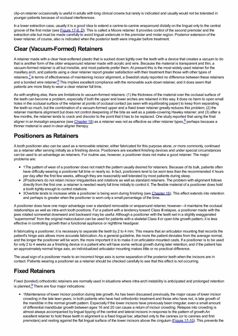
clip-on retainer occasionally is useful in adults with long clinical crowns but rarely is indicated and usually would not be tolerated inyounger patients because of occlusal interferences.
In a lower extraction case, usually it is a good idea to extend a canine-to-canine wraparound distally on the lingual only to the centralgroove of the first molar (see Figure 17-8, D). This is called a Moore retainer. It provides control of the second premolar and theextraction site but must be made carefully to avoid lingual undercuts in the premolar and molar region. Posterior extension of thelower retainer, of course, also is indicated when the posterior teeth were irregular before treatment.
Clear (Vacuum-Formed) RetainersA retainer made with a clear heat-softened plastic that is sucked down tightly over the teeth with a device that creates a vacuum to dothat is another form of the older wraparound retainer made with acrylic and wire. Because the material is transparent and thin, avacuum-formed retainer is all but invisible, and most patients prefer them. At present this is the most widely used retainer for themaxillary arch, and patients using a clear retainer report greater satisfaction with their treatment than those with other types ofretainers.7 In terms of effectiveness of maintaining incisor alignment, a Swedish study reported no difference between these retainersand a bonded wire retainer.6 This implies excellent compliance with the removable suck-down retainer, and it does seem thatpatients are more likely to wear a clear retainer full time.
As with anything else, there are limitations to vacuum-formed retainers: (1) the thickness of the material over the occlusal surface ofthe teeth can become a problem, especially if both the upper and lower arches are retained in this way. It does no harm to open smallholes in the occlusal surface of the retainer at points of occlusal contact (as seen with equilibrating paper) to keep from separatingthe teeth so much, but the combination of a vacuum-formed upper and a fixed lower retainer greatly reduces this problem; (2) theretainer maintains alignment but does not control deepening of the bite as well as a palate-covering Hawley retainer; and (3) after afew months, the retainer tends to crack and discolor to the point that it has to be replaced. One study reported that using the finalaligner in an Invisalign sequence (see Chapter 18) as a retainer was not as effective as other retainer types,8 perhaps because athinner material is used in clear-aligner therapy.
Positioners as RetainersA tooth positioner also can be used as a removable retainer, either fabricated for this purpose alone, or more commonly, continuedas a retainer after serving initially as a finishing device. Positioners are excellent finishing devices and under special circumstancescan be used to an advantage as retainers. For routine use, however, a positioner does not make a good retainer. The majorproblems are:
1The pattern of wear of a positioner does not match the pattern usually desired for retainers. Because of its bulk, patients oftenhave difficulty wearing a positioner full time or nearly so. In fact, positioners tend to be worn less than the recommended 4 hoursper day after the first few weeks, although they are reasonably well tolerated by most patients during sleep.2Positioners do not retain incisor irregularities and rotations as well as standard retainers. The problem with alignment followsdirectly from the first one: a retainer is needed nearly full time initially to control it. The flexible material of a positioner does holda tooth tightly enough to control rotations.3Overbite tends to increase while a positioner is being worn during finishing (see Chapter 16). This effect extends into retentionand perhaps is greater when the positioner is worn only a small percentage of the time.
A positioner does have one major advantage over a standard removable or wraparound retainer, however—it maintains the occlusalrelationships as well as intra-arch tooth positions. For a patient with a tendency toward Class III relapse, a positioner made with thejaws rotated somewhat downward and backward may be useful. Although a positioner with the teeth set in a slightly exaggerated“supernormal” from the original malocclusion can be used for patients with a skeletal Class II or open bite growth pattern, it is lesseffective in controlling growth than a functional appliance or nighttime headgear.
In fabricating a positioner, it is necessary to separate the teeth by 2 to 4 mm. This means that an articulator mounting that records thepatient's hinge axis allows more accurate fabrication. As a general guideline, the more the patient deviates from the average normal,and the longer the positioner will be worn, the more important it is to make it on articulator-mounted casts. If a positioner is to be usedfor only 2 to 4 weeks as a finishing device in a patient who will have some vertical growth during later retention, and if the patient hasan approximately normal hinge axis, an individualized articulator mounting makes little or no practical difference.
The usual sign of a positioner made to an incorrect hinge axis is some separation of the posterior teeth when the incisors are incontact. Patients wearing a positioner as a retainer should be checked carefully to see that this effect is not occurring.
Fixed RetainersFixed (bonded) orthodontic retainers are normally used in situations where intra-arch instability is anticipated and prolonged retentionis planned.9 There are four major indications:
1Maintenance of lower incisor position during late growth. As has been discussed previously, the major cause of lower incisorcrowding in the late teen years, in both patients who have had orthodontic treatment and those who have not, is late growth ofthe mandible in the normal growth pattern. Especially if the lower incisors have previously been irregular, even a small amountof differential mandibular growth between ages 16 and 20 can cause a return of incisor crowding. Relapse into crowding isalmost always accompanied by lingual tipping of the central and lateral incisors in response to the pattern of growth.Anexcellent retainer to hold these teeth in alignment is a fixed lingual bar, attached only to the canines (or to canines and firstpremolars) and resting against the flat lingual surface of the lower incisors above the cingulum (Figure 17-10). This prevents the
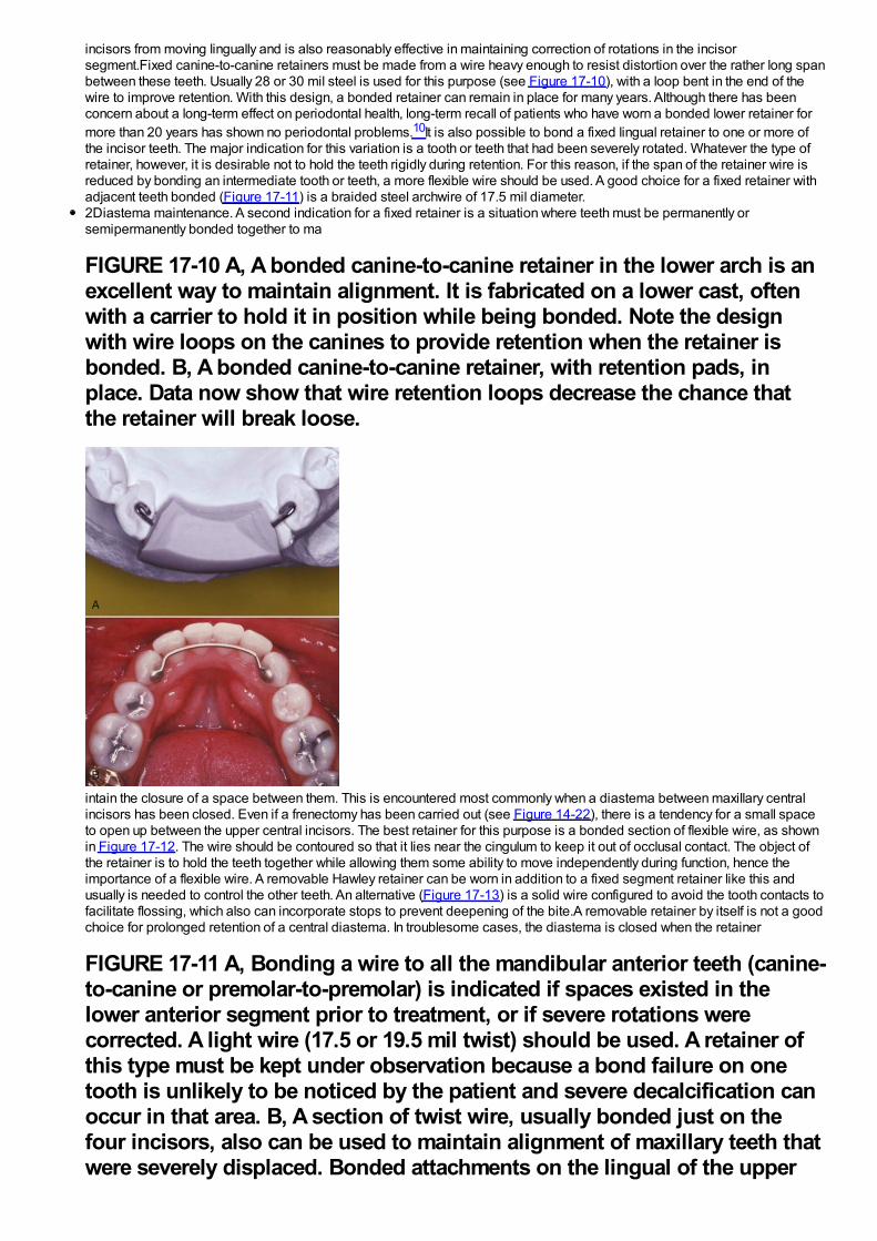
incisors from moving lingually and is also reasonably effective in maintaining correction of rotations in the incisorsegment.Fixed canine-to-canine retainers must be made from a wire heavy enough to resist distortion over the rather long spanbetween these teeth. Usually 28 or 30 mil steel is used for this purpose (see Figure 17-10), with a loop bent in the end of thewire to improve retention. With this design, a bonded retainer can remain in place for many years. Although there has beenconcern about a long-term effect on periodontal health, long-term recall of patients who have worn a bonded lower retainer formore than 20 years has shown no periodontal problems.10It is also possible to bond a fixed lingual retainer to one or more ofthe incisor teeth. The major indication for this variation is a tooth or teeth that had been severely rotated. Whatever the type ofretainer, however, it is desirable not to hold the teeth rigidly during retention. For this reason, if the span of the retainer wire isreduced by bonding an intermediate tooth or teeth, a more flexible wire should be used. A good choice for a fixed retainer withadjacent teeth bonded (Figure 17-11) is a braided steel archwire of 17.5 mil diameter.2Diastema maintenance. A second indication for a fixed retainer is a situation where teeth must be permanently orsemipermanently bonded together to ma
FIGURE 17-10 A, A bonded canine-to-canine retainer in the lower arch is anexcellent way to maintain alignment. It is fabricated on a lower cast, oftenwith a carrier to hold it in position while being bonded. Note the designwith wire loops on the canines to provide retention when the retainer isbonded. B, A bonded canine-to-canine retainer, with retention pads, inplace. Data now show that wire retention loops decrease the chance thatthe retainer will break loose.
intain the closure of a space between them. This is encountered most commonly when a diastema between maxillary centralincisors has been closed. Even if a frenectomy has been carried out (see Figure 14-22), there is a tendency for a small spaceto open up between the upper central incisors. The best retainer for this purpose is a bonded section of flexible wire, as shownin Figure 17-12. The wire should be contoured so that it lies near the cingulum to keep it out of occlusal contact. The object ofthe retainer is to hold the teeth together while allowing them some ability to move independently during function, hence theimportance of a flexible wire. A removable Hawley retainer can be worn in addition to a fixed segment retainer like this andusually is needed to control the other teeth. An alternative (Figure 17-13) is a solid wire configured to avoid the tooth contacts tofacilitate flossing, which also can incorporate stops to prevent deepening of the bite.A removable retainer by itself is not a goodchoice for prolonged retention of a central diastema. In troublesome cases, the diastema is closed when the retainer
FIGURE 17-11 A, Bonding a wire to all the mandibular anterior teeth (canine-to-canine or premolar-to-premolar) is indicated if spaces existed in thelower anterior segment prior to treatment, or if severe rotations werecorrected. A light wire (17.5 or 19.5 mil twist) should be used. A retainer ofthis type must be kept under observation because a bond failure on onetooth is unlikely to be noticed by the patient and severe decalcification canoccur in that area. B, A section of twist wire, usually bonded just on thefour incisors, also can be used to maintain alignment of maxillary teeth thatwere severely displaced. Bonded attachments on the lingual of the upper
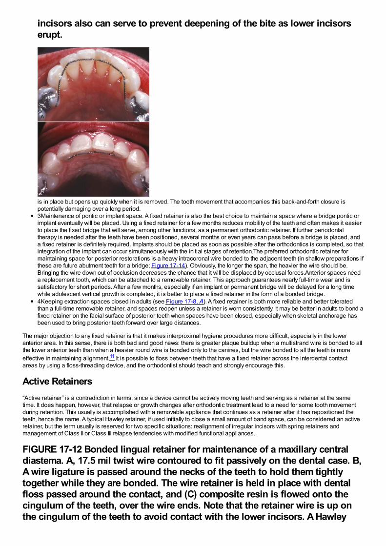
incisors also can serve to prevent deepening of the bite as lower incisorserupt.
is in place but opens up quickly when it is removed. The tooth movement that accompanies this back-and-forth closure ispotentially damaging over a long period.3Maintenance of pontic or implant space. A fixed retainer is also the best choice to maintain a space where a bridge pontic orimplant eventually will be placed. Using a fixed retainer for a few months reduces mobility of the teeth and often makes it easierto place the fixed bridge that will serve, among other functions, as a permanent orthodontic retainer. If further periodontaltherapy is needed after the teeth have been positioned, several months or even years can pass before a bridge is placed, anda fixed retainer is definitely required. Implants should be placed as soon as possible after the orthodontics is completed, so thatintegration of the implant can occur simultaneously with the initial stages of retention.The preferred orthodontic retainer formaintaining space for posterior restorations is a heavy intracoronal wire bonded to the adjacent teeth (in shallow preparations ifthese are future abutment teeth for a bridge; Figure 17-14). Obviously, the longer the span, the heavier the wire should be.Bringing the wire down out of occlusion decreases the chance that it will be displaced by occlusal forces.Anterior spaces needa replacement tooth, which can be attached to a removable retainer. This approach guarantees nearly full-time wear and issatisfactory for short periods. After a few months, especially if an implant or permanent bridge will be delayed for a long timewhile adolescent vertical growth is completed, it is better to place a fixed retainer in the form of a bonded bridge.4Keeping extraction spaces closed in adults (see Figure 17-8, A). A fixed retainer is both more reliable and better toleratedthan a full-time removable retainer, and spaces reopen unless a retainer is worn consistently. It may be better in adults to bond afixed retainer on the facial surface of posterior teeth when spaces have been closed, especially when skeletal anchorage hasbeen used to bring posterior teeth forward over large distances.
The major objection to any fixed retainer is that it makes interproximal hygiene procedures more difficult, especially in the loweranterior area. In this sense, there is both bad and good news: there is greater plaque buildup when a multistrand wire is bonded to allthe lower anterior teeth than when a heavier round wire is bonded only to the canines, but the wire bonded to all the teeth is moreeffective in maintaining alignment.11 It is possible to floss between teeth that have a fixed retainer across the interdental contactareas by using a floss-threading device, and the orthodontist should teach and strongly encourage this.
Active Retainers“Active retainer” is a contradiction in terms, since a device cannot be actively moving teeth and serving as a retainer at the sametime. It does happen, however, that relapse or growth changes after orthodontic treatment lead to a need for some tooth movementduring retention. This usually is accomplished with a removable appliance that continues as a retainer after it has repositioned theteeth, hence the name. A typical Hawley retainer, if used initially to close a small amount of band space, can be considered an activeretainer, but the term usually is reserved for two specific situations: realignment of irregular incisors with spring retainers andmanagement of Class II or Class III relapse tendencies with modified functional appliances.
FIGURE 17-12 Bonded lingual retainer for maintenance of a maxillary centraldiastema. A, 17.5 mil twist wire contoured to fit passively on the dental case. B,A wire ligature is passed around the necks of the teeth to hold them tightlytogether while they are bonded. The wire retainer is held in place with dentalfloss passed around the contact, and (C) composite resin is flowed onto thecingulum of the teeth, over the wire ends. Note that the retainer wire is up onthe cingulum of the teeth to avoid contact with the lower incisors. A Hawley
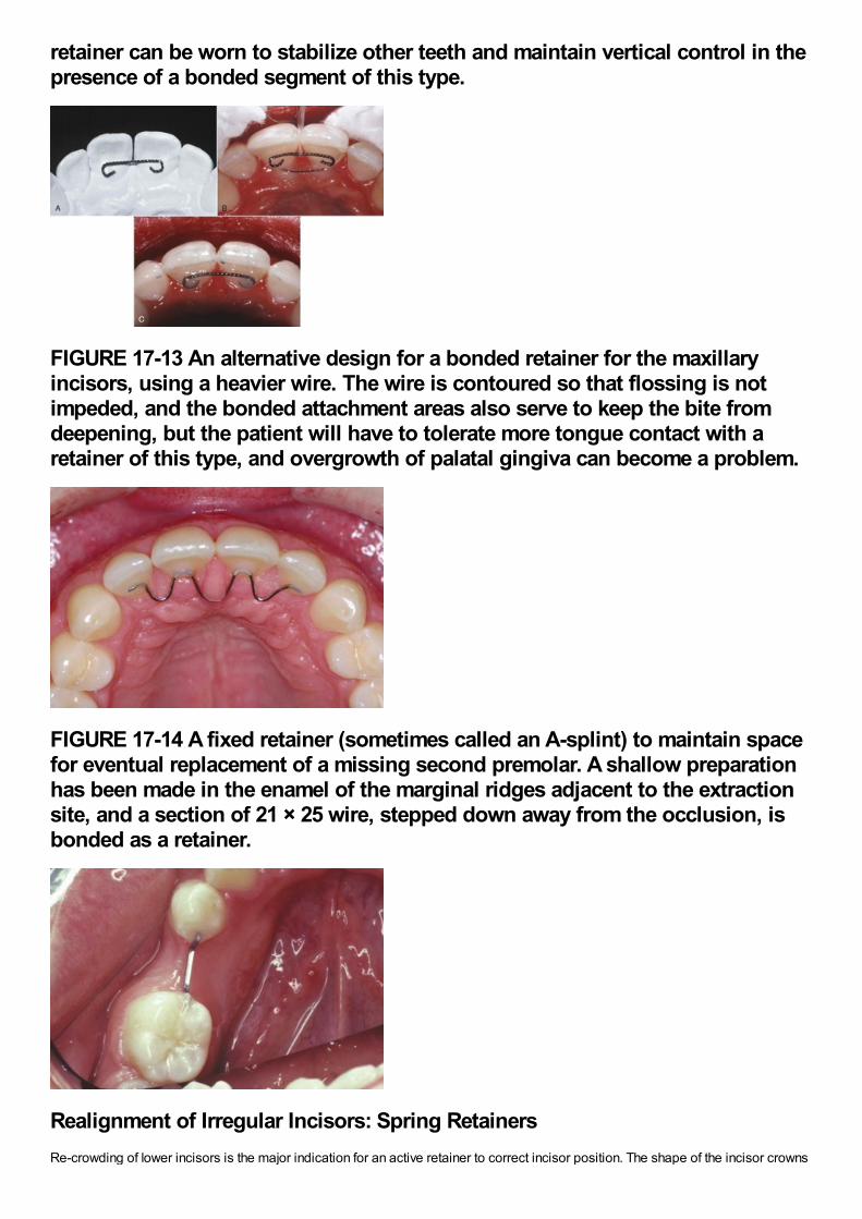
retainer can be worn to stabilize other teeth and maintain vertical control in thepresence of a bonded segment of this type.
FIGURE 17-13 An alternative design for a bonded retainer for the maxillaryincisors, using a heavier wire. The wire is contoured so that flossing is notimpeded, and the bonded attachment areas also serve to keep the bite fromdeepening, but the patient will have to tolerate more tongue contact with aretainer of this type, and overgrowth of palatal gingiva can become a problem.
FIGURE 17-14 A fixed retainer (sometimes called an A-splint) to maintain spacefor eventual replacement of a missing second premolar. A shallow preparationhas been made in the enamel of the marginal ridges adjacent to the extractionsite, and a section of 21 × 25 wire, stepped down away from the occlusion, isbonded as a retainer.
Realignment of Irregular Incisors: Spring RetainersRe-crowding of lower incisors is the major indication for an active retainer to correct incisor position. The shape of the incisor crowns
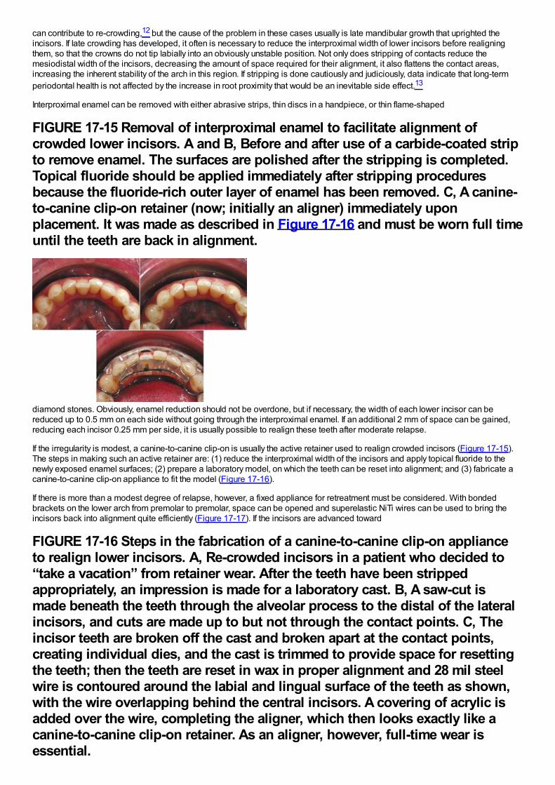
can contribute to re-crowding,12 but the cause of the problem in these cases usually is late mandibular growth that uprighted theincisors. If late crowding has developed, it often is necessary to reduce the interproximal width of lower incisors before realigningthem, so that the crowns do not tip labially into an obviously unstable position. Not only does stripping of contacts reduce themesiodistal width of the incisors, decreasing the amount of space required for their alignment, it also flattens the contact areas,increasing the inherent stability of the arch in this region. If stripping is done cautiously and judiciously, data indicate that long-termperiodontal health is not affected by the increase in root proximity that would be an inevitable side effect.13
Interproximal enamel can be removed with either abrasive strips, thin discs in a handpiece, or thin flame-shaped
FIGURE 17-15 Removal of interproximal enamel to facilitate alignment ofcrowded lower incisors. A and B, Before and after use of a carbide-coated stripto remove enamel. The surfaces are polished after the stripping is completed.Topical fluoride should be applied immediately after stripping proceduresbecause the fluoride-rich outer layer of enamel has been removed. C, A canine-to-canine clip-on retainer (now; initially an aligner) immediately uponplacement. It was made as described in Figure 17-16 and must be worn full timeuntil the teeth are back in alignment.
diamond stones. Obviously, enamel reduction should not be overdone, but if necessary, the width of each lower incisor can bereduced up to 0.5 mm on each side without going through the interproximal enamel. If an additional 2 mm of space can be gained,reducing each incisor 0.25 mm per side, it is usually possible to realign these teeth after moderate relapse.
If the irregularity is modest, a canine-to-canine clip-on is usually the active retainer used to realign crowded incisors (Figure 17-15).The steps in making such an active retainer are: (1) reduce the interproximal width of the incisors and apply topical fluoride to thenewly exposed enamel surfaces; (2) prepare a laboratory model, on which the teeth can be reset into alignment; and (3) fabricate acanine-to-canine clip-on appliance to fit the model (Figure 17-16).
If there is more than a modest degree of relapse, however, a fixed appliance for retreatment must be considered. With bondedbrackets on the lower arch from premolar to premolar, space can be opened and superelastic NiTi wires can be used to bring theincisors back into alignment quite efficiently (Figure 17-17). If the incisors are advanced toward
FIGURE 17-16 Steps in the fabrication of a canine-to-canine clip-on applianceto realign lower incisors. A, Re-crowded incisors in a patient who decided to“take a vacation” from retainer wear. After the teeth have been strippedappropriately, an impression is made for a laboratory cast. B, A saw-cut ismade beneath the teeth through the alveolar process to the distal of the lateralincisors, and cuts are made up to but not through the contact points. C, Theincisor teeth are broken off the cast and broken apart at the contact points,creating individual dies, and the cast is trimmed to provide space for resettingthe teeth; then the teeth are reset in wax in proper alignment and 28 mil steelwire is contoured around the labial and lingual surface of the teeth as shown,with the wire overlapping behind the central incisors. A covering of acrylic isadded over the wire, completing the aligner, which then looks exactly like acanine-to-canine clip-on retainer. As an aligner, however, full-time wear isessential.
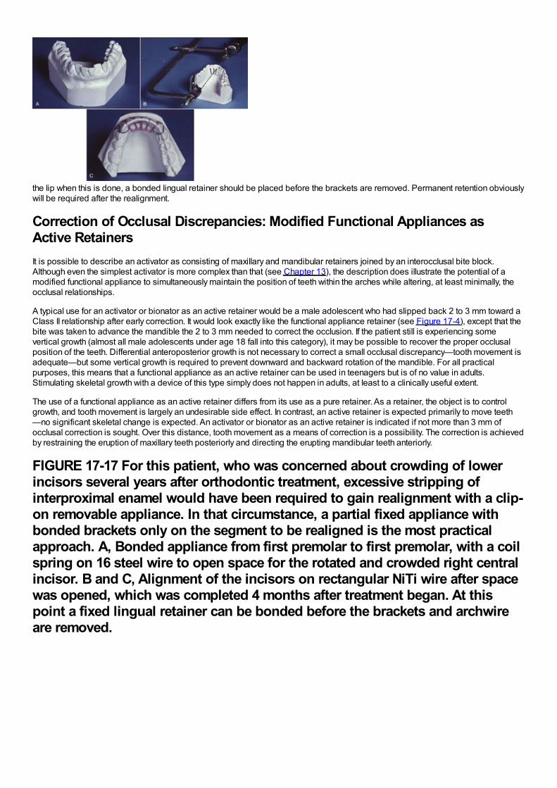
essential.
the lip when this is done, a bonded lingual retainer should be placed before the brackets are removed. Permanent retention obviouslywill be required after the realignment.
Correction of Occlusal Discrepancies: Modified Functional Appliances asActive RetainersIt is possible to describe an activator as consisting of maxillary and mandibular retainers joined by an interocclusal bite block.Although even the simplest activator is more complex than that (see Chapter 13), the description does illustrate the potential of amodified functional appliance to simultaneously maintain the position of teeth within the arches while altering, at least minimally, theocclusal relationships.
A typical use for an activator or bionator as an active retainer would be a male adolescent who had slipped back 2 to 3 mm toward aClass II relationship after early correction. It would look exactly like the functional appliance retainer (see Figure 17-4), except that thebite was taken to advance the mandible the 2 to 3 mm needed to correct the occlusion. If the patient still is experiencing somevertical growth (almost all male adolescents under age 18 fall into this category), it may be possible to recover the proper occlusalposition of the teeth. Differential anteroposterior growth is not necessary to correct a small occlusal discrepancy—tooth movement isadequate—but some vertical growth is required to prevent downward and backward rotation of the mandible. For all practicalpurposes, this means that a functional appliance as an active retainer can be used in teenagers but is of no value in adults.Stimulating skeletal growth with a device of this type simply does not happen in adults, at least to a clinically useful extent.
The use of a functional appliance as an active retainer differs from its use as a pure retainer. As a retainer, the object is to controlgrowth, and tooth movement is largely an undesirable side effect. In contrast, an active retainer is expected primarily to move teeth—no significant skeletal change is expected. An activator or bionator as an active retainer is indicated if not more than 3 mm ofocclusal correction is sought. Over this distance, tooth movement as a means of correction is a possibility. The correction is achievedby restraining the eruption of maxillary teeth posteriorly and directing the erupting mandibular teeth anteriorly.
FIGURE 17-17 For this patient, who was concerned about crowding of lowerincisors several years after orthodontic treatment, excessive stripping ofinterproximal enamel would have been required to gain realignment with a clip-on removable appliance. In that circumstance, a partial fixed appliance withbonded brackets only on the segment to be realigned is the most practicalapproach. A, Bonded appliance from first premolar to first premolar, with a coilspring on 16 steel wire to open space for the rotated and crowded right centralincisor. B and C, Alignment of the incisors on rectangular NiTi wire after spacewas opened, which was completed 4 months after treatment began. At thispoint a fixed lingual retainer can be bonded before the brackets and archwireare removed.
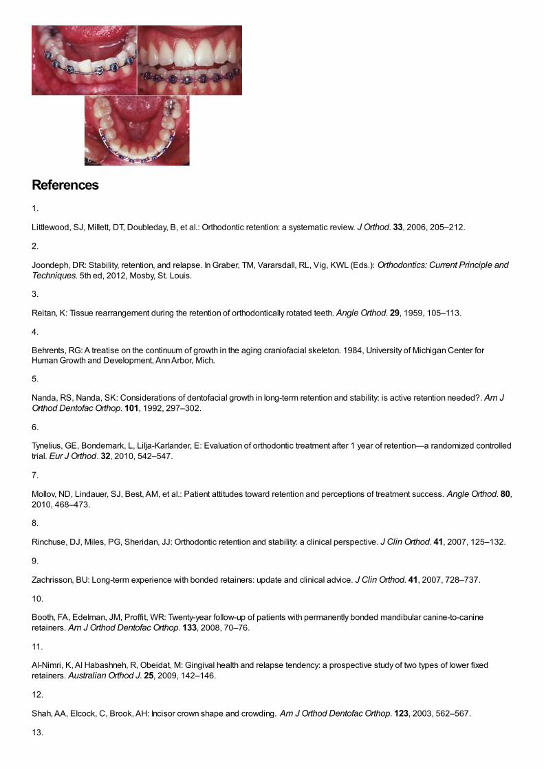
References1.
Littlewood, SJ, Millett, DT, Doubleday, B, et al.: Orthodontic retention: a systematic review. J Orthod. 33, 2006, 205–212.
2.
Joondeph, DR: Stability, retention, and relapse. In Graber, TM, Vararsdall, RL, Vig, KWL (Eds.): Orthodontics: Current Principle andTechniques. 5th ed, 2012, Mosby, St. Louis.
3.
Reitan, K: Tissue rearrangement during the retention of orthodontically rotated teeth. Angle Orthod. 29, 1959, 105–113.
4.
Behrents, RG: A treatise on the continuum of growth in the aging craniofacial skeleton. 1984, University of Michigan Center forHuman Growth and Development, Ann Arbor, Mich.
5.
Nanda, RS, Nanda, SK: Considerations of dentofacial growth in long-term retention and stability: is active retention needed?. Am JOrthod Dentofac Orthop. 101, 1992, 297–302.
6.
Tynelius, GE, Bondemark, L, Lilja-Karlander, E: Evaluation of orthodontic treatment after 1 year of retention—a randomized controlledtrial. Eur J Orthod. 32, 2010, 542–547.
7.
Mollov, ND, Lindauer, SJ, Best, AM, et al.: Patient attitudes toward retention and perceptions of treatment success. Angle Orthod. 80,2010, 468–473.
8.
Rinchuse, DJ, Miles, PG, Sheridan, JJ: Orthodontic retention and stability: a clinical perspective. J Clin Orthod. 41, 2007, 125–132.
9.
Zachrisson, BU: Long-term experience with bonded retainers: update and clinical advice. J Clin Orthod. 41, 2007, 728–737.
10.
Booth, FA, Edelman, JM, Proffit, WR: Twenty-year follow-up of patients with permanently bonded mandibular canine-to-canineretainers. Am J Orthod Dentofac Orthop. 133, 2008, 70–76.
11.
Al-Nimri, K, Al Habashneh, R, Obeidat, M: Gingival health and relapse tendency: a prospective study of two types of lower fixedretainers. Australian Orthod J. 25, 2009, 142–146.
12.
Shah, AA, Elcock, C, Brook, AH: Incisor crown shape and crowding. Am J Orthod Dentofac Orthop. 123, 2003, 562–567.
13.

Zachrisson, BU, Nyøygaard, L, Mobarak, K: Dental health assessed more than 10 years after interproximal enamel reduction ofmandibular anterior teeth. Am J Orthod Dentofac Orthop. 131, 2007, 162–169.
Treatment for AdultsAdult orthodontics has been the fastest-growing type of orthodontic treatment in recent years, going from a relative rarity as late asthe 1970s to a commonplace procedure today. In the United States, adults (those over age 18 at the start of treatment) now compriseabout 30%of all patients receiving comprehensive orthodontic treatment. A similar trend is occurring worldwide in orthodonticpractices, trailing behind the U.S. percentage in less-developed countries but increasing steadily everywhere. Adult orthodontics, atthis point, is a major component of orthodontic practice.
This does not mean that the treatment procedures can be the same as for adolescents or children. Perhaps the biggest difference isthat for adults, other types of dental treatment almost always are required, which makes interdisciplinary interaction and cooperationa necessity from the beginning. The prevalence of periodontal problems increases with age, and even young adults are likely torequire some level of periodontal care by either a generalist skilled in doing this or a periodontist. As adult patients become older,orthodontic treatment must be done in the context of a used dentition with worn teeth and restorative implications, not a new one aswith adolescents. The absence of growth in adults (or more accurately, the very small increments of continuing growth) means thatgrowth modification is not a treatment option—everything has to be done with either tooth movement, restorative dentistry, ororthognathic surgery. In a sense, planning orthodontic treatment for adults can be easier because there are no uncertainties related tothe amount and direction of growth, but treating adults requires a high level of technical skill, knowledge of other disciplines, and anunderstanding of biomechanics.
There are several other considerations that are particularly important in the treatment of adults:
1Treatment planning must involve all the dentists who will play a role in the treatment. It cannot be done by the orthodontist inisolation. With a group of practitioners, an important question is “Who is the conductor of this orchestra?” This, of course,depends on the details of treatment, but when replacement of teeth or extensive restorations are necessary, the planning almosthas to start with what the prosthodontist or restorative dentist wants as his or her starting point, and the extent to which thosedesires can be met.2Given that many specialties are usually involved in diagnosis, treatment decisions, and treatment delivery, it makes even moresense to start the treatment with the final result in mind. This can be accomplished with a diagnostic setup/waxup that can beused as a diagnostic and communication tool among the treatment team and between them and the patient.3Ideal dental occlusion and facial appearance are not necessarily an appropriate treatment goal, even for adults who will havecomprehensive treatment involving a complete fixed appliance and specialty care. There is a difference between realistictreatment that is focused on the patient's problems and ideal treatment aimed at perfection. This has to be evaluated in thecontext of cost and risk versus benefit to the patient from various treatment procedures, so discussion of treatment options andgenuinely informed consent are very important.4Adults react to being orthodontic patients differently from children and adolescents in two ways: almost always they areintensely interested in their treatment and want to understand what is happening and why—so they require more clinical time inexplanations and either they experience more pain than younger patients or they are less tolerant of it—so medication for paincontrol is more important for them.5Disease control is essential before orthodontics can begin. As we have noted earlier in this book, this means bringing bothdental and periodontal disease under control, which may add endodontics and oral surgery to the types of treatment. Theseinteractions are reviewed in Chapter 18.
In the chapters that follow, Chapter 18 focuses on orthodontic treatment in interaction with other dental specialists except maxillofacialsurgeons, and Chapter 19 adds orthognathic surgery to the considerations in planning and implementing coordinated treatment.Although the focus is on orthodontics in both chapters, a discussion of treatment procedures by other dental specialists has to beincluded in the discussion of interdisciplinary treatment. In Chapter 19, the surgical options and the surgeon–orthodontist interactionin the sequencing and management of treatment receive particular attention.?
Chapter 18 Special Considerations in Treatment for AdultsAdults who seek orthodontic treatment fall into two quite different groups: (1) younger adults (typically under 35, often in their 20s) whodesired but did not receive comprehensive orthodontic treatment as youths and now seek it as they become financially independentand (2) an older group, typically in their 40s or 50s, who have other dental problems and need orthodontics as part of a largertreatment plan. For the first group, the goal is to improve their quality of life. They usually seek the maximum improvement that ispossible. They may or may not need extensive treatment by other dental specialists but frequently need interdisciplinary consultation.
The second group seek to maintain what they have, not necessarily to achieve as ideal an orthodontic result as possible. For them,orthodontic treatment is needed to meet specific goals that would make control of dental disease and restoration of missing teetheasier and more effective, so the orthodontics is an adjunctive procedure to the larger periodontal and restorative goals. Untilrecently, the younger group has comprised most adult orthodontic patients. Because of the large number of aging “baby boomers”born during the immediate post-World War II era, it was easy to predict increasing demand for orthodontics from the second group inthe early part of the twenty-first century, and this is occurring. Treatment for older adults has been the fastest growing area inorthodontics during the last decade.
Adjunctive orthodontic treatment, particularly the simpler procedures, often can and should be carried out within the context of generaldental practice, and the first part of Chapter 18 is written with that in mind. This discussion does not require familiarity with theprinciples of comprehensive orthodontic treatment, but it does presume an understanding of orthodontic diagnosis and treatmentplanning.
In contrast, the discussion of comprehensive treatment for adults in the latter part of Chapter 18 builds on the principles discussed inChapters 14 to 16 and focuses on the aspects of comprehensive treatment for adults that are different from treatment for youngerpatients. Comprehensive orthodontics for adults tends to be difficult and technically demanding. The absence of growth means thatgrowth modification to treat jaw discrepancies is not possible. The only possibilities are tooth movement for camouflage ororthognathic surgery, but applications of skeletal anchorage now are broadening the scope of orthodontics to include some patientswho would have required surgery even a few years ago. Applications of skeletal anchorage are discussed and illustrated in detail inthis chapter; a discussion of skeletal anchorage versus surgery follows in Chapter 19.
Adjunctive Versus Comprehensive TreatmentAdjunctive orthodontic treatment for adults is, by definition, tooth movement carried out to facilitate other dental proceduresnecessary to control disease, restore function, and/or enhance appearance. Usually, it involves only a part of the dentition, and theprimary goal usually is to make it easier or more effective to replace missing or damaged teeth. Making it easier for the patient tocontrol periodontal problems is a frequent secondary goal and sometimes is the primary goal. The treatment duration tends to be afew months, rarely more than a year, and long-term retention usually is supplied by the restorations.
With the distinction made in this way, much of the adjunctive treatment discussed in this chapter can be carried out within the contextof general dental practice, and the first part of this chapter is written from that perspective. Adjunctive procedures that probably shouldbe done by an orthodontist are labeled as such. Whether one or several practitioners are involved, adjunctive orthodontics must becoordinated carefully with the periodontal and restorative treatment.
In contrast, the goal of comprehensive orthodontics for adults is the same as for adolescents: to produce the best combination ofdental and facial appearance, dental occlusion, and stability of the result to maximize benefit to the patient. Typically, comprehensiveorthodontics requires a complete fixed orthodontic appliance, intrusion of some teeth is likely to be needed, orthognathic surgery maybe considered to improve jaw relationships, and the duration of treatment from braces on to braces off exceeds 1 year. Adultsreceiving comprehensive treatment are the main candidates for esthetically enhanced appliances; the prime examples are ceramicfacial brackets, clear aligners, and lingual appliances. The complexity of the treatment procedures means that an orthodonticspecialist is likely to be significantly more efficient in delivering the care.
Goals of Adjunctive TreatmentTypically, adjunctive orthodontic treatment will involve any or all of several procedures: (1) repositioning teeth that have drifted afterextractions or bone loss so that more ideal fixed or removable partial dentures can be fabricated or so that implants can be placed,(2) alignment of anterior teeth to allow more esthetic restorations or successful splinting, while maintaining good interproximal bonecontour and embrasure form, (3) correction of crossbite if this compromises jaw function (not all crossbites do), and (4) forcederuption of badly broken down teeth to expose sound root structure on which to place crowns or to level/regenerate alveolar bone.
Whatever the occlusal status originally, the goals of adjunctive treatment should be to:
1Improve periodontal health by eliminating plaque-harboring areas and improving the alveolar ridge contour adjacent to theteeth.2Establish favorable crown-to-root ratios and position the teeth so that occlusal forces are transmitted along the long axes ofthe teeth.3Facilitate restorative treatment by positioning the teeth so that:
•More ideal and conservative techniques (including implants) can be used.•Optimal esthetics can be obtained with bonding, laminates, or full-coverage porcelain restorations.
An old rule says that to make it clear what something is, it helps to point out what it isn't but might be mistaken for. So, some
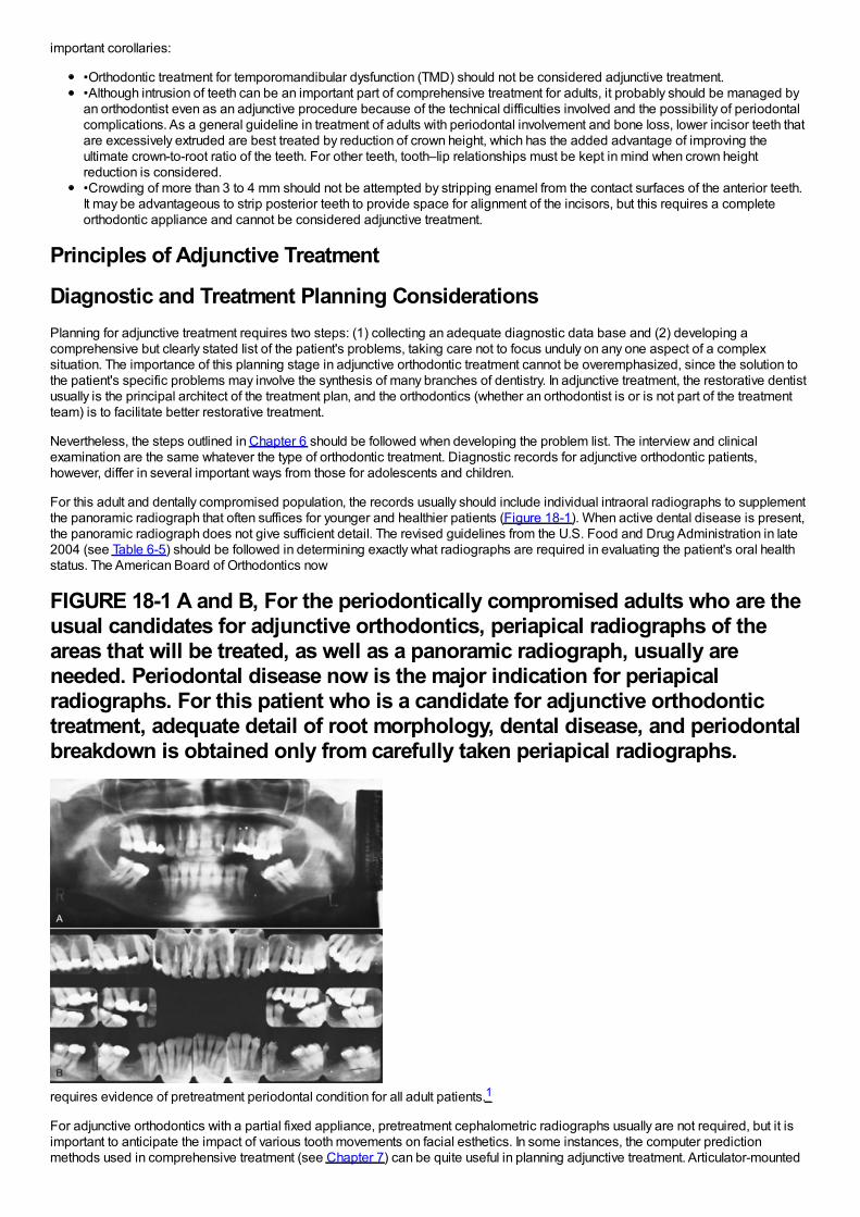
important corollaries:
•Orthodontic treatment for temporomandibular dysfunction (TMD) should not be considered adjunctive treatment.•Although intrusion of teeth can be an important part of comprehensive treatment for adults, it probably should be managed byan orthodontist even as an adjunctive procedure because of the technical difficulties involved and the possibility of periodontalcomplications. As a general guideline in treatment of adults with periodontal involvement and bone loss, lower incisor teeth thatare excessively extruded are best treated by reduction of crown height, which has the added advantage of improving theultimate crown-to-root ratio of the teeth. For other teeth, tooth–lip relationships must be kept in mind when crown heightreduction is considered.•Crowding of more than 3 to 4 mm should not be attempted by stripping enamel from the contact surfaces of the anterior teeth.It may be advantageous to strip posterior teeth to provide space for alignment of the incisors, but this requires a completeorthodontic appliance and cannot be considered adjunctive treatment.
Principles of Adjunctive Treatment
Diagnostic and Treatment Planning ConsiderationsPlanning for adjunctive treatment requires two steps: (1) collecting an adequate diagnostic data base and (2) developing acomprehensive but clearly stated list of the patient's problems, taking care not to focus unduly on any one aspect of a complexsituation. The importance of this planning stage in adjunctive orthodontic treatment cannot be overemphasized, since the solution tothe patient's specific problems may involve the synthesis of many branches of dentistry. In adjunctive treatment, the restorative dentistusually is the principal architect of the treatment plan, and the orthodontics (whether an orthodontist is or is not part of the treatmentteam) is to facilitate better restorative treatment.
Nevertheless, the steps outlined in Chapter 6 should be followed when developing the problem list. The interview and clinicalexamination are the same whatever the type of orthodontic treatment. Diagnostic records for adjunctive orthodontic patients,however, differ in several important ways from those for adolescents and children.
For this adult and dentally compromised population, the records usually should include individual intraoral radiographs to supplementthe panoramic radiograph that often suffices for younger and healthier patients (Figure 18-1). When active dental disease is present,the panoramic radiograph does not give sufficient detail. The revised guidelines from the U.S. Food and Drug Administration in late2004 (see Table 6-5) should be followed in determining exactly what radiographs are required in evaluating the patient's oral healthstatus. The American Board of Orthodontics now
FIGURE 18-1 A and B, For the periodontically compromised adults who are theusual candidates for adjunctive orthodontics, periapical radiographs of theareas that will be treated, as well as a panoramic radiograph, usually areneeded. Periodontal disease now is the major indication for periapicalradiographs. For this patient who is a candidate for adjunctive orthodontictreatment, adequate detail of root morphology, dental disease, and periodontalbreakdown is obtained only from carefully taken periapical radiographs.
requires evidence of pretreatment periodontal condition for all adult patients.1
For adjunctive orthodontics with a partial fixed appliance, pretreatment cephalometric radiographs usually are not required, but it isimportant to anticipate the impact of various tooth movements on facial esthetics. In some instances, the computer predictionmethods used in comprehensive treatment (see Chapter 7) can be quite useful in planning adjunctive treatment. Articulator-mounted
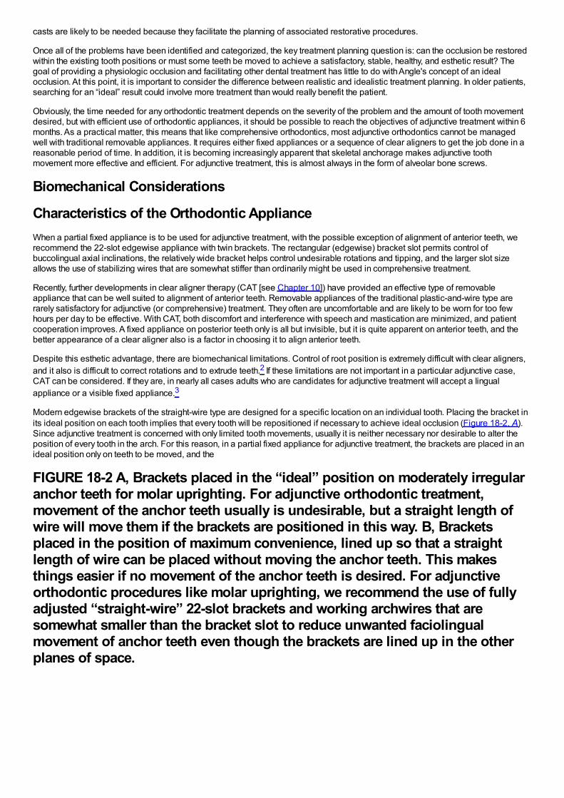
casts are likely to be needed because they facilitate the planning of associated restorative procedures.
Once all of the problems have been identified and categorized, the key treatment planning question is: can the occlusion be restoredwithin the existing tooth positions or must some teeth be moved to achieve a satisfactory, stable, healthy, and esthetic result? Thegoal of providing a physiologic occlusion and facilitating other dental treatment has little to do with Angle's concept of an idealocclusion. At this point, it is important to consider the difference between realistic and idealistic treatment planning. In older patients,searching for an “ideal” result could involve more treatment than would really benefit the patient.
Obviously, the time needed for any orthodontic treatment depends on the severity of the problem and the amount of tooth movementdesired, but with efficient use of orthodontic appliances, it should be possible to reach the objectives of adjunctive treatment within 6months. As a practical matter, this means that like comprehensive orthodontics, most adjunctive orthodontics cannot be managedwell with traditional removable appliances. It requires either fixed appliances or a sequence of clear aligners to get the job done in areasonable period of time. In addition, it is becoming increasingly apparent that skeletal anchorage makes adjunctive toothmovement more effective and efficient. For adjunctive treatment, this is almost always in the form of alveolar bone screws.
Biomechanical Considerations
Characteristics of the Orthodontic ApplianceWhen a partial fixed appliance is to be used for adjunctive treatment, with the possible exception of alignment of anterior teeth, werecommend the 22-slot edgewise appliance with twin brackets. The rectangular (edgewise) bracket slot permits control ofbuccolingual axial inclinations, the relatively wide bracket helps control undesirable rotations and tipping, and the larger slot sizeallows the use of stabilizing wires that are somewhat stiffer than ordinarily might be used in comprehensive treatment.
Recently, further developments in clear aligner therapy (CAT [see Chapter 10]) have provided an effective type of removableappliance that can be well suited to alignment of anterior teeth. Removable appliances of the traditional plastic-and-wire type arerarely satisfactory for adjunctive (or comprehensive) treatment. They often are uncomfortable and are likely to be worn for too fewhours per day to be effective. With CAT, both discomfort and interference with speech and mastication are minimized, and patientcooperation improves. A fixed appliance on posterior teeth only is all but invisible, but it is quite apparent on anterior teeth, and thebetter appearance of a clear aligner also is a factor in choosing it to align anterior teeth.
Despite this esthetic advantage, there are biomechanical limitations. Control of root position is extremely difficult with clear aligners,and it also is difficult to correct rotations and to extrude teeth.2 If these limitations are not important in a particular adjunctive case,CAT can be considered. If they are, in nearly all cases adults who are candidates for adjunctive treatment will accept a lingualappliance or a visible fixed appliance.3
Modern edgewise brackets of the straight-wire type are designed for a specific location on an individual tooth. Placing the bracket inits ideal position on each tooth implies that every tooth will be repositioned if necessary to achieve ideal occlusion (Figure 18-2, A).Since adjunctive treatment is concerned with only limited tooth movements, usually it is neither necessary nor desirable to alter theposition of every tooth in the arch. For this reason, in a partial fixed appliance for adjunctive treatment, the brackets are placed in anideal position only on teeth to be moved, and the
FIGURE 18-2 A, Brackets placed in the “ideal” position on moderately irregularanchor teeth for molar uprighting. For adjunctive orthodontic treatment,movement of the anchor teeth usually is undesirable, but a straight length ofwire will move them if the brackets are positioned in this way. B, Bracketsplaced in the position of maximum convenience, lined up so that a straightlength of wire can be placed without moving the anchor teeth. This makesthings easier if no movement of the anchor teeth is desired. For adjunctiveorthodontic procedures like molar uprighting, we recommend the use of fullyadjusted “straight-wire” 22-slot brackets and working archwires that aresomewhat smaller than the bracket slot to reduce unwanted faciolingualmovement of anchor teeth even though the brackets are lined up in the otherplanes of space.
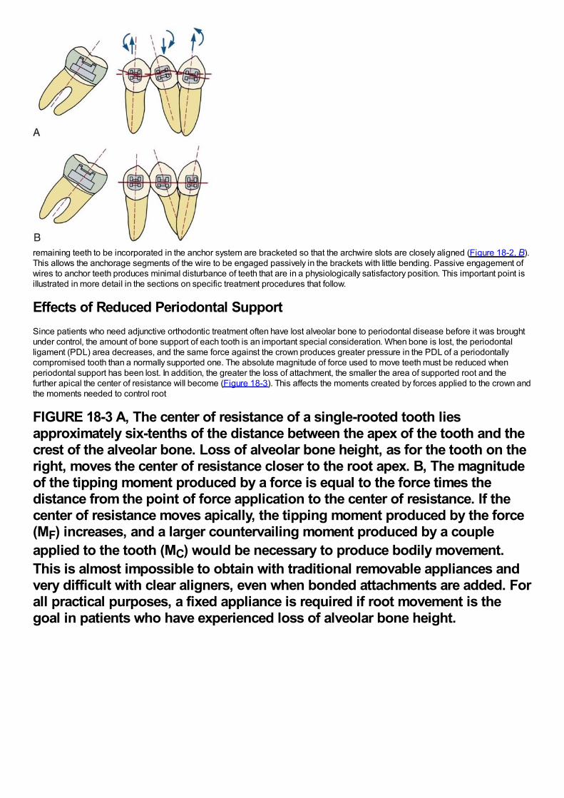
remaining teeth to be incorporated in the anchor system are bracketed so that the archwire slots are closely aligned (Figure 18-2, B).This allows the anchorage segments of the wire to be engaged passively in the brackets with little bending. Passive engagement ofwires to anchor teeth produces minimal disturbance of teeth that are in a physiologically satisfactory position. This important point isillustrated in more detail in the sections on specific treatment procedures that follow.
Effects of Reduced Periodontal SupportSince patients who need adjunctive orthodontic treatment often have lost alveolar bone to periodontal disease before it was broughtunder control, the amount of bone support of each tooth is an important special consideration. When bone is lost, the periodontalligament (PDL) area decreases, and the same force against the crown produces greater pressure in the PDL of a periodontallycompromised tooth than a normally supported one. The absolute magnitude of force used to move teeth must be reduced whenperiodontal support has been lost. In addition, the greater the loss of attachment, the smaller the area of supported root and thefurther apical the center of resistance will become (Figure 18-3). This affects the moments created by forces applied to the crown andthe moments needed to control root
FIGURE 18-3 A, The center of resistance of a single-rooted tooth liesapproximately six-tenths of the distance between the apex of the tooth and thecrest of the alveolar bone. Loss of alveolar bone height, as for the tooth on theright, moves the center of resistance closer to the root apex. B, The magnitudeof the tipping moment produced by a force is equal to the force times thedistance from the point of force application to the center of resistance. If thecenter of resistance moves apically, the tipping moment produced by the force(MF) increases, and a larger countervailing moment produced by a coupleapplied to the tooth (MC) would be necessary to produce bodily movement.This is almost impossible to obtain with traditional removable appliances andvery difficult with clear aligners, even when bonded attachments are added. Forall practical purposes, a fixed appliance is required if root movement is thegoal in patients who have experienced loss of alveolar bone height.
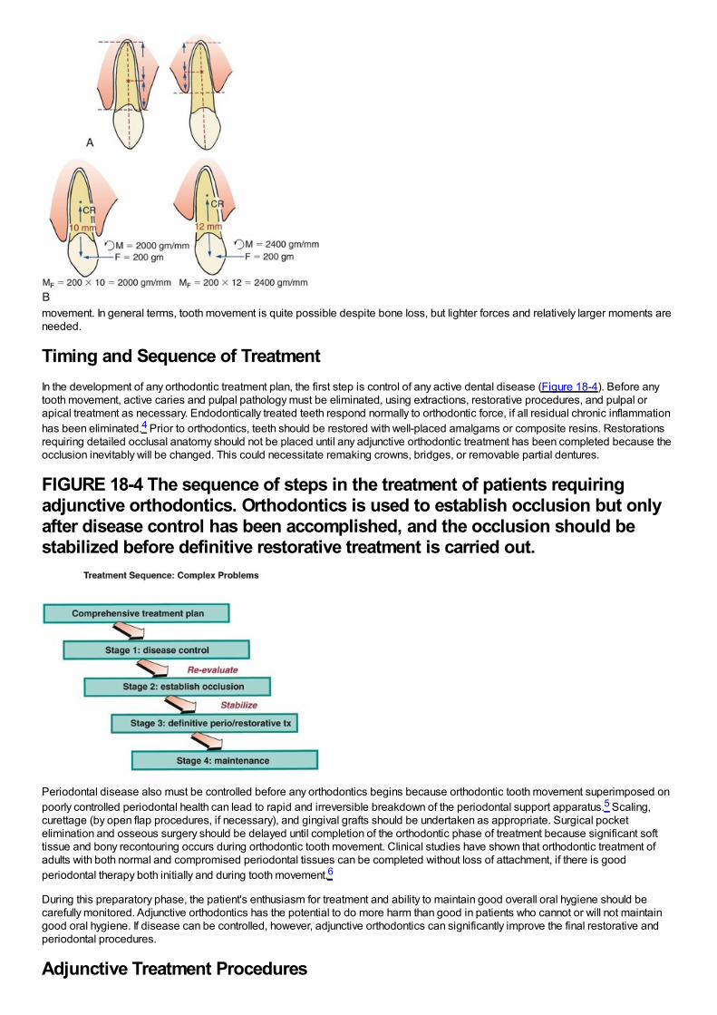
movement. In general terms, tooth movement is quite possible despite bone loss, but lighter forces and relatively larger moments areneeded.
Timing and Sequence of TreatmentIn the development of any orthodontic treatment plan, the first step is control of any active dental disease (Figure 18-4). Before anytooth movement, active caries and pulpal pathology must be eliminated, using extractions, restorative procedures, and pulpal orapical treatment as necessary. Endodontically treated teeth respond normally to orthodontic force, if all residual chronic inflammationhas been eliminated.4 Prior to orthodontics, teeth should be restored with well-placed amalgams or composite resins. Restorationsrequiring detailed occlusal anatomy should not be placed until any adjunctive orthodontic treatment has been completed because theocclusion inevitably will be changed. This could necessitate remaking crowns, bridges, or removable partial dentures.
FIGURE 18-4 The sequence of steps in the treatment of patients requiringadjunctive orthodontics. Orthodontics is used to establish occlusion but onlyafter disease control has been accomplished, and the occlusion should bestabilized before definitive restorative treatment is carried out.
Periodontal disease also must be controlled before any orthodontics begins because orthodontic tooth movement superimposed onpoorly controlled periodontal health can lead to rapid and irreversible breakdown of the periodontal support apparatus.5 Scaling,curettage (by open flap procedures, if necessary), and gingival grafts should be undertaken as appropriate. Surgical pocketelimination and osseous surgery should be delayed until completion of the orthodontic phase of treatment because significant softtissue and bony recontouring occurs during orthodontic tooth movement. Clinical studies have shown that orthodontic treatment ofadults with both normal and compromised periodontal tissues can be completed without loss of attachment, if there is goodperiodontal therapy both initially and during tooth movement.6
During this preparatory phase, the patient's enthusiasm for treatment and ability to maintain good overall oral hygiene should becarefully monitored. Adjunctive orthodontics has the potential to do more harm than good in patients who cannot or will not maintaingood oral hygiene. If disease can be controlled, however, adjunctive orthodontics can significantly improve the final restorative andperiodontal procedures.
Adjunctive Treatment Procedures
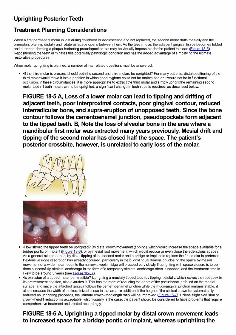
Uprighting Posterior Teeth
Treatment Planning ConsiderationsWhen a first permanent molar is lost during childhood or adolescence and not replaced, the second molar drifts mesially and thepremolars often tip distally and rotate as space opens between them. As the teeth move, the adjacent gingival tissue becomes foldedand distorted, forming a plaque-harboring pseudopocket that may be virtually impossible for the patient to clean (Figure 18-5).Repositioning the teeth eliminates this potentially pathologic condition and has the added advantage of simplifying the ultimaterestorative procedures.
When molar uprighting is planned, a number of interrelated questions must be answered:
•If the third molar is present, should both the second and third molars be uprighted? For many patients, distal positioning of thethird molar would move it into a position in which good hygiene could not be maintained or it would not be in functionalocclusion. In these circumstances, it is more appropriate to extract the third molar and simply upright the remaining secondmolar tooth. If both molars are to be uprighted, a significant change in technique is required, as described below.
FIGURE 18-5 A, Loss of a lower molar can lead to tipping and drifting ofadjacent teeth, poor interproximal contacts, poor gingival contour, reducedinterradicular bone, and supra-eruption of unopposed teeth. Since the bonecontour follows the cementoenamel junction, pseudopockets form adjacentto the tipped teeth. B, Note the loss of alveolar bone in the area where amandibular first molar was extracted many years previously. Mesial drift andtipping of the second molar has closed half the space. The patient'sposterior crossbite, however, is unrelated to early loss of the molar.
•How should the tipped teeth be uprighted? By distal crown movement (tipping), which would increase the space available for abridge pontic or implant (Figure 18-6), or by mesial root movement, which would reduce or even close the edentulous space?As a general rule, treatment by distal tipping of the second molar and a bridge or implant to replace the first molar is preferred.If extensive ridge resorption has already occurred, particularly in the buccolingual dimension, closing the space by mesialmovement of a wide molar root into the narrow alveolar ridge will proceed very slowly. If uprighting with space closure is to bedone successfully, skeletal anchorage in the form of a temporary skeletal anchorage often is needed, and the treatment time islikely to be around 3 years (see Figure 18-37).•Is extrusion of a tipped molar permissible? Uprighting a mesially tipped tooth by tipping it distally, which leaves the root apex inits pretreatment position, also extrudes it. This has the merit of reducing the depth of the pseudopocket found on the mesialsurface, and since the attached gingiva follows the cementoenamel junction while the mucogingival junction remains stable, italso increases the width of the keratinized tissue in that area. In addition, if the height of the clinical crown is systematicallyreduced as uprighting proceeds, the ultimate crown–root length ratio will be improved (Figure 18-7). Unless slight extrusion orcrown–height reduction is acceptable, which usually is the case, the patient should be considered to have problems that requirecomprehensive treatment and treated accordingly.
FIGURE 18-6 A, Uprighting a tipped molar by distal crown movement leadsto increased space for a bridge pontic or implant, whereas uprighting the
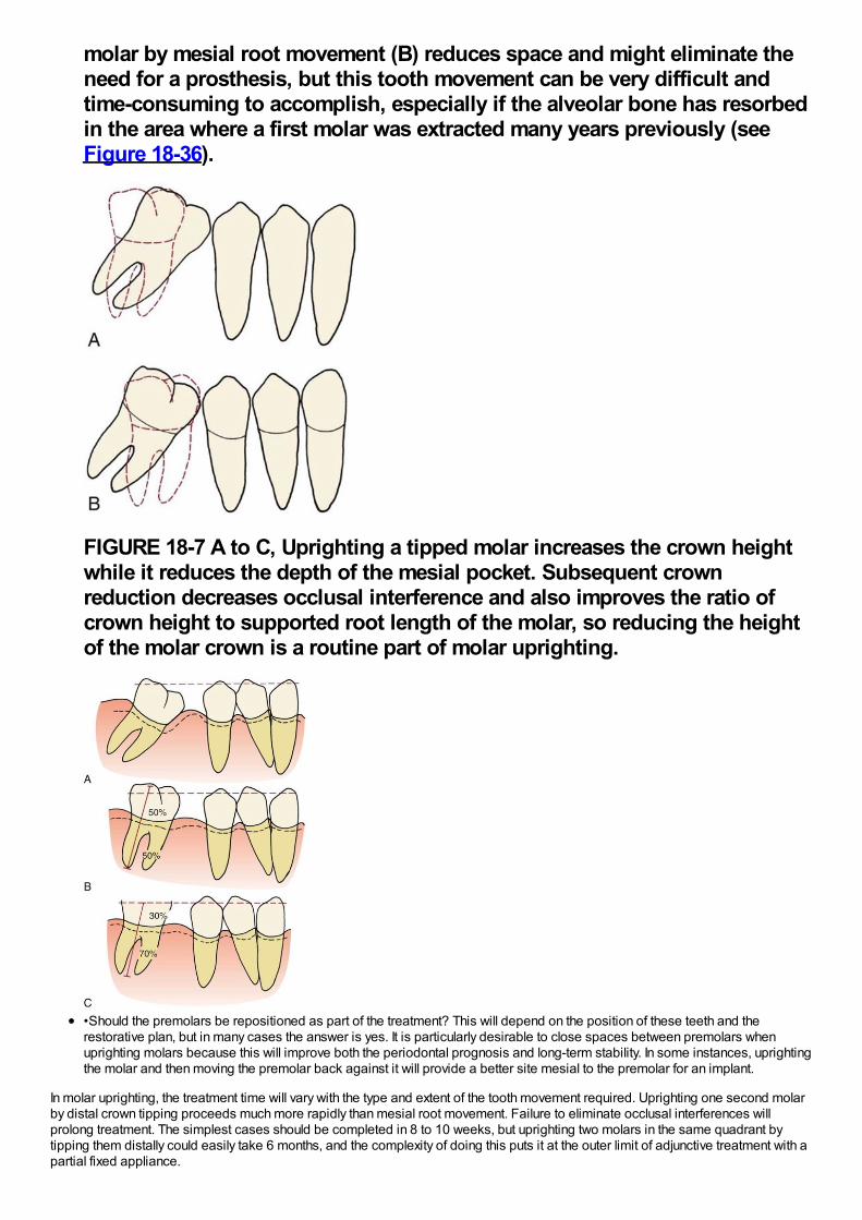
molar by mesial root movement (B) reduces space and might eliminate theneed for a prosthesis, but this tooth movement can be very difficult andtime-consuming to accomplish, especially if the alveolar bone has resorbedin the area where a first molar was extracted many years previously (seeFigure 18-36).
FIGURE 18-7 A to C, Uprighting a tipped molar increases the crown heightwhile it reduces the depth of the mesial pocket. Subsequent crownreduction decreases occlusal interference and also improves the ratio ofcrown height to supported root length of the molar, so reducing the heightof the molar crown is a routine part of molar uprighting.
•Should the premolars be repositioned as part of the treatment? This will depend on the position of these teeth and therestorative plan, but in many cases the answer is yes. It is particularly desirable to close spaces between premolars whenuprighting molars because this will improve both the periodontal prognosis and long-term stability. In some instances, uprightingthe molar and then moving the premolar back against it will provide a better site mesial to the premolar for an implant.
In molar uprighting, the treatment time will vary with the type and extent of the tooth movement required. Uprighting one second molarby distal crown tipping proceeds much more rapidly than mesial root movement. Failure to eliminate occlusal interferences willprolong treatment. The simplest cases should be completed in 8 to 10 weeks, but uprighting two molars in the same quadrant bytipping them distally could easily take 6 months, and the complexity of doing this puts it at the outer limit of adjunctive treatment with apartial fixed appliance.
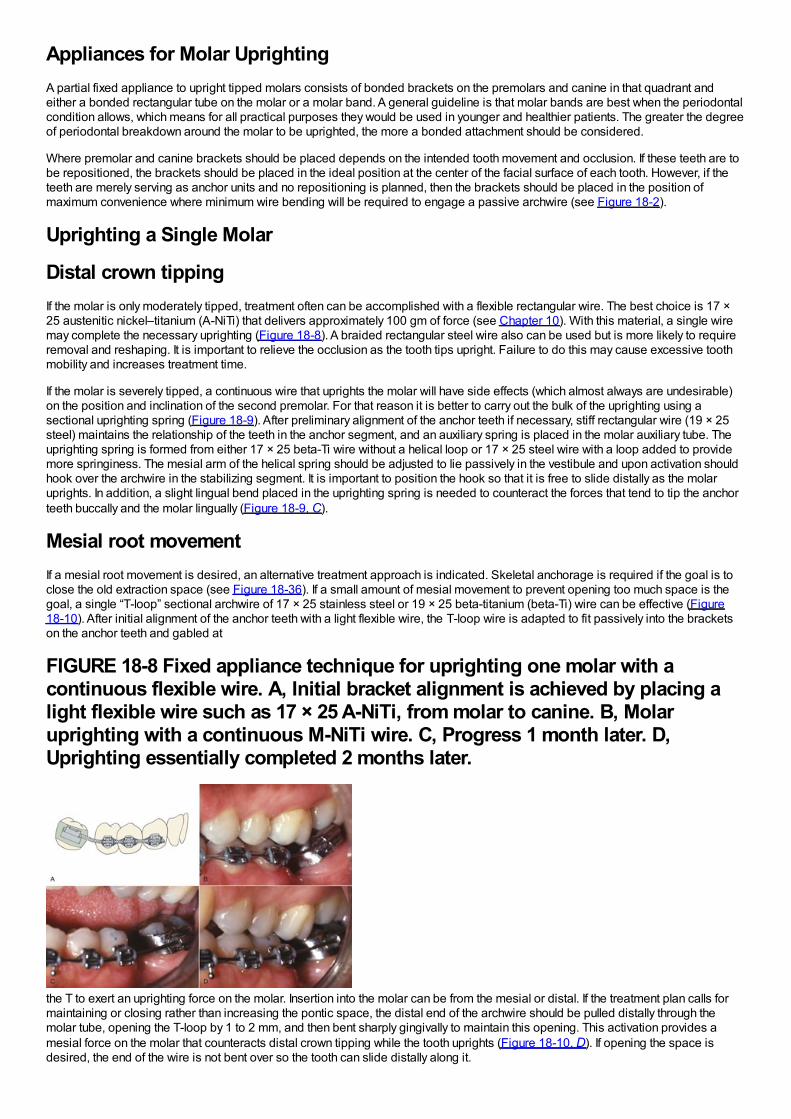
Appliances for Molar UprightingA partial fixed appliance to upright tipped molars consists of bonded brackets on the premolars and canine in that quadrant andeither a bonded rectangular tube on the molar or a molar band. A general guideline is that molar bands are best when the periodontalcondition allows, which means for all practical purposes they would be used in younger and healthier patients. The greater the degreeof periodontal breakdown around the molar to be uprighted, the more a bonded attachment should be considered.
Where premolar and canine brackets should be placed depends on the intended tooth movement and occlusion. If these teeth are tobe repositioned, the brackets should be placed in the ideal position at the center of the facial surface of each tooth. However, if theteeth are merely serving as anchor units and no repositioning is planned, then the brackets should be placed in the position ofmaximum convenience where minimum wire bending will be required to engage a passive archwire (see Figure 18-2).
Uprighting a Single Molar
Distal crown tippingIf the molar is only moderately tipped, treatment often can be accomplished with a flexible rectangular wire. The best choice is 17 ×25 austenitic nickel–titanium (A-NiTi) that delivers approximately 100 gm of force (see Chapter 10). With this material, a single wiremay complete the necessary uprighting (Figure 18-8). A braided rectangular steel wire also can be used but is more likely to requireremoval and reshaping. It is important to relieve the occlusion as the tooth tips upright. Failure to do this may cause excessive toothmobility and increases treatment time.
If the molar is severely tipped, a continuous wire that uprights the molar will have side effects (which almost always are undesirable)on the position and inclination of the second premolar. For that reason it is better to carry out the bulk of the uprighting using asectional uprighting spring (Figure 18-9). After preliminary alignment of the anchor teeth if necessary, stiff rectangular wire (19 × 25steel) maintains the relationship of the teeth in the anchor segment, and an auxiliary spring is placed in the molar auxiliary tube. Theuprighting spring is formed from either 17 × 25 beta-Ti wire without a helical loop or 17 × 25 steel wire with a loop added to providemore springiness. The mesial arm of the helical spring should be adjusted to lie passively in the vestibule and upon activation shouldhook over the archwire in the stabilizing segment. It is important to position the hook so that it is free to slide distally as the molaruprights. In addition, a slight lingual bend placed in the uprighting spring is needed to counteract the forces that tend to tip the anchorteeth buccally and the molar lingually (Figure 18-9, C).
Mesial root movementIf a mesial root movement is desired, an alternative treatment approach is indicated. Skeletal anchorage is required if the goal is toclose the old extraction space (see Figure 18-36). If a small amount of mesial movement to prevent opening too much space is thegoal, a single “T-loop” sectional archwire of 17 × 25 stainless steel or 19 × 25 beta-titanium (beta-Ti) wire can be effective (Figure18-10). After initial alignment of the anchor teeth with a light flexible wire, the T-loop wire is adapted to fit passively into the bracketson the anchor teeth and gabled at
FIGURE 18-8 Fixed appliance technique for uprighting one molar with acontinuous flexible wire. A, Initial bracket alignment is achieved by placing alight flexible wire such as 17 × 25 A-NiTi, from molar to canine. B, Molaruprighting with a continuous M-NiTi wire. C, Progress 1 month later. D,Uprighting essentially completed 2 months later.
the T to exert an uprighting force on the molar. Insertion into the molar can be from the mesial or distal. If the treatment plan calls formaintaining or closing rather than increasing the pontic space, the distal end of the archwire should be pulled distally through themolar tube, opening the T-loop by 1 to 2 mm, and then bent sharply gingivally to maintain this opening. This activation provides amesial force on the molar that counteracts distal crown tipping while the tooth uprights (Figure 18-10, D). If opening the space isdesired, the end of the wire is not bent over so the tooth can slide distally along it.
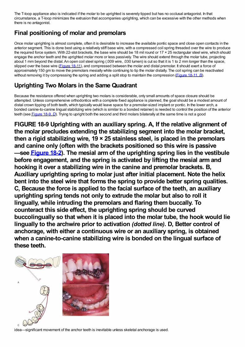
The T-loop appliance also is indicated if the molar to be uprighted is severely tipped but has no occlusal antagonist. In thatcircumstance, a T-loop minimizes the extrusion that accompanies uprighting, which can be excessive with the other methods whenthere is no antagonist.
Final positioning of molar and premolarsOnce molar uprighting is almost complete, often it is desirable to increase the available pontic space and close open contacts in theanterior segment. This is done best using a relatively stiff base wire, with a compressed coil spring threaded over the wire to producethe required force system. With 22-slot brackets, the base wire should be 18 mil round or 17 × 25 rectangular steel wire, which shouldengage the anchor teeth and the uprighted molar more or less passively. The wire should extend through the molar tube, projectingabout 1 mm beyond the distal. An open coil steel spring (.009 wire, .030 lumen) is cut so that it is 1 to 2 mm longer than the space,slipped over the base wire (Figure 18-11), and compressed between the molar and distal premolar. It should exert a force ofapproximately 150 gm to move the premolars mesially while continuing to tip the molar distally. The coil spring can be reactivatedwithout removing it by compressing the spring and adding a split stop to maintain the compression (Figure 18-11, B).
Uprighting Two Molars in the Same QuadrantBecause the resistance offered when uprighting two molars is considerable, only small amounts of space closure should beattempted. Unless comprehensive orthodontics with a complete fixed appliance is planned, the goal should be a modest amount ofdistal crown tipping of both teeth, which typically would leave space for a premolar-sized implant or pontic. In the lower arch, abonded canine-to-canine lingual stabilizing wire (which is similar to a bonded retainer) is needed to control the position of the anteriorteeth (see Figure 18-9, D). Trying to upright both the second and third molars bilaterally at the same time is not a good
FIGURE 18-9 Uprighting with an auxiliary spring. A, If the relative alignment ofthe molar precludes extending the stabilizing segment into the molar bracket,then a rigid stabilizing wire, 19 × 25 stainless steel, is placed in the premolarsand canine only (often with the brackets positioned so this wire is passive—see Figure 18-2). The mesial arm of the uprighting spring lies in the vestibulebefore engagement, and the spring is activated by lifting the mesial arm andhooking it over a stabilizing wire in the canine and premolar brackets. B,Auxiliary uprighting spring to molar just after initial placement. Note the helixbent into the steel wire that forms the spring to provide better spring qualities.C, Because the force is applied to the facial surface of the teeth, an auxiliaryuprighting spring tends not only to extrude the molar but also to roll itlingually, while intruding the premolars and flaring them buccally. Tocounteract this side effect, the uprighting spring should be curvedbuccolingually so that when it is placed into the molar tube, the hook would lielingually to the archwire prior to activation (dotted line). D, Better control ofanchorage, with either a continuous wire or an auxiliary spring, is obtainedwhen a canine-to-canine stabilizing wire is bonded on the lingual surface ofthese teeth.
idea—significant movement of the anchor teeth is inevitable unless skeletal anchorage is used.
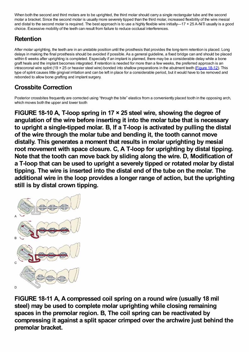
When both the second and third molars are to be uprighted, the third molar should carry a single rectangular tube and the secondmolar a bracket. Since the second molar is usually more severely tipped than the third molar, increased flexibility of the wire mesialand distal to the second molar is required. The best approach is to use a highly flexible wire initially—17 × 25 A-NiTi usually is a goodchoice. Excessive mobility of the teeth can result from failure to reduce occlusal interferences.
RetentionAfter molar uprighting, the teeth are in an unstable position until the prosthesis that provides the long-term retention is placed. Longdelays in making the final prosthesis should be avoided if possible. As a general guideline, a fixed bridge can and should be placedwithin 6 weeks after uprighting is completed. Especially if an implant is planned, there may be a considerable delay while a bonegraft heals and the implant becomes integrated. If retention is needed for more than a few weeks, the preferred approach is anintracoronal wire splint (19 × 25 or heavier steel wire) bonded into shallow preparations in the abutment teeth (Figure 18-12). Thistype of splint causes little gingival irritation and can be left in place for a considerable period, but it would have to be removed andrebonded to allow bone grafting and implant surgery.
Crossbite CorrectionPosterior crossbites frequently are corrected using “through the bite” elastics from a conveniently placed tooth in the opposing arch,which moves both the upper and lower tooth
FIGURE 18-10 A, T-loop spring in 17 × 25 steel wire, showing the degree ofangulation of the wire before inserting it into the molar tube that is necessaryto upright a single-tipped molar. B, If a T-loop is activated by pulling the distalof the wire through the molar tube and bending it, the tooth cannot movedistally. This generates a moment that results in molar uprighting by mesialroot movement with space closure. C, A T-loop for uprighting by distal tipping.Note that the tooth can move back by sliding along the wire. D, Modification ofa T-loop that can be used to upright a severely tipped or rotated molar by distaltipping. The wire is inserted into the distal end of the tube on the molar. Theadditional wire in the loop provides a longer range of action, but the uprightingstill is by distal crown tipping.
FIGURE 18-11 A, A compressed coil spring on a round wire (usually 18 milsteel) may be used to complete molar uprighting while closing remainingspaces in the premolar region. B, The coil spring can be reactivated bycompressing it against a split spacer crimped over the archwire just behind thepremolar bracket.
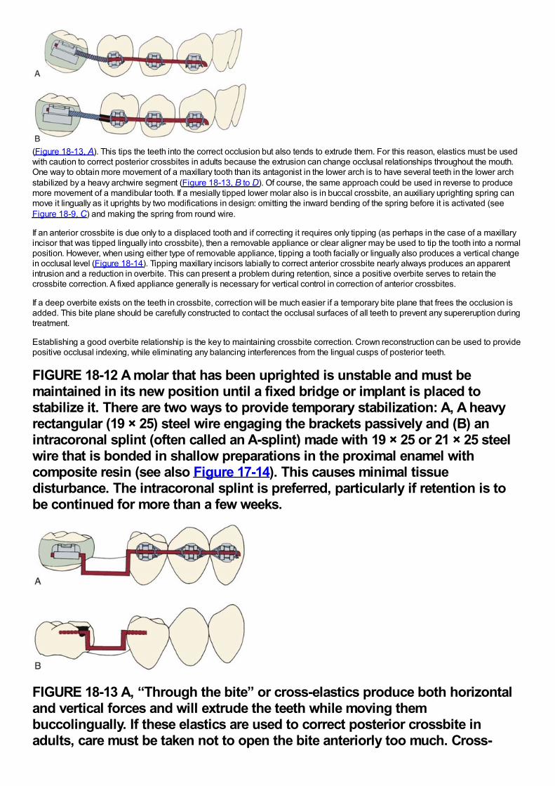
(Figure 18-13, A). This tips the teeth into the correct occlusion but also tends to extrude them. For this reason, elastics must be usedwith caution to correct posterior crossbites in adults because the extrusion can change occlusal relationships throughout the mouth.One way to obtain more movement of a maxillary tooth than its antagonist in the lower arch is to have several teeth in the lower archstabilized by a heavy archwire segment (Figure 18-13, B to D). Of course, the same approach could be used in reverse to producemore movement of a mandibular tooth. If a mesially tipped lower molar also is in buccal crossbite, an auxiliary uprighting spring canmove it lingually as it uprights by two modifications in design: omitting the inward bending of the spring before it is activated (seeFigure 18-9, C) and making the spring from round wire.
If an anterior crossbite is due only to a displaced tooth and if correcting it requires only tipping (as perhaps in the case of a maxillaryincisor that was tipped lingually into crossbite), then a removable appliance or clear aligner may be used to tip the tooth into a normalposition. However, when using either type of removable appliance, tipping a tooth facially or lingually also produces a vertical changein occlusal level (Figure 18-14). Tipping maxillary incisors labially to correct anterior crossbite nearly always produces an apparentintrusion and a reduction in overbite. This can present a problem during retention, since a positive overbite serves to retain thecrossbite correction. A fixed appliance generally is necessary for vertical control in correction of anterior crossbites.
If a deep overbite exists on the teeth in crossbite, correction will be much easier if a temporary bite plane that frees the occlusion isadded. This bite plane should be carefully constructed to contact the occlusal surfaces of all teeth to prevent any supereruption duringtreatment.
Establishing a good overbite relationship is the key to maintaining crossbite correction. Crown reconstruction can be used to providepositive occlusal indexing, while eliminating any balancing interferences from the lingual cusps of posterior teeth.
FIGURE 18-12 A molar that has been uprighted is unstable and must bemaintained in its new position until a fixed bridge or implant is placed tostabilize it. There are two ways to provide temporary stabilization: A, A heavyrectangular (19 × 25) steel wire engaging the brackets passively and (B) anintracoronal splint (often called an A-splint) made with 19 × 25 or 21 × 25 steelwire that is bonded in shallow preparations in the proximal enamel withcomposite resin (see also Figure 17-14). This causes minimal tissuedisturbance. The intracoronal splint is preferred, particularly if retention is tobe continued for more than a few weeks.
FIGURE 18-13 A, “Through the bite” or cross-elastics produce both horizontaland vertical forces and will extrude the teeth while moving thembuccolingually. If these elastics are used to correct posterior crossbite inadults, care must be taken not to open the bite anteriorly too much. Cross-
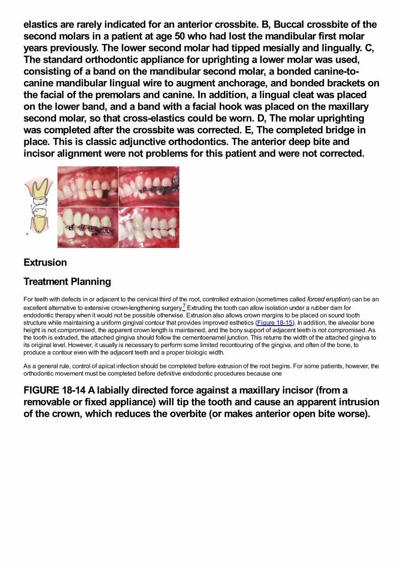
elastics are rarely indicated for an anterior crossbite. B, Buccal crossbite of thesecond molars in a patient at age 50 who had lost the mandibular first molaryears previously. The lower second molar had tipped mesially and lingually. C,The standard orthodontic appliance for uprighting a lower molar was used,consisting of a band on the mandibular second molar, a bonded canine-to-canine mandibular lingual wire to augment anchorage, and bonded brackets onthe facial of the premolars and canine. In addition, a lingual cleat was placedon the lower band, and a band with a facial hook was placed on the maxillarysecond molar, so that cross-elastics could be worn. D, The molar uprightingwas completed after the crossbite was corrected. E, The completed bridge inplace. This is classic adjunctive orthodontics. The anterior deep bite andincisor alignment were not problems for this patient and were not corrected.
Extrusion
Treatment PlanningFor teeth with defects in or adjacent to the cervical third of the root, controlled extrusion (sometimes called forced eruption) can be anexcellent alternative to extensive crown-lengthening surgery.7 Extruding the tooth can allow isolation under a rubber dam forendodontic therapy when it would not be possible otherwise. Extrusion also allows crown margins to be placed on sound toothstructure while maintaining a uniform gingival contour that provides improved esthetics (Figure 18-15). In addition, the alveolar boneheight is not compromised, the apparent crown length is maintained, and the bony support of adjacent teeth is not compromised. Asthe tooth is extruded, the attached gingiva should follow the cementoenamel junction. This returns the width of the attached gingiva toits original level. However, it usually is necessary to perform some limited recontouring of the gingiva, and often of the bone, toproduce a contour even with the adjacent teeth and a proper biologic width.
As a general rule, control of apical infection should be completed before extrusion of the root begins. For some patients, however, theorthodontic movement must be completed before definitive endodontic procedures because one
FIGURE 18-14 A labially directed force against a maxillary incisor (from aremovable or fixed appliance) will tip the tooth and cause an apparent intrusionof the crown, which reduces the overbite (or makes anterior open bite worse).
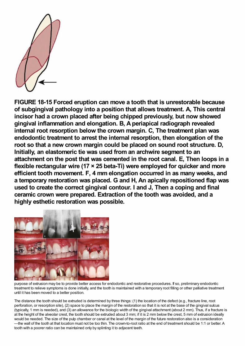
FIGURE 18-15 Forced eruption can move a tooth that is unrestorable becauseof subgingival pathology into a position that allows treatment. A, This centralincisor had a crown placed after being chipped previously, but now showedgingival inflammation and elongation. B, A periapical radiograph revealedinternal root resorption below the crown margin. C, The treatment plan wasendodontic treatment to arrest the internal resorption, then elongation of theroot so that a new crown margin could be placed on sound root structure. D,Initially, an elastomeric tie was used from an archwire segment to anattachment on the post that was cemented in the root canal. E, Then loops in aflexible rectangular wire (17 × 25 beta-Ti) were employed for quicker and moreefficient tooth movement. F, 4 mm elongation occurred in as many weeks, anda temporary restoration was placed. G and H, An apically repositioned flap wasused to create the correct gingival contour. I and J, Then a coping and finalceramic crown were prepared. Extraction of the tooth was avoided, and ahighly esthetic restoration was possible.
purpose of extrusion may be to provide better access for endodontic and restorative procedures. If so, preliminary endodontictreatment to relieve symptoms is done initially, and the tooth is maintained with a temporary root filling or other palliative treatmentuntil it has been moved to a better position.
The distance the tooth should be extruded is determined by three things: (1) the location of the defect (e.g., fracture line, rootperforation, or resorption site), (2) space to place the margin of the restoration so that it is not at the base of the gingival sulcus(typically, 1 mm is needed), and (3) an allowance for the biologic width of the gingival attachment (about 2 mm). Thus, if a fracture isat the height of the alveolar crest, the tooth should be extruded about 3 mm; if it is 2 mm below the crest, 5 mm of extrusion ideallywould be needed. The size of the pulp chamber or canal at the level of the margin of the future restoration also is a consideration—the wall of the tooth at that location must not be too thin. The crown-to-root ratio at the end of treatment should be 1:1 or better. Atooth with a poorer ratio can be maintained only by splinting it to adjacent teeth.
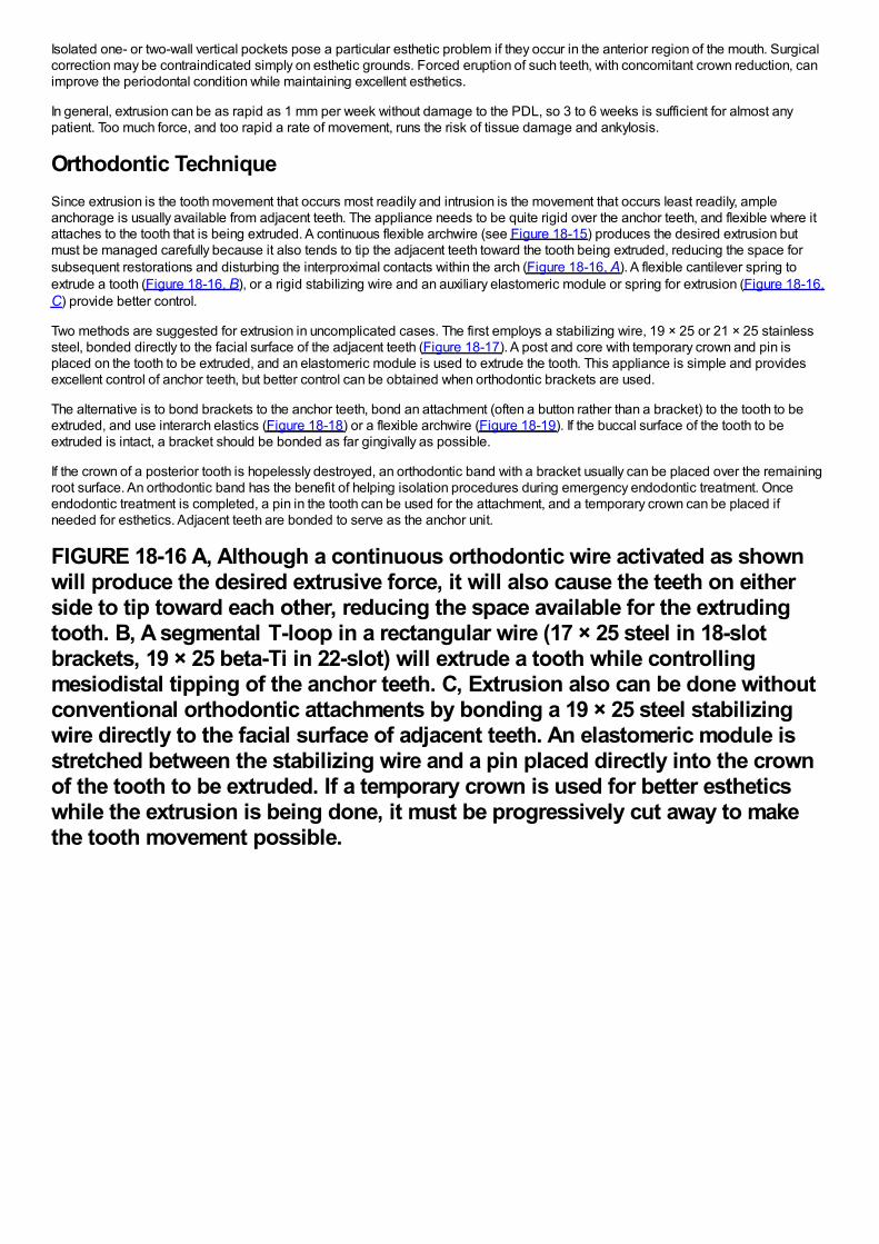
Isolated one- or two-wall vertical pockets pose a particular esthetic problem if they occur in the anterior region of the mouth. Surgicalcorrection may be contraindicated simply on esthetic grounds. Forced eruption of such teeth, with concomitant crown reduction, canimprove the periodontal condition while maintaining excellent esthetics.
In general, extrusion can be as rapid as 1 mm per week without damage to the PDL, so 3 to 6 weeks is sufficient for almost anypatient. Too much force, and too rapid a rate of movement, runs the risk of tissue damage and ankylosis.
Orthodontic TechniqueSince extrusion is the tooth movement that occurs most readily and intrusion is the movement that occurs least readily, ampleanchorage is usually available from adjacent teeth. The appliance needs to be quite rigid over the anchor teeth, and flexible where itattaches to the tooth that is being extruded. A continuous flexible archwire (see Figure 18-15) produces the desired extrusion butmust be managed carefully because it also tends to tip the adjacent teeth toward the tooth being extruded, reducing the space forsubsequent restorations and disturbing the interproximal contacts within the arch (Figure 18-16, A). A flexible cantilever spring toextrude a tooth (Figure 18-16, B), or a rigid stabilizing wire and an auxiliary elastomeric module or spring for extrusion (Figure 18-16,C) provide better control.
Two methods are suggested for extrusion in uncomplicated cases. The first employs a stabilizing wire, 19 × 25 or 21 × 25 stainlesssteel, bonded directly to the facial surface of the adjacent teeth (Figure 18-17). A post and core with temporary crown and pin isplaced on the tooth to be extruded, and an elastomeric module is used to extrude the tooth. This appliance is simple and providesexcellent control of anchor teeth, but better control can be obtained when orthodontic brackets are used.
The alternative is to bond brackets to the anchor teeth, bond an attachment (often a button rather than a bracket) to the tooth to beextruded, and use interarch elastics (Figure 18-18) or a flexible archwire (Figure 18-19). If the buccal surface of the tooth to beextruded is intact, a bracket should be bonded as far gingivally as possible.
If the crown of a posterior tooth is hopelessly destroyed, an orthodontic band with a bracket usually can be placed over the remainingroot surface. An orthodontic band has the benefit of helping isolation procedures during emergency endodontic treatment. Onceendodontic treatment is completed, a pin in the tooth can be used for the attachment, and a temporary crown can be placed ifneeded for esthetics. Adjacent teeth are bonded to serve as the anchor unit.
FIGURE 18-16 A, Although a continuous orthodontic wire activated as shownwill produce the desired extrusive force, it will also cause the teeth on eitherside to tip toward each other, reducing the space available for the extrudingtooth. B, A segmental T-loop in a rectangular wire (17 × 25 steel in 18-slotbrackets, 19 × 25 beta-Ti in 22-slot) will extrude a tooth while controllingmesiodistal tipping of the anchor teeth. C, Extrusion also can be done withoutconventional orthodontic attachments by bonding a 19 × 25 steel stabilizingwire directly to the facial surface of adjacent teeth. An elastomeric module isstretched between the stabilizing wire and a pin placed directly into the crownof the tooth to be extruded. If a temporary crown is used for better estheticswhile the extrusion is being done, it must be progressively cut away to makethe tooth movement possible.
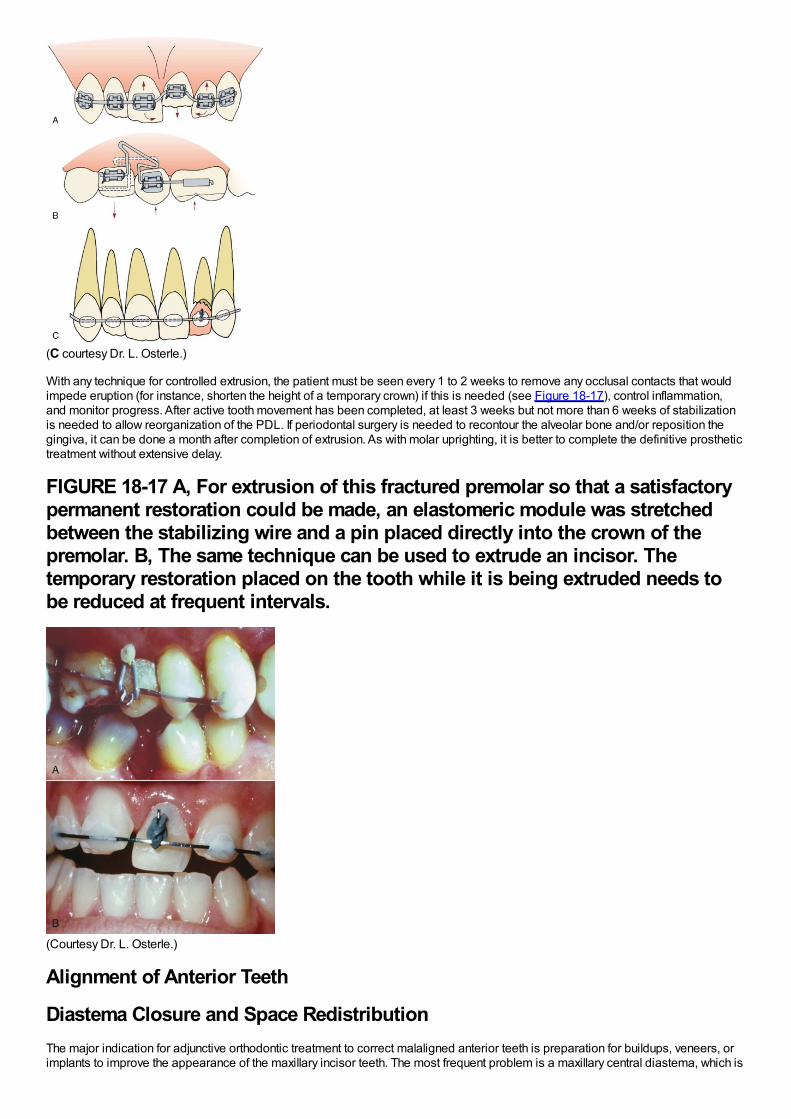
(C courtesy Dr. L. Osterle.)
With any technique for controlled extrusion, the patient must be seen every 1 to 2 weeks to remove any occlusal contacts that wouldimpede eruption (for instance, shorten the height of a temporary crown) if this is needed (see Figure 18-17), control inflammation,and monitor progress. After active tooth movement has been completed, at least 3 weeks but not more than 6 weeks of stabilizationis needed to allow reorganization of the PDL. If periodontal surgery is needed to recontour the alveolar bone and/or reposition thegingiva, it can be done a month after completion of extrusion. As with molar uprighting, it is better to complete the definitive prosthetictreatment without extensive delay.
FIGURE 18-17 A, For extrusion of this fractured premolar so that a satisfactorypermanent restoration could be made, an elastomeric module was stretchedbetween the stabilizing wire and a pin placed directly into the crown of thepremolar. B, The same technique can be used to extrude an incisor. Thetemporary restoration placed on the tooth while it is being extruded needs tobe reduced at frequent intervals.
(Courtesy Dr. L. Osterle.)
Alignment of Anterior Teeth
Diastema Closure and Space RedistributionThe major indication for adjunctive orthodontic treatment to correct malaligned anterior teeth is preparation for buildups, veneers, orimplants to improve the appearance of the maxillary incisor teeth. The most frequent problem is a maxillary central diastema, which is
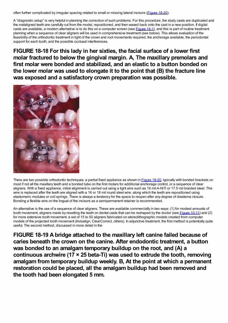
often further complicated by irregular spacing related to small or missing lateral incisors (Figure 18-20).
A “diagnostic setup” is very helpful in planning the correction of such problems. For this procedure, the study casts are duplicated andthe malaligned teeth are carefully cut from the model, repositioned, and then waxed back onto the cast in a new position. If digitalcasts are available, a modern alternative is to do this on a computer screen (see Figure 14-1), and this is part of routine treatmentplanning when a sequence of clear aligners will be used in comprehensive treatment (see below). This allows evaluation of thefeasibility of the orthodontic treatment in light of the crown and root movements required, the anchorage available, the periodontalsupport for each tooth, and the possible occlusal interferences.
FIGURE 18-18 For this lady in her sixties, the facial surface of a lower firstmolar fractured to below the gingival margin. A, The maxillary premolars andfirst molar were bonded and stabilized, and an elastic to a button bonded onthe lower molar was used to elongate it to the point that (B) the fracture linewas exposed and a satisfactory crown preparation was possible.
There are two possible orthodontic techniques: a partial fixed appliance as shown in Figure 18-20, typically with bonded brackets onmost if not all the maxillary teeth and a bonded tube on the first molars for additional anchorage control, or a sequence of clearaligners. With a fixed appliance, initial alignment is carried out using a light wire such as 16 mil A-NiTi or 17.5 mil braided steel. Thiswire is replaced after the teeth are aligned with a 16 or 18 mil round steel wire, along which the teeth are repositioned usingelastomeric modules or coil springs. There is always a tendency for the space to reopen after any degree of diastema closure.Bonding a flexible wire on the lingual of the incisors as a semipermanent retainer is recommended.
An alternative is the use of a sequence of clear aligners. These are available commercially in two ways: (1) for modest amounts oftooth movement, aligners made by resetting the teeth on dental casts that can be reshaped by the doctor (see Figure 10-11) and (2)for more extensive tooth movement, a set of 15 to 50 aligners fabricated on stereolithographic models created from computermodels of the projected tooth movement (Invisalign, ClearCorrect, others). In adjunctive treatment, the first method is potentially quiteuseful. The second method, discussed in more detail in the
FIGURE 18-19 A bridge attached to the maxillary left canine failed because ofcaries beneath the crown on the canine. After endodontic treatment, a buttonwas bonded to an amalgam temporary buildup on the root, and (A) acontinuous archwire (17 × 25 beta-Ti) was used to extrude the tooth, removingamalgam from temporary buildup weekly. B, At the point at which a permanentrestoration could be placed, all the amalgam buildup had been removed andthe tooth had been elongated 5 mm.
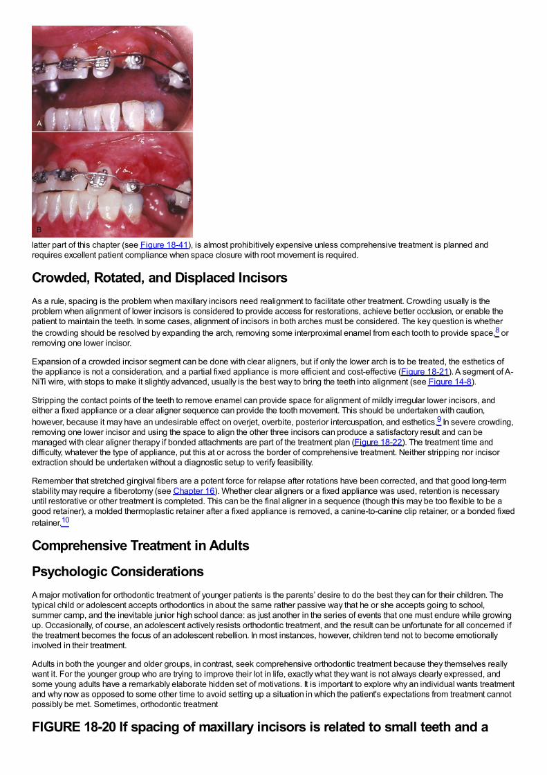
latter part of this chapter (see Figure 18-41), is almost prohibitively expensive unless comprehensive treatment is planned andrequires excellent patient compliance when space closure with root movement is required.
Crowded, Rotated, and Displaced IncisorsAs a rule, spacing is the problem when maxillary incisors need realignment to facilitate other treatment. Crowding usually is theproblem when alignment of lower incisors is considered to provide access for restorations, achieve better occlusion, or enable thepatient to maintain the teeth. In some cases, alignment of incisors in both arches must be considered. The key question is whetherthe crowding should be resolved by expanding the arch, removing some interproximal enamel from each tooth to provide space,8 orremoving one lower incisor.
Expansion of a crowded incisor segment can be done with clear aligners, but if only the lower arch is to be treated, the esthetics ofthe appliance is not a consideration, and a partial fixed appliance is more efficient and cost-effective (Figure 18-21). A segment of A-NiTi wire, with stops to make it slightly advanced, usually is the best way to bring the teeth into alignment (see Figure 14-8).
Stripping the contact points of the teeth to remove enamel can provide space for alignment of mildly irregular lower incisors, andeither a fixed appliance or a clear aligner sequence can provide the tooth movement. This should be undertaken with caution,however, because it may have an undesirable effect on overjet, overbite, posterior intercuspation, and esthetics.9 In severe crowding,removing one lower incisor and using the space to align the other three incisors can produce a satisfactory result and can bemanaged with clear aligner therapy if bonded attachments are part of the treatment plan (Figure 18-22). The treatment time anddifficulty, whatever the type of appliance, put this at or across the border of comprehensive treatment. Neither stripping nor incisorextraction should be undertaken without a diagnostic setup to verify feasibility.
Remember that stretched gingival fibers are a potent force for relapse after rotations have been corrected, and that good long-termstability may require a fiberotomy (see Chapter 16). Whether clear aligners or a fixed appliance was used, retention is necessaryuntil restorative or other treatment is completed. This can be the final aligner in a sequence (though this may be too flexible to be agood retainer), a molded thermoplastic retainer after a fixed appliance is removed, a canine-to-canine clip retainer, or a bonded fixedretainer.10
Comprehensive Treatment in Adults
Psychologic ConsiderationsA major motivation for orthodontic treatment of younger patients is the parents’ desire to do the best they can for their children. Thetypical child or adolescent accepts orthodontics in about the same rather passive way that he or she accepts going to school,summer camp, and the inevitable junior high school dance: as just another in the series of events that one must endure while growingup. Occasionally, of course, an adolescent actively resists orthodontic treatment, and the result can be unfortunate for all concerned ifthe treatment becomes the focus of an adolescent rebellion. In most instances, however, children tend not to become emotionallyinvolved in their treatment.
Adults in both the younger and older groups, in contrast, seek comprehensive orthodontic treatment because they themselves reallywant it. For the younger group who are trying to improve their lot in life, exactly what they want is not always clearly expressed, andsome young adults have a remarkably elaborate hidden set of motivations. It is important to explore why an individual wants treatmentand why now as opposed to some other time to avoid setting up a situation in which the patient's expectations from treatment cannotpossibly be met. Sometimes, orthodontic treatment
FIGURE 18-20 If spacing of maxillary incisors is related to small teeth and a
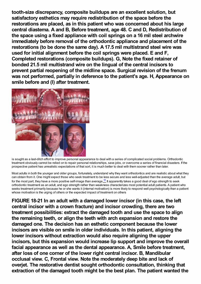
tooth-size discrepancy, composite buildups are an excellent solution, butsatisfactory esthetics may require redistribution of the space before therestorations are placed, as in this patient who was concerned about his largecentral diastema. A and B, Before treatment, age 48. C and D, Redistribution ofthe space using a fixed appliance with coil springs on a 16 mil steel archwireimmediately before removal of the orthodontic appliance and placement of therestorations (to be done the same day). A 17.5 mil multistrand steel wire wasused for initial alignment before the coil springs were placed. E and F,Completed restorations (composite buildups). G, Note the fixed retainer ofbonded 21.5 mil multistrand wire on the lingual of the central incisors toprevent partial reopening of the midline space. Surgical revision of the frenumwas not performed, partially in deference to the patient's age. H, Appearance onsmile before and (I) after treatment.
is sought as a last-ditch effort to improve personal appearance to deal with a series of complicated social problems. Orthodontictreatment obviously cannot be relied on to repair personal relationships, save jobs, or overcome a series of financial disasters. If theprospective patient has unrealistic expectations of that sort, it is much better to deal with them sooner rather than later.
Most adults in both the younger and older groups, fortunately, understand why they want orthodontics and are realistic about what theycan obtain from it. One might expect those who seek treatment to be less secure and less well-adjusted than the average adult, butfor the most part, they have a more positive self-image than average.11 It apparently takes a good deal of ego strength to seekorthodontic treatment as an adult, and ego strength rather than weakness characterizes most potential adult patients. A patient whoseeks treatment primarily because he or she wants it (internal motivation) is more likely to respond well psychologically than a patientwhose motivation is the urging of others or the expected impact of treatment on others
FIGURE 18-21 In an adult with a damaged lower incisor (in this case, the leftcentral incisor with a crown fracture) and incisor crowding, there are twotreatment possibilities: extract the damaged tooth and use the space to alignthe remaining teeth, or align the teeth with arch expansion and restore thedamaged one. The decision has an esthetic component because the lowerincisors are visible on smile in older individuals. In this patient, aligning thelower incisors without extraction would also require aligning the upperincisors, but this expansion would increase lip support and improve the overallfacial appearance as well as the dental appearance. A, Smile before treatment,after loss of one corner of the lower right central incisor. B, Mandibularocclusal view. C, Frontal view. Note the moderately deep bite and lack ofoverjet. The restorative dentist sought orthodontic consultation, thinking thatextraction of the damaged tooth might be the best plan. The patient wanted the
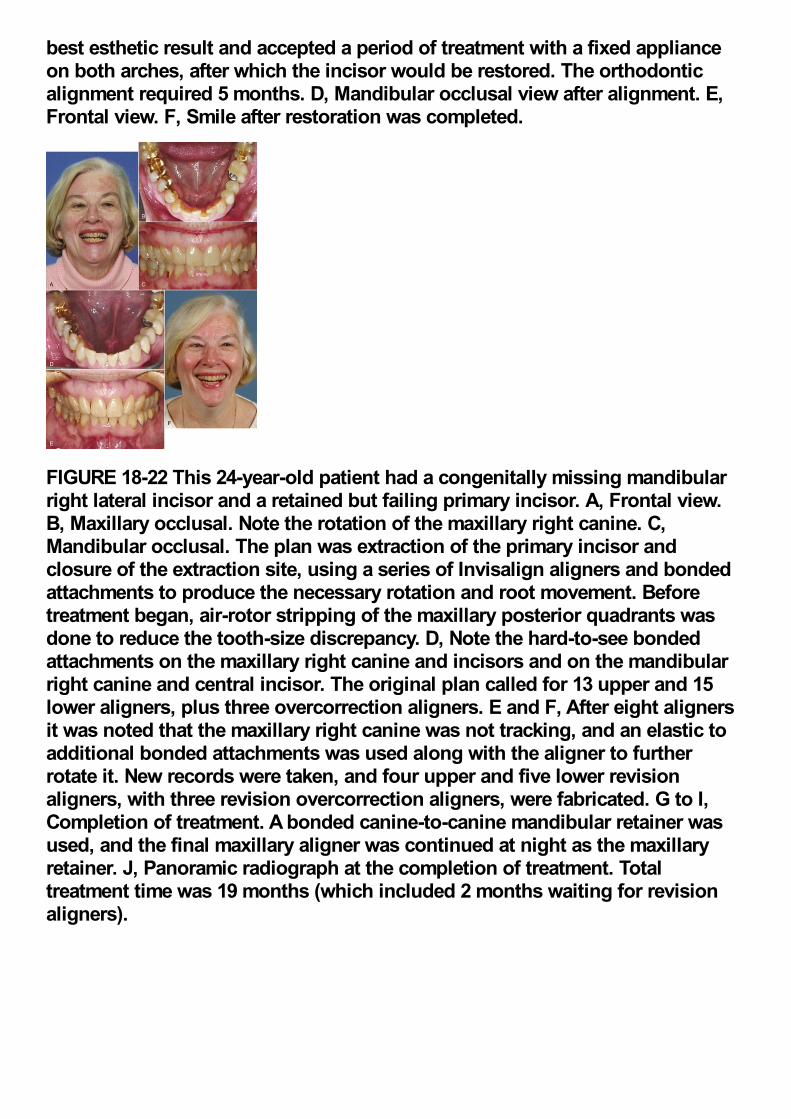
best esthetic result and accepted a period of treatment with a fixed applianceon both arches, after which the incisor would be restored. The orthodonticalignment required 5 months. D, Mandibular occlusal view after alignment. E,Frontal view. F, Smile after restoration was completed.
FIGURE 18-22 This 24-year-old patient had a congenitally missing mandibularright lateral incisor and a retained but failing primary incisor. A, Frontal view.B, Maxillary occlusal. Note the rotation of the maxillary right canine. C,Mandibular occlusal. The plan was extraction of the primary incisor andclosure of the extraction site, using a series of Invisalign aligners and bondedattachments to produce the necessary rotation and root movement. Beforetreatment began, air-rotor stripping of the maxillary posterior quadrants wasdone to reduce the tooth-size discrepancy. D, Note the hard-to-see bondedattachments on the maxillary right canine and incisors and on the mandibularright canine and central incisor. The original plan called for 13 upper and 15lower aligners, plus three overcorrection aligners. E and F, After eight alignersit was noted that the maxillary right canine was not tracking, and an elastic toadditional bonded attachments was used along with the aligner to furtherrotate it. New records were taken, and four upper and five lower revisionaligners, with three revision overcorrection aligners, were fabricated. G to I,Completion of treatment. A bonded canine-to-canine mandibular retainer wasused, and the final maxillary aligner was continued at night as the maxillaryretainer. J, Panoramic radiograph at the completion of treatment. Totaltreatment time was 19 months (which included 2 months waiting for revisionaligners).
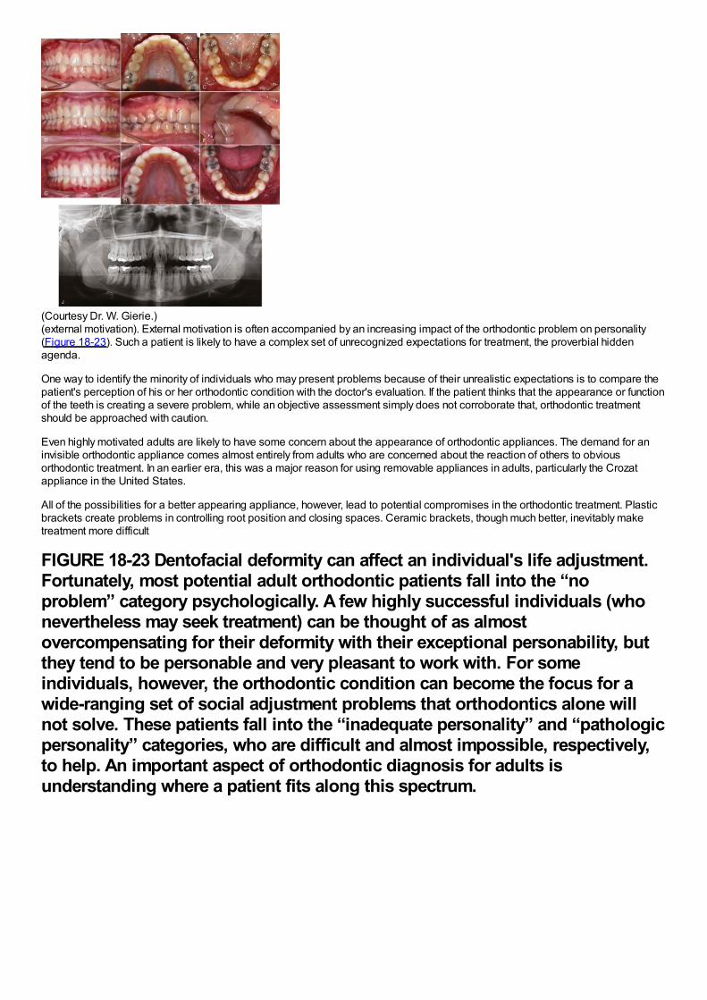
(Courtesy Dr. W. Gierie.)(external motivation). External motivation is often accompanied by an increasing impact of the orthodontic problem on personality(Figure 18-23). Such a patient is likely to have a complex set of unrecognized expectations for treatment, the proverbial hiddenagenda.
One way to identify the minority of individuals who may present problems because of their unrealistic expectations is to compare thepatient's perception of his or her orthodontic condition with the doctor's evaluation. If the patient thinks that the appearance or functionof the teeth is creating a severe problem, while an objective assessment simply does not corroborate that, orthodontic treatmentshould be approached with caution.
Even highly motivated adults are likely to have some concern about the appearance of orthodontic appliances. The demand for aninvisible orthodontic appliance comes almost entirely from adults who are concerned about the reaction of others to obviousorthodontic treatment. In an earlier era, this was a major reason for using removable appliances in adults, particularly the Crozatappliance in the United States.
All of the possibilities for a better appearing appliance, however, lead to potential compromises in the orthodontic treatment. Plasticbrackets create problems in controlling root position and closing spaces. Ceramic brackets, though much better, inevitably maketreatment more difficult
FIGURE 18-23 Dentofacial deformity can affect an individual's life adjustment.Fortunately, most potential adult orthodontic patients fall into the “noproblem” category psychologically. A few highly successful individuals (whonevertheless may seek treatment) can be thought of as almostovercompensating for their deformity with their exceptional personability, butthey tend to be personable and very pleasant to work with. For someindividuals, however, the orthodontic condition can become the focus for awide-ranging set of social adjustment problems that orthodontics alone willnot solve. These patients fall into the “inadequate personality” and “pathologicpersonality” categories, who are difficult and almost impossible, respectively,to help. An important aspect of orthodontic diagnosis for adults isunderstanding where a patient fits along this spectrum.
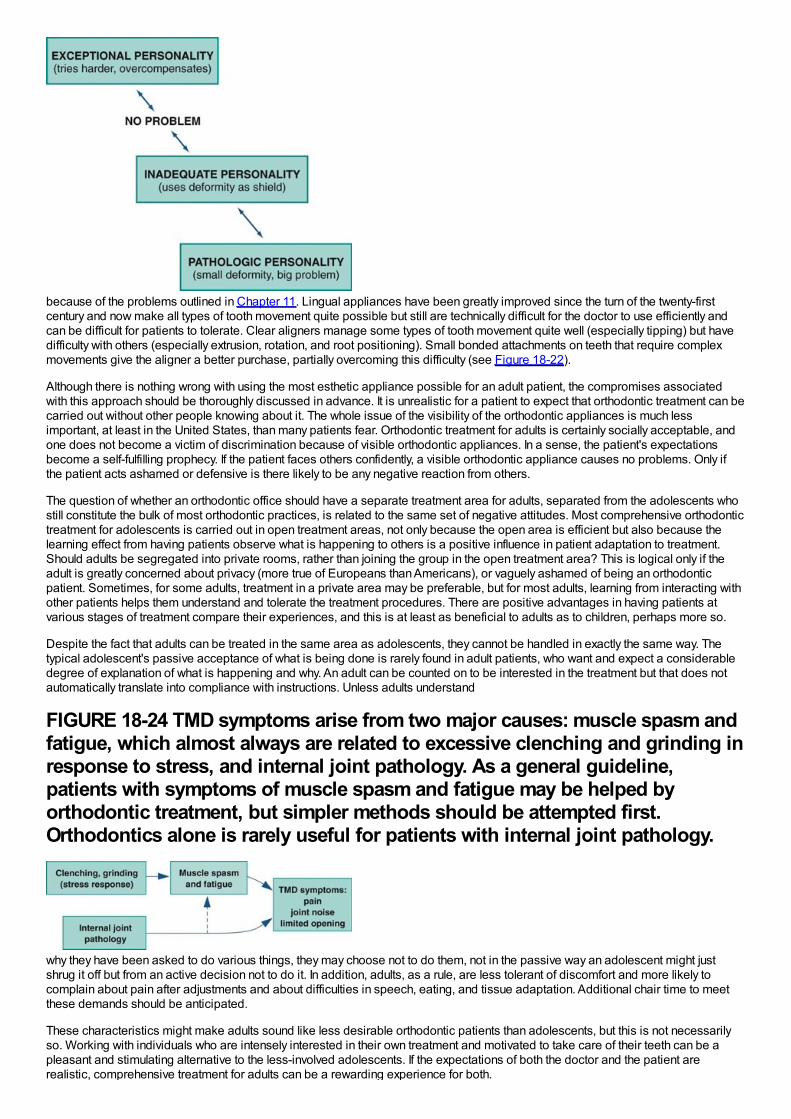
because of the problems outlined in Chapter 11. Lingual appliances have been greatly improved since the turn of the twenty-firstcentury and now make all types of tooth movement quite possible but still are technically difficult for the doctor to use efficiently andcan be difficult for patients to tolerate. Clear aligners manage some types of tooth movement quite well (especially tipping) but havedifficulty with others (especially extrusion, rotation, and root positioning). Small bonded attachments on teeth that require complexmovements give the aligner a better purchase, partially overcoming this difficulty (see Figure 18-22).
Although there is nothing wrong with using the most esthetic appliance possible for an adult patient, the compromises associatedwith this approach should be thoroughly discussed in advance. It is unrealistic for a patient to expect that orthodontic treatment can becarried out without other people knowing about it. The whole issue of the visibility of the orthodontic appliances is much lessimportant, at least in the United States, than many patients fear. Orthodontic treatment for adults is certainly socially acceptable, andone does not become a victim of discrimination because of visible orthodontic appliances. In a sense, the patient's expectationsbecome a self-fulfilling prophecy. If the patient faces others confidently, a visible orthodontic appliance causes no problems. Only ifthe patient acts ashamed or defensive is there likely to be any negative reaction from others.
The question of whether an orthodontic office should have a separate treatment area for adults, separated from the adolescents whostill constitute the bulk of most orthodontic practices, is related to the same set of negative attitudes. Most comprehensive orthodontictreatment for adolescents is carried out in open treatment areas, not only because the open area is efficient but also because thelearning effect from having patients observe what is happening to others is a positive influence in patient adaptation to treatment.Should adults be segregated into private rooms, rather than joining the group in the open treatment area? This is logical only if theadult is greatly concerned about privacy (more true of Europeans than Americans), or vaguely ashamed of being an orthodonticpatient. Sometimes, for some adults, treatment in a private area may be preferable, but for most adults, learning from interacting withother patients helps them understand and tolerate the treatment procedures. There are positive advantages in having patients atvarious stages of treatment compare their experiences, and this is at least as beneficial to adults as to children, perhaps more so.
Despite the fact that adults can be treated in the same area as adolescents, they cannot be handled in exactly the same way. Thetypical adolescent's passive acceptance of what is being done is rarely found in adult patients, who want and expect a considerabledegree of explanation of what is happening and why. An adult can be counted on to be interested in the treatment but that does notautomatically translate into compliance with instructions. Unless adults understand
FIGURE 18-24 TMD symptoms arise from two major causes: muscle spasm andfatigue, which almost always are related to excessive clenching and grinding inresponse to stress, and internal joint pathology. As a general guideline,patients with symptoms of muscle spasm and fatigue may be helped byorthodontic treatment, but simpler methods should be attempted first.Orthodontics alone is rarely useful for patients with internal joint pathology.
why they have been asked to do various things, they may choose not to do them, not in the passive way an adolescent might justshrug it off but from an active decision not to do it. In addition, adults, as a rule, are less tolerant of discomfort and more likely tocomplain about pain after adjustments and about difficulties in speech, eating, and tissue adaptation. Additional chair time to meetthese demands should be anticipated.
These characteristics might make adults sound like less desirable orthodontic patients than adolescents, but this is not necessarilyso. Working with individuals who are intensely interested in their own treatment and motivated to take care of their teeth can be apleasant and stimulating alternative to the less-involved adolescents. If the expectations of both the doctor and the patient arerealistic, comprehensive treatment for adults can be a rewarding experience for both.
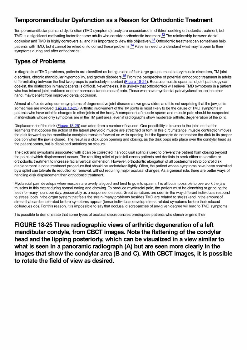
Temporomandibular Dysfunction as a Reason for Orthodontic TreatmentTemporomandibular pain and dysfunction (TMD symptoms) rarely are encountered in children seeking orthodontic treatment, butTMD is a significant motivating factor for some adults who consider orthodontic treatment.12 The relationship between dentalocclusion and TMD is highly controversial, and it is important to view this objectively.13 Orthodontic treatment can sometimes helppatients with TMD, but it cannot be relied on to correct these problems.14 Patients need to understand what may happen to theirsymptoms during and after orthodontics.
Types of ProblemsIn diagnosis of TMD problems, patients are classified as being in one of four large groups: masticatory muscle disorders, TM jointdisorders, chronic mandibular hypomobility, and growth disorders.15 From the perspective of potential orthodontic treatment in adults,differentiating between the first two groups is particularly important (Figure 18-24). Because muscle spasm and joint pathology cancoexist, the distinction in many patients is difficult. Nevertheless, it is unlikely that orthodontics will relieve TMD symptoms in a patientwho has internal joint problems or other nonmuscular sources of pain. Those who have myofascial pain/dysfunction, on the otherhand, may benefit from improved dental occlusion.
Almost all of us develop some symptoms of degenerative joint disease as we grow older, and it is not surprising that the jaw jointssometimes are involved (Figure 18-25). Arthritic involvement of the TM joints is most likely to be the cause of TMD symptoms inpatients who have arthritic changes in other joints of the body. A component of muscle spasm and muscle pain should be suspectedin individuals whose only symptoms are in the TM joint area, even if radiographs show moderate arthritic degeneration of the joint.
Displacement of the disk (Figure 18-26) can arise from a number of causes. One possibility is trauma to the joint, so that theligaments that oppose the action of the lateral pterygoid muscle are stretched or torn. In this circumstance, muscle contraction movesthe disk forward as the mandibular condyles translate forward on wide opening, but the ligaments do not restore the disk to its properposition when the jaw is closed. The result is a click upon opening and closing, as the disk pops into place over the condylar head asthe patient opens, but is displaced anteriorly on closure.
The click and symptoms associated with it can be corrected if an occlusal splint is used to prevent the patient from closing beyondthe point at which displacement occurs. The resulting relief of pain influences patients and dentists to seek either restorative ororthodontic treatment to increase facial vertical dimension. However, orthodontic elongation of all posterior teeth to control diskdisplacement is not a treatment procedure that should be undertaken lightly. Often, the patient whose symptoms have been controlledby a splint can tolerate its reduction or removal, without requiring major occlusal changes. As a general rule, there are better ways ofhandling disk displacement than orthodontic treatment.
Myofascial pain develops when muscles are overly fatigued and tend to go into spasm. It is all but impossible to overwork the jawmuscles to this extent during normal eating and chewing. To produce myofascial pain, the patient must be clenching or grinding theteeth for many hours per day, presumably as a response to stress. Great variations are seen in the way different individuals respondto stress, both in the organ system that feels the strain (many problems besides TMD are related to stress) and in the amount ofstress that can be tolerated before symptoms appear (tense individuals develop stress-related symptoms before their relaxedcolleagues do). For this reason, it is impossible to say that occlusal discrepancies of any given degree will lead to TMD symptoms.
It is possible to demonstrate that some types of occlusal discrepancies predispose patients who clench or grind their
FIGURE 18-25 Three radiographic views of arthritic degeneration of a leftmandibular condyle, from CBCT images. Note the flattening of the condylarhead and the lipping posteriorly, which can be visualized in a view similar towhat is seen in a panoramic radiograph (A) but are seen more clearly in theimages that show the condylar area (B and C). With CBCT images, it is possibleto rotate the field of view as desired.
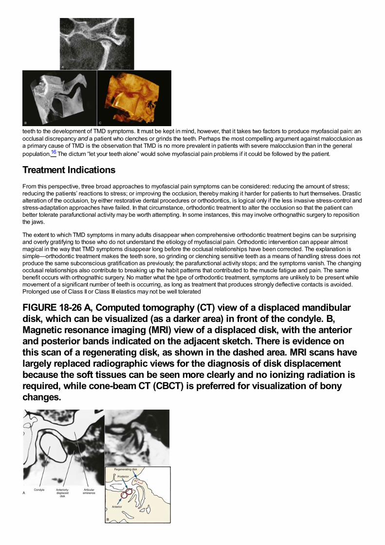
teeth to the development of TMD symptoms. It must be kept in mind, however, that it takes two factors to produce myofascial pain: anocclusal discrepancy and a patient who clenches or grinds the teeth. Perhaps the most compelling argument against malocclusion asa primary cause of TMD is the observation that TMD is no more prevalent in patients with severe malocclusion than in the generalpopulation.16 The dictum “let your teeth alone” would solve myofascial pain problems if it could be followed by the patient.
Treatment IndicationsFrom this perspective, three broad approaches to myofascial pain symptoms can be considered: reducing the amount of stress;reducing the patients’ reactions to stress; or improving the occlusion, thereby making it harder for patients to hurt themselves. Drasticalteration of the occlusion, by either restorative dental procedures or orthodontics, is logical only if the less invasive stress-control andstress-adaptation approaches have failed. In that circumstance, orthodontic treatment to alter the occlusion so that the patient canbetter tolerate parafunctional activity may be worth attempting. In some instances, this may involve orthognathic surgery to repositionthe jaws.
The extent to which TMD symptoms in many adults disappear when comprehensive orthodontic treatment begins can be surprisingand overly gratifying to those who do not understand the etiology of myofascial pain. Orthodontic intervention can appear almostmagical in the way that TMD symptoms disappear long before the occlusal relationships have been corrected. The explanation issimple—orthodontic treatment makes the teeth sore, so grinding or clenching sensitive teeth as a means of handling stress does notproduce the same subconscious gratification as previously; the parafunctional activity stops; and the symptoms vanish. The changingocclusal relationships also contribute to breaking up the habit patterns that contributed to the muscle fatigue and pain. The samebenefit occurs with orthognathic surgery. No matter what the type of orthodontic treatment, symptoms are unlikely to be present whilemovement of a significant number of teeth is occurring, as long as treatment that produces strongly deflective contacts is avoided.Prolonged use of Class II or Class III elastics may not be well tolerated
FIGURE 18-26 A, Computed tomography (CT) view of a displaced mandibulardisk, which can be visualized (as a darker area) in front of the condyle. B,Magnetic resonance imaging (MRI) view of a displaced disk, with the anteriorand posterior bands indicated on the adjacent sketch. There is evidence onthis scan of a regenerating disk, as shown in the dashed area. MRI scans havelargely replaced radiographic views for the diagnosis of disk displacementbecause the soft tissues can be seen more clearly and no ionizing radiation isrequired, while cone-beam CT (CBCT) is preferred for visualization of bonychanges.
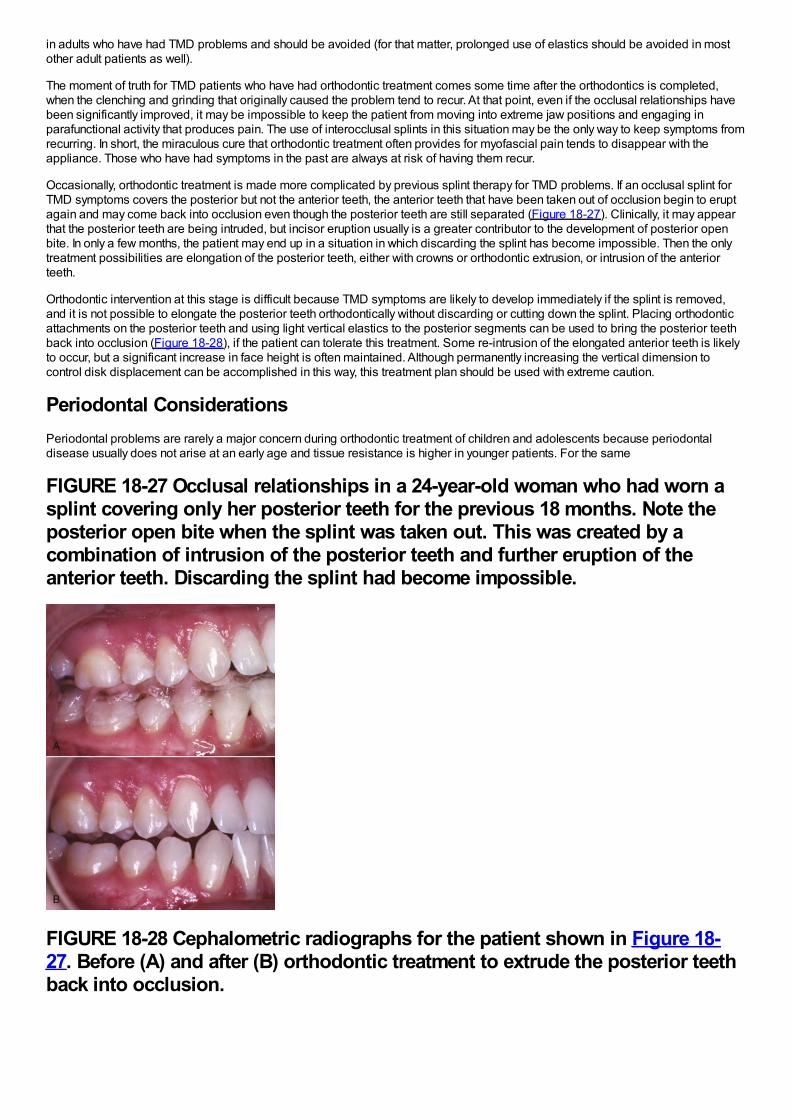
in adults who have had TMD problems and should be avoided (for that matter, prolonged use of elastics should be avoided in mostother adult patients as well).
The moment of truth for TMD patients who have had orthodontic treatment comes some time after the orthodontics is completed,when the clenching and grinding that originally caused the problem tend to recur. At that point, even if the occlusal relationships havebeen significantly improved, it may be impossible to keep the patient from moving into extreme jaw positions and engaging inparafunctional activity that produces pain. The use of interocclusal splints in this situation may be the only way to keep symptoms fromrecurring. In short, the miraculous cure that orthodontic treatment often provides for myofascial pain tends to disappear with theappliance. Those who have had symptoms in the past are always at risk of having them recur.
Occasionally, orthodontic treatment is made more complicated by previous splint therapy for TMD problems. If an occlusal splint forTMD symptoms covers the posterior but not the anterior teeth, the anterior teeth that have been taken out of occlusion begin to eruptagain and may come back into occlusion even though the posterior teeth are still separated (Figure 18-27). Clinically, it may appearthat the posterior teeth are being intruded, but incisor eruption usually is a greater contributor to the development of posterior openbite. In only a few months, the patient may end up in a situation in which discarding the splint has become impossible. Then the onlytreatment possibilities are elongation of the posterior teeth, either with crowns or orthodontic extrusion, or intrusion of the anteriorteeth.
Orthodontic intervention at this stage is difficult because TMD symptoms are likely to develop immediately if the splint is removed,and it is not possible to elongate the posterior teeth orthodontically without discarding or cutting down the splint. Placing orthodonticattachments on the posterior teeth and using light vertical elastics to the posterior segments can be used to bring the posterior teethback into occlusion (Figure 18-28), if the patient can tolerate this treatment. Some re-intrusion of the elongated anterior teeth is likelyto occur, but a significant increase in face height is often maintained. Although permanently increasing the vertical dimension tocontrol disk displacement can be accomplished in this way, this treatment plan should be used with extreme caution.
Periodontal ConsiderationsPeriodontal problems are rarely a major concern during orthodontic treatment of children and adolescents because periodontaldisease usually does not arise at an early age and tissue resistance is higher in younger patients. For the same
FIGURE 18-27 Occlusal relationships in a 24-year-old woman who had worn asplint covering only her posterior teeth for the previous 18 months. Note theposterior open bite when the splint was taken out. This was created by acombination of intrusion of the posterior teeth and further eruption of theanterior teeth. Discarding the splint had become impossible.
FIGURE 18-28 Cephalometric radiographs for the patient shown in Figure 18-27. Before (A) and after (B) orthodontic treatment to extrude the posterior teethback into occlusion.
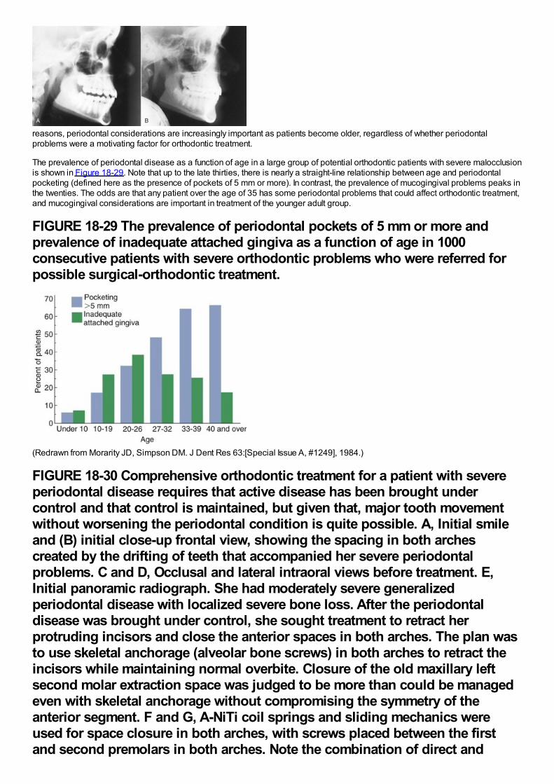
reasons, periodontal considerations are increasingly important as patients become older, regardless of whether periodontalproblems were a motivating factor for orthodontic treatment.
The prevalence of periodontal disease as a function of age in a large group of potential orthodontic patients with severe malocclusionis shown in Figure 18-29. Note that up to the late thirties, there is nearly a straight-line relationship between age and periodontalpocketing (defined here as the presence of pockets of 5 mm or more). In contrast, the prevalence of mucogingival problems peaks inthe twenties. The odds are that any patient over the age of 35 has some periodontal problems that could affect orthodontic treatment,and mucogingival considerations are important in treatment of the younger adult group.
FIGURE 18-29 The prevalence of periodontal pockets of 5 mm or more andprevalence of inadequate attached gingiva as a function of age in 1000consecutive patients with severe orthodontic problems who were referred forpossible surgical-orthodontic treatment.
(Redrawn from Morarity JD, Simpson DM. J Dent Res 63:[Special Issue A, #1249], 1984.)
FIGURE 18-30 Comprehensive orthodontic treatment for a patient with severeperiodontal disease requires that active disease has been brought undercontrol and that control is maintained, but given that, major tooth movementwithout worsening the periodontal condition is quite possible. A, Initial smileand (B) initial close-up frontal view, showing the spacing in both archescreated by the drifting of teeth that accompanied her severe periodontalproblems. C and D, Occlusal and lateral intraoral views before treatment. E,Initial panoramic radiograph. She had moderately severe generalizedperiodontal disease with localized severe bone loss. After the periodontaldisease was brought under control, she sought treatment to retract herprotruding incisors and close the anterior spaces in both arches. The plan wasto use skeletal anchorage (alveolar bone screws) in both arches to retract theincisors while maintaining normal overbite. Closure of the old maxillary leftsecond molar extraction space was judged to be more than could be managedeven with skeletal anchorage without compromising the symmetry of theanterior segment. F and G, A-NiTi coil springs and sliding mechanics wereused for space closure in both arches, with screws placed between the firstand second premolars in both arches. Note the combination of direct and
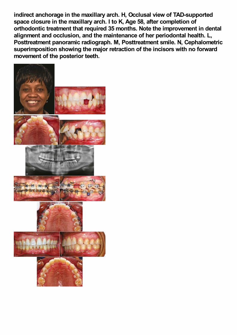
indirect anchorage in the maxillary arch. H, Occlusal view of TAD-supportedspace closure in the maxillary arch. I to K, Age 58, after completion oforthodontic treatment that required 35 months. Note the improvement in dentalalignment and occlusion, and the maintenance of her periodontal health. L,Posttreatment panoramic radiograph. M, Posttreatment smile. N, Cephalometricsuperimposition showing the major retraction of the incisors with no forwardmovement of the posterior teeth.
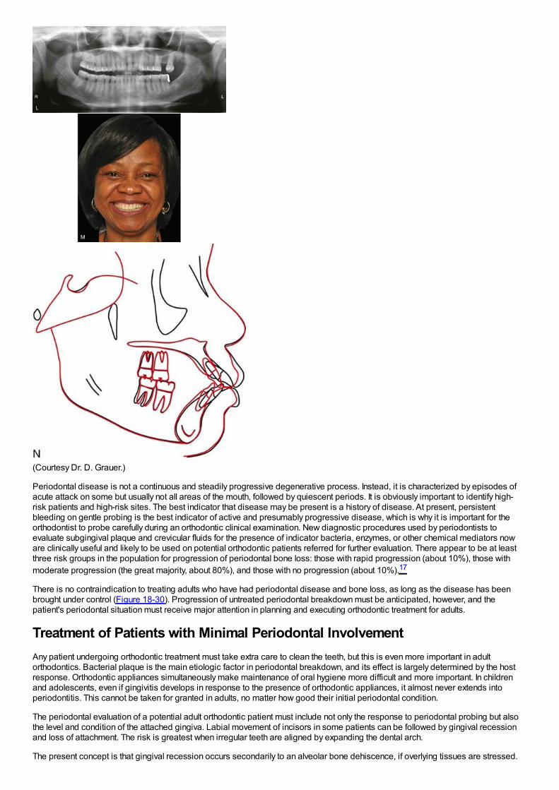
(Courtesy Dr. D. Grauer.)
Periodontal disease is not a continuous and steadily progressive degenerative process. Instead, it is characterized by episodes ofacute attack on some but usually not all areas of the mouth, followed by quiescent periods. It is obviously important to identify high-risk patients and high-risk sites. The best indicator that disease may be present is a history of disease. At present, persistentbleeding on gentle probing is the best indicator of active and presumably progressive disease, which is why it is important for theorthodontist to probe carefully during an orthodontic clinical examination. New diagnostic procedures used by periodontists toevaluate subgingival plaque and crevicular fluids for the presence of indicator bacteria, enzymes, or other chemical mediators noware clinically useful and likely to be used on potential orthodontic patients referred for further evaluation. There appear to be at leastthree risk groups in the population for progression of periodontal bone loss: those with rapid progression (about 10%), those withmoderate progression (the great majority, about 80%), and those with no progression (about 10%).17
There is no contraindication to treating adults who have had periodontal disease and bone loss, as long as the disease has beenbrought under control (Figure 18-30). Progression of untreated periodontal breakdown must be anticipated, however, and thepatient's periodontal situation must receive major attention in planning and executing orthodontic treatment for adults.
Treatment of Patients with Minimal Periodontal InvolvementAny patient undergoing orthodontic treatment must take extra care to clean the teeth, but this is even more important in adultorthodontics. Bacterial plaque is the main etiologic factor in periodontal breakdown, and its effect is largely determined by the hostresponse. Orthodontic appliances simultaneously make maintenance of oral hygiene more difficult and more important. In childrenand adolescents, even if gingivitis develops in response to the presence of orthodontic appliances, it almost never extends intoperiodontitis. This cannot be taken for granted in adults, no matter how good their initial periodontal condition.
The periodontal evaluation of a potential adult orthodontic patient must include not only the response to periodontal probing but alsothe level and condition of the attached gingiva. Labial movement of incisors in some patients can be followed by gingival recessionand loss of attachment. The risk is greatest when irregular teeth are aligned by expanding the dental arch.
The present concept is that gingival recession occurs secondarily to an alveolar bone dehiscence, if overlying tissues are stressed.
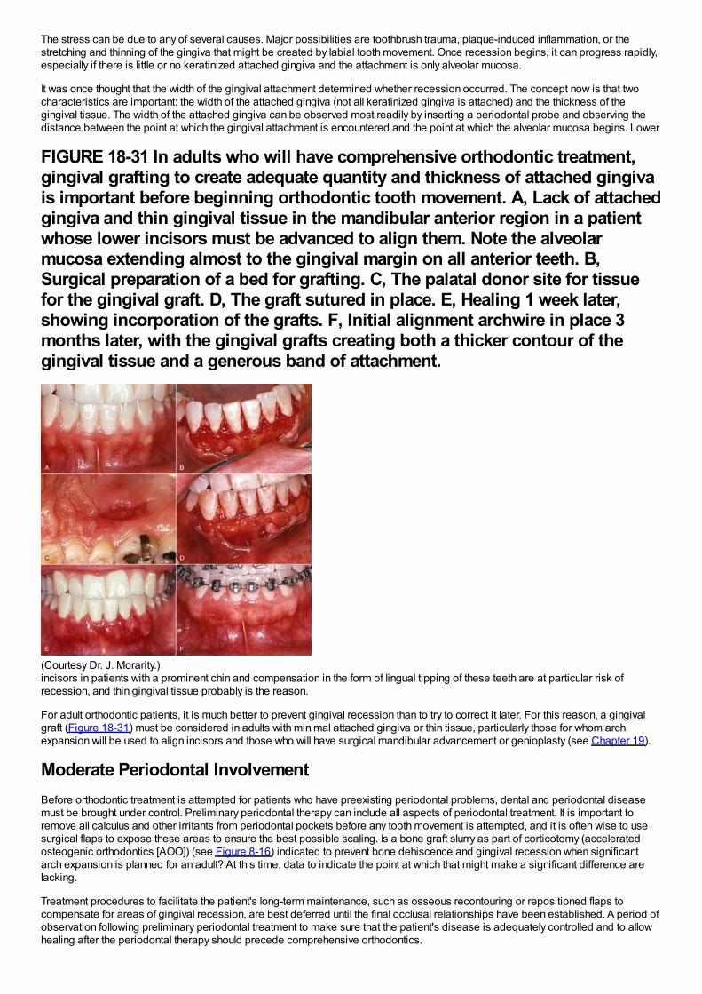
The stress can be due to any of several causes. Major possibilities are toothbrush trauma, plaque-induced inflammation, or thestretching and thinning of the gingiva that might be created by labial tooth movement. Once recession begins, it can progress rapidly,especially if there is little or no keratinized attached gingiva and the attachment is only alveolar mucosa.
It was once thought that the width of the gingival attachment determined whether recession occurred. The concept now is that twocharacteristics are important: the width of the attached gingiva (not all keratinized gingiva is attached) and the thickness of thegingival tissue. The width of the attached gingiva can be observed most readily by inserting a periodontal probe and observing thedistance between the point at which the gingival attachment is encountered and the point at which the alveolar mucosa begins. Lower
FIGURE 18-31 In adults who will have comprehensive orthodontic treatment,gingival grafting to create adequate quantity and thickness of attached gingivais important before beginning orthodontic tooth movement. A, Lack of attachedgingiva and thin gingival tissue in the mandibular anterior region in a patientwhose lower incisors must be advanced to align them. Note the alveolarmucosa extending almost to the gingival margin on all anterior teeth. B,Surgical preparation of a bed for grafting. C, The palatal donor site for tissuefor the gingival graft. D, The graft sutured in place. E, Healing 1 week later,showing incorporation of the grafts. F, Initial alignment archwire in place 3months later, with the gingival grafts creating both a thicker contour of thegingival tissue and a generous band of attachment.
(Courtesy Dr. J. Morarity.)incisors in patients with a prominent chin and compensation in the form of lingual tipping of these teeth are at particular risk ofrecession, and thin gingival tissue probably is the reason.
For adult orthodontic patients, it is much better to prevent gingival recession than to try to correct it later. For this reason, a gingivalgraft (Figure 18-31) must be considered in adults with minimal attached gingiva or thin tissue, particularly those for whom archexpansion will be used to align incisors and those who will have surgical mandibular advancement or genioplasty (see Chapter 19).
Moderate Periodontal InvolvementBefore orthodontic treatment is attempted for patients who have preexisting periodontal problems, dental and periodontal diseasemust be brought under control. Preliminary periodontal therapy can include all aspects of periodontal treatment. It is important toremove all calculus and other irritants from periodontal pockets before any tooth movement is attempted, and it is often wise to usesurgical flaps to expose these areas to ensure the best possible scaling. Is a bone graft slurry as part of corticotomy (acceleratedosteogenic orthodontics [AOO]) (see Figure 8-16) indicated to prevent bone dehiscence and gingival recession when significantarch expansion is planned for an adult? At this time, data to indicate the point at which that might make a significant difference arelacking.
Treatment procedures to facilitate the patient's long-term maintenance, such as osseous recontouring or repositioned flaps tocompensate for areas of gingival recession, are best deferred until the final occlusal relationships have been established. A period ofobservation following preliminary periodontal treatment to make sure that the patient's disease is adequately controlled and to allowhealing after the periodontal therapy should precede comprehensive orthodontics.
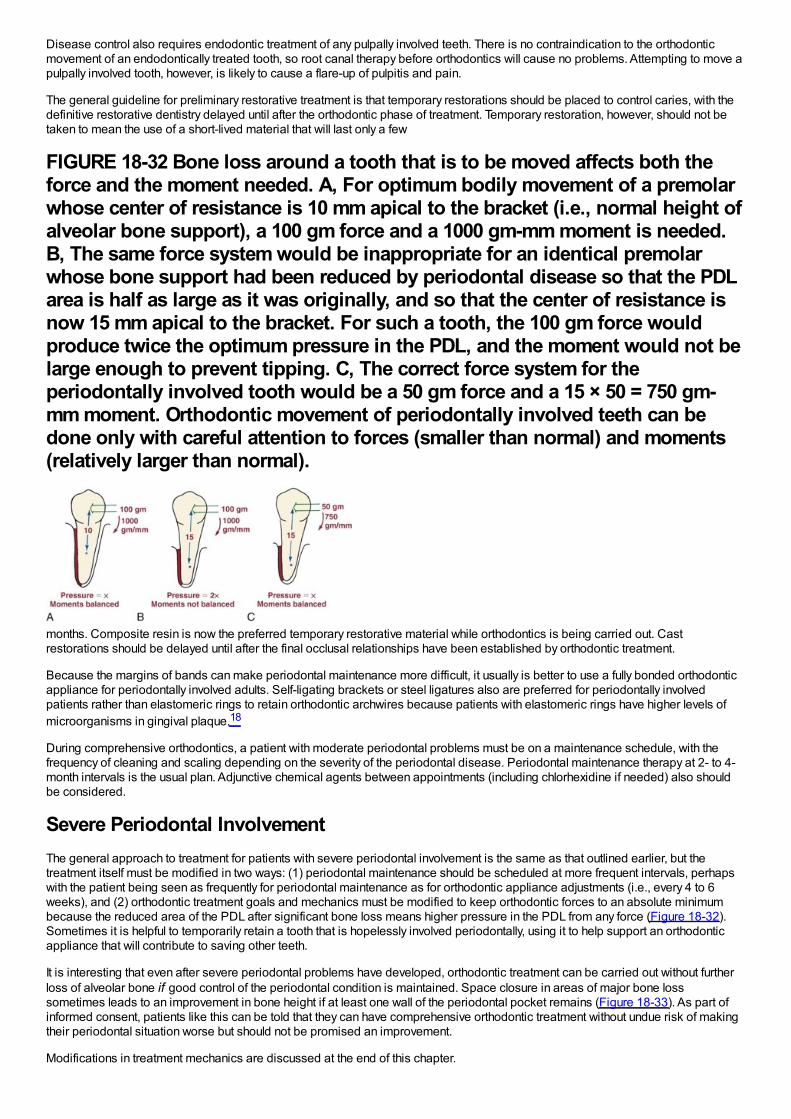
Disease control also requires endodontic treatment of any pulpally involved teeth. There is no contraindication to the orthodonticmovement of an endodontically treated tooth, so root canal therapy before orthodontics will cause no problems. Attempting to move apulpally involved tooth, however, is likely to cause a flare-up of pulpitis and pain.
The general guideline for preliminary restorative treatment is that temporary restorations should be placed to control caries, with thedefinitive restorative dentistry delayed until after the orthodontic phase of treatment. Temporary restoration, however, should not betaken to mean the use of a short-lived material that will last only a few
FIGURE 18-32 Bone loss around a tooth that is to be moved affects both theforce and the moment needed. A, For optimum bodily movement of a premolarwhose center of resistance is 10 mm apical to the bracket (i.e., normal height ofalveolar bone support), a 100 gm force and a 1000 gm-mm moment is needed.B, The same force system would be inappropriate for an identical premolarwhose bone support had been reduced by periodontal disease so that the PDLarea is half as large as it was originally, and so that the center of resistance isnow 15 mm apical to the bracket. For such a tooth, the 100 gm force wouldproduce twice the optimum pressure in the PDL, and the moment would not belarge enough to prevent tipping. C, The correct force system for theperiodontally involved tooth would be a 50 gm force and a 15 × 50 = 750 gm-mm moment. Orthodontic movement of periodontally involved teeth can bedone only with careful attention to forces (smaller than normal) and moments(relatively larger than normal).
months. Composite resin is now the preferred temporary restorative material while orthodontics is being carried out. Castrestorations should be delayed until after the final occlusal relationships have been established by orthodontic treatment.
Because the margins of bands can make periodontal maintenance more difficult, it usually is better to use a fully bonded orthodonticappliance for periodontally involved adults. Self-ligating brackets or steel ligatures also are preferred for periodontally involvedpatients rather than elastomeric rings to retain orthodontic archwires because patients with elastomeric rings have higher levels ofmicroorganisms in gingival plaque.18
During comprehensive orthodontics, a patient with moderate periodontal problems must be on a maintenance schedule, with thefrequency of cleaning and scaling depending on the severity of the periodontal disease. Periodontal maintenance therapy at 2- to 4-month intervals is the usual plan. Adjunctive chemical agents between appointments (including chlorhexidine if needed) also shouldbe considered.
Severe Periodontal InvolvementThe general approach to treatment for patients with severe periodontal involvement is the same as that outlined earlier, but thetreatment itself must be modified in two ways: (1) periodontal maintenance should be scheduled at more frequent intervals, perhapswith the patient being seen as frequently for periodontal maintenance as for orthodontic appliance adjustments (i.e., every 4 to 6weeks), and (2) orthodontic treatment goals and mechanics must be modified to keep orthodontic forces to an absolute minimumbecause the reduced area of the PDL after significant bone loss means higher pressure in the PDL from any force (Figure 18-32).Sometimes it is helpful to temporarily retain a tooth that is hopelessly involved periodontally, using it to help support an orthodonticappliance that will contribute to saving other teeth.
It is interesting that even after severe periodontal problems have developed, orthodontic treatment can be carried out without furtherloss of alveolar bone if good control of the periodontal condition is maintained. Space closure in areas of major bone losssometimes leads to an improvement in bone height if at least one wall of the periodontal pocket remains (Figure 18-33). As part ofinformed consent, patients like this can be told that they can have comprehensive orthodontic treatment without undue risk of makingtheir periodontal situation worse but should not be promised an improvement.
Modifications in treatment mechanics are discussed at the end of this chapter.
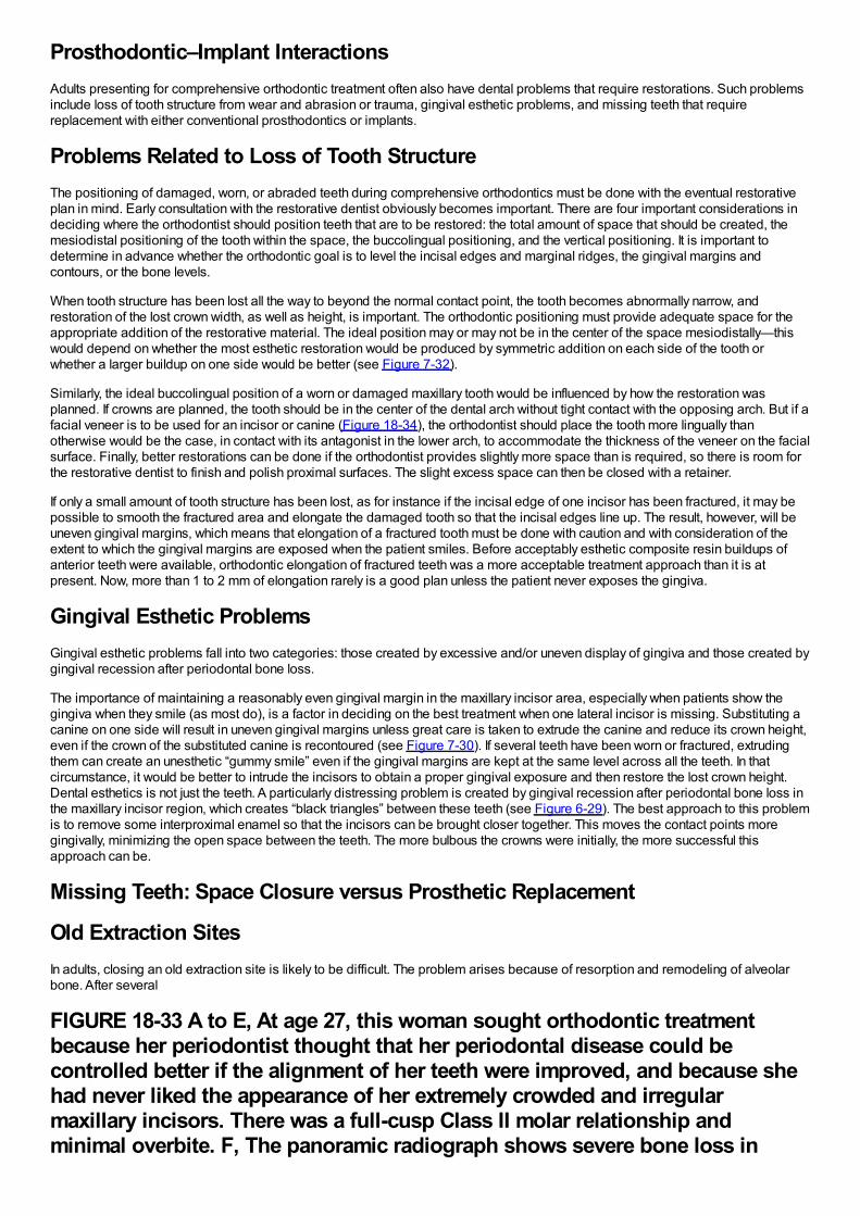
Prosthodontic–Implant InteractionsAdults presenting for comprehensive orthodontic treatment often also have dental problems that require restorations. Such problemsinclude loss of tooth structure from wear and abrasion or trauma, gingival esthetic problems, and missing teeth that requirereplacement with either conventional prosthodontics or implants.
Problems Related to Loss of Tooth StructureThe positioning of damaged, worn, or abraded teeth during comprehensive orthodontics must be done with the eventual restorativeplan in mind. Early consultation with the restorative dentist obviously becomes important. There are four important considerations indeciding where the orthodontist should position teeth that are to be restored: the total amount of space that should be created, themesiodistal positioning of the tooth within the space, the buccolingual positioning, and the vertical positioning. It is important todetermine in advance whether the orthodontic goal is to level the incisal edges and marginal ridges, the gingival margins andcontours, or the bone levels.
When tooth structure has been lost all the way to beyond the normal contact point, the tooth becomes abnormally narrow, andrestoration of the lost crown width, as well as height, is important. The orthodontic positioning must provide adequate space for theappropriate addition of the restorative material. The ideal position may or may not be in the center of the space mesiodistally—thiswould depend on whether the most esthetic restoration would be produced by symmetric addition on each side of the tooth orwhether a larger buildup on one side would be better (see Figure 7-32).
Similarly, the ideal buccolingual position of a worn or damaged maxillary tooth would be influenced by how the restoration wasplanned. If crowns are planned, the tooth should be in the center of the dental arch without tight contact with the opposing arch. But if afacial veneer is to be used for an incisor or canine (Figure 18-34), the orthodontist should place the tooth more lingually thanotherwise would be the case, in contact with its antagonist in the lower arch, to accommodate the thickness of the veneer on the facialsurface. Finally, better restorations can be done if the orthodontist provides slightly more space than is required, so there is room forthe restorative dentist to finish and polish proximal surfaces. The slight excess space can then be closed with a retainer.
If only a small amount of tooth structure has been lost, as for instance if the incisal edge of one incisor has been fractured, it may bepossible to smooth the fractured area and elongate the damaged tooth so that the incisal edges line up. The result, however, will beuneven gingival margins, which means that elongation of a fractured tooth must be done with caution and with consideration of theextent to which the gingival margins are exposed when the patient smiles. Before acceptably esthetic composite resin buildups ofanterior teeth were available, orthodontic elongation of fractured teeth was a more acceptable treatment approach than it is atpresent. Now, more than 1 to 2 mm of elongation rarely is a good plan unless the patient never exposes the gingiva.
Gingival Esthetic ProblemsGingival esthetic problems fall into two categories: those created by excessive and/or uneven display of gingiva and those created bygingival recession after periodontal bone loss.
The importance of maintaining a reasonably even gingival margin in the maxillary incisor area, especially when patients show thegingiva when they smile (as most do), is a factor in deciding on the best treatment when one lateral incisor is missing. Substituting acanine on one side will result in uneven gingival margins unless great care is taken to extrude the canine and reduce its crown height,even if the crown of the substituted canine is recontoured (see Figure 7-30). If several teeth have been worn or fractured, extrudingthem can create an unesthetic “gummy smile” even if the gingival margins are kept at the same level across all the teeth. In thatcircumstance, it would be better to intrude the incisors to obtain a proper gingival exposure and then restore the lost crown height.Dental esthetics is not just the teeth. A particularly distressing problem is created by gingival recession after periodontal bone loss inthe maxillary incisor region, which creates “black triangles” between these teeth (see Figure 6-29). The best approach to this problemis to remove some interproximal enamel so that the incisors can be brought closer together. This moves the contact points moregingivally, minimizing the open space between the teeth. The more bulbous the crowns were initially, the more successful thisapproach can be.
Missing Teeth: Space Closure versus Prosthetic Replacement
Old Extraction SitesIn adults, closing an old extraction site is likely to be difficult. The problem arises because of resorption and remodeling of alveolarbone. After several
FIGURE 18-33 A to E, At age 27, this woman sought orthodontic treatmentbecause her periodontist thought that her periodontal disease could becontrolled better if the alignment of her teeth were improved, and because shehad never liked the appearance of her extremely crowded and irregularmaxillary incisors. There was a full-cusp Class II molar relationship andminimal overbite. F, The panoramic radiograph shows severe bone loss in
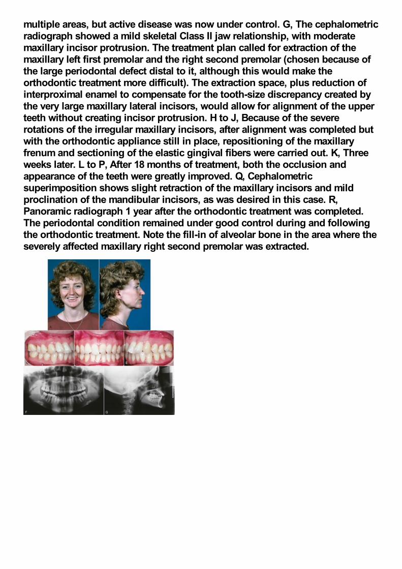
multiple areas, but active disease was now under control. G, The cephalometricradiograph showed a mild skeletal Class II jaw relationship, with moderatemaxillary incisor protrusion. The treatment plan called for extraction of themaxillary left first premolar and the right second premolar (chosen because ofthe large periodontal defect distal to it, although this would make theorthodontic treatment more difficult). The extraction space, plus reduction ofinterproximal enamel to compensate for the tooth-size discrepancy created bythe very large maxillary lateral incisors, would allow for alignment of the upperteeth without creating incisor protrusion. H to J, Because of the severerotations of the irregular maxillary incisors, after alignment was completed butwith the orthodontic appliance still in place, repositioning of the maxillaryfrenum and sectioning of the elastic gingival fibers were carried out. K, Threeweeks later. L to P, After 18 months of treatment, both the occlusion andappearance of the teeth were greatly improved. Q, Cephalometricsuperimposition shows slight retraction of the maxillary incisors and mildproclination of the mandibular incisors, as was desired in this case. R,Panoramic radiograph 1 year after the orthodontic treatment was completed.The periodontal condition remained under good control during and followingthe orthodontic treatment. Note the fill-in of alveolar bone in the area where theseverely affected maxillary right second premolar was extracted.
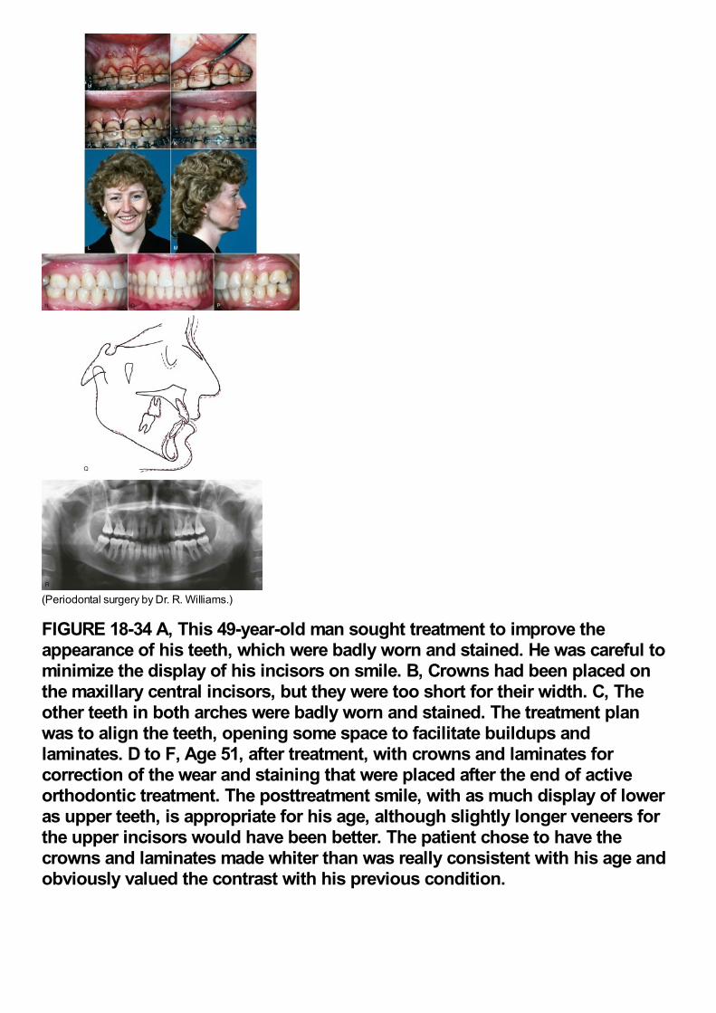
(Periodontal surgery by Dr. R. Williams.)
FIGURE 18-34 A, This 49-year-old man sought treatment to improve theappearance of his teeth, which were badly worn and stained. He was careful tominimize the display of his incisors on smile. B, Crowns had been placed onthe maxillary central incisors, but they were too short for their width. C, Theother teeth in both arches were badly worn and stained. The treatment planwas to align the teeth, opening some space to facilitate buildups andlaminates. D to F, Age 51, after treatment, with crowns and laminates forcorrection of the wear and staining that were placed after the end of activeorthodontic treatment. The posttreatment smile, with as much display of loweras upper teeth, is appropriate for his age, although slightly longer veneers forthe upper incisors would have been better. The patient chose to have thecrowns and laminates made whiter than was really consistent with his age andobviously valued the contrast with his previous condition.
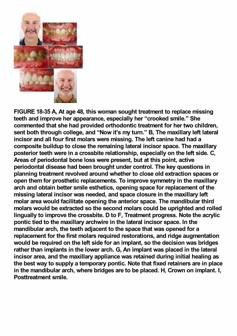
FIGURE 18-35 A, At age 48, this woman sought treatment to replace missingteeth and improve her appearance, especially her “crooked smile.” Shecommented that she had provided orthodontic treatment for her two children,sent both through college, and “Now it's my turn.” B, The maxillary left lateralincisor and all four first molars were missing. The left canine had had acomposite buildup to close the remaining lateral incisor space. The maxillaryposterior teeth were in a crossbite relationship, especially on the left side. C,Areas of periodontal bone loss were present, but at this point, activeperiodontal disease had been brought under control. The key questions inplanning treatment revolved around whether to close old extraction spaces oropen them for prosthetic replacements. To improve symmetry in the maxillaryarch and obtain better smile esthetics, opening space for replacement of themissing lateral incisor was needed, and space closure in the maxillary leftmolar area would facilitate opening the anterior space. The mandibular thirdmolars would be extracted so the second molars could be uprighted and rolledlingually to improve the crossbite. D to F, Treatment progress. Note the acrylicpontic tied to the maxillary archwire in the lateral incisor space. In themandibular arch, the teeth adjacent to the space that was opened for areplacement for the first molars required restorations, and ridge augmentationwould be required on the left side for an implant, so the decision was bridgesrather than implants in the lower arch. G, An implant was placed in the lateralincisor area, and the maxillary appliance was retained during initial healing asthe best way to supply a temporary pontic. Note that fixed retainers are in placein the mandibular arch, where bridges are to be placed. H, Crown on implant. I,Posttreatment smile.
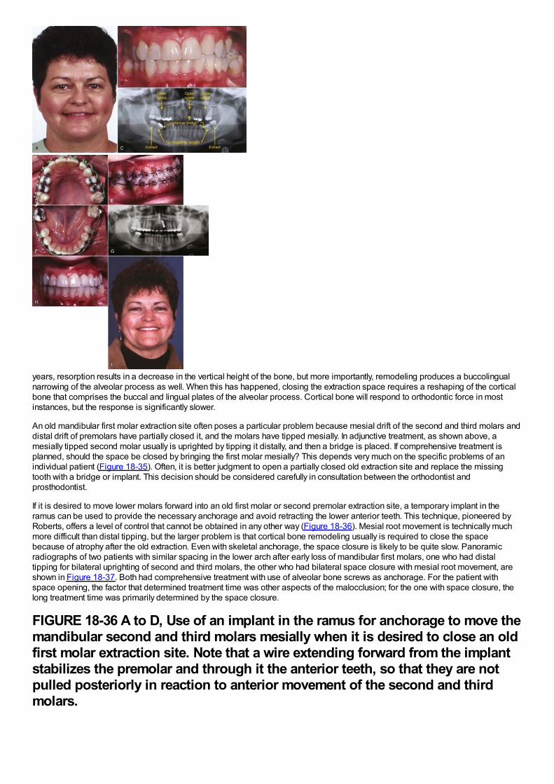
years, resorption results in a decrease in the vertical height of the bone, but more importantly, remodeling produces a buccolingualnarrowing of the alveolar process as well. When this has happened, closing the extraction space requires a reshaping of the corticalbone that comprises the buccal and lingual plates of the alveolar process. Cortical bone will respond to orthodontic force in mostinstances, but the response is significantly slower.
An old mandibular first molar extraction site often poses a particular problem because mesial drift of the second and third molars anddistal drift of premolars have partially closed it, and the molars have tipped mesially. In adjunctive treatment, as shown above, amesially tipped second molar usually is uprighted by tipping it distally, and then a bridge is placed. If comprehensive treatment isplanned, should the space be closed by bringing the first molar mesially? This depends very much on the specific problems of anindividual patient (Figure 18-35). Often, it is better judgment to open a partially closed old extraction site and replace the missingtooth with a bridge or implant. This decision should be considered carefully in consultation between the orthodontist andprosthodontist.
If it is desired to move lower molars forward into an old first molar or second premolar extraction site, a temporary implant in theramus can be used to provide the necessary anchorage and avoid retracting the lower anterior teeth. This technique, pioneered byRoberts, offers a level of control that cannot be obtained in any other way (Figure 18-36). Mesial root movement is technically muchmore difficult than distal tipping, but the larger problem is that cortical bone remodeling usually is required to close the spacebecause of atrophy after the old extraction. Even with skeletal anchorage, the space closure is likely to be quite slow. Panoramicradiographs of two patients with similar spacing in the lower arch after early loss of mandibular first molars, one who had distaltipping for bilateral uprighting of second and third molars, the other who had bilateral space closure with mesial root movement, areshown in Figure 18-37. Both had comprehensive treatment with use of alveolar bone screws as anchorage. For the patient withspace opening, the factor that determined treatment time was other aspects of the malocclusion; for the one with space closure, thelong treatment time was primarily determined by the space closure.
FIGURE 18-36 A to D, Use of an implant in the ramus for anchorage to move themandibular second and third molars mesially when it is desired to close an oldfirst molar extraction site. Note that a wire extending forward from the implantstabilizes the premolar and through it the anterior teeth, so that they are notpulled posteriorly in reaction to anterior movement of the second and thirdmolars.
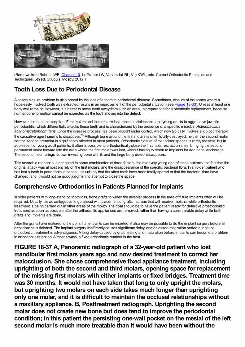
(Redrawn from Roberts WE. Chapter 10. In: Graber LW, Vanarsdall RL, Vig KWL, eds. Current Orthodontic Principles andTechniques. 5th ed. St Louis: Mosby; 2012.)
Tooth Loss Due to Periodontal DiseaseA space closure problem is also posed by the loss of a tooth to periodontal disease. Sometimes, closure of the space where ahopelessly involved tooth was extracted results in an improvement of the periodontal situation (see Figure 18-33). Unless at least onebony wall remains, however, it is better to move teeth away from such an area, in preparation for a prosthetic replacement, becausenormal bone formation cannot be expected as the tooth moves into the defect.
However, there is an exception. First molars and incisors are lost in some adolescents and young adults to aggressive juvenileperiodontitis, which differentially attacks these teeth and is characterized by the presence of a specific microbe, Actinobacillusactinomycetemcomitans. Once the disease process has been brought under control, which now typically involves antibiotic therapy,the causative agent seems to disappear.19 Although bone around the first molars is often totally destroyed, neither the second molarnor the second premolar is significantly affected in most patients. Orthodontic closure of the incisor spaces is rarely feasible, but inadolescent or young adult patients, it often is possible to orthodontically close the first molar extraction sites, bringing the secondpermanent molar forward into the area where the first molar was lost, without having to resort to implants for additional anchorage.The second molar brings its own investing bone with it, and the large bony defect disappears.
This favorable response is attributed to some combination of three factors: the relatively young age of these patients, the fact that theoriginal attack was almost entirely on the first molars, and the disappearance of the specific bacterial flora. In an older patient whohas lost a tooth to periodontal disease, it is unlikely that the other teeth have been totally spared or that the bacterial flora havechanged, and it would not be good judgment to attempt to close the space.
Comprehensive Orthodontics in Patients Planned for ImplantsIn older patients with long-standing tooth loss, bone grafts to widen the alveolar process in the area of future implants often will berequired. Usually it is advantageous to go ahead with placement of grafts in areas that will receive implants while orthodontictreatment is being carried out in other areas of the mouth. The goal should be to have the patient ready for definitive prosthodontictreatment as soon as possible after the orthodontic appliances are removed, rather than having a considerable delay while bothgrafts and implants are done.
After the grafts have matured to the point that implants can be inserted, it also may be possible to do the implant surgery before allorthodontics is finished. The implant surgery itself rarely causes significant delay, and an osseointegration period during theorthodontic treatment is advantageous. A long delay caused by graft healing and maturation before implants can become a problemin orthodontic retention. Almost always, a fixed orthodontic retainer is the best
FIGURE 18-37 A, Panoramic radiograph of a 32-year-old patient who lostmandibular first molars years ago and now desired treatment to correct hermalocclusion. She chose comprehensive fixed appliance treatment, includinguprighting of both the second and third molars, opening space for replacementof the missing first molars with either implants or fixed bridges. Treatment timewas 30 months. It would not have taken that long to only upright the molars,but uprighting two molars on each side takes much longer than uprightingonly one molar, and it is difficult to maintain the occlusal relationships withouta maxillary appliance. B, Posttreatment radiograph. Uprighting the secondmolar does not create new bone but does tend to improve the periodontalcondition; in this patient the persisting one-wall pocket on the mesial of the leftsecond molar is much more treatable than it would have been without the
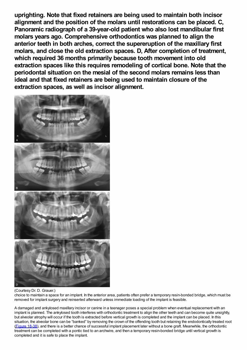
uprighting. Note that fixed retainers are being used to maintain both incisoralignment and the position of the molars until restorations can be placed. C,Panoramic radiograph of a 39-year-old patient who also lost mandibular firstmolars years ago. Comprehensive orthodontics was planned to align theanterior teeth in both arches, correct the supereruption of the maxillary firstmolars, and close the old extraction spaces. D, After completion of treatment,which required 36 months primarily because tooth movement into oldextraction spaces like this requires remodeling of cortical bone. Note that theperiodontal situation on the mesial of the second molars remains less thanideal and that fixed retainers are being used to maintain closure of theextraction spaces, as well as incisor alignment.
(Courtesy Dr. D. Grauer.)choice to maintain a space for an implant. In the anterior area, patients often prefer a temporary resin-bonded bridge, which must beremoved for implant surgery and reinserted afterward unless immediate loading of the implant is feasible.
A damaged and ankylosed maxillary incisor or canine in a teenager poses a special problem when eventual replacement with animplant is planned. The ankylosed tooth interferes with orthodontic treatment to align the other teeth and can become quite unsightly,but alveolar atrophy will occur if the tooth is extracted before vertical growth is completed and the implant can be placed. In thissituation, the alveolar bone can be “banked” by removing the crown of the offending tooth but retaining the endodontically treated root(Figure 18-38), and there is a better chance of successful implant placement later without a bone graft. Meanwhile, the orthodontictreatment can be completed with a pontic tied to an archwire, and then a temporary resin-bonded bridge until vertical growth iscompleted and it is safe to place the implant.
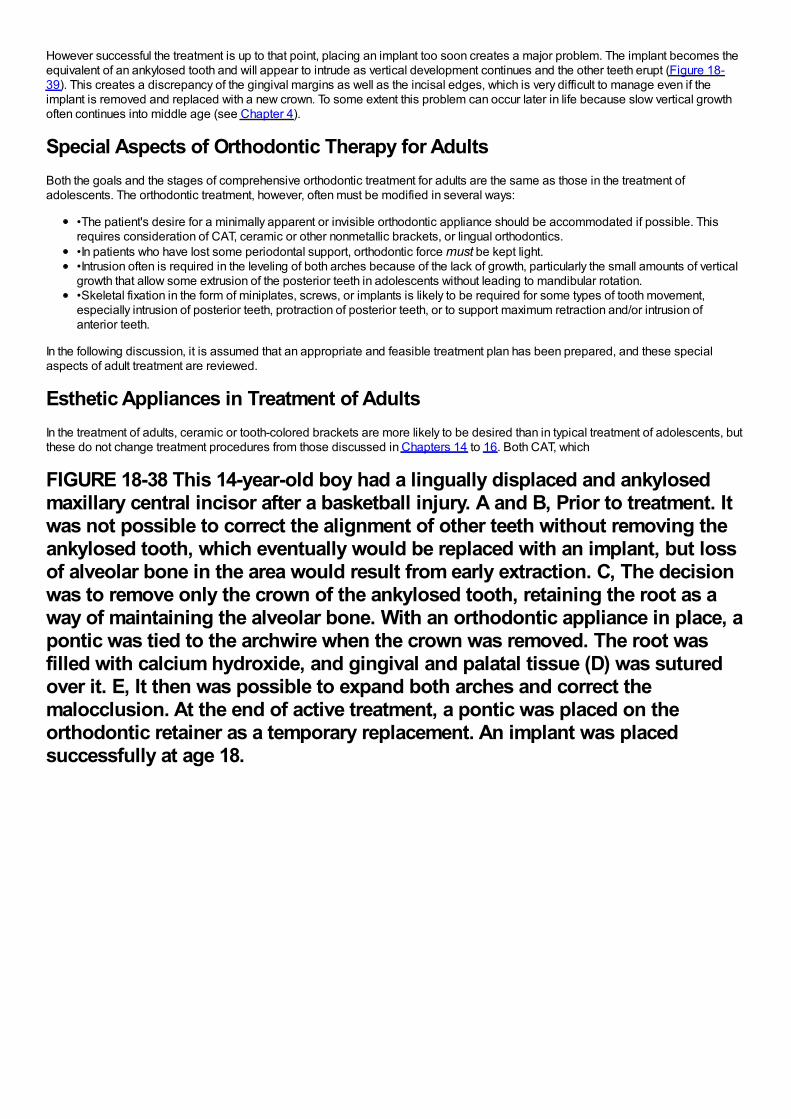
However successful the treatment is up to that point, placing an implant too soon creates a major problem. The implant becomes theequivalent of an ankylosed tooth and will appear to intrude as vertical development continues and the other teeth erupt (Figure 18-39). This creates a discrepancy of the gingival margins as well as the incisal edges, which is very difficult to manage even if theimplant is removed and replaced with a new crown. To some extent this problem can occur later in life because slow vertical growthoften continues into middle age (see Chapter 4).
Special Aspects of Orthodontic Therapy for AdultsBoth the goals and the stages of comprehensive orthodontic treatment for adults are the same as those in the treatment ofadolescents. The orthodontic treatment, however, often must be modified in several ways:
•The patient's desire for a minimally apparent or invisible orthodontic appliance should be accommodated if possible. Thisrequires consideration of CAT, ceramic or other nonmetallic brackets, or lingual orthodontics.•In patients who have lost some periodontal support, orthodontic force must be kept light.•Intrusion often is required in the leveling of both arches because of the lack of growth, particularly the small amounts of verticalgrowth that allow some extrusion of the posterior teeth in adolescents without leading to mandibular rotation.•Skeletal fixation in the form of miniplates, screws, or implants is likely to be required for some types of tooth movement,especially intrusion of posterior teeth, protraction of posterior teeth, or to support maximum retraction and/or intrusion ofanterior teeth.
In the following discussion, it is assumed that an appropriate and feasible treatment plan has been prepared, and these specialaspects of adult treatment are reviewed.
Esthetic Appliances in Treatment of AdultsIn the treatment of adults, ceramic or tooth-colored brackets are more likely to be desired than in typical treatment of adolescents, butthese do not change treatment procedures from those discussed in Chapters 14 to 16. Both CAT, which
FIGURE 18-38 This 14-year-old boy had a lingually displaced and ankylosedmaxillary central incisor after a basketball injury. A and B, Prior to treatment. Itwas not possible to correct the alignment of other teeth without removing theankylosed tooth, which eventually would be replaced with an implant, but lossof alveolar bone in the area would result from early extraction. C, The decisionwas to remove only the crown of the ankylosed tooth, retaining the root as away of maintaining the alveolar bone. With an orthodontic appliance in place, apontic was tied to the archwire when the crown was removed. The root wasfilled with calcium hydroxide, and gingival and palatal tissue (D) was suturedover it. E, It then was possible to expand both arches and correct themalocclusion. At the end of active treatment, a pontic was placed on theorthodontic retainer as a temporary replacement. An implant was placedsuccessfully at age 18.
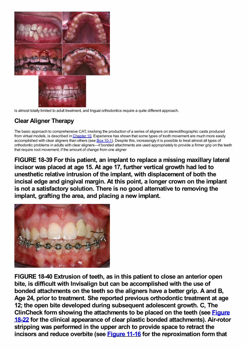
is almost totally limited to adult treatment, and lingual orthodontics require a quite different approach.
Clear Aligner TherapyThe basic approach to comprehensive CAT, involving the production of a series of aligners on stereolithographic casts producedfrom virtual models, is described in Chapter 10. Experience has shown that some types of tooth movement are much more easilyaccomplished with clear aligners than others (see Box 10-1). Despite this, increasingly it is possible to treat almost all types oforthodontic problems in adults with clear aligners—if bonded attachments are used appropriately to provide a firmer grip on the teeththat require root movement, if the amount of change from one aligner
FIGURE 18-39 For this patient, an implant to replace a missing maxillary lateralincisor was placed at age 15. At age 17, further vertical growth had led tounesthetic relative intrusion of the implant, with displacement of both theincisal edge and gingival margin. At this point, a longer crown on the implantis not a satisfactory solution. There is no good alternative to removing theimplant, grafting the area, and placing a new implant.
FIGURE 18-40 Extrusion of teeth, as in this patient to close an anterior openbite, is difficult with Invisalign but can be accomplished with the use ofbonded attachments on the teeth so the aligners have a better grip. A and B,Age 24, prior to treatment. She reported previous orthodontic treatment at age12; the open bite developed during subsequent adolescent growth. C, TheClinCheck form showing the attachments to be placed on the teeth (see Figure18-22 for the clinical appearance of clear plastic bonded attachments). Air-rotorstripping was performed in the upper arch to provide space to retract theincisors and reduce overbite (see Figure 11-16 for the reproximation form that
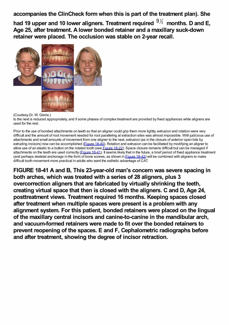
accompanies the ClinCheck form when this is part of the treatment plan). Shehad 19 upper and 10 lower aligners. Treatment required months. D and E,Age 25, after treatment. A lower bonded retainer and a maxillary suck-downretainer were placed. The occlusion was stable on 2-year recall.
(Courtesy Dr. W. Gierie.)to the next is reduced appropriately, and if some phases of complex treatment are provided by fixed appliances while aligners areused for the rest.
Prior to the use of bonded attachments on teeth so that an aligner could grip them more tightly, extrusion and rotation were verydifficult and the amount of root movement needed for root paralleling at extraction sites was almost impossible. With judicious use ofattachments and small amounts of movement from one aligner to the next, extrusion (as in the closure of anterior open bite byextruding incisors) now can be accomplished (Figure 18-40). Rotation and extrusion can be facilitated by modifying an aligner toallow use of an elastic to a button on the rotated tooth (see Figure 18-22). Space closure remains difficult but can be managed ifattachments on the teeth are used correctly (Figure 18-41). It seems likely that in the future, a brief period of fixed appliance treatment(and perhaps skeletal anchorage in the form of bone screws, as shown in Figure 18-42) will be combined with aligners to makedifficult tooth movement more practical in adults who want the esthetic advantage of CAT.
FIGURE 18-41 A and B, This 23-year-old man's concern was severe spacing inboth arches, which was treated with a series of 28 aligners, plus 3overcorrection aligners that are fabricated by virtually shrinking the teeth,creating virtual space that then is closed with the aligners. C and D, Age 24,posttreatment views. Treatment required 16 months. Keeping spaces closedafter treatment when multiple spaces were present is a problem with anyalignment system. For this patient, bonded retainers were placed on the lingualof the maxillary central incisors and canine-to-canine in the mandibular arch,and vacuum-formed retainers were made to fit over the bonded retainers toprevent reopening of the spaces. E and F, Cephalometric radiographs beforeand after treatment, showing the degree of incisor retraction.
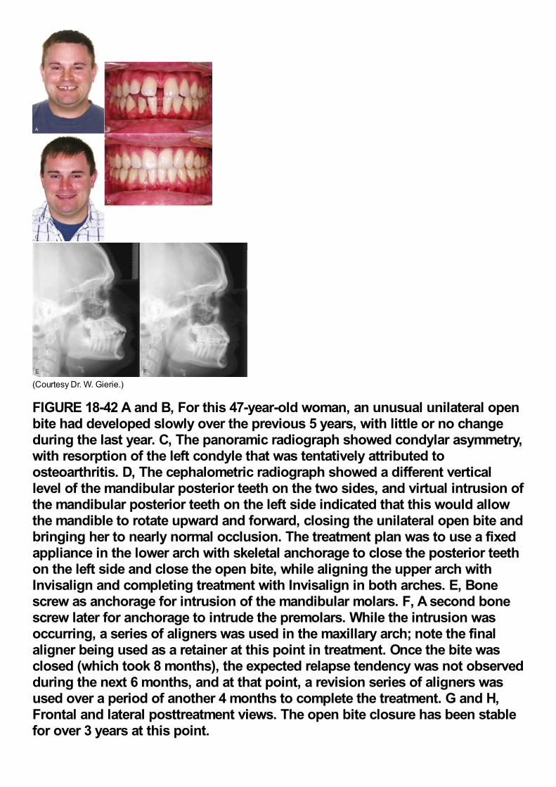
(Courtesy Dr. W. Gierie.)
FIGURE 18-42 A and B, For this 47-year-old woman, an unusual unilateral openbite had developed slowly over the previous 5 years, with little or no changeduring the last year. C, The panoramic radiograph showed condylar asymmetry,with resorption of the left condyle that was tentatively attributed toosteoarthritis. D, The cephalometric radiograph showed a different verticallevel of the mandibular posterior teeth on the two sides, and virtual intrusion ofthe mandibular posterior teeth on the left side indicated that this would allowthe mandible to rotate upward and forward, closing the unilateral open bite andbringing her to nearly normal occlusion. The treatment plan was to use a fixedappliance in the lower arch with skeletal anchorage to close the posterior teethon the left side and close the open bite, while aligning the upper arch withInvisalign and completing treatment with Invisalign in both arches. E, Bonescrew as anchorage for intrusion of the mandibular molars. F, A second bonescrew later for anchorage to intrude the premolars. While the intrusion wasoccurring, a series of aligners was used in the maxillary arch; note the finalaligner being used as a retainer at this point in treatment. Once the bite wasclosed (which took 8 months), the expected relapse tendency was not observedduring the next 6 months, and at that point, a revision series of aligners wasused over a period of another 4 months to complete the treatment. G and H,Frontal and lateral posttreatment views. The open bite closure has been stablefor over 3 years at this point.
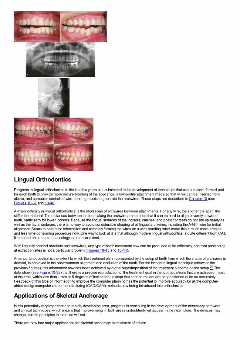
Lingual OrthodonticsProgress in lingual orthodontics in the last few years has culminated in the development of techniques that use a custom-formed padfor each tooth to provide more secure bonding of the appliance, a low-profile attachment made so that wires can be inserted fromabove, and computer-controlled wire-bending robots to generate the archwires. These steps are described in Chapter 10 (seeFigures 10-37 and 10-40).
A major difficulty in lingual orthodontics is the short span of archwires between attachments. For any wire, the shorter the span, thestiffer the material. The distances between the teeth along the archwire are so short that it can be hard to align severely crowdedteeth, particularly for lower incisors. Because the lingual surfaces of the incisors, canines, and posterior teeth do not line up nearly aswell as the facial surfaces, there is no way to avoid considerable shaping of all lingual archwires, including the A-NiTi wire for initialalignment. Scans to obtain the information and remotely forming the wires on a wire-bending robot make this a much more preciseand less time-consuming procedure now. One way to look at it is that although modern lingual orthodontics is quite different from CAT,it is based on computer technology to a similar extent.
With lingually bonded brackets and archwires, any type of tooth movement now can be produced quite efficiently, and root positioningat extraction sites is not a particular problem (Figures 18-43 and 18-44).
An important question is the extent to which the treatment plan, represented by the setup of teeth from which the shape of archwires isderived, is achieved in the posttreatment alignment and occlusion of the teeth. For the Incognito lingual technique (shown in theprevious figures), this information now has been achieved by digital superimposition of the treatment outcome on the setup.20 Thedata show (see Figure 10-38) that there is a precise reproduction of the treatment goal in the tooth positions that are achieved (mostof the time, within less than 1 mm or 5 degrees of inclination), except that second molars are not positioned quite as accurately.Feedback of this type of information to improve the computer planning has the potential to improve accuracy for all the computer-aided design/computer-aided manufacturing (CAD/CAM) methods now being introduced into orthodontics.
Applications of Skeletal AnchorageIn this potentially very important and rapidly developing area, progress is continuing in the development of the necessary hardwareand clinical techniques, which means that improvements in both areas undoubtedly will appear in the near future. The devices maychange, but the principles in their use will not.
There are now four major applications for skeletal anchorage in treatment of adults:
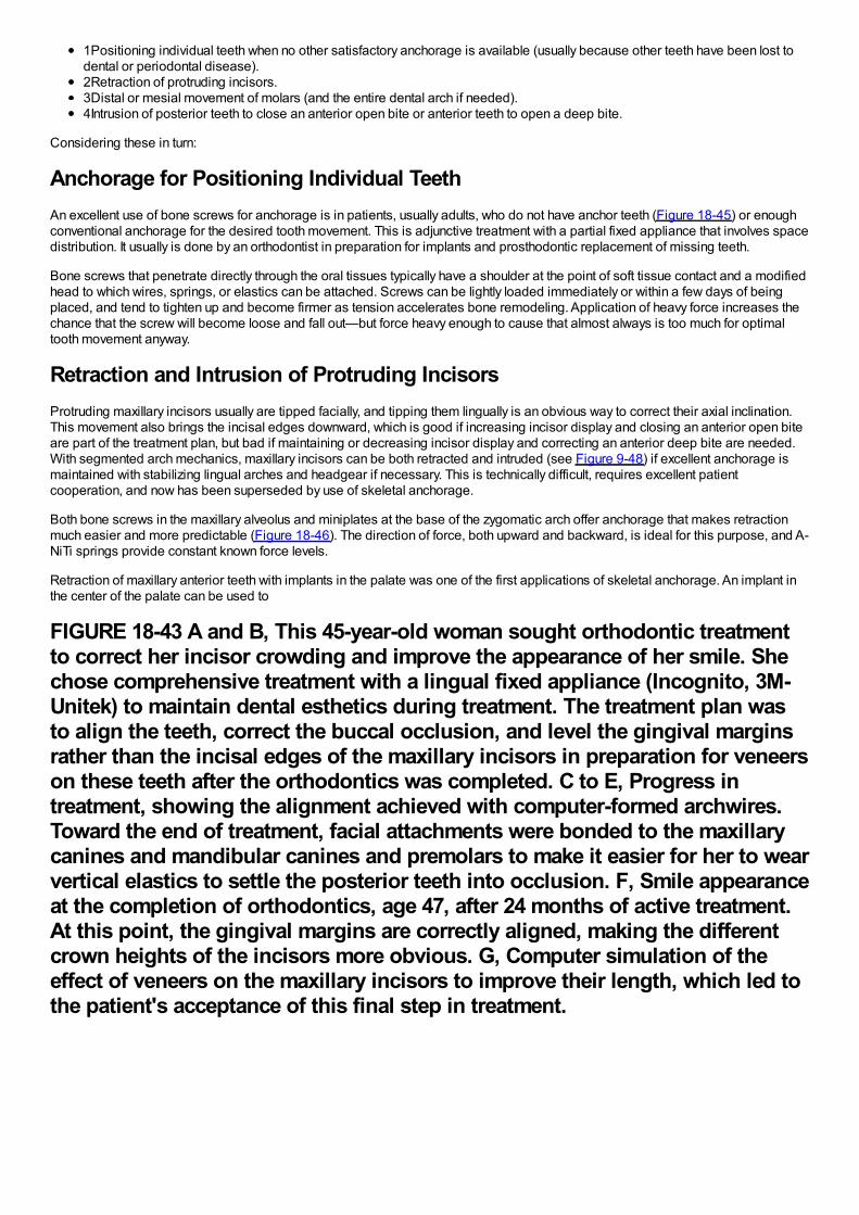
1Positioning individual teeth when no other satisfactory anchorage is available (usually because other teeth have been lost todental or periodontal disease).2Retraction of protruding incisors.3Distal or mesial movement of molars (and the entire dental arch if needed).4Intrusion of posterior teeth to close an anterior open bite or anterior teeth to open a deep bite.
Considering these in turn:
Anchorage for Positioning Individual TeethAn excellent use of bone screws for anchorage is in patients, usually adults, who do not have anchor teeth (Figure 18-45) or enoughconventional anchorage for the desired tooth movement. This is adjunctive treatment with a partial fixed appliance that involves spacedistribution. It usually is done by an orthodontist in preparation for implants and prosthodontic replacement of missing teeth.
Bone screws that penetrate directly through the oral tissues typically have a shoulder at the point of soft tissue contact and a modifiedhead to which wires, springs, or elastics can be attached. Screws can be lightly loaded immediately or within a few days of beingplaced, and tend to tighten up and become firmer as tension accelerates bone remodeling. Application of heavy force increases thechance that the screw will become loose and fall out—but force heavy enough to cause that almost always is too much for optimaltooth movement anyway.
Retraction and Intrusion of Protruding IncisorsProtruding maxillary incisors usually are tipped facially, and tipping them lingually is an obvious way to correct their axial inclination.This movement also brings the incisal edges downward, which is good if increasing incisor display and closing an anterior open biteare part of the treatment plan, but bad if maintaining or decreasing incisor display and correcting an anterior deep bite are needed.With segmented arch mechanics, maxillary incisors can be both retracted and intruded (see Figure 9-48) if excellent anchorage ismaintained with stabilizing lingual arches and headgear if necessary. This is technically difficult, requires excellent patientcooperation, and now has been superseded by use of skeletal anchorage.
Both bone screws in the maxillary alveolus and miniplates at the base of the zygomatic arch offer anchorage that makes retractionmuch easier and more predictable (Figure 18-46). The direction of force, both upward and backward, is ideal for this purpose, and A-NiTi springs provide constant known force levels.
Retraction of maxillary anterior teeth with implants in the palate was one of the first applications of skeletal anchorage. An implant inthe center of the palate can be used to
FIGURE 18-43 A and B, This 45-year-old woman sought orthodontic treatmentto correct her incisor crowding and improve the appearance of her smile. Shechose comprehensive treatment with a lingual fixed appliance (Incognito, 3M-Unitek) to maintain dental esthetics during treatment. The treatment plan wasto align the teeth, correct the buccal occlusion, and level the gingival marginsrather than the incisal edges of the maxillary incisors in preparation for veneerson these teeth after the orthodontics was completed. C to E, Progress intreatment, showing the alignment achieved with computer-formed archwires.Toward the end of treatment, facial attachments were bonded to the maxillarycanines and mandibular canines and premolars to make it easier for her to wearvertical elastics to settle the posterior teeth into occlusion. F, Smile appearanceat the completion of orthodontics, age 47, after 24 months of active treatment.At this point, the gingival margins are correctly aligned, making the differentcrown heights of the incisors more obvious. G, Computer simulation of theeffect of veneers on the maxillary incisors to improve their length, which led tothe patient's acceptance of this final step in treatment.
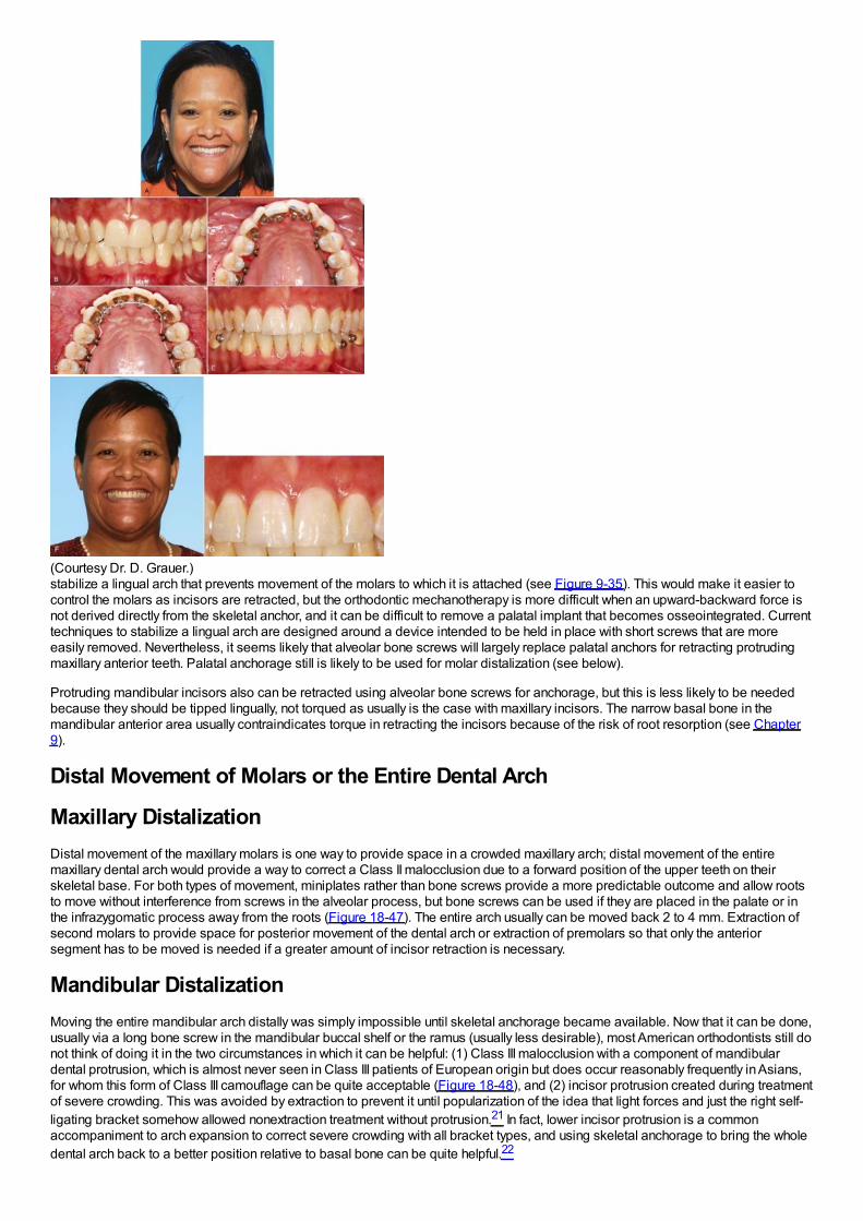
(Courtesy Dr. D. Grauer.)stabilize a lingual arch that prevents movement of the molars to which it is attached (see Figure 9-35). This would make it easier tocontrol the molars as incisors are retracted, but the orthodontic mechanotherapy is more difficult when an upward-backward force isnot derived directly from the skeletal anchor, and it can be difficult to remove a palatal implant that becomes osseointegrated. Currenttechniques to stabilize a lingual arch are designed around a device intended to be held in place with short screws that are moreeasily removed. Nevertheless, it seems likely that alveolar bone screws will largely replace palatal anchors for retracting protrudingmaxillary anterior teeth. Palatal anchorage still is likely to be used for molar distalization (see below).
Protruding mandibular incisors also can be retracted using alveolar bone screws for anchorage, but this is less likely to be neededbecause they should be tipped lingually, not torqued as usually is the case with maxillary incisors. The narrow basal bone in themandibular anterior area usually contraindicates torque in retracting the incisors because of the risk of root resorption (see Chapter9).
Distal Movement of Molars or the Entire Dental Arch
Maxillary DistalizationDistal movement of the maxillary molars is one way to provide space in a crowded maxillary arch; distal movement of the entiremaxillary dental arch would provide a way to correct a Class II malocclusion due to a forward position of the upper teeth on theirskeletal base. For both types of movement, miniplates rather than bone screws provide a more predictable outcome and allow rootsto move without interference from screws in the alveolar process, but bone screws can be used if they are placed in the palate or inthe infrazygomatic process away from the roots (Figure 18-47). The entire arch usually can be moved back 2 to 4 mm. Extraction ofsecond molars to provide space for posterior movement of the dental arch or extraction of premolars so that only the anteriorsegment has to be moved is needed if a greater amount of incisor retraction is necessary.
Mandibular DistalizationMoving the entire mandibular arch distally was simply impossible until skeletal anchorage became available. Now that it can be done,usually via a long bone screw in the mandibular buccal shelf or the ramus (usually less desirable), most American orthodontists still donot think of doing it in the two circumstances in which it can be helpful: (1) Class III malocclusion with a component of mandibulardental protrusion, which is almost never seen in Class III patients of European origin but does occur reasonably frequently in Asians,for whom this form of Class III camouflage can be quite acceptable (Figure 18-48), and (2) incisor protrusion created during treatmentof severe crowding. This was avoided by extraction to prevent it until popularization of the idea that light forces and just the right self-ligating bracket somehow allowed nonextraction treatment without protrusion.21 In fact, lower incisor protrusion is a commonaccompaniment to arch expansion to correct severe crowding with all bracket types, and using skeletal anchorage to bring the wholedental arch back to a better position relative to basal bone can be quite helpful.22
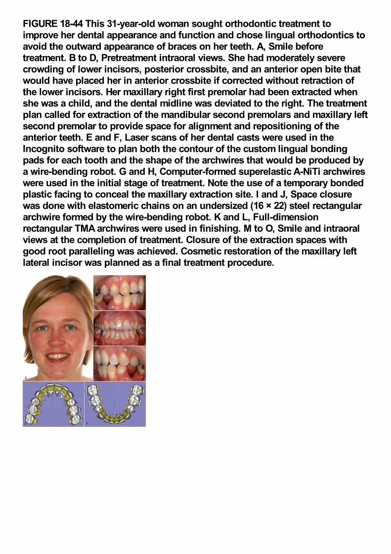
FIGURE 18-44 This 31-year-old woman sought orthodontic treatment toimprove her dental appearance and function and chose lingual orthodontics toavoid the outward appearance of braces on her teeth. A, Smile beforetreatment. B to D, Pretreatment intraoral views. She had moderately severecrowding of lower incisors, posterior crossbite, and an anterior open bite thatwould have placed her in anterior crossbite if corrected without retraction ofthe lower incisors. Her maxillary right first premolar had been extracted whenshe was a child, and the dental midline was deviated to the right. The treatmentplan called for extraction of the mandibular second premolars and maxillary leftsecond premolar to provide space for alignment and repositioning of theanterior teeth. E and F, Laser scans of her dental casts were used in theIncognito software to plan both the contour of the custom lingual bondingpads for each tooth and the shape of the archwires that would be produced bya wire-bending robot. G and H, Computer-formed superelastic A-NiTi archwireswere used in the initial stage of treatment. Note the use of a temporary bondedplastic facing to conceal the maxillary extraction site. I and J, Space closurewas done with elastomeric chains on an undersized (16 × 22) steel rectangulararchwire formed by the wire-bending robot. K and L, Full-dimensionrectangular TMA archwires were used in finishing. M to O, Smile and intraoralviews at the completion of treatment. Closure of the extraction spaces withgood root paralleling was achieved. Cosmetic restoration of the maxillary leftlateral incisor was planned as a final treatment procedure.
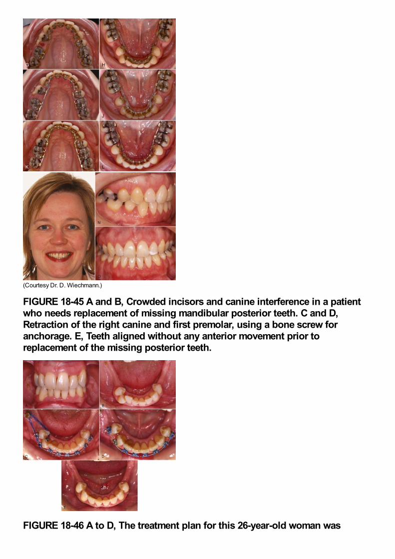
(Courtesy Dr. D. Wiechmann.)
FIGURE 18-45 A and B, Crowded incisors and canine interference in a patientwho needs replacement of missing mandibular posterior teeth. C and D,Retraction of the right canine and first premolar, using a bone screw foranchorage. E, Teeth aligned without any anterior movement prior toreplacement of the missing posterior teeth.
FIGURE 18-46 A to D, The treatment plan for this 26-year-old woman was
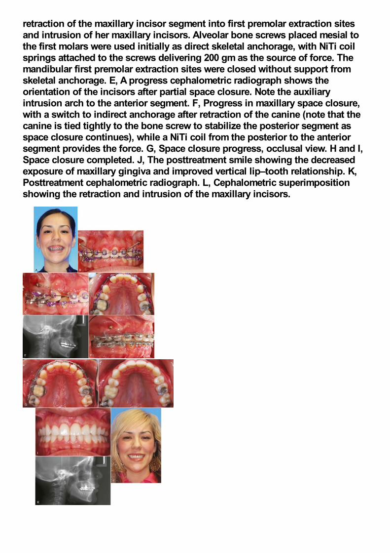
retraction of the maxillary incisor segment into first premolar extraction sitesand intrusion of her maxillary incisors. Alveolar bone screws placed mesial tothe first molars were used initially as direct skeletal anchorage, with NiTi coilsprings attached to the screws delivering 200 gm as the source of force. Themandibular first premolar extraction sites were closed without support fromskeletal anchorage. E, A progress cephalometric radiograph shows theorientation of the incisors after partial space closure. Note the auxiliaryintrusion arch to the anterior segment. F, Progress in maxillary space closure,with a switch to indirect anchorage after retraction of the canine (note that thecanine is tied tightly to the bone screw to stabilize the posterior segment asspace closure continues), while a NiTi coil from the posterior to the anteriorsegment provides the force. G, Space closure progress, occlusal view. H and I,Space closure completed. J, The posttreatment smile showing the decreasedexposure of maxillary gingiva and improved vertical lip–tooth relationship. K,Posttreatment cephalometric radiograph. L, Cephalometric superimpositionshowing the retraction and intrusion of the maxillary incisors.
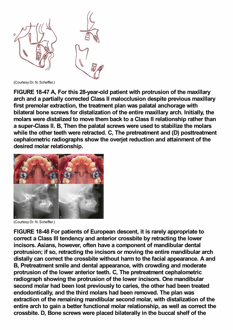
(Courtesy Dr. N. Scheffler.)
FIGURE 18-47 A, For this 28-year-old patient with protrusion of the maxillaryarch and a partially corrected Class II malocclusion despite previous maxillaryfirst premolar extraction, the treatment plan was palatal anchorage withbilateral bone screws for distalization of the entire maxillary arch. Initially, themolars were distalized to move them back to a Class II relationship rather thana super-Class II. B, Then the palatal screws were used to stabilize the molarswhile the other teeth were retracted. C, The pretreatment and (D) posttreatmentcephalometric radiographs show the overjet reduction and attainment of thedesired molar relationship.
(Courtesy Dr. N. Scheffler.)
FIGURE 18-48 For patients of European descent, it is rarely appropriate tocorrect a Class III tendency and anterior crossbite by retracting the lowerincisors. Asians, however, often have a component of mandibular dentalprotrusion; if so, retracting the incisors or moving the entire mandibular archdistally can correct the crossbite without harm to the facial appearance. A andB, Pretreatment smile and dental appearance, with crowding and moderateprotrusion of the lower anterior teeth. C, The pretreatment cephalometricradiograph showing the protrusion of the lower incisors. One mandibularsecond molar had been lost previously to caries, the other had been treatedendodontically, and the third molars had been removed. The plan wasextraction of the remaining mandibular second molar, with distalization of theentire arch to gain a better functional molar relationship, as well as correct thecrossbite. D, Bone screws were placed bilaterally in the buccal shelf of the
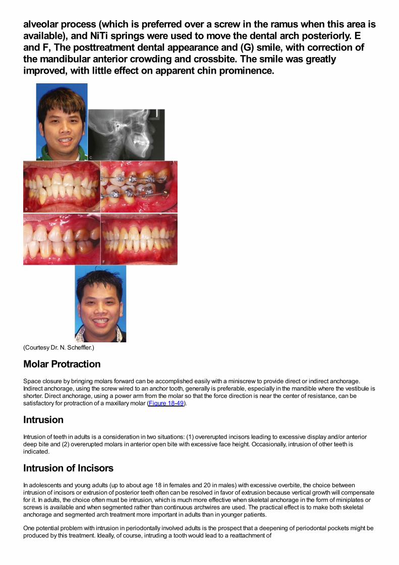
alveolar process (which is preferred over a screw in the ramus when this area isavailable), and NiTi springs were used to move the dental arch posteriorly. Eand F, The posttreatment dental appearance and (G) smile, with correction ofthe mandibular anterior crowding and crossbite. The smile was greatlyimproved, with little effect on apparent chin prominence.
(Courtesy Dr. N. Scheffler.)
Molar ProtractionSpace closure by bringing molars forward can be accomplished easily with a miniscrew to provide direct or indirect anchorage.Indirect anchorage, using the screw wired to an anchor tooth, generally is preferable, especially in the mandible where the vestibule isshorter. Direct anchorage, using a power arm from the molar so that the force direction is near the center of resistance, can besatisfactory for protraction of a maxillary molar (Figure 18-49).
IntrusionIntrusion of teeth in adults is a consideration in two situations: (1) overerupted incisors leading to excessive display and/or anteriordeep bite and (2) overerupted molars in anterior open bite with excessive face height. Occasionally, intrusion of other teeth isindicated.
Intrusion of IncisorsIn adolescents and young adults (up to about age 18 in females and 20 in males) with excessive overbite, the choice betweenintrusion of incisors or extrusion of posterior teeth often can be resolved in favor of extrusion because vertical growth will compensatefor it. In adults, the choice often must be intrusion, which is much more effective when skeletal anchorage in the form of miniplates orscrews is available and when segmented rather than continuous archwires are used. The practical effect is to make both skeletalanchorage and segmented arch treatment more important in adults than in younger patients.
One potential problem with intrusion in periodontally involved adults is the prospect that a deepening of periodontal pockets might beproduced by this treatment. Ideally, of course, intruding a tooth would lead to a reattachment of
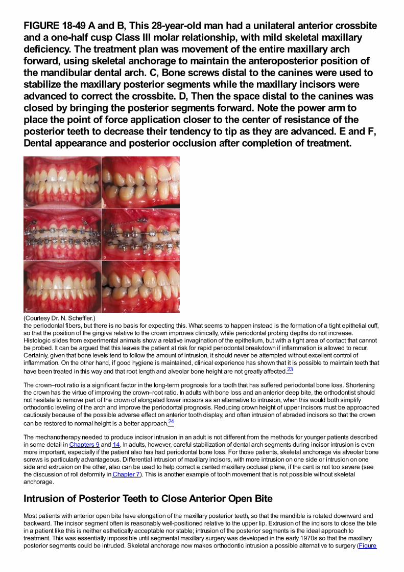
FIGURE 18-49 A and B, This 28-year-old man had a unilateral anterior crossbiteand a one-half cusp Class III molar relationship, with mild skeletal maxillarydeficiency. The treatment plan was movement of the entire maxillary archforward, using skeletal anchorage to maintain the anteroposterior position ofthe mandibular dental arch. C, Bone screws distal to the canines were used tostabilize the maxillary posterior segments while the maxillary incisors wereadvanced to correct the crossbite. D, Then the space distal to the canines wasclosed by bringing the posterior segments forward. Note the power arm toplace the point of force application closer to the center of resistance of theposterior teeth to decrease their tendency to tip as they are advanced. E and F,Dental appearance and posterior occlusion after completion of treatment.
(Courtesy Dr. N. Scheffler.)the periodontal fibers, but there is no basis for expecting this. What seems to happen instead is the formation of a tight epithelial cuff,so that the position of the gingiva relative to the crown improves clinically, while periodontal probing depths do not increase.Histologic slides from experimental animals show a relative invagination of the epithelium, but with a tight area of contact that cannotbe probed. It can be argued that this leaves the patient at risk for rapid periodontal breakdown if inflammation is allowed to recur.Certainly, given that bone levels tend to follow the amount of intrusion, it should never be attempted without excellent control ofinflammation. On the other hand, if good hygiene is maintained, clinical experience has shown that it is possible to maintain teeth thathave been treated in this way and that root length and alveolar bone height are not greatly affected.23
The crown–root ratio is a significant factor in the long-term prognosis for a tooth that has suffered periodontal bone loss. Shorteningthe crown has the virtue of improving the crown–root ratio. In adults with bone loss and an anterior deep bite, the orthodontist shouldnot hesitate to remove part of the crown of elongated lower incisors as an alternative to intrusion, when this would both simplifyorthodontic leveling of the arch and improve the periodontal prognosis. Reducing crown height of upper incisors must be approachedcautiously because of the possible adverse effect on anterior tooth display, and often intrusion of abraded incisors so that the crowncan be restored to normal height is a better approach.24
The mechanotherapy needed to produce incisor intrusion in an adult is not different from the methods for younger patients describedin some detail in Chapters 9 and 14. In adults, however, careful stabilization of dental arch segments during incisor intrusion is evenmore important, especially if the patient also has had periodontal bone loss. For those patients, skeletal anchorage via alveolar bonescrews is particularly advantageous. Differential intrusion of maxillary incisors, with more intrusion on one side or intrusion on oneside and extrusion on the other, also can be used to help correct a canted maxillary occlusal plane, if the cant is not too severe (seethe discussion of roll deformity in Chapter 7). This is another example of tooth movement that is not possible without skeletalanchorage.
Intrusion of Posterior Teeth to Close Anterior Open BiteMost patients with anterior open bite have elongation of the maxillary posterior teeth, so that the mandible is rotated downward andbackward. The incisor segment often is reasonably well-positioned relative to the upper lip. Extrusion of the incisors to close the bitein a patient like this is neither esthetically acceptable nor stable; intrusion of the posterior segments is the ideal approach totreatment. This was essentially impossible until segmental maxillary surgery was developed in the early 1970s so that the maxillaryposterior segments could be intruded. Skeletal anchorage now makes orthodontic intrusion a possible alternative to surgery (Figure
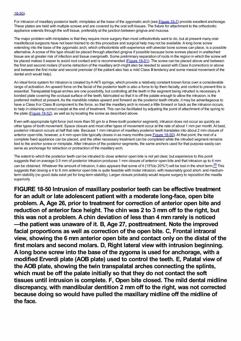
18-50).
For intrusion of maxillary posterior teeth, miniplates at the base of the zygomatic arch (see Figure 15-7) provide excellent anchorage.These plates are held with multiple screws and are covered by the oral soft tissues. The fixture for attachment to the orthodonticappliance extends through the soft tissue, preferably at the junction between gingiva and mucosa.
The major problem with miniplates is that they require more surgery than most orthodontists want to do, but at present many oral-maxillofacial surgeons have not been trained to do this procedure and surgical help may not be available. A long bone screwextending into the base of the zygomatic arch, which orthodontists with experience with alveolar bone screws can place, is a possiblealternative. A screw of this type should be placed through attached gingiva if possible because bone screws placed in unattachedtissue are at greater risk of infection and tissue overgrowth. Some preliminary separation of roots in the region in which the screw willbe placed makes it easier to avoid root contact and is recommended (Figure 18-51). The screw can be placed above and betweenthe first and second molars (if some retraction of the maxillary arch might also be needed to assist with Class II correction) or aboveand between the first molar and second premolar (if the patient also has a mild Class III tendency and some mesial movement of thedental arch would help).
An ideal force system for intrusion is created by A-NiTi springs, which provide a relatively constant known force over a considerablerange of activation. An upward force on the facial of the posterior teeth is also a force to tip them facially, and control to prevent this isessential. Transpalatal lingual arches are one possibility, but controlling all the teeth in the segment being intruded is necessary. Abonded plate covering the occlusal surface of the teeth, fabricated so that it is off the palate enough to allow the intrusion, is thepreferred method at present. As the mandible rotates upward and forward as the posterior teeth intrude, it may be advantageous tohave a Class II or Class III component to the force, so that the maxillary arch is moved a little forward or back as the intrusion occurs,to help in obtaining correct overjet at the end of treatment. This can be facilitated by adjusting the point of attachment of the spring tothe plate (Figure 18-52), as well as by locating the screw as described above.
Even with appropriate light force (not more than 50 gm to a three-tooth posterior segment), intrusion does not occur as quickly asother types of tooth movement. Space closure and most other types of movement occur at the rate of about 1 mm per month. At best,posterior intrusion occurs at half that rate. Because 1 mm intrusion of maxillary posterior teeth translates into about 2 mm closure ofanterior open bite, however, a 4 mm open bite typically closes in as many months (see Figure 18-50). At that point, the rest of acomplete fixed appliance can be placed, and the other necessary treatment can be completed while the intruded segment remainstied to the anchor screw or miniplate. After intrusion of the posterior segments, the same anchors used for that purpose easily canserve as anchorage for retraction or protraction of the maxillary arch.
The extent to which the posterior teeth can be intruded to close anterior open bite is not yet clear, but experience to this pointsuggests that on average 0.5 mm of posterior intrusion produces 1 mm closure of anterior open bite and that intrusion up to 4 mmcan be obtained. Whatever the amount of intrusion, it also appears that some of it (15%to 20%?) will be lost in the short term.25 Thissuggests that closing a 4 to 6 mm anterior open bite is quite feasible with molar intrusion, with reasonably good short- and medium-term stability (no good data exist yet for long-term stability). Larger closure probably would require surgery to reposition the maxillasuperiorly.
FIGURE 18-50 Intrusion of maxillary posterior teeth can be effective treatmentfor an adult or late adolescent patient with a moderate long-face, open biteproblem. A, Age 26, prior to treatment for correction of anterior open bite andreduction of anterior face height. The chin was 2 to 3 mm off to the right, butthis was not a problem. A chin deviation of less than 4 mm rarely is noticed—the patient was unaware of it. B, Age 27, posttreatment. Note the improvedfacial proportions as well as correction of the open bite. C, Frontal intraoralview, showing the 6 mm anterior open bite and contact only on the distal of thefirst molars and second molars. D, Right lateral view with intrusion beginning.A long bone screw into the base of the zygoma is used for anchorage, with amodified Erverdi plate (AOB plate) used to control the teeth. E, Palatal view ofthe AOB plate, showing the twin transpalatal arches connecting the splints,which must be off the palate initially so that they do not contact the softtissues until intrusion is complete. F, Open bite closed. The mild dental midlinediscrepancy, with mandibular dentition 2 mm off to the right, was not correctedbecause doing so would have pulled the maxillary midline off the midline ofthe face.
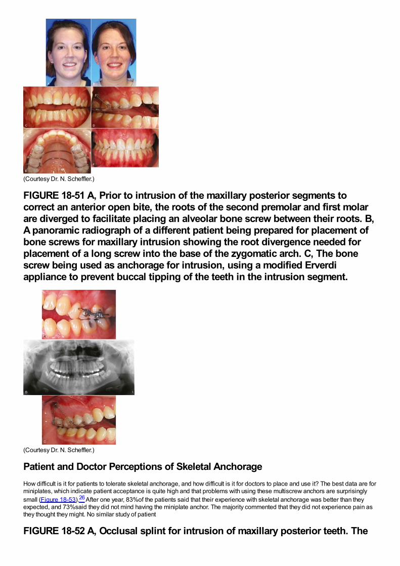
(Courtesy Dr. N. Scheffler.)
FIGURE 18-51 A, Prior to intrusion of the maxillary posterior segments tocorrect an anterior open bite, the roots of the second premolar and first molarare diverged to facilitate placing an alveolar bone screw between their roots. B,A panoramic radiograph of a different patient being prepared for placement ofbone screws for maxillary intrusion showing the root divergence needed forplacement of a long screw into the base of the zygomatic arch. C, The bonescrew being used as anchorage for intrusion, using a modified Erverdiappliance to prevent buccal tipping of the teeth in the intrusion segment.
(Courtesy Dr. N. Scheffler.)
Patient and Doctor Perceptions of Skeletal AnchorageHow difficult is it for patients to tolerate skeletal anchorage, and how difficult is it for doctors to place and use it? The best data are forminiplates, which indicate patient acceptance is quite high and that problems with using these multiscrew anchors are surprisinglysmall (Figure 18-53).26 After one year, 83%of the patients said that their experience with skeletal anchorage was better than theyexpected, and 73%said they did not mind having the miniplate anchor. The majority commented that they did not experience pain asthey thought they might. No similar study of patient
FIGURE 18-52 A, Occlusal splint for intrusion of maxillary posterior teeth. The
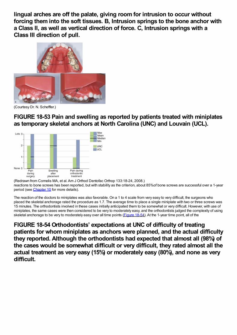
lingual arches are off the palate, giving room for intrusion to occur withoutforcing them into the soft tissues. B, Intrusion springs to the bone anchor witha Class II, as well as vertical direction of force. C, Intrusion springs with aClass III direction of pull.
(Courtesy Dr. N. Scheffler.)
FIGURE 18-53 Pain and swelling as reported by patients treated with miniplatesas temporary skeletal anchors at North Carolina (UNC) and Louvain (UCL).
(Redrawn from Cornelis MA, et al. Am J Orthod Dentofac Orthop 133:18-24, 2008.)reactions to bone screws has been reported, but with stability as the criterion, about 85%of bone screws are successful over a 1-yearperiod (see Chapter 10 for more details).
The reaction of the doctors to miniplates was also favorable. On a 1 to 4 scale from very easy to very difficult, the surgeons whoplaced the skeletal anchorage rated the procedure as 1.7. The average time to place a single miniplate with two or three screws was15 minutes. The orthodontists involved in these cases initially anticipated them to be somewhat or very difficult. However, with use ofminiplates, the same cases were then considered to be very to moderately easy, and the orthodontists judged the complexity of usingskeletal anchorage to be very to moderately easy over all time points (Figure 18-54). At the 1-year time point, all of the
FIGURE 18-54 Orthodontists’ expectations at UNC of difficulty of treatingpatients for whom miniplates as anchors were planned, and the actual difficultythey reported. Although the orthodontists had expected that almost all (98%) ofthe cases would be somewhat difficult or very difficult, they rated almost all theactual treatment as very easy (15%) or moderately easy (80%), and none as verydifficult.
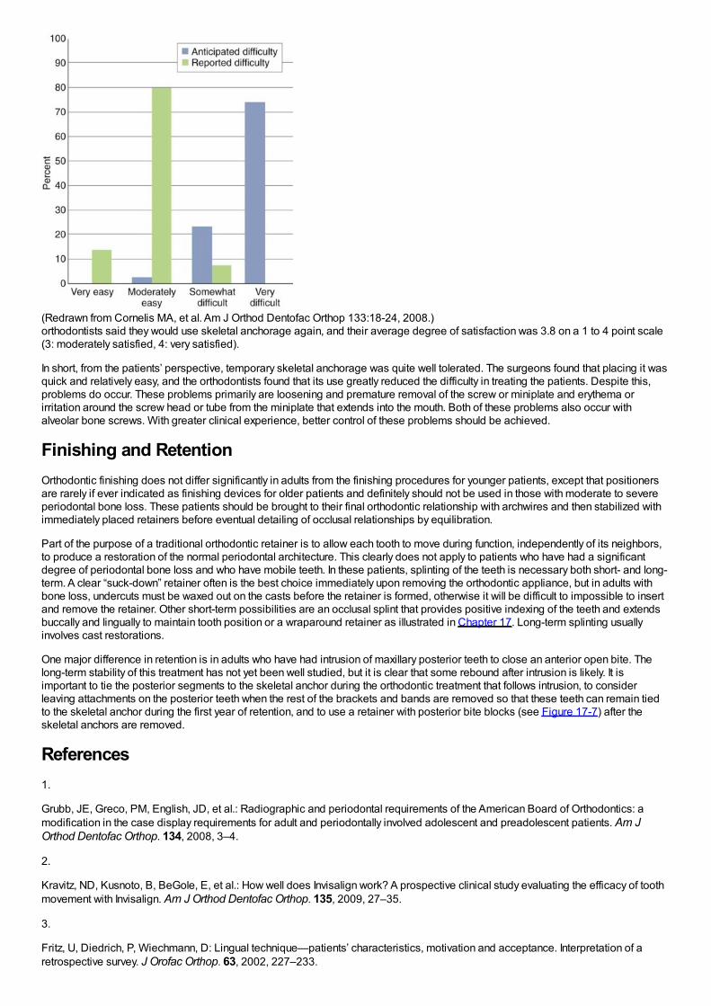
(Redrawn from Cornelis MA, et al. Am J Orthod Dentofac Orthop 133:18-24, 2008.)orthodontists said they would use skeletal anchorage again, and their average degree of satisfaction was 3.8 on a 1 to 4 point scale(3: moderately satisfied, 4: very satisfied).
In short, from the patients’ perspective, temporary skeletal anchorage was quite well tolerated. The surgeons found that placing it wasquick and relatively easy, and the orthodontists found that its use greatly reduced the difficulty in treating the patients. Despite this,problems do occur. These problems primarily are loosening and premature removal of the screw or miniplate and erythema orirritation around the screw head or tube from the miniplate that extends into the mouth. Both of these problems also occur withalveolar bone screws. With greater clinical experience, better control of these problems should be achieved.
Finishing and RetentionOrthodontic finishing does not differ significantly in adults from the finishing procedures for younger patients, except that positionersare rarely if ever indicated as finishing devices for older patients and definitely should not be used in those with moderate to severeperiodontal bone loss. These patients should be brought to their final orthodontic relationship with archwires and then stabilized withimmediately placed retainers before eventual detailing of occlusal relationships by equilibration.
Part of the purpose of a traditional orthodontic retainer is to allow each tooth to move during function, independently of its neighbors,to produce a restoration of the normal periodontal architecture. This clearly does not apply to patients who have had a significantdegree of periodontal bone loss and who have mobile teeth. In these patients, splinting of the teeth is necessary both short- and long-term. A clear “suck-down” retainer often is the best choice immediately upon removing the orthodontic appliance, but in adults withbone loss, undercuts must be waxed out on the casts before the retainer is formed, otherwise it will be difficult to impossible to insertand remove the retainer. Other short-term possibilities are an occlusal splint that provides positive indexing of the teeth and extendsbuccally and lingually to maintain tooth position or a wraparound retainer as illustrated in Chapter 17. Long-term splinting usuallyinvolves cast restorations.
One major difference in retention is in adults who have had intrusion of maxillary posterior teeth to close an anterior open bite. Thelong-term stability of this treatment has not yet been well studied, but it is clear that some rebound after intrusion is likely. It isimportant to tie the posterior segments to the skeletal anchor during the orthodontic treatment that follows intrusion, to considerleaving attachments on the posterior teeth when the rest of the brackets and bands are removed so that these teeth can remain tiedto the skeletal anchor during the first year of retention, and to use a retainer with posterior bite blocks (see Figure 17-7) after theskeletal anchors are removed.
References1.
Grubb, JE, Greco, PM, English, JD, et al.: Radiographic and periodontal requirements of the American Board of Orthodontics: amodification in the case display requirements for adult and periodontally involved adolescent and preadolescent patients. Am JOrthod Dentofac Orthop. 134, 2008, 3–4.
2.
Kravitz, ND, Kusnoto, B, BeGole, E, et al.: How well does Invisalign work? A prospective clinical study evaluating the efficacy of toothmovement with Invisalign. Am J Orthod Dentofac Orthop. 135, 2009, 27–35.
3.
Fritz, U, Diedrich, P, Wiechmann, D: Lingual technique—patients’ characteristics, motivation and acceptance. Interpretation of aretrospective survey. J Orofac Orthop. 63, 2002, 227–233.

4.
Esteves, T, Ramos, AL, Pereira, CM, et al.: Orthodontic root resorption of endodontically treated teeth. J Endodont. 33, 2007, 119–122.
5.
Thilander, B: Infrabony pockets and reduced alveolar bone height in relation to orthodontic therapy. Semin Orthod. 2, 1996, 55–61.
6.
Ogihara, S, Wang, HL: Periodontal regeneration with or without limited orthodontics for the treatment of 2- or 3-wall infrabony defects.J Periodontol. 81, 2010, 1734–1742.
7.
Ziskind, D, Schmidt, A, Hirschfeld, Z: Forced eruption technique: Rationale and technique. J Pros Dent. 79, 1998, 246–248.
8.
Sheridan, JJ: Air Rotor Stripping (ARS) Manual. 2005, Raintree Essix, New Orleans.
9.
Grauer D, Heymann GC. Clinical management of tooth-size discrepancies. J Esthetic Restorative Dent, in press.
10.
Heymann GC, Grauer D. Contemporary approach to orthodontic retention. J Esthetic Restorative Dent, in press.
11.
Phillips, C, Broder, HL, Bennett, ME: Dentofacial disharmony: motivations for seeking treatment. Int J Adult Orthod Orthognath Surg.12, 1997, 7–15.
12.
Dahlström, L, Carlsson, GE: Temporomandibular disorders and oral health-related quality of life. A systematic review. Acta OdontolScand. 68, 2010, 80–85.
13.
Mohlin, B, Axelsson, S, Paulin, G, et al.: TMD in relation to malocclusion and orthodontic treatment. Angle Orthod. 77, 2007, 542–548.
14.
Macfarlane, TV, Kenealy, P, Kingdon, HA, et al.: Twenty-year cohort study of health gain from orthodontic treatment:temporomandibular disorders. Am J Orthod Dentofac Orthop. 135, 2009, 692, e1-8; discussion 692-693.
15.
Okeson, JP: Management of Temporomandibular Disorders and Occlusion. 6th ed, 2008, Mosby-Elsevier, St. Louis.
16.
Rugh, JD, Solberg, WK: Oral health status in the United States: temporomandibular disorders. J Dent Educ. 49, 1985, 399–405.
17.
Brown, LJ, Brunelle, JA, Kingman, A: Periodontal status in the United States, 1988-91: Prevalence, extent, and demographicvariation. J Dent Res. 75, 1996, 672–683.
18.
Türkkahraman, H, Sayin, MO, Bozkurt, FY, et al.: Archwire ligation techniques, microbial colonization, and periodontal status inorthodontically treated patients. Angle Orthod. 75, 2005, 231–236.
19.
Oh, TJ, Eber, R, Wang, HL: Periodontal diseases in the child and adolescent. J Clin Periodontol. 29, 2002, 400–410.
20.
Grauer, D, Proffit, WR: Accuracy in tooth positioning with fully customized lingual orthodontic appliances. Am J Orthod Dentofac

Orthop. 140, 2011, 433–443.
21.
Damon, D: Treatment of the face with biocompatible orthodontics. In Graber, TM, Vanarsdall, RL, Vig, KWL (Eds.): OrthodonticPrinciples and Techniques. 4th ed, 2005, Elsevier/Mosby, St Louis.
22.
Lin, J: Creative orthodontics blending the Damon system and TADs to manage difficult malocclusions. 2007, Yong Chieh Co., Taipei.
23.
Melsen, B: Intrusion of incisors in adult patients with marginal bone loss. Am J Orthod Dentofac Orthop. 96, 1989, 232–241.
24.
Bellamy, LJ, Kokich, VG, Weissman, JA: Using orthodontic intrusion of abraded incisors to facilitate restoration: the technique'seffects on alveolar bone level and root length. J Am Dent Assoc . 139, 2008, 725–733.
25.
McCall, G: The efficacy of temporary skeletal anchorage versus maxillary osteotomy in the treatment of anterior open bite. 2012, Univof North Carolina, MS thesis, Chapel Hill.
26.
Cornelis, MA, Scheffler, NR, Nyssen-Behets, C, et al.: Patients’ and orthodontists’ perceptions of miniplates used for temporaryskeletal anchorage: a prospective study. Am J Orthod Dentofac Orthop. 133, 2008, 18–24.
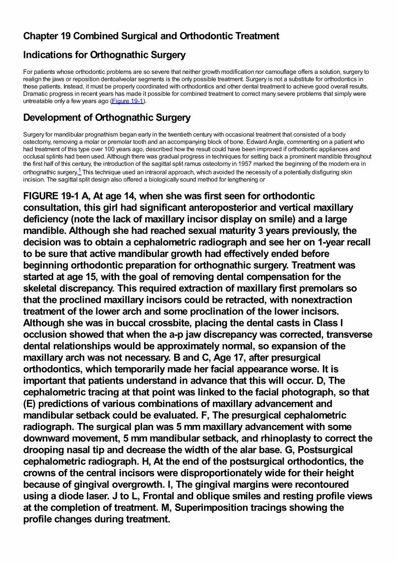
Chapter 19 Combined Surgical and Orthodontic Treatment
Indications for Orthognathic SurgeryFor patients whose orthodontic problems are so severe that neither growth modification nor camouflage offers a solution, surgery torealign the jaws or reposition dentoalveolar segments is the only possible treatment. Surgery is not a substitute for orthodontics inthese patients. Instead, it must be properly coordinated with orthodontics and other dental treatment to achieve good overall results.Dramatic progress in recent years has made it possible for combined treatment to correct many severe problems that simply wereuntreatable only a few years ago (Figure 19-1).
Development of Orthognathic SurgerySurgery for mandibular prognathism began early in the twentieth century with occasional treatment that consisted of a bodyostectomy, removing a molar or premolar tooth and an accompanying block of bone. Edward Angle, commenting on a patient whohad treatment of this type over 100 years ago, described how the result could have been improved if orthodontic appliances andocclusal splints had been used. Although there was gradual progress in techniques for setting back a prominent mandible throughoutthe first half of this century, the introduction of the sagittal split ramus osteotomy in 1957 marked the beginning of the modern era inorthognathic surgery.1 This technique used an intraoral approach, which avoided the necessity of a potentially disfiguring skinincision. The sagittal split design also offered a biologically sound method for lengthening or
FIGURE 19-1 A, At age 14, when she was first seen for orthodonticconsultation, this girl had significant anteroposterior and vertical maxillarydeficiency (note the lack of maxillary incisor display on smile) and a largemandible. Although she had reached sexual maturity 3 years previously, thedecision was to obtain a cephalometric radiograph and see her on 1-year recallto be sure that active mandibular growth had effectively ended beforebeginning orthodontic preparation for orthognathic surgery. Treatment wasstarted at age 15, with the goal of removing dental compensation for theskeletal discrepancy. This required extraction of maxillary first premolars sothat the proclined maxillary incisors could be retracted, with nonextractiontreatment of the lower arch and some proclination of the lower incisors.Although she was in buccal crossbite, placing the dental casts in Class Iocclusion showed that when the a-p jaw discrepancy was corrected, transversedental relationships would be approximately normal, so expansion of themaxillary arch was not necessary. B and C, Age 17, after presurgicalorthodontics, which temporarily made her facial appearance worse. It isimportant that patients understand in advance that this will occur. D, Thecephalometric tracing at that point was linked to the facial photograph, so that(E) predictions of various combinations of maxillary advancement andmandibular setback could be evaluated. F, The presurgical cephalometricradiograph. The surgical plan was 5 mm maxillary advancement with somedownward movement, 5 mm mandibular setback, and rhinoplasty to correct thedrooping nasal tip and decrease the width of the alar base. G, Postsurgicalcephalometric radiograph. H, At the end of the postsurgical orthodontics, thecrowns of the central incisors were disproportionately wide for their heightbecause of gingival overgrowth. I, The gingival margins were recontouredusing a diode laser. J to L, Frontal and oblique smiles and resting profile viewsat the completion of treatment. M, Superimposition tracings showing theprofile changes during treatment.
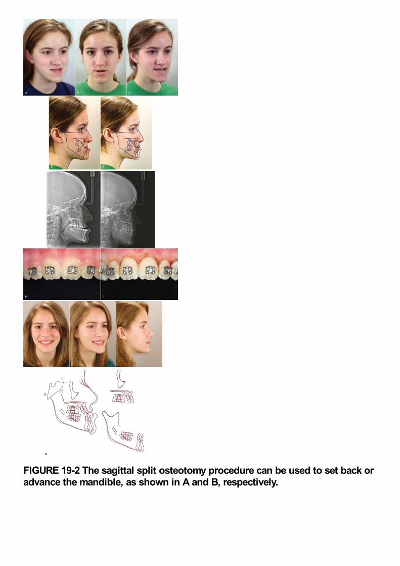
FIGURE 19-2 The sagittal split osteotomy procedure can be used to set back oradvance the mandible, as shown in A and B, respectively.
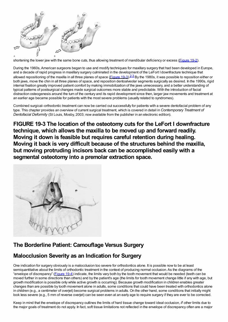
shortening the lower jaw with the same bone cuts, thus allowing treatment of mandibular deficiency or excess (Figure 19-2).
During the 1960s, American surgeons began to use and modify techniques for maxillary surgery that had been developed in Europe,and a decade of rapid progress in maxillary surgery culminated in the development of the LeFort I downfracture technique thatallowed repositioning of the maxilla in all three planes of space (Figure 19-3).2,3 By the 1980s, it was possible to reposition either orboth jaws, move the chin in all three planes of space, and reposition dentoalveolar segments surgically as desired. In the 1990s, rigidinternal fixation greatly improved patient comfort by making immobilization of the jaws unnecessary, and a better understanding oftypical patterns of postsurgical changes made surgical outcomes more stable and predictable. With the introduction of facialdistraction osteogenesis around the turn of the century and its rapid development since then, larger jaw movements and treatment atan earlier age became possible for patients with the most severe problems (usually related to syndromes).
Combined surgical–orthodontic treatment can now be carried out successfully for patients with a severe dentofacial problem of anytype. This chapter provides an overview of current surgical treatment, which is covered in detail in Contemporary Treatment ofDentofacial Deformity (St Louis, Mosby, 2003; now available from the publisher in an electronic edition).
FIGURE 19-3 The location of the osteotomy cuts for the LeFort I downfracturetechnique, which allows the maxilla to be moved up and forward readily.Moving it down is feasible but requires careful retention during healing.Moving it back is very difficult because of the structures behind the maxilla,but moving protruding incisors back can be accomplished easily with asegmental osteotomy into a premolar extraction space.
The Borderline Patient: Camouflage Versus Surgery
Malocclusion Severity as an Indication for SurgeryOne indication for surgery obviously is a malocclusion too severe for orthodontics alone. It is possible now to be at leastsemiquantitative about the limits of orthodontic treatment in the context of producing normal occlusion. As the diagrams of the“envelope of discrepancy” (Figure 19-4) indicate, the limits vary both by the tooth movement that would be needed (teeth can bemoved further in some directions than others) and by the patient's age (the limits for tooth movement change little if any with age, butgrowth modification is possible only while active growth is occurring). Because growth modification in children enables greaterchanges than are possible by tooth movement alone in adults, some conditions that could have been treated with orthodontics alonein children (e.g., a centimeter of overjet) become surgical problems in adults. On the other hand, some conditions that initially mightlook less severe (e.g., 5 mm of reverse overjet) can be seen even at an early age to require surgery if they are ever to be corrected.
Keep in mind that the envelope of discrepancy outlines the limits of hard tissue change toward ideal occlusion, if other limits due tothe major goals of treatment do not apply. In fact, soft tissue limitations not reflected in the envelope of discrepancy often are a major
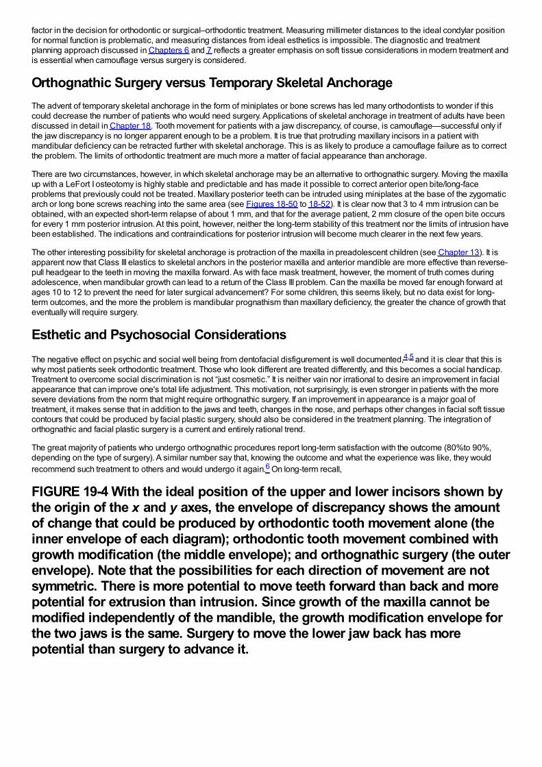
factor in the decision for orthodontic or surgical–orthodontic treatment. Measuring millimeter distances to the ideal condylar positionfor normal function is problematic, and measuring distances from ideal esthetics is impossible. The diagnostic and treatmentplanning approach discussed in Chapters 6 and 7 reflects a greater emphasis on soft tissue considerations in modern treatment andis essential when camouflage versus surgery is considered.
Orthognathic Surgery versus Temporary Skeletal AnchorageThe advent of temporary skeletal anchorage in the form of miniplates or bone screws has led many orthodontists to wonder if thiscould decrease the number of patients who would need surgery. Applications of skeletal anchorage in treatment of adults have beendiscussed in detail in Chapter 18. Tooth movement for patients with a jaw discrepancy, of course, is camouflage—successful only ifthe jaw discrepancy is no longer apparent enough to be a problem. It is true that protruding maxillary incisors in a patient withmandibular deficiency can be retracted further with skeletal anchorage. This is as likely to produce a camouflage failure as to correctthe problem. The limits of orthodontic treatment are much more a matter of facial appearance than anchorage.
There are two circumstances, however, in which skeletal anchorage may be an alternative to orthognathic surgery. Moving the maxillaup with a LeFort I osteotomy is highly stable and predictable and has made it possible to correct anterior open bite/long-faceproblems that previously could not be treated. Maxillary posterior teeth can be intruded using miniplates at the base of the zygomaticarch or long bone screws reaching into the same area (see Figures 18-50 to 18-52). It is clear now that 3 to 4 mm intrusion can beobtained, with an expected short-term relapse of about 1 mm, and that for the average patient, 2 mm closure of the open bite occursfor every 1 mm posterior intrusion. At this point, however, neither the long-term stability of this treatment nor the limits of intrusion havebeen established. The indications and contraindications for posterior intrusion will become much clearer in the next few years.
The other interesting possibility for skeletal anchorage is protraction of the maxilla in preadolescent children (see Chapter 13). It isapparent now that Class III elastics to skeletal anchors in the posterior maxilla and anterior mandible are more effective than reverse-pull headgear to the teeth in moving the maxilla forward. As with face mask treatment, however, the moment of truth comes duringadolescence, when mandibular growth can lead to a return of the Class III problem. Can the maxilla be moved far enough forward atages 10 to 12 to prevent the need for later surgical advancement? For some children, this seems likely, but no data exist for long-term outcomes, and the more the problem is mandibular prognathism than maxillary deficiency, the greater the chance of growth thateventually will require surgery.
Esthetic and Psychosocial ConsiderationsThe negative effect on psychic and social well being from dentofacial disfigurement is well documented,4,5 and it is clear that this iswhy most patients seek orthodontic treatment. Those who look different are treated differently, and this becomes a social handicap.Treatment to overcome social discrimination is not “just cosmetic.” It is neither vain nor irrational to desire an improvement in facialappearance that can improve one's total life adjustment. This motivation, not surprisingly, is even stronger in patients with the moresevere deviations from the norm that might require orthognathic surgery. If an improvement in appearance is a major goal oftreatment, it makes sense that in addition to the jaws and teeth, changes in the nose, and perhaps other changes in facial soft tissuecontours that could be produced by facial plastic surgery, should also be considered in the treatment planning. The integration oforthognathic and facial plastic surgery is a current and entirely rational trend.
The great majority of patients who undergo orthognathic procedures report long-term satisfaction with the outcome (80%to 90%,depending on the type of surgery). A similar number say that, knowing the outcome and what the experience was like, they wouldrecommend such treatment to others and would undergo it again.6 On long-term recall,
FIGURE 19-4 With the ideal position of the upper and lower incisors shown bythe origin of the x and y axes, the envelope of discrepancy shows the amountof change that could be produced by orthodontic tooth movement alone (theinner envelope of each diagram); orthodontic tooth movement combined withgrowth modification (the middle envelope); and orthognathic surgery (the outerenvelope). Note that the possibilities for each direction of movement are notsymmetric. There is more potential to move teeth forward than back and morepotential for extrusion than intrusion. Since growth of the maxilla cannot bemodified independently of the mandible, the growth modification envelope forthe two jaws is the same. Surgery to move the lower jaw back has morepotential than surgery to advance it.
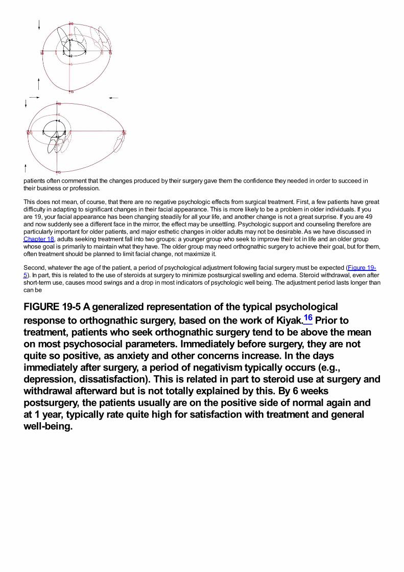
patients often comment that the changes produced by their surgery gave them the confidence they needed in order to succeed intheir business or profession.
This does not mean, of course, that there are no negative psychologic effects from surgical treatment. First, a few patients have greatdifficulty in adapting to significant changes in their facial appearance. This is more likely to be a problem in older individuals. If youare 19, your facial appearance has been changing steadily for all your life, and another change is not a great surprise. If you are 49and now suddenly see a different face in the mirror, the effect may be unsettling. Psychologic support and counseling therefore areparticularly important for older patients, and major esthetic changes in older adults may not be desirable. As we have discussed inChapter 18, adults seeking treatment fall into two groups: a younger group who seek to improve their lot in life and an older groupwhose goal is primarily to maintain what they have. The older group may need orthognathic surgery to achieve their goal, but for them,often treatment should be planned to limit facial change, not maximize it.
Second, whatever the age of the patient, a period of psychological adjustment following facial surgery must be expected (Figure 19-5). In part, this is related to the use of steroids at surgery to minimize postsurgical swelling and edema. Steroid withdrawal, even aftershort-term use, causes mood swings and a drop in most indicators of psychologic well being. The adjustment period lasts longer thancan be
FIGURE 19-5 A generalized representation of the typical psychologicalresponse to orthognathic surgery, based on the work of Kiyak.16 Prior totreatment, patients who seek orthognathic surgery tend to be above the meanon most psychosocial parameters. Immediately before surgery, they are notquite so positive, as anxiety and other concerns increase. In the daysimmediately after surgery, a period of negativism typically occurs (e.g.,depression, dissatisfaction). This is related in part to steroid use at surgery andwithdrawal afterward but is not totally explained by this. By 6 weekspostsurgery, the patients usually are on the positive side of normal again andat 1 year, typically rate quite high for satisfaction with treatment and generalwell-being.
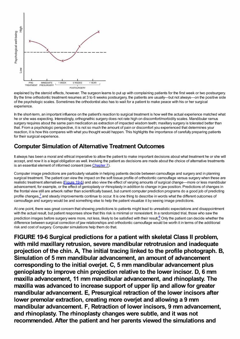
explained by the steroid effects, however. The surgeon learns to put up with complaining patients for the first week or two postsurgery.By the time orthodontic treatment resumes at 3 to 6 weeks postsurgery, the patients are usually—but not always—on the positive sideof the psychologic scales. Sometimes the orthodontist also has to wait for a patient to make peace with his or her surgicalexperience.
In the short-term, an important influence on the patient's reaction to surgical treatment is how well the actual experience matched whathe or she was expecting. Interestingly, orthognathic surgery does not rate high on discomfort/morbidity scales. Mandibular ramussurgery requires about the same pain medication as extraction of impacted wisdom teeth; maxillary surgery is tolerated better thanthat. From a psychologic perspective, it is not so much the amount of pain or discomfort you experienced that determines yourreaction, it is how this compares with what you thought would happen. This highlights the importance of carefully preparing patientsfor their surgical experience.
Computer Simulation of Alternative Treatment OutcomesIt always has been a moral and ethical imperative to allow the patient to make important decisions about what treatment he or she willaccept, and now it is a legal obligation as well. Involving the patient as decisions are made about the choice of alternative treatmentsis an essential element of informed consent (see Chapter 7).
Computer image predictions are particularly valuable in helping patients decide between camouflage and surgery and in planningsurgical treatment. The patient can view the impact on the soft tissue profile of orthodontic camouflage versus surgery when these arerealistic treatment alternatives (Figure 19-6) and also view the effect of varying amounts of surgical change—more or less mandibularadvancement, for example, or the effect of genioplasty or rhinoplasty in addition to change in jaw position. Predictions of changes inthe frontal view still are artwork rather than scientifically based, but current computer prediction programs do a good job of predictingprofile changes,7 and steady improvements continue to occur. It is one thing to describe in words what the different outcomes ofcamouflage and surgery would be and something else to help the patient visualize it by seeing image predictions.
At one point, there was great concern that showing predictions to patients might lead to unrealistic expectations and disappointmentwith the actual result, but patient responses show that this risk is minimal or nonexistent. In a randomized trial, those who saw theprediction images before surgery were more, not less, likely to be satisfied with their result.8 Only the patient can decide whether thedifference between surgical correction of jaw relationships and orthodontic camouflage would be worth it in terms of the additionalrisk and cost of surgery. Computer simulations help them do that.
FIGURE 19-6 Surgical predictions for a patient with skeletal Class II problem,with mild maxillary retrusion, severe mandibular retrotrusion and inadequateprojection of the chin. A, The initial tracing linked to the profile photograph. B,Simulation of 5 mm mandibular advancement, an amount of advancementcorresponding to the initial overjet. C, 5 mm mandibular advancement plusgenioplasty to improve chin projection relative to the lower incisor. D, 6 mmmaxilla advancement, 11 mm mandibular advancement, and rhinoplasty. Themaxilla was advanced to increase support of upper lip and allow for greatermandibular advancement. E, Presurgical retraction of the lower incisors afterlower premolar extraction, creating more overjet and allowing a 9 mmmandibular advancement. F, Retraction of lower incisors, 9 mm advancement,and rhinoplasty. The rhinoplasty changes were subtle, and it was notrecommended. After the patient and her parents viewed the simulations and
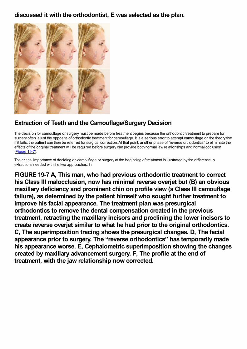
discussed it with the orthodontist, E was selected as the plan.
Extraction of Teeth and the Camouflage/Surgery DecisionThe decision for camouflage or surgery must be made before treatment begins because the orthodontic treatment to prepare forsurgery often is just the opposite of orthodontic treatment for camouflage. It is a serious error to attempt camouflage on the theory thatif it fails, the patient can then be referred for surgical correction. At that point, another phase of “reverse orthodontics” to eliminate theeffects of the original treatment will be required before surgery can provide both normal jaw relationships and normal occlusion(Figure 19-7).
The critical importance of deciding on camouflage or surgery at the beginning of treatment is illustrated by the difference inextractions needed with the two approaches. In
FIGURE 19-7 A, This man, who had previous orthodontic treatment to correcthis Class III malocclusion, now has minimal reverse overjet but (B) an obviousmaxillary deficiency and prominent chin on profile view (a Class III camouflagefailure), as determined by the patient himself who sought further treatment toimprove his facial appearance. The treatment plan was presurgicalorthodontics to remove the dental compensation created in the previoustreatment, retracting the maxillary incisors and proclining the lower incisors tocreate reverse overjet similar to what he had prior to the original orthodontics.C, The superimposition tracing shows the presurgical changes. D, The facialappearance prior to surgery. The “reverse orthodontics” has temporarily madehis appearance worse. E, Cephalometric superimposition showing the changescreated by maxillary advancement surgery. F, The profile at the end oftreatment, with the jaw relationship now corrected.
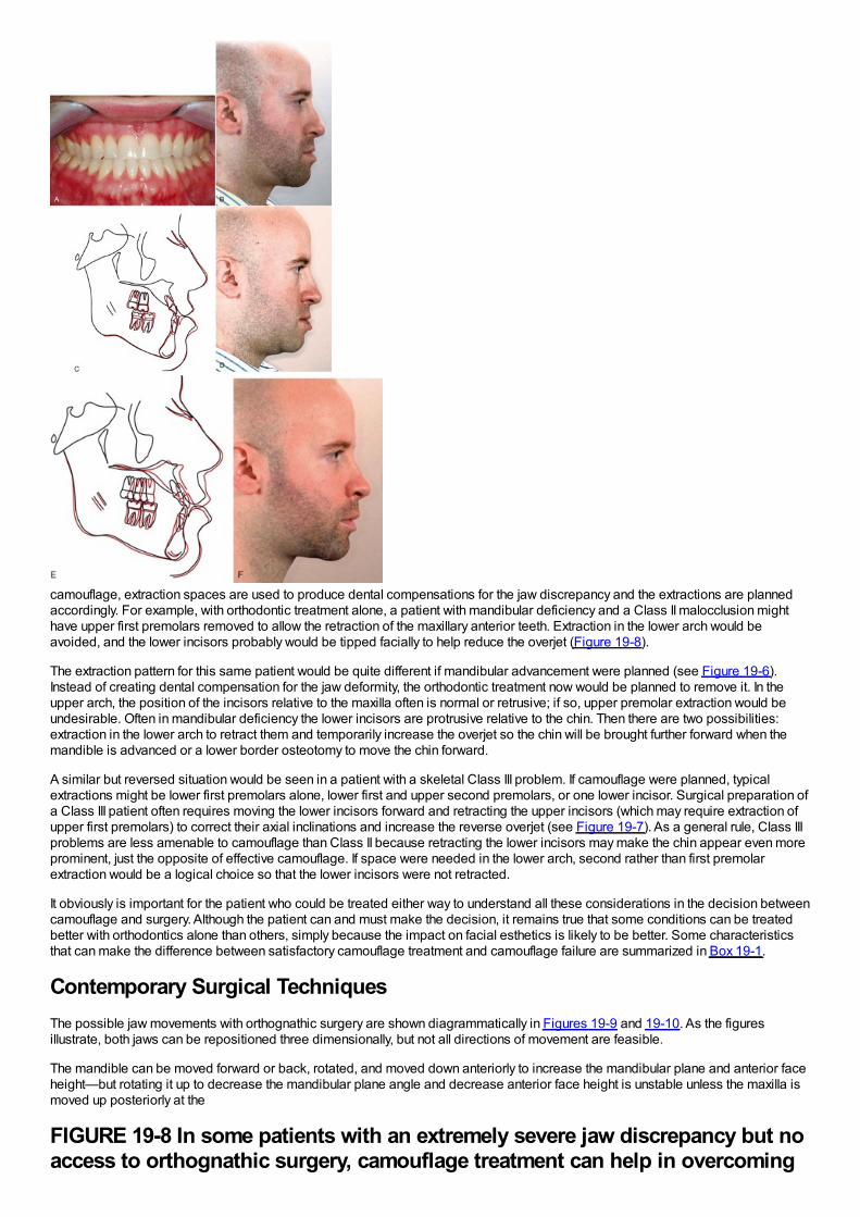
camouflage, extraction spaces are used to produce dental compensations for the jaw discrepancy and the extractions are plannedaccordingly. For example, with orthodontic treatment alone, a patient with mandibular deficiency and a Class II malocclusion mighthave upper first premolars removed to allow the retraction of the maxillary anterior teeth. Extraction in the lower arch would beavoided, and the lower incisors probably would be tipped facially to help reduce the overjet (Figure 19-8).
The extraction pattern for this same patient would be quite different if mandibular advancement were planned (see Figure 19-6).Instead of creating dental compensation for the jaw deformity, the orthodontic treatment now would be planned to remove it. In theupper arch, the position of the incisors relative to the maxilla often is normal or retrusive; if so, upper premolar extraction would beundesirable. Often in mandibular deficiency the lower incisors are protrusive relative to the chin. Then there are two possibilities:extraction in the lower arch to retract them and temporarily increase the overjet so the chin will be brought further forward when themandible is advanced or a lower border osteotomy to move the chin forward.
A similar but reversed situation would be seen in a patient with a skeletal Class III problem. If camouflage were planned, typicalextractions might be lower first premolars alone, lower first and upper second premolars, or one lower incisor. Surgical preparation ofa Class III patient often requires moving the lower incisors forward and retracting the upper incisors (which may require extraction ofupper first premolars) to correct their axial inclinations and increase the reverse overjet (see Figure 19-7). As a general rule, Class IIIproblems are less amenable to camouflage than Class II because retracting the lower incisors may make the chin appear even moreprominent, just the opposite of effective camouflage. If space were needed in the lower arch, second rather than first premolarextraction would be a logical choice so that the lower incisors were not retracted.
It obviously is important for the patient who could be treated either way to understand all these considerations in the decision betweencamouflage and surgery. Although the patient can and must make the decision, it remains true that some conditions can be treatedbetter with orthodontics alone than others, simply because the impact on facial esthetics is likely to be better. Some characteristicsthat can make the difference between satisfactory camouflage treatment and camouflage failure are summarized in Box 19-1.
Contemporary Surgical TechniquesThe possible jaw movements with orthognathic surgery are shown diagrammatically in Figures 19-9 and 19-10. As the figuresillustrate, both jaws can be repositioned three dimensionally, but not all directions of movement are feasible.
The mandible can be moved forward or back, rotated, and moved down anteriorly to increase the mandibular plane and anterior faceheight—but rotating it up to decrease the mandibular plane angle and decrease anterior face height is unstable unless the maxilla ismoved up posteriorly at the
FIGURE 19-8 In some patients with an extremely severe jaw discrepancy but noaccess to orthognathic surgery, camouflage treatment can help in overcoming
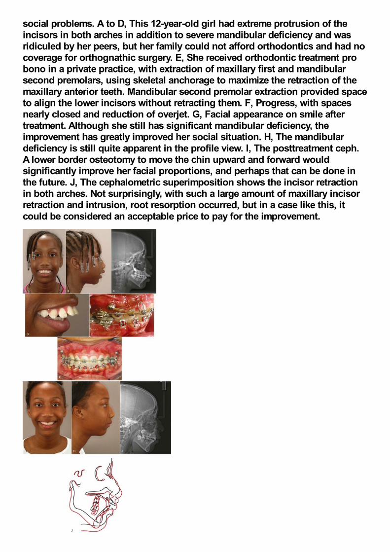
social problems. A to D, This 12-year-old girl had extreme protrusion of theincisors in both arches in addition to severe mandibular deficiency and wasridiculed by her peers, but her family could not afford orthodontics and had nocoverage for orthognathic surgery. E, She received orthodontic treatment probono in a private practice, with extraction of maxillary first and mandibularsecond premolars, using skeletal anchorage to maximize the retraction of themaxillary anterior teeth. Mandibular second premolar extraction provided spaceto align the lower incisors without retracting them. F, Progress, with spacesnearly closed and reduction of overjet. G, Facial appearance on smile aftertreatment. Although she still has significant mandibular deficiency, theimprovement has greatly improved her social situation. H, The mandibulardeficiency is still quite apparent in the profile view. I, The posttreatment ceph.A lower border osteotomy to move the chin upward and forward wouldsignificantly improve her facial proportions, and perhaps that can be done inthe future. J, The cephalometric superimposition shows the incisor retractionin both arches. Not surprisingly, with such a large amount of maxillary incisorretraction and intrusion, root resorption occurred, but in a case like this, itcould be considered an acceptable price to pay for the improvement.
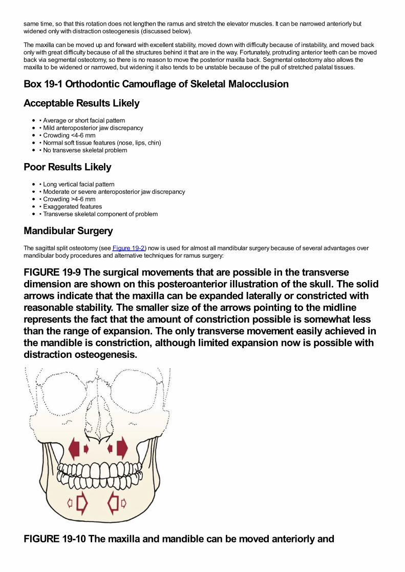
same time, so that this rotation does not lengthen the ramus and stretch the elevator muscles. It can be narrowed anteriorly butwidened only with distraction osteogenesis (discussed below).
The maxilla can be moved up and forward with excellent stability, moved down with difficulty because of instability, and moved backonly with great difficulty because of all the structures behind it that are in the way. Fortunately, protruding anterior teeth can be movedback via segmental osteotomy, so there is no reason to move the posterior maxilla back. Segmental osteotomy also allows themaxilla to be widened or narrowed, but widening it also tends to be unstable because of the pull of stretched palatal tissues.
Box 19-1 Orthodontic Camouflage of Skeletal Malocclusion
Acceptable Results Likely• Average or short facial pattern• Mild anteroposterior jaw discrepancy• Crowding <4-6 mm• Normal soft tissue features (nose, lips, chin)• No transverse skeletal problem
Poor Results Likely• Long vertical facial pattern• Moderate or severe anteroposterior jaw discrepancy• Crowding >4-6 mm• Exaggerated features• Transverse skeletal component of problem
Mandibular SurgeryThe sagittal split osteotomy (see Figure 19-2) now is used for almost all mandibular surgery because of several advantages overmandibular body procedures and alternative techniques for ramus surgery:
FIGURE 19-9 The surgical movements that are possible in the transversedimension are shown on this posteroanterior illustration of the skull. The solidarrows indicate that the maxilla can be expanded laterally or constricted withreasonable stability. The smaller size of the arrows pointing to the midlinerepresents the fact that the amount of constriction possible is somewhat lessthan the range of expansion. The only transverse movement easily achieved inthe mandible is constriction, although limited expansion now is possible withdistraction osteogenesis.
FIGURE 19-10 The maxilla and mandible can be moved anteriorly and
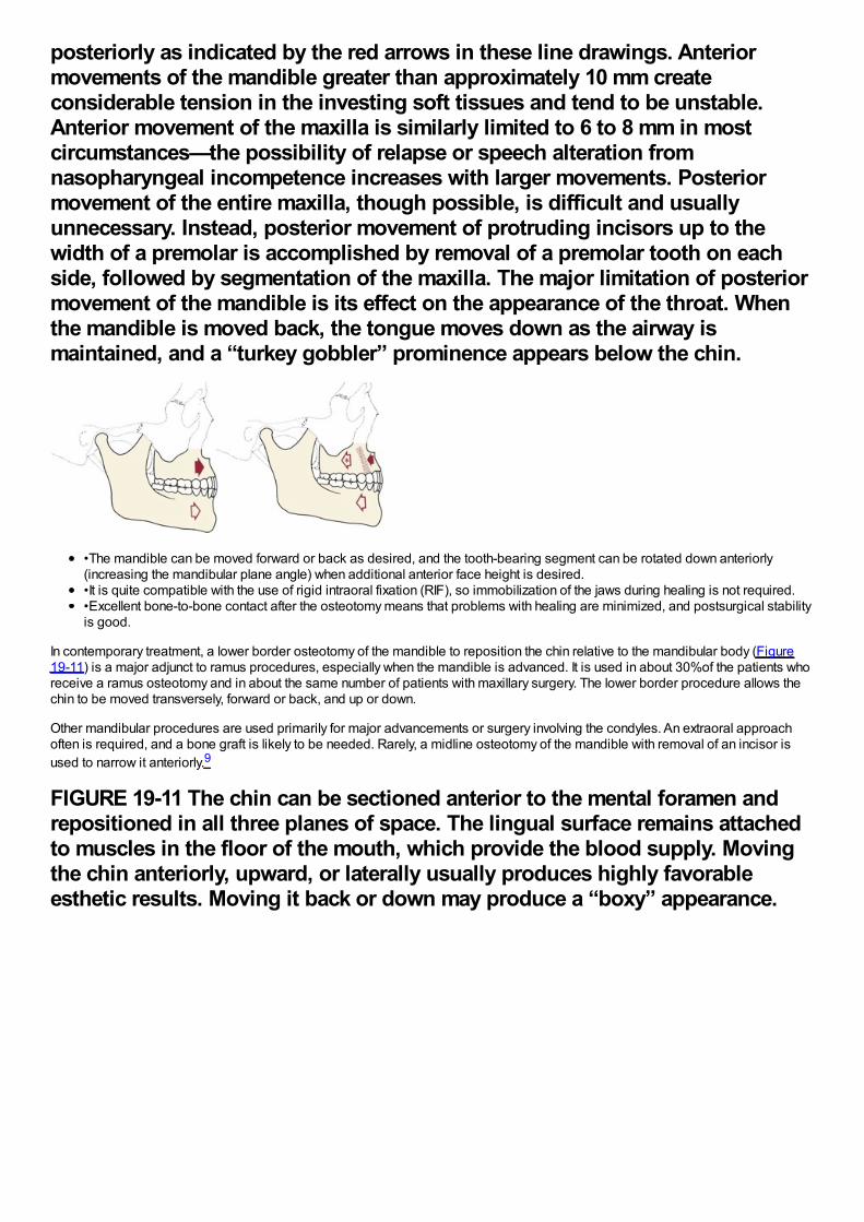
posteriorly as indicated by the red arrows in these line drawings. Anteriormovements of the mandible greater than approximately 10 mm createconsiderable tension in the investing soft tissues and tend to be unstable.Anterior movement of the maxilla is similarly limited to 6 to 8 mm in mostcircumstances—the possibility of relapse or speech alteration fromnasopharyngeal incompetence increases with larger movements. Posteriormovement of the entire maxilla, though possible, is difficult and usuallyunnecessary. Instead, posterior movement of protruding incisors up to thewidth of a premolar is accomplished by removal of a premolar tooth on eachside, followed by segmentation of the maxilla. The major limitation of posteriormovement of the mandible is its effect on the appearance of the throat. Whenthe mandible is moved back, the tongue moves down as the airway ismaintained, and a “turkey gobbler” prominence appears below the chin.
•The mandible can be moved forward or back as desired, and the tooth-bearing segment can be rotated down anteriorly(increasing the mandibular plane angle) when additional anterior face height is desired.•It is quite compatible with the use of rigid intraoral fixation (RIF), so immobilization of the jaws during healing is not required.•Excellent bone-to-bone contact after the osteotomy means that problems with healing are minimized, and postsurgical stabilityis good.
In contemporary treatment, a lower border osteotomy of the mandible to reposition the chin relative to the mandibular body (Figure19-11) is a major adjunct to ramus procedures, especially when the mandible is advanced. It is used in about 30%of the patients whoreceive a ramus osteotomy and in about the same number of patients with maxillary surgery. The lower border procedure allows thechin to be moved transversely, forward or back, and up or down.
Other mandibular procedures are used primarily for major advancements or surgery involving the condyles. An extraoral approachoften is required, and a bone graft is likely to be needed. Rarely, a midline osteotomy of the mandible with removal of an incisor isused to narrow it anteriorly.9
FIGURE 19-11 The chin can be sectioned anterior to the mental foramen andrepositioned in all three planes of space. The lingual surface remains attachedto muscles in the floor of the mouth, which provide the blood supply. Movingthe chin anteriorly, upward, or laterally usually produces highly favorableesthetic results. Moving it back or down may produce a “boxy” appearance.
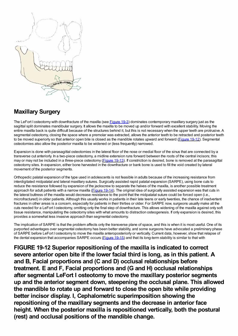
Maxillary SurgeryThe LeFort I osteotomy with downfracture of the maxilla (see Figure 19-3) dominates contemporary maxillary surgery just as thesagittal split dominates mandibular surgery. It allows the maxilla to be moved up and/or forward with excellent stability. Moving theentire maxilla back is quite difficult because of the structures behind it, but this is not necessary when the upper teeth are protrusive. Asegmental osteotomy, closing the space where a premolar was extracted, allows the anterior teeth to be retracted and posterior teethto be moved superiorly so that anterior open bite is closed as the mandible rotates upward and forward (Figure 19-12). Segmentalosteotomies also allow the posterior maxilla to be widened or (less frequently) narrowed.
Expansion is done with parasagittal osteotomies in the lateral floor of the nose or medial floor of the sinus that are connected by atransverse cut anteriorly. In a two-piece osteotomy, a midline extension runs forward between the roots of the central incisors; thismay or may not be included in a three-piece osteotomy (Figure 19-13). If constriction is desired, bone is removed at the parasagittalosteotomy sites. In expansion, either bone harvested in the downfracture or bank bone is used to fill the void created by lateralmovement of the posterior segments.
Orthopedic palatal expansion of the type used in adolescents is not feasible in adults because of the increasing resistance frominterdigitated midpalatal and lateral maxillary sutures. Surgically assisted rapid palatal expansion (SARPE), using bone cuts toreduce the resistance followed by expansion of the jackscrew to separate the halves of the maxilla, is another possible treatmentapproach for adult patients with a narrow maxilla (Figure 19-14). The original idea of surgically assisted expansion was that cuts inthe lateral buttress of the maxilla would decrease resistance to the point that the midpalatal suture could be forced open (i.e.,microfractured) in older patients. Although this usually works in patients in their late teens or early twenties, the chance of inadvertentfractures in other areas is a concern, especially for patients in their thirties or older. For SARPE now, surgeons usually make all thecuts needed for a LeFort I osteotomy, omitting only the final step of downfracture. This allows widening of the maxilla against only softtissue resistance, manipulating the osteotomy sites with what amounts to distraction osteogenesis. If only expansion is desired, thisprovides a somewhat less invasive approach than segmental osteotomy.
The implication of SARPE is that the problem affects only the transverse plane of space, and this is when it is most useful. One of itspurported advantages over segmental osteotomy has been better stability, and some surgeons have advocated a preliminary phaseof SARPE before LeFort I osteotomy to move the maxilla anteroposteriorly or vertically. Current data, however, show that relapse ofthe dental expansion that accompanies SARPE occurs (Figure 19-15) and that its long-term stability is similar to that with
FIGURE 19-12 Superior repositioning of the maxilla is indicated to correctsevere anterior open bite if the lower facial third is long, as in this patient. Aand B, Facial proportions and (C and D) occlusal relationships beforetreatment. E and F, Facial proportions and (G and H) occlusal relationshipsafter segmental LeFort I osteotomy to move the maxillary posterior segmentsup and the anterior segment down, steepening the occlusal plane. This allowedthe mandible to rotate up and forward to close the open bite while providingbetter incisor display. I, Cephalometric superimposition showing therepositioning of the maxillary segments and the decrease in anterior faceheight. When the posterior maxilla is repositioned vertically, both the postural(rest) and occlusal positions of the mandible change.
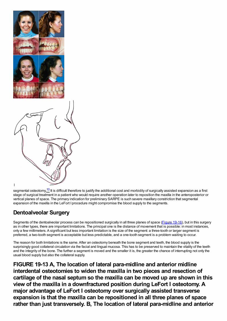
segmental osteotomy.10 It is difficult therefore to justify the additional cost and morbidity of surgically assisted expansion as a firststage of surgical treatment in a patient who would require another operation later to reposition the maxilla in the anteroposterior orvertical planes of space. The primary indication for preliminary SARPE is such severe maxillary constriction that segmentalexpansion of the maxilla in the LeFort I procedure might compromise the blood supply to the segments.
Dentoalveolar SurgerySegments of the dentoalveolar process can be repositioned surgically in all three planes of space (Figure 19-16), but in this surgeryas in other types, there are important limitations. The principal one is the distance of movement that is possible: in most instances,only a few millimeters. A significant but less important limitation is the size of the segment: a three-tooth or larger segment ispreferred, a two-tooth segment is acceptable but less predictable, and a one-tooth segment is a problem waiting to occur.
The reason for both limitations is the same. After an osteotomy beneath the bone segment and teeth, the blood supply is thesurprisingly good collateral circulation via the facial and lingual mucosa. This has to be preserved to maintain the vitality of the teethand the integrity of the bone. The further a segment is moved and the smaller it is, the greater the chance of interrupting not only theusual blood supply but also the collateral supply.
FIGURE 19-13 A, The location of lateral para-midline and anterior midlineinterdental osteotomies to widen the maxilla in two pieces and resection ofcartilage of the nasal septum so the maxilla can be moved up are shown in thisview of the maxilla in a downfractured position during LeFort I osteotomy. Amajor advantage of LeFort I osteotomy over surgically assisted transverseexpansion is that the maxilla can be repositioned in all three planes of spacerather than just transversely. B, The location of lateral para-midline and anterior
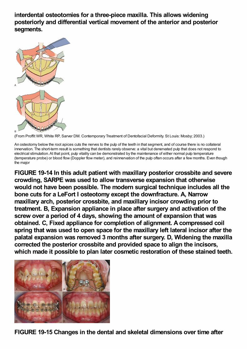
interdental osteotomies for a three-piece maxilla. This allows wideningposteriorly and differential vertical movement of the anterior and posteriorsegments.
(From Proffit WR, White RP, Sarver DM. Contemporary Treatment of Dentofacial Deformity. St Louis: Mosby; 2003.)
An osteotomy below the root apices cuts the nerves to the pulp of the teeth in that segment, and of course there is no collateralinnervation. The short-term result is something that dentists rarely observe: a vital but denervated pulp that does not respond toelectrical stimulation. At that point, pulp vitality can be demonstrated by the maintenance of either normal pulp temperature(temperature probe) or blood flow (Doppler flow meter), and reinnervation of the pulp often occurs after a few months. Even thoughthe major
FIGURE 19-14 In this adult patient with maxillary posterior crossbite and severecrowding, SARPE was used to allow transverse expansion that otherwisewould not have been possible. The modern surgical technique includes all thebone cuts for a LeFort I osteotomy except the downfracture. A, Narrowmaxillary arch, posterior crossbite, and maxillary incisor crowding prior totreatment. B, Expansion appliance in place after surgery and activation of thescrew over a period of 4 days, showing the amount of expansion that wasobtained. C, Fixed appliance for completion of alignment. A compressed coilspring that was used to open space for the maxillary left lateral incisor after thepalatal expansion was removed 3 months after surgery. D, Widening the maxillacorrected the posterior crossbite and provided space to align the incisors,which made it possible to plan later cosmetic restoration of these stained teeth.
FIGURE 19-15 Changes in the dental and skeletal dimensions over time after
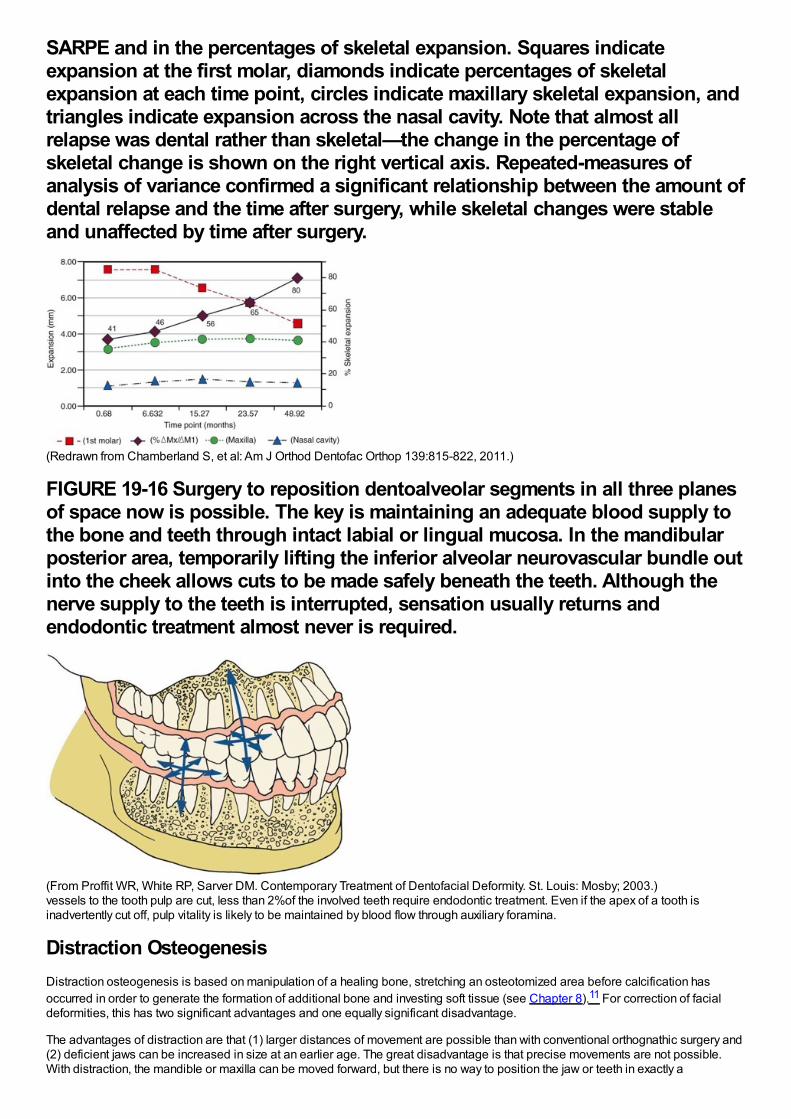
SARPE and in the percentages of skeletal expansion. Squares indicateexpansion at the first molar, diamonds indicate percentages of skeletalexpansion at each time point, circles indicate maxillary skeletal expansion, andtriangles indicate expansion across the nasal cavity. Note that almost allrelapse was dental rather than skeletal—the change in the percentage ofskeletal change is shown on the right vertical axis. Repeated-measures ofanalysis of variance confirmed a significant relationship between the amount ofdental relapse and the time after surgery, while skeletal changes were stableand unaffected by time after surgery.
(Redrawn from Chamberland S, et al: Am J Orthod Dentofac Orthop 139:815-822, 2011.)
FIGURE 19-16 Surgery to reposition dentoalveolar segments in all three planesof space now is possible. The key is maintaining an adequate blood supply tothe bone and teeth through intact labial or lingual mucosa. In the mandibularposterior area, temporarily lifting the inferior alveolar neurovascular bundle outinto the cheek allows cuts to be made safely beneath the teeth. Although thenerve supply to the teeth is interrupted, sensation usually returns andendodontic treatment almost never is required.
(From Proffit WR, White RP, Sarver DM. Contemporary Treatment of Dentofacial Deformity. St. Louis: Mosby; 2003.)vessels to the tooth pulp are cut, less than 2%of the involved teeth require endodontic treatment. Even if the apex of a tooth isinadvertently cut off, pulp vitality is likely to be maintained by blood flow through auxiliary foramina.
Distraction OsteogenesisDistraction osteogenesis is based on manipulation of a healing bone, stretching an osteotomized area before calcification hasoccurred in order to generate the formation of additional bone and investing soft tissue (see Chapter 8).11 For correction of facialdeformities, this has two significant advantages and one equally significant disadvantage.
The advantages of distraction are that (1) larger distances of movement are possible than with conventional orthognathic surgery and(2) deficient jaws can be increased in size at an earlier age. The great disadvantage is that precise movements are not possible.With distraction, the mandible or maxilla can be moved forward, but there is no way to position the jaw or teeth in exactly a
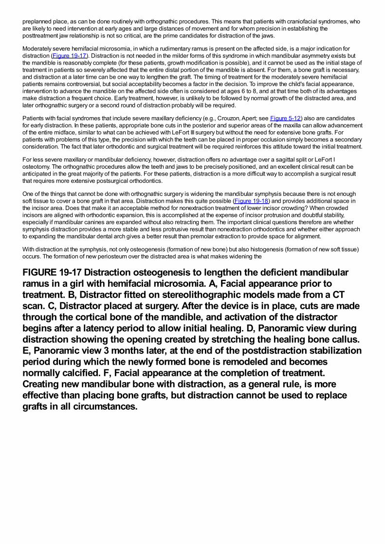
preplanned place, as can be done routinely with orthognathic procedures. This means that patients with craniofacial syndromes, whoare likely to need intervention at early ages and large distances of movement and for whom precision in establishing theposttreatment jaw relationship is not so critical, are the prime candidates for distraction of the jaws.
Moderately severe hemifacial microsomia, in which a rudimentary ramus is present on the affected side, is a major indication fordistraction (Figure 19-17). Distraction is not needed in the milder forms of this syndrome in which mandibular asymmetry exists butthe mandible is reasonably complete (for these patients, growth modification is possible), and it cannot be used as the initial stage oftreatment in patients so severely affected that the entire distal portion of the mandible is absent. For them, a bone graft is necessary,and distraction at a later time can be one way to lengthen the graft. The timing of treatment for the moderately severe hemifacialpatients remains controversial, but social acceptability becomes a factor in the decision. To improve the child's facial appearance,intervention to advance the mandible on the affected side often is considered at ages 6 to 8, and at that time both of its advantagesmake distraction a frequent choice. Early treatment, however, is unlikely to be followed by normal growth of the distracted area, andlater orthognathic surgery or a second round of distraction probably will be required.
Patients with facial syndromes that include severe maxillary deficiency (e.g., Crouzon, Apert; see Figure 5-12) also are candidatesfor early distraction. In these patients, appropriate bone cuts in the posterior and superior areas of the maxilla can allow advancementof the entire midface, similar to what can be achieved with LeFort III surgery but without the need for extensive bone grafts. Forpatients with problems of this type, the precision with which the teeth can be placed in proper occlusion simply becomes a secondaryconsideration. The fact that later orthodontic and surgical treatment will be required reinforces this attitude toward the initial treatment.
For less severe maxillary or mandibular deficiency, however, distraction offers no advantage over a sagittal split or LeFort Iosteotomy. The orthognathic procedures allow the teeth and jaws to be precisely positioned, and an excellent clinical result can beanticipated in the great majority of the patients. For these patients, distraction is a more difficult way to accomplish a surgical resultthat requires more extensive postsurgical orthodontics.
One of the things that cannot be done with orthognathic surgery is widening the mandibular symphysis because there is not enoughsoft tissue to cover a bone graft in that area. Distraction makes this quite possible (Figure 19-18) and provides additional space inthe incisor area. Does that make it an acceptable method for nonextraction treatment of lower incisor crowding? When crowdedincisors are aligned with orthodontic expansion, this is accomplished at the expense of incisor protrusion and doubtful stability,especially if mandibular canines are expanded without also retracting them. The important clinical questions therefore are whethersymphysis distraction provides a more stable and less protrusive result than nonextraction orthodontics and whether either approachto expanding the mandibular dental arch gives a better result than premolar extraction to provide space for alignment.
With distraction at the symphysis, not only osteogenesis (formation of new bone) but also histogenesis (formation of new soft tissue)occurs. The formation of new periosteum over the distracted area is what makes widening the
FIGURE 19-17 Distraction osteogenesis to lengthen the deficient mandibularramus in a girl with hemifacial microsomia. A, Facial appearance prior totreatment. B, Distractor fitted on stereolithographic models made from a CTscan. C, Distractor placed at surgery. After the device is in place, cuts are madethrough the cortical bone of the mandible, and activation of the distractorbegins after a latency period to allow initial healing. D, Panoramic view duringdistraction showing the opening created by stretching the healing bone callus.E, Panoramic view 3 months later, at the end of the postdistraction stabilizationperiod during which the newly formed bone is remodeled and becomesnormally calcified. F, Facial appearance at the completion of treatment.Creating new mandibular bone with distraction, as a general rule, is moreeffective than placing bone grafts, but distraction cannot be used to replacegrafts in all circumstances.
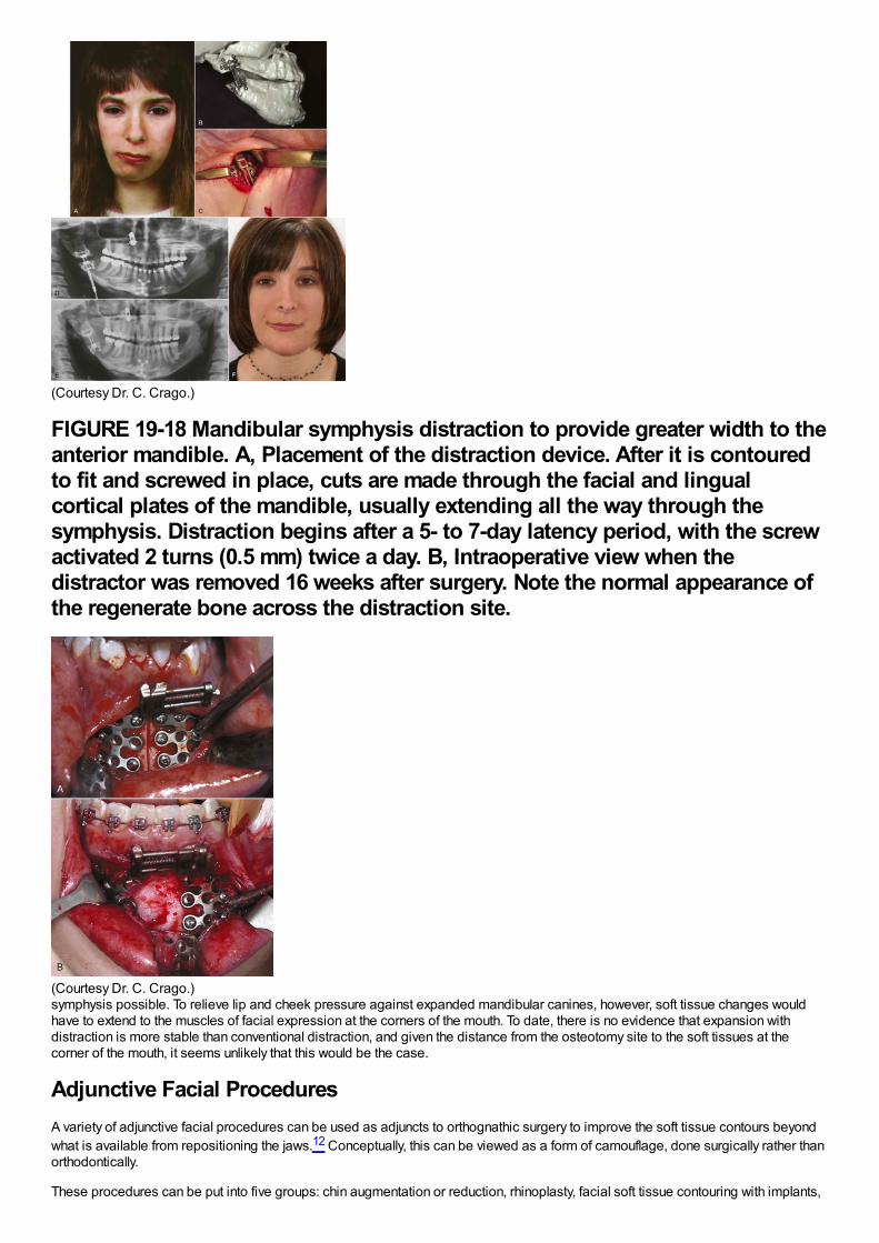
(Courtesy Dr. C. Crago.)
FIGURE 19-18 Mandibular symphysis distraction to provide greater width to theanterior mandible. A, Placement of the distraction device. After it is contouredto fit and screwed in place, cuts are made through the facial and lingualcortical plates of the mandible, usually extending all the way through thesymphysis. Distraction begins after a 5- to 7-day latency period, with the screwactivated 2 turns (0.5 mm) twice a day. B, Intraoperative view when thedistractor was removed 16 weeks after surgery. Note the normal appearance ofthe regenerate bone across the distraction site.
(Courtesy Dr. C. Crago.)symphysis possible. To relieve lip and cheek pressure against expanded mandibular canines, however, soft tissue changes wouldhave to extend to the muscles of facial expression at the corners of the mouth. To date, there is no evidence that expansion withdistraction is more stable than conventional distraction, and given the distance from the osteotomy site to the soft tissues at thecorner of the mouth, it seems unlikely that this would be the case.
Adjunctive Facial ProceduresA variety of adjunctive facial procedures can be used as adjuncts to orthognathic surgery to improve the soft tissue contours beyondwhat is available from repositioning the jaws.12 Conceptually, this can be viewed as a form of camouflage, done surgically rather thanorthodontically.
These procedures can be put into five groups: chin augmentation or reduction, rhinoplasty, facial soft tissue contouring with implants,
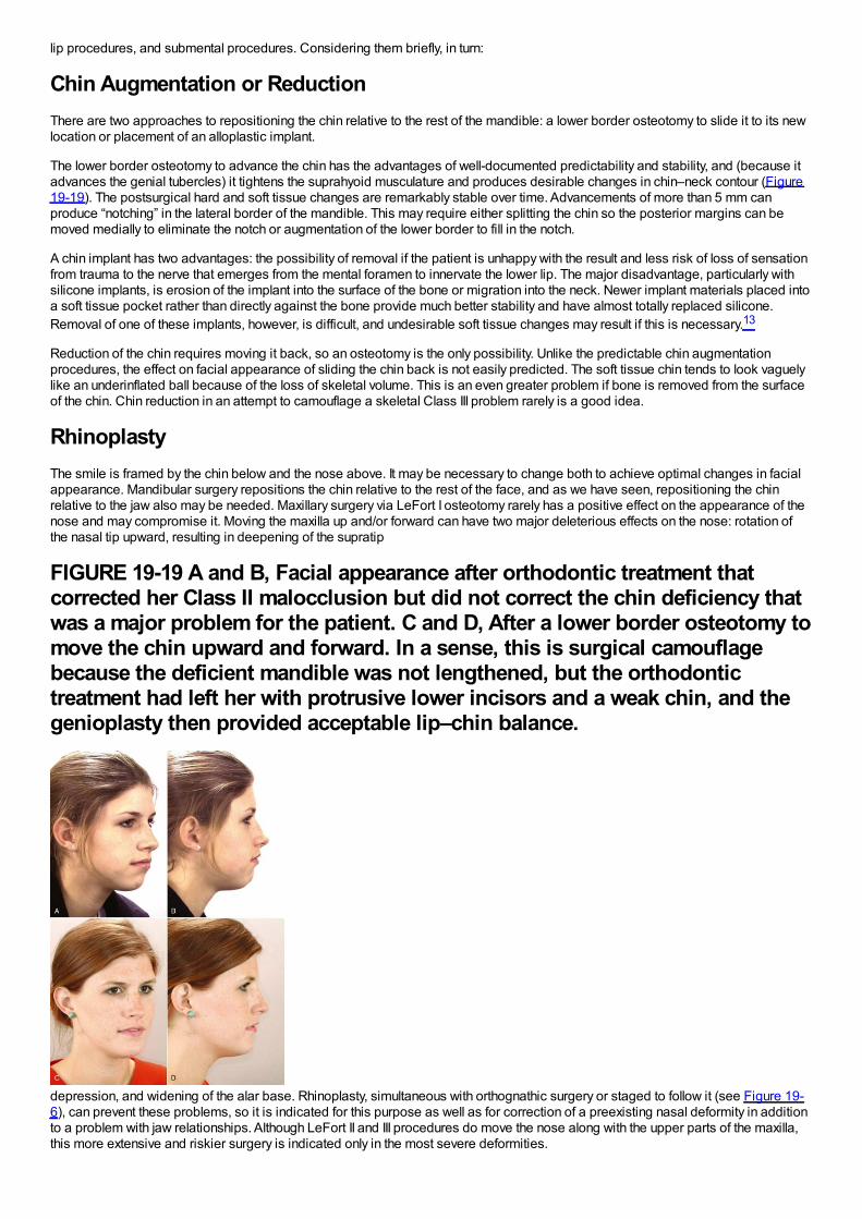
lip procedures, and submental procedures. Considering them briefly, in turn:
Chin Augmentation or ReductionThere are two approaches to repositioning the chin relative to the rest of the mandible: a lower border osteotomy to slide it to its newlocation or placement of an alloplastic implant.
The lower border osteotomy to advance the chin has the advantages of well-documented predictability and stability, and (because itadvances the genial tubercles) it tightens the suprahyoid musculature and produces desirable changes in chin–neck contour (Figure19-19). The postsurgical hard and soft tissue changes are remarkably stable over time. Advancements of more than 5 mm canproduce “notching” in the lateral border of the mandible. This may require either splitting the chin so the posterior margins can bemoved medially to eliminate the notch or augmentation of the lower border to fill in the notch.
A chin implant has two advantages: the possibility of removal if the patient is unhappy with the result and less risk of loss of sensationfrom trauma to the nerve that emerges from the mental foramen to innervate the lower lip. The major disadvantage, particularly withsilicone implants, is erosion of the implant into the surface of the bone or migration into the neck. Newer implant materials placed intoa soft tissue pocket rather than directly against the bone provide much better stability and have almost totally replaced silicone.Removal of one of these implants, however, is difficult, and undesirable soft tissue changes may result if this is necessary.13
Reduction of the chin requires moving it back, so an osteotomy is the only possibility. Unlike the predictable chin augmentationprocedures, the effect on facial appearance of sliding the chin back is not easily predicted. The soft tissue chin tends to look vaguelylike an underinflated ball because of the loss of skeletal volume. This is an even greater problem if bone is removed from the surfaceof the chin. Chin reduction in an attempt to camouflage a skeletal Class III problem rarely is a good idea.
RhinoplastyThe smile is framed by the chin below and the nose above. It may be necessary to change both to achieve optimal changes in facialappearance. Mandibular surgery repositions the chin relative to the rest of the face, and as we have seen, repositioning the chinrelative to the jaw also may be needed. Maxillary surgery via LeFort I osteotomy rarely has a positive effect on the appearance of thenose and may compromise it. Moving the maxilla up and/or forward can have two major deleterious effects on the nose: rotation ofthe nasal tip upward, resulting in deepening of the supratip
FIGURE 19-19 A and B, Facial appearance after orthodontic treatment thatcorrected her Class II malocclusion but did not correct the chin deficiency thatwas a major problem for the patient. C and D, After a lower border osteotomy tomove the chin upward and forward. In a sense, this is surgical camouflagebecause the deficient mandible was not lengthened, but the orthodontictreatment had left her with protrusive lower incisors and a weak chin, and thegenioplasty then provided acceptable lip–chin balance.
depression, and widening of the alar base. Rhinoplasty, simultaneous with orthognathic surgery or staged to follow it (see Figure 19-6), can prevent these problems, so it is indicated for this purpose as well as for correction of a preexisting nasal deformity in additionto a problem with jaw relationships. Although LeFort II and III procedures do move the nose along with the upper parts of the maxilla,this more extensive and riskier surgery is indicated only in the most severe deformities.
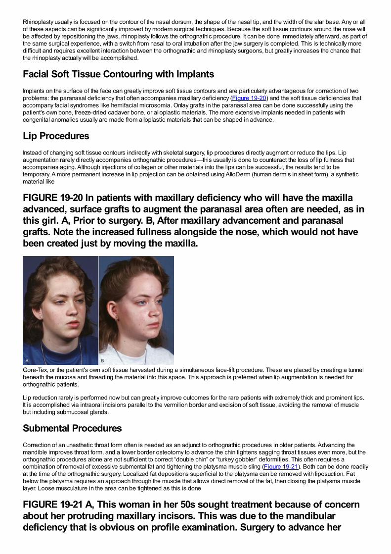
Rhinoplasty usually is focused on the contour of the nasal dorsum, the shape of the nasal tip, and the width of the alar base. Any or allof these aspects can be significantly improved by modern surgical techniques. Because the soft tissue contours around the nose willbe affected by repositioning the jaws, rhinoplasty follows the orthognathic procedure. It can be done immediately afterward, as part ofthe same surgical experience, with a switch from nasal to oral intubation after the jaw surgery is completed. This is technically moredifficult and requires excellent interaction between the orthognathic and rhinoplasty surgeons, but greatly increases the chance thatthe rhinoplasty actually will be accomplished.
Facial Soft Tissue Contouring with ImplantsImplants on the surface of the face can greatly improve soft tissue contours and are particularly advantageous for correction of twoproblems: the paranasal deficiency that often accompanies maxillary deficiency (Figure 19-20) and the soft tissue deficiencies thataccompany facial syndromes like hemifacial microsomia. Onlay grafts in the paranasal area can be done successfully using thepatient's own bone, freeze-dried cadaver bone, or alloplastic materials. The more extensive implants needed in patients withcongenital anomalies usually are made from alloplastic materials that can be shaped in advance.
Lip ProceduresInstead of changing soft tissue contours indirectly with skeletal surgery, lip procedures directly augment or reduce the lips. Lipaugmentation rarely directly accompanies orthognathic procedures—this usually is done to counteract the loss of lip fullness thataccompanies aging. Although injections of collagen or other materials into the lips can be successful, the results tend to betemporary. A more permanent increase in lip projection can be obtained using AlloDerm (human dermis in sheet form), a syntheticmaterial like
FIGURE 19-20 In patients with maxillary deficiency who will have the maxillaadvanced, surface grafts to augment the paranasal area often are needed, as inthis girl. A, Prior to surgery. B, After maxillary advancement and paranasalgrafts. Note the increased fullness alongside the nose, which would not havebeen created just by moving the maxilla.
Gore-Tex, or the patient's own soft tissue harvested during a simultaneous face-lift procedure. These are placed by creating a tunnelbeneath the mucosa and threading the material into this space. This approach is preferred when lip augmentation is needed fororthognathic patients.
Lip reduction rarely is performed now but can greatly improve outcomes for the rare patients with extremely thick and prominent lips.It is accomplished via intraoral incisions parallel to the vermilion border and excision of soft tissue, avoiding the removal of musclebut including submucosal glands.
Submental ProceduresCorrection of an unesthetic throat form often is needed as an adjunct to orthognathic procedures in older patients. Advancing themandible improves throat form, and a lower border osteotomy to advance the chin tightens sagging throat tissues even more, but theorthognathic procedures alone are not sufficient to correct “double chin” or “turkey gobbler” deformities. This often requires acombination of removal of excessive submental fat and tightening the platysma muscle sling (Figure 19-21). Both can be done readilyat the time of the orthognathic surgery. Localized fat depositions superficial to the platysma can be removed with liposuction. Fatbelow the platysma requires an approach through the muscle that allows direct removal of the fat, then closing the platysma musclelayer. Loose musculature in the area can be tightened as this is done
FIGURE 19-21 A, This woman in her 50s sought treatment because of concernabout her protruding maxillary incisors. This was due to the mandibulardeficiency that is obvious on profile examination. Surgery to advance her
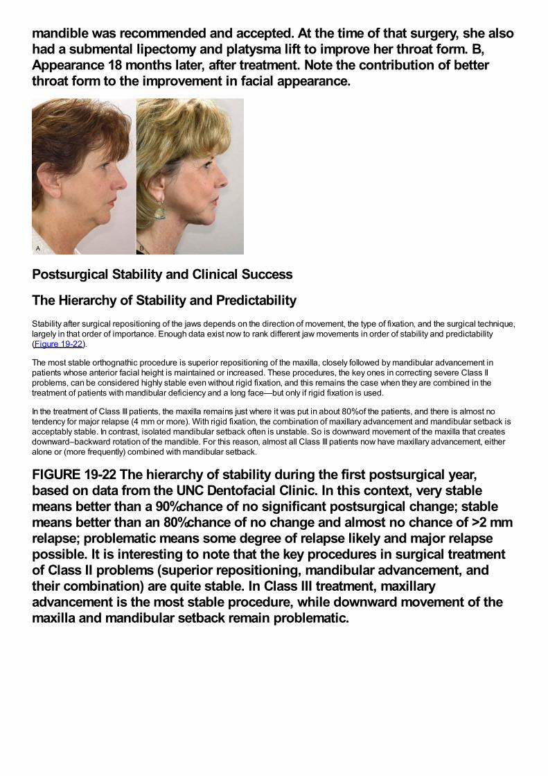
mandible was recommended and accepted. At the time of that surgery, she alsohad a submental lipectomy and platysma lift to improve her throat form. B,Appearance 18 months later, after treatment. Note the contribution of betterthroat form to the improvement in facial appearance.
Postsurgical Stability and Clinical Success
The Hierarchy of Stability and PredictabilityStability after surgical repositioning of the jaws depends on the direction of movement, the type of fixation, and the surgical technique,largely in that order of importance. Enough data exist now to rank different jaw movements in order of stability and predictability(Figure 19-22).
The most stable orthognathic procedure is superior repositioning of the maxilla, closely followed by mandibular advancement inpatients whose anterior facial height is maintained or increased. These procedures, the key ones in correcting severe Class IIproblems, can be considered highly stable even without rigid fixation, and this remains the case when they are combined in thetreatment of patients with mandibular deficiency and a long face—but only if rigid fixation is used.
In the treatment of Class III patients, the maxilla remains just where it was put in about 80%of the patients, and there is almost notendency for major relapse (4 mm or more). With rigid fixation, the combination of maxillary advancement and mandibular setback isacceptably stable. In contrast, isolated mandibular setback often is unstable. So is downward movement of the maxilla that createsdownward–backward rotation of the mandible. For this reason, almost all Class III patients now have maxillary advancement, eitheralone or (more frequently) combined with mandibular setback.
FIGURE 19-22 The hierarchy of stability during the first postsurgical year,based on data from the UNC Dentofacial Clinic. In this context, very stablemeans better than a 90%chance of no significant postsurgical change; stablemeans better than an 80%chance of no change and almost no chance of >2 mmrelapse; problematic means some degree of relapse likely and major relapsepossible. It is interesting to note that the key procedures in surgical treatmentof Class II problems (superior repositioning, mandibular advancement, andtheir combination) are quite stable. In Class III treatment, maxillaryadvancement is the most stable procedure, while downward movement of themaxilla and mandibular setback remain problematic.
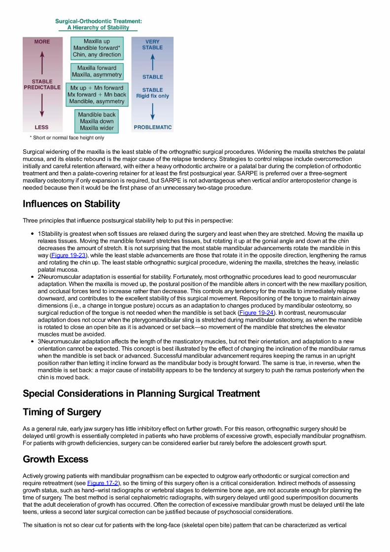
Surgical widening of the maxilla is the least stable of the orthognathic surgical procedures. Widening the maxilla stretches the palatalmucosa, and its elastic rebound is the major cause of the relapse tendency. Strategies to control relapse include overcorrectioninitially and careful retention afterward, with either a heavy orthodontic archwire or a palatal bar during the completion of orthodontictreatment and then a palate-covering retainer for at least the first postsurgical year. SARPE is preferred over a three-segmentmaxillary osteotomy if only expansion is required, but SARPE is not advantageous when vertical and/or anteroposterior change isneeded because then it would be the first phase of an unnecessary two-stage procedure.
Influences on StabilityThree principles that influence postsurgical stability help to put this in perspective:
1Stability is greatest when soft tissues are relaxed during the surgery and least when they are stretched. Moving the maxilla uprelaxes tissues. Moving the mandible forward stretches tissues, but rotating it up at the gonial angle and down at the chindecreases the amount of stretch. It is not surprising that the most stable mandibular advancements rotate the mandible in thisway (Figure 19-23), while the least stable advancements are those that rotate it in the opposite direction, lengthening the ramusand rotating the chin up. The least stable orthognathic surgical procedure, widening the maxilla, stretches the heavy, inelasticpalatal mucosa.2Neuromuscular adaptation is essential for stability. Fortunately, most orthognathic procedures lead to good neuromuscularadaptation. When the maxilla is moved up, the postural position of the mandible alters in concert with the new maxillary position,and occlusal forces tend to increase rather than decrease. This controls any tendency for the maxilla to immediately relapsedownward, and contributes to the excellent stability of this surgical movement. Repositioning of the tongue to maintain airwaydimensions (i.e., a change in tongue posture) occurs as an adaptation to changes produced by mandibular osteotomy, sosurgical reduction of the tongue is not needed when the mandible is set back (Figure 19-24). In contrast, neuromuscularadaptation does not occur when the pterygomandibular sling is stretched during mandibular osteotomy, as when the mandibleis rotated to close an open bite as it is advanced or set back—so movement of the mandible that stretches the elevatormuscles must be avoided.3Neuromuscular adaptation affects the length of the masticatory muscles, but not their orientation, and adaptation to a neworientation cannot be expected. This concept is best illustrated by the effect of changing the inclination of the mandibular ramuswhen the mandible is set back or advanced. Successful mandibular advancement requires keeping the ramus in an uprightposition rather than letting it incline forward as the mandibular body is brought forward. The same is true, in reverse, when themandible is set back: a major cause of instability appears to be the tendency at surgery to push the ramus posteriorly when thechin is moved back.
Special Considerations in Planning Surgical Treatment
Timing of SurgeryAs a general rule, early jaw surgery has little inhibitory effect on further growth. For this reason, orthognathic surgery should bedelayed until growth is essentially completed in patients who have problems of excessive growth, especially mandibular prognathism.For patients with growth deficiencies, surgery can be considered earlier but rarely before the adolescent growth spurt.
Growth ExcessActively growing patients with mandibular prognathism can be expected to outgrow early orthodontic or surgical correction andrequire retreatment (see Figure 17-2), so the timing of this surgery often is a critical consideration. Indirect methods of assessinggrowth status, such as hand–wrist radiographs or vertebral stages to determine bone age, are not accurate enough for planning thetime of surgery. The best method is serial cephalometric radiographs, with surgery delayed until good superimposition documentsthat the adult deceleration of growth has occurred. Often the correction of excessive mandibular growth must be delayed until the lateteens, unless a second later surgical correction can be justified because of psychosocial considerations.
The situation is not so clear cut for patients with the long-face (skeletal open bite) pattern that can be characterized as vertical
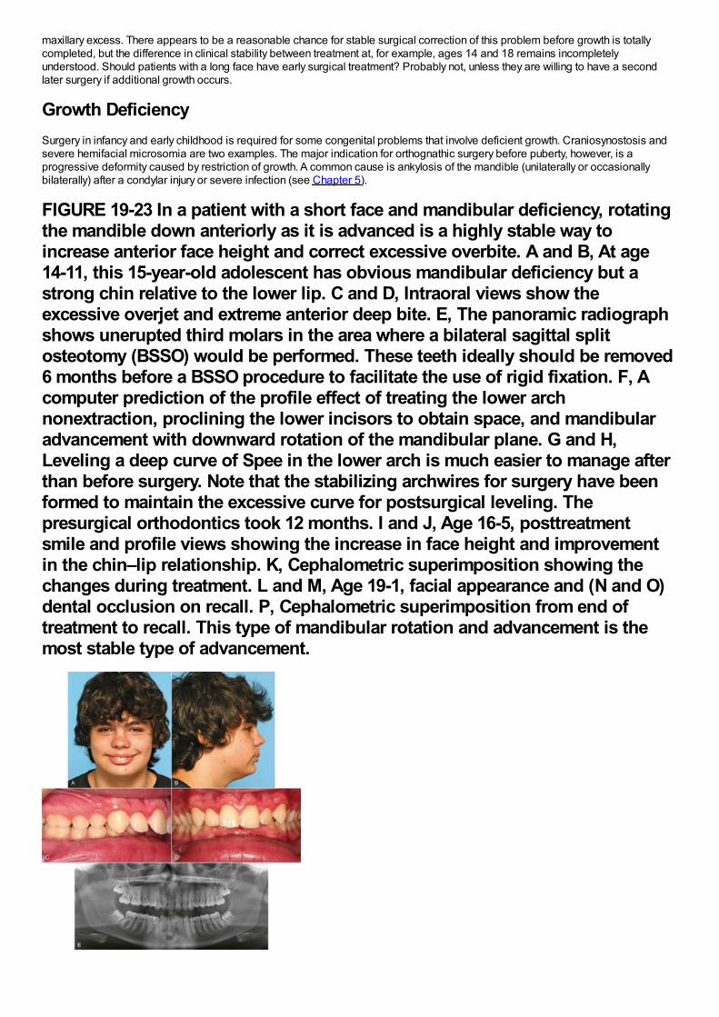
maxillary excess. There appears to be a reasonable chance for stable surgical correction of this problem before growth is totallycompleted, but the difference in clinical stability between treatment at, for example, ages 14 and 18 remains incompletelyunderstood. Should patients with a long face have early surgical treatment? Probably not, unless they are willing to have a secondlater surgery if additional growth occurs.
Growth DeficiencySurgery in infancy and early childhood is required for some congenital problems that involve deficient growth. Craniosynostosis andsevere hemifacial microsomia are two examples. The major indication for orthognathic surgery before puberty, however, is aprogressive deformity caused by restriction of growth. A common cause is ankylosis of the mandible (unilaterally or occasionallybilaterally) after a condylar injury or severe infection (see Chapter 5).
FIGURE 19-23 In a patient with a short face and mandibular deficiency, rotatingthe mandible down anteriorly as it is advanced is a highly stable way toincrease anterior face height and correct excessive overbite. A and B, At age14-11, this 15-year-old adolescent has obvious mandibular deficiency but astrong chin relative to the lower lip. C and D, Intraoral views show theexcessive overjet and extreme anterior deep bite. E, The panoramic radiographshows unerupted third molars in the area where a bilateral sagittal splitosteotomy (BSSO) would be performed. These teeth ideally should be removed6 months before a BSSO procedure to facilitate the use of rigid fixation. F, Acomputer prediction of the profile effect of treating the lower archnonextraction, proclining the lower incisors to obtain space, and mandibularadvancement with downward rotation of the mandibular plane. G and H,Leveling a deep curve of Spee in the lower arch is much easier to manage afterthan before surgery. Note that the stabilizing archwires for surgery have beenformed to maintain the excessive curve for postsurgical leveling. Thepresurgical orthodontics took 12 months. I and J, Age 16-5, posttreatmentsmile and profile views showing the increase in face height and improvementin the chin–lip relationship. K, Cephalometric superimposition showing thechanges during treatment. L and M, Age 19-1, facial appearance and (N and O)dental occlusion on recall. P, Cephalometric superimposition from end oftreatment to recall. This type of mandibular rotation and advancement is themost stable type of advancement.
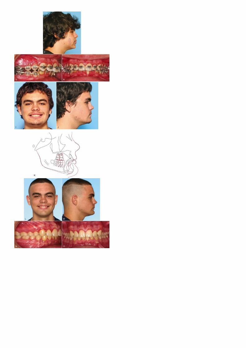
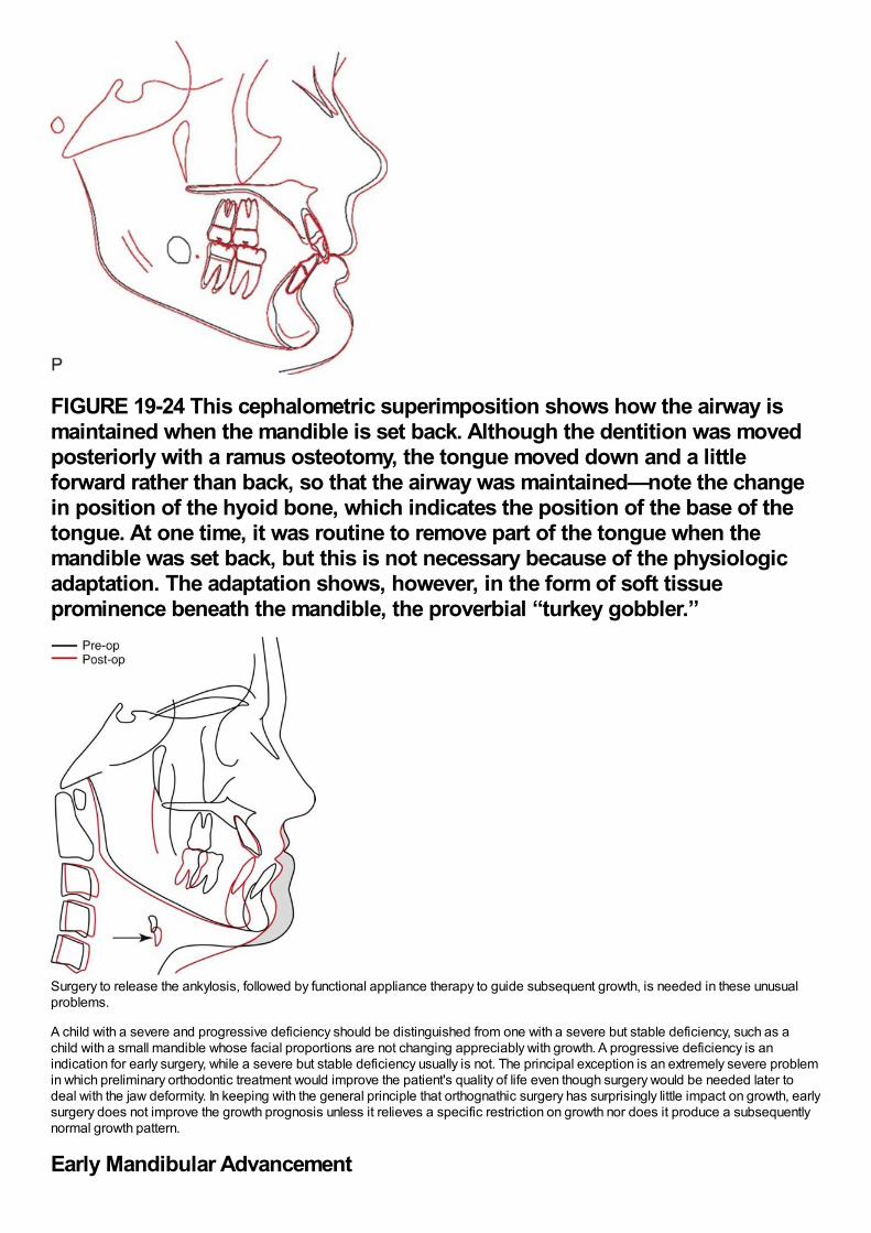
FIGURE 19-24 This cephalometric superimposition shows how the airway ismaintained when the mandible is set back. Although the dentition was movedposteriorly with a ramus osteotomy, the tongue moved down and a littleforward rather than back, so that the airway was maintained—note the changein position of the hyoid bone, which indicates the position of the base of thetongue. At one time, it was routine to remove part of the tongue when themandible was set back, but this is not necessary because of the physiologicadaptation. The adaptation shows, however, in the form of soft tissueprominence beneath the mandible, the proverbial “turkey gobbler.”
Surgery to release the ankylosis, followed by functional appliance therapy to guide subsequent growth, is needed in these unusualproblems.
A child with a severe and progressive deficiency should be distinguished from one with a severe but stable deficiency, such as achild with a small mandible whose facial proportions are not changing appreciably with growth. A progressive deficiency is anindication for early surgery, while a severe but stable deficiency usually is not. The principal exception is an extremely severe problemin which preliminary orthodontic treatment would improve the patient's quality of life even though surgery would be needed later todeal with the jaw deformity. In keeping with the general principle that orthognathic surgery has surprisingly little impact on growth, earlysurgery does not improve the growth prognosis unless it relieves a specific restriction on growth nor does it produce a subsequentlynormal growth pattern.
Early Mandibular Advancement
In the 1980s, some surgeons advocated early mandibular advancement, assuming that normal growth would occur thereafter and theproblem would not recur. At present, the same theory has been offered in favor of early distraction osteogenesis to correct severemandibular deficiency. Many younger patients have further mandibular growth following surgical advancement. Most of this growth isexpressed vertically, however, and results in minimal forward movement at pogonion.14 It is clear already, despite the absence ofgood long-term data, that normal mandibular growth cannot be expected after early distraction. In our view, mandibular advancementbefore the adolescent growth spurt, with surgery or distraction, is not indicated for patients who do not have a progressive deformityor psychosocial problems severe enough to warrant a second surgery later.
On the other hand, there is no reason to delay mandibular advancement after sexual maturity. Minimal facial growth can be expectedin patients with severe deficiency during late adolescence, and relapse from that cause is unlikely. In contrast to mandibular setback,mandibular advancement after the adolescent growth spurt is completed, which can be as early as age 14 or 15, is quite feasible.
Early Maxillary AdvancementEarly advancement of a sagittally deficient maxilla or midface remains relatively stable if there is careful attention to detail and graftsare used to combat relapse, but further forward growth of the maxilla is quite unlikely. Subsequent growth of the mandible is likely toresult in reestablishing Class III malocclusion and a concave profile. The patient and parents should be cautioned about the possibleneed for a second stage of surgical treatment later. In general, maxillary advancement should be delayed until after the adolescentgrowth spurt unless earlier treatment is needed for psychosocial reasons.
Although surgery to reposition the entire maxilla may affect future growth, this is not necessarily the case for the surgical proceduresused to correct cleft lip and palate. In cleft patients, bone grafts to alveolar clefts prior to eruption of the permanent canines caneliminate the bony defect, which greatly improves the long-term prognosis for the dentition. A review of cleft palate patients treatedwith the Oslo protocol (i.e., closure of the lip and hard palate at 3 months, posterior palatal closure at 18 months, and cancellousalveolar bone grafting at 8 to 11 years) showed no interference with the total amount of facial growth.15 As surgery methods for initialclosure of a cleft palate continue to improve, the number of cleft patients who need maxillary advancement as a final stage oftreatment should continue to decrease.
Correction of Combined Vertical and Anteroposterior Problems
Short-Face Class II: Increasing Anterior Face HeightBoth mandibular and maxillary deficiencies often are accompanied by short anterior face height, and a goal of treatment should be toincrease it. It is important to realize that moving the mandible forward easily allows a stable increase in face height along with theanteroposterior movement, while moving the maxilla down and forcing the mandible to rotate down and back can be problematic.
The most stable type of mandibular advancement rotates the mandibular body segment as it is advanced, so that the chin comesforward and downward and the mandibular plane angle increases (see Figure 19-23). The excellent bony contact after a sagittal splitosteotomy easily allows the rotation. The effect is to shorten the mandibular ramus. Although the soft tissues of the anterior lower faceare stretched as the chin is advanced and moved down, this is mitigated by relaxation of the posterior soft tissues (which include themandibular elevator muscles), and the result is little soft tissue pressure in a relapse direction.
In contrast, moving the maxilla down stretches both the anterior and posterior facial soft tissues. Although muscle adaptation appearsto occur, there is a strong tendency for the maxilla to relapse upward. As a general rule therefore, mandibular ramus surgery ispreferred to increase face height, and downward movement of the posterior maxilla, so that the mandible is forced to rotate downand back, is avoided if possible.
Long-Face Class II: Decreasing Face HeightMoving the maxilla up, so that the mandible can rotate up and forward, is the most stable orthognathic procedure (see discussion ofstability below). A LeFort I osteotomy therefore is the preferred procedure for a patient with an anterior open bite and/or a Class IImalocclusion due to downward–backward rotation of the mandible (see Figure 19-12).
In contrast, although a mandibular ramus osteotomy can be used to decrease anterior face height and decrease the mandibularplane angle, this is highly unstable because the mandibular elevator muscles are stretched and do not adapt. Moving the maxilla upproduces a change in the postural position of the mandible. A ramus osteotomy does not produce the same neuromuscularadaptation, which is why it is unstable. As a general rule therefore, a LeFort I osteotomy to elevate the posterior maxilla is preferred toreduce face height. If the mandible is still deficient after it rotates up and forward, a mandibular advancement in combination with themaxillary procedure does not stretch the muscles and is acceptably stable.
For Class III patients, the same guidelines for vertical change are applicable.
The bottom line:
To increase face height, use a mandibular ramus osteotomy in combination with a maxillary osteotomy if downward movementof the maxilla is desired.To decrease face height, use a maxillary osteotomy in combination with a mandibular ramus osteotomy if further mandibularadvancement or mandibular setback is required.
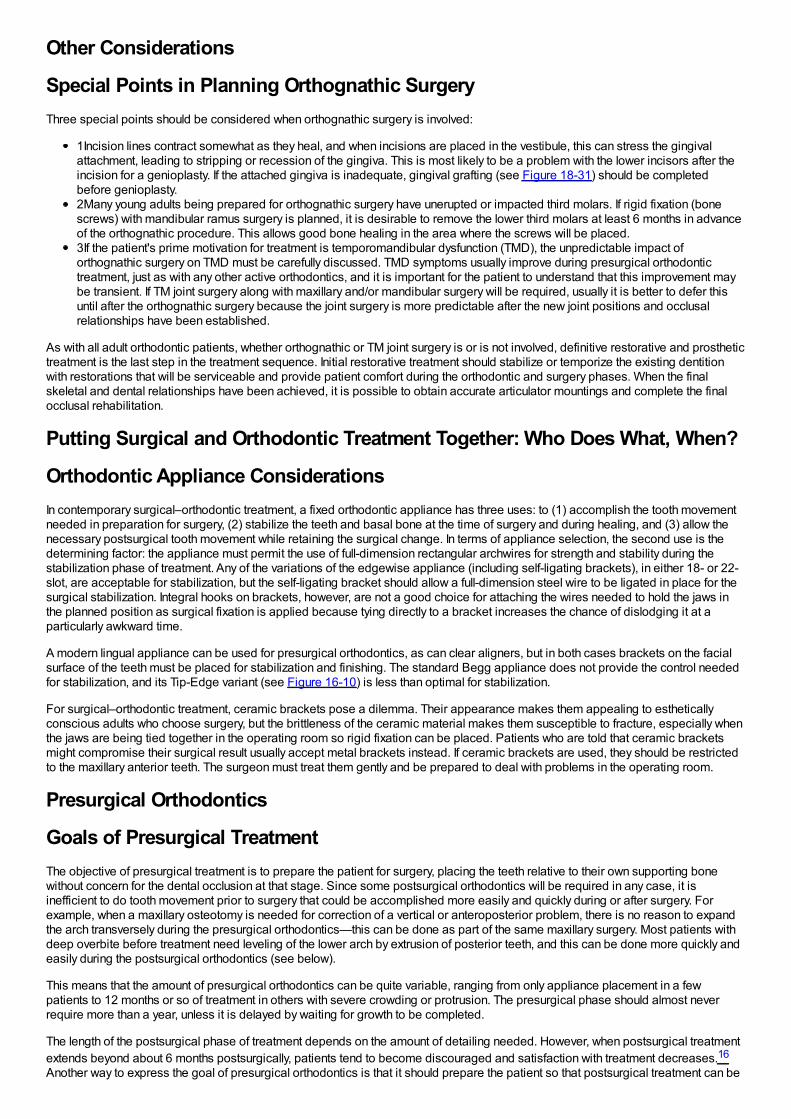
Other Considerations
Special Points in Planning Orthognathic SurgeryThree special points should be considered when orthognathic surgery is involved:
1Incision lines contract somewhat as they heal, and when incisions are placed in the vestibule, this can stress the gingivalattachment, leading to stripping or recession of the gingiva. This is most likely to be a problem with the lower incisors after theincision for a genioplasty. If the attached gingiva is inadequate, gingival grafting (see Figure 18-31) should be completedbefore genioplasty.2Many young adults being prepared for orthognathic surgery have unerupted or impacted third molars. If rigid fixation (bonescrews) with mandibular ramus surgery is planned, it is desirable to remove the lower third molars at least 6 months in advanceof the orthognathic procedure. This allows good bone healing in the area where the screws will be placed.3If the patient's prime motivation for treatment is temporomandibular dysfunction (TMD), the unpredictable impact oforthognathic surgery on TMD must be carefully discussed. TMD symptoms usually improve during presurgical orthodontictreatment, just as with any other active orthodontics, and it is important for the patient to understand that this improvement maybe transient. If TM joint surgery along with maxillary and/or mandibular surgery will be required, usually it is better to defer thisuntil after the orthognathic surgery because the joint surgery is more predictable after the new joint positions and occlusalrelationships have been established.
As with all adult orthodontic patients, whether orthognathic or TM joint surgery is or is not involved, definitive restorative and prosthetictreatment is the last step in the treatment sequence. Initial restorative treatment should stabilize or temporize the existing dentitionwith restorations that will be serviceable and provide patient comfort during the orthodontic and surgery phases. When the finalskeletal and dental relationships have been achieved, it is possible to obtain accurate articulator mountings and complete the finalocclusal rehabilitation.
Putting Surgical and Orthodontic Treatment Together: Who Does What, When?
Orthodontic Appliance ConsiderationsIn contemporary surgical–orthodontic treatment, a fixed orthodontic appliance has three uses: to (1) accomplish the tooth movementneeded in preparation for surgery, (2) stabilize the teeth and basal bone at the time of surgery and during healing, and (3) allow thenecessary postsurgical tooth movement while retaining the surgical change. In terms of appliance selection, the second use is thedetermining factor: the appliance must permit the use of full-dimension rectangular archwires for strength and stability during thestabilization phase of treatment. Any of the variations of the edgewise appliance (including self-ligating brackets), in either 18- or 22-slot, are acceptable for stabilization, but the self-ligating bracket should allow a full-dimension steel wire to be ligated in place for thesurgical stabilization. Integral hooks on brackets, however, are not a good choice for attaching the wires needed to hold the jaws inthe planned position as surgical fixation is applied because tying directly to a bracket increases the chance of dislodging it at aparticularly awkward time.
A modern lingual appliance can be used for presurgical orthodontics, as can clear aligners, but in both cases brackets on the facialsurface of the teeth must be placed for stabilization and finishing. The standard Begg appliance does not provide the control neededfor stabilization, and its Tip-Edge variant (see Figure 16-10) is less than optimal for stabilization.
For surgical–orthodontic treatment, ceramic brackets pose a dilemma. Their appearance makes them appealing to estheticallyconscious adults who choose surgery, but the brittleness of the ceramic material makes them susceptible to fracture, especially whenthe jaws are being tied together in the operating room so rigid fixation can be placed. Patients who are told that ceramic bracketsmight compromise their surgical result usually accept metal brackets instead. If ceramic brackets are used, they should be restrictedto the maxillary anterior teeth. The surgeon must treat them gently and be prepared to deal with problems in the operating room.
Presurgical Orthodontics
Goals of Presurgical TreatmentThe objective of presurgical treatment is to prepare the patient for surgery, placing the teeth relative to their own supporting bonewithout concern for the dental occlusion at that stage. Since some postsurgical orthodontics will be required in any case, it isinefficient to do tooth movement prior to surgery that could be accomplished more easily and quickly during or after surgery. Forexample, when a maxillary osteotomy is needed for correction of a vertical or anteroposterior problem, there is no reason to expandthe arch transversely during the presurgical orthodontics—this can be done as part of the same maxillary surgery. Most patients withdeep overbite before treatment need leveling of the lower arch by extrusion of posterior teeth, and this can be done more quickly andeasily during the postsurgical orthodontics (see below).
This means that the amount of presurgical orthodontics can be quite variable, ranging from only appliance placement in a fewpatients to 12 months or so of treatment in others with severe crowding or protrusion. The presurgical phase should almost neverrequire more than a year, unless it is delayed by waiting for growth to be completed.
The length of the postsurgical phase of treatment depends on the amount of detailing needed. However, when postsurgical treatmentextends beyond about 6 months postsurgically, patients tend to become discouraged and satisfaction with treatment decreases.16
Another way to express the goal of presurgical orthodontics is that it should prepare the patient so that postsurgical treatment can be
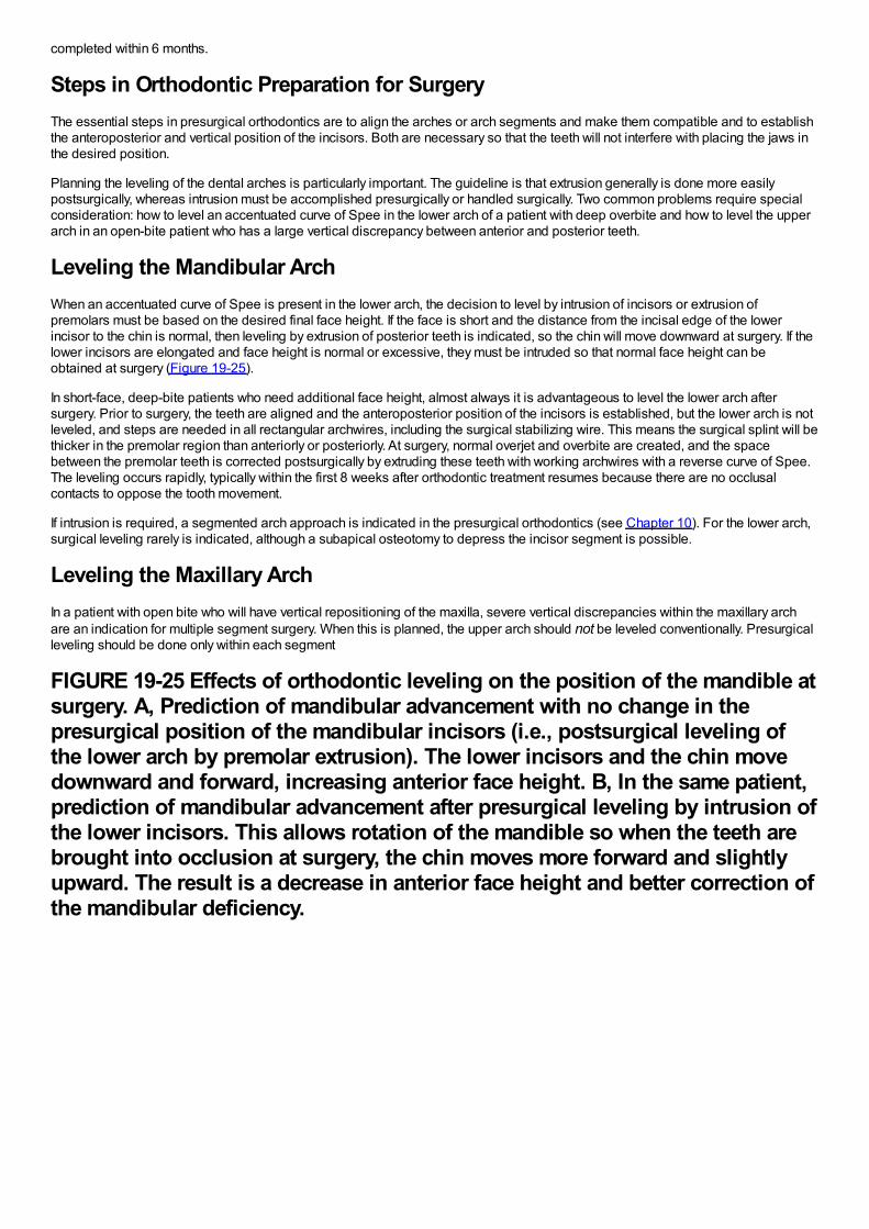
completed within 6 months.
Steps in Orthodontic Preparation for SurgeryThe essential steps in presurgical orthodontics are to align the arches or arch segments and make them compatible and to establishthe anteroposterior and vertical position of the incisors. Both are necessary so that the teeth will not interfere with placing the jaws inthe desired position.
Planning the leveling of the dental arches is particularly important. The guideline is that extrusion generally is done more easilypostsurgically, whereas intrusion must be accomplished presurgically or handled surgically. Two common problems require specialconsideration: how to level an accentuated curve of Spee in the lower arch of a patient with deep overbite and how to level the upperarch in an open-bite patient who has a large vertical discrepancy between anterior and posterior teeth.
Leveling the Mandibular ArchWhen an accentuated curve of Spee is present in the lower arch, the decision to level by intrusion of incisors or extrusion ofpremolars must be based on the desired final face height. If the face is short and the distance from the incisal edge of the lowerincisor to the chin is normal, then leveling by extrusion of posterior teeth is indicated, so the chin will move downward at surgery. If thelower incisors are elongated and face height is normal or excessive, they must be intruded so that normal face height can beobtained at surgery (Figure 19-25).
In short-face, deep-bite patients who need additional face height, almost always it is advantageous to level the lower arch aftersurgery. Prior to surgery, the teeth are aligned and the anteroposterior position of the incisors is established, but the lower arch is notleveled, and steps are needed in all rectangular archwires, including the surgical stabilizing wire. This means the surgical splint will bethicker in the premolar region than anteriorly or posteriorly. At surgery, normal overjet and overbite are created, and the spacebetween the premolar teeth is corrected postsurgically by extruding these teeth with working archwires with a reverse curve of Spee.The leveling occurs rapidly, typically within the first 8 weeks after orthodontic treatment resumes because there are no occlusalcontacts to oppose the tooth movement.
If intrusion is required, a segmented arch approach is indicated in the presurgical orthodontics (see Chapter 10). For the lower arch,surgical leveling rarely is indicated, although a subapical osteotomy to depress the incisor segment is possible.
Leveling the Maxillary ArchIn a patient with open bite who will have vertical repositioning of the maxilla, severe vertical discrepancies within the maxillary archare an indication for multiple segment surgery. When this is planned, the upper arch should not be leveled conventionally. Presurgicalleveling should be done only within each segment
FIGURE 19-25 Effects of orthodontic leveling on the position of the mandible atsurgery. A, Prediction of mandibular advancement with no change in thepresurgical position of the mandibular incisors (i.e., postsurgical leveling ofthe lower arch by premolar extrusion). The lower incisors and the chin movedownward and forward, increasing anterior face height. B, In the same patient,prediction of mandibular advancement after presurgical leveling by intrusion ofthe lower incisors. This allows rotation of the mandible so when the teeth arebrought into occlusion at surgery, the chin moves more forward and slightlyupward. The result is a decrease in anterior face height and better correction ofthe mandibular deficiency.
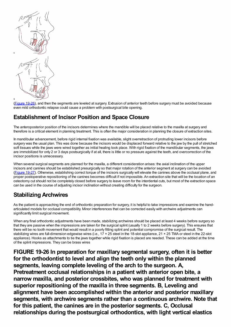
(Figure 19-26), and then the segments are leveled at surgery. Extrusion of anterior teeth before surgery must be avoided becauseeven mild orthodontic relapse could cause a problem with postsurgical bite opening.
Establishment of Incisor Position and Space ClosureThe anteroposterior position of the incisors determines where the mandible will be placed relative to the maxilla at surgery andtherefore is a critical element in planning treatment. This is often the major consideration in planning the closure of extraction sites.
In mandibular advancement, before rigid internal fixation was available, slight overretraction of protruding lower incisors beforesurgery was the usual plan. This was done because the incisors would be displaced forward relative to the jaw by the pull of stretchedsoft tissues while the jaws were wired together as initial healing took place. With rigid fixation of the mandibular segments, the jawsare immobilized for only 2 or 3 days postsurgically if at all, there is little or no pressure against the teeth, and overcorrection of theincisor positions is unnecessary.
When several surgical segments are planned for the maxilla, a different consideration arises: the axial inclination of the upperincisors and canines should be established presurgically so that major rotation of the anterior segment at surgery can be avoided(Figure 19-27). Otherwise, establishing correct torque of the incisors surgically will elevate the canines above the occlusal plane, andproper postoperative repositioning of the canines becomes difficult if not impossible. An extraction site that will be the location of anosteotomy cut should not be completely closed before surgery to leave room for the interdental cuts, but most of the extraction spacecan be used in the course of adjusting incisor inclination without creating difficulty for the surgeon.
Stabilizing ArchwiresAs the patient is approaching the end of orthodontic preparation for surgery, it is helpful to take impressions and examine the hand-articulated models for occlusal compatibility. Minor interferences that can be corrected easily with archwire adjustments cansignificantly limit surgical movement.
When any final orthodontic adjustments have been made, stabilizing archwires should be placed at least 4 weeks before surgery sothat they are passive when the impressions are taken for the surgical splint (usually 1 to 2 weeks before surgery). This ensures thatthere will be no tooth movement that would result in a poorly fitting splint and potential compromise of the surgical result. Thestabilizing wires are full-dimension edgewise wires (i.e., 17 × 25 steel in the 18-slot appliance, 21 × 25 TMA or steel in the 22-slotappliance). Hooks as attachments to tie the jaws together while rigid fixation is placed are needed. These can be added at the timeof the splint impressions. They can be brass wires
FIGURE 19-26 In preparation for maxillary segmental surgery, often it is betterfor the orthodontist to level and align the teeth only within the plannedsegments, leaving complete leveling of the arch to the surgeon. A,Pretreatment occlusal relationships in a patient with anterior open bite, anarrow maxilla, and posterior crossbites, who was planned for treatment withsuperior repositioning of the maxilla in three segments. B, Leveling andalignment have been accomplished within the anterior and posterior maxillarysegments, with archwire segments rather than a continuous archwire. Note thatfor this patient, the canines are in the posterior segments. C, Occlusalrelationships during the postsurgical orthodontics, with light vertical elastics
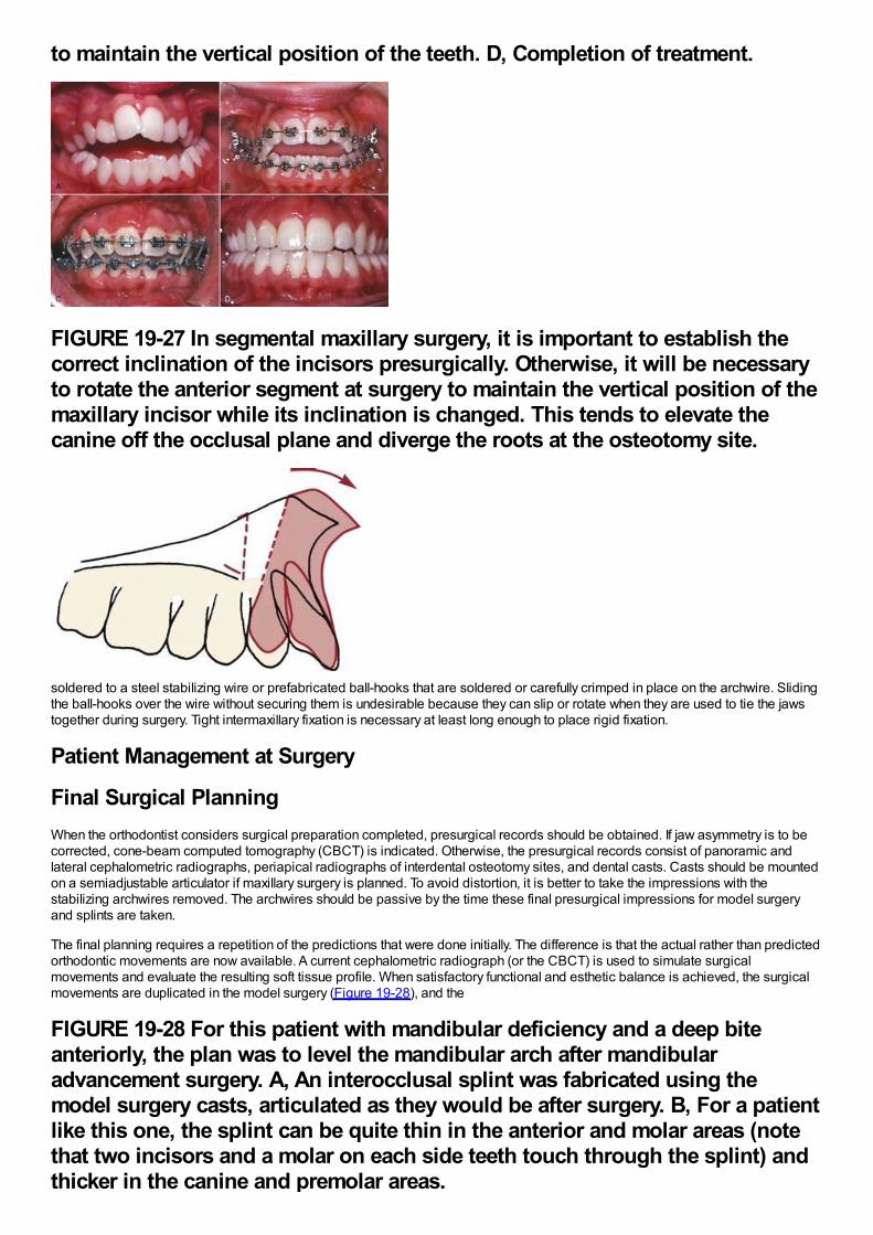
to maintain the vertical position of the teeth. D, Completion of treatment.
FIGURE 19-27 In segmental maxillary surgery, it is important to establish thecorrect inclination of the incisors presurgically. Otherwise, it will be necessaryto rotate the anterior segment at surgery to maintain the vertical position of themaxillary incisor while its inclination is changed. This tends to elevate thecanine off the occlusal plane and diverge the roots at the osteotomy site.
soldered to a steel stabilizing wire or prefabricated ball-hooks that are soldered or carefully crimped in place on the archwire. Slidingthe ball-hooks over the wire without securing them is undesirable because they can slip or rotate when they are used to tie the jawstogether during surgery. Tight intermaxillary fixation is necessary at least long enough to place rigid fixation.
Patient Management at Surgery
Final Surgical PlanningWhen the orthodontist considers surgical preparation completed, presurgical records should be obtained. If jaw asymmetry is to becorrected, cone-beam computed tomography (CBCT) is indicated. Otherwise, the presurgical records consist of panoramic andlateral cephalometric radiographs, periapical radiographs of interdental osteotomy sites, and dental casts. Casts should be mountedon a semiadjustable articulator if maxillary surgery is planned. To avoid distortion, it is better to take the impressions with thestabilizing archwires removed. The archwires should be passive by the time these final presurgical impressions for model surgeryand splints are taken.
The final planning requires a repetition of the predictions that were done initially. The difference is that the actual rather than predictedorthodontic movements are now available. A current cephalometric radiograph (or the CBCT) is used to simulate surgicalmovements and evaluate the resulting soft tissue profile. When satisfactory functional and esthetic balance is achieved, the surgicalmovements are duplicated in the model surgery (Figure 19-28), and the
FIGURE 19-28 For this patient with mandibular deficiency and a deep biteanteriorly, the plan was to level the mandibular arch after mandibularadvancement surgery. A, An interocclusal splint was fabricated using themodel surgery casts, articulated as they would be after surgery. B, For a patientlike this one, the splint can be quite thin in the anterior and molar areas (notethat two incisors and a molar on each side teeth touch through the splint) andthicker in the canine and premolar areas.
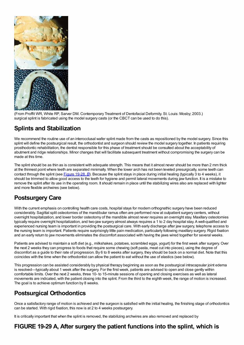
(From Proffit WR, White RP, Sarver DM. Contemporary Treatment of Dentofacial Deformity. St. Louis: Mosby; 2003.)surgical splint is fabricated using the model surgery casts (or the CBCT can be used to do this).
Splints and StabilizationWe recommend the routine use of an interocclusal wafer splint made from the casts as repositioned by the model surgery. Since thissplint will define the postsurgical result, the orthodontist and surgeon should review the model surgery together. In patients requiringprosthodontic rehabilitation, the dentist responsible for this phase of treatment should be consulted about the acceptability ofabutment and ridge relationships. Minor changes that will facilitate subsequent treatment without compromising the surgery can bemade at this time.
The splint should be as thin as is consistent with adequate strength. This means that it almost never should be more than 2 mm thickat the thinnest point where teeth are separated minimally. When the lower arch has not been leveled presurgically, some teeth cancontact through the splint (see Figure 19-28, B). Because the splint stays in place during initial healing (typically 3 to 4 weeks), itshould be trimmed to allow good access to the teeth for hygiene and permit lateral movements during jaw function. It is a mistake toremove the splint after its use in the operating room. It should remain in place until the stabilizing wires also are replaced with lighterand more flexible archwires (see below).
Postsurgery CareWith the current emphasis on controlling health care costs, hospital stays for modern orthognathic surgery have been reducedconsiderably. Sagittal split osteotomies of the mandibular ramus often are performed now at outpatient surgery centers, withoutovernight hospitalization, and lower border osteotomy of the mandible almost never requires an overnight stay. Maxillary osteotomiestypically require overnight hospitalization, and two-jaw surgery almost always requires a 1 to 2 day hospital stay. A well-qualified andexperienced nursing team is important in providing the postsurgical care. With early discharge after jaw surgery, telephone access tothe nursing team is important. Patients require surprisingly little pain medication, particularly following maxillary surgery. Rigid fixationand an early return to jaw movements eliminates the discomfort associated with having the jaws wired together for several weeks.
Patients are advised to maintain a soft diet (e.g., milkshakes, potatoes, scrambled eggs, yogurt) for the first week after surgery. Overthe next 2 weeks they can progress to foods that require some chewing (soft pasta, meat cut into pieces), using the degree ofdiscomfort as a guide to their rate of progression. By 6 to 8 weeks after surgery, they should be back on a normal diet. Note that thiscoincides with the time when the orthodontist can allow the patient to eat without the use of elastics (see below).
This progression can be assisted considerably by physical therapy beginning as soon as the postsurgical intracapsular joint edemais resolved—typically about 1 week after the surgery. For the first week, patients are advised to open and close gently withincomfortable limits. Over the next 2 weeks, three 10- to 15-minute sessions of opening and closing exercises as well as lateralmovements are indicated, with the patient closing into the splint. From the third to the eighth week, the range of motion is increased.The goal is to achieve optimum function by 8 weeks.
Postsurgical OrthodonticsOnce a satisfactory range of motion is achieved and the surgeon is satisfied with the initial healing, the finishing stage of orthodonticscan be started. With rigid fixation, this now is at 2 to 4 weeks postsurgery.
It is critically important that when the splint is removed, the stabilizing archwires are also removed and replaced by
FIGURE 19-29 A, After surgery the patient functions into the splint, which is
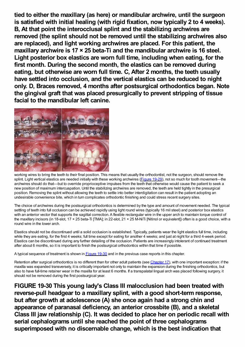
tied to either the maxillary (as here) or mandibular archwire, until the surgeonis satisfied with initial healing (with rigid fixation, now typically 2 to 4 weeks).B, At that point the interocclusal splint and the stabilizing archwires areremoved (the splint should not be removed until the stabilizing archwires alsoare replaced), and light working archwires are placed. For this patient, themaxillary archwire is 17 × 25 beta-Ti and the mandibular archwire is 16 steel.Light posterior box elastics are worn full time, including when eating, for thefirst month. During the second month, the elastics can be removed duringeating, but otherwise are worn full time. C, After 2 months, the teeth usuallyhave settled into occlusion, and the vertical elastics can be reduced to nightonly. D, Braces removed, 4 months after postsurgical orthodontics began. Notethe gingival graft that was placed presurgically to prevent stripping of tissuefacial to the mandibular left canine.
working wires to bring the teeth to their final position. This means that usually the orthodontist, not the surgeon, should remove thesplint. Light vertical elastics are needed initially with these working archwires (Figure 19-29), not so much for tooth movement—thearchwires should do that—but to override proprioceptive impulses from the teeth that otherwise would cause the patient to seek anew position of maximum intercuspation. Until the stabilizing archwires are removed, the teeth are held tightly in the presurgicalposition. Removing the splint without allowing the teeth to settle into better interdigitation can result in the patient adopting anundesirable convenience bite, which in turn complicates orthodontic finishing and could stress recent surgery sites.
The choice of archwires during the postsurgical orthodontics is determined by the type and amount of movement needed. The typicalsettling of teeth into full occlusion can be achieved rapidly using light round wires (typically 16 mil steel) and posterior box elasticswith an anterior vector that supports the sagittal correction. A flexible rectangular wire in the upper arch to maintain torque control ofthe maxillary incisors (in 18-slot, 17 × 25 beta-Ti [TMA]; in 22-slot, 21 × 25 M-NiTi [Nitinol or equivalent]) often is a good choice, with around wire in the lower arch.
Elastics should not be discontinued until a solid occlusion is established. Typically, patients wear the light elastics full time, includingwhile they are eating, for the first 4 weeks; full time except for eating for another 4 weeks; and just at night for a third 4-week period.Elastics can be discontinued during any further detailing of the occlusion. Patients are increasingly intolerant of continued treatmentafter about 6 months, so it is important to finish the postsurgical orthodontics within that time if possible.
A typical sequence of treatment is shown in Figure 19-30 and in the previous case reports in this chapter.
Retention after surgical orthodontics is no different than for other adult patients (see Chapter 17), with one important exception: if themaxilla was expanded transversely, it is critically important not only to maintain the expansion during the finishing orthodontics, butalso to have full-time retainer wear in the maxilla for at least 6 months. If a transpalatal lingual arch was placed following surgery, itshould not be removed during the first postsurgical year.
FIGURE 19-30 This young lady's Class III malocclusion had been treated withreverse-pull headgear to a maxillary splint, with a good short-term response,but after growth at adolescence (A) she once again had a strong chin andappearance of paranasal deficiency, an anterior crossbite (B), and a skeletalClass III jaw relationship (C). It was decided to place her on periodic recall withserial cephalograms until she reached the point of three cephalogramssuperimposed with no discernable change, which is the best indication that
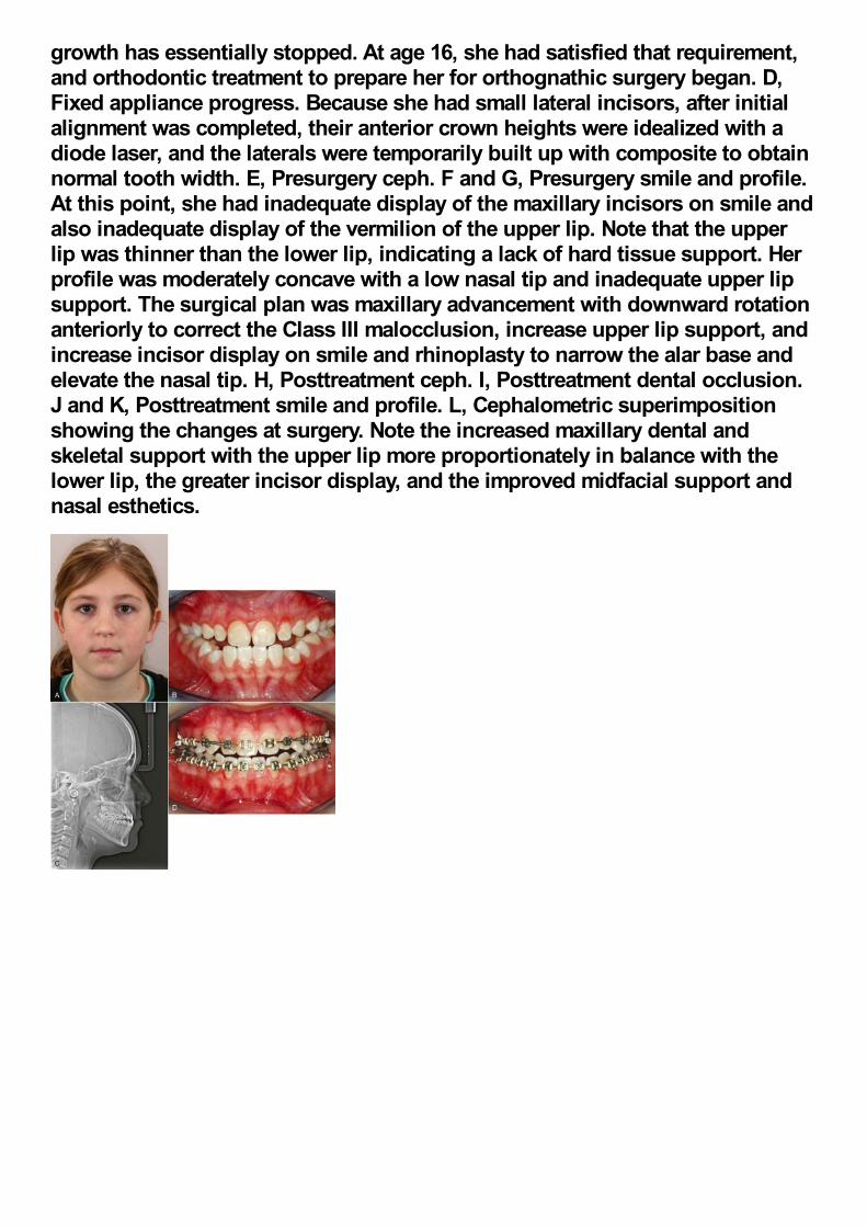
growth has essentially stopped. At age 16, she had satisfied that requirement,and orthodontic treatment to prepare her for orthognathic surgery began. D,Fixed appliance progress. Because she had small lateral incisors, after initialalignment was completed, their anterior crown heights were idealized with adiode laser, and the laterals were temporarily built up with composite to obtainnormal tooth width. E, Presurgery ceph. F and G, Presurgery smile and profile.At this point, she had inadequate display of the maxillary incisors on smile andalso inadequate display of the vermilion of the upper lip. Note that the upperlip was thinner than the lower lip, indicating a lack of hard tissue support. Herprofile was moderately concave with a low nasal tip and inadequate upper lipsupport. The surgical plan was maxillary advancement with downward rotationanteriorly to correct the Class III malocclusion, increase upper lip support, andincrease incisor display on smile and rhinoplasty to narrow the alar base andelevate the nasal tip. H, Posttreatment ceph. I, Posttreatment dental occlusion.J and K, Posttreatment smile and profile. L, Cephalometric superimpositionshowing the changes at surgery. Note the increased maxillary dental andskeletal support with the upper lip more proportionately in balance with thelower lip, the greater incisor display, and the improved midfacial support andnasal esthetics.
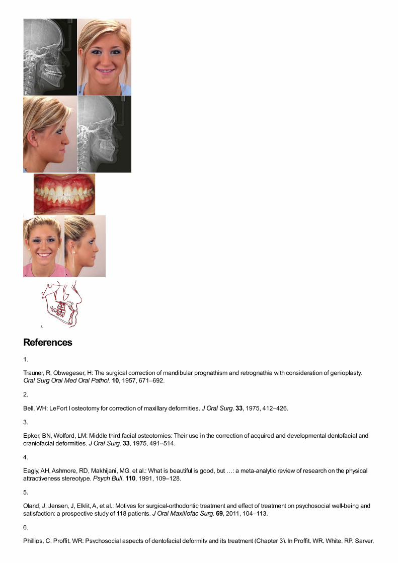
References1.
Trauner, R, Obwegeser, H: The surgical correction of mandibular prognathism and retrognathia with consideration of genioplasty.Oral Surg Oral Med Oral Pathol. 10, 1957, 671–692.
2.
Bell, WH: LeFort I osteotomy for correction of maxillary deformities. J Oral Surg. 33, 1975, 412–426.
3.
Epker, BN, Wolford, LM: Middle third facial osteotomies: Their use in the correction of acquired and developmental dentofacial andcraniofacial deformities. J Oral Surg. 33, 1975, 491–514.
4.
Eagly, AH, Ashmore, RD, Makhijani, MG, et al.: What is beautiful is good, but …: a meta-analytic review of research on the physicalattractiveness stereotype. Psych Bull. 110, 1991, 109–128.
5.
Oland, J, Jensen, J, Elklit, A, et al.: Motives for surgical-orthodontic treatment and effect of treatment on psychosocial well-being andsatisfaction: a prospective study of 118 patients. J Oral Maxillofac Surg. 69, 2011, 104–113.
6.
Phillips, C, Proffit, WR: Psychosocial aspects of dentofacial deformity and its treatment (Chapter 3). In Proffit, WR, White, RP, Sarver,
Phillips, C, Proffit, WR: Psychosocial aspects of dentofacial deformity and its treatment (Chapter 3). In Proffit, WR, White, RP, Sarver,DM (Eds.): Contemporary Treatment of Dentofacial Deformity . 2003, Mosby, St. Louis.
7.
Smith, JD, Thomas, PM, Proffit, WR: A comparison of current prediction image programs. Am J Orthod Dentofac Orthop. 125, 2004,527–536.
8.
Phillips, C, Bailey, LJ, Kiyak, HA, et al.: Effects of a computerized treatment simulation on patient expectations for orthognathicsurgery. Int J Adult Orthod Orthogn Surg. 16, 2001, 87–98.
9.
Joondeph, DR, Bloomquist, D: Mandibular midline osteotomy for constriction. Am J Orthod Dentofac Orthop. 126, 2004, 268–270.
10.
Chamberland, S, Proffit, WR: Short- and long-term stability of SARPE revisited. Am J Orthod Dentofac Orthop. 139, 2011, 815–822.
11.
Crago, CA, Proffit, WR, Ruiz, RL: Maxillofacial distraction osteogenesis (Chapter 12. In Proffit, WR, White, RP, Sarver, DM (Eds.):Contemporary Treatment of Dentofacial Deformity . 2003, Mosby, St. Louis, 357–393.
12.
Sarver, DM, Rousso, DR, White, RP Jr.: Adjunctive esthetic surgery (Chapter 13. In Proffit, WR, White, RP, Sarver, DM (Eds.):Contemporary Treatment of Dentofacial Deformity . 2003, Mosby, St. Louis, 394–415.
13.
Sarver, DM, Rousso, DR: Plastic surgery combined with orthodontic and orthognathic procedures. Am J Orthod Dentofac Orthop.126, 2004, 305–307.
14.
Snow, MD, Turvey, TA, Walker, D, et al.: Surgical mandibular advancement in adolescents: postsurgical growth related to stability. IntJ Adult Orthod Orthognath Surg. 6, 1991, 143–151.
15.
Roberts, HG, Semb, G, Hathorn, I, et al.: Facial growth in patients with unilateral clefts of the lip and palate: a two-center study. CleftPalate-Craniofacial J. 31, 1996, 372–375.
16.
Kiyak, HA, West, RA, Hohl, T, et al.: The psychological impact of orthognathic surgery: a 9-month followup. Am J Orthod. 81, 1982,404–412.

Index
Page numbers followed by t indicate tables; b, boxes; f , figures.
A
Aborigines
digestion, example, 10f
mandibles, example, 109f
Absolute intrusion, 255f
AcceleDent vibration device, 295f
Accelerated osteogenic orthodontics (AOO), 292-293
bone grafting, 292f
corticotomy, 292f, 651
Accelerated tooth movement, 290-295
Accommodation, 60
Achondroplasia
rarity, 132
severity, midface deficiency, 132f
Acid microabrasion, 369
Ackerman-Proffit scheme, elements (combination), 204
Acquisition, behavior, 55
Acromegaly, profile view/cephalometric radiograph, 127f
Acrylic caps, usage, 499f
Acrylic pontic, usage, 657f-658f
Acrylic retainer, usage, 479f
Actinobacillus actinomycetemcomitans presence, 659
Activator
bulk, removal, 350f
differentiation, 348-349
term, usage, 308
tooth-borne passive appliance, 349f
usage, 231f
Activator (Andresen), basis, 348
Activator-type appliance, usage, 498-499
Active expansion, 501
Active lingual arch
effects, 438
molars, posterior movement, 437-438
Active plates, usage, 353
Active retainers, 616-619
modified functional appliances, relationship, 619
Active retention, 595
Active stabilization, 606-607
Active tooth-borne, functional appliance category, 350
Adams, Philip, 348-349
Adams clasp, clinical adjustments, 349f
Adenoidectomy, requirement, 143
Adenoid facies
appearance, 141
characterization, 142f
Adenoids, size, 142
Adhesive bandage, application, 396-397
Adjacent teeth, space (diastema), 6f
Adjunctive facial procedures, 705-707
Adjunctive orthodontics
partial fixed appliance, usage, 625
treatment sequence, 627f
Adjunctive orthodontic treatment, 623
biomechanical considerations, 626-627
comprehensive orthodontic treatment, contrast, 624
diagnostic considerations, 624-626
goals, 624
indication, 636
principles, 624-627
procedures, 627-637
timing/sequence, 627
treatment planning considerations, 624-626
Adjunctive periodontal surgery, 596-597
Adolescence, 92-96
aging changes, 104-113
alignment, changes, 108-111
complexity, 59f
dentofacial complex, growth patterns, 96-103
disturbances, 126-128
early permanent dentition years, 92-96
facial soft tissues, changes, 105-108

girls, stages, 94
growth
cessation, 94-95
racial/ethnic/national variables, impact, 95f
velocity curves, 94f
incisor display, age function, 106f
initiation, 92-93
jaw growth, rotation, 99-103
maturational changes, 104-113
nasomaxillary complex, growth, 96-97
occlusion, changes, 108-111
permanent teeth, crown height (increase), 112f
physical development, 59
physical growth, seasonal/cultural factors, 95
treatment desire, 60
Adolescents
aggressive periodontitis, 157f
class II treatment, differential growth, 556-557
growth, secondary sexual characteristics (contrast), 160t
imaginary audience, influence, 62
impacted second molar, surgical uprighting, 544-545
jaws, growth spurt, 95f
maxilla, transverse force, 226f
palatal expansion, rigid framework (requirement), 538f
suture, expansion, 227-228
treatment planning, 240
Adrenarche, 95-96
Adult-onset rheumatoid arthritis, impact, 266
Adults
biomechanical considerations, 626-627
chewing movements, contrast, 72f
chewing pattern, 72
clear aligners, usage, 354
comprehensive orthodontic treatment, 637-660
discussion, 623-624
gingival grafting, usage, 650f
psychologic considerations, 637-642
cooperation, problem, 156

facial anthropometric measurements, 160t
facial growth, 104-105
growth changes, 104f-105f
guidance, 60
occlusal equilibrium, 81
orthodontic therapy, 661-683
orthodontic treatment, 623
comparison, 17f
contraindications, absence, 646
esthetic appliances, usage, 661-667
groupings, 623
rarity, 17
periodontal evaluation, 646
periodontically compromise characteristics, 625f
swallow pattern, appearance, 140
Age, chronological measurement, 25
Aggressive periodontitis, 157f
Airway, establishment, 71
Aligners
divot, creation, 354f
preparation, steps, 355
production, steps, 356f
sequence, formation, 357f
Alignment
arches, selection principles, 531-532
archwires, properties, 532-533
changes, adolescence, 108-111
components, 501
comprehensive orthodontic treatment, 531-536
crowding, space analysis, 182
evaluation, 211
impacted teeth, 540-545
nonextraction situations, 535-536
premolar extraction situations, 534-535
rectangular archwire, usage, 532f
sequence, 533f
space (necessity), digitized dental casts (usage), 531f
symmetric crowding, 533-534
unerupted teeth, 540-545
Align Technology, process computerization, 355
Alizarin (dye), 29-30
injections, 31f
specimen, example, 35f
AlloDerm, usage, 707
Alveolar bone
bending, 108
direct anchorage, 386f
loss, 298f
screw, insertion (sequence), 385f
supporting structure, construction, 134
Alveolar bone height
tendency, 304
tooth position, relationship, 304
treatment, effects, 303-304
Alveolar process, ultrasound, 294-295
Alveolar segment, distraction, 290
Alveolar TADs, miniplates (comparison), 388
American standard cephalometric arrangement, diagrammatic representation, 184f
Anatomically complete template, 196-197
Anatomic drawings, facial structural components (superimposition), 184f
Anatomic porion, 189
ANB angle, 190
increase, 214
ANB limitations, 193-194
Anchorage
availability, 635
bone screws, 665f-666f
usage, 672f
Class I crowding/protrusion, 570-575
cortical anchorage, 298
importance, 535f
maximum, 575-577
mechanical aspects, 328-336
preparation, 576
ramus, implant, 659f

reinforcement, 297
extraoral appliance, usage, 334
production, 333f
requirements, 333
resistance, 295-299
situations, 296-299
skeletal anchorage, 298-299
stationary anchorage, 297-298
strain, reduction, 577
temporary anchorage devices, 382-388
value, 296
root surface area, equivalence, 297f
Anchorage control, 295-299
difficulty/importance, 395
improvement, 334
lingual arches, necessity, 576
methods, 333-336
Anchor teeth
displacement, minimization, 297f
PDL pressure, 297f
Anchor teeth, response, 297f
Angle, Edward H., 2
classification, descriptions, 205f
E-arch, 359f
edgewise appliance, 359
image, 3f
key ridge, 234
line, teeth (relationship), 207f
paradigms, soft tissue paradigms (contrast), 5t
progression, edgewise appliances, 358-359
rectangular archwire introduction, 328
ribbon arch appliance, 359f
sleeping habit, 139
system, 204
Animism, 61
Ankylosed maxillary incisor, 660
repositioning, 290-291
Ankylosed maxillary second primary molar, eruption (delay), 81f

Ankylosed permanent teeth, eruption failure, 400
Ankylosed primary teeth
permanent successors, 426
preadolescents, 426
removal, vertical discrepancies, 427f
Ankylosed teeth, movement, 291f
Anodontia, 128
Anterior bite malocclusion, skeletal open bite (characterization), 213
Anterior biteplate, usage, 410
Anterior box elastic, vertical elastics (combination), 591f
Anterior cranial fossa
mandibular changes, 489t
surface, miniplate registration, 487f
Anterior crossbite, 409-411
cause, 632
correction, 409
appropriateness, 676f-677f
dental anterior crossbite, correction, 538f
development, lingual deflection, 409f
etiology, 409
example, 6f
impact, 409
maxillary incisor, lingual position (impact), 411f
options, 412f
presence, 411f
teeth, displacement, 537
Anterior crowding, straight anterior incisor segment (combination), 440f
Anterior deep bite, 554f
mandibular deficiency, combination, 719f
Anterior face height
increase, 714-715
shortness, 237
Anterior maxillary implants, mean growth tracks, 99f
Anterior midline interdental osteotomies, location, 701f
Anterior occlusion, 109
Anterior open bite, 413-415, 553f-554f
closure, 663f
posterior teeth, intrusion, 679
correction, retention, 610-611
malocclusion, 141
nondental intervention, 413
open bites, 413-415
oral habits, 413-415
prevalence, 141f
severity, correction, 700f-701f
sucking habits
effects, 413
impact, 140
thumbsucking, association, 138
treatment, absence, 403
vertical incisor relationships, correction, 591
Anterior overbite, correction, 252
Anterior palate, stability, 559
Anterior segment, tipping, 297-298
Anterior teeth
alignment, 636-637
control, removable clip-type retainer (usage), 613f
appliances, impact, 234f
protrusion, 441f
size discrepancy, analysis, 183-184
tipping, radiographic demonstration, 426f
2×6 appliance, 397f
Anterior teeth eruption
control, incisal/occlusal stops (usage), 499f
delay, 424f
functional appliances, impact, 492-493
Anterior vertical dimensions, cephalometric analysis, 215f
Anteroposterior facial growth, 476
Anteroposterior mandibular posture, lingual pad/flange, 498f
Anteroposterior maxillary deficiency, 480-484
importance, 686f-688f
Anteroposterior maxillary skeletal impact, 520
Anteroposterior plane of space, jaw position (proportion), 164
Anteroposterior problems
preadolescents, 397
prevalence, 8
vertical problems, combination, 514-520
correction, 714-715
Anthropometric analysis, facial measurements, 161f
Anthropometric data, cross-section expression, 27
Anthropometry, 26
Apical infection, control, 633-634
A-pogonion line, usage, 194
Appliances
fabrication, 406f
lingual appliances, 377-378
materials, 369-372
patient preferences, 378
philosophy, 335
prescription, 362
torque, amount (recommendation), 374
therapy, 413-415
therapy, requirement, 420f
Arches
alignment arches, selection principles, 531-532circumference, increase, 465f
posterior crossbite, correction, 403
dimensions, 88flengthaddition, 534fdiscrepancy, 224-225
relief, 467f
mechanics
continuity, 345-346segmentation, 345
segmented arches, 551-552spacing, severity, 664f-665fvertical clearance, 452width measurements, 212t
Arch expansion
active plates, usage, 353impact, 224treatment, 170f
Arch form
catenary arch form, inclusion, 380ffabrication, 378-382principle, 379selection, 378-381
Archwires
alignment archwires, properties, 532-533approach, 466fbracket
movement, 331ftipping, allowance, 332f
clear polymer archwires, 382closing loop, change, 571fcomparison, 318fabrication, 378-382faciolingual bends, 361-362formation, 380fmovement, freedom, 532postsurgical orthodontic selection, 720preformed archwire, catenary arch form (inclusion), 380fselection, 533-534sequence, 584bshapes, 321-323sizes, 321-323, 321tsurface
distortion, 332fqualities, 329
undersize, 328
Arkansas spring, 419fAround the tooth CSF approach, papilla split procedure, 597fArthritic degeneration, impact, 266Articulator mounting, 178-180Artistic positioning bends, 372-373A-splint, 617fAssimilation, 60Asymmetric bends, 338-340Asymmetric crowding
alignment, 535-536incisor alignment, auxiliary superelastic wire (usage), 537f
Asymmetric deficiency, causes, 268Asymmetric dental development, 399-400Asymmetric facial skeleton, dimensioned stereolithographic model, 200-202Asymmetric mandibular deficiency, 268
condylar fracture, impact, 124
Asymmetric mandibular setback, presurgery/postsurgery (color map representation), 203fAsymmetric V-bends, 339
intrusive force, 342fmoment, creation, 340f
Asymmetry, correction, 503Attachments
bands, 362-364bonding, 364-369intermittent forces, 362method, 542surface, 365usage, 356
Attraction, magnets (usage), 543fAustenite NiTi (A-NiTi), 316
properties, 317springiness, 322-323springs, creation (intrusion), 679wires
activation/deactivation curves, 317f
Austenitic NiTi (A-NiTi) wire, activation/reactivation curves, 317fAustralian aboriginal mandibles, 109fAutonomy
development, 57-58
example, 58ffailure, 58
paternalism, contrast, 258
Autotransplantation, 457-458Auxiliary intrusion, 337-338
arch, placement, 552
Auxiliary leveling archwire, usefulness, 549fAuxiliary NiTi wire, recommendation, 543Auxiliary root positioning springs, usage, 326fAuxiliary spring, superelastic wire (addition), 536Auxiliary superelastic wire, usage, 537fAuxiliary torquing springs, usage, 326fAverage-maturing girls, growth velocity, 25fAverage root length change, 302tAxial CT, application, 27
B
Band-and-loop space maintainers, 429-432
usage, 431f
Band and spring appliance, intraoral fabrication, 420fBanded/bonded attachments, 466fBanded expander, bonded expander (contrast), 539fBanded palatal expander, attachment, 478fBanding
cementation, 364debanding, 366-368indications, 362-363separation, 363
methods, 363
steps, 363-364
Band-removing pliers, usage, 593fBands
fitting, 363-364fixed jackscrew appliances, attachment, 477removal, 593-594
Basic trust, development, 57Basioccipital bones, location, 37Basion-nasion line, reference plate usage, 194Beam
diameter, change, 321flength, change, 322fmaterials, properties, 312
Begg, Raymond, 3-4, 360
technique, 550
Class II elastics, usage, 567example, 583f
usage, 586
treatment, second stage (forces), 567f
Begg appliance, 359-361
change, 357-358illustration, 326fribbon arch attachment modification, 360f
Behavior
acquisition, 55modification, operant conditioning (usage), 54-55performance, 55-56
Behavioral development, 50-64
dentist office, 52learning, relationship, 51-56stages, construction, 51
Behavioral evaluation, 155-156Bending
description, 318moment, deflection (contrast), 315fnomograms, 319f
Beta-titanium (beta-Ti), 317-318
bending nomograms, 319ftorsion nomograms, 320f
Bilateral cleft lip/palate, 121f
movement, necessity, 269
Bilateral expansion, creation, 344fBilateral impacted maxillary canines, soldered lingual arch (placement), 543fBilaterally missing permanent mandibular second premolars, 455fBilateral maxillary constriction, 404f
contact, 405fcorrection, quad helix (usage), 406f
Bilateral molar distalization, space regaining, 438Bilateral toe-in bends, couple creation, 344fBimaxillary dentoalveolar protrusion, 164
facial appearance, 165fpreadolescents, 398f
Bimaxillary protrusion, 164Binding
friction, contrast, 328-333sliding resistance, 331f
Biologic electricity, 281-282Biolux device, 295fBionator
design, 350fpalatal connector, usage, 490fusage, 498-499
Birth, 66-67
injuries, 122-123physical adaptations, 66trauma, mandible, 123
bis-GMA resins, usage, 366Bisphosphonates, 290
impact, 447-448problem, reasons, 290receiving, increase, 448
Bite blocks, functional appliances (usage), 520Bitewing radiographs, diagnosis, 419fBiting force, eruption (relationship), 135-137Björk, Arne, 31
implant studies, lateral cephalometric radiograph, 32f
Black triangles
correction, 245creation, 652example, 600fresult, 598
Black youths, orthodontic need, 17fBlood flow
changes, 282freduction, 285f
Blood vascular elements, ingrowth, 33Blood vessels
compression, increase (diagrammatic representation), 284focclusion, 285
Blood vessels, dilation, 283fBodily distal movement, 462-463Bodily tooth movement, requirement, 461fBody
growth, jaw growth (correlation), 95movement, 286fproportions
changes, schematic representation, 21fsecular changes, 70
tissue systems, growth (Scammon's curves), 22f
Bolton analysis, 183Bolton point, 187fBolton template
cranial base superimposition, 197fsuperimposition, 197f-198f
usage, 198
Bonded anterior teeth, 395Bonded appliance, advantages, 585Bonded attachments, 364-369
removal, 593-594usage, 663
Bonded brackets, removal, 593
pliers, usage, 594f
Bonded canine-to-canine retainer, 615fBonded expander
advantages, 539fplacement, 538-540
Bonded functional appliance, 502-503Bonded lingual retainer, usage, 617fBonded palatal expander, usage, 480Bonded retainer, alternative, 617fBonded splints, fixed jackscrew appliances (attachment), 477Bond failure, occurrence, 594fBonding
adhesives, strength (increase), 366-368basis, 364-368bis-GMA resins, usage, 366debonding, 366-368direct bonding, 366fluoride-releasing bonding agents, availability, 369indirect bonding, 366materials, 366modified glass-ionomer cements, usage, 366preparation, diagrammatic representation, 365fstrength, optimum (obtaining), 366
Bone
anchor, 235f
placement, 564fretention, screws (usage), 335f
bending, extent, 279calcification, occurrence, 29-30direct apposition, 33force, application, 280fformation, 35grafts, 294f
panoramic radiograph, 270f-271fplacement, 269
loss, 266f, 651fresorption, 76
defectiveness, occurrence, 74rate, 74
response, 278-281scan, 99mTc (usage), 268fsurface
apposition, 33remodeling, 38f
teeth relationship, expansion limit, 222
Bone screws, 381-382
alveolar bone screw, insertion sequence, 385fdesign factors, 383bdiameter, impact, 384driver, formulation, 356intraoral TAD function, 383length, impact, 383-384miniplates, contrast, 388bplacement, 229
ease, factors, 384
primary stability, 383
creation, 383f
self-tapping designs, 384short-term stability, 383
stability, 383-384
factors, 383-384
success, factors, 383-384taper, impact, 384threads
pitch, importance, 383surface, impact, 384
tip, form (impact), 384tissue punch, usage (necessity), 384turning, ease/difficulty, 384types, 383fusage, 576
ease, 384
Bone-seeking isotope (99mTC), usage, 268Bone-supported miniplates, bilateral placement, 484Bone-to-bone contact, 699Bony changes, vital staining, 29-30Borderline patient, 690-695
esthetic/psychosocial considerations, 690-692
Boston University, treatment, 438-439Bovine/allograft bone, mixture, 292-293Bow calipers, usage, 161fBoys (males)
arches, space, 87fheight growth curve, 69finfancy, length/weight growth (graphs), 69fmandible
fracture, radiographs, 78fmean dimensional changes, 105f
maturation, slowness, 96medical problem, growth chart, 23f-24fsecondary sexual characteristics, attainment, 159sexual development, stages, 94
Braces, removal, 603f-604f
white spot lesion treatment, 369
Brackets
angulation, 362ceramic brackets, popularity, 330composite plastic brackets, usage, 330design, straight-wire concept, 372-374inclination, second-order bend (impact), 374findividually customized brackets, 375-377modification, 361fmovement, force (impact), 331fnarrowness, 548placement, 626fpositioning, problem, 584removal, 592scanning electron microscope views, 371fself-ligating brackets, 375shaped brackets, 378sliding, 332fslot dimensions, alteration, 361surface qualities, 329-330tipping, allowance, 332fwidth, 327, 548-549
impact, 328f
wire orientation, 330f
Bracket/tube prescription, 373tBrader arches
trifocal ellipse, 380variations, 380
Brain case (calvarium), length increase/width decrease, 66Buccal corridors
negative space, 170width, 170f
maxilla, transverse expansion, 244f
Buccal crossbite (X-occlusion), 8-9Buccal drift, 74Buccal root torque, 589Buccal shields
addition, 500usage, 501f
Bumper, construction, 437fBurstone torquing auxiliary, 588
usefulness, 588f
Bypass arches, 550-551
systems, weaknesses, 550
C
Calcification, sequence, 66Calvarium (brain case), length increase/width decrease, 66Camouflage
Class III camouflage, 237, 569growth modification, contrast, 226-239surgery
contrast, 241, 690-695decision, 694-695
tooth movement, 232-235
Canines
anterior space, changes, 86bodily retraction, spring assembly (diagrammatic representation), 354fbrackets, placement, 629ectopic eruption, 422findependent retraction, 576interferences, impact, 404freplacement, space relationships, 89-91retraction, 334f
anchorage, importance, 535fGjessing retraction spring, usage, 577fsliding movement, 333f
segmented retraction, 576-577substitution, performance, 245technique, 245
Canine-to-canine anterior bow, 612fCanine-to-canine clip-on
fabrication, steps, 619fusage, 618
Cantilever beams, 319
illustration, 313f
Cantilever spring
applications, 337creation, 337f
Caries (control), fluoridated water/fluoride-containing toothpaste (usage), 369Carious enamel lesions, 368-369Cartilage
craniofacial growth determinant, 44-46growth center, tests, 44proliferation, 34fremoval, effect (tests), 45theory, usage, 44
Cartilaginous nasal septum
loss, cases, 45removal, 45f
Cartilaginous skeletal development, occurrence, 33Case presentation, outline (example), 257bCast stainless steel brackets, metal-injected-molded stainless steel brackets (contrast), 369Catenary arch form, inclusion, 380fCatenary curve, 3fCell membrane potentials/permeability, electromagnetic fields (impact), 282Cell populations, origins/migrations/interactions, 114Cementation, 364Cemented functional appliance, 502-503Cemented habit crib, wire (usage), 415fCemented Twin-Block, 492Cementum, clast cells (attack), 301fCenter of resistance
attachments, extension, 326fbodily movement, 651fdefinition, 324midpoint, 325f
Center of rotation, 325Central incisors
crown placement, 634felongation, 249feruption, 86height-width ratios, change, 598lateral incisor size, contrast, 598protrusion, 325-326spaces, development, 479f
Centric occlusion, 405fCephalocaudal growth gradient, 21
impact, 21
Cephalometric analysis
advent, 230development, 187-188goal, 188lateral digitization model, 188f
Cephalometric data
analysis, principle, 188cross-section expression, 27
Cephalometric landmarks, definitions, 187f
lateral cephalometric tracing, usage, 187f
Cephalometric methodology, summary, 198-199Cephalometric radiograph
disadvantage, 26head positioning device, usage, 27fobtaining, 74synthetic ceph, comparison, 202fvertebral pathology, observation, 186f
Cephalometric radiography, 26
advent, 159popularity, 4
Cephalometric superimpositions
changes, display, 263f-264ftracings, 186fusage, 230f
Cephalometric tracings, superimposition, 29fCephalometric values, 191tCeramic brackets
debonding
approaches, 593problems, 368
durability/staining resistance, 370glass-reinforced clear polymer archwire, usage, 382fmodification, 368popularity, 330problems, 370-371production, 371sliding resistance, 371-372types, 371t
Ceramic twin brackets, 370fCervical headgear
appliance, 496fcomponents, 507fusage, 462
Cervical neckstrap, usage, 496fCervical vertebrae, lateral cephalometric radiograph, 75fCervical vertebral maturation staging (CVMS), 476Cheek
holding, buccal shield (usage), 501floss, tropical infection (impact), 134fpressures, 138-139resting pressures, 280fteeth, vertical relationship, 208f
Chewing
activity, pressure (generation), 135simulation, occlusal force (comparison), 137f
Childhood
diastema, spontaneous correction, 6fjaw fractures, 124
malignancies, long-term survival, 267midline diastema, presence, 7midpalatal suture, 305fprogressive deformities, 123-126
Children
acquired behavior, performance (factors), 56adaption, age-related concept, 60adenoidectomy, requirement, 143
composite (mean) cephalometric tracings, 144f
adults, chewing movements (contrast), 72faggressive periodontitis, 157fasymmetric mandibular deficiency, condylar fracture (impact), 124brain damage, infantile swallow, 140comprehensive orthodontic treatment, 267cooperation, problem, 156deficiencies, severity/progression, 714dentist treatment area, exit (reward), 54fdentofacial conditions, orthodontic treatment, 17-18developmental parameters, changes, 76fectodermal dysplasia, 128fenvironmental influences, 133-145equilibrium, considerations, 133-135faces, proportion, 428facial asymmetry, 523-527genetic influences, 130-133habits, 137-139instructions, example, 62fjaw discrepancy, treatment benefit, 475lingual arch type maxillary expansion devices, 403flingually erupting maxillary central incisors, 159fmandibular asymmetry, 124fmature/adult swallow pattern, 140maxilla, transverse force, 228fmaxillary incisors, lateral flare, 89fmedical/dental history, obtaining, 153f-154fnormal-face children, occlusal forces (comparison), 137focclusion, indication, 438open bites, sucking (association), 415orthodontic problems, 400orthodontic triage, 396palatal expansion, 227fparents, bond, 57posterior bite blocks, vertical development (control), 521fremovable partial denture, 432fsucking, habit, 137-139tonsillectomy, requirement, 143tooth movement, removable appliances (usage), 351-353treatment
cooperation, 58planning, 240
Chin
augmentation, 705deviation, 209f
evaluation, 524f-527f
implant, advantages, 705inactivity, 39prominence, accentuation, 97protrusion, complaints, 251reduction, 705sectioning, 699fshift, 397f
Chin cup
device, illustration, 237fextraoral force, application, 236-237force, duration, 307treatment, 488f
hard plastic cup, usage, 488-489
Chondrocranium
development, 34f
early stage, diagrammatic representation, 44f
maturation, 34f
Chronic illness, 67
impact, 68
Chronic respiratory obstruction, production, 142Chronologic ages, developmental stages (association), 56Cingulum thickness, reduction, 247fCircadian rhythm, 79Circumferential supracrestal fibrotomy (CSF), 596Class I malocclusion, 3Class I molar, retraction, 235fClass I protrusion/crowding, 570-581Class II buccal segment, 212-213Class II camouflage, upper first premolar extraction, 564-567Class II correction
extraoral force, 229ffacilitation, 494fmaxilla, extraoral force, 558fpremolar extraction, 232retention, 608-609
Class II division 2 malocclusion, 503fClass II division 2 patient, overjet limitation, 502Class II elastics
anteroposterior/transverse effects, 569Begg technique, 567effect, 492nonextraction treatment, usage, 232occlusal plane, rotation, 569focclusal relationships, production, 569response, cephalometric superimposition, 568fside effects, 395usage, 233f, 560vertical force, 569
Class II functional appliance treatment, response, 495fClass II growth
modification, completion, 252pattern, 204
Class II jaw relationship, 204
high-pull headgear/functional appliance combination, 520
Class II malocclusion, 3
arches, presence, 462headgear treatment, response, 509fmaxillary incisors, retraction, 166forthodontic correction, growth (cephalometric tracings), 98f
upper first molar, mesiolingual rotation, 234fupper molars, mesial rotation, 559f
Class II malocclusion correction, 507, 596
Class II elastics
response, 568fusage, 233f
elastics/guide planes, usage, 230orthodontic treatment, facial appearance, 706fskeletal relationships, change, 493ftooth movement patterns, usage, 232
Class II molar occlusion, 213Class II patients
growth modification, 557relapse tendency, 609
Class II pattern, growth (continuation), 609fClass II problems, 229-235
early treatment, benefits, 496treatment, 490-514
approaches, 490-497timing, 496
Class II profile, teeth trauma susceptibility, 475fClass II relationship
maintenance, 565obtaining, 579f-580f
Class II skeletal malocclusion, correction, 492fClass II treatment
differential growth, 556-557functional appliances, usage, 477views, change, 229-231
Class III buccal segment, 212-213Class III camouflage, 237, 569
basis, 569
Class III correction
facilitation, 482fretention, 610
Class III elastics
extrusion impact, 591focclusal plane, rotation, 569fside effects, 395treatment, 487fusage, 238f, 489wearing, 486f
Class III functional appliance, working bite (production), 486Class III malocclusion, 3
Chinese, migration, 132correction, 596
Class III elastics, usage, 238forthodontic treatment, 694f-695f
genetic component, 32-33
production, 11treatment, reverse-pull headgear (usage), 721f-723f
Class III problems, 235-237
growth, impact, 608fmaxillary deficiency, impact, 484treatment, 480-490
Classical conditioning, 51-53
impact, 51foperant conditioning, contrast, 53fperspective, 53
Classical genetics (Mendelian genetics), development, 145Classification
scheme, focus, 204-206systems, development, 204-206view, 204f
Clear aligners
clinical usage, considerations, 355-357development, 354-355sequence, usage, 636-637usage, 354
Clear aligner therapy (CAT), 350, 354-357, 662-663
applicability, 356bdevelopments, 626diagnostic records, 355
Clear polymer archwires, 382
approaches, 382development, 382glass-reinforced clear polymer archwire, invisibility, 382f
Clear retainers (vacuum-formed retainers), 614Cleft lip, 269-274, 396-397
orthognathic surgery, 274
Cleft palate, 269-274, 396-397
orthognathic surgery, 274treatment sequence, 269b
Cleft site, alveolar segments (displacement), 270f-271fCleidocranial dysplasia, panoramic radiograph, 77fClenching, occlusion (imperfections), 12ClinCheck, 355
clinician role, 355modification, 358f
Clinical crowns, shortness, 362Clinical effectiveness, evidence, 13bClinical evaluation, 156-181
micro-esthetic considerations, 598oral health, 156
Clinical examination
Angle classification, 205fdata, example, 218bfacial dimensions, evaluation checklist, 164bfocus, increase, 4
Clinical orthodontics, NiTi wires (usage), 316-317Clinical procedures, evaluation (gold standard), 13Clip retainers (removable wraparound retainers), 613-614Close-up smile, perspective, 598f-599fClosing loop archwires
activation, 573Gable bends, usage, 573frecommendations, 574usage, 453f
Closing loops
aspects, changing (effect), 571fclinical recommendations, 572-574design factors, 572design principles, 571-572location, 570-571Opus closing loop, 571fperformance, determination, 570placement, 574preformed closing loops, space closure, 572f16×22 wire, 573fspring properties, 570usage, 333f, 570-574vertical legs, three-prong pliers (usage), 573f
Cobalt-chromium alloys, 314Cognitive development, 51, 60-64
periods, division, 61fstages, 56-64
Cognitive structures, 60Coil spring, usage, 478fCold-cure acrylic, usage, 478fCollagen
cross-linking, 79-81force, application, 280fmaturation, localized variations, 78
Collagenous matrix materials, production, 279Complete appliances, partial appliances, biomechanical differences, 395Complex malocclusion, glass-reinforced clear polymer archwire (treatment sequence), 382fComposite buildups, solution, 638fComposite examples, usage, 161fComposite plastic brackets, usage, 330Composite plastics, 318Composite retraction spring, design, 575fComprehensive orthodontic treatment
adjunctive orthodontic treatment, contrast, 624adult discussion, 623-624alignment, 531-536first stage, goals, 530-531goal, 624second stage, 556third stage, 582
example, 583f
Comprehensive orthodontic treatment, first phase (alignment), 293Compressed coil spring, usage, 632fCompressed PDL, histologic specimen, 285fComputed axial tomography (CAT), 27Computed tomography (CT) scans
superimposition, 29fusage, 28f
Computer-aided design/computer-aided manufacturing (CAD/CAM)
brackets, formation, 377usage, 375
Computer analysis, usage, 198Computer-assisted appliance, test, 377-378Computer-formed finishing wires, usage, 381-382Computer-formed superelastic A-NiTi archwires, usage, 670f-671fComputer image predictions, 239-240
value, 692
Concrete operational period, 60, 62Conditioned behavior, extinction, 52Conditioned stimulus
generalization, opposite, 52-53unconditioned stimulus, association, 52
strengthening, 52f
Condylar cartilage, development, 35
condensation area, 35f
Condylar fracture
condyle, regeneration, 47fdiagnosis, absence, 523growth reduction, 46
Condylar hyperplasia, 126Condylar process
destruction, panoramic radiograph, 267ffracture, 45floss, rheumatoid arthritis (impact), 267fregeneration, 45-46
Condyle
extraoral force, application, 307fresorption/regeneration, 47f
Condylectomy, usage, 268Cone-beam computed tomography (CBCT), 27, 150-151
advent, 199availability, 200images
diagnostic scope, 202superiority, 422
indication, 540-541radiation dose, reduction, 199-200three-dimensional images, analysis, 199-203usage, 176
increase, 202
Congenital deformities, 202Congenitally missing mandibular right lateral incisor, 640fCongenitally missing teeth, 128Connectors, 174-175
length, success, 602f
Contact placement, success, 602fContact points, stripping, 637Continuous arches
advantages/disadvantages, 346edgewise technique, 584bmechanics, 345-346
Continuous archwire, placement, 549fContinuous forces
avoidance, 289production, 288
Continuous orthodontic wire, activation, 635fCopper NiTi, usage, 316Cortical anchorage, 298Cortical bone, area (creation), 298fCorticosteroids, interference, 289Corticotomy
impact, 290-295modified corticotomy, 293
Corticotomy-assisted tooth movement, treatment outcomes, 293Cosmetic facial surgery, 241Counterpart analysis, 194-196Couple
creation, interbracket bend (usage), 340-342definition, 324-325forces, equivalence, 325fusage, 325-326
Cranial base, 37
growth, 49-50mandible, growth, 39fregistration, 197superimposition, 197
Bolton template, 197fillustration, 102f
short face pattern, 103f
indication, 509f
sutures, premature fusion, 48fsynchondroses
diagrammatic representation, 37fgrowth center action, 46
Cranial (horizontal) reference line, choice, 189-190Cranial vault, 36-37
flat bones, 36
Craniofacial anomalies, 115-116Craniofacial complex
growth sites/types, 36-40tissues, interaction, 32
Craniofacial development
bony changes, vital staining studies, 29-30stages, 114
Craniofacial growth
determinants
cartilage, usage, 44-46
theories, 40
periosteal tissues, determinants, 43-44sutures, determinant, 43-44understanding, 20
Craniofacial malformations, occurrence, 119-122Craniofacial microsomia, 116-117Craniofacial skeleton, growth determinant, 46Craniofacial sutures, usage, 226-227Craniofacial units, growth, 49tCraniometry, 26Cranium
3-D reconstruction, 27growth, 46hydrocephaly, impact, 46width, narrowness, 48f
Crestal bone height, loss (excess), 303-304Crest cells, postmigratory activity, 116Crooked smile, 657f-658fCrossbite
anterior crossbite, 6fbuccal crossbite (X-occlusion), 8-9classification, 402correction, 536-540, 596
through the bite elastics, usage, 631-632
determination, 403posterior crossbite, existence, 6f
Cross-elastics
effectiveness, 541fusage, 540
Crouzon's syndrome, 396-397
facial appearance, 122foccurrence, 122
Crowded incisors, 637
segment, expansion, 637
Crowding
alignment, space analysis, 182amount, quantification, 427borderline case, 470conservative approach, 461expression, 401fgeneralized moderate crowding, 440minimum, 9fseverity, 459-470symmetric crowding, alignment, 533-534
Crown
application, simultaneity, 286attachment, method, 542corners, rounding, 247fforce, application, 286fformation, 74forward (creation), torque forces (impact), 578fheight, increase, 112f
tipped molar, uprighting (impact), 629f
Crown-root ratio, importance, 679Crown-to-root ratios/position, establishment, 624Crozat appliances, 348f
popularity, 348usage, 641
Crystal lattice, electrons (migration), 281Crystalline structure
distortion, 281force, application, 280f
Cultural conditions, need/demand (perception), 15-16Curve of Spee
accentuation, 716excess, 255f
lower arch, leveling, 548f
Custom brackets, usage, 375Custom-fitted gold bands, fabrication, 362Cyclic adenosine monophosphate (cAMP), increase, 283Cyclic nucleotide levels, increase, 287Cystic fibrosis, 267
D
Dachshund, achondroplasia, 132Damon-Q bracket, 376fDebanding, 366-368Debonding, 366-368
bond failure, occurrence, 594fceramic brackets, impact, 368
Deep bite, 415
analysis, 591correction, retention, 610severity, 8short face, 514-517
Deep overbite, 441-442
existence, 632
Deflection
bending moment, contrast, 315fmeasurements, 313f
Degenerative joint disease, symptoms, 642Dehydroepiandrosterone (DHEA), 95-96Delaire-type facemask, 236f
stability, 482f
Delayed incisor eruption, 424-426
morphology, consideration, 425teeth, position, 425-426
Demineralized freeze-dried bone, 292-293Dental age
characterization, 83-84
eruptions, 84f
eruption, sequence/timing, 81-86
indicator, 83
Dental alignment, occlusion (relationship), 176-180Dental anterior crossbite, correction, 538fDental appearance, 158-175, 181
micro-esthetics, 172-175orthodontic treatment, 670f-671f
Dental arches
alignment/symmetry, evaluation, 211asymmetry, 181dimensions, changes, 226distal movement, 669-677expansion, 222fform, variation, 379pressure, third molar (impact), 110fsize, function (impact), 135width, increase, 88
Dental casts
analysis, 181
symmetry/space/tooth size, 181-184
Angle classification, 157forthodontic purposes, 177transparent ruled grid, usage, 180f
Dental components, facial components (relationship), 185fDental conditions, disfiguring (psychic distress), 11Dental crowding
esthetic considerations, 222expansion/extraction, 222-226extraction guidelines, 224-226orthodontic treatment, 127fstability considerations, 224
Dental decay, malocclusion (impact), 12Dental development
abnormal sequence, treatment, 399-400disturbances, 128-130ugly duckling phase, 442f
Dental disease
malocclusion, relationship, 12problems, 266
Dental effects, early treatment, 497Dental expansion
cross-elastics, usage, 540usage, 243-245
Dental history, 152
information requirement, 151-152obtaining, 153f-154f
Dental midline deviations, 210Dental occlusion
emphasis, 3example, 265f
Dental posterior crossbites, correction, 540Dental protrusion, excess, 397-399
Dental response, diagrammatic representation, 228fDental retrusion, excess, 397-399Dental treatment, anxiety (example), 57fDentist office, behavior management, 52Dentition
downward roll, 209festhetic line, 206
pitch/roll/yaw, 206
headgear, attachment, 509rotation, 210supporting structures, consideration, 134up-down transverse rotation, 168
Dentoalveolar segments (repositioning), surgery (usage), 703fDentoalveolar surgery, 701-703Dentofacial complex
dimensional changes, 96-99growth patterns, 96-103
Dentofacial conditions, orthodontic treatment, 17-18Dentofacial deformity
etiologic processes, 40impact, 641f
Dentofacial development, teratogens (impact), 115tDentofacial relationships, cephalometric analysis, 181Dentofacial traits, characteristics (classification), 211bDesired movement, subdivision, 334Determinate force systems, 336
indeterminate force systems, contrast, 336-346
Development
growth, relationship, 20studies, 21-22term, usage, 20timing, variability, 25variability, 22
Developmental abnormalities, 396-397Developmental ages
assessment, 73-74, 159basis, 74correlation, 74
Developmental problems, pathologic problems (contrast), 250Developmental stages, chronologic ages (association), 56Dewey, Martin, 204Diagnosis, problem-oriented approach/method, 150, 258Diagnostic database, development, itr, 147Diagnostic evaluation, stages (information requirements), 150-151Diagnostic records
analysis, 181-203
example, 218b
requirement, 176-181
Diagnostic setup, 636Diagnostic workup, 260fDiaphysis, 33-35Diastema (teeth spacing), 6f, 89
childhood diastema, spontaneous correction, 6f

development, 456fmaintenance, 615-616midline diastema, presence, 7
Diastema closure (teeth spacing), 451-452, 545
anterior teeth, alignment, 636-637fixed appliance, usage, 452fmaintenance, fixed retainer (usage), 453frequirement, 452f
Diet, attrition (absence), 108Differential anteroposterior tooth movement, extraction spaces (usage), 564-568Digital casts, generation, 178Digital records, advent, 181Digitized dental casts, usage (effectiveness), 531fDigit sucking, effect (comparison), 413Dilaceration, 76-78, 129-130Diode laser, usage, 542fDirect bonding, 366
difficulty, 366steps, 367ftechnique, light-activated resin (usage), 366
Discrepancy outlines, 690Discrimination, 52-53Disking, usage, 438fDisplaced incisors, 637Dissected skull, examination, 86
example, 86f
Distal crown
movement, impact, 628ftipping, 629
Distal driving, concept, 557Distalization-expansion appliance (Pendex), 234fDistal molar movement, 458-459Distal shoe
application, 432space maintainers, 432
indication, 433f
Distal step, 90Distraction osteogenesis, 46-48, 703-705
ankylosed tooth, movement, 291fdiagrammatic representation, 50fusage, 704f
Dogs, breeding experiments/malocclusions, 131fDolphin Imaging, 188fDouble chin, correction, 707Drag loop, usage, 536fDuchenne smile, 168
E
E-arch (Angle), 359
ligatures, usage, 359f
Early adolescence, midpalatal suture, 305fEarly adult life, disturbances, 126-128Early childhood, primary dentition years, 67-73Early class II treatment, randomized clinical trials, 231-232
Early embryos, weight increase (data), 30fEarly expansion, question, 479Early extraction (serial extraction), 463-470
approach, alternative, 469fcomplication, 468ffixed appliance treatment, absence, 470ftreatment, initiation, 464
Early mandibular advancement, 714Early-maturing girls, growth velocity, 25fEarly maxillary advancement, 714Early mixed dentition
crowding (treatment), expansion (usage), 460-462palatal expansion, 476-477treatment, 274
Early permanent dentition
headgear, usage, 557treatment, 274years (adolescence), 92-96
Ectodermal dysplasia, 128
appearance, 128f
Ectopically erupting teeth, 199-200
surgical exposure, 199
Ectopic eruption, 417-423
lateral incisors, 417mandibular lateral incisor, 447fmaxillary canines, 422-423maxillary first molars, 418permanent molars, 421f
Edgewise appliance (Angle), 359, 361-362
Angle progression, 358-359automatic rotational control, 361bracket slot dimensions, alteration, 361bracket width, impact, 567insertion, 360fpositioner advantage, 594rotation control, alternative methods, 362fstraight-wire prescriptions, 361-362
Edgewise brackets, straight-wire type (design), 626Edgewise techniques, 582Edgewise wires, first-order/second-order/third-order bends, 372fEffective torque, 589tEgocentrism, 6118-slot appliance, 548
finishing archwire, usage, 586
18-slot bracket, effective torque, 589t18-slot edgewise, usage, 570-574Elastic binding, impact, 330-332Elastic force, source, 323-324Elastic gingival fibers, sectioning, 596-597Elastic materials
asperities, 329force-deflection curve, 313fgeometry
length/attachment, 321size/shape, 318-320
progress, 318properties, 312-314shape memory, 315springiness/strength, combination, 322stiffness, 313fsurfaces, contact, 329fusage, 312-324variation, 321-323wire sizes, 321t
Elastic properties, beams (effects), 318-323Elastics
downward/forward direction, 482fusage, 230
Elastomeric plastics, orthodontic purposes, 323-324Elastomeric ring (doughnut), usage, 364fElastomeric separators, 418Electromagnetic fields, impact, 282Electrons, migration, 281Elgiloy, advantage, 314Embrasures, 174-175
black triangles, 175success, 602f
Embryologic development, disturbances, 114-122Embryonic craniofacial development, stages, 115tEmbryos, diagrammatic lateral sections, 116fEmotional development, 56-60
stages, 56-64
sequence, 57f
Enamel
damage, metal bracket debonding (impact), 593lesions, types, 368-369surface, bonding preparation (diagrammatic representation), 365f
Enamel decalcification
control, 368-369prevalence, 368-369prevention, 368-369
Endochondral ossification, 33
occurrence, 35
Endocrine signals, diagrammatic representation, 93fEnhanced esthetics, teeth (reshaping), 597-599Enhancements, 17-18
technology, orthodontics, 18
Enlow's counterpart analysis, emphasis, 196fEnucleation, 464Environmental chemicals, estrogenic effects, 68-70Environmental influences, 133-145Epigenetic control (indirect genetic control), 40-41Epiphyseal cartilage, growth center action, 46Epiphyseal plate, 33-35
cartilage cells, active division, 35endochondral ossification, 34f
exposure, 44f
Epiphysis, 33-35
removal, 44f
Equilibration, usage, 403-404Equilibrium considerations, 133-135Equilibrium influences, 135tErikson, Erik, 56
autonomy, development, 57-58basic trust, development, 57emotional development stages, 57finitiative, development, 58intimacy, development, 60personal identity, development, 59-60skills, mastery, 58-59
Eruption
amount, requirement, 81panoramic radiograph, 76fpath, clearance, 448fprimary failure, 76, 447
characterization, 448f
problems, 446-448
management, 417-426preadolescents, 400
rate, jaw growth rate (parallelism), 81sequence, 81-86
change, 84-85variations, 85
timing, 81-86
Eskimos, craniofacial morphology (characteristics), 135Esthetics
acceptability, maximum/minimum, 172bappliances, usage, 661-667biomechanical limitations, 626considerations, 222effects, 241enhancement, teeth (reshaping), 597-599evaluation, 211improvement, maximum (planning treatment), 240-250line, pitch/roll/yaw, 206variables, 172b
Estrogen production, Leydig cells (impact), 94Ethmoid bones, location, 37European descent, class III tendency (correction), 676f-677fEuropean removable appliance orthodontics
functional appliances, 491impact, 348
Expander, coil spring (usage), 478fExpansion
appliance, slow activation, 478-479extraction, contrast, 459-460parasagittal osteotomies, usage, 699rate, selection, 477-479screws
incorporation, 502fsagittal/transverse dimensions, 502f
techniques, 538transpalatal lingual arch, usage, 540
Expansion lingual arches, 405External ear, deficiency/absence, 117fExternal motivation, treatment, 155External rotation, 99
occurrence, 101
Extinction, reinforcement (contrast), 55Extinction of the conditioned behavior, 52Extracellular material
mineralization, 33secretion, 33
Extracellular matrix, secretion, 35Extraction
expansion, contrast, 459-460guidelines, 224-226pattern, 695site, closure, 328treatment, cephalometric superimposition, 566f-567f
Extraction space
closure, 570-581
maintenance, 616
presence, 225tusage, 567-568
Extraoral anchorage attachments, effects, 510f-511fExtraoral appliance, 464f
usage, 334
Extraoral force
application, 236-237
radiation, 306f
headgear, 507-514usage, 556-557
Extreme tipping, 299fExtremities, long bones (ossification), 33-35Extrusion, 287, 633-635
arches, 337-338methods, 635orthodontic technique, 635relative intrusion, usage, 545-549treatment planning, 633-635
F
Face
anteroposterior position, Sassouni evaluation, 192cephalocaudal growth gradient, impact, 21dentition, relationship, 158frontal view, examination, 162growth
modification, 305pattern, 37
height, decrease, 715mask
changes, production, 306
proportions, changes, 22fstructural components, anatomic drawing (superimposition), 184f3-D reconstruction, 27views, CBCT (usage), 199
Facebow
attachments, effects, 510f-511ffitting, steps, 512finner bow, expansion, 540neckstrap, attachment, 514fusage, 507
Facemask (reverse-pull headgear), 482-484
forward pull, 483ftreatment, changes (cephalometric superimposition), 485f-486f
Facial anthropometric measurements, 160tFacial appearance, 158-175, 181
bimaxillary dentoalveolar protrusion, 165fdiscrimination, 11extraction/nonextraction, impact, 226posttreatment facial appearance, 263f-264f
Facial asymmetry, 200-202
cause, 268children, 523-527chin deviation, 524f-527fcomposite examples, usage, 161fdental crowding, orthodontic treatment, 127fdevelopment, left mandibular condylar process fracture (impact), 187fmasseter muscle, absence (impact), 125frheumatoid arthritis, impact, 125fseverity, 199torticollis, 126f
Facial attractiveness
esthetic acceptability, maximum/minimum, 172b
Facial attractiveness, impact, 172Facial changes, functional appliance treatment (usage), 516f-517fFacial components, dental components (relationship), 185fFacial conditions, disfiguring (psychic distress), 11Facial considerations, 14Facial convexity, increase, 215Facial deformity, long-face pattern, 133Facial dimensions, evaluation checklist, 164bFacial disproportions, correction, 241Facial esthetics
improvement, incisor retraction (impact), 223f
Facial esthetics, facial proportions (contrast), 159Facial examples, 265f
orthodontic diagnostic records, 181
Facial form analysis, 167Facial growth
adults, 104-105anteroposterior facial growth, 476continuation, 104determination, serial cephalometric radiographs (usage), 155prediction, 239vertical facial growth, 476
Facial height/width, proportional relationship (facial index), 162Facial index (indices), 162
list, 162t
Facial measurements, anthropometric analysis, 161fFacial muscles, impact, 124Facial processes, fusion (schematic representations), 119fFacial profile
analysis, 397-399goals, 164
Facial proportions, 158
evaluation, 211facial esthetics, contrast, 159frontal plane, 160fmacro-esthetics, 159-167occlusion, impact, 3-4
Facial scans, axial CT (application), 27Facial skeleton
anatomic studies, 38lips, growth, 41fsutures, 305f
Facial soft tissues, 40
changes, 40
adolescence, 105-108
downward movement, 108fgrowth, 40implant contour, 707
Facial surfaces
custom brackets, usage, 375flattening, 247f
Facial surgery, cosmetic facial surgery, 241Facial symmetry, improvement, 524f-527fFacial syndromes, 703
patient separation, 396-397
Facial tipping, control, 338Facial tissue, micro-incisions (usage), 294fFacial trauma, 202
syndromes/sequelae, 199
Faciolingual bends, 361-362Faciolingual discrepancies, 438Fat spurt, 94Fetal alcohol syndrome
facial appearance, 116f
Fetal alcohol syndrome (FAS)
facies, characteristic, 115
Fetal molding, 122-123Fetal period, growth disturbances, 122-123Fetal rat bones, autoradiograph, 32fFibroblasts, osteoblasts (comparison), 279Field of view (FOV)
CBCT scan, 199f
jaw asymmetry, 201f
CBCT 3-D images, 422fsize, decrease, 199-200
Final treatment plan, example, 259bFinger, adhesive bandage application, 415fFingersprings, usage, 443fFinishers, positioners (usage), 594-595Finishing, 683
micro-esthetic procedures, 597-599positioner, usage, 595fprocedures, relapse (avoidance), 595-597stage, midline discrepancies, 584-585
First molars
backward movement, 559fbands, lingual arch (insertion), 541fdistalization, second molar extraction, 563-564distal movement, maxillary left second molar (extraction), 565felastomeric separators, wedging, 418
First molars, bilateral toe-in bends (usage), 344fFirst-order bends (in-out bends), 361-362
compensations, 372usage, 372f
First permanent molars, transverse movement (production), 343fFirst premolars
early eruption, 469feruption, transposition, 272f-273fextraction, 466
site, 673f-675fsite, spring (placement), 296
lateral incisor position, 272f-273fretraction, 672f
Five-characteristics classification system
additions, 206-210systematic description, pitch/roll/yaw, 206
Fixed appliances, 357-388
advantages, 499alignment, sequence, 533fcharacteristics, 369-382development, 358-362space, regaining, 436fsystems, 359-361
brackets, contrast, 327-328
technique, 630f
Fixed appliance treatment, 261f
friction, 329-330

posterior eruption, control, 522f
Fixed canine-to-canine retainers, 615Fixed class II functional appliances, components, 498-505Fixed functional appliance (Herbst appliance), 352f
selection problem, 517usage, 505
Fixed jackscrew appliances, attachment, 477Fixed orthodontic appliances, objections, 377Fixed prosthodontics, abutments, 274Fixed retainers, 615-616
objection, 616space maintenance, 617f
Flap (reflection), modified corticotomy (usage), 294fFlared maxillary incisors, 440-442Flat bones, separation, 36Flattened (nonconsonant) smile arc, 170Floating point norms, usage, 196Fluoride-releasing bonding agents, availability, 369Flush terminal plane, 90
molar relationship, 91relationship, 90f
end-to-end relationship, 91
Focal adhesion kinase (FAK), mechanoreceptor, 283Fontanelles, 36fForamen magnum, anterior margin, 187fForce
bends, step bends/V-bends (impact), 341tcontinuous force, production, 288control, 321-323creation, interbracket bend (usage), 340-342decay
diagrammatic representation, 288feffects, 287-289
definition, 324distribution, effects, 286-287effect, decay, 288efficiency/duration, contrast (theoretical plot), 287fintermittent force, production, 288interrupted force, production, 288magnitude, effects, 283-285magnitude, interaction, 288measurements, 313fprescription, 306reduction, 341systems, defining, 336tangential force, application, 329tooth movement, relationship, 296usage, 325-326
Force-deflection curve, 313f
A-NiTi wires, 533f
Forced eruption, 633
impact, 634f
Force duration
classification, 287-288
effects, 287-289threshold, clinical experience, 287
Formability, defining, 314fFormal operational period, 60, 62-64Form-function relationships, 133Forward traction, application, 485f-486fFox plane demonstration, 209fFrankel appliance, 351
configuration, 501flingual pads, usage, 498-499, 498flower cast position, 353f
Frankel-II appliance, active advancement, 491fFrankfort plane, 189
dried skull orientation, 189fproblems, 189usage, 194
Freud, Sigmund, 56Friction
binding, contrast, 328-333factors, 329
Frictional resistance, absence, 330fFR-III functional appliance, 480-482
response, 481fupper lip stretching, 480f
Frontal examination, 159-162Frontal plane, facial proportions, 160fFrontal resorption, undermining resorption (contrast), 286fFrontal smiles, 686f-688fFrontal view, vertical facial proportion, 163fFrontonasal dysplasia, primary cilia (truncation), 31-32Front teeth, trauma, 473f-474fFront-to-back maturation, principle, 71Full-cusp Class II molar relationship, 653f-655fFull-dimension rectangular wires, replacement, 592Full field CBCT, obtaining, 422Full-time retention, requirement, 607Functional appliances
activator, usage, 231factive retainer function, contrast, 619active tooth-borne category, 350bite blocks, usage, 520categories, 350clinical management, 503-505components, 351tconstruction, working bite (obtaining), 504fdevelopment, 490-491differentiation, 348-349effectiveness, 503-505growth
modification usage, 350-351occurrence, 492
hybrid category, 351impact, 492-493introduction, 350, 491passive tooth-borne category, 350pretreatment alignment, 502therapy, effects, 492ftissue-borne category, 351
treatment, 493f
cephalometric tracings, usage, 308-310design, 521feffectiveness, 520procedures, 502result, 309fusage, 516f-517f
usage, 515-516
Functional jaw orthopedics, method, 4Functional mandibular movements, occlusal interferences, 158Functional matrix growth theory, 46-50Functional occlusal plane, drawing, 194Functional occlusion, 4Functional removable appliance, active elements, 501Function regulator, 351
G
Gable bends
degree delineation, 574usage, 573f
Gamma-emitting isotope (99mTc), usage, 30Generalized moderate crowding, 440, 459-470Genetic control, expression, 40-41Genetic influences, 130-133Geometry
length/attachment, 321size/shape, 318-320
Germ layer formation, 114Gingiva
attachment, 650fcontour, appearance, 174fdisplay, amount, 168-170height/contour, 174improvement, positioner wear (impact), 596frecession, 225frecontouring, 597shape, 174
curvature, 174
Gingival attachment, compromise, 601fGingival contours, 262f-263f
reshaping, soft tissue laser (applications), 250
Gingival embrasure, excess, 598Gingival esthetic problems, 652Gingival fibers
networks, disturbance, 607response, slowness, 607
Gingival grafting, usage, 650fGingival margin, maintenance (importance), 652Gingival surgery, results, 261fGingival tissues, reorganization, 606-607Girls (females)
adolescence, division, 94arches, space, 87ffirst molar, eruption (cessation), 82f

growth chart, 23f-24fsecondary sexual characteristics, attainment, 159velocity curves, 26f
Gjessing retraction spring, usage, 577fGlass-reinforced clear polymer archwire, 382f
treatment sequence, 382f
Gold
bands, usage, 362metal alternative, 370replacement, steel archwires (usage), 328
Golden proportion, 172Grid, mathematical transformation (Thompson), 30fGrinding, occlusion (imperfections), 12Growth
absence, 66, 235acceleration, difference, 231fcenters, sites (contrast), 41-44computer predictions, inaccuracy, 254fdeficiency, 709-714development, relationship, 20diagrammatic representation, 37fdisorders, 396-397effects, timing variation (impact), 25evaluation, 202-203excess, 709functional matrix theory, 46-50genetic influences, 31-33height/weight plotting, 25fhormone deficiency, 69flength/weight, graphs, 69flong face pattern, 237-239modification (display), cephalometric superimposition (usage), 230fnormal variability, 22occlusal changes, 607-611occurrence, 34fpattern, 21-25
predictability, 21-22rates, variation, 21
prediction, 239
difficulty, 239
problem, 70fScammon's curves, 22fsecular trend, 68stimulation, defining, 230studies, 21-22, 239temporary cessation, 68term, usage, 20timing, 21-25
relationship, 474-475
timing, variability, 25variability, 21-25velocity
curves, 25fdata, plotting, 30f
Growth control, 595
experiments, 33
level, 41-44theories, 40-50
Growth modification, 304-310
approach, 522f-523fcamouflage, contrast, 226-239cephalometric superimposition, 307ffunctional appliances, usage, 350-351principles, 304-305timing, principles, 474-476
Growth-related relapse, cephalometric superimposition, 609fGuide planes
extension, 432usage, 230
Gummy smile, 263f-264f
creation, 652
H
Haas-type RPE, usage, 479Habit appliances, indentations, 406fHand, radiograph (usage), 73fHandicapping malocclusion, concept, 11Hapsburg jaw, 130
mandibular prognathism, 130f
Harvold analysis, 193-194
measurements, usage, 193fWits analysis, contrast, 194
Harvold standard values (millimeters), 194tHawley retainers, 612-613
clasp locations, 613example, 612f
Head
cephalocaudal growth gradient, impact, 21distortion, 67fpositioning device, usage (cephalometric radiograph), 27fposture, change, 142fproportions, changes, 22fviews, CBCT (usage), 199
Headcap, usage, 507Headgear
addition, 520appliance, components, 507attachment, 509clinical management, 511-514components, 507effectiveness, 497fextraoral force, 507-514facebow fitting, steps, 512fforce directions, 507fforce prescription, 306instructions, example, 63fpressure, application, 513freinforcement, 576reintroduction, 230stabilization, 565treatment
treatment
response, 508f
quality, absence, 509f
side effects, 509f
tubes, labial archwire (usage), 540ftype, selection, 508-511usage, 560
Health literacy, importance, 258Hedgehog pathway, decrease (impact), 31-32Height-width relationships, 172-174Hemifacial microsomia, 116-117, 396-397, 704f
CT scans, 28fexternal ear/mandibular ramia, deficiency/absence, 117f
Hemimandibular hypertrophy, 126, 268
treatment modes, 268
Herbst appliance
fixed functional appliance, 352finspection, 505success, 494f
Herbst treatment, transition, 557Heredity, influence (estimation), 133Higher animals, mandible (development), 35High-pull headgear
cap, plastic maxillary splint (connection), 520fcontinuation, 261fdemonstration, 464ffunctional appliance, bite blocks (usage), 520insertion, 510f-511fmaxillary splint, 520response, 519fusage, 462, 518
Hispanic population, alignment, 7fHoldaway ratio, 190Hollywood smile, 87fHoloprosencephaly, cause, 31-32Horizontal forces (production), through the bite/cross elastics (usage), 633fHorizontal planes, inspection, 193fHorizontal (cranial) reference line, choice, 189-190Horizontal-vertical maxillary deficiency, 235-236Hormone, replacement, 68Human growth hormone (HGH) administration, 69fHuman racial groups, differences, 135Hunter, John, 29-30Hybrid functional appliances
components, 353ftreatment, 524f-527fusage, 268
Hybrid tooth-borne, functional appliance category, 351Hydrocephaly, 46Hyperplasia, 33
prominence, 33
Hypertelorism, primary cilia (truncation), 31-32Hypertrophy, 33
I
Identity, establishment, 59Imaginary audience, reaction, 62Impacted canine, 266f
FOV CBCT scan, 199ftissue (removal), diode laser (usage), 542f
Impacted lower second molars, 544-545Impacted mandibular second molar
radiographic view, 544fsurgical uprighting, 546f
Impacted maxillary canine, panoramic radiograph, 178fImpacted second molar
correction, 544surgical uprighting, 544-545
Impacted teeth, 199-200
alignment, 540-545extraction, 458-459surgical exposure, 199
Implants
patients, comprehensive orthodontics, 659-660radiography, 31space, maintenance, 616superimposition, 101f
Implant-supported expansion, 229Impressions, usage, 502-503Incisal stops, extension, 499fIncisor display, 169f
age function, 106famount, 168-170increase, 244f
Incisor irregularity
expression, 6fracial-ethnic groups, basis, 7fU.S. population basis, 7f
Incisors
alignment, auxiliary superelastic wire (usage), 537fanchorage, reinforcement (possibility), 577-581bracket/tube prescription, 373tcrossbite, 409crowding, 637
orthodontic treatment, 668f-669ftreatment possibilities, 639f
developmental spaces, 72-73displacement, 637display, minimization, 656fexposure, orthodontic treatment completion, 107fflare, forward direction, 165fflared maxillary incisors, 440-442forward movement (prevention), segmented arch (strategies), 552inclination (change), two-couple archwires (usage), 342interferences, 159fintrusion, 677-679
commonness, 428production, mechanotherapy (usage), 679
2×4 appliance, span (impact), 550f
irregularity, 438lingual root torque, 587-589mild-to-moderate crowding, 438-440position, alteration, 585prominence, evaluation, 164
profile view, 166
replacement, space relationships, 86-89rotation, 637segment, lateral perspective, 551fspaced incisors, 440-442teeth, contact point (distances), 6f
Incisors, eruption, 417
continuation, average velocity, 102fdelay, 424-426prevention, 548ftraumatic displacement, 403
Incisors, protrusion
crowding, relationship, 397-399excess, 223flingual tipping, 587retraction/intrusion, 676f-677f
Incisors, retraction, 222
maximum, 575-577minimum, 577-581pretreatment/posttreatment cephalograms, superimposition, 646f-649fratio, 334f
Incognito lingual appliance
archwires, formation, 380fplanned/achieved inclination, difference, 379f
Indeterminate force systems, 336
determinate force systems, contrast, 336-346
Index of Treatment Need (IOTN)
development, 14esthetic index, stimulus examples, 16fgrades, NHANES III data set, 14scores, comparison, 14treatment grades, 15b
India ink, perfusion, 282fIndirect bonding, 366
popularity, increase, 366steps, 368f
Indirect genetic control (epigenetic control), 40-41Individually customized brackets, 375-377
attachment, precision, 375-377
Inelastic binding, impact, 330-332Infancy
dentition years, 67-73length/weight, growth (graphs), 69f
Infantile swallow
brain-damaged children, 140sequence, 71
Infants
airway, establishment, 71at-risk groups, growth curves, 69fbilateral cleft lip/palate, 121f, 269flower lip, tongue placement, 71fmaturation, 71orthopedics, 269presurgical orthopedics, impact, 269respiratory movements, 71segments, repositioning, 269unilateral cleft lip, 119f
Informed consent, obtaining, 258-259Inheritance, tests, 132Initial crowding, accommodation, 466fInitial orthodontic interview, investigation, 156fInitiative, development, 58Injury, malocclusion (relationship), 12Inner bow sizes, supply, 512fInner headgear bow, plastic maxillary splint (connection), 520fIn-out bends (first-order bends), 361-362
compensations, 372
Insignia system, 377f
marketing, 375
Integrity, attainment, 60Intellectual capabilities, development, 60Intelligence, development, 60Interarch elastics
discontinuation, 593usage, 568-569, 576
finishing treatment, 592-593
Interarch mechanics, usage, 395
limitations, 398f
Interbracket bends, usage, 340-342Interdental fibrous tissue, removal, 545Interdigitation, wax bite/polysiloxane record, 177Intermittent forces, production, 288Internal motivation, treatment, 155Internal rotation, 99
occurrence, 101
Interproximal enamel reduction (IPR), usage, 356-357Interproximal enamel removal, 618
impact, 618f
Interproximal gingiva, incisions, 293Interrupted forces, production, 288Intersphenoid synchondrosis, 37
growth, diagrammatic representation, 37f
Interstitial growth, 33
impossibility, 36
Interview, 151-156
data, example, 217bquestions, 151f
Interzone, mineralization zone, 50fIntimacy, development, 60
factors, 60
Intramembranous bone formation, 36Intramembranous ossification, 35
impact, 37
Intraoral examples, purpose, 176Intraoral scanning device, usage, 381fIntrauterine development, 33Intrauterine molding, 122-123Intrusion
auxiliary arch, placement, 551-552impossibility, continuous archwire (impact), 549findication, 589-591problem, 677-679skeletal anchorage, usage, 552usage, 550-555utility arches, usage, 338
Intrusion arches, 287
actions, factors, 338fcreation, 336futility arch, comparison, 339f
Intrusive force (production), step bend (usage), 341fInvisalign
ClinCheck form, modification, 358fintroduction, 355production process, 355-357reproximation form, 358f
In vivo submental-vertex CBCT view, 207fIrregular incisors
presence, 7frealignment, 618-619
Irregularity, mixed dentition treatment, 466fIrregular maxillary incisors, rotations, 653f-655fIschemic (hyalinized) areas, development, 300
pain source, 300
J
Jackscrew appliance
activation, 227fbulk, 290-291
Jaw
adolescents, growth spurt, 95fasymmetry
FOV CBCT scan, 201fsigns, absence, 127f
childhood fractures, 124development, habits (impact), 139discrepancy
severity, 696f-697ftreatment benefit, 475
discrepancy, increase, 196fdisproportion, 165fexternal rotation, visualization, 99-100force, application, 306forward displacement, 485f-486ffunction, 156-158
changes, determination, 11screening exam, 158bTMJ function, relationship, 158
growth, modification (possibility), 305injuries, 267-268internal rotation, visualization, 99-100nasion perpendicular, relationship, 194positioning precision, impossibility, 48-49proportionate position, anteroposterior plane of space, 164-166relationships, 453respiration, impact, 142rotation, 210size, progressive reduction, 10space (increase), vertical growth (impact), 80fwidth, growth, 98
Jaw growth
acceleration, 96alteration, orthodontic treatment (usage), 4body growth, correlation, 95extraoral force, impact, 556-557functional appliances, impact, 556-557rate, 81rotation, 99-103
Jaw rotation
changes, terminology, 100timplant studies, 99-102long face pattern, 102ftooth eruption, interaction, 102-103
Juvenile occlusal equilibrium, 78-79Juvenile rheumatoid arthritis (JRA), impact, 266
K
Key ridge, 234Kingsley, Norman, 2Kloehn, Silas, 494Kloehn-type headgear appliance, 496fKusy, Robert, 318
L
Labial archwire, placement, 540fLabial attachments, requirement, 362Labial drift, 74Labially directed force, 634fLabiolingual appliance, 359Labiolingual displacements, resolution, 464Laced elastics, usage, 592fLaced posterior vertical elastics, usage, 592Lactating mammals, milk ducts, 71Laminate veneers, appearance, 248fLandmarks, superimposition (alternative), 203Late adult, integrity (attainment), 60
Late childhood
developmental ages, assessment, 73-74mixed dentition years, 73-91physical development, 73skeletal ages, assessment, 73-74
Late class II treatment, randomized clinical trials, 231-232Late fetal development, 66-67Late incisors, crowding, 110-111Late mandibular growth, 109Late-maturing girls, growth velocity, 25fLate mixed dentition
crowding, expansion (usage), 462-463expansion rate, selection, 477-479palatal expansion, 477-480sutural expansion, force requirements, 477TAD supported molar distalization, 466f
Late primary dentition treatment, 274Lateral cephalometric radiograph, 32fLateral digitization model, usage, 188fLateral incisors
central incisor size, contrast, 598dilaceration, 130fectopic eruption, 417maxillary left canine, position, 423fsmallness, 249f
Lateral para-midline, location, 701fLateral pterygoid muscle, impact, 45fLateral view, vertical facial proportion, 163fLearning, behavior development (relationship), 51-56Learning by association, 51Leeway space, 89LeFort I downfracture technique, osteotomy cuts (location), 689fLeFort I osteotomy, maxilla (downfracture), 699Left lateral incisor, mesial movement, 579f-580fLeft mandibular condylar process fracture, impact, 155fLeft mandibular condyle, arthritic degeneration (radiographic views), 643fLeveling, 545-555
arches, forces (diagrammatic representation), 551farchwire design, 545bypass arch, usage (requirements), 550extrusion (relative intrusion), usage, 545-549intrusion, usage, 550-555
Leydig cells, estrogen production, 94Limited maxillary appliances, usage, 441fLimited treatment, 398f
attempt, 398f
Lingual appliances, 377-378
custom approach, 378fplanned/achieved inclination, difference, 379f
Lingual arches
activation, 343addition, 576necessity, 576primary tooth extraction/exfoliation, combination, 439fspace maintainers, 432-433
soldering, 433
spur, usage, 418fstabilization, 565two-couple systems, 343-345
Lingual arch type maxillary expansion devices, 403fLingual attachments, requirement, 362Lingual flange, usage, 498fLingual holding arch, selection, 434fLingually bonded brackets/archwires, usage, 667Lingually erupting maxillary central incisors, 159fLingual mucosa, lingual flanges (contact), 490fLingual orthodontics, 667
difficulty, 667popularity, increase, 377selection, 670f-671f
Lingual pads, 498f
usage, 498-499
Lingual root torque, 587-589Lingual shield, usage, 500fLingual surfaces, custom brackets (usage), 375Lips
bilateral cleft lip, 121fbumper, construction, 437fclefting, occurrence, 118connection, strain, 222downward sag, 105fullness, decrease, 107fgrowth, 40
facial skeleton, 41f
height, increase, 108fincompetence, 164-166pads
addition, 500plastic buccal shields, combination, 500
posture, evaluation, 164
profile view, 166
procedures, 707prominence
evaluation, 166fimpact, 166
protrusion, evaluation, 166reduction, 707resting pressures, 280fteeth, vertical relationship, 208fthickness, increase, 42ftongue, equilibrium (disruption), 437fupper lip, backward incline, 223fvertical tooth-lip relationships, 241-242
Load-deflection curve, ratios (application), 318Local injury, effects, 290-295Localized growth problems, diagnosis, 30Localized moderate-to-severe crowding, 458-459Localized space loss, space regaining, 434-438Logical processes, usage, 62Logical reasoning, capabilities, 61Long-face pattern
facial deformity, 133growth pattern, 237-239identification, 136jaw rotation, 102f
Long faces, 101-102
biting forces, 136characterization, 101-102class II, 715nasal respiration, percentage (comparison), 144fopen bite, 517-520problems, treatment, 397severity, growth modification approach, 522f-523f
Longitudinal data, production, 26Long-term crowding, indication, 417Long-term medication, patient usage, 152Long-term relapse, occurrence, 609Long-term total nasal obstruction, 142-143Low birth weight (premature birth), 67Lower anterior face height, decrease, 515fLower anterior teeth, lingual tipping, 462fLower arches
bonded canine-to-canine retainer, 615fconstraint, 224fCrozat appliances, 348fexpansion
fixed appliance, usage, 462flimited space, regaining, 437flimits, 224
leveling, possibilities, 255f, 548f
Lower border osteotomy, chin advancement, 705Lower crowding, mixed dentition treatment, 466fLower face
height
excess, 519ftrue reduction, 415
lengthening, 126f
Lower first molar
fracture, facial surface, 636fmesial movement, 568
Lower incisor crowding, 220, 292f
alignment
drag loop, usage, 536ffacilitation, interproximal enamel removal, 618f
gingival recession, 225fpatient concern, 620f
Lower incisors
alignment, retention, 611damage, 639fforward movement, 502flingual tipping, increase, 110fminimal attached gingiva, 157fposition, 691f
maintenance, 615
re-crowding, 618Ricketts analysis, relationship, 194supereruption, 554ftipping, 461
Lower jaw, growth (absence), 66Lower lip curvature, smile arc (relationship), 171fLower molars
archwire placement, 373feruption, excess, 215floss, impact, 628f
Lower posterior teeth, eruption (limitation), 503Lower premolar extraction, 693fLower second premolars, extraction (cephalometric superimposition), 568fLymphoid tissue, proliferation, 73
M
Macro-esthetics, 211
considerations, 241facial proportions, 159-167
Magnetic resonance imaging (MRI), 27
usage, 176
Magnets
bonding, 324fusage, 324, 560f
Malformed teeth, 128-129Malocclusion
causes, 114-130characteristics
classification, 211-214current data, 5differences, 8NHANES evaluation, 5Venn diagram, 205f
classification (Angle), 3
classes, 3illustration, 4f
clinical effectiveness, evidence, 13bdental disease, relationship, 12dental/skeletal contributions, cephalometric analysis, 185fdevelopmental condition, 114disease of civilization, 135epidemiology, 5-8etiologic processes, understanding, 40genetic problem, 131-132handicapping, concept, 11impact, 12increase, evidence, 10-11injury, relationship, 12mouth breathing, relationship, 143musical instrument playing, impact, 139occurrence, 8-9
experiments (Stockard), 131-132
prevalence
increase, 11reason, 8-11
psychosocial problems, 11racial/ethnic composition, differences, 8randomized clinical trials, 12-13retrospective studies, control group (requirement), 13-14severity
impact, 11mastication difficulty, 157surgery indication, 690
speech difficulties, list, 158tspeech problems, relationship, 157TMJ problems, correlation, 12treatment
demand, 14-18identification, 11type, evidence-based selection, 12-14
types, prevalence (changes), 7f
Mandible, 39-40
advancement
components, usage, 498-499posterior bite blocks, usage, 518f
alizarin injections, 31fangles, bone formation (excess), 136fanterior movement, 698fanteroposterior position, maxilla vertical position (interaction), 255fbirth trauma, 123blow, impact, 45fbody, growth, 39-40Bolton template, superimposition, 198fbone
formation, diagrammatic representation, 35flimb bones, structural similarity, 48-49
condylar fracture, 152condylar neck, vulnerability, 124core, rotation, 100dentition, position, 109development, 35differential growth, 90-91downward-backward rotation, 185fforward holding, 308forward movement, working bite, 520forward rotation, 102ffracture, radiographs, 78fFrankel-II appliance, active advancement, 491fheight, growth (timing), 98-99internal rotation, 101flength, growth (timing), 98-99long bone, analogy, 44flowering, 141mean dimensional changes, 105forthodontic force, effects, 307-310position, orthodontic leveling (effects), 717fposterior movement, 698frotation, 486setback, 714fsize, determination, 32superimposition, 198
vertical control components, 499-500vertical position, maxilla vertical position (interaction), 255fvisualization, 100f
method, 44
width, growth (timing), 98-99
Mandible growth (mandibular growth), 66
curves, 93fdeterminant, 46effect, 230-231excess, prolongation, 110ffeature, 97impairment, TMJ ankylosis (impact), 46pattern, representation, 39perspective, 39f
Mandible length
changes, 97tgrowth, 40fincrease, longitudinal data, 96f
Mandibular advancement
induction, 490flimitation, 505surgery, advantages, 241
Mandibular anterior repositioning appliance (MARA), 492
appliance, 492, 498-499
removal, 505
Mandibular anterior teeth, wire bonding, 616fMandibular arch
leveling, 716molars, distal movement, 437fspace, 72-73
Mandibular asymmetry, 124f
appearance, 397fcause, 268results, 403
Mandibular buccal cusps, lingual inclination, 406fMandibular buccal segment expansion, facial movement (usage), 460Mandibular canines
changes, average, 98feruption, 84frepositioning, 88-89space, 72
Mandibular changes, 489tMandibular condyle
endochondral ossification, occurrence, 35fracture, impact, 45-46neck, fragility, 45posterior border, maxillary unit length measurement, 193
Mandibular deficiency, 473f-474f
anterior deep bite, combination, 719fimportance, 696f-697fposterior teeth, eruption, 493-494
problem, growth modification approach, 522f-523fseverity, 703short face, appearance, 710f-713fsleep apnea, relationship, 157treatment, 494
headgear effectiveness, 497f
Mandibular deficient patients
bionator/activator-type appliance, usage, 498-499lower face height, excess, 518f
Mandibular dental arches, 9fMandibular dentition
forward movement, 568-569superimposition, 207f
Mandibular disk displacement, 642
computed tomography (CT) view, 644f
Mandibular distalization, 669Mandibular excess, 236-237, 484-490Mandibular first molars
extraction site, problems, 657loss, panoramic radiograph, 660f-661f
Mandibular first premolars, eruption, 84fMandibular growth
augmentation, 308-310excess (treatment), functional appliances (usage), 484-486
Mandibular growth restraint, 307-308
chin cup
appliances, usage, 488-489impact, 307-308
Mandibular implants, superimposition, 103fMandibular incisors
crowding, tendency, 108irregularity, 88fproclination, 653f-655fprotrusion, 237, 669
Mandibular landmarks, growth direction (variation), 239fMandibular lateral incisor, ectopic eruption (radiograph), 447fMandibular permanent central incisors, proximal contact, 89Mandibular permanent first molar, restoration (compromise), 460fMandibular plane angles
clinical visualization, 167fcomparison, 144tevaluation, 167flatness/steepness, 214
Mandibular posterior teeth
absence, replacement, 672fvertical level, cephalometric radiograph, 665f-666f
Mandibular premolars, extraction, 567-568Mandibular primary canines
loss, 459retention, 464-466
Mandibular prognathism
Hapsburg family, 130finherited tendencies, impact, 133
Mandibular projection, absence, 216fMandibular ramus
absence, 117fdeficiency, 117f
distraction osteogenesis, usage, 704f
Mandibular retrotrusion, 693fMandibular right lateral incisor, absence, 640fMandibular right second primary molar, ankylosis, 81fMandibular second molars
early eruption, 85impaction, radiographic view, 544f
Mandibular second premolars
absence, space closure, 578feruption, 85f
Mandibular shift
canine interferences, 404felimination, equilibration (usage), 403-404
Mandibular space regaining, 436-438Mandibular stabilizing lingual arch, 541fMandibular superimposition, 198Mandibular surgery, 698-699Mandibular symphysis
distraction, 705fwidening, 703
Mandibular teeth
backward displacement, 484eruption path, 103
Mandibulofacial dysostosis (Treacher Collins syndrome), 117fMARA appliance (fixed functional appliance variation), 352fMartenistic NiTi (M-NiTi), 316
bending nomograms, 319frelative strength/stiffness/range, 317ftorsion nomograms, 320f
Masseter muscle
absence, impact, 125fhypertrophy, 136f
Mastication
difficulty, malocclusion (impact), 157problems, 11
Masticatory function, 135-137
teeth/periodontal structures, forces, 279
Masticatory muscles, neuromuscular adaptation (impact), 709Masticatory system, disturbances, 131Mastoid air cells, infection, 49fMaternal deprivation, syndrome, 57Mathematical transformations
grid (Thompson), 30fusage, 29, 35-36
Maturing collagen, cross-link development (interference), 78Maxilla
anterior movement, 698fanterior part, supernumerary teeth (location), 400Bolton template, superimposition, 197fbone screw placement, 229carriage, 38fdentition, position, 109downfracture, 699downward/forward translation, 97fdownward movement, 715extraoral force
effects, 507-508usage, 229f, 558f
formation, 35-36forward traction, 236fgrowth curves, 93fheight, growth (timing), 98-99implants, superimposition, 101finternal rotation, occurrence, 101length, growth (timing), 98-99movement, 698
control, 508
nasomaxillary complex, 37-39orthodontic force, effects, 305-307posterior movement, 698fpostnatal development, 37rotation, 193fsoft tissue, growth, 38fsuperimposition, 197
illustration, 103f
superior repositioning, 700f-701ftooth position, mean changes, 562f-563ftransverse expansion, 244ftransverse force, 226fvertical position, mandible positions (interaction), 255fwidth, growth (timing), 98-99
Maxilla growth
determinant, 46explanation, cartilage theory (usage), 44front surfaces, remodeling, 38mechanism, diagrammatic representation, 96frestraint, extraoral force (usage), 494
Maxillary advancement, 714
presurgery/postsurgery, color map representation, 203f
Maxillary anterior alveolar bone (retention), root burial (usage), 451fMaxillary anterior teeth
ceramic twin brackets, 370firregularity, 411flaminate veneers, appearance, 248fprotrusion, retraction, 565space closure, appearance, 248f
Maxillary arch
constriction, expansion, 404-405leveling, 716-717narrowness, 170f
palatal screws, usage, 229fperspective, 590f
protrusion, 675fspace, opening, 559f
Maxillary canines
ectopic eruption, 422-423eruption, 85f
absence, 176timing, 85-86
gingiva, contour, 174fimpaction, panoramic radiograph, 178freshaping, 247fspace, 72uprighting spring, placement, 587f
Maxillary central diastema (maintenance), bonded lingual retainer (usage), 617fMaxillary central incisors
ankylosis, 662fdisplacement, 662ffracture, 12fgingiva, contour, 174fheight-width proportions, 173fheight-width relationships, 172-174malformation, 603f-604ftorque, 342f
Maxillary constriction, tendency, 143Maxillary deficiency
anteroposterior maxillary deficiency, 480-484Class III treatment, 397diagnosis, 226horizontal-vertical maxillary deficiency, 235-236maxilla advancement, 707fseverity, 703vertical maxillary deficiency, 480-484
Maxillary-deficient child, class III elastics (wearing), 486fMaxillary dental arch, width (proportion), 171fMaxillary dental expansion, 460Maxillary dental protrusion/spacing, 452-453Maxillary dentition
true distal movement (improvement), skeletal anchorage (usage), 234yaw, 210f
Maxillary distalization, 669Maxillary expanders, configurations, 480fMaxillary expansion, 477fMaxillary first molars
distalization, magnets (usage), 560fectopic eruption, 418tip, distal inclination, 375f
Maxillary first premolars
eruption, 84fextraction, 675f
Maxillary gingiva
display, 169f
excess, 241-242
excessive display, cause, 163f
Maxillary growth
augmentation, 306-307manipulation, 48-49restraint, 305-306
Maxillary incisors
ankylosis, 660crowding, 175fdamage, 660exposure, 106fextreme tipping, 299fforward movement, 238flabially directed force, 634flingual position, impact, 411fmesial root position, 442fprotrusion, 12
measurement, 195fretraction, bone anchor (placement), 564ftreatment, 708f
rectangular archwire, plane (relationship), 375fretrusion, 237risk factors, 304trotation, 175fspacing, 442f
relationship, 638f
uprighting, 103f
Maxillary incisors, retraction, 166f
cephalometric superimposition, 653f-655fclosing loop, usage, 333fusage, 673f-675f
Maxillary injuries, 267Maxillary landmarks, growth (variation), 239fMaxillary lateral incisors
absence, 454-457
replacement, implants (usage), 663fsubstitution, 247f
eruption, characterization, 83fplacement, 84froots, damage (panoramic radiograph), 422fsize, disproportion, 129fsupereruption, 552ftooth-size discrepancy, creation, 586f
Maxillary left canine
bridge, failure, 637fcrowding, 553f-554fposition, 423f
Maxillary left central incisor
loss, trauma (impact), 579f-580fsupereruption, 552f
Maxillary left central incisor, avulsion, 451fMaxillary left incisor region, limited overbite/overjet, 398fMaxillary left second molar, extraction (treatment plan), 565fMaxillary lingual arches, space maintainers, 433Maxillary midline, supernumerary teeth location, 129fMaxillary midline diastema, 6f, 442-443
complication, 545management, 547frecurrence, 545
Maxillary molars
distal movement, headgear (usage), 462mesial/vertical eruption, 482f
Maxillary occlusal, 640fMaxillary papillae, swelling, 596fMaxillary posterior anchorage, reinforcement, 576Maxillary posterior crossbite, 702fMaxillary posterior lingual cusps, occlusion, 406fMaxillary posterior teeth
eruption
excess, 255finhibition, 515-516
intrusion, 679
effectiveness, 680focclusal splint, 682f
Maxillary premolars, extraction, 567-568
effect, 566f-567fHawley retainer, usage, 612f
Maxillary protraction
deferral, 482-483Delaire-type facemask, usage, 482f
Maxillary protrusion, 195fMaxillary removable splint, usage, 483fMaxillary right canine, position, 423fMaxillary right central incisor
apex, periapical radiolucency, 449fgingival inflammation, 516f-517froots, resorption, 451f
Maxillary right lateral incisor
resorption, 397froot
apex, curvature, 79fposition, 423f
Maxillary segmental surgery, preparation, 718fMaxillary segments, repositioning (cephalometric superimposition), 700f-701fMaxillary skeletal base, width (appearance), 212Maxillary skeletal effects, early treatment, 497Maxillary space regaining, 435Maxillary splint, high-pull headgear, 520Maxillary structures, active growth, 96Maxillary superimposition, 197Maxillary surgery, 699-701
techniques, usage/modification, 689
Maxillary teeth
contact points, gingival progression, 174feruption path, 102exposure, inadequacy, 244fextraoral force, 306f
radiation, 306f
forward displacement, 484protrusion, 185fsplint, usage, 483f
Maxillary unit length, measurement, 193Maximum anchorage, 575-577Maximum incisor retraction (maximum anchorage), 575-577Maximum retraction
18-slot appliance, 576-577reinforcement, headgear/interarch elastics (usage), 576reinforcement, stabilizing lingual arches (usage), 57622-slot appliance, usage, 577
McNamara analysis, 194
measurements, usage, 195fusage, 195f
Measurement
analysis, 189-196approaches, cephalometric analysis (elements combination), 213fdata
acquisition, 26-27analysis, 27-29graphic presentation, 27-29
Meckel's cartilage
bone formation, 35fdisintegration, 35
Medical history, 152
information requirement, 151-152obtaining, 153f-154f
Menarche
decline, 70ftimes, velocity curves, 26f
Mendelian genetics (classical genetics), development, 145Mesial crown movement, 451Mesial root movement, 629-630Mesial step, 90Mesiobuccal cusp, prominence, 372Mesiodens, 129
location, 129f
Metal alternatives, 370Metal brackets, debonding (impact), 593Metal chain, attachment, 425-426Metal crowns, usage, 502-503Metal-injected-molded (MIM) stainless steel brackets, cast stainless steel brackets (contrast), 369Mexican-American youths, orthodontic need, 17fMicrocephaly, 46Micro-esthetics
considerations, 211, 245-250
clinical evaluation, impact, 598
dental appearance, 172-175finishing procedures, 599procedures, 597-599treatment plan, 598-599
Micro-incisions, usage, 294fMicroperforation, 293Midface
orthodontic force, effects, 305-307width, proportion, 171f
Midface deficiency
achondroplasia, impact, 132fdevelopment, 45fimprovement, 123f
Midline correction, approach, 585fMidline diastema
closure, 402
accomplishment, 443f
localized excess space problem, 451presence, 7
Midline discrepancies, 584-585
considerations, 585
Midline shift
bodily tooth movement, requirement, 461fprevention, 417
Midpalatal suture
expansion techniques, 538opening, 226f, 243-245, 477f
early expansion, advocacy, 464ftransverse maxillary expansion, 537-540
problems, 226-227tortuosity, increase, 305f
Midsagittal suture, absence, 48fMineralization
occurrence, 33zone, 50f
Mini-esthetics, 158
considerations, 211, 241-245tooth-lip relationships, 167-172
Minimal attached gingiva, 157fMinimal periodontal involvement, patient treatment, 646-650Minimum incisor retraction, 577-581Miniplates, 384-388
alveolar TADs, comparison, 388attachment points (creation), wire extensions (usage), 387fbone screws, contrast, 388bcharacteristics, 385-386difficulty, 683ffailure rate, 387t
force tolerance, 387locking mechanism, 387pain/swelling, 682fpatient acceptance, 386-387placement, 384-385problem, 679root placement, 387success rates, 386fzygomatic arch base placement, 386f
MI Paste Plus, application, 369Missing teeth, replacement, 657f-658fMixed dentition
anterior crossbites, options, 412fband-and-loop space maintainer, usage, 431fbonded expander, placement, 538-540diastemas, investigation, 444fHerbst appliance, success, 494flimited maxillary appliances, usage, 441flimited treatment, 396f
attempt, 398f
occlusal relationships, 90posterior crossbite correction, 408fremovable appliance, usage, 441fspace analysis, 429space maintenance options, 435ftreatment, 466fyears, late childhood, 73-91
Mixed dentition treatment
expansion, extraction (contrast), 459-460partial fixed appliance, usage, 395retention, requirement, 395
Modeling, 36
observational learning, 55-56
Moderate anchorage
situations, 570-575space closure, 22-slot edgewise (usage), 574-575treatment, 18-slot edgewise (usage), 570-574
Moderate arch-length, increase, 463fModerate generalized resorption, 302Moderately severe hemifacial microsomia, 703Moderate periodontal involvement, 651Modified brackets, 361fModified corticotomy, 293
impact, 294f
Modified functional appliances, active retainer function, 619Modified glass-ionomer cements, usage, 366Molars
bilateral expansion, creation, 344fbuccal root torque, 589correction, interarch elastics (usage), 568-569distal movement, 437f, 559-560, 669-677
advancement, 460anchorage systems, usage, 559-560
extraction, 225high-pull headgear, usage, 518

positioning, 630posterior movement, 437-438prevention, early treatment goal, 450-451protraction, 677rectangular archwire, plane (relationship), 375fregion, soft tissue pressures (diagrammatic representation), 139frotation, distalization factor, 561f-562fseparation, maximum effort, 137fshift, space deficiency (impact), 438-440tube/bracket prescription, 374t2×6 appliance, 397fwidths, changes (average), 98f
Molars, bands, 395
cementation readiness, 365flingual arch space maintainer, soldering, 433removal, band-removing pliers (usage), 593fsteel wire, soldering, 404
Molars, distalization, 234f
arch circumference, increase, 465fexpansion, usage, 462-463pendulum appliance, usage, 561f-562fskeletal anchorage, advantage, 560
Molars, relationship, 205f
correction, 556-569
goal, 557
transition, possibilities, 91
Molars, uprighting, 629-630
appliances, usage, 629-630auxiliary spring, usage, 631fbrackets, placement, 626ffixed appliance technique, 630finstability, 633fplanning, 628-629quadrant proximity, 630-631treatment time, variation, 629
Moment
creation, asymmetric V-bend (usage), 340fdefinition, 324force, ratio, 327fmagnitude, decrease, 325reduction, 341usage, 325-326
Moment of the couple (MC), 326
moment of the force, ratio, 326-327
Moment of the force (MF), 326Moment-to-force ratio, 327Monozygotic twins, dizygotic twins (comparison), 132Moorrees mesh, 196Mothering, instability, 57Mounting casts, reasons, 179Mouse embryos, scanning electron micrographs, 118f
frontal plane, 120fpalate closure, stages, 120f-121f
Mouth
anterior region, unilateral orthodontic space closure (avoidance), 457negative pressure, sucking (impact), 138-139scarring, 134f
Mouth breathing
clinical tests, 143extent, quantification, 143malocclusion, relationship, 143
Multiple permanent teeth, roots (panoramic radiograph), 448fMultiple supernumerary teeth
impact, 424flocation, 424
Multistrand wire, usage, 453fMuscle contraction, excess (growth impact), 124-126Muscle dysfunction, 124-126Muscle weakness syndrome, lower face (lengthening), 126fMyofascial pain, development, 642
N
Narrow brackets, wide brackets (contrast), 327-328Nasal bone (N), 189
growth, 43f
Nasal breathers, 141Nasal contours, treatment, 227fNasal deformity, correction, 243fNasal hump, 227fNasal respiration, percentage (comparison), 144fNasal structures, passive displacement, 97Nasomaxillary complex
growth, 44
adolescence, 96-97
maxillary structures/nose, active growth, 96passive displacement, 96
Natal teeth, presence, 72National Health and Nutrition Estimates Survey III (NHANES III), 5
IOTN grades, 14malocclusion evaluation, 5
Natural dental arch form, mathematical description, 379Natural dentition, normal occlusion (definition), 3Natural head position (NHP), cephalometric radiographs, 190
true vertical line, 190f
Natural remineralization, usage, 369Near-perfect alignment, 9fNeckstrap
adjustment, 514fusage, 507
Negative reinforcement, 53
operant conditioning, 54problem, accentuation, 54punishment, contrast, 53
Negative space, 170Neonatal period, survival, 67
Neural crest
cells
migrations, 114, 117origins/interactions, 114
formation, 116fmigration, importance, 116
Neural folds, formation, 116fNeural groove, formation, 116fNeural tube formation, 114Neuromuscular adaptation, 709
impact, 709
Neutral stimulus, classical conditioning (impact), 51fNewborn infant
head distortion, 67fsurvival, 70-71
Newborn skull, fontanelles, 36fNickel-titanium (NiTi) alloys, 314-317
austenite form (A-NiTi), 316bending moment, deflection (contrast), 315fcrystal structures, 315martenistic form (M-NiTi), 316properties, 314-316shape memory, 315superelasticity, 315wires, usage, 316-317
Nickel-titanium (NiTi) overlay wire, 425-42619x-25 wire, usage, 57499mTc (gamma-emitting isotope), usage, 30Nitinol
bending nomograms, 319ftorsion nomograms, 320fusage, 317
Nomograms
bending nomograms, 319fhelpfulness, 318torsion nomograms, 320f
Noncarious enamel lesions, 368-369Nonconsonant (flattened) smile arc, 170Nondental intervention, 413
reminder therapy, 413
Nonextraction
alignment, impact, 535-536treatment plan, 466f
Nonmetallic appliance materials, 370-372Non-nutritive sucking habits, options, 416fNonskeletal anterior crossbite
etiology, 409treatment, 409-411
Nonsteroidal antiinflammatory drugs (NSAIDs), impact, 289Normal eruption, panoramic radiograph, 76fNormal-face children, occlusal forces (comparison), 137fNormal function
periodontal/bone response, 278-281response, 279-280
Normal girl (female), growth chart, 23f-24fNormal occlusion
classes (Angle), 4fconcept, establishment, 3ideal, consideration, 5
Normal variability, growth, 22Nose
active growth, 96floor, movement, 39fgrowth, 40
Nostrils, blockage, 142fNutrition, inadequacy, 68Nutritional status, 68
O
Oblique smiles, 686f-688fObservational learning, 51
behavior acquisition, 55fmodeling, 55-56
Occlusal discrepancies, 402-403
correction, 619
Occlusal function, 156-158Occlusal interferences, 537Occlusal plane
cant, 168forientation, Fox plane demonstration, 209frotation, 484-486
Class II/III elastics, 569f
Occlusal relationship
consideration, 7-8overcorrection, 592
finishing procedure, 608
problems, management, 403-415splint, usage, 645f
Occlusion
Angle's line, teeth (relationship), 207fchanges, adolescence, 108-111concept, development, 2dental alignment, relationship, 176-180functional occlusion, 4imperfections, impact, 12improvement, 524f-527fline, catenary curve, 3fnormal occlusion, concept (establishment), 3stability, 272f-273f, 593
Older children, positive reinforcement, 54Oligodontia, 128Omission (time-out), 54One-couple systems, 336-338
One-half cusp Class III molar relationship, 678fOne-wall vertical pockets, problems, 635Open bite
classification, 402deep bite, relationship, 8flong face, 517-520malocclusion (development), tongue etiologic role, 140sucking, association, 415
Open habits, 413-415Operant conditioning, 51, 53-55
classical conditioning, contrast, 53fprinciple, 53punishment, 54theory, 53types, 53, 53fusage, 54-55
Opus closing loop, 571f
demonstration, 572
Oral cavity, physiologic functions, 70Oral Deformities (Kingsley), 2Oral disease, orthodontic treatment (etiologic agent), 12Oral function, 11-12
malocclusion, impact, 11maturation, 70-72
characterization, 71
Oral health, clinical evaluation, 156-181Oral hygiene, importance, 61Oral structures, health, 176Organ culture, fetal rat bones (autoradiograph), 32fOrgan systems, formation, 114Orthodontic anchorage, impact, 332Orthodontic anomalies, 267-268Orthodontic appliances
characteristics, 626considerations, 715-716design factors, 324-328reactivation, avoidance, 289removal, 262f-263f
problems, 610f
Orthodontic archwires
beta-titanium, 317-318cobalt-chromium alloys, 314comparative properties, 316tcomparison, 318composite plastics, 318consideration, 312diameter, decrease, 320elastic material, force-deflection curve, 313fmaterials, 314-318
comparison, 318
nickel-titanium alloys, 314-317properties, 314shapes, 321-323sizes, 321-323, 321t
comparison, 318
stainless steel alloys, 314surface qualities, 329
Orthodontic band, interior surfaces (cement coating), 364Orthodontic casts (trimming), symmetric bases (usage), 179fOrthodontic classification, 203-214
five-characteristics classification system, additions, 206-210scheme, focus, 204-206systems, development, 204-206view, 204f
Orthodontic comprehensive treatment, planning (steps), 250Orthodontic consultation, 686f-688fOrthodontic diagnosis, 220Orthodontic elastic materials, progress, 318Orthodontic elastics, wearing, 64fOrthodontic force
control, 321-323duration, classification, 287-288effects, 299-307production, 312-324response, drug effects, 289-290skeletal effects, 304-310threshold, implication, 280-281
Orthodontic growth, prediction, 239Orthodontic intervention, requirement (absence), 274Orthodontic interview, questions, 151fOrthodontic mechanotherapy, 259Orthodontic movement, tipping, 286Orthodontic patients, diagnostic evaluation, 251fOrthodontic-pediatric dentistry practice, child entry, 52fOrthodontic pretreatment
facial views, 216fintraoral views, 217fpanoramic/cephalometric radiographs, 218f
Orthodontic problems, 5-8
etiology, contemporary perspective, 145interactions, evaluation, itr, 148items, prioritization, itr, 148list, priorities, 251solutions, consideration, itr, 148understanding, 32-33
Orthodontic research, 14Orthodontic-restorative interaction, management, 248-249Orthodontics
CBCT, usage (increase), 202clinical effectiveness, evidence, 13benhancement technology, 18opinion-driven specialty, cessation, 14quality, hierarchy, 13brandomized clinical trials, 12-13retrospective studies, control group (requirement), 13-14
Orthodontic teeth, movement, 280
alveolar process, ultrasound, 294-295bone loss, 266foptimum forces, 287t
Orthodontic text, chin cup illustration, 237fOrthodontic traction, 542Orthodontic treatment
alignment, 293alternative approaches, development, itr, 148basis, 278burden, 293cessation, example, 598f-599fchanges, evaluation, 202-203completion, 646f-649fcomplexity, 150deferral, 260fdemand, 14-18
financial constraints, impact, 16-17
dentist/dental specialist plan, 220-221detailed plan, 259dilemma, 449early treatment, 2-4effectiveness, 133-134etiologic agent, 12external motivation, 155functional appliance (activator), usage, 231fgoals, 250, 256identification, 11-12implementation, 150internal motivation, 155mobility, relationship, 299-300motivation, classification, 155need, epidemiologic estimates, 14Norwegian system, 348outcomes, prediction, 239-240pain, relationship, 299-300patient expectation, 155-156patient inquiry, 152patient problems (solution), thought process, 5periodontal considerations, 645-652plans
conference, 255ffinal treatment plan, example, 259bpatient-parent understanding, 150
possibilities, 221-240
evaluation, factors, 252-257interaction, example, 256b
posttreatment profile, computer-generated simulation, 240fprimary goal, 4procedures, benefit/cost/risk (analysis), 257proposal, complexity, 221psychosocial problems, 11rarity, 17responses, 240
data, obtaining, 14
root resorption, combination, 303fsecondary goal, 4surgical treatment, combination, 715-720temporomandibular dysfunction, 642-644time, reduction, 293type, evidence-based selection, 12-14U.S. population percentage, 17fusage, 59users, identification, 14-18
Orthodontic treatment goals
change, 2-5
perspective, 5tsoft tissue paradigm, 4-5
Orthodontic treatment planning
comprehensiveness, 250-259decisions, patient interaction, 259discussion points, 258-259errors, 259patient input, 221problem-oriented approach, 150sequence, 220special circumstances, 266-274uncertainty, reduction, 239-240usage, 240
Orthodontic triage, 395-403
steps, 396f-397f, 399f, 401f-402f
Orthodontic wires, comparative properties, 316tOrthodontist, restorative dentist (interaction), 248-250Orthognathic procedures, 690-692
esthetic/psychosocial considerations, 690-692stability, 708
Orthognathic surgery
access, absence, 696f-697fdevelopment, 685-689esthetic effects, 241indications, 685planning, 715psychological response, generalized representation, 692frhinoplasty, combination, 243ftemporary skeletal anchorage, contrast, 690widening, 703
Orthopedic palatal expansion, 699Ossification centers, appearance, 37Osteoblastic activity, stimulation, 283-285Osteoblasts
fibroblasts, comparison, 279requirement, 283-285
Osteoclastic activity, stimulation, 283-285Osteoporosis, postmenopausal problem, 290Osteoprotegerin (OPG), increase, 283Osteotomy cuts, location, 689fOuter bow, length (requirement), 513fOverbite
classification, 402definition, 6fexcess, 589-591increase, 464-466relationship, establishment, 632vertical deviations, 8
Overcorrection aligners, 640f
usage, 664f-665f
Overjet
anteroposterior deviation indication, 7-8Class II (U.S. population), 8fexcess, 403incisor horizontal overlap, 6f
presence, 140reverse overjet, 6f
Overretained primary teeth, 417Overtreatment, 596
P
Pacifier, usage (comparison), 413Palatal anchor, surgical placement, 335fPalatal anchorage, 559-560
establishment, 559
Palatal expansion, 227f
acrylic retainer, usage, 479fdevices, clinical management, 479-480methods, 476rapidity, 228rigid framework, requirement, 538fslowness, 228
Palatally positioned bilateral impacted maxillary canines, soldered lingual arch (placement), 543fPalatal plate, pinning, 270f-271fPalatal root torque, improvement, 263f-264fPalatal screws, usage, 229fPalatal vault, remodeling, 39fPalate
bilateral cleft lip/palate, 121fremodeling, 101
Panoramic radiograph
supplementation, 176value, 176
Papilla-dividing procedure, 597Papilla split procedure, 597fParadigm, definition, 4Parallel elastics, arrangement, 585fParanasal swelling, 227fParasagittal osteotomies, usage, 699Parathyroid hormone receptor gene (PTHR1), 76Parent, child (bond), 57Partial appliances, complete appliances (biomechanical differences), 395Partial denture space maintainers, 432Partial fixed appliance, adjunctive orthodontics, 625Partially corrected Class II malocclusion, 675fPartially fixed functional appliance, 502-503Passive components, usage, 500Passive tooth-borne, functional appliance category, 350Paternalism, autonomy (contrast), 258Pathologic problems
developmental problems, contrast, 250example, 251b
Pathology
cephalometric radiographs, screen, 186dental radiographic examination (U.S. Public Health Service guidelines), 176t
Patient compliance, timing, 476Patient-parent consultation, 258-259Patient-parent understanding, 150Pavlov, Ivan, 51Pediatric dentistry-orthodontic office, orthodontic treatment (example), 56fPeer Assessment Rating (PAR) scores, 496
Pendulum appliance
application, 562fusage, 561f-562f
Perinatal period, growth disturbances, 122-123Periodontal disease
comprehensive orthodontic treatment, 646f-649fcontrol, 627
improvement, 653f-655f
discontinuity, 646moderate level, 651prevalence, 645susceptibility, 11tooth loss, 659
Periodontal evaluation, 156Periodontal health, improvement, 624Periodontal involvement, 651
severity, 651-652
Periodontal ligament (PDL)
adaptation, 280area, decrease, 626-627blood flow, changes, 282fcells, FAK mechanoreceptor, 283cellular elements, 279collagen cross-linking, 79-81compression, 282, 286
decrease, 283histologic specimen, 285fzone, 301f
cyclic nucleotide levels, increase, 288distraction, 291fibers, angulation, 279ffibroblasts, osteoblasts (comparison), 279force generation ability, 280ischemic (hyalinized) areas, development, 300necrosis, 281pressure
maximum, 286relationship, theoretical representation, 296f
pressure-tension, 282reorganization, 606
importance, 606-607
response, 300-301role, 152-155space, 278-279
enlargement, 283ffluid, presence, 279-280
structure/function, 278-279supporting structure, construction, 134sustained force, impact, 281-295
Periodontal pockets, prevalence, 645fPeriodontal problems, 645Periodontal response, 278-281Periodontal structures, diagrammatic representation, 279f
Periodontal support, reduction (effects), 626-627Periodontal tissues, reorganization, 606-607Periodontal treatment procedures, usage, 266Permanent canines
premature eruption, serial extraction (complication), 468freplacement, 456f
Permanent dentition
tooth development, chronology, 82ttreatment, 475
Permanent first molars
distal tipping, 436fectopic eruption, 419fmaxillary protraction, deferral, 482-483tipping, 419f
Permanent incisors
crowns, 73feruption, 409f, 432
habit, cessation, 413
extrusive displacement injuries, 450flabial positioning, 88lingual tipping, 459size, increase, 86
Permanent maxillary first molars, ectopic eruption, 454f
resorption, 419f
Permanent maxillary lateral incisors, absence, 456f
impact, 457fpanoramic radiograph, 458f
Permanent maxillary left central incisor, crossbite eruption, 410fPermanent maxillary left first molar, lingual displacement, 407fPermanent maxillary right central incisor, eruption, 409f
absence, 425f
Permanent molars
distal tipping, 420fectopic eruption options, 421fend-to-end relationship, 91occlusal relationships, 90fresorption, 418
Permanent premolars
primary molars, size difference, 90f
Permanent teeth
absence, 400crown height, increase, 112feruption, absence, 428-429generalized spacing, 451-452intrusion, traction (impact), 450fpulp chamber, size (decrease), 111f
Permanent teeth, eruption, 74-81
objective, 274panoramic radiograph, 76f
positions, abnormality, 417fpulp chamber size, 111retention, requirement, 395stage, 81-83
characterization, 82f
Permeability, electromagnetic fields (impact), 282Personal fable, functions (usefulness), 63Personal identity, development, 59-60Pharyngeal arches, formation, 114Pharyngeal tonsils, size, 142Phototherapy, usage, 293-294Physical casts, virtual casts (contrast), 176-178Physical defect, impact, 11Physical development, 25
intensity, 59
Physical growth, 25
consideration, 50-51deficit, production, 57evaluation, 152-155experimental approaches, 29-31mathematical transformations, usage, 29measurement approaches, 26-29measurement data
acquisition, 26-27analysis, 27-29graphic presentation, 27-29
protein formation, 68-70seasonal/cultural factors, 95status, 151-152studying, methods, 26-33vital staining, 29-30
Physiologic adaptations, dramatic set (requirement), 66Piaget, Jean, 60Pierre Robin anomalad/sequence, 122-123
appearance, 123f
Piezoelectric knife, usage, 294fPiezoelectric signals, characteristics, 281Piggyback flexible wire, control, 395Pin and tube appliance, 359Pituitary gonadotropins, 92-93
stimulation, 93
Pituitary portal system, 92Plastic brackets, problems, 641Plastic buccal shields, lip pads (incorporation), 500Plastic deformation, cold work, 314fPlastic materials, 323-324Plastic maxillary splint, connection, 520fPolycrystalline alumina brackets
rough surfaces, 371-372scanning electron microscope view, 371f
Polymer archwires, 382Polysiloxane record, 177Polyvinyl siloxane (PVS), impressions, 355Pontic space, maintenance, 616Pont's index, usage, 226Poor man's cephalometric analysis, 162-164Positioners
advantages, 614fabrication, 614hinge axis problem, sign, 614retainer function, 614-615usage, 594-595, 595fwear, impact, 596f
Positive centric relation, 158Positive reinforcement, 53
example, 55foperant conditioning, 54
Post-emergent eruption, 78-81Post-emergent spurt, 78-79Posterior anchorage
control, 552reinforcement, 565
stabilizing arch, usage, 577
Posterior bite blocks, 518fPosterior biteplate, usage, 410Posterior crossbite, 403-408, 553f-554f
correction, 342
mixed dentition, 403options, decision making, 408f
dental/skeletal characteristic, 211fdescription, 211deviations, 7-8existence, 6fovercorrection, 406ftreatment, 404
Posterior eruption
cephalometric tracing, 139fcontrol, 522f
Posterior maxillary implants, mean growth tracks, 99fPosterior occlusal interdigitation, maxillary first molar tip (distal inclination), 375fPosterior permanent teeth, eruption (primary failure), 448fPosterior segments (stabilization), bone screws (usage), 576Posterior space maintenance, appliance indication, 432Posterior teeth
extrusion, cephalometric radiographs, 645fintrusion, 679
extent, 679
occlusal surfaces, bonded adhesive (usage), 410separation methods, 363tipping, radiographic demonstration, 426ftransverse movement, 342uprighting, 627-631
Posterior teeth eruption
control, 611f
incisal/occlusal stops, usage, 499f
functional appliances, impact, 492-493
Postsurgery care, 719Postsurgical orthodontics, 719-720
archwires, selection, 720
Postsurgical stability
clinical success, 708-709hierarchy, 708-709
chart, 708f
predictability, 708-709
Posttreatment cephalometric radiographs, usage, 263f-264fPosttreatment dental occlusion, example, 721f-723fPosttreatment facial appearance, example, 263f-264fPosttreatment profile, computer-generated simulation, 240fPosttreatment smile/profile, example, 721f-723fPosturing, control, 592-593Preadolescents
ankylosed primary teeth, 426anterior open bite, 413-415anteroposterior problems, 397appliance/braces, usage, 155asymmetric dental development, 399-400bimaxillary dentoalveolar protrusion, 398fdelayed incisor eruption, 424-426dental development, 399-400dental protrusion/retrusion, excess, 397-399developmental abnormalities, 396-397early treatment
goals, outlining/understanding, 395usage, 395
ectopic eruption, 417-423eruption problems, 400facial profile analysis, 397-399headgear, usage, 507maxillary arch, constriction (expansion), 404-405mixed dentition treatment, partial fixed appliance (usage), 395moderate/complex treatment problems, 395-403nonskeletal anterior crossbite, treatment, 409-411palatal expansion methods, 476permanent teeth, absence, 400skeletal problem, 398fspace problems, 400-402supernumerary teeth, 400syndromes, 396-397treatment
focus, 395problems, 395-403spectrum, presentation, 395
vertical problems, 397
Prediction program, lateral digitization model (usage), 188fPre-emergent eruption, 74-78
processes, requirement, 74
Pre-emergent propulsive mechanism, 78Preformed archwires
Brader arch variations, 380catenary arch form, inclusion, 380f
Preformed bands
design, 364
fitting, 363
Preformed closing loops, space closure, 572fPreformed facebows, supply, 512fPreformed steel bands, usage, 362Premature birth (low birth weight), 67Premature infant, survival, 67Premature teeth, loss (space adequacy), 429-433Premolars
brackets
placement, 629prescription, 373t
buccal root torque, 589congenital absence, 81fdistal drift, 657distal movement, maxillary left second molar (extraction), 565fextraction, 613
alignment, 534-535site, closure, 334fskeletal anchorage, 565-567space, upper incisors (retraction), 232
forces, diagrammatic representation, 551ffracture, extrusion, 636fpositioning, 630root
coronal section, 301ffracture, magnets (usage), 543f
space, maintenance, 434ftube prescription, 373tuprighting, 589
Preoperational period, 60-62Prepubescent children, long-face pattern (identification), 136Preschool years
chronic illness, 67nutritional status, 68physical development, 67-70premature birth (low birth weight), 67
Presurgery/postsurgery, color map representation, 203fPresurgery smile, example, 721f-723fPresurgical orthodontics, 716-718
amount, variation, 716
Presurgical treatment
goals, 716objective, 716
Pretreatment facial views, 216fPretreatment smile, perspectives, 603f-604fPrimary canines
distal surfaces, disking, 438fextraction, 464interproximal enamel surfaces, disking, 438loss, midline shift (prevention), 417mesial surfaces, disking, 438f
Primary cilia, truncation, 31-32Primary dentition
anterior crossbite, options, 412fearly treatment, 475posterior crossbite correction, 408frelationship, 90fspace maintenance options, 435fspacing, 72-73tooth development, chronology, 67t
Primary failure of eruption (PFE), 76
identification, 32-33
Primary first molars, extraction, 469fPrimary incisors
magnitude, spacing, 87fspacing, distribution, 86
Primary laterals, long-term retention, 454-455Primary mandibular second molars, retention, 454fPrimary maxillary second molars, distal root, 419fPrimary mixed dentition, palatal expansion, 476-477Primary molars
eruption, 71occlusal relationship, 90fpermanent premolars, size difference, 90freplacement, space relationships, 89-91resorption, extensiveness, 418
Primary palate, formation, 114Primary posterior teeth (disking), space maintenance (usage), 439fPrimary second molars
extraction, 454floss, 90, 432
distal shoe space maintainer, indication, 433f
maintenance, 453
Primary teeth
developmental scale, 68fearly loss, 429
absence, 439-440
eruption, 72-73
timing/sequence, 72
extraction/exfoliation, lingual arch (combination), 439fmultiple surfaces, disking (usage), 438foverretention, 417resorption, 76-78selective removal, 457f
Primate evolution, teeth number (reduction), 10fPrimate spaces, 72-73Primitive human populations, malocclusion, 131Prioritized problem
list, example, 251bsolutions, evaluation, 251f
Problem list
development, 259diagnosis
example, 250b
prioritized problem list, example, 251bproblem types, 269solutions
example, 252binteraction, 256
Problem-oriented approach, 150
diagnosis/treatment planning, 150
Problem-oriented method
requirements, 258usefulness, 258
Profile analysis, 162-167Profile convexity/concavity, 165fProfile relationships, 453Prognathic mandible, 130Progressive posterior remodeling, space creation, 40Proliferating cartilage cells, location, 37fProliferating fibroblasts, presence, 50fPROPEL, development, 293Prostaglandin E (PgE)
mediation, 283role, importance, 289
Prostaglandins
drugs, effects, 300inhibitors, 289-290
Prosthetic replacement
space closure, contrast, 652-660teeth, creation, 2
Prosthodontic-implant interactions, 652-660Prosthodontics, 2Protruding front teeth, trauma, 473f-474fProtruding incisors, retraction/intrusion, 667-683Protrusion, presence, 225-226Protrusive maxillary incisors, 237
retraction, closing loop archwire (usage), 453f
Psychic distress, 11Psychosocial considerations, 14Psychosocial development, 56Psychosocial stress, mechanism, 70fPubertal growth spurt, cessation, 81Puberty
occurrence, 92questions, 152-154timing, 93-96
genetic/environmental influences, 95
Pulp
chambers, size (decrease), 111feffects, 300-301
Punishment
negative reinforcement, contrast, 53operant conditioning type, 54usage, 54
Q
Quad helixes, 403f
designs, lingual arches, 477flexibility, 404-405indentations, 406flength arms, variation, 407reliability, 404usage, 406f
Quality, hierarchy, 13bQuality of life (QOL), improvement, 152Questionnaire/interview, 151-156
R
Radiation exposure, problem, 13-14Radiation therapy, impact, 447-448Radioactive tracers, development, 30Radiographic equipment, doses/risks, 177tRamus
implant, 659flocation, 40osteotomy, usage, 268vertical growth, 80f
Randomized trials, avoidance, 13Range
definition, 313-314equation, 314improvement, 323f
Rapid expansion
execution, 477-478group, 478-479question, 479selection, 477-479
Rapid maxillary expansion, central incisor space development, 479fRapid palatal expansion (RPE), 228
misunderstanding, 228rate, impact, 228usage, 479
Rapid tooth movement, corticotomy (impact), 292-293Rat (growth), mandible, 31fRebound
control, 592-593overtreatment, 596soft tissue rebound, control, 595-597
Recaldent, application, 369Receptor activator of nuclear factor-kappa ligand (RANKL), increase, 283Reciprocal tooth movement, 296
production, 296f
Rectangular archwire
avoidance, 532fitting, 327fplane, maxillary incisor/molar (relationship), 375freplacement, 592usage, 328
fitting assumption, 588-589
Rectangular finishing archwire, placement, 589-591Rectangular slot, archwire (fitting), 327fReinforced anchorage, 297
term, usage, 297
Reinforcement, 333-334
concepts, 55extinction, contrast, 55negative reinforcement, 53positive reinforcement, 53production, 333f
Relapse
avoidance, 595-597causes, 607fdirection, identification, 607growth-related relapse, cephalometric superimposition, 609flong-term relapse, occurrence, 609tendency, 609
Relative intrusion, 255f
extrusion, usage, 545-549
Releasing factors, 92Reminder therapy, 413Remodeling, 36
resorption, example, 39-40
Removable appliances, 347-357
cantilever springs, incorporation, 322fchild usage, 351-353development, 348-350, 490-491
continuation, 348
fingerspring, 436fretainer function, 611Schwarz plate design, 349fsplit-plate type, 404springs, usage, 353therapy, components, 350usage, 441f, 443fvulcanite bases/metal/nickel-silver wires, combination, 348wearing, 59
Removable class II functional appliances, components, 498-505Removable clip-type retainer, control, 613fRemovable functional appliances, 503-505
cephalometric superimposition, 502fimpression technique, 502
Removable orthodontic appliances
advantages, 347disadvantages, 347-348
Removable partial denture, usage, 432fRemovable retainer, selection, 615-616Removable wraparound (clip) retainers, 613-614Repulsion, magnets (usage), 560fReshaped aligners, problems, 355Resilience, defining, 314f
Resistance
center, 627f
lingual characteristic, 551f
friction/binding, contrast, 328-333
Resistance center
attachments, extension, 326fdefinition, 324midpoint, 325f
Resistance to sliding, 328-333
ceramic brackets, 371-372
Resorption
moderate generalized resorption, 302severe generalized resorption, 302severe localized resorption, 302-303severity, 418surfaces, illustration, 38f
Respiratory pattern, 141-145
resting conditions, 141-142
Resting tongue (restriction), lingual shield (usage), 500fRestorations, extensiveness, 362-363Restorative dentist, orthodontist (interaction), 248-250Restorative treatment, 369
facilitation, 624
Retainers
active retainers, 616-619clear retainers (vacuum-formed retainers), 614fixed retainers, 615-616function, 611-615Hawley retainers, 612-613positioners, relationship, 614-615removable wraparound (clip) retainers, 613-614spring retainers, 618-619
Retaining springs, usage, 376fRetention, 631, 683
addition, clasps (usage), 500fanterior open bite correction, 610-611class II correction, 608-609class III correction, 610deep bite correction, 610lower incisor alignment, 611necessity, reasons, 606-611requirement, 395timing, 611usage, 399f
Retraction
force, placement, 575fskeletal anchorage, usage, 577springs, attachment, 332-333
Retrusive maxillary incisors, 237Reverse headgear, 236fReverse overjet, 6f
anteroposterior deviation indication, 7-8Class III (U.S. population), 8fimpact, 237
Reverse-pull headgear (facemask), 482-484
usage, 721f-723f
Rheumatoid arthritis, impact, 125f
condylar process loss, 267f
Rhinoplasty, 705-707
focus, 706-707orthognathic surgery, combination, 243f
Ribbon arch appliance (Angle), 359
Begg instruction, 360flexibility problems, 359fmodification, 360f
Ricketts analysis, 194Right canine, retraction, 672fRigid clip, usage, 376fRigid intraoral fixation (RIF), usage, 699Roll deformity, 168fRoot-backward tendency, 578fRoot-filled teeth, root resorption (impact), 266Root position
control, 326-327
importance, 327two-point contact, 324-327
distortion, severity, 130MC/MF ratios, 326-327terms, definition, 324-325
Root resorption
degree, percentage, 303torthodontic treatment, combination, 303fsusceptibility, 302-303
Roots
apex, balance, 303burial, 451fdamage, repair, 301-302form, distortion (dilaceration), 129-130
appearance, 130f
lingual movement, torquing force, 587movement, 451paralleling, 586-587
moments, 570, 587
structure, effects, 301-303surface area, anchorage value (relationship), 297f
Rotated incisors, 637Rotation, 99-103, 159
center, definition, 325production, 286-287
Rotational changes, terminology (confusion), 99
Rotational irregularity, resolution, 464Round beams, placement, 320Round wire, compressed coil spring (usage), 632fRubber materials, 323-324
S
Sagittal split osteotomy, 698-699
procedure, 689f
Sassouni analysis, 192Sassouni horizontal planes, interrelationships (examination), 198Sassouni lines, indication, 214fScammon's curves, 22f
background, 93f
Schwarz, Martin, 348-349Schwarz plate design (removable appliance), 349fSecondary palate
closure, 118-119formation, 114
Secondary sexual characteristics
adolescent growth, contrast, 160tattainment, 159
Second molars
banding/bonding, 545fextraction, 563-564mesial drift, 657
Second-order bends (tip bends), 362
compensations, 372-373effect, 374fusage, 372f
Second premolars
absence, 453-454
space, absence (treatment reduction), 453-454treatment, extraction (usage), 454f
eruption plots
fiber optic cable, usage, 79f-80fMoire magnification, 79f-80f
extraction, 225
Second primary molars
loss, 89-90space creation, progressive posterior remodeling, 40
Segmental maxillary surgery, 718fSegmented arches, 551-552
approach, 345fspace closure, disadvantage, 575strategies, 552technique, composite retraction spring (design), 575f
Segmented arch mechanics, 345
advantages, 345
Segmented canine retraction, 576-577Segmented closing loops, usage, 576Self-control, sense, 58Self-ligating brackets, 375
clips/springs, usage, 376fusage, 669
Sella turcica (S), line, 189Sensorimotor period, 60-61Sentinol, usage, 316Separation, 363
elastomeric ring (doughnut), usage, 364fmethods, 363steel separating springs, usage, 363f
Separation anxiety, 57Sequential aligners, usage, 356-357Sequential 3-D images, 202-203Serial extraction (early extraction), 463-470
approach, alternative, 469fcomplication, 468ffixed appliance treatment, absence, 470fterm, 463treatment, initiation, 464usage, 467f
Sertoli cells, impact, 94Severe crowding, 459-470Severe generalized resorption, 302
etiology, 302
Severe localized resorption, 302-303
risk, 303
Severe periodontal involvement, 651-652Severe root resorption, risk factors, 304tSex hormones
control, hypothalamus (impact), 93release, pituitary gonadotropins (impact), 93secretion, 92
Sexual development
boys, stages, 94endocrine signals, diagrammatic representation, 93f
Sexual maturation, signs, 68Shaped brackets, 378Shape memory, 315Short anterior face height, lower incisors (supereruption), 554fShort facebow, insertion, 510f-511fShort faces
biting forces, 136characterization, 101class II, anterior face height (increase), 714-715deep bite, 514-517functional appliance treatment, 516f-517fmandibular deficiency, 710f-713fnasal respiration, percentage (comparison), 144fpattern
cranial base superimposition, 103fdevelopment, 102f
problems, 397
Simulated chewing, occlusal force (comparison), 137fSingle-rooted tooth, resistance center, 627fSingle supernumeraries, malformation, 40016×22 wire, l, 574
closing loops, 573fusage, 572-573
Skeletal ages, assessment, 73-74
cervical vertebrae, basis, 74
Skeletal anchorage, 298-299, 335-336
absolute anchorage, provision, 299fadvantage, 560application, 484, 667derivation, 335-336impact, 234intrusion possibility, 552patient/doctor perceptions, 681-683usage, 395
Skeletal anchors, 552-555Skeletal anchors, class III elastics
treatment, 489tusage, 489
Skeletal asymmetry, 397Skeletal cartilage, transplantation effects, 44Skeletal Class II
description, 268malocclusion, 473f-474f
removable functional appliance, cephalometric superimposition, 502f
mandibular deficiency, 233fproblem
correction, possibilities, 253fsurgical predictions, 693f
Skeletal Class III description, 212-213Skeletal deep bite, 192Skeletal deformities (details), CT scans (usage), 28fSkeletal development, 34fSkeletal discrepancies
distinction, 194increase, 196f
Skeletal expansion, 460Skeletal fixation, 661Skeletal growth, 33-36
process, occurrence, 67
Skeletal malocclusion, orthodontic camouflage, 698bSkeletal mandibular deficiency, juvenile rheumatoid arthritis (impact), 266Skeletal maxillary constriction, 476Skeletal open bite, characterization, 213Skeletal problems, 226-239
existence, treatment discussion, 259transverse maxillary deficiency, 226-229
Skeletal proportions, incisor teeth protrusion, 397-399Skeletal relationships, changes, 496
Skeletal response
absence, 502fdiagrammatic representation, 228f
Skeletal vertical problems, 237Skeleton, extracellular material (mineralization), 33Skills, mastery, 58-59Skin, tightening, 242fSkinner, B.F., 53Skull
bones, cleared alizarin-stained specimen, 35fdissection, examination, 86
example, 86f
flat bones, separation, 36hydrocephaly, 48fscaphocephaly, 48f
Sleep apnea, mandibular deficiency (relationship), 157Sleeping habit (Angle), 139Sliding, resistance, 328-333
binding, impact, 331fceramic brackets, 371-372elastic/inelastic binding, impact, 330-332magnitude, 332-333
Slow expansion, execution, 477-479Slow palatal expansion, 228Small-for-gestational age (SGA) twins, growth curves, 69fSmart-Clip, 376fSmile
analysis, 168
oblique/frontal views, importance, 168
appearance
impairment, 244fimprovement, 668f-669f
brackets, placement, 245close-up views, 217f, 262f-263festhetics, improvement, 244f, 590ffacial appearance, 696f-697fframework, improvement, 241-245gummy smile, 263f-264fincisor exposure, 107fmaxillary gingiva, display (excess), 241-242maxillary incisor exposure, 106fsymmetry, 245teeth, exposure, 108ftransverse dimensions, 170, 242-245variables, 169b
Smile arc, 170-172, 245
examples, 265fflatness, 603f-604fimportance, 246flower lip curvature, relationship, 171f
SNA/SNB
angles, usage, 191fcontrast, 190
SN distance, approximation, 197SN line, horizontal planes (drawing), 192fSocial conditions, need/demand (perception), 15-16Social development, 50-64Social environment, change (effect), 70fSocial evaluation, 155-156Social smile, 168Soft tissue
facial soft tissues, 40growth, 33
translation, 38f
laser, applications, 250limitation, 224matrix, 40paradigm, 4-5
angle paradigm, contrast, 5t
pressures
diagrammatic representation, 139fimportance, 81
rebound, control, 595-597recovery, timetable, 607stability, 709
Soldered lingual arch, placement, 543fSpace
addition, transverse maxillary expansion (usage), 537-538adequacy, 409f, 429-433anteroposterior planes, 207f
evaluation, 212-213
availability, 427
comparison, 427fmeasurement, 428fstability, 428
cast analysis, 181-184consolidation, 557creation, 440discrepancy, minimum, 438distribution, 441fexcess, 451-458gaining, transverse expansion (usage), 462graphic representation, 87fmaintainers, 429-433
fixed retainers, usage, 617fmaxillary lingual arches, 433
maintenance, 429-433
primary posterior teeth, disking (combination), 439f
management, 438-440physiologic adaptation, 440-441planes, differences, 475-476redistribution, 636-637regaining, fixed appliance (usage), 436frelationships, 453requirement, 427transverse planes, 207f
evaluation, 211-212
vertical clearance, 452vertical planes, 207f
evaluation, 213-214
Space analysis, 182, 427-429
accomplishment, computer algorithm (usage), 431fform, 430fmanual operation, 427-428principles, 427-428requirement, 417results, 400
Space closure, 274
anchorage control, 334-335appearance, 248fbracket advantage, 328closing loop archwire, usage, 453fedgewise appliance, usage, 586goal, 455-457management, 395problem, 659prosthetic replacement, contrast, 652-660segment arch approach, 575
Space deficiencies
severity, documentation, 467fusage, 438-440variation, 400-402
Spaced incisors, 440-442Space problems
consideration, 427management, 427-429preadolescents, 400-402quantification, 427-429treatment, 429-443
Space-related problems, 450-458Specialist, natural bias, 150Speech, problems, 11
malocclusion, relationship, 157
Spheno-ethmoidal synchondrosis, 37Sphenoid bones, location, 37Spheno-occipital synchondrosis, 37Splints
patient functions, 720fusage, 483f, 719
Split plate appliances, 348-349Spring clip, usage, 376fSpringiness, improvement, 323fSpring retainers, 618-619Springs
activation, 561f-562fassembly, diagrammatic representation, 354fattachment, ease (factors), 384consideration, 312properties, closing loops, 570
Stability
considerations, 224influences, 709
Stabilization, usage, 719Stabilizing archwires, 717-718Stabilizing components, usage, 500Stabilizing lingual arches
addition, 576attachment, 335f
Stainless bracket, scanning electron microscope view, 371fStainless steel alloys, 314
archwires, springiness/range (improvement), 323fbending nomograms, 319fgold replacement, 328relative strength/stiffness/range, 317ftitanium, alternative, 369-370torsion nomograms, 320f
Stationary anchorage, 297-298Steel bracket, contact (effect), 372Steel closing loop, spring characteristics, 570Steel separating springs, usage, 363fSteel spring clip separator, 418Steel spring separators, tolerance, 363Steiner analysis, 190-192
problems, 192SNA/SNB angles, usage, 191fupper incisor, NA line (relationship), 191f
Stem cell transplantation (SCT), prevalence (increase), 447-448Step bends, 340
impact, 341tintrusive force, 341f
Stereolithographic (SL) casts, fabrication, 357fStiffness, equation, 314Straight anterior incisor segment, anterior crowding (combination), 440fStraight calipers, usage, 161fStraight-wire appliance, production, 377fStraight-wire brackets/tubes, 375-378Straight-wire prescriptions, 361-362Streaming potential, 281Strength
properties, 314springiness, combination, 322stress unit measurement, 313
Stress-generated signals, importance, 281Stress-strain curve
resilience/formability, defining, 314fsuperelasticity, demonstration, 315f
Stress-strain diagram, 312-313Subdivision of desired movement, 334Submental procedures, 707Submental tissues, contour, 167fSuccedaneous permanent teeth, eruption, 83Succedaneous teeth, eruption
absence, 77fcharacterization, 85f
Suck-down materials, usage, 354
Sucking
comparison, 138fhabit, 137-139
cessation, 140effects, 413
open bite, association, 415
Sunday bite, 158Superelastic A-NiTi archwires, usage, 670f-671fSuperelastic auxiliary archwire (A-NiTi)
archwire, advancement, 534feffectiveness/efficiency, 532flexibility, 426fobjections, 534usage, 532wires, force-deflection curves, 533f
Superelasticity, 315
defining, 315f
Superelastic material, usage, 316Superelastic NiTi (A-NiTi) wires, performance, 586-587Superelastic wires
addition, 536problem, 535fspringiness, impact, 534usage, 395
Supererupted lower incisors, 554fSuperficially positioned permanent maxillary right central incisor, eruption (absence), 425fSupernumerary teeth, 128-129, 424
disruption, 424location, 129f, 400, 424panoramic radiograph, 424fpreadolescents, 400result, 129
Supported beams, 319-320
illustration, 313f
Supporting structures, aging changes, 111-113Supracrestal elastic fibers, surgery, 596SureSmile technique, 381
intraoral scan recommendation, 381outcomes, University of Indiana study, 381-382system, 381f
Surface irregularities, interlocking, 329Surface remodeling
impact, 96-97occurrence, 38
Surgery
camouflage
contrast, 241, 690-695decision, 694-695
final surgical planning, 718-719indication, malocclusion severity (impact), 690orthodontic preparation, steps, 716-717
patient management, 718-719timing, 709-714
Surgically assisted rapid palatal expansion (SARPE), 699
advantage, 709dental/skeletal dimensions, changes, 702fimplication, 699-701usage, 702f
Surgical mandibular advancement, 242fSurgical techniques, 695-709Surgical treatment
orthodontic treatment, combination, 715-720planning considerations, 709-715
Sustained force
teeth response, 281
Sustained force, bone response, 281-295Swallowing
occlusal force, comparison, 137fproblems, 11
Symmetric bases, usage, 179fSymmetric bends, 338-340Symmetric crowding
alignment, 533-534archwires, selection, 533-534
Symmetric V-bend, 338-339
placement, 340f
Symmetry
cast analysis, 181-184evaluation, 211
Symphysis, distraction, 703-705Synchondroses, diagrammatic representation, 37fSynostosis, 119-122Synthetic cephalometric radiograph, standard cephalometric radiograph (comparison), 202fSystemic disease problems, 266-267
T
Tanaka and Johnson prediction values, 429bTangential force, application, 329Teenagers, imaginary audience, 63Teeth
absence, 652-660aging changes, 111-113anchorage value, 296Angle's line, relationship, 207fappearance
enhancement, 245-250improvement, 656f
bodily movement, decision, 509-511bone loss, 651fcheek, vertical relationship, 208fcolor, 175
correction, 248f
congenital absence, 128contact points, stripping, 637contour, correction, 248fcrowding/malalignment, 8-9crown, force (application), 286fdecay, susceptibility, 11development, chronology, 67t
permanent dentition, 82t
displacements, 440-443
anterior crossbite, impact, 537
display
improvement, gingiva (recontouring), 597inadequacy, 241
early alignment, 331emergence, 83estimation, proportionality tables (usage), 428-429exposure, increase, 112-113extraction, 694-695extrusion, 663ffacial surface, variation, 362follicle, labial/buccal drift, 74force, application, 482fossil records, 9-10full-time retention, requirement, 607health, 176heavy pressure, physiologic response, 280theight-width relationships, 172-174intrusion, 287f, 677-679lips
relationships, 167-172vertical relationship, 208f
malformation, 128-129measurement, radiographs (usage), 428movement, 449-450
forced eruption, impact, 634f
number, reduction, 10focclusion, patient concern, 152open apices, absence, 450foral structures, health, 176overtreatment, 596position
adjustment, 583-589alveolar bone height, relationship, 304mean changes, 562f-563f
positioner, usage, 592, 594positioning, anchorage (usage), 667pressure
application, 299-300physiologic response, 280t
proportions, 172
change, 245improvement, gingiva (recontouring), 597
protrusion, complaint, 600fregulation devices, 2reshaping, 597-599
respiration, impact, 142retraction, 291roots, shortening, 302settling, 591-594
laced elastics, usage, 592fmethods, 592
shade, 175splaying, 134fstabilization, periodontal ligament (role), 280-281structure, loss (problems), 652supernumerary teeth, 128-129surface
contamination, 423fpreparation, 365
sustained force, impact, 285sustained pressure, physiologic response, 284ttetracycline staining, 32ftipping
decision, 509-511uprighting process, 628
translation, 286ftrauma susceptibility, 475ftraumatic displacement, 129-130, 448-450unilateral repositioning, 407-408vertical displacement, 449vertical position
control, 610fdescription, roll (usage), 209f
vertical tooth-lip relationships, 241-242visibility, 66-67vitality, loss, 300wear, 81width relationships, 172
frontal view, 173f
Teeth, alignment
figure-8 wire ligature, usage, 547fmagnets, bonding, 324fpatient concern, 152
Teeth, bone
bionator, 490floss, 266frelationships, expansion limit, 222
Teeth, eruption
absence, caution, 395alveolar bone, relationship, 304amount, 80fjaw rotation, interaction, 102-103obstacles, removal, 541periodontal ligament (PDL), role, 280-281
Teeth, forces
application, 278concentration, 287fmagnitude/duration, 135t
Teeth, movement, 76-78
acceleration, 290-295aligner, usage, 354-355biologic control, 281-282clast cells, attack, 301fcorticotomy-assisted tooth movement, treatment outcomes, 293couples, 325-326direction, 283fefficiency, 285
duration, contrast (theoretical plot), 287f
force, 325-326
duration threshold, 306
force, relationship, 296moments, 325-326removable appliances, springs (inclusion), 353side effect, 306subdivision, impact, 334time course, diagrammatic representation, 286ftypes, 286-287
Teeth, size, 88f
analysis, 182-184
Bolton analysis, 183f
cast analysis, 181-184decline, 9fdiscrepancies, 182-183, 585
creation, 586f
problems, 585relationships, 183t
Template analysis, 196-198
dentofacial structures, relationship, 198measurements, series, 198steps, 197
Templates
computer analysis, usage, 198superimposition, 198
Template schematic, 196-197Temporary anchorage devices (TADs), 382-388
helpfulness, 455-457intraoral TAD function, 383molar distalization support, 466fskeletal anchorage, 395TAD-supported molar-distalizing appliances, usage, 463usage, 453-454
Temporary skeletal anchorage, orthognathic surgery (contrast), 690Temporary skeletal anchor units, effectiveness, 552-553Temporomandibular articulation, maintenance, 304-305Temporomandibular dysfunction (TMD), 4
malocclusion/adaptive function, relationship, 11-12orthodontic treatment, 624, 642-644problems, types, 642-643risk factor, 232symptoms, 642f
cause, 642development, 644extent, 643-644
treatment indications, 643-644
Temporomandibular (TM) fossae, displacement/remodeling, 484Temporomandibular joint (TMJ)
ankylosis, impact, 46damage, 123dysfunction, 11formation, 31-32jaw function
relationship, 158screening exam, 158b
problems, malocclusion (correlation), 12
Teratogens, impact, 114
list, 115t
Testosterone production (increase), Sertoli cells (impact), 94Tetracycline staining, 32fTherapeutic diagnosis, 240Third molars
horizontal impaction, pressure, 110fmesial drift, 657pressure, 108-109
Third-order bends (torque bends), 362
compensation, 373-374usage, 372f
Thompson, D'Arcy
mathematical transformation, 30fproportions/growth changes, similarities, 29
Thought processes, 61Threaded connector, stop, 478f3dMD camera, 29f3-D superimpositions, frontal view, 487fThree-dimensional CBCT images, analysis, 181Three-dimensional imaging, 27Throat form, evaluation, 166Through the bite elastics
horizontal/vertical force production, 633fusage, 631-632
Thumbsucking
anterior open bite, association, 138cessation, 414fcomparison, 138fnegative pressure, 138-139placement, 138fprevalence, 141fprolongation, 440-441
Time-out (omission), 54Timing, difference, 475-476Tipback bends, reduction, 562fTip bends (second-order bends), 362
compensations, 372-373effect, 374f
Tip-Edge appliance, change, 357-358Tipped molars
crown height (increase), uprighting (impact), 629fextrusion, 628uprighting, distal crown movement (impact), 628f
Tipped teeth, uprighting process, 628Tipping, 286, 334
extreme tipping, 299flower molar, loss (impact), 628f
Tissue-borne, functional appliance category, 351Tissue punch, necessity, 384Tissues
differentiation, 114interaction, 32systems, growth (Scammon's curves), 22f
Titanium, stainless steel alternative, 369-370Titanium bracket
contact, effect, 372scanning electron microscope view, 371f
T-loop appliance, indication, 630T-loop spring, 17×25 steel wire, 632fTMA wires
bending nomograms, 319fstrength/stiffness/range, 317ftorsion nomograms, 320fusage, 317
Tongue
forward resting posture, 140-141lip-cheek pressures, imbalances, 606-607lowering, 141placement, 71fresting pressures, 280fsuperior surface, indentations, 406fthrust
swallowing, prevalence, 141fterm, misnomer, 140
thrusting, 139-141
transitional stage, 140
thrust swallow, appearance, 140f
Tonsillectomy, requirement, 143Tooth-borne functional appliances, expansion screws (incorporation), 502fTorque, 587-589
effective torque, 589texpression, 589factors, 588forces, 578frecommendation, 374
Torque bends (third-order bends), 362
compensation, 373-374
Torquing arch, placement, 583fTorquing auxiliary, Burstone torquing arch, 588
Torquing auxiliary archwires, impact, 588fTorquing force, impact, 587Torquing movements, limitation, 298Torsion nomograms, 320fTorticollis, facial asymmetry, 126fTotal arcial analysis, Sassouni description, 192Total body irradiation (TBI), prevalence (increase), 447-448Total nasal obstruction
effect, cephalometric superimposition, 143frarity, 142-143
Traction, impact, 450fTranspalatal lingual arch, usage, 540Transparent ruled grid, placement, 180fTransplantation
autotransplantation, 457-458usage, 458
Transposition, 446-447Transverse maxillary constriction, treatment, 476-480Transverse maxillary deficiency, 226-229Transverse maxillary expansion, midpalatal suture (opening), 537-540Trauma, susceptibility, 11Traumatically injured anterior teeth, restoration (problem), 450Traumatized teeth, multiple vertically positioned radiographs, 449fTreacher Collins syndrome (mandibulofacial dysostosis), 396-397
example, 117f
Treatment
approaches, alternatives (development), itr, 148changes, evaluation, 202-203limitation
attempt, 398finterarch mechanics, usage, 398f
motivation, 59-60order, 598-599outcomes, computer simulation, 692plan, patient-parent understanding, 150possibilities, 221-240proposal, complexity, 221retention, usage, 399f
Treatment planning
issues, 221patient input, 221problem-oriented approach, 150uncertainty, reduction, 239-240
Triage scheme, 403True distal movement (improvement), skeletal anchorage (usage), 234True horizontal line, usage, 189-190True unilateral maxillary constriction (correction), asymmetric W-arch (usage), 407fTrue unilateral maxillary posterior constriction, 407fTrue vertical line
upper lip, backward incline, 223fusage, 194
Truth, goal, 150Tube/bracket prescription, molars, 374tTube design, straight-wire concept, 372-374Turkey gobbler, correction, 707Tweed, Charles, 3-4Tweed approach, 576
22-slot appliance, 548-549
sliding space closure, 574fusage, 577
22-slot bracket, effective torque, 589t22-slot edgewise, usage, 574-575Twin-Block appliance
components, 351fusage, 506f
Twin-Block functional appliance, retention, 491fTwin wire appliance, 3592×4 appliance, 410-411
span, impact, 550f
2×6 appliance
placement, 397fusage, 343f
Two-couple archwires, impact, 342Two-couple configuration, utility arch (usage), 339fTwo-couple systems, 338-346
lingual arch usage, 343-345
Two-dimensional (2D) images, CBCT images (contrast), 422Two-point contact, 324-327Two-stage retraction, 574-575Two-stage space closure, 334fTwo-wall vertical pockets, problems, 635Typodont, bonded expander (usage), 539f
U
Ugly duckling stage, 89f, 442Ultrasound, 294-295Unconditioned stimulus
conditioned stimulus, association, 52pain, association, 52
Uncontrolled diabetes, bone loss, 266fUndermining resorption, 285
frontal resorption, contrast, 286f
Undifferentiated mesenchymal cells, presence, 50fUnerupted incisor, initial traction, 426fUnerupted lower second molars, 544-545Unerupted permanent maxillary left central incisor, dilacerated root (impact), 459fUnerupted permanent teeth
estimation, proportionality tables (usage), 428-429measurement, radiographs (usage), 428size, estimation, 428-429
Unerupted teeth
alignment, 540-545
mechanical approaches, 542-544
caution, 395movement, orthodontic traction (usage), 542surgical exposure, 540-541
Unilateral anterior crossbite, 678f
Unilateral cleft lip, 119f
long-term treatment observation, 270f-271f
Unilateral condylar fracture, appearance, 524f-527fUnilateral mandibular space, regaining, 436Unilateral maxillary posterior constriction, 407fUnilateral molar distalization, indication, 564Unilateral open bite, development, 665f-666fUnilateral orthodontic space closure, avoidance, 457Unilateral repositioning, 407-408Unilateral space
closure, facilitation, 453-454opening, 458-459
Unilateral space regaining, 435Unilateral toe-in bends, rotation, 344fUnstable mothering, 57Upper arches
alignment, 561f-562fcrowding, development, 473f-474fCrozat appliances, 348fmaxillary removable splint, usage, 483fsmile, transverse dimensions, 170
Upper first molars
extraction, treatment (cephalometric superimposition), 568fmesiolingual rotation, 234f
Upper first premolars, extraction, 564-567Upper incisors
angulation, improvement, 263f-264fappearance, patient complaint, 249fforward flare, 441lingual surface, lower incisal edges (contact), 6fNA line, relationship, 191foverjet, excess, 403position, 691fpositioning, 292fprotrusion
retraction, inability, 441-442sucking habits, impact, 140
retraction, 223f
premolar extraction space, 232
Upper lip
backward incline, 223fbase, soft tissue (stretching), 480f
Upper molars
distal movement, 557-564extrusion, Class III elastics (impact), 591flingual, cross-elastics (usage), 541fmesial rotation, 559f
Upper molars, archwire placement, 373fUpper posterior teeth, eruption (limitation), 503Upper teeth, distal movement, 232-235Uprighting, 334
auxiliary spring, usage, 631fsprings, placement, 583f, 587f
U.S. children, incisors (alignment), 7U.S. population
incisor irregularity, 7focclusion, normalcy (percentage), 115fopen bite/deep bite relationships, 8forthodontic treatment, percentage, 17foverjet (Class II), 8freverse overjet (Class III), 8f
U.S. Public Health Service (USPHS)
guidelines, dental radiographic examination, 176t
U.S. Public Health Service (USPHS), surveys, 5Utility arches
activation, 339fintrusion arch, comparison, 339fusage, 338
V
Vacuum-formed retainers (clear retainers), 614
limitations, 614
V-bends
impact, 341tposition, 584
Velocity curve, 25f
menarche, times, 26f
Vertebral ages, calculation, 75fVertebral development, stage (usage), 155Vertebral pathology, observation, 186fVertical control components, 499-500Vertical development
control, functional appliance treatment (response), 521fincrease, 515f
Vertical deviations, overbite, 8Vertical elastics
anterior box elastic, combination, 591fside effects, 395
Vertical facial growth, 476
continuation, 518
Vertical facial proportions
reevaluation, 167
Vertical facial proportions, frontal/lateral views, 163fVertical forces, production, 341
through the bite/cross elastics, usage, 633f
Vertical growth
continuation, 610expectation, 254
Vertical incisor relationships, correction, 589-591Vertical mandibular posture, lingual pad/flange, 498fVertical maxillary deficiency, 480-484
importance, 686f-688f
Vertical position
control, 610fdescription, 209f
Vertical problems, 237-239
anteroposterior problems, combination, 514-520
correction, 714-715
cause, 162preadolescents, 397severity, cephalometric analysis, 214f
Vertical tooth-lip relationships, 241-242Very large forces, differential effect, 298Vibratory method, 293Virtual articulators, 180Virtual casts, physical casts (contrast), 176-178Virtual dental cast, measurements, 182fVital staining, 29-30
studies, 29-30
Vital stains, studies, 30Voice control, punishment, 54
W
W-arches, 403f
flexibility, 404-405indentations, 406flength arms, variation, 407lingual arches, demonstration, 477reliability, 404usage, 407f
Wax biet, usage, 177Weight, increase (data), 30fWhite spots
lesions, treatment, 369problem, 368treatment, 369
White youths, orthodontic need, 17fWide brackets, narrow brackets (contrast), 327-328Wildsmiles, shaped brackets, 378Wire-bending robots, 381-382
precision, 381f
Wires
bonding, 616fmaterial, properties, 314surface qualities, 329
Wisdom, treatment planning goal, 150Wits analysis, 193-194
conception, 193-194Harvold analysis, contrast, 194
Working bite
mandible, forward movement, 520
obtaining, steps, 504fproduction, 486usage, 502-503
Wrinkles, decrease, 242fWrist, radiograph (assessment), 73f
X
X-occlusion (buccal crossbite), 8-9
Y
Young adults
facial anthropometric measurements, 160tfacial indices, 162torthodontic care, 60
Z
Zygomatic arch
base
bone anchor, attachment, 235fminiplate, placement, 386f, 486f
miniplates, placement, 384-385shadow, 187f


