Embed Size (px)
Citation preview
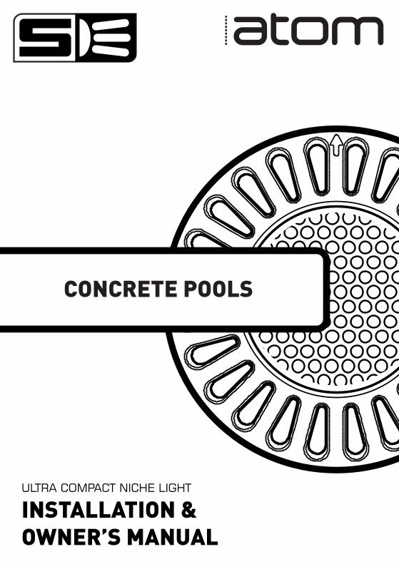
CONCRETE POOLS
ULTRA COMPACT NICHE LIGHT
INSTALLATION &OWNER’S MANUAL

9
18
19
INSTALLATION INSTRUCTIONS
LIGHT ASSEMBLY
LIGHT REMOVAL
READ THIS FIRST 5
6
7
21
TOOLS REQUIRED
6PRODUCT SUPPORT & INFORMATION
INCLUDED PARTS
TROUBLESHOOTING
20KEY DIMENSIONS
22ELECTRICAL GROUNDING & FCC COMPLIANCE STATEMENT
8FINISHED INSTALLATION
FRESH WATER USE ONLY HORIZONTAL MOUNT ONLY
NOT INTENDED FOR OPERATION OUT OF WATER
NOTICE
FOR SUPPLY CONNECTION, USE ONLY AN ISOLATING LOW VOLTAGE POWER SUPPLY WITH UNGROUNDED OUTPUT, EVALUATED FOR SWIMMING POOL USE
CONTENTS
3

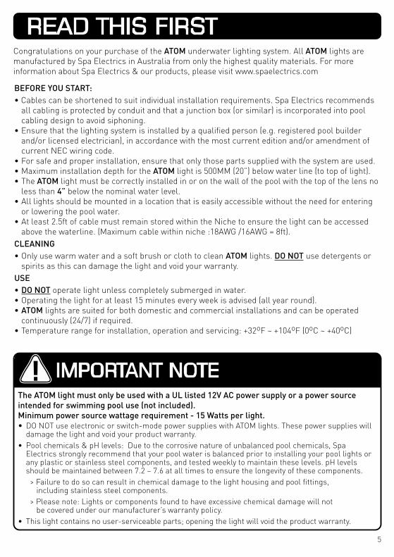
Congratulations on your purchase of the ATOM underwater lighting system. All ATOM lights are manufactured by Spa Electrics in Australia from only the highest quality materials. For more information about Spa Electrics & our products, please visit www.spaelectrics.com
BEFORE YOU START:• Cables can be shortened to suit individual installation requirements. Spa Electrics recommends
all cabling is protected by conduit and that a junction box (or similar) is incorporated into pool cabling design to avoid siphoning.
• Ensure that the lighting system is installed by a qualified person (e.g. registered pool builder and/or licensed electrician), in accordance with the most current edition and/or amendment of current NEC wiring code.
• For safe and proper installation, ensure that only those parts supplied with the system are used. • Maximum installation depth for the ATOM light is 500MM (20”) below water line (to top of light).• The ATOM light must be correctly installed in or on the wall of the pool with the top of the lens no
less than 4” below the nominal water level. • All lights should be mounted in a location that is easily accessible without the need for entering
or lowering the pool water.• At least 2.5ft of cable must remain stored within the Niche to ensure the light can be accessed
above the waterline. (Maximum cable within niche :18AWG /16AWG = 8ft).CLEANING• Only use warm water and a soft brush or cloth to clean ATOM lights. DO NOT use detergents or
spirits as this can damage the light and void your warranty.USE• DO NOT operate light unless completely submerged in water. • Operating the light for at least 15 minutes every week is advised (all year round). • ATOM lights are suited for both domestic and commercial installations and can be operated
continuously (24/7) if required.• Temperature range for installation, operation and servicing: +32oF ~ +104oF (0oC ~ +40oC)
The ATOM light must only be used with a UL listed 12V AC power supply or a power source intended for swimming pool use (not included).Minimum power source wattage requirement - 15 Watts per light.• DO NOT use electronic or switch-mode power supplies with ATOM lights. These power supplies will
damage the light and void your product warranty.• Pool chemicals & pH levels: Due to the corrosive nature of unbalanced pool chemicals, Spa
Electrics strongly recommend that your pool water is balanced prior to installing your pool lights or any plastic or stainless steel components, and tested weekly to maintain these levels. pH levels should be maintained between 7.2 – 7.6 at all times to ensure the longevity of these components.
> Failure to do so can result in chemical damage to the light housing and pool fittings, including stainless steel components.
> Please note: Lights or components found to have excessive chemical damage will not be covered under our manufacturer’s warranty policy.
• This light contains no user-serviceable parts; opening the light will void the product warranty.
IMPORTANT NOTE
READ THIS FIRST
5
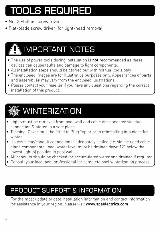
• No. 2 Phillips screwdriver• Flat-blade screw driver (for light-head removal)
• The use of power tools during installation is not recommended as these devices can cause faults and damage to light components.
• All installation steps should be carried out with manual tools only.• The enclosed images are for illustrative purposes only. Appearances of parts
and assemblies may vary from the enclosed illustrations.• Please contact your reseller if you have any questions regarding the correct
installation of this product.
IMPORTANT NOTES
WINTERIZATION• Lights must be removed from pool wall and cable disconnected via plug
connection & stored in a safe place.• Terminal Cover must be fitted to Plug Top prior to reinstalling into niche for
winter.• Unless niche/conduit connection is adequately sealed (i.e. via included cable
gland components), pool water level must be drained down 12” below the lowest light(s) position in pool wall.
• All conduits should be checked for accumulated water and drained if required.• Consult your local pool professional for complete pool winterization process.
PRODUCT SUPPORT & INFORMATIONFor the most update to date installation information and contact information for assistance in your region, please visit www.spaelectrics.com
TOOLS REQUIRED
6
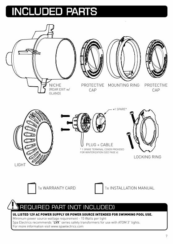
1x WARRANTY CARD 1x INSTALLATION MANUAL
MOUNTING RING
LIGHT
PROTECTIVE CAP
NICHE(REAR EXIT w/ GLAND)
PROTECTIVE CAP
PLUG + CABLE* 1 SPARE TERMINAL COVER PROVIDED FOR WINTERIZATION (SEE PAGE 6)
LOCKING RING
REQUIRED PART (NOT INCLUDED)UL LISTED 12V AC POWER SUPPLY OR POWER SOURCE INTENDED FOR SWIMMING POOL USE.Minimum power source wattage requirement - 15 Watts per lightSpa Electrics recommends “LVX” series safety transformers for use with ATOM 3” lights.For more information visit www.spaelectrics.com
+1 SPARE*
INCLUDED PARTS
7
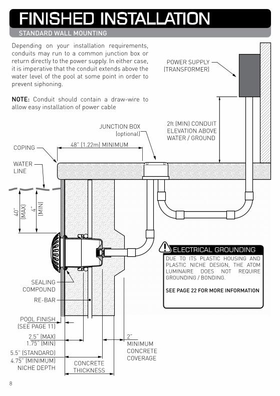
RE-BAR
40”
(MAX
)
2.5“ (MAX)1.75“ (MIN)
CONCRETETHICKNESS
POOL FINISH(SEE PAGE 11)
2”MINIMUMCONCRETECOVERAGE
SEALINGCOMPOUND
WATERLINE
COPING
5.5” (STANDARD)4.75” (MINIMUM)
NICHE DEPTH
2ft (MIN) CONDUITELEVATION ABOVEWATER / GROUND
POWER SUPPLY(TRANSFORMER)
4”(M
IN)
48” (1.22m) MINIMUM
JUNCTION BOX(optional)
ELECTRICAL GROUNDINGDUE TO ITS PLASTIC HOUSING AND PLASTIC NICHE DESIGN, THE ATOM LUMINAIRE DOES NOT REQUIRE GROUNDING / BONDING.
SEE PAGE 22 FOR MORE INFORMATION
Depending on your installation requirements, conduits may run to a common junction box or return directly to the power supply. In either case, it is imperative that the conduit extends above the water level of the pool at some point in order to prevent siphoning.
NOTE: Conduit should contain a draw-wire to allow easy installation of power cable
FINISHED INSTALLATIONSTANDARD WALL MOUNTING
8
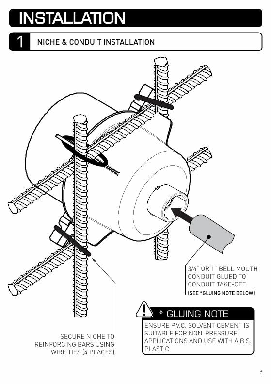
SECURE NICHE TO REINFORCING BARS USING
WIRE TIES (4 PLACES)
* GLUING NOTEENSURE P.V.C. SOLVENT CEMENT IS SUITABLE FOR NON-PRESSURE APPLICATIONS AND USE WITH A.B.S. PLASTIC
3/4” OR 1” BELL MOUTH CONDUIT GLUED TO CONDUIT TAKE-OFF(SEE *GLUING NOTE BELOW)
1 NICHE & CONDUIT INSTALLATION
INSTALLATION
9
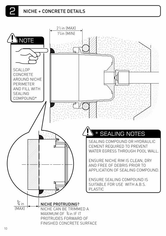
NICHE PROTRUDING?NICHE CAN BE TRIMMED A MAXIMUM OF in IF IT PROTRUDES FORWARD OF FINISHED CONCRETE SURFACE
in(MAX)
NOTE
SCALLOP CONCRETE AROUND NICHE PERIMETER AND FILL WITH SEALING COMPOUND*
* SEALING NOTESSEALING COMPOUND OR HYDRAULIC CEMENT REQUIRED TO PREVENT WATER EGRESS THROUGH POOL WALL.
ENSURE NICHE RIM IS CLEAN, DRY AND FREE OF DEBRIS PRIOR TO APPLICATION OF SEALING COMPOUND.
ENSURE SEALING COMPOUND IS SUITABLE FOR USE WITH A.B.S. PLASTIC
2 in (MAX)12
2in (MIN)CONCRETECOVERAGE
34
34
1 in (MIN)34
2 NICHE + CONCRETE DETAILS
10
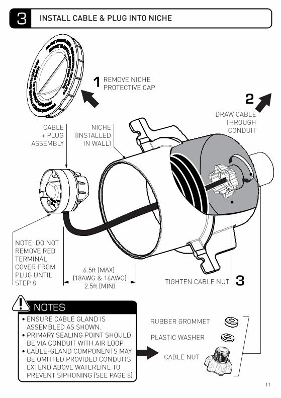
NOTE: DO NOT REMOVE RED TERMINAL COVER FROM PLUG UNTIL STEP 8
REMOVE NICHEPROTECTIVE CAP
6.5ft (MAX) (18AWG & 16AWG)
2.5ft (MIN)
NOTES• ENSURE CABLE GLAND IS
ASSEMBLED AS SHOWN.• PRIMARY SEALING POINT SHOULD
BE VIA CONDUIT WITH AIR LOOP• CABLE-GLAND COMPONENTS MAY
BE OMITTED PROVIDED CONDUITS EXTEND ABOVE WATERLINE TO PREVENT SIPHONING (SEE PAGE 8)
NICHE(INSTALLED
IN WALL)
TIGHTEN CABLE NUT
CABLE+ PLUG
ASSEMBLY
DRAW CABLETHROUGHCONDUIT
RUBBER GROMMET
PLASTIC WASHER
CABLE NUT
3 INSTALL CABLE & PLUG INTO NICHE
11
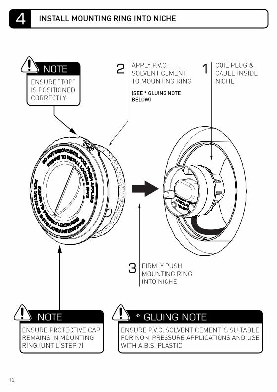
COIL PLUG & CABLE INSIDE NICHE
APPLY P.V.C. SOLVENT CEMENT TO MOUNTING RING
(SEE * GLUING NOTE BELOW)
FIRMLY PUSH MOUNTING RING INTO NICHE
12
3
NOTEENSURE PROTECTIVE CAP REMAINS IN MOUNTING RING (UNTIL STEP 7)
* GLUING NOTEENSURE P.V.C. SOLVENT CEMENT IS SUITABLE FOR NON-PRESSURE APPLICATIONS AND USE WITH A.B.S. PLASTIC
NOTEENSURE “TOP” IS POSITIONED CORRECTLY
4 INSTALL MOUNTING RING INTO NICHE
12
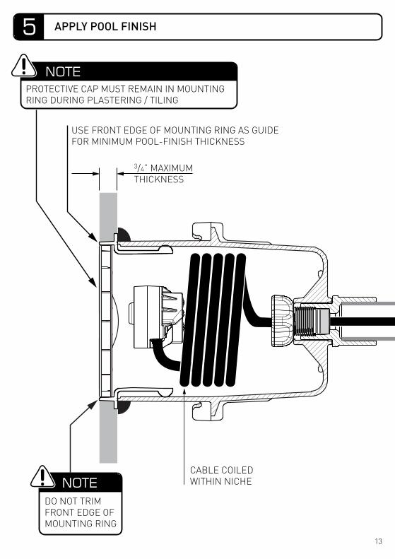
CABLE COILEDWITHIN NICHENOTE
DO NOT TRIM FRONT EDGE OF MOUNTING RING
NOTEPROTECTIVE CAP MUST REMAIN IN MOUNTING RING DURING PLASTERING / TILING
USE FRONT EDGE OF MOUNTING RING AS GUIDEFOR MINIMUM POOL-FINISH THICKNESS
3/4” MAXIMUMTHICKNESS
5 APPLY POOL FINISH
13
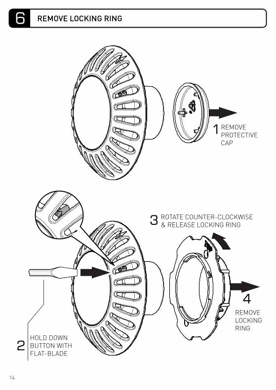
1REMOVEPROTECTIVECAP
HOLD DOWNBUTTON WITHFLAT-BLADE
4
3 ROTATE COUNTER-CLOCKWISE & RELEASE LOCKING RING
REMOVELOCKINGRING
2
6 REMOVE LOCKING RING
14
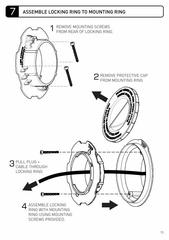
PULL PLUG +CABLE THROUGHLOCKING RING
ASSEMBLE LOCKINGRING WITH MOUNTINGRING USING MOUNTINGSCREWS PROVIDED.
4
3
2
1 REMOVE MOUNTING SCREWS FROM REAR OF LOCKING RING.
REMOVE PROTECTIVE CAP FROM MOUNTING RING
7 ASSEMBLE LOCKING RING TO MOUNTING RING
15
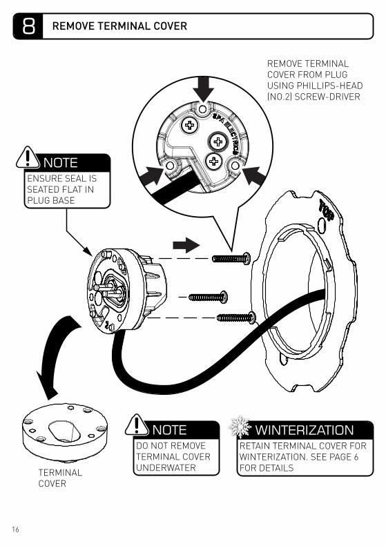
NOTEENSURE SEAL IS SEATED FLAT IN PLUG BASE
NOTEDO NOT REMOVE TERMINAL COVER UNDERWATER
WINTERIZATIONRETAIN TERMINAL COVER FOR WINTERIZATION. SEE PAGE 6 FOR DETAILS
REMOVE TERMINAL COVER FROM PLUG USING PHILLIPS-HEAD (NO.2) SCREW-DRIVER
TERMINALCOVER
REMOVE TERMINAL COVER8
16
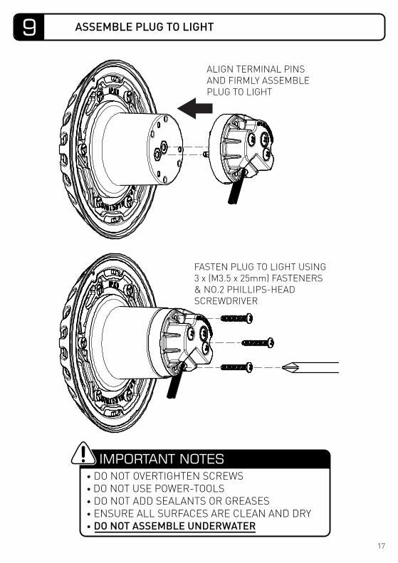
FASTEN PLUG TO LIGHT USING 3 x (M3.5 x 25mm) FASTENERS & NO.2 PHILLIPS-HEAD SCREWDRIVER
• DO NOT OVERTIGHTEN SCREWS• DO NOT USE POWER-TOOLS• DO NOT ADD SEALANTS OR GREASES• ENSURE ALL SURFACES ARE CLEAN AND DRY• DO NOT ASSEMBLE UNDERWATER
IMPORTANT NOTES
ALIGN TERMINAL PINS AND FIRMLY ASSEMBLE PLUG TO LIGHT
9 ASSEMBLE PLUG TO LIGHT
17
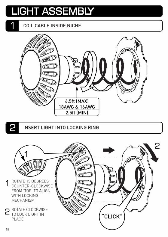
12
1
2
ROTATE 15 DEGREES COUNTER-CLOCKWISE FROM ‘TOP’ TO ALIGN WITH LOCKING MECHANISM
ROTATE CLOCKWISE TO LOCK LIGHT IN PLACE
6.5ft (MAX)18AWG & 16AWG
2.5ft (MIN)
“CLICK”
1
LIGHT ASSEMBLY
2
COIL CABLE INSIDE NICHE
INSERT LIGHT INTO LOCKING RING
18
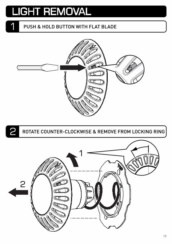
1
2
LIGHT REMOVAL
1 PUSH & HOLD BUTTON WITH FLAT BLADE
2 ROTATE COUNTER-CLOCKWISE & REMOVE FROM LOCKING RING
19
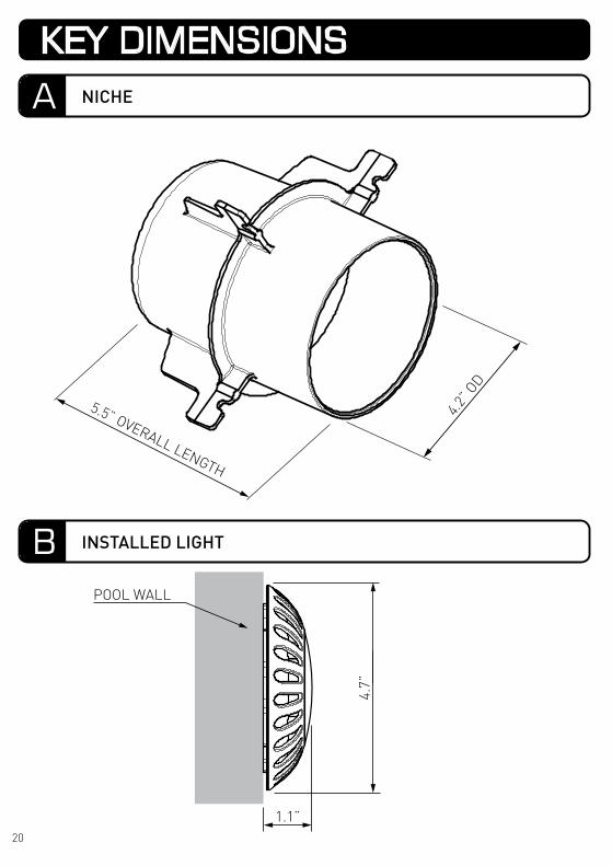
POOL WALL
1.1”
4.7”
4.2” O
D
5.5” OVERALL LENGTH
KEY DIMENSIONS
A NICHE
B INSTALLED LIGHT
20
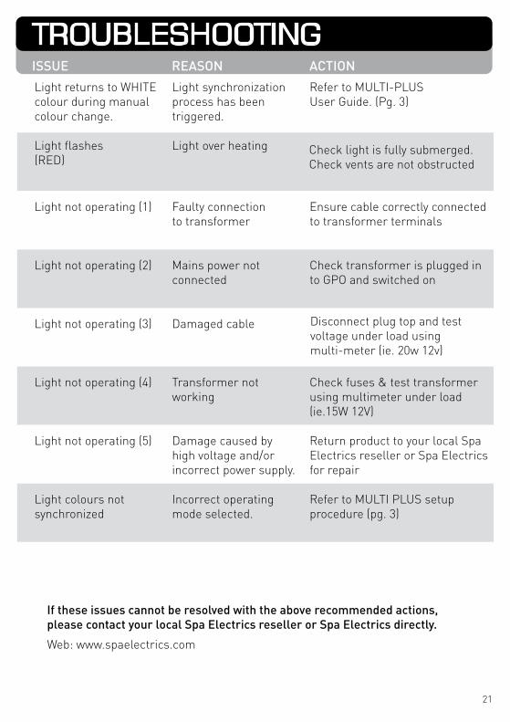
If these issues cannot be resolved with the above recommended actions,please contact your local Spa Electrics reseller or Spa Electrics directly.
Web: www.spaelectrics.com
Light flashes(RED)
Light over heating
Light returns to WHITEcolour during manual colour change.
Refer to MULTI-PLUSUser Guide. (Pg. 3)
Light synchronizationprocess has been triggered.
Check light is fully submerged.Check vents are not obstructed
Light not operating (1) Faulty connectionto transformer
Ensure cable correctly connectedto transformer terminals
Light not operating (3) Damaged cable
Light not operating (2) Mains power notconnected
Check transformer is plugged into GPO and switched on
Light not operating (4) Transformer notworking
Check fuses & test transformerusing multimeter under load(ie.15W 12V)
Light not operating (5) Damage caused byhigh voltage and/orincorrect power supply.
Return product to your local SpaElectrics reseller or Spa Electricsfor repair
Light colours notsynchronized
Incorrect operating mode selected.
Refer to MULTI PLUS setup procedure (pg. 3)
Disconnect plug top and test voltage under load using multi-meter (ie. 20w 12v)
ISSUE REASON ACTION
TROUBLESHOOTING
21
This device complies with part 15 of the FCC rules. Operation is subject to the following two (2) conditions:(1) This device may not cause harmful interference, and(2) this device must accept any interference received, including interference that may cause undesired operation.
Note: This equipment has been tested and found to comply with the limits for a Class B digital device, pursuant to part 15 of the FCC Rules. These limits are designed to provide reasonable protection against harmful interference in a residential installation. This equipment generates, uses and can radiate radio frequency energy and, if not installed and used in accordance with the instructions, may cause harmful interference to radio communications. However, there is no guarantee that interference will not occur in a particular installation. If this equipment does cause harmful interference to radio or television reception, which can be determined by turning the equipment off and on, the user is encouraged to try to correct the interference by one or more of the following measures:• Reorient or relocate the receiving antenna.• Increase the separation between the equipment and receiver.• Connect the equipment into an outlet on a circuit different
to that to which the receiver is connected.• Consult the dealer or an experienced radio / TV technician for help.
Do not make any changes or modifications to the equipment unless otherwise specified in the manual.
Underwriters Laboratories (UL) StatementPer the NEC, NFPA 70, Article 680.23 (B)(5), states that bonding shall not be required for luminaires that are listed for the application and have no non-current carrying metal parts. In addition, per Article 680.26 (B)(4), exception states that Listed low-voltage lighting systems with non-metallic forming shells shall not require bonding.
Therefore, luminaires with polymeric/non-current carrying metal parts are not required to be grounded / bonded.
Manufacturers StatementSpa Electrics ATOM & QUANTUM (EM & WN9) luminaires with their plastic hous-ing designs and plastic niches do not require grounding / bonding.
Spa Electrics ATOM & QUANTUM (EM & WN9) lights have also been determined to comply with the applicable requirements for wet-niche, LED type Swimming Pool and Spa Luminaires.
FCC COMPLIANCE STATEMENT
ELECTRICAL GROUNDING
22

NOTEPLEASE STORE THIS
MANUAL IN A SAFE PLACE FOR FUTURE REFERENCE
COPYRIGHT 2020 SPA ELECTRICS PTY. LTD.ALL RIGHTS RESERVED
US 20200501
www.spaelectrics.com


