Embed Size (px)
Citation preview

Concrete Code Check EN-1992Design and code-checks of concrete members (SCIA Engineer 15.0 and newer version)
Contacts 13Abstract 15Concrete in SCIA Engineer 16Command properties 20
Command properties 20
Name 21
Selection 22
Type of loads 22
Filter 22
Extreme 22
Values 23
Output 23
Results in sections 23
Drawing setup 23
Run usingModelData files (Debug) 23
Action buttons 23
Concrete member data 241D member data 24
Propertiesof 1DMember data 25
Solver settings 26
Design defaults 33
Beamslab 39
Column 41
Concrete settings (structure) 44Concrete settings dialogue 44
Find 44
View 45
Filters 47
Default 48
Concrete settings - Values 48
Solver settings 48
Concrete settings - Design Defaults 78
- 2 -
Design defaults 78
Output 95Numerical output 95
Numerical output 95
Graphical output 101
Graphical output 101
Design 103Design of reinforcement 103
Longitudinal reinforcement 103
Shear reinforcement 104
Internal forces - theory 104
Introduction 104
Parameters influencing the calculation 105
Additional tensile forcescaused byshear and torsion (shifting of bendingmoments) 114
Determinationwhether member is in compression 115
First order bendingmomentswith imperfection 115
Calculation of second order effects 118
Design of reinforcement for rectangular section 121
Design of reinforcement for circular section 122
Design of reinforcement for other cross-sections 123
Checks for all type of cross-sections 124
Ribs 127
Literature 132
Reduction of shear forces and bending moment 133
Assumptions 133
Concrete setup 134
Concretemember data 135
Application to internal forces 138
Slenderness 143
Introduction 143
Buckling data 143
Creep coefficient 144
- 3 -
Chapter 0
Estimation of ratio of longitudinal reinforcement 144
Calculation of slenderness 145
Calculation of limit slenderness 145
Warning and errors 149
Abbreviations 149
Literature 149
Reinforcement design - theory 150
Introduction 150
Design of longitudinal reinforcement 153
Design of shear reinforcement 161
Torsional longitudinal reinforcement 173
Design 2D - Introduction 174Internal forces 2D - Introduction 174
Theoretical background 174
Additional tensile force caused byshear-shifting 179
Command Internal forces2D 180
Output 182
Definition of provided reinforcement 191
Design As - Theoretical background 191
DesignAs - Shear Reinforcement 193
DesignAs - Checkof compressive strut 197
DesignAs - Detailing provisions 198
Reinforcement diameter for detailing provisions 198
Checkminimal ratio of principal reinforcement 9.3.1.1(1) 199
Checkmaximal ratio of principal reinforcement 9.3.1.1(1) 199
Checkminimal transverse ratio of secondary reinforcement 9.3.1.1(2) 199
Checkmaximal spacing of principal and secondary longitudinal reinforcement 9.3.1.1(3) 199
Checkminimal ratio of shear reinforcement 9.3.2(2) 200
Checkminimal thicknessofmember with shear reinforcement 9.3.2(1) 201
Checkmaximal spacing of shear links9.3.2(4) 201
Checkminimal ratio of vertical reinforcement 9.6.2(1) 201
Checkmaximal ratio of vertical reinforcement 9.6.2(1) 202
- 4 -
Checkmaximal spacing of vertical reinforcement 9.6.2(3) 202
Checkminimal ratio of horizontal reinforcement 9.6.3(1) 202
Standard EC-EN 202
Checkmaximal spacing of horizontal reinforcement 9.6.3(2) 203
Checkmaximal spacing of shear links9.6.4(1) 203
Checkminimal spacing of shear links9.6.4(2) 204
Checkminimal ratio of horizontal reinforcement 9.7(1) 204
Checkmaximal spacing of reinforcement 9.7(2) 204
Command 205
Design As - Output 207
Graphical output 207
Numerical output 208
Practical reinforcement 218Basic and additional reinforcement - introduction 218
Introduction 219
Provided library 220
Provided librarysettings 221
Definition ofmain settings 221
Action buttons 222
Drawing 222
Table input 223
Provided library - Member types 223
Rectangle 223
Definition of additional l reinforcement 225
T shape, L shape, I shape andOther 225
Rectangle 228
Circular 228
Oval 229
Other 229
Design Defaults 233
Beam (Rib) 235
Beamslab 241
- 5 -
Chapter 0
Columns 243
Plate, Shell (Plate) 246
Wall, Shell (Wall), Deep beam 253
Concrete Member Data 258
Concretemember data 1D 258
Concretemember data 2D 262
Checks 265Stiffness 265
Introduction 265
Assumptions 268
Theory 269
Setup 272
Errorsandwarnings 272
Capacity - response (ULS) 273
Introduction 273
Assumptionsand limitations 273
Theoretical background 273
Calculation xu,lim_DutchNENNA 276
Effective depth of cross-section 279
Inner lever arm 280
Errorsandwarnings 281
National annexes 282
Capacity - diagram (ULS) 283
Introduction 283
Assumptionsand limitations 283
Theoretical background 284
Setup 290
Errorsandwarnings 292
National annexes 293
Shear + torsion (ULS) 293
Introduction 293
Equivalent thin-walled closed cross-section 294
- 6 -
Parameters influencing the calculation 297
Determination stirrupsaround section 297
Calculation number of stirrup link (number of cuts) 298
Stirrup for torsion 298
Calculation of average characteristicsof shear reinforcement 299
Calculation characteristicof shear reinforcement 299
Calculation procedure 300
Width of cross-section for shear check 304
Effective depth of cross-section for shear check 304
Inner lever arm for shear check 305
Calculation basic characteristics for shear 306
Shear check 306
Calculation procedure 307
Calculation of basic characteristics 309
Torsion check 310
Calculation procedure 311
Checkof interaction shear and torsion 314
Warnings, errorsand notes 314
Literature 314
Stress limitations (SLS) 315
Introduction 315
Assumption and limitations 315
Theoretical background 318
Setup 320
National annexes in stress limitation 322
Errors,Warnings, Notes 323
Crack width (SLS) 324
Introduction 324
Value of strength for calculation of cracking forces 324
Checkof normal stresses (occurring of crackwidth) 324
Type of strength for calculation of cracking forces 325
Use of effectivemodulusof concrete 325
- 7 -
Chapter 0
Type ofmaximal crackwidth 326
Type of strength for calculation of cracking forces 326
Parameters influencing the calculation 327
Calculation ofmean strain in the reinforcement and concrete 327
Calculation ofmaximumcrackspacing 330
Calculation of crackwidth in direction of principal stresses 332
Checkof normal stresses (occurring of crackwidth) 332
Calculation ofmean strain in the reinforcement and concrete 333
Calculation ofmaximumcrackspacing 336
Calculation of crackwidth 338
Warning and errors 338
Abbreviations 339
Warning and errors 339
Abbreviations 340
Literature 341
Literature 341
Deflections (SLS) 341
Introduction 341
Assumption 342
Theory 343
Setup 345
Errors,Warnings, Notes 347
Detailing provisions 348
Introduction 348
Assumption and limitations 349
Minimal clear spacing of bars - Code chapter 8.2(2) 349
Maximal percentage of shear reinforcement (6.2.3(3)) 350
Minimalmandrel diameter (8.3(2)) 350
Minimal reinforcement area (9.2.1.1(1)) 351
Maximal area of reinforcement (9.2.1.1(3)) 352
Minimal percentage of shear reinforcement (9.2.2(5)) 353
Maximal longitudinal spacing of stirrupsbased on shear (9.2.2(6)) 353
- 8 -
Maximal longitudinal spacing of stirrupsbased on torsion requirements (9.2.3(3)) 354
Maximal centre-to-centre bar distance based on torsion (9.2.3(4)) 355
Maximal clear spacing of bars (Code independent) 355
Unity checkcalculation 355
Minimal bar diameter of longitudinal reinforcement (9.5.2(1)) 356
Minimal area of longitudinal reinforcement (9.5.2(2)) 356
Maximal area of longitudinal reinforcement (9.5.2(3)) 357
Minimal number of bars in circular column (9.5.2(4)) 357
Minimal bar diameter of transverse reinforcement (9.5.3(1)) 358
Maximal longitudinal spacing of stirrups (9.5.3(3)) 358
Maximal centre-to-centre bar distance (9.3.1.1(3)) 358
Concrete settings 359
Concrete settings for beams 361
Checkmin. bar distance 361
Minimal bar distance 361
Checkmax. bar distance 362
Maximal bar distance 362
Checkmax. bar distance (torsion) 362
Maximal bar distance (torsion) 363
Checkmin. reinforcement area 363
Checkmin. reinforcement area for secondarymember 363
Checkmax. reinforcement area 364
Checkmin.mandrel diameter 364
Checkmax. longitudinal spacing (shear) 364
Checkmax. longitudinal spacing (torsion) 364
Checkmax. transverse spacing (shear) 365
Checkmin. percentage of stirrups 365
Checkmax. percentage of stirrups 365
Settings for beamslabs 365
Checkmin. bar distance 365
Minimal bar distance 366
Checkmax. bar distance 366
- 9 -
Chapter 0
Checkmin. reinforcement area 366
Checkmax. reinforcement area 367
Settings for columns 367
Checkmin. bar distance 367
Minimal bar distance 368
Checkmax. bar distance 368
Maximal bar distance 368
Checkmax. bar distance (torsion) 369
Maximal bar distance (torsion) 369
Checkmin. reinforcement area 369
Checkmax. reinforcement area 370
Checkmin. bar diameter 370
Checkmin. number of bars in circular column 371
Min. number of bars in circular column 371
Checkmin.mandrel diameter 371
Checkmax. longitudinal spacing 371
Checkmin. bar diameter 372
Min bar diameter 372
Min bar diameter 372
Crack check for 2D members - introduction 372
Assumption 373
Internal forces for crackcheck 378
0Reinforcement transformation 380
Recalculation of reinforcement to direction of principal stress 383
Crackappearance 384
Crackwidth calculation 386
Output 392
Code dependent deflections - introduction 406Influence of deflection values 407
Effect of load 407
Effect of cracking 407
Effect of creep 407
- 10 -
Procedure for calculation 407
Limitation for version SEN 17.0 408
Setting Project data 408
Global setting 409
410
411
Parameters for calculation of creep coefficient 412
Coefficient for increasing amount of reinforcement 413
Maximal total deflection for 1Dmember 413
Maximal additional deflection for 1Dmember 413
Maximal total deflection for 2Dmember 414
Maximal additional deflection for 2Dmember 414
Type of variable load coefficient for the automaticgeneration of a combination 414
Command for Code dependent deflection 415
Group selection 418
Automatic combination 419
GroupResult case for deflection 419
Type of reinforcement 420
GroupResult case for required reinforcement 420
GroupExtreme 1D 421
GroupExtreme 2D 421
Direction(local) 421
Values 421
Output 422
Print combination key 423
Print explanation of symbol 424
GroupErrors,warningsand notessettings 424
GroupDrawing setup 1D 426
GroupDrawing setup 2D 427
Theoretical background 427
Combination for CDD 427
Calculation stiffnessof 1D element 429
- 11 -

Chapter 0
Calculation stiffnessof 2D element 431
Calculation of deflection 433
Calculationmaximal deflection 434
- 12 -
Contacts
Belgium HeadquartersSCIA nv
Industrieweg 1007
B-3540 Herk-de-Stad
Tel: +32 13 55 17 75
E-mail: [email protected]
Support Phone
CAE (SCIA Engineer)
Tel: +32 13 55 09 90
CAD (Allplan)
Tel: +32 13 55 09 80
Support E-mail:
FranceSCIA France sarl
Centre d'Affaires
29, Grand' Rue
FR-59100 Roubaix
Tel.: +33 3.28.33.28.67
Fax: +33 3.28.33.28.69
E-mail: [email protected]
Agence commerciale
8, Place des vins de france
FR-75012 Paris
Tel.: +33 3.28.33.28.67
Fax: +33 3.28.33.28.69
E-mail: [email protected]
BrazilSCIA do Brasil Software Ltda
Rua Dr. LuizMigliano, 1986 - sala 702 , CEP
SP 05711-001 São Paulo
Tel.: +55 11 4314-5880
E-mail: [email protected]
USASCIA North America
7150 Riverwood Drive
21046 Columbia,MD
Tel.; +1 443-542-0638
Fax.:+1 410-290-8050
E-mail: [email protected]
NetherlandsSCIA Nederland B.V.
Wassenaarweg 40
NL-6843 NWARNHEM
Tel.:+31 26 320 12 30
Fax.: +31 26 320 12 39
E-mail: [email protected]
SwitzerlandSCIA SwissOffice
Dürenbergstrasse 24
CH-3212 Gurmels
Tel.: +41 26 341 74 11
Fax: +41 26 341 74 13
E-mail: [email protected]
Czech RepublicSCIA CZ s.r.o. Praha
Evropská 2591/33d
160 00 Praha 6
Tel.: +420 226 205 600
Fax: +420 226 201 673
E-mail: [email protected]
SCIA CZ s.r.o. Brno
Slavickova 827/1a
638 00 Brno
Tel.: +420 530 501 570
Fax: +420 226 201 673
E-mail: [email protected]
SlovakiaSCIA SK s.r.o.
Murgašova 1298/16
SK-010 01 Žilina
Tel.: +421 415 003 070
Fax: +421 415 003 072
E-mail: [email protected]
- 13 -

Chapter 0
AustriaSCIA Datenservice Ges.m.b.H.
Dresdnerstrasse 68/2/6/9
A-1200 WIEN
Tel.: +43 1 7433232-11
Fax: +43 1 7433232-20
E-mail: [email protected]
Support
Tel.: +43 1 7433232-12
E-mail: [email protected]
GermanySCIA Software GmbH
Technologie ZentrumDortmund, Emil-Figge-Strasse 76-80
D-44227 Dortmund
Tel.: +49 231/9742586
Fax: +49 231/9742587
E-mail: [email protected]
All information in this document is subject to modification without prior notice. No part of this manual may be reproduced,stored in a database or retrieval system or published, in any form or in anyway, electronically, mechanically, by print, photoprint, microfilm or anyother meanswithout prior written permission from the publisher. SCIAis not responsible for anydirector indirect damage because of imperfections in the documentation and/or the software.
©Copyright 2017SCIAnv. All rights reserved.
Document created: 18 / 07 / 2017
SCIAEngineer 17.0
- 14 -
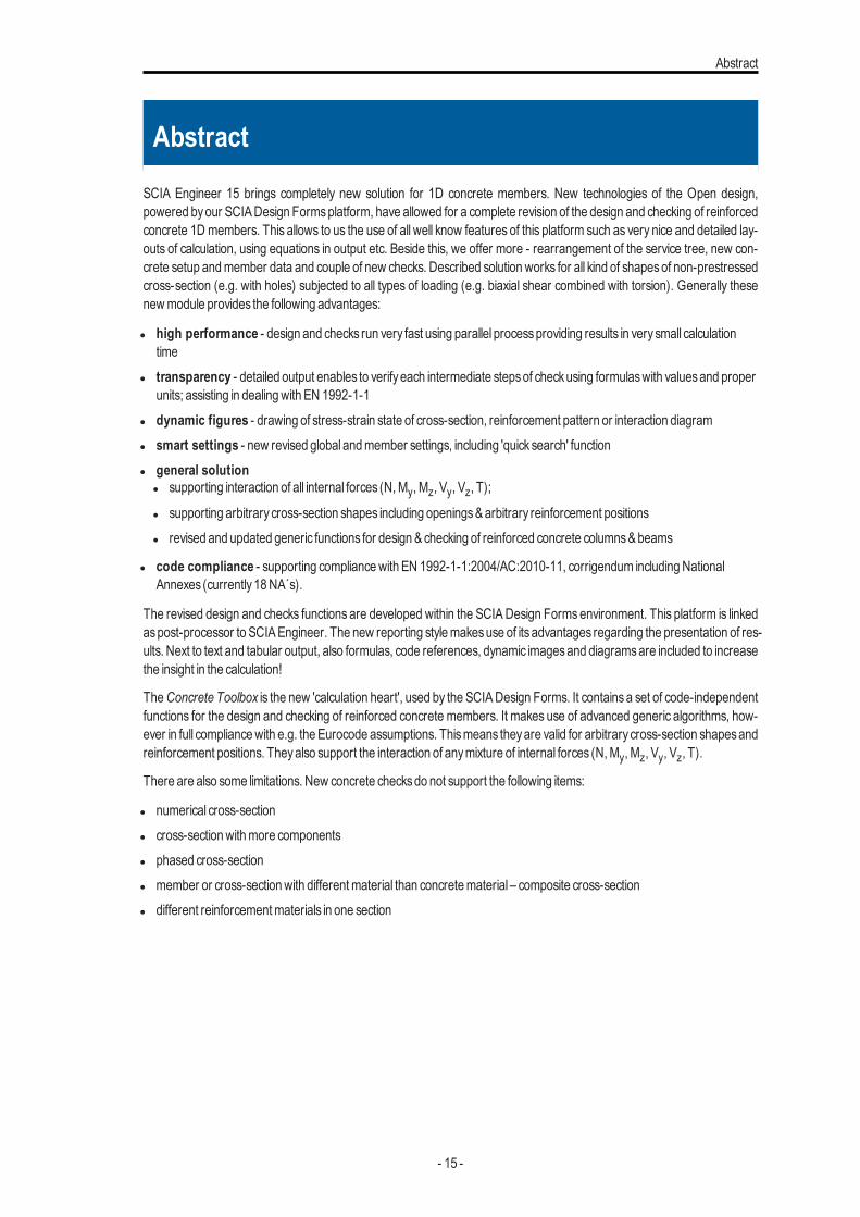
Abstract
Abstract
SCIA Engineer 15 brings completely new solution for 1D concrete members. New technologies of the Open design,powered byour SCIADesign Formsplatform, have allowed for a complete revision of the design and checking of reinforcedconcrete 1D members. This allows to us the use of all well know features of this platform such as very nice and detailed lay-outs of calculation, using equations in output etc. Beside this, we offer more - rearrangement of the service tree, new con-crete setup andmember data and couple of new checks. Described solution works for all kind of shapesof non-prestressedcross-section (e.g. with holes) subjected to all types of loading (e.g. biaxial shear combined with torsion). Generally thesenewmodule provides the following advantages:
l high performance - design and checks run very fast using parallel processproviding results in verysmall calculationtime
l transparency - detailed output enables to verifyeach intermediate stepsof checkusing formulaswith valuesand properunits; assisting in dealingwith EN 1992-1-1
l dynamic figures - drawing of stress-strain state of cross-section, reinforcement pattern or interaction diagraml smart settings - new revised global andmember settings, including 'quicksearch' functionl general solution
l supporting interaction of all internal forces (N,My, Mz, Vy, Vz, T);
l supporting arbitrarycross-section shapes including openings&arbitrary reinforcement positionsl revised and updated generic functions for design &checking of reinforced concrete columns&beams
l code compliance - supporting compliancewith EN 1992-1-1:2004/AC:2010-11, corrigendum includingNationalAnnexes (currently18NA´s).
The revised design and checks functions are developed within the SCIADesign Forms environment. This platform is linkedaspost-processor to SCIAEngineer. The new reporting stylemakesuse of itsadvantages regarding the presentation of res-ults. Next to text and tabular output, also formulas, code references, dynamic imagesand diagramsare included to increasethe insight in the calculation!
TheConcrete Toolbox is the new 'calculation heart', used by the SCIADesign Forms. It contains a set of code-independentfunctions for the design and checking of reinforced concrete members. It makes use of advanced generic algorithms, how-ever in full compliancewith e.g. the Eurocode assumptions. Thismeans theyare valid for arbitrarycross-section shapesandreinforcement positions. Theyalso support the interaction of anymixture of internal forces (N,My, Mz, Vy, Vz, T).
There are also some limitations. New concrete checksdo not support the following items:
l numerical cross-sectionl cross-sectionwithmore componentsl phased cross-sectionl member or cross-sectionwith differentmaterial than concretematerial – composite cross-sectionl different reinforcementmaterials in one section
- 15 -
Chapter 2
Concrete in SCIA Engineer
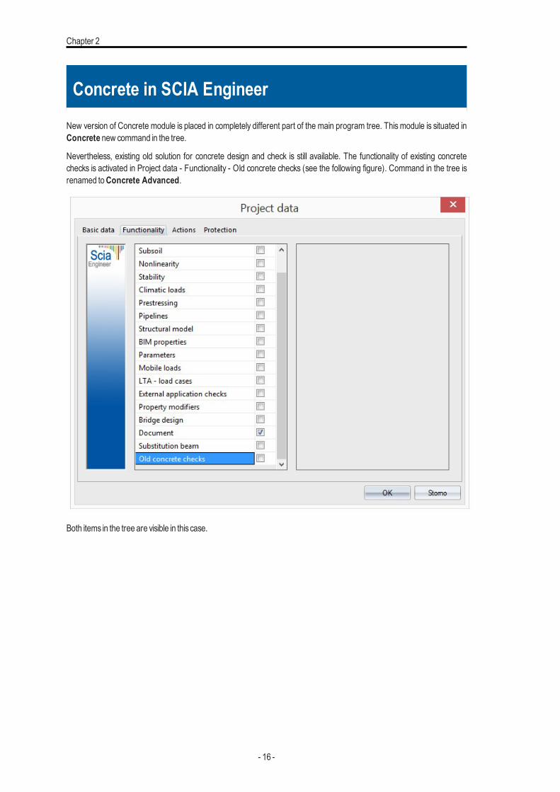
New version of Concrete module is placed in completely different part of the main program tree. This module is situated inConcrete new command in the tree.
Nevertheless, existing old solution for concrete design and check is still available. The functionality of existing concretechecks is activated in Project data - Functionality - Old concrete checks (see the following figure). Command in the tree isrenamed toConcrete Advanced.
Both items in the tree are visible in this case.
- 16 -
Concrete in SCIAEngineer
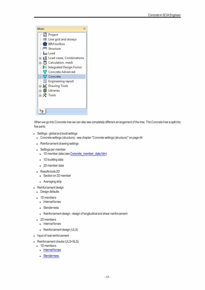
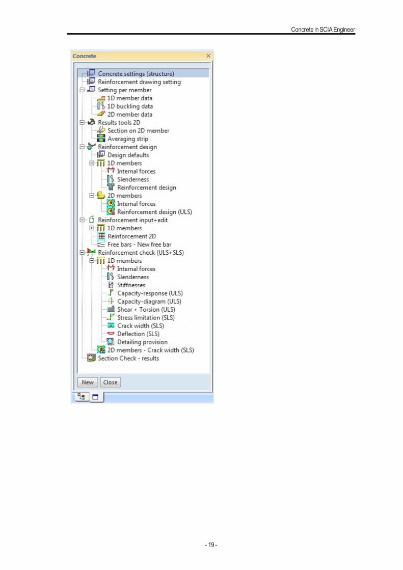
Whenwe go into Concrete tree we can also see completely different arrangement of the tree. TheConcrete tree is split intofive parts:
l Settings - global and local settingsl Concrete settings (structure) - see chapter "Concrete settings (structure)" on page 44l Reinforcement drawing settingsl Settingsper member
l 1Dmember data (seeConcrete_member_data.htm)l 1D buckling datal 2Dmember data
l Results tools2Dl Section on 2Dmemberl Averaging strip
l Reinforcement designl Design defaultsl 1Dmembers
l Internal forcesl Slendernessl Reinforcement design - design of longitudinal and shear reinforcement
l 2Dmembersl Internal forcesl Reinforcement design (ULS)
l Input of real reinforcementl Reinforcement checks (ULS+SLS)
l 1Dmembersl Internal forcesl Slenderness
- 17 -

Chapter 2
l Stiffnessesl Capacity - response (ULS)l Capacity - diagram (ULS)l Shear +Torsion (ULS)l Stress limitation (SLS)l Crackwidth (SLS)l Deflection (SLS)l Detailing provisions
l 2Dmembers - Crackwidth (SLS)l SectionCheck - results
- 18 -
Concrete in SCIAEngineer
- 19 -

Chapter 3
Command properties
Command propertiesConcrete checks run from the new commands mentioned in chapter "Concrete in SCIA Engineer" on page 16. The com-mand for these checks includesstandard itemswhere it ispossible to selectmember, type of load, filter, extreme and others.The description of all values is the following.
- 20 -
Command properties
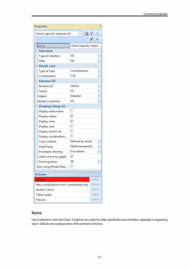
NameUser is allowed to name the Check. It might be very useful for better specification and orientation, especially in engineeringreport. Default name isalwaysnameof the command in the tree.
- 21 -
Chapter 3
SelectionThis attribute influences the total amount of members, which will be taken into the concrete checks. There are four pos-sibilities to be chosen from:
l All – all active 1Dmemberswill be checkedl Current – onlyselected 1Dmemberswill be checkedl Advanced – user maydefine the selectionmore specificallywith relation to previousselectionl Named selection – only1Dmembers from certain named selection, will be checked. new attribute “Named selection” will
appear in the propertiesl Design groups - groupsofmemberswith same length, type, cross-section or additional rules, see "Design groups"
Type of loadsBy thisattribute user defines the type of the load for checks. There are three possibilities to choose from:
l Combinations– user maychoose fromall combinationsl Load cases– user maychoose fromall load casesl Class– user maychoose fromall result classes
In dependence on selected type of the load, new attribute Combination or Load cases or Class will appear right under thisattribute. User mayselect desiredCombination, Load case or Class from filtered list here.
FilterIt is possible to define filter for adjusting already selected type of selection. This will affect the number of 1D member takeninto the check. User mayselect one from the following possibilities:
l No– no filter will be appliedl Wildcard – user maydefine the attributes for selection byhimselfl Material – user mayselect specificmateriall Cross-section – user mayselect specific cross-sectionl Layer – user mayselect desired layerl Type of beam
Again, after selection one possibility a new appropriate attributewill be displayed right under, for further selection.
ExtremeThis attribute defines which results should be shown in Preview window or document. User may choose from five pos-sibilities:
l Section - Resultswill be presented in all sectionson allmember - WARNING: displaying standard or detailed resultswiththese extreme selected can take a lot of time
l Cross-section - Extremeson all typesof sectionswill be displayedl Design group - Extremeson design groupswill be displayedl Member - Extremesper memberswill be displayedl Global - Onlyglobal extremeswill be displayed
- 22 -

Command properties
ValuesEach design or check includes its own values. Usually Unity check is the first typical value for all checks. There is also pos-sibility to seeMore component.
OutputThisattribute defines type of numerical output. There are available three levelsof numerical outputs:
l Brief – one table for all checkswith the unity checks, default EngineeringReport table.l Standard –more detailed output coming fromSCIADesign Formsl Detailed – verydeep output coming fromSCIADesign Forms
Results in sectionsThissetting specifyonwhich sectionswill be calculation performed and extremeswill be found
l All - All sectionsare evaluatedl Selected - Onlyselected sectionsare evaluated. Sectionsare defined in service Structure
Drawing setupBy selecting edit button for this parameter, a 1D results display dialogue will be open. Here user may specify the rep-resentation of check results on 1Dmember. This dialogue is a standard dialogue for graphical presentation of results on 1Dmember. Themost important settingsare the following:
l Limits–maximal andminimal valueswhich should be drawnl Description –which information is required to be printed (values, section, load case or combination and units)l Angle of text – angle of text related to centreline of thememberl Setup for more components
l same scale or heightl spacesbetween diagramsand shifting of the first diagram
Run using Model Data files (Debug)This check boxallows to save allmodel data including detailed trace of all calculation steps into files in SCIAEngineer TEMPfolder.
Action buttonsThere are two buttons in the lower part of the Propertiesdialogue.
l Refresh – thisbutton starts the processof check itself and it isneeded to press thisbutton to refresh previouschecked res-ultsand to get new results, based on chosen attributes)
l Preview – thisbutton opensPreviewwindowwith tablescontaining resultsof finished check
Note: Content of command propertiescan be slightlydifferent in future versions
- 23 -
Chapter 4
Concrete member data
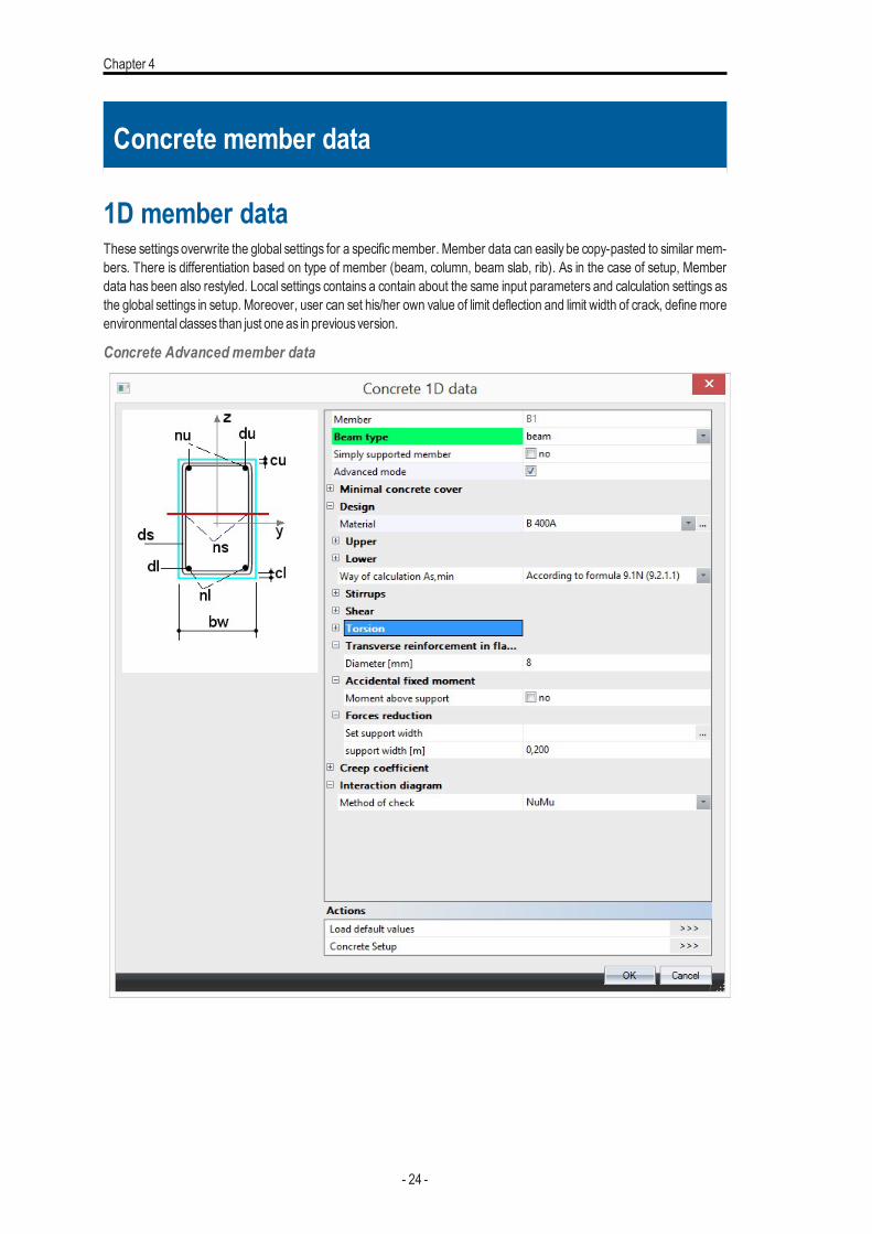
1D member dataThese settings overwrite the global settings for a specificmember. Member data can easily be copy-pasted to similar mem-bers. There is differentiation based on type of member (beam, column, beam slab, rib). As in the case of setup, Memberdata has been also restyled. Local settings contains a contain about the same input parameters and calculation settings asthe global settings in setup. Moreover, user can set his/her own value of limit deflection and limit width of crack, define moreenvironmental classes than just one as in previousversion.
Concrete Advancedmember data
- 24 -
Concretemember data
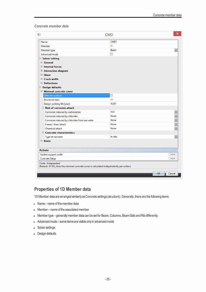
Concrete member data
Properties of 1D Member data1DMember data are arranged similarlyasConcrete settings (structure). Generally, there are the following items.
l Name– nameof themember datal Member – nameof the associatedmemberl Member type – generallymember data can be set for Beam,Columns, BeamSlab andRib differently.l Advancedmode – some itemsare visible only in advancedmodel Solver settingsl Design defaults
- 25 -
Chapter 4
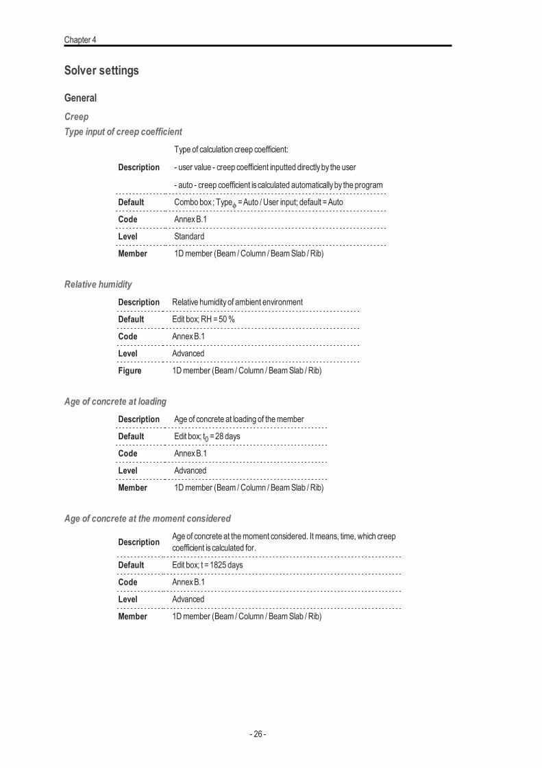
Solver settings
GeneralCreepType input of creep coefficient
Description
Type of calculation creep coefficient:
- user value - creep coefficient inputted directlyby the user
- auto - creep coefficient is calculated automaticallyby the program
Default Combo box ; Typeϕ =Auto / User input; default =Auto
Code AnnexB.1
Level Standard
Member 1Dmember (Beam /Column / BeamSlab / Rib)
Relative humidityDescription Relative humidityof ambient environment
Default Edit box; RH =50%
Code AnnexB.1
Level Advanced
Figure 1Dmember (Beam /Column / BeamSlab / Rib)
Age of concrete at loadingDescription Age of concrete at loading of themember
Default Edit box; t0 =28 days
Code AnnexB.1
Level Advanced
Member 1Dmember (Beam /Column / BeamSlab / Rib)
Age of concrete at the moment considered
Description Age of concrete at themoment considered. It means, time, which creepcoefficient is calculated for.
Default Edit box; t =1825 days
Code AnnexB.1
Level Advanced
Member 1Dmember (Beam /Column / BeamSlab / Rib)
- 26 -
Concretemember data
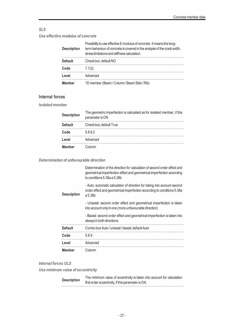
SLSUse effective modulus of concrete
DescriptionPossibility to use effective Emodulusof concrete. It means the long-termbehaviour of concrete is covered in the analysisof the crackwidth,stress limitationsand stiffnesscalculation.
Default Checkbox, default NO
Code 7.1(2)
Level Advanced
Member 1Dmember (Beam /Column / BeamSlab / Rib)
Internal forcesIsolated member
Description The geometric imperfection is calculated as for isolated member, if thisparameter isON
Default Checkbox; default True
Code 5.8.8.2
Level Advanced
Member Column
Determination of unfavourable direction
Description
Determination of the direction for calculation of second order effect andgeometrical imperfection effect and geometrical imperfection accordingto conditions5.38a a 5.38b
- Auto: automatic calculation of direction for taking into account secondorder effect and geometrical imperfection according to conditions 5.38aa 5.38b
- Uniaxial: second order effect and geometrical imperfection is takeninto account only in one (more unfavourable direction)
- Biaxial: second order effect and geometrical imperfection is taken intoalways in both directions
Default Combo boxAuto / uniaxial / biaxial; default Auto
Code 5.8.9
Level Advanced
Member Column
Internal forces ULSUse minimum value of eccentricity
Description The minimum value of eccentricity is taken into account for calculationfirst order eccentricity, if thisparameter isON.
- 27 -
Chapter 4
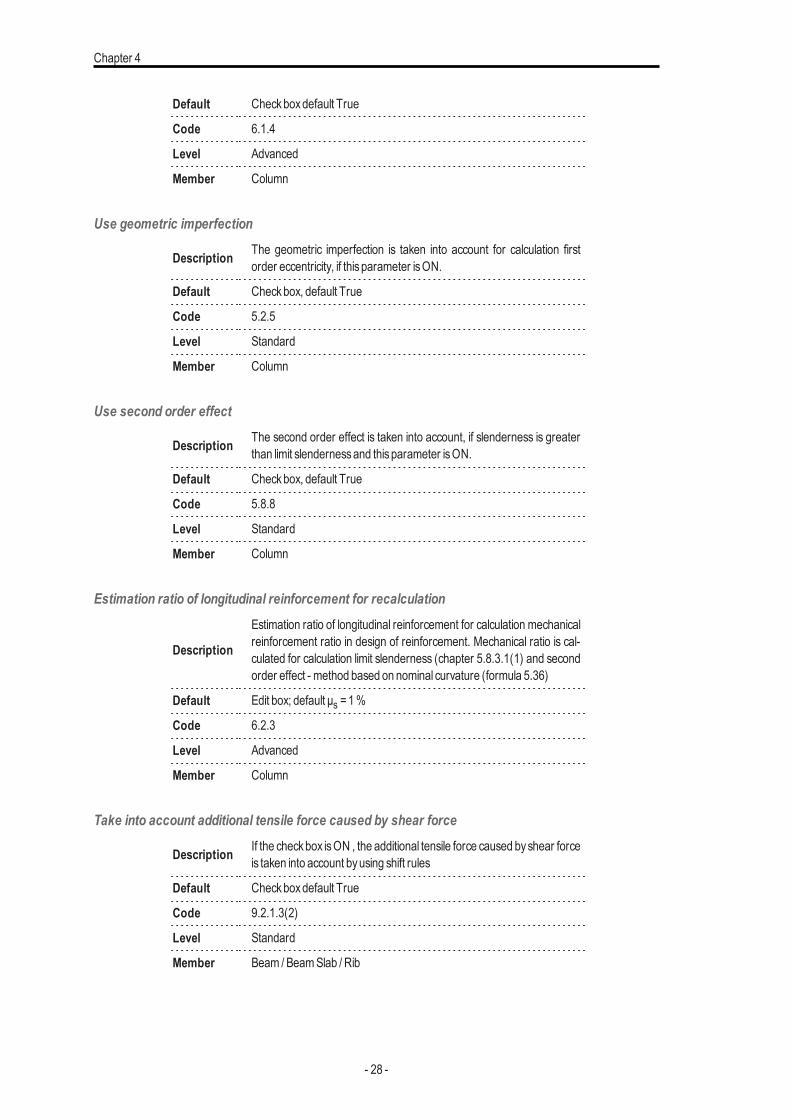
Default Checkboxdefault True
Code 6.1.4
Level Advanced
Member Column
Use geometric imperfection
Description The geometric imperfection is taken into account for calculation firstorder eccentricity, if thisparameter isON.
Default Checkbox, default True
Code 5.2.5
Level Standard
Member Column
Use second order effect
Description The second order effect is taken into account, if slenderness is greaterthan limit slendernessand thisparameter isON.
Default Checkbox, default True
Code 5.8.8
Level Standard
Member Column
Estimation ratio of longitudinal reinforcement for recalculation
Description
Estimation ratio of longitudinal reinforcement for calculation mechanicalreinforcement ratio in design of reinforcement. Mechanical ratio is cal-culated for calculation limit slenderness (chapter 5.8.3.1(1) and secondorder effect - method based on nominal curvature (formula 5.36)
Default Edit box; default μs =1%
Code 6.2.3
Level Advanced
Member Column
Take into account additional tensile force caused by shear force
Description If the checkbox isON , the additional tensile force caused byshear forceis taken into account byusing shift rules
Default Checkboxdefault True
Code 9.2.1.3(2)
Level Standard
Member Beam / BeamSlab / Rib
- 28 -

Concretemember data
Design AsDesign method (beams)
Description Method for design of longitudinal reinforcement for beams and beamsslab
Default Combo box; Auto / Uniaxial around y / Uniaxial around z / Biaxial;Default Auto
Code -
Level Advanced
Member Beam / BeamSlab / Rib
Design method (columns)Description Method for design of longitudinal reinforcement for columns
Default Combo box; Auto / Uniaxial around y / Uniaxial around z / Biaxial;Default Auto
Code -
Level Advanced
Member Column
Interaction diagramInteraction diagram method
Description
Possibility to set method for evaluation of results using interaction dia-gram:
- NRd - assumingMEd is constant
- MRd - assumingNEd is constant
- NRdMrd - - assuming eccentricity is constant
- Mrdy - assumingMEdz is constant
- Mrdz - - assumingMEdy is constant
Default Combo boxNRd /MRd / NRdMrd /Mrdy /Mrdz, default NRdMRd
Code 6.1
Level Standard
Member 1Dmember (Beam /Column / BeamSlab / Rib)
ShearType calculation / input of angle of compression strut
DescriptionType calculation of angle of between of compression strut and memberaxis for shear check
- Auto: automatic calculation ofminimumangle based on condition
- 29 -
Chapter 4
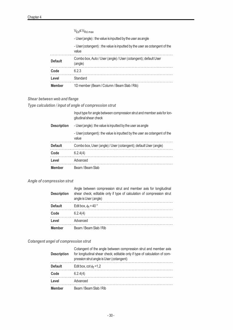
VEd≤VRd.max
- User(angle) : the value is inputted by the user asangle
- User(cotangent) : the value is inputted by the user as cotangent of thevalue
Default Combo box, Auto / User (angle) / User (cotangent); default User(angle)
Code 6.2.3
Level Standard
Member 1Dmember (Beam /Column / BeamSlab / Rib)
Shear between web and flangeType calculation / input of angle of compression strut
Description
Input type for angle between compression strut andmember axis for lon-gitudinal shear check
- User(angle): the value is inputted by the user asangle
- User(cotangent): the value is inputted by the user as cotangent of thevalue
Default Combo box, User (angle) / User (cotangent); default User (angle)
Code 6.2.4(4)
Level Advanced
Member Beam / BeamSlab
Angle of compression strut
DescriptionAngle between compression strut and member axis for longitudinalshear check; editable only if type of calculation of compression strutangle isUser (angle)
Default Edit box,ϕf =40 °
Code 6.2.4(4)
Level Advanced
Member Beam / BeamSlab / Rib
Cotangent angel of compression strut
DescriptionCotangent of the angle between compression strut and member axisfor longitudinal shear check; editable only if type of calculation of com-pression strut angle isUser (cotangent)
Default Edit box, cotϕf =1,2
Code 6.2.4(4)
Level Advanced
Member Beam / BeamSlab / Rib
- 30 -
Concretemember data
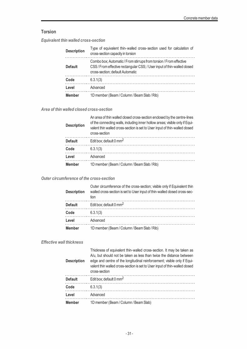
TorsionEquivalent thin walled cross-section
Description Type of equivalent thin- walled cross- section used for calculation ofcross-section capacity in torsion
DefaultCombo box; Automatic / From stirrups from torsion / FromeffectiveCSS / Fromeffective rectangular CSS; / User input of thin-walled closedcross-section; default Automatic
Code 6.3.1(3)
Level Advanced
Member 1Dmember (Beam /Column / BeamSlab / Rib)
Area of thin walled closed cross-section
Description
An area of thin walled closed cross-section enclosed by the centre-linesof the connecting walls, including inner hollow areas; visible only if Equi-valent thin walled cross-section is set to User input of thin-walled closedcross-section
Default Edit box; default 0mm2
Code 6.3.1(3)
Level Advanced
Member 1Dmember (Beam /Column / BeamSlab / Rib)
Outer circumference of the cross-section
DescriptionOuter circumference of the cross-section; visible only if Equivalent thinwalled cross-section is set to User input of thin-walled closed cross-sec-tion
Default Edit box; default 0mm2
Code 6.3.1(3)
Level Advanced
Member 1Dmember (Beam /Column / BeamSlab / Rib)
Effective wall thickness
Description
Thickness of equivalent thin-walled cross-section. It may be taken asA/u, but should not be taken as less than twice the distance betweenedge and centre of the longitudinal reinforcement; visible only if Equi-valent thin walled cross-section is set to User input of thin-walled closedcross-section
Default Edit box; default 0mm2
Code 6.3.1(3)
Level Advanced
Member 1Dmember (Beam /Column / BeamSlab)
- 31 -
Chapter 4
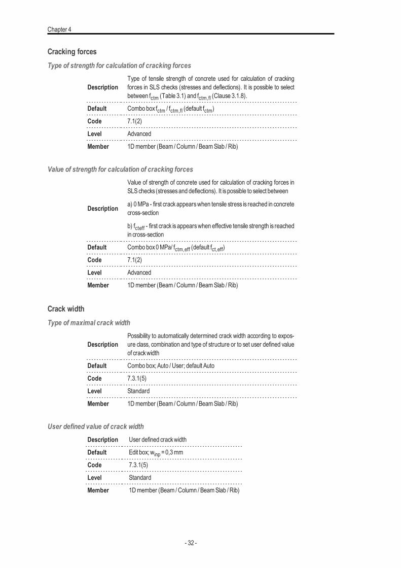
Cracking forcesType of strength for calculation of cracking forces
DescriptionType of tensile strength of concrete used for calculation of crackingforces in SLS checks (stresses and deflections). It is possible to selectbetween fctm (Table 3.1) and fctm,fl (Clause 3.1.8).
Default Combo box fctm / fctm,fl (default fctm)
Code 7.1(2)
Level Advanced
Member 1Dmember (Beam /Column / BeamSlab / Rib)
Value of strength for calculation of cracking forces
Description
Value of strength of concrete used for calculation of cracking forces inSLSchecks (stressesand deflections). It is possible to select between
a) 0MPa - first crackappearswhen tensile stress is reached in concretecross-section
b) fcteff - first crack is appearswhen effective tensile strength is reachedin cross-section
Default Combo box0MPa/ fctm,eff (default fct,eff)
Code 7.1(2)
Level Advanced
Member 1Dmember (Beam /Column / BeamSlab / Rib)
Crack widthType of maximal crack width
DescriptionPossibility to automatically determined crack width according to expos-ure class, combination and type of structure or to set user defined valueof crackwidth
Default Combo box; Auto / User; default Auto
Code 7.3.1(5)
Level Standard
Member 1Dmember (Beam /Column / BeamSlab / Rib)
User defined value of crack widthDescription User defined crackwidth
Default Edit box; winp =0,3mm
Code 7.3.1(5)
Level Standard
Member 1Dmember (Beam /Column / BeamSlab / Rib)
- 32 -
Concretemember data
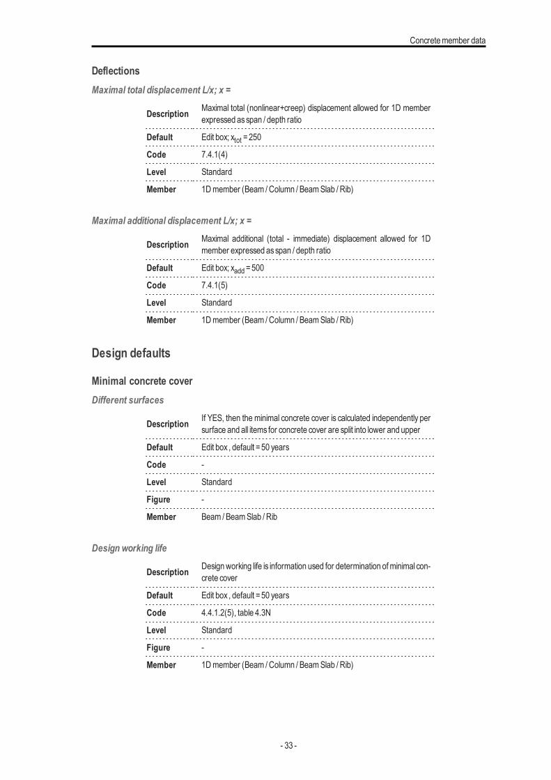
DeflectionsMaximal total displacement L/x; x =
Description Maximal total (nonlinear+creep) displacement allowed for 1D memberexpressed asspan / depth ratio
Default Edit box; xtot =250
Code 7.4.1(4)
Level Standard
Member 1Dmember (Beam /Column / BeamSlab / Rib)
Maximal additional displacement L/x; x =
Description Maximal additional (total - immediate) displacement allowed for 1Dmember expressed asspan / depth ratio
Default Edit box; xadd =500
Code 7.4.1(5)
Level Standard
Member 1Dmember (Beam /Column / BeamSlab / Rib)
Design defaults
Minimal concrete coverDifferent surfaces
Description If YES, then the minimal concrete cover is calculated independently persurface and all items for concrete cover are split into lower and upper
Default Edit box , default =50 years
Code -
Level Standard
Figure -
Member Beam / BeamSlab / Rib
Design working life
Description Designworking life is information used for determination ofminimal con-crete cover
Default Edit box , default =50 years
Code 4.4.1.2(5), table 4.3N
Level Standard
Figure -
Member 1Dmember (Beam /Column / BeamSlab / Rib)
- 33 -
Chapter 4
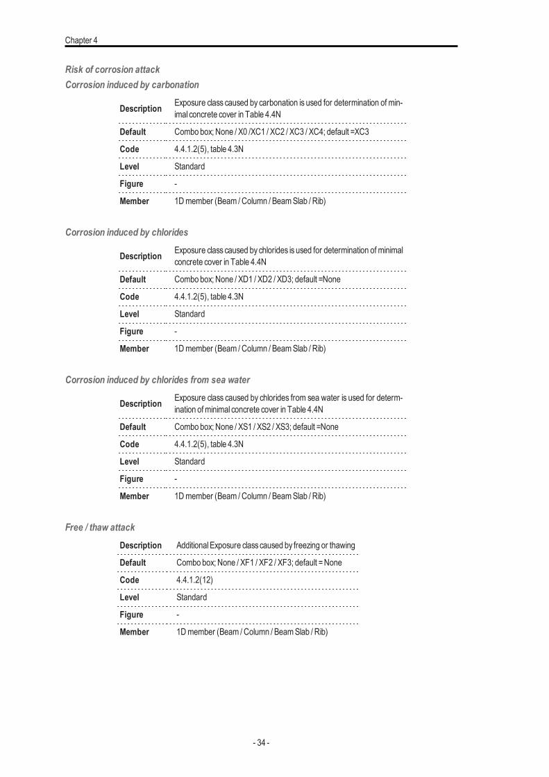
Risk of corrosion attackCorrosion induced by carbonation
Description Exposure class caused by carbonation is used for determination of min-imal concrete cover in Table 4.4N
Default Combo box; None / X0 /XC1 / XC2 / XC3 / XC4; default =XC3
Code 4.4.1.2(5), table 4.3N
Level Standard
Figure -
Member 1Dmember (Beam /Column / BeamSlab / Rib)
Corrosion induced by chlorides
Description Exposure class caused by chlorides is used for determination of minimalconcrete cover in Table 4.4N
Default Combo box; None / XD1 / XD2 / XD3; default =None
Code 4.4.1.2(5), table 4.3N
Level Standard
Figure -
Member 1Dmember (Beam /Column / BeamSlab / Rib)
Corrosion induced by chlorides from sea water
Description Exposure class caused by chlorides from sea water is used for determ-ination ofminimal concrete cover in Table 4.4N
Default Combo box; None / XS1 / XS2 / XS3; default =None
Code 4.4.1.2(5), table 4.3N
Level Standard
Figure -
Member 1Dmember (Beam /Column / BeamSlab / Rib)
Free / thaw attackDescription AdditionalExposure classcaused by freezing or thawing
Default Combo box; None / XF1 / XF2 / XF3; default =None
Code 4.4.1.2(12)
Level Standard
Figure -
Member 1Dmember (Beam /Column / BeamSlab / Rib)
- 34 -
Concretemember data
Chemical attackDescription AdditionalExposure classcaused bychemical attack
Default Combo box; None / XA1 / XA2 / XA3; default =None
Code 4.4.1.2(12)
Level Standard
Figure -
Member 1Dmember (Beam /Column / BeamSlab / Rib)
Risk of abrasion attackDescription AdditionalExposure classcaused byabrasion attack
Default Combo box; None / XM1 / XM2 / XM3; default =None
Code 4.4.1.2(13)
Level Advanced
Figure -
Member 1Dmember (Beam /Column / BeamSlab / Rib)
Possibility of special controlSpecial geometric control
Description To take into account additional deviation to nominal concrete covercaused byspecial geometric control
Default Checkbox; default =True
Code 4.4.1.3(3)
Level Advanced
Figure -
Member 1Dmember (Beam /Column / BeamSlab / Rib)
Special quality control
Description To take into account additional deviation to nominal concrete covercaused byspecial concrete quality control
Default Checkbox; default =True
Code 4.4.1.2(5)
Level Advanced
Figure -
Member 1Dmember (Beam /Column / BeamSlab / Rib)
Risk of casting on atypical surface
Description To take into account additional deviation to nominal concrete cover
- 35 -
Chapter 4
caused bycasting on atypical surface
Default Combo box; Standard / Against prepared ground / Again soil / Unevensurface default =Standard
Code 4.4.1.3(4)
Level Advanced
Figure -
Member 1Dmember (Beam /Column / BeamSlab / Rib)
Concrete characteristicType of concrete
Description To take into account additional deviation to nominal concrete covercaused byproduction type
Default Combo box; In-situ / Prefabricated ; default = In-situ
Code 4.4.1.3(1P, 3)
Level Advanced
Figure -
Member 1Dmember (Beam /Column / BeamSlab / Rib)
Beam
LongitudinalMaterial
Description Information aboutmaterial of longitudinal reinforcement
Default Link to library; default taken from setting in Project data
Code -
Level Standard
Figure -
Member Beam /Rib
UpperDiameter of upper reinforcement
Description Information about diameter of upper of reinforcement
Default Edit box; default ds,u =16mm
Code -
Level Standard
Figure -
Member Beam /Rib
- 36 -
Concretemember data
Type of cover of upper reinforcementDescription Information about type of cover of upper reinforcement
Default Combo box; Auto / User; default =Auto
Code 4.4.1
Level Standard
Figure -
Member Beam /Rib
User defined concrete cover of upper reinforcement
Description Possibility to define concrete cover of upper reinforcement; thisitem isvisible only if the itemabove isset to User
Default Edit box; cu =30mm
Code 4.4.1
Level Standard
Figure -
Member Beam /Rib
LowerDiameter of lower reinforcement
Description Information about diameter of lower of reinforcement
Default Edit box; default ds,l =16mm
Code -
Level Standard
Figure -
Member Beam /Rib
Type of cover of lower reinforcementDescription Information about type of cover of lower reinforcement
Default Combo box; Auto / User; default =Auto
Code 4.4.1
Level Standard
Figure -
Member Beam /Rib
User defined concrete cover of lower reinforcement
Description Possibility to define concrete cover of lower reinforcement; this item isvisible only if the itemabove isset to User
- 37 -
Chapter 4
Default Edit box; cl =30mm
Code 4.4.1
Level Standard
Figure -
Member Beam /Rib
SideType of cover of side reinforcement
Description Information about type of cover of side reinforcement
Default Combo box; Auto / User; default =Auto
Code 4.4.1
Level Standard
Figure -
Member Beam /Rib
User defined concrete cover of side reinforcement
Description Possibility to define concrete cover of side reinforcement; this item is vis-ible only if the itemabove isset to User
Default Edit box; cs =30mm
Code 4.4.1
Level Standard
Figure -
Member Beam /Rib
StirrupsMaterial
Description Information aboutmaterial of stirrups reinforcement
Default Link to library; default taken from setting in Project data
Code -
Level Standard
Figure -
Member Beam /Rib
Diameter of stirrupsDescription Information about diameter of stirrups
Default Edit box; dss =8mm
- 38 -
Concretemember data
Code -
Level Standard
Figure -
Member Beam /Rib
Number of cutsDescription Information about number of cuts for shear reinforcement
Default Edit box; ns =2
Code -
Level Standard
Figure -
Member Beam /Rib
Angle
Description Angle between shear reinforcement and the beam axis perpendicularto the shear force
Default Edit box; α =90 °
Code -
Level Standard
Figure -
Member Beam /Rib
Beam slab
LongitudinalMaterial
Description Information aboutmaterial of longitudinal reinforcement
Default Link to library; default taken from setting in Project data
Code -
Level Standard
Figure -
Member Beamslab
UpperDiameter of upper reinforcement
Description Information about diameter of upper of reinforcement
Default Edit box; default ds,u =16mm
- 39 -
Chapter 4
Code -
Level Standard
Figure -
Member Beamslab
Type of cover of upper reinforcementDescription Information about type of cover of upper reinforcement
Default Combo box; Auto / User; default =Auto
Code 4.4.1
Level Standard
Figure -
Member Beamslab
User defined concrete cover of upper reinforcement
Description Possibility to define concrete cover of upper reinforcement; this item isvisible only if the itemabove isset to User
Default Edit box; cu =30mm
Code 4.4.1
Level Standard
Figure -
Member Beamslab
LowerDiameter of lower reinforcement
Description Information about diameter of lower of reinforcement
Default Edit box; default ds,l =16mm
Code -
Level Standard
Figure -
Member Beamslab
Type of cover of lower reinforcementDescription Information about type of cover of lower reinforcement
Default Combo box; Auto / User; default =Auto
Code 4.4.1
Level Standard
Figure -
Member Beamslab
- 40 -
Concretemember data
User defined concrete cover of lower reinforcement
Description Possibility to define concrete cover of lower reinforcement; this item isvisible only if the itemabove isset to User
Default Edit box; cl =30mm
Code 4.4.1
Level Standard
Figure -
Member Beamslab
Column
LongitudinalMaterial
Description Information aboutmaterial of main reinforcement
Default Link to library; default taken from setting in Project data
Code -
Level Standard
Figure -
Member Column
MainDiameter of main reinforcement
Description Information about diameter ofmain of reinforcement
Default Edit box; default ds,m =16mm
Code -
Level Standard
Figure
Member Column
Type of cover of main reinforcementDescription Information about type of cover ofmain reinforcement
Default Combo box; Auto / User; default =Auto
Code 4.4.1
Level Standard
Figure -
Member Column
- 41 -
Chapter 4
User defined concrete cover of main reinforcement
Description Possibility to define concrete cover ofmain reinforcement; this item isvis-ible only if the itemabove isset to User
Default Edit box; cm =30mm
Code 4.4.1
Level Standard
Figure -
Member Column
StirrupsMaterial
Description Information aboutmaterial of stirrups reinforcement
Default Link to library; default taken from setting in Project data
Code -
Level Standard
Figure -
Member Beam /Column
Diameter of stirrupsDescription Information about diameter of stirrups
Default Edit box; dss =8mm
Code -
Level Standard
Figure -
Member Beam /Column
Number of cutsDescription Information about number of cuts for shear reinforcement
Default Edit box; ns =2
Code -
Level Standard
Figure -
Member Beam /Column / Rib
Angle
Description Angle between shear reinforcement and the beam axis perpendicularto the shear force
- 42 -
Concretemember data
Default Edit box; α =90 °
Code -
Level Standard
Figure -
Member Beam /Column / Rib
Basic (user defined) stirrupThis group of items is related to user defined shear reinforcement which is considered as real inputted reinforcement onmember. This replaces user defined shear reinforcement which is not taken into account for design. Check shear and tor-sion isnot influenced by this settings.
MaterialDescription Information aboutmaterial of inputted stirrups reinforcement
Default Link to library; default taken from setting in Project data
Code -
Level Advanced
Figure -
Member Beam /Column / Rib
Angle
Description Angle between shear reinforcement and the beam axis perpendicularto the shear force
Default Edit box; α =90 °
Code -
Level Advanced
Figure -
Member Beam /Column / Rib
Area of shear reinforcement per meter
Description Information about defined shear reinforcement taken into account asreal reinforcement for shear design
Default 0mm2
Code -
Level Advanced
Figure -
Member Beam /Column / Rib
- 43 -
Chapter 5
Concrete settings (structure)
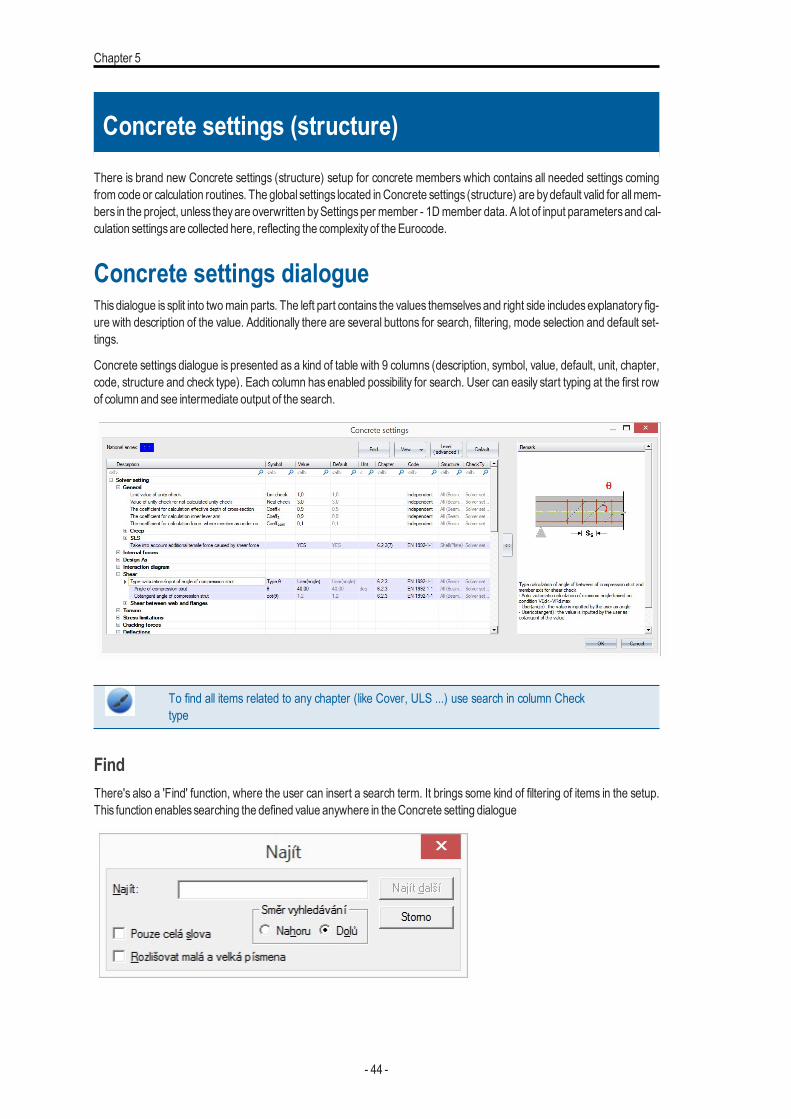
There is brand new Concrete settings (structure) setup for concrete members which contains all needed settings comingfrom code or calculation routines. The global settings located inConcrete settings (structure) are bydefault valid for allmem-bers in the project, unless theyare overwritten bySettingsper member - 1Dmember data. A lot of input parametersand cal-culation settingsare collected here, reflecting the complexityof the Eurocode.
Concrete settings dialogueThis dialogue is split into twomain parts. The left part contains the values themselvesand right side includesexplanatory fig-ure with description of the value. Additionally there are several buttons for search, filtering, mode selection and default set-tings.
Concrete settings dialogue is presented as a kind of table with 9 columns (description, symbol, value, default, unit, chapter,code, structure and check type). Each column has enabled possibility for search. User can easily start typing at the first rowof column and see intermediate output of the search.
To find all items related to any chapter (like Cover, ULS ...) use search in column Checktype
FindThere's also a 'Find' function, where the user can insert a search term. It brings some kind of filtering of items in the setup.This function enablessearching the defined value anywhere in theConcrete setting dialogue
- 44 -
Concrete settings (structure)
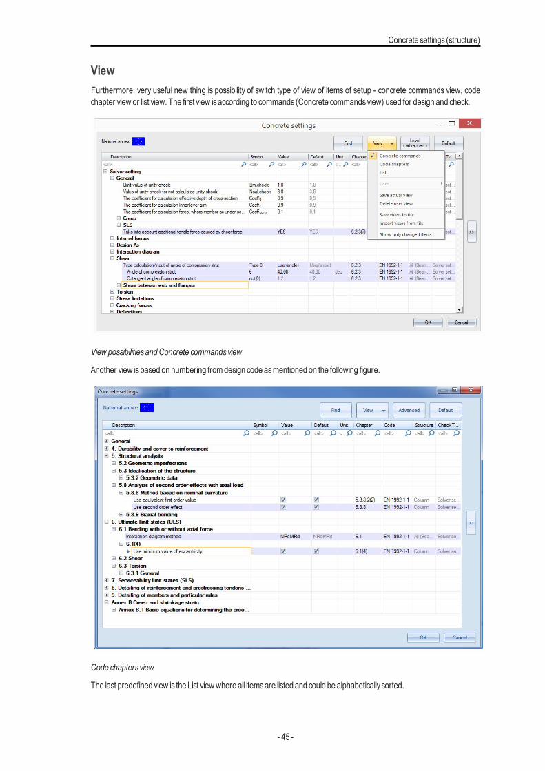
ViewFurthermore, very useful new thing is possibility of switch type of view of items of setup - concrete commands view, codechapter view or list view. The first view isaccording to commands (Concrete commandsview) used for design and check.
View possibilitiesandConcrete commandsview
Another view isbased on numbering fromdesign code asmentioned on the following figure.
Code chaptersview
The last predefined view is the List viewwhere all itemsare listed and could be alphabetically sorted.
- 45 -
Chapter 5
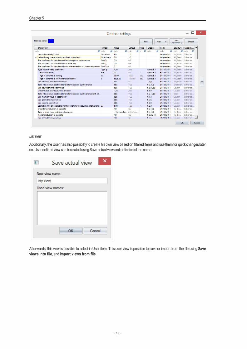
List view
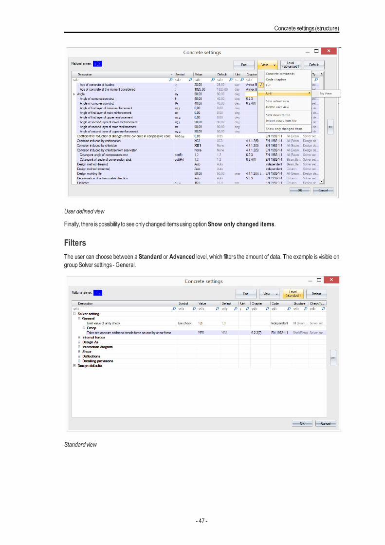
Additionally, the User hasalso possibility to create his own view based on filtered itemsand use them for quick changes lateron. User defined view can be crated usingSave actual view and definition of the name.
Afterwards, this view is possible to select in User item. This user view is possible to save or import from the file using Saveviews into file, and Import views from file.
- 46 -
Concrete settings (structure)
User defined view
Finally, there ispossibility to see onlychanged itemsusing optionShow only changed items.
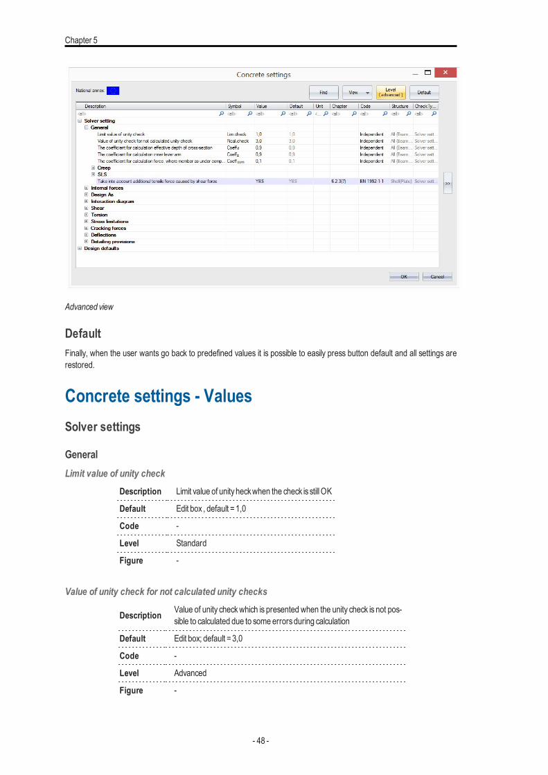
FiltersThe user can choose between a Standard or Advanced level, which filters the amount of data. The example is visible ongroupSolver settings - General.
Standard view
- 47 -
Chapter 5
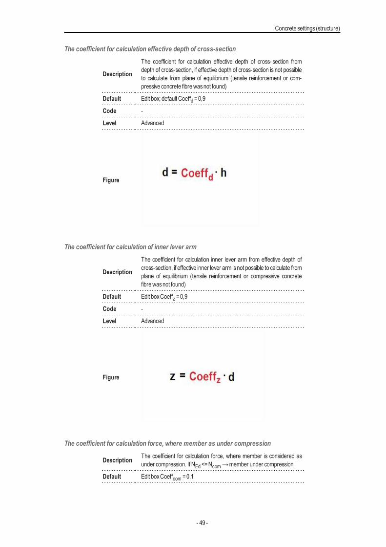
Advanced view
DefaultFinally, when the user wants go back to predefined values it is possible to easily press button default and all settings arerestored.
Concrete settings - ValuesSolver settings
GeneralLimit value of unity check
Description Limit value of unityheckwhen the check is stillOK
Default Edit box , default =1,0
Code -
Level Standard
Figure -
Value of unity check for not calculated unity checks
Description Value of unity checkwhich is presented when the unity check is not pos-sible to calculated due to some errorsduring calculation
Default Edit box; default =3,0
Code -
Level Advanced
Figure -
- 48 -
Concrete settings (structure)
The coefficient for calculation effective depth of cross-section
Description
The coefficient for calculation effective depth of cross- section fromdepth of cross-section, if effective depth of cross-section is not possibleto calculate from plane of equilibrium (tensile reinforcement or com-pressive concrete fibrewasnot found)
Default Edit box; default Coeffd =0,9
Code -
Level Advanced
Figure
The coefficient for calculation of inner lever arm
Description
The coefficient for calculation inner lever arm from effective depth ofcross-section, if effective inner lever arm isnot possible to calculate fromplane of equilibrium (tensile reinforcement or compressive concretefibrewasnot found)
Default Edit boxCoeffz =0,9
Code -
Level Advanced
Figure
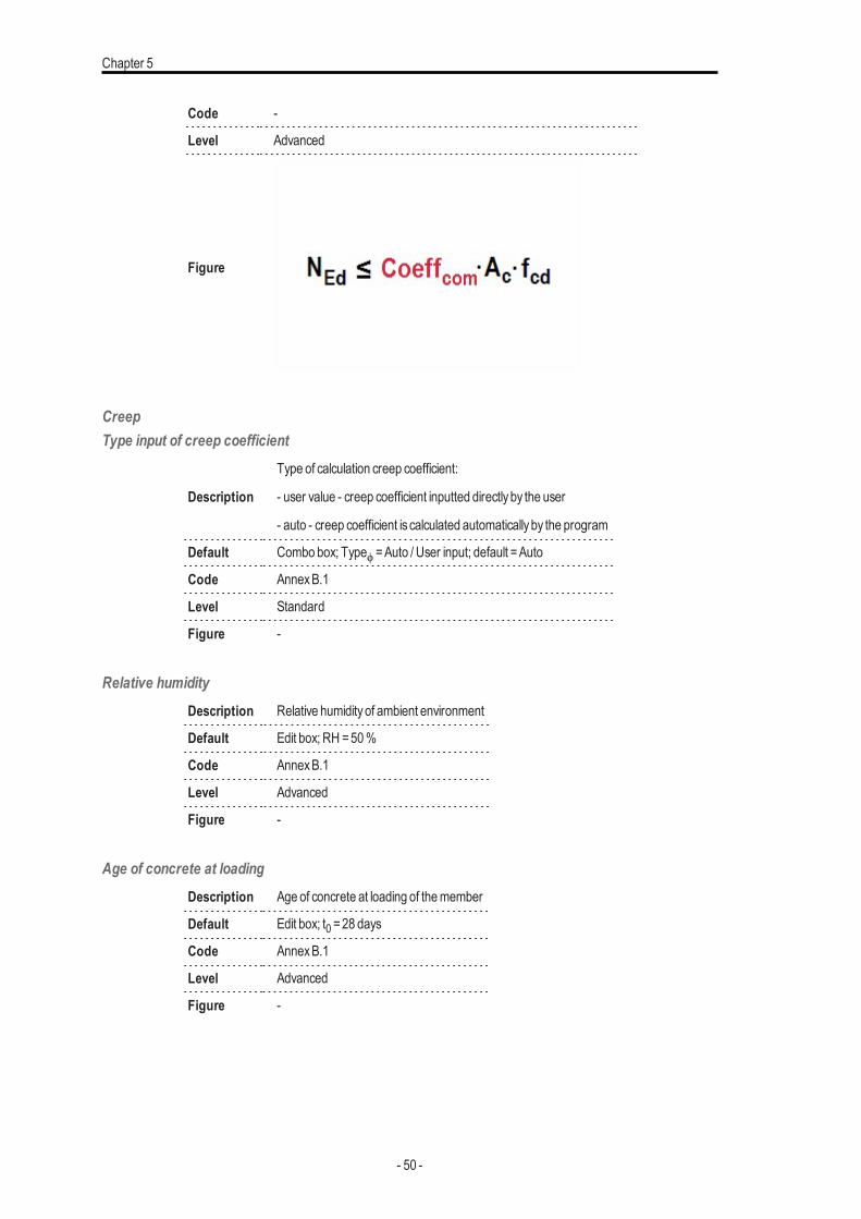
The coefficient for calculation force, where member as under compression
Description The coefficient for calculation force, where member is considered asunder compression. If NEd <=Ncom→member under compression
Default Edit boxCoeffcom =0,1
- 49 -
Chapter 5
Code -
Level Advanced
Figure
CreepType input of creep coefficient
Description
Type of calculation creep coefficient:
- user value - creep coefficient inputted directlyby the user
- auto - creep coefficient is calculated automaticallyby the program
Default Combo box; Typeϕ =Auto / User input; default =Auto
Code AnnexB.1
Level Standard
Figure -
Relative humidityDescription Relative humidityof ambient environment
Default Edit box; RH =50%
Code AnnexB.1
Level Advanced
Figure -
Age of concrete at loadingDescription Age of concrete at loading of themember
Default Edit box; t0 =28 days
Code AnnexB.1
Level Advanced
Figure -
- 50 -
Concrete settings (structure)
Age of concrete at the moment considered
Description Age of concrete at the moment considered. It means, time, which creepcoefficient is calculated for.
Default Edit box; t =1825 days
Code AnnexB.1
Level Advanced
Figure -
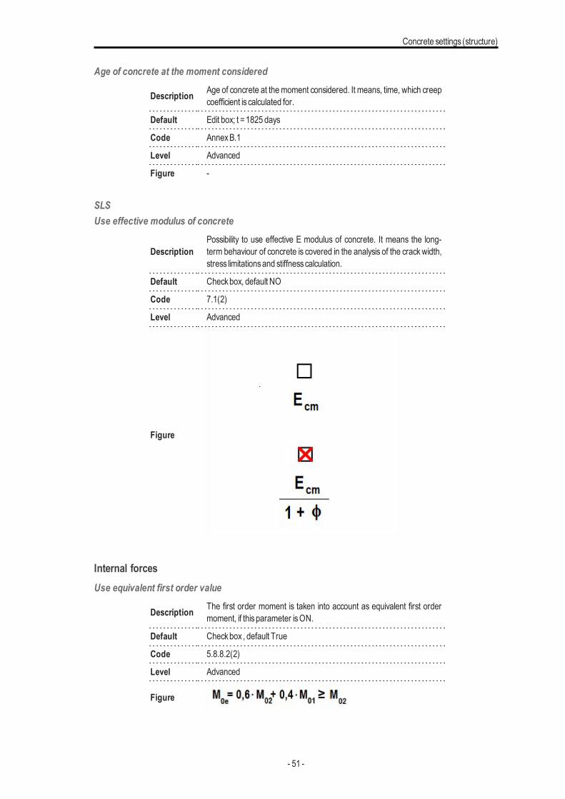
SLSUse effective modulus of concrete
DescriptionPossibility to use effective E modulus of concrete. It means the long-term behaviour of concrete is covered in the analysis of the crackwidth,stress limitationsand stiffnesscalculation.
Default Checkbox, default NO
Code 7.1(2)
Level Advanced
Figure
Internal forcesUse equivalent first order value
Description The first order moment is taken into account as equivalent first ordermoment, if thisparameter isON.
Default Checkbox , default True
Code 5.8.8.2(2)
Level Advanced
Figure
- 51 -
Chapter 5
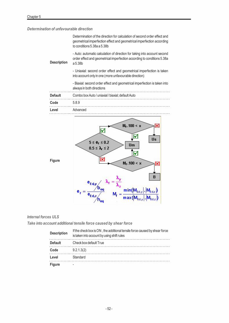
Determination of unfavourable direction
Description
Determination of the direction for calculation of second order effect andgeometrical imperfection effect and geometrical imperfection accordingto conditions5.38a a 5.38b
- Auto: automatic calculation of direction for taking into account secondorder effect and geometrical imperfection according to conditions 5.38aa 5.38b
- Uniaxial: second order effect and geometrical imperfection is takeninto account only in one (more unfavourable direction)
- Biaxial: second order effect and geometrical imperfection is taken intoalways in both directions
Default Combo boxAuto / uniaxial / biaxial; default Auto
Code 5.8.9
Level Advanced
Figure
Internal forces ULSTake into account additional tensile force caused by shear force
Description If the checkbox isON , the additional tensile force caused byshear forceis taken into account byusing shift rules
Default Checkboxdefault True
Code 9.2.1.3(2)
Level Standard
Figure -
- 52 -
Concrete settings (structure)
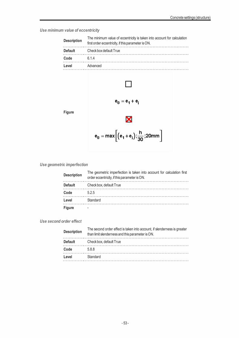
Use minimum value of eccentricity
Description The minimum value of eccentricity is taken into account for calculationfirst order eccentricity, if thisparameter isON.
Default Checkboxdefault True
Code 6.1.4
Level Advanced
Figure
Use geometric imperfection
Description The geometric imperfection is taken into account for calculation firstorder eccentricity, if thisparameter isON.
Default Checkbox, default True
Code 5.2.5
Level Standard
Figure -
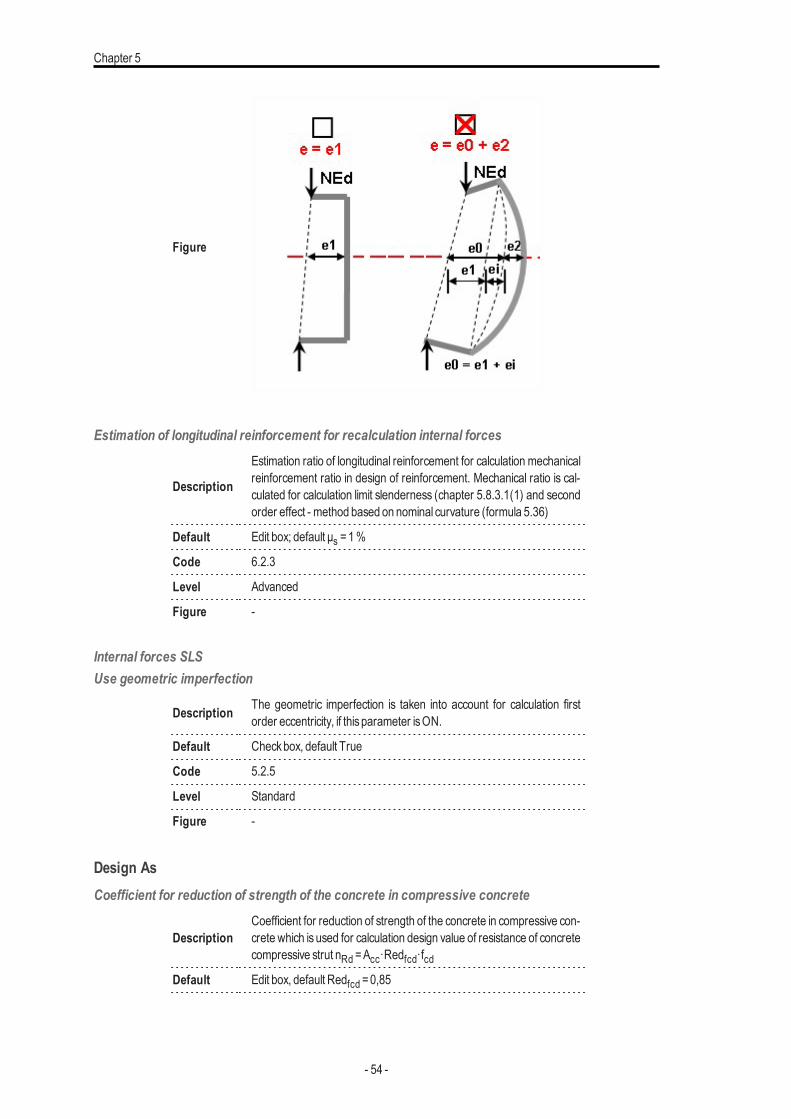
Use second order effect
Description The second order effect is taken into account, if slenderness is greaterthan limit slendernessand thisparameter isON.
Default Checkbox, default True
Code 5.8.8
Level Standard
- 53 -
Chapter 5
Figure
Estimation of longitudinal reinforcement for recalculation internal forces
Description
Estimation ratio of longitudinal reinforcement for calculation mechanicalreinforcement ratio in design of reinforcement. Mechanical ratio is cal-culated for calculation limit slenderness (chapter 5.8.3.1(1) and secondorder effect - method based on nominal curvature (formula 5.36)
Default Edit box; default μs =1%
Code 6.2.3
Level Advanced
Figure -
Internal forces SLSUse geometric imperfection
Description The geometric imperfection is taken into account for calculation firstorder eccentricity, if thisparameter isON.
Default Checkbox, default True
Code 5.2.5
Level Standard
Figure -
Design AsCoefficient for reduction of strength of the concrete in compressive concrete
DescriptionCoefficient for reduction of strength of the concrete in compressive con-crete which is used for calculation design value of resistance of concretecompressive strut nRd =Acc·Redfcd·fcd
Default Edit box, default Redfcd =0,85
- 54 -
Concrete settings (structure)
Code -
Level Advanced
Figure -
Limit ratio of bending moment for uni axial method
Description
Limit ratio of bending moments for using uniaxial design method. If ratioof bending moments is lesser than limit ratio, uniaxial design method isused and smaller value of bending moment and shear force is neg-lected.
Ratiouni =min ( MEdy/ MEdz) / max ( MEdy/ MEdz)
Default Edit box, Ratio lim =0,1
Code -
Level Standard
Figure -
Design method (beams)
Description Method for design of longitudinal reinforcement for beams and beamsslab
Default Combo box; Auto / Uniaxial around y / Uniaxial around z / Biaxial;Default Auto
Code -
Level Advanced
Figure -
Design method (columns)Description Method for design of longitudinal reinforcement for columns
Default Combo box; Auto / Uniaxial around y / Uniaxial around z / Biaxial;Default Auto
Code -
Level Advanced
Figure -
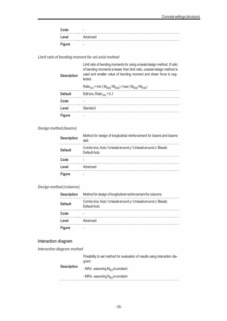
Interaction diagramInteraction diagram method
Description
Possibility to set method for evaluation of results using interaction dia-gram:
- NRd - assumingMEd is constant
- MRd - assumingNEd is constant
- 55 -
Chapter 5
- NRdMrd - - assuming eccentricity is constant
- Mrdy - assumingMEdz is constant
- Mrdz - - assumingMEdy is constant
Default ComboboxNRd /MRd / NRdMrd /Mrdy /Mrdz, default NRdMRd
Code 6.1
Level Standard
Figure
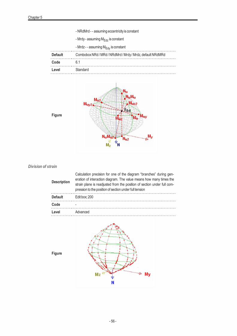
Division of strain
Description
Calculation precision for one of the diagram “branches” during gen-eration of interaction diagram. The value means how many times thestrain plane is readjusted from the position of section under full com-pression to the position of section under full tension
Default Edit box; 200
Code -
Level Advanced
Figure
- 56 -
Concrete settings (structure)
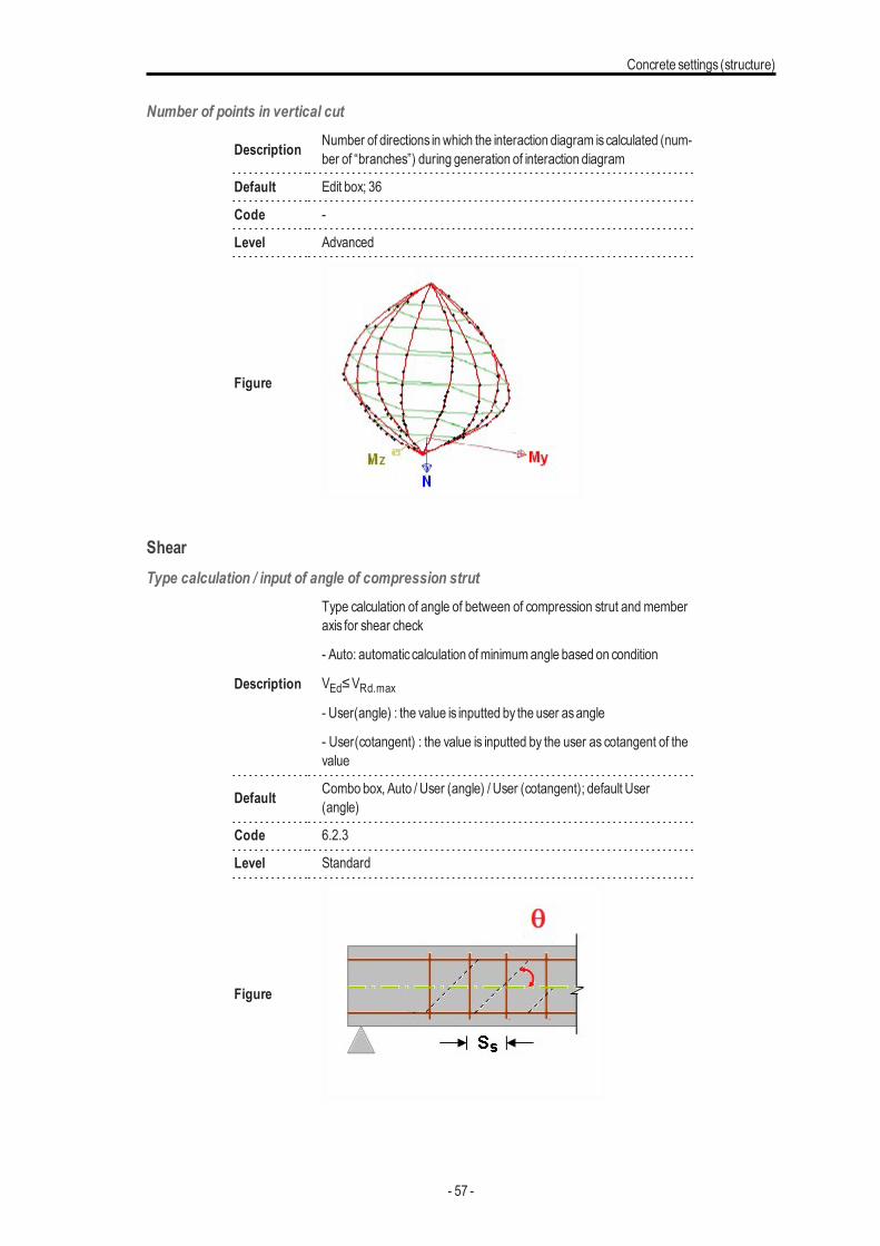
Number of points in vertical cut
Description Number of directions inwhich the interaction diagram iscalculated (num-ber of “branches”) during generation of interaction diagram
Default Edit box; 36
Code -
Level Advanced
Figure
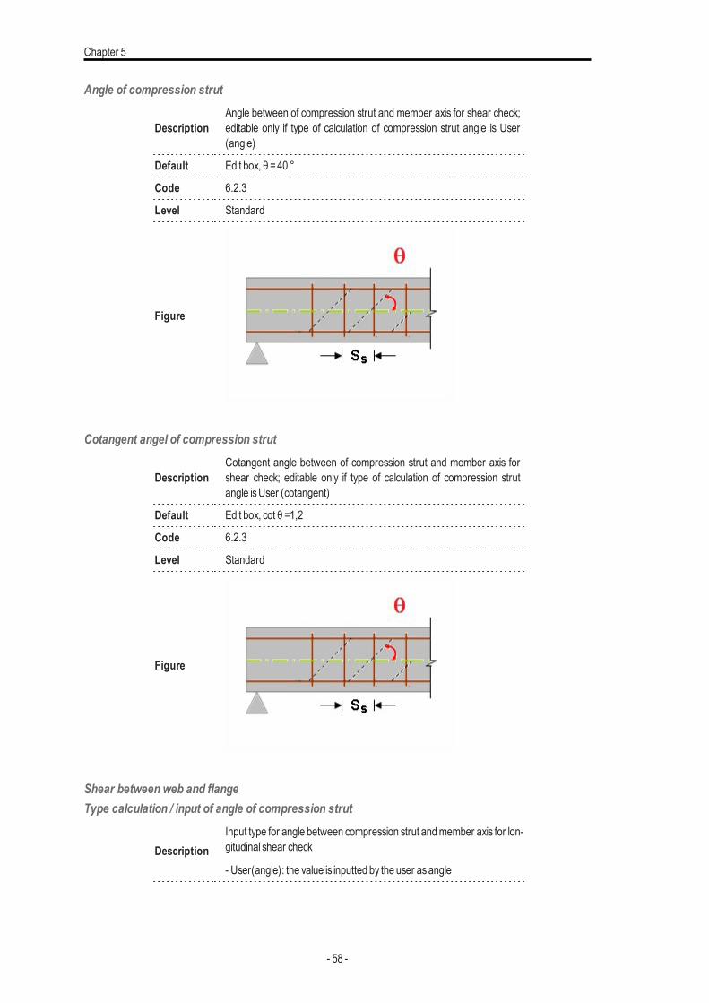
ShearType calculation / input of angle of compression strut
Description
Type calculation of angle of between of compression strut and memberaxis for shear check
- Auto: automatic calculation ofminimumangle based on condition
VEd≤VRd.max
- User(angle) : the value is inputted by the user asangle
- User(cotangent) : the value is inputted by the user as cotangent of thevalue
Default Combo box, Auto / User (angle) / User (cotangent); default User(angle)
Code 6.2.3
Level Standard
Figure
- 57 -
Chapter 5
Angle of compression strut
DescriptionAngle between of compression strut and member axis for shear check;editable only if type of calculation of compression strut angle is User(angle)
Default Edit box, θ =40 °
Code 6.2.3
Level Standard
Figure
Cotangent angel of compression strut
DescriptionCotangent angle between of compression strut and member axis forshear check; editable only if type of calculation of compression strutangle isUser (cotangent)
Default Edit box, cot θ =1,2
Code 6.2.3
Level Standard
Figure
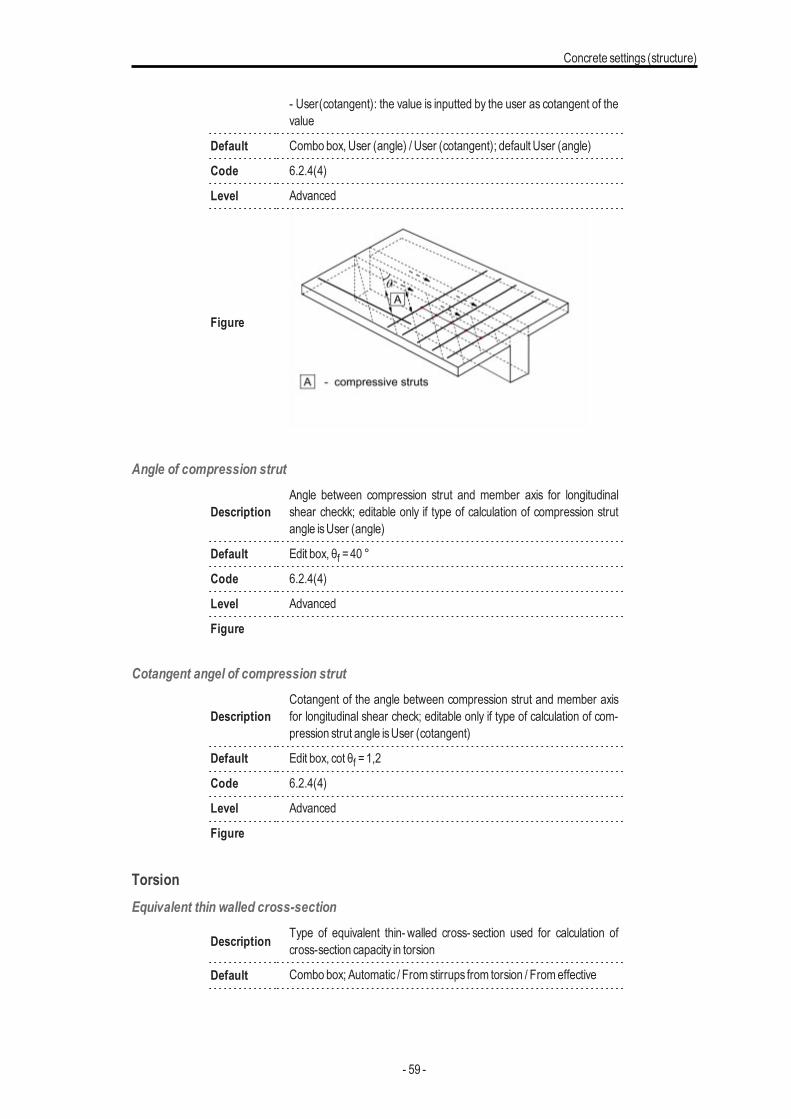
Shear between web and flangeType calculation / input of angle of compression strut
DescriptionInput type for angle between compression strut andmember axis for lon-gitudinal shear check
- User(angle): the value is inputted by the user asangle
- 58 -
Concrete settings (structure)
- User(cotangent): the value is inputted by the user as cotangent of thevalue
Default Combo box, User (angle) / User (cotangent); default User (angle)
Code 6.2.4(4)
Level Advanced
Figure
Angle of compression strut
DescriptionAngle between compression strut and member axis for longitudinalshear checkk; editable only if type of calculation of compression strutangle isUser (angle)
Default Edit box, θf =40 °
Code 6.2.4(4)
Level Advanced
Figure
Cotangent angel of compression strut
DescriptionCotangent of the angle between compression strut and member axisfor longitudinal shear check; editable only if type of calculation of com-pression strut angle isUser (cotangent)
Default Edit box, cot θf =1,2
Code 6.2.4(4)
Level Advanced
Figure
TorsionEquivalent thin walled cross-section
Description Type of equivalent thin- walled cross- section used for calculation ofcross-section capacity in torsion
Default Combo box; Automatic / From stirrups from torsion / Fromeffective
- 59 -
Chapter 5
CSS / Fromeffective rectangular CSS; default Automatic
Code 6.3.1(3)
Level Advanced
Figure -
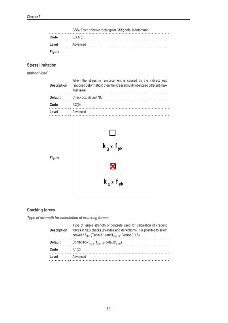
Stress limitationIndirect load
DescriptionWhen the stress in reinforcement is caused by the indirect load(imposed deformation) then the stressshould not exceed differentmax-imal value
Default Checkbox, default NO
Code 7.2(5)
Level Advanced
Figure
Cracking forcesType of strength for calculation of cracking forces
DescriptionType of tensile strength of concrete used for calculation of crackingforces in SLS checks (stresses and deflections). It is possible to selectbetween fctm (Table 3.1) and fctm,fl (Clause 3.1.8).
Default Combo box fctm / fctm,fl (default fctm)
Code 7.1(2)
Level Advanced
- 60 -
Concrete settings (structure)
Figure
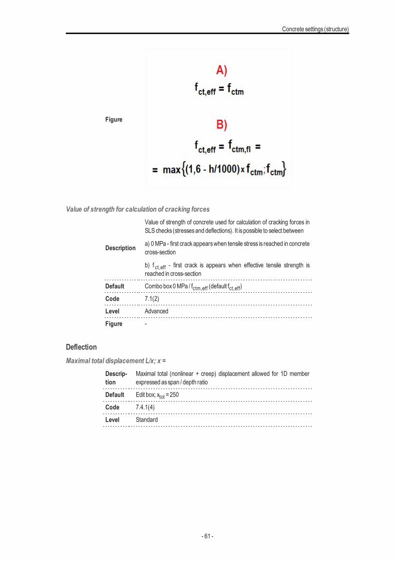
Value of strength for calculation of cracking forces
Description
Value of strength of concrete used for calculation of cracking forces inSLSchecks (stressesand deflections). It is possible to select between
a) 0MPa - first crackappearswhen tensile stress is reached in concretecross-section
b) f ct,eff - first crack is appears when effective tensile strength isreached in cross-section
Default Combo box0MPa / fctm,eff (default fct,eff)
Code 7.1(2)
Level Advanced
Figure -
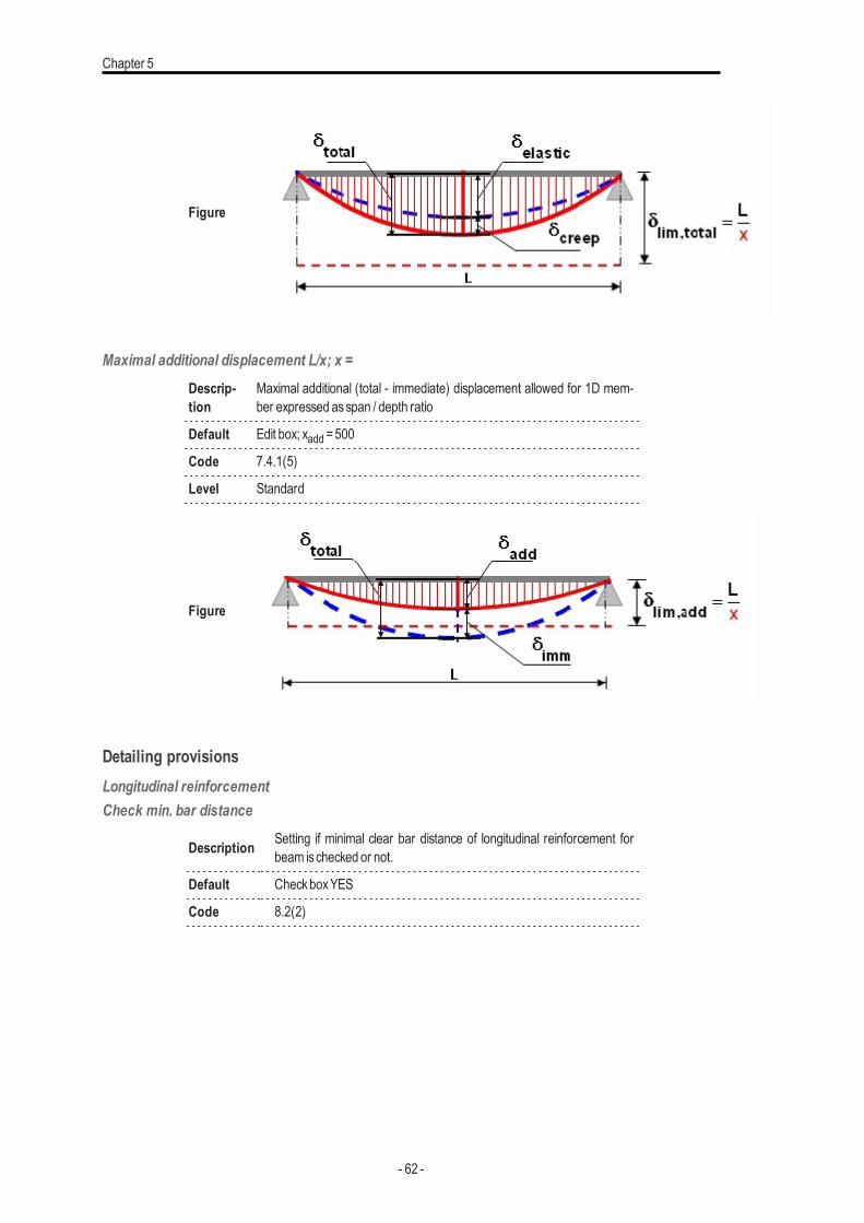
DeflectionMaximal total displacement L/x; x =
Descrip-tion
Maximal total (nonlinear + creep) displacement allowed for 1D memberexpressed asspan / depth ratio
Default Edit box; xtot =250
Code 7.4.1(4)
Level Standard
- 61 -
Chapter 5
Figure
Maximal additional displacement L/x; x =Descrip-tion
Maximal additional (total - immediate) displacement allowed for 1D mem-ber expressed asspan / depth ratio
Default Edit box; xadd =500
Code 7.4.1(5)
Level Standard
Figure
Detailing provisionsLongitudinal reinforcementCheck min. bar distance
Description Setting if minimal clear bar distance of longitudinal reinforcement forbeam ischecked or not.
Default CheckboxYES
Code 8.2(2)
- 62 -
Concrete settings (structure)
Figure
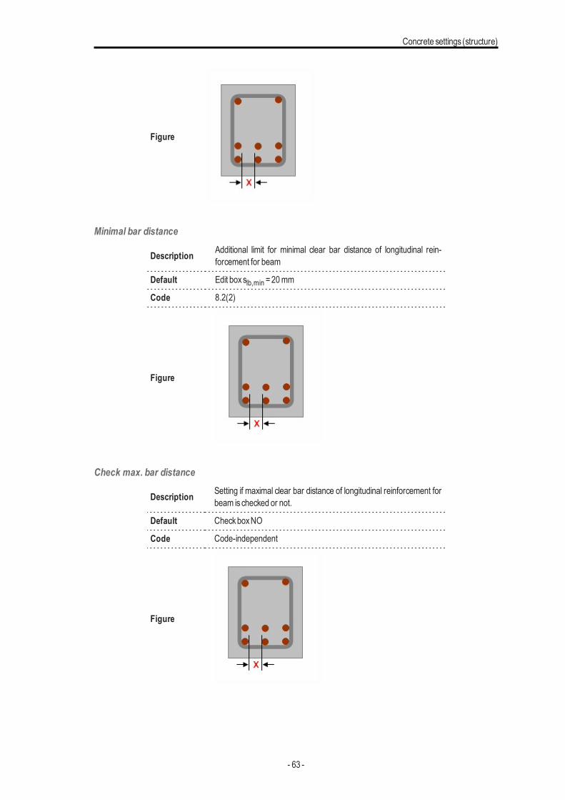
Minimal bar distance
Description Additional limit for minimal clear bar distance of longitudinal rein-forcement for beam
Default Edit boxslb,min =20mm
Code 8.2(2)
Figure
Check max. bar distance
Description Setting if maximal clear bar distance of longitudinal reinforcement forbeam ischecked or not.
Default CheckboxNO
Code Code-independent
Figure
- 63 -
Chapter 5
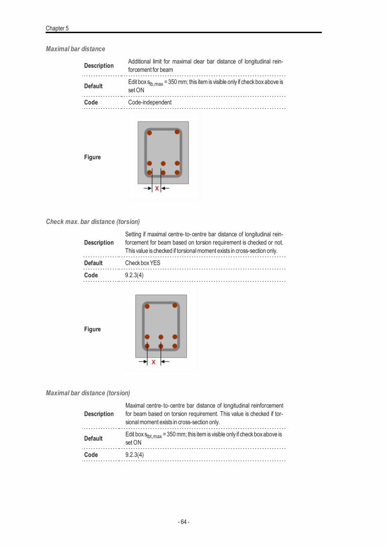
Maximal bar distance
Description Additional limit for maximal clear bar distance of longitudinal rein-forcement for beam
Default Edit boxslb,max =350mm; this item isvisible only if checkboxabove isset ON
Code Code-independent
Figure
Check max. bar distance (torsion)
DescriptionSetting if maximal centre- to-centre bar distance of longitudinal rein-forcement for beam based on torsion requirement is checked or not.This value is checked if torsionalmoment exists in cross-section only.
Default CheckboxYES
Code 9.2.3(4)
Figure
Maximal bar distance (torsion)
DescriptionMaximal centre- to-centre bar distance of longitudinal reinforcementfor beam based on torsion requirement. This value is checked if tor-sionalmoment exists in cross-section only.
Default Edit boxslbt,max =350mm; this item isvisible only if checkboxabove isset ON
Code 9.2.3(4)
- 64 -
Concrete settings (structure)
Figure
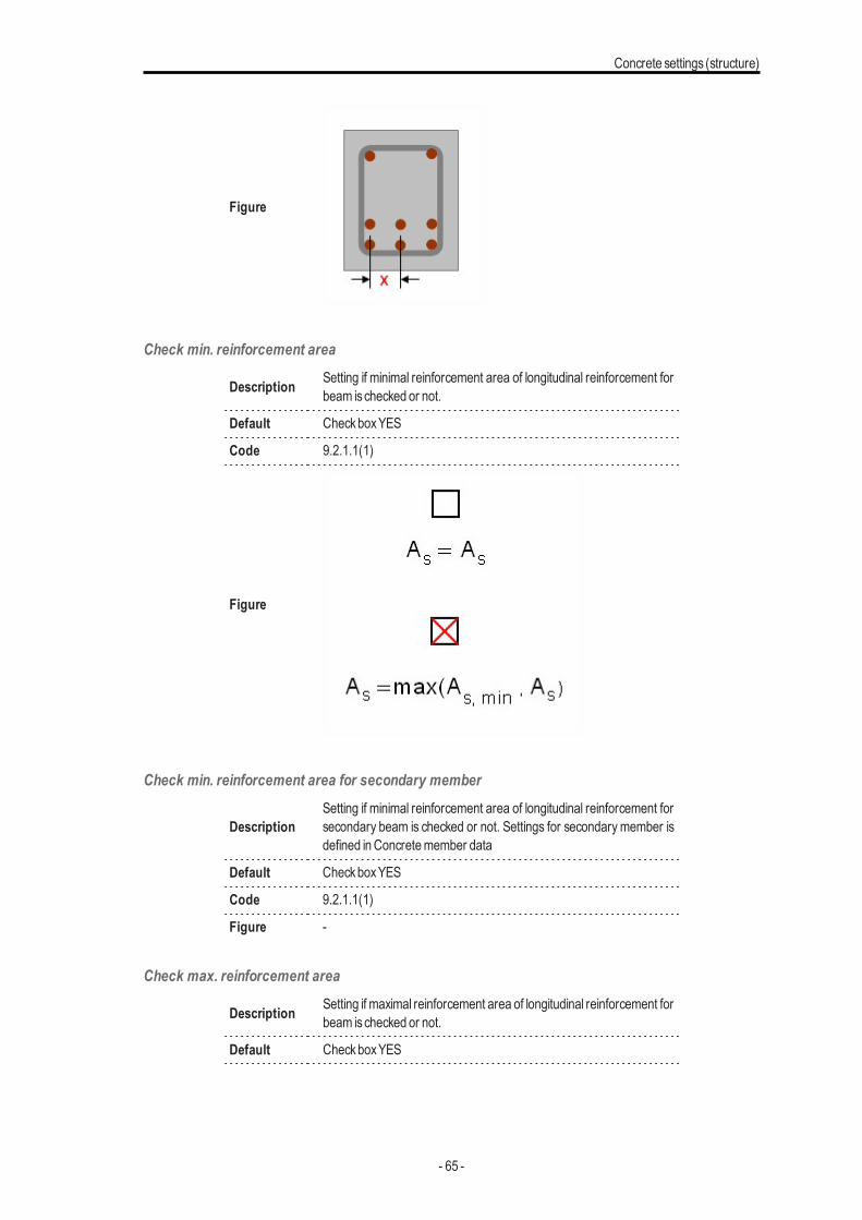
Check min. reinforcement area
Description Setting if minimal reinforcement area of longitudinal reinforcement forbeam ischecked or not.
Default CheckboxYES
Code 9.2.1.1(1)
Figure
Check min. reinforcement area for secondary member
DescriptionSetting if minimal reinforcement area of longitudinal reinforcement forsecondary beam is checked or not. Settings for secondary member isdefined inConcretemember data
Default CheckboxYES
Code 9.2.1.1(1)
Figure -
Check max. reinforcement area
Description Setting if maximal reinforcement area of longitudinal reinforcement forbeam ischecked or not.
Default CheckboxYES
- 65 -
Chapter 5
Code 9.2.1.1(3)
Figure
StirrupsCheck min. mandrel diameter
Description Setting if minimal mandrel diameter of stirrups for beam is checkedor not
Default CheckboxNO
Code 8.3(2)
Figure -
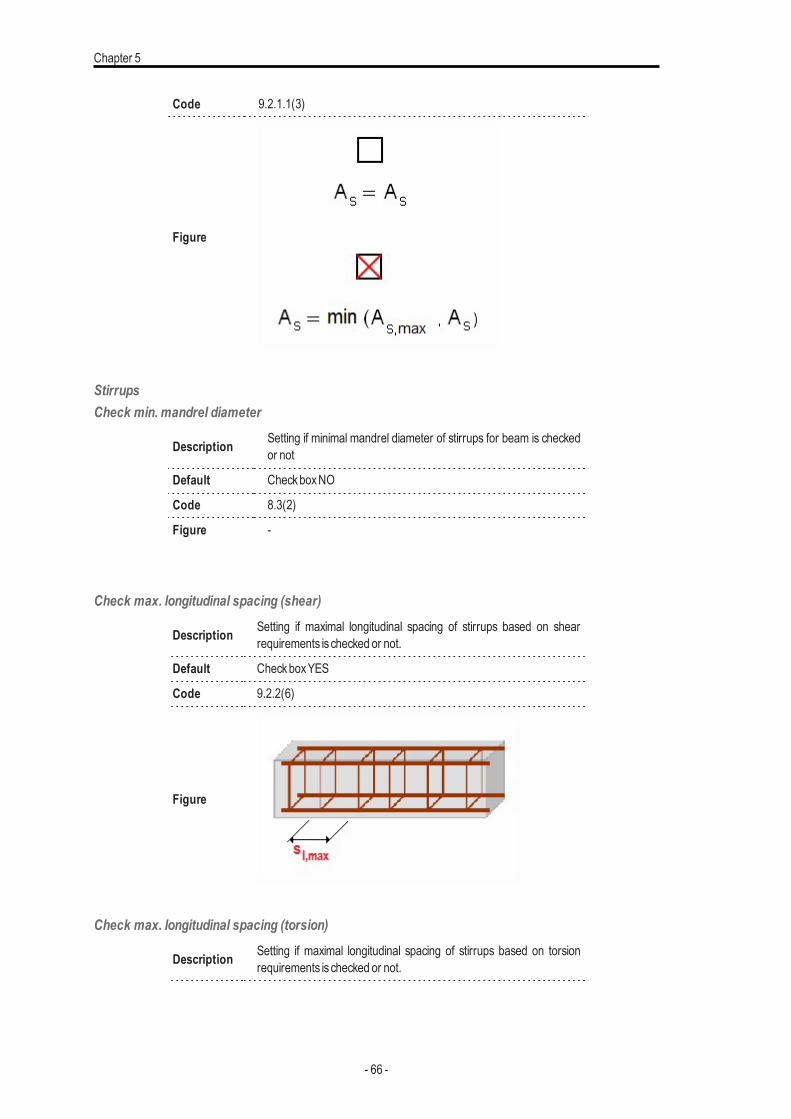
Check max. longitudinal spacing (shear)
Description Setting if maximal longitudinal spacing of stirrups based on shearrequirements is checked or not.
Default CheckboxYES
Code 9.2.2(6)
Figure
Check max. longitudinal spacing (torsion)
Description Setting if maximal longitudinal spacing of stirrups based on torsionrequirements is checked or not.
- 66 -
Concrete settings (structure)
Default CheckboxYES
Code 9.2.3(3)
Figure
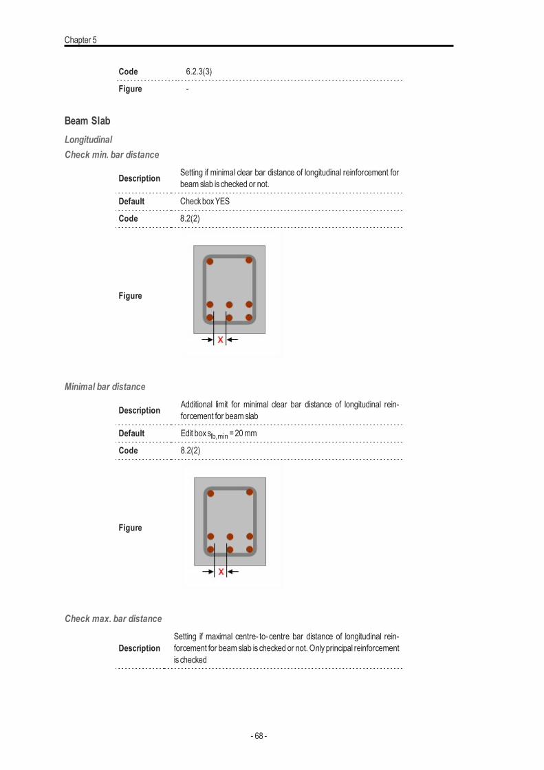
Check max. transverse spacing (shear)
Description Setting if maximal transverse spacing of stirrups based on shearrequirements is checked or not.
Default CheckboxYES
Code 9.2.2(8)
Figure
Check min. percentage of stirrupsDescription Setting if minimal percentage of stirrups for beam ischecked or not.
Default CheckboxYES
Code 9.2.2(5)
Figure -
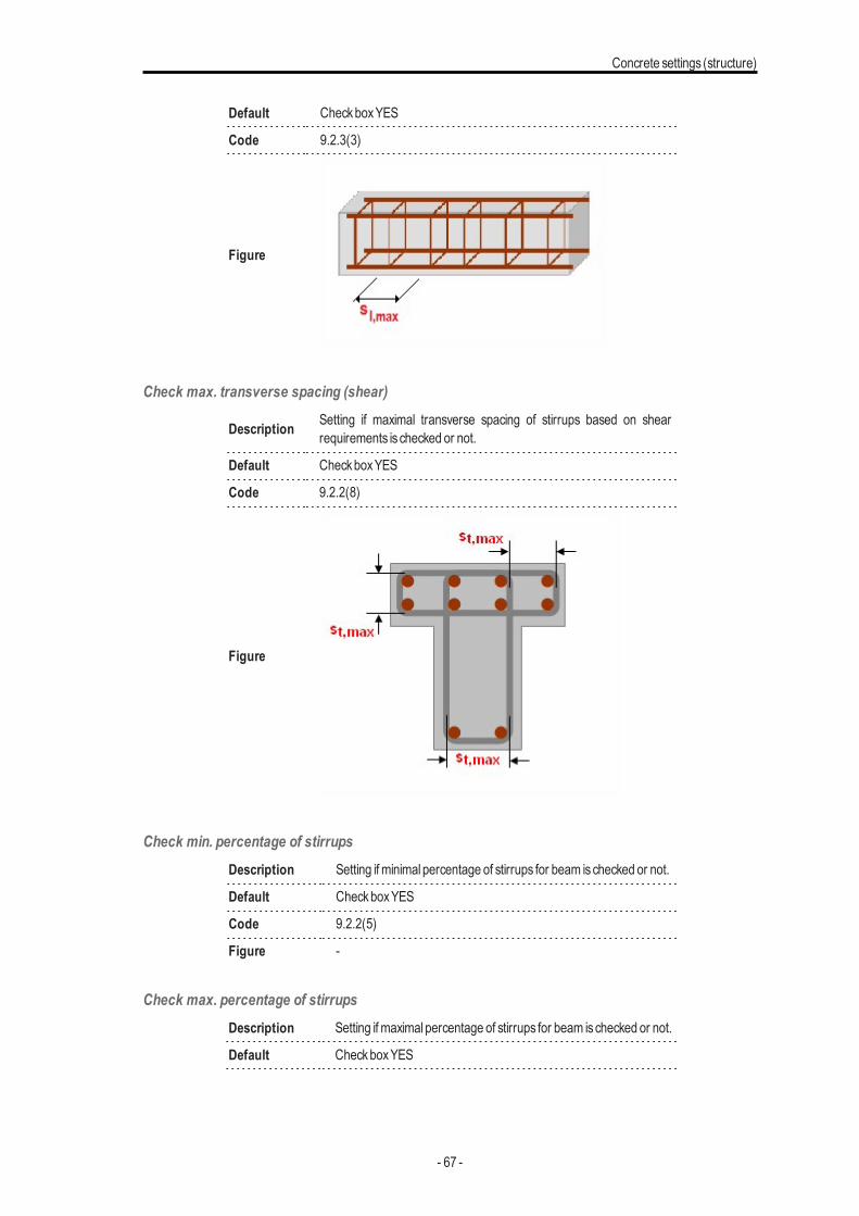
Check max. percentage of stirrupsDescription Setting if maximal percentage of stirrups for beam ischecked or not.
Default CheckboxYES
- 67 -
Chapter 5
Code 6.2.3(3)
Figure -
Beam SlabLongitudinalCheck min. bar distance
Description Setting if minimal clear bar distance of longitudinal reinforcement forbeamslab is checked or not.
Default CheckboxYES
Code 8.2(2)
Figure
Minimal bar distance
Description Additional limit for minimal clear bar distance of longitudinal rein-forcement for beamslab
Default Edit boxslb,min =20mm
Code 8.2(2)
Figure
Check max. bar distance
DescriptionSetting if maximal centre- to- centre bar distance of longitudinal rein-forcement for beam slab is checked or not. Onlyprincipal reinforcementis checked
- 68 -
Concrete settings (structure)
Default CheckboxYES
Code 9.3.1.1(3)
Figure
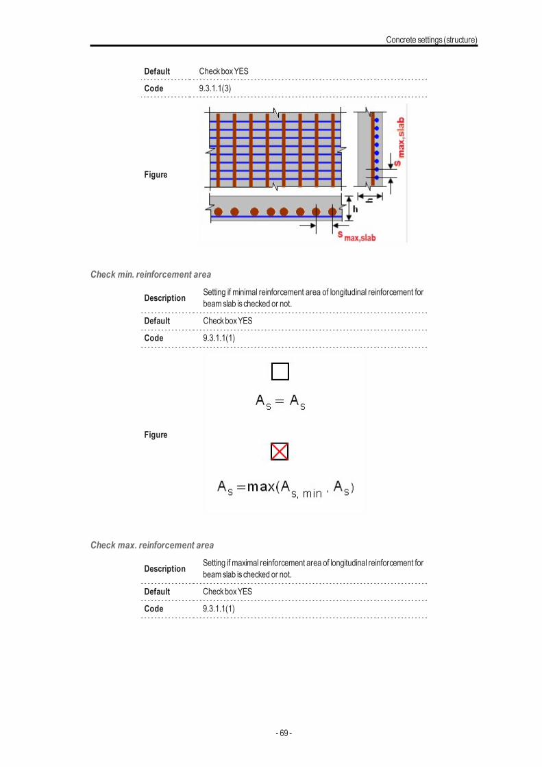
Check min. reinforcement area
Description Setting if minimal reinforcement area of longitudinal reinforcement forbeamslab is checked or not.
Default CheckboxYES
Code 9.3.1.1(1)
Figure
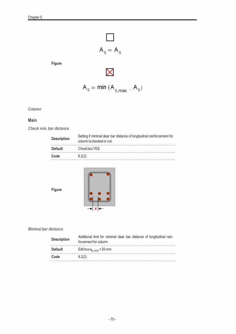
Check max. reinforcement area
Description Setting if maximal reinforcement area of longitudinal reinforcement forbeamslab is checked or not.
Default CheckboxYES
Code 9.3.1.1(1)
- 69 -
Chapter 5
Figure
Column
MainCheck min. bar distance
Description Setting if minimal clear bar distance of longitudinal reinforcement forcolumn ischecked or not.
Default CheckboxYES
Code 8.2(2)
Figure
Minimal bar distance
Description Additional limit for minimal clear bar distance of longitudinal rein-forcement for column
Default Edit boxslc,min =20mm
Code 8.2(2)
- 70 -
Concrete settings (structure)
Figure
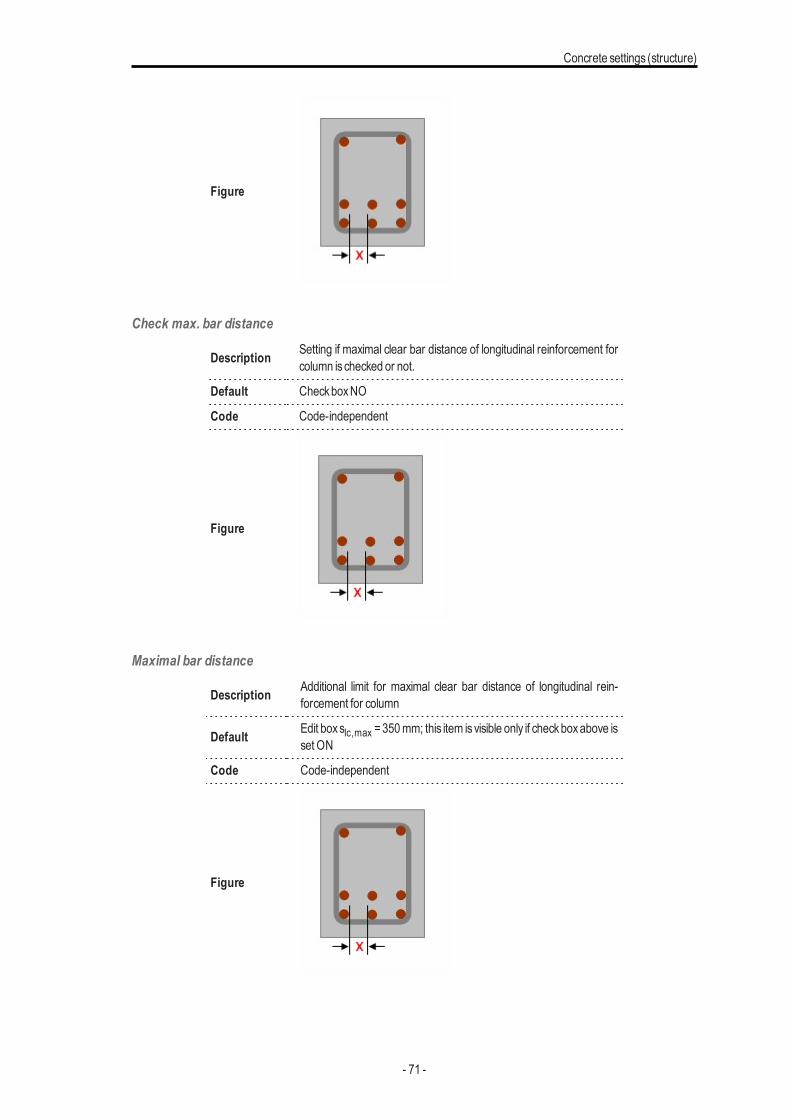
Check max. bar distance
Description Setting if maximal clear bar distance of longitudinal reinforcement forcolumn ischecked or not.
Default CheckboxNO
Code Code-independent
Figure
Maximal bar distance
Description Additional limit for maximal clear bar distance of longitudinal rein-forcement for column
Default Edit boxslc,max =350mm; this item isvisible only if checkboxabove isset ON
Code Code-independent
Figure
- 71 -
Chapter 5
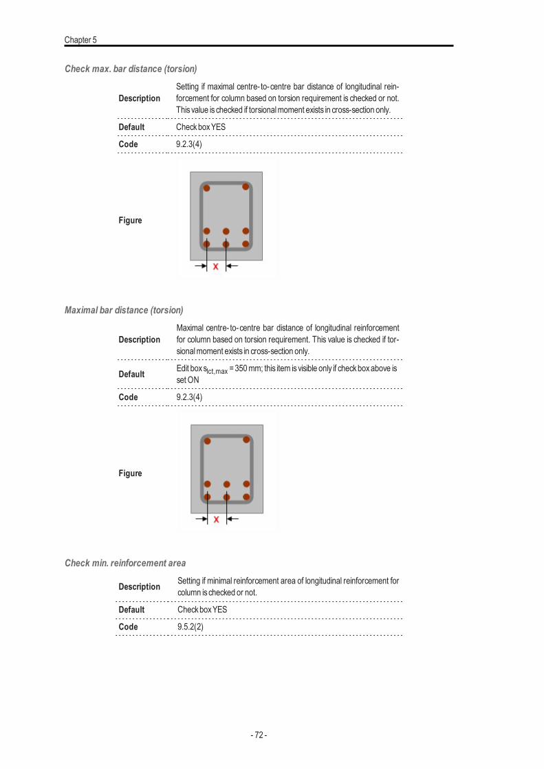
Check max. bar distance (torsion)
DescriptionSetting if maximal centre- to-centre bar distance of longitudinal rein-forcement for column based on torsion requirement is checked or not.This value is checked if torsionalmoment exists in cross-section only.
Default CheckboxYES
Code 9.2.3(4)
Figure
Maximal bar distance (torsion)
DescriptionMaximal centre- to-centre bar distance of longitudinal reinforcementfor column based on torsion requirement. This value is checked if tor-sionalmoment exists in cross-section only.
Default Edit boxslct,max =350mm; this item isvisible only if checkboxabove isset ON
Code 9.2.3(4)
Figure
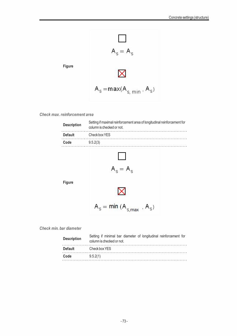
Check min. reinforcement area
Description Setting if minimal reinforcement area of longitudinal reinforcement forcolumn ischecked or not.
Default CheckboxYES
Code 9.5.2(2)
- 72 -
Concrete settings (structure)
Figure
Check max. reinforcement area
Description Setting if maximal reinforcement area of longitudinal reinforcement forcolumn ischecked or not.
Default CheckboxYES
Code 9.5.2(3)
Figure
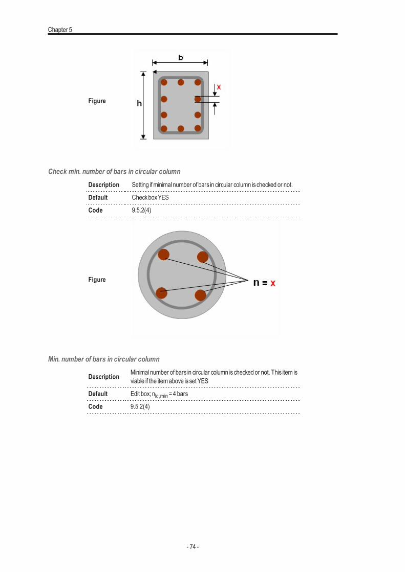
Check min. bar diameter
Description Setting if minimal bar diameter of longitudinal reinforcement forcolumn ischecked or not.
Default CheckboxYES
Code 9.5.2(1)
- 73 -
Chapter 5
Figure
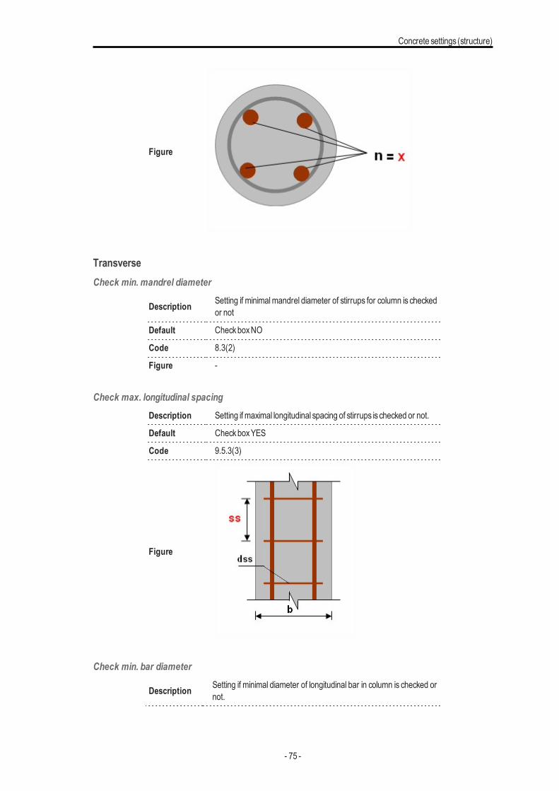
Check min. number of bars in circular columnDescription Setting if minimal number of bars in circular column ischecked or not.
Default CheckboxYES
Code 9.5.2(4)
Figure
Min. number of bars in circular column
Description Minimal number of bars in circular column ischecked or not. This item isviable if the itemabove isset YES
Default Edit box; nlc,min =4 bars
Code 9.5.2(4)
- 74 -
Concrete settings (structure)
Figure
TransverseCheck min. mandrel diameter
Description Setting if minimalmandrel diameter of stirrups for column is checkedor not
Default CheckboxNO
Code 8.3(2)
Figure -
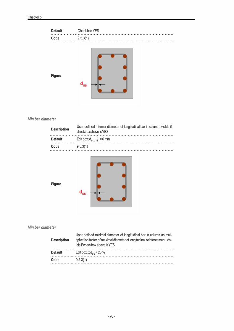
Check max. longitudinal spacingDescription Setting if maximal longitudinal spacing of stirrups is checked or not.
Default CheckboxYES
Code 9.5.3(3)
Figure
Check min. bar diameter
Description Setting if minimal diameter of longitudinal bar in column is checked ornot.
- 75 -
Chapter 5
Default CheckboxYES
Code 9.5.3(1)
Figure
Min bar diameter
Description User defined minimal diameter of longitudinal bar in column; visible ifcheckboxabove isYES
Default Edit box; dsc,min =6mm
Code 9.5.3(1)
Figure
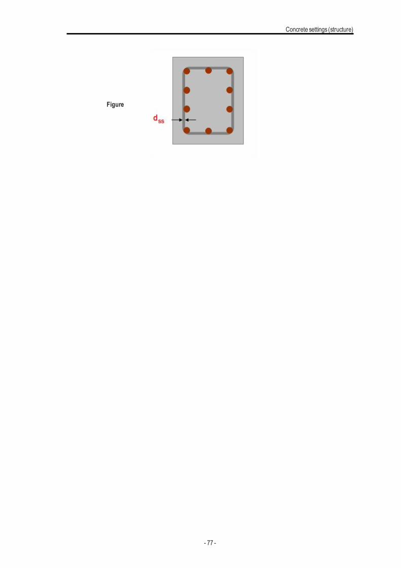
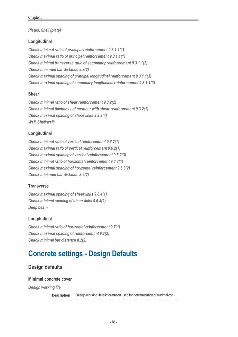
Min bar diameter
DescriptionUser defined minimal diameter of longitudinal bar in column as mul-tiplication factor of maximal diameter of longitudinal reinforcement; vis-ible if checkboxabove isYES
Default Edit box; xdsc =25%
Code 9.5.3(1)
- 76 -
Concrete settings (structure)
Figure
- 77 -
Chapter 5
Plates, Shell (plate)
LongitudinalCheck minimal ratio of principal reinforcement 9.3.1.1(1)Check maximal ratio of principal reinforcement 9.3.1.1(1)Check minimal transverse ratio of secondary reinforcement 9.3.1.1(2)Check minimum bar distance 8.2(2)Check maximal spacing of principal longitudinal reinforcement 9.3.1.1(3)Check maximal spacing of secondary longitudinal reinforcement 9.3.1.1(3)
ShearCheck minimal ratio of shear reinforcement 9.3.2(2)Check minimal thickness of member with shear reinforcement 9.3.2(1)Check maximal spacing of shear links 9.3.2(4)Wall, Shell(wall)
LongitudinalCheck minimal ratio of vertical reinforcement 9.6.2(1)Check maximal ratio of vertical reinforcement 9.6.2(1)Check maximal spacing of vertical reinforcement 9.6.2(3)Check minimal ratio of horizontal reinforcement 9.6.3(1)Check maximal spacing of horizontal reinforcement 9.6.3(2)Check minimum bar distance 8.2(2)
TransverseCheck maximal spacing of shear links 9.6.4(1)Check minimal spacing of shear links 9.6.4(2)Deep beam
LongitudinalCheck minimal ratio of horizontal reinforcement 9.7(1)Check maximal spacing of reinforcement 9.7(2)Check minimal bar distance 8.2(2)
Concrete settings - Design DefaultsDesign defaults
Minimal concrete coverDesign working life
Description Designworking life is information used for determination ofminimal con-
- 78 -
Concrete settings (structure)
crete cover
Default Edit box , default =50 years
Code 4.4.1.2(5), table 4.3N
Level Standard
Figure -
Member 1Dmember (Beam /Column / BeamSlab / Rib)
Risk of corrosion attackCorrosion induced by carbonation
Description Exposure class caused by carbonation is used for determination of min-imal concrete cover in Table 4.4N
Default Combo box;None / X0 /XC1 / XC2 / XC3 / XC4; default =XC3
Code 4.4.1.2(5), table 4.3N
Level Standard
Figure -
Member 1Dmember (Beam /Column / BeamSlab / Rib)
Corrosion induced by chlorides
Description Exposure class caused by chlorides is used for determination of minimalconcrete cover in Table 4.4N
Default Combo box; None / XD1 / XD2 / XD3; default =None
Code 4.4.1.2(5), table 4.3N
Level Standard
Figure -
Member 1Dmember (Beam /Column / BeamSlab / Rib)
Corrosion induced by chlorides from sea water
Description Exposure class caused by chlorides from sea water is used for determ-ination ofminimal concrete cover in Table 4.4N
Default Combo box; None / XS1 / XS2 / XS3; default =None
Code 4.4.1.2(5), table 4.3N
Level Standard
Figure -
Member 1Dmember (Beam /Column / BeamSlab / Rib)
Free / thaw attackDescription AdditionalExposure classcaused by freezing or thawing
- 79 -
Chapter 5
Default Combo box; None / XF1 / XF2 / XF3; default =None
Code 4.4.1.2(12)
Level Standard
Figure -
Member 1Dmember (Beam /Column / BeamSlab / Rib)
Chemical attackDescription AdditionalExposure classcaused bychemical attack
Default Combo box; None / XA1 / XA2 / XA3; default =None
Code 4.4.1.2(12)
Level Standard
Figure -
Member 1Dmember (Beam /Column / BeamSlab / Rib)
Risk of abrasion attackDescription AdditionalExposure classcaused byabrasion attack
Default Combo box; None / XM1 / XM2 / XM3; default =None
Code 4.4.1.2(13)
Level Advanced
Figure -
Member 1Dmember (Beam /Column / BeamSlab / Rib)
Possibility of special controlRisk of casting on atypical surface
Description To take into account additional deviation to nominal concrete covercaused bycasting on atypical surface
Default Combo box; Standard / Against prepared ground / Again soil / Unevensurface default =Standard
Code 4.4.1.3(4)
Level Advanced
Figure -
Member 1Dmember (Beam /Column / BeamSlab / Rib)
Concrete characteristicType of concrete
Description To take into account additional deviation to nominal concrete covercaused byproduction type
- 80 -
Concrete settings (structure)
Default Combo box; In-situ / Prefabricated ; default = In-situ
Code 4.4.1.3(1P, 3)
Level Advanced
Figure -
Member 1Dmember (Beam /Column / BeamSlab / Rib)
BeamLongitudinal
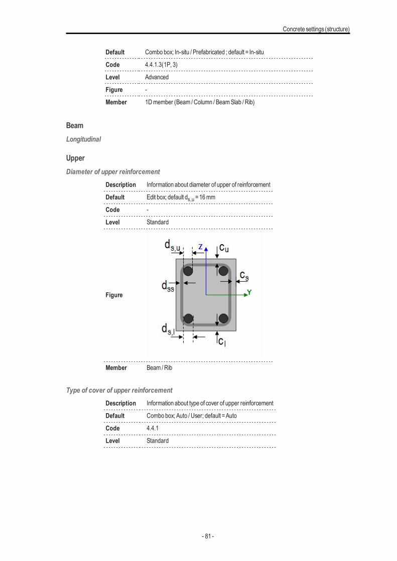
UpperDiameter of upper reinforcement
Description Information about diameter of upper of reinforcement
Default Edit box; default ds,u =16mm
Code -
Level Standard
Figure
Member Beam /Rib
Type of cover of upper reinforcementDescription Information about type of cover of upper reinforcement
Default Combo box; Auto / User; default =Auto
Code 4.4.1
Level Standard
- 81 -
Chapter 5
Figure
Member Beam /Rib
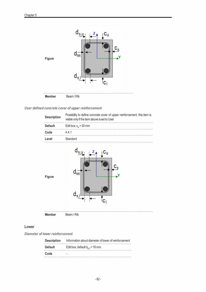
User defined concrete cover of upper reinforcement
Description Possibility to define concrete cover of upper reinforcement; this item isvisible only if the itemabove isset to User
Default Edit box; cu =30mm
Code 4.4.1
Level Standard
Figure
Member Beam /Rib
LowerDiameter of lower reinforcement
Description Information about diameter of lower of reinforcement
Default Edit box; default ds,l =16mm
Code -
- 82 -
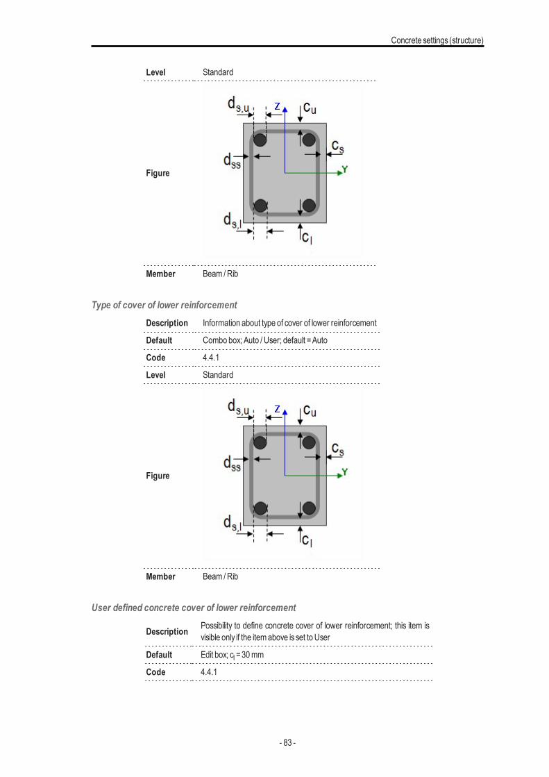
Concrete settings (structure)
Level Standard
Figure
Member Beam /Rib
Type of cover of lower reinforcementDescription Information about type of cover of lower reinforcement
Default Combo box; Auto / User; default =Auto
Code 4.4.1
Level Standard
Figure
Member Beam /Rib
User defined concrete cover of lower reinforcement
Description Possibility to define concrete cover of lower reinforcement; this item isvisible only if the itemabove isset to User
Default Edit box; cl =30mm
Code 4.4.1
- 83 -
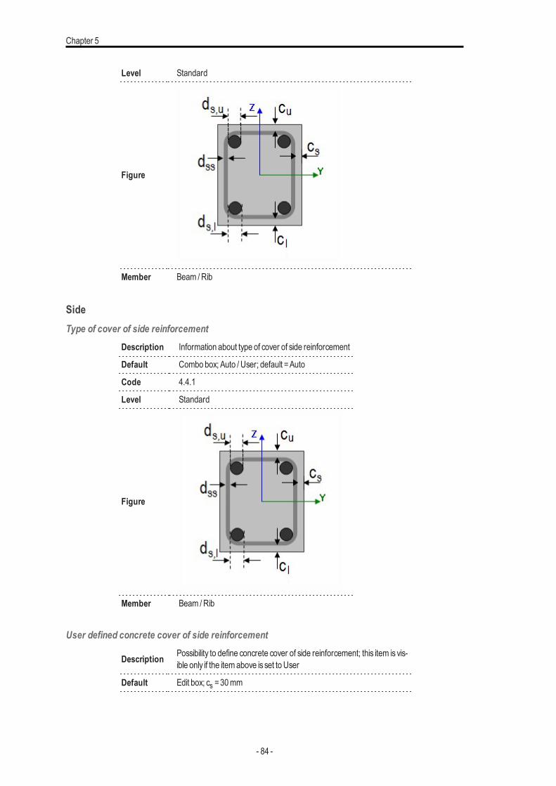
Chapter 5
Level Standard
Figure
Member Beam /Rib
SideType of cover of side reinforcement
Description Information about type of cover of side reinforcement
Default Combo box; Auto / User; default =Auto
Code 4.4.1
Level Standard
Figure
Member Beam /Rib
User defined concrete cover of side reinforcement
Description Possibility to define concrete cover of side reinforcement; this item is vis-ible only if the itemabove isset to User
Default Edit box; cs =30mm
- 84 -
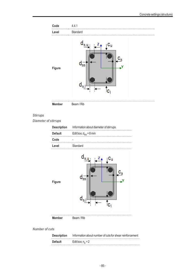
Concrete settings (structure)
Code 4.4.1
Level Standard
Figure
Member Beam /Rib
StirrupsDiameter of stirrups
Description Information about diameter of stirrups
Default Edit box; dss =8mm
Code -
Level Standard
Figure
Member Beam /Rib
Number of cutsDescription Information about number of cuts for shear reinforcement
Default Edit box; ns =2
- 85 -
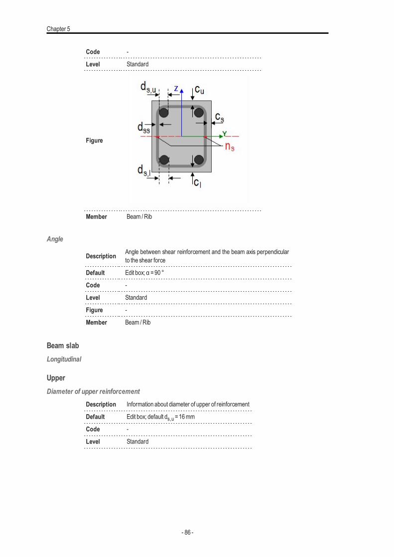
Chapter 5
Code -
Level Standard
Figure
Member Beam /Rib
Angle
Description Angle between shear reinforcement and the beam axis perpendicularto the shear force
Default Edit box; α =90 °
Code -
Level Standard
Figure -
Member Beam /Rib
Beam slabLongitudinal
UpperDiameter of upper reinforcement
Description Information about diameter of upper of reinforcement
Default Edit box; default ds,u =16mm
Code -
Level Standard
- 86 -
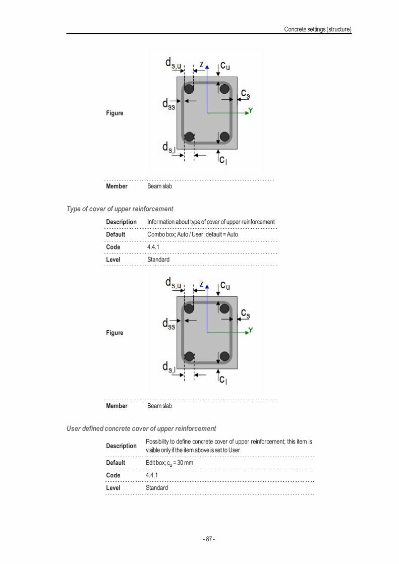
Concrete settings (structure)
Figure
Member Beamslab
Type of cover of upper reinforcementDescription Information about type of cover of upper reinforcement
Default Combo box; Auto / User; default =Auto
Code 4.4.1
Level Standard
Figure
Member Beamslab
User defined concrete cover of upper reinforcement
Description Possibility to define concrete cover of upper reinforcement; this item isvisible only if the itemabove isset to User
Default Edit box; cu =30mm
Code 4.4.1
Level Standard
- 87 -
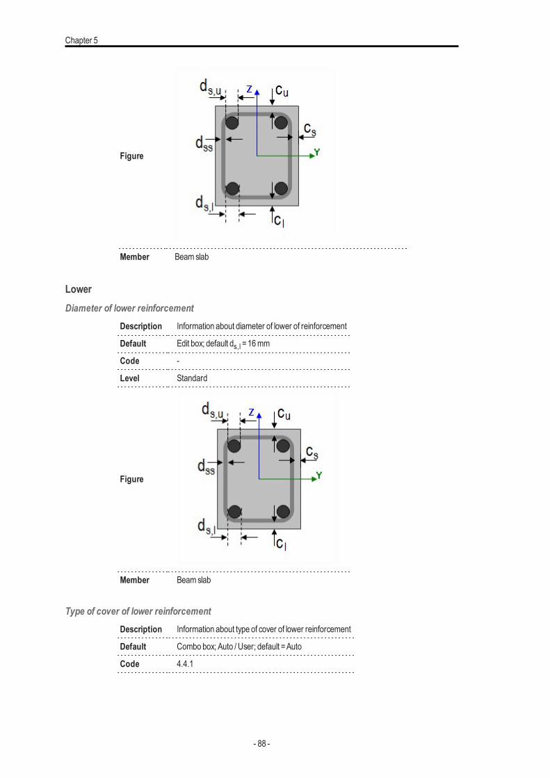
Chapter 5
Figure
Member Beamslab
LowerDiameter of lower reinforcement
Description Information about diameter of lower of reinforcement
Default Edit box; default ds,l =16mm
Code -
Level Standard
Figure
Member Beamslab
Type of cover of lower reinforcementDescription Information about type of cover of lower reinforcement
Default Combo box; Auto / User; default =Auto
Code 4.4.1
- 88 -
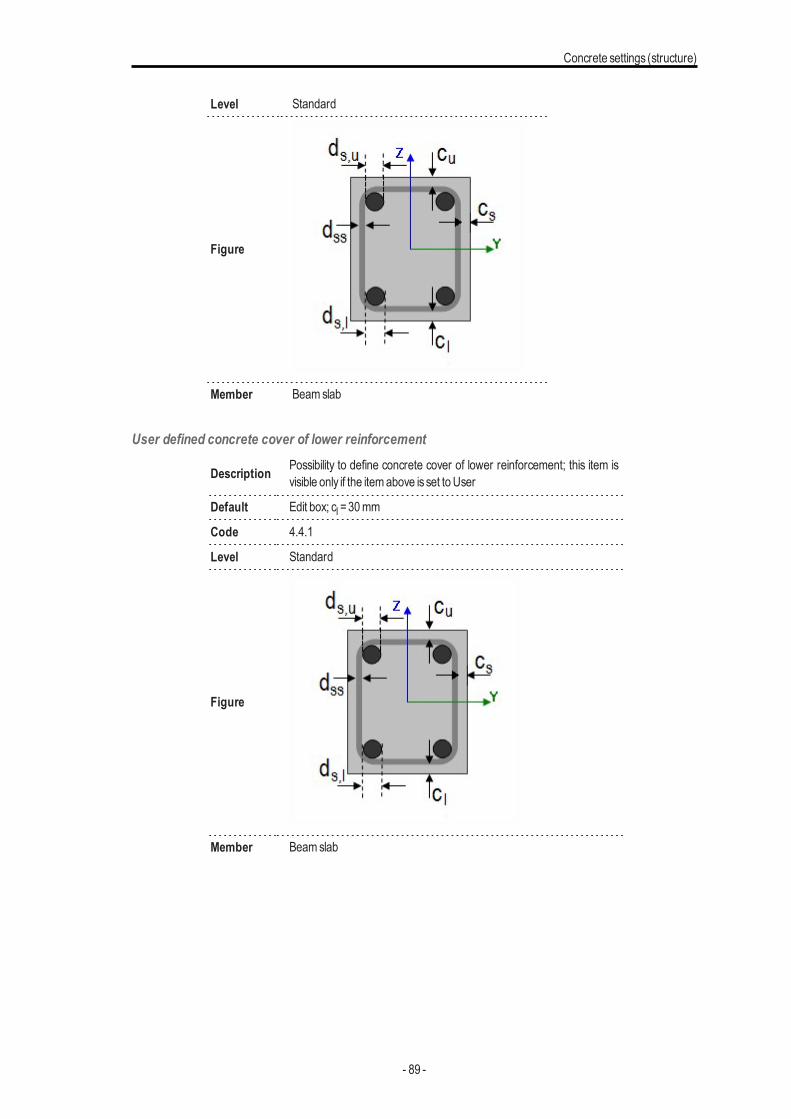
Concrete settings (structure)
Level Standard
Figure
Member Beamslab
User defined concrete cover of lower reinforcement
Description Possibility to define concrete cover of lower reinforcement; this item isvisible only if the itemabove isset to User
Default Edit box; cl =30mm
Code 4.4.1
Level Standard
Figure
Member Beamslab
- 89 -
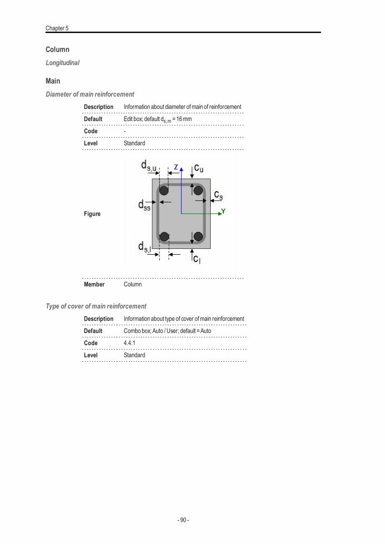
Chapter 5
ColumnLongitudinal
MainDiameter of main reinforcement
Description Information about diameter ofmain of reinforcement
Default Edit box; default ds,m =16mm
Code -
Level Standard
Figure
Member Column
Type of cover of main reinforcementDescription Information about type of cover ofmain reinforcement
Default Combo box; Auto / User; default =Auto
Code 4.4.1
Level Standard
- 90 -
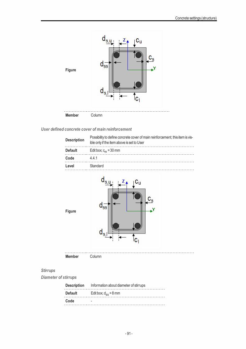
Concrete settings (structure)
Figure
Member Column
User defined concrete cover of main reinforcement
Description Possibility to define concrete cover ofmain reinforcement; this item isvis-ible only if the itemabove isset to User
Default Edit box; cm =30mm
Code 4.4.1
Level Standard
Figure
Member Column
StirrupsDiameter of stirrups
Description Information about diameter of stirrups
Default Edit box; dss =8mm
Code -
- 91 -
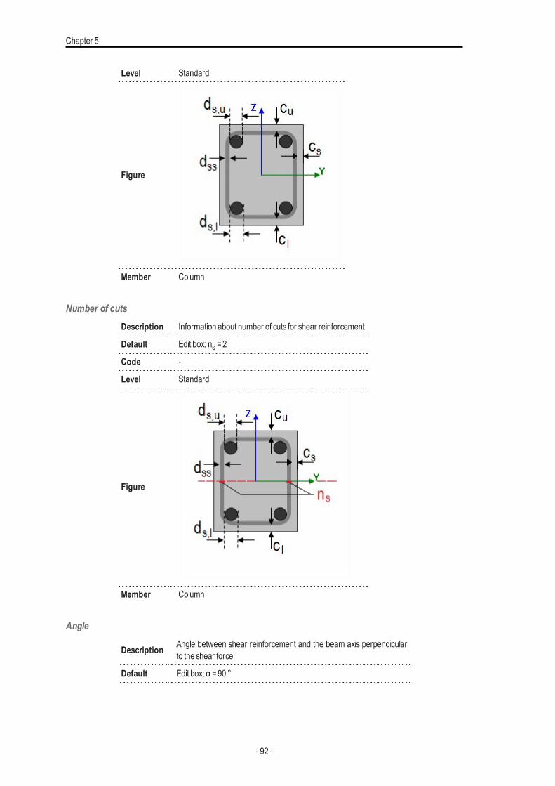
Chapter 5
Level Standard
Figure
Member Column
Number of cutsDescription Information about number of cuts for shear reinforcement
Default Edit box; ns =2
Code -
Level Standard
Figure
Member Column
Angle
Description Angle between shear reinforcement and the beam axis perpendicularto the shear force
Default Edit box; α =90 °
- 92 -
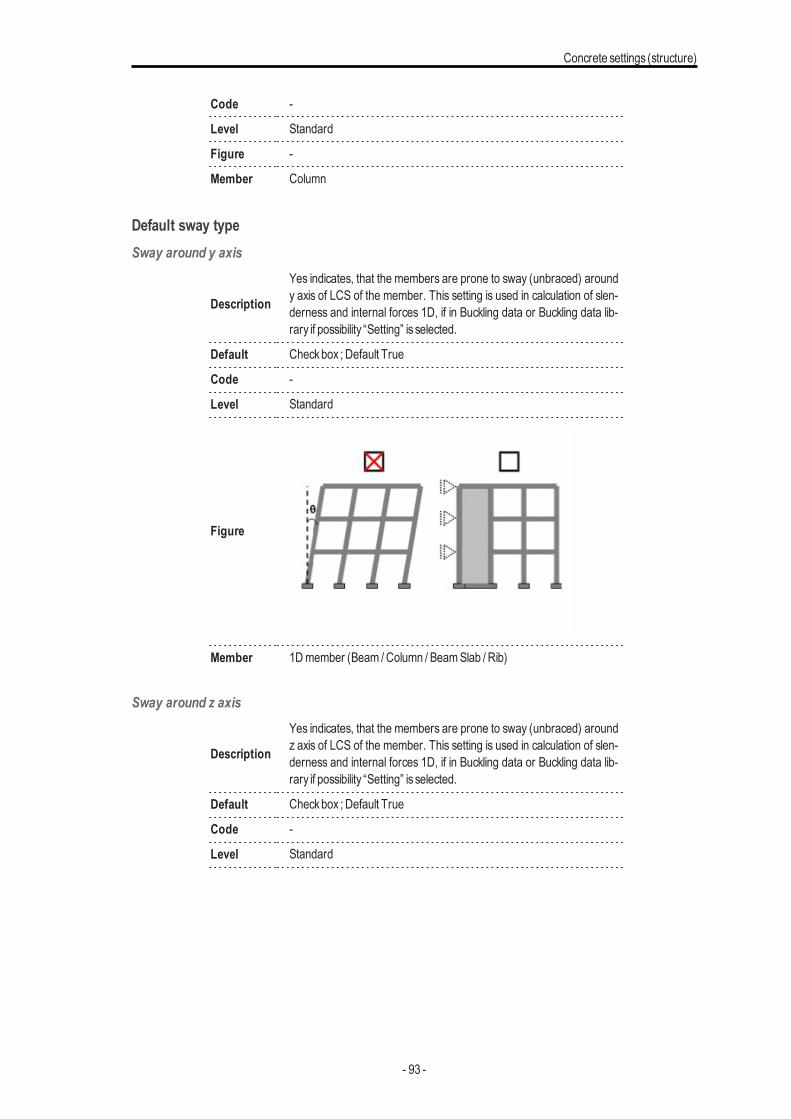
Concrete settings (structure)
Code -
Level Standard
Figure -
Member Column
Default sway typeSway around y axis
Description
Yes indicates, that the members are prone to sway (unbraced) aroundy axis of LCS of the member. This setting is used in calculation of slen-derness and internal forces 1D, if in Buckling data or Buckling data lib-rary if possibility “Setting” is selected.
Default Checkbox ; Default True
Code -
Level Standard
Figure
Member 1Dmember (Beam /Column / BeamSlab / Rib)
Sway around z axis
Description
Yes indicates, that the members are prone to sway (unbraced) aroundz axis of LCS of the member. This setting is used in calculation of slen-derness and internal forces 1D, if in Buckling data or Buckling data lib-rary if possibility “Setting” is selected.
Default Checkbox ; Default True
Code -
Level Standard
- 93 -
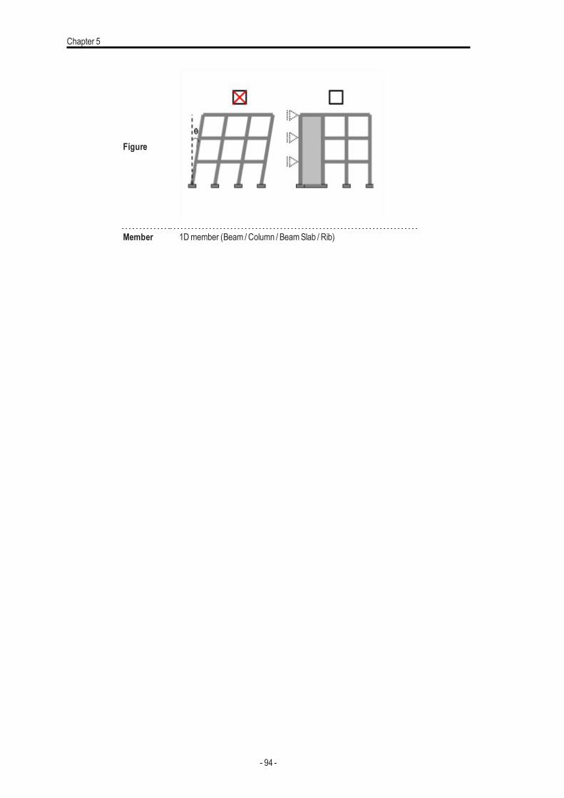
Chapter 5
Figure
Member 1Dmember (Beam /Column / BeamSlab / Rib)
- 94 -
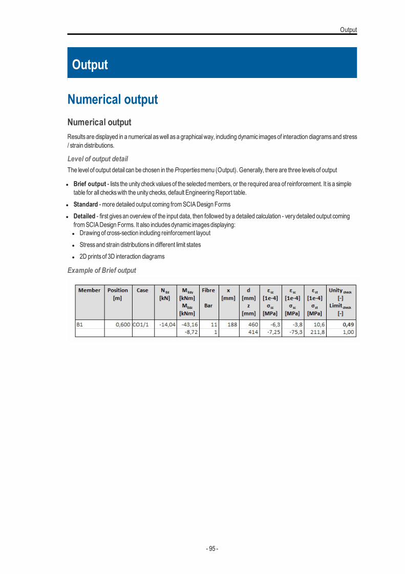
Output
Output
Numerical outputNumerical outputResultsare displayed in a numerical aswell asa graphicalway, including dynamic imagesof interaction diagramsand stress/ strain distributions.
Level of output detailThe level of output detail can be chosen in thePropertiesmenu (Output). Generally, there are three levelsof output
l Brief output - lists the unity checkvaluesof the selectedmembers, or the required area of reinforcement. It is a simpletable for all checkswith the unity checks, default EngineeringReport table.
l Standard - more detailed output coming fromSCIADesign Formsl Detailed - first givesan overview of the input data, then followed bya detailed calculation - verydetailed output coming
fromSCIADesign Forms. It also includesdynamic imagesdisplaying:l Drawing of cross-section including reinforcement layoutl Stressand strain distributions in different limit statesl 2D printsof 3D interaction diagrams
Example of Brief output
- 95 -
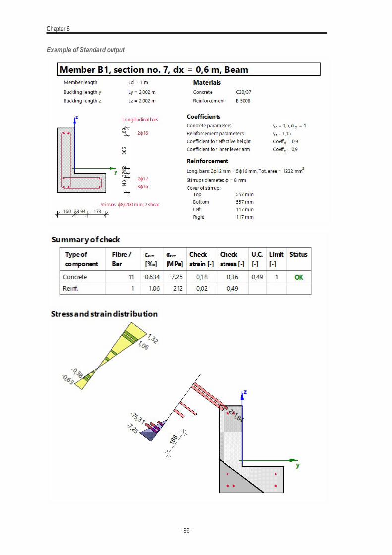
Chapter 6
Example of Standard output
- 96 -
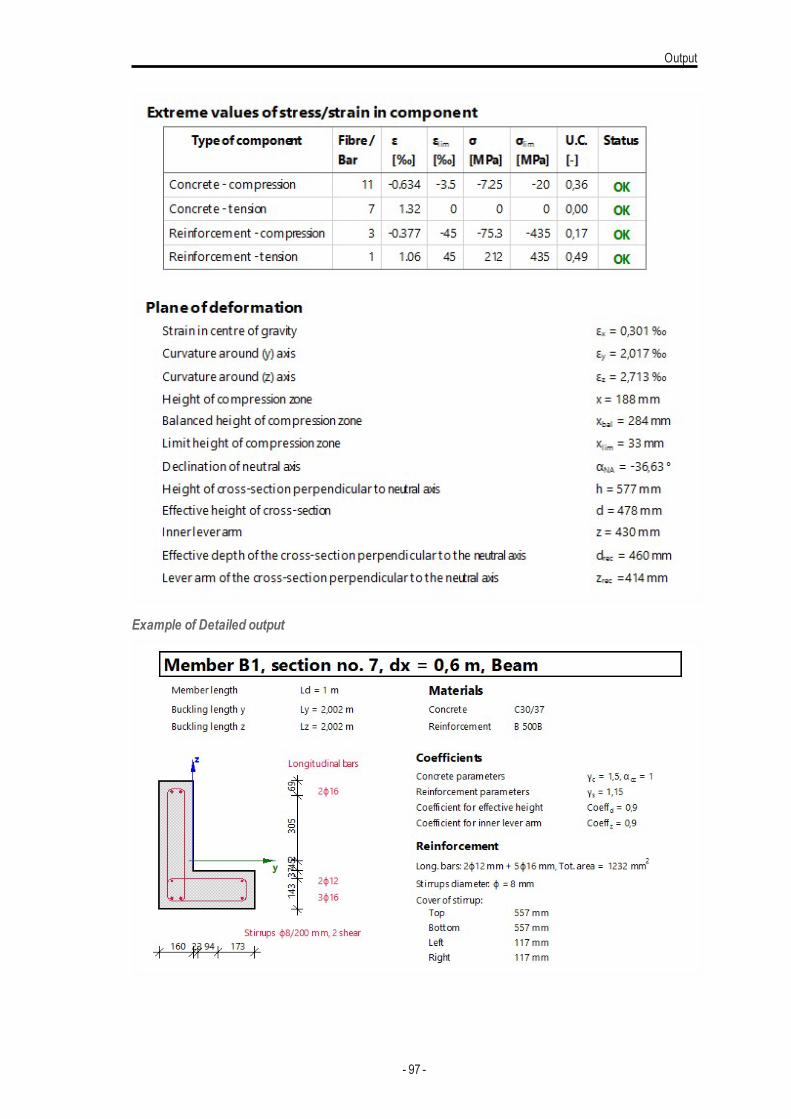
Output
Example of Detailed output
- 97 -
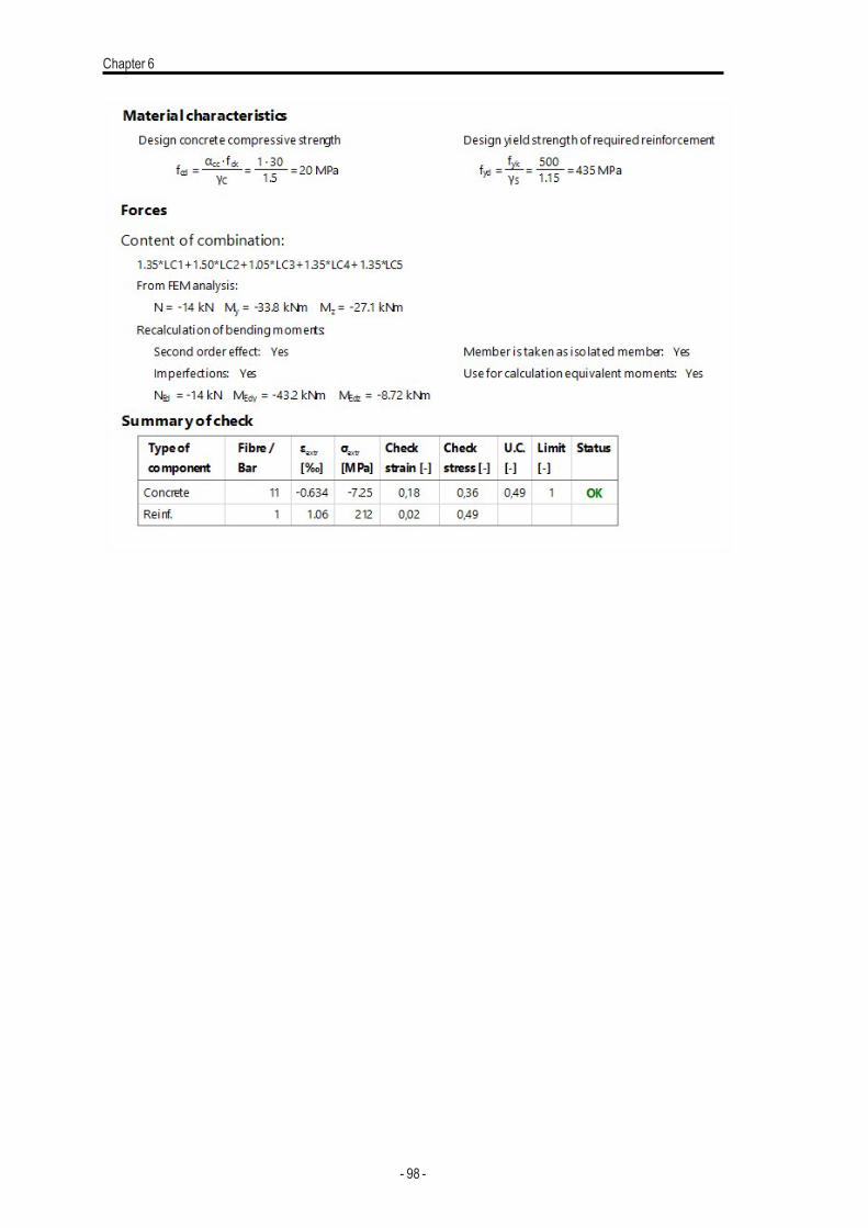
Chapter 6
- 98 -
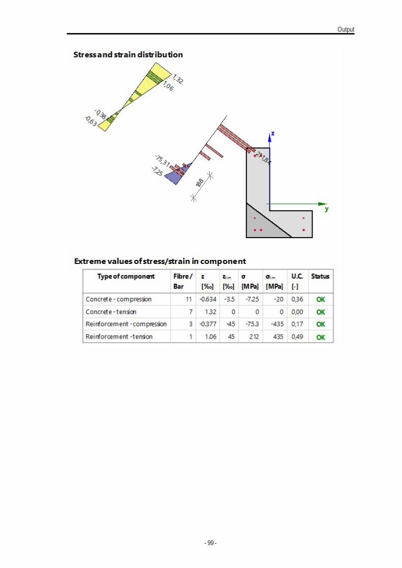
Output
- 99 -
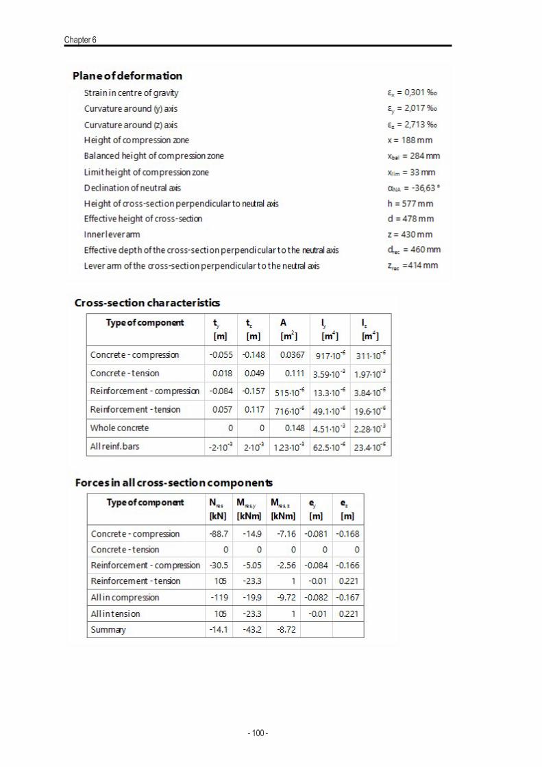
Chapter 6
- 100 -
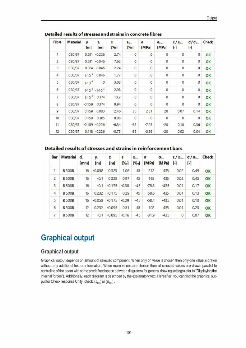
Output
Graphical outputGraphical outputGraphical output depends on amount of selected component. When only on value is chosen then only one value is drawnwithout any additional text or information. When more values are chosen then all selected values are drawn parallel tocentreline of the beamwith some predefined space between diagrams (for general drawing settings refer to "Displaying theinternal forces"). Additionally, each diagram is described by the explanatory text. Hereafter, you can find the graphical out-put for Check responseUnity_check; (εcc) or (σcc) .
- 101 -
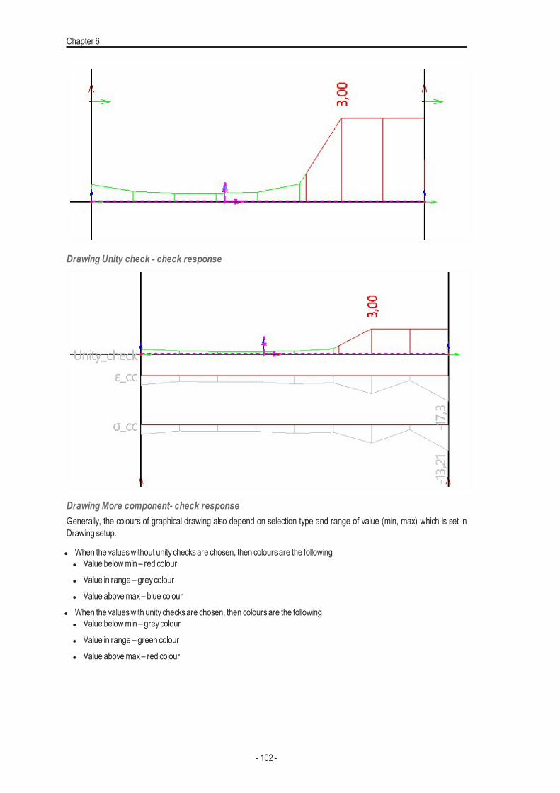
Chapter 6
Drawing Unity check - check response
Drawing More component- check responseGenerally, the colours of graphical drawing also depend on selection type and range of value (min, max) which is set inDrawing setup.
l When the valueswithout unity checksare chosen, then coloursare the followingl Value belowmin – red colourl Value in range – greycolourl Value abovemax– blue colour
l When the valueswith unity checksare chosen, then coloursare the followingl Value belowmin – greycolourl Value in range – green colourl Value abovemax– red colour
- 102 -
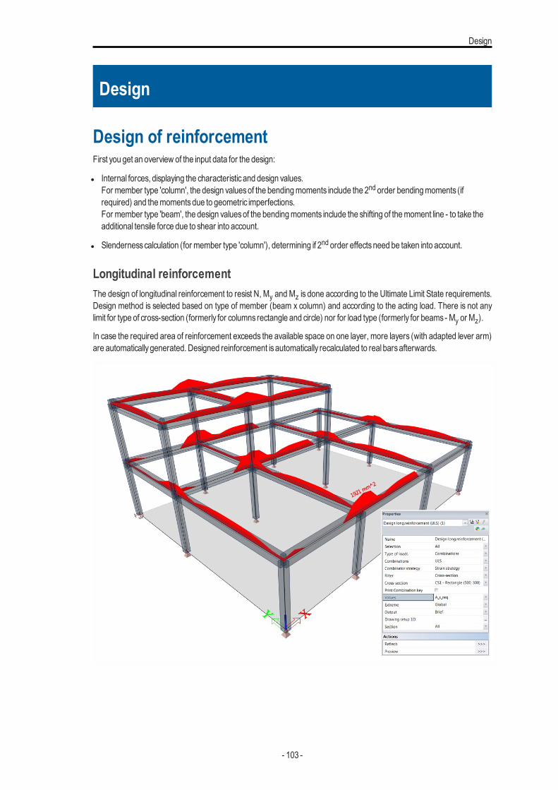
Design
Design
Design of reinforcementFirst you get an overview of the input data for the design:
l Internal forces, displaying the characteristicand design values.For member type 'column', the design valuesof the bendingmoments include the 2nd order bendingmoments (ifrequired) and themomentsdue to geometric imperfections.For member type 'beam', the design valuesof the bendingmoments include the shifting of themoment line - to take theadditional tensile force due to shear into account.
l Slendernesscalculation (for member type 'column'), determining if 2nd order effectsneed be taken into account.
Longitudinal reinforcementThe design of longitudinal reinforcement to resist N, My andMz is done according to the Ultimate Limit State requirements.Design method is selected based on type of member (beam x column) and according to the acting load. There is not anylimit for type of cross-section (formerly for columns rectangle and circle) nor for load type (formerly for beams - My or Mz).
In case the required area of reinforcement exceeds the available space on one layer, more layers (with adapted lever arm)are automaticallygenerated. Designed reinforcement isautomatically recalculated to real barsafterwards.
- 103 -
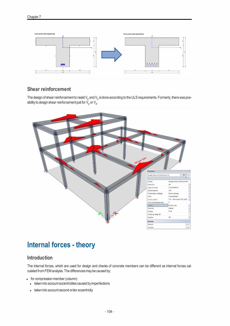
Chapter 7
Shear reinforcementThe design of shear reinforcement to resist Vy andVz is done according to theULS requirements. Formerly, therewaspos-sibility to design shear reinforcement just for Vy or Vz.
Internal forces - theoryIntroductionThe internal forces, which are used for design and checks of concrete members can be different as internal forces cal-culated fromFEManalysis. The differencesmaybe caused by:
l for compressionmember (column)l taken into account eccentricitiescaused by imperfectionsl taken into account second order eccentricity
- 104 -
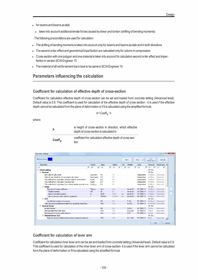
Design
l for beamsand beamsasslab
l taken into account additional tensile forcescaused byshear and torsion (shifting of bendingmoments)
. The following preconditionsare used for calculation :
l The shifting of bendingmoments is taken into account only for beamsand beamsasslab and in both directionsl The second order effect and geometrical imperfection are calculated only for column in compressionl Cross-sectionwith one polygon and onematerial is taken into account for calculation second order effect and imper-
fection in version SCIAEngineer 15l Thematerial of all reinforcement barshave to be same in SCIAEngineer 15
Parameters influencing the calculation
Coefficient for calculation of effective depth of cross-sectionCoefficient for calculation effective depth of cross-section can be set and loaded from concrete setting (Advanced level).Default value is 0.9. This coefficient is used for calculation of the effective depth of cross-section - it is used if the effectivedepth cannot be calculated from the plane of deformation or if it is calculated using the simplified formula
d =Coeffd ∙ h
where
h is height of cross-section in direction, which effectivedepth of cross-section is calculated in
Coeffdcoefficient for calculation effective depth of cross-sec-tion
Coefficient for calculation of lever armCoefficient for calculation inner lever arm can be set and loaded from concrete setting (Advanced level). Default value is0.9.This coefficient is used for calculation of the inner lever arm of cross-section- it is used if the lever arm cannot be calculatedform the plane of deformation or if it is calculated using the simplified formula
- 105 -
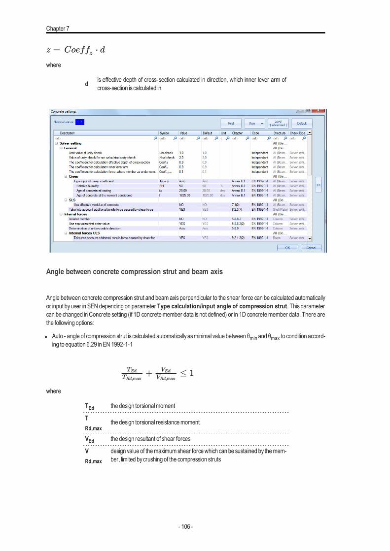
Chapter 7
where
d is effective depth of cross-section calculated in direction, which inner lever arm ofcross-section is calculated in
Angle between concrete compression strut and beam axis
Angle between concrete compression strut and beam axis perpendicular to the shear force can be calculated automaticallyor input byuser in SEN depending on parameter Type calculation/input angle of compression strut. Thisparametercan be changed in Concrete setting (if 1D concretemember data is not defined) or in 1D concretemember data. There arethe following options:
l Auto - angle of compression strut is calculated automaticallyasminimal value between θmin and θmax to condition accord-ing to equation 6.29 in EN 1992-1-1
where
TEd the design torsionalmoment
TRd,max
the design torsional resistancemoment
VEd the design resultant of shear forces
VRd,max
design value of themaximumshear forcewhich can be sustained by themem-ber, limited bycrushing of the compression struts
- 106 -
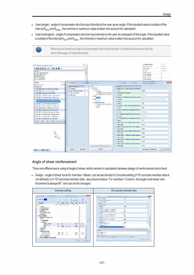
Design
l User(angle) - angle of compression strut be input directlyby the user asan angle. If the inputted value isoutside of theinterval θmin and θmax , theminimal or maximumvalue is taken into account for calculation
l User(cotangent) - angle of compression strut be input directlyby the user ascotangent of the angle. If the inputted valueisoutside of the interval θmin and θmax , theminimal or maximumvalue is taken into account for calculation.
Minimal andmaximal angle of compression strut is parameter of national annexand can beedit inManager of national annex
Angle of shear reinforcementThere are differences in using of angle of shear reinforcement in calculation between design of reinforcement and check.
l Design - angle of shear force for member =Beam, can be set directly in Concrete setting (if 1D concretemember data isnot defined) or in 1D concretemember data , see picturesbelow. For member =Column, the anglemost shear rein-forcement isalways90 °and can not be changed.
Concrete setting 1D concrete member data
- 107 -
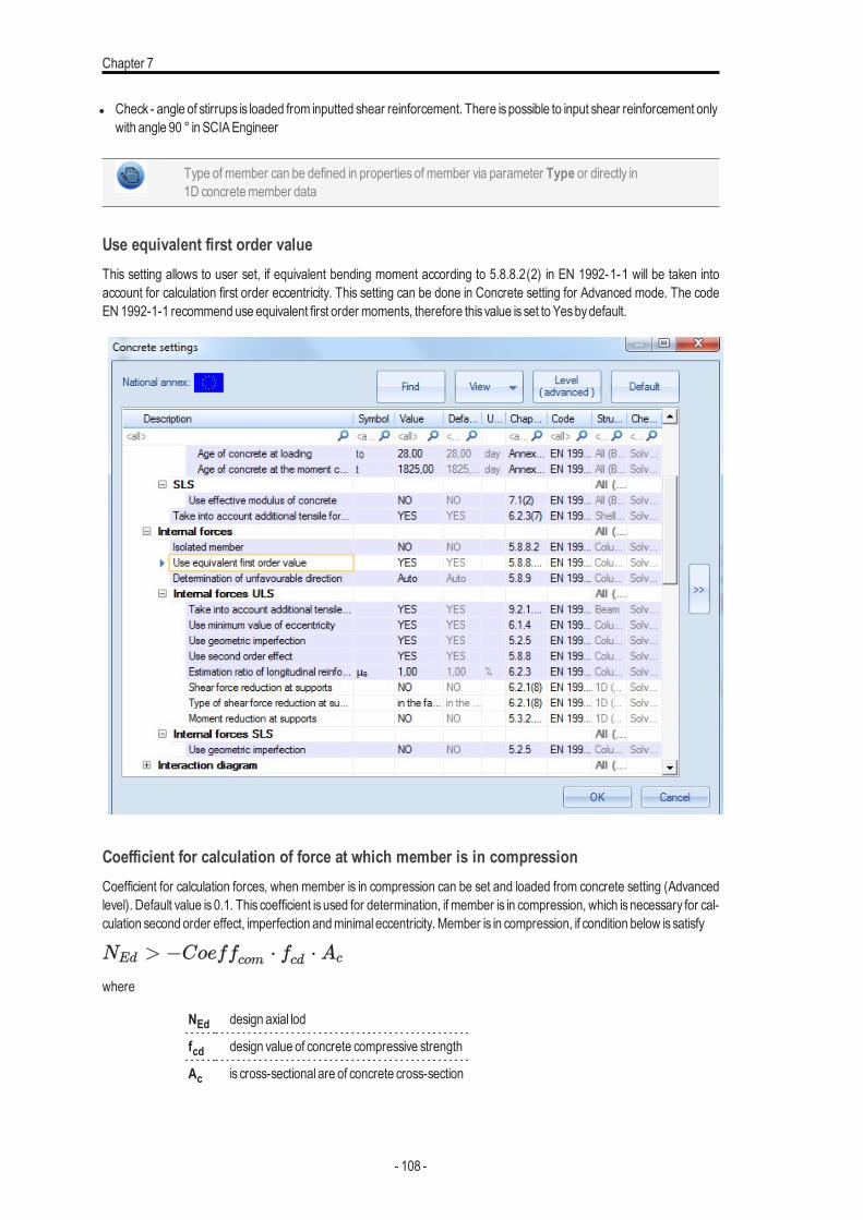
Chapter 7
l Check - angle of stirrups is loaded from inputted shear reinforcement. There ispossible to input shear reinforcement onlywith angle 90 ° in SCIAEngineer
Type of member can be defined in properties of member via parameter Type or directly in1D concretemember data
Use equivalent first order valueThis setting allows to user set, if equivalent bending moment according to 5.8.8.2(2) in EN 1992-1-1 will be taken intoaccount for calculation first order eccentricity. This setting can be done in Concrete setting for Advanced mode. The codeEN 1992-1-1 recommend use equivalent first order moments, therefore this value is set to Yesbydefault.
Coefficient for calculation of force at which member is in compressionCoefficient for calculation forces, when member is in compression can be set and loaded from concrete setting (Advancedlevel). Default value is 0.1. This coefficient is used for determination, if member is in compression, which is necessary for cal-culation second order effect, imperfection andminimal eccentricity. Member is in compression, if condition below issatisfy
where
NEd design axial lod
fcd design value of concrete compressive strength
Ac is cross-sectional are of concrete cross-section
- 108 -
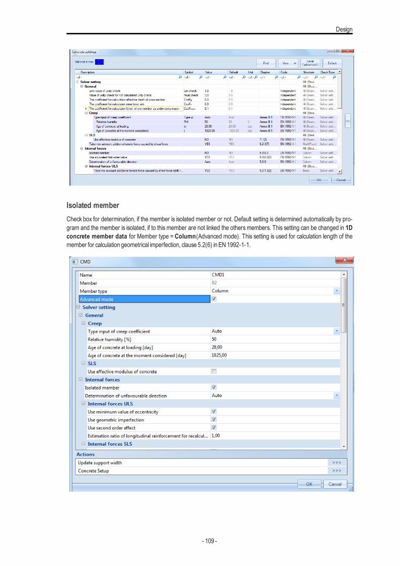
Design
Isolated memberCheck box for determination, if the member is isolated member or not. Default setting is determined automatically by pro-gram and the member is isolated, if to this member are not linked the others members. This setting can be changed in 1Dconcrete member data for Member type = Column(Advanced mode). This setting is used for calculation length of themember for calculation geometrical imperfection, clause 5.2(6) in EN 1992-1-1.
- 109 -
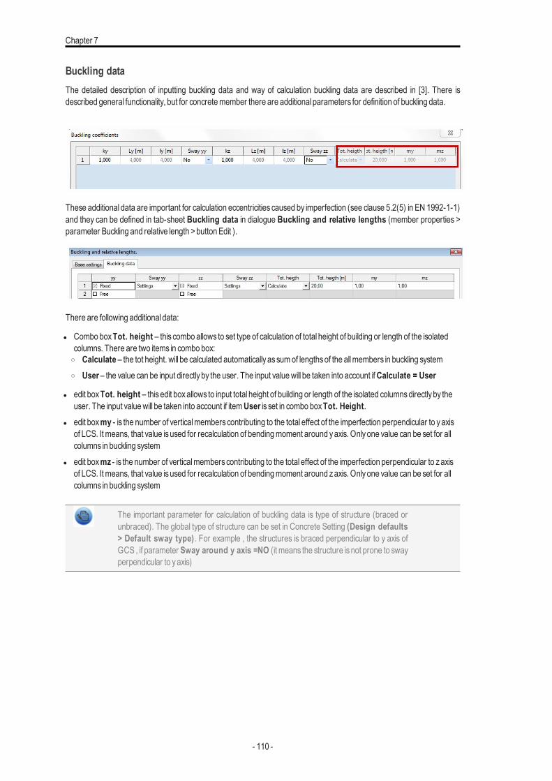
Chapter 7
Buckling dataThe detailed description of inputting buckling data and way of calculation buckling data are described in [3]. There isdescribed general functionality, but for concretemember there are additional parameters for definition of buckling data.
These additional data are important for calculation eccentricities caused by imperfection (see clause 5.2(5) in EN 1992-1-1)and they can be defined in tab-sheet Buckling data in dialogue Buckling and relative lengths (member properties >parameter Buckling and relative length >button Edit ).
There are following additional data:
l Combo boxTot. height – this combo allows to set type of calculation of total height of building or length of the isolatedcolumns. There are two items in combo box:o Calculate – the tot height. will be calculated automaticallyassumof lengthsof the allmembers in buckling systemo User– the value can be input directlyby the user. The input valuewill be taken into account ifCalculate = User
l edit boxTot. height – thisedit boxallows to input total height of building or length of the isolated columnsdirectlyby theuser. The input valuewill be taken into account if itemUser is set in combo boxTot. Height.
l edit boxmy - is the number of verticalmemberscontributing to the total effect of the imperfection perpendicular to yaxisof LCS. It means, that value isused for recalculation of bendingmoment around yaxis. Onlyone value can be set for allcolumns in buckling system
l edit boxmz - is the number of verticalmemberscontributing to the total effect of the imperfection perpendicular to zaxisof LCS. It means, that value isused for recalculation of bendingmoment around zaxis. Onlyone value can be set for allcolumns in buckling system
The important parameter for calculation of buckling data is type of structure (braced orunbraced). The global type of structure can be set in Concrete Setting (Design defaults> Default sway type). For example , the structures is braced perpendicular to y axis ofGCS , if parameter Sway around y axis =NO (it means the structure isnot prone to swayperpendicular to yaxis)
- 110 -
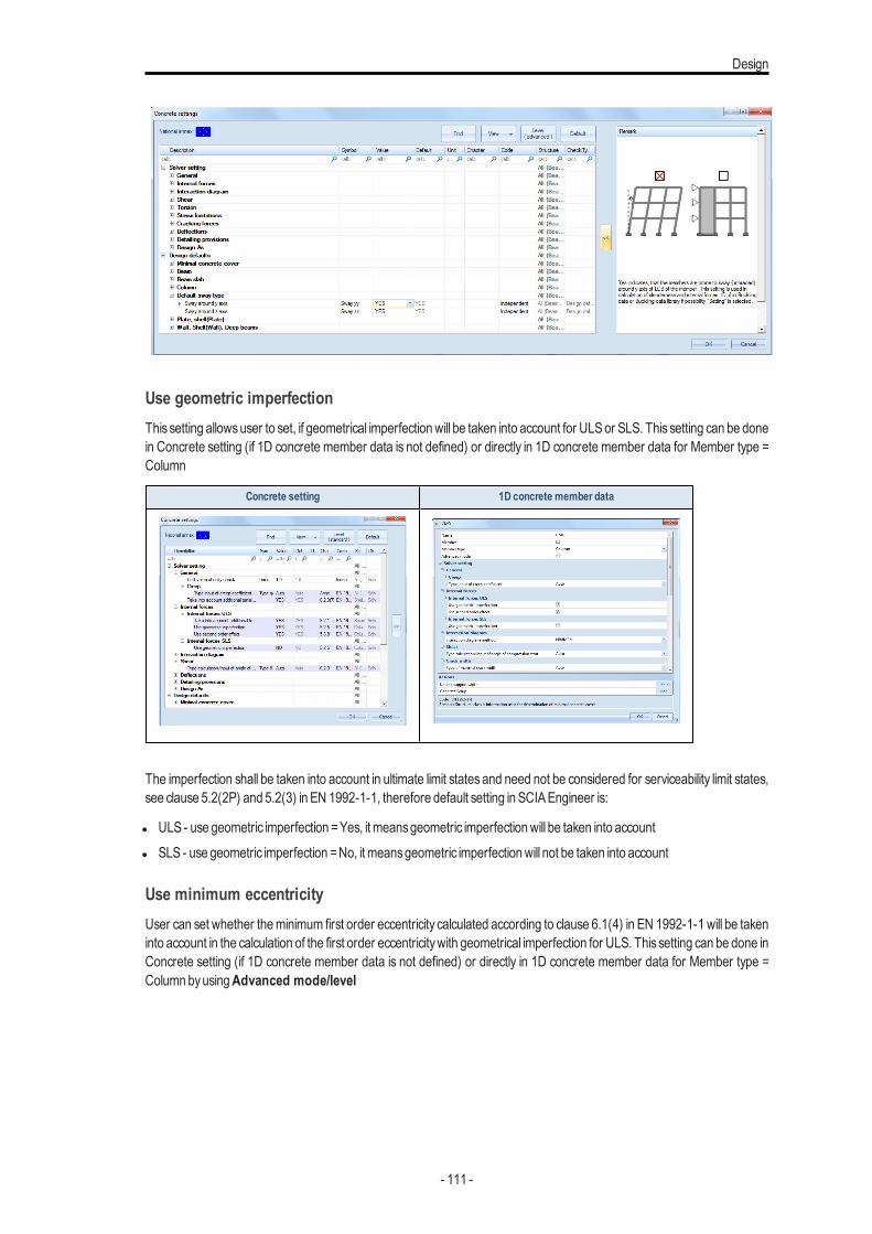
Design
Use geometric imperfectionThis setting allowsuser to set, if geometrical imperfectionwill be taken into account for ULSor SLS. This setting can be donein Concrete setting (if 1D concrete member data is not defined) or directly in 1D concrete member data for Member type =Column
Concrete setting 1D concrete member data
The imperfection shall be taken into account in ultimate limit states and need not be considered for serviceability limit states,see clause 5.2(2P) and 5.2(3) in EN 1992-1-1, therefore default setting in SCIAEngineer is:
l ULS - use geometric imperfection =Yes, it meansgeometric imperfectionwill be taken into accountl SLS - use geometric imperfection =No, it meansgeometric imperfectionwill not be taken into account
Use minimum eccentricityUser can set whether theminimum first order eccentricity calculated according to clause 6.1(4) in EN 1992-1-1 will be takeninto account in the calculation of the first order eccentricitywith geometrical imperfection for ULS. This setting can be done inConcrete setting (if 1D concrete member data is not defined) or directly in 1D concrete member data for Member type =Column byusingAdvanced mode/level
- 111 -
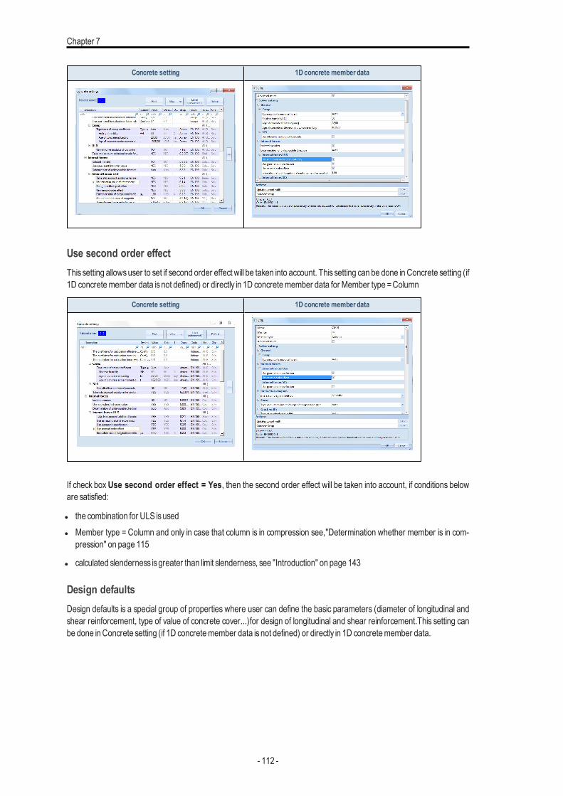
Chapter 7
Concrete setting 1D concrete member data
Use second order effectThis setting allowsuser to set if second order effect will be taken into account. This setting can be done in Concrete setting (if1D concretemember data isnot defined) or directly in 1D concretemember data for Member type =Column
Concrete setting 1D concrete member data
If check boxUse second order effect = Yes, then the second order effect will be taken into account, if conditions beloware satisfied:
l the combination for ULS isusedl Member type = Column and only in case that column is in compression see,"Determination whether member is in com-
pression" on page 115
l calculated slenderness isgreater than limit slenderness, see "Introduction" on page 143
Design defaultsDesign defaults is a special group of properties where user can define the basic parameters (diameter of longitudinal andshear reinforcement, type of value of concrete cover...)for design of longitudinal and shear reinforcement.This setting canbe done inConcrete setting (if 1D concretemember data isnot defined) or directly in 1D concretemember data.
- 112 -
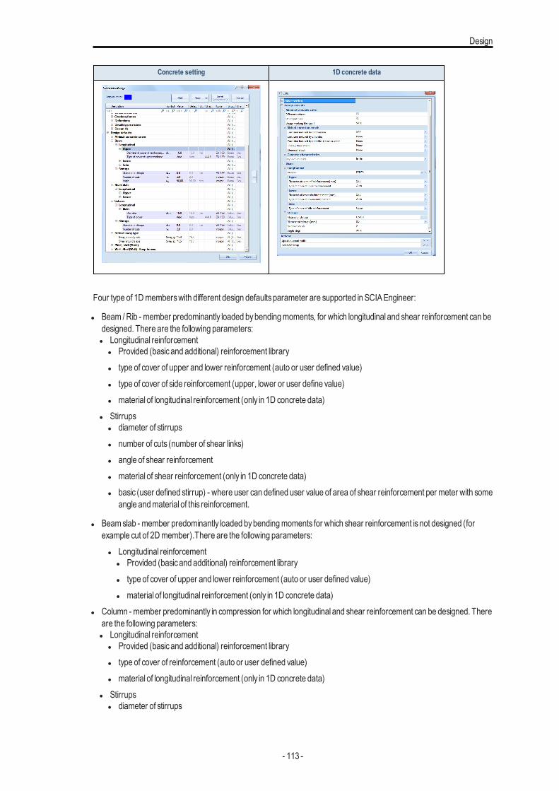
Design
Concrete setting 1D concrete data
Four type of 1Dmemberswith different design defaultsparameter are supported in SCIAEngineer:
l Beam /Rib - member predominantly loaded bybendingmoments, for which longitudinal and shear reinforcement can bedesigned. There are the following parameters:l Longitudinal reinforcement
l Provided (basicand additional) reinforcement libraryl type of cover of upper and lower reinforcement (auto or user defined value)l type of cover of side reinforcement (upper, lower or user define value)l material of longitudinal reinforcement (only in 1D concrete data)
l Stirrupsl diameter of stirrupsl number of cuts (number of shear links)l angle of shear reinforcementl material of shear reinforcement (only in 1D concrete data)l basic (user defined stirrup) - where user can defined user value of area of shear reinforcement per meter with some
angle andmaterial of this reinforcement.
l Beamslab - member predominantly loaded bybendingmoments for which shear reinforcement isnot designed (forexample cut of 2Dmember).There are the following parameters:l Longitudinal reinforcement
l Provided (basicand additional) reinforcement libraryl type of cover of upper and lower reinforcement (auto or user defined value)l material of longitudinal reinforcement (only in 1D concrete data)
l Column - member predominantly in compression for which longitudinal and shear reinforcement can be designed. Thereare the following parameters:l Longitudinal reinforcement
l Provided (basicand additional) reinforcement libraryl type of cover of reinforcement (auto or user defined value)l material of longitudinal reinforcement (only in 1D concrete data)
l Stirrupsl diameter of stirrups
- 113 -
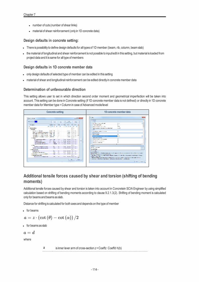
Chapter 7
l number of cuts (number of shear links)l material of shear reinforcement (only in 1D concrete data)
Design defaults in concrete setting:l There ispossibility to define design defaults for all typesof 1Dmember (beam, rib, column, beamslab)l thematerial of longitudinal and shear reinforcement isnot possible to input/edit in this setting, butmaterial is loaded from
project data and it is same for all type ofmembers
Design defaults in 1D concrete member datal onlydesign defaultsof selected type ofmember can be edited in this settingl material of shear and longitudinal reinforcement can be edited directly in concretemember data
Determination of unfavourable directionThis setting allows user to set in which direction second order moment and geometrical imperfection will be taken intoaccount. This setting can be done in Concrete setting (if 1D concrete member data is not defined) or directly in 1D concretemember data for Member type =Column in case of Advancedmode/level
Concrete setting 1D concrete member data
Additional tensile forces caused by shear and torsion (shifting of bendingmoments)Additional tensile forces caused by shear and torsion is taken into account in Concretein SCIA Engineer by using simplifiedcalculation based on shifting of bending moments according to clause 9.2.1.3(2). Shifting of bending moment is calculatedonly for beamsand beamsasslab.
Distance for shifting is calculated for both axesand dependson the type ofmember
l for beams
l for beamsasslab
where
z is inner lever armof cross-section z=Coeffz· Coeffd·h(b)
- 114 -
Design
d is effective depth of cross-section d =Coeffd·h(b)
Coeffd
coefficient for calculation effective depth of cross-section "Coefficient for cal-culation of effective depth of cross-section" on page 105
Coeffz
coefficient for calculation inner lever armof cross-section
h (b) dimension of cross-section in centre of gravityof cross-section in z(y) directionin LCSof cross-section
θangle between the concrete compression strut and the beamaxisper-pendicular to the shear force "Angle between concrete compression strut andbeamaxis" on page 106
α angle between shear reinforcement and the beamaxisperpendicular to theshear force
Automatic calculation of angle between the concrete compression strut and beam axis iscalculated bysimplifiedmethod for shiftingwith the following simplifications:
l shear ofmember for calculation valueVRd.max is calculated asminimumwidth of cross-section at whole cross-sectionperpendicular to direction of shear forces
l valueAk and uk for calculation of TRd.max is calculated for effective rectangular cross-section, which has the same cross-sectional area and sameperimeter as inputted cross-section
Determination whether member is in compressionThe second order effect, minimal eccentricity and geometrical imperfection are taken into account only for member =Column, which is in compression. Column is in compression if conditionsbelow issatisfied
where
NEd design axial load
Coeffcom
coefficient for calculation force for determination, ofmember is in compressionor not, see "Coefficient for calculation of force at whichmember is in com-pression" on page 108
fcd design value of concrete compressive strength
Ac cross-sectional area of concrete cross-section
First order bending moments with imperfectionThe calculation of first order moment is calculated only for Member type = Column and it in case, that columnis in com-pression see,"Determinationwhether member is in compression" above and it runsaccording to the following procedure:
l first order eccentricitywithout effect of imperfection is calculated,l eccentricity caused by imperfection is calculated ,l first order eccentricity including effect of imperfection is calculated.
- 115 -
Chapter 7
Calculation of first order eccentricity without effect of imperfectionThere are two options for calculation first order moments and eccentricity in SCIA Engineer depending on check boxUseequivalent first order value,see "Use equivalent first order value" on page 108
l the equivalent first order bendingmomentsare taken into account. It means, that bendingmomentswill be same at wholelength of themember. Thisoption isused if checkboxUse equivalent first order value = Yes in Concrete setting (if1D concretemember data isnot defined) or in 1D concretemember data
l the first order eccentricity is calculated frombendingmoments in current section. It follows, that bendingmoments in eachsection can be different. Thisoption isused if checkboxUse equivalent first order value = No in Concrete setting (if1D concretemember data isnot defined) or in 1D concretemember data
where
e0,y(z) the 1st order eccentricity in direction of y (z) axisof LCS
My(z) the 1st order moment around of y (z) axisof LCS
NEd the design axial force in calculated section of the column (in SCIAEngineer valueN)
e0e,y(z) the 1st order equivalent eccentricity in direction of y (z) axisof LCS
M0e,y(z) the 1st order equivalentmoment around of y (z) axisof LCS
The 1st order equivalentmoment is calculated according to clause 5.8.8.2 (2) in EN 1992-1-1
M0,ey =max (0,6*M02,y +0,4*M01,y; 0,4*M02,y)
M0,ez =max (0,6*M02,z +0,4*M01,z; 0,4*M02,z)
where
M01y(z) is first end bending moments around y(z) axis of LCS with lesser absolute value as second end bending moment.|M01y(z)|< |M02y(z)| The same valuesare used for calculation limit slenderness
M02y(z) is second end bending moments around y(z) axis of LCSwith greater absolute value as first end bending moment.|M02y(z)|≥ |M01y(z)| The same valuesare used for calculation limit slenderness
The user (real) reinforcement defined via REDESand free bars are not taken into accountfor calculation effective depth of cross-section for design reinforcement to column (Typeof check = Design ULS in service Internal forces)
Calculation of eccentricity due to imperfectionThe imperfection in SEN is represented by an inclination according to clause 5.2(5) in EN 1992-1-1. The imperfection shallbe taken into account in ultimate limit statesand need not be considered for serviceability limit states, see clause 5.2(2P) and5.2(3) in EN 1992-1-1. User can set independently if the imperfectionwill be taken into account for ULSor SLS, see .
The inclination is calculated around both axes ( axis yand z) of LCSaccording to formula:
where
- 116 -
Design
F0 is the basic value of inclination. The value is National parameter, it means that value can be different for each country.The value can be set inManager for national annex > EN 1992-1-1 > General > ULS > General > Theta_0 )
αh is the reduction factor for length of column or height of structure. The value is calculated according to formula
αm,y(z) is the reduction factor for numbersofmemberscalculated according to formula
l is length of column or height of structure depending on, if the member is isolated or not, see "Isolated member" onpage 109
l isolatedmember l =L, where L is length of thememberl not isolatedmember l =H, whereH is total height of building (buckling system). Thisheight can be defined in Buckling
data, see "Buckling data" on page 110
my(mz) is the number of verticalmembers contributing to the total effect of the imperfection perpendicular to y(z) of LCS. Itmeans, that value is used for recalculation of bendingmoment around y(z) axis of LCS. These value can be defined in Buck-ling data, see "Buckling data" on page 110
The effect of imperfection for isolated column and for structure is taken into account always as an eccentricity according toclause 5.2(7a) in EN 1992-1-1.
where
Fi,y(z) is the inclination around y(z) axisof LCS (perpendicular to y (z) axisof LCS)
l0,y(z) is the effective length of themember (column) around y(z) axis of LCS (perpendicular to y (z) axis of LCS), which canbe defined in Buckling data, see "Buckling data" on page 110
The direction (sign) of value of eccentricity caused by imperfection has to be same as dir-ection (sign) of first order eccentricity.
Minimum first order eccentricityTheminimum first order eccentricity is calculated according to clause 6.1(4) in EN 1992-1-1.
where
e0,min,y(z) isminimum first order eccentricity in direction of y (z) axisof LCS
b dimension of cross-section in centre of gravity in direction of yaxisof LCS
h dimension of cross-section in centre of gravity in direction of zaxisof LCS
Theminimumeccentricity is taken into account,if checkboxUse minimum value of eccentricity =Yes
- 117 -
Chapter 7
The direction (sign) of minimum first order eccentricity has to be same asdirection (sign) offirst order eccentricity
Calculation of first order eccentricity including effect of imperfectionFirst order eccentricity including effect of imperfection is calculated according to formula below
eoEd,y(z) =e0,y(z) +ei,y(z) >e0,min,y(z)
where
e0,y(z)is the 1st order eccentricity in direction of y (z) axisof LCS ,see "Calculation offirst order eccentricitywithout effect of imperfection" on page 116
ei,y(z)is eccentricity caused by imperfection in direction of y (z) axisof LCS, see "Cal-culation of eccentricitydue to imperfection" on page 116
e0,min,y(z)
isminimum first order eccentricity in direction of y (z) axisof LCS, see "Min-imum first order eccentricity" on the previouspage
After calculation of first order eccentricity including effect of imperfection, the 1st order moment, including the effect of imper-fectionsaround y (z) axisof LCS iscalculated:
M0Ed,y(z) =NEd* eoEd,z(y)
Calculation of second order effectsThe EN 1992-1-1 defines several methods for analysis of second order effects with axial load (general method, simplifiedmethod based on nominal stiffness, simplified method based on nominal curvature...). The SEN allows making analysis ofsecond order effect byusing the followingmethods:
l Generalmethod - equilibriumand resistance isverified in the deformed state, deformationsare calculated taking intoaccount the relevant effectsof cracking, non-linear material propertiesand creep, see clause 5.8.2(2) in EN 1992-1-1,
l Simplifiedmethod based on nominal curvature according to EN 1992-1-1, clause 5.8.8
The second order effect bysimplifiedmethod is taken into account:
l for ultimate limit statel only for Member type = Column and it in case, that column is in compression see,"Determination whether member is in
compression" on page 115
l checkboxUse second order effect in switchedON, seel calculated slenderness isgreater than limit slenderness, see"Introduction" on page 143
Calculation of second order momentNominal second order moment is calculated according to clause 5.8.8.2(3) in EN 1992-1-1
M2,y(z) =NEd∙ e2,z(y)where
NEdis the design axial force in calculated section of the column (in SCIAEngineervalueN)
e2,z(y)
is the second order eccentricity in direction of z (y) axisof LCS
- 118 -
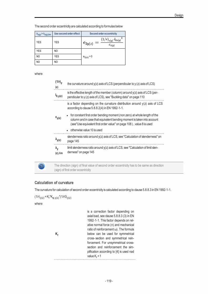
Design
The second order eccentricityare calculated according to formulasbelow
λz(y) > λz(y),lim Use second order effect Second order eccentricity
YES YES
YES NO
e2y(z) = 0NO YES
NO NO
where
(1/r)y(z)
the curvature around y(z) axisof LCS (perpendicular to y (z) axisof LCS)
l0,y(z)is the effective length of themember (column) around y(z) axisof LCS (per-pendicular to y (z) axisof LCS), see "Buckling data" on page 110
cy(z)
is a factor depending on the curvature distribution around y(z) axis of LCSaccording to clause 5.8.8.2(4) in EN 1992-1-1.
l for constant first order bendingmoment (non zero) at whole length of thecolumn and in case that equivalent bendingmoment is taken into account(see"Use equivalent first order value" on page 108 ) , value 8 isused
l otherwise value 10 isused
λy(z)slenderness ratio around y(z) axisof LCS, see "Calculation of slenderness" onpage 145
λy(z),lim
limit slenderness ratio around y(z) axisof LCS, see "Calculation of limit slen-derness" on page 145
The direction (sign) of final value of second order eccentricity has to be same as direction(sign) of first order eccentricity
Calculation of curvatureThe curvature for calculation of second order eccentricity is calculated according to clause 5.8.8.3 in EN 1992-1-1.
(1/r)y(z) =Kr*Kφ,y(z)*(1/r0)y(z)where
Kr
is a correction factor depending onaxial load, see clause 5.8.8.3 (3) in EN1992-1-1. This factor depends on rel-ative normal force (n) and mechanicalratio of reinforcement ω). The formulabelow can be used for symmetricalcross- section and symmetrical rein-forcement. For unsymmetrical cross-section and reinforcement the sim-plification according to [4] is used nadvalueKr =1
- 119 -
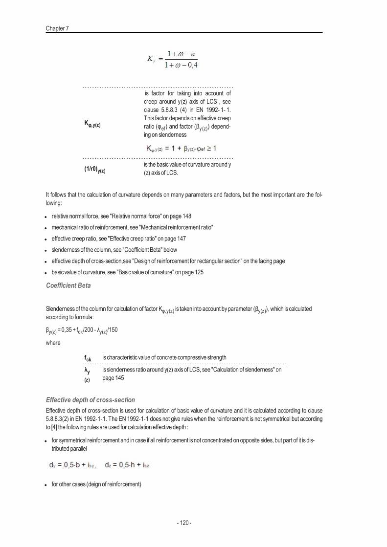
Chapter 7
Kφ,y(z)
is factor for taking into account ofcreep around y(z) axis of LCS , seeclause 5.8.8.3 (4) in EN 1992- 1- 1.This factor depends on effective creepratio (φef) and factor (βy(z)) depend-ing on slenderness
(1/r0)y(z)is the basic value of curvature around y(z) axisof LCS.
It follows that the calculation of curvature depends on many parameters and factors, but the most important are the fol-lowing:
l relative normal force, see "Relative normal force" on page 148l mechanical ratio of reinforcement, see "Mechanical reinforcement ratio"l effective creep ratio, see "Effective creep ratio" on page 147l slendernessof the column, see "Coefficient Beta" belowl effective depth of cross-section,see "Design of reinforcement for rectangular section" on the facing pagel basic value of curvature, see "Basic value of curvature" on page 125
Coefficient Beta
Slendernessof the column for calculation of factor Kφ,y(z) is taken into account byparameter (βy(z)), which is calculatedaccording to formula:
βy(z) =0,35 + fck/200 - λy(z)/150
where
fck is characteristic value of concrete compressive strength
λy(z)
is slenderness ratio around y(z) axisof LCS, see "Calculation of slenderness" onpage 145
Effective depth of cross-sectionEffective depth of cross-section is used for calculation of basic value of curvature and it is calculated according to clause5.8.8.3(2) in EN 1992-1-1. The EN 1992-1-1 does not give rules when the reinforcement is not symmetrical but accordingto [4] the following rulesare used for calculation effective depth :
l for symmetrical reinforcement and in case if all reinforcement isnot concentrated on opposite sides, but part of it is dis-tributed parallel
l for other cases (deign of reinforcement)
- 120 -
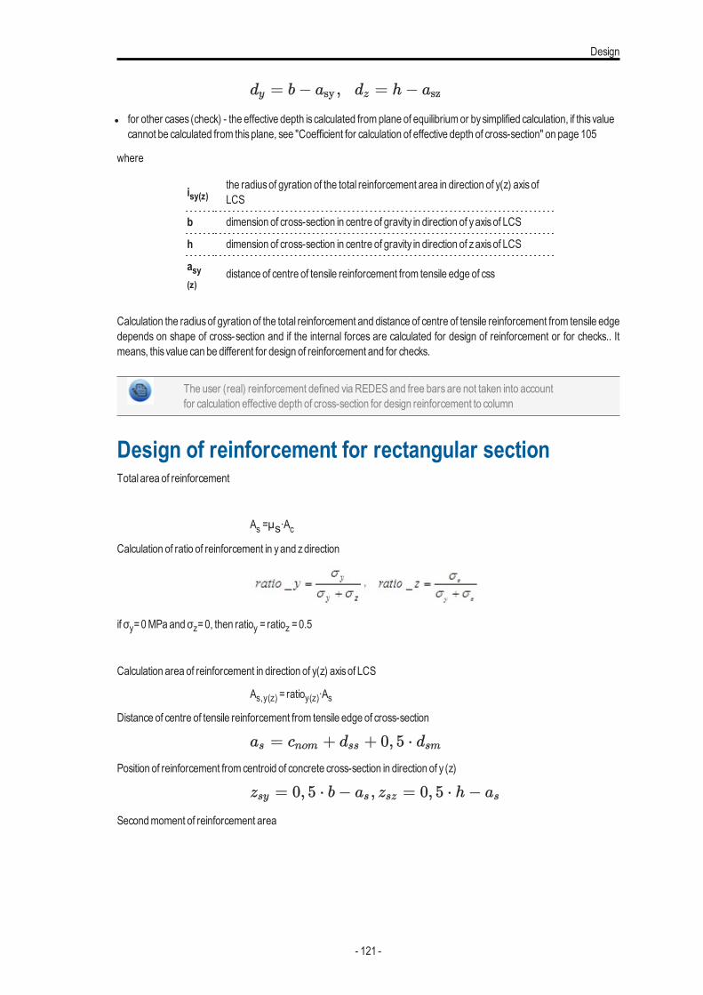
Design
l for other cases (check) - the effective depth is calculated fromplane of equilibriumor bysimplified calculation, if this valuecannot be calculated from thisplane, see "Coefficient for calculation of effective depth of cross-section" on page 105
where
isy(z)the radiusof gyration of the total reinforcement area in direction of y(z) axisofLCS
b dimension of cross-section in centre of gravity in direction of yaxisof LCS
h dimension of cross-section in centre of gravity in direction of zaxisof LCS
asy(z)
distance of centre of tensile reinforcement from tensile edge of css
Calculation the radiusof gyration of the total reinforcement and distance of centre of tensile reinforcement from tensile edgedepends on shape of cross-section and if the internal forces are calculated for design of reinforcement or for checks.. Itmeans, this value can be different for design of reinforcement and for checks.
The user (real) reinforcement defined via REDESand free bars are not taken into accountfor calculation effective depth of cross-section for design reinforcement to column
Design of reinforcement for rectangular sectionTotal area of reinforcement
As =μs∙AcCalculation of ratio of reinforcement in yand zdirection
if σy=0MPaandσz=0, then ratioy = ratioz =0.5
Calculation area of reinforcement in direction of y(z) axisof LCS
As,y(z) = ratioy(z)∙AsDistance of centre of tensile reinforcement from tensile edge of cross-section
Position of reinforcement from centroid of concrete cross-section in direction of y (z)
Secondmoment of reinforcement area
- 121 -
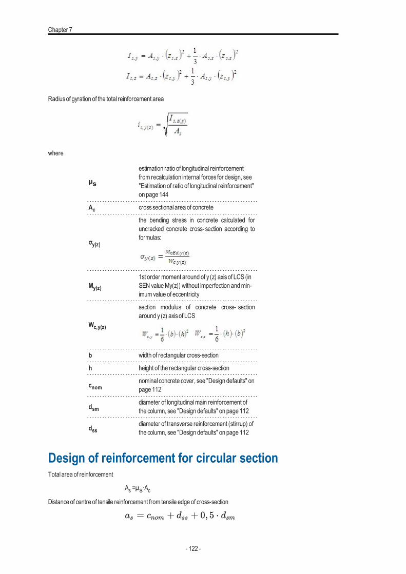
Chapter 7
Radiusof gyration of the total reinforcement area
where
μs
estimation ratio of longitudinal reinforcementfrom recalculation internal forces for design, see"Estimation of ratio of longitudinal reinforcement"on page 144
Ac crosssectional area of concrete
σy(z)
the bending stress in concrete calculated foruncracked concrete cross- section according toformulas:
My(z)
1st order moment around of y (z) axisof LCS (inSEN valueMy(z)) without imperfection andmin-imumvalue of eccentricity
Wc,y(z)
section modulus of concrete cross- sectionaround y (z) axisof LCS
b width of rectangular cross-section
h height of the rectangular cross-section
cnomnominal concrete cover, see "Design defaults" onpage 112
dsmdiameter of longitudinalmain reinforcement ofthe column, see "Design defaults" on page 112
dssdiameter of transverse reinforcement (stirrup) ofthe column, see "Design defaults" on page 112
Design of reinforcement for circular sectionTotal area of reinforcement
As =μs∙AcDistance of centre of tensile reinforcement from tensile edge of cross-section
- 122 -
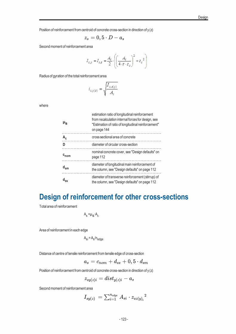
Design
Position of reinforcement from centroid of concrete cross-section in direction of y (z)
Secondmoment of reinforcement area
Radiusof gyration of the total reinforcement area
where
μs
estimation ratio of longitudinal reinforcementfrom recalculation internal forces for design, see"Estimation of ratio of longitudinal reinforcement"on page 144
Ac crosssectional area of concrete
D diameter of circular cross-section
cnomnominal concrete cover, see "Design defaults" onpage 112
dsmdiameter of longitudinalmain reinforcement ofthe column, see "Design defaults" on page 112
dssdiameter of transverse reinforcement (stirrup) ofthe column, see "Design defaults" on page 112
Design of reinforcement for other cross-sectionsTotal area of reinforcement
As =μs∙Ac
Area of reinforcement in each edge
Asi =As/nedge
Distance of centre of tensile reinforcement from tensile edge of cross-section
Position of reinforcement from centroid of concrete cross-section in direction of y (z)
Secondmoment of reinforcement area
- 123 -
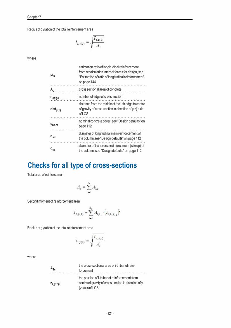
Chapter 7
Radiusof gyration of the total reinforcement area
where
μs
estimation ratio of longitudinal reinforcementfrom recalculation internal forces for design, see"Estimation of ratio of longitudinal reinforcement"on page 144
Ac crosssectional area of concrete
nedge number of edge of cross-section
disty(z)distance from themiddle of the i-th edge to centreof gravityof cross-section in direction of y(z) axisof LCS
cnomnominal concrete cover, see "Design defaults" onpage 112
dsmdiameter of longitudinalmain reinforcement ofthe column,see "Design defaults" on page 112
dssdiameter of transverse reinforcement (stirrup) ofthe column, see "Design defaults" on page 112
Checks for all type of cross-sectionsTotal area of reinforcement
Secondmoment of reinforcement area
Radiusof gyration of the total reinforcement area
where
A1sithe cross-sectional area of i-th bar of rein-forcement
zs,y(z)ithe position of i-th bar of reinforcement fromcentre of gravityof cross-section in direction of y(z) axisof LCS
- 124 -
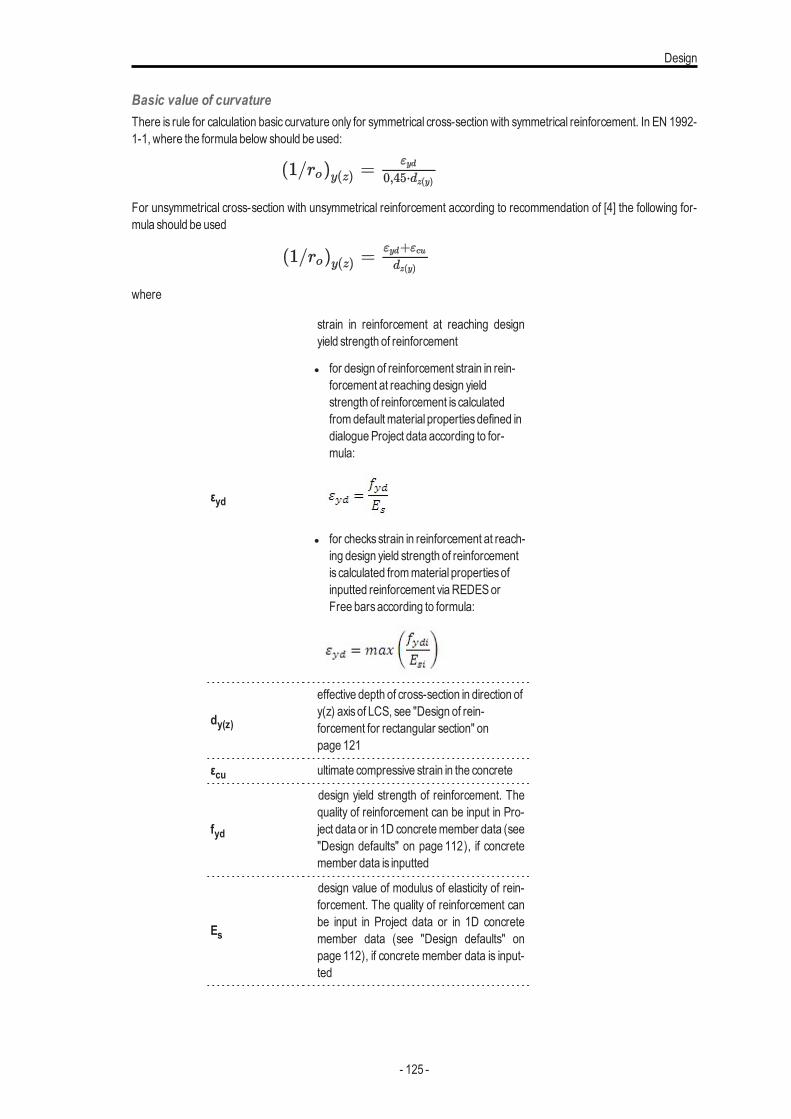
Design
Basic value of curvatureThere is rule for calculation basic curvature only for symmetrical cross-section with symmetrical reinforcement. In EN 1992-1-1, where the formula below should be used:
For unsymmetrical cross-section with unsymmetrical reinforcement according to recommendation of [4] the following for-mula should be used
where
εyd
strain in reinforcement at reaching designyield strength of reinforcement
l for design of reinforcement strain in rein-forcement at reaching design yieldstrength of reinforcement is calculatedfromdefault material propertiesdefined indialogueProject data according to for-mula:
l for checksstrain in reinforcement at reach-ing design yield strength of reinforcementis calculated frommaterial propertiesofinputted reinforcement via REDESorFree barsaccording to formula:
dy(z)
effective depth of cross-section in direction ofy(z) axisof LCS, see "Design of rein-forcement for rectangular section" onpage 121
εcu ultimate compressive strain in the concrete
fyd
design yield strength of reinforcement. Thequality of reinforcement can be input in Pro-ject data or in 1D concretemember data (see"Design defaults" on page 112), if concretemember data is inputted
Es
design value of modulus of elasticity of rein-forcement. The quality of reinforcement canbe input in Project data or in 1D concretemember data (see "Design defaults" onpage 112), if concrete member data is input-ted
- 125 -
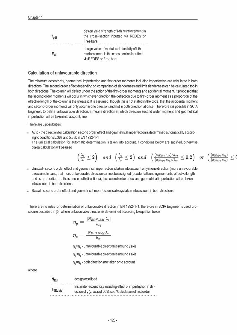
Chapter 7
fydidesign yield strength of i-th reinforcement inthe cross- section inputted via REDES orFree bars
Esidesign value ofmodulusof elasticityof i-threinforcement in the cross-section inputtedviaREDESor Free bars
Calculation of unfavourable directionThe minimum eccentricity, geometrical imperfection and first order moments including imperfection are calculated in bothdirections. The second order effect depending on comparison of slenderness and limit slenderness can be calculated too inboth directions. The columnwill deflect under the action of the first-order momentsand accidentalmoment. It proposed thatthe second order moments will occur in whichever direction the deflection due to first-order moment as a proportion of theeffective length of the column is the greatest. It is assumed, though this is not stated in the code, that the accidentalmomentand second-order momentswill only occur in one direction and not in both direction at once. Therefore it is possible in SCIAEngineer, to define unfavourable direction, it means direction in which direction second order moment and geometricalimperfectionwill be taken into account, see
There are 3 possibilities:
l Auto - the direction for calculation second order effect and geometrical imperfection isdetermined automaticallyaccord-ing to conditions5.38a and 5.38b in EN 1992-1-1The uni axial calculation for automatic determination is taken into account, if conditions below are satisfied, otherwisebiaxial calculationwill be used
l Uniaxial - second order effect and geometrical imperfection is taken into account only in one direction (more unfavourabledirection). In case, thatmore unfavourable direction can not be assigned (accidental bendingmoments, effective lengthand csspropertiesare the same in both directions), the second order effect and geometrical imperfectionwill be takeninto account in both directions.
l Biaxial - second order effect and geometrical imperfection isalways taken into account in both directions
There are no rules for determination of unfavourable direction in EN 1992-1-1, therefore in SCIA Engineer is used pro-cedure described in [5], where unfavourable direction isdetermined according to equation below:
ηy>ηz - unfavourable direction isaround yaxis
ηy<ηz - unfavourable direction isaround zaxis
ηy=ηz - both direction are taken onto account
where
NEd design axial load
e0Edy(z)first order eccentricity including effect of imperfection in dir-ection of y (z) axisof LCS, see "Calculation of first order
- 126 -
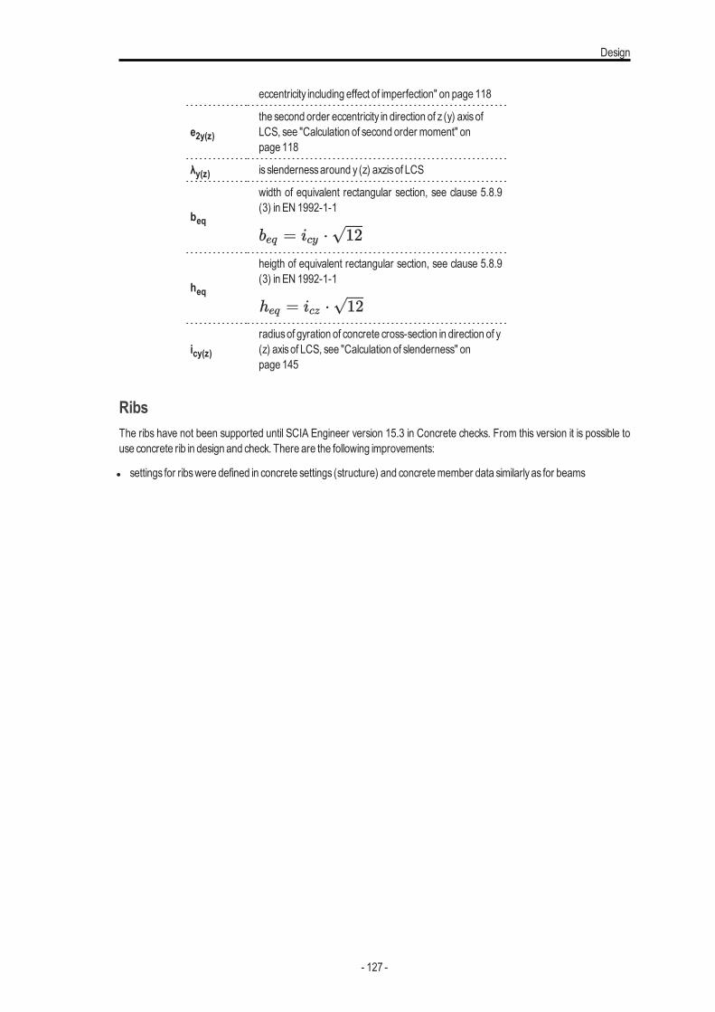
Design
eccentricity including effect of imperfection" on page 118
e2y(z)the second order eccentricity in direction of z (y) axisofLCS, see "Calculation of second order moment" onpage 118
λy(z) is slendernessaround y (z) axzisof LCS
beq
width of equivalent rectangular section, see clause 5.8.9(3) in EN 1992-1-1
heq
heigth of equivalent rectangular section, see clause 5.8.9(3) in EN 1992-1-1
icy(z)radiusof gyration of concrete cross-section in direction of y(z) axisof LCS, see "Calculation of slenderness" onpage 145
RibsThe ribs have not been supported until SCIA Engineer version 15.3 in Concrete checks. From this version it is possible touse concrete rib in design and check. There are the following improvements:
l settings for ribswere defined in concrete settings (structure) and concretemember data similarlyas for beams
- 127 -
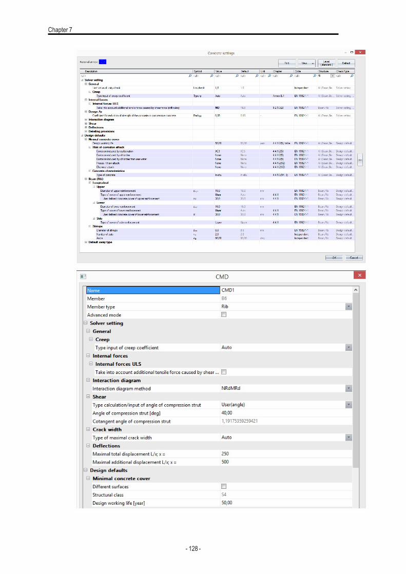
Chapter 7
- 128 -
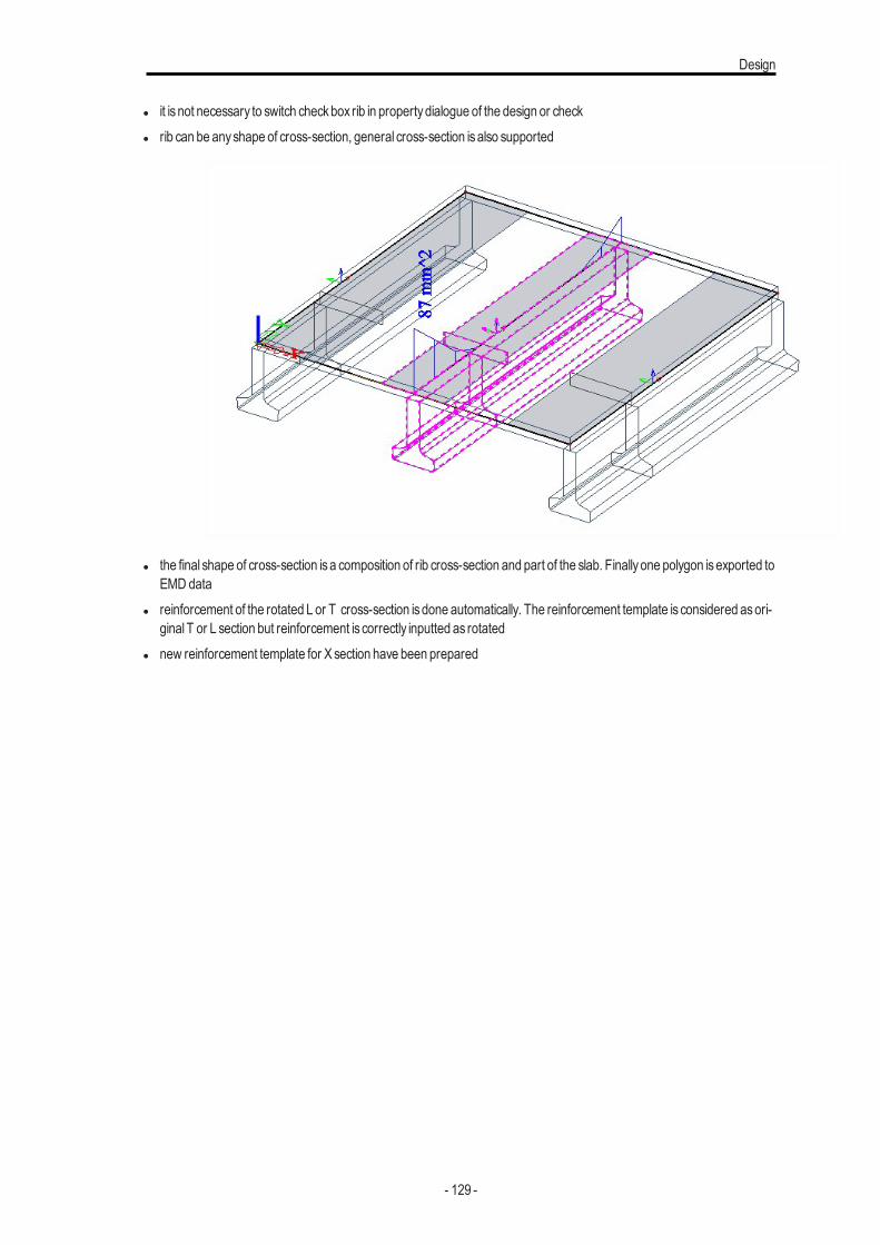
Design
l it is not necessary to switch checkbox rib in propertydialogue of the design or checkl rib can be anyshape of cross-section, general cross-section isalso supported
l the final shape of cross-section isa composition of rib cross-section and part of the slab. Finallyone polygon isexported toEMD data
l reinforcement of the rotated L or T cross-section isdone automatically. The reinforcement template is considered asori-ginalT or L section but reinforcement is correctly inputted as rotated
l new reinforcement template for X section have been prepared
- 129 -
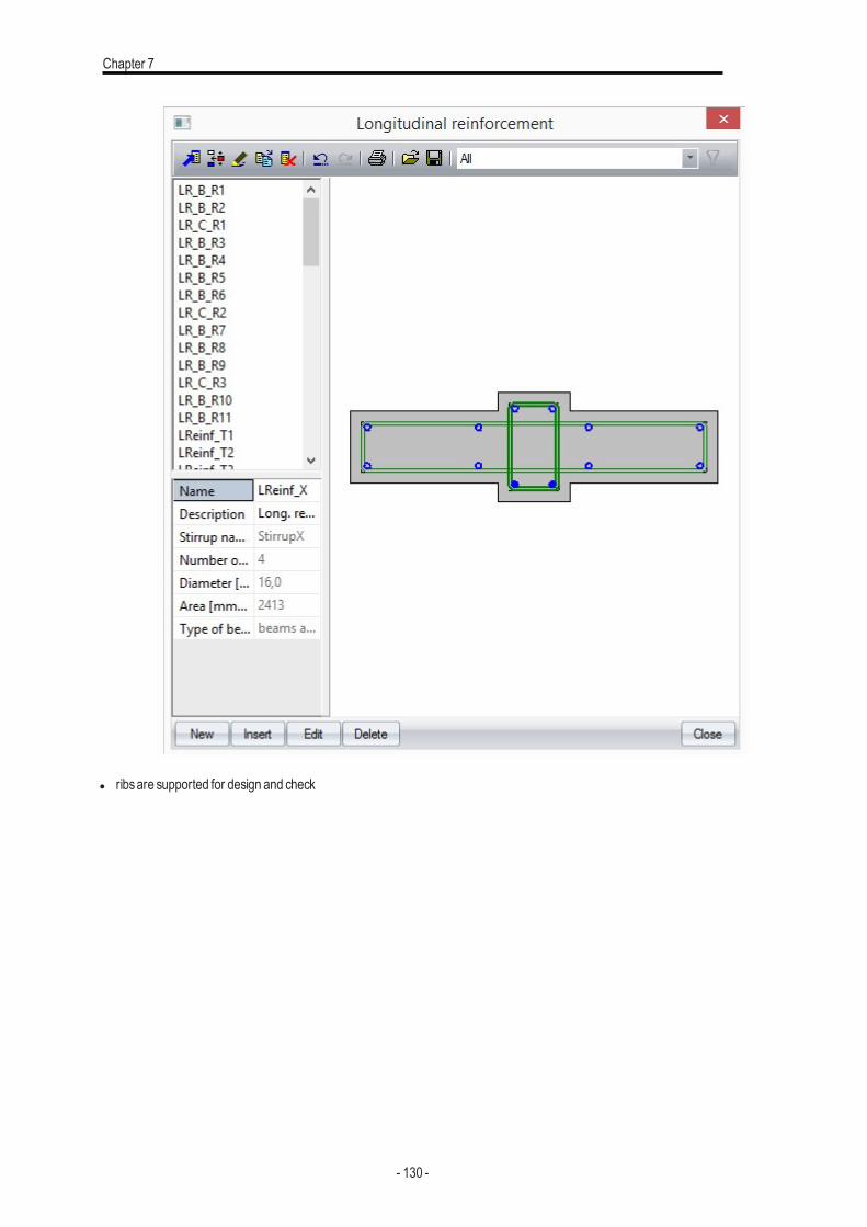
Chapter 7
l ribsare supported for design and check
- 130 -
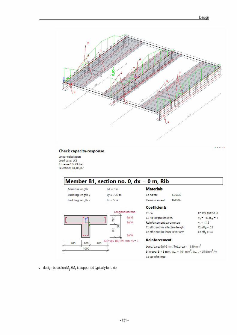
Design
l design based onMy+Mz is supported typically for L rib
- 131 -
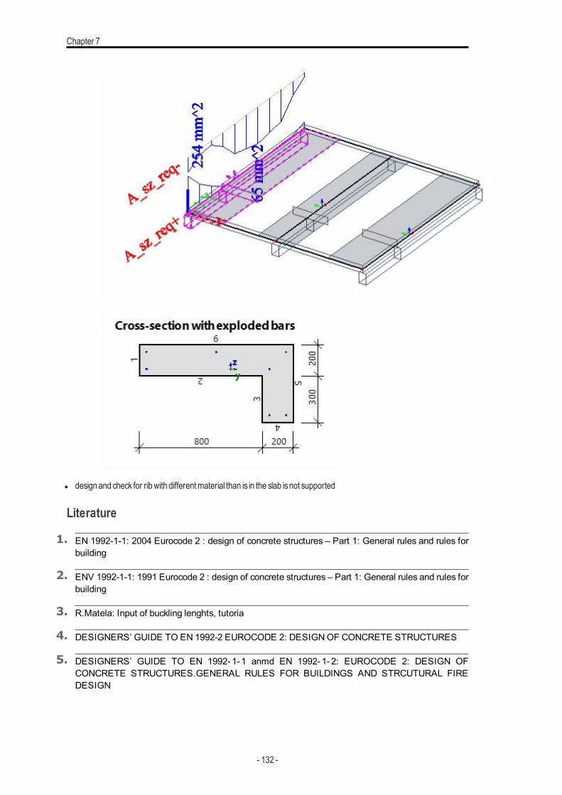
Chapter 7
l design and check for rib with differentmaterial than is in the slab isnot supported
Literature
1. EN 1992-1-1: 2004 Eurocode 2 : design of concrete structures – Part 1: General rules and rules forbuilding
2. ENV 1992-1-1: 1991 Eurocode 2 : design of concrete structures – Part 1: General rules and rules forbuilding
3. R.Matela: Input of buckling lenghts, tutoria
4. DESIGNERS’ GUIDE TO EN 1992-2 EUROCODE 2: DESIGNOF CONCRETE STRUCTURES
5. DESIGNERS’ GUIDE TO EN 1992-1- 1 anmd EN 1992-1- 2: EUROCODE 2: DESIGN OFCONCRETE STRUCTURES.GENERAL RULES FOR BUILDINGS AND STRCUTURAL FIREDESIGN
- 132 -
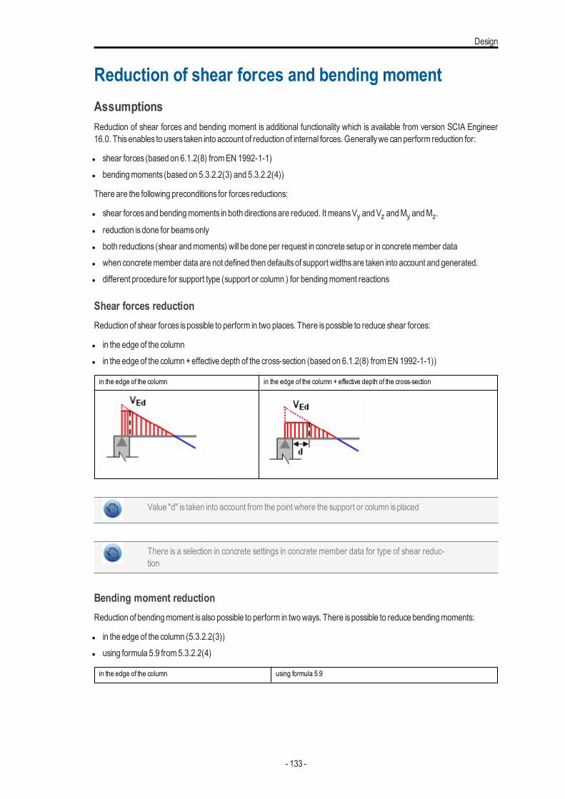
Design
Reduction of shear forces and bending momentAssumptionsReduction of shear forces and bending moment is additional functionality which is available from version SCIA Engineer16.0. Thisenables to users taken into account of reduction of internal forces. Generallywe can perform reduction for:
l shear forces (based on 6.1.2(8) fromEN 1992-1-1)l bendingmoments (based on 5.3.2.2(3) and 5.3.2.2(4))
There are the following preconditions for forces reductions:
l shear forcesand bendingmoments in both directionsare reduced. It meansVy andVz andMy andMz.
l reduction isdone for beamsonlyl both reductions (shear andmoments) will be done per request in concrete setup or in concretemember datal when concretemember data are not defined then defaultsof support widthsare taken into account and generated.l different procedure for support type (support or column ) for bendingmoment reactions
Shear forces reductionReduction of shear forces ispossible to perform in two places. There ispossible to reduce shear forces:
l in the edge of the columnl in the edge of the column+effective depth of the cross-section (based on 6.1.2(8) fromEN 1992-1-1))
in the edge of the column in the edge of the column + effective depth of the cross-section
Value "d" is taken into account from the point where the support or column isplaced
There is a selection in concrete settings in concrete member data for type of shear reduc-tion
Bending moment reductionReduction of bendingmoment isalso possible to perform in twoways. There ispossible to reduce bendingmoments:
l in the edge of the column (5.3.2.2(3))l using formula 5.9 from5.3.2.2(4)
in the edge of the column using formula 5.9
- 133 -
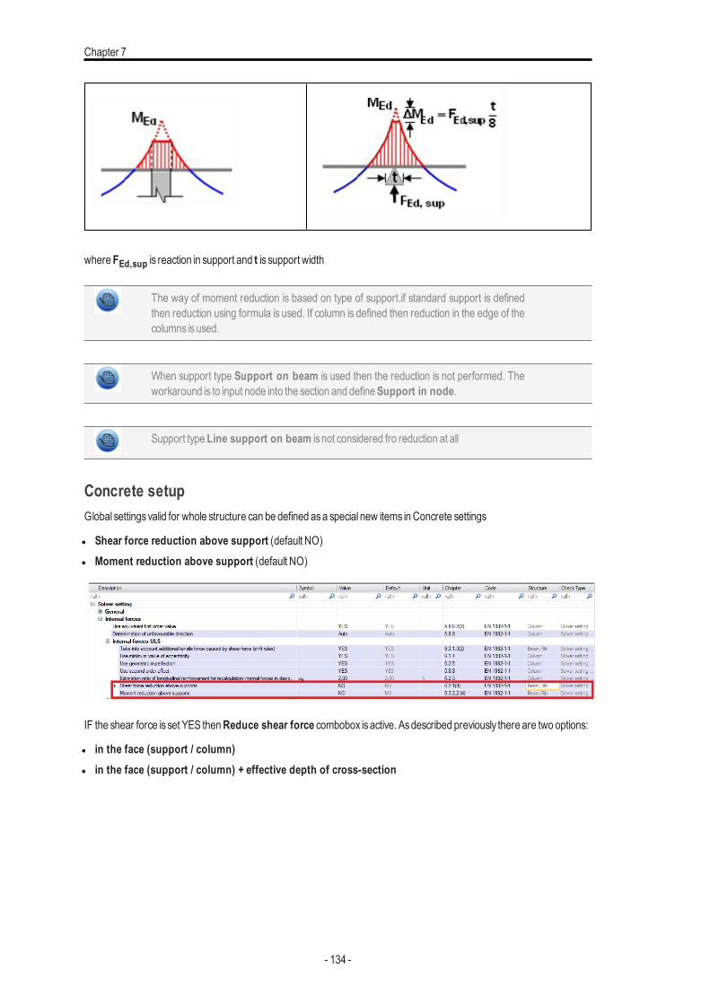
Chapter 7
whereFEd,sup is reaction in support and t is support width
The way of moment reduction is based on type of support.if standard support is definedthen reduction using formula is used. If column is defined then reduction in the edge of thecolumns isused.
When support type Support on beam is used then the reduction is not performed. Theworkaround is to input node into the section and defineSupport in node.
Support typeLine support on beam is not considered fro reduction at all
Concrete setupGlobal settingsvalid for whole structure can be defined asa special new items inConcrete settings
l Shear force reduction above support (default NO)l Moment reduction above support (default NO)
IF the shear force is set YES thenReduce shear force combobox isactive. Asdescribed previously there are two options:
l in the face (support / column)l in the face (support / column) + effective depth of cross-section
- 134 -
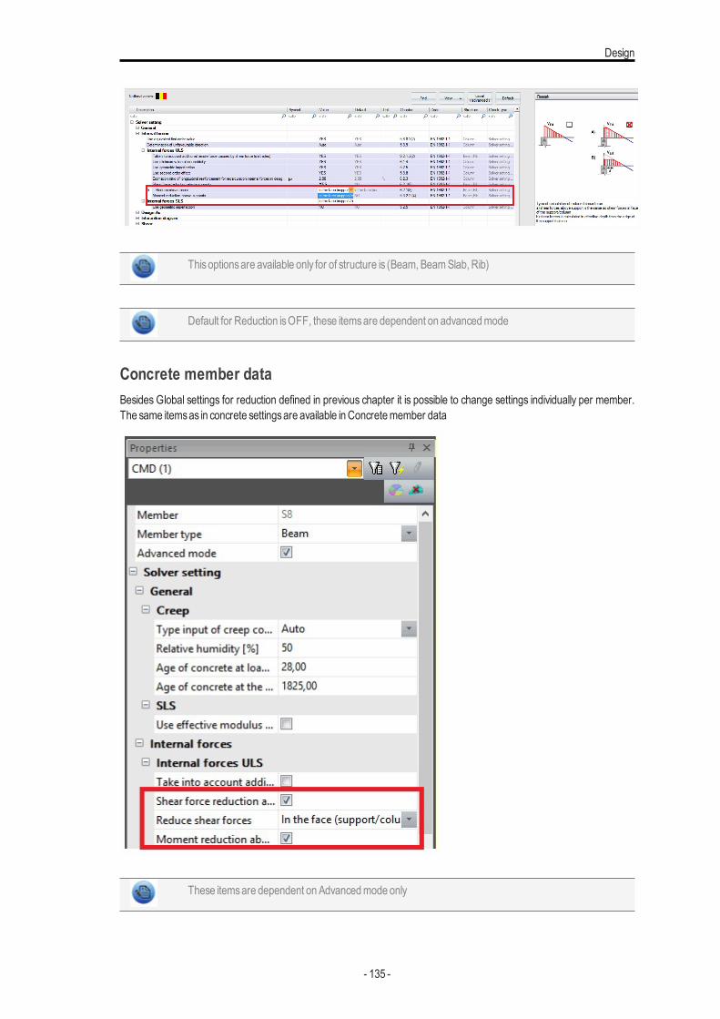
Design
Thisoptionsare available only for of structure is (Beam, BeamSlab, Rib)
Default for Reduction isOFF, these itemsare dependent on advancedmode
Concrete member dataBesides Global settings for reduction defined in previous chapter it is possible to change settings individually per member.The same itemsas in concrete settingsare available in Concretemember data
These itemsare dependent onAdvancedmode only
- 135 -
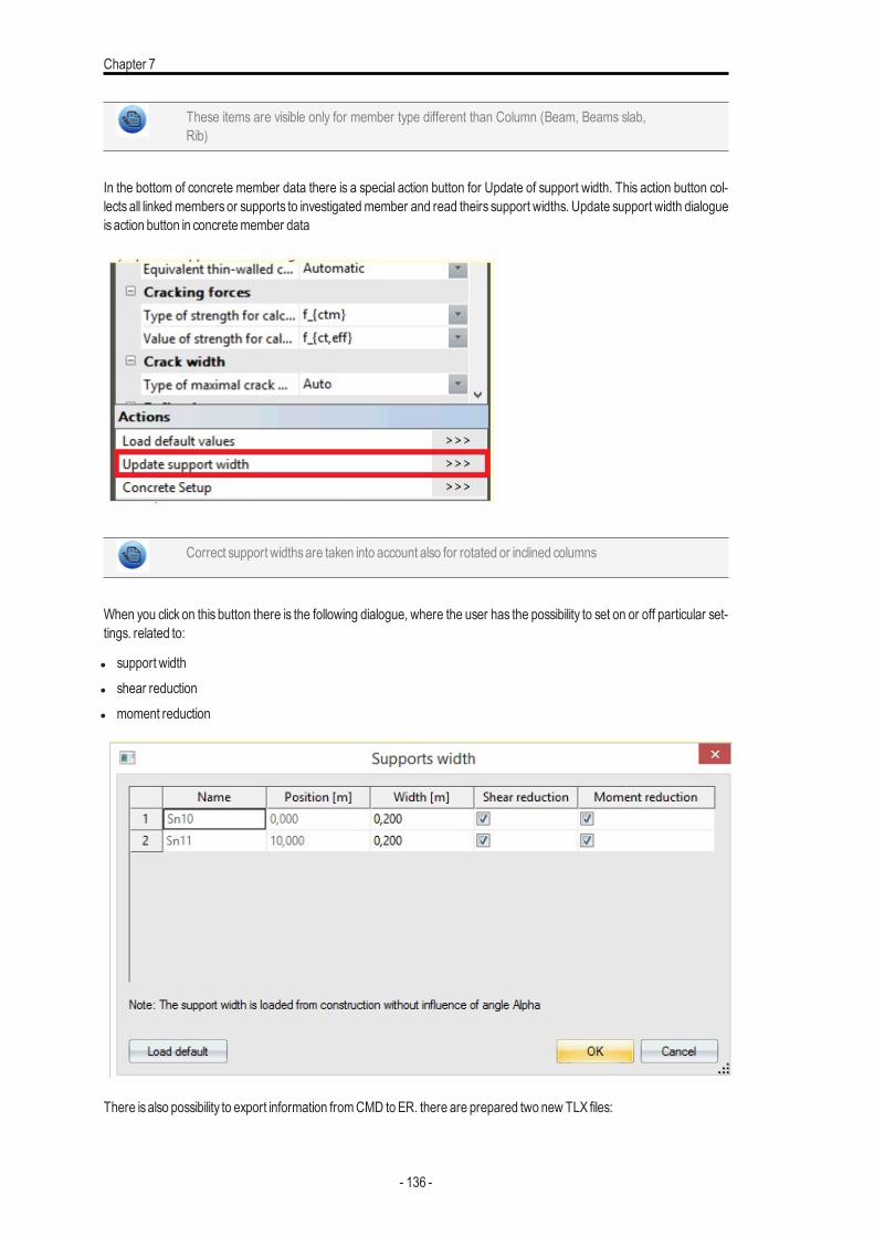
Chapter 7
These items are visible only for member type different than Column (Beam, Beams slab,Rib)
In the bottom of concrete member data there is a special action button for Update of support width. This action button col-lects all linkedmembers or supports to investigatedmember and read theirs support widths. Update support width dialogueisaction button in concretemember data
Correct support widthsare taken into account also for rotated or inclined columns
When you click on this button there is the following dialogue, where the user has the possibility to set on or off particular set-tings. related to:
l support widthl shear reductionl moment reduction
There isalso possibility to export information fromCMD toER. there are prepared two new TLX files:
- 136 -
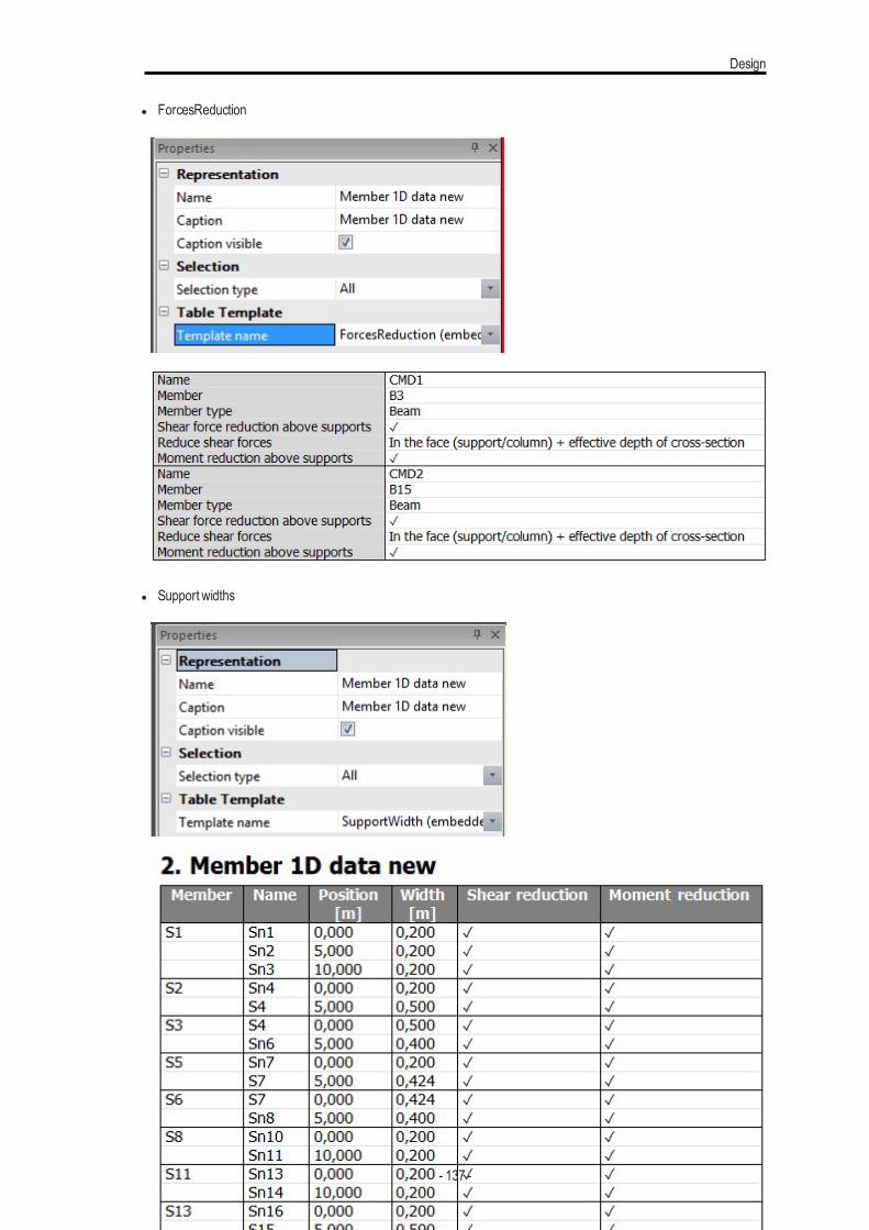
Design
l ForcesReduction
l Support widths
- 137 -
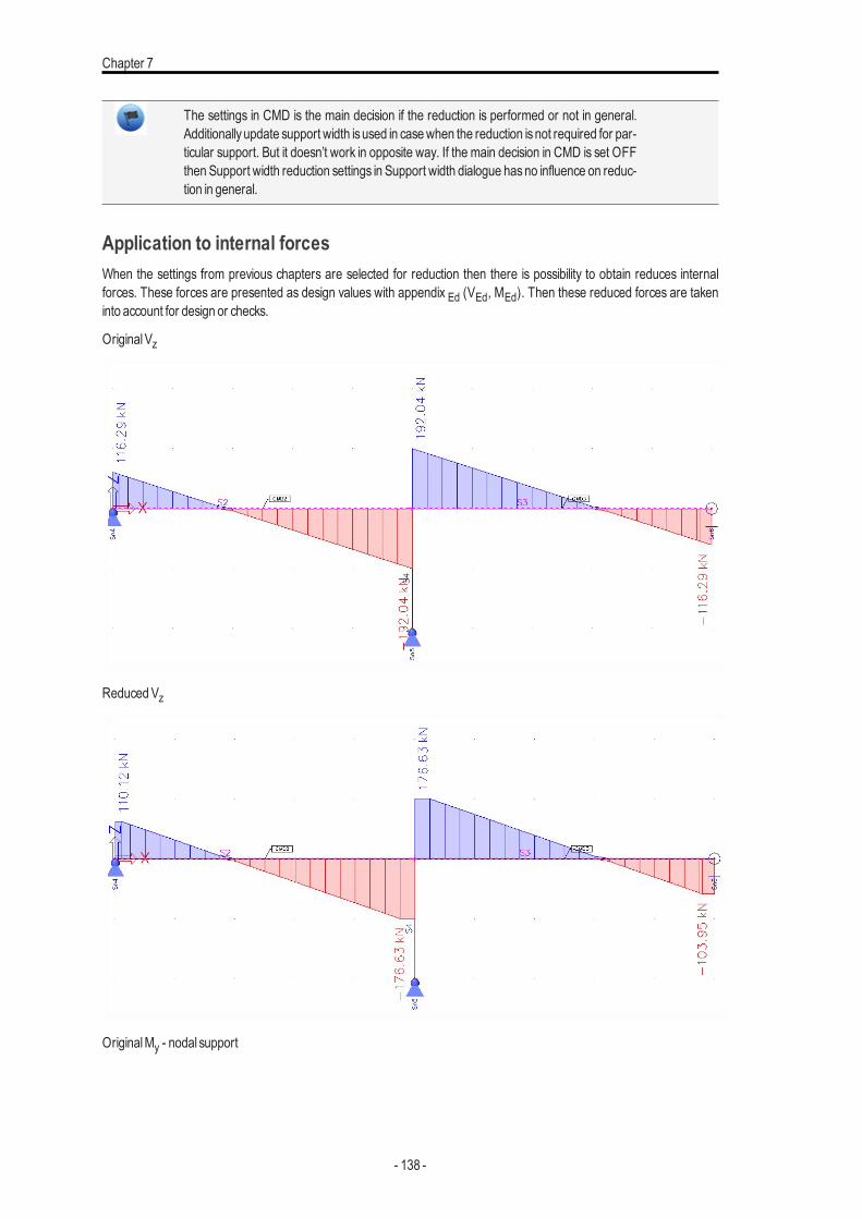
Chapter 7
The settings in CMD is the main decision if the reduction is performed or not in general.Additionallyupdate support width isused in casewhen the reduction isnot required for par-ticular support. But it doesn’t work in opposite way. If the main decision in CMD is set OFFthen Support width reduction settings in Support width dialogue hasno influence on reduc-tion in general.
Application to internal forcesWhen the settings from previous chapters are selected for reduction then there is possibility to obtain reduces internalforces. These forces are presented as design values with appendix Ed (VEd, MEd). Then these reduced forces are takeninto account for design or checks.
OriginalVz
ReducedVz
OriginalMy - nodal support
- 138 -
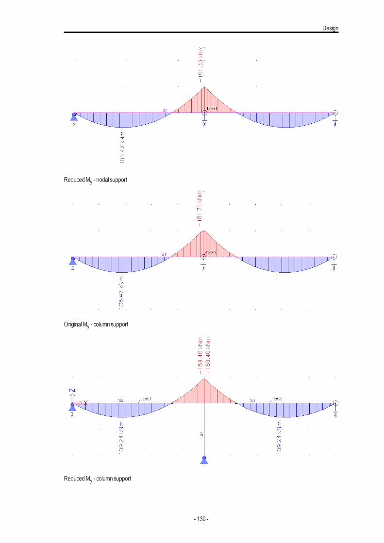
Design
ReducedMy - nodal support
OriginalMy - column support
ReducedMy - column support
- 139 -
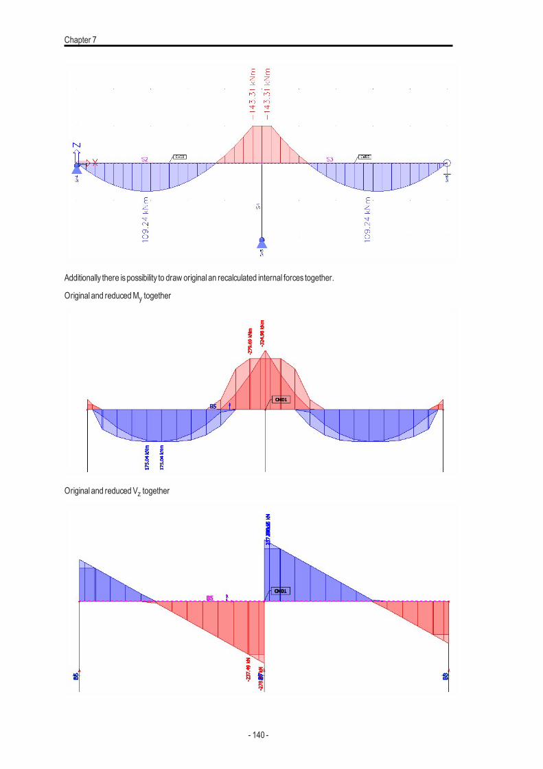
Chapter 7
Additionally there ispossibility to draw original an recalculated internal forces together.
Original and reducedMy together
Original and reducedVz together
- 140 -
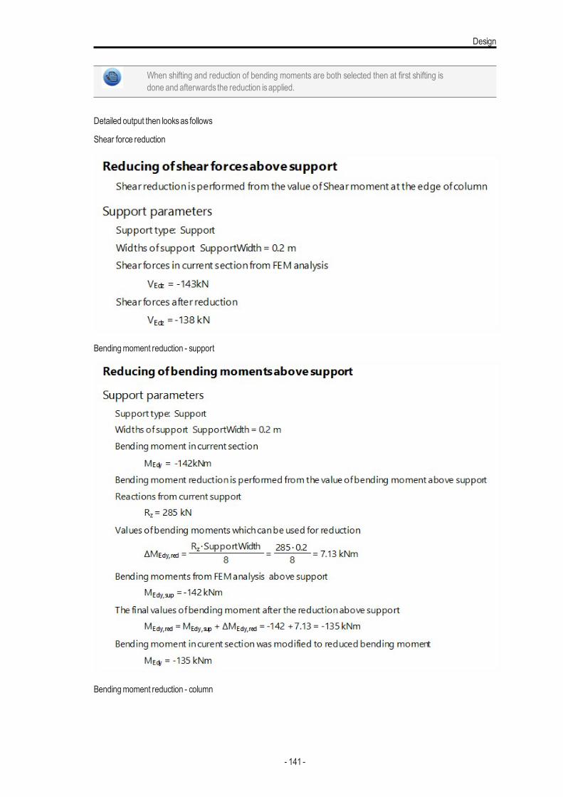
Design
When shifting and reduction of bending moments are both selected then at first shifting isdone and afterwards the reduction isapplied.
Detailed output then looksas follows
Shear force reduction
Bendingmoment reduction - support
Bendingmoment reduction - column
- 141 -
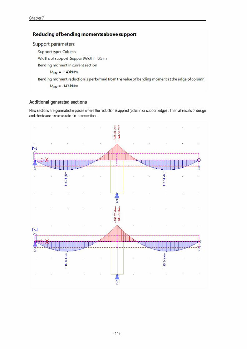
Chapter 7
Additional generated sectionsNew sections are generated in places where the reduction is applied (column or support edge) . Then all results of designand checksare also calculate din these sections.
- 142 -
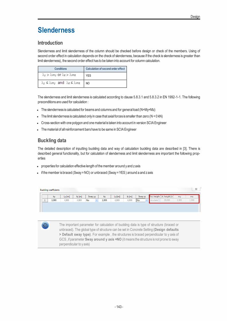
Design
SlendernessIntroductionSlenderness and limit slenderness of the column should be checked before design or check of the members. Using ofsecond order effect in calculation depends on the check of slenderness, because if the check is slenderness is greater thanlimit slenderness), the second order effect has to be taken into account for column calculation.
Conditions Calculation of second order effect
YES
NO
The slenderness and limit slenderness is calculated according to clause 5.8.3.1 and 5.8.3.2 in EN 1992-1-1. The followingpreconditionsare used for calculation :
l The slenderness is calculated for beamsand columnsand for general load (N+My+Mz)l The limit slenderness is calculated only in case that axial forces is smaller than zero (N <0 kN)l Cross-sectionwith one polygon and onematerial is taken into account in version SCIAEngineerl Thematerial of all reinforcement barshave to be same in SCIAEngineer
Buckling dataThe detailed description of inputting buckling data and way of calculation buckling data are described in [3]. There isdescribed general functionality, but for calculation of slenderness and limit slenderness are important the following prop-erties
l properties for calculation effective length of themember around yand zaxisl if themember isbraced (Sway=NO) or unbraced (Sway=YES ) around a and zaxis
The important parameter for calculation of buckling data is type of structure (braced orunbraced). The global type of structure can be set in Concrete Setting (Design defaults> Default sway type). For example , the structures is braced perpendicular to y axis ofGCS , if parameter Sway around y axis =NO (it means the structure isnot prone to swayperpendicular to yaxis)
- 143 -
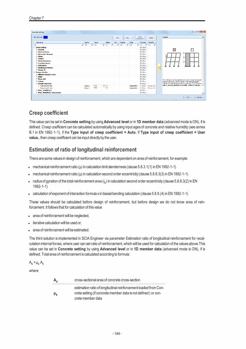
Chapter 7
Creep coefficientThis value can be set inConcrete setting by usingAdvanced level or in 1D member data (advancedmode isON), if isdefined. Creep coefficient can be calculated automatically by using input ages of concrete and relative humidity (see annexB.1 in EN 1992-1-1), if the Type input of creep coefficient = Auto. If Type input of creep coefficient = Uservalue., then creep coefficient can be input directlyby the user.
Estimation of ratio of longitudinal reinforcementThere are some values in design of reinforcement, which are dependent on area of reinforcement, for example:
l mechanical reinforcement ratio (μ) in calculation limit slenderness (clause 5.8.3.1(1) in EN 1992-1-1)l mechanical reinforcement ratio (μ) in calculation second order eccentricity (clause 5.8.8.3(3) in EN 1992-1-1)l radiusof gyration of the total reinforcement area (is) in calculation second order eccentricity (clause 5.8.8.3(2) in EN
1992-1-1)l calculation of exponent of interaction formula x in biaxial bending calculation (clause 5.8.9.(4) in EN 1992-1-1)
These values should be calculated before design of reinforcement, but before design we do not know area of rein-forcement. It follows that for calculation of this value
l area of reinforcement will be neglected,l iterative calculationwill be used or,l area of reinforcement will be estimated.
The third solution is implemented in SCIA Engineer via parameter Estimation ratio of longitudinal reinforcement for recal-culation internal forces, where user can set ratio of reinforcement, whichwill be used for calculation of the valuesabove.Thisvalue can be set in Concrete setting by using Advanced level or in 1D member data (advanced mode is ON), if isdefined. Total area of reinforcement is calculated according to formula:
As =μs∙Acwhere
Ac cross-sectional area of concrete cross-section
μsestimation ratio of longitudinal reinforcement loaded fromCon-crete setting (if concretemember data isnot defined ) or con-cretemember data
- 144 -
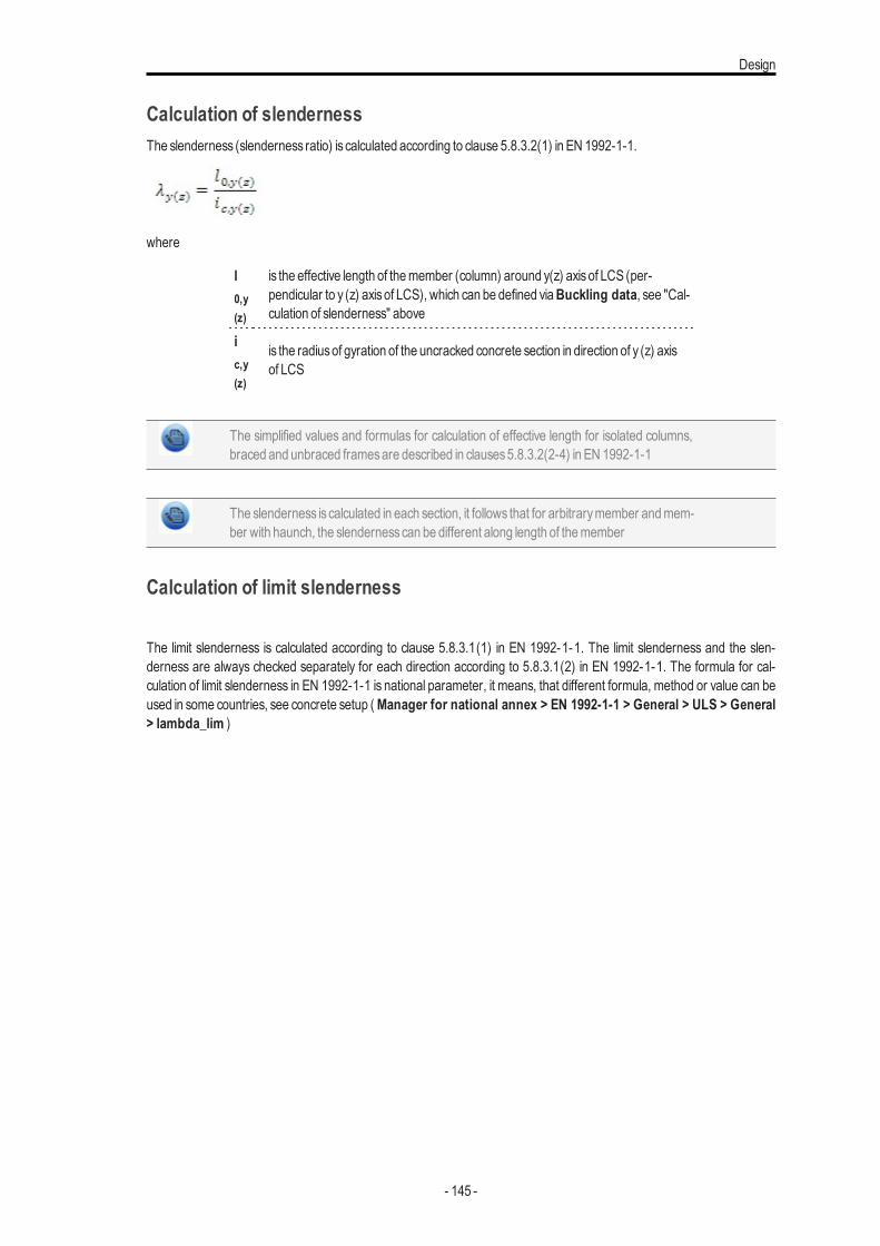
Design
Calculation of slendernessThe slenderness (slenderness ratio) is calculated according to clause 5.8.3.2(1) in EN 1992-1-1.
where
l0,y(z)
is the effective length of themember (column) around y(z) axisof LCS (per-pendicular to y (z) axisof LCS), which can be defined viaBuckling data, see "Cal-culation of slenderness" above
ic,y(z)
is the radiusof gyration of the uncracked concrete section in direction of y (z) axisof LCS
The simplified values and formulas for calculation of effective length for isolated columns,braced and unbraced framesare described in clauses5.8.3.2(2-4) in EN 1992-1-1
The slenderness is calculated in each section, it follows that for arbitrarymember andmem-ber with haunch, the slendernesscan be different along length of themember
Calculation of limit slenderness
The limit slenderness is calculated according to clause 5.8.3.1(1) in EN 1992-1-1. The limit slenderness and the slen-derness are always checked separately for each direction according to 5.8.3.1(2) in EN 1992-1-1. The formula for cal-culation of limit slenderness in EN 1992-1-1 is national parameter, it means, that different formula, method or value can beused in some countries, see concrete setup ( Manager for national annex > EN 1992-1-1 > General > ULS > General> lambda_lim )
- 145 -
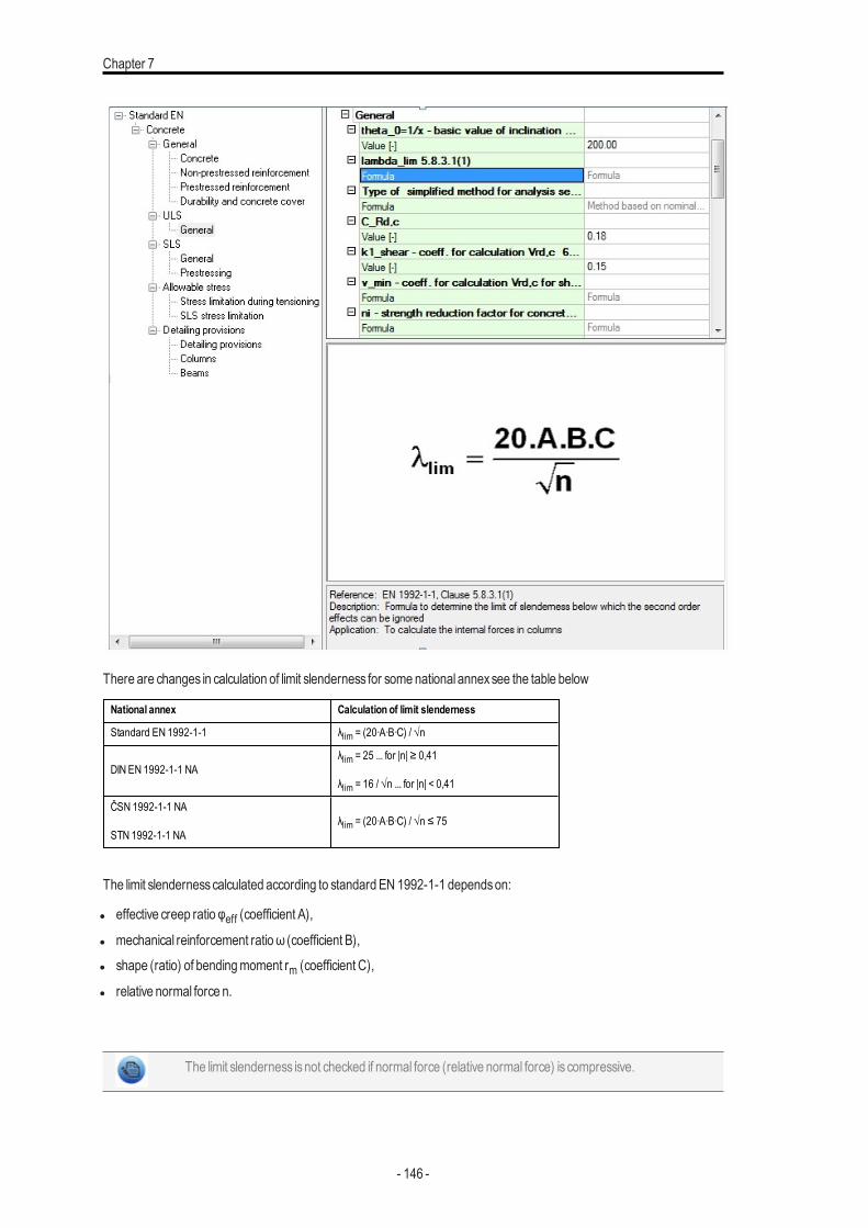
Chapter 7
There are changes in calculation of limit slenderness for some national annexsee the table below
National annex Calculation of limit slenderness
Standard EN 1992-1-1 λlim = (20∙A∙B∙C) / √n
DIN EN 1992-1-1 NAλlim = 25 ... for |n| ≥ 0,41
λlim = 16 / √n ... for |n| < 0,41
ČSN 1992-1-1 NA
STN 1992-1-1 NAλlim = (20∙A∙B∙C) / √n ≤ 75
The limit slendernesscalculated according to standard EN 1992-1-1 dependson:
l effective creep ratio φeff (coefficient A),
l mechanical reinforcement ratioω (coefficient B),l shape (ratio) of bendingmoment rm (coefficient C),
l relative normal force n.
The limit slenderness isnot checked if normal force (relative normal force) is compressive.
- 146 -
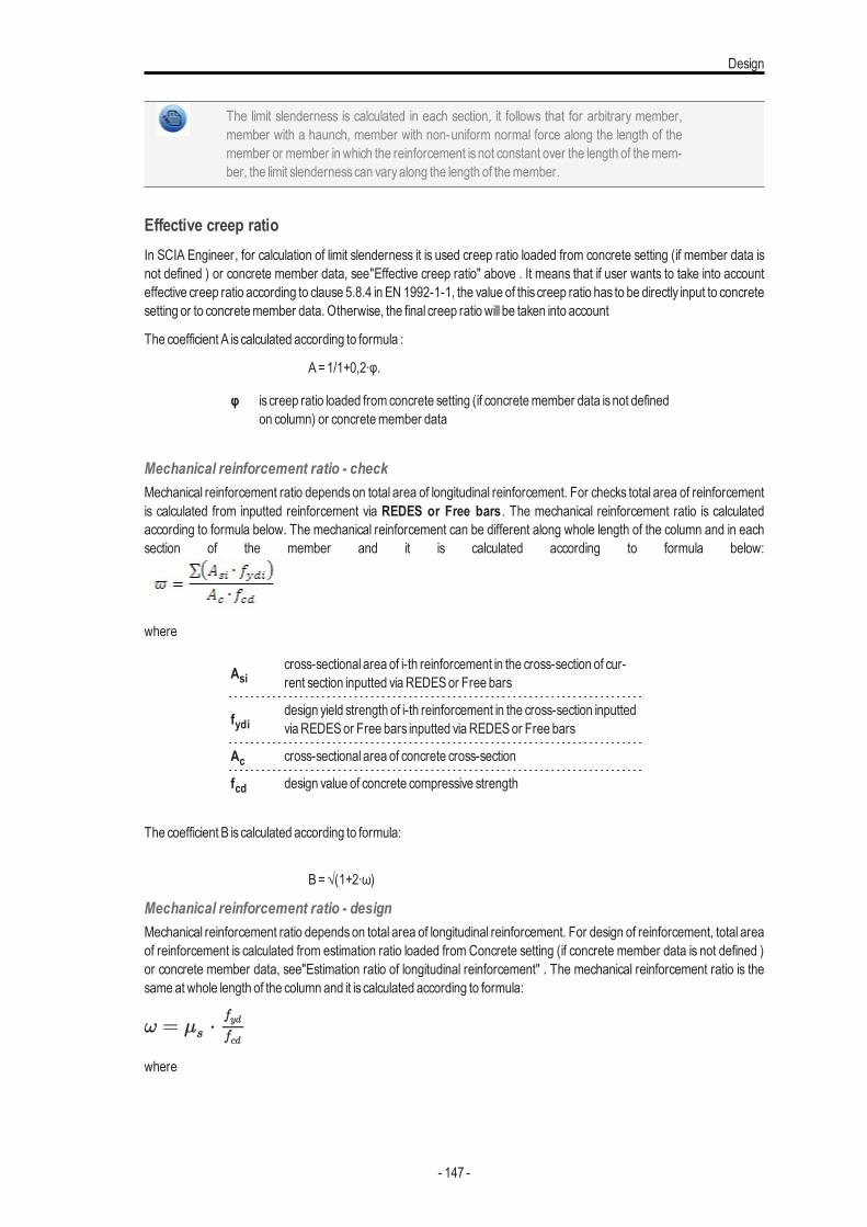
Design
The limit slenderness is calculated in each section, it follows that for arbitrary member,member with a haunch, member with non-uniform normal force along the length of themember or member in which the reinforcement is not constant over the length of themem-ber, the limit slendernesscan varyalong the length of themember.
Effective creep ratioIn SCIA Engineer, for calculation of limit slenderness it is used creep ratio loaded from concrete setting (if member data isnot defined ) or concrete member data, see"Effective creep ratio" above . It means that if user wants to take into accounteffective creep ratio according to clause 5.8.4 in EN 1992-1-1, the value of this creep ratio has to be directly input to concretesetting or to concretemember data. Otherwise, the final creep ratio will be taken into account
The coefficient A iscalculated according to formula :
A=1/1+0,2∙φ.
φ is creep ratio loaded from concrete setting (if concretemember data isnot definedon column) or concretemember data
Mechanical reinforcement ratio - checkMechanical reinforcement ratio depends on total area of longitudinal reinforcement. For checks total area of reinforcementis calculated from inputted reinforcement via REDES or Free bars . The mechanical reinforcement ratio is calculatedaccording to formula below. The mechanical reinforcement can be different along whole length of the column and in eachsection of the member and it is calculated according to formula below:
where
Asicross-sectional area of i-th reinforcement in the cross-section of cur-rent section inputted viaREDESor Free bars
fydidesign yield strength of i-th reinforcement in the cross-section inputtedviaREDESor Free bars inputted viaREDESor Free bars
Ac cross-sectional area of concrete cross-section
fcd design value of concrete compressive strength
The coefficient B iscalculated according to formula:
B=√(1+2∙ω)
Mechanical reinforcement ratio - designMechanical reinforcement ratio dependson total area of longitudinal reinforcement. For design of reinforcement, total areaof reinforcement is calculated from estimation ratio loaded from Concrete setting (if concrete member data is not defined )or concrete member data, see"Estimation ratio of longitudinal reinforcement" . The mechanical reinforcement ratio is thesame at whole length of the column and it is calculated according to formula:
where
- 147 -
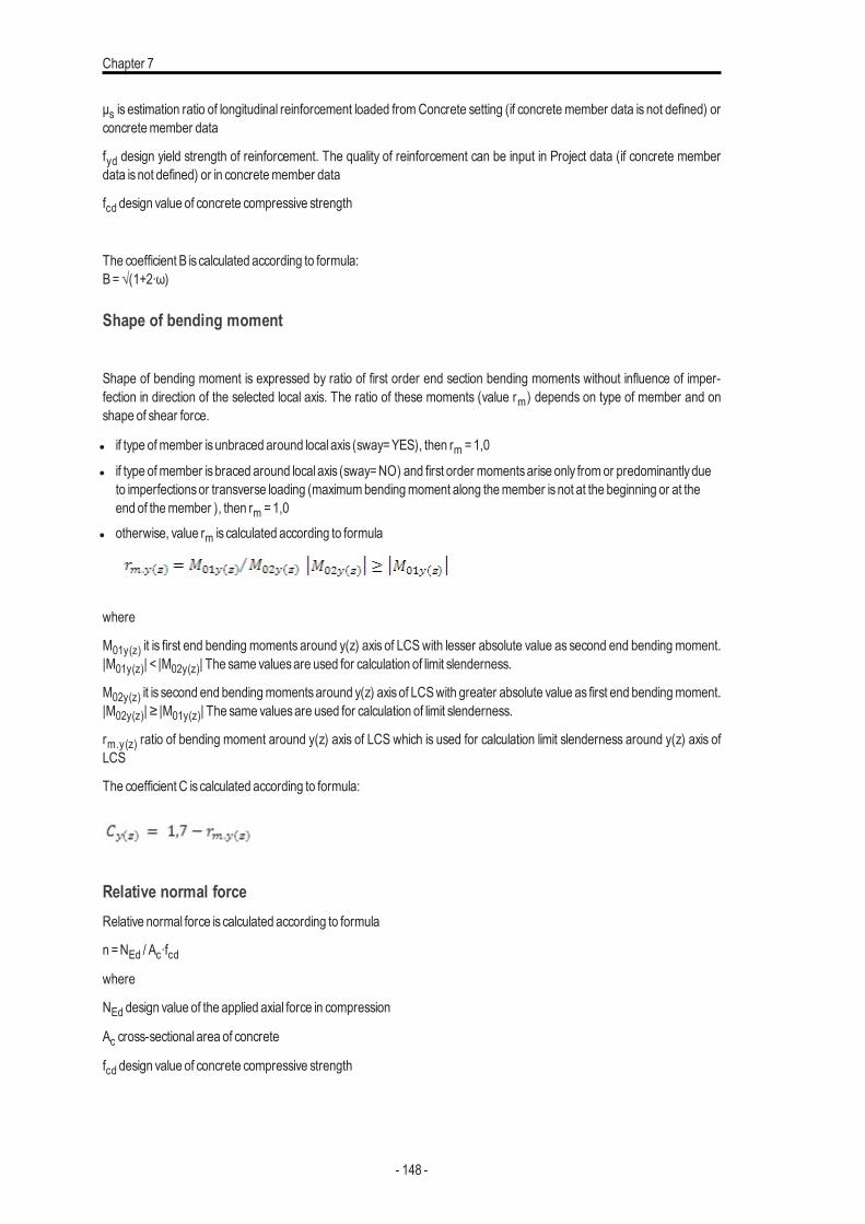
Chapter 7
μs is estimation ratio of longitudinal reinforcement loaded fromConcrete setting (if concrete member data is not defined) orconcretemember data
fyd design yield strength of reinforcement. The quality of reinforcement can be input in Project data (if concrete memberdata isnot defined) or in concretemember data
fcd design value of concrete compressive strength
The coefficient B iscalculated according to formula:B=√(1+2∙ω)
Shape of bending moment
Shape of bending moment is expressed by ratio of first order end section bending moments without influence of imper-fection in direction of the selected local axis. The ratio of these moments (value rm) depends on type of member and onshape of shear force.
l if type ofmember isunbraced around local axis (sway=YES), then rm =1,0
l if type ofmember isbraced around local axis (sway=NO) and first order momentsarise only fromor predominantlydueto imperfectionsor transverse loading (maximumbendingmoment along themember isnot at the beginning or at theend of themember ), then rm =1,0
l otherwise, value rm is calculated according to formula
where
M01y(z) it is first end bending moments around y(z) axis of LCSwith lesser absolute value as second end bending moment.|M01y(z)| < |M02y(z)| The same valuesare used for calculation of limit slenderness.
M02y(z) it is second end bendingmomentsaround y(z) axisof LCSwith greater absolute value as first end bendingmoment.|M02y(z)| ≥ |M01y(z)| The same valuesare used for calculation of limit slenderness.
rm.y(z) ratio of bending moment around y(z) axis of LCS which is used for calculation limit slenderness around y(z) axis ofLCS
The coefficient C iscalculated according to formula:
Relative normal forceRelative normal force is calculated according to formula
n =NEd / Ac∙fcdwhere
NEd design value of the applied axial force in compression
Ac cross-sectional area of concrete
fcd design value of concrete compressive strength
- 148 -
Design
If normal force is not uniform along the length of column or the part of the column (for arbit-rary member and member with haunch), the maximum value of normal force at length ofcolumn or the part of the columnwill be taken into account.
Warning and errorsThe following errors, warningsand notesmayoccurre during the checkof crackwidth
Number Type Description Description/Solution
N1/1 Note Cross-sectional area of reinforcement is calculated for defined user reinforcement.
N1/2 Note Cross-sectional area of reinforcement is calculated for inputted ratio of reinforcement.
N1/3 Note The effective creep ratio is taken into account as creep ratio.
N1/4 Note The value rmy is 1,0, because the member is unbraced around y axis or value M02y is zero.
N1/5 NoteThe value rmy is 1,0, because the member is braced around y and first order moments ariseonly from or predominantly due to imperfections or transverse loading.
N1/6 Note The value rmz is 1,0, because the member is unbraced around y axis or value M02z is zero.
N1/7 NoteThe value rmz is 1,0, because the member is braced around y and first order moments ariseonly from or predominantly due to imperfections or transverse loading.
N1/8 Note Limit slenderness is not calculated for tensile or zero normal force.
N1/9 NoteSlenderness around y axis is lesser than limit slenderness, it follows second order effect willbe ignored.
W1/1 Warning Slenderness around y axis is bigger than limit slendernessSecond order effect has tobe taken into account.
N1/1 NoteSlenderness around z axis is lesser than limit slenderness, it follows second order effect willbe ignored.
W1/2 Warning Slenderness around z axis is bigger than limit slendernessSecond order effect has tobe taken into account.
AbbreviationsAbbreviation Explanation
SEN Software SCIA Engineer
PNL Physical nonlinear calculation
GNL Geometrical nonlinear calculation
LCS Local coordinate system
GCS Global coordinate system
REDES The module in SEN for inputting user reinforcement to 1Dmember via template
SLS Serviceability limit state
ULS Ultimate limit state
Literature
1. EN 1992-1-1: 2004 Eurocode 2 : design of concrete structures – Part 1: General rules and rules forbuilding
- 149 -
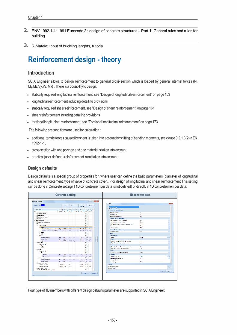
Chapter 7
2. ENV 1992-1-1: 1991 Eurocode 2 : design of concrete structures – Part 1: General rules and rules forbuilding
3. R.Matela: Input of buckling lenghts, tutoria
Reinforcement design - theoryIntroductionSCIA Engineer allows to design reinforcement to general cross-section which is loaded by general internal forces (N,My,Mz,Vy,Vz,Mx) . There isa possibility to design:
l statically required longitudinal reinforcement, see "Design of longitudinal reinforcement" on page 153l longitudinal reinforcement including detailing provisionsl statically required shear reinforcement, see "Design of shear reinforcement" on page 161l shear reinforcement including detailing provisionsl torsional longitudinal reinforcement, see "Torsional longitudinal reinforcement" on page 173
The following preconditionsare used for calculation :
l additional tensile forcescaused byshear is taken into account byshifting of bendingmoments, see clause 9.2.1.3(2)in EN1992-1-1,
l cross-sectionwith one polygon and onematerial is taken into account,l practical (user defined) reinforcement isnot taken into account.
Design defaultsDesign defaults is a special group of properties for, where user can define the basic parameters (diameter of longitudinaland shear reinforcement, type of value of concrete cover...) for design of longitudinal and shear reinforcement.This settingcan be done inConcrete setting (if 1D concretemember data isnot defined) or directly in 1D concretemember data.
Concrete setting 1D concrete data
Four type of 1Dmemberswith different design defaultsparameter are supported in SCIAEngineer:
- 150 -
Design
l Beam /Rib - member predominantly loaded bybendingmoments, for which longitudinal and shear reinforcement can bedesigned. There are the following parameters:l Longitudinal reinforcement
l Provided (basicand additional) reinforcement libraryl type of cover of upper and lower reinforcement (auto or user defined value)l type of cover of side reinforcement (upper, lower or user define value)l material of longitudinal reinforcement (only in 1D concrete data)
l Stirrupsl diameter of stirrupsl number of cuts (number of shear links)l angle of shear reinforcementl material of shear reinforcement (only in 1D concrete data)l basic (user defined stirrup) - where user can defined user value of area of shear reinforcement per meter with some
angle andmaterial of this reinforcement.
l Beamslab - member predominantly loaded bybendingmoments for which shear reinforcement isnot designed (forexample cut of 2Dmember).There are the following parameters:l Longitudinal reinforcement
l Provided (basicand additional) reinforcement libraryl type of cover of upper and lower reinforcement (auto or user defined value)l material of longitudinal reinforcement (only in 1D concrete data)
l Column - member predominantly in compression for which longitudinal and shear reinforcement can be designed. Thereare the following parameters:l Longitudinal reinforcement
l Provided (basicand additional) reinforcement libraryl type of cover of reinforcement (auto or user defined value)l material of longitudinal reinforcement (only in 1D concrete data)
l Stirrupsl diameter of stirrupsl number of cuts (number of shear links)l material of shear reinforcement (only in 1D concrete data)
Design defaults in concrete setting:
l There ispossibility for define design defaults for all type of 1Dmember (beam, column, beamslab)l thematerial of longitudinal and shear reinforcement isnot possible to input/edit in this setting, butmaterial is loaded from
project data and it is same for all type ofmembers
Design defaults in 1D concrete member data
l onlydesign defaultsof selected type ofmember can be edited in this settingl material of shear and longitudinal reinforcement can be edited directly in concretemember data
Design methodUser can set type of method for design reinforcement for columns and beams This setting can be done in Concrete setting(if 1D concretemember data isnot defined) or directly in 1D concretemember data for Member type =Column or beamsbyusingAdvanced mode/level
- 151 -
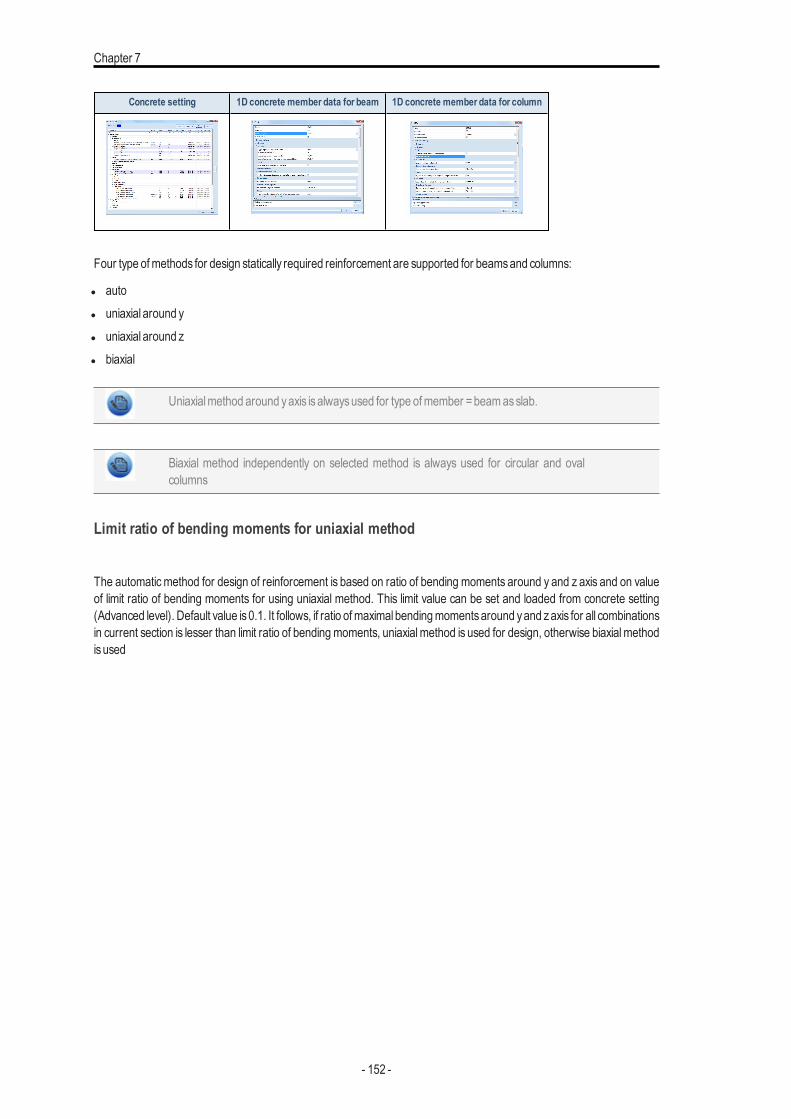
Chapter 7
Concrete setting 1D concrete member data for beam 1D concrete member data for column
Four type ofmethods for design statically required reinforcement are supported for beamsand columns:
l autol uniaxial around yl uniaxial around zl biaxial
Uniaxialmethod around yaxis isalwaysused for type ofmember =beamasslab.
Biaxial method independently on selected method is always used for circular and ovalcolumns
Limit ratio of bending moments for uniaxial method
The automaticmethod for design of reinforcement is based on ratio of bending moments around y and z axis and on valueof limit ratio of bending moments for using uniaxial method. This limit value can be set and loaded from concrete setting(Advanced level). Default value is0.1. It follows, if ratio ofmaximal bendingmomentsaround yand zaxis for all combinationsin current section is lesser than limit ratio of bending moments, uniaxialmethod is used for design, otherwise biaxialmethodisused
- 152 -
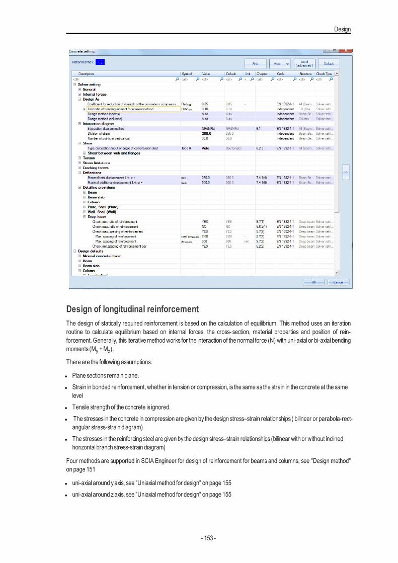
Design
Design of longitudinal reinforcementThe design of statically required reinforcement is based on the calculation of equilibrium. This method uses an iterationroutine to calculate equilibrium based on internal forces, the cross- section, material properties and position of rein-forcement. Generally, this iterativemethodworks for the interaction of the normal force (N) with uni-axial or bi-axial bendingmoments (My +Mz).
There are the following assumptions:
l Plane sections remain plane.l Strain in bonded reinforcement, whether in tension or compression, is the same as the strain in the concrete at the same
levell Tensile strength of the concrete is ignored.l The stresses in the concrete in compression are given by the design stress–strain relationships ( bilinear or parabola-rect-
angular stress-strain diagram)l The stresses in the reinforcing steel are given by the design stress–strain relationships (bilinear with or without inclined
horizontal branch stress-strain diagram)
Four methods are supported in SCIA Engineer for design of reinforcement for beams and columns, see "Design method"on page 151
l uni-axial around yaxis, see "Uniaxialmethod for design" on page 155l uni-axial around zaxis, see "Uniaxialmethod for design" on page 155
- 153 -
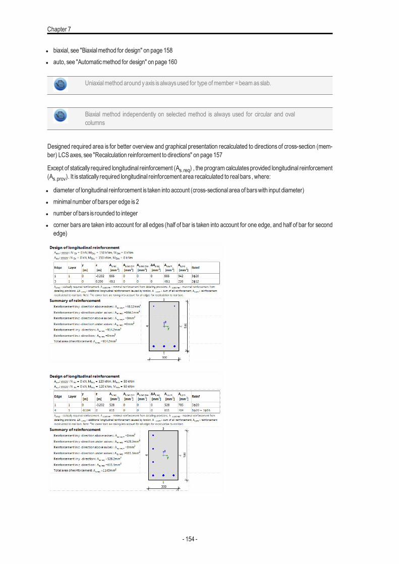
Chapter 7
l biaxial, see "Biaxialmethod for design" on page 158l auto, see "Automaticmethod for design" on page 160
Uniaxialmethod around yaxis isalwaysused for type ofmember =beamasslab.
Biaxial method independently on selected method is always used for circular and ovalcolumns
Designed required area is for better overview and graphical presentation recalculated to directions of cross-section (mem-ber) LCSaxes, see "Recalculation reinforcement to directions" on page 157
Except of statically required longitudinal reinforcement (As.req) , the program calculatesprovided longitudinal reinforcement(As.prov). It is statically required longitudinal reinforcement area recalculated to real bars , where:
l diameter of longitudinal reinforcement is taken into account (cross-sectional area of barswith input diameter)l minimal number of barsper edge is2l number of bars is rounded to integerl corner bars are taken into account for all edges (half of bar is taken into account for one edge, and half of bar for second
edge)
- 154 -
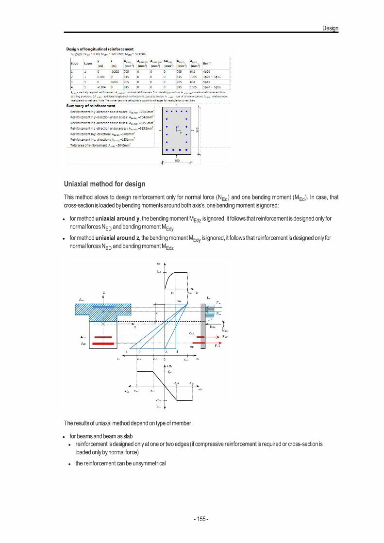
Design
Uniaxial method for designThis method allows to design reinforcement only for normal force (NEd) and one bending moment (MEd). In case, thatcross-section is loaded bybendingmomentsaround both axis’s, one bendingmoment is ignored:
l for methoduniaxial around y, the bendingmomentMEdz is ignored, it follows that reinforcement isdesigned only fornormal forcesNED and bendingmomentMEdy
l for methoduniaxial around z, the bendingmomentMEdy is ignored, it follows that reinforcement isdesigned only fornormal forcesNED and bendingmomentMEdz
The resultsof uniaxalmethod depend on type ofmember:
l for beamsand beamasslabl reinforcement isdesigned onlyat one or two edges (if compressive reinforcement is required or cross-section is
loaded onlybynormal force)l the reinforcement can be unsymmetrical
- 155 -
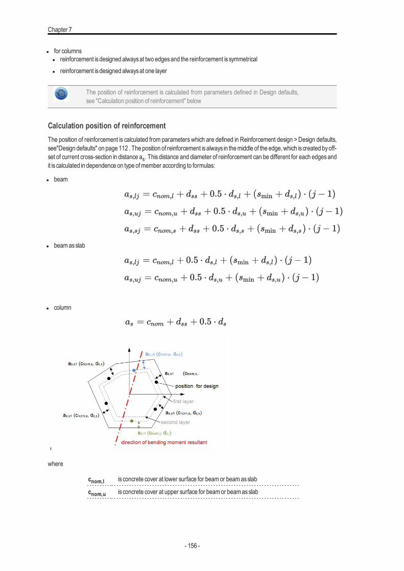
Chapter 7
l for columnsl reinforcement isdesigned alwaysat two edgesand the reinforcement is symmetricall reinforcement isdesigned alwaysat one layer
The position of reinforcement is calculated from parameters defined in Design defaults,see "Calculation position of reinforcement" below
Calculation position of reinforcementThe position of reinforcement is calculated from parameters which are defined in Reinforcement design > Design defaults,see"Design defaults" on page 112 . The position of reinforcement isalways in themiddle of the edge, which is created byoff-set of current cross-section in distance as. This distance and diameter of reinforcement can be different for each edgesandit is calculated in dependence on type ofmember according to formulas:
l beam
l beamasslab
l column
where
cnom,l is concrete cover at lower surface for beamor beamasslab
cnom,u is concrete cover at upper surface for beamor beamasslab
- 156 -
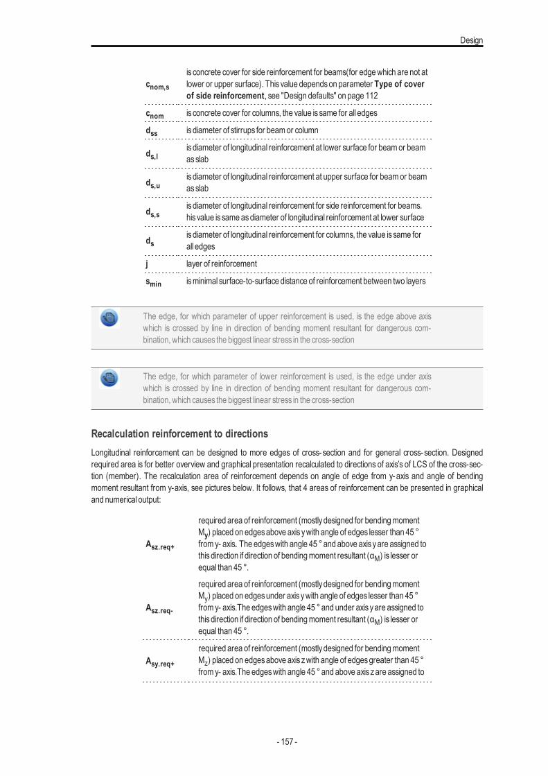
Design
cnom,s
is concrete cover for side reinforcement for beams(for edgewhich are not atlower or upper surface). This value dependson parameter Type of coverof side reinforcement, see "Design defaults" on page 112
cnom is concrete cover for columns, the value is same for all edges
dss is diameter of stirrups for beamor column
ds,lis diameter of longitudinal reinforcement at lower surface for beamor beamasslab
ds,uis diameter of longitudinal reinforcement at upper surface for beamor beamasslab
ds,sis diameter of longitudinal reinforcement for side reinforcement for beams.his value is same asdiameter of longitudinal reinforcement at lower surface
dsis diameter of longitudinal reinforcement for columns, the value is same forall edges
j layer of reinforcement
smin isminimal surface-to-surface distance of reinforcement between two layers
The edge, for which parameter of upper reinforcement is used, is the edge above axiswhich is crossed by line in direction of bending moment resultant for dangerous com-bination, which causes the biggest linear stress in the cross-section
The edge, for which parameter of lower reinforcement is used, is the edge under axiswhich is crossed by line in direction of bending moment resultant for dangerous com-bination, which causes the biggest linear stress in the cross-section
Recalculation reinforcement to directionsLongitudinal reinforcement can be designed to more edges of cross-section and for general cross-section. Designedrequired area is for better overview and graphical presentation recalculated to directions of axis’s of LCS of the cross-sec-tion (member). The recalculation area of reinforcement depends on angle of edge from y-axis and angle of bendingmoment resultant from y-axis, see pictures below. It follows, that 4 areas of reinforcement can be presented in graphicaland numerical output:
Asz.req+
required area of reinforcement (mostlydesigned for bendingmomentMy) placed on edgesabove axis ywith angle of edges lesser than 45 °from y- axis. The edgeswith angle 45 °and above axis yare assigned tothisdirection if direction of bendingmoment resultant (αM) is lesser orequal than 45 °.
Asz.req-
required area of reinforcement (mostlydesigned for bendingmomentMy) placed on edgesunder axis ywith angle of edges lesser than 45 °from y- axis.The edgeswith angle 45 °and under axis yare assigned tothisdirection if direction of bendingmoment resultant (αM) is lesser orequal than 45 °.
Asy.req+required area of reinforcement (mostlydesigned for bendingmomentMz) placed on edgesabove axis zwith angle of edgesgreater than 45 °from y- axis.The edgeswith angle 45 °and above axis zare assigned to
- 157 -
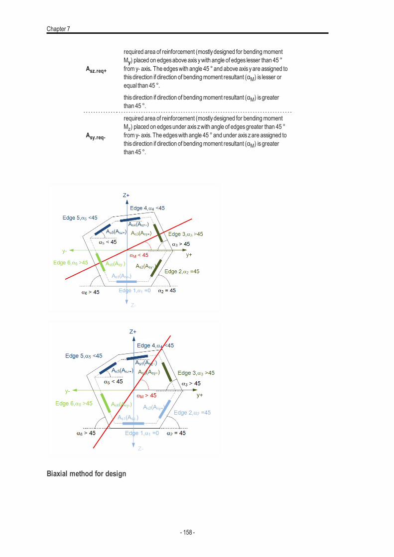
Chapter 7
Asz.req+
required area of reinforcement (mostlydesigned for bendingmomentMy) placed on edgesabove axis ywith angle of edges lesser than 45 °from y- axis. The edgeswith angle 45 °and above axis yare assigned tothisdirection if direction of bendingmoment resultant (αM) is lesser orequal than 45 °.
thisdirection if direction of bendingmoment resultant (αM) isgreaterthan 45 °.
Asy.req-
required area of reinforcement (mostlydesigned for bendingmomentMz) placed on edgesunder axis zwith angle of edgesgreater than 45 °from y- axis. The edgeswith angle 45 °and under axis zare assigned tothisdirection if direction of bendingmoment resultant (αM) isgreaterthan 45 °.
Biaxial method for design
- 158 -
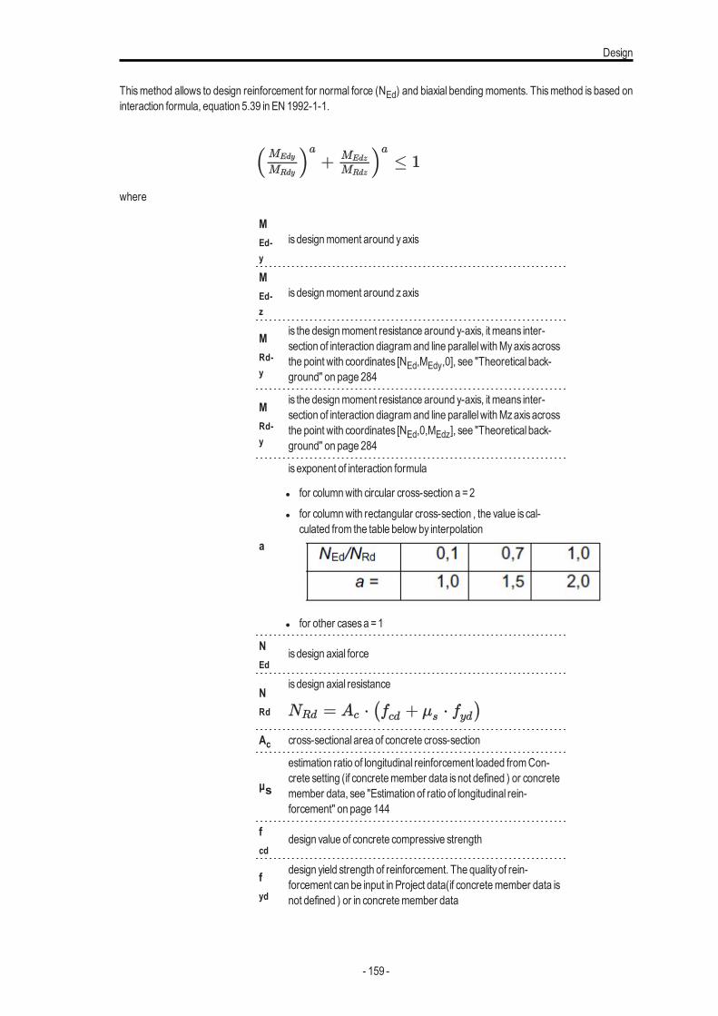
Design
Thismethod allows to design reinforcement for normal force (NEd) and biaxial bending moments. Thismethod is based oninteraction formula, equation 5.39 in EN 1992-1-1.
where
MEd-y
is designmoment around yaxis
MEd-z
is designmoment around zaxis
MRd-y
is the designmoment resistance around y-axis, it means inter-section of interaction diagramand line parallelwithMyaxisacrossthe point with coordinates [NEd,MEdy,0], see "Theoretical back-ground" on page 284
MRd-y
is the designmoment resistance around y-axis, it means inter-section of interaction diagramand line parallelwithMzaxisacrossthe point with coordinates [NEd,0,MEdz], see "Theoretical back-ground" on page 284
a
is exponent of interaction formula
l for columnwith circular cross-section a =2l for columnwith rectangular cross-section , the value is cal-
culated from the table below by interpolation
l for other casesa =1
NEd
is design axial force
NRd
is design axial resistance
Ac cross-sectional area of concrete cross-section
μs
estimation ratio of longitudinal reinforcement loaded fromCon-crete setting (if concretemember data isnot defined ) or concretemember data, see "Estimation of ratio of longitudinal rein-forcement" on page 144
fcd
design value of concrete compressive strength
fyd
design yield strength of reinforcement. The qualityof rein-forcement can be input in Project data(if concretemember data isnot defined ) or in concretemember data
- 159 -
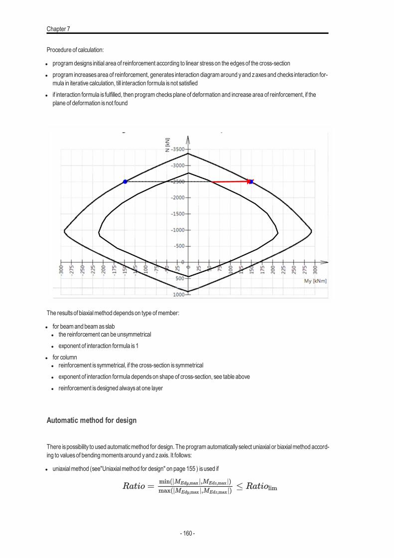
Chapter 7
Procedure of calculation:
l programdesigns initial area of reinforcement according to linear stresson the edgesof the cross-sectionl program increasesarea of reinforcement, generates interaction diagramaround yand zaxesand checks interaction for-
mula in iterative calculation, till interaction formula isnot satisfiedl if interaction formula is fulfilled, then programchecksplane of deformation and increase area of reinforcement, if the
plane of deformation isnot found
The resultsof biaxialmethod dependson type ofmember:
l for beamand beamasslabl the reinforcement can be unsymmetricall exponent of interaction formula is1
l for columnl reinforcement is symmetrical, if the cross-section is symmetricall exponent of interaction formula dependson shape of cross-section, see table abovel reinforcement isdesigned alwaysat one layer
Automatic method for design
There ispossibility to used automaticmethod for design. The programautomatically select uniaxial or biaxialmethod accord-ing to valuesof bendingmomentsaround yand zaxis. It follows:
l uniaxialmethod (see"Uniaxialmethod for design" on page 155 ) isused if
- 160 -
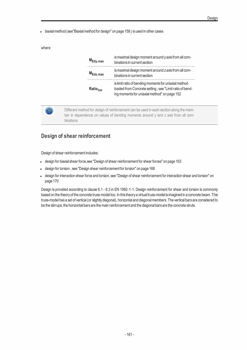
Design
l biaxialmethod (see"Biaxialmethod for design" on page 158 ) isused in other cases
where
MEdy.maxismaximal designmoment around yaxis fromall com-binations in current section
MEdz.maxismaximal designmoment around zaxis fromall com-binations in current section
Ratiolimis limit ratio of bendingmoments for uniaxialmethodloaded fromConcrete setting , see "Limit ratio of bend-ingmoments for uniaxialmethod" on page 152
Different method for design of reinforcement can be used in each section along the mem-ber in dependence on values of bending moments around y and z axis from all com-binations
Design of shear reinforcement
Design of shear reinforcement includes:
l design for biaxial shear force,see "Design of shear reinforcement for shear forces" on page 163l design for torsion , see "Design shear reinforcement for torsion" on page 168l design for interaction shear force and torsion, see "Design of shear reinforcement for interaction shear and torsion" on
page 170
Design is provided according to clause 6.1 - 6.3 in EN 1992-1-1. Design reinforcement for shear and torsion is commonlybased on the theoryof the concrete truss-model too. In this theorya virtual truss-model is imagined in a concrete beam. Thistruss-model hasa set of vertical (or slightly diagonal), horizontal and diagonalmembers. The vertical barsare considered tobe the stirrups; the horizontal barsare themain reinforcement and the diagonal barsare the concrete struts.
- 161 -
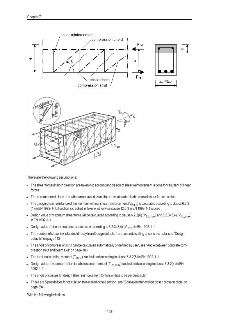
Chapter 7
There are the following assumptions:
l The shear forces in both direction are taken into account and design of shear reinforcement isdone for resultant of shearforces
l The parametersof plane of equilibrium (value, d, zand h) are recalculated to direction of shear force resultantl The design shear resistance of themember without shear reinforcement (VRd,c) is calculated according to clause 6.2.2
(1) in EN 1992-1-1, if section is cracked in flexure, otherwise clause 12.6.3 in EN 1992-1-1 isusedl Design value ofmaximumshear forcewill be calculated according to clause 6.2.2(6) (VEd,max) and 6.2.3 (3,4) (VRd,max)
in EN 1992-1-1l Design value of shear resistance iscalculated according to 6.2.3 (3,4) (VRd,s) in EN 1992-1-1
l The number of shear link is loaded directly fromDesign defaults from concrete setting or concrete data, see "Designdefaults" on page 112
l The angle of compression strut can be calculated automaticallyor defined byuser, see "Angle between concrete com-pression strut and beamaxis" on page 106
l The torsional crackingmoment (TRd,c) is calculated according to clause 6.3.2(5) in EN 1992-1-1
l Design value ofmaximumof torsional resistancemoment (TRd,max)is calculated according to clause 6.3.2(4) in EN1992-1-1
l The angle of stirrups for design shear reinforcement for torsion has to be perpendicularl There are 5 possibilities for calculation thin-walled closed section, see "Equivalent thin-walled closed cross-section" on
page 294
With the following limitations
- 162 -

Design
l Cross-sectionwith one polygon and onematerial is taken into account in version SCIAEngineer 15.l The user(practical) reinforcement isnot taken into account.l Design should be done only in case that the angle between gradient of the strain plane and the resultant of shear forces is
not greater than 15 °.l Inclined compression chord or inclined tensile chord are not taken into account.l Thewidthsof cross-section for shear checks (value bw and bw1) are calculated automatically. There isno possibility for
definition of user value in SCIAEngineer 15.
Except of statically required shear reinforcement per meter(Aswm.req), the program cal-culates provided shear reinforcement (Aswm.prov ). It is statically required shear rein-forcement, where the spacing of the stirrups in longitudinal direction is rounded to 25mm
Design of shear reinforcement for shear forces
As was mentioned above, there exists general concept of “strut-and-tie” model for the prediction of shear effects in con-crete. In thismodel, the top compression and bottom tensilemembers represent the compressive concrete and tensile rein-forcement, respectively. The procedure for design can be represented bydiagrambelow:
- 163 -
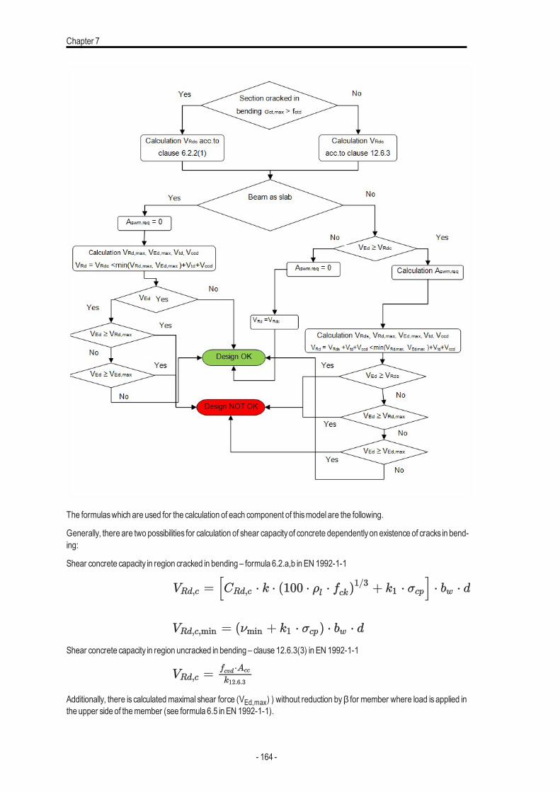
Chapter 7
The formulaswhich are used for the calculation of each component of thismodel are the following.
Generally, there are two possibilities for calculation of shear capacityof concrete dependentlyon existence of cracks in bend-ing:
Shear concrete capacity in region cracked in bending – formula 6.2.a,b in EN 1992-1-1
Shear concrete capacity in region uncracked in bending – clause 12.6.3(3) in EN 1992-1-1
Additionally, there is calculatedmaximal shear force (VEd,max) ) without reduction byβ for member where load is applied inthe upper side of themember (see formula 6.5 in EN 1992-1-1).
- 164 -
Design
Maximal capacity of concrete compressive strut (VRd,max ) is determined according to formula 6.9 in EN 1992-1-1, becauseashasbeenmentioned before, the angle of stirrups (θ) isalwaysperpendicular tomember axis.
Statically required cross- sectional area of the shear reinforcement per meter is calculated from the formula 6.13 inEN 1992-1-1
Design value of shear force sustained byshear reinforcement (VRd,s ) is calculated according to formula 6.13 in EN 1992-1-1
Design value of shear force sustained byshear reinforcement (VRd,s ) is calculated according to formula 6.13 in EN 1992-1-1
Final design value of shear force (VRd ) carried bymember is calculated based on the following formulasdepending on typeofmember and area of shear reinforcement.
l for beamasslab and for other member with onlydetailing stirrups (Aswm.req =0)
l for other cases
where
VEd
resultant of shear force
VEd,y(z)
shear force in direction of y(z)-axisof LCS
VRd,c the design shear resistance of themember without shear reinforcement
σct,ma-x
maximal tensile strength in uncracked cross-section
VRd,c,-min
theminimal value of design shear resistance of themember without shear rein-forcement
CRd,c
coefficient for calculation VRd,c loaded fromManager for National annexes
- 165 -
Chapter 7
k
coefficient of effective height of cross-section
ρl
ratio of tensile reinforcement
fck characteristic compressive cylinder strength of concrete
k1 coefficient for calculation VRd,c loaded fromManager for National annexes
σcp
stresscaused byaxial force (NEd>0 for compression)
bwthe smallest width of the cross-section in tensile area of cross-section per-pendicular to direction of resultant shear force, see "Width of cross-section forshear check" on page 304
d effective depth of cross-section recalculated to direction of shear forces res-ultant, see "Effective depth of cross-section for shear check" on page 304
Aslstatically required tensile area of reinforcement, see "Design of longitudinalreinforcement" on page 153
NEd the axial force in the cross-section due to loading or prestressing.
Ac the area of concrete crosssection
fcd design value of concrete compressive strength
νmin
Coefficient ofminimumvalue of shear resistance of themember without shearreinforcement loaded fromManager for National annexes,see equation 6.3Nin EN 1992-1-1
fcvd
the concrete design strength in shear and compression, see equations 12.5and 12.6 in EN 1992-1-1
fctd design axial tensile strength of concrete
σccp
normal (axial)stressof uncracked cross-section
σc,lim
limit value of stresscaused byaxial force,see equations12.7 in EN 1992-1-1
Acc compressed concrete area for uncracked cross-section
V maximumvalue of shear force resultant calculatedwithout reduction bycoef-ficientβ , see clause 6.2.2(6) in EN 1992-1-1
- 166 -
Design
Ed,ma-x
bw1minimumwidth of cross-section between tension and compression chord per-pendicular to direction of shear force, see "Width of cross-section for shearcheck" on page 304
ν strength reduction factor for concrete cracked in shear loaded fromManagerfor National annexes, see equation 6.6N in EN 1992-1-1
VRd,m-ax
the design value of themaximumshear forcewhich can be sustained by themember, limited bycrushing of the compression struts
αcwcoefficient taking into account state of the stress in the compression chord, seenote 3 in clause 6.2.3(3) in EN 1992-1-1. The value 1 isalways taken intoaccount for non -prestressed structures
z inner lever armof cross-section recalculated to direction of shear forces res-ultant, see "Inner lever arm for shear check" on page 305
ν1
strength reduction factor for concrete cracked in shear loaded from Managerfor National annexes, see note 1 and 2in clause 6.2.3(3) in EN 1992-1-1.
θAngle between concrete compression strut and beamaxisperpendicular to theshear force, see "Angle between concrete compression strut and beamaxis"on page 106
VRd,sdesign value of the shear forcewhich can be sustained by the yielding shearreinforcement.
Aswm.r-eq
Statically required cross-sectional area of the shear reinforcement per meter
Asw
the cross-sectional area of the shear reinforcement calculated from inputtedparameters in design default, see "Design defaults" on page 112
dssdiameter of stirrups loaded fromConcrete setting or Concrete data, see"Design defaults" on page 112
nsnumber of cuts (shear links) loaded fromConcrete setting or Concrete data,see "Design defaults" on page 112
sl.req
the spacing of the stirrups in longitudinal direction,
fywd the design yield strength of the shear reinforcement.
α angle of shear reinforcement loaded fromConcrete setting or Concrete data,see "Design defaults" on page 112. Thisangle for column is90 °.
- 167 -
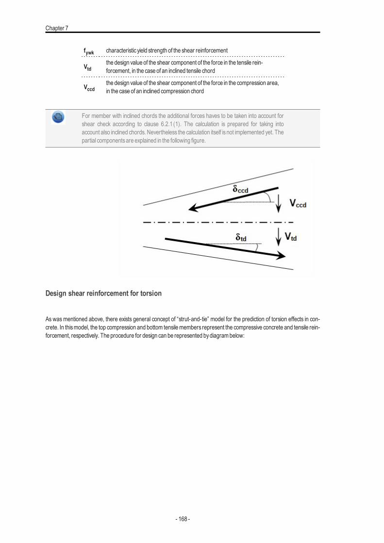
Chapter 7
fywk characteristic yield strength of the shear reinforcement
Vtdthe design value of the shear component of the force in the tensile rein-forcement, in the case of an inclined tensile chord
Vccdthe design value of the shear component of the force in the compression area,in the case of an inclined compression chord
For member with inclined chords the additional forces haves to be taken into account forshear check according to clause 6.2.1 (1). The calculation is prepared for taking intoaccount also inclined chords. Nevertheless the calculation itself is not implemented yet. Thepartial componentsare explained in the following figure.
Design shear reinforcement for torsion
As was mentioned above, there exists general concept of “strut-and-tie” model for the prediction of torsion effects in con-crete. In thismodel, the top compression and bottom tensilemembers represent the compressive concrete and tensile rein-forcement, respectively. The procedure for design can be represented bydiagrambelow:
- 168 -
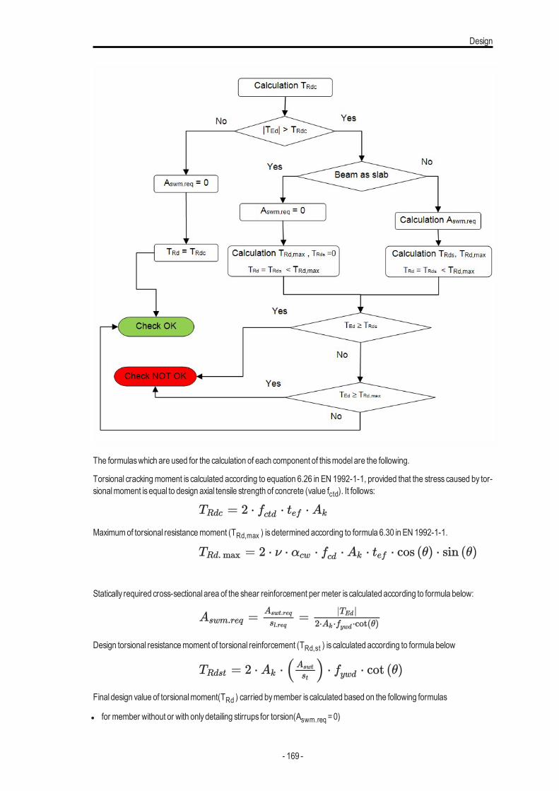
Design
The formulaswhich are used for the calculation of each component of thismodel are the following.
Torsional crackingmoment is calculated according to equation 6.26 in EN 1992-1-1, provided that the stress caused by tor-sionalmoment isequal to design axial tensile strength of concrete (value fctd). It follows:
Maximumof torsional resistancemoment (TRd,max ) isdetermined according to formula 6.30 in EN 1992-1-1.
Statically required cross-sectional area of the shear reinforcement per meter is calculated according to formula below:
Design torsional resistancemoment of torsional reinforcement (TRd,st ) is calculated according to formula below
Final design value of torsionalmoment(TRd ) carried bymember is calculated based on the following formulas
l for member without or with onlydetailing stirrups for torsion(Aswm.req =0)
- 169 -
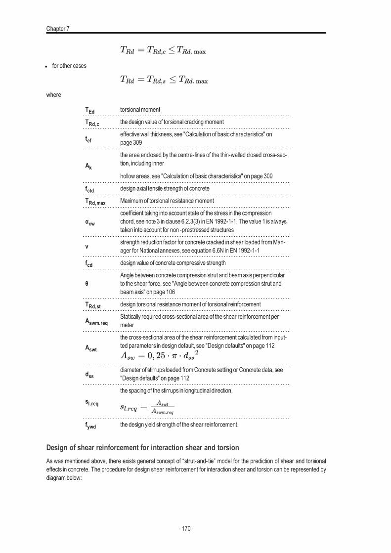
Chapter 7
l for other cases
where
TEd torsionalmoment
TRd,c the design value of torsional crackingmoment
tefeffectivewall thickness, see "Calculation of basic characteristics" onpage 309
Ak
the area enclosed by the centre-lines of the thin-walled closed cross-sec-tion, including inner
hollow areas, see "Calculation of basic characteristics" on page 309
fctd design axial tensile strength of concrete
TRd,max Maximumof torsional resistancemoment
αcwcoefficient taking into account state of the stress in the compressionchord, see note 3 in clause 6.2.3(3) in EN 1992-1-1. The value 1 isalwaystaken into account for non -prestressed structures
ν strength reduction factor for concrete cracked in shear loaded fromMan-ager for National annexes, see equation 6.6N in EN 1992-1-1
fcd design value of concrete compressive strength
θAngle between concrete compression strut and beamaxisperpendicularto the shear force, see "Angle between concrete compression strut andbeamaxis" on page 106
TRd,st design torsional resistancemoment of torsional reinforcement
Aswm.reqStatically required cross-sectional area of the shear reinforcement permeter
Aswt
the cross-sectional area of the shear reinforcement calculated from input-ted parameters in design default, see "Design defaults" on page 112
dssdiameter of stirrups loaded fromConcrete setting or Concrete data, see"Design defaults" on page 112
sl.req
the spacing of the stirrups in longitudinal direction,
fywd the design yield strength of the shear reinforcement.
Design of shear reinforcement for interaction shear and torsionAs was mentioned above, there exists general concept of “strut-and-tie” model for the prediction of shear and torsionaleffects in concrete. The procedure for design shear reinforcement for interaction shear and torsion can be represented bydiagrambelow:
- 170 -
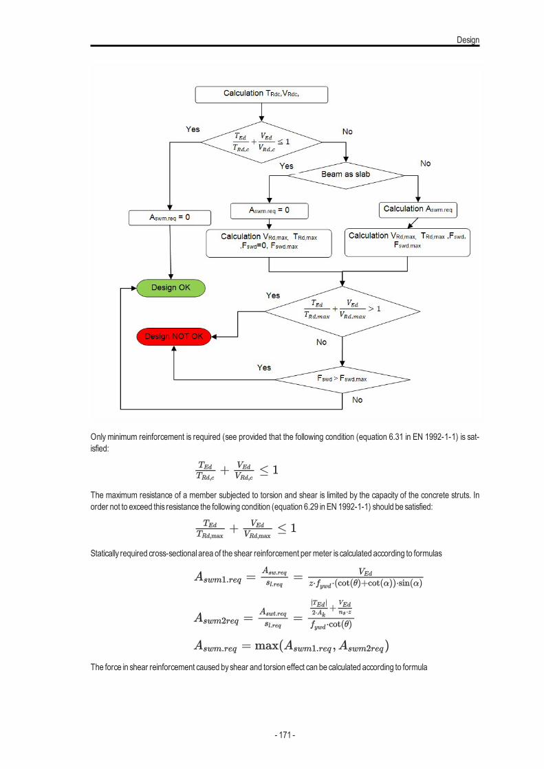
Design
Only minimum reinforcement is required (see provided that the following condition (equation 6.31 in EN 1992-1-1) is sat-isfied:
The maximum resistance of a member subjected to torsion and shear is limited by the capacity of the concrete struts. Inorder not to exceed this resistance the following condition (equation 6.29 in EN 1992-1-1) should be satisfied:
Statically required cross-sectional area of the shear reinforcement per meter is calculated according to formulas
The force in shear reinforcement caused byshear and torsion effect can be calculated according to formula
- 171 -
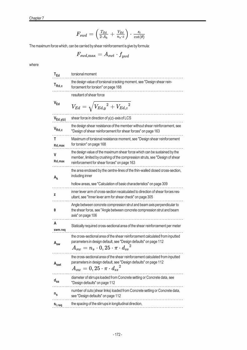
Chapter 7
Themaximum forcewhich, can be carried byshear reinforcement isgive by formula:
where
TEd torsionalmoment
TRd,cthe design value of torsional crackingmoment, see "Design shear rein-forcement for torsion" on page 168
VEd
resultant of shear force
VEd,y(z) shear force in direction of y(z)-axisof LCS
VRd,cthe design shear resistance of themember without shear reinforcement, see"Design of shear reinforcement for shear forces" on page 163
TRd,max
Maximumof torsional resistancemoment, see "Design shear reinforcementfor torsion" on page 168
VRd,max
the design value of themaximumshear forcewhich can be sustained by themember, limited bycrushing of the compression struts, see "Design of shearreinforcement for shear forces" on page 163
Ak
the area enclosed by the centre-lines of the thin-walled closed cross-section,including inner
hollow areas, see "Calculation of basic characteristics" on page 309
z inner lever armof cross-section recalculated to direction of shear forces res-ultant, see "Inner lever arm for shear check" on page 305
θAngle between concrete compression strut and beamaxisperpendicular tothe shear force, see "Angle between concrete compression strut and beamaxis" on page 106
Aswm.req
Statically required cross-sectional area of the shear reinforcement per meter
Asw
the cross-sectional area of the shear reinforcement calculated from inputtedparameters in design default, see "Design defaults" on page 112
Aswt
the cross-sectional area of the shear reinforcement calculated from inputtedparameters in design default, see "Design defaults" on page 112
dssdiameter of stirrups loaded fromConcrete setting or Concrete data, see"Design defaults" on page 112
nsnumber of cuts (shear links) loaded fromConcrete setting or Concrete data,see "Design defaults" on page 112
sl.req the spacing of the stirrups in longitudinal direction,
- 172 -
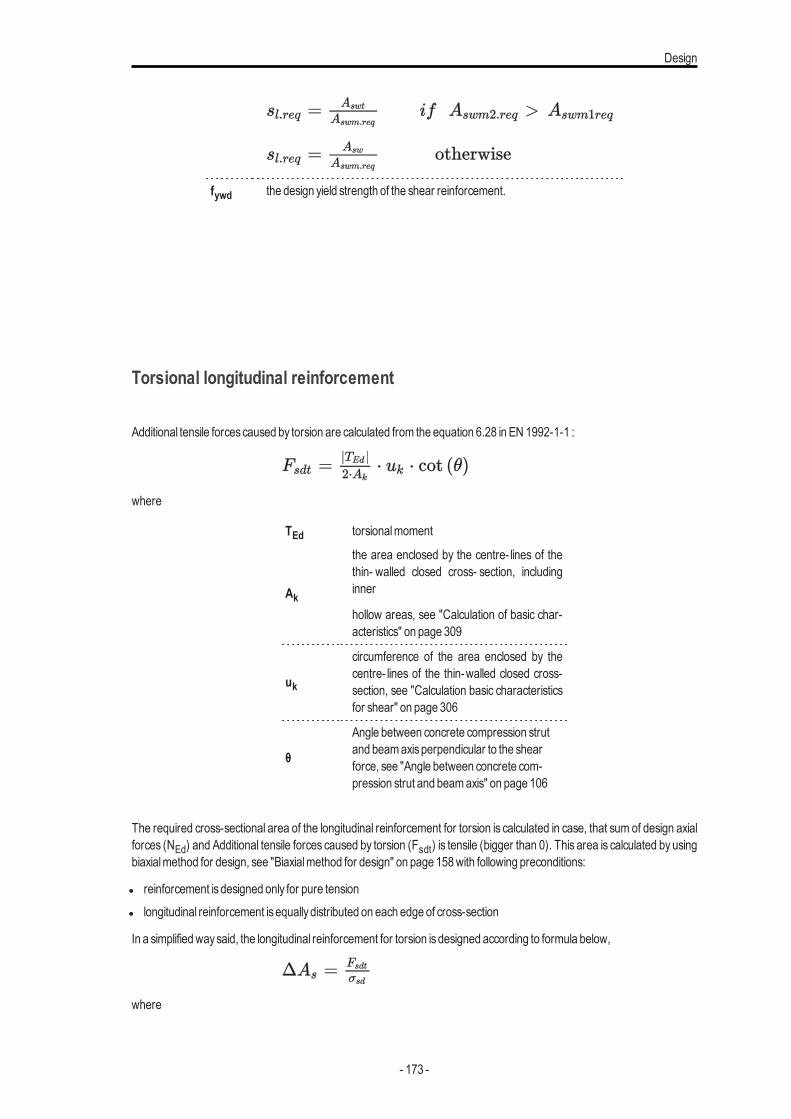
Design
fywd the design yield strength of the shear reinforcement.
Torsional longitudinal reinforcement
Additional tensile forcescaused by torsion are calculated from the equation 6.28 in EN 1992-1-1 :
where
TEd torsionalmoment
Ak
the area enclosed by the centre- lines of thethin- walled closed cross- section, includinginner
hollow areas, see "Calculation of basic char-acteristics" on page 309
uk
circumference of the area enclosed by thecentre- lines of the thin-walled closed cross-section, see "Calculation basic characteristicsfor shear" on page 306
θ
Angle between concrete compression strutand beamaxisperpendicular to the shearforce, see "Angle between concrete com-pression strut and beamaxis" on page 106
The required cross-sectional area of the longitudinal reinforcement for torsion is calculated in case, that sum of design axialforces (NEd) and Additional tensile forces caused by torsion (Fsdt) is tensile (bigger than 0). This area is calculated by usingbiaxialmethod for design, see "Biaxialmethod for design" on page 158with following preconditions:
l reinforcement isdesigned only for pure tensionl longitudinal reinforcement isequallydistributed on each edge of cross-section
In a simplifiedwaysaid, the longitudinal reinforcement for torsion isdesigned according to formula below,
where
- 173 -
Chapter 7
Fsdt additional tensile force caused by torsion
σsd design value of stress in longitudinal reinforcement
Additional tensile forces caused by shear forces is taken into account in design of staticallyrequired reinforcement by shifting of bending moments, see "Additional tensile forcescaused byshear and torsion (shifting of bendingmoments)" on page 114
Design 2D - Introduction
SCIAEngineer allows to design reinforcement to 2Dmemberswhich are loaded bygeneral internal forces (n, my,mz,vy;vz,mx) . There isa possibility to design:
l statically required longitudinal reinforcement, see "Design of longitudinal reinforcement" on page 153l longitudinal reinforcement including detailing provisions "DesignAs - Detailing provisions" on page 198l statically required shear reinforcement, see "Design of shear reinforcement" on page 161l shear reinforcement including detailing provisionsDetailing provisions
and similarlyas for 1D use the concept of Provided reinforcement
Internal forces 2D - Introduction
As the first step for design and check procedure of 2D concrete is necessary to prepare dimensional 2D forces for concretestructures. These dimensional forceswill be calculated byBaumann transformation formula. These forceswill be related toLCSof 2Dmesh element it means to direction XYof LCS. Themain reasonwhy to recalculate forcescoming fromFEMana-lysis is take into account also effect of torsionalmoment to calculation.
The following preconditionwill be used for calculation of 2D dimensional forces in one node of 2Dmember:
l the dimensional internal forceswill be calculated only in direction of reinforcement. The different directions for lower andupper surface can be used
l Calculation in two directions+direction of concrete strutl The directionsof calculationwill be defined inDesign default in Concrete setting or concretemember datal Baumann’s transformation formulas [1] will be used in calculationl the angle of concrete strut will be optimized to force in thisdirectionwill be the smallest.l the dimensional forceswith influence of additional tensile force caused byshear will be calculated - effect ofmoment shift-
ingl
Theoretical background
The following procedurewill be used for calculation of dimensional forces2D:
- 174 -
Design 2D - Introduction
l Definition of input value for calculation
l Calculation of inner lever arm
l Calculation of normal forcesat both surfacesof 2D element
l Calculation of principal forcesat both surfacesof 2D element
l Recalculation of principal forcesat both surfaces to inputted direction (Baumann’s transformation formula)
l Optimization of angle of concrete strut
l Calculation of virtual forces at lower(upper) surface for inputted direction and direction of concrete strut for upper(lowersurface)
l Recalculation of forcesat surfaces to centre of gravityof cross-section of 2Dmember
Definition of input value for calculationThe following value are defined asbasic forces in centres:
l nx(y) - normal force in node of 2Dmember in x(y) direction
l mx(y) - bendingmoment in node of 2Dmember in x(y) direction
l nxy - membrane shear force in node of 2Dmember
l mxy - twistingmoment in node of 2Dmember
l h - thicknessof 2D elementl αx - angle of xaxisof LCSof FEMelement. The angle of xaxiswill be dependson selected LCSsystem towhich forces
will be calculated (LCSof FEMelement, LCSof 2D element, UCS…)l αinp,1(2)+ - the first (second) inputted direction of calculation at upper surface defined from xaxisof LCSof FEMelement
l αinp,1(2)- - the first (second) inputted direction of calculation at lower surface defined from xaxisof LCSof FEMelement
l θα Minimal angle between angle of inputted direction and angle of concrete strut, default valuewill be 15 degreesl as+(-)Distance of the centroid of the upper(lower) defined longitudinal reinforcement fromupper (lower) edge of 2D ele-
ment. For surfacewith two layer of reinforcementlas+(-) =cover+(-) +ds1+(-)
l d1(2)+(-)Diameter of longitudinal reinforcement in first(second) direction at upper(lower) surface
l Cover+(-)Cover of longitudinal reinforcement at upper(lower) surface calculated to surface of the closer bar to the sur-face
l z - Inner lever arm for upper (lower) surface.l z+(-) - The position for recalculation forcesat surfaces to centre of gravityof cross-section of 2Dmember.
Calculation lever arm for 2D elementThe lever arm is necessary to know for calculation surface forces. The a special cross-section set has to be created for cal-culation of lever arm (value z). Value zwill be calculated in direction of angle of first principalmoment (the forceswill be recal-culated to this direction and cross- section set will be created in this direction).The reinforcement will be designed forrecalculated forcesand fromdesigned reinforcement inner lever armwill be calculated
If value z isnot calculated (forcesare zero or equilibrium isnot found) the value zwill be calculated according to formula
z=0,9*d
where
d iseffective height , which is calculated according to formula.
IF mα>=0 then d =dlo else d =dup;
- 175 -

Chapter 7
dlo - the effective height for lower surface is distance of centroid of inputted element at lower surface for whole element fromupper edge of the element
dlo =h-as-dup- the effective height for upper surface is distance of centroid of inputted element at upper surface for whole elementfrom lower edge of the element .
dup =h-as+The distance of center of compressive concrete and center of tensile reinforcement to centre of cross-section has to be cal-culated too
z=z++z-
where
z+ the part of lever arm for upper surface (above centre of cross-section)IF mα>=0 then z+ isdistance of center of compressive concrete to centre of CSS
IF mα<0 then z+ isdistance of center of tensile reinforcement to centre of CSS
IF value z isnot calculated (forcesare zero or equilibrium isnot found) then z=0.45d
z- the part of lever arm for lower surface (under centre of cross-section)IF mα>=0 then z- isdistance of center of tensile reinforcement to centre of CSS
IF mα<0 then z- is distance of center of compressive concrete to centre of CSS If value z isnot calculated (forcesare zero orequilibrium isnot found) then z=0.45d
The forces for calculation of zwill bewill be calculated according to formulasbelow
m(α)=mx∙cos2(α)+my∙sin2(α)+mxy∙sin(2∙α)
n(α)=nx∙cos2(α)+ny∙sin2(α)+nxy∙sin(2∙α)
Calculation of normal forces at both surfaces of 2D elementThe inputted internal forceswill be recalculated to both surfacesaccording the following formulas
nx-(+))=nx/2+(-)mx/z
ny-(+))=ny/2+(-)my/z
nxy-(+)=nxy/2+(-)mxy/z
Calculation of principal forces at both surfaces of 2D elementThe principal forcesat both surfaceswill be calculated according to the following formulas
n1∓=(nx∓ +ny∓)/2 +1/2 √((nx∓ +ny∓) 2+4∙nxy,∓ )
n2∓=(nx∓ +ny∓)/2 -1/2 √((nx∓ +ny∓) 2+4∙nxy,∓ )
and direction of first principal forcewill be calculated according to formula
αn1∓=0,5∙tan-1((2∙nxy∓)/(nx∓-ny∓ ))
- 176 -
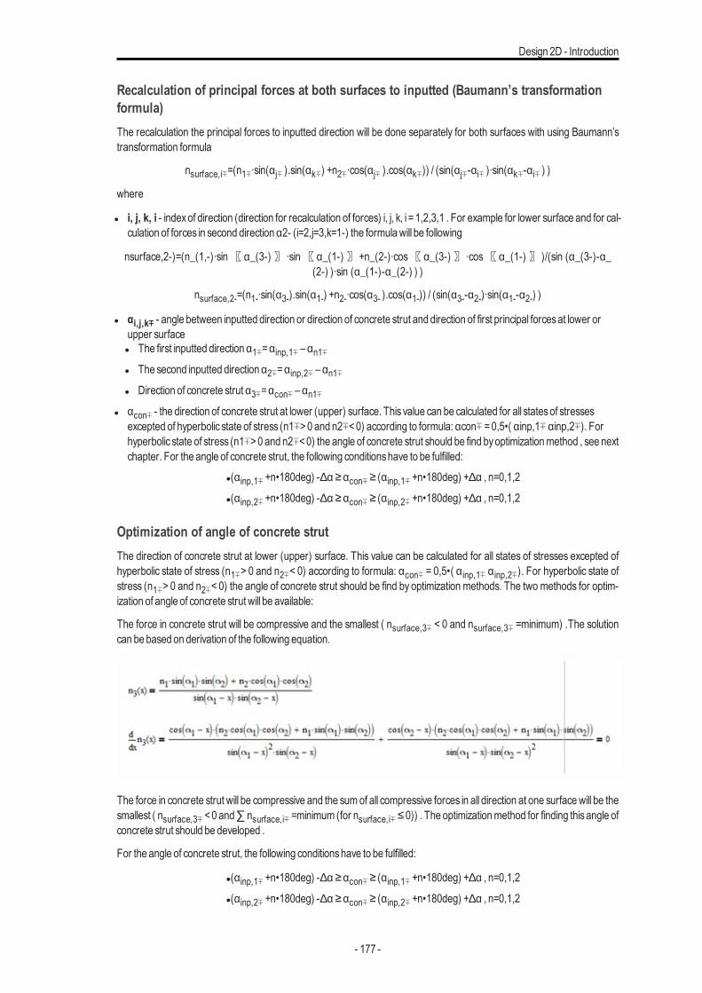
Design 2D - Introduction
Recalculation of principal forces at both surfaces to inputted (Baumann’s transformationformula)The recalculation the principal forces to inputted direction will be done separately for both surfaces with using Baumann’stransformation formula
nsurface,i∓=(n1∓∙sin(αj∓ ).sin(αk∓) +n2∓∙cos(αj∓ ).cos(αk∓)) / (sin(αj∓-αi∓ )∙sin(αk∓-αi∓ ) )
where
l i, j, k, i - indexof direction (direction for recalculation of forces) i, j, k, i =1,2,3,1 . For example for lower surface and for cal-culation of forces in second direction α2- (i=2,j=3,k=1-) the formulawill be following
nsurface,2-)=(n_(1,-)∙sin〖α_(3-)〗 ∙sin〖α_(1-)〗+n_(2-)∙cos〖α_(3-)〗 ∙cos〖α_(1-)〗 )/(sin (α_(3-)-α_(2-) )∙sin (α_(1-)-α_(2-) ) )
nsurface,2-=(n1-∙sin(α3-).sin(α1-) +n2-∙cos(α3- ).cos(α1-)) / (sin(α3--α2-)∙sin(α1--α2-) )
l αi,j,k∓ - angle between inputted direction or direction of concrete strut and direction of first principal forcesat lower orupper surfacel The first inputted direction α1∓=αinp,1∓ – αn1∓l The second inputted direction α2∓=αinp,2∓ – αn1∓l Direction of concrete strut α3∓=αcon∓ – αn1∓
l αcon∓ - the direction of concrete strut at lower (upper) surface. This value can be calculated for all statesof stressesexcepted of hyperbolic state of stress (n1∓>0 and n2∓<0) according to formula: αcon∓ =0,5•( αinp,1∓ αinp,2∓). Forhyperbolic state of stress (n1∓>0 and n2∓<0) the angle of concrete strut should be find byoptimizationmethod , see nextchapter. For the angle of concrete strut, the following conditionshave to be fulfilled:
l(αinp,1∓ +n•180deg) -∆α ≥αcon∓ ≥ (αinp,1∓ +n•180deg) +∆α , n=0,1,2
l(αinp,2∓ +n•180deg) -∆α ≥αcon∓ ≥ (αinp,2∓ +n•180deg) +∆α , n=0,1,2
Optimization of angle of concrete strutThe direction of concrete strut at lower (upper) surface. This value can be calculated for all states of stresses excepted ofhyperbolic state of stress (n1∓> 0 and n2∓< 0) according to formula: αcon∓ = 0,5•( α inp,1∓ α inp,2∓). For hyperbolic state ofstress (n1∓> 0 and n2∓< 0) the angle of concrete strut should be find by optimization methods. The two methods for optim-ization of angle of concrete strut will be available:
The force in concrete strut will be compressive and the smallest ( nsurface,3∓ < 0 and nsurface,3∓ =minimum) .The solutioncan be based on derivation of the following equation.
The force in concrete strut will be compressive and the sumof all compressive forces in all direction at one surfacewill be thesmallest ( nsurface,3∓ <0 and∑ nsurface,i∓ =minimum (for nsurface,i∓ ≤0)) . The optimizationmethod for finding thisangle ofconcrete strut should be developed .
For the angle of concrete strut, the following conditionshave to be fulfilled:
l(αinp,1∓ +n•180deg) -∆α ≥αcon∓ ≥ (αinp,1∓ +n•180deg) +∆α , n=0,1,2
l(αinp,2∓ +n•180deg) -∆α ≥αcon∓ ≥ (αinp,2∓ +n•180deg) +∆α , n=0,1,2
- 177 -
Chapter 7
Calculation of virtual forces at lower(upper) surface for inputted direction and direction ofconcrete strut for upper (lower surface)The virtual forces will be calculated according to Baumann’s transformation formula, where instead of angle of concretestrut angle of direction for upper or lower surfacewill be added
l nsurface,virt,1-
IF αinp,1- =αinp,1+,
THEN nsurface,virt,1-=nsurface,1-ELSEnsurface,virt,1-=(n1-∙sin(α2- ) .sin(α1+ ) +n2-∙cos(α2- ) ∙cos(α1+ ))/(sin(α2-- α1- )∙sin(α1+-α1- ) )
(Baumann’s transformation formulawhere α3- =α1+)
nsurface,virt,2-
IF αinp,2- =αinp,2+,
THEN nsurface,virt,2-=nsurface,2-ELSEnsurface,virt,2-=(n1-∙sin(α2+ ) .sin(α1- ) +n2-∙cos(α2+ ) ∙cos(α1- ))/(sin(α2+- α2- )∙sin(α1--α2- ) )
(Baumann’s transformation formulawhere α3- =α2+)
l nsurface,virt,3-
IF αinp,3- =αinp,3+,
THEN nsurface,virt,3-=nsurface,3-ELSEnsurface,virt,3-=(n1-∙sin(α2+ ) .sin(α1- ) +n2-∙cos(α2- ) ∙cos(α1- ))/(sin(α2-- α3+ )∙sin(α1--α3+ ) )
(Baumann’s transformation formulawhere α3- =α3+)
l nsurface,virt,1+
IF αinp,1+=αinp,1-,
THEN nsurface,virt,1+=nsurface,1+ELSEnsurface,virt,1+=(n1+∙sin(α2- ) .sin(α1+ ) +n2+∙cos(α2- ) ∙cos(α1+ ))/(sin(α2+- α1+ )∙sin(α1--α1+ ) )
(Baumann’s transformation formulawhere α3+=α1-)
l nsurface,virt,2+
IF αinp,2+=αinp,2-,
THEN nsurface,virt,2-=nsurface,2-ELSEnsurface,virt,2-=(n1-∙sin(α2+ ) .sin(α1- ) +n2-∙cos(α2+ ) ∙cos(α1- ))/(sin(α2+- α2- )∙sin(α1--α2- ) )
(Baumann’s transformation formulawhere α3+=α2-)
nsurface,virt,3+
IF αinp,3+=αinp,3-,
THEN nsurface,virt,3+=nsurface,3+ELSEnsurface,virt,3+=(n1+∙sin(α2+ ) .sin(α1+ ) +n2+∙cos(α2+ ) ∙cos(α1+ ))/(sin(α2+- α3- )∙sin(α1+-α3- ) )
(Baumann’s transformation formulawhere α3+=α3-)
- 178 -
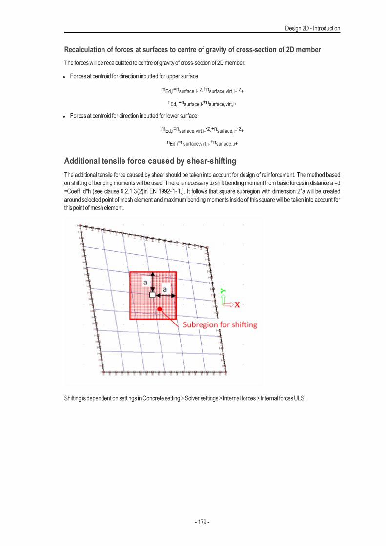
Design 2D - Introduction
Recalculation of forces at surfaces to centre of gravity of cross-section of 2D memberThe forceswill be recalculated to centre of gravityof cross-section of 2Dmember.
l Forcesat centroid for direction inputted for upper surface
mEd,i=nsurface,i-∙z-+nsurface,virt,i+∙z+nEd,i=nsurface,i-+nsurface,virt,i+
l Forcesat centroid for direction inputted for lower surface
mEd,i=nsurface,virt,i-∙z-+nsurface,i+∙z+nEd,i=nsurface,virt,i-+nsurface,,i+
Additional tensile force caused by shear-shiftingThe additional tensile force caused by shear should be taken into account for design of reinforcement. The method basedon shifting of bending momentswill be used. There is necessary to shift bending moment from basic forces in distance a =d=Coeff_d*h (see clause 9.2.1.3(2)in EN 1992-1-1,). It follows that square subregion with dimension 2*a will be createdaround selected point of mesh element and maximum bending moments inside of this square will be taken into account forthispoint ofmesh element.
Shifting isdependent on settings inConcrete setting >Solver settings> Internal forces> Internal forcesULS.
- 179 -
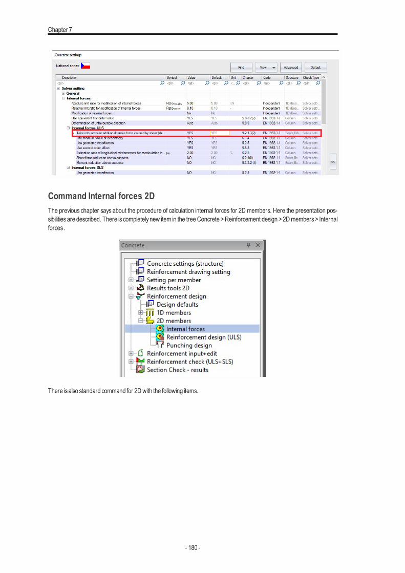
Chapter 7
Command Internal forces 2DThe previous chapter says about the procedure of calculation internal forces for 2D members. Here the presentation pos-sibilities are described. There is completely new item in the tree Concrete >Reinforcement design >2D members> Internalforces .
There isalso standard command for 2Dwith the following items.
- 180 -
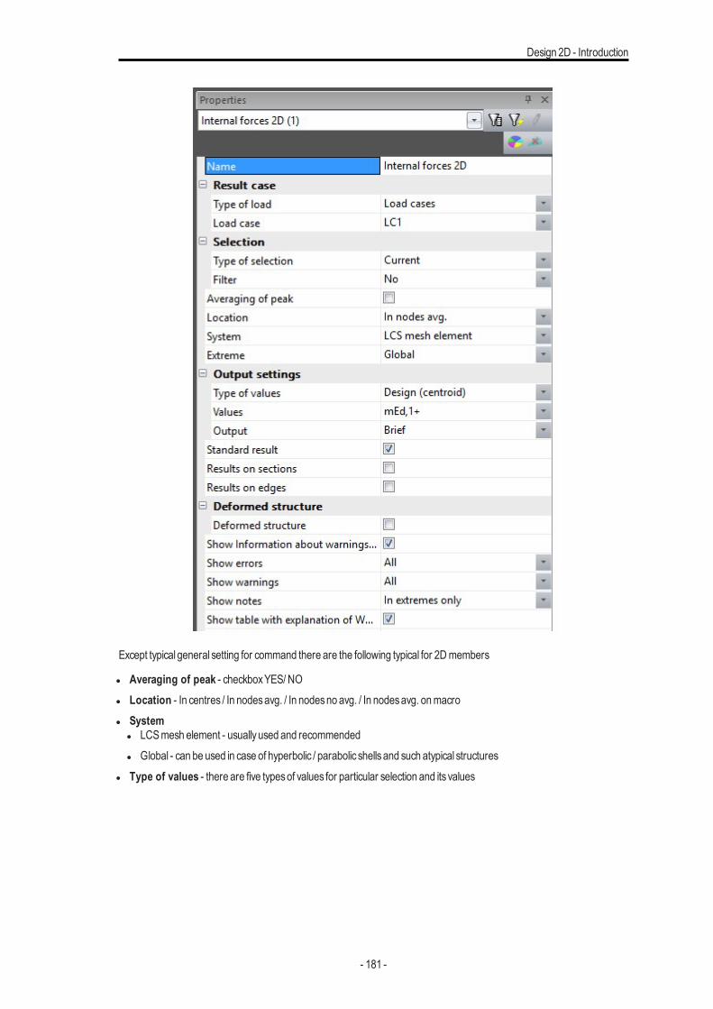
Design 2D - Introduction
Except typical general setting for command there are the following typical for 2Dmembers
l Averaging of peak - checkboxYES/ NOl Location - In centres / In nodesavg. / In nodesno avg. / In nodesavg. onmacrol System
l LCSmesh element - usuallyused and recommendedl Global - can be used in case of hyperbolic / parabolic shellsand such atypical structures
l Type of values - there are five typesof values for particular selection and its values
- 181 -
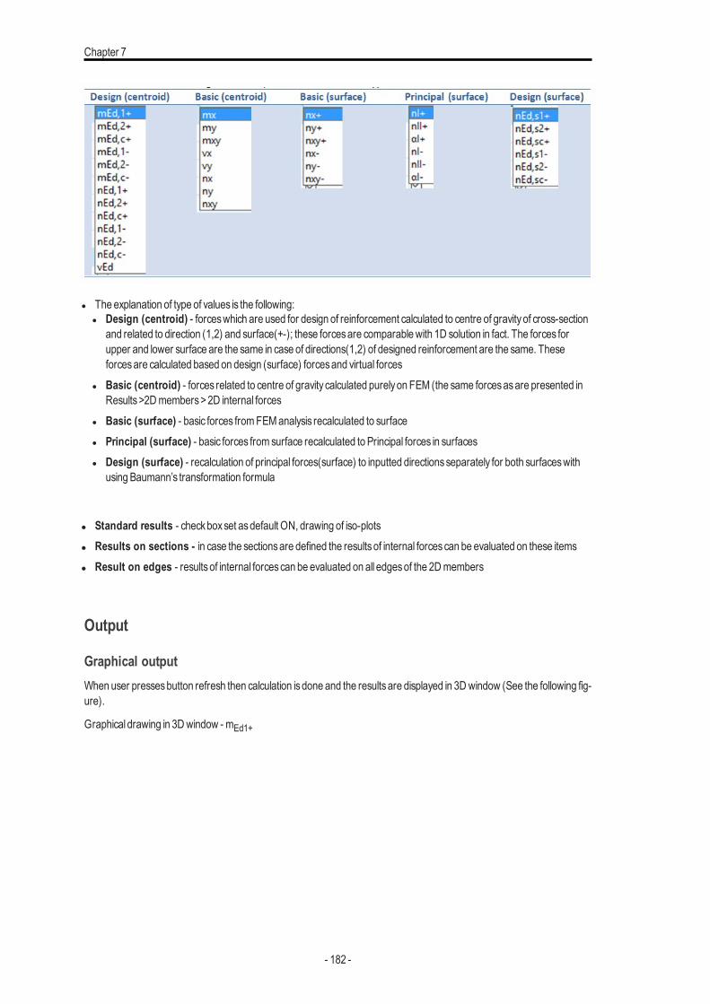
Chapter 7
l The explanation of type of values is the following:l Design (centroid) - forceswhich are used for design of reinforcement calculated to centre of gravityof cross-section
and related to direction (1,2) and surface(+-); these forcesare comparablewith 1D solution in fact. The forces forupper and lower surface are the same in case of directions(1,2) of designed reinforcement are the same. Theseforcesare calculated based on design (surface) forcesand virtual forces
l Basic (centroid) - forces related to centre of gravity calculated purelyon FEM (the same forcesasare presented inResults>2Dmembers>2D internal forces
l Basic (surface) - basic forces fromFEManalysis recalculated to surfacel Principal (surface) - basic forces from surface recalculated to Principal forces in surfacesl Design (surface) - recalculation of principal forces(surface) to inputted directionsseparately for both surfaceswith
using Baumann’s transformation formula
l Standard results - checkboxset asdefault ON, drawing of iso-plotsl Results on sections - in case the sectionsare defined the resultsof internal forcescan be evaluated on these itemsl Result on edges - resultsof internal forcescan be evaluated on all edgesof the 2Dmembers
Output
Graphical outputWhen user pressesbutton refresh then calculation isdone and the resultsare displayed in 3Dwindow (See the following fig-ure).
Graphical drawing in 3Dwindow - mEd1+
- 182 -
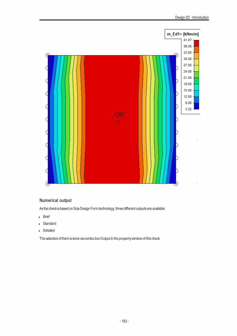
Design 2D - Introduction
Numerical outputAs the check isbased onSciaDesign Form technology, three different outputsare available
l Briefl Standardl Detailed
The selection of them isdone via combo boxOutput in the propertywindow of this check.
- 183 -
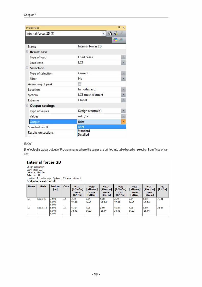
Chapter 7
BriefBrief output is typical output of Program name where the values are printed into table based on selection from Type of val-ues
- 184 -
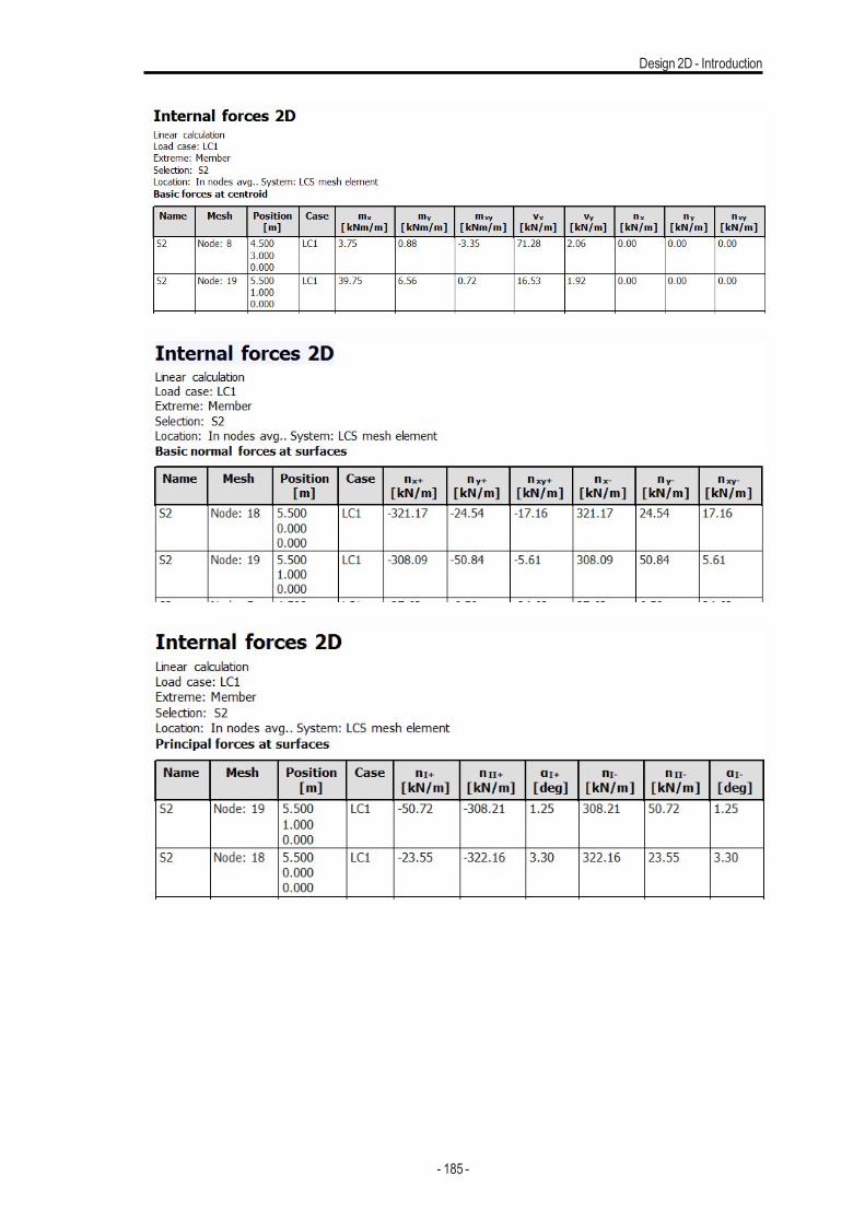
Design 2D - Introduction
- 185 -
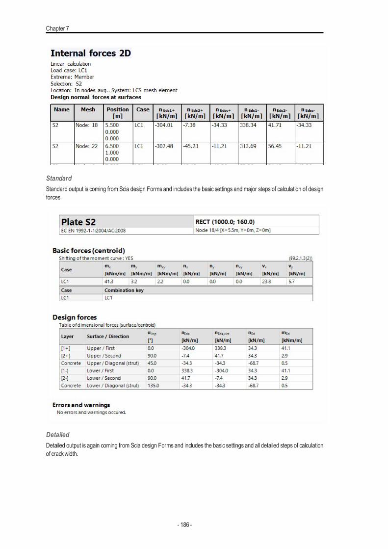
Chapter 7
StandardStandard output is coming from Scia design Forms and includes the basic settings and major steps of calculation of designforces
DetailedDetailed output is again coming from Scia design Forms and includes the basic settings and all detailed steps of calculationof crackwidth.
- 186 -
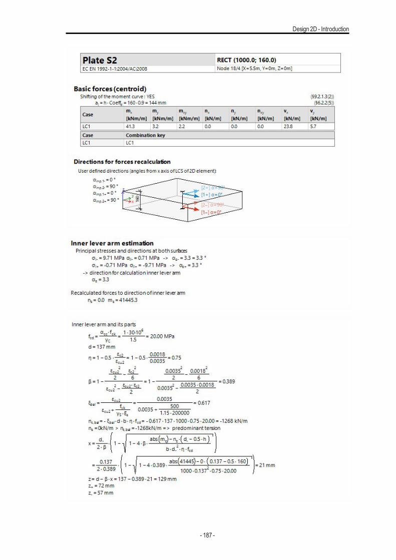
Design 2D - Introduction
- 187 -
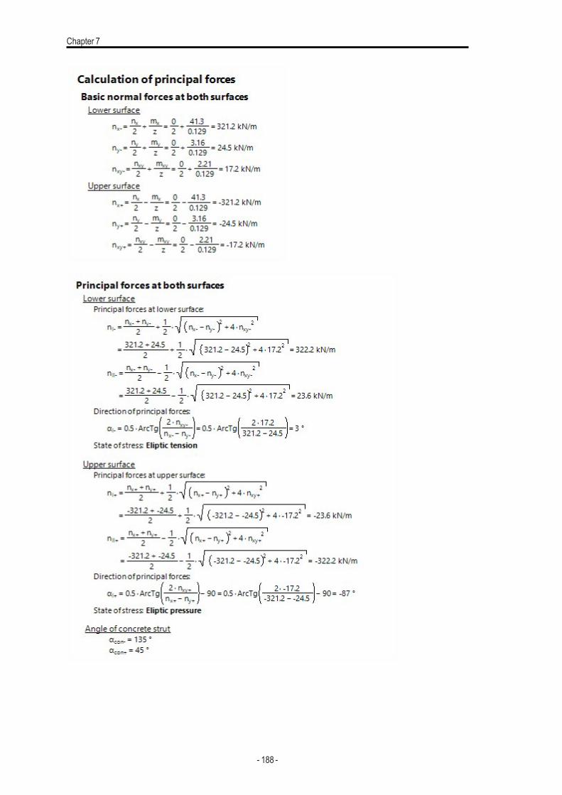
Chapter 7
- 188 -
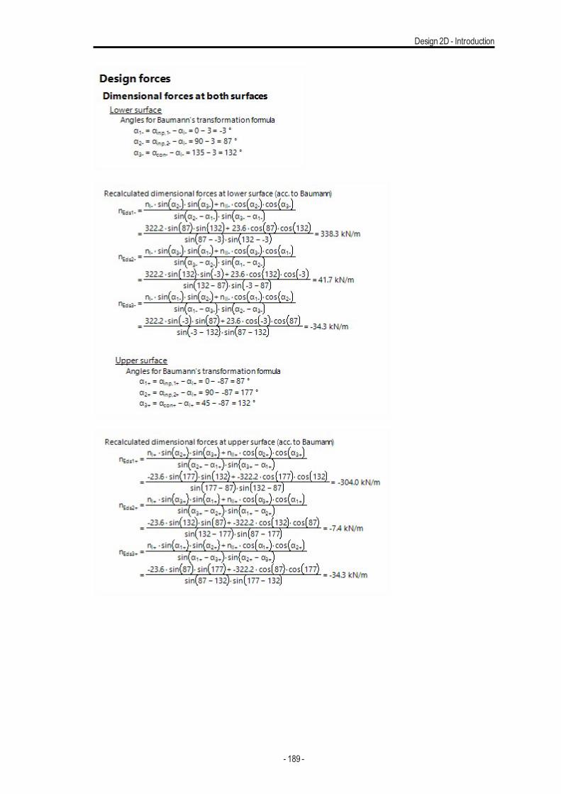
Design 2D - Introduction
- 189 -
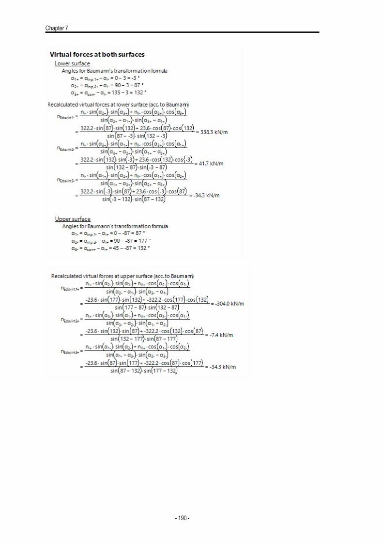
Chapter 7
- 190 -
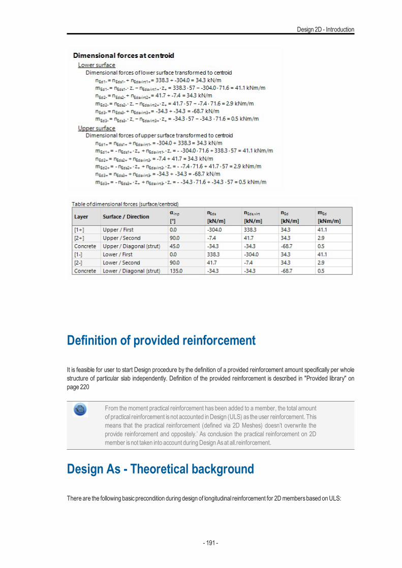
Design 2D - Introduction
Definition of provided reinforcement
It is feasible for user to start Design procedure by the definition of a provided reinforcement amount specifically per wholestructure of particular slab independently. Definition of the provided reinforcement is described in "Provided library" onpage 220
From the moment practical reinforcement has been added to a member, the total amountof practical reinforcement isnot accounted inDesign (ULS) as the user reinforcement. Thismeans that the practical reinforcement (defined via 2D Meshes) doesn’t overwrite theprovide reinforcement and oppositely.’ As conclusion the practical reinforcement on 2Dmember isnot taken into account duringDesignAsat all.reinforcement.
Design As - Theoretical background
There are the following basicprecondition during design of longitudinal reinforcement for 2Dmembersbased onULS:
- 191 -
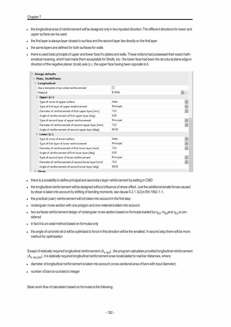
Chapter 7
l the longitudinal area of reinforcement will be designed only in two inputted direction.The different directions for lower andupper surface can be used
l the first layer isalways layer closest to surface and the second layer liesdirectlyon the first layerl the same layersare defined for both surfaces for wallsl there isused basicprinciple of upper and lower face fro platesandwalls. These notionshad possessed their exactmath-
ematicalmeaning, which hadmade themacceptable for Shells, too : the lower face had been the structural plane edge indirection of the negative planar (local) axis (z-), the upper face having been opposite to it.
l there isa possibility to define principal and secondary layer reinforcement bysetting inCMDl the longitudinal reinforcement will be designedwithout influence of shear effect. Just the additional tensile forcescaused
byshear is taken into account byshifting of bendingmoments, see clause 9.2.1.3(2)in EN 1992-1-1,l the practical (user) reinforcement will not taken into account in the first stepl rectangular cross-sectionwith one polygon and onematerial is taken into account,l two surfaces reinforcement design of rectangular cross-section based on formulas loaded bynEd; mEdand vEd is con-
sideredl in fact it is uni-axialmethod based on formulasonly
l the angle of concrete strut will be optimized to force in thisdirectionwill be the smallest. In second step therewill bemoremethod for optimization
Except of statically required longitudinal reinforcement (As.req) , the program calculatesprovided longitudinal reinforcement(As.req,bar). It is statically required longitudinal reinforcement area recalculated to real bar distances, where:
l diameter of longitudinal reinforcement is taken into account (cross-sectional area of barswith input diameter)
l number of bars is rounded to integer
Basicwork-flow of calculation based on formulas is the following:
- 192 -
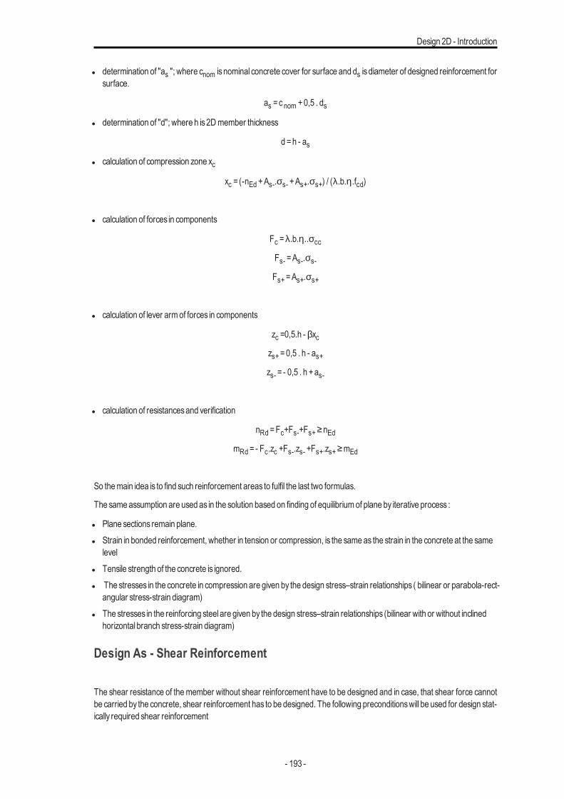
Design 2D - Introduction
l determination of "as "; where cnom is nominal concrete cover for surface and ds is diameter of designed reinforcement forsurface.
as =c nom +0,5 . ds
l determination of "d"; where h is2Dmember thickness
d =h - as
l calculation of compression zone xc
xc = (-nEd +As-.σs- +As+.σs+) / (λ.b.η.fcd)
l calculation of forces in components
Fc =λ.b.η..σcc
Fs- =As-.σs-
Fs+=As+.σs+
l calculation of lever armof forces in components
zc =0,5.h - βxczs+=0,5 . h - as+zs- = - 0,5 . h +as-
l calculation of resistancesand verification
nRd =Fc+Fs-+Fs+≥nEdmRd = - Fc.zc +Fs-.zs- +Fs+.zs+≥mEd
So themain idea is to find such reinforcement areas to fulfil the last two formulas.
The sameassumption are used as in the solution based on finding of equilibriumof plane by iterative process :
l Plane sections remain plane.l Strain in bonded reinforcement, whether in tension or compression, is the same as the strain in the concrete at the same
levell Tensile strength of the concrete is ignored.l The stresses in the concrete in compression are given by the design stress–strain relationships ( bilinear or parabola-rect-
angular stress-strain diagram)l The stresses in the reinforcing steel are given by the design stress–strain relationships (bilinear with or without inclined
horizontal branch stress-strain diagram)
Design As - Shear Reinforcement
The shear resistance of the member without shear reinforcement have to be designed and in case, that shear force cannotbe carried by the concrete, shear reinforcement has to be designed. The following preconditionswill be used for design stat-ically required shear reinforcement
- 193 -
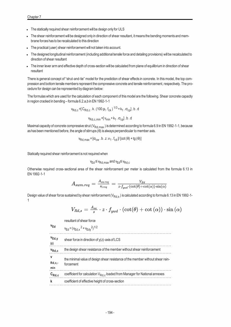
Chapter 7
l The statically required shear reinforcement will be design only for ULSl The shear reinforcement will be designed only in direction of shear resultant, it means the bendingmomentsandmem-
brane forceshas to be recalculated to thisdirectionl The practical (user) shear reinforcement will not taken into account.l The designed longitudinal reinforcement (including additional tensile force and detailing provisions) will be recalculated to
direction of shear resultantl The inner lever armand effective depth of cross-sectionwill be calculated fromplane of equilibrium in direction of shear
resultant
There is general concept of “strut-and-tie” model for the prediction of shear effects in concrete. In thismodel, the top com-pression and bottom tensilemembers represent the compressive concrete and tensile reinforcement, respectively. The pro-cedure for design can be represented bydiagrambelow:
The formulaswhich are used for the calculation of each component of thismodel are the following. Shear concrete capacityin region cracked in bending – formula 6.2.a,b in EN 1992-1-1
vRd,c =[ CRd,c . k . (100ρl . fck ) 1/3 +k1 .σcp] . b . d
vRd,c,min =[ vmin +k1 .σcp] . b . d
Maximal capacity of concrete compressive strut (VRd,max ) is determined according to formula 6.9 in EN 1992-1-1, becauseashasbeenmentioned before, the angle of stirrups (θ) isalwaysperpendicular tomember axis.
vRd,max = [αcw . b . z .ν1 . fcd ]/ [cot (θ) + tg (θ)]
Statically required shear reinforcement isnot requiredwhen
vEd≤vRd,max and vEd≤vRd,cOtherwise required cross- sectional area of the shear reinforcement per meter is calculated from the formula 6.13 inEN 1992-1-1
Design value of shear force sustained byshear reinforcement (VRd,s ) is calculated according to formula 6.13 in EN 1992-1-1
vEdresultant of shear force
vEd = (vEd,x 2 +vEdy2)1/2
vEd,y(z)
shear force in direction of y(z)-axisof LCS
vRd,c the design shear resistance of themember without shear reinforcement
vRd,c,-min
theminimal value of design shear resistance of themember without shear rein-forcement
CRd,c coefficient for calculation VRd,c loaded fromManager for National annexes
k coefficient of effective height of cross-section
- 194 -
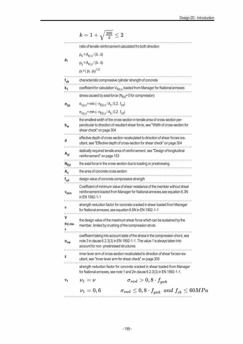
Design 2D - Introduction
ρl
ratio of tensile reinforcement calculated fro both direction
ρx =Asl,x / (b . d)
ρy =Asl,y / (b . d)
ρl = ( ρl .ρl)1/2
fck characteristic compressive cylinder strength of concrete
k1 coefficient for calculation VRd,c loaded fromManager for National annexes
σcp
stresscaused byaxial force (NEd>0 for compression)
σcp,x=min (- nEd,x / Ac; 0,2 . fcd)
σcp,y=min (- nEd,y / Ac; 0,2 . fcd)
bwthe smallest width of the cross-section in tensile area of cross-section per-pendicular to direction of resultant shear force, see "Width of cross-section forshear check" on page 304
d effective depth of cross-section recalculated to direction of shear forces res-ultant, see "Effective depth of cross-section for shear check" on page 304
Aslstatically required tensile area of reinforcement, see "Design of longitudinalreinforcement" on page 153
NEd the axial force in the cross-section due to loading or prestressing.
Ac the area of concrete crosssection
fcd design value of concrete compressive strength
νmin
Coefficient ofminimumvalue of shear resistance of themember without shearreinforcement loaded fromManager for National annexes,see equation 6.3Nin EN 1992-1-1
ν strength reduction factor for concrete cracked in shear loaded fromManagerfor National annexes, see equation 6.6N in EN 1992-1-1
VRd,ma-x
the design value of themaximumshear forcewhich can be sustained by themember, limited bycrushing of the compression struts
αcwcoefficient taking into account state of the stress in the compression chord, seenote 3 in clause 6.2.3(3) in EN 1992-1-1. The value 1 isalways taken intoaccount for non -prestressed structures
z inner lever armof cross-section recalculated to direction of shear forces res-ultant, see "Inner lever arm for shear check" on page 305
ν1
strength reduction factor for concrete cracked in shear loaded from Managerfor National annexes, see note 1 and 2in clause 6.2.3(3) in EN 1992-1-1.
- 195 -
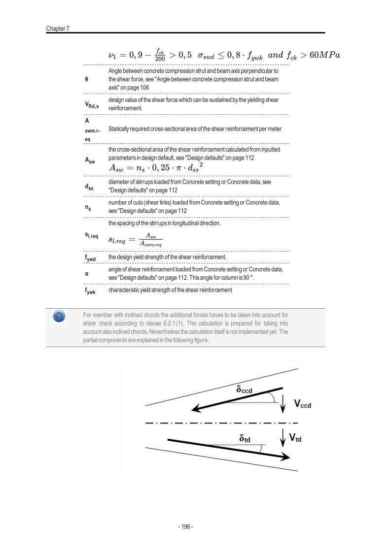
Chapter 7
θAngle between concrete compression strut and beamaxisperpendicular tothe shear force, see "Angle between concrete compression strut and beamaxis" on page 106
VRd,sdesign value of the shear forcewhich can be sustained by the yielding shearreinforcement.
Aswm.r-eq
Statically required cross-sectional area of the shear reinforcement per meter
Asw
the cross-sectional area of the shear reinforcement calculated from inputtedparameters in design default, see "Design defaults" on page 112
dssdiameter of stirrups loaded fromConcrete setting or Concrete data, see"Design defaults" on page 112
nsnumber of cuts (shear links) loaded fromConcrete setting or Concrete data,see "Design defaults" on page 112
sl.req
the spacing of the stirrups in longitudinal direction,
fywd the design yield strength of the shear reinforcement.
α angle of shear reinforcement loaded fromConcrete setting or Concrete data,see "Design defaults" on page 112. Thisangle for column is90 °.
fywk characteristic yield strength of the shear reinforcement
For member with inclined chords the additional forces haves to be taken into account forshear check according to clause 6.2.1 (1). The calculation is prepared for taking intoaccount also inclined chords. Nevertheless the calculation itself is not implemented yet. Thepartial componentsare explained in the following figure.
- 196 -
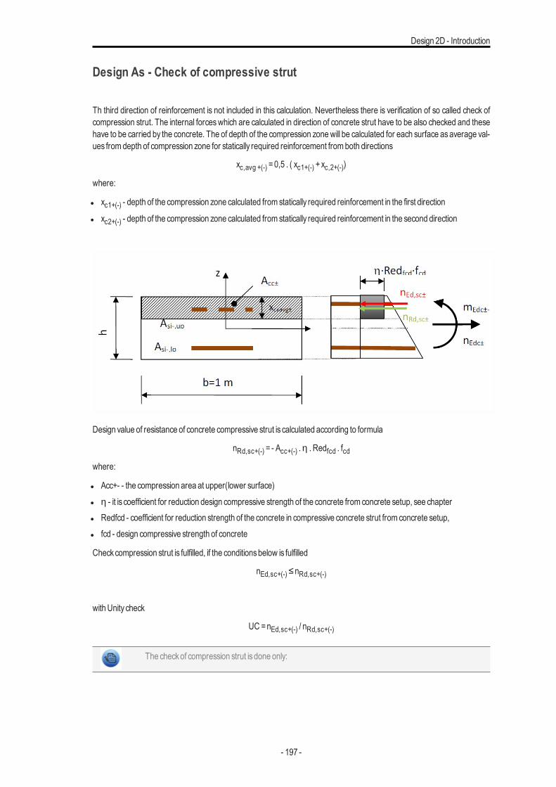
Design 2D - Introduction
Design As - Check of compressive strut
Th third direction of reinforcement is not included in this calculation. Nevertheless there is verification of so called check ofcompression strut. The internal forceswhich are calculated in direction of concrete strut have to be also checked and thesehave to be carried by the concrete. The of depth of the compression zonewill be calculated for each surface asaverage val-ues fromdepth of compression zone for statically required reinforcement fromboth directions
xc,avg +(-) =0,5 . ( xc1+(-) +xc,2+(-))
where:
l xc1+(-) - depth of the compression zone calculated from statically required reinforcement in the first direction
l xc2+(-) - depth of the compression zone calculated from statically required reinforcement in the second direction
Design value of resistance of concrete compressive strut is calculated according to formula
nRd,sc+(-) = - Acc+(-) .η . Redfcd . fcdwhere:
l Acc+- - the compression area at upper(lower surface)l η - it is coefficient for reduction design compressive strength of the concrete from concrete setup, see chapterl Redfcd - coefficient for reduction strength of the concrete in compressive concrete strut from concrete setup,l fcd - design compressive strength of concrete
Checkcompression strut is fulfilled, if the conditionsbelow is fulfilled
nEd,sc+(-)≤nRd,sc+(-)
withUnity check
UC =nEd,sc+(-) / nRd,sc+(-)
The checkof compression strut isdone only:
- 197 -
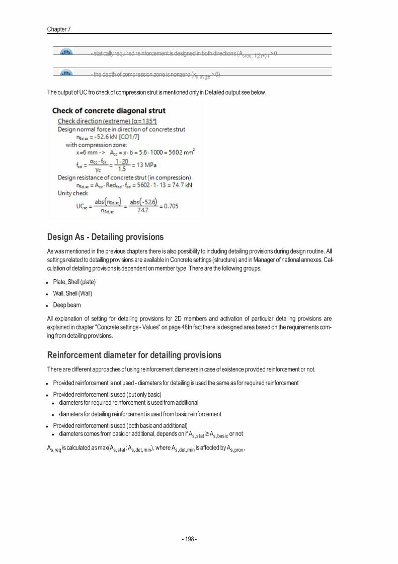
Chapter 7
- statically required reinforcement isdesigned in both directions (Asreq, 1(2)+(-) >0
- the depth of compression zone isnonzero (xc,avg± >0)
The output of UC fro checkof compression strut ismentioned only in Detailed output see below.
Design As - Detailing provisionsAswasmentioned in the previous chapters there is also possibility to including detailing provisions during design routine. Allsettings related to detailing provisionsare available in Concrete settings (structure) and inManager of national annexes. Cal-culation of detailing provisions isdependent onmember type. There are the following groups.
l Plate, Shell (plate)l Wall, Shell (Wall)l Deep beam
All explanation of setting for detailing provisions for 2D members and activation of particular detailing provisions areexplained in chapter "Concrete settings - Values" on page 48In fact there is designed area based on the requirements com-ing fromdetailing provisions.
Reinforcement diameter for detailing provisionsThere are different approachesof using reinforcement diameters in case of existence provided reinforcement or not.
l Provided reinforcement isnot used - diameters for detailing isused the sameas for required reinforcementl Provided reinforcement isused (but onlybasic)
l diameters for required reinforcement isused fromadditional,l diameters for detailing reinforcement isused frombasic reinforcement
l Provided reinforcement isused (both basicand additional)l diameterscomes frombasicor additional, dependson if As,stat ≥As,basic or not
As,req is calculated asmax(As,stat; As,det,min), where As,det,min is affected byAs,prov,
- 198 -
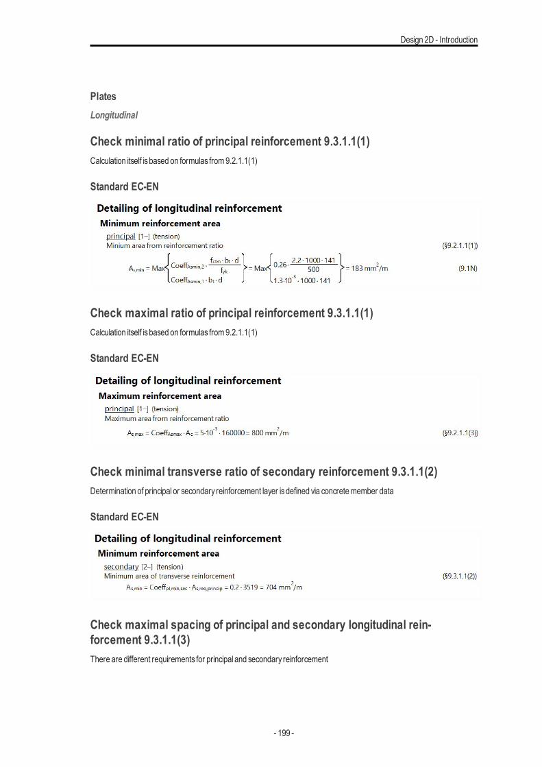
Design 2D - Introduction
PlatesLongitudinal
Check minimal ratio of principal reinforcement 9.3.1.1(1)Calculation itself isbased on formulas from9.2.1.1(1)
Standard EC-EN
Check maximal ratio of principal reinforcement 9.3.1.1(1)Calculation itself isbased on formulas from9.2.1.1(1)
Standard EC-EN
Check minimal transverse ratio of secondary reinforcement 9.3.1.1(2)Determination of principal or secondary reinforcement layer isdefined via concretemember data
Standard EC-EN
Check maximal spacing of principal and secondary longitudinal rein-forcement 9.3.1.1(3)There are different requirements for principal and secondary reinforcement
- 199 -
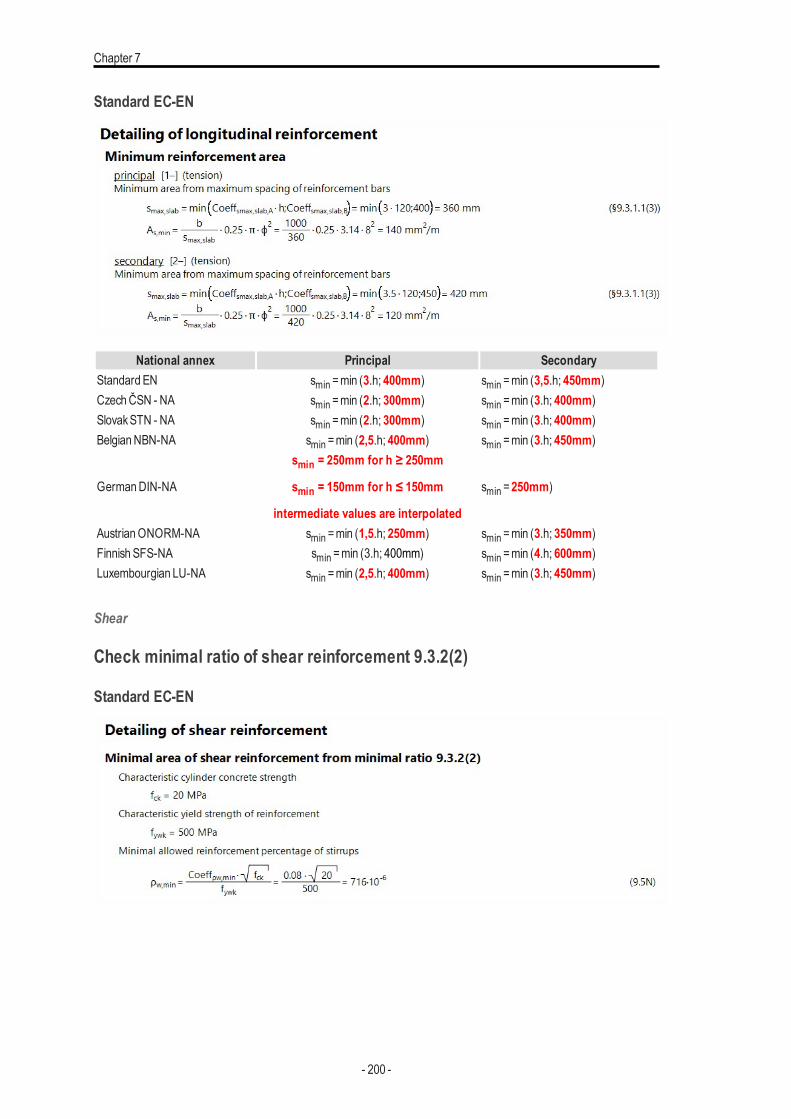
Chapter 7
Standard EC-EN
National annex Principal SecondaryStandard EN smin =min (3.h; 400mm) smin =min (3,5.h; 450mm)CzechČSN - NA smin =min (2.h; 300mm) smin =min (3.h; 400mm)SlovakSTN - NA smin =min (2.h; 300mm) smin =min (3.h; 400mm)BelgianNBN-NA smin =min (2,5.h; 400mm) smin =min (3.h; 450mm)
GermanDIN-NA
smin = 250mm for h ≥ 250mm
smin = 150mm for h ≤ 150mm
intermediate values are interpolated
smin =250mm)
AustrianONORM-NA smin =min (1,5.h; 250mm) smin =min (3.h; 350mm)Finnish SFS-NA smin =min (3.h; 400mm) smin =min (4.h; 600mm)Luxembourgian LU-NA smin =min (2,5.h; 400mm) smin =min (3.h; 450mm)
Shear
Check minimal ratio of shear reinforcement 9.3.2(2)
Standard EC-EN
- 200 -
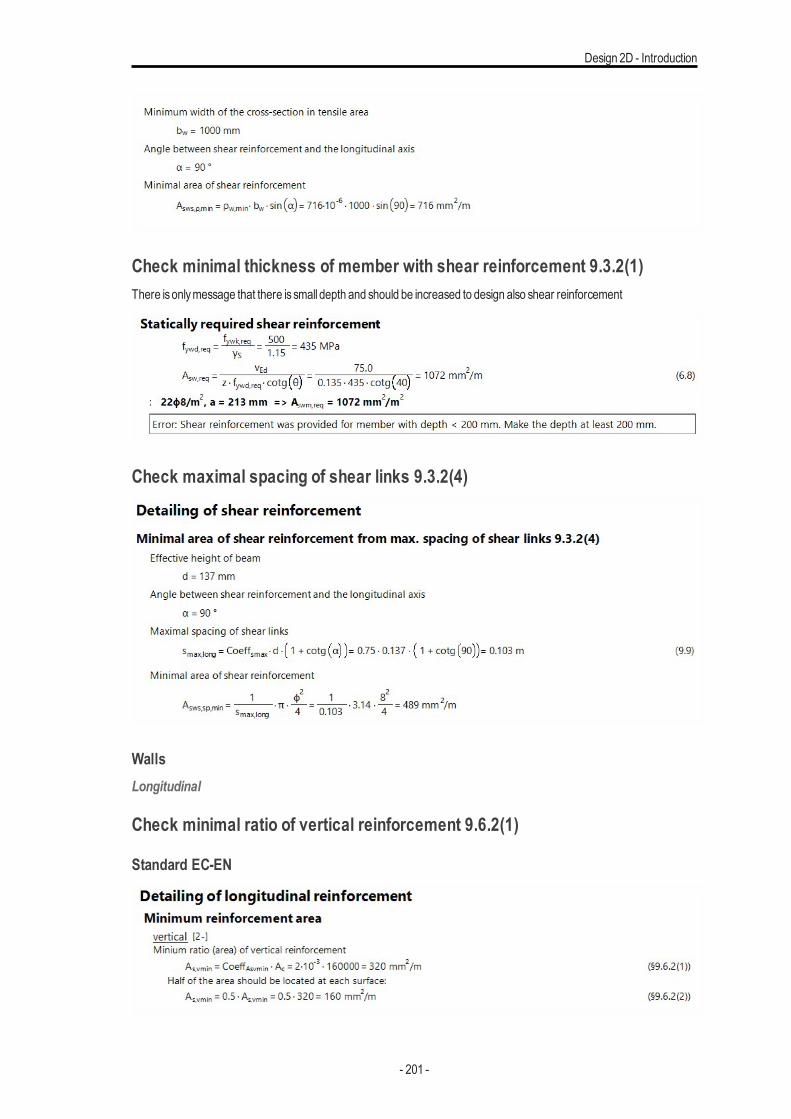
Design 2D - Introduction
Check minimal thickness of member with shear reinforcement 9.3.2(1)There isonlymessage that there is small depth and should be increased to design also shear reinforcement
Check maximal spacing of shear links 9.3.2(4)
WallsLongitudinal
Check minimal ratio of vertical reinforcement 9.6.2(1)
Standard EC-EN
- 201 -
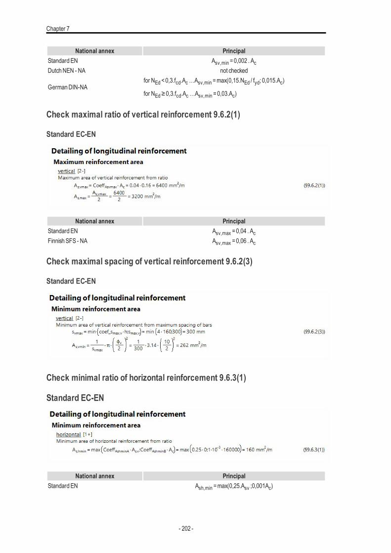
Chapter 7
National annex PrincipalStandard EN Asv,min =0,002 . AcDutchNEN - NA not checked
GermanDIN-NAfor NEd <0,3.fcd.Ac…Asv,min =max(0,15.NEd / fyd; 0,015.Ac)
for NEd≥0,3.fcd.Ac…Asv,min =0,03.Ac)
Check maximal ratio of vertical reinforcement 9.6.2(1)
Standard EC-EN
National annex PrincipalStandard EN Asv,max =0,04 . AcFinnish SFS - NA Asv,max =0,06 . Ac
Check maximal spacing of vertical reinforcement 9.6.2(3)
Standard EC-EN
Check minimal ratio of horizontal reinforcement 9.6.3(1)
Standard EC-EN
National annex PrincipalStandard EN Ash,min =max(0,25.Asv ;0,001Ac)
- 202 -
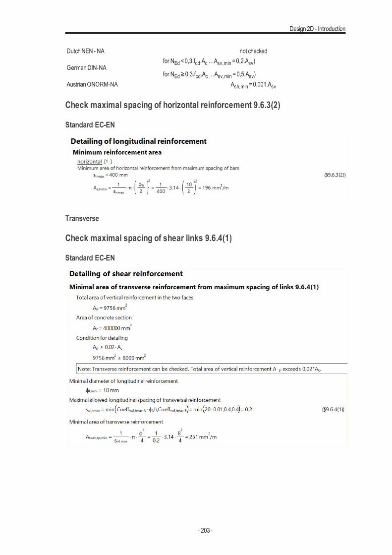
Design 2D - Introduction
DutchNEN - NA not checked
GermanDIN-NAfor NEd <0,3.fcd.Ac…Asv,min =0,2.Asv)
for NEd≥0,3.fcd.Ac…Asv,min =0,5.Asv)AustrianONORM-NA Ash,min =0,001.Asv
Check maximal spacing of horizontal reinforcement 9.6.3(2)
Standard EC-EN
Transverse
Check maximal spacing of shear links 9.6.4(1)
Standard EC-EN
- 203 -
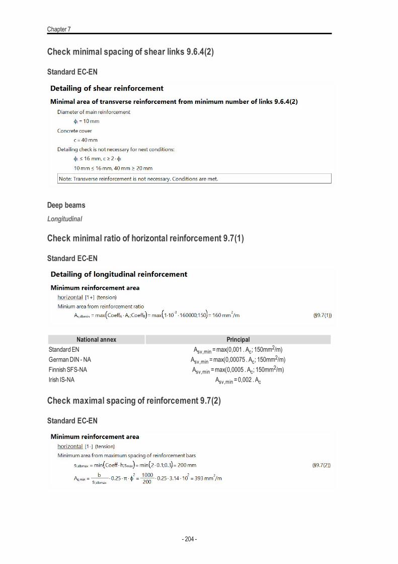
Chapter 7
Check minimal spacing of shear links 9.6.4(2)
Standard EC-EN
Deep beamsLongitudinal
Check minimal ratio of horizontal reinforcement 9.7(1)
Standard EC-EN
National annex PrincipalStandard EN Asv,min =max(0,001 . Ac; 150mm2/m)GermanDIN - NA Asv,min =max(0,00075 . Ac; 150mm2/m)Finnish SFS-NA Asv,min =max(0,0005 . Ac; 150mm2/m)Irish IS-NA Asv,min =0,002 . Ac
Check maximal spacing of reinforcement 9.7(2)
Standard EC-EN
- 204 -
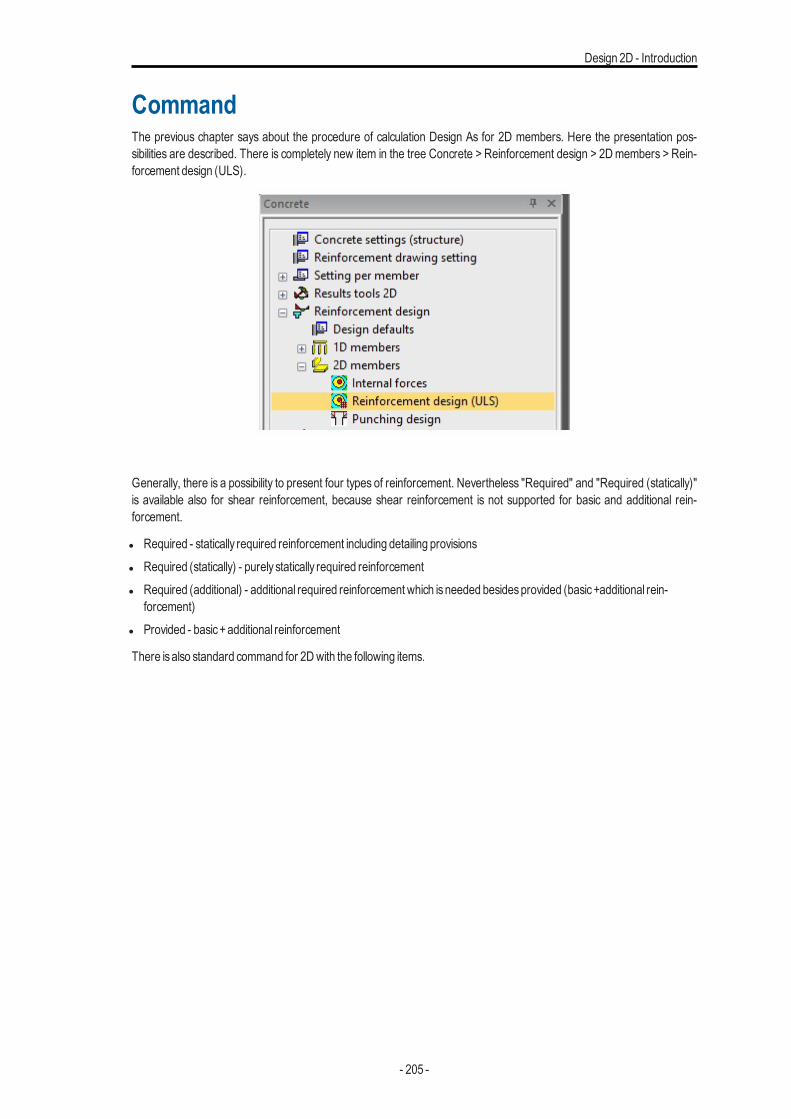
Design 2D - Introduction
CommandThe previous chapter says about the procedure of calculation Design As for 2D members. Here the presentation pos-sibilities are described. There is completely new item in the tree Concrete > Reinforcement design > 2D members > Rein-forcement design (ULS).
Generally, there is a possibility to present four types of reinforcement. Nevertheless "Required" and "Required (statically)"is available also for shear reinforcement, because shear reinforcement is not supported for basic and additional rein-forcement.
l Required - statically required reinforcement including detailing provisionsl Required (statically) - purely statically required reinforcementl Required (additional) - additional required reinforcement which isneeded besidesprovided (basic+additional rein-
forcement)l Provided - basic+additional reinforcement
There isalso standard command for 2Dwith the following items.
- 205 -
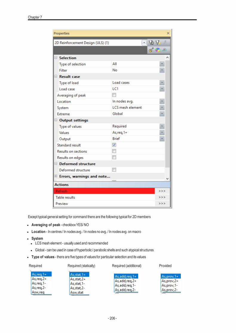
Chapter 7
Except typical general setting for command there are the following typical for 2Dmembers
l Averaging of peak - checkboxYES/ NOl Location - In centres / In nodesavg. / In nodesno avg. / In nodesavg. onmacrol System
l LCSmesh element - usuallyused and recommendedl Global - can be used in case of hyperbolic / parabolic shellsand such atypical structures
l Type of values - there are five typesof values for particular selection and its values
Required Required (statically) Required (additional) Provided
- 206 -
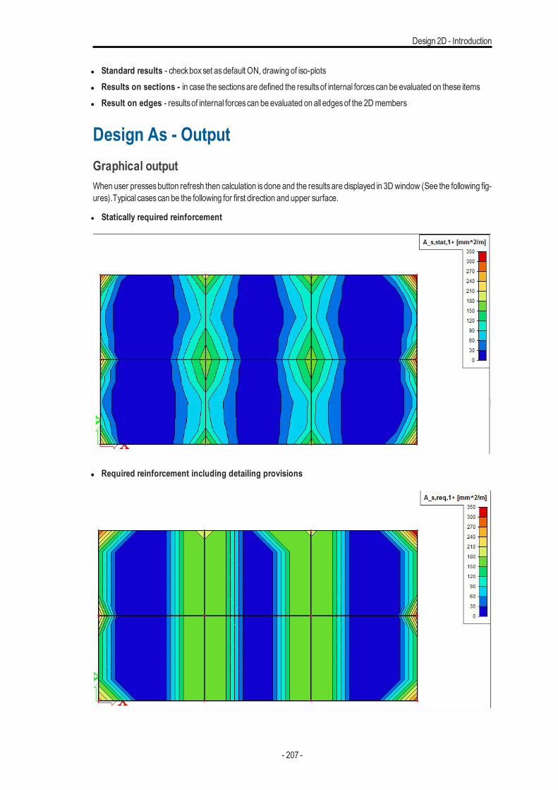
Design 2D - Introduction
l Standard results - checkboxset asdefault ON, drawing of iso-plotsl Results on sections - in case the sectionsare defined the resultsof internal forcescan be evaluated on these itemsl Result on edges - resultsof internal forcescan be evaluated on all edgesof the 2Dmembers
Design As - OutputGraphical outputWhen user pressesbutton refresh then calculation isdone and the resultsare displayed in 3Dwindow (See the following fig-ures).Typical casescan be the following for first direction and upper surface.
l Statically required reinforcement
l Required reinforcement including detailing provisions
- 207 -
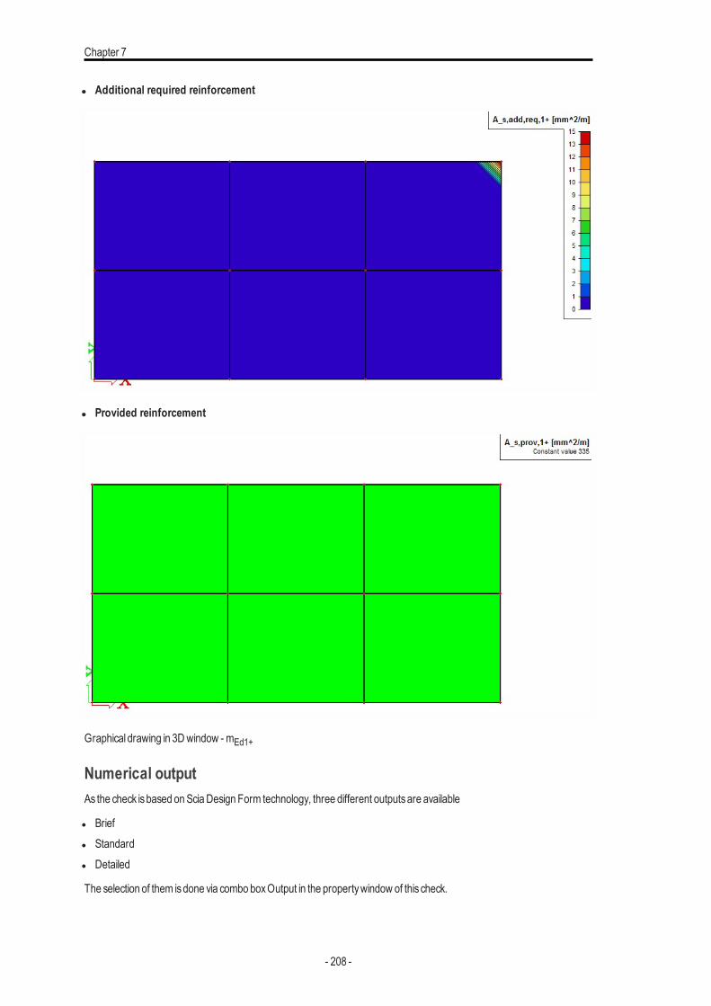
Chapter 7
l Additional required reinforcement
l Provided reinforcement
Graphical drawing in 3Dwindow - mEd1+
Numerical outputAs the check isbased onSciaDesign Form technology, three different outputsare available
l Briefl Standardl Detailed
The selection of them isdone via combo boxOutput in the propertywindow of this check.
- 208 -
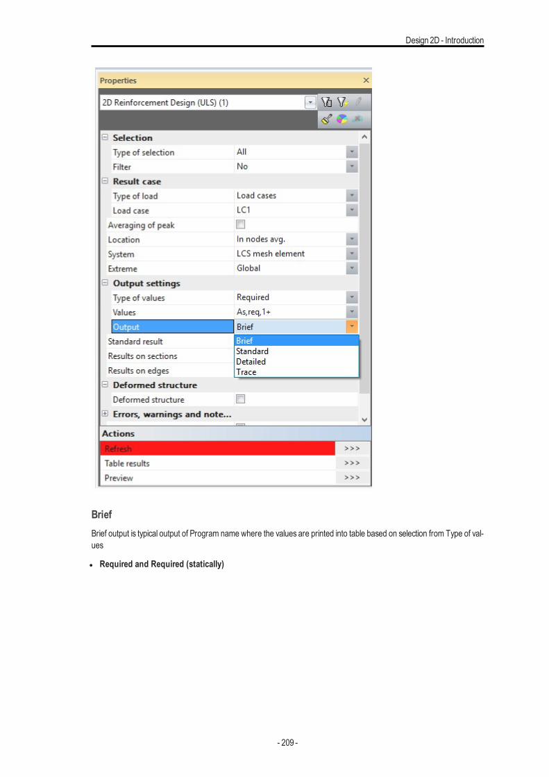
Design 2D - Introduction
BriefBrief output is typical output of Program name where the values are printed into table based on selection from Type of val-ues
l Required and Required (statically)
- 209 -
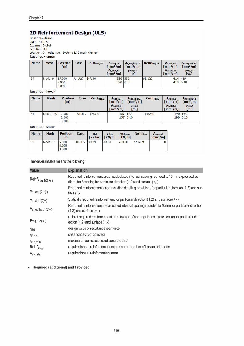
Chapter 7
The values in tablemeans the following:
Value Explanation
ReinfReq,1(2)+(-)Required reinforcement area recalculated into real spacing rounded to 10mmexpressed asdiameter / spacing for particular direction (1,2) and surface (+,-)
As,req1(2)+(-)Required reinforcement area including detailing provisions for particular direction (1,2) and sur-face (+,-)
As,stat1(2)+(-) Statically required reinforcement for particular direction (1,2) and surface (+,-)
As,req,bar,1(2)+(-)Required reinforcement recalculated into real spacing rounded to 10mm for particular direction(1,2) and surface (+,-)
ρreq,1(2)+(-)ratio of required reinforcement area to area of rectangular concrete section for particular dir-ection (1,2) and surface (+,-)
vEd design value of resultant shear forcevRd,c shear capacityof concretevRd,max maximal shear resistance of concrete strutReinfAsw required shear reinforcement expressed in number of basand diameterAsw,stat required shear reinforcement area
l Required (additional) and Provided
- 210 -
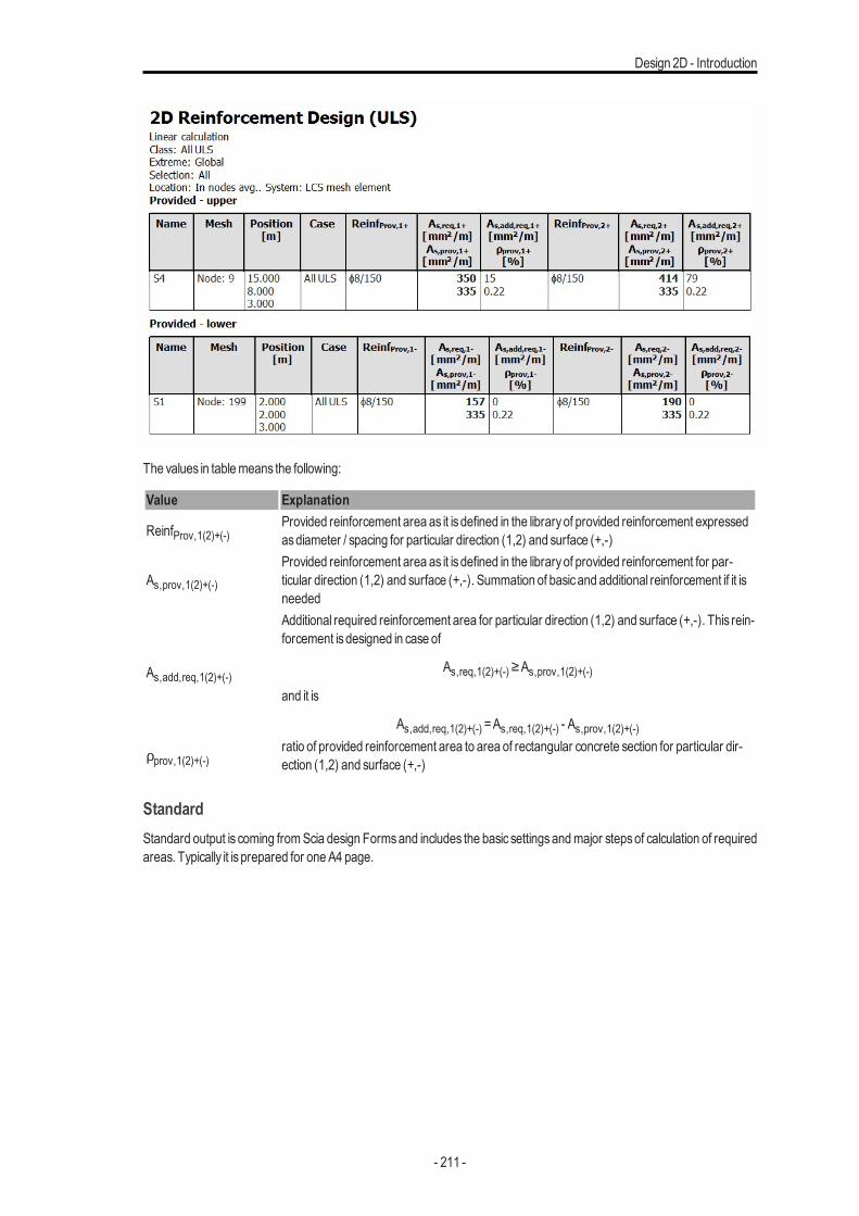
Design 2D - Introduction
The values in tablemeans the following:
Value Explanation
ReinfProv,1(2)+(-)Provided reinforcement area as it isdefined in the libraryof provided reinforcement expressedasdiameter / spacing for particular direction (1,2) and surface (+,-)
As,prov,1(2)+(-)Provided reinforcement area as it isdefined in the libraryof provided reinforcement for par-ticular direction (1,2) and surface (+,-). Summation of basicand additional reinforcement if it isneeded
As,add,req,1(2)+(-)
Additional required reinforcement area for particular direction (1,2) and surface (+,-). This rein-forcement isdesigned in case of
As,req,1(2)+(-)≥As,prov,1(2)+(-)and it is
As,add,req,1(2)+(-) =As,req,1(2)+(-) - As,prov,1(2)+(-)
ρprov,1(2)+(-)ratio of provided reinforcement area to area of rectangular concrete section for particular dir-ection (1,2) and surface (+,-)
StandardStandard output is coming fromScia design Formsand includes the basic settingsandmajor stepsof calculation of requiredareas. Typically it is prepared for oneA4 page.
- 211 -
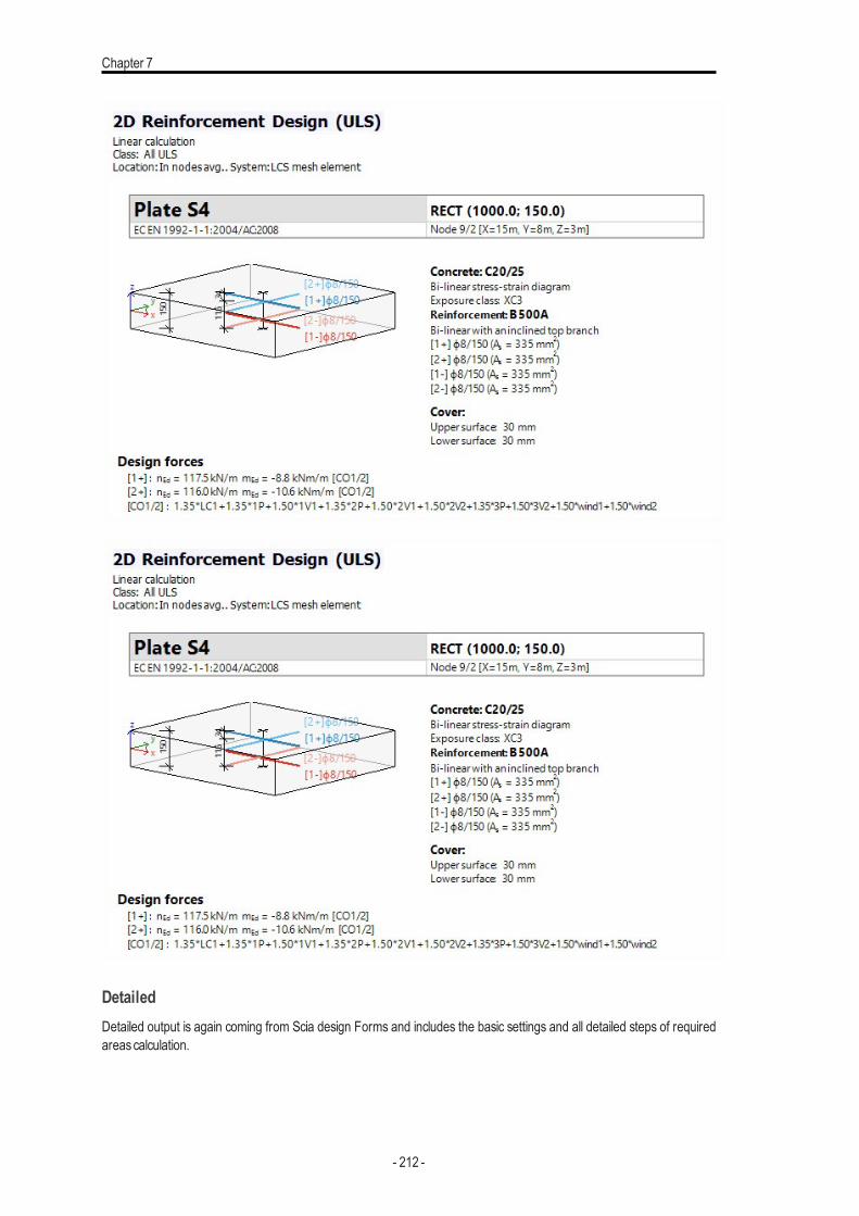
Chapter 7
DetailedDetailed output is again coming from Scia design Forms and includes the basic settings and all detailed steps of requiredareascalculation.
- 212 -
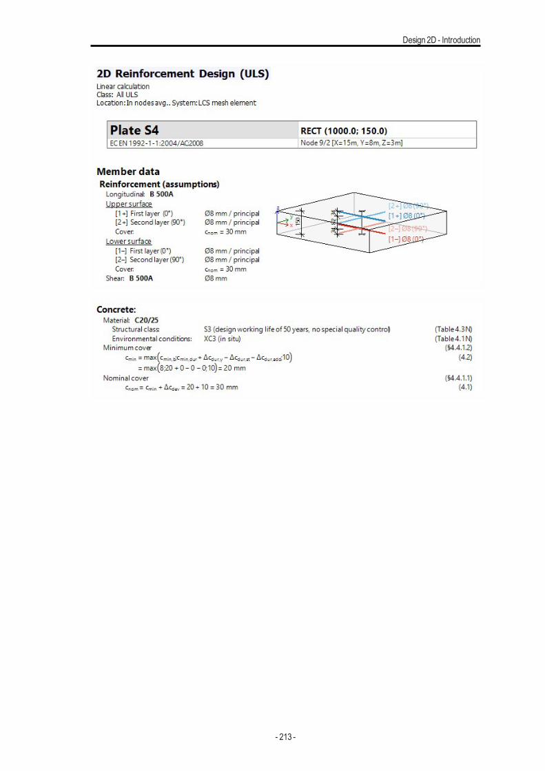
Design 2D - Introduction
- 213 -
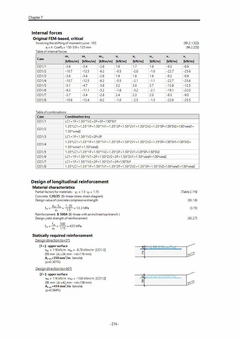
Chapter 7
- 214 -
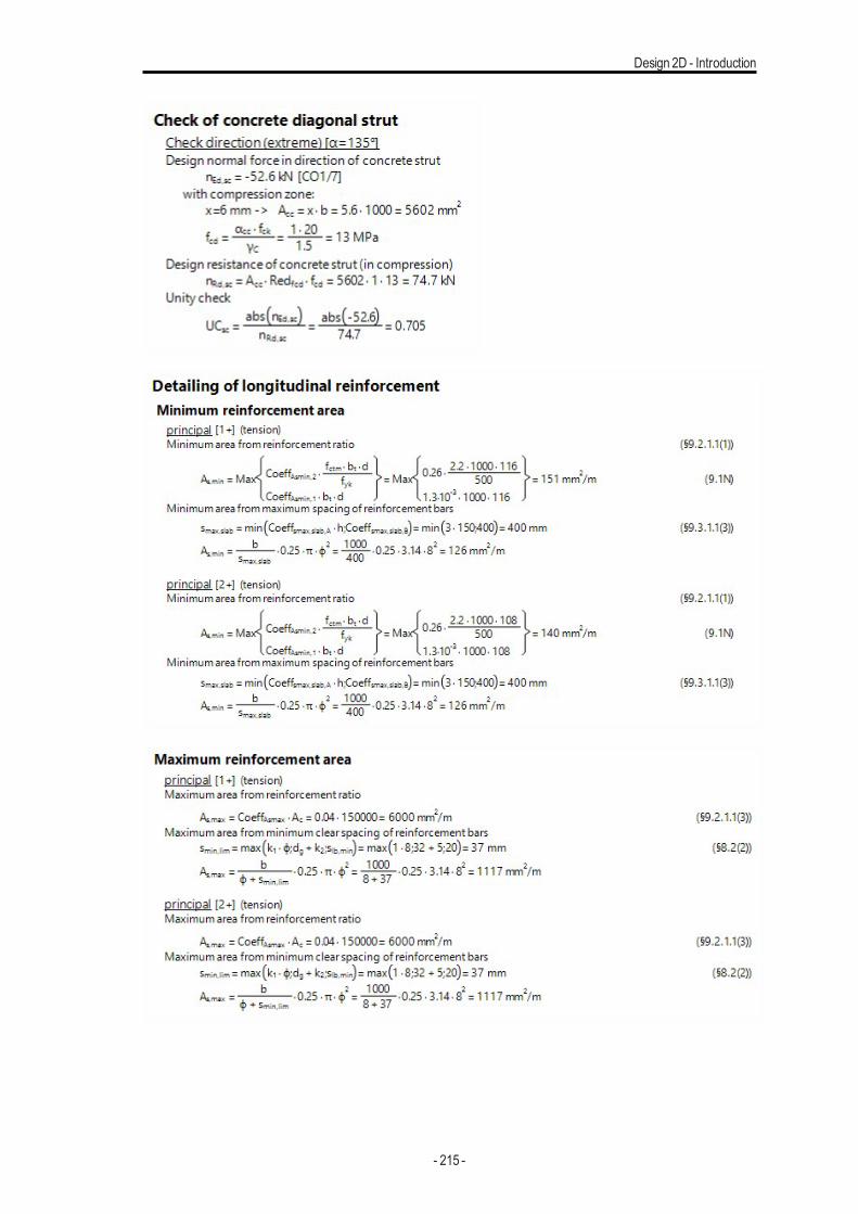
Design 2D - Introduction
- 215 -
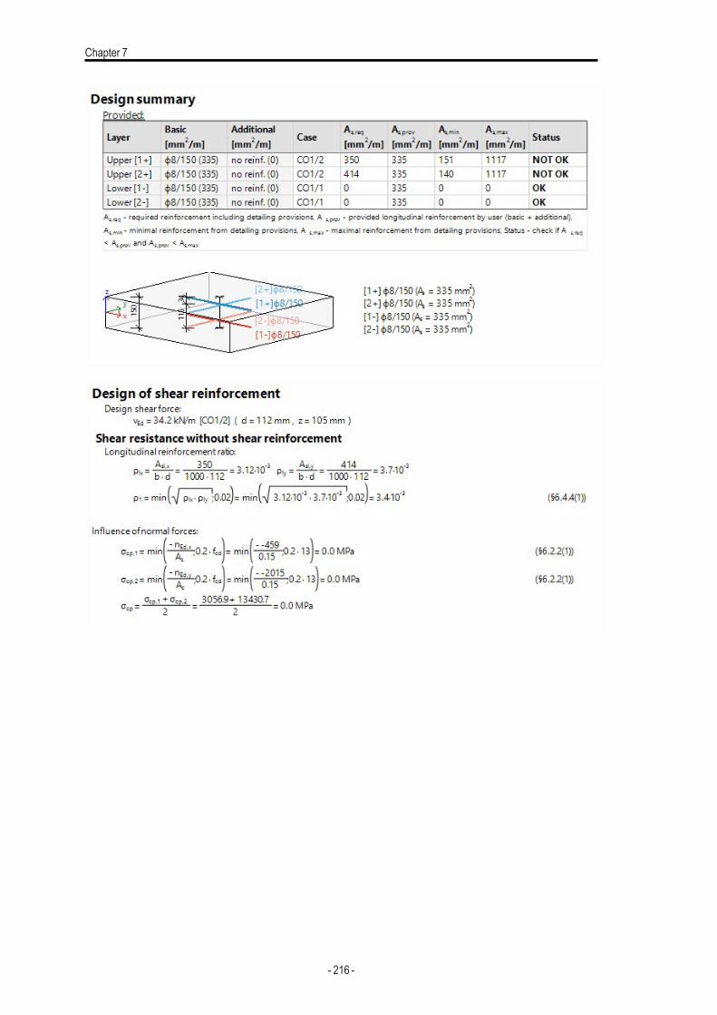
Chapter 7
- 216 -
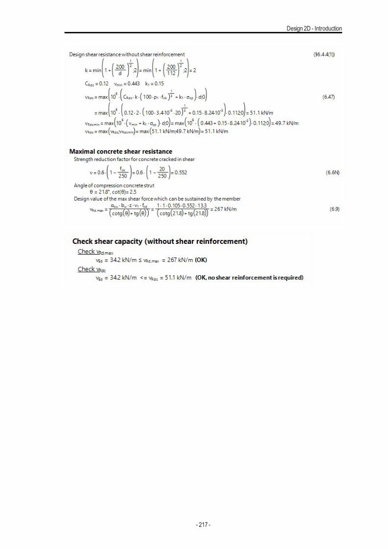
Design 2D - Introduction
- 217 -
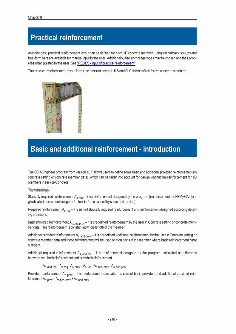
Chapter 8
Practical reinforcement
As in the past, practical reinforcement layout can be defined for each 1D concrete member. Longitudinal bars, stirrups andfree-form barsare available for manual input by the user. Additionally, also anchorage typesmaybe chosen and their prop-ertiesmanipulated by the user. See "REDES - input of practical reinforcement"
Thispractical reinforcement layout forms the basis for severalULSandSLSchecksof reinforced concretemembers.
Basic and additional reinforcement - introduction
The SCIAEngineer program from version 16.1 allowsusers to define some basic and additional provided reinforcement (inconcrete setting or concrete member data), which can be taken into account for design longitudinal reinforcement for 1Dmembers in serviceConcrete.
Terminology:Statically required reinforcement As,stat – it is reinforcement designed by the program (reinforcement for N+My+Mz, lon-gitudinal reinforcement designed for tensile force caused byshear and torsion)
Required reinforcement As,req – it is sum of statically required reinforcement and reinforcement designed according detail-ing provisions
Basic provided reinforcement As,bas,prov – it is predefined reinforcement by the user in Concrete setting or concrete mem-ber data. This reinforcement is constant at whole length of themember.
Additional provided reinforcement As,add,prov – it is predefined additional reinforcement by the user in Concrete setting orconcrete member data and these reinforcement will be used only on parts of the member where basic reinforcement is notsufficient.
Additional required reinforcement As,add,req – it is reinforcement designed by the program, calculated as differencebetween required reinforcement and provided reinforcement
As,add,req =As,req - As,prov =As,req - As,bas,prov - As,add,provProvided reinforcement As,prov – it is reinforcement calculated as sum of basic provided and additional provided rein-forcement As,prov =As,bas,prov +As,add,prov
- 218 -
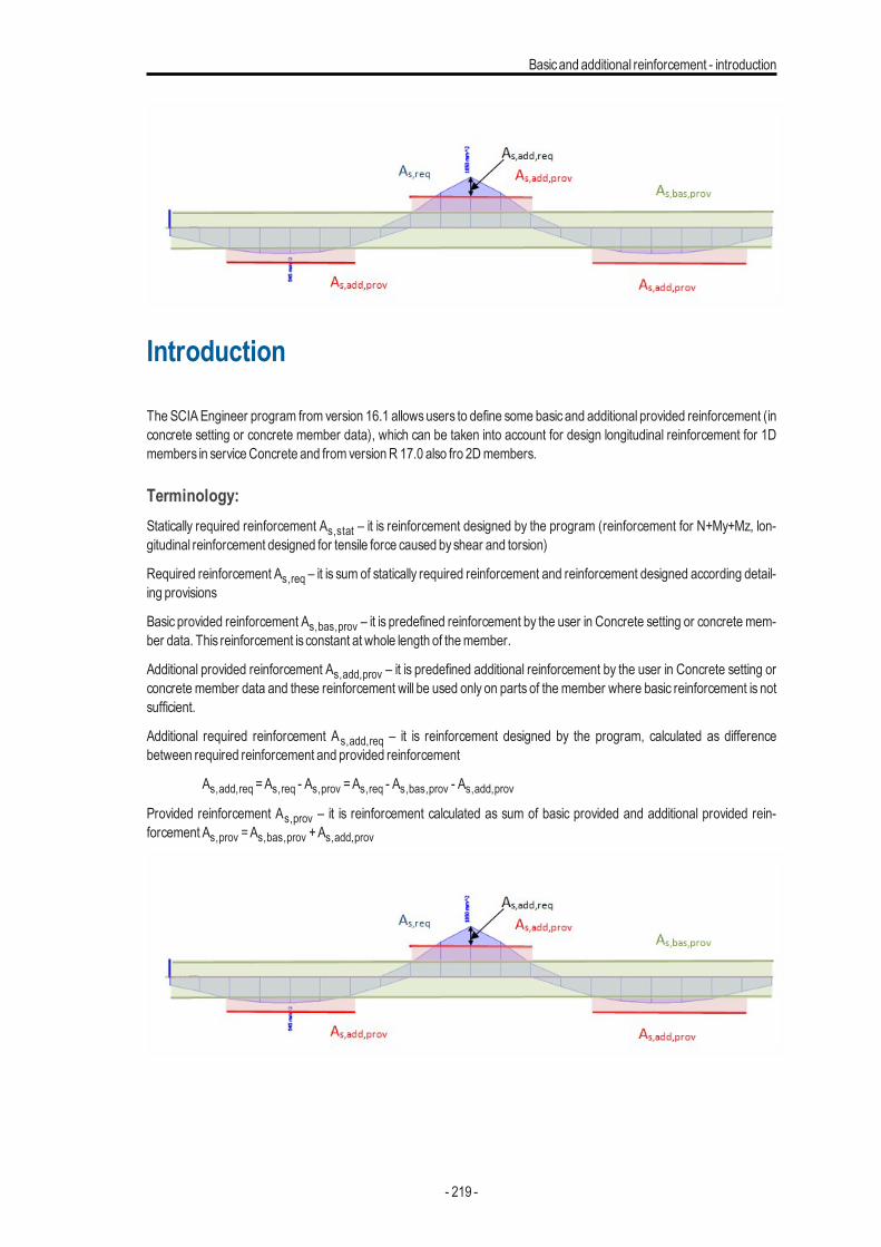
Basicand additional reinforcement - introduction
Introduction
The SCIAEngineer program from version 16.1 allowsusers to define some basic and additional provided reinforcement (inconcrete setting or concrete member data), which can be taken into account for design longitudinal reinforcement for 1Dmembers in serviceConcrete and from versionR 17.0 also fro 2Dmembers.
Terminology:Statically required reinforcement As,stat – it is reinforcement designed by the program (reinforcement for N+My+Mz, lon-gitudinal reinforcement designed for tensile force caused byshear and torsion)
Required reinforcement As,req – it is sum of statically required reinforcement and reinforcement designed according detail-ing provisions
Basic provided reinforcement As,bas,prov – it is predefined reinforcement by the user in Concrete setting or concrete mem-ber data. This reinforcement is constant at whole length of themember.
Additional provided reinforcement As,add,prov – it is predefined additional reinforcement by the user in Concrete setting orconcrete member data and these reinforcement will be used only on parts of the member where basic reinforcement is notsufficient.
Additional required reinforcement As,add,req – it is reinforcement designed by the program, calculated as differencebetween required reinforcement and provided reinforcement
As,add,req =As,req - As,prov =As,req - As,bas,prov - As,add,provProvided reinforcement As,prov – it is reinforcement calculated as sum of basic provided and additional provided rein-forcement As,prov =As,bas,prov +As,add,prov
- 219 -

Chapter 8
Provided libraryNew library Provided reinforcement (design) is introduced where Basic and Additional provided reinforcement of lon-gitudinal and shear (not part of R17.0) reinforcement is defined for taking into account in design of reinforcement. The lib-rary isplaced in Libraries>Concrete.
It is a standard library of SCIA Engineer for managing layouts of basic and additional reinforcement for design.The librarycontains templates for definition of basic and additional reinforcement, which are used in design depending on type of struc-ture (1D/2D); member type (beam/ column/ beam slab / plate / wall de beamand cross-section (rectangular / circle / oval / I-section / T-section andOther). In fact it is standard SCIAEngineer librarywith the following properties:
l Name– nameof layout, which can be edit by the userl Description – brief description of the layout. The default iswithout description, but description can be create or edit by the
userl Member type–member type for which basicand additional provided reinforcement is created (beam(rib), column, beam
slab, plate, wall, deep beam). Thisproperty isnot editable and it is created automaticallyaccording selectedmember typein dialogue for editing of the layout
l Cross-section – type of cross-section according tomember type for which basicand additional provided reinforcement iscreated (rectangular, T section, circular...). Thisproperty isnot editable and it is created automaticallyaccording selectedcross-section in dialogue for editing of the layout
l Mode – standard or advancedmode for definition basicand additional provided reinforcement.
l Only standardmode is supported in version 17.0, it follows that basicand additional rein-forcement can be defined only for selected
There are supported standard operations in the library:
Create new layout - button New or icon . New layout of basic reinforcement is created and dialogue for definitionlayout isopened, see "Layout definition". The new layout will add to end of the list of the layout
Insert layout - button Insert or icon . New layout of basic reinforcement is created and dialogue for definition layoutisopened, see"Layout definition" . The new layout will add above selected layout from the list
Edit layout - button Edit or icon . Dialogue for definition layout isopened.
Copy layout - icon . New layout is created bycopying selected existed layout.
Delete layout - button Delete or icon . Selected layout is deleted.There is possible to delete only layout which is notassigned to some type ofmember and cross-section inDesign defaultsor in 1Dmember data
Undo/Redo - icons .
- 220 -
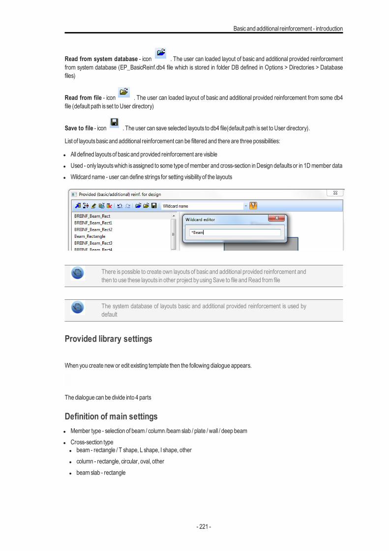
Basicand additional reinforcement - introduction
Read from system database - icon . The user can loaded layout of basic and additional provided reinforcementfrom system database (EP_BasicReinf.db4 file which is stored in folder DB defined in Options > Directories > Databasefiles)
Read from file - icon . The user can loaded layout of basic and additional provided reinforcement from some db4file (default path is set to User directory)
Save to file - icon . The user can save selected layouts to db4 file(default path is set to User directory).
List of layoutsbasicand additional reinforcement can be filtered and there are three possibilities:
l All defined layoutsof basicand provided reinforcement are visiblel Used - only layoutswhich isassigned to some type ofmember and cross-section inDesign defaultsor in 1Dmember datal Wildcard name - user can define strings for setting visibility of the layouts
There is possible to create own layouts of basic and additional provided reinforcement andthen to use these layouts in other project byusing Save to file andRead from file
The system database of layouts basic and additional provided reinforcement is used bydefault
Provided library settings
When you create new or edit existing template then the following dialogue appears.
The dialogue can be divide into 4 parts
Definition of main settingsl Member type - selection of beam / column /beamslab / plate / wall / deep beaml Cross-section type
l beam - rectangle / T shape, L shape, I shape, otherl column - rectangle, circular, oval, otherl beamslab - rectangle
- 221 -

Chapter 8
This item isnot editable in case of selection of 2Dmember type
l Mode - fixed standardmodel Type of reinforcement - dialoguewith selection of position ofmain reinforcement
l beam - main reinf in Ydirection /main reinf in Z directionl column - edgeY in corner / Edge z in corner
This item isnot editable for other cases
Action buttonsThere are two action buttons
l basic count to zero - when you press thisbutton all basic reinforcement count is set to zerol additional count to zero - when you press thisbutton all additional reinforcement count is set to zero
DrawingThe representative drawing isplace on the left side of dialogue. There are the following rules:
l green dot - basic reinforcement barl blue dot - additional reinf barl orange dot - currently selected bar or layerl dashed line - selection of List type of additional reinf
Typical drawing for 1Dmember can bee seen as follows
Typical drawing for 2Dmember can bee seen as follows
- 222 -
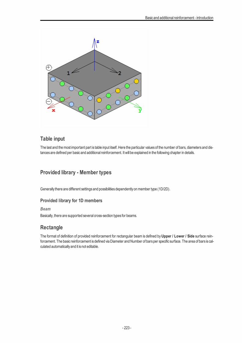
Basicand additional reinforcement - introduction
Table inputThe last and themost important part is table input itself. Here the particular valuesof the number of bars, diametersand dis-tancesare defined per basicand additional reinforcement. It will be explained in the following chapter in details.
Provided library - Member types
Generally there are different settingsand possibilitiesdependentlyonmember type (1D/2D).
Provided library for 1D membersBeamBasically, there are supported several cross-section types for beams.
RectangleThe format of definition of provided reinforcement for rectangular beam is defined byUpper / Lower / Side surface rein-forcement. The basic reinforcement isdefined viaDiameter andNumber of barsper specific surface. The area of bars is cal-culated automaticallyand it isnot editable.
- 223 -

Chapter 8
Additionally there is one option which determines predominant direction of reinforcement. This possibility is in selection ofmain direction of reinforcementMain reinf in Y dir /Main reinf in Z dir
M-ainrei-nfinYdir-r
- 224 -
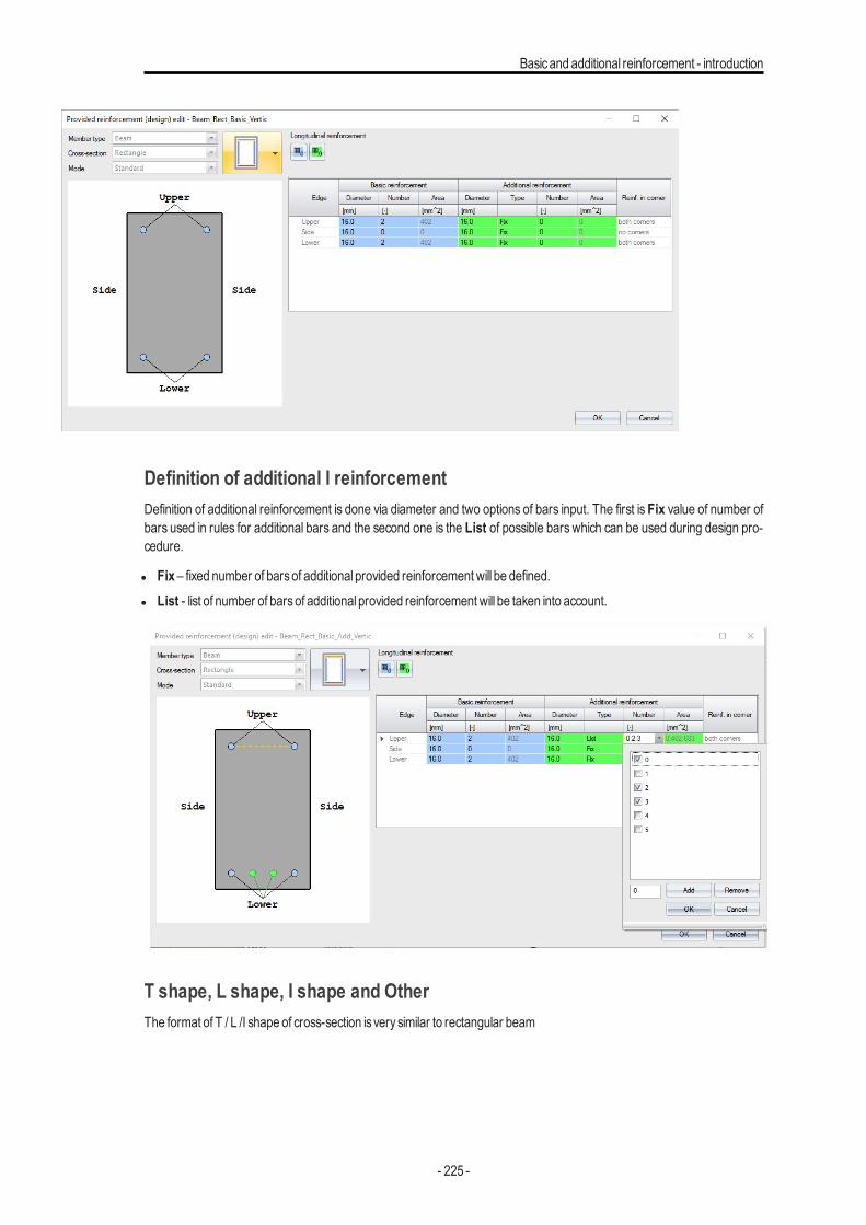
Basicand additional reinforcement - introduction
M-ainrei-nfinZdir
Definition of additional l reinforcementDefinition of additional reinforcement is done via diameter and two options of bars input. The first is Fix value of number ofbars used in rules for additional bars and the second one is the List of possible bars which can be used during design pro-cedure.
l Fix – fixed number of barsof additional provided reinforcement will be defined.l List - list of number of barsof additional provided reinforcement will be taken into account.
T shape, L shape, I shape and OtherThe format of T / L /I shape of cross-section is verysimilar to rectangular beam
- 225 -
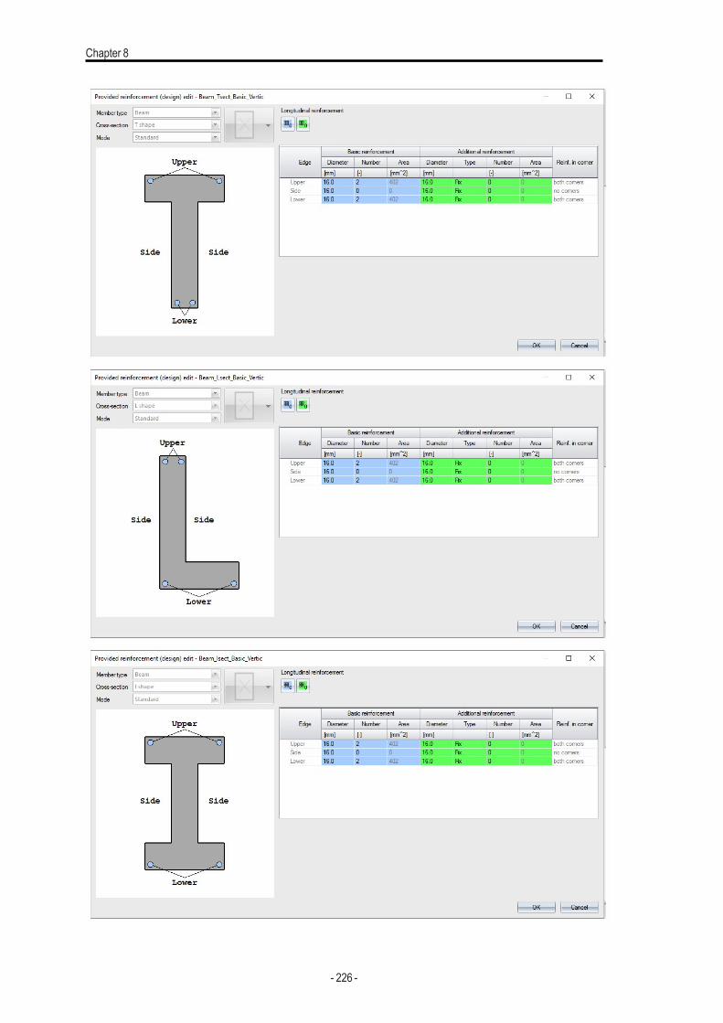
Chapter 8
- 226 -
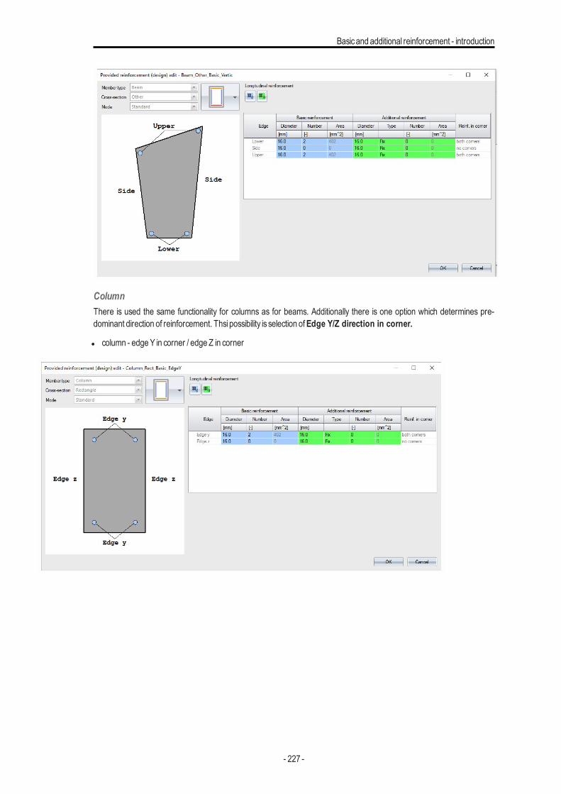
Basicand additional reinforcement - introduction
ColumnThere is used the same functionality for columns as for beams. Additionally there is one option which determines pre-dominant direction of reinforcement. Thsi possibility is selection ofEdge Y/Z direction in corner.
l column - edgeY in corner / edge Z in corner
Ed-geY incor-ner
- 227 -
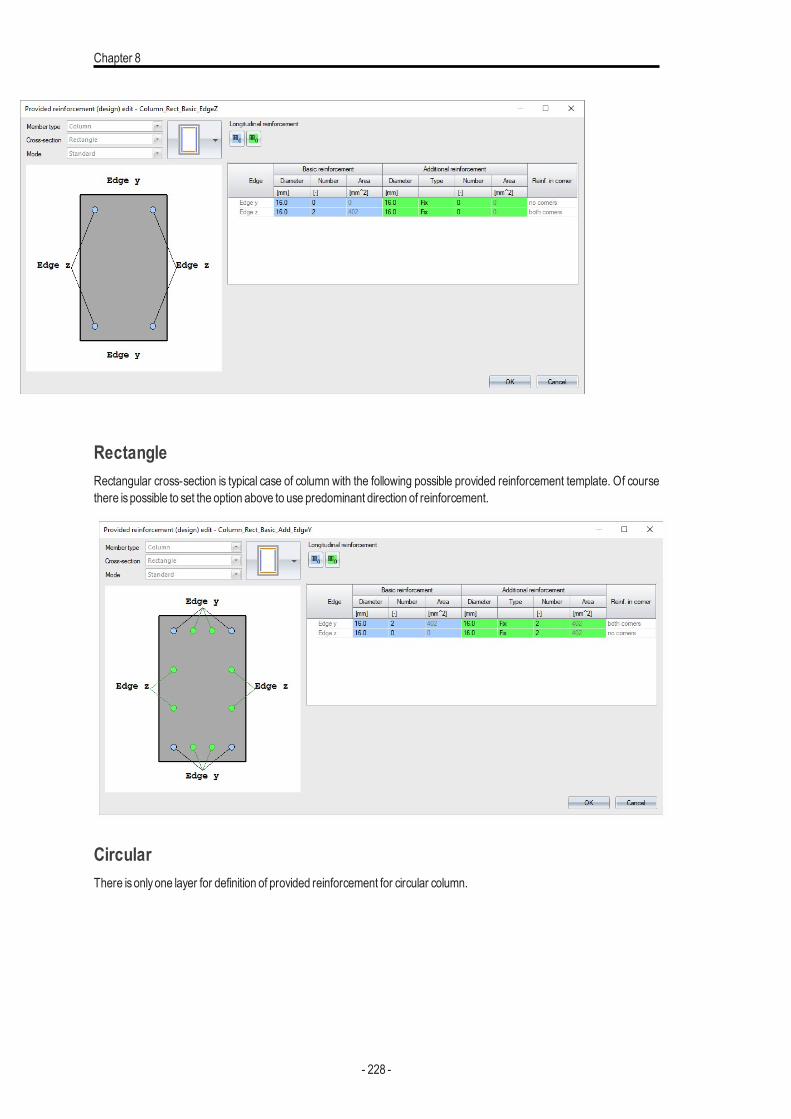
Chapter 8
Ed-ge zincor-ner
RectangleRectangular cross-section is typical case of column with the following possible provided reinforcement template. Of coursethere ispossible to set the option above to use predominant direction of reinforcement.
CircularThere isonlyone layer for definition of provided reinforcement for circular column.
- 228 -
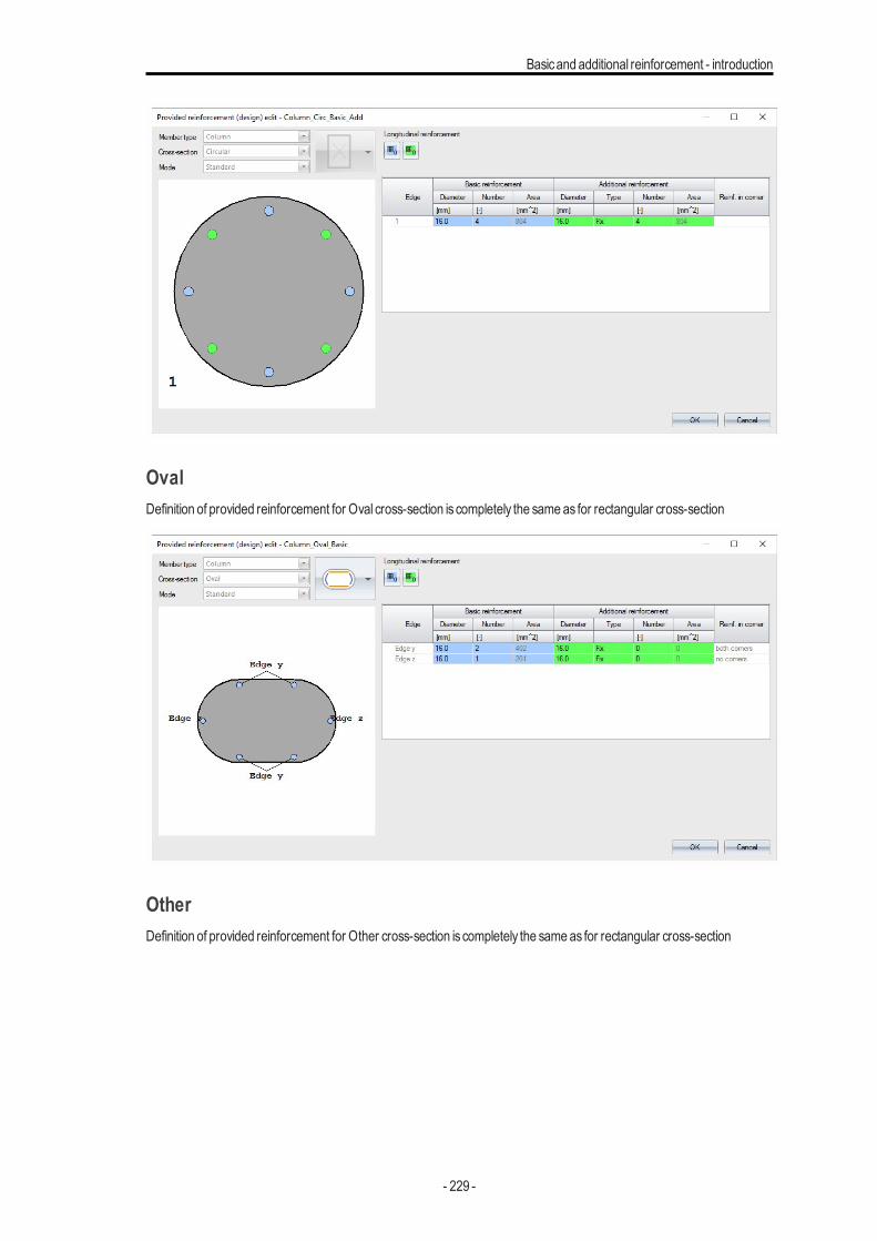
Basicand additional reinforcement - introduction
OvalDefinition of provided reinforcement for Oval cross-section is completely the same as for rectangular cross-section
OtherDefinition of provided reinforcement for Other cross-section is completely the same as for rectangular cross-section
- 229 -
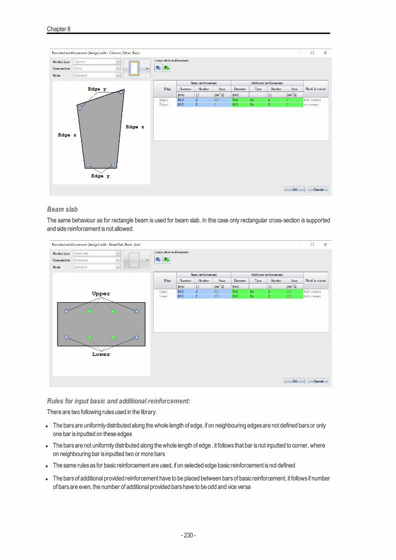
Chapter 8
Beam slabThe same behaviour as for rectangle beam is used for beam slab. In this case only rectangular cross-section is supportedand side reinforcement isnot allowed.
Rules for input basic and additional reinforcement:There are two following rulesused in the library:
l The barsare uniformlydistributed along thewhole length of edge, if on neighbouring edgesare not defined barsor onlyone bar is inputted on these edges
l The barsare not uniformlydistributed along thewhole length of edge , it follows that bar isnot inputted to corner, whereon neighbouring bar is inputted two or more bars
l The same rulesas for basic reinforcement are used, if on selected edge basic reinforcement isnot defined
l The barsof additional provided reinforcement have to be placed between barsof basic reinforcement, it follows if numberof barsare even, the number of additional provided barshave to be odd and vice versa
- 230 -
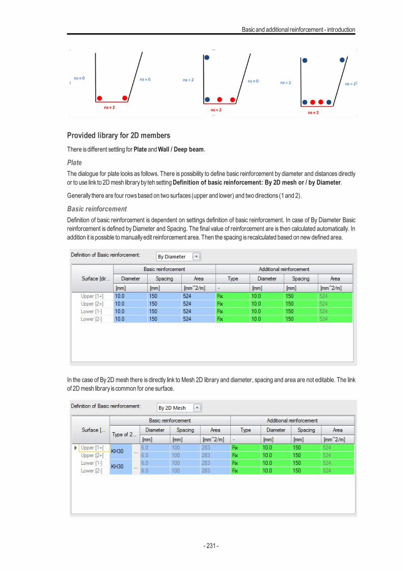
Basicand additional reinforcement - introduction
Provided library for 2D membersThere isdifferent settling for Plate andWall / Deep beam.
PlateThe dialogue for plate looks as follows. There is possibility to define basic reinforcement by diameter and distances directlyor to use link to 2Dmesh libraryby teh settingDefinition of basic reinforcement: By 2D mesh or / by Diameter.
Generally there are four rowsbased on two surfaces (upper and lower) and two directions (1 and 2).
Basic reinforcementDefinition of basic reinforcement is dependent on settings definition of basic reinforcement. In case of By Diameter Basicreinforcement is defined by Diameter and Spacing. The final value of reinforcement are is then calculated automatically. Inaddition it ispossible tomanuallyedit reinforcement area. Then the spacing is recalculated based on new defined area.
In the case of By 2D mesh there is directly link to Mesh 2D library and diameter, spacing and area are not editable. The linkof 2Dmesh library is common for one surface.
- 231 -
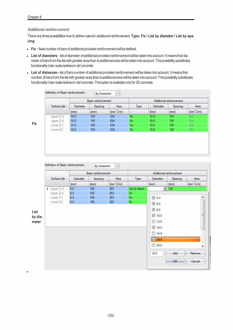
Chapter 8
Additional reinforcementThere are three possibilitieshow to define rules for additional reinforcement. Type: Fix / List by diameter / List by spa-cing.
l Fix – fixed number of barsof additional provided reinforcement will be defined.l List of diameters – list of diameter of additional provided reinforcement will be taken into account. It means that dia-
meter of bars from the list with greater area than isadditional areawill be taken into account. Thispossibility substitutesfunctionalityUser scale isolines in old concrete
l List of distances – list of barsnumber of additional provided reinforcement will be taken into account. It means thatnumber of bars from the list with greater area than isadditional areawill be taken into account. Thispossibility substitutesfunctionalityUser scale isolines in old concrete. Thsi option isavailable only for 2D concrete
l
Fix
Listby dia-meter
- 232 -
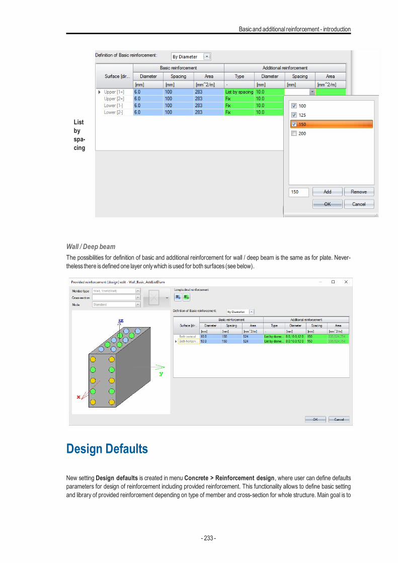
Basicand additional reinforcement - introduction
Listbyspa-cing
Wall / Deep beamThe possibilities for definition of basic and additional reinforcement for wall / deep beam is the same as for plate. Never-theless there isdefined one layer onlywhich isused for both surfaces (see below).
Design Defaults
New setting Design defaults is created in menu Concrete > Reinforcement design, where user can define defaultsparameters for design of reinforcement including provided reinforcement. This functionality allows to define basic settingand library of provided reinforcement depending on type of member and cross-section for whole structure. Main goal is to
- 233 -
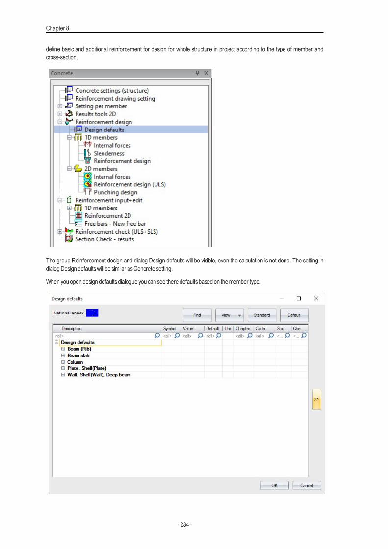
Chapter 8
define basic and additional reinforcement for design for whole structure in project according to the type of member andcross-section.
The group Reinforcement design and dialog Design defaults will be visible, even the calculation is not done. The setting indialogDesign defaultswill be similar asConcrete setting.
When you open design defaultsdialogue you can see there defaultsbased on themember type.
- 234 -
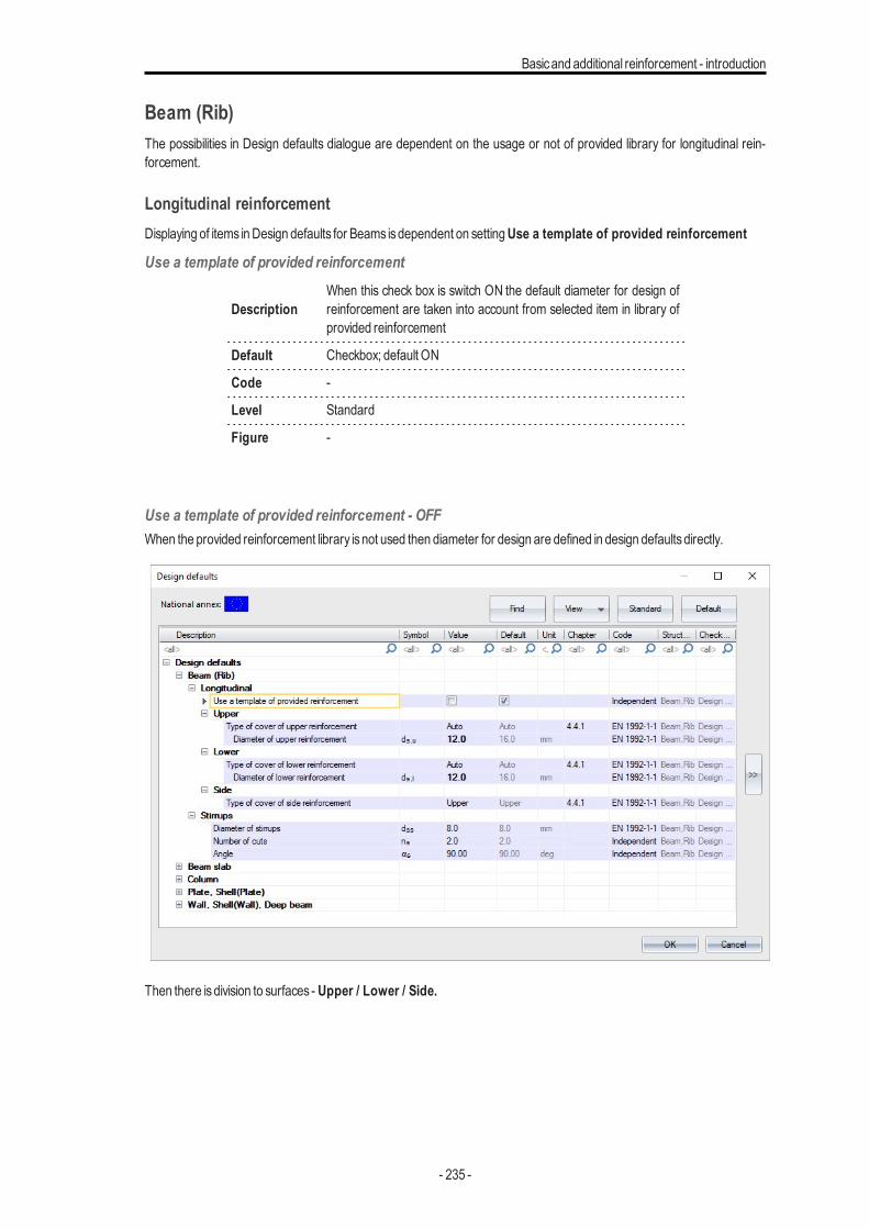
Basicand additional reinforcement - introduction
Beam (Rib)The possibilities in Design defaults dialogue are dependent on the usage or not of provided library for longitudinal rein-forcement.
Longitudinal reinforcementDisplaying of items inDesign defaults for Beams isdependent on settingUse a template of provided reinforcement
Use a template of provided reinforcement
DescriptionWhen this check box is switch ON the default diameter for design ofreinforcement are taken into account from selected item in library ofprovided reinforcement
Default Checkbox; default ON
Code -
Level Standard
Figure -
Use a template of provided reinforcement - OFFWhen the provided reinforcement library isnot used then diameter for design are defined in design defaultsdirectly.
Then there isdivision to surfaces - Upper / Lower / Side.
- 235 -
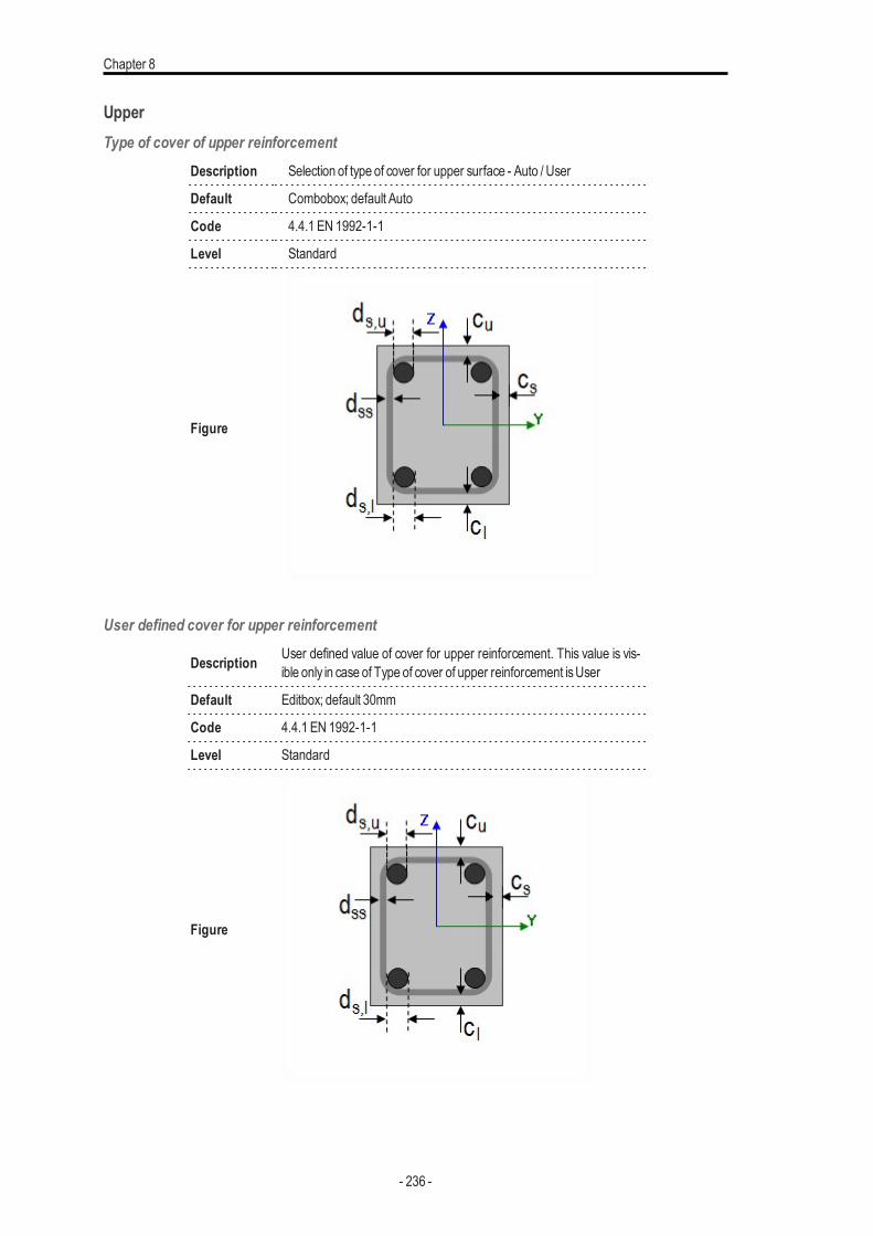
Chapter 8
UpperType of cover of upper reinforcement
Description Selection of type of cover for upper surface - Auto / User
Default Combobox; default Auto
Code 4.4.1 EN 1992-1-1
Level Standard
Figure
User defined cover for upper reinforcement
Description User defined value of cover for upper reinforcement. This value is vis-ible only in case of Type of cover of upper reinforcement isUser
Default Editbox; default 30mm
Code 4.4.1 EN 1992-1-1
Level Standard
Figure
- 236 -
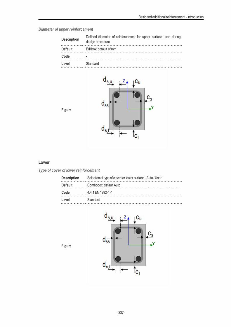
Basicand additional reinforcement - introduction
Diameter of upper reinforcement
Description Defined diameter of reinforcement for upper surface used duringdesign procedure
Default Editbox; default 16mm
Code -
Level Standard
Figure
LowerType of cover of lower reinforcement
Description Selection of type of cover for lower surface - Auto / User
Default Combobox; default Auto
Code 4.4.1 EN 1992-1-1
Level Standard
Figure
- 237 -
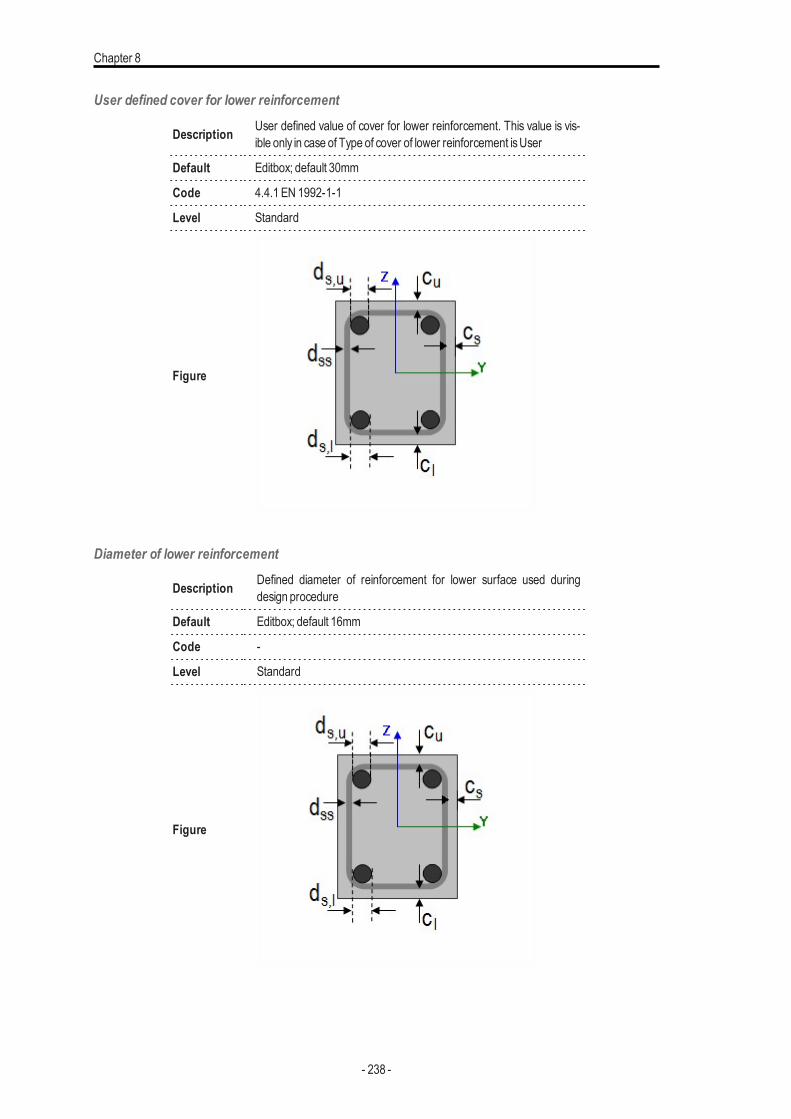
Chapter 8
User defined cover for lower reinforcement
Description User defined value of cover for lower reinforcement. This value is vis-ible only in case of Type of cover of lower reinforcement isUser
Default Editbox; default 30mm
Code 4.4.1 EN 1992-1-1
Level Standard
Figure
Diameter of lower reinforcement
Description Defined diameter of reinforcement for lower surface used duringdesign procedure
Default Editbox; default 16mm
Code -
Level Standard
Figure
- 238 -
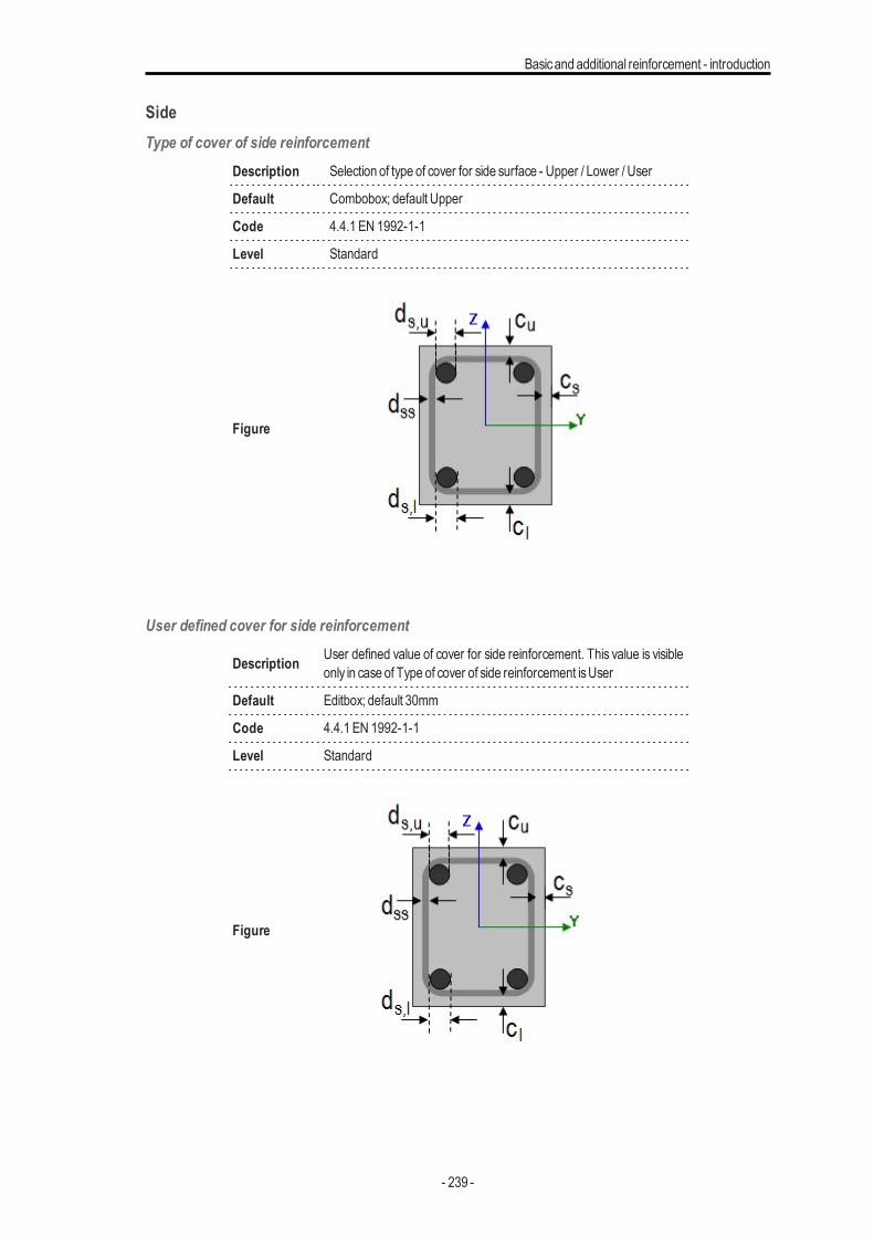
Basicand additional reinforcement - introduction
SideType of cover of side reinforcement
Description Selection of type of cover for side surface - Upper / Lower / User
Default Combobox; default Upper
Code 4.4.1 EN 1992-1-1
Level Standard
Figure
User defined cover for side reinforcement
Description User defined value of cover for side reinforcement. This value is visibleonly in case of Type of cover of side reinforcement isUser
Default Editbox; default 30mm
Code 4.4.1 EN 1992-1-1
Level Standard
Figure
- 239 -
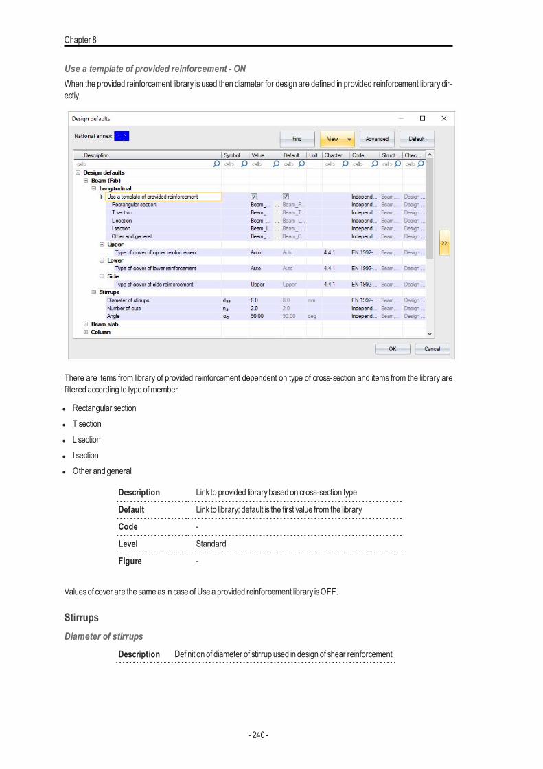
Chapter 8
Use a template of provided reinforcement - ONWhen the provided reinforcement library is used then diameter for design are defined in provided reinforcement library dir-ectly.
There are items from library of provided reinforcement dependent on type of cross-section and items from the library arefiltered according to type ofmember
l Rectangular sectionl T sectionl L sectionl I sectionl Other and general
Description Link to provided librarybased on cross-section type
Default Link to library; default is the first value from the library
Code -
Level Standard
Figure -
Valuesof cover are the sameas in case of Use a provided reinforcement library isOFF.
StirrupsDiameter of stirrups
Description Definition of diameter of stirrup used in design of shear reinforcement
- 240 -
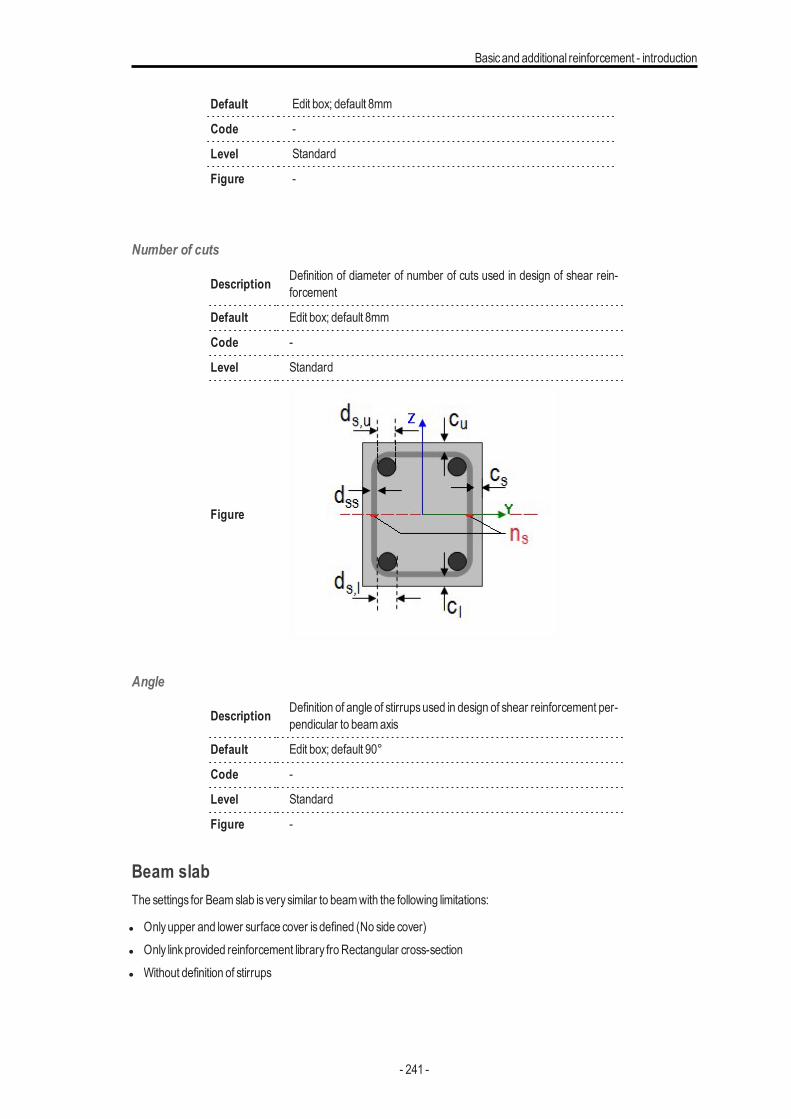
Basicand additional reinforcement - introduction
Default Edit box; default 8mm
Code -
Level Standard
Figure -
Number of cuts
Description Definition of diameter of number of cuts used in design of shear rein-forcement
Default Edit box; default 8mm
Code -
Level Standard
Figure
Angle
Description Definition of angle of stirrupsused in design of shear reinforcement per-pendicular to beamaxis
Default Edit box; default 90°
Code -
Level Standard
Figure -
Beam slabThe settings for Beamslab is verysimilar to beamwith the following limitations:
l Onlyupper and lower surface cover isdefined (No side cover)l Only linkprovided reinforcement library fro Rectangular cross-sectionl Without definition of stirrups
- 241 -
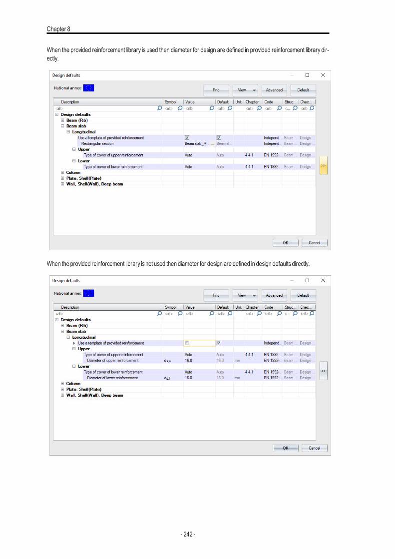
Chapter 8
When the provided reinforcement library is used then diameter for design are defined in provided reinforcement library dir-ectly.
When the provided reinforcement library isnot used then diameter for design are defined in design defaultsdirectly.
- 242 -
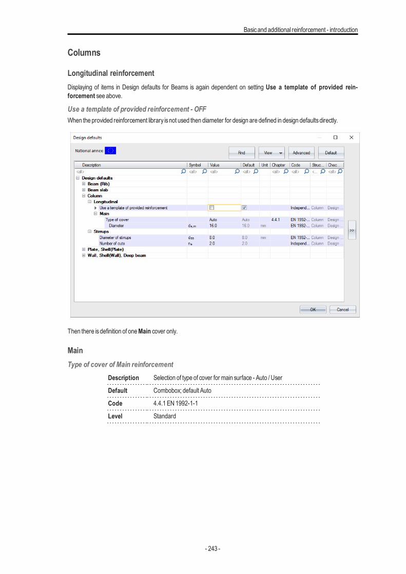
Basicand additional reinforcement - introduction
Columns
Longitudinal reinforcementDisplaying of items in Design defaults for Beams is again dependent on setting Use a template of provided rein-forcement see above.
Use a template of provided reinforcement - OFFWhen the provided reinforcement library isnot used then diameter for design are defined in design defaultsdirectly.
Then there isdefinition of oneMain cover only.
MainType of cover of Main reinforcement
Description Selection of type of cover for main surface - Auto / User
Default Combobox; default Auto
Code 4.4.1 EN 1992-1-1
Level Standard
- 243 -
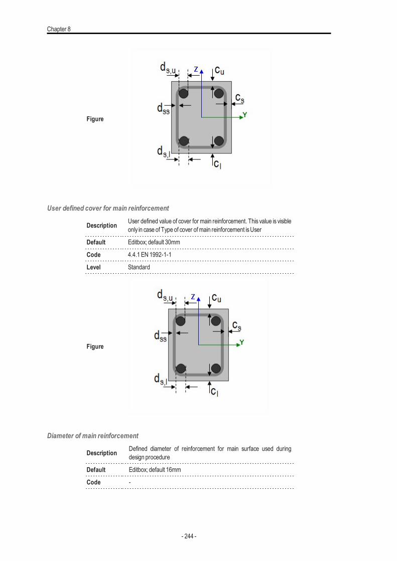
Chapter 8
Figure
User defined cover for main reinforcement
Description User defined value of cover for main reinforcement. This value is visibleonly in case of Type of cover ofmain reinforcement isUser
Default Editbox; default 30mm
Code 4.4.1 EN 1992-1-1
Level Standard
Figure
Diameter of main reinforcement
Description Defined diameter of reinforcement for main surface used duringdesign procedure
Default Editbox; default 16mm
Code -
- 244 -
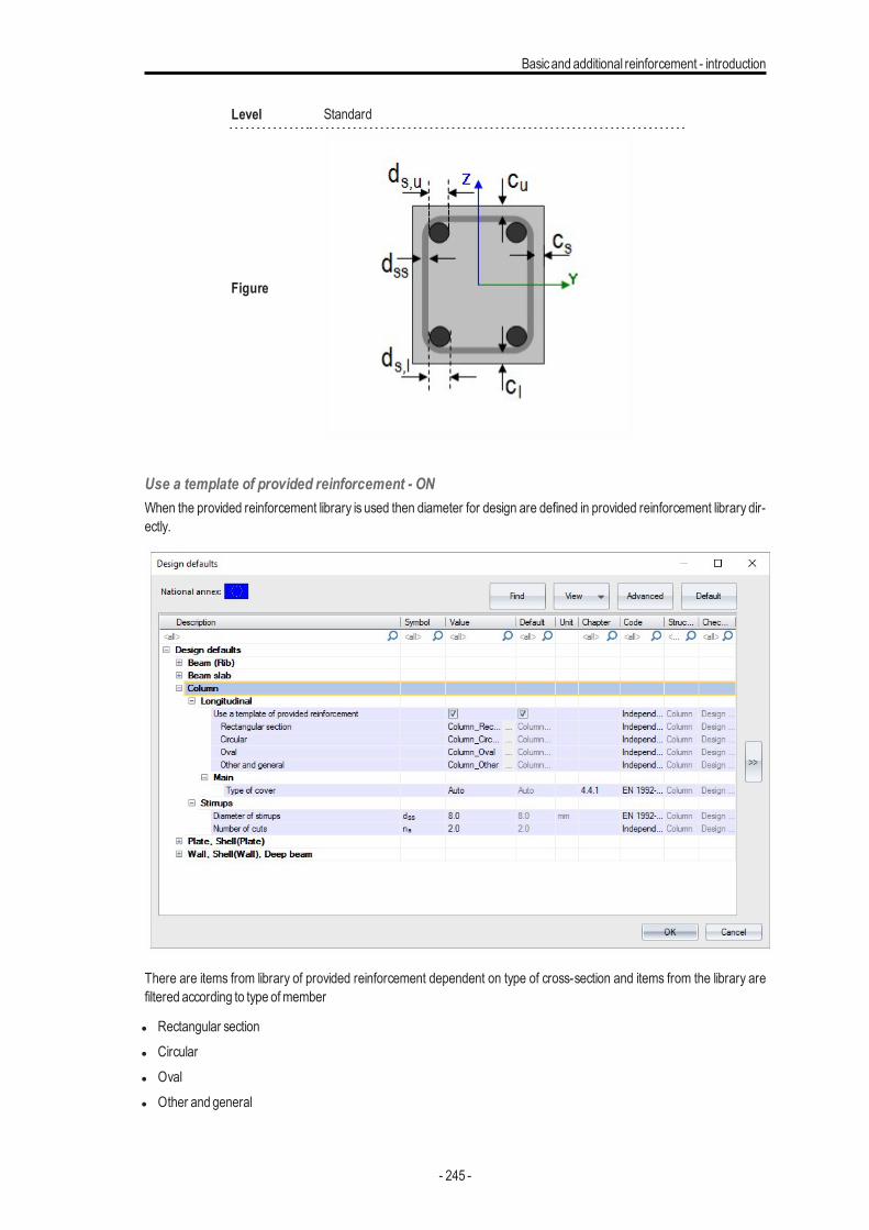
Basicand additional reinforcement - introduction
Level Standard
Figure
Use a template of provided reinforcement - ONWhen the provided reinforcement library is used then diameter for design are defined in provided reinforcement library dir-ectly.
There are items from library of provided reinforcement dependent on type of cross-section and items from the library arefiltered according to type ofmember
l Rectangular sectionl Circularl Ovall Other and general
- 245 -
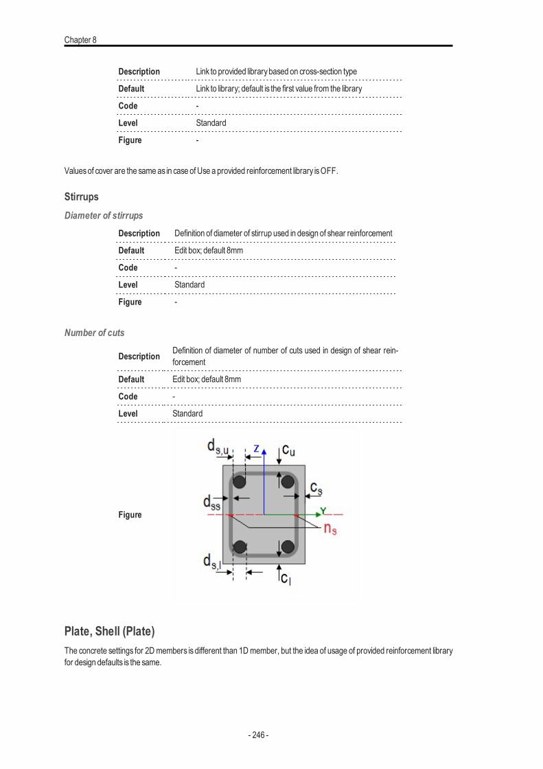
Chapter 8
Description Link to provided librarybased on cross-section type
Default Link to library; default is the first value from the library
Code -
Level Standard
Figure -
Valuesof cover are the sameas in case of Use a provided reinforcement library isOFF.
StirrupsDiameter of stirrups
Description Definition of diameter of stirrup used in design of shear reinforcement
Default Edit box; default 8mm
Code -
Level Standard
Figure -
Number of cuts
Description Definition of diameter of number of cuts used in design of shear rein-forcement
Default Edit box; default 8mm
Code -
Level Standard
Figure
Plate, Shell (Plate)The concrete settings for 2Dmembers is different than 1Dmember, but the idea of usage of provided reinforcement libraryfor design defaults is the same.
- 246 -
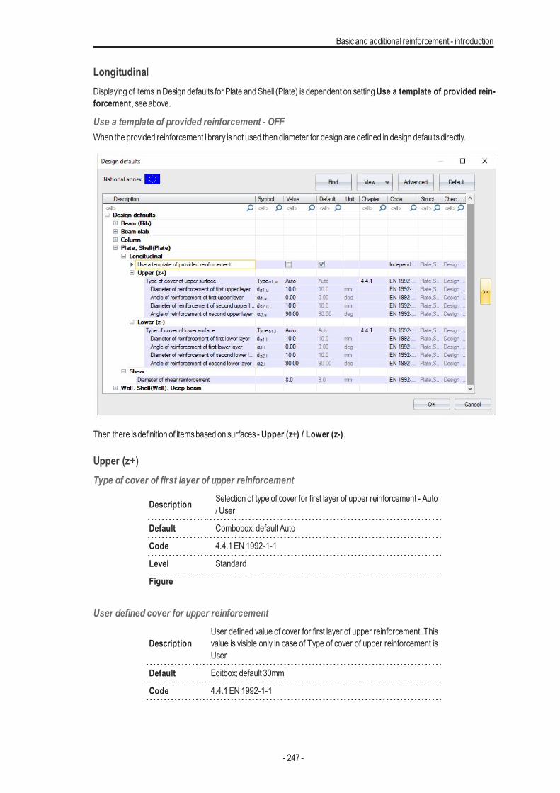
Basicand additional reinforcement - introduction
LongitudinalDisplaying of items inDesign defaults for Plate andShell (Plate) isdependent on settingUse a template of provided rein-forcement, see above.
Use a template of provided reinforcement - OFFWhen the provided reinforcement library isnot used then diameter for design are defined in design defaultsdirectly.
Then there isdefinition of itemsbased on surfaces - Upper (z+) / Lower (z-).
Upper (z+)Type of cover of first layer of upper reinforcement
Description Selection of type of cover for first layer of upper reinforcement - Auto/ User
Default Combobox; default Auto
Code 4.4.1 EN 1992-1-1
Level Standard
Figure
User defined cover for upper reinforcement
DescriptionUser defined value of cover for first layer of upper reinforcement. Thisvalue is visible only in case of Type of cover of upper reinforcement isUser
Default Editbox; default 30mm
Code 4.4.1 EN 1992-1-1
- 247 -
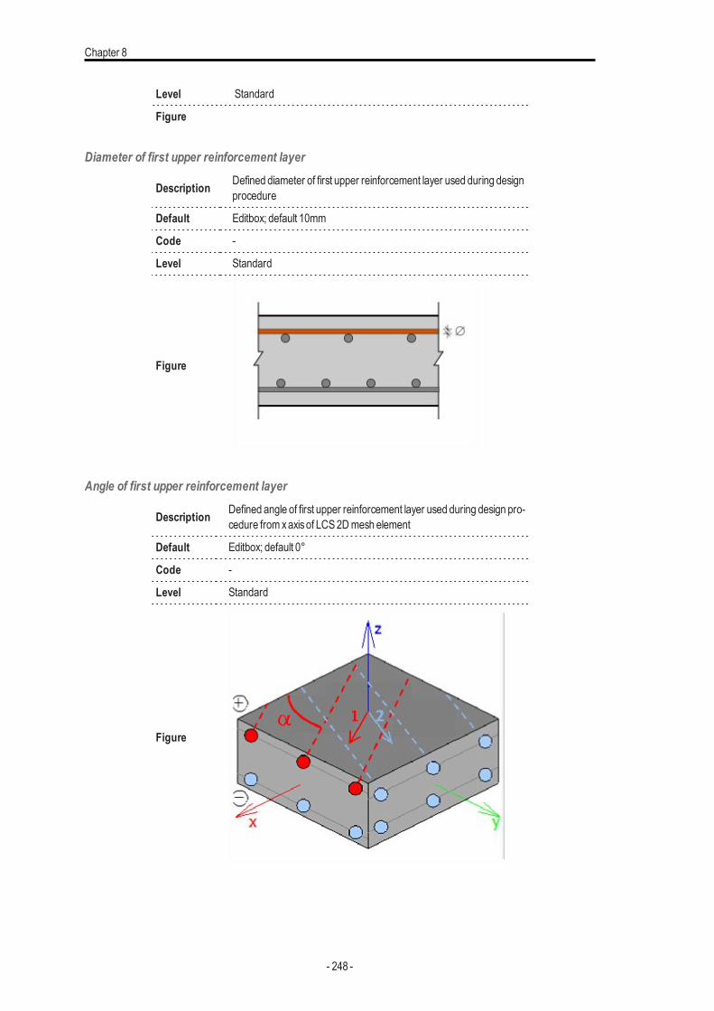
Chapter 8
Level Standard
Figure
Diameter of first upper reinforcement layer
Description Defined diameter of first upper reinforcement layer used during designprocedure
Default Editbox; default 10mm
Code -
Level Standard
Figure
Angle of first upper reinforcement layer
Description Defined angle of first upper reinforcement layer used during design pro-cedure from xaxisof LCS 2Dmesh element
Default Editbox; default 0°
Code -
Level Standard
Figure
- 248 -
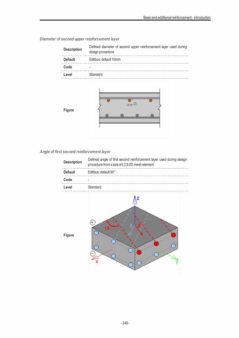
Basicand additional reinforcement - introduction
Diameter of second upper reinforcement layer
Description Defined diameter of second upper reinforcement layer used duringdesign procedure
Default Editbox; default 10mm
Code -
Level Standard
Figure
Angle of first second reinforcement layer
Description Defined angle of first second reinforcement layer used during designprocedure from xaxisof LCS 2Dmesh element
Default Editbox; default 90°
Code -
Level Standard
Figure
- 249 -
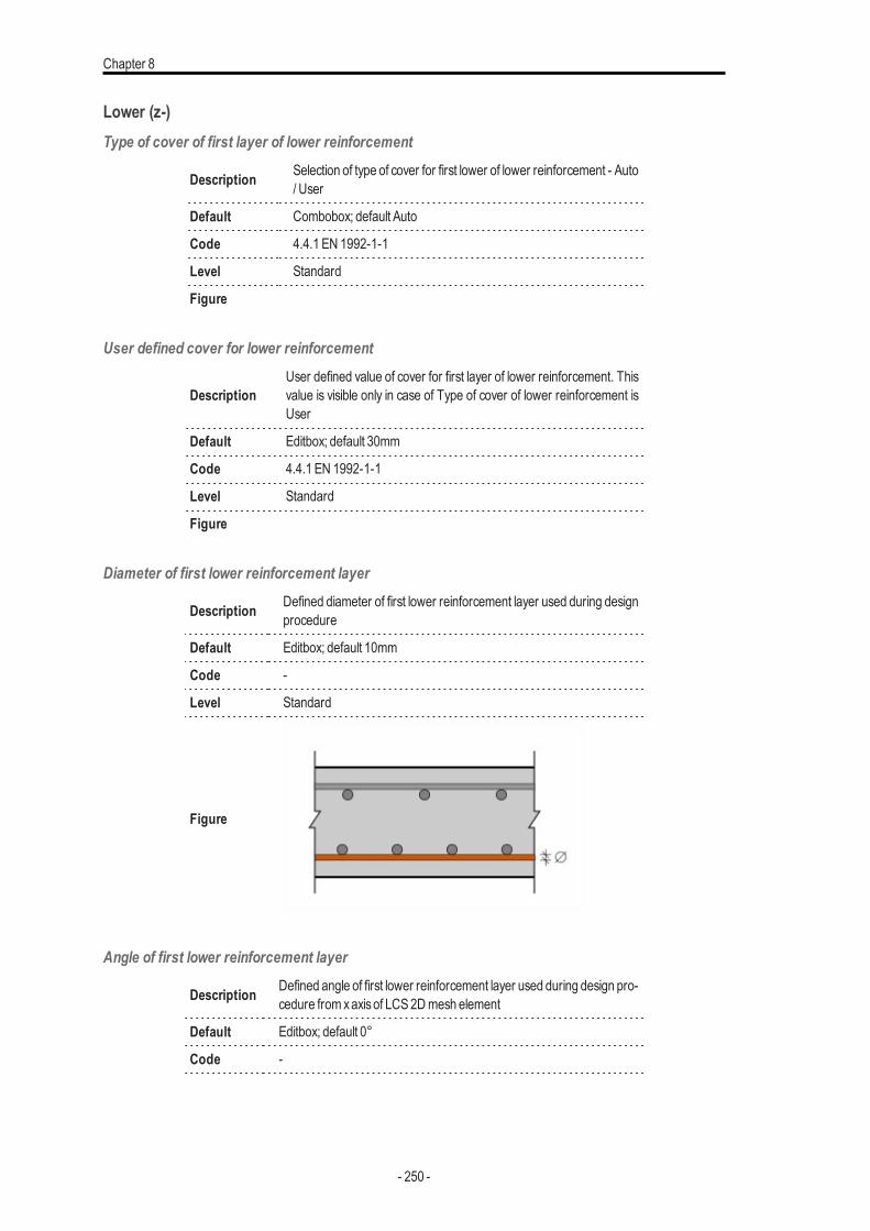
Chapter 8
Lower (z-)Type of cover of first layer of lower reinforcement
Description Selection of type of cover for first lower of lower reinforcement - Auto/ User
Default Combobox; default Auto
Code 4.4.1 EN 1992-1-1
Level Standard
Figure
User defined cover for lower reinforcement
DescriptionUser defined value of cover for first layer of lower reinforcement. Thisvalue is visible only in case of Type of cover of lower reinforcement isUser
Default Editbox; default 30mm
Code 4.4.1 EN 1992-1-1
Level Standard
Figure
Diameter of first lower reinforcement layer
Description Defined diameter of first lower reinforcement layer used during designprocedure
Default Editbox; default 10mm
Code -
Level Standard
Figure
Angle of first lower reinforcement layer
Description Defined angle of first lower reinforcement layer used during design pro-cedure from xaxisof LCS 2Dmesh element
Default Editbox; default 0°
Code -
- 250 -
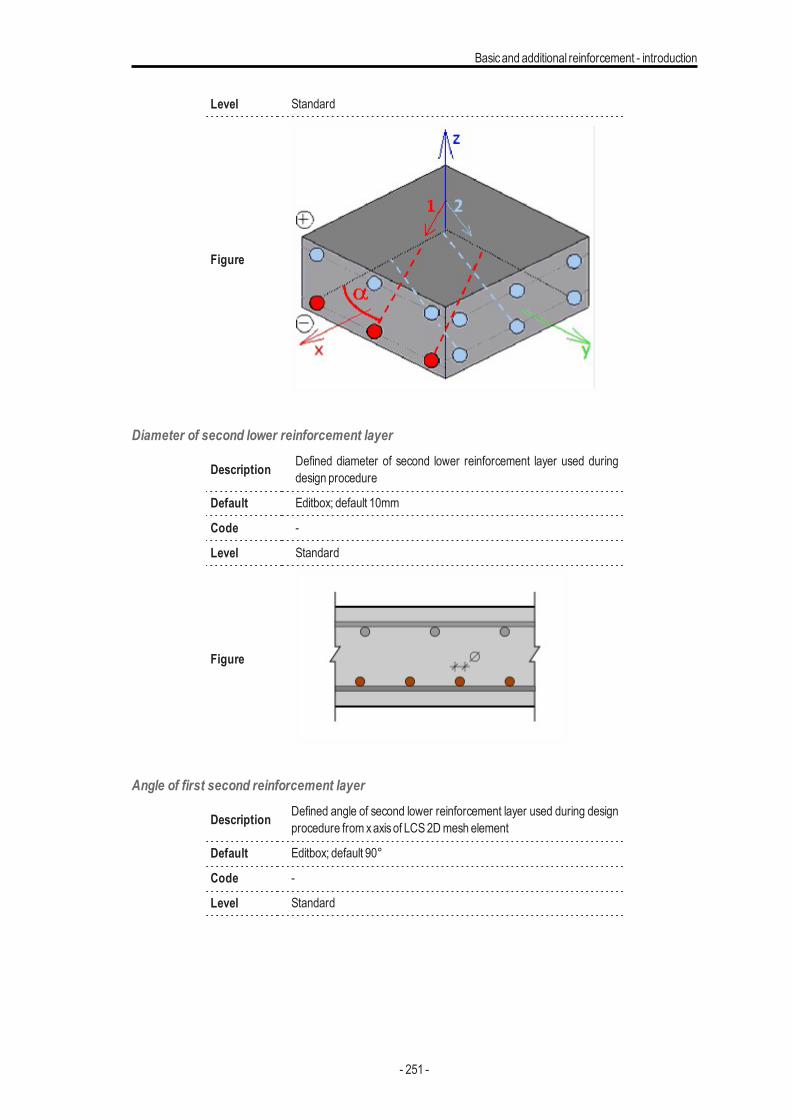
Basicand additional reinforcement - introduction
Level Standard
Figure
Diameter of second lower reinforcement layer
Description Defined diameter of second lower reinforcement layer used duringdesign procedure
Default Editbox; default 10mm
Code -
Level Standard
Figure
Angle of first second reinforcement layer
Description Defined angle of second lower reinforcement layer used during designprocedure from xaxisof LCS 2Dmesh element
Default Editbox; default 90°
Code -
Level Standard
- 251 -
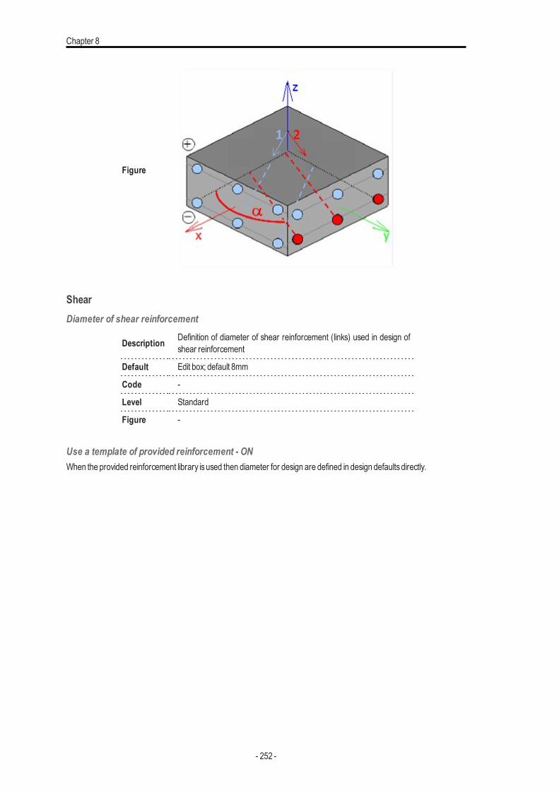
Chapter 8
Figure
ShearDiameter of shear reinforcement
Description Definition of diameter of shear reinforcement (links) used in design ofshear reinforcement
Default Edit box; default 8mm
Code -
Level Standard
Figure -
Use a template of provided reinforcement - ONWhen the provided reinforcement library isused then diameter for design are defined in design defaultsdirectly.
- 252 -
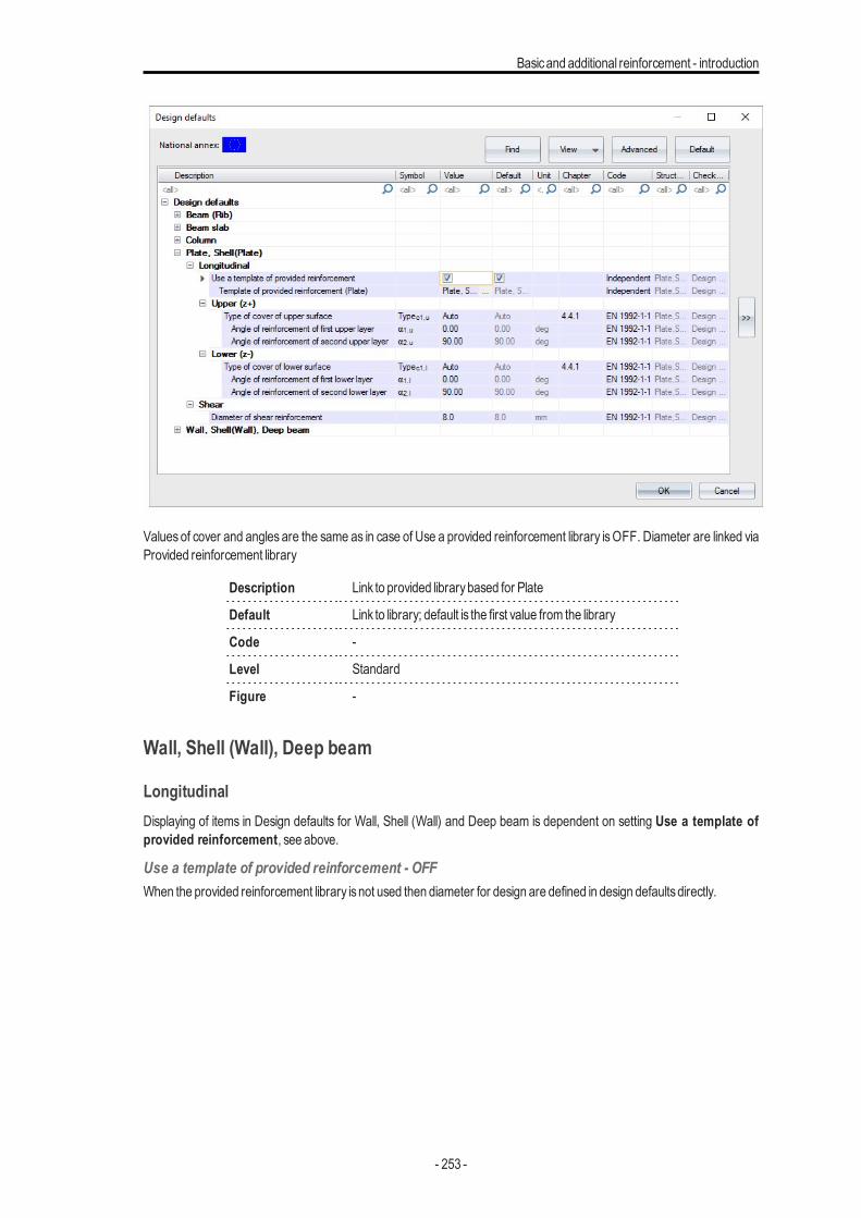
Basicand additional reinforcement - introduction
Values of cover and angles are the same as in case of Use a provided reinforcement library isOFF. Diameter are linked viaProvided reinforcement library
Description Link to provided librarybased for Plate
Default Link to library; default is the first value from the library
Code -
Level Standard
Figure -
Wall, Shell (Wall), Deep beam
LongitudinalDisplaying of items in Design defaults for Wall, Shell (Wall) and Deep beam is dependent on setting Use a template ofprovided reinforcement, see above.
Use a template of provided reinforcement - OFFWhen the provided reinforcement library isnot used then diameter for design are defined in design defaultsdirectly.
- 253 -
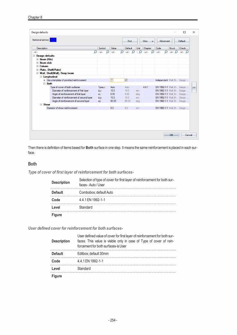
Chapter 8
Then there is definition of itemsbased for Both surface in one step. It means the same reinforcement is placed in each sur-face.
BothType of cover of first layer of reinforcement for both surfaces-
Description Selection of type of cover for first layer of reinforcement for both sur-faces - Auto / User
Default Combobox; default Auto
Code 4.4.1 EN 1992-1-1
Level Standard
Figure
User defined cover for reinforcement for both surfaces-
DescriptionUser defined value of cover for first layer of reinforcement for both sur-faces. This value is visible only in case of Type of cover of rein-forcement for both surfaces-isUser
Default Editbox; default 30mm
Code 4.4.1 EN 1992-1-1
Level Standard
Figure
- 254 -
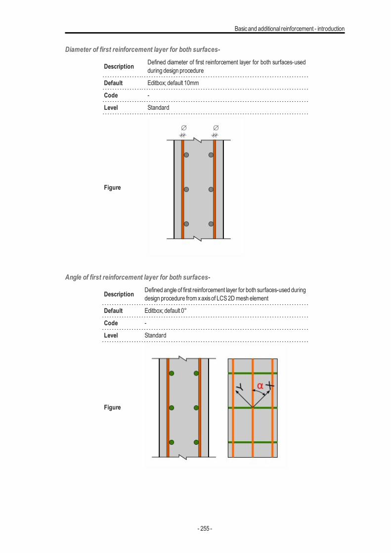
Basicand additional reinforcement - introduction
Diameter of first reinforcement layer for both surfaces-
Description Defined diameter of first reinforcement layer for both surfaces-usedduring design procedure
Default Editbox; default 10mm
Code -
Level Standard
Figure
Angle of first reinforcement layer for both surfaces-
Description Defined angle of first reinforcement layer for both surfaces-used duringdesign procedure from xaxisof LCS 2Dmesh element
Default Editbox; default 0°
Code -
Level Standard
Figure
- 255 -
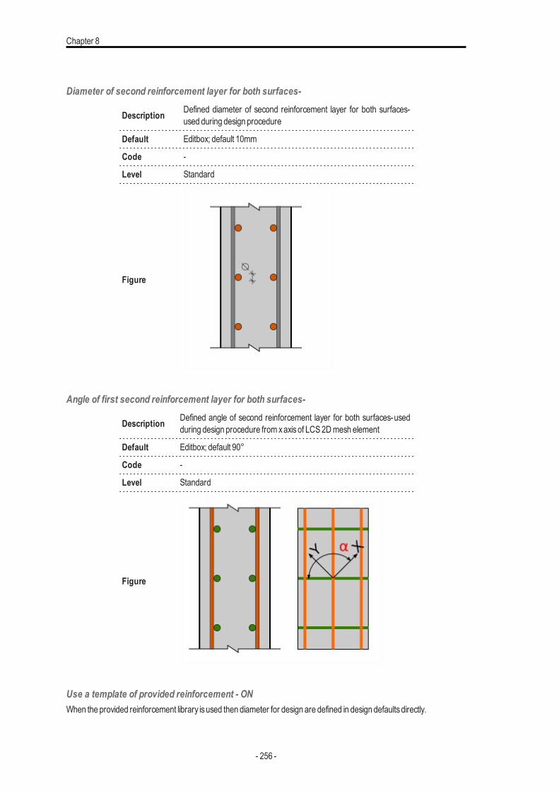
Chapter 8
Diameter of second reinforcement layer for both surfaces-
Description Defined diameter of second reinforcement layer for both surfaces-used during design procedure
Default Editbox; default 10mm
Code -
Level Standard
Figure
Angle of first second reinforcement layer for both surfaces-
Description Defined angle of second reinforcement layer for both surfaces-usedduring design procedure from xaxisof LCS 2Dmesh element
Default Editbox; default 90°
Code -
Level Standard
Figure
Use a template of provided reinforcement - ONWhen the provided reinforcement library isused then diameter for design are defined in design defaultsdirectly.
- 256 -
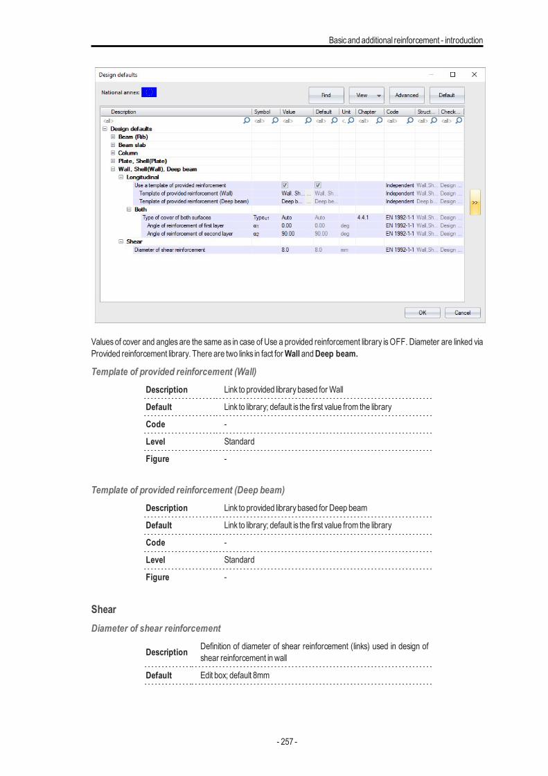
Basicand additional reinforcement - introduction
Values of cover and angles are the same as in case of Use a provided reinforcement library isOFF. Diameter are linked viaProvided reinforcement library. There are two links in fact forWall andDeep beam.
Template of provided reinforcement (Wall)Description Link to provided librarybased for Wall
Default Link to library; default is the first value from the library
Code -
Level Standard
Figure -
Template of provided reinforcement (Deep beam)Description Link to provided librarybased for Deep beam
Default Link to library; default is the first value from the library
Code -
Level Standard
Figure -
ShearDiameter of shear reinforcement
Description Definition of diameter of shear reinforcement (links) used in design ofshear reinforcement in wall
Default Edit box; default 8mm
- 257 -
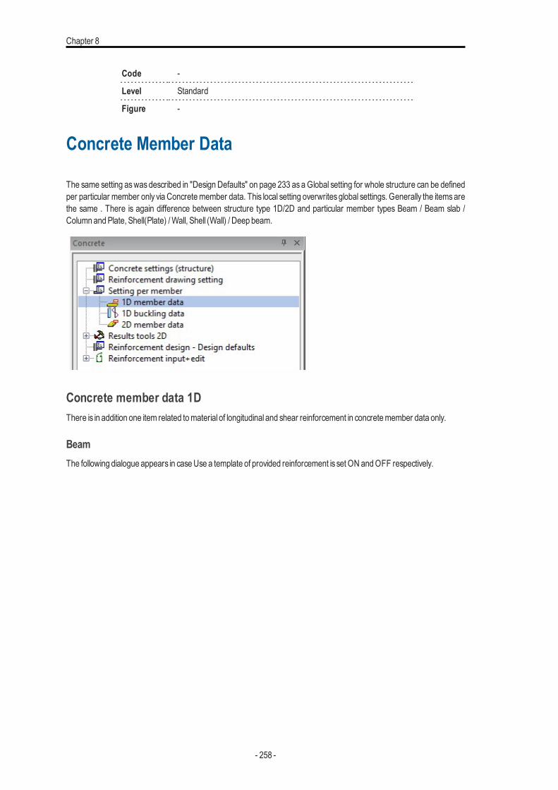
Chapter 8
Code -
Level Standard
Figure -
Concrete Member Data
The same setting aswasdescribed in "Design Defaults" on page 233 as a Global setting for whole structure can be definedper particular member only via Concretemember data. This local setting overwrites global settings. Generally the itemsarethe same . There is again difference between structure type 1D/2D and particular member types Beam / Beam slab /Column andPlate, Shell(Plate) /Wall, Shell (Wall) / Deep beam.
Concrete member data 1DThere is in addition one item related tomaterial of longitudinal and shear reinforcement in concretemember data only.
BeamThe following dialogue appears in caseUse a template of provided reinforcement is set ON andOFF respectively.
- 258 -
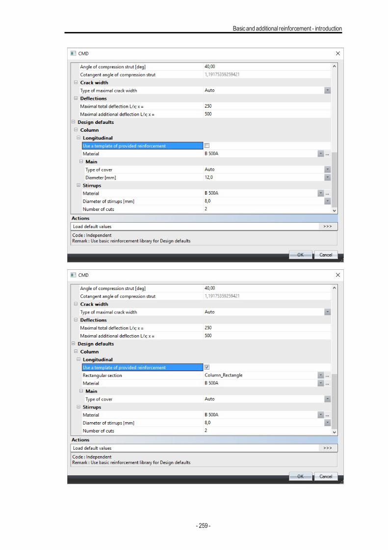
Basicand additional reinforcement - introduction
- 259 -
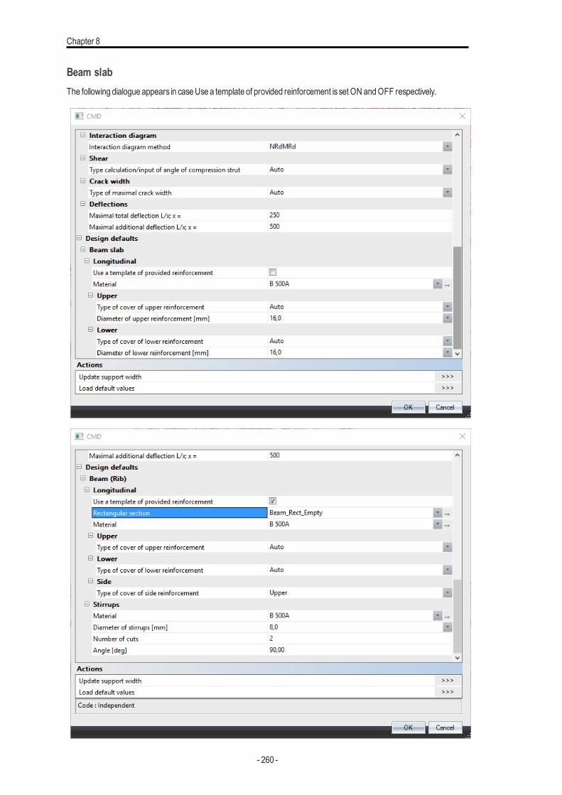
Chapter 8
Beam slabThe following dialogue appears in caseUse a template of provided reinforcement is set ON andOFF respectively.
- 260 -
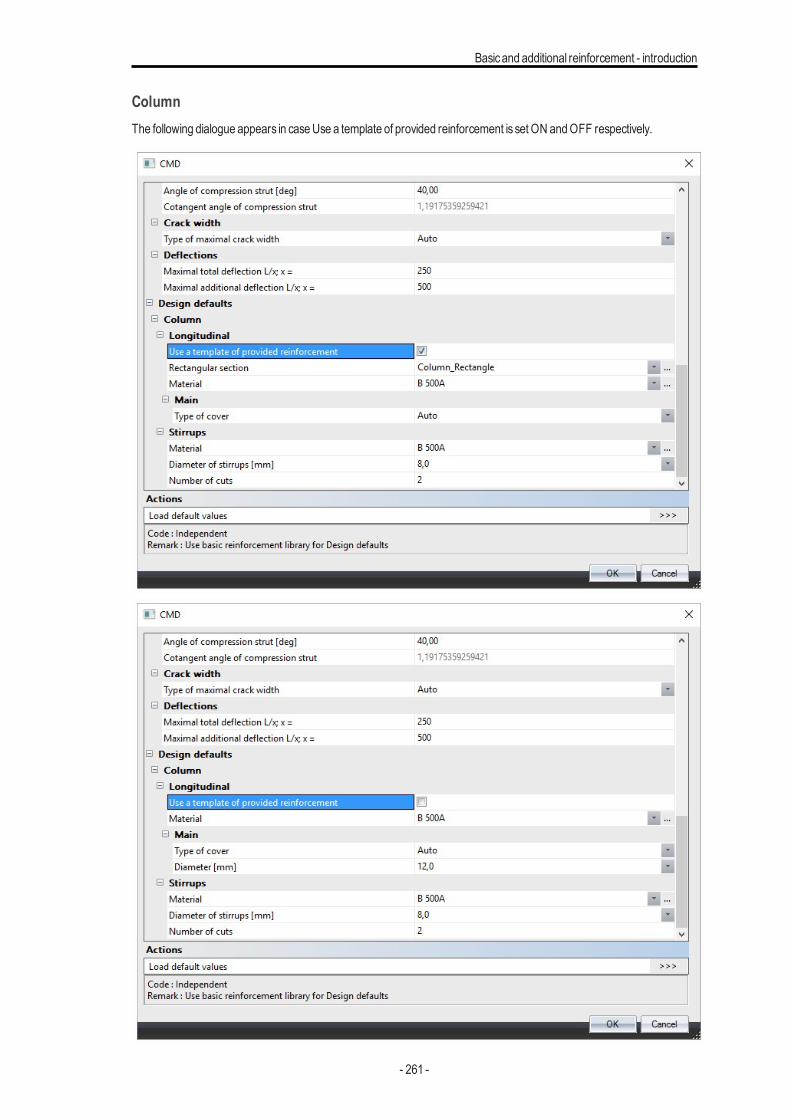
Basicand additional reinforcement - introduction
ColumnThe following dialogue appears in caseUse a template of provided reinforcement is set ON andOFF respectively.
- 261 -
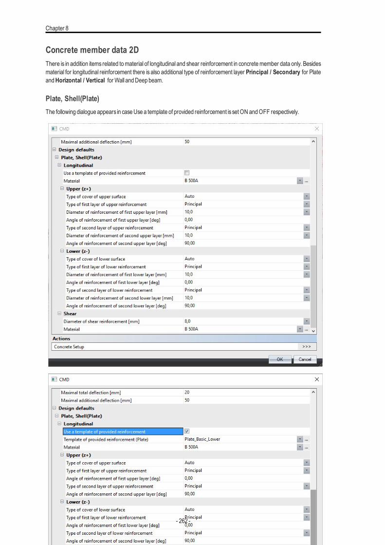
Chapter 8
Concrete member data 2DThere is in addition items related tomaterial of longitudinal and shear reinforcement in concretemember data only. Besidesmaterial for longitudinal reinforcement there is also additional type of reinforcement layer Principal / Secondary for PlateandHorizontal / Vertical for Wall andDeep beam.
Plate, Shell(Plate)The following dialogue appears in caseUse a template of provided reinforcement is set ON andOFF respectively.
- 262 -
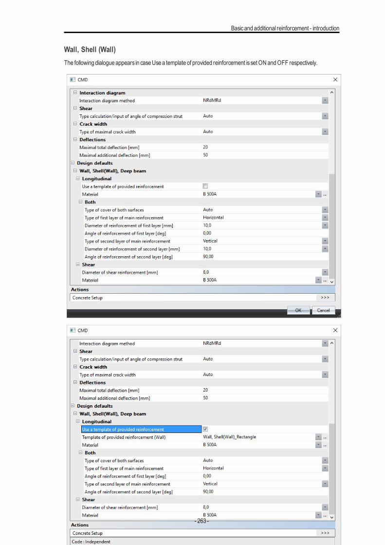
Basicand additional reinforcement - introduction
Wall, Shell (Wall)The following dialogue appears in caseUse a template of provided reinforcement is set ON andOFF respectively.
- 263 -
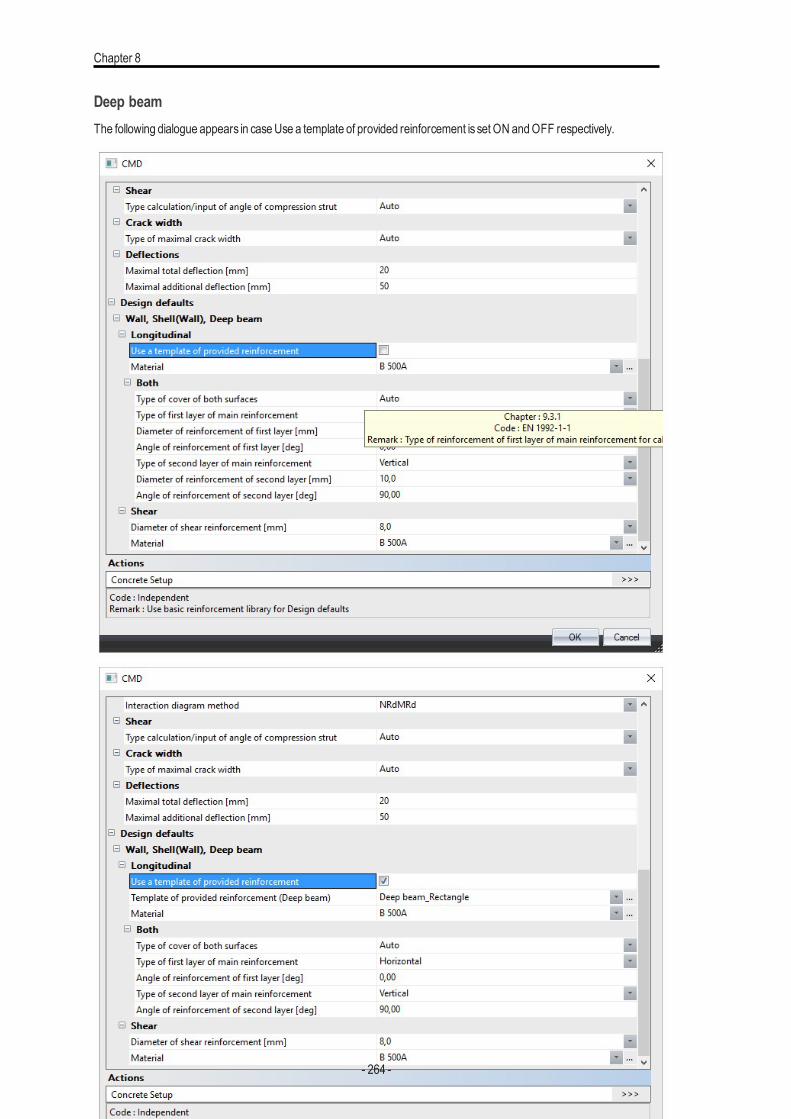
Chapter 8
Deep beamThe following dialogue appears in caseUse a template of provided reinforcement is set ON andOFF respectively.
- 264 -
Checks
Checks
First you get an overview of the input data for the checks:
l Internal forces, displaying the characteristicand design values.For member type 'column', the design valuesof the bendingmoments include the 2nd order bendingmoments (ifrequired) and themomentsdue to geometric imperfections.For member type 'beam', the design valuesof the bendingmoments include the shifting of themoment line - to take theadditional tensile force due to shear into account.
l Slendernesscalculation (for member type 'column'), determining if 2nd order effectsneed be taken into account.
l Stiffnesses, displaying the valuesEA, EIy andEIz.
Available checksat theUltimate Limit State:
l Capacity check for N-My-Mz interaction - based on resistance calculated from interaction diagram
l Response check - based on checkof ultimate stressesand strains for N-My-Mz interaction
l Checkof shear and torsionl Checkof interaction of shear, torsion, bending and normal force
Available checksat the Serviceability Limit State:
l l Stress limitation (for concrete aswell as reinforcing steel)l Crackwidth limitationl Simple check for deflection - based on calculation of stiffness ratio, without necessity to calculateCDD
StiffnessIntroductionThe behaviour of reinforced concrete is not linear-elastic, even with loads within working stress limits, and it is thereforenecessary to adjust either E or I depending on the magnitude of the applied load. In addition concrete is subjected to sig-nificant long term strains due to creep and shrinkage, which will affect the curvature and stiffness of a reinforced concretestructures.This chapter describeshow the curvature and stiffnessof a reinforced concrete section is calculated.
Stiffness presentation command is used for presentation of calculated stiffness. The procedure for calculation of stiffness isbased on the requirementsmentioned in chapter 7.4.3 from EN 1992-1-1. Generally, two states of cross-section are con-sidered:
l I) uncracked cross-section - which is loaded below the levelwhen tensile strength of concrete is reached, here thecross-sectionwith tensile strength isused
l II) fully cracked cross-section - which is loaded above the levelwhen tensile strength of concrete is reached, here thecross-sectionwithout tensile strength isused
The stiffness is decreased when the load achieve cracking moment (My,cr). The dependency of stiffness on crackingmoment is visible from the following figure. The curve isnot linear due to tensile stiffeningwhich partlyhigher then cross-sec-tion completelywithout tensile strength
- 265 -
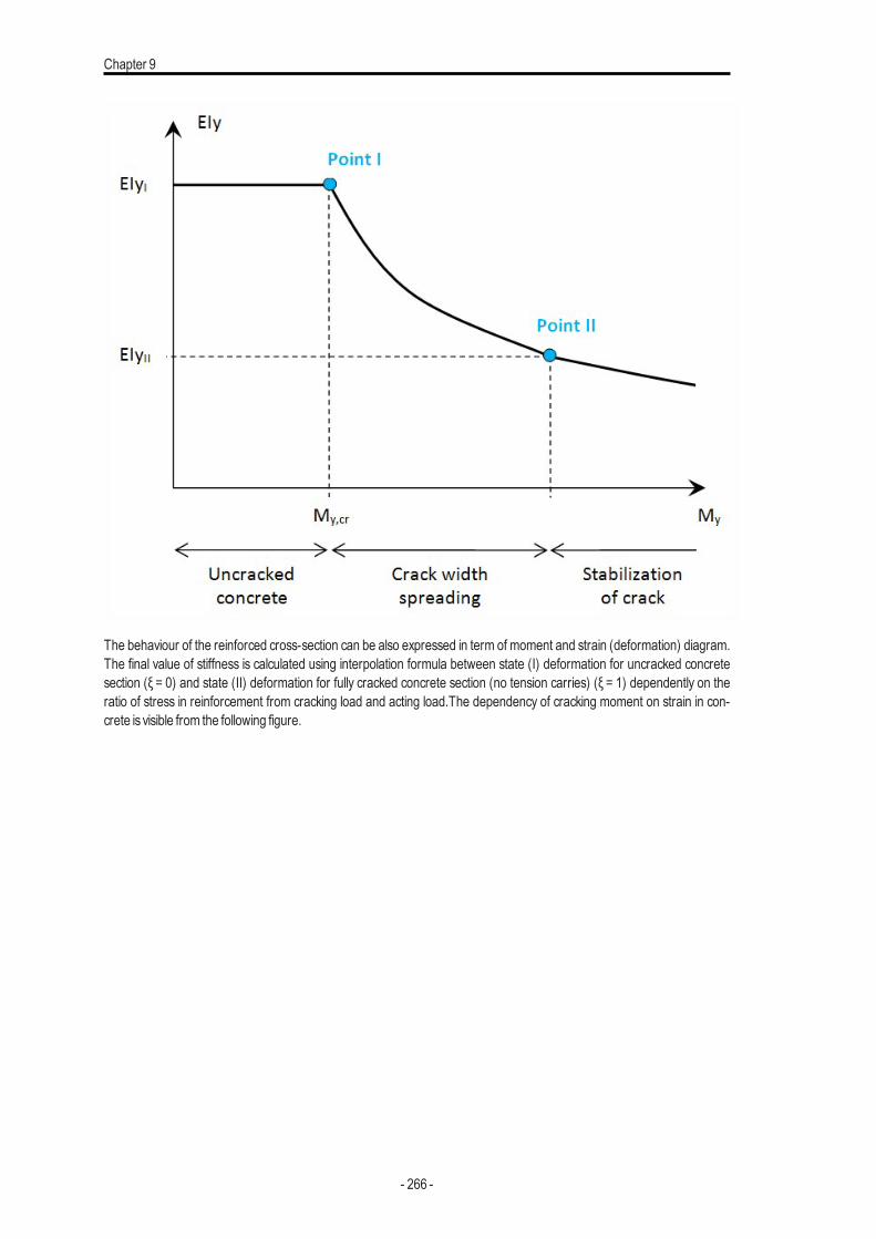
Chapter 9
The behaviour of the reinforced cross-section can be also expressed in term of moment and strain (deformation) diagram.The final value of stiffness is calculated using interpolation formula between state (I) deformation for uncracked concretesection (ξ = 0) and state (II) deformation for fully cracked concrete section (no tension carries) (ξ = 1) dependently on theratio of stress in reinforcement from cracking load and acting load.The dependency of cracking moment on strain in con-crete is visible from the following figure.
- 266 -
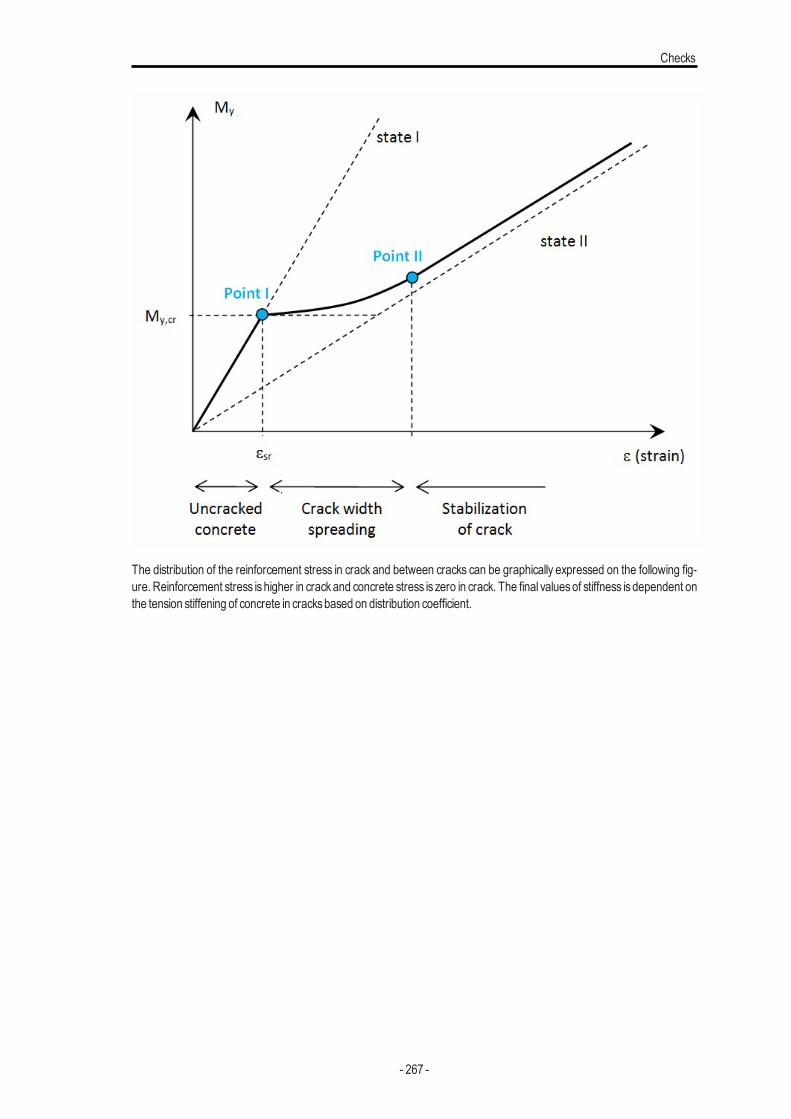
Checks
The distribution of the reinforcement stress in crack and between cracks can be graphically expressed on the following fig-ure. Reinforcement stress is higher in crackand concrete stress is zero in crack. The final valuesof stiffness is dependent onthe tension stiffening of concrete in cracksbased on distribution coefficient.
- 267 -
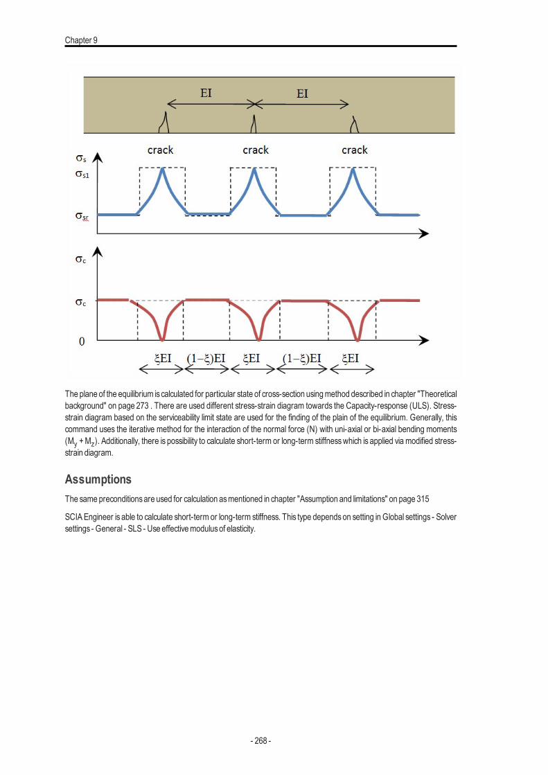
Chapter 9
The plane of the equilibrium iscalculated for particular state of cross-section usingmethod described in chapter "Theoreticalbackground" on page 273 . There are used different stress-strain diagram towards the Capacity-response (ULS). Stress-strain diagram based on the serviceability limit state are used for the finding of the plain of the equilibrium. Generally, thiscommand uses the iterative method for the interaction of the normal force (N) with uni-axial or bi-axial bending moments(My +Mz). Additionally, there is possibility to calculate short-term or long-term stiffnesswhich is applied via modified stress-strain diagram.
AssumptionsThe samepreconditionsare used for calculation asmentioned in chapter "Assumption and limitations" on page 315
SCIAEngineer is able to calculate short-term or long-term stiffness. This type dependson setting in Global settings - Solversettings - General - SLS - Use effectivemodulusof elasticity.
- 268 -
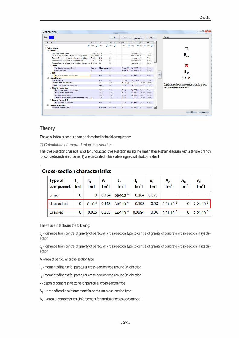
Checks
TheoryThe calculation procedure can be described in the following steps:
1) Calculation of uncracked cross-sectionThe cross-section characteristics for uncracked cross-section (using the linear stress-strain diagram with a tensile branchfor concrete and reinforcement) are calculated. This state is signedwith bottom index I
.
The values in table are the following:
ty - distance from centre of gravity of particular cross-section type to centre of gravity of concrete cross-section in (y) dir-ection
tz - distance from centre of gravity of particular cross-section type to centre of gravity of concrete cross-section in (z) dir-ection
A - area of particular cross-section type
Iy - moment of inertia for particular cross-section type around (y) direction
Iz - moment of inertia for particular cross-section type around (z) direction
x - depth of compressive zone for particular cross-section type
Ast - area of tensile reinforcement for particular cross-section type
Asc - area of compressive reinforcement for particular cross-section type
- 269 -
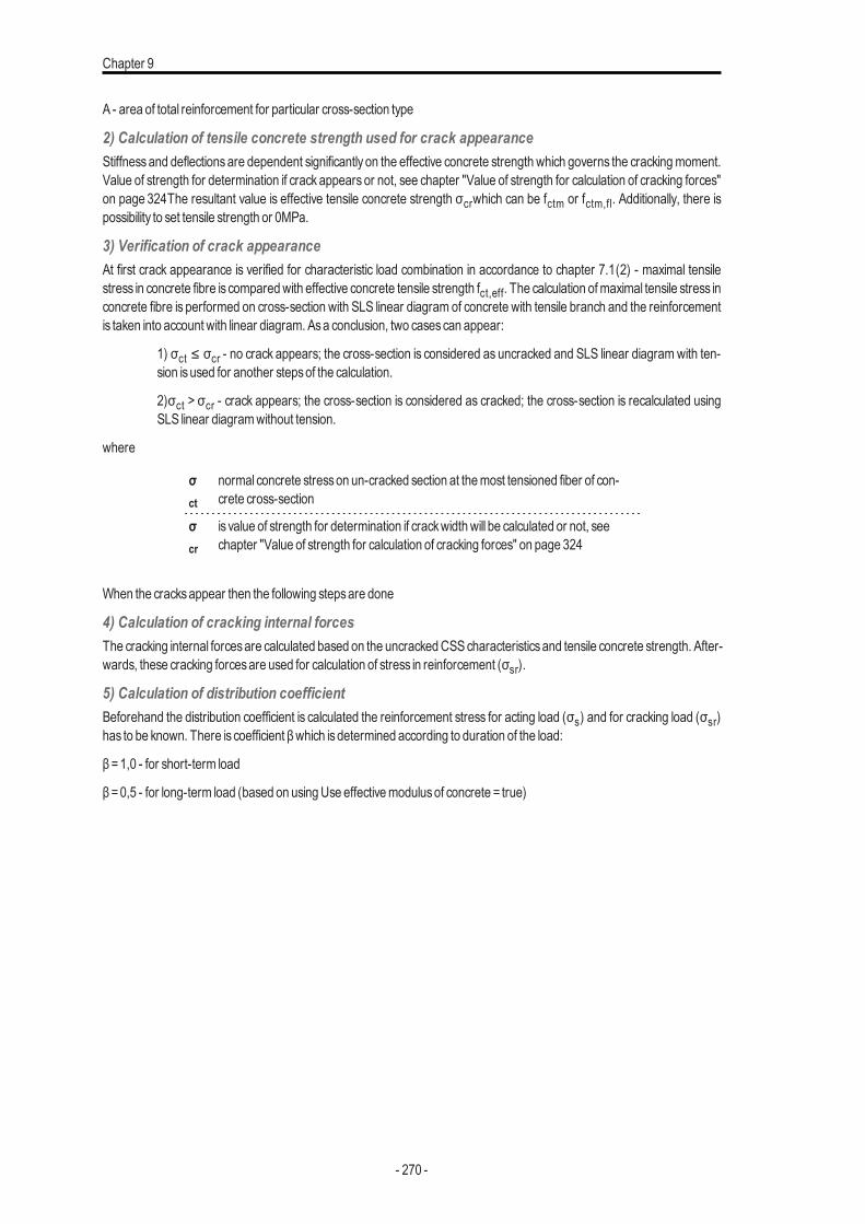
Chapter 9
A - area of total reinforcement for particular cross-section type
2) Calculation of tensile concrete strength used for crack appearanceStiffnessand deflectionsare dependent significantly on the effective concrete strength which governs the crackingmoment.Value of strength for determination if crack appears or not, see chapter "Value of strength for calculation of cracking forces"on page 324The resultant value is effective tensile concrete strength σcrwhich can be fctm or fctm,fl. Additionally, there ispossibility to set tensile strength or 0MPa.
3) Verification of crack appearanceAt first crack appearance is verified for characteristic load combination in accordance to chapter 7.1(2) - maximal tensilestress in concrete fibre is comparedwith effective concrete tensile strength fct,eff. The calculation ofmaximal tensile stress inconcrete fibre is performed on cross-section with SLS linear diagram of concrete with tensile branch and the reinforcementis taken into account with linear diagram. Asa conclusion, two casescan appear:
1) σct ≤ σcr - no crack appears; the cross-section is considered as uncracked and SLS linear diagram with ten-sion isused for another stepsof the calculation.
2)σct > σcr - crack appears; the cross-section is considered as cracked; the cross-section is recalculated usingSLS linear diagramwithout tension.
where
σct
normal concrete stresson un-cracked section at themost tensioned fiber of con-crete cross-section
σcr
is value of strength for determination if crackwidthwill be calculated or not, seechapter "Value of strength for calculation of cracking forces" on page 324
When the cracksappear then the following stepsare done
4) Calculation of cracking internal forcesThe cracking internal forcesare calculated based on the uncrackedCSScharacteristicsand tensile concrete strength. After-wards, these cracking forcesare used for calculation of stress in reinforcement (σsr).
5) Calculation of distribution coefficientBeforehand the distribution coefficient is calculated the reinforcement stress for acting load (σs) and for cracking load (σsr)has to be known. There is coefficient βwhich isdetermined according to duration of the load:
β =1,0 - for short-term load
β =0,5 - for long-term load (based on usingUse effectivemodulusof concrete = true)
- 270 -
Checks
The distribution coefficient (in fact coefficient of tension stiffening) is calculated based on the type of load (β) and also on theratio of reinforcement stress for cracking and acting load
ξ=1-β∙(σsr/σs)2
6) Calculation of fully cracked cross-sectionThe cross-section characteristic for full cracked cross-section (using linear stress-strain diagram without tensile branch forconcrete and reinforcement) are calculated. This state is signedwith bottom index II.
Explanation ismentioned above.
7) calculation of resultant values of stiffnesses and curvaturesWhen the steps above are calculated then resultant values of stiffnesses can be calculated using interpolation formularespecting uncracked state (I) and fully cracked state (II).
Calculation of the resultant bending stiffness,
axial stiffness,
- 271 -
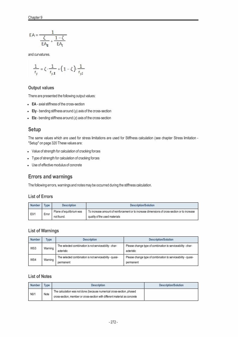
Chapter 9
and curvatures.
Output valuesThere are presented the following output values:
l EA - axial stiffnessof the cross-sectionl EIy - bending stiffnessaround (y) axisof the cross-sectionl EIz - bending stiffnessaround (z) axisof the cross-section
SetupThe same values which are used for stress limitations are used for Stiffness calculation (see chapter Stress limitation -"Setup" on page 320 These valuesare:
l Value of strength for calculation of cracking forcesl Type of strength for calculation of cracking forcesl Use of effectivemodulusof concrete
Errors and warningsThe following errors, warningsand notesmaybe occurred during the stiffnesscalculation.
List of ErrorsNumber Type Description Description/Solution
E0/1 ErrorPlane of equilibriumwasnot found.
To increase amount of reinforcement or to increase dimensions of cross-section or to increasequality of the used materials
List of WarningsNumber Type Description Description/Solution
W5/3 WarningThe selected combination is not serviceability - char-acteristic
Please change type of combination to serviceability - char-acteristic
W5/4 WarningThe selected combination is not serviceability - quasi-permanent
Please change type of combination to serviceability - quasi-permanent
List of NotesNumber Type Description Description/Solution
N0/1 NoteThe calculation was not done (because numerical cross-section, phasedcross-section,member or cross-section with differentmaterial as concrete
- 272 -
Checks
Number Type Description Description/Solution
material is used)
N0/2 Note The prestressed reinforcement is not taken into account
N0/3 Note The "Free bars " reinforcement is not taken into account
N0/4 NoteThere is some detailing longitudinal reinforcement, which is not taken intoaccount for the ULS and SLS check
N2/1 Note The normal forces and bending moments are zero (N = 0,My = 0,Mz = 0)
N8/1 NoteThe maximal effective concrete strength is exceeded; cracks appear under the" & State & "-term characteristic load combination. Furthermore, the concretestress-strain diagramwithout tensile branch is used.
Change (a) the dimensions of the cross-sec-tion, (b) the amount of reinforcement or (c)the quality of the used materials.
" &State & " in noteN8/1 is replaced by "short" or "long" according used combination
Capacity - response (ULS)IntroductionThe Capacity - response is based on the calculation of strain and stress in particular component (concrete fibre, rein-forcement bar) and comparisonwith limited valueswith respect of EN 1992-1-1 requirements. Based on the internal forces,concrete cross-section and defined reinforcement by the user, SCIAEngineer isable to calculate the response of amemberor a single cross-section. This method uses an iteration routine to calculate equilibrium based on the internal forces, thecross-section, material properties and reinforcement layout. However, thismethod does not calculate extremes (capacitiesof cross-section) like the interaction diagram, but calculates the state of equilibrium for that section (response). The cal-culation also includesdepth of compression zones (d), curvatures in each axis (εx, εy and εz), stresses, strains and forces inparticular components. Generally, this iterative method works for the interaction of the normal force (N) with uni-axial or bi-axial bendingmoments (My +Mz).
Assumptions and limitationsThere are the following assumptions:
l Strain and stressof diagramdefined in propertiesofmaterialwill be used
l Concrete – bilinear or parabola-rectangular stress-strain diagraml Reinforcement – bilinear with or without inclined horizontal branch stress-strain diagram
l Tensile stress in concrete isnot consideredl StandardREDES reinforcement is considered
With the following limitations
l The area of longitudinal reinforcement isnot subtracted from concrete area in the first step
Theoretical background
Calculation procedureImagine a diagram representing the strain in a reinforced concrete cross-section. Generally, the cross-section can be non-symmetric to y or z axis and loaded with a combination of N, My and Mz. Then the vector of strain consists of three nonzerovalues ε = {εx; εy, εz}. This vector determinesso called plane of deformation (see following figure). More information can befound in VONDRÁČEK, R.: NumericalMethods inNonlinear ConcreteDesign, Diploma thesis, 2000.
- 273 -
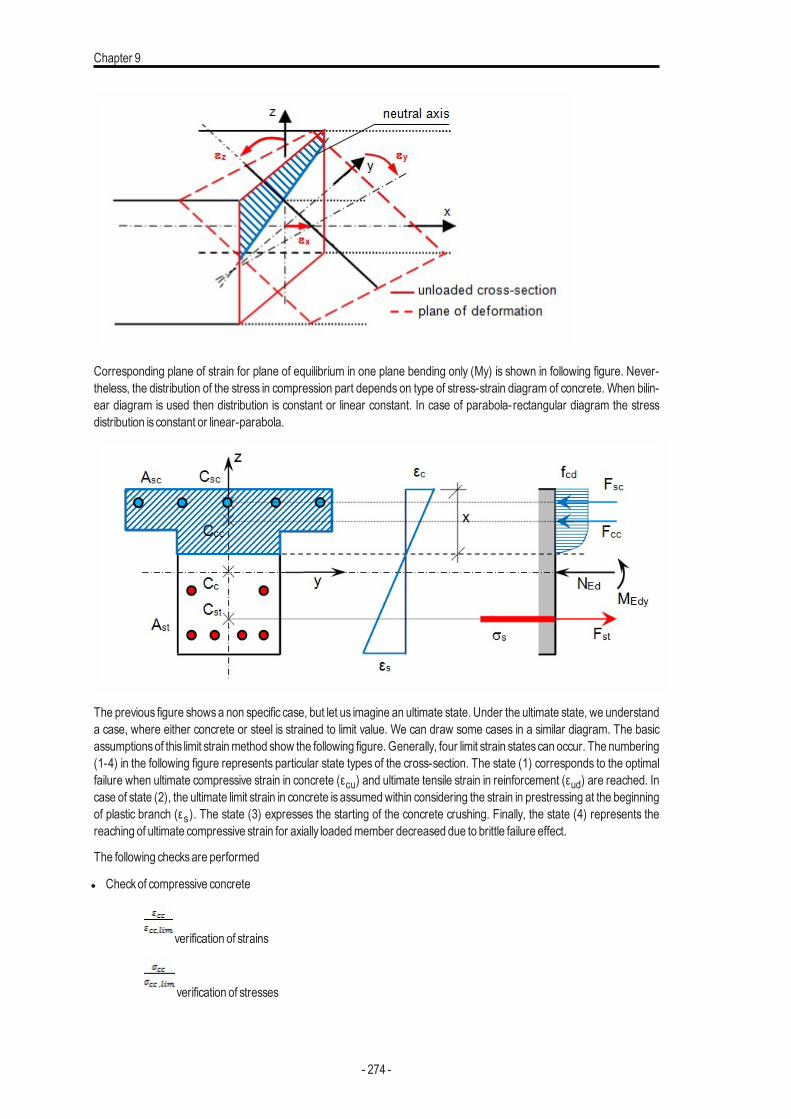
Chapter 9
Corresponding plane of strain for plane of equilibrium in one plane bending only (My) is shown in following figure. Never-theless, the distribution of the stress in compression part depends on type of stress-strain diagram of concrete. When bilin-ear diagram is used then distribution is constant or linear constant. In case of parabola-rectangular diagram the stressdistribution is constant or linear-parabola.
The previous figure showsa non specific case, but let us imagine an ultimate state. Under the ultimate state, we understanda case, where either concrete or steel is strained to limit value. We can draw some cases in a similar diagram. The basicassumptionsof this limit strainmethod show the following figure. Generally, four limit strain statescan occur. The numbering(1-4) in the following figure represents particular state types of the cross-section. The state (1) corresponds to the optimalfailure when ultimate compressive strain in concrete (εcu) and ultimate tensile strain in reinforcement (εud) are reached. Incase of state (2), the ultimate limit strain in concrete is assumedwithin considering the strain in prestressing at the beginningof plastic branch (εs). The state (3) expresses the starting of the concrete crushing. Finally, the state (4) represents thereaching of ultimate compressive strain for axially loadedmember decreased due to brittle failure effect.
The following checksare performed
l Checkof compressive concrete
verification of strains
verification of stresses
- 274 -
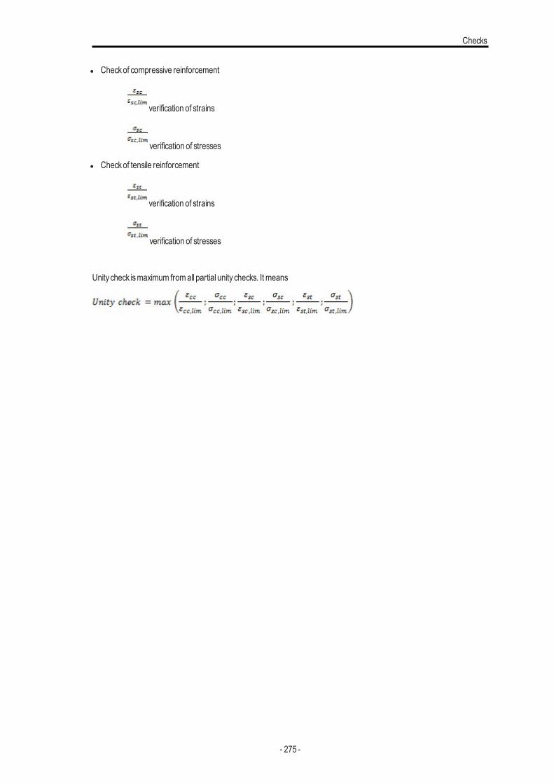
Checks
l Checkof compressive reinforcement
verification of strains
verification of stresses
l Checkof tensile reinforcement
verification of strains
verification of stresses
Unity check ismaximum fromall partial unity checks. It means
- 275 -
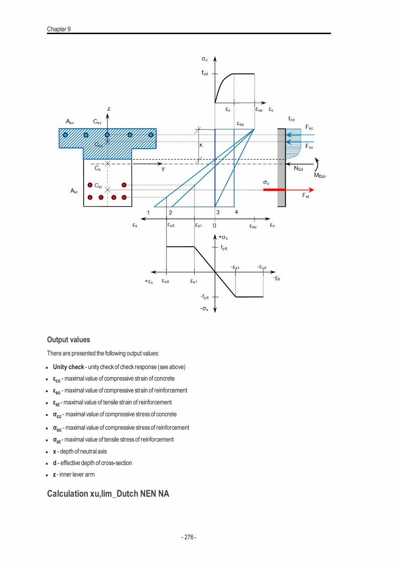
Chapter 9
Output valuesThere are presented the following output values:
l Unity check - unity checkof check response (see above)l εcc - maximal value of compressive strain of concrete
l εsc - maximal value of compressive strain of reinforcement
l εst - maximal value of tensile strain of reinforcement
l σcc - maximal value of compressive stressof concrete
l σsc - maximal value of compressive stressof reinforcement
l σst - maximal value of tensile stressof reinforcement
l x - depth of neutral axisl d - effective depth of cross-sectionl z - inner lever arm
Calculation xu,lim_Dutch NEN NA
- 276 -

Checks
There is special requirement in Dutch NEN NA (6.1(9)) for calculation of limited value of xu,lim. In sections of beams sub-jected to bending without normal force - other than by pretensioning the height of the concrete compression zone xumustbe limited. This limitation also applies if the relevant section is loaded by a normal force - other than by pretensioning - lessthan 0.1 ∙ fcd ∙ Ac.
Must be fulfilled the condition based on fck:
l xu≤xu,lim
where fck ≤50MPa
l xulim =500∙d / (500+f)
otherwise
l xulim =εcu2(3) ∙d / (εcu2(3)+7∙f)
where:
l d - effective depth of cross-sectionl εcu2(3)- limit value of concrete strain in compression based on usedmaterial diagram (bilinear or parabola-rectangular)
l xu- is the height of the concrete compression zone at that portion of the reinforcement which isnecessary for the takingthe prescribed loading;
l f - average strength of reinforcement calculated as followsl f = fyd ∙ As / As;
l where:l As - area of reinforcement
l fyd - design yield strength of reinforcement
Thiscalculation isdone aspart of the following commands
l Design of Asl Checkcapacity - responsel Checkcapacity - diagram
Design AsLimit value of xu is set as limit for design of reinforcement.
- 277 -
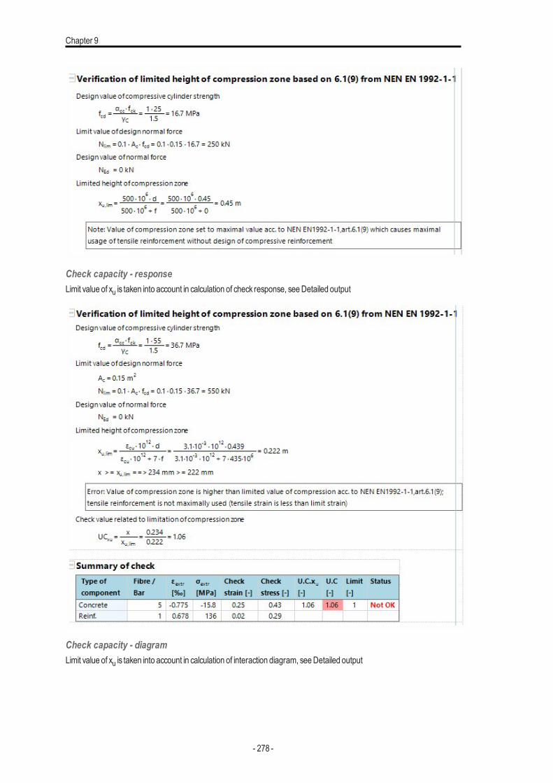
Chapter 9
Check capacity - responseLimit value of xu is taken into account in calculation of check response, seeDetailed output
Check capacity - diagramLimit value of xu is taken into account in calculation of interaction diagram, seeDetailed output
- 278 -
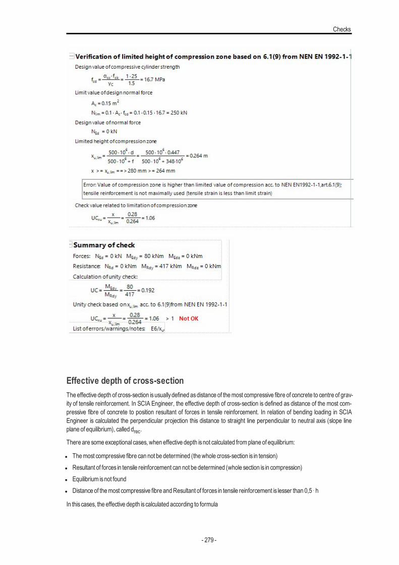
Checks
Effective depth of cross-sectionThe effective depth of cross-section isusuallydefined asdistance of themost compressive fibre of concrete to centre of grav-ity of tensile reinforcement. In SCIA Engineer, the effective depth of cross-section is defined as distance of the most com-pressive fibre of concrete to position resultant of forces in tensile reinforcement. In relation of bending loading in SCIAEngineer is calculated the perpendicular projection this distance to straight line perpendicular to neutral axis (slope lineplane of equilibrium), called drec.
There are some exceptional cases, when effective depth isnot calculated fromplane of equilibrium:
l Themost compressive fibre can not be determined (thewhole cross-section is in tension)l Resultant of forces in tensile reinforcement can not be determined (whole section is in compression)l Equilibrium isnot foundl Distance of themost compressive fibre andResultant of forces in tensile reinforcement is lesser than 0,5⋅h
In this cases, the effective depth is calculated according to formula
- 279 -
Chapter 9
d =drec =Coeffd⋅hl
where
Coeffdis coefficient for calculation effective depth of cross-section loaded form Concrete setup, if effectivedepth of cross-section is not possible to calculate from plane of equilibrium ). Default value is 0,9.
hl is height of cross-section perpendicular to neutral axis.
If there are the most compressive concrete fibres with the same value of compressivestress, the fibrewhich is the nearest to straight line in direction resultant of bendingmomentand crossing the centre of gravity of cross-section, is taken into account for calculationeffective depth .
Inner lever armInner lever arm in EN 1992-1-1, clause 6.2.3 (3) is defined as a distance of forces in tensile and compression chord, it fol-lows that is it the distance of position resultant of tensile force (tensile reinforcement) and position of resultant of com-pressive force (compressive reinforcement and compressive concrete). For better overview, there is calculated theperpendicular projection inner lever arm to straight line perpendicular to neutral axis (slope line plane of equilibrium), calledzrec.
Except of value inner lever arm, there is calculated part of inner lever armonly:
l part of inner lever arm (distance from centre of tensile force to centre of gravityof cross-section) – value z+or projectionthis value to straight line perpendicular to neutral axis– value zrec+
l is part of inner lever arm (distance from centre of compressive force to to centre of gravityof cross-section)– value z- orprojection this value to straight line perpendicular to neutral axis– value zrec-
There are some exceptional cases, when inner lever arm isnot calculated fromplane of equilibrium:
l Themost compressive fibre can not be determined (thewhole cross-section is in tension)l Resultant of forces in tensile reinforcement can not be determined (whole section is in compression)l equilibrium isnot found
In this cases, the inner lever armand partsof inner lever arm iscalculated according to formula
z=zrec =Coeffz⋅d
z+=zrec+=z- =zrec- =0.5⋅z
where
Coeffz
is coefficient for calculation inner lever arm of cross-section loaded form Concrete setup, if innerlever arm of cross-section is not possible to calculate from plane of equilibrium ). Default value is0,9.
d Is effective depth of cross-section
- 280 -
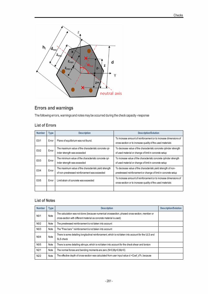
Checks
Errors and warningsThe following errors, warningsand notesmaybe occurred during the checkcapacity -response
List of ErrorsNumber Type Description Description/Solution
E0/1 Error Plane of equilibriumwas not found.To increase amount of reinforcement or to increase dimensions ofcross-section or to increase quality of the used materials
E0/2 ErrorThe maximum value of the characteristic concrete cyl-inder strength was exceeded
To decrease value of the characteristic concrete cylinder strengthof used material or change of limit in concrete setup
E0/3 ErrorThe minimum value of the characteristic concrete cyl-inder strength was exceeded
To increase value of the characteristic concrete cylinder strengthof used material or change of limit in concrete setup
E0/4 ErrorThe maximum value of the characteristic yield strengthof non-prestressed reinforcement was exceeded
To decrease value of the characteristic yield strength of non-prestressed reinforcement or change of limit in concrete setup
E0/5 Error Limit strain of concrete was exceededTo increase amount of reinforcement or to increase dimensions ofcross-section or to increase quality of the used materials
List of NotesNumber Type Description Description/Solution
N0/1 NoteThe calculation was not done (because numerical crosssection, phased cross-section,member orcross-section with differentmaterial as concrete material is used)
N0/2 Note The prestressed reinforcement is not taken into account
N0/3 Note The "Free bars " reinforcement is not taken into account
N0/4 NoteThere is some detailing longitudinal reinforcement, which is not taken into account for the ULS andSLS check
N0/5 Note There is some detailing stirrups, which is not taken into account for the check shear and torsion
N2/1 Note The normal forces and bending moments are zero (N=0,My=0,Mz=0)
N2/2 Note The effective depth of cross-section was calculated from user input value d =Coef_d*h, because
- 281 -
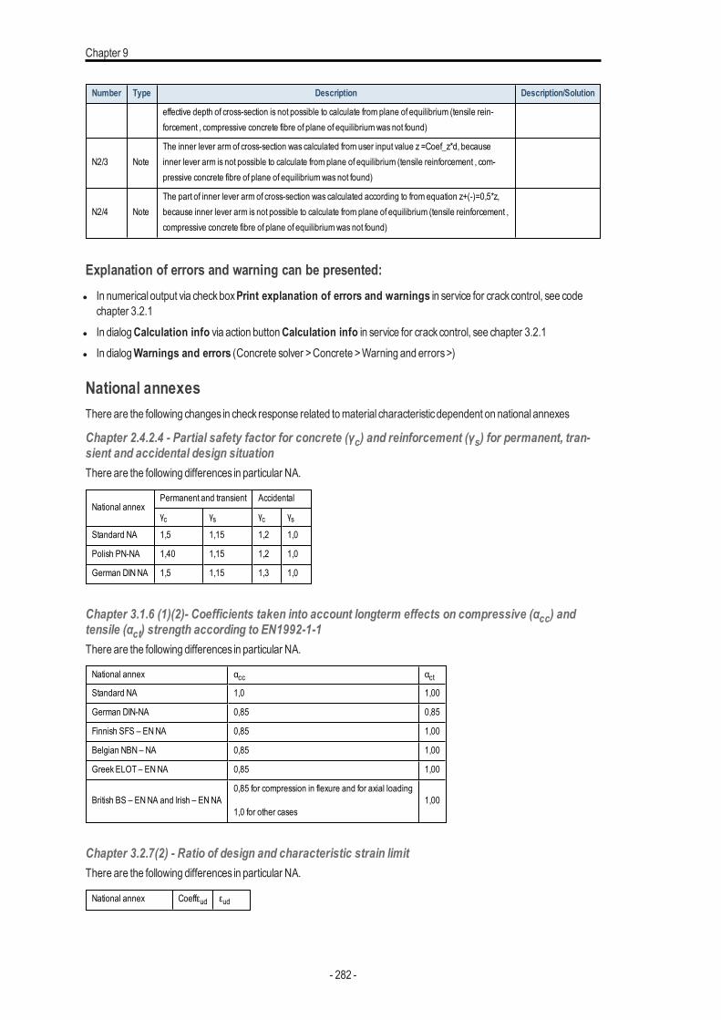
Chapter 9
Number Type Description Description/Solution
effective depth of cross-section is not possible to calculate from plane of equilibrium (tensile rein-forcement , compressive concrete fibre of plane of equilibriumwas not found)
N2/3 NoteThe inner lever arm of cross-section was calculated from user input value z =Coef_z*d, becauseinner lever arm is not possible to calculate from plane of equilibrium (tensile reinforcement , com-pressive concrete fibre of plane of equilibriumwas not found)
N2/4 NoteThe part of inner lever arm of cross-section was calculated according to from equation z+(-)=0,5*z,because inner lever arm is not possible to calculate from plane of equilibrium (tensile reinforcement ,compressive concrete fibre of plane of equilibriumwas not found)
Explanation of errors and warning can be presented:l In numerical output via checkboxPrint explanation of errors and warnings in service for crackcontrol, see code
chapter 3.2.1l In dialogCalculation info via action buttonCalculation info in service for crackcontrol, see chapter 3.2.1l In dialogWarnings and errors (Concrete solver >Concrete >Warning and errors>)
National annexesThere are the following changes in check response related tomaterial characteristicdependent on national annexes
Chapter 2.4.2.4 - Partial safety factor for concrete (γc) and reinforcement (γs) for permanent, tran-sient and accidental design situationThere are the following differences in particular NA.
National annexPermanent and transient Accidental
γc γs γc γsStandard NA 1,5 1,15 1,2 1,0
Polish PN-NA 1,40 1,15 1,2 1,0
German DINNA 1,5 1,15 1,3 1,0
Chapter 3.1.6 (1)(2)- Coefficients taken into account longterm effects on compressive (αcc) andtensile (αct) strength according to EN1992-1-1There are the following differences in particular NA.
National annex αcc αctStandard NA 1,0 1,00
German DIN-NA 0,85 0,85
Finnish SFS – ENNA 0,85 1,00
Belgian NBN – NA 0,85 1,00
Greek ELOT – ENNA 0,85 1,00
British BS – ENNA and Irish – ENNA0,85 for compression in flexure and for axial loading
1,0 for other cases1,00
Chapter 3.2.7(2) - Ratio of design and characteristic strain limitThere are the following differences in particular NA.
National annex Coeffεud εud
- 282 -
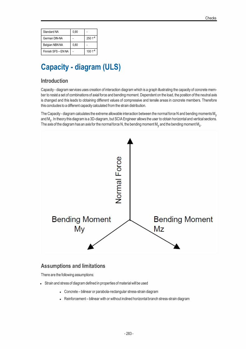
Checks
Standard NA 0,90 -
German DIN-NA - 250 1-4
Belgian NBNNA 0,80 -
Finnish SFS – ENNA - 100 1-4
Capacity - diagram (ULS)IntroductionCapacity - diagram services uses creation of interaction diagramwhich is a graph illustrating the capacity of concrete mem-ber to resist a set of combinationsof axial force and bendingmoment. Dependent on the load, the position of the neutral axisis changed and this leads to obtaining different values of compressive and tensile areas in concrete members. Thereforethis concludes to a different capacity calculated from the strain distribution.
TheCapacity - diagram calculates the extreme allowable interaction between the normal force N and bendingmomentsMyandMz. In theory thisdiagram isa 3D-diagram, but SCIAEngineer allows the user to obtain horizontal and vertical sections.The axisof the diagramhasan axis for the normal forceN, the bendingmomentMy and the bendingmomentMz.
Assumptions and limitationsThere are the following assumptions:
l Strain and stressof diagramdefined in propertiesofmaterialwill be used
l Concrete – bilinear or parabola-rectangular stress-strain diagraml Reinforcement – bilinear with or without inclined horizontal branch stress-strain diagram
- 283 -
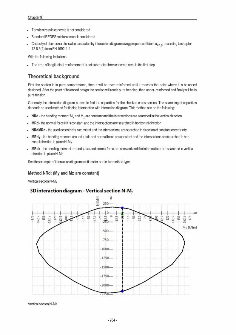
Chapter 9
l Tensile stress in concrete isnot consideredl StandardREDES reinforcement is consideredl Capacityof plain concrete isalso calculated by interaction diagramusing proper coefficient αcc,pl according to chapter
12.6.3(1) fromEN 1992-1-1
With the following limitations
l The area of longitudinal reinforcement isnot subtracted from concrete area in the first step
Theoretical backgroundFirst the section is in pure compressions, then it will be over- reinforced until it reaches the point where it is balanceddesigned. After the point of balanced design the section will reach pure bending, then under-reinforced and finally will be inpure tension.
Generally the interaction diagram is used to find the capacities for the checked cross-section. The searching of capacitiesdependson usedmethod for finding intersectionwith interaction diagram. Thismethod can be the following:
l NRd - the bendingmomentMy andMz are constant and the intersectionsare searched in the vertical direction
l MRd - the normal forceN t is constant and the intersectionsare searched in horizontal directionl NRdMRd - the used eccentricity is constant and the intersectionsare searched in direction of constant eccentricityl MRdy - the bendingmoment around zaxisand normal force are constant and the intersectionsare searched in hori-
zontal direction in planeN-Myl MRdz - the bendingmoment around yaxisand normal force are constant and the intersectionsare searched in vertical
direction in planeN-Mz
See the example of interaction diagramsections for particular method type:
Method NRd: (My and Mz are constant)Vertical sectionN-My
Vertical sectionN-Mz
- 284 -
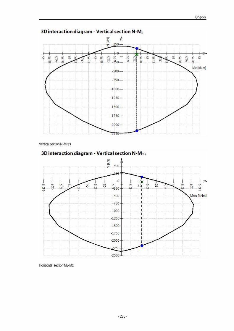
Checks
Vertical sectionN-Mres
Horizontal sectionMy-Mz
- 285 -
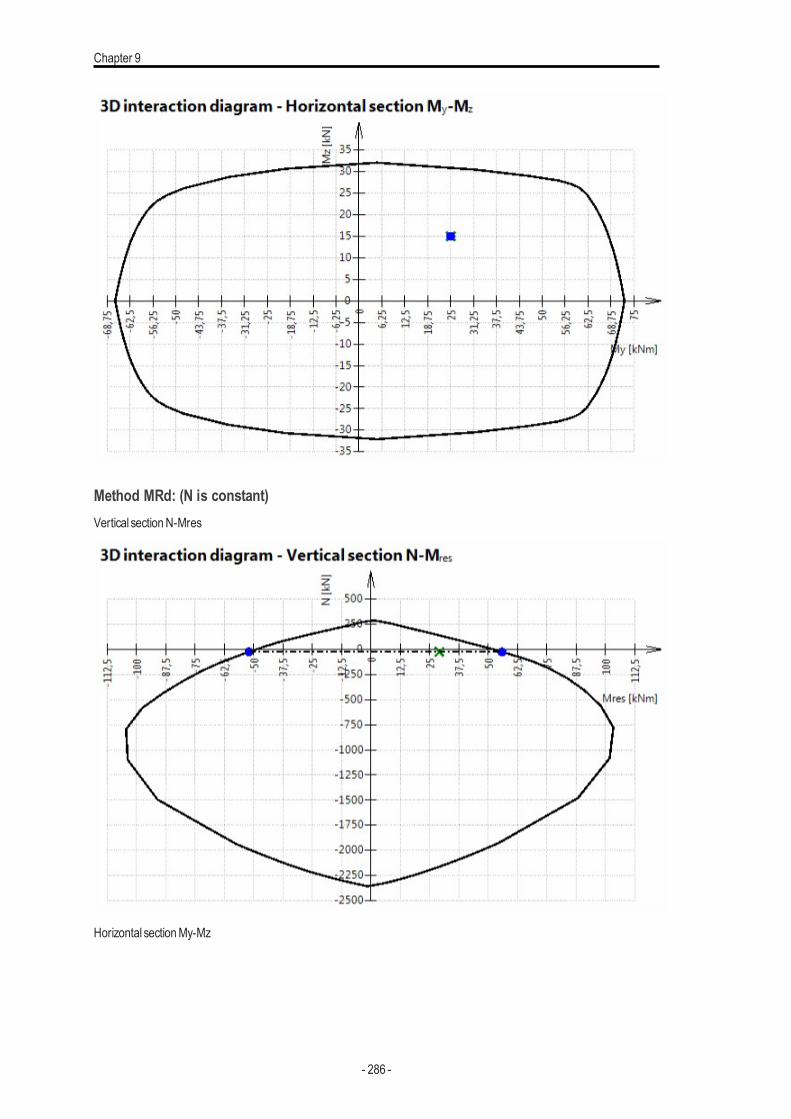
Chapter 9
Method MRd: (N is constant)Vertical sectionN-Mres
Horizontal sectionMy-Mz
- 286 -
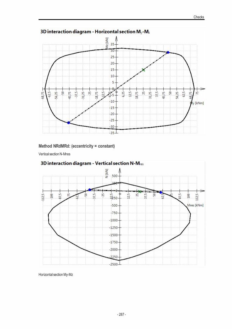
Checks
Method NRdMRd: (eccentricity = constant)Vertical sectionN-Mres
Horizontal sectionMy-Mz
- 287 -
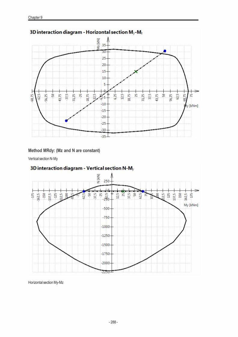
Chapter 9
Method MRdy: (Mz and N are constant)Vertical sectionN-My
Horizontal sectionMy-Mz
- 288 -
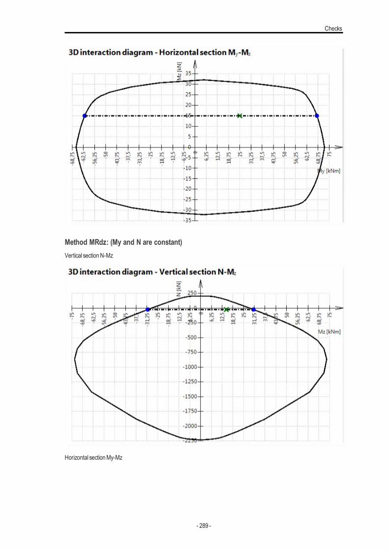
Checks
Method MRdz: (My and N are constant)Vertical sectionN-Mz
Horizontal sectionMy-Mz
- 289 -
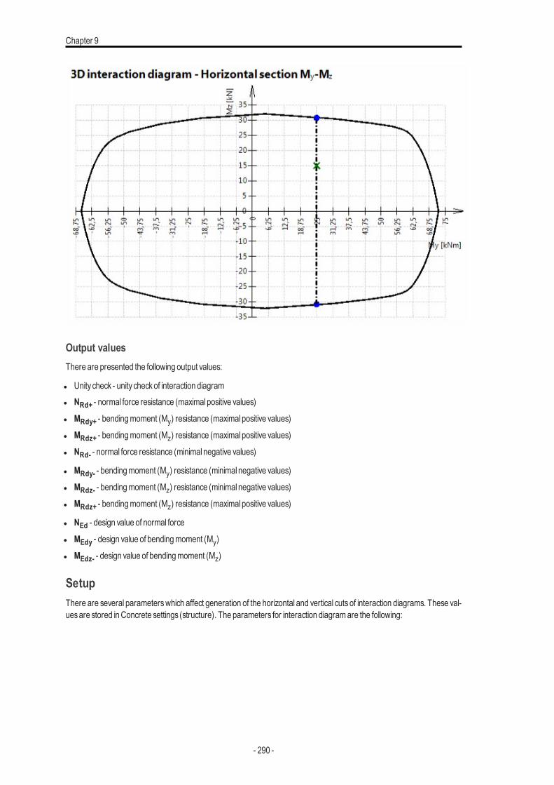
Chapter 9
Output valuesThere are presented the following output values:
l Unity check - unity checkof interaction diagraml NRd+ - normal force resistance (maximal positive values)
l MRdy+ - bendingmoment (My) resistance (maximal positive values)
l MRdz+ - bendingmoment (Mz) resistance (maximal positive values)
l NRd- - normal force resistance (minimal negative values)
l MRdy- - bendingmoment (My) resistance (minimal negative values)
l MRdz- - bendingmoment (Mz) resistance (minimal negative values)
l MRdz+ - bendingmoment (Mz) resistance (maximal positive values)
l NEd - design value of normal force
l MEdy - design value of bendingmoment (My)
l MEdz- - design value of bendingmoment (Mz)
SetupThere are several parameterswhich affect generation of the horizontal and vertical cuts of interaction diagrams. These val-uesare stored inConcrete settings (structure). The parameters for interaction diagramare the following:
- 290 -
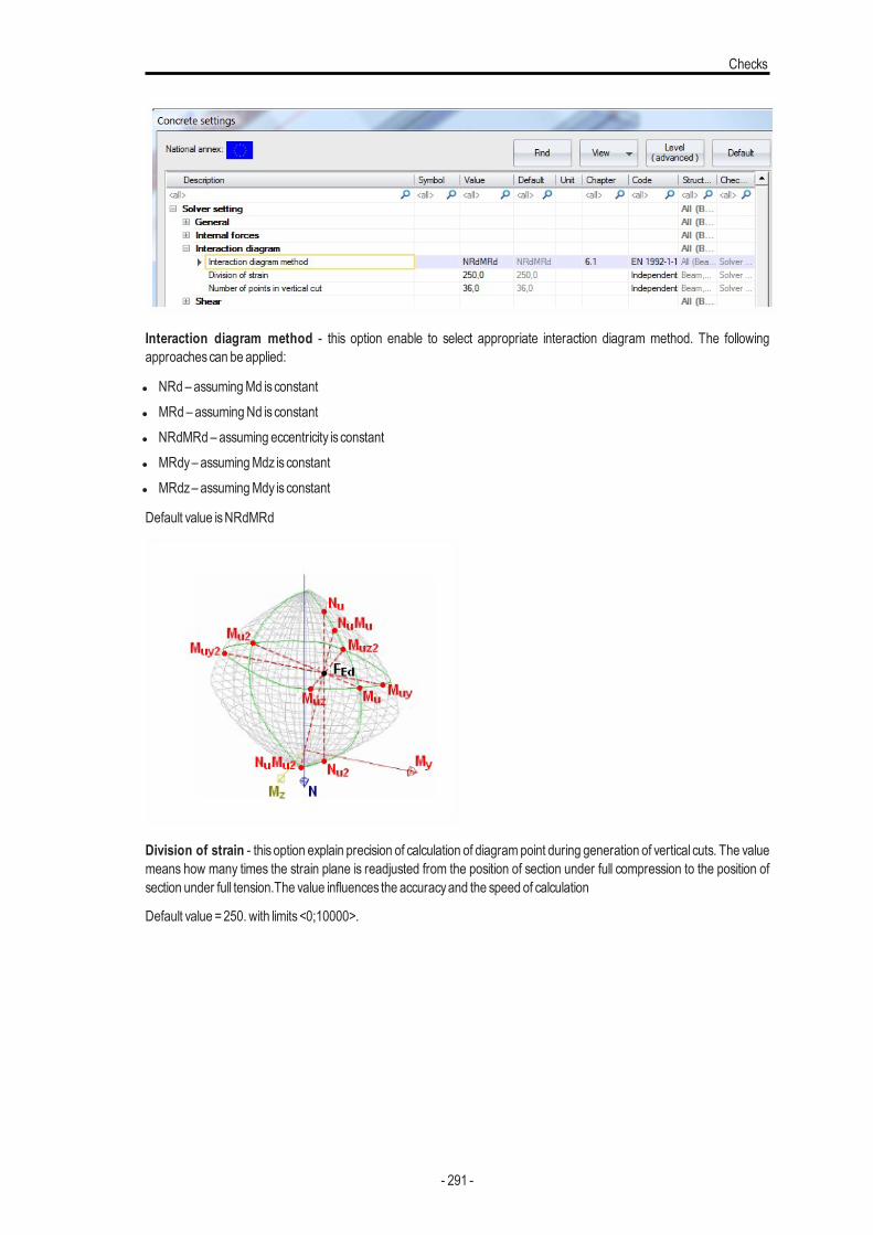
Checks
Interaction diagram method - this option enable to select appropriate interaction diagram method. The followingapproachescan be applied:
l NRd– assumingMd isconstantl MRd– assumingNd isconstantl NRdMRd– assuming eccentricity is constantl MRdy– assumingMdz isconstantl MRdz– assumingMdy isconstant
Default value isNRdMRd
Division of strain - thisoption explain precision of calculation of diagrampoint during generation of vertical cuts. The valuemeans how many times the strain plane is readjusted from the position of section under full compression to the position ofsection under full tension.The value influences the accuracyand the speed of calculation
Default value =250. with limits<0;10000>.
- 291 -
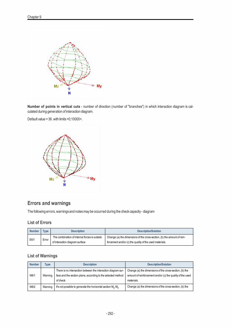
Chapter 9
Number of points in vertical cuts - number of direction (number of "branches") in which interaction diagram is cal-culated during generation of interaction diagram.
Default value =36. with limits<0;10000>.
Errors and warningsThe following errors, warningsand notesmaybe occurred during the checkcapacity - diagram
List of ErrorsNumber Type Description Description/Solution
E6/1 ErrorThe combination of internal forces is outsideof interaction diagram surface
Change (a) the dimensions of the cross-section, (b) the amount of rein-forcement and/or (c) the quality of the used materials.
List of WarningsNumber Type Description Description/Solution
W6/1 WarningThere is no intersection between the interaction diagram sur-face and the section plane, according to the selected methodof check.
Change (a) the dimensions of the cross-section, (b) theamount of reinforcement and/or (c) the quality of the usedmaterials.
W6/2 Warning It's not possible to generate the horizontal section My-Mz Change (a) the dimensions of the cross-section, (b) the
- 292 -
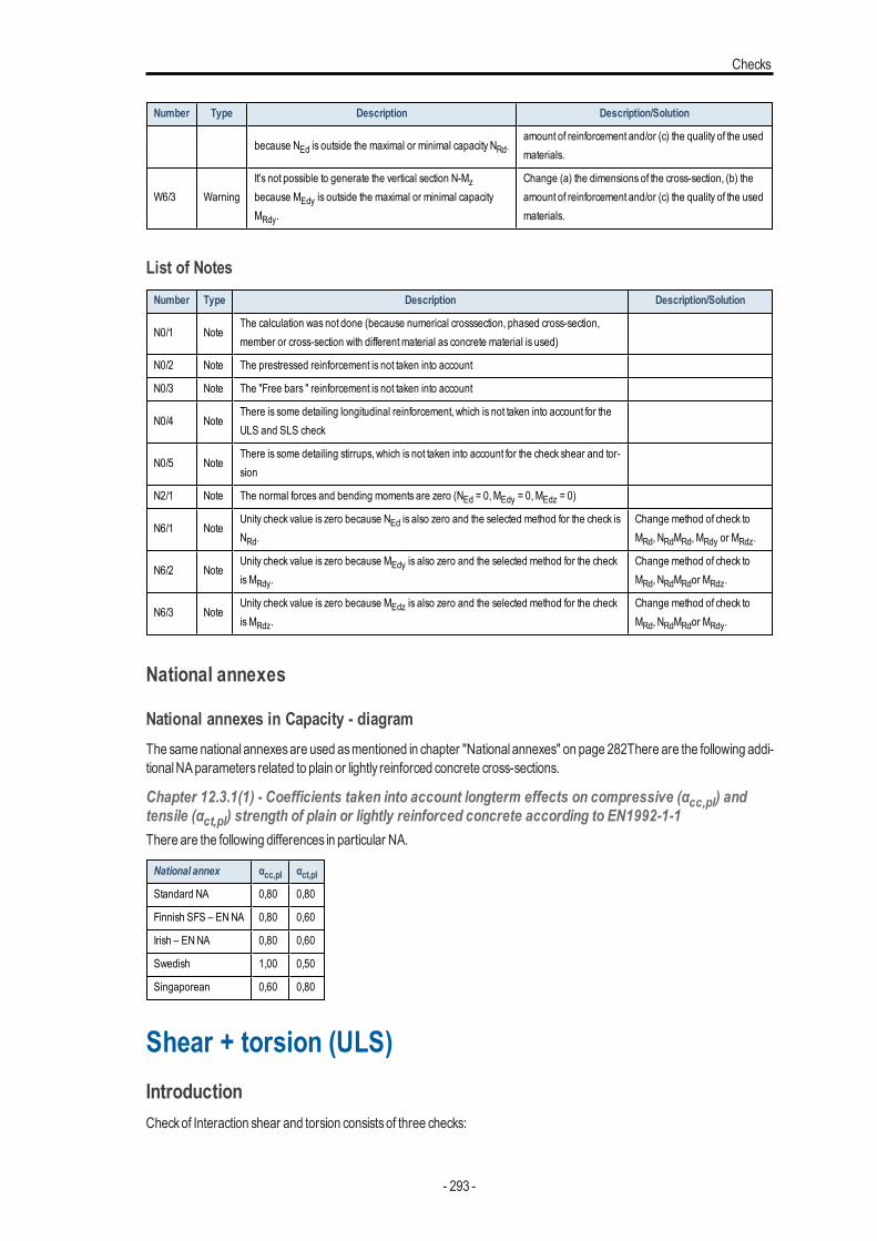
Checks
Number Type Description Description/Solution
because NEd is outside the maximal or minimal capacity NRd.amount of reinforcement and/or (c) the quality of the usedmaterials.
W6/3 WarningIt's not possible to generate the vertical section N-Mzbecause MEdy is outside the maximal or minimal capacityMRdy.
Change (a) the dimensions of the cross-section, (b) theamount of reinforcement and/or (c) the quality of the usedmaterials.
List of NotesNumber Type Description Description/Solution
N0/1 NoteThe calculation was not done (because numerical crosssection, phased cross-section,member or cross-section with differentmaterial as concrete material is used)
N0/2 Note The prestressed reinforcement is not taken into account
N0/3 Note The "Free bars " reinforcement is not taken into account
N0/4 NoteThere is some detailing longitudinal reinforcement, which is not taken into account for theULS and SLS check
N0/5 NoteThere is some detailing stirrups, which is not taken into account for the check shear and tor-sion
N2/1 Note The normal forces and bending moments are zero (NEd = 0,MEdy = 0,MEdz = 0)
N6/1 NoteUnity check value is zero because NEd is also zero and the selected method for the check isNRd.
Change method of check toMRd, NRdMRd, MRdy or MRdz.
N6/2 NoteUnity check value is zero because MEdy is also zero and the selected method for the checkisMRdy.
Change method of check toMRd, NRdMRdor MRdz.
N6/3 NoteUnity check value is zero because MEdz is also zero and the selected method for the checkisMRdz.
Change method of check toMRd, NRdMRdor MRdy.
National annexes
National annexes in Capacity - diagramThe samenational annexesare used asmentioned in chapter "National annexes" on page 282There are the following addi-tionalNAparameters related to plain or lightly reinforced concrete cross-sections.
Chapter 12.3.1(1) - Coefficients taken into account longterm effects on compressive (αcc,pl) andtensile (αct,pl) strength of plain or lightly reinforced concrete according to EN1992-1-1There are the following differences in particular NA.
National annex αcc,pl αct,plStandard NA 0,80 0,80
Finnish SFS – ENNA 0,80 0,60
Irish – ENNA 0,80 0,60
Swedish 1,00 0,50
Singaporean 0,60 0,80
Shear + torsion (ULS)IntroductionCheckof Interaction shear and torsion consistsof three checks:
- 293 -
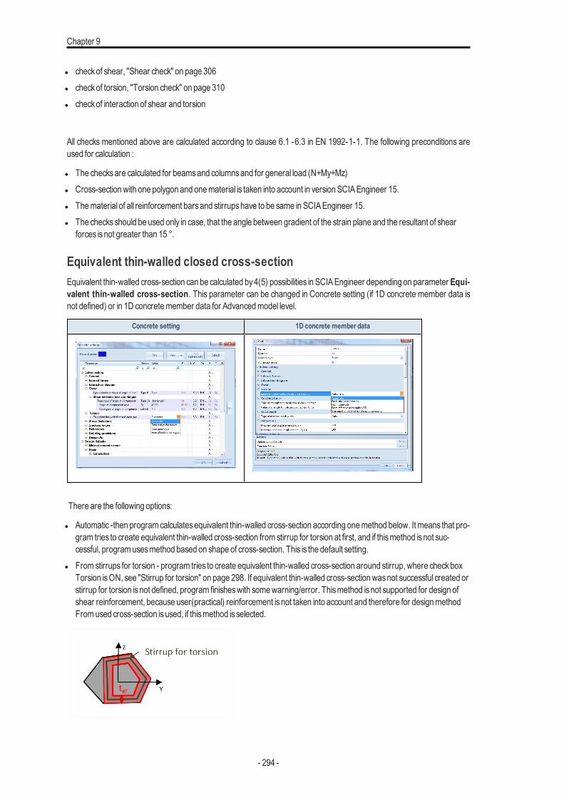
Chapter 9
l checkof shear, "Shear check" on page 306l checkof torsion, "Torsion check" on page 310l checkof interaction of shear and torsion
All checks mentioned above are calculated according to clause 6.1 -6.3 in EN 1992-1-1. The following preconditions areused for calculation :
l The checksare calculated for beamsand columnsand for general load (N+My+Mz)l Cross-sectionwith one polygon and onematerial is taken into account in version SCIAEngineer 15.l Thematerial of all reinforcement barsand stirrupshave to be same in SCIAEngineer 15.l The checksshould be used only in case, that the angle between gradient of the strain plane and the resultant of shear
forces isnot greater than 15 °.
Equivalent thin-walled closed cross-sectionEquivalent thin-walled cross-section can be calculated by4(5) possibilities in SCIAEngineer depending on parameter Equi-valent thin-walled cross-section. This parameter can be changed in Concrete setting (if 1D concrete member data isnot defined) or in 1D concretemember data for Advancedmodel level.
Concrete setting 1D concrete member data
There are the following options:
l Automatic -then programcalculatesequivalent thin-walled cross-section according onemethod below. It means that pro-gram tries to create equivalent thin-walled cross-section from stirrup for torsion at first, and if thismethod isnot suc-cessful, programusesmethod based on shape of cross-section. This is the default setting.
l Fromstirrups for torsion - program tries to create equivalent thin-walled cross-section around stirrup, where checkboxTorsion isON, see "Stirrup for torsion" on page 298. If equivalent thin-walled cross-sectionwasnot successful created orstirrup for torsion isnot defined, program finisheswith somewarning/error. Thismethod isnot supported for design ofshear reinforcement, because user(practical) reinforcement isnot taken into account and therefore for designmethodFromused cross-section isused, if thismethod isselected.
- 294 -
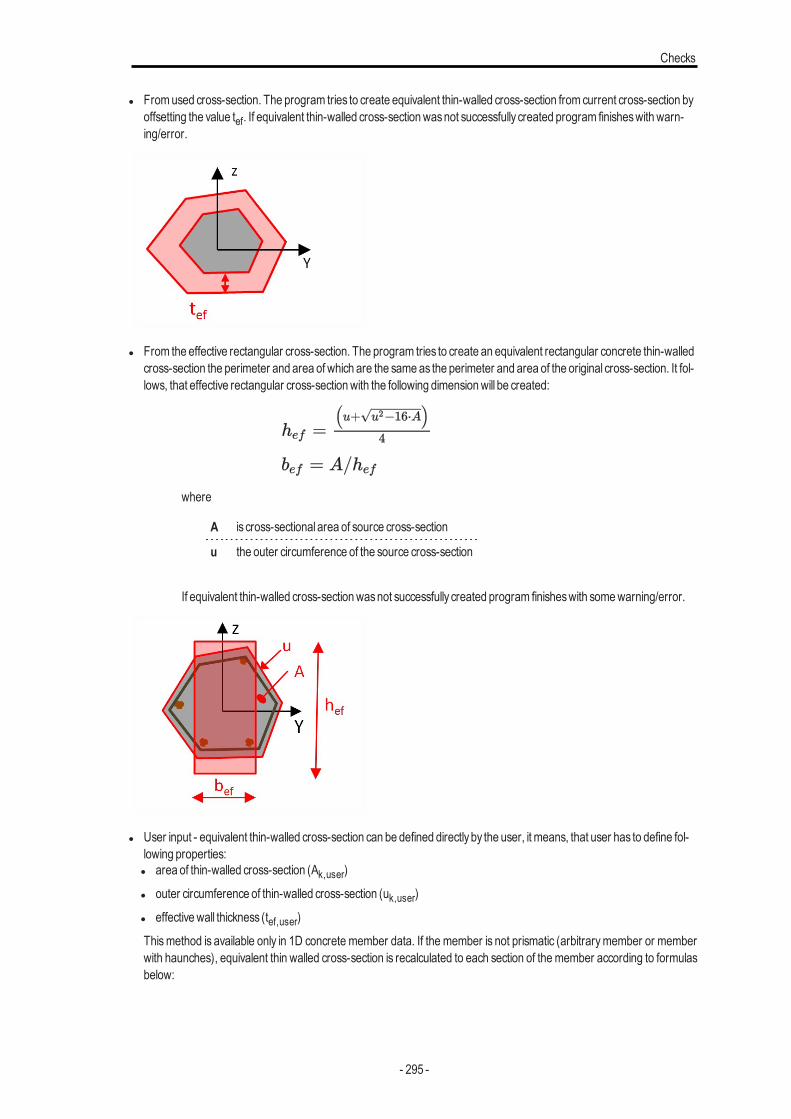
Checks
l Fromused cross-section. The program tries to create equivalent thin-walled cross-section from current cross-section byoffsetting the value tef. If equivalent thin-walled cross-sectionwasnot successfully created program finisheswith warn-ing/error.
l From the effective rectangular cross-section. The program tries to create an equivalent rectangular concrete thin-walledcross-section the perimeter and area of which are the sameas the perimeter and area of the original cross-section. It fol-lows, that effective rectangular cross-sectionwith the following dimensionwill be created:
where
A is cross-sectional area of source cross-section
u the outer circumference of the source cross-section
If equivalent thin-walled cross-sectionwasnot successfully created program finisheswith somewarning/error.
l User input - equivalent thin-walled cross-section can be defined directlyby the user, it means, that user has to define fol-lowing properties:l area of thin-walled cross-section (Ak,user)
l outer circumference of thin-walled cross-section (uk,user)
l effectivewall thickness (tef,user)
Thismethod is available only in 1D concrete member data. If the member is not prismatic (arbitrarymember or memberwith haunches), equivalent thin walled cross-section is recalculated to each section of the member according to formulasbelow:
- 295 -
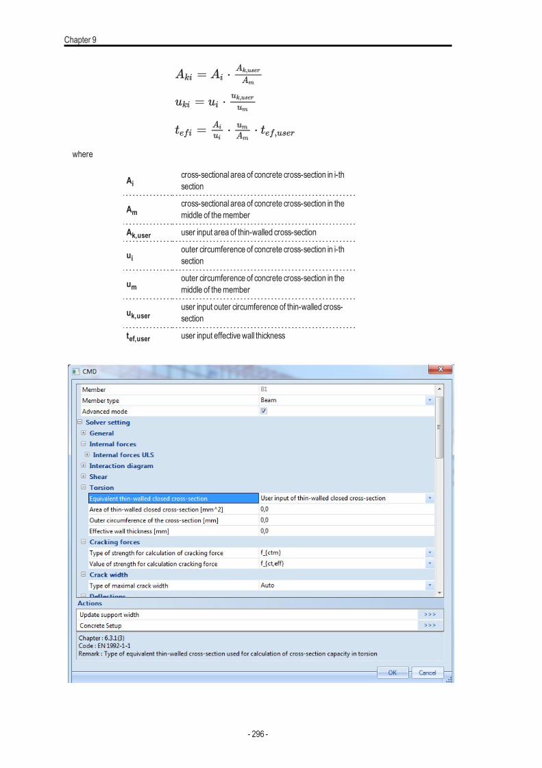
Chapter 9
where
Aicross-sectional area of concrete cross-section in i-thsection
Amcross-sectional area of concrete cross-section in themiddle of themember
Ak,user user input area of thin-walled cross-section
uiouter circumference of concrete cross-section in i-thsection
umouter circumference of concrete cross-section in themiddle of themember
uk,useruser input outer circumference of thin-walled cross-section
tef,user user input effectivewall thickness
- 296 -
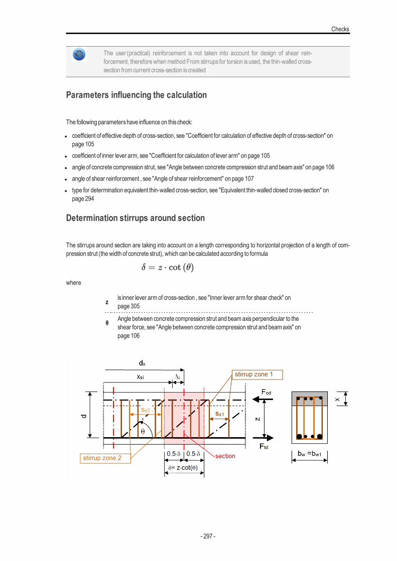
Checks
The user (practical) reinforcement is not taken into account for design of shear rein-forcement, therefore whenmethod From stirrups for torsion is used, the thin-walled cross-section from current cross-section is created
Parameters influencing the calculation
The following parametershave influence on this check:
l coefficient of effective depth of cross-section, see "Coefficient for calculation of effective depth of cross-section" onpage 105
l coefficient of inner lever arm, see "Coefficient for calculation of lever arm" on page 105l angle of concrete compression strut, see "Angle between concrete compression strut and beamaxis" on page 106l angle of shear reinforcement , see "Angle of shear reinforcement" on page 107l type for determination equivalent thin-walled cross-section, see "Equivalent thin-walled closed cross-section" on
page 294
Determination stirrups around section
The stirrups around section are taking into account on a length corresponding to horizontal projection of a length of com-pression strut (thewidth of concrete strut), which can be calculated according to formula
where
z is inner lever armof cross-section , see "Inner lever arm for shear check" onpage 305
θ Angle between concrete compression strut and beamaxisperpendicular to theshear force, see "Angle between concrete compression strut and beamaxis" onpage 106
- 297 -
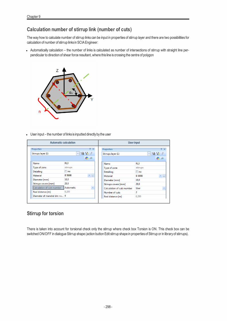
Chapter 9
Calculation number of stirrup link (number of cuts)The way how to calculate number of stirrup links can be input in properties of stirrup layer and there are two possibilities forcalculation of number of stirrup links in SCIAEngineer:
l Automatically calculation – the number of links is calculated as number of intersections of stirrup with straight line per-pendicular to direction of shear force resultant, where this line is crossing the centre of polygon
l User input – the number of links is inputted directlyby the user
Automatic calculation User input
Stirrup for torsion
There is taken into account for torsional check only the stirrup where check box Torsion is ON. This check box can beswitchedON/OFF in dialogueStirrup shape (action button Edit stirrup shape in propertiesof Stirrup or in libraryof stirrups).
- 298 -
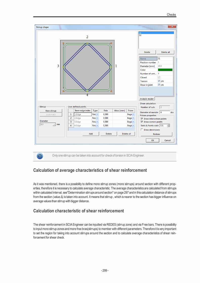
Checks
Onlyone stirrup can be taken into account for checkof torsion in SCIAEngineer.
Calculation of average characteristics of shear reinforcement
As it was mentioned, there is a possibility to define more stirrup zones (more stirrups) around section with different prop-erties, therefore it is necessary to calculate average characteristic. The average characteristics are calculated from stirrupswithin calculated interval, see"Determination stirrupsaround section" on page 297 and in this calculation distance of stirrupsfrom the section (value Δ) is taken into account. It means that stirrup , which is nearer to the section has bigger influence onaverage values than stirrupwith bigger distance.
Calculation characteristic of shear reinforcement
The shear reinforcement in SCIAEngineer can be inputted via REDES (stirrup zone) and via Free bars. There is possibilityto inputmore stirrup zonesandmore free bras(stirrups) tomember with different parameters. Therefore it is very importantto set the region for taking into account stirrups around the section and to calculate average characteristics of shear rein-forcement for shear check.
- 299 -
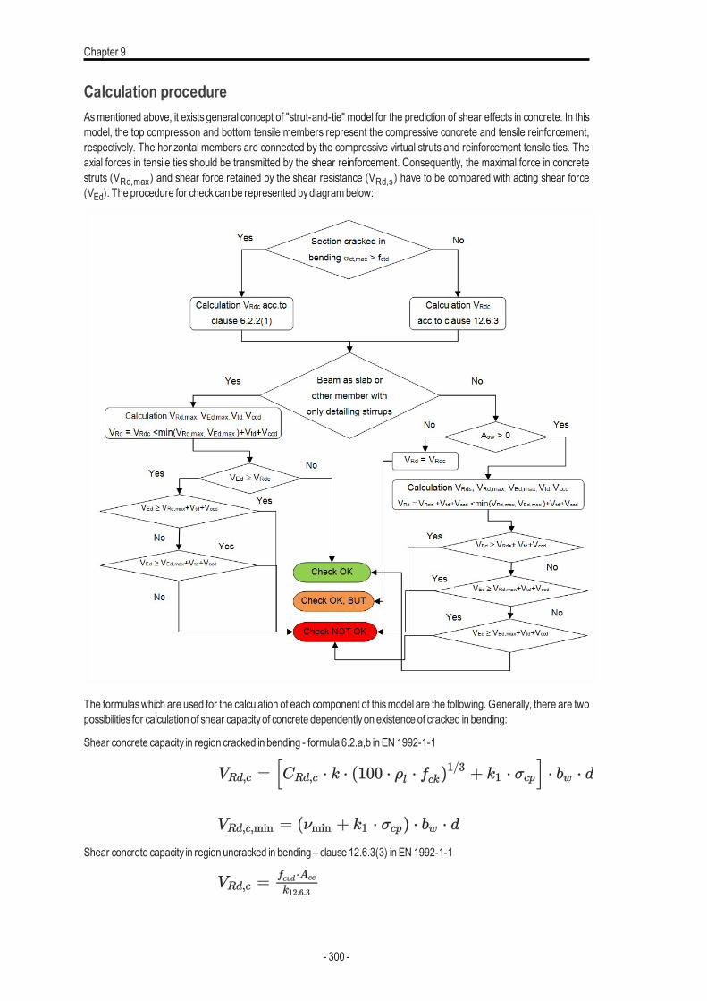
Chapter 9
Calculation procedureAsmentioned above, it exists general concept of "strut-and-tie" model for the prediction of shear effects in concrete. In thismodel, the top compression and bottom tensile members represent the compressive concrete and tensile reinforcement,respectively. The horizontal members are connected by the compressive virtual struts and reinforcement tensile ties. Theaxial forces in tensile ties should be transmitted by the shear reinforcement. Consequently, the maximal force in concretestruts (VRd,max) and shear force retained by the shear resistance (VRd,s) have to be compared with acting shear force(VEd). The procedure for checkcan be represented bydiagrambelow:
The formulaswhich are used for the calculation of each component of thismodel are the following. Generally, there are twopossibilities for calculation of shear capacityof concrete dependentlyon existence of cracked in bending:
Shear concrete capacity in region cracked in bending - formula 6.2.a,b in EN 1992-1-1
Shear concrete capacity in region uncracked in bending – clause 12.6.3(3) in EN 1992-1-1
- 300 -
Checks
Additionally, there is calculated maximal shear force (VEd,max) ) without reduction by β for member where load is applied inthe upper side of themember (see formula 6.5 in EN 1992-1-1).
Maximal capacity of concrete compressive strut (VRd,max ) is determined according to formula 6.9 in EN 1992-1-1, becauseashasbeenmentioned before, the angle of stirrups (θ) isalwaysperpendicular tomember axis.
Design value of shear force sustained byshear reinforcement (VRd,s ) is calculated according to formula 6.13 in EN 1992-1-1
Final design value of shear force (VRd ) carried bymember is calculated based on the following formulasdepending on typeofmember and area of shear reinforcement.
l for beamasslab and for other member with onlydetailing stirrups (Asw =0)
l for other cases
where
VEd
resultant of shear force
VEd,y(z) shear force in direction of y(z)-axisof LCS
VRd,c the design shear resistance of themember without shear reinforcement
σct,max maximal tensile strength in uncracked cross-section
VRd,c,min
theminimal value of design shear resistance of themember without shearreinforcement
CRd,c coefficient for calculation VRd,c loaded fromManager for National annexes
k
coefficient of effective height of cross-section
ρl
ratio of tensile reinforcement
fck characteristic compressive cylinder strength of concrete
k1 coefficient for calculation VRd,c loaded fromManager for National annexes
σcp stresscaused byaxial force (NEd>0 for compression)
- 301 -
Chapter 9
bwthe smallest width of the cross-section in tensile area of cross-section per-pendicular to direction of resultant shear force, see "Width of cross-sectionfor shear check" on page 304
d effective depth of cross-section recalculated to direction of shear forces res-ultant, see "Effective depth of cross-section for shear check" on page 304
Asl tensile area of reinforcement
NEd the axial force in the cross-section due to loading or prestressing.
Ac the area of concrete crosssection
fcd design value of concrete compressive strength
νmin
Coefficient ofminimumvalue of shear resistance of themember withoutshear reinforcement loaded fromManager for National annexes,see equa-tion 6.3N in EN 1992-1-1
fcvd
the concrete design strength in shear and compression, see equations12.5and 12.6 in EN 1992-1-1
fctd design axial tensile strength of concrete
σccp
normal (axial)stressof uncracked cross-section
σc,lim
limit value of stresscaused byaxial force,see equations12.7 in EN 1992-1-1
Acc compressed concrete area for uncracked cross-section
VEd,maxmaximumvalue of shear force resultant calculatedwithout reduction bycoefficientβ , see clause 6.2.2(6) in EN 1992-1-1
bw1minimumwidth of cross-section between tension and compression chordperpendicular to direction of shear force, see "Width of cross-section forshear check" on page 304
ν strength reduction factor for concrete cracked in shear loaded fromMan-ager for National annexes, see equation 6.6N in EN 1992-1-1
VRd,maxthe design value of themaximumshear forcewhich can be sustained by themember, limited bycrushing of the compression struts
αcwcoefficient taking into account state of the stress in the compression chord,see note 3 in clause 6.2.3(3) in EN 1992-1-1. The value 1 isalways takeninto account for non -prestressed structures
- 302 -
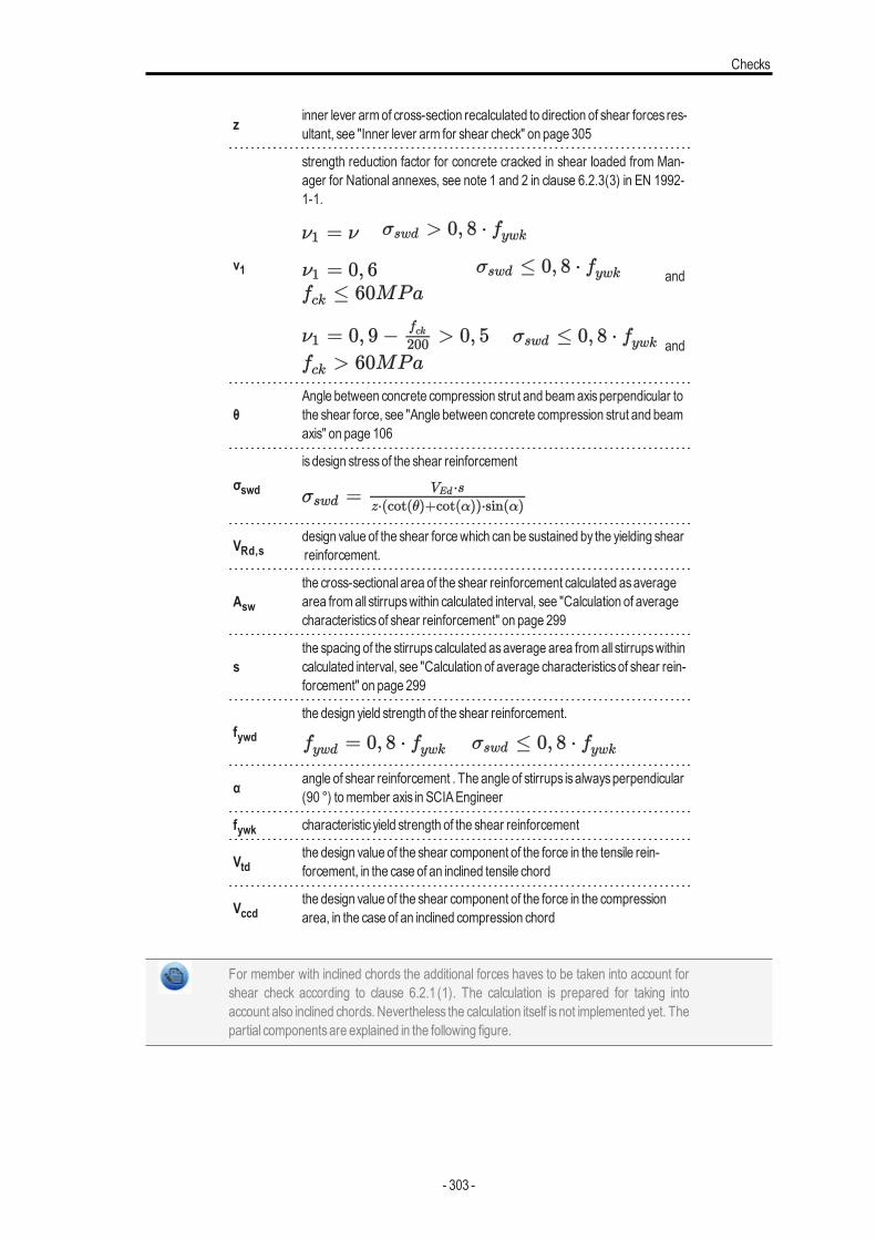
Checks
z inner lever armof cross-section recalculated to direction of shear forces res-ultant, see "Inner lever arm for shear check" on page 305
ν1
strength reduction factor for concrete cracked in shear loaded from Man-ager for National annexes, see note 1 and 2 in clause 6.2.3(3) in EN 1992-1-1.
and
and
θAngle between concrete compression strut and beamaxisperpendicular tothe shear force, see "Angle between concrete compression strut and beamaxis" on page 106
σswd
is design stressof the shear reinforcement
VRd,sdesign value of the shear forcewhich can be sustained by the yielding shearreinforcement.
Aswthe cross-sectional area of the shear reinforcement calculated asaveragearea fromall stirrupswithin calculated interval, see "Calculation of averagecharacteristicsof shear reinforcement" on page 299
sthe spacing of the stirrupscalculated asaverage area fromall stirrupswithincalculated interval, see "Calculation of average characteristicsof shear rein-forcement" on page 299
fywdthe design yield strength of the shear reinforcement.
α angle of shear reinforcement . The angle of stirrups isalwaysperpendicular(90 °) tomember axis in SCIAEngineer
fywk characteristic yield strength of the shear reinforcement
Vtdthe design value of the shear component of the force in the tensile rein-forcement, in the case of an inclined tensile chord
Vccdthe design value of the shear component of the force in the compressionarea, in the case of an inclined compression chord
For member with inclined chords the additional forces haves to be taken into account forshear check according to clause 6.2.1 (1). The calculation is prepared for taking intoaccount also inclined chords. Nevertheless the calculation itself is not implemented yet. Thepartial componentsare explained in the following figure.
- 303 -
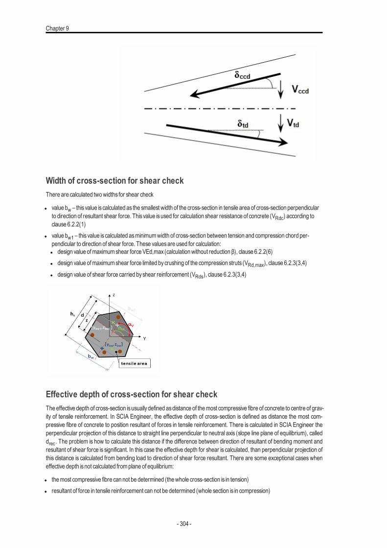
Chapter 9
Width of cross-section for shear checkThere are calculated twowidths for shear check
l value bw – this value is calculated as the smallest width of the cross-section in tensile area of cross-section perpendicularto direction of resultant shear force. This value isused for calculation shear resistance of concrete (VRdc) according toclause 6.2.2(1)
l value bw1 – this value is calculated asminimumwidth of cross-section between tension and compression chord per-pendicular to direction of shear force. These valuesare used for calculation:l design value ofmaximumshear force VEd,max (calculationwithout reduction β), clause 6.2.2(6)l design value ofmaximumshear force limited bycrushing of the compression struts (VRd,max), clause 6.2.3(3,4)
l design value of shear force carried byshear reinforcement (VRds), clause 6.2.3(3,4)
Effective depth of cross-section for shear checkThe effective depth of cross-section isusuallydefined asdistance of themost compressive fibre of concrete to centre of grav-ity of tensile reinforcement. In SCIA Engineer, the effective depth of cross-section is defined as distance the most com-pressive fibre of concrete to position resultant of forces in tensile reinforcement. There is calculated in SCIA Engineer theperpendicular projection of this distance to straight line perpendicular to neutral axis (slope line plane of equilibrium), calleddrec. The problem is how to calculate this distance if the difference between direction of resultant of bending moment andresultant of shear force is significant. In this case the effective depth for shear is calculated, than perpendicular projection ofthis distance is calculated from bending load to direction of shear force resultant. There are some exceptional cases wheneffective depth isnot calculated fromplane of equilibrium:
l themost compressive fibre can not be determined (thewhole cross-section is in tension)l resultant of force in tensile reinforcement can not be determined (whole section is in compression)
- 304 -
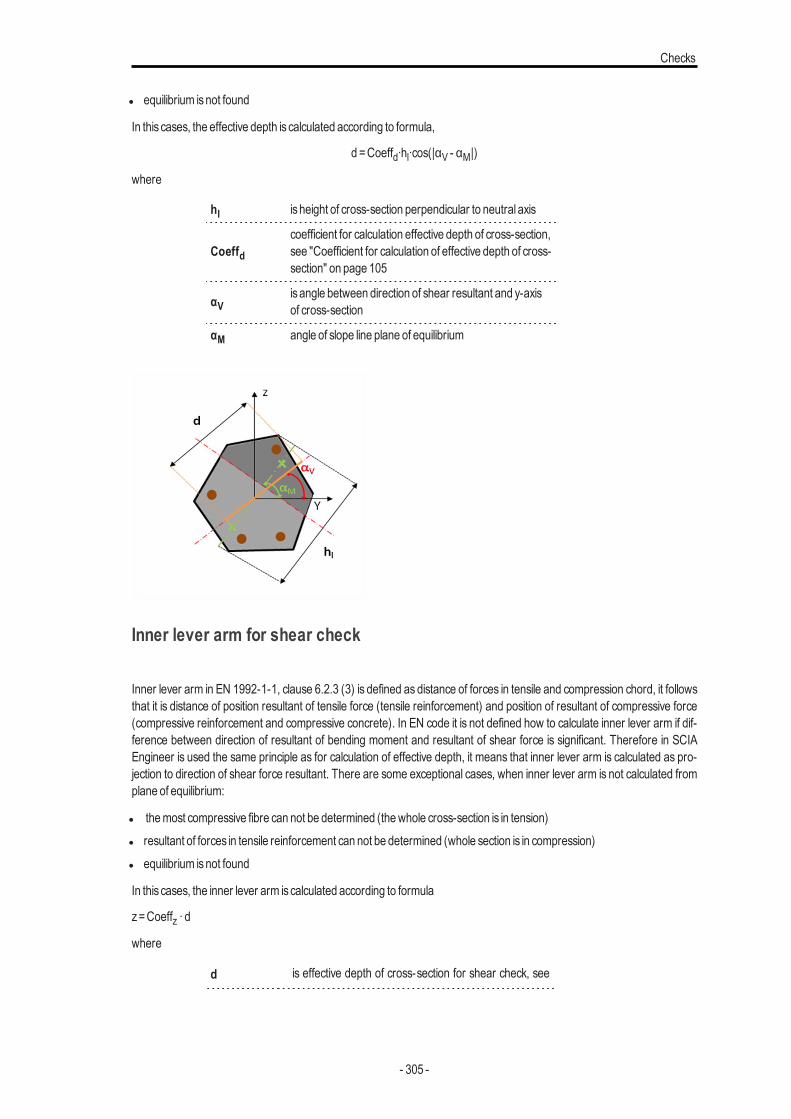
Checks
l equilibrium isnot found
In this cases, the effective depth is calculated according to formula,
d =Coeffd∙hl∙cos(|αV - αM|)
where
hl is height of cross-section perpendicular to neutral axis
Coeffdcoefficient for calculation effective depth of cross-section,see "Coefficient for calculation of effective depth of cross-section" on page 105
αVis angle between direction of shear resultant and y-axisof cross-section
αM angle of slope line plane of equilibrium
Inner lever arm for shear check
Inner lever arm in EN 1992-1-1, clause 6.2.3 (3) is defined as distance of forces in tensile and compression chord, it followsthat it is distance of position resultant of tensile force (tensile reinforcement) and position of resultant of compressive force(compressive reinforcement and compressive concrete). In EN code it is not defined how to calculate inner lever arm if dif-ference between direction of resultant of bending moment and resultant of shear force is significant. Therefore in SCIAEngineer is used the same principle as for calculation of effective depth, it means that inner lever arm is calculated as pro-jection to direction of shear force resultant. There are some exceptional cases, when inner lever arm is not calculated fromplane of equilibrium:
l themost compressive fibre can not be determined (thewhole cross-section is in tension)l resultant of forces in tensile reinforcement can not be determined (whole section is in compression)l equilibrium isnot found
In this cases, the inner lever arm iscalculated according to formula
z=Coeffz ∙ d
where
d is effective depth of cross-section for shear check, see
- 305 -
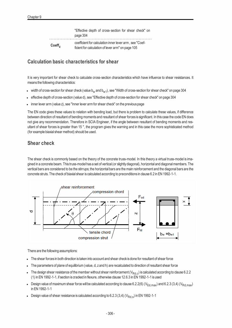
Chapter 9
"Effective depth of cross- section for shear check" onpage 304
Coeffzcoefficient for calculation inner lever arm , see "Coef-ficient for calculation of lever arm" on page 105
Calculation basic characteristics for shear
It is very important for shear check to calculate cross-section characteristics which have influence to shear resistances. Itmeans the following characteristics:
l width of cross-section for shear check (value bw and bw1), see "Width of cross-section for shear check" on page 304
l effective depth of cross-section (value d), see "Effective depth of cross-section for shear check" on page 304l inner lever arm (value z), see "Inner lever arm for shear check" on the previouspage
The EN code gives these values to relation with bending load, but there is problem to calculate these values, if differencebetween direction of resultant of bendingmomentsand resultant of shear forces is significant. In this case the code EN doesnot give any recommendation. Therefore in SCIA Engineer, if the angle between resultant of bending moments and res-ultant of shear forces is greater than 15 °, the program gives the warning and in this case the more sophisticated method(for example biaxial shear method) should be used.
Shear check
The shear check is commonly based on the theory of the concrete truss-model. In this theory a virtual truss-model is ima-gined in a concrete beam. This truss-model hasa set of vertical (or slightlydiagonal), horizontal and diagonalmembers. Thevertical bars are considered to be the stirrups; the horizontal bars are themain reinforcement and the diagonal bars are theconcrete struts. The checkof biaxial shear is calculated according to preconditions in clause 6.2 in EN 1992-1-1.
There are the following assumptions:
l The shear forces in both direction is taken into account and shear check isdone for resultant of shear forcel The parametersof plane of equilibrium (value, d, zand h) are recalculated to direction of resultant shear forcel The design shear resistance of themember without shear reinforcement (VRd,c) is calculated according to clause 6.2.2
(1) in EN 1992-1-1, if section is cracked in flexure, otherwise clause 12.6.3 in EN 1992-1-1 isusedl Design value ofmaximumshear forcewill be calculated according to clause 6.2.2(6) (VEd,max) and 6.2.3 (3,4) (VRd,max)
in EN 1992-1-1l Design value of shear resistance iscalculated according to 6.2.3 (3,4) (VRd,s) in EN 1992-1-1
- 306 -
Checks
l The number of shear linkcan be calculated automaticallyor defined byuser (in propertiesof stirrup zone), see "Cal-culation number of stirrup link (number of cuts)" on page 298
l The angle of compression strut can be calculated automaticallyor defined byuser, see "Angle between concrete com-pression strut and beamaxis" on page 106
l The angle of stirrups for check isalwaysperpendicular tomember axis.
With the following limitations:
l Inclined compression chord or inclined tensile chord are not taken into accountl Thewidth of cross-section for shear checks (value bw and bw1) are calculated automatically. There isno possibility to
define user value in SCIAEngineerl Free bars reinforcement isnot taken into accountl The area of longitudinal reinforcement isnot subtracted from concrete area
Calculation procedure
Asmentioned above, there exists general concept of “strut-and-tie” model for the prediction of torsional effects in concrete.In this model, the top compression and bottom tensile members represent the compressive concrete and tensile rein-forcement, respectively. The horizontalmembersare connected by the compressive virtual struts and reinforcement tensileties. Consequently, themaximumof torsional resistancemoment carried byconcrete strut (TRd,max) and torsionalmomentretained by the torsional resistance (TRd,s) have to be compared with acting torsional moment TEd). The procedure forcheckcan be represented bydiagrambelow:
- 307 -
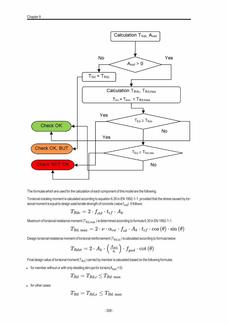
Chapter 9
The formulaswhich are used for the calculation of each component of thismodel are the following.
Torsional crackingmoment is calculated according to equation 6.26 in EN 1992-1-1 ,provided that the stress caused by tor-sionalmoment isequal to design axial tensile strength of concrete (value fctd). It follows:
Maximumof torsional resistancemoment (TRd,max ) isdetermined according to formula 6.30 in EN 1992-1-1.
Design torsional resistancemoment of torsional reinforcement (TRd,st ) is calculated according to formula below
Final design value of torsionalmoment(TRd ) carried bymember is calculated based on the following formulas
l for member without or with onlydetailing stirrups for torsion(Aswt =0)
l for other cases
- 308 -
Checks
where
TEd torsionalmoment
TRd,c the design value of torsional crackingmoment
tef effectivewall thickness, see "Calculation of basic characteristics" below
Ak
the area enclosed by the centre-lines of the thin-walled closed cross-sec-tion, including inner
hollow areas, see "Calculation of basic characteristics" below
fctd design axial tensile strength of concrete
TRd,max Maximumof torsional resistancemoment
αcwcoefficient taking into account state of the stress in the compressionchord, see note 3 in clause 6.2.3(3) in EN 1992-1-1. The value 1 isalways taken into account for non -prestressed structures
ν strength reduction factor for concrete cracked in shear loaded fromMan-ager for National annexes, see equation 6.6N in EN 1992-1-1
fcd design value of concrete compressive strength
θAngle between concrete compression strut and beamaxisperpendicularto the shear force, see "Angle between concrete compression strut andbeamaxis" on page 106
TRd,st design torsional resistancemoment of torsional reinforcement
Aswtthe cross-sectional area of the torsional reinforcement calculated asaver-age area fromall stirrups for torsionwithin calculated interval, see "Cal-culation of average characteristicsof shear reinforcement" on page 299
stthe spacing of the stirrupscalculated asaverage area fromall stirrups fortorsionwithin calculated interval, see "Calculation of average char-acteristicsof shear reinforcement" on page 299
fywd the design yield strength of the shear reinforcement.
Calculation of basic characteristics
The torsional resistance of sections is calculated on the basis of a thin-walled closed section, even if the section is actuallysolid. For solid members, the section is idealized as a thin-walled section. There are several options for generation of thin -walled cross-section in SCIAEngineer, see "Equivalent thin-walled closed cross-section" on page 294
- 309 -
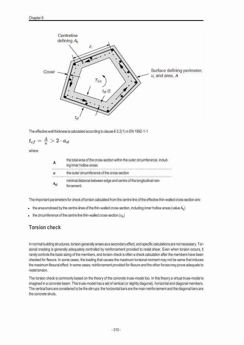
Chapter 9
The effectivewall thickness is calculated according to clause 6.3.2(1) in EN 1992-1-1
where
A the total area of the cross-sectionwithin the outer circumference, includ-ing inner hollow areas
u the outer circumference of the cross-section
aslminimal distance between edge and centre of the longitudinal rein-forcement.
The important parameters for checkof torsion calculated from the centre line of the effective thin-walled cross-section are:
l the area enclosed by the centre-linesof the thin-walled cross-section, including inner hollow areas (value Ak)
l the circumference of the centre line thin-walled cross-section (uk)
Torsion check
In normal building structures, torsion generallyarisesasa secondaryeffect, and specific calculationsare not necessary. Tor-sional cracking is generally adequately controlled by reinforcement provided to resist shear. Even when torsion occurs, itrarely controls the basic sizing of the members, and torsion check is often a check calculation after the members have beenchecked for flexure. In some cases, the loading that causes the maximum torsional moment may not be same that inducesthemaximum flexural effect. In some cases, reinforcement provided for flexure and the other forcesmayprove adequate toresist torsion.
The torsion check is commonly based on the theory of the concrete truss-model too. In this theory a virtual truss-model isimagined in a concrete beam. This truss-model has a set of vertical (or slightly diagonal), horizontal and diagonalmembers.The vertical barsare considered to be the stirrups; the horizontal barsare themain reinforcement and the diagonal barsarethe concrete struts.
- 310 -
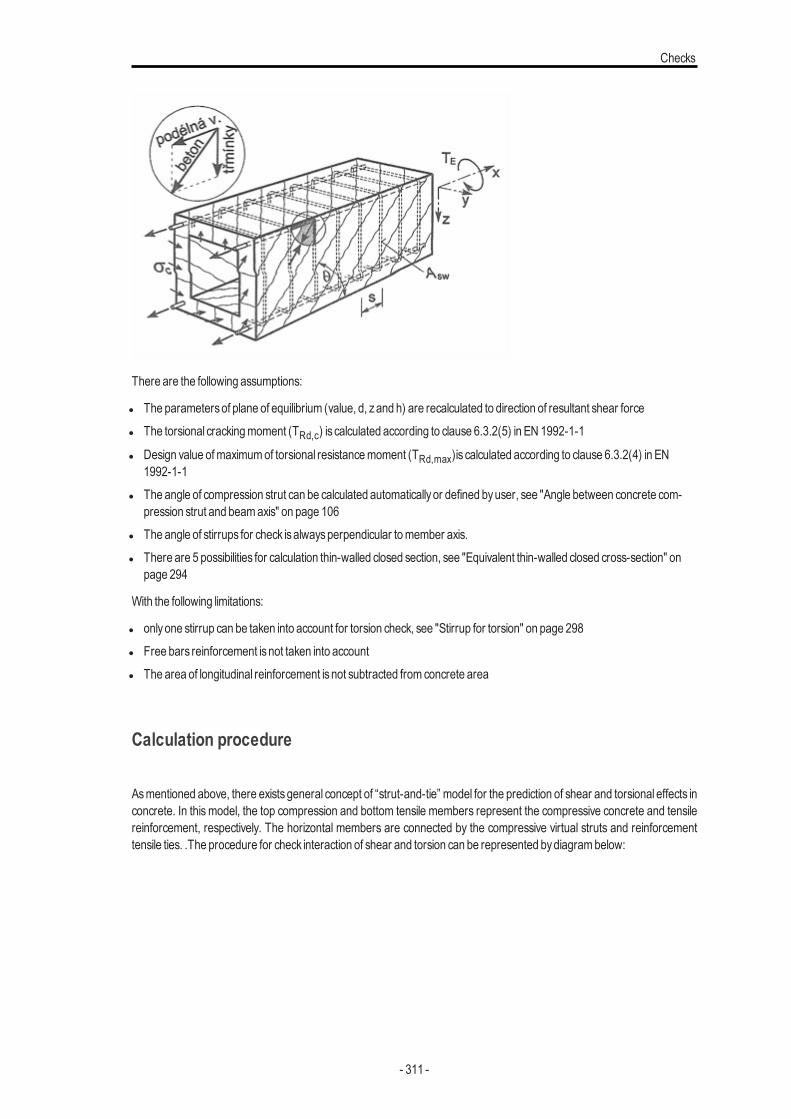
Checks
There are the following assumptions:
l The parametersof plane of equilibrium (value, d, zand h) are recalculated to direction of resultant shear forcel The torsional crackingmoment (TRd,c) is calculated according to clause 6.3.2(5) in EN 1992-1-1
l Design value ofmaximumof torsional resistancemoment (TRd,max)is calculated according to clause 6.3.2(4) in EN1992-1-1
l The angle of compression strut can be calculated automaticallyor defined byuser, see "Angle between concrete com-pression strut and beamaxis" on page 106
l The angle of stirrups for check isalwaysperpendicular tomember axis.l There are 5 possibilities for calculation thin-walled closed section, see "Equivalent thin-walled closed cross-section" on
page 294
With the following limitations:
l onlyone stirrup can be taken into account for torsion check, see "Stirrup for torsion" on page 298l Free bars reinforcement isnot taken into accountl The area of longitudinal reinforcement isnot subtracted from concrete area
Calculation procedure
Asmentioned above, there exists general concept of “strut-and-tie” model for the prediction of shear and torsional effects inconcrete. In this model, the top compression and bottom tensile members represent the compressive concrete and tensilereinforcement, respectively. The horizontal members are connected by the compressive virtual struts and reinforcementtensile ties. .The procedure for check interaction of shear and torsion can be represented bydiagrambelow:
- 311 -
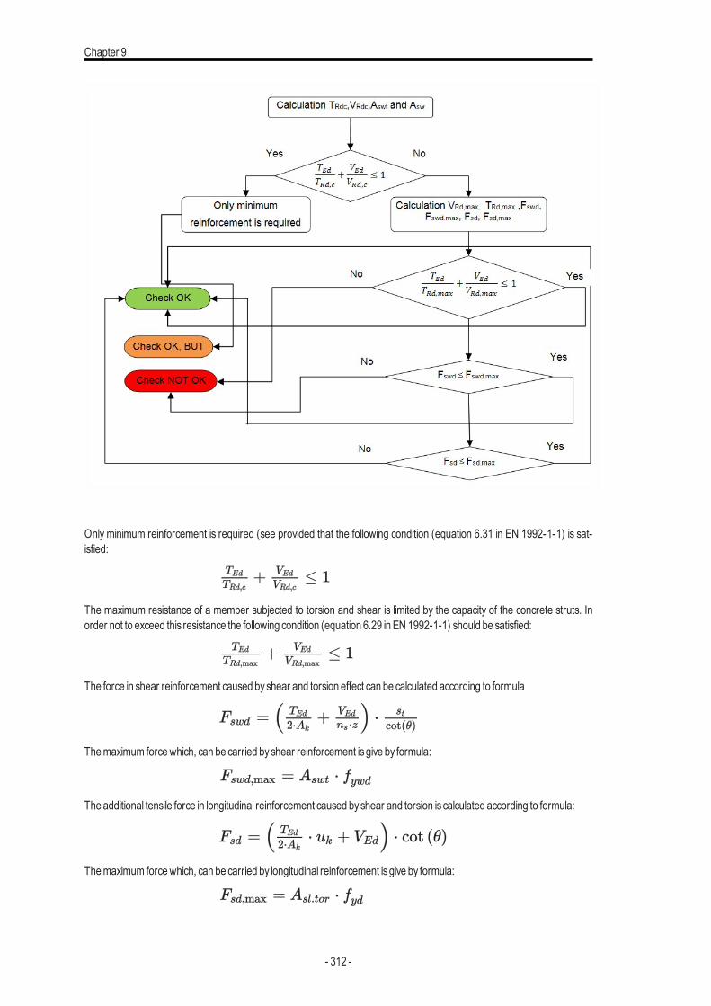
Chapter 9
Only minimum reinforcement is required (see provided that the following condition (equation 6.31 in EN 1992-1-1) is sat-isfied:
The maximum resistance of a member subjected to torsion and shear is limited by the capacity of the concrete struts. Inorder not to exceed this resistance the following condition (equation 6.29 in EN 1992-1-1) should be satisfied:
The force in shear reinforcement caused byshear and torsion effect can be calculated according to formula
Themaximum forcewhich, can be carried byshear reinforcement isgive by formula:
The additional tensile force in longitudinal reinforcement caused byshear and torsion is calculated according to formula:
Themaximum forcewhich, can be carried by longitudinal reinforcement isgive by formula:
- 312 -
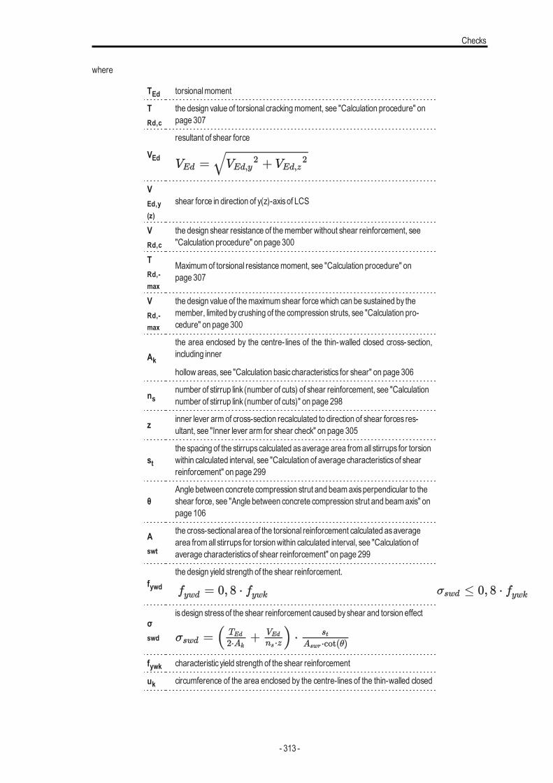
Checks
where
TEd torsionalmoment
TRd,c
the design value of torsional crackingmoment, see "Calculation procedure" onpage 307
VEd
resultant of shear force
VEd,y(z)
shear force in direction of y(z)-axisof LCS
VRd,c
the design shear resistance of themember without shear reinforcement, see"Calculation procedure" on page 300
TRd,-max
Maximumof torsional resistancemoment, see "Calculation procedure" onpage 307
VRd,-max
the design value of themaximumshear forcewhich can be sustained by themember, limited bycrushing of the compression struts, see "Calculation pro-cedure" on page 300
Ak
the area enclosed by the centre- lines of the thin-walled closed cross-section,including inner
hollow areas, see "Calculation basic characteristics for shear" on page 306
nsnumber of stirrup link (number of cuts) of shear reinforcement, see "Calculationnumber of stirrup link (number of cuts)" on page 298
z inner lever armof cross-section recalculated to direction of shear forces res-ultant, see "Inner lever arm for shear check" on page 305
stthe spacing of the stirrupscalculated asaverage area fromall stirrups for torsionwithin calculated interval, see "Calculation of average characteristicsof shearreinforcement" on page 299
θAngle between concrete compression strut and beamaxisperpendicular to theshear force, see "Angle between concrete compression strut and beamaxis" onpage 106
Aswt
the cross-sectional area of the torsional reinforcement calculated asaveragearea fromall stirrups for torsionwithin calculated interval, see "Calculation ofaverage characteristicsof shear reinforcement" on page 299
fywdthe design yield strength of the shear reinforcement.
σswd
is design stressof the shear reinforcement caused byshear and torsion effect
fywk characteristic yield strength of the shear reinforcement
uk circumference of the area enclosed by the centre-lines of the thin-walled closed
- 313 -
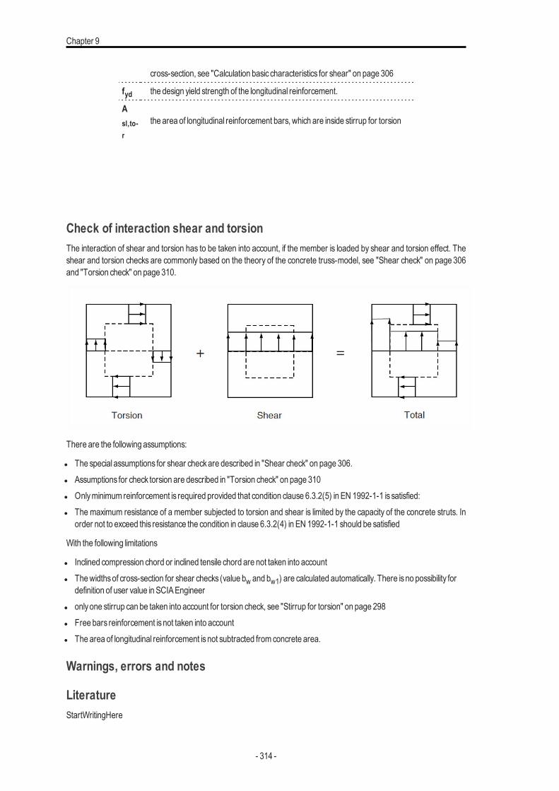
Chapter 9
cross-section, see "Calculation basic characteristics for shear" on page 306
fyd the design yield strength of the longitudinal reinforcement.
Asl,to-r
the area of longitudinal reinforcement bars, which are inside stirrup for torsion
Check of interaction shear and torsionThe interaction of shear and torsion has to be taken into account, if the member is loaded by shear and torsion effect. Theshear and torsion checks are commonly based on the theory of the concrete truss-model, see "Shear check" on page 306and "Torsion check" on page 310.
There are the following assumptions:
l The special assumptions for shear checkare described in "Shear check" on page 306.l Assumptions for check torsion are described in "Torsion check" on page 310l Onlyminimum reinforcement is required provided that condition clause 6.3.2(5) in EN 1992-1-1 is satisfied:l The maximum resistance of a member subjected to torsion and shear is limited by the capacity of the concrete struts. In
order not to exceed this resistance the condition in clause 6.3.2(4) in EN 1992-1-1 should be satisfied
With the following limitations
l Inclined compression chord or inclined tensile chord are not taken into accountl Thewidthsof cross-section for shear checks (value bw and bw1) are calculated automatically. There isno possibility for
definition of user value in SCIAEngineerl onlyone stirrup can be taken into account for torsion check, see "Stirrup for torsion" on page 298l Free bars reinforcement isnot taken into accountl The area of longitudinal reinforcement isnot subtracted from concrete area.
Warnings, errors and notes
LiteratureStartWritingHere
- 314 -
Checks
Stress limitations (SLS)
IntroductionStress limitation (SLS) check is based on the calculation of stresses in particular component (concrete fibre, reinforcementbar) and comparison with limited valueswith respect of EN 1992-1-1 requirements. Based on the internal forces, concretecross-section and reinforcement defined by the user, SCIAEngineer isable to calculate the plain of equilibrium of amemberor a single cross-section and find the actual value of stresses in each component.
Generally, stress limitation from the point of the serviceability limit state isbased on the verification of the following states:
l compressive stress in concrete - the high value of compressive stress in concrete could lead to appearance of lon-gitudinal cracks, spreading ofmicro-cracks in concrete and higher valuesof creep (mainlynon linear) . Thiseffect can ledto statewhen the structure isunusable.
l tensile stress in reinforcement - stress in reinforcement is verified due to limitation of unacceptable strain existenceand thusappearance of cracks in concrete .
The method described in chapter "Theoretical background" on page 273 is used for determination of the plane of the equi-librium. There are used different stress-strain diagrams towards the Capacity- response (ULS). Stress-strain diagramsbased on the serviceability limit state are used for the finding of the plain of the equilibrium. This check provides the cal-culation of the stresses in particular components for each state of cross-section.
Generally, this check uses the iterative method for the interaction of the normal force (N) with uni-axial or bi-axial bendingmoments (My + Mz ). Additionally, there is possibility to calculate stresses for short- term or long- term stiffness which isapplied viamodified stress-strain diagram.
Assumption and limitations
There are the following assumptions:
l Strain and stressof diagramdefined in propertiesofmaterialwill be used
l Concrete – linear stress-strain diagramdependent on:l type of E-modulus - short-term (Ec) or long-term (Ec,eff) E-modulus for preparation of stress-strain dia-
graml cracking of the cross-section
l un-cracked cross-section - stress-strain diagramwith tensile concrete is consideredl cracked cross-section - stress-strain diagramwithout tensile concrete is considered
l Reinforcement – linear stress-strain diagramwith tensile branch
l StandardREDES reinforcement is considered
With the following limitations
l The area of longitudinal reinforcement isnot subtracted from concrete area in the first step
As an example the preparation of the stress-strain diagram for C25/30 (fck = 25 MPa, Ec = 31 GPa) is visible from the fol-lowing figures.
Concrete SLSshort-termuncracked
- 315 -
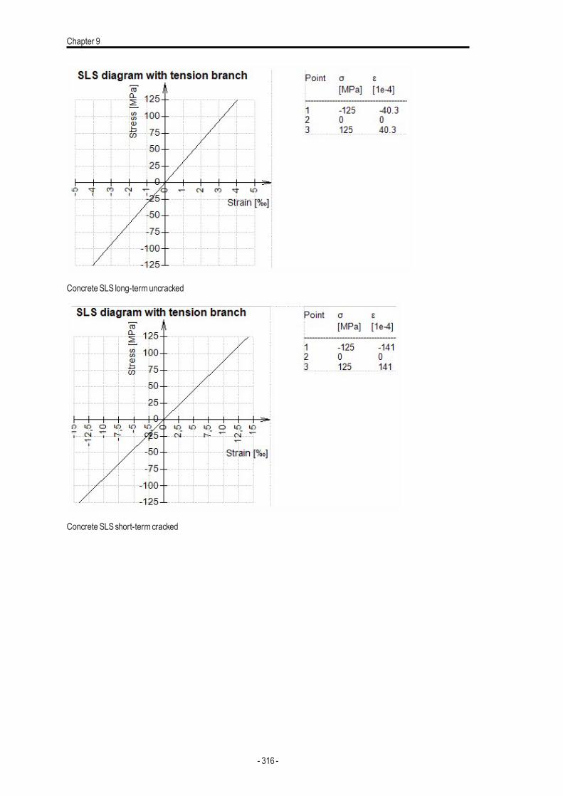
Chapter 9
Concrete SLS long-termuncracked
Concrete SLSshort-term cracked
- 316 -
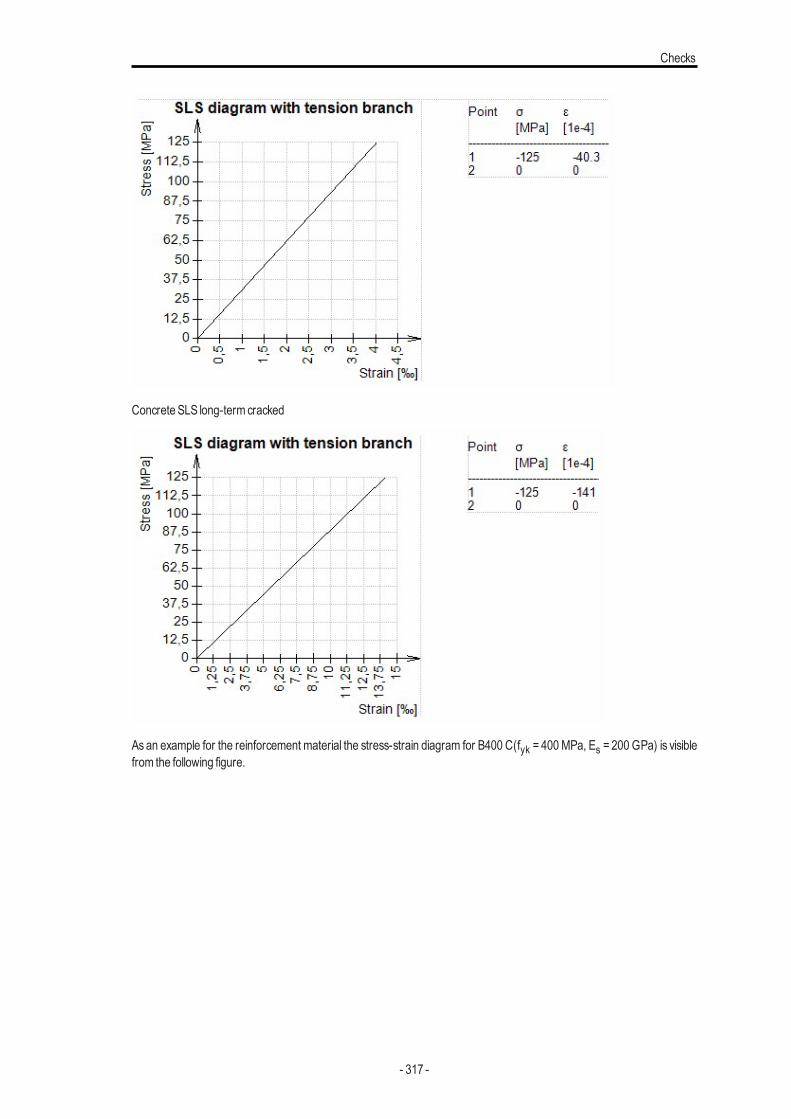
Checks
Concrete SLS long-term cracked
As an example for the reinforcement material the stress-strain diagram for B400 C(fyk = 400MPa, Es = 200 GPa) is visiblefrom the following figure.
- 317 -
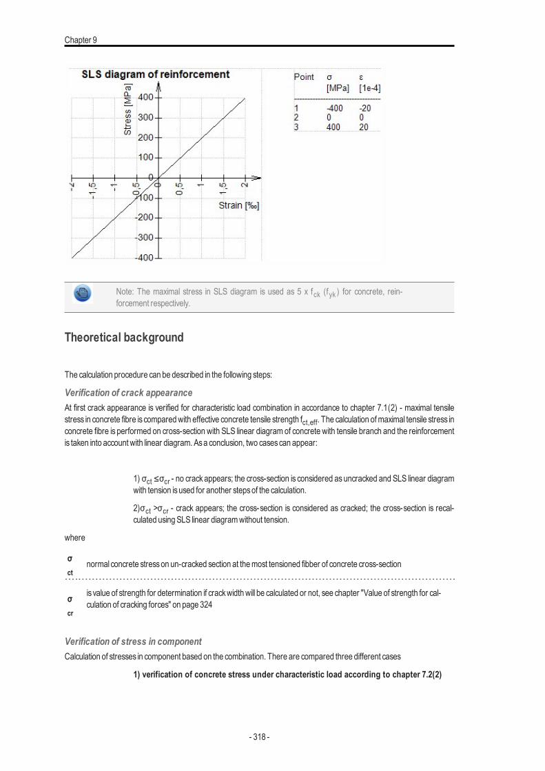
Chapter 9
Note: The maximal stress in SLS diagram is used as 5 x fck (fyk ) for concrete, rein-forcement respectively.
Theoretical background
The calculation procedure can be described in the following steps:
Verification of crack appearanceAt first crack appearance is verified for characteristic load combination in accordance to chapter 7.1(2) - maximal tensilestress in concrete fibre is comparedwith effective concrete tensile strength fct,eff. The calculation ofmaximal tensile stress inconcrete fibre is performed on cross-section with SLS linear diagram of concrete with tensile branch and the reinforcementis taken into account with linear diagram. Asa conclusion, two casescan appear:
1) σct ≤σcr - no crack appears; the cross-section is considered as uncracked and SLS linear diagramwith tension isused for another stepsof the calculation.
2)σct >σcr - crack appears; the cross-section is considered as cracked; the cross-section is recal-culated usingSLS linear diagramwithout tension.
where
σct
normal concrete stresson un-cracked section at themost tensioned fibber of concrete cross-section
σcr
is value of strength for determination if crackwidthwill be calculated or not, see chapter "Value of strength for cal-culation of cracking forces" on page 324
Verification of stress in componentCalculation of stresses in component based on the combination. There are compared three different cases
1) verification of concrete stress under characteristic load according to chapter 7.2(2)
- 318 -
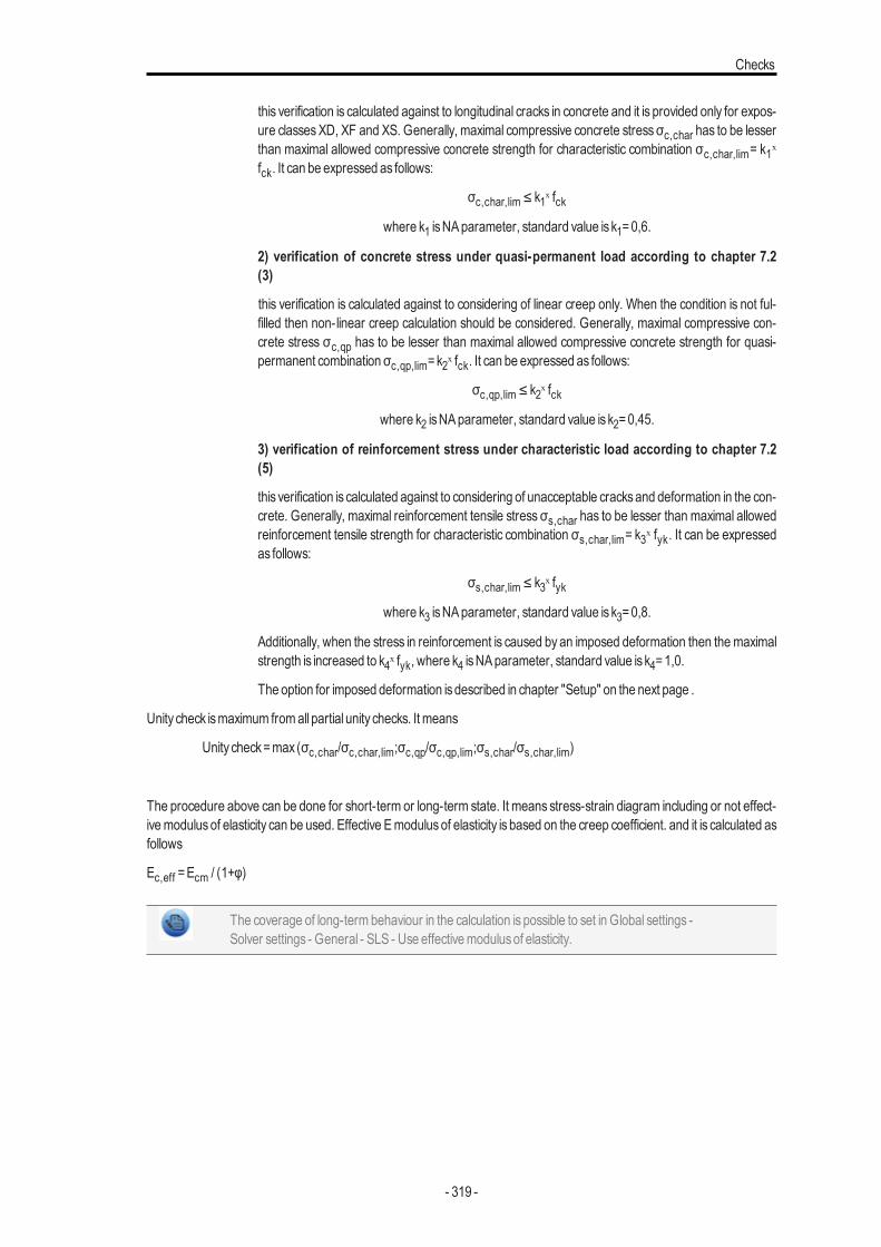
Checks
this verification is calculated against to longitudinal cracks in concrete and it is provided only for expos-ure classesXD, XF and XS. Generally, maximal compressive concrete stressσc,char has to be lesserthan maximal allowed compressive concrete strength for characteristic combination σc,char,lim= k1ˣfck. It can be expressed as follows:
σc,char,lim ≤ k1ˣ fckwhere k1 isNAparameter, standard value is k1=0,6.
2) verification of concrete stress under quasi-permanent load according to chapter 7.2(3)
this verification is calculated against to considering of linear creep only. When the condition is not ful-filled then non-linear creep calculation should be considered. Generally, maximal compressive con-crete stress σc,qp has to be lesser than maximal allowed compressive concrete strength for quasi-permanent combination σc,qp,lim=k2ˣ fck. It can be expressed as follows:
σc,qp,lim ≤ k2ˣ fckwhere k2 isNAparameter, standard value is k2=0,45.
3) verification of reinforcement stress under characteristic load according to chapter 7.2(5)
this verification is calculated against to considering of unacceptable cracksand deformation in the con-crete. Generally, maximal reinforcement tensile stress σs,char has to be lesser than maximal allowedreinforcement tensile strength for characteristic combination σs,char,lim= k3ˣ fyk. It can be expressedas follows:
σs,char,lim ≤ k3ˣ fykwhere k3 isNAparameter, standard value is k3=0,8.
Additionally, when the stress in reinforcement is caused by an imposed deformation then themaximalstrength is increased to k4ˣ fyk, where k4 isNAparameter, standard value is k4=1,0.
The option for imposed deformation isdescribed in chapter "Setup" on the next page .
Unity check ismaximum fromall partial unity checks. It means
Unity check=max (σc,char/σc,char,lim;σc,qp/σc,qp,lim;σs,char/σs,char,lim)
The procedure above can be done for short-term or long-term state. It means stress-strain diagram including or not effect-ivemodulus of elasticity can be used. Effective Emodulus of elasticity is based on the creep coefficient. and it is calculated asfollows
Ec,eff =Ecm / (1+φ)
The coverage of long-term behaviour in the calculation is possible to set in Global settings -Solver settings - General - SLS - Use effectivemodulusof elasticity.
- 319 -
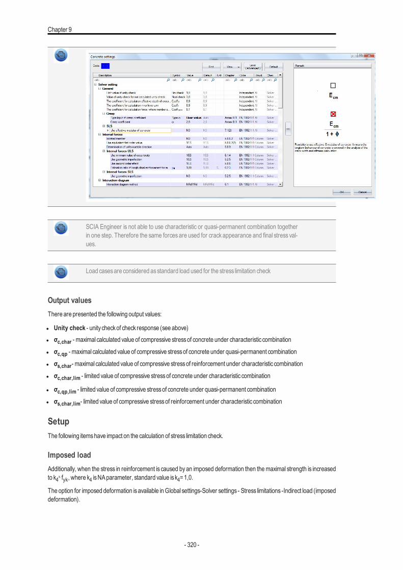
Chapter 9
SCIA Engineer is not able to use characteristic or quasi-permanent combination togetherin one step. Therefore the same forces are used for crack appearance and final stress val-ues.
Load casesare considered asstandard load used for the stress limitation check
Output valuesThere are presented the following output values:
l Unity check - unity checkof check response (see above)l σc,char - maximal calculated value of compressive stressof concrete under characteristic combination
l σc,qp - maximal calculated value of compressive stressof concrete under quasi-permanent combination
l σs,char- maximal calculated value of compressive stressof reinforcement under characteristic combination
l σc,char,lim - limited value of compressive stressof concrete under characteristic combination
l σc,qp,lim - limited value of compressive stressof concrete under quasi-permanent combination
l σs,char,lim- limited value of compressive stressof reinforcement under characteristic combination
SetupThe following itemshave impact on the calculation of stress limitation check.
Imposed loadAdditionally, when the stress in reinforcement is caused by an imposed deformation then the maximal strength is increasedto k4ˣ fyk, where k4 isNAparameter, standard value is k4=1,0.
The option for imposed deformation isavailable inGlobal settings-Solver settings - Stress limitations -Indirect load (imposeddeformation).
- 320 -

Checks
Value of strength for calculation of cracking forcesThis value can be set in Concrete setting by using Advanced level or in 1D member data (advanced mode is ON), ifdefined. If normal concrete stress on un-cracked section at the most tensioned fiber of concrete cross-section is greaterthan this value, the crackwidthwill be occurred andwill be calculated. There are two possibilities:
0 MPa it means that crackwidth is calculated if there is some tension in cross-section
fct,effit means, that crackwidth is calculated only in case, that normal concrete stresson un-cracked section at themost tensioned fibre of concrete cross-section isgreater themean value of the tensile strength of the concreteeffective at the time
Type of strength for calculation of cracking forcesThis value can be set in Concrete setting by using Advanced level or in 1D member data (advanced mode isON).There are two possibilities:
fctm it means thatmean tensile strength of concrete in time 28 days is taken into account, see picture below
fctm,fl
it means that themean flexural tensile strength (EN 1992-1-1,clause 3.1.8(1)) is taken into account. This valueshould be used if restrained deformationssuch asshrinkage or temperaturemovementsare taking into accountfor calculation of crackwidth
- 321 -
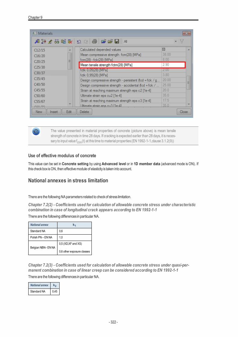
Chapter 9
The value presented in material properties of concrete (picture above) is mean tensilestrength of concrete in time 28 days. If cracking is expected earlier than 28 days, it is neces-sary to input value fctm(t) at this time tomaterial properties (EN 1992-1-1,clause 3.1.2(9))
Use of effective modulus of concreteThis value can be set in Concrete setting by using Advanced level or in 1D member data (advanced mode is ON). Ifthis checkbox isON, then effectivemodule of elasticity is taken into account.
National annexes in stress limitation
There are the followingNAparameters related to checkof stress limitation.
Chapter 7.2(2) - Coefficients used for calculation of allowable concrete stress under characteristiccombination in case of longitudinal crack appears according to EN 1992-1-1There are the following differences in particular NA.
National annex k1Standard NA 0,6
Polish PN – ENNA 1,0
Belgian NBN– ENNA0,5 (XD,XF and XS)
0,6 other exposure classes
Chapter 7.2(3) - Coefficients used for calculation of allowable concrete stress under quasi-per-manent combination in case of linear creep can be considered according to EN 1992-1-1There are the following differences in particular NA.
National annex k2Standard NA 0,45
- 322 -
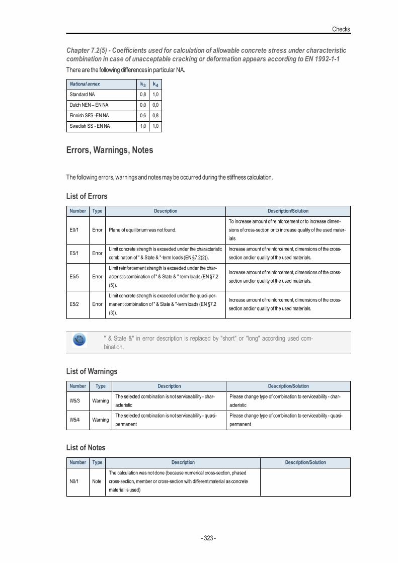
Checks
Chapter 7.2(5) - Coefficients used for calculation of allowable concrete stress under characteristiccombination in case of unacceptable cracking or deformation appears according to EN 1992-1-1There are the following differences in particular NA.
National annex k3 k4Standard NA 0,8 1,0
Dutch NEN – ENNA 0,0 0,0
Finnish SFS -ENNA 0,6 0,8
Swedish SS - ENNA 1,0 1,0
Errors, Warnings, Notes
The following errors, warningsand notesmaybe occurred during the stiffnesscalculation.
List of ErrorsNumber Type Description Description/Solution
E0/1 Error Plane of equilibriumwas not found.To increase amount of reinforcement or to increase dimen-sions of cross-section or to increase quality of the used mater-ials
E5/1 ErrorLimit concrete strength is exceeded under the characteristiccombination of " & State & "-term loads (EN §7.2(2)).
Increase amount of reinforcement, dimensions of the cross-section and/or quality of the used materials.
E5/5 ErrorLimit reinforcement strength is exceeded under the char-acteristic combination of " & State & "-term loads (EN §7.2(5)).
Increase amount of reinforcement, dimensions of the cross-section and/or quality of the used materials.
E5/2 ErrorLimit concrete strength is exceeded under the quasi-per-manent combination of " & State & "-term loads (EN §7.2(3)).
Increase amount of reinforcement, dimensions of the cross-section and/or quality of the used materials.
" & State &" in error description is replaced by "short" or "long" according used com-bination.
List of WarningsNumber Type Description Description/Solution
W5/3 WarningThe selected combination is not serviceability - char-acteristic
Please change type of combination to serviceability - char-acteristic
W5/4 WarningThe selected combination is not serviceability - quasi-permanent
Please change type of combination to serviceability - quasi-permanent
List of NotesNumber Type Description Description/Solution
N0/1 NoteThe calculation was not done (because numerical cross-section, phasedcross-section,member or cross-section with differentmaterial as concretematerial is used)
- 323 -
Chapter 9
Number Type Description Description/Solution
N0/2 Note The prestressed reinforcement is not taken into account
N0/3 Note The "Free bars " reinforcement is not taken into account
N0/4 NoteThere is some detailing longitudinal reinforcement, which is not taken intoaccount for the ULS and SLS check
N2/1 Note The normal forces and bending moments are zero (N = 0,My = 0,Mz = 0)
N5/1 NoteThe maximal effective concrete strength is exceeded; cracks appear under the" & State & "-term characteristic load combination. Furthermore, the concretestress-strain diagramwithout tensile branch is used.
Change (a) the dimensions of the cross-sec-tion, (b) the amount of reinforcement or (c)the quality of the used materials.
N5/2 Note Check of stress limitation is not required for the selected exposure class.Change the exposure class to XD, XS orXF.
Crack width (SLS)IntroductionThe crackwidth is calculated according to clause 7.3.4 in EN 1992-1-1. The following preconditionsare used for calculation :
l The crackwidth is calculated for beamsand columnsand for general load (N+My+Mz)l Cross-sectionwith one polygon and onematerial is taken into account in version SCIAEngineer 15l Thematerial of all reinforcement barshave to be same in SCIAEngineer 15l Normal stresson un-cracked section at themost tensioned fibre for determination if crackoccurred or not (checkof nor-
mal stresses), should be calculated for characteristic combination of the load according to EN 1992-1-1, clause 7.2(2).There ismade simplification in SCIAEngineer 15 that thisnormal stress is calculated for the same type of combination asit isused for calculation of crackwidth (load/combination/class inputted in serviceCrackcontrol.
Value of strength for calculation of cracking forcesThis value can be set in Concrete setting by using Advanced level or in 1D member data (advanced mode is ON), ifdefined. If normal concrete stress on un-cracked section at the most tensioned fibre of concrete cross-section is greaterthan this value, the crackwill occur and the crackwidthwill be calculated. There are two possibilities:
0 MPa it means that crackwidth is calculated if there is some tension in cross-section
fct,effit means, that crackwidth is calculated only in case that normal concrete stresson un-cracked section at themost tensioned fiber of concrete cross-section isgreater themean value of the tensile strength of the concreteeffective at the time
Check of normal stresses (occurring of crack width)Before calculation of crack width the normal concrete stresses on un-cracked section at the most tensioned fibre has to bechecked. If condition below issatisfied, the crackwidth doesnot create and the crackwidth isnot calculated
σct ≤σcrwhere
σct
normal concrete stresson un-cracked section at themost tensioned fibber of concrete cross-section
σcr
is value of strength for determination if crackwidthwill be calculated or not, see chapter "Value of strength for cal-culation of cracking forces" above
- 324 -
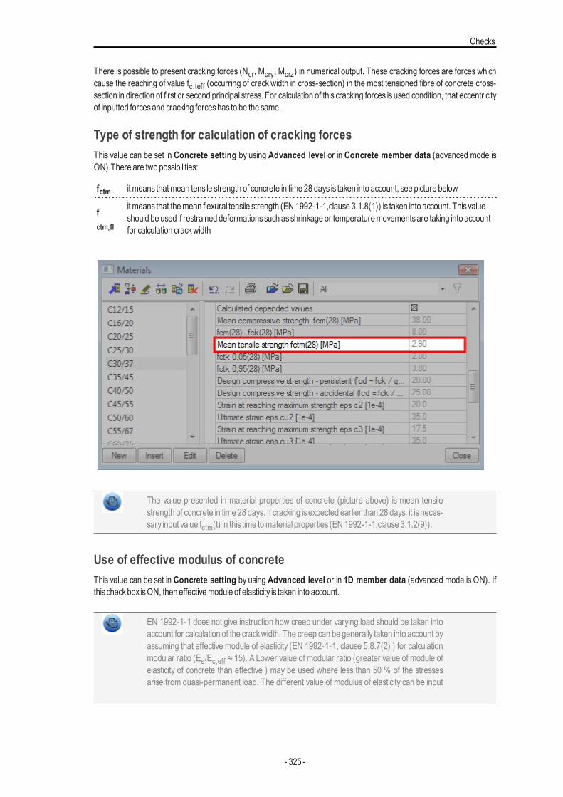
Checks
There is possible to present cracking forces (Ncr, Mcry, Mcrz) in numerical output. These cracking forces are forces whichcause the reaching of value fc,teff (occurring of crack width in cross-section) in the most tensioned fibre of concrete cross-section in direction of first or second principal stress. For calculation of this cracking forces is used condition, that eccentricityof inputted forcesand cracking forceshas to be the same.
Type of strength for calculation of cracking forcesThis value can be set in Concrete setting by using Advanced level or in Concrete member data (advanced mode isON).There are two possibilities:
fctm it means thatmean tensile strength of concrete in time 28 days is taken into account, see picture below
fctm,fl
it means that themean flexural tensile strength (EN 1992-1-1,clause 3.1.8(1)) is taken into account. This valueshould be used if restrained deformationssuch asshrinkage or temperaturemovementsare taking into accountfor calculation crackwidth
The value presented in material properties of concrete (picture above) is mean tensilestrength of concrete in time 28 days. If cracking is expected earlier than 28 days, it is neces-sary input value fctm(t) in this time tomaterial properties (EN 1992-1-1,clause 3.1.2(9)).
Use of effective modulus of concreteThis value can be set in Concrete setting by using Advanced level or in 1D member data (advanced mode is ON). Ifthis checkbox isON, then effectivemodule of elasticity is taken into account.
EN 1992-1-1 does not give instruction how creep under varying load should be taken intoaccount for calculation of the crackwidth. The creep can be generally taken into account byassuming that effective module of elasticity (EN 1992-1-1, clause 5.8.7(2) ) for calculationmodular ratio (Es/Ec,eff ≈ 15). A Lower value of modular ratio (greater value of module ofelasticity of concrete than effective ) may be used where less than 50 % of the stressesarise from quasi-permanent load. The different value of modulus of elasticity can be input
- 325 -
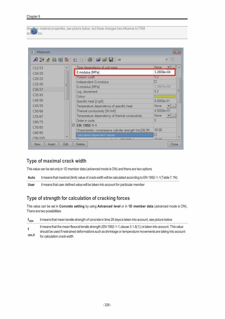
Chapter 9
directly in material properties, see picture below, but these changes has influence to FEManalysis too.
Type of maximal crack widthThisvalue can be set only in 1Dmember data (advancedmode isON) and there are two options
Auto it means thatmaximal (limit) value of crackwidthwill be calculated according to EN 1992-1-1(Table 7.1N)
User it means that user defined valuewill be taken into account for particular member
Type of strength for calculation of cracking forcesThis value can be set in Concrete setting by using Advanced level or in 1D member data (advanced mode is ON).There are two possibilities:
fctm it means thatmean tensile strength of concrete in time 28 days is taken into account, see picture below
fctm,fl
it means that themean flexural tensile strength (EN 1992-1-1,clause 3.1.8(1)) is taken into account. This valueshould be used if restrained deformationssuch asshrinkage or temperaturemovementsare taking into accountfor calculation crackwidth
- 326 -
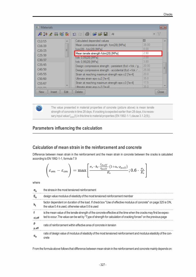
Checks
The value presented in material properties of concrete (picture above) is mean tensilestrength of concrete in time 28 days. If cracking is expected earlier than 28 days, it is neces-sary input value fctm(t) in this time tomaterial properties (EN 1992-1-1,clause 3.1.2(9)).
Parameters influencing the calculation
Calculation of mean strain in the reinforcement and concreteDifference between mean strain in the reinforcement and the mean strain in concrete between the cracks is calculatedaccording to EN 1992-1-1, formula 7.9
where
σs the stress in themost tensioned reinforcement
Es design valuemodulusof elasticityof themost tensioned reinforcementmember
ktfactor dependent on duration of the load. If check box "Use of effective modulus of concrete" on page 325 isON,the value 0.4 isused, otherwise value 0.6 isused
fct,eff
is themean value of the tensile strength of the concrete effective at the timewhen the cracksmay first be expec-ted to occur.The value can be set by "Type of strength for calculation of cracking forces" on the previouspage
ρp,eff
ratio of reinforcement within effective area of concrete in tension
αeratio of design value ofmodulusof elasticityof themost tensioned reinforcement andmoduluselasticityof the con-crete
From the formula above follows that difference betweenmean strain in the reinforcement and concretemainlydependson:
- 327 -
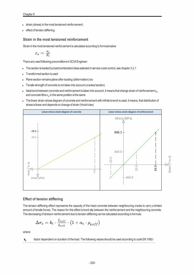
Chapter 9
l strain (stress) in themost tensioned reinforcement,l effect of tension stiffening.
Strain in the most tensioned reinforcementStrain in themost tensioned reinforcement is calculated according to formula below
There are used following preconditions in SCIAEngineer:
l The section is loaded by load/combination/classselected in service crackcontrol, see chapter 3.2.1l Transformed section isusedl Plane section remainsplane after loading (deformation) tool Tensile strength of concrete isnot taken into account (cracked section)l Ideal bond between concrete and reinforcement is taken into account, it means that change strain of reinforcement εs
and concrete fibre εc in the same position is the samel The linear strain-stressdiagramof concrete and reinforcement with infinite branch isused, it means, that distribution of
stress is linear and dependson change of strain (Hook’s law)
Linear stress-strain diagram of concrete Linear stress-strain diagram of reinforcement
Effect of tension stiffeningThe tension stiffening effect represents the capacity of the intact concrete between neighbouring cracks to carry a limitedamount of tensile forces. The reason for this effect is bond slip between the reinforcement and the neighbouring concrete.The decreasing of stress in reinforcement due to tension stiffening can be calculated according to formula:
where
kt factor dependent on duration of the load. The following values should be used according to code EN 1992-
- 328 -
Checks
1-1, chapter 7.3.4(2).
l kt =0,6 for short term loading
l kt =0,4 for long term loading
The value of kt in SCIA Engineer depends on type of modulus of concrete. If check box "Use of effectivemodulusof concrete" on page 325 isON, the value 0.4 isused, otherwise value 0.6 isused.
fct,eff
is themean value of the tensile strength of the concrete effective at the time.
When the cracksmay first be expected to occur.The value can be set by "Type of strength for calculation ofcracking forces" on page 326.
ρp,eff
ratio of reinforcement within effective area of concrete in tension. This ratio is calculated only for non-prestressed reinforcement (prestressed reinforcement is not taken into account for check crack width)according to formula
As,eff
area of non-prestressed reinforcement (see chapter 4.4) within effective area of concrete in tension
Ac,eff
the effective area of concrete in tension surrounding the reinforcement. This isarea of reinforcementbounded by line, which is in distance hc,eff from themost tensioned fibre of concrete in the direction of bend-ingmoment resultant
hc,eff
the depth of effective area of concrete in tension surrounding the reinforcement.
h the height of cross-section in direction of resultant of the bendingmoments (thicknessof FEMelement incentroid)
d effective depth of cross-section in direction of resultant of the bendingmoments
x depth of concrete in compression calculated for uncracked section
αe
ratio of design value of modulus of elasticity of the most tensioned reinforcement and modulus elasticity ofthe concrete
Esdesign value ofmodulusof elasticityof themost tensioned The value is loaded frommaterial propertiesofthe reinforcement, see picture below
Ec modulusof elasticityof concrete. The value is loaded frommaterial propertiesof the concrete
- 329 -
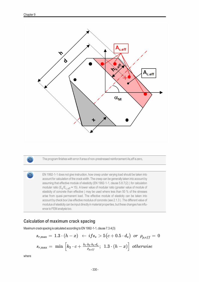
Chapter 9
The program finisheswith error if area of non-prestressed reinforcement As,eff is zero,
EN 1992-1-1 does not give instruction, how creep under varying load should be taken intoaccount for calculation of the crackwidth. The creep can be generally taken into account byassuming that effective module of elasticity (EN 1992-1-1, clause 5.8.7(2) ) for calculationmodular ratio (Es/Ec,eff ≈ 15). A lower value of modular ratio (greater value of module ofelasticity of concrete than effective ) may be used where less than 50 % of the stressesarise from quasi- permanent load. The effective module of elasticity can be taken intoaccount by checkboxUse effectivemodulus of concrete (see 2.1.3 ) .The different value ofmodulusof elasticity can be input directly inmaterial properties, but these changeshas influ-ence to FEManalysis too.
Calculation of maximum crack spacingMaximumcrackspacing is calculated according to EN 1992-1-1, clause 7.3.4(3)
where
- 330 -
Checks
k3, k4
coefficientsof calculation loaded fromnational annexsetting (Manager of national annex>codeEN 1992-1-1 >SLS)
c cover of themost tensioned reinforcement calculated in direction of resultant of bendingmoments
k1
k1 coefficient which takesaccount of the bond propertiesof the bonded reinforcement
l k1 =0,8 for high bond bars (in SCIAEngineer bar surface = ribbed)
l k1 =1,6 for barswith an effectivelyplain surface e.g. prestressing tendons (in SCIAEngineer bar surface =smooth)
The bar surface can be defined inmaterial propertiesof the reinforcement
k2,i+
coefficient which takesaccount of the distribution of strain
l k2=0.5 for pure bending
l k2 =1.0 for pure tension
l k2= (ε1+ε2)/2 • ε1
ε1the greater tensile strain at the boundaries (edges) of the cross-section The strain is calculated for uncracked sec-tionwith taking into account conditions in chapter 4.6.1.1 and the value of strain is zero for edge in compression
ε2the lesser tensile strain at the boundaries (edges) of the cross-section The strain is calculated for uncracked sec-tionwith taking into account conditions in chapter 4.6.1.1 and the value of strain is zero for edge in compression
ρp,eff
ratio of reinforcement within effective area of concrete in tension
αeratio of design value ofmodulusof elasticityofmost tensioned reinforcement andmoduluselasticityof the con-crete
x is depth of concrete in compression calculated for uncracked sectionwith taking into account conditions in chapter4.6.1.1.
h the height of cross-section in direction of resultant of the bendingmoments
sscentre to centre spacing between bars of reinforcement of the most tensioned layer of reinforcement per-pendicular to direction of bendingmoments resultant
dsdiameter of barsof themost tensioned layer of reinforcement. If barswith different diameter are inside of theeffective area of concrete, the equivalent diameter according to equation 7.12 in EN 1992-1-1 is taken intoaccount
- 331 -
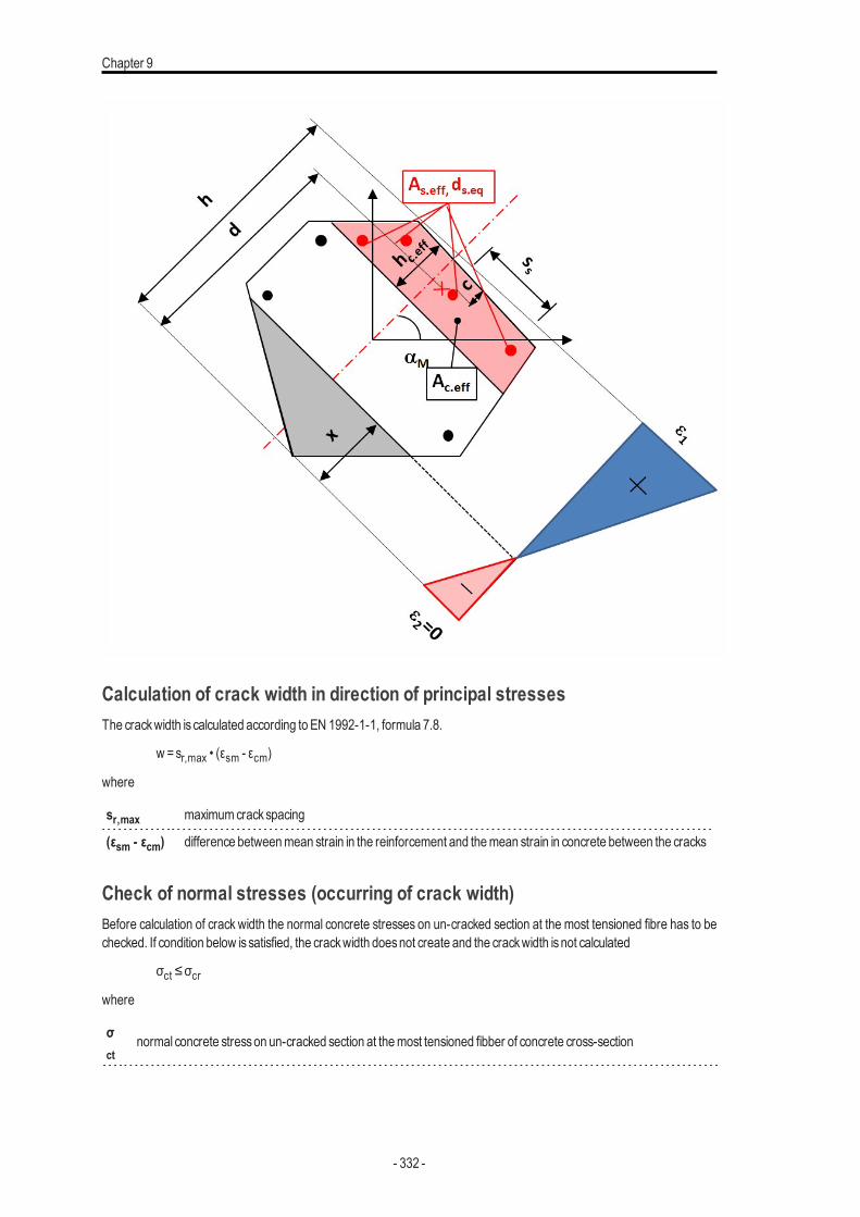
Chapter 9
Calculation of crack width in direction of principal stressesThe crackwidth is calculated according to EN 1992-1-1, formula 7.8.
w =sr,max • (εsm - εcm)
where
sr,max maximumcrackspacing
(εsm - εcm) difference betweenmean strain in the reinforcement and themean strain in concrete between the cracks
Check of normal stresses (occurring of crack width)Before calculation of crack width the normal concrete stresses on un-cracked section at the most tensioned fibre has to bechecked. If condition below issatisfied, the crackwidth doesnot create and the crackwidth isnot calculated
σct ≤σcrwhere
σct
normal concrete stresson un-cracked section at themost tensioned fibber of concrete cross-section
- 332 -
Checks
σcr
is value of strength for determination if crackwidthwill be calculated or not, see chapter "Value of strength for cal-culation of cracking forces" on page 324
There is possible to present cracking forces (Ncr, Mcry, Mcrz) in numerical output. These cracking forces are forces whichcause the reaching of value fc,teff (occurring of crack width in cross-section) in the most tensioned fibre of concrete cross-section in direction of first or second principal stress. For calculation of this cracking forces is used condition, that eccentricityof inputted forcesand cracking forceshas to be the same.
Calculation of mean strain in the reinforcement and concreteDifference between mean strain in the reinforcement and the mean strain in concrete between the cracks is calculatedaccording to EN 1992-1-1, formula 7.9
where
σs the stress in themost tensioned reinforcement
Es design valuemodulusof elasticityof themost tensioned reinforcementmember
ktfactor dependent on duration of the load. If check box "Use of effective modulus of concrete" on page 325 isON,the value 0.4 isused, otherwise value 0.6 isused
fct,eff
is themean value of the tensile strength of the concrete effective at the timewhen the cracksmay first be expec-ted to occur.The value can be set by "Type of strength for calculation of cracking forces" on page 325
ρp,eff
ratio of reinforcement within effective area of concrete in tension
αeratio of design value ofmodulusof elasticityof themost tensioned reinforcement andmoduluselasticityof the con-crete
From the formula above follows that difference betweenmean strain in the reinforcement and concretemainlydependson:
l strain (stress) in themost tensioned reinforcement,l effect of tension stiffening.
Strain in the most tensioned reinforcementStrain in themost tensioned reinforcement is calculated according to formula below
There are used following preconditions in SCIAEngineer:
l The section is loaded by load/combination/classselected in service crackcontrol, see code chapter 3.2.1l Transformed section isusedl Plane section remainsplane after loading (deformation) tool Tensile strength of concrete isnot taken into account (cracked section)l Ideal bond between concrete and reinforcement is taken into account, it meanschange strain of reinforcement εs and
concrete fibre εc in the same position is the same
- 333 -
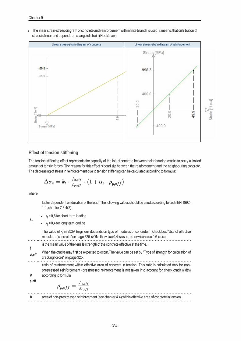
Chapter 9
l The linear strain-stressdiagramof concrete and reinforcement with infinite branch isused, it means, that distribution ofstress is linear and dependson change of strain (Hook’s law)
Linear stress-strain diagram of concrete Linear stress-strain diagram of reinforcement
Effect of tension stiffeningThe tension stiffening effect represents the capacity of the intact concrete between neighbouring cracks to carry a limitedamount of tensile forces. The reason for this effect is bond slip between the reinforcement and the neighbouring concrete.The decreasing of stress in reinforcement due to tension stiffening can be calculated according to formula:
where
kt
factor dependent on duration of the load. The following values should be used according to code EN 1992-1-1, chapter 7.3.4(2).
l kt =0,6 for short term loading
l kt =0,4 for long term loading
The value of kt in SCIA Engineer depends on type of modulus of concrete. If check box "Use of effectivemodulusof concrete" on page 325 isON, the value 0.4 isused, otherwise value 0.6 isused.
fct,eff
is themean value of the tensile strength of the concrete effective at the time.
When the cracksmay first be expected to occur.The value can be set by "Type of strength for calculation ofcracking forces" on page 325.
ρp,eff
ratio of reinforcement within effective area of concrete in tension. This ratio is calculated only for non-prestressed reinforcement (prestressed reinforcement is not taken into account for check crack width)according to formula
A area of non-prestressed reinforcement (see chapter 4.4) within effective area of concrete in tension
- 334 -
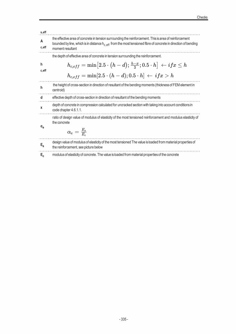
Checks
s,eff
Ac,eff
the effective area of concrete in tension surrounding the reinforcement. This isarea of reinforcementbounded by line, which is in distance hc,eff from themost tensioned fibre of concrete in direction of bendingmoment resultant
hc,eff
the depth of effective area of concrete in tension surrounding the reinforcement.
h the height of cross-section in direction of resultant of the bendingmoments (thicknessof FEMelement incentroid)
d effective depth of cross-section in direction of resultant of the bendingmoments
x depth of concrete in compression calculated for uncracked sectionwith taking into account conditions incode chapter 4.6.1.1.
αe
ratio of design value of modulus of elasticity of the most tensioned reinforcement and modulus elasticity ofthe concrete
Esdesign value ofmodulusof elasticityof themost tensioned The value is loaded frommaterial propertiesofthe reinforcement, see picture below
Ec modulusof elasticityof concrete. The value is loaded frommaterial propertiesof the concrete
- 335 -
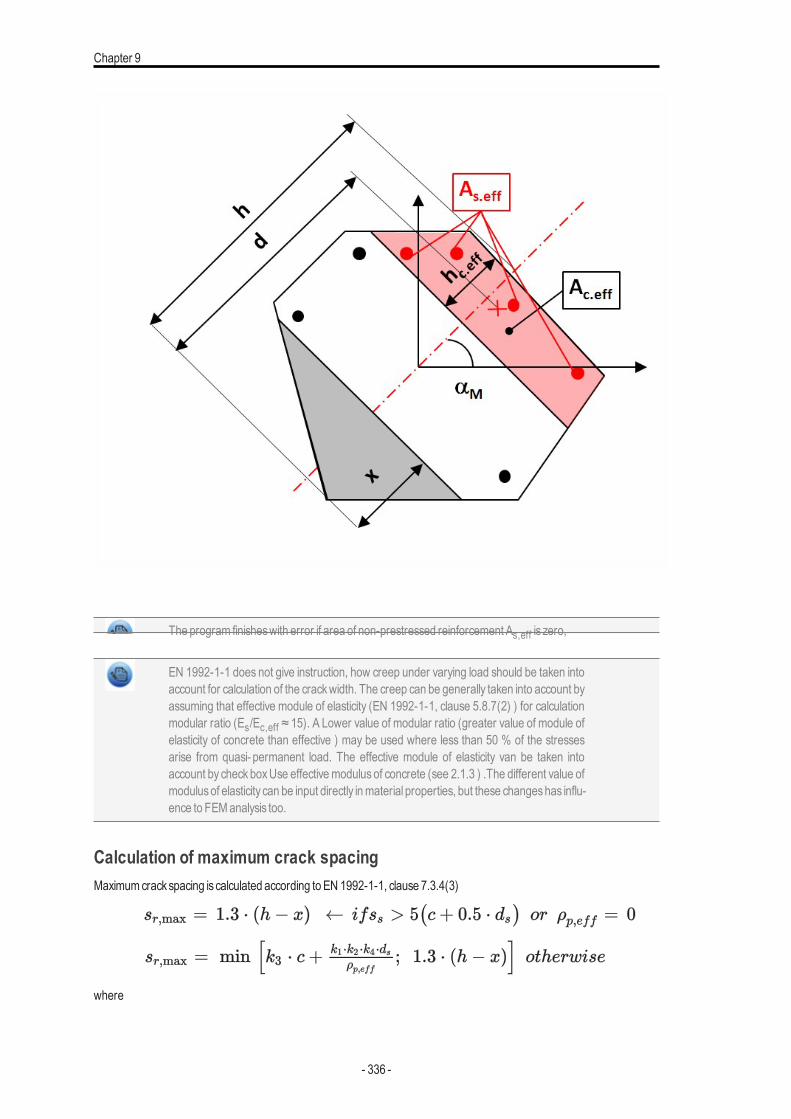
Chapter 9
The program finisheswith error if area of non-prestressed reinforcement As,eff is zero,
EN 1992-1-1 does not give instruction, how creep under varying load should be taken intoaccount for calculation of the crackwidth. The creep can be generally taken into account byassuming that effective module of elasticity (EN 1992-1-1, clause 5.8.7(2) ) for calculationmodular ratio (Es/Ec,eff ≈ 15). A Lower value of modular ratio (greater value of module ofelasticity of concrete than effective ) may be used where less than 50 % of the stressesarise from quasi- permanent load. The effective module of elasticity van be taken intoaccount by checkboxUse effectivemodulus of concrete (see 2.1.3 ) .The different value ofmodulusof elasticity can be input directly inmaterial properties, but these changeshas influ-ence to FEManalysis too.
Calculation of maximum crack spacingMaximumcrackspacing is calculated according to EN 1992-1-1, clause 7.3.4(3)
where
- 336 -

Checks
k3, k4
coefficientsof calculation loaded fromnational annexsetting (Manager of national annex>codeEN 1992-1-1 >SLS)
c cover of themost tensioned reinforcement calculated in direction of resultant of bendingmoments
k1
k1 coefficient which takesaccount of the bond propertiesof the bonded reinforcement
l k1 =0,8 for high bond bars (in SCIAEngineer bar surface = ribbed)
l k1 =1,6 for barswith an effectivelyplain surface e.g. prestressing tendons (in SCIAEngineer bar surface =smooth)
The bar surface can be defined inmaterial propertiesof the reinforcement
k2,i+
coefficient which takesaccount of the distribution of strain
l k2=0.5 for pure bending
l k2 =1.0 for pure tension
l k2= (ε1+ε2)/2 • ε1
ε1the greater tensile strain at the boundaries (edges) of the cross-section The strain is calculated for uncracked sec-tionwith taking into account conditions in chapter 4.6.1.1 and the value of strain is zero for edge in compression
ε2the lesser tensile strain at the boundaries (edges) of the cross-section The strain is calculated for uncracked sec-tionwith taking into account conditions in chapter 4.6.1.1 and the value of strain is zero for edge in compression
ρp,eff
ratio of reinforcement within effective area of concrete in tension
αeratio of design value ofmodulusof elasticityofmost tensioned reinforcement andmoduluselasticityof the con-crete
x is depth of concrete in compression calculated for uncracked sectionwith taking into account conditions in chapter4.6.1.1.
h the height of cross-section in direction of resultant of the bendingmoments
sscentre to centre spacing between bars of reinforcement of the most tensioned layer of reinforcement per-pendicular to direction of bendingmoments resultant
dsdiameter of barsof themost tensioned layer of reinforcement. If barswith different diameter are inside of theeffective area of concrete, the equivalent diameter according to equation 7.12 in EN 1992-1-1 is taken intoaccount
- 337 -
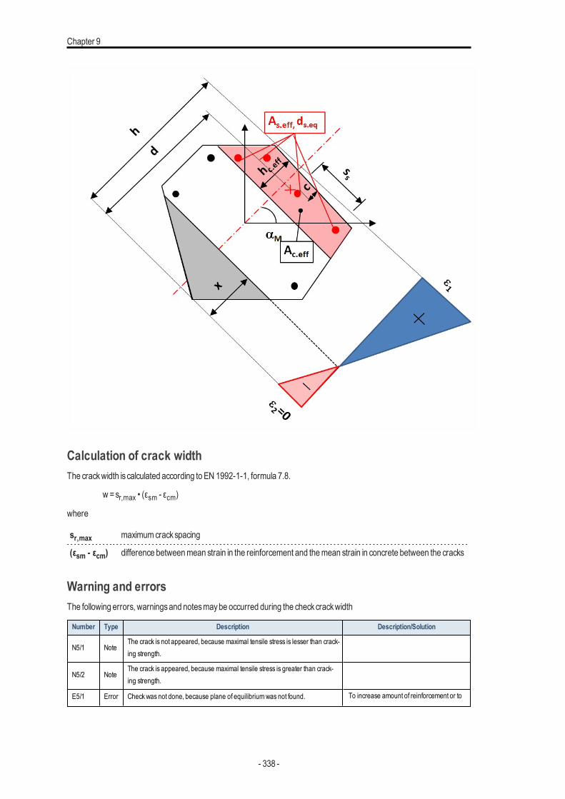
Chapter 9
Calculation of crack widthThe crackwidth is calculated according to EN 1992-1-1, formula 7.8.
w =sr,max • (εsm - εcm)
where
sr,max maximumcrackspacing
(εsm - εcm) difference betweenmean strain in the reinforcement and themean strain in concrete between the cracks
Warning and errorsThe following errors, warningsand notesmaybe occurred during the checkcrackwidth
Number Type Description Description/Solution
N5/1 NoteThe crack is not appeared, because maximal tensile stress is lesser than crack-ing strength.
N5/2 NoteThe crack is appeared, because maximal tensile stress is greater than crack-ing strength.
E5/1 Error Checkwas not done, because plane of equilibriumwas not found. To increase amount of reinforcement or to
- 338 -
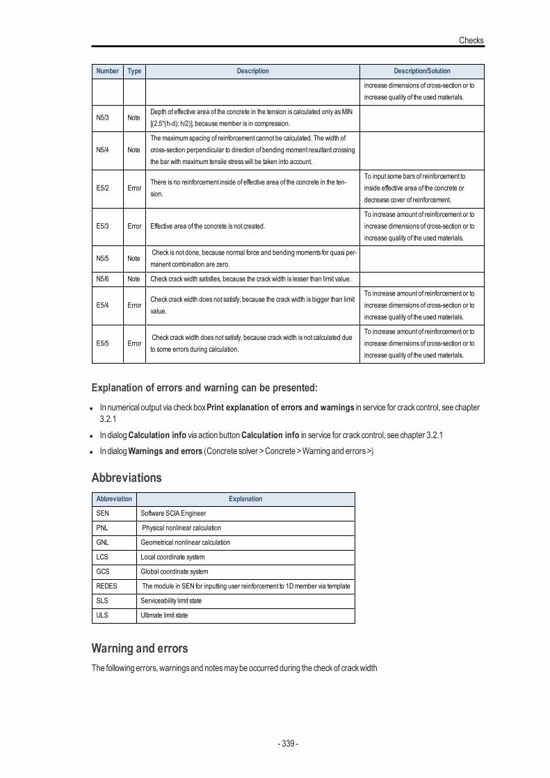
Checks
Number Type Description Description/Solution
increase dimensions of cross-section or toincrease quality of the used materials.
N5/3 NoteDepth of effective area of the concrete in the tension is calculated only asMIN[(2.5*(h-d); h/2)], because member is in compression.
N5/4 NoteThe maximum spacing of reinforcement cannot be calculated. The width ofcross-section perpendicular to direction of bending moment resultant crossingthe bar with maximum tensile stress will be taken into account.
E5/2 ErrorThere is no reinforcement inside of effective area of the concrete in the ten-sion.
To input some bars of reinforcement toinside effective area of the concrete ordecrease cover of reinforcement.
E5/3 Error Effective area of the concrete is not created.To increase amount of reinforcement or toincrease dimensions of cross-section or toincrease quality of the used materials.
N5/5 NoteCheck is not done, because normal force and bending moments for quasi per-manent combination are zero.
N5/6 Note Check crack width satisfies, because the crack width is lesser than limit value.
E5/4 ErrorCheck crack width does not satisfy, because the crack width is bigger than limitvalue.
To increase amount of reinforcement or toincrease dimensions of cross-section or toincrease quality of the used materials.
E5/5 ErrorCheck crack width does not satisfy, because crack width is not calculated dueto some errors during calculation.
To increase amount of reinforcement or toincrease dimensions of cross-section or toincrease quality of the used materials.
Explanation of errors and warning can be presented:l In numerical output via checkboxPrint explanation of errors and warnings in service for crackcontrol, see chapter
3.2.1l In dialogCalculation info via action buttonCalculation info in service for crackcontrol, see chapter 3.2.1l In dialogWarnings and errors (Concrete solver >Concrete >Warning and errors>)
AbbreviationsAbbreviation Explanation
SEN Software SCIA Engineer
PNL Physical nonlinear calculation
GNL Geometrical nonlinear calculation
LCS Local coordinate system
GCS Global coordinate system
REDES The module in SEN for inputting user reinforcement to 1Dmember via template
SLS Serviceability limit state
ULS Ultimate limit state
Warning and errorsThe following errors, warningsand notesmaybe occurred during the checkof crackwidth
- 339 -
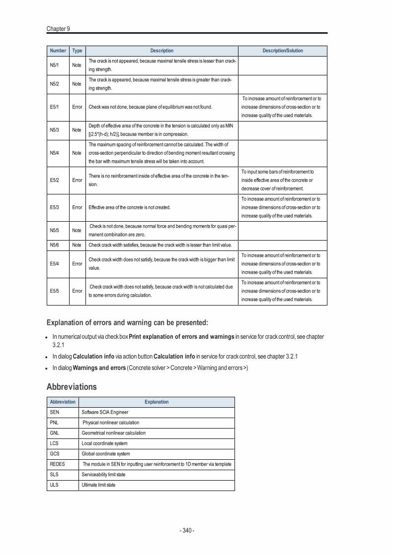
Chapter 9
Number Type Description Description/Solution
N5/1 NoteThe crack is not appeared, because maximal tensile stress is lesser than crack-ing strength.
N5/2 NoteThe crack is appeared, because maximal tensile stress is greater than crack-ing strength.
E5/1 Error Checkwas not done, because plane of equilibriumwas not found.To increase amount of reinforcement or toincrease dimensions of cross-section or toincrease quality of the used materials.
N5/3 NoteDepth of effective area of the concrete in the tension is calculated only asMIN[(2.5*(h-d); h/2)], because member is in compression.
N5/4 NoteThe maximum spacing of reinforcement cannot be calculated. The width ofcross-section perpendicular to direction of bending moment resultant crossingthe bar with maximum tensile stress will be taken into account.
E5/2 ErrorThere is no reinforcement inside of effective area of the concrete in the ten-sion.
To input some bars of reinforcement toinside effective area of the concrete ordecrease cover of reinforcement.
E5/3 Error Effective area of the concrete is not created.To increase amount of reinforcement or toincrease dimensions of cross-section or toincrease quality of the used materials.
N5/5 NoteCheck is not done, because normal force and bending moments for quasi per-manent combination are zero.
N5/6 Note Check crack width satisfies, because the crack width is lesser than limit value.
E5/4 ErrorCheck crack width does not satisfy, because the crack width is bigger than limitvalue.
To increase amount of reinforcement or toincrease dimensions of cross-section or toincrease quality of the used materials.
E5/5 ErrorCheck crack width does not satisfy, because crack width is not calculated dueto some errors during calculation.
To increase amount of reinforcement or toincrease dimensions of cross-section or toincrease quality of the used materials.
Explanation of errors and warning can be presented:l In numerical output via checkboxPrint explanation of errors and warnings in service for crackcontrol, see chapter
3.2.1l In dialogCalculation info via action buttonCalculation info in service for crackcontrol, see chapter 3.2.1l In dialogWarnings and errors (Concrete solver >Concrete >Warning and errors>)
AbbreviationsAbbreviation Explanation
SEN Software SCIA Engineer
PNL Physical nonlinear calculation
GNL Geometrical nonlinear calculation
LCS Local coordinate system
GCS Global coordinate system
REDES The module in SEN for inputting user reinforcement to 1Dmember via template
SLS Serviceability limit state
ULS Ultimate limit state
- 340 -
Checks
Literature
1. [1] EN 1992-1-1: 2004Eurocode 2 : design of concrete structures–Part 1: General rulesand rules for building
2. [2] ENV1992-1-1: 1991Eurocode 2 : design of concrete structures–Part 1: General rulesand rules for building
Literature
[1] EN 1992-1-1: 2004 Eurocode 2 : design of concrete structures – Part 1: Generalrulesand rules for building
[2] ENV1992-1-1: 1991Eurocode 2 : design of concrete structures–Part 1: Generalrulesand rules for building
Deflections (SLS)IntroductionThe calculation of deflection is done according to chapter 7.4.3 from EN 1992-1-1. The verification of deflections should beperformed due to the following reasons:
l Unacceptable deflection should not affect proper function of the structure or aesthetic - limit for total deflectionl To avoid damage to partitionsand finishesdue to increments in deflection following their construction - limit for additional
deflection
The behaviour of the reinforced cross-section for deflection needs is the same as used for the stiffness calculation and canbe also expressed in term of moment and strain (deformation) diagram. The final value of stiffness is calculated using inter-polation formula between state (I) deformation for uncracked concrete section (ξ = 0) and state (II) deformation for fullycracked concrete section (no tension carries) (ξ = 1) dependently on the ratio of stress in reinforcement from cracking loadand acting load. The dependency of cracking moment on strain in concrete is visible from the following figure. The value ofdeformation is then recalculated from the stiffnessand acting load.
- 341 -
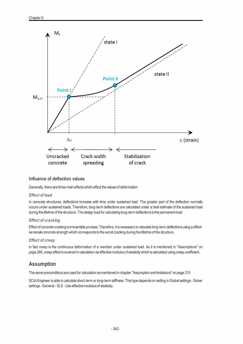
Chapter 9
Influence of deflection valuesGenerally, there are threemain effectswhich affect the valuesof deformation
Effect of loadIn concrete structures, deflections increase with time under sustained load. The greater part of the deflection normallyoccurs under sustained loads. Therefore, long-term deflections are calculated under a best estimate of the sustained loadduring the lifetime of the structure. The design load for calculating long-termdeflections is the permanent load
Effect of crackingEffect of concrete cracking is irreversible process. Therefore, it is necessary to calculate long-termdeflectionsusing a effect-ive tensile concrete strengthwhich corresponds to theworst cracking during the lifetime of the structure.
Effect of creepIn fact creep is the continuous deformation of a member under sustained load. As it is mentioned in "Assumptions" onpage 268, creep effect is covered in calculation via effectivemodulusof elasticitywhich is calculated using creep coefficient.
AssumptionThe samepreconditionsare used for calculation asmentioned in chapter "Assumption and limitations" on page 315
SCIAEngineer is able to calculate short-term or long-term stiffness. This type dependson setting in Global settings - Solversettings - General - SLS - Use effectivemodulusof elasticity.
- 342 -
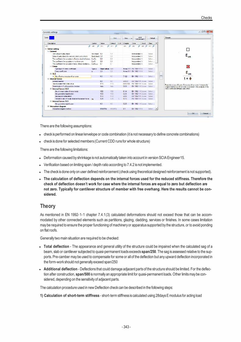
Checks
There are the following assumptions:
l check isperformed on linear/envelope or code combination (it is not necessary to define concrete combinations)l check isdone for selectedmembers (Current CDD runs for whole structure)
There are the following limitations:
l Deformation caused byshrinkage isnot automatically taken into account in version SCIAEngineer15.l Verification based on limiting span / depth ratio according to 7.4.2 isnot implemented.l The check isdone onlyon user defined reinforcement (checkusing theoretical designed reinforcement isnot supported).l The calculation of deflection depends on the internal forces used for the reduced stiffness. Therefore the
check of deflection doesn’t work for case where the internal forces are equal to zero but deflection arenot zero. Typically for cantilever structure of member with free overhang. Here the results cannot be con-sidered.
TheoryAs mentioned in EN 1992-1-1 chapter 7.4.1(3) calculated deformations should not exceed those that can be accom-modated by other connected elements such as partitions, glazing, cladding, services or finishes. In some cases limitationmaybe required to ensure the proper functioning ofmachineryor apparatussupported by the structure, or to avoid pondingon flat roofs.
Generally twomain situation are required to be checked:
l Total deflection - The appearance and general utility of the structure could be impaired when the calculated sag of abeam, slab or cantilever subjected to quasi-permanent loadsexceedsspan/250. The sag is assessed relative to the sup-ports. Pre-camber maybe used to compensate for some or all of the deflection but anyupward deflection incorporated inthe form-workshould not generallyexceed span/250
l Additional deflection - Deflections that could damage adjacent partsof the structure should be limited. For the deflec-tion after construction, span/500 is normallyan appropriate limit for quasi-permanent loads. Other limitsmaybe con-sidered, depending on the sensitivityof adjacent parts.
The calculation procedure used in newDeflection checkcan be described in the following steps:
1) Calculation of short-term stiffness - short-term stiffness is calculated using 28daysEmodulus for acting load
- 343 -
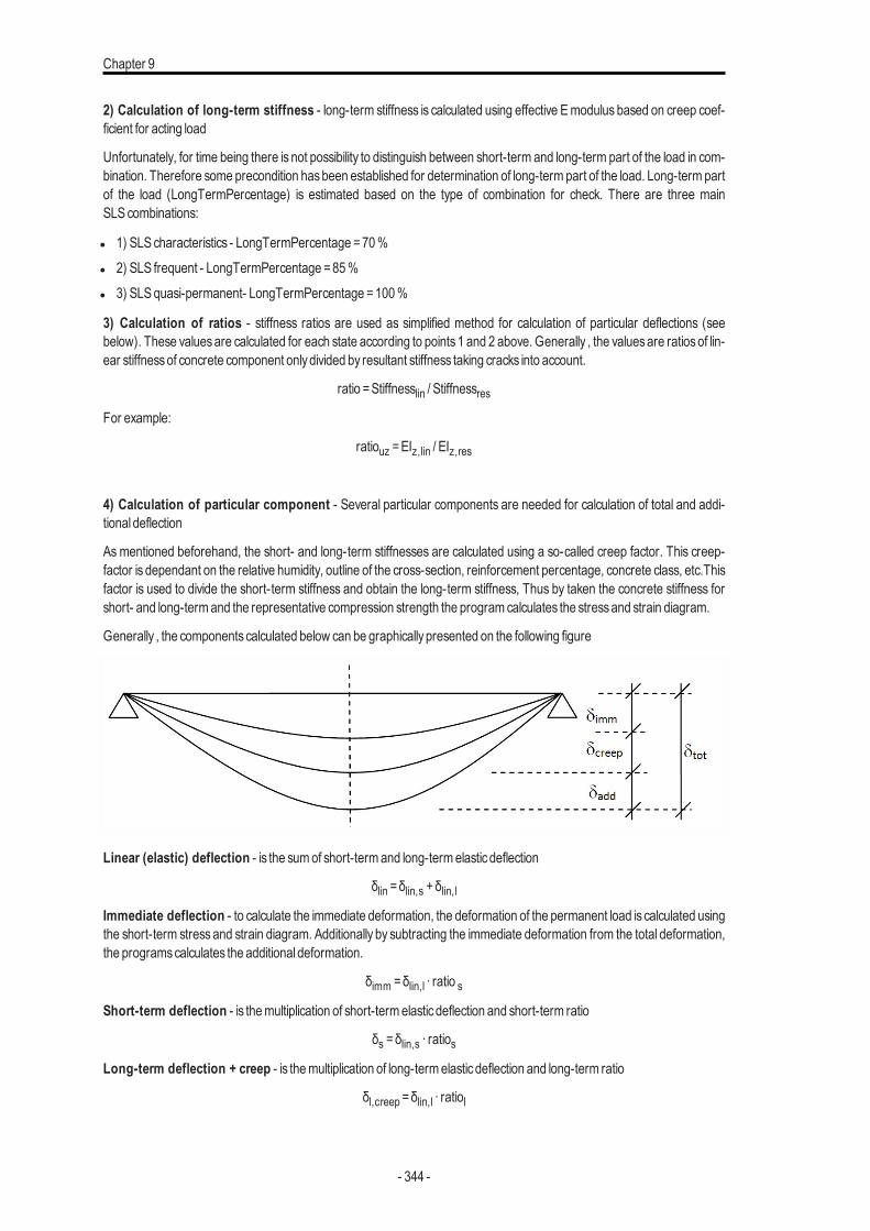
Chapter 9
2) Calculation of long-term stiffness - long-term stiffness is calculated using effective Emodulus based on creep coef-ficient for acting load
Unfortunately, for time being there is not possibility to distinguish between short-term and long-term part of the load in com-bination. Therefore some precondition hasbeen established for determination of long-term part of the load. Long-term partof the load (LongTermPercentage) is estimated based on the type of combination for check. There are three mainSLS combinations:
l 1) SLScharacteristics - LongTermPercentage =70%l 2) SLS frequent - LongTermPercentage =85%l 3) SLSquasi-permanent- LongTermPercentage =100%
3) Calculation of ratios - stiffness ratios are used as simplified method for calculation of particular deflections (seebelow). These valuesare calculated for each state according to points 1 and 2 above. Generally , the valuesare ratiosof lin-ear stiffnessof concrete component onlydivided by resultant stiffness taking cracks into account.
ratio =Stiffnesslin / StiffnessresFor example:
ratiouz =EIz,lin / EIz,res
4) Calculation of particular component - Several particular components are needed for calculation of total and addi-tional deflection
As mentioned beforehand, the short- and long-term stiffnesses are calculated using a so-called creep factor. This creep-factor is dependant on the relative humidity, outline of the cross-section, reinforcement percentage, concrete class, etc.Thisfactor is used to divide the short-term stiffness and obtain the long-term stiffness, Thus by taken the concrete stiffness forshort- and long-termand the representative compression strength the programcalculates the stressand strain diagram.
Generally , the componentscalculated below can be graphicallypresented on the following figure
Linear (elastic) deflection - is the sumof short-termand long-termelasticdeflection
δlin =δlin,s +δlin,lImmediate deflection - to calculate the immediate deformation, the deformation of the permanent load is calculated usingthe short-term stress and strain diagram. Additionally by subtracting the immediate deformation from the total deformation,the programscalculates the additional deformation.
δimm =δlin,l ∙ ratio sShort-term deflection - is themultiplication of short-termelasticdeflection and short-term ratio
δs =δlin,s ∙ ratiosLong-term deflection + creep - is themultiplication of long-termelasticdeflection and long-term ratio
δl,creep =δlin,l ∙ ratiol
- 344 -
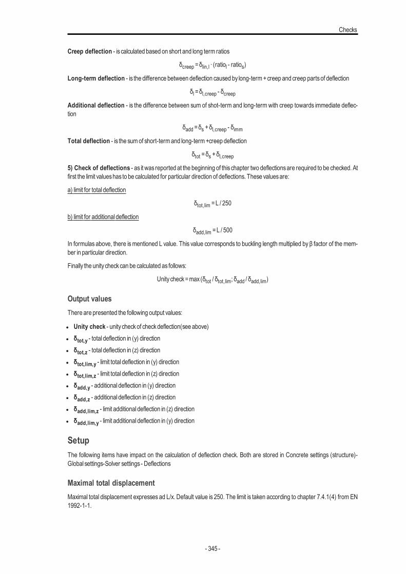
Checks
Creep deflection - is calculated based on short and long term ratios
δcreep =δlin,l ∙ (ratiol - ratios)
Long-term deflection - is the difference between deflection caused by long-term+creep and creep partsof deflection
δl =δl,creep - δcreepAdditional deflection - is the difference between sum of shot-term and long-term with creep towards immediate deflec-tion
δadd =δs +δl,creep - δimm
Total deflection - is the sumof short-termand long-term+creep deflection
δtot =δs +δl,creep5) Check of deflections - as it was reported at the beginning of this chapter two deflectionsare required to be checked. Atfirst the limit valueshas to be calculated for particular direction of deflections. These valuesare:
a) limit for total deflection
δtot,lim =L / 250
b) limit for additional deflection
δadd,lim =L / 500
In formulas above, there ismentioned L value. This value corresponds to buckling length multiplied by β factor of the mem-ber in particular direction.
Finally the unity checkcan be calculated as follows:
Unity check=max (δtot / δtot,lim; δadd / δadd,lim)
Output valuesThere are presented the following output values:
l Unity check - unity checkof checkdeflection(see above)l δtot,y - total deflection in (y) directionl δtot,z - total deflection in (z) directionl δtot,lim,y - limit total deflection in (y) directionl δtot,lim,z - limit total deflection in (z) directionl δadd,y - additional deflection in (y) directionl δadd,z - additional deflection in (z) directionl δadd,lim,z - limit additional deflection in (z) directionl δadd,lim,y - limit additional deflection in (y) direction
SetupThe following items have impact on the calculation of deflection check. Both are stored in Concrete settings (structure)-Global settings-Solver settings - Deflections
Maximal total displacementMaximal total displacement expresses ad L/x. Default value is 250. The limit is taken according to chapter 7.4.1(4) from EN1992-1-1.
- 345 -
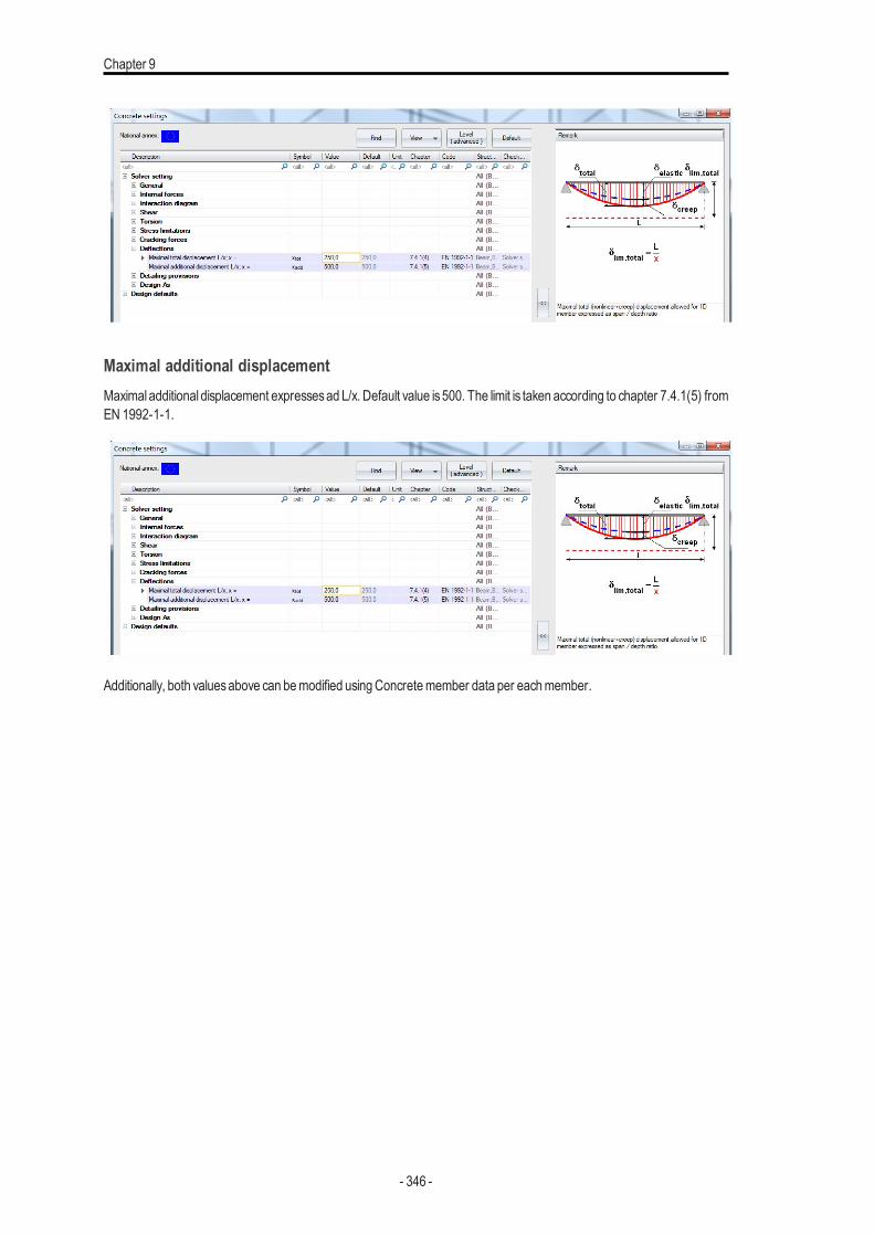
Chapter 9
Maximal additional displacementMaximal additional displacement expressesad L/x. Default value is500. The limit is taken according to chapter 7.4.1(5) fromEN 1992-1-1.
Additionally, both valuesabove can bemodified usingConcretemember data per eachmember.
- 346 -
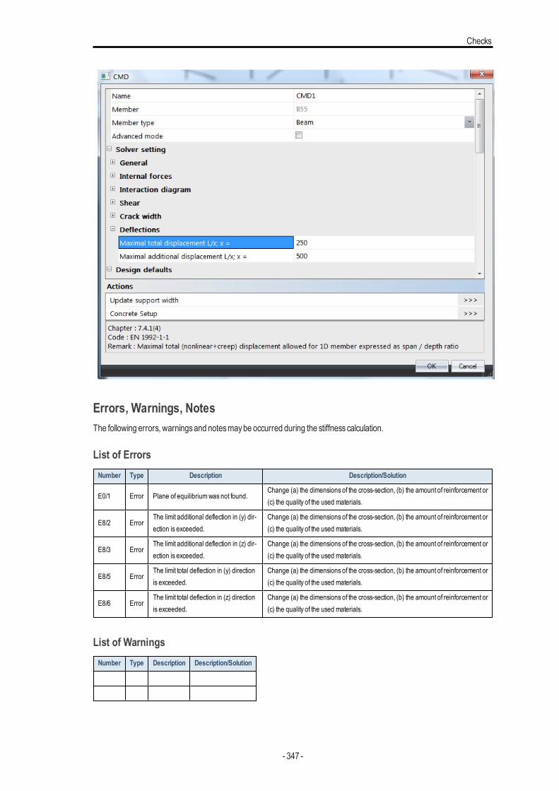
Checks
Errors, Warnings, NotesThe following errors, warningsand notesmaybe occurred during the stiffnesscalculation.
List of ErrorsNumber Type Description Description/Solution
E0/1 Error Plane of equilibriumwas not found.Change (a) the dimensions of the cross-section, (b) the amount of reinforcement or(c) the quality of the used materials.
E8/2 ErrorThe limit additional deflection in (y) dir-ection is exceeded.
Change (a) the dimensions of the cross-section, (b) the amount of reinforcement or(c) the quality of the used materials.
E8/3 ErrorThe limit additional deflection in (z) dir-ection is exceeded.
Change (a) the dimensions of the cross-section, (b) the amount of reinforcement or(c) the quality of the used materials.
E8/5 ErrorThe limit total deflection in (y) directionis exceeded.
Change (a) the dimensions of the cross-section, (b) the amount of reinforcement or(c) the quality of the used materials.
E8/6 ErrorThe limit total deflection in (z) directionis exceeded.
Change (a) the dimensions of the cross-section, (b) the amount of reinforcement or(c) the quality of the used materials.
List of WarningsNumber Type Description Description/Solution
- 347 -
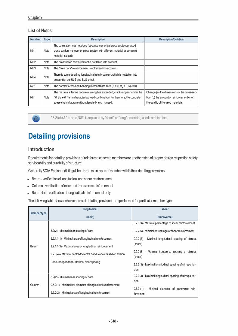
Chapter 9
List of NotesNumber Type Description Description/Solution
N0/1 NoteThe calculation was not done (because numerical cross-section, phasedcross-section,member or cross-section with differentmaterial as concretematerial is used)
N0/2 Note The prestressed reinforcement is not taken into account
N0/3 Note The "Free bars" reinforcement is not taken into account
N0/4 NoteThere is some detailing longitudinal reinforcement, which is not taken intoaccount for the ULS and SLS check
N2/1 Note The normal forces and bending moments are zero (N = 0,My = 0,Mz = 0)
N8/1 NoteThe maximal effective concrete strength is exceeded; cracks appear under the" & State & "-term characteristic load combination. Furthermore, the concretestress-strain diagramwithout tensile branch is used.
Change (a) the dimensions of the cross-sec-tion, (b) the amount of reinforcement or (c)the quality of the used materials.
" &State & " in noteN8/1 is replaced by "short" or "long" according used combination
Detailing provisionsIntroductionRequirements for detailing provisions of reinforced concretemembers are another step of proper design respecting safety,serviceability and durability of structure.
GenerallySCIAEngineer distinguishes threemain typesofmember within their detailing provisions:
l Beam - verification of longitudinal and shear reinforcementl Column - verification ofmain and transverse reinforcementl Beamslab - verification of longitudinal reinforcement only
The following table showswhich checksof detailing provisionsare performed for particular member type:
Member typelongitudinal
(main)
shear
(transverse)
Beam
8.2(2) - Minimal clear spacing of bars
9.2.1.1(1) - Minimal area of longitudinal reinforcement
9.2.1.1(3) - Maximal area of longitudinal reinforcement
9.2.3(4) - Maximal centre-to-centre bar distance based on torsion
Code-Independent - Maximal clear spacing
6.2.3(3) - Maximal percentage of shear reinforcement
9.2.2(5) - Minimal percentage of shear reinforcement
9.2.2 (6) - Maximal longitudinal spacing of stirrups(shear)
9.2.2 (8) - Maximal transverse spacing of stirrups(shear)
9.2.3(3) - Maximal longitudinal spacing of stirrups (tor-sion)
Column
8.2(2) - Minimal clear spacing of bars
9.5.2(1) - Minimal bar diameter of longitudinal reinforcement
9.5.2(2) - Minimal area of longitudinal reinforcement
9.2.3(3) - Maximal longitudinal spacing of stirrups (tor-sion)
9.5.3 (1) - Minimal diameter of transverse rein-forcement
- 348 -
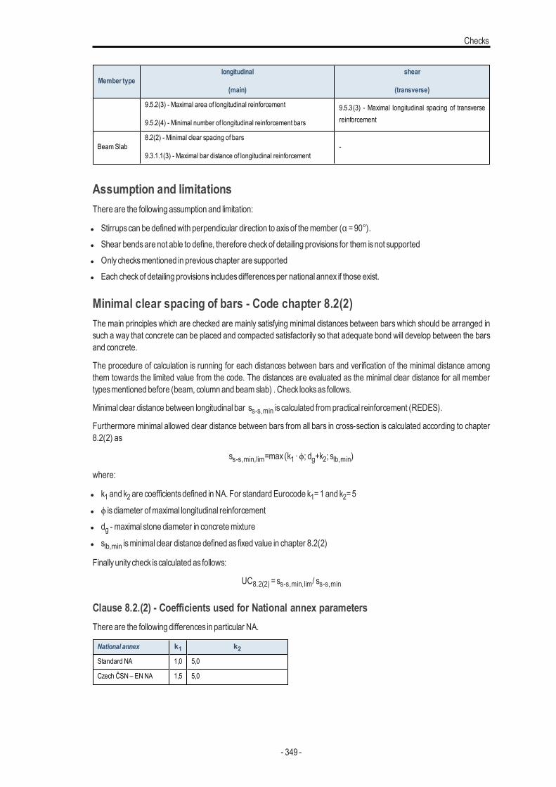
Checks
Member typelongitudinal
(main)
shear
(transverse)
9.5.2(3) - Maximal area of longitudinal reinforcement
9.5.2(4) - Minimal number of longitudinal reinforcement bars
9.5.3(3) - Maximal longitudinal spacing of transversereinforcement
BeamSlab8.2(2) - Minimal clear spacing of bars
9.3.1.1(3) - Maximal bar distance of longitudinal reinforcement-
Assumption and limitationsThere are the following assumption and limitation:
l Stirrupscan be definedwith perpendicular direction to axisof themember (α =90°).l Shear bendsare not able to define, therefore checkof detailing provisions for them isnot supportedl Onlychecksmentioned in previouschapter are supportedl Each checkof detailing provisions includesdifferencesper national annex if those exist.
Minimal clear spacing of bars - Code chapter 8.2(2)The main principles which are checked are mainly satisfying minimal distances between bars which should be arranged insuch a way that concrete can be placed and compacted satisfactorily so that adequate bond will develop between the barsand concrete.
The procedure of calculation is running for each distances between bars and verification of the minimal distance amongthem towards the limited value from the code. The distances are evaluated as the minimal clear distance for all membertypesmentioned before (beam, column and beamslab) . Check looksas follows.
Minimal clear distance between longitudinal bar ss-s,min is calculated frompractical reinforcement (REDES).
Furthermore minimal allowed clear distance between bars from all bars in cross-section is calculated according to chapter8.2(2) as
ss-s,min,lim=max (k1 ∙ϕ; dg+k2; slb,min)
where:
l k1 and k2 are coefficientsdefined inNA. For standard Eurocode k1=1 and k2=5
l ϕ is diameter ofmaximal longitudinal reinforcementl dg - maximal stone diameter in concretemixture
l slb,min isminimal clear distance defined as fixed value in chapter 8.2(2)
Finallyunity check is calculated as follows:
UC8.2(2) =ss-s,min,lim/ ss-s,min
Clause 8.2.(2) - Coefficients used for National annex parametersThere are the following differences in particular NA.
National annex k1 k2Standard NA 1,0 5,0
Czech ČSN – ENNA 1,5 5,0
- 349 -
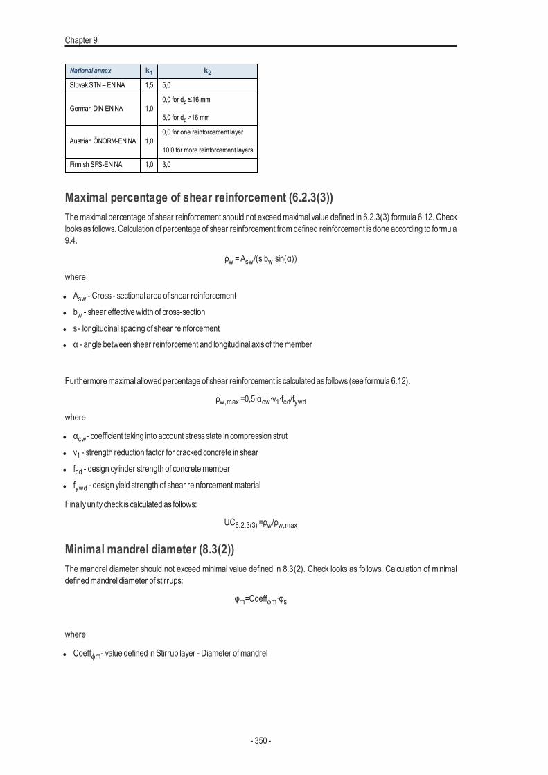
Chapter 9
National annex k1 k2Slovak STN – ENNA 1,5 5,0
German DIN-ENNA 1,00,0 for dg ≤16 mm
5,0 for dg >16 mm
Austrian ÖNORM-ENNA 1,00,0 for one reinforcement layer
10,0 for more reinforcement layers
Finnish SFS-ENNA 1,0 3,0
Maximal percentage of shear reinforcement (6.2.3(3))Themaximal percentage of shear reinforcement should not exceed maximal value defined in 6.2.3(3) formula 6.12. Checklooksas follows. Calculation of percentage of shear reinforcement from defined reinforcement is done according to formula9.4.
ρw =Asw/(s∙bw∙sin(α))
where
l Asw - Cross - sectional area of shear reinforcement
l bw - shear effectivewidth of cross-section
l s - longitudinal spacing of shear reinforcementl α - angle between shear reinforcement and longitudinal axisof themember
Furthermoremaximal allowed percentage of shear reinforcement is calculated as follows (see formula 6.12).
ρw,max =0,5∙αcw∙ν1∙fcd/fywdwhere
l αcw- coefficient taking into account stressstate in compression strut
l ν1 - strength reduction factor for cracked concrete in shear
l fcd - design cylinder strength of concretemember
l fywd - design yield strength of shear reinforcementmaterial
Finallyunity check is calculated as follows:
UC6.2.3(3) =ρw/ρw,max
Minimal mandrel diameter (8.3(2))The mandrel diameter should not exceed minimal value defined in 8.3(2). Check looks as follows. Calculation of minimaldefinedmandrel diameter of stirrups:
φm=Coeffϕm∙φs
where
l Coeffϕm- value defined in Stirrup layer - Diameter ofmandrel
- 350 -
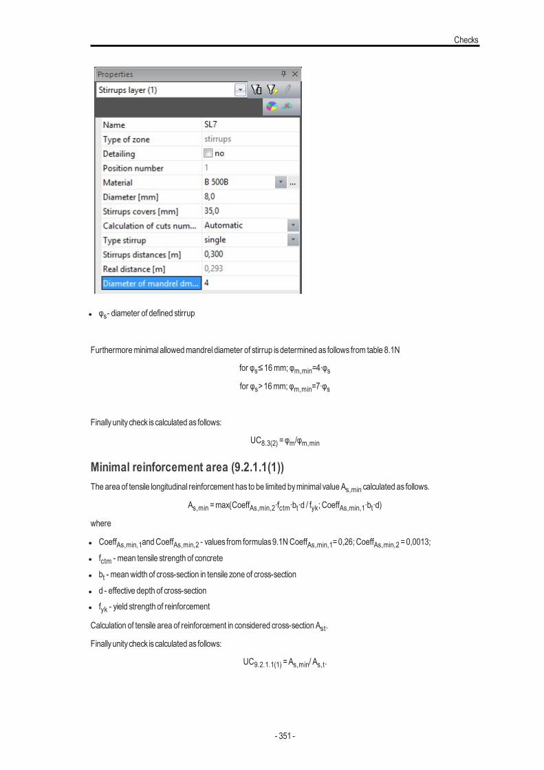
Checks
l φs- diameter of defined stirrup
Furthermoreminimal allowedmandrel diameter of stirrup isdetermined as follows from table 8.1N
for φs≤16mm; φm,min=4∙φsfor φs>16mm; φm,min=7∙φs
Finallyunity check is calculated as follows:
UC8.3(2) =φm/φm,min
Minimal reinforcement area (9.2.1.1(1))The area of tensile longitudinal reinforcement has to be limited byminimal value As,min calculated as follows.
As,min =max(CoeffAs,min,2∙fctm∙bt∙d / fyk; CoeffAs,min,1∙bt∙d)
where
l CoeffAs,min,1andCoeffAs,min,2 - values from formulas9.1NCoeffAs,min,1=0,26; CoeffAs,min,2 =0,0013;
l fctm - mean tensile strength of concrete
l bt - meanwidth of cross-section in tensile zone of cross-section
l d - effective depth of cross-sectionl fyk - yield strength of reinforcement
Calculation of tensile area of reinforcement in considered cross-section Ast.
Finallyunity check is calculated as follows:
UC9.2.1.1(1) =As,min/ As,t.
- 351 -
Chapter 9
Clause 9.2.1.1(1) - Minimal tensile reinforcement for National annexThere are the following differences in particular NA.
National annex formula 9.1N formula 9.1N
Standard NA CoeffAs,min,2∙fctm∙bt∙d / fyk CoeffAs,min,1∙bt∙d
German DIN-ENNA Not used Not used
Dutch NEN-EN NA CoeffAs,min,2∙fctm∙bt∙d / fyk * CoeffAs,min,1∙bt∙d *
German NA doesn’t give the limit for minimal tensile area of longitudinal reinforcement. Inthis case unity check is=0
* The procedure for Dutch NEN-NA gives another rule. The values from table above aremarked as As,min,1 . Additionally necessary area from ULS (As,req ) is calculated asAs,min,2 = 1,25 ∙ As,req. Finally, the minimal allowed value of longitudinal reinforcement is:As,min =max (As,min,1; As,min,2).
Maximal area of reinforcement (9.2.1.1(3))The maximal area of longitudinal reinforcement As,max should not exceed the values described in 9.2.1.1(3). and is cal-culated as follows.
As,max =0,04∙Acwhere
l Ac - area of concrete cross-section
Calculation of longitudinal reinforcement area in considered cross-section AsFinallyunity check is calculated as follows:
UC9.2.1.1(3) =As/ As,max
Clause 9.2.1.1(3) - Maximal area of reinforcement for National annexThere are the following differences in particular NA.
National annex formula
Standard NA 0,04∙AcGerman DIN-ENNA 0,08∙AcFinnish SFS-ENNA Not limited
Swedish SS-ENNA Not limited
Slovenian SIST-ENNA Not limited
The verification for SFS, SS and SIST NA is not done at all and unity check is set toUC9.2.1.1(3) =0
- 352 -
Checks
Minimal percentage of shear reinforcement (9.2.2(5))The minimal percentage of shear reinforcement should not exceed minimal value defined in 9.2.2(5). Check looks as fol-lows. Calculation of percentage of shear reinforcement fromdefined reinforcement isdone according to formula 9.4.
ρw =Asw / (s ∙ bw ∙ sin(α))
where
l Asw - Cross - sectional area of shear reinforcement
l bw - shear effectivewidth of cross-section
l s - longitudinal spacing of shear reinforcementl α - angle between shear reinforcement and longitudinal axisof themember
Furthermoreminimal allowed percentage of shear reinforcement is calculated as follows (see formula 9.5N).
ρw,min =0.08 ∙ √fck / fykwhere
l fck - characteristic cylinder strength of concretemember
l fyk - characteristic yield strength of reinforcementmaterial
Finallyunity check is calculated as follows:
UC9.2.2(5) =ρw,min / ρw
Clause 9.2.2.(5) - Minimal percentage of shear reinforcement for National annexThere are the following differences in particular NA.
National annex formula 9.5N
Standard NA 0.08 ∙ √fck / fykGerman DIN-ENNA 0.16 ∙ fctm / fykAustrian ÖNORM-ENNA 0.15 ∙ fctm / fyd
Maximal longitudinal spacing of stirrups based on shear (9.2.2(6))The maximal longitudinal spacing between stirrups links should not exceed maximal value defined in 9.2.2(6). Check looksas follows. Calculation ofmaximal defined longitudinal distance of stirrups sl.
Furthermoremaximal allowed longitudinal distance between stirrups is calculated as follows
sl,max =0,75∙d∙(1+cotg (α))
where:
l d - effective depth of cross-sectionl α - angle of stirrups to longitudinal axisof themember
Finallyunity check is calculated as follows:
UC9.2.2(6) =sl/ sl,max.
Clause 9.2.2.(6) - Maximal longitudinal spacing of stirrups for National annexThere are the following differences in particular NA.
- 353 -
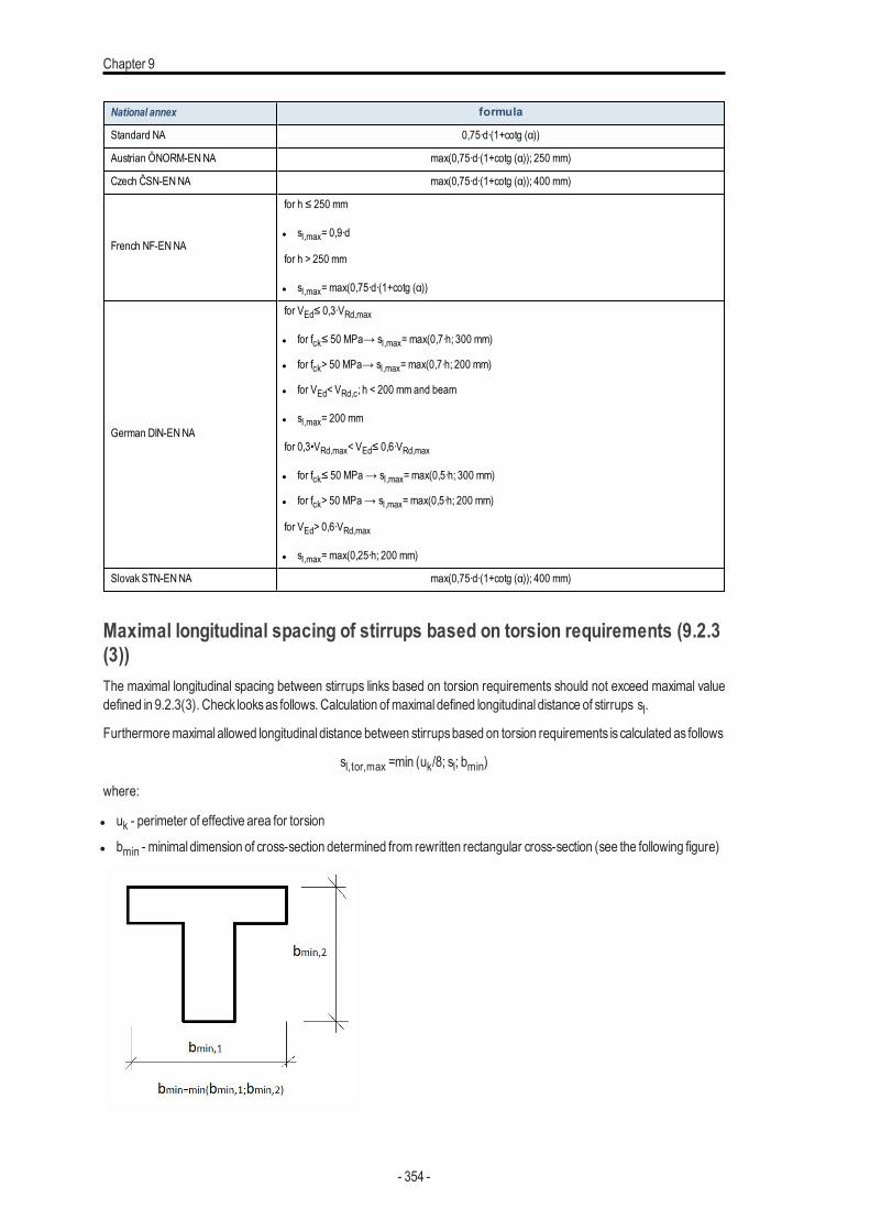
Chapter 9
National annex formula
Standard NA 0,75∙d∙(1+cotg (α))
Austrian ÖNORM-ENNA max(0,75∙d∙(1+cotg (α)); 250 mm)
Czech ČSN-ENNA max(0,75∙d∙(1+cotg (α)); 400 mm)
French NF-ENNA
for h ≤ 250 mm
l sl,max= 0,9∙d
for h > 250 mm
l sl,max= max(0,75∙d∙(1+cotg (α))
German DIN-ENNA
for VEd≤ 0,3∙VRd,max
l for fck≤ 50 MPa→ sl,max= max(0,7∙h; 300 mm)
l for fck> 50 MPa→ sl,max= max(0,7∙h; 200 mm)
l for VEd< VRd,c; h < 200 mmand beam
l sl,max= 200 mm
for 0,3•VRd,max< VEd≤ 0,6∙VRd,max
l for fck≤ 50 MPa→ sl,max= max(0,5∙h; 300 mm)
l for fck> 50 MPa→ sl,max= max(0,5∙h; 200 mm)
for VEd> 0,6∙VRd,max
l sl,max= max(0,25∙h; 200 mm)
Slovak STN-ENNA max(0,75∙d∙(1+cotg (α)); 400 mm)
Maximal longitudinal spacing of stirrups based on torsion requirements (9.2.3(3))The maximal longitudinal spacing between stirrups links based on torsion requirements should not exceed maximal valuedefined in 9.2.3(3). Check looksas follows. Calculation ofmaximal defined longitudinal distance of stirrups sl.
Furthermoremaximal allowed longitudinal distance between stirrupsbased on torsion requirements is calculated as follows
sl,tor,max =min (uk/8; sl; bmin)
where:
l uk - perimeter of effective area for torsion
l bmin - minimal dimension of cross-section determined from rewritten rectangular cross-section (see the following figure)
- 354 -
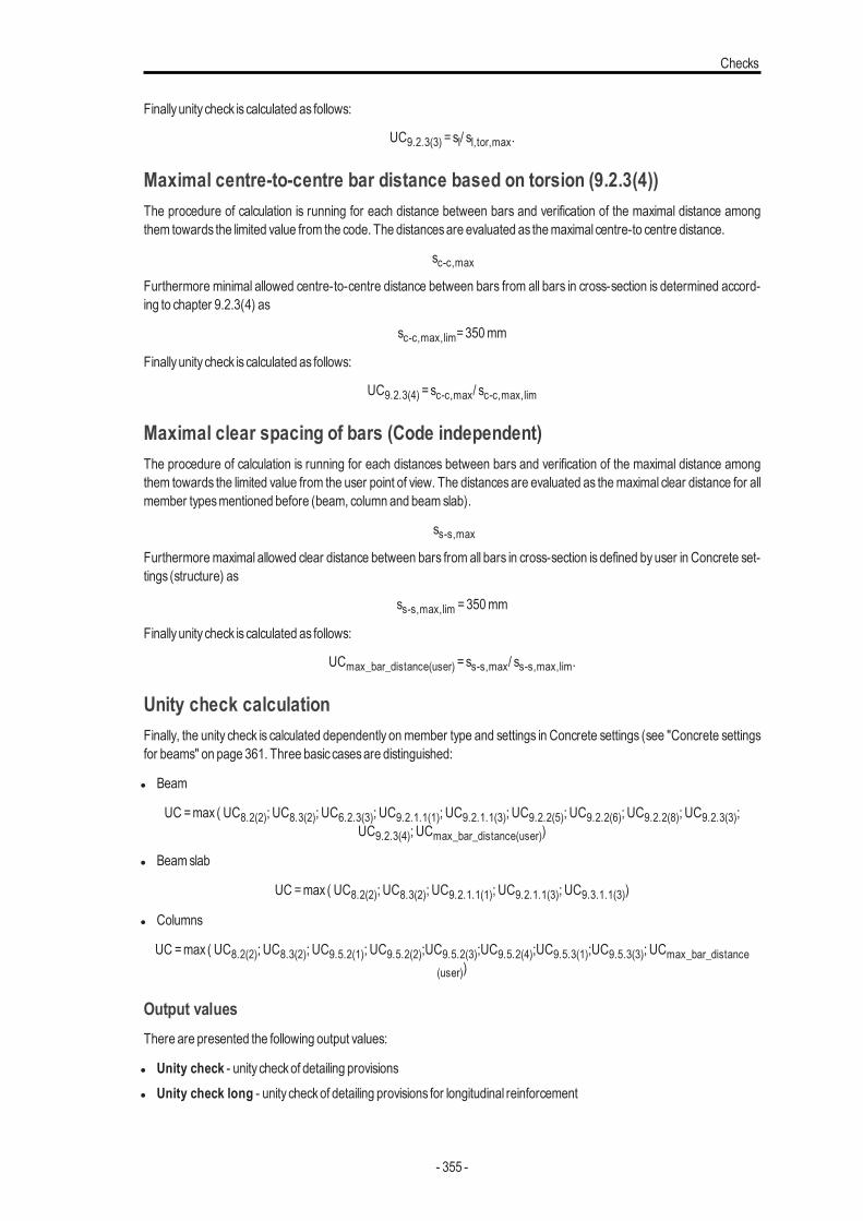
Checks
Finallyunity check is calculated as follows:
UC9.2.3(3) =sl/ sl,tor,max.
Maximal centre-to-centre bar distance based on torsion (9.2.3(4))The procedure of calculation is running for each distance between bars and verification of the maximal distance amongthem towards the limited value from the code. The distancesare evaluated as themaximal centre-to centre distance.
sc-c,max
Furthermore minimal allowed centre-to-centre distance between bars from all bars in cross-section is determined accord-ing to chapter 9.2.3(4) as
sc-c,max,lim=350mm
Finallyunity check is calculated as follows:
UC9.2.3(4) =sc-c,max/ sc-c,max,lim
Maximal clear spacing of bars (Code independent)The procedure of calculation is running for each distances between bars and verification of the maximal distance amongthem towards the limited value from the user point of view. The distancesare evaluated as themaximal clear distance for allmember typesmentioned before (beam, column and beamslab).
ss-s,max
Furthermoremaximal allowed clear distance between bars from all bars in cross-section is defined byuser in Concrete set-tings (structure) as
ss-s,max,lim =350mm
Finallyunity check is calculated as follows:
UCmax_bar_distance(user) =ss-s,max/ ss-s,max,lim.
Unity check calculationFinally, the unity check is calculated dependently onmember type and settings in Concrete settings (see "Concrete settingsfor beams" on page 361. Three basic casesare distinguished:
l Beam
UC=max ( UC8.2(2); UC8.3(2); UC6.2.3(3); UC9.2.1.1(1); UC9.2.1.1(3); UC9.2.2(5); UC9.2.2(6); UC9.2.2(8); UC9.2.3(3);UC9.2.3(4); UCmax_bar_distance(user))
l Beamslab
UC =max ( UC8.2(2); UC8.3(2); UC9.2.1.1(1); UC9.2.1.1(3); UC9.3.1.1(3))
l Columns
UC =max ( UC8.2(2); UC8.3(2); UC9.5.2(1); UC9.5.2(2);UC9.5.2(3);UC9.5.2(4);UC9.5.3(1);UC9.5.3(3); UCmax_bar_distance(user))
Output valuesThere are presented the following output values:
l Unity check - unity checkof detailing provisionsl Unity check long - unity checkof detailing provisions for longitudinal reinforcement
- 355 -
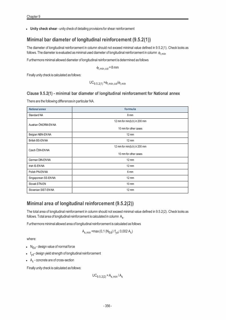
Chapter 9
l Unity check shear - unity checkof detailing provisions for shear reinforcement
Minimal bar diameter of longitudinal reinforcement (9.5.2(1))The diameter of longitudinal reinforcement in column should not exceed minimal value defined in 9.5.2(1). Check looks asfollows. The diameter isevaluated asminimal used diameter of longitudinal reinforcement in column ϕl,min
Furthermoreminimal allowed diameter of longitudinal reinforcement isdetermined as follows
ϕl,min,col =8mm
Finallyunity check is calculated as follows:
UC9.5.2(1) =ϕl,min,col/ϕl,min
Clause 9.5.2(1) - minimal bar diameter of longitudinal reinforcement for National annexThere are the following differences in particular NA.
National annex formula
Standard NA 8 mm
Austrian ÖNORM-ENNA12 mm for min(b,h) ≥ 200 mm
10 mm for other cases
Belgian NBN-ENNA 12 mm
British BS-ENNA 12 mm
Czech ČSN-ENNA12 mm for min(b,h) ≥ 200 mm
10 mm for other cases
German DIN-ENNA 12 mm
Irish IS-ENNA 12 mm
Polish PN-ENNA 6 mm
Singaporean SS-ENNA 12 mm
Slovak STN-EN 10 mm
Slovenian SIST-ENNA 12 mm
Minimal area of longitudinal reinforcement (9.5.2(2))The total area of longitudinal reinforcement in column should not exceed minimal value defined in 9.5.2(2). Check looks asfollows. Total area of longitudinal reinforcement is calculated in column As.
Furthermoreminimal allowed area of longitudinal reinforcement is calculated as follows
As,min =max (0,1∙|NEd| / fyd; 0,002∙Ac)
where:
l NEd - design value of normal force
l fyd- design yield strength of longitudinal reinforcement
l Ac - concrete are of cross-section
Finallyunity check is calculated as follows:
UC9.5.2(2) =As,min / As
- 356 -
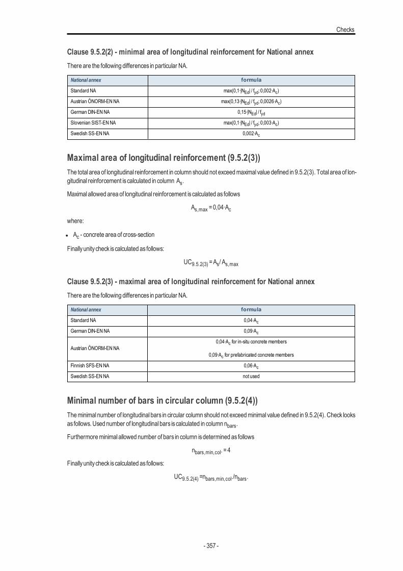
Checks
Clause 9.5.2(2) - minimal area of longitudinal reinforcement for National annexThere are the following differences in particular NA.
National annex formula
Standard NA max(0,1∙|NEd| / fyd; 0,002∙Ac)
Austrian ÖNORM-ENNA max(0,13∙|NEd| / fyd; 0,0026∙Ac)
German DIN-ENNA 0,15∙|NEd| / fydSlovenian SIST-ENNA max(0,1∙|NEd| / fyd; 0,003∙Ac)
Swedish SS-ENNA 0,002∙Ac
Maximal area of longitudinal reinforcement (9.5.2(3))The total area of longitudinal reinforcement in column should not exceedmaximal value defined in 9.5.2(3). Total area of lon-gitudinal reinforcement is calculated in column As.
Maximal allowed area of longitudinal reinforcement is calculated as follows
As,max =0,04∙Acwhere:
l Ac - concrete area of cross-section
Finallyunity check is calculated as follows:
UC9.5.2(3) =As/ As,max
Clause 9.5.2(3) - maximal area of longitudinal reinforcement for National annexThere are the following differences in particular NA.
National annex formula
Standard NA 0,04∙AcGerman DIN-ENNA 0,09∙Ac
Austrian ÖNORM-ENNA0,04∙Ac for in-situ concrete members
0,09∙Ac for prefabricated concrete members
Finnish SFS-ENNA 0,06∙AcSwedish SS-ENNA not used
Minimal number of bars in circular column (9.5.2(4))Theminimal number of longitudinal bars in circular column should not exceedminimal value defined in 9.5.2(4). Check looksas follows. Used number of longitudinal bars is calculated in column nbars.
Furthermoreminimal allowed number of bars in column isdetermined as follows
nbars,min,col. =4
Finallyunity check is calculated as follows:
UC9.5.2(4) =nbars,min,col./nbars.
- 357 -
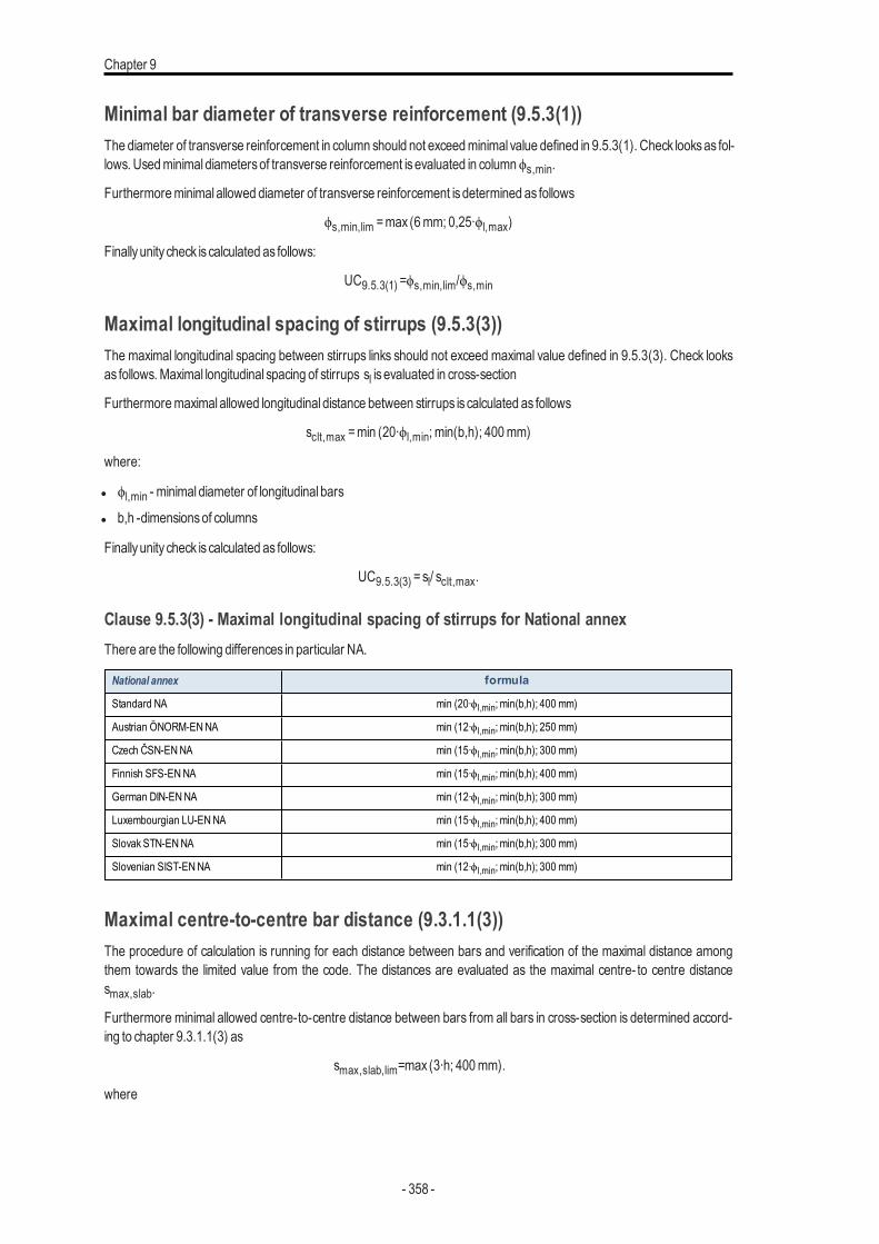
Chapter 9
Minimal bar diameter of transverse reinforcement (9.5.3(1))The diameter of transverse reinforcement in column should not exceedminimal value defined in 9.5.3(1). Check looksas fol-lows. Usedminimal diametersof transverse reinforcement isevaluated in columnϕs,min.
Furthermoreminimal allowed diameter of transverse reinforcement isdetermined as follows
ϕs,min,lim =max (6mm; 0,25∙ϕl,max)
Finallyunity check is calculated as follows:
UC9.5.3(1) =ϕs,min,lim/ϕs,min
Maximal longitudinal spacing of stirrups (9.5.3(3))The maximal longitudinal spacing between stirrups links should not exceed maximal value defined in 9.5.3(3). Check looksas follows.Maximal longitudinal spacing of stirrups sl is evaluated in cross-section
Furthermoremaximal allowed longitudinal distance between stirrups is calculated as follows
sclt,max =min (20∙ϕl,min; min(b,h); 400mm)
where:
l ϕl,min - minimal diameter of longitudinal bars
l b,h -dimensionsof columns
Finallyunity check is calculated as follows:
UC9.5.3(3) =sl/ sclt,max.
Clause 9.5.3(3) - Maximal longitudinal spacing of stirrups for National annexThere are the following differences in particular NA.
National annex formula
Standard NA min (20∙ϕl,min; min(b,h); 400 mm)
Austrian ÖNORM-ENNA min (12∙ϕl,min; min(b,h); 250 mm)
Czech ČSN-ENNA min (15∙ϕl,min; min(b,h); 300 mm)
Finnish SFS-ENNA min (15∙ϕl,min; min(b,h); 400 mm)
German DIN-ENNA min (12∙ϕl,min; min(b,h); 300 mm)
Luxembourgian LU-ENNA min (15∙ϕl,min; min(b,h); 400 mm)
Slovak STN-ENNA min (15∙ϕl,min; min(b,h); 300 mm)
Slovenian SIST-ENNA min (12∙ϕl,min; min(b,h); 300 mm)
Maximal centre-to-centre bar distance (9.3.1.1(3))The procedure of calculation is running for each distance between bars and verification of the maximal distance amongthem towards the limited value from the code. The distances are evaluated as the maximal centre- to centre distancesmax,slab.
Furthermore minimal allowed centre-to-centre distance between bars from all bars in cross-section is determined accord-ing to chapter 9.3.1.1(3) as
smax,slab,lim=max (3∙h; 400mm).
where
- 358 -
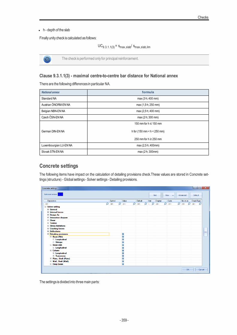
Checks
l h - depth of the slab
Finallyunity check is calculated as follows:
UC9.3.1.1(3) = smax,slab/ smax,slab,lim
The check isperformed only for principal reinforcement.
Clause 9.3.1.1(3) - maximal centre-to-centre bar distance for National annexThere are the following differences in particular NA.
National annex formula
Standard NA max (3∙h; 400 mm)
Austrian ÖNORM-ENNA max (1,5∙h; 250 mm)
Belgian NBN-ENNA max (2,5∙h; 400 mm)
Czech ČSN-ENNA max (2∙h; 300 mm)
German DIN-ENNA
150 mm for h ≤ 150 mm
h for (150 mm< h < 250 mm)
250 mm for h ≥ 250 mm
Luxembourgian LU-ENNA max (2,5∙h; 400mm)
Slovak STN-ENNA max (2∙h; 300mm)
Concrete settingsThe following items have impact on the calculation of detailing provisions check.These values are stored in Concrete set-tings (structure) - Global settings - Solver settings - Detailing provisions.
The settings isdivided into threemain parts:
- 359 -
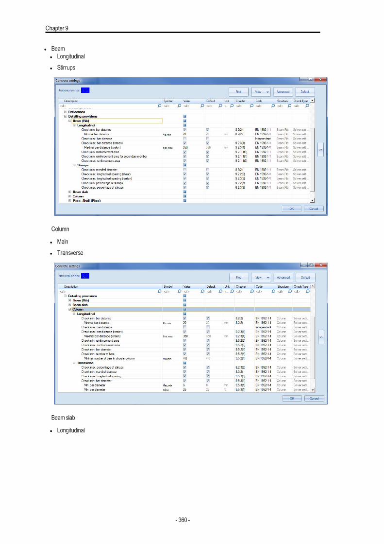
Chapter 9
l Beaml Longitudinall Stirrups
Column
l Mainl Transverse
Beamslab
l Longitudinal
- 360 -
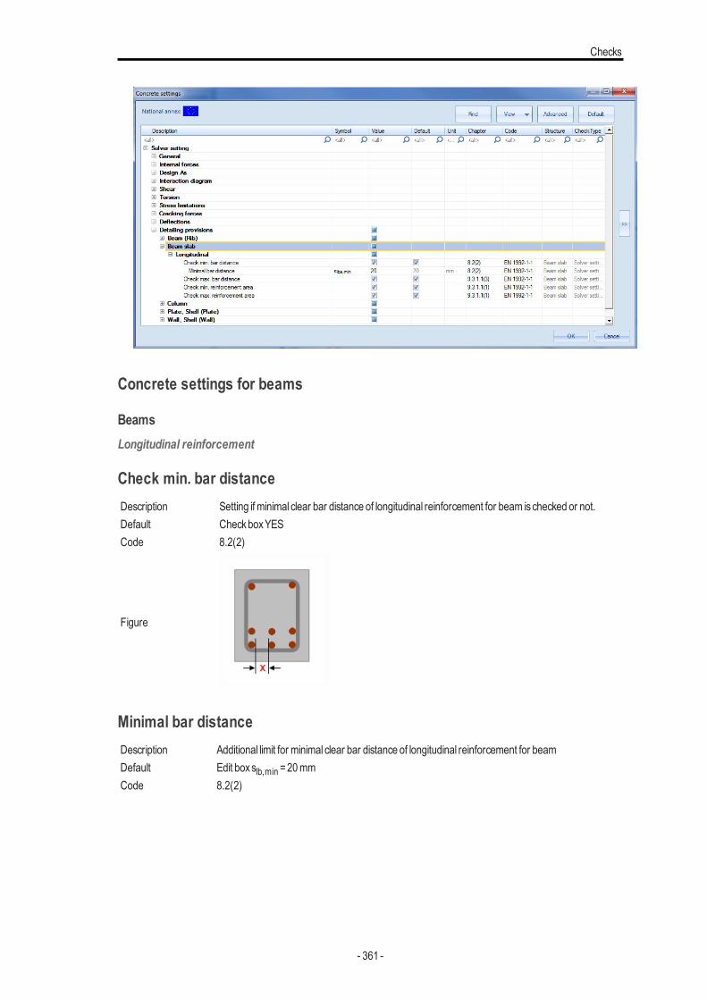
Checks
Concrete settings for beams
BeamsLongitudinal reinforcement
Check min. bar distanceDescription Setting if minimal clear bar distance of longitudinal reinforcement for beam ischecked or not.Default CheckboxYESCode 8.2(2)
Figure
Minimal bar distanceDescription Additional limit for minimal clear bar distance of longitudinal reinforcement for beamDefault Edit boxslb,min =20mmCode 8.2(2)
- 361 -
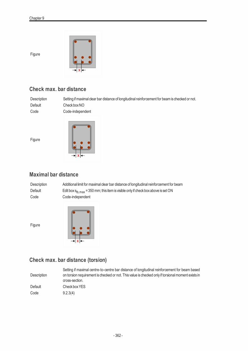
Chapter 9
Figure
Check max. bar distanceDescription Setting if maximal clear bar distance of longitudinal reinforcement for beam ischecked or not.Default CheckboxNOCode Code-independent
Figure
Maximal bar distanceDescription Additional limit for maximal clear bar distance of longitudinal reinforcement for beamDefault Edit boxslb,max =350mm; this item isvisible only if checkboxabove isset ONCode Code-independent
Figure
Check max. bar distance (torsion)
DescriptionSetting if maximal centre-to-centre bar distance of longitudinal reinforcement for beam basedon torsion requirement is checked or not. This value is checked only if torsionalmoment exists incross-section.
Default CheckboxYESCode 9.2.3(4)
- 362 -
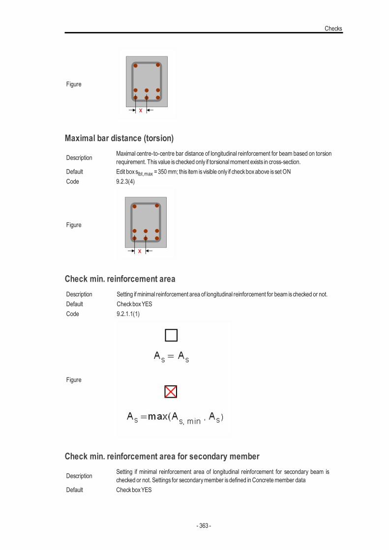
Checks
Figure
Maximal bar distance (torsion)
Description Maximal centre-to-centre bar distance of longitudinal reinforcement for beam based on torsionrequirement. This value is checked only if torsionalmoment exists in cross-section.
Default Edit boxslbt,max =350mm; this item isvisible only if checkboxabove isset ONCode 9.2.3(4)
Figure
Check min. reinforcement areaDescription Setting if minimal reinforcement area of longitudinal reinforcement for beam ischecked or not.Default CheckboxYESCode 9.2.1.1(1)
Figure
Check min. reinforcement area for secondary member
Description Setting if minimal reinforcement area of longitudinal reinforcement for secondary beam ischecked or not. Settings for secondarymember isdefined inConcretemember data
Default CheckboxYES
- 363 -
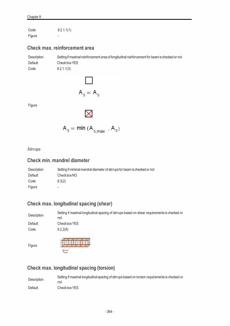
Chapter 9
Code 9.2.1.1(1)Figure -
Check max. reinforcement areaDescription Setting if maximal reinforcement area of longitudinal reinforcement for beam ischecked or not.Default CheckboxYESCode 9.2.1.1(3)
Figure
Stirrups
Check min. mandrel diameterDescription Setting if minimalmandrel diameter of stirrups for beam ischecked or notDefault CheckboxNOCode 8.3(2)Figure -
Check max. longitudinal spacing (shear)
Description Setting if maximal longitudinal spacing of stirrups based on shear requirements is checked ornot.
Default CheckboxYESCode 9.2.2(6)
Figure
Check max. longitudinal spacing (torsion)
Description Setting if maximal longitudinal spacing of stirrups based on torsion requirements is checked ornot.
Default CheckboxYES
- 364 -
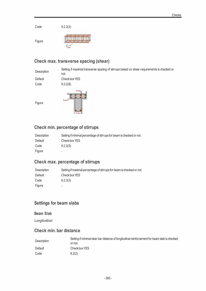
Checks
Code 9.2.3(3)
Figure
Check max. transverse spacing (shear)
Description Setting if maximal transverse spacing of stirrups based on shear requirements is checked ornot.
Default CheckboxYESCode 9.2.2(8)
Figure
Check min. percentage of stirrupsDescription Setting if minimal percentage of stirrups for beam ischecked or not.Default CheckboxYESCode 9.2.2(5)Figure -
Check max. percentage of stirrupsDescription Setting if maximal percentage of stirrups for beam ischecked or not.Default CheckboxYESCode 6.2.3(3)Figure -
Settings for beam slabs
Beam SlabLongitudinal
Check min. bar distance
Description Setting if minimal clear bar distance of longitudinal reinforcement for beam slab is checkedor not.
Default CheckboxYESCode 8.2(2)
- 365 -
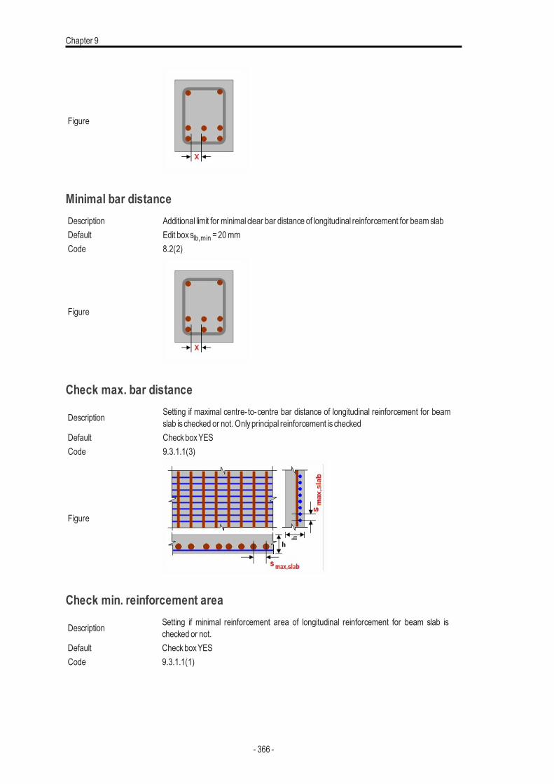
Chapter 9
Figure
Minimal bar distanceDescription Additional limit for minimal clear bar distance of longitudinal reinforcement for beamslabDefault Edit boxslb,min =20mmCode 8.2(2)
Figure
Check max. bar distance
Description Setting if maximal centre-to-centre bar distance of longitudinal reinforcement for beamslab is checked or not. Onlyprincipal reinforcement is checked
Default CheckboxYESCode 9.3.1.1(3)
Figure
Check min. reinforcement area
Description Setting if minimal reinforcement area of longitudinal reinforcement for beam slab ischecked or not.
Default CheckboxYESCode 9.3.1.1(1)
- 366 -
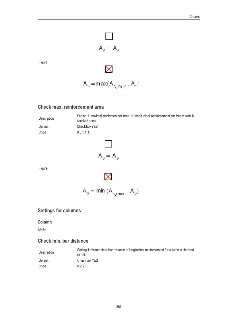
Checks
Figure
Check max. reinforcement area
Description Setting if maximal reinforcement area of longitudinal reinforcement for beam slab ischecked or not.
Default CheckboxYESCode 9.3.1.1(1)
Figure
Settings for columns
ColumnMain
Check min. bar distance
Description Setting if minimal clear bar distance of longitudinal reinforcement for column is checkedor not.
Default CheckboxYESCode 8.2(2)
- 367 -
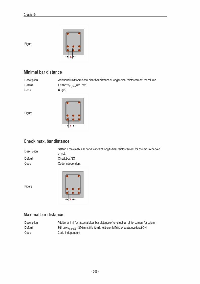
Chapter 9
Figure
Minimal bar distanceDescription Additional limit for minimal clear bar distance of longitudinal reinforcement for columnDefault Edit boxslc,min =20mmCode 8.2(2)
Figure
Check max. bar distance
Description Setting if maximal clear bar distance of longitudinal reinforcement for column is checkedor not.
Default CheckboxNOCode Code-independent
Figure
Maximal bar distanceDescription Additional limit for maximal clear bar distance of longitudinal reinforcement for columnDefault Edit boxslc,max =350mm; this item isvisible only if checkboxabove isset ONCode Code-independent
- 368 -
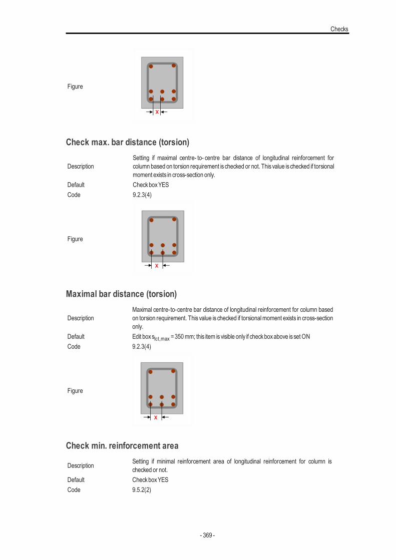
Checks
Figure
Check max. bar distance (torsion)
DescriptionSetting if maximal centre- to- centre bar distance of longitudinal reinforcement forcolumn based on torsion requirement is checked or not. This value is checked if torsionalmoment exists in cross-section only.
Default CheckboxYESCode 9.2.3(4)
Figure
Maximal bar distance (torsion)
DescriptionMaximal centre-to-centre bar distance of longitudinal reinforcement for column basedon torsion requirement. This value is checked if torsionalmoment exists in cross-sectiononly.
Default Edit boxslct,max =350mm; this item isvisible only if checkboxabove isset ONCode 9.2.3(4)
Figure
Check min. reinforcement area
Description Setting if minimal reinforcement area of longitudinal reinforcement for column ischecked or not.
Default CheckboxYESCode 9.5.2(2)
- 369 -
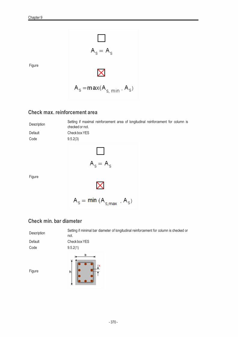
Chapter 9
Figure
Check max. reinforcement area
Description Setting if maximal reinforcement area of longitudinal reinforcement for column ischecked or not.
Default CheckboxYESCode 9.5.2(3)
Figure
Check min. bar diameter
Description Setting if minimal bar diameter of longitudinal reinforcement for column is checked ornot.
Default CheckboxYESCode 9.5.2(1)
Figure
- 370 -
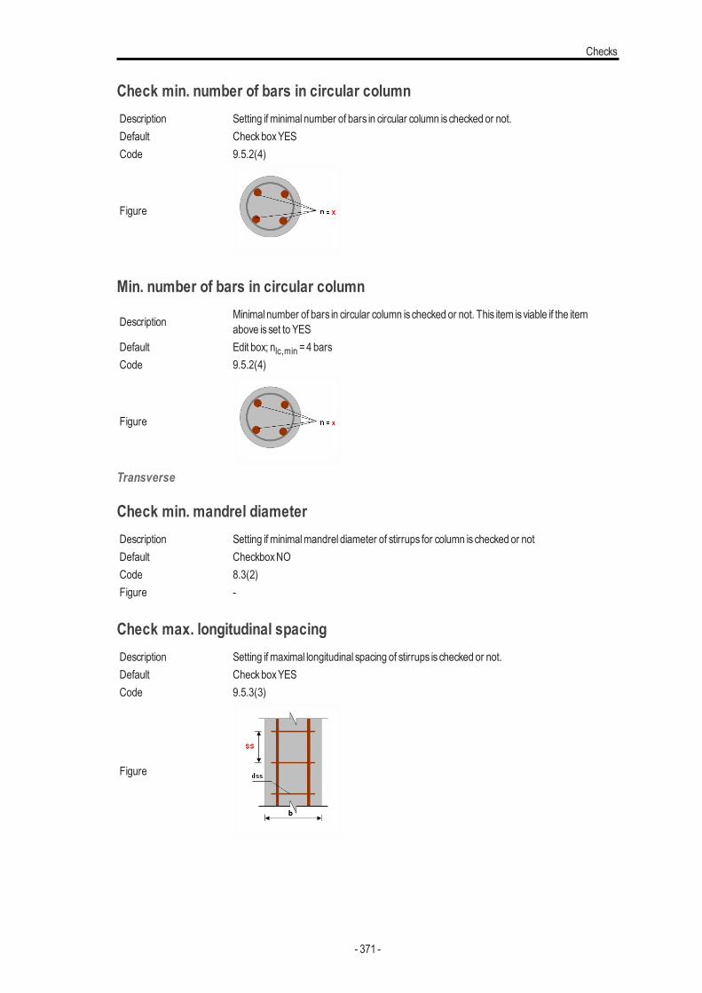
Checks
Check min. number of bars in circular columnDescription Setting if minimal number of bars in circular column ischecked or not.Default CheckboxYESCode 9.5.2(4)
Figure
Min. number of bars in circular column
Description Minimal number of bars in circular column ischecked or not. This item isviable if the itemabove isset to YES
Default Edit box; nlc,min =4 barsCode 9.5.2(4)
Figure
Transverse
Check min. mandrel diameterDescription Setting if minimalmandrel diameter of stirrups for column ischecked or notDefault CheckboxNOCode 8.3(2)Figure -
Check max. longitudinal spacingDescription Setting if maximal longitudinal spacing of stirrups is checked or not.Default CheckboxYESCode 9.5.3(3)
Figure
- 371 -
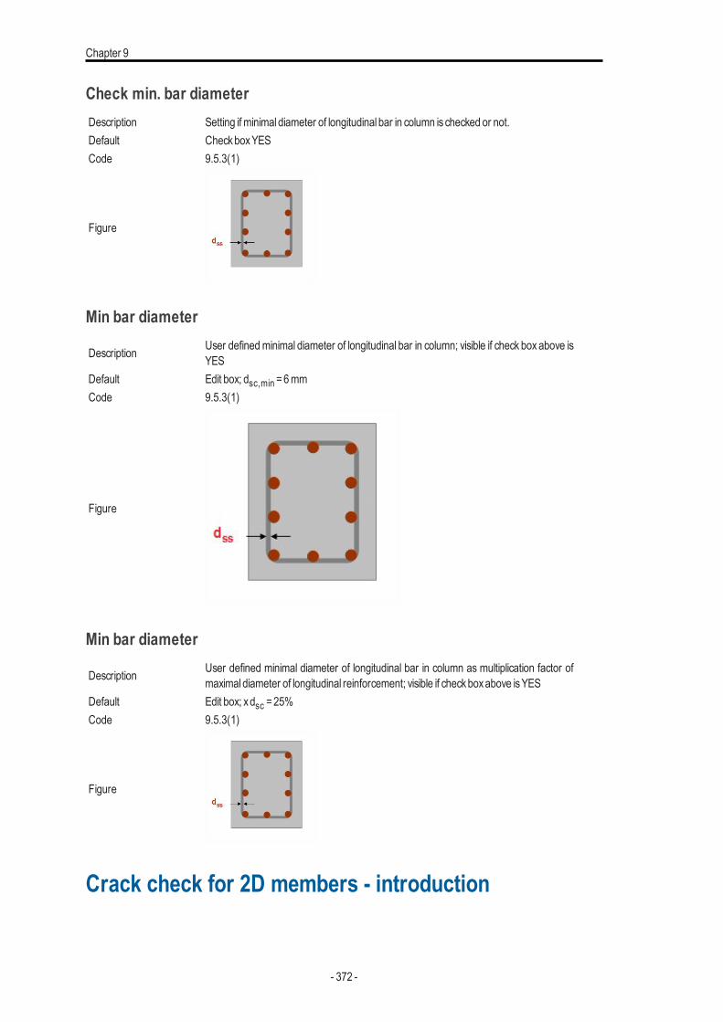
Chapter 9
Check min. bar diameterDescription Setting if minimal diameter of longitudinal bar in column ischecked or not.Default CheckboxYESCode 9.5.3(1)
Figure
Min bar diameter
Description User definedminimal diameter of longitudinal bar in column; visible if check box above isYES
Default Edit box; dsc,min =6mmCode 9.5.3(1)
Figure
Min bar diameter
Description User defined minimal diameter of longitudinal bar in column as multiplication factor ofmaximal diameter of longitudinal reinforcement; visible if checkboxabove isYES
Default Edit box; xdsc =25%Code 9.5.3(1)
Figure
Crack check for 2D members - introduction
- 372 -
Checks
The SCIAEngineer program from version 16.1 allowsusers to check crackwidths for 2Dmember according to EN 1992-1-1 includingNA inConcrete.
The main principle of calculation:l The crackwidth is calculated for both surfacesof 2Dmemberl All typesof 2Dmembersare supported (plate, shells, wall)l The crackwidth is calculated in the direction of the principal stressesat both surfacesof 2Dmemberl The tension stiffening of concrete between crackscan be taken into accountl The prestressing reinforcement inputted in the 2Dmember isnot taken into accountl The influence of ribs isalways taken into account (the internal forcesand designed reinforcement in the direction of the rib
at the effectivewidth of the rib is zero for 2Dmember)l The following load cases/combination/classesare supported
l all typesof load casesl standard SLScombination (linear-serviceability, EN-SLSChar, EN-SLSFreq, EN –SLSQuasi)l nonlinear combinationwith Type =serviceabilityl classwhere one or more combinationsdescribed above are available
l The crackwidth can be calculated for the user (real) defined reinforcement
Note - The direction of crackwidth isnot currently (version 16.1) shown in the graphicalwin-dow
Designed reinforcement isnot taken into account in version 16.1
Assumption
Setting of calculationBefore the calculation of crackwidth can be done, it is necessary to:
l run linear calculationl checkor edit default values in the concrete setupl input user reinforcement via 2Dmeshesor via Concretemember data
ReinforcementAswasmentioned before user reinforcement only is taken into account. The user reinforcement can be inputted via
l reinforcement 2D (meshes)l free barsl concretemember data (the reinforcement is the same for whole 2Dmember)
User reinforcement via Concrete member dataWhen the reinforcement via 2Dmeshes is not defined then it is possible to define User reinforcement via Concrete memberdata.
- 373 -
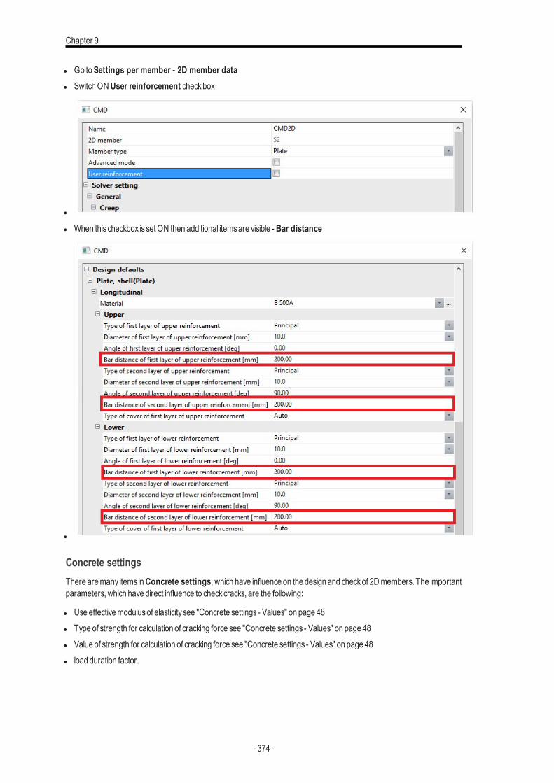
Chapter 9
l Go toSettings per member - 2D member datal SwitchONUser reinforcement checkbox
l
l When this checkbox is set ON then additional itemsare visible - Bar distance
l
Concrete settingsThere aremany items inConcrete settings, which have influence on the design and checkof 2Dmembers. The importantparameters, which have direct influence to checkcracks, are the following:
l Use effectivemodulusof elasticity see "Concrete settings - Values" on page 48l Type of strength for calculation of cracking force see "Concrete settings - Values" on page 48l Value of strength for calculation of cracking force see "Concrete settings - Values" on page 48l load duration factor.
- 374 -
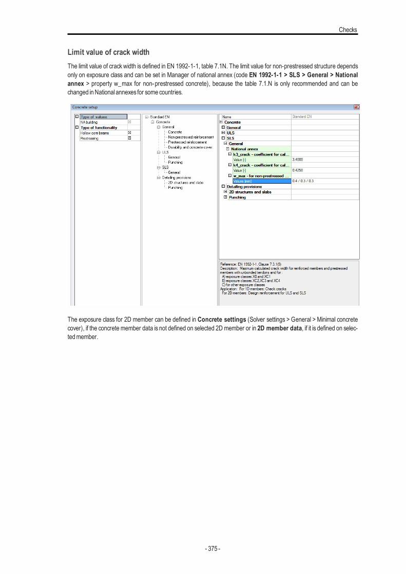
Checks
Limit value of crack widthThe limit value of crack width is defined in EN 1992-1-1, table 7.1N. The limit value for non-prestressed structure dependsonly on exposure class and can be set in Manager of national annex (code EN 1992-1-1 > SLS > General > Nationalannex > property w_max for non-prestressed concrete), because the table 7.1.N is only recommended and can bechanged inNational annexes for some countries.
The exposure class for 2D member can be defined in Concrete settings (Solver settings > General > Minimal concretecover), if the concrete member data is not defined on selected 2D member or in 2D member data, if it is defined on selec-tedmember.
- 375 -
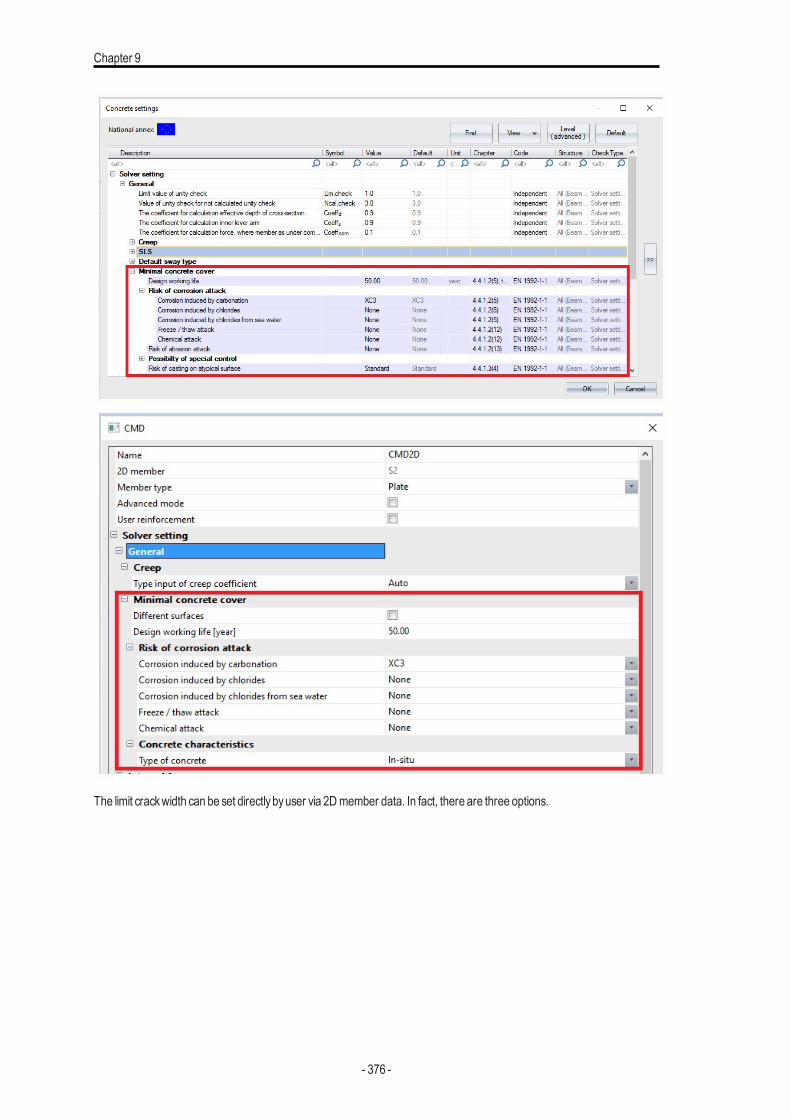
Chapter 9
The limit crackwidth can be set directlybyuser via 2Dmember data. In fact, there are three options.
- 376 -
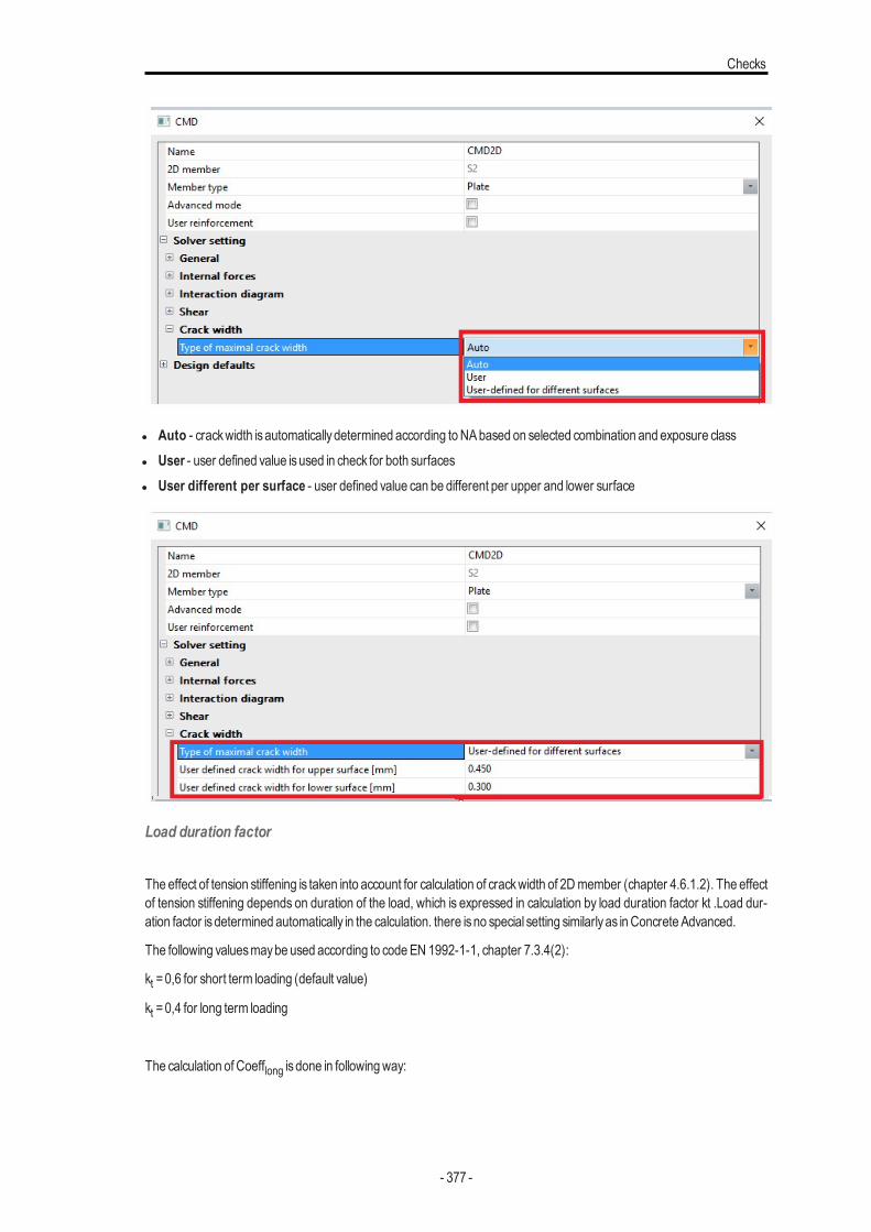
Checks
l Auto - crackwidth isautomaticallydetermined according toNAbased on selected combination and exposure classl User - user defined value isused in check for both surfacesl User different per surface - user defined value can be different per upper and lower surface
Load duration factor
The effect of tension stiffening is taken into account for calculation of crackwidth of 2Dmember (chapter 4.6.1.2). The effectof tension stiffening depends on duration of the load, which is expressed in calculation by load duration factor kt .Load dur-ation factor isdetermined automatically in the calculation. there isno special setting similarlyas inConcrete Advanced.
The following valuesmaybe used according to codeEN 1992-1-1, chapter 7.3.4(2):
kt =0,6 for short term loading (default value)
kt =0,4 for long term loading
The calculation of Coefflong is done in followingway:
- 377 -
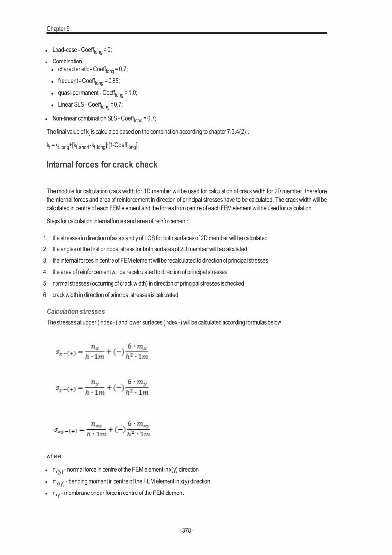
Chapter 9
l Load-case - Coefflong =0;
l Combinationl characteristic - Coefflong =0,7;
l frequent - Coefflong =0,85;
l quasi-permanent - Coefflong =1,0;
l Linear SLS - Coefflong =0,7;
l Non-linear combination SLS - Coefflong =0,7;
The final value of kt is calculated based on the combination according to chapter 7.3.4(2)..
kt =kt.long+[kt.short-kt.long]∙[1-Coefflong];
Internal forces for crack check
The module for calculation crack width for 1D member will be used for calculation of crack width for 2D member, thereforethe internal forces and area of reinforcement in direction of principal stresses have to be calculated. The crackwidth will becalculated in centre of each FEMelement and the forces from centre of each FEMelement will be used for calculation
Steps for calculation internal forcesand area of reinforcement:
1. the stresses in direction of axis xand yof LCS for both surfacesof 2Dmember will be calculated2. the anglesof the first principal stress for both surfacesof 2Dmember will be calculated3. the internal forces in centre of FEMelement will be recalculated to direction of principal stresses4. the area of reinforcement will be recalculated to direction of principal stresses5. normal stresses (occurring of crackwidth) in direction of principal stresses is checked6. crackwidth in direction of principal stresses is calculated
Calculation stressesThe stressesat upper (index+) and lower surfaces (index -) will be calculated according formulasbelow
where
l nx(y) - normal force in centre of the FEMelement in x(y) direction
l mx(y) - bendingmoment in centre of the FEMelement in x(y) direction
l nxy - membrane shear force in centre of the FEMelement
- 378 -
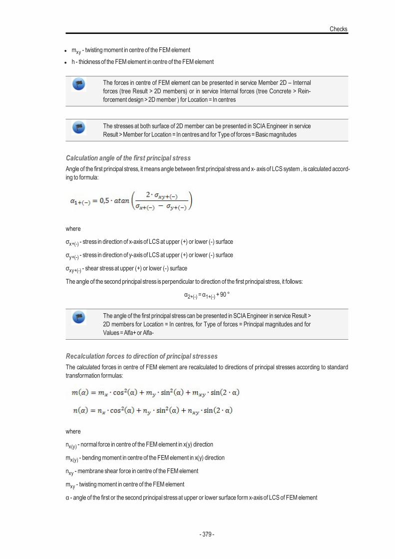
Checks
l mxy - twistingmoment in centre of the FEMelement
l h - thicknessof the FEMelement in centre of the FEMelement
The forces in centre of FEM element can be presented in service Member 2D – Internalforces (tree Result > 2D members) or in service Internal forces (tree Concrete > Rein-forcement design >2Dmember ) for Location = In centres
The stresses at both surface of 2D member can be presented in SCIA Engineer in serviceResult >Member for Location = In centresand for Type of forces=Basicmagnitudes
Calculation angle of the first principal stressAngle of the first principal stress, it meansangle between first principal stressand x- axisof LCSsystem , is calculated accord-ing to formula:
where
σx+(-) - stress in direction of x-axisof LCSat upper (+) or lower (-) surface
σy+(-) - stress in direction of y-axisof LCSat upper (+) or lower (-) surface
σxy+(-) - shear stressat upper (+) or lower (-) surface
The angle of the second principal stress isperpendicular to direction of the first principal stress, it follows:
α2+(-) =α1+(-) +90 °
The angle of the first principal stress can be presented in SCIAEngineer in service Result >2D members for Location = In centres, for Type of forces = Principal magnitudes and forValues=Alfa+or Alfa-
Recalculation forces to direction of principal stressesThe calculated forces in centre of FEM element are recalculated to directions of principal stresses according to standardtransformation formulas:
where
nx(y) - normal force in centre of the FEMelement in x(y) direction
mx(y) - bendingmoment in centre of the FEMelement in x(y) direction
nxy - membrane shear force in centre of the FEMelement
mxy - twistingmoment in centre of the FEMelement
α - angle of the first or the second principal stressat upper or lower surface form x-axisof LCSof FEMelement
- 379 -
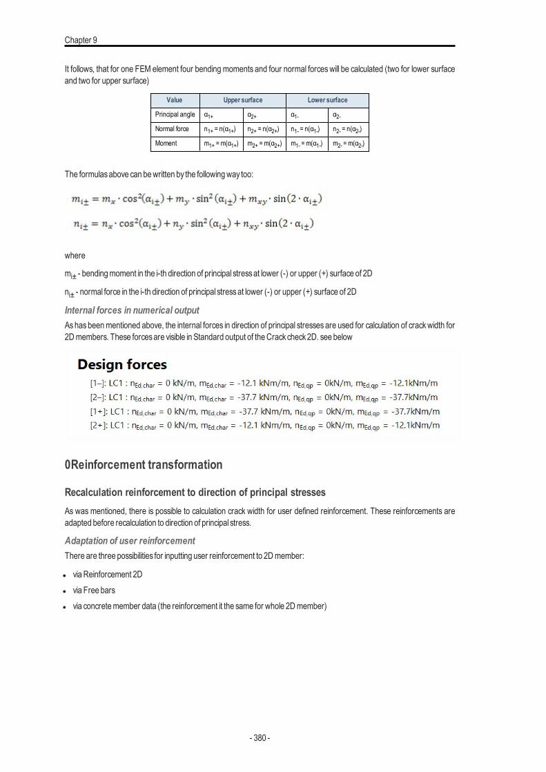
Chapter 9
It follows, that for one FEM element four bending moments and four normal forceswill be calculated (two for lower surfaceand two for upper surface)
Value Upper surface Lower surface
Principal angle α1+ α2+ α1- α2-Normal force n1+ = n(α1+) n2+ = n(α2+) n1- = n(α1-) n2- = n(α2-)
Moment m1+ = m(α1+) m2+ = m(α2+) m1- = m(α1-) m2- = m(α2-)
The formulasabove can bewritten by the followingway too:
where
mi± - bendingmoment in the i-th direction of principal stressat lower (-) or upper (+) surface of 2D
ni± - normal force in the i-th direction of principal stressat lower (-) or upper (+) surface of 2D
Internal forces in numerical outputAshas beenmentioned above, the internal forces in direction of principal stresses are used for calculation of crackwidth for2Dmembers. These forcesare visible in Standard output of theCrackcheck2D. see below
0Reinforcement transformation
Recalculation reinforcement to direction of principal stressesAs was mentioned, there is possible to calculation crack width for user defined reinforcement. These reinforcements areadapted before recalculation to direction of principal stress.
Adaptation of user reinforcementThere are three possibilities for inputting user reinforcement to 2Dmember:
l viaReinforcement 2Dl via Free barsl via concretemember data (the reinforcement it the same for whole 2Dmember)
- 380 -
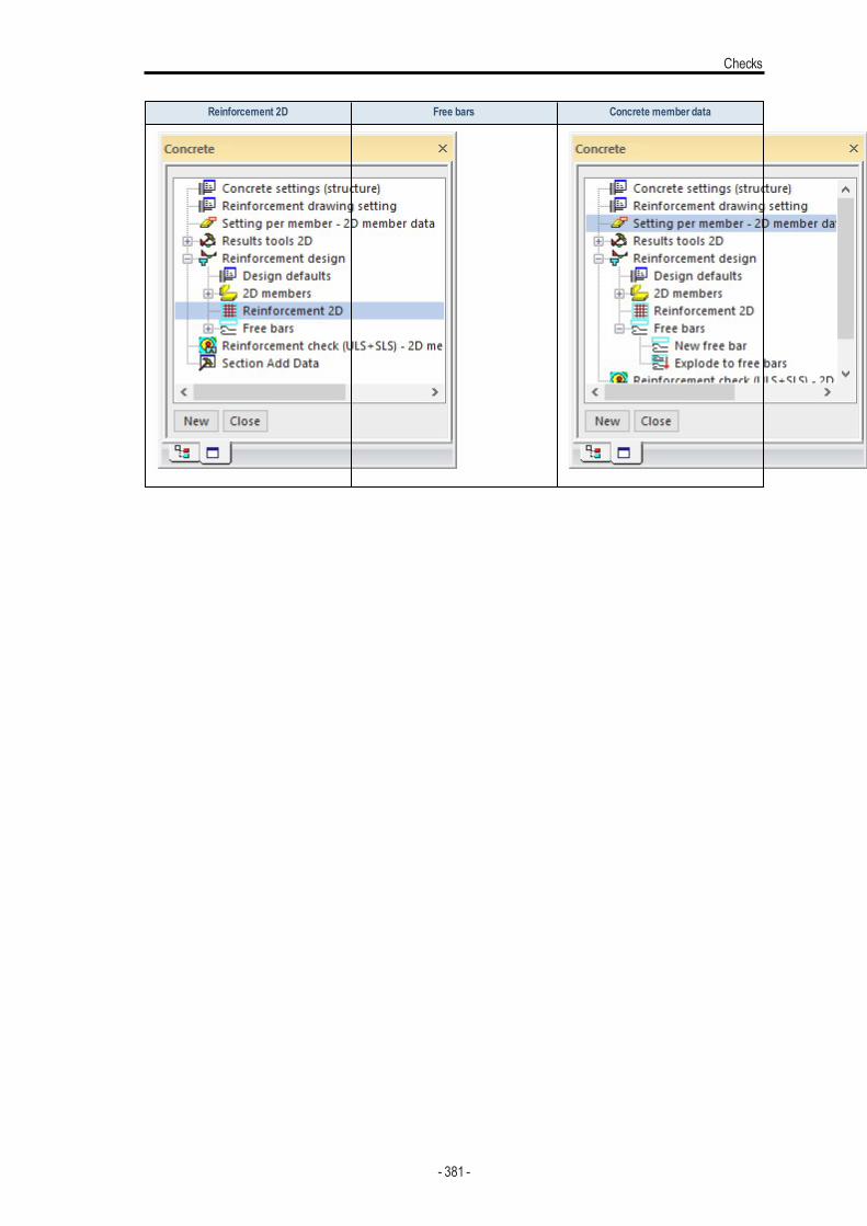
Checks
Reinforcement 2D Free bars Concrete member data
- 381 -
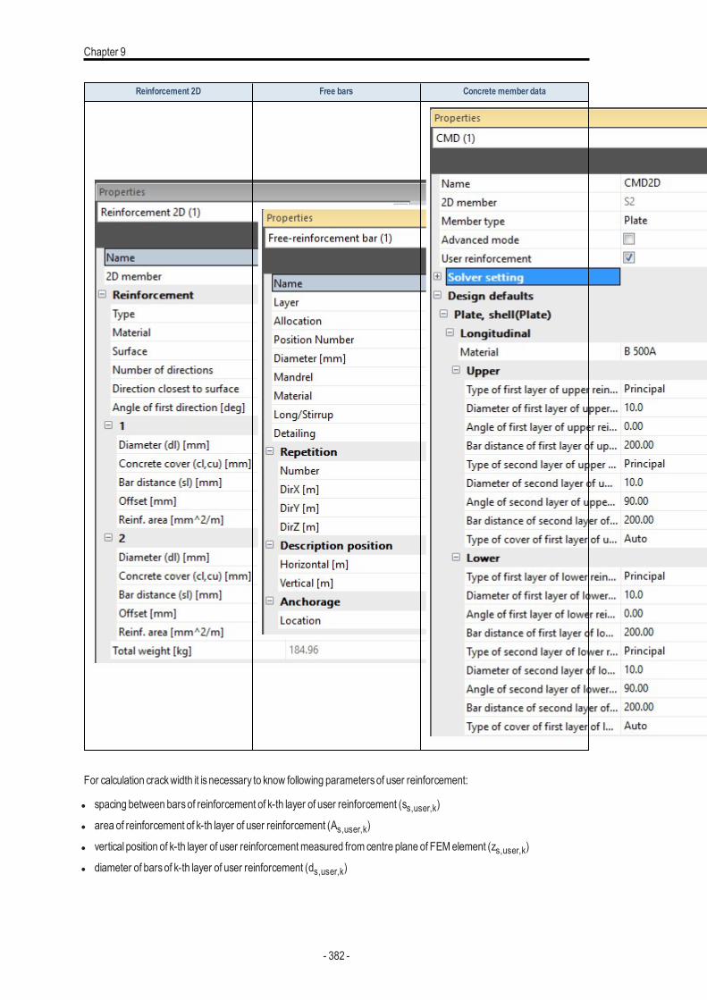
Chapter 9
Reinforcement 2D Free bars Concrete member data
For calculation crackwidth it isnecessary to know following parametersof user reinforcement:
l spacing between barsof reinforcement of k-th layer of user reinforcement (ss,user,k)
l area of reinforcement of k-th layer of user reinforcement (As,user,k)
l vertical position of k-th layer of user reinforcementmeasured from centre plane of FEMelement (zs,user,k)
l diameter of barsof k-th layer of user reinforcement (ds,user,k)
- 382 -
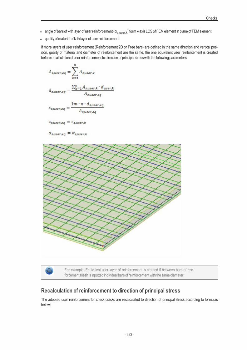
Checks
l angle of barsof k-th layer of user reinforcement (αs,user,k) form x-axisLCSof FEMelement in plane of FEMelement
l qualityofmaterial of k-th layer of user reinforcement
If more layers of user reinforcement (Reinforcement 2D or Free bars) are defined in the same direction and vertical pos-ition, quality of material and diameter of reinforcement are the same, the one equivalent user reinforcement is createdbefore recalculation of user reinforcement to direction of principal stresswith the following parameters:
For example: Equivalent user layer of reinforcement is created if between bars of rein-forcementmesh is inputted individual barsof reinforcement with the same diameter.
Recalculation of reinforcement to direction of principal stressThe adopted user reinforcement for check cracks are recalculated to direction of principal stress according to formulasbelow:
- 383 -
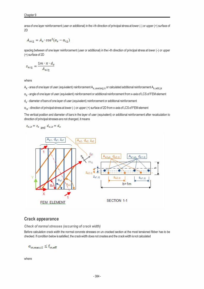
Chapter 9
area of one layer reinforcement (user or additional) in the i-th direction of principal stress at lower (-) or upper (+) surface of2D
spacing between of one layer reinforcement (user or additional) in the i-th direction of principal stress at lower (-) or upper(+) surface of 2D
where
As - area of one layer of user (equivalent) reinforcement As,user(eq),k or calculated additional reinforcement As,add,j±αs - angle of one layer of user (equivalent) reinforcement or additional reinforcement from x-axisof LCSof FEMelement
ds - diameter of barsof one layer of user (equivalent) reinforcement or additional reinforcement
αi± - direction of principal stressat lower (-) or upper (+) surface of 2D from x-axisof LCSof FEMelement
The vertical position and diameter of bars in the layer of user (equivalent) or additional reinforcement after recalculation todirection of principal stressesare not changed, it means
and
Crack appearanceCheck of normal stresses (occurring of crack width)Before calculation crack width the normal concrete stresses on un-cracked section at the most tensioned fibber has to bechecked. If condition below issatisfied, the crackwidth doesnot createsand the crackwidth isnot calculated
where
- 384 -
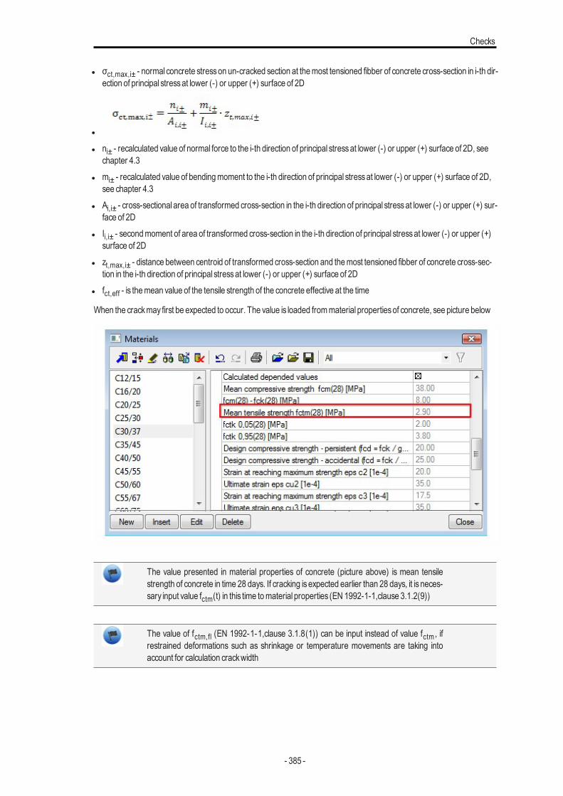
Checks
l σct,max,i± - normal concrete stresson un-cracked section at themost tensioned fibber of concrete cross-section in i-th dir-ection of principal stressat lower (-) or upper (+) surface of 2D
l
l ni± - recalculated value of normal force to the i-th direction of principal stressat lower (-) or upper (+) surface of 2D, seechapter 4.3
l mi± - recalculated value of bendingmoment to the i-th direction of principal stressat lower (-) or upper (+) surface of 2D,see chapter 4.3
l Ai,i± - cross-sectional area of transformed cross-section in the i-th direction of principal stressat lower (-) or upper (+) sur-face of 2D
l Ii,i± - secondmoment of area of transformed cross-section in the i-th direction of principal stressat lower (-) or upper (+)surface of 2D
l zt,max,i± - distance between centroid of transformed cross-section and themost tensioned fibber of concrete cross-sec-tion in the i-th direction of principal stressat lower (-) or upper (+) surface of 2D
l fct,eff - is themean value of the tensile strength of the concrete effective at the time
When the crackmay first be expected to occur. The value is loaded frommaterial propertiesof concrete, see picture below
The value presented in material properties of concrete (picture above) is mean tensilestrength of concrete in time 28 days. If cracking is expected earlier than 28 days, it is neces-sary input value fctm(t) in this time tomaterial properties (EN 1992-1-1,clause 3.1.2(9))
The value of fctm,fl (EN 1992-1-1,clause 3.1.8(1)) can be input instead of value fctm , ifrestrained deformations such as shrinkage or temperature movements are taking intoaccount for calculation crackwidth
- 385 -
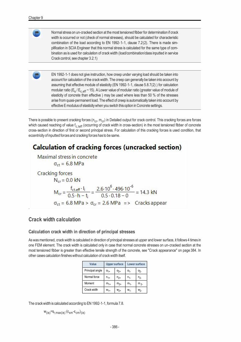
Chapter 9
Normal stresson un-cracked section at themost tensioned fibber for determination if crackwidth is occurred or not (check of normal stresses), should be calculated for characteristiccombination of the load according to EN 1992-1-1, clause 7.2(2). There is made sim-plification in SCIA Engineer that this normal stress is calculated for the same type of com-bination as is used for calculation of crackwidth (load/combination/class inputted in serviceCrackcontrol, see chapter 3.2.1)
EN 1992-1-1 does not give instruction, how creep under varying load should be taken intoaccount for calculation of the crackwidth. The creep can generally be taken into account byassuming that effective module of elasticity (EN 1992-1-1, clause 5.8.7(2) ) for calculationmodular ratio (Es / Ec,eff ~ 15). A Lower value of modular ratio (greater value of module ofelasticity of concrete than effective ) may be used where less than 50 % of the stressesarise from quasi-permanent load. The effect of creep is automatically taken into account byeffective Emodulusof elasticitywhen you switch thisoption inConcrete settings.
There is possible to present cracking forces (ncr, mcr) in Detailed output for crack control. This cracking forces are forceswhich caused reaching of value fc,teff (occurring of crack width in cross-section) in the most tensioned fibber of concretecross-section in direction of first or second principal stress. For calculation of this cracking forces is used condition, thateccentricityof inputted forcesand cracking forceshas to be same.
.
Crack width calculation
Calculation crack width in direction of principal stressesAswasmentioned, crackwidth is calculated in direction of principal stresses at upper and lower surface, it follows 4 times inone FEM element. The crack width is calculated only in case that normal concrete stresses on un-cracked section at themost tensioned fibber is greater than effective tensile strength of the concrete, see "Crack appearance" on page 384. Inother casescalculation finisheswithout calculation of crackwidth itself.
Value Upper surface Lower surface
Principal angle α1+ α2+ α1- α2-Normal force n1+ n2+ n1- n2-Moment m1+ m2+ m1- m 2-
Crack width w1+ w2+ w1- w2-
The crackwidth is calculated according to EN 1992-1-1, formula 7.8.
w(i±)=sr,max(i±)∙(εsm-εcm)(i±)
- 386 -
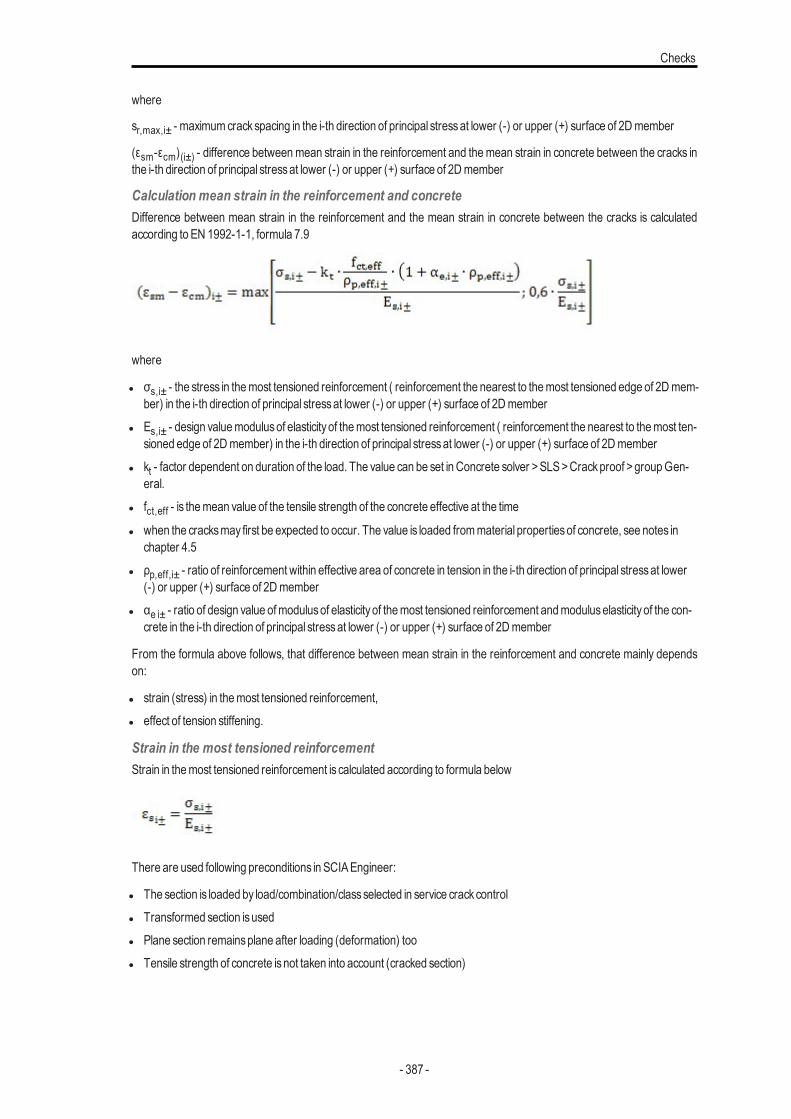
Checks
where
sr,max,i± - maximumcrackspacing in the i-th direction of principal stressat lower (-) or upper (+) surface of 2Dmember
(εsm-εcm)(i±) - difference betweenmean strain in the reinforcement and themean strain in concrete between the cracks inthe i-th direction of principal stressat lower (-) or upper (+) surface of 2Dmember
Calculation mean strain in the reinforcement and concreteDifference between mean strain in the reinforcement and the mean strain in concrete between the cracks is calculatedaccording to EN 1992-1-1, formula 7.9
where
l σs,i± - the stress in themost tensioned reinforcement ( reinforcement the nearest to themost tensioned edge of 2Dmem-ber) in the i-th direction of principal stressat lower (-) or upper (+) surface of 2Dmember
l Es,i± - design valuemodulusof elasticityof themost tensioned reinforcement ( reinforcement the nearest to themost ten-sioned edge of 2Dmember) in the i-th direction of principal stressat lower (-) or upper (+) surface of 2Dmember
l kt - factor dependent on duration of the load. The value can be set in Concrete solver >SLS>Crackproof >groupGen-eral.
l fct,eff - is themean value of the tensile strength of the concrete effective at the time
l when the cracksmay first be expected to occur. The value is loaded frommaterial propertiesof concrete, see notes inchapter 4.5
l ρp,eff,i± - ratio of reinforcement within effective area of concrete in tension in the i-th direction of principal stressat lower(-) or upper (+) surface of 2Dmember
l αe i± - ratio of design value ofmodulusof elasticityof themost tensioned reinforcement andmoduluselasticityof the con-crete in the i-th direction of principal stressat lower (-) or upper (+) surface of 2Dmember
From the formula above follows, that difference between mean strain in the reinforcement and concrete mainly dependson:
l strain (stress) in themost tensioned reinforcement,l effect of tension stiffening.
Strain in the most tensioned reinforcementStrain in themost tensioned reinforcement is calculated according to formula below
There are used following preconditions in SCIAEngineer:
l The section is loaded by load/combination/classselected in service crackcontroll Transformed section isusedl Plane section remainsplane after loading (deformation) tool Tensile strength of concrete isnot taken into account (cracked section)
- 387 -
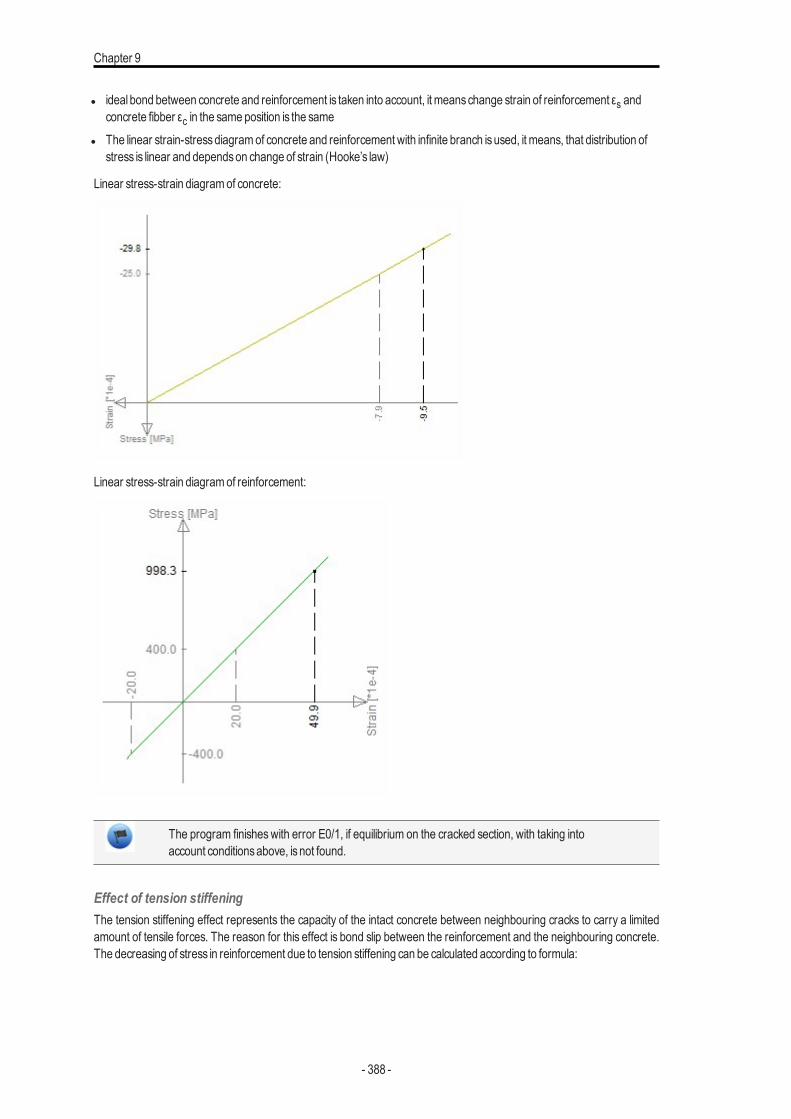
Chapter 9
l ideal bond between concrete and reinforcement is taken into account, it meanschange strain of reinforcement εs andconcrete fibber εc in the same position is the same
l The linear strain-stressdiagramof concrete and reinforcement with infinite branch isused, it means, that distribution ofstress is linear and dependson change of strain (Hooke’s law)
Linear stress-strain diagramof concrete:
Linear stress-strain diagramof reinforcement:
The program finisheswith error E0/1, if equilibrium on the cracked section, with taking intoaccount conditionsabove, isnot found.
Effect of tension stiffeningThe tension stiffening effect represents the capacity of the intact concrete between neighbouring cracks to carry a limitedamount of tensile forces. The reason for this effect is bond slip between the reinforcement and the neighbouring concrete.The decreasing of stress in reinforcement due to tension stiffening can be calculated according to formula:
- 388 -
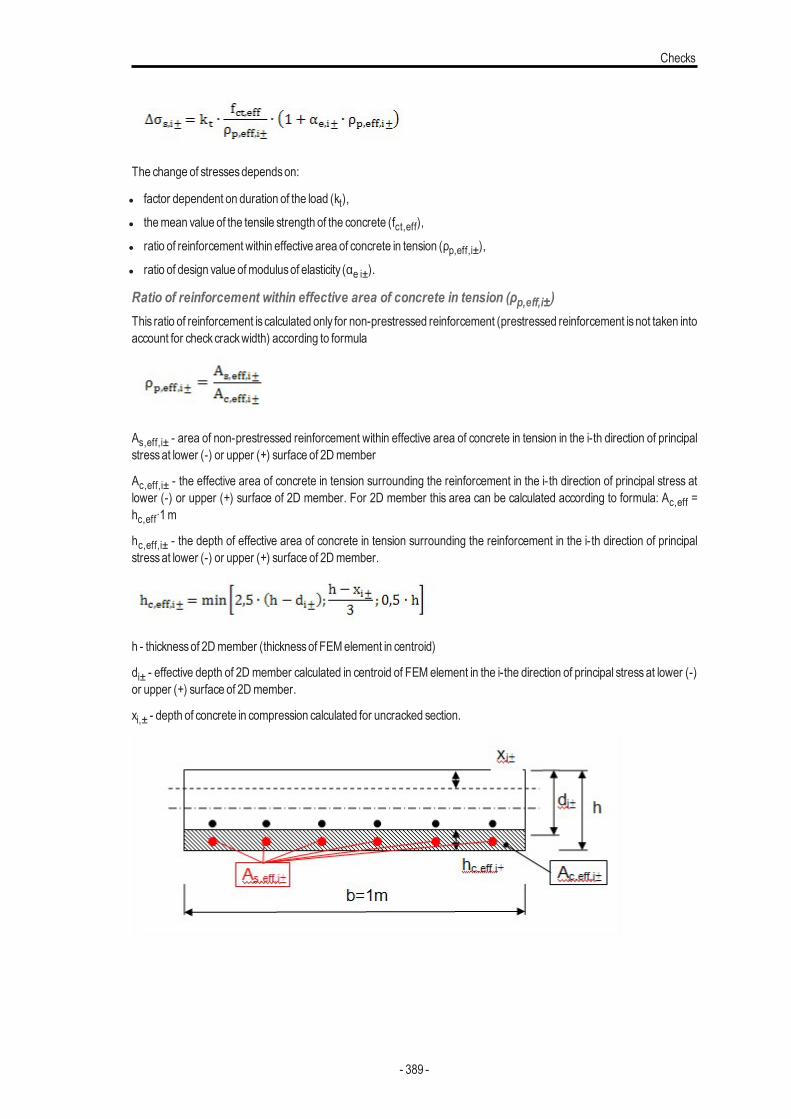
Checks
The change of stressesdependson:
l factor dependent on duration of the load (kt),
l themean value of the tensile strength of the concrete (fct,eff),
l ratio of reinforcement within effective area of concrete in tension (ρp,eff,i±),
l ratio of design value ofmodulusof elasticity (αe i±).
Ratio of reinforcement within effective area of concrete in tension (ρp,eff,i±)This ratio of reinforcement is calculated only for non-prestressed reinforcement (prestressed reinforcement isnot taken intoaccount for checkcrackwidth) according to formula
As,eff,i± - area of non-prestressed reinforcement within effective area of concrete in tension in the i-th direction of principalstressat lower (-) or upper (+) surface of 2Dmember
Ac,eff,i± - the effective area of concrete in tension surrounding the reinforcement in the i-th direction of principal stress atlower (-) or upper (+) surface of 2D member. For 2D member this area can be calculated according to formula: Ac,eff =hc,eff∙1m
hc,eff,i± - the depth of effective area of concrete in tension surrounding the reinforcement in the i-th direction of principalstressat lower (-) or upper (+) surface of 2Dmember.
h - thicknessof 2Dmember (thicknessof FEMelement in centroid)
di± - effective depth of 2D member calculated in centroid of FEM element in the i-the direction of principal stress at lower (-)or upper (+) surface of 2Dmember.
xi,± - depth of concrete in compression calculated for uncracked section.
- 389 -
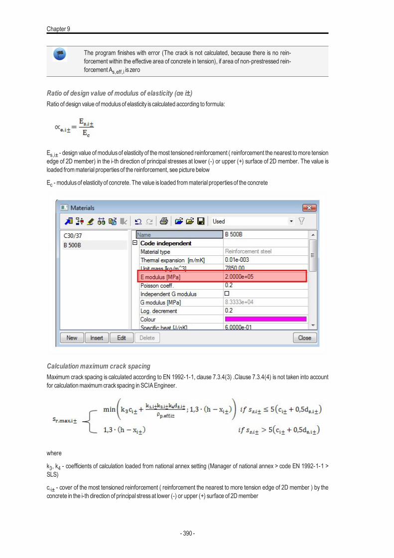
Chapter 9
The program finishes with error (The crack is not calculated, because there is no rein-forcement within the effective area of concrete in tension), if area of non-prestressed rein-forcement As,eff,i is zero
Ratio of design value of modulus of elasticity (αe i±)Ratio of design value ofmodulusof elasticity is calculated according to formula:
Es,i± - design value ofmodulusof elasticity of themost tensioned reinforcement ( reinforcement the nearest tomore tensionedge of 2D member) in the i-th direction of principal stresses at lower (-) or upper (+) surface of 2D member. The value isloaded frommaterial propertiesof the reinforcement, see picture below
Ec - modulusof elasticityof concrete. The value is loaded frommaterial propertiesof the concrete
Calculation maximum crack spacingMaximum crack spacing is calculated according to EN 1992-1-1, clause 7.3.4(3) .Clause 7.3.4(4) is not taken into accountfor calculationmaximumcrackspacing in SCIAEngineer.
where
k3, k4 - coefficients of calculation loaded from national annex setting (Manager of national annex > code EN 1992-1-1 >SLS)
c,i± - cover of the most tensioned reinforcement ( reinforcement the nearest to more tension edge of 2D member ) by theconcrete in the i-th direction of principal stressat lower (-) or upper (+) surface of 2Dmember
- 390 -
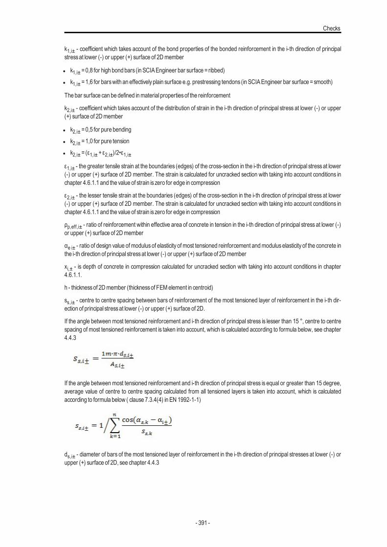
Checks
k1,i± - coefficient which takes account of the bond properties of the bonded reinforcement in the i-th direction of principalstressat lower (-) or upper (+) surface of 2Dmember
l k1,i± =0,8 for high bond bars (in SCIAEngineer bar surface = ribbed)
l k1,i± =1,6 for barswith an effectivelyplain surface e.g. prestressing tendons (in SCIAEngineer bar surface =smooth)
The bar surface can be defined inmaterial propertiesof the reinforcement
k2,i± - coefficient which takes account of the distribution of strain in the i-th direction of principal stress at lower (-) or upper(+) surface of 2Dmember
l k2,i± =0,5 for pure bending
l k2,i± =1,0 for pure tension
l k2,i± = (ε1,i± +ε2,i±)/2•ε1,i±
ε1,i± - the greater tensile strain at the boundaries (edges) of the cross-section in the i-th direction of principal stress at lower(-) or upper (+) surface of 2D member. The strain is calculated for uncracked section with taking into account conditions inchapter 4.6.1.1 and the value of strain is zero for edge in compression
ε2,i± - the lesser tensile strain at the boundaries (edges) of the cross-section in the i-th direction of principal stress at lower(-) or upper (+) surface of 2D member. The strain is calculated for uncracked section with taking into account conditions inchapter 4.6.1.1 and the value of strain is zero for edge in compression
ρp,eff,i± - ratio of reinforcement within effective area of concrete in tension in the i-th direction of principal stress at lower (-)or upper (+) surface of 2Dmember
αe i± - ratio of design value of modulus of elasticity of most tensioned reinforcement andmodulus elasticity of the concrete inthe i-th direction of principal stressat lower (-) or upper (+) surface of 2Dmember
xi,± - is depth of concrete in compression calculated for uncracked section with taking into account conditions in chapter4.6.1.1.
h - thicknessof 2Dmember (thicknessof FEMelement in centroid)
ss,i± - centre to centre spacing between bars of reinforcement of the most tensioned layer of reinforcement in the i-th dir-ection of principal stressat lower (-) or upper (+) surface of 2D.
If the angle between most tensioned reinforcement and i-th direction of principal stress is lesser than 15 °, centre to centrespacing of most tensioned reinforcement is taken into account, which is calculated according to formula below, see chapter4.4.3
If the angle between most tensioned reinforcement and i-th direction of principal stress is equal or greater than 15 degree,average value of centre to centre spacing calculated from all tensioned layers is taken into account, which is calculatedaccording to formula below ( clause 7.3.4(4) in EN 1992-1-1)
ds,i± - diameter of bars of the most tensioned layer of reinforcement in the i-th direction of principal stresses at lower (-) orupper (+) surface of 2D, see chapter 4.4.3
- 391 -
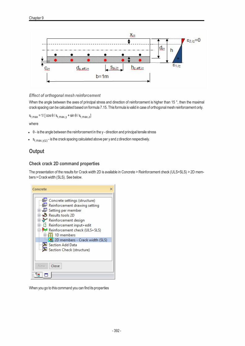
Chapter 9
Effect of orthogonal mesh reinforcementWhen the angle between the axes of principal stress and direction of reinforcement is higher than 15 °, then the maximalcrackspacing can be calculated based on formula 7.15. This formula is valid in case of orthogonalmesh reinforcement only.
sr,max =1/ [ cosθ / sr,max,y +sin θ / sr,max,z]
where
l θ - is the angle between the reinforcement in the y - direction and principal tensile stressl sr,max,y(z) - is the crackspacing calculated above per yand zdirection respectively.
Output
Check crack 2D command propertiesThe presentation of the results for Crack width 2D is available in Concrete > Reinforcement check (ULS+SLS) > 2D mem-bers>Crackwidth (SLS). See below.
When you go to this command you can find itsproperties
- 392 -
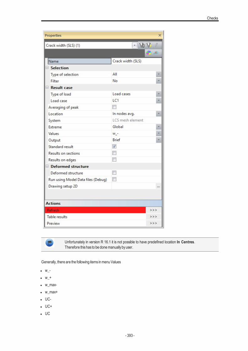
Checks
Unfortunately in version R 16.1 it is not possible to have predefined location In Centres.Therefore thishas to be donemanuallybyuser.
Generally, there are the following items inmenuValues
l w_-l w_+l w_max-l w_max+l UC-l UC+l UC
- 393 -
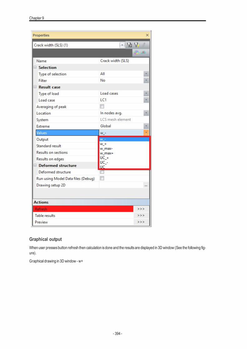
Chapter 9
Graphical outputWhen user pressesbutton refresh then calculation isdone and the resultsare displayed in 3Dwindow (See the following fig-ure).
Graphical drawing in 3Dwindow - w+
- 394 -
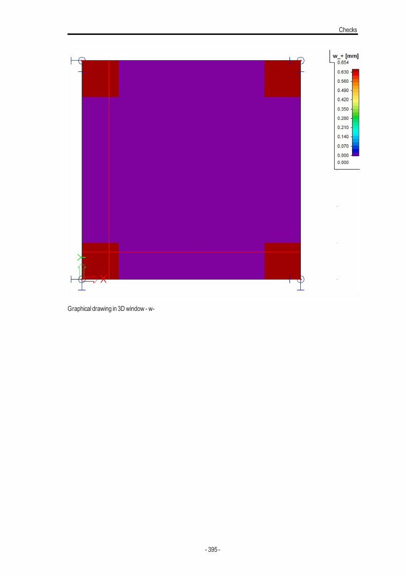
Checks
Graphical drawing in 3Dwindow - w-
- 395 -
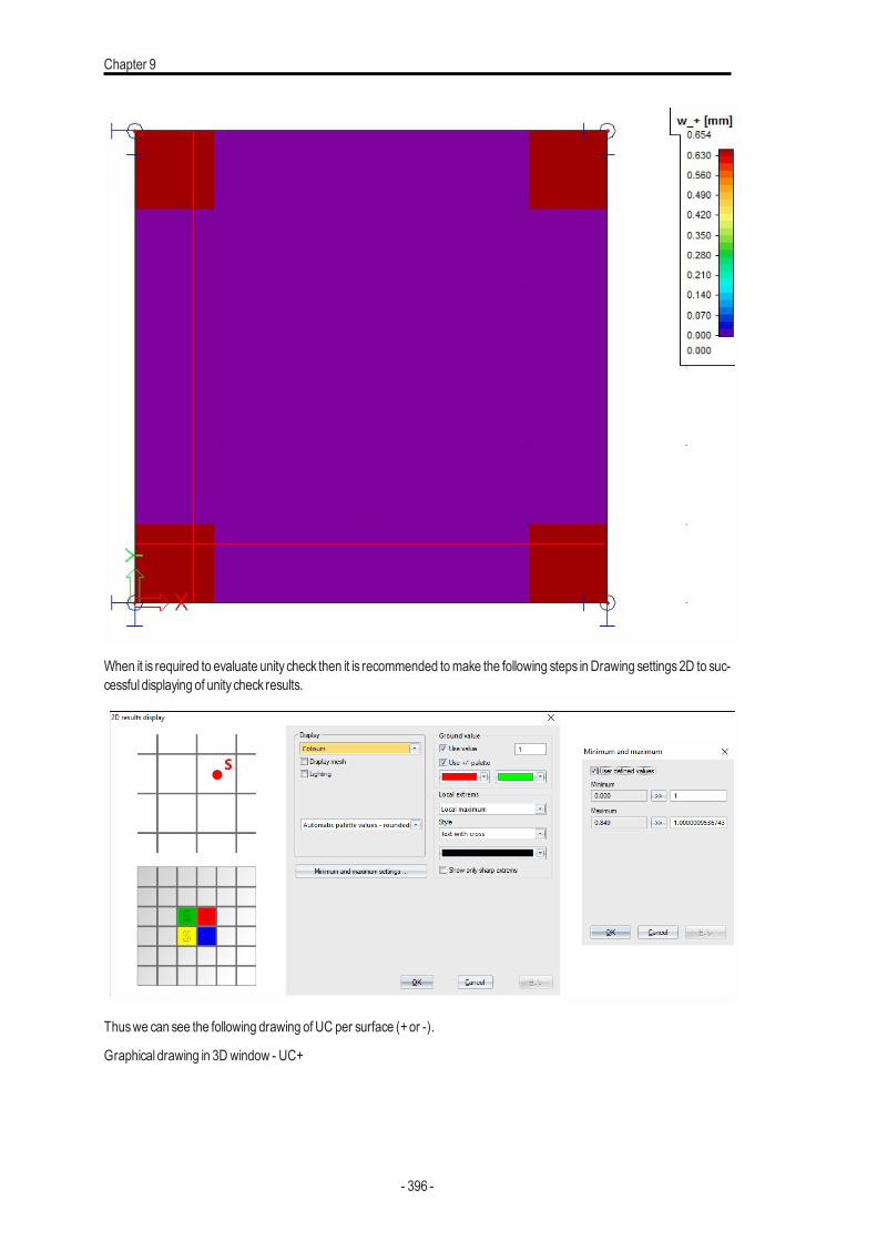
Chapter 9
When it is required to evaluate unity check then it is recommended tomake the following steps inDrawing settings2D to suc-cessful displaying of unity check results.
Thuswe can see the following drawing of UC per surface (+or -).
Graphical drawing in 3Dwindow - UC+
- 396 -
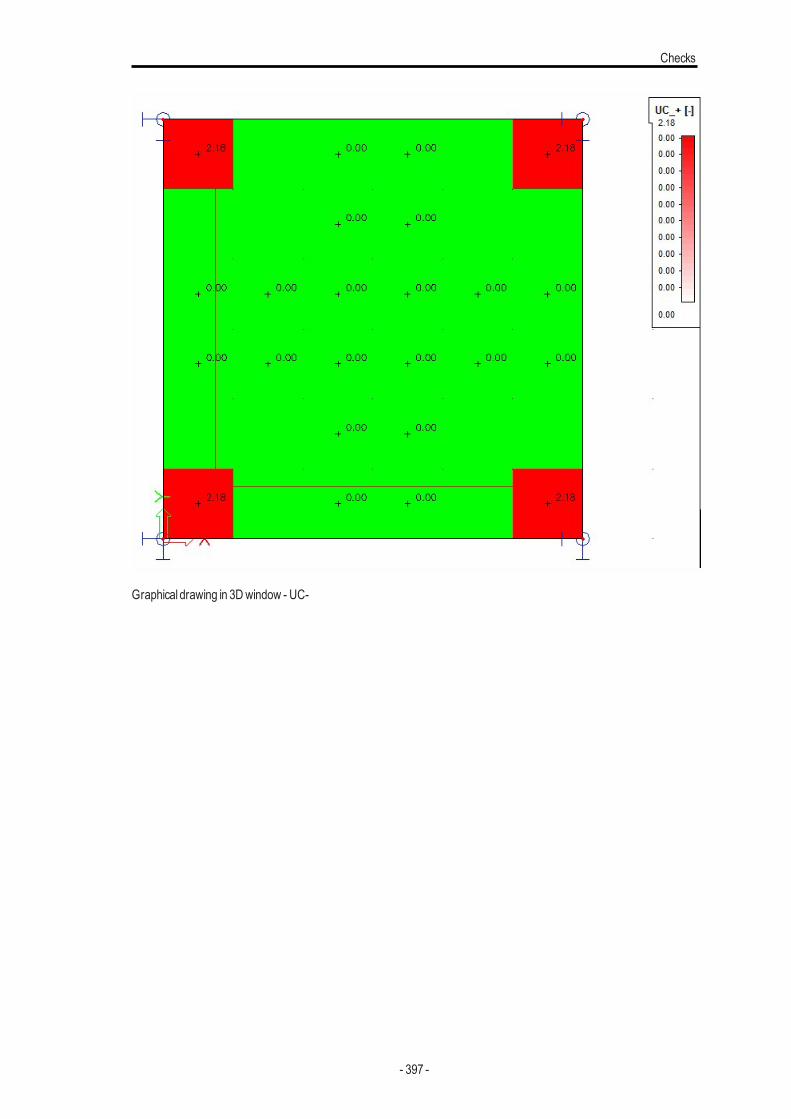
Checks
Graphical drawing in 3Dwindow - UC-
- 397 -
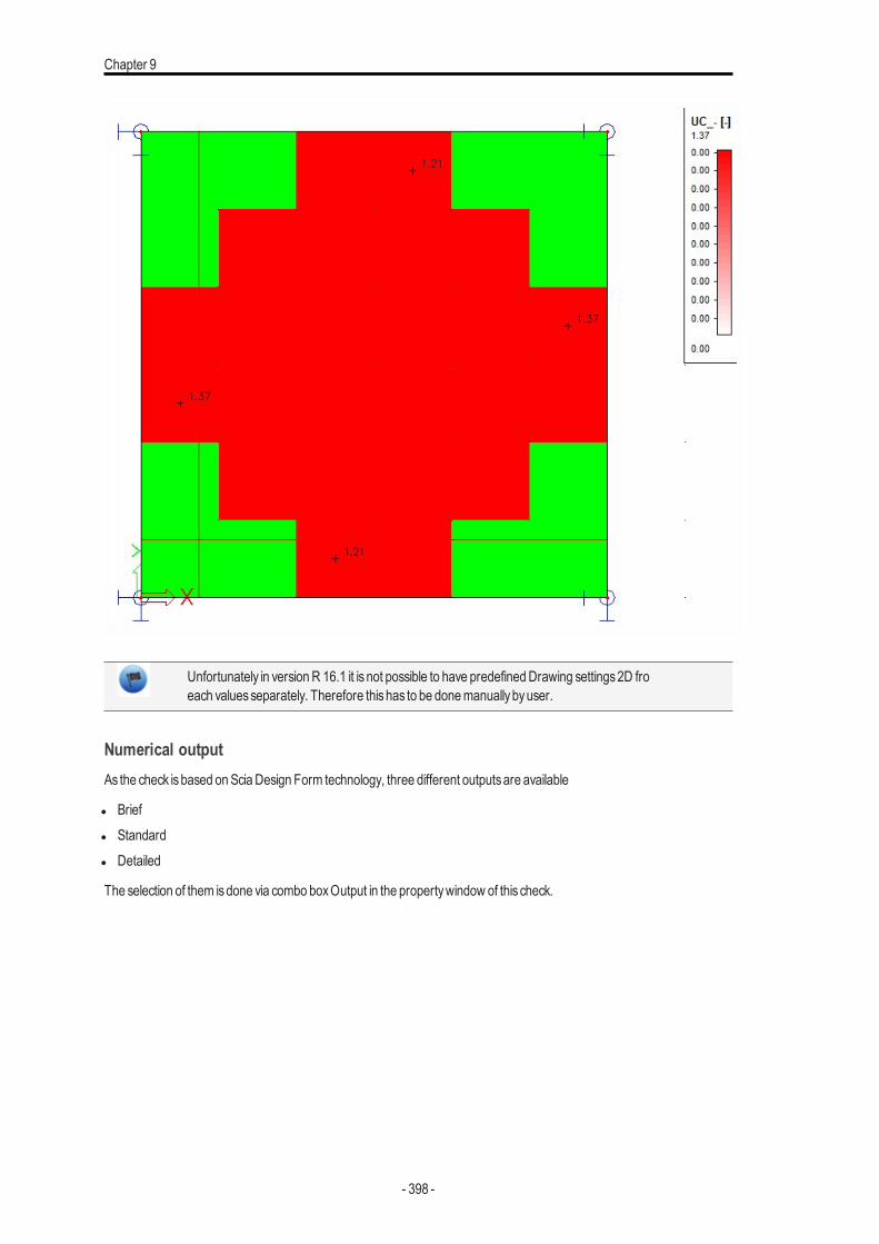
Chapter 9
Unfortunately in versionR 16.1 it is not possible to have predefinedDrawing settings2D froeach valuesseparately. Therefore thishas to be donemanuallybyuser.
Numerical outputAs the check isbased onSciaDesign Form technology, three different outputsare available
l Briefl Standardl Detailed
The selection of them isdone via combo boxOutput in the propertywindow of this check.
- 398 -
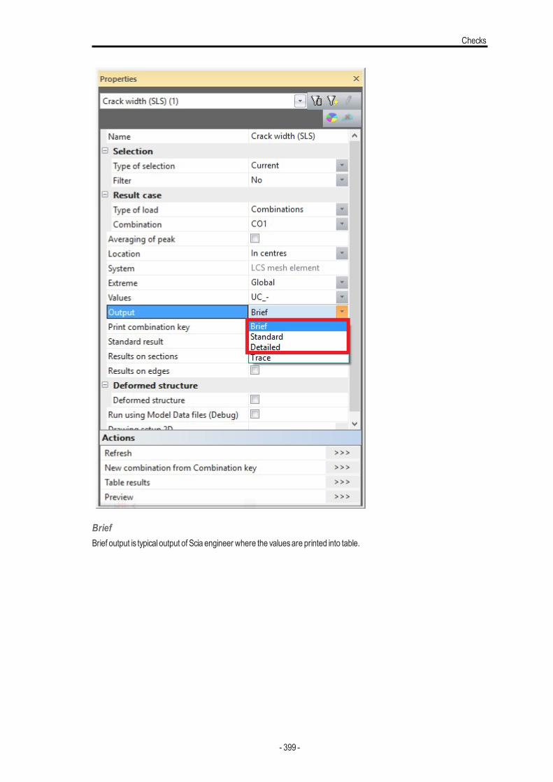
Checks
BriefBrief output is typical output of Scia engineer where the valuesare printed into table.
- 399 -
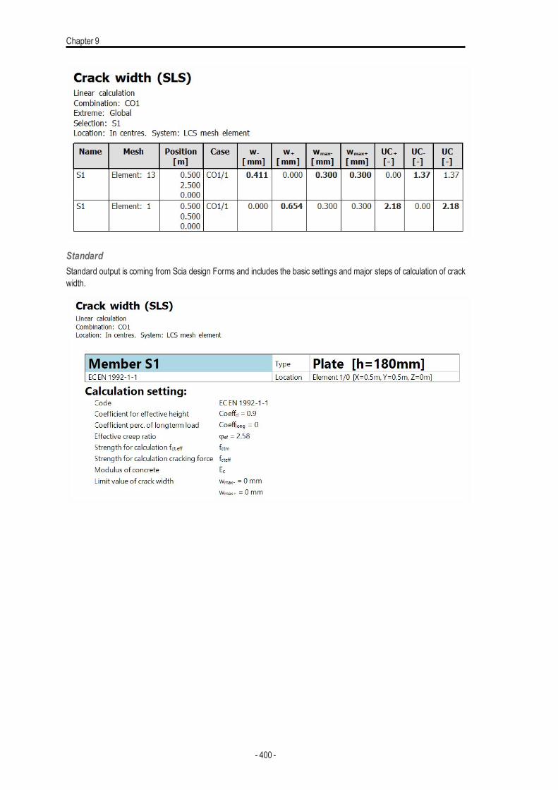
Chapter 9
StandardStandard output is coming from Scia design Forms and includes the basic settings and major steps of calculation of crackwidth.
- 400 -
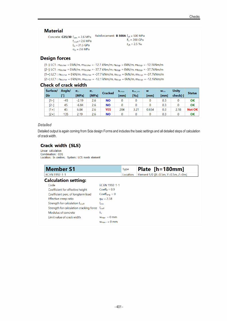
Checks
DetailedDetailed output is again coming from Scia design Forms and includes the basic settings and all detailed steps of calculationof crackwidth.
- 401 -
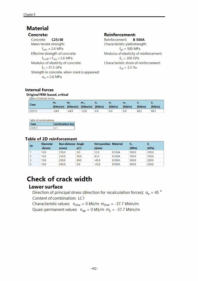
Chapter 9
- 402 -
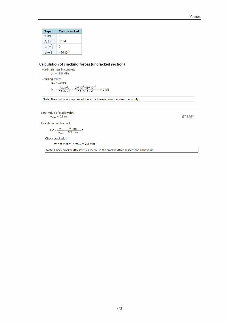
Checks
- 403 -
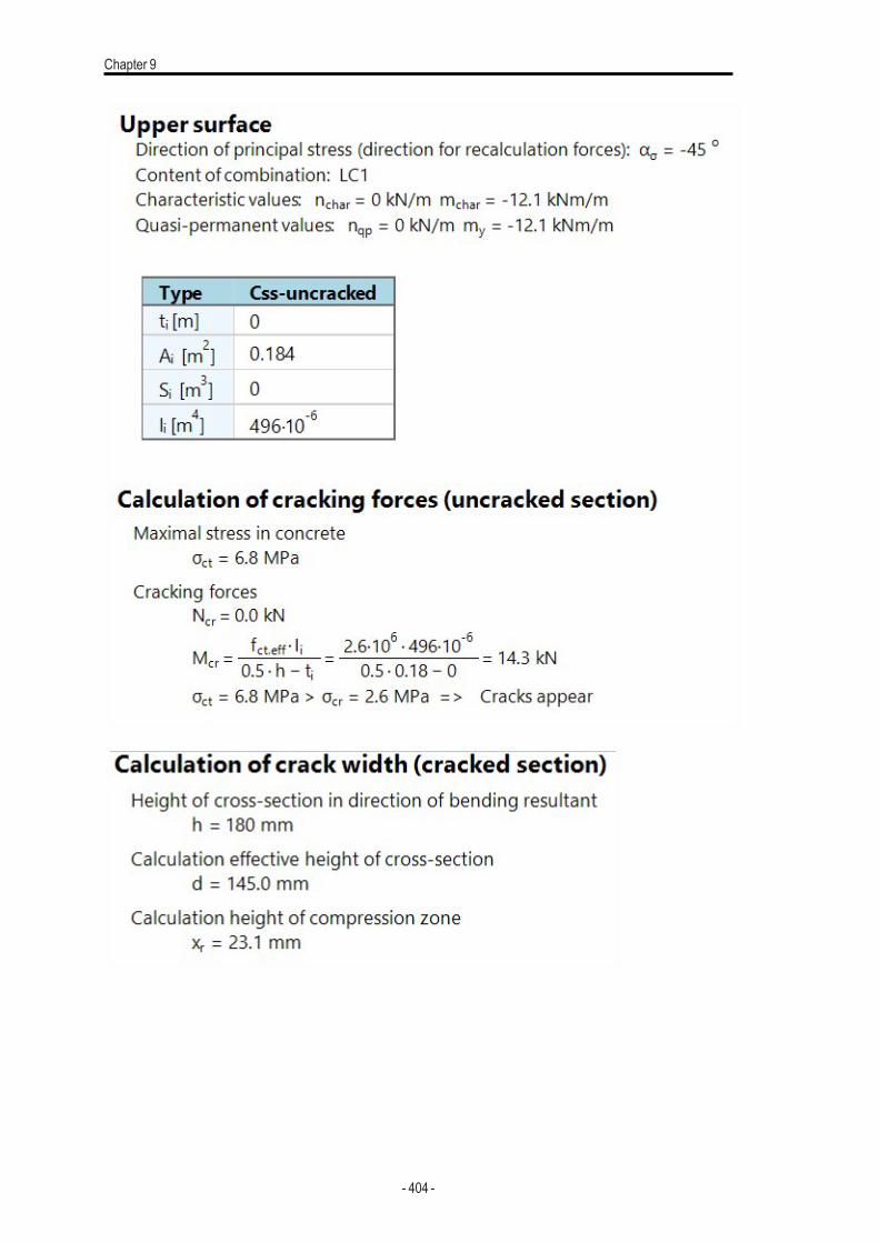
Chapter 9
- 404 -
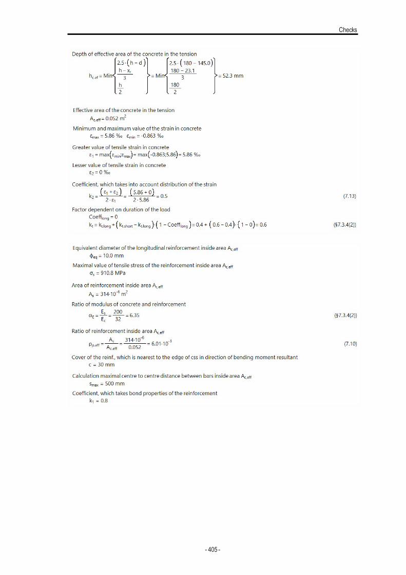
Checks
- 405 -
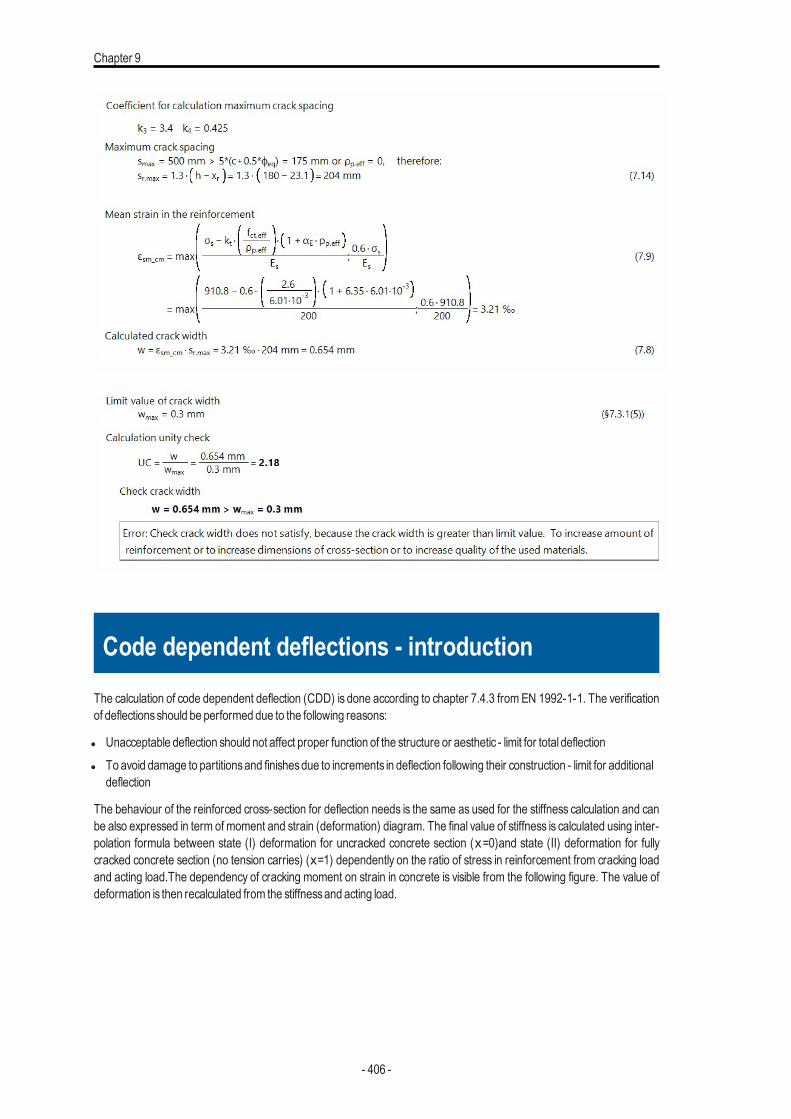
Chapter 9
Code dependent deflections - introduction
The calculation of code dependent deflection (CDD) is done according to chapter 7.4.3 from EN 1992-1-1. The verificationof deflectionsshould be performed due to the following reasons:
l Unacceptable deflection should not affect proper function of the structure or aesthetic - limit for total deflectionl To avoid damage to partitionsand finishesdue to increments in deflection following their construction - limit for additional
deflection
The behaviour of the reinforced cross-section for deflection needs is the same as used for the stiffness calculation and canbe also expressed in term of moment and strain (deformation) diagram. The final value of stiffness is calculated using inter-polation formula between state (I) deformation for uncracked concrete section (x=0)and state (II) deformation for fullycracked concrete section (no tension carries) (x=1) dependently on the ratio of stress in reinforcement from cracking loadand acting load.The dependency of cracking moment on strain in concrete is visible from the following figure. The value ofdeformation is then recalculated from the stiffnessand acting load.
- 406 -
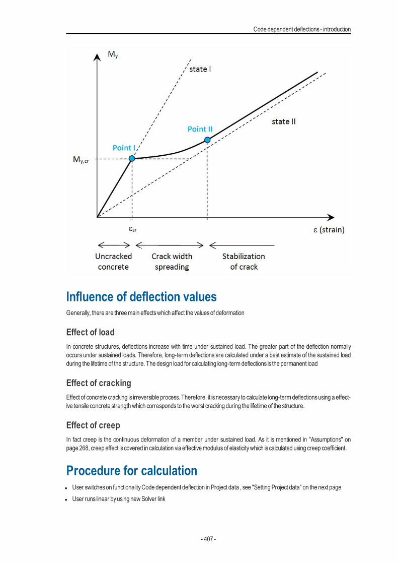
Code dependent deflections - introduction
Influence of deflection valuesGenerally, there are threemain effectswhich affect the valuesof deformation
Effect of loadIn concrete structures, deflections increase with time under sustained load. The greater part of the deflection normallyoccurs under sustained loads. Therefore, long-term deflections are calculated under a best estimate of the sustained loadduring the lifetime of the structure. The design load for calculating long-termdeflections is the permanent load
Effect of crackingEffect of concrete cracking is irreversible process. Therefore, it is necessary to calculate long-termdeflectionsusing a effect-ive tensile concrete strengthwhich corresponds to theworst cracking during the lifetime of the structure.
Effect of creepIn fact creep is the continuous deformation of a member under sustained load. As it is mentioned in "Assumptions" onpage 268, creep effect is covered in calculation via effectivemodulusof elasticitywhich is calculated using creep coefficient.
Procedure for calculationl User switcheson functionalityCode dependent deflection in Project data , see "Setting Project data" on the next pagel User runs linear byusing newSolver link
- 407 -
Chapter 9
l User definescreep coefficient, shrinkage coefficient and coefficient for increasing amount of reinforcement in Concretesetting (global setting) or in concretemember data (local setting), see "Global setting" on the facing page
l User open commandCode dependent deflection and select, see "Command for Code dependent deflection" onpage 415l 1D and 2Dmember for calculationl combination for calculationl type of reinforcementl drawing setting and output setting
l User runsCode dependent deflection byclicking on buttonRefresh in the commandl The programcalculatesdeflection andmakesnumerical and graphical output for 1D and 2Dmembers for selected value,
extreme...., see "Theoretical background" on page 427
Limitation for version SEN 17.0l the Plane generator andAbsencesare not supported in structuresl calculation deflection for the rib isnot supportedl onlydeflection in zaxisof LCSof 2Dmember is calculated (deflection perpendicular for plane of 2Dmember)l deflection in yand zaxisof LCSof 1Dmember is supportedl shrinkage isnot taken into accountl it is not possible run code dependent deflection for non-linear combination
Setting Project data
Code dependent deflection can be calculated in SCIA Engineer only in case, that check boxCode dependent deflection(Project data >Functionality>Concrete) isON.
- 408 -

Code dependent deflections - introduction
The old results (results calculated by Nexis) will be removed after switching ON this checkbox
New code dependent deflection used functionality of new solver link, therefore there issome limitations for calculation in version 17.0
Global setting
The following itemshave impact on the calculation of deflection check
l Parametersof creep coefficient, see "Parameters for calculation of creep coefficient" on page 412l Type of strength for calculation of cracking forces, see "Type of strength for calculation of cracking forces" on page 326l Value of strength for calculation of cracking forces, see "Value of strength for calculation of cracking forces" on page 324l Coefficient for increasing amount of reinforcement, see "Coefficient for increasing amount of reinforcement" on
page 413l Maximal total deflection for 1Dmember, see "Maximal total deflection for 1Dmember" on page 413l Maximal additional deflection for 1Dmember, see "Maximal additional deflection for 1Dmember" on page 413l Maximal total deflection for 2Dmember, see "Maximal total deflection for 2Dmember" on page 414l Maximal additional deflection for 2Dmember,see "Maximal additional deflection for 2Dmember" on page 414
- 409 -
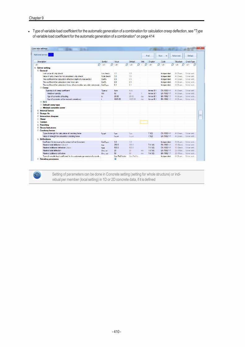
Chapter 9
l Type of variable load coefficient for the automaticgeneration of a combination for calculation creep deflection, see "Typeof variable load coefficient for the automaticgeneration of a combination" on page 414
Setting of parameters can be done in Concrete setting (setting for whole structure) or indi-vidual per member (local setting) in 1D or 2D concrete data, if it is defined
- 410 -
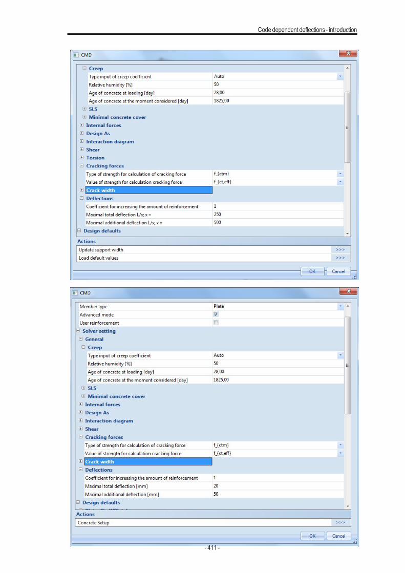
Code dependent deflections - introduction
- 411 -
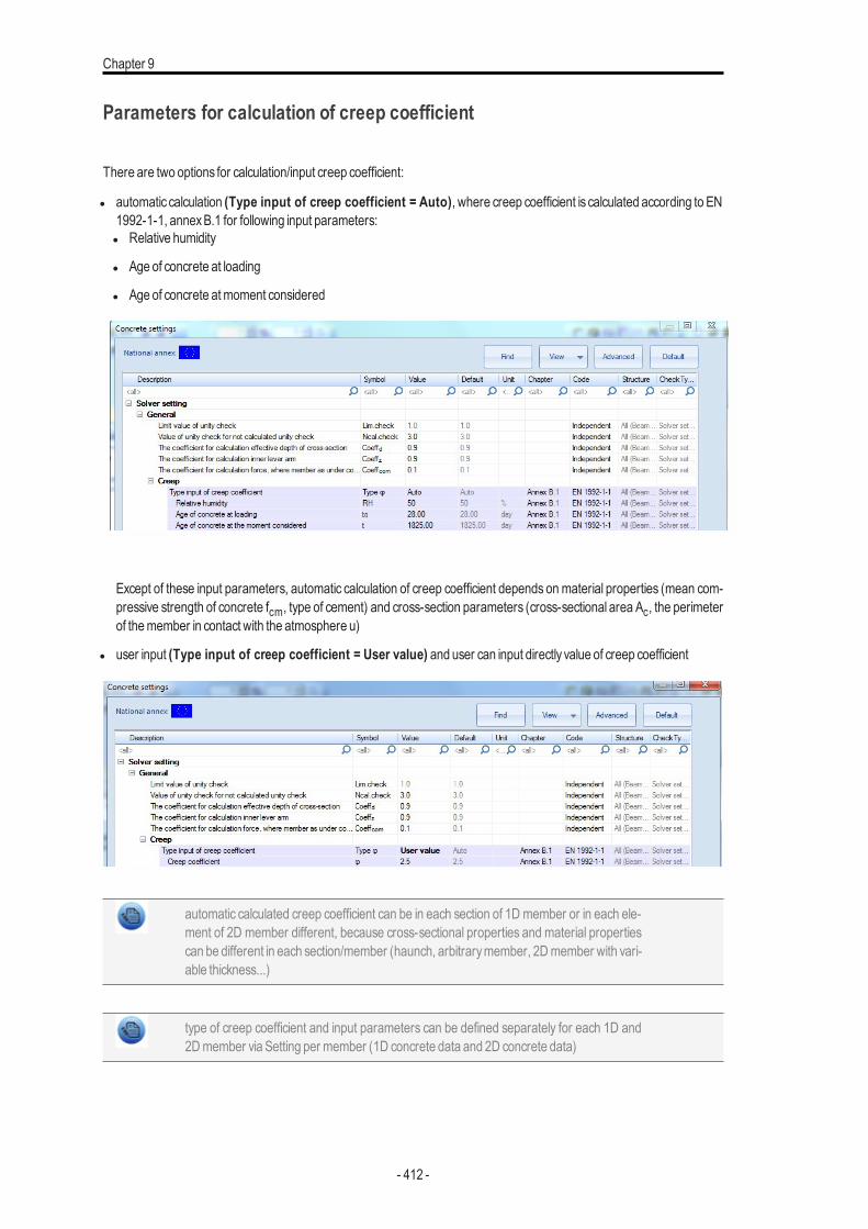
Chapter 9
Parameters for calculation of creep coefficient
There are two options for calculation/input creep coefficient:
l automatic calculation (Type input of creep coefficient = Auto), where creep coefficient is calculated according to EN1992-1-1, annexB.1 for following input parameters:l Relative humidity
l Age of concrete at loading
l Age of concrete atmoment considered
Except of these input parameters, automatic calculation of creep coefficient depends onmaterial properties (mean com-pressive strength of concrete fcm, type of cement) and cross-section parameters (cross-sectional area Ac, the perimeterof themember in contact with the atmosphere u)
l user input (Type input of creep coefficient = User value) and user can input directly value of creep coefficient
automatic calculated creep coefficient can be in each section of 1D member or in each ele-ment of 2D member different, because cross-sectional properties and material propertiescan be different in each section/member (haunch, arbitrarymember, 2Dmember with vari-able thickness...)
type of creep coefficient and input parameters can be defined separately for each 1D and2Dmember via Setting per member (1D concrete data and 2D concrete data)
- 412 -
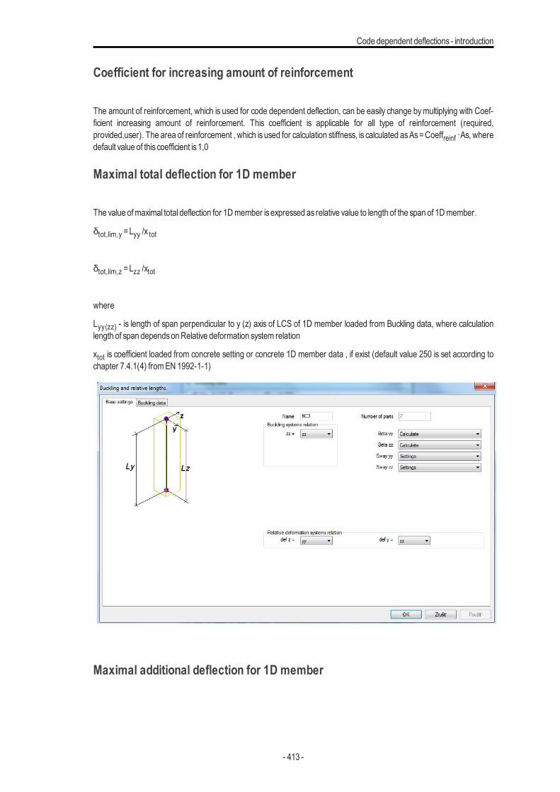
Code dependent deflections - introduction
Coefficient for increasing amount of reinforcement
The amount of reinforcement, which is used for code dependent deflection, can be easily change bymultiplying with Coef-ficient increasing amount of reinforcement. This coefficient is applicable for all type of reinforcement (required,provided,user). The area of reinforcement , which is used for calculation stiffness, is calculated asAs=Coeffreinf ·As, wheredefault value of this coefficient is1,0
Maximal total deflection for 1D member
The value ofmaximal total deflection for 1Dmember isexpressed as relative value to length of the span of 1Dmember.
δtot,lim,y =Lyy /x tot
δtot,lim,z =Lzz /xtot
where
Lyy(zz) - is length of span perpendicular to y (z) axis of LCS of 1D member loaded from Buckling data, where calculationlength of span dependsonRelative deformation system relation
xtot is coefficient loaded from concrete setting or concrete 1D member data , if exist (default value 250 is set according tochapter 7.4.1(4) fromEN 1992-1-1)
Maximal additional deflection for 1D member
- 413 -
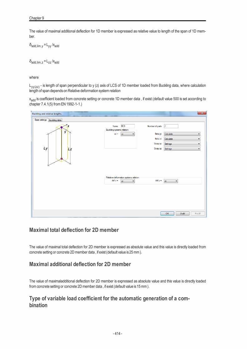
Chapter 9
The value of maximal additional deflection for 1D member is expressed as relative value to length of the span of 1D mem-ber.
δadd,lim,y =Lyy /xadd
δadd,lim,z =Lzz /xadd
where
Lyy(zz) - is length of span perpendicular to y (z) axis of LCS of 1D member loaded from Buckling data, where calculationlength of span dependsonRelative deformation system relation
xadd is coefficient loaded from concrete setting or concrete 1D member data , if exist (default value 500 is set according tochapter 7.4.1(5) fromEN 1992-1-1.)
Maximal total deflection for 2D member
The value of maximal total deflection for 2D member is expressed as absolute value and this value is directly loaded fromconcrete setting or concrete 2Dmember data , if exist (default value is25mm ).
Maximal additional deflection for 2D member
The value of maximaladditional deflection for 2D member is expressed as absolute value and this value is directly loadedfrom concrete setting or concrete 2Dmember data , if exist (default value is15mm ).
Type of variable load coefficient for the automatic generation of a com-bination
- 414 -
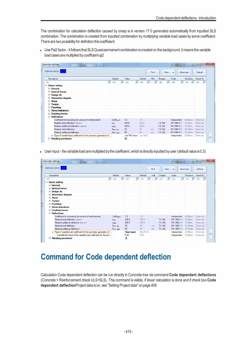
Code dependent deflections - introduction
The combination for calculation deflection caused by creep is in version 17.0 generated automatically from inputted SLScombination. The combination is created from inputted combination bymultiplying variable load cases by some coefficient.There are two possibility for definition this coefficient:
l UsePsi2 factor - it follows that SLSQuasi permanent combination is created on the background, it means the variableload casesaremultiplied bycoefficientψ2
l User input - the variable load aremultiplied by the coefficient, which isdirectly inputted byuser (default value is0,3)
Command for Code dependent deflection
Calculation Code dependent deflection can be run directly in Concrete tree via command Code dependent deflections(Concrete > Reinforcement check ULS+SLS). This command is visible, if linear calculation is done and if check box Codedependent deflectionProject data ison, see "Setting Project data" on page 408
- 415 -

Chapter 9
There ispossible to evaluate deflection for 1D and 2D in one command and properties in these command are filtered accord-ing to, if in the project are only1Dmembers, only2Dmembersor both
- 416 -
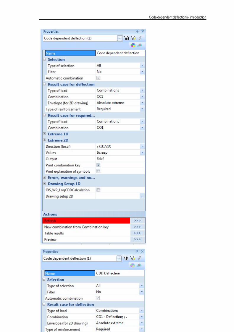
Code dependent deflections - introduction
- 417 -
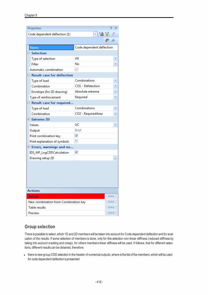
Chapter 9
Group selectionThere ispossible to select ,which 1D and 2Dmemberswill be taken into account for Code dependent deflection and for eval-uation of the results. If some selection of members is done, only for this selection non-linear stiffness (reduced stiffness bytaking into account cracking and creep), for others members linear stiffness will be used. It follows, that for different selec-tions, different results can be obtained, therefore:
l there isnew groupCDD selection in the header of numerical outputs, where is the list of themembers ,whichwill be usedfor code dependent deflection ispresented
- 418 -
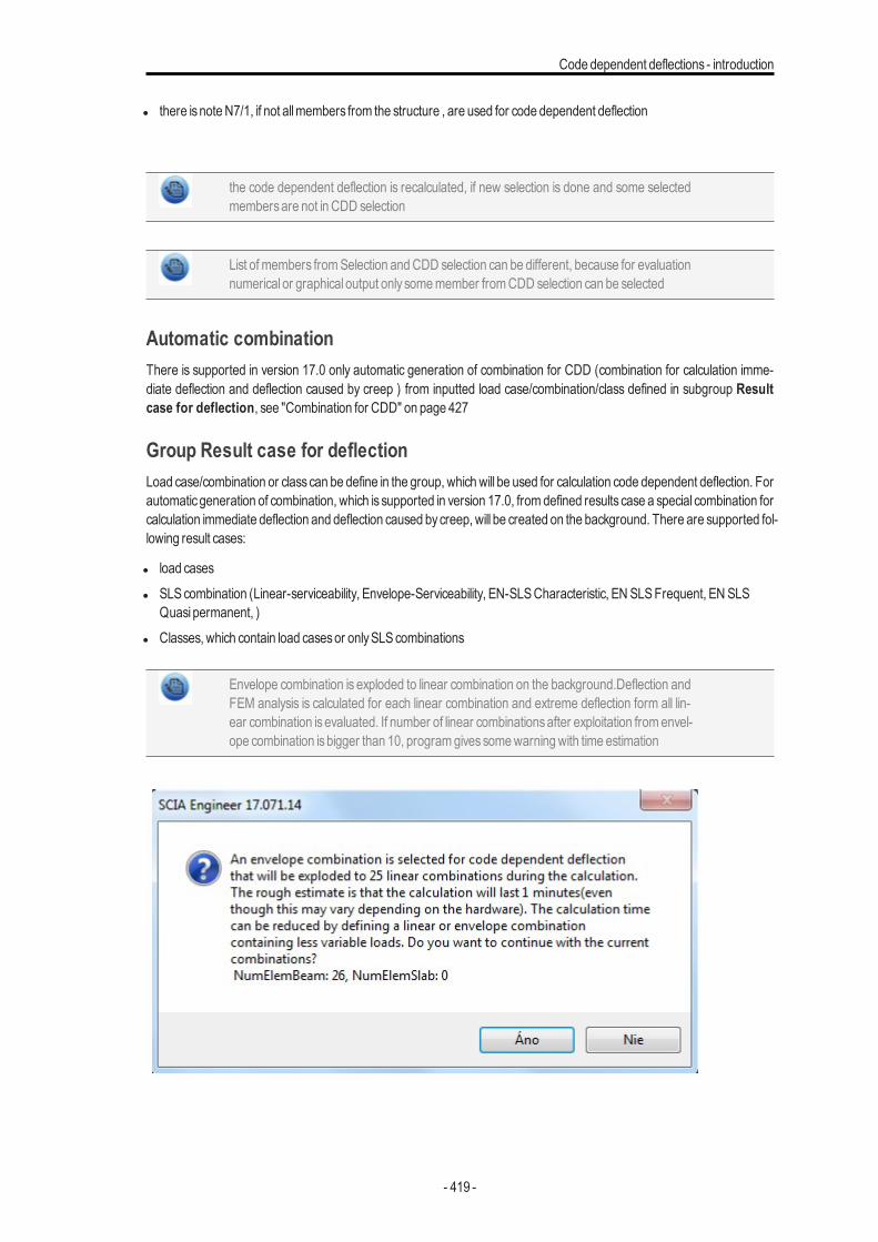
Code dependent deflections - introduction
l there isnoteN7/1, if not allmembers from the structure , are used for code dependent deflection
the code dependent deflection is recalculated, if new selection is done and some selectedmembersare not in CDD selection
List of members fromSelection andCDD selection can be different, because for evaluationnumerical or graphical output only somemember fromCDD selection can be selected
Automatic combinationThere is supported in version 17.0 only automatic generation of combination for CDD (combination for calculation imme-diate deflection and deflection caused by creep ) from inputted load case/combination/class defined in subgroup Resultcase for deflection, see "Combination for CDD" on page 427
Group Result case for deflectionLoad case/combination or classcan be define in the group, whichwill be used for calculation code dependent deflection. Forautomatic generation of combination, which is supported in version 17.0, from defined results case a special combination forcalculation immediate deflection and deflection caused bycreep, will be created on the background. There are supported fol-lowing result cases:
l load casesl SLScombination (Linear-serviceability, Envelope-Serviceability, EN-SLSCharacteristic, EN SLSFrequent, EN SLS
Quasi permanent, )l Classes, which contain load casesor onlySLScombinations
Envelope combination is exploded to linear combination on the background.Deflection andFEM analysis is calculated for each linear combination and extreme deflection form all lin-ear combination isevaluated. If number of linear combinationsafter exploitation fromenvel-ope combination isbigger than 10, programgivessomewarningwith time estimation
- 419 -
Chapter 9
Type of reinforcementThree type of reinforcement are supported for code dependent deflections:
l required reinforcement -it is reinforcement designed by the program in commandReinforcement design. It is a sumofstatically required reinforcement (reinforcement designed for normal forcesand bendingmoments, longitudinal rein-forcement designed for tensile force caused byshear and torsion) and reinforcement designed according detailing pro-visions.
l provided reinforcement - it is reinforcement, which is input inDesign defaults or Concrete member data via libraryProvided reinforcement
l user reinforcement - it is reinforcement input by the user
Load case/combination/class, which will be used for design required and provided rein-forcement, can be defined in groupResult case for required reinforcement
type of reinforcement which is used for code dependent deflection is presented in numer-ical output too. If required/provided reinforcement was not calculated or user rein-forcement was not inputted in some sections of 1D members or elements of 2D member,than linear stiffness for uncracked section/element or 10% of linear stiffness for crackedsection/element isused and programgivessomewarning
If the required or provided reinforcement for 1D members is already designed for selectedcombination in Result case for required reinforcement and selected selection, thedesigned required/provided reinforcement will be used, otherwise required/provided rein-forcement will be designed before calculation of code dependent deflection for selectedcombination and selection
The required/provided reinforcement of 2D member, which is calculated for Location = Incentres and for System = LCSmesh elements is supported for code dependent deflectionof 2D members. If the required or provided reinforcement for 2D members is alreadydesigned for selected combination inResult case for required reinforcement, selectedselection, Location = In centres and for System = LCS mesh elements , the required/-provided reinforcement will be used, otherwise required/provided reinforcement will bedesigned before calculation of code dependent deflection for selected combination andselection.
Group Result case for required reinforcementLoad case/combination or class can be define in the group, which will be used for design required or provided rein-forcement, in the case that for selected selection and combination, required or provided reinforcement is not already cal-culated..This group is visible for Type of reinforcement = Required or Type of reinforcement = Provided. There aresupported following result cases:
l load casesl ULScombination (Linear-ultimate, Envelope-Ultimate, EN-ULS..., )l Classes, which contain load casesor onlyULScombinations
- 420 -
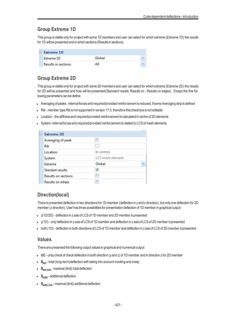
Code dependent deflections - introduction
Group Extreme 1DThis group is visible only for project with some 1Dmembers and user can select for which extreme (Extreme 1D) the resultsfor 1Dwill be presented and inwhich sections (Results in sections)
Group Extreme 2DThis group is visible only for project with some 2Dmembers and user can select for which extreme (Extreme 2D) the resultsfor 2D will be presented and how will be presented(Standard results, Results on , Results on edges) . Except the fine fol-lowing parameterscan be define:
l Averaging of peaks - internal forcesand required/provided reinforcement is reduced, if someAveraging strip isdefinedl Rib - member typeRib isnot supported in version 17.0, therefore this checkbox isnot editablel Location - the stiffnessand required/provided reinforcement is calculated in centre of 2D elementsl System -internal forcesand required/provided reinforcement is related to LCSofmesh elements
Direction(local)There is presented deflection in two directions for 1Dmember (deflection in yand zdirection), but only one deflection for 2Dmember (zdirection). User has three possibilities for presentation deflection of 1Dmember in graphical output :
l z(1D/2D) - deflection in zaxisof LCS of 1Dmember and 2Dmember ispresentedl y(1D) - onlydeflection in yaxisof LCS of 1Dmember and deflection in zaxisof LCS of 2Dmember ispresentedl both (1D) - deflection in both directionsof LCS of 1Dmember and deflection in zaxisof LCS of 2Dmember ispresented
ValuesThere are presented the following output values in graphical and numerical output:
l UC - unity checkof checkdeflection in both direction (yand z) of 1Dmember and in direction z for 2Dmemberl δtot - total (long-term)deflectionwith taking into account cracking and creep
l δtot,lim - maximal (limit) total deflection
l δadd - additional deflection
l δadd,lim - maximal (limit) additional deflection
- 421 -
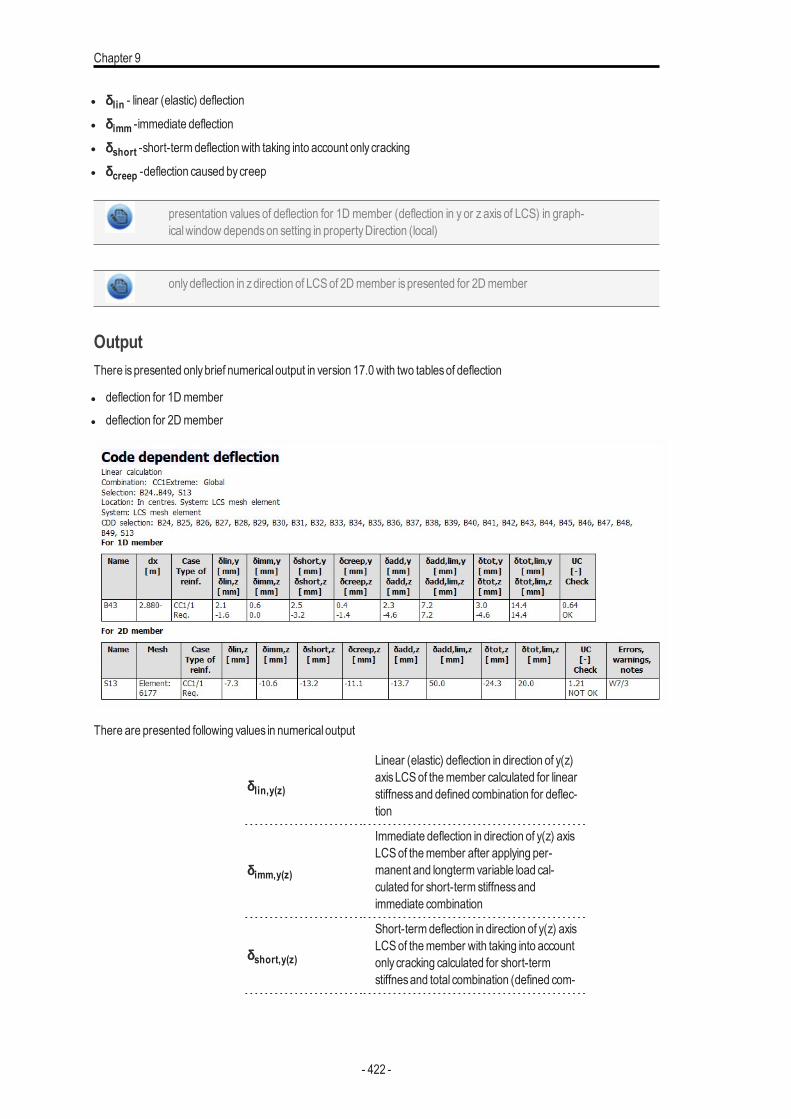
Chapter 9
l δlin - linear (elastic) deflection
l δimm -immediate deflection
l δshort -short-termdeflectionwith taking into account only cracking
l δcreep -deflection caused bycreep
presentation values of deflection for 1D member (deflection in y or z axis of LCS) in graph-icalwindow dependson setting in propertyDirection (local)
onlydeflection in zdirection of LCSof 2Dmember ispresented for 2Dmember
OutputThere ispresented onlybrief numerical output in version 17.0with two tablesof deflection
l deflection for 1Dmemberl deflection for 2Dmember
There are presented following values in numerical output
δlin,y(z)
Linear (elastic) deflection in direction of y(z)axisLCSof themember calculated for linearstiffnessand defined combination for deflec-tion
δimm,y(z)
Immediate deflection in direction of y(z) axisLCSof themember after applying per-manent and longterm variable load cal-culated for short-term stiffnessandimmediate combination
δshort,y(z)
Short-termdeflection in direction of y(z) axisLCSof themember with taking into accountonly cracking calculated for short-termstiffnesand total combination (defined com-
- 422 -
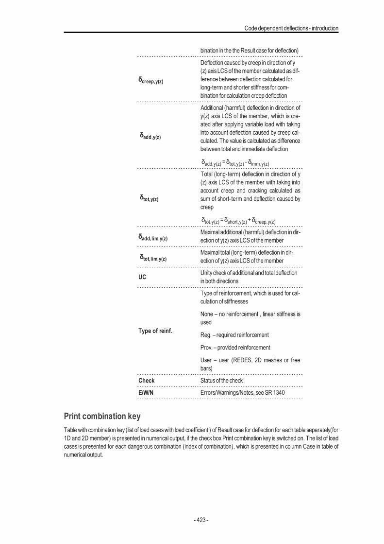
Code dependent deflections - introduction
bination in the theResult case for deflection)
δcreep,y(z)
Deflection caused bycreep in direction of y(z) axisLCSof themember calculated asdif-ference between deflection calculated forlong-termand shorter stiffness for com-bination for calculation creep deflection
δadd,y(z)
Additional (harmful) deflection in direction ofy(z) axis LCS of the member, which is cre-ated after applying variable load with takinginto account deflection caused by creep cal-culated. The value is calculated asdifferencebetween total and immediate deflection
δadd,y(z) =δtot,y(z) - δimm,y(z)
δtot,y(z)
Total (long-term) deflection in direction of y(z) axis LCS of the member with taking intoaccount creep and cracking calculated assum of short-term and deflection caused bycreep
δtot,y(z) =δshort,y(z) +δcreep,y(z)
δadd,lim,y(z)Maximal additional (harmful) deflection in dir-ection of y(z) axisLCSof themember
δtot,lim,y(z)Maximal total (long-term) deflection in dir-ection of y(z) axisLCSof themember
UC Unity checkof additional and total deflectionin both directions
Type of reinf.
Type of reinforcement, which is used for cal-culation of stiffnesses
None – no reinforcement , linear stiffness isused
Reg. – required reinforcement
Prov. – provided reinforcement
User – user (REDES, 2D meshes or freebars)
Check Statusof the check
E/W/N Errors/Warnings/Notes, seeSR 1340
Print combination keyTable with combination key (list of load caseswith load coefficient ) of Result case for deflection for each table separately(for1D and 2D member) is presented in numerical output, if the check boxPrint combination key is switched on. The list of loadcases is presented for each dangerous combination (index of combination), which is presented in column Case in table ofnumerical output.
- 423 -
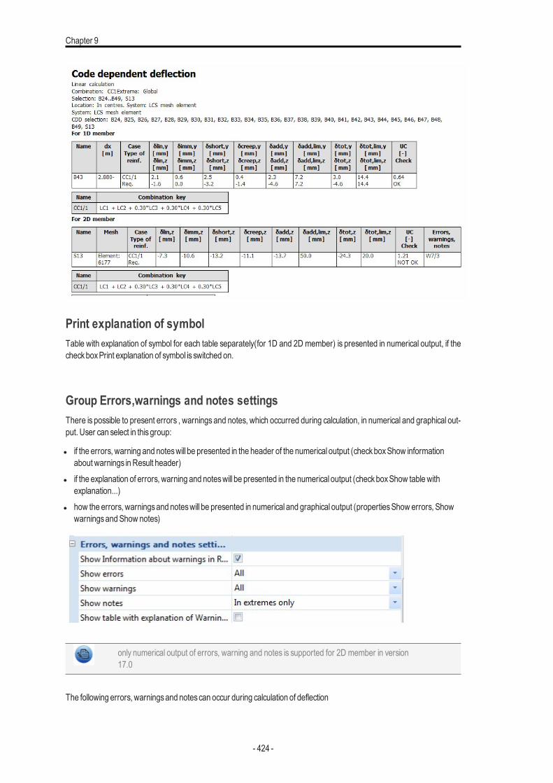
Chapter 9
Print explanation of symbolTable with explanation of symbol for each table separately(for 1D and 2D member) is presented in numerical output, if thecheckboxPrint explanation of symbol is switched on.
Group Errors,warnings and notes settingsThere is possible to present errors , warnings and notes, which occurred during calculation, in numerical and graphical out-put. User can select in thisgroup:
l if the errors, warning and noteswill be presented in the header of the numerical output (checkboxShow informationabout warnings inResult header)
l if the explanation of errors, warning and noteswill be presented in the numerical output (checkboxShow tablewithexplanation...)
l how the errors, warningsand noteswill be presented in numerical and graphical output (propertiesShow errors, ShowwarningsandShow notes)
only numerical output of errors, warning and notes is supported for 2D member in version17.0
The following errors, warningsand notescan occur during calculation of deflection
- 424 -
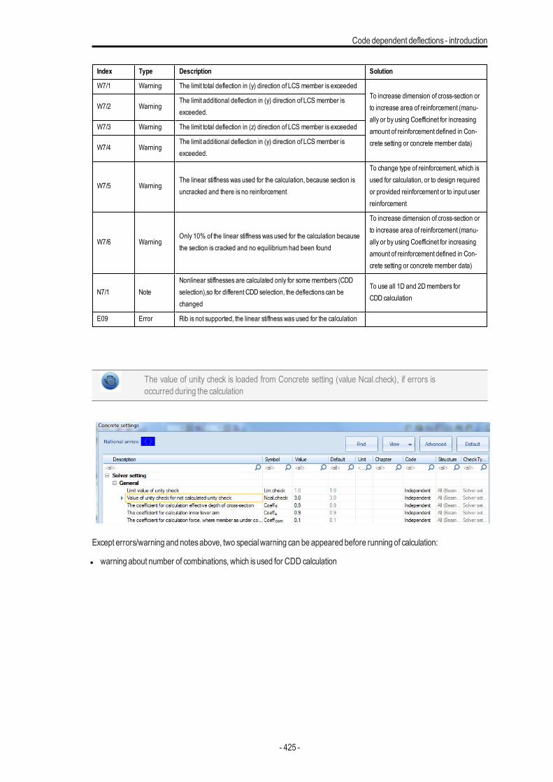
Code dependent deflections - introduction
Index Type Description Solution
W7/1 Warning The limit total deflection in (y) direction of LCS member is exceededTo increase dimension of cross-section orto increase area of reinforcement (manu-ally or by using Coefficinet for increasingamount of reinforcement defined in Con-crete setting or concrete member data)
W7/2 WarningThe limit additional deflection in (y) direction of LCS member isexceeded.
W7/3 Warning The limit total deflection in (z) direction of LCS member is exceeded
W7/4 WarningThe limit additional deflection in (y) direction of LCS member isexceeded.
W7/5 WarningThe linear stiffness was used for the calculation, because section isuncracked and there is no reinforcement
To change type of reinforcement, which isused for calculation, or to design requiredor provided reinforcement or to input userreinforcement
W7/6 WarningOnly 10% of the linear stiffness was used for the calculation becausethe section is cracked and no equilibrium had been found
To increase dimension of cross-section orto increase area of reinforcement (manu-ally or by using Coefficinet for increasingamount of reinforcement defined in Con-crete setting or concrete member data)
N7/1 NoteNonlinear stiffnesses are calculated only for some members (CDDselection),so for different CDD selection, the deflections can bechanged
To use all 1D and 2Dmembers forCDD calculation
E09 Error Rib is not supported, the linear stiffness was used for the calculation
The value of unity check is loaded from Concrete setting (value Ncal.check), if errors isoccurred during the calculation
Except errors/warning and notesabove, two specialwarning can be appeared before running of calculation:
l warning about number of combinations, which isused for CDD calculation
- 425 -
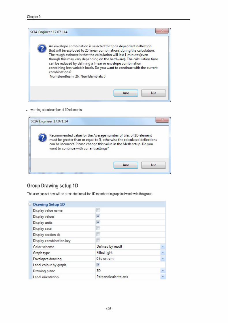
Chapter 9
l warning about number of 1D elements
Group Drawing setup 1DThe user can set howwill be presented result for 1Dmembers in graphicalwindow in thisgroup
- 426 -
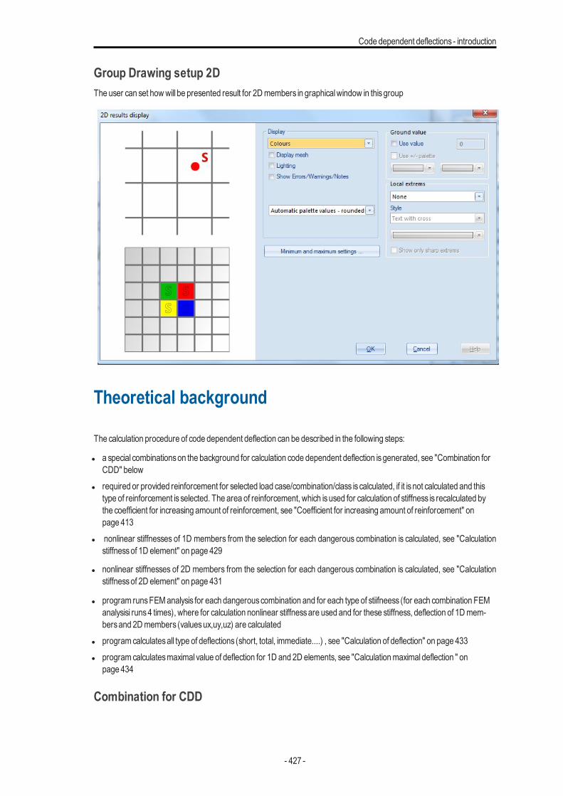
Code dependent deflections - introduction
Group Drawing setup 2DThe user can set howwill be presented result for 2Dmembers in graphicalwindow in thisgroup
Theoretical background
The calculation procedure of code dependent deflection can be described in the following steps:
l a special combinationson the background for calculation code dependent deflection isgenerated, see "Combination forCDD" below
l required or provided reinforcement for selected load case/combination/class is calculated, if it is not calculated and thistype of reinforcement is selected. The area of reinforcement, which isused for calculation of stiffness is recalculated bythe coefficient for increasing amount of reinforcement, see "Coefficient for increasing amount of reinforcement" onpage 413
l nonlinear stiffnesses of 1D members from the selection for each dangerous combination is calculated, see "Calculationstiffnessof 1D element" on page 429
l nonlinear stiffnesses of 2D members from the selection for each dangerous combination is calculated, see "Calculationstiffnessof 2D element" on page 431
l program runsFEM analysis for each dangerouscombination and for each type of stiifneess (for each combination FEManalysisi runs4 times), where for calculation nonlinear stiffnessare used and for these stiffness, deflection of 1Dmem-bersand 2Dmembers (valuesux,uy,uz) are calculated
l programcalculatesall type of deflections (short, total, immediate....) , see "Calculation of deflection" on page 433l programcalculatesmaximal value of deflection for 1D and 2D elements, see "Calculationmaximal deflection " on
page 434
Combination for CDD
- 427 -
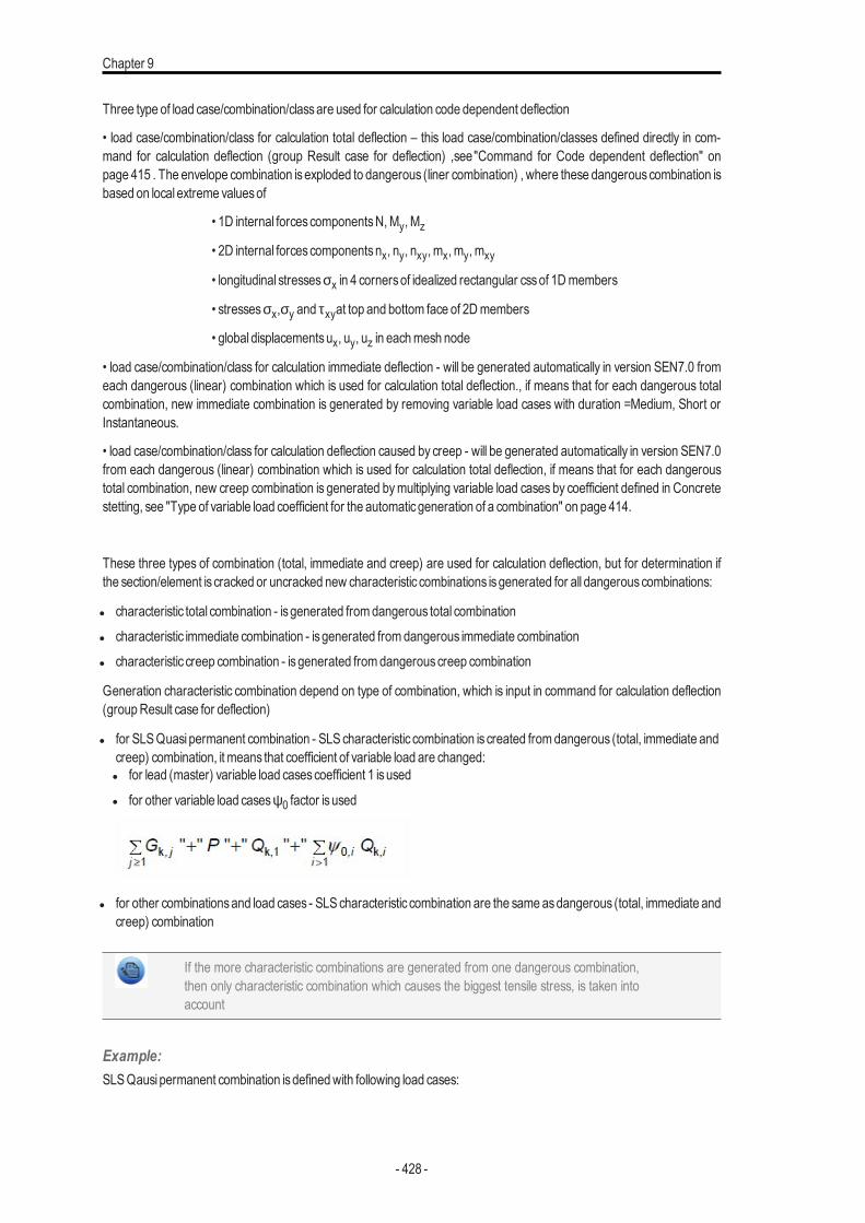
Chapter 9
Three type of load case/combination/classare used for calculation code dependent deflection
• load case/combination/class for calculation total deflection – this load case/combination/classes defined directly in com-mand for calculation deflection (group Result case for deflection) ,see"Command for Code dependent deflection" onpage 415 . The envelope combination isexploded to dangerous (liner combination) , where these dangerouscombination isbased on local extreme valuesof
• 1D internal forcescomponentsN,My, Mz
• 2D internal forcescomponentsnx, ny, nxy, mx, my, mxy
• longitudinal stressesσx in 4 cornersof idealized rectangular cssof 1Dmembers
• stressesσx,σy and τxyat top and bottom face of 2Dmembers
• global displacementsux, uy, uz in eachmesh node
• load case/combination/class for calculation immediate deflection - will be generated automatically in version SEN7.0 fromeach dangerous (linear) combination which is used for calculation total deflection., if means that for each dangerous totalcombination, new immediate combination is generated by removing variable load cases with duration =Medium, Short orInstantaneous.
• load case/combination/class for calculation deflection caused by creep - will be generated automatically in version SEN7.0from each dangerous (linear) combination which is used for calculation total deflection, if means that for each dangeroustotal combination, new creep combination is generated bymultiplying variable load cases by coefficient defined in Concretestetting, see "Type of variable load coefficient for the automaticgeneration of a combination" on page 414.
These three types of combination (total, immediate and creep) are used for calculation deflection, but for determination ifthe section/element is cracked or uncracked new characteristic combinations isgenerated for all dangerouscombinations:
l characteristic total combination - isgenerated fromdangerous total combinationl characteristic immediate combination - isgenerated fromdangerous immediate combinationl characteristic creep combination - isgenerated fromdangerouscreep combination
Generation characteristic combination depend on type of combination, which is input in command for calculation deflection(groupResult case for deflection)
l for SLSQuasi permanent combination - SLScharacteristic combination is created fromdangerous (total, immediate andcreep) combination, it means that coefficient of variable load are changed:l for lead (master) variable load casescoefficient 1 isusedl for other variable load casesψ0 factor isused
l for other combinationsand load cases - SLScharacteristic combination are the sameasdangerous (total, immediate andcreep) combination
If the more characteristic combinations are generated from one dangerous combination,then only characteristic combination which causes the biggest tensile stress, is taken intoaccount
Example:SLSQausi permanent combination isdefinedwith following load cases:
- 428 -
Code dependent deflections - introduction
l LC1 - self weight (permanent load)l LC2 - other permanent loadl LC3 - variable load casewith long duration (load type =categoryA)l LC4 - variable load casewith short duration (load type =snow for Finland)
The following combination are generated for calculation code dependent deflection:
Type of combination Combikeyof all dangerouscombinations
Total1:LC1+LC2
2:LC1 +LC2+0.30*LC3 +0.2*LC4
Immediate1:LC1+LC2
2:LC1 +LC2+0.30*LC3
Creep1:LC1+LC2
2:LC1 +LC2+0.30*LC3 +0.2*LC4
Total characteristic
1:LC1+LC2
2a:LC1 + LC2 + LC3 + 0.70*LC4
2b:LC1 +LC2+0.70*LC3 +LC4
Immediate characteristic1:LC1+LC2
2:LC1 +LC2+LC3
Creep characteristic
1:LC1+LC2
2a:LC1 + LC2 + LC3 + 0.70*LC4
2b:LC1 +LC2+0.70*LC3 +LC4
Calculation stiffness of 1D element
Memberswhich are not expected to be loaded above the level which would cause the tensile strength of the concrete to beexceeded anywhere within the member should be considered to be uncracked. Memberswhich are expected to crack, butmay not be fully cracked, will behave in a manner intermediate between the uncracked and fully cracked conditions. Newstiffness (stiffnesswith taking into account cracking) is calculated in centre of each 1D element.
Two typesof stiffnessare calculated:
Short-term stiffness - is calculated using 28 daysmodulus of elasticity Ec =Ecm, it follows that value of stiffness is loadeddirectly frompropertiesof the concretematerial
Long-term stiffness - is calculated using effective E modulus based on creep coefficient for acting load, it follows Ec =Ec,eff =Ecm/(1+ϕ).
Calculation effective modulus of elasticity is based on equation 5.27 in EN 1992-1-1, butinstead of effective creep coefficientϕef, only creep coefficientϕ is used
The following procedure isused for calculation stiffens for
l calculation transformedCsscharacteristicsof uncracked section (Ai, Ii, ti...)
l calculation stiffness’sof uncracked cross-section ((EIy)I,( EIz)I, (EA)I) to centre of uncracked transformed cross-section
l calculation maximum value of tensile stress of uncracked cross-section (value σct,res) for respective characteristic
- 429 -
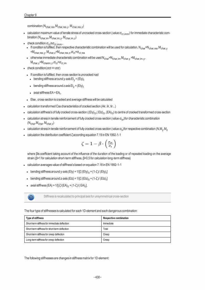
Chapter 9
combination (Nchar,res,Mchar,res,y, Mchar,res,z)
l calculationmaximumvalue of tensile stressof uncracked cross-section (valueσct,imm) for immediate characteristic com-bination (Nchar,im,Mchar,im,y, Mchar,im,z)
l checkconditionσct≥σct,imm,.l If condition is fulfilled, then respective characteristic combinationwill be used for calculation, Nchar=Nchar,res,Mchar,y
=Mchar,res,y, Mchar,z=Mchar,res,z,σct=σct,resl otherwise immediate characteristic combinationwill be usedNchar=Nchar,im,Mchar,y =Mchar,im,y,
Mchar,z=Mcharim,z,σct=σct,iml checkcondition(σct <=σcr)
l If condition is fulfilled, then cross-section isuncracked nadl bending stiffnessaround y-axisEIy = (EIy)Il bending stiffnessaround zaxisEIz = (EIy)Il axial stiffnessEA=EAI,
l Else , cross-section is cracked and average stiffnesswill be calculated
l calculation transformedCsscharacteristicsof cracked section (Air, Iir, tir...)l calculation stiffness’sof fully cracked cross-section ((EIy)II,( EIz)II, (EA)II) to centre of cracked transformed cross-section
l calculation stress in tensile reinforcement of fully cracked cross-section (valueσsr)for characteristic combination(Nchar,Mchar, Mchar,z)
l calculation stress in tensile reinforcement of fully cracked cross-section (valueσs)for respective combination (N,My,Mz
l calculation the distribution coefficientζaccording equation 7.19 in EN 1992-1-1
where βis coefficient taking account of the influence of the duration of the loading or of repeated loading on the averagestrain (β=1 for calculation short-term stiffness,β=0,5 for calculation long-term stiffness)
l calculation averagesvalue of stiffness’sbased on equation 7.18 in EN 1992-1-1
l bending stiffnessaround y-axis (EIy) =1/[ζ/(EIy)II + (1-ζ)/ (EIy)I]
l bending stiffnessaround z-axis (EIz) =1/[ζ/(EIz)II + (1-ζ)/ (EIz)I]
l axial stiffness (EA) =1/[(ζ/(EA)II + (1-ζ)/( EA)I],
Stiffness is recalculated to principal axis for unsymmetrical cross-section
The four type of stiffnesses is calculated for each 1D element and each dangerouscombination:
Type of stiffness Respective combination
Short-term stiffness for immediate deflection Immediate
Short-term stiffness for short-term deflection Total
Short-term stiffness for creep deflection Creep
Long-term stiffness for creep deflection Creep
The following stiffnessesare changes in stiffnessmatrix for 1D element:
- 430 -
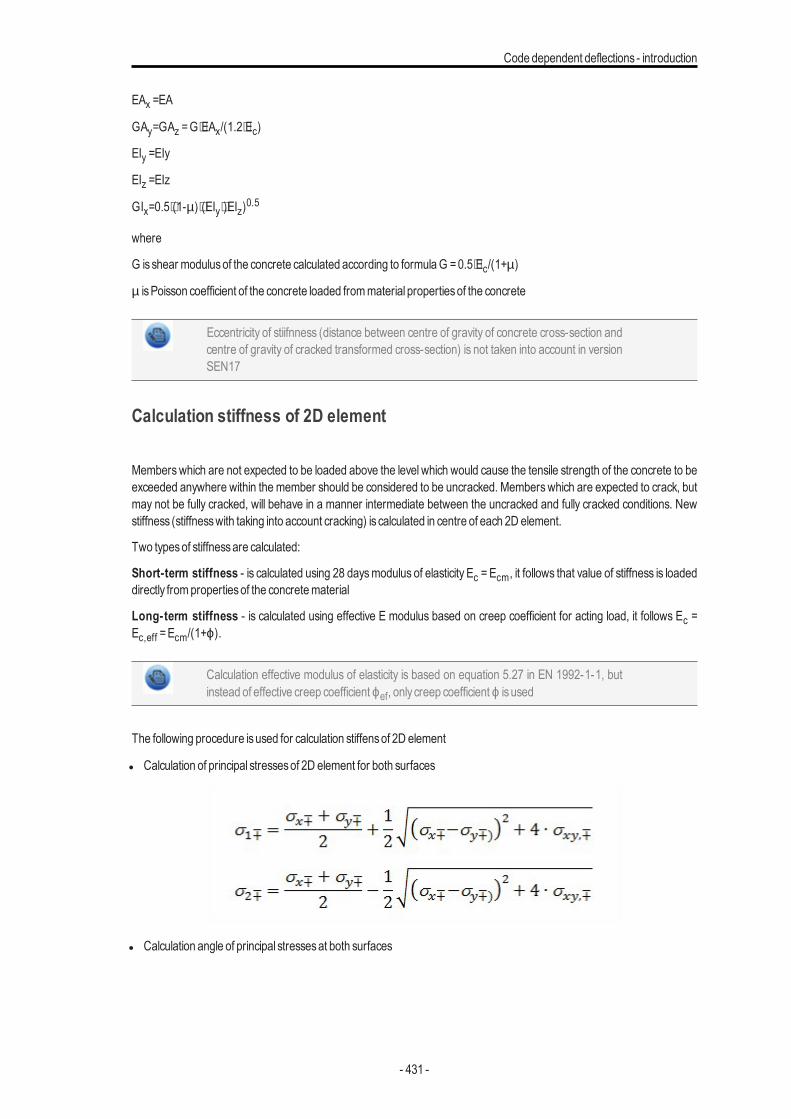
Code dependent deflections - introduction
EAx =EA
GAy=GAz =G⋅EAx/(1.2⋅Ec)
EIy =EIy
EIz =EIz
GIx=0.5⋅(1-µ)⋅(EIy⋅)EIz)0.5
where
G isshear modulusof the concrete calculated according to formulaG =0.5⋅Ec/(1+µ)
µ isPoisson coefficient of the concrete loaded frommaterial propertiesof the concrete
Eccentricity of stiifnness (distance between centre of gravity of concrete cross-section andcentre of gravity of cracked transformed cross-section) is not taken into account in versionSEN17
Calculation stiffness of 2D element
Memberswhich are not expected to be loaded above the level which would cause the tensile strength of the concrete to beexceeded anywhere within the member should be considered to be uncracked. Memberswhich are expected to crack, butmay not be fully cracked, will behave in a manner intermediate between the uncracked and fully cracked conditions. Newstiffness (stiffnesswith taking into account cracking) is calculated in centre of each 2D element.
Two typesof stiffnessare calculated:
Short-term stiffness - is calculated using 28 daysmodulus of elasticity Ec =Ecm, it follows that value of stiffness is loadeddirectly frompropertiesof the concretematerial
Long-term stiffness - is calculated using effective E modulus based on creep coefficient for acting load, it follows Ec =Ec,eff =Ecm/(1+ϕ).
Calculation effective modulus of elasticity is based on equation 5.27 in EN 1992-1-1, butinstead of effective creep coefficientϕef, only creep coefficientϕ is used
The following procedure isused for calculation stiffensof 2D element
l Calculation of principal stressesof 2D element for both surfaces
l Calculation angle of principal stressesat both surfaces
- 431 -
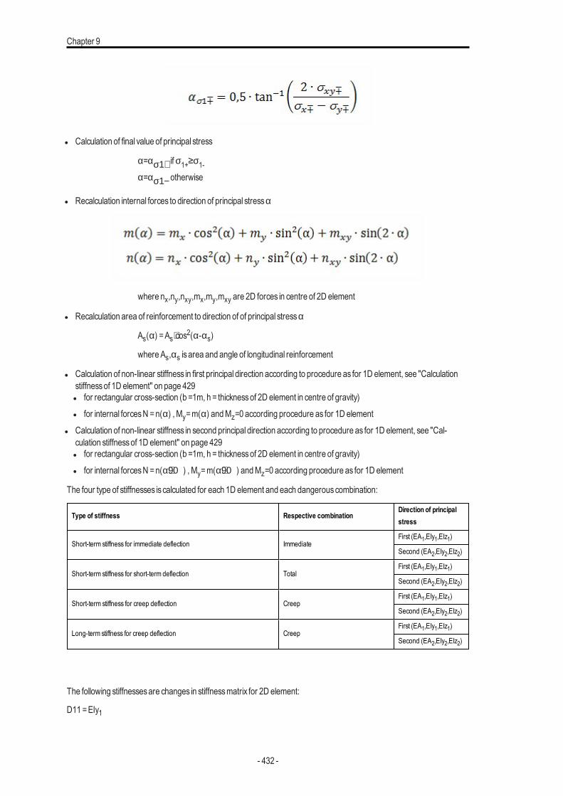
Chapter 9
l Calculation of final value of principal stress
α=ασ1+ ifσ1+≥σ1-α=ασ1−otherwise
l Recalculation internal forces to direction of principal stressα
where nx,ny,nxy,mx,my,mxy are 2D forces in centre of 2D element
l Recalculation area of reinforcement to direction of of principal stressα
As(α) =As⋅cos2(α-αs)
where As,αs is area and angle of longitudinal reinforcement
l Calculation of non-linear stiffness in first principal direction according to procedure as for 1D element, see "Calculationstiffnessof 1D element" on page 429l for rectangular cross-section (b =1m, h = thicknessof 2D element in centre of gravity)l for internal forcesN =n(α) , My=m(α) andMz=0 according procedure as for 1D element
l Calculation of non-linear stiffness in second principal direction according to procedure as for 1D element, see "Cal-culation stiffnessof 1D element" on page 429l for rectangular cross-section (b =1m, h = thicknessof 2D element in centre of gravity)l for internal forcesN =n(α+90) , My=m(α+90) andMz=0 according procedure as for 1D element
The four type of stiffnesses is calculated for each 1D element and each dangerouscombination:
Type of stiffness Respective combinationDirection of principalstress
Short-term stiffness for immediate deflection ImmediateFirst (EA1,EIy1,EIz1)
Second (EA2,EIy2,EIz2)
Short-term stiffness for short-term deflection TotalFirst (EA1,EIy1,EIz1)
Second (EA2,EIy2,EIz2)
Short-term stiffness for creep deflection CreepFirst (EA1,EIy1,EIz1)
Second (EA2,EIy2,EIz2)
Long-term stiffness for creep deflection CreepFirst (EA1,EIy1,EIz1)
Second (EA2,EIy2,EIz2)
The following stiffnessesare changes in stiffnessmatrix for 2D element:
D11 =EIy1
- 432 -
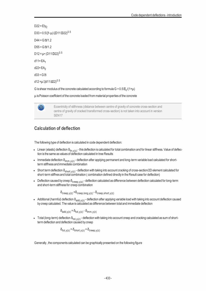
Code dependent deflections - introduction
D22 =EIy2
D33=0.5⋅(1-µ)⋅(D11⋅D22)0.5
D44=G⋅h/1.2
D55 =G⋅h/1.2
D12 =µ• (D11⋅D22)0.5
d11=EA1d22=EA2
d33 =G⋅h
d12 =µ⋅ (d11⋅d22)0.5
G isshear modulusof the concrete calculated according to formulaG =0.5⋅Ec/(1+µ)
µ isPoisson coefficient of the concrete loaded frommaterial propertiesof the concrete
Eccentricity of stiifnness (distance between centre of gravity of concrete cross-section andcentre of gravity of cracked transformed cross-section) is not taken into account in versionSEN17
Calculation of deflection
The following type of deflection is calculated in code dependent deflection:
l Linear (elastic) deflectionδlin,y(z) - thisdeflection is calculated for total combination and for linear stiffness. Value of deflec-tion is the same asvaluesof deflection calculated in treeResults
l Immediate deflectionδimm,y(z) - deflection after applying permanent and long-term variable load calculated for short-term stiffnessand immediate combination
l Short termdeflectionδshort,y(z) - deflectionwith taking into account cracking of cross-section/2D element calculated forshort-term stiffnesand total combination ( combination defined directly in theResult case for deflection)
l Deflection caused bycreepδcreep,y(z) - deflection calculated asdifference between deflection calculated for long-termand short-term stiffness for creep combination
δcreep,y(z) =δcreep,long,y(z) - δcreep,short,y(z)
l Additional (harmful) deflectionδadd,y(z) - deflection after applying variable loadwith taking into account deflection causedbycreep calculated. The value is calculated asdifference between total and immediate deflection
δadd,y(z) =δtot,y(z) - δimm,y(z)
l Total (long-term) deflectionδtot,y(z) - deflectionwith taking into account creep and cracking calculated assumof short-termdeflection and deflection caused bycreep
δtot,y(z) =δshort,y(z) +δcreep,y(z)
Generally , the componentscalculated can be graphicallypresented on the following figure
- 433 -
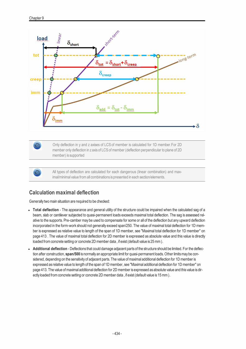
Chapter 9
Only deflection in y and z axises of LCS of member is calculated for 1D member.For 2Dmember onlydeflection in zaxisof LCS of member (deflection perpendicular to plane of 2Dmember) is supported
All types of deflection are calculated for each dangerous (linear combination) and max-imal/minimal value fromall combinations ispresented in each section/elements.
Calculation maximal deflectionGenerally twomain situation are required to be checked:
l Total deflection - The appearance and general utility of the structure could be impaired when the calculated sag of abeam, slab or cantilever subjected to quasi-permanent loads exceedsmaximal total deflection. The sag is assessed rel-ative to the supports. Pre-camber maybe used to compensate for some or all of the deflection but any upward deflectionincorporated in the form-work should not generally exceed span/250. The value of maximal total deflection for 1D mem-ber is expressed as relative value to length of the span of 1D member, see "Maximal total deflection for 1D member" onpage 413 . The value of maximal total deflection for 2D member is expressed as absolute value and this value is directlyloaded from concrete setting or concrete 2Dmember data , if exist (default value is25mm ).
l Additional deflection - Deflections that could damage adjacent partsof the structure should be limited. For the deflec-tion after construction, span/500 is normallyan appropriate limit for quasi-permanent loads. Other limitsmaybe con-sidered, depending on the sensitivityof adjacent parts. The value ofmaximal additional deflection for 1Dmember isexpressed as relative value to length of the span of 1Dmember, see "Maximal additional deflection for 1Dmember" onpage 413. The value ofmaximal additional deflection for 2Dmember isexpressed asabsolute value and this value isdir-ectly loaded from concrete setting or concrete 2Dmember data , if exist (default value is15mm ).
- 434 -