Embed Size (px)
Citation preview

Proceedings of theThird International Workshop onComponent-Oriented Programming(WCOP ’98)
Editors:Wolfgang WeckJan BoschClemens Szyperski
Turku Centre for Computer ScienceTUCS General Publication No 10October 1998
ISBN 952-12-0284-XISSN 1239-1905


Contents
Jan Bosch, Clemens Szyperski, Wolfgang Weck:Summary of the Third International Workshop onComponent-Oriented Programming (WCOP ’98) 1
I Adaptation and Composition 7
Gunter Kniesel:Type-Safe Delegation for Dynamic Component Adaptation 9
Anna Mikhajlova:Consistent Extension of Components in Presence of ExplicitInvariants 19
Geoff Outhred, John Potter:A Model for Component Composition with Sharing 29
II Adaptation and Configuration 39
Ralph Keller, Urs H¨olzle:Late Component Adaptation 41
Ian Welch, Robert Stroud:Adaptation of Connectors in Software Architectures 47
Bulent Kucuk, M. Nedim Alpdemir, Richard N. Zobel:Customizable Adapters for Black-Box Components 53
Eila Niemela, Juha Marjeta:Dynamic Configuration of Distributed Software Components 61
III Component Frameworks and Quality Attributes 73
Bert Robben, Frank Matthijs, Wouter Joosen, Bart Vanhauteand Pierre Verbaeten:Components for Non-Functional Requirements 75
Mark Lycett, Ray J. Paul:Component-Based Development:Dealing with Operational Aspects of Architecture 83
Gunter Graw, Arnulf Mester:Federated Component Frameworks 93
P.S.C. Alencar, D.D. Cowan, C.J.P. Lucena, L.C.M. Nova:A Model for Gluing Components 101
i

IV Large-Scale Application and Experience 109
Mark Grossman:Component Testing 111
James Ingham, Malcolm Munro:Applying a Domain Specific Language Approach to ComponentOriented Programming 117
David Helton:The Impact of Large-Scale Component and FrameworkApplication Development on Business 127
R. Cherinka, C. Michael Overstreet, J. Ricci, M. Schrank:Maintaining a COTS Component-Based Solution - Can TraditionalStatic Analysis Techniques be Useful for this new ProgrammingMethodology? 135
ii

Preface
The Third International Workshop of Component-Oriented Programming (WCOP’98)was held on July 21, 1998 in Brussels, Belgium, together with ECOOP, as had been thepreceding workshops WCOP’96 and WCOP’97. Again, participants had been askedto submitt short position papers to focus the discussion. These position papers werecarefully reviewed by the organizers, revised, presented at the workshop, and finalizedfor publication. This book is the result of this process.
This volume contains a summary of the workshop followed by four parts, eachconsisting of three to four related papers. This layout reflects the four sessions of theworkshop itself.
At this place, we wish to express our acknowledgments and thanks to everybodywho contributed to WCOP’98. These are — of course — all the authors and partic-ipants, but also the ECOOP workshop organization, headed by Serge Demeyer. Thisproceedings volume was only possible due to the financial support of the Turku Centrefor Computer Science (TUCS), Turku, Finland, and the help of Mats Aspn¨as with thetechnical issues.
The editor of this volume wants to express special thanks to all the authors whomade special efforts in preparing LATEXversions of their papers. This made it possibleagain to produce a book with a consistent look of all the individual papers, a specificesthetic quality.
For the WCOP’98 OrganizersWolfgang Weck, September 1998
iii


Summary of the Third InternationalWorkshop on Component-Oriented
Programming (WCOP ’98)
Jan BoschUniversity of Karlskrona/Ronneby, Dept. of Computer Science
Ronneby, [email protected]
Clemens SzyperskiQueensland University of Technology, School of Computing Science
Brisbane, [email protected]
Wolfgang WeckTurku Centre for Computer Science andAbo Akademi University
Turku, [email protected]
WCOP’98, held together with ECOOP’98 in Brussels, Belgium, was the thirdworkshop in the now established series of workshops on component-oriented program-ming. The previous two workshops were held with ECOOP’96 in Linz, Austria, andwith ECOOP’97 in Jyv¨askyla, Finland. WCOP’96 had focussed on the principal ideaof software components and worked towards definitions of terms. In particular, a high-level definition of what a software component is was formed. WCOP’97 concentratedon compositional aspects, architecture and gluing, substitutability, interface evolution,and non-functional requirements. WCOP’98 had a closer look at issues arising in in-dustrial practice and developed a major focus on the issues of adaptation. Qualityattributes (as non-functional requirements are preferably now called) and componentframeworks featured as well, although much less than was hoped by the workshoporganisers.
WCOP’98 had been announced as follows:
After WCOP’96, focusing on the fundamental terminology of COP, andWCOP’97, expanding into the many related facets of component soft-ware, WCOP’98 shall concentrate on those software architecture aspectsof component-software that directly affect the actual design and imple-mentation, i.e., programming of component-based solutions. In particular,a focus on component frameworks, as introduced below, is suggested.
COP aims at producing software components for a component market andfor late composition. Composers are third parties, possibly the end user,who are not able or willing to change components. This requires standards
1

to allow independently created components to interoperate, and specifica-tions that put the composer into the position to decide what can be com-posed under which conditions. On these grounds, WCOP’96 led to thefollowing definition:
A component is a unit of composition with contractually specified inter-faces and explicit context dependencies only. Components can be de-ployed independently and are subject to composition by third parties.
A problem discussed at length at WCOP’97 arenon-functional require-ments. Another key problem that results from the dual nature of compo-nents between technology and markets are the non-technical aspects ofcomponents, including marketing, distribution, selection, licensing, andso on. While it is already hard to establish functional properties underfree composition of components, non-functional and non-technical aspectsseem quickly beyond controlability.
One promising key approach to establishing composition-wide propertiesof functional and non-functional nature is the use ofcomponent frame-works. A component framework is a framework that itself is not modifiedby components, but that accepts component instances as ”plug-ins”. Acomponent framework is thus a deliverable on its own that can enforce(sub)system-wide properties of a component system. As such, a compo-nent framework is sharply distinct from application frameworks that aresubject to (partial) whitebox reuse and that do not retain an identify oftheir own in deployed systems.
The call for contributions in the area ofsystemsrather than individual componentsand their pairwise coupling was addressed in only a minority of the submissions. It canbe speculated that this is symptomatic for the relative youth of the component softwarediscipline.
Fifteen papers from seven countries were submitted to the workshop and formallyreviewed. Due to the good quality, all papers were accepted for presentation at theworkshop and publication in the proceedings. About 40 participants from around theworld participated in the workshop.
Based on the accepted submissions, the workshop was organised into four sessions:
1. Adaptation and composition (three papers).
2. Adaptation and configuration (four papers).
3. Component frameworks and quality attributes (four papers).
4. Large-scale applications and experience (four papers).
The workshop was opened by an invited keynote presented by Pierre America andHenk Obbink entitled ‘Component-based domain-specific family architectures’, nicelysetting the scene with a look at some of the domains and issues targeted by teams atPhilips Research. All of the following sessions were organised into dense bursts ofa few presentations followed by an extended period of discussion, with the session’spresenters forming a panel. This format was experimentally chosen over one that usesbreak-out groups, to allow all participants to follow all activities. All sessions weremoderated by one of the workshop organisers.
2

1 Adaptation and composition
The first session focused on detailed technical problems of adaptation in a componentsetting. A first issue [Kniesel] was type-safe delegation to enhance object-compositionbased adaptation to the potential of inheritance-based composition of classes (in termsof maintenance of a common identity of the adapted object). This was countered by aformal analysis of the semantic problems of inheritance [Mikhajlova], arguing that in-heritance (of implementation) is more error-prone than forwarding-based composition,and that the same problems hold for delegation-based composition. Finally, composi-tion based on trading was proposed [Outhred & Potter], where it was noted that tradingwould not be based on run-time matching of semantics but on something similar toCOM category identifiers (CATIDs).
The discussion then wandered off into the pros and cons of formal methods. Start-ing with the question whether the presented type-safe delegation mechanism wouldnot suffer from the inheritance anomaly, the answer was that while this approach wasprovably safe, it may well be overly constraining and thus rule out type-safe cases thatare important in practice but not allowed in the proposed scheme. This led to the ob-servation that this is a general problem with algebraic approaches and that refinementcalculus like approaches would be of advantage. While the participants agreed thatin the context of component software formal reasoning (with an explicit avoidance ofglobal analysis!) was useful and cost-effective, the suspicion remained that it is alwaysthose aspects that get formalised that are easy to formalise. Quality attributes wereseen as an example.
Returning to the immediate matters at hand, the participants then focused on theprogramming language issues in the context of the proposed delegation and tradingmechanisms. A single programming language approach was clearly seen as inadequatein a practical setting; the agreement was that while multiple programming languagesought to be allowed, a common underlying model would be required for both the trad-ing and the delegation mechanism.
2 Adaptation and configuration
While extending the first session by continuing the theme of component adaptation,the second session somewhat shifted the emphasis from the adaptation of individualcomponents and the resulting compositional consequences to the role of adaptationin the configuration of systems. This line is rather fine, though, and the workshoporganisers could not outright reject the suspicion that this was merely done to avoida single dominating morning session on adaptation. The current interest in a widevariety of adaptation issues and approaches is indeed wide-spread. The discussion-half of the second session culminated in the existential question: do we really want toadapt? Or much rather: should architecture, standardisation, and normalisation not aimto eliminate all but a few cases that require adaptation? This question was left open inthe end.
[Keller & Holzle] opened the session discussing late component adaptation in Javathrough the binary adaptation of classes during program loading. [Welch & Stroud]discussed the adaptation of connectors in software architectures whereas [Kucuk etal.] addressed customizable adapters for black-box components. Finally, [Niemel¨a &Marjeta] discussed the dynamic configuration of distributed components.
Particular points addressed in the discussion were:
3

� The wish to separate quality-attribute behaviour and domain behaviour and toallow for late adaptation.
� The problem of object identity in conjunction with adaptation. Should an adaptedobject have a new identity or should it share the identity of the original object?
� Can meta-programming be really used for adaptation in multiple quality dimen-sions, or is this just a very sophisticated way to hack a system in order to integrateconflicting issues? The key problem here is that the apparent orthogonality ofseparated issues may not actually hold. Resulting effective non-composabilityof meta-level fragments can lead to very subtle errors. At the same time, it isclear that the undisciplined approach to composition and handling of quality at-tributes is not promising either.
� Components can be adapted in their binary form and very late in process of ap-plication creation, e.g., during the loading component binaries. One of the issuesraised during the discussion was whether the correctness of these adaptationscould be guaranteed or formally proven? In addition, assuming that an adaptedcomponent maintains the same identity, how should the case be dealt with wheremultiple extensions are applied to the same component (although to different in-stances)? Otherwise, for one component identity, multiple behaviours may existin the system.
� Finally, several authors mentioned that rather than working with small or largecomponents, they made use ofmedium-grained components. However, no authorgave a definition of medium-grained components nor of the difference to smalland large components in other than very vague terms. Nevertheless, a sharedview existed among the workshop participants that reusable components shouldbe larger than individual classes but not have the size of, e.g., an entire object-oriented framework.
3 Component Frameworks and Quality Attributes
Moving from smaller to larger scale, the third session focused on system-wide archi-tectural issues. The first contribution [Robben et al.] proposed to separate applicationcomponents from non-functional components (addressing distribution etc.) using metacomponents, picking up on a thread started in the second session. In particular, it wasproposed to use a meta hierarchy to layer separate aspects, e.g., application + relia-bility + security + distribution. The second contribution [Lycett & Paul] proposed tomake communication, cooperation, and coordination as composable as the componentsthemselves. The third [Graw & Mester] looked into the issues of federated componentframeworks (which delighted the organisers, since at least one presenter directly ad-dressed the proposed workshop theme). The main issue being the interoperability andcooperation between component frameworks. The fourth contribution [Alencar et al.]proposed a methodology to systematically determine components and glue.
The separation/composability proposals relaunched the discussion on whether dif-ferent quality attributes really can be handled in an orthogonal way. Participants spon-taneously found examples where that would not be the case, leading to the observationthat dependencies between qualities would need to be pinpointed.
A general consensus among the participants, and in particular backed by those withsignificant industrial experience, was that well-performing systems today are always
4

the result of competent overall design. It was emphasised that quality attributes todayaredesigned in and that their separation may help to explore design alternatives, but atleast today does not seem to really solve the problems.
The layered approach to the separation of quality attributes was also questioned. Ifthe qualities were orthogonal, single-layer composition would suffice. However, sincethey admittedly are not, the order of layering effects semantics and making it explicitmay help to organise things. The state-of-the-art does not permit systematic analysisof more than one quality at a time, while experienced designers know how to handlemany simultaneously, but usually are unable to fully explain their heuristics.
4 Large-scale application and experience
The fourth session attempted to zoom out fully and look at current industrial activ-ities and large-scale issues. An interesting contribution [Grossman] on componenttesting proposed 100 % code coverage testing for all components, based on test har-nesses that systematically fail such intricate things as heap space allocation requests.(The approach does not reach 100 % path coverage, of course.) Based on the difficul-ties with domain-neutral component approaches, the second contribution [Ingham &Munro] proposed domain-specific languages. The third contribution [Helton] lookedat the business impacts of basing large-scale development on components and frame-works. Finally, the fourth contribution to the session [Cherinka et al.] proposed to usestatic analysis methods to eliminate dead code in component-based solutions, whichcan become a real problem in very large systems that evolve over time.
The component testing approach raised concerns regarding scalability and cover-age. Also, would ‘protocol-based’ testing be needed to properly deal with internalstates? The proposed approach does allow for ‘spying’ of component-internal statesthrough special interfaces between the component and the test harness, addressingsome of these issues, but the concern remained whether one interface could be usedto take a component into a state that would not be reachable through another interface,also supported by the component. Another concern was whether the testing approachwould be strong enough if it concentrated on individual components at a time. For ex-ample, how would callbacks be tested? Nevertheless, it was reported that the approachactually works and that those components that passed all test have been released todevelopers without any errors being reported so far.
5 Brief summary
The workshop was organised in four sessions without a final session to explicitly gatherconclusions and trends. Nevertheless, there was a strong indication that the field is cur-rently focusing on adaptation and quality attributes. Adaptation needs can be seen as acertain sign of discipline immaturity and thus as a problem in the relatively small, al-though there will always be remaining cases that require adaptation. Quality attributeson the other hand cannot be captured usefully by concentrating on the small and arereally systemic properties that require focusing on the large. This tension between theproblems in the small and the problems in the large is really characteristic of compo-nent technology.
5


Part I
Adaptation and Composition
7


Type-Safe Delegation for DynamicComponent Adaptation
Gunter KnieselUniversitat Bonn
Institut fur Informatik IIIRomerstr. 164, D-53117 Bonn
[email protected], http://javalab.cs.uni-bonn.de/research/darwin/
The aim of component technology is the replacement of large monolithic appli-cations with sets of smaller components, whose particular functionality and inter-operation can be adapted to users’ needs. However, the adaptation mechanisms ofcomponent software are still limited. Most proposals concentrate on adaptationsthat can be achieved either at compile time or at link time. Current support fordynamic component adaptation, i.e. unanticipated, incremental modifications of acomponent system at run-time, is not sufficient.
This position paper proposes object-based inheritance (also known as delega-tion) as a complement to purely forwarding-based object composition. It presentsa type-safe integration of dynamic delegation into a class-based object model andshows how it overcomes the problems faced by forwarding-based component “wir-ing”, how it supports independent extensibility of components and unanticipated,dynamic component adaptation.
Keywords: programming language support, dynamic adaptation, independentextensibility, dynamic delegation, type-safety.
1 Introduction
Component-oriented programming aims at the replacement of monolithic applicationswith sets of small components. For software engineers, assembly of applications fromexisting components should increase reuse, thus allowing them to concentrate on value-added tasks and to produce high-quality software within a shorter time. For users, itpromises the ability to select the relevant functionality of an application and to adapt itto their own needs.
Currently, the problem of component adaptation is mainly tackled from a program-mer’s point of view. Most proposals aim at easing reuse of existing components inthe development of new applications. They are applicable at compile-time or link-time but not at run-time. Applications made up of components that may not be shutdown cannot be adapted. This is especially regrettable, since systems that must alwaysbe operational would profit most from the ability to be structured into small inter-changeable components that could evolve independently.
When existing components can neither be directly modified nor unloaded from therunning system, we are faced with the problem to change their behavior solely byadding more components. This paper explores how far delegation can help to solvethis apparent contradiction and how component adaptation can be performed withoutdeleting the “old” version of a component, eliminating another shortcoming of current
9

approaches. Delegation enables the joint use of different versions of a component andthe easy modeling of components that present different interfaces to different clients.
Adaptation and the selfproblem. Currently, component interaction at run-time issolely based on message sending1. It has been repeatedly pointed out (e.g. by [Har97,Szy98]) that message sending limits the range of component interaction and componentadaptation that can be achieved. This is due to the so called “self-problem” [Lie86]that is inherent in message passing. In [Har97] Harrison and Ossher rephrased theself-problem in component-based terminology:
Robust solutions [...] require that when components of composite objectsinvoke operations [...], the operations need to be applied to the compositeobject, rather than to the component object alone.
The ability to make one component a specialization of another one by sharing itsself is provided by two infrastructures for component adaptation: code modificationand delegation.
Code Modification. Code modification uses two inputs, a class to be modified anda specification of the modification. The result is a modified version of the initial codewhich is used instead of the old version. Examples in this category are Jan Bosch’ssuperimposition technique ([Bos98]), the class composition proposal of Harrison andOssher ([Har97]) and the recent work of Keller and H¨olzle on binary component adap-tation ([Kel97]). Superimposition is a language construct within a special object model,LayOM. LayOM programs are translated to C++ and Java, making the modified sourcecode available for further use. Class composition as proposed by Harrison and Ossheris also applied at “compile-time” and requires source-code availability. Binary compo-nent adaptation can be seen as a more general form of class composition, which canadaptbinarycomponents when they areloaded.
It is unlikely that code modification will become applicable to run-time componentadaptation anytime soon. Its essence is the replacement of an existing class by a newversion of that class. This is very difficult in a running system, where instances of theclass to be replaced already exist and are being used. This is the well-known yet stillgenerally unsolved problem of schema evolution in database systems, transferred to therun-time environment of an object-oriented language.
Delegation. ”Delegation” was originally introduced by Lieberman ([Lie86]) inthe framework of a class-free (prototype-based) object model. An object, called thechild, may have modifiable references to other objects, called itsparents. Messages forwhich the message receiver has no matching method are automatically forwarded to itsparents. When a suitable method is found in a parent object (themethod holder) it isexecuted after binding its implicitself2 parameter. This parameter refers to the objecton whose behalf the method is executed. Automatic forwarding with binding ofselftothe message receiver is calleddelegation(figure 1).
In contrast to class composition, delegation does not require source code or abstractbinaries – it works equally well on native code and can be employed at run-time ratherthan at compile- or load time. Operating by addition rather than replacement and atthe level of objects rather than classes delegation does not incur the schema-evolutionproblems of run-time class composition.
Why delegation is (said to be) difficult. Many authors have acknowledged themodeling power and elegance of dynamic delegation but at the same time called for
1For the purpose of this discussion events do not add any new insight and are therefore not mentioned.2The implicit self parameter is also called this (in Simula, Java and C++) and current (in Eiffel).
10

self
delegation
... ...
messagereceiver
methodholder
messagereceiver
self
methodholder
consultance
... ...
Figure 1: Different effect of delegation and consultation onself
ways to harness this power and to make it more amenable to a “disciplined use”([Aba96, Don92, Szy98, Tai93, Wec97]). This is a critique on the lack of a statictype system for delegation-based languages. It is the main achievement of the DAR-WIN model ([Kni98]) to have shown that type-safe dynamic delegation with subtypingis possible andcanbe integrated into a class-based environment. The DARWIN modelis sketched next, to the degree relevant in the context of this paper, concentrating es-pecially on the interesting parallels between independent extensibility of components([Szy96]) and type-safety of a system that combines delegation and subtyping.
2 Darwin and Lava: Combining Class-based andObject-based Inheritance
We assume that the reader is familiar with the notions of class, instance, and class-based inheritance. For simplicity of presentation, we shall introduce DARWIN using thesyntax of LAVA ([Cos98, Sch97]), a proof of concept extension of Java that conformsto the DARWIN model3 .
Parents and Declared Parents. In DARWIN / LAVA , objects may delegate to otherobjects referenced by theirdelegation attributes. Delegation attributes have to be de-clared in an object’s class by adding the keywordmandatory delegatee to aninstance variable declaration. Delegation attributes aremandatory, i.e. they must al-ways have a non-nil value. This is automatically enforced by the compiler and suitablerun-time checks. If classC declares a delegation attribute of typeT we say thatC isa declared child classof T (and ofT’s subtypes), andT is adeclared parent typeof C(and ofC’s subclasses).
Dynamic Delegation.Since a delegation attribute can reference any value that con-forms to its declared type, assignment to a delegation attribute can be used to changethe behavior of an object at run-time by changing its parent object(s). This is calleddynamicdelegation.
Types. In purely inheritance-based models, the type of an instance corresponds tothe signature of the methods defined by its class (and its superclasses). Delegation hasthe effect of extending this interface by the interfaces defined for thedeclaredtypesof mandatory delegation attributes. Thus, in LAVA delegation and inheritance are twoorthogonal ways to create subtypes of a base type.
An Example. In LAVA , a class of text formatting objects (Formatting ) that mayuse and dynamically switch between different line breaking strategies (typeLine-
3The only deviation of Lava from Darwin is the restriction to single inheritance following the design ofJava. This is not a real limitation because Lava offers multiple delegation.
11

Breaking ) can be written as shown in Listing 1
public class Formatting f// delegate line breaking requests to the object referred to by lb;
mandatory delegatee LineBreaking lb;// create object with default strategy
public Formatting () f lb = new SimpleLineBreaking();g
// switch strategypublic setLBStrategy (LineBreaking _lb) f lb = _lb;g
// By how many pixels can individual text components be stretched// Overrides method from parent type LineBreaking.
public int[] getStretchability() f ...g
g
Listing 1: The strategy pattern in Lava
TheFormatting class may use all methods of theLineBreaking type as ifthey where locally defined or inherited from a superclass - with the essential differencethat it may dynamically switch to a different set of method implementations simplyby assigning an object of a differentLineBreaking subtype to the variablelb .Like in the case of inheritance, theFormatting class can fine tune the “inherited”behavior via overriding. For instance, in the above example it was assumed that theline LineBreaking type specifies that the line breaking algorithm calls the methodgetStretchability() to determine by how many pixels individual text elementscan be stretched. Then providing a specialized version of this method (as shown above)might be all that is needed to adapt the “inherited” behavior to the delegator’s needs.Note especially that the designer and the implementors of theLineBreaking typedo not need to be aware of its use as a parent class and hard-code any hooks to enablethis use.
2.1 Type Safety, Independent Extensibility and Overriding
Let us consider the scenario illustrated in figure 2 (Gray arrows represent delegation atinstance and class level, arrows with hollow heads instantiation resp. inheritance, andsolid arrows “normal” object references.) :c, an instance of classChild , delegatesto p, an instance of classParent ; Parent is a subtype of the declared parent classof Child .
Typing Problem. In figure 2 the twobang methods have different argument types:Child expects an argument of typeStockExchange whereasParent provides anargument of typeBomb. Therefore, Fisher ([Fis95]) argues that during the evaluationof the messagec.b() delegated fromc to p the messageself.bang(aBomb) sentback toc would be unsafe, because its argument would not have the expected type.However, arguing about type-safety in the above example is misleading, because theessence of the problem is not typing.
Independent Extensibility Problem. The astute reader might have noted thatthe classesChild andParent might have been developed and compiled indepen-dently, knowing onlyDeclaredParent but not each other. Therefore, even if thetwo independently introducedbang methods had the same signature it would stillbe very unlikely that they have the same semantics. Overriding ofParent::bangby Child::bang would therefore be undesirable anyway, because it would silentlychange the semantics relied upon by methods fromParent , leading to obscure, hardto locate errors.
12

DeclaredParent
b()
b() { self.bang(...) }bang(Bomb) = ...
Parent
bang(SE) = ...
Child
c pb()
Figure 2: What happens during evaluation of the messagec.b() ?
The importance of independent extensibility for component programming has al-ready been described by Szyperski ([Szy96, Szy98]) in a delegation-free environment.Whereas Szyperski focused on the joint use of two independent extensions of a basetype by a third party, our discussion relates to the delegation-based composition of oneindependent extension with another one.
Overriding . The point of the above discussion of type-safety and independentextensibility is that both seemingly unrelated problems have a common cause: theimplicit assumption that methods with the same name (and possible same signature)may override each other.
This assumption can be safely made only if it is guaranteed that the author of theoverriding method is aware of the effect. This is always the case with class-based in-heritance: a method implementation in a class can only override one in a known super-class. Assuming a sensible documentation of the superclass and no intentional fraud,authors of subclasses will not create semantically incompatible overriding methods.
The assumption is unsafe if independent extensibility is possible. Therefore, thesolution to both problems discussed above is the following adapted rule for methodoverriding:
For a messagerecv.n(args)a method with signatureσ from typeT over-rides the matching4 method from the static type ofrecv, T stat, if there issome commondeclaredsupertype ofT andT stat that containsσ.
This rule reflects the fact that the common declared supertype (DeclaredParentin figure 2 and figure 3) is the common semantic base on which implementors of inde-pendent extensions can rely.
The above definition of overriding influences the operational semantics of the sys-tem. A method of an object is applicable to a message only if it may override thematching method from the static type of the receiver expression. Messages with noapplicable local method are delegated further to a parent object. It is guaranteed thatan applicable method will be found during this process since the sender of the mes-sage toself is itself among the parent objects. For instance, in figure 3a, the messageself.bang() sent fromp to c will not find an applicable method inc and be del-
4A method with signature n(T1, ..., Tn):T matches a message recv.n(expr1, ..., exprn) if for all i = 1...n,the static type of expri is a subtype of Ti.
13

DeclaredParent
b()
b() { self.bang(...) }bang() = ...
Parent
bang() = ...
Child
c pb()
commonoriginof bang()
DeclaredParent
b()bang()
b() = { self.bang(...) }bang() = ...
Parent
bang() = ...
Child
c pb()
(a) Independently introduced methods: (b) Methods with common origin:Nooverriding. Overriding enabled.
Figure 3: Overriding
egated further up the object hierarchy, back top (where the search will succeed). Infigure 3b the message will find an applicable method inc .
To recap, the integration of delegation into statically typed object-oriented lan-guages offers, among others, an easy way
� to make an object appear to be part of and act on behalf of various other ones,and
� to extend existing objects in unanticipated ways, without fear of semantic con-flicts.
As a general object-oriented language mechanism delegation has a multitude ofpossible uses. In the sequel we shall concentrate on its use for dynamic componentadaptation.
3 Dynamic Component Adaptation
Dynamic component adaptation is a modification of a component’s functionality atrun-time that can be achieved by
� adding further components to a system and
� transferring part of the existing component’s ”wiring” to the new components.
The technical prerequisites for this functionality are language support for delega-tion, and support for component ”re-wiring” by the underlying component architecture.
3.1 Incremental Component Assembly and Adaptation with Dele-gation
Delegation enables extension and modification (overriding) of a parent component’sbehavior. Child components can be transparently used in any place where parent com-ponents are expected. Unlike other approaches, which irrecoverably destroy the oldversion of a component, delegation enables two types of component modifications.Additive modifications are the product of a series of modifications, each applied to the
14

Original Component
1. Increment
2. Increment
3. Increment
4. Increment
5.th 6.th
1st 3rd
2nd 4th
5th
Orig.
6th
Component
Delegation
a) User view b) System view
Figure 4: Additive and disjunctive composition
result of a previous one. Disjunctive modifications are applied independently to thesame original component.
Additive modifications are enabled by the recursive nature of delegation. Theymeet the requirement that the result of compositions / adaptations should itself be com-posable / adaptable ([Bos98, Szy98]). In the user view (figure 4a) additive compositionis depicted by stacking components one on top of the other. The system view in figure4b shows the implementation by building chains of delegating components. E.g. thefirst and second increment of the original component form together an additive modifi-cation.
Disjunctive extensions are enabled by the fact that each extension is encapsulatedin a separate component instance that can be addressed and reused independently. Dis-junctive extensions are most useful in modeling components that need to present them-selves differently to different clients. In the system view (figure 4a), disjunctive ex-tension are visualized sitting on top of the jointly extended component. For instancecomponent 5 and 6 represent different extensions of component 4, which itself is partof a disjunctive extension branch of the original component. At the implementationlevel (figure 4b), disjunctive extensions delegate to the same parent component.
3.2 Dynamic Component Assembly
The effects described so far only take effect if the most specialized increment com-ponents along each disjunctive modification branch are used instead of the originalcomponent. More precisely, dynamic component adaptation depends on dynamic com-ponent (re)assembly, which consists of
� rerouting of all ”input connections” of a component to its increment (or to dif-ferent disjunctive increments) and
� routing of the ”output connections” of all increments to the same destinations asthe corresponding outputs of the original component.
The complete schema for dynamic component adaptation, including componentreassembly (”re-wiring”), is illustrated in figure 5. Part a) shows the implementationview of the original component configuration. Part b) shows the re-wired configuration
15

1st 2nd
3rd
Orig.
Incoming Outgoing
Orig.
Incoming Outgoing
a)
b)
Figure 5: Component (re)wiring: before extension (a) and after extension (b)
after addition of three increment components, one of which represents a disjunctivemodification.
A component architecture that supports dynamic component assembly must pro-vide
� a run-time component directory,
� the ability to ask for the current input and output connections of every compo-nent,
� the ability to ask every component to abandon all its input connections in favorof one or more other components. This must happen as an atomic operation inorder to guarantee that the system is not left in an inconsistent state.
These requirements are not met by current component architectures. However,we hope that they will be incorporated into future versions because dynamic compo-nent rewiring is an essential infrastructure which would benefit also simple forwardingbased dynamic composition techniques, not just delegation.
4 Conclusions
In recent years, the crucial role of delegation as a basis of component interaction andthe need for an integration of delegation into the statically typed class-based model hasbeen repeatedly pointed out by many researchers. In this context the contributions ofthis paper are two-fold:
� In the first place, it introduced a general model for dynamic, type-safe delega-tion, DARWIN, and an implemented language, LAVA , that provide the requiredlanguage support for component-oriented programming.
� Secondly, the problem ofdynamiccomponent adaptation, that has not been ad-dressed so far, was discussed, a delegation-based solution was presented.
16

There are, nevertheless, still many open questions. For instance, a high-perform-ance implementation of LAVA is required, to help the current proposal make its wayinto mainstream commercial languages like Java or C++, thus providing broad lan-guage support for delegation-based component interaction. Also, components to becomposed by delegation depend on the “specialization interface” of their parent com-ponents. Therefore, advanced component interface specifications and approaches to the“semantic fragile base class problem” are required ([Lam93], [Ste96], [Mik97, Szy98,Wec97]).
Bibliography
[Aba96] Abadi, Martin and Cardelli, Luca.A Theory of Objects. Springer, 1996.
[Bos98] Bosch, Jan. Superimposition - A Component Adaptation Technique, 1998.
[Cos98] Costanza, Pascal.Lava: Delegation in a Strongly Typed Programming Lan-guage – Language Design and Compiler (In German: Lava: Delegation ineiner streng typisierten Programmiersprache – Sprachdesign und Compiler).Masters thesis, University of Bonn, 1998.
[Don92] Dony, Christophe and Malenfant, Jacques and Cointe, Pierre. Prototype-Based Languages: From a New Taxonomy to Constructive Proposals andTheir Validation. Proceedings OOPSLA ’92, ACM SIGPLAN Notices,27(10):201–217, 1992.
[Fis95] Fisher, Kathleen and Mitchell, John C. A Delegation-based Object Calculuswith Subtyping. InProceedings of 10th International Conference on Funda-mentals of Computation Theory (FCT ’95), volume 965 ofLecture Notes inComputer Science, pages 42–61. Springer, 1995.
[Har97] Harrison, William and Ossher, Harold and Tarr, Peter. Using Delegation forSoftware and Subject Composition. Research Report RC 20946 (922722),IBM Research Division, T.J. Watson Research Center, Aug 1997.
[Kel97] Keller, Ralph and H¨olzle, Urs. Supporting the Integration and Evolutionof Components Through Binary Component Adaptation. Technical ReportTRCS97-15, University of California at Santa Barbara, September 1997.
[Kni98] Kniesel, Gunter. Darwin - Dynamic Object-Based Inheritance with Subtyp-ing. Ph.D. thesis (forthcoming), University of Bonn, 1998.
[Lam93] Lamping, John. Typing the Specialization Interface.Proceedings OOPSLA’93, ACM SIGPLAN Notices, 28(10):201–214, 1993.
[Lie86] Lieberman, Henry. Using Prototypical Objects to Implement Shared Behav-ior in Object Oriented Systems.Proceedings OOPSLA ’86, ACM SIGPLANNotices, 21(11):214–223, 1986.
[Mik97] Mikhajlov, Leonid and Sekerinski, Emil. The Fragile Base Class Problemand Its Impact on Component Systems. In Weck, Wolfgang and Bosch,Jan and Szyperski, Clemens, editor,Proceedings of the Second InternationalWorkshop on Component-Oriented Programming (WCOP ’97), pages 59–68.Turku Center for Computer Science, Turku, Finland, 1997. ISBN 952-12-0039-1.
17

[Sch97] Schickel, Matthias.Lava: Design and Implementation of Delegation Mech-anisms in the Java Runtime Environment (In German: Lava: Konzep-tionierung und Implementierung von Delegationsmechanismen in der JavaLaufzeitumgebung). Masters thesis, University of Bonn, 1997.
[Ste96] Steyaert, Patrick and Lucas, Carine and Mens, Kim and D’Hondt, Theo.Reuse Contracts: Managing the Evolution of Reusable Assets.ProceedingsOOPSLA ’96, ACM SIGPLAN Notices, pages 268–285, 1996.
[Szy96] Szyperski, Clemens. Independently Extensible Systems - Software Engi-neering Potential and Challenges -. InProceedings of the 19th AustralianComputer Science Conference, Melbourne, Australia. Computer Science As-sociation, 1996.
[Szy98] Szyperski, Clemens.Component Software - Beyond Object-Oriented Pro-gramming. Addison-Wesley, 1998.
[Tai93] Taivalsaari, Antero. Object-Oriented Programming with Modes.Journal ofObject-Oriented Programming (JOOP), 6(3):25–32, 1993.
[Wec97] Weck, Wolfgang. Inheritance Using Contracts & Object Composition. InWeck, Wolfgang and Bosch, Jan and Szyperski, Clemens, editor,Proceed-ings of the Second International Workshop on Component-Oriented Pro-gramming (WCOP ’97), pages 105–112. Turku Center for Computer Sci-ence, Turku, Finland, 1997. ISSN 1239-1905.
18

Consistent Extension of Componentsin Presence of Explicit Invariants
Anna MikhajlovaTurku Centre for Computer Science,Abo Akademi University
Lemminkaisenkatu 14A, Turku 20520, FinlandAnna.Mikhajlova @ abo.fi
Extension of components should be consistent in the sense that the extendingcomponent does not introduce any unexpected behaviour. We formulate require-ments which allow consistent extension of components in presence of explicit in-variants. We concentrate on the issue of extension consistency with forwarding asthe reuse mechanism, and discuss the additional problems which require solutionwhen inheritance is used.
1 Introduction
In an open component-based system, the ultimate goal of creating an extension is toimprove and enhance functionality of an existing component by tuning it for specificneeds, making it more concrete, implementing a faster algorithm, and so on. Effec-tively, the client of a component benefits from using an extension, only if the extensiondoes not invalidate the client. Imposing semantic constraints on extensions ensurestheir consistency from the client perspective.
We consider a component composition scenario when a component is delivered toa client, who might also be an extension developer, as a formal specification with theimplementation hidden behind this specification. For motivation of such organizationof a component market see, e.g. [5, 14]. Explicit invariants state the properties theclient of a component may safely assume about the component behaviour. We formu-late requirements for component specification, implementation, and extension whichallow consistent extension of components in presence of explicit invariants. We con-centrate on the issue of extension consistency for component-based systems employingforwarding as the reuse mechanism, in the style of Microsoft COM [15]. Our analysisindicates that ensuring consistency of component extensions in presence of explicit in-variants is less error-prone with forwarding than with inheritance, and we discuss theadditional consistency problems which arise with the use of inheritance.
2 Components, Contracts, and Invariants
We view a component as an abstract data type having an encapsulated local state, car-ried in component attributes, and a set of globally visible methods, which are usedto access the attributes and modify them. In addition, every component usually has aconstructor, initializing the attributes.
Each component implements a certain interface, which is a set of method signa-tures, including the name and the types of value and result parameters. An extending
19

component implements an interface which includes all method signatures of the origi-nal component and, in addition, may have new method signatures. This conformance ofinterfaces forms a basis for subtyping polymorphism and subsumption of components.
As was mentioned in the introduction, we consider a component composition sce-nario when a component is delivered to a client as a formal specification, and the im-plementation is hidden behind this specification. In general, several components canimplement the same specification, and one component can implement several differ-ent specifications. We assume that the specification language includes, apart fromstandard executable statements, assertions, assumptions, and nondeterministic speci-fication statements, which abstractly yet precisely describe the intended behaviour. Aproposal and motivation for such a language are given in [5], and formal semantics ofthe involved constructs may be found in [2].
Essentially, the formal specification of a component is a contract binding the devel-oper of the implementation and the clients, including extension developers. Assump-tions [p] and assertionsfpg of a state predicatep are the main constituents of such acontract. The assumptions state expectations of one party that must be met by the otherparty, whereas the assertions state promises of one party that the other party may relyon. Naturally, the assumptions of one party are the assertions of the other and viceversa. When a party fails to keep its promise (the asserted predicate does not hold ina state), this party aborts. When the assumptions of a party are not met (the assumedpredicate does not hold in a state), it is released from the contract and the other partyaborts. For a detailed discussion of contracts and their formal semantics see, e.g. [3].
Invariants binding the values of component attributes play an important role inmaintaining consistency of component extensions. An implicit, or the strongest, in-variant characterizes exactly all reachable states of the component, whereas an ex-plicit invariant restricts the values the component might have. The implicit invariantis established by the component constructor, preserved by all its methods, and can becalculated from the component specification. As suggested by its name, the explicitinvariant, on the other hand, is stated explicitly in the component specification, beingpart of the contract the component promises to satisfy. The component developer issupposed to meet the contract by verifying that the constructor establishes the explicitinvariant and all methods preserve it.
The advantages of stating invariants explicitly in abstract data types and especiallycomponents have been stressed by several researchers, e.g. [8, 5, 10]. Indeed, explicitinvariants are useful for facilitation of implementation, consistency checking, and forguiding revisions and extensions. Namely, component designers might want to guar-antee that certain invariant holds in all states, and by explicitly stating this fact in thecomponent specification, they would allow clients to assume it. In most existing com-ponent frameworks the implicit invariant is not safe to assume, and clients relying onit may get invalidated. This is especially the case when one component implementsseveral specifications with different interfaces. One client, using this component asthe implementation of a certain specification, may take it to a state which is perceivedas unreachable from the perspective of another client having a different specificationof this component’s behaviour. Moreover, the implicit invariant is, in general, strongerthan necessary, and preserving it in client extensions might be too restrictive. When onecomponent implements several specifications, ensuring that it preserves the strongestinvariants of all these specifications can be unimplementable.
Explicit invariants are supported by at least one programming language, Eiffel [11],and although, to our knowledge, none of the existing component-based systems sup-ports explicit invariants at present, research in this direction is underway.
20

Extensioninvariant J
...
Specificationinvariant I
...
Implementationinvariant I'
...
original component
extends
implements
aggregates
Figure 1: Illustration of component extension layout.
3 Consistent Extension of Components in Presence ofExplicit Invariants
When the implementation of a component is hidden behind a formal specification, withthe invariant stated explicitly in the latter, both the extension and the implementationmust satisfy certain requirements with respect to this invariant to obtain a consistentcomponent composition. In what follows, we will refer to the component being ex-tended as the original component, distinguishing when necessary between its specifi-cation and implementation. The corresponding layout is illustrated in Fig. 1.
3.1 Requirements Imposed on Extensions
When extension is achieved through forwarding, the extending component plays a dualrole. On one hand, it offers services to the clients of the original component, whensubstituted for that component, and, on the other hand, it is a client of the originalcomponent. This duality requires that the extension matches in a certain sense the con-tract of the original component specification and simultaneously satisfies this contract.
Let us analyze the restrictions that must be imposed on components and their ex-tensions to guarantee consistency. Consider a componentBag, which represents a bagof characters, and its extensionCountBag, which aggregatesBagand has an attributeof its ownn : Nat:
Bag = component
b : bag of Char
invariant I = #b�max
Bag() = b := bjjc
Size(res r : Nat) = r := #b: : :
end
CountBag= component extendsBag
Bag;n : Nat
invariant J = #Bag:b�max^ #Bag:b= n
CountBag() = Bag();n := 0
Size(res r : Nat) = r := n: : :
end
As such,Bag is the specification of a component whose implementation is hiddenfrom the developer ofCountBag. By aggregatingBag, the extensionCountBag, in fact,aggregates its implementation which will be substituted at run-time. The invariant ofBagstates that the size of the bag does not exceed some constant valuemax, and theinvariant ofCountBagin addition stipulates thatn is the counter of elements in thebag. Maintaining the explicit invariant means that the body of the constructorBag isequal tob := bjjc;fIg, and the body of the methodSizein the componentBag is equalto [I ]; r := #b;fIg. Similarly, bodies ofCountBagandSizein the componentCountBag
21

are respectively equal toBag();n := 0;fJg and[J]; r := n;fJg. That is, the constructorsunconditionally assert the corresponding invariant, whereas the methods assuming thatthe invariant holds in the beginning promise to establish it in the end.
It is well-known from the theory of abstract data types that, to guarantee safe sub-stitutability, the invariant in the more concrete ADT must be stronger than or equalto that in the more abstract ADT. Similarly, a client of the componentBag, assumingthe invariantI maintained byBag, can safely use the extensionCountBagonly if theinvariantJ is at least as strong asI , written J � I . Note that by establishingJ, theconstructor and the methods ofCountBagalso establishI , which is a weaker property.Also, the assumption of the weaker invariantI passes through, whenever the strongerassumption[J] holds. For example, consider specification of a methodContains:
Bag::Contains(val c : Char; res r : Bool) =
[I ]; r := c2 b;fIg
CountBag::Contains(val c : Char; res r : Bool) =
[J];Bag:Contains(c; r);fJg
To facilitate reasoning, we have written out assumptions and assertions of the cor-responding invariants. Substituting the definition ofBag :: Containsfor the methodinvocation, we have that the body ofContainsin CountBagis equal to
[J]; [I ]; r := c2 Bag:b;fIg;fJg
Since[J]; [I ] = [J] andfIg;fJg= fJg, for all I ;J such thatJ � I , this is further equalto
[J]; r := c2 Bag:b;fJg
Essentially, this means that, if the assumption[J] holds, then the assumption[I ] skips,and also means that establishingJ establishesI as well.
The extension has no way of breaking the invariant of the original component be-cause it changes the attributes of the latter only by invoking its methods, which areguaranteed to preserve the invariant. However, if a component breaks its invariantbefore invoking its methods, then the assumption of this invariant in the self-calledmethods will lead to a crash. Consider, for example, specifications of methodsAddandAddSet:
Bag = component
: : :
Add(val c : Char) =
[I ]; if #b< maxthenb := b[bjcjc
else skip fi;fIgAddSet(val nb : set ofChar) =
[I ];[b := b0 j#b0 � max
b� b0 ^ b0 � b[nb];fIg
CountBag= component extendsBag
: : :
Add(val c : Char) =
[J]; if n< maxthenn := n+1;Bag:Add(c)
else skip fi;fJgAddSet(val nb : set ofChar) =
[J]; if n+#nb> maxthenn := max
elsen := n+#nb fi;while nb 6= bjjc do
begin var c � c2 nb;self:Add(c);nb := nb�bjcjc
endod;fJg
Here, the addition of elements from the setnb to the original bag is specified inBagus-ing the nondeterministic specification statement [4] which expresses thatb is assigneda nondeterministically chosen valueb0 satisfying the invariant and also satisfying theconditions that the previous value ofb is included inb0 and that every element inb0
22

comes either fromb or fromnb. The extension redefines the methodAddSetby updat-ing the counter and iteratively adding elements fromnb to the bag untilnb becomesempty. The methodAdd, iteratively invoked inCountBag:: AddSet, adds elements tothe bag provided that its size is smaller than the maximum, and otherwise does nothing.Therefore, it may seem that everything should work fine, if there are more elements innb than can be added to the bag, then the extra elements are simply discarded. However,only whennb is empty will this method work correctly, as the methodAddpromises tocarry out its contract under the assumption that the countern is equal to the size of thebag, and this assumption is broken by the conditional statement updatingn. The bro-ken assumption will result in aborting the party which initiated the self-call, namely,the methodAddSet. To fix the problem, it is sufficient to remove the conditional state-ment altogether, since then the invariantJ is preserved before all self-calls toAdd;adding(n< max) to the termination condition of the while-loop would also eliminateunnecessary iteration steps.
Based on this example, we formulate a requirement that the invariant must bereestablished in a component before every self-call to a method which makes use ofthe assumed invariant. Naturally, this requirement must be satisfied in all componentsunder consideration, including specification components and implementation compo-nents.
Unfortunately, the three requirements we have stated so far, namely, preservingthe corresponding invariants in the original component specification and its extension,strengthening the specification invariant in the extension, and reestablishing the corre-sponding invariants before self-calls, do not alone guarantee consistency of extensionsas seen from the client perspective. For example, the methodAddSetof CountBagcould preserve the invariant, yet add completely arbitrary elements to theBag. Theclient of the original component, when using the extension, could become invalidatedif, after passing a certain set of characters toAddSet, it would suddenly discover thatthe resulting component contains characters different from those it expects.
To avoid this kind of situation, the extension developer should ensure that the ex-tensionE is a refinementof the original component specificationS, written Sv E.Refinement means preservation of observable behaviour, while decreasing nondeter-minism. To verify thatE is a refinement ofS, one must show that the constructor ofErefines the constructor ofSand that the methods ofE refine the corresponding meth-ods ofS. Usually, this verification will be trivial in case a method is forwarded to thecorresponding method of the aggregated component.
Since the new methods added in the extension may not be invoked by the client ofthe original component, there is no danger of breaking client expectations about theirbehaviour. The only requirements the new methods must satisfy are preserving theinvariant of the extension and reestablishing this invariant before self-calls.
3.2 Requirements Imposed on Implementations
The implementation of a component has freedom to change the attributes of the spec-ification completely, being hidden behind this specification. However, in presence ofan explicit invariant, it must ensure that the new attributes are such that it is possible toformulate an invariant which is stronger than the specification invariant with respect toanabstraction relation. Let us illustrate this idea with an example of a bag implemen-tation using an array to represent a bag.
23

BagImp = component implementsBag
bag: array [1::max] of Char;size: Nat
invariant I 0 = size�max
BagImp() = size:= 0
Add(val c : Char) =
if size< maxthen size:= size+1;bag[size] := celse skip fi;
: : :
end
The attributesizekeeps the number of elements in the arraybagwhich have, so far,been added to this array. Note that the number of all elements in the array is alwaysmaxwith the elements fromsize+1 to maxbeing arbitrary characters. The invariantI 0 does not, as such, give us all this information and it has no way of doing so. Theimplementation invariant, in general, has to be related to the specification invariant viaan abstraction relation which stipulates how the abstract attributes can be coerced tothe concrete attributes. In the case of our example, the abstraction relationR is suchthat
R(bag;size)(b) = #b= size^ (8i � 1� i � size) bag[i] 2 b)^(8e � e2 b) (9i � 1� i � size^ bag[i] = e))
As we have already mentioned, the invariantI 0 of the implementation must bestronger than the invariantI of the specification with respect to an abstraction rela-tion R, written I 0 �R I . The rationale behind this requirement is similar to the onefor the requirement that the extension invariant must be stronger than the specificationinvariant. Strictly speaking, the former must be stronger than the latter also with re-spect to an abstraction relation which is a projection. For both the extension and theimplementation, if the attributes of the specification are not changed, the abstraction re-lation is the identity. The relation between the invariants in our example is expressed byI 0 ^R(bag;size)(b) ) I and is satisfied sincesize�max^ #b= size^ (8 : : :) ) #b�max.
Just as was the case with the specification and the extension, semantic conformancein the form of refinement must be established between the specification of the compo-nent and its implementation. Namely, it must be verified that the concrete constructorrefines the abstract one with respect to an abstraction relation, and that every method ofthe implementation refines the corresponding method of the specification with respectto the same relation. For details see [2].
As was mentioned in Sec.2, one specification can be implemented by several com-ponents, and each component can implement several specifications with different in-terfaces. In the latter case the implementation must semantically conform to everyspecification it implements. For example, apart fromBagImp, the specification ofBagcan also be implemented by, e.g,EntryFieldwhich is a standard widget used in dialogboxes. As such,EntryField must also implement a component specificationWidgetwith interface including such methods asMove, Resize, HandleKeyand so on.
In general, if a componentC implements several component specificationsS1; : : : ;Sn, maintaining the invariantsI1; : : : ; In, then the invariantJ ofC must be strongerthan all of Ii ; i = 1::n with respect to the corresponding abstraction relations:J �R1
I1 ^ : : : ^ J �Rn In. The constructor ofC must establishJ, all methods must preserveit and reestablish before self-calls. Moreover, every method ofC must refine the corre-sponding method ofSi with respect to the abstraction relationRi.
24

4 Invariants and Inheritance
Our initial analysis of component extension in presence of explicit invariants indicatesthat ensuring consistency of component extensions is easier and, as a consequence,less error-prone with forwarding than with inheritance. Inheriting the attributes of theoriginal component opens a possibility for method inheritance through super-callingfrom the extension the methods of the original component. Moreover, self-referentialmethod invocations, also known as call-backs, become possible in this case. As such,a component and its extension become mutual clients, and are required to satisfy eachother’s contracts when invoking methods via self and super. However, reestablishinginvariants before all self and super-calls still does not guarantee consistency, becausean invariant of the extension can be broken in the original component before a self-call redirected to the extension, due to dynamic binding. Since the original componentis, in general, unaware of extensions and their invariants, there is no possibility ofreestablishing such invariants in the original component before self-calls. Obviouslythis constitutes a serious problem and we intend to study in a formal setting the re-strictions that must be imposed on components and their extensions to avoid such andsimilar problems.
It may seem that explicit invariants must be blamed for all these problems and com-plications, but even without them inheritance across component boundaries is knownto create a lot of consistency problems. Also, disciplining inheritance [13] helps toavoid the problems, but reduces flexibility, which is always advocated as the majoradvantage of inheritance over forwarding. For instance, our interest in explicit invari-ants was initiated when analyzing the problems addition of new methods creates inpresence of subtype aliasing [9]. Our analysis reveals that when invariants are notstated explicitly, new methods do not introduce inconsistencies only if they preservethe strongest invariant maintained by the original component. In practice this meansthat the new methods may change the additional attributes of the extension and invokethe old methods. Obviously, this is no much more flexible than what can be done withforwarding.
5 Conclusion
We have analyzed the requirements that must be imposed on components to ensureconsistency of component extension. Our analysis has focused on the scenario when aclient or an extension developer works with a component seeing only its formal spec-ification, explicitly stating invariant properties, whereas the actual implementation ishidden from the client. This layout, which we consider to be the most promising foun-dation for a component market, requires that all implementations of a component se-mantically conform to the specification of that component, and so do all extensions.Semantic conformance means refinement of observable properties, while decreasingnondeterminism. Explicit statement of invariant properties benefits in a number ofways independent component composition and extensibility, although it imposes cer-tain requirements on component specifications, implementations, and extensions.
Although the role of explicit invariants has been considered before by various re-searchers, e.g. [10, 6], we discuss this issue in proper relief, accenting on detailsspecific to component- and class-based systems with a particular composition sce-nario. Meyer’s “Design by Contract” [10, 12] advocates the use of explicit invariants inclasses, and Eiffel [11] even supports the proposed construct. However, the problems
25

with explicit invariants in presence of dynamic binding of self-referential methods arenot discussed in [10, 12]. Contracts of Helm et al. [6], as in our approach, are in-tended to capture behavioral dependencies and also support invariants. However, theyare separated from classes, which have to be mapped to the contracts via a conformancedeclaration. Alternatively, we capture the behavioral dependencies by using specifica-tion statements and explicitly including method calls in specifications. As such, classor component methods, on both the abstract and the concrete levels, are the contractsthemselves. Besides, as contracts in [6] have no formal semantics, reasoning aboutconformance and refinement can only be done informally, whereas in our frameworkevery construct has precise mathematical meaning as described in [2, 3].
The related work on abstract data types [7, 8, 1] usually concentrates on algebraicspecifications of methods and procedures, where self-calls are not present altogether,concealing the problems with re-establishment of invariants. Treatment of explicit in-variants in presence of dynamic binding of self-referential methods also requires spe-cial consideration, whereas the classical theory of ADTs does not deal with this issue.
Our analysis has outlined a number of research directions related to ensuring con-sistency of component composition and extension in presence of explicit invariantswith both forwarding and inheritance as reuse mechanisms, and we intend to carry outa formal study of these issues.
Bibliography
[1] J.-R. Abrial. The B-Book: Assigning Programs to Meanings. Cambridge Univer-sity Press, 1996.
[2] R. J. R. Back, A. Mikhajlova, and J. von Wright. Class refinement as semantics ofcorrect subclassing. Technical Report 147, Turku Centre for Computer Science,December 1997.
[3] R. J. R. Back and J. von Wright. Contracts, games and refinement. TechnicalReport 138, Turku Centre for Computer Science, October 1997.
[4] R. J. R. Back and J. von Wright.Refinement Calculus: A Systematic Introduction.Springer-Verlag, April 1998.
[5] M. Buchi and E. Sekerinski. Formal methods for component software: The re-finement calculus perspective. InSecond Workshop on Component-Oriented Pro-gramming (WCOP’97) held in conjunction with ECOOP’97, June 1997.
[6] R. Helm, I. M. Holland, and D. Gangopadhyay. Contracts: Specifying be-havioural compositions in object-oriented systems. InProceedings of OOP-SLA/ECOOP’90, ACM SIGPLAN Notices, pages 169–180, Oct. 1990.
[7] C. A. R. Hoare. Proofs of correctness of data representation.Acta Informatica,1(4):271–281, 1972.
[8] C. Jones.Systematic Software Development Using VDM. Prentice–Hall Interna-tional, 1986.
[9] B. Liskov and J. M. Wing. A behavioral notion of subtyping.ACM Transactionson Programming Languages and Systems, 16(6):1811–1841, November 1994.
26

[10] B. Meyer. Applying “design by contract”.Computer, 25(10):40–51, Oct. 1992.
[11] B. Meyer. Eiffel: The Language. Object-Oriented Series. Prentice Hall, NewYork, N.Y., 1992.
[12] B. Meyer. Object-Oriented Software Construction. Prentice Hall, New York,N.Y., second edition, 1997.
[13] L. Mikhajlov and E. Sekerinski. A study of the fragile base class problem. InE. Jul, editor,Proceedings of ECOOP’98, pages 355–382. Springer, July 1998.
[14] C. Szyperski. Component Software – Beyond Object-Oriented Software.Addison-Wesley, 1997.
[15] S. Williams and C. Kinde. The component object model: Technical overview.Dr.Dobbs Journal, December 1994.
27

A Model for Component Compositionwith Sharing
Geoff Outhred and John PotterMicrosoft Research Institute
Macquarie University, Sydney 2109fgouthred,[email protected]
The primary mechanism for reuse in component architectures is componentcomposition. Current language support for composition generally leaves littleroom for dynamic behaviour. Ernie is a component composition language thatexplores flexible binding of component aggregations. Constraints provide a mech-anism for specifying component behaviour beyond that normally associated withinterface types. A novel scoping mechanism is used to support sharing of compo-nents. This combination of constraint-based component selection and scoping theextent of sharing of components aims to support the generation and evolution offlexible component applications.
1 Introduction
Currently the strongest support in industry for component-based frameworks appearswith Microsoft’s component architecture (COM) [1]. However with COM it is difficultto program for evolution or adaptation. It is common for class identifiers to be boundinto component structures, naming services are limited and there is no support for trad-ing of services in distributed environments. CORBA [2] has basic support for theseservices in the form of a trader specification and type repositories but there is littleindustry adoption of these services. By integrating such services into the program-ming model for a component-based framework we believe that we can provide a morepractical and useful industrial-strength approach to the construction and deployment ofcomponent-based distributed applications.
This paper outlines our approach to the construction of component-based applica-tions. As with most component architectures, we promote reuse of existing compo-nents via aggregation. Applications are described within our component compositionlanguage Ernie. Ernie attempts to gain flexibility in describing aggregates by allowingcomponent parts to be selected based on behavioural properties, including their supportfor named roles and aspects of their configuration state.
The primary entities in Ernie are component aggregates built from existing com-ponents. We support explicit creation and connection as found in existing languagessuch as Darwin [4] but the key aspect that differentiates Ernie is support for sharing ofcomponent instances. Sharing allows separation of construction and use, and allowscomponent instances to participate in more than one aggregation. Ernie includes con-structs for determining the scope of sharing. Components may be declared to be privateor shared; shared components may be shared at various levels. To support this model,we must track binding contexts for aggregates at runtime.
29

When an aggregate requires a particular component, depending on its descriptionwithin Ernie, it may either find an existing component matching its description withinthe allowed binding context and attach to that, or cause a new component to be instan-tiated. This integration of binding and component instantiation allows Ernie to achievea high degree of independence between the parts of an application, with the flexibilityof binding to existing or externally provided components.
The Ernie programming model is designed to integrate the functionality of a typerepository and a trader service in order to seamlessly support binding of services, eitherprovided by other parts of the application or by the execution environment. By provid-ing this functionality we aim to blur the lines between the use of proprietary and thirdparty components. Instead of producing monolithic applications that cannot adapt toexisting infrastructure or evolving environments, we allow the programmer to specifywhere and how an application may introduce and override existing functionality.
Elsewhere we have described the design and prototype implementation of a struc-tured trader service [3]. This trader service is designed to provide precisely the kindof component publication and search facilities needed by Ernie. The binding contextsprovided within the Ernie environment can be exposed to the trader service, therebyallowing components to be shared across applications in a distributed environment.
The key aim of our work then is to provide a component-based model for the con-struction and connection of components that will allow sharing of components withinand between applications, and that can easily be extended to distributed environmentswith the support of compliant trader services.
This paper provides an overview of the Ernie model. Section 3 considers the basicform of constraints used for describing and selecting components. Section 4 considersthe binding model, focusing particularly on sharing scope. Section 5 addresses theissues with component construction, in the event that appropriate component instancescan not be found. Section 6 provides a simple example of a Web server described as anaggregate with shared components.
2 Motivation
The motivation behind the introduction of sharing in Ernie is the ability it has to sim-plify application design. Using sharing we can promote encapsulation and avoid thetendency for configuration information to clutter component interfaces. In the follow-ing example (figure 1), a user manager aggregate tracks accesses by users to a specificresource. The Manager may manage multiple clients but would like them to share acommon event database. With current binding techniques, the client wrapper com-ponent must be aware that the event log component requires an event database. Thisexposes the internal structure of the event log and clutters the Client wrapper interface.The Manager in turn is required to provide or manage an instance of an appropriatedatabase. We prefer a second design that encapsulates the event database within theevent log. The aim then is to provide appropriate binding mechanisms that allow us touse the second design while still providing the functionality of the first design. Erniedoes this by allowing the programmer to specify the event database as a shared com-ponent instance, without the Client wrapper needing to be aware of it.
COM’s model of blind aggregation can serve to simplify the client wrapper, allow-ing exposure of a configuration interface from the eventlog without knowledge of thisinterface on the part of the client wrapper. This approach has the potential for intro-ducing conflict between the interfaces supported by the client wrapper and those of the
30

Client A
User manager
Event Log
EventDatabase Client B
Event Log
Client A
User manager
Event Log
EventDatabase
Client B
Event Log
EventDatabase
A shared component instance
Figure 1: Connection and Encapsulation
eventlog and in general is not recommended. Using blind aggregation still requires theUserManager to know and manage the requirements of the event log.
3 Components and Aggregations
Component aggregates within Ernie are declared in three sections: body, behaviour,and interface. Thebodyof an aggregate describes the component instances requiredby this aggregate and the connections between these instances;interfacedescribes theinterfaces provided by this aggregate and the interfaces required by the aggregate; andthebehavioursection is used to declare the constraints this component satisfies.
3.1 Binding
Binding in its most general sense is the act of connecting to a service that satisfies aclient’s requirement. In component based systems binding generally consists of theinitial selection of the component class at compile time followed by the selection orcreation of an instance at run time.
The basis of the Ernie sharing model is the binding of component references de-clared in the aggregate body to component instances. The specification of the referenceincludes information that describes the behaviour, internal state and execution environ-ment of possible target components, includes information that describes the searchscope for possible services and describes the response if a reference cannot be bound.
3.2 Constraints
Constraints are used to match suitable services. There are five aspects that are con-sidered when selecting a service. The first three, class, interfaces and role constraintsare used to define the type of a matching service; the other two constraints are on thestate of a component instance and its environment. The class of the target componentmay or may not be specified. If specified, often class will be sufficient to describe therequired type. Without a specified class, description of the interfaces that are requiredmay provide enough clues to determine an appropriate implementation. But more oftenit is insufficient, describing a set of methods that has significantly differing semanticinterpretation across implementations. For example, Microsoft’s set of interfaces formanaging active data objects may be supported with varying levels of conformance.
31

A
B
C
A’
B’
C’
Figure 2: The Ernie runtime model (left - aggregates, right - contexts)
Role constraints in conjunction with interface sets are then used to differentiate be-tween component classes based on their functionality. Role constraints obtain meaningthrough external specifications, that may be formal or informal.
State constraints are used to select between instances of the same type. For ex-ample in an application there may be multiple components representing connectionsto a database. We can use state constraints to select the connection to the database ofinterest. State constraints may either use simple name value pairs or trader scripts tospecify required internal state.
Environmental constraints are used to describe the environment under which suit-able component instances must exist. Within COM, component instances may be ex-ecuting in the same process space, on the same machine or on a completely separatemachine. We would use environmental constraints to select between these options.Environmental constraints use simple properties and library functions to determine theruntime execution environment for a component instance.
Ernie does not interpret these specifications. This means that Ernie does not un-derstand the meaning of a constraint. Instead each constraint is expressed either viasimple name value pairs or via externally defined functions. It is left to the compo-nent designer and third party tools to ensure matching between implementation andspecification
Separating the use of constraints from their definitions is a key element of Erniewith two advantages. Firstly it allows us to keep Ernie simple and to use appropriateformal techniques and scripting languages to capture specific behaviour. This meanswe can use combinations of formal techniques for domain dependent applications andwe can build on languages that already exist for evaluating state and environmentalinformation. Secondly, we can search for and bind components simply and easily ateither compile time or run time with minimal overhead.
4 Scope
Controlling the search scope when binding a component reference plays a number ofimportant roles. It bounds the uniqueness required of the constraints, it bounds thefailure time and it determines which aggregates can alter the behaviour of a componentcomposition.
Ernie’s runtime model associates aggregates with contexts. This association occurson construction. Each aggregate only maps to a single context, but a single context
32

A
B C
D
1
2
3
4
Figure 3: Sharing between aggre-gates
A
Figure 4: Sharing components viagroups
may be shared amongst many aggregates. Each context has a parent context with theexception of the application context which is created upon execution of the application.The application context acts as the root context for all aggregates within the application.
In figure 2, the solid lines indicate construction time relationships between compo-nents, the dashed line represents a binding, the thin grey lines represent the search pathand the arrows between the contexts A’,B’ and C’ represent parent relationships.
Figure 3 shows four possible binding relationships. Binding to aparent suppliedinstance(1) allows the parent to share services between or customise the behaviour ofits children. Similar functionality could be achieved by providing services as part ofthe initialisation process for the child but this complicates the child’s interfaces andbreaks encapsulation: the specification of the child component is no longer completewithout including the environment in which the component executes. An example thatmight use this kind of binding is sharing a common database amongst several loggingtools.
Binding to asibling supplied instance(2) removes the requirement on the parentto provide or understand the service. This allows the top-level components to ignoremany of the complexities associated with the implementation of child components. Forexample, in an editing suite, video source, compression and display components couldbe combined without the parent being aware of the interconnection protocol.
Binding to achild supplied instance(3) allows plug in components to supply ser-vices to the aggregate or other elements within the aggregate.
Binding to anexternally provided instance(4) allows the aggregate to interact withits environment. For example, a news reader client may bind to a news server thatalready exists within the execution environment. The ability to define aggregates thatinclude externally defined services is a key requirement when building application frag-ments that have to integrate tightly within their execution environments when deployed.
4.1 Defining Scope in Ernie
Ernie usescomponent sourcesandcomponent sinksto manage component references.A component source is responsible for mapping sets of requirements to component in-stances. A component sink accepts a component instance and associated descriptionfor publication. The keywordfrom , allows specification of a sequence of sources tosearch when attempting to bind a component instance. The keyword to specifies a se-
33

quence of sinks to which a bound component instance will be published. Transactionalsearch and publish is also supported using the keywordfromto .
Any component may support either source or sink behaviour or both. A class fac-tory is an example of a simple source and a resource manager, a simple sink. Eachaggregation has built-in elements that support both source and sink behaviour. Theseare referred to by the keywordslocal , application andglobal and are used tosupport the four binding behaviours described above.Binding fromglobal searchesboth inside the application and externally through the trader service.Binding fromapplication searches all contexts on the path to the root node andbinding fromlocal finds any components in the local context. Similarlypublishing toglobalexposes a service externally via the trading service,publishing toapplication reg-isters the instance with each context on the path to the root node andpublishing tolocal only exposes the component in the local context.
To bind to a parent supplied instance, the instance must bepublished toone ofthe three contexts by the parent andbound fromapplication or global by thechild. To bind to a child supplied instance the child mustpublish toapplicationor global and the parent mustbind from local ,application or global . Tobind to a sibling supplied instance each reference must bepublished toandbound fromapplication .
The ability toshare a group(figure 4) of component instances amongst a set ofsiblings is a powerful mechanism for managing shared resources. In figure 4, each ofthe siblings uses a subset of the shared group, the parent is unaware of the existenceof the group and only a single instance of each element is created. An example of thismight be pooling connections to a database. Managing sharing in the binding mecha-nism hides the existence of resource managers thus simplifying the implementation ofaggregates. From the child’s perspective the child component may function in environ-ments both where resources are managed and where there are no shared resources. Todo this in Ernie, a component source is published and bound instead of a componentinstance. Since component sources are simply components, they can be passed aroundusinglocal , application , global or other component sources.
If the requirements placed on a component reference do not uniquely define a com-ponent instance from amongst the available component instances then a choice mustbe made. Under these circumstances the client can request all matching instances orit can specify that it does not care which instance is returned. This provides freedomfor component sources to implement resource management strategies, such as poolingcomponent instances and returning an instance based on an internal cost function.
4.2 Creating component instances
If a component cannot be bound or afrom clause is not provided, a component maybe created using thecreate clause in Ernie. The create clause allows specificationof the component type and named parameters. After creation the component instancewill be published to all sinks in theto or fromto clause.
5 Developing a Web Server
The following example of a web server shows how sharing can be used to simplifyapplication design. We avoid passing explicit component references by using the bind-ing mechanisms discussed in the previous section. The web server is partitioned into
34

Web Server
Log Manager
Security Manager
Request Manager
UserAuthentiction
MachineAuthentiction
ConnectionLog
EventDatabase
SecurityLog
SecurityDatabase
SecurityLog
SecurityLog
Request Dispatcher
MachineAuthenti
IWebServer
Data Store
ProtocolClassFactory
ConnectionLog
UserAuthenti
Data Store
HTTP Handler
PCF
Figure 5: A simple web server
three functional areas: security, logging and request handling. We would like to beable to vary the behaviour of each, subject to interaction constraints and we also re-quire the potential to scale the web server to match load by distributing and replicatingcomponents across machines.
Figure 5 shows the explicit connections made between components in black andthe implicit linkages in grey. Components that appear with dashed borders are sharedcomponents that must be bound to an instance created elsewhere. Security and loggingare service provision aggregates, varied according to platform requirements. The re-quest manager represents the core functionality of the server. We could explicitly passcomponent references from the log and security managers to the request manager butthis would considerably complicate the behaviour of the web server aggregate.
The log manager and the security manager have similar structures: they both de-clare application shared resources. The authentication classes within the security man-ager implicitly bind to the event logs provided by the Log Manager.
class SecurityManager{...Authenticate user create(target = "users") to application;Authenticate machine create(target = "machines") to application;...}
The request manager contains a group of one or more request dispatchers . Allthe request dispatchers share the protocol class factory and all request dispatchers alsoshare the same underlying data store. The definition below only creates a simple dis-patcher, but in order to scale, a distributed implementation may use multiple dispatchersbound to protocol sources that implement load balancing.
class RequestManager{...RequestDispatcher dispatcher create RequestDispatcher();DataStore data fromto application create DefaultDataStore();ProtocolClassFactory PCF fromto application create DefaultProtoclFactory();...}
35

class RequestDispatcher{...Authenticate machine from application;ProtocolClassFactory PCF from applicationProtocol ftp from PCF;Protocol http from PCF;state machine.target = "machines";state ftp.protocol = "ftp";state http.protocol = "http";...}
class HttpHandler extends Protocol{...DataStore data from application;Authenticate authUser from application;Log connection from application;state authUser.target = "users";state connection.logtype = "connection";...Behaviour:state protocol = "http";}
The protocol class factory is responsible for creating protocol managers that do notalready exist. It is possible for the WebServer to override the protocol class factoryin order to add support for new protocols. This is an example of an encapsulatedcomponent that will work in a stand alone manner but allows the execution environmentto override its normal behaviour.
The request dispatchers use constraints to bind to the protocol handlers and to themachine authentication service. The protocol handlers use constraints to bind to theuser authentication service and to the connection log file. The protocol handler alsodeclares the state behaviourprotocolwith the value “http”.
Building the same design with standard binding mechanisms would require explicitpassing of interfaces for authentication and logging services which would have compli-cated the interfaces for the top level managers. The ability to constrain the functionalityof these services beyond the interface would not exist for example differentiating be-tween the user and connection logs would have required an agreed protocol.
6 Related work
Configuration languages are not new. The closest language to Ernie is Darwin [4] aconfiguration language for building components on top of a distributed environmentcalled Regis [5] . Darwin’s aggregates support service requirement and service provi-sion but do not allow binding based on component behaviour. Proteus [6] is a configu-ration language that attempts to deal with variability in component versions at runtimeusing a single language. Proteus supports conditional binding based on simple tests butonly between classes defined at compile time.
Contracts, a technique for specifying behavioural compositions based on contrac-tual obligations, highlights the need to go beyond simple types for binding [7]. Archi-tectural mismatch [8] motivates the need to make explicit assumptions about the natureof components, about the nature of connections about global architecture and aboutthe construction process. These are the issues we aim to address through the use ofconstraints.
Zaremski and Wing use formal specifications [9] to describe the behaviour of com-ponents and to determine whether two components match. This provides a possibleapproach for describing and comparing role constraints offline. Acme [10] aims to actas a binding for multiple architectural description languages. It differs from Ernie inthat it focuses more on specifying the interaction and less on components requirementsand providing a mechanism for creating flexible bindings.
36

7 Conclusion
The sharing mechanism described in this paper has the potential to greatly simplify ap-plication design. By removing the need to propagate configuration information throughaggregate interfaces it allows these interfaces to focus on the functionality of the aggre-gate. Furthermore, by providing support for constraints and scoping, the programmercan provide controlled support for application evolution.
Ernie’s ability to describe a component’s type in terms of its interfaces, function-ality, internal state and environment requirements provides a flexible environment inwhich to build applications. Ernie provides a framework for building application frag-ments, supports runtime binding to services from multiple vendors and allows param-eterisation of component functionality on more than one basis.
Currently, a prototype development environment is under construction. Modifica-tions to the COM aggregation model were required to allow aggregation after construc-tion and across process and apartment boundaries.
Bibliography
[1] The Component Object Model Specification, Microsoft, Seattle, WA, 1995.
[2] Object Management Group, The Common Object Request Broker: Architectureand Specification, Revision 2, 1995.
[3] G. Outhred and J. Potter, A Flexible Service Selection Model for Enterprise Dis-tributed Systems, Proceedings of the First International Enterprise Distributed Ob-ject Computing Workshop, Gold Coast, Australia, October, 1997.
[4] Jeff Magee, Naranker Dulay, Susan Eisenback and Jeff Kramer, Specifying Dis-tributed Software Architectures, Proceedings of the Fifth European Software En-gineering Conference, Sitges, Spain, September, 1995.
[5] Jeff Magee, Naranker Dulay, and Jeff Kramer, Regis : A Constructive Develop-ment Environment for Distributed Programs, In IEE/IOP/BCS Distributed SystemsEngineering, 1(5), pp. 304-312, September 1994
[6] Eirik Tryggeseth, Bjørn Gulla and Reidar Conradi, Modelling Systems with Vari-ability using the Proteus Configuration Language, Software Configuration Man-agement, pages 216-240, LNCS 1005, Springer Verlag, Berlin, 1995.
[7] Richard Helm, Ian M. Holland and Dipayan Gangopadhyay, Contracts: Specify-ing Behavioural Compositions in Object-Oriented Systems, ECOOP/OOPSLA ’90Proceedings, October 1990.
[8] David Garlan, Robert Allen and John Ockerbloom, Architectural Mismatch orWhy it’s hard to build systems out of existing parts, Proceedings of the Seven-teenth International Conference on Software Engineering, Seattle WA, April 1995.
[9] Amy Zaremski and Jeanette Wing, Specification Matching of Software Compo-nents, In ACM Transactions on Software Engineering and Methodology, October1997.
[10] David Garlan, Robert Monroe and David Wile, Acme: An Architectural Descrip-tion Interchange Language, Proceedings of CASCON’97, November 1997.
37


Part II
Adaptation and Configuration
39


Late Component Adaptation
Ralph Keller and Urs HolzleDepartment of Computer Science
University of California, Santa Barbarafralph,[email protected]
In this paper we advocate our position for late component adaptation. Wepropose binary component adaptation (BCA) as a mechanism to modify existingcomponents (such as Java classfiles) to the specific needs of a programmer. Bi-nary component adaptation allows components to be adapted and evolved in bi-nary form and during program loading. BCA rewrites component binaries whilethey are loaded, requires no source code access and guarantees release-to-releasecompatibility.
1 Binary Component Adaptation
Binary component adaptation (BCA) [1] allows more flexible object couplings by shift-ing many small but important decisions (e.g., method names or explicit subtype rela-tionships) from component production time to component integration time, thus en-abling programmers to adapt even third-party binary components to their needs. BCArewrites component binaries while they are loaded. This rewriting is possible if binariescontain enough symbolic information (as do Java class files). Component adaptationtakes placeafter the component has been delivered to the programmer, and the internalstructure of a component is directly modifiedin placein order to make changes. Ratherthan creating new classes such as wrapper classes, the definition of the original class ismodified.
Figure 1 illustrates the general structure of BCA system integrated into a Java Vir-tual Machine (JVM). The class loader reads the original binary representation of a class(class file); this file was previously compiled from source code by a Java compiler andappears in the standard class file format. The class file is retrieved from either a filesystem or network as an unstructured stream of bytes. It contains enough high-levelinformation about the underlying program to allow inspection and modification of itsstructure. The file includes code (bytecodes) and a symbol table (constant pool), aswell as other ancillary information required to support key features such as safe ex-ecution (verification of untrusted binaries), dynamic loading, linking, and reflection.Unlike other object file formats, type information is present for the complete set ofobject types that are included in a class file. These properties include the name andsignature of methods, name and type of fields (class or instance variables), and theircorresponding access rights. All references to classes, interfaces, methods, and fieldsare symbolic and are resolved at load time or during execution of the program. Mostof this symbolic information is present because it is required for the safe execution ofprograms. For example, the JVM requires type information on all methods so that itcan verify that all potential callers of a method indeed pass arguments of the correcttype. Similarly, method names are required to enable dynamic linking. The loader
41

Class file
Class loader
Modifier
Verifier
Interpreter JIT
Runtime system
Adaptation
Delta filecompiler
Delta file
byte stream
class file structure
class file structure
Figure 1: Overview of a binary component adaptation system
parses the byte stream of the class file and constructs an internal data structure to rep-resent the class. In a standard implementation of the JVM, this internal representationwould be passed on to the verifier. With BCA, the loader hands the data structure to themodifier which applies any necessary transformations to the class. The modificationsare specified in adelta filethat is read in by the modifier at start-up of the VM. (We callit delta filesince the file contains a list of differences ordeltasbetween the standardclass file and the desired application-specific variant.) The user defines the changes inform of anadaptation specification, which is compiled to a binary format (delta file) inorder to process it more efficiently at load time. After modification, the changed classrepresentation is passed on to the verifier which checks that the code does not violateany JVM rules and therefore can safely be executed. After successful verification, theclass representation is then handed over to the execution part of the JVM (e.g., an in-terpreter and/or compiler). BCA does not require any changes to either the verifier orthe core JVM implementation.
2 Solving the Integration Problem
Assume an application using componentsA andB, each obtained from a different ven-dor or organization. The simplified class interfaces of these types are as follows (inreality both classes would define additional methods):
class A { public void output(PrintStream os); }
class B {public void print();
}
42

Note that both classes define support for printing, although the details (method namesand signatures) differ slightly. Unfortunately, these minor differences suffice to makethe two classes hard to integrate into the same program. For example, suppose a pro-grammer wanted to store components derived fromA andB in a list in the applicationand later iterate over the list to print all objects:
Enumeration e;while (e.hasMoreElements()) {
Printable p = (Printable)e.nextElement();p.print();
}
However, this usage is impossible because of two superficial problems. First, in classA the print method is calledoutput and expects a stream as a parameter. If theprogrammer had access to source code, it would be possible to add aprint method toA; its implementation would simply calloutput(System.out) . But source codeaccess is unlikely since the component was bought from an independent vendor.
Even after solving the first problem, the two components still cannot be combinedbecause of a second problem:A and B have no common superclass or supertype.This problem could be resolved by adding an implementsPrintable clause to bothclasses, indicating that both support the interfacePrintable . Again, this changerequires source code access and a recompilation.
Binary component adaptation allows classes to be modified on a per-applicationbasis; adelta filedescribes the differences between the standard classes and the ap-plication-specific variant. To integrate componentsA and B, both classes require acommon supertypePrintable ; in addition, classA needs aprint method. Thesechanges result in the following adaptation specification:
delta class A {add interface Printable;add method public void print()
{ output(System.out); }}delta class B {
add interface Printable;}
This adaptation specification is then compiled to a binary delta file in order to processit more efficiently at load time. Note that both changes retain binary compatibility:Adding a new method cannot affect existing components since they do not refer to thismethod, and adding an interface is similarly transparent to code that does not use thisinterface.
BCA also guarantees release-to-release compatibility. That is, an adaptation isguaranteed to be compatible with a new releases of the base component as long asthe new release is itself compatible with clients compiled using the earlier release.Therefore, the adaptations above can be used for any future (compatible) release ofcomponentsA andB.
3 Solving the Interface Evolution Problem
In widely distributed and relatively loosely coordinated environments like the Internet,it is impractical or impossible to automatically recompile pre-existing binaries that
43

depend on a component that is evolving. Thus, component evolution should preservebinary compatibility with pre-existing applications.
The requirement for binary compatibility places stringent restrictions even on theuse of simple language constructs such as Java’s interfaces. For example, assume aninterfaceEnumeration as shown below which provides a uniform way to iteratethrough various collections:
interface Enumeration {boolean hasMoreElements();Object nextElement();
}
The methodhasMoreElements checks for the end of the iteration and the methodnextElement returns the next element of the collection.
After this interface was released, suppose we would like to extend it with a methodthat returns the last element:
Object lastElement();
However, adding a new member to an interface requires all classes conforming to theinterface to provide an implementation for the new method. That is, existing classesthat implementEnumeration must implementlastElement because a client maydepend on the modified interface. Therefore, this change to the interface does notpreserve binary compatibility.
Note that the new method can be expressed by the functionality already providedby the public interface, with an implementation like this:
Object lastElement() {Object o = null;while (hasMoreElements()) o = nextElement();return o;
}
While it is easy in theory to write a default implementation oflastElement for allclasses that need it, this approach is impractical. The basic problem is that interfacechanges must be reflectedimmediatelyby all classes that implement a specific inter-face. But these classes are generally not known to the interface developer since theywere developed independently by others, and thus they cannot be changed or recom-piled.
Interfaces are widely used and generally considered good programming practice,and thus the interface evolution problem is severe. Since any change abandons thesupport for already compiled code, interfaces are essentially unevolvable. In otherwords, the interface designer gets ”only one chance to do it right.”
This problem is easy to solve with binary component modification as well. To addthe lastElement method to the Enumeration interface, we just need to provide adefault implementation in the delta file, to be added to any class supporting the oldinterface:
delta interface Enumerationadd method public Object lastElement() {
/* code omitted, see above */}
}
44

This adaptation specification extends interfaceEnumeration with the additionalmethod declaration and implicitly performs an add method adaptation to every classthat supportsEnumeration (or any subinterface ofEnumeration ).
4 Conclusion
Component producers and consumers spend considerable effort on integrating andevolving components. Binary component adaptation (BCA) can reduce this effort byenabling the reuser to more effectively customize components to the needs of the par-ticular application and by supporting predictable and non-predictable component evo-lution.
BCA differs from most other techniques in that it rewrites component binaries be-fore (or while) they are loaded. Since component adaptation takes placeafter the com-ponent has been delivered to the programmer, BCA shifts many small but importantdecisions (e.g., method names or explicit subtype relationships) from component pro-duction time to component integration time, thus enabling programmers to adapt eventhird-party binary components to their needs. By directly rewriting binaries, BCAcombines the flexibility of source-level changes without incurring its disadvantages:
� It allows adaptation of any component without requiring source code access.
� It provides release-to-release binary compatibility, guaranteeing that the modifi-cations can successfully be applied to future releases of the base component.
� It can perform virtually all legal modifications (at least for Java), such as addingor renaming methods or fields, extending interfaces, and changing inheritanceor subtyping hierarchies. Several of these changes (e.g., extending an existinginterface) would be impossible or impractical without BCA since they wouldbreak binary compatibility.
� BCA handles open, distributed systems well because the programmer can specifyadaptations for an open set of classes (e.g., all subclasses of a certain class) eventhough the exact number and identity of the classes in this set is not known untilload time.
� Since binary adaptations do not require the re-typechecking of any code at adap-tation time, BCA is efficient enough to be performed at load time.
Bibliography
[1] Ralph Keller and Urs H¨olzle. Binary Component Adaptation.To appear in Pro-ceedings of ECOOP’98, Brussels, Belgium. Springer Verlag, July 1998.
45


Adaptation of Connectors in SoftwareArchitectures
Ian Welch, Robert StroudDepartment of Computing ScienceUniversity of Newcastle upon Tyne
Newcastle upon Tyne NE1 7RUfI.S.Welch, [email protected], www.cs.ncl.ac.uk/˜people
Software architectures provide tools for high level reasoning about softwarestructures. Advances in formalisation allow automated reasoning and checking ofthe properties of software architecture - no deadlocks, refinement, and type check-ing. We are interested in using software architectures to model metaobject proto-cols. Currently, there is no formal model for reasoning about metaobject protocols(MOPs). However, these are ideally modelled as connectors. Metaobject proto-cols should be orthogonal to other connectors and allow composition with existingconnectors. In this way they can produce useful modified connectors that representthe connector’s former behaviour plus the new behaviour added via the metaobjectprotocol. We believe this can be modelled as adaptation of connectors and weoutline an approach to doing this using theWRIGHT architectural description lan-guage.WRIGHT can then be used to reason about the metaobject protocol, eitherseparately and in composition with connectors.
1 Introduction
We want to be able to adapt the behaviour of existing software components. Examplesof such behaviour are fault-tolerance or security enforcement. In the rest of this paperwe refer to these behaviours as non-functional. Ideally we want these adaptations to betransparent, not require access to the source code of the components and to be widelyreusable.
We believe that metaobject protocols (MOPs) [1] can be used to perform this adap-tation and provide precisely these advantages. Metaobject protocols define the be-haviours we want to add in a general way and implement these new behaviours byspecifying particular protocols of interaction between components. In fact what is oc-curring is an adaptation of interactions between components rather than adapting thecomponent itself. We believe this to be a useful viewpoint and one complimentary tothe adaptation of components that was suggested as a topic of interest for WCOP’98.
In our other work [2] we have used metaobject protocols implemented as wrappersto allow dynamic and static adaptation of components without access to source code.Unlike normal wrappers these are abstract reusable wrappers that represent desirablebehaviours that can be composed together.
Unfortunately, there is currently no general formal model developed for metaob-ject protocols, which makes it difficult to reason about their use. However, we believethat recent work in software architectures - in particular theWRIGHT [3] architec-tural specification language allows us to model metaobject protocols as parameterisedconnectors.
47

In the rest of this paper we outline our contribution to this topic. In section 2 weintroduce metaobject protocols in more detail, in section 3 we outline the architecturalspecification languageWRIGHT, in section 4 we present our model of metaobjectprotocols usingWRIGHT and in section 5 we briefly discuss our work and outlinefuture work.
2 Metaobject Protocols
A general approach to adding behaviours such as security enforcement or fault-toler-ance without changing the component is to use wrappers. In the rest of this paper werefer to such behaviours as non-functional because they are in some sense orthogonaland therefore independent of the component’s functionality. A wrapper implementsthe non-functional behaviour and delegates to the wrapped component for functionalbehaviour. Wrappers are widely used, for example in Unix to protect certain commands[4].
Using wrappers avoids changing the source code of the wrapped component. How-ever, it is not a dynamic approach, and requires a wrapper to be implemented repeatedlyfor each component. What would be a better approach is the ability to write a wrapperthat implements a specific non-functional behaviour and then be able to reuse it withmany components. Wrappers exhibiting this kind of behaviour can be seen as particularexamples of metaobject protocols. Stroud and Wu [5] describe metaobject protocols asinterfaces to a system that give users the ability to modify the system’s behaviour andimplementation incrementally. Reflection and object-oriented programming are core tothe approach. Reflection allows the opening up of a system’s implementation withoutrevealing unnecessary implementation detail. Object-oriented programming allows themodel of the system’s implementation and behaviour to be adjusted locally and incre-mentally. Reification is the process by which a model of the internal workings of thesystem is presented to the metalevel.
Applications can be seen as objects. Our proposal is to reflect on the executionmodel of the application and/or the objects that make up the application.
One criticism made of reflection and metaobject protocols is that because they po-tentially allow arbitrary redefinition of the computational model they make reasoningabout the behaviour of the system impossible. In effect ”all bets are off” when reason-ing about the reflective system. However, we take a pragmatic approach and do notstrive for the full generality of a reflective system. Instead, our approach is to reify oneparticular aspect and allow a limited choice of changes to the behaviour of that aspect.These behaviour changes can be defined statically but added dynamically. Since theyare orthogonal to the component behaviour they can then be modelled independently ofthe component they are being composed with. This simplifies formal reasoning aboutthe system.
3 WRIGHT
WRIGHT is an architectural description language that allows a formal description ofthe abstract behaviour of architectural components and connectors [3]. It supportsthe description of system configurations that identify the components in a system andthe interactions between them. It usesCSP [6] as the basis for formally describing
48

Connector PipeRole Source = DataOutputRole Sink = DataInputGlue = [protocol described using CSP]
Spec[ ... ]End Pipe
Figure 1: Pipe Specified UsingWRIGHT Architectural Language
the behaviour of components and the interactions between components described byconnectors.
Components are modelled in terms of their interface (as defined by ports) and be-haviour (modelled usingCSP). Connectors are modelled in terms of the roles playedby the components at either end and the glue or protocol that governs the flow of mes-sages across the connector (modelled usingCSP). Connectors are particularly inter-esting to us as we view metaobject protocols as a type of connector although one thatis orthogonal in behaviour to other connectors.
An outline of theWRIGHT specification for a pipe is shown in Fig. 1. It specifiesthat a pipe connects two components that play a data output and a data input rolerespectively and their interaction obeys a protocol specified usingCSP.
As WRIGHT is an architectural description language with a formal base it allowsprecise architectural descriptions that can be analysed in terms of consistency, com-pleteness, deadlock and refinement checks using tools developed to modelCSP.
4 Metaobject Protocol as a Connector
The pipe is an example of a simple connector. Connectors can be decomposed intoother architectural descriptions. Our view of a metaobject protocol is that it is a com-posite connector made up of two metaobjects that mediate between the components it isused to connect. In Fig. 2 a secure communication metaobject protocol is implementedas two encryption/decryption metaobjects that secure the connector between them byapplying cryptographic protection to the messages passed between component A andcomponent B.
Note that we have not specified the connector between the two metaobjects. Thisshould not be a set type. If this were the case then there would be as many SecureCommunication metaobject protocols as there are existing connectors. Also if a newconnector was defined then a new Secure Communications MOP would also have tobe defined.
What is required is a parameterisation of the Secure Communication MOP so it canuse any type of connector in its implementation. This would allow its protocol to bespecified and verified independently of the connector it is applied to. Our view of thisis shown in Fig. 3 where the MOP is applied to the pipe connector. In this figure thecomposition is indicated by passing the instance of the pipe to a metaobject connector.The implementation that results is shown at the bottom of the figure. Figure 4 shows theequivalentWRIGHT specification. In these the connector that will join the metaobjectsimplementing the metaobject protocol is passed as a parameter so it can act as the gluebetween them. In this case the metaobjects perform the encryption and decryption
49

ComponentA
ComponentB
SecureCommunication MOP
ComponentA
Encrypt/DecryptMeta Object
ComponentB
Encrypt/DecryptMeta Object
Figure 2: Metaobject Protocol as Composite Connector
Pipe
ComponentA
ComponentB
ComponentA
ComponentB
ComponentA
ComponentB
Pipe
Secure CommunicationMOP(Pipe)
Encrypt/DecryptMeta Object
Encrypt/DecryptMeta Object
Figure 3: Secure Communications MOP Composed with a Pipe
50

Connector Secure Communication MOP(C:Connector)Role A = DataRole B = DataGlue =
Configuration Secure CommunicationComponent EncryptDecrypt Metaobject A [...]Component EncryptDecrypt Metaobject B [...]Connector C
End Secure CommunicationSpec[ ... ]End Secure Communication MOP
Figure 4: Metaobject Protocol Specified as Parameterised Connector
of messages passed over the connector. The metaobject behaviour is modelled usingCSP.
5 Discussion
Being able to model metaobject protocols as parameterised connectors provides manybenefits. It increases understanding of metaobject protocols and how they relate tosystem architectures. It provides a tool for composing systems that allows the reuseof non-functional behaviours. Finally,WRIGHT’s formal basis allows analysis andreasoning about the composed connectors. Formal analysis will allow modelling ofmetaobject protocols separately from the connectors that they are composed with. Itcan then be shown that after composition the adapted connector preserves both the non-functional and functional behaviours of the metaobject connector and the unadaptedconnector respectively.
Our future aim will be to experiment with implementing this approach usingWRIGHT. We believe it is a promising approach to formalising metaobject protocols,and designing systems that make use of metaobject protocols.
6 Acknowledgements
We would like to thank DERA for their support for our research.
Bibliography
[1] Kiczales, G., J. des Rivi`eres, and D. G. Bobrow. The Art of the Metaobject Proto-col. The MIT Press, 1991.
[2] Welch, I. S. and Stroud, R. J. (1998). Using MetaObject Protocols to Adapt Third-Party Components. Work in Progress paper to be presented at Middleware’98.
[3] Allen J. R. (1997). A Formal Approach to Software Architecture. PhD Thesis.School of Computer Science, Carnegie Mellon University.
51

[4] Garfinkel S., and Spafford G. (1996). Practical UNIX and Internet Security.O’Reilly & Associates.
[5] Stroud, R. J. and Z. Wu (1996). Using MetaObject Protocols to Satisfy Non-Functional Requirements. Chapter 3 from ”Advances in Object-Oriented MetalevelArchitectures and Reflection”, ed. Chris Zimmermann. Published by CRC Press.
[6] C.A.R. Hoare (1985). Communicating Sequential Processes. Prentice Hall.
52

Customizable Adapters for Black-BoxComponents
Bulent Kucuk, M. Nedim Alpdemir and Richard N. ZobelDepartment of Computer Science
University of ManchesterOxford Road, Manchester M13 9PL, U.K.
[email protected], [email protected], [email protected]
An approach to arrangement of component responsibilities in a component-based software system is proposed, in which black-box components constitute themajor building blocks and perform the main part of computation while whiteboxadapter componentsenhance their interoperability. We recommend a techniquein which components contribute to the construction of the adapters in a struc-tured way. A component supplies one or more customizable classes to be usedin implementation of the portion of the adapter associated with that component.Through various examples we investigate the advantages and feasibility of usingcustomizable adapters that compensate for the inevitable gaps between interactingcomponents’ interfaces. Their usage allows a black-box component to be designedas concise as possible, i.e. providing a (minimal) interface that is confined to itsfunctionality, and assuming the most convenient interface from the components itmakes use of. An important outcome of this conciseness is improved reusability.
1 Introduction
The idea of building complex software systems from ready-made components can ap-parently lead to substantial reduction in the engineering time and effort — hence thegreat amount of research devoted to this goal [10, 7]. The ultimate aim is to make soft-ware construction almost a process of connecting components through their plugs. Theco-operation of components is, ideally, achieved by their adherence to some standardprotocols.
The idea is elegant, and has proven successful in various engineering disciplines.However, due to the limited spectrum of available components, in a component-basedindustry the designs are driven not only by the requirements, but also by availability.This has a particularly adverse effect in the field of software where the structure ofthe information to be exchanged between components, and the exchange mechanismcan take exceptionally complex forms: It is not feasible to produce binary off-the-shelf components to suit the requirements of every possible application in an optimummanner, and similarly it is impossible to develop protocols to describe every type ofcomponent-set co-operation. Consequently, extra coding is usually necessary to com-pensate for the interface mismatches. A straightforward solution is to access an incom-patible component through another component, called anadapterwhich converts itsinterface into a form desirable by its client [3]. Several research efforts are devoted todevise a formal approach to adapter construction [1, 11, 6].
53

Theadaptingtechnique can be utilized to give the application builder a high degreeof freedom, despite the finite variety of ready-made components. This benefit, like anyother, comes at some cost, that is a small amount of programming. In this paper, weaccept that adaptation is inevitable in most cases [4, 1], and to try to do it in a way thatmaximizes efficiency and reusability. An important issue is determining what type offunctionality should be implemented by components and what aspects should be leftfor implementation in their adapters, to gain maximum reusability. Another issue is thedevelopment of adapters. The degree to which the suppliers of ready-made componentscan facilitate this task is discussed.
2 Adapters for Software Components
Engineering systems are almost always connected through some form of adapter suchas gauges, digital to analog or analog to digital converters, amplifiers, rectifiers, buffers,etc. In the computer hardware industry, for a specific example, a graphics adapter isused to isolate a monitor from the main board that drives it. The monitor’s interfacedoes not make assumptions specific to a particular type of main board. Instead, all thearchitecture-specific properties are placed in the adapter. Thus it becomes possible toconnect a monitor to many different computer architectures; all that has to be done isto use the appropriate adapter. Similarly adapters make it possible to connect varioustypes of monitor to a computer.
One difficulty that the developer of a novel computer architecture faces is to makean adapter for each peripheral device as the manufacturers of devices produce theiradapters only for common architectures. It would have been very useful if the manu-facturers were able to produce generic, highly customizable adapters. This is not easy,because the degree of flexibility that can be built into hardware is very limited due to itbeinghard. Fortunately the idea can be applied to the adapters ofsoftware.
In general, as observed above, an adapter module is a convenient place to keep theclient- or access-related aspects of a component. Thus, the component’s characteris-tic properties and behaviour can be kept separate, in binary form, as ablack-box[10]which is accessed only through its interface. The blackness feature is essential forcomplex components as it ensures that their implementation can be modified or en-hanced without affecting their clients. The adapter, on the contrary, is — in this context— preferably something alterable/customizable by the people who use the associatedcomponent.
Providing an adapter in binary form as a dynamically configurable black-box com-ponent will not work in general, because the task of configuring an adapter usuallycannot be reduced down to parameter adjustments; it is hard to avoid programming.Our suggestion instead, is that adapters be provided in source code. A whitebox, i.e.source-level adapter turns the rigid interface of a black-box component into an ex-tremely flexible one. Although working with source code seems to contradict with theideal solution of plugging, the level of skill and effort required for understanding andcustomizing an adapter program is reduced by the fact that the concern of an adapteris only interface conversion rather than the details of a specific application domain. Soan adapter module will mostly be limited in terms of software complexity, and its sizecan be kept small enough to comprehend without a great amount of effort.
Since the engineers of a component can predict, to some degree, the form of cus-tomization the users might need, they can develop a model adapter to be completed bythe user. A more detailed discussion of this idea is presented in Section 4. An alter-
54

native source of adapter for a component can be the third parties expert in a particularapplication domain who can develop multi-purpose libraries for adapter construction.To achieve this, software patterns [3] which are frequently used in adapting compo-nents can be identified and a multi-purpose class library based on these patterns can beconstructed to serve the engineers of a particular domain of application.
A few significant usage areas for adapters are presented in the following section,and at the same time, the benefits of their being provided source-level are observed.The examples given below could be seen as a starting point to the identification ofcommon adapter-related patterns.
3 Examples of Adapter Responsibilities
A component’s interface can be altered in several ways. As the adaptee is a black-boxcomponent, the alteration is restricted to what can be done using its public operationset. A possible classification of types of adaptation is presented below, starting fromthe lowest level of complexity up.
3.1 Conversion of Parameters
Through an adapter a client can make use of more convenient data structures than theones accepted by the adaptee’s operations. The adapter in this case re-implementssome operations using the client-defined data types as parameters. It has to performthe necessary type conversions before calling the corresponding original operations.
3.2 Refinement of Operations
Changing the operations’ parameters can be coupled with improvement in their be-haviour. The adapted version will make use of the original operation set, adding someextra features to them. For example, a very time-consuming function can be replacedwith one that returns immediately after initiating a separate thread of execution to runthe function concurrently. Then the client can learn whether the function has been com-pleted by checking an adapter-defined flag before asking for the result. Alternatively,the adapter can return the output to the client by message passing or by triggeringan event. Since neither concurrent execution nor event production is an inherent orindispensable feature of our core component, excluding them from the black-box im-plementation and offering them by means of an adapter prevents the risk of reducingreusability at the expense of extra features. Moreover, moving these highly platform-dependent facilities out of the component contributes to its portability.
As another example in this category, we can think of improving input managementby an adapter. The core component’s operations may be designed for ideal input; theadapter then deals with the possibility of erroneous input. The error handling mecha-nism can be customized according to the user’s preferences. If, for instance, an out-of-expected- range value is given for a parameter, the adapted function can be made toissue a meaningful warning message.
3.3 Modification of Access Mechanism
An adapter can be used to switch to a more convenient access mechanism. Such anadapter takes the calls from its client through a particular kind of communication
55

medium, does the necessary data structure conversions and calls the core component’sfunctions through another medium. For example, a server that can only be accessed viathe PVM [9] middleware can be made accessible to a COM [5] component through anadapter with a COM interface and using PVM inside. Thus, acting as a proxy [3] canbe one of the responsibilities of an adapter component.
3.4 Extension of Functionality
Usually an adapter will not affect all the operations in an interface. In fact in some casesthe aim may be toextendthe functionality of an interface, rather than change it. A typ-ical capability to add to a component is to visualize the drawable objects it contains.This is a capability that every visible object should possess in an object-oriented vi-sualization or animation environment. However, adaptation of the component’s visualrepresentation into the environment is also important. There are various factors such aslocation, size, colour, level-of-detail, etc. which concern the environment as well as thecomponent. These factors should not be hard-wired by determining them from within ablack-box component. A much more flexible solution is to provide the possible visual-ization solutions for a component through a source-level adapter. An additional benefitfrom this approach is increased reusability, as the visualization techniques moved outof the black-box are highly platform-dependent.
Functionality can also be extended by adding functions which provide informationthey derive from the existing features, e.g. average values, totals, or more complexanalysis results.
3.5 Modification of Overall Functionality
The range of conversion an adapter does can vary to the degree that sometimes analmost different interface may result. A typical reason for this much of adaptationis obtaining a higher level interface than that of the component. In order to increasethe reusability of a component, its design and implementation should make as fewassumptions about the characteristics of a client as possible, and should try to maximizeflexibility. However, this may lead to a too generic and too detailed interface accordingto many of the clients. An adapter in this case can specialize it to a particular way ofusage and reduce the complexity of functionality. A higher level function offered bythe adapter will usually contain several calls to the core component’s various methods.
For example, the component for simulation of an electric servo motor with manyinput parameters such as input and source voltages, output load, etc. can be encapsu-lated by an adapter that assumes constant source voltages and simulates various feed-back control mechanisms (at a behavioral level). The result is a very different interfacewhich excludes source voltages and accepts small, possibly digital, control-signals asinputs. The adapter being whitebox, the user is given the ability to examine and modifythe control algorithms.
Substantial change in an interface can also result when a component is being cus-tomized to be used in an environment of an alien software architecture. Introducinga component with explicitly called methods into a system with an implicit invocationmechanism [8] is an example for this case.
56

4 Facilitation of Adaptor Construction by Reuse
Traditionally a binary component is coupled with an interface definition file and a set ofexamples illustrating the usage of the component through the interface. The adaptationof the component is usually done in an ad hoc manner through copying and pastingof these examples. As mentioned earlier, several research efforts aim at formalizingthe adapter construction task. Yellin and Strom [11] and Konstantas [6] investigate theissues of automatically generating adapters from a high-level description language. Al-though these approaches are capable of providing solutions for interface translation andprotocol conversion, in case of various other highly complicated adaptation types suchas the ones exemplified above, they do not seem to be adequate yet. Bosch lists sev-eral types of component adaptation and introduces superimposition, a novel, powerfulblack-box adaptation technique that allows pre-defined, configurable types of function-ality to be imposed on a reusable component [1, 2]. Superimposition is implementedas a language construct in an extended object model called LayOM, through the notionof layers.
We suggest a simpler approach which does not require a specific environment orformalism, and:
� enables adapter development with a considerably small amount of effort,
� eliminates ad-hoc reuse by introducing a structure,
� is powerful enough to facilitate a wide range of adaptation types.
Component A Component B
Adapter
Supplies Supplies
Ideal A A‘s ClientModel
Figure 1: Adaptation by contribution from the adaptees
The main objective of this approach is to let the component developers contribute toadapter development as much as possible. A challenge is that a component’s develop-ers cannot know the exact specifications of the adapters required to connect it to othercomponents. However, if the component is in a client position, the developers knowwhat functionality it needs and can predict to a certain extent what aspects of this func-tionality are suitable for implementation by an adapter; similarly, if the component isin a server position, the developers will know what it provides and what other function-ality could be needed by its clients that may be conveniently performed by an adapter.Therefore, component developers are able to produce customizable classes that consti-tute a partial implementation for an adapter. Figure 1 illustrates this approach.
We have applied the concept in the development of an integrated CAM applicationfor the clothing industry. Interoperation of three major components of the environment,Coordinator , Cloth Cutter andCADIntegrator , is depicted in Figure 2.
57

TheCoordinator manages the overall activities including importing the geometryof the pieces to be cut from a CAD file via theCADIntegrator , processing the ge-ometry data, and generating cutting information based on a group of cuttable primitives(features), for theCloth Cutter . TheCloth Cutter takes a list of commandsinterpretable by the hardware controller card and drives the card to perform the cuttingoperation.
Coordinator CAM
AdapterDXF
Reader
Cutter
AdapterCard
Driver
Marker
Document
View
ParserIdeal
IdealCutter
CutterClient
ParserClient
Element
CADIntegrator
Figure 2: Adaptation of Cutter and Parser components to a CAM Coordinator
There are various reasons for using adapters to connect these components. In thisexample we elaborate on the adaptation between theCoordinator andCloth -Cutter . Firstly, there is a large difference between the data structures used by them.Secondly, multi-threading has to be introduced since the cut() operation of theCloth -Cutter blocks its caller for a long time, i.e. throughout the whole procedure. Thirdly,theCloth Cutter does not provide event-based notification which is necessary fora real-time observation of the cutter’s activity. TheCoordinator is designed towork with an idealized cutter component, capable of multi-threading and event produc-tion. Considering that these features are not among the cutter’s main responsibilities,the Coordinator ’s developers embed them in a model class calledIdeal Cutter ,as shown in Figure 2. TheCloth Cutter on the other hand, places the code thatimplements the protocol for its correct usage including procedures such as buffer man-agement and error checking in the classCutter Client as part of the adapter.
5 Conclusions
Customizable adapters could not only provide a solution to the problem of difficulty inresolving interface incompatibilities, but also could reduce the environment-dependence
58

of black-box components. An important outcome of reduced environment-dependenceis an improvement in reusability.
The degree of an adapter’s customization can be maximized by making it whitebox,but this requires component assembler to work at the source-level. Nevertheless, themanufacturers of components can support the users by providing template adapters,since they can predict, to some degree, the form of customization the users might need.
We describe an approach in which the model classes supplied by the componentsprovide a skeleton solution for the most complicated types of adaptation that are hard tobe achieved manually or automatically. Moreover, the overall structure is open to eclec-tic contributions in the sense that straightforward adaptation types such as parameterconversion and interface matching can be performed by automatic adapter generationtechniques and integrated into the adapter construction process.
Bibliography
[1] J. Bosch. Adapting object-oriented components. In W. Weck and J. Bosch, ed-itors, Proc. 2nd International Workshop on Component Oriented Programming,pages 13–21. Turku Centre for Computer Science, September 1997.
[2] J. Bosch. Superimposition: A component adaptation technique.http://www.ide.hk-r.se/˜bosch, 1998.
[3] E. Gamma, R. Helm, R. Johnson, and J. Vlissides.Design Patterns — Elementsof Reusable Object-Oriented Software. Addison-Wesley, 1995.
[4] D. Garlan, R. Allen, and J. Ockerbloom. Architectural mismatch: Why reuse isso hard.IEEE Software, pages 17–26, November 1995.
[5] R. Grimes.Professional DCOM Programming. Wrox Press, 1997.
[6] D. Konstantas. Interoperation of object-oriented applications. In O. Nierstraszand D. Tsichritzis, editors,Object-Oriented Software Composition, chapter 3,pages 69–95. Prentice-Hall, 1995.
[7] O. Nierstrasz and L. Dami. Component-oriented software technology. In O. Nier-strasz and D. Tsichritzis, editors,Object-Oriented Software Composition, chap-ter 1, pages 3–28. Prentice-Hall, 1995.
[8] M. Shaw and D. Garlan.Software Architecture. Prentice-Hall, 1996.
[9] V. S. Sunderam. PVM: A framework for parallel distributed computing.Concur-rency: Practice and Experience, 2(4):315–339, 1990.
[10] C. Szyperski. Component Software — Beyond Object-Oriented Programming.Addison-Wesley, 1998.
[11] D.M. Yellin and R.E. Strom. Protocol specifications and component adaptors.ACM Transactions on Programming Languages and Systems, 19(2):292–333,1997.
59


Dynamic Configuration of DistributedSoftware Components
Eila NiemelaVTT Electronics
P.O.Box 1100 FIN-90571 Oulu, [email protected]
Juha MarjetaSonera Corporation
Laserkatu 6, FIN-53850 Lappeenranta, [email protected]
Dynamic configuration, implying the ability to add, delete and replace softwarecomponents, needs to be used in conjunction with configuration data and adapt-able interfaces to develop flexible distributed systems. Software adaptability andreusability often generate contradictory requirements, which have to be balancedagainst those that emerge from the application domain and product features. In ourapproach, software reconfiguration is based on a layered software architecture andmedium-grained components implemented as distributed agents. Software flexi-bility is achieved by Distributed Presentation Abstraction Control (DPAC) agentscommunicating through a two-level Configurable Module Interface (COMI) whichsupports broadcast and multicast asynchronous message passing. The COMI in-terface developed here is a set of object classes providing run-time configurationsupport and intended for use by a configuration manager and a connection man-ager, which create another part of the configuration support.
1 Introduction
Modern real-time systems evolve during their life cycle due to the introduction of newcustomer features and hardware extensions, etc. Software adaptability is a means forexpanding and scaling systems during their evolution. There are more and more casesin which systems cannot be shut down while performing the required modifications,and normal execution has to be assured. A software architecture designed accord-ing to the requirements of the application domain is a good basis for a configurablesystem, but the configuration support also has to be adjusted according to various cus-tomer requirements and different kinds of commercial and in-house implementationtechnologies [1, 2].
This paper describes a framework for the run-time configuration of distributedreal-time systems. Its adaptability is derived from a layered software architecture andmedium-grained architectural components, implemented as distributed agents that usegeneric interfaces for communication. A software agent consists of a Presentation, anAbstraction, and a Control component [3]. This PAC architecture is adjusted by in-tegrating the run-time configuration support into the framework of a distributed user
61

interface and the core components of a software agent. The solution offers a stablearchitecture with a configurable module interface suitable for heterogeneous platformsand software implementations.
2 Key factors in adaptive systems
Modern control systems are distributed systems based on a three-tier topology and anumber of embedded real-time controllers and workstations. The top level consistsof transaction management with graphical user interfaces and a database. The nextlevels down use embedded controllers to response to soft or hard real-time require-ments. An embedded controller can have the two real-time requirements, hard andsoft, and a mixed communication policy at the same real-time level. Embedded PCswith a graphical user interface and partly commercial software components are used asmedium-level controllers. Nodes at the lowest level act as autonomous reactive agentswith high frequency data acquisition, monitoring, and control.
Maintainability, reuse and flexibility have to be determined when allocating re-quirements to the available implementation technologies in the software design phase.The evolution of a system should be considered in advance by solving the followingissues:
1. Extendibility of the system. The goal is to provide a flexible and scalable softwarearchitecture and software components which are suited to this and large enoughfor efficient reuse. Product features are allocated into architectural componentswhich can be added to the system afterwards.
2. Connectivity of components. A generic interface technology is needed to createloosely connected software modules, and software adapters have to be used toadapt such as COTS and off-the-self (OTS) components to object-oriented soft-ware components. Component connections have to fulfil the real-time require-ments of the application domain and support different execution environments.
3. Run-time configuration. This is needed when software updates are made with-out execution breaks, as factory management systems and some process controlapplications. The component-based software platform should provide built-inknowledge and mechanisms for run-time configuration with real-time require-ments.
Styles of software architecture
The style of software architecture should be selected according to the problem domain.Different kinds of architectural styles lead to designs that focus on different aspectsof the problem [4]. The choice of the software architecture has an influence on thefunctionality of the system, and on software decomposition and adaptability. Object-oriented methods emphasise abstract data types and inheritance. Because events andevent sequences are extremely important in real-time software design, a component-oriented software architecture should focus on event invocations and asynchronousmessage passing. State-based methods, e.g. ROOM, can be used to design the mode-based operability of the system [5]. Relations between actual and desired quantities arethe main object of interest in process-control design. All these styles have to be consid-ered when designing the software architecture of a real-time control system. Moreover,
62

if adaptability is required, also the configuring viewpoint has to be added to the soft-ware analysis, design and implementation. These aspects make the design of adaptivesoftware for control systems a complex and time-consuming process.
Layering of an agent architecture can be based on levels of data abstraction, func-tional decomposition or responsibilities. Hybrid agent architectures, as applied in con-trol systems, use the first two, i.e. hierarchical layers dealing with data at differentabstraction levels or named according to the functionality concerned, e.g. modelling,planning, and reactive layers [6]. The PAC architecture is a design pattern represent-ing an object-oriented architectural style that gives a basic outline for the softwarearchitecture of flexible systems. The PAC architecture has three layers: a top level, anintermediate level and a bottom level. The top level is the functional core of the systemcontrolling the hierarchy of PAC agents, while the bottom level provides a specific viewof the application software or the system-level services, including associated human-computer interactions. The intermediate level co-ordinates bottom-level PAC agentsand composes lower-level PAC agents into a single unit at the higher level abstraction.
3 Run-time configuration methods
A layered software architecture with medium-grained components
The PAC design pattern was employed as a basis for decomposing software to dis-tributed architectural components, as a layered architecture facilitates the definitionof application domain-oriented software, product features and adaptive software pack-ages which can be developed, changed, managed and used in different ways. Domain-specific features are designed and implemented by object-oriented fine-grain compo-nents which, at the top-level, offer the core services of the system, e.g. implementation-independent connections, primary elements of graphical user interfaces, control andscheduling algorithms. A package of abstract hardware interface classes forms a set ofservices with implementation-independent connections. A window is a top-level PACcomponent in the UI, and a PID control algorithm and a pre-emptive scheduling algo-rithm act as top-level services in the real-time control domain. The bottom-level of thePAC architecture consists of customisable software container components which useprimary components of the core services.
The bottom-level components can be classified by reference to the following as-pects:
� The physical aspect classifies physical features of product families, e.g. a step-motor with constant or profile velocity control.
� The responsibility aspect defines a set of components used to carry out one ofthe operational responsibilities of a system, e.g. error handling.
� The reuse aspect is used to specify in-house components for different reuse pur-poses, e.g. to separate the software requirements of static and dynamic configu-ration.
� The integration aspect classifies generally used commercial components, e.g.communication protocols.
Middle-level PAC agents are used as architectural components in the adaptive dis-tributed system, with component interfaces designed in accordance with the feature-
63

based domain analysis. Real-time systems require mainly asynchronous communica-tion. Product analysis defines interface types, i.e. how the components are connected,and adaptability requirements define the connections used by the configuration man-ager.
The use of middle-level PAC
MessageTransfer Layer
Operating System
UserInterface
ArchitecturalComponent
COMI
UserInterface
ArchitecturalComponent
COMI
UserInterface
ArchitecturalComponent
COMI
P
AC
Figure 1: Architectural components of an adaptivedistributed system.
agents as architectural compo-nents with run-time configura-tion ability presupposes that com-ponents are designed with looseconnections. By allocating theuser interface to PAC componentsthe whole architectural compo-nent can be configured dynam-ically at the same time (Figure1). We used a flat user inter-face which acts as a presentationcomponent for a PAC agent. Theuser interface is optional, as notall components need a presenta-tion part, e.g. a co-operator be-tween a control component anda data management component.The basic structure of an archi-tectural component consists of anabstraction component which de-
scribes the abstract data structures required in it and a control component which acts asthe core of a PAC agent and defines its main behaviour and connections with other PACagents. The configurable module interface offers a generic interface with the messagetransfer layer.
Configuration support
Connections of different kinds are needed if adaptability is to be achieved by data con-figuration, by adapting interfaces, or by adding, deleting, and replacing software com-ponents dynamically. The configuration manager and the connection manager, whichprovide the configuration management support in the software platform, are DPACagents with special system-level knowledge – in the form of configuration rules, allo-cable resources and relationships of DPAC agents – and with the ability to make morelong-term decisions than other DPAC components (Figure 2). Configuration supportuses the maintenance interface of the DPAC agents.
Distributed applications are DPAC agents which are represented as DAC compo-nents, i.e. the abstraction control parts of a DPAC, and DP components, the presenta-tion components of DPAC agents. Each DPAC agent has a interaction description, andconnections between agents during the configuration phase are provided according tothese descriptions. Three message passing types can be provided and supported by theconnection manager. Agents normally use peer-to-peer communication, which is themost efficient communication manner. Asynchronous message passing allows controlsystems to be constructed as highly autonomous agents with request-reply doubles.Agents can form a team which uses multicast communication to pass state changeson to all team members, and system-level information spreads efficiently by broadcast
64

message passing.The run-time configuration is executed only if the DPAC agents in question are
committed to the configuration request; i.e. the interconnections are cut and an agentis deleted or replaced. For this reason, all DPAC components require low-level config-uration knowledge, i.e. when and how an agent can perform a configuration request.The configuration manager has centralised rule-based configuration knowledge for usewhen negotiating with the user. Configuration rules can be stored in a file or databaseor defined by the system administrator.
The connection manager is responsible for links between agents and has knowl-edge of the interconnections in the system which is used for the purposes of dynamiclinking. The configuration manager loads the partnership information, and the connec-tion manager uses this information to prepare message passing procedures of differentkinds. An agent to be created has a description component which defines the commu-nication partners and the message passing type between partners, and the connectionmanager provides communication channels that inform the partners about the request.If the request is accepted, the communication channels are prepared for message trans-ferring.
Agent Communication Support
Configuration Management Support
ConnectionManager
BindingInformation
ConfigurationManager
ConfigurationRules
ResourceAllocation
DAC-Component
DAC-Component
DP-Component
DP-Component
DAC-Component
DP-Component
DAC-Component
Agent Team Agent Team
MaintenanceInterface
CommunicationInterface
Distributed Application Components
Software Platform
Figure 2: Distributed agents and run-timeconfiguration.
Configurable module interface
A configurable module interface is a set of object classes which behaves like a two-leveladapter consisting of a generic application layer and a implementation-specific layer to
65

adapt the selected message transfer layer (MTL) to the COMI interface. The interfacecan also be used as a wrapper for COTS and OTS components if the components areotherwise suitable to use as a medium-grained PAC agents. Different COTS or OTScomponents can also be used as the message transfer layer, according to the messagepassing requirements of the application domain.
The COMI interface is based on a set of implementation-independentclasses whichare inherited by every DPAC agent (Figure 3). TheDynamicTaskclass defines the con-figuration control for the DPAC agents, theTaskDescriptorclass describes abstractdata structures for application agents, and theTaskPrimitivesclass consists of meth-ods for the abstraction component. The abstraction component has been decomposedinto two classes in order to minimise memory size, because the connection manageruses theTaskDecriptorclass to create the elements of a dynamic list for architecturalcomponents. An operating-system-independent interface is defined by the abstractOS-Primitives class. Implementation specific parts, e.g. connections to QNX messagequeues are collected to aQNXInterfaceclass which is one of available concrete classesin the OSInterface package and is not presented in the figure. Thus, the source codecan be executed under any operating system with a change in the relevant interfacecomponent.
OSPrimitives TaskDescriptor
DynamicTask ConnectionManager ConfigurationManager
TaskPrimitives
Figure 3: Basic classes of the COMI interface.
TaskDescriptorandTaskPrimitivesare separated to increase software reuse. TheDynamicTaskclass describes the responsibility aspect of the run-time configuration.Physical and integration aspects cause the OSPrimitives and QNXInterface classes tobe cut off.
The connection manager and the configuration manager have the same abstractioncomponent, i.e.TaskDescriptor, as instances of theDynamicTaskclass. In addition,both managers have also a specific part in the abstraction components and a controlcomponent which defines the behaviour of the management agents.
66

Distributed agents
Parts of the COMI interface, the MLT layer and the connection manager create com-munication services which support distribution and transparent interconnections. Dis-tributed PAC agents are provided by means of a separate connection component be-tween the control and presentation components (Figure 4). The user interface consistsof a UI component and a connection component which joins the presentation and thecontrol components of a DPAC agent. Physically, the connection component is de-composed and allocated to the UI component and the control component. A DPACagent is executed as two concurrent tasks which could be allocated to any node in thedistributed system.
A layered architecture can
PresentationComponent
ControlComponent
AbstractionComponent
UI-Component
ConnectionComponent
ControlComponent
DescriptionComponent
Figure 4: Correspondence with PAC and DPACagents.
also be employed when de-signing GUIs. Photon is anexample of an object-basedtool for creating GUIs forcontrol systems [7]. Themicro kernel and the wid-get library of the tool pro-vide the core of a user in-terface. The bottom layeris constructed using Pho-ton and graphic widgets inthe primary widget library.Medium-grained componentsof a graphical user interface
exploit the module widget library and the module database property of the tool. Since acomponent database could be created and used only inside an application, a UI compo-nent has to be built separately for each DPAC agent. A user interface for a DPAC agentconsists of the following components: a GUI interface, a GUI handler component, andGUI components generated by the Photon appication builder. The GUI interface is de-rived from TaskPrimitives, OSPrimitivesandQNXInterfaceclasses and implementedby a C code. The GUI handler component is an additional control component for han-dling events and application messages. Finally, the GUI components were integratedwith the GUI handler and the GUI interface component.
4 Results and analysis
As an application we used a simplified simulation model of a material transfer manage-ment functionality of a cell-based factory automation system. The control systems forthe cells were implemented as DPAC agents which communicate in a negotiation-basedmanner for the purpose of ordering material components from each other according tothe local needs of a cell agent. Agents inform each other on their external state or anychange in this, and service requests are sent to the partners, defined in a configurationdescription. The partners reply, according to their internal state, as to how they canmeet the request. Physically, the components of a DPAC agent, i.e. the user interfaceand the core component, are tasks which communicate through message queues.
67

Run-time configuration scenario
The run-time configuration scenario is described by sequences of messages between theconfiguration manager, the connection manager, and a DynamicTask, which describesthe behaviour of the COMI interface (Figure 5). Creation of the appropriate applicationobjects and a communication channel is activated by anaddmessage. After creatingthe necessary objects, the COMI interface sends arequestfor initialization message tothe connection manager. The connection manager binds the DPAC agent according tothe partnership definition passed with the request. If a partner’s message queue doesnot exist, it is created by the connection manager. If the DPAC agent has a presentationcomponent, the user interface (DP) is created after sending aDPAC ready-messagetothe configuration manager.
A delete message
Con
figur
atio
nMan
ager
Dyn
amic
Tas
k
Con
nect
ionM
anag
er
Spawn
REQUEST_FOR_INITIALIZATION
Oth
er D
ynam
oTas
ksPARTNER_UPDATE_INFO
Spawn
HISTORY_OK
REPLY_INITIALIZATION_OK
HISTORY_DATA
CONFIGURATION_DONE
DPAC_READY
START
PARTNER_UPDATE_INFO
Created
Preparing ForConfiguration
Running
Ready
Initializing
CONFIGURATION_REQ_DELETECONFIGURATION_REQ_REPLACE
Add
DeleteReplace
REQUEST_FOR_CLOSING_CON-NECTIONS
Disconnecting
SEND_HISTORY
HISTORY_OK PARTNER_UPDATE_INFO
Exit
CONNECTIONS_CLOSED
TASK_EXIT_MESSAGE
DELETE_REQ_DONE
Figure 5: MSC for run-time configuration.
activates the corre-sponding sequencein the opposite or-der. The connectionmanager also actsas storage for his-tory data. In thereplace scenario, theconnection managersaves the state of theDPAC agent, whichis used for updatingthe substitutive DPACagent. When replacingan agent with a newone, the operationsequence is continuedaccording to the addscenario after deletingthe agent. The state ofconnections is passedto the partners of theDPAC agent by apartner updateinfo.
Performance tests
An example of run-time configuration support was implemented by constructing a testplatform which consists of a desktop PC, an embedded PC and a 10 Mhz Ethernetnetwork between them. The desktop was a 486/66Mhz PC, with an Ampro Little Board
68

Spawn
TASK_READY
GET_HISTORY
TASK_HAS_MADEEXIT
START
Replace
REQUEST_FORINITIALIZATION
REPLY_REINITIALI-ZATION_OK
UI_READY
Con
figur
atio
nMan
ager
UI
Con
figur
atio
nMan
ager
Con
nect
ionM
anag
er
Cel
l
Cel
lUI
REQ_REPLACE
REQ_CLOSECONNECTIONS
SEND_HISTORYSENDING_HISTOR
YHISTORY_OK
CONNECTIONS_CLOSED
CLOSE_UI
UI_EXITTASK_EXIT
Spawn
12
3
4
5
6
7
8
9
14
11
17
13
10
15
12
16
TASK_RUNNING( for test purposes )
UIStop time
UIStart time
Total time
Init time
Figure 6: Measuring points of the replace operation.
with 586/100Mhz CPU as the embedded PC. Both nodes consisted of 32 Mb RAM,QNX 4.23 operating systems and Photon 1.10 GUI micro kernels. The QNX kernelhas an in-built network capability known as QNX/NET.
The performance of the run-time configuration software was tested by using thedesktop PC (node 1) as a configuration manager, so that both nodes had two applicationagents. A DPAC agent consists of two tasks: a DP and DAC task. The configurationmanager has both tasks, but the connection manager has only the latter. The messagequeue server was allocated to node 1 and is not of the DynamicTask class. This meansthat there were four tasks in node 2 and six tasks in node 1. The scheduling was donewith the adaptive scheduling algorithm, the tick size was 1 ms, and all tasks were atthe same priority level (11). The message sequence chart of a replace operation isdescribed in Figure 6. The replace time is calculated by subtracting times that it tookto stop and start the UI task of the DPAC agent from the total time, since not everyDPAC agent has a UI component.
Each test was done 30 times. The average execution times are depicted in Table 1.Four replace combinations were tested.
The results show that the run-time configuration of the node 1 is much faster thanof node 2. The reason is the message queue server which was allocated to node 1.
The tick size did not have any appreciable impact on the replace time, but the
69

UIStop UIStart Init Total Replacereplace in node 1 4.3 78.8 31.9 169.5 86.4update from node 1 to node 24.3 470.3 187.3 859.2 384.6update from node 2 to node 138.7 104.9 51.5 324.1 180.5replace in node 2 41.8 435.7 189.2 945.0 467.5
Table 1: Execution times [ms] of the replace function.
priority level did. This is due to the fact that a number of tasks belonging to the QNXare run at the priority level 10, which affects the spawn and message passing times. Forthis reason, the measurements were done at priority level 11.
The location of tasks, both replaced and replacing, has a major effect on the replac-ing times. If the control task and the UI task were in the same node as the messagequeue server, the message passing would be a lot faster.
Although the execution times are quite slow for real-time systems, the replace op-eration can be done by making the new application agent ready to work before theconnection manager cuts the bindings between the old partners. In this way the timespent on initialisation can be avoided and the replace time is much faster, although itcannot derived directly from the measurements presented here.
5 Related work
Despite recognition of the importance of software components in reuse-oriented pro-gramming, much less attention has been paid up to now to the connections betweencomponents. The interface definition language in the CORBA specification describesan interface as a part of a component, in contrast to MILs (Module Interconnection Lan-guage), e.g. Polylith, that separate interconnections [8, 9]. We use the latter, combiningobject-oriented and configuration programming by means of a framework approachand by describing interfaces between architectural software components as interfaceclasses inherited by dynamically configurable tasks. We prefer to describe an interfaceas property of an architectural component, while the OSACA model describes it as aset of application services [10]. Our interface is also designed to be used as a part ofthe set of wrappers for in-house components and off-the-self components.
OPC (OLE for Process Control) is based Microsoft’s OLE/COM and emphasisesflexibility, openness, and ease of integration [11, 12]. It provides plug-and-play com-munication and interoperability between field devices, control systems and enterprise-wide business applications, and is based on client/server architecture; the lowest levelin which consists of field devices which produce the real-time data for OPC serversused by the control systems at the middle level. OPC specifications serve as guidelinesfor device manufacturers to develop the servers required to communicate with their de-vices. An OPC custom interface is used between C++ clients and an OPC automationinterface with Visual Basic applications. The OPC is a layered architecture in whichthe layers are based hierarchical data, e.g. an item, a group and a server. The princi-ples of the software decomposition are left to systems developers, while the problem ofimplementing the OPC custom interface, which also fulfils the real-time requirementsneeded at the device and control system levels, is left to the device vendors. Somesimilarities are obvious, however, e.g. that communication between clients and OPCservers is mediated by an OPC handler, which acts in the same role as the GUI handler
70

in our model. On the other hand, the clients are assumed to be fat user interfaces whilewe prefer thin ones. Configuration is supported by grouping on the client side. Mean-while, the OPC does not specify how the servers should be defined or configured, orhow dynamic configuration should be supported.
6 Conclusion
A layered software architecture with medium-grained architectural components offersan efficient means of software reuse. Employing software agents, the increased auton-omy that goes with distributed medium-grained components is achieved. A distributeduser interface contributes to flexible and scalable user interfaces and the clear isola-tion between the user interface and the other application software enhances softwareadaptability.
Distributing configuration knowledge to the configuration manager, the connectionmanager and the interfaces of architectural components shares out control over theconfiguration according to established responsibilities and creates a basis for run-timeconfiguration support. The COMI interface – implemented in the form of reusableobject classes – supports run-time configuration for architectural DPAC agents.
Bibliography
[1] Ihme, T. & Niemela E. 1997. Adaptability in Object-Oriented Embedded andDistributed Software. In Muhlh¨auser M. (ed.). Special Issues in Object-OrientedProgramming. Heidelberg: Dpunkt Verlag. Workshop reader of the 10th Euro-pean Conference on Object Oriented Programming ECOOP’96. pp. 29-36. ISBN3-920993-67-5.
[2] Kang, K-C, Cohen, S.G., Hess, J.A., Novak, W.E. & Petersson, A.S. 1990.Feature-oriented Domain Analysis (FODA). Technical Report CMU/SEI-90-TR-21. 147 p.
A Model-Based MICOM Application Software Development Model. In the Pro-ceedings of 1st Asia-Pacific Software Engineering Conference., 7-9 Dec. 1994,Tokyo, Japan. IEEE Comp. Soc. Press, Loas Alamitos, CA. pp. 124-132.
[3] Buschman, F., Meunier, R., Rohnert, H., Sommerlad, P. & Stal, M. 1996. Pattern-Oriented Software Architecture, a System of Patterns. Chichester, England: JohnWiley & Sons. 457 p.
[4] Shaw, M. 1995. Comparing Architectural Design Styles. IEEE Software, Vol. 12,No. 6. pp. 27-41.
[5] Selic, B., Gullekson, G. & Ward, P. 1994. Real-time object-oriented modeling.New York: John Wiley & Sons. 525 p.
[6] Wooldridge, M. & Jennings,N. 1995. Intelligent Agents: Theory and Practice.Knowledge Engineering Review. Vol. 10, No. 2. 62 p.
[7] QNX Software Systems Ltd. 1995. Photon microGUI. Photon ApplicationBuilder. User’s guide. Ontario, Canada. 204 p.
71
[8] Siegel, J. 1996. CORBA Fundamentals and Programming. New York: John Wiley& Sons, Inc. 693 p. ISBN 0-471-12148-7.
[9] Purtilo, J. 1994. The Polylith Software Bus. ACM TOPLAS. 1994 and UMCPTR 2469. 22 p.
[10] OSACA. 1995. Open System Arcitecture for Controls within Automation Sys-tems. ESPRIT III Project 6379. Final Report. 66 p.
[11] Santori, M. 1997. OPC: OLE for Process Control. Real-time Magazine. 97-4. pp.78-81.
[12] OPC Foundation. 1996. OLE for Process Control (OPC) standard. Available fromhttp://www.opcfoundation.org/
72

Part III
Component Frameworks andQuality Attributes
73


Components for Non-FunctionalRequirements
Bert Robben, Frank Matthijs, Wouter Joosen,Bart Vanhaute and Pierre Verbaeten
K.U.Leuven, Dept. of Computer ScienceCelestijnenlaan 200A, B3001 Leuven - Belgium
Modern software systems are increasingly required to be open and distributed.These requirements can only be adequately addressed by adopting a component-oriented approach where the emphasis shifts from programming to composing.
This position paper shows how non-functional requirements like reliability andsecurity can be developed as components in a meta-level architecture. We discussa set of mechanisms that application programmers can use to configure these com-ponents. We gathered our experience while developing Correlate, a concurrentobject-oriented language with a meta-level architecture.
1 Introduction
Building distributed applications is very hard as we not only have to take care of theapplication semantics, but of non-functional requirements such as distributed execu-tion, security and reliability as well. These distribution aspects are often handled invery complex subsystems that need to be developed by domain experts.
A component-orientedapproach[6] can be a powerful technique to master this com-plexity, and to manage the development of such applications. In such an approach,each non-functional requirement is realised by a single component. A solid softwarearchitecture is created that defines the standard interface for these components. Thisstandard interface enables the construction of components by different organizations.The task of the application programmer becomes much easier and is reduced to de-scribing the application’s semantics inside the software architecture. Non-functionalrequirements can be easily realized by just plugging in the appropriate components.
This position paper describes how such an approach can be supported by Correlate.Correlate is a concurrent object-oriented language with a meta-level architecture. Theprototype serves as an ideal environment for experiments with distributed applicationsand non-functional requirements. The first section in this position paper describes thesoftware architecture we propose. The following section gives some examples of non-functional components. Then two simple mechanisms are described to illustrate howsuch components can be configured. A brief note on the performance of our prototypeis given and finally a conclusion is formulated.
2 Software Architecture
To master the complexity of distribution applications, we propose the use of a soft-ware architecture that enforces a strict separations of concerns between application
75

Security
Reliability
Diary Application
...Component
Component
Application
Physical Distribution
Figure 1: The System Architecture
semantics and the different non-functional requirements. In this architecture, eachnon-functional requirement is modelled as a single component. We might have forinstance a component that ensures secure communication, one for reliability and an-other for physical distribution. The architecture defines the interactions among thesecomponents and is shown in the following figure.
In general, we propose a layered architecture where each component interacts onlywith its upper and lower neighbour. The bottom layer always contains the application.As an example, consider a diary application that keeps track of appointments between anumber of people. In addition, it has to be physically distributed, secure and reliable. Apossible architecture for this application would be a stack of components with the diaryapplication at the bottom, on top of which are put a reliability component, a securitycomponent and finally a component that takes care of physical distribution.
This layered architecture is supported by Correlate. Correlate[2] is a concurrentobject-oriented language with a metalevel architecture. In Correlate, the developmentprocess is tackled in two phases. First, the application developers describe a high-levelmodel of the application: they describe the application as a set of autonomous and ac-tive objects living in a global object space. This concept effectively hides distribution.Secondly application developers describe a physical view of the global object space toinstantiate an optimal execution environment tailored to the needs of their applications.In this phase, they add non-functional components to the architecture in order to tacklethe non-functional requirements.
The metalevel architecture of Correlate[4] enables this development process. Inthis context, a metalevel denotes a higher sphere of control. In Correlate, the metalevelcontrols object interaction, object creation and object destruction. An application pro-grammer can define a new metalevel and thus control the way messages are sent andobjects are instantiated. In addition, the metalevel has access to the state of the base-level objects. In the rest of this text, objects at the metalevel will be called metalevelobjects; the objects that are controlled by the metalevel objects are called baselevelobjects. The metaobject protocol (MOP) of Correlate defines the interface between thebaselevel and the metalevel. Each component in Figure 1 represents a metalevel; theinteraction between two levels is defined by the MOP.
76

The MOP implements a reification protocol that transforms (reifies) each baselevelinteraction into an object of a specific class defined in the MOP. An important conse-quence is that a metalevel becomes application independent; it does not matter whatthe actual classes of the baselevel objects are, the metalevel only depends on the fixedinterface defined by the MOP. In addition, the MOP of Correlate is strictly implicit.This means that a baselevel can never directly interact with its metalevel. This kind ofinteraction is completely transparent and realized by the execution environment. As aresult, a baselevel never depends on its metalevel. Consequently, a subsystem at themetalevel can be developed as a component that can be deployed independently. Inthis view, the language together with the MOP can be seen as the contractually speci-fied interface that enables independent development of application and non-functionalcomponents.
One specific element of the meta-level architecture has to be stressed. Meta-levelobjects are Correlate objects themselves and can thus have a meta-meta-level as well.This enables the construction of a layered architecture where multiple components arepresent, each realizing a certain non-functional requirement.
3 Non-functional Components
This section gives some simple examples of non-functional components that can be(and have been) built with the Correlate MOP.
3.1 Reliability
Suppose we want to make our application more resilient to failures. A possible tech-nique is to take persistent snapshots during execution. After a failure, the snapshot canbe used to restart the application. [1] describes an algorithm that determines such aglobal state for a fixed set of communicating processes. The algorithm defines a pro-cess as an entity that has a state and can send and receive messages. In essence, thealgorithm requires each object to save its state at regular time periods. In addition,some additional messages are logged in order to get a consistent distributed snapshot.Objects coordinate by sending markers to each other that indicate when a new check-point might be required.
This algorithm can be implemented in a metalevel component. Every applicationobject corresponds to a process from the algorithmic description. The metalevel objectsthat control the baselevel application objects implement the message logging and statesaving. They cooperate by sending marker messages to record a consistent global state.
3.2 Security
Often distributed applications need to be secured against a number of treats. A well-known protocol that ensures authentication and provides mechanisms for privacy isKerberos[5]. In Kerberos, a client and a server follow a secure protocol to acquire asecret session key. This key is then used to encrypt the client-server communication inorder to ensure privacy and authentication.
This protocol can be implemented at the metalevel. Application objects play therole of the clients and servers. The corresponding metalevel objects interact with eachother to define session keys. As the metalevel objects intercept all message passing,they can easily encrypt all baselevel communication.
77

3.3 Physical distribution
A third level covers physical distribution. The main goal of this component is to trans-parently distribute objects over a set of hosts. More complex versions of this com-ponent might also perform dynamic load management. In this case, the distributioncomponent tries to balance the computational load over the different hosts and tries tominimize the communication traffic on the network by strategic allocation and migra-tion of objects.
The principal building blocks of this component are a distributed communicationmechanism that implements network communication and a nameserver that keeps trackof the location of the different objects. Given these blocks, it becomes fairly easy toimplement a distributed metalevel. Baselevel object interaction is intercepted by themetalevel and can thus be redirected to the host the receiver object lives on. Objectcreation is reified as well. This enables the integration of object allocation policies.
4 Configuring components
The example components shown in the previous section are very simple. In practice,real non-functional components are more complex and require tuning to get optimalresults. In our prototype, we are experimenting with a set of mechanisms that allowcomponents to be configured by the application programmer. This issue is illustratedbelow.
The first and most simple mechanism can be used for static configuration. It isbased on a list of name-value pairs that is interpreted by the component. This listis made before execution and statically configures the component. Take for instancea simple replicating component that offers both active and passive replication. Theproperty list then indicates which policy should be assigned to the instances of a certainclass. Another example of this kind might be a list that defines the hosts on which theapplication should run.
examples.Producer = ActiveReplicationexamples.Consumer = PassiveReplication...
This mechanism is very limited in the sense that it can only deal with a static con-figuration. In addition, as the component needs to interpret the meaning of the values,the expressive power is limited.
The second mechanism supports dynamic configuration. In this case, the applica-tion programmer can add configuration objects to the component. These configurationobjects are consulted by the component at run-time every time it needs to take a config-uration decision. The interface of the configuration objects as well as their semanticsis defined by the component. For instance, take the static allocation of object to hosts.Each time a new object is instantiated, the distribution component needs to decide onwhich host to create the object. This decision might be made for reasons of load bal-ancing, but this is not always appropriate as some applications might need an explicitallocation of certain objects on certain hosts. A distribution component can support thispolicy by specifying an Allocator interface. This interface has an allocate() operationthat defines on which host the object that is to be created from the constructionmessageshould be allocated.
78

public interface Allocator {CorrelateHost allocate(ConstructionMessage msg);
}
To control object allocation, an application needs to define its own application spe-cific class that implements this interface.
These two configuration mechanisms are not only used to enhance performance,but are essential as well in cases were non-functional requirements are not completelyorthogonal. For instance, when a replicating metalevel is distributed, it is essentialthat the different replicas of a certain baselevel object are all allocated at differenthosts. Failure of a single host will then cause the destruction of at most one replicawhich can be tolerated by the replication algorithm. From a security point of view,similar concerns are possible. A security policy might require that certain objects areonly allocated on a trusted machine; in addition these objects should remain stationaryduring their lifetime. This ensures that the state of these objects is never sent over the(untrusted) network. Appropriate configuration can realize both concerns.
A drawback of this approach is that configuration is no longer simple plug-and-play but requires some knowledge at least about the semantics of the components. Anevaluation of the extent of this drawback and further experiments with respect to theexpressiveness of the two mechanisms are subject to future work.
5 A Note on Performance
The execution of an application under control of a metalevel is inherently slowerthan non-reflective execution as the metalevel interprets a subset of the baselevel’sbehaviour. In the case of Correlate, interpretation is limited to object interaction.
The overhead imposed by the metalevel for a single invocation is not small. Mea-surements indicate a ratio of about 7 between an invocation with and without a met-alevel. The same ratio applies to object construction and destruction. A similar resulthas been observed for other metalevel architectures[7]. The ratio only weakly dependson the platform, the virtual machine and the usage of just-in-time compilation.
In practice, the actual performance penalty introduced by an entire metalevel issmaller than this ratio as an application is more than communication. Figure 2 showsthe measured execution time of a numerical application (an iterative solver of the heatequation) with and without a reliability metalevel, both written in Correlate. In thisapplication, the number of interactions grows linear with the number of active objects.The graph clearly shows how performance of the metalevel drops when the numberof base level interactions increases. Measurements were done on a Sun SPARC-20running the Sun JDK. version 1.1.6 under Solaris 2.6.
This experiment confirms our expectation that the number of active objects is acrucial factor for the performance of an application. In Correlate, this number is adesign decision[3]. The application programmer chooses at design time whether or notto make a class active. Objects that are not active are passive; they are in fact simpleJava objects that are encapsulated inside an active object. Calls on passive objectsare not reflected to the metalevel and introduce as such no performance penalty. Inthis sense, the choice of whether to make an object active or not is in fact a trade-offbetween flexibility and performance.
79

0 5 10 15 20 25 30 35 40 45 500
20
40
60
80
100
120
140
number of objects
exec
utio
n tim
e
default execution with checkpointing
Figure 2: Performance in terms of the number of objects
80

6 Conclusion
In this position statement, we sketched how non-functional requirements can be mod-elled as components in the Correlate metalevel architecture. We indicated two ad hocmechanisms that can be used to configure a component with respect to the application.
A drawback of the proposed approach is that the architecture is strictly layered.This means that each component is configured for its lower neighbour in the tower. Ifthe configuration of the components in the tower changes, each component that gets anew neighbour needs to be reconfigured. An interesting avenue of future work wouldbe to look for alternative composition techniques that do not suffer from this reconfig-uration problem.
Bibliography
[1] K. Mani Chandy and Leslie Lamport. Distributed Snapshots: Determining GlobalStates of Distributed Systems. InACM Transactions on Computer Systems, vol 1,nr 1, pages 63-75. February 1985.
[2] Wouter Joosen, Stijn Bijnens, Frank Matthijs, Bert Robben, Johan Van Oeyen andPierre Verbaeten. Building Multi-Agent Systems with CORRELATE. InProceed-ings of the 8th European Workshop on Modelling Autonomous Agents in a Multi-Agent World, MAAMAW’97, Ronneby Sweden, May 1997, LNAI 1237 Springer-Verlag.
[3] Wouter Joosen, Stijn Bijnens, Johan Van Oeyen, Bert Robben, Frank Matthijs,Pierre Verbaeten and John Perram. Affordable Overhead in Correlate: Comparingtwo MD Simulators. InProceedings of High Performance Computing and Net-working, pages 217-227, 1996.
[4] Bert Robben, Wouter Joosen, Frank Matthijs, Bart Vanhaute, Pierre Verbaeten.Building a Metalevel Architecture for Distributed Applications.Technical reportCW265, department of Computer Science, K.U.Leuven, Belgium, May 1998.
[5] Steiner J, Neuman C and Schiller J. Kerberos: an authentication service for opennetwork systems. InProceedings Usenix Winter Conference, Berkeley, 1988.
[6] Oscar Nierstrasz and Laurent Dami. Component-Oriented Software Technology.In Object-Oriented Software Composition, editors Oscar Nierstrasz and DennisTsichritzis. Prentice Hall, 1995.
[7] Shigeru Chiba and Takashi Masuda. Designing an Extensible Distributed Lan-guage with a Meta-Level Architecture. InProceedings ECOOP ‘93, pages 483-502, Kaisers- lautern, July 1993. Springer-Verlag.
81


Component-Based Development:Dealing with Operational Aspects
of Architecture
Mark Lycett and Ray J. PaulDepartment of Information Systems and Computing
Brunel UniversityUxbridge, Middlesex. UB8 3PH.
United [email protected], www.brunel.ac.uk/research/clist
There is an emerging consensus within the component-based literature thatnon-trivial systems require the use of architectural concepts to legitimately con-strain the behaviour of their constituent components. These allow for the scala-bility of the component concept and primarily manifest themselves in the form ofcomponent frameworks. In outlining the emergent concepts of component archi-tecture, the paper proposes that the operational policies embodied in such frame-works should themselves be treated as composable entities. Further, it is proposedthat means must be established to deal with the duplication or conflict of policieswhere several frameworks participate in an architecture.
1 Introduction
Component-based development may be argued to represent a logical evolution to object-oriented development that offers the promise of increased evolutionary flexibility andfurther promotes notions of design reuse in addition to code reuse. The former iswitnessed in the concept of independent extensibility combined with dynamic compo-sition. The latter is witnessed in the inherent reuse of components, alongside a growinginterest in architectural concepts such as component frameworks. Where developmentis non-trivial, architectural concepts accept that the ideal of a system that may be com-posed by simply mixing-and-matching components in an unstructured fashion may beargued to be a recipe for chaos. Thus, some modicum of constraint is required. Througha brief review of emerging concepts of component architecture, this paper aims to high-light a perceived need that the operational aspects of communication, co-operation andco-ordination embodied in a component framework/architecture should be as compos-able and open to manipulation as components themselves. This does not appear to bethe approach of many commercial technologies that are currently being targeted towardthe component market. In this light, the aim of the paper is to provoke discussion andthe position presented is that further research is needed in this area if we are to designand develop truly heterogeneous component systems of a complex nature.
2 Component System Architecture
As an individual within a society, interaction is mediated by rules and conventions thatmost individuals adhere to [1]. These provide a fabric for the environment in which
83

interaction takes place and allow contingencies for cases where individuals transgresssuch rules and conventions. For software development this fabric is increasingly pro-vided by software architecture, a subject which itself has received wide attention inrecent times [2][3]. Software architecture adds a design level that focuses on the struc-tural issues related to the system and may be defined as follows [4]:
The structure of the components of a program/system, their interrelation-ships, and the principles and guidelines governing their design and evolu-tion over time.
The roots of software architecture may be found in early studies of software struc-ture [5], which were given further impetus by work related to information-hiding, struc-tures and program families [6][7]. The advantage of evolving the latter in a givendomain is primarily that of the economics of the reuse of common assets of design,source code, test cases and work schedules for example [8]. More recent derivationsof such reuse concepts have resulted in the object-oriented notions of design patternsand frameworks. Traditionally, object-oriented frameworks promote white-box reuse;application developers gain an understanding of the framework through studying thesource-form implementation. Modification requires that the developer has intimateknowledge of the internal structure of a framework and is achieved via object-orientedlanguage features such as inheritance and dynamic binding. A framework is reused andextended by inheriting from the framework’s base classes and overriding pre-defined‘hook methods’, the latter representing abstract methods that may be called by othernon-abstract methods of the same class [9][10]. Despite the promise that traditionalframeworks herald, they inherently ‘meld’ the framework with the application post-customisation. Additionally, it is widely accepted that they are more complex to designthan applications, require significant investment of effort and remain ‘art’ as opposedto science [11][9][12][13] [14][15].
Though the latter remains an outstanding research problem, component-based vari-ations of reuse concepts seek to retain a separation between the framework and anygiven instantiation, one where each has it’s own responsibilities. To this extent, the useof design patterns and frameworks in the component world points to a potentially fruit-ful distinction between atomic and architectural components. The former describesa black-box encapsulation that contains a set of closely related classes, or immutableprototype objects, packaged alongside a set of immutable resources [10]. The latterdescribe higher-order encapsulations that allow for both economy of concept and scal-ability of concept [16]. For example, at a second-order level, sets of components thatparticipate in well-understood design patterns may be composed, marketed and sold ascomposite components. At a third-order level, focused sets of atomic/composite com-ponents that aim for reusable designs applicable to a given context may be composed,marketed and sold as component frameworks. At a fourth-order level, focused sets ofcomponent frameworks may be composed, marketed and sold as component systems.The importance here is that, at any given level, the constructs of the next lower levelmay essentially be seen as black-box entities that can be composed and trusted not toaffect the system integrity as a whole. This provides for a potentially powerful conceptof both code and design reuse.
Given this scenario, a vital factor for component-based architecture is enabling aduality that provides the basis for both component independence and interoperation.This translates to a set of ‘policy decisions’ that curb variation by limiting the degreesof freedom given to mechanisms of communication, co-operation and co-ordination. A
84

component architecture would thus likely consist of a set of platform decisions, a set ofcomponent frameworks and a design for the interoperation of those frameworks [10].In turn, a component framework may be seen as a set of policy decisions that providesthe common ground allowing multiple components to coexist in a single environment[1]. To this extent it represents a dedicated and focused architecture that provides theprotocols or contracts for interaction alongside the dimensions in which a frameworkmay be independently extended. Current research indicates there are at least threedimensions of extension that should not be considered as mutually exclusive [10][1]:
� Parallel. The scenario where mutually equal components are allowed to exist inparallel along the same dimension. For example, multiple control componentsmay exist in the same container within a compound document framework. Here,controls may compete for common resources and a framework needs to definearbitration policies.
� Orthogonal. The scenario where components that have different purposes serveto separate concerns. Controls and containers again provide example as theyserve different purposes. Here, the framework needs to define policies that allowinteraction of components that does not couple them too tightly.
� Singleton. The scenario where an orthogonal extension that is open may requireone and only one component to participate at any one time. For example, aframework may require a security component but would not wish to have morethan one such component active at any one time. Here, the framework needs todefine enforcement policies.
Szyperski [10] proposes that the key contribution of a component framework is thepartial enforcement of architectural principles; in forcing components to perform cer-tain tasks via mechanisms that are controlled by the framework, the framework retainsthe ability to enforce policies. For complex systems it may be argued that this argu-ment needs to be scalable and Figure 1 illustrates the levels at which communication,co-operation and co-ordination between heterogeneous components may need to takeplace.
The general means for implementing policies and the mechanisms for their enforce-ment is through information hiding via framework interfaces [1]. Concomitantly, thestandardisation of interfaces provides a means of allowing heterogeneous componentsto inter-operate by binding to a component model or interface definition language [17].Interfaces thus play a very prominent role and provide the means by which most mid-dleware technologies approach the problem. For example, Microsoft’s COM (Com-ponent Object Model) provides a binary standard to handle transparent inter-processand cross-network calls. The Object Management Group’s CORBA (Common ObjectRequest Broker Architecture) deals with inter-process and cross-network interopera-tion by providing a common language to which different interface standards can bemapped. This is extended in the OMA (Object Management Architecture), which aimsto set out specifications for object services, facilities and applications. In general, theapproach to component interfaces is traditionally syntactic and the general approachestaken toward them are seen to be too weak to solve problems in the short-term [18].Semantic issues related to context dependencies and interaction may be seen to be ofincreasing importance and now form an active research area. The consensus within theliterature is that, at a minimum, components interface(s) should provide a contract thatstates both the services a component offers and the services that it requires in order to
85

(a) Inter-component (b) Inter-framework
Architecture
Framework 1 . . .
(c) Distributed inter-framework (possibly inter-platform)
Architecture
Framework n
Platform Platform
Framework 1 . . . Framework n . . . Framework 1 . . . Framework n
Figure 1: Interoperation Scenarios
fulfil its commitments [19]. Research approaches to the contract specification rangefrom supplying additional informal documentation [20], to more formal approaches,some of which seek to make interaction structures explicit [21][22][23][24][25].
3 Connecting Components
By definition, components are designed for composition [16][10]. A market-based ap-proach to component-based development suggests a process where a system designerselects the functionality they require, purchases the appropriate atomic/architecturalcomponents, and assembles a system from them within the confines of a given archi-tecture. This proposes that composition is a connection-oriented activity, which maybe sub-divided into static and dynamic aspects [26]. The prominent means of staticcomposition is based on the binding of provided and required interfaces, which maybe viewed as an extension of the traditional approaches of interface definition lan-guages and/or module interconnection languages. A component makes explicit theinterfaces that it both provides and requires and the job of the ‘glue’ is to resolve theprovided/required relationships by indicating, for each facility, where the correspond-ing definition can be found [3]. Dynamic composition relates to different forms ofrun-time behaviour. These may include deciding where requests should be placed, co-ordinating concurrent (or simultaneous) access to shared resources, establishing validexecution orders for requests, maintaining consistency of persistent state and gather-
86

ing and integrating results from various resources [26]. Essentially, these relate to theoperational requirements of a system that need to be addressed in addition to the func-tionality provided by components.
Certain classes of operational requirements, such as performance or fault contain-ment, may be inherent in the design of a component. Others, such as those listed above,arise out of the interaction of components and need to be addressed at a different level.Bosch et al [27] propose that there are at least four such levels. Firstly, componentscan be parameterised so that the specific property required can be requested from them.Secondly, component structures can be rearranged to deal with the property. Thirdly, ameta-level mechanism can be used to provide access to deal with the property. Lastly,the property can be designed into a framework or architecture, which components mustadhere to if they require that property. This latter approach is a growing subject for de-bate. Current commercial approaches to component software implicitly require a clientto ‘buy-in’ to a particular set of policies for operational requirements. This ‘fixed’approach is increasingly under fire from architectural quarters, who note that it is ap-propriate that the mechanisms that ‘glue’ components together should be as open andcomposable as the components themselves [28][3]. It is also argued that interface-based composition favours implementation relationships over interaction relationships[3]. Recognition of the latter is the motivation for ongoing work toward the definitionof architectural description languages, where recent research seeks to define roles andrelationships and support dynamic system composition at a higher level of abstraction[29].
The proposal made in this respect is that the connectors that mediate interactionshould be promoted to the same order as components themselves [30][31][32][3]. Aconnector may be thought of as a protocol specification that defines properties thatinclude the policies regarding the types of interfaces that it can mediate for, along-side certain assurances regarding the operational aspect of interaction [3]. The dualrole of a connector is that of specifying and enforcing policies over a collection ofcomponents, both covering the individual protocols that govern interaction and higher-level policies that control how components are deployed in an architectural setting[30]. Making connectors explicit has some value from the perspective of both marketsand system evolution. Clear separation of operational requirements gives a componentmore context independence, possibly allowing applicability (and thus reuse) across awider range of contexts. It also allows for connectors to be marketed as components.Clear separation of connectors, while allowing for high-level mediation of changingcollections of components, also means that the relations between components may betreated in a dynamic fashion [3]. Interface-based and connector-based approaches arenot mutually exclusive; component interfaces establish the means of communication,connectors allow specific manipulation of aspects of co-operation and co-ordination.Components compose through interface specification, connectors compose through theapplication of multiple policies simultaneously applied to a collection of components[30]. Following previous discussion, this points to the architectural concept illustratedat Figure 2.
Components at the architectural level generally have a one-to-one mapping withcomponents at the implementation level. Oreizy et al [31] note that this mapping iscurrently unclear in the case of connectors. That said, several research approachesbroadly follow this line of thinking either by wrapping or chaining architectural con-nectors to components [33][27][34]. Garlan [35] addresses the issue of composingnew connectors from existing ones. In an object-oriented setting these conceptuallyfunction by acting as a filter on messages passed by objects, which suggests a mix of
87
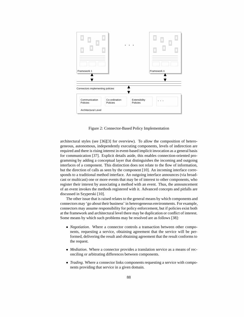
CommunicationPolicies
Architectural Level
Framework 1
. . .
Connectors implementing policies
Framework n
Co-ordinationPolicies
ExtensibilityPolicies
. . .
Figure 2: Connector-Based Policy Implementation
architectural styles (see [36][3] for overview). To allow the composition of hetero-geneous, autonomous, independently executing components, levels of indirection arerequired and there is rising interest in event-based implicit invocation as a general basisfor communication [37]. Explicit details aside, this enables connection-oriented pro-gramming by adding a conceptual layer that distinguishes the incoming and outgoinginterfaces of a component. This distinction does not relate to the flow of information,but the direction of calls as seen by the component [10]. An incoming interface corre-sponds to a traditional method interface. An outgoing interface announces (via broad-cast or multicast) one or more events that may be of interest to other components, whoregister their interest by associating a method with an event. Thus, the announcementof an event invokes the methods registered with it. Advanced concepts and pitfalls arediscussed in Szyperski [10].
The other issue that is raised relates to the general means by which components andconnectors may ‘go about their business’ in heterogeneous environments. For example,connectors may assume responsibility for policy enforcement, but if policies exist bothat the framework and architectural level there may be duplication or conflict of interest.Some means by which such problems may be resolved are as follows [38]:
� Negotiation. Where a connector controls a transaction between other compo-nents, requesting a service, obtaining agreement that the service will be per-formed, delivering the result and obtaining agreement that the result conforms tothe request.
� Mediation. Where a connector provides a translation service as a means of rec-onciling or arbitrating differences between components.
� Trading. Where a connector links components requesting a service with compo-nents providing that service in a given domain.
88

� Federation. Where a connector provides a means of negotiation that binds acollection of components that wish to come together in a federation in whichcomponents retain their autonomy. The connector may be responsible for im-porting and exporting service offers to other frameworks/subsystems, allowingor forbidding offers from federated components, communicating and negotiatingpolicies and supporting information sharing for example.
4 Conclusion
Component-based development offers the promise of flexible systems that have themeans to remain coupled to the environment in which they interact. These meansare given grounding through the concepts of independent extensibility and dynamiccomposition. In non-trivial situations, the naive assumption that a system will re-sult through unstructured mixing-and-matching of components may be argued to bea recipe for chaos. Scalability of the component concept offers help in this respect anda distinction has been drawn between atomic and architectural components. Higher-order variations of the latter (such as component frameworks) can be utilised to provideoperational policies associated with communication, co-operation and co-ordination bywhich lower-level atomic and composite components must abide if they wish to par-ticipate in a system. In general, current technologies that facilitate communication,co-operation and co-ordination lock the means by which they are achieved into an un-derlying object/component model to which the user of that technology implicitly ‘buysin’. For complex systems that are open, distributed and heterogeneous this may be un-desirable. In such situations the proposal is forwarded that the entities connecting com-ponents should themselves be treated as composable and open to manipulation. Giventhe aims of component-based development, it may be argued to be self-defeating torely on monolithic approaches to communication, co-operation and co-ordination. Un-fortunately, while architectural components generally have a one-to-one mapping withcomponents at the implementation level, this mapping is unclear in the case of con-nectors. Additionally, it has been proposed that research needs to be directed towardthe means by which policy duplication or conflict may be addressed at an architec-tural level. Our aim in this exposition has not been to provide answers but to articulatethe potential need for connectors to be made explicit and to provoke the appropriatediscussion and research.
Bibliography
[1] W. Weck. Independently extensible component frameworks. In M. Muhlhauser,editor,Special Issues in Object-Oriented Programming: Workshop Reader of the10th European Conference on Object-Oriented Programming ECOOP’96, Linz,July, pages 177–183. dpunkt.verlag, Heidelberg, 1997.
[2] P. C. Clements and L. M. Northrop. Software architecture: An executiveoverview. In A. W. Brown, editor,Component-Based Software Engineering: Se-lected Papers form the Software Engineering Institute, pages 55–68. IEEE Com-puter Society Press, Los Alamitos, California, 1996.
[3] M. Shaw and D. Garlan.Software Architectures: Perspectives on an EmergingDiscipline. Prentice-Hall, Englewood Cliffs, NJ, 1996.
89

[4] D. Garlan and D. Perry. Software architecture: Editorial.IEEE Software,21(4):269–274, 1995.
[5] E. W. Dijkstra. The structure of the the multiprogramming system.Communica-tions of the ACM, 11(5):341–346, 1968.
[6] D. Parnas. On a ’buzzword’: Hierarchical structure. InIFIP Congess 74. NorthHolland, 1974.
[7] D. Parnas. On the design and development of program families.IEEE Transac-tions on Software Engineering, SE-2(1):1–9, 1976.
[8] P. Lalanda. A control model for the dynamic selection and configuration of soft-ware components. In W. Weck, J. Bosch, and C. Szyperski, editors,Second Inter-national Workshop on Component-Oriented Programming, volume TUCS Gen-eral Publication No. 5, pages 51–57, Jyvaskyla, Finland, 1997. Turku Centre forComputer Science, Turku.
[9] M. E. Fayed and D. C. Schmidt. Object-oriented application frameworks.Com-munications of the ACM, 40(10):32–38, 1997.
[10] C. Szyperski. Component Software - Beyond Object-Oriented Programming.Addison-Wesley, Harlow, Essex, 1998.
[11] D. Baumer, G. Gryczan, R. Knoll, C. Lilienthal, D. Riehle, and H. Zullighoven.Framework development for large systems.Communications of the ACM,40(10):52–59, 1997.
[12] E. Gamma, R. Helm, R. Johnson, and J. Vlissides.Design Patterns: Elements ofReusable Object-Oriented Software. Addison-Wesley, Reading, Mass., 1995.
[13] D. Garlan, R. Allen, and J. Ockerbloom. Architectural mismatch: Why reuse isso hard.IEEE Transactions on Software Engineering, 12(6):17–26, 1995.
[14] R. E. Johnson. Frameworks = (components + patterns).Communications of theACM, 40(10):39–42, 1997.
[15] H. A. Schmid. Systematic framework design by generalisation.Communicationsof the ACM, 40(10):48–51, 1997.
[16] O. Nierstrasz and L. Dami. Component-oriented software technology. In O. Nier-strasz and D. Tsichritzis, editors,Object-Oriented Software Composition, pages3–28. Prentice Hall, Englewood Cliffs, N.J., 1995.
[17] D. Kiely. Are components the future of software?IEEE Computer, 31(2):10–11,1998.
[18] C. Szyperski and C. Pfister. Component-oriented programming: WCOP’96workshop report. In M. Muhlhauser, editor,Special Issues in Object-OrientedProgramming: Workshop Reader of the 10th European Conference on Object-Oriented Programming ECOOP’96, Linz, July, pages 127–130. dpunkt.verlag,Heidelberg, 1997.
90

[19] A. Olafsson and D. Bryan. On the need for ’required interfaces’ of components. InM. Muhlhauser, editor,Special Issues in Object-Oriented Programming: Work-shop Reader of the 10th European Conference on Object-Oriented ProgrammingECOOP’96, Linz, July, pages 159–165. dpunkt.verlag, Heidelberg, 1997.
[20] T. Murer, W. Scherer, and A. Wurtz. Improving component interoperability. InM. Muhlhauser, editor,Special Issues in Object-Oriented Programming: Work-shop Reader of the 10th European Conference on Object-Oriented ProgrammingECOOP’96, Linz, July, pages 150–158. dpunkt.verlag, Heidelberg, 1997.
[21] M. Buchi and E. Sekerinski. Formal methods for component software: The re-finement calculus perspective. In W. Weck, J. Bosch, and C. Szyperski, editors,Second International Workshop on Component-Oriented Programming, volumeTUCS General Publication No. 5, pages 23–32, Jyvaskyla, Finland, 1997. TurkuCentre for Computer Science, Turku.
[22] M. Buchi and W. Weck. A plea for grey-box components. In G. T. Leavensand M. Sitaraman, editors,Foundations of Component-Based Systems Workshop,pages 39–49, Zurich, Switzerland, 1997. ACM.
[23] K. De Hondt, C. Lucas, and P. Steyaert. Reuse contracts as component interfacedescriptions. In W. Weck, J. Bosch, and C. Szyperski, editors,Second Interna-tional Workshop on Component-Oriented Programming, volume TUCS GeneralPublication No. 5, pages 43–49, Jyvaskyla, Finland, 1997. Turku Centre for Com-puter Science, Turku.
[24] R. Helm, I. M. Holland, and D. Gangophyay. Contracts: Specifying behaviouralcompositions in object-oriented systems.ACM SIGPLAN Notices, 25(10):169–180, 1990.
[25] P. Steyaert, C. Lucas, K. Mens, and T. De Hondt. Reuse contracts: Managing theevolution of reusable assets.ACM SIGPLAN Notices, 31(10):268–285, 1996.
[26] T. D. Meijler and O. Nierstrasz. Beyond objects: Components. In M. Papa-zoglou, editor,Cooperative Information Systems. Academic Press, London: Inpress, 1998.
[27] J. Bosch, C. Szyperski, and W. Weck. Summary of the second international work-shop on component-oriented programming. In W. Weck, J. Bosch, and C. Szyper-ski, editors,Second International Workshop on Component-Oriented Program-ming, volume TUCS General Publication No. 5, pages 1–4, Jyvaskyla, Finland,1997. Turku Centre for Computer Science, Turku.
[28] M. Lumpe, J. Schneider, O. Nierstrasz, and F. Achermann. Towards a formalcomposition language. In G. T. Leavens and M. Sitaraman, editors,Foundationsof Component-Based Systems Workshop, pages 178–187, Zurich, Switzerland,1997. ACM.
[29] P. C. Clements. A survey of architecture description languages. InEighth Inter-national Workshop on Software Specification and Design, Germany, 1996.
[30] G. A. Agha. Compositional development from reusable components requiresconnectors for managing protocols and resources. InOMG-DARPA Work-shop on Compositional Software Architectures, Monterey, California, 1998.http://www.objs.com/workshops/ws9801/cfp.htm.
91

[31] P. Oreizy, N. Medvidovic, R. N. Taylor, and D. S. Rosenblum. Software ar-chitecture and component technologies: Bridging the gap. InOMG-DARPAWorkshop on Compositional Software Architectures, Monterey, California, 1998.http://www.objs.com/workshops/ws9801/cfp.htm.
[32] M. Shaw. Procedure calls are the assembly language of software interconnection;connectors deserve first-class status. Technical Report CMU/SEI-94-TR-02, Soft-ware Engineering Institute, Carnegie Mellon University, 1994 1994.
[33] J. Bosch. Composition through superimposition. In M. Muhlhauser, editor,Spe-cial Issues in Object-Oriented Programming: Workshop Reader of the 10th Euro-pean Conference on Object-Oriented Programming ECOOP’96, Linz, July, pages94–101. dpunkt.verlag, Heidelberg, 1997.
[34] J. M. Troya and A. Vallecillo. On the addition of properties to components. InW. Weck, J. Bosch, and C. Szyperski, editors,Second International Workshopon Component-Oriented Programming, volume TUCS General Publication No.5, pages 95–103, Jyvaskyla, Finland, 1997. Turku Centre for Computer Science,Turku.
[35] D. Garlan. Higher-order connectors. InOMG-DARPA Workshopon Compositional Software Architectures, Monterey, California, 1998.http://www.objs.com/workshops/ws9801/cfp.htm.
[36] J. A. Rader. Mechanisms for integration and enhancement of software compo-nents. In E Nahouraii, editor,Fifth International Symposium on Assessment ofSoftware Tools and Technologies (SAST ’97), pages 24–31, Pittsburgh, Pennsyl-vania, 1997. IEEE Computer Society.
[37] D. S. Rosenblum, A. L. Wolf, and A. Carzaniga. Critical considerations anddesigns for internet-scale, event-based compositional architectures. InOMG-DARPA Workshop on Compositional Software Architectures, Monterey, Califor-nia, 1998. http://www.objs.com/workshops/ws9801/cfp.htm.
[38] J. R. Putman. Interoperability and transparency perspectives for com-ponent based software: Position paper. InOMG-DARPA Workshopon Compositional Software Architectures, Monterey, California, 1998.http://www.objs.com/workshops/ws9801/cfp.htm.
92

Federated Component Frameworks
Gunter GrawUniversitat Dortmund, Fachbereich Informatik, D-44221 Dortmund
Arnulf MesterUniversitat Dortmund, Fachbereich Informatik, D-44221 Dortmund
Dr. Materna GmbH, Open Enterprise Systems Division, D-44141 [email protected]
Components and component based framework are currently hot discussed top-ics. Components offer the possibility of increased reuse. Component frameworksprovide reference architectures for dedicated domains. Although different solu-tions to the composition mechanisms of components exist, the understanding ofthe interoperation of component frameworks is still immature: neither developersare able to choose from a range of different architectures for this purpose, nor theypossess detailed information on the applicability of each architecture. In [SV98]a solution with two hierarchically organized tiers is proposed. The basic level tiercontains the component frameworks for the different framework domains. The toplevel tier serves for interoperation and integration purposes. This paper proposes adifferent approach which is based on the idea of federated component frameworks.Federated architectures are used for the design of information systems (e.g. feder-ated databases) and distributed systems (e.g. trading and brokering, cf. [GGK96]).They provide for higher autonomy of the incorporated partners, but they have tocope with semantical conflicts, which stem from the different interpretation of dataand behaviour of the incorporated partners. This position paper first reviews thetwo-tier approach, then introduces our federated approach, and compares both.Our contribution to the workshop and the component community is the proposal(and in the moment partly experimental validation) of the other extreme of possiblecomponent framework interaction architectures.
1 Introduction
1.1 Component Frameworks
In [S97] Szyperski defines component frameworks in the following way: ”A compo-nent framework is a software entity that supports components conforming to certainstandards and allows instances of these components to be plugged into the compo-nent framework.” Component frameworks provide the ”hot-spots/plug-ins” in whichcomponents may be put to interact with groups of other components. Furthermore theinteroperation of components must be supported. On the one hand a component frame-work might be an isolated solution for a domain. On the other hand the cooperationand interoperation of component frameworks is possible and is strongly encouraged toallow multi domain software architectures. Currently a multi tier approach has beenproposed in [SV98]. As opposite possibility in the spectrum we propose a federatedapproach. Both approaches will be described in the following subsections.
93

1.2 2 tier-architecture
Separation of systems into hierarchically structured layers is a basic method of Soft-ware Engineering to cope with complexity. This fundamental technique can be usedin component systems, too. Once we take over this structuring concept into the fieldof component frameworks we recognize that component frameworks can be organizedin multiple layers or better tiers. It is stated that two tiers will suffice in most of thecases.The basic level tier contains the component frameworks for the different domainswhich are connected to the framework in the higher level tier. Thus the framework ofthe higher tier has to provide slots in which basic tier components are plugged in. Theoperation of plugging is performed by making connections between instantiations ofcomponents of a basic tier framework and the higher tier framework. The plugging ofcomponents of different frameworks is performed at system design time. The interac-tion of higher and basic tier components is realized in a fixed or hardwired way.
2 Federated component frameworks
In contrast to hierarchically organized systems in which one component manages in-teroperation or interactions of basic level components, federative structures of au-tonomous components exist. In these federative structures each partner is equippedwith higher autonomy, which may be crucial for guaranteeing local framework prop-erties (and thus global system properties, too). Typically for the context of componentframeworks these autonomies are:
� The autonomy to decide whether to interoperate or not with other componentframeworks in general or in particular situations (participation autonomy).
� The autonomy to design each framework independently of other frameworkswithout conflicting interfaces.
� The autonomy to evolve component frameworks independently (evolution au-tonomy).
� The autonomy to instantiate or delete components of foreign frameworks (life-cycle autonomy).
� The autonomy to decide, which services to offer and how to offer these (execu-tion autonomy).
Whether regardable as instance of a 2-tier framework or as a separated proposal for analternative architecture (we will answer this question later), one may try to refine abovecomponent framework definition to: a federated component framework is a compo-nent architecture, where component instances are dynamically plug- and unpluggable,where usage relations can also be established by searching for static component at-tributes and/or current values of dynamic component attributes, where usages (of singleoperations) and usage sequences (like seen in an UML interaction diagram) can be con-structed dynamically, and where different kinds of autonomies are granted. Endowingcomponent frameworks with so much autonomy may lead to conflicts. Thus conflictshave to be managed and resolved by the federated system. In order to provide thisconflict management global knowledge of each federation partner has to be prepared.Furthermore, conflict managing entities have to exist. Trading is an approach whichhas been used in distributed systems to handle service offers in client-server systemsand to handle potential conflicts. Trading will be explained in the next section.
94

3 Trading
Originally trading was used to mediate services in open distributed systems [BS98],[MML94]. A service is a set of methods which are offered by the interface of anobject. In contrast to single methods only, multiple methods mostly have to be triggeredin a coordinated way. We call such kind of interface computational interface. It is anabstraction of the behavior of an object. Services describe the capabilities which can beaccessed at the interface of an object. Furthermore, a service has properties. Static anddynamic properties can be distinguished. Static properties of services do not change,dynamic properties might be changed often. The name of a service is associated withits dynamic properties. Services of an object can be exported, changed or withdrawn toa trader. A trader includes these in his trading offer domain. An object which is lookingfor foreign services to fulfill its own purpose imports a service. This is performed bysearching in the trading offer domain of a trader. After retrieval of the service withthe characteristics desired, the exporting component is used by the importer. Thisincludes obeying a sort of encoded interaction diagram for the coordinated method useconstituting the service. A trader consists of the following parts:
� Trading administrator. Has to enforce the trading policies of a trader.
� Trading policies.The behavioral rules of a trader.
� Trading policy maker. Defines behavioral rules of a trader according to existingrequirements.
� Export Policy Controller. Controls the usage of trader resources.
� Internal Abitrator. Instance which has the task to conciliate and avoid conflicts.
� Trader owner. Object which owns the trader.
A trader equipped with these elements together with its importing and exportingobjects is called a trading community. It is of course possible to build federations oftraders, too. A trading federation consists of a union of trading communities and anexternal arbitrator. There are three fundamental activities in a trading federation. Theseare federation establishment, federation export and federation import. The federationestablishment is an interaction of trading communities with the aim to build up a traderfederation. This federation is based on the behavioral rules of the incorporated tradingcommunities. The interaction of a set of traders is defined using contracts. It is possibleto distinguish import and export contracts.
4 Properties of trading-based component frameworks
In this section the relation between trading and component frameworks will be dis-cussed in detail. Firstly, the interaction of the trader and framework components isexplained. Secondly, it is described how services are offered to the trader and searchedby means of a service description. The term service denotes a set of methods of acomponent interface to be used in a coordinated manner.
95

4.1 Interaction of trader and framework components
The question appears how trading is performed in component frameworks. We defineimporting and exporting component interfaces for this purpose (cf. Figure below). Ser-vice exporting components transfer a service description to an appropiate trader. Thestructure of a service description will be explained later on. Each component frame-work is equipped with a trader. The trader may also be a component of the framework[O98]. The traders of the federated frameworks and the external arbitrator form afederation of component frameworks. The components of each framework serve asexporters and importers. These form import and export contracts. Federation contractsbetween component frameworks are built in pairs. Once a service importing componentis looking for a service of a component of another framework, it searches in the traderby the use of a runtime created service (request) specification. To allow multicasts toseveral incoming interfaces it is necessary to specify their number (cardinality). Onceservice descriptions and specifications fit together the hits are delivered to the outgoinginterface. This matching is achieved using service properties, which will be explainedlater on. Thus calls and call sequences can be performed. Although trading effectsperformance of component software flexibility is enforced.
FW1.Component FW2.Component
ITI, n, sd
exporting Trader interface
ETI, ssp
ssp = service specification n = Cardinality of multicast
sd = description of service properties
importing Trader interfaceexport
import
Trader FW1 Trader FW2
Trader federation
Figure 1: Trading for component framework interoperation
4.2 Service description
The export of component services of a framework is similar to introspection of prop-erties. A service exporting component has to offer the name of its framework, its owncomponent name, the name of a service, the signatures of the methods, as well as anencoding of an interaction-prescription. Furthermore static and dynamic properties canbe exported with the according service to the trader. Regarding the current state of acomponent, the following structure can be derived:
96

� Framework Name
� Component Name
� Service Name
� Argument1 Name
� Argument1 Type
� Static Property1
� Dynamic Property1
To make the export technically possible, an exporting component has to provide meanswhich allow the export of services to the trader. The export of methods and propertiesis performed once a component is instantiated. Before a component is deleted its ac-cording services have to be withdrawn. Once a component is changed in the softwareprocess the services of the component might be changed when method interfaces wheresubject to change. Static properties can be used to specify the way a service is called.This supports the existence of components with different kinds of incoming or outgoinginterfaces according the underlying method specification (synchronous, asynchronous,balking etc.). If components provide interfaces with different kinds of method spec-ifications trading helps to avoid problems of architectural mismatch [GB98]. Otherstatic properties may include predefined service descriptions or component usage pre-scription schemes. Trading also allows to respect dynamic properties of componentframeworks. Dynamic properties are used to describe load and performance charac-teristics e.g. the number of parallel executed threads of an object of a component, theactual service request backlog of a component,...
5 Example scenarios
The following examples depict typical situations, where the characteristics of the trad-ing-based approach may be of value. Particularly, all systems with a high need ofdynamic flexibility are possible candidates, e.g. business processes [GG95], controltask in robotics or batch-process oriented chemical plant engineering, or even systemmanagement tasks. We will elaborate on two of them: The development of controlsoftware of an autonomous mobile robot may rely on a set of frameworks for the in-dividual control problems, e.g. stereo camera analysis, infrared analyis, obstacle de-tection, route planning, ... The classical architecture defines a backplane supressing oradvancing behavioural controls according to a dynamically determinded logical com-ponent hierarchy. Furthermore, single components may be replaced during operationto cope with new environmental or experiment conditions. The ’dynamic wiring’ canbe realized with a trader, rooting its decisions also on the current operational states ofthe components. The trader also supports for mediation of direct cooperation betweencomponents of different domain frameworks, e.g. the cooperation of infrared, visiblespectrum analysis and obstacle detection components.
The trend in network or system management is determined by a shift towards acomponent-oriented construction of management applications. Management of com-plex IT-infrastructure needs different component frameworks, each suited for a specificclass of management tasks or managed elements. Typical actual problems now are
97

delivering a contracted service level by coordinated element management. Each ele-ment class, as well as the service management domain, will have their own componentframeworks. As IT-infrastructure are evolving within operation and management deci-sions also have to be based on current operational states, a trader-based approach is ofhelp in mediating cooperations between different component frameworks. Addition-ally, this scenario also depicts independent evolvements of the components and theirframeworks, as different vendors are participating. Under the premises of establishedconventions for service description encodings, a trader-based approach offers the highautonomy demanded in this scenario.
6 Comparison of tiered and federated componentframeworks
In this section both approaches will be compared according to the aspects of evolution,interoperation, adaption, performance and composition. It also highlights practicalconsequences of both approaches in system construction.
� Evolution. Introducing a new domain framework (2-tier approach) might causethe restructuring of parts of the higher-level framework. The reason is thatlogic/behavior is spread over a couple of components. Thus we claim that thehigher level framework is difficult to design. Evolution is performed at compiletime. Changes to properties or the message specification at the plug-in posi-tions in the higher level framework cause changes in the basic level framework.Vice versa changes in a domain framework cause changes in the higher-levelframework.The change of an interface makes connections senseless. Evolutionis concentrated on the trader(trading-based approach). Evolution happens at run-time. Once an interface is changed no new connections are necessary. Insteadservice descriptions are removed or updated from the trader.
� Interoperation . Logic and behavior for interoperation is spread over the higherlevel framework in the 2-tier approach. The higher tier framework is responsiblefor architectural matching of parts. Logic for interoperation remains private ineach framework using the trading-based approach.
� Performance. Because of the hardwired composition vs. the additional levelof indirection due to the service search, systems constructed with the 2-tier ap-proach are slightly more performant than those done with the trading-based ap-proach. Designs with heavy use of dynamic properties in service searches haveto employ performance-optimized traders.
� Composition. The composition of the new higher level framework using com-ponents and/or component services of/from other frameworks is determinded atsystem design time. The resulting system structure is fixed. In the trading-basedapproach the composition is determined dynamically based on dynamic prop-erties and service requests. The resulting system structure is dynamic and canbenefit from situation dependent architecture changes.
A practical consequence when using the 2-tier model in system construction is theproblem of tier conversion: creating a higher tier framework (tier n+1) also establishesa new domain framework (i.e. tier n). This is a candidate for later use within other
98

again higher frameworks (tier> n+1), which makes understanding a little bit harder,when both tier n and tier n+1 frameworks are used simultaneously. In the trading-basedapproach no hierarchical tiers exists. Furthermore, a trading-based approach providesfor flexible architecture determined by dynamic properties within service mediations.Beside this, also interaction schemes in form of components can be traded, i.e. add anadditional level of flexibility. Above arguments should have made clear that a federatedcomponent framework has the value to be regarded as possible architecture proposal.
7 Conclusion
We see the trading approach as one extreme counterpart to the hierarchical solution.We could image that both solutions can coexist in a component system. This de-pends on the requirements of the application. Trading is a well-known concept indistributed systems. The novel contribution of this paper is our proposal for its ap-plication to issues of interoperation and architecture of multi component frameworksystems. Parts of the concepts presented have already been validated within the area ofnetwork/element/service management application development. There several domainspecific component frameworks have been devised and services are inter-frameworktraded to form the basis of the framework for a new application.
Bibliography
[BS98] Blair, G.S., Stefani, J.-B.: Open distributed processing and multimedia,Addison-Wesley Longman, England, 1998.
[GB98] Gacek, C., Boehm, B.: Composing Components: How does one detect po-tential architectural mismatches? in: Proc. of OMG-DARPA-MCC work-shop on compositional software architectures, January 1998.
[GGK96] Graw, G., Gruhn, V., and Krumm, H.: Support of Cooperating and Dis-tributed Business Processes, ICDP ’96 / IFIP IEEE International Confer-ence on Distributed Plattforms, pp. 231-235, 1996.
[GG95] Graw, G., Gruhn, V..: Distributed Modeling and Distributed Enaction ofBusiness Processes, ESEC ’95 / 5th European Software Engineering Con-ference pp. 9-27, 1995.
[MML94] Merz, M., Muller, K., and Lamersdorf, W.: Service trading and mediaton indistributed computing environments, Proceedings of the 14th InternationalConference on Distributed Computing Systems, IEEE Computer SocietyPress, pp. 450-457, 1994.
[O98] Outhred, G.: A model for component composition with sharing, Third In-ternational Workshop on Component-Oriented Programming, July 1998.
[SV98] Szyperski, C. and Vernik, R.: Establishing System-Wide Properties ofConponent-Based Systems - A Case for Tiered Component Frameworks,Workshop on Compositional Software Architectures, January 1998.
[S97] Szyperski, C.: Component Software, Addison Wesley, 1997.
99


A Model for Gluing Components
P.S.C. Alencar, D.D. Cowan, C.J.P. Lucena, L.C.M. NovaDepartment of Computer Science
University of Waterloo, Waterloo, Ont, Canada N2L 3G1falencar, dcowan, lucena, [email protected]
Accomplishing effective reuse within the component-based approach dependsnot only on the selection of appropriate reusable components, but also on the waysthese components are adapted and combined. This process of “gluing” compo-nents together is an essential step, as there is often a need to connect componentsthat have not been designed to be composed. The component-based software engi-neering (CBSE) community has identified the need for formal models that allow abetter understanding of the semantics of gluing components. In this paper, we de-scribe a model for gluing object-oriented software components that together withour viewpoint-based development approach for CBSE, provides background to theglue model. The glue model is presented as a design relationship between com-ponents which is characterized by a set of semantic properties. We illustrate themodel by presenting some of the typical properties that describe how componentscan be adapted and combined.
1 Introduction
One of the goals of component-based software engineering (CBSE) development is theconstruction of software from large-grained reusable components rather than re-writinga software system from “scratch” for each new application. However, accomplishingeffective reuse within the component-based approach depends not only on the selectionof appropriate reusable components, but also on the ways these components are adaptedand combined [12]. As Jan Bosch stated [6], “as-is” reuse is unlikely to occur and, inmost cases, a selected component needs to be adapted to cope with specific applicationrequirements.
The element of programming concerned with “putting things together” is generallycalled “glue” [10]. The role of the glue is essential, as there is often a need to connectcomponents that have not been designed to be composed. Therefore, glue deals withadaptation and combination issues, including any “mismatches” between componentssuch as different interfaces or interaction styles.
The CBSE community has identified the need for formal models which allow abetter understanding of the semantics for gluing components together [10]. Besidesproviding adaptation and combination techniques at the implementation level, we alsoneed an abstraction to model the glue formally at the design level. Such an abstractionwould allow the software developer to visualize the adaptation and assembly operationsmore clearly, since normally, the glue would be buried in a complex programmingstructure that would obscure its real purpose.
1The work described here has been supported by the Natural Sciences and Engineering Research Councilof Canada (NSERC), the Information Technology Research Centre of Canada (ITRC), the National ResearchCouncil of Brazil (CNPq), and Sybase Inc.
101

In this paper, we describe a model for gluing object-oriented software componentstogether in conjunction with our viewpoint-based development approach for CBSE,which provides a practical background to the glue model. This glue model is presentedas a design relationship between components with an accompanying set of semanticproperties. We illustrate the model by presenting some of the typical properties thatdescribe how components can be adapted and combined. In this way, the glue relation-ship can be isolated and defined separately from the components and different waysof adapting/combining components can be defined by choosing a specific subset of theglue properties.
1.1 A Viewpoint-Based Development Approach for CBSE
Our general objective is the creation of a complete development approach for compo-nent-oriented systems based on viewpoints [1, 4, 3]. In this respect, we plan on reusingpre-built components to create black box frameworks in a more methodical fashion.
The reuse of pre-built components in software development has generated substan-tial interest [7, 9, 10, 11]. However, current methods are based on ad-hoc techniques,and, at best, adopt general descriptions such as the component-based system referencemodel [7]. Reported research has focused on the description of systems and associ-ated problems, while there has been little investigation of a design and implementationprocess and, in particular, of models for gluing object-oriented reusable components.
We propose an approach for the specification, design, and implementation of com-ponent-based software consisting of five steps:
1. Determine the perspectives or viewpoints of an application - viewpoint analysisand consistency is applied to component-based software design.
2. Determine the kernel or framework of an application using unification of view-points - unification and domain specific languages are used to determine blackbox frameworks, and the points at which components can be glued to frame-works.
3. Glue the components and frameworks together to create a complete application- the glue semantics are characterized through theviews-arelationship. Pre-builtcomponents are connected to frameworks by using this glue model.
4. Map the glue into design patterns - theviews-asemantics are used to guide theselection of appropriate design patterns. Pattern-based implementations of theapplications are produced.
5. Transform the resulting object-oriented design into “real” components - the inter-face and functionality of some components from an object-oriented perspectiveis described, and the corresponding transformations are developed.
We have partially tested each of these steps in a number of applications. Thus,we believe this process is feasible, and will make significant contributions to softwareengineering. Here we restrict the description of this approach to the topics relevant forthis paper. For further details see [2].
In step 1, we determine how to describe and use viewpoints. A “viewpoint” is aview of a system from a suitable perspective where we focus on a specific set of con-cerns. We could view a distribution system from a user or supplier perspective, or fromthe business rules that have been implemented. Alternatively, we could view a software
102

system from a structural, functional or sequencing perspective. In the first case we areexamining the system from the functionality presented to the external world, while inthe second case we are examining the different relationships of the same aspect of thesystem.
The two types of viewpoints are called inter- and intra- viewpoint representations,respectively. A key consideration of viewpoints is that multiple viewpoints must presentthe same system consistently. We choose to describe a viewpoint in terms of an object-oriented model, because of the rich constructs provided by this form of design lan-guage.
The concepts associated with viewpoints are still evolving. For example, the Uni-fied Modeling Language (UML) uses intra-viewpoints, while the Open DistributedProcessing (ODP) Standard uses inter-viewpoints. However, neither UML nor ODPaddress consistency among viewpoints, a concept that is critical if viewpoints are to beuseful in design. Since viewpoint analysis and requirements analysis are similar, weexpect to be able to use concepts and methods from the latter to assist with understand-ing and developing viewpoints.
In step 2, we find the common characteristics or “intersection” of the viewpoints inorder to define the framework.
In step 3, this resulting object-oriented framework or core of the system is aug-mented using a software glue to produce the various applications that formed the orig-inal viewpoints. In this paper, theviews-arelationship [1] is used as a model for theglue. Using this abstraction, we allow the software developer to visualize the assemblyoperation more clearly. Normally, the glue would be buried in a complex programmingstructure that would obscure its real purpose.
Theviews-arelationship can be implemented in terms of one of the standard object-oriented design patterns. In step 4 we choose the appropriate design pattern by com-paring a collection of design patterns with theviews-asemantics properties required ina specific design. The result of this process is an object-oriented design model for theentire set of applications. We have informally demonstrated the mapping of theviews-arelationship into different design patterns, but a more structured approach is requiredbefore the technique is truly usable by a software designer.
We believe that some of the steps in our proposed approach to component-baseddesign can be used even when the software developer uses ad-hoc methods. We havefound through experimentation, that using some of the steps to analyze a design inprogress clarifies many of the design decisions, and often leads to an improved softwaresystem.
1.2 An Example
In this section, we briefly present one of the case studies developed with our viewpoint-based approach to CBSE. The case study is based on the NACHOS file system. Thisfile system is reused as a component and extended with functionality that deals withadditional concerns. Each additional concern is represented by a viewpoint.
The kernel of the application is the original NACHOS file system, which was reusedas a black-box component and extended with viewpoints. This particular example (see[4] for details) has two viewpoints (also called subjects): one for concurrency andone for large extensible files (see Figure 2). As we have only one application (andnot a domain) we did not have unification of viewpoints. Theviews-arelationshipwas used to glue the two viewpoints and the black-box component together to createa complete application. This glue relationship represented by the vertical arrows in
103

Operation1( )Operation1Start( )Operation1End( )
Operation1Start( )Operation1End( )
Attach(View)Operation1( )
Operation1( )
View
Concrete View 1
Operation1Start( )Operation1End( )
Concrete View 2 Surrogate Object
for each o in viewso->Operation1Start( )
Object->Operation1for each o in views
o->Operation1End( )
Surrogate->Operation1( )
Calls toview1->Operation1
Calls toview2->Operation1
Calls toobject->Operation1
Figure 1: Design model forviewsrelationship
Figure 2, is later transformed into a design pattern (Figure 1). Theviews-asemantics,which is described in the next section, was used to characterize how the viewpointsare glued and to guide the selection of an appropriate design pattern. The resultingobject-oriented design is then implemented in terms of the “real” components.
2 Modeling the Glue
In this section we briefly describe the semantics of theviews-arelationship, whichsupports a methodical separation of components representing different concerns in asoftware specification. Thisviews-arelationship is used to glue viewpoints and black-box components. Eachviews-arelationship is represented by a vertical arrow in theexample shown in Figure 2.
In this relationship, one of the viewpoint objects “views” the state of another objectin the reused component. This second object is completely independent and unawareof the existence of the first. Theviews-arelationship also guarantees the consistencybetween the elements connected, i.e. the viewer and viewed objects.
Figure 3 briefly illustrates the technique used in the formalization of theviews-a relationship. This diagram shows two class theories –R (the viewer) andD (theviewed) – and one relationship theoryV (views-a). MR andMD are also theories thatmanage the creation and destruction of instances of classesR andD, respectively. Allof these theories are interconnected by morphisms to derive the composite theoryC.TheoryC is interpreted as the colimit of theoriesR, D, andV. Informally, the colimitis the mechanism that combines the two classes and theviews-arelationship. In thiscontext, the formal theory forviews-amay be seen as a model that glues componentstogether.
2.1 Properties of the Relationship
Each different type of object-oriented relationship connects objects with a specific setof properties. The semantics of these relationships define static and dynamic con-straints that characterize the type of interaction between two components. These con-
104

FILESYS
Create(char * name, int initialSize)OpenFile * Open(char * name)
bool Remove (char *name)List( )
Print( )
OPENFILEint ReadAt (char * into, int size, int position)
int WriteAt (char * from, int size, int position)int Read (char * into, int size )
int Write (char * from, int size)Seek (int position)
int Length( )
DIRECTORYFetchFrom( OpenFile * file)
WriteBack( OpenFile * file)int Find (char * name)
bool Add (char * name, int sector )bool Remove(char * name)
List( )Print( )
FILEHDRbool Allocate (BitMap * freeMap, int size)
Deallocate (BitMap *)FetchFrom(int sector)
WriteBack(int sector)int ByteToSector (int offset)
int FileLength( )Print( )
SYNCHDISK
ReadSector (int sector, char * data)WriteSector (int sector, char * data)
RequestDone ( )
Open
Module entry point Module entry point
store andretrieve
OPENFILE
int WriteAt (char * from, int size, int position)
FILEHDRbool Allocate (BitMap * freeMap, int size)
Deallocate (BitMap *)FetchFrom(int sector)
WriteBack(int sector)int ByteToSector (int offset)
int FileLength( )Print( )
AddBytes(int numBytes)
FILESYS
Create(char * name, int initialSize)OpenFile * Open(char * name)
bool Remove (char *name)List( )
Print( )
OPENFILE
int ReadAt (char * into, int size, int position)int WriteAt (char * from, int size, int position)
int Read (char * into, int size )int Write (char * from, int size)
FILEHDRbool Allocate (BitMap * freeMap, int size)
Deallocate (BitMap *)FetchFrom(int sector)
WriteBack(int sector)int ByteToSector (int offset)
int FileLength( )Print( )
AddBytes(int numBytes)
Open
Module entry point Module entry point
OPENFILETABLE
bool Add (int sector)bool Find (int sector)
Remove (int sector)
FILETABLENODE
int ByteToSector (int offset)int FileLength( )
Print( )
Large extensiblefile subject
Original programsubject
Concurrentsubject
Figure 2: Viewpoint composition
straints determine how an action triggered in a component affects the subsequent re-lated component. Our current interest is to specify the constraints of theviews-are-lationship (V in Figure 3) which connects two components fulfilling the viewer andviewed roles. We now provide an informal description of these constraints and proper-ties, a formal definition is provided in [1, 5].
� Component identity: one simple rule for theviews-atheory is that componentsplaying the viewer and viewed roles in the relationship should have differentidentities. This implies that the viewer’s actions and attributes cannot be mappedto its own object structure. Thus, theviews-arelation is irreflexive. Note, how-ever, that the restriction is on the object identities, not on the component classstructures.
105

Figure 3: Diagram showing the colimit of object and relationship theories.
pre-conditions post-conditionsViews-a Viewer Viewed Viewed
Views-a created – created /0 existsdestroyed – destroyed exists /0
Viewer created created – /0 existsdestroyed destroyed – exists /0
Viewed created /0 /0 – –destroyed destroyed destroyed – –
Table 1: Lifetime conditions on components and their relationships
� Creation/Destruction of Components:viewer components may be connectedor disconnected during the lifetime of viewed component. Table 1 shows allthe creation and destruction dependencies among the three theories involved (i.e.viewer and viewed components, andviews-arelationship). From this table, a fewinteresting properties can be inferred, such as: whenever a viewed component isdestroyed all of its viewers should be destroyed; and a viewer may not existwithout a viewed component, but the reverse is not true.
� Vertical consistency:the state of a viewer component should be consistent withthe state of the viewed component at all times. The consistency is achieved byguaranteeing constraints defined by theviews-arelationship between objects. Wecall this set of constraintsmapping. The mapping of actions and attributes is themechanism that allows the propagation of a change in the state of an applicationobject to all of its views.
� Horizontal consistency: two or more different viewers connected to the sameviewed component should have consistent state and behavior at all times. Con-sistency of states is directly achieved as a consequence of the vertical consistencybetween the many viewers and the viewed component. State consistency is basedon equivalence of attribute values and it is a symmetric and transitive relation.
Consistent behavior is guaranteed by constraints specified in the relationship the-ory gluing the many viewers to one viewed component. These constraints pre-vent different viewers from triggering incompatible actions in the viewed com-ponent at the same time.
106

� Viewer multiplicity: a viewed component may have several viewers connectedat the same time. Not only viewers of the same class, but also viewers withdifferent class structures which are connected by differentviews-arelationshiptheories. Thismultiplicityproperty allows several components to work in parallelwith the same viewed component.
� Viewed singularity: viewer attributes and actions are required to mimic thebehavior of the viewed components to which they are mapped. To avoid thepossibility of inconsistent mappings between one single viewer and two otherviewed components, we constrain the component playing a viewer role to bea viewer in at most oneviews-arelationship. Therefore, each component will“view” at most one other viewed component.
� Relationship cardinality: ( ). the viewer multiplicity and view-
ed singularity properties define constraints on the number of object instances re-lated byviews-a, independent of the class of these objects. Alternatively, thecardinality property establishes constraints to the relationship between two classstructures. According to this property, the cardinality of the component classplaying a viewer role in the relationship is represented by the intervaln::m, wheren andm are integers such that 0� n� m. On the other side of the relationship,the component class playing a viewed role has cardinality equal to one. Thismeans that eachviews-arelationship connects exactly one viewed component.
� Component visibility: Fiadeiro and Maibaum [8] explain that two objects ina system interact by sharing some other object, i.e. by having a common sub-component which they use to synchronize through mappings or morphisms. Theviews-ainterconnection between viewer and viewed components is also speci-fied by sharing object signatures. The identification of these shared signaturesshould be founded on the visibility rules characterizing theviews-aapproach ofmodeling. These rules determine which part of an object is “visible” or “shared”by both objects.
The structure of a viewed component has only signatures that are relevant to theapplication being defined. In other words, it has no attributes or actions thatare specifically intended to access any kind of information maintained by theviewer object. On the other hand, viewer component specifications have not onlyapplication-specific signatures (behavior specific), but they also have signaturesthat allow a viewer to monitor or access the state of a viewed component (in-terconnection signatures). Thus, we say that a viewer “knows” about its viewedcomponents, but viewed component does not know it is being viewed.
3 Conclusion
The viewpoint-based development approach for CBSE provides a practical backgroundfor the characterization of the semantics for gluing object-oriented components to-gether. The glue model is presented as a design relationship between components thatare characterized by a set of properties. Gluing (independently developed) componentsis possible at both the design and implementation levels. At the design level the com-position is represented by theviews-arelationship. At the implementation level thecomposition is represented by design patterns satisfying theviews-aproperties.
107

The views-amodel has been partially validated while used in the construction ofsoftware applications such as a community network, a Web-based education environ-ment, and the NACHOS file system case study presented in this paper. We expectthat further experiences will lead to additional properties characterizing other ways ofcombining and adapting components.
Bibliography
[1] P.S.C. Alencar, D.D. Cowan, and C.J.P. Lucena. A logical theory of interfacesand objects.revised for IEEE Transactions on Software Engineering, 1998.
[2] P.S.C. Alencar, D.D. Cowan, and C.J.P. Lucena. Using viewpoints for component-based software development. InProceedings of the Workshop on Component-Based Information Systems Engineering (CBISE’98), (to appear), 1998.
[3] P.S.C. Alencar, D.D. Cowan, C.J.P. Lucena, and M.A.V. Nelson. An approach tohypermap-based applications.Proceedings of the Second International Sympo-sium on Environmental Software Systems (ISESS’97), Whistler, British Columbia,pages 244–251, 1997.
[4] P.S.C. Alencar, D.D. Cowan, C.J.P. Lucena, and T. Nelson. Viewpoints as anevolutionary approach to software system maintenance.Proceedings of the Inter-national Conference on Software Maintenance, Bari, Italy, 1997.
[5] P.S.C. Alencar, D.D. Cowan, and L.C.M. Nova. A formal theory for the viewsrelationship. InProceedings of the 3rd Northern Formal Methods Workshop,Ilkley, UK, September 1998.
[6] J. Bosch. Adapting object-oriented components. InProceedings of the 2nd Inter-national Workshop on Component-Oriented Programming (WCOP’97), volume 5of TUCS General Publication, pages 13–21, 1997.
[7] A. W. Brown and K. C. Wallnau. Engineering of component-based systems. InComponent-Based Software Engineering, Selected Papers from the SEI, pages7–15. IEEE Computer Society, 1996.
[8] J. Fiadeiro and T. Maibaum. Temporal Theories as Modularisation Units for Con-current System Specification.Formal Aspects of Computing, 4(3):239–272, 1992.
[9] D. Kiely. Are components the future of software.IEEE Computer, Vol. 31, No. 2,pages 10–11, February 1998.
[10] G.T. Leavens, O. Nierstrasz, and M. Sitaraman. 1997 workshop on foundationsof component-based systems.ACM SIGSOFT Software Engineering Notes, pages38–41, January 1998.
[11] Oscar Nierstrasz and Dennis Tsichritzis.Object-Oriented Software Composition.Prentice Hall, 1995.
[12] Mary Shaw. Architectural Issues in Software Reuse: It’s Not Just the Function-ality, It’s the Packaging. InProceedings of Symposium on Software Reusability,Seattle, USA, April 1995.
108

Part IV
Large-Scale Application andExperience
109


Component Testing
Mark GrossmanComponent Applications Group, Microsoft Corporation
One Microsoft Way, Redmond, WA 98052, [email protected]
Recent slips of major large-scale software products indicate that the problemswith today’s development approaches are getting worse. We plan on eliminatingthese problems by creating software with components that are well factored andfinished. Since the cost of revisiting a component after shipment is high, we planon pushing the quality of a component to a high level. Our testing approach in-cludes several techniques:
1. Interface-specific tests that can be re-used to test each implementation of agiven interface.
2. Progressive failure generation for system API’s and interface methods calledby the object being tested
3. Automatic permutation of interesting parameter values for an interface sothat all parameter combinations are exercised
4. Verification of abstract and concrete object state behavior
5. Tests designed and verified to exhibit 100 % code coverage
6. Class-specific tests to verify behavior specific to a given class (such as inter-nal state or performance characteristics)
Our test harness is designed to enable each of these techniques to be appliedto any given component with a minimum of investment in new test code. Theindividual components of the test harness are described and illustrated in our paper.
1 Who Are We
The Component Applications Group (comapps for short) builds applications using anextensive library of small, high quality COM components. These components providerich application functionality in a reusable form. Using a component composition dis-cipline and mechanism, we create products that are significantly more consistent andreliable, with substantially reduced time to market.
Our current work covers fundamental design issues in application structure, and as-sociated infrastructure. Design issues include view/data separation, data and commandbinding, workspace/document/selection architecture, and template/stylesheet/instancemodels. Infrastructure issues include distribution and concurrency management, trans-action management, and component testing and packaging. We are presently situatedin Microsoft Research but will move to the appropriate location within the companywhen we approach the delivery of our first product.
111

2 Overview
The software industry has made and continues to make attempts to address the prob-lems of large-scale software development. Recent slips of major products indicate thatthe problems with today’s development approaches are getting worse. We plan on elim-inating these problems by creating software with components [3]. Our components aredistinguished by their factoring and finish.
A well factored component:
� favors smaller, simpler interfaces - we estimate at most 5,000 lines of C code percomponent.
� has been planned to be extensible
� favors composition style over framework style
� was based on the study of other designs
� has at least three well understood potential uses
� has its large scale performance issues addressed
� has its factoring verified before its final implementation
A well finished component:
� was finished for more than one client
� addresses small scale performance issues
� has a well designed packaging plan
� has a versioning plan (even for its first version)
� has a full set of regression tests for its interfaces
� has a set of conformance tests for clients to use
� avoids concurrent development if possible, e.g., only uses finished components
Since the cost of revisiting a component after shipment is high, we plan on pushingthe quality of a component to a high level. The next section of this paper will discussaspects of interfaces related to robustness and testing and the final section will discusssome of our testing techniques.
3 Interfaces — Describing Reliable Components
We make heavy use of the concepts of pre- and post-conditions. Like Bertrand Meyer,we believe that pre-conditions must be satisfied by the caller [2]. This allows for effi-cient operation of a complex system of pre-tested parts (pre-tested alone and with eachother in combination). The pre-conditions are setup by the caller in the most efficientmanner possible and need not be checked by the called implementation.
A pre-condition may specify any level of detail about the conditions to be met.Pre-conditions include the basic validity of pointers, writability of out parameters, etc.They may include values in certain ranges or bit flags of specific values. Generally,there is a minimum standard to which all code must conform (e.g., valid pointers). Forsome data, say passed in a stream, the preconditions may include only the statementthat the data can be read. It would then be up to the code that processes the data to
112

ensure that it does not crash on bad data. If pre-conditions are not met, we may crash.If the conditions are met, but the data is otherwise bad, some kind of error shouldbe returned. The interface documentation describes the pre-conditions in detail; theparameter validation code implements the pre-conditions.
As implied by the statements above, we can optionally run the pre-condition check-ing code (a.k.a. parameter validation code) in debugging situations, including in thefield. The execution of the per-interface checks is determined by a flag per-group of in-terfaces in an object instance. Thus, two different instances may have different settingsof the flag with one doing the checks and another not. Per-class checks (those writtenby the author of the class) are controlled by another, similar flag and have the furtherpossibility of including post-condition checks.
In addition to specifying pre- and post-conditions we use state models to furtherdocument our interfaces. For example our Overview component is an implementationof IStream over a range of memory addresses. The Memory Stream component is givena description of a chunk of memory, via its IInitMemoryStream interface. The com-ponent then exposes this memory through its implementation of the standard IStreaminterface. The Memory Stream thus provides a way to give a data structure in memoryto something expecting an IStream interface. The signature of the IInitMemoryStreaminterface’s Init method is:
HRESULT Init (void *pv , const STATSTG *pstatstg , IUnknown *punkForRelease ,MSIFLAGS msiFlags );
Its model is shown by Table 1.
Model Description Table
Model Variable Type Explanation
pv void An array of bytes, shared with the caller.statstg STATSTG description of the stream that will be implemented.punkForRelease IUnknown punkForRelease-> Release() will be called when the
implementor closes down.fFreeOnRelease BOOL Whether or not thepv will be given to CoTaskMemFree
when the implementor closes down.fInitialized BOOL Whether or not Init() has been called.
Table 1: The array of bytes and the STATSTG (see documentation for IStream), whichare expected to be shared with those of a suitable stream interface, e.g. IStream
Its states and transitions are shown by Table 2 and Figure 1.
State Transition Table
Method in State! Uninitialized InitializedIInitMemoryStream::Init Initialized E UNEXPECTED
Table 2: State Transition Table
At a lower level of detail, we use COM as the standard for implementing, creating,connecting, and naming our components. That is, a component is one or more COMobjects. Assemblies of objects and components are also components. We are using theC language to facilitate optimization.
113

Uninited Initedothermethods
IInitMemoryStream::Init
Figure 1: This interface is used to initialize memory streams. After Init has been called,the memory stream is initialized, and other methods can be called.
4 Testing — A Key Feature Of Our Process
Since we are trying to create useful and reusable components we don’t know all theenvironments the components will be in or all the ways in which they will be used.This reduces the utility of the typical scenario or user-script testing common in mostcompanies. It encourages us to test interfaces and object behavior exhaustively andexamine the state transitions of the object as well as the user observable behavior.Related work on testing can be found in [1, 4].
Our testing approach includes several techniques:
1. Interface-specific tests that can be re-used to test each implementation of a giveninterface.
2. Progressive failure generation for system API’s and interface methods called bythe object being tested
3. Automatic permutation of interesting parameter values for an interface so that allparameter combinations are exercised
4. Verification of abstract and concrete object state behavior
5. Tests designed and verified to exhibit 100 % code coverage
6. Class-specific tests to verify behavior specific to a given class (such as internalstate or performance characteristics)
Our test harness is designed to enable each of these techniques to be applied toany given component with a minimum of investment in new test code. The individualcomponents of the test harness are described in the following paragraphs and illustratedin the accompanying diagram.
The test harness is a process, testcomp.exe, which parses the command line andinstantiates the test engine. The test engine implements ITestClass and runs the testsuite. For class-specific testing any test engine can be substituted, but normally thegeneric class test engine will be used. The generic test engine is an object that runs thenormal suite of tests against any target test object. The generic class test engine usesregistry information to query the test object and determine the interfaces to be tested.The test engine will instantiate, as necessary, interface-specific test objects and state-mapping objects and connect them up with the test subject. Then the test engine willcall the various interface tests, including parameter permutation, with state checkingand progressive failure support.
Interface specific tests are implemented by interface test objects that know how toexercise a given interface. The test engine invokes these tests via the interface test
114

TestHarness
TestEngine
InterfaceTests
TestObject
ITestClass
IUnknown, IWhiteBox,Interfaces being tested
Interfacesbeing tested
StateMappingFactory
StateMappingObjects
IUnknown
IStateFactory
IWhiteBoxIWhiteBox,IOpaqueState
IWhiteBox
WinHarness
Output
Creates
TestReport
ITestReport
ITestReport
ITestReport
IBlackBox
Figure 2: Test Engine
object’s IBlackBox interface methods. The test objects may also provide an ITestInfointerface to support parameter permutation testing. Class specific interface test objectscan be provided to implement interface tests in a class specific manner.
The test engine may also use special interface test objects that implement IWhite-Box and IOpaqueState to obtain an abstract view of the test object’s internal concretestate during testing. These interface specific objects are obtained by the test engine fora particular test object via the test object’s state mapping factory object.
There are several acceptable levels of state support; the developer must determinewhich level is appropriate. At a minimum the canonical state number from the statetransition diagram for each supported interface must be exposed via the IWhiteBoxinterface. Support for additional abstract information for each interface can be providedvia additional properties on IWhiteBox. These properties should be specified in theinterface contract. For example, IStream might expose its state transition diagram’sstate number as property zero, in this case the state number would always be zerobecause IStream is a stateless interface. But in addition, IWhiteBox might expose asproperty one the stream’s seek pointer, and as property two the size of the stream.
In addition, changes in the opaque internal state of a test object that are not reflectedin the state of an interface may be exposed through an interface testing object thatimplements the IOpaqueState interface. This interface gives the test engine a genericmechanism for detecting changes in the test object’s internal state. In other words, thetest engine can use IOpaqueState methods to detect if a particular interface test hascaused the appropriate change in the state of the test object without the test engine
115

having to know any internal details of the specific test object (see Figure 2).Thus far we have been able to reach 100 % code coverage of our completed compo-
nents and are working towards 100 % arc/path coverage. We are also refining the testframework for use in new scenarios and environments (e.g., to test for correct supportof reentrant calls).
An Open Issue:How can we specify components to better support automated testing?
Bibliography
[1] Beizer, Boris.Black-Box Testing. John Wiley & Sons Inc., 1995.
[2] Meyer, Bertrand.Object-Oriented Software Construction, chapter 11: Design byContract. Prentice Hall, second edition, 1997.
[3] Szyperski, Clemens.Component Software : Beyond Object-oriented Program-ming. Addison-Wesley, 1998.
[4] Weide, Bruce, et. al. A framework for detecting interface violations in component-based software. InProceedings of the Fifth International Conference on SoftwareReuse. IEEE Computer Science, June 1998.
116

Applying aDomain Specific Language Approach
toComponent Oriented Programming
James Ingham and Malcolm MunroCentre for Software Maintenance
University Of DurhamUnited Kingdom
[email protected], [email protected]
A number of methods have been suggested to deal with component specifica-tion (e.g. Buchi and Sekerinski [1]), re-use (e.g Lalanda [2]) and fault-management(e.g Baggiolini and Harms [3]). At Durham we propose the use of a Domain Ori-ented method in order to specify the semantic and syntactic properties of compo-nents, to provide a framework in which to re-use and re-configure the componentsand to provide additional optimisation and fault-tolerant behaviour. We are cur-rently developing a prototype Domain Specific Language (DSL) which describesa ‘model’ domain of cost-accounting. In order to implement this prototype we areusing Java, CORBA (Java IDL [4] ) and JESS (Java Expert System Shell [5]) anda distributed component model. Different categories of component types (e.g. per-sistent components) are being identified and guidelines for their use documented.By developing many little languages (as per Deursen and Klint [6]) it is claimedthat the maintenance effort will be reduced. After the implementation and evalu-ation of this “toy domain”, we propose to apply these techniques to an industrialsoftware system by working closely with a large telecommunications company.
1 Introduction
The importance of Component Oriented Programming (COP) has been recognised fora number of years with component based software being used in domains as diverse asAir traffic control and credit spread simulation applications (according to IONA [7]).Although component re-use, rapid system development, fault tolerant systems, ease ofdevelopment of distributed applications and a global component market have all beencited as reasons for using COP there are a number of important issues that still need tobe addressed before these goals can be achieved:
1.1 Actual function of component
The actual function of a component cannot be ascertained by simply looking at thecomponent interfaces such as JavaIDL’s [5] Interface Definition Langauge. This wasdocumented, among others, by B¨uchi and Sekerinski in [1]. They describe:
117

The lack of standardized contracts for software components is due to thehigh degree of freedom compared to hardware, the immaturity of the field,the difficulties in automated verification, and the - partly unnecessary -complexity and ill-definedness of common programming languages whichfurther complicates verification.
It is clear that in order for a global component market as proposed by Murer [8]some common description mechanism will be required. We claim that the task ofdeveloping a universally descriptive model would be very difficult to complete.
1.2 Reliability of component
In order for components from different companies to function in a system there mustbe a concept of system integrity. Otherwise we shall expect a resurgence of the “notinvented here” syndrome (Freeman [9]). However even with high quality componentsunforeseen incompatibility problems may result (e.g. Deadlock, Livelock or Interfer-ence). Therefore we require an architecture which can deal with these difficulties in apredictable yet useful way. According to Sommerville [10]:
There are four main activities which must be carried out if a system is tobe fault tolerant:
Failure detection- the system must detect that a particular state combina-tion has resulted or will result in a system failure
Damage assessment- The parts of the system state which have been af-fected by the failure must be detected
Fault recovery- The system must restore its state to a known “safe” state.This may be achieved by correcting the damaged state (forward recovery)or by restoring the system to a know “safe” state (backward error recovery)
Fault repair - This involves modifying the system so that the fault doesnot recur
Baggiolini and Harms in [3] describe a method of run-time fault management froma Component-Oriented perspective. According to Beizer [11] fault1 detection is in thegeneral case non-deterministic and certainly a non-trivial task. Not all errors should beexpected to be detected and not all faults should be expected to be found. Accordingto Wegner [12] and Duncan et al. [13] this is not a surprising result.
1.3 Dynamic reconfiguration
If a system is deemed to be behaving inadequately a new solution may be sought.The system would ideally be able to re-configure itself while minimising the need forhuman intervention. This means that the system must understand which componentscan be exchanged and under what conditions. The concepts of contracts, e.g. as de-scribed in Weck [14], and frameworks for component re-use have been proposed. Sucha framework is described by Lalanda in [2]
1In this document we are using fault to describe a deviation from the expected system behaviour and errorto describe an event caused by such a fault
118

. . . Thedynamic control model provides a framework in which appropriatesets of components can be selected and configured at both design and run-time . . .
This problem is certainly non-trivial as the system must decide which componentto use where, how and (preferably) know why the solution is the most optimal. Thisalso assumes that there exists sufficient redundancy in the system that components canbe replaced.
1.4 Optimisation Issues
It is possible to profile component and architecture performance and, when advanta-geous, re-configure the system. This methodology could take into account predictivenetwork load at certain times, localised data sources, or even memory requirements
. . . the separation of specifications and implementations, which are refine-ments there-of, permits the replacement of inefficient components by effi-cient components which adhere to the same specificationBuchi and Sek-erinski[1] . . .
In order to perform these kind of optimisations some concept of why one compo-nent is better than another in certain conditions would be of great use.
1.5 Dynamic addition of components
The ability to add new components at run-time, when coupled with a method of spec-ifying the actual function of component, could feasibly allow the system to find newcomponents as needed. This would make a truly dynamic system and possibly allowthe main system to remain small, as rarely used components could be downloaded asrequired.
2 The approach
2.1 Overall statement of approach
We at Durham propose the use of a Domain Oriented methodology in order to specifythe semantic and syntactic properties of components, to provide a framework in whichto re-use and re-configure the components and to provide additional optimisation andfault-tolerant behaviour.
2.2 Description of approach
Our initial research hypothesis is as follows:
Given a number of components described in sufficient detail it is possibleto automatically develop systems in a manner such that human interven-tion is minimalised. In a similar vein, given a specification of the problemmodelled in sufficient detail it is possible to detect some errors occurringin a system and in some cases find the cause of those errors (faults) andsuggest viable alternatives.
119

After further investigation the use of a Domain Specific Language (DSL) was pro-posed. The problem statement, defined using the DSL, would be translated into com-ponents which would be defined in terms of the DSL. The DSL would describe both thesyntactic (e.g. type) and semantic (e.g. function) of the component. Other data couldalso be stored in the DSL constructs (e.g. pre./post conditions, sample test data) whichcould be used in detecting errors and attributing blame for components where neces-sary. Certain performance factors could also be modelled by the DSL components.
The problem description and component description would be used to see whetherthe components provided could be combined in a recognised form to fulfil the problemdescription. If multiple solutions could be found then the optimal solution should beselected.
Definition of a Domain Specific Language (DSL)
We will use the Deursen and Klint [6] definition of a Domain Specific Language:
A small, usually declarative, language expressive over distinguishing char-acteristics of a set of programs in a particular problem domain
At this point we wish to emphasise that Domain Specific Languages should only beapplied to stable, well-understood domains. If the domain is too likely to change thena domain specific language approach is not appropriate.
We acknowledge that certain changes in the language are inevitable:
A program that is used in the real-world environment necessarily mustchange or become progressively less useful in that environmentLehman[15]
However the cost incurred by updating the language may become prohibitive if careis not taken.
Why use a DSL?
The main disadvantage of general programming languages is that they are reasonableat performing many tasks but rarely good at anything. Domain Specific Languages(DSLs) are designed to describe a particular problem domain at a certain level of ab-straction.
Deursen and Klint [6] state:
A well-designed DSL will help the application builder to write short, de-scriptive, and platform-independent . . . [program or specification]. More-over, the good DSL will be effectively implementable [when the systemwhich interprets or converts the DSL to an executable] . . . capture[s] thestable concepts and algorithmic ingredients of a particular domain
We propose that instead of attempting to describe the real world through one model,be it a formal description or programming language, we should define a number ofsmall, well understood and stable problem domains and generate Domain SpecificLanguages for them. A DSL in current existence is SQL although it contains someproperties which could be considered undesirable in a DSL. However discussion ofthese is deemed to be out of the scope of this document. A number of analogies be-tween a good set of libraries for a generic programming language and a good DSL canbe drawn.
120

The DSL approach addresses the issues of component oriented programming asfollows:
1 Actual function of componentThe component is described in terms of a DSL. Therefore assuming that the DSL
is well defined and tailored to describing the problem domain then the actual functionof a component should be ascertainable by the description in terms of the DSL.
2. Reliability of componentThe architecture as proposed should be able to profile errors and propose where
faults have occurred. Although this is not a straight forward thing to do an architecturesuch as ours along with a domain model of the system could possibly recover fromsome if not all errors occurring.
3. Dynamic reconfigurationSince the system is mapped from DSL problem description to components, the only
thing required for dynamic reconfigurations is to re-run the mapping process but thistime select a different configuration. This assumes that there were alternative configu-rations.
4. Optimisation IssuesThe DSL can describe more that simply the function of the component. Perfor-
mance characteristics may also be modelled at this level by simply adding attributes.5. Dynamic addition of componentsA component can be added at run-time, by allowing it to register itself with the
DSL component registry. The next time a mapping is required the component can beapplied.
It should be noted that a real world application program would typically still consistof a generic programming language which would deal with problem domains which donot qualify for having DSLs and also to act as the “glue” to hold the DSLs together.An example of such a system with one DSL contained in generic code is a C programwith embedded SQL.
Architecture of the system
The system is structured as follows:1. ParserThe requirement is parsed and the statements broken down into individual require-
ments.2. Syntax checkerThe DSL statement is checked for syntax errors (e.g. type errors).3. MappingThe individual requirements are matched to components. At this stage all possible
combinations of solutions are produced (with respect to the component descriptions).The component’s descriptions are stored in a DSL Component registry, which theyhave previously registered with.
4. Solution SelectionThe solutions are evaluated with respect to a certain set of criteria (selection crite-
ria) and the ”optimal” solution is selected.5. Solution ImplementerThe System creates a ”recipe” of the components. This recipe is then used as the
structure for the system.6. System Testing
121

The run-time system is evaluated. The structure of the system from the solutionimplementer is known at this stage and certain run-time checks can be applied.
7. System Fault PredictionIf an error is detected by the System Testing stage then the system fault predicter is
informed, with the run-time data and the structure of the system. A proposed compo-nent or structure may be blamed for the fault, or in some cases, it may be ignored. Thesystem returns to the Mapping stage excluding, where possible, the erroneous compo-nent or structure. The attempted fixes are stored so that the maintainer can look at theproblems being experienced by the system and also so that the system knows whichmethods have been tried before.
3 Current state of work
We are currently implementing a Domain Specific Language (DSL) to describe the ’toydomain’ (a theoretical domain which is simplified in order to ease implementation) ofcost accounting.
3.1 Domain concepts:
We have designed a DSL with four domains:1. Data Store DomainThis is a persistent data domain. This deals with the storing of data in a conceptual
data-base. The data can be added, deleted or a list of all the data can be obtained.2. List Domain.This domain deals with lists of data. It produces totals and averages of lists.3. Data DomainThis describes the input and output of the Data from a DataRecord type. The struc-
ture of the data is fixed. It also supplies comparators for each field in the DataRecord(e.g. An operation which takes compares a value with a DataRecord field value suchas CompanyNameIs CompanyNameField ’A company’).
4. Boolean operator domainThis provides boolean operators (e.g. And, Or, Not).
3.2 Existing Architecture
Basic DSL Grammar
We have developed a basic grammar for our DSL. This is sufficiently generic that itcould be applied to many different DSLs.
DSL statement ::= "{" <Expression> "}"Expression ::= <DSL-Construct-ID> ( "{" <ValOrSt> "}" )+ValOrSt ::= <Expression> || AbsVal Type Value
Where:DSL-Construct-IDis a construct as defined in one of the domains of our DSL,Ab-
sVal is an identifier to denote the presence of a literal value (e.g. a string or a number)rather than a operation,Typedenotes the type of the AbsVal denoted (e.g. Company-NameField or OrderNo) andValuedenotes the actual value (e.g. ’company name’ or3).
122

System Implementation so far
The underlying architecture of the component system is implemented in JavaIDL [4].We have currently implemented the Parser in Java. It performs as described in
“Architecture Of The System”The Syntax checker was not implemented because we knew how to do this and
hence implementation of this stage on a toy domain was not deemed to be important.The Mapping section has been implemented in JESS (Java Expert System Shell
[5]). There are too many details to document here but by using the Domain SpecificLanguage as a framework we have achieved simple component exchange. The compo-nents register themselves along with their locations, and DSL descriptions at a the DSLcomponent registry. At Mapping time this registry is queried to see what componentscan be mapped to.
The mapping process delivers the combinations of components that fulfil the prob-lem description, along with performance characteristics and information about thestructures of the proposed systems.
System implementation to come
TheSolution SelectorandSolution Implementorhave not yet been implemented. How-ever due to the mapping process producing (where possible) multiple solutions, theirperformance characteristics and their structure these stages should be greatly simpli-fied.
One area of concern is persistent data components. If a system’s data is being heldin a component then it is not permissible to swap components without retrieving thedata first. We are currently looking at methods of standardising the retrieval of suchdata. Persistent data components also increase the chance of resultant errors (by thiswe mean an error which occurred earlier but whose effects are only now becomingevident). These difficulties need to be overcome in order for such a system to be ofuse.
In order to implementSystem Testingfurther research is currently being undertakeninto fault tolerance and software testing in order to ascertain the best method of errordetection. Leading contenders include invariant assertions and pre/post conditions.These both can be inserted at component level, DSL construct level and even at largerstages of granularity. Java and JavaIDL’s [4] Exception handling will be utilised at thisstage.
Finally, theSystem Fault Predictionstage requires modelling at the domain leveland also looking at generic approaches to fault prediction including Baggiolini et al.[3].
4 Future work
After the full implementation and evaluation of the cost accounting domain, we in-tend to work in partnership with British Telecommunications plc. in capturing at leastone sample domain, and to implement such a system. This will enable us to evaluatewhether these methods work in industry.
We are particularly interested in whether having multiple domain languages createsneedless difficulty for the software engineer, how easy it is to create DSLs for generalproblem domains, whether the DSL approach really does improve maintenance and
123

when should the DSL evolve. These questions need to be answered before we canevaluate how useful our approach is.
5 Evaluation
We have until now avoided one important issue. As is stated by Bosch in [16]
Most traditional approaches assume that components are re-used “as-is”. . . but in practice “as-is” re-use is very unlikely to occur and most compo-nents need to be adapted to match the requirements of the application
This method has actually assumed the components will be re-used “as-is”. Howeverthis can be argued to not be a problem from a Domain Oriented viewpoint as so long aswe can describe the problem in the domain specific language and then the componentscan be re-used “as-is”. Any modifications to the actual components would occur whena component programmer created components to use in the domain model or when thedomain model was changed. Therefore, although the approach has minimised humanintervention at this stage, human intervention at the stage of component creation andspecification is still required.
6 Conclusions
We have proposed the use of a Domain Oriented methodology in order to specify the se-mantic and syntactic properties of components, to provide a framework in which to re-use and re-configure the components and to provide additional fault-tolerant behaviour.We have outlined a number of problems to be solved by component oriented program-ming and argued that the domain oriented methodology seems to apply to them well.The prototype Domain Specific Language (DSL) currently under development has alsobeen described. In order to implement this prototype we have used Java, CORBA (JavaIDL [4]) and JESS (Java Expert System Shell [5]) and a distributed component model.We have acknowledged that our domain-specific approach still assumes re-use will be“as-is” but have argued that in order for the problem to be described inside the DSL wemust be able to re-use the existing components described in the DSL. Finally we havepropose to apply these techniques to an industrial software system by working closelywith a large telecommunications company.
Bibliography
[1] M. Buchi and E. SekerinskiFormal methods for component software : The refine-ment calculus perspective.presented at WCOP 97, Finland, 1997.
[2] P. LalandaA control model for the dynamic selection and configuration of soft-ware componentspresented at WCOP 97, Finland, 1997.
[3] V. Baggiolini and J. Harmstoward automatic, run-time fault management forcomponent-based applciationspresented at WCOP 97, Finland, 1997.
[4] Suns Java IDL available athttp://java.sun.com/products/jdk/idl/docs/index.html , 1998.
124

[5] E. Friedman-Hill Java Expert system Shell (JESS)vol. 4.0Beta.http://herzberg.ca.sandia.gov/jess/ , Sandia National Laboratories, 1997.
[6] A. v. Deursen and P. KlintLittle Languages: Little Maintenance?CWI, Amster-dam December 16, 1996
[7] IonaOrbix. A CORBA implementationAvailable athttp://www.iona.com ,Iona technologies, 1998
[8] Murer The challenge of the global software processpresented at WCOP 97, Fin-land, 1997.
[9] P. FreemanA tutorial on software re-usabilityWashington DC: IEEE ComputerSociety Press, 1987.
[10] I. SommervilleSoftware Engineering4th ed: Addison-Wesley, 1992.
[11] B. BeizerSoftware Testing Techniques2nd ed. New York: Van Nostrand Rein-hold, 1990.
[12] P. WegnerWhy interaction is more powerful than algorithmsCommunications ofthe ACM, vol. 40, pp. 80-91, 1997.
[13] I. Duncann, N. Thomas, S. Glover, D. Robson, and M. MunroThe Testing ofAgentsUniversity of Durham, Durham UK Date published Unknown.
[14] W. WeckInheritence using contracts and object compositionpresented at WCOP97, Finland, 1997.
[15] M. M. LehmanPrograms, Life cycles and laws of software evolutionProceedingsof the IEEE 19., vol. 68, pp. 1060-1076, 1980.
[16] J. BoschSuperimposition: A component Adaptation Techniquepresented atWCOP 97, Finland, 1997.
125


The Impact of Large-Scale Componentand Framework Application
Development on Business
David HeltonDepartment of Information Systems and Quantitative Sciences
Texas Tech UniversityLubbock, Texas, [email protected]
Recent advances in computer hardware have generated corresponding demandsfor complex software that is increasingly difficult to build, maintain, and modify.This problem has become so serious that industry analysts have called it a ”soft-ware crisis.” Building applications from reusable components, component-baseddevelopment (CBD), emerged as a possible solution to the software crisis. MostCBD development, to date, has focused upon user-interface type components thatare merely attachments to larger applications. However, the component-based ap-proach is essentially one that focuses upon the development of large software sys-tems. Large-scale CBD generally requires components of large size. In this paper,we address the effect of large-scale component and framework development uponbusiness. Theoretically, composing collections of components into frameworksshould be similar to assembly of a atomic components. However, scaling up in-creases complexity significantly.
1 Introduction
Recent, unprecedented advances in computer hardware have generated correspondingdemands for complex software that is increasingly difficult to build, maintain, andmodify[12]. This problem has become so serious that for several decades industry an-alysts have called it a ’ ’software crisis’ ’[6]. A recent study[4] documents the severityof this software crisis by describing specific failures in developing large informationsystems. Both organizational and technical factors contribute to the cancellation ofprojects. Companies cancel 31 per cent of new software projects before completion,costing industry billions of dollars.The software crisis exacerbates the maintenance oflarge existing information systems. Despite all of the technological advances of the1990s, major corporations are facing the twenty-first century encumbered with aginglegacy applications at the core of the enterprise[16]. The year 2000 problem, causedby programmers representing the year of a date with two digits rather than four, ac-centuates the deficiencies of these old transaction processing applications. Companieshave resorted to a wide variety of fixes to patch up old code[11]. Some have attemptedto reengineer poorly documented programs. Other organizations have wrapped graph-ical user interfaces (GUIs) around existing code. Irrespective of the plethora of visual,object-oriented and fourth-generation languages (4GLs) on the market, and despite theavailability of numerous CASE and reengineering products, corporations have beenreluctant to redo large-scale legacy applications. Indeed, many are hesitant to develop
127

any new major programs, without the familiar moorings of COBOL and conventionaldatabase systems. The introduction of object-oriented (OO) development seemed tooffer a solution for building large systems quickly and inexpensively. However, therehas been a scarcity of major business applications successfully implemented with OOtools[15]. Perhaps the cover story in a popular computer magazine overstated the casefor the failure of OO development, but at least it brought widespread attention to thedeficiencies of the OO approach[24]. Corporations have not embraced OO method-ologies as their standard for developing large-scale business applications. Promotersof the OO approach contended that this methodology would revolutionize informationsystems development. Developers have not been able to reuse objects to the degreeenvisioned. Studies have indicated that OO methodologies baffle many, if not most,programmers[11]. Many companies have found OO challenging to integrate with ex-isting technologies. Researchers have been trying to analyze why some major OOprojects have failed recently. Krajnc[9] attributes these setbacks to problems intrinsicto the OO approach. He points out, that if not carried out carefully, OO can produceobject-type spaghetti code because all objects may reference each other. This excessof references precludes extracting a single object and reusing it independently. Criticsare cynical about the possibility of scaling OO programs up to large applications.
2 Component-Based Development
Building applications from reusable components emerged as an alternate solution tothe software crisis. A component is a separately created piece of software that maybe combined or ’ ’composed’ ’ with other similar units to build an application[17].A component hides or encapsulates its implementation details. Thus, a component’simplementation may contain an object-oriented paradigm procedure, code, or even as-sembly language. A separate interface provides a group of service specifications forthe component[2]. A distinguishing characteristic of a component is that it may bedeployed independently[22]. Until quite recently, the definition of a software compo-nent was ambiguous. For example, Basili and Caldiera [1] included programs, codefragments, classes, and objects in their definition, as well as related products from thesoftware development life-cycle. Szyperski [20]correctly adds that components musthave binary form to permit independent development and efficient composition. Healso points out another key characteristic of a component–its lack of a persistent state.Participants at the First International Workshop on Component Oriented Programming(WCOP ’96)[22] produced this definition of a software component: ”A componentis a unit of composition with contractually specified interfaces and explicit contextdependencies only. Components can be deployed independently and are subject tocomposition by third parties.” A component’s specification is required, but not how itwas implemented. An ”interface” conceals the particular implementation details. Theinterface provides a group of service specifications for a component[2]. A separateclass decouples the implementation and the interface. Since implementation is hidden,special facilities may furnish specification information that permit the component to beadapted to specific user requirements.
128

3 Component Standards
Ideally, CBD would be as easy as plugging together stereophonic components fromdifferent manufacturers. Industry interface standards would guarantee the interoper-ability of the system’s heterogeneous components. Unfortunately, there are three defacto competing sets of standards for components[8][20]. First, the Object Manage-ment Group (OMG), a consortium of over 700 companies, has developed the CommonObject Request Broker Architecture (CORBA), a model oriented to enterprise systems.Interfaces are specified in the OMG Interface Definition Language, with bindings avail-able for C, C++, Smalltalk, and Java. The second standard, Microsoft’s ComponentObject Model (COM) emerged from the company’s desktop software. Its Object Link-ing and Embedding (OLE) compliant components (ActiveX) can be built in variouslanguages. Third, Sun Microsystems developed standards centered upon the Internetand its popular Java object-oriented programming language. The specification is Jav-aBeans. The components are called Beans, written in the Java language, but portableto any environment supporting the Java Virtual Machine. Companies have discoveredthat the tools currently available for building major systems are immature or lackingaltogether. Standardization would accelerate the maturation of such tools. Conflict-ing CBD standards, mentioned above, are detrimental to the creation of such tools.Nevertheless, most software vendors are developing products that simplify componentconstruction and modification. Intraindustry rivalry is a strong force in making thesoftware tool environment chaotic. Those attempting to develop large systems facea bewildering range of packages to coordinate. Since the competition is intense inthe component-based software industry, organizations must work diligently in industrygroups to attain standardization.
4 Composing Large-Scale Applications
Most CBD development, to date, has focused upon user-interface type componentsthat are merely attachments to larger applications[18]. However, the technical reviewon CBD by the Software Engineering Institute (SEI) at Carnegie Mellon University[5]describes the component-based approach as essentially one that focuses upon the de-velopment of large software systems, ones that have a major impact upon an organi-zation. Notwithstanding its potential for dramatically improving software, CBD hasbeen used little in mission-critical corporate applications. Kara[8], a leading softwareindustry analyst, recently observed that ’ ’early component development efforts werelimited to desktop bound, visual controls,’ ’ and stated further that ’ ’the full poten-tial of component-based development will only be realized when the approach canalso support the development of large, complex systems.’ ’ The definition of com-ponent, within the CBD context, varies. Granularity, that is the size of components,is a key consideration. In small-scale development, a component frequently is just asmall library item, such as a year 2000 date calculation[26]. Large-scale CBD gener-ally requires components of much larger size. These fine grained components simplycannot depict the high level of data abstraction needed to perform an entire businessfunction. Indeed, large grained components provide the foundation for major CBD.Kara[8] predicted that ’ ’future systems built using the component development ap-proach will increasingly incorporate larger, server-based, non-visual components froma variety of sources and based on a variety of object models.’ ’
129

5 Application and Component Frameworks
Wegner[25] defines an application framework as a collaborating group of componentswith an extensible interface for a particular domain. In other words, this type of frame-work or template is an incomplete application from a vendor, in which the customerextends the code to fit the particular needs of the business. For example, IBM andBCI Bank of Milan, Italy, used Seer*HPS to develop a customer relationship template,which they sold to SunTrust Banks Inc. SunTrust will complete the template applica-tion, adapting it to their own business requirements. John Hutto, SunTrust executivevice president of the application systems division, indicated that today his companyseeks to buy applications, not to create them. However, SunTrust views off-the-shelfpackages as too rigid and thus is trying the application framework approach for thisproject. A component framework is an entity that enforces rules and standards forcomponents plugged into it. A component framework may operate independently orwith other components and component frameworks. Thus, we may model a compo-nent framework as a component. Szyperski [20] classifies a component as a first-tierarchitecture; a component framework as a second-tier architecture; and a componentsystem (a framework of a component framework)–which does not exist yet–as a thirdtier architecture. Component frameworks offer promise for streamlining the develop-ment of large systems. However, as developers aggregate more and more components,it becomes difficult to maintain functionality with the increasing levels of abstractionrequired to manage large systems.
6 Challenges to Composing Frameworks for Large-Scale Systems
There are signs that companies are hesitant to use CBD for large-scale applications.Though there is substantial CBD at the desktop level, developers have encounteredmany obstacles in applying CBD to mission critical systems. Despite the hesitancyof corporations to attempt major CBD, some of the forerunners have reported resultsthat suggest that large-scale CBD has considerable potential. Warner Music Francedeveloped in one month the core for a major component-based system that normallywould have required a year[10]. Purolator, a large courier service based in Canada, alsoreported significant time savings in a big CBD project. Other companies are planningmajor CBD, convinced that the approach should provide savings in development and/ormaintenance effort. Those attempting CBD for mission critical business systems havefound components from various vendors are not easy to integrate because there are in-adequate standards for components sold by competing companies. Researchers[3] atthe Decision Systems Group at Harvard Medical School, Brigham and Women’s Hos-pital have found this lack of standards to be the greatest detriment to their large-scaleCBD. This lack of standardization for components has been an obstacle to companieswidely adopting CBD, particularly for large-scale projects. Organizations seeking toassemble components into suitable applications usually are restricted to one vendor.SunTrust is using Seer*HPS for its CBD. The Missouri State Highway Patrol (USA)is doing CBD with Sterling Software’s COOL:GEN, originally developed by TexasInstruments, as Composer[26]. During the present, early stage of using CBD for ma-jor projects, developers have found that many tools are either inadequate or missingentirely from the market. The lack of standards does not enhance the production ofthese missing tools from CBD. Though vendors are introducing products to work with
130

large computer systems, these products are still immature. Companies buy middlewareor write their own software modules to fill in the gaps. Another approach is to createa wrapper around legacy code. Thus, the small-scale model for CBD does not reallyfacilitate large-scale development. A case in point is Trans World Airlines (TWA),which is using Sterling Software’s COOL CBD tool (formerly it was Texas Instru-ments’ Composer) to build a desktop application that can access legacy MVS code[23].In order to bridge the gap between desktop and mainframe, TWA is employing IBM’sMQSeries middleware for messaging. Other corporations report that they still have touse custom development in combination with assembling components. Microsoft is de-veloping similar middleware to fill in the gaps between components and large existingsystems[14]. An example is its Microsoft Transaction Server (MTS). MTS productsfacilitate the development of online transaction processing (OLTP) systems. Develop-ers use MTS in conjunction with ActiveX and other related component-based tools.Merrill Lynch, Ryder truck rentals, and BankBoston are using these MTS tools. Somevendors of pre-built components are preparing alternate versions of their applicationsthat break things down into large components. Thus there is a distinction betweencomponents and prebuilt applications or ’ ’packages’ ’ from vendors such as SAP AG,Waldorf, Germany and PeopleSoft, Inc., Walnut Creek, CA, USA. SAP has packagesystems, such as Rn3, that are replacing resource planning systems for manufacturingthat formerly were developed from scratch[7]. Du Pont Company, headquartered inWilmington, DE, USA, has discovered, in using SAP’s Rn3, that even a packaged ap-plication requires configuration for a particular environment. PeopleSoft has similarpackages for human resources applications. The CBD approach is quicker than build-ing entire applications from scratch, yet it offers more flexibility than buying enterpriseoff-the-shelf software. The component software market is very immature, with morethan 70 vendors in the enterprise area and over 40 in the workgroup specialization[13].Analysts anticipate that this number will be reduced dramatically as the market sta-bilizes. Enterprise today does not mean that a project has to be based upon a main-frame. Instead, it means an environment involving large-scale projects. WorkgroupCBD tools are intended for smaller applications. Software companies are attemptingto develop mature products for large-scale CBD, but they have not yet realized this ob-jective. Scalability has persisted as a problem in the actual development of these typesof applications. Microsoft has demonstrated huge applications with over one billiontransactions per day, and a terabyte database, but not in a real system functioning inthe business world. In response to Microsoft’s incursions into the arena of componentoriented transaction processing tools, IBM is introducing similar Component Brokerproducts. However, each vendor tends to develop its own vertical product line. Thus,developers can create large mission-critical applications only by using a wide variety ofproducts. There was a recent report of a large aerospace company that devoted almost ayear to putting together a framework for components[19]. The company had to discardthis architectural framework for CBD because of problems with interoperability. Theysettled upon a more conventional development approach.
7 Conclusion
In this paper, we have addressed the effect of large-scale component and frameworkdevelopment upon business. Theoretically, composing collections of components intoframeworks should be similar to assembly of a few atomic components. However,scaling up increases complexity significantly.
131

Bibliography
[1] Victor R. Basili and Gianluigi Caldiera. ’ ’A Reference Architecture for the Com-ponent Factory, ’ ’ACM Transactions on Software Engineering and Methodology,Vol. 1, No. 1, January 1992, pp. 53-80.
[2] Alan Brown and Keith Short.’ ’On Components and Objects: The Foundationsof Component-Based Development,’ ’http://www.jorvik.com/technical/CBD-web/relatedtopics/sast97-foot.htm, 1997.
[3] Stephen Deibel and Robert Greenes.’ ’ Component Based Computing in Radi-ology Systems Architecture,’ ’Decision Systems Group Technical Report, DSG-AR-005-1.0, Harvard University, Brigham & Women’s Hospital, August 1995.
[4] Kweku Ewusi-Mensah .’ ’Critical Issues in Abandoned Information Systems De-velopment Projects,’ ’Communications of the ACM,Vol. 40, No. 9, pp. 74-80.
[5] Gary Gaines, David Carney, and John Foreman.’ ’Component-Based SoftwareDevelopment/COTS Integration,’ ’Software Technology Review, Software Engi-neering Institute, Carnegie Mellon University, 1997.
[6] W. Wayt Gibbs.’ ’Software’s Chronic Crisis,’ ’Scientific American,September1994, pp. 86-95.
[7] Frank Kayes.’ ’Corporate Development Puzzle: Buy vs. Build,’’Computerworld,December 11, 1995, p. 79.
[8] Dan Kara.’ ’The Repository’s Role in Component Development,’ ’Sterling Soft-ware, 1997.
[9] Marko Krajnc.’ ’Why Component-Oriented Programming?’ ’Oberon Microsys-tems, Zurich, Switzerland, 1997.
[10] Rich Levin.’ ’Using Objects Gets Easier,’ ’Informationweek,June 16, 1997, p. 32.
[11] A. Lindsey and P. Hoffman.’ ’Bridging Traditional and Object Technologies: Cre-ating Transitional Applications,’ ’IBM Systems Journal,Vol. 36, No. 1, 1997.
[12] Johannes Marais.’ ’Design and Implementation of a Component Architecture forOberon,’ ’doctoral dissertation, Swiss Federal Institute of Technology (ETH),Zurich, 1996.
[13] John Mayer.’ ’Application Development,’ ’Software Magazine,Vol. 17, No. 7,July 1997, pp. 79-85.
[14] Debra O Donnell.” Can Microsoft Make it in a Mission-Critical World?’ ’Soft-ware Magazine,Volume 8, No. 8, Supplement, July 1997, pp. 56-63.
[15] Cuno Pfister.” Bridging the Gap between Power and Simplicity,”Oberon Tri-bune,Vol. 1, No.1, July 1995.
[16] R. Pressman.Software Engineering: A Practitioner’s Approach,4th ed, McGraw-Hill, New York, 1997.
132

[17] Rainer Schmidt.’ ’Component-Based Systems, Composite Applications andWorkflow-Management,’ ”Proceedings, Foundations of Component-Based Sys-tems Workshop,Zurich, Switzerland, pp. 206-214.
[18] Keith Short.’ ’Component Based Development and Object Modeling,’ ’Unpub-lished paper, Texas Instruments Software, February 1997.
[19] Craig Stedman.’ ’Component-Based Developers Face Many Issues,’’Computerworld,July 28, 1997, p. 20.
[20] Clemens Szyperski.’ ’Component-Oriented Programming: A Refined Variationon Object-Oriented Programming,’ ’Oberon Tribune, Vol. 1, No.2, December1995.
[21] Clemens Szyperski.Component Software: Beyond Object-OrientedProgramming,Addison-Wesley, New York, NY, 1998.
[22] Clemens Szyperski and Cuno Pfister.’ ’ Report,’ ’First International Workshop onComponent-Oriented Programming WCOP’96, Linz, Austria, 1996.
[23] Michael Jay Tucker.’ ’MQSeries Tools Take Flight,’ ’Datamation,Vol. 43, No. 8,Aug. 1997, pp. 70-73.
[24] Jon Udell.’ ’Componentware ’ ’Byte,May 1994.
[25] Peter Wegner.’ ’Frameworks for Compound Active Documents,’ ’Unpublishedpaper, Brown University, Providence, RI, 1997.
[26] Richard Whiting.’ ’Buy! Sell!’ ’Software Magazine,Vol. 17, No. 14, December1997, pp. 32-46.
133


Maintaining a COTSComponent-Based Solution -
Can Traditional Static AnalysisTechniques be Useful for this new
Programming Methodology?
R. Cherinka, J. Ricci, M. SchrankThe MITRE Corporation
1 Enterprise ParkwayHampton, VA 23666 USA
C. Michael OverstreetComputer Science Department
Old Dominion UniversityNorfolk, VA 23529-0162 USA
Even as a process that integrates commercial off-the-shelf (COTS) productsinto new homogeneous systems replaces “traditional” software development ap-proaches, software maintenance problems persist. Such a system is now a col-lection of distributed object-oriented components such as forms, code snippets,reports, modules, databases, objects, containers, and the like. These componentsare glued together by attaching code snippets written in a visual language to othercomponents and controls, such as a command button on a form. A majority of thecode in such an application is pre-generated and self-contained in the individualcomponents being reused and, as a result, is typically difficult to understand andmaintain. Our experience shows these approaches actually increase some problemsduring maintenance, such as the introduction of dead code. Even with these visuallanguages, traditional static analysis techniques may facilitate common mainte-nance activities. This work reports on the use of data flow techniques on severalmedium-sized COTS integrated solutions that were developed for use within thegovernment and which have become difficult to maintain. We found that by ex-ploiting semantic information, traditional techniques can be augmented to handlesome of the unique maintenance issues of component-base
1 Introduction
In an effort to decrease software costs and to shorten time-to-market, industry and gov-ernment alike are moving away from more “traditional” development approaches and
135

towards integration of commercial off-the-shelf (COTS) components. This new de-velopment methodology emphasizes combining COTS products with the “glue code”needed to integrate them into a heterogeneous solution. Visual languages, such asMicrosoft (MS) Visual Basic, provide an integration mechanism to tie together client-based office products (e.g., MS Word, MS Excel), server-based “BackOffice” products(e.g., MS SQL server, MS Index server and other data sources) and web-based ser-vices/applications (e.g., browsers, active server pages, html).
An interesting aspect of COTS-based development is that automated solutions arecomprised of a variety of “nontraditional” constructs. Such a system is now a collec-tion of distributed object-oriented components such as forms, code snippets, reports,modules, databases, objects, containers, and the like. These components are glued to-gether by attaching code snippets written in a visual language to other components andcontrols, such as a command button on a form.
Our experience shows that component-based development and the subsequent useof visual development environments, while reducing an application’s total developmenttime, actually increases certain maintenance problems. A majority of the code in suchan application resides in the individual components being reused, rather than havingbeen written by the developer. Portions of the code are introduced automatically by thevisual development environment (e.g., code generated when controls are dragged anddropped onto forms, or by programming “wizards” in response to parameters enteredby the developer). Moreover, we have found that problems such as the proliferationof dead code can be a common outgrowth of typical maintenance activities in thesecomponent-based environments. Consequently, the resulting overall application is typ-ically difficult to understand and maintain.
2 Background
It is well understood that throughout an application’s lifecycle the cost of softwaremaintenance is typically much higher than the original cost of development. The factthat COTS component-based solutions represent a new methodology and set of chal-lenges does not alter this. The nature of the COTS-based environment is such thatrapid change becomes the norm. On the one hand, the ability to effect rapid changes inthe functionality of their software enables maintainers to respond quickly to changingrequirements, thus shortening the maintenance lifecycle. On the other hand, COTS-based solutions require that maintainers be able to adapt to vendor-induced changes inthe underlying components from which their applications are built.
This research asserts that developing appropriate analytic aids to assist with theunderstanding, development and maintenance of COTS integration applications is crit-ical to the long-term goal of decreasing software development time and costs withoutunduly complicating future software maintenance. Traditional static analysis encom-passes a mature set of techniques (such as dead code identification, program slicing andpartial evaluation) for helping maintainers understand and optimize programs. Theycan be applied to debugging, testing, integration and maintenance activities. Such tra-ditional static analysis techniques may not be sufficient to handle some of the uniquenon-traditional constructs of COTS component-based methodology. However, we be-lieve traditional techniques may be augmented to address some of these constructs,thereby increasing the accuracy of static analysis results and ultimately making thetask of maintaining these applications manageable.
136

3 An Example of Maintaining A Component-Based So-lution
This section presents our experience in developing and maintaining a COTS compo-nent-based solution for the Department of Defense. Our example solution is a special-purpose tool (called AFJCME) built to support analysts in the maintenance and designof data interoperability standards and in the creation, maintenance and analysis of sys-tem implementations of those standards [2]. The tool extracts implementation datafrom a database, and presents it to the analyst in spreadsheet form for modification. Itfurther facilitates navigation among the data items by building a tree-structure controlfrom the database that can be expanded and compressed as needed. These capabilitiesare implemented by a collection of COTS components. MS Visual Basic is used toimplement the user interface and tree-structure, and to provide overall program con-trol and integration [1]. By the mechanism of OLE Automation, it interfaces with MSAccess for database management; with MS Excel for spreadsheet support; with MSOutlook for event logging; and with the Internet via a Web browser to provide accessto online DoD standards information.
Maintenance mode commenced upon delivery of the baseline version describedabove. Five months of maintenance spanned the spectrum of typical maintenance activ-ities including fixing bugs, responding to requirements changes, and fulfilling requestsfor enhancements. In particular, a requirement surfaced to support a different class ofusers - analysts at remote locations who would not have access to the underlying datatables. This requirement necessitated development of a specialized version of the tool(“AFJCME Lite”) in which the links to Outlook and the Internet are eliminated, and inwhich the database provides only the navigation tree data.
This was a typical real-world maintenance effort in that it was conducted with-out access to the original developers, and under extreme time and budget constraints.The maintenance problems faced included traditional software maintenance issues plusothers particular to this new software development model. Of these, many would beamenable to static analysis. Traditional issues included:
� Because of the nature of this effort, many of the changes made to meet dead-lines actually increased the level of dead code. There was a reluctance to deleteapparently unused routines for fear that they might be needed in future.
� Although a specialized, reduced-capability version should mean a smaller pro-gram, the code size actually increased. This came about largely from a reluctanceto make changes due to uncertainty about possible side effects, and resulted inthe presence of procedures having duplicate functionality. Slicing (impact anal-ysis) could have helped in this area.
� During the development of the reduced version, manual processes were used todetermine the code paths associated with reduced functionality. The resultantcode modifications were prone to error and required extensive testing. A partialevaluation tool, if available, could have helped there.
In addition, several issues resulted either wholly or in part from the nature of aCOTS component-based development using visual tools. These include:
� It is often difficult to locate the code responsible for some observed programbehavior. A code snippet can be reside in any of several places, such as on a form,
137

a control, or in a module. Code can also be located in any of the applications thatcomprise an integrated solution, e.g., in a Visual Basic for Applications macroin MS Excel or MS Word.
� Name shadowing presents debugging difficulties. Although this problem is notspecific to visual and/or object-oriented programming, it is exacerbated by thenumber of disparate places in which variable declarations may reside.
� The behavior of the individual application being interfaced with is a function ofits API and properties. For example, loading a spreadsheet in a particular man-ner depends on the settings of its properties (such as virus checking which maydisable macros from working). When new versions of an integrated applicationare released, the expectant behavior, API and properties may change.
� It may transpire that a compiled version of the application will fail to run becausesome component is missing on the target computer, or because the wrong versionof a run-time library is present. In general, managing this infrastructure is amajor problem. In the case of the AFJCME tool it required a built-in installfunction to ensure that all the necessary support facilities will be in place andcurrent.
� Dynamic Link Libraries (DLLs), vendor-supplied controls and the like may notprovide a window into their APIs. If not, we cannot apply slicing for impactanalysis. Even if so, lack of access to the source code makes the program under-standing problem more difficult.
� Events can be made inaccessible by particular values of object properties. Forexample, changing the width property of a form may “hide” controls on thatform. The code associated with those controls is still compiled into the programbut events (e.g., mouse-click) for the control may be prohibited from runningbecause there is no way for a user to interact with the control. Changing thevisibility property of a control can have the same effect.
Issues such as those described above soon convinced us that we could benefit fromsome automation help in our maintenance efforts. We turned to static code analysisto provide that help. The next section describes the techniques we chose to use andhighlights our results applying those techniques to both versions of the AFJCME tool.
4 Results of Applying Traditional Static Analysis ToThis Nontraditional Problem
Faced with the spectrum of maintenance issues described above, we looked for staticanalysis tools to help us. We chose not to pursue dynamic analysis options because ourschedule constraints dictated that there would not be enough time to accommodate thebroad range of test cases that would be required; moreover, affordable tools that metour needs were not available.
We decided that, among the available static analysis options, our best return wouldresult from analyzing for dead code and variables, performing live variable/cross-reference analysis and gathering program metrics. A survey of available tools led us toProject Analyzer, a shareware Visual Basic analysis tool [3].
138

We used Project Analyzer to help us perform some basic static analysis techniquessuch as detailed cross-reference reports and the identification of dead code and vari-ables. Project Analyzer makes a full, two-phase source code analysis. In phase 1, basicinformation about the structure of the project is collected, including: procedure names,procedure parameter names, variable names, constant names, type definitions, and con-trol names. Some basic metrics, like lines of code, are calculated as well. In phase 2,cross-references are detected. The whole project is scanned to find where proceduresare called, where variables are assigned a value or the values used, where constantsare referenced, etc. Other metrics, such as nested conditionals, are also calculated inthis phase. Finally, Project Analyzer calculates additional information based on thecross-reference data to determine if any procedures, variables, constants, and types aredead. We applied Project Analyzer to both the original baseline AFJCME tool, and thereduced (AFJCMELite) version. First we note that AFJCMELite, while a reducedversion of AFJCME, is yet appreciably larger - from 2351 to 2729 lines of code andfrom 119 to 144 procedures. This results from the way in which many of the mod-ifications were implemented - controls and routines were added to support differentmodes of operation without first removing previously existing controls and routines. Inmany cases obsolete/superseded code was rendered inaccessible to the user by meansof making its invoking control invisible or by changing a form’s geometry.
The count of dead procedures rose from 21 to 32. This represents the dead code thatis detectable by traditional static analysis. It does not include procedures that, whilepresent and associated with controls in the project, are yet inaccessible to the user atrun-time. Similar effects were seen in the variable counts.
The results showed that the traditional static analysis techniques we applied wereuseful in detecting much of the dead code that was injected in the specialized versionas a result of numerous changes. However, as mentioned previously, we encounteredseveral maintenance examples where we modified certain semantic properties of someobjects that caused the underlying code to become dead in the sense of being inacces-sible at run-time. The traditional dead code algorithm used in the Project Analyzer tooldoes not flag such code. That is because traditional static code analysis techniques donot take semantic information into account. As a result, we make the claim that thetraditional static analysis techniques we used were useful, but not necessarily sufficientto handle some of the unique maintenance issues of component-based software. Weexamine this claim in more detail in the following section.
5 Applying Nontraditional Static Analysis By UsingObject Semantics to Increase Accuracy of Results
To illustrate our maintenance example, we will describe in detail the maintenance issuepertaining to component object events that have been made inaccessible by modifyingobject semantics within the Visual Basic development environment. These examplesshow the importance semantic information can play in the static analysis of the pro-gram.
Consider code that is attached to a click event of a command button object, namedcmdMoveUp, located on a form named frmSessions. It is not a trivial matter to deter-mine whether this code can/will ever be executed when the tool is in operation. Thecode will run only in response to a mouse click event issued to the form element namedcmdMoveUp. The user may be prohibited from causing that event to take place in sev-
139

eral ways including, for example, program logic that would prohibit the form fromever being displayed. That sort of thing is more in the realm of standard analysis.However, other conditions are more specific to the class of visual programming toolsand component-base maintenance under consideration here. Two examples are: 1) ThecmdMoveUp object might be invisible; and 2) The cmdMoveUp object might be inac-cessible altogether. Each of these conditions can, in turn, come about in more than oneway, because the properties of objects can be set at design time, and/or modified at runtime.
It is not clear from an examination of the code when either of these conditions ob-tains. For the (static) case of properties set at design time, examination of the propertieswould be required. To illustrate the first example, consider a form, called frmSessionswith a command button. The command button, cmdMoveUp, is selected and a prop-erty window is open to allow the semantic values of the properties for the button to bemodified.
At this point suppose we set the visible property to false in order to hide the com-mand button during run-time. This type of modification actually occurred on numerousoccasions because the maintainer was under a time constraint and was uncomfortablewith making extensive changes which may have had other side-effects (i.e. a typicalmaintenance patch). The runtime result of having set cmdMoveUp.Visible to false isthat the control is not displayed, and therefore cannot receive a click event. For ananalysis tool to see this would require that it examine object properties and then drawinferences from the results.
A much more difficult analysis problem would arise in the second example, wherethe dimensions of the form have been changed so that the portion of the form containingthe control is hidden at runtime. The analysis would have to include recognizing thefact that setting frmSessions.ScaleWidth to some value precludes the control namedcmdMoveUp from being accessed at run time. For example, we know that the originalfrmSessions.ScaleWidth was 9960 before the resize. We also know that the button,cmdMoveUp has a container left-hand starting position of cmdMoveUp.Left = 8520and a width of 735. Comparing the modified frmSessions.ScaleWidth of 4410 showsthat the right-hand side of the form is less than the starting position of the button (8520),meaning that the button is now hidden.
As a result of several modifications similar to the ones just described, the under-lying code associated with the hidden controls should be identified as dead for ouranalysis. However, the traditional static analysis did not detect this code as dead forobvious reasons. The examples described above allowed us to realize that the tradi-tional static code techniques used previously to detect dead code and variables wasnot sufficient. We subsequently extended the tool’s algorithm to take into account theobject semantic properties that were pertinent to detecting the semi-dead state of codeand variables that can arise from examples similar to those shown above. The resultsfrom running the extended dead code detection algorithm on our specialized versionof the AFJCMELite tool show a significant number of new dead procedures and vari-ables have been detected as a result of taking into account the semantic information ofobject properties. In this way, we have shown how the traditional static algorithm canbe improved.
140

6 Future Work
Our current efforts to utilize static code analysis techniques to aid in our maintenanceefforts of component-based projects have been focused on using a basic set of tech-niques, in particular live variable analysis, dead code detection and a variety of met-rics. Within this scope, we have shown that these techniques can be improved by takinginto account semantic information during the analysis. However since this additionalanalysis was performed manually, we cannot certify that all dead code has been iden-tified. The next step will be to examine more advanced analysis techniques, such asprogram slicing to identify potential side-effects within the component-based solution,which incorporate semantic information in similar fashion to that described in this pa-per. We will also attempt to identify additional types of semantic information that canbe exploited to improve the identification of dead code.
7 Conclusions
Throughout this paper we have described our experience in developing and maintain-ing a COTS component-based solution for the Department of Defense. We have sharedsome example maintenance issues which we faced as a result of maintaining this soft-ware, and illustrated our use of traditional and not-so traditional static analysis tech-niques, such as live variable analyses, dead code detection, and metric collection in aneffort to aid our maintenance efforts. We have made the case that the traditional staticanalysis techniques that we used were useful, but not necessarily sufficient to han-dle some of the unique maintenance issues of component-based software. It appearsthat particularly with these new software development methodologies, these techniquesshould be extended to exploit semantic information. Based on this study, we can makeseveral observations:
� The traditional maintenance problems are still present in this new methodology.
� A majority of the code that comprises a COTS component-based solution is notgenerated or often understood by the developer/maintainer.
� COTS component-based solutions appear to increase the presence dead code thatincreases software maintenance costs.
� Semantic information can be used to supplement traditional static analysis ap-proaches in order to increase the precision and accuracy of the results from ana-lyzing COTS component-based software.
Our research shows that the use of traditional and not-so traditional static codeanalysis techniques, at least for those used within this effort, can aid in the understand-ing of unfamiliar code and in monitoring potential side-effects that can be caused bymodifications to source code. It has application for debugging, testing, integration,maintenance, complexity estimation, resource allocation, and training. We feel that theinitial work reported here is promising and indicates that further research should be per-formed in this area, especially since COTS component-based solutions are becoming awidely used development technique in software engineering.
141

Bibliography
[1] P. Aitkin. Visual Basic 5 Programming ExplorerCoriolis Group Books. 1997.
[2] R. Cherinka, J. Ricci and G. Cox.Air Force JINTACCS Configuration Manage-ment Environment (AFJCME) Strawman Architecture and Automation Require-ments, Technical ReportThe MitreCorporation. August, 1997.
[3] T. Salste. Priject Analyzer Aivosto oy Software Company.http://www.aivosto.com/vb.html. 1998.
142


Turku Centre for Computer ScienceLemminkaisenkatu 14FIN-20520 TurkuFinland
http://www.tucs.abo.fi
University of Turku� Department of Mathematical Sciences
Abo Akademi University� Department of Computer Science� Institute for Advanced Management Systems Research
Turku School of Economics and Business Administration� Institute of Information Systems Science


