Embed Size (px)
Citation preview

Comparisons Between R.C.C and Steel Hopper Designs, Riya Dey Abhirup Bhattacharjee, Journal Impact Factor (2015): 9.1215 (Calculated by GISI) www.jifactor.com
www.iaeme.com/ijciet.asp 114 [email protected]
1Dept. Incharge of Civil Engineering, St. Mary’s Technical Campus, Kolkata
2Dept. of Civil Engineering, St. Mary’s Technical Campus, Kolkata
ABSTRACT
In this paper a 3-D model of Hopper has been developed in Staad Pro to analyze the behavior
of reinforced concrete & steel Hopper structure under all probable loads. This paper explain briefly
also the effect of wind or earthquake loads on the structures for the comparative study between wind
and earthquake effects on RCC framed & steel framed Hopper structure. Importance factor of
building and finally soil factor were talking into considerations and there effects on the performance
of structure were discussed. Our purpose is to analyze & design both the structure & study the effect
on foundation & as well as the effect on costing of material for construction purpose. The model has
been designed for a capacity of 40 cubic meter Hopper whose bottom part is conical.
Keywords: Load calculation & Analysation using STAAD-Pro, Limit State Design Confronting to
IS Codal Provisions, Rate of Flow
INTRODUCTION
Storage is one of the essential and vital stages between the marketing and consumption
phases. People have stored powdered materials for thousands of years, at least as far back as man
have harvested and stored crops. Prior to the 1960s storage bins were designed largely by guessing.
This was all changed by the research of Andrew W. Jenike in the 1960s. His work identified the
criteria that affect material flow in storage vessels. [8] Jenike developed the theory and methods to
apply the theory, including the equations and measurement of the necessary material properties. The
way the hopper is designed affects how much of the stored material can discharge and whether there
mixing of solid sizes or dead space that reduces the effective holding capacity of the hopper. These
issues and others discussed here are important to consider when designing storage hoppers.
OBJECTIVE AND SCOPE
The main objective of this work is to contribute to the development of design guidance for
different R.C.C and steel hoppers considering measures for wind load, seismic load, material load,
dead and live load. The design involves load calculations and analyzing the whole structure through
Staad Pro in accordance with Limit State Method conforming to Indian standard Code of Practice.
COMPARISONS BETWEEN R.C.C AND STEEL HOPPER DESIGNS
Riya Dey1, Abhirup Bhattacharjee2
Volume 6, Issue 6, June (2015), Pp. 114 -123 Article ID: 20320150606012
International Journal of Civil Engineering and Technology (IJCIET) © IAEME: www.iaeme.com/Ijciet.asp ISSN 0976 – 6308 (Print) ISSN 0976 – 6316 (Online)
IJCIET
© I A E M E

Comparisons Between R.C.C and Steel Hopper Designs, Riya Dey Abhirup Bhattacharjee, Journal Impact Factor (2015): 9.1215 (Calculated by GISI) www.jifactor.com
www.iaeme.com/ijciet.asp 115 [email protected]
The material load is applied on the hopper side wall and the bottom conical portion and to analyze
the loads coming through the walls. Further work can be done on more complicated designs and
come to conclusion as to which is more stable and economic under given conditions.
Classification of Hopper There are two distinctive types of flow of solids in Hopper namely Mass Flow and Expanded
Flow.
There is also a combination of these two flows known as Expanded Flow. Hoppers are
mainly used for protection and storage of powdered materials and designed as such to load and
unload easily. The way the Hopper is designed affects how much of the stored material can discharge
and whether any dead space reduces the capacity of the storage.
Design and Considerations of Hoppers Ratholing (piping), Arching (Doming), Inadequate Irregular Flow, Time Consolidation
(Caking), Segregation is being considered in our work.
The structure of elevated hopper has been calculated taking considerations of wind load, live
load, dead load and seismic load. The R.C.C and the steel frame designs has been designed with
respect to the load analysis result conforming to the latest IS Codal Provisions.
Primary loading and load combination of Hopper The primary loading of Hopper has been done in accordance with Dead load, Live Load,
Wind Load, Material Load and Seismic Load.
The performed Load calculations include:
Dead Load + Live Load + Material Load
Dead Load+ Live Load+ Material load + Wind Load
Dead Load + Live Load + Material Load+ Seismic Load
Dead Load + Wind Load
Dead Load + Seismic Load
A 3D Model For Hopper Analysis

Comparisons Between R.C.C and Steel Hopper Designs, Riya Dey Abhirup Bhattacharjee, Journal Impact Factor (2015): 9.1215 (Calculated by GISI) www.jifactor.com
www.iaeme.com/ijciet.asp 116 [email protected]
Calculation of Dead Load and Live Load
Application of Material Load
Comparisons Between R.C.C and Steel Hopper Designs, Riya Dey Abhirup Bhattacharjee, Journal Impact Factor (2015): 9.1215 (Calculated by GISI) www.jifactor.com
www.iaeme.com/ijciet.asp
A Complete View
nd Steel Hopper Designs, Riya Dey Abhirup Bhattacharjee, Journal Impact Factor (2015): 9.1215 (Calculated by GISI) www.jifactor.com
117
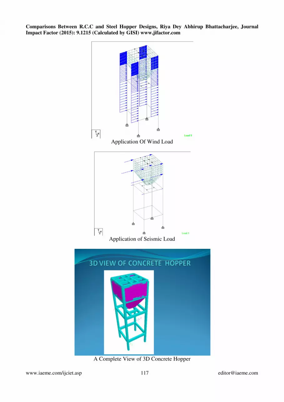
Application Of Wind Load
Application of Seismic Load
A Complete View of 3D Concrete Hopper
nd Steel Hopper Designs, Riya Dey Abhirup Bhattacharjee, Journal

Comparisons Between R.C.C and Steel Hopper Designs, Riya Dey Abhirup Bhattacharjee, Journal Impact Factor (2015): 9.1215 (Calculated by GISI) www.jifactor.com
www.iaeme.com/ijciet.asp 118 [email protected]
Maximum Moment Affecting Zone
Maximum Shear Force Affecting Zone
Grade of concrete M 25 Grade of steel fy = fe 500
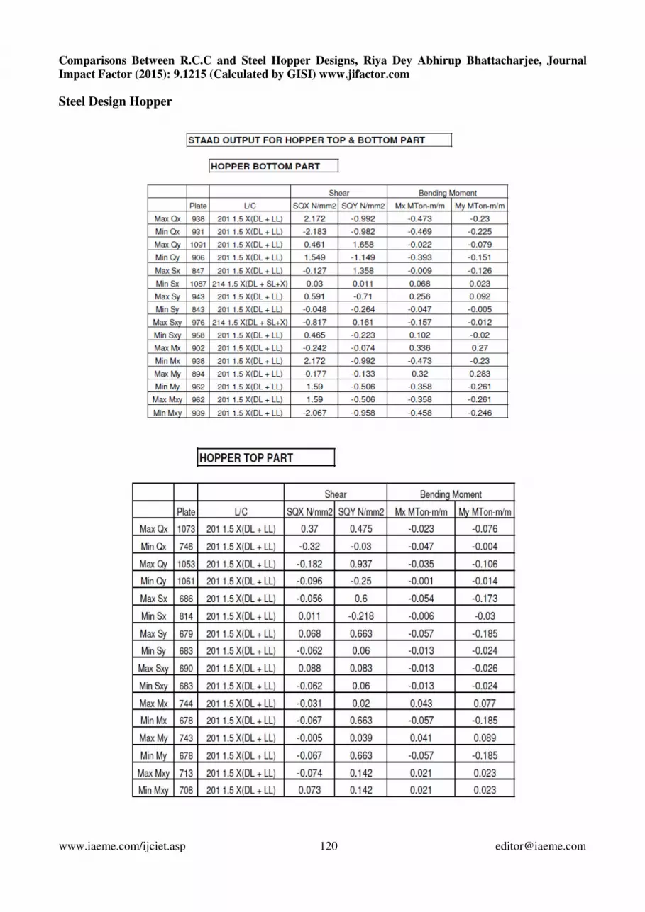
MOMENT FROM STAAD OUT PUT
HOPPER TOP PART HOPPER BOTTOM PART
VERTICAL HORIZONTAL VERTICAL HORIZONTAL
MOMENT MOMENT MOMENT MOMENT
My Mx My Mx
KN-m/m KN-m/m KN-m/m KN-m/m
5.00 10.00 5.000 10.00
HOPPER TOP PLATE
VERTICAL REINFORCEMENT
Depth of the Raft D = 250 mm
Clear cover d ' = 25 mm Bar diameter = 12 mm
Effective depth d = 219 mm
Comparisons Between R.C.C and Steel Hopper Designs, Riya Dey Abhirup Bhattacharjee, Journal Impact Factor (2015): 9.1215 (Calculated by GISI) www.jifactor.com
www.iaeme.com/ijciet.asp 119 [email protected]
My/bd2 = (5x1000000)/(1000x219^2) = 0.10
Pt = 0.024 Pt provided= 0.200
Ast = (0.2/100)x(1000 x 219) = 438 mm2
Provide 12 Ø @ 125 mm c/c at bottom
Area of steel provided= 904.8 mm2
Provide steel= .41 %
HORIZONTAL REINFORCEMENT
Bar diameter = 12 mm
Effective depth d = 207 mm
Mx/bd2 = (10x1000000)/(1000x207^2) = 0.23
Pt = 0.054 Pt provided= 0.200
Ast = (0.2/100)x(1000 x 207) = 414 mm2
Provide 12 Ø @ 125 mm c/c at bottom
Area of steel provided= 904.779 mm2
Pt provided= 0.44
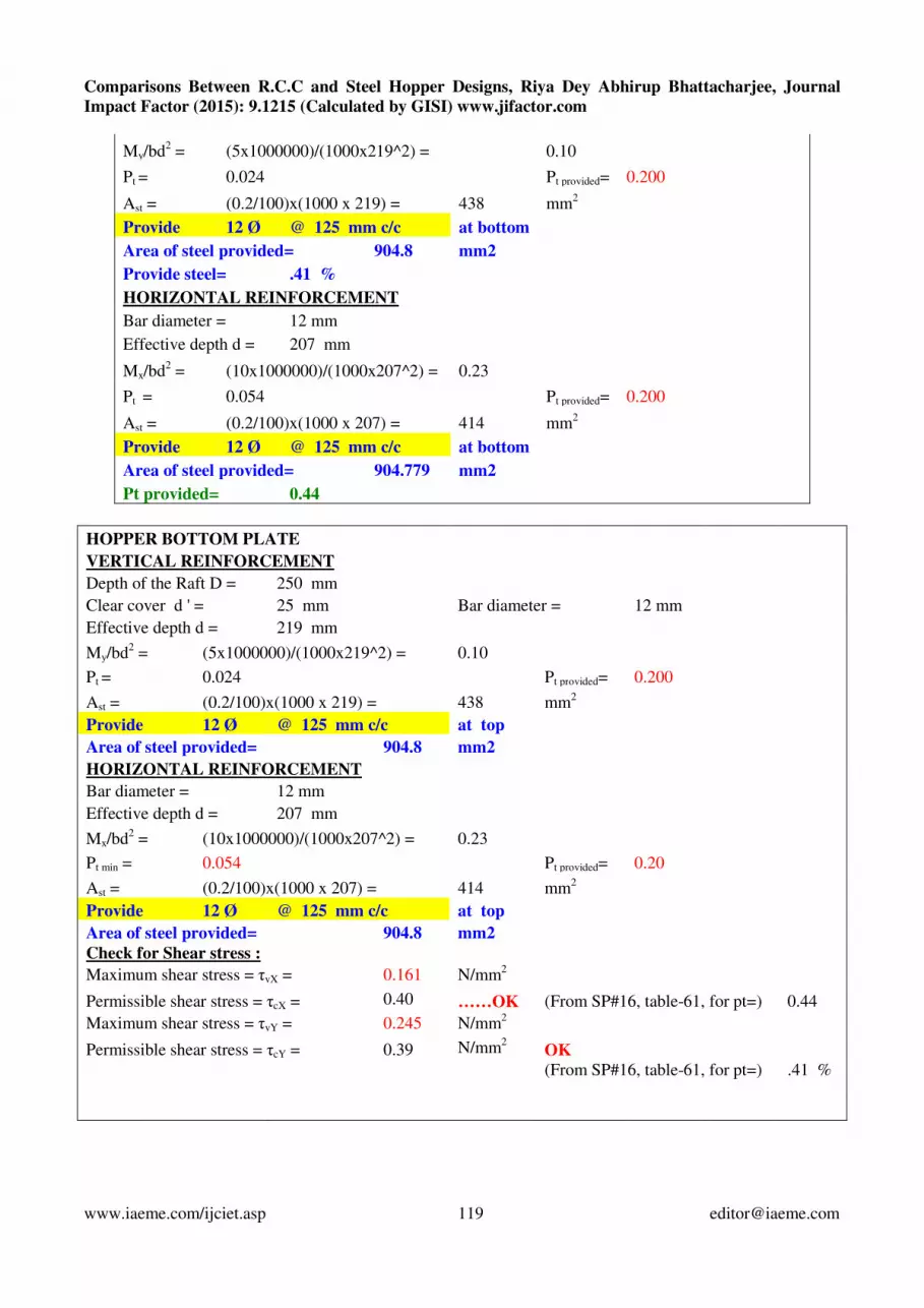
HOPPER BOTTOM PLATE
VERTICAL REINFORCEMENT
Depth of the Raft D = 250 mm
Clear cover d ' = 25 mm Bar diameter = 12 mm
Effective depth d = 219 mm
My/bd2 = (5x1000000)/(1000x219^2) = 0.10
Pt = 0.024 Pt provided= 0.200
Ast = (0.2/100)x(1000 x 219) = 438 mm2
Provide 12 Ø @ 125 mm c/c at top
Area of steel provided= 904.8 mm2
HORIZONTAL REINFORCEMENT
Bar diameter = 12 mm
Effective depth d = 207 mm
Mx/bd2 = (10x1000000)/(1000x207^2) = 0.23
Pt min = 0.054 Pt provided= 0.20
Ast = (0.2/100)x(1000 x 207) = 414 mm2
Provide 12 Ø @ 125 mm c/c at top
Area of steel provided= 904.8 mm2
Check for Shear stress :
Maximum shear stress = τvX = 0.161 N/mm2
Permissible shear stress = τcX = 0.40 ……OK (From SP#16, table-61, for pt=) 0.44
Maximum shear stress = τvY = 0.245 N/mm2
Permissible shear stress = τcY = 0.39 N/mm2 OK
(From SP#16, table-61, for pt=) .41 %
Comparisons Between R.C.C and Steel Hopper Designs, Riya Dey Abhirup Bhattacharjee, Journal Impact Factor (2015): 9.1215 (Calculated by GISI) www.jifactor.com
www.iaeme.com/ijciet.asp 120 [email protected]
Steel Design Hopper

Comparisons Between R.C.C and Steel Hopper Designs, Riya Dey Abhirup Bhattacharjee, Journal Impact Factor (2015): 9.1215 (Calculated by GISI) www.jifactor.com
www.iaeme.com/ijciet.asp 121 [email protected]
Maximum moment Affecting Zone
Maximum Shear force Affecting Zone
A 3D view of Steel Hopper

Comparisons Between R.C.C and Steel Hopper Designs, Riya Dey Abhirup Bhattacharjee, Journal Impact Factor (2015): 9.1215 (Calculated by GISI) www.jifactor.com
www.iaeme.com/ijciet.asp 122 [email protected]
SN No. Description Concrete Structure Steel Structure
1.
Size Of Foundation
2.5*2.5*0.40
Approx. Concrete quantity for
4 FDN – 10.0 Cu.Cm
1.75 X 1.75 X 0.40
APPROX CONCRETE QTY
FOR 4 FDN = 5.0 CUM
2.
Quantity Of Material
TOTAL CONCRETE QTY
= 37 CUM
TOTAL REINF. BAR QTY
= 14.0 TON
TOTAL STEEL QTY
= 17 TON
TOTAL CONCRETE QTY
= 7.5 CUM
3.
Thickness Of Hopper Wall 250 MM 10 MM
4.
Cost Estimate Of Structure 14.50 LAKHS 16.80 LAKHS
5.
Durability MORE DURABLE THAN
STEEL STRUCTURE
LESS DURABLE THAN
CONCRETE STRUCTURE
6.
Repair REPAIR WORK IN EASIER
& CHEAPER
REPAIR WORK IS
COSTLIER
7.
Relocation of Structure RELOCATION IS NOT
POSSIBLE
EASY TO RELOCATE THE
STRUCTURE AS PER
REQUIREMENT
8.
Looks
Detailed Comparison between RCC and Steel Hoppers CONCLUSION
Thickness Of hopper is 250 mm for RCC hopper and it has got more dead weight and
whereas the thickness of steel hopper slab is 10 mm as a matter of which the dead weight is much
less. Overall expense is higher in steel hopper in comparison to RCC Hopper. The RCC hoppers are
more stable and durable. The steel hoppers are easy to relocate, cost effective for long usage and
basically suitable in mining areas.

Comparisons Between R.C.C and Steel Hopper Designs, Riya Dey Abhirup Bhattacharjee, Journal Impact Factor (2015): 9.1215 (Calculated by GISI) www.jifactor.com
www.iaeme.com/ijciet.asp 123 [email protected]
REFERENCES 1. Indian standard Codes of [456,1893 Part - II,875,800]
2. AISC 360-05
3. Bridging the rheologyog granular flows Sebastian chivalo, Jin Sun, Sankaran sundareasan
American Pysical Soceity
4. Quantity Estimation Modeling of hr rice plant hopper infestation area on rice stems based on
2D Wavelet packet transform and corner detection algorithm Elsevier Science Publishers
Zhiyan Zhou, Ying Zang , Menglu Yan, Xiwen Luo
5. Near field 3D CFD modeling of over flow Plumes
6. Finite elment Analysis of a Stiffened Steel Silo International Journal of Civil and Structural
Engg. Research.
7. Sohel Ahmed Quadri and Mangulkar Madhuri N, “Investigation of The Critical Direction of
Seismic Force For The Analysis of R.C.C Frames” International Journal of Civil Engineering
& Technology (IJCIET), Volume 5, Issue 6, 2012, pp. 10 - 15, ISSN Print: 0976 – 6308, ISSN
Online: 0976 – 6316.
8. Dr. B. Ramesh Babu, “Neural Network Model For Design of One-Way R.C.C Slabs”
International Journal of Civil Engineering & Technology (IJCIET), Volume 5, Issue 3, 2014,
pp. 71 - 76, ISSN Print: 0976 – 6308, ISSN Online: 0976 – 6316.
9. Dr. B. Ramesh Babu, “Neural Network Model For Design of One-Way R.C.C Slabs Using
Ga/Bpn” International Journal of Civil Engineering & Technology (IJCIET), Volume 5, Issue
3, 2014, pp. 100 - 106, ISSN Print: 0976 – 6308, ISSN Online: 0976 – 6316.