Embed Size (px)
Citation preview
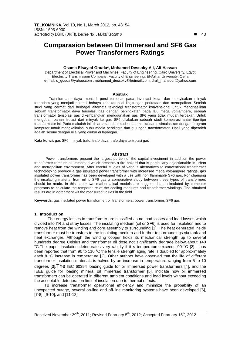
TELKOMNIKA, Vol.10, No.1, March 2012, pp. 43~54 ISSN: 1693-6930 accredited by DGHE (DIKTI), Decree No: 51/Dikti/Kep/2010 � 43
Received November 29th, 2011; Revised February 5th, 2012; Accepted February 15th, 2012
Comparasion between Oil Immersed and SF6 Gas Power Transformers Ratings
Osama Elsayed Gouda*, Mohamed Dessoky Ali, Ali-Hassan Department of Electrical Power and Machines, Faculty of Engineering, Cairo University, Egypt
Electricity Transmission Company, Faculty of Engineering, El-Azhar University, Qena e-mail: [email protected] , [email protected], [email protected]
Abstrak Transformator daya menjadi porsi terbesar pada investasi kota, dan menyisakan minyak
terendam yang menjadi potensi bahaya kebakaran di lingkungan perkotaan dan metropolitan. Setelah studi yang cermat dari berbagai alternatif teknologi transformator konvensional untuk menghasilkan sebuah transformator daya terisolasi gas dengan peningkatan pada laju mega volt-ampere, sebuah transformator terisolasi gas dikembangkan menggunakan gas SF6 yang tidak mudah terbakar. Untuk mengubah bahan isolasi dari minyak ke gas SF6 dilakukan sebuah studi komparasi antar tipe-tipe transformator ini. Pada makalah ini, disarankan dua model matematika dan disimulasikan dengan program komputer untuk mengkalkulasi suhu media pendingin dan gulungan transformator. Hasil yang diperoleh adalah sesuai dengan nilai yang diukur di lapangan.
Kata kunci: gas SF6, minyak trafo, trafo daya, trafo daya terisolasi gas
Abstract Power transformers present the largest portion of the capital investment in addition the power transformer remains oil immersed which presents a fire hazard that is particularly objectionable in urban and metropolitan environment. After careful studies of various alternatives to conventional transformer technology to produce a gas insulated power transformer with increased mega volt-ampere ratings, gas insulated power transformer has been developed with a use with non flammable SF6 gas. For changing the insulating material from oil to SF6 gas a comparative study between these types of transformers should be made. In this paper two mathematical models are suggested and simulated by computer programs to calculate the temperature of the cooling mediums and transformer windings. The obtained results are in agreement wit the measured values in the field.
Keywords: gas insulated power transformer, oil transformers, power transformer, SF6 gas 1. Introduction The energy losses in transformer are classified as no load losses and load losses which divided into I2R and stray losses. The insulating medium (oil or SF6) is used for insulation and to remove heat from the winding and core assembly to surrounding [1]. The heat generated inside transformer must be transfers to the insulating medium and further to surroundings via tank and heat exchanger. Although the winding copper holds its mechanical strength up to several hundreds degree Celsius and transformer oil dose not significantly degrade below about 140 oC.The paper insulation deteriorates very rabidly if it s temperature exceeds 90 oC [2].It has been reported that from 90 to 110 oC the tensile strength aging rate is doubled for approximately each 8 oC increase in temperature [2]. Other authors have observed that the life of different transformer insulation materials is halved by an increase in temperature ranging from 5 to 10
degrees [3].The IEC 60354 loading guide for oil immersed power transformers [4], and the IEEE guide for loading mineral oil immersed transformer [5], indicate how oil immersed transformers can be operated in different ambient conditions and load levels without exceeding the acceptable deterioration limit of insulation due to thermal effects. To increase transformer operational efficiency and minimize the probability of an unexpected outage, several on-line and off-line monitoring systems have been developed [6], [7-8], [9-10], and [11-12].
�
TELKOMNIKA Vol. 10, No. 1
44
Direct measurement of ahas been increasing since the mid 2. Thermal Models of Power Transformers2. 1. Thermal Model of Oil Power Transformer
The final thermal over all model for oilbased on the thermal-electrical analogy and heat transfer theory [17], [18], [19].
Figure 1. Thermal over all circuit models
where: qtot is the total losses; qheat generated in the winding; Rambient temperature; θhs is the hot spot temperature; θ
Rth-hs-oil is the non linear winding to oil thermal resistance; Ccapacitance and Cth-oil is the oilload and load transformer losses are represented by two ideal heat sources [19], [20]. The ambient temperature is represented as ideal temperature source [19], [20]. The nonlinearities i.e., oil viscosity and other transformer oil parameter changes and loss variation with temperature are taken into account by employing non The differential equations of the thermal circuits that given in Figure 1 for modeling both the top oil temperature and the hot spot temperature respectively are as follows [17]:
noilpunpunpu
npu
epul
kC
RKPR 2,
1)(1
ρβ
µ
β
θ
×××
×+
××+
noilpunpunpu
npu
pu
hswdnpu
kC
PK )(2
ρβµ
βθ
×××
××
Where:
R is the ratio of rated load losses and no load losses [21]K is the load factor [21]; µpu is the oil viscosity per unit value [17];Coilpu is the specific heat capacity of oil in per unit value;βpu is the coefficient of thermal cubic expansion in per unit value;kpu is the thermal conductivity of oil in per unit value;ρpu is the oil density in per unit value;
1, March 2012 : 43 – 54
Direct measurement of actual transformer winding temperatures using fiber optic probes has been increasing since the mid-1980s [13],[14],[15],[16].
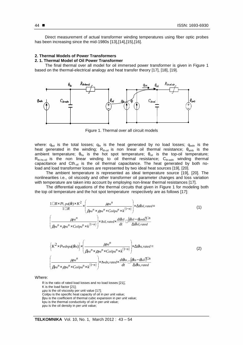
2. Thermal Models of Power Transformers Thermal Model of Oil Power Transformer The final thermal over all model for oil immersed power transformer is given in Figure 1
electrical analogy and heat transfer theory [17], [18], [19].
Figure 1. Thermal over all circuit models
is the total losses; qfe is the heat generated by no load losses; qheat generated in the winding; Rth-oil is non linear oil thermal resistance;
is the hot spot temperature; θoil is the topar winding to oil thermal resistance; Cth-wdn
the oil thermal capacitance. The heat generated by both noload and load transformer losses are represented by two ideal heat sources [19], [20].
The ambient temperature is represented as ideal temperature source [19], [20]. The nonlinearities i.e., oil viscosity and other transformer oil parameter changes and loss variation with temperature are taken into account by employing non-linear thermal resistances [17].
The differential equations of the thermal circuits that given in Figure 1 for modeling both the top oil temperature and the hot spot temperature respectively are as follows [17]:
( )ratedoil
namboiloilratedoil
n
ratedoilnnoilpunpunpu
npu
dtd
k
kC
,
1,
1
,1
θθθθτ
θρβ
µ
∆−+××
=∆××××
+
−
−
( )ratedhs
noilhshsratedwdn
n
ratedhsnnoilpunpunpu
npu
dtd
k
kC
,
1,
1
,1
θθθθτ
θρ
µ
∆−+××
=∆××××
+
−
−
R is the ratio of rated load losses and no load losses [21];
µpu is the oil viscosity per unit value [17]; is the specific heat capacity of oil in per unit value;
βpu is the coefficient of thermal cubic expansion in per unit value; kpu is the thermal conductivity of oil in per unit value; ρpu is the oil density in per unit value;
ISSN: 1693-6930
ctual transformer winding temperatures using fiber optic probes
immersed power transformer is given in Figure 1 electrical analogy and heat transfer theory [17], [18], [19].
is the heat generated by no load losses; qwdn is the is non linear oil thermal resistance; θamb is the
is the top-oil temperature; winding thermal
thermal capacitance. The heat generated by both no-load and load transformer losses are represented by two ideal heat sources [19], [20].
The ambient temperature is represented as ideal temperature source [19], [20]. The nonlinearities i.e., oil viscosity and other transformer oil parameter changes and loss variation
hermal resistances [17]. The differential equations of the thermal circuits that given in Figure 1 for modeling both
the top oil temperature and the hot spot temperature respectively are as follows [17]:
(1)
(2)
TELKOMNIKA ISSN: 1693-6930 �
Comparasion between Oil Immersed and SF6 Gas Power …. (Osama Elsayed Gouda)
45
θamb is the ambient temperature ; θoil is the top oil temperature; ∆θoil is the rated top oil temperature rise over ambient temperature; ∆θhs,is the rated hot spot temperature rise over top oil; Pl, pu (θe) is the temperature dependence on the load losses in per unit value; Pwdnpu (θhs) is the winding losses dependence on temperature losses in per unit value; τoil,rated is the rated oil time constant [22]; Τwdn, rated is the rated winding time constant and n is constant equal to 0.25 [17].
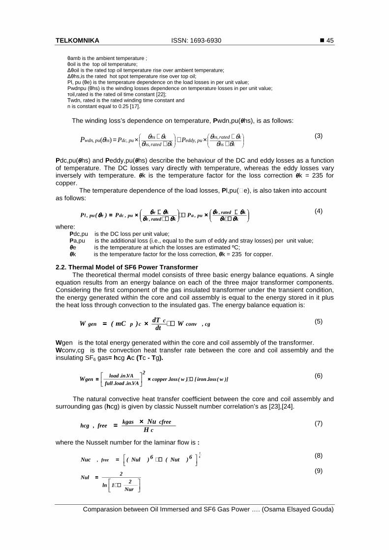
The winding loss’s dependence on temperature, Pwdn,pu(θhs), is as follows:
++×++
+×=khs
kratedhspueddy
kratedhs
khspudchspuwdn PPP θθ
θθθθ
θθθ ,,
,,, )(
(3)
Pdc,pu(θhs) and Peddy,pu(θhs) describe the behaviour of the DC and eddy losses as a function of temperature. The DC losses vary directly with temperature, whereas the eddy losses vary inversely with temperature. θk is the temperature factor for the loss correction θk = 235 for copper.
The temperature dependence of the load losses, Pl,pu(�e), is also taken into account as follows:
++++++++++++++++
++++××××==== ××××ke
krated,epu,a
krated,eke
pu,dcepu,l PP)(P θθθθθθθθθθθθθθθθ
θθθθθθθθθθθθθθθθθθθθ (4)
where: Pdc,pu is the DC loss per unit value; Pa,pu is the additional loss (i.e., equal to the sum of eddy and stray losses) per unit value; θe is the temperature at which the losses are estimated ºC; θk is the temperature factor for the loss correction, θk = 235 for copper.
2.2. Thermal Model of SF6 Power Transformer
The theoretical thermal model consists of three basic energy balance equations. A single equation results from an energy balance on each of the three major transformer components. Considering the first component of the gas insulated transformer under the transient condition, the energy generated within the core and coil assembly is equal to the energy stored in it plus the heat loss through convection to the insulated gas. The energy balance equation is:
cg,convc
cpgen Wdt
dT)mC(W ++++××××==== (5)
Wgen is the total energy generated within the core and coil assembly of the transformer. Wconv,cg is the convection heat transfer rate between the core and coil assembly and the insulating SF6 gas= hcg Ac (Tc - Tg).
)]w(loss.iron[)w(loss.copper2
VA.in.load.fullVA.in.load
genW ++++××××
==== (6)
The natural convective heat transfer coefficient between the core and coil assembly and
surrounding gas (hcg) is given by classic Nusselt number correlation’s as [23],[24].
ccfreekgas
free,hcgH
Nu××××==== (7)
where the Nusselt number for the laminar flow is :
6
1
6)Nut(6)Nul(Nuc free,
++++==== (8)
++++====
Nur2
1ln
2Nul
(9)
� ISSN: 1693-6930
TELKOMNIKA Vol. 10, No. 1, March 2012 : 43 – 54
46
4
1
gaslr RacNu ××××==== (10)
)RaPr104.11(
RaCNu
gas
gas
gas
9
31t
t
××××++++
××××==== (11)
gas
gas
cgcgasgascg PrH)TT(gRa 2
32××××××××−−−−××××××××××××====
µµµµρρρρββββ (12)
gas
pgasgasgas
kCPr ××××==== µµµµ (13)
94169ga
l])sPr/492.0(1[
671.0C
++++==== (14)
42.0gas
22.0
t
)Pr61.01(
gasPr13.0C
81.0××××++++××××==== (15)
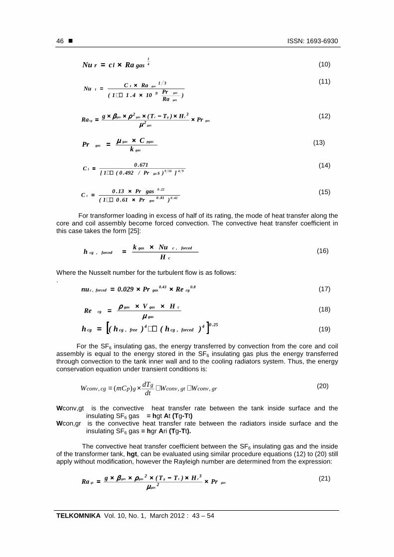
For transformer loading in excess of half of its rating, the mode of heat transfer along the core and coil assembly become forced convection. The convective heat transfer coefficient in this case takes the form [25]:
c
forced,cgasforced,cg
HNuk
h××××==== (16)
Where the Nusselt number for the turbulent flow is as follows: .
8.0cg
43.0gasforced,c RePr029.0nu ××××××××==== (17)
gas
cgasgascg
HVRe
µµµµρρρρ ××××××××==== (18)
[[[[ ]]]] 25.04forced,cg
4free,cgcg )h()h(h ++++==== (19)
For the SF6 insulating gas, the energy transferred by convection from the core and coil assembly is equal to the energy stored in the SF6 insulating gas plus the energy transferred through convection to the tank inner wall and to the cooling radiators system. Thus, the energy conservation equation under transient conditions is:
grconvgtconvg
gpcgconv WWdt
dTmCW ,,, )( ++×= (20)
Wconv,gt is the convective heat transfer rate between the tank inside surface and the
insulating SF6 gas = hgt At (Tg-Tt) Wcon,gr is the convective heat transfer rate between the radiators inside surface and the
insulating SF6 gas = hgr Ari (Tg-Tt). The convective heat transfer coefficient between the SF6 insulating gas and the inside of the transformer tank, hgt, can be evaluated using similar procedure equations (12) to (20) still apply without modification, however the Rayleigh number are determined from the expression:
gas
gas
ttggasgasgt PrH)TT(gRa 2
32××××××××−−−−××××××××××××====
µµµµρρρρββββ (21)
TELKOMNIKA ISSN: 1693-6930 �
Comparasion between Oil Immersed and SF6 Gas Power …. (Osama Elsayed Gouda)
47
gas
gasgasgas
kCp
Pr××××==== µµµµ (22)
gas
tgasgasgt
HVRe µµµµρρρρ ××××××××==== (23)
where Ht is the height of the transformer tank and the convective heat transfer coefficients are given by:
t
free,tigasfree,gt
HNukh ××××==== (24)
t
forced,tigasforced,gt
HNukh ××××==== (25)
The following correlation has been proposed for conditions which result in combined free and forced convection between the tank inside surface and the SF6 insulating gas [23]:
25.04)forced,hgt(4)free,hgt(h gt
++++==== (26)
Convection heat transfer coefficient (hgr)
r
free,grgasfree,gr
DNkh u××××==== (27)
Where Dr is the cooling tube diameter
3131
r
rgasfree,grfree,gr
HD)Pr(Re86.1Nu
××××==== (28)
gas
rfree,gasgasfree,gr
DVRe µµµµρρρρ ××××××××==== (29)
The natural or free convection velocity Vgas,free was measured using laser velocimeter [24] and found to be about 0.3 m/sec. The following relation for evaluation of the Nusselt number in flow through along tube is recommended [26]:
4.0gasforced,gr
8.0forced,gr PrRe023.0Nu ××××××××==== For turbulent (30)
31)sPr(Re86.1Nu gaforced,grforced,gr ××××××××==== For laminar (31)
gas
rforced,gasgasforced,gr
DVRe µµµµρρρρ ××××××××==== (32)
The heat transfer coefficient in this case can be determined using the expression:
r
forced,grgasforced,gr
DNkh u××××==== (33)
The following correlation has been proposed for conditions which result in combined free and forced convection between the inside of the cooling tubes and the SF6 insulating gas [23]:
25.04)forced,hgr(4)free,hgr(h gr
++++==== (34)
At the out side surface of the tank and the cooling radiators, the energy transferred through convection to the tank and cooling radiators from the insulating SF6 gas, are balanced
� ISSN: 1693-6930
TELKOMNIKA Vol. 10, No. 1, March 2012 : 43 – 54
48
by the energy stored in the tank plus the convective and radiative energy losses to the atmosphere. Therefore, the energy conservation equation is:
taradraradraconvta
convt
tpgrconvgtconv
WWW
Wdt
dTWW mC
,,,
,,, )(
+++
+=+ (35)
where Wconv,ta is the rate of heat flow by convection between the transformer tank outside surface and the ambient air =
)( attta TTAh −× .
Wconv,ra is the rate of heat flow by convection between the outside surface of the radiators and the ambient air =
)]([ atririroro TTAhAh −×+×
Wrad,ta is the rate of heat flow by radiation from the transformer tank outside surface to the ambient air
)( 44 TaTtA tot −×××= εσ
Wrad,ra is the rate of heat flow by radiation from the outside surface of the radiators cooling system to the ambient
air = )]([ 44atutoro TTFAA ri −×+× εσ
The free convection heat transfer Nusselt number can be approximated by the expression [25]:
+
×+=278169
61
,
492.01
387.0825.0
air
tafreeta
pr
RaNu
(36)
where
air
air
tatairaita
HTTrgRa Pr
)(2
32
××−×××=µ
ρβ (37)
The convective heat transfer coefficient for free convection between the outside of the tank and the air is given by:
t
free,taairfree,ta
HNukh ××××==== (38)
In case of forced convection the following expression can be used to evaluate the average Nusselt number for turbulent flow over the external surface of the tank [26]:
8.0ta
43.0airforced,ta RePr029.0Nu ××××××××==== (39)
Where the Renold’s number, Re is defined as:
air
tairairta
HVRe
µµµµρρρρ ××××××××==== (40)
The convective heat transfer coefficient for forced convection between the tank outside surface and the air is:
t
forced,taairforced,ta
HNuk
h××××==== (41)
The following correlation has been proposed for conditions which result in combined free and forced convection between the outside enclosure of a tank and outside air [23]:
25.044 ])h()h[(h forced,tafree,tata ++++==== (42)
TELKOMNIKA ISSN: 1693-6930 �
Comparasion between Oil Immersed and SF6 Gas Power …. (Osama Elsayed Gouda)
49
Heat transfer for the outer fins is evaluated by [27]:
++++
××××++++==== 278169
air
61ra
ra
pr492.0
1
Ra387.0825.0Nu
(43)
air2air
3rat
2airair
ro PrH)TT(g
Ra ××××××××−−−−××××××××××××====
µµµµρρρρββββ (44)
The convective heat transfer coefficient for free convection between the outside of the radiators and the air is given by:
r
roairro
HNuk
h××××==== (45)
Heat transfer from the interior fin passages is evaluated by [27]:
××××−−−−−−−−====43
ri
riri
Ra
5.0exp1
RaNu ψψψψ
ψψψψ (46)
Where:
( ) ( )[ ]{ }32183.0 61.014.911)2/1(
))/17.0exp(483.01(24
−××−+×+−×−=
− vsa eaea
aψ (47)
airri
r
r
r
PrGrHrr
Ra
sL2sL2
r
Ls
a
465v
××××××××
====
++++××××××××××××====
====
−−−−====
(48)
rNurikair
hri××××==== (49)
The amount of heat transferred by a radiation depends upon a number of factors including surface temperature and emissivity. The radiation exchange factor for rectangular U-channel radiator Fu may be calculated following the same procedure described in [27].the factor Fu takes the form:
)l2S(H
C2Frr
netu
++++==== (50)
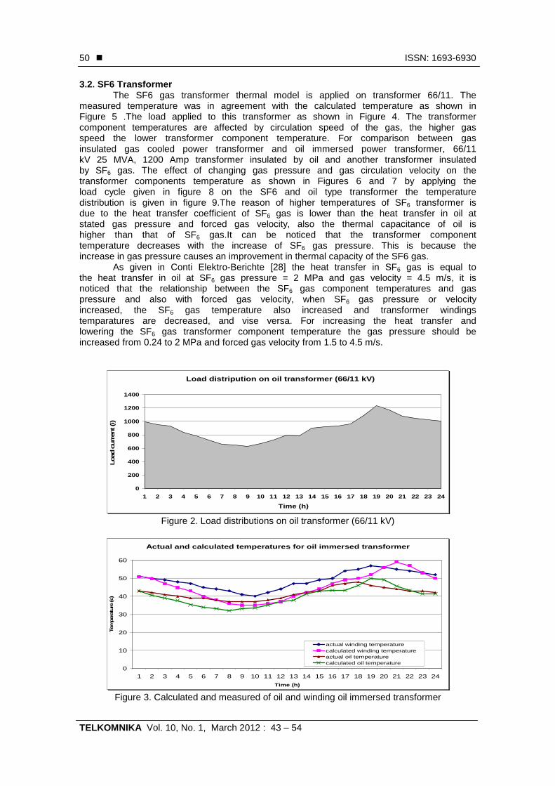
Cnet is the net radiation conductance. It is a function of the U-channel can be found is [27]. 3. Results and Dissection 3.1. Oil immersed transformer The suggested thermal model is applied on 66/11 kV transformer. The applied load as a function of time is given in Figure 2. The obtained results are compared with the measured values and agreement between them is noticed as shown in Figure 3.
� ISSN: 1693-6930
TELKOMNIKA Vol. 10, No. 1, March 2012 : 43 – 54
50
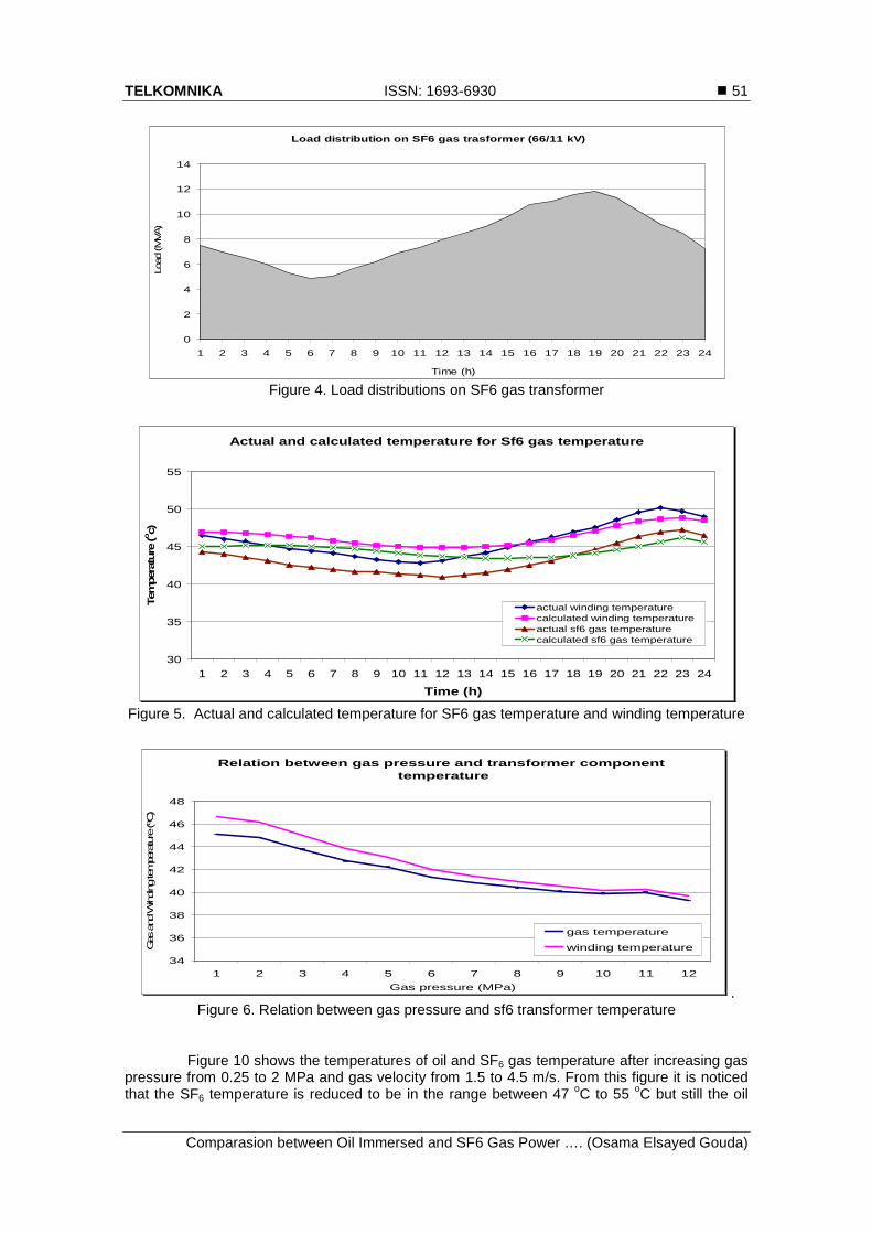
3.2. SF6 Transformer The SF6 gas transformer thermal model is applied on transformer 66/11. The
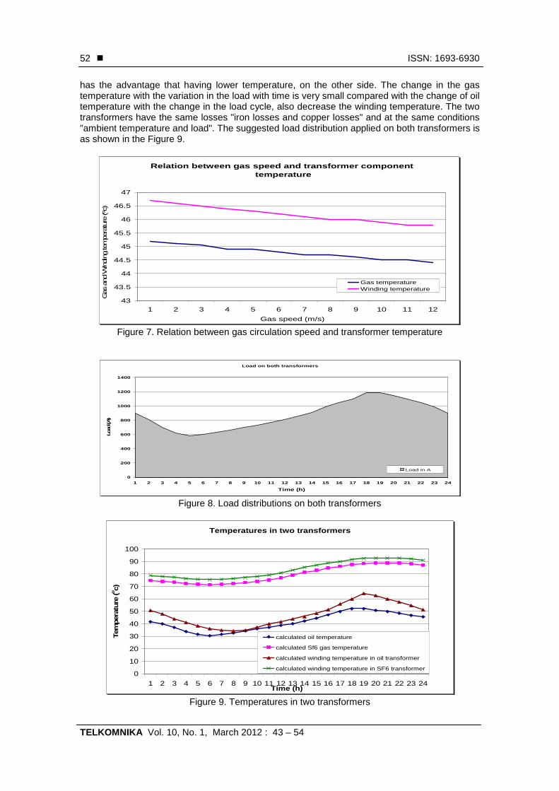
measured temperature was in agreement with the calculated temperature as shown in Figure 5 .The load applied to this transformer as shown in Figure 4. The transformer component temperatures are affected by circulation speed of the gas, the higher gas speed the lower transformer component temperature. For comparison between gas insulated gas cooled power transformer and oil immersed power transformer, 66/11 kV 25 MVA, 1200 Amp transformer insulated by oil and another transformer insulated by SF6 gas. The effect of changing gas pressure and gas circulation velocity on the transformer components temperature as shown in Figures 6 and 7 by applying the load cycle given in figure 8 on the SF6 and oil type transformer the temperature distribution is given in figure 9.The reason of higher temperatures of SF6 transformer is due to the heat transfer coefficient of SF6 gas is lower than the heat transfer in oil at stated gas pressure and forced gas velocity, also the thermal capacitance of oil is higher than that of SF6 gas.It can be noticed that the transformer component temperature decreases with the increase of SF6 gas pressure. This is because the increase in gas pressure causes an improvement in thermal capacity of the SF6 gas.
As given in Conti Elektro-Berichte [28] the heat transfer in SF6 gas is equal to the heat transfer in oil at SF6 gas pressure = 2 MPa and gas velocity = 4.5 m/s, it is noticed that the relationship between the SF6 gas component temperatures and gas pressure and also with forced gas velocity, when SF6 gas pressure or velocity increased, the SF6 gas temperature also increased and transformer windings temparatures are decreased, and vise versa. For increasing the heat transfer and lowering the SF6 gas transformer component temperature the gas pressure should be increased from 0.24 to 2 MPa and forced gas velocity from 1.5 to 4.5 m/s.
Figure 2. Load distributions on oil transformer (66/11 kV)
Figure 3. Calculated and measured of oil and winding oil immersed transformer
Load distripution on oil transformer (66/11 kV)
0
200
400
600
800
1000
1200
1400
1 2 3 4 5 6 7 8 9 10 11 12 13 14 15 16 17 18 19 20 21 22 23 24
Time (h)
Load
curr
ent (i)
Actual and calculated temperatures for oil immersed transformer
0
10
20
30
40
50
60
1 2 3 4 5 6 7 8 9 10 11 12 13 14 15 16 17 18 19 20 21 22 23 24
Time (h)
Tem
per
ature
(c)
actual winding temperaturecalculated winding temperatureactual oil temperaturecalculated oil temperature
TELKOMNIKA ISSN: 1693-6930 �
Comparasion between Oil Immersed and SF6 Gas Power …. (Osama Elsayed Gouda)
51
Figure 4. Load distributions on SF6 gas transformer
Figure 5. Actual and calculated temperature for SF6 gas temperature and winding temperature
. Figure 6. Relation between gas pressure and sf6 transformer temperature
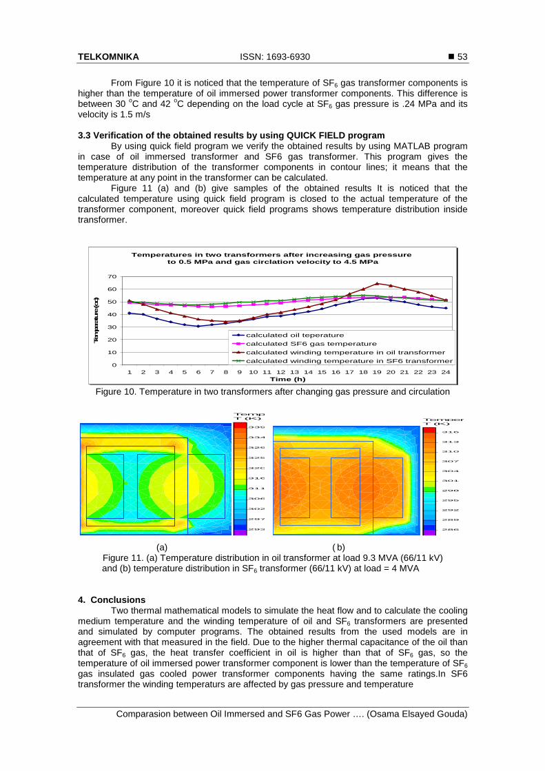
Figure 10 shows the temperatures of oil and SF6 gas temperature after increasing gas pressure from 0.25 to 2 MPa and gas velocity from 1.5 to 4.5 m/s. From this figure it is noticed that the SF6 temperature is reduced to be in the range between 47 oC to 55 oC but still the oil
Load distribution on SF6 gas trasformer (66/11 kV)
0
2
4
6
8
10
12
14
1 2 3 4 5 6 7 8 9 10 11 12 13 14 15 16 17 18 19 20 21 22 23 24
Time (h)
Load
(M
VA)
Actual and calculated temperature for Sf6 gas temperature
30
35
40
45
50
55
1 2 3 4 5 6 7 8 9 10 11 12 13 14 15 16 17 18 19 20 21 22 23 24
Time (h)
Tem
per
ature
(oc)
actual winding temperaturecalculated winding temperatureactual sf6 gas temperaturecalculated sf6 gas temperature
Relation between gas pressure and transformer component temperature
34
36
38
40
42
44
46
48
1 2 3 4 5 6 7 8 9 10 11 12
Gas pressure (MPa)
Gas
and
Winding
tempe
rature
(ºC
)
gas temperature
winding temperature
� ISSN: 1693-6930
TELKOMNIKA Vol. 10, No. 1, March 2012 : 43 – 54
52
has the advantage that having lower temperature, on the other side. The change in the gas temperature with the variation in the load with time is very small compared with the change of oil temperature with the change in the load cycle, also decrease the winding temperature. The two transformers have the same losses "iron losses and copper losses" and at the same conditions "ambient temperature and load". The suggested load distribution applied on both transformers is as shown in the Figure 9.
Figure 7. Relation between gas circulation speed and transformer temperature
Figure 8. Load distributions on both transformers
Figure 9. Temperatures in two transformers
Relation between gas speed and transformer component temperature
43
43.5
44
44.5
45
45.5
46
46.5
47
1 2 3 4 5 6 7 8 9 10 11 12
Gas speed (m/s)
Gas
and
Windi
ng te
mpe
ratu
re (ºc
)
Gas temperatureWinding temperature
Load on both transformers
0
200
400
600
800
1000
1200
1400
1 2 3 4 5 6 7 8 9 10 11 12 13 14 15 16 17 18 19 20 21 22 23 24
Time (h)
Load
(A)
Load in A
Temperatures in two transformers
0
10
20
30
40
50
60
70
80
90
100
1 2 3 4 5 6 7 8 9 10 11 12 13 14 15 16 17 18 19 20 21 22 23 24Time (h)
Tem
per
ature
(oc)
calculated oil temperature
calculated Sf6 gas temperature
calculated winding temperature in oil transformer
calculated winding temperature in SF6 transformer
TELKOMNIKA ISSN: 1693-6930 �
Comparasion between Oil Immersed and SF6 Gas Power …. (Osama Elsayed Gouda)
53
From Figure 10 it is noticed that the temperature of SF6 gas transformer components is higher than the temperature of oil immersed power transformer components. This difference is between 30 oC and 42 oC depending on the load cycle at SF6 gas pressure is .24 MPa and its velocity is 1.5 m/s 3.3 Verification of the obtained results by using QUICK FIELD program
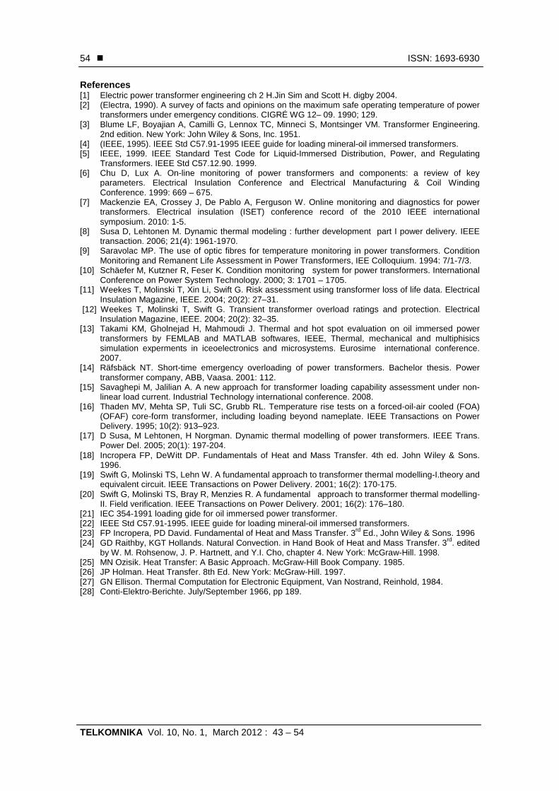
By using quick field program we verify the obtained results by using MATLAB program in case of oil immersed transformer and SF6 gas transformer. This program gives the temperature distribution of the transformer components in contour lines; it means that the temperature at any point in the transformer can be calculated.
Figure 11 (a) and (b) give samples of the obtained results It is noticed that the calculated temperature using quick field program is closed to the actual temperature of the transformer component, moreover quick field programs shows temperature distribution inside transformer.
Figure 10. Temperature in two transformers after changing gas pressure and circulation
(a) ( b) Figure 11. (a) Temperature distribution in oil transformer at load 9.3 MVA (66/11 kV)
and (b) temperature distribution in SF6 transformer (66/11 kV) at load = 4 MVA 4. Conclusions
Two thermal mathematical models to simulate the heat flow and to calculate the cooling medium temperature and the winding temperature of oil and SF6 transformers are presented and simulated by computer programs. The obtained results from the used models are in agreement with that measured in the field. Due to the higher thermal capacitance of the oil than that of SF6 gas, the heat transfer coefficient in oil is higher than that of SF6 gas, so the temperature of oil immersed power transformer component is lower than the temperature of SF6 gas insulated gas cooled power transformer components having the same ratings.In SF6 transformer the winding temperaturs are affected by gas pressure and temperature
Temperatures in two transformers after increasing gas pressure to 0.5 MPa and gas circlation velocity to 4.5 MPa
0
10
20
30
40
50
60
70
1 2 3 4 5 6 7 8 9 10 11 12 13 14 15 16 17 18 19 20 21 22 23 24
Time (h)
Tem
per
ature
(oc)
calculated oil teperature
calculated SF6 gas temperature
calculated winding temperature in oil transformer
calculated winding temperature in SF6 transformer
TemperatureT (K)
339.0
334.4
329.8
325.2
320.6
316.0
311.4
306.8
302.2
297.6
293.0
TemperatureT (K)
316
313
310
307
304
301
298
295
292
289
286
� ISSN: 1693-6930
TELKOMNIKA Vol. 10, No. 1, March 2012 : 43 – 54
54
References [1] Electric power transformer engineering ch 2 H.Jin Sim and Scott H. digby 2004. [2] (Electra, 1990). A survey of facts and opinions on the maximum safe operating temperature of power
transformers under emergency conditions. CIGRÉ WG 12– 09. 1990; 129. [3] Blume LF, Boyajian A, Camilli G, Lennox TC, Minneci S, Montsinger VM. Transformer Engineering.
2nd edition. New York: John Wiley & Sons, Inc. 1951. [4] (IEEE, 1995). IEEE Std C57.91-1995 IEEE guide for loading mineral-oil immersed transformers. [5] IEEE, 1999. IEEE Standard Test Code for Liquid-Immersed Distribution, Power, and Regulating
Transformers. IEEE Std C57.12.90. 1999. [6] Chu D, Lux A. On-line monitoring of power transformers and components: a review of key
parameters. Electrical Insulation Conference and Electrical Manufacturing & Coil Winding Conference. 1999: 669 – 675.
[7] Mackenzie EA, Crossey J, De Pablo A, Ferguson W. Online monitoring and diagnostics for power transformers. Electrical insulation (ISET) conference record of the 2010 IEEE international symposium. 2010: 1-5.
[8] Susa D, Lehtonen M. Dynamic thermal modeling : further development part I power delivery. IEEE transaction. 2006; 21(4): 1961-1970.
[9] Saravolac MP. The use of optic fibres for temperature monitoring in power transformers. Condition Monitoring and Remanent Life Assessment in Power Transformers, IEE Colloquium. 1994: 7/1-7/3.
[10] Schäefer M, Kutzner R, Feser K. Condition monitoring system for power transformers. International Conference on Power System Technology. 2000; 3: 1701 – 1705.
[11] Weekes T, Molinski T, Xin Li, Swift G. Risk assessment using transformer loss of life data. Electrical Insulation Magazine, IEEE. 2004; 20(2): 27–31.
[12] Weekes T, Molinski T, Swift G. Transient transformer overload ratings and protection. Electrical Insulation Magazine, IEEE. 2004; 20(2): 32–35.
[13] Takami KM, Gholnejad H, Mahmoudi J. Thermal and hot spot evaluation on oil immersed power transformers by FEMLAB and MATLAB softwares, IEEE, Thermal, mechanical and multiphisics simulation experments in iceoelectronics and microsystems. Eurosime international conference. 2007.
[14] Räfsbäck NT. Short-time emergency overloading of power transformers. Bachelor thesis. Power transformer company, ABB, Vaasa. 2001: 112.
[15] Savaghepi M, Jalilian A. A new approach for transformer loading capability assessment under non-linear load current. Industrial Technology international conference. 2008.
[16] Thaden MV, Mehta SP, Tuli SC, Grubb RL. Temperature rise tests on a forced-oil-air cooled (FOA) (OFAF) core-form transformer, including loading beyond nameplate. IEEE Transactions on Power Delivery. 1995; 10(2): 913–923.
[17] D Susa, M Lehtonen, H Norgman. Dynamic thermal modelling of power transformers. IEEE Trans. Power Del. 2005; 20(1): 197-204.
[18] Incropera FP, DeWitt DP. Fundamentals of Heat and Mass Transfer. 4th ed. John Wiley & Sons. 1996.
[19] Swift G, Molinski TS, Lehn W. A fundamental approach to transformer thermal modelling-I.theory and equivalent circuit. IEEE Transactions on Power Delivery. 2001; 16(2): 170-175.
[20] Swift G, Molinski TS, Bray R, Menzies R. A fundamental approach to transformer thermal modelling-II. Field verification. IEEE Transactions on Power Delivery. 2001; 16(2): 176–180.
[21] IEC 354-1991 loading gide for oil immersed power transformer. [22] IEEE Std C57.91-1995. IEEE guide for loading mineral-oil immersed transformers. [23] FP Incropera, PD David. Fundamental of Heat and Mass Transfer. 3rd Ed., John Wiley & Sons. 1996 [24] GD Raithby, KGT Hollands. Natural Convection. in Hand Book of Heat and Mass Transfer. 3rd. edited
by W. M. Rohsenow, J. P. Hartnett, and Y.I. Cho, chapter 4. New York: McGraw-Hill. 1998. [25] MN Ozisik. Heat Transfer: A Basic Approach. McGraw-Hill Book Company. 1985. [26] JP Holman. Heat Transfer. 8th Ed. New York: McGraw-Hill. 1997. [27] GN Ellison. Thermal Computation for Electronic Equipment, Van Nostrand, Reinhold, 1984. [28] Conti-Elektro-Berichte. July/September 1966, pp 189.