Embed Size (px)
Citation preview
Unreinforced heavy-duty elastomeric bearing
Thermal separation in structural steelwork
COMPACT CORE BEARING
2 I
Bearing design formulaeContents Page
Product description 2
Design formulae 2
Material data 2
How to specify 3
Shape factors 3
Elastic deformation 1 4
Elastic deformation 2 5
Design table 1 (t = 5, 10 mm) 6
Design table 2 (t = 15, 20 mm) 7
Bearing design end plate butt joint 8-10
Spring reactions 10
Characteristics 11
Use and areas of application 11
Material 11
Dimensions, delivery forms 11
Test certificate, proof of suitability 12
Fire behaviour 12
Standard cut-outs 12
Product descriptionThe Calenberg Compact Core Bearing is
an unreinforced heavy-duty elastomeric
bearing with a smooth surface. The
red-brown colour of the material clearly
identifies the product.
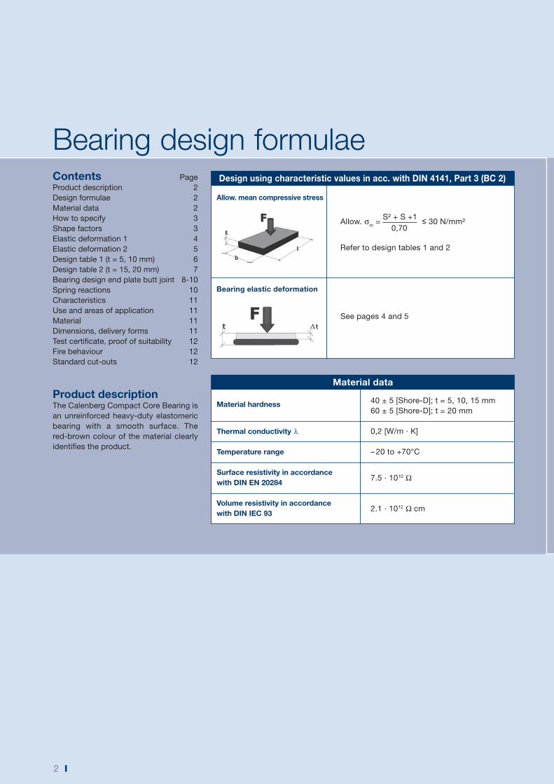
Design using characteristic values in acc. with DIN 4141, Part 3 (BC 2)
Allow. mean compressive stress
Allow. σm =
S² + S +1 ≤ 30 N/mm²
0,70
Refer to design tables 1 and 2
See pages 4 and 5
Bearing elastic deformation
Material data
Material hardness 40 ± 5 [Shore-D]; t = 5, 10, 15 mm
60 ± 5 [Shore-D]; t = 20 mm
Thermal conductivity λ 0,2 [W/m · K]
Temperature range – 20 to +70°C
Surface resistivity in accordance with DIN EN 20284
7.5 · 1010 Ω
Volume resistivity in accordance with DIN IEC 93
2.1 · 1012 Ω cm
I 3
Shape factor
How to specifySupply Calenberg Compact Core
Bearing, unreinforced homogeneous
elastomeric bearing in accordance with
DIN 4141 Part 3, bearing class 2,
through-coloured red-brown with smooth
surface, loadable depending on format
up to an average compressive stress of
30 N/mm², National Technical Approval
No. P-852.0448.
a) Standard InstallationLength: ……...... mm
Width: ……...... mm
Thickness: ……...... mm
Quantity: ……...... piece
Price: ……...... €/piece
b) Embedded in polystyrene or Ciflamon fire-proofing plateOverall width: ……...... mm
Elastomer width: ……...... mm
Thickness: ……...... mm
Quantity: ……...... m
Price: ……...... €/m
Supplier:Calenberg Ingenieure GmbH
Am Knübel 2-4
31020 Salzhemmendorf, Germany
Phone +49 (0) 51 53 / 94 00-0
Fax +49 (0) 51 53 / 94 00-49
d
bl
t
D
d
t
b
tl
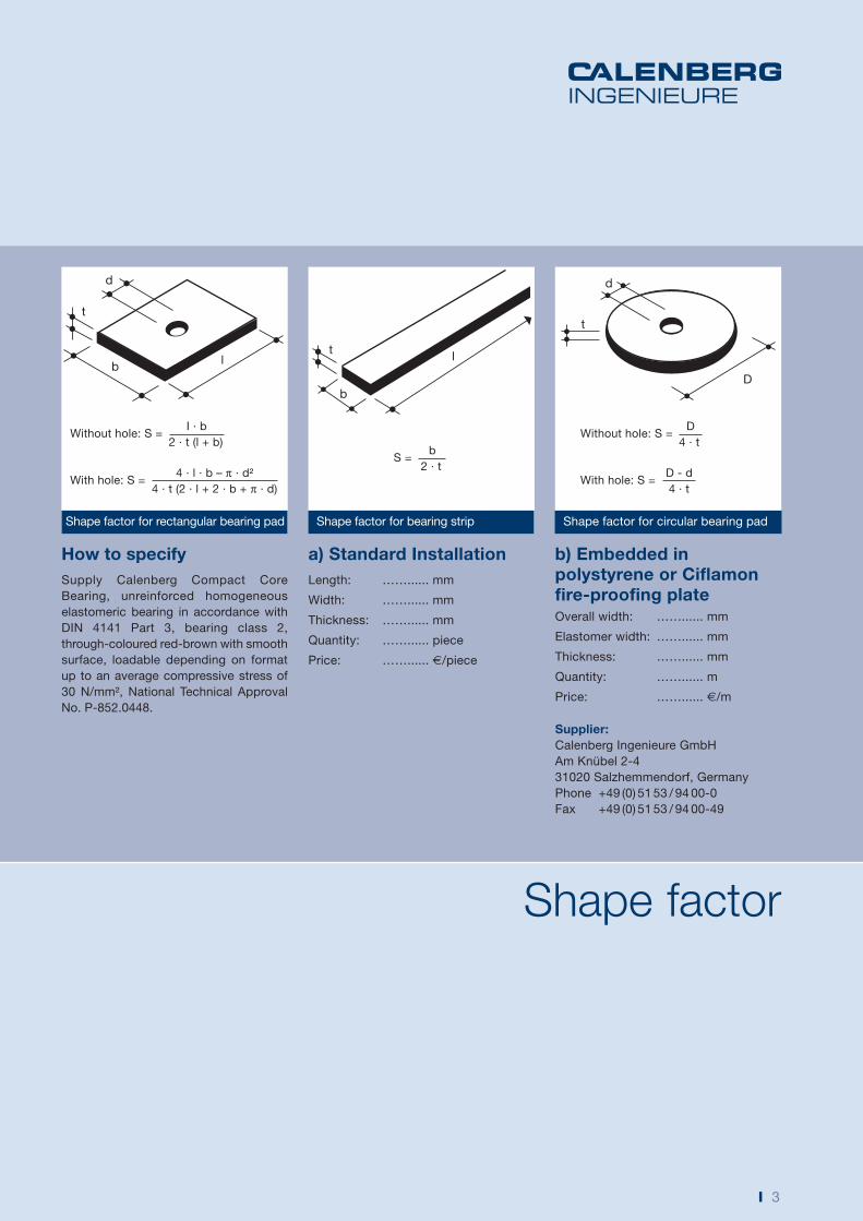
Without hole: S = I · b
2 · t (l + b)Without hole: S =
D
4 · t
With hole: S = D - d
4 · t
S = b
2 · t
With hole: S = 4 · l · b – π · d²
4 · t (2 · l + 2 · b + π · d)
Shape factor for rectangular bearing pad Shape factor for bearing strip Shape factor for circular bearing pad
4 I
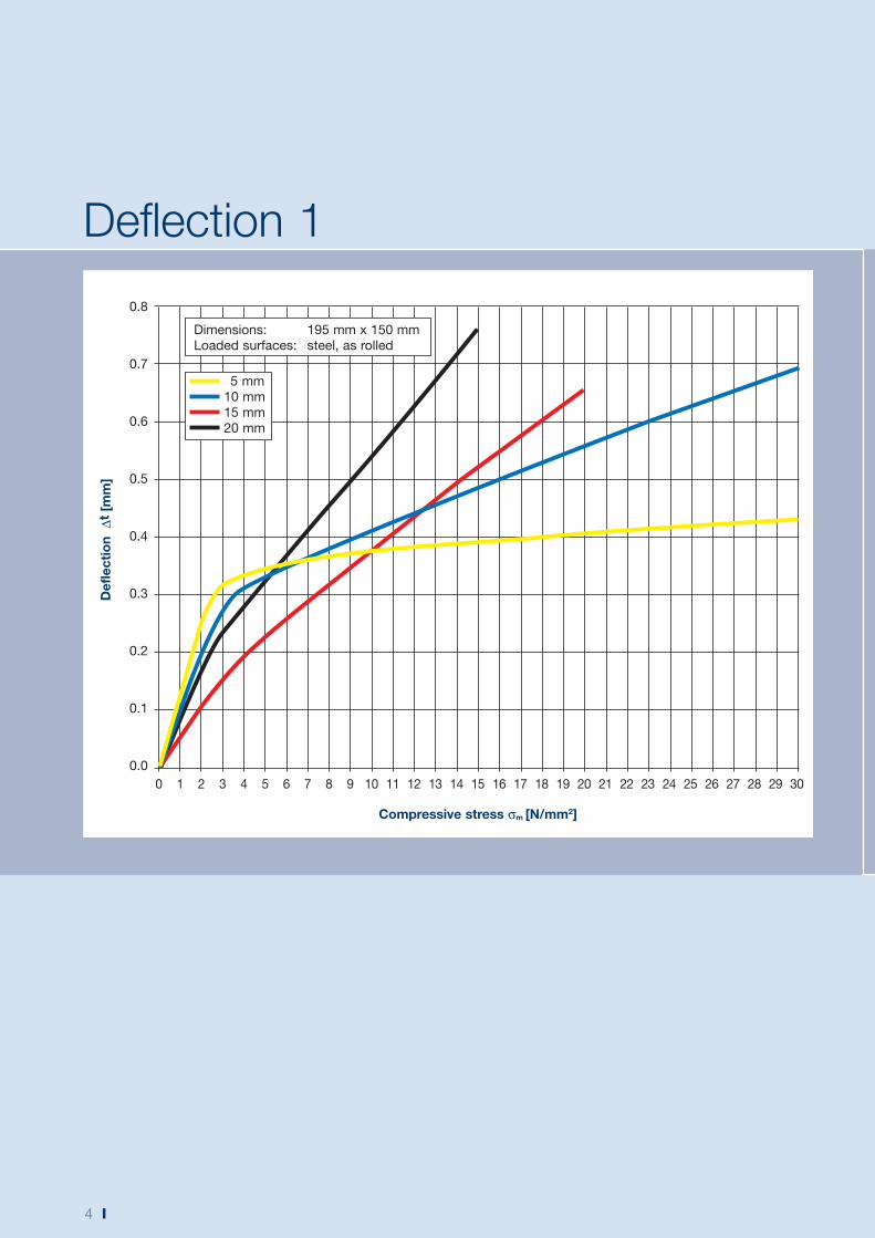
Deflection 1
Compressive stress σm [N/mm2]
0.8
0.7
0.6
0.5
0.4
0.3
0.2
0.1
0.0
Def
lect
ion
Δt
[mm
]
0 1 2 3 4 5 6 7 8 9 10 11 12 13 14 15 16 17 18 19 20 21 22 23 24 25 26 27 28 29 30
5 mm
10 mm
15 mm
20 mm
Dimensions: 195 mm x 150 mm
Loaded surfaces: steel, as rolled
I 5
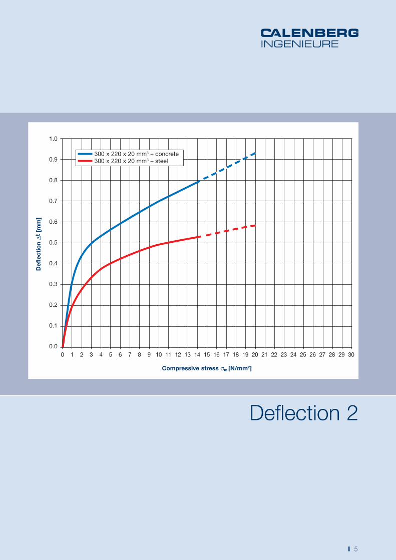
Deflection 2
Compressive stress σm [N/mm2]
1.0
0.9
0.8
0.7
0.6
0.5
0.4
0.3
0.2
0.1
0.0
Def
lect
ion
Δt [
mm
]
0 1 2 3 4 5 6 7 8 9 10 11 12 13 14 15 16 17 18 19 20 21 22 23 24 25 26 27 28 29 30
300 x 220 x 20 mm3 – concrete
300 x 220 x 20 mm3 – steel
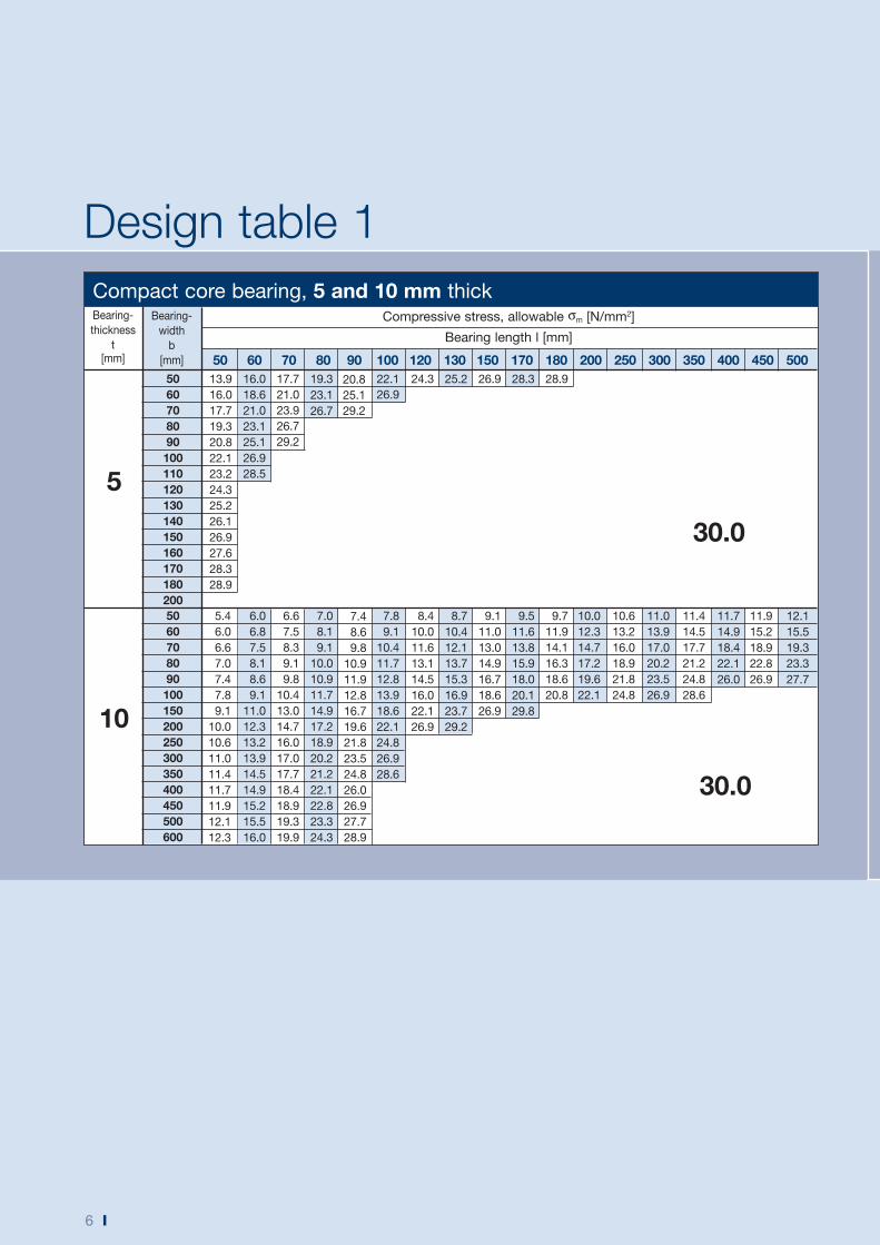
Design table 1
6 I
Compressive stress, allowable σm [N/mm2]
Bearing length l [mm]
Bearing-
thickness
t[mm]
30.0
Compact core bearing, 5 and 10 mm thick
13.9
16.0
17.7
19.3
20.8
22.1
23.2
24.3
25.2
26.1
26.9
27.6
28.3
28.9
5060708090100110120130140150160170180200
16.0
18.6
21.0
23.1
25.1
26.9
28.5
17.7
21.0
23.9
26.7
29.2
19.3
23.1
26.7
20.8
25.1
29.2
22.1
26.9
24.3 25.2 26.9 28.3 28.9
5
50 60 70 80 90 100 120 130 150 170 180 200 250 300 350 400 450 500
5.4
6.0
6.6
7.0
7.4
7.8
9.1
10.0
10.6
11.0
11.4
11.7
11.9
12.1
12.3
5060708090100150200250300350400450500600
6.0
6.8
7.5
8.1
8.6
9.1
11.0
12.3
13.2
13.9
14.5
14.9
15.2
15.5
16.0
6.6
7.5
8.3
9.1
9.8
10.4
13.0
14.7
16.0
17.0
17.7
18.4
18.9
19.3
19.9
7.0
8.1
9.1
10.0
10.9
11.7
14.9
17.2
18.9
20.2
21.2
22.1
22.8
23.3
24.3
7.4
8.6
9.8
10.9
11.9
12.8
16.7
19.6
21.8
23.5
24.8
26.0
26.9
27.7
28.9
7.8
9.1
10.4
11.7
12.8
13.9
18.6
22.1
24.8
26.9
28.6
8.4
10.0
11.6
13.1
14.5
16.0
22.1
26.9
8.7
10.4
12.1
13.7
15.3
16.9
23.7
29.2
9.1
11.0
13.0
14.9
16.7
18.6
26.9
9.5
11.6
13.8
15.9
18.0
20.1
29.8
9.7
11.9
14.1
16.3
18.6
20.8
10.0
12.3
14.7
17.2
19.6
22.1
10.6
13.2
16.0
18.9
21.8
24.8
11.0
13.9
17.0
20.2
23.5
26.9
11.4
14.5
17.7
21.2
24.8
28.6
11.7
14.9
18.4
22.1
26.0
11.9
15.2
18.9
22.8
26.9
12.1
15.5
19.3
23.3
27.7
10
30.0
Bearing-
width
b
[mm]
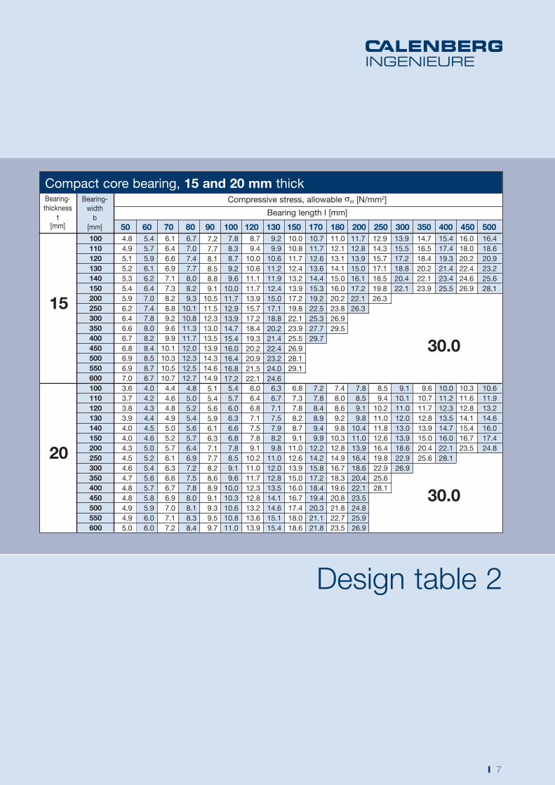
Design table 2
I 7
Compressive stress, allowable σm [N/mm2]
Bearing length l [mm]
Bearing-
thickness
t[mm] 50 60 70 80 90 100 120 130 150 170 180 200 250 300 350 400 450 500
100110120130140150200250300350400450500550600
20
30.0
100110120130140150200250300350400450500550600
15
30.0
Bearing-
width
b
[mm]
Compact core bearing, 15 and 20 mm thick
3.6
3.7
3.8
3.9
4.0
4.0
4.3
4.5
4.6
4.7
4.8
4.8
4.9
4.9
5.0
4.0
4.2
4.3
4.4
4.5
4.6
5.0
5.2
5.4
5.6
5.7
5.8
5.9
6.0
6.0
4.4
4.6
4.8
4.9
5.0
5.2
5.7
6.1
6.3
6.6
6.7
6.9
7.0
7.1
7.2
4.8
5.0
5.2
5.4
5.6
5.7
6.4
6.9
7.2
7.5
7.8
8.0
8.1
8.3
8.4
5.1
5.4
5.6
5.9
6.1
6.3
7.1
7.7
8.2
8.6
8.9
9.1
9.3
9.5
9.7
5.4
5.7
6.0
6.3
6.6
6.8
7.8
8.5
9.1
9.6
10.0
10.3
10.6
10.8
11.0
6.0
6.4
6.8
7.1
7.5
7.8
9.1
10.2
11.0
11.7
12.3
12.8
13.2
13.6
13.9
6.3
6.7
7.1
7.5
7.9
8.2
9.8
11.0
12.0
12.8
13.5
14.1
14.6
15.1
15.4
6.8
7.3
7.8
8.2
8.7
9.1
11.0
12.6
13.9
15.0
16.0
16.7
17.4
18.0
18.6
7.2
7.8
8.4
8.9
9.4
9.9
12.2
14.2
15.8
17.2
18.4
19.4
20.3
21.1
21.8
7.4
8.0
8.6
9.2
9.8
10.3
12.8
14.9
16.7
18.3
19.6
20.8
21.8
22.7
23.5
7.8
8.5
9.1
9.8
10.4
11.0
13.9
16.4
18.6
20.4
22.1
23.5
24.8
25.9
26.9
8.5
9.4
10.2
11.0
11.8
12.6
16.4
19.8
22.9
25.6
28.1
9.1
10.1
11.0
12.0
13.0
13.9
18.6
22.9
26.9
9.6
10.7
11.7
12.8
13.9
15.0
20.4
25.6
10.0
11.2
12.3
13.5
14.7
16.0
22.1
28.1
10.3
11.6
12.8
14.1
15.4
16.7
23.5
10.6
11.9
13.2
14.6
16.0
17.4
24.8
4.8
4.9
5.1
5.2
5.3
5.4
5.9
6.2
6.4
6.6
6.7
6.8
6.9
6.9
7.0
5.4
5.7
5.9
6.1
6.2
6.4
7.0
7.4
7.8
8.0
8.2
8.4
8.5
8.7
8.7
6.1
6.4
6.6
6.9
7.1
7.3
8.2
8.8
9.2
9.6
9.9
10.1
10.3
10.5
10.7
6.7
7.0
7.4
7.7
8.0
8.2
9.3
10.1
10.8
11.3
11.7
12.0
12.3
12.5
12.7
7.2
7.7
8.1
8.5
8.8
9.1
10.5
11.5
12.3
13.0
13.5
13.9
14.3
14.6
14.9
7.8
8.3
8.7
9.2
9.6
10.0
11.7
12.9
13.9
14.7
15.4
16.0
16.4
16.8
17.2
8.7
9.4
10.0
10.6
11.1
11.7
13.9
15.7
17.2
18.4
19.3
20.2
20.9
21.5
22.1
9.2
9.9
10.6
11.2
11.9
12.4
15.0
17.1
18.8
20.2
21.4
22.4
23.2
24.0
24.6
10.0
10.8
11.7
12.4
13.2
13.9
17.2
19.8
22.1
23.9
25.5
26.9
28.1
29.1
10.7
11.7
12.6
13.6
14.4
15.3
19.2
22.5
25.3
27.7
29.7
11.0
12.1
13.1
14.1
15.0
16.0
20.2
23.8
26.9
29.5
11.7
12.8
13.9
15.0
16.1
17.2
22.1
26.3
12.9
14.3
15.7
17.1
18.5
19.8
26.3
13.9
15.5
17.2
18.8
20.4
22.1
14.7
16.5
18.4
20.2
22.1
23.9
15.4
17.4
19.3
21.4
23.4
25.5
16.0
18.0
20.2
22.4
24.6
26.9
16.4
18.6
20.9
23.2
25.6
28.1
8 I
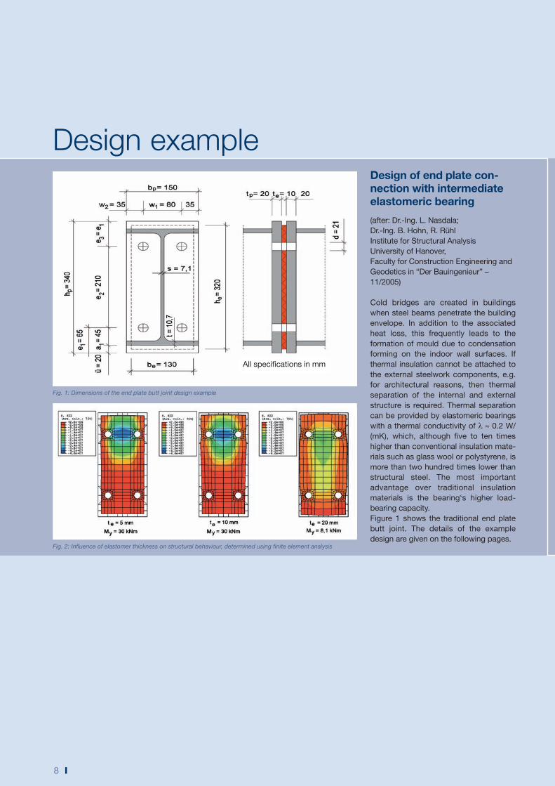
Design of end plate con-nection with intermediate elastomeric bearing
(after: Dr.-Ing. L. Nasdala;
Dr.-Ing. B. Hohn, R. Rühl
Institute for Structural Analysis
University of Hanover,
Faculty for Construction Engineering and
Geodetics in “Der Bauingenieur” –
11/2005)
Cold bridges are created in buildings
when steel beams penetrate the building
envelope. In addition to the associated
heat loss, this frequently leads to the
formation of mould due to condensation
forming on the indoor wall surfaces. If
thermal insulation cannot be attached to
the external steelwork components, e.g.
for architectural reasons, then thermal
separation of the internal and external
structure is required. Thermal separation
can be provided by elastomeric bearings
with a thermal conductivity of λ ≈ 0.2 W/
(mK), which, although five to ten times
higher than conventional insulation mate-
rials such as glass wool or polystyrene, is
more than two hundred times lower than
structural steel. The most important
advantage over traditional insulation
materials is the bearing‘s higher load-
bearing capacity.
Figure 1 shows the traditional end plate
butt joint. The details of the example
design are given on the following pages.
Design example
Fig. 2: Influence of elastomer thickness on structural behaviour, determined using finite element analysis
Fig. 1: Dimensions of the end plate butt joint design example
All specifications in mm
I 9
The end plates of the IPE 300 beam butt
joint are made from S 235 steel. A height
of he = 320 mm, a width of be = 130 mm
and a thickness of te = 10 mm were
selected for the elastomer. The fasteners
are 4 x M20 bolts strength class 10.9 with
a 1 mm tolerance.
The design of the joint without the
intermediate elastomer layer in
accordance with EC 3 will not be
discussed any further here.
As elastomers are almost incompressible,
they bulge out at the sides under load.
Therefore – for the same material
properties – thick elastomer plates cannot
carry as much load as thin ones. Using the
Shape Factor S, and taking into account
the elastomer dimensions and the number
Design example
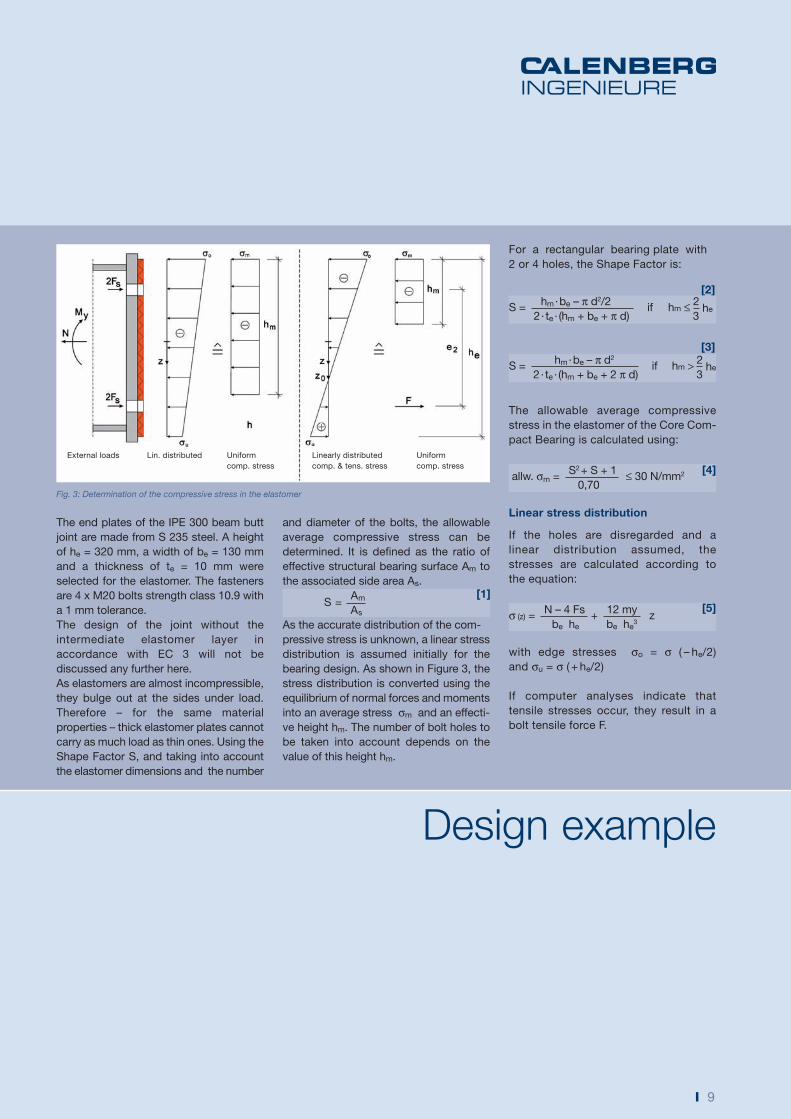
External loads Lin. distributed Uniform
comp. stress
Linearly distributed
comp. & tens. stress
Uniform
comp. stress
Fig. 3: Determination of the compressive stress in the elastomer
[2]
[3]
For a rectangular bearing plate with
2 or 4 holes, the Shape Factor is:
S = hm · be – π d2/2
if hm ≤ 2 he
2 · te · (hm + be + π d) 3
S = hm · be – π d2
if hm > 2 he
2 · te · (hm + be + 2 π d) 3
The allowable average compressive
stress in the elastomer of the Core Com-
pact Bearing is calculated using:
allw. σm = S2 + S + 1
≤ 30 N/mm2
0,70
Linear stress distribution
If the holes are disregarded and a
linear distribution assumed, the
stresses are calculated according to
the equation:
σ (z) = N – 4 Fs
+ 12 my
z be he be he
3
with edge stresses σo = σ ( – he/2)
and σu = σ ( + he/2)
If computer analyses indicate that
tensile stresses occur, they result in a
bolt tensile force F.
[4]
[5]
and diameter of the bolts, the allowable
average compressive stress can be
determined. It is defined as the ratio of
effective structural bearing surface Am to
the associated side area As.
S = Am
As
As the accurate distribution of the com-
pressive stress is unknown, a linear stress
distribution is assumed initially for the
bearing design. As shown in Figure 3, the
stress distribution is converted using the
equilibrium of normal forces and moments
into an average stress σm and an effecti-
ve height hm. The number of bolt holes to
be taken into account depends on the
value of this height hm.
[1]
10 I
Design exampleExample calculation:Bending moment My = 30 kNm
Normal force N = –20 kN
Bolt prestress force Fs = 80 kN/bolt
zo = 4 · 80 – (–20)
· 0,322 = 0,097 m using [6] 12 · 30
As My > 0 the bolt tensile force is
calculated using [9]
F = (– 20) – 4 · 80
+ 6 · 30
0,32 0,323� 0,32 – 0,097�2 � 0,322
– 0,0972�4
F = 22 kN
and an effective height hm using [10]
hm = 0,32 + 2 · 30 – 22 · 0,21
= 0,167 m – 20 – 4 · 80 – 22
The average compressive stress using [11]
σm = (– 20 – 4 · 80 – 22)2
103 · 0,13 [0,32 (– 20 – 4 · 80 –22) + 2· 30 – 22 · 0,21]
σm = 16,67 N/mm2
From hm = 0,167 m < 2
0,32 = 0,21 m
3
the shape factor is calculated using [2]
S = 167 · 130 – π ·21/2
= 2,9
2 · 10 · (167 + 130 + π · 21)
The allowable bearing load in accordance
with [4] is
allow. σm = 2,92 + 2,9 + 1
= 17,58 N/mm2 ≤ 30 N/mm2
0,70
With the following result
Actual σm = 16,67 N/mm2 ≤ Allow. σm = 17,58 N/mm2
compliance with the requirements is
confirmed.
At point
zo = 4 Fs – N
he2 ∈
12 My �–
he ; + he�2 2
[6]
a large moment My results in a sign
change, σ (zo) = 0.
Compressive stress only
For
zo ∈
and 4 Fs > N it follows:�– he ; +
he�2 2
[7]hm = he +
2 My and N – 4 Fs
σm = (N – 4 Fs)2
be [he (N – 4 Fs) + 2 My]
[8]
Compressive & tensile stresses
For
zo ∈
and My > 0 the bolt�– he ; +
he�2 2
tensile forces are calculated as:
F = N – 4 Fs
+ 6 My
he he3 � he – zo�2 � he
2
– zo2�4
[9]
and the following apply
[10]hm = he +
2 My – F e2 and N – 4 Fs – F
σm = (N – 4 Fs – F)2
be [he (N – 4 Fs – F) + 2 My – F · e2]
[11]
I 11
Characteristics
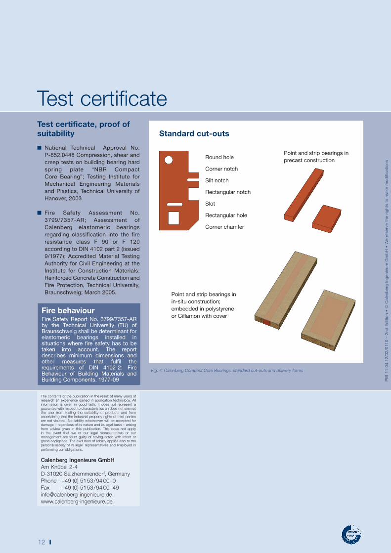
Delivery formsCalenberg Compact Core Bearings are
supplied ready-made in the shape and
dimensions required for each project.
(Figure 4)
Holes, cut-outs, slots etc. can be
provided to allow bolts or dowels to
pass through the bearings.
Dimensions■ Bearing thicknesses:
5, 10, 15, 20 mm
■ Maximum cut dimensions:
1200 mm x 1200 mm
CharacteristicsDue to its high material hardness, the
Compact Core Bearing – in contrast to
ordinary, softer elastomeric bearings –
deforms very little under load. In practice
this means:
■ The high stiffness of the bearing
means it is not suitable for
accommodating shear deformations
and rotations.
■ Transverse deformation is extremely
low thanks to the bearing‘s excellent
shape stability.
■ Moments are transferred without
large deformations.
■ Due to its low deformation and high
thermal resistivity, the bearing is
particularly suitable for use as a
thermal separation layer in end plate
butt joints in structural steelwork.
Use and areas of applicationCompact Core Bearings are used in all
fields of metal construction to provide
thermal separation, such as in the
installation of building facades, solar
energy equipment on roofs or the
connection of balconies and canopies to
the main loadbearing structure.
MaterialElastomeric material based on butadiene-
acrylonitrile rubber, colour red-brown
(common short name: NBR (nitrile
rubber)
Compact Core Bearings are resistant
to oil, grease and fuel; they are also
resistant to abrasion and wear.
12 I
Test certificate, proof of suitability
■ National Technical Approval No.
P-852.0448 Compression, shear and
creep tests on building bearing hard
spring plate “NBR Compact
Core Bearing”; Testing Institute for
Mechanical Engineering Materials
and Plastics, Technical University of
Hanover, 2003
■ Fire Safety Assessment No.
3799/7357-AR; Assessment of
Calenberg elastomeric bearings
regarding classification into the fire
resistance class F 90 or F 120
according to DIN 4102 part 2 (issued
9/1977); Accredited Material Testing
Authority for Civil Engineering at the
Institute for Construction Materials,
Reinforced Concrete Construction and
Fire Protection, Technical University,
Braunschweig; March 2005.
Test certificate
PIB
11
.04
.12
/02
/01
10
– 2
nd
Ed
itio
n •
© C
ale
nb
erg
In
gen
ieu
re G
mb
H •
We r
eserv
e t
he r
igh
ts t
o m
ake m
od
ific
atio
ns
Fire behaviourFire Safety Report No. 3799/7357-AR by the Technical University (TU) of Braunschweig shall be determinant for elastomeric bearings installed in situations where fire safety has to be taken into account. The report describes minimum dimensions and other measures that fulfil the requirements of DIN 4102-2: Fire Behaviour of Building Materials and Building Components, 1977-09
The contents of the publication in the result of many years of
research an experience gained in application technology. All
information is given in good faith; it does not represent a
guarantee with respect to characteristics an does not exempt
the user from testing the suitability of products and from
ascertaining that the industrial property rights of third parties
are not violated. No liability whatsoever will be accepted for
damage – regardless of its nature and its legal basis – arising
from advice given in this publication. This does not apply
in the event that we or our legal representatives or our
management are fount guilty of having acted with intent or
gross negligence. The exclusion of liability applies also to the
personal liability of or legal representatives and employed in
performing our obligations.
Calenberg Ingenieure GmbH
Am Knübel 2-4
D-31020 Salzhemmendorf, Germany
Phone +49 (0) 5153/94 00-0
Fax +49 (0) 5153/94 00-49
www.calenberg-ingenieure.de
Fig. 4: Calenberg Compact Core Bearings, standard cut-outs and delivery forms
Standard cut-outs
Round hole
Corner notch
Slit notch
Rectangular notch
Slot
Rectangular hole
Corner chamfer
Point and strip bearings in
precast construction
Point and strip bearings in
in-situ construction;
embedded in polystyrene
or Ciflamon with cover


