Embed Size (px)
Citation preview

ALPHA COMPACT 12V AND 24V SERIES
HIGH PERFORMANCE ALTERNATORS
USER AND INSTALLATION MANUAL 10000014840-03

2 Alpha Compact – User and Installation manual
TABLE OF CONTENTS
1 GENERAL INFORMATION ......................................... 3
1.1 Use of this manual .............................................. 3
1.2 Identification label ............................................... 3
1.3 Liability ................................................................ 3
1.4 Warranty ............................................................. 3
1.5 Disclaimer ........................................................... 4
1.6 Correct Disposal of This Product ........................ 4
2 Safety Instructions....................................................... 5
3 System example.......................................................... 6
4 Before you start the installation ................................... 7
4.1 Mounting bracket ................................................ 7
4.2 Sense of rotation ................................................ 7
4.3 Isolation bushings ............................................... 7
4.4 Drive belt ............................................................ 7
4.5 Engine load ......................................................... 7
4.6 Pulleys ................................................................ 7
4.6.1 Pulley type selection ................................ 7
4.6.2 Pulley size selection ................................ 8
4.6.3 Calculating alternator output.................... 8
4.6.4 Pulley alignment ...................................... 8
4.7 Pulley installation ................................................ 9
4.7.1 Standard pulley ..................................... 10
4.7.2 Clutch pulley .......................................... 10
5 Mechanical Installation .............................................. 11
5.1 Preparations ..................................................... 11
5.2 Prepare mounting location ................................ 11
5.2.1 Main alternator upgrade ........................ 11
5.2.2 Secondary alternator installation ........... 11
5.3 Alternator mounting .......................................... 11
5.4 Drive belt re-installation .....................................12
5.4.1 With auto-tensioner pulley ......................12
5.4.2 No auto-tensioner pulley ........................12
5.4.3 Final check .............................................12
6 Electrical Installation ..................................................13
6.1 Precautions .......................................................13
6.2 Fuse ..................................................................13
6.3 Wiring ................................................................13
7 Commissioning ..........................................................15
7.1 Preparations ......................................................15
7.2 Regulator configuration .....................................15
7.2.1 Set alternator type ..................................15
7.2.2 Other settings .........................................15
7.3 First operation....................................................15
7.4 Normal operation ...............................................15
8 Maintenance ..............................................................16
8.1 Mounting points .................................................16
8.2 Cleaning ............................................................16
8.3 Check tension and condition of the drive belt ....16
9 Troubleshooting .........................................................17
9.1 Trouble shooting hints .......................................17
9.2 Fault finding table ..............................................17
10 Technical Data ...........................................................18
10.1 General specifications .......................................18
10.2 Technical specifications .....................................19
10.3 Mechanical specifications – Alternators .............20
10.4 Mechanical specifications – Pulleys ..................22
10.5 Output curves ....................................................23
Alpha Compact – User and Installation manual 3
1 GENERAL INFORMATION
1.1 Use of this manual
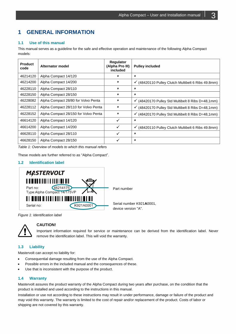
This manual serves as a guideline for the safe and effective operation and maintenance of the following Alpha Compact
models:
Product code
Alternator model Regulator
(Alpha Pro III) included
Pulley included
46214120 Alpha Compact 14/120
46214200 Alpha Compact 14/200 ✓ (48420110 Pulley Clutch Multibelt 6 Ribs 49.8mm)
46228110 Alpha Compact 28/110
46228150 Alpha Compact 28/150
46228082 Alpha Compact 28/80 for Volvo Penta ✓ (48420170 Pulley Std Multibelt 8 Ribs D=48,1mm)
46228112 Alpha Compact 28/110 for Volvo Penta ✓ (48420170 Pulley Std Multibelt 8 Ribs D=48,1mm)
46228152 Alpha Compact 28/150 for Volvo Penta ✓ (48420170 Pulley Std Multibelt 8 Ribs D=48,1mm)
46614120 Alpha Compact 14/120 ✓
46614200 Alpha Compact 14/200 ✓ ✓ (48420110 Pulley Clutch Multibelt 6 Ribs 49.8mm)
46628110 Alpha Compact 28/110 ✓
46628150 Alpha Compact 28/150 ✓
Table 1: Overview of models to which this manual refers
These models are further referred to as “Alpha Compact”.
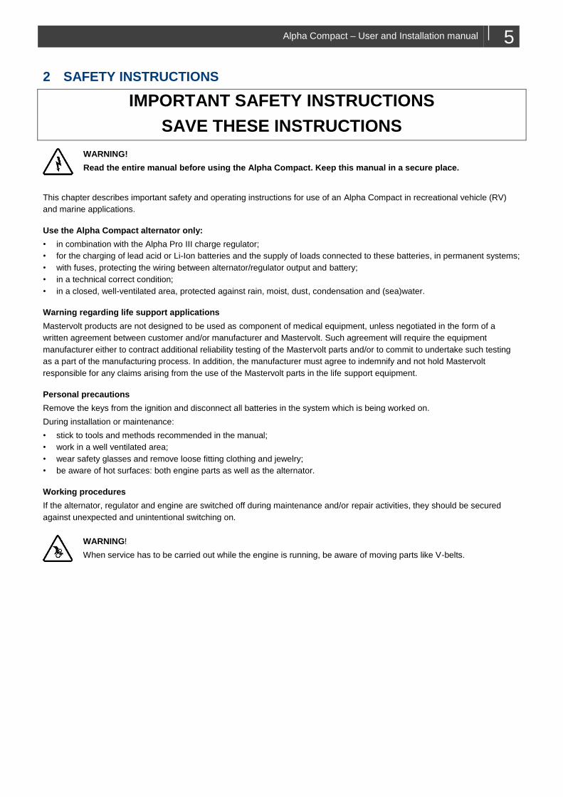
1.2 Identification label
Part number
Serial number K921A0001,
device version "A".
Figure 1: Identification label
CAUTION!
Important information required for service or maintenance can be derived from the identification label. Never
remove the identification label. This will void the warranty.
1.3 Liability
Mastervolt can accept no liability for:
• Consequential damage resulting from the use of the Alpha Compact.
• Possible errors in the included manual and the consequences of these.
• Use that is inconsistent with the purpose of the product.
1.4 Warranty
Mastervolt assures the product warranty of the Alpha Compact during two years after purchase, on the condition that the
product is installed and used according to the instructions in this manual.
Installation or use not according to these instructions may result in under performance, damage or failure of the product and
may void this warranty. The warranty is limited to the cost of repair and/or replacement of the product. Costs of labor or
shipping are not covered by this warranty.

4 Alpha Compact – User and Installation manual
1.5 Disclaimer
Our products are subject to continual development and improvement. Therefore, additions or modifications to the products
may cause changes to the technical data and functional specifications. No rights can be derived from this document. Please
consult our most current Terms & Conditions of Sale.
1.6 Correct Disposal of This Product
This product is designed and manufactured with high quality materials and components, which can be recycled and
reused. When this crossed-out wheeled bin symbol is attached to a product, it means the product is covered by the
European Directive 2012/19/EU.
Please be informed about the local separate collection system for electrical and electronic products.
Please act according to your local rules and do not dispose of your old products with your normal household waste. The
correct disposal of your old product will help prevent potential negative consequences to the environment and human health.
Alpha Compact – User and Installation manual 5
2 SAFETY INSTRUCTIONS
IMPORTANT SAFETY INSTRUCTIONS
SAVE THESE INSTRUCTIONS
WARNING!
Read the entire manual before using the Alpha Compact. Keep this manual in a secure place.
This chapter describes important safety and operating instructions for use of an Alpha Compact in recreational vehicle (RV)
and marine applications.
Use the Alpha Compact alternator only:
• in combination with the Alpha Pro III charge regulator;
• for the charging of lead acid or Li-Ion batteries and the supply of loads connected to these batteries, in permanent systems;
• with fuses, protecting the wiring between alternator/regulator output and battery;
• in a technical correct condition;
• in a closed, well-ventilated area, protected against rain, moist, dust, condensation and (sea)water.
Warning regarding life support applications
Mastervolt products are not designed to be used as component of medical equipment, unless negotiated in the form of a
written agreement between customer and/or manufacturer and Mastervolt. Such agreement will require the equipment
manufacturer either to contract additional reliability testing of the Mastervolt parts and/or to commit to undertake such testing
as a part of the manufacturing process. In addition, the manufacturer must agree to indemnify and not hold Mastervolt
responsible for any claims arising from the use of the Mastervolt parts in the life support equipment.
Personal precautions
Remove the keys from the ignition and disconnect all batteries in the system which is being worked on.
During installation or maintenance:
• stick to tools and methods recommended in the manual;
• work in a well ventilated area;
• wear safety glasses and remove loose fitting clothing and jewelry;
• be aware of hot surfaces: both engine parts as well as the alternator.
Working procedures
If the alternator, regulator and engine are switched off during maintenance and/or repair activities, they should be secured
against unexpected and unintentional switching on.
WARNING!
When service has to be carried out while the engine is running, be aware of moving parts like V-belts.
6 Alpha Compact – User and Installation manual
3 SYSTEM EXAMPLE
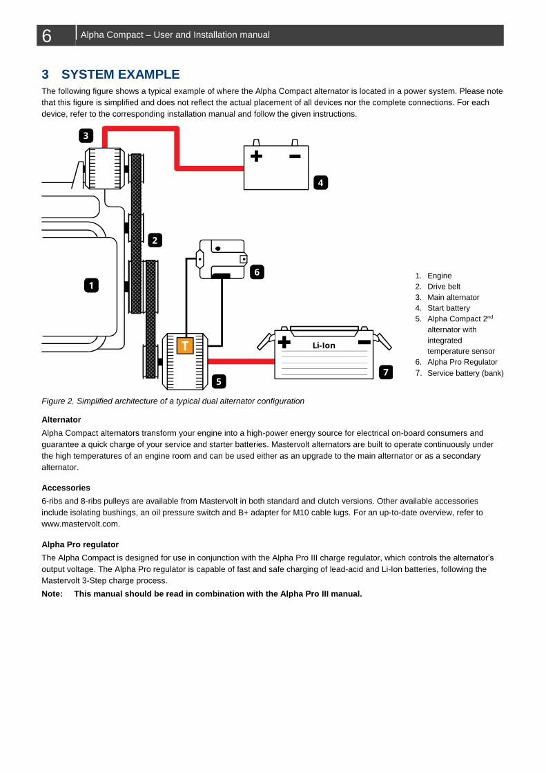
The following figure shows a typical example of where the Alpha Compact alternator is located in a power system. Please note
that this figure is simplified and does not reflect the actual placement of all devices nor the complete connections. For each
device, refer to the corresponding installation manual and follow the given instructions.
1. Engine
2. Drive belt
3. Main alternator
4. Start battery
5. Alpha Compact 2nd
alternator with
integrated
temperature sensor
6. Alpha Pro Regulator
7. Service battery (bank)
Figure 2. Simplified architecture of a typical dual alternator configuration
Alternator
Alpha Compact alternators transform your engine into a high-power energy source for electrical on-board consumers and
guarantee a quick charge of your service and starter batteries. Mastervolt alternators are built to operate continuously under
the high temperatures of an engine room and can be used either as an upgrade to the main alternator or as a secondary
alternator.
Accessories
6-ribs and 8-ribs pulleys are available from Mastervolt in both standard and clutch versions. Other available accessories
include isolating bushings, an oil pressure switch and B+ adapter for M10 cable lugs. For an up-to-date overview, refer to
www.mastervolt.com.
Alpha Pro regulator
The Alpha Compact is designed for use in conjunction with the Alpha Pro III charge regulator, which controls the alternator’s
output voltage. The Alpha Pro regulator is capable of fast and safe charging of lead-acid and Li-Ion batteries, following the
Mastervolt 3-Step charge process.
Note: This manual should be read in combination with the Alpha Pro III manual.
2
7
4
5
6
1
T Li-Ion
3
Alpha Compact – User and Installation manual 7
4 BEFORE YOU START THE INSTALLATION
4.1 Mounting bracket
To add a secondary alternator, you need a solid mounting bracket which must be resistant to strong vibrations. There are
various possibilities:
1. Order the engine with pre-installed alternator bracket (also known as PTO or Generator option).
2. Consult your dealer/distributor for the availability of an aftermarket 2nd alternator mounting kit.
3. Construct your own bracket. This is specialist work and should be carried out by qualified personnel only.
Check the instructions, dimensions and specifications included with the alternator bracket or kit to decide which Alpha
Compact model best fits your engine.
4.2 Sense of rotation
When selecting the installation location, you must consider the sense of rotation. For the internal fans to work properly, the
sense of rotation should be clockwise, viewed from the pulley side of the Alpha Compact.
4.3 Isolation bushings
Alpha Compact alternators are non-isolated, meaning the negative output is connected to the metal enclosure. Engine
manufacturers may stipulate isolated mounting of the alternator, e.g. to protect sensitive engine electronics. Mastervolt can
provide optional isolating bushings suitable for this purpose. For each mounting hole of the alternator, order one set of isolating
bushings. See also Figure 4 on page 11.
Note: The mounting hole diameters may vary in size, even within a single model. Make sure to order the correct bushing by
looking up the mounting hole diameters in section 10.3.
4.4 Drive belt
Alpha Compact alternators must be combined with multigroove pulleys and corresponding multirib belt (also known as
multibelt or serpentine belt) with profile “PK”; further referred to as “drive belt” or “belt” for short. The drive belt must be capable
of driving the total mechanical load of all power consumers on the belt, including the alternator. Please note that Mastervolt
does not supply the drive belt.
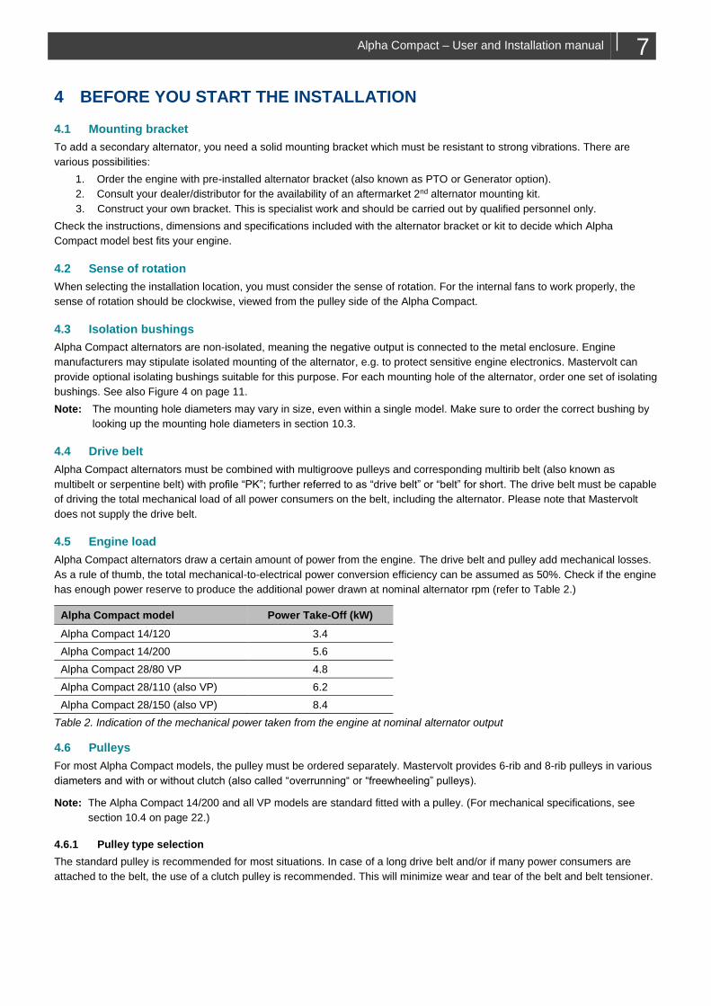
4.5 Engine load
Alpha Compact alternators draw a certain amount of power from the engine. The drive belt and pulley add mechanical losses.
As a rule of thumb, the total mechanical-to-electrical power conversion efficiency can be assumed as 50%. Check if the engine
has enough power reserve to produce the additional power drawn at nominal alternator rpm (refer to Table 2.)
Alpha Compact model Power Take-Off (kW)
Alpha Compact 14/120 3.4
Alpha Compact 14/200 5.6
Alpha Compact 28/80 VP 4.8
Alpha Compact 28/110 (also VP) 6.2
Alpha Compact 28/150 (also VP) 8.4
Table 2. Indication of the mechanical power taken from the engine at nominal alternator output
4.6 Pulleys
For most Alpha Compact models, the pulley must be ordered separately. Mastervolt provides 6-rib and 8-rib pulleys in various
diameters and with or without clutch (also called “overrunning“ or “freewheeling” pulleys).
Note: The Alpha Compact 14/200 and all VP models are standard fitted with a pulley. (For mechanical specifications, see
section 10.4 on page 22.)
4.6.1 Pulley type selection
The standard pulley is recommended for most situations. In case of a long drive belt and/or if many power consumers are
attached to the belt, the use of a clutch pulley is recommended. This will minimize wear and tear of the belt and belt tensioner.
8 Alpha Compact – User and Installation manual
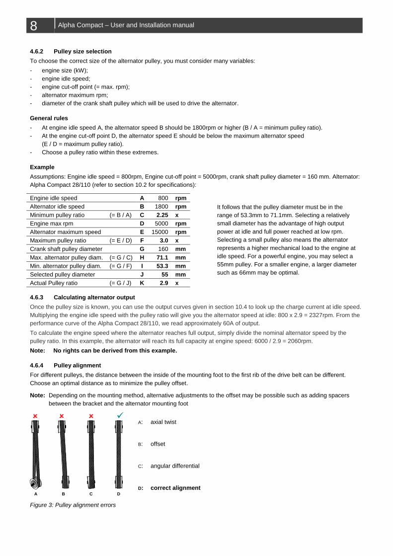
4.6.2 Pulley size selection
To choose the correct size of the alternator pulley, you must consider many variables:
- engine size (kW);
- engine idle speed;
- engine cut-off point (= max. rpm);
- alternator maximum rpm;
- diameter of the crank shaft pulley which will be used to drive the alternator.
General rules
- At engine idle speed A, the alternator speed B should be 1800rpm or higher (B / A = minimum pulley ratio).
- At the engine cut-off point D, the alternator speed E should be below the maximum alternator speed
(E / D = maximum pulley ratio).
- Choose a pulley ratio within these extremes.
Example
Assumptions: Engine idle speed = 800rpm, Engine cut-off point = 5000rpm, crank shaft pulley diameter = 160 mm. Alternator:
Alpha Compact 28/110 (refer to section 10.2 for specifications):
Engine idle speed A 800 rpm
It follows that the pulley diameter must be in the
range of 53.3mm to 71.1mm. Selecting a relatively
small diameter has the advantage of high output
power at idle and full power reached at low rpm.
Selecting a small pulley also means the alternator
represents a higher mechanical load to the engine at
idle speed. For a powerful engine, you may select a
55mm pulley. For a smaller engine, a larger diameter
such as 66mm may be optimal.
Alternator idle speed B 1800 rpm
Minimum pulley ratio (= B / A) C 2.25 x
Engine max rpm D 5000 rpm
Alternator maximum speed E 15000 rpm
Maximum pulley ratio (= E / D) F 3.0 x
Crank shaft pulley diameter G 160 mm
Max. alternator pulley diam. (= G / C) H 71.1 mm
Min. alternator pulley diam. (= G / F) I 53.3 mm
Selected pulley diameter J 55 mm
Actual Pulley ratio (= G / J) K 2.9 x
4.6.3 Calculating alternator output
Once the pulley size is known, you can use the output curves given in section 10.4 to look up the charge current at idle speed.
Multiplying the engine idle speed with the pulley ratio will give you the alternator speed at idle: 800 x 2.9 = 2327rpm. From the
performance curve of the Alpha Compact 28/110, we read approximately 60A of output.
To calculate the engine speed where the alternator reaches full output, simply divide the nominal alternator speed by the
pulley ratio. In this example, the alternator will reach its full capacity at engine speed: 6000 / 2.9 = 2060rpm.
Note: No rights can be derived from this example.
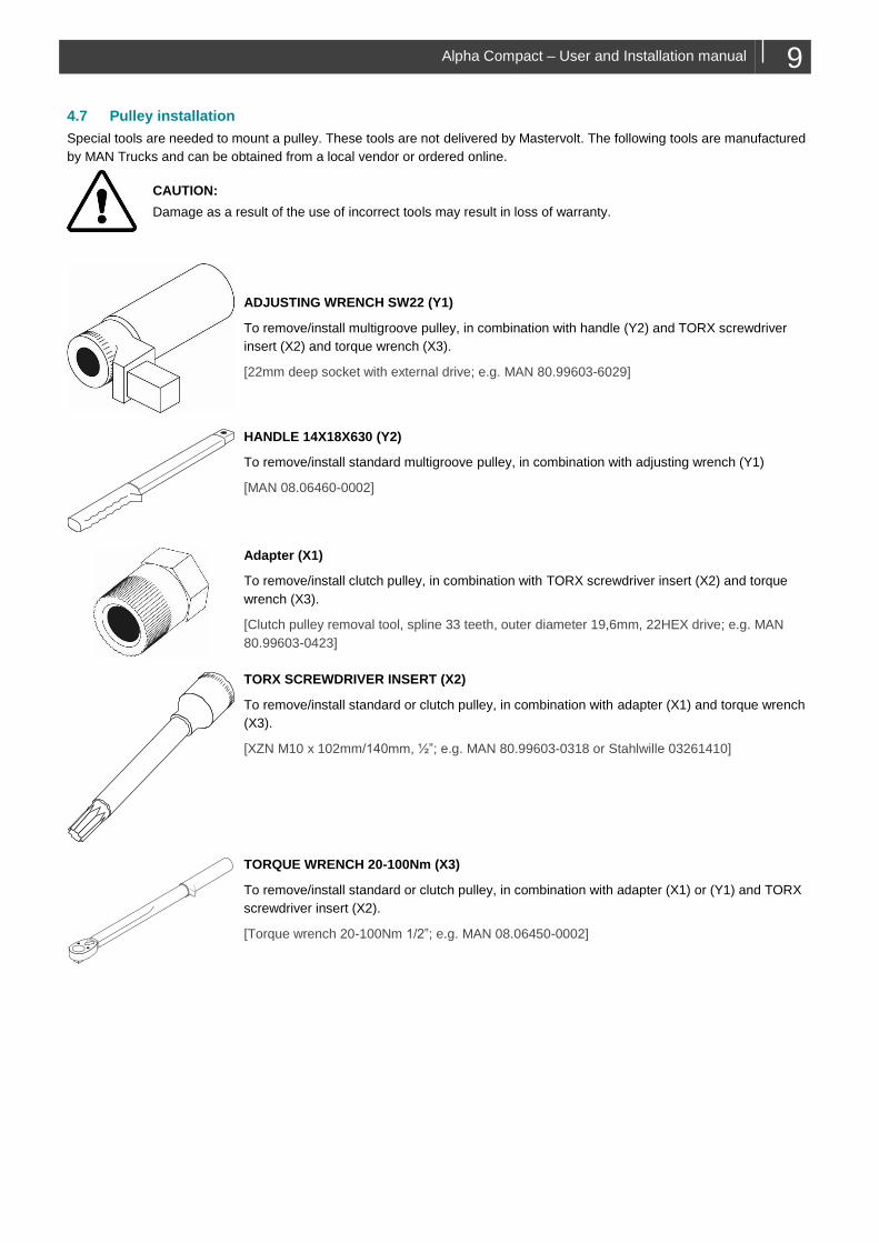
4.6.4 Pulley alignment
For different pulleys, the distance between the inside of the mounting foot to the first rib of the drive belt can be different.
Choose an optimal distance as to minimize the pulley offset.
Note: Depending on the mounting method, alternative adjustments to the offset may be possible such as adding spacers
between the bracket and the alternator mounting foot
A: axial twist
B: offset
C: angular differential
D: correct alignment
Figure 3: Pulley alignment errors
A B C D
Alpha Compact – User and Installation manual 9
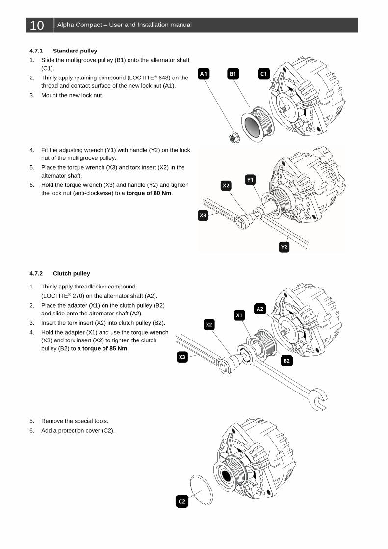
4.7 Pulley installation
Special tools are needed to mount a pulley. These tools are not delivered by Mastervolt. The following tools are manufactured
by MAN Trucks and can be obtained from a local vendor or ordered online.
CAUTION:
Damage as a result of the use of incorrect tools may result in loss of warranty.
ADJUSTING WRENCH SW22 (Y1)
To remove/install multigroove pulley, in combination with handle (Y2) and TORX screwdriver
insert (X2) and torque wrench (X3).
[22mm deep socket with external drive; e.g. MAN 80.99603-6029]
HANDLE 14X18X630 (Y2)
To remove/install standard multigroove pulley, in combination with adjusting wrench (Y1)
[MAN 08.06460-0002]
Adapter (X1)
To remove/install clutch pulley, in combination with TORX screwdriver insert (X2) and torque
wrench (X3).
[Clutch pulley removal tool, spline 33 teeth, outer diameter 19,6mm, 22HEX drive; e.g. MAN
80.99603-0423]
TORX SCREWDRIVER INSERT (X2)
To remove/install standard or clutch pulley, in combination with adapter (X1) and torque wrench
(X3).
[XZN M10 x 102mm/140mm, ½”; e.g. MAN 80.99603-0318 or Stahlwille 03261410]
TORQUE WRENCH 20-100Nm (X3)
To remove/install standard or clutch pulley, in combination with adapter (X1) or (Y1) and TORX
screwdriver insert (X2).
[Torque wrench 20-100Nm 1/2”; e.g. MAN 08.06450-0002]
10 Alpha Compact – User and Installation manual
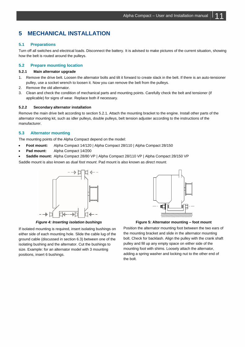
4.7.1 Standard pulley
1. Slide the multigroove pulley (B1) onto the alternator shaft
(C1).
2. Thinly apply retaining compound (LOCTITE® 648) on the
thread and contact surface of the new lock nut (A1).
3. Mount the new lock nut.
4. Fit the adjusting wrench (Y1) with handle (Y2) on the lock
nut of the multigroove pulley.
5. Place the torque wrench (X3) and torx insert (X2) in the
alternator shaft.
6. Hold the torque wrench (X3) and handle (Y2) and tighten
the lock nut (anti-clockwise) to a torque of 80 Nm.
4.7.2 Clutch pulley
1. Thinly apply threadlocker compound
(LOCTITE® 270) on the alternator shaft (A2).
2. Place the adapter (X1) on the clutch pulley (B2)
and slide onto the alternator shaft (A2).
3. Insert the torx insert (X2) into clutch pulley (B2).
4. Hold the adapter (X1) and use the torque wrench
(X3) and torx insert (X2) to tighten the clutch
pulley (B2) to a torque of 85 Nm.
5. Remove the special tools.
6. Add a protection cover (C2).
C1B1A1
X3
X2
X1A2
B2
C2
Alpha Compact – User and Installation manual 11
5 MECHANICAL INSTALLATION
5.1 Preparations
Turn off all switches and electrical loads. Disconnect the battery. It is advised to make pictures of the current situation, showing
how the belt is routed around the pulleys.
5.2 Prepare mounting location
5.2.1 Main alternator upgrade
1. Remove the drive belt. Loosen the alternator bolts and tilt it forward to create slack in the belt. If there is an auto-tensioner
pulley, use a socket wrench to loosen it. Now you can remove the belt from the pulleys.
2. Remove the old alternator.
3. Clean and check the condition of mechanical parts and mounting points. Carefully check the belt and tensioner (if
applicable) for signs of wear. Replace both if necessary.
5.2.2 Secondary alternator installation
Remove the main drive belt according to section 5.2.1. Attach the mounting bracket to the engine. Install other parts of the
alternator mounting kit, such as idler pulleys, double pulleys, belt tension adjuster according to the instructions of the
manufacturer.
5.3 Alternator mounting
The mounting points of the Alpha Compact depend on the model:
• Foot mount: Alpha Compact 14/120 | Alpha Compact 28/110 | Alpha Compact 28/150
• Pad mount: Alpha Compact 14/200
• Saddle mount: Alpha Compact 28/80 VP | Alpha Compact 28/110 VP | Alpha Compact 28/150 VP
Saddle mount is also known as dual foot mount. Pad mount is also known as direct mount.
Figure 4: Inserting isolation bushings
If isolated mounting is required, insert isolating bushings on
either side of each mounting hole. Slide the cable lug of the
ground cable (discussed in section 6.3) between one of the
isolating bushing and the alternator. Cut the bushings to
size. Example: for an alternator model with 3 mounting
positions, insert 6 bushings.
Figure 5: Alternator mounting – foot mount
Position the alternator mounting foot between the two ears of
the mounting bracket and slide in the alternator mounting
bolt. Check for backlash. Align the pulley with the crank shaft
pulley and fill up any empty space on either side of the
mounting foot with shims. Loosely attach the alternator,
adding a spring washer and locking nut to the other end of
the bolt.
12 Alpha Compact – User and Installation manual
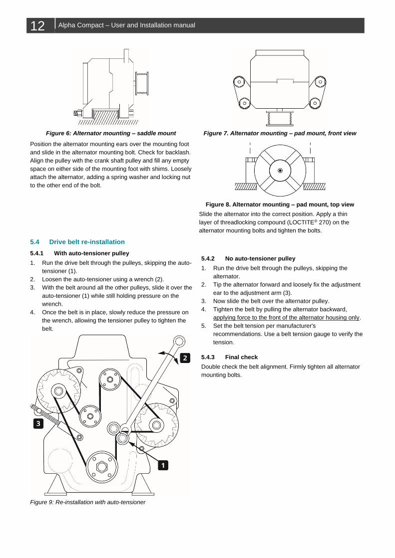
Figure 6: Alternator mounting – saddle mount
Position the alternator mounting ears over the mounting foot
and slide in the alternator mounting bolt. Check for backlash.
Align the pulley with the crank shaft pulley and fill any empty
space on either side of the mounting foot with shims. Loosely
attach the alternator, adding a spring washer and locking nut
to the other end of the bolt.
Figure 7. Alternator mounting – pad mount, front view
Figure 8. Alternator mounting – pad mount, top view
Slide the alternator into the correct position. Apply a thin
layer of threadlocking compound (LOCTITE® 270) on the
alternator mounting bolts and tighten the bolts.
5.4 Drive belt re-installation
5.4.1 With auto-tensioner pulley
1. Run the drive belt through the pulleys, skipping the auto-
tensioner (1).
2. Loosen the auto-tensioner using a wrench (2).
3. With the belt around all the other pulleys, slide it over the
auto-tensioner (1) while still holding pressure on the
wrench.
4. Once the belt is in place, slowly reduce the pressure on
the wrench, allowing the tensioner pulley to tighten the
belt.
Figure 9: Re-installation with auto-tensioner
5.4.2 No auto-tensioner pulley
1. Run the drive belt through the pulleys, skipping the
alternator.
2. Tip the alternator forward and loosely fix the adjustment
ear to the adjustment arm (3).
3. Now slide the belt over the alternator pulley.
4. Tighten the belt by pulling the alternator backward,
applying force to the front of the alternator housing only.
5. Set the belt tension per manufacturer's
recommendations. Use a belt tension gauge to verify the
tension.
5.4.3 Final check
Double check the belt alignment. Firmly tighten all alternator
mounting bolts.
Alpha Compact – User and Installation manual 13
6 ELECTRICAL INSTALLATION
WARNING
Installation work should be carried out by qualified personnel only.
CAUTION! Risk of equipment damage
Short circuiting or reversing polarity may lead to serious damage to the batteries, the alternator, the Alpha Pro
regulator, the cabling and/or the terminal connections. Fuses cannot prevent damage caused by reversed polarity.
Damage caused by reverse polarity is not covered by the warranty.
Interrupting current from a running alternator may lead to a significant voltage surge, with damage to the
alternator and/or connected equipment and loss of warranty as a result. Carefully follow the instructions in
this chapter regarding wiring, fuse size and fuse position.
CAUTION! Risk of fire
Too-thin cables and/or loose connections can cause dangerous overheating of the cables and/or terminals. Tighten
all connections well, in order to limit transition resistance as far as possible. Use cables of the correct size. Refer to
technical specifications (section10.2) for recommended wire sizes.
6.1 Precautions
Make sure that everything is switched off:
• remove the engine ignition key;
• disconnect all batteries or remove the DC fuse(s);
• make sure that third parties cannot reverse the measures taken.
6.2 Fuse
The alternator is connected to the battery via an alternator fuse, located as close as possible to the battery. Refer to section
10.2 Technical specifications, on page 19, for more information.
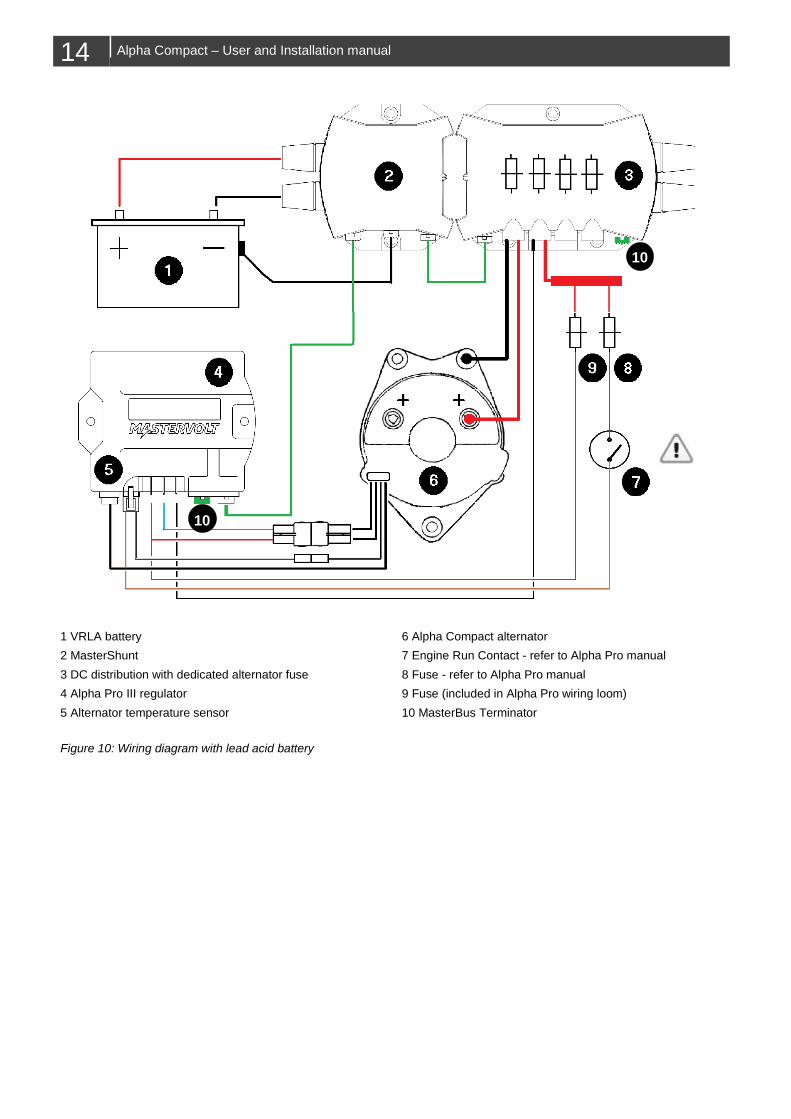
6.3 Wiring
Refer to Figure 10 on page 14.
Notes:
▪ Whether the alternator is mounted in an isolated or a non-isolated way, it is OBLIGATORY to always route a ground
conductor from one of the alternator mounting points to electrical ground.
▪ The current rating of the positive and negative alternator wiring must be higher than the fuse size.
▪ Use the supplied cable assembly for connection of the Alpha Pro regulator.
▪ The alternator temperature sensor must be connected to the temperature input of Alpha Pro. In case lead acid batteries are
used, it is advised to install a MasterShunt with battery temperature sensor and make a MasterBus connection to the Alpha
Pro to use automatic temperature compensation.
CAUTION:
Point 7 in Figure 10 should NOT be connected to engine ignition. Refer to the Alpha Pro manual, which explains
how to obtain a proper “engine run” signal. Failure to do so may lead to overcharging of the batteries and /
or overheating of the alternator field winding, which is not covered by warranty.
14 Alpha Compact – User and Installation manual
1 VRLA battery 6 Alpha Compact alternator
2 MasterShunt 7 Engine Run Contact - refer to Alpha Pro manual
3 DC distribution with dedicated alternator fuse 8 Fuse - refer to Alpha Pro manual
4 Alpha Pro III regulator 9 Fuse (included in Alpha Pro wiring loom)
5 Alternator temperature sensor 10 MasterBus Terminator
Figure 10: Wiring diagram with lead acid battery
10
10
Alpha Compact – User and Installation manual 15
7 COMMISSIONING
7.1 Preparations
1. Wear safety glasses and remove loose fitting clothing and jewelry.
2. Clear the area around moving parts. Remove loose wires and tools.
3. Double check all electrical connections.
4. Reconnect the battery.
5. Switch on the DC power.
7.2 Regulator configuration
Refer to the Alpha Pro regulator manual for details on MasterBus configuration.
Leave the selector switch of Alpha Pro on its default setting: “MasterBus”.
Note: The Alpha Pro will be disabled until it is configured and locked via the MasterBus menu.
7.2.1 Set alternator type
On the Alpha Pro MasterBus configuration page:
1. Go to Alternator type.
2. Set alternator type to the correct [Alpha Compact XX/YYY] type.
3. If your type is not in the list, select [user defined].
• Set the system voltage for your alternator.
˗ Alpha Compact 14/YYY models: [12V]
˗ Alpha Compact 28/YYY models: [24V]
• Set # of pole pairs to [6]
4. Set the temperature sensor to [Alternator].
5. Set Start reducing to [100°C].
6. Set Stop charging to [120°C].
7. Double check the settings and keep a record of them in this manual.
7.2.2 Other settings
Refer to the Alpha Pro manual for other settings and how to lock the Alpha Pro regulator.
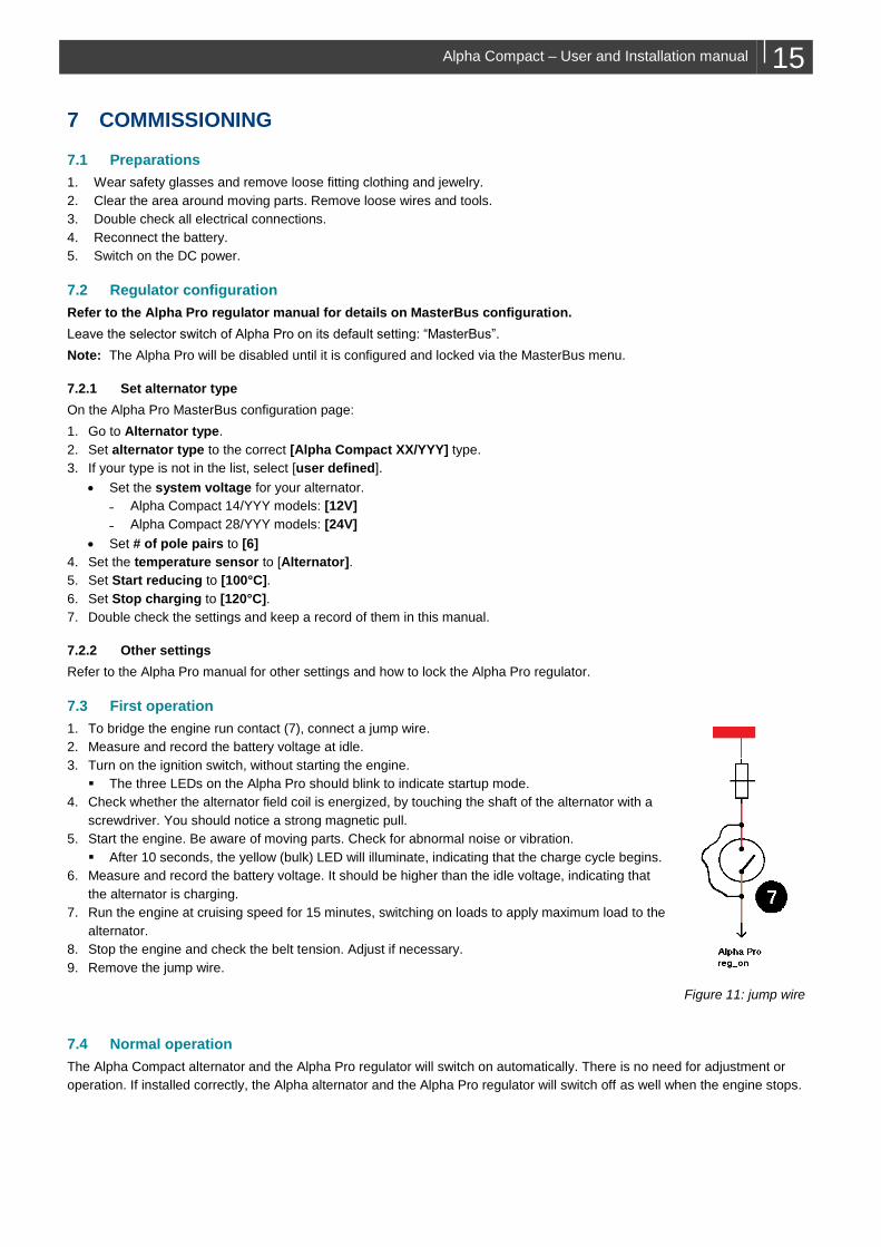
7.3 First operation
1. To bridge the engine run contact (7), connect a jump wire.
2. Measure and record the battery voltage at idle.
3. Turn on the ignition switch, without starting the engine.
▪ The three LEDs on the Alpha Pro should blink to indicate startup mode.
4. Check whether the alternator field coil is energized, by touching the shaft of the alternator with a
screwdriver. You should notice a strong magnetic pull.
5. Start the engine. Be aware of moving parts. Check for abnormal noise or vibration.
▪ After 10 seconds, the yellow (bulk) LED will illuminate, indicating that the charge cycle begins.
6. Measure and record the battery voltage. It should be higher than the idle voltage, indicating that
the alternator is charging.
7. Run the engine at cruising speed for 15 minutes, switching on loads to apply maximum load to the
alternator.
8. Stop the engine and check the belt tension. Adjust if necessary.
9. Remove the jump wire.
Figure 11: jump wire
7.4 Normal operation
The Alpha Compact alternator and the Alpha Pro regulator will switch on automatically. There is no need for adjustment or
operation. If installed correctly, the Alpha alternator and the Alpha Pro regulator will switch off as well when the engine stops.
16 Alpha Compact – User and Installation manual
8 MAINTENANCE
Alternator installations are pretty much maintenance free except for changing the belt periodically and keeping correct belt
tension. For better cooling it helps to keep the alternator clean. A periodic test of its performance will help to spot problems in
advance.
8.1 Mounting points
Check the mounting of the alternator after the first 50 running hours. Then every 150 running hours or at least every year,
whichever comes first. Make sure that the alternator is securely mounted to its applicable brackets. The brackets, in turn, need
to be bolted securely to the engine. Poor or loose mountings may lead to damaging vibration as well as reduced belt drive
performance.
8.2 Cleaning
CAUTION:
Use only non-aggressive detergents.
The cleaning interval of the alternator strongly depends on environmental conditions but should be maximum six months.
Prevent build-up of dirt, grease or dust. If you notice significant build-up of black dust on your alternator and surrounding
engine area, check belt tension.
Air flow passages must also be clear so that air can easily pass through the unit. The alternator’s bearings are greased for life
and cannot be degreased.
8.3 Check tension and condition of the drive belt
An under-tensioned belt will slip on the pulley, fail to turn the alternator’s rotor and as a result of the friction, overheat the
alternator. An over-tensioned belt causes reduced belt life. The tension of new belts must be checked after the first 50 running
hours; then every 150 running hours or at least every year.
Before adjusting the belt tension, inspect it for glazing, cracks, or dryness. A worn or damaged belt should be replaced,
including the tensioner (if applicable). If the belt is in satisfactory condition, check the belt tension with cricket belt tension
gauge. Refer to the manufacturer's specifications for proper belt tension.
If you replace a worn or damaged drive belt, the new belt should be checked for proper tension as well. A new drive belt loses
up to 60% of its tension during the first few hours of operation. If a new belt has been installed, run the engine with full load
connected to the alternator for approximately 15 minutes. Then check the belt tension again and adjust it if necessary.
Alpha Compact – User and Installation manual 17
9 TROUBLESHOOTING
9.1 Trouble shooting hints
˗ Check if 12-14V is present at alternator output
˗ Check if 12-14V is available at field current input. When field current is present, hold a Ferro-metallic object near the shaft
of the alternator. The field coil functions correctly if a strong magnetic pull is observed.
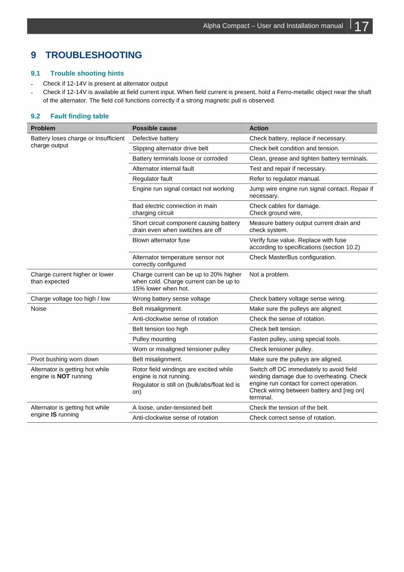
9.2 Fault finding table
Problem Possible cause Action
Battery loses charge or Insufficient charge output
Defective battery Check battery, replace if necessary.
Slipping alternator drive belt Check belt condition and tension.
Battery terminals loose or corroded Clean, grease and tighten battery terminals.
Alternator internal fault Test and repair if necessary.
Regulator fault Refer to regulator manual.
Engine run signal contact not working Jump wire engine run signal contact. Repair if necessary.
Bad electric connection in main charging circuit
Check cables for damage. Check ground wire,
Short circuit component causing battery drain even when switches are off
Measure battery output current drain and check system.
Blown alternator fuse Verify fuse value. Replace with fuse according to specifications (section 10.2)
Alternator temperature sensor not correctly configured
Check MasterBus configuration.
Charge current higher or lower than expected
Charge current can be up to 20% higher when cold. Charge current can be up to 15% lower when hot.
Not a problem.
Charge voltage too high / low Wrong battery sense voltage Check battery voltage sense wiring.
Noise Belt misalignment. Make sure the pulleys are aligned.
Anti-clockwise sense of rotation Check the sense of rotation.
Belt tension too high Check belt tension.
Pulley mounting Fasten pulley, using special tools.
Worn or misaligned tensioner pulley Check tensioner pulley.
Pivot bushing worn down Belt misalignment. Make sure the pulleys are aligned.
Alternator is getting hot while engine is NOT running
Rotor field windings are excited while engine is not running.
Regulator is still on (bulk/abs/float led is on)
Switch off DC immediately to avoid field winding damage due to overheating. Check engine run contact for correct operation. Check wiring between battery and [reg on] terminal.
Alternator is getting hot while engine IS running
A loose, under-tensioned belt Check the tension of the belt.
Anti-clockwise sense of rotation Check correct sense of rotation.
18 Alpha Compact – User and Installation manual
10 TECHNICAL DATA
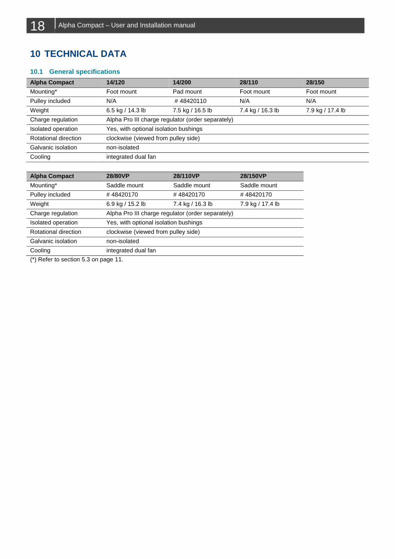
10.1 General specifications
Alpha Compact 14/120 14/200 28/110 28/150
Mounting* Foot mount Pad mount Foot mount Foot mount
Pulley included N/A # 48420110 N/A N/A
Weight 6.5 kg / 14.3 lb 7.5 kg / 16.5 lb 7.4 kg / 16.3 lb 7.9 kg / 17.4 lb
Charge regulation Alpha Pro III charge regulator (order separately)
Isolated operation Yes, with optional isolation bushings
Rotational direction clockwise (viewed from pulley side)
Galvanic isolation non-isolated
Cooling integrated dual fan
Alpha Compact 28/80VP 28/110VP 28/150VP
Mounting* Saddle mount Saddle mount Saddle mount
Pulley included # 48420170 # 48420170 # 48420170
Weight 6.9 kg / 15.2 lb 7.4 kg / 16.3 lb 7.9 kg / 17.4 lb
Charge regulation Alpha Pro III charge regulator (order separately)
Isolated operation Yes, with optional isolation bushings
Rotational direction clockwise (viewed from pulley side)
Galvanic isolation non-isolated
Cooling integrated dual fan
(*) Refer to section 5.3 on page 11.
Alpha Compact – User and Installation manual 19
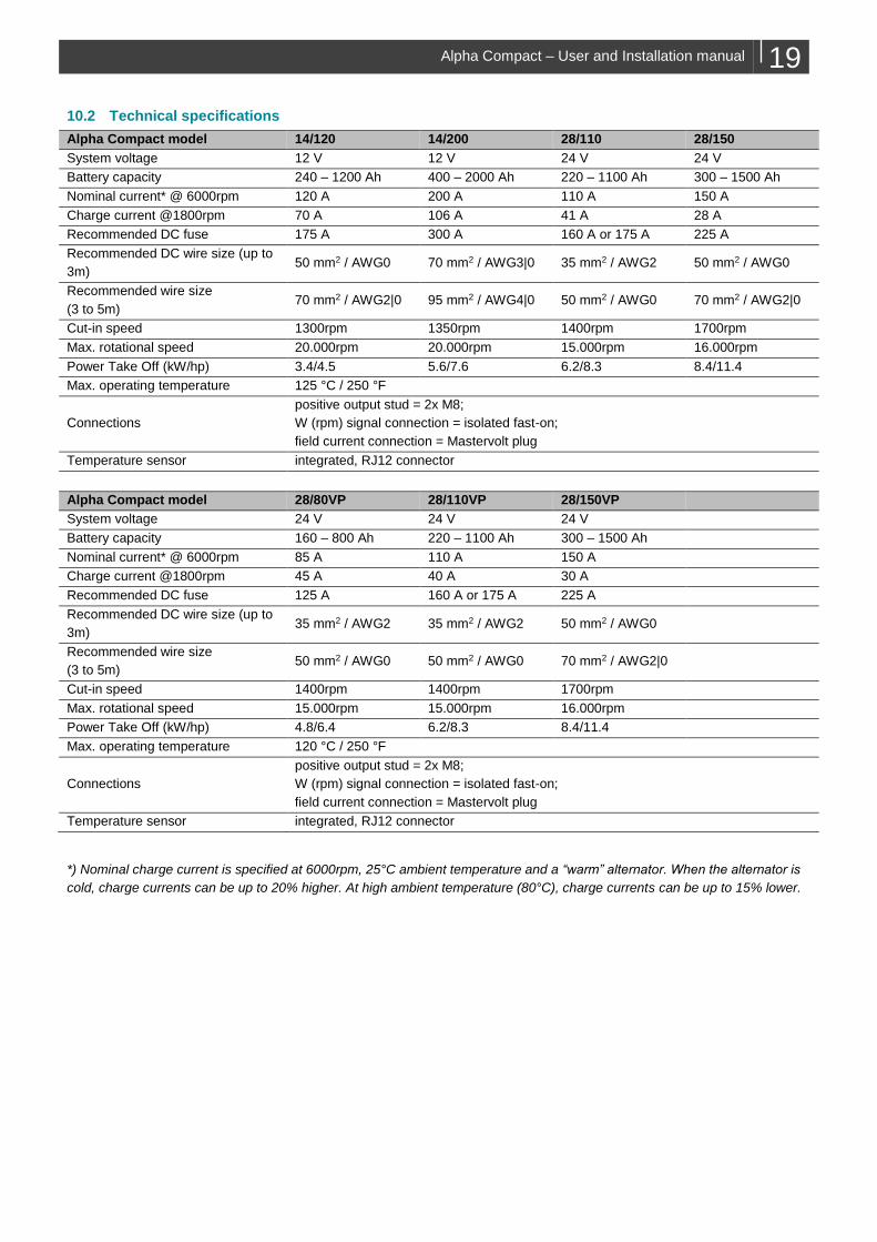
10.2 Technical specifications
Alpha Compact model 14/120 14/200 28/110 28/150
System voltage 12 V 12 V 24 V 24 V
Battery capacity 240 – 1200 Ah 400 – 2000 Ah 220 – 1100 Ah 300 – 1500 Ah
Nominal current* @ 6000rpm 120 A 200 A 110 A 150 A
Charge current @1800rpm 70 A 106 A 41 A 28 A
Recommended DC fuse 175 A 300 A 160 A or 175 A 225 A
Recommended DC wire size (up to
3m) 50 mm2 / AWG0 70 mm2 / AWG3|0 35 mm2 / AWG2 50 mm2 / AWG0
Recommended wire size
(3 to 5m) 70 mm2 / AWG2|0 95 mm2 / AWG4|0 50 mm2 / AWG0 70 mm2 / AWG2|0
Cut-in speed 1300rpm 1350rpm 1400rpm 1700rpm
Max. rotational speed 20.000rpm 20.000rpm 15.000rpm 16.000rpm
Power Take Off (kW/hp) 3.4/4.5 5.6/7.6 6.2/8.3 8.4/11.4
Max. operating temperature 125 °C / 250 °F
Connections
positive output stud = 2x M8;
W (rpm) signal connection = isolated fast-on;
field current connection = Mastervolt plug
Temperature sensor integrated, RJ12 connector
Alpha Compact model 28/80VP 28/110VP 28/150VP
System voltage 24 V 24 V 24 V
Battery capacity 160 – 800 Ah 220 – 1100 Ah 300 – 1500 Ah
Nominal current* @ 6000rpm 85 A 110 A 150 A
Charge current @1800rpm 45 A 40 A 30 A
Recommended DC fuse 125 A 160 A or 175 A 225 A
Recommended DC wire size (up to
3m) 35 mm2 / AWG2 35 mm2 / AWG2 50 mm2 / AWG0
Recommended wire size
(3 to 5m) 50 mm2 / AWG0 50 mm2 / AWG0 70 mm2 / AWG2|0
Cut-in speed 1400rpm 1400rpm 1700rpm
Max. rotational speed 15.000rpm 15.000rpm 16.000rpm
Power Take Off (kW/hp) 4.8/6.4 6.2/8.3 8.4/11.4
Max. operating temperature 120 °C / 250 °F
Connections
positive output stud = 2x M8;
W (rpm) signal connection = isolated fast-on;
field current connection = Mastervolt plug
Temperature sensor integrated, RJ12 connector
*) Nominal charge current is specified at 6000rpm, 25°C ambient temperature and a “warm” alternator. When the alternator is
cold, charge currents can be up to 20% higher. At high ambient temperature (80°C), charge currents can be up to 15% lower.
20 Alpha Compact – User and Installation manual
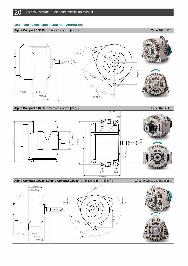
10.3 Mechanical specifications – Alternators
Alpha Compact 14/120 (dimensions in mm [inch] ) Code 46214120
Alpha Compact 14/200 (dimensions in mm [inch] ) Code 46214200
Alpha Compact 28/110 & Alpha Compact 28/150 (dimensions in mm [inch] ) Code 46228110 & 46228150
91 [3.58]
92
[3
.62
]
120°
56 [2.20]
56 [2.20]
77 [3.03]
76 [2.99]
97 [3.82]
M16x1.517[0.67]
10[0.39]
10[0.39]
15
6 [
6.1
4]
41
[1.6
1]
29
[1
.14
]
9[0.35]
151 [5.94]
73 [2.87]
17 [0.67]
22[0.87]
M16x1.5
17
3 [
6.8
1]
17
[0
.67
]
16
4 [
6.4
6]
9[0.35]
9[0.35]
9[0.35]
85 [3.35]
69 [2.72]
80 [3.15]
101 [3.98]
65 [2.56]
91 [3.58]
91 [3.58]
93
[3
.66
]
130 [5.12]
120° 120°
M16x1.517[0.67]
12[0.47]
12[0.47]
10[0.39]
Alpha Compact – User and Installation manual 21
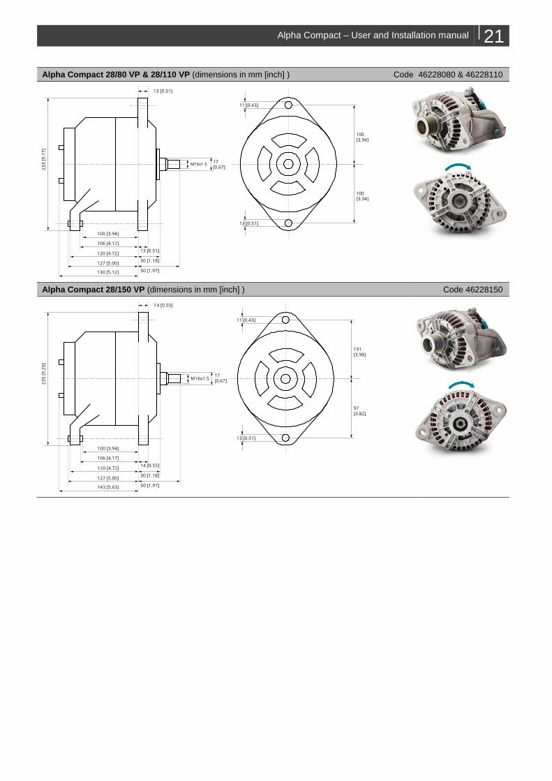
Alpha Compact 28/80 VP & 28/110 VP (dimensions in mm [inch] ) Code 46228080 & 46228110
Alpha Compact 28/150 VP (dimensions in mm [inch] ) Code 46228150
13 [0.51]
23
3 [
9.1
7]
106 [4.17]
100 [3.94]
120 [4.72]
127 [5.00]
130 [5.12]
13 [0.51]
30 [1.18]
50 [1.97]
M16x1.517[0.67]
11 [0.43]
13 [0.51]
100[3.94]
100[3.94]
11 [0.43]
13 [0.51]
101[3.98]
97[3.82]
14 [0.55]
23
5 [
9.2
5]
106 [4.17]
100 [3.94]
120 [4.72]
127 [5.00]
143 [5.63]
14 [0.55]
30 [1.18]
50 [1.97]
M16x1.517[0.67]
22 Alpha Compact – User and Installation manual
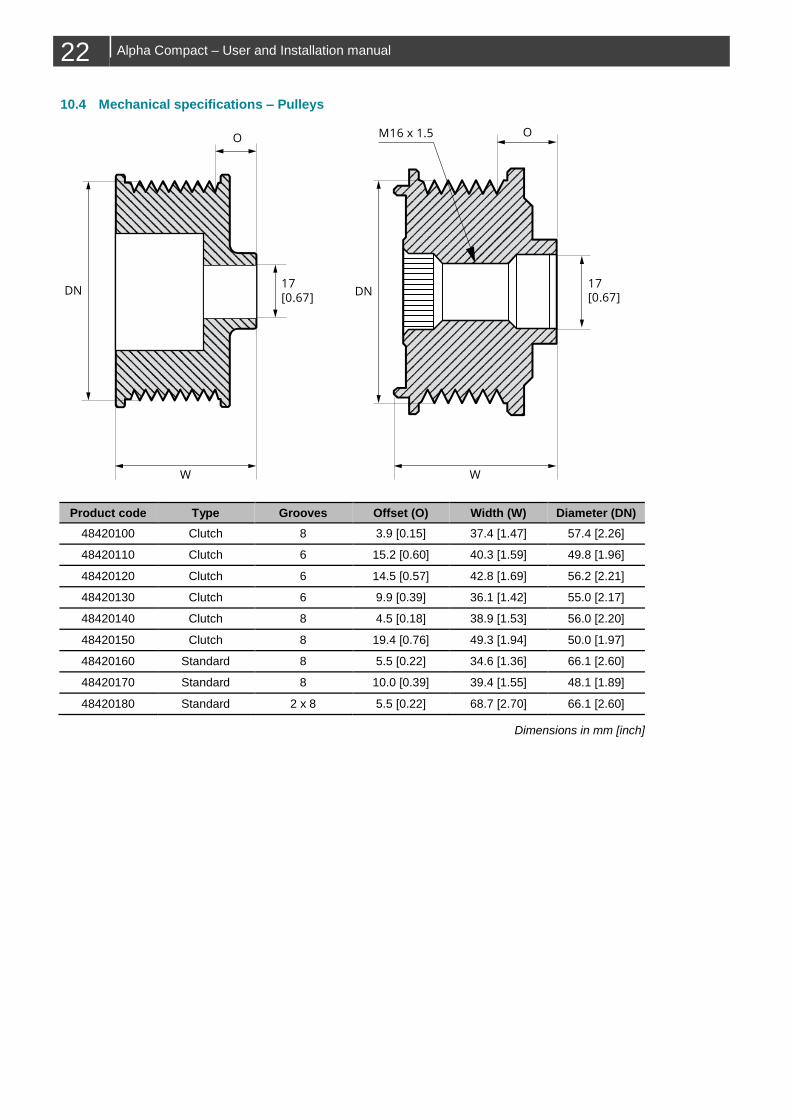
10.4 Mechanical specifications – Pulleys
Product code Type Grooves Offset (O) Width (W) Diameter (DN)
48420100 Clutch 8 3.9 [0.15] 37.4 [1.47] 57.4 [2.26]
48420110 Clutch 6 15.2 [0.60] 40.3 [1.59] 49.8 [1.96]
48420120 Clutch 6 14.5 [0.57] 42.8 [1.69] 56.2 [2.21]
48420130 Clutch 6 9.9 [0.39] 36.1 [1.42] 55.0 [2.17]
48420140 Clutch 8 4.5 [0.18] 38.9 [1.53] 56.0 [2.20]
48420150 Clutch 8 19.4 [0.76] 49.3 [1.94] 50.0 [1.97]
48420160 Standard 8 5.5 [0.22] 34.6 [1.36] 66.1 [2.60]
48420170 Standard 8 10.0 [0.39] 39.4 [1.55] 48.1 [1.89]
48420180 Standard 2 x 8 5.5 [0.22] 68.7 [2.70] 66.1 [2.60]
Dimensions in mm [inch]
17[0.67]
O
DN
OM16 x 1.5
WW
17[0.67]
DN
Alpha Compact – User and Installation manual 23
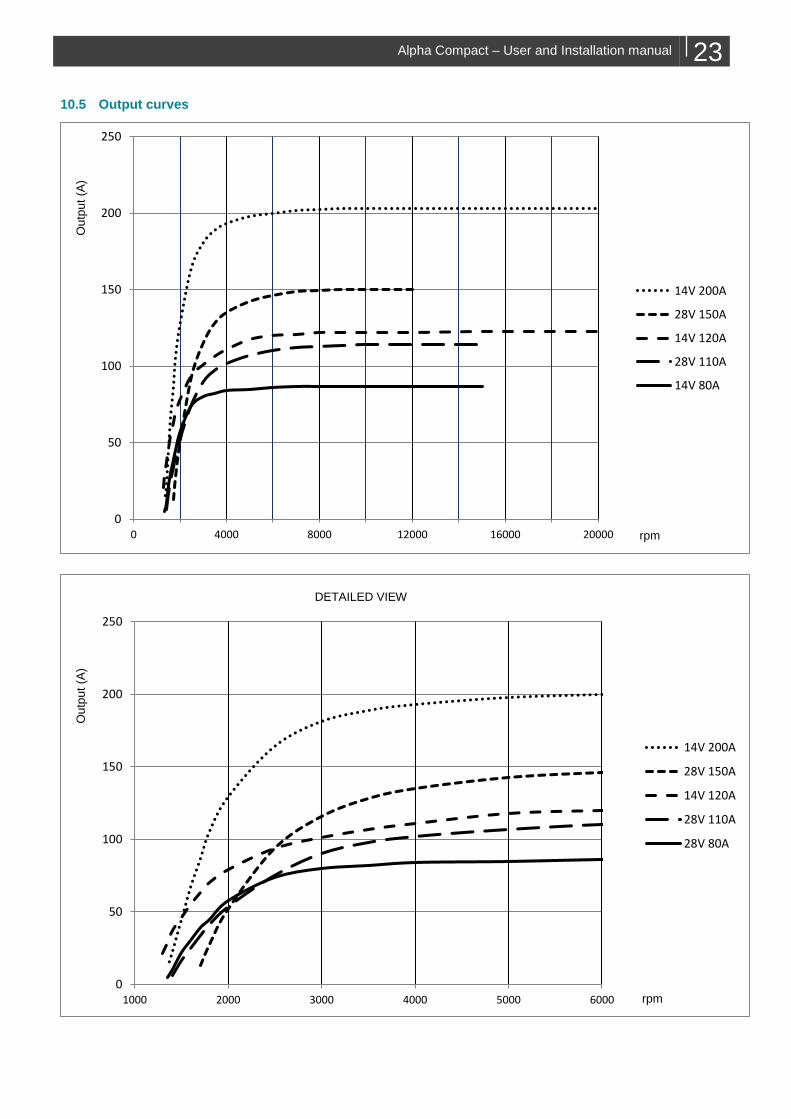
10.5 Output curves
0
50
100
150
200
250
0 4000 8000 12000 16000 20000
14V 200A
28V 150A
14V 120A
28V 110A
14V 80A
0
50
100
150
200
250
1000 2000 3000 4000 5000 6000
14V 200A
28V 150A
14V 120A
28V 110A
28V 80A
rpm
Ou
tpu
t (A
) O
utp
ut
(A)
DETAILED VIEW
rpm

Europe, Middle East & Africa
Customer Service
T: +31 (0) 20 34 22 100
Technical Support
T: +31 (0) 20 34 22 100
Location & Shipping
Mastervolt
Snijdersbergweg 93
1105 AN Amsterdam
The Netherlands
Americas & Caribbean
Customer Service
T: +1 800 307 6702, Option 1
Technical Support
T: +1 800 307 6702, Option 2
Location & Shipping
Power Products, LLC
N85 W12545 Westbrook Crossing
Menomonee Falls, Wisconsin 53051
United States
Asia Pacific
Customer Service
T: +64 9 415 7261 Option 1
Technical Support
T: +64 9 415 7261 Option 3
Location & Shipping
BEP Marine
42 Apollo Drive
Rosedale, Auckland 0632
New Zealand
Copyrig
ht ©
2019 M
aste
rvolt. A
ll rights
reserv
ed.
Repro
ductio
n, tra
nsfe
r, dis
tributio
n o
r sto
rage o
f part o
r all o
f the c
onte
nts
in th
is
docum
ent in
any fo
rm w
ithout th
e p
rior w
ritten p
erm
issio
n o
f Maste
rvolt is
pro
hib
ited.


