Embed Size (px)
Citation preview
1
Coexistence of Wireless Technologies in the 5 GHz Bands: A Survey
of Existing Solutions and a Roadmap for Future Research
Gaurang Naik, Student Member, IEEE, Jinshan Liu, Jung-Min (Jerry) Park, Fellow, IEEE
Abstract—As the 2.4 GHz spectrum band has become sig-nificantly congested, there is growing interest from the Wi-Fiproponents, cellular operators, and other stakeholders to use thespectrum in the 5 GHz bands. The 5 GHz bands have emerged asthe most coveted bands for launching new wireless applicationsand services, because of their relatively favorable propagationcharacteristics and the relative abundance of spectrum therein.To meet the exploding demand for more unlicensed spectrum,regulators across the world such as the United States (US) FederalCommunications Commission (FCC) and the European Elec-tronic Communications Committee (ECC) have recently startedconsiderations for opening up additional spectrum in the 5 GHzbands for use by unlicensed devices. Moreover, to boost cellularnetwork capacity, wireless service providers are considering thedeployment of unlicensed Long Term Evaluation (LTE) in the5 GHz bands. This and other emerging wireless technologiesand applications have resulted in likely deployment scenarioswhere multiple licensed and unlicensed networks operate inoverlapping spectrum. This paper provides a comprehensiveoverview of the various coexistence scenarios in the 5 GHz bands.In this paper, we discuss coexistence issues between a numberof important wireless technologies—viz., LTE and Wi-Fi, radarand Wi-Fi, Dedicated Short Range Communication (DSRC)and Wi-Fi, and coexistence among various 802.11 protocolsoperating in the 5 GHz bands. Additionally, we identify andprovide brief discussions on an impending coexistence issue – onebetween Cellular V2X and DSRC/Wi-Fi. We summarize relevantstandardization initiatives, explain existing coexistence solutions,and discuss open research problems.
I. INTRODUCTION
The proliferation of mobile devices has led to an exponential
increase in mobile data traffic that shows no sign of being
abated. Global mobile data traffic reached 3.7 exabytes per
month at the end of 2015, growing 76% over 2.1 exabytes per
month at the end of 2014 [1]. It is expected that monthly global
mobile data traffic will be 30.6 exabytes by the year 2020. The
explosive growth in mobile data traffic has led to a surging
demand for more radio frequency spectrum, but the supply
has not kept up with the demand. This spectrum scarcity has
motivated the development of technologies and techniques for
increasing the efficiency of spectrum already in use.
The exorbitant cost of licensed spectrum has led to the
development of wireless technologies operating in the unli-
censed bands. The two most widely used unlicensed bands
are in the 2.4 GHz and 5 GHz range. As the 2.4 GHz
band has become increasingly congested, there is a great deal
This work was supported in part by NSF, the industry affiliates of theBroadband Wireless Access & Applications Center (BWAC), and the Wire-less@Virginia Tech group. Any opinions or conclusions expressed in thispaper are those of the author(s), and do not necessarily reflect the views ofNSF.
The authors are with the Bradley Department of Electrical and Com-puter Engineering, Virginia Tech, Arlington, VA 22203 USA (Email: [email protected]; [email protected]; [email protected])
U-NII-1
100 MHz
U-NII-2A
100 MHz
U-NII-2B
120 MHz
U-NII-2C
255 MHz
U-NII-3
125 MHz
U-NII-4
75 MHz
5.150 GHz 5.250 GHz 5.350 GHz 5.470 GHz 5.725 GHz 5.850 GHz 5.925 GHz
5 GHz Spectrum
US, China,
Korea, Europe,
Japan, India
US, Korea,
Europe, Japan
US, China,
Korea,
India
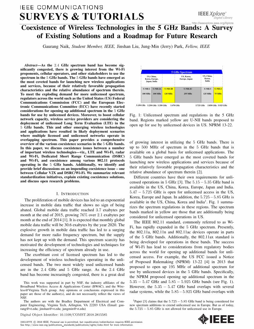
Fig. 1: Unlicensed spectrum and regulations in the 5 GHz
band. Regions marked yellow are U-NII bands proposed to
open up for use by unlicensed devices in US. NPRM 13-22.
of growing interest in utilizing the 5 GHz bands. There is
up to 500 MHz of spectrum in the 5 GHz bands that is
available on a global basis for unlicensed applications. The
5 GHz bands have emerged as the most coveted bands for
launching new wireless applications and services because of
their relatively favorable propagation characteristics and the
relative abundance of spectrum therein [2].
Different countries have their own requirements for unli-
censed operations in 5 GHz [3]. The 5.15−5.35 GHz band is
available in the US, China, Korea, Europe, Japan and India.
5.47 − 5.725 GHz is open for unlicensed access in the US,
Korea, Europe and Japan. In addition, the 5.725−5.85 GHz is
available in the US, China, Korea and India1. Fig. 1 summa-
rizes the spectrum regulations in these regions. The spectrum
bands marked in yellow are those that are additionally being
considered for unlicensed operations in US.
The IEEE 802.11 standard, commonly referred to as Wi-
Fi, has rapidly expanded in the 5 GHz spectrum. Presently,
the 802.11a, 802.11n and 802.11ac devices operate in parts
of the 5 GHz bands. Additionally, the 802.11ax standard is
being developed for operations in these bands. The success
of Wi-Fi has lead to considerations from regulatory bodies
across the world for opening up additional bands for unli-
censed access. For example, the US FCC issued a Notice
of Proposed Rulemaking (NPRM) 13-22 [4] in 2013 that
proposed to open up 195 MHz of additional spectrum for
use by unlicensed devices in the 5 GHz bands. Specifically,
the NPRM proposed opening up additional spectrum in the
5.35 − 5.47 GHz and 5.85 − 5.925 GHz bands (see Fig. 1).
However, the 5.35 − 5.47 GHz band overlaps with several
radar systems, while the 5.85−5.925 GHz band overlaps with
1Paper [3] claims that the 5.725− 5.85 GHz band is being considered fornew spectrum additions to extend unlicensed use in Europe. But as of today,the 5.725− 5.85 GHz is not allowed for unlicensed use in Europe.
Digital Object Identifier: 10.1109/COMST.2018.2815585
1553-877X c© 2018 IEEE. Personal use is permitted, but republication/redistribution requires IEEE permission.See http://www.ieee.org/publications standards/publications/rights/index.html for more information.
2
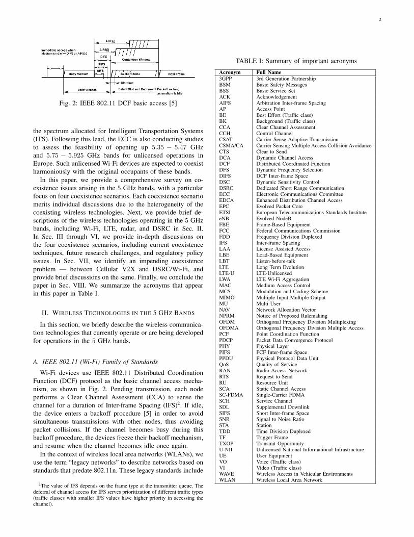
Fig. 2: IEEE 802.11 DCF basic access [5]
the spectrum allocated for Intelligent Transportation Systems
(ITS). Following this lead, the ECC is also conducting studies
to assess the feasibility of opening up 5.35 − 5.47 GHz
and 5.75 − 5.925 GHz bands for unlicensed operations in
Europe. Such unlicensed Wi-Fi devices are expected to coexist
harmoniously with the original occupants of these bands.
In this paper, we provide a comprehensive survey on co-
existence issues arising in the 5 GHz bands, with a particular
focus on four coexistence scenarios. Each coexistence scenario
merits individual discussions due to the heterogeneity of the
coexisting wireless technologies. Next, we provide brief de-
scriptions of the wireless technologies operating in the 5 GHz
bands, including Wi-Fi, LTE, radar, and DSRC in Sec. II.
In Sec. III through VI, we provide in-depth discussions on
the four coexistence scenarios, including current coexistence
techniques, future research challenges, and regulatory policy
issues. In Sec. VII, we identify an impending coexistence
problem — between Cellular V2X and DSRC/Wi-Fi, and
provide brief discussions on the same. Finally, we conclude the
paper in Sec. VIII. We summarize the acronyms that appear
in this paper in Table I.
II. WIRELESS TECHNOLOGIES IN THE 5 GHZ BANDS
In this section, we briefly describe the wireless communica-
tion technologies that currently operate or are being developed
for operations in the 5 GHz bands.
A. IEEE 802.11 (Wi-Fi) Family of Standards
Wi-Fi devices use IEEE 802.11 Distributed Coordination
Function (DCF) protocol as the basic channel access mecha-
nism, as shown in Fig. 2. Pending transmission, each node
performs a Clear Channel Assessment (CCA) to sense the
channel for a duration of Inter-frame Spacing (IFS)2. If idle,
the device enters a backoff procedure [5] in order to avoid
simultaneous transmissions with other nodes, thus avoiding
packet collisions. If the channel becomes busy during this
backoff procedure, the devices freeze their backoff mechanism,
and resume when the channel becomes idle once again.
In the context of wireless local area networks (WLANs), we
use the term “legacy networks” to describe networks based on
standards that predate 802.11n. These legacy standards include
2The value of IFS depends on the frame type at the transmitter queue. Thedeferral of channel access for IFS serves prioritization of different traffic types(traffic classes with smaller IFS values have higher priority in accessing thechannel).
TABLE I: Summary of important acronyms
Acronym Full Name
3GPP 3rd Generation PartnershipBSM Basic Safety MessagesBSS Basic Service SetACK AcknowledgementAIFS Arbitration Inter-frame SpacingAP Access PointBE Best Effort (Traffic class)BK Background (Traffic class)CCA Clear Channel AssessmentCCH Control ChannelCSAT Carrier Sense Adaptive TransmissionCSMA/CA Carrier Sensing Multiple Access Collision AvoidanceCTS Clear to SendDCA Dynamic Channel AccessDCF Distributed Coordinated FunctionDFS Dynamic Frequency SelectionDIFS DCF Inter-frame SpaceDSC Dynamic Sensitivity ControlDSRC Dedicated Short Range CommunicationECC Electronic Communications CommitteeEDCA Enhanced Distribution Channel AccessEPC Evolved Packet CoreETSI European Telecommunications Standards InstituteeNB Evolved NodeBFBE Frame-Based EquipmentFCC Federal Communications CommissionFDD Frequency Division DuplexedIFS Inter-frame SpacingLAA License Assisted AccessLBE Load-Based EquipmentLBT Listen-before-talkLTE Long Term EvolutionLTE-U LTE-UnlicensedLWA LTE Wi-Fi AggregationMAC Medium Access ControlMCS Modulation and Coding SchemeMIMO Multiple Input Multiple OutputMU Multi UserNAV Network Allocation VectorNPRM Notice of Proposed RulemakingOFDM Orthogonal Frequency Division MultiplexingOFDMA Orthogonal Frequency Division Multiple AccessPCF Point Coordination FunctionPDCP Packet Data Convergence ProtocolPHY Physical LayerPIFS PCF Inter-frame SpacePPDU Physical Protocol Data UnitQoS Quality of ServiceRAN Radio Access NetworkRTS Request to SendRU Resource UnitSCA Static Channel AccessSC-FDMA Single-Carrier FDMASCH Service ChannelSDL Supplemental DownlinkSIFS Short Inter-frame SpaceSNR Signal to Noise RatioSTA StationTDD Time Division DuplexedTF Trigger FrameTXOP Transmit OpportunityU-NII Unlicensed National Informational InfrastructureUE User EquipmentVO Voice (Traffic class)VI Video (Traffic class)WAVE Wireless Access in Vehicular EnvironmentsWLAN Wireless Local Area Network
3
PIFS
DIFS Backoff Time Data Transmission
Transmission beginCannot transmit
Primary 20 MHz channel
Secondary 20 MHz channelPIFS
DIFS Backoff Time
Channel is occupiedData Transmission
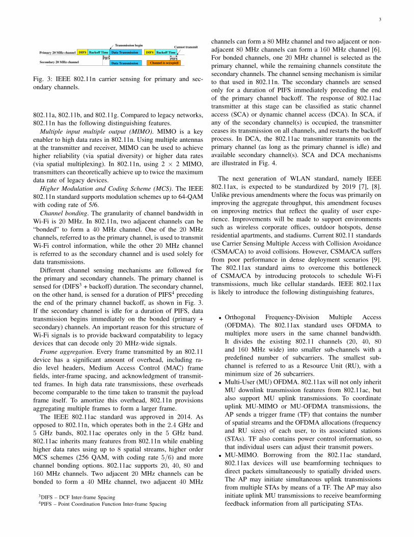
Fig. 3: IEEE 802.11n carrier sensing for primary and sec-
ondary channels.
802.11a, 802.11b, and 802.11g. Compared to legacy networks,
802.11n has the following distinguishing features.
Multiple input multiple output (MIMO). MIMO is a key
enabler to high data rates in 802.11n. Using multiple antennas
at the transmitter and receiver, MIMO can be used to achieve
higher reliability (via spatial diversity) or higher data rates
(via spatial multiplexing). In 802.11n, using 2 × 2 MIMO,
transmitters can theoretically achieve up to twice the maximum
data rate of legacy devices.
Higher Modulation and Coding Scheme (MCS). The IEEE
802.11n standard supports modulation schemes up to 64-QAM
with coding rate of 5/6.
Channel bonding. The granularity of channel bandwidth in
Wi-Fi is 20 MHz. In 802.11n, two adjacent channels can be
“bonded” to form a 40 MHz channel. One of the 20 MHz
channels, referred to as the primary channel, is used to transmit
Wi-Fi control information, while the other 20 MHz channel
is referred to as the secondary channel and is used solely for
data transmissions.
Different channel sensing mechanisms are followed for
the primary and secondary channels. The primary channel is
sensed for (DIFS3 + backoff) duration. The secondary channel,
on the other hand, is sensed for a duration of PIFS4 preceding
the end of the primary channel backoff, as shown in Fig. 3.
If the secondary channel is idle for a duration of PIFS, data
transmission begins immediately on the bonded (primary +
secondary) channels. An important reason for this structure of
Wi-Fi signals is to provide backward compatability to legacy
devices that can decode only 20 MHz-wide signals.
Frame aggregation. Every frame transmitted by an 802.11
device has a significant amount of overhead, including ra-
dio level headers, Medium Access Control (MAC) frame
fields, inter-frame spacing, and acknowledgment of transmit-
ted frames. In high data rate transmissions, these overheads
become comparable to the time taken to transmit the payload
frame itself. To amortize this overhead, 802.11n provisions
aggregating multiple frames to form a larger frame.
The IEEE 802.11ac standard was approved in 2014. As
opposed to 802.11n, which operates both in the 2.4 GHz and
5 GHz bands, 802.11ac operates only in the 5 GHz band.
802.11ac inherits many features from 802.11n while enabling
higher data rates using up to 8 spatial streams, higher order
MCS schemes (256 QAM, with coding rate 5/6) and more
channel bonding options. 802.11ac supports 20, 40, 80 and
160 MHz channels. Two adjacent 20 MHz channels can be
bonded to form a 40 MHz channel, two adjacent 40 MHz
3DIFS – DCF Inter-frame Spacing4PIFS – Point Coordination Function Inter-frame Spacing
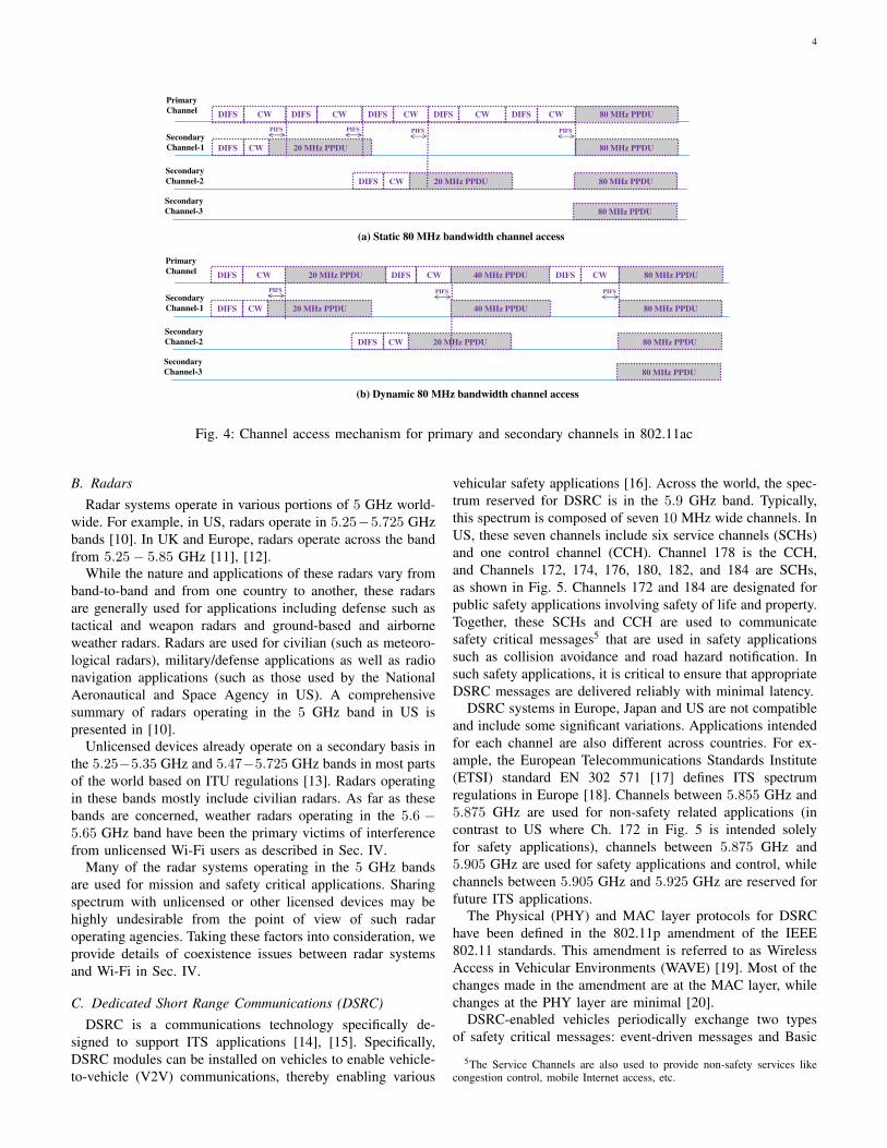
channels can form a 80 MHz channel and two adjacent or non-
adjacent 80 MHz channels can form a 160 MHz channel [6].
For bonded channels, one 20 MHz channel is selected as the
primary channel, while the remaining channels constitute the
secondary channels. The channel sensing mechanism is similar
to that used in 802.11n. The secondary channels are sensed
only for a duration of PIFS immediately preceding the end
of the primary channel backoff. The response of 802.11ac
transmitter at this stage can be classified as static channel
access (SCA) or dynamic channel access (DCA). In SCA, if
any of the secondary channel(s) is occupied, the transmitter
ceases its transmission on all channels, and restarts the backoff
process. In DCA, the 802.11ac transmitter transmits on the
primary channel (as long as the primary channel is idle) and
available secondary channel(s). SCA and DCA mechanisms
are illustrated in Fig. 4.
The next generation of WLAN standard, namely IEEE
802.11ax, is expected to be standardized by 2019 [7], [8].
Unlike previous amendments where the focus was primarily on
improving the aggregate throughput, this amendment focuses
on improving metrics that reflect the quality of user expe-
rience. Improvements will be made to support environments
such as wireless corporate offices, outdoor hotspots, dense
residential apartments, and stadiums. Current 802.11 standards
use Carrier Sensing Multiple Access with Collision Avoidance
(CSMA/CA) to avoid collisions. However, CSMA/CA suffers
from poor performance in dense deployment scenarios [9].
The 802.11ax standard aims to overcome this bottleneck
of CSMA/CA by introducing protocols to schedule Wi-Fi
transmissions, much like cellular standards. IEEE 802.11ax
is likely to introduce the following distinguishing features,
• Orthogonal Frequency-Division Multiple Access
(OFDMA). The 802.11ax standard uses OFDMA to
multiplex more users in the same channel bandwidth.
It divides the existing 802.11 channels (20, 40, 80and 160 MHz wide) into smaller sub-channels with a
predefined number of subcarriers. The smallest sub-
channel is referred to as a Resource Unit (RU), with a
minimum size of 26 subcarriers.
• Multi-User (MU) OFDMA. 802.11ax will not only inherit
MU downlink transmission features from 802.11ac, but
also support MU uplink transmissions. To coordinate
uplink MU-MIMO or MU-OFDMA transmissions, the
AP sends a trigger frame (TF) that contains the number
of spatial streams and the OFDMA allocations (frequency
and RU sizes) of each user, to its associated stations
(STAs). TF also contains power control information, so
that individual users can adjust their transmit powers.
• MU-MIMO. Borrowing from the 802.11ac standard,
802.11ax devices will use beamforming techniques to
direct packets simultaneously to spatially divided users.
The AP may initiate simultaneous uplink transmissions
from multiple STAs by means of a TF. The AP may also
initiate uplink MU transmissions to receive beamforming
feedback information from all participating STAs.
4
Primary
ChannelDIFS CW DIFS CW DIFS CW DIFS CW DIFS CW 80 MHz PPDU
Secondary
Channel-1 DIFS CW 80 MHz PPDU20 MHz PPDU
PIFS PIFS PIFS PIFS
Secondary
Channel-2 DIFS CW 80 MHz PPDU20 MHz PPDU
Secondary
Channel-3 80 MHz PPDU
Primary
ChannelDIFS CW DIFS CW DIFS CW
Secondary
Channel-1 DIFS CW 80 MHz PPDU20 MHz PPDU
PIFS PIFS PIFS
Secondary
Channel-2 DIFS CW 80 MHz PPDU20 MHz PPDU
Secondary
Channel-3 80 MHz PPDU
20 MHz PPDU 80 MHz PPDU40 MHz PPDU
40 MHz PPDU
(a) Static 80 MHz bandwidth channel access
(b) Dynamic 80 MHz bandwidth channel access
Fig. 4: Channel access mechanism for primary and secondary channels in 802.11ac
B. Radars
Radar systems operate in various portions of 5 GHz world-
wide. For example, in US, radars operate in 5.25−5.725 GHz
bands [10]. In UK and Europe, radars operate across the band
from 5.25− 5.85 GHz [11], [12].While the nature and applications of these radars vary from
band-to-band and from one country to another, these radars
are generally used for applications including defense such as
tactical and weapon radars and ground-based and airborne
weather radars. Radars are used for civilian (such as meteoro-
logical radars), military/defense applications as well as radio
navigation applications (such as those used by the National
Aeronautical and Space Agency in US). A comprehensive
summary of radars operating in the 5 GHz band in US is
presented in [10].Unlicensed devices already operate on a secondary basis in
the 5.25−5.35 GHz and 5.47−5.725 GHz bands in most parts
of the world based on ITU regulations [13]. Radars operating
in these bands mostly include civilian radars. As far as these
bands are concerned, weather radars operating in the 5.6 −
5.65 GHz band have been the primary victims of interference
from unlicensed Wi-Fi users as described in Sec. IV.Many of the radar systems operating in the 5 GHz bands
are used for mission and safety critical applications. Sharing
spectrum with unlicensed or other licensed devices may be
highly undesirable from the point of view of such radar
operating agencies. Taking these factors into consideration, we
provide details of coexistence issues between radar systems
and Wi-Fi in Sec. IV.
C. Dedicated Short Range Communications (DSRC)
DSRC is a communications technology specifically de-
signed to support ITS applications [14], [15]. Specifically,
DSRC modules can be installed on vehicles to enable vehicle-
to-vehicle (V2V) communications, thereby enabling various
vehicular safety applications [16]. Across the world, the spec-
trum reserved for DSRC is in the 5.9 GHz band. Typically,
this spectrum is composed of seven 10 MHz wide channels. In
US, these seven channels include six service channels (SCHs)
and one control channel (CCH). Channel 178 is the CCH,
and Channels 172, 174, 176, 180, 182, and 184 are SCHs,
as shown in Fig. 5. Channels 172 and 184 are designated for
public safety applications involving safety of life and property.
Together, these SCHs and CCH are used to communicate
safety critical messages5 that are used in safety applications
such as collision avoidance and road hazard notification. In
such safety applications, it is critical to ensure that appropriate
DSRC messages are delivered reliably with minimal latency.DSRC systems in Europe, Japan and US are not compatible
and include some significant variations. Applications intended
for each channel are also different across countries. For ex-
ample, the European Telecommunications Standards Institute
(ETSI) standard EN 302 571 [17] defines ITS spectrum
regulations in Europe [18]. Channels between 5.855 GHz and
5.875 GHz are used for non-safety related applications (in
contrast to US where Ch. 172 in Fig. 5 is intended solely
for safety applications), channels between 5.875 GHz and
5.905 GHz are used for safety applications and control, while
channels between 5.905 GHz and 5.925 GHz are reserved for
future ITS applications.The Physical (PHY) and MAC layer protocols for DSRC
have been defined in the 802.11p amendment of the IEEE
802.11 standards. This amendment is referred to as Wireless
Access in Vehicular Environments (WAVE) [19]. Most of the
changes made in the amendment are at the MAC layer, while
changes at the PHY layer are minimal [20].DSRC-enabled vehicles periodically exchange two types
of safety critical messages: event-driven messages and Basic
5The Service Channels are also used to provide non-safety services likecongestion control, mobile Internet access, etc.
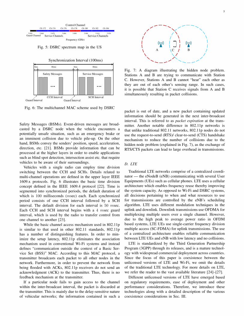
5
5.850 5.860 5.870 5.880 5.890 5.900 5.910 5.920
Frequency (GHz)
Ch 172 Ch 174 Ch 176 Ch 178 Ch 180 Ch 182 Ch 184
Control Channel
Service Channels Service ChannelsGuard Channel
Fig. 5: DSRC spectrum map in the US
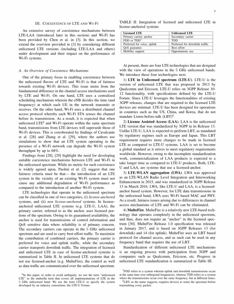
Safety Messages Service Messages
CCH Interval SCH IntervalGuard Interval
4ms 4ms46ms 46ms
Synchronization Interval (100ms)
Guard Interval
Fig. 6: The multichannel MAC scheme used by DSRC
Safety Messages (BSMs). Event-driven messages are broad-
casted by a DSRC node when the vehicle encounters a
potentially unsafe situation, such as an emergency brake or
an imminent collision due to vehicle pile-up. On the other
hand, BSMs convey the senders’ position, speed, acceleration,
direction, etc. [21]. BSMs provide information that can be
processed at the higher layers in order to enable applications
such as blind spot detection, intersection assist etc. that require
vehicles to be aware of their surroundings.
Vehicles with a single radio can employ time division
switching between the CCH and SCHs. Details related to
multi-channel operations are defined in the upper layer IEEE
1609.x protocols. Fig. 6 illustrates the basic time division
concept defined in the IEEE 1609.4 protocol [22]. Time is
segmented into synchronized periods, the default duration of
which is 100 milliseconds (msec) each. Each synchronized
period consists of one CCH interval followed by a SCH
interval. The default division for each interval is 50 msec.
Each CCH and SCH interval begins with a 4 msec guard
interval, which is used by the radio to transfer control from
one channel to another [23].
While the basic channel access mechanism used in 802.11p
is similar to that used in other 802.11 standards, 802.11p
has a number of distinguishing features. In order to min-
imize the setup latency, 802.11p eliminates the association
mechanism used in conventional Wi-Fi systems and instead
defines “communication outside the context of a Basic Ser-
vice Set (BSS)” MAC. According to this MAC protocol, a
transmitter broadcasts each packet to all other nodes in the
network. Furthermore, in order to prevent the network from
being flooded with ACKs, 802.11p receivers do not send an
acknowledgment (ACK) to the transmitter. Thus, there is no
feedback mechanism at the transmitter.
If a particular node fails to gain access to the channel
within the inter-broadcast interval, the packet is discarded at
the transmitter. This is mainly due to the delay-sensitive nature
of vehicular networks; the information contained in such a
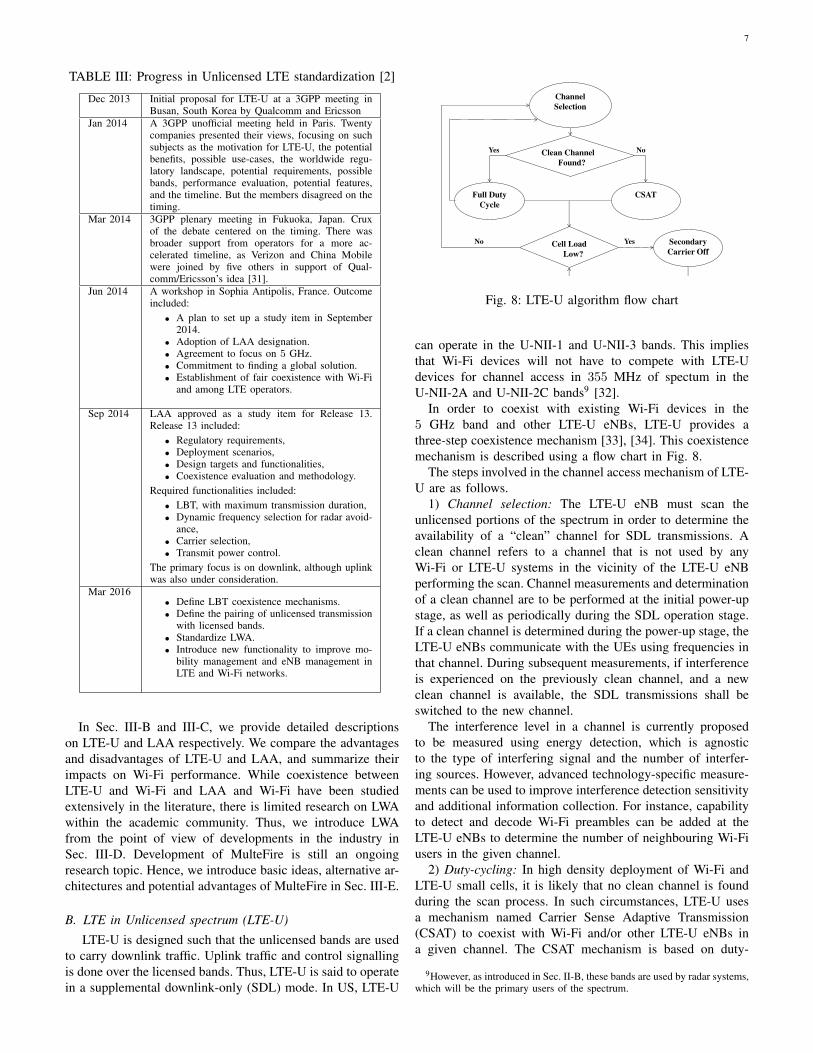
A BC
Fig. 7: A diagram illustrating the hidden node problem.
Stations A and B are trying to communicate with Station
C. However, Stations A and B cannot “hear” each other as
they are out of each other’s sensing range. In such cases,
it is possible that Station C receives signals from A and B
simultaneously resulting in packet collisions.
packet is out of date, and a new packet containing updated
information should be generated in the next inter-broadcast
interval. This is referred to as packet expiration at the trans-
mitter. Another notable difference in 802.11p networks is
that unlike traditional 802.11 networks, 802.11p nodes do not
use the request-to-send (RTS)/ clear-to-send (CTS) handshake
mechanism to reduce the number of collisions due to the
hidden node problem (explained in Fig. 7), as the exchange of
RTS/CTS packets can lead to large overhead in transmissions.
D. LTE
Traditional LTE networks comprise of a centralized coordi-
nator — the eNodeB (eNB) communicating with several User
Equipments (UEs) such as cellular phones. LTE uses a cellular
architecture which enables frequency reuse thereby improving
the system capacity. As opposed to Wi-Fi and DSRC systems,
all decisions pertaining to when and what resources to use
for transmissions are controlled by the eNB’s scheduling
algorithm. LTE uses different modulation techniques in the
uplink and downlink. Downlink transmissions use OFDMA for
multiplexing multiple users over a single channel. However,
due to the high peak to average power ratio in OFDM
based systems, LTE UEs use single-carrier frequency division
multiple access (SC-FDMA) for uplink transmissions. The use
of a centralized architecture enables reliable communication
between LTE UEs and eNB with low latency and no collisions.
LTE is standardized by the Third Generation Partnership
Program (3GPP) through its releases, and is a mature technol-
ogy with widespread commercial deployment across countries.
Since the focus of this paper is coexistence between the
unlicensed versions of LTE and Wi-Fi, we omit the details
of the traditional LTE technology. For more details on LTE,
we refer the reader to the vast available literature [24]–[27].
Different unlicensed versions of LTE have emerged based
on regulatory requirements, ease of deployment and other
performance considerations. Therefore, we introduce these
technologies along with a detailed description of the various
coexistence considerations in Sec. III.
6
III. COEXISTENCE OF LTE AND WI-FI
An extensive survey of coexistence mechanisms between
LTE-LAA (introduced later in this section) and Wi-Fi has
been provided by Chen et al. in [3]. In this section, we
extend the overview provided in [3] by considering different
unlicensed LTE versions (including LTE-LAA and others)
under development and their impact on the performance of
Wi-Fi systems.
A. An Overview of Coexistence Mechanisms
One of the primary focus in enabling coexistence between
the unlicensed flavors of LTE and Wi-Fi is that of fairness
towards existing Wi-Fi devices. This issue stems from the
fundamental difference in the channel access mechanisms used
by LTE and Wi-Fi. On one hand, LTE uses a centralized
scheduling mechanism wherein the eNB decides the time (and
frequency) at which each UE in the network transmits or
receives. On the other hand, Wi-Fi uses a distributed channel
access protocol whereby each Wi-Fi STA senses the channel
before its transmission. As a result, it is expected that when
unlicensed LTE6 and Wi-Fi operate within the same spectrum
band, transmissions from LTE devices will supersede those of
Wi-Fi devices. This is corroborated by findings of Cavalcante
et al. [28] and Zhang et al. [29], where the authors use
simulations to show that an LTE system operating in the
presence of a Wi-Fi network can degrade the Wi-Fi system
throughput by up to 68%.
Findings from [28], [29] highlight the need for developing
suitable coexistence mechanisms between LTE and Wi-Fi in
the unlicensed spectrum. While no metric for such coexistence
is widely agreed upon, Paolini et al. [2] suggest that one
fairness criteria must be that— the introduction of an LTE
system in the vicinity of an existing Wi-Fi system must not
cause any additional degradation of Wi-Fi performance as
compared to the introduction of another Wi-Fi system.
LTE technologies that operate in the unlicensed spectrum
can be classified in one of two categories, (i) license-anchored
systems, and (ii) non license-anchored systems. In license-
anchored unlicensed LTE systems (e.g. LTE-U, LAA), the
primary carrier, referred to as the anchor, uses licensed por-
tions of the spectrum. Owing to its guaranteed availability, the
anchor is used for transmissions of control information and
QoS sensitive data where reliability is of primary concern.
The secondary carriers can operate in the 5 GHz unlicensed
spectrum and are used to carry best-effort traffic. To maximize
the contribution of combined carriers, the primary carrier is
preferred for voice and uplink traffic, while the secondary
carrier transports downlink traffic. The integration of licensed
and unlicensed LTE in case of license-anchored systems is
summarized in Table II. In unlicensed LTE systems that do
not use licensed-anchor (e.g. MulteFire), the control as well
as data traffic are communicated over the unlicensed spectrum.
6In this paper, in order to avoid ambiguity, we use the term “unlicensedLTE” as the umbrella term that covers all implementations of LTE in the5 GHz unlicensed band. We use the term LTE-U to specify the systemdeveloped by an industry consortium, the LTE-U Forum.
TABLE II: Integration of licensed and unlicensed LTE in
license-anchored systems
Licensed LTE Unlicensed LTE
Primary carrier, anchor Secondary carrier
FDD or TDD7 TDDPreferred for voice, uplink Preferred for downlink trafficQoS guarantee Best effortMobility support Opportunistic use
At present, there are four LTE technologies that are designed
with the view of operations in the 5 GHz unlicensed bands.
We introduce these four technologies next.
1) LTE in Unlicensed spectrum (LTE-U). LTE-U is the
version of unlicensed LTE that was proposed in 2013 by
Qualcomm and Ericsson. LTE-U relies on 3GPP Release 10-
12 functionality, with specifications defined by the LTE-U
Forum. Since LTE-U leverages the functionalities of existing
3GPP releases, changes that are required to the licensed LTE
devices are minimal. LTE-U has been designed for operations
in countries such as the US, China, and Korea, that do not
mandate Listen-before-talk (LBT)8.
2) License Assisted Access (LAA). LAA is the unlicensed
LTE version that was standardized by 3GPP in its Release 13.
Unlike LTE-U, LAA is expected to perform LBT, as mandated
by regulatory regimes such as Europe and Japan. This LBT
requirement requires more changes to be made in licensed
LTE as compared to LTE-U systems. LAA is set to become
a global standard as it strives to meet regulatory requirements
worldwide. However, owing to the incomplete standardization
work, commercialization of LAA products is expected to a
take longer time as compared to LTE-U products. Both, LTE-
U and LAA, are systems that use a licensed-anchor.
3) LTE-WLAN aggregation (LWA). LWA was approved
as an LTE-WLAN Radio Level Integration and Interworking
Enhancement in 2015, and was standardized in 3GPP Release
13 in March 2016. LWA, like LTE-U and LAA, is a licensed-
anchor based system. However, for LTE data transmissions in
the unlicensed band, LWA uses Wi-Fi based MAC and PHY.
As a result, fairness issues arising due to differences in channel
access mechanisms of LTE and Wi-Fi can be eliminated.
4) MulteFire. MulteFire is a relatively new LTE-based tech-
nology that operates completely in the unlicensed spectrum,
and thus, does not require an “anchor” in the licensed spec-
trum [30]. MulteFire Release 1.0 specification was released
in January 2017, and is based on 3GPP Releases 13 (for
downlink) and 14 (for uplink). MulteFire uses an LBT based
protocol for channel access, and as such can be used in any
frequency band that requires the use of LBT.
Standardization of different unlicensed LTE mechanisms
is an ongoing process with participation from 3GPP and
companies such as Qualcomm, Ericsson, etc. Progress in
unlicensed LTE standardization is summarized in Table III.
7FDD refers to a system wherein uplink and downlink transmissions occurat the same time over orthogonal frequencies, whereas TDD refers to a systemwhere the transmissions occur over the same frequency, but at different times.
8LBT, as the name suggests, requires devices to sense the spectrum beforetransmitting every packet.
7
TABLE III: Progress in Unlicensed LTE standardization [2]
Dec 2013 Initial proposal for LTE-U at a 3GPP meeting inBusan, South Korea by Qualcomm and Ericsson
Jan 2014 A 3GPP unofficial meeting held in Paris. Twentycompanies presented their views, focusing on suchsubjects as the motivation for LTE-U, the potentialbenefits, possible use-cases, the worldwide regu-latory landscape, potential requirements, possiblebands, performance evaluation, potential features,and the timeline. But the members disagreed on thetiming.
Mar 2014 3GPP plenary meeting in Fukuoka, Japan. Cruxof the debate centered on the timing. There wasbroader support from operators for a more ac-celerated timeline, as Verizon and China Mobilewere joined by five others in support of Qual-comm/Ericsson’s idea [31].
Jun 2014 A workshop in Sophia Antipolis, France. Outcomeincluded:
• A plan to set up a study item in September2014.
• Adoption of LAA designation.• Agreement to focus on 5 GHz.• Commitment to finding a global solution.• Establishment of fair coexistence with Wi-Fi
and among LTE operators.
Sep 2014 LAA approved as a study item for Release 13.Release 13 included:
• Regulatory requirements,• Deployment scenarios,• Design targets and functionalities,• Coexistence evaluation and methodology.
Required functionalities included:
• LBT, with maximum transmission duration,• Dynamic frequency selection for radar avoid-
ance,• Carrier selection,• Transmit power control.
The primary focus is on downlink, although uplinkwas also under consideration.
Mar 2016• Define LBT coexistence mechanisms.• Define the pairing of unlicensed transmission
with licensed bands.• Standardize LWA.• Introduce new functionality to improve mo-
bility management and eNB management inLTE and Wi-Fi networks.
In Sec. III-B and III-C, we provide detailed descriptions
on LTE-U and LAA respectively. We compare the advantages
and disadvantages of LTE-U and LAA, and summarize their
impacts on Wi-Fi performance. While coexistence between
LTE-U and Wi-Fi and LAA and Wi-Fi have been studied
extensively in the literature, there is limited research on LWA
within the academic community. Thus, we introduce LWA
from the point of view of developments in the industry in
Sec. III-D. Development of MulteFire is still an ongoing
research topic. Hence, we introduce basic ideas, alternative ar-
chitectures and potential advantages of MulteFire in Sec. III-E.
B. LTE in Unlicensed spectrum (LTE-U)
LTE-U is designed such that the unlicensed bands are used
to carry downlink traffic. Uplink traffic and control signalling
is done over the licensed bands. Thus, LTE-U is said to operate
in a supplemental downlink-only (SDL) mode. In US, LTE-U
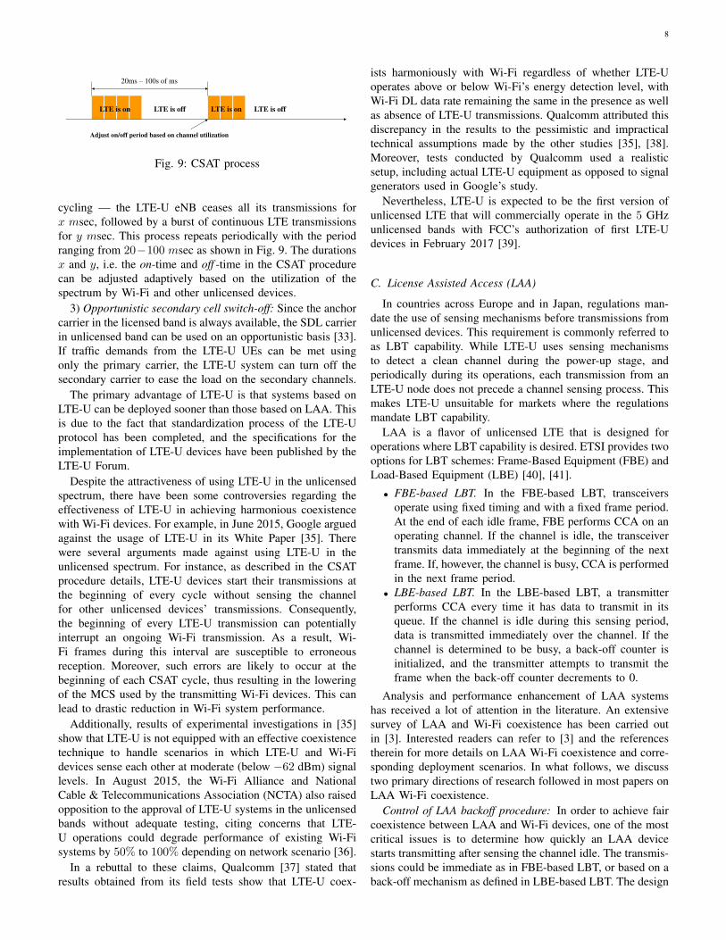
Clean Channel
Found?
Channel
Selection
Full Duty
Cycle
CSAT
Cell Load
Low?
Secondary
Carrier Off
Yes
YesNo
No
Fig. 8: LTE-U algorithm flow chart
can operate in the U-NII-1 and U-NII-3 bands. This implies
that Wi-Fi devices will not have to compete with LTE-U
devices for channel access in 355 MHz of spectum in the
U-NII-2A and U-NII-2C bands9 [32].
In order to coexist with existing Wi-Fi devices in the
5 GHz band and other LTE-U eNBs, LTE-U provides a
three-step coexistence mechanism [33], [34]. This coexistence
mechanism is described using a flow chart in Fig. 8.
The steps involved in the channel access mechanism of LTE-
U are as follows.
1) Channel selection: The LTE-U eNB must scan the
unlicensed portions of the spectrum in order to determine the
availability of a “clean” channel for SDL transmissions. A
clean channel refers to a channel that is not used by any
Wi-Fi or LTE-U systems in the vicinity of the LTE-U eNB
performing the scan. Channel measurements and determination
of a clean channel are to be performed at the initial power-up
stage, as well as periodically during the SDL operation stage.
If a clean channel is determined during the power-up stage, the
LTE-U eNBs communicate with the UEs using frequencies in
that channel. During subsequent measurements, if interference
is experienced on the previously clean channel, and a new
clean channel is available, the SDL transmissions shall be
switched to the new channel.
The interference level in a channel is currently proposed
to be measured using energy detection, which is agnostic
to the type of interfering signal and the number of interfer-
ing sources. However, advanced technology-specific measure-
ments can be used to improve interference detection sensitivity
and additional information collection. For instance, capability
to detect and decode Wi-Fi preambles can be added at the
LTE-U eNBs to determine the number of neighbouring Wi-Fi
users in the given channel.
2) Duty-cycling: In high density deployment of Wi-Fi and
LTE-U small cells, it is likely that no clean channel is found
during the scan process. In such circumstances, LTE-U uses
a mechanism named Carrier Sense Adaptive Transmission
(CSAT) to coexist with Wi-Fi and/or other LTE-U eNBs in
a given channel. The CSAT mechanism is based on duty-
9However, as introduced in Sec. II-B, these bands are used by radar systems,which will be the primary users of the spectrum.
8
20ms – 100s of ms
LTE is on LTE is off LTE is on LTE is off
Adjust on/off period based on channel utilization
Fig. 9: CSAT process
cycling — the LTE-U eNB ceases all its transmissions for
x msec, followed by a burst of continuous LTE transmissions
for y msec. This process repeats periodically with the period
ranging from 20−100 msec as shown in Fig. 9. The durations
x and y, i.e. the on-time and off -time in the CSAT procedure
can be adjusted adaptively based on the utilization of the
spectrum by Wi-Fi and other unlicensed devices.
3) Opportunistic secondary cell switch-off: Since the anchor
carrier in the licensed band is always available, the SDL carrier
in unlicensed band can be used on an opportunistic basis [33].
If traffic demands from the LTE-U UEs can be met using
only the primary carrier, the LTE-U system can turn off the
secondary carrier to ease the load on the secondary channels.
The primary advantage of LTE-U is that systems based on
LTE-U can be deployed sooner than those based on LAA. This
is due to the fact that standardization process of the LTE-U
protocol has been completed, and the specifications for the
implementation of LTE-U devices have been published by the
LTE-U Forum.
Despite the attractiveness of using LTE-U in the unlicensed
spectrum, there have been some controversies regarding the
effectiveness of LTE-U in achieving harmonious coexistence
with Wi-Fi devices. For example, in June 2015, Google argued
against the usage of LTE-U in its White Paper [35]. There
were several arguments made against using LTE-U in the
unlicensed spectrum. For instance, as described in the CSAT
procedure details, LTE-U devices start their transmissions at
the beginning of every cycle without sensing the channel
for other unlicensed devices’ transmissions. Consequently,
the beginning of every LTE-U transmission can potentially
interrupt an ongoing Wi-Fi transmission. As a result, Wi-
Fi frames during this interval are susceptible to erroneous
reception. Moreover, such errors are likely to occur at the
beginning of each CSAT cycle, thus resulting in the lowering
of the MCS used by the transmitting Wi-Fi devices. This can
lead to drastic reduction in Wi-Fi system performance.
Additionally, results of experimental investigations in [35]
show that LTE-U is not equipped with an effective coexistence
technique to handle scenarios in which LTE-U and Wi-Fi
devices sense each other at moderate (below −62 dBm) signal
levels. In August 2015, the Wi-Fi Alliance and National
Cable & Telecommunications Association (NCTA) also raised
opposition to the approval of LTE-U systems in the unlicensed
bands without adequate testing, citing concerns that LTE-
U operations could degrade performance of existing Wi-Fi
systems by 50% to 100% depending on network scenario [36].
In a rebuttal to these claims, Qualcomm [37] stated that
results obtained from its field tests show that LTE-U coex-
ists harmoniously with Wi-Fi regardless of whether LTE-U
operates above or below Wi-Fi’s energy detection level, with
Wi-Fi DL data rate remaining the same in the presence as well
as absence of LTE-U transmissions. Qualcomm attributed this
discrepancy in the results to the pessimistic and impractical
technical assumptions made by the other studies [35], [38].
Moreover, tests conducted by Qualcomm used a realistic
setup, including actual LTE-U equipment as opposed to signal
generators used in Google’s study.
Nevertheless, LTE-U is expected to be the first version of
unlicensed LTE that will commercially operate in the 5 GHz
unlicensed bands with FCC’s authorization of first LTE-U
devices in February 2017 [39].
C. License Assisted Access (LAA)
In countries across Europe and in Japan, regulations man-
date the use of sensing mechanisms before transmissions from
unlicensed devices. This requirement is commonly referred to
as LBT capability. While LTE-U uses sensing mechanisms
to detect a clean channel during the power-up stage, and
periodically during its operations, each transmission from an
LTE-U node does not precede a channel sensing process. This
makes LTE-U unsuitable for markets where the regulations
mandate LBT capability.
LAA is a flavor of unlicensed LTE that is designed for
operations where LBT capability is desired. ETSI provides two
options for LBT schemes: Frame-Based Equipment (FBE) and
Load-Based Equipment (LBE) [40], [41].
• FBE-based LBT. In the FBE-based LBT, transceivers
operate using fixed timing and with a fixed frame period.
At the end of each idle frame, FBE performs CCA on an
operating channel. If the channel is idle, the transceiver
transmits data immediately at the beginning of the next
frame. If, however, the channel is busy, CCA is performed
in the next frame period.
• LBE-based LBT. In the LBE-based LBT, a transmitter
performs CCA every time it has data to transmit in its
queue. If the channel is idle during this sensing period,
data is transmitted immediately over the channel. If the
channel is determined to be busy, a back-off counter is
initialized, and the transmitter attempts to transmit the
frame when the back-off counter decrements to 0.
Analysis and performance enhancement of LAA systems
has received a lot of attention in the literature. An extensive
survey of LAA and Wi-Fi coexistence has been carried out
in [3]. Interested readers can refer to [3] and the references
therein for more details on LAA Wi-Fi coexistence and corre-
sponding deployment scenarios. In what follows, we discuss
two primary directions of research followed in most papers on
LAA Wi-Fi coexistence.
Control of LAA backoff procedure: In order to achieve fair
coexistence between LAA and Wi-Fi devices, one of the most
critical issues is to determine how quickly an LAA device
starts transmitting after sensing the channel idle. The transmis-
sions could be immediate as in FBE-based LBT, or based on a
back-off mechanism as defined in LBE-based LBT. The design
9
of an appropriate channel access mechanism is crucial towards
LAA and Wi-Fi performance in this coexistence scenario.
In [42], Chen et al. propose a Markov chain based model
to characterize the performance of LAA as well as Wi-Fi
devices and determine the downlink throughput for each set of
devices. Moreover, the proposed model shows the effectiveness
of using the LBT mechanism in terms of the impact of LAA
transmissions on Wi-Fi performance. Downlink throughput for
both, LTE and Wi-Fi systems, can be theoretically calculated
in different coexistence scenarios (LAA and LAA, or LAA and
Wi-Fi). Intra-system interference in LAA-LAA and LAA-WiFi
as well as LAA-WiFi hidden terminal problems are analyzed
by Lien et al. in [43]. Lien et al. [43] also propose dynamic
switching between scheduling-based access and random access
scheme as an outcome of their model.
Three different Wi-Fi and LTE deployment scenarios,
namely indoor, outdoor and indoor/outdoor mixed scenarios
are tested by Jeon et al. in [44]. It is observed that if WLAN
BSSs are located indoor, the impact of LAA transmissions on
WLAN performance is not severe. However, the performance
of Wi-Fi devices suffers non-negligible degradation in other
cases. Besides the above mentioned works, enhancements to
the basic LAA mechanism have been proposed [45]–[52]. An
important objective of these works is to ensure fair coexistence
in terms of Wi-Fi performance in the presence of LAA.
Control of LAA sensing mechanism: Along with a careful
design of the LAA back-off mechanism, appropriate setting of
the CCA threshold is also critical to LAA as well as Wi-Fi per-
formance. Chai et al. [53] point out that there exists a subtle,
yet critical, problem that arises due to the asymmetric channel
access mechanisms employed by Wi-Fi and LTE technologies
with the potential to degrade the performance of LAA as well
as Wi-Fi users, with more impact on Wi-Fi’s performance.
Both, Wi-Fi and LTE transmitters, can use energy detection
in order to detect signals stronger than −62 dBm. However,
Wi-Fi devices can also perform preamble detection, which
enables Wi-Fi transmitters to detect signals from other Wi-Fi
transmitters that are larger than −82 dBm in signal strength.
The performance of LAA as well as Wi-Fi systems is, thus,
unclear when the signal strength at both devices is within
the [−82,−62] dBm range. Experimental results in [35], [53]
show that when the strength of LAA signal at the Wi-Fi
transmitter and Wi-Fi signal at the LAA transmitter are in the
[−82,−62] dBm range, simultaneous packet transmissions can
result in collisions in numerous situations since LTE and Wi-Fi
cannot detect each other, resulting in a drop in throughput of
LAA and Wi-Fi systems by up to 15% and 37% respectively.
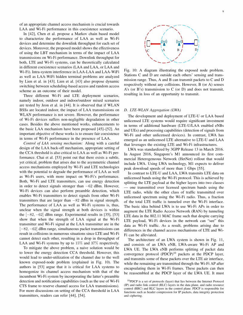
To mitigate the above problem, a naive solution would be
to lower the energy detection CCA threshold. However, this
would lead to under-utilization of the channel due to the well
known exposed-node problem (explained in Fig. 10). The
authors in [53] argue that it is critical for LAA systems to
homogenize its channel access mechanism with that of the
incumbent Wi-Fi system by incorporating the latter’s preamble
detection and notification capabilities (such as the use of Wi-Fi
CTS frame to reserve channel access for LAA transmissions).
For more discussions on setting of the CCA threshold in LAA
transmitters, readers can refer [44], [54].
A BC D
Fig. 10: A diagram illustrating the exposed node problem.
Stations C and D are outside each others’ sensing and trans-
mission range. Thus, A and B can transmit packets to C and D
respectively without any collisions. However, B (or A) senses
A’s (or B’s) transmission to C (or D) and does not transmit,
resulting in loss of an opportunity to transmit.
D. LTE-WLAN Aggregation (LWA)
The development and deployment of LTE-U or LAA based
unlicensed LTE systems would require significant investment
in terms of additional hardware (LTE-U/LAA enabled eNBs
and UEs) and processing capabilities (detection of signals from
Wi-Fi and other unlicensed devices). In contrast, LWA has
emerged as an unlicensed LTE alternative to LTE-U and LAA
that leverages the existing LTE and Wi-Fi infrastructures.
LWA was standardized by 3GPP Release 13 in March 2016.
In August 2016, Singapore’s M1 announced its first com-
mercial Heterogeneous Network (HetNet) rollout that would
include LWA. Using LWA technology, M1 expects to deliver
peak download speeds of more than 1 Gbps [55].
In contrast to LTE-U and LAA, LWA transmits LTE data on
unlicensed bands using the Wi-Fi protocol. This is achieved by
splitting the LTE payload at the higher layers into two classes
— one transmitted over licensed spectrum bands using the
LTE radio, while the other class of traffic transmitted over
unlicensed spectrum using the Wi-Fi radio. Thus, a fraction
of the total LTE traffic is tunneled over the Wi-Fi interface.
The basic idea behind LWA is to use Wi-Fi APs in order to
augment the LTE Radio Access Network (RAN) by tunneling
LTE data in the 802.11 MAC frame such that despite carrying
LTE payload, Wi-Fi devices in the network can “see” this
data as Wi-Fi traffic. As a result, problems arising due to
differences in the channel access mechanisms of LTE and Wi-
Fi can be alleviated.
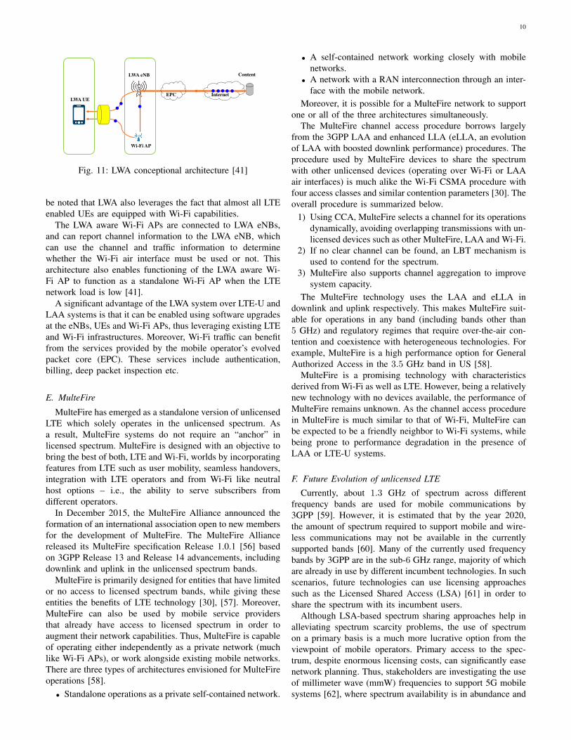
The architecture of an LWA system is shown in Fig. 11,
and consists of an LWA eNB, LWA-aware Wi-Fi AP and
LWA UE. The LWA eNB performs splitting of packet data
convergence protocol (PDCP)10 packets at the PDCP layer,
and transmits some of these packets over the LTE air interface,
while the remaining are transmitted through the Wi-Fi AP after
encapsulating them in Wi-Fi frames. These packets can then
be reassembled at the PDCP layer of the LWA UE. It must
10PDCP is a set of protocols (layer) that lies between the Internet Protocol(IP) and radio link control (RLC) layers in the data plane, and radio resourcecontrol (RRC) and RLC layers in the control plane. PDCP is responsible forfunctions such as header compression for IP packets, data integrity protectionand ciphering.
10
Internet
Content
Wi-Fi AP
LWA UE
LWA eNB
EPC
Fig. 11: LWA conceptional architecture [41]
be noted that LWA also leverages the fact that almost all LTE
enabled UEs are equipped with Wi-Fi capabilities.
The LWA aware Wi-Fi APs are connected to LWA eNBs,
and can report channel information to the LWA eNB, which
can use the channel and traffic information to determine
whether the Wi-Fi air interface must be used or not. This
architecture also enables functioning of the LWA aware Wi-
Fi AP to function as a standalone Wi-Fi AP when the LTE
network load is low [41].
A significant advantage of the LWA system over LTE-U and
LAA systems is that it can be enabled using software upgrades
at the eNBs, UEs and Wi-Fi APs, thus leveraging existing LTE
and Wi-Fi infrastructures. Moreover, Wi-Fi traffic can benefit
from the services provided by the mobile operator’s evolved
packet core (EPC). These services include authentication,
billing, deep packet inspection etc.
E. MulteFire
MulteFire has emerged as a standalone version of unlicensed
LTE which solely operates in the unlicensed spectrum. As
a result, MulteFire systems do not require an “anchor” in
licensed spectrum. MulteFire is designed with an objective to
bring the best of both, LTE and Wi-Fi, worlds by incorporating
features from LTE such as user mobility, seamless handovers,
integration with LTE operators and from Wi-Fi like neutral
host options – i.e., the ability to serve subscribers from
different operators.
In December 2015, the MulteFire Alliance announced the
formation of an international association open to new members
for the development of MulteFire. The MulteFire Alliance
released its MulteFire specification Release 1.0.1 [56] based
on 3GPP Release 13 and Release 14 advancements, including
downlink and uplink in the unlicensed spectrum bands.
MulteFire is primarily designed for entities that have limited
or no access to licensed spectrum bands, while giving these
entities the benefits of LTE technology [30], [57]. Moreover,
MulteFire can also be used by mobile service providers
that already have access to licensed spectrum in order to
augment their network capabilities. Thus, MulteFire is capable
of operating either independently as a private network (much
like Wi-Fi APs), or work alongside existing mobile networks.
There are three types of architectures envisioned for MulteFire
operations [58].
• Standalone operations as a private self-contained network.
• A self-contained network working closely with mobile
networks.
• A network with a RAN interconnection through an inter-
face with the mobile network.
Moreover, it is possible for a MulteFire network to support
one or all of the three architectures simultaneously.
The MulteFire channel access procedure borrows largely
from the 3GPP LAA and enhanced LLA (eLLA, an evolution
of LAA with boosted downlink performance) procedures. The
procedure used by MulteFire devices to share the spectrum
with other unlicensed devices (operating over Wi-Fi or LAA
air interfaces) is much alike the Wi-Fi CSMA procedure with
four access classes and similar contention parameters [30]. The
overall procedure is summarized below.
1) Using CCA, MulteFire selects a channel for its operations
dynamically, avoiding overlapping transmissions with un-
licensed devices such as other MulteFire, LAA and Wi-Fi.
2) If no clear channel can be found, an LBT mechanism is
used to contend for the spectrum.
3) MulteFire also supports channel aggregation to improve
system capacity.
The MulteFire technology uses the LAA and eLLA in
downlink and uplink respectively. This makes MulteFire suit-
able for operations in any band (including bands other than
5 GHz) and regulatory regimes that require over-the-air con-
tention and coexistence with heterogeneous technologies. For
example, MulteFire is a high performance option for General
Authorized Access in the 3.5 GHz band in US [58].
MulteFire is a promising technology with characteristics
derived from Wi-Fi as well as LTE. However, being a relatively
new technology with no devices available, the performance of
MulteFire remains unknown. As the channel access procedure
in MulteFire is much similar to that of Wi-Fi, MulteFire can
be expected to be a friendly neighbor to Wi-Fi systems, while
being prone to performance degradation in the presence of
LAA or LTE-U systems.
F. Future Evolution of unlicensed LTE
Currently, about 1.3 GHz of spectrum across different
frequency bands are used for mobile communications by
3GPP [59]. However, it is estimated that by the year 2020,
the amount of spectrum required to support mobile and wire-
less communications may not be available in the currently
supported bands [60]. Many of the currently used frequency
bands by 3GPP are in the sub-6 GHz range, majority of which
are already in use by different incumbent technologies. In such
scenarios, future technologies can use licensing approaches
such as the Licensed Shared Access (LSA) [61] in order to
share the spectrum with its incumbent users.
Although LSA-based spectrum sharing approaches help in
alleviating spectrum scarcity problems, the use of spectrum
on a primary basis is a much more lucrative option from the
viewpoint of mobile operators. Primary access to the spec-
trum, despite enormous licensing costs, can significantly ease
network planning. Thus, stakeholders are investigating the use
of millimeter wave (mmW) frequencies to support 5G mobile
systems [62], where spectrum availability is in abundance and
11
existing operations are few. At this stage, there are several
challenges in the design and rollout of commercial systems
that operate in the mmW frequencies [62], [63]. However,
the use of mmW frequencies for 5G cellular systems on a
massive scale cannot be ruled out. Under such circumstances,
the evolution path of the unlicensed LTE versions developed
thus far, along with their 5G extensions remains unclear.
G. Open Research Problems
Based on current standardization and research status, we
summarize the following potential research directions in the
area of unlicensed LTE and Wi-Fi coexistence.
• Dynamic duty-cycling based on the current channel uti-
lization information in the CSAT procedure can be used
to maximize LTE-U performance as well as achieve fair
coexistence with Wi-Fi systems. An algorithm to adjust
the LTE-U on-time and off -time based on technology-
specific sensing results could help LTE-U systems in
achieving larger throughput while sharing the spectrum
in a fair manner with Wi-Fi systems.
• Carrier sensing using energy detection can detect signals
above −62 dBm, while preamble detection can detect
signals above −82 dBm. LTE and Wi-Fi cannot detect
each other when signals are between −62 dBm and
−82 dBm. Such interference can degrade performance
for both LTE and Wi-Fi systems by as much as 40%even if the SINR is above 10 dB [53]. It is, therefore,
crucial to design mechanisms to deal with signals in the
[−82,−62] dBm range.
• The back-off procedure in LBT based mechanisms has a
large impact on balancing spectrum usage between LTE
and Wi-Fi devices. Design of optimal LBT schemes for
unlicensed LTE devices is an open research problem.
• LWA is efficient in alleviating the interference issues
caused between LTE and Wi-Fi due to differing channel
access mechanisms. However, determination of data flow
routing between LTE and Wi-Fi radio interfaces remains
an open problem. Moreover, varying traffic conditions
combined with arrival and departure of Wi-Fi devices
in the network pose additional challenges in designing
efficient flow routing algorithms.
• MulteFire is in its early stages of development. The
impact of MulteFire transmissions on Wi-Fi system per-
formance, specially in comparison and contrast to Wi-Fi
– Wi-Fi coexistence, is yet to be understood.
• The adoption of channel access parameters similar to
those used in Wi-Fi also makes MulteFire devices prone
to interference from LTE-U and LAA systems much like
Wi-Fi devices. Thus, performance evaluation of Multe-
Fire in the presence of other unlicensed LTE technologies
remains an open problem.
IV. COEXISTENCE OF RADAR AND WI-FI
The first step toward allowing unlicensed devices (such as
Wi-Fi) to operate in the 5.150 − 5.350 GHz and 5.470 −
5.725 GHz bands was taken at the World Radiocommunication
Conference 2003 (WRC-03) [13]. As per the regulations,
unlicensed devices can operate in these frequencies so long as
they do not interfere with the incumbent users of the spectrum
– radars. Thus, radars are the primary users of the band, and
Wi-Fi devices can operate in the shared spectrum if no radar
activity is reported.
In this section, we look at the coexistence issues that
arise due to the operation of Wi-Fi devices in the 5 GHz
bands with radar systems as their primary users. We divide
the discussion in two parts — (i) coexistence issues in the
5.25− 5.35 GHz and 5.47− 5.725 GHz bands, where Wi-Fi
devices continue to coexist with radars, and (ii) coexistence
issues in the 5.35−5.47 GHz, where WLAN systems are being
considered to operate alongside radars in the future.
A. Coexistence issues in the 5.25 − 5.35 GHz and 5.47 −
5.725 GHz bands
Wi-Fi devices operating in certain parts of the 5 GHz
spectrum must use the Dynamic Frequency Selection (DFS)
mechanism11 to detect the presence of operating radars and
avoid co-channel operations. The sensing technique in DFS
involves signal detection based on the knowledge of radar
parameters, such as pulse width, pulse repetition rate, number
of pulses per burst, etc., at the Wi-Fi transmitter.
The DFS mechanism is implemented at the Wi-Fi AP.
Associated STAs have to rely on the AP to avoid causing any
interference to radar systems. Before selecting a channel for
operations, a Wi-Fi AP must perform a Channel Availability
Check (CAC) whereby the AP must check for the presence
of radar signals for a predetermined interval12. If a channel
has ongoing radar activity (radar energy > −62 dBm), the AP
continues to scan for other idle channels in the band. If none of
the channels are idle, the AP enters a “sleep mode”. If an idle
channel is available, the Wi-Fi AP and STAs can continue their
transmissions on such a channel. The AP must periodically
perform CAC for radar activity in between transmissions. If
a radar activity is detected, the AP and its associated STAs
must cease channel usage within 10 seconds. During these
10 seconds, the AP can send normal data traffic to the STAs for
a maximum duration of 200 msec. The AP can also transmit
control information to its associated STAs in order to facilitate
moving to an idle channel. The channel must then be declared
busy for 30 minutes.
Before WLAN products operating in the 5 GHz bands can
be introduced in the market, the product manufacturers are
required to test the devices for compliance certifications from
the regulatory agencies (such as FCC in US and ETSI in
Europe). These compliance tests usually involve checking the
ability of the deployed DFS algorithm to detect characteristic
radar signals, specified in terms of radar pulse width and
pulse repetition factors. In case of the 5.47 − 5.725 GHz
band, where weather radars are prone to interference from
11The exact frequencies that require the use of DFS is regulation specific.For example, Ofcom in UK mandates the use of DFS from 5.47−5.85 GHz,while FCC in the use requires DFS in the 5.47− 5.725 GHz bands [11].
12The exact interval is decided by country-specific regulations. For example,regulations in US require the AP to scan the channel for 60 seconds, whilethe Canadian regulations specify an interval of 10 minutes – a duration thatoverlaps with scan cycle time of most weather radars operating in 5.6 GHz.
12
Wi-Fi transmissions, it is sometimes possible to provide a
predecided set of waveforms for testing. However, with newer
radar systems being developed, providing an exhaustive set of
waveforms is infeasible, and may be impossible in scenarios
where the radars are developed for defense purposes.
The DFS algorithm has continued to evolve ever since the
ITU regulations in 2003. Several experimental studies have
been conducted to determine the efficacy of DFS in detecting
radar activity and the ability of the Wi-Fi devices to move to a
different channel when radar activity is detected. Experiments
performed by Joe et al. [64] show that Wi-Fi APs are capable
of detecting activity of weather radars operating in 5.6 GHz
band in a highly mobile environment like inside an aircraft.
However, at low enough distances (< 25 km) the WLAN
presence can be seen at the weather radars. In [65], the authors
show that the detection threshold of −62 dBm is sufficient
to detect weather activity at most occasions. However, this
detection capability depends to a large extent on the direction
of the radar signals. If the AP is unable to detect the radar
activity before the radar beam directly aims at the Wi-Fi
network, the radar system is blinded by Wi-Fi transmissions.
Moreover, radar systems with larger bandwidths are more
susceptible to Wi-Fi interference.
Tercero et al. [66] present a mathematical model to analyze
the interference caused by aggregate Wi-Fi users to weather
radars operating in the 5.6 GHz band. The authors consider the
basic DFS mechanism at the Wi-Fi AP and show that in dense
urban scenarios where density of Wi-Fi users is greater than
10 WLANs per square kilometer, radar systems experience
aggregated interference larger than their interference threshold.
Several approaches have been adopted with the objective of
mitigating Wi-Fi interference at radar receivers. For example,
the authors in [67] propose a channel allocation scheme that
takes into consideration meteorological radar operations and
show that by using existing Wi-Fi mechanisms such as the
RTS/CTS handshake, Wi-Fi devices can minimize interfer-
ence at radar systems. Signal processing based interference
cancellation strategies have also been proposed in the liter-
ature. Take [68] for example. The authors argue that Wi-Fi
transmission characteristics can be leveraged at radar systems
in order to detect and cancel interfering signals. Moreover,
since Wi-Fi standards are universal, the authors claim that
techniques based on identifying Wi-Fi characteristics can be
used to solve such interference problems universally. The
authors test their scheme on time-series waveforms obtained
from Brazil, India and Estonia to validate their claims. Similar
work has been presented in [69]. In [70], the author proposes
the use of computer vision based techniques for removal of
interference signals at radar receivers that can potentially filter
out transmissions from Wi-Fi like emitters.
Technologies to enhance the DFS mechanisms have also
been proposed in the literature. Tercero et al. [71] exploit the
temporal nature of radar systems to increase the transmission
opportunities for Wi-Fi devices. The authors quantitatively
estimate the number of Wi-Fi users that can operate as
secondary users in radar occupied bands. Furthermore, they
show that using their scheme, a Wi-Fi user operating as close
as 4 km from the radar can transmit up to 99.45% of the time
without interfering with the radar receiver.
Despite the proposal and adoption of the aforementioned
interference-mitigation techniques, incidences of interference
caused to radar systems (particularly to the weather radars
operating in 5.60− 5.65 GHz) by Wi-Fi operations have been
reported in US [72], [73], Canada [74], across Europe [75]–
[77] and other regions [78]. The primary reasons for such
Wi-Fi-induced interference are summarized below.
• DFS mechanism can be deliberately turned off by the
operator or even by the users. Detection and enforcement
of these rogue WLAN devices is difficult even with the
presence of azimuth data at the radars. In the past, several
cases of interference to the weather radars have been
reported in the US and Europe due to deliberate disabling
of the DFS mechanism in WLAN devices [73], [75].
• DFS does not address the hidden node problem. The DFS
mechanism is used only at the AP to detect the presence
of radar systems. However, there is a possibility that the
radar signal is not detectable at the AP, but associated
STAs may cause interference at the radar receivers [67].
• Unlicensed devices operating on an adjacent channel can
cause harmful interference to radar systems. In the ideal
scenario, once a DFS device detects a radar signal, it
must move to a channel that is separated far enough
in frequency to eliminate adjacent channel interference.
However, interference investigations lead by the National
Telecommunications and Information Administration in
US have determined that some devices have not been
moving far enough away in frequency, and as a result,
their out-of-channel emissions were causing interference
to weather radars [10].
B. Coexistence issues in the 5.35− 5.47 GHz band
Coexistence between radars and Wi-Fi in the 5.25 −
5.35 GHz and 5.47− 5.725 GHz bands have been a problem
worldwide. In this subsection, we discuss issues of coexistence
that are expected to arise between the two technologies in the
5.35−5.47 GHz band. It must be noted that Wi-Fi devices do
not currently operate in the 5.35− 5.47 GHz worldwide, but
several regulators are considering the possibility of allowing
unlicensed devices to operate in these frequencies [10]–[12].
The primary reason for such considerations is that by allowing
unlicensed devices to operate in the 5.35 − 5.47 GHz band
along with 5.85 − 5.92 GHz band will result in up to 70%increase in the available spectrum, and increase the number of
80 MHz channels by 125% (from 4 to 9) [12].
With considerations from regulators for allowing unlicensed
operations in the 5.350− 5.470 GHz band, there is a need for
developing coexistence mechanisms between unlicensed users
and radars in this band. The methods used for detection of
radars in the 5.25−5.35 GHz and 5.47−5.725 GHz bands are
generally unsuitable for detecting radar signals in the 5.35−5.47 GHz band due to the following reasons.
• Unlike other 5 GHz bands, the 5.35− 5.47 GHz band is
used for many military and safety-critical applications.
Adequate protection for these systems from WLAN-
induced interference is extremely important. In the DFS

13
certification test, a set of waveforms is defined, but it does
not necessarily include waveforms from all radar systems.
There are a large number of radar systems operating in
the 5.35− 5.47 GHz band, which are not present in the
5.25 − 5.35 GHz and 5.47 − 5.725 GHz bands. These
waveforms need to be added in the certification list.
• In the 5.25 − 5.35 GHz and 5.47 − 5.725 GHz bands,
radar parameters such as pulse width, pulse repetition
interval, and the number of pulses per burst are well
known [10]. On the other hand, a large and diverse set
of radar systems operate in the 5.35 − 5.47 GHz band.
The pulse widths, pulse repetition frequency and other
characteristics vary significantly from system to system.
Even for a single radar, the pulse width can change with
time. In addition, some recently fielded radar systems and
those under development operate in low power modes
or are designed to avoid detection to meet their mission
requirements. These radar systems are challenging for the
WLAN devices to correctly detect.
• Signal processing techniques are typically employed at
radars to minimize the impact of interference caused by
other radars. However, these techniques are only effective
for low duty cycle emitters. WLAN devices typically
use very high duty cycles (for instance, with frame
aggregation techniques the duty cycle can go as high
as 80% [10]). This makes it difficult for radar systems
to mitigate WLAN interference using signal processing
techniques that are useful in the case of low duty-cycle
(single-pulse) filters at the radars.
• The existing DFS mechanisms were developed specifi-
cally to protect radar systems in which the transmitter and
receiver are co-located. Airborne systems employ ground
and airborne transmitters and receivers located in differ-
ent locations. Full duplex systems with the uplink and
downlink on different frequencies can introduce hidden
node problems for WLAN APs that rely on sensing.
• The use of signal detection-based DFS techniques used
in other 5 GHz bands may be unsuitable for use in the
5.35 − 5.47 GHz band. Detection techniques based on
the use of geo-location databases used in TV White Space
(TVWS) [79]–[82] are more suitable for spectrum sharing
in the 5.35 − 5.47 GHz band [10]. Although database
based techniques can be useful in scenarios where the
radar transmitter and receiver are collocated, radar sys-
tems with non-collocated transmitters and receivers may
not be adequately protected from Wi-Fi transmissions.
• Moreover, several database management and authoriza-
tion related issues while drafting regulations for the
TVBDs (e.g., construction of databases, sharing data
between databases, how to determine available channels,
securing the information etc. [79]) will have to be ad-
dressed if geo-location databases are created to protect
critical radar systems.
• Furthermore, this necessitates the protection of incumbent
information in case of radar systems that are of critical
importance for national security. Such studies have been
carried out in the context of radar systems operating in
other spectrum bands [83], [84].
C. Open Research Problems
We list the following open research problems with respect
to the coexistence of heterogeneous wireless systems in the
5 GHz bands.
• Reliable techniques for the detection of radar signals with
dynamic pulse characteristics operating in the 5.35 −
5.47 GHz band need to be designed for Wi-Fi APs.
• Spectrum sensing based mechanisms may not be effec-
tive in the detection of radar systems operating in the
5.35 − 5.47 GHz band. In such scenarios, feasibility
of database-based solutions for coexistence of Wi-Fi
and radar systems operating in the 5.35 − 5.47 GHz
band needs to be assessed, specifically when the radar
transmitter and receiver are non-collocated.
• Because many military and public-safety systems (which
are considered incumbent users) operate in the 5.35 −
5.47 GHz band, regulators and industry stakeholders will
need to work together to develop mechanisms, rules, and
procedures to protect the operational security (OPSEC)
of the incumbent users when they coexist with Wi-Fi
systems. OPSEC is expected to be a critical component
in realizing harmonious coexistence between incumbents
and secondary entrants in the 5.35− 5.47 GHz band.
• Technologies and techniques for detecting, identifying,
and adjudicating rogue devices are needed. Here, rogue
devices refer to devices that have disabled the DFS
functionality or intentionally operate in the presence
of incumbent systems. In addition, these enforcement
approaches need to be automated and cost effective in
order to be considered commercially viable.
• Solutions to combat the hidden node problem in the
5.25−5.35 GHz and 5.47−5.725 GHz bands (due to DFS
implementation only at the AP), and the 5.35−5.47 GHz
band (due to non-collocated transmitters and receivers)
need to developed.
• PHY layer techniques that enable underlay cognitive
radio networks, such as transmit beamforming [85], [86]
that can null the secondary user waveforms at the radar
systems can be an interesting subject of investigation.
V. COEXISTENCE OF DSRC AND WI-FI
The 5.85−5.925 GHz band, being considered for unlicensed
operations overlaps exactly with the band allocated for ITS
services. In this section, we address the coexistence issues
expected to arise as a result of DSRC and Wi-Fi devices
operating in the same frequency band.
Impetus to exploring band sharing techniques between
DSRC and Wi-Fi was provided by the introduction of Wi-
Fi Innovation Act in the U.S. Senate and House [87]. This
act directs the FCC to move swiftly in conducting tests
to assess the feasibility of opening up the upper 5 GHz
band, including the DSRC band, for unlicensed use. In this
coexistence scenario, DSRC users shall remain the primary
users, while Wi-Fi users will be the secondary users of the
shared spectrum. The channelization of the U-NII-4 band in
5.850− 5.925 GHz is shown in Fig. 12. It is noteworthy that
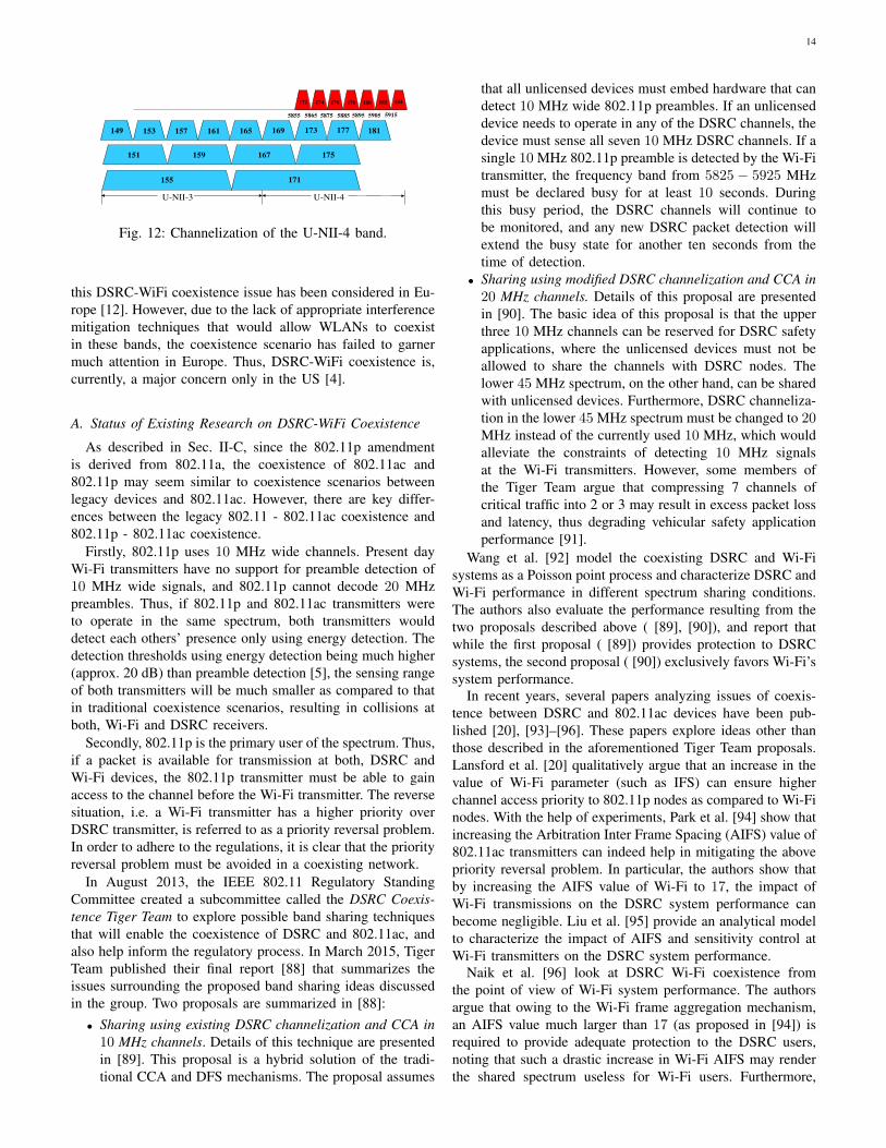
14
172 174 176 178 180 182 184
153
5855
157 161 165 169 173 177 181
159 167 175
155 171
5865 5875 5885 5895 5905 5915
149
151
U-NII-3 U-NII-4
Fig. 12: Channelization of the U-NII-4 band.
this DSRC-WiFi coexistence issue has been considered in Eu-
rope [12]. However, due to the lack of appropriate interference
mitigation techniques that would allow WLANs to coexist
in these bands, the coexistence scenario has failed to garner
much attention in Europe. Thus, DSRC-WiFi coexistence is,
currently, a major concern only in the US [4].
A. Status of Existing Research on DSRC-WiFi Coexistence
As described in Sec. II-C, since the 802.11p amendment
is derived from 802.11a, the coexistence of 802.11ac and
802.11p may seem similar to coexistence scenarios between
legacy devices and 802.11ac. However, there are key differ-
ences between the legacy 802.11 - 802.11ac coexistence and
802.11p - 802.11ac coexistence.
Firstly, 802.11p uses 10 MHz wide channels. Present day
Wi-Fi transmitters have no support for preamble detection of
10 MHz wide signals, and 802.11p cannot decode 20 MHz
preambles. Thus, if 802.11p and 802.11ac transmitters were
to operate in the same spectrum, both transmitters would
detect each others’ presence only using energy detection. The
detection thresholds using energy detection being much higher
(approx. 20 dB) than preamble detection [5], the sensing range
of both transmitters will be much smaller as compared to that
in traditional coexistence scenarios, resulting in collisions at
both, Wi-Fi and DSRC receivers.
Secondly, 802.11p is the primary user of the spectrum. Thus,
if a packet is available for transmission at both, DSRC and
Wi-Fi devices, the 802.11p transmitter must be able to gain
access to the channel before the Wi-Fi transmitter. The reverse
situation, i.e. a Wi-Fi transmitter has a higher priority over
DSRC transmitter, is referred to as a priority reversal problem.
In order to adhere to the regulations, it is clear that the priority
reversal problem must be avoided in a coexisting network.
In August 2013, the IEEE 802.11 Regulatory Standing
Committee created a subcommittee called the DSRC Coexis-
tence Tiger Team to explore possible band sharing techniques
that will enable the coexistence of DSRC and 802.11ac, and
also help inform the regulatory process. In March 2015, Tiger
Team published their final report [88] that summarizes the
issues surrounding the proposed band sharing ideas discussed
in the group. Two proposals are summarized in [88]:
• Sharing using existing DSRC channelization and CCA in
10 MHz channels. Details of this technique are presented
in [89]. This proposal is a hybrid solution of the tradi-
tional CCA and DFS mechanisms. The proposal assumes
that all unlicensed devices must embed hardware that can
detect 10 MHz wide 802.11p preambles. If an unlicensed
device needs to operate in any of the DSRC channels, the
device must sense all seven 10 MHz DSRC channels. If a
single 10 MHz 802.11p preamble is detected by the Wi-Fi
transmitter, the frequency band from 5825 − 5925 MHz
must be declared busy for at least 10 seconds. During
this busy period, the DSRC channels will continue to
be monitored, and any new DSRC packet detection will
extend the busy state for another ten seconds from the
time of detection.
• Sharing using modified DSRC channelization and CCA in
20 MHz channels. Details of this proposal are presented
in [90]. The basic idea of this proposal is that the upper
three 10 MHz channels can be reserved for DSRC safety
applications, where the unlicensed devices must not be
allowed to share the channels with DSRC nodes. The
lower 45 MHz spectrum, on the other hand, can be shared
with unlicensed devices. Furthermore, DSRC channeliza-
tion in the lower 45 MHz spectrum must be changed to 20MHz instead of the currently used 10 MHz, which would
alleviate the constraints of detecting 10 MHz signals
at the Wi-Fi transmitters. However, some members of
the Tiger Team argue that compressing 7 channels of
critical traffic into 2 or 3 may result in excess packet loss
and latency, thus degrading vehicular safety application
performance [91].
Wang et al. [92] model the coexisting DSRC and Wi-Fi
systems as a Poisson point process and characterize DSRC and
Wi-Fi performance in different spectrum sharing conditions.
The authors also evaluate the performance resulting from the
two proposals described above ( [89], [90]), and report that
while the first proposal ( [89]) provides protection to DSRC
systems, the second proposal ( [90]) exclusively favors Wi-Fi’s
system performance.In recent years, several papers analyzing issues of coexis-
tence between DSRC and 802.11ac devices have been pub-
lished [20], [93]–[96]. These papers explore ideas other than
those described in the aforementioned Tiger Team proposals.
Lansford et al. [20] qualitatively argue that an increase in the
value of Wi-Fi parameter (such as IFS) can ensure higher
channel access priority to 802.11p nodes as compared to Wi-Fi
nodes. With the help of experiments, Park et al. [94] show that
increasing the Arbitration Inter Frame Spacing (AIFS) value of
802.11ac transmitters can indeed help in mitigating the above
priority reversal problem. In particular, the authors show that
by increasing the AIFS value of Wi-Fi to 17, the impact of
Wi-Fi transmissions on the DSRC system performance can
become negligible. Liu et al. [95] provide an analytical model
to characterize the impact of AIFS and sensitivity control at
Wi-Fi transmitters on the DSRC system performance.Naik et al. [96] look at DSRC Wi-Fi coexistence from
the point of view of Wi-Fi system performance. The authors
argue that owing to the Wi-Fi frame aggregation mechanism,
an AIFS value much larger than 17 (as proposed in [94]) is
required to provide adequate protection to the DSRC users,
noting that such a drastic increase in Wi-Fi AIFS may render
the shared spectrum useless for Wi-Fi users. Furthermore,
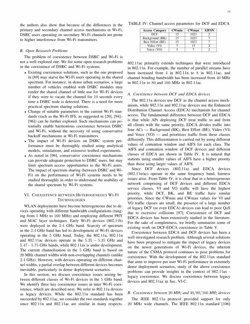
15
the authors also show that because of the differences in the
primary and secondary channel access mechanisms in Wi-Fi,
DSRC users operating on secondary Wi-Fi channels are prone
to higher interference from Wi-Fi transmitters.
B. Open Research Problems
The problem of coexistence between DSRC and Wi-Fi is
not a well explored one. We list some open research problems
in the coexistence of DSRC and Wi-Fi systems.
• Existing coexistence solutions, such as the one proposed
in [89] may starve the Wi-Fi users operating in the shared
spectrum. For instance, in dense urban scenarios, a large
number of vehicles enabled with DSRC modules may
render the shared channel of little use for Wi-Fi devices
if they were to vacate the channel for 10 seconds every
time a DSRC node is detected. There is a need for more
practical spectrum sharing solutions.
• Change of suitable parameters in the current Wi-Fi stan-
dards (such as the Wi-Fi IFS, as suggested in [20], [94]–
[96]) can be further explored. Such mechanisms can po-
tentially enable harmonious coexistence between DSRC
and Wi-Fi, without the necessity of using conservative
backoff mechanisms at Wi-Fi transmitters.
• The impact of Wi-Fi devices on DSRC system per-
formance must be thoroughly studied using analytical
models, simulations, and extensive testbed experiments.
• As noted in [96], conservative coexistence mechanisms
can provide adequate protection to DSRC users, but may
limit spectrum access opportunities to the Wi-Fi users.
The impact of spectrum sharing (between DSRC and Wi-
Fi) on the performance of Wi-Fi systems needs to be
studied thoroughly in order to understand the usability of
the shared spectrum by Wi-Fi systems.
VI. COEXISTENCE BETWEEN HETEROGENEOUS WI-FI
TECHNOLOGIES
WLAN deployments have become heterogeneous due to de-
vices operating with different bandwidth configurations (rang-
ing from 5 MHz to 160 MHz) and employing different PHY
and MAC layer techniques. Early Wi-Fi devices (802.11b)
were deployed in the 2.4 GHz band. Scarcity of spectrum
in the 2.4 GHz band has led to development of Wi-Fi devices
operating in the 5 GHz band. Today, the 802.11a, 802.11n
and 802.11ac devices operate in the 5.25 − 5.35 GHz and
5.47−5.75 GHz bands, while 802.11ax is under development.
The current channelization in the 5 GHz band is based on
20 MHz channel widths with non-overlapping channels (unlike
2.4 GHz). However, with devices operating on different chan-
nel widths, a partial overlap between different devices becomes
inevitable, particularly in dense deployment scenarios.
In this section, we discuss coexistence issues arising be-
tween different classes of Wi-Fi devices in the 5 GHz band.
We identify three key coexistence issues in inter Wi-Fi coex-
istence, which are described next. We refer to 802.11a devices
as legacy devices. While the 802.11n standard has been
succeeded by 802.11ac, we consider the two standards together
since 802.11n and 802.11ac are similar in many respects.
TABLE IV: Channel access parameters for DCF and EDCA
Access Category CWmin CWmax AIFSN
DCF 15 1023 2Background (BK) 15 1023 7Best Effort (BE) 15 1023 7
Video (VI) 7 15 2Voice (VO) 3 7 2
802.11ac primarily extends techniques that were introduced
in 802.11n. For example, the number of parallel streams have
been increased from 4 in 802.11n to 8 in 802.11ac, and
channel bonding bandwidth has been increased from 40 MHz
in 802.11n to 80 and 160 MHz in 802.11ac.
A. Coexistence between DCF and EDCA devices
The 802.11a devices use DCF as the channel access mech-
anism, while 802.11n and 802.11ac devices use the Enhanced
Distribution Channel Access (EDCA) mechanism for channel
access. The fundamental difference between DCF and EDCA
is that while APs deploying DCF treat traffic to and from
all clients with the same priority, EDCA divides traffic into
four ACs — Background (BK), Best Effort (BE), Video (VI)
and Voice (VO) — and prioritizes traffic from these classes
differently. This differentiation is carried out by using different
values of contention window and AIFS for each class. The
AIFS and contention window of DCF devices and different
classes of EDCA are shown in Table IV. It is natural that
stations using smaller values of AIFS have a higher priority
than those using larger values of AIFS.
Since DCF devices (802.11a) and EDCA devices
(802.11n/ac) operate in the same frequency band, fairness
issues arise. From Table IV, it is clear that in a heterogeneous
network comprising of DCF devices and different EDCA
service classes, VI and VO traffic will have the highest
priority, while DCF, BK, and BE traffic have similar
priorities. Since the CWmin and CWmax values for VI and
VO traffic classes are small, the presence of a large number
of legacy DCF (or even EDCA) devices can lead to poor QoS
due to excessive collisions [97]. Coexistence of DCF and
EDCA devices has been extensively studied in the literature.
For the sake of completeness, we briefly summarize some of
existing work on DCF-EDCA coexistence in Table V.
Coexistence between EDCA and DCF devices has been a
well investigated research problem. Although several solutions
have been proposed to mitigate the impact of legacy devices
on the newer generations of Wi-Fi devices, the inherent
nature of the CSMA protocol continues to pose problems for
coexistence. With the development of the 802.11ax standard
that aims to improve per user Wi-Fi performance in extremely
dense deployment scenarios, study of the above coexistence
problems can provide insights in the context of 802.11ax -
legacy coexistence. We discuss coexistence between legacy
devices and 802.11ax in Sec. VI-C.
B. Coexistence between 20 MHz and 40/80/160 MHz devices
The IEEE 802.11a protocol provided support for only
20 MHz wide channels. The IEEE 802.11n standard [106]
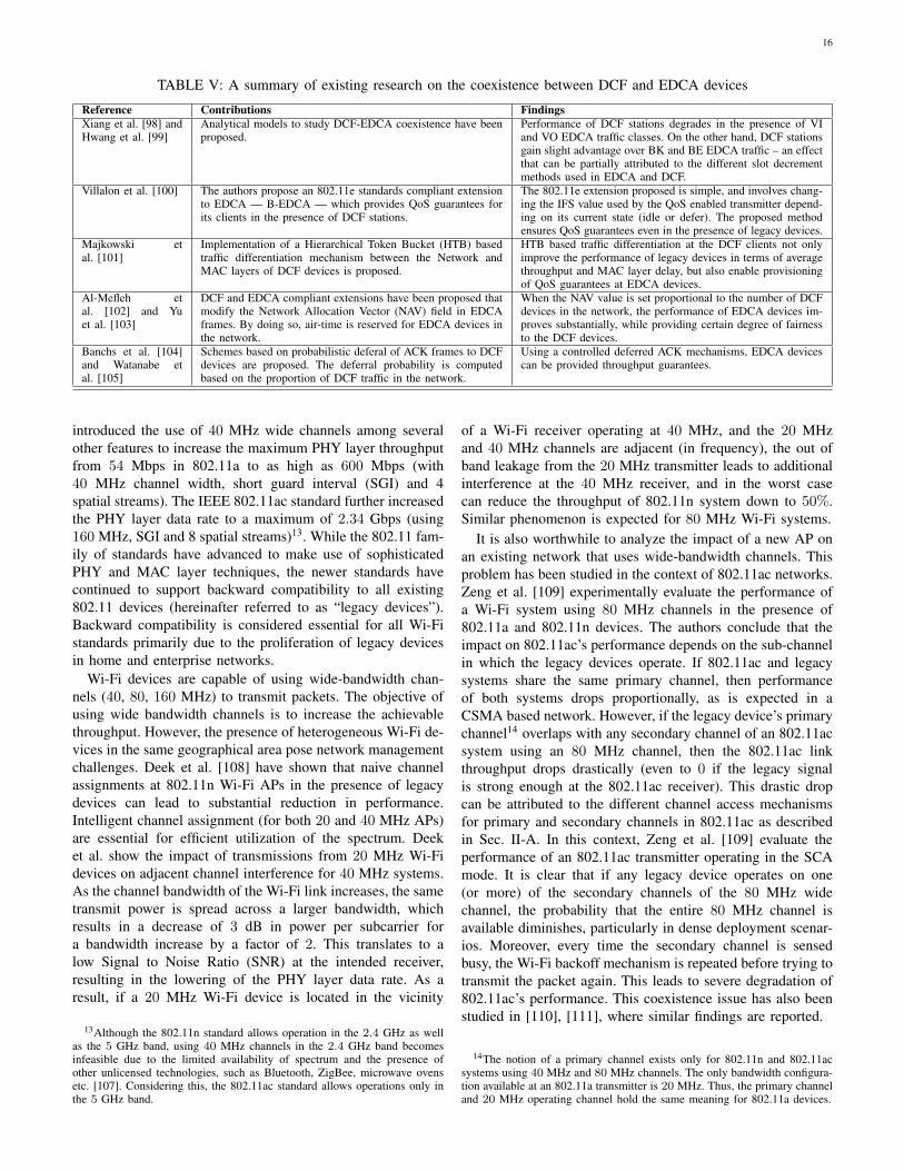
16
TABLE V: A summary of existing research on the coexistence between DCF and EDCA devices
Reference Contributions Findings
Xiang et al. [98] andHwang et al. [99]
Analytical models to study DCF-EDCA coexistence have beenproposed.
Performance of DCF stations degrades in the presence of VIand VO EDCA traffic classes. On the other hand, DCF stationsgain slight advantage over BK and BE EDCA traffic – an effectthat can be partially attributed to the different slot decrementmethods used in EDCA and DCF.
Villalon et al. [100] The authors propose an 802.11e standards compliant extensionto EDCA — B-EDCA — which provides QoS guarantees forits clients in the presence of DCF stations.
The 802.11e extension proposed is simple, and involves chang-ing the IFS value used by the QoS enabled transmitter depend-ing on its current state (idle or defer). The proposed methodensures QoS guarantees even in the presence of legacy devices.
Majkowski etal. [101]
Implementation of a Hierarchical Token Bucket (HTB) basedtraffic differentiation mechanism between the Network andMAC layers of DCF devices is proposed.
HTB based traffic differentiation at the DCF clients not onlyimprove the performance of legacy devices in terms of averagethroughput and MAC layer delay, but also enable provisioningof QoS guarantees at EDCA devices.
Al-Mefleh etal. [102] and Yuet al. [103]
DCF and EDCA compliant extensions have been proposed thatmodify the Network Allocation Vector (NAV) field in EDCAframes. By doing so, air-time is reserved for EDCA devices inthe network.
When the NAV value is set proportional to the number of DCFdevices in the network, the performance of EDCA devices im-proves substantially, while providing certain degree of fairnessto the DCF devices.
Banchs et al. [104]and Watanabe etal. [105]
Schemes based on probabilistic deferal of ACK frames to DCFdevices are proposed. The deferral probability is computedbased on the proportion of DCF traffic in the network.
Using a controlled deferred ACK mechanisms, EDCA devicescan be provided throughput guarantees.
introduced the use of 40 MHz wide channels among several
other features to increase the maximum PHY layer throughput
from 54 Mbps in 802.11a to as high as 600 Mbps (with
40 MHz channel width, short guard interval (SGI) and 4
spatial streams). The IEEE 802.11ac standard further increased
the PHY layer data rate to a maximum of 2.34 Gbps (using
160 MHz, SGI and 8 spatial streams)13. While the 802.11 fam-
ily of standards have advanced to make use of sophisticated
PHY and MAC layer techniques, the newer standards have
continued to support backward compatibility to all existing
802.11 devices (hereinafter referred to as “legacy devices”).
Backward compatibility is considered essential for all Wi-Fi
standards primarily due to the proliferation of legacy devices
in home and enterprise networks.
Wi-Fi devices are capable of using wide-bandwidth chan-
nels (40, 80, 160 MHz) to transmit packets. The objective of
using wide bandwidth channels is to increase the achievable
throughput. However, the presence of heterogeneous Wi-Fi de-
vices in the same geographical area pose network management
challenges. Deek et al. [108] have shown that naive channel
assignments at 802.11n Wi-Fi APs in the presence of legacy
devices can lead to substantial reduction in performance.
Intelligent channel assignment (for both 20 and 40 MHz APs)
are essential for efficient utilization of the spectrum. Deek
et al. show the impact of transmissions from 20 MHz Wi-Fi
devices on adjacent channel interference for 40 MHz systems.
As the channel bandwidth of the Wi-Fi link increases, the same
transmit power is spread across a larger bandwidth, which
results in a decrease of 3 dB in power per subcarrier for
a bandwidth increase by a factor of 2. This translates to a
low Signal to Noise Ratio (SNR) at the intended receiver,
resulting in the lowering of the PHY layer data rate. As a
result, if a 20 MHz Wi-Fi device is located in the vicinity
13Although the 802.11n standard allows operation in the 2.4 GHz as wellas the 5 GHz band, using 40 MHz channels in the 2.4 GHz band becomesinfeasible due to the limited availability of spectrum and the presence ofother unlicensed technologies, such as Bluetooth, ZigBee, microwave ovensetc. [107]. Considering this, the 802.11ac standard allows operations only inthe 5 GHz band.
of a Wi-Fi receiver operating at 40 MHz, and the 20 MHz
and 40 MHz channels are adjacent (in frequency), the out of
band leakage from the 20 MHz transmitter leads to additional
interference at the 40 MHz receiver, and in the worst case
can reduce the throughput of 802.11n system down to 50%.
Similar phenomenon is expected for 80 MHz Wi-Fi systems.
It is also worthwhile to analyze the impact of a new AP on
an existing network that uses wide-bandwidth channels. This
problem has been studied in the context of 802.11ac networks.
Zeng et al. [109] experimentally evaluate the performance of
a Wi-Fi system using 80 MHz channels in the presence of
802.11a and 802.11n devices. The authors conclude that the
impact on 802.11ac’s performance depends on the sub-channel
in which the legacy devices operate. If 802.11ac and legacy
systems share the same primary channel, then performance
of both systems drops proportionally, as is expected in a
CSMA based network. However, if the legacy device’s primary
channel14 overlaps with any secondary channel of an 802.11ac
system using an 80 MHz channel, then the 802.11ac link
throughput drops drastically (even to 0 if the legacy signal
is strong enough at the 802.11ac receiver). This drastic drop
can be attributed to the different channel access mechanisms
for primary and secondary channels in 802.11ac as described
in Sec. II-A. In this context, Zeng et al. [109] evaluate the
performance of an 802.11ac transmitter operating in the SCA
mode. It is clear that if any legacy device operates on one
(or more) of the secondary channels of the 80 MHz wide
channel, the probability that the entire 80 MHz channel is
available diminishes, particularly in dense deployment scenar-
ios. Moreover, every time the secondary channel is sensed
busy, the Wi-Fi backoff mechanism is repeated before trying to
transmit the packet again. This leads to severe degradation of
802.11ac’s performance. This coexistence issue has also been
studied in [110], [111], where similar findings are reported.
14The notion of a primary channel exists only for 802.11n and 802.11acsystems using 40 MHz and 80 MHz channels. The only bandwidth configura-tion available at an 802.11a transmitter is 20 MHz. Thus, the primary channeland 20 MHz operating channel hold the same meaning for 802.11a devices.
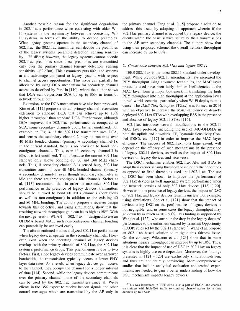
17
Another possible reason for the significant degradation
in 802.11ac’s performance when coexisting with older Wi-
Fi systems is the asymmetry between the coexisting Wi-
Fi systems in terms of the ability to decode preambles.
When legacy systems operate in the secondary channel of
802.11ac, the 802.11ac transmitter can decode the preambles
of the legacy systems (preamble detection: sensing sensitiv-
ity −72 dBm); however, the legacy systems cannot decode
802.11ac preambles since these preambles are transmitted
only over the primary channel (energy detection: sensing
sensitivity −62 dBm). This asymmetry puts 802.11ac systems
at a disadvantage compared to legacy systems with respect
to channel access opportunities. This issue can partially be
alleviated by using DCA mechanism for secondary channel
access as described by Park in [110], where the author shows
that DCA can outperform SCA by up to 85% in terms of
network throughput.
Extensions to the DCA mechanism have also been proposed.
Kim et al. [112] propose a virtual primary channel reservation
extension to standard DCA that can achieve up to 10%higher throughput than standard DCA. Furthermore, although
DCA improves the 802.11ac performance as compared to
SCA, some secondary channels could be left unutilized. For
example, in Fig. 4, if the 802.11ac transmitter uses DCA,
and senses the secondary channel-2 busy, it transmits over
40 MHz bonded channel (primary + secondary channel-1).
In the current standard, there is no provision to bond non-
contiguous channels. Thus, even if secondary channel-3 is
idle, it is left unutilized. This is because the current 802.11ac
standard only allows bonding 40, 80 and 160 MHz chan-
nels. Thus, if secondary channel-3 is sensed busy, 802.11ac
transmitter transmits over 40 MHz bonded channel (primary
+ secondary channel-1) even though secondary channel-2 is
idle and there are three contiguous idle channels. Stelter et
al. [113] recommend that in order to maximize 802.11ac
performance in the presence of legacy devices, transmitters
should be allowed to bond 60 MHz channels (contiguous
as well as non-contiguous) in addition to the existing 40and 80 MHz bonding. The authors propose a receiver design
towards this objective, and using simulations, show that the
resulting network throughput gain can be as high as 25%. With
the next generation WLAN — 802.11ax — designed to use an
OFDMA based MAC, such non-contiguous channel bonding
can potentially be achieved easily.
The aforementioned studies analyzed 802.11ac performance
when legacy devices operate in the secondary channels. How-
ever, even when the operating channel of legacy devices
overlaps with the primary channel of 802.11ac, the 802.11ac
system’s performance drops. This phenomenon is due to two
factors. First, since legacy devices communicate over narrower
bandwidth, the transmission typically occurs at lower PHY
layer data rates. As a result, when legacy devices gain access
to the channel, they occupy the channel for a longer interval
of time [114]. Second, while the legacy devices communicate
over the primary channel, none of the secondary channels
can be used by the 802.11ac transmitters since all Wi-Fi
clients in the BSS expect to receive beacon signals and other
control messages which are transmitted by the AP only in
the primary channel. Fang et al. [115] propose a solution to
address this issue, by adopting an approach wherein if the
802.11ac primary channel is occupied by a legacy device, the
clients within the basic service set relay their transmissions
to the AP over secondary channels. The authors show that
using their proposed scheme, the overall network throughput
can increase by up to 38%.
C. Coexistence between 802.11ax and legacy 802.11
IEEE 802.11ax is the latest 802.11 standard under develop-
ment. While previous 802.11 amendments have increased the
PHY throughput using advanced techniques, the MAC layer
protocols used have been fairly similar. Inefficiencies at the
MAC layer form a major bottleneck in translating the high
PHY throughput into high throughput at the application layer
in real-world scenarios, particularly when Wi-Fi deployment is
dense. The IEEE Task Group ax (TGax) was formed in 2014
with an objective to increase the MAC efficiency of densely
deployed 802.11ax STAs with overlapping BSS in the presence
and absence of legacy 802.11 STAs [116].
802.11ax introduces several modifications to the 802.11
MAC layer protocol, including the use of MU-OFDMA in
both the uplink and downlink, TF, Dynamic Sensitivity Con-
trol (DSC), etc. [117] in order to improve the MAC layer
efficiency. The success of 802.11ax, to a large extent, will
depend on the efficacy of such mechanisms in the presence
of legacy 802.11 devices, as well as the impact of 802.11ax
devices on legacy devices and vice versa.
The DSC mechanism enables 802.11ax APs and STAs to
adapt their carrier sensing threshold based on traffic conditions
as opposed to fixed thresholds used until 802.11ac. The use
of DSC has been shown to improve the performance of
802.11ax devices as well aggregate system performance when
the network consists of only 802.11ax devices [118]–[120].
However, in the presence of legacy devices, the impact of DSC
on 802.11ax and legacy devices remains unclear. For example,
using simulations, Son et al. [121] show that the impact of
devices using DSC on the performance of legacy devices is
not negligible, and in some cases the legacy throughput may
go down by as much as 70−80%. This finding is supported by
Wang et al. [122], who attribute the drop in the legacy devices’
performance to the unfairness caused by Transmit Opportunity
(TXOP) rules set by the 802.11 standard15. Wang et al. propose
an 802.11ah based solution to mitigate this fairness issue.
On the contrary, Wikstrom et al. [123] show that in some
situations, legacy throughput can improve by up to 10%. Thus,
it is clear that the impact of use of DSC in 802.11ax on legacy
systems is highly use-case dependent. Moreover, the findings
presented in [121]–[123] are exclusively simulations-driven,
and thus are not entirely convincing. More comprehensive
studies that include analytical evaluation and testbed exper-
iments, are needed to gain a better understanding of how the
DSC mechanism impacts legacy devices.
15This was introduced in IEEE 802.11e as a part of EDCA, and enabledtransmitters with high-QoS traffic to continue channel access for a timeduration up to TXOP.
18
The use of MU-OFDMA in the uplink of 802.11ax is
envisioned to enable multi-user transmissions by dividing the
entire channel into multiple sub-channels (i.e., a contiguous
or non-contiguous group of subcarriers), and assigning these
sub-channels to different STAs. The performance analysis of
MU-OFDMA in 802.11ax has been carried out in [124]–[126].
However, these papers consider an 802.11ax only network and
the performance of a heterogeneous network comprising of
legacy and 802.11ax devices remains unclear at the moment.
Furthermore, the use of MU-OFDMA in uplink by STAs is
likely to complicate the channel state assessment procedure.
As described by Hedayat et al. in [127], an STA participating
in uplink MU-OFDMA could transmit less or no energy in
some of the sub-channels of the channel used by the AP. As
a result, a legacy STA present in its vicinity may determine
that these sub-channels are idle, and start transmitting data
frames, resulting in collisions at the 802.11ax AP. This can
potentially degrade the performance of 802.11ax as well as
legacy devices. This situation is referred to as the creation of
artificial hidden nodes in 802.11ax [127].
D. Open Research Problems
Current Wi-Fi standards do not explicitly address the inter
Wi-Fi coexistence problems. As a result, reactive mechanisms
have been proposed in the literature to achieve coexistence
between newer and legacy Wi-Fi systems. We argue that in the
upcoming 802.11ax standard, proactive steps can be taken to
facilitate harmonious coexistence between current and future
Wi-Fi standards. The following prominent research problems
have been identified.
• It is well known that providing support to legacy devices
results in the degradation of 802.11ax’s overall perfor-
mance. While the initial working documents on IEEE
802.11ax mention the need to provide backward compat-
ibility and support to legacy devices, there are limited
discussions on how the coexistence between 802.11ax
and legacy Wi-Fi systems may impact 802.11ax’s per-
formance. This complex issue needs to be studied quali-
tatively as well as quantitatively.
• The use of OFDMA for channel access in 802.11ax
can potentially solve some of the coexistence problems
discussed in the above subsections. For example, in the
presence of legacy systems on one of the secondary chan-
nels of an 80 MHz-wide 802.11ax link, the corresponding
subcarriers can be nulled, and the idle subcarriers can be
allocated to the associated clients. The efficacy of such
solutions, however, needs to be evaluated.
• The use of trigger frames in scheduling multi-user trans-
missions is expected to have an impact on the perfor-
mance of legacy systems, especially because whenever
the MU-OFDMA mode is in progress, legacy systems
will have to cease their contention process. However,
there have been no studies on this important problem.
This problem needs to be better understood.
• The impact of using DSC on the legacy performance and
other 802.11ax systems needs to be investigated.
• In order to mitigate the artificial hidden nodes problem,
Hedayat et al. [127] propose that the AP must assign
sub-channels to different STAs in a manner such that
each 20 MHz sub-channel has a minimum number of
subcarriers so that any legacy device operating in the
neighborhood can detect that all sub-channels are busy.
The design of such a subcarrier division mechanism in a
heterogeneous Wi-Fi network warrants further studies.
VII. OTHER COEXISTING TECHNOLOGIES
In the previous sections, we discussed coexistence issues
between multiple technologies operating at present in the
5 GHz bands. In future, other technologies can be expected
to begin operations in different unlicensed bands within the
5 GHz range. For example, in the 2.4 GHz ISM band, after the
initial success of Wi-Fi and Bluetooth, many other small scale
technologies were developed for operations in the unlicensed
spectrum. In this section, we explore one such coexistence
scenarios that is expected to arise in the upcoming future.
A. Cellular V2X
V2V communications have the potential to significantly
reduce the number of road accidents [128]. DSRC is the
current de facto standard for V2V communications, albeit
with no commercial deployments yet. The 5G Automotive
Association (5GAA) [129] has been actively developing a
cellular infrastructure based solution for V2V as well as
vehicle to pedestrians (V2P) and vehicle to networks (V2N)
communications. Together, this paradigm is referred to as
the vehicle to everything (V2X) [130], [131] communication
paradigm. 5GAA’s proposed solution is known as Cellular
V2X or C-V2X and is expected to operate in the 5.9 GHz
ITS band [132].
C-V2X is based on the Ultra Reliable Low Latency Com-
munication (URLLC) mode of 5G which enables one-way
latencies of as low as 5 msec while ensuring 99.999% re-
liability in packet transmissions [133]. With such low latency
and high reliability, C-V2X is a perfect contender for enabling
delay sensitive and safety critical vehicular applications such
as Emergency Electronic Brake Lights, Blind spot detection,
intersection assist etc [134]. It is well known that DSRC,
owing to its Wi-Fi inheritance, has scalability issues [135],
[136]. C-V2X is designed to address this issue by leverag-
ing the cellular infrastructure. Although present day cellular
networks have high end-to-end latencies due to an additional
hop as compared to DSRC16, this is set to come down in 5G
networks owing to the adoption of mobile edge computing,
smaller transmission time intervals etc. [137].
C-V2X is also being developed to operate in the device-to-
device mode whereby C-V2X equipped vehicles can commu-
nicate with each other (and also with roadside infrastructure
and pedestrians) directly when cellular infrastructure is absent
such as along remote areas [132]. This mechanism can help in
further reducing the communication latency, but the scheduling
of users (C-V2X equipped vehicles) is a challenging problem.
Where the cellular infrastructure is present, C-V2X can use
16All packets in LTE/cellular networks must pass through the eNB, whereasDSRC works in an adhoc fashion whereby communicating vehicles can sendpackets to each other in one hop.
19
a semi-persistent scheduling mechanism whereby the eNB
can transmit scheduling information at regular intervals which
remain valid until the next set of scheduling information is
received. Under such a mechanism, C-V2X users do not need
to wait for resources to be scheduled before every packet trans-
mission. This is particularly useful in dense roads, where each
eNB may have to support up to several hundreds of vehicles. In
terms of resource scheduling, an alternative is cross-frequency
scheduling whereby eNB can transmit scheduling information
over licensed frequencies, while safety critical packets are
transmitted over the 5.9 GHz ITS band.
The debate on C-V2X versus DSRC is an ongoing
one [132], [138]. Nevertheless, C-V2X is an active contender
to operate in the 5.9 GHz band reserved for ITS operations. If
such a situation were to arise in the future, C-V2X will have
to operate and possibly coexist with incumbent DSRC as well
as possibly Wi-Fi users (as seen in Sec. V). Coexistence be-
tween C-V2X and DSRC/Wi-Fi will pose interesting research
challenges. Much alike unlicensed LTE and Wi-Fi coexistence,
C-V2X is based on a centralized schedule based MAC, while
DSRC as well as Wi-Fi use a random access MAC. Thus,
lessons learnt from unlicensed LTE and Wi-Fi coexistence
can be applied to better orchestrate this coexistence problem.
However, the primary difference between the unlicensed LTE-
WiFi coexistence and C-V2X coexistence with DSRC/Wi-Fi
will be that unlike the former, the latter represents a case
where one set of users are co-primary while the other set
of users may be co-primary (DSRC) or secondary (Wi-Fi).
With C-V2X still in its development phase, it is unclear as to
how such a coexistence scenario will turn out, but it is clear
that – to ensure harmonious coexistence active participation
will be required from the automotive and telecommunications
industry, regulators as well as the academia.
VIII. CONCLUSIONS
In this paper, we provided a comprehensive survey of the
various technical challenges that exist or are expected to
arise in the near future when multiple heterogeneous wireless
systems share spectrum in the 5 GHz bands. We presented rel-
evant background information, and discussed existing research
that have studied the various coexistence scenarios between the
coexisting wireless technologies operating in the 5 GHz bands.
From our investigation, it became evident that while some
of the coexistence problems have been addressed, there still
remains several challenging problems that remain unresolved.
Finding pragmatic solutions to these problems will be critical
to the success of next-generation Wi-Fi technologies. In each
of the coexistence scenarios, we highlighted some of these
open research problems.
REFERENCES
[1] Cisco Systems Inc., Cisco Visual Networking Index: Global Mobile
Data Traffic Forecast Update, 2015-2020, 2016.[2] M. Paolini and S. Fili, “LTE unlicensed and Wi-Fi: moving beyond
coexistence.”[3] B. Chen et al., “Coexistence of LTE-LAA and Wi-Fi on 5 GHz with
Corresponding Deployment Scenarios: A Survey,” IEEE Communica-
tions Surveys & Tutorials, 2016.
[4] “Revision of Part 15 of the Commission’s Rules to Permit UnlicensedNational Information Infrastructure (U-NII) Devices in the 5 GHzBand,” tech. rep., Federal Communications Commission, 2013.
[5] LAN/MAN standards Committee and others, “Part 11: Wireless LANmedium access control (MAC) and physical layer (PHY) specifica-tions,” IEEE-SA Standards Board, 2012.
[6] Cisco, 802.11ac: The Fifth Generation of Wi-Fi Technical White Paper,2014.
[7] National Instruments, Introduction to 802.11ax High-Efficiency Wire-
less, 2013.[8] High Efficiency (HE) Wireless LAN Task Group, 2013 (accessed March
5, 2018).[9] J. Zhu et al., “Adaptive CSMA for scalable network capacity in high-
density WLAN: A hardware prototyping approach.,” in Infocom, 2006.[10] R. Blank and L. E. Strickling, “Evaluation of the 5350-5470 MHz and
5850-5925 MHz bands pursuant to section 6406 (b) of the middle classtax relief and job creation act of 2012,” 2013.
[11] “Improving spectrum access for consumers in the 5 GHz band,” 2016(accessed March 5, 2018).
[12] “CEPT Report 157,” 2015 (accessed March 5, 2018).[13] ITU-R Resolution 229 [COM5/16], “Use of the bands 5150-5250MHz,
5250-5350MHz and 5470-5725MHz by the mobile service for theimplementation of wireless access systems including radio local areanetworks,” The World Radio-communication Conference (WRC-03),2013.
[14] Q. Xu, T. Mak, J. Ko, and R. Sengupta, “Vehicle-to-vehicle safetymessaging in DSRC,” in Proceedings of the 1st ACM international
workshop on Vehicular ad hoc networks, pp. 19–28, ACM, 2004.[15] D. Jiang, V. Taliwal, A. Meier, W. Holfelder, and R. Herrtwich,
“Design of 5.9 GHz DSRC-based vehicular safety communication,”IEEE Wireless Communications, vol. 13, no. 5, 2006.
[16] H. Hartenstein and K. Laberteaux, VANET vehicular applications and
inter-networking technologies, vol. 1. John Wiley & Sons, 2009.[17] A. Festag, “Cooperative intelligent transport systems standards in
Europe,” IEEE communications magazine, vol. 52, no. 12, pp. 166–172, 2014.
[18] “Intelligent Transport Systems (ITS); Radiocommunications equipmentoperating in the 5855 MHz to 5925 MHz frequency band; HarmonisedStandard covering the essential requirements of article 3.2 of Directive2014/53/EU,” European Telecommunications Standards Institute, 2016.
[19] R. A. Uzcategui, A. J. De Sucre, and G. Acosta-Marum, “Wave: Atutorial,” IEEE Communications magazine, vol. 47, no. 5, 2009.
[20] J. Lansford, J. B. Kenney, and P. Ecclesine, “Coexistence of unlicenseddevices with DSRC systems in the 5.9 GHz ITS band,” in Vehicular
Networking Conference (VNC), 2013 IEEE, pp. 9–16, IEEE, 2013.[21] SAE International, DSRC Implementation Guide, A guide to users of
SAE J2735 message sets over DSRC, 2010.[22] Q. Chen, D. Jiang, and L. Delgrossi, “IEEE 1609.4 DSRC multi-
channel operations and its implications on vehicle safety communica-tions,” in Vehicular Networking Conference (VNC), 2009 IEEE, pp. 1–8, IEEE, 2009.
[23] J. Kenny, “Dedicated Short-Range Communications (DSRC) Standardsin the United States,” Proceedings of IEEE, vol. 99, 2011.
[24] S. Sesia, M. Baker, and I. Toufik, LTE-the UMTS long term evolution:
from theory to practice. John Wiley & Sons, 2011.[25] C. Cox, An introduction to LTE: LTE, LTE-advanced, SAE and 4G
mobile communications. John Wiley & Sons, 2012.[26] “LTE Physical Layer Overview.” Online: http://rfmw.em.keysight.
com/wireless/helpfiles/89600b/webhelp/subsystems/lte/content/lte\overview.htm, (accessed March 5, 2018).
[27] Anritsu Corporation, LTE Resource Guide.[28] A. M. Cavalcante et al., “Performance evaluation of LTE and Wi-Fi
coexistence in unlicensed bands,” in Vehicular Technology Conference
(VTC Spring), 2013 IEEE 77th, pp. 1–6, IEEE, 2013.[29] R. Zhang et al., “LTE-unlicensed: the future of spectrum aggregation
for cellular networks,” IEEE Wireless Communications, vol. 22, no. 3,pp. 150–159, 2015.
[30] M. Alliance, “MulteFire Release 1.0 Technical Paper.” Online:https://www.multefire.org/specification/release-1-0-technical-paper-download/, 2017 (accessed March 5, 2018).
[31] T. Peters, “LTE-Unlicensed-The new WiFi,” Hogan Lovells.[32] D. R. Brenner and J. W. Kuzin, “Comments of Qualcomm incorpo-
rated,” 2013.[33] Qualcomm Technologies, Inc., Qualcomm research LTE in unlicensed
spectrum: harmonious coexistence with Wi-Fi.[34] A. K. Sadek, “Carrier sense adaptive transmission (CSAT) in unli-
censed spectrum,” 2014. US Patent App. 14/486,855.
20
[35] Google Inc, Google whitepaper on LTE-U/WiFi coexistence, 2015.[36] “Comments of the National Cable & Telecommunications Association.”
Online: https://ecfsapi.fcc.gov/file/60001078155.pdf.[37] “Qualcomm Test Results.” Online:
https://www.qualcomm.com/documents/cablelabs-and-qualcomm-wi-filte-u-coexistence-study-test-results, 2015 (accessed March 5,2018).
[38] J. Brodkin, “LTE over Wi-Fi spectrum sets up industry-wide fight overinterference,” 2015 (accessed March 5, 2018).
[39] Federal Communications Commission, “Chairman Pai Statementon Commission Authorization of First LTE-U Devices.” Online:http://transition.fcc.gov/Daily Releases/Daily Business/2017/db0222/DOC-343598A1.pdf, 2017 (accessed March 5, 2018).
[40] ETSI, “Harmonized EN covering the essential requirements of article3.2 of the R&TTE Directive,” 2012 (accessed March 5, 2018).
[41] “Analysis of LTE-WiFi aggregation solutions.” Online: http://www.netmanias.com/en/post/reports/8532/laa-lte-lte-u-lwa-mptcp-wi-fi/analysis-of-lte-wifi-aggregation-solutions, 2016 (accessed March 5,2018).
[42] C. Chen, R. Ratasuk, and A. Ghosh, “Downlink performance analysisof LTE and WiFi coexistence in unlicensed bands with a simplelisten-before-talk scheme,” in 2015 IEEE 81st Vehicular Technology
Conference (VTC Spring), pp. 1–5, IEEE, 2015.[43] S.-Y. Lien, J. Lee, and Y.-C. Liang, “Random Access or Scheduling:
Optimum LTE Licensed-Assisted Access to Unlicensed Spectrum,”IEEE Communications Letters, vol. 20, no. 3, pp. 590–593, 2016.
[44] J. Jeon et al., “LTE with Listen-Before-Talk in unlicensed spectrum,”in 2015 IEEE International Conference on Communication Workshop
(ICCW), pp. 2320–2324, IEEE, 2015.[45] A. Bhorkar et al., “Medium access design for LTE in unlicensed band,”
in Wireless Communications and Networking Conference Workshops
(WCNCW), 2015 IEEE, pp. 369–373, IEEE, 2015.[46] R. Ratasuk, N. Mangalvedhe, and A. Ghosh, “LTE in unlicensed
spectrum using licensed-assisted access,” in 2014 IEEE Globecom
Workshops (GC Wkshps), pp. 746–751, IEEE, 2014.[47] Y. Li, J. Zheng, and Q. Li, “Enhanced listen-before-talk scheme for
frequency reuse of licensed-assisted access using LTE,” in Personal,
Indoor, and Mobile Radio Communications (PIMRC), 2015 IEEE 26th
Annual International Symposium on, pp. 1918–1923, IEEE, 2015.[48] N. Rupasinghe and I. Guvenc, “Licensed-assisted access for WiFi-
LTE coexistence in the unlicensed spectrum,” in 2014 IEEE Globecom
Workshops (GC Wkshps), pp. 894–899, IEEE, 2014.[49] N. Rupasinghe and I. Guvenc, “Reinforcement learning for licensed-
assisted access of LTE in the unlicensed spectrum,” in 2015 IEEE Wire-
less Communications and Networking Conference (WCNC), pp. 1279–1284, IEEE, 2015.
[50] T. Tao, F. Han, and Y. Liu, “Enhanced LBT algorithm for LTE-LAAin unlicensed band,” in Personal, Indoor, and Mobile Radio Commu-
nications (PIMRC), 2015 IEEE 26th Annual International Symposium
on, pp. 1907–1911, IEEE, 2015.[51] C. Cano et al., “Fair coexistence of scheduled and random
access wireless networks: Unlicensed LTE/WiFi,” arXiv preprint
arXiv:1605.00409, 2016.[52] A. Mukherjee et al., “System architecture and coexistence evaluation of
licensed-assisted access LTE with IEEE 802.11,” in 2015 IEEE Inter-
national Conference on Communication Workshop (ICCW), pp. 2350–2355, IEEE, 2015.
[53] E. Chai et al., “LTE in unlicensed spectrum: are we there yet?,” inProceedings of the 22nd Annual International Conference on Mobile
Computing and Networking, pp. 135–148, ACM, 2016.[54] P. Xia, Z. Teng, and J. Wu, “How loud to talk and how hard to listen-
before-talk in unlicensed LTE,” in 2015 IEEE International Conference
on Communication Workshop (ICCW), pp. 2314–2319, IEEE, 2015.[55] M1, “M1, Nokia announce Singapore’s first commercial nationwide
HetNet rollout.” Online: http://www.thetechrevolutionist.com/2016/08/m1-nokia-announce-singapores-first.html, 2016 (accessed March 5,2018).
[56] M. Alliance, “MulteFire Release 1.0.1 Specification.” Online: https://www.multefire.org/specification/, 2017 (accessed March 5, 2018).
[57] Qualcomm Inc, “Introducing MulteFire: LTE-like performance withWi-Fi-like simplicity.” Online: https://www.qualcomm.com/news/onq/2015/06/11/introducing-multefire-lte-performance-wi-fi-simplicity,2015 (accessed March 5, 2018).
[58] D. Chambers, MulteFire lights up the path for universal wireless
service, 2016.[59] A. Osseiran, J. F. Monserrat, and P. Marsch, 5G mobile and wireless
communications technology. Cambridge University Press, 2016.
[60] A. Osseiran, F. Boccardi, V. Braun, K. Kusume, P. Marsch, M. Mater-nia, O. Queseth, M. Schellmann, H. Schotten, H. Taoka, et al.,“Scenarios for 5G mobile and wireless communications: the vision ofthe METIS project,” IEEE Communications Magazine, vol. 52, no. 5,pp. 26–35, 2014.
[61] M. Matinmikko, H. Okkonen, M. Palola, S. Yrjola, P. Ahokangas, andM. Mustonen, “Spectrum sharing using licensed shared access: theconcept and its workflow for LTE-advanced networks,” IEEE Wireless
Communications, vol. 21, no. 2, pp. 72–79, 2014.[62] Y. Niu, Y. Li, D. Jin, L. Su, and A. V. Vasilakos, “A survey of
millimeter wave communications (mmWave) for 5G: opportunities andchallenges,” Wireless Networks, vol. 21, no. 8, pp. 2657–2676, 2015.
[63] T. E. Bogale and L. B. Le, “Massive MIMO and mmWave for 5Gwireless HetNet: Potential benefits and challenges,” IEEE Vehicular
Technology Magazine, vol. 11, no. 1, pp. 64–75, 2016.[64] P. Joe, F. Whetten, J. Scott, and D. Whetten, “Airborne RLAN
and weather radar interference at C-band,” in 33rd Conf. on Radar
Meteorology, 2007.[65] P. Joe, J. Scott, J. Sydor, A. Brandao, and A. Yongacoglu, “Radio local
area network (RLAN) and C-band weather radar interference studies,”in Proc. 32nd AMS Radar Conference on Radar Meteorology, 2005.
[66] M. Tercero, K. W. Sung, and J. Zander, “Impact of aggregate inter-ference on meteorological radar from secondary users,” in 2011 IEEE
Wireless Communications and Networking Conference, pp. 2167–2172,IEEE, 2011.
[67] Z. Horvath and D. Varga, “Elimination of RLAN interference onweather radars by channel allocation in 5 GHz band,” in 2009 Interna-
tional Conference on Ultra Modern Telecommunications & Workshops,pp. 1–6, IEEE, 2009.
[68] R. Keranen, L. Rojas, and P. Nyberg, “Progress in mitigation of WLANinterferences at weather radar,” in 36th Conf. on Radar Meteorology,2013.
[69] M. Wen and L. Hanwen, “Radar detection for 802.11 a systems in 5GHz band,” in Proceedings. 2005 International Conference on Wireless
Communications, Networking and Mobile Computing, 2005., vol. 1,pp. 512–514, IEEE, 2005.
[70] M. Peura, “Computer vision methods for anomaly removal,” in Proc.
ERAD, pp. 312–317, 2002.[71] M. Tercero, K. W. Sung, and J. Zander, “Temporal secondary access
opportunities for WLAN in radar bands,” in Wireless Personal Multi-
media Communications (WPMC), 2011 14th International Symposium
on, pp. 1–5, IEEE, 2011.[72] M. Gast, “Why we lost the weather radar channels.” Online:
http://boundless.aerohive.com/technology/why-we-lost-the-weather-radar-channels.html, 2013 (accessed March 5, 2018).
[73] E. Saltikoff et al., “The Threat to Weather Radars by Wireless Tech-nology,” Bulletin of the American Meteorological Society, no. 2015,2015.
[74] A. L. Brandao et al., “5 GHz RLAN interference on active meteoro-logical radars,” in 2005 IEEE 61st Vehicular Technology Conference,vol. 2, pp. 1328–1332, IEEE, 2005.
[75] P. Tristant, “RLAN 5 GHz interference to C-band meteorological radarsin Europe: solutions, lessons, follow-up,” in 34th Conference on Radar
Meteorology, 2009.[76] “ECC Report 192.” Online: http://www.erodocdb.dk/Docs/doc98/
official/pdf/ECCREP192.PDF, 2014 (accessed March 5, 2018).[77] P. Tristant, “RLAN 5 GHz interference to weather radars in Europe,” in
ITU/WMO Seminar on use of radio spectrum for meteorology: Weather,
Water and Climate monitoring and prediction, 2009.[78] D. Leiss, “Military radars and WLANs Wrestle with interfer-
ence issues.” Online: http://archive.cotsjournalonline.com/articles/view/100225, 2004 (accessed March 5, 2018).
[79] T. Baykas et al., “Overview of TV White Spaces: Current regulations,standards and coexistence between secondary users,” in Personal,
Indoor and Mobile Radio Communications Workshops (PIMRC Work-
shops), 2010 IEEE 21st International Symposium on, pp. 38–43, IEEE,2010.
[80] D. Gurney, G. Buchwald, L. Ecklund, S. L. Kuffner, and J. Grosspi-etsch, “Geo-Location Database Techniques for Incumbent Protection inthe TV White Space,” in 2008 3rd IEEE Symposium on New Frontiers
in Dynamic Spectrum Access Networks, pp. 1–9, Oct 2008.[81] C. Ghosh, S. Roy, and D. Cavalcanti, “Coexistence challenges for
heterogeneous cognitive wireless networks in TV white spaces,” IEEE
Wireless Communications, vol. 18, pp. 22–31, August 2011.[82] S. Ghosh, G. Naik, A. Kumar, and A. Karandikar, “OpenPAWS: An
open source PAWS and UHF TV White Space database implementation
21
for India,” in 2015 Twenty First National Conference on Communica-
tions (NCC), pp. 1–6, Feb 2015.[83] B. Bahrak, S. Bhattarai, A. Ullah, J.-M. Park, J. Reed, and D. Gurney,
“Protecting the primary users’ operational privacy in spectrum shar-ing,” in Dynamic Spectrum Access Networks (DYSPAN), 2014 IEEE
International Symposium on, pp. 236–247, IEEE, 2014.[84] C. Dwork, “Differential privacy: A survey of results,” in International
Conference on Theory and Applications of Models of Computation,pp. 1–19, Springer, 2008.
[85] R. Mudumbai, D. R. B. Iii, U. Madhow, and H. V. Poor, “Distributedtransmit beamforming: challenges and recent progress,” IEEE Commu-
nications Magazine, vol. 47, no. 2, pp. 102–110, 2009.[86] S. Bhattarai, G. Naik, and L. Hong, “A computationally efficient node-
selection scheme for cooperative beamforming in Cognitive Radioenabled 5G systems,” in Computer Communications Workshops (IN-
FOCOM WKSHPS), 2016 IEEE Conference on, pp. 1021–1026, IEEE,2016.
[87] “H.R.821, Wi-Fi Innovation Act.” Online: https://www.congress.gov/bill/114th-congress/house-bill/821, 2015 (accessed March 5, 2018).
[88] “Final report of DSRC coexistence Tiger Team.” Online:https://mentor.ieee.org/802.11/dcn/15/11-15-0347-00-0reg-final-report-of-dsrc-coexistence-tiger-team-clean.pdf, 2015 (accessed March5, 2018).
[89] J. Lansford and J. Kenney, “Coexistence issues between802.11p and 802.11ac in the proposed UNII-4 band.” Online:https://mentor.ieee.org/802.11/dcn/13/11-13-0552-00-0wng-802-11p-dsrc-and-802-11ac-coexistence.ppt, 2013 (accessed March 5, 2018).
[90] T. Yucek, “Proposal for UNII-4 band coexistence.” Online:https://mentor.ieee.org/802.11/dcn/13/11-13-1449-02-0reg-proposal-for-dsrc-band-coexistence.pptx, 2013 (accessed March 5, 2018).
[91] J. Kenney, “A response to the re-channelization proposal.” Online:https://mentor.ieee.org/802.11/dcn/14/11-14-1101-01-0reg-a-response-to-the-re-channelization-proposal.pptx, 2014 (accessed March 5,2018).
[92] J. Wang et al., “Modeling and performance analysis of dynamicspectrum sharing between DSRC and Wi-Fi systems,” Wireless Com-
munications and Mobile Computing, vol. 16, no. 16, pp. 2743–2758,2016.
[93] K.-H. Chang, “Wireless communications for vehicular safety,” Wireless
Communications, IEEE, vol. 22, no. 1, pp. 6–7, 2015.[94] Y. Park and H. Kim, “On the Coexistence of IEEE 802.11ac and WAVE
in the 5.9 GHz Band,” Communications Magazine, IEEE, vol. 52, no. 6,pp. 162–168, 2014.
[95] J. Liu, G. Naik, and J.-M. J. Park, “Coexistence of DSRC andWi-Fi: Impact on the performance of vehicular safety applications,”in Communications (ICC), 2017 IEEE International Conference on,pp. 1–6, IEEE, 2017.
[96] G. Naik, J. Liu, and J.-M. J. Park, “Coexistence of Dedicated ShortRange Communications (DSRC) and Wi-Fi: Implications to Wi-Fiperformance,” in INFOCOM 2017-IEEE Conference on Computer
Communications, IEEE, pp. 1–9, IEEE, 2017.[97] G. Bianchi, I. Tinnirello, and L. Scalia, “Understanding 802.11e
contention-based prioritization mechanisms and their coexistence withlegacy 802.11 stations,” IEEE network, vol. 19, no. 4, pp. 28–34, 2005.
[98] L. Xiong and G. Mao, “An Analysis of the Coexistence of IEEE802.11 DCF and IEEE 802.11e EDCA,” in 2007 IEEE Wireless
Communications and Networking Conference, pp. 2264–2269, IEEE,2007.
[99] G. h. Hwang and D. h. Cho, “Performance Analysis on Coexistence ofEDCA and Legacy DCF Stations in IEEE 802.11 Wireless LANs,”IEEE Transactions on Wireless Communications, vol. 5, pp. 3355–3359, December 2006.
[100] J. Villalon et al., “B-EDCA: A QoS mechanism for multimedia com-munications over heterogeneous 802.11/802.11e WLANs,” Computer
Communications, vol. 31, no. 17, pp. 3905–3921, 2008.[101] J. Majkowski and F. C. Palacio, “Coexistence of IEEE 802.11b and
IEEE 802.11e Stations in QoS Enabled Wireless Local Area Network.,”in Wireless and Optical Communications, pp. 102–106, 2006.
[102] H. Al-Mefleh and J. M. Chang, “A new ACK policy to mitigate theeffects of coexisting IEEE 802.11/802.11e devices,” in INFOCOM
2008. The 27th Conference on Computer Communications. IEEE,IEEE, 2008.
[103] Y. Yu, Y. Bai, and L. Chen, “NAV (Network Allocation Vector)-baseddifferentiation mechanism for VoWLAN enhancement,” in Vehicular
Technology Conference, 2008. VTC Spring 2008. IEEE, pp. 2198–2202,IEEE, 2008.
[104] A. Banchs, P. Serrano, and L. Vollero, “Providing service guaranteesin 802.11e EDCA WLANs with legacy stations,” IEEE Transactions
on Mobile Computing, vol. 9, no. 8, pp. 1057–1071, 2010.[105] K. Watanabe et al., “Receiving-Opportunity Control-employed QoS
guarantee scheme in DCF and EDCA stations coexisting WLAN,” in2012 IEEE Consumer Communications and Networking Conference
(CCNC), pp. 372–373, IEEE, 2012.[106] “IEEE Standard for Information technology–Telecommunications and
information exchange between systems Local and metropolitan areanetworks–Specific requirements Part 11: Wireless LAN Medium Ac-cess Control (MAC) and Physical Layer (PHY) Specifications,” IEEE
Std 802.11-2012 (Revision of IEEE Std 802.11-2007), pp. 1–2793,March 2012.
[107] R. Chandra et al., “A case for adapting channel width in wireless net-works,” in ACM SIGCOMM computer communication review, vol. 38,pp. 135–146, ACM, 2008.
[108] L. Deek et al., “The Impact of Channel Bonding on 802.11n NetworkManagement,” in Proceedings of the Seventh COnference on Emerging
Networking EXperiments and Technologies, CoNEXT ’11, (New York,NY, USA), pp. 11:1–11:12, ACM, 2011.
[109] Y. Zeng, P. H. Pathak, and P. Mohapatra, “A first look at 802.11acin action: energy efficiency and interference characterization,” in Net-
working Conference, 2014 IFIP, pp. 1–9, IEEE, 2014.[110] M. Park, “IEEE 802.11ac: Dynamic bandwidth channel access,” in
2011 IEEE international conference on communications (ICC), pp. 1–5, IEEE, 2011.
[111] M.-D. Dianu, J. Riihijarvi, and M. Petrova, “Measurement-based studyof the performance of IEEE 802.11ac in an indoor environment,”in 2014 IEEE International Conference on Communications (ICC),pp. 5771–5776, IEEE, 2014.
[112] W. Kim, J.-P. Jeong, and Y.-J. Suh, “Delayed Dynamic BandwidthChannel Access scheme for IEEE 802.11ac WLANs,” in 2017 Inter-
national Conference on Information Networking (ICOIN), pp. 70–75,Jan 2017.
[113] A. Stelter et al., “Dynamic 20/40/60/80 MHz Channel Access for 80MHz 802.11ac,” Wireless Personal Communications, vol. 79, no. 1,pp. 235–248, 2014.
[114] M. Heusse et al., “Performance anomaly of 802.11b,” in INFOCOM
2003. Twenty-Second Annual Joint Conference of the IEEE Computer
and Communications. IEEE Societies, vol. 2, pp. 836–843, IEEE, 2003.[115] J. Fang and I.-T. Lu, “Efficient utilisation of extended bandwidth in
802.11ac with and without overlapping basic service sets,” Electronics
Letters, vol. 50, no. 24, pp. 1884–1886, 2014.[116] L. Wang et al., “Proposed 802.11ax Functional Re-
quirements.” Online: https://mentor.ieee.org/802.11/dcn/14/11-14-0567-03-00ax-proposed-tgax-functionalrequirements.doc,2015 (accessed March 5, 2018).
[117] B. Bellalta, “IEEE 802.11ax: high-efficiency WLANs,” IEEE Wireless
Communications, vol. 23, no. 1, pp. 38–46, 2016.[118] I. Jamil, L. Cariou, and J.-F. Helard, “Efficient MAC protocols op-
timization for future high density WLANs,” in 2015 IEEE Wireless
Communications and Networking Conference (WCNC), pp. 1054–1059,IEEE, 2015.
[119] M. S. Afaqui, E. Garcia-Villegas, and E. Lopez-Aguilera, “Dynamicsensitivity control algorithm leveraging adaptive RTS/CTS for IEEE802.11ax,” in Wireless Communications and Networking Conference
(WCNC), 2016 IEEE, pp. 1–6, IEEE, 2016.[120] Z. Zhong, F. Cao, P. Kulkarni, and Z. Fan, “Promise and perils of
Dynamic Sensitivity control in IEEE 802.11 ax WLANs,” in Wireless
Communication Systems (ISWCS), 2016 International Symposium on,pp. 439–444, IEEE, 2016.
[121] J. Son et al., “Legacy Fairness Issues of Enhanced CCA.” Online:https://mentor.ieee.org/802.11/dcn/15/11-15-0085-00-00ax-legacy-fairness-issues-of-enhanced-cca.pptx, 2014 (accessed March 5, 2018).
[122] J. Wang et al., “Spatial Reuse and Coexistence with Legacy De-vices.” Online: https://mentor.ieee.org/802.11/dcn/14/11-14-0637-00-00ax-spatial-reuse-and-coexistence-with-legacy-devices.ppt, 2014 (ac-cessed March 5, 2018).
[123] G. Wikstrom et al., “DSC and Legacy Coexistence.” Online:https://mentor.ieee.org/802.11/dcn/14/11-14-1426-02-00ax-dsc-and-legacy-coexistence.pptx, 2014 (accessed March 5, 2018).
[124] B. Bellalta and K. Kosek-Szott, “AP-initiated Multi-User Transmis-sions in IEEE 802.11ax WLANs,” CoRR, vol. abs/1702.05397, 2017.
[125] L. Lanante, H. O. T. Uwai, Y. Nagao, M. Kurosaki, and C. Ghosh,“Performance analysis of the 802.11 ax UL OFDMA random accessprotocol in dense networks,” in Communications (ICC), 2017 IEEE
International Conference on, pp. 1–6, IEEE, 2017.
22
[126] G. Naik, S. Bhattarai, and J.-M. J. Park, “Performance Analysis ofUplink Multi-User OFDMA in IEEE 802.11ax,” in Communications
(ICC), 2018 IEEE International Conference on, IEEE, 2018.[127] R. Hedayat et al., “Uplink MU Transmission and Coexis-
tence.” Online: https://mentor.ieee.org/802.11/dcn/15/11-15-0086-02-00ax-uplink-mu-transmission-and-legacy-coexistence.pptx, 2015 (ac-cessed March 5, 2018).
[128] G. S. Nair, M. E. Eltayeb, R. W. Heath Jr, C. R. Bhat, and N. R.Juri, “A microsimulation approach to quantify the safety benefits ofconnected vehicles: A road hazard warnings application,” 2017.
[129] “5G Automotive Association (5GAA).” Online: http://www.5gaa.org,2013 (accessed March 5, 2018).
[130] S. h. Sun, J. l. Hu, Y. Peng, X. m. Pan, L. Zhao, and J. y. Fang,“Support for vehicle-to-everything services based on LTE,” IEEE
Wireless Communications, vol. 23, pp. 4–8, June 2016.[131] H. Seo, K.-D. Lee, S. Yasukawa, Y. Peng, and P. Sartori, “LTE
evolution for vehicle-to-everything services,” IEEE Communications
Magazine, vol. 54, no. 6, pp. 22–28, 2016.[132] 5GAA, “The Case for Cellular V2X for Safety and Cooperative
Driving,” November 2016.[133] O. N. Yilmaz, “Ultra-Reliable and Low-Latency 5G Communication,”
in European Conference on Networks and Communications (EuCNC),vol. 2016, 2016.
[134] A. Carter, “The status of vehicle-to-vehicle communication as a meansof improving crash prevention performance,” tech. rep., Tech. Rep. 05-0264, 2005, http://www-nrd. nhtsa. dot. gov/pdf/nrd-01/esv/esv19/05-0264-W. pdf, 2005.
[135] Y. J. Li, “An overview of the DSRC/WAVE technology,” in Interna-
tional Conference on Heterogeneous Networking for Quality, Reliabil-
ity, Security and Robustness, pp. 544–558, Springer, 2010.[136] G. Bansal and J. B. Kenney, “Achieving weighted-fairnessin message
rate-based congestion control for DSRC systems,” in Wireless Vehicular
Communications (WiVeC), 2013 IEEE 5th International Symposium on,pp. 1–5, IEEE, 2013.
[137] I. Parvez, A. Rahmati, I. Guvenc, A. I. Sarwat, and H. Dai, “ASurvey on Low Latency Towards 5G: RAN, Core Network and CachingSolutions,” arXiv preprint arXiv:1708.02562, 2017.
[138] “DSRC/802.11p or Cellular, Qualcomm Technologies canbring direct V2X communications in any flavor.” Online:https://www.qualcomm.com/news/onq/2016/11/23/dsrc80211p-or-cellular-qualcomm-technologies-can-bring-direct-v2x-communications, 2016 (accessed March 5, 2018).
Gaurang Naik received the bachelor’s degreein electronics and telecommunications engineeringfrom University of Mumbai, India and the master’sdegree in electrical engineering from Indian Instituteof Technology Bombay, India in 2012 and 2015,respectively. He is currently pursuing the Ph.D.degree in electrical engineering at the Bradley De-partment of Electrical and Computer Engineering,Virginia Tech, USA. His research interests includenext generation Wi-Fi design, vehicular networks,dynamic spectrum sharing and applications of ma-
chine learning to wireless communications.
Jinshan Liu received the B.S. degree in Electricaland Computer Engineering from Shanghai Jiao TongUniversity (SJTU), Shanghai, China, in 2014. He iscurrently a Ph.D. candidate in Electrical and Com-puter Engineering at Virginia Tech. In May 2017,he received a simultaneous M.S. degree in Mathdepartment at Virginia Tech. His research inter-ests include Wi-Fi technology, applied cryptography,deep learning and security issues in autonomousvehicles.
Jung-Min (Jerry) Park received his Ph.D. degreein Electrical and Computer Engineering from PurdueUniversity in 2003. He is currently a Professor inthe Department of Electrical and Computer Engi-neering at Virginia Tech and the Site Director ofan NSF Industry-University Cooperative ResearchCenter (I-UCRC) called Broadband Wireless Access& Applications Center (BWAC). Park is also anExecutive Committee member of the National Spec-trum Consortium (NSC). NSC is a large consortiumof wireless industry stakeholders and universities
collaborating with multiple US federal government agencies through a $1.25billion agreement to support the development of advanced spectrum accesstechnologies. Park’s research interests include dynamic spectrum sharing,cognitive radio networks, wireless security and privacy, applied cryptography,and IoT applications. Current or recent research sponsors include the NationalScience Foundation (NSF), National Institutes of Health (NIH), DefenseAdvanced Research Projects Agency (DARPA), Army Research Office (ARO),Office of Naval Research (ONR), and several industry sponsors. Park is arecipient of a 2017 Virginia Tech College of Engineering Deans Award forResearch Excellence, a 2014 Virginia Tech College of Engineering FacultyFellow Award, a 2008 NSF Faculty Early Career Development (CAREER)Award, a 2008 Hoeber Excellence in Research Award, and a 1998 AT&TLeadership Award. He is currently serving on the editorial boards of a numberof IEEE journals, and is actively involved in the organization of a number offlagship conferences. Park is currently serving as the Co-Chair of the SteeringCommittee of the IEEE International Symposium on Dynamic SpectrumAccess Networks (DySPAN). He is an IEEE Fellow for his contributionsto dynamic spectrum sharing, cognitive radio networks, and security issues.


