Embed Size (px)
Citation preview
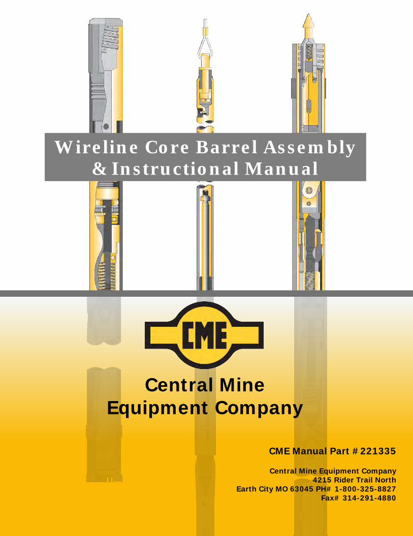
Wireline Core Barrel Assembly & Instructional Manual
Central Mine Equipment Company
CME Manual Part #221335
Central Mine Equipment Company 4215 Rider Trail North
Earth City MO 63045 PH# 1-800-325-8827 Fax# 314-291-4880
4215 Rider Trail North, Earth City, MO, USA 63045-1106 (314) 291-7700 • (800) 325-8827 • fax (314) 291-4880 Page 1 of 59 www.cmeco.com • [email protected] Revised 5/3/21
Central Mine Equipment Company
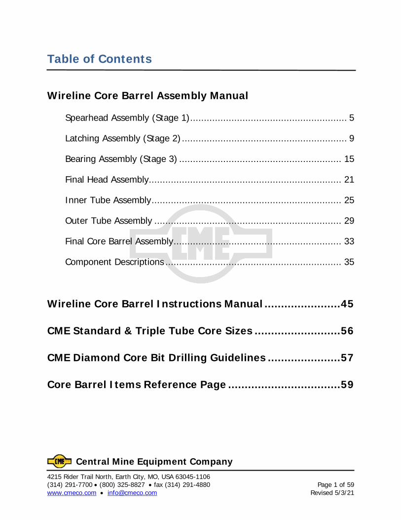
Table of Contents
Wireline Core Barrel Assembly Manual
Spearhead Assembly (Stage 1) ......................................................... 5
Latching Assembly (Stage 2) ............................................................ 9
Bearing Assembly (Stage 3) ........................................................... 15
Final Head Assembly...................................................................... 21
Inner Tube Assembly ..................................................................... 25
Outer Tube Assembly .................................................................... 29
Final Core Barrel Assembly ............................................................. 33
Component Descriptions ................................................................ 35
Wireline Core Barrel Instructions Manual ....................... 45
CME Standard & Triple Tube Core Sizes .......................... 56
CME Diamond Core Bit Drilling Guidelines ...................... 57
Core Barrel Items Reference Page .................................. 59

4215 Rider Trail North, Earth City, MO, USA 63045-1106 Page 2 of 59 (314) 291-7700 • (800) 325-8827 • fax (314) 291-4880 Revised 5/3/21 www.cmeco.com • [email protected]
Central Mine Equipment Company
4215 Rider Trail North, Earth City, MO, USA 63045-1106 (314) 291-7700 • (800) 325-8827 • fax (314) 291-4880 Page 3 of 59 www.cmeco.com • [email protected] Revised 5/3/21
Central Mine Equipment Company
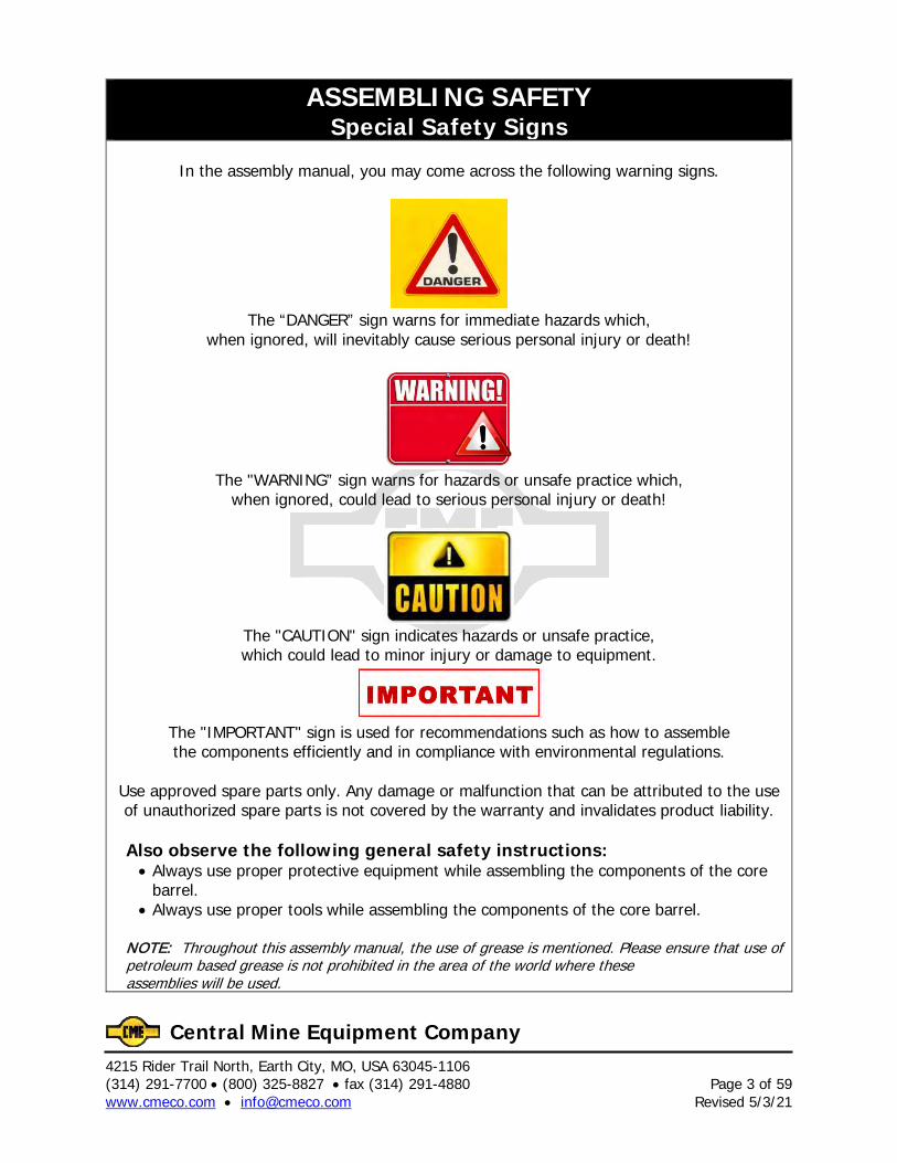
ASSEMBLING SAFETY Special Safety Signs
In the assembly manual, you may come across the following warning signs.
The “DANGER” sign warns for immediate hazards which,
when ignored, will inevitably cause serious personal injury or death!
The "WARNING” sign warns for hazards or unsafe practice which,
when ignored, could lead to serious personal injury or death!
The "CAUTION" sign indicates hazards or unsafe practice, which could lead to minor injury or damage to equipment.
The "IMPORTANT" sign is used for recommendations such as how to assemble the components efficiently and in compliance with environmental regulations.
Use approved spare parts only. Any damage or malfunction that can be attributed to the use of unauthorized spare parts is not covered by the warranty and invalidates product liability.
Also observe the following general safety instructions: • Always use proper protective equipment while assembling the components of the core
barrel. • Always use proper tools while assembling the components of the core barrel.
NOTE: Throughout this assembly manual, the use of grease is mentioned. Please ensure that use of petroleum based grease is not prohibited in the area of the world where these assemblies will be used.
4215 Rider Trail North, Earth City, MO, USA 63045-1106 Page 4 of 59 (314) 291-7700 • (800) 325-8827 • fax (314) 291-4880 Revised 5/3/21 www.cmeco.com • [email protected]
Central Mine Equipment Company
4215 Rider Trail North, Earth City, MO, USA 63045-1106 (314) 291-7700 • (800) 325-8827 • fax (314) 291-4880 Page 5 of 59 www.cmeco.com • [email protected] Revised 5/3/21
Central Mine Equipment Company
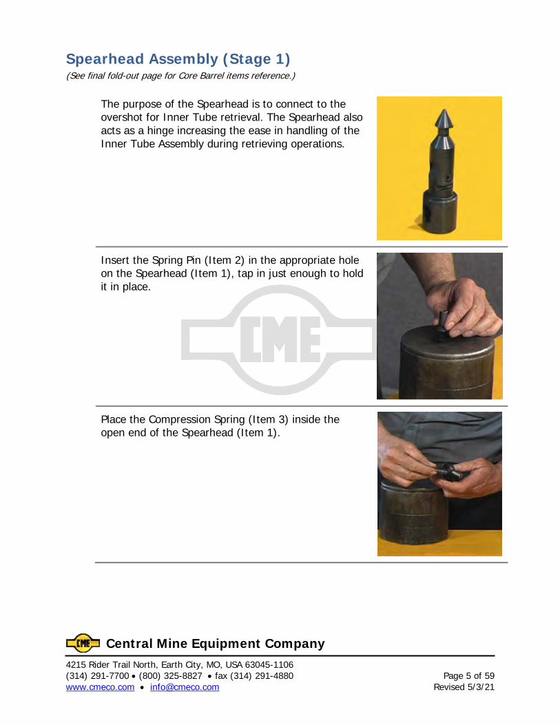
Spearhead Assembly (Stage 1) (See final fold-out page for Core Barrel items reference.)
The purpose of the Spearhead is to connect to the overshot for Inner Tube retrieval. The Spearhead also acts as a hinge increasing the ease in handling of the Inner Tube Assembly during retrieving operations.
Insert the Spring Pin (Item 2) in the appropriate hole on the Spearhead (Item 1), tap in just enough to hold it in place.
Place the Compression Spring (Item 3) inside the open end of the Spearhead (Item 1).

4215 Rider Trail North, Earth City, MO, USA 63045-1106 Page 6 of 59 (314) 291-7700 • (800) 325-8827 • fax (314) 291-4880 Revised 5/3/21 www.cmeco.com • [email protected]
Central Mine Equipment Company
Place the Detent (Item 4) inside the Spearhead (Item 1) with the pointed end facing away from the Compression Spring (Item 3). The Compression Spring (Item 3) should rest inside the open end of the Detent (Item 4).
Use proper personal protective equipment and proper tools. Avoid the pinch point.
Push the Spearhead Base (Item 5) into the Spearhead (Item 1) so the Detent (Item 4) rests securely in it.
Push in the Spearhead Base (Item 5) until the holes in the Spearhead Base (Item 5) and the holes in the Spearhead (Item 1) line up, then drive the Spring Pin (Item 2) through.
4215 Rider Trail North, Earth City, MO, USA 63045-1106 (314) 291-7700 • (800) 325-8827 • fax (314) 291-4880 Page 7 of 59 www.cmeco.com • [email protected] Revised 5/3/21
Central Mine Equipment Company
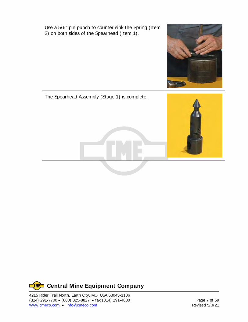
Use a 5/6” pin punch to counter sink the Spring (Item 2) on both sides of the Spearhead (Item 1).
The Spearhead Assembly (Stage 1) is complete.

4215 Rider Trail North, Earth City, MO, USA 63045-1106 Page 8 of 59 (314) 291-7700 • (800) 325-8827 • fax (314) 291-4880 Revised 5/3/21 www.cmeco.com • [email protected]
Central Mine Equipment Company
4215 Rider Trail North, Earth City, MO, USA 63045-1106 (314) 291-7700 • (800) 325-8827 • fax (314) 291-4880 Page 9 of 59 www.cmeco.com • [email protected] Revised 5/3/21
Central Mine Equipment Company
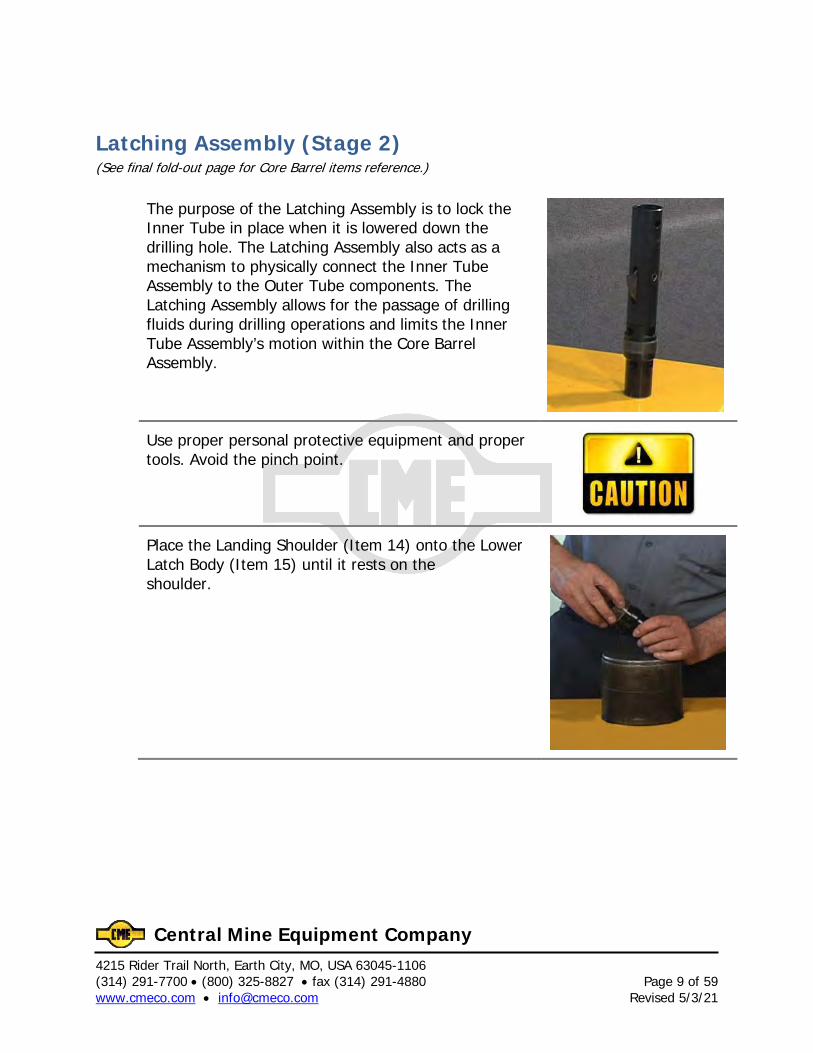
Latching Assembly (Stage 2) (See final fold-out page for Core Barrel items reference.)
The purpose of the Latching Assembly is to lock the Inner Tube in place when it is lowered down the drilling hole. The Latching Assembly also acts as a mechanism to physically connect the Inner Tube Assembly to the Outer Tube components. The Latching Assembly allows for the passage of drilling fluids during drilling operations and limits the Inner Tube Assembly’s motion within the Core Barrel Assembly.
Use proper personal protective equipment and proper tools. Avoid the pinch point.
Place the Landing Shoulder (Item 14) onto the Lower Latch Body (Item 15) until it rests on the shoulder.
4215 Rider Trail North, Earth City, MO, USA 63045-1106 Page 10 of 59 (314) 291-7700 • (800) 325-8827 • fax (314) 291-4880 Revised 5/3/21 www.cmeco.com • [email protected]
Central Mine Equipment Company
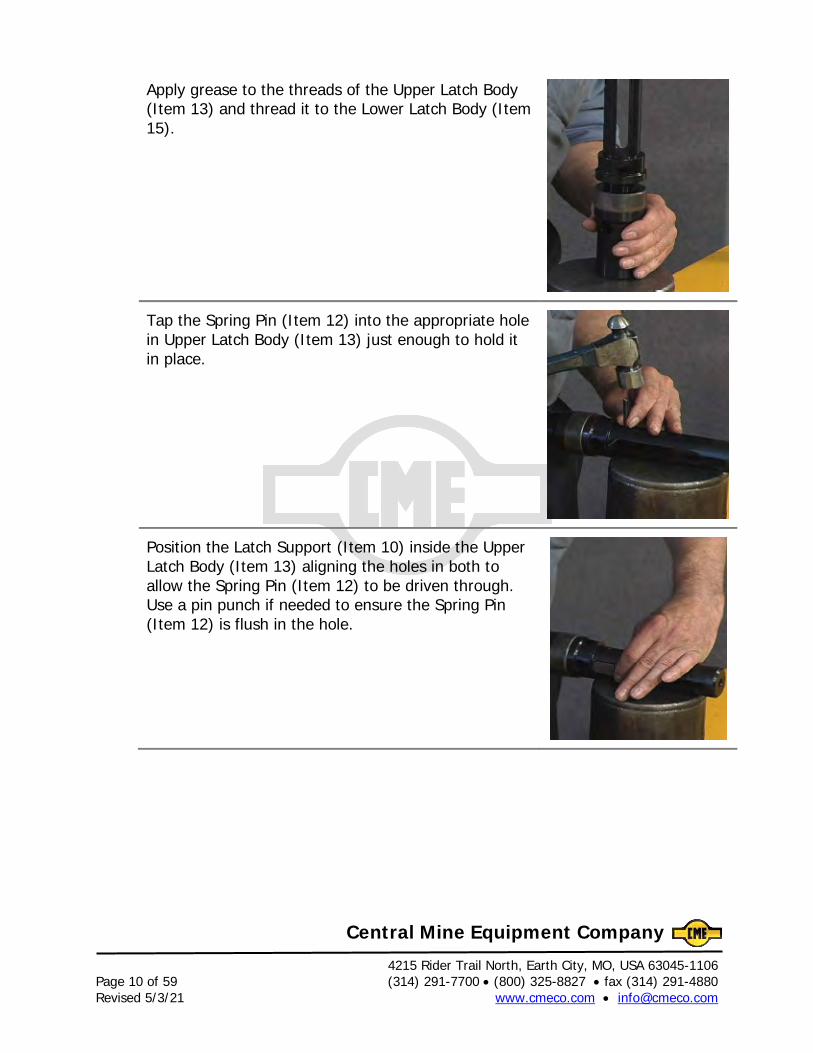
Apply grease to the threads of the Upper Latch Body (Item 13) and thread it to the Lower Latch Body (Item 15).
Tap the Spring Pin (Item 12) into the appropriate hole in Upper Latch Body (Item 13) just enough to hold it in place.
Position the Latch Support (Item 10) inside the Upper Latch Body (Item 13) aligning the holes in both to allow the Spring Pin (Item 12) to be driven through. Use a pin punch if needed to ensure the Spring Pin (Item 12) is flush in the hole.
4215 Rider Trail North, Earth City, MO, USA 63045-1106 (314) 291-7700 • (800) 325-8827 • fax (314) 291-4880 Page 11 of 59 www.cmeco.com • [email protected] Revised 5/3/21
Central Mine Equipment Company
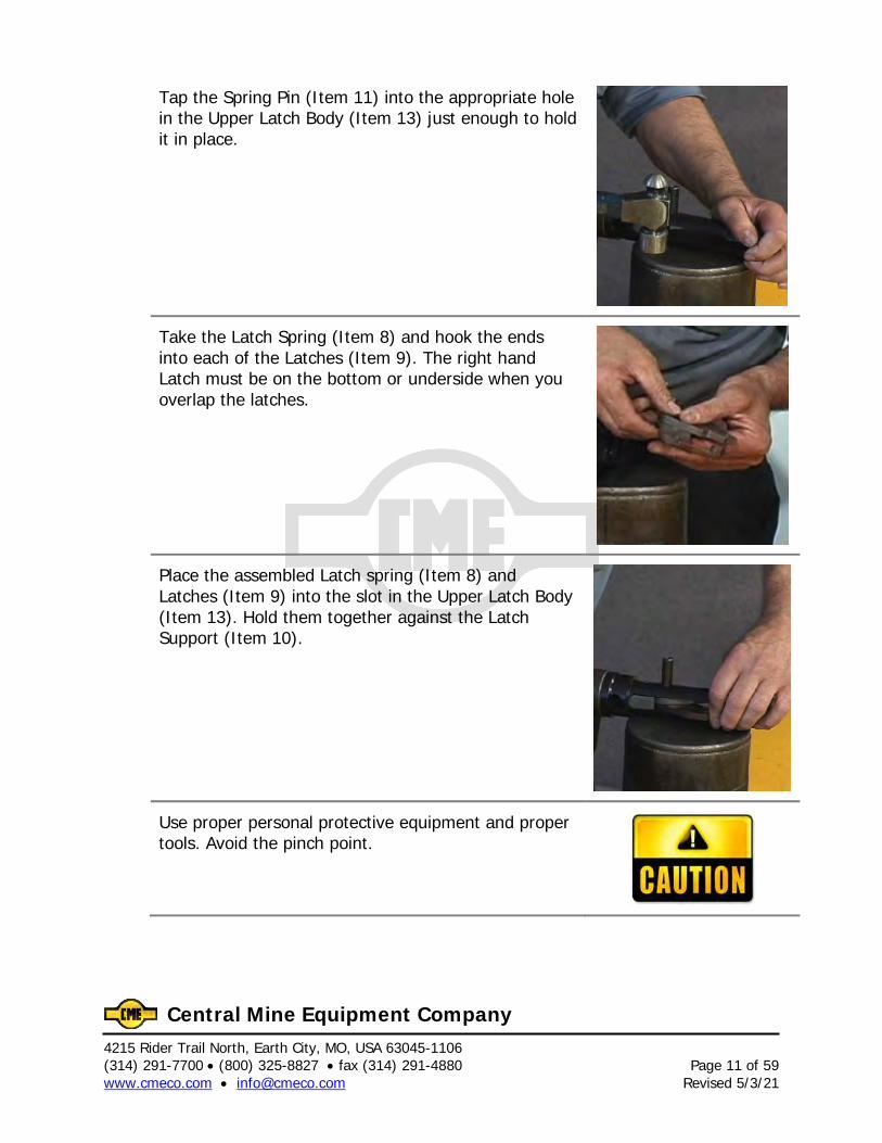
Tap the Spring Pin (Item 11) into the appropriate hole in the Upper Latch Body (Item 13) just enough to hold it in place.
Take the Latch Spring (Item 8) and hook the ends into each of the Latches (Item 9). The right hand Latch must be on the bottom or underside when you overlap the latches.
Place the assembled Latch spring (Item 8) and Latches (Item 9) into the slot in the Upper Latch Body (Item 13). Hold them together against the Latch Support (Item 10).
Use proper personal protective equipment and proper tools. Avoid the pinch point.
4215 Rider Trail North, Earth City, MO, USA 63045-1106 Page 12 of 59 (314) 291-7700 • (800) 325-8827 • fax (314) 291-4880 Revised 5/3/21 www.cmeco.com • [email protected]
Central Mine Equipment Company
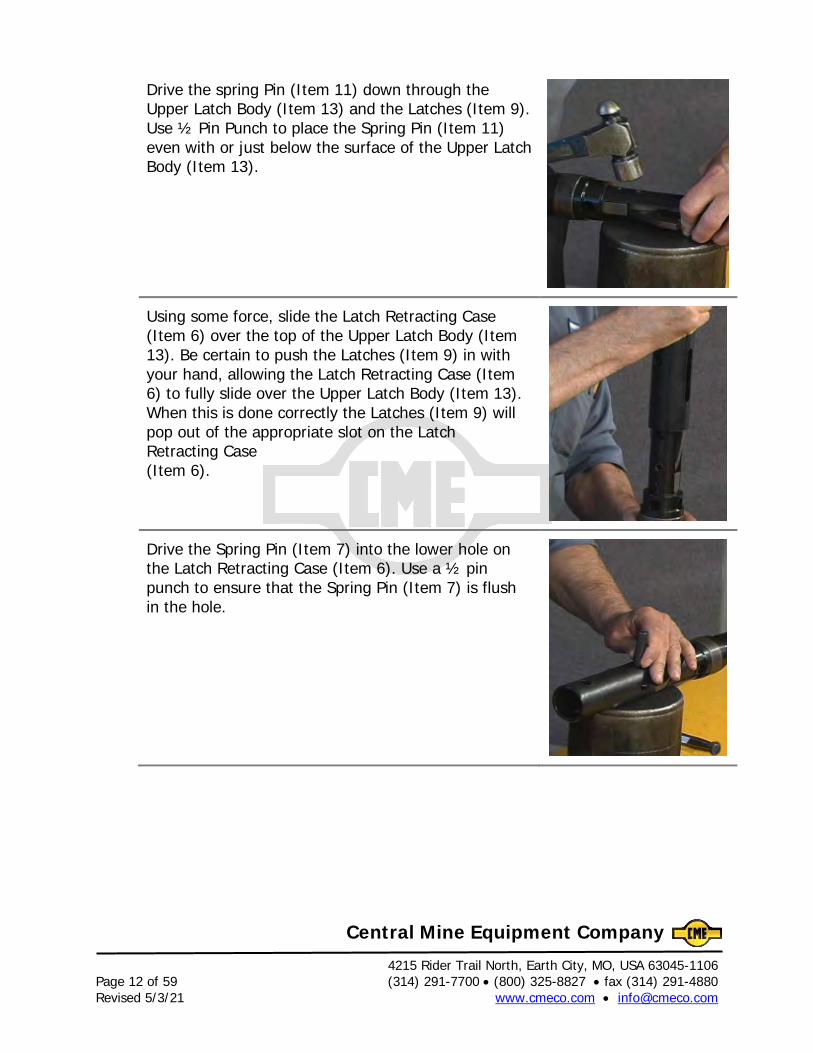
Drive the spring Pin (Item 11) down through the Upper Latch Body (Item 13) and the Latches (Item 9). Use ½ Pin Punch to place the Spring Pin (Item 11) even with or just below the surface of the Upper Latch Body (Item 13).
Using some force, slide the Latch Retracting Case (Item 6) over the top of the Upper Latch Body (Item 13). Be certain to push the Latches (Item 9) in with your hand, allowing the Latch Retracting Case (Item 6) to fully slide over the Upper Latch Body (Item 13). When this is done correctly the Latches (Item 9) will pop out of the appropriate slot on the Latch Retracting Case (Item 6).
Drive the Spring Pin (Item 7) into the lower hole on the Latch Retracting Case (Item 6). Use a ½ pin punch to ensure that the Spring Pin (Item 7) is flush in the hole.
4215 Rider Trail North, Earth City, MO, USA 63045-1106 (314) 291-7700 • (800) 325-8827 • fax (314) 291-4880 Page 13 of 59 www.cmeco.com • [email protected] Revised 5/3/21
Central Mine Equipment Company
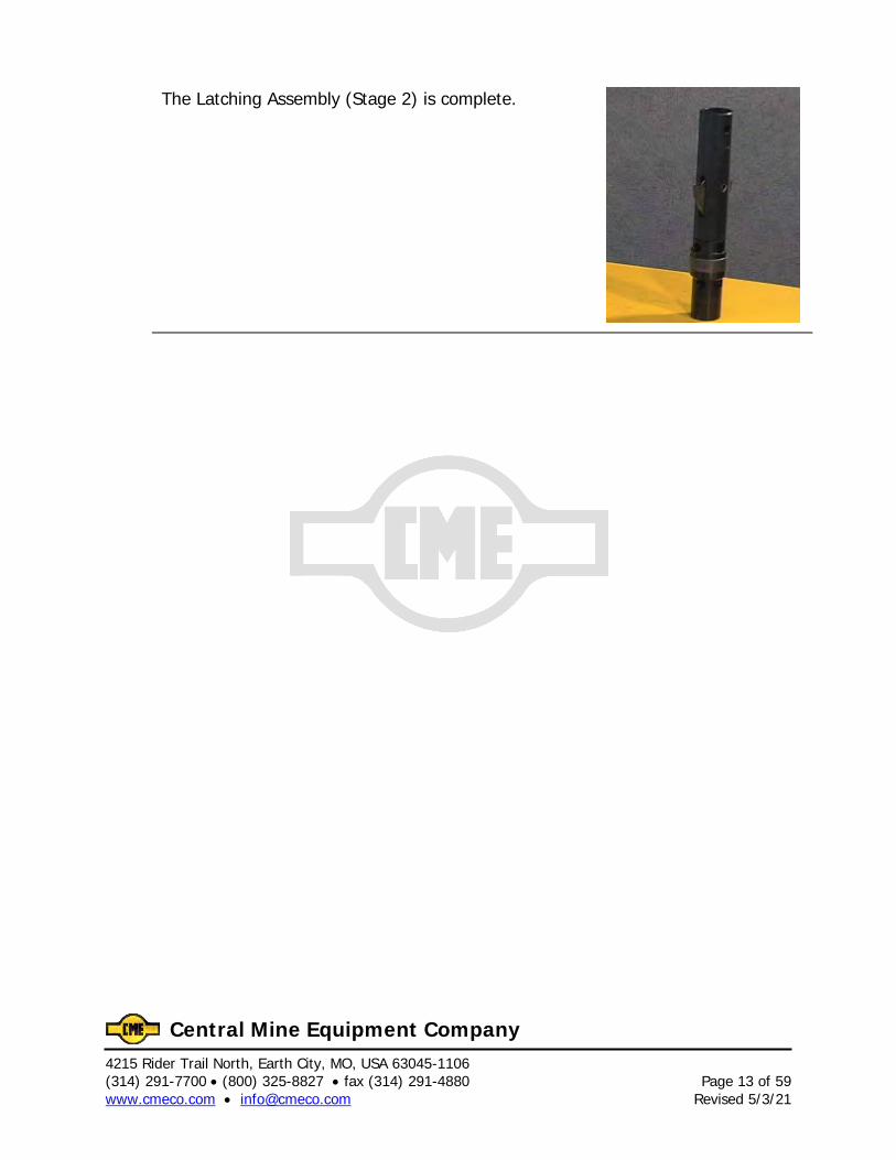
The Latching Assembly (Stage 2) is complete.

4215 Rider Trail North, Earth City, MO, USA 63045-1106 Page 14 of 59 (314) 291-7700 • (800) 325-8827 • fax (314) 291-4880 Revised 5/3/21 www.cmeco.com • [email protected]
Central Mine Equipment Company
4215 Rider Trail North, Earth City, MO, USA 63045-1106 (314) 291-7700 • (800) 325-8827 • fax (314) 291-4880 Page 15 of 59 www.cmeco.com • [email protected] Revised 5/3/21
Central Mine Equipment Company
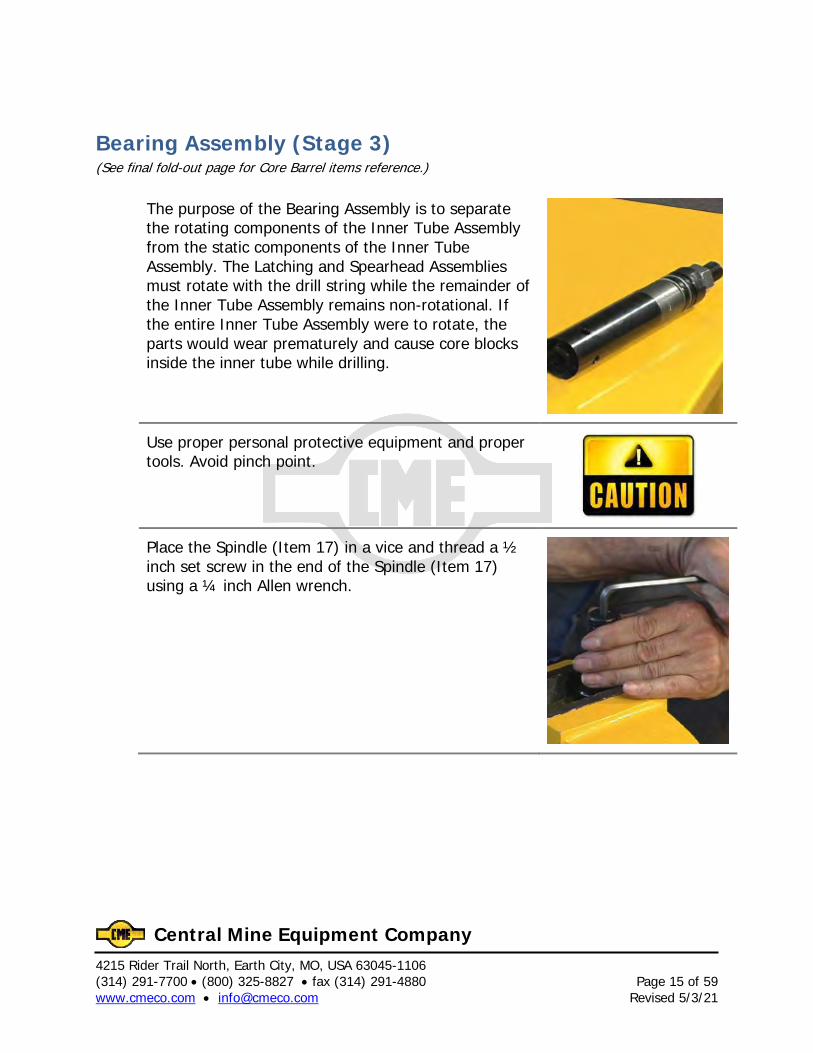
Bearing Assembly (Stage 3) (See final fold-out page for Core Barrel items reference.)
The purpose of the Bearing Assembly is to separate the rotating components of the Inner Tube Assembly from the static components of the Inner Tube Assembly. The Latching and Spearhead Assemblies must rotate with the drill string while the remainder of the Inner Tube Assembly remains non-rotational. If the entire Inner Tube Assembly were to rotate, the parts would wear prematurely and cause core blocks inside the inner tube while drilling.
Use proper personal protective equipment and proper tools. Avoid pinch point.
Place the Spindle (Item 17) in a vice and thread a ½ inch set screw in the end of the Spindle (Item 17) using a ¼ inch Allen wrench.
4215 Rider Trail North, Earth City, MO, USA 63045-1106 Page 16 of 59 (314) 291-7700 • (800) 325-8827 • fax (314) 291-4880 Revised 5/3/21 www.cmeco.com • [email protected]
Central Mine Equipment Company
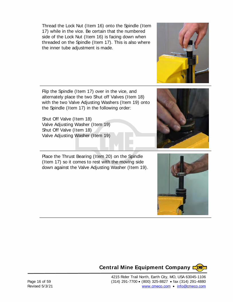
Thread the Lock Nut (Item 16) onto the Spindle (Item 17) while in the vice. Be certain that the numbered side of the Lock Nut (Item 16) is facing down when threaded on the Spindle (Item 17). This is also where the inner tube adjustment is made.
Flip the Spindle (Item 17) over in the vice, and alternately place the two Shut off Valves (Item 18) with the two Valve Adjusting Washers (Item 19) onto the Spindle (Item 17) in the following order: Shut Off Valve (Item 18) Valve Adjusting Washer (Item 19) Shut Off Valve (Item 18) Valve Adjusting Washer (Item 19)
Place the Thrust Bearing (Item 20) on the Spindle (Item 17) so it comes to rest with the moving side down against the Valve Adjusting Washer (Item 19).
4215 Rider Trail North, Earth City, MO, USA 63045-1106 (314) 291-7700 • (800) 325-8827 • fax (314) 291-4880 Page 17 of 59 www.cmeco.com • [email protected] Revised 5/3/21
Central Mine Equipment Company
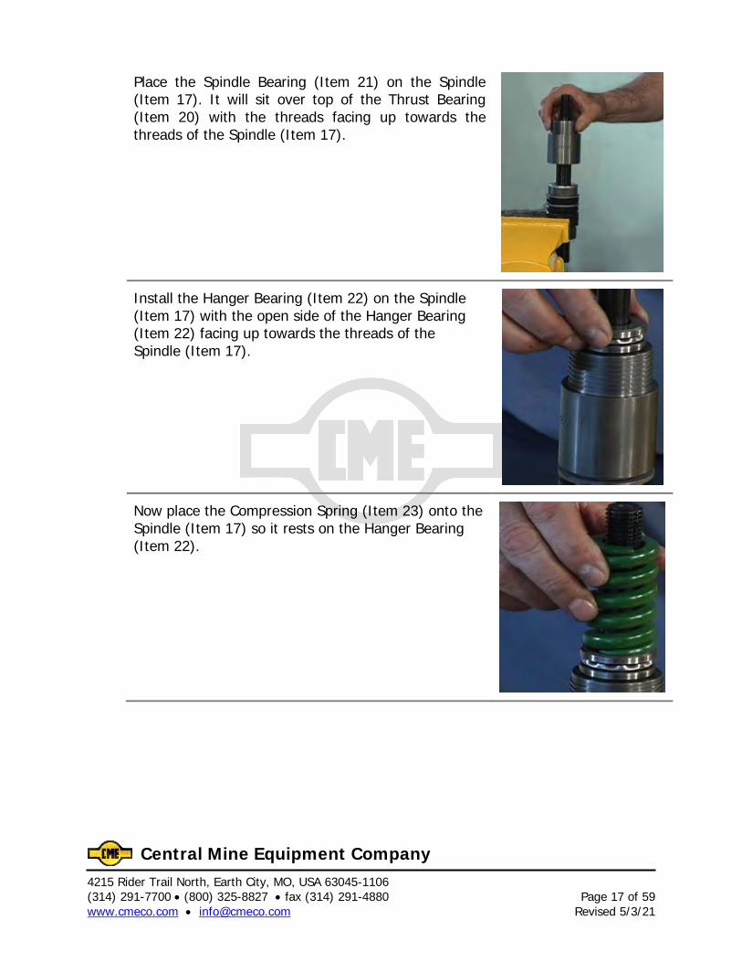
Place the Spindle Bearing (Item 21) on the Spindle (Item 17). It will sit over top of the Thrust Bearing (Item 20) with the threads facing up towards the threads of the Spindle (Item 17).
Install the Hanger Bearing (Item 22) on the Spindle (Item 17) with the open side of the Hanger Bearing (Item 22) facing up towards the threads of the Spindle (Item 17).
Now place the Compression Spring (Item 23) onto the Spindle (Item 17) so it rests on the Hanger Bearing (Item 22).
4215 Rider Trail North, Earth City, MO, USA 63045-1106 Page 18 of 59 (314) 291-7700 • (800) 325-8827 • fax (314) 291-4880 Revised 5/3/21 www.cmeco.com • [email protected]
Central Mine Equipment Company
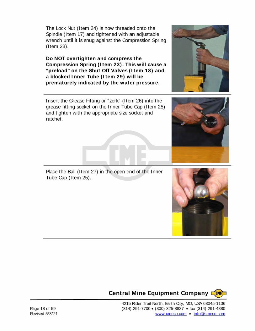
The Lock Nut (Item 24) is now threaded onto the Spindle (Item 17) and tightened with an adjustable wrench until it is snug against the Compression Spring (Item 23). Do NOT overtighten and compress the Compression Spring (Item 23). This will cause a “preload” on the Shut Off Valves (Item 18) and a blocked Inner Tube (Item 29) will be prematurely indicated by the water pressure.
Insert the Grease Fitting or “zerk” (Item 26) into the grease fitting socket on the Inner Tube Cap (Item 25) and tighten with the appropriate size socket and ratchet.
Place the Ball (Item 27) in the open end of the Inner Tube Cap (Item 25).
4215 Rider Trail North, Earth City, MO, USA 63045-1106 (314) 291-7700 • (800) 325-8827 • fax (314) 291-4880 Page 19 of 59 www.cmeco.com • [email protected] Revised 5/3/21
Central Mine Equipment Company
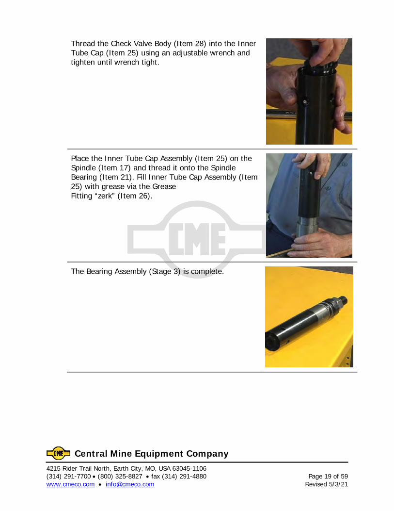
Thread the Check Valve Body (Item 28) into the Inner Tube Cap (Item 25) using an adjustable wrench and tighten until wrench tight.
Place the Inner Tube Cap Assembly (Item 25) on the Spindle (Item 17) and thread it onto the Spindle Bearing (Item 21). Fill Inner Tube Cap Assembly (Item 25) with grease via the Grease Fitting “zerk” (Item 26).
The Bearing Assembly (Stage 3) is complete.

4215 Rider Trail North, Earth City, MO, USA 63045-1106 Page 20 of 59 (314) 291-7700 • (800) 325-8827 • fax (314) 291-4880 Revised 5/3/21 www.cmeco.com • [email protected]
Central Mine Equipment Company
4215 Rider Trail North, Earth City, MO, USA 63045-1106 (314) 291-7700 • (800) 325-8827 • fax (314) 291-4880 Page 21 of 59 www.cmeco.com • [email protected] Revised 5/3/21
Central Mine Equipment Company
Final Head Assembly (See final fold-out page for Core Barrel items reference.)
The purpose of this assembly is to create the Inner Tube Head Assembly. This is one of the main components of the Wireline Core Barrel Assembly.
Use proper personal protective equipment and proper tools. Avoid the pinch point.
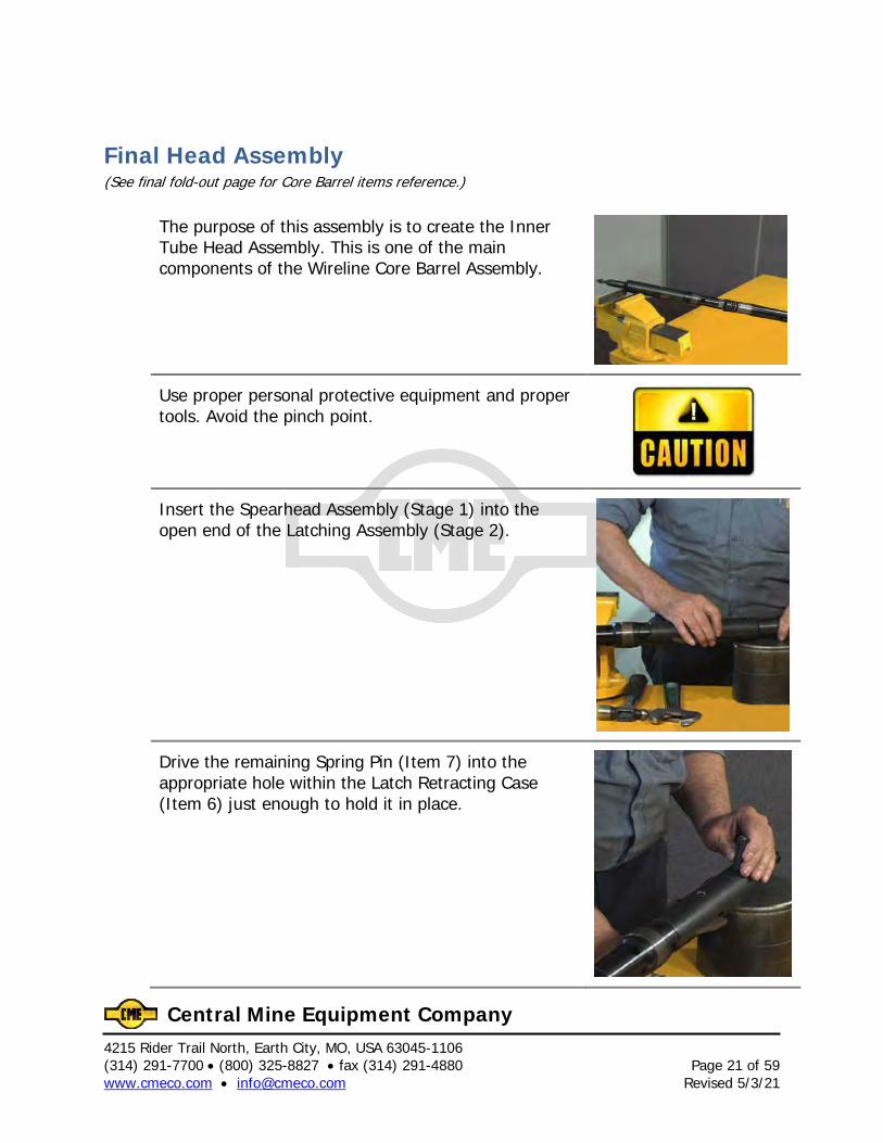
Insert the Spearhead Assembly (Stage 1) into the open end of the Latching Assembly (Stage 2).
Drive the remaining Spring Pin (Item 7) into the appropriate hole within the Latch Retracting Case (Item 6) just enough to hold it in place.
4215 Rider Trail North, Earth City, MO, USA 63045-1106 Page 22 of 59 (314) 291-7700 • (800) 325-8827 • fax (314) 291-4880 Revised 5/3/21 www.cmeco.com • [email protected]
Central Mine Equipment Company
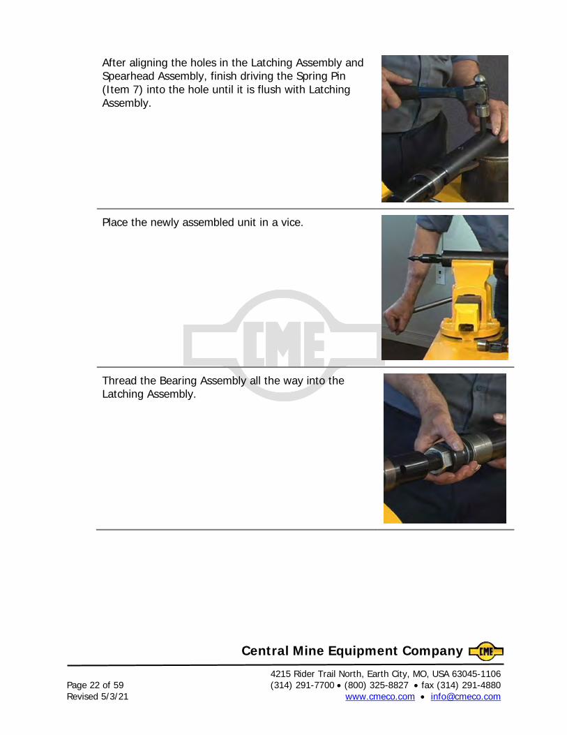
After aligning the holes in the Latching Assembly and Spearhead Assembly, finish driving the Spring Pin (Item 7) into the hole until it is flush with Latching Assembly.
Place the newly assembled unit in a vice.
Thread the Bearing Assembly all the way into the Latching Assembly.
4215 Rider Trail North, Earth City, MO, USA 63045-1106 (314) 291-7700 • (800) 325-8827 • fax (314) 291-4880 Page 23 of 59 www.cmeco.com • [email protected] Revised 5/3/21
Central Mine Equipment Company
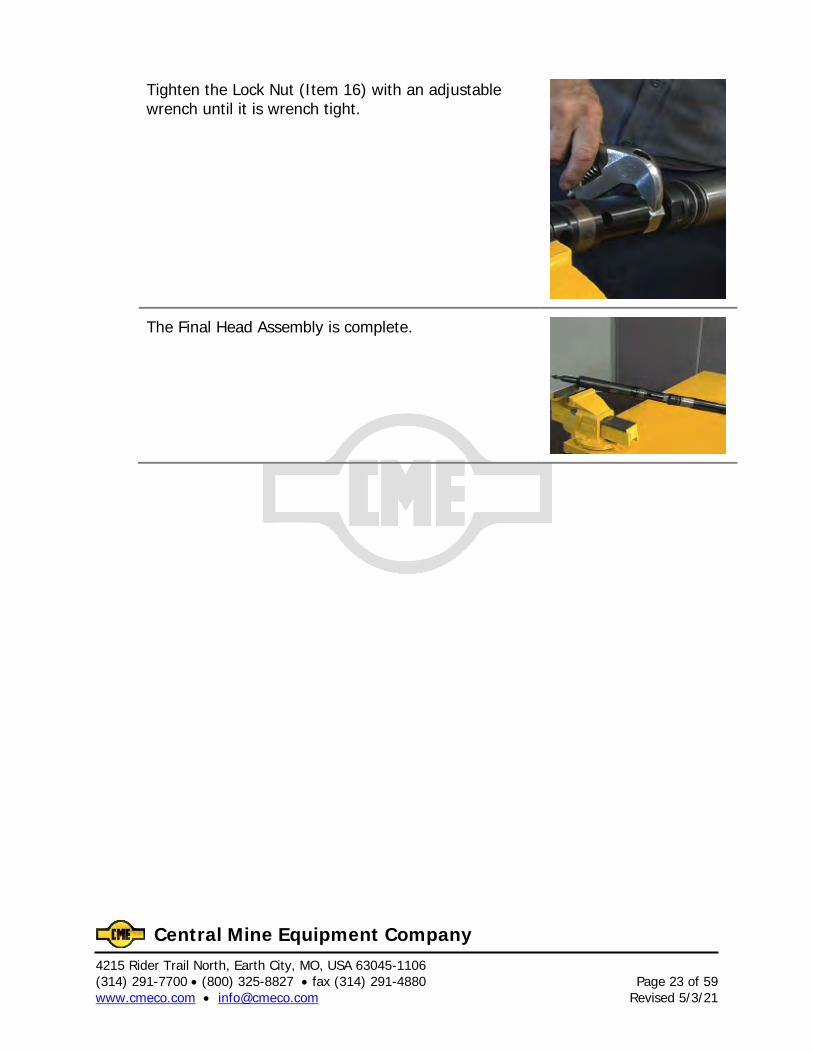
Tighten the Lock Nut (Item 16) with an adjustable wrench until it is wrench tight.
The Final Head Assembly is complete.

4215 Rider Trail North, Earth City, MO, USA 63045-1106 Page 24 of 59 (314) 291-7700 • (800) 325-8827 • fax (314) 291-4880 Revised 5/3/21 www.cmeco.com • [email protected]
Central Mine Equipment Company
4215 Rider Trail North, Earth City, MO, USA 63045-1106 (314) 291-7700 • (800) 325-8827 • fax (314) 291-4880 Page 25 of 59 www.cmeco.com • [email protected] Revised 5/3/21
Central Mine Equipment Company
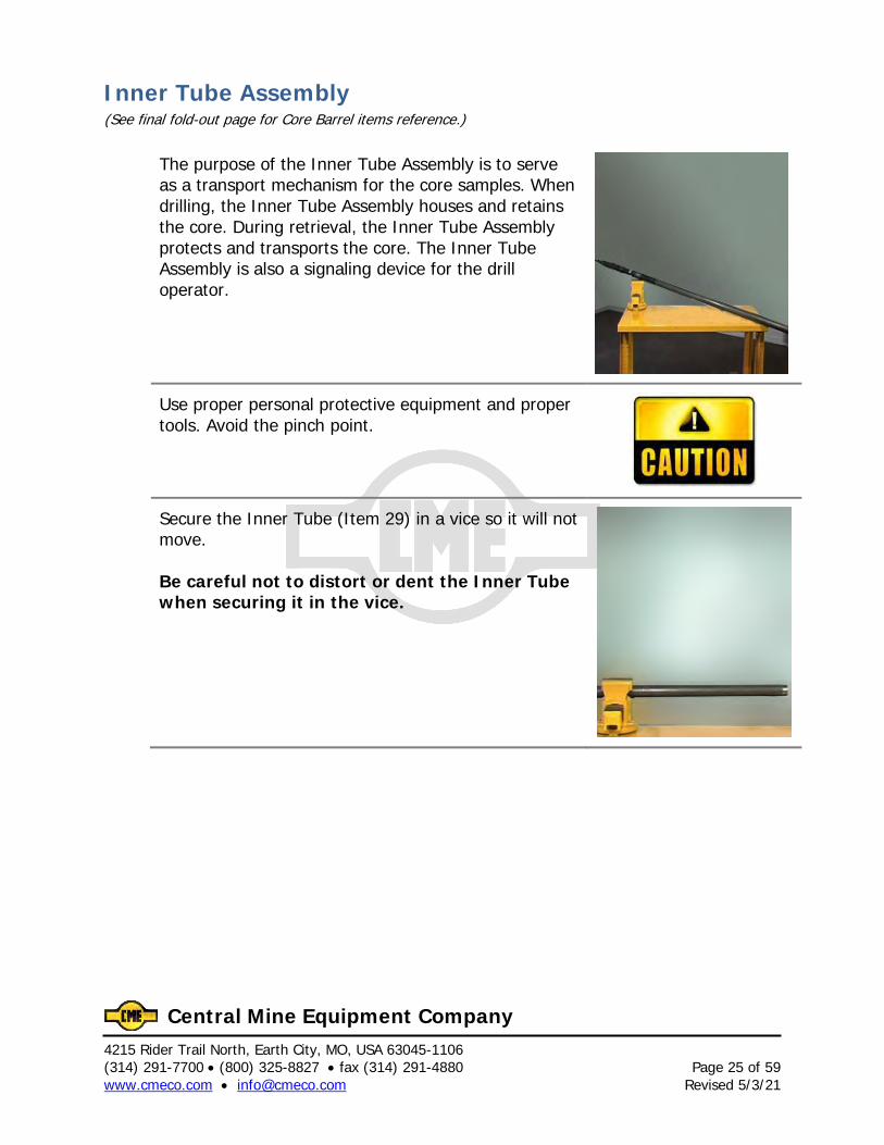
Inner Tube Assembly (See final fold-out page for Core Barrel items reference.)
The purpose of the Inner Tube Assembly is to serve as a transport mechanism for the core samples. When drilling, the Inner Tube Assembly houses and retains the core. During retrieval, the Inner Tube Assembly protects and transports the core. The Inner Tube Assembly is also a signaling device for the drill operator.
Use proper personal protective equipment and proper tools. Avoid the pinch point.
Secure the Inner Tube (Item 29) in a vice so it will not move. Be careful not to distort or dent the Inner Tube when securing it in the vice.
4215 Rider Trail North, Earth City, MO, USA 63045-1106 Page 26 of 59 (314) 291-7700 • (800) 325-8827 • fax (314) 291-4880 Revised 5/3/21 www.cmeco.com • [email protected]
Central Mine Equipment Company
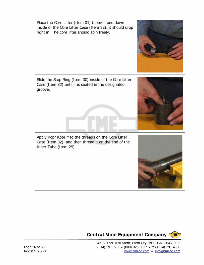
Place the Core Lifter (Item 31) tapered end down inside of the Core Lifter Case (Item 32); it should drop right in. The core lifter should spin freely.
Slide the Stop Ring (Item 30) inside of the Core Lifter Case (Item 32) until it is seated in the designated groove.
Apply Kopr Kote™ to the threads on the Core Lifter Case (Item 32), and then thread it on the end of the Inner Tube (Item 29).
4215 Rider Trail North, Earth City, MO, USA 63045-1106 (314) 291-7700 • (800) 325-8827 • fax (314) 291-4880 Page 27 of 59 www.cmeco.com • [email protected] Revised 5/3/21
Central Mine Equipment Company
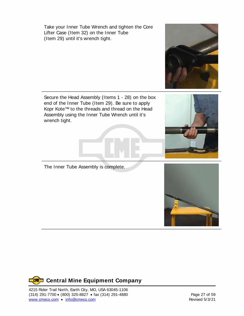
Take your Inner Tube Wrench and tighten the Core Lifter Case (Item 32) on the Inner Tube (Item 29) until it's wrench tight.
Secure the Head Assembly (Items 1 - 28) on the box end of the Inner Tube (Item 29). Be sure to apply Kopr Kote™ to the threads and thread on the Head Assembly using the Inner Tube Wrench until it's wrench tight.
The Inner Tube Assembly is complete.

4215 Rider Trail North, Earth City, MO, USA 63045-1106 Page 28 of 59 (314) 291-7700 • (800) 325-8827 • fax (314) 291-4880 Revised 5/3/21 www.cmeco.com • [email protected]
Central Mine Equipment Company
4215 Rider Trail North, Earth City, MO, USA 63045-1106 (314) 291-7700 • (800) 325-8827 • fax (314) 291-4880 Page 29 of 59 www.cmeco.com • [email protected] Revised 5/3/21
Central Mine Equipment Company
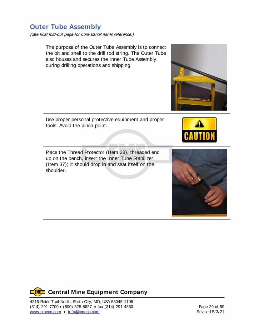
Outer Tube Assembly (See final fold-out page for Core Barrel items reference.)
The purpose of the Outer Tube Assembly is to connect the bit and shell to the drill rod string. The Outer Tube also houses and secures the Inner Tube Assembly during drilling operations and shipping.
Use proper personal protective equipment and proper tools. Avoid the pinch point.
Place the Thread Protector (Item 38), threaded end up on the bench, insert the Inner Tube Stabilizer (Item 37); it should drop in and seat itself on the shoulder.
4215 Rider Trail North, Earth City, MO, USA 63045-1106 Page 30 of 59 (314) 291-7700 • (800) 325-8827 • fax (314) 291-4880 Revised 5/3/21 www.cmeco.com • [email protected]
Central Mine Equipment Company
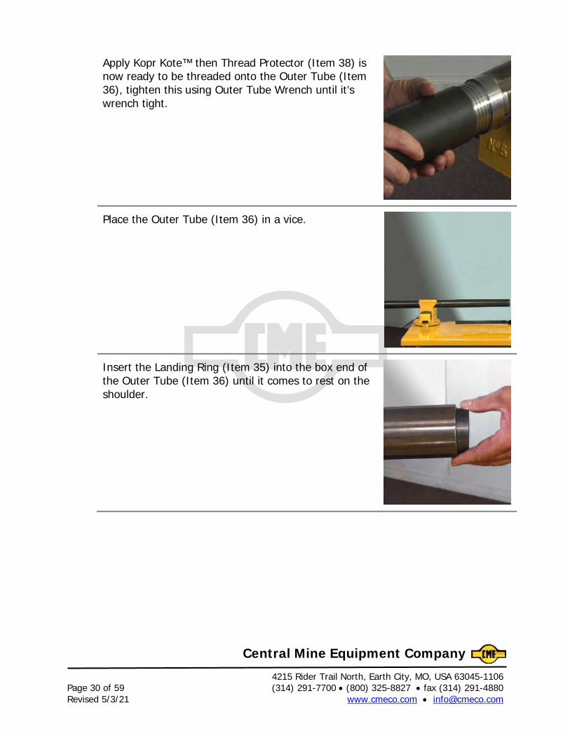
Apply Kopr Kote™ then Thread Protector (Item 38) is now ready to be threaded onto the Outer Tube (Item 36), tighten this using Outer Tube Wrench until it’s wrench tight.
Place the Outer Tube (Item 36) in a vice.
Insert the Landing Ring (Item 35) into the box end of the Outer Tube (Item 36) until it comes to rest on the shoulder.
4215 Rider Trail North, Earth City, MO, USA 63045-1106 (314) 291-7700 • (800) 325-8827 • fax (314) 291-4880 Page 31 of 59 www.cmeco.com • [email protected] Revised 5/3/21
Central Mine Equipment Company
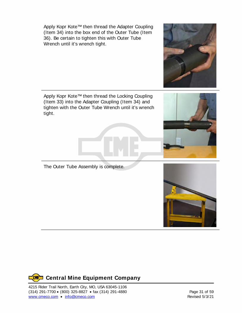
Apply Kopr Kote™ then thread the Adapter Coupling (Item 34) into the box end of the Outer Tube (Item 36). Be certain to tighten this with Outer Tube Wrench until it's wrench tight.
Apply Kopr Kote™ then thread the Locking Coupling (Item 33) into the Adapter Coupling (Item 34) and tighten with the Outer Tube Wrench until it's wrench tight.
The Outer Tube Assembly is complete.

4215 Rider Trail North, Earth City, MO, USA 63045-1106 Page 32 of 59 (314) 291-7700 • (800) 325-8827 • fax (314) 291-4880 Revised 5/3/21 www.cmeco.com • [email protected]
Central Mine Equipment Company
4215 Rider Trail North, Earth City, MO, USA 63045-1106 (314) 291-7700 • (800) 325-8827 • fax (314) 291-4880 Page 33 of 59 www.cmeco.com • [email protected] Revised 5/3/21
Central Mine Equipment Company
Final Core Barrel Assembly (See final fold-out page for Core Barrel items reference.)
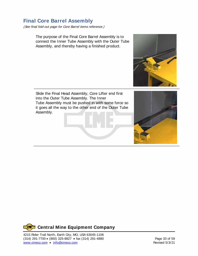
The purpose of the Final Core Barrel Assembly is to connect the Inner Tube Assembly with the Outer Tube Assembly, and thereby having a finished product.
Slide the Final Head Assembly, Core Lifter end first into the Outer Tube Assembly. The Inner Tube Assembly must be pushed in with some force so it goes all the way to the other end of the Outer Tube Assembly.
4215 Rider Trail North, Earth City, MO, USA 63045-1106 Page 34 of 59 (314) 291-7700 • (800) 325-8827 • fax (314) 291-4880 Revised 5/3/21 www.cmeco.com • [email protected]
Central Mine Equipment Company
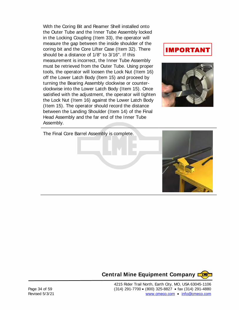
With the Coring Bit and Reamer Shell installed onto the Outer Tube and the Inner Tube Assembly locked in the Locking Coupling (Item 33), the operator will measure the gap between the inside shoulder of the coring bit and the Core Lifter Case (Item 32). There should be a distance of 1/8" to 3/16". If this measurement is incorrect, the Inner Tube Assembly must be retrieved from the Outer Tube. Using proper tools, the operator will loosen the Lock Nut (Item 16) off the Lower Latch Body (ltem 15) and proceed by turning the Bearing Assembly clockwise or counter-clockwise into the Lower Latch Body (Item 15). Once satisfied with the adjustment, the operator will tighten the Lock Nut (Item 16) against the Lower Latch Body (Item 15). The operator should record the distance between the Landing Shoulder (Item 14) of the Final Head Assembly and the far end of the Inner Tube Assembly.
The Final Core Barrel Assembly is complete.
4215 Rider Trail North, Earth City, MO, USA 63045-1106 (314) 291-7700 • (800) 325-8827 • fax (314) 291-4880 Page 35 of 59 www.cmeco.com • [email protected] Revised 5/3/21
Central Mine Equipment Company
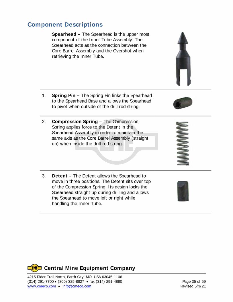
Component Descriptions Spearhead – The Spearhead is the upper most component of the Inner Tube Assembly. The Spearhead acts as the connection between the Core Barrel Assembly and the Overshot when retrieving the Inner Tube.
1. Spring Pin – The Spring Pin links the Spearhead to the Spearhead Base and allows the Spearhead to pivot when outside of the drill rod string.
2. Compression Spring – The Compression Spring applies force to the Detent in the Spearhead Assembly in order to maintain the same axis as the Core Barrel Assembly (straight up) when inside the drill rod string.
3. Detent – The Detent allows the Spearhead to move in three positions. The Detent sits over top of the Compression Spring. Its design locks the Spearhead straight up during drilling and allows the Spearhead to move left or right while handling the Inner Tube.
4215 Rider Trail North, Earth City, MO, USA 63045-1106 Page 36 of 59 (314) 291-7700 • (800) 325-8827 • fax (314) 291-4880 Revised 5/3/21 www.cmeco.com • [email protected]
Central Mine Equipment Company
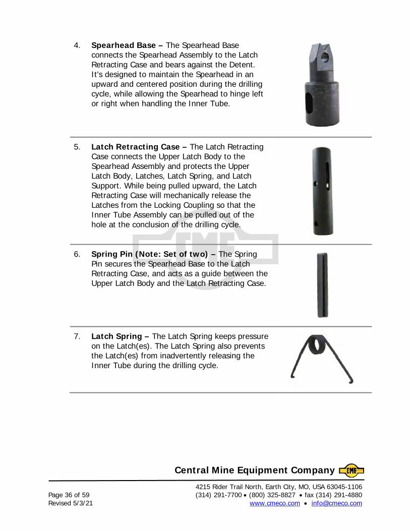
4. Spearhead Base – The Spearhead Base connects the Spearhead Assembly to the Latch Retracting Case and bears against the Detent. It's designed to maintain the Spearhead in an upward and centered position during the drilling cycle, while allowing the Spearhead to hinge left or right when handling the Inner Tube.
5. Latch Retracting Case – The Latch Retracting Case connects the Upper Latch Body to the Spearhead Assembly and protects the Upper Latch Body, Latches, Latch Spring, and Latch Support. While being pulled upward, the Latch Retracting Case will mechanically release the Latches from the Locking Coupling so that the Inner Tube Assembly can be pulled out of the hole at the conclusion of the drilling cycle.
6. Spring Pin (Note: Set of two) – The Spring Pin secures the Spearhead Base to the Latch Retracting Case, and acts as a guide between the Upper Latch Body and the Latch Retracting Case.
7. Latch Spring – The Latch Spring keeps pressure on the Latch(es). The Latch Spring also prevents the Latch(es) from inadvertently releasing the Inner Tube during the drilling cycle.
4215 Rider Trail North, Earth City, MO, USA 63045-1106 (314) 291-7700 • (800) 325-8827 • fax (314) 291-4880 Page 37 of 59 www.cmeco.com • [email protected] Revised 5/3/21
Central Mine Equipment Company
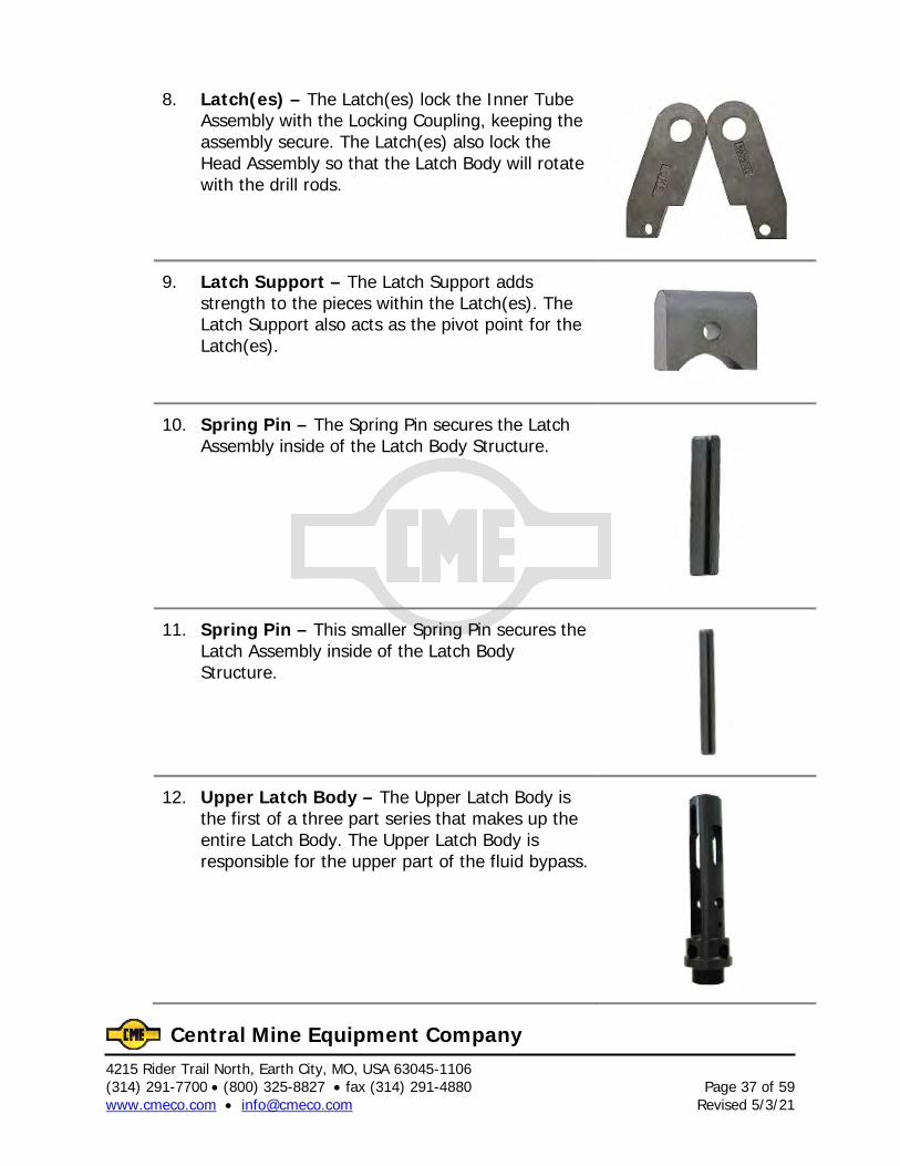
8. Latch(es) – The Latch(es) lock the Inner Tube Assembly with the Locking Coupling, keeping the assembly secure. The Latch(es) also lock the Head Assembly so that the Latch Body will rotate with the drill rods.
9. Latch Support – The Latch Support adds strength to the pieces within the Latch(es). The Latch Support also acts as the pivot point for the Latch(es).
10. Spring Pin – The Spring Pin secures the Latch Assembly inside of the Latch Body Structure.
11. Spring Pin – This smaller Spring Pin secures the Latch Assembly inside of the Latch Body Structure.
12. Upper Latch Body – The Upper Latch Body is the first of a three part series that makes up the entire Latch Body. The Upper Latch Body is responsible for the upper part of the fluid bypass.
4215 Rider Trail North, Earth City, MO, USA 63045-1106 Page 38 of 59 (314) 291-7700 • (800) 325-8827 • fax (314) 291-4880 Revised 5/3/21 www.cmeco.com • [email protected]
Central Mine Equipment Company
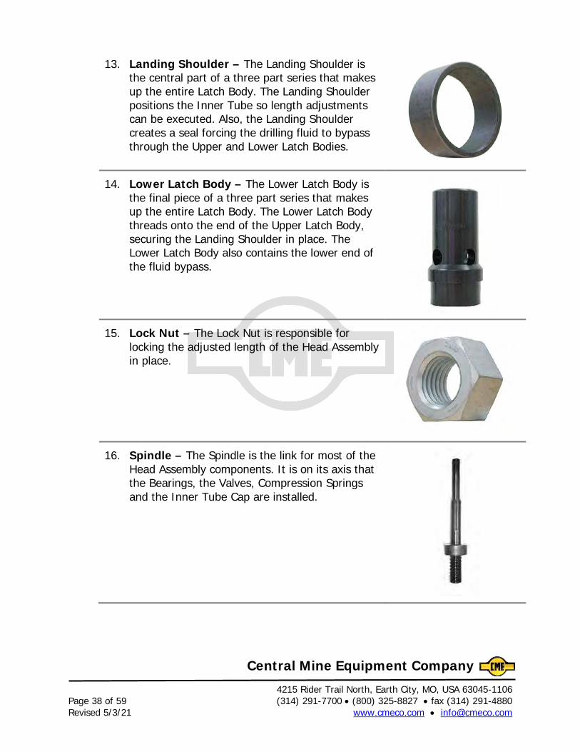
13. Landing Shoulder – The Landing Shoulder is the central part of a three part series that makes up the entire Latch Body. The Landing Shoulder positions the Inner Tube so length adjustments can be executed. Also, the Landing Shoulder creates a seal forcing the drilling fluid to bypass through the Upper and Lower Latch Bodies.
14. Lower Latch Body – The Lower Latch Body is the final piece of a three part series that makes up the entire Latch Body. The Lower Latch Body threads onto the end of the Upper Latch Body, securing the Landing Shoulder in place. The Lower Latch Body also contains the lower end of the fluid bypass.
15. Lock Nut – The Lock Nut is responsible for locking the adjusted length of the Head Assembly in place.
16. Spindle – The Spindle is the link for most of the Head Assembly components. It is on its axis that the Bearings, the Valves, Compression Springs and the Inner Tube Cap are installed.
4215 Rider Trail North, Earth City, MO, USA 63045-1106 (314) 291-7700 • (800) 325-8827 • fax (314) 291-4880 Page 39 of 59 www.cmeco.com • [email protected] Revised 5/3/21
Central Mine Equipment Company
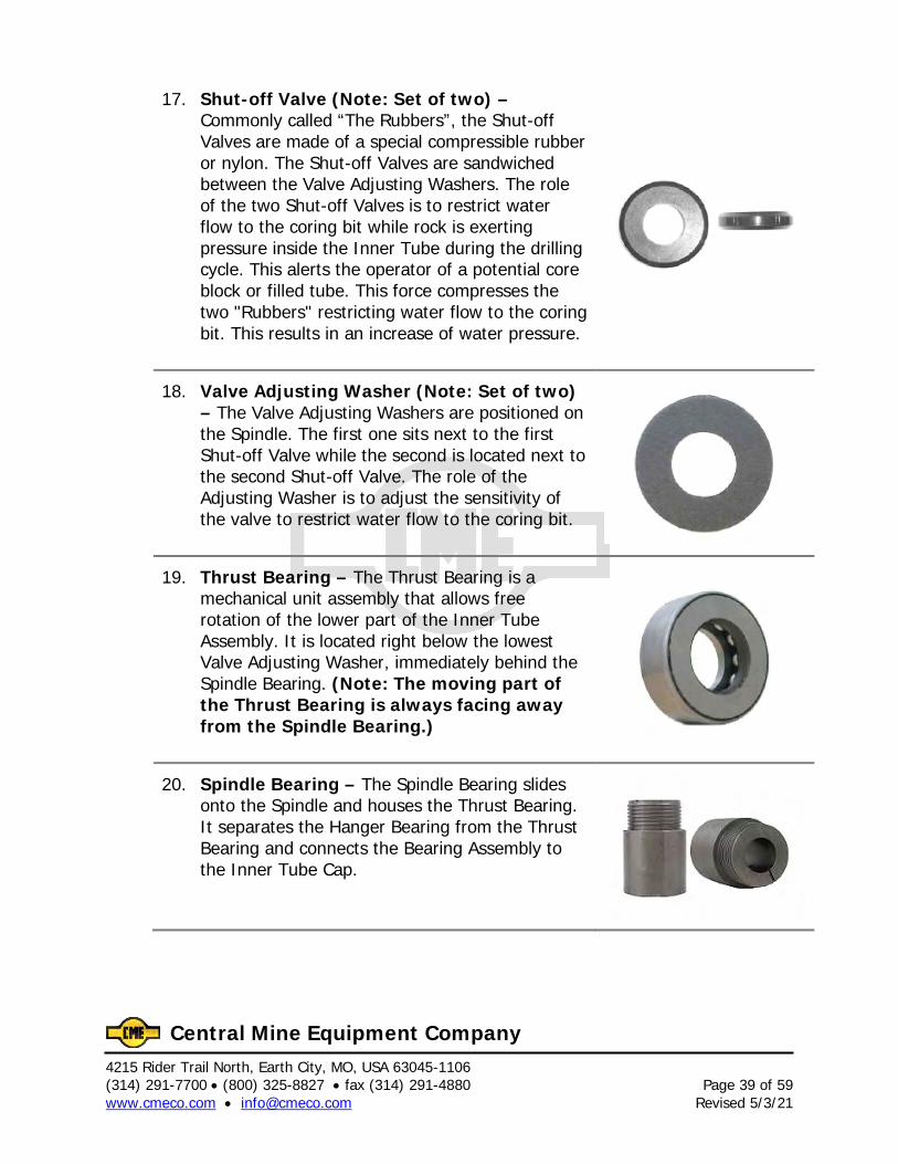
17. Shut-off Valve (Note: Set of two) – Commonly called “The Rubbers”, the Shut-off Valves are made of a special compressible rubber or nylon. The Shut-off Valves are sandwiched between the Valve Adjusting Washers. The role of the two Shut-off Valves is to restrict water flow to the coring bit while rock is exerting pressure inside the Inner Tube during the drilling cycle. This alerts the operator of a potential core block or filled tube. This force compresses the two "Rubbers" restricting water flow to the coring bit. This results in an increase of water pressure.
18. Valve Adjusting Washer (Note: Set of two) – The Valve Adjusting Washers are positioned on the Spindle. The first one sits next to the first Shut-off Valve while the second is located next to the second Shut-off Valve. The role of the Adjusting Washer is to adjust the sensitivity of the valve to restrict water flow to the coring bit.
19. Thrust Bearing – The Thrust Bearing is a mechanical unit assembly that allows free rotation of the lower part of the Inner Tube Assembly. It is located right below the lowest Valve Adjusting Washer, immediately behind the Spindle Bearing. (Note: The moving part of the Thrust Bearing is always facing away from the Spindle Bearing.)
20. Spindle Bearing – The Spindle Bearing slides onto the Spindle and houses the Thrust Bearing. It separates the Hanger Bearing from the Thrust Bearing and connects the Bearing Assembly to the Inner Tube Cap.
4215 Rider Trail North, Earth City, MO, USA 63045-1106 Page 40 of 59 (314) 291-7700 • (800) 325-8827 • fax (314) 291-4880 Revised 5/3/21 www.cmeco.com • [email protected]
Central Mine Equipment Company
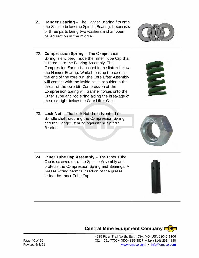
21. Hanger Bearing – The Hanger Bearing fits onto the Spindle below the Spindle Bearing. It consists of three parts being two washers and an open balled section in the middle.
22. Compression Spring – The Compression Spring is enclosed inside the Inner Tube Cap that is fitted onto the Bearing Assembly. The Compression Spring is located immediately below the Hanger Bearing. While breaking the core at the end of the core run, the Core Lifter Assembly will contact with the inside bevel shoulder in the throat of the core bit. Compression of the Compression Spring will transfer forces onto the Outer Tube and rod string aiding the breakage of the rock right below the Core Lifter Case.
23. Lock Nut – The Lock Nut threads onto the Spindle shaft securing the Compression Spring and the Hanger Bearing against the Spindle Bearing.
24. Inner Tube Cap Assembly – The Inner Tube Cap is screwed onto the Spindle Assembly and protects the Compression Spring and Bearings. A Grease Fitting permits insertion of the grease inside the Inner Tube Cap.
4215 Rider Trail North, Earth City, MO, USA 63045-1106 (314) 291-7700 • (800) 325-8827 • fax (314) 291-4880 Page 41 of 59 www.cmeco.com • [email protected] Revised 5/3/21
Central Mine Equipment Company
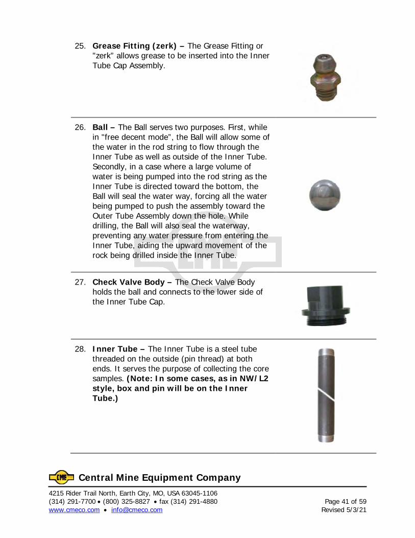
25. Grease Fitting (zerk) – The Grease Fitting or "zerk” allows grease to be inserted into the Inner Tube Cap Assembly.
26. Ball – The Ball serves two purposes. First, while in "free decent mode”, the Ball will allow some of the water in the rod string to flow through the Inner Tube as well as outside of the Inner Tube. Secondly, in a case where a large volume of water is being pumped into the rod string as the Inner Tube is directed toward the bottom, the Ball will seal the water way, forcing all the water being pumped to push the assembly toward the Outer Tube Assembly down the hole. While drilling, the Ball will also seal the waterway, preventing any water pressure from entering the Inner Tube, aiding the upward movement of the rock being drilled inside the Inner Tube.
27. Check Valve Body – The Check Valve Body holds the ball and connects to the lower side of the Inner Tube Cap.
28. Inner Tube – The Inner Tube is a steel tube threaded on the outside (pin thread) at both ends. It serves the purpose of collecting the core samples. (Note: In some cases, as in NW/L2 style, box and pin will be on the Inner Tube.)
4215 Rider Trail North, Earth City, MO, USA 63045-1106 Page 42 of 59 (314) 291-7700 • (800) 325-8827 • fax (314) 291-4880 Revised 5/3/21 www.cmeco.com • [email protected]
Central Mine Equipment Company
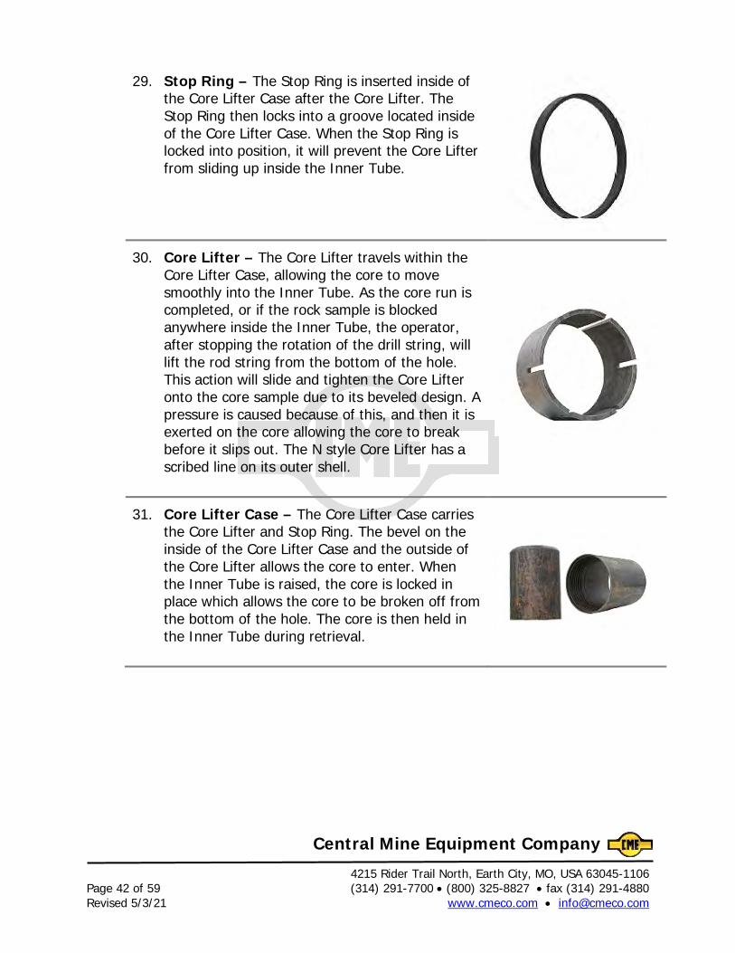
29. Stop Ring – The Stop Ring is inserted inside of the Core Lifter Case after the Core Lifter. The Stop Ring then locks into a groove located inside of the Core Lifter Case. When the Stop Ring is locked into position, it will prevent the Core Lifter from sliding up inside the Inner Tube.
30. Core Lifter – The Core Lifter travels within the Core Lifter Case, allowing the core to move smoothly into the Inner Tube. As the core run is completed, or if the rock sample is blocked anywhere inside the Inner Tube, the operator, after stopping the rotation of the drill string, will lift the rod string from the bottom of the hole. This action will slide and tighten the Core Lifter onto the core sample due to its beveled design. A pressure is caused because of this, and then it is exerted on the core allowing the core to break before it slips out. The N style Core Lifter has a scribed line on its outer shell.
31. Core Lifter Case – The Core Lifter Case carries the Core Lifter and Stop Ring. The bevel on the inside of the Core Lifter Case and the outside of the Core Lifter allows the core to enter. When the Inner Tube is raised, the core is locked in place which allows the core to be broken off from the bottom of the hole. The core is then held in the Inner Tube during retrieval.
4215 Rider Trail North, Earth City, MO, USA 63045-1106 (314) 291-7700 • (800) 325-8827 • fax (314) 291-4880 Page 43 of 59 www.cmeco.com • [email protected] Revised 5/3/21
Central Mine Equipment Company
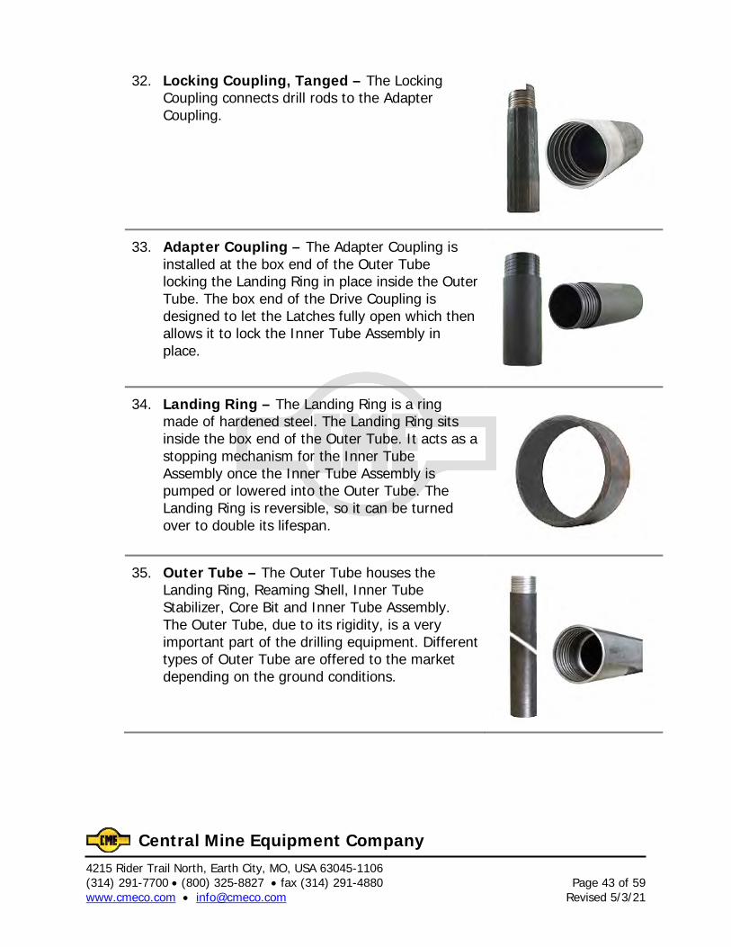
32. Locking Coupling, Tanged – The Locking Coupling connects drill rods to the Adapter Coupling.
33. Adapter Coupling – The Adapter Coupling is installed at the box end of the Outer Tube locking the Landing Ring in place inside the Outer Tube. The box end of the Drive Coupling is designed to let the Latches fully open which then allows it to lock the Inner Tube Assembly in place.
34. Landing Ring – The Landing Ring is a ring made of hardened steel. The Landing Ring sits inside the box end of the Outer Tube. It acts as a stopping mechanism for the Inner Tube Assembly once the Inner Tube Assembly is pumped or lowered into the Outer Tube. The Landing Ring is reversible, so it can be turned over to double its lifespan.
35. Outer Tube – The Outer Tube houses the Landing Ring, Reaming Shell, Inner Tube Stabilizer, Core Bit and Inner Tube Assembly. The Outer Tube, due to its rigidity, is a very important part of the drilling equipment. Different types of Outer Tube are offered to the market depending on the ground conditions.
4215 Rider Trail North, Earth City, MO, USA 63045-1106 Page 44 of 59 (314) 291-7700 • (800) 325-8827 • fax (314) 291-4880 Revised 5/3/21 www.cmeco.com • [email protected]
Central Mine Equipment Company
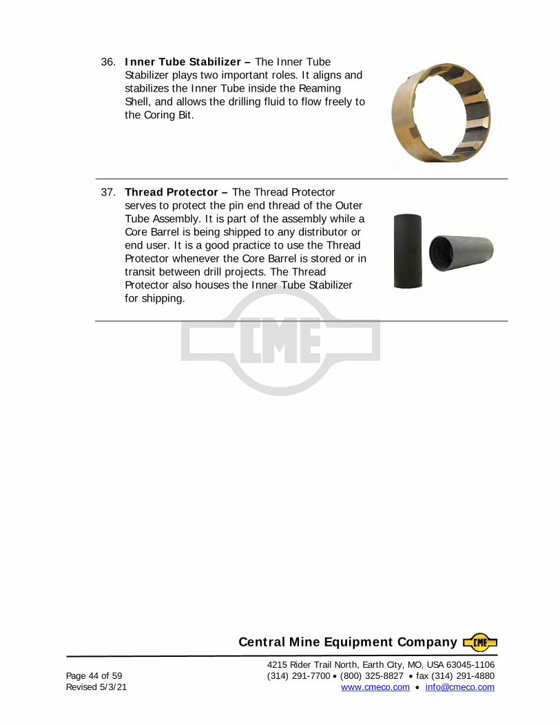
36. Inner Tube Stabilizer – The Inner Tube Stabilizer plays two important roles. It aligns and stabilizes the Inner Tube inside the Reaming Shell, and allows the drilling fluid to flow freely to the Coring Bit.
37. Thread Protector – The Thread Protector serves to protect the pin end thread of the Outer Tube Assembly. It is part of the assembly while a Core Barrel is being shipped to any distributor or end user. It is a good practice to use the Thread Protector whenever the Core Barrel is stored or in transit between drill projects. The Thread Protector also houses the Inner Tube Stabilizer for shipping.
4215 Rider Trail North, Earth City, MO, USA 63045-1106 (314) 291-7700 • (800) 325-8827 • fax (314) 291-4880 Page 45 of 59 www.cmeco.com • [email protected] Revised 5/3/21
Central Mine Equipment Company
Instructions CME Wireline Core Barrel
(See final fold-out page for Core Barrel items reference.)
The CME Wireline Core Barrel has been carefully assembled and inspected at the factory. It is recommended that the user inspect the core barrel assembly prior to use to verify proper working order. When disassembling or assembling the threaded parts of the core barrel use the full circle grip wrenches to avoid egg-shaping the connections. Core Barrel 1. Study the parts lists and core barrel illustrations attached to the end of these instructions. 2. Remove the inner tube assembly (Items 1 through 27) from the outer tube assembly (28-35) by grasping the spearhead (1) with an overshot, then pulling until the latches release. Pull out the inner tube assembly and place it alongside the outer tube assembly. 3. Disconnect the inner tube from the head assembly.
4. Check the action of the latches (9) of the inner tube head assembly. They should swing out freely and have a “snappy” action when the latch retracting case (6) is moved up and down. 5. Remove the core lifter case (27). Note that both ends of the inner tube have pin threads on N W/L, H W/L and P W/L inner tubes and are reversible so the operating life is almost doubled as compared to N W/L2 inner tubes which has pin to box. 6. Examine the core lifter case (27). Note the stop ring (25) above the core lifter (26). The stop ring provides a hardened surface for the core lifter to bear against during coring. Before a worn core lifter can be extracted, the stop ring must be removed. To remove the stop ring, insert a screw driver blade under the split in the ring and pry loose. Rotate the stop ring so that the ring is at 90° with the diameter of the core lifter case and pull it out. Replace with new core lifter and be sure it moves freely. To install: slide in the stop ring in the 90° position, then rotate the stop ring and snap it into the recess. Visually inspect the inside of the core lifter case to be sure the stop ring is properly positioned. 7. Reconnect the core lifter case to the inner tube and reconnect the inner tube to the head assembly.
4215 Rider Trail North, Earth City, MO, USA 63045-1106 Page 46 of 59 (314) 291-7700 • (800) 325-8827 • fax (314) 291-4880 Revised 5/3/21 www.cmeco.com • [email protected]
Central Mine Equipment Company
8. Examine the outer tube. Note that the outer tube assembly consists of the following items: locking coupling (28), adapter coupling (29), landing ring (30), outer tube (31) and brass inner tube stabilizing ring (32). A thread protector is attached to the outer tube. Remove the thread protector. Within the thread protector counter-bore is the brass inner tube stabilizer ring (32). The thread protector provided for transportation of the core barrel is not shown on the cross sectional drawing. Servicing the Core Barrel for Use 1. Remove the brass inner tube stabilizer ring (32) from the thread protector and install it into the deep counter bore of a new reaming shell (34). This stabilizer ring centralizes the inner tube and is a particularly important aid in coring because it holds the core lifter and the core lifter case in the proper position to receive core. 2. Assemble both the reaming shell and the diamond bit (35) to the outer tube. 3. Wipe the inner tube assembly clean and lightly lubricate the inside and outside surface with core lube. Install the inner tube assembly into the outer tube so the landing shoulder (13¹) is seated firmly on the landing ring (30). The head assembly sets in the center of the landing ring of the outer tube so it cannot vibrate during operation. 4. Check the gap or distance between the beveled shoulder inside of the bit and the lower end of the core lifter case. The gap should measure 1/16 of an inch (1.6 mm), plus or minus 1/32 of an inch. If the gap setting is not within the limits specified above, extract the inner tube assembly, loosen lock nut (16) and adjust the spindle assembly so the proper gap, 1/16” (1.6 mm) is made. After the adjustment is made, tighten lock nut (14). Insert the inner tube and again check the gap as indicated above. 5. Whenever a new bit or reaming shell is first installed or if the inner tube or a core lifter case is replaced, the gap between the core lifter case and the bit should be checked. 6. Whenever more than one inner tube assembly is used interchangeably with the same outer tube assembly, each companion inner tube assembly must be gap adjusted to the same length from the landing shoulder to the core lifter case. A Final Check for Proper Gap Setting Before the core barrel assembly is used, suspend the entire assembly sufficiently so that a gap inspection can be made in the vertically suspended position. The required gap 1/16” (1.6 mm) must be evident; otherwise, core recovery may be adversely affected. If gap is not correct readjust the inner tube assembly and resuspend for final inspection. This gap can be adjusted based on the current rock formation to maximize difficult core recovery.
4215 Rider Trail North, Earth City, MO, USA 63045-1106 (314) 291-7700 • (800) 325-8827 • fax (314) 291-4880 Page 47 of 59 www.cmeco.com • [email protected] Revised 5/3/21
Central Mine Equipment Company
Adding New Tool Joints to the Drill String Experience shows that the first few trips in the hole are the most ‘hazardous’ in the life of rod tool joints. For this reason, extra care must be taken during the break-in period. On newly machined surfaces, galling is most likely to occur. Resistance to galling can be built by applying Kopr Kote™ and by properly torquing each rod joint. After some service, the metal surfaces undergo changes which make them less susceptible to galling. The following are the recommended steps for handling new tool joints: 1. It is important to keep the threads on the connecting sub and the hoisting plug in good condition as they mate with every box. 2. Pin and box threads and shoulders must be thoroughly cleaned. 3. When rod joints are run in the hole, both the pin and the box threads and shoulders should be liberally coated with Kopr Kote™. 4. Upon making each trip back into the hole, the box threads and shoulders should be coated with Kopr Kote™ again. 5. Avoid forced make up of improperly engaged threads. In stabbing, the flat crests of new threads sometimes wedge against each other. A slight amount of back up will free them. 6. Tighten drill rods wrench tight using recommended drill rod torque specifications. Do not use the drill rig to tighten the joints. Starting the Coring Operation 1. After the last rod is connected and the drill string is still held by the rod holder or foot clamp, disconnect the hoisting plug. 2. Release the rod from the rod holder or raise the rod string high enough to remove the foot clamp jaws. 3. Lower the drill string within a few inches of the bottom of the hole. 4. If using a hydraulic chuck engage the chuck jaws onto the drill string. 5. Engage the water pump and the drill, but do not advance the drill string into the hole until the water pressure rises as indicated on the pressure gauge or until water
4215 Rider Trail North, Earth City, MO, USA 63045-1106 Page 48 of 59 (314) 291-7700 • (800) 325-8827 • fax (314) 291-4880 Revised 5/3/21 www.cmeco.com • [email protected]
Central Mine Equipment Company
is returning from the hole. Water must be circulating around the diamond bit before core cutting begins. 6. For the proper water flow (gallons per minute) check the parameters for the diamond bit. Once there is sufficient water return, start advancing the rotating drill head into the hole to start coring. As the hole deepens, the water pressure will gradually rise to higher operating pressures. Core Drilling
1. There should be sufficient fluid return during the coring process. If there is no return, special care should be taken to observe the water pressure gauge to monitor for spikes in water pressure indicating a fluid blockage. If a spike occurs, immediately stop the feed rate and wait for the blockage to clear. If unsuccessful, then the drill string can then be raised and lowered until the blockage is cleared and fluid return is achieved. If fluid return is not recovered retrieve the entire drill string and proceed with casing the hole. 2. When the inner tube is full (or there is a core block) the core barrel outer tube continues to advance relative to the full or jammed inner tube causing the rubber shut-off valves in the inner tube head assembly to compress and seal off the drilling fluid flow. A core block is caused by the wedging and jamming of core in the tube. Rising pump pressure indicates to the driller that the inner tube is full or a core block has occurred. A core block can also occur without an increase in water pressure. If the penetration rate stops due to a core block, the inner tube assembly should be removed and emptied then reinserted. 3. The drill string is lifted a short distance to break the core. Lifting the drill string causes the throat of the bit to contact the bottom of the core lifter case. The core lifter case is pushed upwards causing the core lifter to slide down to the bottom of the core lifter case and grip the core, thus breaking the core from the formation for removal. By lifting and holding the drill string off the bottom it will also help eliminate mislatches when the inner tube assembly is reinserted. Retracting the Inner Tube 1. Paint a 5 foot section of the wireline cable about 30 feet above the overshot. The painted section will help to signal the approach of the overshot when it is being retrieved from the hole. 2. Insert the overshot (less locking sleeve #11) into the drill string and lower it into the rods without over-running the cable.
4215 Rider Trail North, Earth City, MO, USA 63045-1106 (314) 291-7700 • (800) 325-8827 • fax (314) 291-4880 Page 49 of 59 www.cmeco.com • [email protected] Revised 5/3/21
Central Mine Equipment Company
3. As the overshot approaches the inner tube, slow its speed until the overshot is latched onto the inner tube head assembly. 4. When the overshot assembly has contacted the inner tube spearhead, tie a string marker to the wireline cable a few feet above the point of contact. This string marker will help warn the drill operator when the overshot approaches the inner tube spearhead on future runs. Move this marker upward after each core run. 5. Slow the overshot when the string marker appears; then ease the overshot over the inner tube spearhead. 6. To check if the overshot has properly latched over the inner tube assembly spearhead, take up the cable slack so the cable is tight and then by pulling the taut cable by hand, it will be noted that the combined weight of the core filled inner tube and the overshot is greater than the weight of the overshot alone. 7. Hoist the overshot and the inner tube assembly from the hole. As the overshot assembly approaches the surface, the paint marker will appear. Reduce the speed of the hoist. 8. Lift the inner tube assembly until it is out of the hole. Then, carefully lower the core laden inner tube assembly so the overshot can be removed. 9. Disengage the overshot from the inner tube. Place the inner tube in a chain vise installed off the side of the deck or tripod chain vise. 10. Unscrew the inner tube from the inner tube head assembly using a full circle grip wrench on the head assembly and the inner tube. 11. Before coring runs, inspect the inner tube assembly for wear or bends. Set the head assembly aside for servicing between core runs -- see servicing instructions. Move the core laden inner tube to the core removal area. Removing Core From the Inner Tube
1. Empty core from the inner tube. Jar the core loose from the inner tube by tapping with a rubber mallet. Place the core carefully in a box as instructed by the geologist or engineer on site.
CAUTION: When emptying the inner tube, do not attempt to stop the core by hand. Core can be
sharp or heavy and cause severe injury. If it’s necessary to look into an inner tube, always look down into the tube.
4215 Rider Trail North, Earth City, MO, USA 63045-1106 Page 50 of 59 (314) 291-7700 • (800) 325-8827 • fax (314) 291-4880 Revised 5/3/21 www.cmeco.com • [email protected]
Central Mine Equipment Company
2. If running a triple tube (W/L3) assembly, insert piston plug into split tube piston. Thread the pump-out adapter onto the inner tube. Pump out the split tubes and core sample. Service and Maintenance – Between Core Runs Inner Tube 1. After the core has been removed, pour clean water down the inner tube to wash out the sand particles and grit. Inspect the inner tube to see if any particles are lodged on the smooth inside surface. 2. Check the core lifter case, stop ring and core lifter. The core lifter should rotate freely. If the inside surface of the core lifter is smooth, the core lifter should be checked by inserting a short section of core into the core lifter and pulling it out to see if the core lifter will grip the core. If the core slips, the core lifter should be replaced. See Core Barrel Section (#6) on Page 1. Inner Tube Head Assembly 1. Wash the head assembly in clear water to remove drilling mud and grit. 2. Inspect spearhead point for wear. Replace as necessary. The spearhead point should be able to stay upright on its own. If not, replace the compression spring. 3. Inspect the action of the latches and the latch retracting case. Both should work freely. 4. Check the movement of the spindle bearings. They should spin freely and there should be no end play. If end play exists, the head assembly may need further repairs. 5. Check the rubber shut-off valve for shredding. At this point, a determination should be made on repositioning the rubber shut-off valves. If the rubber shut-off valves are to be repositioned, it is necessary to remove the inner tube cap (23), lock nut (22), compression spring (21) and the 3 bearings. Make the necessary changes with the rubber valves. Install new rubber valves or replace with valve adjusting washers instead. Install the bearings in the same position as originally assembled. Do not reverse either ball bearing. Assemble the lower end and tighten the lock nut (22) to remove free play, but do not preload the compression spring (21). 6. If no parts have been replaced and the bearings are in good condition, apply cup grease to the latches and the latch retracting case. Pump grease into the grease fitting until clean grease exudes out of the top thrust bearings. 7. Rejoin the head assembly to the inner tube.
4215 Rider Trail North, Earth City, MO, USA 63045-1106 (314) 291-7700 • (800) 325-8827 • fax (314) 291-4880 Page 51 of 59 www.cmeco.com • [email protected] Revised 5/3/21
Central Mine Equipment Company
Overshot
1. Make sure that the lifting dogs latch onto the spearpoint of the head assembly.
2. Examine the spearpoint of the head assembly by comparing with an unused spare spearpoint and replace if worn.
3. Inspect the hooked ends of the overshot lifting dogs by comparing them with an unused spare lifting dog and replace if worn.
4. Grease the cable swivel assembly at the top of the overshot cable swivel body. Dropping the Inner Tube Assembly (During a Coring Cycle)
1. Attach overshot assembly to the inner tube spearhead.
2. Hoist inner tube assembly above rod opening.
3. Insertion
a) Dry Hole Insertion (most preferred and safest method) If there is no water (fluid) in the hole, the inner barrel assembly cannot be inserted using free fall procedure. This in all probability would damage both the inner and outer barrel assemblies. The assembly is lowered by means of the attached wireline cable. Be sure the overshot release mechanism is operative so that once the inner barrel is in position and latched, the overshot can be released and retrieved before the drilling begins.
b) Free Fall Insertion
Release inner tube so it falls freely, providing there is at least 20 feet of fluid in the drill hole. The water will cushion and slow the final phase of the fall and permit the assembly to seat without damage. When the inner tube assembly latches into the outer tube assembly the vibration can be felt in the drill string. If it is possible to hear around the drill rig as the inner barrel descends in free fall the sound it makes as it travels thru the fluid is audible if you hold an ear close to the open end of the drill rod. The loud click as it latches in the outer tube assembly can also be discernible.
4. Add necessary rod. 5. Attach spindle adaptor/water swivel to rods.
4215 Rider Trail North, Earth City, MO, USA 63045-1106 Page 52 of 59 (314) 291-7700 • (800) 325-8827 • fax (314) 291-4880 Revised 5/3/21 www.cmeco.com • [email protected]
Central Mine Equipment Company
6. You are now ready to start the next core run. Refer to section “STARTING THE CORING OPERATION” on page 3. Maintenance – After Service
1. Remove the inner tube assembly from the outer tube assembly.
2. Check the general condition of the outer tube and inner tube assemblies. A dented
or bent outer tube causes premature core blocking and vibration. Inspect for any wear or deep grooves to avoid a failure down the hole. A dented or bent inner tube causes it to get stuck in the rods or prevent it from latching into the outer tube and may also cause core blocking.
3. Use full circle grip wrenches to disassemble all core barrel components to avoid damaging the threaded connections.
4. Inspect the outer tube assembly a) Remove the core bit and reamer shell using the full circle grip wrenches.
Secure for transport.
b) Remove the inner tube stabilizer from the reamer shell by carefully tapping it out of the reamer shell using a punch and hammer. Clean the stabilizer and the counter bore in the reamer shell.
c) Check the inner tube stabilizer for wear. If it looks worn slide it over the inner tube. If there is more than 5/16” clearance, replace it.
d) Remove the locking coupling. If latch dents are found replace the locking coupling. Inspect the threads where the wireline drill rods connect to the locking coupling. If the locking coupling appears thin (or sharp), or the threads are worn, replace.
e) Remove the adaptor coupling and inspect the shoulder above the threads for wear.
f) Remove the landing ring from the outer tube. If it is tight insert the inner tube assembly from the bit end of the outer tube. Grab ahold of the inner tube and use the assembly as a slide hammer to jar the landing ring loose.
g) Inspect the landing ring and reverse if necessary or replace Also clean the counterbore in the outer tube where it is seated. Apply grease to the landing ring and counterbore before replacing.
4215 Rider Trail North, Earth City, MO, USA 63045-1106 (314) 291-7700 • (800) 325-8827 • fax (314) 291-4880 Page 53 of 59 www.cmeco.com • [email protected] Revised 5/3/21
Central Mine Equipment Company
h) Reassemble the outer tube assembly, replacing all worn parts. Clean each threaded connection and apply Kopr Kote™ to each joint. Connect the thread protector for transport.
5. Inspect the inner tube assembly a) Grease the bearings in the bearing assembly through the grease fitting found
in the inner tube cap assembly.
b) Lightly lubricate the inner tube with core lube then reinsert it into the outer tube assembly. The landing shoulder of the inner tube assembly should seat into the landing ring and the latches should snap out quickly and latch in firmly.
c) Check the core lifter and replace if necessary. See Core Barrel Section (#6) on Page 1.

4215 Rider Trail North, Earth City, MO, USA 63045-1106 Page 54 of 59 (314) 291-7700 • (800) 325-8827 • fax (314) 291-4880 Revised 5/3/21 www.cmeco.com • [email protected]
Central Mine Equipment Company
4215 Rider Trail North, Earth City, MO, USA 63045-1106 (314) 291-7700 • (800) 325-8827 • fax (314) 291-4880 Page 55 of 59 www.cmeco.com • [email protected] Revised 5/3/21
Central Mine Equipment Company
NOTES:
4215 Rider Trail North, Earth City, MO, USA 63045-1106 Page 56 of 59 (314) 291-7700 • (800) 325-8827 • fax (314) 291-4880 Revised 5/3/21 www.cmeco.com • [email protected]
Central Mine Equipment Company
STANDARD CORE SIZES SIZE CORE DIAMETER HOLE DIAMETER
N W/L 1.875" 2.980"
NXB 1.875" 2.980"
N W/L2 1.995" 2.980"
NWD4 2.06" 2.980"
H W/L 2.50" 3.782"
P W/L 3.345" 4.827"
TRIPLE TUBE CORE SIZES
N W/L3 1.775" 2.980"
H W/L3 2.406" 3.782"
P W/L3 3.270" 4.827"
P W/L3 3.270"
H W/L3 2.406"
N W/L3 1.775"
TRIPLE TUBE
STANDARD
NWD4 2.06"
NXB 1.875"
(actual size)
P W/L 3.345"
H W/L 2.50"
N W/L2 1.995"
N W/L 1.875"
See CME Diamond Bits section in our Product Catalog!
4215 Rider Trail North, Earth City, MO, USA 63045-1106 (314) 291-7700 • (800) 325-8827 • fax (314) 291-4880 Page 57 of 59 www.cmeco.com • [email protected] Revised 5/3/21
Central Mine Equipment Company
CME Diamond Core Bit Drilling Guidelines
Impregnated Bit Guidelines Core Bit Size Drilling Fluid Rotation Bit Weight Penetration Rates Output Range Speed Range GPM’s RPM’s FT/LBS In/Min N W/L N W/L2 N W/L3 8-10 800-1,350 3,000-6,000 3-7 NWD4 NXB H W/L 10-12 400-1,000 4,000-8,000 2-5 H W/L3 P W/L P W/L3 18-23 350-800 5,000-10,000 2-4 A good rule of thumb to establish bit weight/down pressure is approximately 1000lbs per 1” outside diameter of the core bit. Proper Diamond Impregnated Bits wear down evenly through the crown. Concave crown wear indicates excessive bit weights.
4215 Rider Trail North, Earth City, MO, USA 63045-1106 Page 58 of 59 (314) 291-7700 • (800) 325-8827 • fax (314) 291-4880 Revised 5/3/21 www.cmeco.com • [email protected]
Central Mine Equipment Company
Surface Set Bit Guidelines
Core Bit Size Drilling Fluid Rotation Penetration Rates Output Range Speed GPM’s RPM’s In/Min N W/L N W/L2 N W/L3 5-7 500-800 2-6 NWD4 NXB H W/L 6-11 400-600 2-6 H W/L3 P W/L P W/L3 10-15 350-500 2-6 The guidelines for surface set diamond core bits are a little different. When coring with a new surface set core bit there is minimal bit weight (down pressure) required since there are many sharp angles on each individual diamond. As coring continues sharp angles are worn down which will require increased bit weight to allow them to cut. As the required bit weight increases a subjective decision will need to be made to take it out of service. The carat weight of the bit is required to calculate the proper down pressures. The carat weight can be found on the bit card included with each new bit or can obtained from the bit manufacturer. Total bit carat weight x stone per carat average x 7 = Recommended Bit Weight Example: N W/L 15SPC BIT RSG- 15 Stones Per Carat, Reamer Shell Gauge, 24 total carat weight. 24 x 15 x 7 = 2520 lbs of bit weight (down pressure)
4215 Rider Trail North, Earth City, MO, USA 63045-1106 (314) 291-7700 • (800) 325-8827 • fax (314) 291-4880 Page 59 of 59 www.cmeco.com • [email protected] Revised 5/3/21
Central Mine Equipment Company