Embed Size (px)
Citation preview
Cloth X-Ray: MoCap of People Wearing Textiles ?
B. Rosenhahn1, U. G. Kersting2, Katie Powell2 and Hans-Peter Seidel1
1 Max Planck Institute for Informatics, Stuhlsatzhausenweg 85,D-66123 Saarbrucken, [email protected]
2Department of Sport and Exercise ScienceThe University of Auckland, New Zealand
Abstract. The contribution presents an approach for motion capturing (MoCap)of dressed people. A cloth draping method is embedded in a silhouette basedMoCap system and an error functional is formalized to minimize image errorswith respect to silhouettes, pose and kinematic chain parameters, the cloth drap-ing components and external wind forces. We report on various experiments withtwo types of clothes, namely a skirt and a pair of shorts. Finally we compare theangles of the MoCap system with results from a commercially available markerbased tracking system. The experiments show, that we are basically within theerror range of marker based tracking systems, though body parts are occludedwith cloth.
1 Introduction
Marker-less motion capturing is a highly challenging topic of research and many promis-ing approaches exist to tackle the problem [12, 5, 1, 10, 4, 7]. In most setups it is requiredthat the subjects have to wear either body suits, to be naked or at least to wear clothingwhich stresses the body contours (e.g. swim suits). Such clothing is often uncomfort-able to wear in contrast to loose clothing (shirts or shorts). The analysis of outdoorsport events also requires to take clothing into account. On the other hand, cloth drap-ing is a well established field of research in computer graphics and virtual clothingcan be moved and rendered so that it blends seamlessly with motion and appearancein movie scenes [6, 8, 9, 17]. Existing approaches can be roughly divided in geomet-rically or physically based ones. Physical approaches model cloth behavior by usingpotential and kinetic energies. The cloth itself is often represented as a particle gridin a spring-mass scheme or by using finite elements [9]. Geometric approaches [17]model clothes by using other mechanics theories which are often determined empiri-cally. These methods can be very fast computationally but are often criticized as beingvisually unappealing.
The motivation of this work is to combine a cloth draping algorithm with a marker-less MoCap system. The key idea is to use the appearance of the cloth and the visibleparts of the human being to determine the underlying kinematic structure, though itmight be heavily occluded.
? We gratefully acknowledge funding by the Max-Planck Center for visual computing and com-munication.

2 Foundations: Silhouette based MoCap
This work is an extension of a previously developed marker-less MoCap system [16].In this system, the human being is represented in terms of free-form surface patches,joint indices are added to each surface node and the joint positions are assumed. Thisallows to generate arbitrary body configurations, steered through joint angles. The as-sumed corresponding counterparts in the images are 2D silhouettes: These are used toreconstruct 3D ray bundles and a spatial distance constraint is minimized to determinethe position and orientation of the surface mesh and the joint angles. In this section wewill give a brief summary of the MoCap system. These foundations are needed later toexplain concisely, where and how the cloth draping approach is incorporated.
2.1 Silhouette extraction
Image segmentation usually means to estimate boundaries of objects in an image. Itis an important step for data abstraction, but the task can become very difficult due tonoise, shading, occlusion or texture transitions between the object and the background.Our approach is based on image segmentation based on level sets [3, 14, 2].
Fig. 1. Silhouette extraction based on level set functions. Left: Initial segmentation. Right: Seg-mentation result.
A level set function Φ ∈ Ω 7→ R splits the image domain Ω into two regions Ω1
and Ω2 with Φ(x) > 0 if x ∈ Ω1 and Φ(x) < 0 if x ∈ Ω2. The zero-level line thus marksthe boundary between both regions. On a discrete image, the level set functions aremodeled through a distance transform from the contour line to the inner and outer re-gion with negative and positive distance values, respectively. Both regions are analyzedwith respect to the probabilities of image features (e.g. gray value distributions, coloror texture channels). Now the key idea is to evolve the contour line, to maximize theprobability density functions with respect to each other. Furthermore, the boundary be-tween both regions should be as small as possible. This can be expressed by adding a

smoothness term. Both parts lead to the following energy functional that is sought to beminimized:
E(Φ , p1, p2) = −
∫
Ω
(H(Φ(x)) log p1 +(1−H(Φ(x))) log p2 +ν |∇H(Φ(x))|
)dx
where ν > 0 is a weighting parameter and H(s) is a regularized version of the Heavisidefunction, e.g. the error function. The probability densities pi are estimated according tothe expectation-maximization principle. Having the level set function initialized withsome contour, the probability densities within the two regions are estimated by the grayvalue histograms smoothed with a Gaussian kernel Kσ and its standard deviation σ .Figure 1 shows on the left an example image with an initialization of the region asrectangle. The right image shows the estimated (stationary) contour after 50 iterations.As can be seen, the legs and the skirt are well extracted, but there are some deviationsin the feet region, due to shadows. Such inaccuracies can be compensated through thepose estimation procedure.
2.2 Registration, Pose estimation
Assuming an extracted image contour and the silhouette of the projected surface mesh,the closest point correspondences between both contours are used to define a set ofcorresponding 3D lines and 3D points. Then a 3D point-line based pose estimationalgorithm for kinematic chains is applied to minimize the spatial distance between bothcontours: For point based pose estimation each line is modeled as a 3D Plucker lineLi = (ni,mi), with a (unit) direction ni and moment mi [13]. The 3D rigid motion isexpressed as exponential form
M = exp(θ ξ ) = exp
(ω v
03×1 0
)
(1)
where θ ξ is the matrix representation of a twist ξ ∈ se(3) = (v, ω)|v∈R3, ω ∈ so(3),
with so(3) = A∈ R3×3|A =−AT. The Lie algebra so(3) is the tangential space of the
3D rotations. Its elements are (scaled) rotation axes, which can either be represented asa 3D vector or screw symmetric matrix,
θω = θ
ω1ω2ω3
, with ‖ω‖2 = 1 or θω = θ
0 −ω3 ω2ω3 0 −ω1−ω2 ω1 0
. (2)
A twist ξ contains six parameters and can be scaled to θξ for a unit vector ω . The pa-rameter θ ∈ R corresponds to the motion velocity (i.e., the rotation velocity and pitch).For varying θ , the motion can be identified as screw motion around an axis in space.The six twist components can either be represented as a 6D vector or as a 4×4 matrix,
θξ = θ (ω1,ω2,ω3,v1,v2,v3)T , ‖ω‖2 = 1, θ ξ = θ
0 −ω3 ω2 v1ω3 0 −ω1 v2−ω2 ω1 0 v3
0 0 0 0
. (3)
To reconstruct a group action M ∈ SE(3) from a given twist, the exponential function
exp(θ ξ ) = ∑∞k=0
(θ ξ )k
k! = M ∈ SE(3) must be computed. This can be done efficiently byusing the Rodriguez formula [13].
For pose estimation the reconstructed Plucker lines are combined with the screwrepresentation for rigid motions: Incidence of the transformed 3D point Xi with the 3Dray Li = (ni,mi) can be expressed as
(exp(θ ξ)Xi)3×1 ×ni −mi = 0. (4)
Since exp(θ ξ )Xi is a 4D vector, the homogeneous component (which is 1) is neglectedto evaluate the cross product with ni. Then the equation is linearized and iterated, see[16].
Joints are expressed as special screws with no pitch of the form θ jξ j with known ξ j(the location of the rotation axes is part of the model) and unknown joint angle θ j. Theconstraint equation of an ith point on a jth joint has the form
(exp(θ jξ j) . . .exp(θ1ξ1)exp(θ ξ )Xi)3×1 ×ni −mi = 0 (5)
which is linearized in the same way as the rigid body motion itself. It leads to threelinear equations with the six unknown pose parameters and j unknown joint angles.
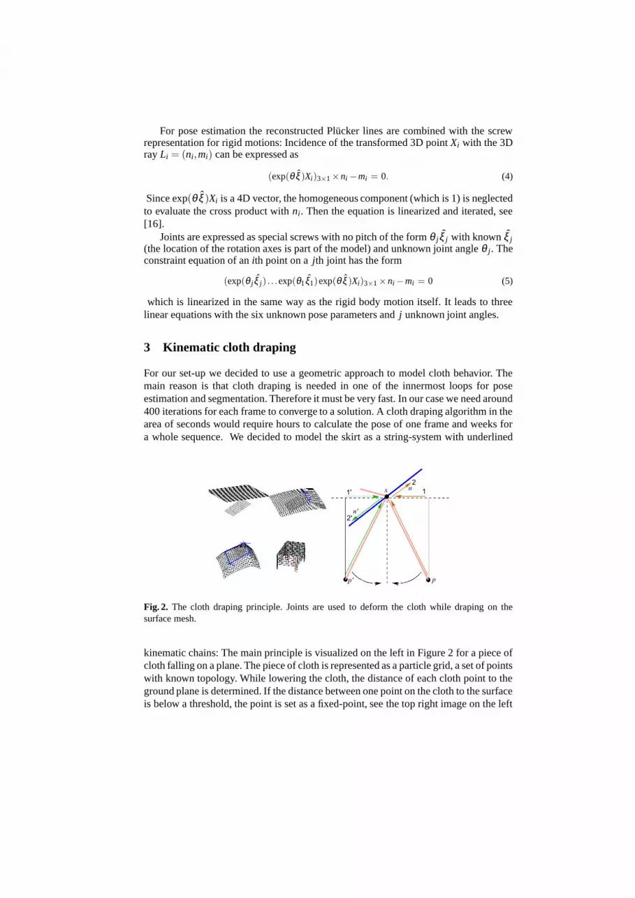
3 Kinematic cloth draping
For our set-up we decided to use a geometric approach to model cloth behavior. Themain reason is that cloth draping is needed in one of the innermost loops for poseestimation and segmentation. Therefore it must be very fast. In our case we need around400 iterations for each frame to converge to a solution. A cloth draping algorithm in thearea of seconds would require hours to calculate the pose of one frame and weeks fora whole sequence. We decided to model the skirt as a string-system with underlined
Fig. 2. The cloth draping principle. Joints are used to deform the cloth while draping on thesurface mesh.
kinematic chains: The main principle is visualized on the left in Figure 2 for a piece ofcloth falling on a plane. The piece of cloth is represented as a particle grid, a set of pointswith known topology. While lowering the cloth, the distance of each cloth point to theground plane is determined. If the distance between one point on the cloth to the surfaceis below a threshold, the point is set as a fixed-point, see the top right image on the left

Fig. 3. Cloth draping of a skirt and shorts in a simulation environment.
Fig. 4. Wind model on the shorts (left) and the skirt (right). Visualized is frontal and backwardwind.
of Figure 2. Now the remaining points are not allowed to fall downwards any more.Instead, for each point, the nearest fixed-point is determined and a joint (perpendicularto the particle point) is used to rotate the free point along the joint axis through the fixedpoint. The used joint axes are marked as blue lines in Figure 2. The image on the rightin Figure 2 shows the geometric principle to determine the twist for rotation around afixed point: The blue line represents a mesh of the rigid body, x is the fixed point and the(right) pink line segment connects x to a particle p of the cloth. The direction betweenboth points is projected onto the y-plane of the fixed point (1). The direction is thenrotated around 90 degrees (2), leading to the rotation axis n. The point pair (n, x×n) arethe components of the twist, see equation (3). While lowering the cloth, free particlesnot touching a second rigid point, will swing below the fixed point (e.g. p′). This leads toan opposite rotation (indicated with (1’), (2’) and n′) and the particle swings back again,resulting in a natural swinging draping pattern. The draping velocity is steered througha rotation velocity θ , which is set to 2 degrees during iteration. Since all points eitherbecome fixed points, or result in a stationary configuration while swinging backwardsand forwards, we constantly use 50 iterations to drape the cloth. The remaining imageson the left in Figure 2 show the ongoing draping and the final result.
Figure 3 shows example images of a skirt and a pair of shorts falling on the legmodel. The skirt is modeled as a 2-parametric mesh model. Due to the use of generalrotations, the internal distances in the particle mesh cannot change with respect to one ofthese dimensions, since a rotation maintains the distance between the involved points.However, this is not the case for the second sampling dimension. For this reason, theskirt needs to be re-constrained after draping. If a stretching parameter is exceeded,the particles are re-constrained to minimal distance to each other. This is only done

for the non-fixed points (i.e. for those which are not touching the skin). It results in abetter appearance, especially for certain leg configurations. Figure 3 shows that eventhe creases are maintained. In this case, shorts are simpler since they are modeled ascylinders, transformed together with the legs and then draped.
To improve the dynamic behavior of clothing during movements, we also add awind-model to the cloth draping. We continue with the cloth-draping in the followingway: dependent on the direction of wind we determine a joint on the nearest fixed pointfor each free point on the surface mesh with the joint direction being perpendicular tothe wind direction. Now we rotate the free point around this axis dependent on the windforce (expressed as an angle) or until the cloth is touching the underlying surface. Figure4 shows examples of the shorts and skirt with frontal or backward wind. The wind forceand direction are later part of the minimization function during pose tracking. Since themotion dynamics of the cloth are determined dynamically, we need no informationabout the cloth type or weight since they are implicitly determined from the minimizedcloth dynamics in the image data; we only need the measurements of the cloth.
4 Combined cloth draping and MoCap
The assumptions are as follows: We assume the representation of a subject’s lowertorso (i.e. for the hip and legs) in terms of free-form surface patches. We also assumeknown joint positions along the legs. Furthermore we assume the wearing of a skirt
Fig. 5. The basic algorithm for combined cloth draping and motion capturing
or shorts with known measures. The person is walking or stepping in a four-camerasetup. These cameras are triggered and calibrated with respect to one world coordinatesystem. The task is to determine the pose of the model and the joint configuration. Forthis we minimize the image error between the projected surface meshes to the extractedimage silhouettes. The unknowns are the pose, kinematic chain and the cloth parameters
(wind forces, cloth thickness, etc.). The task can be represented as an error functionalas follows:
E(Φ , p1, p2,θξ ,θ1, . . . ,θn,c,w) = −∫
Ω
(H(Φ) log p1 +(1−H(Φ)) log p2 +ν|∇H(Φ)|
)dx
︸ ︷︷ ︸
segmentation
+λ∫
Ω(Φ −Φ0( θξ ,θ1, . . . ,θn
︸ ︷︷ ︸
pose and kinematic chain,
, c,w︸︷︷︸
wind parameters
))dx
︸ ︷︷ ︸
shape error
Due to the large number of parameters and unknowns we decided for an iterative min-imization scheme, see Figure 5: Firstly, the pose, kinematic chain and wind parametersare kept constant, while the error functional for the segmentation (based on Φ , p1, p2) isminimized (section 2.1). Then the segmentation and wind parameters are kept constantwhile the pose and kinematic chain are determined to fit the surface mesh and the clothto the silhouettes (section 2.2). Finally, different wind directions and wind forces aresampled to refine the pose result (section 3). Since all parameters influence each other,the process is iterated until a steady state is reached. In our experiments, we alwaysconverged to a local minimum.
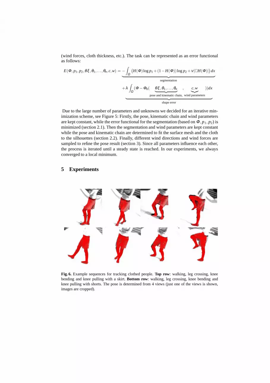
5 Experiments
Fig. 6. Example sequences for tracking clothed people. Top row: walking, leg crossing, kneebending and knee pulling with a skirt. Bottom row: walking, leg crossing, knee bending andknee pulling with shorts. The pose is determined from 4 views (just one of the views is shown,images are cropped).

Fig. 7. Error during grabbing the images
Fig. 8. Example leg configurations of the sequences. The examples are taken from the subjectwearing the shorts (blue) and the skirt (red) (leg crossing, walking, knee bending, knee pulling).
For the experiments we used a four-camera set up and grabbed image sequences ofthe lower torso with different motion patterns: The subject was asked to wear the skirtand the shorts while performing walking, leg crossing and turning, knee bending andwalking with knees pulled up. We decided on these different patterns, since they arenot only of importance for medical studies (e.g. walking), but they are also challengingfor the cloth simulator, since the cloth is partially stretched (knee pulling sequence)or hanging down loosely (knee bending). The turning and leg crossing sequence isinteresting due to the higher occlusions. Figure 6 shows some pose examples for thesubject wearing the skirt (top) and shorts (bottom). The pose is visualized by overlayingthe projected surface mesh onto the images. Just one of the four cameras is shown. Eachsequence consists of 150-240 frames. Figure 7 visualizes the stability of our approach:While grabbing the images, a couple of frames were stored completely wrong. Thesesporadic outliers can be compensated from our algorithm, and a few frames later (seethe image on the right) the pose is correct. Figure 8 shows leg configurations in a virtualenvironment. The position of the body and the joints reveal a natural configuration.
Finally, the question about the stability arises. To answer this question, we attachedmarkers to the subject and tracked the sequences simultaneously with the commerciallyavailable Motion Analysis system [11]. The markers are attached to the visible parts ofthe leg and are not disturbed by the cloth. We then compare joint angles for differentsequences with the results of the marker based system, similar to [16]. The overall
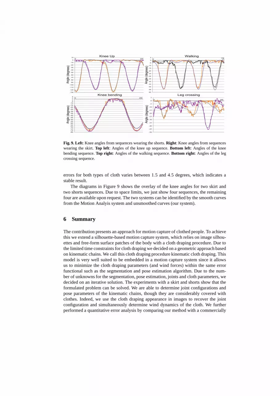
Fig. 9. Left: Knee angles from sequences wearing the shorts. Right: Knee angles from sequenceswearing the skirt. Top left: Angles of the knee up sequence. Bottom left: Angles of the kneebending sequence. Top right: Angles of the walking sequence. Bottom right: Angles of the legcrossing sequence.
errors for both types of cloth varies between 1.5 and 4.5 degrees, which indicates astable result.
The diagrams in Figure 9 shows the overlay of the knee angles for two skirt andtwo shorts sequences. Due to space limits, we just show four sequences, the remainingfour are available upon request. The two systems can be identified by the smooth curvesfrom the Motion Analyis system and unsmoothed curves (our system).
6 Summary
The contribution presents an approach for motion capture of clothed people. To achievethis we extend a silhouette-based motion capture system, which relies on image silhou-ettes and free-form surface patches of the body with a cloth draping procedure. Due tothe limited time constraints for cloth draping we decided on a geometric approach basedon kinematic chains. We call this cloth draping procedure kinematic cloth draping. Thismodel is very well suited to be embedded in a motion capture system since it allowsus to minimize the cloth draping parameters (and wind forces) within the same errorfunctional such as the segmentation and pose estimation algorithm. Due to the num-ber of unknowns for the segmentation, pose estimation, joints and cloth parameters, wedecided on an iterative solution. The experiments with a skirt and shorts show that theformulated problem can be solved. We are able to determine joint configurations andpose parameters of the kinematic chains, though they are considerably covered withclothes. Indeed, we use the cloth draping appearance in images to recover the jointconfiguration and simultaneously determine wind dynamics of the cloth. We furtherperformed a quantitative error analysis by comparing our method with a commercially

available marker based tracking system. The experiments show that we are in the sameerror range as marker based tracking systems [15].
For future works we plan to extend the cloth draping model with more advancedones [9] and we will compare different draping approaches and parameter optimizationschemes in the motion capturing setup.
References
1. C. Bregler, J. Malik, and K. Pullen. Twist based acquisition and tracking of animal andhuman kinetics. International Journal of Computer Vision, 56(3):179–194, 2004.
2. T. Brox, M. Rousson, R. Deriche, and J. Weickert. Unsupervised segmentation incorporatingcolour, texture, and motion. In N. Petkov and M. A. Westenberg, editors, Proc. ComputerAnalysis of Images and Patterns, volume 2756 of Lecture Notes in Computer Science, pages353–360. Springer, Berlin, 2003.
3. A. Dervieux and F. Thomasset. A finite element method for the simulation of Rayleigh–Taylor instability. In R. Rautman, editor, Approximation Methods for Navier–Stokes Prob-lems, volume 771 of Lecture Notes in Mathematics, pages 145–158. Springer, Berlin, 1979.
4. P. Fua, R. Plankers, and D. Thalmann. Tracking and modeling people in video sequences.Computer Vision and Image Understanding, 81(3):285–302, March 2001.
5. D.M. Gavrilla. The visual analysis of human movement: A survey. Computer Vision andImage Understanding, 73(1):82–92, 1999.
6. J. Haddon, D. Forsyth, and D. Parks. The appearance of clothing.http://http.cs.berkeley.edu/haddon/clothingshade.ps, June 2005.
7. L. Herda, R. Urtasun, and P. Fua. Implicit surface joint limits to constrain video-based motioncapture. In T. Pajdla and J. Matas, editors, Proc. 8th European Conference on ComputerVision, volume 3022 of Lecture Notes in Computer Science, pages 405–418, Prague, May2004. Springer.
8. D.H. House, R.W. DeVaul, and D.E. Breen. Towards simulating cloth dynamics using inter-acting particles. Clothing Science and Technology, 8(3):75–94, 1996.
9. N. Magnenat-Thalmann and P. Volino. From early draping to haute cotoure models: 20 yearsof research. Visual Computing, 21:506–519, 2005.
10. I. Mikic, M. Trivedi, E. Hunter, and P. Cosman. Human body model acquisition and trackingusing voxel data. International Journal of Computer Vision, 53(3):199–223, 2003.
11. MoCap-System. Motion analysis: A marker based tracking system.www.motionanalysis.com, June 2005.
12. T.B. Moeslund and E. Granum. A survey of computer vision based human motion capture.Computer Vision and Image Understanding, 81(3):231–268, 2001.
13. R.M. Murray, Z. Li, and S.S. Sastry. Mathematical Introduction to Robotic Manipulation.CRC Press, Baton Rouge, 1994.
14. S. Osher and J. A. Sethian. Fronts propagating with curvature-dependent speed: Algorithmsbased on Hamilton–Jacobi formulations. Computational Physics, 79:12–49, 1988.
15. J. Richards. The measurement of human motion: A comparison of commercially availablesystems. Human Movement Science, 18:589–602, 1999.
16. B. Rosenhahn, U. Kersting, A. Smith, J. Gurney, T. Brox, and R. Klette. A system for marker-less human motion estimation. In W. Kropatsch, R. Sablatnig, and A. Hanbury, editors,Pattern Recognition, 27th DAGM-symposium, volume 3663 of Lecture Notes in ComputerScience, pages 230–237, Vienna, Austria, September 2005. Springer.
17. J. Weil. The synthesis of cloth objects. Computer Graphics (Proc. SigGraph), 20(4):49–54,1986.


