Embed Size (px)
Citation preview
.
1
Clinical significance of mandibular movements
By Vishnu soni
⚫ A prosthodontist designs a prosthesis to replace the lost teeth for replacement of missing teeth and restoring function.
⚫ Knowledge of mandibular movements is essential ;it helps the dentist in:
⚫ -selecting and programming of articulators
⚫ -understanding the occlusion
⚫ -treating TMJ disorders
⚫ -development of tooth for dental restorations
⚫ - arranging artificial teeth
⚫ Protrusive movements:⚫ Condylar guidance and anterior guidance:⚫ These are the two end controlling factors of
mandibular movement.⚫ Whaen the movement of solid body is
governed by contacting surfaces at either ends of that body,the direction of movement of any point within the body is determined by its location in relation to the guiding two surfaces.
⚫ The closer it is to the one of the controlling surfaces,the more effect will that surface have on the direction of its movement.
⚫ Thus ,since a second molar is closer to the condylar guidance than is a lateral incisor, the condylar guidance has a greater effect on the direction of movement of the lower second molar than it does on the lower lateral incisor.
⚫ The anterior guidance on the other hand, has a greater effect on the direction of movement of the lower canine than it does on the lower first molar.
⚫ Of the two end guidances , the anterior guidance has the greater effect of direction of tooth movement during mandibular movement as all of teeth are closer to the anterior guidance than they are to the condylar guidance.
⚫ Effects of condylar guidance and anteriorguidance on cusp height and fossa depth:
⚫ the lesser the condylar guidance angle,the shorter the cusps must be
⚫ The greater the condylar guidance angle,the longer the cusps
⚫ The greater the horizontal overlap of the maxillary anterior teeth, the shorter the posterior teeth cusps
⚫ The lesser the horizontal overlap the longer the cusps of posterior teeth
⚫ The lesser the vertical overlap, the shorter the cusps of posterior teeth
⚫ The greater the vertical overlap,the longer the posterior cusps
.
2
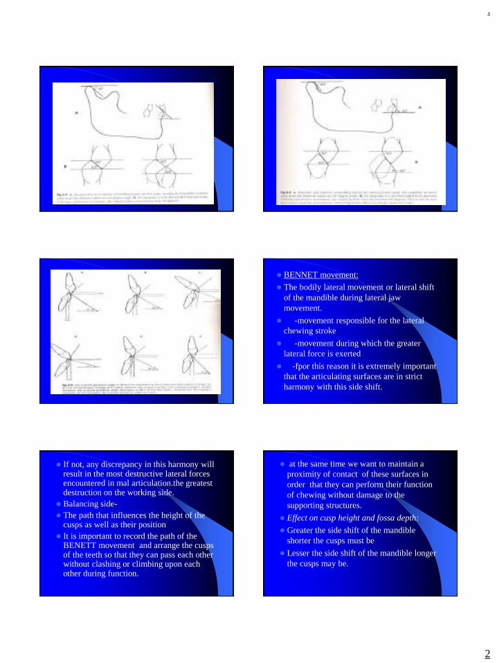
⚫ BENNET movement:
⚫ The bodily lateral movement or lateral shift of the mandible during lateral jaw movement.
⚫ -movement responsible for the lateral chewing stroke
⚫ -movement during which the greater lateral force is exerted
⚫ -fpor this reason it is extremely important that the articulating surfaces are in strict harmony with this side shift.
⚫ If not, any discrepancy in this harmony will result in the most destructive lateral forces encountered in mal articulation.the greatest destruction on the working side.
⚫ Balancing side-⚫ The path that influences the height of the
cusps as well as their position⚫ It is important to record the path of the
BENETT movement and arrange the cusps of the teeth so that they can pass each other without clashing or climbing upon each other during function.
⚫ at the same time we want to maintain a proximity of contact of these surfaces in order that they can perform their function of chewing without damage to the supporting structures.
⚫ Effect on cusp height and fossa depth:
⚫ Greater the side shift of the mandible shorter the cusps must be
⚫ Lesser the side shift of the mandible longer the cusps may be.
.
3
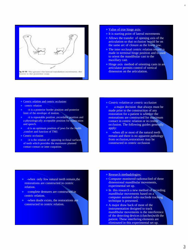
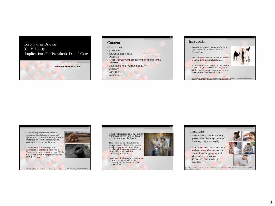
⚫ Value of true hinge axis:⚫ It is starting point of lateral movements⚫ Allows the transfer of opening axis of the
articulation so that occlusion would be on the same arc of closure as the lower jaw.
⚫ The inter occlusal centric relation record is made in terminal hinge position and is used to orient the mandibular cast to the maxillary cast.
⚫ Hinge axis method of orienting casts in an articulator permits control of vertical dimension on the articulation.
⚫ Centric relation and centric occlusion:
⚫ centric relation
⚫ -it is a posterior border position and posterior limit of the envelope of motion.
⚫ -it is repeatable position ,recordable position and a physiologically acceptable position for mastication and speech.
⚫ -it is an optimum position of jaws for the health ,comfort and function of TMJ.
⚫ Centric occlusion
⚫ -it is the relation of opposing occlusal surfaces of teeth which provides the maximum planned contact contact or inter cuspation.
⚫ Centric relation or centric occlusion⚫ a major decision that always must be
made prior to the construction of any restoration for a patient is whether the restorations are constructed for maximum contact in centric relation or in centric occlusion. The following guides generally apply:
⚫ -when all or most of the natural teeth remain and there is no apparent pathology from occlusion,restorations may be constructed in centric occlusion
⚫ -when only few natural teeth remain,the restorations are constructed in centric relation.
⚫ -complete dentures are constructed in centric relation.
⚫ -when doubt exists, the restorations are constructed in centric relation.
⚫ Research methadologies:⚫ Computer monitered radionuclied of three
dimensional mandibular movements, experimental set up.
⚫ In this research a new method of recording mandibular movements based on a computer assisted radio nucliede tracking technique is presented.
⚫ A major draw back of most of the instrumentation designed to track mandibular movements is the interference of the detecting devices (clutches)with the patient. These interfering elements are eliminated in this experimental set up.
.
4
⚫ Three major set of experiments are described.
⚫ Adaptation of detecting technique used in nucleus medicine to the problem of tracking jaw motion.
⚫ Verification of accuracy of measurements ,including calibration of displacements and simulated movements with dentures on an articulator.
⚫ Variation recordings of patient functional movements.
⚫ Methods and materials:
⚫ Recording equipment is divided into two parts of the gamma gcamera has a 30cm diametwer detecting head and sis equipped with a 4mm pinhole collimeter to provide an enlarged image of the of the moving source.
⚫ Computer is linked to camera & runs an Zinder an RTU rear time operating system with `gamma 11` software monitoring the data collection .
⚫ Emitting source : the source which is tracked during the equipment has to be placed on the patient & is prepared from TECHNITIUM PORTABLE GENERATOR
⚫ A source is prepared by depositing a few micro drops of high concentrated solution of Tc 99m in saline on to a piece of non absorbing cardboard .
⚫ Patient recordings: after the radio active source is placed on his chin, the patient sits in front of collimeter with his head in resting position. Data are collected in a list mode for several seconds (e.g. few chewing cycles), results are processed by the computer are movements & displayed on the colour t.v. monitor.
⚫ Chewing cycles , all plane motions are displayed .
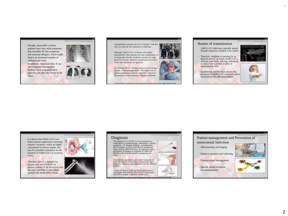
⚫ PANTOGRAPH: it is an extra oral technique of recording jaw movements by graphical methods.
⚫ the extra oral technique was pionered by GYSI & was the forerunner of pantograph as it is known today.
⚫ A pantograph consists of maxillary & mandibular facebow to the marking style & plate holders respectively. The clutches were cast in an aluminium alloy from study models & cemented to the teeth, with paste.
⚫ a central bearing point is incorporated in the lower clutch to rest as a guide plate in the upper arch to just relieve all cuspal contacts.
⚫ A vertical & horizontal tracings are located on each side of patients face overlying TMJ & a pair of horizontal tables approximately at the level of plane of occlusion is located below the eyes.
⚫ A stylus is used on each table to record border movements as a pressure sensitive material .the tracing procedure is carried out to record terminal hinge axis as the reffernce point & lateral border paths are traced whilst the jaw is gently guided.
.
5
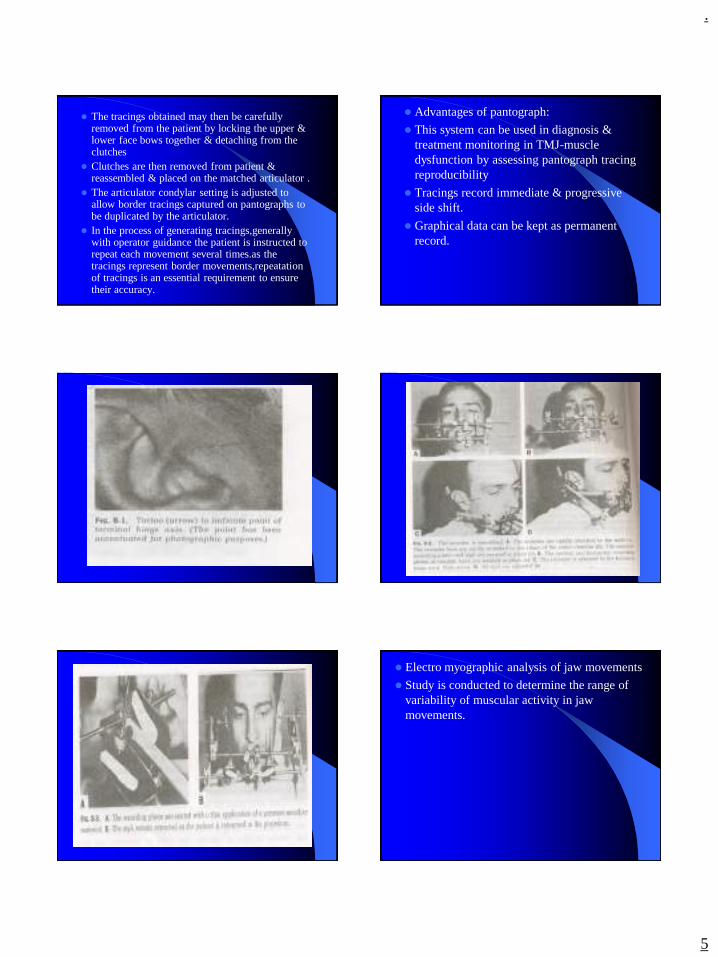
⚫ The tracings obtained may then be carefully removed from the patient by locking the upper & lower face bows together & detaching from the clutches
⚫ Clutches are then removed from patient & reassembled & placed on the matched articulator .
⚫ The articulator condylar setting is adjusted to allow border tracings captured on pantographs to be duplicated by the articulator.
⚫ In the process of generating tracings,generally with operator guidance the patient is instructed to repeat each movement several times.as the tracings represent border movements,repeatation of tracings is an essential requirement to ensure their accuracy.
⚫ Advantages of pantograph:
⚫ This system can be used in diagnosis & treatment monitoring in TMJ-muscle dysfunction by assessing pantograph tracing reproducibility
⚫ Tracings record immediate & progressive side shift.
⚫ Graphical data can be kept as permanent record.
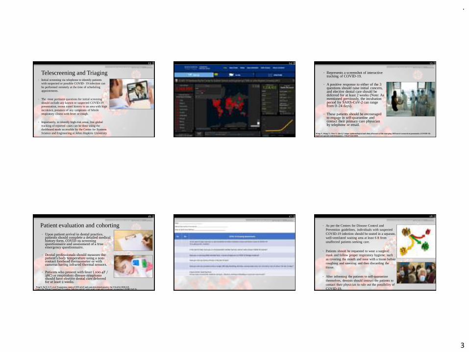
⚫ Electro myographic analysis of jaw movements
⚫ Study is conducted to determine the range of variability of muscular activity in jaw movements.

.
6
⚫ Conclusion:⚫ The mandibular movement is considered as the
chewing apparatus of masticatory system.the major reason for this is the presence of teeth.the dentition of maqn is crucial and integral aspect of normal anatomy mandibular movements differentiating it from other movement(or) locomotor system in the human body.but it should be born in mind that mandibular movement occures besides mastication like biting,chewing ,swallowing, breathing ,spaeaking etc.in other words, it plays life promoting and other important roles in respiratory and digestive acts,vocal performance and more or less every day human activities behaviour.
⚫ References:⚫ OKESON-management of Tmdisorders and
occlusion⚫ MOHL-text book of occlusion⚫ SUMIYA HOBO-osseo integration and occlusal
rehabilitation⚫ THE UNIVERSITY OF WESTERN ONTARIO
UNIVERSITY-notes on occlusion⚫ DR.E.G.R SOLOMON-notes on gnathology⚫ ZARB-BOUCHER’S prosthodontic treatment for
edentulous patients⚫ SHARRY-complete denture prosthodontics⚫ HEARTWELL-syllabus of complete dentures
.
1
Coronavirus Disease(COVID-19):Implications For Prosthetic Dental Care
Presented by :Vishnu Soni
1
Content• Introduction• Symptoms• Routes of transmission• Diagnosis • Patient management and Prevention of nosocomial
Infection• Implication for Prosthetic Dentistry• Summary• Conclusion• References
2
Introduction
• The novel coronavirus belongs to a family of single-stranded RNA viruses known as Coronaviridae.
• This family of viruses are known to be zoonotic or transmitted from animals to humans.
• Severe acute respiratory syndrome coronavirus (SARS-CoV), first identified in 2003, and the Middle East respiratory syndrome coronavirus (MERS-CoV), first identified in 2012.
3
Gorbalenya AE, Baker SC, Baric RS, et al. The species Severe acute respiratory syndromerelatedcoronavirus: classifying 2019-nCoV and naming it SARS-CoV-2. Nat Microbiol 2020
• There is strong evidence that this novel coronavirus has similarity to coronavirus species found in bats and potentially pangolins, confirming the zoonotic nature of this new cross-species viral-mediated disease.
• The Coronavirus Study Group of the International Committee on Taxonomy of Viruses has given it the scientific name SARS-CoV-2, even though it is popularly called the COVID-19 virus.
4
Zhu N, Zhang D, Wang W, et al. A novel coronavirus from patients with pneumonia in China,2019. N Engl J Med 2020;382:727–33
• Dental professionals are at high risk for nosocomial infection and can become potential carriers of the disease.
• These risks can be attributed to the unique nature of dental interventions, which include aerosol generation, handling of sharps, and proximity of the provider to the patient’s oropharyngeal region.
• In addition, if adequate precautions are not taken, the dental office can potentially expose patients to cross contamination.
5
Symptoms• Patients with COVID-19 usually
present with clinical symptoms of fever, dry cough, and myalgia.
• In addition, less obvious symptoms such as nausea, diarrhea, reduced sense of smell (hyposmia), and abnormal taste sensation (dysguesia) have also been reported.
6
Giacomelli A, Laura Pezzati L, Conti F, et al. Self-reported olfactory and taste disorders in SARSCoV- 2 patients: a cross-sectional study, Clinical Infectious Diseases, , ciaa330,
.
2
• Notably, about 80% of these patients have only mild symptoms that resemble flu like symptoms and seasonal allergies, which might lead to an increased number of undiagnosed cases.
• In addition, abnormal chest X-ray and computed tomographic findings such as ground-glass opacities are typically found in the chest.
7
• Asymptomatic patients can act as “carriers” and also
serve as reservoir for recurrence of infection.
• Although SARS-CoV-2 is known to be highly transmissible when patients are most symptomatic, it is noteworthy that the incubation period can range from 0 to 24 days, therefore transmission can occur before any symptoms are apparent.
• Pre existing chronic illnesses such as cardiovascular disease or immunosuppression. The higher-risk of patient population manifests symptoms typical of pneumonia or acute respiratory distress syndrome.
8
Guan W, Ni Z, Hu Y, et al. Clinical characteristics of 2019 novel coronavirus infection in China. medRxiv ,March 11, 2020..
Routes of transmission• SARS-CoV-2 infections typically spread
through respiratory droplets or by contact.
• Therefore, coughing or sneezing by an infected person can render SARS-CoV-2 airborne, potentially infecting individuals in close contact (within a radius of approximately 6 ft).
• In addition, studies have shown the presence of SARS-CoV-2 in both saliva and feces of the affected patients.
9
• It is known that SARS-CoV-2 can bind to human angiotensin-converting enzyme 2 receptors, which are highly concentrated in salivary glands; this may be a possible explanation for the presence of SARS-CoV-2 in secretory saliva.
• Therefore, there is a potential for transmission of COVID-19 via aerosol, fomites, or the fecal-oral route that may contribute to nosocomial spread in the dental office setting.
10
Diagnosis• The diagnosis of COVID-19 can be based on a
combination of epidemiologic information, clinical symptoms, CT imaging findings, and laboratory tests (example: reverse transcriptase polymerase chain reaction [RT-PCR] tests on respiratory tract specimens) according to standards of either the WHO) or the National Health Commission of China.
• Use infection prevention and control measures to lower the risk of transmission; and provide early diagnosis, isolation, and supportive care for affected patients .
• A series of clinical trials are being carried out to investigate interventions that are potentially more effective (example: lopinavir, remdesivir)
11
Del Rio C, Malani PN. 2020. 2019 novel coronavirus-important information for clinicians. JAMA [epub ahead of print 5 Feb 2020]
Patient management and Prevention of nosocomial Infection
• Telescreening and triaging
• Patient evaluation and cohorting
• Pharmacologic management
• Specific dental treatment recommendations
12
.
3
Telescreening and Triaging• Initial screening via telephone to identify patients
with suspected or possible COVID- 19 infection can be performed remotely at the time of scheduling appointments.
• The most pertinent questions for initial screening should include any known or suspected COVID-19 presentation, recent travel history to an area with high incidence, presence of any symptoms of febrile respiratory illness with fever or cough.
• Importantly, to identify high-risk areas, live global tracking of reported cases can be done using the dashboard made accessible by the Center for Systems Science and Engineering at Johns Hopkins University .
13 14
• Represents a screenshot of interactive tracking of COVID-19.
• A positive response to either of the 3 questions should raise initial concern, and elective dental care should be deferred for at least 2 weeks (Note: As mentioned previously, the incubation period for SARS-CoV-2 can range from 0–24 days).
• These patients should be encouraged to engage in self-quarantine and contact their primary care physician by telephone or email.
15
Wang Y, Wang Y, Chen Y, Qin Q. Unique epidemiological and clinical features of the emerging 2019 novel coronavirus pneumonia (COVID-19) implicate special control measures. J Med Virol 2020.
Patient evaluation and cohorting• Upon patient arrival in dental practice,
patients should complete a detailed medical history form, COVID-19 screening questionnaire and assessment of a true emergency questionnaire.
• Dental professionals should measure the patient’s body temperature using a non-contact forehead thermometer or with cameras having infrared thermal sensors.
• Patients who present with fever (.100.4F / 38C) or respiratory disease symptoms should have elective dental care deferred for at least 2 weeks.
16
Centers for Disease Control and Prevention. Infection control: severe acute respiratory syndrome coronavirus 2 (SARS-CoV-2).Peng X, Xu X, Li Y, et al. Transmission routes of 2019-nCoV and controls in dental practice. Int J Oral Sci 2020;12:9.
17
• As per the Centers for Disease Control and Prevention guidelines, individuals with suspected COVID-19 infection should be seated in a separate, well-ventilated waiting area at least 6 ft from unaffected patients seeking care.
• Patients should be requested to wear a surgical mask and follow proper respiratory hygiene, such as covering the mouth and nose with a tissue before coughing and sneezing and then discarding the tissue.
• After informing the patients to self-quarantine themselves, dentists should instruct the patients to contact their physician to rule out the possibility of COVID-19.
18
.
4
Pharmacologic Management
• In suspected or confirmed cases of COVID-19 infections requiring urgent dental care for conditions such as tooth pain and/or swelling, pharmacologic management in the form of antibiotics and/or analgesics is an alternative.
• This approach may offer symptomatic relief and will provide dentists sufficient time to either refer the patient to a specialist or deliver dental care with all appropriate measures in place to prevent the spread of infection.
19
Specific dental treatment recommendations• American Dental Association
recommandations.
• Certain instances such as dentoalveolartrauma and progressive fascial space infection warrant emergency dental intervention.
• In the unlikely event of providing dental care to suspected or confirmed cases of COVID-19 infection, dentists should be cognizant of the following recommendations:
20
• Dentists should follow standard, contact, and airborne precautions including the appropriate use of personal protective equipment and hand hygiene practices.
• Due to the uncertainty of this outbreak, there might be a shortage of personal protective equipment.
• Therefore, it is advisable to use them judiciously and follow the Centers for Disease Control and Prevention guidelines for N95 respirator use and reuse.
21
Eggers M, Koburger-Janssen T, Eickmann M, Zorn J. In vitro bactericidal and virucidal efficacy of povidone-iodine gargle/mouthwash against respiratory and oral tract pathogens. Infect Dis Ther 2018;7:249–59.
• Pre procedural mouth rinse: previous studies have shown that SARS-CoVand MERS-CoV were highly susceptible to povidone mouth rinse.
• Radiographs: extra oral imaging such as panoramic radiography or cone-beam computed tomographic imaging should be used to avoid gag or cough reflex that may occur with intraoral imaging.
• When intra oral imaging is mandated, sensors should be double barbered to prevent perforation and cross contamination.
22
EPA’s registered antimicrobial products for use against novel coronavirus SARS-CoV-2, the cause of COVID-19. Washington, DC: United States Environmental Protection Agency. March 18, 2020.
• Dentists should use a rubber dam to minimize splatter generation (of course, this is the standard of care for nonsurgical endodontic treatment/ tooth prepration).
• It may be advantageous to place the rubber dam so that it covers the nose.
• Dentists should minimize the use of ultrasonic instruments, high-speed hand pieces, and 3-way syringes to reduce.
23
Verma N, Sangwan P, Tewari S, Duhan J. Effect of Different Concentrations of Sodium Hypochlorite on Outcome of Primary Root Canal Treatment: A Randomized Controlled Trial. J Endod 2019;45:357–63.
• Therefore, pre procedural mouth rinse with 0.2%povidone-iodine might reduce the load of corona viruses in saliva.
• Another alternative would be to use 0.5-1% hydrogen peroxide mouth rinse, as it has non specific virucidalactivity against coronaviruses.
• Use of disposable (single-use) devices such as mouth mirror, syringes, and blood pressure cuff to prevent cross contamination is encouraged the risk of generating contaminated aerosols.
24
Verma N, Sangwan P, Tewari S, Duhan J. Effect of Different Concentrations of Sodium Hypochlorite on Outcome of Primary Root Canal Treatment: A Randomized Controlled Trial. J Endod 2019;45:357–63.
.
5
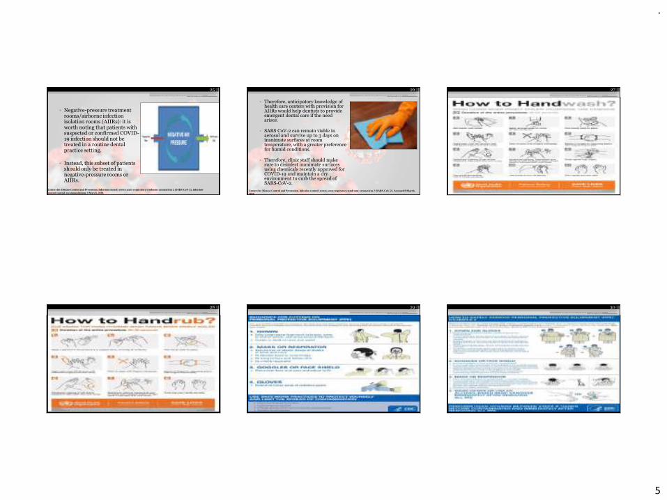
• Negative-pressure treatment rooms/airborne infection isolation rooms (AIIRs): it is worth noting that patients with suspected or confirmed COVID-19 infection should not be treated in a routine dental practice setting.
• Instead, this subset of patients should only be treated in negative-pressure rooms or AIIRs.
25
Centers for Disease Control and Prevention. Infection control: severe acute respiratory syndrome coronavirus 2 (SARS-CoV-2). infection-control/control-recommendations. 9 March, 2020.
• Therefore, anticipatory knowledge of health care centers with provision for AIIRs would help dentists to provide emergent dental care if the need arises.
• SARS CoV-2 can remain viable in aerosol and survive up to 3 days on inanimate surfaces at room temperature, with a greater preference for humid conditions.
• Therefore, clinic staff should make sure to disinfect inanimate surfaces using chemicals recently approved for COVID-19 and maintain a dry environment to curb the spread of SARS-CoV-2.
26
Centers for Disease Control and Prevention. Infection control: severe acute respiratory syndrome coronavirus 2 (SARS-CoV-2). Accessed 9 March, 2020.
27
28 29 30
.
6
Implication for Prosthetic Dentistry
• Salivary suction should be done with care to avoid gagging.
• During Fixed partial denture or single crown preparation treatment alteration must be considered to incorporate rubber dam application example: Supragingival margins or Split Dam Technique.
31
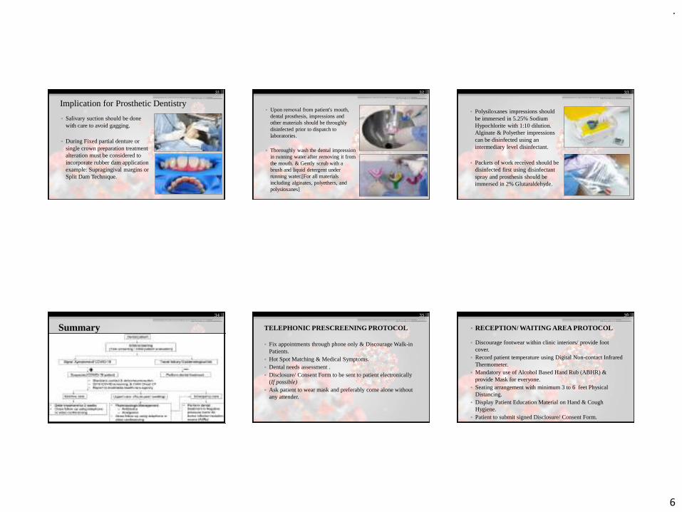
• Upon removal from patient's mouth, dental prosthesis, impressions and other materials should be throughlydisinfected prior to dispatch to laboratories.
• Thoroughly wash the dental impression in running water after removing it from the mouth. & Gently scrub with a brush and liquid detergent under running water.[For all materials including alginates, polyethers, and polysioxanes]
32
• Polysiloxanes impressions should be immersed in 5.25% Sodium Hypochlorite with 1:10 dilution. Alginate & Polyether impressions can be disinfected using an intermediary level disinfectant.
• Packets of work received should be disinfected first using disinfectant spray and prosthesis should be immersed in 2% Glutaraldehyde.
33
Summary
34 35
TELEPHONIC PRESCREENING PROTOCOL
• Fix appointments through phone only & Discourage Walk-in Patients.
• Hot Spot Matching & Medical Symptoms.• Dental needs assessment .• Disclosure/ Consent Form to be sent to patient electronically
(If possible)• Ask patient to wear mask and preferably come alone without
any attender.
• RECEPTION/ WAITING AREA PROTOCOL
• Discourage footwear within clinic interiors/ provide foot cover.
• Record patient temperature using Digital Non-contact Infrared Thermometer.
• Mandatory use of Alcohol Based Hand Rub (ABHR) & provide Mask for everyone.
• Seating arrangement with minimum 3 to 6 feet Physical Distancing.
• Display Patient Education Material on Hand & Cough Hygiene.
• Patient to submit signed Disclosure/ Consent Form.
36
.
7
DENTAL OPERATORY PROTOCOL
• Keep the clinical operatory clutter-free.• Improve air circulation and avoid air-conditioners.• 0.01% NaOCl for disinfection of dental water lines.• Donning of appropriate PPE for Dental Surgeon and one
dental assistant.
37
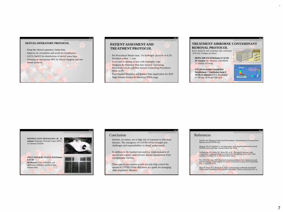
PATIENT ASSESMENT AND TREATMENT PROTOCOL
• Pre-Procedural Mouth rinse: 1% Hydrogen peroxide or 0.2% Povidone-iodine : 1 min
• Extra oral scrubbing of face with Antiseptic wipe• Diagnose & Treatment Plan Into Aerosol Generating
Procedures (AGP) and Non Aerosol Generating Procedures (Non-AGP)
• Four-Handed Dentistry and Rubber Dam Application for AGP• High Volume Suction & Minimize IOPA usage
38
• HEPA AIR FILTERS(min 12 ACH) 20 minutes Air filtration with HEPA 13 /HEPA 14 Filters
• UVGI(Ultraviolet Germicidal Irradiation) + Ventilation (min 6 ACH) 15 minutes UV-C Irradiation of 245 nm, 40 W per 100 sq.ft
39
TREATMENT AIRBORNE CONTAMINANT REMOVAL PROTOCOLRoom should be well ventilated with a minimum ACH (Air Changes per Hour)
• DISINFECTANT DEFOGGING 30 - 45 minutes Hydrogen Peroxide Vapor (HPV) or Chlorine Dioxide
• ONLY NATURAL VENTILATION(min 6 ACH)60 Minutes Cross ventilation and additional ventilators (pedestal fans, exhaust fans)
40
Conclusion• Dentists, by nature, are at high risk of exposure to infectious
diseases. The emergence of COVID-19 has brought new challenges and responsibilities to dental professionals.
• In addition to the standard precautions, implementation of special precautions could prevent disease transmission from asymptomatic carriers.
• These special precautions would not only help control the spread of COVID-19 but also serve as a guide for managing other respiratory diseases.
41
References 1. Centers for Disease Control and Prevention. Transmission of coronavirus
disease 2019 (COVID-19).
2. Dong E, Du H, Gardner L. An interactive web-based dashboard to track COVID-19 in real time. Lancet Infect Dis 2020.
3. Gorbalenya AE, Baker SC, Baric RS, et al. The species Severe acute respiratory syndromerelated coronavirus: classifying 2019-nCoV and naming it SARS-CoV-2. Nat Microbiol 2020.
4. Wax RS, Christian MD. Practical recommendations for critical care and anesthesiology teams caring for novel coronavirus (2019-nCoV) patients. Can J Anaesth 2020.
5. Zhou P, Yang X-L, Wang X-G, et al. A pneumonia outbreak associated with a new coronavirus of probable bat origin. Nature 2020;579:270–3.
42
.
8
6. Wahba L, Jain N, Fire AZ, et al. Identification of a pangolin niche for a 2019-nCoV-like coronavirus through an extensive meta-metagenomicsearch. bioRxiv 2020.
7. Zhu N, Zhang D, Wang W, et al. A novel coronavirus from patients with pneumonia in China,2019. N Engl J Med 2020;382:727–33.
8. Gorbalenya AE. Severe acute respiratory syndrome-related coronavirus –the species and its viruses, a statement of the Coronavirus Study Group. bioRxiv 2020.
9. Sohrabi C, Alsafi Z, O’Neill N, et al. World Health Organization declares global emergency: a review of the 2019 novel coronavirus (COVID-19). Int J Surg 2020;76:71–6.
10. WHO director-general’s opening remarks at the media briefing on COVID-19 - 3 March 2020. Accessed 11 March, 2020.
43
.
1
Developmental
disturbances
Dr . Vishnu Soni
• Developmental disturbances- In the size of the TOOTH
• Developmental disturbances –In the shape of the TOOTH
• Developmental disturbances –In the number of the TOOTH
• Developmental disturbances- In the structure of the TOOTH
Developmental disturbances in size of teeth
1. Microdontia
2. Macrodontia
Microdontia:-This term is used to describe teeth which are
smaller than normal.
• Three types of microdontia are recognised1).True generalised microdontia
2).Relative generalised microdontia
3).Microdontia involving a single tooth
• True generalised microdontia:- In this all the teeth are
smaller than normal
Example:Pituatory dwarfism.This condition is extremely rare
• Relative generalised microdontia:- Normal or slightly
smaller than normal teeth are present. The jaws are some
what larger than normal and so it is an illusion of true
microdontia
• Microdontia involving only a single tooth:- It is rather
common condition and often affects maxillary lateral incisor
and third molar.
• One of the common forms is peg lateral,peg shaped OR
cone shaped crown with shorter root is noticed
• Macrodontia:-Teeth are larger than normal. It may be classified as
1. True generalised macrodontia
2. Relative generalised macrodontia
3. Macrodontia of single tooth
True generalised macrodontia:- Here all the teeth are larger than normal, has been associated with pituitory gigantism
Relative generalised macrodontia:-It is common and is a result of the presence of normal or slightly larger than normal teeth in small jaws.
Macrodontia of single tooth:-It is relatively un common. Tooth may appear normal in every respect except for its size. This sige should not be confused with the fusion of the teeth. It is occasionally seen in cases of hemi hyper trophy of the face
Developmental disturbances in shape of teeth
• Gemination
• Fusion
• Concrescence
• Dilaceration
• Taloncusp
• Dense in denty
• Dense Evaginatus
• Taurodontism
• Super numerary roots
.
2
Gemination:-
*Anomalie which arise from an attempt at division of a single tooth germ by an invagination with resultant incomplete formation of two teeth.
*Structure is usually is one with two completely or incompletely separated crowns that have a single root and root canal.
*Seen in Deciduos and permanent dentition
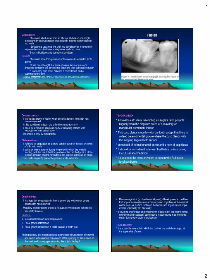
Fusion:-
*Anomalie arise through union of two normally separated tooth germs
*It has been thought that some physical force or pressure produces contact of the developing teeth and their subsequent fusion
*Fusion may also occur between a normal tooth and a supernumerary tooth
Clinical problems:-Appearance, spacing and periodontal conditions
Fusion
Concrescence:-
* It is actually a form of fusion which occurs after root formation has been completed
* In this condition the teeth are united by cementum only
* It could be a result of traumatic injury or crowding of teeth with resorption of inter dental bone
* Diagnosis is only by radiographs
Dialaceretion:-
* It refers to an angulation or a sharp bend or curve in the root or crown of a formed tooth.
* It could be due to trauma during the period in which the tooth is forming, with the result that the position of the calcified portion of the tooth is changed and the reminder of the tooth is formed at an angle
* This teeth frequently present a problem while extraction
Taloncusp:-
* Anomalous structure resembling an eagle’s talon,projects
lingually from the cingulum areas of a maxillary or
mandibular permanent incisor
* This cusp blends smoothly with the tooth except that there is
a deep developmental groove where the cusp blends with
the slopping lingual tooth surface
* composed of normal enamel dentin and a horn of pulp tissue
* It should be considered in terms of esthetics caries control,
Occulusal accomadation
* It appears to be more prevalent in person with Rubinsteni-
taybi syndrome
Densindente:-
* It is a result of invasination in the surface of the tooth crown before
calcification has occurred
* Maxillary lateral incisors are most frequently involved and condition is
frequently bilateral
Causes:-
1. Increased localised external pressure
2. Focal growth retardation
3. Focal growth stimulation in certain areas of tooth bud
Radiograpically it is recognised as a pear shaped invasination of enamel
and dentin with a narrow constriction at the opening on the surface of
the tooth and closely approximating the pulp in its depth
• Dense evaginatus (occlusal enamel pearl);- Developmental condition that appears clinically as an accessory cusp or globule of the enamel on the occlusal surface between the buccal and lingual cusps of pre molars unilaterally OR bilaterally
* It could be proliferation and evagination of an area of the inner enamel epithelium and subjacent odontogenic mesenchyme in to the dental organ during early tooth development
Taurodontism:-
* It is a peculiar anamoly in which the body of the tooth is enlarged at the expensive of roots
.
3
Causes include:
* When the mandelian recessive trait
* Atavastic feature
* Mutation resulting from odontoblastic deficiency during
dentinogenesis of the roots
Super numerary roots:-
* An additional root develops to the involved tooth
* Any tooth can exhibit these roots
Developmental disturbances in number of Teeth
1. Anodontia
2. Super numerary teeth
Anodontia:-Congenital absence of teeth
It is of TWO types
1.Total anodontia
2.Partial Anodontia
Total anodontia:-
All the teeth are missing,may involve both the deciduous and the permanent dentition .Example :Ectodermal Hypoplasia
Partial Anodontia:-
* Any tooth may be congenitally missing
* There is tendency for certain teeth to be missing more frequently than others being the mandible second premolar commonest
Super Numerary teeth:-
* The tooth may closely resemble the teeth of the group to which it belongs I.e Molars or pre molars or Anteriors
* Most common super numerary tooth are mesiodens followed by maxillary fourth molar
* Gardner’s syndrome consist of he multiple impacted super numerary teeth
Developmental disturbances in structure of
Teeth
1. Amelogenesis Imperfecta
2. Enamel Hypoplacia
3. Dentinogenesis imperecta
Amelogenesis Imperfecta:-
* Represents a group of hereditary defects of enamel un associated with any other generalised defects.
* It is an ectodermal diturbance classified in to
1) Hypo plastic
2) Hypo calcified
3) Hypo maturation
• Clinically the crowns of the teeth may or may not show discolouration
if present varies depending on the type of disorder, ranging from
Yellow to dark brown
• In some cases enamel may be totally absent r it may have chalky
texture or even a cheesy consistency or be relatively hard
• Sometimes the enamel is smooth or it may have numerous parallel
vertical wrinkles or grooves
• It may be chipped or show depressions in the base of which dentin
may be exposed
• Contact points between teeth are often open and occlusal surfaces
and incisal edges frequently abraded
Enamel Hypoplasia:-
* It is defined as a incomplete or defective formation of the organic matrix of teeth
* A number of different factors each capable of producing injury to the amiloblast may give rise to this condition.
Causes are:
-Nutitional deficiency (Vitamin A,D,C)
-Examthematous diseases (Measels,chicken fox,scarlet fever)
-Congenital syphilis
-Hypocalcemia
-Birth Injury,prematurity, RH Heamolytc disease
-Local Infection or Trauma
-Ingestion of chemical such as flouride
.
4
Radiographically:-
* The most striking feature is the partial or total precocious
* Obliteration of the pulp chamberand root cannals by continued formation of the dentin.
Chemical and physical features:-
• Chemical analysis shows that type-1 &2&3 increased water content as much as above while the inorganic content is less than that of normal dentin
• Dentin dysplasia(rootless teeth):- It is a rare disturbance of dentin formation characterized
• By normal enamel but atypical dentin formation with abnormal pulpal morphology.
• Transmitted as an autosomal dominant character.
Type-1(Radicular dysplasia):-
These teeth characteristically exhibit extreme mobility
&after only minor trauma as a result of their abnormally short roots.
Type-2(Coronal dysplasia) :-
-The permanent teeth how ever exhibit an abnormally
-Large pulp chamber in the coronal portion of the tooth often
described as THISTLE TUBE in shape.
Regionalodontoplasia
• They exhibit either delay or total failure in eruption.
• Show a marked reduction in radiodensity , so that the teeth assume a ghost appearance
Disturbances in the growth of the teeth:-
1. Premature eruption
2. Eruption sequestrum
3. Delayed eruption
4. Impacted teeth
5. Ankylosed teeth
1).Premature eruption:-
• Neonatal teeth are example for the premature eruption.
• The premature eruption of the permanent teeth is usually a sequelae of the loss of the deciduous teeth.
• This could be the possibility of the endocrine dysfunction.(hyperthyroidism)
2).Eruption sequestrum:-
-It is tiny irregular spicule of the bone overlying the crown of an erupting permanent molar found just prior to or immediately following the emergence of the tips of the cusps through the oral mucosa.
3).Delayed eruption:-
• Local factors: -Fibromatosis gingivae
• Systemic factors:-Rickets, cretinism,cleido cranial dysplasia
4).Impactedteeth:-
• Individual teeth which are unerupted usually because of lack of eruptive force.
Causes:-
• Lack of space
• Rotation of the tooth buds resulting in teeth which are aimed in the wrong direction
• Because their long axis is not parallel to a normal eruptive path.
5).Ankylosedteeth:-
• Most commonly mandibular second molars that have undergone
a variable degree of root resorption & then have become
ankylosed to the bone.
Causes:-
-Trauma,infection,disturbed local metabolism or a genetic influence
.
5
• Hypoplasia results only if the injury occurs during the time
the teeth developing or more specifically during the
formative stage of enamel development.Once the enamel is
calcified no such defects can be produced
E.H due to exanthmatous fever:-
• Pitting varilog and this pits tend to strain.The clinical
apearances of it mau be very unsightly.
• E.H due to congenitalsyphilis:-
-Involves the maxillary and mandibular permanent
incisors and the first molars
-The anterior teeth affected are called HUTCHINSONS TEETH
and molars are referred to as mulberry molars , moon’s
molars, fournier,s molars.
The anterior teeth will be screw driver shaped ,themesial and
distal surfaces of the crown tapering and converging towards
the cervical margin and it could be due the absence of cental
tubercle or calcification center.
-In the first molar crowns ,the enamel of the occlusal surfaces
and the occlusal third of the tooth appears to be arranged in
an agglomerate mass of the globules rather than in well
formed cusps.
The crown is narrower on the occlusal surfaces than at the
cervical margin.
E.H due to local infection or trauma
• It is occasionally seen,only a single tooth is involved ,most
commonly one of the permanent maxillary incissor or
maxillary or mandibular premolar.
• There may be any degree of hypoplasia ranging from the
mild brownish discoluration of the enamel to sever pitting or
irregularity of the tooth crown.
• This single tooth is called turners toothand the conditionis
called as Turners hypoplasia.
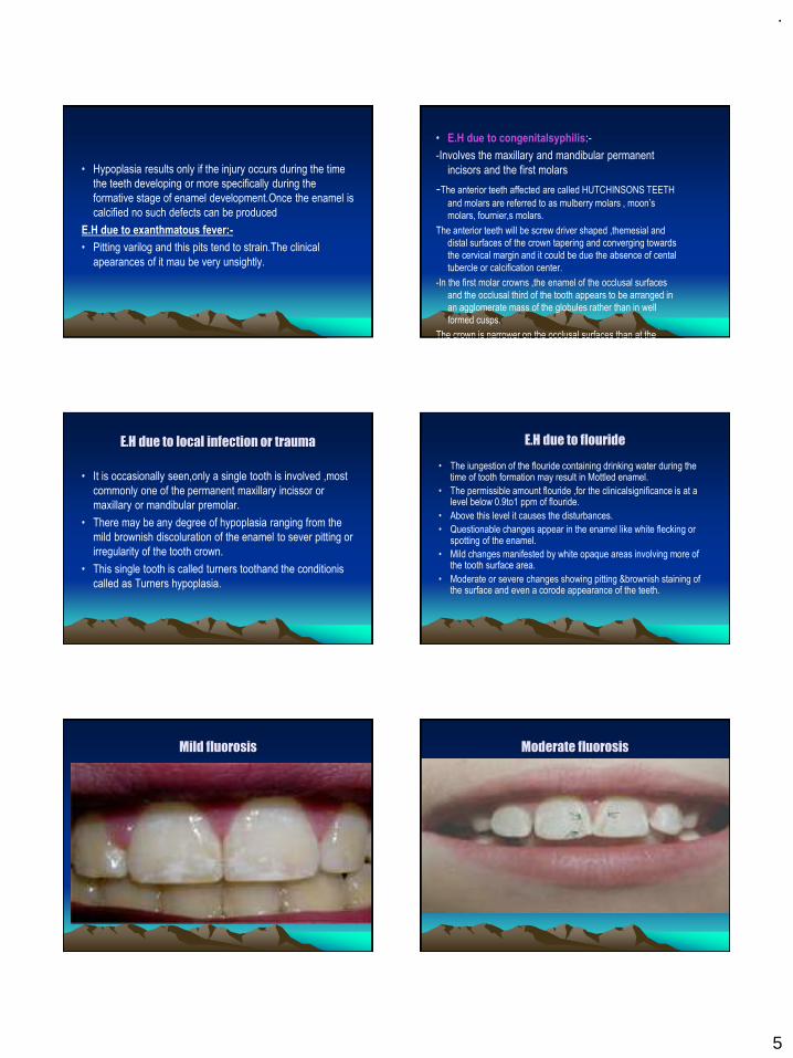
E.H due to flouride
• The iungestion of the flouride containing drinking water during the time of tooth formation may result in Mottled enamel.
• The permissible amount flouride ,for the clinicalsignificance is at a level below 0.9to1 ppm of flouride.
• Above this level it causes the disturbances.
• Questionable changes appear in the enamel like white flecking or spotting of the enamel.
• Mild changes manifested by white opaque areas involving more of the tooth surface area.
• Moderate or severe changes showing pitting &brownish staining of the surface and even a corode appearance of the teeth.
Mild fluorosis Moderate fluorosis
.
6
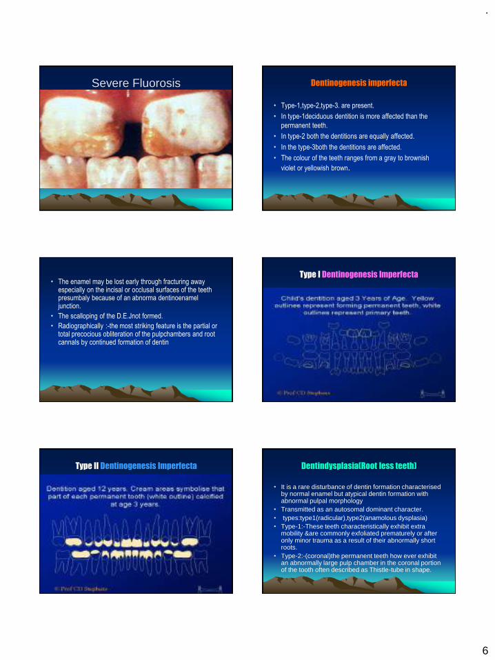
Severe Fluorosis Dentinogenesis imperfecta
• Type-1,type-2,type-3. are present.
• In type-1deciduous dentition is more affected than the
permanent teeth.
• In type-2 both the dentitions are equally affected.
• In the type-3both the dentitions are affected.
• The colour of the teeth ranges from a gray to brownish
violet or yellowish brown.
• The enamel may be lost early through fracturing away especially on the incisal or occlusal surfaces of the teeth presumbaly because of an abnorma dentinoenamel junction.
• The scalloping of the D.E.Jnot formed.
• Radiographically :-the most striking feature is the partial or total precocious obliteration of the pulpchambers and root cannals by continued formation of dentin
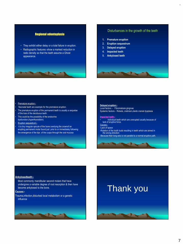
Type I Dentinogenesis Imperfecta
Type II Dentinogenesis Imperfecta Dentindysplasia(Root less teeth)
• It is a rare disturbance of dentin formation characterised by normal enamel but atypical dentin formation with abnormal pulpal morphology
• Transmitted as an autosomal dominant character.• types:type1(radicular),type2(anamolous dysplasia)• Type-1:-These teeth characteristically exhibit extra
mobility &are commonly exfoliated prematurely or after only minor trauma as a result of their abnormally short roots.
• Type-2:-(coronal)the permanent teeth how ever exhibit an abnormally large pulp chamber in the coronal portion of the tooth often described as Thistle-tube in shape.
.
7
Regional odontoplasia
• They exhibit either delay or a total failure in eruption.
• Radiographic features:-show a marked reduction in
radio density so that the teeth assume a Ghost
appearance.
Disturbances in the growth of the teeth
1. Premature eruption
2. Eruption sequestrum
3. Delayed eruption
4. Impacted teeth
5. Ankylosed teeth
• Premature eruption:-
• Neonatal teeth are example for the premature eruption.
• The premature eruption of the permanent teeth is usually a sequelae
of the loss of the deciduous teeth.
• This could be the possibility of the endocrine
dysfunction.(hyperthyroidism)
• Eruption sequestrum:-
• It is tiny irregular spicule of the bone overlying the crownof an
erupting permanent molar found just prior to or immediately following
the emergence of the tips of the cusps through the oral mucosa
Delayed eruption:-
Local factors: - Fibromatosis gingivae
Systemic factors:- Rickets, cretinism,cleido cranial dysplasia
Impacted teeth:-
• Individual teeth which are unerupted usually because of lack of eruptive force.
Causes:-
-Lack of space
-Rotation of the tooth buds resulting in teeth which are aimed in the wrong direction
-Because their long axis is not parallel to a normal eruptive path.
Ankylosedteeth:-
Most commonly mandibular second molars that have
undergone a variable degree of root resorption & then have
become ankylosed to the bone.
Causes:-
Trauma,infection,disturbed local metabolism or a genetic
influence
Thank you
.
1
FACIAL NERVEDr Vishnu Soni
FACIAL NERVE
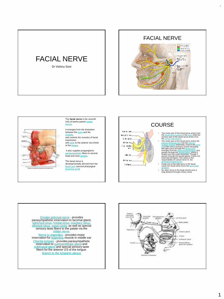
The facial nerve is the seventh (VII) of twelve paired cranial nerves.
It emerges from the brainstem between the pons and the medulla, and controls the muscles of facial expression, and taste to the anterior two-thirds of the tongue.
It also supplies preganglionic parasympathetic fibers to several head and neck ganglia.
The facial nerve is developmentally derived from the hyoid arch (second pharyngeal branchial arch).
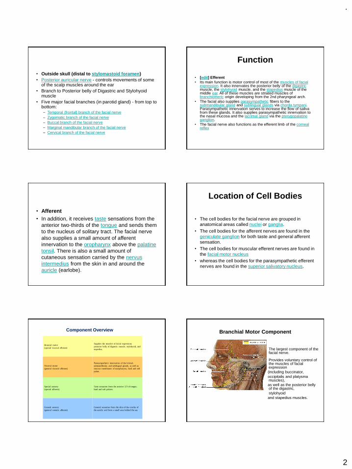
COURSE• The motor part of the facial nerve arises from
the facial nerve nucleus in the pons while the sensory part of the facial nerve arises from the nervus intermedius.
• The motor part of the facial nerve enters the petrous temporal bone into the internal auditory meatus (intimately close to the inner ear) then runs a tortuous course (including two tight turns) through the facial canal, emerges from the stylomastoid foramen and passes through the parotid gland, where it divides into five major branches. Though it passes through the parotid gland, it does not innervate the gland. This action is the responsibility of cranial nerve IX, the glossopharyngeal nerve.
• Inside one of the tight turns in the facial canal, the facial nerve forms the geniculate ganglion.
• No other nerve in the body travels such a long distance through a bony canal.
Greater petrosal nerve - provides parasympathetic innervation to lacrimal gland, sphenoid sinus, frontal sinus, maxillary sinus, ethmoid sinus, nasal cavity, as well as special
sensory taste fibers to the palate via the Vidian nerve.
Nerve to stapedius - provides motor innervation for stapedius muscle in middle ear Chorda tympani - provides parasympathetic
innervation to submandibular gland and sublingual gland and special sensory taste
fibers for the anterior 2/3 of the tongue. branch to the tympanic plexus
.
2
• Outside skull (distal to stylomastoid foramen)• Posterior auricular nerve - controls movements of some
of the scalp muscles around the ear • Branch to Posterior belly of Digastric and Stylohyoid
muscle • Five major facial branches (in parotid gland) - from top to
bottom: – Temporal (frontal) branch of the facial nerve– Zygomatic branch of the facial nerve– Buccal branch of the facial nerve– Marginal mandibular branch of the facial nerve– Cervical branch of the facial nerve
Function
• [edit] Efferent• Its main function is motor control of most of the muscles of facial
expression. It also innervates the posterior belly of the digastricmuscle, the stylohyoid muscle, and the stapedius muscle of the middle ear. All of these muscles are striated muscles of branchiomeric origin developing from the 2nd pharyngeal arch.
• The facial also supplies parasympathetic fibers to the submandibular gland and sublingual glands via chorda tympani. Parasympathetic innervation serves to increase the flow of saliva from these glands. It also supplies parasympathetic innervation to the nasal mucosa and the lacrimal gland via the pterygopalatine ganglion.
• The facial nerve also functions as the efferent limb of the corneal reflex
• Afferent• In addition, it receives taste sensations from the
anterior two-thirds of the tongue and sends them to the nucleus of solitary tract. The facial nerve also supplies a small amount of afferent innervation to the oropharynx above the palatine tonsil. There is also a small amount of cutaneous sensation carried by the nervus intermedius from the skin in and around the auricle (earlobe).
Location of Cell Bodies
• The cell bodies for the facial nerve are grouped in anatomical areas called nuclei or ganglia.
• The cell bodies for the afferent nerves are found in the geniculate ganglion for both taste and general afferent sensation.
• The cell bodies for muscular efferent nerves are found in the facial motor nucleus
• whereas the cell bodies for the parasympathetic efferent nerves are found in the superior salivatory nucleus.
Component Overview
The facial nerve has four components with distinct functions:
Brancial motor(special visceral efferent)
Supplies the muscles of facial expression; posterior belly of digastric muscle; stylohyoid, and stapedius.
Visceral motor(general visceral efferent)
Parasympathetic innervation of the lcrimal, submandibular, and sublingual glands, as well as mucous membranes of nasopharynx, hard and soft palate.
Special sensory(special afferent)
Taste sensation from the anterior 2/3 of tongue; hard and soft palates.
General sensory(general somatic afferent)
General sensation from the skin of the concha of the auricle and from a small area behind the ear.
Branchial Motor Component
The largest component of the facial nerve.
Provides voluntary control of the muscles of facial expression(including buccinator, occipitalis and platysma muscles), as well as the posterior belly of the digastric, stylohyoidand stapedius muscles.
.
3
• Origin and Central Course
The branchial motor component originates from the motor nucleus of CN VII in the caudal pons.
Fibers leaving the motor nucleus of CN VII initially travel medially and dorsally to loop around the ipsilateral abducens nucleus (CN VI) producing a slight bulge in the floor of the fourth ventricle - the facial colliculus.
Fibers then course so as to exit the ventrolateral aspect of the brainstem at the caudal border of the pons in conjunction with the nervus intermedius components of CN VII.
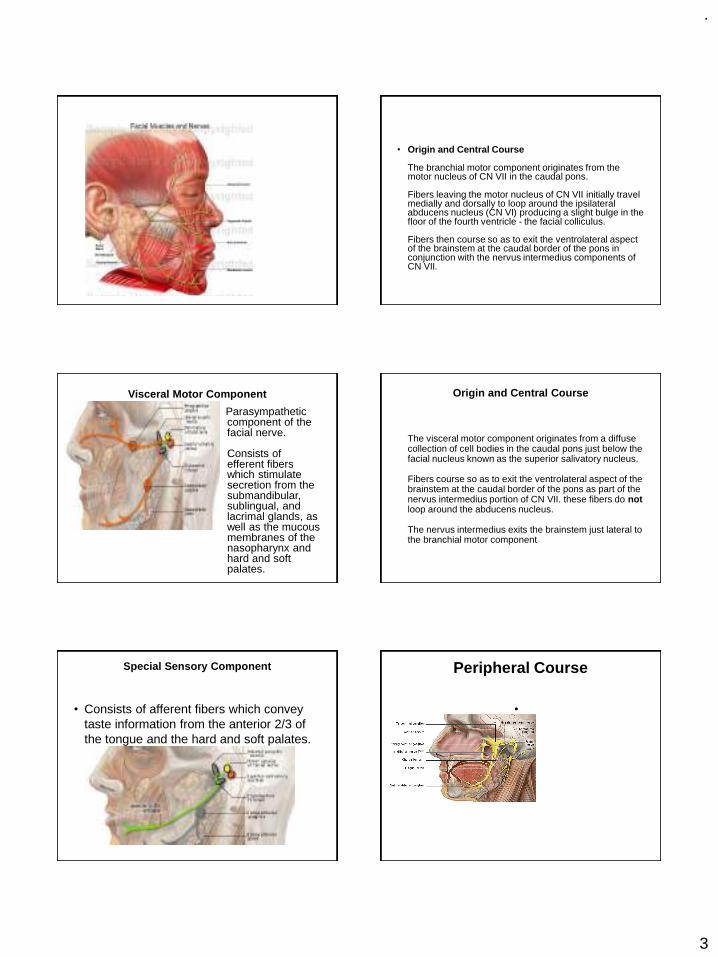
Visceral Motor Component
Parasympathetic component of the facial nerve.
Consists of efferent fibers which stimulate secretion from the submandibular, sublingual, and lacrimal glands, as well as the mucous membranes of the nasopharynx and hard and soft palates.
Origin and Central Course
The visceral motor component originates from a diffuse collection of cell bodies in the caudal pons just below the facial nucleus known as the superior salivatory nucleus.
Fibers course so as to exit the ventrolateral aspect of the brainstem at the caudal border of the pons as part of the nervus intermedius portion of CN VII. these fibers do notloop around the abducens nucleus.
The nervus intermedius exits the brainstem just lateral to the branchial motor component
Special Sensory Component
• Consists of afferent fibers which convey taste information from the anterior 2/3 of the tongue and the hard and soft palates.
Peripheral Course
•
.
4
• Chemoreceptors of the taste buds located on the anterior 2/3 of the tongue and hard and soft palates initiate receptor (generator) potentials in response to chemical stimuli.
The taste buds synapse with the peripheral processes of special sensory neurons from CN VII. These neurons generate action potentials in response to the taste bud's receptor potentials. The peripheral processes of these neurons follow the lingual nerve and then chorda tympani to the petrous portion of the temporal bone (similar to the path followed by the efferent visceral motor fibers).
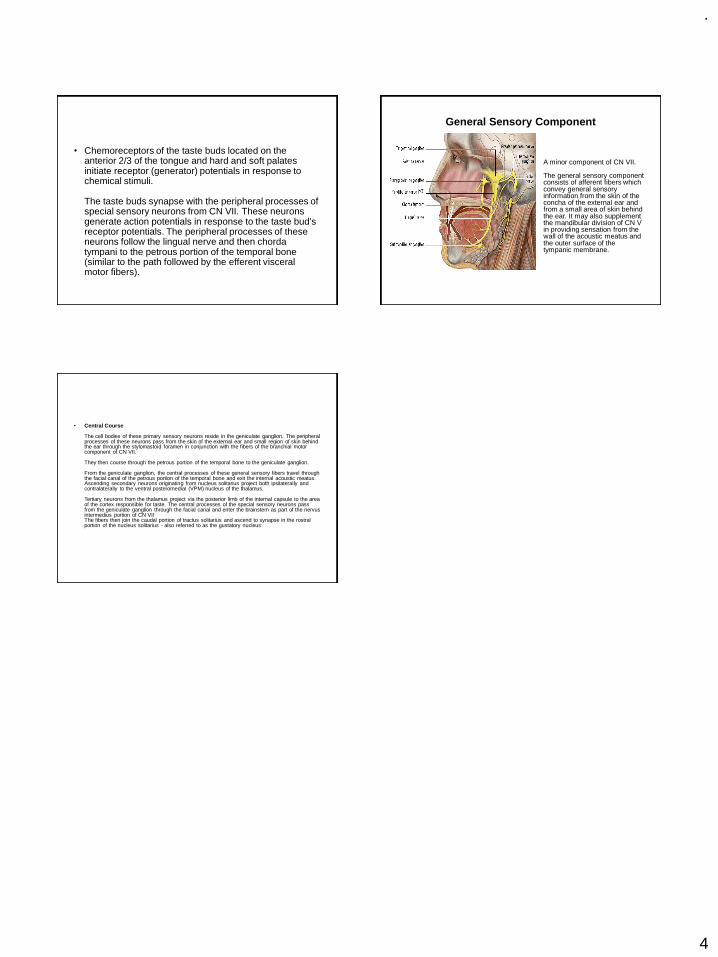
General Sensory Component
A minor component of CN VII.
The general sensory component consists of afferent fibers which convey general sensory information from the skin of the concha of the external ear and from a small area of skin behind the ear. It may also supplement the mandibular division of CN V in providing sensation from the wall of the acoustic meatus and the outer surface of the tympanic membrane.
• Central Course
The cell bodies of these primary sensory neurons reside in the geniculate ganglion. The peripheral processes of these neurons pass from the skin of the external ear and small region of skin behind the ear through the stylomastoid foramen in conjunction with the fibers of the branchial motor component of CN VII.
They then course through the petrous portion of the temporal bone to the geniculate ganglion.
From the geniculate ganglion, the central processes of these general sensory fibers travel through the facial canal of the petrous portion of the temporal bone and exit the internal acoustic meatus.Ascending secondary neurons originating from nucleus solitarius project both ipsilaterally and contralaterally to the ventral posteromedial (VPM) nucleus of the thalamus.
Tertiary neurons from the thalamus project via the posterior limb of the internal capsule to the area of the cortex responsible for taste. The central processes of the special sensory neurons pass from the geniculate ganglion through the facial canal and enter the brainstem as part of the nervus intermedius portion of CN VIIThe fibers then join the caudal portion of tractus solitarius and ascend to synapse in the rostral portion of the nucleus solitarius - also referred to as the gustatory nucleus:
.
1
Presented by:
Dr. Vishnu Soni
Failures in Fixed Partial Denture
1
Contents
2
Introduction Classification Biologic Failure Mechanical Failure Esthetic Failure Psychogenic Failure
Methods of Removing a Failed FPD Review of Literature References
INTRODUCTION
3 4
Fixed prosthodontic treatment can offer exceptional satisfaction for both patientand dentist.
It can transform an unhealthy, unattractive dentition with poor function into acomfortable, healthy occlusion capable of giving years of further service whilegreatly enhancing esthetics.
To achieve such success, however, requires meticulous attention to every detailfrom initial patient interview, through the active treatment phase, to a plannedschedule of follow-up care.
Failure to achieve the desired specifications of design for function and estheticswould result in failure of the prosthesis.
5
It is important to analyze failure so that the reasons can be evaluated andprevention is imparted.
A fixed partial denture (FPD) can fail as a result of: Poor patient care Defective design Inadequate execution of clinical procedures Inadequate execution of lab procedures
6
The causes of FPD failures were summarized as early as in 1920 when Tinker wrote -“ Chief among the causes for such disappointing results have been:
First : Faulty, and in some cases, no attempt at diagnosis and prognosis.
Second: Failure to remove foci of infection in attention to treatment and care of theinvesting tissues and mouth sanitation.
Third: Disregard for tooth form
Fourth: Absence of proper embrasures
Fifth: Inter-proximal spaces
Sixth: Faulty occlusion and articulation
.
2
CLASSIFICATION
7 8
Bennard G. N. Smith
1. Loss of retention
2. Mechanical failure of crowns or bridge components Porcelain fracture Failure of solder joints Distortion Occlusal wear and perforation Lost facings
9
3. Changes in the abutment tooth Periodontal disease Problems with the pulp Caries Fracture of the prepared natural crown or root Movement of the tooth
4. Design failures Under-prescribed FPDs Over-prescribed FPDs
5. Inadequate clinical or laboratory technique Positive ledge Negative ledge Defect Poor shape and color
6. Occlusal problems
John F. Johnston1. Discomfort
Malocclusion or premature contact
An oversized or poorly positioned mastication area, with retention of food by pontics or
retainers
Torque produced from the seating of the bridge or from occlusion
An excess of pressure on the tissue
Improperly protected gingival and ridge tissue
Thermal shock
2. Looseness of FPD
Deformation of the metal casting on the abutment
Torque
Technique of cementation
Solubility of cement
Caries
Mobility of one or more abutments
Lack of full occlusal coverage
Insufficient retention in the abutment preparation
Poor initial fit of the casting
.
3
3. Recurrence of caries
Improper extension of margins
Short castings
Open margins
Wear
A retainer becoming loose
Pontic form that fills the embrasure
Poor oral hygiene
Use of wrong type of retainer, which will promote caries susceptibility
Permanent displacement of the gingiva
4. Recession of supporting structure Length of the span Size of the occlusal table Embrasure form Improper extensions of the cervical margins Improper impression technique can also stimulate recession of the gingiva
5. Degeneration of Pulp
6. Fractures of bridge components A faulty solder joint Incorrect casting technique Overwork of the metal due to length of the span or parts that are too small
7. Loss of veneers Little retention Badly designed metal protection Deformation of the protecting metal Malocclusion Improper fusing or technique
8. Loss of function They don’t function in occlusion They have no contact with opposing teeth They have permanent contact Over carved or under carved occlusal surface may impair efficiency Loss of opposing or approximating teeth
9. Loss of teeth tone or form Pontic design Position and size of the joints Embrasure form Over contouring or under contouring of retainers Oral hygiene practiced by the patient
10.Failure to seat The abutment preparations may not be near parallel Soldering assembly may have been incorrect, or relationship of the retainers may have
been altered during soldering
17
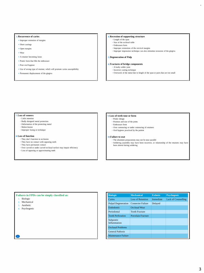
Failures in FPDs can be simply classified as:1. Biologic2. Mechanical3. Aesthetic4. Psychogenic
18
Biologic Mechanical Esthetic Psychogenic
Caries Loss of Retention Immediate Lack of Counselling
Pulpal Degeneration Connecter Failure Delayed
Endodontic Occlusal Wear
Periodontal Tooth Fracture
Tooth Perforation Porcelain Fracture
Subpontic Inflammation
Occlusal Problems
General Pathosis
Maintenance Failure
.
4
BIOLOGIC FAILURE
19
Caries
20
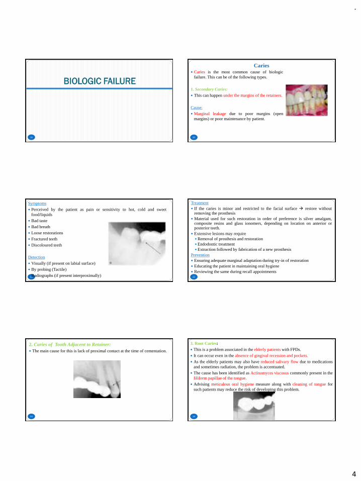
Caries is the most common cause of biologicfailure. This can be of the following types.
1. Secondary Caries: This can happen under the margins of the retainers.
Cause:
Marginal leakage due to poor margins (openmargins) or poor maintenance by patient.
21
Symptoms
Perceived by the patient as pain or sensitivity to hot, cold and sweetfood/liquids
Bad taste
Bad breath
Loose restorations
Fractured teeth
Discoloured teeth
Detection
Visually (if present on labial surface)
By probing (Tactile)
Radiographs (if present interproximally) 22
Treatment If the caries is minor and restricted to the facial surface → restore without
removing the prosthesis Material used for such restoration in order of preference is silver amalgam,
composite resins and glass ionomers, depending on location on anterior orposterior teeth.
Extensive lesions may require Removal of prosthesis and restoration Endodontic treatment Extraction followed by fabrication of a new prosthesis
Prevention Ensuring adequate marginal adaptation during try-in of restoration Educating the patient in maintaining oral hygiene Reviewing the same during recall appointments
23
2. Caries of Tooth Adjacent to Retainer: The main cause for this is lack of proximal contact at the time of cementation.
24
3. Root Caries: This is a problem associated in the elderly patients with FPDs.
It can occur even in the absence of gingival recession and pockets.
As the elderly patients may also have reduced salivary flow due to medicationsand sometimes radiation, the problem is accentuated.
The cause has been identified as Actinomyces viscosus commonly present in thefiliform papillae of the tongue.
Advising meticulous oral hygiene measure along with cleaning of tongue forsuch patients may reduce the risk of developing this problem.
.
5
Pulpal Degeneration of Abutment
25
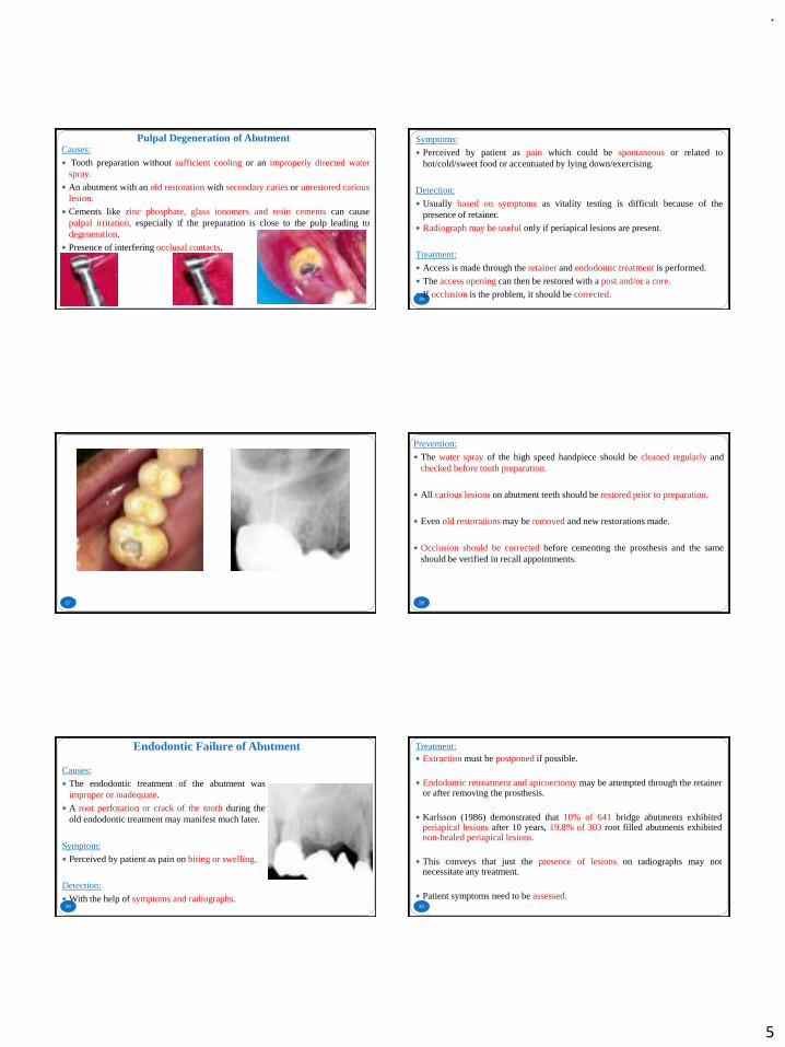
Causes:
Tooth preparation without sufficient cooling or an improperly directed waterspray.
An abutment with an old restoration with secondary caries or unrestored cariouslesion.
Cements like zinc phosphate, glass ionomers and resin cements can causepulpal irritation, especially if the preparation is close to the pulp leading todegeneration.
Presence of interfering occlusal contacts.
26
Symptoms:
Perceived by patient as pain which could be spontaneous or related tohot/cold/sweet food or accentuated by lying down/exercising.
Detection:
Usually based on symptoms as vitality testing is difficult because of thepresence of retainer.
Radiograph may be useful only if periapical lesions are present.
Treatment:
Access is made through the retainer and endodontic treatment is performed.
The access opening can then be restored with a post and/or a core.
If occlusion is the problem, it should be corrected.
27 28
Prevention:
The water spray of the high speed handpiece should be cleaned regularly andchecked before tooth preparation.
All carious lesions on abutment teeth should be restored prior to preparation.
Even old restorations may be removed and new restorations made.
Occlusion should be corrected before cementing the prosthesis and the sameshould be verified in recall appointments.
Endodontic Failure of Abutment
29
Causes:
The endodontic treatment of the abutment wasimproper or inadequate.
A root perforation or crack of the tooth during theold endodontic treatment may manifest much later.
Symptom:
Perceived by patient as pain on biting or swelling.
Detection:
With the help of symptoms and radiographs.30
Treatment: Extraction must be postponed if possible.
Endodontic retreatment and apicoectomy may be attempted through the retaineror after removing the prosthesis.
Karlsson (1986) demonstrated that 10% of 641 bridge abutments exhibitedperiapical lesions after 10 years, 19.8% of 303 root filled abutments exhibitednon-healed periapical lesions.
This conveys that just the presence of lesions on radiographs may notnecessitate any treatment.
Patient symptoms need to be assessed.
.
6
31
Prevention:
Endodontically treated teeth must be used as abutments only after thoroughevaluation.
If endodontic treatment is found inadequate, retreatment may be performed.
When in doubt, the design of the prosthesis should be altered to exclude thetooth as abutment.
Periodontal Failure
32
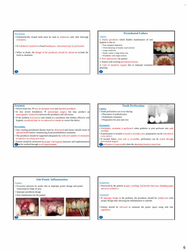
Causes:
1. Faulty prosthesis which hinders maintenance of oralhygiene is due to:
Poor marginal adaptation Overcontouring of retainer axial surfaces Large connectors Pontic contact a large tissue area Prostheses with rough surfaces
2. Poor maintenance by patient
3. Patient with existing periodontal disease
4. Lack of abutment support due to improper treatmentplanning
33
Treatment: Severe bone loss→ loss of abutment teeth and attached prosthesis.
In less severe breakdown → periodontal surgery but may produce anunacceptable relationship between the prosthesis and soft tissue.
If the problem is localized and related to a prosthesis that hinders effective oralhygiene, prosthesis may be recontoured or remade to correct the defect.
Prevention: Any existing periodontal disease must be eliminated and tissues should return to
optimal health before commencing fixed prosthodontics treatment.
The prosthesis should be supported adequately by sufficient number of abutmentsto function on a long term basis.
Patient should be instructed on proper oral hygiene measures and implementationmust be verified through recall appointments.
Tooth Perforation
34
Causes: Tooth perforation can occur during: Placement of pinholes/pins Endodontic treatment Preparation for post and core
Treatment: Endodontic treatment is performed when pinholes or pins perforate into pulp
chamber. If perforation is located occlusal to alveolar crest, preparation can be extended to
cover defect. If located below crest and is accessible, perforation can be sealed through
periodontal surgery. If perforation is inaccessible then the abutment requires extraction.
Sub-Pontic Inflammation
35
Causes:
Excessive pressure by pontic due to improper pontic design and ponticcontacting too large an area
Improper prosthesis design
Poor maintenance by the patient
36
Symptoms:
Perceived by the patient as pain, swelling, bad breath, bad taste, bleeding gumsand poor aesthetics.
Treatment:
If improper design is the problem, the prosthesis should be refabricated withproper design after allowing the inflammation to subside.
Patient should be educated to maintain the pontic space using aids likesuperfloss.
.
7
Occlusal Problems
37
Symptoms: Problems in occlusion is perceived by the patient as discomfort on biting, sore
teeth, loose teeth or bridges, sensitive teeth and tired or sore muscles.
Causes and Treatments: Interfering centric or eccentric contacts → tooth mobility and irreversible pulpal
damage.
Tooth mobility is reversible if problem is detected early and adjusted butcorrection may cause prostheses failure due to perforation and loss of aesthetics.
Pulpal damage should receive endodontic treatment following occlusalcorrection.
38
Mobility due to long term occlusal interferences on normal teeth and due totraumatic occlusion on teeth weakened by periodontal disease, are treated byremoving FPD and splinting teeth with removable prosthesis.
If mobility is severe, extraction is necessary.
An altered vertical dimension also leads to occlusal problems.
This is the result of poor treatment planning and needs to be identified andcorrected.
It may also lead to temporomandibular disorders.
General Pathosis
39
Failure to diagnose a pathological change, having a vital bearing on the patient’slife expectancy is a failure.
For example a patient with a squamous cell carcinoma being treated for missingteeth with a FPD instead of the more important condition is a failure.
Many times patients come back to the dentist after many years for restorativetreatment. Patient’s current medical condition should be evaluated.
A change in a patient’s medical condition like cerebral hemorrhage alterspatient’s motivation, physical ability to maintain teeth, diet and generalresistance, leading to a deterioration of restorations and abutments.
Maintenance Failure
40
Maintenance of the prosthesis is very important for the biologic survival of therestoration.
Failure may be due to:
Failure of the dentist to prescribe a maintenance program
Failure to implement or prescribe a recall system
Inadequate motivation of patient
Inadequate motivation by dentist
MECHANICAL FAILURE
41
Loss of Retention
42
For a restoration to accomplish its purpose, it must stay in place on the tooth.
No cements that are compatible with living tooth structure and the biologicenvironment of the oral cavity possess adequate adhesive properties to hold arestoration in place solely through adhesion.
The geometric configuration of the tooth preparation must place the cement incompression to provide the necessary retention and resistance.
.
8
43
Causes: Excessive taper Short clinical crowns Misfit Misalignment Improper cementation procedure Poor fit of casting Excessive span length Heavy occlusal forces like cantilevers if designed improperly
If not detected early, a loose retainer can lead to extensive caries of theabutment.
Excessive taper: As a cast metal or ceramic restoration is placed on or in the preparation after the
restoration has been fabricated in its final form → the axial walls of thepreparation must taper slightly to permit the restoration to seat.
Theoretically, the more nearly parallel the opposing walls of the preparation are,the greater should be the retention.
Recommendations for optimal axial wall taper of tooth preparations for castrestorations ranges from 10 to 12 degrees.
Tooth preparation taper should be kept minimal because of its adverse effect onretention, but Mock estimates that a minimum taper of 12 degrees is necessaryjust to insure the absence of undercuts.
Short clinical crown: Cements create mechanical interlocks between the inner surface of the
restoration and the axial wall of the preparation.
Greater the surface area of the preparation→ greater is its retention.
Preparations on large teeth >> retentive >> preparations on small teeth.
A short, over-tapered or short clinical crown would be without retention →many paths of removal.
A shorter wall cannot afford enough resistance. The walls of short preparationsshould have as little taper as possible.
Clinical conditions with excessive taper and short clinical crowns should betreated with :-
1. In case of excessive taper: Incorporation of proximal grooves Additional retentive grooves (should be along with the path of insertion) Additional pins
2. In case of short crowns: Crown lengthening procedure Modification of supra-gingival margin → sub-gingival margin Additional retentive grooves and proximal box Incorporation of pins Addition of extra abutments
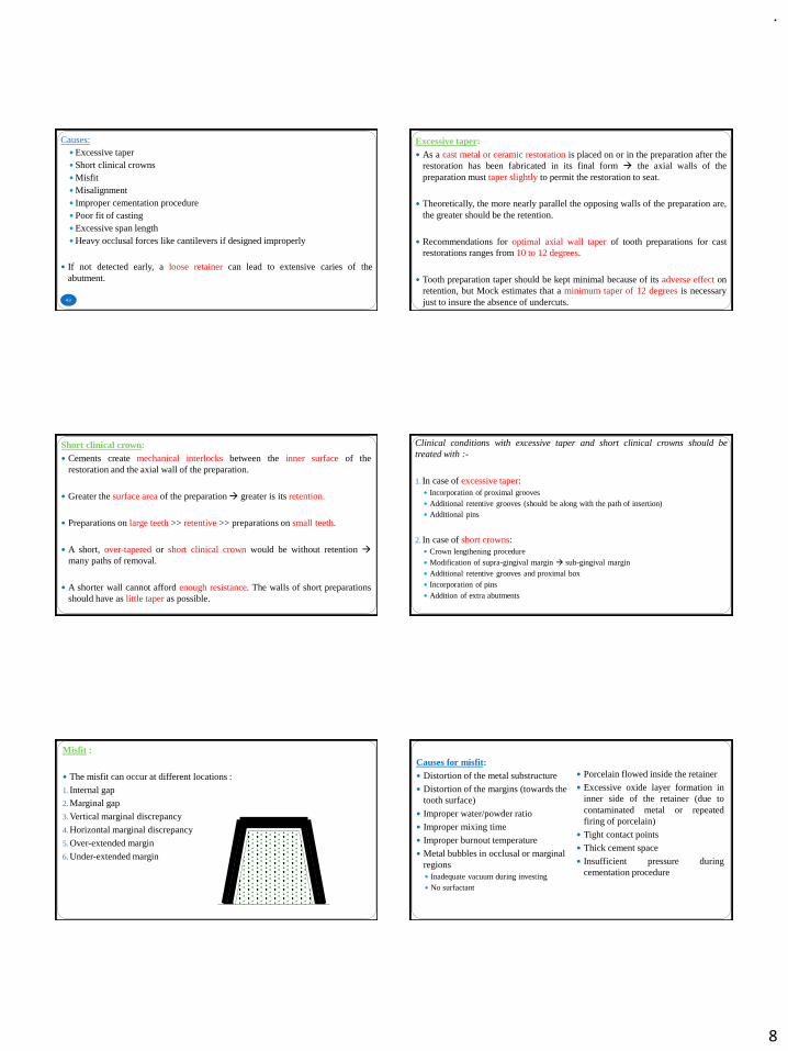
Misfit :
The misfit can occur at different locations :
1. Internal gap2. Marginal gap
3. Vertical marginal discrepancy
4. Horizontal marginal discrepancy
5. Over-extended margin
6. Under-extended margin
Causes for misfit: Distortion of the metal substructure
Distortion of the margins (towards the tooth surface)
Improper water/powder ratio
Improper mixing time
Improper burnout temperature
Metal bubbles in occlusal or marginal regions Inadequate vacuum during investing No surfactant
Porcelain flowed inside the retainer
Excessive oxide layer formation ininner side of the retainer (due tocontaminated metal or repeatedfiring of porcelain)
Tight contact points
Thick cement space
Insufficient pressure duringcementation procedure
.
9
Misalignment: In case of the cemented FPD, it is more difficult to differentiate whether an FPD
is not seating because of a faulty fit, or the alignment of the retainers relative toeach other is incorrect.
The only difference which may sometimes be apparent is that, in the case ofmisalignment, the FPD will have some ‘spring’ in it and tend to seat further onpressure due to the abutment teeth moving slightly, whereas in the case of adefective fit, the resistance felt will be solid.
Causes for misalignment:
Abutment displacement due to improper temporization
Distortion of wax pattern while sprueing and investing
Casting defects Distortion of metal frameworks in porcelain firing
Porcelain flow inside the retainers
Misalignment of soldering points
Insufficient pressure in cementation
Thick cement film
Excessive metal or porcelain in tissue surface (ridge lap) of pontic prevents theproper seating of FPD and open margin (can be detected by observing theblanching of the tissue or patient may complain of pressure on the ponticregion).
51
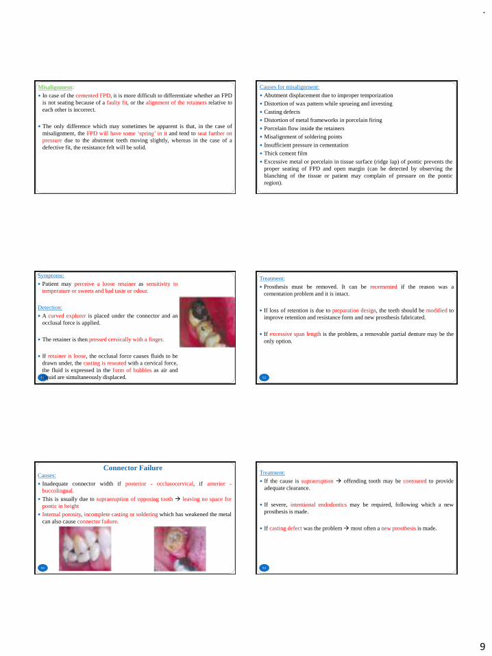
Symptoms:
Patient may perceive a loose retainer as sensitivity totemperature or sweets and bad taste or odour.
Detection:
A curved explorer is placed under the connector and anocclusal force is applied.
The retainer is then pressed cervically with a finger.
If retainer is loose, the occlusal force causes fluids to bedrawn under, the casting is reseated with a cervical force,the fluid is expressed in the form of bubbles as air andliquid are simultaneously displaced. 52
Treatment:
Prosthesis must be removed. It can be recemented if the reason was acementation problem and it is intact.
If loss of retention is due to preparation design, the teeth should be modified toimprove retention and resistance form and new prosthesis fabricated.
If excessive span length is the problem, a removable partial denture may be theonly option.
Connector Failure
53
Causes:
Inadequate connector width if posterior - occlusocervical, if anterior -buccolingual.
This is usually due to supraeruption of opposing tooth → leaving no space forpontic in height
Internal porosity, incomplete casting or soldering which has weakened the metalcan also cause connector failure.
54
Treatment:
If the cause is supraeruption → offending tooth may be contoured to provideadequate clearance.
If severe, intentional endodontics may be required, following which a newprosthesis is made.
If casting defect was the problem→ most often a new prosthesis is made.
.
10
Occlusal Wear
55
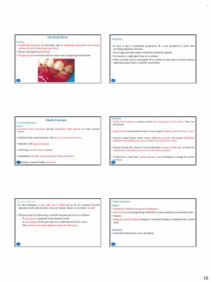
Causes:
Insufficient thickness of restoration due to inadequate preparation of occlusalsurface or lack of functional cusp bevel.
Heavy chewing forces/bruxism
Rough porcelain occlusal surfaces cause wear of opposing natural teeth
56
Treatment:
If wear is due to inadequate preparation → a new prosthesis is made afterproviding adequate clearance
Any rough porcelain surface should be polished or glazed.
For bruxers, a night guard may be a solution.
When occlusal wear is anticipated → it is better to plan metal occlusal surfacesopposing natural teeth or metallic restorations.
Tooth Fracture
57
1. Crown fracture:Causes: Excessive tooth preparation leaving insufficient tooth structure to resist occlusal
forces.
Endodontically treated abutment with excessive tooth structure loss.
Abutment with large restorations.
Interfering centric/eccentric contacts.
Attempting to forcibly seat an improperly fitting prosthesis.
Unseating a cemented bridge incorrectly. 58
Treatment:
Small coronal fractures common around inlays and partial veneer crowns. These canbe restored.
Large fractures around partial veneer crowns require a build-up and full veneer crown.
Fracture around partial veneer crowns with pulp exposure will require endodontictreatment with/without post and core followed by full veneer crown.
Fracture around full crowns if occurs horizontally at level of finish line, is treated byendodontics, followed by post and core and a new prosthesis.
If finish line is intact then ‘retrofit technique’ can be attempted to salvage the retaineror crown.
59
Retrofit technique:
In this technique, a post and core is fabricated to fit an existing fracturedabutment tooth with an intact crown or retainer. Hence, it is termed ‘retrofit’.
The procedure for fabricating a retrofit cast post and core is as follows:A post space is prepared in the abutment tooth.A resin pattern of the post and core is fabricated to fit the crown.The pattern is cast and cemented along with the crown.
60
2. Root Fracture:Causes:
Improperly designed or a poorly fitting post
Root fracture occurring during endodontic or post treatment, but manifests later Trauma
Reduced neural feedback leading to increased loading in endodontically treatedteeth
Treatment: Extraction followed by a new prosthesis
.
11
Porcelain Fracture
61
1. Metal-ceramic fractureCauses:
❖ Improper framework design: Sharp angles or irregular areas over coping surface → stress concentrations →
cracks
Perforations in metal or overly thin metal casting → inadequate support forporcelain
With facings, occlusal contact on or adjacent to metal-to-ceramic junctioncauses porcelain fracture
Any unsupported porcelain can fracture.
62
❖ Occlusion: Heavy occlusal forces like clenching, bruxism.
Centric or eccentric occlusal interferences.
❖ Metal handling procedures: Improper handling of alloy during casting, finishing or porcelain application can
cause contamination which leads to ceramic fracture.
Excessive oxide formation in metal can also cause porcelain fracture.
This is caused by improper conditioning of base metal alloys.
63
❖ During clinical procedures:
Teeth prepared with slight undercut can cause bending of prostheses duringinsertion, which initiates crack propagation.
Distorted impressions can also cause prosthesis failure.
When teeth are prepared with feather-edge finish lines or if finish lines are notrecorded properly in impression, the technician may extend the metal beyondfinish line as finish line is vague.
The thin metal may bind against tooth and initiate crack of overlying porcelain.
64
Cleaning fitting surface of prosthesis using ultrasonic scalers can initiate cracksin the porcelain.
This typically happens when the prosthesis has been fixed provisionally or whena dislodged prosthesis is recemented.
❖ Metal and porcelain incompatibility: This happens rarely. This can be easily prevented if manufacturer’s instructions
are followed when choosing the porcelains for a particular metal.
65 66
.
12
67 68
Treatment:
The best method is to fabricate a new prosthesis.
Repairs can be attempted until a new prosthesis is fabricated.
69
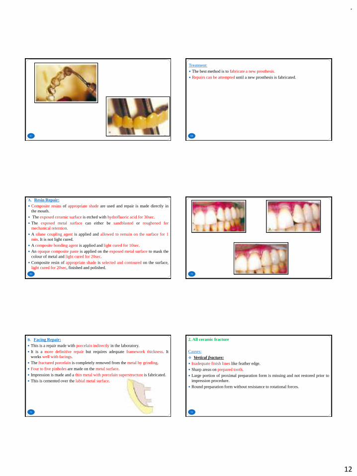
A. Resin Repair: Composite resins of appropriate shade are used and repair is made directly in
the mouth.
The exposed ceramic surface is etched with hydrofluoric acid for 30sec.
The exposed metal surface can either be sandblasted or roughened formechanical retention.
A silane coupling agent is applied and allowed to remain on the surface for 1min. It is not light cured.
A composite bonding agent is applied and light cured for 10sec. An opaque composite paste is applied on the exposed metal surface to mask the
colour of metal and light cured for 20sec.
Composite resin of appropriate shade is selected and contoured on the surface,light cured for 20sec, finished and polished.
70
71
B. Facing Repair: This is a repair made with porcelain indirectly in the laboratory.
It is a more definitive repair but requires adequate framework thickness. Itworks well with facings.
The fractured porcelain is completely removed from the metal by grinding.
Four to five pinholes are made on the metal surface.
Impression is made and a thin metal with porcelain superstructure is fabricated.
This is cemented over the labial metal surface.
72
2. All ceramic fracture
Causes:
❖ Vertical fracture: Inadequate finish lines like feather edge.
Sharp areas on prepared tooth.
Large portion of proximal preparation form is missing and not restored prior toimpression procedure.
Round preparation form without resistance to rotational forces.
.
13
73
❖ Facial-cervical fracture:
If tooth is over-prepared and it is less than two-third or three-fourth of finalrestoration in height, this fracture occurs due to poor resistance.
Opposing tooth contact located incisally to prepared tooth.
❖ Lingual fracture:
Inadequate lingual tooth preparation.
ESTHETIC FAILURE
74
Immediate Aesthetic Failure
75
Aesthetic problems at the time of cementation can be due to: Poor shade match – reasons for this may be: Inadequate selection and communicationMetamerism Insufficient tooth preparationFailure to properly apply and fire porcelain
Poor tooth contour, gingival contour, pontic ridge contour and embrasure
Poor margin placement
Framework design that displays metal
Unrealistic expectations of patient due to poor communication
DELAYED AESTHETIC FAILURE
76
These occur over a period of time following cementation due to: Gingival recession due to:Poor fitOvercontourExcessive trauma during tooth preparation and impression making.
Subpontic tissue shrinkage following extraction – if insufficient time for healingof tissues.
After periodontal surgery – margins will be exposed due to gingival recession ifinsufficient healing time.
Unglazed porcelain can cause unsightly wear of opposing natural teeth. Poorly glazed porcelain restorations also develop black specks over time.
PSYCHOGENIC FAILURE
77 78
When all the parameters for a successful FPD have been met with,rarely a patient may still feel uncomfortable with the restoration.
This has been attributed to the stress and behavioural changes in theindividual.
The patient may require counselling to get over this problem.
A failure to recognize this problem during the diagnostic phase itself,can lead to a failure of the prosthesis.
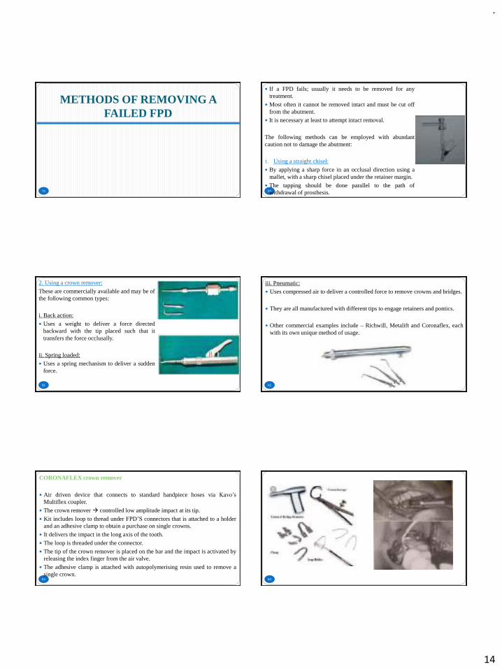
.
14
METHODS OF REMOVING A FAILED FPD
79 80
If a FPD fails; usually it needs to be removed for anytreatment.
Most often it cannot be removed intact and must be cut offfrom the abutment.
It is necessary at least to attempt intact removal.
The following methods can be employed with abundantcaution not to damage the abutment:
1. Using a straight chisel:
By applying a sharp force in an occlusal direction using amallet, with a sharp chisel placed under the retainer margin.
The tapping should be done parallel to the path ofwithdrawal of prosthesis.
81
2. Using a crown remover:
These are commercially available and may be ofthe following common types:
i. Back action:
Uses a weight to deliver a force directedbackward with the tip placed such that ittransfers the force occlusally.
ii. Spring loaded:
Uses a spring mechanism to deliver a suddenforce.
82
iii. Pneumatic:
Uses compressed air to deliver a controlled force to remove crowns and bridges.
They are all manufactured with different tips to engage retainers and pontics.
Other commercial examples include – Richwill, Metalift and Coronaflex, eachwith its own unique method of usage.
83
CORONAFLEX crown remover
Air driven device that connects to standard handpiece hoses via Kavo’s
Multiflex coupler.
The crown remover → controlled low amplitude impact at its tip.
Kit includes loop to thread under FPD’S connectors that is attached to a holderand an adhesive clamp to obtain a purchase on single crowns.
It delivers the impact in the long axis of the tooth.
The loop is threaded under the connector.
The tip of the crown remover is placed on the bar and the impact is activated byreleasing the index finger from the air valve.
The adhesive clamp is attached with autopolymerising resin used to remove asingle crown.
84
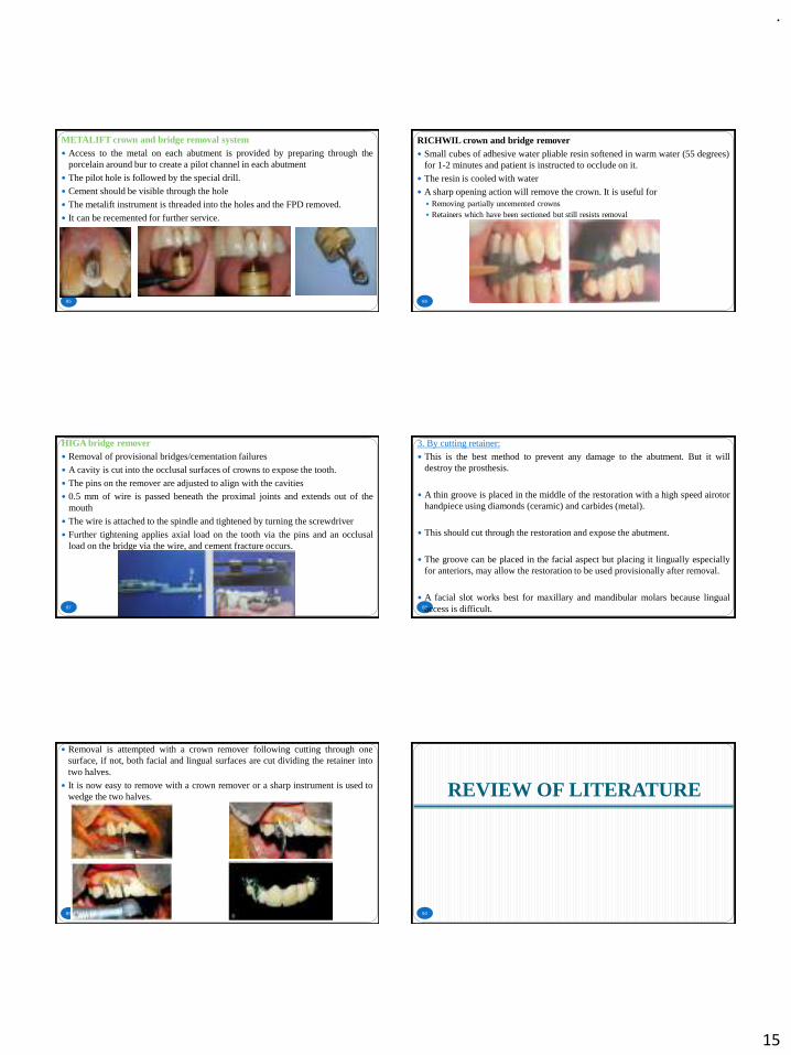
.
15
85
METALIFT crown and bridge removal system Access to the metal on each abutment is provided by preparing through the
porcelain around bur to create a pilot channel in each abutment
The pilot hole is followed by the special drill.
Cement should be visible through the hole
The metalift instrument is threaded into the holes and the FPD removed.
It can be recemented for further service.
86
RICHWIL crown and bridge remover Small cubes of adhesive water pliable resin softened in warm water (55 degrees)
for 1-2 minutes and patient is instructed to occlude on it.
The resin is cooled with water
A sharp opening action will remove the crown. It is useful for Removing partially uncemented crowns Retainers which have been sectioned but still resists removal
87
HIGA bridge remover Removal of provisional bridges/cementation failures
A cavity is cut into the occlusal surfaces of crowns to expose the tooth.
The pins on the remover are adjusted to align with the cavities 0.5 mm of wire is passed beneath the proximal joints and extends out of the
mouth
The wire is attached to the spindle and tightened by turning the screwdriver
Further tightening applies axial load on the tooth via the pins and an occlusalload on the bridge via the wire, and cement fracture occurs.
88
3. By cutting retainer:
This is the best method to prevent any damage to the abutment. But it willdestroy the prosthesis.
A thin groove is placed in the middle of the restoration with a high speed airotorhandpiece using diamonds (ceramic) and carbides (metal).
This should cut through the restoration and expose the abutment.
The groove can be placed in the facial aspect but placing it lingually especiallyfor anteriors, may allow the restoration to be used provisionally after removal.
A facial slot works best for maxillary and mandibular molars because lingualaccess is difficult.
89
Removal is attempted with a crown remover following cutting through onesurface, if not, both facial and lingual surfaces are cut dividing the retainer intotwo halves.
It is now easy to remove with a crown remover or a sharp instrument is used towedge the two halves. REVIEW OF LITERATURE
90
.
16
91
Koenig V, Vanheusden A, LeGoff S and Mainjot A conducted a clinical riskfactors related to failures with zirconia-based restorations: an up to 9-yearretrospective study.
147 ZBR were evaluated after a mean observation period of 60 months.
Accessorily, zirconia implant abutments (n = 46) were also observed.
The technical and the biological outcomes of the ZBR were evaluated.
Occlusal risk factors were examined: occlusal relationships, parafunctionalhabits and the presence of occlusal nightguard.
Journal of Dentistry 41 (2018) 1164 – 1174 92
The results showed the survival rate of crowns and FPDs was 93.2%, thesuccess rate was 81.63%.
The chipping rate was 15% and the framework fracture rate was 2.7%.
Most fractographic analyses revealed that veneer fractures originated fromocclusal surface roughness.
Several parameters were shown to significantly influence veneer fracture: theabsence of occlusal nightguard, the presence of a ceramic restoration as anantagonist, the presence of parafunctional activity and the presence of implantsas support.
The results of the study confirm that chipping is the first cause of ZBRfailure.
93
E. G. Kontakiotis, C. G. Filippatos, S. Stefopoulos & G. N. Tzanetakis conducteda prospective study of the incidence of asymptomatic pulp necrosis followingcrown preparation.
A total of 120 teeth with healthy pulps scheduled to receive fixed crowns.
Teeth divided into two groups:- Intact teeth and Teeth with preoperative caries,restorations or crowns and into further four groups:- maxillary anterior andposterior teeth, mandibular anterior and posterior teeth
Experimental and control teeth → electric pulp testing on three differentoccasions before treatment commencement (stage 0), at the impression makingsession (stage 1) and just before the final cementation of the crown (stage 2).
International Endodontic Journal 2017 94
Teeth that were considered to contain necrotic pulps were submitted to rootcanal treatment.
Upon access, absence of bleeding was considered as a confirmation of pulpnecrosis.
The overall incidence of pulp necrosis was 9%.
Intact teeth had a significantly lower incidence of pulp necrosis (5%) comparedwith preoperatively structurally compromised teeth (13%).
No significant differences were found amongst the four groups with regard totooth type.
They concluded that the incidence of asymptomatic pulp necrosis of teethfollowing crown preparation is noteworthy.
95
Al-Sinaidi A and Preethanath R conducted a study on the effect of fixed partialdentures on periodontal status of abutment teeth.
This study was aimed to assess the periodontal status of Saudi adult femaleswho had received regular oral prophylaxis following the insertion of fixed
partial dentures.
The effects of sub- and supra-gingivally placed crown margins were alsoassessed.
Sample size - 78 females who had fixed partial dentures
From each study participant, two paired eligible sites, one for the abutment andone for the matched non-abutment teeth, were selected.
The plaque index, gingival index, probing pocket depth, tooth mobility andlocations of the crown margins were assessed and recorded by one calibratedexaminer. The Saudi Journal for Dental Research 2018. 96
The abutment teeth scored significantly higher plaque and gingival indices andgreater probing pocket depth than non-abutment teeth.
In addition, the abutment teeth scored greatest mean values of the clinicalparameters in subjects who were 46 year-old or older and those who had theirfunctioning fixed partial dentures for more than 5 years.
The teeth with supra-gingivally placed crown margins had significantly highermean values of plaque index, gingival index and probing pocket depth thanteeth with sub-gingival crown margins.
The results of this study indicated that in subjects with fixed partial dentures,the abutment teeth are more prone to periodontal inflammation than the non-abutment teeth.
Additionally, the individual’s age, duration of insertion of fixed partial denturesand location of the crown margins affect the periodontal health of theabutments.
.
17
CONCLUSION
97 98
Fixed prosthodontic treatment does not end with the fitting of restorations.
Subsequent maintenance is an integral part of treatment. If this is not adequatelyprescribed, failure can occur.
The first consideration when confronted with any failure is to ascertain thecause.
If there is a cause that is correctable, it should be taken care of first.
Care should be taken not to become involved in repairs that should have beenremakes. Repairs are usually the second best to the original in one or moreways.
Most failures are unique and present varying challenges to the dentist. Thereforetreatment plan for each situation must be individualized.
REFERENCES
99 100
Planning and making crowns and bridges. Smith B, Howe L. 4th edition. Abingdon, Informahealthcare.
Contemporary fixed prosthodontics. Rosenstiel S, Land M, Fujimoto J. 4th edition. St Louis,Mosby Elsevier.
Shillingburg HT, Hobo S, Whitsett LD, Jacobi R, Brackett SE. Fundamentals of fixedprosthodontics. Quintessence Publishing Company.
Koenig V, Vanheusden A, LeGoff S and Mainjot A. A clinical risk factors related tofailures with zirconia-based restorations: an up to 9-year retrospective study. Journal ofDentistry 2018;41:1164 – 1174.
E. G. Kontakiotis, C. G. Filippatos, S. Stefopoulos & G. N. Tzanetakis. A prospective studyof the incidence of asymptomatic pulp necrosis following crown preparation. InternationalEndodontic Journal 2017.
Seong LG, May LW. Key Indicators of success or survival for clinical performance of fixedpartial denture. Annals of Dentistry University of Malaya. 2019 Dec 3;26:53-8.
Kapoor C, Vaidya S. Evaluation of Complications Associated with Fixed Partial Denture-Anobservational study. Journal of Advanced Medical and Dental Sciences Research. 2019 Aug1;7(8):149-52.
101
Al-Sinaidi A and Preethanath R. A study on the effect of fixed partial dentures on periodontalstatus of abutment teeth. The Saudi Journal for Dental Research 2018.
Triwatana P, Nagaviroj N, Tulapornchai C. Clinical performance and failures of zirconia-based fixed partial dentures: a review literature. The journal of advanced prosthodontics.2012 May 1;4(2):76-83.
Muddugangadhar BC, Amarnath GS, Sonika R, Chheda PS, Garg A. Meta-analysis of failureand survival rate of implant-supported single crowns, fixed partial denture, and implanttooth-supported prostheses. Journal of international oral health: JIOH. 2015 Sep;7(9):11.
Swain PK. Failure Rate in Fixed Partial Denture Patients-A Clinical Study. Journal ofAdvanced Medical and Dental Sciences Research. 2018 Oct;6(10).
Jain JK, Sethuraman R, Chauhan S, Javiya P, Srivastava S, Patel R, Bhalani B. Retentionfailures in cement-and screw-retained fixed restorations on dental implants in partiallyedentulous arches: A systematic review with meta-analysis. The Journal of the IndianProsthodontic Society. 2018 Jul;18(3):201.
Alraheam IA, Ngoc CN, Wiesen CA, Donovan TE. Five‐year success rate of resin‐bondedfixed partial dentures: A systematic review. Journal of Esthetic and Restorative Dentistry.2019 Jan;31(1):40-50.
102
.
1
GERIATRICNUTRITION
PRESENTED BY: DR. Vishnu Soni
CONTENTS
• INTRODUCTION
• DEFINITIONS
• ROLE OF A DENTIST
• COMMUNICATION WITH A GERIATRIC PATIENT
• NUTRITIONAL OBJECTIVES
• CLINICAL SIGNS OF NUTRITIONAL PROBLEMS
• DIETARY COUNSELING FOR GERIATIC PATIENTS
• CONCLUSION
• REFERENCES
INTRODUCTION
Geriatric Nutrition
4
Ageing being a natural process requires special considerations.
Thus proper nutrition is essential for health and comfort of oral tissues which , in turn enhances the possibility of
successful Prosthodontic treatment in the elderly.
o Geriatric dentistry deals with delivery of dental care to the elderly citizen. It is concerned with diagnosis, prevention and treatment of dental problems associated with normal aging.
o Dentistry for elderly must be practiced with increased awareness ofthe biologic factors ,since the adaptive mechanism and tissueregeneration potentials in the elderly patients are usually significantlylowered.
o The elderly require a different approach, modified treatment planning, and knowledge of how the tissue changes associated with senescence affects oral health service.
DEFINITIONS
Geriatric Nutrition
6
▪ In science and human medicine, Nutrition is the science or practice of consuming and utilizing foods.
▪ Geriatric nutrition applies the nutrition principles to delay effects of aging and disease, to aid in the management of the physical, psychological, psychosocial changes commonly associated with growing old!
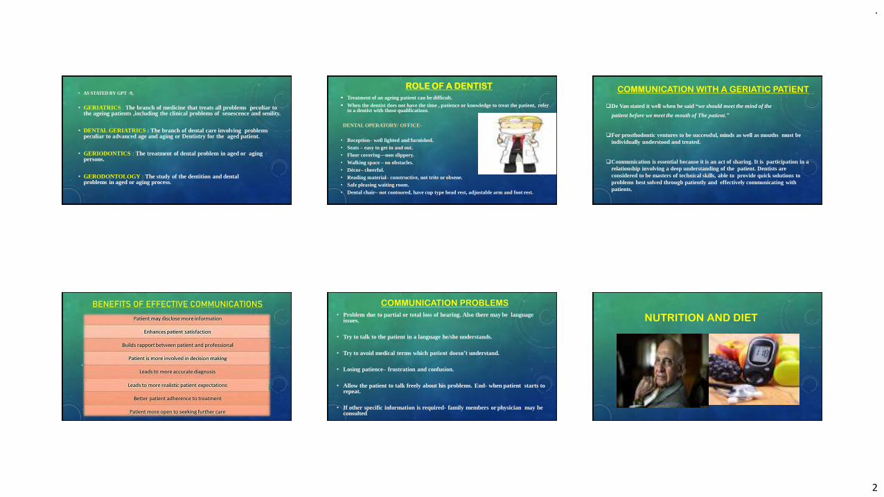
.
2
• AS STATED BY GPT -9,
• GERIATRICS : The branch of medicine that treats all problems peculiar tothe ageing patients ,including the clinical problems of senescence and senility.
• DENTAL GERIATRICS : The branch of dental care involving problems peculiar to advanced age and aging or Dentistry for the aged patient.
• GERIODONTICS : The treatment of dental problem in aged or aging persons.
• GERODONTOLOGY : The study of the dentition and dental problems in aged or aging process.
ROLE OF A DENTIST
▪ Treatment of an ageing patient can be difficult.▪ When the dentist does not have the time , patience or knowledge to treat the patient, refer
to a dentist with those qualifications.
DENTAL OPERATORY/ OFFICE-
• Reception– well lighted and furnished.• Seats – easy to get in and out.• Floor covering—non slippery.• Walking space – no obstacles.• Décor– cheerful.• Reading material– constructive, not trite or obsene.• Safe pleasing waiting room.• Dental chair– not contoured, have cup type head rest, adjustable arm and foot rest.
❑De Van stated it well when he said “we should meet the mind of the
patient before we meet the mouth of The patient.”
❑For prosthodontic ventures to be successful, minds as well as mouths must be individually understood and treated.
❑Communication is essential because it is an act of sharing. It is participation in arelationship involving a deep understanding of the patient. Dentists are considered to be masters of technical skills, able to provide quick solutions to problems best solved through patiently and effectively communicating withpatients.
COMMUNICATION WITH A GERIATIC PATIENT
BENEFITS OF EFFECTIVE COMMUNICATIONS
• .
COMMUNICATION PROBLEMS
• Problem due to partial or total loss of hearing. Also there may be languageissues.
• Try to talk to the patient in a language he/she understands.
• Try to avoid medical terms which patient doesn’t understand.
• Losing patience– frustration and confusion.
• Allow the patient to talk freely about his problems. End- when patient starts torepeat.
• If other specific information is required- family members or physician may beconsulted.
NUTRITION AND DIET
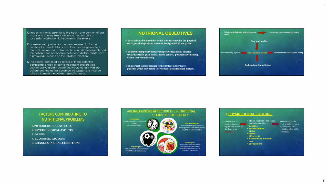
.
3
NUTRIONAL OBJECTIVES
❖To establish a balanced diet which is consistent with the physical, social, psychological and economic background of the patient.
❖To provide temporary dietary supportive treatment, directed towards specific goals such as caries control, postoperative healing, or soft tissue conditioning.
❖To interpret factors peculiar to the denture age group of patients, which may relate to or complicate nutritional therapy.
• Relationship between oral and generalhealth
Particularly pronounced among elderly
Poor general health
Poor oral health
Compromised chewing and eatingLow immunity system
Reduced nutritional intake
FACTORS CONTRIBUTING TO NUTRITIONAL PROBLEMS
1. PHYSIOLOGICAL ASPECTS
2. PSYCHOLOGICAL ASPECTS
3. DRUGS
4. ECONOMIC FACTORS
5. CHANGES IN ORAL CONDITIONS
AGEING FACTORS AFFECTING THE NUTRITIONALSTATUS OF THE ELDERLY
Geriatric Nutrition
Functional:Impairments affect nutritional
statuse.g. stroke arthritis
Psychological:Life situational factors increase
nutritional risk in elderly
Pharmacological:Over counter drugs and several
prescriptions = nutrient deficiency, weight loss & malnutrition.
Physiological:Body mass decline= calorie needs
Dehydration= kidney function Overt deficiency= neurological/
behavioral impairment
17
1.PHYSIOLOGICAL FACTORS:
• Gradual loss of function in most organs and tissues of the body withAGEING
• These changes are slowand influenced by -
• genetics• socioeconomic
status• Illness• Life events• Accessibility of health
care• environment
These changes take place at different rates, not only between individuals, but within individuals.
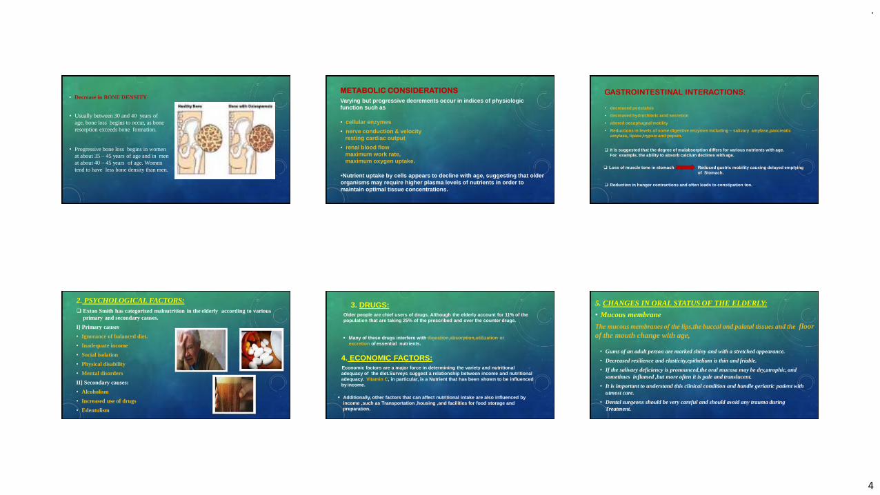
.
4
• Decrease in BONE DENSITY:
• Usually between 30 and 40 years of age, bone loss begins to occur, as bone resorption exceeds bone formation.
• Progressive bone loss begins in women at about 35 – 45 years of age and in men at about 40 – 45 years of age. Women tend to have less bone density than men.
METABOLIC CONSIDERATIONS
Varying but progressive decrements occur in indices of physiologic function such as
• cellular enzymes
• nerve conduction & velocity resting cardiac output
• renal blood flow maximum work rate, maximum oxygen uptake.
•Nutrient uptake by cells appears to decline with age, suggesting that older organisms may require higher plasma levels of nutrients in order to maintain optimal tissue concentrations.
GASTROINTESTINAL INTERACTIONS:
• decreased peristalsis
• decreased hydrochloric acid secretion
• altered oesophageal motility
• Reductions in levels of some digestive enzymes including – salivary amylase,pancreaticamylase, lipase,trypsin and pepsin.
❑ It is suggested that the degree of malabsorption differs for various nutrients with age.For example, the ability to absorb calcium declines with age.
❑ Loss of muscle tone in stomach Reduced gastric mobility causing delayed emptyingof Stomach.
❑ Reduction in hunger contractions and often leads to constipation too.
2. PSYCHOLOGICAL FACTORS:❑ Exton Smith has categorized malnutrition in the elderly according to various
primary and secondary causes.
I] Primary causes
• Ignorance of balanced diet.
• Inadequate income
• Social isolation
• Physical disability
• Mental disorders
II] Secondary causes:
• Alcoholism
• Increased use of drugs
• Edentulism
3. DRUGS:Older people are chief users of drugs. Although the elderly account for 11% of thepopulation that are taking 25% of the prescribed and over the counter drugs.
▪ Many of these drugs interfere with digestion,absorption,utilization or excretion of essential nutrients.
4. ECONOMIC FACTORS:Economic factors are a major force in determining the variety and nutritional adequacy of the diet.Surveys suggest a relationship between income and nutritional adequacy. Vitamin C, in particular, is a Nutrient that has been shown to be influenced by income.
▪ Additionally, other factors that can affect nutritional intake are also influenced byincome ,such as Transportation ,housing ,and facilities for food storage andpreparation.
5. CHANGES IN ORAL STATUS OF THE ELDERLY:
• Mucous membrane
The mucous membranes of the lips,the buccal and palatal tissues and the floor of the mouth change with age,
• Gums of an adult person are marked shiny and with a stretched appearance.
• Decreased resilience and elasticity,epithelium is thin and friable.
• If the salivary deficiency is pronounced,the oral mucosa may be dry,atrophic, and sometimes inflamed ,but more often it is pale and translucent.
• It is important to understand this clinical condition and handle geriatric patient with utmost care.
• Dental surgeons should be very careful and should avoid any trauma during Treatment.
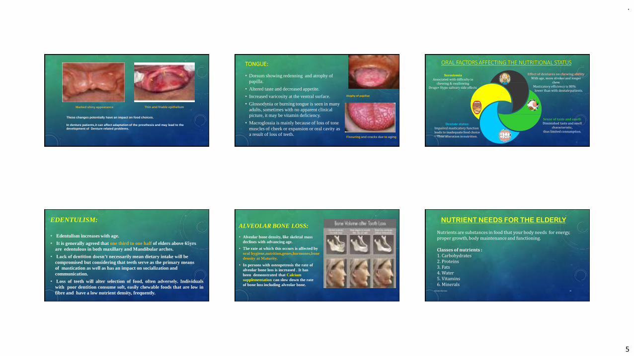
.
5
Marked shiny appearance Thin and friable epithelium
These changes potentially have an impact on food choices.
In denture patients,it can affect adaptation of the prosthesis and may lead to the development of Denture related problems.
TONGUE:
• Dorsum showing redenning and atrophy of papilla.
• Altered taste and decreased appetite.
• Increased varicosity at the ventral surface.
• Glossodynia or burning tongue is seen in many adults, sometimes with no apparent clinical picture, it may be vitamin deficiency.
• Macroglossia is mainly because of loss of tone muscles of cheek or expansion or oral cavity as a result of loss of teeth.
Fissuring and cracks due to aging
Atophy of papillae
ORAL FACTORS AFFECTING THE NUTRITIONAL STATUS
Geriatric Nutrition
XerostomiaAssociated with difficulty in
chewing & swallowing Drugs= Hypo salivary side effects
Sense of taste and smell: Diminished taste and smell
characteristic,thus limited consumption.
Dentate status: Impaired masticatory function leads to inadequate food choice
Thus alteration in nutrition.
Effect of dentures on chewing ability With age, more strokes and longer
chew.Masticatory efficiency is 80%
lower than with dentate patients.
6
EDENTULISM:
• Edentulism increases with age.
• It is generally agreed that one third to one half of elders above 65yrs are edentulous in both maxillary and Mandibular arches.
• Lack of dentition doesn’t necessarily mean dietary intake will be compromised but considering that teeth serve as the primary means of mastication as well as has an impact on socialization and communication.
• Loss of teeth will alter selection of food, often adversely. Individualswith poor dentition consume soft, easily chewable foods that are low infibre and have a low nutrient density, frequently.
ALVEOLAR BONE LOSS:
• Alveolar bone density, like skeletal mass declines with advancing age.
• The rate at which this occurs is affected by oral hygiene,nutrition,genes,hormones,bonedensity at Maturity.
• In persons with osteopetrosis the rate of alveolar bone loss is increased . It has been demonstrated that Calcium supplementation can slow down the rate of bone loss including alveolar bone.
NUTRIENT NEEDS FOR THE ELDERLY
Geriatric Nutrition 30
Nutrients are substances in food that your body needs for energy, proper growth, body maintenance and functioning.
Classes of nutrients :1. Carbohydrates2. Proteins3. Fats4. Water5. Vitamins6. Minerals
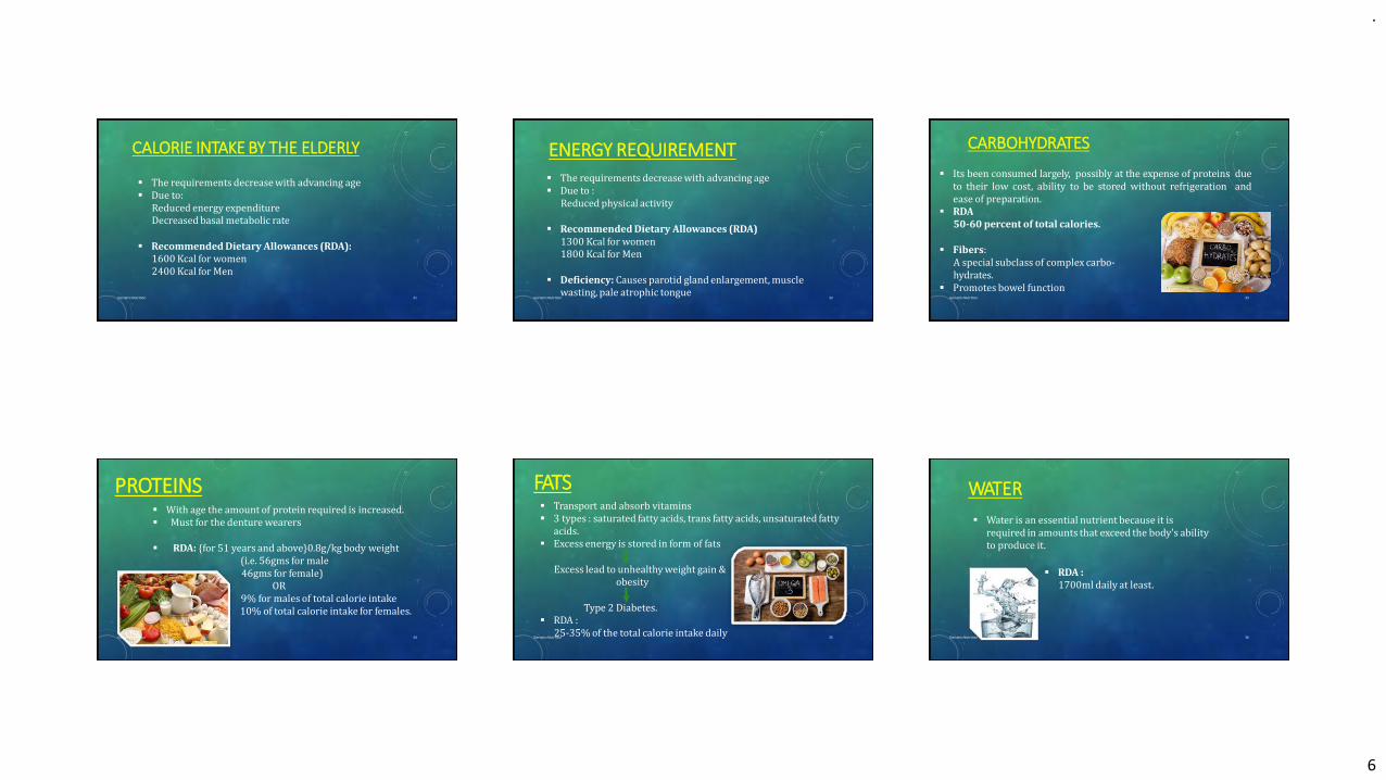
.
6
▪ The requirements decrease with advancing age▪ Due to:
Reduced energy expenditure Decreased basal metabolic rate
▪ Recommended Dietary Allowances (RDA):1600 Kcal for women 2400 Kcal for Men
CALORIE INTAKE BY THE ELDERLY
Geriatric Nutrition 31
▪ The requirements decrease with advancing age▪ Due to :
Reduced physical activity
▪ Recommended Dietary Allowances (RDA)1300 Kcal for women 1800 Kcal for Men
▪ Deficiency: Causes parotid gland enlargement, muscle wasting, pale atrophic tongue
ENERGY REQUIREMENT
Geriatric Nutrition 32
▪ Its been consumed largely, possibly at the expense of proteins dueto their low cost, ability to be stored without refrigeration andease of preparation.
▪ RDA50-60 percent of total calories.
▪ Fibers:A special subclass of complex carbo-hydrates.
▪ Promotes bowel function
CARBOHYDRATES
Geriatric Nutrition 33
▪ With age the amount of protein required is increased.▪ Must for the denture wearers
▪ RDA: {for 51 years and above}0.8g/kg body weight(i.e. 56gms for male 46gms for female)
OR9% for males of total calorie intake 10% of total calorie intake for females.
PROTEINS
Geriatric Nutrition 34
▪ Transport and absorb vitamins▪ 3 types : saturated fatty acids, trans fatty acids, unsaturated fatty
acids.▪ Excess energy is stored in form of fats
Excess lead to unhealthy weight gain &obesity
Type 2 Diabetes.▪ RDA :
25-35% of the total calorie intake daily
FATS
Geriatric Nutrition 35
WATER
Geriatric Nutrition 36
▪ Water is an essential nutrient because it is required in amounts that exceed the body's ability to produce it.
▪ RDA :1700ml daily at least.

.
7
▪ Helps control the body process & also release energy to do work.
▪ They don’t contain calories▪ Neither provide body with energy
▪ 2 types:Fat soluble (A,D,E,K)Water soluble (C and B complex)
VITAMINS
Geriatric Nutrition 37
➢FAT SOLUBLE: carried by fat present in food and stored in the body
VITAMIN A:▪ RDA:
900µg for males and 700µg for females
▪ Deficiency: Decreased salivary flow, desquamation of oral mucosa, Keratosis, decreased taste acuity, metaplasia of salivary gland epithelium.
VITAMIN D:▪ The sunshine vitamin crucially important to the body▪ RDA:
10µg in males and females.▪ Deficiency: Osteomalacia, Osteoporosis, Poor immune Function.Geriatric Nutrition 38
VITAMIN E:▪ The total plasma vitamin E levels increase with age.
▪ RDA:15mg for males and females.
▪ Deficiency: Doesn’t seem to be much of a problem orally per se.
VITAMIN K:▪ The coagulation vitamin is very crucial in relation to
blood clotting process.▪ RDA:
1µg in males and females.
▪ Deficiency: Coagulopathy, Petechiae, Ecchymosis, Low Bone Density, Increased risk of gingival bleeding.
Geriatric Nutrition 39
➢WATER SOLUBLE: carried to the body tissues
B-COMPLEX
• B1 (THIAMINE):Helps cell convert carbohydrates into energy
RDA:2 mg for males and
1.1mg for femalesDeficiency: Beriberi
• B6 (Pyridoxine):It helps metabolize carbs, proteins & fat & also help to keep the
immune system healthy.RDA:
1.7mg in males and 1.5mg in females.
Deficiency: Nasolabial Seborrhea, Glossitis.
Geriatric Nutrition 40
B9 (FOLIC ACID)Its acts as a co-enzyme with vitamin b12 and vitamin C to
produce cells in the body.
RDA:400µg for males and females
Deficiency: Mouth Ulcers, Glossodynia, Glossitis, Stomatitis.
• B12 (RIBOFLAVIN)It is the largest and most structurally complicated vitamin
involved in the metabolism of every cell of the human body.
RDA:2.4µg in males and females.
Deficiency: Fiery or Beefy red tongue, Candidiasis,
Aphthous Stomatitis, Intra-oral Burning.
Geriatric Nutrition 41
VITAMIN C (Ascorbic acid):
It is an essential nutrient involved in the repair of tissue and the enzymatic production of
certain neurotransmitters. It also functions as an antioxidant.
• RDA:90mg for males and 75mg for females
Deficiency: Scurvy, Petechiae, delayed wound healing
Geriatric Nutrition42
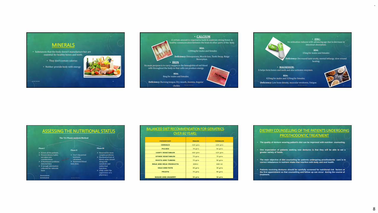
.
8
MINERALS
Geriatric Nutrition 43
• Substances that the body doesn’t manufacture but areessential for healthy bones and teeth.
• They don’t contain calories
• Neither provide body with energy
• CALCIUMA certain amount is required to build & maintain strong bones &
healthy communication between the brain & other parts of the body.
RDA:1200mg for males and females
Deficiency: Osteoporosis, Muscle loss, Tooth Decay, RidgeResorption.
• IRONIts main purpose is to carry oxygen in the hemoglobin of red blood
cells throughout the body so that cells can produce energy.
RDA:8mg for males and females.
Deficiency: Burning tongue, Dry mouth, Anemia, Angular
chelitis Geriatric Nutrition 22
• ZINC:Its utilization reduces with advancing age due to decrease in
intestinal absorption.
RDA:15mg for males and females
Deficiency: Decreased taste acuity, mental lethargy, slow wound healing.
• MAGNESIUM:It helps form bones and teeth and also activates enzymes.
RDA:420mg for males and 320mg for females.
Deficiency: Low bone density, muscular weakness, Fatigue.Geriatric Nutrition 23
ASSESSING THE NUTRITIONAL STATUSThe Tri-Phasic analysis Method
Phase I
➢ Screen all the patients.➢ Present dietary habits
are taken into considerations.
➢ If Nutritional problemsdetected then
➢ If enough informationcollected for rationalebasis
Phase IIPhase III
➢ Reserved for more complex problems.
➢ Biochemical test of blood, urine, tissues along with metabolic and endocrinal functions.
➢ (Only under thesupervision of aphysician.)Assessment
terminated.
➢ 3 to 5 day period nutrients calculated.
➢ Automated bloodtests done.
Geriatric Nutrition 25
BALANCED DIET RECOMMENDATION FOR GERIATRICS OVER 60 YEARS:
DIETARY COUNSELLING OF THE PATIENTS UNDERGOING PROSTHODONTIC TREATMENT
• The quality of denture wearing patient’s diet can be improved with nutrition counseling.
• One expectation of patients seeking new dentures is that they will be able to eat agreater variety of foods.
• The main objective of diet counseling for patients undergoing prosthodontic care is tocorrect imbalances in nutrient intake that interfere with body and oral health.
• Patients receiving dentures should be carefully screened for nutritional risk factors atthe first appointment so that counselling and follow up can occur during the course oftreatment.
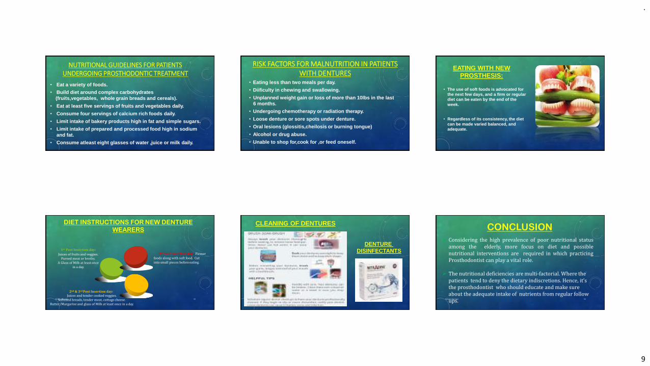
.
9
NUTRITIONAL GUIDELINES FOR PATIENTS UNDERGOING PROSTHODONTIC TREATMENT
• Eat a variety of foods.
• Build diet around complex carbohydrates (fruits,vegetables, whole grain breads and cereals).
• Eat at least five servings of fruits and vegetables daily.
• Consume four servings of calcium rich foods daily.
• Limit intake of bakery products high in fat and simple sugars.
• Limit intake of prepared and processed food high in sodium and fat.
• Consume atleast eight glasses of water ,juice or milk daily.
RISK FACTORS FOR MALNUTRITION IN PATIENTS WITH DENTURES
• Eating less than two meals per day.
• Diificulty in chewing and swallowing.
• Unplanned weight gain or loss of more than 10lbs in the last 6 months.
• Undergoing chemotherapy or radiation therapy.
• Loose denture or sore spots under denture.
• Oral lesions (glossitis,cheilosis or burning tongue)
• Alcohol or drug abuse.
• Unable to shop for,cook for ,or feed oneself.
EATING WITH NEW PROSTHESIS:
• The use of soft foods is advocated for the next few days, and a firm or regular diet can be eaten by the end of theweek.
• Regardless of its consistency, the diet can be made varied balanced, and adequate.
DIET INSTRUCTIONS FOR NEW DENTURE
WEARERS
Geriatric Nutrition 52
4th Post Insertion day: Firmer foods along with soft food. Cut into small pieces before eating.
2nd & 3rd Post Insertion day:Juices and tender cooked veggies.
Softened breads, tender meat, cottage cheese.Butter/Margarine and glass of Milk at least once in a day.
1st Post Insertion day:
Juices of fruits and veggies.Pureed meat or broths.
A Glass of Milk at least once in a day.
CLEANING OF DENTURES
DENTUREDISINFECTANTS
CONCLUSION
Geriatric Nutrition 54
➢ Considering the high prevalence of poor nutritional statusamong the elderly, more focus on diet and possiblenutritional interventions are required in which practicingProsthodontist can play a vital role.
➢ The nutritional deficiencies are multi-factorial. Where the patients tend to deny the dietary indiscretions. Hence, it’s the prosthodontist who should educate and make sure about the adequate intake of nutrients from regular followups.
.
10
REFERENCES
1. Zarb –Bolender : Prosthodontic treatment for patients, 12th edition
2. Glossary of Prosthodontic terms – 9. J. Prosthet Dent. May. 2017:e1-e105
3. Heartwell C.M. Jr. Syllabus of complete dentures.Fourth edition – 1986
4. Essentials of complete denture prosthodontics.3rd edition,Sheldon Winkler–2015
5. Patient-Dentist Communication:An Adjunct to Successful Complete Denture Treatment
• Journal of Prosthodontics 19 (2010) 491–493 c 2010 by The American College of Prosthodontists
6. Nutrition for geriatric denture patients : Bandodkar,MeenaAras
• The Journal of Indian Prosthodontic Society | March 2006|vol 6|Issue 1
THANK YOU
Geriatric Nutrition 56
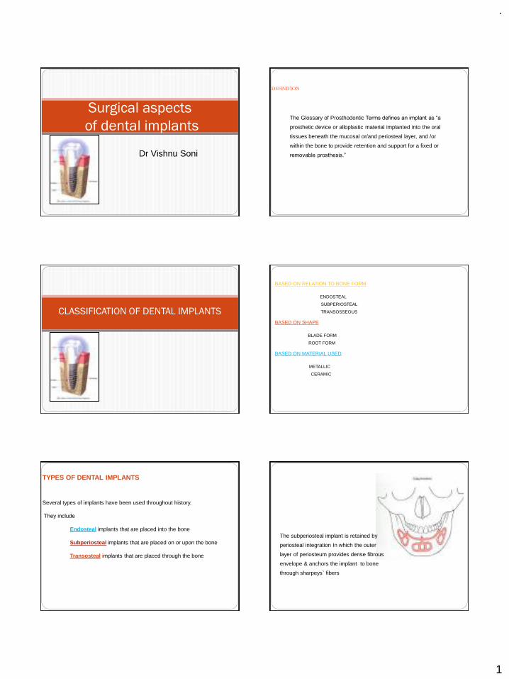
.
1
Surgical aspects
of dental implants
Dr Vishnu Soni
DEFINITION
The Glossary of Prosthodontic Terms defines an implant as “a
prosthetic device or alloplastic material implanted into the oral
tissues beneath the mucosal or/and periosteal layer, and /or
within the bone to provide retention and support for a fixed or
removable prosthesis.”
CLASSIFICATION OF DENTAL IMPLANTS
BASED ON RELATION TO BONE FORM
ENDOSTEAL
SUBPERIOSTEAL
TRANSOSSEOUS
BASED ON SHAPE
BLADE FORM
ROOT FORM
BASED ON MATERIAL USED
METALLIC
CERAMIC
TYPES OF DENTAL IMPLANTS
Several types of implants have been used throughout history.
They include
Endosteal implants that are placed into the bone
Subperiosteal implants that are placed on or upon the bone
Transosteal implants that are placed through the bone
The subperiosteal implant is retained by
periosteal integration In which the outer
layer of periosteum provides dense fibrous
envelope & anchors the implant to bone
through sharpeys` fibers
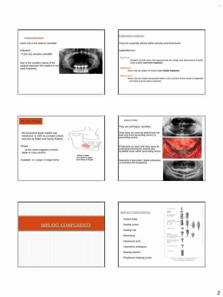
.
2
Used only in the anterior mandible
Indication :
In the very atrophic mandible
Due to the complex nature of the surgical approach this implant is not used frequently.
Transosteal implantsEndosteal implants:
They are surgically placed within alveolar and basal bone
subdivided into
Root formimplants include those that approximate the shape and dimensions of tooth roots (called root form implants)
Blade formthose that are plates of metal (called blade implants)
Ramus formthose that are metal frameworks where only a portion of the metal is implanted
into bone (ramus frame implants).
The Endosteal Blade implant was introduced in 1967 by Leonard Linkowand also by Ralph and Harold Roberts
Shape:
as the name suggests a metal / blade in cross-section
Available in 1 stage / 2 stage forms
BLADE FORM
2.5mm in width8 to 15mm in depth
15 to 30mm in length
They are technique- sensitive
They have an external attachment bar that runs from ascending ramus to ascending ramus
Posteriorly on each side they have an endosteal extensions, inserts into available bone within ascending ramus
Anteriorly it has plate / blade extension ,is inserted into symphysis
RAMUS FORM
IMPLANT COMPONENTS
IMPLANT COMPONENTS
Implant body
Sealing screw
Healing cap
Abutement
Impression post
Laboratory analogues
Waxing sleeves
Prosthesis retaining screw
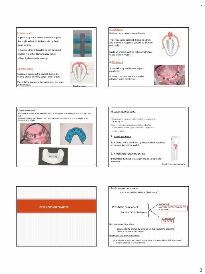
.
3
1.Implant body:
Implant body is the endosteal dental implant
that is placed within the bone during first
stage surgery.
It may be either a threaded or non threaded
cylinder It is either titanium alloy with or
without hydroxyapatite coating.
2.Sealing screw :
A screw is placed in the implant during the healing phase following stage –one surgery.
Prevents the growth of the tissue over the edge of the implant.
Sealing screw
3.Healing cap
Healing cap is dome –shaped screw .
They may range in length from 2 to 10mm and projects through the soft tissue into the oral cavity.
Made up of resin such as polyoxymethyline or the titanium metals
4.Abutment:
Screws directly into implant support prosthesis.
Primary component which provides retention to the prosthesis.
5.Impression post:
Facilitates transfer of intra oral location of abutment to similar position in laboratory cast.It screws directly into fixture / into abutment.once impression post is in place ,an impression is made.
6.Laboratory analog:
Component to represent either implant or abutment in
laboratory cast.
It screws onto the impression post after it has been
removed from mouth & placed back into impression
before pouring
7. Waxing sleeve :
Is attached to the abutment by the prosthesis retaining screw on a laboratory model.
8. Prosthesis retaining screw :
Penetrates the fixed restoration and secures to the abutment
Prosthesis retaining screw
IMPLANT ABUTMENT
Anchorage component:that is embedded in bone (the implant).
Prosthetic component
that attaches to the implant
segmented
non-segmented
MULTIPLE PIECES CONNECTEDTOGETHER
ONE PIECE
Segmented prosthetic component:
an abutment is attached to the implant using a screw and the definitive crown is then attached to the abutment.
Non segmented / one piece :
attaches to the implant by using screw that passes the occludingSurface & threads into implant
.
4
When abutments are used, the crowns or fixed partial dentures can either be
cemented to the abutments
or
attached to the abutment via screws
The following factors determine whether intermediary abutments are used with single crowns and fixed partial dentures or whether they can be attached
directly to the implants.
1.Implant angulation
2. Interocclusal space
3. Cost
Bone to implant interface
Two basic theories
1.Fibro-osseous integration by Linkow, James & Weis
2 Osseointegration by Branemark
EVENTS AFTER IMPLANT PLACEMENT
Bone Necrosis
• About 1 millimeter of cortical bone adjacent to the osseous wound (osteotomy site) undergoes post surgical necrosis in spite of careful surgical technique.
Three phases have been described in the development of the bone-implant interface ------
1.stabilization phase
subendosteal and subperiosteal calluses form and adhere to the implant surface.
2.THE STERENGTH PHASE
The implant is stabilized
The process of resorption begins
Stronger, weight bearing bone is formed (lamellar bone)
Osteoclasts resorb nonvital bone and restore it with new lamellar bone
3. THE DURABILITY PHASE
extensive remodeling occur and additional strength is developed.
With remodeling and proper prosthodontic function, the interface bone will tend to show very mature osteonal and lamellated bone
Destruction of Osseointegration
The main contributing factor to bone resorption are
1. local inflammation from plaque
Direct action of plaque products induces formation of
osteoclasts, destroys bone through a non cellular
mechanism
2.Trauma from occlusion
Stimulate gingival cells, which release mediators for
osteoclast formation..
Factors influencing Osseointegration
Biomaterial for dental implant
Surface composition and structure
Implant design
Heat
Contamination
Primary stability or initial stability
Bone quality
Epithelial down growth
Loading
A minimum of 3 month healing in mandible and 6 months in maxilla is necessary before load is applied
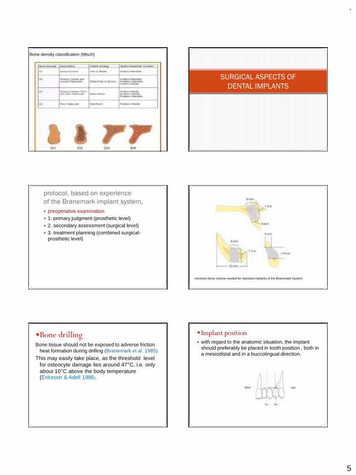
.
5
Bone density classification (Misch)
SURGICAL ASPECTS OF
DENTAL IMPLANTS
protocol, based on experience
of the Branemark implant system,
preoperative examination 1. primary judgment (prosthetic level) 2. secondary assessment (surgical level) 3. treatment planning (combined surgical-
prosthetic level)
minimum bone volume needed for standard implants of the Branemark System.
Bone drillingBone tissue should not be exposed to adverse friction
heat formation during drilling (Branemark et al. 1985).
This may easily take place, as the threshold level for osteocyte damage lies around 47°C, i.e. only about 10°C above the body temperature (Eriksson & Adell 1986).
Implant position with regard to the anatomic situation, the implant
should preferably be placed in tooth position , both in a mesiodistal and in a buccolingual direction.
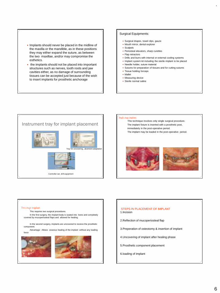
.
6
Implants should never be placed in the midline of the maxilla or the mandible, as in these positions they may either expand the suture, as between the two maxillae, and/or may compromise the esthetics.
the implants should not be placed into important structures such as nerves, tooth roots and jaw cavities either, as no damage of surrounding tissues can be accepted just because of the wish to insert implants for prosthetic anchorage
Surgical Equipments:
Surgical drapes, towel clips, gauze Mouth mirror, dental explorer Scalpels Periosteal elevators, sharp curettes Flap retractors Drills and burrs with internal or external cooling systems Implant system kit including the sterile implant to be placed Needle holder, suture material Sutures for preparation of tissues and for cutting sutures Tissue holding forceps Mallet Measuring device Sterile normal saline
Instrument tray for implant placement
Tray for uncovering,, abutment adaptation
Controller set, drill equipment
Single stage implant:
This technique involves only single surgical procedure.
The implant fixture is inserted with a prosthetic post,
immediately in the post-operative period.
The implant may be loaded in the post-operative period.
Two stage implant:
This requires two surgical procedures.
In the first surgery, the implant body is seated into bone and completely covered by mucoperiosteal flaps and allowed for healing.
In the second surgery, implants are uncovered to receive the prosthetic component.
Advantage : Allows osseous healing of the implant without any loading force
STEPS IN PLACEMENT OF IMPLANT1.Incision
2.Reflection of mucoperiosteal flap
3.Preperation of osteotomy & insertion of implant
4.Uncovering of implant after healing phase
5.Prosthetic component placement
6.loading of implant
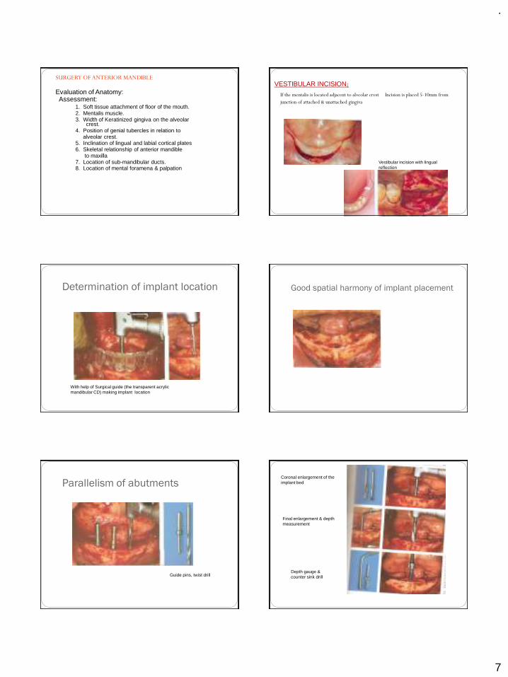
.
7
SURGERY OF ANTERIOR MANDIBLE
Evaluation of Anatomy:Assessment:
1. Soft tissue attachment of floor of the mouth. 2. Mentalis muscle.3. Width of Keratinized gingiva on the alveolar
crest.4. Position of genial tubercles in relation to
alveolar crest.5. Inclination of lingual and labial cortical plates6. Skeletal relationship of anterior mandible
to maxilla7. Location of sub-mandibular ducts.8. Location of mental foramena & palpation
VESTIBULAR INCISION:
If the mentalis is located adjacent to alveolar crest Incision is placed 5-10mm from
junction of attached & unattached gingiva
Vestibular incision with lingual reflection
Determination of implant location
With help of Surgical guide (the transparent acrylic mandibular CD) making implant location
Good spatial harmony of implant placement
Parallelism of abutments
Guide pins, twist drill
Coronal enlargement of the implant bed
Final enlargement & depth measurement
Depth gauge & counter sink drill
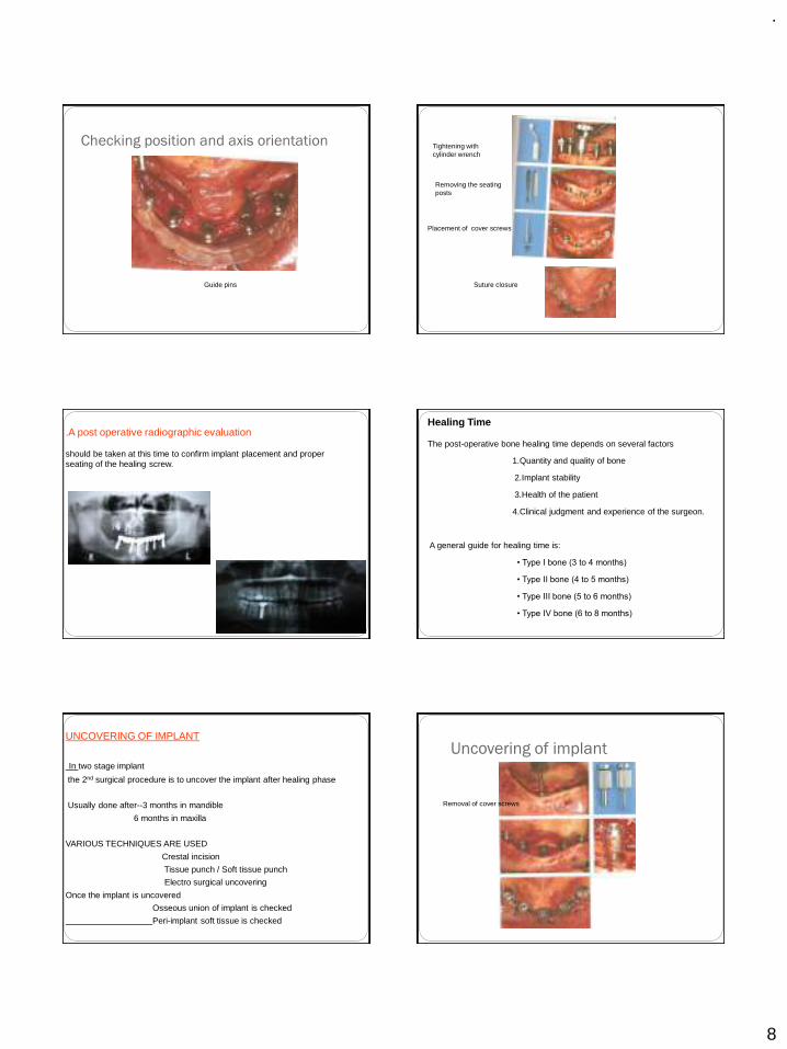
.
8
Checking position and axis orientation
Guide pins
Tightening with cylinder wrench
Removing the seating posts
Placement of cover screws
Suture closure
.A post operative radiographic evaluation
should be taken at this time to confirm implant placement and proper seating of the healing screw.
Healing Time
The post-operative bone healing time depends on several factors
1.Quantity and quality of bone
2.Implant stability
3.Health of the patient
4.Clinical judgment and experience of the surgeon.
A general guide for healing time is:
• Type I bone (3 to 4 months)
• Type II bone (4 to 5 months)
• Type III bone (5 to 6 months)
• Type IV bone (6 to 8 months)
UNCOVERING OF IMPLANT
In two stage implant
the 2nd surgical procedure is to uncover the implant after healing phase
Usually done after--3 months in mandible
6 months in maxilla
VARIOUS TECHNIQUES ARE USED
Crestal incision
Tissue punch / Soft tissue punch
Electro surgical uncovering
Once the implant is uncovered
Osseous union of implant is checked
Peri-implant soft tissue is checked
Uncovering of implant
Removal of cover screws
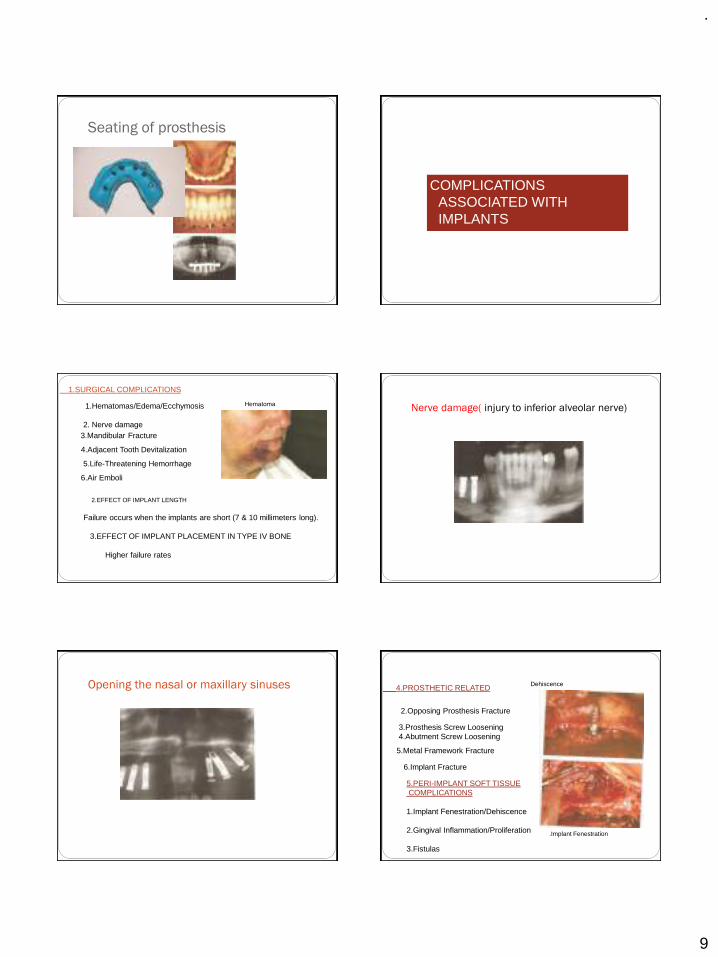
.
9
Seating of prosthesis
COMPLICATIONS ASSOCIATED WITH IMPLANTS
1.SURGICAL COMPLICATIONS
1.Hematomas/Edema/Ecchymosis
2. Nerve damage3.Mandibular Fracture
4.Adjacent Tooth Devitalization
5.Life-Threatening Hemorrhage
6.Air Emboli
2.EFFECT OF IMPLANT LENGTH
Failure occurs when the implants are short (7 & 10 millimeters long).
3.EFFECT OF IMPLANT PLACEMENT IN TYPE IV BONE
Higher failure rates
Hematoma Nerve damage( injury to inferior alveolar nerve)
Opening the nasal or maxillary sinuses 4.PROSTHETIC RELATED
2.Opposing Prosthesis Fracture
3.Prosthesis Screw Loosening 4.Abutment Screw Loosening
5.Metal Framework Fracture
6.Implant Fracture
5.PERI-IMPLANT SOFT TISSUECOMPLICATIONS
1.Implant Fenestration/Dehiscence
2.Gingival Inflammation/Proliferation
3.Fistulas
Dehiscence
.Implant Fenestration
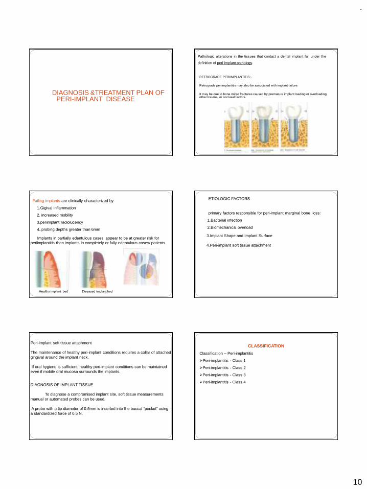
.
10
DIAGNOSIS &TREATMENT PLAN OF PERI-IMPLANT DISEASE
Pathologic alterations in the tissues that contact a dental implant fall under the
definition of peri implant pathology.
RETROGRADE PERIIMPLANTITIS:-
Retrograde periimplantitis may also be associated with implant failure.
It may be due to bone micro fractures caused by premature implant loading or overloading, other trauma, or occlusal factors.
Failing implants are clinically characterized by
1.Gigival inflammation
2. increased mobility
3.periimplant radiolucency
4..probing depths greater than 6mm
Implants in partially edentulous cases appear to be at greater risk for periimplantitis than implants in completely or fully edentulous cases/ patients
Healthy implant bed Diseased implant bed
ETIOLOGIC FACTORS
primary factors responsible for peri-implant marginal bone loss:
1.Bacterial infection
2.Biomechanical overload
3.Implant Shape and Implant Surface
4.Peri-implant soft tissue attachment
Peri-implant soft tissue attachment
The maintenance of healthy peri-implant conditions requires a collar of attached gingival around the implant neck.
If oral hygiene is sufficient, healthy peri-implant conditions can be maintained even if mobile oral mucosa surrounds the implants.
DIAGNOSIS OF IMPLANT TISSUE
To diagnose a compromised implant site, soft tissue measurements manual or automated probes can be used.
A probe with a tip diameter of 0.5mm is inserted into the buccal “pocket” using
a standardized force of 0.5 N.
CLASSIFICATION
Classification – Peri-implantitis
➢Peri-implantitis - Class 1
➢Peri-implantitis - Class 2
➢Peri-implantitis - Class 3
➢Peri-implantitis - Class 4
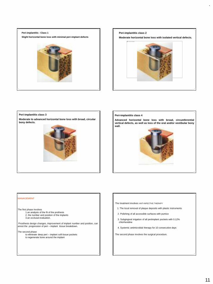
.
11
Peri-implantitis - Class 1
Slight horizontal bone loss with minimal peri-implant defects
Peri-implantitis class 2
Moderate horizontal bone loss with isolated vertical defects.
Peri-implantitis class 3
Moderate to advanced horizontal bone loss with broad, circular bony defects.
Peri-implantitis class 4
Advanced horizontal bone loss with broad, circumferentialvertical defects, as well as loss of the oral and/or vestibular bonywall.
MANAGEMENT
The first phase involves 1.an analysis of the fit of the prothesis2. the number and position of the implants3.an occlusal evaluation.
Prosthesis design changes, improvement of implant number and position, can arrest the progression of peri – implant tissue breakdown.
The second phaseto eliminate deep peri – implant soft tissue pockets to regenerate bone around the implant
The treatment involves ANTI-INFECTIVE THERAPY
1. The local removal of plaque deposits with plastic instruments
2. Polishing of all accessible surfaces with pumice
3. Subgingival irrigation of all periimplant pockets with 0.12% chlorhexidine
4. Systemic antimicrobial therapy for 10 consecutive days
The second phase involves the surgical procedure.
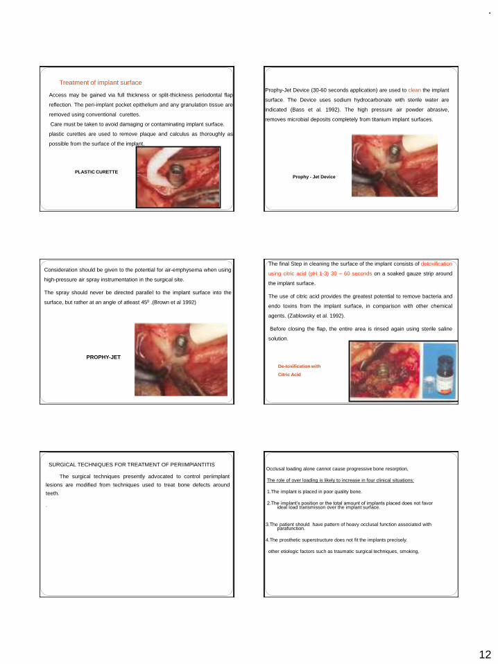
.
12
Access may be gained via full thickness or split-thickness periodontal flap
reflection. The peri-implant pocket epithelium and any granulation tissue are
removed using conventional curettes.
Care must be taken to avoid damaging or contaminating implant surface.
plastic curettes are used to remove plaque and calculus as thoroughly as
possible from the surface of the implant.
PLASTIC CURETTE
Treatment of implant surfaceProphy-Jet Device (30-60 seconds application) are used to clean the implant
surface. The Device uses sodium hydrocarbonate with sterile water are
indicated (Bass et al. 1992). The high pressure air powder abrasive,
removes microbial deposits completely from titanium implant surfaces.
Prophy - Jet Device
Consideration should be given to the potential for air-emphysema when using
high-pressure air spray instrumentation in the surgical site.
The spray should never be directed parallel to the implant surface into the
surface, but rather at an angle of atleast 450 .(Brown et al 1992)
PROPHY-JET
The final Step in cleaning the surface of the implant consists of detoxification
using citric acid (pH 1-3) 30 – 60 seconds on a soaked gauze strip around
the implant surface.
The use of citric acid provides the greatest potential to remove bacteria and
endo toxins from the implant surface, in comparison with other chemical
agents. (Zablowsky et al. 1992).
Before closing the flap, the entire area is rinsed again using sterile saline
solution.
De-toxification with
Citric Acid
SURGICAL TECHNIQUES FOR TREATMENT OF PERIIMPlANTITIS
The surgical techniques presently advocated to control periimplant
lesions are modified from techniques used to treat bone defects around
teeth.
.
Occlusal loading alone cannot cause progressive bone resorption,
The role of over loading is likely to increase in four clinical situations:
1.The implant is placed in poor quality bone.
2.The implant’s position or the total amount of implants placed does not favor ideal load transmisson over the implant surface.
3.The patient should have pattern of heavy occlusal function associated with parafunction.
4.The prosthetic superstructure does not fit the implants precisely.
other etiologic factors such as traumatic surgical techniques, smoking,
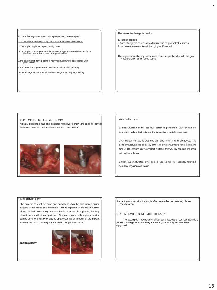
.
13
Occlusal loading alone cannot cause progressive bone resorption,
The role of over loading is likely to increase in four clinical situations:
1.The implant is placed in poor quality bone.
2.The implant’s position or the total amount of implants placed does not favor ideal load transmisson over the implant surface.
3.The patient shld have pattern of heavy occlusal function associated with parafunction.
4.The prosthetic superstructure does not fit the implants precisely.
other etiologic factors such as traumatic surgical techniques, smoking,
The ressective therapy is used to
1.Reduce pockets 2.Correct negative osseous architecture and rough implant surfaces3. Increase the area of keratinized gingiva if needed.
The regenerative therapy is also used to reduce pockets but with the goal of regeneration of lost bone tissue
PERI –IMPLANT RESECTIVE THERAPY
Apically positioned flap and osseous resective therapy are used to correct
horizontal bone loss and moderate vertical bone defects
With the flap raised
1. Degranulation of the osseous defect is performed. Care should be
taken to avoid contact between the implant and metal instruments.
2.An implant surface is prepared with chemicals and air abrasives. It is
done by applying the air spray of the air-powder abrasive for a maximum
time of 60 seconds on the implant surface, followed by copious irrigation
with saline solution.
3.Then supersaturated citric acid is applied for 30 seconds, followed
again by irrigation with saline
IMPLANTOPLASTY
The process to level the bone and apically position the soft tissues during
surgical treatment for peri-implantitis leads to exposure of the rough surface
of the implant. Such rough surface tends to accumulate plaque, So they
should be smoothed and polished. Diamond stones with copious cooling
can be used to grind away plasma-spray coatings or threads on the implant
surface, with final polishing accomplished using rubber disks
Implantoplasty
Implantoplasty remains the single effective method for reducing plaque accumulation
PERI – IMPLANT REGENERATIVE THERAPY:
To accomplish regeneration of lost bone tissue and reosseointegration, guided bone regeneration (GBR) and bone graft techniques have been suggested.
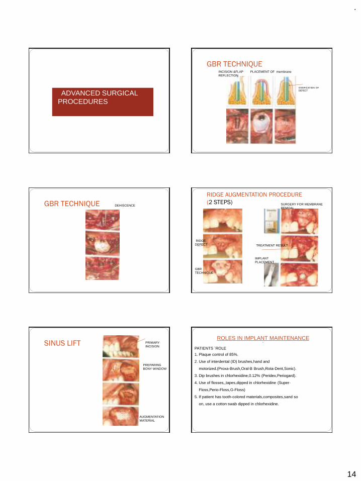
.
14
ADVANCED SURGICAL PROCEDURES
GBR TECHNIQUEINCISION &FLAP REFLECTION
PLACEMENT OF membrane
OSSIFICATION OF DEFECT
GBR TECHNIQUE DEHISCENCE
RIDGE AUGMENTATION PROCEDURE
(2 STEPS)
RIDGE DEFECT
GBR TECHNIQUE
SURGERY FOR MEMBRANE REMOAL
TREATMENT RESULT
IMPLANT PLACEMENT
SINUS LIFT PRIMARY INCISION
PREPARING BONY WINDOW
AUGMENTATION MATERIAL
ROLES IN IMPLANT MAINTENANCE `
PATIENTS `ROLE
1. Plaque control of 85%.
2. Use of interdental (ID) brushes,hand and
motorized.(Proxa-Brush,Oral-B Brush,Rota-Dent,Sonic).
3. Dip brushes in chlorhexidine,0.12% (Peridex,Periogard).
4. Use of flosses,,tapes,dipped in chlorhexidine (Super-
Floss,Perio-Floss,G-Floss)
5. If patient has tooth-colored materials,composites,sand so
on, use a cotton swab dipped in chlorhexidine.
.
15
HYGIENIST ROLE
1. Check plaque control effectiveness (85%).
2. Check for inflammatory changes
3. IF pathology is present,probe gently with plastic probe
(sensor).
4. Scale supragingivally only (or slightly subgingivally).
5. Check for problems such as loose suprastructure.
6. No need to probe if no pathology is present.
CLINICAL ROLE
1.Check every 3 or 4 months
2.Check for 85% plaque control effectiveness.
3. Expose radiographs every 12 to 18 months if no pathology is present and
as needed pathology is present.
4. Is suprastructure is retrievable, remove and clean the
ultrasonic every 10 to 24 months.
5. If implant needs it repair, degranulate, detoxify and graft with guided bone
regeneration (GBR) if necessary.
REFERENCES
1.CLINICAL PERIODONTOLOGY 10TH EDITION –CARRANZA
2.CLINICAL PERIODONTOLOGY AND IMPLANTOGY 5TH EDITION-JAN LINDHE
3.IMPLANTOLOGY—COLOR -ATLAS-SPIKEERANN
4.PRINCIPLES AND PRACTICE OF IMPLANT DENTISTRY-------WEISS
5.GOOGLE NET SEARCH
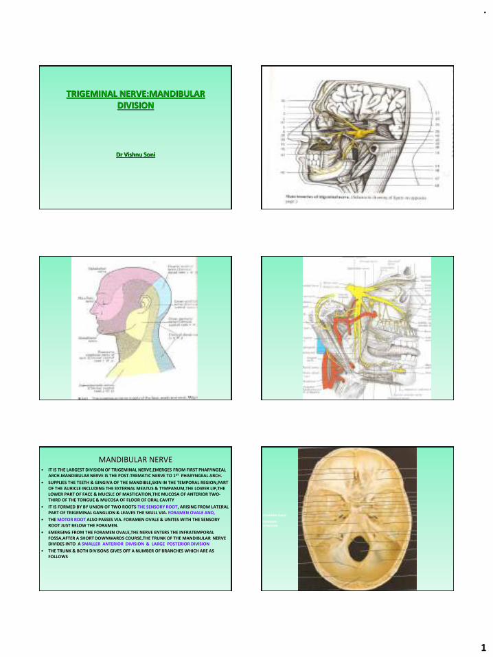
.
1
TRIGEMINAL NERVE:MANDIBULAR DIVISION
Dr Vishnu Soni
MANDIBULAR NERVE• IT IS THE LARGEST DIVISION OF TRIGEMINAL NERVE,EMERGES FROM FIRST PHARYNGEAL
ARCH.MANDIBULAR NERVE IS THE POST-TREMATIC NERVE TO 1ST PHARYNGEAL ARCH.
• SUPPLIES THE TEETH & GINGIVA OF THE MANDIBLE,SKIN IN THE TEMPORAL REGION,PART OF THE AURICLE INCLUDING THE EXTERNAL MEATUS & TYMPANUM,THE LOWER LIP,THE LOWER PART OF FACE & MUCSLE OF MASTICATION,THE MUCOSA OF ANTERIOR TWO-THIRD OF THE TONGUE & MUCOSA OF FLOOR OF ORAL CAVITY
• IT IS FORMED BY BY UNION OF TWO ROOTS-THE SENSORY ROOT, ARISING FROM LATERAL PART OF TRIGEMINAL GANGLION & LEAVES THE SKULL VIA. FORAMEN OVALE AND,
• THE MOTOR ROOT ALSO PASSES VIA. FORAMEN OVALE & UNITES WITH THE SENSORY ROOT JUST BELOW THE FORAMEN.
• EMERGING FROM THE FORAMEN OVALE,THE NERVE ENTERS THE INFRATEMPORAL FOSSA,AFTER A SHORT DOWNWARDS COURSE,THE TRUNK OF THE MANDIBULAR NERVE DIVIDES INTO A SMALLER ANTERIOR DIVISION & LARGE POSTERIOR DIVISION
• THE TRUNK & BOTH DIVISONS GIVES OFF A NUMBER OF BRANCHES WHICH ARE AS FOLLOWS
FORAMEN OVALE
FORAMEN SPINOSUM
.
2
I.BRANCHES FROM THE UNDIVIDED NERVEA.NERVUS SPINOSUSB.NERVE TO INTERNAL PTERYGOID MUSCLE
II.BRANCHES FROM THE DIVIDED NERVEA.ANTERIOR DIVISION1.BRANCH TO EXTERNAL PTERYGOID MUSCLE2.BRANCH TO MASSETER3.BRANCHES TO TEMPORAL MUSCLEa.ANTERIOR DEEP TEMPORALb.POSTERIOR DEEP TEMPORAL4.BUCCAL(LONG BUCCAL)NERVEB.POSTERIOR DIVISION1.AURICULOTEMPORAL NERVE2.LINGUAL NERVE3.INFERIOR ALVEOLAR NERVE III.AUTONOMIC GANGLIA ASSOCIATED WITH THE MANDIBULAR DIVISION OF TRIGEMINAL NERVEA.SUBMANDIBULAR(SUBMAXILLARY)GANGLIONB.OTIC GANGLIONI.PARASYMPATHETIC PREGANGLIONIC(SECRETORY) FIBRES2.SYMPATHETIC ROOT
I.BRANCHES FROM THE UNDIVIDED NERVE
A.NERVUS SPINOSUSB.NERVE TO INTERNAL PTERYGOID MUSCLE
A.NERVUS SPINOSUS(MENINGEAL BRANCH)
• IT IS THE BRANCH FROM THE TRUNK ( OR BRAIN STEM)
• IT IS GIVEN OFF,FROM THE NERVE JUST AFTER THE UNION OF THE MOTOR & SENSORY ROOT
• & ENTERS THE FORAMEN SPINOSUM.
• IT ACCOMPANIES THE MIDDLE MENINGEAL ARTERY & DIVIDES INTO ANTERIOR & POSTERIOR BRANCHES WHICH ACCOMPANIES THE MAIN DIVISION OF THE ARTERY & SUPPLIES THE DURA MATER IN THE MIDDLE CRANIAL FOSSA & TO A LESSER EXTENT IN THE ANTERIOR FOSSA & CALVARIUM.
• THE POSTERIOR BRANCH ALSO SUPPLIES THE MUCOUS LINING OF MASTOID AIR CELLS WHILE THE ANTERIOR COMMUNICATES WITH THE MENINGEAL BR. OF MAXILLARY NERVE.
• IT ALSO CONTAINS SYMPATHETIC POSTGANGLIONIC FIBRES FROM THE MIDDLE MENINGEAL PLEXUS.
NERVE TO THE MEDIAL PTERYGOID
• THIS IS A SLENDER RAMUS ENTERING THE DEEP ASPECT OF THE MUSCLE.
• IT SUPPLIES ONE OR TWO FILAMENTS WHICH PASS VIA. THE OTIC GANGLION WITHOUT INTERRUPTION TO SUPPLY TENSOR TYMPANI & TENSOR VELI PALTIN.
II.BRANCHES FROM THE DIVIDED NERVE
A.ANTERIOR DIVISION
1.BRANCH TO EXTERNAL PTERYGOID MUSCLE2.BRANCH TO MASSETER
3.BRANCHES TO TEMPORAL MUSCLEa.ANTERIOR DEEP TEMPORAL
b.POSTERIOR DEEP TEMPORAL4.BUCCAL(LONG BUCCAL)NERVE
B.POSTERIOR DIVISION
1.AURICULOTEMPORAL NERVE2.LINGUAL NERVE
3.INFERIOR ALVEOLAR NERVE
BUCCAL NERVE
• IT IS THE ONLY SENSORY BRANCH IN THE ANTERIOR DIVISION & THE REMAINING BRANCHES OF ANTERIOR DIVISION ARE MOTOR
• IT PROCEEDS BETWEEN THE TWO PARTS OF THE LATERAL PTERYGOID MUSCLE,DESCENDING DEEP THEN ANTERIOR TO TENDON OF TEMPORALIS MUSCLE
• IT THEN PASSES LATERALLY IN FRONT OF MASSETER M. TO UNITE WITH BUCCAL BR. OF FACIAL N.
• IT SUPPLIES LATERAL PTERYGOID WHILE PASSING VIA. IT.
• IT SUPPLIES THE SKIN OVER THE ANTERIOR PART OF BUCCINATOR MUSCLE & BUCCAL MUCOUS MEMBRANE,TOGETHER WITH THE POST.PART OF BUCCAL GINGIVA AJDACENT OF SECOND & THIRD MOLAR TEETH
.
3
AURICULOTEMPORALNERVE
• IT USUALLY HAS 2 ROOTS ENCIRCLING THE MIDDLE MENINGEAL ARTERY
• IT RUNS BACK UNDER THE LATERAL PTERYGOID M. ON THE SURFACE OF TENSOR VELI PALATINI ,TO PASS BET. THE SPENOMANDIBULAR LIGAMENT & THE NECK OF MANDIBLE & THEN LATERALLY BEHIND TMJ IN RELATION TO UPPER PART OF PAROTID GLAND
• EMERGING FROM BEHIND TMJ ,IT ASCENDS POSTERIOR TO SUPERFICIAL TEMPORAL VESSELS OVER THE POSTERIOR ROOT OF ZYGOMA & DIVIDES INTO SUPERFICIAL TEMPORAL BRANCHES
• IT COMMUNICATE WITH THE FACIAL NERVE & OTIC GANGION
• THE RAMI TO THE FACIA L NERVE,USUALLY TWO, PASS ANTEROLATERALLY BEHIND THE NECK OF MANDIBLE TO JOIN THE FACIAL NERVE AT POSTERIOR BORDER OF MASSETER
• FILAMENT FROM OTIC GANGLION JOIN THE ROOTS OF AURICULOTEMPORAL N.CLOSE TO ITS ORIGIN.
• THE BRANCHES OF AURCULOTEMPORAL N. ARE-THE PAROTID,ARTICULAR,AURICULAR, MEATAL & TERMINAL BRANCHES
MASSETERIC NERVE
• THIS PASSES LATERALLY,ABOVE THE LATERAL PTERYGOID,ON THE SKULL BASE,ANTERIOR TO TMJ & POSTERIOR TO TENDON OF TEMPORALIS
• IT CROSSES THE POSTERIOR PART OF MANDIBULAR CORONOID NOTCH WITH THE MASSETRIC ARTERY, RAMIFIES ON & ENTERS THE DEEP SURFACE OF MASSETER & ALSO SUPPLIES TMJ
DEEP TEMPORAL NERVE
• THE TEMPORALIS MUSCLE IS SUPPLIED VIA. THE ANTERIOR , MIDDLE & POSTERIOR DEEP TEMPORAL NERVE
• USUALLY THE ANTERIOR & POSTERIOR BRANCH PASS ABOVE THE LATERAL PTERYGOID TO ENTER THE DEEP SURFACE OF TEMPORALIS
• THE SMALL POSTERIOR NERVE SOMETIMES ARISES IN COMMON WITH MASSETRIC NERVE
• THE ANTERIOR NERVE IS FREQUENTLY RHE BRANCH OF BUCCAL NERVE,IT ASCENDS OVER THE UPPER HEAD OF LATERAL PTERYGOID M.
• A MIDDLE BRANCH OFTEN OCCURS
NERVE TO LATERAL PTERYGOID
• IT ENTERS DEEP SURFACE SURFACEOF THE MUSCLE
• IT MAY ARISES EPERATELY FROM THE ANTERIOR DIVISION OR WITH THE BUCCAL NERVE
B.POSTERIOR DIVISION
1.AURICULOTEMPORAL NERVE2.LINGUAL NERVE
3.INFERIOR ALVEOLAR NERVE
COMMUNICATION OF AURICULOTEMPORAL NERVE
• 1.TWO ROOTS OF THE NERVE
• EACH ROOT RECEIVE COMMUNICATING FIBRES FROM THE OTIC GANGLION
• THESE FIBRES ARE POSTGANGLIONIC,PARASYMPATHETIC SECRETORY FIBRES THAT HAVE COME FROM GLOSSOPHARENGEAL NERVE BY WAY OF THE LESSER SUPERFICIAL PETROSAL NERVE
• THEY CONTROL THE SECRETION OF PAROTID GLAND
• 2.COMMUNICATING BRANCHES OF POSTGANGLIONIC SYMPATHETIC FIBRES
• THESE VASOMOTOR FIBRES PASS TO THE PAROTID GLAND VIA.THE AURICULOTEMPORAL NERVE.
• 3.COMMUNICATING BRANCHES TO THE FACIAL NERVE
• THESE FIBRES ARE PURELY SENSORY FROM THE AURICULOTEMPORAL NERVE
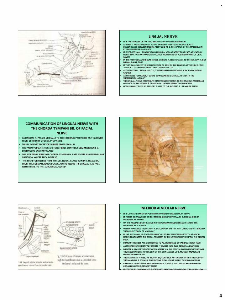
.
4
LINGUAL NERVE• IT IS THE SMALLER OF THE TWO BRANCHES OF POSTERIOR DIVISION
• AT FIRST IT PASSES MEDIALLY TO THE EXTERNAL PTERYGOID MUSCLE & AS IT DESCENDS,LIES BETWEEN MEDIAL PTERYGOID M. & THE RAMUS OF THE MANDIBLE IN PTERYGOMANDIBULAR SPACE
• IT GIVES OFF SMALL BRNCHES TO INFERIOR ALVEOLAR NERVE THAT PASS AS SENSORY FIBRES TO A PART OF TONSIL & MUCOOUS MEMBRANE OF POSTERIOR PART OF ORAL CAVITY
• IN THE PTERYGOMANDIBULAR SPACE ,LINGUAL N. LIES PARALLEL TO THE INF. ALV. N. BUT MEDIAL & ANT. TO IT
• IT THEN PASSES DEEP TO REACH THE SIDE OF BASE OF THE TONGUE.AT THE SIDE OF THE TONGUE IT LIES BELOW THE LATERAL LINGUAL SULCUS
• AT THE LATERAL LINGUAL SULCUS,IT IS SEPERATED FROM TONGUE BY ALVEOLINGUAL GROOVE
• AS IT PASSES FORWARDS,IT LOOPS DOWNWARDS & MEDIALLY BENEATH THE SUBMANDIBULAR DUCT
• THE LINGUAL NERVE CONTRIBUTE MANY SENSORY FIBRES TO THE MUCOUS MEMBRANE OF FLOOR OF THE MOUTH & GINGIVA ON LINGUAL SURFACE OF MANDIBLE
• OCCASSIONALY SUPPLIES SENSORY FIBRES TO THE BICUSPID & I ST MOLAR TEETH
COMMUNICATION OF LINGUAL NERVE WITH THE CHORDA TYMPANI BR. OF FACIAL
NERVE• AS LINGUAL N. PASSES MEDIALLY TO THE EXTERNAL PTERYGOID M,IT IS JOINED
FROM BEHIND BY CHORDA TYMPANI N.
• THIS N. CONVEY SECRETORY FIBRES FROM FACIAL N.
• THE PARASYMPATHETIC SECRETORY FIBRES CONTROL SUBMANDIBULAR & SUBLINGUAL SALIVARY GLAND
• THE SECRETORY FIBRES OF CHORDA TYMPANI N. PASS TO THE SUBMANDIBULAR GANGLION WHERE THEY SYNAPSE.
• THE SECRETORY NERVE FIBRE TO SUBLINGUAL GLAND JOIN IN A SMALL BR. FROM THE SUBMANDIBULAR GANGLION TO REJOIN THE LINGUAL N. & PASS WITH THIS N. TO THE SUBLINGUAL GLAND INF.ALVEOLAR
N.,VESSELS
INFERIOR ALVEOLAR NERVE
• IT IS LARGEST BRANCH OF POSTERIOR DIVISION OF MANDIBULAR NERVE
• IT PASSES DOWNWARDS ON THE MEDIAL SIDE OF EXTERNAL M & MEDIAL SIDE OF MANDIBULAR RAMUS
• ON THE MEDIAL SIDE OF RAMUS IN PTERYGOMANDIBULAR SPACE,IT ENTERS THE MANDIBULAR FORAMEN.
• WITHIN MANDIBLE THE INF.ALV. N. DESCENDS IN THE INF. ALV. CANAL & IS DISTRIBUTED THROUHOUT BODY OF MANDIBLE.
• IN INF. ALV.CANAL, IT GIVES OFF BRANCHES TO THE MANDIBULAR TEETH AS APICAL FIBRES THAT ENTERS THE APICAL FORAMEN OF THE LOWER TEEH TO SUPPLY THE DENTAL PULP.
• SOME OF THE FIBES ARE DISTRIBUTED TO PD.MEMBRANE OF VARIOUS LOWER TEETH
• AS IT REACHES THE MENTAL FORMEN, IT DIVIDES INTO TWO TERMINAL BRANCHES
• MENTAL N. LEAVES THE BODY OF MANDIBLE VIA. THE MENTAL FORAMEN TO TRANSMIT THE SENSORY FIBRES TO THE SKIN OF THE CHIN ,LOWER LIP & MUCOUS MEMBRANE LINING THE LOWER LIP
• THE REMAINING FIBRES,THE INCISIVE BR, CONTINUE ANTERIORLY WITHIN THE BODY OF THE MANDIBLE & FORMS A FINE INCISIVE PLEXUS THAT SUPPLY CUSPID & INCISORS
• B EFORE IT ENTERS MANDIBULAR FORAMEN, IT GIVE A MYLOHYOID BRANCH WHICH CONAINS MOTOR & SENSORY FIBRES
• IT CONTINUES DOWNWARDS & FORWARDS IN MYLOHYOID GROOVE,IT PASSES BELOW MYLOHYOID M.,TO WHICH IT SENDS MOTOR FIBRES,IT SUPPLIES MOTOR FIBRES TO
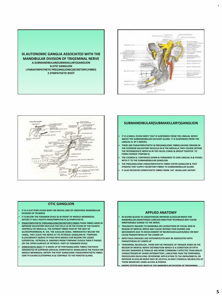
.
5
III.AUTONOMIC GANGLIA ASSOCIATED WITH THE MANDIBULAR DIVISION OF TRIGEMINAL NERVE
A.SUBMANDIBULAR(SUBMAXILLARY)GANGLIONB.OTIC GANGLION
I.PARASYMPATHETIC PREGANGLIONIC(SECRETORY) FIBRES2.SYMPATHETIC ROOT
SUBMANDIBULAR(SUBMAXILLARY)GANGLION
• IT IS A SMALL OVOID BODY THAT IS SUSPENDED FROM THE LINGUAL NERVE ABOVE THE SUBMANDIBULAR SALIVARY GLAND. IT IS SUSPENDED FROM THE LINGUAL N. BY 2 NERVES.
• THESE ARE PARASYMPATHETIC & PREGANGLIONIC FIBRES,HAVING ORIGINS IN THE SUPERIOR SALIVATORY NUCLEUS IN N THE MEDULLA.THEY COURSE WITHIN THE INTERMEDIATE NERVE & IN THE FACIAL CANAL & GROUP TOGHTER TO FORM CHORDA TYMPANI N.
• THE CHORDA N. CONTINUES DOWN & FORWARDS TO JOIN LINGUAL N.& PASSES WITH IT TO THE SUBMANDIBULAR GANGLION.
• THE PREGANGLIONIC PARASYMPATHETIC FIBRES ENTER GANGLION & THEY SYNAPSE.THEY SUPPLY SECRETORY FIBRES TO SUBMANDIBULAR GLAND.
• IT ALSO RECEIEVES SYMPATHETIC FIBRES FROM EXT. MAXILLARY ARTERY.
OTIC GANGLION
• IT IS A FLATTEND OVOID BODY ON MEDIAL SIDE OF UNDIVIDED MANDIBULAR DIVISION OF TN.NERVE
• IT IS BELOW THE FORAMEN OVALE & IN FRONT OF MIDDLE MENIINGEAL ARTERY.IT HAS 2 ROOTS-PARASYMPATHETIC & SYMPATHETIC
• PARASYMPATHETIC PREGANGLIONIC(SECRETORY) FIBRES-THESE FIBRES ARISE IN INFERIOR SALIVATORY NUCLEUS.THE CELLS LIE IN THE FLOOR OF THE FOURTH VENTRICLE OF MEDULLA. THE AFFRENT FIBRES PASS BY THE WAY OF GLOSSOPHARNGEAL N. VIA. THE JUGULAR CANAL. IMMEDIATELY BELOW THE CANAL, THEY LEAVE THE NERVE AT ITS PETROSAL GANGLION IN TYMPANIC N.(JACOBSON’S NERVE) TO PASS INTO MIDDLE EAR REGION.THE LESSER SUPERFICIAL PETROSAL N. EMERGES FROM TYMPANIC PLEXUS.THEN IT PASSES ON THE UPPER SURFACE OF PETROUS PART OF FORAMEN OVALE
• SYMPATHETIC ROOT-IT IS MADE UP OF POSTGANGLIONIC FIBRES THATHAVE ORIGINATED IN SUPERIOR CERVICAL SYMPATHETIC GANGLION & THE PLEXUS ON MIDDLE MENINGEAL ARTERY.THE POST GANGLIONIC PARASYMPATHETIC FIBRES JOIN TH EAURICULOTEMPRAL N.& CONTINUE TO THE PAROTID GLAND.
APPLIED ANATOMY• IN GIVING BLOCKS TO ANAESTHESIZE INFERIOR ALVEOLAR NERVE FOR
MANDIBULAR ANAESTHESIA CARELESS INJECTION TECHNIQUE MAY CAUSE INREPAIRABLE DAMGE TO THE NERVE.
• TRAUMATIC INJURIES TO MANDIBLE,OR LACERATIONS OF FACIAL SKIN IN REGION OF MENTAL NERVE MAY CAUSE INTENSE PAIN DURING JAW MOVEMENTS DUE TO INVOLVEMENT OF NEUROVASCULAR BUNDLE OR MAY CAUSE PARAESTHESIA OF THE LOWER LIP.
• INFECTIOUS DISEASES LIKE OSTEOMYELITIS MAY BE ASSOCIATED WITH PARAESTHESIA OF LOWER LIP
• TRIGEMINAL NEURALGIA ,THERE MAY BE PRESENCE OF TRIGGER ZONES IN THE REGION OF MENTAL NERVE DISTRIBUTION WHICH IS A CONDITION OF FIFTH DECADE ONWARDS & FEMALES ARE MORE COMMONLY AFFECTED THAN MALES CHARACTERISED BY SHARP,INTERMITTENT, LANCATING PAIN.THE PERIPHERAL PROCEDURES INVOLVING CRYOPROBE APPLICATION TO THE INFRAORBITAL OR INFERIOR ALVEOLAR NERVE MAY BE HELPFUL,AS MAY CHEMICAL NEUROLYSIS OF THOSE BRANCHES USING ALCHOL & PHENOL
• HERPES ZOSTER MAY INVOLVE THE MANDIBULAR DIVISION OF TRIGEMINAL NERVE

.
6
REFERENCES
• COLOR ATLAS OF ANATOMY,THIRD EDITION BY ROHEN/YOKOCHI
• GRAY’S ANATOMY 38TH EDITION PG(1230-1238)
• MONHEIM’S LOCAL ANAESTHESIA AND PAIN CONTROL IN DENTAL PRACTICE PG 44-50
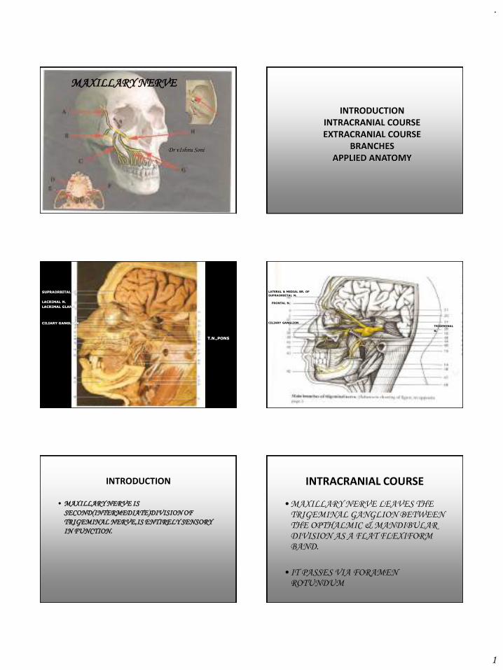
.
1
MAXILLARY NERVE
Dr vIshnu Soni
INTRODUCTIONINTRACRANIAL COURSEEXTRACRANIAL COURSE
BRANCHESAPPLIED ANATOMY
SUPRAORBITAL N.
T.N.,PONS
CILIARY GANGLION
LACRIMAL N.
LACRIMAL GLAND
LATERAL & MEDIAL BR. OF
SUPRAORBITAL N.
FRONTAL N.
TRIGEMINAL
N.
CILIARY GANGLION
INTRODUCTION
• MAXILLARY NERVE IS
SECOND(INTERMEDIATE)DIVISION OF
TRIGEMINAL NERVE,IS ENTIRELY SENSORY
IN FUNCTION.
INTRACRANIAL COURSE
• MAXILLARY NERVE LEAVES THE TRIGEMINAL GANGLION BETWEEN THE OPTHALMIC & MANDIBULAR DIVISION AS A FLAT FLEXIFORM BAND.
• IT PASSES VIA FORAMEN ROTUNDUM
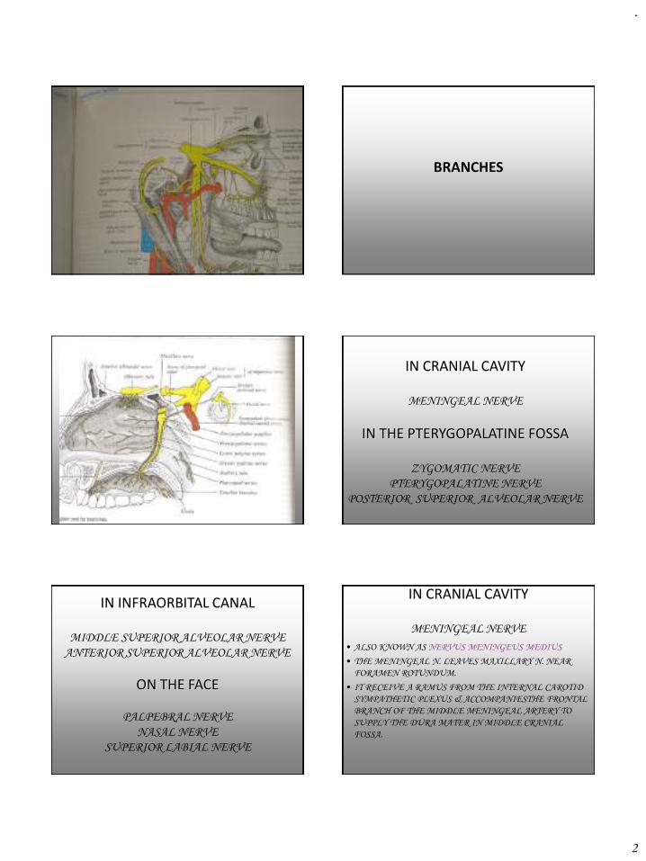
.
2
BRANCHES
IN CRANIAL CAVITY
MENINGEAL NERVE
IN THE PTERYGOPALATINE FOSSA
ZYGOMATIC NERVE
PTERYGOPALATINE NERVE
POSTERIOR SUPERIOR ALVEOLAR NERVE
IN INFRAORBITAL CANAL
MIDDLE SUPERIOR ALVEOLAR NERVE
ANTERIOR SUPERIOR ALVEOLAR NERVE
ON THE FACE
PALPEBRAL NERVE
NASAL NERVE
SUPERIOR LABIAL NERVE
IN CRANIAL CAVITY
MENINGEAL NERVE
• ALSO KNOWN AS NERVUS MENINGEUS MEDIUS
• THE MENINGEAL N. LEAVES MAXILLARY N. NEAR
FORAMEN ROTUNDUM.
• IT RECEIVE A RAMUS FROM THE INTERNAL CAROTID
SYMPATHETIC PLEXUS & ACCOMPANIESTHE FRONTAL
BRANCH OF THE MIDDLE MENINGEAL ARTERY TO
SUPPLY THE DURA MATER IN MIDDLE CRANIAL
FOSSA.
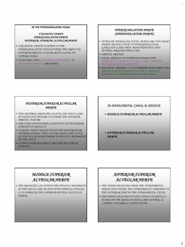
.
3
IN THE PTERYGOPALATINE FOSSA
ZYGOMATIC NERVE
PTERYGOPALATINE NERVE
POSTERIOR SUPERIOR ALVEOLAR NERVE
• ZYGOMATIC NERVE-IT STARTS IN THE
PTERYGOPALATINE FOSSA,ENTERS THE ORBIT VIA.
INFERIOR ORBITAL FISSURE,RUNS ALONG ITS
LATERAL WALL
• IT DIVIDES INTO –ZYGOMATICOTEMPORAL &
ZYGOMATICOFACIAL BRANCHES
PTERYGOPALATINE NERVE
(SPHENOPALATINE NERVE)
• TUTED HE PTERYGOPALATINE NERVE ARE TWO SHORT NERVE TRUNKS UNITE AT PTERYGOPALATINE GANGLION & ARE THEN REDISTRIBUTED INTO SEVERAL BRACHES.THESE ARE
• ORBITAL BRANCH
• NASAL BRANCH- IT FURTHER DIVIDES INTO POSTERIOR SUPERIOR LATERAL NASAL BRANCH, MIDDLE OR SEPTAL BRANCH
• PALATINE BRANCH – IT IS FURTHER SUDIVIDED INTO GREATER OR ANTERIOR PALATINE N., MIDDLE PALATINE N., POSTERIOR PALATINE FIBRES.
POSTERIOR SUPERIOR ALVEOLAR
NERVE
• TWO OR THREE BRANCHES LEAVES THE MAXILLARY DIVISION JUST BEFORE IT ENTERS THE INFERIOR ORBITAL FISSURE
• THEY PASS DOWNWARD & CONTINUE ON POSTERIOR SURFACE OF MAXILLA
• IN BONE, NERVE PASSES DOWN THE POSTERIOR OR POSTEROLATERAL WALL OF THE MAXILLARY SINUS GIVING OFF SENSORY FIBERS TO MUCOUS MEMBRANE OF THE SINUS.
• IT THEN SUPPLIES MAXILLARY MOLAR & THEIR GINGIVA.
IN INFRAORBITAL CANAL & GROOVE
• MIDDLE SUPERIOR ALVEOLAR NERVE
• ANTERIOR SUPERIOR ALVEOLAR
NERVE
MIDDLE SUPERIOR
ALVEOLAR NERVE
• THE BRANCHES LIE WITHIN THE MUCOUS MEMBRANE
OF THE MAXILLARY TO JOIN WITH OTHER ALVEOLAR
N. IN FORMING THE SUPERIOR DENTAL PLEXUS OF
NERVE.
ANTERIOR SUPERIOR
ALVEOLAR NERVE
• THE NERVE DESCENDS FROM THE INFRAORBITAL
NERVE JUST INSIDE THE INFRAORBITAL FORAMEN IN
THE ANTERIOR PART OF THE INFRAORBITAL CANAL
• THE NERVE DESCEND IN FINE CANALS IN MAXILLA
TO PASS TO THE ROOTS OF MAXILLARY CENTRAL &
LATERAL INCISORS & CUSPID TEETH.
.
4
ON THE FACE
• PALPEBRAL NERVE
•
NASAL NERVE
• SUPERIOR LABIAL NERVE
APPLIED ANATOMY
• WHILE GIVING INFRAORBITAL NERVE BLOCK CARE SHOULD BE TAKEN,CARELESS INJECTION COULD RESULT IN ANES FLUID IN ORBIT-TEMPORARY PARALYSIS OF EXTRAOCULAR MUSCLES.
• THE NERVE IS INVARIABLY DAMAGED IN DEPRRESED # OF ZYGOMATIC BONE.IT MAY ALSO BE COMPROMISED IN BLOW-OUT # OF ORBITAL FLOOR,& IS AT CONSIDRABLE RISK DURING THEIR SURGICAL REPAIR.DAMAGE LEADS TO NUMBNESS OF THE CHEEK, LOWER EYELID & IPSILAERAL INCISOR TEETH & ASSOCIATED GINGIVA.
APPLIED ANATOMY• MALIGNANT TUMOURS OF THE MAXILLARY SINUS MAY BE
PRESENT WITH PAIN & NUMBNESS OVER THE DISTRIBUTION
OF THE INFRAORBITAL NERVE.
• WHILE GIVING POSTERIOR SUPERIOR NERVE
BLOCK,HAEMATOMA FORMATION IS QUITE COMMON.THE
LENGTH OF THE NEEDLE USED FOR THIS BLOCK SHOULD BE
CALIBERATED IN SHORT STATURED INDIVIDUALS
• HERPES ZOSTER,SHINGLES,INFECTION CAUSED BY HERPES
ZOSTER,PRODUCES VESICLES FOLLOWING COURSE OF
AFFECTED NERVE.INVOLVEMENT OF TRIGEMINAL GANGLION
IN 20% CASES,ANY DIVISION MAY BE INVOLVED,OPTHLMIC IS
THE MOST COMMON
REFERENCES
GRAY’S ANATOMY 38TH EDITION PG(1230-1234)
COLOUR ATLAS OF HUMAN ANATOMY-3RD
EDITION BY ROHEN/YOKOCHI
WIKIPEDIA,THE FREE ENCYCLOPEDIA
GRAY’S ANATOMY OF THE HUMAN BODY-ON
YAHOO EDUCATION
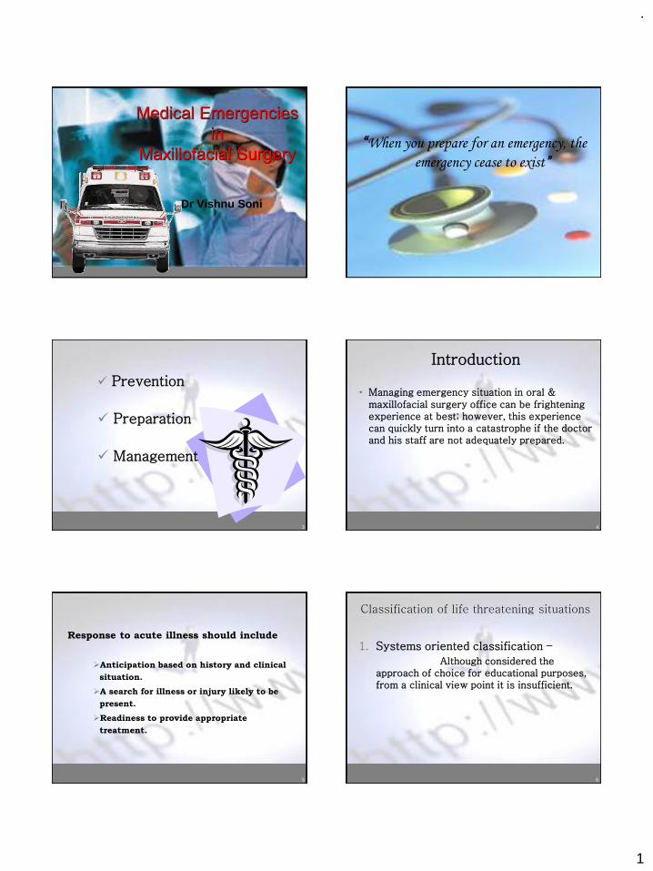
.
1
Medical Emergencies in
Maxillofacial Surgery
Dr Vishnu Soni
2
“When you prepare for an emergency, the
emergency cease to exist”
3
✓ Prevention
✓ Preparation
✓ Management
4
Introduction
• Managing emergency situation in oral & maxillofacial surgery office can be frightening experience at best; however, this experience can quickly turn into a catastrophe if the doctor and his staff are not adequately prepared.
5
Response to acute illness should include
➢Anticipation based on history and clinical
situation.
➢A search for illness or injury likely to be
present.
➢Readiness to provide appropriate
treatment.
6
Classification of life threatening situations
1. Systems oriented classification –
Although considered the approach of choice for educational purposes, from a clinical view point it is insufficient.
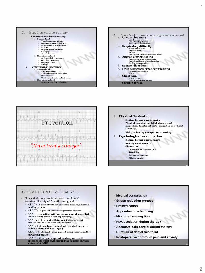
.
2
7
2. Based on cardiac etiology➢ Noncardiovascular emergency
a. Stress related» Vasodepressor syncope» Hyperventilation syndrome.» Acute adrenal insufficiency» Asthma» Hypoglycemic reactions.» Epilepsy» Thyroid crisis
b. Non- stress related. » Orthostatic hypotension» Overdose reaction.» Hyperglycemia» Allergy.
➢ Cardiovascular emergency a. Stress related
» Angina pectoris» Acute Myocardial Infraction» Heart failure» Cerebral ischemia and infraction
b. Non- stress related.» Acute myocardial infraction
8
3. Classification based clinical signs and symptoms:a. Unconsciousness
▪ Vasodepressor syncope
▪ Orthostatic hypotension▪ Acute adrenal insufficiency
b. Respiratory difficulty▪ Airway obstruction▪ Hyperventilation▪ Asthma ▪ Heart failure and acute pulmonary edema
c. Altered consciousness ▪ Hyperglycemia and hypoglycemia ▪ Hyperthyroidism and hypothyroidism▪ Cerebrovascular accident
d. Seizure disorderse. Drug related emergency situations
▪ Drug overdose reactions▪ Allergy
f. Chest pain▪ Angina pectoris▪ Acute myocardial infarction.
g. Cardiac arrest.
9
Prevention
“Never treat a stranger”
10
1. Physical Evaluation• Medical history questionnaire
• Physical examination (vital signs, visual
inspection, functional tests, auscultation of heart
and lungs)
• Dialogue history (recognition of anxiety)
2. Psychological examination• Medical history questionnaire
• Anxiety questionnaire
• Observation
✓ Increased BP & Heart rate
✓ Trembling
✓ Excessive sweating
✓ Dilated pupils
11
DETERMINATION OF MEDICAL RISK.
• Physical status classification system (1962, American Society of Anesthesiologists)
• ASA I : A patient without systemic disease, a normal healthy patient
• ASA II : A patient with mild systemic disease
• ASA III : A patient with severe systemic disease that limits activity but is not incapacitating
• ASA IV : A patient with incapacitating systemic disease that is a constant threat to life.
• ASA V : A moribund patient not expected to survive 24 hrs with or with out surgery.
• ASA VI : Clinically dead patient being maintained for
harvesting organs.
• ASA E : Emergency operation of any variety; E precedes the number, indicating the patients physical status( ASA E-III) 12
✓Medical consultation
✓Stress reduction protocol
✓Premedication
✓Appointment scheduling
✓Minimized waiting time
✓Psycosedation during therapy
✓Adequate pain control during therapy
✓Duration of dental treatment
✓Postoperative control of pain and anxiety
.
3
13
Preparation
“More patients will do well when you act
than when you don’t act”
14
1. Staff training should include:
• Basic life support training for all members of dental office staff
• Training in the recognition and management of specific emergency situations
• Emergency “fire drills”
2. Office preparation should include:
• Posting emergency assistance numbers
• Stocking emergency drugs and equipment
15
• Basic Life Support (CPR)
• Advanced cardiac life support
✓Adjuncts to airway control (intubation)
✓Patient monitoring and dysrhythmia recognition
✓Defibrillation and synchronized cardioversion
✓Cardiovascular pharmacology
✓Acid-base balance maintenance
✓Venipuncture
✓Resuscitation of infants, including newborns
16
Emergency Drugs and Equipments
Commercial Vs
Home made emergency kits
17
Management of emergency situations should follow the A-B-C-D protocol
• A – Airway
• B – Breathing
• C – Circulation
• D - Drugs
18
Administration routes for drugs:(by rate of onset)
1. Endotracheal (when available):
Epinephrine, lidocaine, atropine and naloxone only
2. Intravenous
3. Sublingual or intralingual
4. Intramuscular a. Vastus lateralis
b. Mid-deltoid
c. Gluteal region
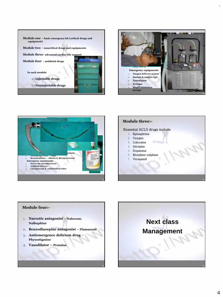
.
4
19
Module one - basic emergency kit (critical drugs and
equipment)
Module two - noncritical drugs and equipments
Module three- advanced cardiac life support
Module four - antidotal drugs
In each module
a) Injectable drugs
b) Noninjectable drugs
20
Module one:-
• Injectable drugs
1. Epinephrine – 1: 1000
2. Antihistamine – CPM
• Noninjectable drugs
1. Oxygen – E- Cylinder
2. Vasodialator – NTG,
Amyl nitrite
• Emergency equipments
1. Oxygen delivery system
2. Suction & suction tips
3. Tourniquets
4. Syringes
5. Magill intubation
forceps
• Positive pressure oxygen
• Bag-valve-mask device (ambu bag)
• Pocket mask
21
Module two:-• Injectable drugs
1. Anticonvulsant – Midazolam, Diazepam
2. Analgesic – Morphine
3. Vasopressor – Methoxamine, Phenylephrine.
4. Antihypoglycemic – 50% dextrose, Glucogon.
5. Corticosteroid – Hydrocortisone, Dexamethosone
6. Antihypertensive – Lebetalol, Propronolol
7. Anticholinergic – Atropine
• Noninjectable drugs1. Respiratory stimulant – Aromatic Ammonia
2. Antihypoglycemic – Sugar
3. Bronchodilator – Albuterol, Metaproterenol.
• Emergency equipments1. Device for cricothyrotomy
2. Artificial airways
3. Laryngoscope & endotracheal tubes
22
Module three:-
Essential ACLS drugs include
1. Epinephrine
2. Oxygen
3. Lidocaine
4. Atropine
5. Dopamine
6. Morphine sulphate
7. Verapamil
23
Module four:-
1. Narcotic antagonist – Naloxone,
Nalbuphine
2. Benzodiazepine antagonist – Flumazenil
3. Antiemergence delirium drug –
Physostigmine
4. Vasodilator – Procaine
24
Next classManagement
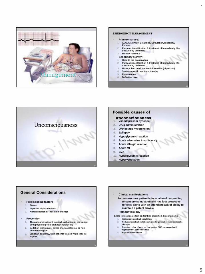
.
5
25
Management
26
EMERGENCY MANAGEMENT
• Primary survey:1. ABCDE: Airway, Breathing, Circulation, Disability,
Expose.2. Purpose: identification & treatment of immediately life-
threatening problems3. History: “AMPLE”
• Secondary survey:1. Head to toe examination2. Purpose: identification & treatment of immediately life-
threatening problems3. History: find quick source information (physician)4. System-specific tests and therapy5. Reevaluation6. Definitive care.
27
Unconsciousness
28
Possible causes of
unconsciousness1. Vasodepressor syncope2. Drug administration3. Orthostatic hypotension4. Epilepsy5. Hypoglycemic reaction6. Acute adrenaline insufficiency7. Acute allergic reaction8. Acute MI9. CVA10. Hyperglycemic reaction 11. Hyperventilation
29
General Considerations
• Predisposing factors 1. Stress2. Impaired physical status3. Administration or ingestion of drugs
• Prevention 1. Through pretreatment medical evaluation of the patient
both physiologically and psychologically 2. Sedation techniques: either pharmacological or non
pharmacological.3. Sit-down dentistry, with patients treated while they lie
supine.
30
• Clinical manifestationsAn unconscious patient is incapable of responding
to sensory stimulation and has lost protective reflexes along with an attendant lack of ability to maintain a patent airway.
• Pathophysiology Engle in his classic test on fainting classified 4 mechanisms
1. Inadequate cerebral circulation 2. Reduced cerebral metabolism due to general or local metabolic
changes3. Direct or reflex effects on that part of CNS concerned with
regulation of consciousness 4. Psychic mechanisms
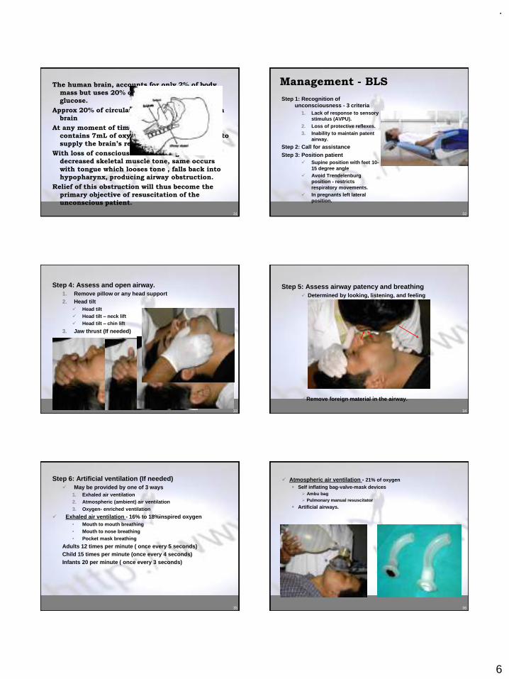
.
6
31
The human brain, accounts for only 2% of body
mass but uses 20% of oxygen and 65% of total
glucose.
Approx 20% of circulation per minute must reach
brain
At any moment of time blood circulation of brain
contains 7mL of oxygen, an amount sufficient to
supply the brain’s requirement for 10 seconds
With loss of consciousness there is generalized
decreased skeletal muscle tone, same occurs
with tongue which looses tone , falls back into
hypopharynx, producing airway obstruction.
Relief of this obstruction will thus become the
primary objective of resuscitation of the
unconscious patient.
32
Management - BLS
Step 1: Recognition of unconsciousness - 3 criteria
1. Lack of response to sensory stimulus (AVPU).
2. Loss of protective reflexes.3. Inability to maintain patent
airway.
Step 2: Call for assistanceStep 3: Position patient
✓ Supine position with feet 10-15 degree angle
✓ Avoid Trendelenburg position - restricts respiratory movements.
✓ In pregnants left lateral position.
33
Step 4: Assess and open airway.1. Remove pillow or any head support2. Head tilt
✓ Head tilt✓ Head tilt – neck lift✓ Head tilt – chin lift
3. Jaw thrust (If needed)
34
Step 5: Assess airway patency and breathing✓ Determined by looking, listening, and feeling
✓Remove foreign material in the airway.
35
Step 6: Artificial ventilation (If needed)✓ May be provided by one of 3 ways
1. Exhaled air ventilation2. Atmospheric (ambient) air ventilation3. Oxygen- enriched ventilation
✓ Exhaled air ventilation - 16% to 18%inspired oxygen• Mouth to mouth breathing• Mouth to nose breathing• Pocket mask breathing
Adults 12 times per minute ( once every 5 seconds)Child 15 times per minute (once every 4 seconds)Infants 20 per minute ( once every 3 seconds)
36
✓ Atmospheric air ventilation - 21% of oxygen▪ Self inflating bag-valve-mask devices
➢ Ambu bag➢ Pulmonary manual resuscitator
▪ Artificial airways.
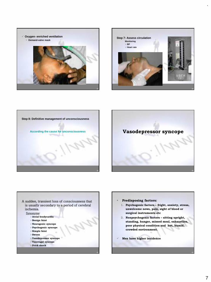
.
7
37
✓ Oxygen- enriched ventilation▪ Demand-valve mask
38
Step 7: Assess circulationMonitoring➢BP➢Heart rate
39
Step 8: Definitive management of unconsciousness
According the cause for unconsciousness
40
Vasodepressor syncope
41
A sudden, transient loss of consciousness that is usually secondary to a period of cerebral ischemia.
Synonyms:➢Atrial bradycardia
➢Benign faint
➢Neurogenic syncope
➢Psychogenic syncope
➢Simple faint
➢Swoon
➢Vasodepressor syncope
➢Vasovagal syncope
➢Prick shock
42
▪ Predisposing factors:
1. Psychogenic factors – fright, anxiety, stress,
unwelcome news, pain, sight of blood or
surgical instruments etc
2. Nonpsychogenic factors – sitting upright,
standing, hunger, missed meal, exhaustion,
poor physical condition and hot, humid,
crowded environment.
✓ Men have higher incidence
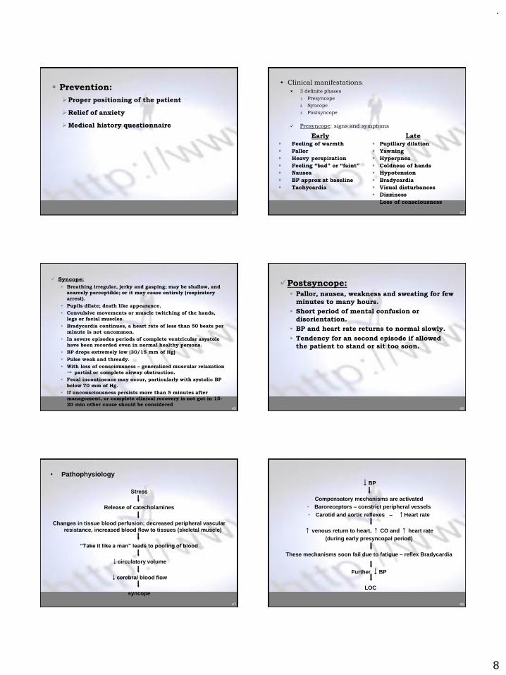
.
8
43
▪ Prevention:
➢Proper positioning of the patient
➢Relief of anxiety
➢Medical history questionnaire
44
Early▪ Feeling of warmth
▪ Pallor
▪ Heavy perspiration
▪ Feeling “bad” or “faint”
▪ Nausea
▪ BP approx at baseline
▪ Tachycardia
Late▪ Pupillary dilation
▪ Yawning
▪ Hyperpnea
▪ Coldness of hands
▪ Hypotension
▪ Bradycardia
▪ Visual disturbances
▪ Dizziness
▪ Loss of consciousness
• Clinical manifestations:
3 definite phases
1. Presyncope
2. Syncope
3. Postsyncope
✓ Presyncope: signs and symptoms
45
✓ Syncope:
• Breathing irregular, jerky and gasping; may be shallow, and
scarcely perceptible; or it may cease entirely (respiratory
arrest).
• Pupils dilate; death like appearance.
• Convulsive movements or muscle twitching of the hands,
legs or facial muscles.
• Bradycardia continues, a heart rate of less than 50 beats per
minute is not uncommon.
• In severe episodes periods of complete ventricular asystole
have been recorded even in normal healthy persons.
• BP drops extremely low (30/15 mm of Hg)
• Pulse weak and thready.
• With loss of consciousness – generalized muscular relaxation
→ partial or complete airway obstruction.
• Fecal incontinence may occur, particularly with systolic BP
below 70 mm of Hg.
• If unconsciousness persists more than 5 minutes after
management, or complete clinical recovery is not got in 15-
20 min other cause should be considered46
✓Postsyncope:• Pallor, nausea, weakness and sweating for few
minutes to many hours.
• Short period of mental confusion or
disorientation.
• BP and heart rate returns to normal slowly.
• Tendency for an second episode if allowed
the patient to stand or sit too soon.
47
• Pathophysiology
Stress
Release of catecholamines
Changes in tissue blood perfusion; decreased peripheral vascular resistance, increased blood flow to tissues (skeletal muscle)
“Take it like a man” leads to pooling of blood
↓circulatory volume
↓cerebral blood flow
syncope
48
↓BP
Compensatory mechanisms are activated• Baroreceptors – constrict peripheral vessels• Carotid and aortic reflexes – ↑Heart rate
↑ venous return to heart, ↑ CO and ↑ heart rate (during early presyncopal period)
These mechanisms soon fail due to fatigue – reflex Bradycardia
Further ↓BP
LOC
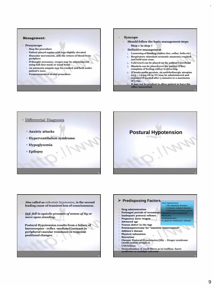
.
9
49
Management:
• Presyncope
• Stop the procedure
• Patient placed supine with legs slightly elevated
• Muscular movements, aids the return of blood from periphery
• If thought necessary, oxygen may be administered, using full-face mask or nasal hood.
• An ammonia ampule may be crushed and held under patient’s nose.
• Postponement of dental procedure.
50
• Syncope
• Should follow the basic management steps
Step 1 to step 7
• Definitive management
1. Loosening of binding clothes ties, collar, belts etc)
2. Respiratory stimulant aromatic ammonia crushed and held near nose.
3. Cold towel can be placed on the patient’s forehead
4. Blankets can be placed over the patient if they complain of feeling cold or is shivering.
5. If bradycardia persists, an anticholinergic atropine (0.5 – 1.0 mg IM or IV) may be administered and repeated if needed after 5 minutes to a maximum of 3 mg..
6. It may not be prudent to allow patient to leave the office unescorted.
51
• Differential Diagnosis
▪ Anxiety attacks
▪ Hyperventilation syndrome
▪ Hypoglycemia
▪ Epilepsy
52
Postural Hypotension
53
• Also called as orthostatic hypotension, is the second leading cause of transient loss of consciousness.
• Def: fall in systolic pressure of 20mm of Hg or more upon standing.
Postural Hypotension results from a failure of baroreceptor –reflex -mediated increase in peripheral vascular resistance in response positional changes.
54
➢ Predisposing Factors
✓ Drug administration
✓ Prolonged periods of recumbancy and covalescence
✓ Inadequate postural reflexes
✓ Pregnancy (later stages)
✓ Advanced age
✓ Venous defect in the legs
✓ Postsympatectomy for “essential hypertension”
✓ Addison’s disease
✓ Physical exhaustion
✓ Starvation
✓ Chronic Postural Hypotension [Shy – Drager syndrome (multi system atrophy)]
✓ CNS lesions
✓ Demyelination of small fibers as in Guillian- barre syndrome or multiple sclerosis
▪Anti hypertensive➢Na depleting diuretics➢Calcium channel blockers➢Ganglionic blocking agents
▪Sedatives and tranquilizers▪Narcotics▪Antihistaminics▪L-dopa for Parkinson's disease
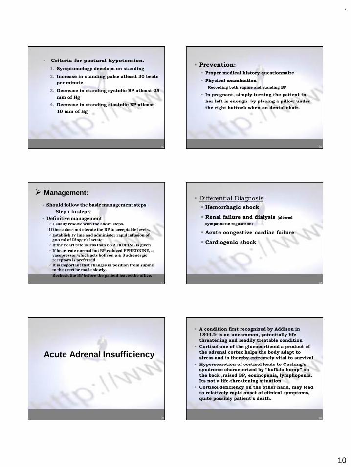
.
10
55
• Criteria for postural hypotension.
1. Symptomology develops on standing
2. Increase in standing pulse atleast 30 beats
per minute
3. Decrease in standing systolic BP atleast 25
mm of Hg
4. Decrease in standing diastolic BP atleast
10 mm of Hg
56
• Prevention:
• Proper medical history questionnaire
• Physical examination
Recording both supine and standing BP
• In pregnant, simply turning the patient to
her left is enough: by placing a pillow under
the right buttock when on dental chair.
57
➢ Management:
• Should follow the basic management steps
Step 1 to step 7
• Definitive management
✓Usually resolve with the above steps.
If these does not elevate the BP to acceptable levels,
✓Establish IV line and administer rapid infusion of 500 ml of Ringer’s lactate
✓If the heart rate is less than 60 ATROPINE is given
✓If heart rate normal but BP reduced EPHEDRINE, a vasopressor which acts both on α & β adrenergic receptors is preferred
✓It is important that changes in position from supine to the erect be made slowly.
✓Recheck the BP before the patient leaves the office.
58
• Differential Diagnosis
▪ Hemorrhagic shock
▪ Renal failure and dialysis (altered
sympathetic regulation)
▪ Acute congestive cardiac failure
▪ Cardiogenic shock
59
Acute Adrenal Insufficiency
60
• A condition first recognized by Addison in
1844.It is an uncommon, potentially life
threatening and readily treatable condition
• Cortisol one of the glucocorticoid a product of
the adrenal cortex helps the body adapt to
stress and is thereby extremely vital to survival.
• Hypersecretion of cortisol leads to Cushing's
syndrome characterized by “buffalo hump” on
the back ,raised BP, eosinopenia, lymphopenia.
Its not a life-threatening situation
• Cortisol deficiency on the other hand, may lead
to relatively rapid onset of clinical symptoms,
quite possibly patient’s death.
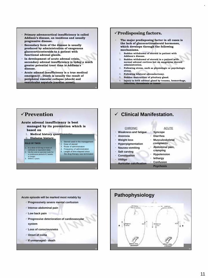
.
11
61
• Primary adrenocortical insufficiency is called
Addison’s disease, an insidious and usually
progressive disease.
• Secondary form of the disease is usually
produced by administration of exogenous
glucocorticosteroids to a patient with
functional adrenal glands.
• In development of acute adrenal crisis,
secondary adrenal insufficiency is today a much
greater potential treat than is Addison's
disease.
• Acute adrenal insufficiency is a true medical
emergency . Death is usually the result of
peripheral vascular collapse (shock) and
ventricular asystole (cardiac arrest).
62
✓Predisposing factors.
• The major predisposing factor in all cases is
the lack of glucocorticosteroid hormones,
which develops through the following
mechanisms.
1. Sudden withdrawal of steroid in patient with
Addison's disease.
2. Sudden withdrawal of steroid in a patient with
normal adrenal cortices but on exogenous steroid
administration.
3. Following stress, such as physiologic or psychologic
stress.
4. Following bilateral adrenalectomy.
5. Sudden destruction of pituitary gland.
6. Injury to both adrenal gland by trauma, hemorrhage,
infection, thrombosis or tumor.
63
✓Prevention
Acute adrenal insufficiency is best
managed by its prevention which is
based on
1. Medical history questionnaire.
2. Dialogue history.
1. Steroid used in the management2. Dose of steroid 3. Route of administration4. Frequency of administration5. Length of time elapsed since
the drug therapy was terminated
RULE OF TWOS
1. In a dose of 20 mg or more of cortisone or equivalent daily.
2. Via the oral or parental route fora continuous period of 2 weeksor longer.
3. Within 2 years.
64
✓ Clinical Manifestation.
CHRONIC• Weakness and fatigue• Anorexia• Weight loss• Hyperpigmentation• Nausea vomiting• Salt carving• Constipation• Vitiligo • Auricular calcification
ACUTE• Syncope• Diarrhea• Musculoskeletal
complaints• Abdominal pain,
cramping• Hypotension• lethargy• Confusion• Psychosis
65
Acute episode will be marked most notably by
✓Progressively severe mental confusion
✓ Intense abdominal pain
✓Low back pain
✓Progressive deterioration of cardiovascular
system
✓Loss of consciousness
✓Onset of coma
✓ If unmanaged - death
66
Pathophysiology
.
12
67 68
69 70
71
✓Management
• The patient with acute adrenal
insufficiency is an immediate danger
because of
✓Glucocorticoid deficiency
✓Depletion of extracellular fluid
✓Hyperkalemia
• Treatment is based on the prompt
correction of these conditions.
72
• Conscious patient1. Terminal dental therapy2. Position the patient ( supine )3. Monitor vital signs4. Summon medical assistance ( patients physician )5. Oxygen6. Administer glucocorticosteroids
i. If a known adrenal insufficiency patient administer 100 mg of hydrocortisone sodium succinate (IV or IM) and repeat every 6 – 8 hours
ii. If no prior history, dexamethasone phosphate 4 mg IV every 6 – 8 hours until diagnosis is confirmed by ACTH stimulation test.
7. Additional management1. 1 liter of normal saline infused in first hour2. 5 % dextrose added next to help combat hypoglycemia3. If absence of IV line 1 – 2 mg of glucagon should be
administered IM

.
13
73
• Unconscious patient1. Recognize unconsciousness
2. Position the patient
3. Provide BLS
4. Definitive management1. Oxygen
2. There will be no response by patient to ammonia
3. Administer 100 mg hydrocortisone IV or IM should be injected over 30 seconds
4. 1 liter of normal saline infused in first hour
5. 5% dextrose added next to help combat hypoglycemia
74
Respiratory distress
75
Possible causes of unconsciousness
1. Hyperventilation2. Vasodepressor syncope3. Asthma4. Heart failure5. Hypoglycemia6. Overdose reaction7. Acute myocardial infarction8. Anaphylaxis9. Angioneurotic edema10. Cerebrovascular accident11. Epilepsy12. Hyperglycemic reaction
76
General management of respiratory distress
Recognize :sounds (wheezing, cough)
Terminate dental procedure
Position patient
BLS
Monitor vital signs
Manage patient’s anxiety
Provide definitive management
77
Airway Obstruction
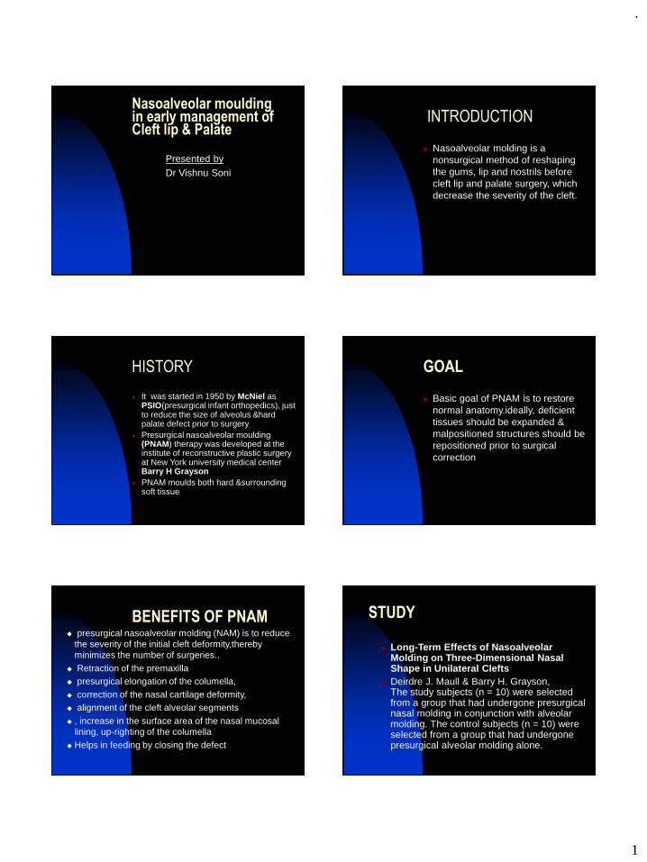
.
1
Nasoalveolar moulding in early management of Cleft lip & Palate
Presented byDr Vishnu Soni
INTRODUCTION
◼ Nasoalveolar molding is a nonsurgical method of reshaping the gums, lip and nostrils before cleft lip and palate surgery, which decrease the severity of the cleft.
HISTORY
◼ It was started in 1950 by McNiel as PSIO(presurgical infant orthopedics), just to reduce the size of alveolus &hard palate defect prior to surgery
◼ Presurgical nasoalveolar moulding (PNAM) therapy was developed at the institute of reconstructive plastic surgery at New York university medical center Barry H Grayson
◼ PNAM moulds both hard &surrounding soft tissue
GOAL
◼ Basic goal of PNAM is to restore normal anatomy.ideally, deficient tissues should be expanded & malpositioned structures should be repositioned prior to surgical correction
BENEFITS OF PNAM◆ presurgical nasoalveolar molding (NAM) is to reduce
the severity of the initial cleft deformity,thereby minimizes the number of surgeries..
◆ Retraction of the premaxilla◆ presurgical elongation of the columella,◆ correction of the nasal cartilage deformity,◆ alignment of the cleft alveolar segments◆ , increase in the surface area of the nasal mucosal
lining, up-righting of the columella◆ Helps in feeding by closing the defect
STUDY
◼ Long-Term Effects of Nasoalveolar Molding on Three-Dimensional Nasal Shape in Unilateral Clefts
◼ Deirdre J. Maull & Barry H. Grayson, The study subjects (n = 10) were selected from a group that had undergone presurgical nasal molding in conjunction with alveolar molding. The control subjects (n = 10) were selected from a group that had undergone presurgical alveolar molding alone.
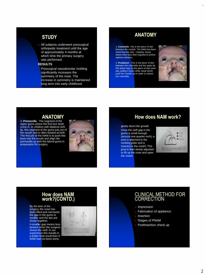
.
2
STUDY
◼ All subjects underwent presurgical orthopedic treatment until the age of approximately 4 months at which time the primary surgery was performed.
RESULTS◼ Presurgical nasoalveolar molding
significantly increases the symmetry of the nose. The increase in symmetry is maintained long term into early childhood
ANATOMY
◼
1. Columella - this is the piece of skin between the nostrils. The NAM has been stretching this skin , creating tissue where there less then required to achive optimal esthetics.
2. Prolabium - This is the piece of skin between the columella and the upper lip. We attach tape to this piece of skin each day, pulling it down while nasal stents push her nostrils up in order to stretch her columella.
ANATOMY◼ 3. Premaxilla - The segment of the
upper gums where the first four teeth come in. In children with bilateral cleft lip, this segment of the gums juts out of the mouth and is often twisted at birth. The first job of the NAM is to push this back into the mouth and align her premaxilla up with the lateral gums in preparation for surgery.
How does NAM work?
◼ gently direct the growth ◼ Once the cleft gap in the
gums is small enough (around one quarter-inch), a post is attached to the molding plate and is inserted in the nostril. This post is then slowly adjusted to lift up the nose and open the nostril.
How does NAM work?(CONTD.)
◼ By the time of the surgery, the nose has been lifted and narrowed, the gap in the gums is smaller and the lips are closer together.
◼ A smaller gap means less tension when the surgeon closes the cleft. In our experience this results in a better final result than if NAM had not been done.
CLINICAL METHOD FOR CORRECTION
◼ Impression◼ Fabrication of appliance
◼ Insertion◼ Stages of PNAM
◼ Postinsertion check up
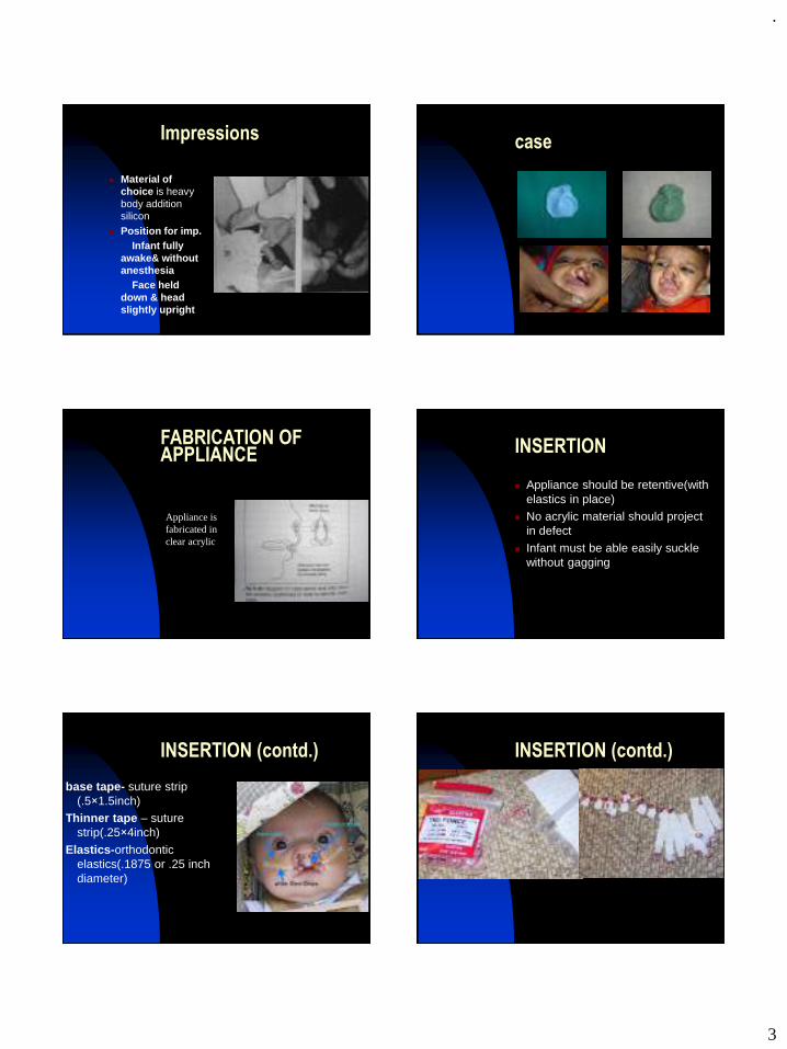
.
3
Impressions
◼ Material of choice is heavy body addition silicon
◼ Position for imp.Infant fully
awake& without anesthesia
Face held down & head slightly upright
case
FABRICATION OF APPLIANCE
Appliance is fabricated in clear acrylic
INSERTION
◼ Appliance should be retentive(with elastics in place)
◼ No acrylic material should project in defect
◼ Infant must be able easily suckle without gagging
INSERTION (contd.)
base tape- suture strip (.5×1.5inch)
Thinner tape – suture strip(.25×4inch)
Elastics-orthodontic elastics(.1875 or .25 inch diameter)
INSERTION (contd.)
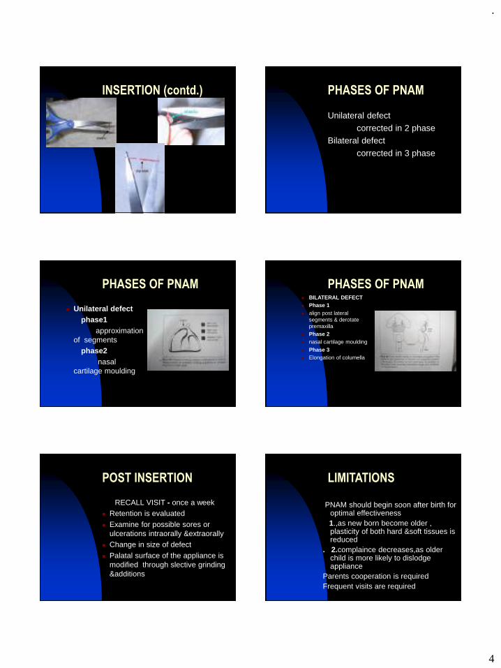
.
4
INSERTION (contd.)
◼
PHASES OF PNAM
Unilateral defect
corrected in 2 phaseBilateral defect
corrected in 3 phase
PHASES OF PNAM
◼ Unilateral defectphase1
approximation of segments
phase2nasal
cartilage moulding
PHASES OF PNAM◼ BILATERAL DEFECT◼ Phase 1 ◼ align post lateral
segments & derotate premaxilla
◼ Phase 2 ◼ nasal cartilage moulding
◼ Phase 3 ◼ Elongation of columella
POST INSERTION
RECALL VISIT - once a week◼ Retention is evaluated
◼ Examine for possible sores or ulcerations intraorally &extraorally
◼ Change in size of defect
◼ Palatal surface of the appliance is modified through slective grinding &additions
LIMITATIONS
PNAM should begin soon after birth for optimal effectiveness 1.,as new born become older , plasticity of both hard &soft tissues is reduced
. 2.complaince decreases,as older child is more likely to dislodge appliance
Parents cooperation is requiredFrequent visits are required
.
5
COMPLICATIONS
1. Locked out segment2. Nostril over expansion
3. Tissue ulceration4. Failure to retain appliance
5. Exposure of a primary tooth
THANK YOU
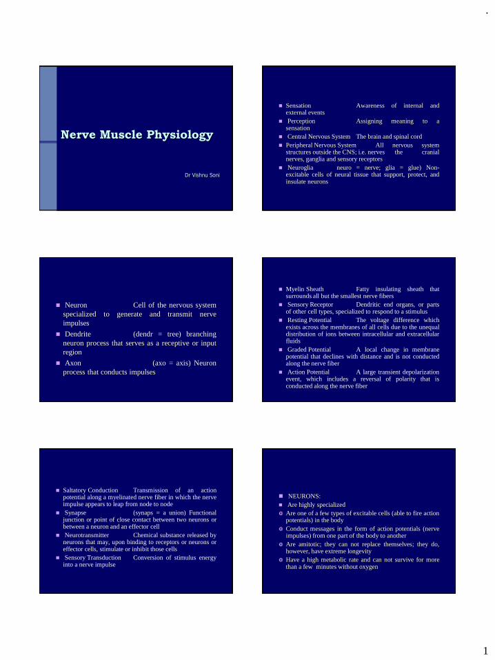
.
1
Nerve Muscle Physiology
Dr Vishnu Soni
◼ Sensation Awareness of internal andexternal events
◼ Perception Assigning meaning to asensation
◼ Central Nervous System The brain and spinal cord◼ Peripheral Nervous System All nervous system
structures outside the CNS; i.e. nerves the cranialnerves, ganglia and sensory receptors
◼ Neuroglia neuro = nerve; glia = glue) Non-excitable cells of neural tissue that support, protect, andinsulate neurons
◼ Neuron Cell of the nervous systemspecialized to generate and transmit nerveimpulses
◼ Dendrite (dendr = tree) branchingneuron process that serves as a receptive or inputregion
◼ Axon (axo = axis) Neuronprocess that conducts impulses
◼ Myelin Sheath Fatty insulating sheath thatsurrounds all but the smallest nerve fibers
◼ Sensory Receptor Dendritic end organs, or partsof other cell types, specialized to respond to a stimulus
◼ Resting Potential The voltage difference whichexists across the membranes of all cells due to the unequaldistribution of ions between intracellular and extracellularfluids
◼ Graded Potential A local change in membranepotential that declines with distance and is not conductedalong the nerve fiber
◼ Action Potential A large transient depolarizationevent, which includes a reversal of polarity that isconducted along the nerve fiber
◼ Saltatory Conduction Transmission of an actionpotential along a myelinated nerve fiber in which the nerveimpulse appears to leap from node to node
◼ Synapse (synaps = a union) Functionaljunction or point of close contact between two neurons orbetween a neuron and an effector cell
◼ Neurotransmitter Chemical substance released byneurons that may, upon binding to receptors or neurons oreffector cells, stimulate or inhibit those cells
◼ Sensory Transduction Conversion of stimulus energyinto a nerve impulse
◼ NEURONS:◼ Are highly specialized Are one of a few types of excitable cells (able to fire action
potentials) in the body Conduct messages in the form of action potentials (nerve
impulses) from one part of the body to another Are amitotic; they can not replace themselves; they do,
however, have extreme longevity Have a high metabolic rate and can not survive for more
than a few minutes without oxygen
.
2
Have a cell body or soma and numerous thinprocesses (extensions)
Most cell bodies of neurons are located in theCNS where they are protected by the cranium andvertebral column
Within cell bodies all standard organelles arecontained
◼ Dendrites are processes that receive information, they areinput regions of the neuron but they do not have the abilityto generate action potentials.
◼ Axons are processes that can generate andconduct action potentials, they arise at an area associatedwith neuron's soma called the axon hillock or spikeinitiation zone (trigger zone); they may be very short orvery long depending on where they are conductinginformation; can give off branches called axon collaterals;finally they form synapses at their terminals.
MYELlNATED AND UNMYELINATED NERVE FIBERS
The large fibers are myelinated, and the small ones are unmyelinated.
The average nerve trunk contains about twice as many unmyelinated fibers as myelinated fibers.
◼ The central core of the fiber is the axon, and the membrane of the axon is the actual conductive membrane for conducting the 'action potential. The axon is filled in its center with axoplasm, which is a viscid intracellular fluid.
◼ Surrounding the axon is a myelin sheath that is often thicker than the axon itself, and about once every 1 to 3 millimeters along the length of the axon the myelin sheath is interrupted by a node of Ranvier.
◼ The myelin sheath is deposited around the axon by Schwann cells
◼ Saltatory conduction in myelinated fibers from node to node -action potentials are conducted from node to node
◼ electrical current flows through the surrounding extracellular fluids outside the myelin sheath as well as through the axoplasm from node to node, exciting successive nodes one after another.
Velocity of Conduction in Nerve Fibers
◼ The velocity of conduction in nerve fibers varies from as little as 0.25 m/sec in very small unmyelinated fibers to as high as 100 m/sec (the length of a football field in 1 second) in very large myelinated fibers.
◼ The velocity increases approximately with the fiber diameter in myelinated nerve fibers and approximately with the square root of fiber diameter in unmyelinated fibers.
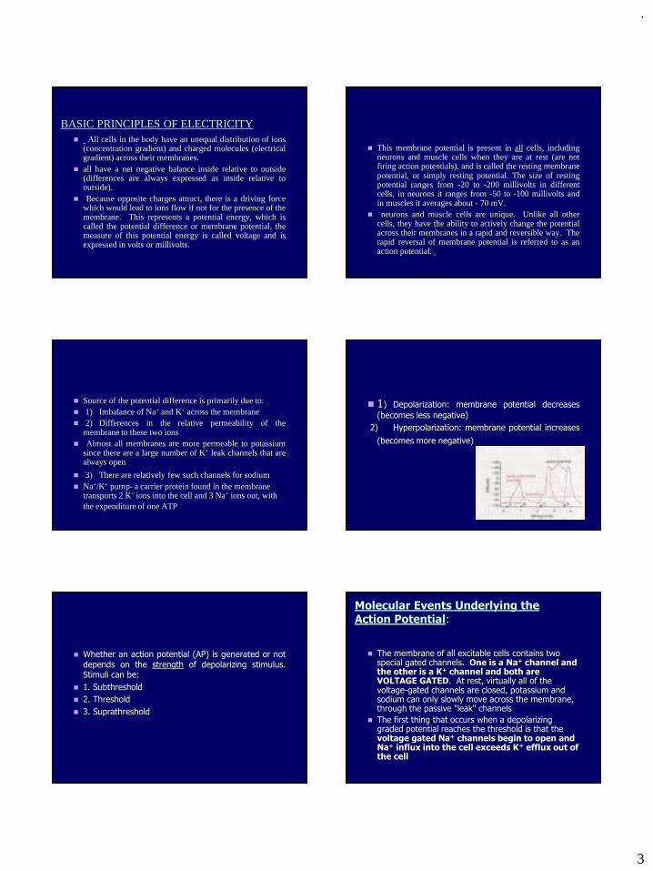
.
3
BASIC PRINCIPLES OF ELECTRICITY◼ All cells in the body have an unequal distribution of ions
(concentration gradient) and charged molecules (electricalgradient) across their membranes.
◼ all have a net negative balance inside relative to outside(differences are always expressed as inside relative tooutside).
◼ Because opposite charges attract, there is a driving forcewhich would lead to ions flow if not for the presence of themembrane. This represents a potential energy, which iscalled the potential difference or membrane potential, themeasure of this potential energy is called voltage and isexpressed in volts or millivolts.
◼ This membrane potential is present in all cells, includingneurons and muscle cells when they are at rest (are notfiring action potentials), and is called the resting membranepotential, or simply resting potential. The size of restingpotential ranges from -20 to -200 millivolts in differentcells, in neurons it ranges from -50 to -100 millivolts andin muscles it averages about - 70 mV.
◼ neurons and muscle cells are unique. Unlike all othercells, they have the ability to actively change the potentialacross their membranes in a rapid and reversible way. Therapid reversal of membrane potential is referred to as anaction potential.
◼ Source of the potential difference is primarily due to:◼ 1) Imbalance of Na+ and K+ across the membrane◼ 2) Differences in the relative permeability of the
membrane to these two ions◼ Almost all membranes are more permeable to potassium
since there are a large number of K+ leak channels that arealways open
◼ 3) There are relatively few such channels for sodium◼ Na+/K+ pump- a carrier protein found in the membrane
transports 2 K+ ions into the cell and 3 Na+ ions out, with the expenditure of one ATP
◼ 1) Depolarization: membrane potential decreases
(becomes less negative)
2) Hyperpolarization: membrane potential increases
(becomes more negative)
◼ Whether an action potential (AP) is generated or notdepends on the strength of depolarizing stimulus.Stimuli can be:
◼ 1. Subthreshold
◼ 2. Threshold
◼ 3. Suprathreshold
◼ The membrane of all excitable cells contains two special gated channels. One is a Na+ channel and the other is a K+ channel and both are VOLTAGE GATED. At rest, virtually all of the voltage-gated channels are closed, potassium and sodium can only slowly move across the membrane, through the passive "leak" channels
◼ The first thing that occurs when a depolarizing graded potential reaches the threshold is that the voltage gated Na+ channels begin to open and Na+ influx into the cell exceeds K+ efflux out of the cell
Molecular Events Underlying the Action Potential:
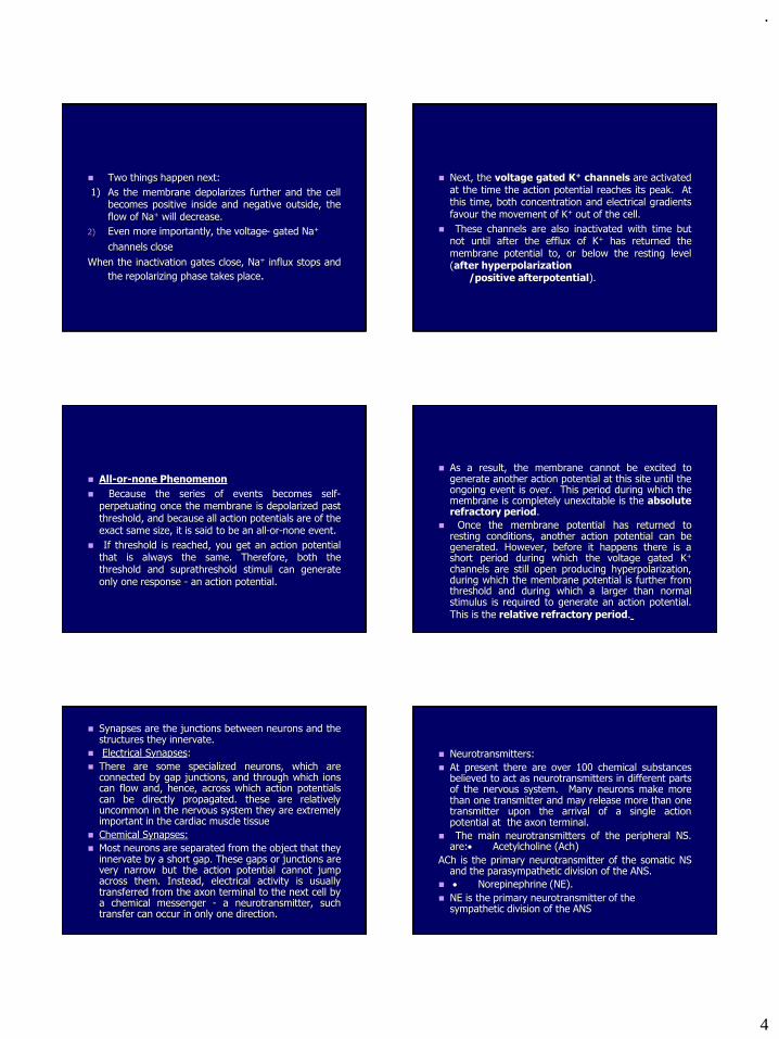
.
4
◼ Two things happen next:
1) As the membrane depolarizes further and the cellbecomes positive inside and negative outside, theflow of Na+ will decrease.
2) Even more importantly, the voltage- gated Na+
channels close
When the inactivation gates close, Na+ influx stops and
the repolarizing phase takes place.
◼ Next, the voltage gated K+ channels are activatedat the time the action potential reaches its peak. Atthis time, both concentration and electrical gradientsfavour the movement of K+ out of the cell.
◼ These channels are also inactivated with time butnot until after the efflux of K+ has returned themembrane potential to, or below the resting level(after hyperpolarization
/positive afterpotential).
◼ All-or-none Phenomenon
◼ Because the series of events becomes self-perpetuating once the membrane is depolarized pastthreshold, and because all action potentials are of theexact same size, it is said to be an all-or-none event.
◼ If threshold is reached, you get an action potentialthat is always the same. Therefore, both thethreshold and suprathreshold stimuli can generateonly one response - an action potential.
◼ As a result, the membrane cannot be excited togenerate another action potential at this site until theongoing event is over. This period during which themembrane is completely unexcitable is the absoluterefractory period.
◼ Once the membrane potential has returned toresting conditions, another action potential can begenerated. However, before it happens there is ashort period during which the voltage gated K+
channels are still open producing hyperpolarization,during which the membrane potential is further fromthreshold and during which a larger than normalstimulus is required to generate an action potential.
This is the relative refractory period.
◼ Synapses are the junctions between neurons and thestructures they innervate.
◼ Electrical Synapses:
◼ There are some specialized neurons, which areconnected by gap junctions, and through which ionscan flow and, hence, across which action potentialscan be directly propagated. these are relativelyuncommon in the nervous system they are extremelyimportant in the cardiac muscle tissue
◼ Chemical Synapses:
◼ Most neurons are separated from the object that theyinnervate by a short gap. These gaps or junctions arevery narrow but the action potential cannot jumpacross them. Instead, electrical activity is usuallytransferred from the axon terminal to the next cell bya chemical messenger - a neurotransmitter, suchtransfer can occur in only one direction.
◼ Neurotransmitters:
◼ At present there are over 100 chemical substancesbelieved to act as neurotransmitters in different partsof the nervous system. Many neurons make morethan one transmitter and may release more than onetransmitter upon the arrival of a single actionpotential at the axon terminal.
◼ The main neurotransmitters of the peripheral NS.are:• Acetylcholine (Ach)
ACh is the primary neurotransmitter of the somatic NSand the parasympathetic division of the ANS.
◼ • Norepinephrine (NE).
◼ NE is the primary neurotransmitter of the sympathetic division of the ANS
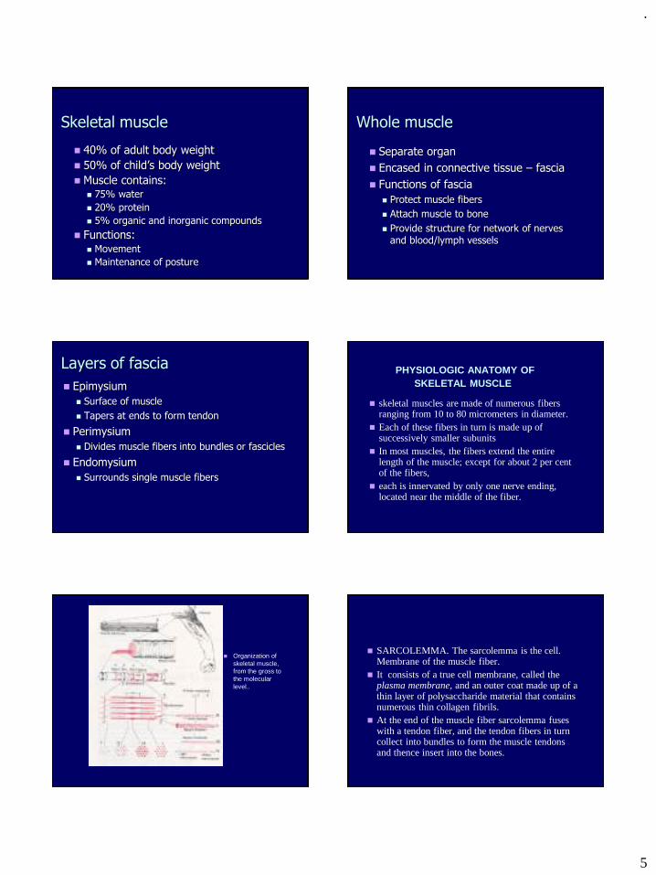
.
5
Skeletal muscle
◼ 40% of adult body weight
◼ 50% of child’s body weight
◼ Muscle contains:◼ 75% water
◼ 20% protein
◼ 5% organic and inorganic compounds
◼ Functions:◼ Movement
◼ Maintenance of posture
Whole muscle
◼ Separate organ
◼ Encased in connective tissue – fascia
◼ Functions of fascia
◼ Protect muscle fibers
◼ Attach muscle to bone
◼ Provide structure for network of nerves and blood/lymph vessels
Layers of fascia
◼ Epimysium
◼ Surface of muscle
◼ Tapers at ends to form tendon
◼ Perimysium
◼ Divides muscle fibers into bundles or fascicles
◼ Endomysium
◼ Surrounds single muscle fibers
PHYSIOLOGIC ANATOMY OFSKELETAL MUSCLE
◼ skeletal muscles are made of numerous fibers ranging from 10 to 80 micrometers in diameter.
◼ Each of these fibers in turn is made up of successively smaller subunits
◼ In most muscles, the fibers extend the entire length of the muscle; except for about 2 per cent of the fibers,
◼ each is innervated by only one nerve ending, located near the middle of the fiber.
◼ Organization of skeletal muscle, from the gross to the molecular level..
◼ SARCOLEMMA. The sarcolemma is the cell. Membrane of the muscle fiber.
◼ It consists of a true cell membrane, called the plasma membrane, and an outer coat made up of a thin layer of polysaccharide material that contains numerous thin collagen fibrils.
◼ At the end of the muscle fiber sarcolemma fuses with a tendon fiber, and the tendon fibers in turn collect into bundles to form the muscle tendons and thence insert into the bones.
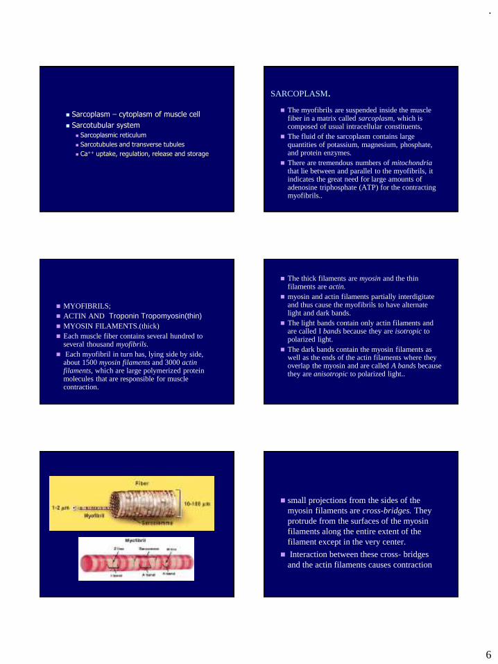
.
6
◼ Sarcoplasm – cytoplasm of muscle cell
◼ Sarcotubular system
◼ Sarcoplasmic reticulum
◼ Sarcotubules and transverse tubules
◼ Ca++ uptake, regulation, release and storage
SARCOPLASM.◼ The myofibrils are suspended inside the muscle
fiber in a matrix called sarcoplasm, which is composed of usual intracellular constituents,
◼ The fluid of the sarcoplasm contains large quantities of potassium, magnesium, phosphate, and protein enzymes.
◼ There are tremendous numbers of mitochondria that lie between and parallel to the myofibrils, it indicates the great need for large amounts of adenosine triphosphate (ATP) for the contracting myofibrils..
◼ MYOFIBRILS;◼ ACTIN AND Troponin Tropomyosin(thin)◼ MYOSIN FILAMENTS.(thick)◼ Each muscle fiber contains several hundred to
several thousand myofibrils.◼ Each myofibril in turn has, lying side by side,
about 1500 myosin filaments and 3000 actin filaments, which are large polymerized protein molecules that are responsible for muscle contraction.
◼ The thick filaments are myosin and the thin filaments are actin.
◼ myosin and actin filaments partially interdigitate and thus cause the myofibrils to have alternate light and dark bands.
◼ The light bands contain only actin filaments and are called I bands because they are isotropic to polarized light.
◼ The dark bands contain the myosin filaments as well as the ends of the actin filaments where they overlap the myosin and are called A bands because they are anisotropic to polarized light..
◼ small projections from the sides of the myosin filaments are cross-bridges. They protrude from the surfaces of the myosin filaments along the entire extent of the filament except in the very center.
◼ Interaction between these cross- bridges and the actin filaments causes contraction
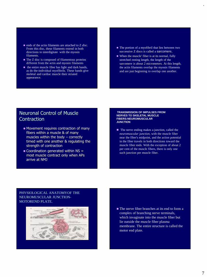
.
7
◼ ends of the actin filaments are attached to Z disc. From this disc, these filaments extend in both directions to interdigitate with the myosin filaments.
◼ The Z disc is composed of filamentous proteins different from the actin and myosin filaments
◼ the entire muscle fiber has light and dark bands, as do the-individual myofibrils. These bands give skeletal and cardiac muscle their striated appearance.
◼ The portion of a myofibril that lies between two successive Z discs is called a sarcomere,
◼ When the muscle' fiber is at its normal, fully stretched resting length, the length of the sarcomere is about 2 micrometers. At this length, the actin filaments overlap the myosin filaments and are just beginning to overlap one another.
Neuronal Control of Muscle Contraction
◼ Movement requires contraction of many fibers within a muscle & of many muscles within the body – correctly timed with one another & regulating the strength of contraction
◼ Coordination generated within NS = most muscle contract only when APs arrive at NMJ
◼ The nerve ending makes a junction, called the neuromuscular junction, with the muscle fiber near the fiber's midpoint, and the action potential in the fiber travels in both directions toward the muscle fiber ends. With the exception of about 2 per cent of the muscle fibers, there is only one such junction per muscle fiber.
TRANSMISSION OF IMPULSES FROMNERVES TO SKELETAL MUSCLE FIBERS:NEUROMUSCULARJUNCTION
PHYSIOLOGICAL ANATOMYOF THE NEUROMUSCULAR JUNCTION-MOTOREND PLATE.
◼ The nerve fiber branches at its end to form a complex of branching nerve terminals, which invaginate into the muscle fiber but lie outside the muscle fiber plasma membrane. The entire structure is called the motor end plate.
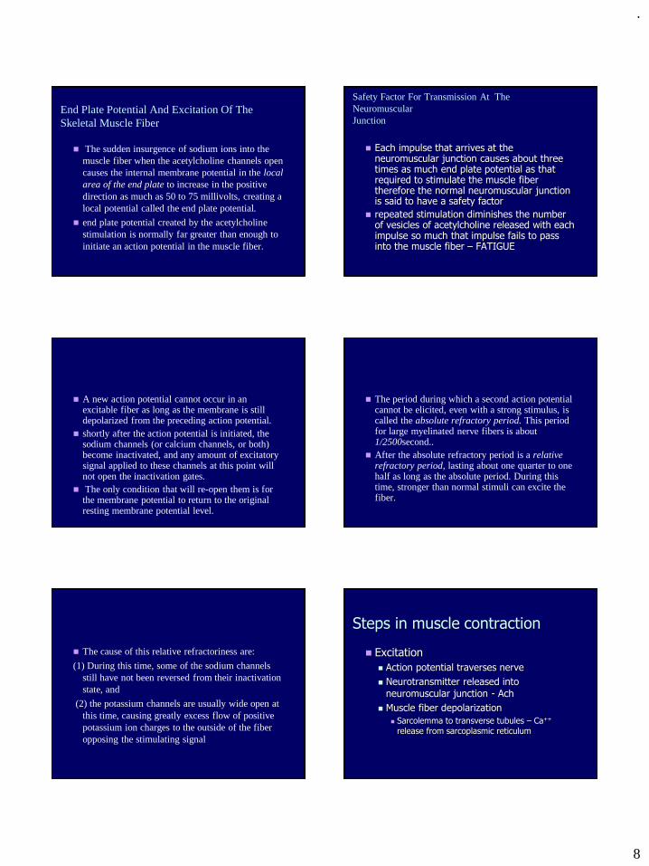
.
8
End Plate Potential And Excitation Of The Skeletal Muscle Fiber
◼ The sudden insurgence of sodium ions into the muscle fiber when the acetylcholine channels open causes the internal membrane potential in the local area of the end plate to increase in the positive direction as much as 50 to 75 millivolts, creating a local potential called the end plate potential.
◼ end plate potential created by the acetylcholine stimulation is normally far greater than enough to initiate an action potential in the muscle fiber.
Safety Factor For Transmission At The NeuromuscularJunction
◼ Each impulse that arrives at the neuromuscular junction causes about three times as much end plate potential as that required to stimulate the muscle fiber therefore the normal neuromuscular junction is said to have a safety factor
◼ repeated stimulation diminishes the number of vesicles of acetylcholine released with each impulse so much that impulse fails to pass into the muscle fiber – FATIGUE
◼ A new action potential cannot occur in an excitable fiber as long as the membrane is still depolarized from the preceding action potential.
◼ shortly after the action potential is initiated, the sodium channels (or calcium channels, or both) become inactivated, and any amount of excitatory signal applied to these channels at this point will not open the inactivation gates.
◼ The only condition that will re-open them is for the membrane potential to return to the original resting membrane potential level.
◼ The period during which a second action potential cannot be elicited, even with a strong stimulus, is called the absolute refractory period. This period for large myelinated nerve fibers is about 1/2500second..
◼ After the absolute refractory period is a relative refractory period, lasting about one quarter to one half as long as the absolute period. During this time, stronger than normal stimuli can excite the fiber.
◼ The cause of this relative refractoriness are:
(1) During this time, some of the sodium channels still have not been reversed from their inactivation state, and
(2) the potassium channels are usually wide open at this time, causing greatly excess flow of positive potassium ion charges to the outside of the fiber opposing the stimulating signal
Steps in muscle contraction
◼ Excitation
◼ Action potential traverses nerve
◼ Neurotransmitter released into neuromuscular junction - Ach
◼ Muscle fiber depolarization
◼ Sarcolemma to transverse tubules – Ca++
release from sarcoplasmic reticulum
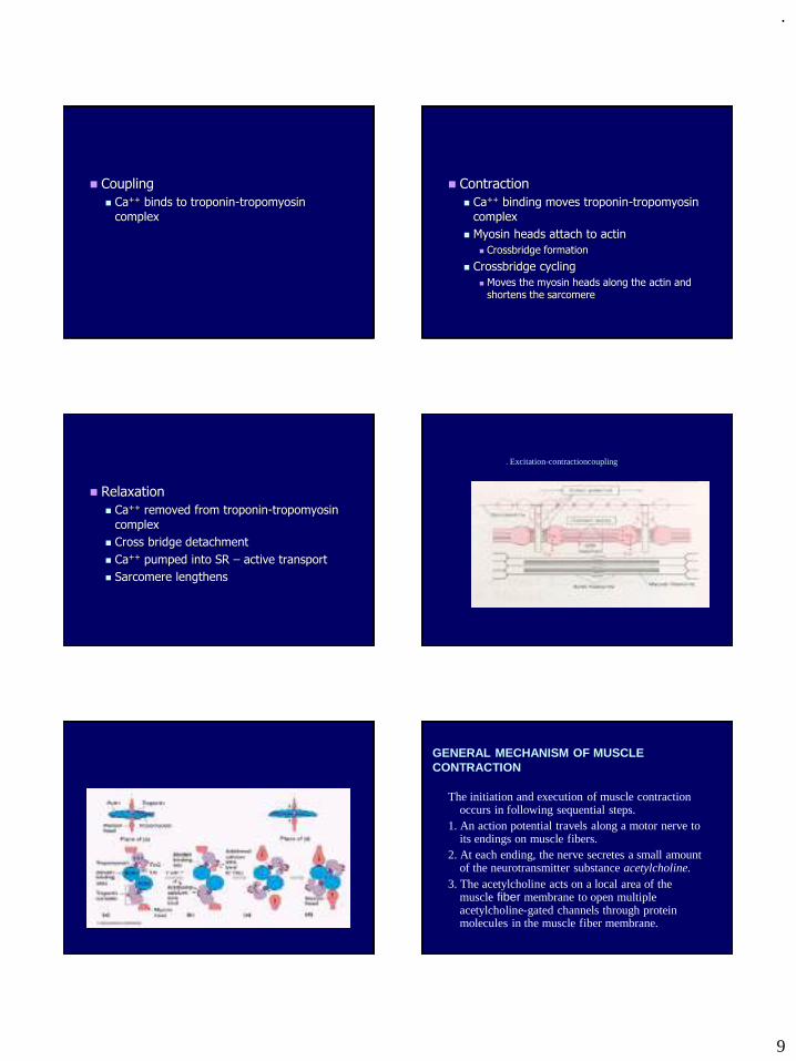
.
9
◼ Coupling
◼ Ca++ binds to troponin-tropomyosin
complex
◼ Contraction
◼ Ca++ binding moves troponin-tropomyosin
complex
◼ Myosin heads attach to actin
◼ Crossbridge formation
◼ Crossbridge cycling
◼ Moves the myosin heads along the actin and shortens the sarcomere
◼ Relaxation
◼ Ca++ removed from troponin-tropomyosin
complex
◼ Cross bridge detachment
◼ Ca++ pumped into SR – active transport
◼ Sarcomere lengthens
. Excitation-contractioncoupling
GENERAL MECHANISM OF MUSCLECONTRACTION
The initiation and execution of muscle contraction occurs in following sequential steps.
1. An action potential travels along a motor nerve to its endings on muscle fibers.
2. At each ending, the nerve secretes a small amount of the neurotransmitter substance acetylcholine.
3. The acetylcholine acts on a local area of the muscle fiber membrane to open multiple acetylcholine-gated channels through protein molecules in the muscle fiber membrane.
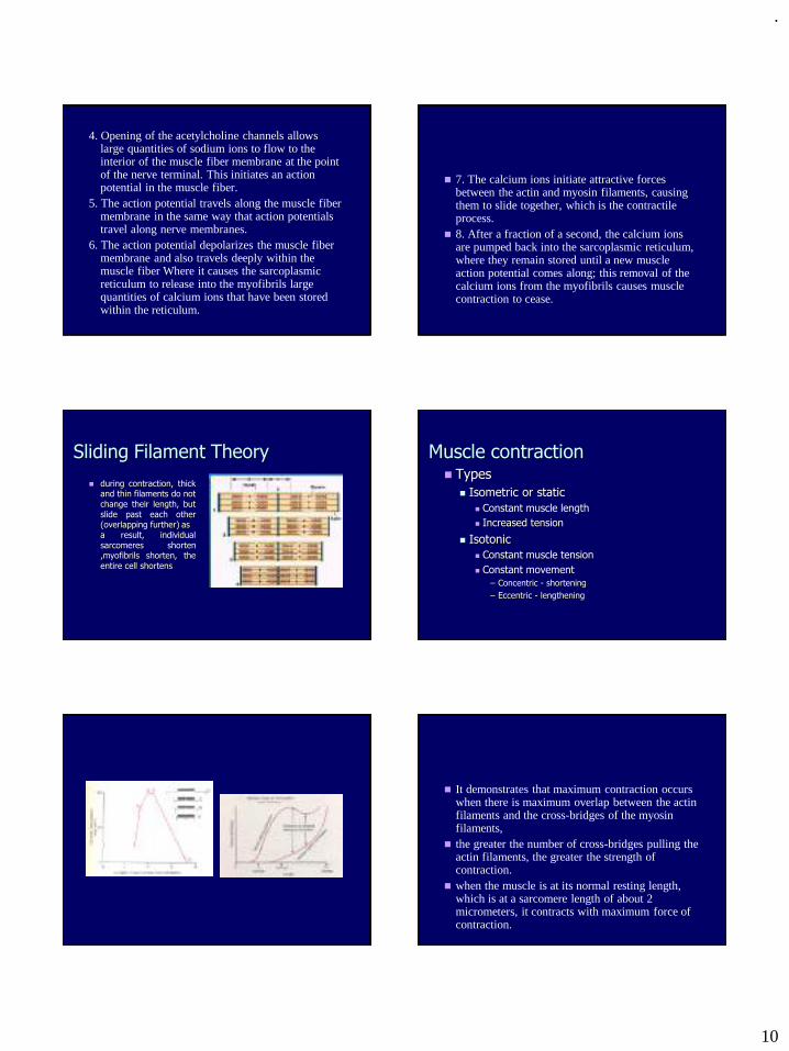
.
10
4. Opening of the acetylcholine channels allows large quantities of sodium ions to flow to the interior of the muscle fiber membrane at the point of the nerve terminal. This initiates an action potential in the muscle fiber.
5. The action potential travels along the muscle fiber membrane in the same way that action potentials travel along nerve membranes.
6. The action potential depolarizes the muscle fiber membrane and also travels deeply within the muscle fiber Where it causes the sarcoplasmic reticulum to release into the myofibrils large quantities of calcium ions that have been stored within the reticulum.
◼ 7. The calcium ions initiate attractive forces between the actin and myosin filaments, causing them to slide together, which is the contractile process.
◼ 8. After a fraction of a second, the calcium ions are pumped back into the sarcoplasmic reticulum, where they remain stored until a new muscle action potential comes along; this removal of the calcium ions from the myofibrils causes muscle contraction to cease.
Sliding Filament Theory
◼ during contraction, thickand thin filaments do notchange their length, butslide past each other(overlapping further) asa result, individualsarcomeres shorten,myofibrils shorten, theentire cell shortens
Muscle contraction◼ Types
◼ Isometric or static
◼ Constant muscle length
◼ Increased tension
◼ Isotonic
◼ Constant muscle tension
◼ Constant movement
– Concentric - shortening
– Eccentric - lengthening
◼ It demonstrates that maximum contraction occurs when there is maximum overlap between the actin filaments and the cross-bridges of the myosin filaments,
◼ the greater the number of cross-bridges pulling the actin filaments, the greater the strength of contraction.
◼ when the muscle is at its normal resting length, which is at a sarcomere length of about 2 micrometers, it contracts with maximum force of contraction.
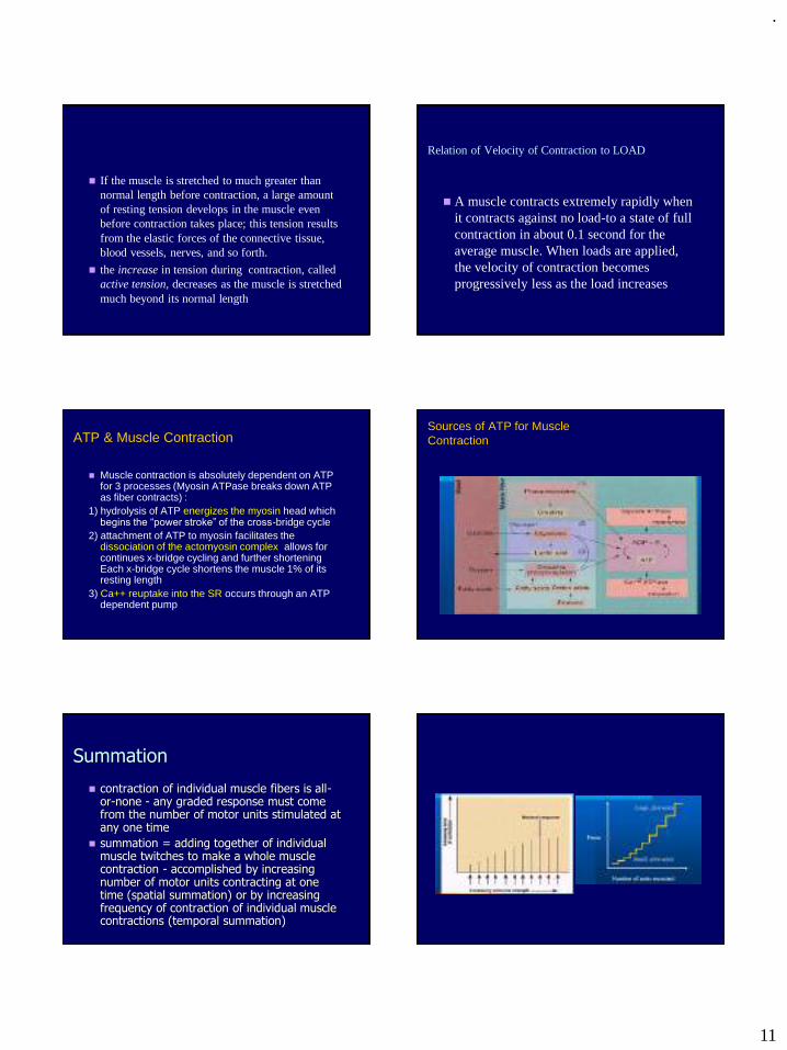
.
11
◼ If the muscle is stretched to much greater than normal length before contraction, a large amount of resting tension develops in the muscle even before contraction takes place; this tension results from the elastic forces of the connective tissue, blood vessels, nerves, and so forth.
◼ the increase in tension during contraction, called active tension, decreases as the muscle is stretched much beyond its normal length
Relation of Velocity of Contraction to LOAD
◼ A muscle contracts extremely rapidly when it contracts against no load-to a state of full contraction in about 0.1 second for the average muscle. When loads are applied, the velocity of contraction becomes progressively less as the load increases
ATP & Muscle Contraction
◼ Muscle contraction is absolutely dependent on ATP for 3 processes (Myosin ATPase breaks down ATP as fiber contracts) :
1) hydrolysis of ATP energizes the myosin head which begins the “power stroke” of the cross-bridge cycle
2) attachment of ATP to myosin facilitates the dissociation of the actomyosin complex allows for continues x-bridge cycling and further shortening Each x-bridge cycle shortens the muscle 1% of its resting length
3) Ca++ reuptake into the SR occurs through an ATP dependent pump
Sources of ATP for MuscleContraction
Summation
◼ contraction of individual muscle fibers is all-or-none - any graded response must come from the number of motor units stimulated at any one time
◼ summation = adding together of individual muscle twitches to make a whole muscle contraction - accomplished by increasing number of motor units contracting at one time (spatial summation) or by increasing frequency of contraction of individual muscle contractions (temporal summation)
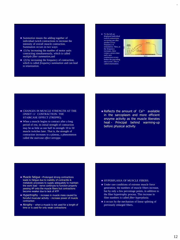
.
12
◼ Summotion means the adding together of individual twitch contractions to increase the intensity of overall muscle contraction. Summation occurs in two ways:
◼ (1) by increasing the number of motor units contracting simultaneously, which is called multiple fiber summation,and
◼ (2) by increasing the frequency of contraction, which is called frequency summation and can lead to tetanization.
◼ To the left are displayed individual twitch contractions occurring one after another at low frequency of stimulation. Then, as the frequency increases, there comes a point when each, new contraction occurs before the preceding one is over. This is called tetanization.
◼ CHANGES IN MUSCLE STRENGTH AT THE ONSET OF CONTRACTION- THE STAIRCASE EFFECT (TREPPE).
◼ When a muscle begins to contract after a long period of rest, its initial strength of contraction may be as little as one half its strength 10 to 50 muscle twitches later. That is, the strength of contraction increases to a plateau, a phenomenon called the staircase effect ortreppe.
◼ Reflects the amount of Ca2+ availablein the sarcoplasm and more efficientenzyme activity as the muscle liberatesheat - Principal behind warming-upbefore physical activity
◼ Muscle fatigue –Prolonged strong contractions
leads to fatigue due to inability of contractile & metabolic processes to supply adequately to maintain the work load - nerve continues to function properly passing AP onto the muscle fibers but contractions become weaker due to lack of ATP
◼ Hypertrophy - increase in muscle mass caused by
forceful muscular activity – increase power of muscle contraction
◼ Atrophy - when a muscle is not used for a length of
time or is used for only weak contractions
◼ HYPERPLASIA OF MUSCLE FIBERS.
◼ Under rare conditions of extreme muscle force generation, the numbers of muscle fibers increase, but by only a few percentage points, in addition to the fiber hypertrophy process. This increase in fiber numbers is called fiber hyperplasia.
◼ it occurs by the mechanism of linear splitting of previously enlarged fibers.
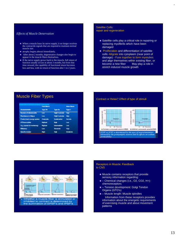
.
13
Effects of Muscle Denervation
◼ When a muscle loses its nerve supply, it no longer receives the contractile signals that are required to maintain normal muscle size.
◼ atrophy begins almost immediately.◼ After about 2 months, degenerative changes also begin to
appear in the muscle fibers themselves. ◼ If the nerve supply grows back to the muscle, full return of
function usually occurs in about 3 months, but from that time onward, the capability of functional return becomes less and less, with no return of function after 1 to 2 years.
Satellite Cells:repair and regeneration
◼ Satellite cells play a critical role in repairing or replacing myofibrils which have been damaged
◼ Proliferation and differentiation of satellite cells -Migrate into cytoplasm (near point of damage) - Fuse together to form myotubes and align themselves within existing fiber, or become a new fiber May play a role in stretch induced muscle growth
Muscle Fiber TypesContract or Relax? Effect of type of stimuli
Receptors in Muscle: Feedbackto CNS
◼ Muscle contains receptors that provide sensory information regarding:
◼ – Chemical changes (i.e., O2, CO2, H+): chemoreceptors
◼ – Tension development: Golgi Tendon Organs (GTO’s)
◼ – Muscle length: Muscle spindlesInformation from these receptors provides
information about the energetic requirements of exercising muscle and about movement patterns
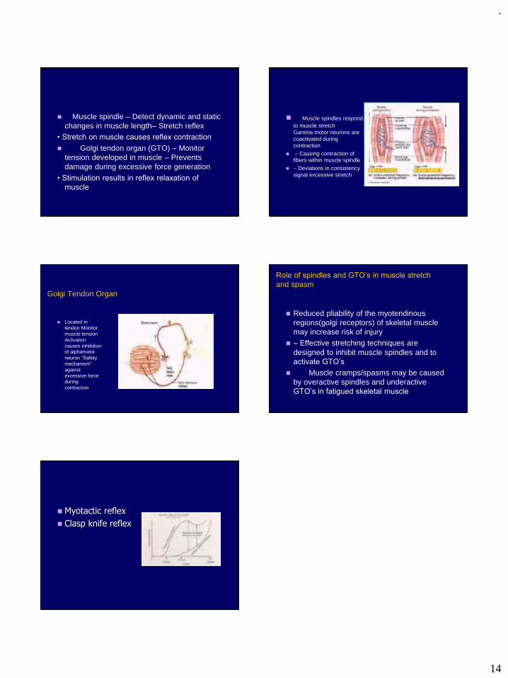
.
14
◼ Muscle spindle – Detect dynamic and static changes in muscle length– Stretch reflex
• Stretch on muscle causes reflex contraction
◼ Golgi tendon organ (GTO) – Monitor tension developed in muscle – Prevents damage during excessive force generation
• Stimulation results in reflex relaxation of
muscle
◼ Muscle spindles respond to muscle stretch Gamma motor neurons are coactivated during contraction
◼ – Causing contraction of fibers within muscle spindle
◼ – Deviations in consistency signal excessive stretch
Golgi Tendon Organ
◼ Located in tendon Monitor muscle tension Activation causes inhibition of alphamotor neuron “Safety
mechanism”
against excessive force during contraction
Role of spindles and GTO’s in muscle stretch
and spasm
◼ Reduced pliability of the myotendinous regions(golgi receptors) of skeletal muscle may increase risk of injury
◼ – Effective stretching techniques are designed to inhibit muscle spindles and to activate GTO’s
◼ Muscle cramps/spasms may be caused by overactive spindles and underactive GTO’s in fatigued skeletal muscle
◼ Myotactic reflex
◼ Clasp knife reflex
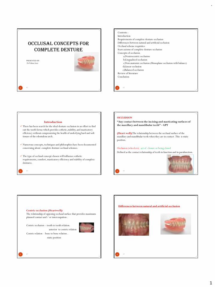
.
1
1
Occlusal concepts for complete denture
PRESENTED BY
Dr Vishnu Soni
62 2
Contents :
Introduction
Requirements of complete denture occlusion
Differences between natural and artificial occlusion
Occlusal scheme requisites
Sears axioms of complete denture occlusion
Concepts of occlusion
a)Neutrocentric occlusion
b)Lingualized occlusion
c)Non anatomic occlusion (Monoplane occlusion with balance)
d)Linear occlusion
e)Balanced occlusion
Review of literature
Conclusion
62
3
Introduction
✓ There has been search for the ideal denture occlusion in an effort to find
out the tooth forms which provides esthetic,stability, and masticatory
efficiency without compromising the health of underlying hard and soft
tissues of the edentulous arch.
✓ Numerous concepts, techniques and philosophies have been documented
concerning about complete denture occlusal schemes.
✓ The type of occlusal concept chosen will influence esthetic
requirements, comfort, masticatory efficiency and stability of complete
dentures.
62 4
OCCLUSION
“Any contact between the incising and masticating surfaces of
the maxillary and mandibular teeth” – GPT
(Heart well):The relationship between the occlusal surface of the
maxillary and mandibular teeth when they are in contact .This is static
position.
Occlusion (wheelers): act of closure or being closed
Defined as the contact relationship of teeth in function and in parafunction.
62
5
Centric occlusion (Heartwell):
The relationship of opposing occlusal surface that provides maximum
planned contact and / or intercuspation .
Centric occlusion – tooth to tooth relation.
anterior to centric relation
Centric relation – bone to bone relation .
static position
62 6
Differences between natural and artificial occlusion
62
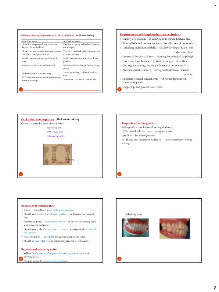
.
2
7
Differences between natural and artificial occlusion (sheldon wrinkler)
Natural occlusion Artificial occlusion
1)Function independently and each tooth
disperses the occlusal load.
2)Proprioceptive impulses from periodontium
avoid the occlusal prematurities.
3)Malocclusion can be non problematic for
years.
4)Nonvertical forces are well tolerated.
5)Bilateral balance is not necessary.
6)2nd molar favoured for mastication owing to
power and leverage.
Function as a group and occlusal loads are
not managed.
There is no feedback and the denture rests
in centric relation.
Malocclusion can pose immediate drastic
problems.
Nonvertical forces damage the supporting
tissues.
necessary, incising ---affect all teeth on
base
Mastication – 2nd molar – tilt the base
62 8
Requirements of complete denture occlusion :
o Stability of occlusion--- at centric and in forward, lateral area.
o Bilateral balanced occlusal contacts---for all eccentric movements.
o Unlocking cusps mesiodistally ---to allow settling of bases –due
ridge resorption .
o Control of horizontal forces---reducing buccolingual cusp height .
o Functional lever balance--- by tooth to ridge crest position .
o Cutting, penetrating, shearing efficiency of occlusal surface.
o Anterior incisal clearance---during mastication and bruxism
activity.
o Minimum occlusal contact areas-- for reduced pressure in
comminuting food .
o Sharp cusps and general sluice ways.62
9
Occlusal scheme requisites : (Sheldon wrinkler)
Occlusal scheme has three characteristics.
1)Incising unit
2)Working unit
3)Balancing units
Working
side
Balancing
side
62 10
Requisites of incising units :
a)Sharp units ----for improved incising efficiency.
b)The units should not contact during mastication.
c)Shallow / flat incisal guidance.
d) Should have horizontal overlap to----- avoid interference during
settling.
62
11
Requisites of working units:
✓ Cusps --- should have good cutting and grinding .
✓ Should have Smaller buccolingual width -----to decrease the occlusal
load.
✓ function as group ---harmonious contact---at the end of chewing cycle
and eccentric positions.
✓ Should centre the Occlusal load -----near anteroposterior centre of
the denture.
✓ Plane should be---- parallel to mean foundation of the ridge.
✓ Should be over ridge crest in masticating area for lever balance.
Requisites of balancing units:
✓ a)They should contact along with the working side at the end of
chewing cycle.
✓ b)There should be smooth gliding contacts.62 12
Balancing units
62
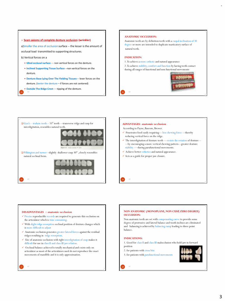
.
3
13
➢ Sears axioms of complete denture occlusion: (wrinkler)
a)Smaller the area of occlusion surface -- the lesser is the amount of
occlusal load transmitted to supporting structures.
b) Vertical forces on a
tilted occlusal surface --- non vertical forces on the denture.
Inclined Supporting Tissue Surface --non vertical forces on the
denture.
Denture Base Lying Over The Yielding Tissues--- lever forces on the
denture. (teeter the denture – if forces are not centered)
Outside The Ridge Crest---- tipping of the denture.62 14
ANATOMIC OCCLUSION:
Anatomic teeth are by definition teeth with a cuspal inclination of 30
degree or more are intended to duplicate masticatory surface of
natural teeth.
INDICATION:
1. To achieve a more esthetic and natural appearance
2. To achieve stability, comfort and function by having teeth contact
during all ranges of functional and non functional movements
62
15
❑Gysi’s – trubyte teeth – 33° teeth ---transverse ridge and cusp for
interdigitation, resembles natural teeth.
❑Pilkington and turner –slightly shallower cusp 30° ,closely resembles
natural occlusal form.
62 16
ADVANTAGES: anatomic occlusion
According to Payne, Bascom, Brewer.
✓ Penetrates food easily requiring--- less chewing force ---thereby
reducing vertical force on the ridge.
✓ The interdigitation of denture teeth ----resists the rotation of denture --
---by encouraging a more vertical chewing pattern---greater denture
stability ----during parafunctional movements.
✓ Achieve better esthetics and natural appearance.
✓ Acts as a guide for proper jaw closure.
62
17
DISADVANTAGES : anatomic occlusion
✓ Precise reproducible records are required to generate this occlusion on
the articulator which is time consuming.
✓ With slight ridge resorption occlusal position of denture changes which
is more difficult to adjust
✓ Anatomic occlusion generates greater lateral forces against the residual
ridges resulting in ridge resorption.
✓ Use of anatomic occlusion with tight interdigitation of cusp makes it
difficult for use in class II and class III jaw relation.
✓ Occlusal balance achieved is totally mechanical and exists only on
articulator as most of the articulators used do not reproduce the exact
movements of mandible and it is only approximation.
62 18
NON ANATOMIC (MONOPLANE, NON CUSP, ZERO DEGREE)
OCCLUSION:
Non anatomic teeth are set with compensating curve to provide some
degree of protrusive and lateral balance and tooth inclines are eliminated
and balancing is achieved by balancing ramp leading to three point
balance.
INDICATIONS:
1. Good for class II and class III malocclusion who hold jaw in forward
position
2. for patients with cross bite
3. for patients with parafunctional movements
62
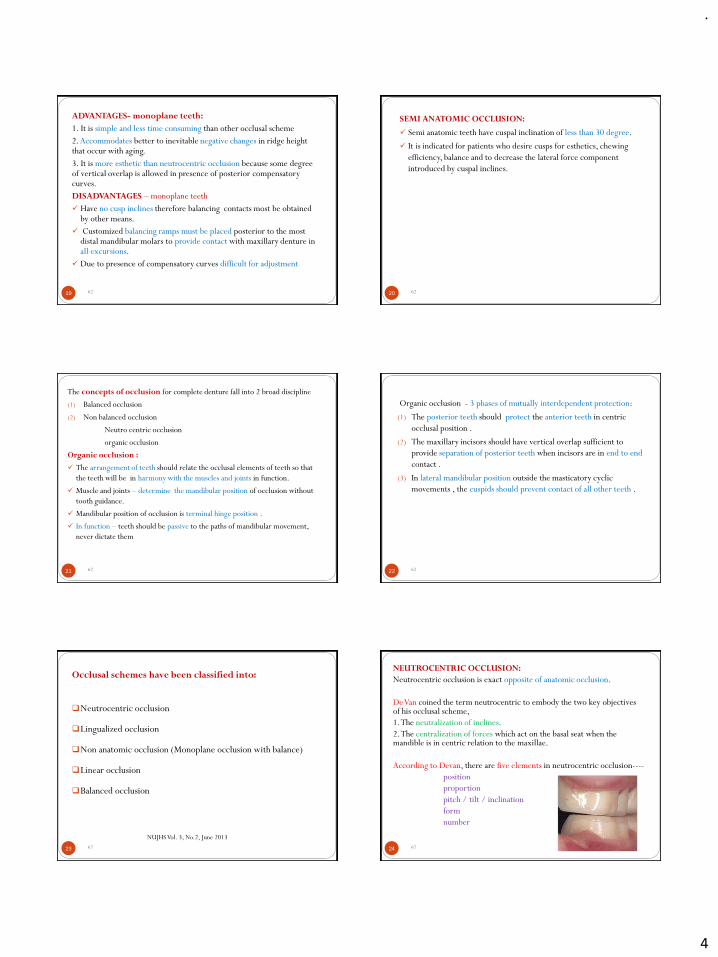
.
4
19
ADVANTAGES- monoplane teeth:
1. It is simple and less time consuming than other occlusal scheme
2.Accommodates better to inevitable negative changes in ridge height that occur with aging.
3. It is more esthetic than neutrocentric occlusion because some degree of vertical overlap is allowed in presence of posterior compensatory curves.
DISADVANTAGES – monoplane teeth
✓ Have no cusp inclines therefore balancing contacts most be obtained by other means.
✓ Customized balancing ramps must be placed posterior to the most distal mandibular molars to provide contact with maxillary denture in all excursions.
✓ Due to presence of compensatory curves difficult for adjustment
62 20
SEMI ANATOMIC OCCLUSION:
✓ Semi anatomic teeth have cuspal inclination of less than 30 degree.
✓ It is indicated for patients who desire cusps for esthetics, chewing
efficiency, balance and to decrease the lateral force component
introduced by cuspal inclines.
62
21
The concepts of occlusion for complete denture fall into 2 broad discipline
(1) Balanced occlusion
(2) Non balanced occlusion
Neutro centric occlusion
organic occlusion
Organic occlusion :
✓ The arrangement of teeth should relate the occlusal elements of teeth so that
the teeth will be in harmony with the muscles and joints in function.
✓ Muscle and joints – determine the mandibular position of occlusion without
tooth guidance.
✓ Mandibular position of occlusion is terminal hinge position .
✓ In function – teeth should be passive to the paths of mandibular movement,
never dictate them
62 22
Organic occlusion - 3 phases of mutually interdependent protection:
(1) The posterior teeth should protect the anterior teeth in centric
occlusal position .
(2) The maxillary incisors should have vertical overlap sufficient to
provide separation of posterior teeth when incisors are in end to end
contact .
(3) In lateral mandibular position outside the masticatory cyclic
movements , the cuspids should prevent contact of all other teeth .
62
23
Occlusal schemes have been classified into:
❑Neutrocentric occlusion
❑Lingualized occlusion
❑Non anatomic occlusion (Monoplane occlusion with balance)
❑Linear occlusion
❑Balanced occlusion
NUJHS Vol. 3, No.2, June 2013
62 24
NEUTROCENTRIC OCCLUSION:
Neutrocentric occlusion is exact opposite of anatomic occlusion.
De Van coined the term neutrocentric to embody the two key objectives of his occlusal scheme,
1. The neutralization of inclines.
2. The centralization of forces which act on the basal seat when the mandible is in centric relation to the maxillae.
According to Devan, there are five elements in neutrocentric occlusion----
position
proportion
pitch / tilt / inclination
form
number
62
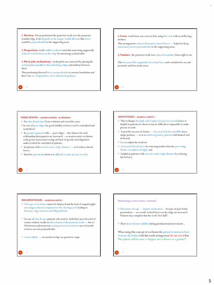
.
5
25
1. Position- Devan positioned the posterior teeth over the posterior
residual ridge as far lingually as the tongue would allow so that forces
would be perpendicular to the supporting areas
2. Proportion- tooth width is reduced such that narrowing supposedly
reduced vertical stress on the ridge by narrowing occlusal table
3. Pitch (tilt, inclination) - tooth pitch was corrected by placing the
occlusal plane parallel to the underlying ridges and midway between
them.
This positioning directed forces perpendicular to osseous foundation and
there was no compensatory curve and incisal guidance.
62 26
4. Form- tooth form was corrected by using flat teeth with no deflecting
inclines.
This arrangement reduced destructive lateral forces---- helped to keep
masticatory forces perpendicular to the supporting areas.
5. Number- the posterior teeth was reduced in number from eight to six
.
This decreased the magnitude of occlusal force and centralized to second
premolar and first molar areas.
62
27
INDICATIONS – neutrocentric occlusion :
✓ For class II and class III jaw relations and cross bite cases
✓ In case of poor ridges for good stability as forces can be centralized and
neutralized.
✓ In geriatric patients with---- poor ridges ---the chances for arch
relationship discrepancies are increased ---so neutrocentric occlusion
with greater horizontal overlap and lack of specific interdigitation
makes it ideal for such kind of patients.
✓ In patients with excessive inter-ridge distance---- as it reduces lateral
forces.
✓ Ideal for patients in whom it is difficult to make precise records.
62 28
ADVANTAGES – neutro centric :
✓ This technique is simple and requires less precise records hence is
helpful in patients in whom it may be difficult or impossible to make
precise records.
✓ It provides an area of closure ----does not lock the mandible into a
single position ----so it is useful in geriatric patients with limited oral
dextricity
✓ Easy to adjust the teeth set
✓ Decreased lateral forces by removing inclines thereby preventing
further resorption of ridges and
✓ helpful in patients with excessive inter-ridge distance by reducing
lateral force
62
29
DISADVANTAGES - neutrocentric:
✓ Flat type of occlusion cannot be balanced and the lack of cuspal heights
encourages a lateral component to the chewing cycle leading to
bruxism, ridge soreness and TMJ problems.
✓ In case of class II cases patients who tend to hold their jaws forward of
centric relation results in disocclusion of the posterior teeth --- due to
Christensens phenomenon causing soreness in anterior area of mouth
as forces are not perpendicular.
✓ Least esthetic --- no mesial overlap ,no posterior cusps
62 30
Disadvantage neutrocentric continued
✓ Flat nature of cusp ----impairs mastication--- because of poor bolus
penetration;--- as a result vertical forces on the ridge are increased.
Patients may complain that the teeth ''feel dull''.
✓ There is no denture stability during parafunctional movements .
When using this concept of occlusion the patient is instructed not
to incise the bolus, with this tooth arrangement Devan noted that
“the patient will become a chopper, not a chewer or a grinder”.
62
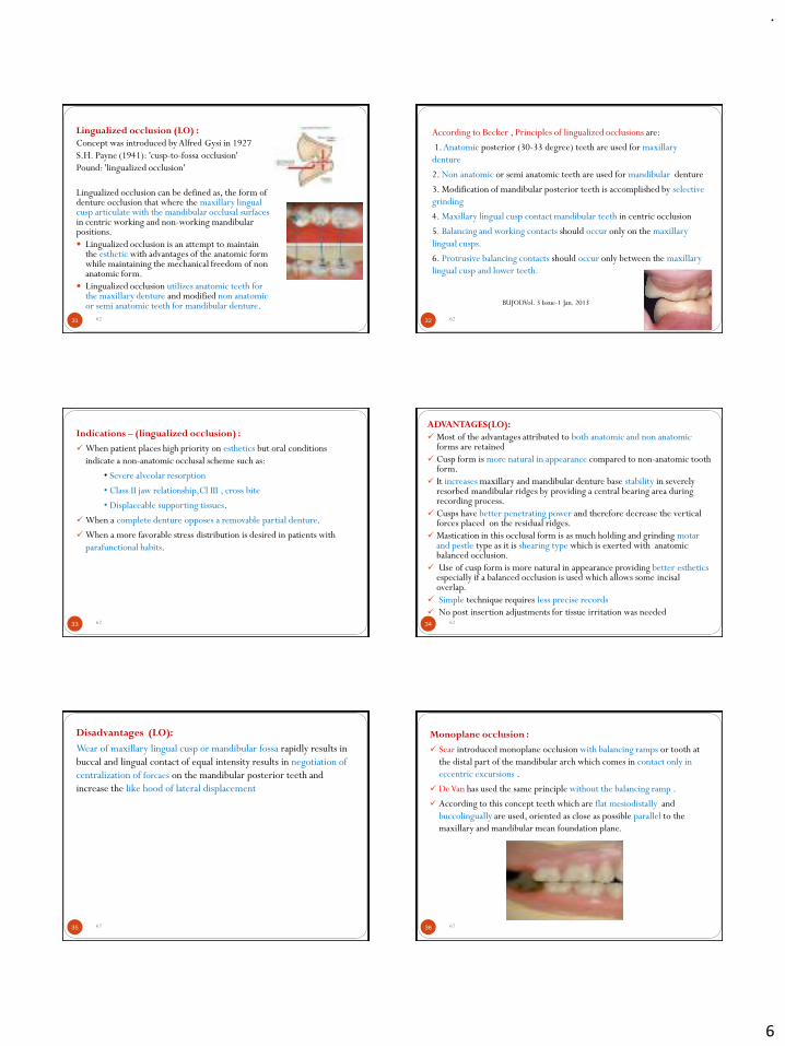
.
6
31
Lingualized occlusion (LO) :
Concept was introduced by Alfred Gysi in 1927
S.H. Payne (1941): 'cusp-to-fossa occlusion'
Pound: 'lingualized occlusion'
Lingualized occlusion can be defined as, the form of denture occlusion that where the maxillary lingual cusp articulate with the mandibular occlusal surfaces in centric working and non-working mandibular positions.
Lingualized occlusion is an attempt to maintain the esthetic with advantages of the anatomic form while maintaining the mechanical freedom of non anatomic form.
Lingualized occlusion utilizes anatomic teeth for the maxillary denture and modified non anatomic or semi anatomic teeth for mandibular denture.
62 32
According to Becker , Principles of lingualized occlusions are:
1. Anatomic posterior (30-33 degree) teeth are used for maxillary
denture
2. Non anatomic or semi anatomic teeth are used for mandibular denture
3. Modification of mandibular posterior teeth is accomplished by selective
grinding
4. Maxillary lingual cusp contact mandibular teeth in centric occlusion
5. Balancing and working contacts should occur only on the maxillary
lingual cusps.
6. Protrusive balancing contacts should occur only between the maxillary
lingual cusp and lower teeth.
BUJODVol. 3 Issue-1 Jan. 2013
62
33
Indications – (lingualized occlusion) :
✓ When patient places high priority on esthetics but oral conditions
indicate a non-anatomic occlusal scheme such as:
• Severe alveolar resorption
• Class II jaw relationship,Cl III , cross bite
• Displaceable supporting tissues.
✓ When a complete denture opposes a removable partial denture.
✓ When a more favorable stress distribution is desired in patients with
parafunctional habits.
62 34
ADVANTAGES(LO):
✓ Most of the advantages attributed to both anatomic and non anatomic forms are retained
✓ Cusp form is more natural in appearance compared to non-anatomic tooth form.
✓ It increases maxillary and mandibular denture base stability in severely resorbed mandibular ridges by providing a central bearing area during recording process.
✓ Cusps have better penetrating power and therefore decrease the vertical forces placed on the residual ridges.
✓ Mastication in this occlusal form is as much holding and grinding motarand pestle type as it is shearing type which is exerted with anatomic balanced occlusion.
✓ Use of cusp form is more natural in appearance providing better estheticsespecially if a balanced occlusion is used which allows some incisaloverlap.
✓ Simple technique requires less precise records
✓ No post insertion adjustments for tissue irritation was needed62
35
Disadvantages (LO):
Wear of maxillary lingual cusp or mandibular fossa rapidly results in
buccal and lingual contact of equal intensity results in negotiation of
centralization of forcaes on the mandibular posterior teeth and
increase the like hood of lateral displacement
62 36
Monoplane occlusion :
✓ Sear introduced monoplane occlusion with balancing ramps or tooth at
the distal part of the mandibular arch which comes in contact only in
eccentric excursions .
✓ De Van has used the same principle without the balancing ramp .
✓ According to this concept teeth which are flat mesiodistally and
buccolingually are used, oriented as close as possible parallel to the
maxillary and mandibular mean foundation plane.
62
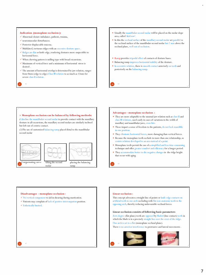
.
7
37
Indication (monoplane occlusion ):
✓ Abnormal closure imbalance, pathosis, trauma,
✓ neuromuscular disturbances.
✓ Posterior displaceable mucosa.
✓ Multilated, tortuous ridges with an excessive denture space .
✓ Ridges are flat or knife edge, rendering dentures more suspectible to
horizontal force.
✓ When chewing pattern is milling type with broad excursions.
✓ Maximum of vertical force and a minimum of horizontal stress is
desired .
✓ The amount of horizontal overlap is determined by jaw relation, ranges
from 0mm (edge to edge) Class III relation to as much as 12mm for
severe class II relation .
62 38
Usually the mandibular second molar will be placed on the molar slope
area, called 'skid row'.
In this the occlusal surface of the maxillary second molar set parallel to
the occlusal surface of the mandibular second molar but 2 mm above the
occlusal plane, well out of occlusion.
Ramp provides tripodal effect of contacts of denture bases.
Balancing ramp improves horizontal stability of the denture.
In eccentric relation, there is smooth contact anteriorly on teeth and
posteriorly on the balancing ramp.
62
39
➢ Monoplane occlusion can be balanced by following methods:
(1)Incline the mandibular second molar to provide contact with the maxillary
denture in all excursions, the maxillary second molars are similarly inclined
but left out of centric contact.
(2)The use of customized balancing ramp placed distal to the mandibular
second molar
placing the balancing
ramp
tilting the second
molar
Compensating curve62 40
Advantages – monoplane occlusion :
They are more adaptable to the unusual jaw relation such as class II and
class III relations, used easily in cases of variations in the width of
maxillary and mandibular jaws, cross bite.
These impart a sense of freedom to the patients, do not lock mandible
in one position.
They eliminate horizontal forces, more damaging than vertical forces.
Because the monoplane teeth occlude in more than one relationship, so
centric relation developed to an area instead of a point.
Monoplane teeth permit the use of a simplified and less time consuming
technique and offer greater comfort and efficiency for a longer period.
They accommodate better to the negative changes in the ridge height
that occur with aging.
62
41
Disadvantages - monoplane occlusion :
✓ No vertical component to aid in shearing during mastication.
✓ Patients may complain of lack of positive intercuspation position.
✓ Esthetically limited.
62 42
Linear occlusion :
This concept advocates a straight line of points or knife edge contacts on
artificial teeth in one arch occluding with flat non-anatomic teeth in the
opposing arch, thereby reducing unfavourable occlusal forces.
Linear occlusion consists of following basic parameters
Zero degree (flat plane) teeth are opposed by bladed (line contact) teeth in
which the blade is in a precisely straight line over the crest of the ridge.
One arch is set to a flat (monoplane occlusal plane).
There is no anterior interference to protrusive and lateral movements .
62
.
8
43
Plane of occlusion
The plane is set steeper.
Esthetics and phonetics --determine the maxillary anterior tooth position
Stabilization of mandibular denture
Mandibular dentures are almost always less stable than maxillary
dentures.
Esthetics
For esthetic purpose anatomic teeth -----are used in maxillary posterior
region, which occlude with non-anatomic------ mandibular teeth
62 44
Balanced occlusion :
The bilateral, simultaneous, anterior and posterior occlusal contact of teeth in centric and eccentric positions .
It is not seen in natural dentition.
Characteristic requirements of balanced occlusion:
✓ All the teeth of the working side (central incisor to second molar) should glide evenly against the opposing teeth.
✓ No single tooth should produce any interference or disocclusion of the other teeth.
✓ There should be contacts in the balancing side, but they should not interfere with the smooth gliding movements of the working side.
✓ There should be simultaneous contact during protrusion .
62
45
Importance of balanced occlusion :
Balanced occlusion is one of the most important factors that affect denture stability, absence of occlusal balance will result in leverage of the denture during mandibular movement.
Sheppard stated that, “Enter bolus, Exit balance” according to this statement, the balancing contact is absent when food enters the oral cavity. This makes us think that balanced occlusion has no function during mastication; hence, it is not essential in a complete denture, but this is not true.
On an average, a normal individual makes masticatory tooth contact only for 10 minutes in one full day compared to 4 hours of total tooth contact during other functions.
So, for these 4 hours of tooth contact, balanced occlusion is important to maintain the stability of the denture.
Hence, balanced occlusion is more critical during parafunctionalmovements.
62 46
Types of Balanced occlusion
Occlusal balance or balanced occlusion can be classified as
follows
✓ Unilateral balanced occlusion
✓ Bilateral balanced occlusion
✓ Protrusive balanced occlusion
✓ Lateral balanced occlusion
62
6247
Rudolph L.Hanau (1926)-
He proposed nine factors that govern the articulation of artificial teeth.
-
Laws of articulation.
1. Horizontal condylar inclination
2. Compensating curve
3. Protrusive incisal guidance
4. Plane of orientation
5. Bucco lingual inclination of tooth axis
6. Sagittal condylar pathway
7. Sagittal incisal guidance
8. Tooth alignment
9. Relative cusp height
6248
Condylar guidance is a mandibular guidance generated by the
condyles traversing the contours of the glenoid fossa.
The degree of condylar inclination results from:
1. The shape of the bony contour of the TMJ.
2. Action of muscles attaching the mandible.
3. Limitations of movements effected by the attaching ligaments.
4. Neuromuscular control of the patient
.
9
6249
INCISAL GUIDANCE
This is defined as “The influence of the contacting surfaces of the
mandibular and maxillary anterior teeth on mandibular movements”-
GPT.
The angle formed by the protrusive path to the horizontal plane is called
as the protrusive incisal path inclination or the incisal guide angle
▪ The incisal guidance should be as flat as possible as the esthetics and
phonetics permits.
▪ It depends upon following factors:
1. Phonetic
2. Esthetic
3. Shape of residual ridges
4. Ridge relation
5. Inter-alveolar distance6250
Plane of occlusion
It is defined as, “An imaginary surface which is related anatomically to
the cranium and which theoretically touches the incisal edges of the
incisors and the tips of the occluding surface of the posterior teeth.”
Cuspal inclination refers to the angle between the total occlusal
surface of the tooth and the inclination of cusp to that surface
Compensating curves It refers to Antero- Posterior and lateral curve
produced in the alignment and arrangement of occluding surfaces and
incisal edges in anterior teeth.
51
Factors affecting balanced Occlusion
Hanau’s Quint
✓ Condylar guidance
✓ Incisal guidance
✓ Plane of occlusion
✓ Cuspal inclination
✓ Compensating curves
62 52
Advantages of Bilateral Occlusal Balance
✓ Bilateral simultaneous contact help to seat the denture in a stable position during mastication, swallowing and
✓ maintain retention and stability of the denture and the health of the oral tissues.
✓ Due to cross-arch balance, as the bolus is chewed on one side, the balancing cusps will come close or will contact on the other.
✓ Denture bases are stable even during bruxing activity.
Disadvantages of Balanced Occlusion :
✓ It is difficult to achieve in mouths where an increased vertical incisor overlap is present.
✓ It may tend to encourage lateral and protrusive grinding habits.
✓ A semi adjustable or fully adjustable articulator is required .
62
53
Cross references :
Comparisons of Patient Satisfaction Levels with Complete
Dentures of Different Occlusions: A Randomized Clinical Trial
Mohhamadjavad Shirani, DDS-jpd 2014
15 Patients were arranged randomly-divided into 3 groups of 5 each.
1st group- first received FBBO then LO,BO
2nd group-LO,BO,FBBO
3rd group-BO,FBBO,LO
FBBO-fully balanced bilateral occlusion
LO-lingualized occlusion
BO-buccalized occlusion62 54
QUESTIONAIRES
FL 1 Chewing problems
FL 2 Food catching
P1 3 Pain in mouth
P1 4 Uncomfortable eating any food
P1 5 Sore spots
FL 6 Fitting improperly
P1 7 Uncomfortable denture
P2 8 Worried about dental problems
P2 9 Self-conscious due to denture
D1 10 Avoid eating some foods
D1 11 Unable to eat
D1 12 Interrupted meals
D2 13 Upset because of denture problems
D2 14 Embarrassed by denture problems
D3 15 Avoid going out
D3 16 Less tolerant with family
D3 17 Irritable with other people
H 18 Dislike other peoples’ company
H 19 Lower life satisfaction
FL: functional limitation
P1:physical pain
P2:physical discomfort
D1: physical disability
D2:psychological disability
D3:social disability
H: handicap
62
.
10
55
BO (buccalized occlusion):
-simple occlusal adjustments
-less occlusal interferences
-fewer mandibular disloadgements
-greater retention without unpleasent dark spaces between maxillary and
mandibular buccal cusp in centric position
CONCLUSIONS:
With the caution of small sample size, the results of this study provide
evidence that use of BO can improve food avoidance and physical disability
aspects of patient satisfaction with complete dentures.
62 56
Cross references:
Clough et al fabricated dentures -30 patients - crossover randomized clinical
trial.
Dentures worn - 3-week period and then exchanged.
They found that LO was superior to monoplane occlusion in terms of chewing
ability, patient comfort, and esthetics.
In 2007, Sutton and McCord
Prepared- 3 sets of dentures - 45 patients - followed up each set for 8 weeks.
Patients reported greater satisfaction with LO dentures than with monoplane
occlusions, particularly with regard to sore spots
Also reported that FBBO provided better masticatory function compared
with a 0◦ occlusal form.62
57
Matsumaru suggested that patients with severely resorbed ridges treated
with FBBO present decreased masticatory efficiency in contrast with LO.
62
REVIEW OF LITERATURE
Complete Denture Occlusion: An Evidence-Based Approach Arcelino Farias-
Neto, DDS, MS-JPD 2012
Purpose
This study involved an extensive search for randomized controlled clinical trials
comparing bilateral balanced and canine-guided dentures, and questioned whether a
bilateral balanced occlusion is imperative for successful denture treatment.
Two occlusal concepts exist in CD treatment: BBO and canine guidance. Both
include simultaneous contact in centric occlusion, but they differ in eccentric
movements.
Patients were asked to respond to questions with three-grade answers (well satisfied,
satisfied, dissatisfied) regarding 12 factors: “chewing, tasting, speech, pain (upper
and lower), esthetics, fit (upper and lower), (upper and lower), and comfort (upper
and lower).” No difference was observed between bilateral balanced and canine
guided dentures.
Conclusion
Current scientific evidence suggests that bilateral balanced occlusion is not imperative
for successful treatment with conventional CDs in average patients. More studies are
necessary to identify if specific clinical conditions may benefit from a balanced
occlusion.
6258
59
Influence of mandibular residual ridge resorption on
objective masticatory measures of lingualized and fully
bilateral balanced denture articulation.
Lingulized occlusion is prefered occlusal scheme for patients with
severe RRR
(Journal of prosthodontics research 2010)
62 60
References :
Text book of complete dentures – 5th edition Heartwell.
Prosthodontic treatment for edentulous patients -9th edition Boucher’s
Essentials of complete denture prosthodontics- 2nd edition Sheldon wrinkler
Dental anatomy ,physiology and occlusion -8th edition Wheelers
62
.
11
61
Cross references:
1. Enhancing stability : a review of various occlusal schemes in complete denture prosthesis--- krishna prasad D---NUJHS vol. 3, no.2, june 2013
2. Occlusal schemes for complete dentures - A review article---drsavitha K. C.----Bhavnagar university's journal of dentistry-vol. 3 issue-1 jan. 2013
3. Comparisons of patient satisfaction levels with complete dentures of different occlusions: A randomized clinical trial-- mohhamadjavadshirani, dds-jpd 2014
4. Complete denture occlusion: an evidence-based approach ArcelinoFarias-Neto, DDS, MS-JPD 2012
5. Influence of mandibular residual ridge resorption on objective masticatory measures of lingualized and fully bilateral balanced denture articulation (Journal of prosthodontics research 2010)
62 62
Thank you
62
.
1
POLYETHER-ETHER-KETONE (PEEK)APPLICATIONS IN CLINICAL DENTISTRY.
Dr Vishnu Soni
1
Introduction
PEEK is a member of the polyaryletherketone family (PAEK).
PEEK
PEK
PEKKPEEKK
PEKEKK
2
PEEK Chemical structure
PEEK is composed of repeating units of three phenyl rings, two ester
groups and one keto group.
3
PEEK Synthesis
A common synthesis route for PEEK is the reaction between 4,4-
difluorobenzophenone and the disodium salt of hydroquinone in a polar
solvent such as diphenyl sulphone at 300°C.
4
PEEK History
5
■ In 1978, a group of English scientists developed PEEK , a semi-
crystalline linear polycyclic aromatic polymer .
■ It was first commercialized in the 1980s for industrial applications in
the manufacture of aircraft, turbine blades, piston parts, cable
insulation, and compressor plate valves.
■ PEEK was introduced to dental applications in 1992.
6
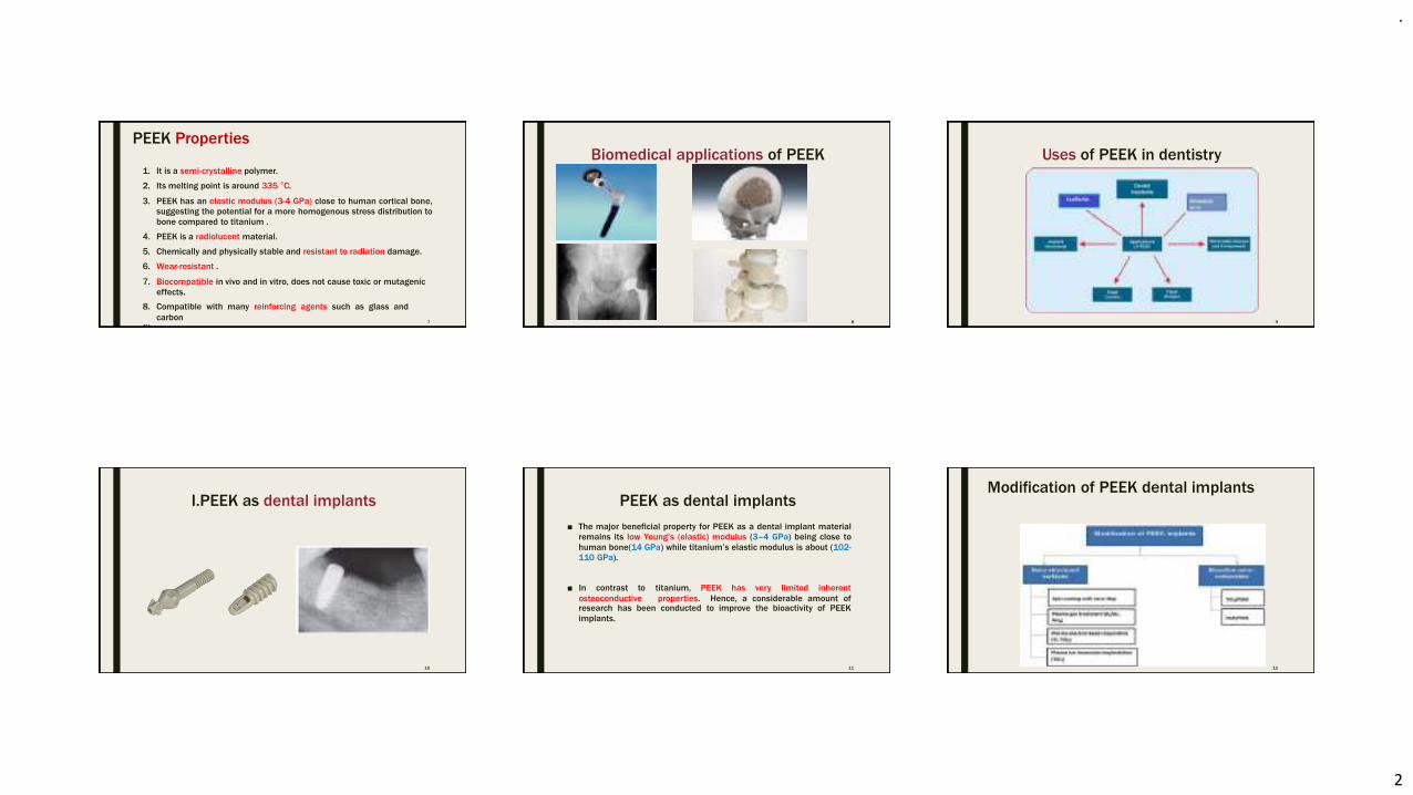
.
2
PEEK Properties
7
1. It is a semi-crystalline polymer.
2. Its melting point is around 335 °C.
3. PEEK has an elastic modulus (3-4 GPa) close to human cortical bone,
suggesting the potential for a more homogenous stress distribution to
bone compared to titanium .
4. PEEK is a radiolucent material.
5. Chemically and physically stable and resistant to radiation damage.
6. Wear-resistant .
7. Biocompatible in vivo and in vitro, does not cause toxic or mutagenic
effects.
8. Compatible with many reinforcing agents such as glass and
carbon
fibers.
Biomedical applications of PEEK
8
Uses of PEEK in dentistry
9
I.PEEK as dental implants
10
PEEK as dental implants
11
■ The major beneficial property for PEEK as a dental implant material
remains its low Young’s (elastic) modulus (3–4 GPa) being close to
human bone(14 GPa) while titanium’s elastic modulus is about (102-
110 GPa).
■ In contrast to
osteoconductive
titanium, PEEK has very limited inherent
properties. Hence, a considerable amount ofresearch has been conducted to improve the bioactivity of PEEK
implants.
Modification of PEEK dental implants
12
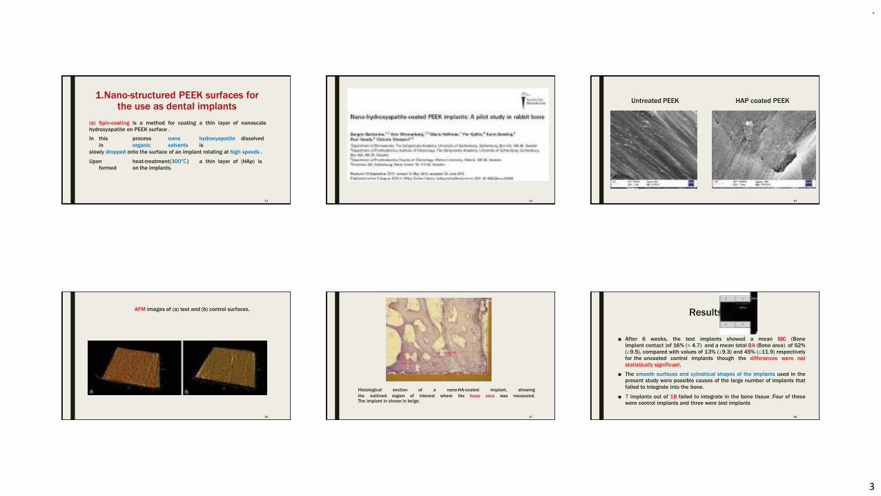
.
3
1.Nano-structured PEEK surfaces forthe use as dental implants
13
(a) Spin-coating is a method for coating a thin layer of nanoscale
hydroxyapatite on PEEK surface .
In this process nano hydroxyapatite dissolved
in organic solvents is
slowly dropped onto the surface of an implant rotating at high speeds .
Upon heat-treatment(300ºC) a thin layer of (HAp) is
formed on the implants.
14
Untreated PEEK HAP coated PEEK
15
AFM images of (a) test and (b) control surfaces.
16
The implant in shown in beige.
17
Histological section of a nano-HA-coated implant, showing
the outlined region of interest where the bone area was measured.
Results
■ After 6 weeks, the test implants showed a mean BIC (Bone
implant contact )of 16% (± 4.7) and a mean total BA (Bone area) of 52%
(±9.5), compared with values of 13% (±9.3) and 45% (±11.9) respectively
for the uncoated control implants though the differences were not
statistically significant.
■ The smooth surfaces and cylindrical shapes of the implants used in the
present study were possible causes of the large number of implants that
failed to integrate into the bone.
■ 7 implants out of 18 failed to integrate in the bone tissue .Four of these
were control implants and three were test implants
18
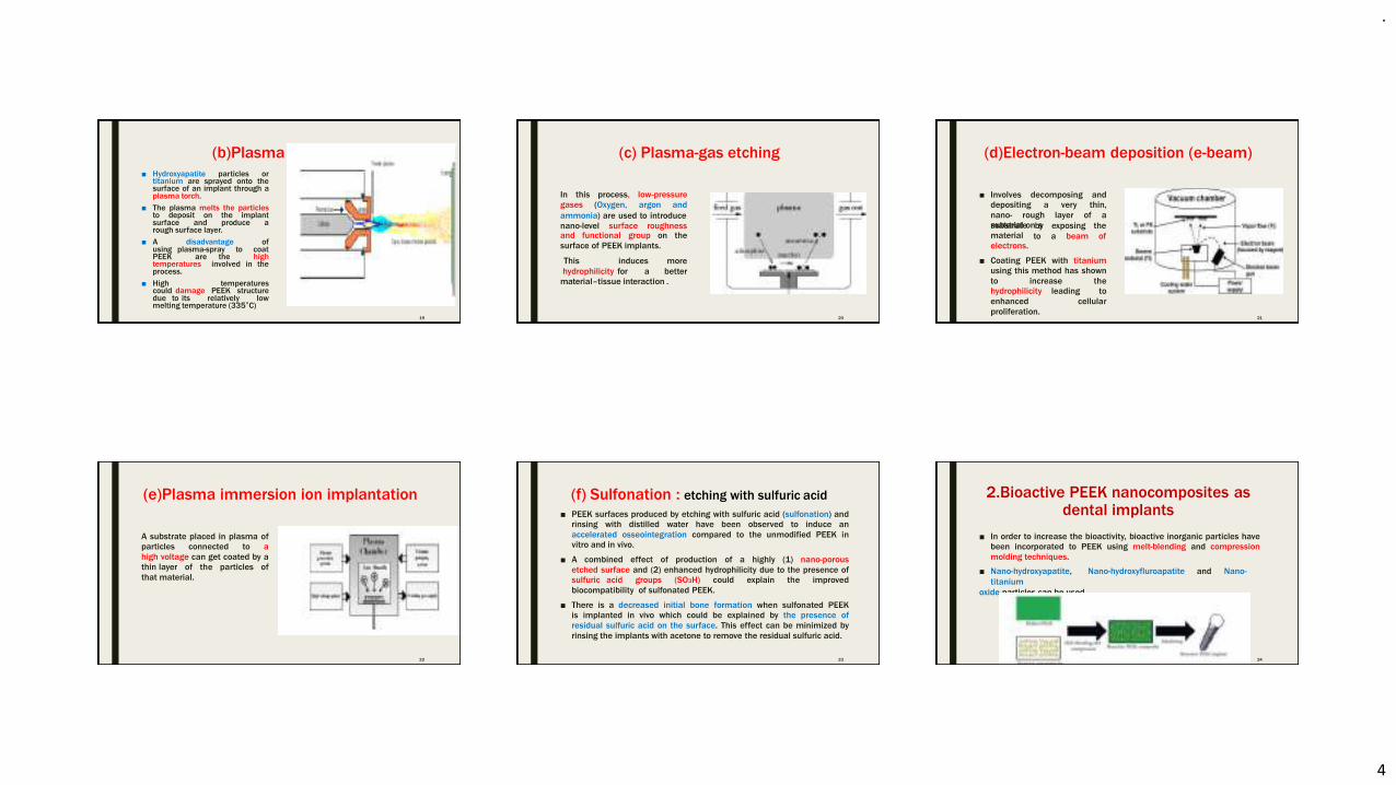
.
4
(b)Plasma spraying
■ Hydroxyapatite particles ortitanium are sprayed onto thesurface of an implant through aplasma torch.
■ The plasma melts the particlesto deposit on the implantsurface and produce arough surface layer.
■ A disadvantage ofusing plasma-spray to coatPEEK are the hightemperatures involved in theprocess.
■ High temperaturescould damage PEEK structuredue to its relatively lowmelting temperature (335°C)
19
(c) Plasma-gas etching
In this
gases
process,
(Oxygen,
low-pressure
argon and
ammonia) are used to introduce
nano-level surface roughnessand functional group on the
surface of PEEK implants.
This induces
hydrophilicity for a
more
better
material–tissue interaction .
20
(d)Electron-beam deposition (e-beam)
■ Involves decomposing and
depositing a very thin,
nano- rough layer of a
material on asubstrate
material
electrons.
by exposing the
to a beam of
■ Coating PEEK with titanium
using this method has shown
to increase the
hydrophilicity leading to
enhanced cellular
proliferation.21
(e)Plasma immersion ion implantation
A substrate placed in plasma of
particles connected to a
high voltage can get coated by a
thin layer of the particles of
that material.
22
(f) Sulfonation : etching with sulfuric acid
23
■ PEEK surfaces produced by etching with sulfuric acid (sulfonation) and
rinsing with distilled water have been observed to induce an
accelerated osseointegration compared to the unmodified PEEK in
vitro and in vivo.
■ A combined effect of production of a highly (1) nano-porous
etched surface and (2) enhanced hydrophilicity due to the presence of
sulfuric acid groups (SO3H) could explain the improved
biocompatibility of sulfonated PEEK.
■ There is a decreased initial bone formation when sulfonated PEEK
is implanted in vivo which could be explained by the presence of
residual sulfuric acid on the surface. This effect can be minimized by
rinsing the implants with acetone to remove the residual sulfuric acid.
2.Bioactive PEEK nanocomposites asdental implants
■ In order to increase the bioactivity, bioactive inorganic particles have
been incorporated to PEEK using melt-blending and compression
molding techniques.
■ Nano-hydroxyapatite, Nano-hydroxyfluroapatite and Nano-
titanium
oxide particles can be used .
24
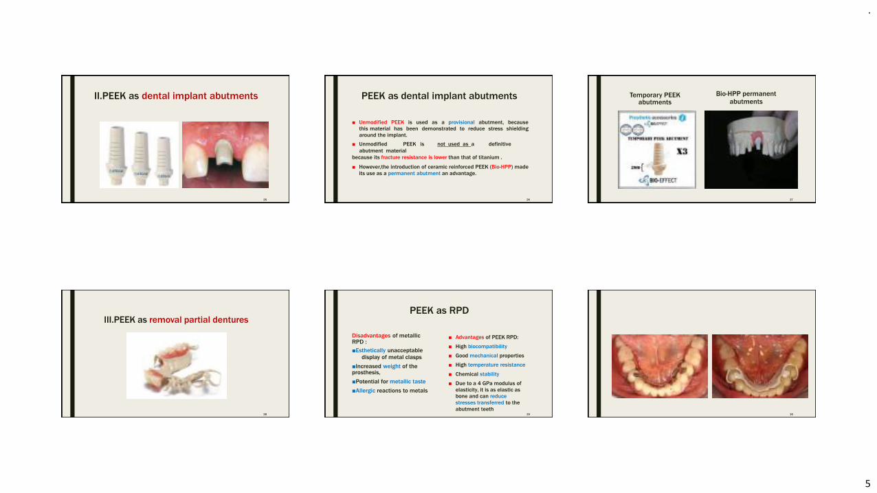
.
5
II.PEEK as dental implant abutments
25
PEEK as dental implant abutments
26
■ Unmodified PEEK is used as a provisional abutment, because
this material has been demonstrated to reduce stress shielding
around the implant.
■ Unmodified PEEK is not used as a definitive
abutment material
because its fracture resistance is lower than that of titanium .
■ However,the introduction of ceramic reinforced PEEK (Bio-HPP) made
its use as a permanent abutment an advantage.
Temporary PEEKabutments
Bio-HPP permanentabutments
27
III.PEEK as removal partial dentures
28
PEEK as RPD
29
Disadvantages of metallicRPD :
■Esthetically unacceptabledisplay of metal clasps
■Increased weight of theprosthesis,
■Potential for metallic taste
■Allergic reactions to metals
■ Advantages of PEEK RPD:
■ High biocompatibility
■ Good mechanical properties
■ High temperature resistance
■ Chemical stability
■ Due to a 4 GPa modulus of
elasticity, it is as elastic as
bone and can reduce
stresses transferred to the
abutment teeth30
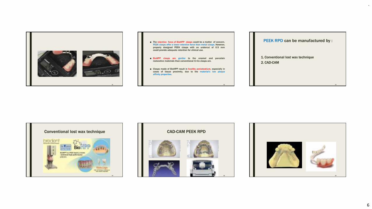
.
6
31
■ The retentive force of BioHPP clasps could be a matter of concern.
PEEK clasps offer a lower retentive force than metal clasps. However,
properly designed PEEK clasps with an undercut of 0.5 mm
could provide adequate retention for clinical use.
■ BioHPP clasps are gentler to the enamel and porcelain
restorative materials than conventional Cr-Co clasps are.
■ Clasps made of BioHPP result in healthy periodontium, especially in
cases of tissue proximity, due to the material’s low plaque
affinity properties.
32
PEEK RPD can be manufactured by :
33
1. Conventional lost wax technique
2. CAD-CAM
Conventional lost wax technique
34
CAD-CAM PEEK RPD
35 36
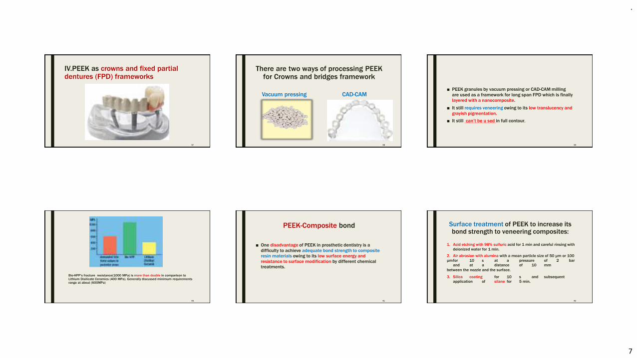
.
7
IV.PEEK as crowns and fixed partialdentures (FPD) frameworks
37
There are two ways of processing PEEKfor Crowns and bridges framework
Vacuum pressing CAD-CAM
38
■ PEEK granules by vacuum pressing or CAD-CAM milling
are used as a framework for long span FPD which is finally
layered with a nanocomposite.
■ It still requires veneering owing to its low translucency and
grayish pigmentation.
■ It still can’t be u sed in full contour.
39
Bio-HPP’s fracture resistance(1000 MPa) is more than double in comparison toLithium Disilicate Ceramics (400 MPa). Generally discussed minimum requirementsrange at about (600MPa)
40
PEEK-Composite bond
41
■ One disadvantage of PEEK in prosthetic dentistry is a
difficulty to achieve adequate bond strength to composite
resin materials owing to its low surface energy and
resistance to surface modification by different chemical
treatments.
Surface treatment of PEEK to increase itsbond strength to veneering composites:
42
1. Acid etching with 98% sulfuric acid for 1 min and careful rinsing with
deionized water for 1 min.
2. Air abrasion with alumina with a mean particle size of 50 µm or 100
µmfor 10 s at a pressure of 2 bar
and at a distance of 10 mm
between the nozzle and the surface.
3. Silica coating for 10 s and subsequent
application of silane for 5 min.
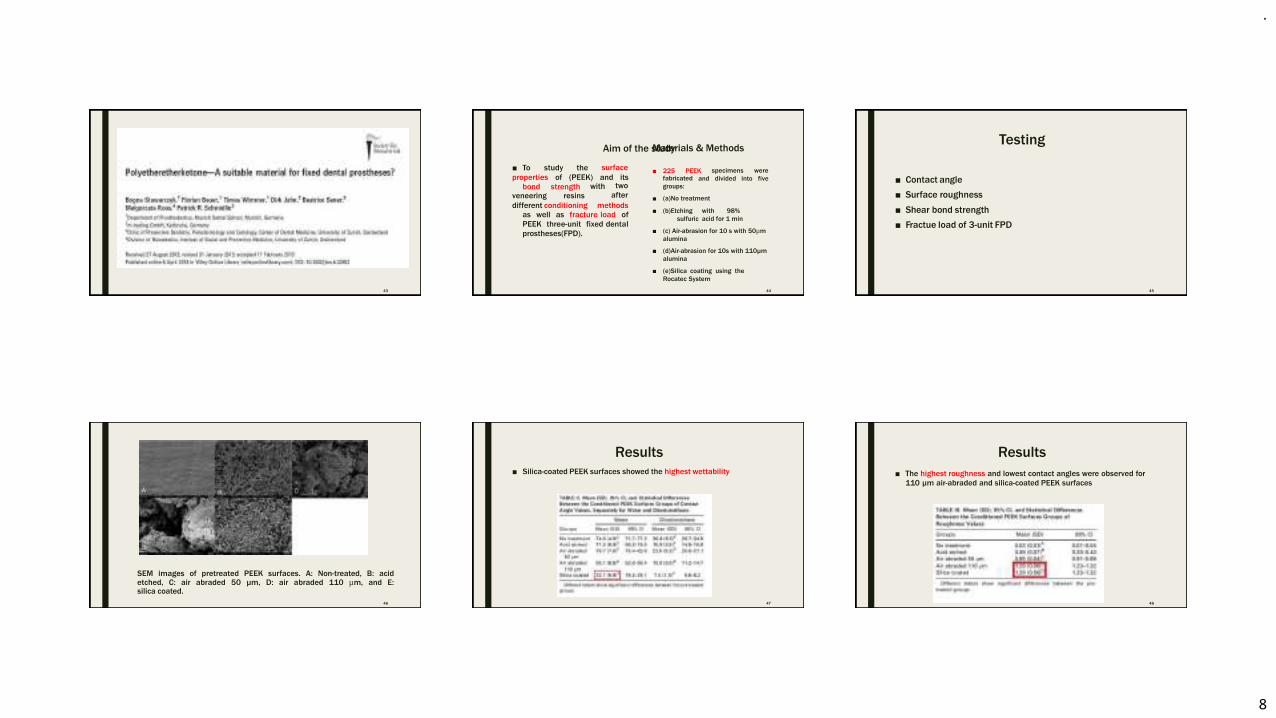
.
8
43
Aim of the study
44
■ To study the
properties of (PEEK) and its
bond strengthveneering resins
different conditioning methods
as well as fracture load of
PEEK three-unit fixed dental
prostheses(FPD).
surface
with two
after
Materials & Methods
■ 225 PEEK specimens
and divided into
were
fivefabricated
groups:
■ (a)No treatment
■ (b)Etching with 98%
sulfuric acid for 1 min
■ (c) Air-abrasion for 10 s with 50µm
alumina
■ (d)Air-abrasion for 10s with 110µm
alumina
■ (e)Silica coating using the
Rocatec System
Testing
45
■ Contact angle
■ Surface roughness
■ Shear bond strength
■ Fractue load of 3-unit FPD
SEM images of pretreated PEEK surfaces. A: Non-treated, B: acidetched, C: air abraded 50 µm, D: air abraded 110 µm, and E:silica coated.
46
Results
■ Silica-coated PEEK surfaces showed the highest wettability
47
Results
■ The highest roughness and lowest contact angles were observed for
110 µm air-abraded and silica-coated PEEK surfaces
48
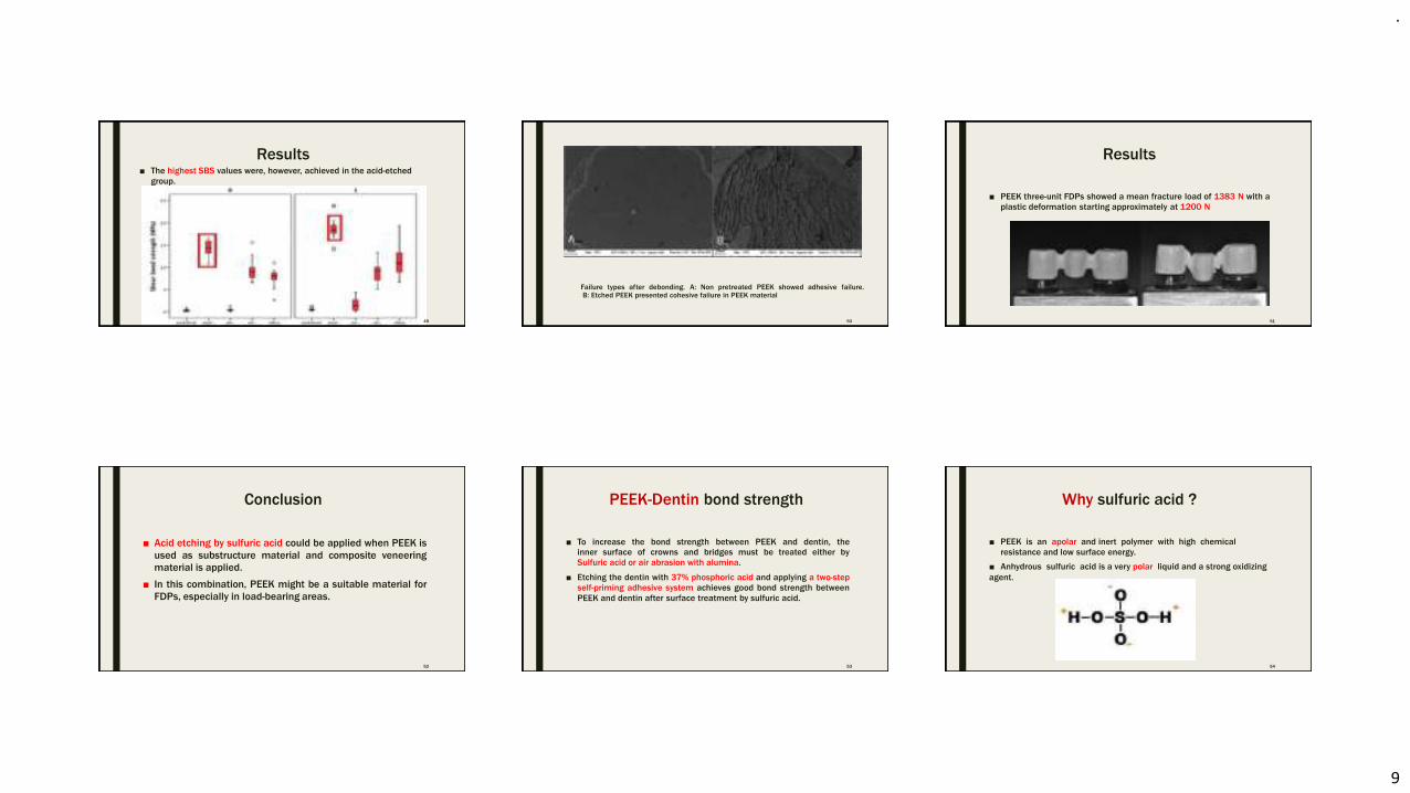
.
9
Results■ The highest SBS values were, however, achieved in the acid-etched
group.
49
Failure types after debonding. A: Non pretreated PEEK showed adhesive failure.B: Etched PEEK presented cohesive failure in PEEK material
50
Results
■ PEEK three-unit FDPs showed a mean fracture load of 1383 N with a
plastic deformation starting approximately at 1200 N
51
Conclusion
52
■ Acid etching by sulfuric acid could be applied when PEEK is
used as substructure material and composite veneering
material is applied.
■ In this combination, PEEK might be a suitable material for
FDPs, especially in load-bearing areas.
PEEK-Dentin bond strength
53
■ To increase the bond strength between PEEK and dentin, the
inner surface of crowns and bridges must be treated either by
Sulfuric acid or air abrasion with alumina.
■ Etching the dentin with 37% phosphoric acid and applying a two-step
self-priming adhesive system achieves good bond strength between
PEEK and dentin after surface treatment by sulfuric acid.
Why sulfuric acid ?
■ PEEK is an apolar and inert polymer with high chemical
resistance and low surface energy.
■ Anhydrous sulfuric acid is a very polar liquid and a strong oxidizing
agent.
54
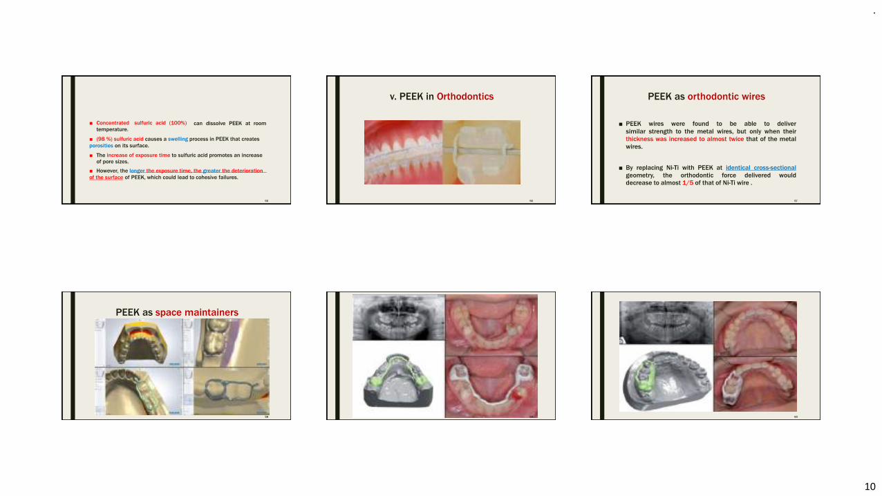
.
10
■ Concentrated sulfuric acid (100%)
temperature.can dissolve PEEK at room
■ (98 %) sulfuric acid causes a swelling process in PEEK that creates
porosities on its surface.
■ The increase of exposure time to sulfuric acid promotes an increase
of pore sizes.
■ However, the longer the exposure time, the greater the deterioration
of the surface of PEEK, which could lead to cohesive failures.
55
v. PEEK in Orthodontics
56
PEEK as orthodontic wires
57
■ PEEK wires were found to be able to deliver
similar strength to the metal wires, but only when their
thickness was increased to almost twice that of the metal
wires.
■ By replacing Ni-Ti with PEEK at identical cross-sectional
geometry, the orthodontic force delivered would
decrease to almost 1/5 of that of Ni-Ti wire .
PEEK as space maintainers
58 59 60
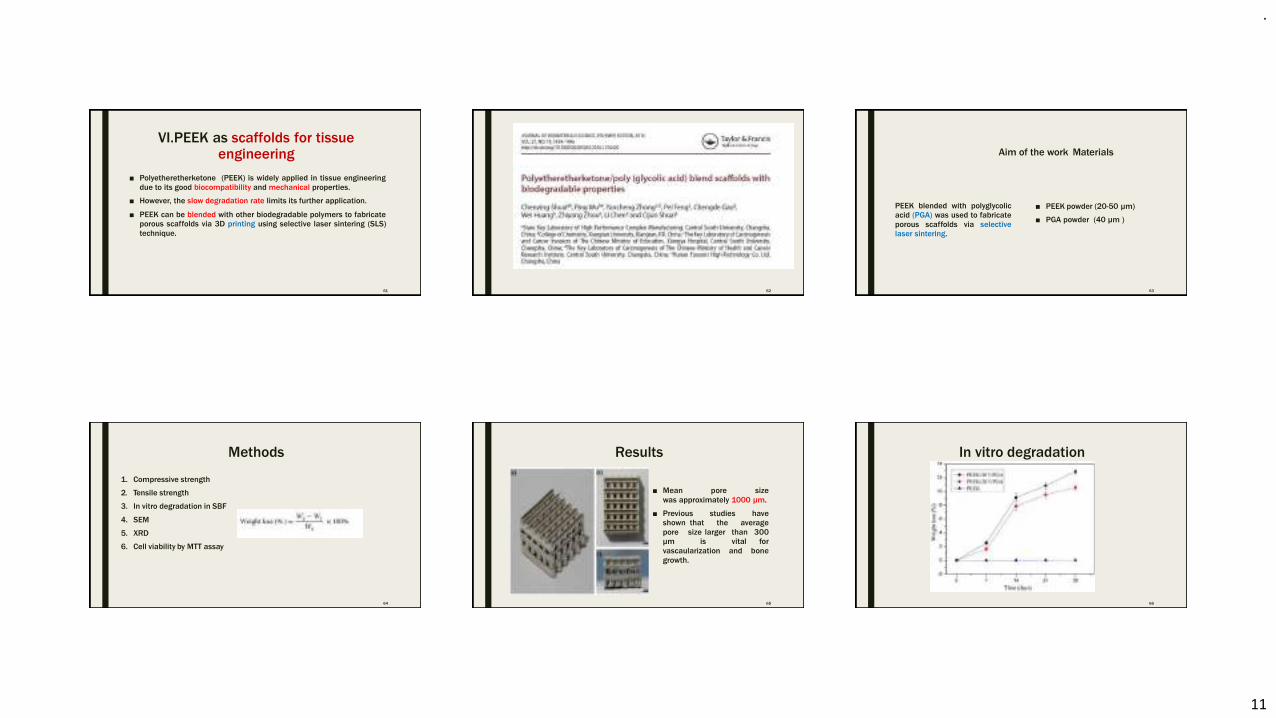
.
11
VI.PEEK as scaffolds for tissueengineering
61
■ Polyetheretherketone (PEEK) is widely applied in tissue engineering
due to its good biocompatibility and mechanical properties.
■ However, the slow degradation rate limits its further application.
■ PEEK can be blended with other biodegradable polymers to fabricate
porous scaffolds via 3D printing using selective laser sintering (SLS)
technique.
62
Aim of the work
63
PEEK blended with polyglycolic
acid (PGA) was used to fabricate
porous scaffolds via selective
laser sintering.
Materials
■ PEEK powder (20-50 µm)
■ PGA powder (40 µm )
Methods
1. Compressive strength
2. Tensile strength
3. In vitro degradation in SBF
4. SEM
5. XRD
6. Cell viability by MTT assay
64
Results
■ Mean pore size
was approximately 1000 μm.
■ Previous studies have
shown that the average
pore size larger than 300
μm is vital for
vascaularization and bone
growth.
65
In vitro degradation
66
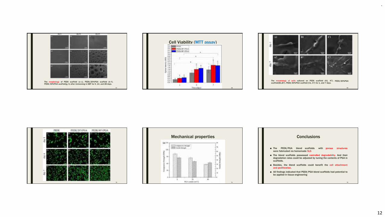
.
12
The morphology of PEEK scaffold (a–c), PEEK/20%PGA scaffold (d–f),PEEK/40%PGA scaffold(g, h) after immersing in SBF for 0, 14, and 28 days.
67
Cell Viability (MTT assay)
68
The morphology of cells cultured on PEEK scaffold (A1, A7),scaffold(B1,B7), PEEK/40%PGA scaffold (C1, C7) for 1, and 7 days.
PEEK/20%PGA
69
70
Mechanical properties
71
Conclusions
72
■ The PEEK/PGA blend scaffolds with porous structures
were fabricated via homemade SLS
■ The blend scaffolds possessed controlled degradability. And their
degradation rates could be adjusted by tuning the contents of PGA in
scaffolds.
■ Besides, the blend scaffolds could benefit the cell attachment
and proliferation.
■ All findings indicated that PEEK/PGA blend scaffolds had potential to
be applied in tissue engineering
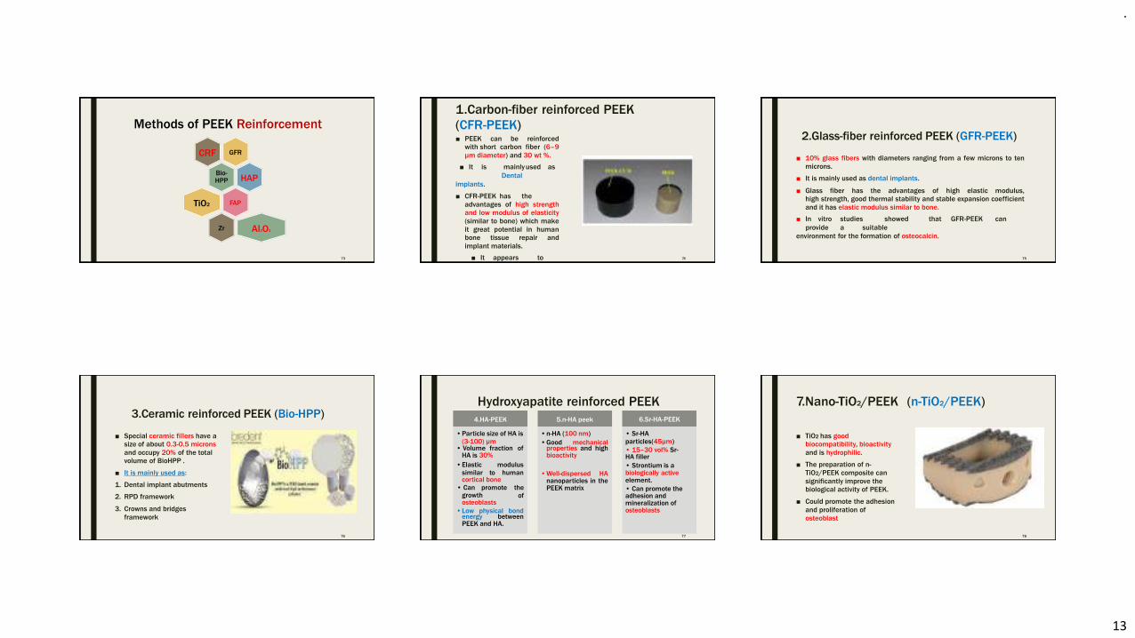
.
13
Methods of PEEK Reinforcement
GFRCRF
Bio-HPP HAP
FAPTiO2
Zr Al2O3
73
1.Carbon-fiber reinforced PEEK
(CFR-PEEK)■ PEEK can be reinforced
with short carbon fiber (6–9
μm diameter) and 30 wt %.
■ It is mainlyused as
Dental
implants.
■ CFR-PEEK has the
advantages of high strength
and low modulus of elasticity
(similar to bone) which make
it great potential in human
bone tissue repair and
implant materials.
■ It appears to
stimulate
74
2.Glass-fiber reinforced PEEK (GFR-PEEK)
75
■ 10% glass fibers with diameters ranging from a few microns to ten
microns.
■ It is mainly used as dental implants.
■ Glass fiber has the advantages of high elastic modulus,
high strength, good thermal stability and stable expansion coefficient
and it has elastic modulus similar to bone.
■ In vitro studies showed that GFR-PEEK can
provide a suitable
environment for the formation of osteocalcin.
3.Ceramic reinforced PEEK (Bio-HPP)
■ Special ceramic fillers have a
size of about 0.3-0.5 microns
and occupy 20% of the total
volume of BioHPP .
■ It is mainly used as:
1. Dental implant abutments
2. RPD framework
3. Crowns and bridges
framework
76
Hydroxyapatite reinforced PEEK
energy betweenPEEK and HA.
4.HA-PEEK 5.n-HA peek
•Particle size of HA is •n-HA (100 nm)
(3-100) µm• Volume fraction of
HA is 30%
•Elastic
similar to
modulus
humancortical bone
• Can promote the
ofgrowthosteoblasts
•Low physical bond
•Good mechanicalproperties and highbioactivity
•Well-dispersed HAnanoparticles in thePEEK matrix
6.Sr-HA-PEEK
• Sr-HA
particles(45µm)
• 15–30 vol% Sr-HA filler
• Strontium is abiologically activeelement.
• Can promote theadhesion andmineralization ofosteoblasts
77
7.Nano-TiO2/PEEK (n-TiO2/PEEK)
■ TiO2 has good
biocompatibility, bioactivity
and is hydrophilic.
■ The preparation of n-
TiO2/PEEK composite can
significantly improve the
biological activity of PEEK.
■ Could promote the adhesion
and proliferation of
osteoblast
78
.
14
8.Nano-fluroapatite PEEK (n-FA/PEEK)
■ The fluoride ions from the
n- FA can affect the
energy metabolism and
enzyme activity of the
bacteria, so n- FA/PEEK
composite has
antibacterial effect.
■ Fluoride ion inhibits the
activity of osteoclast
and phagocyte and stimulate
new bone formation.
79
Conclusion
80
■ PEEK is a promising polymeric material that could replace metallic
and ceramic materials in dental applications.
■ Studies have shown that it performs well as a dental implant
after surface modification to render it bioactive and
increase osseointegration .
■ It can also be used as dental implant
abutmentsand removable
partial denture frameworks.
■ Due to its grayish color it still needs to be veneered by
composite resin when used as crowns and bridges.
■ Long term clinicalstudies are needed to
confirm the eligibility of
PEEK as dental biomaterial considering that it is still a new material.81
.
1
RESIN BONDED PROSTHESIS
CONTENTS➢Introduction➢Resin bonded bridges - Definition- Classification- Types in detail- Indications- Contraindications- Advantages- Disadvantages- Design concepts- Tooth preparation and cementation- Failures➢Fiber reinforced resin FPDs➢Literature review➢Conclusion➢References
INTRODUCTION
The use of synthetic resins has recently expanded to become an essential part of Prosthodontic treatment. Resin materials may be
indicated for an individual restoration, or as a veneer over a casting or as luting agents. Whereas acrylic resins have dominated
resin applications for many years, more refined polymers have emerged and assumed a more extensive role.
Definition of Resin Bonded Prosthesis
Fixed partial denture that is luted to tooth structures, primarily enamel, which has been etched to provide micro mechanical
retention for the resin luting agent.
- GPT 9
CLASSIFICATION
I) According to Rosenstiel:
a) Bonded Pontics
b) Cast perforated resin-retained FPDs (mechanical retention)
c) Etched cast resin-retained FPDs (micro-mechanical retention –Maryland bridge)
d) Macro-mechanical retention resin-retained FPDs (Virginia bridge)
e) Chemical bonding resin-retained FPDs (adhesion bridges)
According to type of retention
•Mechanical retention- resin retained FPD’s
•Micromechanical retention - resin retained FPD’s
•Macroscopic mechanical -retention resin retained FPD’s
•Chemical bonding -resin retained FPD’s
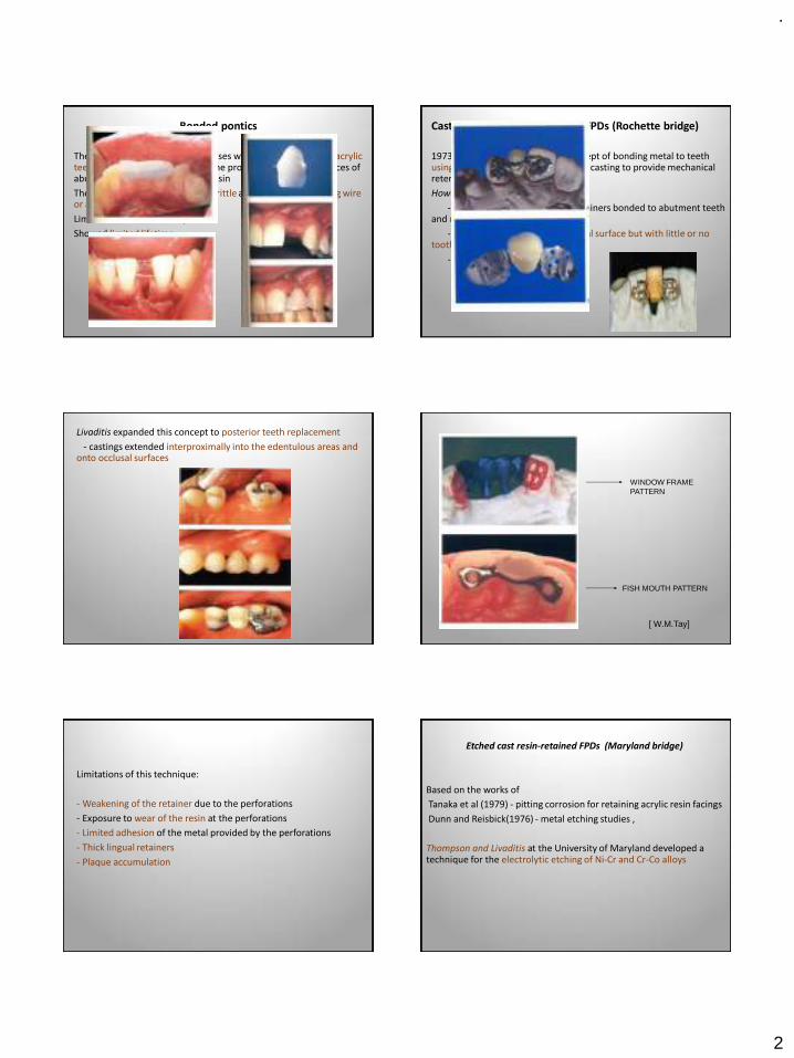
.
2
Bonded pontics
The earliest resin retained prostheses were extracted teeth or acrylic teeth used as pontics bonded to the proximal and lingual surfaces of abutment teeth with composite resin
The composite connectors were brittle and required supporting wire or a mesh framework
Limited to short anterior spans
Showed limited lifetime
Cast perforated resin-retained FPDs (Rochette bridge)
1973 – Rochette introduced the concept of bonding metal to teeth using flared perforations of the metal casting to provide mechanical retention.
Howe and Denehy –
- used cast –perforated metal retainers bonded to abutment teeth and metal ceramic pontics
- covered maximum area of lingual surface but with little or no tooth preparation
- bonded with composite resin
Livaditis expanded this concept to posterior teeth replacement
- castings extended interproximally into the edentulous areas and onto occlusal surfaces
WINDOW FRAME PATTERN
FISH MOUTH PATTERN
[ W.M.Tay]
Limitations of this technique:
- Weakening of the retainer due to the perforations
- Exposure to wear of the resin at the perforations
- Limited adhesion of the metal provided by the perforations
- Thick lingual retainers
- Plaque accumulation
Etched cast resin-retained FPDs (Maryland bridge)
Based on the works of
Tanaka et al (1979) - pitting corrosion for retaining acrylic resin facings
Dunn and Reisbick(1976) - metal etching studies ,
Thompson and Livaditis at the University of Maryland developed a technique for the electrolytic etching of Ni-Cr and Cr-Co alloys
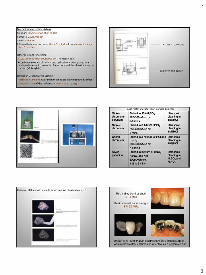
.
3
Method for electrolytic etching
Solution:- 3.5% solution of nitric acid
Current :- 250mA/sq cm
Time:- 5 minutes
followed by immersion in an 18% HCL solution in an ultrasonic cleaner for 10 minutes
Other solutions for etching:
➢10% sulfuric acid at 300mA/sq cm (Thompson et al)
➢Combined solution of sulfuric and hydrochloric acids placed in an activated ultrasonic cleaner for 99 seconds and the electric current is passed (McLaughlin)
Limitation Of Electrolytic Etching –
- Technique sensitive. Over etching can cause electropolished surface
- Contamination of the surface can reduce bond strength
TWO STEP TECHNIQUE
ONE-STEP TECHNIQUE
Nickel-chromium-beryllium
Etched in 10%H2SO4
220-300mA/sq cm3-6 mins
Ultrasonic cleaning in 18%HCl
Nickel-chromium
Etched in 0.1-0.5M HNO3
250-400mA/sq cm5 mins
Ultrasonic cleaning in 18%HCl
Cobalt-chromium
Etched in a mixture of HCl and HNO3
200-300mA/sq cm7-8 mins
Ultrasonic cleaning in 18%HCl
Silver-palladium
Etched in mixture of HNO3
NaNO3 and NaF300mA/sq cm1 ½ to 3 mins
Ultrasonic cleaning in H2SO4 and H3PO4
Base metal alloys for resin bonded bridges:
Chemical etching with a stable aqua regia gel (Doukoudakis) *10
Resin alloy bond strength 27.3 Mpa
Resin enamel bond strength 8.5-9.9 MPa
Dhillon et al found that an electrochemically etched surface was approximately 2.9 times as retentive as a perforated one.
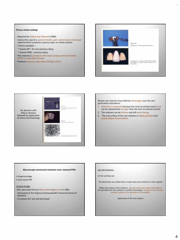
.
4
Porous metal coatings
- Reported by Stokes and Tidmarsh (1986)
- Used a thin coat of a special metallic paint called Inzoma interzonalmaterial which produces a porous layer on metal surfaces
- 2 forms available –
* Inzoma NP – for non-precious alloys
* Inzoma P990 – precious alloys
- This material is painted on the metal surface and then fired to 9700C in a porcelain furnace
- Produces a porous layer about 20-30m thick
Air abrasion with 250m abrasive
followed by application of silane (sand blasting)
Etched cast retainers have definite advantages over the cast -perforated restorations:
1. Retention is improved because the resin-to-etched metal bondcan be substantially stronger than the resin-to-etched enamel.
2. The retainers can be thinner and still resist flexing.
3. The oral surface of the cast retainers is highly polished and resists plaque accumulation.
Macroscopic mechanical retention resin-retained FPDs
➢Virginia bridge
➢Cast mesh FPD
Virginia bridge
-Was advocated first by Moon and Hudgins et al in 1984
- Developed at the Virginia Commonwealth University School of dentistry
- It involves the ‘lost salt technique’
Lost salt technique:
On the working cast
The abutments are coated with a model spray and a lubricant is then applied
Within the outline of the retainers, specially sized salt crystals (150-250m) are sprinkled over the surface in a uniform monolayer, leaving a 0.5mm border
without crystals at the periphery of the pattern
Application of the resin pattern
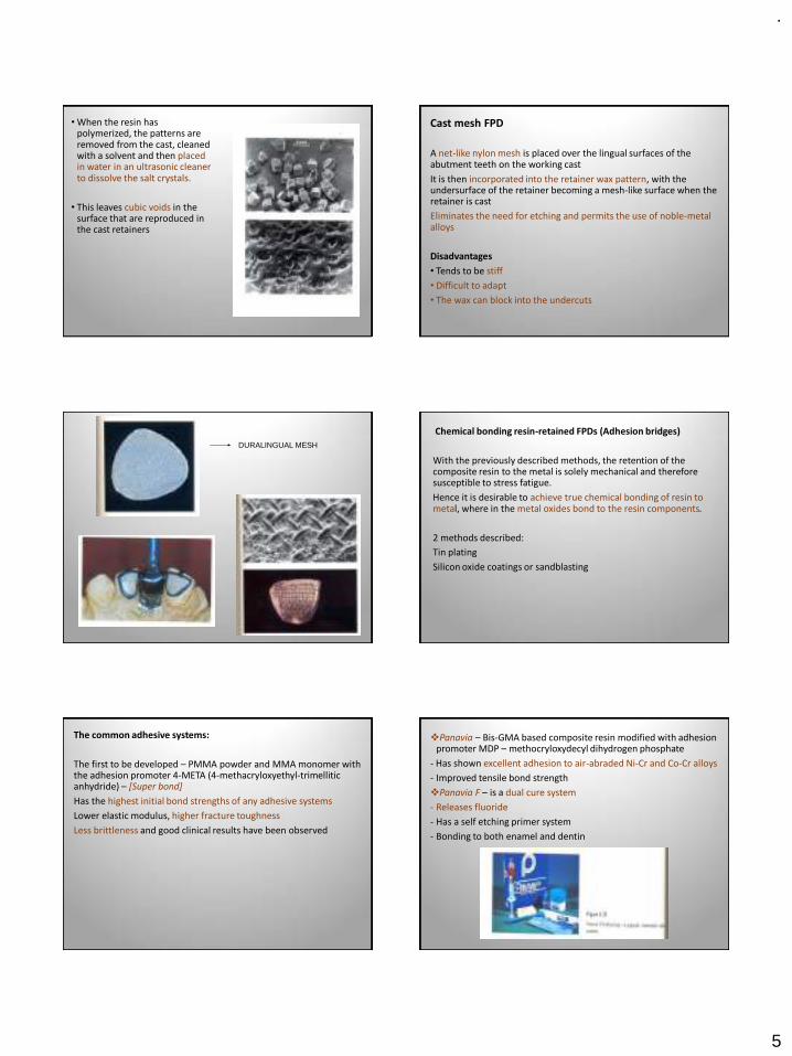
.
5
• When the resin has polymerized, the patterns are removed from the cast, cleaned with a solvent and then placed in water in an ultrasonic cleaner to dissolve the salt crystals.
• This leaves cubic voids in the surface that are reproduced in the cast retainers
Cast mesh FPD
A net-like nylon mesh is placed over the lingual surfaces of the abutment teeth on the working cast
It is then incorporated into the retainer wax pattern, with the undersurface of the retainer becoming a mesh-like surface when the retainer is cast
Eliminates the need for etching and permits the use of noble-metal alloys
Disadvantages
• Tends to be stiff
• Difficult to adapt
• The wax can block into the undercuts
DURALINGUAL MESH
Chemical bonding resin-retained FPDs (Adhesion bridges)
With the previously described methods, the retention of the composite resin to the metal is solely mechanical and therefore susceptible to stress fatigue.
Hence it is desirable to achieve true chemical bonding of resin to metal, where in the metal oxides bond to the resin components.
2 methods described:
Tin plating
Silicon oxide coatings or sandblasting
The common adhesive systems:
The first to be developed – PMMA powder and MMA monomer with the adhesion promoter 4-META (4-methacryloxyethyl-trimellitic anhydride) – [Super bond]
Has the highest initial bond strengths of any adhesive systems
Lower elastic modulus, higher fracture toughness
Less brittleness and good clinical results have been observed
❖Panavia – Bis-GMA based composite resin modified with adhesion promoter MDP – methocryloxydecyl dihydrogen phosphate
- Has shown excellent adhesion to air-abraded Ni-Cr and Co-Cr alloys
- Improved tensile bond strength
❖Panavia F – is a dual cure system
- Releases fluoride
- Has a self etching primer system
- Bonding to both enamel and dentin
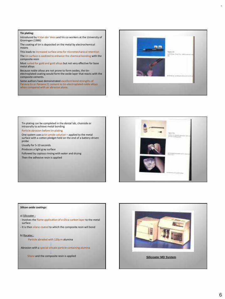
.
6
Tin plating:
Introduced by H.Van der Veen and his co-workers at the University of Groningen (1986)
The coating of tin is deposited on the metal by electrochemical means
This leads to increased surface area for micromechanical retention
The tin surface is oxidized to enhance the chemical bonding with the composite resin
Most suited for gold and gold alloys but not very effective for base metal alloys
Because noble alloys are not prone to form oxides, the tin-electroplated coating would form the oxide layer that reacts with the composite cements.
Some authors have demonstrated excellent bond strengths of Panavia Ex or Panavia 21 cement to tin-electroplated noble alloys when compared with air abrasion alone.
Tin plating can be completed in the dental lab, chairside or intraorally to achieve metal bonding
Particle abrasion before tin plating
One system uses a tin amide solution – applied to the metal surface with a cotton pledget held on the end of a battery-driven probe
Usually for 5-10 seconds
Produces a light gray surface
Followed by copious rinsing with water and drying
Then the adhesive resin is applied
Silicon oxide coatings:
a) Silicoater :
- Involves the flame application of a silica-carbon layer to the metal surface
- It is then silane coated to which the composite resin will bond
b) Rocatec :
Particle abraded with 120m alumina
Abrasion with a special silicate particle containing alumina
Silane and the composite resin is applied Silicoater MD System
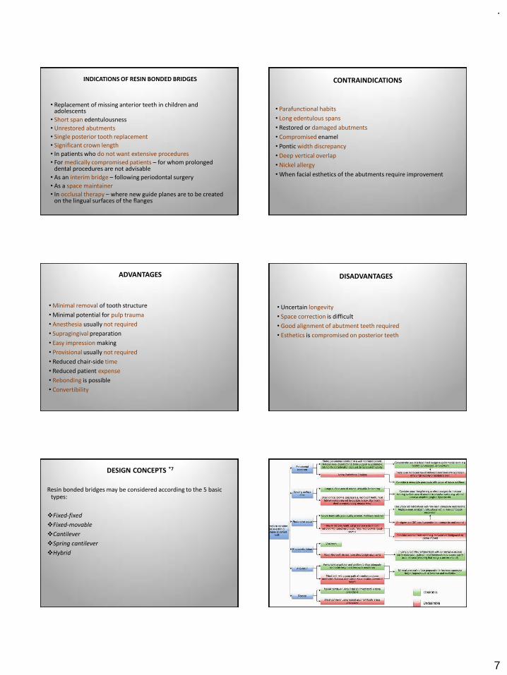
.
7
INDICATIONS OF RESIN BONDED BRIDGES
• Replacement of missing anterior teeth in children and adolescents
• Short span edentulousness
• Unrestored abutments
• Single posterior tooth replacement
• Significant crown length
• In patients who do not want extensive procedures
• For medically compromised patients – for whom prolonged dental procedures are not advisable
• As an interim bridge – following periodontal surgery
• As a space maintainer
• In occlusal therapy – where new guide planes are to be created on the lingual surfaces of the flanges
CONTRAINDICATIONS
• Parafunctional habits
• Long edentulous spans
• Restored or damaged abutments
• Compromised enamel
• Pontic width discrepancy
• Deep vertical overlap
• Nickel allergy
• When facial esthetics of the abutments require improvement
ADVANTAGES
• Minimal removal of tooth structure
• Minimal potential for pulp trauma
• Anesthesia usually not required
• Supragingival preparation
• Easy impression making
• Provisional usually not required
• Reduced chair-side time
• Reduced patient expense
• Rebonding is possible
• Convertibility
DISADVANTAGES
• Uncertain longevity
• Space correction is difficult
• Good alignment of abutment teeth required
• Esthetics is compromised on posterior teeth
DESIGN CONCEPTS *7
Resin bonded bridges may be considered according to the 5 basic types:
❖Fixed-fixed
❖Fixed-movable
❖Cantilever
❖Spring cantilever
❖Hybrid
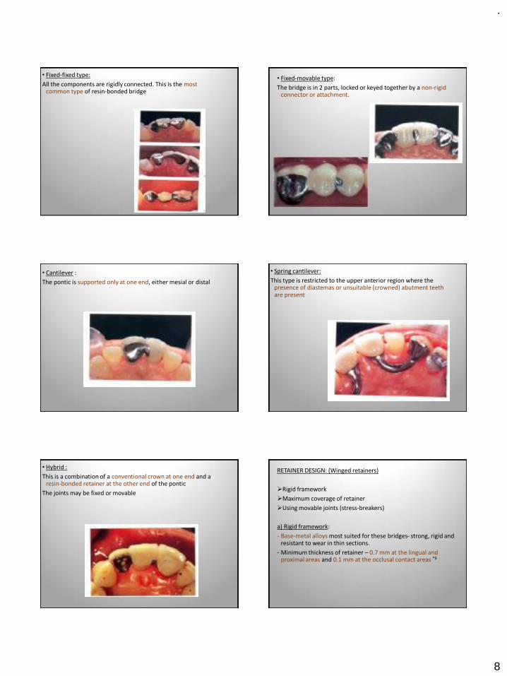
.
8
• Fixed-fixed type:
All the components are rigidly connected. This is the most common type of resin-bonded bridge
• Fixed-movable type:
The bridge is in 2 parts, locked or keyed together by a non-rigid connector or attachment.
• Cantilever :
The pontic is supported only at one end, either mesial or distal
• Spring cantilever:
This type is restricted to the upper anterior region where the presence of diastemas or unsuitable (crowned) abutment teeth are present
• Hybrid :
This is a combination of a conventional crown at one end and a resin-bonded retainer at the other end of the pontic
The joints may be fixed or movable
RETAINER DESIGN: (Winged retainers)
➢Rigid framework
➢Maximum coverage of retainer
➢Using movable joints (stress-breakers)
a) Rigid framework:
- Base-metal alloys most suited for these bridges- strong, rigid and resistant to wear in thin sections.
- Minimum thickness of retainer – 0.7 mm at the lingual and proximal areas and 0.1 mm at the occlusal contact areas *9
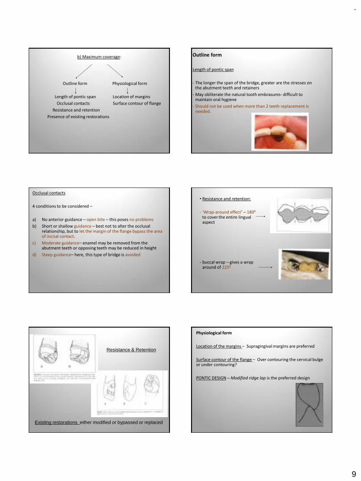
.
9
b) Maximum coverage:
Outline form Physiological form
Length of pontic span Location of margins
Occlusal contacts Surface contour of flange
Resistance and retention
Presence of existing restorations
Outline form
Length of pontic span
- The longer the span of the bridge, greater are the stresses on the abutment teeth and retainers
- May obliterate the natural tooth embrasures- difficult to maintain oral hygiene
- Should not be used when more than 2 teeth replacement is needed.
Occlusal contacts
4 conditions to be considered –
a) No anterior guidance – open bite – this poses no problems
b) Short or shallow guidance – best not to alter the occlusal relationship, but to let the margin of the flange bypass the area of incisal contact.
c) Moderate guidance– enamel may be removed from the abutment teeth or opposing teeth may be reduced in height
d) Steep guidance– here, this type of bridge is avoided
• Resistance and retention:
- ‘Wrap-around effect’ – 1800
to cover the entire lingual aspect
- buccal wrap – gives a wrap around of 2250
Resistance & Retention
Existing restorations either modified or bypassed or replaced
Physiological form
Location of the margins – Supragingival margins are preferred
Surface contour of the flange – Over contouring the cervical bulge or under contouring?
PONTIC DESIGN – Modified ridge lap is the preferred design
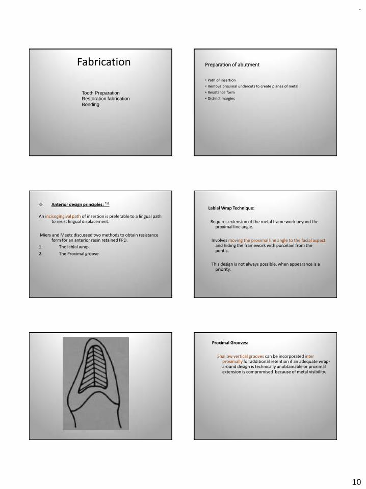
.
10
Fabrication
Tooth PreparationRestoration fabricationBonding
Preparation of abutment
• Path of insertion
• Remove proximal undercuts to create planes of metal
• Resistance form
• Distinct margins
❖ Anterior design principles: *11
An incisogingival path of insertion is preferable to a lingual path to resist lingual displacement.
Miers and Meetz discussed two methods to obtain resistance form for an anterior resin retained FPD.
1. The labial wrap.
2. The Proximal groove
Labial Wrap Technique:
Requires extension of the metal frame work beyond the proximal line angle.
Involves moving the proximal line angle to the facial aspect and hiding the framework with porcelain from the pontic.
This design is not always possible, when appearance is a priority.
Proximal Grooves:
Shallow vertical grooves can be incorporated inter proximally for additional retention if an adequate wrap-around design is technically unobtainable or proximal extension is compromised because of metal visibility.
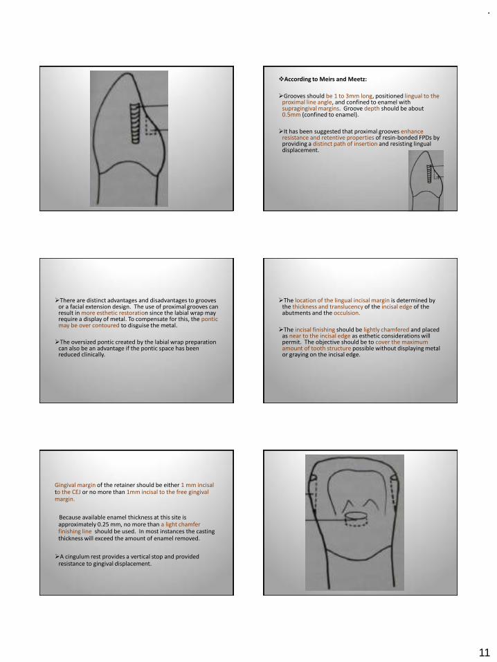
.
11
❖According to Meirs and Meetz:
➢Grooves should be 1 to 3mm long, positioned lingual to the proximal line angle, and confined to enamel with supragingival margins. Groove depth should be about 0.5mm (confined to enamel).
➢It has been suggested that proximal grooves enhance resistance and retentive properties of resin-bonded FPDs by providing a distinct path of insertion and resisting lingual displacement.
➢There are distinct advantages and disadvantages to grooves or a facial extension design. The use of proximal grooves can result in more esthetic restoration since the labial wrap may require a display of metal. To compensate for this, the ponticmay be over contoured to disguise the metal.
➢The oversized pontic created by the labial wrap preparation can also be an advantage if the pontic space has been reduced clinically.
➢The location of the lingual incisal margin is determined by the thickness and translucency of the incisal edge of the abutments and the occulsion.
➢The incisal finishing should be lightly chamfered and placed as near to the incisal edge as esthetic considerations will permit. The objective should be to cover the maximum amount of tooth structure possible without displaying metal or graying on the incisal edge.
Gingival margin of the retainer should be either 1 mm incisal to the CEJ or no more than 1mm incisal to the free gingival margin.
Because available enamel thickness at this site is approximately 0.25 mm, no more than a light chamfer finishing line should be used. In most instances the casting thickness will exceed the amount of enamel removed.
➢A cingulum rest provides a vertical stop and provided resistance to gingival displacement.
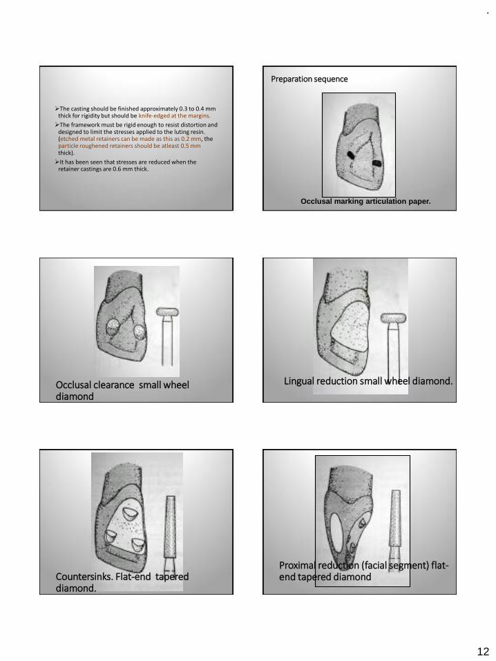
.
12
➢The casting should be finished approximately 0.3 to 0.4 mm thick for rigidity but should be knife-edged at the margins.
➢The framework must be rigid enough to resist distortion and designed to limit the stresses applied to the luting resin. (etched metal retainers can be made as this as 0.2 mm, the particle roughened retainers should be atleast 0.5 mm thick).
➢It has been seen that stresses are reduced when the retainer castings are 0.6 mm thick.
Occlusal marking articulation paper.
Preparation sequence
Occlusal clearance small wheel diamond
Lingual reduction small wheel diamond.
Countersinks. Flat-end tapered diamond.
Proximal reduction (facial segment) flat-end tapered diamond
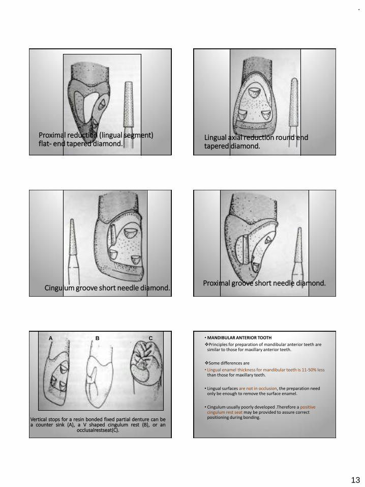
.
13
Proximal reduction (lingual segment) flat- end tapered diamond.
Lingual axial reduction round end tapered diamond.
Cingulum groove short needle diamond.Proximal groove short needle diamond.
Vertical stops for a resin bonded fixed partial denture can bea counter sink (A), a V shaped cingulum rest (B), or an
occlusalrestseat(C).
A B C • MANDIBULAR ANTERIOR TOOTH
❖Principles for preparation of mandibular anterior teeth are similar to those for maxillary anterior teeth.
❖Some differences are
• Lingual enamel thickness for mandibular teeth is 11-50% less than those for maxillary teeth.
• Lingual surfaces are not in occlusion, the preparation need only be enough to remove the surface enamel.
• Cingulum usually poorly developed .Therefore a positive cingulum rest seat may be provided to assure correct positioning during bonding.
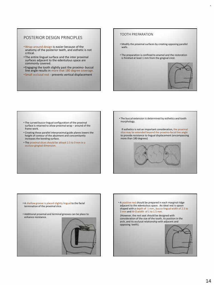
.
14
POSTERIOR DESIGN PRINCIPLES
•Wrap-around design is easier because of the anatomy of the posterior teeth, and esthetic is not critical.
•The entire lingual surface and the inter proximal surfaces adjacent to the edentulous space are commonly covered.
•Engaging the tooth slightly past the proximo- buccal line angle results in more that 180 degree coverage.
•Small occlusal rest - prevents vertical displacement
TOOTH PREPARATION
• Modify the proximal surfaces by creating opposing parallel walls.
• The preparation is confined to enamel and the restoration is finished at least 1 mm from the gingival crest.
• The curved bucco-lingual configuration of the proximal surface is retained to allow proximal wrap – around of the frame work.
• Creating these parallel interproximal guide planes lowers the height of contour of the abutment and concomitantly increases the bonding surface.
• The proximal slices should be atleast 2.5 to 3 mm in a occluso-gingival dimension.
• The buccal extension is determined by esthetics and tooth morphology.
If esthetics is not an important consideration, the proximal slice may be extended beyond the proximo-facial line angle to provide resistance to lingual displacement (encompassing more than 180 degrees)
• A shallow groove is placed slightly lingual to the facial termination of the proximal slice.
• Additional proximal and terminal grooves can be place to enhance resistance.
• A positive rest should be prepared in each marginal ridge adjacent to the edentulous space. An ideal rest is spoon shaped with a depth of 1 mm , bucco-lingual width of 2.5 to 3 mm and M-D.width of 1 to 1.5 mm.
(However, the rest seat should be designed with consideration of the size of the tooth, its position in the arch, and its occlusal relationship with adjacent and opposing teeth).
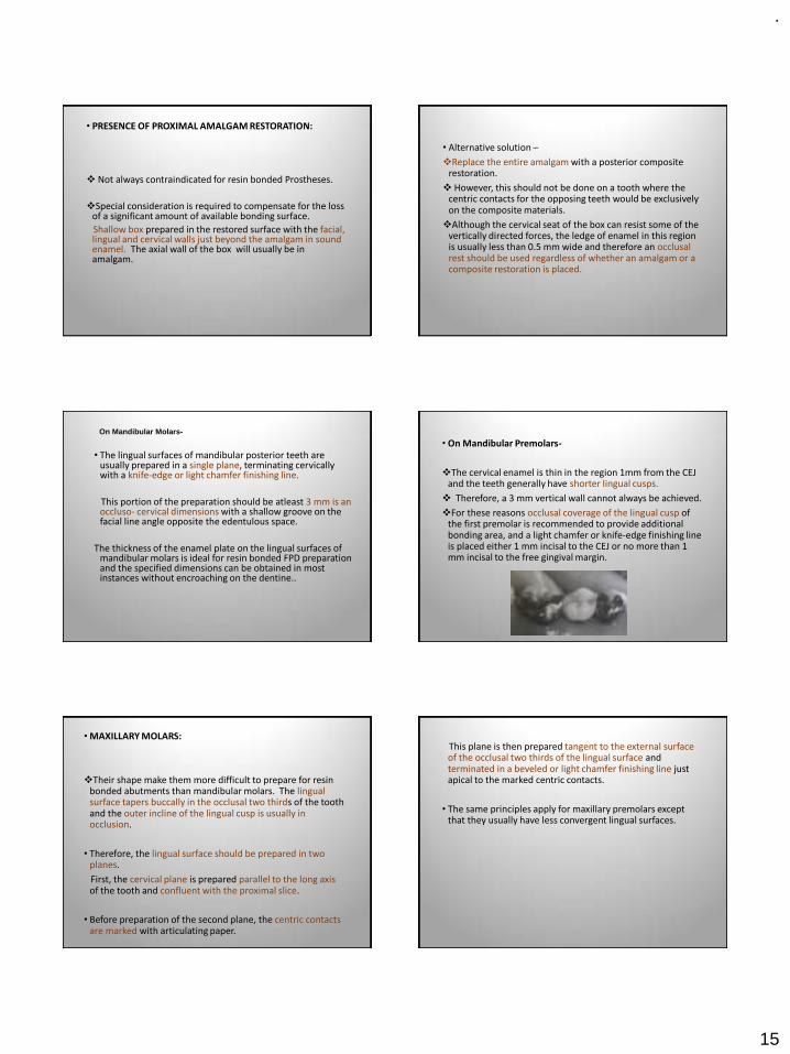
.
15
• PRESENCE OF PROXIMAL AMALGAM RESTORATION:
❖ Not always contraindicated for resin bonded Prostheses.
❖Special consideration is required to compensate for the loss of a significant amount of available bonding surface.
Shallow box prepared in the restored surface with the facial, lingual and cervical walls just beyond the amalgam in sound enamel. The axial wall of the box will usually be in amalgam.
• Alternative solution –
❖Replace the entire amalgam with a posterior composite restoration.
❖ However, this should not be done on a tooth where the centric contacts for the opposing teeth would be exclusively on the composite materials.
❖Although the cervical seat of the box can resist some of the vertically directed forces, the ledge of enamel in this region is usually less than 0.5 mm wide and therefore an occlusal rest should be used regardless of whether an amalgam or a composite restoration is placed.
• The lingual surfaces of mandibular posterior teeth are usually prepared in a single plane, terminating cervicallywith a knife-edge or light chamfer finishing line.
This portion of the preparation should be atleast 3 mm is an occluso- cervical dimensions with a shallow groove on the facial line angle opposite the edentulous space.
The thickness of the enamel plate on the lingual surfaces of mandibular molars is ideal for resin bonded FPD preparation and the specified dimensions can be obtained in most instances without encroaching on the dentine..
On Mandibular Molars-
• On Mandibular Premolars-
❖The cervical enamel is thin in the region 1mm from the CEJ and the teeth generally have shorter lingual cusps.
❖ Therefore, a 3 mm vertical wall cannot always be achieved.
❖For these reasons occlusal coverage of the lingual cusp of the first premolar is recommended to provide additional bonding area, and a light chamfer or knife-edge finishing line is placed either 1 mm incisal to the CEJ or no more than 1 mm incisal to the free gingival margin.
• MAXILLARY MOLARS:
❖Their shape make them more difficult to prepare for resin bonded abutments than mandibular molars. The lingual surface tapers buccally in the occlusal two thirds of the tooth and the outer incline of the lingual cusp is usually in occlusion.
• Therefore, the lingual surface should be prepared in two planes.
First, the cervical plane is prepared parallel to the long axis of the tooth and confluent with the proximal slice.
• Before preparation of the second plane, the centric contacts are marked with articulating paper.
This plane is then prepared tangent to the external surface of the occlusal two thirds of the lingual surface and terminated in a beveled or light chamfer finishing line just apical to the marked centric contacts.
• The same principles apply for maxillary premolars except that they usually have less convergent lingual surfaces.
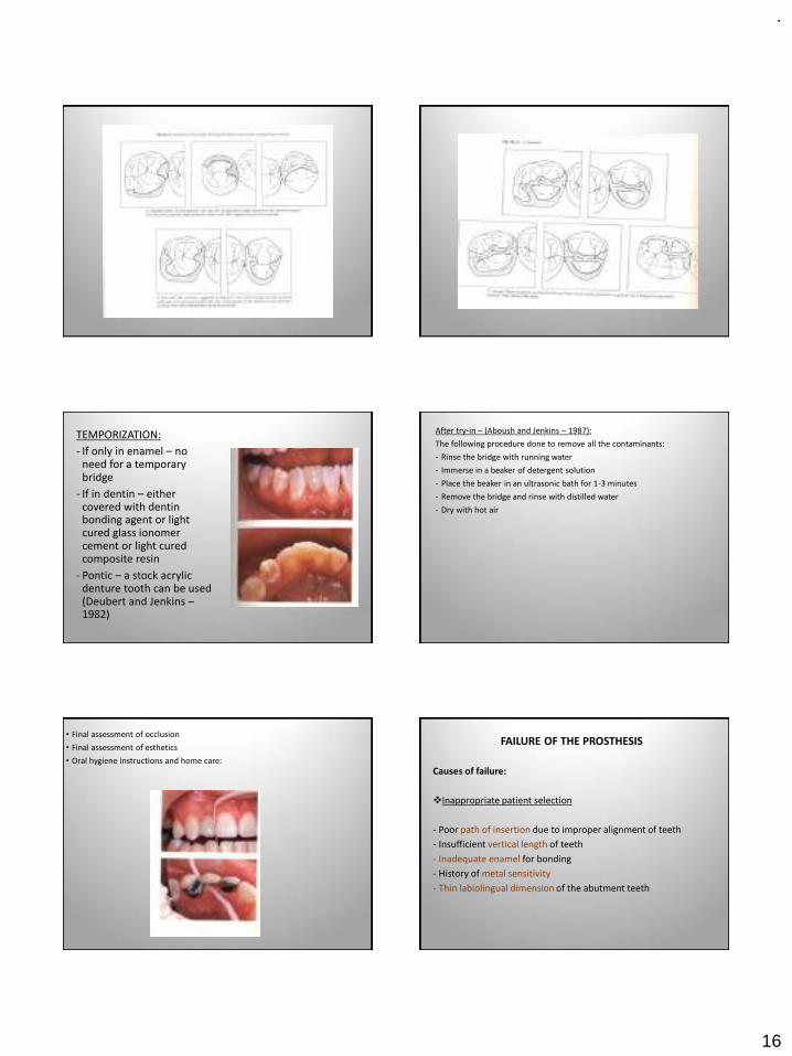
.
16
TEMPORIZATION:
- If only in enamel – no need for a temporary bridge
- If in dentin – either covered with dentin bonding agent or light cured glass ionomer cement or light cured composite resin
- Pontic – a stock acrylic denture tooth can be used (Deubert and Jenkins –1982)
After try-in – (Aboush and Jenkins – 1987):
The following procedure done to remove all the contaminants:
- Rinse the bridge with running water
- Immerse in a beaker of detergent solution
- Place the beaker in an ultrasonic bath for 1-3 minutes
- Remove the bridge and rinse with distilled water
- Dry with hot air
• Final assessment of occlusion
• Final assessment of esthetics
• Oral hygiene instructions and home care:
FAILURE OF THE PROSTHESIS
Causes of failure:
❖Inappropriate patient selection
- Poor path of insertion due to improper alignment of teeth
- Insufficient vertical length of teeth
- Inadequate enamel for bonding
- History of metal sensitivity
- Thin labiolingual dimension of the abutment teeth
.
17
❖Incomplete tooth preparation
- Insufficient proximal and lingual surface reduction
- Less than 180 degree wrap-around
- Lack of accommodation to mandibular excursion
❖Bonding to the Resin cement
- Contamination
- Prolonged mixing
BOND FAILURES (Debonds)
Complete debond Partial debond
The bond failure can be between:
- Metal-resin interface
- Tooth-resin
- Cohesive failure within the resin
Complete debond:
- If the bridge is serviceable it is rebonded in place
- The traces of resin cement are removed by sandblasting or burnt in a porcelain furnace at 7000C for 15-20 minutes
Then the metal flange treated in one of the following ways:
▪For perforated, mesh or bead forms – only ultrasonic cleaning before rebonding
▪Maryland bridges – re-etching
▪Adhesive bridges – tin plating
▪ If no facilities for above available – convert to Rochette bridge
Partial debond:
May be indicated as follows –
- Patient tells that the bridge is loose
- Place a spoon excavator on the cervical margin and give a pull-debond can be felt
- Press on each retainer in turn with a ball-ended burnisher – bubbles forming in the fluid around the margins indicates bond failure
Treated as follows –
- Remove the debonded flange and convert into cantilever type
- Remove the entire bridge, clean the traces of cement on teeth, metal surfaces are cleaned and then the bridge cemented back in place
Fiber reinforced composite fixed prosthesis
INDICATIONS
• Optimal esthetic result
• Desire for metal-free prosthesis
• Need to decrease wear of opposing dentition
• Use of conservative intracoronal abutment tooth preparations
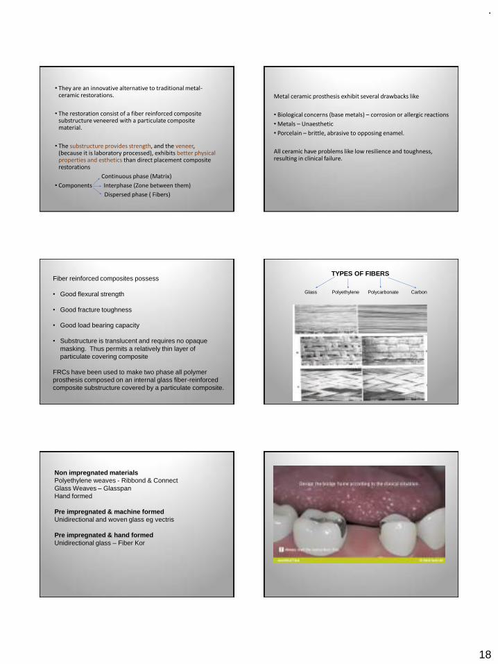
.
18
• They are an innovative alternative to traditional metal-ceramic restorations.
• The restoration consist of a fiber reinforced composite substructure veneered with a particulate composite material.
• The substructure provides strength, and the veneer, (because it is laboratory processed), exhibits better physical properties and esthetics than direct placement composite restorations
Continuous phase (Matrix)
• Components Interphase (Zone between them)
Dispersed phase ( Fibers)
Metal ceramic prosthesis exhibit several drawbacks like
• Biological concerns (base metals) – corrosion or allergic reactions
• Metals – Unaesthetic
• Porcelain – brittle, abrasive to opposing enamel.
All ceramic have problems like low resilience and toughness, resulting in clinical failure.
Fiber reinforced composites possess
• Good flexural strength
• Good fracture toughness
• Good load bearing capacity
• Substructure is translucent and requires no opaque masking. Thus permits a relatively thin layer of particulate covering composite
FRCs have been used to make two phase all polymer prosthesis composed on an internal glass fiber-reinforced composite substructure covered by a particulate composite.
TYPES OF FIBERS
Glass Polyethylene Polycarbonate Carbon
Non impregnated materialsPolyethylene weaves - Ribbond & ConnectGlass Weaves – GlasspanHand formed
Pre impregnated & machine formedUnidirectional and woven glass eg vectris
Pre impregnated & hand formedUnidirectional glass – Fiber Kor
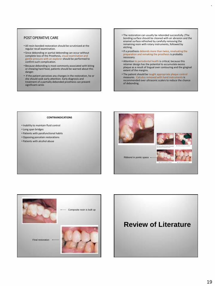
.
19
POST OPERATIVE CARE
• All resin-bonded restoration should be scrutinized at the regular recall examination.
• Since debonding or partial debonding can occur without complete loss of the Prosthesis, visual examination and gentle pressure with an explorer should be performed to confirm such complication.
• Because debonding is most commonly associated with biting or chewing hard food, patients should be warned about this danger.
• If the patient perceives any changes in the restoration, he or she should seek early attention. Early diagnosis and treatment of a partially debonded prosthesis can prevent significant caries
• The restoration can usually be rebonded successfully. (The bonding surface should be cleaned with air abrasion and the enamel surface refreshed by carefully removing the remaining resin with rotary instruments, followed by etching.
• If a prosthesis debonds more than twice, revaluating the preparation and remaking the prosthesis is probably necessary.
• Attention to periodontal health is critical, because this retainer design has the potential to accumulate excess plaque as a result of lingual over contouring and the gingival extent of the margins.
• The patient should be taught appropriate plaque control measures. Calculus removed with hand instruments is recommended over ultrasonic scalers to reduce the chance of debonding.
CONTRAINDICATIONS
• Inability to maintain fluid control
• Long span bridges
• Patients with parafunctional habits
• Opposing porcelain restorations
• Patients with alcohol abuse
Ribbond in pontic space
Composite resin is built up
Final restoration
Review of Literature
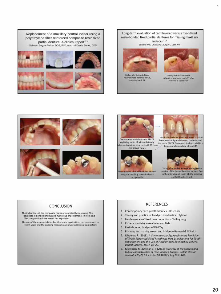
.
20
Replacement of a maxillary central incisor using a polyethylene fiber reinforced composite resin fixed
partial denture: A clinical report*13
Sebnem Begum Turker, DDS, PhD,aand Isil Damla Sener, DDS
Long-term evaluation of cantilevered versus fixed-fixed resin-bonded fixed partial dentures for missing maxillary
incisors *14
Botelho MG, Chan AW, Leung NC, Lam WY.
Unilaterally debonded two-retainer metal-ceramic RBFDP,
replacing tooth 21.
Clearly visible caries at the debonded abutment tooth 11 after
removal of the RBFDP.
Two-retainer metal-ceramic RBFDP replacing tooth 12 with unilaterally
debonded retainer wing on tooth 11 from the lingual view...
...and from the labial view. Abutment tooth 11 has moved (migrated) toward thelabial, and
the metal RBFDP framework is clearly visible in the proximal area distal of tooth11.
After removal of the debonded retainer wing the resulting caries is clearly
recognizable.
Status after caries removal and adhesive sealing of the lingual bonding surface. Due to the migration of tooth 11, the proximal
contact has been lost.
CONCLUSION
The indications of the composite resins are constantly increasing. The advances in dentin bonding and numerous improvements in resin and filler composition have fueled this expansion
The use of these materials for Prosthodontic applications has progressed in recent years and the ongoing research can unveil additional applications
REFERENCES
1. Contemporary fixed prosthodontics – Rosenstiel
2. Theory and practice of fixed prosthodontics – Tylman
3. Fundamentals of fixed prosthodontics – Shillingburg
4. Esthetic dentistry – Asccheim and Dale
5. Resin-bonded bridges – W.M.Tay
6. Planning and making crown and bridges – Bernard G N Smith
7. Ibbetson, R. (2018). A Contemporary Approach to the Provision of Tooth-Supported Fixed Prostheses Part 1: Indications for Tooth Replacement and the Use of Fixed Bridges Retained by Crowns. Dental Update, 45(1), 10–20.
8. Miettinen, M.,&Millar, B. J. (2013). A review of the success and failure characteristics of resin-bonded bridges. British Dental Journal, 215(2), E3–E3. doi:10.1038/sj.bdj.2013.686

.
21
9. Durey KA, Nixon PJ, Robinson S, Chan MY. Resin bonded bridges: techniques for success. British dental journal. 2011 Aug;211(3):113.
10. A new chemical method for etching metal frame works of the acid-etched prosthesis: A Doukoudakis, JPD Oct 1987, Vol 58, No. 4(421-23)
11. Meiers JC, Meetz HK. Design modifications for etched-metal, resin-bonded retainers. General dentistry. 1985;33(1):41-4.
12. Rubo JH, Pegoraro LF, Marolato F, Rubo MH. The effect of tin-electroplating on the bond of four dental alloys to resin cement: an in vitro study. The Journal of prosthetic dentistry. 1998 Jul 1;80(1):27-31.
13. Turker, S. B.,&Sener, I. D. (2008). Replacement of a maxillary central incisor using a polyethylene fiber-reinforced composite resin fixed partial denture: A clinical report. The Journal of Prosthetic Dentistry, 100(4), 254–258. doi:10.1016/s0022-3913(08)60201-2
14. Botelho MG, Chan AW, Leung NC, Lam WY. Long-term evaluation of cantilevered versus fixed-fixed resin-bonded fixed partial dentures for missing maxillary incisors. J Dent 2016;45: 59–66.
THANK YOU


