Embed Size (px)
Citation preview

Circulating Current High Impedance Differential Protection using 7SJ8
www.siemens.com/siprotec5
SIPROTEC 5 Application Circulating Current High Impedance Differential Protection using 7SJ8
APN-030 2 Edition 1
SIPROTEC 5 Application
Circulating Current High Impedance Differential Protection using 7SJ8
APN-030, Edition 1
Content 1 Circulating Current High Impedance Differential Protection using 7SJ8 .................................................................. 3
1.1 Introduction............................................................................................................................................................ 3
1.2 Circulating Current High Impedance Protection ...................................................................................................... 3
1.3 Procedure for High Impedance Protection Scheme Calculations ............................................................................. 5
1.4 Working example .................................................................................................................................................. 14
1.5 Applications .......................................................................................................................................................... 19
1.6 Testing procedure and test results for 87B HI ....................................................................................................... 23
1.7 Summary for usage of SIPROTEC 7SJ8x relay as 87B HI ......................................................................................... 44
1.8 References ............................................................................................................................................................ 45

SIPROTEC 5 Application Circulating Current High Impedance Differential Protection using 7SJ8
Edition 1 3 APN-030
1 Circulating Current High Impedance Differential Protection using 7SJ8
1.1 Introduction This application note describes the multifunctional relay SIPROTEC 7SJ8x used in high impedance protection applications.
Three-phase (phase-segregated) circulating current high impedance protection schemes are typically applied for the following protection objects: busbars, auto-transformer, series reactor, shunt reactor or even to motors or generators. Regarding busbars arrangements, the high impedance protection scheme is widely used for arrangements like single
busbars, single busbars with sectionalizer, or circuit-breaker-and-a-half arrangements. The usage of high impedance busbar protection for double busbars is not recommended, because of high complexity related to switching-over of CT secondaries that decreases the scheme reliability.
Single-phase restricted earth fault (REF) protection schemes may be used in principle to all the protected object as listed above, but the most common application is to protect transformer windings which are earthed via impedance, solidly earthed or even for transformer winding connected in delta (in this case the scheme is sometimes called high impedance balanced earth fault).
The multifunctional relay SIPROTEC 5 7SJ8x can be used within all the mentioned high impedance protection schemes, both in phase-segregated circulating current high impedance protection applications, as well as in single phase restricted
earth fault protection applications.
This document provides description of the multifunctional relay SIPROTEC 5 7SJ8x application in phase-segregated circulating current high impedance protection scheme. Thereby the guideline for the calculations related to the high
impedance differential protection schemes is described together with the comments on the relay setting parameters.
1.2 Circulating Current High Impedance Protection
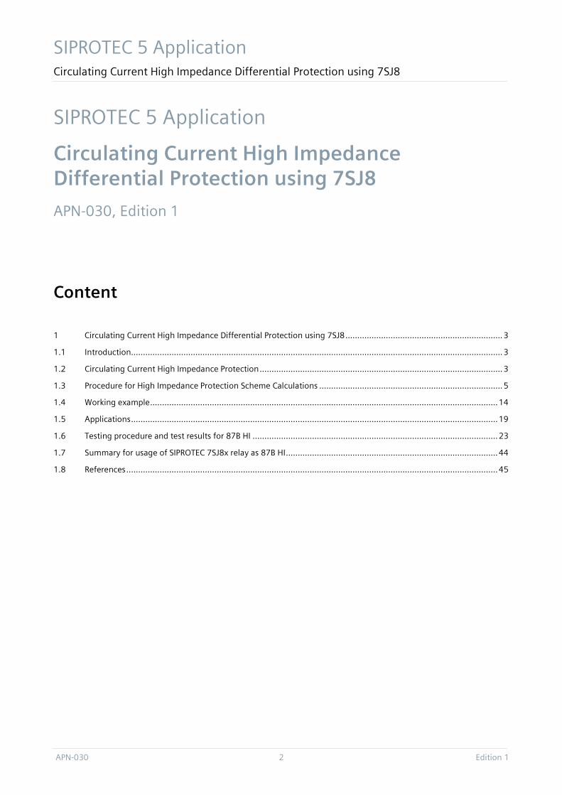
1.2.1 General information of High Impedance Protection Schemes In contrary to the low impedance differential protection schemes, where each of several CTs forming differential protection zone is directly connected to a separate relay input, the high impedance protection scheme is formed by the parallel connection of all CTs secondaries within a given protection zone (Figure 1).
While low impedance protection schemes evaluate signals within the relay that come from each of the CTs independently, the relay in the high impedance scheme evaluates the current that results from the interaction of all the involved CTs as it
flows in the differential branch (Figure 1).
Figure 1 Typical connection of elements within a high impedance differential protection scheme.
setI stabR
varR
primary system, e.g.
busbar
high impedancedifferential branch
multifunctionalnumerical relay
stabilizing resistor
non-linear resistor (varistor)
CT paralleling point
SIPROTEC 5 Applikation Circulating Current High Impedance Differential Protection using 7SJ8
APN-030 4 Edition 1
Thereby, the stability of the differential scheme on CT saturation plays in all schemes an important role.
Low impedance protection schemes evaluate CT secondary currents which may be saturated by their high burden and/or high secondary currents. Thereby, multiple CT currents are evaluated by relay (nowadays relay software), whereas each
CT saturates independently from the others, i.e. the CTs do not influence each other in their performance. Therefore, in the low impedance differential protection devices several different stabilizing measures and algorithms for better stability and selectivity are applied.
Within a high impedance scheme the CTs do influence each other, as all of them are connected in parallel (Figure 1). The stabilization against CT saturation is realized by the placement of an extra element (hardware), namely the stabilizing resistor so no further measures against CT saturation have to be implemented in the relay. Therefore, the relay used within the high impedance protection scheme can be of over-current relay type without involving any additional
measures against CT saturation. All the other high impedance scheme performance quantities: as required fault sensitivity, scheme stability are then dependent on the scheme design involving adequately chosen CT parameters and auxiliary components (stabilizing resistor, varistor) that suit given application.
1.2.2 High Impedance Protection Scheme Design
1.2.2.1 Relevant primary system data Protection object characteristic has major influence on the protection scheme design. Therefore, typically the following properties shall be known
Short-circuit fault level including:
maximum symmetrical short-circuit withstand current of the switchgear
maximum symmetrical short-circuit current for external (through) faults
maximum symmetrical short-circuit current for internal faults
minimum symmetrical short-circuit current for internal faults
For the later ones especially neutral earthing conditions (earth-fault limitation) shall be considered, as well. Moreover, all
the above currents can be three-phase, double-phase or phase-to earth depending on the application/protected object.
Rated parameters of the protected object including
rated power, resp. rated current, impedance voltage, sub-transient reactance, …
Rating of the primary switching elements like circuit breaker, isolators within the switchgear that are relevant to the
protected object
1.2.2.2 Relevant current transformer data The prerequisite (a must) to high impedance schemes is that all the involved CTs have to have the same current ratio. The usage of CTs as per IEC 61869-2 Standard [1] class PX (former BS class X) is generally recommended. Those CTs have
current ratio error limitation and are of low-leakage type. However, for some high impedance protection schemes involving less number of CTs (e.g. REF) also CT of IEC 61869-2 class 5P can be used. Thereby, their current ratio error as well as the respective magnetizing curves together with internal resistances shall be known. Also CTs of the former (now obsolete) IEC 44-6 class TPS can be used within high impedance protection applications.
1 Definition as per IEC 61869-2; in practice the term ‘knee point voltage’ is widely used for this quantity. However, as per standard the
term knee point voltage describes rather the voltage that is applied to the secondary terminals of the CT during testing. For the sack of
the standard compatibility and correctness the term emf will be used through this application guide.
Hereby, it is recommended to transfer their nameplate parameters to the respective IEC class PX parameters. For high impedance busbar protection SIEMENS recommends usage of IEC class PX cores.
SIPROTEC 5 Application Circulating Current High Impedance Differential Protection using 7SJ8
Edition 1 5 APN-030
The following relevant CT parameters shall be known:
CT nameplate data (preferably confirmed by test protocols)
CT ratio
CT knee-point electromotive force (emf)1
CT exciting current at the knee-point emf
CT secondary winding resistance at 75 OC
CT secondary wiring resistance from the CT clamps to the paralleling point of the scheme (loop resistance)
Number of CTs that belong to the differential protection zone
Remark: Regarding knee-point emfs, exciting currents and secondary winding resistances of the used CTs it can be stated that small deviations between the used CTs can be typically tolerated without negative influence on the scheme
performance. The scale of deviation and its influence on the scheme design and performance, however, shall be analyzed on a case basis.
1.2.2.3 Relevant protection device data and auxiliary component data For the high impedance scheme design the relay operating (settable) current range shall be known, so that it can suit the
application with regard to the fault sensitivity. The burden of the relay input is typically very small comparing to external stabilizing resistance and can in most applications be neglected.
Remark: In the past the relays used constant operating current (e.g. 20 mA or 100 mA) and the setting was adjusted by
settable resistors (mounted internally within the relay). Very often such relays were named ‘voltage operated’. Nowadays, modern digital protection relay with wide range settable current setting are used. This gives additional flexibility for covering several high impedance protection applications using one type of the relay. The auxiliary component like resistors and varistors are then typically installed separately within the protection cubicle.
Further chapters guide on relevant calculations and propose scheme design for using multifunctional relay SIPROTEC 5 7SJ8x within high impedance differential protection schemes.
1.3 Procedure for High Impedance Protection Scheme Calculations This chapter provides remarks on scheme design and a guide for the scheme relevant calculations.
1.3.1 Relevant required data
1.3.1.1 Establish the relevant power system data At first the power system primary data that are relevant to the protected object shall be collected.
1. From the scheme stability and thermal design of components point of view the following relevant power system information shall be known:
the maximum symmetrical short-circuit current for external (through) faults extmax,sc,''I
SIPROTEC 5 Applikation Circulating Current High Impedance Differential Protection using 7SJ8
APN-030 6 Edition 1
the maximum symmetrical short-circuit current for internal faults intmax,sc,''I
Remark: In case of a busbar, the maximum short-time symmetrical short-circuit withstand current of the switchgear
swgmax,sc,''I
may be considered for both of the above quantities.
2. From the scheme sensitivity and relay setting range point of view the following relevant power system information shall be known:
the rating of the feeder /diameter circuit breakers or maximum prospective load on those feeders loadr,I
the minimum symmetrical short-circuit current for internal faults intmin,sc,''I
Remark: In power systems with solidly (effectively) earthed neutral-points, the double-phase fault is typically the smallest one and it can be typically considered here. In power systems with earth-fault current limitation (neutral point of power transformers is not directly earthed) the single-pole fault current shall be considered. However, for busbar protection schemes in networks with strongly limited earth fault current (e.g. to several Amps in medium voltage networks with presence of rotating machines) there is often not necessary to detect the earth- fault using such scheme.
1.3.1.2 Establish the relevant current transformer data As previously mentioned the CTs used in the high impedance schemes shall be with equal ratios, of low leakage type and
with limited current ratio error. For high impedance busbar protection SIEMENS recommends usage of IEC class PX CTs.
At first:
the number of CTs that belong to the considered /designed differential protection zone CTN
shall be known, and for each of these CTs their respective IEC class PX [1] parameters shall be collected :
CT Ratio, sr
prr I
Ik =
where prI and srI are primary and secondary rated current, respectively
rated CT knee-point emf kE
CT exciting current at the knee-point emf eI
CT secondary winding resistance CTR (d.c. resistance corrected to 75 OC)
Remark: The values of knee-point emf and the respective exciting current can be obtained / read from the magnetizing characteristic or testing protocols. Both values shall be rms-values, as per IEC class PX.
Furthermore for each CT:
the resistance of secondary wring from the CT clamps to the paralleling point of the scheme (loop resistance) wireR
Remark: The wiring resistances are either given in the tender documentation or can be calculated from the layout
drawings of the switchgear. Typically, a maximum wiring resistance can be estimated and specified as a maximum allowable for the worst case considerations.
SIPROTEC 5 Application Circulating Current High Impedance Differential Protection using 7SJ8
Edition 1 7 APN-030
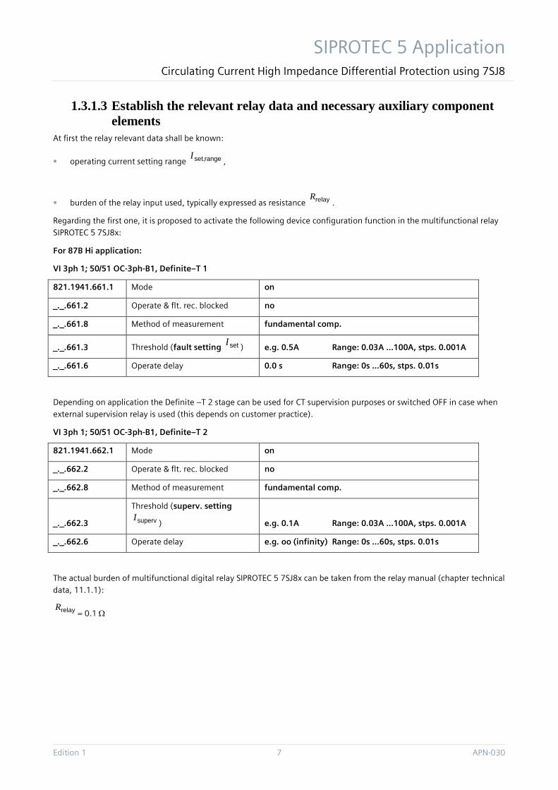
1.3.1.3 Establish the relevant relay data and necessary auxiliary component elements
At first the relay relevant data shall be known:
operating current setting range rangeset,I,
burden of the relay input used, typically expressed as resistance relayR.
Regarding the first one, it is proposed to activate the following device configuration function in the multifunctional relay SIPROTEC 5 7SJ8x:
For 87B Hi application:
VI 3ph 1; 50/51 OC-3ph-B1, Definite–T 1
821.1941.661.1 Mode on
_._.661.2 Operate & flt. rec. blocked no
_._.661.8 Method of measurement fundamental comp.
_._.661.3 Threshold (fault setting setI) e.g. 0.5A Range: 0.03A …100A, stps. 0.001A
_._.661.6 Operate delay 0.0 s Range: 0s …60s, stps. 0.01s
Depending on application the Definite –T 2 stage can be used for CT supervision purposes or switched OFF in case when external supervision relay is used (this depends on customer practice).
VI 3ph 1; 50/51 OC-3ph-B1, Definite–T 2
821.1941.662.1 Mode on
_._.662.2 Operate & flt. rec. blocked no
_._.662.8 Method of measurement fundamental comp.
_._.662.3
Threshold (superv. setting
supervI) e.g. 0.1A Range: 0.03A …100A, stps. 0.001A
_._.662.6 Operate delay e.g. oo (infinity) Range: 0s …60s, stps. 0.01s
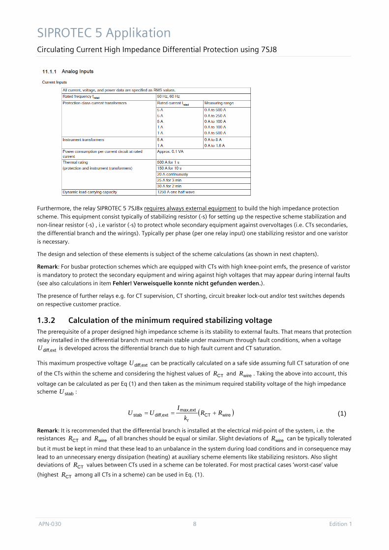
The actual burden of multifunctional digital relay SIPROTEC 5 7SJ8x can be taken from the relay manual (chapter technical data, 11.1.1):
relayR= 0.1 Ω
SIPROTEC 5 Applikation Circulating Current High Impedance Differential Protection using 7SJ8
APN-030 8 Edition 1
Furthermore, the relay SIPROTEC 5 7SJ8x requires always external equipment to build the high impedance protection scheme. This equipment consist typically of stabilizing resistor (-s) for setting up the respective scheme stabilization and non-linear resistor (-s) , i.e varistor (-s) to protect whole secondary equipment against overvoltages (i.e. CTs secondaries, the differential branch and the wirings). Typically per phase (per one relay input) one stabilizing resistor and one varistor
is necessary.
The design and selection of these elements is subject of the scheme calculations (as shown in next chapters).
Remark: For busbar protection schemes which are equipped with CTs with high knee-point emfs, the presence of varistor is mandatory to protect the secondary equipment and wiring against high voltages that may appear during internal faults (see also calculations in item Fehler! Verweisquelle konnte nicht gefunden werden.).
The presence of further relays e.g. for CT supervision, CT shorting, circuit breaker lock-out and/or test switches depends on respective customer practice.
1.3.2 Calculation of the minimum required stabilizing voltage The prerequisite of a proper designed high impedance scheme is its stability to external faults. That means that protection
relay installed in the differential branch must remain stable under maximum through fault conditions, when a voltage
extdiff,U is developed across the differential branch due to high fault current and CT saturation.
This maximum prospective voltage extdiff,U can be practically calculated on a safe side assuming full CT saturation of one
of the CTs within the scheme and considering the highest values of CTR and wireR . Taking the above into account, this
voltage can be calculated as per Eq (1) and then taken as the minimum required stability voltage of the high impedance scheme stabU :
( )wireCTr
extmax,extdiff,stab RR
kI
UU +== (1)
Remark: It is recommended that the differential branch is installed at the electrical mid-point of the system, i.e. the resistances CTR and wireR of all branches should be equal or similar. Slight deviations of wireR can be typically tolerated
but it must be kept in mind that these lead to an unbalance in the system during load conditions and in consequence may lead to an unnecessary energy dissipation (heating) at auxiliary scheme elements like stabilizing resistors. Also slight deviations of CTR values between CTs used in a scheme can be tolerated. For most practical cases ‘worst-case’ value
(highest CTR among all CTs in a scheme) can be used in Eq. (1).
SIPROTEC 5 Application Circulating Current High Impedance Differential Protection using 7SJ8
Edition 1 9 APN-030
Summarizing, the setting voltage of the scheme setU (in practice this voltage results from the multiplication of the relay
current setting and stabilizing resistor value) over the differential branch must be made equal or greater than the required stability voltage (Eq. (1)).
stabset UU ≥ (2)
1.3.3 Calculation of the required fault setting In further steps the following scheme requirements shall be assured:
a) the functionality (trip on internal fault) and b) sensitivity of the scheme that suits given application.
Ad a): To assure the first requirement, the CT knee-point emf kE shall fulfill the following requirement:
setk UE ⋅≥ 2 (3)
Remark: Re-writing the Eq. (3)in form
2/kset EU ≤ (4)
and comparing it to Eq (2):
stabset UU ≥ (5)
one may become the minimum and maximum values for the scheme setting voltage. As per our practice it is worthy to keep in mind that the setting voltage setU shall practically not exceed 300 V because this will introduce difficulties in
finding the proper auxiliary equipment (like varistors, etc.).
Ad b): In order to reach the desired scheme sensitivity, i.e. to trip on internal fault, the current setting of the relay in the differential branch shall be calculated.
To do that, the desired primary fault sensitivity desp,I of the scheme shall be chosen at first.
The primary fault sensitivity, (i.e. the value of the primary internal fault current that the protection scheme shall be able to detect) must suit the corresponding application. So its choice depends on the protected object, the minimum fault level
and/or the type of neutral point earthing. The choice is typically made by protection engineers according to their practice or e.g. as per ENA standard ([2]). Exemplarily, choosing the primary fault sensitivity for busbars, the rated load of the
outgoing feeder loadr,I or rating of the circuit breaker or minimum fault level intmin,sc,''I can be considered.
Having chosen the primary fault sensitivity desp,I of the scheme, the secondary setting of the relay setI can be calculated
bearing in mind that the elements connected together within a high impedance protection scheme will decrease the
sensitivity consuming a portion of current at the corresponding scheme setting voltage setU (i.e. exciting currents eI of
the CTs, varistor spill current varI at the setting voltage):
)()( setvarek
setCT
r
desp,
1setvare.x
k,x
set
r
desp,set
CT
UIIE
UN
kI
UIIEU
kI
IN
x
−−≈−−= ∑=
(6)
Remark: A rough calculation as per right side of the Eq. (6) is enough for most practical cases. Thereby, often the ‘worst-case’ CT data are considered, i.e. the lowest kE , the highest eI . This has an influence on the calculated sensitivity, so the
real fault sensitivity can differ (is higher in this case). This fact shall be considered when choosing required primary fault sensitivity.
SIPROTEC 5 Applikation Circulating Current High Impedance Differential Protection using 7SJ8
APN-030 10 Edition 1
1.3.4 Calculation of the required stabilizing resistor With the steps described in items Fehler! Verweisquelle konnte nicht gefunden werden. and Fehler! Verweisquelle konnte nicht gefunden werden. the basic properties of the high impedance protection scheme were calculated: the scheme setting voltage setU and the current setting of the relay setI .
The multifunctional relay SIPROTEC 5 7SJ8x requires external stabilizing resistor stabR to be connected in series to the
relay input in order to assure the necessary scheme setting voltage setU .
The value of the stabilizing resistor can be calculated in straightforward way using the scheme setting voltage setU and
the setting of the relay setI , as chosen in the previous steps:
set
setrelay
set
setstab I
UR
IU
R ≈−= (7)
Thereby, the relay input burden relayR can be typically neglected.
1.3.5 Calculation of the required non-linear resistor (varistor) As stated in the previous chapters, during an internal fault high voltage may arise across the differential branch (i.e. the tie with relay and stabR connected in series). Therefore, non-linear resistors are necessary in order to avoid secondary
circuits (wirings, CT clamps, resistors, etc) be exposed to high voltages. Such varistors shall be connected across the differential branch.
The secondary circuits are typically designed to withstand 3000 V peak. In practice, in order to safely protect secondary circuits of high impedance schemes the usage of a varistor is necessary when the voltage across the differential branch may exceed around 1500 V rms, which is 2121 V peak. That can be rounded down with a safety margin to 2000 V peak.
In order to estimate whether this voltage may appear in the designed scheme, at first the theoretical rms voltage
rmsint,max,sc,U which would occur across the differential branch if CT did not saturate shall be determined according to
the following equation:
( )stabrelayr
intmax,sc,rmsint,max,sc, RR
kIU +=
'' (8)
Considering CT saturation, the resulting maximum peak voltage across the differential branch tiemax,U can be calculated
[2]:
( )krmsint,max,sc,ktiemax, EUEU −= 22ˆ (9)
Summarizing, when the relationship in (10) is fulfilled the usage of varistor is mandatory:
Vtiemax, 2000ˆ >U (10)
Remark: High impedance restricted earth-fault protection applications may sometimes not require varistor, but busbar protection applications in general do. However, it is considered as good practice to equip with a varistor all high impedance protection installations.
The protection level of the varistor can be estimated from its characteristic (for dc or instantaneous values)
βICU ˆˆ ⋅=var , (11)
where the constants C and β shall be given by the varistor manufacturer.
SIPROTEC 5 Application Circulating Current High Impedance Differential Protection using 7SJ8
Edition 1 11 APN-030
The rms protection level is then: 2/ˆ~ varvar UU , (12)
1.3.6 Calculation of the required thermal ratings of the auxiliary components: Stabilizing resistors and varistors
The ratings of both components, stabilizing resistor and varistor, shall be then chosen to match the application.
1.3.6.1 Thermal rating of varistor The varistor shall be chosen to match the differential branch setting voltage and to limit the voltage to a safe value. i.e. its
characteristic must not change significantly for voltages below and beyond the differential branch setting setU up to the
voltage limit of e.g. 2000 V peak. The varistor must be also capable of passing the maximum prospective fault current that can be transformed by the CT.
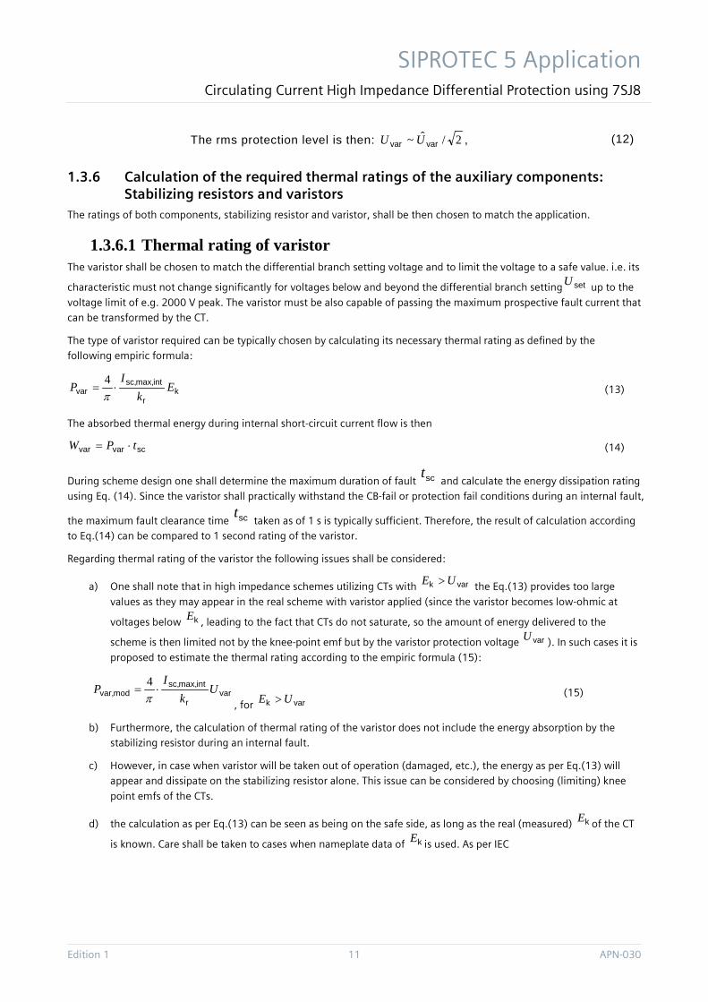
The type of varistor required can be typically chosen by calculating its necessary thermal rating as defined by the following empiric formula:
kr
intmax,sc,var E
kI
P ⋅=π4
(13)
The absorbed thermal energy during internal short-circuit current flow is then
scvarvar tPW ⋅= (14)
During scheme design one shall determine the maximum duration of fault sct and calculate the energy dissipation rating
using Eq. (14). Since the varistor shall practically withstand the CB-fail or protection fail conditions during an internal fault,
the maximum fault clearance time sct taken as of 1 s is typically sufficient. Therefore, the result of calculation according
to Eq.(14) can be compared to 1 second rating of the varistor.
Regarding thermal rating of the varistor the following issues shall be considered:
a) One shall note that in high impedance schemes utilizing CTs with vark UE > the Eq.(13) provides too large
values as they may appear in the real scheme with varistor applied (since the varistor becomes low-ohmic at
voltages below kE , leading to the fact that CTs do not saturate, so the amount of energy delivered to the
scheme is then limited not by the knee-point emf but by the varistor protection voltage varU ). In such cases it is
proposed to estimate the thermal rating according to the empiric formula (15):
varr
intmax,sc,modvar, U
kI
P ⋅=π4
, for vark UE > (15)
b) Furthermore, the calculation of thermal rating of the varistor does not include the energy absorption by the stabilizing resistor during an internal fault.
c) However, in case when varistor will be taken out of operation (damaged, etc.), the energy as per Eq.(13) will appear and dissipate on the stabilizing resistor alone. This issue can be considered by choosing (limiting) knee
point emfs of the CTs.
d) the calculation as per Eq.(13) can be seen as being on the safe side, as long as the real (measured) kE of the CT
is known. Care shall be taken to cases when nameplate data of kE is used. As per IEC
SIPROTEC 5 Applikation Circulating Current High Impedance Differential Protection using 7SJ8
APN-030 12 Edition 1
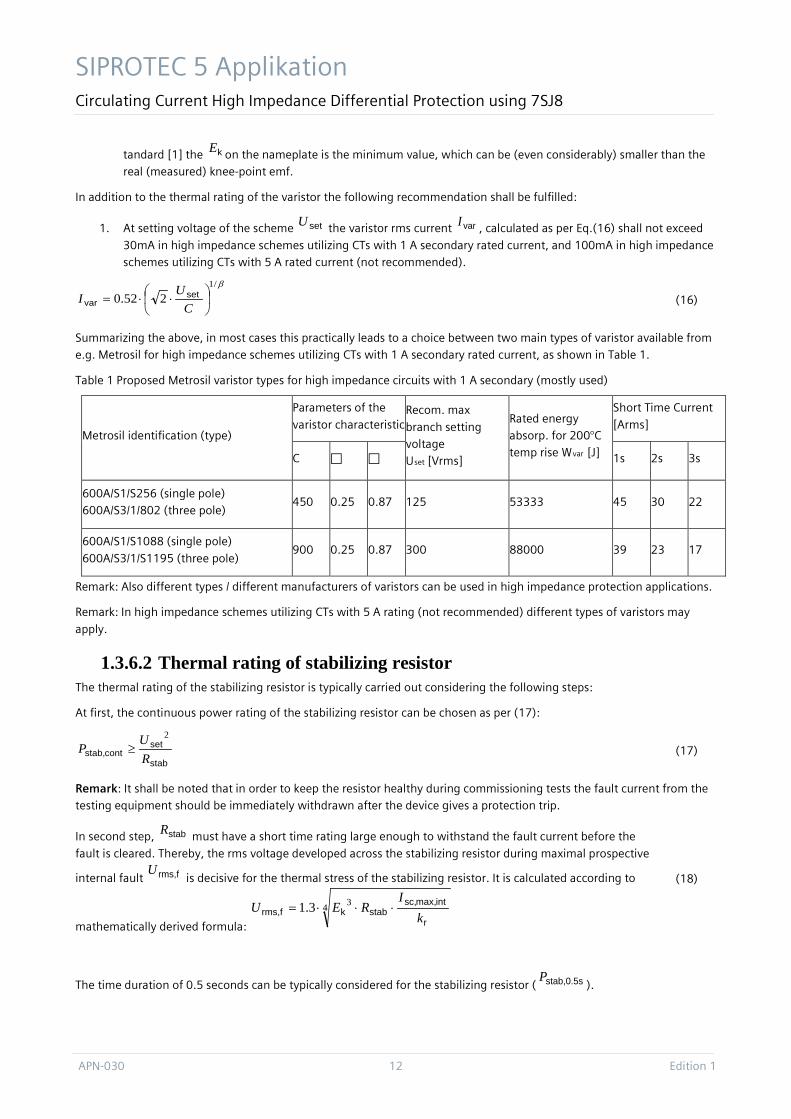
tandard [1] the kE on the nameplate is the minimum value, which can be (even considerably) smaller than the real (measured) knee-point emf.
In addition to the thermal rating of the varistor the following recommendation shall be fulfilled:
1. At setting voltage of the scheme setU the varistor rms current varI , calculated as per Eq.(16) shall not exceed
30mA in high impedance schemes utilizing CTs with 1 A secondary rated current, and 100mA in high impedance schemes utilizing CTs with 5 A rated current (not recommended).
β/1
252.0
⋅⋅=C
UI set
var
(16)
Summarizing the above, in most cases this practically leads to a choice between two main types of varistor available from e.g. Metrosil for high impedance schemes utilizing CTs with 1 A secondary rated current, as shown in Table 1.
Table 1 Proposed Metrosil varistor types for high impedance circuits with 1 A secondary (mostly used)
Metrosil identification (type)
Parameters of the
varistor characteristic Recom. max
branch setting voltage Uset [Vrms]
Rated energy absorp. for 200°C temp rise Wvar [J]
Short Time Current
[Arms]
C 1s 2s 3s
600A/S1/S256 (single pole) 600A/S3/1/802 (three pole)
450 0.25 0.87 125 53333 45 30 22
600A/S1/S1088 (single pole)
600A/S3/1/S1195 (three pole) 900 0.25 0.87 300 88000 39 23 17
Remark: Also different types / different manufacturers of varistors can be used in high impedance protection applications.
Remark: In high impedance schemes utilizing CTs with 5 A rating (not recommended) different types of varistors may
apply.
1.3.6.2 Thermal rating of stabilizing resistor The thermal rating of the stabilizing resistor is typically carried out considering the following steps:
At first, the continuous power rating of the stabilizing resistor can be chosen as per (17):
stab
setcontstab, R
UP
2
≥
(17)
Remark: It shall be noted that in order to keep the resistor healthy during commissioning tests the fault current from the testing equipment should be immediately withdrawn after the device gives a protection trip.
In second step, stabR must have a short time rating large enough to withstand the fault current before the
fault is cleared. Thereby, the rms voltage developed across the stabilizing resistor during maximal prospective
internal fault frms,U is decisive for the thermal stress of the stabilizing resistor. It is calculated according to
mathematically derived formula:
4 33.1r
intmax,sc,stabkfrms, k
IREU ⋅⋅⋅=
(18)
The time duration of 0.5 seconds can be typically considered for the stabilizing resistor ( stab,0.5sP).
SIPROTEC 5 Application Circulating Current High Impedance Differential Protection using 7SJ8
Edition 1 13 APN-030
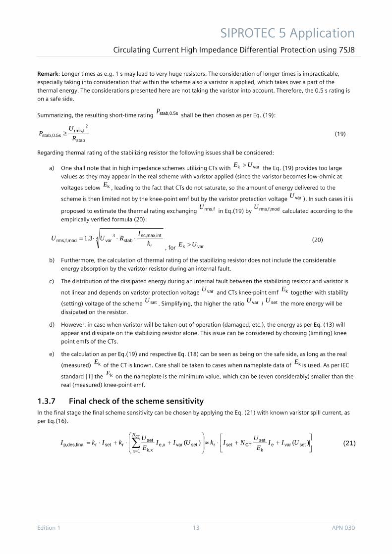
Remark: Longer times as e.g. 1 s may lead to very huge resistors. The consideration of longer times is impracticable, especially taking into consideration that within the scheme also a varistor is applied, which takes over a part of the thermal energy. The considerations presented here are not taking the varistor into account. Therefore, the 0.5 s rating is on a safe side.
Summarizing, the resulting short-time rating stab,0.5sP shall be then chosen as per Eq. (19):
stab
frms,stab,0.5s R
UP
2
≥
(19)
Regarding thermal rating of the stabilizing resistor the following issues shall be considered:
a) One shall note that in high impedance schemes utilizing CTs with vark UE > the Eq. (19) provides too large values as they may appear in the real scheme with varistor applied (since the varistor becomes low-ohmic at
voltages below kE , leading to the fact that CTs do not saturate, so the amount of energy delivered to the
scheme is then limited not by the knee-point emf but by the varistor protection voltage varU ). In such cases it is
proposed to estimate the thermal rating exchanging frms,U in Eq.(19) by modf,rms,U
calculated according to the
empirically verified formula (20):
4 33.1r
intmax,sc,stabvarmodf,rms, k
IRUU ⋅⋅⋅=
, for vark UE > (20)
b) Furthermore, the calculation of thermal rating of the stabilizing resistor does not include the considerable
energy absorption by the varistor resistor during an internal fault.
c) The distribution of the dissipated energy during an internal fault between the stabilizing resistor and varistor is
not linear and depends on varistor protection voltage varU and CTs knee-point emf kE together with stability
(setting) voltage of the scheme setU . Simplifying, the higher the ratio varU / setU the more energy will be
dissipated on the resistor.
d) However, in case when varistor will be taken out of operation (damaged, etc.), the energy as per Eq. (13) will appear and dissipate on the stabilizing resistor alone. This issue can be considered by choosing (limiting) knee point emfs of the CTs.
e) the calculation as per Eq.(19) and respective Eq. (18) can be seen as being on the safe side, as long as the real
(measured) kE of the CT is known. Care shall be taken to cases when nameplate data of kE is used. As per IEC
standard [1] the kE on the nameplate is the minimum value, which can be (even considerably) smaller than the
real (measured) knee-point emf.
1.3.7 Final check of the scheme sensitivity In the final stage the final scheme sensitivity can be chosen by applying the Eq. (21) with known varistor spill current, as per Eq.(16).
++⋅≈
+⋅+⋅= ∑
=
)()( setvarek
setCTsetr
1setvarxe,
xk,
setrsetrfinaldes,p,
CT
UIIE
UNIkUII
EU
kIkIN
x
(21)
SIPROTEC 5 Applikation Circulating Current High Impedance Differential Protection using 7SJ8
APN-030 14 Edition 1
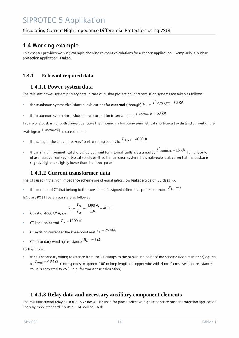
1.4 Working example This chapter provides working example showing relevant calculations for a chosen application. Exemplarily, a busbar protection application is taken.
1.4.1 Relevant required data
1.4.1.1 Power system data The relevant power system primary data in case of busbar protection in transmission systems are taken as follows:
the maximum symmetrical short-circuit current for external (through) faults kAextmax,sc, 63'' =I
the maximum symmetrical short-circuit current for internal faults kAintmax,sc, 63'' =I
In case of a busbar, for both above quantities the maximum short-time symmetrical short-circuit withstand current of the
switchgear swgmax,sc,''I
is considered. :
the rating of the circuit breakers / busbar rating equals to Aloadr, 4000=I
the minimum symmetrical short-circuit current for internal faults is assumed at kAintmin,sc, 15'' =I
for phase-to-phase-fault current (as in typical solidly earthed transmission system the single-pole fault current at the busbar is slightly higher or slightly lower than the three-pole)
1.4.1.2 Current transformer data The CTs used in the high impedance scheme are of equal ratios, low leakage type of IEC class PX.
the number of CT that belong to the considered /designed differential protection zone 8=CTN
IEC class PX [1] parameters are as follows :
CT ratio: 4000A/1A; i.e.
40001
4000===
AA
sr
prr I
Ik
CT knee-point emf Vk 1000=E
CT exciting current at the knee-point emf mAe 25=I
CT secondary winding resistance Ω= 5CTR
Furthermore:
the CT secondary wiring resistance from the CT clamps to the paralleling point of the scheme (loop resistance) equals
to Ω= 55.0wireR (corresponds to approx. 100 m loop length of copper wire with 4 mm2 cross-section, resistance
value is corrected to 75 OC e.g. for worst case calculation)
1.4.1.3 Relay data and necessary auxiliary component elements The multifunctional relay SIPROTEC 5 7SJ8x will be used for phase-selective high impedance busbar protection application. Thereby three standard inputs A1..A6 will be used:
SIPROTEC 5 Application Circulating Current High Impedance Differential Protection using 7SJ8
Edition 1 15 APN-030
operating current setting range A100..001.0..A.03.0=rangeset,I
,
relay input burden, expressed as resistance Ω= 1.0relayR
.
the data of the system components (resistor and varistor) will be calculated in further steps
1.4.2 Calculation of the minimum required stabilizing voltage As per Eq (1) the minimum required stability voltage of the high impedance scheme stabU can be calculated, taking the
given maximum through fault current kAextmax,sc, 63'' =I :
( ) VkAwireCT
r
extmax,stab 41.87)55.05(
400063
=+=+= RRk
IU (22)
The setting voltage setU of the scheme over the differential branch shall be made equal or greater than the required
stability voltage, as calculated in Eq.(22). Let’s take:
Vset 120=U (23)
1.4.3 Calculation of the required fault setting To assure the functionality of the scheme (trip on internal fault), the CT knee-point emf kE shall fulfill the requirement as
given in Eq (3):
setk UE ⋅≥ 2 , i.e.: fulfilledVVV ⇒=⋅≥ 24012021000 (24)
In order to reach the desired scheme sensitivity, i.e. to trip on internal fault, the current setting of the relay in the differential branch shall be now calculated.
Considering that the minimum fault current at the busbar is quite high, the desired primary fault sensitivity desp,I is
chosen (exemplarily for this working example) at 50 % of the rating of the busbar:.
Adesp, 2000=I (25)
Remark: Please note that the primary fault sensitivity for busbar can be chosen at different level. This depends on customer philosophy and experience.
Having chosen the primary fault sensitivity desp,I of the scheme, the secondary setting of the relay setI can be calculated
as per Eq. (6). The varistor spill current will be at this stage neglected:
AAVVA
setvarek
setCT
r
desp,set 476.0025.0
10001208
40002000)( =−=−−≈ UII
EU
Nk
II (26)
The setting current setI of the scheme will be then taken:
Aset 5.0=I (27)
1.4.4 Calculation of the required stabilizing resistor With the scheme setting voltage setU and the current setting of the relay setI . the resistance value of the external
stabilizing resistor stabR can be calculated as per Eq.(7):
SIPROTEC 5 Applikation Circulating Current High Impedance Differential Protection using 7SJ8
APN-030 16 Edition 1
Ω==≈−= 2405.0
120AV
set
setrelay
set
setstab I
UR
IU
R (28)
Thereby, the relay input burden relayR was neglected.
The thermal rating of the resistor is calculated:
The continuous power rating of the stabilizing resistor can be chosen as per Eq. (17):
WV 2
stab
setcontstab, 60
24012022
=Ω
=≥RU
P (29)
Remark: It shall be noted that in order to keep the resistor healthy during commissioning tests the fault current from the testing equipment should be immediately withdrawn after the device gives a protection trip.
Furthermore, stabR must have a short time rating large enough to withstand the fault current before the fault is cleared.
Thereby, the rms voltage developed across the stabilizing resistor during maximal prospective internal fault frms,U is
decisive for the thermal stress of the stabilizing resistor. It is calculated according to Eq.(18):
VAVr
intmax,sc,stabkfrms, 7.1812
400063000240)1000(3.13.1 4 34 3 =⋅Ω⋅⋅=⋅⋅⋅=
kI
REU (30)
The time duration of 0.5 seconds can be typically considered for the stabilizing resistor ( stab,0.5sP ).
The resulting short-time rating stab,0.5sP shall be then chosen as per Eq.(19) :
WV
stab
frms,stab,0.5s 13691
240)7.1812( 22
=Ω
=≥R
UP (31)
Therefore:
Resistor chosen (per relay input): Ω= 240stabR , Wcontstab, 60≥=P , Wstab,0.5s 13691≥P (32)
Regarding short-time thermal rating remarks in chapter Fehler! Verweisquelle konnte nicht gefunden werden. shall be considered in case when size of resistor shall be too large for the given protection cubicle.
1.4.5 Calculation for the required non-linear resistor (varistor) During an internal fault high voltage may arise across the differential branch (i.e. the tie with relay and stabR connected
in series). Therefore, non-linear resistors are necessary in order to avoid secondary circuits (wirings, CT clamps, resistors, etc) be exposed to high voltages. Such varistors shall be connected across the differential branch.
In order to estimate this voltage which may appear in the designed scheme, at first the theoretical rms voltage
rmsint,max,sc,U which would occur across the differential branch if CT did not saturate is determined according to Eq.(8):
( ) VkAstabrelay
r
intmax,sc,rmsint,max,sc, 3780)24005.0(
400063''
=Ω+Ω=+= RRk
IU (33)
Considering CT saturation, the resulting maximum peak voltage across the differential branch tiemax,U is calculated:
( ) ( ) VVVVkrmsint,max,sc,ktiemax, 4716100037802000222ˆ =−=−= EUEU (34)
SIPROTEC 5 Application Circulating Current High Impedance Differential Protection using 7SJ8
Edition 1 17 APN-030
When the relationship in (10) is fulfilled the usage of varistor is mandatory:
necessaryvaristorVVVtiemax, ⇒>⇔> 200047162000U (35)
Considering scheme setting voltage setU of 120 V (very close to the recommended limit of 125 V for the smaller varistor)
a Varisor of type 600A/S3/1/S1195 (three pole) or three varistor of type 600A/S1/S1088 can be chosen (see Table 1).
The protection level of this varistor can be estimated from its characteristic (for dc or instantaneous values) where the constants C and β are given in Table 1 and the maximum prospective secondary current for the internal fault:
Vvar 19554000
630002900ˆˆ25.0
=
⋅⋅=⋅= βICU , (36)
The rms protection level is then:
Vvarvar 13832/ˆ~ =UU , (37)
Its rms spill current at the setting voltage of the scheme (Eq.(16):
mAsetvar 66.0252.0
/1
=
⋅⋅=
β
CU
I (38)
The requirement that at the setting voltage the spill current shall be less than 30 mA (CTs with 1 A secondary) is then fulfilled. The necessary thermal rating of the varistor can be calculated using Eq.(13)
J/sVAk
r
intmax,sc,var 5.200531000
40006300044
=⋅=⋅=ππ
Ek
IP (39)
This necessary thermal rating is smaller than the maximum thermal rating of 88000 J (see Table 1).This maximum energy rating will not be even exceeded by the short-circuit flow of 4 s. Therefore: Varistor chosen: one of 600A/S3/1/S1195 (three pole) type
or three varistors of type 600A/S1/S1088 (40)
1.4.6 Final check of the scheme sensitivity In the final stage the final scheme sensitivity can be chosen by applying the Eq. (21) with known varistor spill current, as
per calculation in Eq.(38):
AAAAVVA
setvarek
setCTsetrfinaldes,p,
6.209852466.04000)00066.0025.0100012085.04000
)(
=⋅=
++⋅=
=
++⋅≈ UII
EU
NIkI (41)
This corresponds to 52.4 % of the rating of the busbar (4000 A) and fulfills the requested fault setting for this example.
1.4.7 Scheme settings The following is then set in SIPROTEC 5 7SJ8x for the main function (high impedance protection trip):
VI 3ph 1; 50/51 OC-3ph-B1, Definite–T 1
SIPROTEC 5 Applikation Circulating Current High Impedance Differential Protection using 7SJ8
APN-030 18 Edition 1
821.1941.661.1 Mode on
_._.661.2 Operate & flt. rec. blocked no
_._.661.8 Method of measurement fundamental comp.
_._.661.3 Threshold (fault setting setI ) 0.5A Range: 0.03A …100A, stps. 0.001A
_._.661.6 Operate delay 0.0 s Range: 0s …60s, stps. 0.01s
Furthermore the following high impedance scheme components are necessary:
Resistor chosen (pro relay input): Ω= 240stabR , Wcontstab, 60≥=P , Wstab,0.5s 13691≥P
Varistor chosen: one of 600A/S3/1/S1195 (three pole) type or three varistors of type 600A/S1/S1088
1.4.7.1 CT supervision The CT circuit supervision can be incorporated within the relay, as well. It can be realized using e.g. Definite–T 2 stage of the multifunctional relay SIPROTEC 5 7SJ8x: Depending on the loading conditions, the CT supervision can be set to detect approx. 12 % of the full loading of the busbar, i.e. 0,12 ∙ 4000 A = 480 A primary. The secondary setting that can be incorporated will be then 0.1 A (24 V setting of the scheme) correspondingly. This leads to the final supervision sensitivity as per Eq (42):
AAAAVVA
setvarek
setCTsetrsuperv
6.49812466.04000)00066.0025.0100012081.04000
)(
=⋅=
++⋅=
=
++⋅≈ UII
EU
NIkI
(42)
This corresponds to 12.5 % of the rating of the busbar (4000 A) and fulfills the requested CT supervision setting for this
example.
The corresponding settings for e.g. Definite–T 2 stage in SIPROTEC 5 7SJ8x will be: VI 3ph 1; 50/51 OC-3ph-B1, Definite–T 2
821.1941.662.1 Mode on
_._.662.2 Operate & flt. rec. blocked no
_._.662.8 Method of measurement fundamental comp.
_._.662.3
Threshold (superv. setting
supervI ) alarm only 0.1A Range: 0.03A …100A, stps. 0.001A
_._.662.6 Operate delay oo s Range: 0s …60s, stps. 0.01s
It is important to configure the Definite T – 2 stage for issuing alarm only. In general, there are several options for further use of the CT supervision alarm. In this worked example this alarm signal will be available after 5 sec based on the timer setting Operate Time Delay. The following options can be chosen: 1. Sending the alarm only (via binary output or via communication protocol). 2. Additionally to 1, route the alarm signal within the relay in order to block the Trip , Definite – T1 element This will avoid a trip of the high impedance busbar protection in case of a through fault under CT broken wire conditions. Please
SIPROTEC 5 Application Circulating Current High Impedance Differential Protection using 7SJ8
Edition 1 19 APN-030
note that this measure will not protect the CT inputs of the relay and the stabilizing resistor / varistor against damage under longer lasting through fault conditions. 3. Additionally to 1 and 2, energize an external CT shorting relay with one coil and at least four related contacts (e.g. 7PA23). The lock-out relay has to be energized by the CT supervision alarm signal. One contact should be placed in front of the varistor to short circuit each CT input of SIPROTEC 5 7SJ8x. The fourth contact of the relay can be used for signaling the ‘high impedance busbar out-of-service’ information. The reset of the external lock-out relay has to be done manually. This measure will protect the CT inputs of the relay and the stabilizing resistor against damage under longer lasting through fault conditions. Alternatively (depending on customer practice), a separate CT supervision relay may be used. The types of further auxiliary components like CT shortening relay, CB lock-out and test switches can be chosen as per respective customer practice.
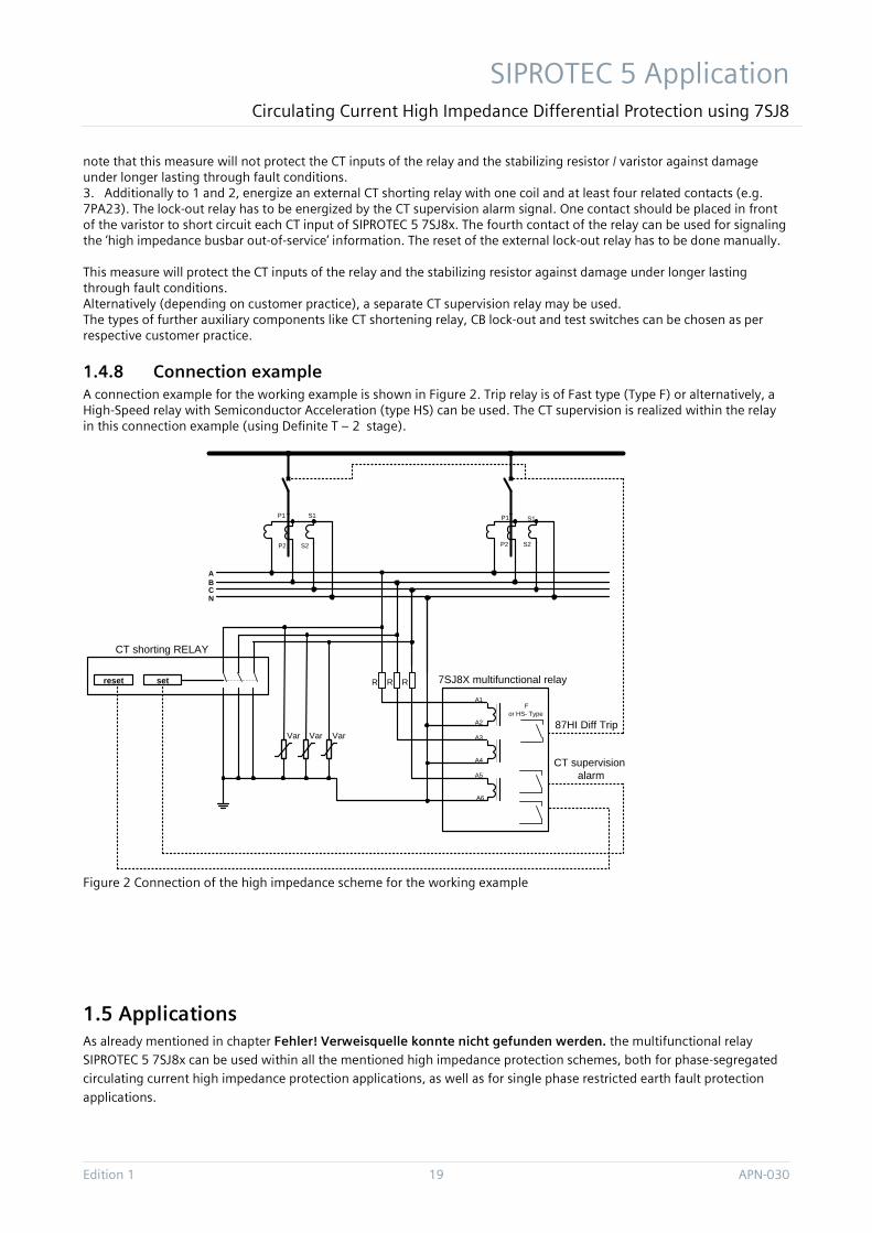
1.4.8 Connection example A connection example for the working example is shown in Figure 2. Trip relay is of Fast type (Type F) or alternatively, a High-Speed relay with Semiconductor Acceleration (type HS) can be used. The CT supervision is realized within the relay in this connection example (using Definite T – 2 stage).
Figure 2 Connection of the high impedance scheme for the working example
1.5 Applications As already mentioned in chapter Fehler! Verweisquelle konnte nicht gefunden werden. the multifunctional relay SIPROTEC 5 7SJ8x can be used within all the mentioned high impedance protection schemes, both for phase-segregated circulating current high impedance protection applications, as well as for single phase restricted earth fault protection
applications.
ABCN
R RR
A1
A6
A3
A4
A5
A2
reset set
CT shorting RELAY
7SJ8X multifunctional relay
87HI Diff Trip
CT supervision alarm
P1
P2
S1
S2
P1 S1
S2P2
VarVar Var
For HS- Type
SIPROTEC 5 Applikation Circulating Current High Impedance Differential Protection using 7SJ8
APN-030 20 Edition 1
For the sake of completeness scheme setting hints for some major applications are shown in following.
1.5.1 Phase and earth-fault high impedance differential protection of busbars The scheme stability setting (voltage over differential branch) [2]:
maximum symmetrical short-circuit withstand current of the switchgear
The scheme sensitivity setting (fault setting or primary operating current), can be chosen as one of the shown below:
10.. 30 % of minimum fault current available as per standard [2] , or as may be agreed
%. of busbar rating (e.g. 33 % or 50 %)
% of outgoing feeder rating (e.g. 100 % or 120 %)
Remark: High impedance protection scheme is widely used for busbar arrangements like single busbars, single busbars
with sectionalizers, or circuit-breaker-and-a-half arrangements. The usage of high impedance busbar protection for double- and more sections busbars (with isolators) is not recommended, because of high complexity related to switching-over of CT secondaries that decreases the scheme reliability.
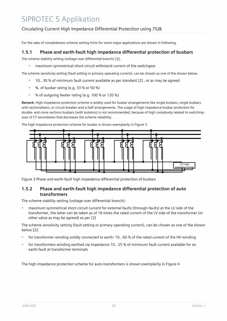
The high impedance protection scheme for busbar is shown exemplarily in Figure 3
Figure 3 Phase and earth-fault high impedance differential protection of busbars
1.5.2 Phase and earth-fault high impedance differential protection of auto transformers
The scheme stability setting (voltage over differential branch):
maximum symmetrical short-circuit current for external faults (through-faults) at the LV side of the transformer, the latter can be taken as of 16 times the rated current of the LV side of the transformer (or other value as may be agreed) as per [2]
The scheme sensitivity setting (fault setting or primary operating current), can be chosen as one of the shown below [2]:
for transformer winding solidly connected to earth: 10.. 60 % of the rated current of the HV winding
for transformers winding earthed via impedance 10.. 25 % of minimum fault current available for an earth-fault at transformer terminals
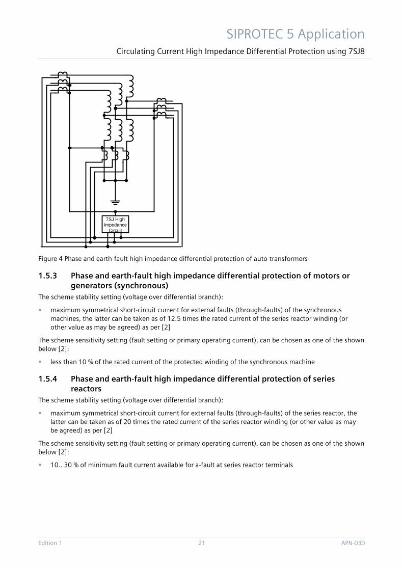
The high impedance protection scheme for auto-transformers is shown exemplarily in Figure 4
7SJ High Impedance Circuit
SIPROTEC 5 Application Circulating Current High Impedance Differential Protection using 7SJ8
Edition 1 21 APN-030
Figure 4 Phase and earth-fault high impedance differential protection of auto-transformers
1.5.3 Phase and earth-fault high impedance differential protection of motors or generators (synchronous)
The scheme stability setting (voltage over differential branch):
maximum symmetrical short-circuit current for external faults (through-faults) of the synchronous machines, the latter can be taken as of 12.5 times the rated current of the series reactor winding (or other value as may be agreed) as per [2]
The scheme sensitivity setting (fault setting or primary operating current), can be chosen as one of the shown below [2]:
less than 10 % of the rated current of the protected winding of the synchronous machine
1.5.4 Phase and earth-fault high impedance differential protection of series reactors
The scheme stability setting (voltage over differential branch):
maximum symmetrical short-circuit current for external faults (through-faults) of the series reactor, the latter can be taken as of 20 times the rated current of the series reactor winding (or other value as may be agreed) as per [2]
The scheme sensitivity setting (fault setting or primary operating current), can be chosen as one of the shown below [2]:
10.. 30 % of minimum fault current available for a-fault at series reactor terminals
7SJ High Impedance
Circuit
SIPROTEC 5 Applikation Circulating Current High Impedance Differential Protection using 7SJ8
APN-030 22 Edition 1
1.5.5 Phase and earth-fault high impedance differential protection of shunt reactors
The scheme stability setting (voltage over differential branch):
maximum symmetrical short-circuit current for external faults (through-faults) of the shunt reactor, the latter can be taken as of 10 times the rated current of the shunt reactor winding (or other value as may be agreed) as per [2]
The scheme sensitivity setting (fault setting or primary operating current), can be chosen as one of the shown below [2]:
10.. 25 % of minimum fault current available for a-fault at shunt reactor terminals
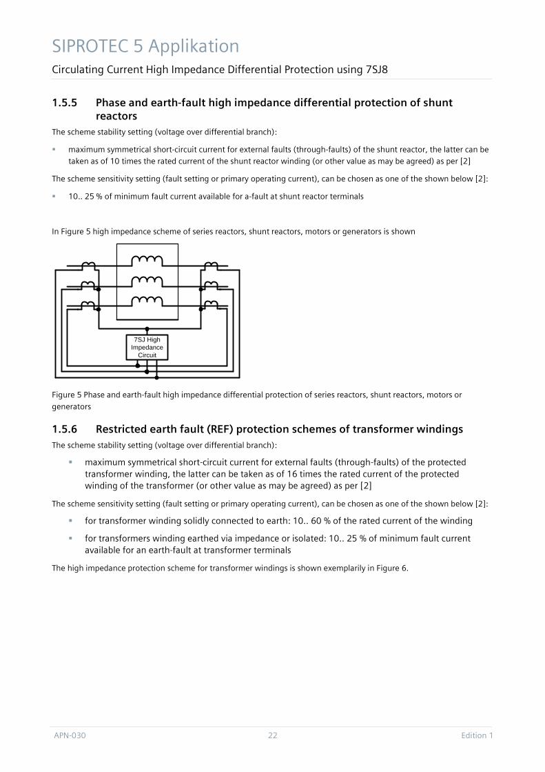
In Figure 5 high impedance scheme of series reactors, shunt reactors, motors or generators is shown
Figure 5 Phase and earth-fault high impedance differential protection of series reactors, shunt reactors, motors or
generators
1.5.6 Restricted earth fault (REF) protection schemes of transformer windings The scheme stability setting (voltage over differential branch):
maximum symmetrical short-circuit current for external faults (through-faults) of the protected transformer winding, the latter can be taken as of 16 times the rated current of the protected winding of the transformer (or other value as may be agreed) as per [2]
The scheme sensitivity setting (fault setting or primary operating current), can be chosen as one of the shown below [2]:
for transformer winding solidly connected to earth: 10.. 60 % of the rated current of the winding
for transformers winding earthed via impedance or isolated: 10.. 25 % of minimum fault current available for an earth-fault at transformer terminals
The high impedance protection scheme for transformer windings is shown exemplarily in Figure 6.
7SJ High Impedance
Circuit
SIPROTEC 5 Application Circulating Current High Impedance Differential Protection using 7SJ8
Edition 1 23 APN-030
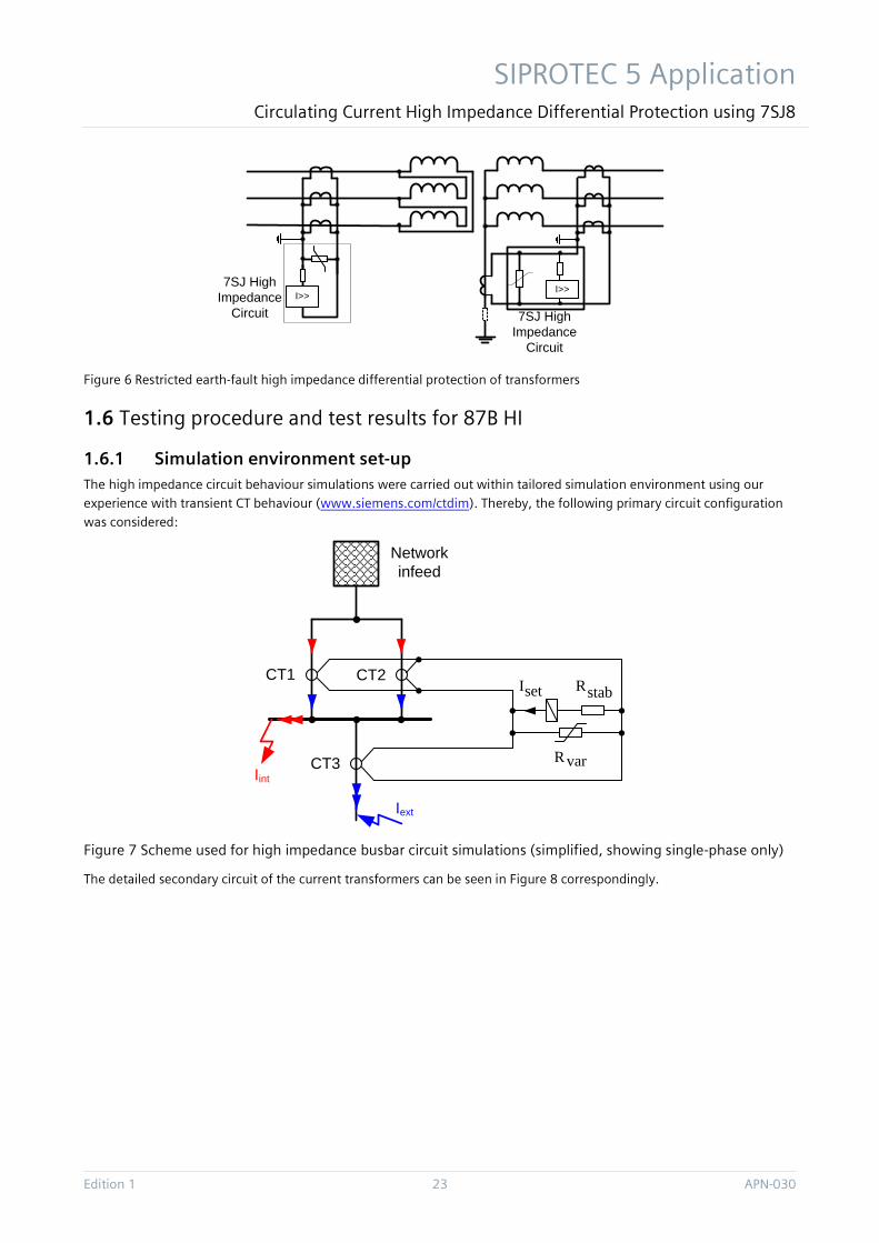
Figure 6 Restricted earth-fault high impedance differential protection of transformers
1.6 Testing procedure and test results for 87B HI
1.6.1 Simulation environment set-up The high impedance circuit behaviour simulations were carried out within tailored simulation environment using our experience with transient CT behaviour (www.siemens.com/ctdim). Thereby, the following primary circuit configuration was considered:
Figure 7 Scheme used for high impedance busbar circuit simulations (simplified, showing single-phase only)
The detailed secondary circuit of the current transformers can be seen in Figure 8 correspondingly.
I>>I>>7SJ High
Impedance Circuit 7SJ High
Impedance Circuit
setI
Iint
Iext
stabR
varR
CT1 CT2
CT3
Network infeed
SIPROTEC 5 Applikation Circulating Current High Impedance Differential Protection using 7SJ8
APN-030 24 Edition 1
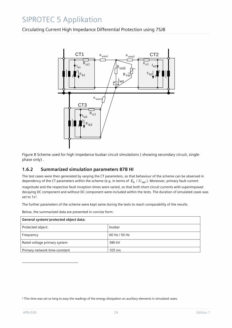
Figure 8 Scheme used for high impedance busbar circuit simulations ( showing secondary circuit, single-phase only) .
1.6.2 Summarized simulation parameters 87B HI The test cases were then generated by varying the CT parameters, so that behaviour of the scheme can be observed in dependency of the CT parameters within the scheme (e.g. in terms of kE / setU ). Moreover, primary fault current
magnitude and the respective fault inception times were varied, so that both short circuit currents with superimposed decaying DC component and without DC component were included within the tests. The duration of simulated cases was
set to 1s2.
The further parameters of the scheme were kept same during the tests to reach comparability of the results.
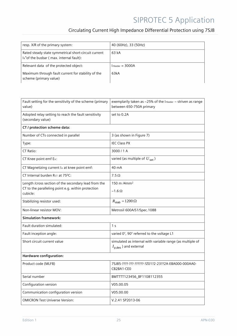
Below, the summarized data are presented in concise form:
General system/ protected object data:
Protected object: busbar
Frequency 60 Hz / 50 Hz
Rated voltage primary system 380 kV
Primary network time-constant 105 ms
2 This time was set so long to easy the readings of the energy dissipation on auxiliary elements in simulated cases.
k1E
ct1R
k2E
e2Ict2Re1I
setI
wire1R wire2R
stabR
CT1 CT2
k3E
ct3Re3I
CT3wire3R
varR
SIPROTEC 5 Application Circulating Current High Impedance Differential Protection using 7SJ8
Edition 1 25 APN-030
resp. X/R of the primary system: 40 (60Hz), 33 (50Hz)
Rated steady state symmetrical short-circuit current
Ik’’of the busbar ( max. internal fault):
63 kA
Relevant data of the protected object: Irfeeder = 3000A
Maximum through fault current for stability of the scheme (primary value)
63kA
Fault setting for the sensitivity of the scheme (primary value)
exemplarily taken as ~25% of the Irfeeder ~ striven as range between 650-750A primary
Adopted relay setting to reach the fault sensitivity (secondary value)
set to 0.2A
CT / protection scheme data:
Number of CTs connected in parallel 3 (as shown in Figure 7)
Type: IEC Class PX
CT Ratio: 3000 / 1 A
CT Knee point emf Ek: varied (as multiple of setU )
CT Magnetizing current Ie at knee point emf: 40 mA
CT Internal burden RCT at 750C: 7.5 Ω
Length /cross section of the secondary lead from the CT to the paralleling point e.g. within protection
cubicle:
150 m /4mm2
~1.6 Ω
Stabilizing resistor used: Ω=1200stabR
Non-linear resistor MOV: Metrosil 600A/S1/Spec.1088
Simulation framework:
Fault duration simulated: 1 s
Fault inception angle: varied 0°, 90° referred to the voltage L1
Short circuit current value simulated as internal with variable range (as multiple of
desp,I ) and external
Hardware configuration:
Product code (MLFB) 7SJ85-????-???-??????-?Z01?2-23??2A-EBA000-000AA0-CB2BA1-CE0
Serial number BMTTTT123456_BF1108112355
Configuration version V05.00.05
Communication configuration version V05.00.00
OMICRON Test Universe Version: V.2.41 SP2013-06
SIPROTEC 5 Applikation Circulating Current High Impedance Differential Protection using 7SJ8
APN-030 26 Edition 1
Summarizing, a typical high impedance busbar protection scheme of setting voltage setU of 240 V, stabR of 1200 Ω,
and the relay setting setI of 0.2 A3 was used. Those parameters were kept same in the simulated cases to reach
comparability of the test results. The resulting primary fault sensitivity was then around 700A primary4. For each case the current transformer sizing reports were carried out using software tool CTDim. An exemplary report is presented in item Fehler! Verweisquelle konnte nicht gefunden werden..
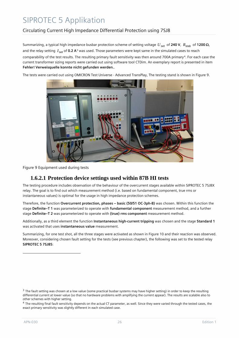
The tests were carried out using OMICRON Test Universe - Advanced TransPlay, The testing stand is shown in Figure 9.
Figure 9 Equipment used during tests
1.6.2.1 Protection device settings used within 87B HI tests The testing procedure includes observation of the behaviour of the overcurrent stages available within SIPROTEC 5 7SJ8X
relay. The goal is to find out which measurement method (i.e. based on fundamental component, true rms or instantaneous values) is optimal for the usage in high impedance protection schemes.
Therefore, the function Overcurrent protection, phases – basic (50/51 OC-3ph-B) was chosen. Within this function the
stage Definite–T 1 was parameterized to operate with fundamental component measurement method, and a further stage Definite–T 2 was parameterized to operate with (true) rms component measurement method.
Additionally, as a third element the function Instantaneous high-current tripping was chosen and the stage Standard 1
was activated that uses instantaneous value measurement.
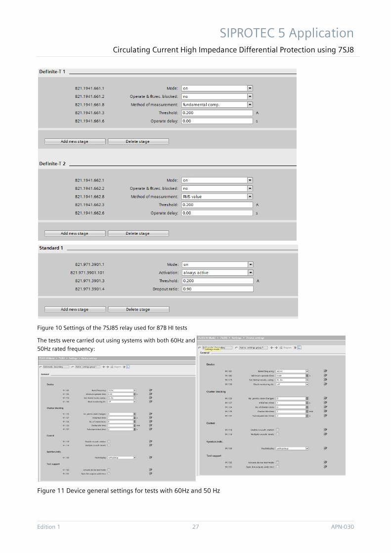
Summarizing, for one test shot, all the three stages were activated as shown in Figure 10 and their reaction was observed.
Moreover, considering chosen fault setting for the tests (see previous chapter), the following was set to the tested relay SIPROTEC 5 7SJ85:
3 The fault setting was chosen at a low value (some practical busbar systems may have higher setting) in order to keep the resulting differential current at lower value (so that no hardware problems with amplifying the current appear). The results are scalable also to other schemes with higher setting. 4 The resulting final fault sensitivity depends on the actual CT parameter, as well. Since they were varied through the tested cases, the exact primary sensitivity was slightly different in each simulated case.
SIPROTEC 5 Application Circulating Current High Impedance Differential Protection using 7SJ8
Edition 1 27 APN-030
Figure 10 Settings of the 7SJ85 relay used for 87B HI tests
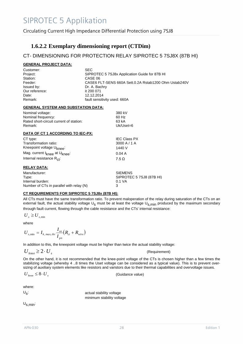
The tests were carried out using systems with both 60Hz and
50Hz rated frequency:
Figure 11 Device general settings for tests with 60Hz and 50 Hz
SIPROTEC 5 Applikation Circulating Current High Impedance Differential Protection using 7SJ8
APN-030 28 Edition 1
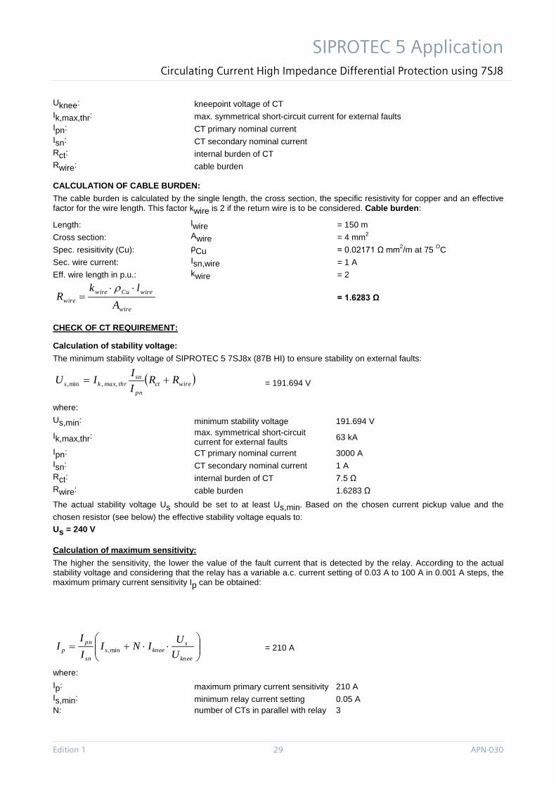
1.6.2.2 Exemplary dimensioning report (CTDim) CT- DIMENSIONING FOR PROTECTION RELAY SIPROTEC 5 7SJ8X (87B HI) GENERAL PROJECT DATA: Customer: SEC Project: SIPROTEC 5 7SJ8x Application Guide for 87B HI Station: CASE 06 Feeder: CASE6 FLT-SENS 660A Sett.0.2A Rstab1200 Ohm Ustab240V Issued by: Dr. A. Bachry Our reference: it 200 071 Date: 12.12.2014 Remark: fault sensitivity used: 660A
GENERAL SYSTEM AND SUBSTATION DATA: Nominal voltage: 380 kV Nominal frequency: 60 Hz Rated short-circuit current of station: 63 kA Remark: Uk/Uset=6
DATA OF CT 1 ACCORDING TO IEC-PX: CT type: IEC Class PX Transformation ratio: 3000 A / 1 A Kneepoint voltage Uknee: 1440 V Mag. current Iknee at Uknee: 0.04 A Internal resistance Rct: 7.5 Ω
RELAY DATA: Manufacturer: SIEMENS Type: SIPROTEC 5 7SJ8 (87B HI) Internal burden: 0.1 VA Number of CTs in parallel with relay (N) 3
CT REQUIREMENTS FOR SIPROTEC 5 7SJ8x (87B HI): All CTs must have the same transformation ratio. To prevent maloperation of the relay during saturation of the CTs on an external fault, the actual stability voltage Us must be at least the voltage Us,min produced by the maximum secondary through fault current, flowing through the cable resistance and the CTs' internal resistance:
where
In addition to this, the kneepoint voltage must be higher than twice the actual stability voltage:
(Requirement)
On the other hand, it is not recommended that the knee-point voltage of the CTs is chosen higher than a few times the stabilizing voltage (whereby 4 ..8 times the Uset voltage can be considered as a typical value). This is to prevent over-sizing of auxiliary system elements like resistors and varistors due to their thermal capabilities and overvoltage issues.
(Guidance value)
where: Us: actual stability voltage
Us,min: minimum stability voltage
min,ss UU ≥
( )wirectpn
snthrmaxks RR
IIIU += ,,min,
sknee UU ⋅≥ 2
sknee UU ⋅≤ 8
SIPROTEC 5 Application Circulating Current High Impedance Differential Protection using 7SJ8
Edition 1 29 APN-030
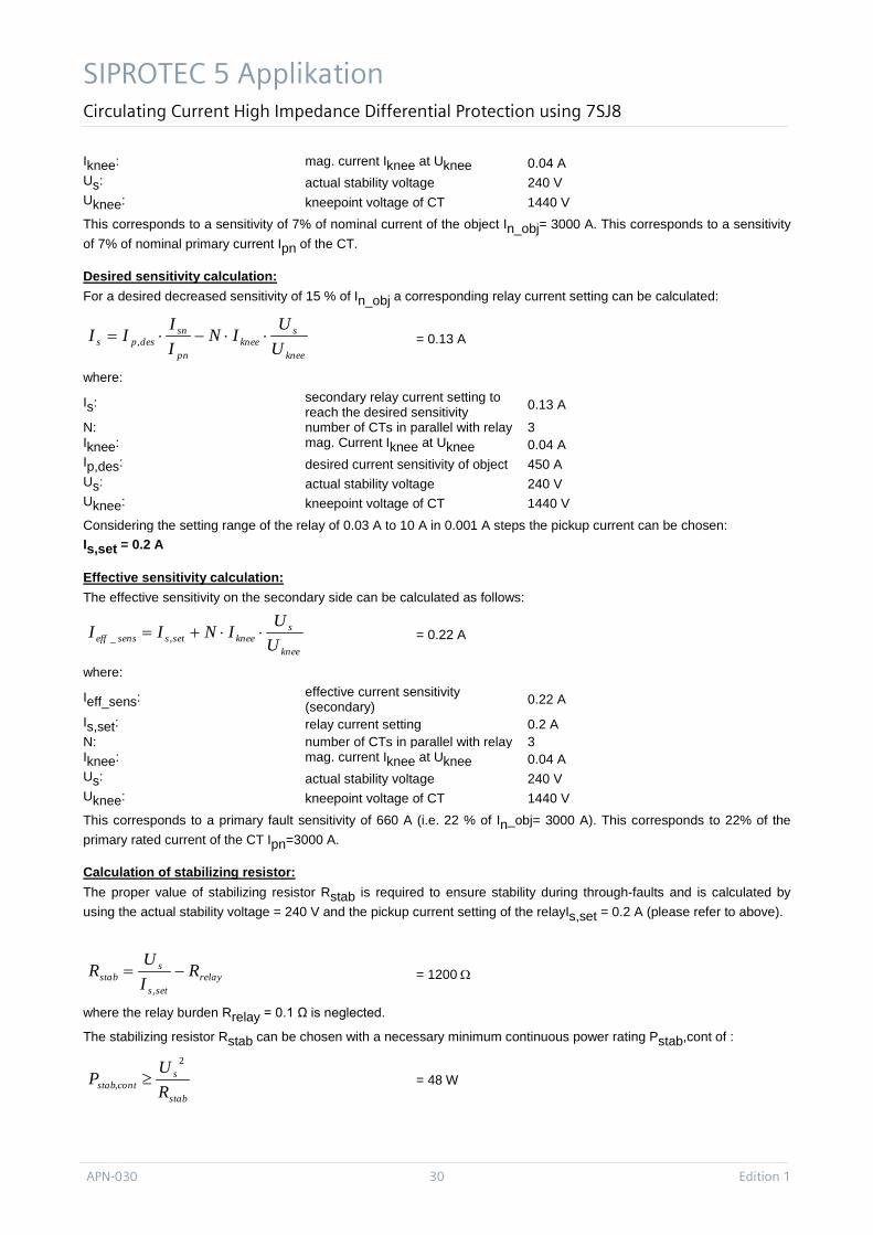
Uknee: kneepoint voltage of CT Ik,max,thr: max. symmetrical short-circuit current for external faults Ipn: CT primary nominal current Isn: CT secondary nominal current Rct: internal burden of CT Rwire: cable burden
CALCULATION OF CABLE BURDEN: The cable burden is calculated by the single length, the cross section, the specific resistivity for copper and an effective factor for the wire length. This factor kwire is 2 if the return wire is to be considered. Cable burden:
Length: lwire = 150 m Cross section: Awire = 4 mm2
Spec. resisitivity (Cu): ρCu = 0.02171 Ω mm2/m at 75 OC Sec. wire current: Isn,wire = 1 A Eff. wire length in p.u.: kwire = 2
= 1.6283 Ω
CHECK OF CT REQUIREMENT:
Calculation of stability voltage: The minimum stability voltage of SIPROTEC 5 7SJ8x (87B HI) to ensure stability on external faults:
= 191.694 V
where: Us,min: minimum stability voltage 191.694 V
Ik,max,thr: max. symmetrical short-circuit current for external faults 63 kA
Ipn: CT primary nominal current 3000 A Isn: CT secondary nominal current 1 A Rct: internal burden of CT 7.5 Ω Rwire: cable burden 1.6283 Ω The actual stability voltage Us should be set to at least Us,min. Based on the chosen current pickup value and the chosen resistor (see below) the effective stability voltage equals to: Us = 240 V
Calculation of maximum sensitivity: The higher the sensitivity, the lower the value of the fault current that is detected by the relay. According to the actual stability voltage and considering that the relay has a variable a.c. current setting of 0.03 A to 100 A in 0.001 A steps, the maximum primary current sensitivity Ip can be obtained:
= 210 A
where: Ip: maximum primary current sensitivity 210 A Is,min: minimum relay current setting 0.05 A N: number of CTs in parallel with relay 3
wire
wireCuwirewire A
lkR
⋅⋅=
ρ
( )wirectpn
snthrmaxks RR
IIIU += ,,min,
⋅⋅+=
knee
sknees
sn
pnp U
UINIII
I min,
SIPROTEC 5 Applikation Circulating Current High Impedance Differential Protection using 7SJ8
APN-030 30 Edition 1
Iknee: mag. current Iknee at Uknee 0.04 A Us: actual stability voltage 240 V Uknee: kneepoint voltage of CT 1440 V This corresponds to a sensitivity of 7% of nominal current of the object In_obj= 3000 A. This corresponds to a sensitivity of 7% of nominal primary current Ipn of the CT.
Desired sensitivity calculation: For a desired decreased sensitivity of 15 % of In_obj a corresponding relay current setting can be calculated:
= 0.13 A
where:
Is: secondary relay current setting to reach the desired sensitivity 0.13 A
N: number of CTs in parallel with relay 3 Iknee: mag. Current Iknee at Uknee 0.04 A Ip,des: desired current sensitivity of object 450 A Us: actual stability voltage 240 V Uknee: kneepoint voltage of CT 1440 V Considering the setting range of the relay of 0.03 A to 10 A in 0.001 A steps the pickup current can be chosen: Is,set = 0.2 A
Effective sensitivity calculation: The effective sensitivity on the secondary side can be calculated as follows:
= 0.22 A
where:
Ieff_sens: effective current sensitivity (secondary) 0.22 A
Is,set: relay current setting 0.2 A N: number of CTs in parallel with relay 3 Iknee: mag. current Iknee at Uknee 0.04 A Us: actual stability voltage 240 V Uknee: kneepoint voltage of CT 1440 V This corresponds to a primary fault sensitivity of 660 A (i.e. 22 % of In_obj= 3000 A). This corresponds to 22% of the primary rated current of the CT Ipn=3000 A.
Calculation of stabilizing resistor: The proper value of stabilizing resistor Rstab is required to ensure stability during through-faults and is calculated by using the actual stability voltage = 240 V and the pickup current setting of the relayIs,set = 0.2 A (please refer to above).
= 1200 Ω
where the relay burden Rrelay = 0.1 Ω is neglected.
The stabilizing resistor Rstab can be chosen with a necessary minimum continuous power rating Pstab,cont of :
= 48 W
knee
sknee
pn
sndesps U
UIN
II
II ⋅⋅−⋅= ,
knee
skneesetssenseff U
UINII ⋅⋅+= ,_
relaysets
sstab R
IU
R −=,
stab
scontstab R
UP
2
, ≥
SIPROTEC 5 Application Circulating Current High Impedance Differential Protection using 7SJ8
Edition 1 31 APN-030
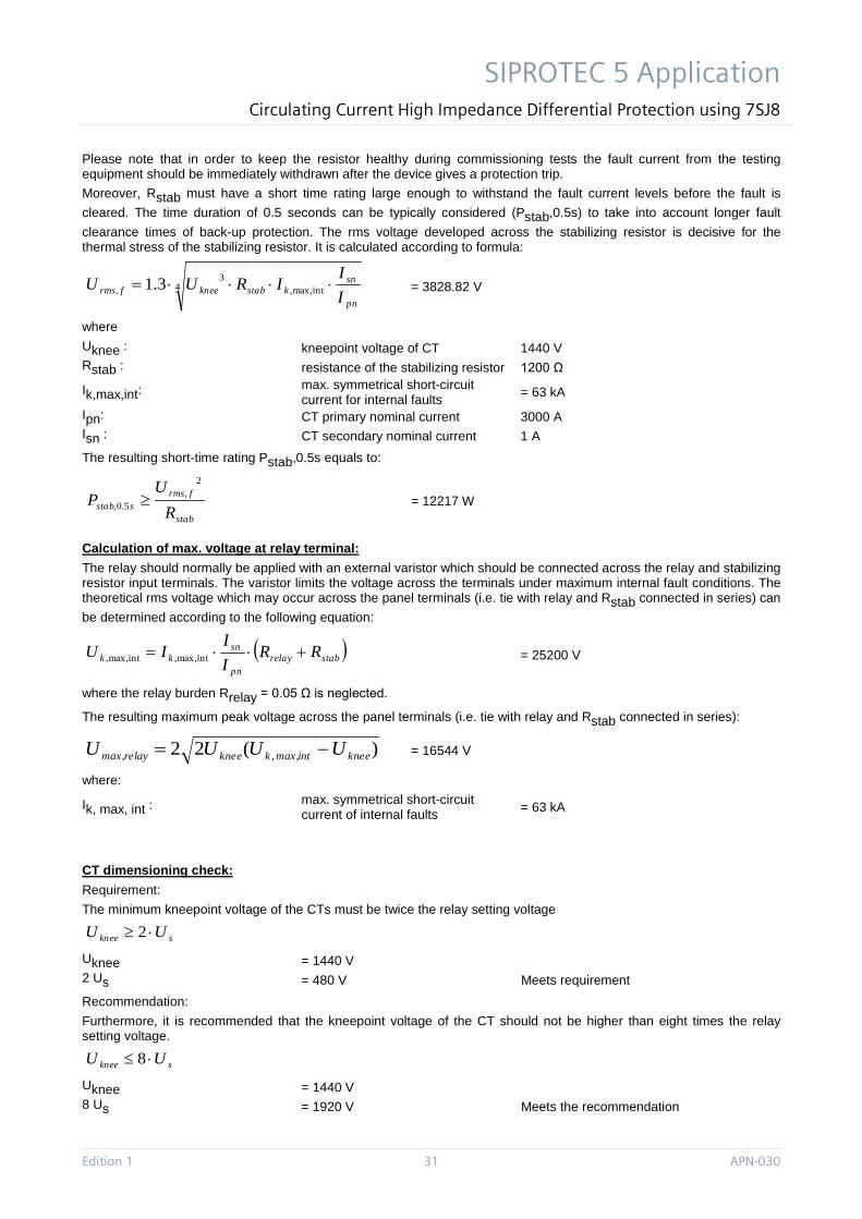
Please note that in order to keep the resistor healthy during commissioning tests the fault current from the testing equipment should be immediately withdrawn after the device gives a protection trip. Moreover, Rstab must have a short time rating large enough to withstand the fault current levels before the fault is cleared. The time duration of 0.5 seconds can be typically considered (Pstab,0.5s) to take into account longer fault clearance times of back-up protection. The rms voltage developed across the stabilizing resistor is decisive for the thermal stress of the stabilizing resistor. It is calculated according to formula:
= 3828.82 V
where Uknee : kneepoint voltage of CT 1440 V Rstab : resistance of the stabilizing resistor 1200 Ω
Ik,max,int: max. symmetrical short-circuit current for internal faults = 63 kA
Ipn: CT primary nominal current 3000 A Isn : CT secondary nominal current 1 A The resulting short-time rating Pstab,0.5s equals to:
= 12217 W
Calculation of max. voltage at relay terminal: The relay should normally be applied with an external varistor which should be connected across the relay and stabilizing resistor input terminals. The varistor limits the voltage across the terminals under maximum internal fault conditions. The theoretical rms voltage which may occur across the panel terminals (i.e. tie with relay and Rstab connected in series) can be determined according to the following equation:
= 25200 V
where the relay burden Rrelay = 0.05 Ω is neglected.
The resulting maximum peak voltage across the panel terminals (i.e. tie with relay and Rstab connected in series):
= 16544 V
where:
Ik, max, int : max. symmetrical short-circuit current of internal faults = 63 kA
CT dimensioning check: Requirement: The minimum kneepoint voltage of the CTs must be twice the relay setting voltage
Uknee = 1440 V 2 Us = 480 V Meets requirement Recommendation: Furthermore, it is recommended that the kneepoint voltage of the CT should not be higher than eight times the relay setting voltage.
Uknee = 1440 V 8 Us = 1920 V Meets the recommendation
4 intmax,,3
, 3.1pn
snkstabkneefrms I
IIRUU ⋅⋅⋅⋅=
stab
frmssstab R
UP
2,
5.0, ≥
( )stabrelaypn
snkk RR
II
IU +⋅⋅= intmax,,intmax,,
)(22 , kneeintmax,kkneerelaymax, UUUU −=
sknee UU ⋅≥ 2
sknee UU ⋅≤ 8
SIPROTEC 5 Applikation Circulating Current High Impedance Differential Protection using 7SJ8
APN-030 32 Edition 1
CTs correctly dimensioned
Varistor check: A varistor is required if: Umax,relay ≥1500 V
In this case: Umax,relay = 16544 V
Varistor required
E.g. in this case a Metrosil of type 600A/S1/1088 can be used.
1.6.3 Relay sensitivity and speed at internal faults (in detail)
1.6.3.1 Examples for internal fault tests The relay was subjected to numerous tests with regard to the speed on internal faults observing it for each of the overcurrent elements (fundamental, true RMS and instantaneous).
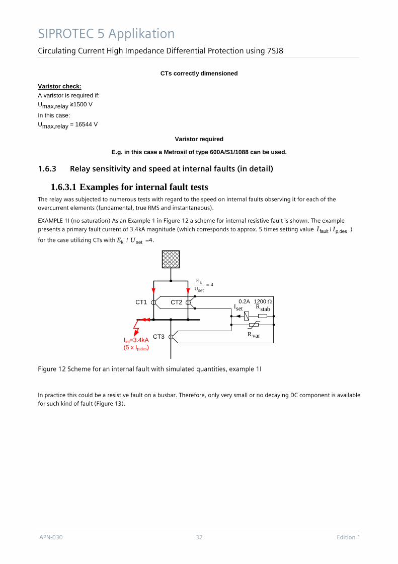
EXAMPLE 1I (no saturation) As an Example 1 in Figure 12 a scheme for internal resistive fault is shown. The example
presents a primary fault current of 3.4kA magnitude (which corresponds to approx. 5 times setting value faultI / desp,I )
for the case utilizing CTs with kE / setU =4.
Figure 12 Scheme for an internal fault with simulated quantities, example 1I
In practice this could be a resistive fault on a busbar. Therefore, only very small or no decaying DC component is available for such kind of fault (Figure 13).
setI
Iint=3.4kA(5 x Ip,des)
stabR
varR
CT1 CT2
CT3
1200 Ω0.2A
4setUkE
=
SIPROTEC 5 Application Circulating Current High Impedance Differential Protection using 7SJ8
Edition 1 33 APN-030
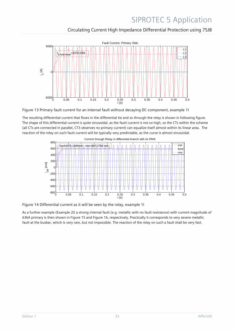
Figure 13 Primary fault current for an internal fault without decaying DC-component, example 1I
The resulting differential current that flows in the differential tie and so through the relay is shown in following figure. The shape of this differential current is quite sinusoidal, as the fault current is not so high, so the CTs within the scheme (all CTs are connected in parallel, CT3 observes no primary current) can equalize itself almost within its linear area. The
reaction of the relay on such fault current will be typically very predictable, as the curve is almost sinusoidal.
Figure 14 Differential current as it will be seen by the relay, example 1I
As a further example (Example 2I) a strong internal fault (e.g. metallic with no fault resistance) with current magnitude of
63kA primary is then shown in Figure 15 and Figure 16, respectively. Practically it corresponds to very severe metallic fault at the busbar, which is very rare, but not impossible. The reaction of the relay on such a fault shall be very fast.
0 0.05 0.1 0.15 0.2 0.25 0.3 0.35 0.4 0.45 0.5-5000
0
5000
t [s]
i F [A]
Fault Current, Primary Side
L1L2L3
Ik-fund-mean=3370.29A
0 0.05 0.1 0.15 0.2 0.25 0.3 0.35 0.4 0.45 0.5-800
-600
-400
-200
0
200
400
600
800
t [s]
i diff [m
A]
Current through Relay in differential branch with its RMS
instfundrms
fund=575.1545mA ; rms=587.2758 mA
SIPROTEC 5 Applikation Circulating Current High Impedance Differential Protection using 7SJ8
APN-030 34 Edition 1
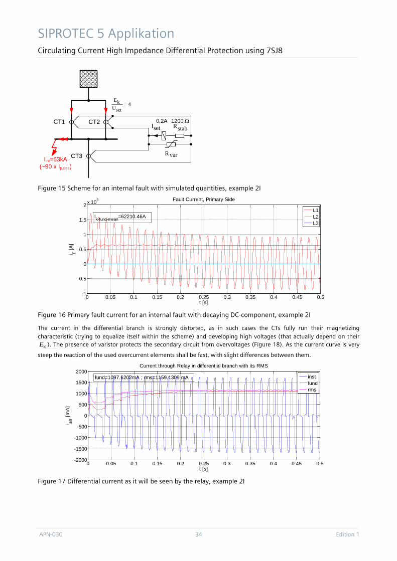
Figure 15 Scheme for an internal fault with simulated quantities, example 2I
Figure 16 Primary fault current for an internal fault with decaying DC-component, example 2I
The current in the differential branch is strongly distorted, as in such cases the CTs fully run their magnetizing characteristic (trying to equalize itself within the scheme) and developing high voltages (that actually depend on their
kE ). The presence of varistor protects the secondary circuit from overvoltages (Figure 18). As the current curve is very
steep the reaction of the used overcurrent elements shall be fast, with slight differences between them.
Figure 17 Differential current as it will be seen by the relay, example 2I
setI
Iint=63kA(~90 x Ip,des)
stabR
varR
CT1 CT2
CT3
1200 Ω0.2A
4setUkE
=
0 0.05 0.1 0.15 0.2 0.25 0.3 0.35 0.4 0.45 0.5-1
-0.5
0
0.5
1
1.5
2 x 10⁵
t [s]
i F [A]
Fault Current, Primary Side
L1L2L3
Ik-fund-mean=62210.46A
0 0.05 0.1 0.15 0.2 0.25 0.3 0.35 0.4 0.45 0.5-2000
-1500
-1000
-500
0
500
1000
1500
2000
t [s]
i diff [m
A]
Current through Relay in differential branch with its RMS
instfundrms
fund=1097.6202mA ; rms=1159.1309 mA
SIPROTEC 5 Application Circulating Current High Impedance Differential Protection using 7SJ8
Edition 1 35 APN-030
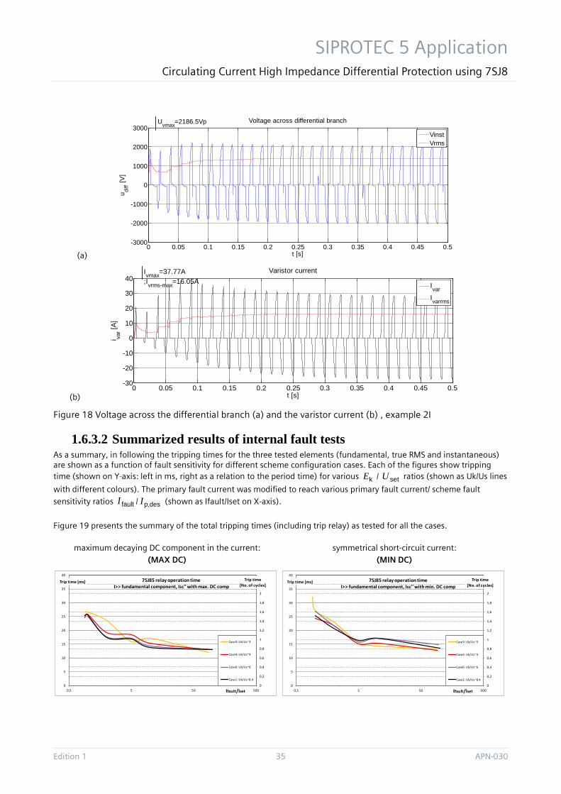
(a)
(b)
Figure 18 Voltage across the differential branch (a) and the varistor current (b) , example 2I
1.6.3.2 Summarized results of internal fault tests As a summary, in following the tripping times for the three tested elements (fundamental, true RMS and instantaneous) are shown as a function of fault sensitivity for different scheme configuration cases. Each of the figures show tripping time (shown on Y-axis: left in ms, right as a relation to the period time) for various kE / setU ratios (shown as Uk/Us lines
with different colours). The primary fault current was modified to reach various primary fault current/ scheme fault
sensitivity ratios faultI / desp,I (shown as Ifault/Iset on X-axis).
Figure 19 presents the summary of the total tripping times (including trip relay) as tested for all the cases.
maximum decaying DC component in the current: (MAX DC)
symmetrical short-circuit current: (MIN DC)
0 0.05 0.1 0.15 0.2 0.25 0.3 0.35 0.4 0.45 0.5-3000
-2000
-1000
0
1000
2000
3000
t [s]
u diff [V
]Voltage across differential branch
VinstVrms
Uvmax=2186.5Vp
0 0.05 0.1 0.15 0.2 0.25 0.3 0.35 0.4 0.45 0.5-30
-20
-10
0
10
20
30
40
t [s]
i var [A
]
Varistor current
IvarIvarrms
Ivmax=37.77A;Ivrms-max=16.05A
0
0,2
0,4
0,6
0,8
1
1,2
1,4
1,6
1,8
2
2,2
0
5
10
15
20
25
30
35
40
0,5 5 50 500
Trip time[No. of cycles]
Trip time [ms]
Ifault/Iset
7SJ85 relay operation time I>> fundamental component, Isc'' with max. DC comp
Case3: Uk/Us~3
Case4: Uk/Us~4
Case6: Uk/Us~6
Case1: Uk/Us~8.4
0
0,2
0,4
0,6
0,8
1
1,2
1,4
1,6
1,8
2
2,2
0
5
10
15
20
25
30
35
40
0,5 5 50 500
Trip time[No. of cycles]
Trip time [ms]
Ifault/Iset
7SJ85 relay operation time I>> fundamental component, Isc'' with min. DC comp
Case3: Uk/Us~3
Case4: Uk/Us~4
Case6: Uk/Us~6
Case1: Uk/Us~8.4
SIPROTEC 5 Applikation Circulating Current High Impedance Differential Protection using 7SJ8
APN-030 36 Edition 1
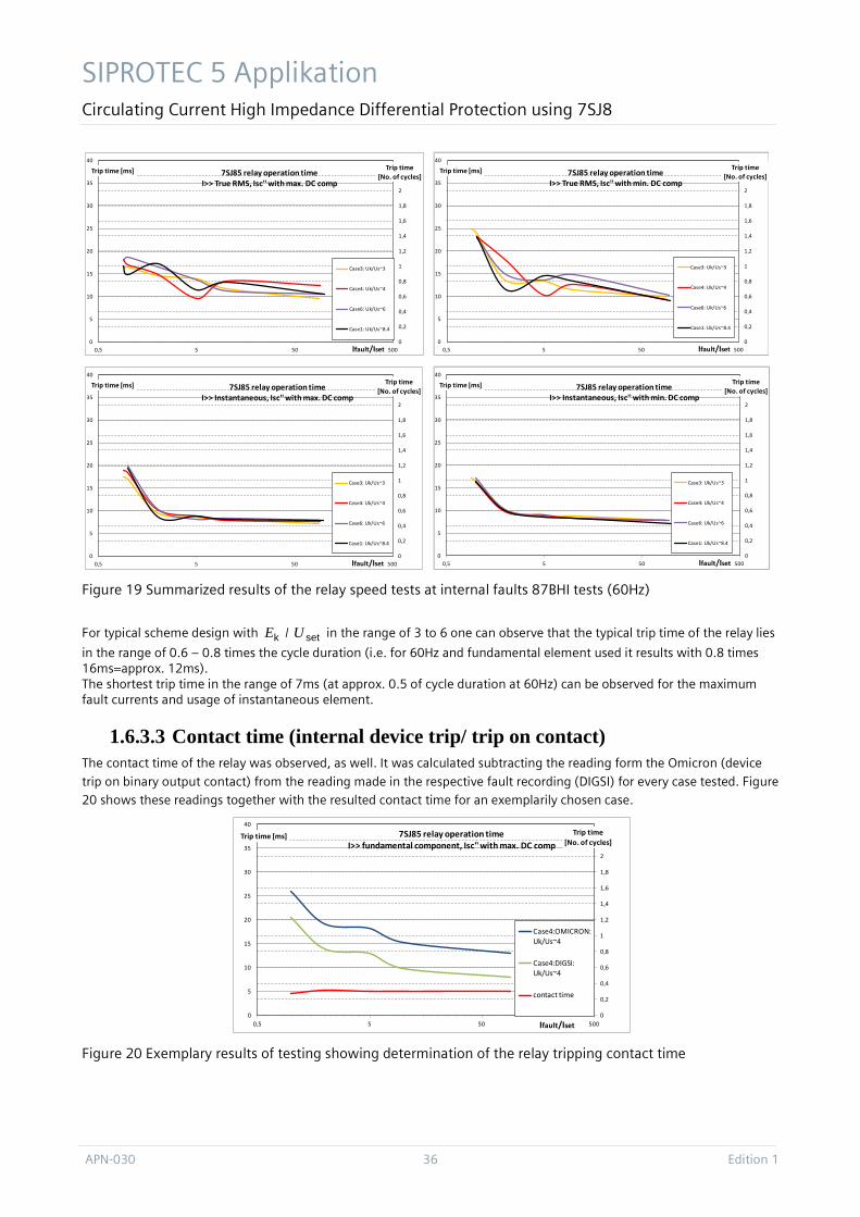
Figure 19 Summarized results of the relay speed tests at internal faults 87BHI tests (60Hz)
For typical scheme design with kE / setU in the range of 3 to 6 one can observe that the typical trip time of the relay lies
in the range of 0.6 – 0.8 times the cycle duration (i.e. for 60Hz and fundamental element used it results with 0.8 times 16ms=approx. 12ms). The shortest trip time in the range of 7ms (at approx. 0.5 of cycle duration at 60Hz) can be observed for the maximum fault currents and usage of instantaneous element.
1.6.3.3 Contact time (internal device trip/ trip on contact) The contact time of the relay was observed, as well. It was calculated subtracting the reading form the Omicron (device
trip on binary output contact) from the reading made in the respective fault recording (DIGSI) for every case tested. Figure 20 shows these readings together with the resulted contact time for an exemplarily chosen case.
Figure 20 Exemplary results of testing showing determination of the relay tripping contact time
0
0,2
0,4
0,6
0,8
1
1,2
1,4
1,6
1,8
2
2,2
0
5
10
15
20
25
30
35
40
0,5 5 50 500
Trip time[No. of cycles]
Trip time [ms]
Ifault/Iset
7SJ85 relay operation time I>> True RMS, Isc'' with max. DC comp
Case3: Uk/Us~3
Case4: Uk/Us~4
Case6: Uk/Us~6
Case1: Uk/Us~8.4
0
0,2
0,4
0,6
0,8
1
1,2
1,4
1,6
1,8
2
2,2
0
5
10
15
20
25
30
35
40
0,5 5 50 500
Trip time[No. of cycles]
Trip time [ms]
Ifault/Iset
7SJ85 relay operation time I>> True RMS, Isc'' with min. DC comp
Case3: Uk/Us~3
Case4: Uk/Us~4
Case6: Uk/Us~6
Case1: Uk/Us~8.4
0
0,2
0,4
0,6
0,8
1
1,2
1,4
1,6
1,8
2
2,2
0
5
10
15
20
25
30
35
40
0,5 5 50 500
Trip time[No. of cycles]
Trip time [ms]
Ifault/Iset
7SJ85 relay operation time I>> Instantaneous, Isc'' with max. DC comp
Case3: Uk/Us~3
Case4: Uk/Us~4
Case6: Uk/Us~6
Case1: Uk/Us~8.4
0
0,2
0,4
0,6
0,8
1
1,2
1,4
1,6
1,8
2
2,2
0
5
10
15
20
25
30
35
40
0,5 5 50 500
Trip time[No. of cycles]
Trip time [ms]
Ifault/Iset
7SJ85 relay operation time I>> Instantaneous, Isc'' with min. DC comp
Case3: Uk/Us~3
Case4: Uk/Us~4
Case6: Uk/Us~6
Case1: Uk/Us~8.4
0
0,2
0,4
0,6
0,8
1
1,2
1,4
1,6
1,8
2
2,2
0
5
10
15
20
25
30
35
40
0,5 5 50 500
Trip time[No. of cycles]
Trip time [ms]
Ifault/Iset
7SJ85 relay operation time I>> fundamental component, Isc'' with max. DC comp
Case4:OMICRON: Uk/Us~4
Case4:DIGSI: Uk/Us~4
contact time
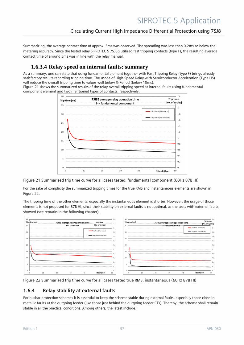
SIPROTEC 5 Application Circulating Current High Impedance Differential Protection using 7SJ8
Edition 1 37 APN-030
Summarizing, the average contact time of approx. 5ms was observed. The spreading was less than 0.2ms so below the metering accuracy. Since the tested relay SIPROTEC 5 7SJ85 utilized fast tripping contacts (type F), the resulting average contact time of around 5ms was in line with the relay manual.
1.6.3.4 Relay speed on internal faults: summary As a summary, one can state that using fundamental element together with Fast Tripping Relay (type F) brings already satisfactory results regarding tripping time. The usage of High-Speed Relay with Semiconductor Acceleration (Type HS) will reduce the overall tripping time to values well below ½ Period (below 10ms). Figure 21 shows the summarized results of the relay overall tripping speed at internal faults using fundamental component element and two mentioned types of contacts, respectively.
Figure 21 Summarized trip time curve for all cases tested, fundamental component (60Hz 87B HI)
For the sake of complicity the summarized tripping times for the true RMS and instantaneous elements are shown in Figure 22.
The tripping time of the other elements, especially the instantaneous element is shorter. However, the usage of those elements is not proposed for 87B HI, since their stability on external faults is not optimal, as the tests with external faults showed (see remarks in the following chapter).
Figure 22 Summarized trip time curve for all cases tested true RMS, instantaneous (60Hz 87B HI)
1.6.4 Relay stability at external faults For busbar protection schemes it is essential to keep the scheme stable during external faults, especially those close-in metallic faults at the outgoing feeder (like those just behind the outgoing feeder CTs). Thereby, the scheme shall remain stable in all the practical conditions. Among others, the latest include:
0
0,2
0,4
0,6
0,8
1
1,2
1,4
1,6
1,8
2
2,2
2,4
0
5
10
15
20
25
30
35
40
0 10 20 30 40 50 60
Trip time[No. of cycles]
Trip time [ms]
Ifault/Iset
7SJ85 average relay operation time I>> fundamental component
Trip Time (F contacts)
Trip Time (HS contacts)
0
0,2
0,4
0,6
0,8
1
1,2
1,4
1,6
1,8
2
2,2
2,4
0
5
10
15
20
25
30
35
40
0 10 20 30 40 50 60
Trip time[No. of cycles]
Trip time [ms]
Ifault/Iset
7SJ85 average relay operation time I>> True RMS
Trip Time (F contacts)
Trip Time (HS contacts)
0
0,2
0,4
0,6
0,8
1
1,2
1,4
1,6
1,8
2
2,2
2,4
0
5
10
15
20
25
30
35
40
0 10 20 30 40 50 60
Trip time[No. of cycles]
Trip time [ms]
Ifault/Iset
7SJ85 average relay operation time I>> Instantaneous
Trip Time (F contacts)
Trip Time (HS contacts)
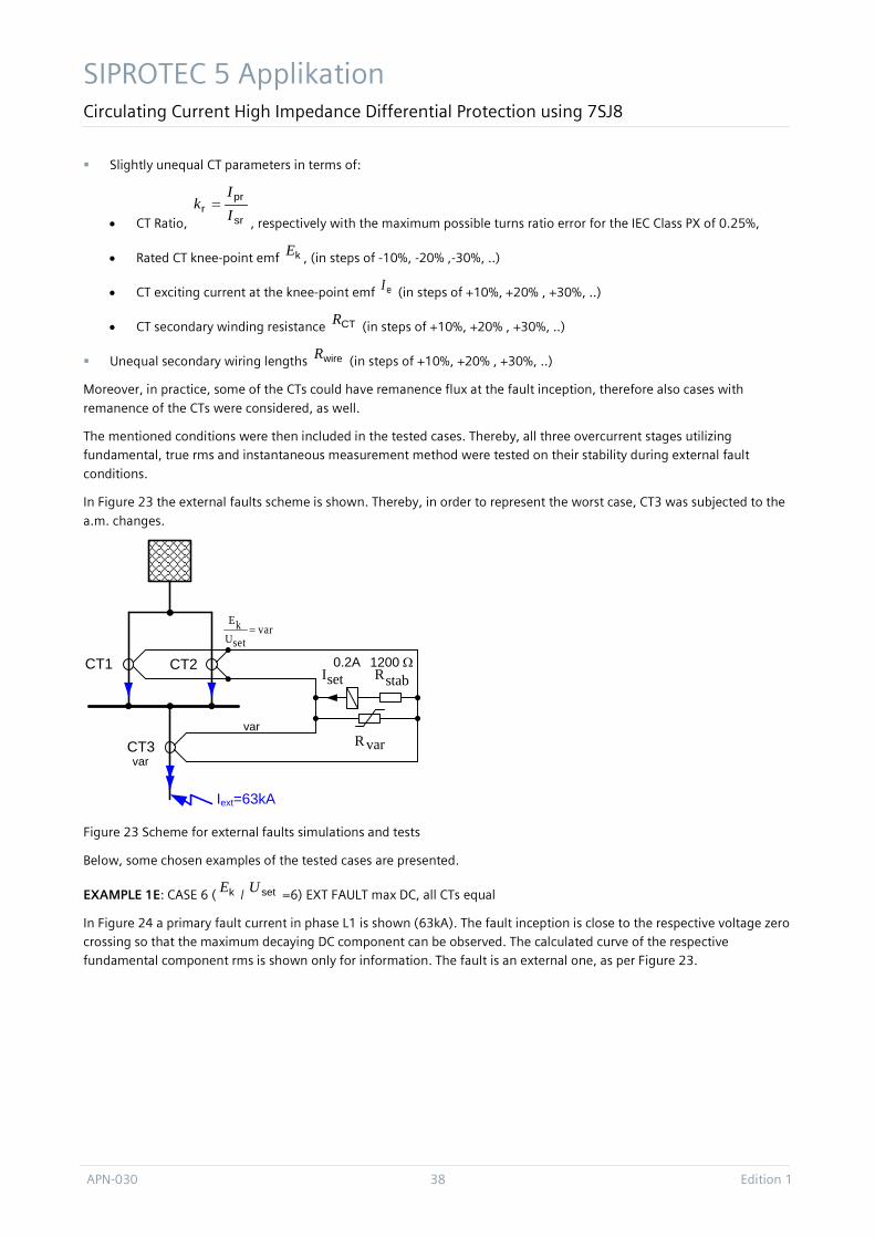
SIPROTEC 5 Applikation Circulating Current High Impedance Differential Protection using 7SJ8
APN-030 38 Edition 1
Slightly unequal CT parameters in terms of:
• CT Ratio, sr
prr I
Ik =
, respectively with the maximum possible turns ratio error for the IEC Class PX of 0.25%,
• Rated CT knee-point emf kE , (in steps of -10%, -20% ,-30%, ..)
• CT exciting current at the knee-point emf eI (in steps of +10%, +20% , +30%, ..)
• CT secondary winding resistance CTR (in steps of +10%, +20% , +30%, ..)
Unequal secondary wiring lengths wireR (in steps of +10%, +20% , +30%, ..)
Moreover, in practice, some of the CTs could have remanence flux at the fault inception, therefore also cases with
remanence of the CTs were considered, as well.
The mentioned conditions were then included in the tested cases. Thereby, all three overcurrent stages utilizing fundamental, true rms and instantaneous measurement method were tested on their stability during external fault
conditions.
In Figure 23 the external faults scheme is shown. Thereby, in order to represent the worst case, CT3 was subjected to the
a.m. changes.
Figure 23 Scheme for external faults simulations and tests
Below, some chosen examples of the tested cases are presented.
EXAMPLE 1E: CASE 6 ( kE / setU =6) EXT FAULT max DC, all CTs equal
In Figure 24 a primary fault current in phase L1 is shown (63kA). The fault inception is close to the respective voltage zero crossing so that the maximum decaying DC component can be observed. The calculated curve of the respective fundamental component rms is shown only for information. The fault is an external one, as per Figure 23.
setI
Iext=63kA
stabR
varR
CT1 CT2
CT3
1200 Ω0.2A
varsetUkE
=
var
var
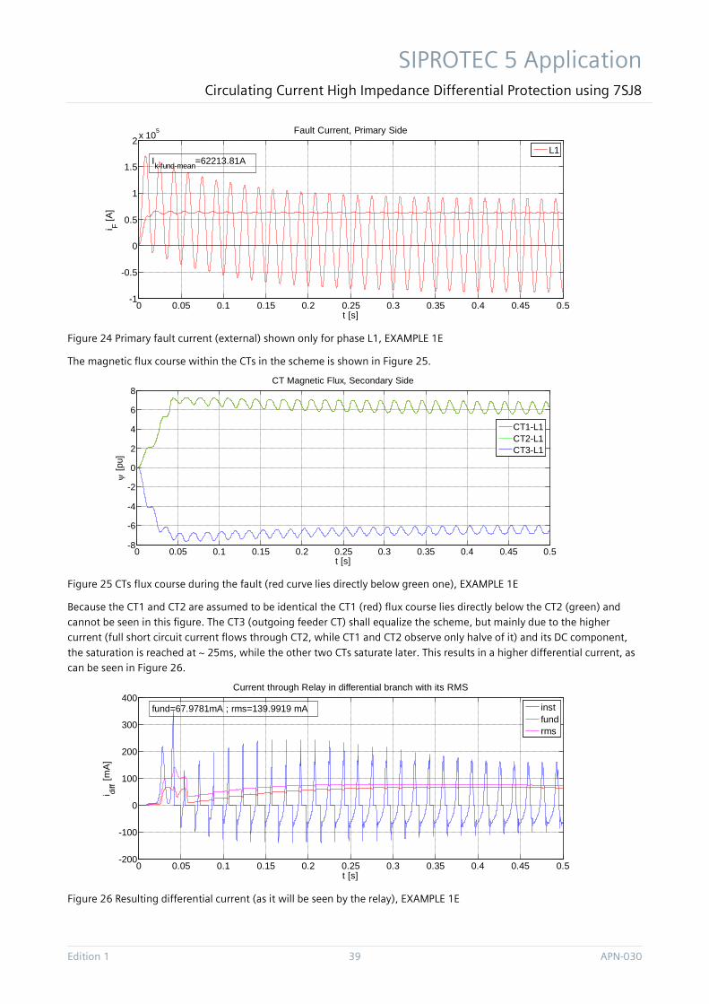
SIPROTEC 5 Application Circulating Current High Impedance Differential Protection using 7SJ8
Edition 1 39 APN-030
Figure 24 Primary fault current (external) shown only for phase L1, EXAMPLE 1E
The magnetic flux course within the CTs in the scheme is shown in Figure 25.
Figure 25 CTs flux course during the fault (red curve lies directly below green one), EXAMPLE 1E
Because the CT1 and CT2 are assumed to be identical the CT1 (red) flux course lies directly below the CT2 (green) and cannot be seen in this figure. The CT3 (outgoing feeder CT) shall equalize the scheme, but mainly due to the higher current (full short circuit current flows through CT2, while CT1 and CT2 observe only halve of it) and its DC component,
the saturation is reached at ~ 25ms, while the other two CTs saturate later. This results in a higher differential current, as can be seen in Figure 26.
Figure 26 Resulting differential current (as it will be seen by the relay), EXAMPLE 1E
0 0.05 0.1 0.15 0.2 0.25 0.3 0.35 0.4 0.45 0.5-1
-0.5
0
0.5
1
1.5
2 x 10⁵
t [s]
i F [A]
Fault Current, Primary Side
L1Ik-fund-mean=62213.81A
0 0.05 0.1 0.15 0.2 0.25 0.3 0.35 0.4 0.45 0.5-8
-6
-4
-2
0
2
4
6
8
t [s]
ψ [p
u]
CT Magnetic Flux, Secondary Side
CT1-L1CT2-L1CT3-L1
0 0.05 0.1 0.15 0.2 0.25 0.3 0.35 0.4 0.45 0.5-200
-100
0
100
200
300
400
t [s]
i diff [m
A]
Current through Relay in differential branch with its RMS
instfundrms
fund=67.9781mA ; rms=139.9919 mA
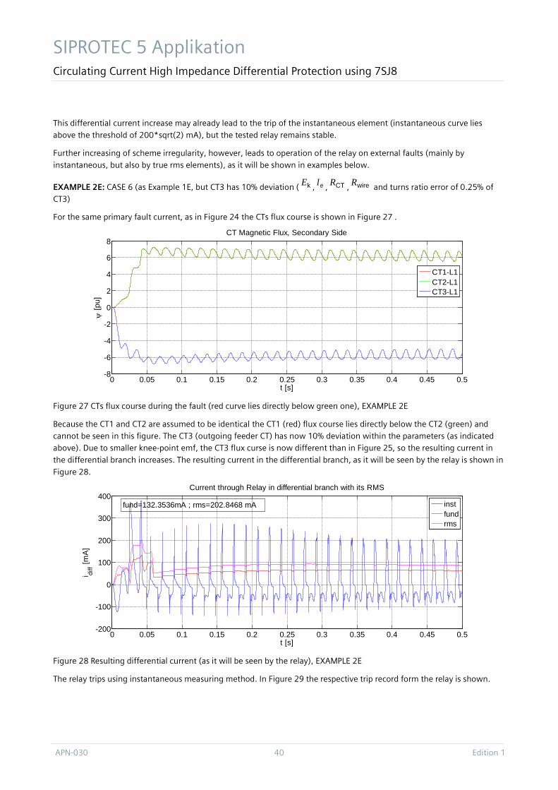
SIPROTEC 5 Applikation Circulating Current High Impedance Differential Protection using 7SJ8
APN-030 40 Edition 1
This differential current increase may already lead to the trip of the instantaneous element (instantaneous curve lies above the threshold of 200*sqrt(2) mA), but the tested relay remains stable.
Further increasing of scheme irregularity, however, leads to operation of the relay on external faults (mainly by instantaneous, but also by true rms elements), as it will be shown in examples below.
EXAMPLE 2E: CASE 6 (as Example 1E, but CT3 has 10% deviation ( kE , eI , CTR , wireR and turns ratio error of 0.25% of CT3)
For the same primary fault current, as in Figure 24 the CTs flux course is shown in Figure 27 .
Figure 27 CTs flux course during the fault (red curve lies directly below green one), EXAMPLE 2E
Because the CT1 and CT2 are assumed to be identical the CT1 (red) flux course lies directly below the CT2 (green) and cannot be seen in this figure. The CT3 (outgoing feeder CT) has now 10% deviation within the parameters (as indicated above). Due to smaller knee-point emf, the CT3 flux curse is now different than in Figure 25, so the resulting current in the differential branch increases. The resulting current in the differential branch, as it will be seen by the relay is shown in
Figure 28.
Figure 28 Resulting differential current (as it will be seen by the relay), EXAMPLE 2E
The relay trips using instantaneous measuring method. In Figure 29 the respective trip record form the relay is shown.
0 0.05 0.1 0.15 0.2 0.25 0.3 0.35 0.4 0.45 0.5-8
-6
-4
-2
0
2
4
6
8
t [s]
ψ [p
u]
CT Magnetic Flux, Secondary Side
CT1-L1CT2-L1CT3-L1
0 0.05 0.1 0.15 0.2 0.25 0.3 0.35 0.4 0.45 0.5-200
-100
0
100
200
300
400
t [s]
i diff [m
A]
Current through Relay in differential branch with its RMS
instfundrms
fund=132.3536mA ; rms=202.8468 mA
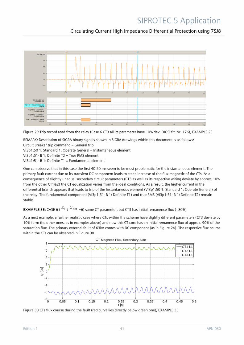
SIPROTEC 5 Application Circulating Current High Impedance Differential Protection using 7SJ8
Edition 1 41 APN-030
Figure 29 Trip record read from the relay (Case 6 CT3 all its parameter have 10% dev, DIGSI flt. Nr. 176), EXAMPLE 2E
REMARK: Description of SIGRA binary signals shown in SIGRA drawings within this document is as follows:
Circuit Breaker trip command = General trip VI3p1:50 1: Standard 1: Operate General = Instantaneous element VI3p1:51- B 1: Definite T2 = True RMS element VI3p1:51- B 1: Definite T1 = Fundamental element
One can observe that in this case the first 40-50 ms seem to be most problematic for the instantaneous element. The primary fault current due to its transient DC component leads to steep increase of the flux magnetic of the CTs. As a consequence of slightly unequal secondary circuit parameters (CT3 as well as its respective wiring deviate by approx. 10%
from the other CT1&2) the CT equalization varies from the ideal conditions. As a result, the higher current in the differential branch appears that leads to trip of the Instantaneous element (VI3p1:50 1: Standard 1: Operate General) of the relay. The fundamental component (VI3p1:51- B 1: Definite T1) and true RMS (VI3p1:51- B 1: Definite T2) remain stable.
EXAMPLE 3E: CASE 6 ( kE / setU =6) same CT parameter, but CT3 has initial remanence flux (~80%)
As a next example, a further realistic case where CTs within the scheme have slightly different parameters (CT3 deviate by
10% form the other ones, as in examples above) and now this CT core has an initial remanence flux of approx. 90% of the saturation flux. The primary external fault of 63kA comes with DC component (as in Figure 24). The respective flux course within the CTs can be observed in Figure 30.
Figure 30 CTs flux course during the fault (red curve lies directly below green one), EXAMPLE 3E
0 0.05 0.1 0.15 0.2 0.25 0.3 0.35 0.4 0.45 0.5-8
-6
-4
-2
0
2
4
6
8
t [s]
ψ [p
u]
CT Magnetic Flux, Secondary Side
CT1-L1CT2-L1CT3-L1
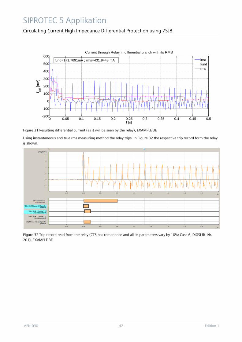
SIPROTEC 5 Applikation Circulating Current High Impedance Differential Protection using 7SJ8
APN-030 42 Edition 1
Figure 31 Resulting differential current (as it will be seen by the relay), EXAMPLE 3E
Using instantaneous and true rms measuring method the relay trips. In Figure 32 the respective trip record form the relay is shown.
Figure 32 Trip record read from the relay (CT3 has remanence and all its parameters vary by 10%; Case 6, DIGSI flt. Nr. 201), EXAMPLE 3E
0 0.05 0.1 0.15 0.2 0.25 0.3 0.35 0.4 0.45 0.5-200
-100
0
100
200
300
400
500
600
t [s]
i diff [m
A]
Current through Relay in differential branch with its RMS
instfundrms
fund=171.7691mA ; rms=431.9448 mA
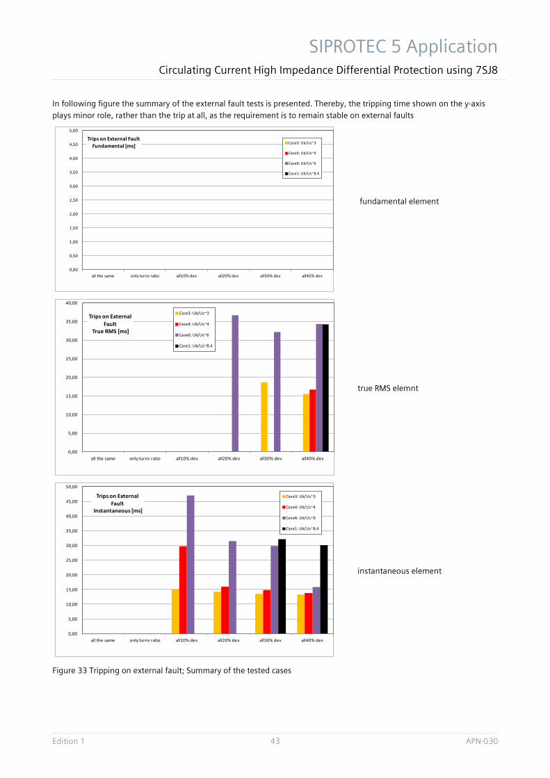
SIPROTEC 5 Application Circulating Current High Impedance Differential Protection using 7SJ8
Edition 1 43 APN-030
In following figure the summary of the external fault tests is presented. Thereby, the tripping time shown on the y-axis plays minor role, rather than the trip at all, as the requirement is to remain stable on external faults
fundamental element
true RMS elemnt
instantaneous element
Figure 33 Tripping on external fault; Summary of the tested cases
0,00
0,50
1,00
1,50
2,00
2,50
3,00
3,50
4,00
4,50
5,00
all the same only turns ratio all10% dev all20% dev all30% dev all40% dev
Trips on External Fault Fundamental [ms] Case3: Uk/Us~3
Case4: Uk/Us~4
Case6: Uk/Us~6
Case1: Uk/Us~8.4
0,00
5,00
10,00
15,00
20,00
25,00
30,00
35,00
40,00
all the same only turns ratio all10% dev all20% dev all30% dev all40% dev
Trips on External Fault
True RMS [ms]
Case3: Uk/Us~3
Case4: Uk/Us~4
Case6: Uk/Us~6
Case1: Uk/Us~8.4
0,00
5,00
10,00
15,00
20,00
25,00
30,00
35,00
40,00
45,00
50,00
all the same only turns ratio all10% dev all20% dev all30% dev all40% dev
Trips on External Fault
Instantaneous [ms]
Case3: Uk/Us~3
Case4: Uk/Us~4
Case6: Uk/Us~6
Case1: Uk/Us~8.4
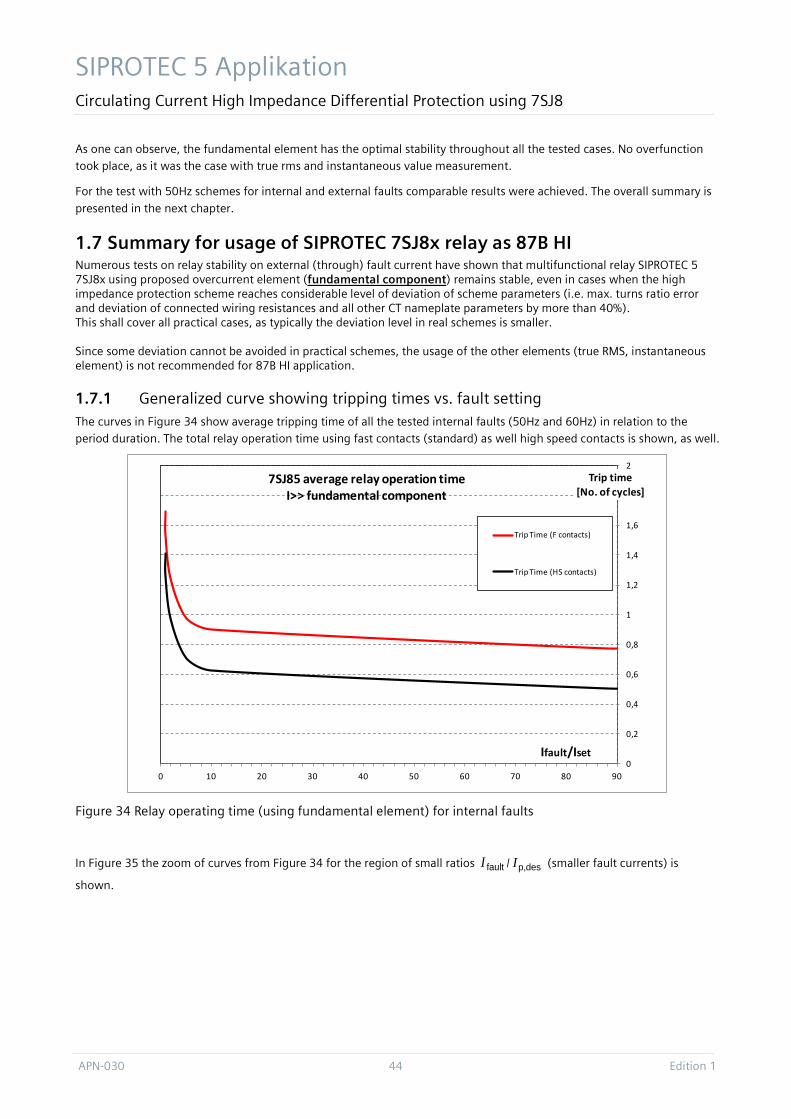
SIPROTEC 5 Applikation Circulating Current High Impedance Differential Protection using 7SJ8
APN-030 44 Edition 1
As one can observe, the fundamental element has the optimal stability throughout all the tested cases. No overfunction took place, as it was the case with true rms and instantaneous value measurement.
For the test with 50Hz schemes for internal and external faults comparable results were achieved. The overall summary is
presented in the next chapter.
1.7 Summary for usage of SIPROTEC 7SJ8x relay as 87B HI Numerous tests on relay stability on external (through) fault current have shown that multifunctional relay SIPROTEC 5 7SJ8x using proposed overcurrent element (fundamental component) remains stable, even in cases when the high impedance protection scheme reaches considerable level of deviation of scheme parameters (i.e. max. turns ratio error and deviation of connected wiring resistances and all other CT nameplate parameters by more than 40%). This shall cover all practical cases, as typically the deviation level in real schemes is smaller. Since some deviation cannot be avoided in practical schemes, the usage of the other elements (true RMS, instantaneous element) is not recommended for 87B HI application.
1.7.1 Generalized curve showing tripping times vs. fault setting The curves in Figure 34 show average tripping time of all the tested internal faults (50Hz and 60Hz) in relation to the period duration. The total relay operation time using fast contacts (standard) as well high speed contacts is shown, as well.
Figure 34 Relay operating time (using fundamental element) for internal faults
In Figure 35 the zoom of curves from Figure 34 for the region of small ratios faultI / desp,I (smaller fault currents) is
shown.
0
0,2
0,4
0,6
0,8
1
1,2
1,4
1,6
1,8
2
0 10 20 30 40 50 60 70 80 90
Trip time[No. of cycles]
Ifault/Iset
7SJ85 average relay operation time I>> fundamental component
Trip Time (F contacts)
Trip Time (HS contacts)
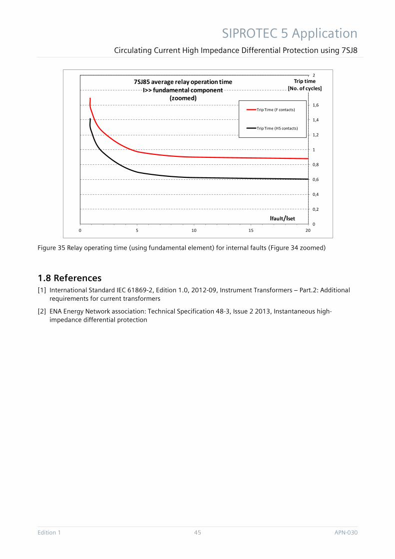
SIPROTEC 5 Application Circulating Current High Impedance Differential Protection using 7SJ8
Edition 1 45 APN-030
Figure 35 Relay operating time (using fundamental element) for internal faults (Figure 34 zoomed)
1.8 References [1] International Standard IEC 61869-2, Edition 1.0, 2012-09, Instrument Transformers – Part.2: Additional
requirements for current transformers
[2] ENA Energy Network association: Technical Specification 48-3, Issue 2 2013, Instantaneous high-impedance differential protection
0
0,2
0,4
0,6
0,8
1
1,2
1,4
1,6
1,8
2
0 5 10 15 20
Trip time[No. of cycles]
Ifault/Iset
7SJ85 average relay operation time I>> fundamental component
(zoomed)
Trip Time (F contacts)
Trip Time (HS contacts)
APN-030 46 Edition 1
Published by Siemens AG 2016 Energy Management Division Digital Grid Automation Products Humboldtstr. 59
90459 Nuremberg, Germany
www.siemens.com/siprotec
For more information,
please contact our
Customer Support Center.
Tel.: +49 180 524 70 00
Fax: +49 180 524 24 71
(Charges depending on provider)
Email: [email protected]
© 2016 Siemens. Subject to changes and errors. The information given in this document only contains general descriptions and/or performance features which may not always specifically reflect those described, or which may undergo modification in the course of further development of the products. The requested performance features are binding only when they are expressly agreed upon in the concluded contract.
For all products using security features of OpenSSL, the following shall apply: This product includes software developed by the OpenSSL Project for use in the OpenSSL Toolkit. (http://www.openssl.org/ ) This product includes cryptographic software written by Eric Young ([email protected] ) This product includes software written by Tim Hudson ([email protected]) This product includes software developed by Bodo Moeller.


