Embed Size (px)
Citation preview
Cell voltage versus electrode potentialrange in aqueous supercapacitorsZengxin Dai1, Chuang Peng1,2,3, Jung Hoon Chae2, Kok Chiang Ng2* & George Z. Chen2,3
1College of Materials Science and Engineering, Hunan University, Changsha, Hunan, China 410082, 2Department of Chemicaland Environmental Engineering, and Energy and Sustainability Research Division, Faculty of Engineering, University of Nottingham,Nottingham, UK NG7 2RD, 3Department of Chemical and Environmental Engineering, Faculty of Science and Engineering,University of Nottingham Ningbo China, Ningbo, China 315100.
Supercapacitors with aqueous electrolytes and nanostructured composite electrodes are attractive becauseof their high charging-discharging speed, long cycle life, low environmental impact and wide commercialaffordability. However, the energy capacity of aqueous supercapacitors is limited by the electrochemicalwindow of water. In this paper, a recently reported engineering strategy is further developed anddemonstrated to correlate the maximum charging voltage of a supercapacitor with the capacitive potentialranges and the capacitance ratio of the two electrodes. Beyond the maximum charging voltage, asupercapacitor may still operate, but at the expense of a reduced cycle life. In addition, it is shown that thesupercapacitor performance is strongly affected by the initial and zero charge potentials of the electrodes.Further, the differences are highlighted and elaborated between freshly prepared, aged under open circuitconditions, and cycled electrodes of composites of conducting polymers and carbon nanotubes. The firstvoltammetric charging-discharging cycle has an electrode conditioning effect to change the electrodes fromtheir initial potentials to the potential of zero voltage, and reduce the irreversibility.
S upercapacitors store electric energy through charge accumulation in the electric double layer, or redoxreactions involving delocalised electrons, or a combination of the two1,2. They have received fast growinginterests from academia and industry alike, due to twomainmerits, high power performance and long cycle
life. In comparable terms of these two types of supercapacitors, the specific capacity of energy storage (WM in unitof J g21) is determined by both the specific capacitance (CM, F g21) and the cell voltage (U, V) via the simpleequation of WM 5 CM 3 U2 / 2. To achieve high specific capacitance, redox active materials with pseudocapa-citance are highly favoured. In the last decade, composites of pseudocapacitive materials and porous or nanos-tructured carbon with specially engineered functionalities have become a research focus as they combine the highenergy and high power of the two components123. In particular, composites of transition metal oxides orconducting polymers with carbon nanotubes (CNTs) or graphene have exhibited very promising perfor-mances123. In many cases, aqueous electrolytes are used in these supercapacitors with composite electrodematerials to take advantages of, such as, low impedance or equivalent series resistance (ESR), low cost, bettersafety, and low environmental concern426. However, the main problem of aqueous supercapacitors for commer-cial applications is the moderate cell voltage as compared to their counterparts with ionic liquid or organicelectrolytes7,8.
Numerous attempts have been made to increase the ‘‘maximum charging voltage’’ (MCV) or the voltage limitof the aqueous supercapacitor4,5,9212. One of the common strategies is the selection of electrode materials withwider operational potential ranges. A number of aqueous supercapacitors have demonstrated MCV higher thanthe thermodynamic breakdown window of water, taking advantage of the stable potential windows of someelectrode materials and their high overpotentials for oxygen and/or hydrogen evolution4,5,11215. Most of thereported studies on aqueous supercapacitor voltage focus on electrode materials, particularly activated carbon(AC) of high specific surface areas, or manganese oxides4,5,9215. To our best knowledge, very little has beenreported in the literature on design and engineering which can potentially offer further cost and performancebenefits to the development of supercapacitors.
In this paper, from the viewpoint of device design and engineering, we provide a basic reference of theMCVs ofaqueous supercapacitors with a wide range of electrodematerials, including composites of CNTs with conductingpolymers or transition metal oxides. The other two voltage-related performance indicators, i.e. the coulombicefficiency and cycle life, are also investigated. A special emphasis is given to explain the phenomena of the‘‘potential of zero voltage’’ (PZV), ‘‘capacitive potential range’’ (CPR) and the ‘‘positive to negative electrode
OPEN
SUBJECT AREAS:CHEMICAL
ENGINEERING
BATTERIES
Received9 December 2013
Accepted10 March 2015
Published
Correspondence andrequests for materials
should be addressed toC.P. (chuang.peng@
nottingham.edu.cn) orG.Z.C. (george.chen@
nottingham.ac.uk)
*Current address:R&D Centre, Leong
Hing Sdn. Bhd., No. 1,Jalan P4/7, Seksyen 4,
Bandar TeknologiKajang, 43500
Semenyih, Selangor,Malaysia
SCIENTIFIC REPORTS | 5 : 9854 | DOI: 10.1038/srep09854 1
2 April 20151
capacitance ratio’’ (C1/C2), and to use them in a simple model tocorrelate MCV with CPR of each of the two electrodes in super-capacitors. Finally, we demonstrate a new example to show howthe optimal C1/C2 ratio in the ‘‘polypyrrole-CNT (1) j KCl j AC(2)’’ asymmetrical supercapacitor can extend the MCV, and doublethe specific energy capacity of the supercapacitor without changingthe materials16,17.
ResultsThe aim of this work is to understand electrode behaviour and cor-relate it with and improve the supercapacitor performance from thepoint of view of device design and engineering. Therefore, we haveundertaken both theoretical and experimental studies. The theor-etical studies, as presented in the first two sub-sections below, focuson understanding and clarification of key performance parametersthat are unique to supercapacitors, but not to batteries. We thenexperimentally test the theoretical understanding and predictionson selected known electrode materials using the most commonlyused electrochemical method, cyclic voltammetry together with sim-ultaneous monitoring of the electrode potential. For other propertiesof the selected materials, these have already been reported in theliterature and the respective references are given in the relevant dis-cussion below.
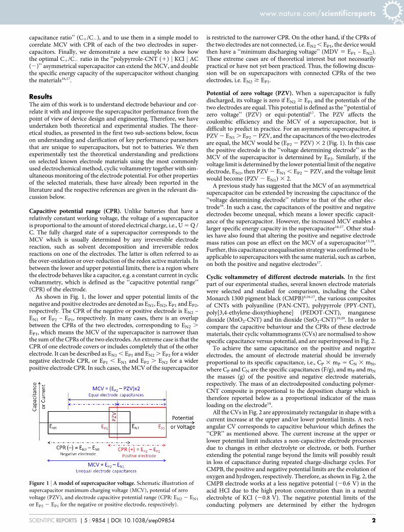
Capacitive potential range (CPR). Unlike batteries that have arelatively constant working voltage, the voltage of a supercapacitoris proportional to the amount of stored electrical charge, i.e., U5Q /C. The fully charged state of a supercapacitor corresponds to theMCV which is usually determined by any irreversible electrodereaction, such as solvent decomposition and irreversible redoxreactions on one of the electrodes. The latter is often referred to asthe over-oxidation or over-reduction of the redox activematerials. Inbetween the lower and upper potential limits, there is a region wherethe electrode behaves like a capacitor, e.g. a constant current in cyclicvoltammetry, which is defined as the ‘‘capacitive potential range’’(CPR) of the electrode.As shown in Fig. 1, the lower and upper potential limits of the
negative and positive electrodes are denoted as EN1, EN2, EP1 and EP2,respectively. The CPR of the negative or positive electrode is EN2 –EN1 or EP2 – EP1, respectively. In many cases, there is an overlapbetween the CPRs of the two electrodes, corresponding to EN2 .EP1, which means the MCV of the supercapacitor is narrower thanthe sum of the CPRs of the two electrodes. An extreme case is that theCPR of one electrode covers or includes completely that of the otherelectrode. It can be described as EN1, EP1 and EN2. EP2 for a widernegative electrode CPR, or EP1 , EN1 and EP2 . EN2 for a widerpositive electrode CPR. In such cases, theMCV of the supercapacitor
is restricted to the narrower CPR. On the other hand, if the CPRs ofthe two electrodes are not connected, i.e. EN2, EP1, the device wouldthen have a ‘‘minimum discharging voltage’’ (MDV 5 EP1 – EN2).These extreme cases are of theoretical interest but not necessarilypractical or have not yet been practiced. Thus, the following discus-sion will be on supercapacitors with connected CPRs of the twoelectrodes, i.e. EN2 $ EP1.
Potential of zero voltage (PZV). When a supercapacitor is fullydischarged, its voltage is zero if EN2 $ EP1 and the potentials of thetwo electrodes are equal. This potential is defined as the ‘‘potential ofzero voltage’’ (PZV) or equi-potential17. The PZV affects thecoulombic efficiency and the MCV of a supercapacitor, but isdifficult to predict in practice. For an asymmetric supercapacitor, ifPZV2 EN1. EP22 PZV, and the capacitances of the two electrodesare equal, the MCV would be (EP2 2 PZV)3 2 (Fig. 1). In this casethe positive electrode is the ‘‘voltage determining electrode’’ as theMCV of the supercapacitor is determined by EP2. Similarly, if thevoltage limit is determined by the lower potential limit of the negativeelectrode, EN1, then PZV2 EN1, EP2 2 PZV, and the voltage limitwould become (PZV 2 EN1) 3 2.A previous study has suggested that the MCV of an asymmetrical
supercapacitor can be extended by increasing the capacitance of the‘‘voltage determining electrode’’ relative to that of the other elec-trode16. In such a case, the capacitances of the positive and negativeelectrodes become unequal, which means a lower specific capacit-ance of the supercapacitor. However, the increased MCV enables alarger specific energy capacity in the supercapacitor16,17. Other stud-ies have also found that altering the positive and negative electrodemass ratios can pose an effect on the MCV of a supercapacitor13,18.Further, this capacitance unequalisation strategywas confirmed to beapplicable to supercapacitors with the samematerial, such as carbon,on both the positive and negative electrodes17.
Cyclic voltammetry of different electrode materials. In the firstpart of our experimental studies, several known electrode materialswere selected and studied for comparison, including the CabotMonarch 1300 pigment black (CMPB)6,16,17, the various compositesof CNTs with polyaniline (PAN-CNT), polypyrrole (PPY-CNT),poly[3,4-ethylene-dioxythiophene] (PEDOT-CNT), manganesedioxide (MnO2-CNT) and tin dioxide (SnO2-CNT)19,20. In order tocompare the capacitive behaviour and the CPRs of these electrodematerials, their cyclic voltammograms (CVs) are normalised to showspecific capacitance versus potential, and are superimposed in Fig. 2.To achieve the same capacitance on the positive and negative
electrodes, the amount of electrode material should be inverselyproportional to its specific capacitance, i.e., CP 3 mP 5 CN 3 mN,where CP and CN are the specific capacitances (F/g), and mP and mN
the masses (g) of the positive and negative electrode materials,respectively. The mass of an electrodeposited conducting polymer-CNT composite is proportional to the deposition charge which istherefore reported below as a proportional indicator of the massloading on the electrode19.All the CVs in Fig. 2 are approximately rectangular in shape with a
current increase at the upper and/or lower potential limits. A rect-angular CV corresponds to capacitive behaviour which defines the‘‘CPR’’ as mentioned above. The current increase at the upper orlower potential limit indicates a non-capacitive electrode processesdue to changes in either electrolyte or electrode, or both. Furtherextending the potential range beyond the limits will possibly resultin loss of capacitance during repeated charge-discharge cycles. ForCMPB, the positive and negative potential limits are the evolution ofoxygen and hydrogen, respectively. Therefore, as shown in Fig. 2, theCMPB electrode works at a less negative potential (20.6 V) in theacid HCl due to the high proton concentration than in a neutralelectrolyte of KCl (20.8 V). The negative potential limits of theconducting polymers are determined by either the hydrogen
Figure 1 | A model of supercapacitor voltage. Schematic illustration of
supercapacitor maximum charging voltage (MCV), potential of zero
voltage (PZV), and electrode capacitive potential range (CPR: EN2 2 EN1or EP2 2 EP1 for the negative or positive electrode, respectively).
www.nature.com/scientificreports
SCIENTIFIC REPORTS | 5 : 9854 | DOI: 10.1038/srep09854 2
evolution reaction or conducting polymers becoming insulating inthe undoped state. The positive potential limits of conducting poly-mers are determined by oxygen evolution or irreversible over-oxida-tion of the polymer. For instance, PAN is oxidised to pernigranilineat very positive potentials and its capacitance decreases upon poten-tial cycling16. The CPR ofMnO2 is limited by the evolution of oxygenand formation of Mn21 at the positive and negative thresholds,respectively. Of the selected materials, SnO2 and its CNT composite
are the only ones that exhibit pseudocapacitance in a relatively nega-tive potential range (20.8 , 0 V)20, and their CPRs have EN1 com-parable to that of CMPB. The CPRs of other two materials studied, i.e. PPY-CNT and PEDOT-CNT, fall in themiddle range of the poten-tial window explored in Fig. 2. Thus, MnO2, PAN and their compo-sites with CNTs are more favourable for the positive electrode in asupercapacitor, while CMPB and SnO2 or its CNT composite aremore suitable as the negative electrode materials. To further studythe MCVs of supercapacitors with different combinations of theseelectrode materials, the tube-cell supercapacitor was fabricated asshown in the inset of Fig. 3a17,21.The open circuit potential (OCP) of an electrode is another
important factor affecting the performance of supercapacitors. Thestable OCPs of different electrodes were measured, exhibiting thefollowing values: 0.484 V for PAN-CNT, 0.290 V for PPY-CNT,0.296 V for PEDOT-CNT, 0.365 and 0.466 V for CMPB in KCland HCl, respectively. These OCP values are also marked in Fig. 2.Interestingly none of the OCP values reside in the middle of theirrespective CPR. Detailed discussion on the relation between OCPand cell voltage will be provided in the next two sections of this paper.
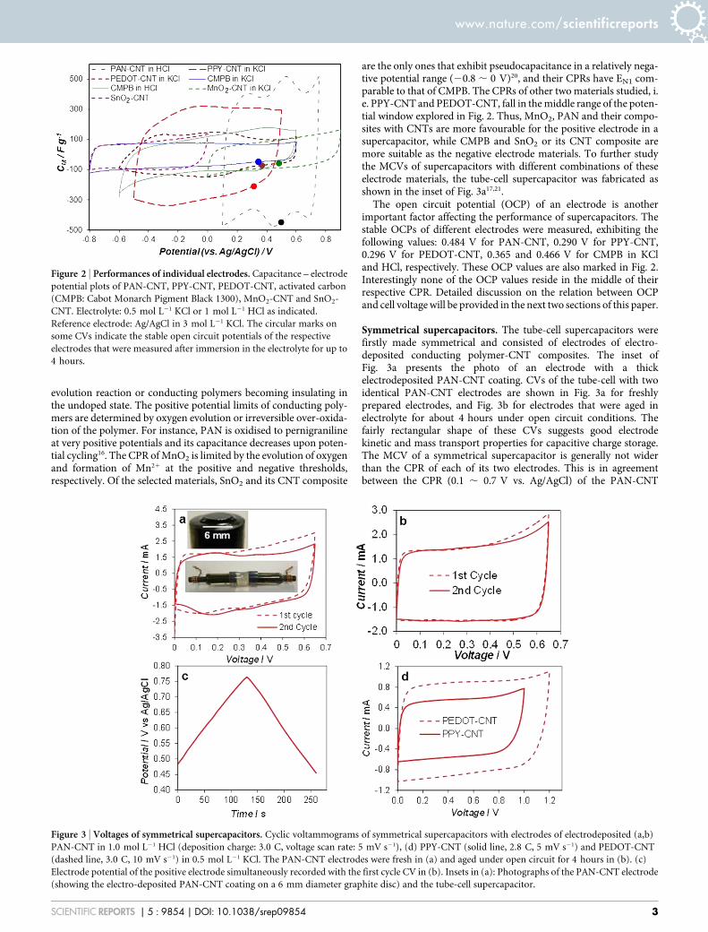
Symmetrical supercapacitors. The tube-cell supercapacitors werefirstly made symmetrical and consisted of electrodes of electro-deposited conducting polymer-CNT composites. The inset ofFig. 3a presents the photo of an electrode with a thickelectrodeposited PAN-CNT coating. CVs of the tube-cell with twoidentical PAN-CNT electrodes are shown in Fig. 3a for freshlyprepared electrodes, and Fig. 3b for electrodes that were aged inelectrolyte for about 4 hours under open circuit conditions. Thefairly rectangular shape of these CVs suggests good electrodekinetic and mass transport properties for capacitive charge storage.The MCV of a symmetrical supercapacitor is generally not widerthan the CPR of each of its two electrodes. This is in agreementbetween the CPR (0.1 , 0.7 V vs. Ag/AgCl) of the PAN-CNT
Figure 2 | Performances of individual electrodes. Capacitance – electrodepotential plots of PAN-CNT, PPY-CNT, PEDOT-CNT, activated carbon
(CMPB: Cabot Monarch Pigment Black 1300), MnO2-CNT and SnO2-
CNT. Electrolyte: 0.5 mol L21 KCl or 1 mol L21 HCl as indicated.
Reference electrode: Ag/AgCl in 3 mol L21 KCl. The circular marks on
some CVs indicate the stable open circuit potentials of the respective
electrodes that were measured after immersion in the electrolyte for up to
4 hours.
Figure 3 | Voltages of symmetrical supercapacitors. Cyclic voltammograms of symmetrical supercapacitors with electrodes of electrodeposited (a,b)
PAN-CNT in 1.0 mol L21 HCl (deposition charge: 3.0 C, voltage scan rate: 5 mV s21), (d) PPY-CNT (solid line, 2.8 C, 5 mV s21) and PEDOT-CNT
(dashed line, 3.0 C, 10 mV s21) in 0.5 mol L21 KCl. The PAN-CNT electrodes were fresh in (a) and aged under open circuit for 4 hours in (b). (c)
Electrode potential of the positive electrode simultaneously recorded with the first cycle CV in (b). Insets in (a): Photographs of the PAN-CNT electrode
(showing the electro-deposited PAN-CNT coating on a 6 mm diameter graphite disc) and the tube-cell supercapacitor.
www.nature.com/scientificreports
SCIENTIFIC REPORTS | 5 : 9854 | DOI: 10.1038/srep09854 3
electrode as revealed in Fig. 2, and the MCV (0.65 V) of thesymmetrical PAN-CNT supercapacitor shown in both Fig. 3a and3b. Ideally, the PZV of a symmetrical supercapacitor should be in themiddle of the electrode CPR, but this is not always the case as it will bediscussed later.Table 1 compares the MCVs of symmetrical supercapacitors with
PAN-CNT, PPY-CNT, PEDOT-CNT, and CMPB, and the literaturereported MnO2-CNT22. These are all in good agreement with theirrespective electrode CPRs. Since the electrodes in a symmetricalsupercapacitor are identical, there is no need to differentiate betweenpositive and negative terminals which brings advantages such as easeof manufacturing and use. However, to achieve higher voltages, theasymmetrical design can be more beneficial.
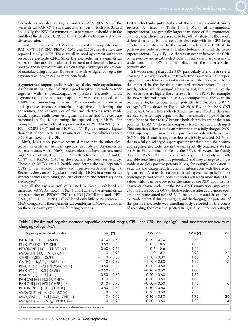
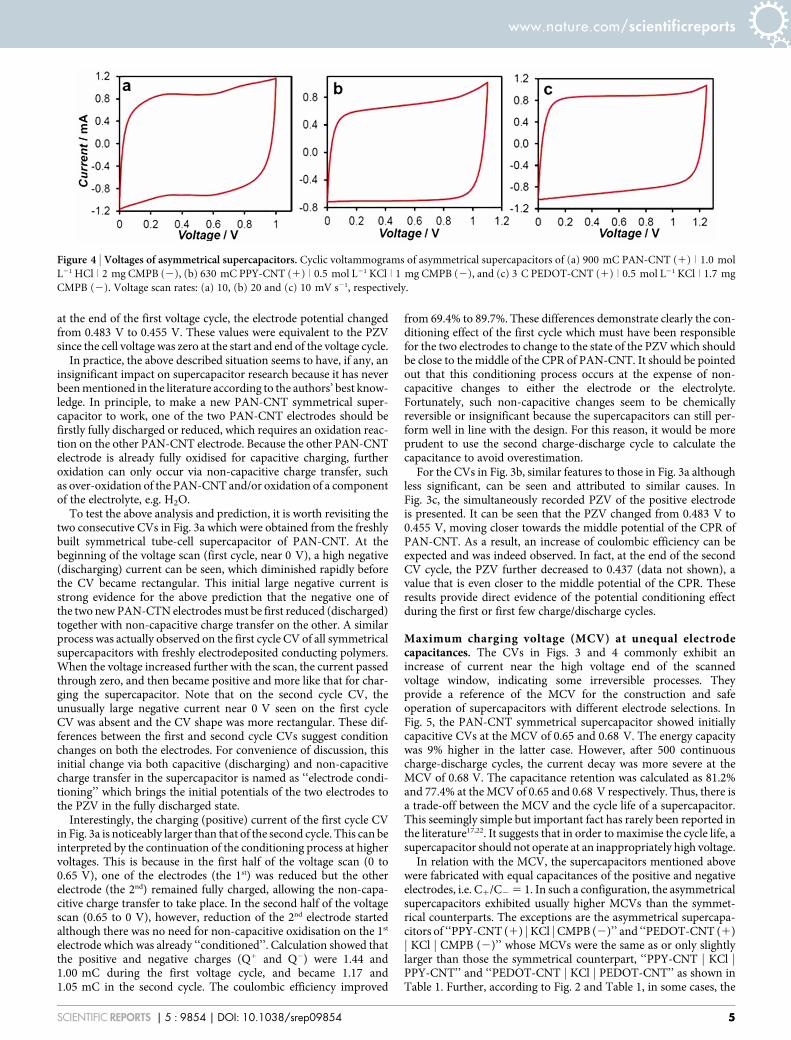
Asymmetrical supercapacitors with equal electrode capacitances.As shown in Fig. 2, the CMPB is a good negative electrode to worktogether with a pseudocapacitive positive electrode. Thus,asymmetrical tube-cell supercapacitors were constructed withCMPB and conducting polymer-CNT composite as the negativeand positive electrode materials respectively. Following theconvention, the capacitances of the two electrodes were madeequal. Typical results from testing such asymmetrical tube-cells arepresented in Fig. 4, confirming the expected larger MCVs. Forexample, the asymmetrical supercapacitor of ‘‘PAN-CNT (1) jHCl j CMPB (2)’’ had an MCV of 1 V (Fig. 4a), notably higherthan that of the PAN-CNT symmetrical capacitor which is about0.65 V as shown in Fig. 3b.MnO2 has a more positive potential range than the other elec-
trode materials in neutral aqueous electrolytes. Asymmetricalsupercapacitors with a MnO2 positive electrode have demonstratedhigh MCVs of 2.0, 1.7, and 1.8 V with activated carbon5, SnO2-CNT20 and PEDOT-CNT4 as the negative electrode, respectively.These high MCVs are all feasible considering the well separatedCPRs of the selected positive and negative electrodes (Fig. 2).Recent reviews on MnO2 also showed high MCVs in asymmetricalsupercapacitors with MnO2 positive electrodes and neutral aqueouselectrolytes14,15.Not all the asymmetrical cells listed in Table 1 exhibited an
increased MCV. As shown in Fig. 4 and Table 1, the asymmetricalsupercapacitor of ‘‘PEDOT-CNT (1) jKCl jCMPB (2)’’ and ‘‘PPY-CNT (1) j KCl j CMPB (2)’’ exhibited only little or no increase inMCV compared to their symmetrical counterparts.More discussionson these cases are given in the following sections.
Initial electrode potentials and the electrode conditioningprocess. As listed in Table 1, the MCVs of asymmetricalsupercapacitors are generally larger than those of the symmetricalcounterparts. These increases can be broadly attributed to the use of adifferent material for the negative electrode with its CPR beingeffectively an extension to the negative side of the CPR of thepositive electrode. However, it is also obvious that for all the testedsupercapacitors, EN2. EP1, i.e. there is an overlap between the CPRsof the positive and negative electrodes. In such cases, it is necessary tounderstand the PZV and its effect on the supercapacitorperformance.It is worth noting that at the PZV, particularly after one or several
charging-discharging cycles, the two electrodematerials in the super-capacitor are each in a state that is not necessarily the same as that ofthe material in the freshly constructed supercapacitor. In otherwords, before any charging-discharging test, the potentials of thetwo electrodes are highly likely far away from the PZV. For example,the newly electrodeposited PAN-CNT composite is always in theoxidised state, i.e. its open circuit potential is at or close to 0.7 Vvs. Ag/AgCl as shown in Fig. 2 (which is EP2 of the PAN-CNTcomposite). When two such electrodes are assembled in the sym-metrical tube-cell supercapacitor, the open circuit voltage of the cellcould be at or close to 0 V because both electrodes are of the samepotential, i.e. 0.7 V where the composite is fully oxidised or charged.This situation differs significantly from that in a fully charged PAN-CNT supercapacitor in which the positive electrode is fully oxidised(0.7 V in Fig. 2) and the negative electrode is fully reduced (0.1 V), orthat in a fully discharged supercapacitor in which both the positiveand negative electrodes are in the same partially oxidised state (ca.0.4 V in Fig. 2, which is ideally the PZV). However, the freshlydeposited PAN-CNT (and others) is likely in a thermodynamicallyunstable state (more positive potentials) and may change to a morestable state (less positive potentials) via, for example, relaxation instructure and charge redistribution or interactions with the electro-lyte, or both. As a result, if a symmetrical supercapacitor is left for aprolonged period of time, both electrodes will reachmore stable OCPvalues which can be close to or the same as the PZV upon its firstcharge-discharge cycle. For the PAN-CNT symmetrical supercapa-citor in Figure 3b, the OCP of both electrodes after aging under opencircuit weremeasured as 0.483 V. To better understand the change ofelectrode potential during charging and discharging, the potential ofthe positive electrode was simultaneously recorded in the courseof recording the CVs, and plotted in Figure 3c. Very interestingly,
Table 1 | Positive and negative electrode capacitive potential ranges, CPR1 and CPR2 (vs. Ag/AgCl), and supercapacitor maximumcharging voltage, MCV
Supercapacitors configuration CPR1 (V) CPR2 (V) MCV (V) Ref
PAN-CNT | HCl | PAN-CNT 0.10 , 0.70 0.10 , 0.70 0.65PPY-CNT | KCl | PPY-CNT 20.50 , 0.50 20.5 , 0.5 1.00PEDOT-CNT | KCl | PEDOT-CNT 20.60 , 0.60 20.6 , 0.6 1.20MnO2-CNT | KCl | MnO2-CNT 0 , 0.90 0 , 0.9 0.90 22CMPB | K2SO4 | CMPB 21.10 , 0.80 21.10 , 0.80 1.60 17CMPB (1) |K2SO4| CMPB (2) a 21.10 , 0.80 21.10 , 0.80 1.90 17PPY-CNT (1) | KCl | PEDOT-CNT (2) 20.50 , 0.50 20.60 , 0.60 1.00PPY-CNT (1) | KCl | CMPB (2) 20.50 , 0.50 20.80 , 0.60 1.00PPY-CNT (1) | KCl | AC (2) b 20.50 , 0.60 20.90 , 0.60 1.50PAN-CNT (1) | HCl | CMPB (2) 0.10 , 0.70 20.60 , 0.60 1.00PAN-CNT (1) | HCl | CMPB (2) a 0.10 , 0.70 20.60 , 0.60 1.40 16PEDOT-CNT (1) | KCl | CMPB (2) 20.60 , 0.60 20.80 , 0.60 1.25MnO2-CNT (1) | KNO3 | AC (2) 0 , 0.90 20.80 , 0.60 2.00 5MnO2-CNT(1) | KCl | SnO2–CNT (2) 0 , 0.90 20.80 , 0.80 1.70 20MnO2-CNT(1) | KNO3 | PEDOT (2) 0 , 0.90 20.60 , 0.60 1.80 4
a, b The capacitance ratios of positive to negative electrodes were a 453 and b 351.
www.nature.com/scientificreports
SCIENTIFIC REPORTS | 5 : 9854 | DOI: 10.1038/srep09854 4
at the end of the first voltage cycle, the electrode potential changedfrom 0.483 V to 0.455 V. These values were equivalent to the PZVsince the cell voltage was zero at the start and end of the voltage cycle.In practice, the above described situation seems to have, if any, an
insignificant impact on supercapacitor research because it has neverbeenmentioned in the literature according to the authors’ best know-ledge. In principle, to make a new PAN-CNT symmetrical super-capacitor to work, one of the two PAN-CNT electrodes should befirstly fully discharged or reduced, which requires an oxidation reac-tion on the other PAN-CNT electrode. Because the other PAN-CNTelectrode is already fully oxidised for capacitive charging, furtheroxidation can only occur via non-capacitive charge transfer, suchas over-oxidation of the PAN-CNT and/or oxidation of a componentof the electrolyte, e.g. H2O.To test the above analysis and prediction, it is worth revisiting the
two consecutive CVs in Fig. 3a which were obtained from the freshlybuilt symmetrical tube-cell supercapacitor of PAN-CNT. At thebeginning of the voltage scan (first cycle, near 0 V), a high negative(discharging) current can be seen, which diminished rapidly beforethe CV became rectangular. This initial large negative current isstrong evidence for the above prediction that the negative one ofthe two new PAN-CTN electrodesmust be first reduced (discharged)together with non-capacitive charge transfer on the other. A similarprocess was actually observed on the first cycle CV of all symmetricalsupercapacitors with freshly electrodeposited conducting polymers.When the voltage increased further with the scan, the current passedthrough zero, and then became positive and more like that for char-ging the supercapacitor. Note that on the second cycle CV, theunusually large negative current near 0 V seen on the first cycleCV was absent and the CV shape was more rectangular. These dif-ferences between the first and second cycle CVs suggest conditionchanges on both the electrodes. For convenience of discussion, thisinitial change via both capacitive (discharging) and non-capacitivecharge transfer in the supercapacitor is named as ‘‘electrode condi-tioning’’ which brings the initial potentials of the two electrodes tothe PZV in the fully discharged state.Interestingly, the charging (positive) current of the first cycle CV
in Fig. 3a is noticeably larger than that of the second cycle. This can beinterpreted by the continuation of the conditioning process at highervoltages. This is because in the first half of the voltage scan (0 to0.65 V), one of the electrodes (the 1st) was reduced but the otherelectrode (the 2nd) remained fully charged, allowing the non-capa-citive charge transfer to take place. In the second half of the voltagescan (0.65 to 0 V), however, reduction of the 2nd electrode startedalthough there was no need for non-capacitive oxidisation on the 1st
electrode which was already ‘‘conditioned’’. Calculation showed thatthe positive and negative charges (Q1 and Q2) were 1.44 and1.00 mC during the first voltage cycle, and became 1.17 and1.05 mC in the second cycle. The coulombic efficiency improved
from 69.4% to 89.7%. These differences demonstrate clearly the con-ditioning effect of the first cycle which must have been responsiblefor the two electrodes to change to the state of the PZV which shouldbe close to the middle of the CPR of PAN-CNT. It should be pointedout that this conditioning process occurs at the expense of non-capacitive changes to either the electrode or the electrolyte.Fortunately, such non-capacitive changes seem to be chemicallyreversible or insignificant because the supercapacitors can still per-form well in line with the design. For this reason, it would be moreprudent to use the second charge-discharge cycle to calculate thecapacitance to avoid overestimation.For the CVs in Fig. 3b, similar features to those in Fig. 3a although
less significant, can be seen and attributed to similar causes. InFig. 3c, the simultaneously recorded PZV of the positive electrodeis presented. It can be seen that the PZV changed from 0.483 V to0.455 V, moving closer towards the middle potential of the CPR ofPAN-CNT. As a result, an increase of coulombic efficiency can beexpected and was indeed observed. In fact, at the end of the secondCV cycle, the PZV further decreased to 0.437 (data not shown), avalue that is even closer to the middle potential of the CPR. Theseresults provide direct evidence of the potential conditioning effectduring the first or first few charge/discharge cycles.
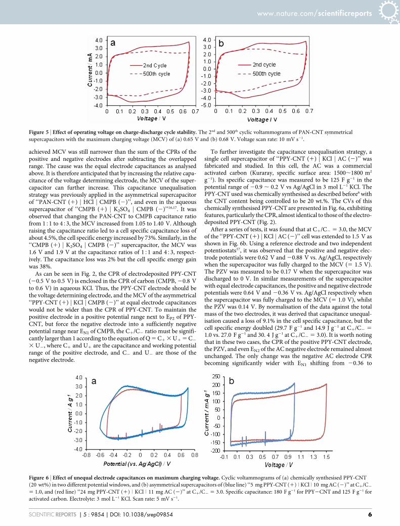
Maximum charging voltage (MCV) at unequal electrodecapacitances. The CVs in Figs. 3 and 4 commonly exhibit anincrease of current near the high voltage end of the scannedvoltage window, indicating some irreversible processes. Theyprovide a reference of the MCV for the construction and safeoperation of supercapacitors with different electrode selections. InFig. 5, the PAN-CNT symmetrical supercapacitor showed initiallycapacitive CVs at the MCV of 0.65 and 0.68 V. The energy capacitywas 9% higher in the latter case. However, after 500 continuouscharge-discharge cycles, the current decay was more severe at theMCV of 0.68 V. The capacitance retention was calculated as 81.2%and 77.4% at theMCV of 0.65 and 0.68 V respectively. Thus, there isa trade-off between the MCV and the cycle life of a supercapacitor.This seemingly simple but important fact has rarely been reported inthe literature17,22. It suggests that in order to maximise the cycle life, asupercapacitor should not operate at an inappropriately high voltage.In relation with the MCV, the supercapacitors mentioned above
were fabricated with equal capacitances of the positive and negativeelectrodes, i.e. C1/C25 1. In such a configuration, the asymmetricalsupercapacitors exhibited usually higher MCVs than the symmet-rical counterparts. The exceptions are the asymmetrical supercapa-citors of ‘‘PPY-CNT (1) jKCl jCMPB (2)’’ and ‘‘PEDOT-CNT (1)j KCl j CMPB (2)’’ whose MCVs were the same as or only slightlylarger than those the symmetrical counterpart, ‘‘PPY-CNT j KCl jPPY-CNT’’ and ‘‘PEDOT-CNT j KCl j PEDOT-CNT’’ as shown inTable 1. Further, according to Fig. 2 and Table 1, in some cases, the
Figure 4 | Voltages of asymmetrical supercapacitors. Cyclic voltammograms of asymmetrical supercapacitors of (a) 900 mC PAN-CNT (1) | 1.0 mol
L21 HCl | 2 mg CMPB (2), (b) 630 mC PPY-CNT (1) | 0.5 mol L21 KCl | 1 mg CMPB (2), and (c) 3 C PEDOT-CNT (1) | 0.5 mol L21 KCl | 1.7 mg
CMPB (2). Voltage scan rates: (a) 10, (b) 20 and (c) 10 mV s21, respectively.
www.nature.com/scientificreports
SCIENTIFIC REPORTS | 5 : 9854 | DOI: 10.1038/srep09854 5
achieved MCV was still narrower than the sum of the CPRs of thepositive and negative electrodes after subtracting the overlappedrange. The cause was the equal electrode capacitances as analysedabove. It is therefore anticipated that by increasing the relative capa-citance of the voltage determining electrode, the MCV of the super-capacitor can further increase. This capacitance unequalisationstrategy was previously applied in the asymmetrical supercapacitorof ‘‘PAN-CNT (1) j HCl j CMPB (2)’’, and even in the aqueoussupercapacitor of ‘‘CMPB (1) j K2SO4 j CMPB (2)’’16,17. It wasobserved that changing the PAN-CNT to CMPB capacitance ratiofrom 151 to 453, the MCV increased from 1.05 to 1.40 V. Althoughraising the capacitance ratio led to a cell specific capacitance loss ofabout 4.5%, the cell specific energy increased by 73%. Similarly, in the‘‘CMPB (1) j K2SO4 j CMPB (2)’’ supercapacitor, the MCV was1.6 V and 1.9 V at the capacitance ratios of 151 and 453, respect-ively. The capacitance loss was 2% but the cell specific energy gainwas 38%.As can be seen in Fig. 2, the CPR of electrodeposited PPY-CNT
(20.5 V to 0.5 V) is enclosed in the CPR of carbon (CMPB,20.8 Vto 0.6 V) in aqueous KCl. Thus, the PPY-CNT electrode should bethe voltage determining electrode, and theMCV of the asymmetrical‘‘PPY-CNT (1) j KCl j CMPB (2)’’ at equal electrode capacitanceswould not be wider than the CPR of PPY-CNT. To maintain thepositive electrode in a positive potential range next to EP2 of PPY-CNT, but force the negative electrode into a sufficiently negativepotential range near EN1 of CMPB, the C1/C2 ratio must be signifi-cantly larger than 1 according to the equation of Q5C13U15C2
3 U2, where C1 and U1 are the capacitance and working potentialrange of the positive electrode, and C2 and U2 are those of thenegative electrode.
To further investigate the capacitance unequalisation strategy, asingle cell supercapacitor of ‘‘PPY-CNT (1) j KCl j AC (2)’’ wasfabricated and studied. In this cell, the AC was a commercialactivated carbon (Kuraray, specific surface area: 1500,1800 m2
g21). Its specific capacitance was measured to be 125 F g21 in thepotential range of 20.9 , 0.2 V vs Ag/AgCl in 3 mol L21 KCl. ThePPY-CNT used was chemically synthesised as described before6 withthe CNT content being controlled to be 20 wt.%. The CVs of thischemically synthesised PPY-CNT are presented in Fig. 6a, exhibitingfeatures, particularly the CPR, almost identical to those of the electro-deposited PPY-CNT (Fig. 2).After a series of tests, it was found that at C1/C2 5 3.0, the MCV
of the ‘‘PPY-CNT (1) j KCl j AC (2)’’ cell was extended to 1.5 V asshown in Fig. 6b. Using a reference electrode and two independentpotentiostats17, it was observed that the positive and negative elec-trode potentials were 0.62 V and20.88 V vs. Ag/AgCl, respectivelywhen the supercapacitor was fully charged to the MCV (5 1.5 V).The PZV was measured to be 0.17 V when the supercapacitor wasdischarged to 0 V. In similar measurements of the supercapacitorwith equal electrode capacitances, the positive and negative electrodepotentials were 0.64 V and 20.36 V vs. Ag/AgCl respectively whenthe supercapacitor was fully charged to the MCV (5 1.0 V), whilstthe PZV was 0.14 V. By normalisation of the data against the totalmass of the two electrodes, it was derived that capacitance unequal-isation caused a loss of 9.1% in the cell specific capacitance, but thecell specific energy doubled (29.7 F g21 and 14.9 J g21 at C1/C2 51.0 vs. 27.0 F g21 and 30. 4 J g21 at C1/C2 5 3.0). It is worth notingthat in these two cases, the CPR of the positive PPY-CNT electrode,the PZV, and even EN2 of the AC negative electrode remained almostunchanged. The only change was the negative AC electrode CPRbecoming significantly wider with EN1 shifting from 20.36 to
Figure 5 | Effect of operating voltage on charge-discharge cycle stability. The 2nd and 500th cyclic voltammograms of PAN-CNT symmetrical
supercapacitors with the maximum charging voltage (MCV) of (a) 0.65 V and (b) 0.68 V. Voltage scan rate: 10 mV s21.
Figure 6 | Effect of unequal electrode capacitances on maximum charging voltage. Cyclic voltammograms of (a) chemically synthesised PPY-CNT
(20 wt%) in two different potential windows, and (b) asymmetrical supercapacitors of (blue line) ‘‘5 mg PPY-CNT (1) | KCl | 10 mgAC (2)’’ at C1/C2
5 1.0, and (red line) ‘‘24 mg PPY-CNT (1) | KCl | 11 mg AC (2)’’ at C1/C2 5 3.0. Specific capacitance: 180 F g21 for PPY2CNT and 125 F g21 for
activated carbon. Electrolyte: 3 mol L21 KCl. Scan rate: 5 mV s21.
www.nature.com/scientificreports
SCIENTIFIC REPORTS | 5 : 9854 | DOI: 10.1038/srep09854 6
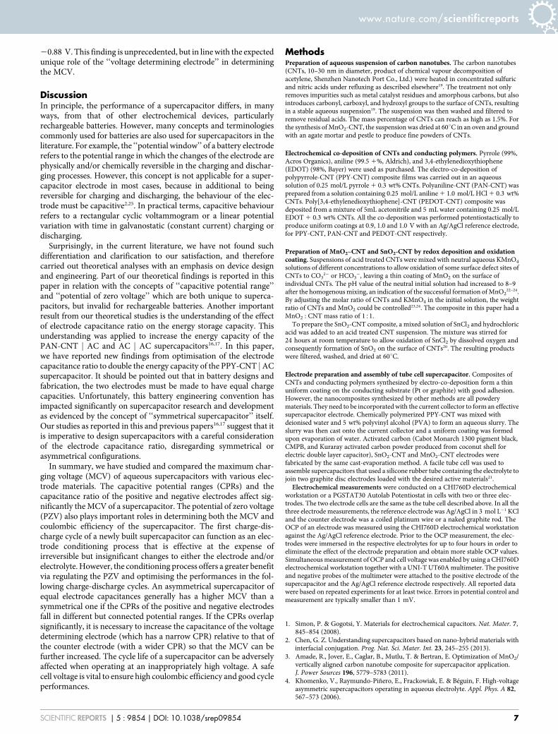
20.88 V. This finding is unprecedented, but in line with the expectedunique role of the ‘‘voltage determining electrode’’ in determiningthe MCV.
DiscussionIn principle, the performance of a supercapacitor differs, in manyways, from that of other electrochemical devices, particularlyrechargeable batteries. However, many concepts and terminologiescommonly used for batteries are also used for supercapacitors in theliterature. For example, the ‘‘potential window’’ of a battery electroderefers to the potential range in which the changes of the electrode arephysically and/or chemically reversible in the charging and dischar-ging processes. However, this concept is not applicable for a super-capacitor electrode in most cases, because in additional to beingreversible for charging and discharging, the behaviour of the elec-trode must be capacitive2,25. In practical terms, capacitive behaviourrefers to a rectangular cyclic voltammogram or a linear potentialvariation with time in galvanostatic (constant current) charging ordischarging.Surprisingly, in the current literature, we have not found such
differentiation and clarification to our satisfaction, and thereforecarried out theoretical analyses with an emphasis on device designand engineering. Part of our theoretical findings is reported in thispaper in relation with the concepts of ‘‘capacitive potential range’’and ‘‘potential of zero voltage’’ which are both unique to superca-pacitors, but invalid for rechargeable batteries. Another importantresult from our theoretical studies is the understanding of the effectof electrode capacitance ratio on the energy storage capacity. Thisunderstanding was applied to increase the energy capacity of thePAN-CNT j AC and AC j AC supercapacitors16,17. In this paper,we have reported new findings from optimisation of the electrodecapacitance ratio to double the energy capacity of the PPY-CNT jACsupercapacitor. It should be pointed out that in battery designs andfabrication, the two electrodes must be made to have equal chargecapacities. Unfortunately, this battery engineering convention hasimpacted significantly on supercapacitor research and developmentas evidenced by the concept of ‘‘symmetrical supercapacitor’’ itself.Our studies as reported in this and previous papers16,17 suggest that itis imperative to design supercapacitors with a careful considerationof the electrode capacitance ratio, disregarding symmetrical orasymmetrical configurations.In summary, we have studied and compared the maximum char-
ging voltage (MCV) of aqueous supercapacitors with various elec-trode materials. The capacitive potential ranges (CPRs) and thecapacitance ratio of the positive and negative electrodes affect sig-nificantly theMCV of a supercapacitor. The potential of zero voltage(PZV) also plays important roles in determining both the MCV andcoulombic efficiency of the supercapacitor. The first charge-dis-charge cycle of a newly built supercapacitor can function as an elec-trode conditioning process that is effective at the expense ofirreversible but insignificant changes to either the electrode and/orelectrolyte. However, the conditioning process offers a greater benefitvia regulating the PZV and optimising the performances in the fol-lowing charge-discharge cycles. An asymmetrical supercapacitor ofequal electrode capacitances generally has a higher MCV than asymmetrical one if the CPRs of the positive and negative electrodesfall in different but connected potential ranges. If the CPRs overlapsignificantly, it is necessary to increase the capacitance of the voltagedetermining electrode (which has a narrow CPR) relative to that ofthe counter electrode (with a wider CPR) so that the MCV can befurther increased. The cycle life of a supercapacitor can be adverselyaffected when operating at an inappropriately high voltage. A safecell voltage is vital to ensure high coulombic efficiency and good cycleperformances.
MethodsPreparation of aqueous suspension of carbon nanotubes. The carbon nanotubes(CNTs, 10–30 nm in diameter, product of chemical vapour decomposition ofacetylene, Shenzhen Nanotech Port Co., Ltd.) were heated in concentrated sulfuricand nitric acids under refluxing as described elsewhere19. The treatment not onlyremoves impurities such as metal catalyst residues and amorphous carbons, but alsointroduces carbonyl, carboxyl, and hydroxyl groups to the surface of CNTs, resultingin a stable aqueous suspension19. The suspension was then washed and filtered toremove residual acids. The mass percentage of CNTs can reach as high as 1.5%. Forthe synthesis ofMnO2-CNT, the suspension was dried at 60uC in an oven and groundwith an agate mortar and pestle to produce fine powders of CNTs.
Electrochemical co-deposition of CNTs and conducting polymers. Pyrrole (99%,Acros Organics), aniline (99.5 1%, Aldrich), and 3,4-ethylenedioxythiophene(EDOT) (98%, Bayer) were used as purchased. The electro-co-deposition ofpolypyrrole-CNT (PPY-CNT) composite films was carried out in an aqueoussolution of 0.25 mol/L pyrrole1 0.3 wt% CNTs. Polyaniline-CNT (PAN-CNT) wasprepared from a solution containing 0.25 mol/L aniline1 1.0 mol/L HCl1 0.3 wt%CNTs. Poly[3,4-ethylenedioxythiophene]-CNT (PEDOT-CNT) composite wasdeposited from a mixture of 5mL acetonitrile and 5 mL water containing 0.25 mol/LEDOT1 0.3 wt% CNTs. All the co-deposition was performed potentiostactically toproduce uniform coatings at 0.9, 1.0 and 1.0 V with an Ag/AgCl reference electrode,for PPY-CNT, PAN-CNT and PEDOT-CNT respectively.
Preparation of MnO2–CNT and SnO2-CNT by redox deposition and oxidationcoating. Suspensions of acid treated CNTs were mixed with neutral aqueous KMnO4
solutions of different concentrations to allow oxidation of some surface defect sites ofCNTs to CO3
22 or HCO32, leaving a thin coating of MnO2 on the surface of
individual CNTs. The pH value of the neutral initial solution had increased to 8–9after the homogenousmixing, an indication of the successful formation ofMnO2
22–24.By adjusting the molar ratio of CNTs and KMnO4 in the initial solution, the weightratio of CNTs and MnO2 could be controlled23,24. The composite in this paper had aMnO2 : CNT mass ratio of 151.
To prepare the SnO2-CNT composite, a mixed solution of SnCl2 and hydrochloricacid was added to an acid treated CNT suspension. The mixture was stirred for24 hours at room temperature to allow oxidation of SnCl2 by dissolved oxygen andconsequently formation of SnO2 on the surface of CNTs20. The resulting productswere filtered, washed, and dried at 60uC.
Electrode preparation and assembly of tube cell supercapacitor. Composites ofCNTs and conducting polymers synthesized by electro-co-deposition form a thinuniform coating on the conducting substrate (Pt or graphite) with good adhesion.However, the nanocomposites synthesized by other methods are all powderymaterials. They need to be incorporated with the current collector to form an effectivesupercapacitor electrode. Chemically polymerized PPY-CNT was mixed withdeionised water and 5 wt% polyvinyl alcohol (PVA) to form an aqueous slurry. Theslurry was then cast onto the current collector and a uniform coating was formedupon evaporation of water. Activated carbon (Cabot Monarch 1300 pigment black,CMPB, and Kuraray activated carbon powder produced from coconut shell forelectric double layer capacitor), SnO2-CNT and MnO2-CNT electrodes werefabricated by the same cast-evaporation method. A facile tube cell was used toassemble supercapacitors that used a silicone rubber tube containing the electrolyte tojoin two graphite disc electrodes loaded with the desired active materials21.
Electrochemical measurements were conducted on a CHI760D electrochemicalworkstation or a PGSTAT30 Autolab Potentiostat in cells with two or three elec-trodes. The two electrode cells are the same as the tube cell described above. In all thethree electrode measurements, the reference electrode was Ag/AgCl in 3 mol L21 KCland the counter electrode was a coiled platinum wire or a naked graphite rod. TheOCP of an electrode was measured using the CHI760D electrochemical workstationagainst the Ag/AgCl reference electrode. Prior to the OCP measurement, the elec-trodes were immersed in the respective electrolytes for up to four hours in order toeliminate the effect of the electrode preparation and obtain more stable OCP values.Simultaneousmeasurement of OCP and cell voltage was enabled by using a CHI760Delectrochemical workstation together with a UNI-T UT60Amultimeter. The positiveand negative probes of the multimeter were attached to the positive electrode of thesupercapacitor and the Ag/AgCl reference electrode respectively. All reported datawere based on repeated experiments for at least twice. Errors in potential control andmeasurement are typically smaller than 1 mV.
1. Simon, P. & Gogotsi, Y. Materials for electrochemical capacitors. Nat. Mater. 7,845–854 (2008).
2. Chen, G. Z. Understanding supercapacitors based on nano-hybrid materials withinterfacial conjugation. Prog. Nat. Sci. Mater. Int. 23, 245–255 (2013).
3. Amade, R., Jover, E., Caglar, B., Mutlu, T. & Bertran, E. Optimization of MnO2/vertically aligned carbon nanotube composite for supercapacitor application.J. Power Sources 196, 5779–5783 (2011).
4. Khomenko, V., Raymundo-Piñero, E., Frackowiak, E. & Beguin, F. High-voltageasymmetric supercapacitors operating in aqueous electrolyte. Appl. Phys. A 82,567–573 (2006).
www.nature.com/scientificreports
SCIENTIFIC REPORTS | 5 : 9854 | DOI: 10.1038/srep09854 7
5. Khomenko, V., Raymundo-Piñero, E. & Beguin, F. Optimisation of anasymmetric manganese oxide/activated carbon. J. Power Sources 153, 183–190(2006).
6. Zhou, X., Peng, C. & Chen, G. Z. 20 V stack of aqueous supercapacitors withcarbon (2), titanium bipolar plates and CNT-polypyrrole composite (1). AIChEJ. 58, 974–983 (2012).
7. Arbizzani, C. et al. high-energy supercapacitors based on solvent-free ionic liquidelectrolytes. J. Power Sources 185, 1575–1579 (2008).
8. Krause, A. & Balducci, A. High voltage electrochemical double layer capacitorcontaining mixtures of ionic liquids and organic carbonate as electrolytes.Electrochem. Comm. 13, 814–817 (2011).
9. Demarconnay, L., Raymundo-Piñero, E. &Beguin, F. A symmetric carbon/carbonsupercapacitor operating at 1.6 V by using a neutral aqueous solution.Electrochem. Comm. 12, 1275–1278 (2010).
10. Shen, C. et al. A high-energy-density micro supercapacitor of asymmetric MnO2-carbon configuration by using micro-fabrication technologies. J. Power Sources234, 302–309 (2013).
11. Cao, J. et al. High voltage asymmetric supercapacitor based on MnO2 andgraphene electrodes. J. Electroanal. Chem. 689, 201–206 (2013).
12. Wu, T., Chu, Y., Hu, C. & Hardwick, L. J. Criteria appointing the highestacceptable cell voltage of asymmetric supercapacitors. Electrochem. Comm. 27,81–84 (2013).
13. Wu, T. H., Hsu, C. T., Hu, C. C. & Hardwick, L. J. Important parameters affectingthe cell voltage of aqueous electrical double-layer capacitors. J. Power Sources 242,289–298 (2013).
14. Long, J. W. et al. Asymmetric electrochemical capacitors—Stretching the limits ofaqueous electrolytes. MRS Bull. 36, 513–522 (2011).
15. Belanger, D., Brousse, T. & Long, J. W. Manganese oxides: battery materials makethe leap to electrochemical capacitors. Electrochem. Soc. Interface. 17, 49–52(2008).
16. Peng, C., Zhang, S. W., Zhou, X. H. & Chen, G. Z. Unequalisation of electrodecapacitances for enhanced energy capacity in asymmetrical supercapacitors.Energy Environ. Sci. 3, 1499–1502 (2010).
17. Chae, J. H. & Chen, G. Z. 1.9 V Aqueous carbon-carbon supercapacitors withunequal electrode capacitances. Electrochim. Acta 86, (SI) 248–254 (2012)
18. Wang, X. & Zheng, J. P. The optimal energy density of electrochemical capacitorsusing two different electrodes. J. Electrochem. Soc. 151, A1683–A1689 (2004).
19. Peng, C., Jin, J. & Chen, G. Z. A comparative study on electrochemical co-deposition and capacitance of composite films of conducting polymers andcarbon nanotubes. Electrochim. Acta 53, 525–537 (2007).
20. Ng, K. C., Zhang, S., Peng, C. & Chen, G. Z. Individual and bipolarly stackedasymmetrical aqueous supercapacitors of CNTs/SnO2 and CNTs/MnO2
nanocomposites. J. Electrochem. Soc. 156, A846–A853 (2009).
21. Hu, D., Peng, C. & Chen, G. Z. Electrodeposition of nonconducting polymers:Roles of carbon nanotubes in the process and products. ACS Nano 4, 4274–4282(2010).
22. Zhang, S., Peng, C., Ng, K. C. & Chen, G. Z. Nanocomposites of manganese oxidesand carbon nanotubes for aqueous supercapacitor stacks. Electrochim. Acta 55,7447–7453 (2010).
23. Stoller, M. D. & Ruoff, R. S. Best practice methods for determining an electrodematerial’s performance for ultracapacitors. Energy Environ. Sci. 3, 1294–1301(2010).
24. Jin, X., Zhou, W., Zhang, S. & Chen, G. Z. Nanoscale micro-electrochemical cellson carbon nanotubes. Small 3, 1513–1517 (2007).
25. Akinwolemiwa, B., Peng, C. & Chen, G. Z. Redox electrolytes in supercapacitors, J.Electrochem. Soc., 162, A5054–A5059 (2015).
AcknowledgmentsThis work received financial supports from the Fundamental Research Funds for theCentral Universities of China, the 3315 Plan and IAMET Special Fund (2014A35001-1) ofthe Ningbo Municipal Government, the NSFC (21403119), and E.ON AG through the E.ON International Research Initiative – Energy Storage 2007.
Author contributionsG.Z.C. and C.P. proposed the work. Z.X.D., C.P., J.H.C. and K.C.N. carried out theexperiments. G.Z.C. finalised the manuscript. All authors contributed to writing up themanuscript.
Additional informationCompeting financial interests: The authors declare no competing financial interests.
How to cite this article: Dai, Z., Peng, C., Chae, J.H., Ng, K.C. & Chen, G.Z. Cell voltageversus electrode potential range in aqueous supercapacitors. Sci. Rep. 5, 9854; DOI:10.1038/srep09854 (2015).
This work is licensed under a Creative Commons Attribution 4.0 InternationalLicense. The images or other third party material in this article are included in thearticle’s Creative Commons license, unless indicated otherwise in the credit line; ifthe material is not included under the Creative Commons license, users will needto obtain permission from the license holder in order to reproduce thematerial. Toview a copy of this license, visit http://creativecommons.org/licenses/by/4.0/
www.nature.com/scientificreports
SCIENTIFIC REPORTS | 5 : 9854 | DOI: 10.1038/srep09854 8


